
Engineering Coordination
346
Engineering Coordination A Methodology for the Coordination of Planning Systems Dissertation zur Erlangung des Doktorgrades der Naturwissenschaften vorgelegt beim Fachbereich Informatik und Mathematik der Johann Wolfgang Goethe – Universit¨ at in Frankfurt am Main von Ren´ e Schumann aus Delmenhorst Frankfurt (2010) (D 30)
-
Upload
khangminh22 -
Category
Documents
-
view
2 -
download
0
Transcript of Engineering Coordination

Engineering CoordinationA Methodology for the Coordination of Planning Systems
Dissertation
zur Erlangung des Doktorgrades
der Naturwissenschaften
vorgelegt beim Fachbereich Informatik und Mathematik
der Johann Wolfgang Goethe – Universitat
in Frankfurt am Main
von
Rene Schumann
aus Delmenhorst
Frankfurt (2010)
(D 30)

vom Fachbereich Informatik und Mathematik der
Johann Wolfgang Goethe – Universitat als Dissertation angenommen
Dekan: Prof. Dr. Tobias Weth . . . . . . . . . . . . . . . . . . . . . . . . . . . . . . . . . . . . . . . . . . . . . . . . .
Gutachter: Prof. Dr. Ingo J. Timm, . . . . . . . . . . . . . . . . . . . . . . . . . . . . . . . . . . . . . . . . . . .Prof. Dr. Jurgen Sauer, . . . . . . . . . . . . . . . . . . . . . . . . . . . . . . . . . . . . . . . . . . . .Prof. Dr. Ulrich Schwanecke . . . . . . . . . . . . . . . . . . . . . . . . . . . . . . . . . . . . . . .
Datum der Disputation: 06.10.2010 . . . . . . . . . . . . . . . . . . . . . . . . . . . . . . . . . . . . . . . . . . . . .

Acknowledgement
The work this thesis is based on, has been done over several years and at threedifferent locations. During my appointment at the OFFIS Institute for Informa-tion Technology in Oldenburg, while I was employed at the Goethe University inFrankfurt am Main, and during my research stays at the Artificial Intelligencegroup at the Rey Juan Carlos University in Mostoles (Spain).
The issue of coordination of autonomous planning systems has been at the centerof my research for more than six years now. It started when I was a student atthe Carl von Ossietzky University Oldenburg. This project took longer than Iexpected and I moved to locations I never thought I would visit when I started it.Consequently, over the course of time I have to thank a number of people I havemeet during this time at the various locations.
First of all, I would like to thank my main supervisor Prof. Dr. Ingo J. Timm(Goethe University Frankfurt am Main). I met him in 2005 at a conference andmoved to Frankfurt in 2007 to become part of his group. I would like to thank himfor the opportunity to move to Frankfurt. It was not only a geographical change,but also offered me a complete new perspective on research. I am very gratefulfor all the valuable advice and encouragement that he still gives me.
Furthermore, I would like thank apl. Prof. Dr. Jurgen Sauer (Carl von Ossiet-zky University Oldenburg). He supervised my diploma thesis in 2004 and to thisday still gives me valuable advice. He encouraged me to start with my PhD andsupport me continuously even after I left Oldenburg.
I also want to thank Prof. Dr. Ulrich Schwanecke (Hochschule RheinMainUniversity of Applied Sciences) for the valuable advice he gave me since I joinedthe Sensyble graduate school.
I am deeply grateful for the hospitality and valuable discussions of Prof. Dr.Sascha Ossowski and his entire group. I spent 10 days in June 2009 and threemonth (Feb.–Apr.) in 2010 as a visiting researcher in his group. Large parts ofthis thesis have been written there.
I want to express my gratitude to Dr. Christoph Mayer (OFFIS Institute forInformation Technology). Christoph Mayer was the division manager of the R&Ddivision Business Information Management at the OFFIS Institute, and my first
iii

iv Acknowledgement
superior. I would like to thank him for his support, his advice and the chance tolearn a lot about projects and leadership in science.
A very special thanks goes to the entire Information Systems and Simulationgroup at the Goethe University Frankfurt am Main. The people that accompa-nied me during my time at this group (in addition to Prof. Dr. Ingo J. Timm)are Marion Terrell, Dr. Andreas Lattner, Tjorben Bogon, Yann Lorion, PascalKatzenbach and Jorg Dallmeyer. I have to thank all of them, and in particularDr. Andreas Lattner, for their support and advices.
Also, a very special thank you goes to my dear friend Mathias Uslar (OFFISInstitute for Information Technology), a former colleague of mine. Especially inmy first years of my endeavors in research he supported me with a lot of valuableadvice while in the last years he offered much needed moral support.
I also have to thank Jens Oehlerking (University Oldenburg), who also sup-ported me during the writing of this thesis.
Another person I met during my time as PhD student, who became a friendthat also helped me is Dr. Leif Meier (Proctor & Gamble Service GmbH). He gotme involved in the container terminal management problem and we have workedcollaboratively on this issue. Also, I would like to thank him for the planningsystems he provided to me.
I was also supported by Dr. David Sabel (Goethe Universitat Frankfurt) andwant to thank him for supporting the Latex template this thesis uses.
I would like to thank Dr. Michael Schwind (Goethe Universitat Frankfurt) forthe insightful discussions concerning combinatorial auctions.
I am very grateful to my former diploma students, who have contributed to as-pects of my research that can partially be found in this thesis. In particular, I haveto mention Thomas Timmermann (Ernst & Young GmbH) and Zijad Kurtanovic(Healy Hudson GmbH).
Also, I have to thank the students who participated in the practical course“Praktikum Wirtschaftsinformatik und Simulation” in the winter term 2009/2010for their efforts in developing planning systems and encapsulate them using webservices.
While I was employed at the Goethe University I was additionally supportedby GRADE, the Goethe Graduate Academy (former Otto Stern School) support-ing me with subsidies for childcare. I received travel funding from the HerrmannWillkomm-Stiftung in 2008 and 2009. Furthermore, I was supported by the EU-COST Action Agreement Technologies. I received a grant for a short-term sci-

Acknowledgement v
entific mission (STSM) for a 10 day visit of the group of Prof. Dr. Sascha Os-sowski in 2009. Finally, I was supported by the German Academic ExchangeService (DAAD) with a short-term grant for doctorate students (grant numberD/09/48031). This scholarship allowed me to stay in Spain for three month in2010.
For their ongoing support in so many different ways I would like to thank myparents. I am very grateful for their support.
Especially in the last months of this thesis, my family supported me very much.They had to put up with my stress and the fact that I was not there for threemonth. Therefore, I am very grateful.
I would like to thank my two sons Philipp Ephraim and Simon Casimir for theirongoing lecture they give to me to focus on the important aspects of life. Theywere born during the time this thesis has been written, and know their father onlyas a PhD. student, so far.
All these persons have influenced me, and consequently, the way this thesis lookslike. But there would be no thesis in any way without the support and love of mywife. I am deeply indebted to Jennifer for the advice and support she provided tome during all this time. She brought me back on track when I lost sight of reality.

vi Acknowledgement

Zusammenfassung
Reale Planungsprobleme, wie etwa die Produktionsplanung in einer Supply Chain,sind komplex Planungsprobleme. Eine ubliche Strategie derart komplexen Proble-men zu losen, ist es diese Probleme in einfachere Teilprobleme zu zerlegen und diesedann separat, meist sequentiell, zu losen (divide-and-conquer Strategie). DieserAnsatz erlaubt die Erstellung von (suboptimalen) Planen fur eine Reihe von realenAnwendungen und ist heute in den Organisationsstrukturen von großeren Un-ternehmen institutionalisiert worden. Allerdings werden Abhangigkeiten zwischenden Teilproblemen nicht ausreichend berucksichtigt, da die Partialprobleme se-quentiell ohne Feedback gelost werden. Die erstellten Teillosungen mussen deswe-gen oft nachtraglich koordiniert werden. Die Beispiele, die in dieser Arbeit genutztwerden, sind die Koordination von Planungssysteme in der Produktion und Dis-tribution von Gutern, die Koordination der Planungssysteme von Partner einesSupply Chain, und die Koordination der Planungssysteme die im Rahmen desContainer Terminal Managements.
In dieser Arbeit wird die operative Koordination von existierenden Planungssys-temen betrachtet. Dabei wird von einer inharent gegebenen Problemstellung aus-gegangen in der fur verteilte, abhangige Planungsentscheidungen automatischePlanungssysteme eingesetzt werden. Die Plane dieser Planungssysteme mussenkoordiniert werden, um die Realisierbarkeit dieser Plane unter Berucksichtigungevtl. wechselseitiger Abhangigkeiten der Planungsprobleme zu gewahrleisten. Jenach gegebener Problemstellung kann dabei der Fokus neben der reinen gemein-samen/parallelen Realisierbarkeit einer Menge von verteilt erstellten Planen auchdie Verbesserung einer Gesamtsystemperformance im Fokus liegen. Eine Koordi-nation von Planungsprozessen auf der taktischen oder strategischen Ebene wirdin dieser Arbeit nicht betrachtet. Ein Beispiel fur derartige taktische oder stra-tegische Koordinationsprobleme sind etwa die Auswahl eines Netzwerkes oder dieZerlegung des Gesamtproblems in unterschiedliche Teilprobleme.
Im Rahmen der hier vorliegenden Arbeit wird zuerst ein Einblick in die Grund-lagen von Planungssystemen und Systemen der verteilten Kunstlichen Intelligenzgegeben. Anschließend wird im dritten Kapitel ein breiter Uberblick uber denStand der Forschung gegeben. Dabei werden mehrere Bereiche untersucht. Zuerstwird die Modellierung von Abhangigkeiten betrachtet und dabei grundsatzliche
vii

viii Zusammenfassung
Uberlegungen zu Problemen und Komplexitat bei der Koordination von au-tonomen Planungssystemen vorgestellt.
Anschließend wird das Gebiet der Koordination wird in verschiedenen For-schungsgebieten, wie etwa der verteilten Kunstlichen Intelligenz, den Wirtschafts-wissenschaften oder der Spieltheorie untersucht. Weiterhin wird das Gebiet desagentenorientiertem Software Engineering betrachtet. Dieses wird insbesondereauf dessen Beitrag zur Wiederverwendung von bereits entwickelten Methodenhin betrachtet. Dabei ist festzuhalten, dass der Hauptbeitrag der Wiederverwen-dung von Konzepten des Gebietes des agentenorientierten Software Engineering imRahmen von Agentenframeworks stattfindet. Daruber hinaus bietet der aktuelleStand der Forschung kaum Moglichkeiten bzw. Methoden, die die Wiederverwen-dung von existierenden Verfahren adressieren. Als Ausnahmen sind lediglich dieAnsatze von Jonker et al. [JTY05] fur die Nutzung von Organisationsformen undBussmann et al. [BJW03] fur die Auswahl von Interaktionsprotokollen zu nennen.Beide Ansatze basieren auf der Idee existierende Verfahren/Methoden anhand vonspezifischen Kriterien zu klassifizieren und uber diese Spezifikation der Charakter-istika der aktuellen Situation eine gerichtete Suche in den existierenden Verfahrennach diesen Kriterien durchzufuhren.
In dieser Arbeit werden aus diesem Grund die existierenden Verfahren zurKlassifikation von Koordinationsverfahren untersucht. Existierende Klassifika-tionen orientieren sich an eingesetzten Technologien (etwa bei Stockheim etal. [SSWG02]), der Perspektive auf das System (etwa bei Schumacher [Sch01])oder auf Basis von allgemeinen Theorien uber Koordination (etwa bei Busiet al. [BCGZ01]). Diese Klassifikationskriterien spiegeln die unterschiedlichenForschungsrichtungen und Theorien wieder, die einen Beitrag zur Erforschungder Koordination im Rahmen der verteilten Kunstlichen Intelligenz geleistethaben. Keine dieser Klassifikationsansatze erlaubt eine Aussage uber Ein-satzmoglichkeiten und Designentscheidungen der jeweiligen Koordinationsver-fahren aus. Aus diesem Grund wird im Rahmen dieser Arbeit einen problem-orientierten Ansatz vorgestellt. Durch die Identifikation von Charakteristika vonKoordinationsproblemen und der Herausarbeitung dieser Anforderungen an einKoordinationsverfahren wird das Konzept der Coordination Requirements ent-wickelt. Dies sind formalisierte Anforderungen an ein Koordinationsverfahren, diedas Koordinationsverfahren erfullen muss, um in der gegeben Situation anwend-bar zu sein. Es wird somit die Moglichkeit eroffnet eine formale Spezifikation desSachverhalts der Anwendbarkeit fur eine Koordinationsaufgabe zu spezifizieren.
Im Abschnitt 4.1 prasentieren wir auf Basis der in dieser Arbeit verwendetenbeispielhaften Koordinationsprobleme die folgenden sechs Charakteristika:
• Ist ein Allokationsproblem vorhanden?

Zusammenfassung ix
• Sind die lokalen Zielfunktionen vergleichbar?
• Sind die Planungssysteme homogen?
• Existiert eine globale Zielfunktion?
• Ist information hiding notwendig?
• Existieren zyklische Abhangigkeiten?
Auf Basis dieser sechs Charakteristika werden die vorgestellten Koordinationsver-fahren klassifiziert. Dies alleine ist zwar nicht ausreichend fur die Identifikationvon vorhanden geeigneten Koordinationsverfahren, allerdings kann es, wie in dendurchgefuhrten Fallstudien gezeigt wird, den Auswahlprozess beschleunigen, daschnell geeignete Kandidaten identifiziert werden konnen, die in einer genauerenAnalyse auf deren Anwendbarkeit hin untersucht werden konnen.
Fur die strukturierte Durchfuhrung der Identifikation von geeigneten Koordi-nationsverfahren wird im Rahmen dieser Arbeit ein Prozessmodell vorgestellt, dersogenannte ECo-Prozess (Engineering Coordination). Dieser Prozess soll sowohlden Auswahlprozess, als auch, sofern notig, den Designprozess eines neuen Koordi-nationsverfahrens unterstutzen. Der Prozess ist in die folgenden Schritte eingeteilt,die iterativ durchlaufen werden konnen:
• Modellierung der Problemstellung und des relevante Kontextes
• Formulierung von Anforderungen an einen Koordinationsmechanismus
• Auswahl/Entwurf eines Koordinationsmechanismuses
• Implementierung des Koordinationsverfahrens
• Evaluation des Koordinationsverfahrens
Diese Schritte werden im Rahmen der vorliegenden Arbeit detailliert beschrieben.Die Modellierung der Problemstellung stellt dabei den ersten Schritt dar, um dieProblemstellung analytisch zuganglich zu machen.
Wie bereits oben erlautert ist die Aufgabe der Coordination Requirements denSachverhalt der Anwendbarkeit zu operationalisieren. Die Anforderungen sollendabei auf Basis der vorangegangen Modellierung formuliert werden, d.h. die Re-quirements haben eine formale Grundlage. Die in Frage kommenden Koordina-tionsverfahren sollen im nachsten Schritt, der Auswahl eines geeigneten Koordi-nationsverfahrens, daraufhin betrachtet werden, ob sie die aufgestellten Anfor-derungen erfullen. Dies wird als qualitative Evaluation bezeichnet. Da die Co-ordination Requirements eine formale Definition besitzen, kann diese Evaluation

x Zusammenfassung
ebenfalls formal durchgefuhrt werden. Das Ergebnis der qualitativen Evaluationist eine Menge von moglichen Koordinationsverfahren, die im gegeben Kontext an-wendbar sind. Dies erlaubt allerdings keine weiteren Aussagen, wie gut, im Sinneeines global erreichbaren Qualitatsmaßes, diese Verfahren sind. Dies geschieht erstin der spater folgenden quantitativen Evaluation. Der von den Anforderungengetrieben Auswahlprozess ist ein Kernstuck der hier vorgestellten Arbeit. Durchdie Formulierung der Anforderungen und der Annotation eines Koordinations-mechanismus bezuglich der erfullten und nicht erfullten Anforderungen werdendie Motive fur Designentscheidungen dieses Verfahren expliziert. Wenn Koor-dinationsverfahren anhand dieser Anforderungen klassifiziert werden konnen, istes weiterhin moglich den Auswahlprozess zu vereinfachen und zu beschleunigen.Stellt sich in diesem Schritt heraus, dass kein existierenden/bekannter Koordina-tionsansatz alle Anforderungen erfullt ist ein solches Koordinationsverfahren nunauf Basis des Modells des Anwendungsfalles und der aufgestellten CoordinationRequirements zu entwerfen.
Um eine quantitative Evaluation durchfuhren zu konnen, ist es notwendig die inFrage kommenden Verfahren zu implementieren. Fur die Unterstutzung der Imple-mentierung eines Koordinationsansatzes wird in dieser Arbeit zusatzlich der CoPSProzess (Coordination of Planning Systems) vorgeschlagen. Der CoPS Prozesserlaubt einen ganzheitlichen systematischen Ansatz fur den Entwurf und die Im-plementierung eines Koordinationsverfahrens. Dabei werden im CoPS sowohl As-pekte auf der globalen Netzwerkebene, wie die Auswahl von Konversationspro-tokollen, als auch Entscheidungen, die lokal bei dem Entwurf eines jeden Agentengetroffen werden mussen berucksichtigt. Beispiele fur lokale Designentscheidun-gen sind etwa die Spezifikation von Verhaltensmustern in Konversationen oder dieAdaption existierender Planungssysteme, etwa mittels Web Services.
Zur Unterstutzung des CoPS Prozesses wird in dieser Arbeit das CoPS Frame-work vorgestellt. Auf Basis dieses Frameworks soll eine schnellere Imple-mentierung ermoglicht werden. Hierzu bietet das CoPS Framework etwa dieMoglichkeit an Konversationsprotokolle als textuelle Beschreibung zu spezifizie-ren und diese dann automatisiert zum Einen in Verhaltensautomaten zu trans-formieren, in denen ein lokales Entscheidungsverfahren modelliert werden kann,und zum Anderen kann diese textuelle Beschreibung in Sequenzdiagramme trans-formiert werden, um den Entwicklern des Systems eine geeignete Dokumentationzu liefern. Ziel des CoPS Frameworks ist es eine Plattform mit Basisfunktion-alitat eines Agenten bereit zu stellten der fur die Koordination von Planungssys-temen verantwortlich ist. Dabei ist es die Zielstellung des CoPS Frameworksdie Erstellung eines Prototyps eines agentenbasierten Koordinationsmechanismusfur existierende Planungssysteme. Dieser Prototyp soll dazu dienen den letzten

Zusammenfassung xi
Schritt, die Evaluation des Koordinationsverfahrens auf Basis quantitativer Datenzu ermoglichen. Das CoPS Framework ist zurzeit fur der produktiven Betrieb nichtgeeignet, da hierzu relevante Funktionalitaten, etwa bzgl. der Skalierbarkeit, derPerformance und der Persistenz nicht ausreichend unterstutzt werden.
Als abschließender Schritt des ECo Prozesses steht die Evaluation. Hierbeisoll eine Evaluation der Performance, etwa in Bezug auf die Performance desGesamtsystems hin, durchgefuhrt werden. Dieser Schritt wird auch als quanti-tative Evaluation bezeichnet, um dies zur oben erwahnten qualitativen Evalua-tion abzugrenzen. Die quantitative Evaluation ist ein wichtiger Prozessschritt,da sie die Uberprufung der beabsichtigten Performancekriterien sicherstellt undsomit uberpruft wird, ob das koordinierte Gesamtsystemverhalten im akzeptablenBereich liegt. Hierbei sind etwa Vergleiche mit alternativen Methoden oder eineEinordnung der Losungsqualitat moglich, etwa durch den Vergleich mit Verfahren,die die Coordination Requirments nicht einhalten, und so in der Regel in der Lagesind bessere Losungen zu finden. Beispielhaft ist hier etwa die zentrale Planung zunennen, die oft bessere Ergebnisse erzielen kann, als eine Menge von koordiniertenverteilten Planen. Aus Basis der Ergebnisse der quantitativen Evaluation kanndann eine Auswahl eines Koordinationsvefahrens fur die gegebene Problemstel-lung erfolgen.
Neben der reinen Definition eines Prozesses ist es weiterhin notwendig die An-wendbarkeit des Prozesses zu belegen. Des Weiteren ist es fur eine Verwendungeines derartigen Prozesses im industriellen Kontext notwendig eine empirischeStudie uber die Potentiale des Prozesses durchzufuhren. Eine derartige soziol-ogisch fundierte empirische Studie ist nicht im Fokus dieser Arbeit. Um dieAnwendbarkeit und Nutzbarkeit des ECo-CoPS Ansatzes zu zeigen werden indieser Arbeit zwei Fallstudien untersucht. Das Ziel dieser Fallstudien ist es dieMoglichkeiten dieses Ansatzes zu demonstrieren und auf Grund der ersten Anwen-dungen des Prozesses Ruckschlusse auf dessen Starken und weitere Forschungsfra-gen zu ziehen. Als Fallstudie dient zum einen die Produktion und Distributionvon Gutern in einem Unternehmen, bestehend aus drei Planungssystemen zumScheduling, Packen und fur die Tourenplanung. Das zweite Fallbeispiel stellteinen vereinfachten Ausschnitt aus der operativen Koordination einer SupplyChain dar, indem die Schedulingssysteme zweier Unternehmen koordiniert wer-den mussen. In beiden Fallstudien hat sich der ECo-CoPS Ansatz als sehr hilf-reich erwiesen ein strukturiertes, ingenieursmaßiges Vorgehen bei der Identifika-tion/Implementierung eines Koordinationsverfahrens fur autonome Planungssys-teme zu ermoglichen.
Im Anschluss an die beiden Fallstudien wird eine kritische Wurdigung desECo-CoPS Ansatzes auf Basis der in den Fallstudien gesammelten Erfahrungen

xii Zusammenfassung
durchgefuhrt. Hieran schließt sich eine Zusammenfassung der gesamten Arbeitund ein Ausblick auf sich aus dieser Arbeit ergebenden weiteren Forschungsfra-gen.

Contents
Acknowledgement iii
Zusammenfassung vii
List of Figures xv
List of Tables xvii
Nomenclature xix
1. Introduction 1
1.1. Motivation and goal of this study . . . . . . . . . . . . . . . . . . . 11.2. Motivating example: Container terminal management . . . . . . . 31.3. Context, scope, and findings of this study . . . . . . . . . . . . . . 71.4. Organization of this study . . . . . . . . . . . . . . . . . . . . . . . 10
2. Foundations and principles 13
2.1. The case studies . . . . . . . . . . . . . . . . . . . . . . . . . . . . 132.1.1. Production scheduling and distribution of goods . . . . . . 132.1.2. Supply chain management . . . . . . . . . . . . . . . . . . . 15
2.2. Planning, Scheduling and Optimization . . . . . . . . . . . . . . . 182.2.1. Planning, scheduling and optimization: definitions and models 182.2.2. Examples for other planning problems . . . . . . . . . . . . 242.2.3. Dynamic environments . . . . . . . . . . . . . . . . . . . . . 262.2.4. Dependencies among planning problems . . . . . . . . . . . 34
2.3. Distributed Artificial Intelligence . . . . . . . . . . . . . . . . . . . 382.3.1. Agents: From reflex to intelligent agents . . . . . . . . . . . 382.3.2. Agent Architecture . . . . . . . . . . . . . . . . . . . . . . . 432.3.3. Internal state representation . . . . . . . . . . . . . . . . . . 472.3.4. Multiagent system: foundation for emergence . . . . . . . . 49
3. State of the art 55
3.1. Coordination . . . . . . . . . . . . . . . . . . . . . . . . . . . . . . 553.1.1. Coordination concepts in business administration . . . . . . 57
xiii

xiv Contents
3.1.2. Coordination in DAI . . . . . . . . . . . . . . . . . . . . . . 663.1.3. Coordination concepts in game theory . . . . . . . . . . . . 87
3.2. Agent-oriented Software Engineering . . . . . . . . . . . . . . . . . 993.2.1. Surveying agent-oriented software engineering . . . . . . . . 1003.2.2. Reuse of existing methodology in AOSE . . . . . . . . . . . 106
3.3. Identification of research gap and goals of this thesis . . . . . . . . 110
4. The ECo-CoPs approach 113
4.1. Characteristics of coordination problems and techniques . . . . . . 1154.2. The ECo Process . . . . . . . . . . . . . . . . . . . . . . . . . . . . 121
4.2.1. Modeling the scenario . . . . . . . . . . . . . . . . . . . . . 1244.2.2. Coordination requirements . . . . . . . . . . . . . . . . . . 1274.2.3. Selection of appropriate coordination mechanisms . . . . . . 1304.2.4. Implementation of coordination mechanisms . . . . . . . . . 1324.2.5. Evaluation of coordination mechanisms . . . . . . . . . . . 134
4.3. CoPS process and framework . . . . . . . . . . . . . . . . . . . . . 1384.3.1. Concept of the coordination process in the CoPS approach 1394.3.2. CoPS process . . . . . . . . . . . . . . . . . . . . . . . . . . 1404.3.3. CoPS framework . . . . . . . . . . . . . . . . . . . . . . . . 155
5. Engineering coordination: The SPT case study 165
5.1. The SPT case study . . . . . . . . . . . . . . . . . . . . . . . . . . 1655.2. Modeling the scenario . . . . . . . . . . . . . . . . . . . . . . . . . 1665.3. Coordination requirements . . . . . . . . . . . . . . . . . . . . . . . 1795.4. Selection of appropriate coordination mechanisms . . . . . . . . . . 1825.5. Implementation of coordination mechanisms . . . . . . . . . . . . . 1875.6. Evaluation of coordination mechanisms . . . . . . . . . . . . . . . . 1895.7. Criticisms of the ECo-CoPS approach . . . . . . . . . . . . . . . . 199
6. Engineering Coordination: The SCM case study 201
6.1. The SCM case study . . . . . . . . . . . . . . . . . . . . . . . . . . 2016.2. Modeling the scenario . . . . . . . . . . . . . . . . . . . . . . . . . 2026.3. Coordination requirements . . . . . . . . . . . . . . . . . . . . . . . 2166.4. Selection of appropriate coordination mechanisms . . . . . . . . . . 2306.5. Implementation of coordination mechanisms . . . . . . . . . . . . . 2406.6. Evaluation of coordination mechanisms . . . . . . . . . . . . . . . . 2496.7. Criticism of the ECo-CoPS approach . . . . . . . . . . . . . . . . . 259
7. Conclusion and Perspectives 261
Bibliography 269

Contents xv
Curriculum Vitae 301
A. Representation of conversation protocols 303
A.1. Textual Representation of the iterative contract net protocol . . . 303A.2. Graphical Representation of the iterative contract net . . . . . . . 303A.3. Representation of the generated automata . . . . . . . . . . . . . . 306
B. Evaluation Coordination: The SPT case study 307
B.1. Task specification . . . . . . . . . . . . . . . . . . . . . . . . . . . . 307B.2. Overview of symbols and formulae for the SPT case study . . . . . 310B.3. Data exchange format for the SPT case study . . . . . . . . . . . . 312B.4. Empirical Evaluation . . . . . . . . . . . . . . . . . . . . . . . . . . 315
C. Evaluation Coordination: The SCM case study 317
C.1. Overview of symbols and formule for the SCM case study . . . . . 317
D. Implementation and evaluation data 321
D.1. Implementation . . . . . . . . . . . . . . . . . . . . . . . . . . . . . 321D.2. Evaluation . . . . . . . . . . . . . . . . . . . . . . . . . . . . . . . . 321

xvi Contents

List of Figures
1.1. Decision fields in the container terminal . . . . . . . . . . . . . . . 41.2. Dependencies of the decision fields in the container terminal . . . . 51.3. Linear planning sequence of the CTMP . . . . . . . . . . . . . . . 51.4. Planning process of the CTMP . . . . . . . . . . . . . . . . . . . . 61.5. Network layout draft . . . . . . . . . . . . . . . . . . . . . . . . . . 8
2.1. Shop layout . . . . . . . . . . . . . . . . . . . . . . . . . . . . . . . 142.2. Workflow of a the production and distribution example . . . . . . 152.3. Ideal of an integrated supply chain . . . . . . . . . . . . . . . . . . 162.4. Planning in supply chains . . . . . . . . . . . . . . . . . . . . . . . 162.5. Tours of a MDVRPTW planning instance . . . . . . . . . . . . . . 262.6. Exemplary conditional plan . . . . . . . . . . . . . . . . . . . . . . 292.7. A taxonomy for online planning . . . . . . . . . . . . . . . . . . . . 312.8. Characteristic plan’s quality trend over time . . . . . . . . . . . . . 332.9. Dependency graph of the SPT scenario . . . . . . . . . . . . . . . . 342.10. Extended dependency graph of the SPT scenario . . . . . . . . . . 352.11. Dependency graph of the container terminal management problem 352.12. Coordination complexity in a static environment . . . . . . . . . . 372.13. Coordination complexity in a dynamic environment . . . . . . . . . 372.14. Agents interaction with its environment . . . . . . . . . . . . . . . 392.15. Schematic diagram of a simple reflex agent . . . . . . . . . . . . . 402.16. Schematic diagram of a model-based reflex agent . . . . . . . . . . 402.17. Schematic diagram of a goal-based agent . . . . . . . . . . . . . . . 412.18. Schematic diagram of a utility-based agent . . . . . . . . . . . . . 422.19. BDI architecture . . . . . . . . . . . . . . . . . . . . . . . . . . . . 452.20. Information and control flow of a horizontal layered architecture . 462.21. Information and control flow of a vertical one pass layered architecture 472.22. Information and control flow of a vertical two pass layered architecture 47
3.1. Timeline of coordination activities . . . . . . . . . . . . . . . . . . 563.2. Taxonomy of interdependencies . . . . . . . . . . . . . . . . . . . . 593.3. Types of coordination . . . . . . . . . . . . . . . . . . . . . . . . . 603.4. Taxonomy of plan relations . . . . . . . . . . . . . . . . . . . . . . 68
xvii

xviii List of Figures
3.5. Objective task structure in TÆMS . . . . . . . . . . . . . . . . . . 713.6. Graphical representation of a trade-off relationship . . . . . . . . . 743.7. Classic seller strategies . . . . . . . . . . . . . . . . . . . . . . . . . 973.8. AUML diagram of the contract net protocol . . . . . . . . . . . . . 1023.9. Components of a simulation tool for validating MAS . . . . . . . . 105
4.1. ECo process model . . . . . . . . . . . . . . . . . . . . . . . . . . . 1244.2. Example of an unfair comparison . . . . . . . . . . . . . . . . . . . 1374.3. Example of an fair comparison . . . . . . . . . . . . . . . . . . . . 1384.4. Process of setting up a network, according to the CoPS process . . 1404.5. Overview of the CoPS process . . . . . . . . . . . . . . . . . . . . . 1414.6. Generated sequence diagram of the contract net protocol . . . . . . 1454.7. Behavior automaton for the initiator role . . . . . . . . . . . . . . 1464.8. Behavior automaton for the participant role . . . . . . . . . . . . . 1464.9. Directed forest representation of a trade-off strategy . . . . . . . . 1494.10. Graphical of trade-off strategy . . . . . . . . . . . . . . . . . . . . 1494.11. Example of a decision tree, representing a conversation behavior. . 1514.12. General agent software integration scenario . . . . . . . . . . . . . 1534.13. Package diagram of the CoPS framework . . . . . . . . . . . . . . . 1564.14. Class diagram of the framework.CA package . . . . . . . . . . . . . 1574.15. FIPA Subscribe Interaction Protocol . . . . . . . . . . . . . . . . . 1584.16. Design of the PAA . . . . . . . . . . . . . . . . . . . . . . . . . . . 1594.17. Class diagram of the framework.PAA package . . . . . . . . . . . . 161
5.1. Workflow of a the production and distribution example . . . . . . 1655.2. Context of the modeling step in the ECo process . . . . . . . . . . 1665.3. Dependency graph for the SPT case study . . . . . . . . . . . . . . 1695.4. Context of the requirement definition step in the ECo process . . . 1805.5. Context of the selection step in the ECo process . . . . . . . . . . 1825.6. Context of the implementation step in the ECo process . . . . . . 1875.7. FIPA Request interaction protocol . . . . . . . . . . . . . . . . . . 1885.8. Context of the evaluation step in the ECo process . . . . . . . . . 1895.9. Performance comparison, part 1 . . . . . . . . . . . . . . . . . . . . 1915.10. Performance comparison, part 2 . . . . . . . . . . . . . . . . . . . . 1925.11. Performance comparison, part 3 . . . . . . . . . . . . . . . . . . . . 1935.12. Histogram for the sequential and improved approach for instance 9 1945.13. Histogram for the sequential and improved approach for instance 17 1955.14. Histogram for the sequential and improved approach for instance 24 1955.15. Box plots for instance 2 and 5 comparing sequential and improved
coordination approach . . . . . . . . . . . . . . . . . . . . . . . . . 196

List of Figures xix
5.16. Box plots for instance 13 and 18 comparing sequential and improvedcoordination approach . . . . . . . . . . . . . . . . . . . . . . . . . 197
5.17. Box plots for instance 23 and 25 comparing sequential and improvedcoordination approach . . . . . . . . . . . . . . . . . . . . . . . . . 198
5.18. Box plots for instance 21 and 30 comparing sequential and improvedcoordination approach . . . . . . . . . . . . . . . . . . . . . . . . . 199
6.1. Context of the modeling step in the ECo process . . . . . . . . . . 2026.2. AND/OR tree representing the planning problem . . . . . . . . . . 2036.3. Context of the requirement definition step in the ECo process . . . 2166.4. Context of the selection step in the ECo process . . . . . . . . . . 2306.5. Example of a bid structure with 7 time slots and 3 resource . . . . 2326.6. Context of the implementation step in the ECo process . . . . . . 2416.7. ABACO representation of a production network . . . . . . . . . . . 2426.8. Architecture of a ABACO PAA agent . . . . . . . . . . . . . . . . 2426.9. Conversation protocol of an improvement discussion . . . . . . . . 2446.10. Context of the evaluation step in the ECo process . . . . . . . . . 2496.11. Comparison of ABACO, due-date heuristic, and optimal solution . 2536.12. Comparison of ABACO, due-date heuristic for 1–15 orders . . . . . 2556.13. Comparison of ABACO, due-date heuristic for 15–30 orders . . . . 2566.14. Box plots for instances with 5, 10, and 14 orders . . . . . . . . . . 258
7.1. The ECo process . . . . . . . . . . . . . . . . . . . . . . . . . . . . 263
A.1. Generated sequence diagram of the iterated contract net . . . . . . 305A.2. Conversation automata for the iterated contract net, initiator role 306A.3. Conversation automata for the iterated contract net, participant role306

xx List of Figures

List of Tables
2.1. Processing plan for different jobs . . . . . . . . . . . . . . . . . . . 142.2. Product descriptions of the production network . . . . . . . . . . . 172.3. Capabilities of production network members . . . . . . . . . . . . . 172.4. Examples of characteristics of scheduling problems . . . . . . . . . 212.5. FIPA ACL Message Parameters . . . . . . . . . . . . . . . . . . . . 522.6. FIPA interaction protocols and their cardinality . . . . . . . . . . . 52
3.1. Dependency classification . . . . . . . . . . . . . . . . . . . . . . . 693.2. Payoff matrix of the prisoner’s dilemma . . . . . . . . . . . . . . . 883.3. Payoff matrix of the penny matching game . . . . . . . . . . . . . 903.4. Payoff matrix of the road side choosing game . . . . . . . . . . . . 903.5. Payoff matrix of the battle of sexes . . . . . . . . . . . . . . . . . . 903.6. Payoff matrix of the video technology decision . . . . . . . . . . . . 913.7. Payoff matrix of an anti-coordination game . . . . . . . . . . . . . 913.8. Bid matrix for a combinatorial auction . . . . . . . . . . . . . . . . 93
4.1. Characteristics of the SPT, SCM and CTM problem . . . . . . . . 1164.2. Suitability of mechanisms according to characteristics . . . . . . . 118
5.1. Dimensions and weight for products . . . . . . . . . . . . . . . . . 189
6.1. Product descriptions of the production network . . . . . . . . . . . 2016.2. Capabilities of production network members . . . . . . . . . . . . . 2016.3. Summarizing the event decommitment of the commitment m . . . 2196.4. Summarizing the event change request of the commitment m . . . 2206.5. Summarizing the event tender of instantiated job ji . . . . . . . . 2216.6. Summarizing the event new order o . . . . . . . . . . . . . . . . . . 2216.7. Summarizing the event withdraw of an order o . . . . . . . . . . . 2226.8. Summarizing the event change of an order o . . . . . . . . . . . . . 2226.9. Summarizing the event an agent a enters the network ν . . . . . . 2236.10. Summarizing the event an agent a leaves the network ν . . . . . . 2246.11. Details of local production details for SC operations . . . . . . . . 2376.12. Growth of complexity for computing bids for a CA . . . . . . . . . 2386.13. Scalability for optimal solutions . . . . . . . . . . . . . . . . . . . . 251
xxi

xxii Nomenclature
6.14. Comparison heuristics and optimal solution . . . . . . . . . . . . . 2526.15. Updated details of local production details for SC operations . . . 2546.16. Comparison between heuristics . . . . . . . . . . . . . . . . . . . . 257
B.1. Listing of labels . . . . . . . . . . . . . . . . . . . . . . . . . . . . . 310B.3. Listing of functions of labels . . . . . . . . . . . . . . . . . . . . . . 310B.2. Listing of used sets . . . . . . . . . . . . . . . . . . . . . . . . . . . 312
C.1. Listing of labels . . . . . . . . . . . . . . . . . . . . . . . . . . . . . 317C.2. Listing of used sets . . . . . . . . . . . . . . . . . . . . . . . . . . . 317C.3. Listing of functions . . . . . . . . . . . . . . . . . . . . . . . . . . . 318C.4. Listing of events . . . . . . . . . . . . . . . . . . . . . . . . . . . . 320

Nomenclature
ABACO agent-based coordination
ACL agent communication languages
ADL Action Description Language
AI Artificial Intelligence
AOSE agent-oriented software engineering
APS advanced planning systems
ARB agent resource broker
AUML Agent UML
BAP berth allocation problem
CA coordination agent
COP constraint optimization problem
CoPS Coordination of Planning Systems
COTS commercial off-the-shelf
CSP cranes scheduling problem
CTM container terminal management
DAI Distributed Artificial Intelligence
DCOP distributed constraint optimization
DCSP distributed constraint satisfaction problem
ECo Engineering Coordination
edd earliest due date first
EMF Eclipse Modeling Framework
xxiii

xxiv Nomenclature
FIPA Foundation of Intelligent Physical Agents
GPGP Generalized Partial Global Planning
KIF knowledge interchange format
KQML knowledge query and manipulation language
MAS Multiagent System
MDD model-driven development
MPL Mathematical Programming Language
NFA non-finite automata
OCL object constraint language
OWL web ontology language
PAA planning authority agent
PDA production data acquisition
PDDL planning domain definition language
PGP Partial Global Planning
PIM platform independent model
pit point in time
SCM Supply Chain Management
SLP storage location problem
SPT scheduling, packing, and transportation
STRIPS Stanford Research Institute Problem Solver
TPP transportation planning problem
TÆMS Task Analysis, Environment Modeling, and Simulation
VDP vehicle dispatching problem
VRP vehicle routing problem

1. Introduction
1.1. Motivation and goal of this study
Real scheduling problems, like production scheduling are very complex. A com-mon strategy to handle such complex problems is the ’divide and conquer’ strategy.Thus, the overall problem is divided into simpler sub-problems and these are solvedin most cases sequentially. This approach enables the generation of (sub-optimal)plans for a number of real-world-applications and has been implemented in orga-nization structures of companies. Consequently, these partial solutions have tobe coordinated. In the research of Distributed Artificial Intelligence (DAI), busi-ness administration, and game theory, various coordination mechanisms have beenpresented. But there is no commonly applicable coordination mechanism [Dec95,p. 2]. Thus, the designer of a system has to choose a coordination mechanismwell suited for the situation at hand. Unfortunately, there exists no appropriateand general methodology to select or design a coordination mechanism for a givensituation. As the ability to coordinate its activities “with others constitutes a cen-trepiece of agenthood” [Oss08, p. 2] a huge number of coordination approacheshave been presented in the last decades.
To support this claim with facts we outline here some number of Google Scholarsearch results. Google Scholar is a search engine for scholarly literature1.
For the search string “agent coordination” the search without references butat least a summary returns a result of about 819.000 documents2. As the searchengine is not specific for a given research discipline it may be useful to restrict thesearch more towards the field of DAI and multiagent systems, which is primarilyaddressed in this study. Therefore, we can narrow down the search by addingthe search term multiagent system. So the search string is “agent coordination
multiagent” the result set has about 26.900 elements3. If we use the search string“agent coordination multi agent” the result set has a size of about 198.000
1http://scholar.google.com/intl/en/scholar/about.html, Accessed: 04/25/20102http://scholar.google.com/scholar?hl=de&q=agent+coordination&lr=&as_ylo=&as_vis=
1, Accessed: 04/24/20103http://scholar.google.com/scholar?hl=de&q=agent+coordination+multiagent&btnG=
Suche&lr=&as_ylo=&as_vis=1, Accessed: 04/25/2010
1

2 1. Introduction
documents4.So even if we can reduce the result set by adding more specific terms that may
characterize the situation at hand more precisely one has to state that the body ofexisting research, and therefore the body of proposed coordination techniques aswell, is quite large. Moreover, as we point out in this thesis, there exists currentlyno methodology for selecting appropriate coordination mechanisms. Thus, theidentification of appropriate coordination mechanisms is a complex task, for thatno structure has been proposed, up to now.
A coordination mechanism “determines its [the agents] internal dynamics, i.e.,the interactions between agents, as well as the external properties of the society”[Oss98, p. 48]. It is possible within a coordination mechanism to destinctionbetween cases, and apply different coordination techniques for different cases. Ex-amples for such case-by-case analysis are the destinctions between predicitive andreactive planning steps, which can be found, for instance, in the ABACO coordi-nation approach [SS05]. Coordination techniques are means for coordination thatdefine interaction protocols or more abstract agents interactions, like auctions,for instance. Coordination techniques do not require any destinction of cases asthey focus on the pure coordination and not the context of is applicatibility. Thedestinction between the terms mechanism and techniques is not common sense inthe literature, but to enables a clear presentation.
Within this thesis a process (the ECo process) is presented that clarifies how co-ordination mechanisms can be chosen and that can assist if no appropriate coordi-nation mechanism is available. ECo is the acronym for Engineering Coordination.The ECo process comprises of the following five steps:
• Modeling the coordination environment
• Formulating the coordination requirements
• Choosing/designing coordination mechanisms
• Implementing the coordination mechanisms
• Evaluating the coordination mechanisms
Within this study these steps are detailed out and applied to the coordinationprocess that is necessary for the coordination of our planning systems.
The domain is formally modeled, and based upon this model, coordination re-quirements are specified. The main idea for the selection of coordination mecha-nisms is that the coordination mechanisms have to regard the current context and
4http://scholar.google.com/scholar?hl=de&as_sdt=2000&as_vis=1&q=agent+
coordination+multi+agent, Accessed: 04/25/2010

1.2. Motivating example: Container terminal management 3
domain they should be used in to be applicable. This can be specified by require-ments towards the coordination mechanisms. The requirement driven selectionof coordination mechanisms represents an effective way for mechanism selectionand is a key issue introduced in this thesis. It enables making the motivation fordesign decisions of the design and implementation of a coordination mechanismexplicit.
To support the implementation of coordination mechanisms a framework (theCoPS framework) has been developed and is presented in this thesis as well. CoPSis the acronym for Coordination of Planning Systems. This framework supportsthe implementation of coordination mechanisms based on direct communicationbetween the entities. To apply the framework to a given scenario the frameworkhas to be localized on two layers. On the first layer of the network activities have tobe coordinated. This comprises the specification of the coordination mechanisms,here encoded in form of communication protocols. If an entity wants to joina network, it is a priori informed about the protocols used for coordination bythe network members. Based on this information it can specify its negotiationstrategy. In this strategy the planning entity defines which information about itsabilities it is willing to publish and which concessions it is willing to make and towhom in the network. The second layer is the localization level. The network widecommunication protocol have to be adapted to implement the local negotiationstrategy. By these two extension points the coordination framework can be usedfor various coordination protocols. The necessary aspects of the implementationare structured in the CoPS process which is presented in this thesis, too. Basedon the evalution of the applicable, implemented coordination mechanisms a finaldecision for one particular coordination mechanism can be made on a quantitativebase.
1.2. Motivating example: Container terminal management
In this introduction we want to give an example for a complex coordination prob-lem of interdependent planning systems. The problem presented here is the con-tainer terminal management (CTM). The task of the CTM is to plan requiredoperations that have to be performed to serve container ships within a port. Con-tainers have to be unloaded, stored and other stored containers have to be loadedon the ship. In the literature, e.g., Zhang et al. [ZLW+03] the problem is dividedinto the sub-fields shown in Figure 1.1. For the management of the containerterminal itself, the field of stowage planning of vessels is not part of the problemscope. This information is typically assumed to be given. This is reasonable as thestowage planning is within the responsibility of the shipping company and not thecompany running the container terminal. The implementation of the generated

4 1. Introduction
Figure 1.1.: Decision fields in the container terminal; [ZLW+03, p. 886]
plans are not regarded as fields of the container terminal management problem[Mei08, p. 80]. Which results in the fact that no reactive planning capabilities areintegrated. The container terminal operations are often divided into the followingfour sub-processes:
1. Ship arrival: When a ship arrives the CTM has to locate a berth position.The berth allocation problem (BAP) has to answer the questions when andwhere the arriving ship should be placed at the berth.
2. Loading and Unloading: Quay cranes and transport equipment have to beallocated to ships for loading and unloading of containers. This allocationproblem is also called quay cranes scheduling problem (CSP).
3. Storage location problem (SLP): Containers are stored on the yard. Theystay at the yard until they leave the terminal (by ship or truck). So for allunloaded containers storage space has to be allocated at the yard. The stor-age space allocation comprises decisions concerning stacking density, yardstack configuration, and container allocation.
4. Transportation planning problem (TPP): An effective transport of contain-ers from and to the cranes is an important aspect as the cranes are oftenbottleneck resources. This transportation planning comprises planning thetrucks transporting the containers, thus routing and truck assignment tocranes are exemplified problems that have to be solved. This problem is alsoreferred to as vehicle dispatching problem (VDP).

1.2. Motivating example: Container terminal management 5
BAP
TPPSLP
CSP
Figure 1.2.: Dependencies of the decision fields in the container terminal, [MS07]
Figure 1.3.: Linear planning sequence of the CTMP
More detailed descriptions of the CTMP can be found, for example in Henesey etal. [HDP06] or Meier [Mei08].
Obviously, the planning tasks of the different sub-processes are interdependent.Their interdependencies have been described in Meier and Schumann [MS07] andare shown in Figure 1.2.
As pointed out by Meier [Mei08, p. 80, p. 220] and in accordance to the modelpresented by Zhang et al. [ZLW+03] (see Figure 1.1) the planning process istypically performed in a linear manner. Therefore, required inputs that are notgiven by previous planning steps are estimated, like the service time of the shipsfor the berth allocation planning. The sequence in which the planning steps areperformed is shown in Figure 1.3.
The estimated vales, e.g., for service times of the ships do not have to be correct,as the result of later planning steps may allow to state these values more precisely.For instance, the service time of a vessel depends heavily on the crane scheduling,which is done after the berth allocation. Consequently, inefficient or infeasibleplans are the result of this simplified sequential planning process, omitting existingdependencies.
To generate a feasible schedule, the different planning steps have to be per-formed more coordinated. This is a particular hard task, as it is not possiblesimply to allow feedback information. For instance, after the crane scheduling

6 1. Introduction
Figure 1.4.: Planning process of the CTMP; [Mei08, p. 222]
the service times are known for each vessel, an information required in a previ-ous planning step. So it is not reasonable to simply restart the berth allocationplanning system with these computed service times as inputs. The resulting berthallocation plan would result in a completely different crane schedule and thus dif-ferent service times. Results from Meier and Schumann [MS07] supports this. Inour experiments we performed iteratively the planning steps for BAP and CSP,and found no indications for convergence concerning any of our metrics.
To allow for a more consistent planning, Meier has proposed a different plan-ning process in his dissertation [Mei08]. He defines a planning process in a waythat some planning steps are done more often. Moreover, the BAP planner canoffer a set of solutions to the subsequent planning steps. He follows the approachsuggested in [MS07] to represent each planning system by an agent, which then co-ordinates their local plan. The process defined by Meier [Mei08, p. 222] is shownin Figure 1.4. After an initial run of the BAP and SLP planning, determiningan initial berth allocation and an initial allocation of containers on the yard arecomputed. Based on the computed storage allocation the berth allocation is ad-justed and a number of BAP solutions are generated that are all acceptable to theBAP planner. In the following crane scheduling step one of these berth allocationplans is selected and an appropriate crane schedule is computed. Subsequently, itis checked if the resulting changes of the storage allocation plan are acceptable. Ifso, the transportation planning problem is solved in the final planning step. Oth-erwise the planning process is restarted. For more details of this planning processsee Meier [Mei08, Chap. 6.1].
The coordination problem within the CTMP is a particular difficult one, in factits computational hard. That is and will remain an open research issue in the nearfuture. Its complexity comes from two aspects: first, the sub-problems are highlyinterdependent, and second, each sub-problem is a complex optimization problemin itself. We use this example in this study, as it allows us to illustrate aspects ofthe coordination of interdependent planning entities.
1.3. Context, scope, and findings of this study 7
1.3. Context, scope, and findings of this study
This study is focussed on the coordination of existing planning systems. Therefore,we take a research perspective primarily from the fields of Artificial Intelligence(AI) and software engineering. Findings of other research areas are mentioned aswell, but are not primarily focussed here.
Commonly, the terms planning and scheduling are used in a distinct way in AI.Often planning is associated with problems like choosing and sequencing actions,like STRIPS planning (see Section 2.2.1). Scheduling is seen as planning withtime. Actions have a duration and typically requires resources either consumableor non-consumable. A well-known instance is the job shop scheduling problem. Aswe deal here with different planning and scheduling problems the term planningis used as a more generic term within this thesis.
The global and local planning problems discussed here can be formulated asoptimization problems, too. The terms planning and optimization often are usedinterchangeable. In the terminology of this study the term optimization is notused because it is often used in the mathematical meaning of optimization, whichdoes not apply here exactly. We do so because the optimality of a solutions is notemphasized as the only criteria. Moreover, the solution quality is an importantaspect among others, like computation time or computational resources, for in-stance. We assume that local planning systems are capable of finding good, eventhough not optimal solutions, which is true for heuristics which are mostly appliedin real world planning systems.
It is assumed in this thesis that a global planning problem exists that is in-herently distributed. The distribution among planning entities is assumed to bepre-existing and not in the focus of this study.
It is not intended here to follow an approach that integrates the sub-problemsin favor of an integrated solution method. In the focus of our research is thecoordination of planning systems that are responsible for the operative planningof activities within organizational entities. We do not explicitly address planningsystems for tactical or strategic decision support. Even though the ECo-CoPS ap-proach can be used for the selection of coordination mechanisms for these problemsas well, we do not address them here specifically. Planning systems are embed-ded in an organizational entity that is responsible for the planning task and theresulting plan, and uses the planning system to generate the plan. These entitiesare referred to as planning entities or planning authorities within this study. Infact, if we are going to address the coordination of plans we have to coordinate theactivities of the planning entities. Thus, these planning entities are first class en-tities in our system model and are represented by agents. We do not argue here infavor of a complete agentification of all concepts but only for the first class entities

8 1. Introduction
Figure 1.5.: Network layout draft
in our model. If a number of planning entities have to coordinate their activities,i.e., their plans, then they form a network. Typically, such a network has beenestablished beforehand on management level. We advocate that for each networka coordination agent can offer centralized infrastructure services like registrationand bookkeeping. This avoids a number of broadcasts that would be necessaryotherwise. If this coordination agent is a trusted third party the confidentialitylevel within the network can be improved, too. Moreover, we assume that agentscan communicate via direct message passing. The overall layout of a network aspointed out here is shown in Figure 1.5.
The agents form an additional layer in the software system that offers additionalservices. They enable the multiagent system to coordinate the local plans gener-ated by the local planning systems. Thereby, we strive towards the generation ofplans that are feasible for a joint execution. Aspects like the quality of a plan orthe joint plan are not effected, as there is no guarantee that a certain overall orlocal quality can be achieved.
After we have outlined the context we discuss the major findings of this study.We have investigated existing work done so far concerning the reuse within thefield of agent-oriented software engineering and mechanism selection in softwareengineering. As a result of our survey we have to state the reuse of existing mech-anisms in agent-oriented software engineering has not been addressed intensivelyso far. For instance, no process exist for the selection of coordination mechanisms

1.3. Context, scope, and findings of this study 9
for a given problem, also, other reuse aspects have not been addressed, either.Within this thesis we give a wide overview of existing coordination techniques
that have been proposed in DAI and also related fields of research like gametheory, economics, and management. Furthermore, existing classification schemesfor coordination mechanisms have been surveyed. Classification is either done bymethodological [SSWG02], perspective [Sch01], or on the basis of general modelscriteria [BCGZ01].
The ECo process, presented in this thesis, provides a systematic approach forthe selection of an existing coordination mechanism for a given context. Thereby,we identify the specification of coordination requirements as a key concept. Ifcoordination mechanisms can be classified according to requirements they eitherfulfill or fail, the selection process can be facilitated. The ECo process structuresthe process of the selection of a coordination mechanism, which is currently notsupported sufficiently by engineering methodologies for distributed systems, inparticular agent-oriented software engineering.
Results of a generalized survey concerning coordination techniques and, typi-cally, characteristics of coordination problems are pointed out. They can be usedfor the identification of suitable coordination mechanisms and, therefore, can guidethe concrete selection of a mechanism. These results have been used in the casestudies presented in this study and allow us to reduce the set of possible candidatemechanisms considerably fast.
For the implementation of coordination approaches the CoPS process is sug-gested here. It addresses the implementation of coordination mechanisms from anengineering perspective. The CoPS process enables an integrated systematical ap-proach that guides the implementation of the selected coordination mechanisms.Additionally, the CoPS process is supported by the CoPS framework which canbe used to ease the implementation process, as it offers a platform for the imple-mentation of agents that can coordinate their local plans.
Within the CoPS process, techniques for the design and engineering of conver-sations in the context of agent-oriented software engineering, are discussed com-prehensively. The design of conversations is an issue that has a much more generalscope than the specification of message encodings as discussed by the FIPA5. Thedesign and implementation of conversations between agents that is discussed inthe CoPS process is not limited to the coordination of planning systems. It issuitable for the design and implementation for all agent-based systems in general.
The ECo-CoPS approach that is suggested in this study is applied exemplaryusing two case studies from the management/logistic domain. In the first case
5FIPA is the acronym for the IEEE standard organization for the “Foundation of Intelligent
Physical Agents” http://www.fipa.org, Accessed: 05/17/2010.

10 1. Introduction
study the planning systems for production, packaging and transportation of goodshave to be coordinated. In the second case study the coordination of planningsystems of entities forming a production network is addressed.
1.4. Organization of this study
This thesis is structured as follows. In the next chapter (Chapter 2) the fun-damentals of this study are introduced. This comprises the introduction of thecase studies (Section 2.1) that are used within this study, exemplifying certainaspects of the coordination problem, but also are used for the validation of theECo-CoPS approach. The fundamentals of planning problems are introduced inSection 2.2. In particular, we are addressing the modeling of planning problems(Section 2.2.1), examples of different planning problems that could be effected bycoordination efforts (Section 2.2.2), the modeling of dynamics and its effects tothe problem solving procedure (Section 2.2.3) and finally we discuss dependenciesbetween planning systems. Note that techniques for solving planning and opti-mization problems are not discussed in this thesis. This study does not contributeto the solution of planning problems, at all.
A second foundation of this study is the field of DAI although termed multia-gent system (MAS). Basis concepts are introduced in Section 2.3. The aspects ofcommunication and interactions between agents is presented in Section 2.3.4.
After the foundation of this study has been laid out the state of the art isdiscussed (Chapter 3). The state of the art presented in this study covers the fieldof coordination (Section 3.1), and the field of agent-oriented software engineering(Section 3.2).
The research concerning coordination is a multidisciplinary one. Coordinationis addressed in different fields of research, including computer science and orga-nizational science, for instance. We review the state of the art in the field ofDAI (Section 3.1.2) but also address the research concerning coordination in therelated research fields of business administration (Section 3.1.1) and game theoryincluding mechanism design (Section 3.1.3).
The last part of the state of the art addresses the field of agent-oriented softwareengineering (AOSE). We survey the field of agent-oriented software engineeringin Section 3.2.1. Then particular aspect of reuse strategies within the field arediscussed (Section 3.2.2). A result of our survey is, that the reuse within the fieldof AOSE is primarily limited to the usage of platforms for agent development.Almost no concepts and methods for the reuse of mechanisms exist that can beincorporated into agents. Consequently, neither no approaches exist for the effi-cient identification and selection of coordination mechanisms for planning agents
1.4. Organization of this study 11
or agents that represent autonomous planning entities.
As a consequence of our findings surveying existing research, we propose theECo-CoPS approach in the following chapter (Chapter 4).
A first step to an efficient identification of coordination mechanism is their clas-sification. In the first section of the chapter (Section 4.1) we point out six char-acteristics of coordination scenarios that have great impact on the applicabilityof coordination mechanisms. These characteristics depend on the local planningsystems, their dependencies among each other, and on context information, aswell. Based on this characterization, the coordination mechanisms are classifiedin accordance to their abilities to be applicable concerning given attributes of thecharacterization. This allows a first and fast identification of coordination mech-anisms candidates for a given situation that can be investigated in more detail.
Then we introduce the ECo process that is presented in detail in Section 4.2.Each step of the ECo process is detailed and appropriate examples are given. Forthe implementation process of the coordination mechanisms, which is a step ofthe ECo process, the CoPS process is presented. The goal of the CoPS processis to guide the implementation decisions that have to be made during the imple-mentation of the selected coordination mechanisms. To further ease the work ofthe developer, the CoPS framework is proposed that allows to ease the implemen-tation process by providing basic features like easier protocol specification andruntime adaptation of conversation protocols. The CoPS process and frameworkare detailed in Section 4.3.
In the following chapters the ECo-CoPS approach is validated. This is done bypresenting the applicability and feasibility of the ECo-CoPS approach. We applythe ECo-CoPS appraoch in two case studies presented previously in Section 2.1.In Chapter 5 the coordination of three different planning systems for scheduling,packaging, and transportation is demonstrated, while in Chapter 6 the coordina-tion of different planning entities within a production network is demonstrated.
Finally, in Chapter 7 a conclusion is drawn. The findings and results of thisstudy are summarized and future research is outlined.
In the appendices additional detailed information concerning the representationof conversation protocols (Appendix A) and the case studies used in the validation(appendix B and C) are given.

12 1. Introduction

2. Foundations and principles
In this chapter the foundation used in this study are presented. At first, we intro-duce the case studies that are used to exemplify different aspects of coordinationbetween autonomous planning entities. For that reason, we present two case stud-ies from the logistic domain. Then the two sub-disciplines from the field of AIthat this word is based on are presented. These are planning and scheduling andDAI.
2.1. The case studies
In this section the case studies used in this study are introduced. They are takenfrom the domain of production and logistics, not because the problem of coordinat-ing autonomous entities is limited to those domains, but it allows us to outline anddemonstrate the problems clearly. The first case study is motivated by a situationin a mid-sized company, covering production and distribution of goods. The sec-ond case study reflects the situation in a production network/supply chain wheredifferent companies have to cooperate to achieve a common goal and thereby coor-dinate their activities to perform them cost-efficient and stay competitive. Thesecase studies covers different kinds of coordination problems that can exist be-tween planning systems. These examples differ in their complexity and in typesof dependencies that exist between the planning entities.
2.1.1. Production scheduling and distribution of goods
Suppose a factory that applies a build to order strategy. The production scheduleis generated based on the given set of orders. An order specifies the quantity ofa certain product that has to be delivered to the customer within a given timeframe. If this frame is missed, e.g., by late delivery, a penalty has to be paid pereach time unit the deadline is missed. It is allowed to fulfill the order by partialdeliveries. An order is fulfilled if all ordered products have arrived at the customersite.
As the resources for the production are expensive they have to be used efficientlyto gain a high utilization of the resources. To achieve this goal a schedulingsystem is used that optimizes the utilization of the existing equipment. To detail
13

14 2. Foundations and principles
Figure 2.1.: Shop layout, according to [CBM+99]
the production environment, assume the shop layout shown in Figure 2.1. Eachshop has an input and an output buffer. It offers exactly one operation. Forsimplicity reasons transportation within the shop floor is not modeled explicitly.It is assumed that enough transport capacity is always available and transportationtime is zero.
The job characteristics were taken from Brennan and O [BO00]. In Table 2.1 theduration and shop sequences are summarized. Five different job types exist, which
Step/job type 1 2 3 4
J1 6/1 8/2 13/3 5/4J2 4/1 3/2 8/3 3/4J3 3/4 6/2 15/1 4/3J4 5/2 6/1 13/3 4/4J5 5/1 3/2 8/4 4/3
Table 2.1.: Processing plan for different jobs, encoded as time/operation, according
to [BO00]
differ in their processing time for each operation and the sequence of operationsthat have to be performed to fulfill a job.
The goods have to be placed on loading devices before they can be shipped tothe customer. The placement of the goods on the loading devices defines a packingproblem. To ensure an efficient usage of these loading devices a specialized softwaresolution has been implemented to ensure an efficient usage of loading devices. Eachproduct has a given volume and a loading device has a maximum volume. Theresulting problem is a 3-D bin packing problem, i.e., the number of loading deviceshas to be minimized to reduce the costs induced by those devices. To simplifymatters we assume that only one kind of loading device with fixed volume andcosts per device exists.

2.1. The case studies 15
Figure 2.2.: Workflow of a the production and distribution example
After the goods have been packed, they can be shipped to the customers bytrucks. Therefore, a homogeneous fleet of trucks is available. Homogeneous in-dicates here that all trucks have the same capacity for loading devices, the samespeed, and a fixed cost rate per distance unit. The resulting transportation prob-lem is to transport the goods within the loaded devices to the correspondingcustomers. We assume a linear relation between traveling time and distance, i.e.,constant speed. The trucks start at the depot in the morning and have to returnto the depot after their tour is finished or their maximum hours of working areelapsed. The workflow of this scenario is summarized in Figure 2.2.
This is a typical example for a sequence of steps that have to be performedto serve a customer, which include three different complex planning problems.Each of these optimization problems: scheduling, bin packing, and transporta-tion planning is computational hard and has been subject of research itself. Asdescribed, planning systems have been developed and are in place to solve thoseproblems, but these systems are not aware of the context of their application andtherefore optimize their plans according to a local objective function. This localoptimization will not necessarily lead to a good overall performance.
Similar examples of coordination problems can be found in manufacturing, e.g.,in the automobile industry with press, paint, and assembly shops which has beendiscussed, e.g., by Eppinger et al. [EHNO08]. Each shop has its objective func-tion while the sequence of cars can only change slightly, which makes it a hardtask to compute a sequence of cars that have to be produced by the overall sys-tem. Sequences leading to a good solution for one shop might cause a miserableperformance for another shop.
This rather simplified example shows that the coordination of planning systemscan be found in a number of situations and is not limited to multi-national largecompanies. But as we show in the next section this problem arises there as well.
2.1.2. Supply chain management
The management of the activities of a supply chain has become an entire branchof research concerning the issue of supply chain management [SK02]. The idealview of a supply chain is depicted in Figure 2.3. There exists one global control

16 2. Foundations and principles
Figure 2.3.: Ideal of an integrated supply chain, on the base of http://be.wi-ol.
de/35677.html, Accessed: 01/06/2010
Figure 2.4.: Planning in supply chains, on the base of http://be.wi-ol.de/35677.
html, Accessed: 01/06/2010
steering all activities within the supply chain. Typically, it is assumed that thiscontrol is done by the focal company, i.e., the company with the market power, likean OEM. For such companies additional software, the advanced planning systems(APS), have been introduced [SK02] to support these planning activities.
But this ideal view of a supply chain has not been realized, by any means.The companies within a supply chain are autonomous entities in the legal and,sometimes with restriction, economical sense. They can be part of different supplychains with different roles [CG01]. Thus, each entity in a supply chain has its ownlocal planning system optimizing the local profit. Therefore, the situation is morelikely to the one shown in Figure 2.4.
Moreover, within a supply chain companies can have overlapping competences

2.1. The case studies 17
Product Variant Operations
1 11 111, 112, 113, 1142 21 211, 212, 213, 214
Table 2.2.: Product descriptions of the production network
company offered operations
A 111, 114, 211, 212, 213, 214B 112, 113, 211, 212, 213, 214
Table 2.3.: Capabilities of production network members
[CG01]. In consequence, the relation between the companies has elements ofcooperation and competition, as companies have to cooperate to achieve the goalsof the supply chain on the one hand, whereas they have to protect their competencefrom their competitor on the other hand.
We restrict this case study to only small instance, because each planning prob-lem can become quite complex and time consuming and thus evaluation becomesuntractable. In the following, we outline this particular scenario. Our networkcomprises only two planning entities, who offer different operations to the net-work. The network is able to generate two different products. For each productonly one variant to produce them is defined. A variant is a sequence of operationsthat can be performed by the supply chain partners. The products offered andtheir description how to build them is shown in Table 2.2.
An order for the network specifies a certain quantity of one product that has tobe produced in a given time window. As pointed out before, each company canoffer a different set of operations that are necessary to fulfill incoming orders. Inthe following Table 2.3 the capabilities of the companies are summarized.
As it becomes clear from Table 2.3, both companies have overlapping compe-tences how to perform operations, even though they may be performed in differ-ent ways, i.e., using different resources and vary in the duration of the operation.Moreover, for orders of the product 1 both companies have to cooperate, as eachof them cannot perform all necessary operations on their own. Thus, both com-panies have a relationship with cooperative and competitive elements, as outlinedabove.
In a production network as sketched here, each operation can be a complextask comprising different planning steps like cutting material, manufacture parts,paint parts, and assemble parts to products. In the perspective of a supply chain,these necessary steps to perform one operation are not detailed any more, as they

18 2. Foundations and principles
are part of the execution of one operation that is performed by one supply chainpartner. The resulting complexity each supply chain partner has to solve canbecome quite high, so that each supply chain partner runs a local planning systemthat details the necessary activities to perform an operation and schedule theirexecution. Thus, each supply chain partner has a scheduling problem to solve.These local schedules have to be coordinated to ensure that the overall scheduleis feasible. It has to contain all operations that are required to fulfill all existingorders in the correct sequence. Moreover, the global plan should try to meet thetime windows of orders, if possible.
2.2. Planning, Scheduling and Optimization
In this section an introduction in AI planning and scheduling is provided. Whileplanning and scheduling are fields that are within the scope of AI, the term op-timization is more likely used in operations research. Nevertheless, optimizationis introduced here as well, as some problems and techniques discussed here arediscussed in operations research, too. As we are dealing with the coordination ofplanning systems in this thesis, the planning systems themselves are not the focusof this study. The techniques for solving those problems are not subject of thisstudy, as well. If appropriate, references will be provided.
2.2.1. Planning, scheduling and optimization: definitions and models
At first, the modeling of planning problems is discussed. Hereby, planning is alsoused as the more general term that can be used to subsume scheduling and opti-mization problems. As already mentioned planning and scheduling have differentnotions in AI. While planning tries to determine the sequence of actions that hasto be performed to achieve a certain goal, the task of scheduling is to determinewhen and how a set of actions should be performed to achieve a goal efficiently.Thus, the activities/operations that have to be scheduled are typically known inadvance, but their execution may have to regard resource and time constraints,which is typically the task of scheduling.
Modeling problems
Here we give a short introduction into the modeling of planning problems. Gen-eral techniques are presented in contrast to domain specific modeling that maybesuitable for a certain domain but cannot be used in a broader field of applications.Examples of more domain specific descriptions are exemplified, e.g., in Section2.2.2.

2.2. Planning, Scheduling and Optimization 19
Modeling planning problems According to Ghallab et al. [GNT04, p. 19] thereexist three different representations for classical planning problems, which are allexpressively equivalent. These representations are the:
• set-theoretic representation: A state of the world is a set of propositions.Actions have sets of propositions for their precondition, a set of propositionsthat it removes, and a set of propositions that are added to the new worldstate.
• classical representation: States and actions are similar defined as in theset-theoretic representation, but first-order literals and logical connectivesinstead of propositions are used. This representation is according to Ghallabet al. [GNT04, p. 19] most widespread.
• state-variable representation: A state is represented by a tuple of n at-tributes. {x1, ...xn}. Actions are formulated as partial functions that mapthis tuples into some other tuples in the space of the n-tuple space.
In the following, we present the well-known classical representation. The StanfordResearch Institute Problem Solver (STRIPS) language, which was one of the firstwide spread language for representation of planning problems. Note that it becomeevident that the expressive power of STRIPS is not sufficient, and therefore otherlanguage like the Action Description Language (ADL) have been developed, whichextend STRIPS. Both languages can be described out of three components: thestates of the environment, the goal(s) that have to be achieved, and the actionsthat can be executed. A more detailed description of the STRIPS language and acomparison between STRIPS and ADL can be found at Russell and Norvig [RN03,pp. 377–379].
In the STRIPS language states can be represented by logical conditions of theenvironment in the form of conjunctions of positive literals. Those literals must begrounded and no function expressions are allowed. Note that STRIPS rely on theclosed world assumption, i.e., the state of the environment can only be changedby the execution of an action. The goals can be expressed as a conjunction ofpositive literals. Actions are characterized by their name and a list of parameters.An action has a precondition that must be fulfilled to execute the action. Aprecondition is a conjunction of function-free positive literals. The effects of anaction describe how the state of the world is affected by the action. It is describedas a conjunction of function free literals. To improve the readability of the effectsof an action the literals are divided into an add list and a delete list. That is literalsthat are added to the world state belong in the add list, while the other are in thedelete list. It is assumed that all literals of a state that are not mentioned in the

20 2. Foundations and principles
effects of an action remain unchanged when the action is executed1.A language recently developed to describe planning problems is the planning do-
main definition language (PDDL). PDDL was developed for the international plan-ning competition in 1998 to describe and exchange the planning task [MGH+98].Therefore, PDDL has been extended and additional expressive power has beenadded to describe various planning problems. PDDL is currently available inversion 3.1 [Hel09].
A very detailed and sound survey regarding the modeling of planning problemsis given by Ghallab et al. [GNT04, Chap. 2].
Modeling scheduling problems There exist a number of representations forscheduling problems. They can be characterized either as based on mathemat-ical model or based on set-constraint models. Mathematical model origins fromthe field of operations research. In contrast set-constraint models have their foun-dations in AI [Sau02, p. 27].
Nevertheless, both approaches share some communalities in their problem for-mulation. The communalities are presented here in a way similar to Sauer [Sau93,pp. 21,22]. The task is commonly to schedule n orders on m machines. To gen-erate a schedule a set of operations have to be scheduled. An operation can bedescribed in its simplest form as a tripe (i, j,K), which encodes the operation j
of order i that has to be performed on resource/machine k. Each operations hasa duration d(i, j, k). Between different operations a precedence relation <p canexist. If (i, j, k) <p (i, j′, k′) holds operation j has to be finished before j′ can bestarted.
Typically a number of assumptions are made to reduce the complexity ofscheduling problems. These assumptions are:
• All jobs are known in advance: This assumption can be relaxed for planningin dynamic environments, which is discussed below (Section 2.2.3).
• Operations cannot be interrupted: This is also referred to as non-preemptivescheduling. Preemptive scheduling is not in the scope of this study andtherefore not described here.
• Only one resource per operation exist: In the later discussed models theseassumption is relaxed and alternative resources are allowed.
• No alternative precedence relations: There exists only one precedence rela-tion per order. In the models presented below variants are introduced, thatrepresent alternative precedence relationships.
1This is the so called STRIPS assumption.

2.2. Planning, Scheduling and Optimization 21
values for α meaning
1 one single machine existsPm m parallel identical machines existFm m machines forming a flow shop problemOm m machines forming an open shop problemJm m machines forming a job shop problem
values for β meaning
rj jobs have release datesprec precedence relations have to be regardedpremp preemptions are allowedMj restrictions for machines exist (e.g., set-up times)
values for γ meaning
Lj lateness of jobsTJ tardiness (i.e., max lateness of a job)
Table 2.4.: Examples of characteristics of scheduling problems
If the precedence relation is equal for all orders the resulting problem is calleda flow shop scheduling problem, as all orders flows in the same sequence throughthe shop floor. If no sequence exists the problem is called an open shop schedulingproblem in such a setting. All operations for each order have to be executed, andit is not allowed to do that in parallel but the sequence of the operations doesnot have to be regarded. If different sequences exist for the orders the problem iscalled job shop scheduling problem. In such a type of problem each job/order canhave its individual precedence relations for its operations.
Mathematical models The most prominent mathematical classification and de-scription means for scheduling problems has been presented by Graham et al.[GLLK79]. A scheduling problem can be described with the triple (α|β|γ). Herebyα denotes the type of the problem, β indicates the characteristics of the jobs andγ gives the objective function. Examples of values for values for α, β and γ areshown in Table 2.4.
To describe a planning problem one element for the α has to be chosen, whereasa number of elements can be used to describe the β fraction of the description andexactly one objective function has to be specified in the γ part.
A more detailed overview of possible values can be found in [Sau02, pp. 27,28].Researchers in operations research aim to solve those kinds problems optimally.
Unfortunately, most of these problems are NP-hard and an optimal solution cannot

22 2. Foundations and principles
be provided even for small problem instances in reasonable time. For instance,the problems 1|release-dates|max-tardiness, J2||max-tardiness and O3||maxspanare NP-hard [GNT04, p. 359].
Set-constraints-based modeling The set constraint-based modeling rely on thespecification of characteristics of a planning problem by describing the relevantentities and their relationships. Different approaches have been proposed thatdiffer in their granularity and expressive power.
According to Keng et al. [KYR88] and Ghallab et al.[GNT04, pp. 351,352] ascheduling problem is characterized by
• a set of resources and their future availability,
• a set of action that have to be scheduled and their required resources,
• a set of constraints that have to be regarded, and
• an objective function.
A more extended characterization has been presented by Sauer, e.g., discussedin [Sau02, Chap. 2.3.2]. Sauer models a planning problem as a 7-tuple:(R,P,A,HC,SC,Z,E). Thereby, the elements are defined as follows:
• R = {r1, ..., rn} a set of resources. Each resource is at each point in timeavailable with a given capacity.
• P = {p1, ..., pn} a set of products that can be produced. For each product theproduction knowledge is available. Within this knowledge a set of variantsare defined. A variant is defined by a set of operations and a precedencerelation. Operations requires resources and have a duration.
• A = {a1, ..., an} a set of orders. An order specifies a product p ∈ P, thequantity of the demanded product, an earliest start time and a due date.
• HC = {hc1, ..., hcn} a set of hard constraints. These constraints have to beguaranteed. Examples of such constraints are, e.g., that only one variantof a product has to be produced, that the precedence relations have to beregarded, or that resource capacity restrictions are satisfied.
• SC = {sc1, ..., scn} a set of soft constraints. These constraints should beregarded. They are used to model economic restrictions. Thus, soft con-straints should guide the scheduler.
• Z = {z1, ..., zn} a set of objective functions. An objective functions maps aschedule to a real number.

2.2. Planning, Scheduling and Optimization 23
• E = {e1, ..., en} a set of events. Events change the environment which mayinvalidate the current schedule. Events are discussed in more detail belowin Section 2.2.3. Thereby, classes of possible events are defined and notconcrete instances.
Modeling of optimization problems The mathematical modeling of schedulingproblems has been already mentioned and is not discussed here in detail. In thefollowing a prototype of a linear programming problem formulation is shown.
min/max :c1x1 + c2x2 + ...+ cnxn
subject to
a11x1 + a12x2 + ...+ a1nxn = b1
a21x1 + a22x2 + ...+ a2nxn ≤ b2. . .
ai1x1 + ai2x2 + ...+ ainxn ≥ bix1, x2, ..., xn ≥ 0
If the formulae used in the objective and the subject part have a linear form, theproblem is called a linear programming problem. If all variables < x1, x2, ..., xn >
have an integer domain the problems becomes significantly harder and is calledinteger programming problem. If some variables can have real number and otheronly can have integer values the resulting problem is called mixed-integer pro-gramming problem. The advantage to use those modelings is that general pur-pose solver are available that can find optimal solutions efficiently. On the onehand it can become a difficult task to formulate a given problem in terms of suchan optimization problem. On the other hand the solving of such a problem canbecome a hard task as well. For instance, mixed integer programming is known tobe NP-hard. In such situations if it is either to complex to formulate or solve theproblem in this more classical formulation for mathematical optimization prob-lems heuristics and in particular metaheuristics are used. Introduction into thefield of metaheuristics are provided, e.g., by Talbi [Tal09]. These metaheuristicsrely on specific models. If such techniques are used the modeling heavenly dependon the applied solution techniques.
A detailed introduction in optimization modeling and solving techniques is pro-vided, e.g., by Neumann and Morlock [NM04].
Modeling solutions
In this section the modeling of plans is discussed. In classical AI planning a planis defined as a sequence of actions, that if applied to the initial state will produce a

24 2. Foundations and principles
state that will satisfy the conditions specified in the goal description. The notionof a schedule in scheduling is more complex. For each operation that has to beperformed an allocation tuple has to be provided. An allocation is defined as(x, i, ki,mnki). Whereby x is the starting time of operation ki of order i on theresource mnki.
A schedule S is feasible if it satisfies all (hard) constraints. If the used modelof the scheduling problem contains soft constraints and the feasible schedule Ssatisfy those constraints, as well, the schedule is consistent . A schedule S isoptimal if no other schedule exists with a higher/lower objective value accordingto the objective function f . So if the goal is to minimize the objective functionformally S is optimal iff
∀S′ ∈ ℘(S) : f(S) ≤ f(S′).
2.2.2. Examples for other planning problems
After classical AI planning and scheduling have been presented here, a selectionof other planning problems is presented here, as they are used in the subsequentchapters. In particular these are packing and transportation planning.
Cutting and packing problems
Cutting and packing problems constitute two well-known problems, namely thebin packing problem and the knapsack planning problem.
A bin packing problem can be described as the task to place a fixed number ofsmall items into the minimal number of boxes. All items have to be placed. Incontrast to the knapsack problem were a finite number of boxes are available andthe provided space should be utilized most effectively by trying to maximize thenumber of small items that can be placed into the boxes.
Dyckhoff [Dyc90] advocates the use of typical characteristics to identify similargroups of cutting and packing problems. These characteristics are:
1. dimensionality (1, 2, 3, n)
2. kind of assignment (B, V)
• (B) all objects and a selection of items
• (V) a selection of objects and all items
3. assortment of large objects (O, I, D)
• (O) one object
• (I) identical figures

2.2. Planning, Scheduling and Optimization 25
• (D) different figured
4. assortment of small items (F, M, R, C)
• (F) few items (of different figures)
• (M) many items of many different figures
• (R) many items of relatively few different figures
• (C) congruent figures
Detailed discussions about this notation are provided by Dyckhoff [Dyc90] andWascher et al. [WHS07]. A problem description of a cutting or packing problemis a 4-tuple, describing the problem in respect to the mentioned characteristics.
Packing and cutting packing are manifold and have various different applicationfields. For instance, the packaging planning of potted plants, as a special form ofa 3-D bin packing. This project has been described in Schumann et al. [SPS10].
Transportation planning
The field of transportation planning is currently mainly focused on the field ofoperations research, even though it is also well studied in computer science. Inthe field of transportation planning different standardized benchmark problemsexist that can be extended for different applications and research issues. Herethree base classes and one extension is presented.
The probably most well-known problem class is the traveling salesman problem.The problem can be described as the task to visit n cities. The distances betweenall cities are known. The task is to find a trip starting from city vi, comprises allother cities exactly one time, ending the trip in city vi, and thereby minimizing thetraveled distance. A detailed discussion can be found, for instance, in Neumannand Morlock [NM04, Chap. 3.5].
The vehicle routing problem (VRP) is an extension of the traveling salesmanproblem. Starting from a depot a number of customers i ∈ N = {1, ...n} have tobe served with di units of a unified good. The task is to minimize the total costsof delivery. Delivery is done by a number of trucks each starting in the depotand must return to the depot, as well. Typically, it is assumed that all trucksare homogenous concerning their capacity and speed. The distances between allcustomers and the depot are given. A more detailed description is provided, e.g.,by Geiger and Wenger [GW07] and Neumann and Morlock [NM04, pp. 468–473].Geiger and Wenger pointed out clearly that the VRP can be decomposed into aclustering problem, assigning the customers to the trucks, and a routing problem,computing the tours for the trucks.

26 2. Foundations and principles
The pick-up and delivery problem relaxes the assumption that all goods areavailable at the depot. Instead a number of transportation request have to befulfilled. Each transportation request specifies a single origin and a single des-tination. All vehicles start and end their tours at a central depot. A broaderdiscussion of the pickup and delivery problem and related problems is presented,e.g., by Savelsbergh and Sol [SS95].
A specialization of the VRP is the MDVRPTW, that is the multi depot vehiclerouting problems with time windows. As indicated by the name there exist notonly one but many depots that could serve customers. And each customer has atime window assigned. In this time window the customer has to be served. If hardtime windows are assumed a delivery is only possible within the time windows. Ifsoft time windows are assumed a delivery not in the time window will result in apenalty. An example of a solution for a MDVRPTW is shown in Figure 2.5. Thisfigure shows a solution of the problem instance pr20 by Cordeau et al. [CLM04]computed by a solution developed by Timmermann and Schumann [TS08].
Figure 2.5.: Tours of a MDVRPTW planning instance
2.2.3. Dynamic environments
The environment for planning, scheduling and coordination should allow dynam-ics. This is a pre-requisite to transfer results into practical applications. In thissection the characteristics and consequences of dynamics in planning and schedul-ing are discussed.

2.2. Planning, Scheduling and Optimization 27
Characterizing dynamics in planning
In nearly all models for reactive planning dynamics is modeled by events thatchange the environment, and may invalidate the current plan2. Those events areoften abstractions from data collected in reality. Note that not all events that areobserved in reality have to lead to an infeasible plan at all. For example, a resourcebreakdown of an unscheduled resource does not disturb the plan, but, of course,these events have to be monitored, as it cannot take for granted that this resourceis never used3. Events can influence the current plan in a positive or negative way.An example of a negative effect on an existing plan is the arrival of a new order.Typically, it is encoded as a hard constraint that all existing orders have to beintegrated into the plan. Thus, this event obviously influence negatively the plan,as it becomes invalid. An example of an event that can have positive effects on aplan is the cancelation of an existing order. Different strategies exist how to reacton this type of event:
• Ignore the event completely and do not change the plan, at all. Of coursethere are unnecessary actions within the plan, but commonly the plan willnot be decreased4.
• Delete the assignments planned to fulfill the withdrawn order. Thereby, onecannot decrease the plan. It can eventually improve, if the fulfillment of thisorder have negative effects on the plan, i.e., the fulfillment of this order wasdelayed.
• Delete the assignments planned to fulfill the withdrawn order. Then evaluateif other assignments in the existing plan can be changed to improve the plan’squality, by using freed resources to improve the fulfillment of the remainingorders.
Actually, it is an open question to what kinds of events an online planning systemhas to react. One would expect that online planning reacts when a plan becomesinvalid. But a literature survey provided by Schumann and Sauer [SS09], showsthat this is not common ground, so far. For example in Larsen [Lar01] only theevent of new customers is regarded, which is not the only event that can invalidatea plan. The set of regarded events in transportation planning has been extendedby Schumann et al. [STT09] to at least five different events that could invalidate
2This is not the only way to handle plan adaption in dynamic environments, of course. In their
framework Vieira et al. [VHL03] classify the approaches into event-driven or periodic. In a
periodic approach the plan is regularly updated regarding to a rolling time horizon.3This situation only indicates a not efficient investment strategy.4Expect you have some contribution margin elements in your objective function, which is rather
infrequent.

28 2. Foundations and principles
the plan. The number of events that can occur is even higher in the job shopscheduling domain, for example Reheja et al. [RRS03] list 17 different events thatcan occur in their model.
It is arguable to only react on negative events, as the plan’s quality is typi-cally decreased by those events, but potentials to improve the plan are not used.Improvement potential often arise as a consequence of positive, i.e., not plan in-validating events.
Reacting to events results typically in change the current plan, which can de-crease the stability of a plan. It is only can here, because a plan adoption mightsave future adjustments of the plan, as a consequence of upcoming events in thefuture. This depends on the characteristics of future events and the event handlingstrategy. Current discussions on plan stability can be found in [FGLS06, PKM07].
Handling dynamic environments
Planning in dynamic environments also termed planning under uncertainty hasbeen dealt in classical AI planning, scheduling, and optimization approaches aswell.
Classical AI planning under uncertainty In most planning approaches presentedin the following it is assumed that the planning can start with initial informationabout the environment that does not change while the planning is performed,but might change during the plan’s execution. Some simple approaches have beensummarized by Russell and Norvig [RN03, pp. 430 – 449]. These are the followingtechniques:
• sensorless planning,
• conditional/contingency planning,
• execution, monitoring and replanning
• continuous planning
In sensorless planning no perception about the current plan’s execution is pro-vided. Therefore, a plan has to be constructed that satisfy the goals in all possiblecircumstances, regardless of the changes in the environments that might happenduring plan execution.
In conditional planning, also called contingency planning, a plan is computedthat provide a plan for different situations. Conditional steps are introducedin the plan. In a conditional step the state of the environment is evaluated.Depending on the received world state the conditional step can branch into a

2.2. Planning, Scheduling and Optimization 29
8
3 687
157 84 2
Left Suck
Right Suck Left SuckGOAL
GOAL
LOOP
LOOP
Figure 2.6.: Exemplary conditional plan [RN03, p. 434]
specific sub-plan that is appropriate/specified for this state of the environment.An exemplary conditional schedule from Russell and Norvig is presented in Figure2.6. Creating a conditional plan is very complex, as all possible states of theenvironment have to be anticipated and corresponding plans have to be generated.A detailed discussion of conditional planning is provided by Russell and Norvig[RN03, Chap. 12.4]. Ghallab et al. discuss some sophisticated planning techniquesfor conditional planning using Markov decision processes and model checking fordetails see [GNT04, Chap. 16, 17].
The idea of the execution, monitoring and execution approach is that a plan isgenerated, e.g., with one of the techniques already presented. The execution ofthe plan is monitored. The monitoring can either focus on the next planned actionor the entire plan. If only the next action is monitored, it is checked if the nextplanned action can be executed in the current situation. Otherwise the open planis monitored. The open plan is the sequence of action that has not been executedso far. This is done by checking all preconditions of the remaining actions that arenot generated by previous executable actions. If the monitoring detects a problem,i.e., the next action or the open plan cannot be executed successfully, a replanningis triggered. During the replanning a new plan is generated that tries to make theexisting plan executable again or an alternative plan is generated that leads tothe desired goals. Note that this notion of the term replanning is not consistentwith the use of the term replanning below. An elaborated discussion about thisapproach can be found in Russell and Norvig [RN03, Chap. 12.5].
The idea of continuous planning is to interleave planning and execution withinan infinite loop. The planner does not terminate when a certain goal is satisfied,so it can handle also dynamic addition of goals. The control loop is sketched inAlgorithm 1.

30 2. Foundations and principles
Algorithm 1 Control loop of a continuous plannerwhile true do
monitor environmentplanexecute
end while
The planner can be, e.g., a partial order planner. During the planning process openpreconditions are refined and existing conflicts are resolved. A detailed discussionis proved by Russell and Norvig [RN03, Chap. 12.6].
Scheduling in dynamic environments Before we present the techniques used forhandling dynamics in scheduling and optimization, some terminological issues haveto be clarified. Especially in the handling of dynamic environments techniques inscheduling and optimization have reached a significant overlap, that justifies to putthem together in one section. But as a consequence of their distinct developmenttheir terminology is still inconsistent.
Some terminology issues The problem of keeping existing plans in a dynamic en-vironment feasible is addressed in different fields of research and applications. Thefields addressed here are operations research and AI. The applications mentionedhere are vehicle routing problems and (job-shop) scheduling problems. Differentterminologies have been established and terms are used partially interchangeable.Therefore, it is necessary to clarify the terminology. The most general term weuse is online planning5. Online planning comprises the fields of reactive schedul-ing and latest commitment planning. The term reactive planning is discussedintensively in Sauer [Sau02, pp. 17–20]. Latest commitment approaches werepresented, e.g., by Pollack [Pol96] and Sauter and Parunak [SP99]. Interestinglymechanisms based on latest commitment strategies do not play an important rolein current research regarding online planning, even if they are used in practicalapplications [FHK+07].
Technically there exist two major approaches how reactive planning can beimplemented [FGLS06]:
• Plan repair: An existing plan is going to be adapted to a changed situation.Approaches are presented, e.g., in [Smi94, AGO08].
5The background for the term online and offline planning are presented, e.g., by Ghallab et al.
[GNT04, pp. 14–15].

2.2. Planning, Scheduling and Optimization 31
Figure 2.7.: A taxonomy for online planning
• Replanning: If an event occurs the existing plan is discarded and a new planis computed from scratch [CK05].
Both approaches have their strengths and weaknesses. From the perspective ofcomplexity it has been shown by Nebel and Koehler [NK95] that both approachesface the same problem structure. A comparison of both approaches emphasizingstability can be found in [FGLS06].
Summarizing the terminology discussed above, the taxonomy of terms in thefield of online planning is shown in Figure 2.7. It has to be mentioned that this ter-minology outlined here is not exclusive. There are different naming schemes in use.For example, in Vieira et al. [VHL03] the most general term used is rescheduling.The authors present an interesting framework for rescheduling approaches thatcan be classified in their framework. Thereby, they distinguish between dynamicscheduling and predictive-reactive scheduling. Dynamic scheduling is characterizesituations where no plan exist a priori, like in latest commitment strategies. Fur-thermore the authors mention that other names for dynamic scheduling are onlinescheduling or reactive scheduling.
Techniques for handling online planning The goals of reactive planning areaccording to Dorn [Dor04] threefold:
1. The reaction to an event should be fast. The current plan should becomefeasible quickly. This is motivated by two reasons. First the plan executionshould not be stopped (to long) until a new feasible plan is available. Ideallythe execution is going on, while the plan for future activities is adapted.Second in a dynamic environment, like the shop floor or the transportationdomain, events are rather frequent. If the system would react to slow thenew plan is overtaken by reality as it is computed.
2. The existing plan should be widely conserved. This is required as it isintended that steps that have already been performed, should be considered

32 2. Foundations and principles
in the new plan, if possible. So work done so far should not be discarded.Moreover, this enforces plan stability that is important for the coordinationof the plan with other planning problems, like procurement, and for thereputation of the planning systems.
3. The third goal is to maintain the plan’s quality. A key motivation for usingenhanced planning systems is, of course, the ability to compute plans of goodquality in short time. Lower evaluated plans lead to inefficient transporta-tion or production and in consequence to operational loss of the company.It goes without saying that this has to be avoided. Therefore, to be prac-tical applicable planning systems have to perform at least acceptable andcomparable to human planners in dynamic environments which is measuredin plan quality.
As previously outlined we can identify different techniques for reactive scheduling.Therefore, we can identify different technologies for plan repair and replanning,even if there exist technologies that can be applied for both approaches, e.g.,metaheuristics.
In the following we are going to discuss techniques that have been applied toplan repair. An important techniques is to use local search techniques. Thereby,plan modification actions are tested to modify the given plan at one position at atime. A typical plan modification is the shifting of dispatched operations in thefuture (right shift) or pull them backwards in time (left shift). An approach usingthose techniques is implemented in the OPIS system presented by Smith [Smi94].Based on local search techniques, metaheuristics can be applied to plan repair aswell. A counterargument therefore is the longer reaction time. But metaheuristicsstrive fast to good solutions, so that the computation can be interrupted at agiven time and results can be of good quality. A typical trend of metaheuristicsfor their plan’s quality over time is sketched in Figure 2.86. An approach usingtabu-search and genetic algorithms for plan repair has been presented by Dornet al. [DGSS96]. Other approaches, that have been applied to plan repair aremultiagent systems and concepts from the field of swarm intelligence.Using the characteristics that agents can adopt their behavior and their plans totheir environment has motivated the usage of multiagent systems for planningin dynamic environments. Often orders and resources are represented by agents.Agents negotiate about the assignments. Typically, orders want to be processed asquickly as possible while resources want to maximize their utilization. Examplesfor the usage of agents in dynamic environments in the manufacturing domaincan be found in [CGMT00, SL95, WW06b], for instance. Applications in thetransportation domain have been presented by [FMPS95, Pol96], for example.
6This figure was provided by Tjorben Bogon, also affiliated at the IS-group in Frankfurt.

2.2. Planning, Scheduling and Optimization 33
0 200 400 600 800 1000
0.0
0.2
0.4
0.6
0.8
1.0
Step
Fitn
ess
Figure 2.8.: Characteristic plan’s quality trend over time, using different parameter
sets
Agent-based approaches have also been combined with ant algorithms, e.g., byHeeren [Hee06] or Verstrate and Valckenaers [VV06]. Thereby, the main ideais that if an event changes the planning environment that cannot be handledlocally by an agent, this agent starts a plan repair sequence that uses concepts ofant algorithms. The ants collect local information of different authorities to find’paths’ for an effective production.
For the field of replanning different techniques have been investigated. A com-plete replanning compromise the generation of a new plan for all activities notexecuted so far. In contrast to partial replanning where only a subset of activitiesis rescheduled. Other parts of the plan remain fixed and scheduled resources aremarked as blocked. After a new schedule has been computed, which can be donefaster as the initial computation, because the number of activities to be scheduledhave been reduced, the unchanged elements of the plan and the newly computedplan can be joined. The quite common technique to remove orders that are af-fected by an event, update those data, and then integrate those events as neworders is a special case of partial replanning. According to Pfeiffer et al. [PKM07]complete replanning leads to better plan’s quality than partial replanning.Of course, looking at aspects, like plan stability, complete replanning is problem-atic, as the plan can change with each event completely. This effect has beendescribed as chaotic planning behavior by Henseler [Hen98, p. 31]. Chaotic plan-ning behavior is characterized by the fact that small changes in the input of aplanning system can lead to completely different plans or can result in no changesat all. Chaotic planning behavior can be observed either by predictive planningand reactive planning [Hen98, p. 37]. One can try to soften those effects by adding

34 2. Foundations and principles
Figure 2.9.: Dependency graph of the SPT scenario
new constraints to the planning problem that fixes parts of the plan in favor ofstability. This decreases typically the ability to find feasible plans at all, becauseit is unknown to what degree similarity can be archived at all.
2.2.4. Dependencies among planning problems
In this part of the study we discuss the modeling of dependencies for analyticalpurposes. These analyses allow us to gain a fast understanding of the depen-dencies of planning systems that have to be coordinated. Note that it does notallow us to automatically reason about the dependencies, but it gives an intuitiveand fast understanding of the coordination problem at hand, and enables to findappropriate mechanisms for the coordination problem.
According to Meier and Schumann [MS07] dependencies between planning sys-tems can be modeled using dependency graphs. A planning system is, from avery abstract point of view, an algorithm that transforms an input I to an outputO concerning a set of constraints C. A dependency exists between two planningsystems a, b iff the output of a has an effects on the input or constraints of b. Thedependency graph is defined as follows:
G = (V,E),V = {A set of nodes, each node representing a planning entity}, andE = {A set of dependency edges, an edge connects two nodes (a, b), iff
there exist a dependency relation as previously defined}.
A simple example of a dependency graph is shown in Figure 2.9. It depictsthe dependencies of the production scheduling and distribution of goods example,presented in Section 2.1.1. The dependencies are defined by the material flow thatis linear in the system. Note that SPT is the abbreviation for scheduling, packing,and transportation.
Suppose that we have a more intelligent packing planning entity that tries to puttogether groups of customers that are located in the same region. This strategydepends on information of the transportation planning, i.e., the regions that aretypically used to cluster the transportation request to different routes. In such asituation the resulting dependency graph is shown in Figure 2.10.
Another example of a dependencies graph is given in Figure 2.11 for the con-tainer terminal management example presented in Section 1.2 as motivating ex-

2.2. Planning, Scheduling and Optimization 35
Figure 2.10.: Extended dependency graph of the SPT scenario
BAP
TPPSLP
CSP
Figure 2.11.: Dependency graph of the container terminal management problem,
[MS07]
ample. A detailed discussion of the dependencies of the CTM example can befound, for instance, in Meier and Schumann [MS07] or Meier [Mei08, Chap. 3.3].
The definition of a dependency graph is a rather abstract one, aiming to geta fast overview and awareness of existing dependencies. Its definition might beextended towards an arc-labeled graph in a way that each arc specifies the de-pendencies. Thus, a label might look like output/input or output/constraint
tuple.Another technique to encode the dependencies in a machine understandable
way is the use of ontologies for representing the planning problems and theirplans. Ontology alignment technologies can be used to express the dependenciesbetween corresponding/dependent concepts in the models of the isolated problems.To allow a fast analysis of dependencies either existing ontologies can be used, e.g.,for scheduling by Pries [Pri08] or specialized ontologies can be derived from anabstract ontology. In those, more abstract ontologies concepts are provided thatcould be found in different planning problem. An example for such an abstractontology has been developed by Koutis [Kou08]. His ontology is an abstractionof ontologies for scheduling, packing and transportation planning problems. Theapproach using ontologies and ontology alignment is not used in this thesis for thefollowing reasons: Ontologies for planning problems, like scheduling have beenproposed in the literature, e.g., by Smith et al. or Pries [SB97, Pri08]. Butfor more specialized problems no widely accepted ontological representation are

36 2. Foundations and principles
available. Moreover severe, the field of ontology alignment and ontology matchingis itself a field of research, that is currently evolving. Especially as the alignmenttechnologies do not have to identify the same concepts in this application scenariobut have to identify dependencies, which is a more complicated task.
Implications of interdependencies between planning systems
If a dependency exists between two planning systems the need for coordinationbecome obvious. Of particular interest are interdependencies, i.e., cycles in thedependency graph. As already mentioned, in Section 3.1.1 these interdependenciesare often not regarded in sequential planning processes that have been suggestedby researchers from the field of business administrative research. The iterativeplan formation (see Section 3.1.2) is not a solution for handling interdependenciesbecause of the chaotic behavior planning system can exhibit, as experiments fromMeier and Schumann [MS07] gives no indication that such an approach leas toconverging between plans for the iteratively planning BAP and CSP. This obser-vation is supported by the following theoretical consideration. A naive approachis to estimate the input data of the first planning system and use the results of thissystem as input of the second one. Then, if the second planning system has com-puted its plan, derive the required information and use them as input for the firstplanning system. The underlying idea of this procedure is to compute a fix-point.To ensure termination of this process it is necessary to ensure that the coordi-nated schedules converge to a stable state (the fix-point) [MS07]. But schedulingproblems can be chaotic, as already mentioned. Thus, in the general case it isnot possible to show that iteratively coordinated scheduling system convergencetowards a stable state. Consequently, cyclic dependencies have to be dealt with.They have to be respected and are not only of academic interest, as shown in theaforementioned examples. Note that not all planning systems are chaotic. Thus,iteratively coordination can work if no such chaotic behavior is present. For in-stance, Jung and Jeong [JJ05] even provide a proof that their iteration processbetween two planning steps will terminate.
Complexity of Coordination
Adam et al. [ABTV04] try to estimate the complexity of coordination along threedimensions:
• the number of systems that have to be coordinated,
• the time the systems has to be kept coordinated, and
• the complexity of the systems that has to be coordinated.

2.2. Planning, Scheduling and Optimization 37
Figure 2.12.: Coordination complexity in a static environment, according to [ABTV04,
p. 25]
In the worst case the dependency graph is fully connected. Each planning prob-lem depends on all others. In such a situation each and every entity has to becoordinated with one another. Adam et al. [ABTV04, pp. 25,26] present a graphstructure to visualize these coordination dependencies that is very similar to theaforementioned definition of dependency graphs, even though they provide no for-mal definition for the graph. An example of such a dependency graph is shown inFigure 2.12.
The complexity resulting from dynamics can be modeled by extending the afore-mentioned graph. For each point in time, a dependency sub-graph is added withtime dependencies as additional edges. Consequently, the complexity grows lin-ear in time. A resulting complexity graph in a dynamic environment is shownin Figure 2.13. The number of edged in this dependency graphs indicates thecoordination complexity. Of course, the maximal number of edges in a directedgraph grows quadratic to the number of nodes and thus the potential complexityof coordination grows quadratical, too. Adam et al. argue that by introducing or-ganizational structures into a system, i.e., arranging the node in an organizationalstructure, a tree for example [ABTV04, p. 27], the set of edges is bounded andthus coordination complexity. The needed amount of coordination can be reducedas fewer systems have to be coordinated with each other.
Concerning the complexity of the local systems Adam et al. claim that theneed for coordination grows with the complexity of the systems that has to becoordinated exponentially7 [ABTV04, p. 22].
7In German: “dass der Koordinationsbedarf mit dem Komplexitatsgrad des zu koordinierenden
Systems exponentiell steigt” [ABTV04, p. 22].

38 2. Foundations and principles
Figure 2.13.: Coordination complexity in a dynamic environment, according to
[ABTV04, p. 26]
2.3. Distributed Artificial Intelligence
In this section key concepts of the field of DAI are introduced. Thereby, we startwith a single entity, the agent. Agents can be rather simple, like reflex agents, orcan be very complex, like intelligent agent. Systems that are composed out of anumber of agents are called multiagent systems.
2.3.1. Agents: From reflex to intelligent agents: complexity andarchitectures
In this section, and for the rest of this study, we use the notion of agency thatis primarily motivated by Wooldridge [Woo09]. The author is aware of the fact,that the term agents was subject of discussion itself and a number of other defini-tions have been proposed, e.g., by Ferber [Fer99]. Nevertheless, the definition byWooldridge is currently predominant. The definition of an agent by Wooldridgeis the following:
“An agent is a computer system that is situated in some environ-ment, and that is capable of autonomous action in this environmentin order to meet its delegated objectives.” [Woo09, p. 21]8
This definition emphasize that an agent has orders that are delegated to him, thathe is acting on behalf of somebody else. This somebody might be a human or
8Adapted version from Wooldridge and Jennings [WJ95].

2.3. Distributed Artificial Intelligence 39
Figure 2.14.: Agents interaction with its environment, according to [RN03, p. 33]
another agent. In the following we refer to this somebody as the principal9 of theagent. The aspect of a situated agent, also referred to as embodiment (discussedfor instance by Schumacher [Sch01, pp. 11,12]), is pointed out more precisely inthe definition presented by Russell and Norvig [RN03]:
“An agent is anything that can be viewed as perceiving its envi-ronment through sensors and action upon that environment throughactuators.” [RN03, p. 32]
This definition is also referred to by Wooldridge [Woo09, p. 22, Fig.2.1]. Thus,each agent can be described as a system with a perception of its environment andits actions performed on the environment. This is shown in Figure 2.14. Typi-cally, the internal computing, that specify which actions are taken into accountis summarized as reasoning of the agent. The complexity of the reasoning withinthe agent can vary drastically. Starting from very simple reflex agents, that per-form an action according to the given input up to complex agents, also referredto as intelligent agents. In this introduction the different levels of complexityare presented, starting with rather simple agent structures and then discuss morecomplex ones. This introduction base on [RN03, Woo09].
Simple reflex agents
As already mentioned, we start with the simplest structure for agents that aresimple reflex agents, also referred to as purely reactive agents, which react ontheir current perception, and do not take a history of their earlier perceptions andactions into account. A schematic diagram of a reflex agent is sketched in Figure2.15. This form of agent has some similarity with simple feedback loops, describedin control theory [AM09, Chap. 2]. The delegated objectives that these kinds of
9Even if this term is borrowed from the principal agent theory it is not intended to restrict the
term agent in this study by any means.
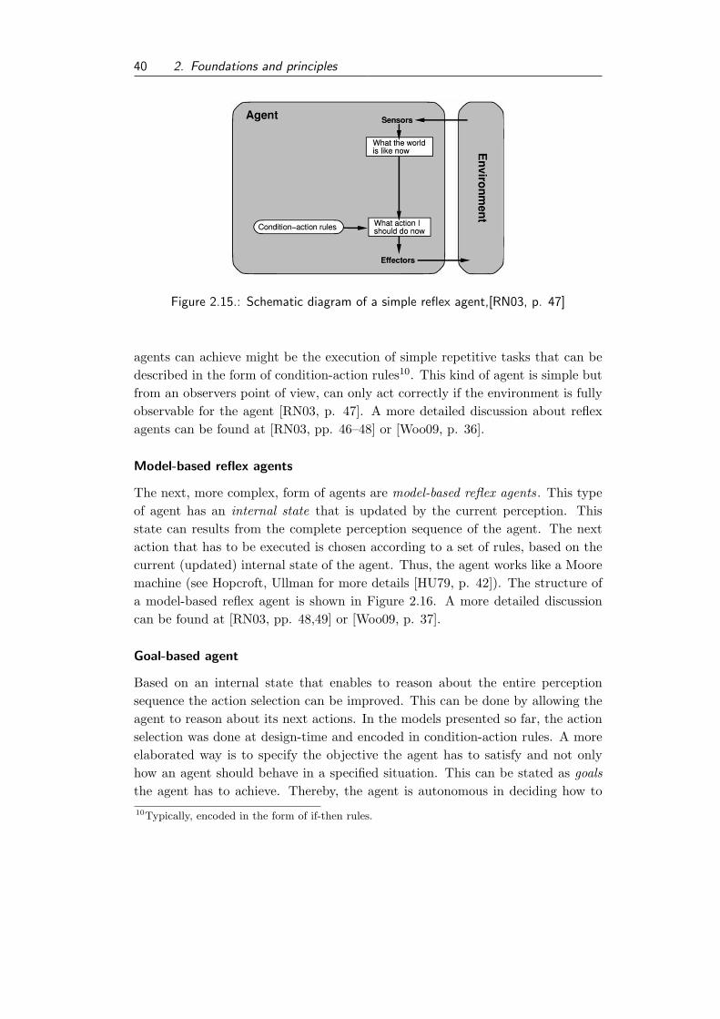
40 2. Foundations and principles
Figure 2.15.: Schematic diagram of a simple reflex agent,[RN03, p. 47]
agents can achieve might be the execution of simple repetitive tasks that can bedescribed in the form of condition-action rules10. This kind of agent is simple butfrom an observers point of view, can only act correctly if the environment is fullyobservable for the agent [RN03, p. 47]. A more detailed discussion about reflexagents can be found at [RN03, pp. 46–48] or [Woo09, p. 36].
Model-based reflex agents
The next, more complex, form of agents are model-based reflex agents. This typeof agent has an internal state that is updated by the current perception. Thisstate can results from the complete perception sequence of the agent. The nextaction that has to be executed is chosen according to a set of rules, based on thecurrent (updated) internal state of the agent. Thus, the agent works like a Mooremachine (see Hopcroft, Ullman for more details [HU79, p. 42]). The structure ofa model-based reflex agent is shown in Figure 2.16. A more detailed discussioncan be found at [RN03, pp. 48,49] or [Woo09, p. 37].
Goal-based agent
Based on an internal state that enables to reason about the entire perceptionsequence the action selection can be improved. This can be done by allowing theagent to reason about its next actions. In the models presented so far, the actionselection was done at design-time and encoded in condition-action rules. A moreelaborated way is to specify the objective the agent has to satisfy and not onlyhow an agent should behave in a specified situation. This can be stated as goalsthe agent has to achieve. Thereby, the agent is autonomous in deciding how to10Typically, encoded in the form of if-then rules.

2.3. Distributed Artificial Intelligence 41
Figure 2.16.: Schematic diagram of a model-based reflex agent [RN03, p. 49]
Figure 2.17.: Schematic diagram of a goal-based agent [RN03, p. 50]
achieve these goals. The resulting structure of such an agent is shown in Figure2.17. The necessary reasoning that an agent has to perform increase the requiredcomputational effort drastically in comparison to the types of agents presentedso far. It is not only a check of some conditionals to find the rules that applyto the current local state anymore. It can become a complex search or planningproblems, which is addressed in AI research itself. This extra effort enables theagent to act much more flexible in contrast to other approaches. It is argued, thatthis flexibility of goal-based agents and more complex forms of agents offer are akey characteristic for agency in computer science (see for instance Kirn [Kir06]).

42 2. Foundations and principles
Figure 2.18.: Schematic diagram of a utility-based agent [RN03, p. 52]
Utility-based agent
By specifying the goal of an agent it remains to the agent how efficient it tries toachieve the goal. Thus, efficiency is out of the scope of goal-based agents. Goalscan be either satisfied or not. With a utility function, mapping a state into a realnumber, the outcome is not binary anymore. Therefore, the next more complexform of an agent is a utility-based agent . The utility function enables the agent tomeasure its performance. So an agent can evaluate its possible actions accordingto a utility function while trying to maximize its earned utility. The structure ofsuch an agent is shown in Figure 2.18. Utility functions are seen as an efficientway to specify the objectives that are delegated to the agent [Woo09, p. 38].Utility-based agent are discussed in game theoretic research as well, e.g., as agentsthat can act in worth oriented domains [RZ98b, Chap. 7]. According to Russelland Norvig the existence of an explicit utility function is a prerequisite for anagent to act rational [RN03, p. 51]. An agent is classified to be a rational agent ifit compliant with the characterization presented by Russell and Norvig as follows:
“For each possible percept sequence, a rational agent should selectan action that is expected to maximize its performance measure, giventhe evidence provided by the percept sequence and whatever built-inknowledge the agent has.” [RN03, p. 36]
Other terms used in DAI research for characterizing agents into different tax-onomies are according to Wooldridge [Woo09] and Timm [Tim04, p. 17]:
• behavioral agent: an agent that decides what do without reasoning
• deliberative agents: an agent that decides what to do via logical/symbolicreasoning

2.3. Distributed Artificial Intelligence 43
• cognitive agents: agents with enhanced adaption and learning abilities
Intelligent agent
In this section we introduce the term intelligent agent . Here the definition ofWooldridge [Woo09, pp. 26,27]11 is presented. An intelligent agent is an agentthat has the following abilities:
• Reactivity: Intelligent agents are able to react on changes in their environ-ment in a timely fashion in a way to satisfy their delegated objectives.
• Proactiveness: Intelligent agent act without an external event to achievetheir goals, typically the delegated objectives/goals.
• Social ability: Intelligent agents can interact with other agents to achievetheir goals.
Of course, this definition is not exclusive. There exist other definitions for intel-ligent agents that emphasize other aspects, e.g., the notion of intelligent agentsby Nwana [Nwa96], who claims that intelligent agents should incorporate learn-ing abilities. As pointed out before, we focus here on the definition presented byWooldridge.
2.3.2. Agent Architecture
Depending on the type of agent that has to be build different architectures aresuitable. In those architectures the components of the agent’s implementationand their interactions are defined. An introduction to software architecture canbe found in Taylor et al. [TMD09] or Sommerville [Som06, Chap. 11] for instance.
The selected architecture must be suitable for the intended type of agent. Forinstance, a utility-based agent cannot be realized using a reactive/reflex agent’sarchitecture. According to Wooldridge [Woo99] four different agent architecturescan be classified into:
• Logic-based agents, decision making is done based on logic deduction.
• Reactive agents, decision making is done by a mapping from a situation toan action.
• BDI agents, decision making is done by manipulation of data structuresrepresenting beliefs, desires and intentions.
11Originally this definition comes from Wooldridge and Jennings [WJ95].

44 2. Foundations and principles
• Layered architectures, decision making is done in a number of software layers.Each layer realizes some reasoning based on parts of, possibly abstracted,environment models.
The idea of purely logic-based agent origins in the traditional symbolic logicoriented AI. Their description is according to Wooldridge [Woo99, pp. 42–48] asfollows. The agent decision making is seen as a deduction process. An agent has atheory for specification and it can reason about and execute action based on thisreasoning. The main idea of their reasoning mechanism is the cyclic behavior ofperception, reasoning (here deduction) and action, as already described in Section2.3.1. Agents have a database with their current believe set, a set of logic formulae.The perception updates the agent’s database, i.e., facts that have become false areremoved and others may be added. For the action selection the agents tries todeduce a predicate of the form Do(a) or at least tries to falsify a predicate like¬Do(a) from his current database and given theory.
Some disadvantages of purely logic-based arise form the fact, that their inferencecan become computational complex, as automated theorem proving is, in general.Thus if the agent has to regard time constraints, logic-based architecture can be-come a problem. Especially as it is necessary that the environment stay stableduring the inference process within the agent, which restricts the field of appli-cations. Nevertheless, for more theoretical investigations this model is interestingbecause of its pure logical structure and its resulting clear semantics.
Next the architecture of a reactive agent is discussed. These architectures arenot based on symbolic logic, and historically were designed as a consequence of theintractability problems logic-based architectures. These type of architectures washeavily influenced by Brooks12 [Bro86]. The idea this type of architecture is thatan agent can have one or more behavior modules. A behavior module implements astate machine. All these modules have access to the input. Typically, in each stateof a behavior module a mapping function exists that maps the input to an activity.In case that more than one behavior module is activated by an input, i.e., thereexists a mapping entry within this module for the given input; an action selectionprocess has to be provided. Therefore, the behavior modules are prioritized. Soif more than one module is activated the output, i.e., action, from the modulewith the highest priority is chosen. A more elaborated presentation of this typearchitectures is provided, e.g., by Wooldridge [Woo99, pp. 48–54].
The main idea of BDI agents is that the knowledge-base of an agent is composedout of three elements, its beliefs, its desires and its intentions. This approach ismotivated by psychology model by Bratman [Bra87] and has been formalized for
12see Wooldridge [Woo99, p. 48] for historical insights.

2.3. Distributed Artificial Intelligence 45
Figure 2.19.: BDI architecture; [Woo99, p. 58]
usage in DAI by Rao and Georgeff [RG95]. Typically, the representation of beliefs,desires and intentions is done using logical formulae, for instance, in first-orderlogic. The BDI agent architecture is therefore a more practical way to formulatelogic-based inferencing agents. The beliefs of an agent can be interpreted as therepresentation of the current world state the agent believes to be true. Whilethe goals and plans of an agent are stored in the set of desires and intentionsrespectively. An abstract BDI architecture is shown in Figure 2.19. The functionbrf is the belief revision function, it updates the believe set, according to thecurrent perception of the agent. The function generate options computes thecurrent desires based on the current belief set and intentions of the agent. Thisfunction of the agent calculates the plans that should be applied to achieve itsintentions. Within the filter function the agent updates its intentions, for instance,if it is not possible to realize an intention, i.e., there exist no valid plan to do so,it might be reasonable to give up this intention. Based on the updated intentionsan executable intention is chosen to be perform a step towards the fulfillment of

46 2. Foundations and principles
the selected intention. This is done by the action-function. A detailed descriptionthis architecture can be found in [Woo99, pp. 58–60]. For the paradigm of BDIagents a number of architectures have been presented, a specific overview aboutthose architectures is provided by Haddadi and Sundermeyer [HS96].
A class of agents, called hybrid agents have layered architectures [Woo09, Chap.5.2]. There exist different strategies how the components of the agents can be ar-ranged in either horizontal or vertical structures. In a horizontal layering the inputis processed by a number of components and then this information is aggregatedto determine the output/action of the agent. The information and control flowof a horizontal architecture is shown in Figure 2.20. In contrast to the horizontal
Figure 2.20.: Information and control flow of a horizontal layered architecture;
[MPT95, p. 263]
arrangement of components are vertical layered architectures. Vertical layeredarchitectures can be subdivided into one pass control or two pass control architec-tures. In one pass layered architectures the input is processed in each stage andthen delegated to the next one. This architecture is therefore similar to the pipesand filters architecture pattern. See Taylor et al. [TMD09, [p. 110] or Buschmannet al. [BMR+02, pp. 53–70 ] for a detailed presentation of this pattern. The in-formation and control flow of a vertical one pass architecture is shown in Figure2.21.
Figure 2.21.: Information and control flow of a vertical one pass layered architecture;
[MPT95, p. 263]

2.3. Distributed Artificial Intelligence 47
The two pass vertical layered architecture pass processed input up to higherlayers in the architecture, where more abstracted decision making is implemented.The information and control flow in such an architecture is sketched in Figure 2.22.The results of higher layers are delegated back to the lower layers for execution. Aprominent example of systems based on layered architectures are the InterRRaparchitecture presented, e.g., by Fischer et al. [FMP96, pp. 403–405].
Figure 2.22.: Information and control flow of a vertical two pass layered architecture;
[MPT95, p. 263]
Layered architectures have also been established in robotics, e.g., Alamai etal. [ACF+98]. The authors present an architecture where aspects like collision-avoidance are implemented based on a reflex-based layer while more complexsteering or planning activities are done on higher-levels of abstraction. Anotherexample of a layered architecture in robotics is the architecture of Stanley the au-tonomous driving robot, e.g., Wooldridge [Woo09, p. 99]. A detailed descriptionof Stanley’s architecture can be found in Thrun et al. [TMD+06].
These architectures remain abstract and have to be instantiated based on theexisting agent implementation languages or frameworks.
2.3.3. Internal state representation
In the following the structure of the internal state of an agent is presented. There-fore, we review the concept of the state of an agent in the aforementioned archi-tectures.
The state of a logic-based agent is the sum of formulae that are in his database.These formulae encodes what the agent assumes to be true about its environment.If reactive agents use an explicit state model, like model-based reflex agents (intro-duced in Section 2.3.1) their internal state is the current state they are currentlyin. Reflex agents without the notion of states, like simple reflex agents, can bemodeled as stateful agents with exactly one state. For example, if agent a has the

48 2. Foundations and principles
set of possible internal states S, at time t its internal state is st ∈ S.The state of a BDI agent is given by its current beliefs, desires and intentions
(B,D,I) [Woo99, p. 58]. With B⊆ Bel , whereby Bel the set of all possible beliefsis, D ⊆ Des with Des the set of all possible desires, and I ⊆ Int with Int the setof all possible intentions.
The state of an agent with a layered architecture is harder to specify. From anabstract perspective it is, like in the case of reactive agent defined as an elementof the powerset of states each layer can have. But the states of a layer cannotbe enumerated on this abstract level, as this depends on what layers exist andhow they are realized. Nevertheless, it is possible to specify their state, as, forinstance, discussed by Thrun et al. [TMD+06, p. 666].
Even if no specific architecture is referred to, there exist common understandingof some aspects of the agent’s internal state, which is also referred to as belief set, e.g., by Decker [Dec95], or knowledge-base, e.g., by Finin et al. [FFMM93]. Theterm knowledge-base origins from research done in knowledge-based systems. Theterm belief set is motivated by the aforementioned BDI architecture, although itis not limited to those architectures. Russell and Norvig use the term belief set inthe following notion:
“We call each such set of states a belief state, representing the agent’scurrent beliefs about the possible physical state it might be in.” [RN03,p. 84]
Thus, the term belief set is used to refer to the representation of the environmentthe agent has perceived, so far. This notation does not have any implication forthe architecture of an agent. There are two way how a fact can be added to thebelief set, either by perception of the agent, including communication with otheragents, or by reasoning, done by the agent itself. Therefore, the agent has someform of logics that enables him to add new facts, derived from existing ones to theinternal state.
Thus, theoretically the knowledge of such an agent at a certain point in timeis defined by its logics and its internal state. From a more practical perspectiveit has to be mentioned that the available computational power of that agents isa limiting factor. If a fact is not in its internal state and can be derived from it,this fact is unknown to the agent.
2.3.4. Multiagent system: foundation for emergence
If multiple agents form one system, this system can be called a multiagent System(MAS). A key characteristic of a MAS is that the agents within a MAS can interactvia direct or indirect communication.

2.3. Distributed Artificial Intelligence 49
In previous research, e.g., von Martial [Mar92], Ossowski [Oss98] or Rosen-schein and Zlotkin [RZ98a] systems with multiple agents has been distinct in twosubclasses: distributed problem solving systems and multiagent systems.
Distributed problem solving systems are systems composed out of differentagents, that have been designed to solve a given problem, most probably by onedesigner. The entire system aims to solve a global problem and thus, the agents insuch a system are benevolent. In contrast a MAS was composed out of agents thatonly try to optimize their local utility function that was given by their designer.So in one system agents from different designers and with different objective func-tions can exist. The entire system does not necessarily has to have a global goalthat has to be achieved. A more detailed discussion is provided by Weiss [Wei99,p. 4] or by Jennings et al. [JSW98].
This distinction has become less relevant as a lot of researchers investigatedhybrid forms of those systems. The term multiagent system is now widely acceptedas a system of multiple agents, independently of their local utility functions. Soaccording to Wooldridge it can be defined as follows:
“Multiagent systems are systems composed of multiple interactioncomputing elements, known as agents.” [Woo09, p. xiii]
An even stricter version of this definition is given by Weiss, where the agents haveto be intelligent13.
[A multiagent system is a] “...systens in which several interaction, in-telligent agents pursue some set of goals of perform some set of tasks.”[Wei99, p. 1]
It has to be mentioned that these definitions are not exclusive, there exist otherdefinitions as well. But they were chosen by the author as they offer a validfoundation for this study, and they are widely accept in the research community.
According to Jennings et al. [JSW98] a MAS can be characterized by the factsthat
• each agent has incomplete information, or capabilities for solving the prob-lem, thus each agent has a limited viewpoint;
• there is no global system control;
• data is decentralized; and
• computation is asynchronous.13Thereby, flexibility and rationality are pointed out as key characteristics of those intelligent
agents [Wei99, pp. 2,3].

50 2. Foundations and principles
As a consequence of these characteristics presented by Jennings et al. a MAS canshow emergence behavior as it has been characterized by Timm [Tim04, p. 24].According to Timm emergence behavior is
• surprising, as it cannot be predicted as a consequence of simple interactions,
• establishing organization forms in complex systems that have not been in-tended before, and
• creating intelligent behavior, based on the interactions of individuals on aless intelligent level.
Communication in MAS
As pointed out before, the interaction among agents plays a central role in MAS.Thereby, communication play a central role, as the most prominent form of agentinteraction. We present here the foundations of agent communication becausecommunication is essential for coordination or by quoting Ferber “all coordinationmust necessarily go through communication” [Fer99, p. 407].
Agent interaction can be direct or indirect. Indirect interaction uses parts ofa shared environment as a mediator. Indirect interaction can either be intendedas indirect communication or can be coincidence as two agents interfere as theyaccess a non-sharable resource in the environment. Indirect communication can beimplemented by marking the environment, e.g., with artificial pheromone traceswhich are used in ant algorithms.
Direct interaction between agents is done via communication, i.e., message pass-ing. This communication requires a common language, a shared ontology andan agent communication infrastructure like a yellow-page service and a messageforwarding protocol. Major research efforts have been undertaken to build appro-priate forms of agent communication languages (ACL), knowledge representationand communication infrastructure. These efforts included the knowledge queryand manipulation language (KQML) and the knowledge interchange format (KIF)(see Huhns and Stephens [HS99] or Wooldridge [Woo09, Chap. 7] for an introduc-tion). The appropriate design of ontologies for agent communication is describedby Wooldridge [Woo09, Chap. 6] and a good description for ontology design ingeneral is provided by Noy and McGuinness [NM01]. Both KIF and KQML weredeveloped within the DARPA knowledge sharing effort (summarized by Finin etal. [FFMM93], for instance, and were forerunners of the FIPA standards. FIPA isthe Foundation for Intelligent Physical Agents an IEEE standards organization.More details about the FIPA organization can be found at the FIPA homepage[FIP10]14. FIPA has standardized among other:14http://www.fipa.org/index.html accessible at 02/04/2010

2.3. Distributed Artificial Intelligence 51
Parameter Category of Parameters
performative Type of communicative actssender Participant in communicationreceiver Participant in communicationreply-to Participant in communicationcontent Content of messagelanguage Description of Contentencoding Description of Contentontology Description of Contentprotocol Control of conversationconversation-id Control of conversationreply-with Control of conversationin-reply-to Control of conversationreply-by Control of conversation
Table 2.5.: FIPA ACL Message Parameters [FIP02c, p. 2]
• agents and agent platforms, e.g., [FIP02a, FIP02h]
• Message Transportation, e.g., [FIP02d, FIP02b]
• Message structure, e.g., [FIP02n, FIP02c]
• interaction protocols15, e.g., [FIP02l, FIP02j]
All standards can be downloaded for free from the referred websites. Anoverview of the standards can be found as well16. Note that within the FIPAstandards only direct communication is considered [FIP02a, pp. 14–16]. Thecommunication facilities have to be provided by the agent environment see Huhnsand Stephens [HS99, p. 81] and FIPA standard [FIP02a].
According to FIPA the exchange of messages between agents it the favorableform for inter-agent communication. To ensure efficient communication and inter-operability the format of messages is standardized by FIPA. The overall structureof the message format has been outlined in FIPA standard [FIP02a, pp. 28–35].In standard [FIP02c] is has been detailed. A message contains a number of fields,also called parameters. An overview of these fields is shown in Table 2.5. Thisformat has been influenced by previously research concerning KQML. An intro-duction to KQML and FIPA based communication can be found in Wooldridge[Woo09, pp. 136–146].15FIPA interaction protocols are discussed in more detail below.16http://www.fipa.org/repository/standardspecs.html Accessed: 02/04/2010

52 2. Foundations and principles
Interaction protocol relation quantity
Request Interaction Protocol [FIP02l] 1:1Query Interaction Protocol [FIP02j] 1:1Request When Interaction Protocol [FIP02m] 1:1Contract Net Interaction Protocol [FIP02f] 1:nIterated Contract Net Interaction Protocol [FIP02g] 1:nBrokering Interaction Protocol [FIP02e] 1:1Recruiting Interaction Protocol [FIP02k] 1:1Subscribe Interaction Protocol [FIP02o] 1:1Propose Interaction Protocol [FIP02i] 1:1English Auction Interaction Protocol [FIP01c] 1:nDutch Auction Interaction Protocol [FIP01b] 1:n
Table 2.6.: FIPA interaction protocols and their cardinality
Interaction protocols among agents play an important role, as they structure asequence of messages that are exchanged between agents. As Huhns and Stephenspoint out by means of these interaction protocols agents can have a conversation
“Interaction protocols govern the exchange of a series of messagesamong agents - a conversation.” [HS99, p. 96] 17
Interaction protocols can be defined for one sender and one receiver, than theyare called binary as they represent a 1:1 relationship. Although interaction pro-tocols can be defined for one sender and n receivers, in which case they are calledn-ary as they represent a 1:n relationship [HS99, p. 86]. Wooldridge [Woo09, p.317] also mention the case of many-to-many negotiations. But this type of nego-tiations is rare to find in multiagent research, probably because of the resultingcomplexity. For the interaction protocols specified by the FIPA these cardinalitiesof the interaction protocols are shown in Table 2.6.
Note that the Dutch and English auction protocol are no confirmed standardsby the FIPA yet. They are still in the experimental stage, but shown here forcompleteness of the specified FIPA interaction protocols.
In the FIPA standards the interaction protocols are visualized by an UML1.xextension named Agent UML (AUML) presented by Odell et al. [OPB01]. AUMLis discussed in more detail in Section 3.2.1 in the context of agent-oriented softwareengineering.
17A similar statement can be found at [HS99, p. 79].

3. State of the art
In this chapter we give an introduction to the current state of the art of the researchof coordination in multiagent systems. Nevertheless, the field of coordination isnot a exclusive for researchers from the field of DAI. For that reason researchconcerning coordination from related fields, like business administration (Section3.1.1) and game theory (Section 3.1.3) are discussed in this chapter, as well.
In the second section of this chapter the engineering of DAI systems, typicallytermed agent-oriented software engineering (AOSE) is focused and especially as-pects of research concerning reuse of concepts in AOSE is presented. Thereby, wepoint out the current shortcomings in the field of reuse of methodologies in AOSEand for the coordination of planning systems in particular. Based on this findingswe identify the research question and issues this thesis has to tackle.
3.1. Coordination
Research considering coordination has attracted researchers from different fieldsof research and thus the body of existing work is hardly to survey, at all. Andeven within the lines of research, like computer science. The scope of research con-cerning coordination is wide. Omicini et al. [ORVR04] consequently paraphraseit in the following way:
“Research on coordination possibly represents the most un-coordi-nated activity in the history of computer science.” [ORVR04]
Consequently, in this section only an extraction of existing work is presented,from fields that have a direct connection to DAI, and thus it cannot claim to becomplete. In the following coordination is described from a rather broad perspec-tive and in the following subsections focused from the perspective of the fields ofbusiness administration, DAI, and game theory.
The term coordination is used in different disciplines with different notations.Coordination as a topic by itself can only be found only rarely. One of the mostprominent papers that suggests to establish a “coordination theory” has beenpresented by Malone and Crowston [MC94, p. 88]. In their interdisciplinarystudy they compare the research about coordination in different fields of research,
53

54 3. State of the art
Figure 3.1.: Timeline of coordination activities
in particular they address the fields of computer science, economics, operationsresearch, and organization theory. A consequence of their work is the widelyaccepted definition of coordination. In their work they define coordination as:
“Coordination is managing dependencies between activities.”[MC94, p. 90]
A fundamental underlying problem of coordination is that actions and/or decisionsare executed/made in a distributed manner. And as Malone and Crowston pointedout the decision making and/or execution have to be managed to achieve a goal orperform an efficient behavior [MC94, 90]. Thus, in all coordination scenarios wecan find a distributed scenario, in other cases all decision making and executionare centralized and no coordination is necessary. Then the coordination problembecomes a planning problem.
Nevertheless, the term coordination comprises a wide field of activities, as it doesnot point out when the coordination takes place. This is pointed out in the Figure3.1. Activities are executed in the execution phase. The execution of activitiesis supervised by a controlling entity. Before the execution of a set of actions isstarted, typically a planning process has arranged the activities. Coordinationcan be performed during execution/control, planning, or even before the planningphase started.
A group of research addresses coordination from strategic [WCDH00] and op-erational [CWDH00] point of view. The strategic coordination is not addressedin this study, as already pointed out. The work done by Coates et al. [CWDH00]is more an update of the work done by Malone and Crowston addressing resourcemanagement, planning, and scheduling. The authors surveyed the applicationof coordination techniques in different fields of application. Among other theypresent planning and scheduling as techniques for coordination.
The vision of Malone and Crowston [MC94] that a research field for coordinationforms has not become truth so far. Today coordination is subject of research indifferent areas. Therefore, it is fruitful to address current fields of research dealingwith coordination. Another introduction into the field of research concerningcoordination from the DAI perspective is provided by Ossowski [Oss98, Chap. 2].

3.1. Coordination 55
3.1.1. Coordination concepts in business administration
In this section the perspective of business administration on coordination is pre-sented. Thereby, different perspectives are presented. According to Hansen andNeumann a number of theories exist that try to explain the coordination of eco-nomical exchange processes [HN09, p. 945]. These authors mention, for instance,the exchange theory1 and the resource dependence theory. The exchange theoryis rooted in sociology. It assumes that resources are rare, the entities/participantshave different specializations/abilities. Under these assumption an exchange hap-pens between the participants if they both gain profit from the exchange. Themain idea of the resource dependence theory is that companies are dependent onexchange facing rare resources. A consequence is that the companies will lose au-tonomy as they depend on external resources. According to this theory this leadsto establishing networks, to make the dependency bilateral. Companies engagein networks to reduce their dependency and gain influence on other [CG01, pp.14–15].
The approaches and ideas presented in this section form the context and ad-ministrative background for the development of actual information and planningsystems that are established today.
In the following the notion of coordination is presented from the perspectiveof decision-oriented business administration2. This field of research has been es-tablished by Heinen [Hei86]. A practically motivated introduction is presented byAdam et al. [ABTV04]. The focus of this line of research lies on the decisionmaking [ABTV04, p. 1]. Decisions are the consequences of plans, developed formodels of the reality [ABTV04, p. 3]. Thus, decision making is a consequenceof planning activities. Thereby, the planning problem is decomposed into fourelements [ABTV04, p. 3]:
1. decision field element: containing all causal relationships, necessary to esti-mate the effects of different action alternatives.
2. evaluation element: mapping the expected outcome to an economic qualitymeasure.
3. objective element: describes what should be achieved.
4. decision making element: computes the optimal solution
If all these aspects are well defined, i.e., they are fully operational defined,then decision making becomes a computing task [ABTV04, p. 4]. In fact the
1in German: Austauschtheorie2in German originally termed “Entscheidungsorientierte Betriebswirtschaftslehre”

56 3. State of the art
authors state that these problems can be rarely found in real world settings. Mostoften the planning problem definition has some defects that prohibit an effectivecomputation. Possible defects are [ABTV04, p. 4,5]:
• Causal defects: the causal relationships cannot be described in detail.
• Evaluation defects: the results of actions cannot directly mapped to a onedimensional economic metric.
• Objective defects: the objective cannot be formulated precisely in a onedimensional objective function.
• Solution defects: there exists no efficient method for solving the planningproblem.
Those defects are, from the business administration point of view, the motivationfor dividing defect problems into a number of less defect sub-problems. Eventhough the authors are aware of the fact that this divide and conquer strategy canendanger the overall solution quality3.
The decomposition of planning problems can be done along two different di-mensions [Woh02, pp. 104–108]:
• factually, e.g., distribution, finance, production, and
• chronological, e.g., in strategically, tactically and operationally planning.
Consequently, resulting interdependencies have factually or chronological charac-teristics. Corsten and Gossinger summarize those dependencies among other asobjective interdependencies4 [CG01, pp. 45–47]. The taxonomy of Corsten andGossinger is presented in Figure 3.2. According to the taxonomy of interdepen-dencies presented by these authors objective interdependencies can exist either byrestrictions or goals. A restriction is defined by physical restriction imposing theinterdependencies. Shared resources or precedence constraint during a productionare example for such dependencies. A goal dependency can be defined in formof profit, evaluation measurements or risk dependencies on other entities. In con-trast to objective interdependencies are behavior interdependencies. A behaviorinterdependency exists if the decision making of an entity depends on, or is takeninto account, the expected decision making behavior of another entity. This is, forinstance, a typically assumption in game theory, when there exists no dominatestrategy.
3In German “Die Bildung von Teilprobleme fordert Partialsichten und steht daher einem
ubergreifenden Denken entgegen.” [ABTV04, p. 8].4In German “Sachinterdependenzen”, to avoid ambiguities we translated them not as factual
interdependencies.

3.1. Coordination 57
Figure 3.2.: Taxonomy of interdependencies adapted from [CG01, p. 47]
A typical example for the decomposition of large problems in business admin-istration is the management of a company. According to Adam et al. [ABTV04,p. 7] and Wohe [Woh02, p. 332] management of a company can be decomposedinto the sub-problems of:
• distribution planning
• production planning
• investment planning
• finance planning
This is in fact a factually decomposition from a strategic perspective. Each ofthese planning problems is abstract and complex, such that automation on thislevel of detail is not realistic. Especially as the planning has to respect various onlyweakly defined constraints, like aspects from legal regulations, corporate policiesand secondary objectives.
A consequence of the decomposition is the necessity for coordination. Dur-ing the integration of the solution of sub-problems, existing dependencies haveto respected [ABTV04, p. 5]. This arises due cutting of potentially existingdependencies in the decomposition step. Therefore, Adam et al. characterize co-ordination as adjusting and controlling dependent decision fields from an overallperspective5. The authors have an abstract view on coordination, which becomesobvious in their classification of coordination techniques that is shown in Figure3.3. According to their classification, coordination can either be done by market-
5“Die Notwendigkeit zur Koordination ergibt sich aus der Arbeitsteilung bzw. Teilproblem-
bildung, wenn durch die Zerlegung die zwischen den gebildeten Teilbereichen bestehende
Kopplungen zerschnitten werden.” [ABTV04, p .10]

58 3. State of the art
Figure 3.3.: Types of coordination, according to [ABTV04, p. 21]
based mechanisms or by mechanisms relying on hierarchy, which is also stated byHansen and Neumann [HN09, p. 946]. These authors agree that hybrid approachesare possible, too. Examples for hybrid coordination forms are, for instance, enter-prise networks [HN09, p. 946]. Enterprise networks have been extensively studies,e.g., by Corsten and Gossinger [CG01].
The authors discuss that the selection of the appropriate coordination approachon this coarse grained level depends on the environment6. If the environment issimple, static and has a low degree of uncertainty then centralized hierarchicalcoordination promises to be more efficient. While in more complex, dynamicenvironments with possibly higher degree of uncertainty the coordination has tobe appropriate to the current situation. This can be achieved by decentralizedand self-aware decision making [ABTV04, pp .23]. Thus, changing environmentenforces paradigm shifts in the coordination philosophy [ABTV04, p. 24].
Taking the assumption that coordination deals mainly with the integration ofdifferent plans that have been motivated so far. We now discuss more concretetechniques that have been proposed in business administration. Wohe [Woh02,pp. 108–112] presents three forms how planning could be structured:
• continuous planning for the combination of chronological decomposed plan-ning,
• top-down, bottom-up or top-down/bottom-up planning for the combinationof different partial plans, or
• bottleneck-first planning.
6This statement is true, also for more concrete coordination mechanisms, see [Dec95].

3.1. Coordination 59
Continuous planning uses different levels of details for planning ahead of time. Thenearby future is planned very accurate, while parts of the plan that are furtherahead in time are only planned based on rough estimations or on a coarse grainedlevel. Finding the right level of detail can become a problem [Kur05, p. 40].
In the following the top-down, bottom-up and the top-down/bottom-up ap-proach are presented and references to some applications of coordination in theseways are given. More details can be found at [Woh02, pp. 109–110].
The top-down approach for combining existing partial plans, assumes that thereexist a superior entity that create abstract plans that are refined in subordinatedentities. Thereby, plans become more and more concrete. To apply this approachit is necessary that each superordinate entity has enough information about thecapabilities of all of its direct subordinated entities. This enables the superor-dinate entity to generate feasible abstract plans that can be implemented by allits subordinates. This problem is referred to as vertical interdependencies. Thisimplies that the information has to be available to each superordinate entity andit has to be updated regularly. The information availability and quality is critical,thus it is mentioned by Kurbel as a counter-argument for the use of simultaneousplanning [Kur05, p. 40]. The idea of top-down planning has been implemented,for instance, in hierarchical planning [HM73]. This approach have similarities withthe approach to perform coordination in a pre-planning phase, which is proposedby Witteveen et al. [WW06a, SW07]. The authors propose to add additional con-straints to the original planning problem to ensure that the local planning doesnot generate conflicting plans.
The bottom-up approach for combining existing partial plans follows a differentapproach. Each entity plans its activities locally. To enforce a feasible plan allthese partial plans are communicated to a coordinating entity that is superordi-nate to all planning entities. It is the task of this entity to ensure that the resultingpartial plans are coordinated. This approach assumes that the coordinating entityhas at least abstracted knowledge of the capabilities of the local planning entities.Moreover, it requires some coordination knowledge. The coordination knowledgecomprises knowledge how conflicts in different partial plans are can be resolved.In a worst case scenario, were all partial plans are maximal conflicting the coor-dination entity has the task to implement a simultaneous planning. An exampleof such a post-planning coordination step has been proposed for instance by vonMartial [Mar92].
In the top down/bottom up approach is a first step guidelines are generatedin a top down way. The feasibility of these abstract plans is then tested by thesubordinate planning entities that try to generate a concrete plan respecting allgiven guidelines. If a conflict occurs or if it is not possible to fulfill all guidelinesa feedback is given and the superordinate entity has to adapt its plan. The in-

60 3. State of the art
corporation of feedback in the planning give the global planning entity additionalinformation about the local abilities to generate feasible plans and that also canbe used to adapt the global plan to changes that may occur during execution. Anexample of such a planning system for multi-site scheduling has been proposedwithin the MUST approach by Sauer [Sau02].
A heuristic approach to handle the coordination problem is, as described earlier,the sequential solution of the partial problems, and the usage of the results ofearlier computations in later ones [Woh02, p. 331]. Thereby, the ordering ofthe partial problems should be done in a bottleneck-first heuristic using forwardand backward planning from the bottleneck [Woh02, p. 331]. Of course, thisapproach suffers if multiple bottlenecks exist or bottlenecks depends on the currentworkload. Moreover, in reactive planning/scheduling scenarios the bottlenecks canshift depending on the event that occurred. The interdependencies of planningsystems cannot be handled in this approach, too.
Summarizing, there exists literature that has analyzed the motivation for thedividing of decision/planning problems and the required integration of partialsolutions. Nevertheless, the findings concerning coordination remain abstract,from a computer scientists point of view, as these models cannot be operationalizedeasily.
Another aspect that is mentioned, e.g., by Kurbel [Kur05, pp. 244–246] andHansen and Neumann [HN09, p. 947] is the efficient, ideally automated, informa-tion flow between different entities. Thus, it is emphasized in business informaticsthat electronic data exchange [HN09, pp. 958–965] and enterprise applicationintegration [RMB01] are important technologies to enable efficient coordination.These approaches mainly deal with the required information infrastructure neededfor the management to coordinate the actions of different companies not only onthe strategic level.
Recently, there exists although a trend in business administration to apply tech-nologies that have been developed in the filed of DAI as well as joint researchefforts. For instance, Meier [Mei08] deals in his work with the coordination of dif-ferent planning systems in the container terminal management problem, see themotivating example, Section 1.2. Coordination is achieved by wrapping the plan-ning systems with agents and communicates the plans, or more precisely specificrelevant information for planning, to agents who are responsible for plan/planningsystem that depend on the first one.
In the context of a joint research project, conducted by economics and computerscientist coordination techniques incorporating multiagent systems have been in-vestigated as well. In the priority research program “Intelligent Agents and Re-alistic Commercial Application Scenarios” Agent.Enterprise has been introduced

3.1. Coordination 61
as demonstrator for distributed planning and scheduling. An introduction can befound in Woelk et al. [WRZN06]. In the context of this effort mechanisms forcoordinating companies forming a supply chain has been investigated. Resultshave been presented in Frey et al. [FSWZ03] and Stockheim et al.[SSWG02], forinstance.
The field of auctions has been excluded from this section as they are discussedin the section coordination in game theory and mechanism design (see Section3.1.3).
Collaborative planning in operations research
The need for coordination among different autonomous planning systems has alsobeen realized in the field of operations research. This research area has mainlyevolved from the field of supply chain management [Sta09], as a consequence ofthe fact that conventional production planning techniques like MRP II (for anintroduction see [Kur05, Chap. 4]) are not suitable for supply chains [Dud04,p. 14]. According to the perspective of operations research there exists two ap-proaches how plans can be coordinated in a supply chain, either by hierarchicalor collaborative planning [Dud04, p. 12]. Hierarchical planning has been men-tioned above and is implemented in current advanced planning system solutions,see Dudeck [Dud04, p. 15], and Stadler and Kilger [SK02]. According to Stadtler[Sta09, p. 5] hierarchical planning approaches suffer, as already mention, from theinherent information asymmetry in networks of autonomous entities. Moreover,Stadtler points out that hierarchical planning cannot cope with the existence oflocal, possibly conflicting, objective functions. Each planning entity might have lo-cal constraints that might cause conflicts [Sta09, p. 5]. In contrast to hierarchicalplanning collaborative planning aims to overcome these weaknesses by acceptingthe fact that autonomous entities have to coordinate their activities. Accordingto a broad definition collaborative planning can be defined
“as a joint decision making process for aligning plans of individualSC [supply chain] members with the aim of achieving coordination inlight of information asymmetry.” [Sta09, p. 6]
A typical collaborative planning mechanism has been presented by Dudeck[Dud04]. He present a collaboration planning mechanism based on non-hierar-chical negotiation among independent supply chain partners. Doing so, the mas-ter plans have been identified as the appropriate level for collaborative planning[Dud04, p. 20]. Note that a master plan frames the production for a time horizonfor about 3 up to 18 month ahead, depending on the line of business. Dudeckassumes that all supply chain partners apply a mathematical program to solve

62 3. State of the art
their local planning problem. As a local planning problem the multi-level capaci-tated lot-sizing problem [Dud04, pp. 30–32] is chosen. Planning entities exchangeproposals and counterproposals that have been generated by their local planningsystems. But this approach is limited by the fact that a mathematical program isassumed for all supply chain partners and that the coordination focuses primar-ily on the material supply on a coarse grained level, which are rather typicallyrestrictions for approaches presented in the field of collaborative planning.
Techniques used in collaborative planning rely on the publication of informationconcerning local cost structures or side payments. Within a side payment an agentgives or asks for additional payment to commit to a change in its plan, e.g., byadding an additional task. Both techniques can be used to achieve solutions ofhigher quality from the global perspective. But these techniques impose the riskof agents behave opportunistic and thus do not publish information truthfully.These risks have been discussed, e.g., by Dudeck [Dud04, Chap. 6.2].
As already pointed out most of the work on collaborative planning has beenperformed on rather abstract plans, like master plans, that fixes the activities forthe next couples of months. A work concerning more concrete schedules have beenpresented by Scheckenbach [Sch09]. In his thesis, Scheckenbach assumes that ateach side a resource constraint project scheduling problem has to be solved, whichis solved by an SAP Detailed Scheduling Optimizer [Sch09, pp. 59, 87]. Theplans are much more detailed. Even though a restricting assumption is used, thatall planning entities have to solve homogenous planning problems. InterestinglyScheckenbach does not use side-payments, as he argue that non-carefully designedside-payment schemes leads to agents that cheat and probe. For coordinationScheckenbach propose a mixture of hierarchical planning and a distributed evo-lutionary algorithm. More details concerning his methodology can be found in[Sch09, Chap. 4].
A work concerning collaborative planning that is not based in the applica-tion field of supply chain management, has been presented by Puttmann [Put07].Puttmann addresses the coordination within a transportation network, concern-ing the transport of goods by multiple parties, in intermodal freight transporta-tion. This scenario address a coordination that is comes closer to the operationallevel, than the coordination in a supply chain. Their approach base on result-sharing techniques and is based on a mathematical optimization model, presentedin Puttmann and Stadtler [PS10].
A recent survey of the state-of-the-art has been presented by Stadtler [Sta09].Stadtler also suggest a framework for classifying these coordination approachesaccording to three categories [Sta09, p. 12]:
• structure of the supply chain and it’s members,

3.1. Coordination 63
• the decision structure of each supply chain member, and
• characteristics of the collaboration planning scheme.
The first two characteristics describe properties of the problem domain, the thirdone tries to gather properties of solutions. These categories are not discussed herein more detail.
Between the field of collaborative planning and multiagent systems research anumber of similar assumptions and metaphors exist: for example decision makersare distributed and are autonomously, their interaction is specified by a protocol[Sta09, p. 20], and negotiations are used to coordinate their plans. Even thoughsimilarities exist there has not been much exchange between those fields of re-search. From the perspective of collaborative planning software agents are seenas one implementation architectures for collaborative planning mechanisms. Theyare primarily seen as a pure software architectural issue [Sta09, p. 11].
Negotiation in business administration
A common technique to reach coordinated behavior are negotiations. Negotia-tions can be modeled in different fields, and are discussed in subsequent sectionsespecially from the perspective of DAI. In the field of business administration anegotiation can be defined as:
“A negotiation is an interactive communication process that maytake place whenever we want something from someone else or anotherperson wants something from us.” [She06, p. 6]
There exist no protocols or constraints on the interaction. The negotiation processcan be characterized by four steps:
• preparation,
• information exchange,
• bargaining, and
• closing, commitment.
During a negotiation the negotiator should therefore search for boundaries andoptions for possible agreements that allow reciprocal accommodation, because adeal can only be reached in a win-win situation. Shell [She06, p. xvi] argues thatall deals made between human negotiators have to be win-win situation becauseotherwise there would not exist a deal, or it would be irrational for for one partyto participate in the deal. Moreover, the win-win situation is a strong motivation

64 3. State of the art
for the implementation of the deal. So if both sides profits from the deal, noone has a motivation to break or resolve the deal, as long as their exist no moreprofitable solution. Negotiations from the perspective of business adminstrationhave a significant overlap with psychology. For instance, Shell points out thatit is important that “people need to feel they have earned concessions” [She06,p. xviii]. Regardless of the fact if these concessions are real or would have beengiven without negotiations anyway. Moreover, ethical guidelines and personalnegotiation styles, as part of an individual character of the negotiator play’s asignificant role. Shell distinct between the following negotiation styles [She06, pp.9–12]:
• avoiding,
• compromise,
• accommodation,
• competitive, and
• collaborative/problem solving.
Even though a lot of psychological aspects come into play, it should not be thedominant factor in a negotiation. But those are aspects that have to be takeninto account in the preparation phase of a negotiation. Therefore, authors likeFisher et al. [FUP91] suggest that the negotiator should try to keep out thesepersonal feelings and focus on the problem and not the people. Moreover, inhuman negotiations it has to be mentioned that the motivation for people tonegotiate is an important information, as they try to achieve a certain interestthat is not necessarily identical to their initial position. But this information canbe crucial to come to a deal that allow all negotiating parties to gain somethingout of the negotiation and therefore accommodate all parts. Fisher et al. [FUP91]therefore present the idea of the principled negotiation strategy, that tries to focuson the problem at hand, and avoid some of the inter-personal psychology aspectsthat can hinders finding a solution during a negotiation.
Although in the field of business administration the idea that negotiations can beautomated by agents representing humans. These automated negotiations shouldbe inspired and guided by principles discovered in negotiations done by humans.This idea has been adopted by researchers in multiagent systems as well. SoVassileva and Mudgal [VM02] argue that it is important to ensure a win-winsituation. And in Schumann, Kurtanovic and Timm [SKT09] a methodology tomodel negotiation strategies and trade-offs in a human readable way, that canautomatically transformed to information accessible for agents, is presented.
3.1. Coordination 65
3.1.2. Coordination in DAI
In this section research concerning coordination in the field of DAI is addressed.In general coordination in multiagent systems research tries to impose a desiredbehavior among autonomous agents. Note that we try to limit on research pri-marily rooted in DAI, research closely related to DAI rooted in game theory, likethe research on decommitments done by Sandholm, is presented in Section 3.1.3.The approaches are grouped into three different fields of research. First, researchbased on classical AI approaches is presented. The second line of research isstrongly motivated by research from distributed computing and resulting coordi-nation mechanisms. Finally, in the third section the approaches combining theprevious ones are discussed.
Classical DAI coordination
At first, the modeling of dependencies performed in AI research is presented.Thereafter mechanisms for handling existing dependencies are described. Thesemechanisms base on ideas of task or result sharing techniques. Finally, coordina-tion is considered as a planning problem and appropriate techniques are discussed.
Modeling and detecting of dependencies According to Ossowski [Oss08] thecoordination process can be decomposed into two parts. First, existing dependen-cies have to be detected, and second, coordination actions have to be selected thatare appropriate. Both are formulated within a coordination mechanism that anagent can apply. But as Omicini et al. [ORVR04, p. 275] state dependency detec-tion is a knowledge intensive task, that can hardly be achieved by agents basedon local knowledge and local perception. As dependency detection is a topic onits own, it is not detailed in this thesis.
Taxonomy of dependencies The most widespread taxonomy of dependencies,that can exist between different plans of agents, has been presented by von Mar-tial [Mar92]. This taxonomy is shown in Figure 3.4. Dependencies can eitherbe negative or positive. Negative relationships between plans can be resourceconflicts concerning some consumable or non-consumable resources. A conflictconcerning a consumable resource is characterized by a demand concerning thisresource that exceeds the existing amount of this resource. A conflict concerninga non-consumable resource is given if two or more agents are not allowed to usethe same resource at the same time. Other negative relationships are called in-compatibilities between plans. An example for such a plan incompatibility is asituation in which two agents who wants to meet and end up at different places,as they did not coordinate properly on the locality to meet.

66 3. State of the art
Figure 3.4.: Taxonomy of plan relations according to [Mar92, p. 90]
Positive relationships are equality, favor, and subsumption. An equality relationexists in two plans, if there is redundancy between the plans that could be avoidedif only one of the agents performs the task. A favor relationship exists betweenif the plan of one agent can contribute to the execution of another agent’s plan.A subsumption relation exists if an action in a plan of an agent will lead tothe fulfillment of a goal in another agent’s plan. Thus, the second agent is notrequired to incorporate the necessary actions to achieve this goal in its plan, as amore general action has already been planned.
The third class of relations that can exist are the obvious relations between twoplans of agents. They are obvious, as they are requested by the agent. An agentcan either perform an actor request or an action request. Using an actor requestan agent requests a specific agent to perform an action. In contrast in an actionrequest an agent requests that an action is performed, regardless by which agentthe action is performed.
Another classification of dependencies has been proposed by Malone and Crow-ston [MC94]. This classification origins from their attempt of the authors tosurvey different fields of research like organization theory, computer science andeconomics for coordination techniques. A simplified version of their taxonomy ispresented in Table 3.1. Note that the authors do not claim that this structure iscomplete. Malone and Crowston identified four different types of dependencies,that can have special subcategories [MC94, pp. 91–97]. The first category areshared resources, where different activities share limited resources, in those cases

3.1. Coordination 67
Dependency Example for coordination process
shared resources e.g., first come/first serve, priority ordertask assignment as shared resources
producer/consumer relationshipsprerequisite constraint notification, sequencing, trackingtransfer inventory managementusability standardization, participatory design
simultaneity constraints scheduling, synchronizationtask/subtask goal selection, task decomposition
Table 3.1.: Dependency classification, simplified version of table in [MC94, p. 91]
a resource allocation has to be done, to coordinate the activities. Task assignmentis seen as a special case of resource allocation, where the rare resource is the timeof the actors.
The second large group of dependencies are producer/consumer relationships.Malone and Crowston identified different subcategories. Prerequisite constraintsensure that an activity is finished before the consumer’s activity starts. Activitieshave to be sequenced or a notification mechanism has to be in place. The secondsubcategory is transfer. Thereby, it is indicated that a product that has beengenerated by the producer must be delivered/transported to the consumer as well.This can be done either by physical transportation of goods or by communicationof results. The third subcategory is usability. This aspect is mainly motivatedby the design of goods, but by far means limited to such scenarios. The producthas to be usable for the consumer. This implies that it has all needed propertiesto get used by the consumer and that the consumer is able to use it. Examplefor techniques to coordinate these dependencies are data-exchange standard thatdefine the syntax and semantic of information that is send via communication.
The third category of dependencies are simultaneity constraint, so that two ormore activities have to be performed simultaneously. An example where suchdependencies have to be dealt with is meeting scheduling or other conventionalsynchronization problems in computer science, where often things are not allowedto happen simultaneously.
The fourth dependency category are task/subtask relationships. Tasks are re-fined by subtask. Thus, to fulfill a task it is typically necessary to fulfill all is tobe assumed if its subtasks are fulfilled. Coordination approaches like task decom-position or hierarchical planning might be used to coordinate these dependencies.
Other ways to classify dependencies have been proposed by Jennings [Jen96] andDecker [Dec95]. A dependency that has to be respected is called strong depen-

68 3. State of the art
dencies [Jen96, p. 192] or hard coordination relationships [Dec95, p. 136]. Theserelations have the character of negative relationships according to von Martialsclassification. Opposed to these strict dependencies weak dependencies [Jen96,p. 192] or soft coordination relationships [Dec95, p. 136] are dependencies thatdo not necessarily have to be regarded. Of course, all positive relationships havesuch a character. But not all weak dependencies are positive for the overall plans.Decker, for example, classifies its hinders relation (see the TÆMS description be-low) as a soft constraint relationship [Dec95, p. 136]. It goes without saying thatdependencies between two entities are directed. Thus, dependencies between twoplans can be either unidirectional, i.e., only one plan depends on the other; orbidirectional, i.e., the plans are interdependent [Jen96, p. 192].
TÆMS TÆMS is an acronym for Task Analysis, Environment Modeling, andSimulation framework designed by Decker [Dec95, Chap. 3]. A task environmentin TÆMS is described on three levels:
• the objective level,
• the subjective level, and
• the generative level.
On the objective level “the particular problem-solving situation or instance overtime” [Dec95, p. 50] is modeled. That is, the overall situation is formally de-scribed, where the coordination has to be done. The tasks that have to be per-formed are modeled in a tree like form, i.e., they are decomposed into subtask.The leaves of this tree, the executable tasks, are called methods. Each method hasa certain time interval, in which it has to be processed, a maximal quality that canbe achieved, and a duration the execution requires to achieving maximal quality.Quality can only be achieved if the task is performed within its time interval.Note that method execution is preemptive, i.e., the execution of a method can beinterrupted, gaining lower quality. The execution can be continued within timeinterval of the task. To model certain aspects of the environment it is possible touse so-called local effects. Those effects can be used to describe if a task can beinterrupted and and how the gained quality is effected by the duration the taskis executed. If a method is executed after its deadline no more quality can beachieved. Each (sub)task, that is not a method, has a quantifier that specifieshow the quality gained from its subtasks has to be aggregated. Decker introducedfour different functions to do so [Dec95, pp. 51.52]. For example taking the mini-mal quality of all sub-tasks can be used to model AND relationships. Taking themaximum quality of a sub-task can be used to model OR relationships. Otherquantifiers introduced by Decker are the summation of qualities or the average

3.1. Coordination 69
Figure 3.5.: Objective task structure in TÆMS, from [Dec95, p. 58]
quality of all subtasks. In the environment different tasks can exist simultane-ously. Dependencies can exist between different task structures, as well. Thesedependencies can be modeled using non-local effects. Non-local effects are edgesin the task graph, ending in the node that depends on the execution of the nodethe edge starts from. Non-local effects can effect duration or quality of a method.Decker [Dec95, pp. 55,56] propose the following set of non-local effects: enables,facilitates, hinders, precedes, favors, cancels and causes. Decker stated that theseset can be extended if necessary. A resulting TÆMS objective structure is shownin Figure 3.5.
The subjective level of TÆMS is a mapping of the objective task structure tothe part of the structure each agents can perceive. Thus, agents do not necessarilyperceive the complete task structure or the correct task structure.
In the generative level of a TÆMS model characteristics of a certain domain,measured by statistical measures, are stored. The information on the generativelevels could be used, to configure a generator of current instances of task groups.
A number of domains have been modeled in TÆMS. Among others, models ofdistributed sensor networks, hospital patient scheduling [Dec95, Chap. 3.6] andsupply chain management [WGP03] have been presented.
Moreover, TÆMS has been extended into CTÆMS, mainly by adding a numberof additional non-local effects. CTÆMS was used as modeling language in the re-cently finished DARPA project COORDINATOR7. In this project three research
7see http://www.darpa.mil/ipto/programs/coor/coor.asp Accessed: 02/11/2010

70 3. State of the art
groups investigated coordination and planning techniques for various coordinationtasks modeled in CTÆMS. Techniques that was used were hierarchical task net-works by Smith et al. [SGZ+06] and Markov decision processes by Maheswaranet al. [MSB+08], for instance.
Task sharing is an idea origin from the research of cooperative distributed prob-lem solving. A task of an agent can be decomposed into a number of sub-tasks.An agent can decompose a task into sub-tasks. These sub-tasks can be distributedamong a number of agents that either perform the subtask or decompose and dis-tribute them again. Thus, the main steps of this problem solving technique are,according to Durfee [Dur99, p. 124]:
• to decompose a complex task into simpler ones,
• allocate the subtasks to an appropriate agent,
• the subtask are accomplished in parallel, and
• finally, the results of the subtasks are combined and a result for the overalltask is synthesized.
A well-known protocol that has been proposed for such situations is the contractnet protocol [DS83]. Within the contract net protocol the contracting process isorganized in form of a public announcement and a bidding process. One agent,that wants to share a task, takes the role of a manager that make a task an-nouncement. If the manager has a prior knowledge about potential agents thatcan perform the task, he can send the task announcement only to these specificagents. If no such knowledge is available to the manger he can broadcast theannouncement. Agents that receive an announcement evaluate if they can per-form the task. If so, they send a bid to the manager specifying the conditionsfor performing the task. The manager might receive a number of bids. He canthen select one bid according to a preference function. The successful bidder isinformed via an award message.
If the manager does not receive a bid or no appropriate one, he can reactaccording to Durfee [Dur99, pp. 128,129] in the following ways:
• broadcasting: If previously the manager has send the task announcementto a selected group of agents, he can broadcast the task announcement, toreach agents that he is not was aware of that they could perform the taskas well.
• retry: The manager could, even periodically, retry to allocate the task tothe agents, by periodically send out the same task announcement.

3.1. Coordination 71
• announcement Revision: The manager might consider relaxing some con-straints he has defined for the fulfillment of the task. Thus, if he relaxesconstraints the task might become executable, or more attractive for otheragents to perform.
• alternative decompositions: The manager can try to find another decompo-sition of the task that might be not optimal but resulting in a set of subtasksthat can be distributed, to achieve the best implementable plan.
The contract net protocol is widely known and has also become part of theFIPA specification [FIP02f, FIP02g]. Moreover, the contract net protocol hasbeen extended by Sandholm [San99] using marginal costs, which is explained inmore detail in Section 3.1.3. In the following we discuss aspects of negotiations inmultiagent systems.
Negotiations in MAS The notion of negotiation is often used in multiagentsystems. Consequently, no coherent definition is available. We use here a definitiongiven by Bussmann and Muller. According to their definition a negotiations isdetailed as “the communication process of a group of agents in order to reach amutually accepted agreement” [BM92]. Negotiations are typically used for taskallocation or conflict resolution among agents [Mul96, p. 212]. According to Muller[Mul96, p. 213] research issuing negotiation can be grouped into the followingclasses:
• negotiation languages,
• negotiation decision, and
• negotiation process.
As pointed out in Section 2.3.4 negotiation between agents base on communicationbetween the negotiating agents. Therefore, in earlier research concerning negoti-ations the topic of adequate negotiation languages has been addressed. Speciallanguages, like COOL [BF95], have been developed for coordinating agents. As aconsequence of the FIPA standardizing process most issues concerning negotiationlanguages, like languages primitives or languages for message exchange, have beenstandardized and are consequently no active research issue anymore. An excep-tion are negotiation protocols, i.e., interaction protocols for negotiation. If FIPAinteraction protocols8 do not offer a natural fit or an efficient solution, additionalmore specialized protocols can be defined for negotiations.
8FIPA interaction protocols have been presented in Section 3.1.3 and summarized in Table 2.6
on page 52.

72 3. State of the art
Figure 3.6.: Graphical representation of a trade-off relationship, see [SKT09] for more
details
As any other communication process, negotiations have a content. The contentof a negotiation is the issue or item the negotiation is about. This issue can ei-ther be described by one or more attributes that are regarded in the negotiationprocess. If only one attribute is the subject of the negotiation it is called a sin-gle issue negotiation otherwise it is called a multiple issue negotiation [Woo09,p. 316]. Single issue negotiations are easier to perform, as they boil down tothe question which negotiation partner makes what concession. In multiple issuenegotiation it becomes more complicated, as each negotiation partner has a set ofprivate trade-off relations among the attributes that guide him in his negotiationprocess. A graphical representation of some trade-off relations, introduced in jointwork with Kurtanovic and Timm [SKT09], is illustrated in Figure 3.6. Definingthose trade-offs and then computing efficient offers to efficiently come to an agree-ment can become difficult, as pointed out in [SKT09]. In this article we provide away to specify trade-offs in a human readable way that can automatically trans-formed into a representation that can be use by agents in negotiations. We havealso presented techniques for efficiently computing bids. Therefore, we computepreference hierarchies offline and store them in a relational database. More detailsare provided in Schumann et al. [SKT09] and Kurtanovic [Kur08].
Negotiations can be sketched into three layers:
• The negotiation protocol: the protocol specify the possible sequences ofmessages, or more precisely, of performative.
• The negotiation behavior: the negotiation behavior specifies for each possiblestep in the negotiation process hot the agent should behave, i.e., what kindof message according to the protocol should be send next.

3.1. Coordination 73
• Negotiation data: the data is on the one hand the data that is exchangedbetween the agents, and on the other hand also the data and functions thatare required to provide enough information to the negotiation behavior.
A negotiation can end with a conflict or with a mutual agreement. Theseagreements are often referred to as commitments. In the following the role ofcommitments for the coordination among agents is discussed.
Commitments and conventions According to Jennings [Jen96, pp. 194,195] acommitment is a binding pledge an agent gives about its actions or beliefs. Anagent can give a commitment to another agent, which reduce the uncertaintyabout the future behavior of the first agent, the second agent has. An examplemight be that agent A commit to agent B to perform task t in a certain timewindow. After this time windows has elapsed agent B assumes that the task t hasbeen performed and eventually gets a confirmation by A. An agent can also givecommitments to himself, which can be seen as an internal plan representation.Commitments can also be conditional, i.e., there exists a condition that has to besatisfied to activate the commitment. As aforementioned a commitment reducesthe uncertainty about the behavior of an agent, but on the other hand the agentthat has given the commitment has to reserve resources to perform the action hehas committed to do and this limits its flexibility. Thus, an agent is limited in itsfuture choices by its given commitment. If a number of agents wants to achieve agoal together that requires a joint action, i.e., an action that require a number ofagents to perform it at the same time; these agents need a joint commitment. Ajoint commitment is a commitment that is given by all participating agents.
Even though commitments are binding it is possible for the agents to drop them.This can only be done with mutual agreement of all effected agents. A situationin which it makes sense to drop a commitment is if the commitment is satisfiedor unreachable. Jennings [Jen96, p. 196] termed those rules to reason aboutcommitments conventions. Additionally, Jennings [Jen96, p. 198] describes socialconventions, which encode the rules for the agent how to behave towards otheragents if its local reasoning about commitments has changed its opinion concerninga commitment. If the agent comes, by local reasoning, to the resolution that ajoint commitment is not achievable anymore, it is not allowed to unilateral skipit by social conventions, for instance. A possible social convention might be thatthe agent has to inform all other participating agent of the joint commitment thatthe current joint action will not be successful, according to its local reasoning.
According to Jennings [Jen96, p. 200] commitments and conventions are es-sential for the coordination among agents. Therefore, Jennings formulated the

74 3. State of the art
following equation [Jen96, p. 200]:
Coordination = commitments+conventions+social conventions+local reasoning.
Jennings encoded all conventions in forms of rules. This enables him to buildagents using rule-based systems to coordinate the behavior of the agents. Theseideas were implemented in the ARCHON system, a short overview can be foundin Wooldridge [Woo09, p. 168] and a more elaborated description is provided byCockburn and Jennings [CJ96]. Another interesting example has been presentedby Busetta et al. [BMRL03].
Result sharing By task sharing, a set of task can be allocated to a number ofagents. Result sharing becomes necessary if the different task depend on eachother or influence each other. Result sharing enables agents to achieve betterperformance. Durfee [Dur99, p. 131] has characterized four kinds of positiveeffects that could be achieved:
• Confidence: if multiple agents have computed the same results their confi-dence in their results can increase.
• Completeness: if the agents have computed results for subtask they can gaina more complete plan by combining their solutions.
• Precision: if agents consider actions taken by other agents into account intheir planning process, they can generate more coherent plans.
• Timeliness: if results from other agents restrict the search space of an agent,it can generate its results faster.
There exist different strategies for the communication of the results to differentagents, ranging from broadcasting, which is typically very costly in terms of com-munication costs, to single point to point communication. So in a contract netlike task/subtask topology, results are typically reported back to the manager thatcontracted the current task. Other approaches use the idea of building structur-ing organizational structure in MAS to guide the flow of information and existingdependencies. Result sharing can either done during the planning process, i.e.,partial plans are shared; or after the local planning systems have finished theircomputation. Examples of result sharing during the planning process are for-warding techniques like forward checking in (distributed) constraint satisfaction,see Yokoo [Yok01, p. 11]. A more detailed discussion of result sharing is providedby Durfee [Dur99].
For the coordination of planning entities, and thus plans, result sharing duringthe planning process is not well suited. As already mentioned, in Section 2.2.3
3.1. Coordination 75
planning systems can show chaotic behavior. Thus, sharing plans in progresscannot be used to achieve coordination among planning systems, as the publishedplan can still drastically change during the local planning process.
The idea of first completing local planning and then share the results, and ifnecessary, adapt the plans is applied, for instance, in von Martials work addressingthe coordination of plans from different agents [Mar92, Chap. 3].
Generalized Partial Global Planning (GPGP) Decker [Dec95, Chap. 5] intro-duced GPGP as an extension of the partial global planning (PGP) from Durfee9.GPGP was designed to work in environments described in TÆMS. A driving ideaof GPGP was to separate the coordination procedure from the local schedulingsystem [Dec95, p. 100]. GPGP comprises a set of coordination mechanisms for ateam of cooperative computational agents. According to Decker [Dec95, p. 117]the coordination mechanism has to be detailed concerning aspects like:
• how and when communicate/construct non-local views,
• how and when exchange partial results, and
• how and when make and break commitments.
A non-local view is an enriched representation of the objective environment anagent can build using the subjective view of the agent plus additional informationreceived from other agents. GPGP emphasizes result sharing and informationsharing about the task structure, thus meta-information, as well. Therefore, it isnot a strict result sharing approach. For applying the GPGP mechanism it hasto be configured. Configuration is done via specifying strategies for five differentcoordination activities. These activities are [Dec95, Chap. 5.6]:
• Updating non-local viewpoints: Defines what degree of local informationabout the problem state has to be published, e.g., all, nothing or fractional.
• Communicating results: Defines the strategy that is used to send results toother agents, e.g., minimal to satisfy commitments, all results or send resultsto interested agents.
• Handling simple redundancy: Defines the strategy how to deal with dupli-cated redundancy in agent’s plan, e.g., a redundant task is performed by onearbitrary chosen agent out off the agents that wants to perform the task,and results are communicated to all of them.
9An introduction to PGP is provided by Durfee in [Dur99, pp. 153–157].

76 3. State of the art
• Handling hard coordination relationships: Define the strategy how to dealwith the violation of hard coordination relationships: e.g., perform a localreplanning.
• Handling soft coordination relationships: Define the strategy how to dealwith the violation of soft coordination relationships: e.g., check if a replan-ning is reasonable or not.
Note that hard and soft coordination relationships have been discussed above.As a consequence of the flexibility GPGP offers in configure, the coordinationalgorithm can be detailed to a family of coordination mechanisms. Accordingto Decker [Dec95, p. 125] the GPGP mechanism can be configured in 72 ways,leading to different results for a given environment at hand. Thus, the mechanismcan be specialized for its target environment.
GPGP has two kinds of commitments, local and non-local ones. Thereby, non-local commitments are given to other agents. A local schedule is generated bythe local scheduling system that has to try to regard all commitments, localsand non-locals. If the plan is computed, the coordination mechanism identifieswhich non-local commitments could not be satisfied, these commitments have tobe resolved, as they cannot be fulfilled anymore. While local commitments thatcould be satisfied can be published to other agents, and thus become non-localcommitments [Dec95, p. 127].
GPGP, as well as TÆMS, have been applied in a number of domains, likedistributed vehicle monitoring by Decker [Dec95], hospital patient scheduling byDecker and Li [DL00] and supply chain management by Wagner et al. [WGP03].
Coordination as a planning problem Another perspective to tackle coordinationproblems is to see them as a planning problem. Durfee distinguished three differentcases [Dur99, Chap. 3.5]. These cases are presented in the following.
Centralized planning for decentralized execution The main idea is that thereexists a centralized planner that has all required knowledge to compute a globalplan. This kind of approach has communalities with the top-down and top-down/bottom-up planning approach presented in Section 3.1.1. Consequently, thesame problems arise, for instance, the centralized planner requires a large amountsof information to perform its task. This information has to be kept updated overtime, which is another problem and the centralized planner has to have the powerto enforce that the agents commit to its plans. Due to these problems this typeof coordination is not focused in this study.

3.1. Coordination 77
Decentralized planning form a global plan The idea of this approach is thata number of experts compute together a plan. Durfee [Dur99, p. 141] especiallymention here planning problems from the fields of supply chain and logistics. Nev-ertheless, in the example he presents the planning was performed in a sequentialway, i.e., results were passed from one planning agent to another. Limitations ofthis sequential solution generation have already been discussed in Section 3.1.1.If there exist interdependencies, and thus cyclic dependencies in the dependencygraph, this approach cannot be applied. As shown, for instance, by Meier andSchumann [MS07], cyclic dependencies can be found in real world planning andcoordination problems, and are not purely of academic interest. Thus this ap-proach might be used solving problems with linear dependencies, only. But itis not sufficient for problem solving, when the coordination problem has cyclicdependencies.
Decentralized planning for decentralized execution This approach addressessituations in which the plans are generated by a number of planning systems andare executed also in a distributed manner. Thus, it might be even not necessaryto form a global plan. Nevertheless, avoiding unwanted plan interactions raisesthe need for coordination among the plans. There exist a number of approachesfor doing so:
• Pre-planning coordination: To avoid conflicting results an idea might beto eliminate the possibility of interference of partial plans at all. The inter-ference of plans are a consequence of the dependencies that exist betweenthe tasks/actions that have to be performed. Witteveen and a number ofresearchers from his group have taken up this approach. The main idea is toadd a number of constraints into the original problem formulation to avoidinterfering plans. The existing potentials for parallel execution should beexploited and possible interference (caused by a too high degree of distri-bution) can be avoided. Unfortunately, the problem of adding additionalconstraints is a very hard one, for details see Steenhuisen and Witteveen[SW07] and Witteveen et al. [WHR09]. )9
• Plan merging: The idea of plan merging origins from classical AI planning,especially STRIPS planning (see Section 2.2.1). Each action has additionalinformation about what conditions have to be satisfied while the action isexecuted. For each intersection between two plans, it has to be checked if thedifferent plans interfere with each other. The intersection of two plans areall their possible interference points. If a negative interference is detectedthey have to be removed, either by synchronizing the plans, or revising them,if synchronization is not possible. An introduction into plan merging can

78 3. State of the art
be found in Durfee [Dur99, p. 141] and more elaborated work has beenpresented by de Weerdt [Wee03].
Plan merging requires a central entity that is capable to reason about theinterdependencies of the plans and means to resolve those interdependencies.This is hard to achieve for domains where the necessary knowledge cannotbe formalized easily.
• Mediator-based approaches: Another way, also using a central entity isbased on the idea of using a mediator. A mediator can observe the over-all systems behavior and can temporally limit the autonomy of the agentsand thus order them to perform certain policies or it can solve subprob-lems in a centralized manner more efficiently. Examples for such mediatedapproaches have been presented by Schumann, Lattner and Timm in the re-search concerning regulated autonomy [SLT08c, SLT08b]. Another approachfor mediation in the field of distributed constraint satisfaction (see below)has been presented by Mailer [Mai04].
• Iterative plan formation: The idea of this approach is based on theassumption that conflicts between agents have to be removed. By iterativelyremove conflicts the plans become more and more coherent. A detaileddescription of these techniques is provided by Durfee [Dur99, p. 144–148].The idea of iteratively generate plans that leads to more and more coherentplans is appealing. For plans that depend on each other, the output of oneplanning system determines the inputs for another planner, a correspondingmethod for iterative plan formation would be a fix point iteration. This ideahas been investigated by Meier and Schumann in [MS07]. It could be shown,as it was expected, that due to the chaotic behavior of planning systems10,no such fix point could be computed and that no narrowing pattern couldbe identified after multiple iterations.
• Negotiations: As already mentioned, negotiations are used for conflict res-olution as well. They are a common technique to harmonize distributedgenerated plans. Negotiations in general have already been discussed above.So here two applications of negotiation designed in the context of the Ger-man priority research program “Intelligent Agents and Realistic CommercialApplication Scenarios” [KHLS06] are presented. Paulussen et al. [PJDH03]present a negotiation scheme in the domain of hospital patient scheduling.Agents representing patients negotiate with resource agents representing hos-pital units which offers services. An artificial currency is introduced to model
10see Section 2.2.3

3.1. Coordination 79
a single-item negotiation among rational agents. An approach in the domainof supply chain management is presented by Frey et al. [FSWZ03]. In theirapproach they coordinate different agent-based planning systems. Each ofthose planning systems hosts a coordination agent that can inspect the localplan and use these data to negotiate efficiently.
Coordination as distributed constraint satisfaction Problem A set of tasksand dependencies can also be formulated as a distributed constraint satisfactionproblem (DCSP) [LS96]. A constraint satisfaction problem [GNT04, p. 168]is defined by a finite set of variables X = {x1, ..., xn}; a finite set of domainsD = {D1, ..., Dn} for the variables with xi ∈ Di; and a finite set of constraintsC = {c1, ..., cm}. Each constraint ci involves a subset of variables and specifiesallowed combination of values for that subset of variables. A constraint is definedby a predicate [Yok01, p. 2].
A solution for a (distributed) constraint satisfaction problem is an assignmentv = {v1, ..., vn} to the variables X such that vi ∈ Di and all constraints aresatisfied.
In a DCSP the variables are distributed among different agents. A constraintci is known to all agents that are assigned to variables that are effected by theconstraint.
Liu and Sycara [LS96] model the coordination problem in a job shop schedulingsequence (see Section 2.2.1) in form of a DCSP. They do so by defining a variablefor the start time of each operation that has to be performed. The precedence re-lations between operations are encoded in the constraint set as well as the capacityrestrictions. Another approach for the coordination of distributed schedules hasbeen presented by Kawamura et al. [KKAO00]. In their approach they try to finda solution via negotiation among agents representing different planning systems.These agents have to ensure that local constraints (e.g., capacity constraints) andglobal constraints (e.g., sequence of activities) are satisfied.
The field of efficiently solving those kinds of problems is not in the focus of thisresearch and thus not explained here. A detailed introduction into DCSP andalgorithms to solve those problems is given by Yokoo [Yok01].
Coordination from the perspective of distributed computing
Coordination was investigated in the field of distributed computing, too. Thisresearch has also influenced the AI research. Here, a short overview about researchin distributed systems is given and shown how this interrelated to multiagentsystems research. A work that tried to bridge both research fields was presentedby Schumacher [Sch01].

80 3. State of the art
Coordination in distributed computing is motivated by the need of data ex-change of threads/processes among each other and their synchronization. Ac-cording to Schumacher [Sch01, p. 15] the coordination approaches, presented sofar, suffering from their agent-centric perspective. Therefore, Schumacher termedthese approaches subjective coordination. He argues that the environment of theagents, as the coordination media, has to be respected at design time as well. Incontrast to the subjective coordination approaches Schumacher termed the coor-dination with a more system-wide perspective the objective coordination [Sch01,p. 17].
Coordination from the perspective of distributed computing can be describedin form of a coordination model . A coordination model comprises [Sch01, p. 34]:
• the coordinable entities, which are the concurrently running activities,
• a coordination medium, which enables the coordination and can be describedas the place where the coordination took place, and
• the coordination laws, which specify the semantics of the model.
Such models can be expressed in form of coordination languages. Thereby, coor-dination languages are defined as follows: “A coordination language is the mate-rialization of the linguistic embodiment of a coordination model” [Sch01, p. 35].Coordination models can be either data-driven, process-oriented or hybrid. Awell-known data-driven model is LINDA. An introduction into LINDA can befound, e.g., in [Sch01, Chap 3.3]. In the LINDA model processes communicatevia a shared data space. The items that are communicated are tuples, whereby atuple can contain a number of data entries each a simple data type. These tuplesare referred to as passive tuples. A special type of tuple is an active tuple. Anactive tuple is a process in the tuple space that computes a result, if it terminatesthe result becomes available as a passive tuple in the tuple space. Information isretrieved from the tuple space using a template matching mechanism. In such atemplate fields can either by filled with a constant value or with a placeholder fora value. Information is retrieved from tuples in the tuple space that satisfy thecharacteristics described in the template. Linda defines a number of primitivesfor interacting with the tuple space like read, write or create active tuples.
LINDA had major influence on the field of coordination in distributed com-puting and its ideas, among others, have taken up into mainstream programminglanguages, like the Java Spaces that have been developed in the efforts developingJini11.
The second class of coordination modes are process-oriented models. Theydescribe the state of the computation. These models enables to distinct between11see http://java.sun.com/docs/books/jini/javaspaces/, Accessed: 02/13/2010

3.1. Coordination 81
the computation and the required coordination. Different types of channels canbe defined and thus different types of interaction among processes, like blockingcommunication and non-blocking. A well-known example for a process-orientedcoordination language is Manifold, described, e.g., by Schumacher [Sch01, pp.42,43].
In his work Schumacher [Sch01] present the ECM coordination model, thatcan serves as a meta model for a number of concrete coordination languages.One of these languages is the SLT++ language. In the SLT++ languages thecommunication is realized via connections that can connect an input and an outputport of a process/agent. An agent that sends a message on a channel does not knowwhich agents will listen to this channel, or if an listener exists at all. Note thatconsequently all communication is anonym, which contrast the typical assumptionsin multiagent communication presented in Section 2.3.4.
Objective and subjective coordination
The idea of objective coordination has influenced research of coordination in DAIand lead to a number of results especially dealing with the ideas of an agentenvironment that could facilitate coordination between agents.
Combination of objective and subjective coordination approaches A similarconcepts to the aforementioned distinction between objective and subjective coor-dination is the distinction between the micro-level (agent-centric) and the macro-level (MAS-centric) that is favored by Omicini and Ossowski [OO03]. Both con-cepts have been compared, e.g., by Bergenti and Ricci [BR02] and by Omiciniand Ossowski in [OO03], for instance. In the following research approaches tointegrate those two perspectives that have been proposed, e.g., by Omicini et al.[ORVR04].
As pointed out by Ricci et al. [RVO06] not all entities in a system have tobe represented as agents. Therefore, Ricci et al. propose the use of artifactsas an additional concept for modeling multiagent systems. Artifacts are part ofthe environment of agents and can be used by them. A special type of theseartifacts are coordination artifacts , discussed, e.g., by Omicini et al. and Ricciet al. [ORV+04, RVO06]. A coordination artifact corresponds to a coordinationmedium, mentioned above. A coordination artifact is an element of the agentsenvironment. Agent can use the artifacts to coordinate their behavior. Thus,these artifacts encapsulate a coordination service that can be reused and can be abuilding block during the design of a MAS. Consequently, it is argued by Ricci et al.[RVO06] that coordination artifacts are an engineered approach to coordination.A coordination artifact, like any coordination media, should exhibit the following

82 3. State of the art
properties [ORV+04]:
• Specialization: agent should coordinate their activities effectively and effi-ciently.
• Encapsulation: the coordination mechanism is encapsulated and thus canbe reused.
• Malleability: the coordination behavior can be adapted at runtime.
• Inspectability: the behavior should be inspectable and observable to enablemaintenance and debugging.
• Predictability: the coordination should be performed predictable, i.e., prov-able, exactly confirming to the coordination laws.
It goes without saying, that these properties are typically not satisfied by intelli-gent agents (see Section 2.3.1). Thus, these artifacts are objects in the multiagentenvironment. The idea to enriching the agents environment with artifacts is usedin recent research creating embodied organizations, described, e.g., by Piunit etal. [PRBH09], too.
An extension of this idea has been presented by Vilencia et al. [VSL+10].Thereby, an agent framework should be enriched by an extra coordination layer[SR08], that handles the coordination explicitly. Thereby, coordination spacessimilar to coordination artifacts are used within this layer. Embedding thesecoordination spaces in the environment should free the agents from reasoningwhich coordination artifact they should use [VSL+10]. Therefore, coordinationspaces have listeners that can intercepts events that occur inside the agent. Resultsof the coordination can be send via events, to the agent. The agents perceive thoseevents as an perception from their environment.
The scope of application for coordination artifacts has been described by Ricciet al. as follows: “coordination artifacts ... basically works when it is possibleand useful to design a priori the solution to the coordination problem” [RVO06, p.211]. Examples of coordination mechanisms embedded in coordination artifactsdiscussed in the literature are for instance, the follow-me artifact, where on agentimitates another one, presented by Omicini et al. [ORV+04]; or synchronizationdemonstrated by the dining philosophers problem used by Ricci et al. [RVO06].Moreover pheromones, used in, e.g., in ant algorithms, have been represented ascoordination artifacts/spaces proposed by Vilencia et al. [VSL+10].
Omicini et al. [OOR04, pp. 284–286] points out that the integration of objectiveand subjective coordination has been inspired by the activity theory. Activitytheory origins from social psychology. According to the activity theory threedifferent layer of cooperative activities can be identified:

3.1. Coordination 83
• Co-ordinated: thereby participants follow their fixed roles aiming to success-fully performing the activity.
• Co-operative: actors focussing on a common objective, thereby the roles ofthe participants are not fixed. The actors have to balance their activitiesregarding possible interdependencies.
• Co-constructive: actors focus on re-conceptualisation of their organizationand their interaction, like the roles used in co-ordinated actions.
In the transfer to MAS the authors argue that co-constructive actions are doneby agents that reason about the objectives of the MAS and thus define socialobjectives and task that have to be performed. In co-operative activities agentsdesign coordination artifacts, either embodied (coordination media) or disembod-ied (plans, interaction protocols), in order to achieve the tasks and coordinatetheir action. Consequently, within the co-ordinated activities agents can use thecoordination artifacts to coordinate their behavior.
Omicini et al. [OOR04] advocate that in contrast to existing agent platformsshould offer a richer feature set. Currently agent platforms enables agents basedon these platforms to communicate. Additional features Omicini et al. proposeare techniques for coordination as build-in features of the platform. This wouldoffer a higher level of abstraction for building multiagent systems. It would alsoincrease the reuse of these basic coordination mechanisms, as they are part ofthe platform the agents are hosted in. The authors [OOR04, Chap. 6] mentionthe TuCSoN platform12 as an example for such an extended platform. TuCSoNprovides coordination services that base on a tuple centered coordination model,which has been outlined above.
Those models enable agents to reason about an appropriate coordinationmedium/artifact to coordinate their behavior among each other. An examplehow such reasoning can be performed has been presented by Excelente-Toledoand Jennings [ETJ04].
Recent joint research effort Recently, the research concerning coordination inmultiagent systems has been facilitated by a joint international research effort.This is in the COST Action ICO801 “Agreement Technologies”13. The COSTaction has been established in 2008 and will continue to 2012. In this actions fivework groups have been defined that concentrate on current research topics. Theissues are:
• semantics,12for details see http://apice.unibo.it/xwiki/bin/view/TuCSoN/, Accessed: 02/13/201013http://www.agreement-technologies.eu/, accessible at 02/13/2010

84 3. State of the art
• norms,
• organization,
• argumentation/negotiation, and
• trust.
In the following the goals of these working groups are presented. A more detailedpresentation of this project is given by Ossowski [Oss08].
Semantics As a prerequisite for agreements is successfull communication. There-fore, it is on the one hand necessary to transfer messages correctly, and on theother hand enables correct interpretation of the content of the message. Conse-quently, semantics is a central research topic enabling to come to agreements. Toachieve mutual understanding between agents techniques like ontology alignmentand the detection and solution of semantic mismatches have to be addressed.
Norms Norms, as well as social laws, regulates agent’s behavior. Note that agentcan break norms if it is rational for them to do so. These norms can be eithergiven by the systems designer or can emerge and evolve from the system’s behavior[Woo09, p. 173]. Both aspects require systematic approaches to achieve desiredbehavior. An approach for norm evolution has been proposed, e.g., by Timm,Lattner and Schumann [TLS09].
Organization As already mentioned, in Section 3.1.1 an organizational structur-ing of agents can reduce the coordination complexity. Consequently, the use oforganizations as a technique to coordinate agent’s behavior has to be explored aswell. An organization in a MAS is composed out of a set of roles that agents canfulfill and a set of rules, often referred to as social laws or norms, that regulatethe interaction among roles [Jen96, p. 204]. The design of organizations has beensubject of research for a long time (see [CG99]). Research concerning organizationin MAS address on the one hand the formation of organization, like team forma-tion or coalition formation, and on the other hand the evolution of organizationalstructures. Beside the pure methodologies tools support is necessary as well, toensure that these concepts and principles become useful in practical applications.Thus, it is essential that tool support is given.
Argumentation and Negotiation A key theme in negotiations is the exchangeof agent’s positions and making concessions to each other. As already mentioned,this process is termed negotiation. Within an argumentation an agent tries to

3.1. Coordination 85
convince its opponent to change its position [PSJ98]. This is typically realizedusing logics, i.e., agents try to manipulate the belief set14 of the agent, so thatthe position of the other agent changes. Argumentation is already an issue forresearch. An integration of argumentation techniques into negotiation approachesseem reasonable to enrich negotiation techniques. This integration has to respectthe fact that for practical applications these negotiation techniques have to berealized regarding limited resources and limited time.
Trust As trust is a prerequisite for finding agreements between actors, it is anissue for the research concerning agreement/coordination. Trust between agentsestablishes by positive experience with another agent, i.e., the other agent behaveas expected. To establish trust agents have to identify similar situations, to decideif they can trust another agent or not in a new situation. While norms have arather static nature, they evolve over time slowly; trust can be used to offer moreflexibility for the agents. Consequently, norms and trust mechanisms have to bebalanced. Additionally, semantics support for trust is required.
3.1.3. Coordination concepts in game theory and mechanism design
Research concerning coordination, especially in DAI, has been heavily influencedby game theory. Papers concerning game theoretical issues, like mechanism design,can be found with a significant proportion in major DAI conferences, like theAAMAS15.
According to Holler and Illing [HI06, p. 1] the focus of game theory is the analy-sis of strategy decision making. Thereby, it is assumed that different autonomousrational decision takers participate in the decision making process and the finaloutcome depends on the interdependence between the different decision chosenby the participants. Thereby, conflicts of interests or coordination problems canoccur. In game theory these decision problems are modeled as games. Beside therationality assumption it is typically assumed that all players have full informa-tion about the possible outcomes of a game, even though these assumptions canbe partially relaxed, e.g., by applying mixed strategies. The field of game theorycan be distinct into game theory and mechanism design. In the subfield of gametheory the strategy rational agents apply in a game is in the focus of investigation.In the field of mechanism design the perspective is different. Given the assumptionof rational agents, the question is, how mechanisms/games should be designed to
14Belief sets are discussed in Section 3.2.1.15See, for instance, for program of AAMAS 2008 (http://gaips.inesc-id.pt/aamas2008/tech_
programme.html Accessed: 02-09-2010) or the list of accepted papers of AAMAS 2009 (http:
//www.conferences.hu/AAMAS2009/accepted_papers.html Accessed: 02-09-2010)

86 3. State of the art
guarantee certain properties. Both branches are presented in the following.A rather short introductions into game theory in AI and in particular in multia-
gent systems is given by Russell and Norvig [RN03, Chap. 17.6], Sandholm [San99]and Wooldridge [Woo09, Chap. 11-15]. A more detailed introduction from theperspective of DAI into game theory is provided by Shoham and Leyton-Brown[SLB09]. Another elaborated introduction from an algorithmic perspective hasbeen edited by Nisan et al. [NRTV07].
Game theory
The field of game theory can be further subdivided into the research concerningnon-cooperative and cooperative games .
In non-cooperative games a detailed investigation about what actions are chosenin each round of the game is done. It is not possible for the agents to committhemselves to a strategy before the game starts. Thus, the agents cannot makedeals and form coalitions. The goal of non-cooperative games is to investigate thebest possible, i.e., utility maximizing, strategies for the players.
Cooperative games have a more abstract perspective on games. The actions ofeach players are not model in detail. Instead the agent knew only its payoff. Agentsare allowed to commit to a strategy and therefore can form coalitions to maximizetheir expected profit. Consequently, cooperative games lay the fundament for aformal approach to investigate coalition forming among self interested, rationalagents. In the focus of this study is the coordination of agents and not the processhow they come to a coalition. A game in game theory is given by:
• a set of players,
• a set actions the players can perform, and
• a payoff matrix, that gives the utility for each player for each combinationof actions.
The probably most widely known game is the prisoner’s dilemma. Two criminalsA and B have been caught by the police. They are interrogated separately andhave no means of communication. They can either confess or stay silent duringtheir interrogation. If both confess the crime they will be arrested for 5 years,each. If both stay silent the can only be arrested for 1 year, each. If only oneconfesses the other will be send to jail for 10 years while the other one goes free.The payoff matrix of this game is shown in Table 3.2
In the analysis of games a number of criteria are focused that are introduced herebriefly, a more elaborated discussion of these criterions is presented by Sandholm[San99].

3.1. Coordination 87
A confess A stay silentB confess A = −5, B = −5 A = −10, B = 0
B stay silent A = 0, B = −10 A = −1, B = −1
Table 3.2.: Payoff matrix of the prisoner’s dilemma, [RN03, p. 633]
• Social welfare: Is defined as the sum of all agent’s payoffs/ utility in a givensolution.
• Pareto efficiency: A solution x is Pareto efficient if there exists no solutionx′ such that at least one agent can do better and no other agent is worse off.
• Individual rationality: The agents payoff is higher when he participate inthe negotiation, than if he would not participate.
• stability: The agents should not be rewarded for manipulating a game.
• Computational efficiency: The computational effort should not be high whenparticipating in a game.
• Distribution and communication efficiency: Games should not have a singlepoint of failure or require a lot of communication effort, typically measuredin number of messages.
Each player has to choose a strategy . A strategy is a complete definition howthe player wants to play its game, i.e., it specifies which action has to be taken atwhat situation. A strategy is called a pure strategy, if the action selection is notinfluenced by random; otherwise the strategy is called mixed strategy. A strategyprofile (s = (s1, . . . sn)) is an assignment that assigns a strategy to each player. Astrategy is rational for an agent, if it is rational for the agent to apply the strategyfor its decision making. Thus the strategy maximize the utility of the agent. Astrategy profile is a solution if for each player the assigned strategy is rational.
A strategy si of a player i is called dominant strategy if whatever strategy sjan other agent j choose, the outcome of i will be at least as good as if he wouldhave played another strategy. Thus, the strategy si specifies the best response toall possible strategies of agent j. The dominant strategy for both players in theaforementioned prisoner’s dilemma is to confess. It is dominant for both playersbecause the payoff matrix is symmetric. Which will lead in the outcome A = −5,B = −5 which is obvious not a solution maximizing the social welfare, and is notPareto optimal/efficient.
Another concept leading to stable strategy is a Nash equilibria. A strategyprofile (s = (s1, . . . sn)) is a Nash equilibria if for all agents i, si is the best

88 3. State of the art
i head i tailj head i = 1, j = −1 i = −1, j = 1j tail i = −1, j = 1 i = 1, j = −1
Table 3.3.: Payoff matrix of the penny matching game, [SLB09, p. 58]
left rightleft 1,1 0,0
right 0,0 1,1
Table 3.4.: Payoff matrix of the road side choosing game, [SLB09, p. 57]
response to all other strategies in s [SLB09, p. 62]. Obviously, the dominatestrategy of the prisoner’s dilemma is a Nash Equilibrium, because each agentcan only get worse by unilateral deviating from the dominant strategy. But theprisoner’s dilemma also shows another property of the Nash equilibrium, it is notunique. The strategy where both prisoners stay silent is a Nash equilibrium, too.In fact the outcome A = −1, B = −1 would be better, i.e., the Pareto efficientsolution, maximizing the social welfare. It is possible that no equilibrium exists,at all, for instance, for the penny matching game16. Two players i and j choosesimultaneously the face of a coin, either head or tail. If they had chosen the sameside player i wins, otherwise j wins the game. The resulting payoff matrix isshown in Table 3.3. The observation that a number of games exists, where nounique Nash equilibrium exists motivates the class of coordination games, alsocalled common-payoff games.
Coordination games A coordination problem arises when a game has multipleequilibria [MSW02, p. 399]. In such games the agents have no conflicting interests;their sole challenge is to coordinate on an action that is maximally beneficial to all[SLB09, pp. 56,57]. An example of a coordination game is the decision on whichside of a road, drivers should drive [SLB09, p. 57]. They can either choose boththe right or left lain and no crashes will occur. As opposed to if both decide tochoose divergent side of the road and will crash if they come ahead on a road. Thepayoff matrix of such a game is shown in Table 3.4. A well-known coordinationgame is the Battle of Sexes (see [SLB09, pp. 58–59]). A couple has to decidewhich movie they want to see at the cinema. While he prefers an action movie,she prefers a romantic movie. They both do not want to go to one of the films16The penny matching game is taken from Wooldridge [Woo09, p. 231]. It is equivalent to the
two finger Morra game, presented by Russell and Norvig [Woo09, p. 632].

3.1. Coordination 89
action movie romantic movieaction movie 2,1 0,0
romantic movie 0,0 1,2
Table 3.5.: Payoff matrix of the battle of sexes, [SLB09, p. 59]
M: DVD M: CDP: DVD M = 9, P = 9 M = −4, P = −1P: CD M = −3, P = −1 M = 5, P = 5
Table 3.6.: Payoff matrix of the video technology decision, [RN03, p. 634]
alone. The payoff matrix of this game can look like shown in Table 3.5. Besidethe two pure Nash equilibria there exist also mixed Nash equilibria. That is, theactions are chosen with a probability. This, of course, implies that the game isrepeated, theoretically over an infinite number of iterations. In such cases theapplication of mixed strategies can solve the coordination game, in a rather fairway for both players.
But there might be games that cannot be repeated over and over again. Forinstance, decisions concerning technical development like standards. Russell andNorvig [RN03, pp. 634–635] detail an example where a video game hardwaremanufacturer (M) has to decide if its next machine will be equipped with a CD orDVD drive. While the video game software provider (P) has to decide on whichmedium it next game will be released. The resulting payoff matrix is given in Table3.6. Note that only one of the both existing Nash equilibria is Pareto efficient.
Other example of coordination problems that have been investigated by gametheory are discussed in [MSW02, p. 401]. They mention different studies wheredifferent standards competing against each other have been investigated, for ex-ample the QWERTY keyboards or the VHS vs. Betamax formats for video tapes.In both coordination scenarios two different standards exists and people have tocoordinate themselves to a single standard.
In contrast to the coordination games there exist also the so called anti-coordination games [SLB09, p. 198]. Where each player has to choose anotheroption than the other did. An example of such a game is routing in networks,where two packages should be routed different way, instead of interfering. Thefollowing Table 3.7 illustrates the payoff matrix of an anti-coordination game.
More elaborated discussions concerning equilibria of games and coordinationgames can be found in Shoham and Leyton-Brown [SLB09] and Nisan et al.[NRTV07].

90 3. State of the art
left rightleft 0,0 1,1
right 1,1 0,0
Table 3.7.: Payoff matrix of an anti-coordination game, [SLB09, p. 198]
Mechanism design
The subject of mechanism design focuses on the design and analysis of economicmechanisms. Such a mechanism is called a protocol. But it has another semanticin contrast to the interaction protocols mentioned earlier in Section 2.3.4. A pro-tocol in game theoretical sense is not a description of the syntactical sequence ofmessages, here offers. It raises requirements concerning the subject of the offers.These mechanisms can be used to design coordination mechanisms for a num-ber of problems, for instance, allocation problems, among self-interested agents.Consequently, the field of mechanism design has influenced research in DAI, sig-nificantly. Another reason might be that due to its engineering approach andits solid mathematical foundation it might be appealing for computer scientist touse. Prominent types of mechanisms that are typically investigated in mechanismdesign are:
• voting,
• markets,
• auctions, and
• government policy.
As this thesis is concerned with the coordination of autonomous planning entities,we address here different types of auctions and markets. For a general introductioninto mechanism design we refer to Nisan et al. [NRTV07, Part II].
Auctions Auctions are a well-known economic mechanism in computer science.Auctions are typically easy to explain, i.e., the protocols are not complex, and aredistribution and communication efficient. Auctions are typically used to allocatescare resources. In such cases it is desired that the resource is allocated in themost efficient way. That is, the resource is allocated to the bidder that evaluatesthis resource most, i.e., typically it is assumed, that this bidder can gain thehighest profit with the resource, or in case of task distribution can handle thistask most efficiently. A key idea of auctions is that the object being auctioned hasa value. This value can be either a common value, i.e., it is known and equal for

3.1. Coordination 91
all bidders, or private, i.e., it can differ for each bidder. Of course, it can happenthat the evaluation of the good of an agent depends also on external factors, likethe reselling price it can achieve for the good. The resulting value is then calledcorrelated. Based on these values a price is fixed the successful bidder has to pay.Auctions form a sub-class of structured negotiations [SLB09, p. 317].
Auctions can be divided into single-item auctions and multi-item auctions.These types vary drastically in their complexity. Single-item auctions can be suit-able for simpler coordination problems. Well-known types of single-item auctionsare the English auction, the Dutch Auction, or the Vickrey auction, for instance.A detailed introduction into the field of auctions, and in particular single-itemauctions, from the DAI perspective is given by Sandholm [San99, pp. 211–219],Wooldridge [Woo09, Chap. 14], Shoham and Leyton-Brown [SLB09, Chap. 11],and Nisan et al. [NRTV07].
The single-item auctions are not appropriate if the items that are auctions canexhibit substitutability or complementarity effects in the valuation of a bidder.
Substitutability can be formalized as follows. Let G be the set of all goodsand v the evaluation function of a bidder. Then the subsets G1, G2 ⊆ G withG1 ∩G2 6= ∅ then G1 and G2 are substitutability iff
v(G1 ∪G2) < v(G1) + v(G2).
In contrast the opposite relationship, when the sum of its subparts is higher eval-uated than the overall set of goods is called complementarity. Let us assume thatthe subsets G1, G2 ⊆ G with G1∩G2 6= ∅ then G1 and G2 are complementarity iff
v(G1 ∪G2) > v(G1) + v(G2).
If such relationships exist between the items to be allocated single-item auctionsare not sufficient. They would lead to inefficient allocations. A well known ap-proach to tackle such situations are combinatorial auctions. The main idea ofcombinatorial auctions is that the goods are grouped into bundles. A bundle isa non-empty element of the powerset of the set of all goods. Each bidder has tobid for each bundle. For example, if the task is to assign three different goods1, 2 and 3 then there exist seven different bundles. If there exist three differentbidders (A,B,C) for these goods the resulting matrix of bids contains 21 entries.A corresponding example is shown in Table 3.8, which is taken from Ruß andVierke [RV99]. In this type of auction an issue arises, that has not been a seri-ous problem in single-item auctions, the winner determination problem. For theauction presented in Table 3.8 the winning bids are shown in bold letters. In theauction presented so far, the winner could be determined simply by sorting thebids according to their price. This could be done rather easily with n log(n) time

92 3. State of the art
Agent Bundles{1} {2} {3} {1,2} {1,3} {2,3} {1,2,3}
A 80 60 50 90 110 100 150B 30 90 20 120 50 100 160C 80 40 40 110 80 90 180
Table 3.8.: Bid matrix for a combinatorial auction [RV99]
complexity, where n corresponds to the number of bids. In a combinatorial auc-tion more than one winner can exist. The winners of a combinatorial auction areidentified by a set of bids B that must fulfill the following conditions. Each good g(g ∈ G) must be contained by exactly one bid b ∈ B. Thus, each good is assigned.Second, only one bid can be assigned to each bidder, otherwise the substitutabilityand complementarity relationships would not be regarded. Suppose we want todistribute m tasks (m = |G|) to a number of agents that have published their bids.Let v(S) be the cost for executing bundle S. The winner determination problemcan then be formalized as an integer programming problem in the following form:
minimize∑i∈N
∑S⊂G
vi(S)xS,i
subject to∑S3j
∑i∈N
xS,i ≤ 1∀j ∈ G
∑S⊂G
xS,i ≤ 1∀i ∈ N
xS, i = {0, 1}∀S ⊂ G, i ∈ N
Thereby, xS,i is a boolean variable that encodes if the bid of bidder i for thebundle S is part of the optimal allocation.
As the winner determination problem can be formulated as an integer program-ming problem, which is known to be NP-hard, it is NP-hard, too. It has also beenshown that the winner determination problem is a set packing problem, which is infact NP-hard, see Ruß and Vierke [RV99] or Shoham and Leyton-Brown [SLB09,p. 350].
To extend combinatorial auctions against strategic bidding extensions based onthe idea of second price auctions, as already mentioned, in the description of theVickrey auction have been discussed. This mechanism is named the Vickrey-Clarke-Groves mechanism, which is detailed out, for instance, in Wooldridge[Woo09, pp. 308–310], and Shoham and Leyton-Brown [SLB09, p. 346].
The idea of combinatorial auction has although applied to other problems, likescheduling. In scheduling, as already outlined in Section 2.2, the question of who

3.1. Coordination 93
performs the task is not the only question. Moreover, the question when the actionis performed has to be dealt with. An idea to handle this challenge is, for examplethe usage of price vector that specifies the prices for different points in time, seeStockheim et al. [SSWG02]. Another approach by Elendner [Ele04] reformulatesthe problem to apply combinatorial auctions to scheduling tasks. Not the tasksare auctioned, but rather the time slots of the resources are objects in auctions.
The idea of combinatorial auction has attracted a number of economic re-searchers that use this concept in a number of different task allocation problemsamong autonomous entities. An example that has been mentioned by a numberof researchers are supply chains, e.g., the work by Schmidt [Sch99] or Schwind[Sch07]. Combinatorial auctions have also been adapted by researchers from AI,e.g., Wellman et al. [WWWMM01].
Having in mind the goal of this thesis, the coordination of planning entities, ata first glance the idea of combinatorial auctions is appealing. Autonomy of thebidders is not effected in combinatorial auctions, only the necessary informationis published to one entity, and the outcome is maximizing the social welfare. Nev-ertheless, there are some fundamental criticism against the usage of combinatorialauctions. The main argument is the complexity of combinatorial auctions. As al-ready mentioned, the winner determination problem is NP-hard. But even worse,to generate the bids an agent has to evaluate the consequence of adding the itemsin the bundle to its current local plan. That is, a bidder has to generate |℘(G)|of bids. For a set of n goods the bidder has to compute 2n − 1 bids17. This inconsequence means that the bidder has to run its planning system 2n− 1 times togenerate the potential plans that are required to derive its bid. As we have seenin Section 2.2 these planning problems are typically NP-hard, or worse, as well.Consequently, conducting a combinatorial auction for the coordination of planningentities for n goods and m bidders would result in solving (2n − 1) ∗m + 1 NP-hard problems. Thus, combinatorial auction are for the coordination of planningentities not computational efficient.Current investigations by Gujo et al. [GSVW07] investigate how efficient com-binatorial auctions work without the presence of all bids. That is, the resultingmatrix of bids would not contain an entry in every cell. But as far as they authoris aware, no final results of this research are available up to now.18.
An introduction into the filed of auctions from a DAI perspective is given byWooldridge [Woo09, Chap. 14] and Shoham and Leyton-Brown [SLB09, Chap.11.2].
17As the empty set is not regarded as a bundle it is 2n − 1 instead of 2n bundles resulting from
n goods.18According to Michael Schwind co-author of the aforementioned article (e-mail communication
02/10/2010).

94 3. State of the art
Bargaining In this section we deal with bargaining, which can be described asthe game theoretical analysis of formally described negotiations. According toWooldridge [Woo09, p. 315] a bargaining situation can be described by:
• a negotiation set, representing the possible proposals an agent can make,
• a protocol, in game theoretical sense presented above, which defines the legalproposals in a given situation,
• a strategy profile, whereby the strategy of an agent is a private information,and
• a rule that determines the termination of the bargaining process.
Based on this formal description of a negotiation different bargaining situationshave been investigated. Typically, the goal is to investigate what properties amechanism have, and what strategies are implied by a given mechanism. Whilesome of these settings are kind of artificial or simplified, other approaches havefound a number of applications in the field of DAI. Here some of these analysesare discussed, see Wooldridge [Woo09, Chap. 15] or Sandholm [San99, Chap 5.5]for more details.
Bargaining for resource division If the task is to divide a resource among agentit is assumed that there exist two rational players how want to divide the resource.If they cannot come to an agreement they will end up in a conflict deal, whichis the worst outcome of the bargaining for both of them. If the negotiation hasonly one round this game is termed an ultimate game. The first player offers adeal and the second one has to accept it, or take the conflict deal, which is theworst outcome. Consequently, the first player can choose an offer that maximizeits profit, which results in taking the resource exclusively. This characteristic stillexist if the number of rounds of the game is increased but finite. This can beshown by induction, for a proof, see Wooldridge [Woo09, p. 318]. Consequently,the bargaining process can be cut short in a one round bargaining process. Thefirst agents offer to take the entire resource, and the second one has to accept.Of course, this result relies on the assumption that the players are aware of theircounterpart’s strategy. The game can be changed, if a time discount factor is takeninto consideration. This will lead to the Rubinstein bargaining result, described,for instance, in more detail by Sandholm [San99, p. 222].
Bargaining for a price Of course, the assumption that each agent knew thestrategy of each other, and thus, can shortcut the negotiation outcome is a strict
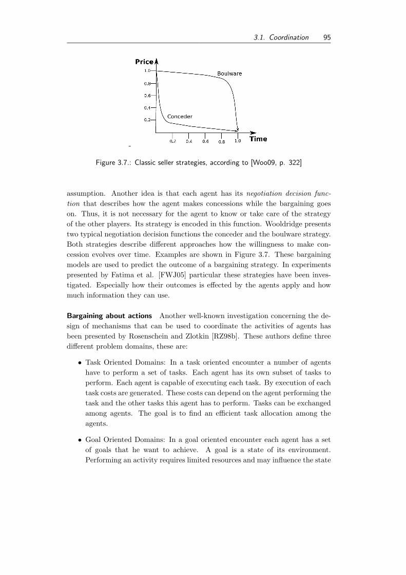
3.1. Coordination 95
-
Figure 3.7.: Classic seller strategies, according to [Woo09, p. 322]
assumption. Another idea is that each agent has its negotiation decision func-tion that describes how the agent makes concessions while the bargaining goeson. Thus, it is not necessary for the agent to know or take care of the strategyof the other players. Its strategy is encoded in this function. Wooldridge presentstwo typical negotiation decision functions the conceder and the boulware strategy.Both strategies describe different approaches how the willingness to make con-cession evolves over time. Examples are shown in Figure 3.7. These bargainingmodels are used to predict the outcome of a bargaining strategy. In experimentspresented by Fatima et al. [FWJ05] particular these strategies have been inves-tigated. Especially how their outcomes is effected by the agents apply and howmuch information they can use.
Bargaining about actions Another well-known investigation concerning the de-sign of mechanisms that can be used to coordinate the activities of agents hasbeen presented by Rosenschein and Zlotkin [RZ98b]. These authors define threedifferent problem domains, these are:
• Task Oriented Domains: In a task oriented encounter a number of agentshave to perform a set of tasks. Each agent has its own subset of tasks toperform. Each agent is capable of executing each task. By execution of eachtask costs are generated. These costs can depend on the agent performing thetask and the other tasks this agent has to perform. Tasks can be exchangedamong agents. The goal is to find an efficient task allocation among theagents.
• Goal Oriented Domains: In a goal oriented encounter each agent has a setof goals that he want to achieve. A goal is a state of its environment.Performing an activity requires limited resources and may influence the state

96 3. State of the art
of the world towards other goals of other agents. Thus, dependencies andconflicts can arise between agents. It is also possible that the agents try tosatisfy most of their goals, in case an existing conflict hinders them formfulfill all their goals.
• Worth Oriented Domains: In a worth oriented encounter the agents areguided by an utility function that they try to maximize. Thus, it is possiblethat a goal can be fulfilled to a certain degree. The usage of an utility enablesthe designer to model the fact that goals can be partially achieved, insteadof binary modeling in goal-oriented domains.
Rosenschein and Zlotkin provide a well-known protocol that can be used to bargainin such domains, the monotonic concession protocol [RZ98b, pp. 40,41]. Accordingto this protocol the negotiation goes on for a number of rounds. In each round theagents propose a deal simultaneously. If an agents accept a deal the negotiationend. It accepts, if the utility of the received offer exceeds or is equal to the utilityof its last proposal. If no agreement could be achieved in a round the next roundstarts. Thereby, no agent is allowed to offer a deal that has a lower utility for theother agent, as it has already offered before. If in a round (that is not the initialround) both agents make no concessions the negotiation ends with the conflictdeal. For this protocol Rosenschein and Zlotkin present an appropriate strategythat is designed to be efficient, stable, and simple. They name of this strategy isZeuthen strategy [RZ98b, pp. 43,44]. According to this strategy an agent shouldstart with his local best deal. The concessions he made depends on the risk theagent wants to take ending in the conflicting deal. Risk is influenced by thedistance from the current offered deal to the conflicting deal (in terms of utility).If this distance is low an agent is more risky then otherwise. The risk of an agenti for step t can be computed as follow:
Riskt1 =utility agent i loses by conceding and accepting j’s offer
utility i loses by not conceding and causing conflict
In each step an agent computes its risk and the risk of the other agent. If itsown risk is smaller or equal to its opponent’s risk he should make a confession.Thereby, he should make a minimally concession, i.e., a concession that is just bigenough that his risk becomes greater than the risk of its opponent.
In their work Rosenschein and Zlotkin extend the bargaining mechanism tohandle conflicting situation and mixed deals, i.e., deals with a random influence,which leads to the Unified Negotiation Protocol [RZ98b, pp. 119–121]. Further-more, these authors investigate different option how agent could behave strate-gically to gain an advantage and how this can be avoided to a larger extend bymodifying the bargaining mechanism. Their work is a first and important step

3.1. Coordination 97
into the research for re-use of coordination mechanisms. They define characteris-tics of coordination problems that define a sub-set of coordination problems andpresent efficient coordination mechanisms for those sub-sets.
The contract net protocol, already been introduced in Section 3.1.2, has been ex-tended for more elaborated, non-cooperative scenarios, as well. Sandholm [San96]defines a semantic of the protocol that makes it possible to apply this protocolfor self-interested agents, as well. Note originally the contract net protocol wasdefined for cooperative agents, only. Thereby, the main idea while generating abid is to compute the marginal costs of an additional task. Thereby, the marginalcosts are the costs that occur additionally, by adding the offered task to the cur-rent set of tasks. Moreover, agents can suggest a re-allocation of tasks/resources.They can suggest four different types of contracts:
• original-contracts: describing one allocation to another agent,
• cluster-contract: specifying a set of allocations atomically to another agent,
• swap contracts: a pair of agents swaps a pair of tasks, and
• multiagent contracts: more than two agents exchange allocations atomically.
If all other participating agents accept, the change of a contract is adapted to theoverall system. These types of contracts and corresponding negotiation schemesenables the agents to improve their situation constantly. An arbitrary sequenceof such contracting operation can improve the overall system’s performance, i.e.,it can stuck in local optima. In fact Sandholm showed that with more complexcontracts it is possible to come to a global optimal outcome with a finite sequenceof individual rational re-allocations. This is possible with the OSCM-contractsthat allow to suggest a complete reallocation of jobs plus the specification ofside-payments from one agent to another. But it has to mentioned that the com-putational effort to compute such contract suggestions can become very complex.A more elaborated discussion about Sandholm’s findings can be found at [San96]or [San99, pp. 236,237].
Based on the idea of commitments Sandholm and Lesser [SL02] discussed in theirarticle the advantages of non-binding commitments. Announcing to break up agiven commitment is called decommitment . In case an agent decide to decommitfrom a given commitment he has to pay a predefined penalty. These penaltiesenables to gradually adjusting the binding character of a commitment. Thus, thesetypes of commitments are called leveled-commitments. Sandholm and Lesser showthat using leveled commitments enables multiagent systems to find more efficientdeals, in comparison to approaches where only binding commitments exist.

98 3. State of the art
3.2. Agent-oriented Software Engineering
Agent-oriented software engineering (AOSE) is a research field connecting DAIand software engineering. Although one has to state that most contributions inthis field are made by researchers from AI. Like in conventional software engineer-ing, AOSE investigates issues concerning the different process steps of softwareengineering, see Sommerville [Som06, Chap. 4]. These are the specification ofsystem’s behavior, modeling systems, and supporting implementation of systemsby methodologies, frameworks, and tools; and finally verification and validation ofimplemented systems. In the following the field of AOSE is surveyed and thereafterefforts and ideas for reusing components in particular coordination mechanismsare discussed.
3.2.1. Surveying agent-oriented software engineering
In the following we discuss results in the field of specification and design of multi-agent systems. An important result, probably the most mature results of AOSEare frameworks to build multiagent systems. Finally, techniques for verifying andvalidating multiagent systems are discussed. A very detailed introduction intothis field is given by Gomez-Sanz et al. [GSGW04].
Designing multiagent systems
In the specification of a system the expected behavior of the system is formalized.The elicitation of these specifications is typically done during the requirementelicitation phase. The field of requirement engineering is a subfield of softwareengineering. The metaphor of agents has been used in conventional requirementsengineering, too. An agent in requirements engineering is “an active system com-ponent playing a role in goal satisfaction” [Lam09, p. 396]. With an agent-basedmodeling approach the responsibilities of the systems can be modeled. Thesemodels can answers the question “who is doing what and why” [Lam09, p. 395].Nevertheless, van Lamsweerde argue that for most projects a goal orientationis more fruitful, as it aims at the questions what goal the entire system shouldachieve. A more detailed discussion is provided by van Lamswerde [Lam09, Chap.7].
The integration of agents into requirements engineering has been surveyed byGomez-Sanz et al. [GSGW04, pp. 36,37]. More recently Fuentes-Fernandez etal. [FFGSP06] have presented a specialized approach or requirement elicitation inAOSE. It enables to acquiring the required information based on an agent-basedmodel, based on ideas of activity theory. In their paper Fuentes-Fernandez et al.transfer the idea of activity checklist to develop guidelines for the requirements

3.2. Agent-oriented Software Engineering 99
elicitation process. Therefore, structured interviews are used, and an UML profiledescribing activity theory concepts has been developed by the authors. Basedon that means a process for the requirement elicitation is proposed. Thus, thisapproach enables formal and informal, i.e., textual modeling of requirements.
Another way to specify the desired behavior of agents bases on formal specifi-cations. The logic formulation might not be well suited for an elicitation processbut rather for experts who want to assure that the system satisfy some behavior.An example for such a specification language is the situation calculus that is, e.g.,the foundation of the ConGOLOG programming language for agents, presentedby Giacomo et al. [GLL00].
Another example is the formal languages presented by Dastani et al. [DJT01].These authors have presented a hierarchy of languages for specifying the dynamicsof multiagent systems. In contrast to conventional systems the systems behav-ior is specified from different perspectives. Dastani et al. [DJT01] present thespecification from a global, an agent’s, and an environmental perspective.
A number of design methodologies have been proposed. Those methods aim-ing to structure the specification and design process of MAS. Examples for suchmethods are Gaia, Tropos, MASSIVE, Zeus, MaSE, and Aalaadin. In the follow-ing only some key concepts of these modeling methods are presented. A detailedintroduction and comparison of these methods can be found in Weiss and Jakob[WJ05] and Bergenti et al. [BGZ04]. Central concepts for the design of multiagentsystems are roles, interactions and organizations.
• Roles A role is an abstraction of a component of the system, see Caire et al.[CCG+04, p. 179]. Roles have the notion of social rules, or job descriptions.According to Wooldridge et al. [WJK00] it can be described by sets ofpermissions, responsibilities, activities, and interactions. An agent can haveone or more roles at the same time.
• Interactions Define the allowed interactions between roles. An interactiondefinition has to specify the interaction protocols the roles apply (see Section2.3.4). Moreover, the goals of the interaction and required input are spec-ified. Interactions define the communicative behavior among the differentcomponents/agents in the system.
• Organization The relations between roles can also be defined using orga-nizational patterns. Roles are arranged in an organization. This enablesgrouping of competence and structuring the agent system.
Applying and extending UML diagrams The use of UML diagrams or extensionof them has attracted a number of researchers, e.g., Depke et al. and Odell et al.

100 3. State of the art
Figure 3.8.: AUML diagram of the contract net protocol [FIP02f, p. 2]
[DHK02, OPB01]. In particular we present here the probably most prominentapproach that has been used in the FIPA specifications as well, the Agent UML(AUML) [OPB01]. Within AUML class diagrams and sequence charts from stan-dard UML has been identified as valuable tool for designing agent-based systems.AUML extends UML1.4[OMG01]. UML 1.4 was the standard UML specificationabout the time AUML was designed [OPB01]. Especially sequence charts havebeen investigated as a mean to specify and design agents interactions [OPB01]. Anexample for such an extended sequence chart is shown in Figure 3.8. Currently,the development of AUML has been slowed down, as a consequence of the releaseof UML 2.1 specification [OMG07], that incorporate aspects of AUML [Com07].For that reason, standard sequence diagrams in UML 2.x can be used instead ofAUML sequence charts, today. The entire efforts among AUML are summarizedby Huget et al. [HOB04].

3.2. Agent-oriented Software Engineering 101
Languages and frameworks for agent-based systems implementation
For the implementation of agent-based systems a number of programming lan-guages from different programming paradigms have been considered. Among oth-ers declarative and functional languages like Mozart, Lisp, Prolog and Concurrent-METATEM are mentioned by Gomez et al.[GSGW04, pp. 55,56].
Moreover, specialized programming languages for agent-based systems havebeen designed, like Agent0, AgentSpeak, which is the foundation of the Jasonframework by Bordini et al. [BHW07]; or ConGOLOG by Giacomo et al. [GLL00].
Agent-oriented development frameworks A lot of effort of research in the fieldof AOSE has been devoted to the development of agent-oriented developmentframeworks. In fact there exists a huge variety of frameworks ranging from frame-works based on logic-based agent programming, like Jason or Jadex, to frameworksextending object-orient paradigms concepts on top of object oriented languages,like JADE19. An overview about some of these frameworks can be found in Weißand Jakob [WJ05] and Bergenti et al. [BGZ04]. Those frameworks offer the infras-tructure in which each single agent can operate in. For instance, those frameworksprovide means for communication between agents. Some of these frameworks arecompliant to the aforementioned FIPA standard, which ensures a certain levelof interoperability. As agents from different authors can communicate and coop-erate within those environments. Most of these platforms, even if they are notcompletely FIPA compliant, take advantage of the FIPA abstract architecturestandard [FIP02a]. These frameworks provide the agent environment discussed inSection 2.3.4.
Omicini et al. [OOR04] characterize those infrastructures for agents into twogroups: the enabling infrastructures and the governing infrastructures. The en-abling infrastructures provide infrastructure mainly for communication betweenagents. These infrastructures enable agents to exist in a MAS. According toOmicini et al. most of the existing infrastructure fall in this category. In con-trast Omicini et al. argue that a governing infrastructure would offer additionalservices, like coordination (see Section 3.1.2). Thus, these infrastructures wouldgovern the interaction space of the agents and offer a higher level of abstractionfor the developer.
From model to implementation A current trend in software engineering is themodel-driven development (MDD). The idea of this approach is to model thesystem and then automatically transform the model into executable code. In the
19http://jade.tilab.com/, Accessed: 03/15/2010

102 3. State of the art
following research taking advantages of model transformation and automatic codegeneration for agent-based systems is presented.
Some agent-specific modeling tools offer code generation, e.g., the Zeus-Tool,offers a number of templates that could be configured by the developer to generatecode. Other tools, e.g., agentTool, can generate method bodies that have to beimplemented by the developer.
Another line of research wants to take advantage of the generation of agent codeapplying principles of model-driven development (MDD). An introduction intothe field of MDD is given, e.g., by Stahl and Volter [SV06, Chap. 2]. Multiagentsystems are specified on a meta model level. This meta model can be mapped todifferent agent platforms, like JADE for instance. This enables the designer todevelop models on a high level of abstraction, and then automatically transformsthe model into executable code. Modeling languages have been proposed, forinstance, by Hahn [Hah08], who presents a domain specific modeling language forMAS. The developer has to specify its system in this domain specific language,which is a platform independent model (PIM). Code generators can transformsuch a PIM with additional templates into a platform specific model, e.g., a JADErepresentation of the system. For more details see Hahn [Hah08] or Hahn et al.[HZWF10].
Verification, Validation and Visualization
If a MAS has been implemented in a formal way, like an implementation using theConGOLOG language, or the system has been generated automatically based onformal model, e.g., by MDA techniques presented above, it is possible to verify theMAS. By verification a formal prove is given, that the system will behave withinits specifications. An interesting approach towards the verification of MAS is pre-sented by Brazier et al. [BCG+98] using the idea of hierarchical decomposition ofsystems for verification. Thus, to proof the specification for the entire systems itis decomposed into its subsystems. For each subsystem specifications are definedthat, assumed they are true, would contribute to the proof of correctness of theoverall system. This process is iteratively repeated for all subsystems until theconsidered subsystems have reasonable size to use conventional verification tech-niques. An introductory into these verification techniques is, e.g., presented byApt and Olderog [AO94].
Other approaches assuming a complete specification of the MAS to be present,e.g., Bulling and Hindriks [BH09] or Hilarie et al. [HSKF05]. If a specificationof the systems behavior, or at least subparts like its communication behavior areprovided agents modeled e.g in logics can be verified. An example with morepractical value is, for instance, implemented in the agent development toolkit

3.2. Agent-oriented Software Engineering 103
Figure 3.9.: Components of a simulation tool for validating MAS, [TS09]
agentTool. In agentTool conversations can be checked for problems, like deadlocksusing the model checker Spin, see Weiß and Jakob [WJ05, p. 251]. Verification onthe model level can be very useful during the design of the system, as design flawscan be identified upfront the implementation. If the system’s implementation hasnot been automatically derived by verified translators, than it is not sufficientonly to verify the model to gain any statement about the implemented system. Inthose cases the verification lacks a computational grounding.
Thus, it is hard to verify a MAS, either because of the lack of computationalgrounding of the formal model or because of the lack of a formal model. Thus whatremains possible is validating the system. By validation we refer to a systematictesting the system and thereby increase confidence in the system.
Validation techniques often rely on testing and simulation as methodology. Acomparison between conventional validation approaches known from software en-gineering and special needs and approaches from the agent-oriented software en-gineering have been compared by Fuentes et al. [FGSP04]. Systematic softwaretesting has not been adopted widely in agent-oriented software engineering. Eventhough extension for conventional testing techniques, like unit-testing, have beenproposed already, e.g., by Hormann [Hor06]. A systematic testing approach forthe overall system has been discussed, e.g., by Fortino et al. [FGR05] and Timmand Schumann [TS09]. The idea is to test the behavior of the MAS in a syntheticenvironment that can be controlled by the tester. Thereby, the tester can changethe environment in a controlled way, and observe the reaction of the MAS. An ar-chitecture for such a test environment has been proposed by Timm and Schumannand is shown in Figure 3.9.

104 3. State of the art
The visualization of interaction of in a MAS can enable an easier understandof an existing agent system. It can also be used for debugging or testing issues.Visualizing communication can be realized by dynamically draw sequence charts,which is offered, e.g., by the Sniffer Agent of the JADE platform. More elabo-rated techniques for visualization, like Dooley graphs, have been proposed by vanParunak [Par96] or Singh [Sin98].
3.2.2. Reuse of existing methodology in AOSE
Research done in the field of AOSE has created a variety of methods. So, it isdesirable to gain the entire benefit out of this large body of work by using existingmechanisms. This will lead to increased development speed and higher reliablesoftware. For that reason existing work has been surveyed according to whatconcepts of reuse exist in AOSE. Therefore, the proceedings of previous workshopson agent-oriented software engineering have been surveyed: [CW01, WWC02,GOW03, GMO03, OGM04, MZ06, PZ07, LP08, LGS09]. This workshop series isan annual workshop co-located with the AAMAS conference20. The series startedin the year 2000. So the results of this section base on a survey of the last tenworkshops21. Moreover, additional literature was surveyed, like the proceedings ofthe International Conference of Software Reuse22 and the International Journal ofAgent-Oriented Software Engineering23. In the specific field of reuse in softwareengineering the field of agent-oriented software engineering has not been recognizedat all, at least there exists no single paper concerning agent technology. Theresearch concerning reuse in software engineering primarily focus on the selectionprocess for commercial off-the-shelf (COTS) software. The international journalof agent-oriented software engineering started in 2007 and appears quarterly. Theimpression from the survey of the AOSE-proceedings, that reuse has not beenidentified as a specific topic of itself in the field of AOSE, get’s supported by thesurvey of this journal. Up to now24 the issue of reuse of methodology has notdrawn much attention by researchers.
Before we go into further detail, two types of reuse have to be distinguished.Reuse of code and reuse of concepts. The first type of reuse can be found inagent-based frameworks/infrastructure, where a code base is common to a num-
20The AAMAS conference is one of the major annual conferences in DAI, organized by the
International Foundation for Autonomous Agents and Multiagent Systems, for more details
see http://www.ifaamas.org/, Accessed: 02/15/2010.21At the time of writing, the papers for the 2010 workshop are under review.22For an overview of the proceedings see http://www.isase.us/pastconferences.htm, Ac-
cessed: 03/08/2010.23http://www.inderscience.com/browse/index.php?journalID=174, Accessed: 03/08/201024Current issue is 2010 (Vol 4., No.1), date 03/08/2010

3.2. Agent-oriented Software Engineering 105
ber of applications. The second type of reuse addresses concepts and mechanismsthat can be reused, as well. An example might be interaction protocols, like thecontract net protocol. Consequently, one can argue that reuse has been facil-itated by the development of efficient frameworks for agent-based systems. Infact we focus here on the second type of reuse, the reuse of concepts and meth-ods. Existing modeling approaches, presented above, might offer reuse of artifactsthat have been created in previous designs or are pre-defined within a toolkit orframework. Although, various frameworks for building agent-based systems havebeen proposed and are in use. Within these frameworks concepts like agents, andmessages and infrastructure aspects like message exchange is supported, but nospecific means for coordination of agents in general or their plans in particular,are supported within those frameworks, typically.
An established way to reuse concepts in software engineering has been the defini-tion of patterns, e.g., the well-known design patterns by Gamma et al. [GHJV94].For the field of agent-oriented software engineering Lind [Lin03] suggested a for-mat for agents oriented pattern and present an architectural and an interactionprotocol, for example. Architectural patterns, like Broker, Moderator, and Wrap-per have also been presented by Heyden et al. [HCY99]. Interaction patterns,like patterns for Subscription, Call for proposals, Broker, and Wrapper have beendiscussed by Kolp et al. [KDF05], as well. Those authors termed those patternssocial patterns. The authors present a framework for describing those patternsin a unified way, that has been specialized for agent-based development. Thosearchitectural and interaction patterns have been standardized by the FIPA. TheFIPA standards have been presented in Section 2.3.4.
A wider scope of patterns in AOSE has been proposed by Sauvage [Sau04].Sauvage distinct in his article between MetaPatterns, that describe abstractconstructs for the design of agent-based systems. He introduces organizationalschemes, like organizations and roles, and protocols as two meta-patterns. The sec-ond group of patterns identified by the author are so-called metaphoric patterns.Sauvage mentioned marks, like pheromones, and influences as two metaphoric pat-terns. The third class of patterns are according to Sauvage architectural patterns,addressing the architecture of agents, like layered architecture or BDI architec-tures, already presented in Section 2.3.2.
Design patterns for the design of self-organizing systems have been summarizedby Gardelli et al. [GVO07]. The patterns presented by those authors are col-lected from the design of nature-inspired design of self-organizing systems, likeant-based systems, for instance, patterns addressing the evaporation, aggregation,and diffusion are presented.
The identification of particular design patterns for the coordination in self-

106 3. State of the art
organizing systems is addressed in the article by de Wolf and Holvoet [WH06].The authors present two design patterns for coordination. These techniques aregradient fields and market-based control. The idea of the gradient field patternis to model a artificial environment for the agent and to model the coordinatedbehavior by the movement within this artificial environment. Market-based con-trol coordination techniques uses the concepts of prices to bring together producerand consumers of services or information, as a coordination mechanism. The au-thors aim in their pattern description on the problem of efficient allocation of taskamong agents.
An idea for reusing proofs within the validation of multiagent systems base onthe idea of the component-based verification proposed by Brazier et al. [BCG+98].Thus, only the proofs for components that have changed have to be updated. Ifit is possible to proof that these subsystems stay within their previously definedspecification, the proof of the overall systems specification remains valid.
Hilarie et al. [HSKF05] argue that to facilitate reuse of agents or componentsof agents, it is necessary to formally specify these components and then proofthe compliance of components to their specification. This can foster reuse, asthose components can become the building blocks for future systems. For thatreason the authors present a formal notation combined out of Objective-Z andstatecharts. The authors present a case study for components of a robotic system.The focus of the authors is on the design of the formal notation and on prove ofcompliance. To the best of the author no common catalog of components existsthat specifies existing components. And even such a catalog exist this is notsufficient. The availability of a number of specified components does not enablereuse, as no process how to select components exists, see also the discussion in thenext section.
A quite similar approach for the reuse of organizations has been proposed byJonker et al. [JTY05]. In their paper the authors present a formalism to describeorganizations and they assign properties to these organizations. They proposeto build a library of organization forms. An organizational designer then shouldbe able to place queries to the library and retrieve possible organization formsthat might suit his requirements. Of course, the indexing of those organizationsbecomes critical. The authors propose different aspects for indexing, e.g., bygroup functionality, environment assumptions or realization constraints [JTY05].The retrieved organization descriptions might be adapted to the given situationat hand.
Bartolini et al. [BPJ03] argue that the current representation of interactionprotocols is not sufficient, for protocols like the English auction, as by current

3.2. Agent-oriented Software Engineering 107
specifications (e.g., FIPA standard [FIP01c]) only the sequence of messages isfixed. But more information is required, e.g., to generate a valid bid in an En-glish auction. A new bid has to be higher than the currently highest bid. Thiskind of information has to be implicitly encoded by the agent designer. Thus, forachieving a better and machine-readable format the authors present a frameworkfor specifying negotiations, based on rules for encoding the negotiation protocol.Agent should be able, i.e., by rule-based systems, to reason about those protocolsand apply them autonomously. The reuse is thereby on emphasizing a more pre-cise and complete form of specification for negotiations. The authors argue thatby more precise description the reuse is facilitated as the agents can choose aninteraction protocol automatically from a given knowledge-base.
Reuse of coordination mechanisms
As previously mentioned in this study we are interested in the coordination ofautonomous planning entities. As outlined in Section 3.1.2 research in coordina-tion of agents has generated a large body of work, containing a lot of differentcoordination mechanisms.
An idea, already discussed, for the reuse of coordination mechanisms is thecoordination artifact (see Section 3.1.2 or [ORV+04]). To briefly re-iterate theconcept, in a coordination artifact a coordination mechanism is embedded thatcan be used by the agents. The problem in defining those coordination artifactsis to find the right level of granularity. So, if an artifact is too general it cannotbe applied by the agents, as it does not fit their purpose. On the other hand atoo specialized coordination mechanism in the artifact cannot be reused as thecoordination between two specific planning entities might be a unique situation.Finding an adequate trade-off between generalization and specialization is hard tofind, if at all. Moreover, the resulting governing infrastructures (already discussedabove) have not been established in the developer community and it is not cleartoday, if they ever will. The only operational agent infrastructure mentioned inthe literature, is the TuSCoN infrastructure. Applications of this platform arepublished only by the developers of this particular platform25. So it looks like ifthere is no active community around that infrastructure.
The need for an easier retrieval for reusing interaction protocols has been iden-tified by Bussmann et al. [BJW03]. Therefore, the authors focus on the selectionprocess of interaction protocols. To be applicable an interaction protocol has torespect the existing dependencies of the current situation. Therefore, the au-thors suggest to classify interaction protocols according to a number of criteria.
25for details see http://apice.unibo.it/xwiki/bin/view/TuCSoN/PublicationsWithTuCSoN,
Accessed: 02/15/2010

108 3. State of the art
These authors suggest to use the number of agents involved, the computability ofconstraints and preferences, the number of agent roles, the role assignment, thenumber of joint commitments, and the size of joint commitment as criteria. Anagent designer should specify its requirements according to these criteria and thenidentify an interaction protocol that might be suitable for the given situation.
3.3. Identification of research gap and goals of this thesis
We have outlined the field of coordination in DAI. The presented coordinationmechanisms have been designed for a variety of applications and base on differenttheoretical assumptions. In the literature [SSWG02, Sch01, BCGZ01] differentschemes for classification of existing coordination approaches have been proposed.For instance Stockheim et al. [SSWG02] characterize different coordination ap-proaches according to the solution methodology they use. In particular they clus-ter existing approaches into:
• combinatorial auctions,
• bargaining processes,
• random search,
• knowledge-based systems, and
• learning systems.
As already pointed out, Schumacher [Sch01] presented a classification that usesthe perspective of the coordination mechanism as criteria, leading to subjectiveand objective coordination approaches.
Moreover, Busi et al. [BCGZ01] presents a framework for models and languagesfor coordination. They point out that key issues for the classification of coordina-tion mechanisms are:
• coordinatables,
• coordination medium, and
• coordination rules.
All these classification schemes reflect the fact that different techniques, perspec-tives and theories have influenced the research concerning coordination in DAI.But non of these classifications either point out any application oriented criteria,neither indicate what motivations, i.e., use cases, have influenced the coordina-tion mechanism. So the current state of the art of the field of coordination in DAI
3.3. Identification of research gap and goals of this thesis 109
contains a huge variety of techniques and existing classifications indicate more theorigins and roots of these approaches instead of their fields of applications, theirstrength, and weaknesses.
Researchers like Durfee [Dur99] and Sandholm [San99] have surveyed principlesand techniques that can be used for coordinating multiple agents. But they donot give indications when to use such techniques. Consequently, the value for re-use of coordination techniques is limited. Rosenschein and Zlotkin [RZ98b] haveproposed specific characteristics for coordination problems and means that allowfor an efficient coordination in those specific problem settings. The state-, goal-,and worth oriented domains, discussed in Section 3.1.3 are an example for sucha classification. If a given coordination problem falls into one of those domainsthe coordination mechanisms identified by Rosenschein and Zlotkin can be used.In contrast to the focus of this work the presented domains are a limiting factor.Moreover, their classification is still abstract, and additional requirements cannotbe integrated. Although no indications for an implementing process are given.
Another field that has been surveyed in this chapter, was the agent-orientedsoftware engineering. After we had given a broad introduction into this field wehave discussed research concerning re-use and mechanism idenfification/selectionin the field of AOSE.
A result of this survey is that the idea of reusing existing concepts is not verywide-spread in AOSE, which is underlined by the relatively rare rate of articlespublished addressing this issue. Most of the research described in the literatureinvestigates techniques or tools concerning the development of new multiagentsystems from scratch. The integration of an agent-based solution into an exist-ing software ecosystem seems to be an open research fields. Similar conclusionshave to be drawb for the rest of the life-cycle of an application, aspects like themaintenance and evolution of existing agent-based systems are not sufficientlycovered.
The identification/selection process for a coordination problem has been tack-led on the one hand by researchers who argue that the selection of a coordinationmechanism should be done at runtime by the agent itself, e.g., by Excelente andJennings, and Omicini et al. [ETJ04, ORV+04]. But in their work only toy-world-examples are presented, where the reasoning of the agent concerning existing de-pendencies is uncomplex. These approaches cannot scale to complex coordinationproblems, like the coordination of autonomous planners.
On the other hand the work from Bussmann et al. [BMR+02] suggest to classifyinteraction protocols and build a catalog of interaction protocols, similar to theapproach presented for organizations by Jonker et al. [JTY05]. But the classifica-tion suggested by Bussmann et al. is not sufficient for coordination mechanisms

110 3. State of the art
because they remain too vague. The approach might be appropriate for the pureidentification of interaction protocols, but coordination mechanisms are on theone hand only a subset of interaction protocols and on the other hand comprisemore than simple rules concerning message exchange, which has also pointed outby Bordini et al. [BHW07] and Ossowski [Oss08].
From an engineer’s point of view, who wants to find an appropriate coordina-tion mechanism for a coordination problem consisting of inherently distributedplanning entities, the current state of the art in the research of coordination andagent-oriented software engineering is unsatisfactory. The identification/selectionproblem of a coordination mechanism, in general and especially for the coordi-nation of autonomous planning entities, is an open question in agent-orientedresearch. There exists neither tooling nor process for the identification/selectionand implementation of coordination mechanisms that could be used for the coor-dination of planning entities.
This constitutes the issue addressed in this thesis, the effective identifica-tion/selection of appropriate coordination mechanisms for the coordination of ex-isting planning systems embedded in autonomous planning entities. Or to rephraseit as the research question of this thesis:
How can existing coordination mechanisms be efficiently identified,that are suitable for the concrete coordination problem of existingplanning systems, in inherent distributed planning environments?
To answer this question it is necessary to define a process. Gaitanides defines aprocess as the “structure for actions” [Gai04, p. 1212]. The process has to struc-ture the necessary actions that are needed to identify the suitable coordinationmechanisms, that are applicable to the given problem. Moreover, it is necessary todetail out the process to provide means for a selection among those mechanisms.To establish a process three steps are necessary:
• process definition
• process validation
• process evaluation
In the first step the process has to be defined and detailed to be executable. Inthe second step the process has to be validated. This is to ensure the feasibilityof the process. In the final step the process has to be empirically evaluated on asociologically sound base. In this thesis we focus on the first two steps, the processdefinition and validation. In the next chapter we define and detail out the ECoprocess that is suggested for the efficient selection of a coordination mechanism.

3.3. Identification of research gap and goals of this thesis 111
In chapters 5 and 6 we present the validation of the ECo process applying it totwo cases studies. Within these case studies we show the feasibility, flexibility,and power of the process that is proposed in this thesis.

112 3. State of the art
4. The ECo-CoPs approach
As pointed out in the last chapter, the goal of this thesis is to define a processthat enables the identification of a coordination mechanism for existing inherentlydistributed planning entities. For this reason we introduce the ECo process in thischapter. The ECo process consists of the following five steps.
1. modeling the scenario,
2. defining coordination requirements,
3. identifying suitable coordination mechanisms,
4. implementing coordination mechanisms, and
5. evaluating coordination mechanisms.
We detail out the ECo process and required process steps in Section 4.2. TheECo process is supported by the CoPS process and the CoPS framework, bothpresented in Section 4.3.
But at first we propose a set of six characteristics of coordination problems thatcould be identified in a number of coordination problems and that are outlinedin the examples used in this study. Moreover, the presented coordination mech-anisms are classified according to these characteristics. This enables a designerto identify suitable coordination mechanisms by matching required and providedcharacteristics.
Using this first classification scheme for coordination techniques enables a firstand fast reduction to a subset of coordination techniques, presented in the previoussection. But this is not sufficient for the selection of an appropriate coordinationmechanism. The goal of coordination is to ensure that the different plans of theplanning entities can be executed in a feasible way. Moreover, the coordinationmechanism should be applicable in the given context. This is defined more pre-cisely in this chapter. The evaluation of the results of the coordination processremain domain specific. Thus, we are not interested here in defining a specializedcoordination mechanism or a family of those, that lead to efficient coordinationmechanisms for a specific number of scenarios, e.g., by removing all redundancy
113
114 4. The ECo-CoPs approach
in a joint plan. Moreover, we are interested in identifying suitable existing co-ordination mechanisms for a given situation and to enable a fast prototypicalimplementation to evaluate the coordination mechanisms in the given situation.
To address this issue, a set of activities has to be performed in a structuredway. By suggesting the ECo process as a mean to do so, we offer a solution for theidentification process for coordination mechanisms. One step of the ECo processis the implementation of the coordination mechanisms, to perform a quantitativeevaluation. To support this step and to address the issue of implementing coor-dination mechanisms in an existing software environment, we present the CoPSprocess and the CoPS framework. In the CoPS process, an optional sub-processof the ECo process, the activities for implementing coordination mechanisms arediscussed and structured. For an easier and faster implementation, the CoPSframework has been designed to support the CoPS process. The CoPS frameworkenables the designer to use pre-defined software agents that can be adapted ac-cording to the selected coordination mechanisms and to the local policies of theplanning entities. While designing the ECo and the CoPS process, we aim to allowthe designer an independent usage of these processes and the CoPS framework,as far as possible. It is possible to apply the ECo process for the identifica-tion/selection and to use other implementation mechanisms. It is also possibleto use the CoPS process implementing a coordination mechanism, that has beenselected in a way, that may not conform with the ECo process. Especially, theCoPS process has been designed in a way that no unnecessary restrictions forthe agents, their architecture or abilities are implied. For that reason we discussmodeling aspects with formal and informal means. A formal specification enablesagents with reasonable inference capacities to reason about appropriate actionsby themselves. But this reasoning within agents should not be mandatory tobuild agents to coordinate the planning processes, as this task is orthogonal to theagent’s architecture. Thus, providing an informal description for agent developers,who encode these policies implicitly into the agents, can foster the developmentof these agents. Moreover, it is possible to replace the implementation frameworkor design an agent for coordination, even without any framework. This modularapproach facilitates independent use and independent development of all parts ofthe ECo-CoPS approach.
The ECo process, as well as the CoPS process and framework is presented herein detail. A validation of this process and the CoPS process and framework assupporting means is presented in the next chapters.

4.1. Characteristics of coordination problems and techniques 115
4.1. Characteristics of coordination problems and
techniques
In this section we point out some characteristics of coordination problems arisingbetween planning systems, that can be identified in the examples used in thisstudy. We define these characteristics in a way that a simple, binary answer couldbe given to point out important characteristics of a coordination problem. Thesecharacteristics guide the identification/selection process for a coordination mech-anism to efficiently coordinate the autonomous planning entities. The questionsto identify the six characteristics are presented in the following. Possible answersare shown in brackets.
• Is an allocation problem part of the coordination, i.e., have tasks top beallocated to planning entities? (Yes/No)
• Are the local objective functions comparable, i.e., is the same measurementused by different planning systems? (Yes/No)
• Are the planning systems involved homogenous or heterogeneous, i.e., arethe planning problems of the same type or are they different? (Homoge-nous/Heterogeneous)
• Does a common objective function exist that can be used to measure thesuccess of the overall system? (Yes/No)
• Is information hiding necessary among the planning entities? (Yes/No)
• Do cyclic dependencies exist? (Yes/No)
Characterization of the examples
In the following we discuss the characteristics of the exemplified coordinationproblems used in this study. The result of this discussion is summarized in Table4.1. Again, the example of production scheduling and distribution of goods (intro-duced in Section 2.1.1) is referred to as SPT. SCM is the common abbreviation forsupply chain management, and CTM is the abbreviation for container terminalmanagement. Obviously, within the SPT problem there exists no task allocationproblem among the different planning entities. Each product has to pass the threeareas in the same linear sequence, like in a flow shop scheduling problem. Eventhough the packing and the transportation planning try to reduce costs, this is nottrue for the scheduling system, which tries to optimize the utilization of resources.Consequently, the objective functions of the planning systems are not comparable.The planning problems are heterogeneous. All these three subsystems are part of

116 4. The ECo-CoPs approach
Characteristics SPT SCM CTM
Allocation No Yes NoComparable objective No both possible No
Homogenous/Heterogeneous heterogeneous both possible heterogeneousOverall objective Yes Yes No
Information hiding No Yes NoCyclic dependencies No No Yes
Table 4.1.: Characteristics of the SPT, SCM and CTM problem
the production and delivery process of one company; consequently, there existsan overall objective function, i.e., the costs incurred for the company. With asimilar explanation it can be argued that no information hiding is necessary. Andas discussed above in the simple linear case of the SPT, no cyclic dependenciesexist.
The SCM (supply chain management) problem has been presented in Section2.1.2. An allocation becomes necessary if companies have overlapping compe-tencies, which is, according to Corsten and Gossing [CG01], rather frequently.Consequently, there exist more than one entity, here company, that could performa task. It can be assumed that all companies want to maximize their profit. On amore detailed level it can be challenging to compare all local plans with a commonmetric. Thus, it depends on the concrete scenario and its modeling if the objec-tive functions are comparable. The same is true for the type of planning problem.From an abstract point of view all planning systems can be abstracted as schedul-ing problems. Some abstract activities have to be performed and each requiresan amount of time. Of course, the concrete planning problems of a shipping com-pany deviate from the planning processes in a ware house or plant. It is reasonableto assume that the overall objective of the supply chain can be measured by anoverall objective function. For instance, final goods produced by the supply chainthat are sold to customers and the production and transport of these goods haveinduced costs. The difference between revenue and costs can be defined as profitof the supply chain, not regarding how this profit is split among the companiesin the supply chain. This is typically a question of market power or more ana-lytically the outcome of a cooperative game. As already mentioned, companieswithin a supply chain have overlapping competencies. Thus, a confidential level isrequested by the companies and information hiding becomes an issue. Typically,it is assumed that supply chains have no cyclic dependencies, the flow of materialis assumed to be linear. This is, of course, an assumption that does not necessarilyhave to be true, for instance, for supply webs the flow of material is not linear

4.1. Characteristics of coordination problems and techniques 117
anymore and cycles could occur.
Finally, the characterization of the CTM (container terminal management)problem is discussed. As in the SPT there exists no allocation problem. Allproblems have to be solved to serve a ship. The used objective functions are notcomparable. For instance, the solver for the berth allocation problem wants toachieve a high utilization of the berth and low waiting time for the ships. Thecrane scheduling solver aims to reduce the process times of ships and maximizethe utilization of its resources. The planning problems are heterogeneous. Evenif the direct monetary effects of all planning decisions could be estimated for thecontainer terminal, this is not sufficient for achieving an overall objective func-tion, because the service time for ships is a competitive factor that can hardlybe estimated in monetary terms. Therefore, a trade-off has to be made betweenoffered service time to ships and induced costs. Consequently, no overall objectivefunction could be defined easily. All planning problems occur within one company,thus no information hiding is required. As shown above in Figure 2.11 (on page35), there exist a number of cycles among the planning problems.
Categorization of presented coordination mechanisms
In Section 3.1.2 a number of different techniques for coordination among agentsplans have been presented. Thereby, we gave a broad overview of existing tech-niques developed in the field of DAI. This overview is not exhaustive in the sensethat all existing variants of all mechanisms have been presented. But it was in-tended to cover the wide field of coordination in DAI. In this section the suitabilityof these concepts for the coordination of planning systems is discussed. There-fore, we use the characteristics discussed in the last section. The findings of thisdiscussion have been summarized in Table 4.2.
In this table we have listed all groups of coordination mechanisms presented inthe previous discussion (see Section 3.1.2). Thereby in each row an entry representsa type of coordination mechanisms, and there could exists a number of mechanismsthat can be classified as a member of a particular group. For instance, the typenegotiations covers various different mechanisms that have been presented in theliterature.
We have investigated the necessary characteristics for each of these mechanismgroups, i.e., what characteristics are necessary to apply the coordination mech-anism. If the mechanism is robust against the different types of a characteristicthis is indicated by an asterisk (*). Rows that are stroke out indicate that thismechanism is classified as not suitable. This table is, of course, not sufficient topick a specific coordination mechanism, but it can guide the search for appropriatemechanisms by narrowing down the list of possible candidates.

118 4. The ECo-CoPs approach
Mech
anism
allocation
comp
.ob
j.h
omo./h
etero.overall
obj.
inf.
hid
ing
cyclic
dep
.
taskSharing
Y*
**
**
contractnet
Y*
**
**
auctionsY
Y*
**
*result
SharingN
**
*N
NG
PG
P*
**
Y*
?negotiations
**
**
**
centralizedplanning
*Y
homogenous
YN
*dpcp
**
**
*N
dpde,preplanning
N*
homogenous
**
*dpde,
planm
erging*
**
YN
*dpde,
mediator
**
*Y
(N)
*dpde,
iterativeD
CSP
coordinationartifacts
Tab
le4.2.:
Su
itability
ofm
echan
isms
accordin
gto
characteristics;
decen
tralizedp
lann
ing
and
execution
(dp
de),
decen
tralized
plan
nin
gfor
acen
tralp
lan(d
pcp
)

4.1. Characteristics of coordination problems and techniques 119
Task sharing, as the name suggests, is an approach to distribute tasks amonga number of agents. Thus, it is primary suited for coordination problems involv-ing a number of tasks to distribute among agents. For all other criteria it doesnot depend on particular characteristics of the coordination problem. The samecharacterization can be made for the contract net protocol. Auctions are anotherapproach to distribute work among a number of agents. But to use them, it isrequired that agents have a comparable objective functions. This is necessary togenerate comparable bids.
The idea of result sharing is a priori not well suited to distribute tasks amongagents. Protecting private information is generally not coherent with the resultsharing approach. As discussed above, the existence of cyclic dependencies canbe a contraindication for applying result sharing approaches, as they may lead toproblems with the termination of the process. Additionally, it has to be mentionedthat through the possible chaotic behavior of planning systems result sharing hasto be used carefully.
In coordination mechanisms like GPGP an overall objective is required, thatall agents try to optimize. This is typically expressed in terms of quality thatthe agents want to maximize while executing methods of the task structure. In-formation hiding can partially be realized by defining a strategy for the resultsharing that can be used to formulate strict rules for publishing information andto give commitments towards other agents. Concerning the characteristic cyclicdependencies, up to now, no clear indications can be made from the case studiesin the literature, to what degree cyclic dependencies can be handled by the GPGPcoordination mechanism.
Negotiations are a general concept that can be adapted to a number of charac-teristics. Therefore, no restrictions could be identified that limit the applicationof this concept. Note that there exists a huge number of different negotiationsthat might have special requirements towards these characteristics.
The centralized planning for the coordination of different agents can lead to verycomplex planning problems. Therefore, we think this might only be reasonablefor homogenous problems. We are aware that there exist approaches for integra-tion different planning problems into larger models, e.g., by Meisel and Bierwirth[MB06] and Park and Kim [PK03] who have presented approaches for integratingthe BAP and CSP problems in the CTM domain. But those integrated modelsare specific for a certain situation and cannot be extended easily. For instance, itcould be desirable to integrate the interdependent storage space allocation prob-lem, too. Thus, the integration of models does not scale from the design pointof view, i.e., the efforts for integrating an additional partial model grow fasterthan linear. Moreover, the computational complexity of the resulting integratedproblem growth and computation complexity also does not scale well for the in-

120 4. The ECo-CoPs approach
tegration approach. To guide the overall planning process, comparable objectivefunctions and an overall objective function are required to estimate and comparedifferent alternatives and select the most suitable one. As all data required forplan generation has to be collected in the centralized planner, information hidingaspects cannot be respected.
The decentralized planning for a centralized plan can handle most of the afore-mentioned characteristics. Nevertheless, as the typical process is a sequential planrefinement process this mechanism can hardly handle cyclic dependencies. Asalready discussed they could lead to a non-terminating coordination process.
For decentralized planning with decentralized execution different techniqueshave been presented and are discussed. Among others, negotiations have beenproposed. As negotiations have been discussed already above, they are omittedhere.
The generation of constraints in the pre-planning coordination approach as-sumes that the initial task assignment has been made already [SW07]. Thus, itcannot be used for task allocation. As already mentioned, the problem is com-plex so we do not think it is useful to increase complexity further by coping withdifferent kinds of planning problems. Therefore, we argue it might be suitable forhomogenous planning problems.
The idea of plan merging requires a lot of information about the existing depen-dencies among plans and about transformation of local plans that can result inexecutable local plans. Thus, information hiding requirements cannot be satisfied.Moreover, a global objective function is a prerequisite to have means to be ableto choose among alternatives solving a conflict.
Mediated-based approaches require a global objective function to decide amongalternatives in conflicting situations. In contrast to merging, the mediator does notnecessarily need all details of the local planning problems and policies, which canmake information hiding realizable. It is necessary to have comparable objectivefunctions among agents, to generate a meaningful representation of the system’sstate and the current system’s overall performance.
As already discussed, the coordination of planning systems cannot be achievedby any type of fix-point iterations. Moreover, the communication of partial resultsis not advantageous because of the chaotic behavior of planning systems. Thus,ideas of iterative plan formations seem not suitable for the coordination of planningsystems.
The re-formulation of the coordination problem as a type of distributed con-straints satisfaction problem is appealing, but it does not offer us to use existingplanning systems and all problems have to be formulated as a constraint satisfac-tion problem and interdependencies have to be added as additional constraints.Techniques for distributed constraint optimization (DCOP) could also be used to

4.2. The ECo Process 121
find optimally coordinated plans. Nevertheless, if each sub problem is not givenas a constraint satisfaction problem, which is the common situation, distributedconstraint satisfaction seems not an appropriate approach. But the formulationas a DCSP or DCOP enables more detailed analysis of effects of different problemdecomposition techniques. Thus, for a more strategic perspective the formulationof coordination problems as DCSPs can be an interesting research issue to inves-tigate effects of different distributions of sub problems among problem solvers onachievable solution’s quality.
The usage of coordination artifacts aims at externalizing the coordination knowl-edge and engineering out of the agent into the environment of the agents, or intothe infrastructure the agent is executed in. This externalization might be advan-tageous for an easier design of agents, but it requires that all knowledge about thecoordination mechanism and required information has to be given to the artifact.In the context of coordination of planning systems this would mean to externalizeall possible plans of the agents, or to access to the local planning system to theartifact. Therefore, we are convinced that this approach is not suitable for thecoordination of planning systems.
4.2. The ECo Process
In this section we present the ECo process. ECo is an abbreviation for EngineeringCoordination. This process comprises an identification process of appropriatecoordination mechanisms. It also covers the implementation and evaluation phase.
The aim of the ECo process is to guide the designer during the process of imple-menting automated coordination mechanisms for autonomous planning entities.Therefore, especially two steps are necessary: Selecting appropriate coordinationmechanisms and implementing them in the given context.
Most research performed in software selection addresses the selection of commer-cial software, like ERP systems which is discussed, e.g., by Wei et al. [WCW05].Another process model has been presented by Krcmar [Krc10, pp. 167–190] , aspart of the management of information systems. Similar process descriptions canbe found by various consulting companies, who have defined their process models,as well. But the resulting process descriptions are not applicable as neither re-quest for information can be handed to a provider nor does it make sense to makecost comparisons or request presentations by vendors, as coordination betweenplanning systems has no market, yet.
In the field of business informatics there exists a subfield of systems theory, e.g.,presented by Krallmann et al. [KST07]. One subfield of this systems theory issystem analysis. Within system analysis Frank et al. [FBH07, p. 135] present astandard process model for software selection processes that can be tailored for

122 4. The ECo-CoPs approach
the selection of an appropriate coordination mechanism. In the standard processmodel the following steps are defined:
• project definition1,
• model the current situation2,
• define the goal situation3,
• selection of appropriate mechanisms to transfer the current situation intothe goal situation4, and
• implementation of the selected solutions5.
In the first step the goals of the project are defined. This phase is in generalnecessary in system analysis, but does not need to be transferred into the ECoprocess. The goal of the ECo process has been outlined clearly up to this point.
The next two steps are subject of the field of requirements engineering. A de-tailed introduction into the field of requirements engineering is provided by vanLamsweerde [Lam09]. The goal of these two phases is to achieve an understandingof the required characteristics and features of a solution. The third step concern-ing the selection of the appropriate concepts. In conventional system analysis thedecision to make or to buy a solution to achieve the goal state is typically madein this process step. Due to the large number of possible approaches to achievea coordination process, we propose that the selection process has to be dividedinto different steps. First, approaches that are applicable have to be identified.These approaches have to satisfy a number of strict coordination requirements.Then, a more detailed review of the remaining coordination mechanisms is possi-ble. Stantechev points out that a final evaluation of the usefulness of a solution,here the coordination mechanisms, can only be drawn if the solution is imple-mented at least in parts of its addressed system [Sta07, pp. 290,291]. This canbe an expensive task, and therefore we suggest in the ECo process the usage ofprototyping for the generation of prototypically implemented systems [Som06, p.410], to ensure a fast, but not necessarily computational most efficient version of acoordination mechanism. The coordination mechanisms in the prototypes mightbe inefficient, e.g., in terms of required time, send messages. Thus, the mecha-nisms cannot be implemented efficiently. The results of the coordination processdo not have to be effected by the fact we are using a prototype. This prototypical
1German original term “Projektbegrundung”2German original term “Istanalyse”3German original term “Sollkonzept”4German original term “Realisierung”5German original term “Implementierung”

4.2. The ECo Process 123
implementation can then be quantitative evaluated. In this last step the qualityof the coordinated plans is measured. Other aspects of the implementation, likethe adaptation and/or the specification of conversation policies should only bedone once in a proper way, as they provide the infrastructure for the coordinationmechanisms. Within the implementation step the selected solution is realized.These process steps have to be detailed for the ECo process. Moreover, we thinkthat it is not sufficient to end the process with the implementation phase. A con-trol phase is necessary to evaluate if the goals have been achieved and to assessthe solutions quality. This is necessary to evaluate if the expected results fromthe selection process can be really gained in the concrete environment, which is arecommended step in systems analysis of Frank et al. [FBH07, p. 185], too. Inconsequence, the ECo process model comprises five steps. These steps are:
1. modeling the scenario,
2. defining coordination requirements,
3. identifying suitable coordination mechanisms,
4. implementing coordination mechanisms, and
5. evaluating coordination mechanisms.
For the application of these process steps we propose an iterative executionmodel, similar to the well-known iterative software development process, like thespiral model or the iterative-waterfall model. For details of these software devel-opment processes we refer to the introduction by Sommerville [Som06, p. 65–74].It enables to go to previous process steps and refine results of process steps if thisbecomes necessary. This is consistent with the perspective of system analysis thatdefines their process as iterative heuristic process with feedback [FBH07, p. 136].The process model is depicted in Figure 4.1.
Note that it is worth of discussion if the realization of the prototypical im-plementation can be seen as part of the implementation phase. The results ofthe following evaluation of the implemented mechanisms can be negative. Theprototype should not be used in productive environments. We suggest classify-ing this as part of the implementation, because prototyping is recommended justfor a part of the overall system, namely the coordination mechanisms, itself. As-pects like the adaptation of the planning system or the definition of conversationalpolicies and behaviors should only be implemented ones. Moreover, by suggest-ing an iterative process execution model, an unsuccessfully evaluated one of thecoordination mechanisms leads to a jump back to an earlier phase of the ECoprocess, namely the selection phase, and then another implementation and evalu-ation phase is going to be performed. After appropriate coordination mechanisms

124 4. The ECo-CoPs approach
Figure 4.1.: ECo process model
have been identified, also positively evaluated in the quantitative evaluation, itbecomes necessary to replace the prototypical implementation in favor for a moreefficient implementation of the selected coordination mechanism. In the followingeach process step is detailed.
4.2.1. Modeling the scenario
Modeling is a necessary step towards the requirement elicitation. A major taskwhile building a model of the scenario is to develop a domain understanding andto identify existing dependencies within the model and to model them explicit,e.g., by means of a dependency graph. Among others the model has to fulfill anumber of goals:
• During the modeling of the domain the dependencies between the planningsystems are located more precisely. Moreover, the data and data sourcesthat are available/required for the coordination have to be identified.
• The description of the requirements base on the terms and concepts intro-duced in the model. Thus, the model defines the vocabulary for the followingsteps of the ECo process.
• Based on the model the evaluation criteria have to be defined, as well. There-fore, the model provides the terminology. During the modeling process suit-able scenario specific evaluation criteria can also be identified.
Based on these goals a formal modeling of the environment is reasonable. Aformal model of the scenario enables the definition of coordination requirements

4.2. The ECo Process 125
and evaluation criteria in a formal way, avoiding ambiguousness and even enablesa formal validation of these criteria.
For formal modeling of domains and especially requirements von Lamsweerde[Lam09, Chap. 4.4] discuss the following techniques:
• specifications based on temporal logics,
• state-based specifications, using Z for instance,
• event-based specifications, e.g., by using Petri-Nets or statemate, and
• algebraic specification.
We have already presented a common formalization of planning problems in Sec-tion 2.2.1 and the modeling of dependencies in the TÆMS modeling framework inSection 3.1.2. Both approaches use algebraic descriptions of their problem space.Note that TÆMS can be visualized as a graph but is based on an algebraic def-inition (see [Dec95, Chap. 3] for details). Most planning problems are modeledbased on an algebraic specification. This indicates that this form of modeling iswell suited for modeling planning problems and therefore might be well suited forthe modeling of coordination problems among multiple planning systems, too.
At this point we do not suggest a specific modeling language as the field ofpotential application is broad and the design of an appropriate general modelinglanguage is not intended in this study.
Independent of the chosen modeling approach, it is important to keep in mindthat the purpose of the modeling is to define the terms required to define thecoordination requirements and evaluation criteria that are used to validate theselected mechanisms. Thus, a formally grounded model is favored.
Example
To give a more concrete impression of modeling a coordination scenario we presentit by an example. Therefore, we use the example of the production and distributionof goods, introduced in Section 2.1.1. In this model we do not deal with the internalmodeling of each of those sub problems but more on the input/output behaviorof the planning system and the overall flow of goods.
As already mentioned, the task of scheduling is to assign operations to resources.An operation o is defined o = 〈r, d〉 with
• r, an identifier for the resource this operation has to be performed on
• d, the duration the operation takes on the resource.
126 4. The ECo-CoPs approach
Let O be the set of all operations. Based on the definition of operations we candefine a product p as follows: p = 〈we, h,w, d, o1, . . . , on〉 with
• we, the weight of a product,
• h,w, d, the geometrical information of this product, as a box with height,width and depth.
• o1, . . . , on, with oi ∈ O a finite sequence of operations that have to be per-formed to produce the product.
An order d can be modeled as a quintuple d = 〈p, q, c, d, e〉. Thereby, theelements of this tuple are defined as follows:
• p, is a product key, specifying the product that has to be produced.
• q, the quantity of the product that has to be produced
• c, is the customer, which encodes the location of a customer by its x and y
coordinates.
• d, the due date, at that point in time the order should be finished.
• e, the penalty that has to be paid to the customer per time unit of lateness.
Based on a set of orders D the production schedule can be generated. Thegenerated schedule consists of a set of assignments. One assignment for each op-eration that has to be performed. In the subsequent process we are not interestedin details how the schedule is formed. What in fact becomes important is thefinish time of a good. We refer to a good as an instance of a product that isproduced for a specific order. A good (g) is finished if all its operations have beenperformed. A finished good f can therefore be defined as f = 〈t, g〉. That is attime t the good g is finished. The set of all finished goods F can be extractedfrom the local production schedule.
For the packing planning system for the finished goods the set F is planningrelevant information. Moreover, information about the bins, the loading devices,is necessary. A loading device type has information about its volume and the costsinduced per used instance. Additionally, there exist constraints for the packingproblem, like the maximal number of loading devices that can be loaded in parallel.The packing, however, has to load the daily production on loading devices to passthem to the transportation unit. As we have now outlined the inputs describingthe packing problem, we have to define the output, the packing plan. The resultof a packing planning is a list of assignments that assigns each product to exactlyone loading device. Again one can abstract the details of the plan only to the

4.2. The ECo Process 127
relevant information, required for the transportation planning. A ready to shiploading device rl is defined as rl = 〈rt,Drl〉. Thereby, rt is the time of availabilityof the loading device and Drl is the set of orders, for which goods are loaded onthe device. From this point onwards the loading device can be shipped by a truck.A packed loading device has at least one item for an order of this list loaded.
As pointed out above, the locations of customers are given as coordinates in aCartesian coordinate system and distances can be computed accordingly. For alltrucks it is assumed that they have the same speed. Thus, distance and travelingtime have a linear relation. All trucks have the same capacity of loading devices.For each daily production the trucks have to deliver the goods to the customers.The result of the transportation planning is a sequence of customers that areserved. For each stop the time of arrival can be computed. If a truck arrives at acustomer’s side, the loaded amount of goods is removed from the loading device.A customer’s order is satisfied if the number of products specified in the order hasbeen delivered to the customer.
4.2.2. Coordination requirements
In the second step of the ECo process coordination requirements are introduced.They define requirements a coordination mechanism has to satisfied in order tobe applicable for the given problem. The term coordination requirement has beenused in the scientific literature, already. But in existing work different notions ofthis term has been used. For instance, Cataldo et al. [CWHC06] use the termto indicate that software developers should communicate and coordinate theiractivities in the development of a software product. Thereby, their research focusmerely on the organization theory and collaborative working environments in thefield of software development processes. A similar usage of this term can be foundin Zelewski and Siedentopf [ZS99]. Within the research of DAI the term has alsobeen used by Singh [Sin98]. Thereby, the notion is different in the sense that acoordination requirement is a requirement of a coordination mechanism towardsthe behavior of its participating agents.
Here, another notion of coordination requirements is used. Coordination re-quirements are requirements that characterize properties of a coordination prob-lem that have to be satisfied to apply a coordination mechanism in the givenproblem/context. Thus, coordination requirements specify the requirements to-wards the coordination mechanisms and consequently guide the selection processof a mechanism. Following the notion of requirements engineering, requirementscan be classified as either functional requirements or non-functional requirements[Lam09, pp. 23,24]. Defining functional requirements in the context of the coor-dination of autonomous planning entities might seem straight forward; the plans

128 4. The ECo-CoPs approach
have to be coordinated. But this has to be defined more precisely. To do so wehave to distinct different cases of dependent plans, i.e., different ways how thepartial plans can be composed and interleaved:
• parallel execution: Different entities plan their activities independently andexecute them according to their local reasoning. This situation can be found,for instance, in classical AI planning, where different action planners formu-late a plan that has to be coordinated, e.g., by plan merging techniques (seeSection 3.1.2). Two plans are executable if no conflicts occur in all possibleinterleaving points of the plans. Details have been discussed in previoussections.
• concurrent execution: In contrast to parallel execution each planning systemcomputes a schedule. The execution of each action in each plan starts at agiven point in time. These schedules are executed concurrently. Such a situ-ation could be found, for instance, in the supply chain management scenario(Section 2.1.2). Here primarily precedence constraints and, if applicable,constraints concerning shared resources are of particular interest during thecoordination. Consequently, two plans are concurrently executable if theydo not require the same resource at each point in time and all precedenceconstraints between the objects that are scheduled, e.g., operations to fulfillan order, are satisfied.
• sequential execution: Here the execution of the partial plans is not doneat the same time. Consider the production and distribution of goods casestudy (introduced in Section 2.1.1), for example. All goods have to be pro-duced before they can be packed and shipped. The material flow is strictlysequential. Thus, the planing step for dealing with a specific good is sequen-tial as well. Coordination has to ensure that this sequential relationship isguaranteed in the different plans. Consequently, two plans are sequentiallyexecutable if all precedence constraints are satisfied between the objects ofthe plan and all plans are complete, i.e., providing all necessary actions forall goods.
• compositional execution: If different planning entities generate parts of anoverall schedule that can only be executed if all parts work together in acoordinated manner, i.e., no plan base on incorrect assumptions concerningthe other plans. An example of such a coordination problem is the containerterminal management problem introduced in Section 1.2. One example inthis scenario is that the berth allocation solver assumes a processing timeof the ships that depends on the number of assigned quay cranes that isdetermined by another planning system.

4.2. The ECo Process 129
The definition for dependency among plans depends on their characteristic joinedexecution.
Beside this functional requirements a number of non-functional requirementsmight have to be defined in different scenarios that constraint the coordinationmechanism in the way how it achieves coordinated plans [Lam09, p. 24]. Thesenon-functional requirements are specific for each scenario, and are essential for theidentification/selection of a coordination mechanism, as they encode characteris-tics that the coordination mechanism has to have, to be applicable in the scenario.Therefore, it is essential that these coordination requirements are identified prop-erly. This is done applying an elicitation process. This process is motivated bythe requirements engineering process. The elicitation process suggested by vonLamsweerde [Lam09, p. 34] has four phases that are executed iteratively in aspiral model. The phases are:
• domain understanding and elicitation,
• evaluation and negotiation of the requirements with the stakeholder,
• specification and documentation of the requirements, and
• quality assurance.
The domain understanding phase corresponds to the modeling discussed in theprevious section. The elicitation of the requirements depends strongly on thedomain a coordination requirement is required for. If a coordination scenario isdesigned, it is important to discuss these issues with the stakeholders, i.e., theentities that have to coordinate their plans.
The evaluation and negotiation of requirements is an important aspect, as somerequirements are show-stoppers, i.e., they have to be satisfied totally to ensureapplicability, e.g., to ensure privacy in form of information hiding in the coordi-nation of the plans of different companies in a supply chain. Other requirementsmight be optional or should be optimized up to a degree that is economicallyreasonable, e.g., needed computation time. For those weaker requirements it maymake sense to define acceptable thresholds that should be met to make them strictrequirements, as well, e.g., it might be unacceptable to wait for a coordination ofnext week production for longer than two days.
As already mentioned, in the section concerning modeling, it is important tospecify the coordination requirements in a formal way that enables a strict distinc-tion between satisfied and non-satisfied requirements of a coordination mechanism.
The specified requirements should be checked if they are consistent and shouldbe validated with the stakeholders, to ensure that the coordination requirementsare specified correctly and adequate specifying the needs of the stakeholders.

130 4. The ECo-CoPs approach
These activities are summarized as quality assurance. This underlines the notionof coordination requirements that should guide the selection process according tothe needs of the current situation at hand.
Example
Again, we want to clarify the definition of coordination requirements using an ex-ample. Suppose we want to define the coordination requirements for the produc-tion and distribution of goods case study, that has been modeled in the previoussection. As pointed out above, in this scenario the plans are executed sequentially,at least from the point of a planning object, i.e., a good that has to be scheduledfirst, then packed and finally transported. It is necessary that the plans are con-sistent, i.e., feasible if all precedence constraints are satisfied. The precedenceconstraint in this scenario is defined in a way that a good cannot be packed beforeit has been produced. Therefore, the input for the packaging planning is the setof finished goods F . This set has to be consistent and complete. F is complete ifall goods necessary to fulfill the orders in D are contained (see Equation 4.1).
∀f ∈ F : good(f) ∈ G (4.1)
F is consistent if for each f ∈ F the last production activity has been finished be-fore it can be packed. This aspect is covered by the definition of f as it guaranteesthat the condition referred to in Equation 4.2.
ttime(f) = max∀a∈Ag
end(a) (4.2)
For more details we refer to the evaluation section of this case study (Section 5).
4.2.3. Selection of appropriate coordination mechanisms
After the domain has been described and requirements have been defined the nextstep of the ECo process is the selection of appropriate coordination mechanisms.This is done applying a qualitative evaluation. The goal of the qualitative evalua-tion is to prove, or at least give strong indications what coordination mechanismsare well suited for the given situation, to fulfill the coordination requirements.There are at least three ways the conformance of a coordination mechanism canbe validated:
• by reuse, i.e., for standard requirements, the result is known and can belooked-up in a repository. This is clearly the most convenient way. But it hastwo drawbacks: First, such repositories do not exist so far in an appropriateway. Within this thesis the foundations for building such a repository are

4.2. The ECo Process 131
laid out. Second, this approach should only be used for requirements thatare not specific for a scenario. A fairly simple example of such an repositoryis shown in Table 4.2 (page 118).
• by design, i.e., some mechanisms satisfy some requirements by their design,either intentionally or unintentionally. An example are auctions that doonly provide information about a monetary validation of a certain good,but no motivations for the value, the true local value, or how each partic-ipant can fulfill the task he is bidding for. By that design auctions are,for instance, a possible option if information hiding becomes an issue as acoordination requirement. Another example is the usage of an interface ofan existing planning system. If the coordination mechanism can interactonly through an interface with the planning systems that specify a simpleset of interactions, like defining the planning task and reading the results,the coordination mechanism gets no insides of the planning system. Thus,the planning system is seen as a black box to the coordination mechanism,which can be a coordination requirement if existing planning systems haveto stay in use or a modular system architecture is desired.
• by proof, i.e., this is typically the hardest form of validating the complianceof a coordination mechanism with a coordination requirement. A formalproof has to be designed that shows that a formalized requirement is satis-fied during the coordination process. This can be done, e.g., for the amountof information published during a negotiation. If a metric exists for theamount of information that is allowed to be published, it can be verifiedor falsified that the coordination mechanism can hold the information hid-ing requirement. Another example might be the avoidance of inconsistentstates at different planning agents, e.g., by model checking techniques. Theseproofs, of course, are only possible if the agent’s local state can be accessedcentrally. But as this step is done before the roll-out for analysis this can beassumed to be given.
Example
We take an abstract point of view here and make a selection on the base of the moregeneral characteristics presented in Section 4.1 and the classification summarizedin Table 4.1 (page 116) in particular.
For the scheduling and distribution of goods case study, the problem was char-acterized as no allocation problem, no comparable objectives, heterogeneous plan-ning problems, the existence of an overall objective, no need for information hiding

132 4. The ECo-CoPs approach
and no cyclic dependencies. Consequently, the following mechanisms can be fil-tered for a more detailed consideration:
• plan merging,
• decentralized planning for a centralized plan,
• result sharing, and
• negotiation.
The supply chain management case study was characterized by an allocationproblem, possible comparable objectives (money), possible heterogeneous planningsystems, an overall objective function (serving the customer on time), the need forinformation hiding among the partners of the supply chain and no cyclic depen-dencies. According to this classification the following coordination mechanismscan be investigated in more detail:
• mediator-based coordination,
• auctions, and
• negotiation.
The container terminal management problem is characterized by no allocationproblem, no comparable objective functions, heterogeneous planning problems,no overall objective function, no need for information hiding and the existence ofcyclic dependencies. Therefore, only negotiations seem a reasonable approach.
4.2.4. Implementation of coordination mechanisms
After appropriate coordination mechanisms have been identified they have to beimplemented. To ensure an efficient implementation of the coordination mecha-nisms, we propose the CoPS (Coordination of Planning Systems) process that of-fers support for a number of necessary steps that have to be done. Complementingthe CoPS framework offers a software framework that facilitates the implemen-tation of coordination mechanisms more quickly, by providing an infrastructure.Note that the CoPS framework complements the CoPS process and is not manda-tory, if the CoPS process is used. Therefore, the framework has more flexibilityto evolve or can be replaced entirely for a more customized solution for a givensituation. The CoPS process and framework are described in detail in the nextsection. Therefore, we give only a brief overview here over the necessary steps ofthe CoPS process which are necessary to perform. The activities are on the levelof the entire network of planning entities that want to coordinate their activities,

4.2. The ECo Process 133
as well as, activities that have to be performed within each of those planning en-tities. The first will be referred to as the global layer, while the latter ones will bereferred to as the local level.
CoPS process on the global level
The entire selection process of coordination mechanisms is performed on the globallevel, as the coordination mechanisms have to be defined for the entire networkof planning entities, and all these entities have to act accordingly to the selectedcoordination mechanisms. During the modeling of the domain the effects thatcause the need for coordination should have been identified. Thus, it is clear inwhich situations coordination becomes necessary. For these situations coordina-tion mechanisms have been selected in the previous step, according to the definedcoordination requirements. Note that for different situations the need for coor-dination occurs, possibly different coordination mechanisms have been identified,or assumed to be beneficial. We are focussing here only on coordination based ondirect communication. So the coordination mechanisms are guided by an inter-action protocol. Consequently, these interaction protocols have to be defined forthe selected coordination mechanisms. Thereby, it is strongly advocated to use, ifpossible, existing interaction protocols, as they have proven useful. But this is, ofcourse, not mandatory. Thus, for the implementation phase of the coordinationmechanisms appropriate interaction protocols have to be defined that implementeach coordination mechanism on the global level.
Moreover, some infrastructure, like a centralized coordination agent, has to beset up, if necessary. The CoPS process is detailed in Section 4.3.
CoPS process on the local level
On the local level, i.e., within each planning entity, a number of adaptation stepshave to be performed. First of all, the local planning/scheduling systems have tobe made accessible for the coordination mechanisms. As pointed out before, eachplanning entity is represented by an agent, called planning authority agent. Suchan agent implementation is provided within the CoPS framework. This agentmust have means to access the local planning systems in a way that it is possiblefor the agent to specify a planning problem and to get a solution for this problem.
The next task is to define local strategies how the agent should behave duringthe coordination process. The basis for this strategy definition are the definedinteraction protocols given by the global level and the selected coordination mech-anism that is currently implemented. If this coordination mechanism implies adominating strategy (see Section 3.1.3) for the planning entities, this strategy canalso be given by the global layer, otherwise a local strategy has to be defined. This

134 4. The ECo-CoPs approach
strategy has to be defined by human managers, and has to be implemented in away that the agent can decide how to behave within a certain conversation withother agents coordinating its activities. Therefore, the strategy has to be brokeninto conversation behaviors that specify for each point in the conversation pro-cess; guided by the interaction protocol, what answer should be sent, if any. Thesebehaviors depend on a number of information that is specific for each planningentity and has to be defined in an appropriate way for the planning entity.
It is also necessary to encode domain knowledge, e.g., how to react efficientlyin case of dynamic changes or during the search for local plan improvements.Procedures to achieve those effects are often known by local experts and canimprove the system’s performance and efficient use of the local planning system.
As mentioned above, the CoPS framework is designed to facilitate a fast proto-typically implementation of a coordination mechanism and is therefore primarilydesigned to be easily adoptable and not necessarily towards an efficient realiza-tion of a special coordination mechanism. Therefore, it is advocated to use theCoPS framework for the evaluation of possible candidate mechanisms and for theusage in a pilot. Before a roll-out in a production environment it may be thereforeuseful to adapt the framework or use a special implementation facilitating theselected coordination mechanisms. More details concerning the CoPS process andthe CoPS framework are given in the next Section 4.3.
4.2.5. Evaluation of coordination mechanisms
The task of the evaluation is to investigate if the desired performance criteriaare met by the implemented coordination mechanisms and to identify the mostsuitable mechanism. This evaluation is named here quantitative evaluation of co-ordination mechanisms. Thereby, it strongly depends on the given situation whichperformance measurements are useful. Measures can range from an overall socialwelfare metric to more subjective criteria. Additional performance measurements,like the needed time for reaching a coordinated solution, can be measured and canbe relevant for the practical usage of a coordination mechanism, as well. Eventhough most of the evaluation criteria are scenario specific and should have beendefined in the domain modeling phase of the ECo process some concerns regardingthe quantitative evaluation can be discussed here. Suppose we are interested inmeasuring the quality of the coordinated plans, i.e., the result of the coordinationmechanism. Assume that this result can be expressed as real value. In the follow-ing three different types of analysis are discussed that can be applied in differentscenarios, to investigate the quality of a coordination mechanism in quantitativeterms. These evaluations are:
• baseline comparison,

4.2. The ECo Process 135
• comparison with other approaches, and
• c-competitive analysis.
The first type is a comparison to a baseline. It is probably the most simplistickind of comparison. It is mainly characterized by comparing the situation beforethe coordination with the result after the coordination. Thus, the leverage of thecoordination mechanisms can be measured. Thereby, problems concerning theevaluation occur if the plans before coordination are not feasible, i.e., they couldnot be executed without generating conflicts. If the plan is infeasible after thecoordination as well, one could measure the violation of such hard constraints,but for sure this will not be a desired outcome and the quality of a coordinationmechanisms is not evident if the plans are not coordinated in at least a feasibleway after the coordination. If the coordinated plans are feasible and before werenot feasible how can the improvement be quantified? If infeasible situations arepenalized in the objective function, the improvement could be measured and willbe significantly high, even though the feasible solution might have a low perfor-mance in contrast to a potentially optimal set of coordinated plans. If this is notpossible, one could use a sorted set of quality metrics. So, one quality metricis feasibility, and a feasible plan, of whatever quality, dominates a non-feasibleplan, if it is rated high by an objective function. In a situation where a set ofuncoordinated infeasible plans can be transformed into a coordinated feasible setof plans the improvement cannot be quantified. Instead it can be measured thatthe plans are on a higher quality level. The advantage is that no continuum ofgood infeasible plans and bad performing feasible plans exists that can be mixedup.
If different coordination mechanisms have been implemented, a comparison toother approaches can be achieved. In contrast to the comparison to a baseline,this approach gives an impression of the gained quality that has been achieved.Nevertheless, it requires different coordination mechanisms to be implemented forthe given situation. This is supported by frameworks, like the proposed CoPSframework, but in any case it results in an extra effort for designing and imple-menting different coordination mechanisms. There exist two special cases of thiscomparison. The first one is the usage of testbeds. A testbed is a standardizedplatform for experiments. Testbeds are widely accepted in the field of DAI, seeDecker [Dec96] for an early survey. Testbeds offer the functionality to representdifferent instances of a fixed application problem and facilitate to implement dif-ferent solution mechanisms for these problems. In contrast to most frameworks,testbeds are designed specifically for one type of problem. They typically offeran interface for the decision making process, to evaluate different problem solving

136 4. The ECo-CoPs approach
strategies for the specific problem class. Often testbeds come along with fixedscenarios for benchmarking or generator for problem instances. Testbeds havebeen proposed for different fields of application, like distributed vehicle monitor-ing, presented by Decker [Dec96], manufacturing control, presented by Cavalieriet al. and Verstraete et al. [CBM+99, VVB+06], or market-based negotiation sys-tems6 presented by Collins et al. [CTMG98]. If testbeds for the given problem athand exist, this is an ideal way to gather information about existing mechanismsor to compare a generated solution with existing ones. Of course, therefore thelocal problem has to be transformed into a format that can be represented in thetestbed if applicable. As testbeds aim at a general class of problem types, specialinstances might not be covered entirely.
Another way to evaluate an implemented solution is to compare it with theoptimal solution. Typically, the computational effort to find the optimal solutionsis very high, and can only be done for small instances. A similar form of com-parison is to use a centralized computed solution, which typically outperforms thecoordinated plans, if the centralized planner has all required information that isavailable, and no time limits for the centralized planner exist. Such a benchmarkis presented, e.g., by Worner and Worn [WW06b]. Note that results of such abenchmark are not useful in the selection process of a coordination mechanism. Ifa comparison should be used in a selection process, a “fair” comparison is required.The notion of fairness is discussed below.
The c-competitive analysis stems from the field of online algorithms. An in-sightful introduction into this field is given by Borodin and El-Yaniv [BEY98]. Itsgoal is to evaluate the quality of an online algorithm. This analysis is well-suitedto evaluate the capability of mechanisms that have to deal with dynamics. Ina c-competitive analysis the maximal factor is computed that expresses to whatdegree the online algorithm is worse in comparison to the optimal solution. Thus,the performance of both solutions is computed. And the different performancevalues are analyzed to identify the largest performance gap. This gap is used tocompute the c-factor that expresses to what degree the online algorithm is worseoff in comparison to the optimal solution.
Of course, this technique requires that the optimal solution is known. If this isnot true, or the computation of the optimal solution becomes intractable, a mod-ified comparison technique is necessary. In the following, we call the comparisonwith a known optimal solution a strong c-competitive analysis. In contrast to aweak c-competitive analysis, where the result of the online algorithm is comparedto the best-known solution by an offline mechanism. An instance of such a weakc-competitive analysis has been performed, e.g., by Timmermann and Schumann
6http://magnet.cs.umn.edu/index.php accessible 03/05/2010

4.2. The ECo Process 137
[TS08].
If results of different mechanisms are compared, the fairness of this comparisonbecomes an issue. Fairness thereby has at least two aspects that are discussedhere. First of all, the functionalities of the mechanisms have to be comparable. Atypical example of an unfair comparison that violates this aspect is, for instance,the benchmark/comparison of a MAS that is capable of reacting to dynamics anda centralized planning system, e.g., based on operations research techniques orclassical planning and scheduling techniques, without capabilities of reacting tochanges and adapting its plan. If those two systems are compared in a dynamicenvironment, the MAS outperforms the centralized planning system easily. Sucha comparison does not allow to make a statement concerning the abilities of multi-agent systems or centralized planning systems, except that one system can handledynamics and the other one cannot. This does not allow any judgments concerningcentralized planning and scheduling systems in general, because those approachescan also be equipped with techniques for handling dynamics, as already discussedin Section 2.2.3.
Another type of “unfair” comparison can be found if two mechanisms are com-pared that have to respect different sets of restrictions. For example, two ap-proaches satisfy different sets of coordination requirements, or other constraintsare opposed to the systems. Typically, less restricted systems can find solutions ofhigher quality. By opposing more restrictions, the change of finding high-qualitysolutions is decreased. Consequently, the comparison with a mechanism that doesnot obey to the same constraints will result in an unfair comparison, like the onesketched in Figure 4.2.
Figure 4.2.: Example of an unfair comparison

138 4. The ECo-CoPs approach
Figure 4.3.: Example of an fair comparison
A fair comparison would instead compare the results of the mechanism underinvestigation with the results of the best possible results of a mechanism thatrespects all coordination requirements. This is sketched in Figure 4.3. A faircomparison gives a more realistic impression of the capabilities of the mechanismunder investigation.
Nevertheless, an unfair comparison can offer additional information, of course.For instance, comparing the result of coordination mechanisms that respects alldefined coordination requirements with a solution computing the global optimalsolution and thereby violating a number of coordination requirements enable, theestimation of the costs for solving this problem in a distributed way, and the costsof the coordination requirements, which can be the starting point of a discussionconcerning the coordination requirements, i.e., is it rational to keep these require-ments, or can they weakened, to ensure a better overall performance. This issueconcerns the tactical and strategic decision making, and the field of how problemsshould be distributed, and therefore is not in the scope of this study, but remainingan important issue for future work.
4.3. CoPS process and framework
The CoPS process and the CoPS framework have been developed to support theimplementation of coordination mechanisms as part of the ECo process. The CoPSprocess and framework support the ECo process, as they detail out one specificstep of the ECo process. Nevertheless, it is possible to use the ECo process and the

4.3. CoPS process and framework 139
CoPS process and framework independently. The ECo process does not demandthe usage of the CoPS process or CoPS framework, and vice versa. Each planningentity is represented by its agent. This agent is called the planning authorityagent (PAA), because it represents the planning authority, which is a synonymfor planning entity.
Coordination mechanisms among agents are used to coordinate the local plans.To implement these mechanisms, every agent has to respect two aspects thatguides its local behavior. First, the agents have to behave accordingly to the pro-tocols defined on the network layer. Second, they also have to behave accordinglyto the specifications of the local planning entity that they represent.
The idea of the CoPS framework is that not every planning entity has to designand implement its own agent, but rather instantiate an agent derived from theCoPS framework, that have been adapted to the local situation at hand. Thisemphasizes the re-use, and more important for the planning entity, a shorterdevelopment phase and less development costs. To facilitate the reuse of theCoPS framework, it is important to ensure that the (PAA) behaves strictly asspecified by the planning entity and that they can be adapted easily. Within theCoPS process it is described how such agents can be customized for a planningentity. But even if the CoPS framework is not applied to coordinate the behaviorof planning entities the CoPS process can offer valuable guidelines, as it addressesissues like adapting agents to existing planning systems, specifying conversationprotocols and conversation behaviors, which are topics that are not exclusive forthe CoPS framework, and in case of the specification of conversation protocolsand behaviors even not specific for the coordination of planning systems, at all.
4.3.1. Concept of the coordination process in the CoPS approach
We use agents to represent the planning entities that have to coordinate theiractivities. Moreover, a coordination agent (CA) is assumed to be in place thatenables some centralized book-keeping and offers services like indirect communi-cation to the network, if necessary, e.g., for information hiding issues. But moreimportant this coordination agent represents the network as a whole. A CoPSnetwork is setup by specifying a coordination agent. Other PAAs can registerthemselves at the CA to become part of the network. In this thesis only the oper-ational coordination of activities is addressed. Thus, it is not in the scope why andwhen an agent enters a network. We assume that the agent is ordered to enter aspecific network by its planning entity. Therefore, it is reasonable to assume that ithas been prepared to do so, e.g., by equipping the agent with the shared ontologyof the specific network and conversation policies and behaviors for that network.To foster a faster implementation of coordination mechanisms, the CoPS frame-

140 4. The ECo-CoPs approach
Prepare PAA
Setup CA
PAA registerat CA
PAA gets interaction protocols
PAA customizesconversation
protocols
PAA can coordinate itsactivities in the network
Specifyingconversation
protocol
Figure 4.4.: Process of setting up a network, according to the CoPS process
work offers a way to reuse the implementation of conversation protocols. Theseprotocols have to be specified on the global network level. Code implementingthese protocols is generated and is distributed among agents, when they registerto participate in the network. Thus, it is not necessary that every planning entityhas to implement the conversation protocol. It can focus on the aspects that arespecific for its own local context. These protocols can be enriched by conversationbehaviors locally defined. After this has been done the agent acts according to theconversation protocols defined for this network. Therefore, the CA functions as anembodiment of the organization, i.e., the network, it represents. The embodimentof organization is also favored by Piunti et al. [PRBH09]. The process describedabove is depicted in Figure 4.4 using an UML activity diagram notation. For anintroduction into UML we refer to Oestereich [Oes09, Chap. 4.6]. More technicaldetails of the CoPS framework are discussed in Section 4.3.3.
4.3.2. CoPS process
The CoPS process can be used to take the necessary steps to implement a coordi-nation mechanism. It is assumed that the selection process of the ECo process hasbeen performed and one or more mechanisms have been selected for implementa-tion. The CoPS process supports the implementation of coordination mechanisms.While the ECo process is executed on a network wide level, i.e., the decisions aremade for the entire network. The CoPS process is executed on both levels, theglobal network wide level and in large parts it comprises process steps that have tobe executed on the local layer, within each and every planning entity. Primary itdescribes how to adapt a PAA of a planning authority to the coordination mech-anism that has been agreed upon on the global level. An overview of the CoPSprocess is given in Figure 4.5.
The CoPS process defines five steps. The specification of conversation proto-cols is given on the one hand in form of an interaction protocol but also offersadditional information about the expected behavior of the agents. This is nec-essary as interaction protocols are not sufficient for specifying agent interactions(see Bartolini et al. [BPJ03]). This process step is done on the network wide
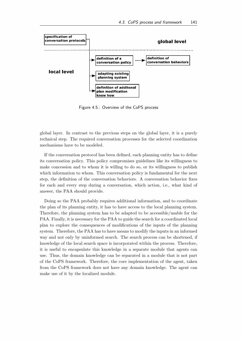
4.3. CoPS process and framework 141
Figure 4.5.: Overview of the CoPS process
global layer. In contrast to the previous steps on the global layer, it is a purelytechnical step. The required conversation processes for the selected coordinationmechanisms have to be modeled.
If the conversation protocol has been defined, each planning entity has to defineits conversation policy. This policy compromises guidelines like its willingness tomake concession and to whom it is willing to do so, or its willingness to publishwhich information to whom. This conversation policy is fundamental for the nextstep, the definition of the conversation behaviors. A conversation behavior fixesfor each and every step during a conversation, which action, i.e., what kind ofanswer, the PAA should provide.
Doing so the PAA probably requires additional information, and to coordinatethe plan of its planning entity, it has to have access to the local planning system.Therefore, the planning system has to be adapted to be accessible/usable for thePAA. Finally, it is necessary for the PAA to guide the search for a coordinated localplan to explore the consequences of modifications of the inputs of the planningsystem. Therefore, the PAA has to have means to modify the inputs in an informedway and not only by uninformed search. The search process can be shortened, ifknowledge of the local search space is incorporated within the process. Therefore,it is useful to encapsulate this knowledge in a separate module that agents canuse. Thus, the domain knowledge can be separated in a module that is not partof the CoPS framework. Therefore, the core implementation of the agent, takenfrom the CoPS framework does not have any domain knowledge. The agent canmake use of it by the localized module.

142 4. The ECo-CoPs approach
Specification of conversations
A conversation is characterized by an interaction among two or more entities,acting on two roles. Even if the number of participants is larger the interactioncan be described by the behavior of two roles. This concept is, for instance, usedin the definition of the contract net protocol or auctions protocols, as well.
Conversations are specified in three parts. An overall interaction protocol, aconversation policy, and conversation behaviors. An interaction protocol specifiescorrect sequences of messages exchanged in a conversation. A conversation policyencodes behavioral guidelines for all conversation behaviors. It encodes additionalinformation that is not covered in the interaction protocol. Conversation behav-iors specify the behavior an agent performs after it has received a message as partof a conversation. We assume that conversation behaviors are defined by humans.Therefore, it is not necessary that conversation policies have to be machine pro-cessable. However, it would facilitate the construction of more advanced agents,that can interpret these rules and behave accordingly. Moreover, a formal notationdisambiguates the notation of conversations.
Specifying interaction protocols First, we discuss the specification of interactionprotocols. These protocols have to be readable by humans: during the designprocess and the subsequent steps of the CoPS process. As outlined before, it isalso advantageous to specify interaction protocols in a machine readable formatto enable an automated generation of state-based implementations for both rolesof the conversation.
Therefore, we suggest using a textual notation to describe these protocols.Based on this representation it is possible to generate a sequence diagram, al-lowing easy human readability. Moreover, the textual representation is parsableto generate the necessary automata for both roles. Using a textual representationfor the description of agents interaction specification has been proposed by Kon-ing and Romero-Hernandez [KRH03], as well. In their paper they use a textualrepresentation of AUML diagrams to generate Promela code that can be verifiedby the model checker Spin to verify certain aspects of the specification of the in-teraction. The authors do not use the textual representation as a mean to fosterimplementation and communication towards the developer.
We have surveyed textual notions for sequence diagrams that can be used to gen-erate graphical representations. Tools like the WebSequenceDiagrams7 or QuickSequence Diagram Editor8 offer to specify UML sequence diagrams in a textualform. Keywords, e.g., for defining alternatives have been defined in the UML stan-
7http://www.websequencediagrams.com/, Accessed: 03/09/20108http://sdedit.sourceforge.net/, Accessed: 03/09/2010

4.3. CoPS process and framework 143
dard. Those keywords have been summarized, for instance, by Oestereich [Oes09,p. 364]. Unfortunately, the syntax of the representation these tools use, is notidentical and standardized. For instance, drawing a line from object Alice toobject Bob is encoded as Alice->Bob:Label of the arc for WebSequenceDia-grams and as Alice:Bob.Label of arc for the Quick Sequence Diagram Editor.We choose the notation of the WebSequenceDiagrams tool, because it facilitatethe construction of compilers that can parse the description and generate behav-ior automata. A behavior automaton describes the correct sequences of messagesfrom the perspective of one role of the conversation. An example of a textualrepresentation is shown in Listing 4.1.
Listing 4.1 Textual description of the contract net protocol1 participant Initiator
2 participant Participant
3 note left of Initiator: onetomany
4 note right of Participant: bilateral
56 Initiator -> Participant : cfp
7 alt
8 Participant -> Initiator : propose
9 note left of Initiator: sync
10 alt
11 Initiator -> Participant : accept-proposal
12 alt
13 Participant -> Initiator : failure
14 else
15 Participant -> Initiator : inform
16 end
17 else
18 Initiator -> Participant : reject-proposal
19 end
20 else
21 Participant -> Initiator: refuse
22 end
In the lines one and two the participating roles are defined. Thereby,participant is a defined keyword of the WebSequenceDiagrams syntax. Thedeclaration is optional for the generation of the diagram, but assumed to bemandatory for the generation of automata, because it eases the parsing of thetext. In lines three and four, two comments (indicated by the WebSequenceDia-

144 4. The ECo-CoPs approach
grams keyword note) are used, to indicate the number of roles that are acting onthese roles. The cardinalities of common interaction protocols have been presentedin Section 2.3.4 (in particular in Table 2.6 on page 52). We identified two possiblesituations that can be encountered from the perspective of each role. These are theone-to-many (onetomany) perspective, and the bilateral (bilateral) perspective.In a one-to-many perspective an agent, acting on a role, has a conversation with anumber of agents, while from a bilateral perspective an agent has a conversationwith only one other agent. In the example of the contract net, the conversationis a one-to-many conversation from the perspective of the manager role, while thesame conversation is a bilateral for all other participants. By the keyword alt aconditional branch is declared, that can have alternatives, which are indicated bythe keyword else. It is also necessary to synchronize a conversation at certainpoints in time. For example, in the contract net, the initiator (manager) has towait for proposals and is not allowed to proceed after the first proposal has arrived.This is indicated by the keyword sync in line nine. It is used in the comment syn-tax of the WebSequenceDiagrams tool, the effected role is mentioned, that has tosynchronize its behavior, here, wait for responses. The resulting sequence diagramis shown in Figure 4.69.
The code shown in Listing 4.1 can be compiled into behavioral automata. Thiscan be done in a single pass parsing. A compiler has been developed for the im-plementation of this thesis. It takes an input in form of a text file and generatesthe representation of two behavior automata, one for each role in the conversa-tion. The automata are non-finite variants of a Mealy machine, e.g., presented byHopcroft and Ullman [HU79, p. 43] with ε-moves. The output of the automatacan be computed by its current state and its input. Arcs are labeled with inputand output. This is done in the following notation input/output. An ε-move in-dicates that no input is necessary to trigger a transition. Even though, it might bepossible to transform this state machine into a non-finite automata (NFA) withoutε-moves in a second parsing step, this is not necessary, as it has been stated thatNFA with and without ε-moves are equivalent, see Hopcroft and Ullman [HU79,p. 26]. Graphical representations of the generated automata from Listing 4.1 areshown in Figures 4.7 and 4.8.
To enable the specification of all kinds of interaction specified by the FIPA, anadditional construct for loops is necessary, e.g., to represent the iterated contractnet protocol. This notation discussed above has been extended to model thoseprotocols, as well. This extension is discussed in Appendix A using the exampleof the iterated contract net protocol [FIP02g].
9The resulting AUML diagram of the contract net protocol has been shown in Figure 3.8 on
page 102.

4.3. CoPS process and framework 145
Initiator
Initiator
Participant
Participant
onetomany
bilateral
cfp
propose
sync
accept-proposal
failure
alt
inform
alt
reject-proposal
alt
refuse
Figure 4.6.: Generated sequence diagram of the contract net protocol
Specification of the conversation policy
A conversation policy is defined by a planning entity to specify general rules thatshould be obeyed by the PAA in conversations. As pointed out by Kagal andFinin, a conversation policies are “restrictions on communication based on thecontent of the communicative act” [KF04, p. 121]. This can strive regulationswhat information is revealed and to whom or what services and service conditionsare offered in a specific network, for instance.
Conversation policies have to be described on the one hand in natural languageor other concepts, e.g., graphical notations. This kind of notation serves as a toolfor communicating the conversation policy to developers or technical staff. These

146 4. The ECo-CoPs approach
Figure 4.7.: Behavior automaton for the initiator role
Figure 4.8.: Behavior automaton for the participant role
are the people who are going to implement the conversation behaviors accordinglyto the defined coordination policy. On the other hand, the specification should beformal to enable inferring agents to reason about their behavior and validate if itis correct according to their conversation policies. The automated validation cangain confidence in the agent as a representative of the planning entity, becausethe conversation policy has to be defined in close cooperation with the responsiblemanagement. In contrast, the implementation of the conversation behavior istypically done by technical people, who do not have responsibilities concerningstrategic decisions, which is encoded in the conversation policy.
Kagal and Finin [KF04] suggested that a conversation policy can be describedas a set of positive and negative permissions and obligations. Thereby, the authorsdefine four different notions of policies that could be defined: permission, prohi-bition, obligation and dispensation. These four aspects are encoded as deonticlogic expressions, which determine allowed or forbidden actions for the agent. Toresolve conflicts that can arise during the reasoning of the agent, the authors sug-gest the usage of priority rules. By using such a rule-set it is possible to expresswhat information is revealed and to whom, for instance. The authors mentionthat the interaction protocols themselves can be expressed with such rules, as

4.3. CoPS process and framework 147
well. This is an interesting approach for reasoning agents. But for the designof interaction protocols the usage of rule sets is not well suited for developers.The usage of graphical notations, like the sequence charts, discussed above, arewidely accepted and developers are familiar using them. Kagal and Finin use anOWL10 description to enable automated reasoning about a conversation policy.The usage of this notion of conversation policy enables description and reasoningabout aspects of a conversation in more detail, e.g., it is well suited to define whatinformation can be revealed and to whom.
The expression of what actions are allowed and forbidden is a useful step inconstraining the actions of an agent. But they are not sufficient for specifyingconsideration about more value-based concerns, like guidelines how to generatea counteroffer. Therefore, trade-offs are useful to cover this aspect. A trade-offquantifies different valuations between two or more attributes of a conversationobject. In the following we discuss the additional value of trade-offs, assuming aconversation to be a negotiation process. Trade-offs enable the detailed specifi-cation of the content of messages during a conversation, like a counteroffer or aconcession in a negotiation.
Trade-offs have been discussed in the context for multi-attribute negotiationsamong software agents, e.g., by Huhns and Stephens [HS99, p. 104] or Lou et al.[LJS06].
For the application of trade-offs in automated negotiations it is crucial to acquirethe correct trade-off information from the humans, who are kept responsible for theeconomic consequence of the agent’s activities. We have developed a techniqueto acquire those information, using trade-offs as part of a conversation policy.Therefore, we need a human readable way to specify those trade-offs.
As already mentioned, a trade-off defines how much one attribute can be wors-ened, in favor for improving another. This can be encoded within a trade-offfunction. According to Luo et al. [LJS06] this function can be defined as shownin Definition 4.3.1.
10OWL is the abbreviation for web ontology language see http://www.w3.org/TR/
owl2-overview/ Accessed: 03/11/2010.

148 4. The ECo-CoPs approach
Definition 4.3.1
Let the domain of the attribute of the negotiation subject x be defined withX = [lx, rx], and let the domain of y be Y = [ly, ry]. Thereby, we assume,that the domains are sorted in a way that the first value is evaluated at least,and the last value is evaluated highest. Then the function is called trade-off function between X and Y if it is continuous, monotonic and meets theboundary condition. The boundary condition assures, that if one attribute isassigned to the best value, the other attribute has to be made worse [LJS06].The pair (x, y) is called a trade-off pair.
For each trade-off pair a preference function is defined, specifying the preferenceover the trade-off alternatives. Trade-off alternatives are value combinations ofthe relevant trade-off pair [LJS06]. Independent attributes are not in a trade-offrelation with other attributes. To each of them a preference function is associated.
A trade-off strategy represents a directed forest, this is formalized in Definition4.3.2.
Definition 4.3.2
Given are the negotiation attributes as nodes and the trade-off pairs as di-rected edges. The direction of an edge is defined by the trade-off function (seeDefinition 4.3.1). If this function has the form τ : X → Y , there exists an edgefrom node X to Y . Then a trade-off strategy represents a directed forest :
• Let a be a negotiation attribute. All values of a’s value set A are ina preference ordering relation �⊆ A × A: the preference direction isdescending if smaller values are allowed, ascending otherwise.
• To each trade-off pair (a, b) with A and B as domains for a and b, thefollowing is associated:
– A trade-off function τ : A→ B in terms of Definition 4.3.1.
– A trade-off preference function p : A×B → [0, 1], which assigns toeach trade-off alternative a preference value. It reflects a trapezoidformula of three segments (analogue to the preference function in[LJS06]) to describe the increasing, steady and decreasing prefer-ence over trade-off alternatives.
• Independent negotiation attributes are trees with only one node. Foreach such negotiation attribute a a preference function is associated p :A→ [0, 1], with A: ∀a, b ∈ A : a � b⇔ p(a) ≤ p(b).
A resulting set of trees is shown in Figure 4.9. In fact, it is ensured that all trade-

4.3. CoPS process and framework 149
Figure 4.9.: Directed forest representation of a trade-off strategy, [SKT09]
off strategies can be represented as a forest. This ensures formal and informalbenefits. A trade-off strategy can be visualized in a clear and accustomed wayto the users. Due to the acyclic structure, the strategy remains consistent. Thisreduces the complexity specifying and validating those strategies.
We used the Ecore meta model of the Eclipse Modeling Framework11 (EMF).Details of this framework are provided by Steinberg et al. [SBPM09, Chap. 5],for instance. We use the EMF to define a model for trade-off strategies that canbe used to define concrete negotiation strategies. Using the EMF meta model asfoundation allows us to define a graphical notation of the model.
A graphical notation of a negotiation strategy is shown in Figure 3.6 (page 74).Another negotiation strategy is visualized in Figure 4.10 that is used here to elab-orate on the graphical notation in more detail. In the trapezoid shape the name ofthe negotiation object is mentioned. Thus, for different items that can be objectof a negotiation, different trade-off strategies can be defined. This node servesas an artificial root of the trade-off strategy. Attributes that are negotiable areshown in boxes, labeled with their name. In the lower level of the box the domainfor this attribute is shown, in curly brackets for an enumeration and in squarebrackets for interval values. The outgoing edges from the trapezoid are labeledwith the priority of the sub-tree to which it connects. Edges between attributesrepresent trade-off pairs, these edges are labeled with the optimal trade-off-pair.Using such a graphical notion makes it reasonable for non-software developers tospecify trade-offs for a conversation policy. Additionally, we can transform thetrade-off model automatically into data-objects representing the strategy usingMDD techniques. A detailed introduction in MDD is given by Steinberg et al.[SBPM09] and Stahl and Volter [SV06]. A detailed presentation of the idea ofacquiring and representing trade-off strategies and case studies can be found inthe work by Kurtanovic [Kur08] and Schumann et al. [SKT09].
11http://www.eclipse.org/modeling/emf/: Accessed 06/30/2010

150 4. The ECo-CoPs approach
Figure 4.10.: Graphical of trade-off strategy, [SKT09].
Consequently, we can formally define trade-off policies and are able to expressthem in an intuitive way to humans. Thereby, their definition is based on a soundformal background.
Specification of conversation behavior
In the next process step conversation behaviors have to be specified. A conver-sation behavior is the behavior that defines how the agent behaves in reactionto a message that is part of a conversation. As pointed out before, the correctsequences of messages in a conversation is modeled by an automaton for each role.A conversation behavior defines the behavior in a state of such a conversationautomata. For each state, a behavior has to be defined. Thereby, a conversationbehavior can be used in different states. For example, the behavior in a final stateof a conversation automaton implementing the roll-back if a negotiation is can-celed. Typically, there exists a number of states in an automaton that representan unsuccessful negotiation. And in each state the behavior can be the same.Each conversation state has incoming and outgoing edges. Exceptions are theinitial state, that does not have any incoming edges and the final states that donot have any outgoing edges. Edges are labeled with an performative of an incom-ing/outgoing message or an ε-move. If a state is entered with an incoming message,like the state labeled with 2 in the contract net initiator conversation automatonshown in Figure 4.7 (on page 146), the conversation behavior has to handle theincoming message. Otherwise the state can be activated without an incomingmessage by an ε-move. If the outgoing edge of a state i is labeled with a messagea, the conversation behavior has to determine the content of this message. If thecurrent state of the conversation automaton has more than one outgoing edge, theconversation behavior has to determine which edge/action has to be taken. While

4.3. CoPS process and framework 151
computing the content of an outgoing message the conversation behavior has torespect the guidelines specified in the conversation policy. If the outgoing edge isan ε-move, the next conversation state is activated after the conversation behaviorof the current state has been performed.
Conversation behaviors can be realized by an inference mechanism that uses thespecification of the interaction protocol and the conversation policy. Goal-orientedor utility-based agents are capable of reasoning of the correct behavior. It is alsopossible that the conversation behaviors are designed and implemented by humandevelopers. If the behaviors are manually developed, we recommend the usage ofdecision trees as implementations patterns.
A conversation behavior that is designed for a state with multiple outgoing edgescan be designed in form of a decision tree. A decision tree takes a description ofa situation as an input, given as a set of attributes, and computes a decision, avalue that has been computed based on the input values (see Russell and Norvig[RN03, p. 653]). According to Witten and Eibe [WF05, pp. 62–65] a decision treeis defined as a tree with the following specific characteristics :
• inner nodes are labeled with attributes or conditions with the input at-tributes as terms.
• the outgoing edges of a node a are labeled with different possible outcomesof the conditions stated in a. In each state the condition is evaluated andthe outcome should match to the value labeled at one outgoing edge. Thistransition is used to move to the next state, evaluating the decision tree.
• the leafs are marked with one element of the set of possible outputs.
Thereby, the decision tree is defined here in a way that the leafs of the treespecify the performative of the answering message, i.e., the outgoing edge of theconversation state. We illustrate this pattern by giving an example of a decisiontree for the conversation behavior that can be applied in the state labeled with 2in the contract net initiator conversation automaton shown in Figure 4.7 (on page146). The conversation behavior has to determine if the agent should accept orreject the offer. A possible decision tree is shown in Figure 4.11.
Adaptation of existing planning systems
In this section we discuss different techniques that can be used to adapt existingplanning system to enable the PAA to get access to the functionality of the localplanning system. The reuse of existing planning systems is a critical issue forthe coordination of planning systems in the industrial context. As pointed outin Section 2.2, those systems have been designed for a number of practical, i.e.,

152 4. The ECo-CoPs approach
Figure 4.11.: Example of a decision tree, representing a conversation behavior. Con
is the abbreviation for Condition
industrial, application fields. Those systems have been developed either as customsoftware or customized commercial software, see Stantchev [Sta07]. According toHansen and Neumann [HN09, pp. 259,260] these software systems require signif-icant investments and contains knowledge of the processes of the company havebeen embedded into those custom software systems. To gain more efficiency, itis desired to reuse those systems and not re-implement their entire functional-ity. Another aspect that emphasizes the adaptation of existing planning systemsoriginate from the fact that a planning entity has to coordinate its activities in anumber of networks. If each network would specify the planning methodology orthe planning system that is interoperable within this particular network a plan-ning entity would have to run a number of planning systems in parallel. Thesesystems do not have to be interoperable with one another, and even if they arethis would be inefficient, because of required redundancy of data and resourcesand the efforts for keeping all data current and synchronized. Although techniqueshave to be implemented to resolve conflicts resulting from different planning deci-sions. Consequently, the adaptation of existing planning systems seems to be themost realistic, and economic alternative. In the following we discuss how planningsystems could be accessed by agent technology.
FIPA has proposed a draft for a standard for the agent software integration[FIP01a]. In this draft an explicit wrapper agent is defined that adapts existingsoftware systems and offers their functionalities to other agents. They are capableto dynamically connect to existing resources, based on a description of the softwaresystem. Therefore, and for communication purposes FIPA has presented a specialAgent Resource Broker Ontology and a Wrapper Ontology [FIP01a, pp. 9–16].

4.3. CoPS process and framework 153
Figure 4.12.: General agent software integration scenario [FIP01a, p. 2]
Wrapper agents have to be able to communicate with this ontology to other agents.Client agents query for wrapper agents using an agent resource broker (ARB). Thisis sketched in Figure 4.12.
The wrapper agent maps a number of integration techniques like CORBA,DCom or Web Service to the ACL used for the communication between agents[FIP01a, p. 3]. The internal structure of the wrapper agent and used techniquesfor adapting existing software are not in the scope of the FIPA standard.
For summary, the FIPA draft specifies how agents access functionality of existingsoftware by using a wrapper agent, but does not indicate how the wrapping of thesoftware is done precisely.
Typically, it is not intended to allow all PAAs to access all planning systems.The access should be strictly limited to software controlled by the planning entity,as the local plans, planning knowledge and the planning process itself are typicallyprivate information of a company. Thus, the FIPA wrapper agent cannot provideits full potential, but it is still useful offering a unified interface to the PAA or insituations where no information hiding aspects are needed.
As the wrapping of legacy systems by the wrapper agent is not addressed bythe FIPA draft, we are going to detail out conventional techniques for wrappinglegacy systems. Mecella and Pernic [MP01] distinct between two different typesof wrappers:
• Access wrappers: which provide a new interface that corresponds exactly tothe one of the existing system, and
• Integration wrappers: which provide new interfaces that do not necessarily,are a direct mapping to existing software systems. An integration wrapper

154 4. The ECo-CoPs approach
uses different access wrappers and additional logic to provide those newinterfaces. Its goal is to present an integrated view of the underlying services.
As pointed out before, the interface to the framework has to be unified for differentplanning systems. Thus, the development of an integration wrapper is advocated,that also functions as the wrapping agent.
For realizing the access to the current planning systems we advocate to use webservices. Web services have been identified a favorable technology for encapsulateexisting functionality of software systems, see Sneed et al. [SWH10, p. 263]. Theidea of using web services to implement an enterprise service bus to allow a broaderapplication integration is widely accepted, see Papazoglou et al. [PTDL07]. Adetailed introduction for web services and their implementation is given, e.g., byZimmermann et al. [ZTP05, p. 2]. The encapsulation of functionality using webservices is described in more detail by Sneed et al. [SWH10, pp. 272–279]. Webservices can be integrated into agents, widely used agent-based frameworks likeJADE offer add-ons like the Web Service Integration Gateway add-on12, whichenables calling web services easily within a JADE agent.
To do so, web services have to be developed that can be made accessible viathe internet, or more realistically in the case of a planning entity to the localarea network. Nevertheless, a web service only offers the interface to externalapplications. The logic of the wrapper has to be implemented, independent ofthe integration technology. For the implementation of wrappers different designpatterns have been proposed. We present some basic design pattern here, allintroduced by Gamma et al. [GHJV94]. Even those patterns have been discussedby the authors for object-oriented programming, they can be used similarly forthe wrapping of existing systems. In the following description of the patterns wetherefore refer to systems instead of objects, as this is more adequate for the scopeof this study.
The first pattern discussed here is the adapter pattern, which is also knownas wrapper pattern. The goal of an adapter is to change the interface of anexisting system into another interface that is expected by its clients. If requiredthe adaptor adds additional features. So it is more than a pure interface conversionbut contains additional logic that is required to provide all functionality the clientexpects. For a detailed discussion with an exemplary implementation see Gammaet al. [GHJV94, pp. 137–150].
Another pattern that is referred to as wrapper is the decorator pattern, pre-sented by Gamma et al. [GHJV94, pp. 175–184]. In contrast to an adapterpattern the decorator does not change the interface of a system, but adds addi-
12The add-on is available for the JADE platform at the web site http://jade.tilab.com/
community-addons.php, Accessed: 03/15/2010.

4.3. CoPS process and framework 155
tional functionality, that is needed.The design of a wrapping web service can either be done top-down defining the
interface, e.g., via the WSDL description, and then implementing the logic of thewrapper afterwards, or bottom-up designing the logic first and generating the webservice description and the web service specific implementation.
Other middleware, as a technology for enterprise application integration, is notdiscussed here. A detailed introduction is provided by Ruh et al. [RMB01].
These design patterns and EAI technologies can be used to implement the adap-tor for the wrapping agent, that offers the services of existing software systems toother agents.
4.3.3. CoPS framework
According to Sommerville [Som06, p. 427] a framework “is a sub-system designmade up of a collection of abstract and concrete classes and interfaces betweenthem.” Its main purpose is to facilitate reuse of components that offers functional-ities that can be reused for the development of systems. According to Sommerville[Som06, p. 427] frameworks can be classified into
• system infrastructure framework,
• middleware integration framework, and
• enterprise application framework.
As the CoPS framework is designed for a specific application domain, namely thecoordination of planning entities, it can be classified as an enterprise applicationframework, which is based on some middleware integration framework, e.g., JADEin particular.
A framework offers either a set of interfaces and components, like abstractclasses, that have to be implemented or instantiated to get use of the framework,or it can offer a set of components that have to be configured and can be usedin the application to be designed. According to Gurp and Bosch [GB01] the firsttype of framework is referred to as white box framework, the later one as black boxframework. The idea of a white box framework is to allow to adapt or to extend theframework at specific extension points, where the framework remains abstract, asthe concrete implementation depends on the application at hand. Abstract classesare typically used to implement these extension points. According to Pree [Pre95,p. 253] these parts of the framework are called hot spots. By using hot spots theframework designer can specify which parts of the framework have to be detailedout for usage. In contrast to hotspots are the fixed parts of the framework. These

156 4. The ECo-CoPs approach
parts of the framework cannot be changed, and are typically even not visible forthe user of the framework. These parts of the framework are called frozen spots[Pre95, p. 253]. The idea of defining hot spots has been presented as a patternfor designing frameworks that is applied here, as well. By defining concrete hotspots we can allow to customize the agents to the given coordination task andthe interest of each planning entity. The implementation of these hot spots issupported by the CoPS process that has been discussed above. On the other handthe usage of frozen spots that cannot be changed by the users of the frameworkcan be used to implement some stable and expectable behavior of the agents.This design approach allows users of the framework the needed freedom to definedomain specific parameters and policies on the one hand, and on the other handrestricts the agent’s capabilities to a common core. Thus, the CoPS framework isa domain specialized agent-based framework.
The CoPS framework should ease the implementation of coordination mecha-nisms for the coordination of planning systems. Therefore, the CoPS frameworkoffers an abstract implementation of the coordination agent and the planning au-thority agent and their interactions. As a consequence of the development processof the CoPS framework as part of this thesis, the framework is young. Moreover,it is not mandatory to use the CoPS framework if the ECo or CoPS process isapplied. Therefore, the framework is not the foundation of the CoPS process, eventhough the CoPS process concerns specific aspects that have to be dealt with ifthe CoPS framework is used. Nevertheless, similar or the same steps have to betaken into consideration if the agents are implemented without the CoPS frame-work. Therefore, we see the CoPS framework as a supplement of the ECo andCoPS processes. In the following the CoPS framework is described in detail.
Overview of the CoPS framework
As pointed out above, the CoPS framework is a white box framework. The con-crete agents have to be derived from the abstract classes of the framework. TheCoPS framework is composed out of two major sub packages, namely the packagefor the coordination agent (CA package) and the planning authority agent (PAApackage). Some, more general, concerns are dealt with in the overall frameworkpackage and some additional helper functionality is combined in an util package.The overall package structure is shown in Figure 4.13. As pointed out before,the CoPS framework is based on broader frameworks, in particular the JADEframework, for developing MAS in the Java programming language.
The packages concerning the coordination agent and the planning authorityagent are presented in more detail in the following.

4.3. CoPS process and framework 157
Cops Framwork
PAACA
protocol
util
Figure 4.13.: Package diagram of the CoPS framework
The coordination agent
The specification of the coordination agent in the CoPS framework is discussedhere. An extended class diagram of the current implementation of the CA packageis shown in Figure 4.14. Note that this is an extended class diagram, as it containsa number of classes that are not part of the CA package. They are included to easethe understanding how the CoPS framework has to be used, and how it is basedon the JADE framework.
The abstract class Coordination Agent inherits from the Agent class of theJADE framework (not shown in the diagram). As a key functionality of a coor-dination agent is to offer registration services for the PAA joining the network,we use the FIPA Subscribe Interaction Protocol [FIP02o], which has been imple-mented by the JADE framework. The interaction protocol is shown in Figure 4.15to give the reader a quick overview of the specification of this interaction protocol.
Therefore, the classes SubscriptionResonder, Subscription and the inter-face SubscriptionManager from the jade.proto package have been added tothe diagram, to visualize how the classes in the CA package are connected andhow they are based on the JADE framework. The CoordinationAgent hasan instance of a CASubsciptionManager as an attribute that implements theSubscriptionManager interface and therefore specifies what bookkeeping activi-ties have to be performed if a PAA enters the network. This bookkeeping is donevia the classes MemberList and NetworkMember in which information, like the of-fered capabilities of each network member are managed. Thus, while registeringto a network the PAA sends a set of capabilities that he can perform as contentof the subscription message for the network to the coordination agent.

158 4. The ECo-CoPs approach
Figure 4.14.: Class diagram of the framework.CA package
Figure 4.15.: FIPA Subscribe Interaction Protocol [FIP02o, p. 1]

4.3. CoPS process and framework 159
The class MyCA is also not part of the framework. It demonstrates the usageof the CoPS framework for the design of a coordination agent. The MyCA classinherits from the abstract class CoordinationAgent. Moreover, it generates aninstance of the CASubscriptionResponder class with specific parameters of thecurrent network, like the network specific conversation protocol specifications, forinstance. The corresponding class is defined in the framework and has to be initial-ized with custom parameters. In its constructor the conversation protocol speci-fication is loaded and the conversation automata, discussed above, are generated.Therefore, the classes from the CA.protocol package, SequenceChartParser andStackItem are used. If an agent registers to an instance of the MyCA agent, theCASubscriptionResponder is activated and handles the subscription message.It generates an answer to the subscription with an AGREE performative. In thecontent of the answer, instances of the conversation automata are sent to thesubscribing PAA.
The CA can be extended to enable anonymous communication between thenetwork members, if we use alias names for the network members and all messagesare send to the CA and then are forwarded to the agent that the message wasintended to send to. The CA is designed to provide such features, but currentlythey are not implemented. This feature would be necessary for industrial use, butfor the pure evaluation of the ECo-CoPS approach this feature does not add anyvalue.
The planning authority agent
In this section, we present the design and the architecture of the PAA agent. Inthe design of the PAA we point out different extensions that can be applied to thePAA framework, and the extension points that have been build in. The designof the PAA is depicted in Figure 4.16. The agent design is based on a layeredarchitecture, aspects like communication, internal reasoning, and interaction withexternal software systems are separated. This is motivated by the idea of theseparation of concerns in software engineering. This separation also enables thecontrol layer to operate on abstraction concerning the concrete implementation.The agent is designed in three layers. A communication layer, a control layerand an execution/wrapper layer for the integration of existing systems. Thisstructuring of an agent can be found in the literature, e.g., Timm [Tim04, pp.67–70], as well. Even though this is not a well-established agent architecture, likeBDI, for instance, the layered approach should facilitate easier implementation forthe separate sub-systems.
The task of the communication layer is to handle the ACL messages from and toother agents, to coordinate the activities. Therefore, it has to manage the network

160 4. The ECo-CoPs approach
Figure 4.16.: Design of the PAA
specific protocols to use the correct interaction patterns in a given network. It isalso responsible for adapting protocols with the customized conversation behaviorsthat have been specified and implemented by the planning entity.
The controller determines the activities of the agent. The reactive part of theagent’s activities is triggered by communication, as request to evaluate the effectsof a change or a request for scheduling some activity. A more pro-active part ofthe PAA is the search for local improvements. This search requires local knowl-edge, of course. As discussed above this knowledge should be embedded in anoptional model of the wrapping service of the planning system. The controllercan activate the search for local improvements. If such an improvement has beenidentified, the controller can try to initiate a negotiation with other agents, usingthe communication layer. The controller is the sub-system that updates the localstate, which represents the environment and the current local plan. Thus, deci-sions concerning the local plan are triggered by the control flow in the controller,which uses additional information provided by the wrapping layer.
In the execution and wrapping layer different existing software systems thatexist have to be addressed. Two aspects have to be mentioned in this layer. First,this layer has to adapt the local planning system. Thus, an execution servicehas to be defined that enables usage of the functionality of the existing planning

4.3. CoPS process and framework 161
system. Moreover, additional features that should be provided are the evaluationof a current plan or the search for modifications in the input of the planningsystem. The search for modifications could, for instance, relax a deadline thatwould allow generating a better plan according to the local evaluation function.The wrapping layer has to deal with the information integration of the PAA agentinto the information flow within existing systems, as well. For instance, eventsthat change the environment have to be identified and the controlling sub systemof the agents has to be triggered. Therefore, interface to information collectingsystems should be provided. Examples for these information collecting systemsare production data acquisition (PDA) systems, manufacturing execution systemsand enterprise resource planning systems. According to Kurbel [Kur05, Chap.7] these systems can be sources for planning relevant information. Problems andpossible techniques to identify planning relevant events in those systems have beendiscussed, e.g., by Schumann and Sauer [SS09]. Moreover, the current plan of theplanning entity has to be communicated to the other information systems withinthe organization. One technique for realizing this, is to use the local planningsystem that has an additional representation of the local plan. But this approachhas some disadvantages and makes it harder to evaluate potential plans, andoptions for future decisions, as one has to ensure that the current plan is notinvalidated by these hypothetical computations. Another way doing so is to allowthe PAA to ensure that the current plan is either send to other systems or storedin a joint database, that can be accessed by other systems, like the MES as well.
An extended class diagram of the current implementation of the PAA package isshown in Figure 4.17. Note that this is an extended class diagram, as it containsclasses that are not part of the PAA package to ease the understanding how theCoPS framework.
A key element is the abstract class PlanningAuthorityAgent which is the baseclass for all implementations of localized PAAs. The class MyPAA is such an imple-mentation of the PAA that inherits from the PlanningAuthorityAgent class. TheMyPAA is not part of the framework, but an agent built on top of this framework.
The PlanningAuthorityAgent uses an instance of the ListenerBehavior
which is derived from the CyclicBehaviour behavior of the JADE framework.As the name indicates this behavior is responsible for receiving all messages thathave been sent to the agent. It passes these messages to an instance of theCommunicationManager class. In this class the different ongoing conversationsof the PAA are managed, using the conversation automata and their customizedconversation behaviors.
During the setup of the PlanningAuthorityAgent it executes the Subscripe-
ToNetworkBehaviour inherited from the JADE SubscriptionInitiator class

162 4. The ECo-CoPs approach
Figure 4.17.: Class diagram of the framework.PAA package
implementing the initiator role of the subscription protocol discussed above (seeFigure 4.15). In this behavior the agent registers to an initial set of coordinationagents. Of course, it can register later on to additional networks, or can de-registeritself, if necessary. The agent manages network information in an instance of theNetworkManager class, which contains some instances of the Network class.
The capabilities of the planning entity, at least their representation in the coor-dination system, are managed by the CapabilityManager. As for each networkthe set of offered capabilities can be differed, for each network a filter has to bedefined that maps the available capabilities of the planning entity to the subsetthat is offered to the specific network. This can be customized by implementingthe interface CapFilter. This interface has been implemented by the MyFilter
class, which is not part of the CoPS framework.
The customization of a PAA is a central issue for the usability of the frame-work. This customization information can be provided to the framework via theLocalalizationReader interface, which has to be implemented by each planningentity to provide the required local adaption. This interface provides informationto the PAA like capabilities of the planning entity, networks it is participatingin, and the adaptation strategies for the conversation automata provided by thecoordination agents of these networks.

4.3. CoPS process and framework 163
The information concerning the necessary adaption is given by a set ofAdaptationStrategy objects. An AdaptationStrategy specifies for a numberof networks the required adaptations. The adaption for a single network is de-scribed by an object of the ConversationStrategy class. Within such a strategyfor each state of a conversation automaton, which is known at the design time,a conversation behavior can be specified. This conversation behavior has to beexecuted in that state of the automaton. Thereby, the designer can specify thelocal behavior within the conversation. The protocols that have been receivedafter the registration are adapted according to the given strategy for the networkand then are stored in a ProtocolManager object. If the agent wants to start aconversation with another agent, an appropriate protocol for the network can beretrieved from this object. More precisely, a new instance of an adapted conver-sation automaton for the specific role in the appropriate conversation protocol isprovided by the ProtocolManager object.
The PAA framework is, up to now, not implemented completely. For exam-ple, the connectors to PDA systems are not realized. The core elements of theframework have been implemented.

164 4. The ECo-CoPs approach

5. Engineering coordination: The SPT
case study
So far, we have presented the ECo process and the supporting CoPS process andthe CoPS framework. In this and the following chapter the ECo-CoPS approachis validated. In this chapter we discuss the coordination problem of the first casestudy, the production of goods and their distribution. This scenario has beenintroduced in Section 2.1.1.
5.1. The SPT case study
Before we are going to execute the ECo process, we briefly describe the casestudy. For a more detailed description see Section 2.1.1. In the production processwithin a company goods have to be produced, packed on loading devices and thentransported to the customers. Each of these steps defines a complex planningproblem. The overall flow of material and workflow for each good is shown inFigure 5.11.
Figure 5.1.: Workflow of a the production and distribution example
We use existing planning systems that have been developed by students of theGoethe University Frankfurt am Main. The planning systems have been designedand implemented in the practical course “Praktikum Wirtschaftsinformatik undSimulation”2 in the winter term 2009/2010, held by Rene Schumann and Prof. Dr.Ingo J. Timm. The task description that was provided to the students is presentedin Appendix B.1. The planning systems have been implemented in Java and can
1This figure is the same as Figure 2.2. It is presented here again, to increase readability.2Practical course “Business Informatics and Simulation”
165

166 5. Engineering coordination: The SPT case study
be used as Web Services, based on the Tomcat3 (version 6.0) and Axis24 (version1.4.1) technology stack. As these systems have been developed by students, aspart of their exercises in a one term course, the quality of the resulting plansshould not be overrated.
We select and implement the needed coordination mechanisms using the ECo-CoPS approach. Therefore, we describe each step of the ECo process in a separatesection.
5.2. Modeling the scenario
In this section we describe the first step of the ECo process, the modeling of thecoordination problem. The context of this process step in the ECo process isshown in Figure 5.2.
As already mentioned the case
Figure 5.2.: Context of the modeling step in
the ECo process
study has been presented in Section2.1.1. Moreover, parts of the for-malization have been presented inexamples during the presentation ofthe ECo process (Section 4.2).
During the modeling of the co-ordination problem in this and thefollowing chapter, a number of con-cepts, sets and functions are de-fined that are required to explain theproblem space. To ease the readingwe use some conventions for nota-
tion. For concepts, sets, and function we use different definition blocks to pointout more clearly the subject of definition. Concepts are referred to in normalmathematical text, like c and a, for instance. Sets of concepts were encoded withcalligraphic capitals like C and A. Powersets are indicated by the notation ℘(A).For the sets of numbers we use the notation N and R to refer to the sets of integerand real numbers. Numbers themselves were highlighted by encoding them sansserif, like x. Functions are identified by typing them in italic, like f (x). All con-cepts, sets and functions introduced in this chapter are summarized in AppendixB.2.
As we here describe a dynamic system, the state of the system can changes overtime. Time is represented as a discrete increasing integer value. Let t be a pointin time (pit) with t ∈ N. So sets that can change over time can be described forevery pit t. In this case study we assume that each time slot has a length of 15
3http://tomcat.apache.org/, Accessed: 03/19/20104http://ws.apache.org/axis2/, Accessed: 03/19/2010

5.2. Modeling the scenario 167
minutes. Thus, a day can be described as 96 time intervals.
The task is to fulfill a number of orders, each requiring a certain good. Eachgood has to be produced, packaged and transported to the customer. An order issatisfied, if all goods have been delivered to the customer that belong to the order.
We now define a set of exclusive resources R.Set Definition 5.2.1
R is a formal language of labels for resources over an alphabet Σ.
A resource is reduced to a unique identifier. Resources are assumed to be non-shareable, and are required exclusively to execute an action. A single resource isspecified with r ∈ R. Resources are used by operations.Concept Definition 5.2.1
An operation o is defined as o = 〈r, d〉 with
• r ∈ R, an identifier of the resource this operation requires
• d ∈ N, the duration the operation needs to be processed.
Based on the definition of an operation, we define the set of all available operations.Set Definition 5.2.2
Let O be the set of all operations.
Based on this definition we can define a product p.Concept Definition 5.2.2
A product p is defined as p = 〈we, h,w, d, o1, . . . , on, <o〉 with
• we ∈ N, the weight of one unit of this product
• h ∈ N,w ∈ N, d ∈ N the geometrical information of this product, as abox with height, width and depth.
• o1, . . . , on, with oi ∈ O a finite sequence of operations that have to beperformed to produce the product.
• <o a precedence relation defined for the operations.
Set Definition 5.2.3
The set of all products is referred to as P.
Attributes of a product can be retrieved by projective functions, described in thefollowing.

168 5. Engineering coordination: The SPT case study
Function Defintion 5.2.1
For the product p = 〈we, h,w, d, o1, . . . , on, <o〉 we define the following func-tions.
The function weight : P → N it is defined as weight(p) = we.
The function ops : P → ℘(O) it is defined as ops(p) = {o1, . . . , on}.
Another fundamental concept is the customer. A customer places orders andgoods have to be delivered to the customers. Thus, her location is the relevantpart for the modeling.Concept Definition 5.2.3
A customer c is defined as c = 〈x, y〉 with x, y ∈ N. The location of thecustomer is encoded by her x and y coordinates.
Set Definition 5.2.4
The set of customers is defined as C.
Based on these concepts we can define an order.Concept Definition 5.2.4
An order d is defined as d = 〈p, q, c, d, e〉 The elements of this tuple are definedas follows:
• p ∈ P, the product that has to be produced,
• q ∈ N, the quantity of the product that has to be produced,
• c ∈ C, a customer,
• d ∈ N, due date, at that point in time the order should be finished, and
• e ∈ R, penalty that has to be paid to the customer per time unit of latedelivery.
Set Definition 5.2.5
Let D be the set of all orders.
Attributes of an order can be accessed by projection functions.Function Defintion 5.2.2
For the order d = 〈p, q, c, d, e〉 we define the following function.
The function quan : D → N is defined as quan(d) = q
The function customer : D → C is defined as customer(d) = c.
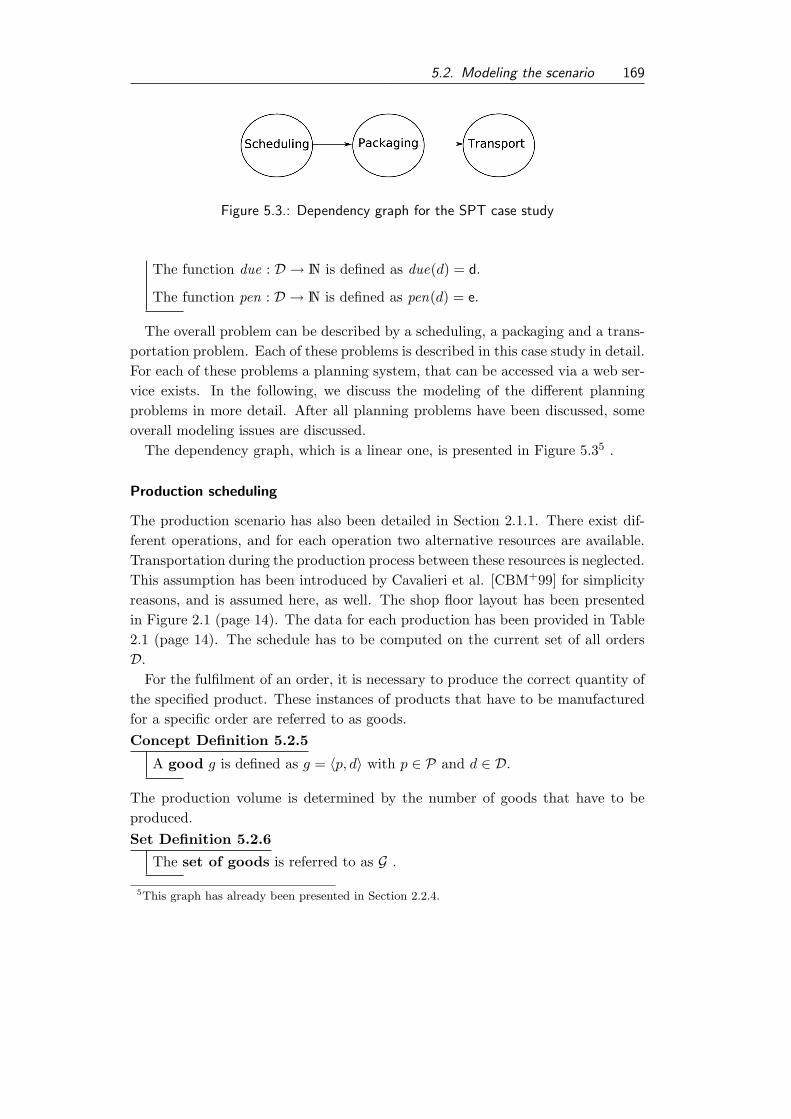
5.2. Modeling the scenario 169
Figure 5.3.: Dependency graph for the SPT case study
The function due : D → N is defined as due(d) = d.
The function pen : D → N is defined as pen(d) = e.
The overall problem can be described by a scheduling, a packaging and a trans-portation problem. Each of these problems is described in this case study in detail.For each of these problems a planning system, that can be accessed via a web ser-vice exists. In the following, we discuss the modeling of the different planningproblems in more detail. After all planning problems have been discussed, someoverall modeling issues are discussed.
The dependency graph, which is a linear one, is presented in Figure 5.35 .
Production scheduling
The production scenario has also been detailed in Section 2.1.1. There exist dif-ferent operations, and for each operation two alternative resources are available.Transportation during the production process between these resources is neglected.This assumption has been introduced by Cavalieri et al. [CBM+99] for simplicityreasons, and is assumed here, as well. The shop floor layout has been presentedin Figure 2.1 (page 14). The data for each production has been provided in Table2.1 (page 14). The schedule has to be computed on the current set of all ordersD.
For the fulfilment of an order, it is necessary to produce the correct quantity ofthe specified product. These instances of products that have to be manufacturedfor a specific order are referred to as goods.Concept Definition 5.2.5
A good g is defined as g = 〈p, d〉 with p ∈ P and d ∈ D.
The production volume is determined by the number of goods that have to beproduced.Set Definition 5.2.6
The set of goods is referred to as G .
5This graph has already been presented in Section 2.2.4.

170 5. Engineering coordination: The SPT case study
Again we can define a projection function for goods in the following way.Function Defintion 5.2.3
For the good g = 〈p, d〉 the following functions are defined.
The function order : G → D is defined as order(g) = d
The function product : G → P is defined as product(g) = p
The set of all goods of an order d can be referred to as Gd.Set Definition 5.2.7
The set of goods of an order d is defined as Gd ⊆ G, with
∀g ∈ G : g ∈ Gd ⇔ order(g) = d
.
As it is required that for each order the correct number of goods is produced, it isnecessary to identify the goods that belong to a specific order. This is done usingthe function orderD , which is defined as follows:Function Defintion 5.2.4
The function orderD : ℘(G)× D → N, is defined for the set Gd and the orderd as follows orderD(G, d) = |Gd|
The set of goods G is complete if the following equation is satisfied.
∀d ∈ D : quan(d) = orderD(G, d) (5.1)
Based on the current set of goods a schedule has to be generated. For each good’soperation specified in the product the corresponding actions have to be performed.An action is the planned execution of an operation.Concept Definition 5.2.6
An action is defined as a = 〈o, g, r, s, e〉 with
• o ∈ O the operation that is performed,
• g ∈ G the good this actions belongs to,
• r ∈ R the resource the action is performed on,
• s ∈ N, e ∈ N the start and end time of the interval the action is performedin.
The action is the smallest unit of a schedule. The set of all actions forms theschedule.

5.2. Modeling the scenario 171
Set Definition 5.2.8
A schedule is the set of all actions it is referred to as A.
Attributes of actions can be accessed to by projective functions, as well.Function Defintion 5.2.5
For the action a = 〈o, g, r, s, e〉 the following functions are defined.
The function good : A → G is defined as good(a) = g.
The function operation : A → O is defined as operation(a) = o.
The function start : A → N is defined as start(a) = s.
The function end : A → N is defined as end(a) = e.
The function resource : A → R is defined as resource(a) = r.
As we pointed out, we are interested in the coordination of plans and schedules.Thereby, our goal is to ensure that these plans are feasible. Therefor it is necessaryto define criteria indicating if a schedule is feasible.
First of all, it is necessary that the schedule is generated on the base of a com-plete set of goods, which has been encoded in Equation 5.1. To clarify additionalaspects, we define a partial schedule for a good g.Set Definition 5.2.9
A partial schedule for g is defined as Ag, with:
∀a ∈ A : a ∈ Ag : good(a) = g
.
In a partial schedule Ag all planned actions, and therefore, all operations thathave to be scheduled to fulfill the order d are contained. For each good produced,all operations have to be performed in the sequence specified by the precedencerelations. This is encoded in the following equations 5.2 and 5.3.
|ops(product(g))| = |Ag| ∧ ∀a1, a2 ∈ Ag, a1 6= a2 : operation(a1) 6= operation(a2).(5.2)
∀a1, a2 ∈ Ag, a1 6= a2. Let w.l.o.g. a1 <o a2 ⇒ enda(a1) ≤ starta(a2) (5.3)
Another constraint, that has to be regarded is that resources are used exclusively,i.e., only one action per time is allowed to utilize the same resource. This isformalized as follows:
∀a1, a2 ∈ A 6= a1, a2 :
@t ∈ N : resource(a1) = resource(a2)∧start(a1) ≤ t ≤ end(a1) ∧ start(a1) ≤ t ≤ end(a1)
(5.4)

172 5. Engineering coordination: The SPT case study
A partial schedule Ag for an order g is feasible, if the equations 5.2, 5.3 and 5.4are satisfied. If all partial schedules are feasible and the resource usage constraint,described in Equation 5.4 is satisfied by the entire schedule, the overall scheduleA is feasible.
To ease the following discussion we specify the concept of finished goods, whichis in particular of interest for the following planning steps.Concept Definition 5.2.7
A finished good f is defined as f = 〈t, g〉, with
• t = max∀a∈Ag
end(a) the time the good is finished
• g the good
Set Definition 5.2.10
The set of all finished goods is referred to as F .
The attributes of a finished product can be accessed by projective functions, aswell.Function Defintion 5.2.6
For the finished product f = 〈t, g〉 the following function are defined.
The function good : F → G is defined as good(f) = g.
The function ttime : F → N is defined as ttime(f) = t.
For easier handling of the following formula we define the following functions asabbreviations.Function Defintion 5.2.7
The function order : F → D, for f = 〈t, g〉 is defined as order(f) =order(good(f)).
In the production data, shown in Table 2.1 (on page 14), a bottleneck occursat resource three (see also Brennan and O [BO00]). Therefore, the group of stu-dents who have implemented the scheduling system favored a shifting bottleneckheuristic to solve the scheduling problem described in this section. A detaileddescription of this heuristic is given by Pinedo [Pin05, pp. 87–93]. The realizedscheduler generates a valid schedule for a given set of orders and aims to maxi-mize the usage of the given resources. The output of the scheduler is the set offinished goods F . The production data described above is given to the scheduler.Furthermore, it is assumed that the production data is valid and deterministicand no resource breakdowns occur.

5.2. Modeling the scenario 173
Packaging planning
For the packing of the goods, the set of finished products F is a necessary input.Moreover, information about the bins and the loading devices, is necessary. Aloading device is characterized by its volume and costs induced per used instance.Concept Definition 5.2.8
A loading device l is defined as l = 〈m, h,w, d, c〉
• m maximal weight that can be loaded
• h ∈ N,w ∈ N, d ∈ N geometrical information defining the volume thatcan be used per loading device
• c ∈ N costs per used loading device
Set Definition 5.2.11
The set of all types of loading devices is referred to as L.
We define projective function for loading devices for abbreviation issues.Function Defintion 5.2.8
The function cost : L → N. For l = 〈m, h,w, d, c〉 it is defined as cost(l) = c.
There exist some general restrictions concerning the number of loading devicesthat can be packed in parallel. The finished goods produced on one day have to bepacked on loading devices at once. For simplification reasons we assume that thepacking does not require any time. Thereby, a loaded device is defined as follows.Concept Definition 5.2.9
A packed loading device pl is defined as pl = 〈l,Fpl〉, with
• l ∈ L the type of used loading device and
• Fpl ⊆ F the set of finished goods contained.
Set Definition 5.2.12
The set of loaded loading devices forms the package plan PL.
Function Defintion 5.2.9
For a packed loading device pl = 〈l,Fpl〉 the following functions are defined.
The function items : PL → ℘(F) is defined as: items(pl) = Fpl.
The function mweight : PL → N is defined as mweight(pl) = mweight(l).

174 5. Engineering coordination: The SPT case study
As it is assumed that the packing itself does not require any time, a packedloading device becomes available for transport if all items have been producedthat should be placed in that particular loading device. This is, of course, asimplification that has been made to ease the tasks for the students. The time ofavailability of a packed loading device is computed by the function available.Function Defintion 5.2.10
The function available : PL → N. For pl = 〈l,Fpl〉 it is defined as:available(pl) = max
f∈Fplttime(f).
In a loading device a subset of the finished goods can be placed. Thereby, somerestrictions have to be satisfied. The first restriction is that the total weight ofthe finished goods must not exceed the maximal allowed payload of the loadingdevice.
∀pl ∈ PL :∑
f∈items(pl)
weight(product(f)) ≤ mweight(pl) (5.5)
Moreover, it is important that all items are placed correctly within the loadingdevice. We enumerate these criteria and do not formalize them here, as it doesnot contribute to the understanding of the case study presented here.
Each item within a loading device is assigned to an anchor point that is used toidentify the position of the item within the loading device. This anchor point isused to determine if the item has been placed within the device correctly. Finishedgoods within one device cannot be placed in a way that they would overlap.Moreover, each finished good must be placed completely within the inner bordersof the loading device. Physical aspects have to be regarded, as well, like the factthat no finished good can float in the air. It must be placed either on the groundof the loading device or on top of another finished good. When stacking finishedgoods it is necessary to place the heavier items on the bottom and not on top ofother finished goods.
If all these constraints are satisfied, a loading device is loaded correctly. More-over, it is important that all finished goods are packed. The packaging plan iscomplete if the equations 5.6 and 5.7 are satisfied.
∀f ∈ F : ∃pl ∈ PL : f ∈ items(pl) (5.6)
∀f ∈ F : @pl1, pl2 ∈ PL : pl1 6= pl2 : f ∈ items(pl1) ∧ f ∈ items(pl2) (5.7)
If all loading devices are loaded correctly and the packing plan PL is completethe packing plan is feasible.
The planning problem that has to be described here is a 3-D bin packing problemwith additional constraints regarding the weight of the objects. The studentsdeveloped a heuristic that generates valid plans and tries minimize to number of

5.2. Modeling the scenario 175
loading devices required to pack all items. Thereby, the induced costs for loadingdevices are minimized, as the costs are linear to the number of devices used.
To give the transportation problem solver only the necessary information, wedefine the concept of ready for shipment loading devices rl. For each pl = 〈l,Fpl〉in PL a ready for shipment loading device is defined.Concept Definition 5.2.10
A ready for shipment loading device is defined as rl = 〈l, rt,Drl〉 with
• l ∈ L the loading device; equal to the corresponding pl.
• rt = maxf∈Fpl
ttime(f) the earliest time the shipping can start
• Drl =⋃
f∈Fplorder(f).
Set Definition 5.2.13
The set f all ready for shipment loading devices is defined as RL.
Function Defintion 5.2.11
For the ready for shipment loading devices rl = 〈l, rt,Drl〉 the following func-tions are defined.
The function rtime : RL → N is defined as rtime(rl) = rt.
The function customer : RL → ℘(C) is defined ascustomer(rl) =
⋃d∈Drl
customer(d).
The function costLD :→ N is defined as costLD(rl) = cost(l).
The function orders : RL → ℘(D) is defined as orders(rl) = Drl.
Transportation planning
The task of the transportation problem is to distribute the ready for shipmentloading devices contained in RL to the customers they belong to. Therefore, afixed number of trucks is available (maxNoofTrucks). A truck has a capacity fora number of loading devices. It starts from a depot and after it has served allcustomers it returns to the depot. Thus, the basic problem can be describedas a vehicle routing problem. As pointed out above, the locations of customersare given as coordinates in a two dimensional Cartesian coordinate system, andthe depot is located at the origin (0, 0). Distances between two points can becomputed using the Euclidean distance. A truck can be described as follows.

176 5. Engineering coordination: The SPT case study
Concept Definition 5.2.11
A truck t is defined as t = 〈ca, s, co〉, with
• ca ∈ N, the capacity of loading devices
• s ∈ N, the speed per time unit
• co ∈ N, the costs per distance unit
Trucks are assumed to have a constant traveling speed. Therefore, the neededtime for traveling is linear to the distance between two points. If a truck arrivesat a customer site, it has to stay there for a specified service time st.Set Definition 5.2.14
The set of all available trucks is defined as T .
Note that |T | = maxNoofTrucks holds.
Function Defintion 5.2.12
For the truck t = 〈ca, s, co〉 the following functions are defined.
The function capa : T → N is defined as capa(t) = ca.
The function speed : T → N is defined as speed(t) = s.
The function costspU : T → N is defined as costspU (t) = co.
As part of the vehicle routing planning, loading devices have to be clusteredtogether to be loaded on one truck and then the sequence of the customers withineach tour has to be determined. The solution of the first sub-problem is calledthe truck load. A truck load is a set of ready for shipment loading devices.Concept Definition 5.2.12
A truck load tl is defined as tl = 〈t,RT tl〉, with
• t ∈ N the earliest time this truck load can be shipped.
• RT tl ⊂ RT the loading devices loaded on the truck.
Note that the earliest time for the shipment of a truck load is determined by thetime determined in the Equation 5.8.
t = maxrl∈RLtl
rtime(rl) (5.8)
Set Definition 5.2.15
The set of all truckloads is defined as T L.

5.2. Modeling the scenario 177
For a truck load the number of loading devices contained in this truckload can beretrieved by the function noelements.
Function Defintion 5.2.13
For the truckload tl = 〈t,RT tl〉 the following functions are defined.
The function noelements : T L → N is defined as noelements(tl) = |RT tl|.
The function elements : T L → ℘(RT ) is defined as elements(tl) = RT tl.
The function rtime : T L → N is defined as rtime(tl) = t.The function customers : T L → ℘(C) is defined as customers(tl) =⋃rt∈RT tl
customer(rt).
The function orders : T L → ℘(D) is defined as orders(tl) =⋃
rt∈RT tlorders(rt).
For each daily production, the trucks have to deliver the goods to the customers.Therefore, truckloads are assigned to trucks. This assignment is defined as follows.
Concept Definition 5.2.13
A loading assignment is defined as la = 〈s, e, tl, t, tour〉, with
• s ∈ N, e ∈ N the start and end time of the tour that distributes the truckload
• tl ∈ T L the truck loading that has to be distributed
• t ∈ T the truck that is assigned
• tour a sequence of locations to visit. The first and the last point in thattour have to be the depot.
Set Definition 5.2.16
The set of all loading assignments is called LA.
Function Defintion 5.2.14
For the loading assignment la = 〈s, e, tl, t, tour〉 the following functions aredefined.
The function load : LA → T L is defined as load(la) = tl.
The function truck : LA → T is defined as truck(la) = t.
The function start : LA → N is defined as start(la) = s.
The function end : LA → N is defined as end(la) = e.

178 5. Engineering coordination: The SPT case study
The length of the tour with n elements in the sequence can be computed by thefollowing function.Function Defintion 5.2.15
The function length : LA → N. For la = 〈s, e, tl, t, tour〉 it is defined as
length(la) =i=n−1∑i=1
: dist(ci, ci+1)
, with ci and ci+1 two subsequent elements of the tour.
The function dist(c1, c2) computes the Euclidian distance between the points spec-ified by the two customers. Note that for each loading assignment the Equation5.9 must hold.
end(la) > start(la) + length(la) (5.9)
It is a strict greater than and not a greater or equal relation here because at eachcustomer side a stop for at least the service time (st) has to be made. Consequently,the duration for a tour can be computed by the function duration.Function Defintion 5.2.16
The function duration : LA → N is defined for la = 〈s, e, tl, t, tour〉 asduration(la) = noelements(tl) ∗ st + length(tour) ∗ speed(t).
Another, more complicated aspect, is to compute the time of service of a customer.Function Defintion 5.2.17
The function serviceTime : C × LA → N is defined for la = 〈s, e, tl, t, tour〉 asserviceTime(c, la) = s + duration ′(la)
The duration is computed for the sub-tour starting from the depot to the customerc. If customer c is not part of the tour the function returns 0. All trucks have atime window per day in which they are available. Thus, the start and end time foreach load assignment have to respect those boundaries earliest start and latest end,as well.
An loading assignment is feasible if the following equations are satisfied.
∀la ∈ LA : noelements(load(la)) ≤ capa(truck(la)) (5.10)
∀la ∈ LA : start(la) ≥ rtime(load(la)) (5.11)
∀la ∈ LA : ∀c ∈ customers(load(la)) : c ∈ tour(la) (5.12)
∀la ∈ LA : end(la)− start(la) ≥ duration(la) (5.13)
∀la ∈ LAstart(la) ≥ earliest start (5.14)
∀la ∈ LAstart(la) + duration(la) ≤ latest end (5.15)

5.3. Coordination requirements 179
In Equation 5.10 it is stated that trucks are not allowed to be overloaded. InEquation 5.11 it is declared that the start time of a tour has to be greater or equalto the time the truck load is ready for transport. For each loading assignment allcustomers contained have to be served by the truck (Equation 5.12). In Equation5.13 it is declared that within the time window of a tour all customers have to beserved. Finally, in the Equations 5.14 and 5.15 it is pointed out that the time thetruck is available are respected.
A truck can be assigned to a number of loading assignments. The assignmentsfor one truck are the plan of the truck.Set Definition 5.2.17
The plan of a truck t is defined as LAt ⊂ LA : ∀la ∈ LA : la ∈ LAt ⇔truck(la) = t
A plan of a truck is feasible iff ∀la ∈ LAt are feasible and additional Equation5.16 is satisfied, that ensures that the assignments are not overlapping.
∀la1, la2 ∈ LAt : @t : start(la1) ≤ t ≤ end(la1)∧ start(la2) ≤ t ≤ end(la2) (5.16)
The set of all loading assignments LA is feasible if all truck plans are feasibleand all ready for shipment loading devices are assigned to exactly one (∃!) loadingassignment. This is encoded in Equation 5.17.
∀rl ∈ RL : ∃! la ∈ LA : rl ∈ elememts(load(la)) (5.17)
Another relevant partitioning of LA is the partitioning according to orders thatare served.Set Definition 5.2.18
The set LAd ⊆ LA is defined as ∀la ∈ LA : la ∈ LAd ⇔ d ∈ orders(load(la))
The students developed a heuristic for generating a feasible tour plan therebytrying to minimize the costs that occur during the delivery. These can be achievedby
• avoidance of penalty costs, due to too late delivery
• minimization of traveling distance, to reduce traveling costs.
5.3. Coordination requirements
The second step of the ECo process is the definition of requirements. The contextof this process step in the ECo process is shown in Figure 5.4.

180 5. Engineering coordination: The SPT case study
The coordination requirements in this case study are rather simple. The mainobjective is to ensure that the overall plan and all partial plans are feasible. Thecriteria for feasibility for the partial
Figure 5.4.: Context of the requirement defi-
nition step in the ECo process
plans for scheduling (A), for pack-aging (PL) and for transportation(LA) have been discussed already.But it is not sufficient that the par-tial plans are feasible. The resultingoverall plan does not have to be con-sistent, even if all partial plans are.Aspects like the fact that all goodshave to be produced before they canbe packed cannot be covered by lo-cal feasibility criteria. Therefore, wehave to detail here the specificationtowards additional feasibility characteristics. To ensure feasibility of the overallplan, two interfaces have to be considered. The interfaces from scheduling to pack-aging planning and from packaging planning to transportation planning. In thefollowing we discuss these interfaces in detail.
At first, we discuss the interface between the scheduling and the packagingplanning. The input for the packaging planning is F . For achieving an overallfeasible plan, F has to be complete and consistent. By completeness we meanthat all goods that are necessary to fulfill the orders are contained. Assume Gis complete, according to the conditions stated in Equation 5.1. If G is completethen F is complete if it satisfies Equation 5.18.
∀f ∈ F : good(f) ∈ G (5.18)
Moreover, F has to be consistent. F is consistent if all goods have been com-pletely produced, i.e., all their actions have been performed. Note that in thedefinition of f (Concept Definition 5.2.7) it has been defined in a way that its ear-liest time for disposal is defined as the maximum of the end times of the activitiesrelated to the good. Thereby, F is consistent by definition of f .
Consequently, if the planning system has to ensure that F is consistent andcomplete. The packaging planning can generate a plan that can be executedsequentially with the production scheduling plan. The planning system that hasbeen developed by the students creates complete and consistent plans. Its resultsare in similar form as the definition of finished goods indicate. All data exchangeformats can be found in the Appendix B.1, as well.
The second interface that has to be investigated in more detail is the interface

5.3. Coordination requirements 181
between the packaging planning and the tour planning. The input for the trans-portation planning is the set of ready for shipment loading devices RL. RL has tobe complete and consistent, to ensure feasibility of the overall plan. Completenesscharacterize that all finished goods have been packed on a ready for shipmentloading device. As pointed out before, the transformation into rt is done for in-terfacing the transportation planning. The internal packaging plan PL has beendefined concerning completeness in an appropriate manner (see equations 5.6 and5.7). For each element of PL a ready for shipment loading device is defined.Therefore, if it can be stated that if PL is complete and the projection is correctthen RL is complete, too.
The second aspect that has to be addressed is consistency. Consistency char-acterize that no loading device can be transported before it is not packed. Aspackaging is assumed to take no time, this is equivalent to the fact that each fin-ished good has to be produced before it can be shipped. As pointed out before,the time when rl can be shipped is defined as
rt = maxf∈Fpl
ttime(f).
Thus, consistency is guaranteed by the definition of rt (see Concept Definition5.2.10). If information concerning F and RL is computed correctly, and thisinformation is processed correctly in the consuming planning system, the overallplan is feasible.
So far, we have defined the criteria for the overall plan to be feasible. In thereminder of this section we define the evaluation function for the quantitativeevaluation and other non-functional requirements.
First, we tackle the aspect of further requirements. In this simple scenario wereno information hiding or other special issues occur, only one aspect remains tobe mentioned. As there exist already planning systems that are able to generatefeasible local plans, these planning systems should stay in use. Ideally they shouldbe used in the form of black boxes by the coordinating agents. Moreover, as theECo-CoPS approach addresses the coordination of planning entities, it is the mostreasonable approach to keep the different autonomously acting planning systemsin place and do not replace them. This replacement is not trivial at all, becauseDefining the problem in form of an optimization problem is not trivial, and asufficient model currently does not exists. Note that we not present one in thisstudy, as this is not in our scope.
The objective function for the entire production scenario is to minimize theoverall costs induced by producing and distributing the goods. No cost informationfor the production system has been given. Thus, in this model, costs are causedby packaging and distribution. A critical issue in determining the overall costs is

182 5. Engineering coordination: The SPT case study
the computation of the penalties that have to be paid for late delivery. To definethe penalty, we first have to define the fulfillment time of an order. As alreadymentioned, an order is fulfilled if all goods have been delivered.Function Defintion 5.3.1
The function ft : D × ℘(LA)→ N is defined for c, d and LAd as ft(d,LAd) =maxla∈LAd
serviceTime(c, la).
Based on this definition we can define the penalty.Function Defintion 5.3.2
The function penalty : D × ℘(LA)→ N is defined for d and LAd as
penalty(d,LAd) =
{0 ft(d,LAd) ≤ due(d)
(ft(d,LAd)− due(d)) ∗ pen(d) otherwise
Thus, the objective function can be defined as shown in Equation 5.19. Itconsists of three parts: the costs for packaging, the costs for transportation, andthe costs for penalties.
cost =∑rl∈RL
costLD(rl)+∑la∈LA
costspU (truck(la)) ∗ length(la)+∑o∈D
penalty(d,LAd)
(5.19)
5.4. Selection of appropriate coordination mechanisms
In the third step of the ECo process applicable mechanisms are identified.The context of this process step in the ECo process is shown in Figure 5.5.
Figure 5.5.: Context of the selection step in
the ECo process
In the following, we discuss the co-ordination methodologies identifiedas applicable for this scenario in Sec-tion 4.2.3 (on page 130). Then wepresent the suitable approaches thatcan be implemented and evaluated inthis study.
• plan merging,
• decentralized planning for acentralized plan,

5.4. Selection of appropriate coordination mechanisms 183
• result sharing, and
• negotiation.
Plan merging
As pointed out in Section 3.1.2, the main idea of plan merging is that a centralizedentity collects the locally generated plans and ensures feasibility of the plan, if theyare executed together. For implementing the centralized entity it is necessarythat this entity is aware of dependencies between planning systems, and that it iscapable to resolve existing conflicts without introducing new conflicts. Therefore,it is necessary to model detailed criteria for feasibility and planning knowledge intothis merging entity. Consequently, this approach will result in a system similar toa centralized planner, which we argued, is not of interest in this study.
Decentralized planning for a centralized plan
The idea of different domain experts creating a shared plan, as presented in Section3.1.2 and outlined by Durfee [Dur99, p. 141] seems to be adequate for the scenarioat hand. Different planners are responsible for different parts of the plan. Durfeedid not present any details how the overall plan should be kept consistent/feasible.In the examples presented by Durfee, each planning expert defines its part of theplan and then passes the results to the next planner. This corresponds to acoordination of the partial plans using a result sharing mechanism. The sequenceof planners is thereby defined by the dependency graph that has been presentedin Figure 5.3. Result sharing as a coordination mechanism is discussed below.
Result sharing
The exchange of information concerning existing plans will be part of any rea-sonable solution for this case study. As it has become clear during the modelingprocess, the output data of one planning system is a mandatory input for the fol-lowing system in the dependency structure. The most simple technique for resultsharing is, as pointed out previously, the sequential execution of each planning sys-tem and then passing the results to the next planning systems in the dependencygraph. This strategy would result in first generating a plan for the production,then for the packaging and finally for the transportation sub-problem. As no cyclicdependency exists in this case study this seems to be a valid approach to achievea feasible overall plan. In fact the students in the practical course, who had todeal with the problem described, have chosen this approach.
A criticism to this coordination mechanisms is that even if the resulting plansare feasible, their quality in terms of the objective function, the costs induced while

184 5. Engineering coordination: The SPT case study
fulfilling the orders do not necessarily have to be low. The largest portion of thecosts are fixed during the transportation planning, even though they might not becaused by poor transportation planning. This is caused by the fact that during thescheduling and partly during the packaging planning no information about effectsof local decision making on the global evaluation function is available. Even ifthis information would be available, the local planning systems have objectivesthat would not take advantage of it, because it does not lead to optimal localplans according to their own local objective function. So, pure result sharing insequential planning can lead to global solutions of lower quality.
Negotiation
Another idea to tackle the problems is to start the planning first with the part thatdetermines the most costs, i.e., the transportation planning. This corresponds tothe idea of backward planning (discussed already in Section 3.1.1). This approachmakes it more complex to ensure consistency/feasibility of the overall plan, as thesequence of executing planning systems is inverted according to the dependencygraph, shown in Figure 5.3.
A solution to this problem can be a mechanism that facilitates the exchange ofrequirements towards the local plans, and plan suggestions that tries to satisfy therequirements and still ensuring feasible local plans. Such a coordination approachwould result in a sequence of exchanges of requirements to, and suggestions ofplans. This corresponds to a negotiation, trying to minimizing the total costs. Bystarting with the parts of the planning process where most of the costs are fixedrequirements can be identified that lead to an overall solutions with lower costs.Previous planning stages have to identify what requirements are possible to fulfilland offer those to the subsequent planning entity.
In summary, we state that mechanisms using plan merging might not be possi-ble. The overall problem of the SPT case study is a type of distributed planningwith a centralized governed execution. Both result sharing and negotiations canlead to an overall feasible plan, but might with different outcomes, concerning theoverall quality of the generated plans.
Qualitative evaluation
In this qualitative evaluation the compliance of the discussed coordination mech-anisms to the coordination requirements is addressed in detail. Plan merging hasbeen excluded already, because it would result in building a centralized planningsystem, and violate the requirement that existing systems should stay in use. Co-ordination by sequential planning with result sharing, and the approach of finding

5.4. Selection of appropriate coordination mechanisms 185
compromises about requirements from subsequent planning entities and feasiblesolutions of preceding entities are discussed in the following.
For the discussion of the compliance to the coordination requirement, one as-sumption has to be made. It is assumed that the planning systems in charge workcorrectly in the sense that with a given input they generate a feasible local planthat is represented correctly as the output of the planning system. The internalmechanisms and functionalities of the planning systems are not part of this study,they are pre-existing.
To ensure that the coordination requirements are satisfied the following aspectshave to be discussed.
• Are the local plans feasible?
• Do the overall plan stay feasible?
• Stay existing planning systems in use?
As already mentioned, both approaches aim at using existing planning systems,and those systems generate only feasible local plans. Thus, two out of threerequirements can be assumed to be satisfied by both approaches. Thus, only oneaspect has to be discussed here in detail.
Before we discuss the approach of result sharing and sequential planning. Theresults of the planning stages, namely the set of finished goods F and the packagingplanning RL, have to be complete and consistent to ensure an overall feasibility.We assumed that both plans are the correctly computed by the planning systems.Those sets are passed directly to the packaging and transportation planning, andare used as inputs. The overall plan is feasible, if the planning systems workcorrectly.
Before we discuss the consistency of the negotiation approach, we briefly de-scribe the procedure of this approach. Most of the costs are generated in thedistribution and packaging planning. Moreover, planning relevant data for thescheduling system cannot be changed, as there exists no earliest start time fororders, for instance. So, what can be changed is the input data of the packagingand transportation planning. In particular, the time when products are releasedto be packed and transported can be shifted into the future without inside knowl-edge of the planning systems. In this coordination process the set of combinableorders has to be computed at first. Two orders are combinable if it is reasonablefor the packaging planning to load their finished goods on the same loading de-vice. Therefore, a packaging plan is computed that assumes that all products areavailable at the same time, to facilitate most efficient packaging planning. Ordersare packed together on one loading device are combinable orders for each other.In the following we encode this set for order d as Dcd.

186 5. Engineering coordination: The SPT case study
Next for each order the costs of the round trip tour are computed. This can bedone with the existing planning system, by generating appropriate input data andinterpreting resulting outputs. Thus, we have to made this information available.We do so in form of the following function.Function Defintion 5.4.1
The function rtdistance is defined as rtdistance : D → R. For d it is definedas rtdistance(d) = x whereby x is the distance computed by the transportationplanning.
With this additional information, the economic efficient combinable orders (Decd )for an order d can be computed. An order d1 is economic efficient combinableorders with order d iff both orders are combinable orders and the distance (andthus the transportation costs) of a joint tour is smaller or equal to the sum of bothround trips tours. This is, of course, a heuristic, as a set of orders can becomean efficient combination, even if they are not, in a pairwise comparison. Then thelatest release time for each order is computed, that would allow to
• deliver time before the official due, and
• combine items of combinable orders within the packaging planning.
We compute the latest acceptable ready time for packaging for each order. There-fore, the finished products are grouped by days. The latest acceptable ready timeis the latest time a product is finished before the due date of the order. An orderis delayed to either its own latest acceptable ready time or the latest acceptableready time of one of its economic efficient combinable orders with a ready timebefore its due. Based on this idea, the latest point an order can be delayed to canbe computed by a fixed point iteration. We delay the finished products of an orderthat are ready for packaging and shipping before that latest acceptable ready time.Thereby, each product is deferred to the first time unit of the following day. Thisis done for simplification reasons, as the entire production of one day is loaded onloading devices (which is assumed to take no time) and then is distributed on thefollowing day.
For this reason the official ready time is smaller than within the delayed datafor each finished product. This guarantees that the interface between productionand packaging planning systems is kept consistent, because neither the number ofproducts nor their product-types are changed at all.
The final production schedule is generated by a run of the scheduling system.Thereafter, the input data for the packaging planning is changed as describedabove. Then packaging and transportation planning are done sequentially. Thus,within the planning sequence the only aspect that we have to discuss is the manip-ulation of the input data of the packaging planning, as this is the only aspect that

5.5. Implementation of coordination mechanisms 187
is changed in comparison to the planning sequence discussed in the first approach.
The interface between the packaging and transportation planning is not changedfor this planning approach, and therefore, the consistency and completeness as-pects discussed above are valid her as well.
5.5. Implementation of coordination mechanisms
In this section we discuss the fourth step of the ECo process. In this step we discussimplementation issues concerning both coordination approaches. The context ofthis process step is given in Figure 5.6.
The result sharing approach is
Figure 5.6.: Context of the implementation
step in the ECo process
based on the idea of forwardingplanning results. This approach hasbeen implemented by the students ofthe practical course. The input datafor the planning systems for packag-ing and transportation have data re-quirements, concerning the produc-tion schedule and the packed load-ing devices. This data is required inaddition to information that is pro-vided to all planning systems, likeorders or products. The data ex-change formats are presented in Appendix B.3. In our validation, we use theimplementation that has been designed by the students as a reference for thesecond approach.
In the following the implementation of the negotiation-based approach is dis-cussed. Therefore, we apply the CoPS process to describe the implementation.First the specification of needed conversation protocols has to be detailed. Forspecifying the conversation protocol the FIPA Request Interaction Protocol Spec-ification [FIP02l] is used. The interaction protocol is shown in Figure 5.7.
As pointed out before, the agents try to achieve a common goal. They arecooperative and truth telling, as they are part of one legal entity and an overallobjective function exists. The specification of the conversation protocol can bedescribed as follows. The requesting agent sends its requirements to the precedingplanning entity. If an agent receives a request, it has to accept the request andhas to try to fulfill the requested specification within its local plan. Therefore, ithas to find inputs, i.e., requirements, of its local plan, that satisfies the requested

188 5. Engineering coordination: The SPT case study
requirements. If it can achieve at least a partial fulfillment of the requirementsit sends an inform message, containing the new relevant information for the sub-sequent planning entity. If it cannot achieve a fulfillment of the requirements itsends a failure message. The conversation policies of the local planning entities are
Figure 5.7.: FIPA Request interaction protocol [FIP02l, p. 1]
simple here. There are no tactical considerations, as all planning entities belongto the same legal entity. If a request comes to the entity, the entity tries to satisfyit.
In our prototypical implementation we accessed the local planning systems viaprepared scripts that agents can execute, and web services executed by the agentsthemselves. For an implementation for industrial application, we advocate forthe usage of dedicated wrapping agent for each planning system. A wrapperagent offers the planning service to the corresponding coordination agent, whichis responsible for the coordination process. Therefore, the wrapping presentedhere corresponds to the FIPA wrapping standard [FIP01a], also discussed above

5.6. Evaluation of coordination mechanisms 189
in Section 4.3.2.
5.6. Evaluation of coordination mechanisms
In the following section we describe the final step of the ECo process, the eval-uation. The context of this process step in the ECo process is given in Figure5.8.
Within the evaluation the re-
Figure 5.8.: Context of the evaluation step in
the ECo process
sults of a comparison between a se-quential planning and the improvedplanning procedure are presented.Therefore, we have developed a gen-erator that automatically createsrandom problem instances. In thestudy performed here, most of theparameters describing a problem in-stance are kept constant, only theorders are subject of change.
The manufacturing scenario cor-responds to the one presented in theintroduction of this case study in Section 2.1.1. All resources are available at allthe time, no breakdowns or stochastic production times are assumed. Addition-ally, for each product the following dimensions are assumed as shown in Table 5.1.For all products it is assumed that they can be rotated in all three dimensions.
There exists one type of loading device that can be used. The loading devicehas the following dimensions: 20× 15× 15 (height, width, depth) and per loadingdevice costs of 25 units have to be paid. A loading device can store items up too20 units of weight. For packaging there is place to use 5 different loading devicesin parallel.
job type weight height width depthJ1 2 10 10 10J2 1 8 6 4J3 3 20 15 6J4 3 10 10 8J5 1 5 6 8
Table 5.1.: Dimensions and weight for products

190 5. Engineering coordination: The SPT case study
For the transportation planning a two dimensional Cartesian coordinate systemis assumed with a space of 200× 200 coordinates, with coordinates ranging from(−100,−100) to (100, 100). The depot is in the center at the point (0, 0). Thedistance between two points is measured by the Euclidian distance.
Each truck has the capacity to transport only one loading device. Per time unitit can travel a distance of 4 units. For each distance unit a cost of one unit isincurred for traveling. For the unloading of goods at the customer site, one timeunit is necessary. In total there are three trucks available for distribution.
This information is kept constant in all experiments performed in this study.We changed the number of orders and their content. An order has specifies therequired product, its quantity, the coordinates of the customer and its due date.This data is generated randomly. The product is chosen randomly out of all fiveproducts. The number of required products is chosen randomly from one up tofive products per order. The coordinates (x and y coordinate) of the customerare also chosen randomly. The computation of the due date of an order is morecomplex. A minimal duration x is computed as follows:
x = 3 ∗minimal production time + travel time + 96
The due date is chosen randomly from the interval [x, 2x]. If a due date is missedfor an order, costs of 25 units are incurred per time unit of delay. Of course, thenumber of orders that have to be processed is another degree of freedom that isvaried during the experiments.
During the tests performed for this study the results of the local planning sys-tems are not deterministic. To describe our experimental settings we use thefollowing terminology. A replication of a test is the repeated execution of a test,based on identical input data. Replications are necessary because the used plan-ning systems do not generate deterministic results. That is, the computed planscan vary in different test runs with identical input data.
An instance describes a test instance, with a fixed number of orders. The degreeof freedom, and thus, different complexity for the production system results fromthe product mix and the quantities that have to be produced for each order. Bothproduct mix and requested quantities per order can change per instance.
A scenario is characterized by a fixed number of orders. Consequently, theredifferent instances can be generated for one scenario.
We present a comparison between the two coordination mechanisms that havebeen discussed before. First, we investigate the performance of both approachesunder different loads, i.e., different number of orders. Thereafter, we investigatein more depth the performance concerning different instances for three differentscenarios.

5.6. Evaluation of coordination mechanisms 191
The results discussed in the following are based on 30 different scenarios. Foreach scenario 10 different instances have been created, and one replication is donefor each instance. For each scenario, the mean costs have been computed based onthe results of the 10 different instances. To give a better overview of the results,we present here the results split into three different figures, instead of one, as thedifferences between the smaller instances cannot be identified in the overall figure.
Note that by simply increasing the number of orders, the stress of the systemis likely to increase, and therefore, the induced costs. This is not a necessity andnot in every time this is true. Therefore we have identified two reasons. First, thecomplexity per order can change, as the products and the required quantity candiffer per order. This variety effects the performance of the production system. Toreduce these effects, different instances of the same scenario are tested. Second,the underlying decision problems are planning and scheduling problems. Theseproblems do not have a have a strict linear increase in complexity.
For the first 10 scenarios (1 to 10 orders) the results of the sequential and theimproved coordination approaches are depicted in Figure 5.9.
2 4 6 8 10
050
015
0025
0035
0045
0055
00
Costs Sequential vs. Improved
Number of orders
cost
s
Costs of sequential solutionCosts of improved solution
Figure 5.9.: Performance comparison, part 1

192 5. Engineering coordination: The SPT case study
The second part of the scenarios (10–20) is shown in Figure 5.10. While inthe first part of this experiment penalties are rare and costs are caused mainlyby transportation, in the second part most of the costs are caused by misseddues, which is a clear indication that the production system comes from a normaloperational state to an overload situation.
10 12 14 16 18 20
050
000
1000
0015
0000
2000
0025
0000
Costs Sequential vs. Improved
Number of orders
cost
s
Costs of sequential solutionCosts of improved solution
Figure 5.10.: Performance comparison, part 2
Finally, in the third part (scenarios with 20–30 orders) costs are tremendous.The graph is shown in Figure 5.11. This clearly indicates that the load of the pro-duction system is far too high. During all scenarios the mean costs of the improvedcoordination mechanism are below the costs of the sequential coordination of theplanning systems. But due to the limited number of instances and replications,this can only be stated as a first observation. This data is not reliable to drawconclusions from.
We now investigate in more depth three different scenarios to compare thecoordination approach in contrast to each other. The first scenario is from thefirst part, where typically the orders can be satisfied without penalties. Therefore,we choose a load of 5 orders. The second scenario is one in the critical section,where instances exist that do not cause penalties and others where large amounts

5.6. Evaluation of coordination mechanisms 193
20 22 24 26 28 30
1e+
052e
+05
3e+
054e
+05
5e+
056e
+05
7e+
05
Costs Sequential vs. Improved
Number of orders
cost
s
Costs of sequential solutionCosts of improved solution
Figure 5.11.: Performance comparison, part 3
of penalties have to be paid. Therefore, we present the results of a scenario with10 orders. Finally, we instigate a scenario with 15 orders, so a situation where aclear overload of the system exists. For this more in depth investigation we use 10instances per scenario and for each instance we compute 1000 replications. We usean analysis per instance here, as it does not seem appropriate for a more detailedanalysis to compare the results of the performance for different sets of orders.Consequently, we have performed 30 analysis different that lay the foundation forthis discussion. All results that could be obtained are summarized in the AppendixB.4.
First, even though in most instances the results of the 1000 replications differs(there was only one instance that leads to the same results in all 1000 replicationsof the sequential and the improved results) it can be stated that in most instancesthe number of different solutions is quite limited. For the instances (1–10), forthe first scenario with 5 orders, the mean number of different results is about 7.The minimal number of solutions for one instance is 1 and the maximal number ofdifferent solutions for the same input is 20. An exemplary distribution of solutionsis shown in Figure 5.12 where the histogram of the instance number nine is shown

194 5. Engineering coordination: The SPT case study
(a) sequential (b) improved
Figure 5.12.: Histogram for the sequential and improved approach for instance 9
that leads to three different solutions using the sequential planning approach and 6different solutions using the improved planning approach. Note that the improvedapproach does not always lead to a more diverse solutions space. For the firstscenario the mean number of solutions with the sequential solutions is 6.8 whilefor the improved it is 7.9.
For the second and third scenarios (10 and 15 orders) the number of differentsolutions increases to 19.1 and 39.1 for the in mean values. It can be assumedthat a higher load might lead to greater plan diversity, as more options have tobe regarded during the planning. In fact this is not true for all larger instances.There exist instances like (instance 14 or instance 29) that have only a few differentsolutions. The difference between the diversity between the sequential and theimproved planning approach seem not to be correlated to the problem size, eventhough the data collection here is to weak to allow a final judgement. The meannumber of solutions for the sequential approach are 10.2 and 39 for the scenariotwo and three. The diversity of the improved approach increases in scenario twoto 28 and is only slightly above the number of solutions of the sequential solutionfor scenario three (from 39 to 39.2). Exemplified histograms can be seen in Figure5.13 for the second and Figure 5.14 for the third scenario.
As it becomes clear from the analysis of the histograms, there are only relativelyfew different solutions that are computed. Therefore, in addition to the mean valuethe mode has been analyzed, too. The mode of a data set is the value that hasthe largest number of occurrence in the data set. That is, it is the highest peak inthe histogram. Thus, the different mechanisms are compared according to theirresulting mean, their mode value, and their standard deviation.

5.6. Evaluation of coordination mechanisms 195
(a) sequential (b) improved
Figure 5.13.: Histogram for the sequential and improved approach for instance 17
(a) sequential (b) improved
Figure 5.14.: Histogram for the sequential and improved approach for instance 24

196 5. Engineering coordination: The SPT case study
(a) Instance 2 (b) Instance 5
Figure 5.15.: Box plots for instance 2 and 5 comparing sequential and improved
coordination approach
All results of this comparison are presented in the Appendix B.4. It could beshown that in 29 out of 30 instances the improved mechanism could outperformthe sequential approach measured by the mean and the mode value. Only for theinstance 21, the mean and mode value of the improved approach are slightly worsethan the sequential approach. Thereby, it has to be noted that this scenario is theonly one where no statistically significant difference could be shown between bothapproaches (p-value=0.9125). For all other instances the pairwise t-test showshigh significance results. For an confidence rate of 95% the p-values is alwaysbelow 10−e8.
Concerning the statical spread, the judgement is not that clear. In 18 out of 30instances the spread could be reduced with the improved approach, but in 11 outof 30 instances the spread is greater then the sequential one. In instance 6 thespread is equal (0.0), as all results for the sequential and the improved approach donot differ, even though the improved approach performs better then the sequentialone.
In the following we discuss some selected results taken out of all three scenarios.All result of this experiments are summarized for all instances in Appendix B.4.From the first scenario the instances 2 and 5 are discussed. Their correspondingbox plots based on the 1000 replications done for these instances are shown inFigure 5.15. In these scenarios most orders are performed within their due date,so resulting costs are caused by transportation and packing.
In both instances, as well as in all other instances of this scenario, the mean costsof the improved approach are smaller than in comparison to the costs induced bythe sequential approach. Additionally, in instance 2 the spread could be reduced bythe improved coordination approach. This could be observed in 5 of 10 instances

5.6. Evaluation of coordination mechanisms 197
(a) Instance 13 (b) Instance 18
Figure 5.16.: Box plots for instance 13 and 18 comparing sequential and improved
coordination approach
of the first scenario. In one instance (instance 6) the spread is equal for bothapproaches as there exists no spread, at all. In the remaining four instances thespread of the improved coordination mechanism is greater than for the sequentialapproach. This includes instance 5, which is shown in Figure 5.15 on the righthand side. In this instance the statistical outlier of the improved coordinationapproach with costs of 2284 units is quite close to the mode costs of the sequentialcosts (2226 units).
The second scenario with 10 orders is of particular interest, as the productionsystems is at the border between normal load to overload. For some instancesit is possible to satisfy most or all orders without penalties, while for other in-stances penalties have to be paid. This is one reason why the costs for differentinstances, but even within one instance, vary largely. The summarized results oftwo instances are shown in Figure 5.16.
Instance 13 (on the left hand side of Figure 5.16) is of particular interest, asit shows that even within the same instance, and therefore with identical inputdata, the system can handle the task without heavy penalties but does not have to.Especially the sequential coordination approach has a large spread. In fact, thisinstance has the largest spread of all instances of this scenario. In this instance thesystem is at the borderline from a load that could be handled to a clear overloadsituation, as the costs depend on smaller deviations of sub-plans. In this, as well asfive other instances, the spread of the improved coordination approach is smallerthan for the sequential approach. In the remaining four instances the sequentialapproach leads to a smaller spread of costs, even though for all instances themean costs are higher using the sequential coordination. The coordination withthe improved approach can avoid of the penalties in instance 13, its mean costs

198 5. Engineering coordination: The SPT case study
(a) Instance 23 (b) Instance 25
Figure 5.17.: Box plots for instance 23 and 25 comparing sequential and improved
coordination approach
are remarkably lower than the sequential ones.A scenario where all 10 orders could be performed without any penalty is in-
stance 18, which is shown on the right hand side of Figure 5.16. In this scenario thecosts are (1437 and 1265) even lower than the results of instance 2 or 5 discussedabove. This deviations can be explained by the fact that even if the number oforders are fixed the load of the system can vary because the number of requiredproducts per order is not fixed and the location of customers are picked randomlyand thus result in different costs for distribution.
In the third scenario, the state of the production system is in a clear overloadsituation. Most of the costs are due to penalties that have to be paid. This canbe clearly seen as we have tripled the number of orders in comparison to the firstscenario (from 5 to 15 orders) while the costs grows more the 25 times. Onlyin instances 23 and 25 the improved coordination approach is able to generateacceptable results. The results for these two instances are shown in Figure 5.17.
In both approaches, the improved coordination approach is capable of reducingthe amount of penalties drastically. Even though in instance 25 the spread is quitelarge for both approaches the improved approach can generate the best results forthis instances. The best solution (with minimal costs) found by the improvedapproach has only costs of 3938 units, while the mode, i.e., the solution foundmost often has costs of 6456. In contrast to the sequential mechanism were thebest solution found during all replications has costs of 6304 units and the solutionfound most often has costs of 34444.
In Figure 5.18 the results of the experiments for the instances 21 and 30 areshown. Instance 21 (left hand side of Figure 5.18) is of particular interest, as itis the only instance where the sequential coordination approach performs better

5.7. Criticisms of the ECo-CoPS approach 199
(a) Instance 21 (b) Instance 30
Figure 5.18.: Box plots for instance 21 and 30 comparing sequential and improved
coordination approach
than the improved one. The possible reasons for the poor performance of theimproved approach are outlined in the following. In the improved approach, thetime a products is released for packing is delayed to facilitate synergies betweendifferent orders during packing and transportation. Thereby, the time neededfor transporting the goods is actually not regarded. Thus, we assume that inthis scenario the time for transporting the goods becomes critical, as this extratime leads to the fact that some orders generate higher penalties in contrast tothe sequential solution. Even though it has to be mentioned that the differencebetween both approaches is quite small. In fact, for this instance, the results arequite similar, which is also indicated by the not significant difference between bothresults in the pairwise t-test. As pointed out above this is the only instance wherethe t-test could not show significant differences between both approaches, with avery high p-value (p-value=0.9125).
Instances 30, in contrast, is a rather typical instance of this scenario. The im-proved coordination approach offers a drastic reduction of penalties (mean costs forsequential plans are 53174.97, while mean costs for improved plans are 16875.16).In 9 out of 10 instances, the improved coordination approach results in plans withlower costs. Additionally, the statistical spread is lower for the plans generatedby the improved approach in instances 30. This effect can be observed in 7 out of10 instances of this scenario in favor for the improved coordination approach.
5.7. Criticisms of the ECo-CoPS approach
In this chapter we have applied the ECo-CoPS approach on the SPT case study.For that reason we have presented the modeling of the approach in Section 5.2.The formal model turned out to be very useful as no suitable coordination mech-

200 5. Engineering coordination: The SPT case study
anism exists, because the model eases the process of designing and implementingan appropriate coordination mechanism. For that reason, it might be useful toinvestigate the potential of other modeling techniques that facilitate a formallygrounded description and allow usage during implementation. Such modelingtechniques can foster a potential implementation phase.
The variety of coordination requirements was not in the focus of this case study.The coordination requirements are mostly functional, i.e., the plans from the differ-ent planning systems have to be coordinated and their execution has to minimizeinduced costs. For that reason we have identified two coordination approach thatdo fulfill this requirement. These are a sequential coordination approach, and animproved coordination scheme, which has been designed specifically for this situ-ation, based on principles of coordination approaches from negotiation and resultsharing.
One point worth mentioning that was striking during the implementation phase,is the adaptation of existing planning systems. The input and output of theexisting planning systems is favoring the sequential execution of planning steps,starting with the production followed by packaging and transportation. Even ifthese interfaces are adapted by web services, it was necessary to develop additionaldecorators to adapt the planning systems for the coordination agents. Therefore,the design of interfaces for planning systems is an issue that can limit the optionsof adapting existing planning systems or can at least make this step harder.
In the evaluation it turned out that the improved coordination approach cangenerate more efficient coordinated plans in contrast to the sequential planningprocess which was initially proposed by the students.

6. Engineering Coordination: The SCM
case study
In this chapter we discuss the application of the ECo-CoPS approach in a pro-duction network and the selection of an existing coordination mechanism for theparticular coordination requirements that exist in production networks. For thevalidation done in this chapter we have reduced the complexity of the scenario,primarily to reduce computational effort. In this case study we relate to previ-ous work done by the author in the field of coordination within supply chains, inparticular we refer to [Sch04, SS05, SLT08a].
6.1. The SCM case study
This chapter is based on the case study presented in Section 2.1.2. We applythe ECo-CoPS approach here. Therefore, we investigate a scenario that has beendesigned to allow an analytical evaluation. For that reason we have introduceda scenario with two companies and two products offered by the network. Thisinformation is summarized in Table 6.1 and Table 6.21.
Product Variant Operations
1 11 111, 112, 113, 1142 21 211, 212, 213, 214
Table 6.1.: Product descriptions of the production network
company offered operations
A 111, 114, 211, 212, 213, 214B 112, 113, 211, 212, 213, 214
Table 6.2.: Capabilities of production network members
1These tables restate the scenario described in Section 2.1.2.
201

202 6. Engineering Coordination: The SCM case study
While the production of A requires a purely collaborative behavior. The re-quired capabilities for the second product are distributed among both companies,that they have overlapping competences. This adds competitive elements to therelation between both companies. Within this case study we point out differentnon-functional requirements that are specific for production networks in whichmembers have to cooperate but have overlapping competences. In the followingwe describe the five steps of the ECo process in detail for this case study.
6.2. Modeling the scenario
At first, we describe the modeling step of the ECo process. The context of thisprocess step with the overall ECo process is shown in Figure 6.1.
The modeling of the entire plan-
Figure 6.1.: Context of the modeling step in
the ECo process
ning process within a supply chaincan become a complex and elabo-rated task. We assume some simpli-fication here, for instance, it is as-sumed that each entity within thesupply chain has to solve a schedul-ing problem, internally. Transporta-tion tasks are not dealt with explic-itly. It is assumed that transporta-tion tasks are planned by the sup-plying entity. As we have alreadypresented a model for a scheduling
problem in the previous chapter, we omit this part of the model in this sectionand focus on the network wide aspects. Note that we discuss a generalization ofsupply chain here. We use in this case study the concept of production network,which is a generalization of supply chains in the production domain, see Corstenand Gossinger [CG01]. Other forms of production networks that have been dis-cussed in the literature are virtual enterprises, see Corsten and Gossinger [CG01]and Goranson [Gor99, pp. 65–68].
Before we are going into details of modeling, we give an overview of the sce-nario that is modeled here. The resulting two tier scheduling problem is sketchedin Figure 6.2. It is modeled in form of an AND/OR tree. The model is inspiredby the production scheduling model presented by Sauer [Sau93], that has been ex-tended towards a two tier concept in subsequent work of this author [Sau02]. Themodel presented here is extended in the way that is does not address primarilythe planning problem but focus more on the representation of planning author-

6.2. Modeling the scenario 203
Figure 6.2.: AND/OR tree representing the planning problem
ities by agents and the means that are necessary for modeling the coordinationrequirements.
As introduced in the previous chapter, we use the same conventions for theformal presentation. Moreover, all concepts, sets and functions defined in thissection have been summarized in the Appendix C.1.
We describe a dynamic system here, i.e., the state of the system can changesover time. Time is represented as a discrete increasing integer value. Let t be apoint in time (pit) with t ∈ N.
A planning entity is represented by a PAA a that act on the behalf of its planningentity. Additionally, a CA c is used to represent a centralized data collection point,that offers services to the agents belonging to the network. To refer to all PAAsand CAs we introduce the following sets.
Set Definition 6.2.1
The set of all CAs is referred to as C.
The set of all PAAs is referred to as A.

204 6. Engineering Coordination: The SCM case study
Each PAA may be part of more than one network at the same time. Therefore,we have to distinct between the networks. Note that the coordination is doneon the network level. We do not intended to establish a coordination mechanismthat aims at a coordination over different networks. Even if agents participatein different networks, they have to coordinate their activities within all of theirnetworks separately.
Concept Definition 6.2.1
A network ν is defined as ν = 〈Aν,t, c〉 with
• Aν,t ⊂ A, the members of the network
• c a coordination agent
As we model a dynamic system the number of members and the composition of thenetwork can change over time. Therefore, the set of members has to be specifiedfor a pit t. To refer to all networks we use the set N .
Set Definition 6.2.2
The set of networks is labeled with N .
The attributes of a network can be referred to by projection functions. An agenta is member in a network ν at pit t, if it is part of a network. This is encodedin the predicate is member .
Function Defintion 6.2.1
The predicate is defined as: is member : A × Nt → {true, false}. For a andnu = 〈Aν,t, c〉 and the current pit t it is defined as:is member(a, ν)⇔ a ∈ Aν,t.
The function n c : N → C for ν = 〈Aν,t, c〉 is defined as: n c(ν) = c.
As the composition of the network can change over time, the result of this functiondepends on the state of the set of member at the time of execution.
For a network ν the CA is unique, i.e., for all networks ν and µ the followingcondition holds:
∀ν, µ ∈ N , ν 6= µ⇒ n c(ν) 6= n c(µ)
A network ν = 〈Aν,t, c〉 is active, if it has at least one PAA and a CA. This isencoded in the predicate is active.
Function Defintion 6.2.2
A network ν = 〈Aν,t, c〉 is active n active : N → {true, false} withn active(ν)⇔ Aν,t 6= ∅ ∧ c 6= ∅

6.2. Modeling the scenario 205
For the rest of this document, we assume that all networks are active.
Each agent offers a set of capabilities to a network. Capabilities are modeledonly by their identifiers2 here.Set Definition 6.2.3
Let B be a formal language over Σ used to label the capabilities.
Let B be mutually unambiguous towards the other presented sets of labels. Eachagent has a set of capabilities, the capabilities of the agent.Set Definition 6.2.4
The capabilities of agent a are referred to as Ba ⊆ B.
At any pit t an agent a can use a subset of those capabilities, which are encodedas Ba,t. The capabilities that an agent has at a given point of time are given bythe function b hasa .Function Defintion 6.2.3
This function is defined as: b hasa : ℘(B) × N → ℘(B). For a at pit t it isdefined as b hasa(Ba, t) = Ba,t ⊂ Ba.
This function is defined by the planning authority of the agent and can be subjectof change. A subset of these capabilities is offered to each network the agents isparticipating in.Set Definition 6.2.5
The set of offered capabilities by the agent is referred to as Ba,t,ν .
This set is specified by the planning authority using the function b allowa .Function Defintion 6.2.4
The function is defined as: b allowa : ℘(Ba)×N ×N→ ℘(Ba). For a at pit t
with Ba,t and ν it is defined as b allowa(Ba,t, ν, t) = Ba,t,ν .
Set Definition 6.2.6
The capabilities of a network ν = 〈Aν,t, c〉 at pit t can be derived as
Bν,t =⋃
∀a∈Aν,t
Ba,t,ν :
The simplest executable steps on the network level are jobs. For the executionof a job a set of capabilities is required.
2More sophisticated models for capabilities have been proposed by Lorenzen et al. [LWD+06]
or Timm et al. [TSH06], for instance.

206 6. Engineering Coordination: The SCM case study
Concept Definition 6.2.2
A job is defined as j = 〈Bj〉, with Bj ⊂ B
A job specifies a set of capabilities that are required to execute it. The set of jobsknown to a network are all jobs that have been defined within the network.
Set Definition 6.2.7
Let Jν be the set of jobs of network ν.
The required capabilities for job j can be retrieved by the function j b.
Function Defintion 6.2.5
The function j b is defined as j b : Jν → ℘(B). For j = 〈Bj〉 it is defined asj b(j) = Bj .
A job can be performed by any agent within the network that offers all requiredcapabilities to this network. More formally, agent a a member of network ν canexecute job j, a job of network ν, iff j b(j) ⊆ Ba,t,ν .
From the perspective of each local planning entity those jobs are the orders thathave to be performed with their local resources. This typically forms a schedulingproblem for all activities that have to be performed on the local level. We donot consider the local scheduling activities and do not model them here explicitly.This can be done analogous to the modeling of the scheduling problem described inSection 5.2. Of course, we have to assume that the local planning entities generateonly valid/feasible schedules and that its coordination activities are based on suchconsistent plans.
To perform some meaningful services or products on the network layer a set ofjobs have to be performed in some sequence. This can be encoded in form of avariant.
Concept Definition 6.2.3
A variant v is defined as v = 〈Jv, <v〉, with Jv ⊂ Jν a set of jobs and <v aninfix operator encoding a partial order among Jv.
With the partial order <v the sequencing of different jobs can be encoded. If twojobs j1, j2 ∈ Jv with j1 <v j2 it implies that job j1 has to be finished before jobj2 can be started.
Set Definition 6.2.8
The set of all variants known to a network ν is referred to Vν .
A variant can be seen as a directed graph. Representing the jobs as the nodes andthe ordering relation <v defines the edges in the graph.

6.2. Modeling the scenario 207
Set Definition 6.2.9
The set of all predecessor of a job in a variant is defined as Jpre,v,j .
The set of all successors of a job in a variant is defined as Jsuc,v,j .
The set of all predecessor Jpre,v,j and successors Jsuc,v,j can be computed by graphsearch algorithms, see Sedgewick [Sed98, pp. 537–541].
The functions j pre and j suc compute the set of all predecessors and successorsin the graph formed by v for job j.Function Defintion 6.2.6
The function j pre is defined as j pre : Vν ×Jν → ℘(Jν). For v and j ∈ Jv itis defined as j pre(v, j) = Jpre,v,j .
The function j suc is defined as j suc : Vν ×Jν → ℘(Jν). For v and j ∈ Jv itis defined as j suc(v, j) = Jsuc,v,j .
The function v j is defined as v j : Vν → ℘(Jν). For v = 〈Jv, <v〉 it is definedas v j (v) = Jv.
A variant specifies production knowledge that is available to the network. Thisknowledge captures information how jobs can be combined to build products.Concept Definition 6.2.4
A product is defined as p = 〈Vp〉, with Vp ⊂ Vν a set of variants.
It is possible that different variants are defined for a product. A similar assumptionis used by Sauer [Sau93, pp. 25,26].
The knowledge of how to produce a set of products is an asset of the networkthat enables the network to offer those products to the market.Set Definition 6.2.10
The set of products of a network ν is referred to as Pν .
The variants of a product can be referred to be the function p var .Function Defintion 6.2.7
The function p var is defined as p var : Pν → ℘(V). For p = 〈Vp〉 it is definedas p var(p) = Vp.
Based on the concept of products, we can define the orders of a network. Anorder of a network o is a request, that the network has to fulfill.Concept Definition 6.2.5
An order is defined as o = 〈ν, p, a, e, d〉.The elements are defined as

208 6. Engineering Coordination: The SCM case study
• ν ∈ N the network
• p ∈ Pν the product
• a ∈ A, is member(a, n, t) the representative of this order
• e, d ∈ N, d > e time interval for the fulfillment
The idea of a representative for each order is inspired by concepts of virtual en-terprises. Virtual enterprises are presented, e.g., by Arnoldt et al. [AFHS95] andGoranson [Gor99]. The representative is the entity that is visible to the customerand gets evaluated by him according to the fulfillment of the order. Therefore,the representative is interested in the correct execution of the order on time. Thismodeling approach contrasts to more conventional modeling approaches, whereorders and resources are both modeled as agents, like, for instance, in Schumannand Sauer [SS07]. Hereby, we emphasize that an order is not a first class entity,as it is processed and not active at all. It is a task agents have to fulfill.
Set Definition 6.2.11
The set of all orders is referred to as O.
We define a number of projective functions here that enable us to specify particularelements of an order easily.
Function Defintion 6.2.8
For order o = 〈ν, p, a, e, d〉 we define the following functions.
The function o ν is defined as o ν : O → N it is defined as: o ν(o) = ν.
The function o rep is defined as o rep : O → A it is defined as o rep(o) = a.
The function o pro is defined as o pro : O → Pν it is defined as o pro(o) = p.
The function o start is defined as o start : O → N it is defined as o start(o) =e.
The function o end is defined as o due : O → N. it is defined as o end(o) = d.
An order o is published at pit t, this is done by publishing it to the representativeof the order. When it has been published it is called active. This is encoded inthe predicate o active.
Function Defintion 6.2.9
The predicate o active is defined as: d active : D → {true, false}. For o =〈n, a, p, e, d〉 it is defined as: o active(o)⇔ a 6= ∅
In the following we assume that for all orders are active.

6.2. Modeling the scenario 209
Orders belong to a network. Thus, we can define the orders of the networkν.Set Definition 6.2.12
For the network ν = 〈An,t, c〉 at pit t the orders of the network are referred toas Oν,t. Formally this set is build as follows:
o ∈ Oν,t ⇔ o ∈ O ∧ o active(o) ∧ o ν(o) = ν
Each agent can be a representative for orders and can be a member in morethan on network at the same time. Therefore, it is worth to define the orders ofthe agent a at pit t.Set Definition 6.2.13
The set of orders of an agent are referred to as Oa,t. This set is defined asfollows:
o ∈ Oa,t ⇔ o ∈ O ∧ o active(o) ∧ o rep(o) = a
If an order has been given to a network it must be processed. The jobs thathave been specified in a variant of this product have to be executed. Therefore,it is necessary to decide which variant of the product has to be executed. This isencoded in the function o ref .Function Defintion 6.2.10
The function o ref is defined as o ref : O → Vν . For o = 〈ν, p, a, e, d〉 it isdefined as o ref (o) = v,with v ∈ p var(o pro(o)).
We do not go into detail how the variant is chosen from the set of existing variants.
An instantiated job ji is a job j, that is part of the variant v = 〈Jv, <v〉.that is necessary for the execution of order o. An initiated job is that fraction ofan order that is distributed among the agents of the network. Thus, instantiatedjobs are the local orders of the agents.Concept Definition 6.2.6
An instantiated job is defined as: ji = 〈o,B,J1,J2e, d〉, with
• o the order that the instantiated job belongs to
• B = j b(j) the required capabilities
• J1 = j pre(v, j) the jobs ji depends on
• J2 = j suc(v, j) the jobs depend on ji
• e ≥ o start(o) start of the execution interval

210 6. Engineering Coordination: The SCM case study
• d < o end(o) suggested end of the execution interval
The instantiated job ji = 〈o,B,J1,J2e, d〉 depends on the jobs in J1. If J1 isempty ji is called independent.Set Definition 6.2.14
The set of all instantiated jobs of an agent a at pit t is referred to as J ia,t.
The set of all instantiated jobs of a network ν at pit t is referred to asJ iν,t.
A job j is transformed into an instantiated job ji by the instantiate jobfunction.Function Defintion 6.2.11
This function is defined as j inst : Jν ×Oν,t → J iν,t. For o = 〈ν, p, a, e, d〉 andj = 〈Bj〉 with j ∈ o ref (o) it is defined as:
j inst(j, o) = ji =
〈o, j b(j), j pre(o ref (o), j),
j suc(o ref (o), j), d start(d), d due(d)〉
For the instantiated job ji = 〈o,B,J1,J2e, d〉 we define the following functions.
The function j i o is defined as j i o : J iν,t → O it is defined as j i o(ji) = o.
The function j i ν is defined as j i ν : J iν,t → N it is defined as j i ν(ji) =o ν(j i o(ji)).
The function j i rep is defined as: j i rep : J iν,t → A it is defined as j i rep(ji) =o rep(j i o(ji)).
The function j i b is defined as: j i b : J iν,t → ℘(B) it is defined as j i b(ji) = B.
The function j i jd is defined as j i jd : J iν,t → ℘(Jν) it is defined as j i jd(ji) =J1.
The function j i js is defined as j i js : J iν,t → ℘(Jν) it is defined as j i js(ji) =J2.
The function j i start is defined as j i start : J iν,t → N it is defined asj i start(ji) = e.
The function j i due is defined as j i due : J iν,t → N it is defined as j i due(ji) =d.

6.2. Modeling the scenario 211
An instantiated job ji is allocatable at an agent a at pit t iff the predicatej i t alc is true.Function Defintion 6.2.12
This predicate j i t alc is defined as j i t alc : J iν,t ×A×N→ {true, false}. Forji = 〈o,B,J1,J2e, d〉, a ∈ A and t the predicate is defined as:
j i t alc(ji, a, t)⇔ is member(a, j i ν(ji), t) ∧ ∀b ∈ j i b(ji)⇒ b ∈ Ba,t,ν
The set of agents, that are capable to execute an instantiated job ji at pit t arecalled the set of candidates.Set Definition 6.2.15
The set of candidates for an instantiated job ji at pit t is referred to as ACji,t.
Formally ACji,t is defined as follows:
a ∈ ACji,t ⇔ a ∈ A ∧ j i t alc(ji, a, t)
An agent that is a member of the set of candidates is called a candidate.
For the execution of an instantiated job ji a candidate a has to generate aproposal.Concept Definition 6.2.7
A proposal is defined as r = 〈ji, a, ν, e, d〉, with
• ji, the instantiated job the proposal addresses,
• a, the agent offering the execution,
• ν, the network the proposal belongs to, and
• [e, d], the time window for execution.
Set Definition 6.2.16
The set of all proposals for an instantiated job ji is referred to as Rji,t.
The proposals of an agent are referred to as Ra,t.
For proposals we define a number of projective functions, to ease the access toelements of a proposal.Function Defintion 6.2.13
For the proposal r = 〈ji, a, ν, e, d〉 we define the following functions.

212 6. Engineering Coordination: The SCM case study
This function is defined as r cand : Rji,t → A it is defined as r cand(p) = a.
The function r j i is defined as r j i : Rji,t → Jν it is defined as r j i(p) = ji.
The function r start is defined as r start : Rji,t → N it is defined asr start(r) = e.
The function r due is defined as r due : Rji,t → N it is defined as r due(r) = d.
As pointed out above, we are not going into detail how each PAA generates itslocal plan. Each agent generates a local schedule that has to be consistent andis optimized towards a local objective function. To generate a proposal an agenthas to evaluate the effects an additional jobs would have on its local schedule.Therefore, it has to compute and evaluate a potential schedule. If the potentialschedule seems to offer an increase in the agents local utility or at least is notworsening it significantly, the agent is willing to generate a proposal. The degreeto which an agent is willing to accept quality decrease is defined by a specificthreshold. The offered interval for the execution of an instantiated job dependson the one hand on the planned execution time in the potential plan but on theother hand on more strategic aspects like adding offsets for redundancy and theoffered service level to the corresponding network the instantiated job belongs to.
If different proposals have been placed for an instantiated job one of them hasto be chosen. The selection of a proposal can either be done by the CA or therepresentative of the corresponding order. The selection of a proposal r for aninstantiated job ji is described by the function r sel .Function Defintion 6.2.14
The function r sel is defined as r sel : ℘(Rji,t)×Oν,t → Rji,t. It is defined asr sel(Rji,t, o) = r ∈ Rji,t.
Thereby, different aspects of the proposal can be evaluated. If a proposal has beenselected a binding commitment has to be formed. Here a commitment m is anobligation of an agent a1 ∈ A (the commitment-presenter) towards another agenta2 ∈ A (the commitment-receiver) to execute an instantiated job ji within thetime interval [e, d].Concept Definition 6.2.8
A commitment is defined as m = 〈ji, a1, a2, e, d〉. If c is granted at pit t thefollowing conditions have to be satisfied:
• ji ∈ J ia1,t
• is member(a1, j i n(ji)) ∧ is member(a2, j i n(ji)
• e, d ∈ N : e < d

6.2. Modeling the scenario 213
Set Definition 6.2.17
Let M be the set of all commitments.
We also define a number of projective functions for commitments, as well.Function Defintion 6.2.15
For the commitment m = 〈ji, a1, a2, e, d〉 we define the following functions.
The function m pres is defined as m pres : M → A it is defined asm pres(m) = a1.
The function m rec is defined as m rec :M→ A it is defined as m rec(m) =a2.
The function m j i is defined as m j i :M→ J iν,t it is defined as m j i(m) = ji,if ji ∈ J ia1,t.
The function m start is defined as m start : M → N it is defined asm start(m) = e.
The function m due is defined as m due :M→ N it is defined as m due(m) =d.
A commitment is active, if it was published by a commitment-presentertowards a receiver. This is encoded in the function m active.Function Defintion 6.2.16
The function m active is defined as m active : M → {true, false}. For m =〈ji, a1, a2, e, d〉 it is defined as: m active(m)⇔ m pres(m) 6= ∅∧m rec(m) 6= ∅
The commitments of an agent a that have been presented by this agent atpit t are gathered in the set of active commitments.Set Definition 6.2.18
For the commitment m = 〈ji, a1, a2, e, d〉 the following sets are defined.The set of the commitments of an agent a at pit t is labeled asMa,t. Thecommitment m is in Ma,t if the presenter a1 is a. That is encoded as:
m ∈Ma,t ⇔ m ∈M∧m active(m) ∧m pres(m) = a
The commitments of a representative a at pit t are referred to asMRa,t. Thecommitment m is in MRa,t if the receiver a2 is a. That is encoded as:
m ∈MRa,t ⇔ m ∈M∧m active(m) ∧m rec(m) = a
The commitments of an agent a towards network ν at pit t are combinedin the set Ma,ν,t. Formally this set can be described as:
∀m ∈Ma,ν,t ⇔ m ∈Ma,t ∧ j i ν(m j i(m)) = ν

214 6. Engineering Coordination: The SCM case study
The commitments of a network ν, indicated as Mν,t, at pit t containscommitments for activities of the network. Formally this can be stated for thenetwork ν = 〈Aν,t, c〉 at pit t as :
Mν,t =⋃
∀a∈Aν,t
Ma,ν,t
A commitment is given by the agent, that has presented the selected proposal.It gives the commitment to the representing agent of the order for the execution ofthe instantiated job specified in the proposal. Thus, a proposal can be transformedinto a commitment using the function m gen.
Function Defintion 6.2.17
The function m gen is defined as m gen : Rji,t →M. For r = 〈ji, a, ν, e, d〉 itis defined as
m gen(r) = 〈r j i , r cand , j i rep(r j i(r)), r start(r), r due(r)〉 = m
.
To identify the commitment that belongs to a certain instantiated job ji thefunction m find can be used. This function identifies the commitment for aninstantiated job ji.
Function Defintion 6.2.18
The function m find is defined as m find : J iν,t × ℘(Mν,t) → Mν,t. For ji =〈ν,B, a,J1,J2, e, d〉 and Mν,t it is defined as: m find(ji,Mν,t) = m, withm ∈Mν,t ∧m j i(m) = ji
Set Definition 6.2.19
The corresponding commitments of an order o at pit t are referred to asMo,t. This set is defined for the current pit t as
m ∈Mo,t ⇔ m ∈M∧ j i o(m j i(m)) = o
The set of commitmentsMo,t for the order o at pit t is complete if the predicatem comp is true.

6.2. Modeling the scenario 215
Function Defintion 6.2.19
The predicate m comp is defined as m comp : ℘(M) × O → {true, false}. Itis defined as:
m comp(Mo,t, o)⇔∀ji ∈ J iν,t : j i o = o∃m ∈Mo,t : m j i(m) = ji.
The set of all commitments of a network ν at pit t is complete iff∧∀o∈Oν,t
m comp(Mo,t, o) (6.1)
The beginning and ending of an order o are defined as follows.Function Defintion 6.2.20
The function o beg is defined as o beg : ℘(M) → N. For o and its completeset of commitments Mo,t it is defined as
o beg(Mo,t) = min∀m∈Mo,t
{m start(m)}
The function o end is defined as o end : ℘(M) → N. For o and its completeset of commitments Mo,t it is defined as
o end(M o, t, d) = max∀m∈Mo,t
{m due(m)}
The set of commitments M o, t for an order o at pit t is consistent if thepredicate m con is true.Function Defintion 6.2.21
The predicate m con is defined as m con : ℘(M) × Oν,t → {true, false}. Foro and Mo,t it is defined as
m con(Mo,t, o)⇔m comp(Mo,t)∧o beg(Mo,t) ≥ o start(o)∧∀mi,mj ∈Mo,t : m j i(mi) <v m j i(mj)⇒m due(mi) < m start(mj)
The set of all commitments Mν,t of a network ν at pit t is consistent iff∧∀o∈Oν,t
m con(Mo,t, o) (6.2)

216 6. Engineering Coordination: The SCM case study
If an order o has been scheduled in a consistent way, i.e., m con(Mo,t, o) istrue, the execution of the order can be evaluated regarding the adherence ofits due date. This is done using the function o eval . This function commonlypunish lateness of orders. An order is late if its completion time (computed byo end(M o, t)) is greater than the due date of the corresponding order (computedby o due(o)).
Function Defintion 6.2.22
The function o eval is defined as o eval : ℘(Mν,t) × Oν,t → R. For o andM o, t the function is defined as o eval(M o, t, o) = x ∈ R.
IfMν,t is consistent, then the performance of the network can be computed,as well. This done by the function ν eval .
Function Defintion 6.2.23
The function ν eval is defined as ν eval : ℘(M) × ℘(Oν,t) → R. For thecurrent, consistent set of commitmentsMν,t and the current set or orders Oν,tthe function is defined as:
ν eval(Mν,t,Oν,t) =∑
∀o∈Oν,t andM o,t
o eval(M o, t, o)
The commitments of a representative MRa,t are complete at pit t iff∧∀o∈Oa,t
m comp(Mo,t)
The commitments of a representative MRa,t are consistent at pit t iff∧∀o∈Oa,t
m con(Mo,t, o)
6.3. Coordination requirements
After we have modeled the problem space we have to detail the coordinationrequirements. This is the second step of the ECo process (the context of the ECoprocess is shown in Figure 6.3.
The requirements of this case study have been derived from the literature ofproduction network like Corsten and Gossinger [CG01] for instance. Similar coor-dination requirements have been discussed by a number of authors, for instance,Frey et al. [FSWZ03], Dudeck [Dud04], Schut et al. [SKL+04], Jung and Jeong[JJ05], and Schumann et al. [SLT08a].

6.3. Coordination requirements 217
Figure 6.3.: Context of the requirement defi-
nition step in the ECo process
In the following the coordinationrequirements will be formalized thathave to be satisfied by a coordinationmechanism to be applicable for thecoordination of the different plan-ning entities of the production net-work.
Thereby, a first objective is, ofcourse, that the coordination has toensure that all local plans and theoverall set of commitments of a net-work, which corresponds to the planof the network, are consistent as de-fined above. Additional requirements are listed in the following.
1. Networks have to handle dynamics,
2. Autonomy has to be preserved,
3. Information hiding, and
4. Scheduling systems have to be black boxes.
Networks have to handle dynamics
Dynamics in the context of planning have been discussed in Section 2.2.3. Aspointed out before, dynamics are typically modeled as events, that occur andchange the environment. Therefore, it is necessary to specify which events canoccur and what consequences each type of event has. The dynamics that canoccur in this scenario are described by events, as well. In the following we outlinethe notation of events and what types of events can occur. This defines the degreeof dynamics that a coordination mechanism must be able to handle. The eventsthat could happen are:
• an agent could decommit from a given commitment,
• an agent could request a change of its commitment,
• a new job has to be issued,
• a new order arrives,
• an existing order is withdrawn,
• an existing order is changed,

218 6. Engineering Coordination: The SCM case study
• a new agent enters the network, and
• an agent leaves the network.
Of course, it is arguable if the changes of orders or commitments have to bemodeled as separate events, as they could be modeled as a sequence of removeand insert events. But this could lead to unnecessary plan nervousness, as thecurrent schedule or a slight modification of it could incorporate the event, whileremoving and inserting would affect larger parts of the plan. Therefore, we thinkthat the additional effort in handling more types of events is justifiable. Otherpossible events that could be modeled, like the changes concerning the availableproducts, or existing variants are not modeled here, as these are tactical decision,that are not addressed here.
Event modeling
Not every event can occur at any time. For instance, the event that an agentleaves a network is not possible if the agent is not a member of this network3.Therefore, events are described with a precondition and its effects, similar to theSTRIPS notation of actions, outlined in Section 2.2.1. An event is described herewith its
• name (shown in fraktal characters),
• preconditions (pre),
• add effects (+eff ), and
• delete effects (−eff ).
Preconditions have to be fulfilled at pit t−1 to ensure the event can occur at pit t.An event can occur at any pit when its precondition is satisfied. An event changethe environment. This changes are described by its effects. The effects are dividedinto add and delete effects to ease readability. Such a distinction between effects isproposed by Russell and Norvig[RN03, p. 378], as well. To avoid problems similarto the frame problem of planning, we use the so-called STRIPS-assumption, thateverything not mentioned in the effects stays the same, see Section 2.2.1 or Russelland Norvig [RN03, p. 378].
Decommitment
By decommiting the presenter or the receiver of a commitment resolves a commit-ment. The presenter can decide to release the event, if it is reasonable to do so
3This could only happen if events, like messages in electronic networks, can overtake each other.

6.3. Coordination requirements 219
name decommit(m)
preconditions pre ={m ∈Ma1,t−1 ∧m ∈MRa2,t−1
}add effects +eff = ∅
delete effects
−eff ={m 6∈ Ma1,t∧
m 6∈ MRa2,t∧
m j i(m) 6∈ J ia,t}
Table 6.3.: Summarizing the event decommitment of the commitment m
for him, either if he cannot or will not satisfy the commitment. The commitmentreceiver can decommit if, for instance, the corresponding instantiated job is notneeded anymore. When a decommitment is published, the corresponding instan-tiated job is removed from the current local schedule. Decommitments have beendiscussed in Section 3.1.3, too.
Let a1 = m pres(m) be the presented of commitment m and a2 = m rec(m) bethe receiver of commitment m. The event is characterized in Table 6.3.
Change request for a commitment
A change request for a commitment is sent by the commitment presenter to thecommitment receiver. Thereby, the agent requests to change aspects of the com-mitment, for instance, the time interval for the execution. The commitment re-ceiver can decide whether it accepts the change or decline it. This decision istypically made based on the effects that the change would have on the local planand utility function of the receiver agent. If the request is accepted the corre-sponding instantiated job and the corresponding assignments have to be updated.Otherwise the commitment remains unchanged. In consequence of a declinedchange request, the commitment presenter might consider to decommit from thecommitment. This, in fact, should be incorporated by the commitment receiver,as well.
Let a1 = m pres(m) be the presented of commitment m and a2 = m rec(m)be the receiver of commitment m. Let m′ be the commitment that is suggestedby a1 to a2 instead of the existing commitment m. Agent a2 has to answer tothis change request. It can either accept it, exchange the commitment m withm′, or it can reject the change request, demanding the fulfilment of m. In thefollowing we assume w.l.o.g. that the instantiated job has been changed to j′i.Depending on the requested change, it can become necessary to adapt the local

220 6. Engineering Coordination: The SCM case study
name change commitment(m,m′)
preconditionspre =
{m ∈Ma1,t−1 ∧m ∈MRa2,t−1∧
m′ 6∈ Ma1,t ∧m′ 6∈ MRa2,t}
add effects +eff =
∅ reject
{m′ ∈Ma1,t ∧m′ ∈MRa2,t∧
j′i ∈ J ia,t} accept
delete effects −eff :=
∅ reject
{m 6∈ Ma1,t ∧m 6∈ MRa2,t−1∧
ji 6∈ J ia,t} accept
Table 6.4.: Summarizing the event change request of the commitment m
plan, because the instantiated job ji has been modified to j′i. Consequently, thereare two alternative effects of this event, depending on the decision of the receiveragent. The event is characterized in Table 6.4.
Instantiated job is tendered
An instantiated job can be tendered, either because an existing commitment hasbeen broken and a new agent for executing the job has to be identified, or com-mitments for a new order has to be arranged.
If agent a receives a call for proposals for the instantiated job ji. It evaluateshow this additional job would effect its local plan. On the base of this informationit might consider to publish a proposal for the instantiated job. All publishedproposal are collected by the requesting agent and one proposal is selected. Thecorresponding agent is then informed and is requested to commit to the proposal.If he does so, the tender is successful, otherwise it has failed and is discard.
Assume the instantiated job ji is tendered. Let ν be the network that theinstantiated job origins from. Multiple agents are involved in this interaction,even if communication is always modeled pairwise. Those allocation are typicallydone in a one-to-many form of negotiation. Let A∗ be the set of agents that are

6.3. Coordination requirements 221
name task tender(ji)
preconditions pre =
{ji ∈ J iν,t−1∧ 6∈ J ia,t−1∧
a ∈ ACji,t−1 ∧ r 6∈ Ra,t−1
}
add effects +eff =
{∀a∗i ∈ A ∗ ∃r : r ∈ Rji,t∧
r ∈ Ra∗i,t ∧ ji ∈ J ia∗,t∧∃m ∈Ma∗,t : m j i(m) = ji∧
m ∈Mν,t
} tender successful
∅ tender failsdelete effects −eff = ∅
Table 6.5.: Summarizing the event tender of instantiated job ji
requested for a proposal for the job ji. Each agent can answer to an offered jobwith a proposal. The agent a will publish its proposal ra if it is advantageous forhim, i.e., increasing its utility function. Otherwise, it will not publish a proposal.If the proposal is published, it is evaluated by the requesting agent ar. Therefore,the agent ar collects all proposals (Rji,t) and selects an appropriate proposal r∗,using its function r sel(Rji,t, o) = r∗. The corresponding agent a∗ is informedand gives, if it wants to, its commitment to perform the job. Otherwise the tenderis failed. The event of a tender for an instantiated job is formalized in Table 6.5.
New order
Orders are part of the dynamic environment of a network. Dynamics concerningan order are within the scope of the perception of the agent that represents theorder. An order o is specified for a specific network ν. Thus, the representingagent a has to be member of the network. If a new order o arrives, this order hasto be decomposed into instantiated jobs. Formally, this event can be described asshown in Table 6.6.
In subsequence of this event, the new instantiated jobs have to be scheduled.Thus, a number of task tender(ji) events are triggered by this event.

222 6. Engineering Coordination: The SCM case study
name order new(o)
preconditions pre ={
is member(a, ν, t− 1) = true}
add effects +eff =
{Oν,t = Oν,t−1 ∪ {o} ∧ Oa,t = Oa,t−1 ∪ {o}∧
J iν,t = J iν,t−1 ∪ {∀j ∈ v j (o ref (o)) : j inst(j, o, i)}}
delete effects −eff = ∅
Table 6.6.: Summarizing the event new order o
name order rem(o)
preconditions pre ={o ∈ Oa,t−1
}add effects +eff = ∅
delete effects −eff =
{o 6∈ Oν,t ∧ o 6∈ Oa,t∧
6 ∃ji ∈ J iν,t : j i o(ji) = o
}Table 6.7.: Summarizing the event withdraw of an order o
Order withdrawn
As well as orders can be added they can be removed, too. The representing agenthas to react to this event by removing the order and its corresponding instantiatedjobs and commitments from the network-wide plan. Let o be the order that hasto be removed and be a the representing agent. The formal definition of this eventis shown in Table 6.7.
This event triggers a set of (decommit(m)) events for the effected instantiatedjobs, that become unnecessary when the order o is withdrawn.
Order changes
The customer can change its order o to o′ before it is fulfilled. As a consequence,the information about orders and instantiated jobs has to be updated. The eventis described in Table 6.8.
As a consequence of the change of an order the global (network-wide) scheduleis threaten to become inconsistent. The existing plan has to be evaluated andpossible inconsistencies have to be removed. It can become necessary that existingcommitments have to be changed, or if this is not possible resolved and new

6.3. Coordination requirements 223
name order change(d, d′)
preconditions pre ={o ∈ Oa,t−1 ∧ o′ 6∈ Oa,t−1
}
add effects +eff =
{o′ ∈ Oν,t ∧ o′ ∈ Oa,t∧
∀ji ∈ {j inst(j, o′, i)(v j (o ref (o)))} ⊂ J iν,t}
delete effects −eff =
{o 6∈ Oν,t ∧ o 6∈ Oa,t∧
6 ∃ji ∈ J iν,t : j i o(ji) = o
}Table 6.8.: Summarizing the event change of an order o
name agent enter(ν)
preconditions pre =
{ν active(ν) = true∧
is member(a, ν, t) = false}
add effects +eff =
{is member(a, ν, t) = true∧
Bν,t = Bν,t−1 ∪ Ba,t,ν}
delete effects −eff = ∅
Table 6.9.: Summarizing the event an agent a enters the network ν
commitments have to be established. Thus, in the following a set of events of thetypes: decommit(m), change commitment(m,m′) and task tender(ji) can occur.
Agent enters network
If an agent a enters network ν, it has to register itself at the corresponding CA.During the registration to the network the agent offers a set of capabilities to thenetwork. Furthermore, it adapts its communication abilities towards the com-munication protocols used in this network. The event is described in Table 6.9.

224 6. Engineering Coordination: The SCM case study
name agent leave(a, ν)
preconditions pre =
{is member(a, n, t− 1) = true∧
Ma,ν,t−1 = ∅∧6 ∃m ∈MRa,t−1 : j i ν(m j i(m)) = ν∧
6 ∃jiJ ia,t−1 : j i ν(ji) = ν
}add effects +eff = ∅
delete effects −eff =
{is member(a, ν, t) = false∧
6 ∃b ∈ Bν,t : ∀a∈Aν,tb 6∈ Ba,t,ν}
Table 6.10.: Summarizing the event an agent a leaves the network ν
Agent leaves network
If an agent a leaves the network ν it has to deregister itself from the correspondingCA. This, of course, requires that the agent is already member of this network.Moreover, the agent cannot be a representative of an order of the particular net-work, and it is not allowed to receive or to given any commitment for instantiatedjobs of this network. So prerequisite for finally leaving the network is to disengagethe agent a from the network’s activities. This could be realized by rising otherevents like decommit(m) or order rem(o). We model it in this way, because enteringand leaving a network are strategic decisions by the planning authority. As we areaddressing the operational level here, we do not model events of the tactical orstrategical level. As a consequence, the agent has to deregister its capabilities andremoves all instantiated jobs and the corresponding assignments and commitmentsfrom its local knowledge-base. The event is described in Table 6.10.
Autonomy has to be preserved
In contrast to the rather broad discussion about the term autonomy in general inthe research of DAI, see, e.g., Bradshaw et al. [BFJ+04], Luck et al. [LDM03],or Nickles et al. [NRW02], we give a more specialized definition of autonomyhere, that has to be preserved. Autonomy of a PAA is characterized by its abilityto determine its local schedule, or more precisely the instantiated jobs that arerealized with its schedule. An autonomous PAA is in control about which jobs itaccepts and how the corresponding proposals and commitments looks like. So inshort:

6.3. Coordination requirements 225
Autonomy is defined by the fact that the agent controls its jobs andthereby its local schedule.
In consequence autonomy implies that
• the local plan is only determined by the local planning system,
• all modifications of the input data for the planning system are made by thePAA according to its local utility function,
• all decisions the PAA made are documented by the commitments it gives toother agents.
It can be summarized that there is no direct inference from other agents to thelocal decision making. Of course, other agents can offer compensations, but thefinal decision, if the agents accept those compensations or other offers are madelocally.
As a consequence of this autonomy, the overall system cannot be optimized onthe network level. Neither guaranties can be given that each order is processed.For instance, if an agent exclusively offers a certain capability for a job to a networkthat needs to be executed to fulfill an existing order, this order cannot be executedif the agent is not willing to integrated the corresponding instantiated job into itslocal schedule. Note that by definition of autonomy there exist no entity exceptthe agent itself that can enforce the agent to integrate that specific instantiatedjob into its schedule.
A similar notion of autonomy has been used by other researchers investigatingthe coordination among agents, e.g., von Martial stated:
“A coordination agent, . . . has to support coordination and cooper-ation and is not allowed to enforce it.” [Mar92, p. 130]
Of course, there might be tactical or strategic considerations at that planningauthority, that if the agents lead the network to fail on a specific order thatthis will have consequences for the reputation of the agent in the network. Butthese consequences are not subject of this study, because only the operationaldecision level is taken into consideration here. Those tactical decision influence thenegotiation strategy the agent has to follow during the operational coordination.
Information hiding
Information hiding can be seen as a different aspect of autonomy. It is not thecontrol over local decision making and local resources, but having control aboutthe externally available information about the entity itself. This is a special aspect

226 6. Engineering Coordination: The SCM case study
of privacy, that might be characterized as informational self-determination, whichorigins in the German term “Informationelle Selbstbestimmung”. Informationhiding is characterized by Halpern and O’Neil [HO05] in a way that all observersof an agent do not gain any new information while the agent is performing itsactions. This privacy concerns have special relevance, as typically the opponentmodeling is a typical aspect of the environment model an agent has to reasonabout, while constructing its future plans. This is typically referred to as mutualmodeling [Woo09, pp. 170–173].
Halpern and O’Neil [HO05] point out three different aspects that are importantfor the design or selection of a privacy enforcing mechanism. These aspects are[HO05]:
• What information needs to be hidden?
• Who does it need to be hidden from?
• How well does it need to be hidden?
For instance, within a production network companies can have overlapping compe-tencies. The relation between the participating entities is in between cooperationand competition, see Corsten and Gossinger [CG01, p. 39]. In this situation par-ticipating companies have typically concerns to lose knowledge concerning theircore competencies or that other companies can benefit from knowing their cur-rent abilities. Examples for such sensitive information are production facilities,production times or costs [CG01, p. 39].
Therefore, it can be reasonable to limit the amount of information exchangedbetween the agents, even if this will lead to an overall plan with lower quality,see D’Amours et al. [DMLS99]. Agents can exchange abstract plans or planninggoals if they are not interested in publishing their concrete detailed plans. Thisapproach is, e.g., presented by von Martial [Mar92]. Or they can exchange partialplans, hiding certain aspects or parts of their plans, the planning knowledge, orthe complete set of intended goals, which is promoted in the approach of PGP,presented by Durfee and Lesser [DL87], and its successor GPGP, presented byDecker and Lesser [DL92], and Decker [Dec95]. The aspect of information hid-ing during coordination is also discussed from a game theoretic perspective byRosenschein and Zlotkin [RZ98b].
Another relevant aspect of information hiding is anonymity, or more precise,the knowledge about which agents participate in which network. In productionnetworks this is typically an aspect that is not intended to make public. Therecan exist suppliers that are part of competing supply chains [CG01, p. 39]. Thus,even the information in which networks an agent participates in can be a private

6.3. Coordination requirements 227
information. In the following we refer to this aspect as anonymity. In contrast tothe aspect of competence protection that was discussed previously.
Anonymity
As already pointed out, by anonymity we refer to the characteristic that an ob-serving agent ag cannot infer from its observation that an agent a is member oftwo networks ν1 and ν2. Thereby, we assume that the observer collects the mes-sages send and received from/to agent a. Anonymity is guaranteed, if the agentag cannot verify or falsify the result of the following equation.
6 ∃t ∈ N : a ∈ Aν1,t ∧ a ∈ Aν2,t (6.3)
This definition assumes that the observer ag uses a boolean reasoning and doesnot use probabilities for its reasoning. If ag does so, this definition of anonymitymight not be sufficient anymore. Because an observer can have a very high proba-bility assigned to the fact that a is member of ν1 and ν2. In this case the definitionhas to be changed in a way that the observer ag has no reasons to increase itsinitial probabilities. So, its confidence that a is member of both networks doesnot grow, while ag is observing the interactions within the network.
Research concerning privacy is not in the focus of this study. We do not refinethis definition to more elaborated models of privacy preservation. Instead werefer to Halpern and O’Neil who give an interesting overview and introduction in[HO05].
Competence protection
The aim of competence protection is to ensure that for a specific agent a in networkν the other members of this network do not get a precise view of the competencesof agent a. Other agents within one network can, of course, see, what instantiatedjobs the agent a has committed itself to, if they are commitment receiver of thisagent.
In consequence, the information what jobs can be executed by agent a can becollected by an agent receiving a number of commitments from a. This informationcan be used to approximate the capabilities the agent a offers towards this network.So, this information cannot be kept secret. Of course, by a stricter definition andimplementation of anonymity it can be possible to hide this information, too.
More critical information than what jobs an agent can execute is informationabout the way the agent a executes these jobs. This information contains detailsabout required resources, required processing time, and required process steps.This information is in fact subject of competence protection.

228 6. Engineering Coordination: The SCM case study
Information about production process can typically be hidden, at least from theperspective of the coordination mechanism. This knowledge is often not modeledexplicitly for coordination purposes. Information about available resources shouldbe hidden, as well. For the processing time we have to state a conflicting situation.It is necessary to exchange information about processing times to reach a feasibleplan on the network layer. But these published processing times do not have tobe equivalent with the processing times required in the internal schedule. Thus,information about the processing time can be noisy, either because an instantiatedjob could not scheduled within its minimal makespan. Another reason that addsnoise in the processing time is the usage of additional buffer to gain more localflexibility, or to obfuscate the real processing time, as part of the negotiationstrategy and offered service-levels. Other agents can observe the processing timesspecified in the commitments. So, if an agent receives a couple of commitmentsfor different instantiations of the same type of job it can approximate the realprocessing time, with the minimal time offered in the received commitments. So,ifM′j is the set of commitments for instantiated jobs of the type j, the processingtime can be approximated by
proc time = min∀m∈M′j
{m due(m)−m start(m)}.
Although it can be possible to estimate processing times on the base of ad-ditional expert knowledge given to the agents. Thus, the degree of competenceprotection depends on the strategy the agent a applies in generating the proposalsand commitments, derived from its local plan. An offset can be added to the in-ternal duration, to obfuscate the internal processing time. This could lead to lesscompetitive proposals. Therefore, it depends on the local strategy of the agent if,and how much additional time is added. If an offset o is added an observer could,at its best, identify a processing time of proc time + o. Thus, the degree of privacythat can be achieved depends on the one hand on the willingness of the agentto expose information about its processing times and on the other hand on theeconomic necessity to expose information to generate competitive proposals. Thesecond aspect leads to the fact that current market average processing times arecommonly known. Even if an agent b wants to force agent a to reduce its offset,e.g., if agent b compete for the same jobs, this does not change the informationbalance. Because it is necessary for b to expose or at least publish values moreclose to its real processing time, to generate more competing proposals, as well.Thus, the situation between competitors is symmetric. Each agent does not knowthe real processing times, and thus, cannot estimate the risk of exposing its realprocessing time in competition with other agents with similar competencies.

6.3. Coordination requirements 229
Scheduling systems have to be black boxes
This requirement follows the design guideline to separate planning and coordina-tion knowledge and mechanisms, which has been suggested by Decker and Lesser[DL93, p. 197]. This guideline leads to a modular architecture containing ascheduling and a coordination mechanism module.
This separation is not widely applied, yet. For instance Dudeck [Dud04] andFrey et al. [FSWZ03] try to take advantage of the integration of local planningsystems and coordination mechanism, for the overall coordination between theentities. A pretended disadvantage of the modularization is that no internal infor-mation of planning system, like available free capacities in the future, can be usedto compute alternative solutions for requests from other agents. This can lead tosolutions that are less efficient than solutions generated by mechanisms withoutmodularization. But as we have stated that autonomy preservation and infor-mation hiding are important coordination requirements, too. These disadvantageis not significant. As the usage of such private information in the coordinationprocess would violate these requirements.
A possible disadvantage is that all computations concerning the effects ofchanges to the local plan have to be evaluated by generating a new plan using theplanning systems. Thus, the planning system could run multiple times generatingplans that are not used in production. Depending on the needed computationtime this can become prohibitive.
In contrast the modularization has a number of advantages that enable theusage of automated coordination mechanisms, at all.
First of all, the coordination mechanisms does not have to imply restrictionson the method that is used to generate local plans. This happened, for instance,in the mechanism proposed by Dudeck [Dud04], where all local planning systemsare assumed to be mathematical optimization problems. By using such an as-sumption the pre-existence of planning systems in companies is neglected. Asalready mentioned, we are addressing here coordination mechanisms for the oper-ative coordination among planning entities. The decision which type of planningsystems, a customized 3rd party software systems or a custom software is used,are tactical decision that should not be effected by systems that offer additionalcapabilities for the operational level. Moreover, a modular approach facilitates toexchange the subsystems independently. Thus, a coordination mechanism can beexchanged, while the local planning system stay in use, and vice versa. Accordingto Gamma et al. [GHJV94, pp. 24,25], this is a consequence of loose coupling ofsystems in software engineering. A planning authority can also use one planningsystem with different coordination mechanisms, which could be in place for thecoordination in different networks.

230 6. Engineering Coordination: The SCM case study
As already indicated, planning systems are often pre-existing at the time itbecomes reasonable to integrate a coordination mechanism. Therefore, a modularapproach facilitates to use existing planning systems. These planning systems areare solely designed to generate goods local plans for the situation in the particularproblem domain. An existing planning system is a single source of information forthe current control of the production of goods or services, that has been establishedto achieve effective value creation, see Kurbel [Kur05, pp. 4–8]. The design ofsuch an infrastructure is a strategic and tactical goal of the IT-management, seeHansen and Neumann [HN09, p. 240]. Using a modular approaches enables topreserve this infrastructure and to not effect the decisions of the tactical andstrategic decision level.
In consequence the coordination mechanisms should only have the ability todefine input data for a planning system, start the planning system, and read andinterpret the resulting plans. Interactions between scheduling and coordinationmodules have been detailed, for instance, in Decker [Dec95, Chap. 5.7] for theGPGP coordination mechanism.
6.4. Selection of appropriate coordination mechanisms
After the coordination requirements have been defined the third step of the ECoprocess is the selection step.
The overall context of this step in
Figure 6.4.: Context of the selection step in
the ECo process
the ECo process is given in Figure6.4. In Section 4.2.3 (on page 130)the following techniques have beenidentified as applicable for this sce-nario, according to the characteris-tics of coordination problems iden-tified in Section 4.1 (on page 117).These mechanisms are listed below:
• mediator-based,
• auctions, and
• negotiation.
In the following we discuss these techniques in the context of the coordinationproblem of this case study and then identify the most suitable approaches that canbe used in this case study. The field of coordination in production networks andsupply chains has been issued by a number of researchers, therefore, we cannotclaim a complete overview, even if we present a wide survey.

6.4. Selection of appropriate coordination mechanisms 231
Mediator-based approaches
Mediator-based approaches have been discussed in Section 3.1.2. A main idea ofthese approaches is that inconsistencies or conflicts between two or more localplans can be resolved by a centralized decision maker, called mediator. Therefore,the concept is similar to the bottom-up planning approaches, discussed in thecontext of coordination approaches from the field of business administration, seeSection 3.1.1.
To implement such an approach, it is necessary that the mediator has enoughknowledge about the local entities to either generate non-conflicting plans thatare feasible at the local level, or at least can provide restrictions to the local plansthat enforce global and local feasibility. Additionally, the mediator does not onlyrequires the knowledge to generate a solution, but also requires the authority toenforce this mediated solution. That is, the local planning entities have to applythe plans or constraints given by the mediator.
An approach where a technique similar to mediators is used has been presentedby Naso and Turchiano [NT04]. In their study a production process in analyzed.Decision making is distributed among parts and workstations. Parts are repre-sented by part agents that are responsible for routing the part through the pro-duction process. Workstation that can perform actions in the production processare represented by workstation agents. They can either accept or reject requestsfrom parts, or determine the sequence of parts that have been accepted for pro-duction. Therefore, the modeling with part and workstation agents is similar towork presented by Schumann and Sauer [SS07]. In their work Naso and Turchianoallow that workstation agent can reason about conflicts and performance lacks dueto local decision making by the part agents that leads to inefficient routings. Theworkstation agents can then build new routings for parts and communicate thoseroutings to the part agents, that have to follow their new route.
Auctions
Auctions, as a technique for coordination, have been discussed in Section 3.1.3.Within a supply chain the coordination problem is similar to solving a schedulingproblem by assigning instantiated jobs to agents that executes these jobs. As itis necessary to execute all instantiated jobs that belong to an order, it can bestated that the assignments are complementarity and a multi-item auction has tobe performed. According to Schmidt [Sch99] combinatorial auctions, presentedin Section 3.1.3, are an adequate mean. Additonal complexity is added as acorrect sequence among the scheduled jobs has to be guaranteed. Sequencingconsiderations are not part of standard techniques for combinatorial auctions. Infact the usage of combinatorial auctions for scheduling problems is subject of

232 6. Engineering Coordination: The SCM case study
Figure 6.5.: Example of a bid structure with 7 time slots and 3 resource (r1,r2,r3)
research itself, e.g., Wellman et al. [WWWMM01] or Elendner [Ele04].A technique for solving distributed scheduling problems that has been advocated
for in the literature [WWWMM01, Ele04] is based on the auctioneering of time slotof the resources. In the following we describe the specifics for the model presentedabove. Each bundle contain all time slots for the time horizon of the scheduling.This horizon has to be bounded, which is in fact not a very restricting assumption,as each schedule is bounded by a time horizon. Lets assume the planning horizoncontains t time units. Then each bundle would consists of t elements. Each slot ina bundle can have an identifier of a resource or a no-op. Whereby a no-op indicatethat no resource is occupied by that bundle at the specific time slot. If there arer possible resources, then for each slot in a bundle r + 1 values are possible. Withthis notation it is indicated that at a specific time slot (the corresponding slotwithin the bundle) this bundles offers the usage of the resource, that is specifiedin the corresponding slot. According to the model we have described above, aresource is characterized by the execution of a specific job at a specific planningentity. Consequently, the execution of a job at agent a and b would have to bemodeled as two different resources. An example of 7 time slots and 3 resources abid is exemplified in Figure 6.5
The orders, or in our model, their representative have to bid for each bundle.Therefore, they have to evaluate for each bundle if the order could be realized, andif so, compute how efficient the order is processed by the corresponding assign-ment. This could be realized by computing the price for a bundle as the differencebetween the maximal end of the jobs required for an order o and its due date. Ifit is not possible to execute an order with a given bundle then the bid should havea maximal negative value.
If for each order bids have been collected the winner determination has to bedone. The winner determination problem is a selection among the bids wherebyfor each order exactly one bid has to be assigned, while maximizing the value ofthe selected bids. The winner determination problem becomes simpler in this typeof auction, because all feasibility checks have been performed during the biddingprocess and are not part of the winner determination problem.
In this auction process it is assumed that all resources are available at each timeslot. Which can only taken for granted, if the resources are not used for other jobsthan those of the particular network. Or, in consequence, for the model presentedhere, the planning entity cannot coordinate their activities within more than one

6.4. Selection of appropriate coordination mechanisms 233
network at time. But the main disadvantage of this procedure is the huge amountof possible bids. With r resources for t time slots there exists (r + 1)t differentbundles. In consequence, this process can only be done for very cause grained timeintervals and even then becomes very fast prohibitive complex. Even though mostbundles do not lead to a feasible plan for an order they all have to be evaluatedduring the bidding process (by each bidder) and during the winner determination.
Another way to model the coordination problem of the production networkusing auctions is described in the following. Bundles are members of the powersetof the instantiated jobs that have to be performed. For each bundle the bid isnot a simple scalar anymore but a set of price vector. A price vector is a vectorthat contains for every time slot a price that has to be paid. An example of theusage of price vectors is presented by Grolik et al. [GSW+01]. A bid has a setof vector. One price vector for each element of the bundle. Bids are given bythe planning entities, encoding the fact that it can offer the service at a specifiedtime for a specified price. Thus, the PAA can distinct between times when itsresources are not available, or it is advantageous to behave opportunistic. Thisenables the coordination within different networks, sequentially. Assuming wewant to generate a schedule for the next t time slots with n instantiated jobs thathave to be performed to execute all orders. The resulting number of bundles perbidder is 2n − 1. And consequently, k ∗ (2n − 1) bids have to be evaluated by theauctioneer. It becomes clear that except for very small number of time slots thenumber of bundles will be smaller than in the second model. But this leads toa more complicated winner determination. As the sequencing and durations ofthe different jobs has to be regarded during the winner determination problem.Moreover, it has to be taken care of the fact that, if possible, the dues for theorders have to be satisfied.
So far, strategic bidding has not been addressed in this auctioning protocols, atall. Wellman et al. [WWWMM01, p. 299] have investigated that the generalizedVickrey auctions could be modified for distributed scheduling, as well. But this willresult in the fact that the winner determination problem, which is a hard problem,has to be solved multiple times. Thus, this becomes typically prohibitive complex.
In summary for the multi-item auction scenarios the resulting complexity, fora scenario like the one presented here, is enormous. The problems used in theliterature, e.g., by Wellman et al. and Elendner [WWWMM01, Ele04] typicallyhave a simpler structure. While auctions are efficient for single-item allocationproblems, this cannot be stated for multi-item allocation or scheduling problems.This observation is supported by Wellman et al. [WWWMM01, p. 300], as well.The repetitive usage of single-item auctions for solving a multi-item problem isneither an option as no guarantees can be given concerning the solution quality,

234 6. Engineering Coordination: The SCM case study
see [WWWMM01], and therefore auctions are not superior to other approaches.
Negotiation
Negotiations in multiagent systems are a widely covered area in DAI researchand have been outlined in Section 3.1.2. Consequently, various negotiation-basedmechanisms for coordination for scheduling problems and for the coordination inproduction networks, like supply chains, have been proposed.
Most of these approaches assume collaborative, or at least truth telling agents.An exception is the work presented by Sandholm and Lesser [SL95]. The main ideais to coordinate plans by information exchange that is regulated by conversationprotocols. This, of course, require that all agents are aware of these protocols andthat they share a common ontology to interpret the messages that are exchanged,correctly. The mechanisms proposed for conflict resolution vary from hierarchiesto bargaining.
A simple forms of a negotiation protocol is the contract net protocol (see Sec-tion 3.1.2). One of the first investigations concerning the usage of the contractnet protocol for the coordination in scheduling problems has been presented byParunak [Par87]. Within the YAMS system local scheduling entities negotiate togenerate a manufacturing plan within a volatile environment.
Sandholm and Lesser [SL95] argued, that the contract net protocol has beendeveloped for cooperate problem solving problems, and that it is not well suitedfor production networks comprising of autonomous entities, like for instance vir-tual enterprises or supply chains. They argue that for representing autonomousentities self-interested agents are more suitable. Therefore, they have extendedthe contract net protocol. In this context they have also introduced the conceptsof leveled commitments and decommitment penalties (see Section 3.1.3).
With the MAGNET system presented by Collins et al.[CTMG98], the inter-action between the negotiating partners is realized by a market framework thatenables indirect negotiation. This could be used, e.g., to foster information hidingaspects and ease the development of agents, as the MAGNET system offers someservices required for the negotiation.
A specific approach for negotiation-based coordination in the context of supplychains has been presented by Barbuceanu et al. [BTF97]. Their approach baseon the specialized coordination language COOL, an extension of the KQML lan-guage, see Section 2.3.4. An introduction into the COOL language is given byBarbuceanu and Fox [BF95]. The planning process is organized as a sequence ofcommunication processes that pass a partial plan to an upstream entity. Each typeof conversation is regulated by a specific rule set. Thus, the plans of each local

6.4. Selection of appropriate coordination mechanisms 235
entity is communicated upstream the supply chain. In consequence, a distributedplanning is realized for a joint plan as introduced in Section 3.1.2.
Wagner et al. [WGP03] present an approach for the coordination within asupply chain based on TÆMS (see Section 3.1.2). Therefore, the productionalternatives are build as TÆMS structures and existing interdependencies havebeen added. The conventional GPGP coordination mechanism is extended by theintegration of commitments, decommitments and decommitment penalties as in-troduced in Section 3.1.3. These penalties are computed using internal costs of theplanning authorities. The focus in their paper is on tactical planning, decisionsconcerning the product mix are coordinated. Consequently, their approach doesnot have to deal with the integration of pre-existing planning systems as they areoperating on more aggregated data.
The SPP “RealAgentS” has contributed significantly to the research concerningthe coordination of distributed planning systems. In particular in the Agent.En-terprise, presented by Woelk et al. [WRZN06]. In this effort different planningsystems have been designed that have to coordinate their local plans. Thesecoordination mechanism has been described by Grolik et al. [GSW+01], and Freyet al [FSWZ03], for instance.
Moreover, in a another project of this research effort the coordination withinmedical units in a hospital has been investigated by Paulussen et al. [PJDH03],which based on negotiation schemes, as well.
Qualitative evaluation
In this qualitative evaluation we discuss the different approaches sketched above.In particular we discuss their abilities to satisfy the coordination requirements.Due to the large number of approaches presented here, this is done in a lessformal way. We point out if an approaches violates a coordination requirementsand if so, why.
Mediator-based approaches
The fact that the mediator requires knowledge about local abilities to generatesolutions or constraints that lead to feasible plans on the local level is in conflictwith the coordination requirement concerning information hiding. Aspects likeprocessing times and current workloads have to be accessible for the mediator, atleast in an abstract way. This includes restrictions to the local plan imposed bycommitments given for contribution to other networks or for network unrelatedjobs. This is a serious restriction concerning the information hiding requirement.Additionally, the mediator has to have the authority to implement the mediated

236 6. Engineering Coordination: The SCM case study
plans. This is in conflict with the coordination requirement concerning the localautonomy of the planning entities. This requirement stated that the planningentity has full control of the jobs it accepts.
In summary, we see that the mediator-based coordination conflicts with thecoordination requirements concerning information hiding and preserving local au-tonomy. Therefore, we do not see that approaches based on this concept aresuitable for the coordination of production networks, addressed here.
Auctions
As already discussed in Section 3.1.3, the advantage of a combinatorial auction isits ability to provide high-quality or even optimal solutions. But the computationof bids for each bundle can be very time consuming and the winner determinationis a hard problem, as well.
Concerning the coordination requirements auctions do fulfill most aspects. De-pending on the implementation of the auction the coordination within multiplenetworks can become a problem. In a situation in which the time slots of theresources are auctioned the local autonomy is lost, as the assignment is done by acentralized winner determination entity and not by the planning entities anymore.Other approaches do not necessarily violate this requirements, for instance, whenplanning entities offer price vectors for services.
Concerning the aspect of information hiding a differentiated analysis has to bedone. If the auction is done based on time slots for resources, the bidding agents,the representatives of order, requires knowledge about the processing times foreach job to compute if it is feasible. Using a price-vector based approach inthe design of bids knowledge about feasibility is required to solve the winnerdetermination problem. Consequently, both approaches require this information.In the one case it has to be distributed among the representative agents, in theother it has only made accessible to one centralized entity. In both cases therequirement of information hiding cannot be satisfied completely.
The separation of coordination and planning systems cannot be implemented inan auction based coordination scheme. The local plan can simply be derived fromthe assignments made in the auctioning process. A planning system might be usedfor the price calculation for the offered price vectors, but the final assignment ismade during the auctioning process.
Moreover, events that change the planning environment have to be infrequent.Infrequent in relation to the time required to compute a solution for the combi-natorial auction. If an event changes the planing situation of one bidder it hasto update its bid. All other bids are assumed to remain valid. After an updatea new winner determination has to be performed. It becomes more critical when

6.4. Selection of appropriate coordination mechanisms 237
an event changes the number of possible bundles, in this situation the entire auc-tioning process has to be repeated. The aspect that handling dynamic requires alot of computational resources and can lead to a complete re-computation of theentire overall plan is critical for the satisfaction of the coordination requirementsto handle dynamics.
As pointed out, the number of bundles growth enormous. For instance, forthe production scenario used in this case studies each order specifies one type ofproduct, and four operations have to be scheduled. Each operation is an elementof a bundle, as it can be allocated at one of the two companies, at least for product2. So, if n is the number of goods, here operations, the number of bundles is 2n−1.
Up to now it was of no importance how the local planning process looks like.Now, as we want to point out the complexity of generating one bid, this becomesan issue. Therefore, we have to detail our case study. At this point in time we usethe simplifying assumption that both planning system have to solve very similarscheduling problems. We relax this assumption later, and allow different compa-nies to have different local scheduling problems. Another restriction we made forthe first part of our investigation is that the companies do not have overlappingcompetences, i.e., they are not able to offer operations that are provided by an-other company. Only for product A in our case study the required operations aredistributed without overlap. Thus, we limit orders only to the first product type.This limiting assumption will also be relaxed in the following. We assume thateach operation can be achieved by scheduling two actions sequentially. Each actionrequires processing time on a local resource. To keep the local scheduling problemssimple, we assume that each action can be performed only on one resource andexecution time is fixed. We assume that there exist five different resources at eachcompany. As we have outlined above, we currently limit the case study to ordersrequiring product 1. Thus, we detail only the production planning problems forthis product. In the following we present more complex local planning problems.The details of these simplified local planning problems are provided in Table 6.11.We use the naming convention that resources of company A are enumerated from1 . . . 5 and for company B we enumerate them from 6 . . . 10.
Both planning approaches can be implemented, e.g., by a constraint solver,which has been done in the work the ABACO approach was originally presentedin, see Schumann [Sch04], and Schumann and Sauer [SS05].
If the computation for the generation of one bid takes three second, which isaccording to our tests a reasonable amount of time, the total computation timefor all bids for one bidder can be approximated by multiplying the number ofbundles with the time needed to compute one bid, as it is necessary to compute abid for each bundle. The resulting needed computation time for bids for different

238 6. Engineering Coordination: The SCM case study
Company Aoperation activity resource duration
1111 1 32 3 2
1141 3 22 5 3
Company B
1121 6 52 7 5
1131 6 52 8 5
Table 6.11.: Details of local production details for SC operations
orders number of bundles approx. computation time for bids1 24 − 1 = 15 45 sec.2 28 − 1 = 255 12,75 min3 212 − 1 = 4095 3,4 h4 216 − 1 = 65535 >2,2 days5 220 − 1 = 1.048.575 36,4 days
. . . . . . . . .10 240 − 1 = 1.099.511.627.775 >104.595 years
Table 6.12.: Growth of complexity for computing bids for a CA
problem sizes is shown in Table 6.12.Consequently, the combinatorial auctions is only reasonable for a small number
of orders. Which is unreasonable, because for such small instances, plans can evengenerated manually. So, we can summarize that for auctions only a number ofcoordination requirements can be partially satisfied and the complexity of thismechanism is a serious problem.
Negotiations
At a first glance negotiations seem to fit very well to the needs of coordination ofplanning systems, which may be a reason for the large fraction of negotiation-basedapproaches presented in this field of research. But a detailed analysis has to beperformed. As indicated in earlier work, published in Schumann et al. [SLT08a],most of these approaches fail to match all coordination requirements.

6.4. Selection of appropriate coordination mechanisms 239
The concept of negotiation protocols is suited for coordination purposes, as theyare not in conflict with the coordination requirements in general. But a detailedanalysis is necessary, as aspects like which data is used and published, depends onthe concrete implementation.
The coordination approach presented by Barbucenau et al. [BTF97] is basedon the idea that local plans are distributed to come to an efficient global plan forthe entire supply chain. Thus, aspects like information hiding are not regarded.
Even if the mechanism of Wagner et al. [WGP03] was designed for a tacticalproblem in the context of supply chains, it allows to clarify one aspect. The designof penalties for decommitment can be particular critical in the sense that for thecomputation of those penalties typically information is required that is privatefor each planning entity. Thus, it has to be critically evaluated if the aspectof information hiding is respected in the computation and in the publication ofdecommitment penalties, as well.
The DISPOWEB approach presented by Frey et al. and Grolik et al.[FSWZ03, GSW+01] applies negotiation among agents to coordinate local plan-ning systems within a supply chain. To foster the performance of the approachinformation from local scheduling systems is used. All local planning systemsare agent-based planning and scheduling systems that have been developed in the“RealAgentS” research effort, as well. A special type of agent is inserted into eachplanning systems and collects information of the local schedule. This informationis used within the negotiation protocol to compute the pricing. Consequently, thecoordination requirement that planning and coordination functionalities shouldbe separated, i.e., scheduling systems have to be black boxes, is not regard.
If existing mechanism fail requirements concerning the information hiding orthe modularity requirement that scheduling systems have to be black boxes, thisis often motivated by the fact that those approaches strive to achieve higher qual-ity solutions from the overall perspective. A consequence of this has been thedevelopment of the ABACO approach. It is a negotiation-based coordination ap-proach that achieves these requirements, see Schumann and Sauer [SS05]. Withinthe ABACO approach a network consists of a number of planning agents, eachrepresenting a planning entity, and one coordination agent, as outlined above. Foran initial assignment of jobs to agents ABACO uses a negotiation-based approachsimilar to the contract net protocol. To handle dynamics a number of additionalconversation protocols have been defined. In total the ABACO approach canhandle the following events, see Schumann [Sch04, p. 114]:
• Agents can change (add and remove) the capabilities they offer to the net-work.

240 6. Engineering Coordination: The SCM case study
• Agents capabilities can be changed on the local level.
• Agents can enter and leave networks.
• Agents can change their conversation strategies at runtime.
• Planning entities can be in multiple networks at the same time. Althoughthey can have non-network related orders, that can be added, removed orchanged.
• Network orders can be added, withdrawn or changed.
• Variants can be added, removed or changed.
• Products can be added or removed.
Thus, the ABACO approach can handle all kinds of dynamics that have beenpointed out above. Moreover, the ABACO approach offers techniques for reactingto more event that are either subject to local decision making or tactical decisionmaking, both not discussed here.
Each ABACO agent has its own utility function that determines for which jobsa proposal is generated, or if a change commitment request is granted or not. Theplanning entity has to specify guidelines concerning what services are offered towhich network, and to what degree concessions are made to whom. There existsno entity that can enforce an agent to perform a job. Thus, the local autonomy,as outlined in the coordination requirements, is satisfied.
The information that is published to each network comprises what kinds of jobseach agent offers to the network. This information is not broadcasted, but onlysend to the coordination agent of the network. Thus, if this entity can be realizedas a thrusted third party entity, this information can be kept confidential. But eachagent can be engaged in negotiation with an agent performing a direct precedingor succeeding job for a given order. Thus, each agent can collect informationabout capabilities. In an offer or a commitment an agent specifies a time windowfor the earliest start and the latest due of a job. Within this interval the job willbe processed. Thus, the execution time can be estimated by the length of thisinterval. As discussed above, it is possible for the planning entity to specify anetwork specific offset that is added to the real execution time of the job, thatis added to the compute the length of the published interval. Advantages anddisadvantages of these information publication strategy have been discussed above.
The access to the local planning systems is realized using files for data ex-changed. The PAA uses a wrapper that generates an input file for the planningsystem. The agent starts the planning system using a script. The planning sys-tem generates an output file that can be read and interpreted by the agent using

6.5. Implementation of coordination mechanisms 241
a wrapper again. Thus, the planning mechanism is encapsulated within the plan-ning system, exclusive. The agent can only access the planning functionalitiesusing wrappers. Consequently, the modular approach is implemented within theABACO approach. Therefore, we can state that the ABACO approach satisfy allcoordination requirements.
6.5. Implementation of coordination mechanisms
In this section we discuss the fourth step of the ECo process. The context of thisprocess step in the ECO process is given in Figure 6.6.
In our previous discussion we have
Figure 6.6.: Context of the implementation
step in the ECo process
pointed out that negotiation mech-anisms, especially the ABACO ap-proach enables an efficient coordi-nation, respecting all coordinationrequirements. Consequently, we re-use the existing implementation ofthe ABACO approach to implementthe coordination process among ex-isting planning systems. Thus, theCoPS process and framework arenot applied in this case study.
For comparing the results of theABACO approach we use two different mechanisms, both rely on centralized prob-lem solution. The first one computes the optimal solution using a linear program.Linear programming has been outlined in Section 2.2.1. Linear programming en-ables us to find the optimal solution, they required computation time limits thisapproach only to smaller problem instances. Scalability of the coordination ap-proach, in terms of problem size and required computational effort, are discussedbelow. But for finding optimal solutions the problem size is a limiting factor.For that reason we present another approach for evaluation, as well. The secondapproach is an order-based heuristic.
The ABACO approach
As the ABACO has been already implemented we are using the existing imple-mentation. Thus, the CoPS process and framework are not used here. But theABACO approach is a forerunner of the CoPS approach. Work on the ABACOapproach has influenced the CoPS process and framework. Similarities especiallyto the CoPS process are discussed below.

242 6. Engineering Coordination: The SCM case study
The overall architecture of a network, which uses the ABACO approach for coor-dination contains a set of PAAs and one coordination server. A PAA represents aplanning authority and adapts an existing planning system. A coordination serveris an entity, possibly an agent, that offers services for the coordination within thenetwork. The overall architecture is depicted in Figure 6.7.
Figure 6.7.: ABACO representation of a production network, [SS05]
Each PAA comprises out of five components. These components are sketchedin Figure 6.8. In this graph of the architecture it becomes also obvious that theABACO approach is a forerunner of the CoPS framework, as the design of a PAAin the CoPS framework (Figure 4.16 on page 159) has similar components. Thecommunication facilities of an agents is externalized in a separate module. Datafor the initialization and results, i.e., the local plan, are stored in a database andfor reasoning a world model is provided.
In the localization modules aspects like the localization of conversation pro-tocols and adaptation of planning systems, both important issues of the CoPSprocess, are provided. In the ABACO approach conversation protocols have been
Figure 6.8.: Architecture of a ABACO PAA agent, [SS05]

6.5. Implementation of coordination mechanisms 243
implemented. The specification of a conversation policy is done by setting param-eters to localize the agent to its planning entity. This is done by specifying whatjobs/capabilities are offered to which networks, what concessions can be made towhom, and which offset has to be added for proposals that are computed for agiven network. These parameters are used in the conversation behaviors that areimplemented in the ABACO agents. As outlined above, the adaptation of plan-ning systems is done based on file exchange and additional wrappers. Thereby,the ABACO agents are only capable to adapt local scheduling systems. Addi-tional planning knowledge can be incorporated to facilitate the search for localplan improvements.
The ABACO approach offers three different coordination schemes for differentplanning situations. It differentiate between:
• predictive scheduling,
• reactive scheduling, and
• iterative plan improvement.
The task of the predictive scheduling is the initial generation of a schedule. Thus,the input of the predictive scheduling is a set of orders and its output is a schedulethat represents a feasible plan to fulfill the orders. Within the ABACO approachthe predictive planning is implemented in a simple way. Orders are scheduled ina linear way. For each order, each variant is evaluated. The best variant is chosenand commitments are collected from each PAA to whom an activity is assigned to.Note that we have defined only one variant per product here, to keep the examplesimple, even though the ABACO approach could handle more complex situations.
In contrast, for reactive scheduling it is assumes that there already exists aschedule that has to be adapted to a change in the environment. Such changesare described as events. Thus, reactive scheduling is one particular technique forplanning in dynamic environments, see Section 2.2.3. In the ABACO approach itis assumed that reactive scheduling is the common/frequent case, while the initialplan formation is a rather infrequent task. This assumption has been influencedby Henseler [Hen98, p. 31]. Henseler even stated that predictive scheduling isa special instance of the reactive scheduling problem. The ABACO strategy forreactive scheduling is to look first for alternative resources that could perform anactivity that is effected by an event. If the event cannot be handled by pickinganother resource all orders effected by the event are removed from the currentschedule and then are re-scheduled on the base of the updated world state.
The idea of iterative plan improvement is to dampen the effect that the planquality decreases with the number of reactive planning steps, which has beenstated by Henseler [Hen98, p. 42]. Therefore, the local system tries to improve

244 6. Engineering Coordination: The SCM case study
CA
CA
PAA_a
PAA_a
PAA_b
PAA_b
ask for permission
allow discussion
request to evaluate change proposal
evaluate change proposal
request to evaluate change proposal
evaluate change proposal
send evaluation result
send evaluation result
summarize evaluations
implement change
terminate with change
alt [change proposal accepted]
terminate without change
alt [no discussion running]
Figure 6.9.: Conversation protocol of an improvement discussion, according to [SS05]
its plan automatically. Thus, a part of the localization module is a sub-system forfinding for local plan improvements. If an agent PAA a has found an improvementby changing a commitment it has given to an agents performing an activity preced-ing or succeeding the activity of PAA a. In the ABACO context a conversation forevaluating if a particular improvement can be implemented is called plan improve-ment discussion, or for short discussion. A conversation flow of one discussion issketched in the sequence chart presented in Figure 6.9. At first, the agent PAA a
has to request the corresponding CA of the network for an allowance to start animprovement discussion. This is necessary to avoid multiple discussions at thesame time, which could lead to a simultaneous discussion about all commitments,which is not desirable for complexity reasons. If no other discussion is ongoingthe CA can grant the request, otherwise the conversation ends. Assume the CA hasgiven the allowance for a discussion. The agent PAA a then sent a change proposalto the agents that are responsible for the preceding and succeeding activities. Ifeither does not exist, it sends its request to the CA, who is responsible for en-suring start and due date of the overall corresponding order. Both entities thathave received the request have to evaluate the consequences on their local plan ofthe change that has been proposed. Each agent has three options to answer to arequest:

6.5. Implementation of coordination mechanisms 245
• refuse,
• accept and contribute, or
• conditionally accept.
The agent PAA a collects all answers. If one agent has refused the request the dis-cussion has to be terminated without the change is implemented. If a requestedagents favors the change, because it enables an improvement of its local plan, aswell, it can accept the change proposal. Moreover, it also can offer to contributeto the implementation of the change with a fixed amount of utility. In contrast, ifan agent accepts conditionally it request some utility compensation for the imple-mentation of the change. The agent PAA a has to evaluated if the requested utilitycan be paid by offered and gained utility. If the requested utility for compensationis larger than offered and gained utility, the discussion ends without a change, asit is not possible to leverage the overall performance to a higher Pareto level. Ifgained and offered utility of a change are greater than the requested compensation,the change can be implemented. The agent PAA a informs the participating agentsand the CA that the change is implemented. All participating agents then updatetheir local plan. The CA updates the information concerning the global plan.This message also informs the CA that the discussion has terminated successfully.
For more details concerning the ABACO approach we refer to Schumann[Sch04], and Schumann and Sauer [SS05].
Optimal solutions by linear programming
Within linear programming a maximization or minimization problem is solved,respecting a number of linear constraints. Thus, it is critical to define an objectivefunction. We use a modified version of the total tardiness of all orders presentedby Pinedo [Pin05, p. 29]. The tardiness of an order o depends on its completiontime co, i.e., the time when the order leaves the system, and the due date of theorder do. Conventionally the tardiness of order o is computed as follows:
to = max{co − do, 0}
. The total tardiness of all orders are consequently the sum of the tardiness ofeach order:
n∑j=1
tj
In contrast to the aforementioned definition of tardiness we use a slightly differentnotation, that enable us to be more distinctive between different solutions/plans.

246 6. Engineering Coordination: The SCM case study
We use the following notion for the tardiness of an order o:
t′o = do − co
T′o is positive, if the job is finished before its due date and becomes negativeotherwise. If we want to evaluate all orders, so we sum our modified tardiness.
n∑j=1
t′j
The higher the value of the modified tardiness is, the more compact is the schedule.The constraints that have to be regarded ensure that all activities of an order
are performed sequentially and that all resource capacities are regarded, i.e., eachresource is used by maximal one activity per time unit.
For the formulation of the linear program(LP) we use the Mathematical Pro-gramming Language (MPL) defined for the MPL Modeling System a tool fromMaximal Software 4. A simple notation of a LP for a scheduling problem is shownin Listing 6.1 and discussed in the following.
In lines 2–5 three different indices are defined that are used in the model. Foreach order one index is required (lines 3 and 4) plus an additional index enumer-ating the number of orders. In the following lines (6–13) input data is provided.In lines 6 and 7 the duration per activity and order is given. In line 9 the duedates for the orders are specified. In lines 10–13 a binary 8 × 8 matrix is shownthat indicates if different activities require the same resource (indicated by 1). Inlines 15–18 the decision variables of the model are defined. In lines 15 and 16a vector is defined, representing the vector of start times for the activities of anorder. In lines 17 and 18 two 8× 8 matrices are defined. They are used to ensurethe capacity constraints, encoding which activity precedes another. For each pairof orders two matrices are required. In lines 20 and 21 the objective function,discussed above, is defined that has to be maximized. In lines 23–27 the resourcecapacity constraints are defined. In line 23 the precedence matrices are activatedor deactivated. They are relevant if both activities (referred to by their index) usethe same resource, which is given in the data block. If this is true, exactly oneof the cells in the precedence matrices has to be 1. Lines 24 and 25 encodes thatif the activity from two orders use the same resource and the activity of the firstorder is executed before the second order, the start time of the second activity hasto be greater or equal than the end time of the first activity. The correspondingcell value of the decision variable pre10 is used to encode the condition that theactivity of order 2 is not before the activity of order1. Note that the constant 712is a huge value, that is always greater than the formulae on the other side of the
4http://www.maximalsoftware.com/, Accessed: 01/06/2010

6.5. Implementation of coordination mechanisms 247
Listing 6.1 Linear program formalizing the scheduling problem for two orders1 TITLE Schedulings11
2 INDEX
3 pr0 = 1..8;
4 pr1 = 1..8;
5 order = 1..2;
6 DATA
7 dur0[pr0] := (11,7,19,19,19,19,7,11);
8 dur1[pr1] := (11,7,19,19,19,19,7,11);
9 dueDates[order]:=(88,178);
10 uSR01[pr0,pr1]:=((1,0,0,0,0,0,0,0), (0,1,0,0,0,0,1,0),
11 (0,0,1,0,1,0,0,0), (0,0,0,1,0,0,0,0),
12 (0,0,1,0,1,0,0,0), (0,0,0,0,0,1,0,0),
13 (0,1,0,0,0,0,1,0), (0,0,0,0,0,0,0,1));
14 DECISION VARIABLES
15 start0[pr0]
16 start1[pr1]
17 pre01[pr0,pr1]
18 pre10[pr0,pr1]
19 MODEL
20 MAX due =(dueDates[order:=0]-start0[pr0:=8]+du0[pr0:=8])+
21 (dueDates[order:=1]-start1[pr1:=8]+dur1[pr1:=8]);
22 SUBJECT TO
23 h01[pr0,pr1]:pre01[pr0,pr1] + pre10[pr0,pr1] = uSR01[pr0,pr1];
24 res01[pr0,pr1]:uSR01[pr0,pr1]*(start0[pr0] + dur0[pr0]+1)<=
25 uSR01[pr0,pr1]*(start1[pr1] + 712(pre10[pr0,pr1]));
26 res10[pr0,pr1]:uSR01[pr0,pr1]*(start1[pr1] + dur1[pr1]+1)<=
27 uSR01[pr0,pr1]*(start0[pr0] + 712(pre01[pr0,pr1]));
28 seq0[pr0]:start0[pr0] >= start0[pr0-1] + dur0[pr0-1];
29 seq1[pr1]:start1[pr1] >= start1[pr1-1] + dur1[pr1-1];
30 INTEGER
31 start0[pr0]
32 start1[pr1]
33 BINARY
34 pre01[pr0,pr1]
35 pre10[pr0,pr1]
36 BOUNDS
37 start0 < 356;
38 start1 < 356;
39 END

248 6. Engineering Coordination: The SCM case study
equation. This enables the encoding of conditional constraints5. In lines 26 and 27the opposite case, the activity of order 2 is executed before the activity of order 1is described. These constraints have to be defined for each possible pair of ordersfrom the set of all orders. In lines 28 and 29 the sequence of activities within eachorder are encoded. In the lines 31 and 32 it is pointed out that the start valuefor each activity is an integer value. While in lines 34 and 35 the matrices pre01
and pre10 are defined as binary matrices. The start time of all operations, i.e.,all entries in the vectors start0 and start1 are bounded below a fixed value.
The code in the listing has been generated by a program written for this studythat generates MPL files for arbitrary number of orders.
The MPL Modeling System can transform the notation of the LP into inputsfor existing solvers, like the CPLEX6 solver. Moreover, it is shipped with the opensource solver CoinMP7, that has been used in the experiments presented here.
The modeling technique described to solve scheduling problems is similar tothe modeling done by Liu and Sycara [LS96]. They model the start times ofsub-tasks as variables that have to be initialized to generate a feasible schedule.In contrast to the model presented here, they use a constraint-based modelingapproach, formulating a distributed constraint satisfaction problem.
Heuristics for solving the allocation
The second approach for evaluating the ABACO predictive planning abilities isan order-based scheduling heuristic. Order-based scheduling heuristics have beendescribed in general form by Sauer [Sau93, p. 50], which is shown in Algorithm2. Of particular interest is the design of the section of the next order that has to
Algorithm 2 Order-based scheduling heuristicwhile exists unscheduled order do
SELECT orderSCHEDULE all activities for selected order
end while
be scheduled. To maximize the objective function it is useful to ensure that eachorder is finished before its due date. Thus, orders with due dates closer to thecurrent time should be finished earlier. For that reason we choose the order withthe minimal due date of all unscheduled orders. If an order has been selected allits activities are scheduled sequentially. For each activity we compute the earliest
5http://www.maximalsoftware.com/support/mplfaq.html#faq4.1, Accessed: 01/06/20106http://www-01.ibm.com/software/integration/optimization/cplex-optimizer/, Ac-
cessed: 01/06/20107http://www.maximalsoftware.com/solvers/coin.html, Accessed: 01/06/2010

6.6. Evaluation of coordination mechanisms 249
start time, i.e., the start time of the order or the completion time of the precedingactivity. Starting from this time we use a first fit heuristic to find a time slot onthe required resource for the activity.
Note that in a distributed way, the ABACO heuristic for the initial planning canbe described by this algorithm, as well. Orders are scheduled sequentially. Theselection of the next order to schedule is not very sophisticated in the ABACOalgorithms. The orders are scheduled sequentially in the sequence the coordinatoragents reads the order from its database. This is reasonable for the ABACOsystem, as it relies on the assumption, that the current schedule is the productof a sequence of continuous schedule repair and schedule improvement steps. Theinitial scheduling is a singular event in the operation of the ABACO system.Nevertheless, we can take advantage of this fact, as we can modify the heuristicto synthesize the outcomes of the ABACO approach using a modified version ofthe heuristics. Of course, this is only valid for a comparison of the outcomes ofthe initial predictive scheduling step.
6.6. Evaluation of coordination mechanisms
Finally the last step of the ECo process is the evaluation. The context of thisprocess step in the ECo process is given in Figure 6.10.
In the following evaluation we
Figure 6.10.: Context of the evaluation step
in the ECo process
compare the results of the ABACOapproach with other planning mech-anisms, concerning their perfor-mance for the predictive planning,only. Aspects like planning underdynamics are not subject of the eval-uation here, as the mechanisms usedfor comparison are not capable ofreactive planning. Note that theABACO approach is capable of reac-tive planning/scheduling, as alreadydiscussed above.
Model simplifications
As already pointed out, we have simplified the model of the supply chain. Welimit the number of participants to two. We have limited the number of possibleproducts offered by the entire supply chain to two final products. We have elimi-nated variants for products. Moreover, we assume that all local planning problems

250 6. Engineering Coordination: The SCM case study
are of the same type and that no alternative resources exist to fulfill activities.Thus, the resulting examples are oversimplified.
This limitations are necessary to apply conventional approaches, linear pro-gramming in particular, to be applicable. The ABACO approach do not rely onsuch restrictions to be applicable.
To perform comparisons between the different planning and coordination mech-anisms we have designed an order generator. This order generator is used in ourexperiments. For each order the following elements have to be defined:
• an ID for the order,
• the product code, so which product has to be produced,
• the required quantity of the product,
• an earliest start time for the order, and
• a due date.
IDs are given sequentially increasing. The product code is chosen randomly outof the two different products. Note that for our first experiments, where we alsocompute optimal solutions, we only use one type of product, because the linearprogram presented above could not deal with alternative resource for operations,at all. The quantity requested within one orders is an arbitrary number between1 and 5. The earliest start time for all orders is set to 0, which corresponds to apure predictive planning. Additionally, this enables us to put extra stress to thesystem, as a load peak is introduced. The due date for an order is computed bythe following formulae:
start time + (quantity ∗ 40) + rand
rand is a random number chosen between 0 and 500. As each order contains eightsteps and the longest step requires 5 time units, the quantity is multiplied with40 which is a rough estimation of the pure execution time the order requires.
Scalability finding the optimal solution
It has already been pointed out that the scalability for computing optimal solu-tions is the limiting factor for the wide usage of mechanisms that ensures to findingguaranteed optimal solutions. In the following we quantify this in our experimentsconcerning the scalability of the optimal approach, using the CoinMP solver. Notethat the scaling effects are not particular related to a specific solver, but are in-herent in the problem size. For that reason, we present the average computation
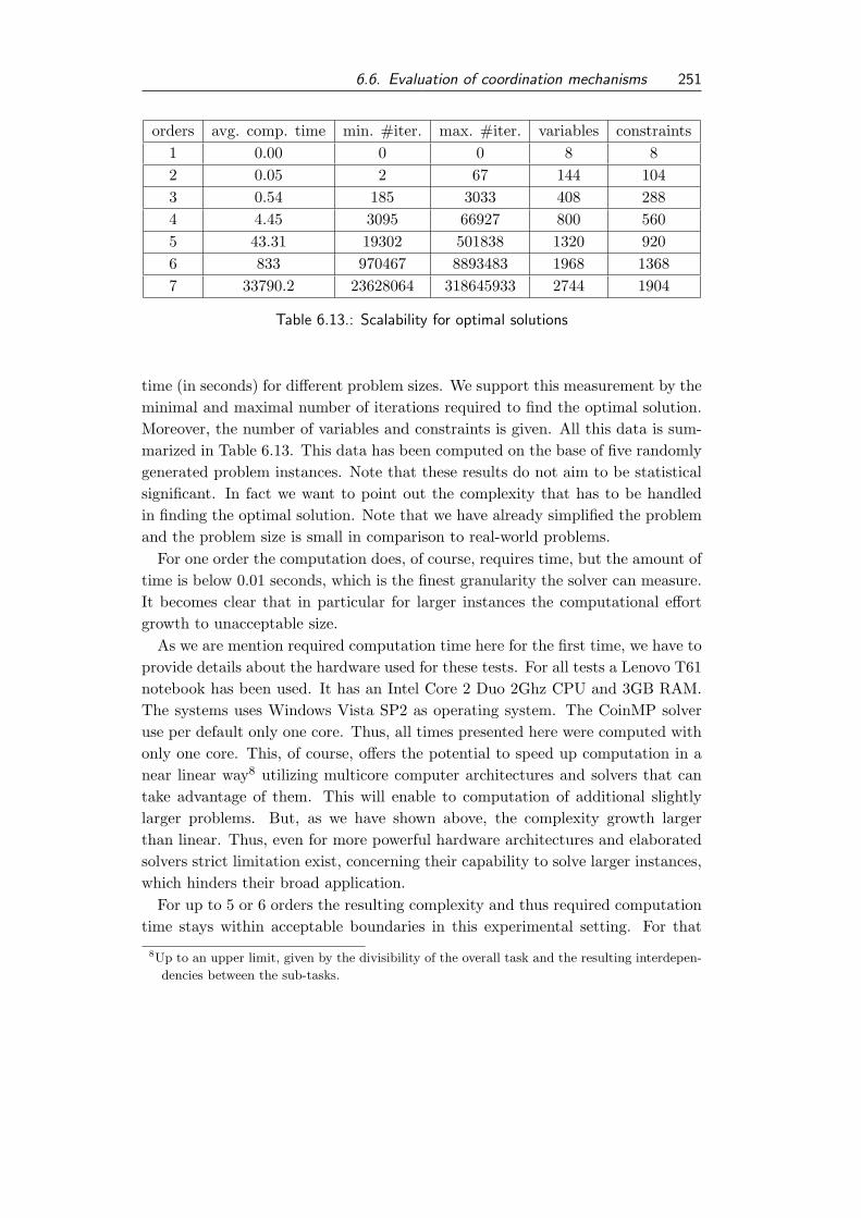
6.6. Evaluation of coordination mechanisms 251
orders avg. comp. time min. #iter. max. #iter. variables constraints1 0.00 0 0 8 82 0.05 2 67 144 1043 0.54 185 3033 408 2884 4.45 3095 66927 800 5605 43.31 19302 501838 1320 9206 833 970467 8893483 1968 13687 33790.2 23628064 318645933 2744 1904
Table 6.13.: Scalability for optimal solutions
time (in seconds) for different problem sizes. We support this measurement by theminimal and maximal number of iterations required to find the optimal solution.Moreover, the number of variables and constraints is given. All this data is sum-marized in Table 6.13. This data has been computed on the base of five randomlygenerated problem instances. Note that these results do not aim to be statisticalsignificant. In fact we want to point out the complexity that has to be handledin finding the optimal solution. Note that we have already simplified the problemand the problem size is small in comparison to real-world problems.
For one order the computation does, of course, requires time, but the amount oftime is below 0.01 seconds, which is the finest granularity the solver can measure.It becomes clear that in particular for larger instances the computational effortgrowth to unacceptable size.
As we are mention required computation time here for the first time, we have toprovide details about the hardware used for these tests. For all tests a Lenovo T61notebook has been used. It has an Intel Core 2 Duo 2Ghz CPU and 3GB RAM.The systems uses Windows Vista SP2 as operating system. The CoinMP solveruse per default only one core. Thus, all times presented here were computed withonly one core. This, of course, offers the potential to speed up computation in anear linear way8 utilizing multicore computer architectures and solvers that cantake advantage of them. This will enable to computation of additional slightlylarger problems. But, as we have shown above, the complexity growth largerthan linear. Thus, even for more powerful hardware architectures and elaboratedsolvers strict limitation exist, concerning their capability to solve larger instances,which hinders their broad application.
For up to 5 or 6 orders the resulting complexity and thus required computationtime stays within acceptable boundaries in this experimental setting. For that
8Up to an upper limit, given by the divisibility of the overall task and the resulting interdepen-
dencies between the sub-tasks.

252 6. Engineering Coordination: The SCM case study
Instance optimalABACO due-date heuristic
quality deviance in % quality deviance in %Inst 1 132 35 73.48% 22 83.33%Inst 2 393 194 50.64% 224 43%Inst 3 360 239 33.61% 179 50.28%Inst 4 196 -40 120.41% 73 62.76%Inst 5 183 142 22.40% 43 76.50%Inst 6 174 30 82.76 1 99.43%Inst 7 438 303 30.82% 318 27.40%Inst 8 399 281 29.57% 176 55.89%Inst 9 386 224 41.97% 213 44.82%Inst 10 221 52 76.47% -45 120.36%
Mean 56.21% 66.38%
Table 6.14.: Comparison heuristics and optimal solution
reason, we use a problem size of 5 orders in the following to evaluate the perfor-mance of the predictive scheduling heuristics, both modeled using the order-basedheuristic.
Assessment of order-based heuristics, and ABACO in contrast to theoptimal solution
We now point out the quality of the heuristics, used by ABACO and the referenceimplementation presented above, in contrast to the optimal solution.
All data presented here base on 10 randomly generated test instances, eachspecifying 5 orders. Note that the data presented is not suitable to comparethe quality of both heuristic approaches. This is done in following parts of thisevaluation, where the results are based on a larger number of instances. Herewe just want to point out the spread in quality between the results provided bythe ABACO approach and our centralized reference heuristics in contrast to theoptimal solution, found by the LP solver.
In Table 6.14 we present the results of this experiment. We compare the qualityof the results, according to the aforementioned objective function, of the optimalsolutions with the outcomes a predictive scheduling with the ABACO approachand the earliest due-date first heuristic. For both heuristics we compute the per-centage of deviation. Percentage values greater than hundred indicate that thevalue of the objective function of the heuristic becomes negative, i.e., the comple-tion time of orders is beyond their due date. What can be seen from this data

6.6. Evaluation of coordination mechanisms 253
Figure 6.11.: Comparison of ABACO, due-date heuristic, and optimal solution
is, that in the mean both heuristics are more than 50% away from the optimalsolution. The best case for each heuristic is highlighted in Table 6.14. For bothheuristic their best case is more than 20% away from the optimal solution. Toprovide a more intuitive impression of these results they have been visualized inFigure 6.11. Thus, in pure predictive planning performance of both heuristics isfar beyond optimal solutions. But, as pointed out in the previous section, thecomputation of optimal solutions is practically limited to small instances. As weare not interested in finding near optimal heuristics for this particular schedulingproblem here, we use both heuristic approaches for the following experiments, aswell. Keep in mind that this particular scheduling problem, even it turns out tobe challenging to solve with good quality, is a strict simplification of the problemsthat were outlined above. Moreover, we are interested in the coordination of ex-isting distributed planning and scheduling problems here, not in finding efficientsolutions for a centralized formulation of those problems.
Relaxing the constraints on the model
In the following experiments we relax some of the restrictions that were necessaryto build a linear program. In the following we allow orders to request productof type two, which can be produced by either company A or B or by both ofthem. Moreover, we allow to have divergent planning problems and potentially

254 6. Engineering Coordination: The SCM case study
planning systems at each planning entity. Therefore, we change the assumptionof how company A produces its good. We do so to introduce the characteristicthat different planning authorities have to handle different planning problems andtherefore use different planning systems. For that reason, we give in Table 6.15 anupdate of the local planning problems, in contrast to the data presented in Table6.11. In particular the planning problem of company A has changed in a formthat it is not necessary to schedule two activities at local resources but to selectone resource for the execution of one activity necessary to perform the operation.Again, we use different names for resources of company A and B. This enables usto specify the scheduling problem for the centralized order-based heuristic.
Scalability of the heuristics
In this experiment we investigate the performance of the heuristic approachesunder different workloads, i.e., orders to schedule. Therefore, we compute theresults for hundred randomly created instances for each scenario. Thereby, ascenario specifies a certain number of orders that have to be scheduled. We createdscenarios ranging from 1 up to 30 orders. For a better analysis we present thegraph with our results in two parts. The first part contains the scenarios with 1to 15 orders. The second graph shows the results with 15 and more orders. Theresults of the first part of our analysis can be found in Figure 6.12. Note thatfor one order both approaches end up with the same result, because for one ordertheir behavior is identical. It can be clearly seen that starting from the scenariowith five orders onwards the results of both heuristics diverge. Up to about a loadof 8 orders the resulting objectives increase. In the scenarios from one to eightorders the addition of a new order leads to an increase of the objective function,because all orders can be finished before their due and therefore extra utility isadded. From 8 to 12 orders the objective function nearly plateaus, expect anoutlier for 10 orders. In these cases the additional order does not increase theobjective values, because some orders are now satisfied just in time, and thereforedo not increase of decrease the value of the objective function. Starting from thescenario with 13 orders the objective drops. From that point on, the addition ofan extra order leads to delays in the realization of orders.
The second part of our results, ranging from 15 to 30 orders is shown in Figure6.13. It can be observed that the objective falls nearly linear with the number oforders that have to be scheduled. In these scenarios the existing resources startsto get over utilized. Orders tend to be later finished. Note that up to 18/19orders the objective function is positive. That is, most of the orders are finishedon time and it is economically beneficial to add orders. For 20 or more orders theobjective function, the total tardiness becomes negative, which indicates that jobs

6.6. Evaluation of coordination mechanisms 255
Company Aoperation activity resource duration
111a 1 5b 3 5
114a 3 5b 5 5
211a 2 5b 5 5
212a 2 5b 4 5
213a 1 5b 2 5
214a 4 5b 5 5
Company B
1121 6 52 7 5
1131 6 52 8 5
2111 7 22 10 3
2121 6 32 9 2
2131 7 42 9 1
2141 8 12 10 5
Table 6.15.: Updated details of local production details for SC operations
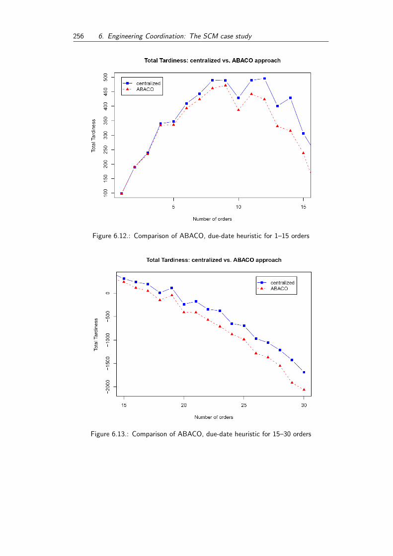
256 6. Engineering Coordination: The SCM case study
Figure 6.12.: Comparison of ABACO, due-date heuristic for 1–15 orders
Figure 6.13.: Comparison of ABACO, due-date heuristic for 15–30 orders
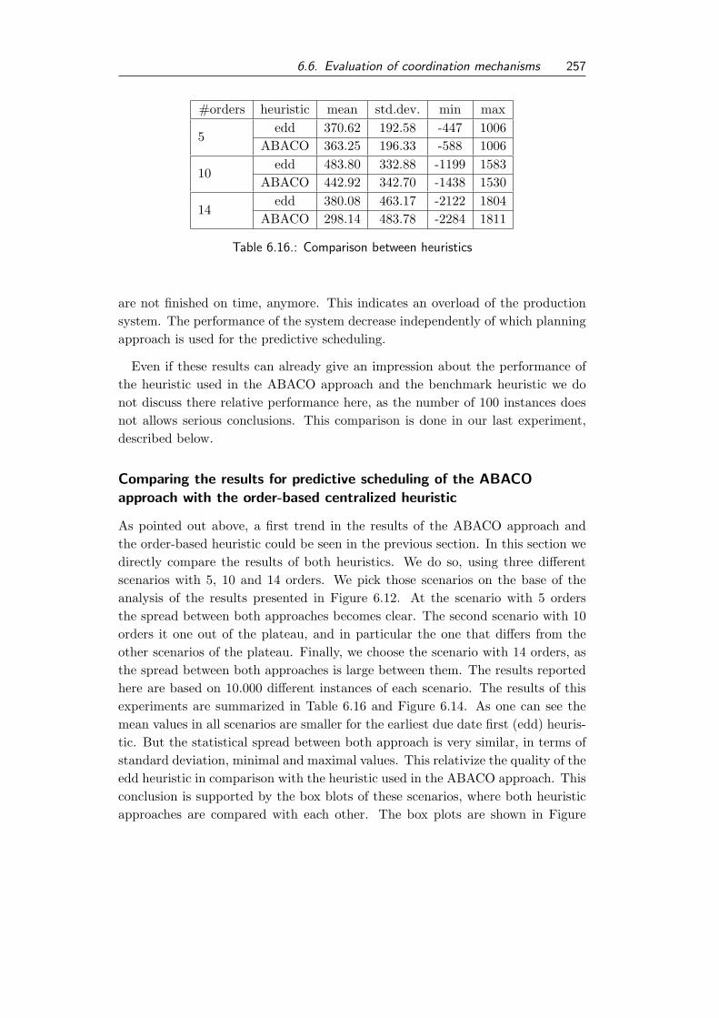
6.6. Evaluation of coordination mechanisms 257
#orders heuristic mean std.dev. min max
5edd 370.62 192.58 -447 1006
ABACO 363.25 196.33 -588 1006
10edd 483.80 332.88 -1199 1583
ABACO 442.92 342.70 -1438 1530
14edd 380.08 463.17 -2122 1804
ABACO 298.14 483.78 -2284 1811
Table 6.16.: Comparison between heuristics
are not finished on time, anymore. This indicates an overload of the productionsystem. The performance of the system decrease independently of which planningapproach is used for the predictive scheduling.
Even if these results can already give an impression about the performance ofthe heuristic used in the ABACO approach and the benchmark heuristic we donot discuss there relative performance here, as the number of 100 instances doesnot allows serious conclusions. This comparison is done in our last experiment,described below.
Comparing the results for predictive scheduling of the ABACOapproach with the order-based centralized heuristic
As pointed out above, a first trend in the results of the ABACO approach andthe order-based heuristic could be seen in the previous section. In this section wedirectly compare the results of both heuristics. We do so, using three differentscenarios with 5, 10 and 14 orders. We pick those scenarios on the base of theanalysis of the results presented in Figure 6.12. At the scenario with 5 ordersthe spread between both approaches becomes clear. The second scenario with 10orders it one out of the plateau, and in particular the one that differs from theother scenarios of the plateau. Finally, we choose the scenario with 14 orders, asthe spread between both approaches is large between them. The results reportedhere are based on 10.000 different instances of each scenario. The results of thisexperiments are summarized in Table 6.16 and Figure 6.14. As one can see themean values in all scenarios are smaller for the earliest due date first (edd) heuris-tic. But the statistical spread between both approach is very similar, in terms ofstandard deviation, minimal and maximal values. This relativize the quality of theedd heuristic in comparison with the heuristic used in the ABACO approach. Thisconclusion is supported by the box blots of these scenarios, where both heuristicapproaches are compared with each other. The box plots are shown in Figure

258 6. Engineering Coordination: The SCM case study
6.14. As one can see in these box plots the outcome of both heuristics does notdiffer significantly, which is also supported by the results of t–test, that indicateno significant difference, as well.
In summary, two issues can be stated about the performance of the ABACOheuristic. First, in comparison to the optimal solution the heuristic used withinthe ABACO approach is outperformed by numbers. Second, in comparison to anedd order-based heuristic no significant differences can be found. Even if the meanperformance is slightly worse, this cannot be verified for the entire data set, as thestatistical spread of both approaches is wide. Of course, one can argue that moresophisticated centralized optimization strategies, like metaheuristics for instance,could find better solutions and thus outperform the performance of the ABACOapproach. But the ABACO approach has two major advantages in favor to thesecentralized scheduling algorithms. First, it satisfy the coordination requirements,and thus can achieve these results respecting the existence of planning systemsin each company. Second, the ABACO approach has mechanisms for reactiveplanning, which at least simple heuristics do not have, and thus need to performa complete replanning. These abilities include techniques for direct reaction toevents that invalidate the current global plan, and additionally enables the par-ticipating companies to try to search for local improvements, which increase planquality over time. Plan improvement is an important supplementing technique,as the overall plan quality tends to decrease by a sequence of plan repair steps,performed by the reactive scheduling methodology.
6.7. Criticism of the ECo-CoPS approach
The modeling of the coordination problems, as a distributed planning problem,containing local planning problems in itself, can become a complex task. Es-pecially because it is not clear in the beginning which concepts are required toformalized each and every coordination requirement. Thus, it might be usefulto iteratively refine the model while trying to formalize the coordination require-ments. This procedure goes perfectly in line with the ECo process, which proposean iterative process model, for its execution.
The formalization of necessary criteria for the applicability of a coordinationmechanism has not been discussed in research, so far. It facilitates pointing outclearly the requirements of a given problem, and moreover, it is possible to usecoordination requirements for the explanation of design decisions of coordinationmechanisms. Note that these coordination requirements go far beyond purely tech-nical aspects, especially the non-functional requirements, like information hiding,maintaining local autonomy, and preserving existing planning systems, are re-

6.7. Criticism of the ECo-CoPS approach 259
(a) 5 orders
(b) 10 orders
(c) 14 orders
Figure 6.14.: Box plots for instances with 5, 10, and 14 orders

260 6. Engineering Coordination: The SCM case study
quirements that are motivated by real applications with economic constraints.The capturing of non-functional coordination requirements has been discussed inthis case study. By applying the ECo process the selection of a coordinationmechanism can be guided by those constraints.
In this case study we identified an existing coordination mechanism for thecoordination, and consequently, an existing implementation. For that reason theCoPS framework has not been used here. Moreover, a solver for linear programswas used to find the optimal solution for a reduced problem and another centralizedheuristic planner has been used, as well.
In the quantitative evaluation we give strong indications that both heuristic ap-proaches (the centralized one, and the ABACO predictive planning) are far awayfrom optimal solutions, but only require small fractions of computation time. Ina more detailed analysis, we found no statistical significant quality decrease usingthe centralized heuristic and the ABACO approach for the initial planning. But,in contrast to the centralized planning heuristic, the ABACO approach satisfiesall coordination requirements that have been formulated. Moreover, the ABACOapproach offers specific additional features for reactive planning and plan improve-ment facilities.
For the selection of a coordination mechanism the ECo process has reconfirmedthe decision to construct a new coordination approach in our previous work. TheABACO approach is identified as the only existing coordination mechanism, thatsatisfy all coordination requirements. A re-implementation is not done here, asthe original implementation can be used in the study.

7. Conclusion and Perspectives
Complex planning and decision problems are often solved by decomposing theoverall problem into smaller, and therefore, often simpler sub-problems. Thesesub-problems are solved, often independent from each other, and the resultingpartial solutions are synthesized to a global solution for the overall problem. Thisstrategy has been implemented in industry and academia, as well. Complex prob-lems like the container terminal management problem are decomposed into simplerproblems like the berth allocation, crane scheduling, storage space allocation, andthe transportation problem, for instance. Often these sub-problems turn out tobe very complex, as well. In consequence, these isolated problems are addressedby researchers as a topic of research by itself. It was pointed out in our discussionabout dependencies between planning systems (see Section 2.2.4), that the sub-problems can have various interdependencies. Thus, the computed partial planscannot simply be combined to construct a feasible global plan. For that reason,coordination mechanisms have to be put in place to ensure that the resulting par-tial plans can be executed together and an acceptable, or ideally good to optimal,overall performance is ensured.
We have addressed here the coordination on the operative level. The decompo-sition of the overall problem, the methods for solving partial problems, and theorganizational formation of planning entities are assumed to be given. Therefore,the coordination mechanisms should only effect decisions on the operative level.In Section 3.1 we have outlined a number of existing coordination approaches thathave been proposed mainly by researchers from the field of DAI, addressing theproblem of coordination of planning entities on the operative level. The issueof coordination is a centerpiece in DAI research. Consequently, a variety of dif-ferent approaches have been presented. Each addressing a certain aspect of thecoordination problem, or designed for a specific coordination problem.
Findings of the study
We summarize the main findings of this work here. In this thesis
• a research gap for the selection of coordination mechanisms for existing au-tonomous planning systems has been identified,
261

262 7. Conclusion and Perspectives
• the ECo process has been designed to bridge this gap,
• the feasibility of the ECo process has been proven by applying it in two casestudies,
• providing the CoPS process and implementing the CoPS framework, theimplementation step of the ECo process is detailed and supported,
• in the case studies the ECo-CoPS approach has proven to be advantageousfor coordination problems in the logistic domain.
To profit from existing research concerning the coordination of autonomous agents,it is promising to re-use existing methodologies. A large body of research has beendocumented in the literature, and numerous coordination techniques for agent-based systems have been proposed. As there exists no suitable classification ofexisting mechanisms, the identification of applicable mechanisms for a given situ-ation is a complex and time consuming task. We have presented a survey in thefield of agent-oriented software engineering (see Section 3.2) to identify suitablemechanisms for the identification and re-use of existing concepts, in particular co-ordination mechanisms. A major result of our survey is that there is rarely workdone dealing with re-use of methodologies in AOSE. The selection of coordinationmechanisms is a field that is currently not covered. We pointed out this researchgap in Section 3.3 and the necessity for means to bridge this gap. Thereby, wefocus on the coordination of existing distributed planning systems, and emphasizethe importance of the applicability of the approach in the given context.
A first, but significant, step towards our goal is the identification of key char-acteristics of coordination problems. We extracted those characteristics from theexamples used in our study. We pointed out six different characteristics of coor-dination problems (see Section 4.1). These characteristics are:
• the existence of an allocation problem,
• the existence of comparable local objective functions,
• the diversification of existing planning systems,
• the existence of a common overall objective function,
• the necessity of information hiding, and
• the existence of cyclic dependencies.
We have classified the presented coordination mechanisms according to the char-acteristics they require. In our case studies the classification turns out to be very

263
efficient in the selection process. It enabled us to focus the search on a reduced setof candidate approaches. In the following detailed analysis, the qualitative evalu-ation, the coordination mechanisms were analyzed according to their compliancewith the coordination requirements. This selection process is open in the sensethat the outcome can be either the identification of existing mechanisms, with orwithout existing implementation, or the finding that no appropriate mechanismexists.
To enable efficient identification
Figure 7.1.: The ECo process
of suitable coordination mechanismswe presented the ECo process, thatguides the identification and selec-tion process (see Section 4.2). TheECo process contains five steps thatcan be executed in an iterative pro-cess model shown in Figure 7.1. Thesteps of the ECo process are:
1. modeling the scenario,
2. defining coordination requirements,
3. identifying suitable coordination mechanisms,
4. implementing coordination mechanisms, and
5. evaluating coordination mechanisms.
The introduction of coordination requirements is a significant step towards amore explicit formalization capturing what a coordination mechanism has to fulfillto be applicable in a given situation. If coordination mechanisms are classifiedaccording to requirements they fulfill, this will facilitate the reuse, and leverage theadvantages of requirements. The selection out of classified mechanisms becomessimpler as detailed analyzing processes can be omitted. Coordination requirementsalso facilitate the documentation of design decisions that were made during thedesign and implementation phase.
A coordination mechanism is applicable if it satisfies all functional and non-functional coordination requirements. The evaluation if these requirements aresatisfied is called qualitative evaluation. As the requirements are formalized on asound model, the qualitative evaluation can be done in a formal way. The result ofthe qualitative evaluation is a set of mechanisms that are applicable in the givensituation, as they satisfy all coordination requirements. Note that this result setcan be empty, as well. Moreover, the qualitative evaluation does not provide any

264 7. Conclusion and Perspectives
indication of the quality of the coordinated plans, except the ones encoded in therequirements, which is typically feasibility of the joint execution of the plans.
To support the implementation step, the CoPS process is proposed (see Section4.3). The CoPS process structures decision making that has to be made dur-ing the implementation of a coordination mechanism. It spawns from decisionsmade on the layer of the overall network, like the selection of conversation pro-tocols, to decisions that have to be made at each participating planning entity,like the definition of conversation policies or the adaptation of existing planningsystems. To ease the implementation process, the CoPS framework has been in-troduced. Within this framework an infrastructure is implemented. It facilitatesfast implementation/prototyping of coordination mechanisms. By enabling to pro-totype coordination mechanisms the CoPS approach facilitates the evaluation ofmechanisms on a quantitative base. The CoPS framework can also speed up theimplementation of new coordination mechanisms.
The CoPS framework is currently not intended for commercial implementations.It has deficits concerning aspects like failover abilities and adapters to standardsoftware systems that are necessary for operating in a productive environment.
In the final step of the ECo process a quantitative evaluation is suggested toevaluate the performance of the selected coordination mechanisms, which enablesthe final judgement which mechanism should be used. This evaluation uses im-plemented systems. Thus, the evaluation can be done using real-world like datain a real-world like environment.
The ECo-process supported by the CoPS process and the CoPS frameworkform the ECo-CoPS approach that is introduced in this thesis. In Chapter 5and Chapter 6 we applied the ECo-CoPS approach to two case studies from thefield of production and logistics. In these two case studies we have validated theECo process by pointing out its applicability, and found indications that this pro-cess adds additional value to the selection process of coordination mechanisms.Our experience with the ECo-CoPS approach have been discussed in the previouschapters. We can summarize them as follows. The ECo and CoPS process facil-itate a structured procedure in the identification, selection, and implementationphase of suitable coordination mechanisms. To draw conclusions about the CoPSframework more case studies are needed.
Aspects that have been identified during our case studies, and that might com-plicate efficient usage of the ECo-CoPS approach are:
• The modeling of the coordination problems can become complex, and mul-tiple iterations between modeling and formulation of coordination require-ments can be necessary. Therefore, it might be useful to investigate differenttypes of modeling techniques. Also, a dedicated sub-process for the modeling

265
step might be valuable.
• The CoPS framework requires more evaluation, and thereby has to beevolved.
It can be argued that the coordination mechanisms discussed in this thesis do notfavor optimal outcomes on the global level, which is, for instance, the goal of col-laborative planning, presented in Section 3.1.1, or other optimization approaches.This criticism is correct. As we have stated, we address the coordination of ex-isting planning systems, and have even stated in the second case study that localautonomy has to be preserved. This strictly limits the ability of the overall sys-tem to come to an optimal global solution. This has been shown in particularin the second case study, where a comparison with an optimal solution has beenperformed. The loss of global optimality is a direct consequence of our approachto restrict ourselves to the coordination of existing planning systems in existingautonomous planning entities. We did so, because planning systems have beenused in real world applications for decades, and are often well established. Thesesoftware systems, and the organizational structures of companies are fixed fromthe perspective of the operational level that is addressed in this research. Thus,this limitation results from assumptions we have made, because we are convincedthat they will allow us to model real-world like scenarios more accurate.
What also has not been addressed in this study is the empirical evaluation ofthe ECo process. The evaluation of a process is a social science task, as well. Itis necessary to apply the process a number of times, and each process executionhas to be observed, and criticism has to be recorded. An experimental settingwould be to have two equally skilled groups facing the same problem, and thenlet one group use the ECo process while the other group does not. The secondgroup is the control group. Moreover, the context, like given deadlines or giventechnology, has to be taken into account, as this can effect the quality of theoutcome of the process, as well. These experiments have to be replicated to drawsound conclusions. Therefore, it is necessary that each participant of such a studycan participate in exactly one experiment. Replications are also required for everyapplication domain that is evaluated.
Perspectives for future research
The research gap identified in this thesis is covered by the proposed ECo-CoPSapproach. The results of this thesis can be an initial pre-requisite for a number ofsubsequent research projects. We outline some aspects here, that should and willbe investigated in future research.

266 7. Conclusion and Perspectives
As already mentioned, the number of case studies applying the ECo-CoPS ap-proach needs to be increased to allow for more reliable evaluation results, concern-ing the additional value the ECo-CoPS approach offers in contrast to an unstruc-tured process. Therefore, it is necessary to apply the ECo-CoPS approach, andcontrasting conversational approach, to various domains, and, ideally, the processshould be performed by different developers. A first candidate for the next casestudy is the coordination of planning systems in container terminal management,which has been used in this thesis as an example, e.g., planning systems for thisdomain have already been provided by Leif Meier [Mei08]. The ECo-CoPS ap-proach has been designed to be generally applicable. However, if a variety of casestudies exist, it could become useful to analyze if domains exist that are particu-lar well suited for the application of the ECo-CoPS approach, and if applicationareas exist that require more specialized or enhanced versions of the process oradditional guidance.
Another aspect that could be used in following case studies is the investigation ofdifferent modeling techniques for the coordination problems. As already pointedout, it can become necessary to iterate between modeling and formulation ofcoordination requirements, and modeling can become a complex task. It might beuseful to investigate modeling techniques that facilitate on the one hand a formallygrounded description of the scenario, and, on the other hand, offer additional valueduring the implementation, and can therefore foster an implementation phase.Modeling with UML profiles and the object constraint language (OCL) might bea first starting point for alternative techniques for modeling.
In the course of the design of conversation protocols, and in particular for thedefinition of conversation policies it turned out that the existing work is often notsufficient. This is especially true, if the agent’s behavior should be specified bythe humans they have to represent, and, thereby, adapt the negotiation strategiesof the humans. Specifying agent’s behavior is often strictly tied to programmingcode the agent can use, or that defines the agent’s behavior. Thus, the modelingof conversations, and conversation policies is still an open research issue. Even ifinteraction protocols are nowadays widely accepted and standardized, there rarelyexist any techniques for modeling conversation policies or strategies for consistencyamong parallel negotiations performed by an agent with multiple other agents atthe same time.
In the ECo process we emphasized the importance of coordination requirements.They can be used to specify characteristics of the current context of the coordi-nation problem, and formalize criteria that have to be regarded by coordinationmechanisms to be applicable. Moreover, they offer additional value. Existing co-ordination mechanisms can be classified according to a fixed set of coordination

267
requirements, and, therefore, form a catalog of coordination mechanisms that canbe used to foster the identification of candidates for a new coordination problem.Thus, coordination requirements build a new scheme for the classification of co-ordination mechanisms that can offer practical value by encouraging and easingre-use of existing mechanisms.
In this thesis, we have strictly limited our focus on the coordination of activi-ties on the operational level. The tactical and strategy decision level have beenexcluded from this study. An example of a tactical decision might be to decide if,and when, to enter/leave a network. A decision on the strategic level is the decom-position of the overall planning problem into sub-problems and planning entities.This decomposition is an interesting topic of research, as well. Therefore, we in-vestigate in a subsequent research project the effects of different decompositionson the achievable overall quality of coordinated solutions.
We are going to model the overall problem as a distributed constraint optimiza-tion problem with privacy issues. A constraint optimization problem (COP) is aconstraint satisfaction problem with an additional objective function for solutionsthat has to be maximized. This optimization problem can be distributed. Differ-ent solvers are responsible for distinct subsets of variables. Privacy issues can beadded if variables, domains, and constraints that are located at exactly one solverare only known to this particular solver. If a constraint involving variables locatedat two or more different solvers exists, these variables and the constraints are semi-private, as are all participating solvers, and only those are aware of the existence ofthe variables within this constraint. Distributed constraint optimization problemswith privacy issues can be used to model the coordination of planning systems.Each local planning system can be modeled as a constraint optimization problemin itself, and additional constraints can be introduced representing the interdepen-dencies between different planning systems. Thus, it is possible to use constraintoptimization techniques to identify optimally coordinated solutions, which can beused as benchmarks. This large COP would be hard to solve optimally. Thisenable a comparison of results of a centralized problem with results of differentdecompositions. Of particular interest is the identification of decomposition tech-niques. This research could give valuable insight on the effects of distributiontechniques on achievable solution quality.

268 7. Conclusion and Perspectives

Bibliography
[ABTV04] Dietrich Adam, Klaus Backhaus, Ulrich W. Thonemann, and Mar-kus Voeth. Allgemeine Betriebswirtschaftslehre - Koordination be-trieblicher Entscheidungen. Springer, Berlin, 3rd edition, 2004.
[ACF+98] Rachid Alami, R. Chatila, S. Fleury, M. Ghallab, and F. Ingrand.An architecture for autonomy. International Journal of RoboticsResearch, 17(4), 1998.
[AFHS95] Oksana Arnold, Wolfgang Faisst, Martina Hartling, and PascalSieber. Virtuelle Unternehmen als Unternehmenstyp der Zukunft?HMD, 185:8 – 23, 1995.
[AGO08] Marlene Arangu, Antonio Garrido, and Eva Onaindia. A gen-eral technique for plan repair. In Proceedings of the 20th IEEEInternational Conference on Tools with Artificial Intelligence, vol-ume 1, pages 515–518, Dayton, Ohio,USA, 2008. IEEE ComputerSociety.
[AM09] Karl Johan Astrom and Richard M. Murray. Feedback Systems:An Introduction for Scientists and Engineers. Princeton Univer-sity Press, Princeton and Oxford, 2009.
[AO94] Krzysztof R. Apt and Ernst-Rudiger Olderog. Programmverifika-tion. Springer, Berlin, 1994.
[BCG+98] Frances M. T. Brazier, Frank Cornelissen, Rune Gustavsson, Ca-tholijn M. Jonker, Olle Lindeberg, Bianca Polak, and Jan Treur.Compositional design and verification of a multi-agent system forone-to-many negotiation. In Proceedings of the Third InternationalConference on Multi-Agent Systems, ICMAS’98, pages 49 – 56.IEEE Computer Society Press, 1998.
[BCGZ01] Nadia Busi, Paolo Ciancarini, Roberto Gorrieri, and GianluigiZavattaro. Models for coordinating agents: a guided tour. InAndrea Omicini, Robert Tolksdorf, Gerhard Weiss, and Franco
269

270 Bibliography
Zambonelli, editors, Coordination for Internet Agents: Mod-els,Technologies, and Applications, pages 6–24. Springer, 2001.
[BEY98] Allan Borodin and Ran El-Yaniv. Online computation and com-petitive analysis. Cambride University Press, Cambridge, 1998.
[BF95] Mihai Barbuceanu and Mark S. Fox. Cool: A language for de-scribing coordination in multi agent systems. In Proceedings ofthe First International Conference on Multiagent Systems (IC-MAS95), pages 17 – 24. AAAI Press, 1995.
[BFJ+04] Jeffrey M. Bradshaw, Paul J. Feltovich, Hyuckchul Jung, Shirni-was Kuklarni, William Taysom, and Andrzej Uszok. Dimen-sions of adjustable autonomy and mixed-initiative-interaction. InMatthias Nickles, Michael Rovatsos, and Gerhard Weiss, editors,AUTONOMY 2003 : International Workshop on computationalautonomy, volume 2969 of LNAI, pages 17 – 39, Melbourne, 2004.Springer, Berlin.
[BGZ04] Federico Bergenti, Marie-Pierre Gleizes, and Franco Zambonelli,editors. Methodologies and Software Engineering for agent sys-tems: The Agent-oriented softwre Engineering Handbook. Mul-tiagent systems, artificial societies, and simulated organizations.Kluwer Academic Publishers, Bosten, 2004.
[BH09] Nils Bulling and Koen V. Hindriks. Towards a verification frame-work for communicating rational agents. In Lars Braubach, Wiebevan der Hoek, Paolo Petta, and Alexander Pokahr, editors, Mul-tiagent System Technologies (MATES 2009), Lecture Notes inArtificial Intelligence (LNAI), pages 177 – 182, Hamburg, 2009.Springer.
[BHW07] Rafael H. Bordini, Jomi Fred Hubner, and Michael Wooldridge.Programming Multi-Agent Systems in AgentSpeak using Jason.Wiley Series in Agent Technology. John Wiley & Sons Ltd., 2007.
[BJW03] Stefan Bussmann, Nick R. Jennings, and Michael Wooldridge. Re-use of interaction protocols for agent-based control applications.In Fausto Giunchiglia, James Odell, and Gerhard Weiss, editors,Agent-Oriented Software Engineering III Proc. of the Third Inter-national Workshop, AOSE 2002, volume 2585 of Lecture Notes inComputer Science, pages 73 – 87, Bologna, Italy, 2003. Springer.

Bibliography 271
[BM92] Stefan Bussmann and H. Jurgen Muller. A negotiation frameworkfor cooperating agents. In S.M.Deen, editor, Proc. of the CKBS-SIG (CKBS’92), pages 1 –17, DAKE Centre, Univ. of Keele, 1992.
[BMR+02] Frank Buschmann, Regine Meunier, Hans Rohnert, Peter Som-merlad, and Michael Stal. A System of Patterns: Pattern-OrientedSoftware Architecture, volume 1 of Wiley Series in Sotware DesignPatterns. John Wiley & Sons Ldt., Chichester, 2002.
[BMRL03] Paolo Busetta, Mattia Merzi, Silvia Rossi, and Franc¸ois Legras.Realtime role coordination for ambient intelligence. In WorkshopRepresentations and Approaches for TimeCritical DecentralizedResource/Role/Task Allocation at AAMAS03, Melbourne, Aus-tralia, 2003.
[BO00] Robert W. Brennan and William O. A simulation test-bed toevaluate multi-agent control of manufacturing systems. In WSC’00: Proceedings of the 32nd conference on Winter simulation,pages 1747–1756, Orlando, Florida, 2000. Society for ComputerSimulation International.
[BPJ03] Claudio Bartolini, Chris Preist, and Nick R. Jennings. Architect-ing for reuse: A software framework for automated negotiation.In John Mylopoulos, Michael Winikoff, and Nick R. Jennings, ed-itors, Agent-Oriented Software Engineering III Proc. of the ThirdInternational Workshop, AOSE 2002, volume 2585, pages 88 –100, Bologna, Italy, 2003. Springer.
[BR02] Federico Bergenti and Alessandro Ricci. Three approaches to thecoordination of multiagent systems. In SAC ’02: Proceedings ofthe 2002 ACM symposium on Applied computing, pages 367–372,Madrid, Spain, 2002. ACM Press.
[Bra87] Michael E. Bratman. Intention, plans, and practical reason. Har-vard University Press, Cambridge, Mass, 1987.
[Bro86] R. Brooks. A robust layered control system for a mobile robot.IEEE Journal of Robotics and Automation, 2(1):14 – 23, 1986.
[BTF97] Mihai Barbuceanu, Rune Teigen, and Mark S. Fox. Agent baseddesign and simulation of supply chain systems. In Proc. of the 6thWorkshop on Enabling Technologies Infrastructure for Collabora-tive Enterprises (WET-ICE ’97), pages 36 – 42, 1997.

272 Bibliography
[CBM+99] Sergio Cavalieri, Luc Bongaerts, Marco Macchi, Marco Taisch,and Jo Weyns. A benchmark framework for manufacturing con-trol. In Second International Workshop on Intelligent Manufac-turing Systems, pages 225 – 236, Leuven, Belgium, 1999.
[CCG+04] Giovanni Caire, Wim Coulier, Francisco Garijo, Jorge J. Gomez-Sanz, Juan Pavon, Paul Kearney, and Philippe Massonet. Themessage methodology. In Federico Bergenti, Marie-Pierre Gleizes,and Franco Zambonelli, editors, Methodologies and Software Engi-neering for agent systems: The Agent-oriented softwre Engineer-ing Handbook, Multiagent systems, artificial societies, and simu-lated organizations, pages 177 – 194. Kluwer Academic Publishers,Bosten, 2004.
[CG99] Kathleen M. Carley and Les Gasser. Computational organizationtheory. In Gerhard Weiss, editor, Multiagent Systems: a modernapproach to distributed artificial intelligence, pages 299 – 330. MITPress, 1999.
[CG01] Hans Corsten and Ralf Gossinger. Unternehmensnetzwerke:Grundlagen - Ausgestaltungsformen - Instrumente. Schriften zumProduktionsmanagement 38, Lehrstuhl fur ProduktionswirtschaftUniversitat Kaiserslautern, Februar 2001 2001.
[CGMT00] Sergio Cavalieri, Marco Garetti, Marco Macchi, and Marco Taisch.An experimental benchmarking of two multi-agent architecturesfor production scheduling and control. Computers in Industry,43:139 – 152, 2000.
[CJ96] David Cockburn and Nick R. Jennings. Archon: A distributedartificial intelligence system for industrial applications. In G.M.P.O’Hare and Nick R. Jennings, editors, Foundations of DistributedArtificial Intelligence, Sixth-Generation Computer Technology Se-ries, pages 319 – 344. John Wiley & Sons, New York, 1996.
[CK05] William Cushing and Subbarao Kambhampati. Replanning: anew perspective. In Poster Program. In Proceedings of theFifteenth International Conference on Automated Planning andScheduling (ICAPS-05), Montery, 2005.
[CLM04] J.-F. Cordeau, G. Laporte, and A .Mercier. Improved tabu searchalgorithm for the handling of route duration constraints in vehicle

Bibliography 273
routing problems with time windows. Journal of the OperationalResearch Society, 55(5):542–546, 2004.
[Com07] FIPA Modeling Technical Committee. Auml web site, 2007. http://www.auml.org/; Accessed: 02/04/10.
[CTMG98] John Collins, Maxim Tsvetovat, Bamshad Mobasher, and MariaGini. Magnet: A multi-agent contracting system for plan exe-cution. In Proc. of the Workshop on Artificial Intelligence andManufacturing (SIGMAN’98), pages 63–68, Albequerque, NewMexico, 1998. AAAI Press.
[CW01] Paolo Ciancarini and Michael Wooldridge, editors. Agent-OrientedSoftware Engineering, First International Workshop AOSE 2000,,volume 1957 of Lecture Notes in Computer Science. Springer,Berlin, 2001.
[CWDH00] Graham Coates, Robert Ian Whitfield, Alex H. B. Duffy, and BillHills. Coordination approaches and systems - part ii: An oper-ational perspective. Research in Engineering Design, 12:73 – 89,2000.
[CWHC06] Marcelo Cataldo, Patrick A. Wagstrom, James D. Herbsleb, andKathleen M. Carley1. Identification of coordination requirements:Implications for the design of collaboration and awareness tools.In Proceedings of the 2006 20th anniversary conference on Com-puter supported cooperative work, pages 353–362, Banff, Alberta,Canada, 2006. ACM Press.
[Dec95] Keith S. Decker. Environment Centered Analysis and Designof Coordination Mechanisms. Phd thesis, University of Mas-sachusetts, 1995.
[Dec96] Keith S. Decker. Distributed artificial intelligence testbeds. InG.M.P. O’Hare and Nick R. Jennings, editors, Foundations of Dis-tributed Artificial Intelligence, Sixth-Generation Computer Tech-nologies, pages 119 – 138. John Wiley & Sons, New York, 1996.
[DGSS96] Jurgen Dorn, Mario Girsch, Gunther Skele, and Wolfgang Slany.Comparison of iterative improvement techniques for schedule op-timization. EJORS European Journal of Operational Research,94(2):349–361, 1996.

274 Bibliography
[DHK02] Ralph Depke, Reiko Heckel, and Jochen Malte Kuster. FormalAgent-Oriented Modeling with UML and Graph Transformation.Science of Computer Programming, 44(2):229–252, 2002.
[DJT01] Mehdi Dastani, Catholijn M. Jonker, and Jan Treur. A require-ment specification language for configuration dynamics of multi-agent systems. In Michael Wooldridge, Gerhard Weiss, and PaoloCiancarini, editors, Proceedings of Second International Workshopon Agent-Oriented Software Engineering II (AOSE 2001), volume2222 of Lecture Notes In Computer Science;, pages 169 – 187,Montreal, Canada, 2001. Springer.
[DL87] Edmund H. Durfee and Victor Lesser. Planning coordinated ac-tions in dynamic domains. Technical Report UM-CS-1987-130,Computer Science Department University of Massachusetts, 1987.
[DL92] Keith S. Decker and Victor Lesser. Generalizing the partial globalplanning algorithm. International Journal of Intelligent and Co-operative Information Systems, 1:319–346, 1992.
[DL93] Keith S. Decker and Victor Lesser. Analyzing a quantitative coor-dination relationship. Group Decision and Negotiation, 2(3):195–217, 1993.
[DL00] Keith S. Decker and Jinjiang Li. Coordinating Mutually Exclu-sive Resources using GPGP. Autonomous Agents and Multi-AgentSystems, 3(2):133 – 157, 2000.
[DMLS99] Sophie D’Amours, Benoit Montreuil, Pierre Lafrancois, and Fan-cois Soumis. Networked manufacturing: The impact of infor-mation sharing. International Journal of Production Economics,58:63 – 79, 1999.
[Dor04] Jurgen Dorn. Evaluating reactive scheduling systems. InIAT ’04: Proceedings of the Intelligent Agent Technology,IEEE/WIC/ACM International Conference on (IAT’04), pages458–461. IEEE Computer Society, 2004.
[DS83] R. Davis and R. Smith. Negotiation as a metaphor for distributedproblem solving. Artificial Intelligence, 20:63 – 109, 1983.
[Dud04] Gregor Dudek. Collaborative Planning in Supply Chains: A ne-gotiation-based approach. Lecture Notes in Economics and Math-ematical Systems. Springer, Berlin, 2004.

Bibliography 275
[Dur99] Edmund H. Durfee. Distributed problem solving and planning. InGerhardt Weiß, editor, Multiagent Systems: a modern approachto distributed artificial intelligence, pages 121 – 164. MIT Press,1999.
[Dyc90] Harald Dyckhoff. A typology of cutting and packing problems.European Journal of Operational Research (EJOR), 44:145 – 159,1990.
[EHNO08] Thomas Epping, Winfried Hochstattler, Robert Nickel, and Pe-ter Oertel. Order sequencing in the automobile industry. InLars Monch and Giselher Pankratz, editors, Intelligente Systemezur Entscheidungsunterstutzung,Teilkonferenz der MultikonferenzWirtschaftsinformatik, pages 49–64, Munchen, 2008. SCS Publish-ing House.
[Ele04] Thomas Elendner. Winner Determination in Combinatorial Auc-tions: Market-based Scheduling. Logos Verlag, Berlin, 2004.
[ETJ04] Cora Beatriz Excelente-Toledo and Nick R. Jennings. The dy-namic selection of coordination mechanisms. Autonomous Agentsand Multi-Agent Sytems, 9:55 – 85, 2004.
[FBH07] Helmut Frank, Annette Bobrik, and Nico Haarlander. Vorgehens-modell. In Hermann Krallmann, Marten Schonherr, and MatthiasTrier, editors, Systemanalyse im Unternehmen: ProzessorientierteMethoden der Wirtschaftsinformatik, pages 135–186. Oldenbourg,Munchen, 5th. edition, 2007.
[Fer99] Jacques Ferber. Multi-Agent Systems: An Introduction to Dis-tributed Artifcial Intelligence. Pearson Edication Ltd., London,1999.
[FFGSP06] Ruben Fuentes-Fernandez, Jorge J. Gomez-Sanz, and Juan Pavon.Requirements elicitation for agent-based applications. In Jorg P.Muller and Franco Zambonelli, editors, Agent-Oriented SoftwareEngineering VI: Proc. of the 6th InternationalWorkshop, AOSE2005, volume 3950 of Lecture Notes in Computer Science, pages40 – 53, Utrecht, Netherlands, 2006. Springer.
[FFMM93] Tim Finin, Rich Fritzson, Don McKay, and Robin McEntire. Kqml- a language and protocol for knowledge and information exchange.In Int. Conf. on Building and Sharing of Very Large-Scale Knowl-edge Bases, Tokyo, 1993.

276 Bibliography
[FGLS06] Maria Fox, Alfonso Gerevini, Derek Long, and Ivan Serina.Plan stability: Replanning versus plan repair. In Derek Long,Stephen F. Smith, Daniel Borrajo, and Lee McCluskey, editors,Proceedings of the Sixteenth International Conference on Auto-mated Planning and Scheduling (ICAPS 2006), pages 212–221,Cumbria, UK, 2006. AAAI Press.
[FGR05] Giancarlo Fortino, Alfred Garro, and Wilma Russo. An integratedapproach for the development and validation of multi-agent sys-tems. Computer Systems Science and Engineering, 4:259 – 271,2005.
[FGSP04] Ruben Fuentes, Jorge J. Gomez-Sanz, and Juan Pavon. Verifica-tion and validation techniques for multi-agent systems. Upgrade,Council of European Informatics Societies, 5(4):15– 19, 2004.
[FHK+07] Truls Flatberg, Geir Hasle, Oddvar Kloster, Eivind J. Nilssen,and Atle Riise. Dynamic and stochastic vehicle routing in prac-tice. In Vasileios Zeimpekis, Christos D. Tarantilis, George M.Giaglis, and Ioannis Minis, editors, Dynamic Fleet Manage-ment: Concepts, Systems, Algorithms & Case Studies, Opera-tions Research/Computer Science Interfaces Series, pages 41 – 63.Springer, 2007.
[FIP01a] Foundations for Intelligent Physical Agents FIPA. Fipa agentsoftware integration specification, 2001. http://www.fipa.org/
specs/fipa00079/index.html; Accessed: 02/04/10.
[FIP01b] Foundations for Intelligent Physical Agents FIPA. Fipa dutch auc-tion interaction protocol specification, 2001. http://www.fipa.
org/specs/fipa00032/index.html; Accessed: 02/04/10.
[FIP01c] Foundations for Intelligent Physical Agents FIPA. Fipa englishauction interaction protocol specification, 2001. http://www.
fipa.org/specs/fipa00031/index.html; Accessed: 02/04/10.
[FIP02a] Foundations for Intelligent Physical Agents FIPA. FIPA AbstractArchitecture Specification, 2002. http://www.fipa.org/specs/
fipa00001/index.html; Accessed: 02/04/10.
[FIP02b] Foundations for Intelligent Physical Agents FIPA. Fipa aclmessage representation in bit-efficient specification, 2002.http://www.fipa.org/specs/fipa00069/index.html; Ac-cessed: 02/04/10.

Bibliography 277
[FIP02c] Foundations for Intelligent Physical Agents FIPA. Fipa acl mes-sage structure specification, 2002. http://www.fipa.org/specs/fipa00061/index.html; Accessed: 02/04/10.
[FIP02d] Foundations for Intelligent Physical Agents FIPA. Fipa agentmessage transport service specification, 2002. http://www.fipa.org/specs/fipa00067/index.html; Accessed: 02/04/10.
[FIP02e] Foundations for Intelligent Physical Agents FIPA. Fipa brokeringinteraction protocol specification, 2002. http://www.fipa.org/
specs/fipa00033/index.html; Accessed: 02/04/10.
[FIP02f] Foundations for Intelligent Physical Agents FIPA. Fipa contractnet interaction protocol specification, 2002. http://www.fipa.
org/specs/fipa00029/index.html; Accessed: 02/04/10.
[FIP02g] Foundations for Intelligent Physical Agents FIPA. Fipa iteratedcontract net interaction protocol specification, 2002. http://www.fipa.org/specs/fipa00030/index.html; Accessed: 02/04/10.
[FIP02h] Foundations for Intelligent Physical Agents FIPA. Fipa nomadicapplication support specification, 2002. http://www.fipa.org/
specs/fipa00014/index.html; Accessed: 02/04/10.
[FIP02i] Foundations for Intelligent Physical Agents FIPA. Fipa proposeinteraction protocol specification, 2002. http://www.fipa.org/
specs/fipa00036/index.html; Accessed: 02/04/10.
[FIP02j] Foundations for Intelligent Physical Agents FIPA. Fipa queryinteraction protocol specification, 2002. http://www.fipa.org/
specs/fipa00027/index.html; Accessed: 02/04/10.
[FIP02k] Foundations for Intelligent Physical Agents FIPA. Fipa recruitinginteraction protocol specification, 2002. http://www.fipa.org/
specs/fipa00034/index.html; Accessed: 02/04/10.
[FIP02l] Foundations for Intelligent Physical Agents FIPA. Fipa requestinteraction protocol specification, 2002. http://www.fipa.org/
specs/fipa00026/index.html; Accessed: 02/04/10.
[FIP02m] Foundations for Intelligent Physical Agents FIPA. Fipa requestwhen interaction protocol specification, 2002. http://www.fipa.org/specs/fipa00028/index.html; Accessed: 02/04/10.

278 Bibliography
[FIP02n] Foundations for Intelligent Physical Agents FIPA. Fipa sl con-tent language specification, 2002. http://www.fipa.org/specs/fipa00008/index.html; Accessed: 02/04/10.
[FIP02o] Foundations for Intelligent Physical Agents FIPA. Fipa subscribeinteraction protocol specification, 2002. http://www.fipa.org/
specs/fipa00035/index.html; Accessed: 02/04/10.
[FIP10] Foundations for Intelligent Physical Agents FIPA. Fipa homepage,2010. http://www.fipa.org/index.html; Accessed: 02/04/10.
[FMP96] Klaus Fischer, Jorg P. Muller, and Markus Pischel. Agenda – ageneral testbed for distributed artificial intelligence applications.In G.M.P. O’Hare and Nick R. Jennings, editors, Foundations ofDistributed Artificial Intelligence, pages 401 – 427. John Wiley &Sons, New York, 1996.
[FMPS95] Klaus Fischer, Jorg P. Muller, Markus Pischel, and Darius Schier.A model for cooperative transportation scheduling. In Victor R.Lesser and Les Gasser, editors, Proceedings of the First Interna-tional Conference on Multiagent Systems (ICMAS), pages 109–116, San Francisco, California, USA, 1995. The MIT Press.
[FSWZ03] Daniel Frey, Tim Stockheim, Peer-Oliver Woelk, and Roland Zim-mermann. Integrated multi-agent-based supply chain manage-ment. In Proc. 5th. Int. Workshop on Enabling Technologies: In-frastructure for Collaborative Enterprise (WET ICE’03), pages 24– 29. IEEE Computer Society Press, 2003.
[FUP91] Roger Fisher, William Ury, and Bruce Patton. Getting to yes:negotiating, agreement without giving in. Penguin Books, NewYork, 2nd. edition, 1991.
[FWJ05] Shaheen S. Fatima, Michael Wooldridge, and Nick R. Jennings.Bargaining with incomplete information. Annals of Mathematicsand Artificial Intelligence, 44:207 – 232, 2005.
[Gai04] Michael Gaitanides. Prozessorganisation. In Georg Schreyogg andAxel von Werder, editors, Handworterbuch Unternehmensfuhrungund Organisation, pages 1208–1218. Schaffer-Poeschel, Stuttgart,4th edition, 2004.

Bibliography 279
[GB01] J. van Gurp and J. Bosch. Design, implementation and evolutionof object oriented frameworks: concepts and guidelines. Software- Practive and Experience, 31:277–300, 2001.
[GHJV94] Erich Gamma, Richard Helm, Ralph Johnson, and John Vlissides.Design Patterns: Elements of reusable object-oriented software.Addison-Wesley Professional Computing Series. Addision WesleyLongman Inc., Reading,, 1994.
[GLL00] Giuseppe De Giacomo, Yves Lesperance, and Hector J. Levesque.Congolog, a concurrent programming language based on the situ-ation calculus. Artificial Intelligence, 121(1-2):109 – 169, 2000.
[GLLK79] R. L. Graham, E. L. Lawler, J. K. Lenstra, and A. H. G. RinnooyKan. Optimizing and approximation in deterministic sequencingand scheduling: A survey. Annals of Discrete Mathematics, 5:287– 326, 1979.
[GMO03] Paolo Giorgini, Jorg P. Muller, and James Odell, editors. Agent-Oriented Software Engineering IV, 4th International Workshop,AOSE 2003. Lecture Notes in Computer Science. Springer, Berlin,2003.
[GNT04] Malik Ghallab, Dana Nau, and Paolo Traverso. Automated plan-ning : theory and practice. Elsevier, Kaufmann, Amsterdam etal., 2004.
[Gor99] H. T. Goranson. The agile virtual enterprise: cases, metrics, tools.Quorum Books, Westport, London, 1999.
[GOW03] Fausto Giunchiglia, James Odell, and Gerhard Weiss, editors.Agent-Oriented Software Engineering III, Third InternationalWorkshop, AOSE 2002,, volume 2585 of Lecture Notes in Com-puter Science. Springer, Berlin, 2003.
[GSGW04] Jorge J. Gomez-Sanz, Marie-Pierre Gervais, and Gerhard Weiss.A survey on agent-oriented software engineering research. InFederico Bergenti, Marie-Pierre Gleizes, and Franco Zambonelli,editors, Methodologies and Software Engineering for agent sys-tems: The Agent-oriented softwre Engineering Handbook, Mul-tiagent systems, artificial societies, and simulated organizations,pages 33–62. Kluwer Academic Publishers, Bosten, 2004.

280 Bibliography
[GSVW07] Oleg Gujo, Michael Schwind, Jens Vykoukal, and Oliver Wendt.Mehrrundige Kombinatorische Auktionen beim innerbetrieblichenAustausch von Logistikdienstleistungen. In Rainer Koschke, Ot-thein Herzog, Karl-Heinz Rodiger, and Marc Ronthaler, editors,Informatik 2007, volume P-109 of Lecture Notes in Informatics(LNI), pages 70 – 74, Bremen, 2007. Gesellschaft fur Informatike.V. (GI).
[GSW+01] Sven Grolik, Tim Stockheim, Oliver Wendt, Sahin Albayrak, andStefan Fricke. Dispositive Supply-Web-Koordination durch Mul-tiagentensysteme. Wirtschaftsinformatik, 43(2):143 – 155, 2001.
[GVO07] Luca Gardelli, Mirko Viroli, and Andrea Omicini. Design patternsfor self-organising systems. In Hans-Dieter Burkhard, GabrielaLindemann, Rineke Verbrugge, and Laszlo Z. Varga, editors, Pro-ceedings of the 5th International Central and Eastern EuropeanConference on Multi-Agent Systems, CEEMAS 2007, volume 4696of Lecture Notes in Artificial Intelligence, pages 123 – 132, Leipzig,2007. Springer.
[GW07] Martin Josef Geiger and Wolf Wenger. On the interactive res-olution of multi-objective vehicle routing problems. In ShigeruObayashi, Kalyanmoy Deb, Carlo Poloni, Tomoyuki Hiroyasu,and Tadahiko Murata, editors, Evolutionary Multi-Criterion Opti-mization: 4th International Conference, EMO 2007, volume 4403of Lecture Notes in Computer Science, pages 687 – 699. SpringerVerlag, Berlin, Heidelberg, New York, 2007.
[Hah08] Christian Hahn. A domain specific modeling language for mul-tiagent systems. In Lin Padgham, David C. Parkes, Jorg P.Muller, and Simon Parsons, editors, Proc. of 7th Int. Conf. on Au-tonomous Agents and Multiagent Systems (AAMAS 2008), pages233 – 240, Estoril, Portugal, 2008.
[HCY99] Sandra C. Hayden, Christina Carrick, and Qiang Yang. Archi-tectural design patterns for multiagent coordination. In Proceed-ings of the 3rd International Conference on Autonomous Agents,AGENTS’99, 1999.
[HDP06] Lawrence Henesey, Paul Davidsson, and Jan A. Persson. Agentbased simulation architecture for evaluating operational policies intransshipping containers. In Klaus Fischer, Ingo Timm, Elisabeth

Bibliography 281
Andre, and Ning Zhong, editors, Multiagent System Technologies(MATES), LNAI, pages 73 – 85, Erfurt, 2006. Springer.
[Hee06] Menno Heeren. Swarm Intelligence als Strategie zur Losung reak-tiver Planungsprobleme in Wertschopfungsketten. Dissertation,Carl von Ossietzki Universitat Oldenburg, 2006.
[Hei86] Edmund Heinen. Einfuhrung in die Betriebswirtschaftslehre.Gabler, Wiesbaden, 9., rev. ed. edition, 1986.
[Hel09] Malte Helmert. Pddl resources, 2009. http://ipc.informatik.
uni-freiburg.de/PddlResources; Accessed: 03/03/10.
[Hen98] Herwig Henseler. Aktive Ablaufplanung mit Multi-Agenten, vol-ume 180 of DISKI. infix Verlag, 1998.
[HI06] Manfred J. Holler and Gerhard Illing. Einfuhrung in die Spielthe-orie. Springer, Berlin, 6., rev. ed. edition, 2006.
[HM73] Arnoldo C Hax and Harlan C. Meal. Hierarchical integrationof production planning and scheduling. Technical report, Mas-sachusetts Institute of Technologie, Operations Research Center,September 1973.
[HN09] Hans Robert Hansen and Gustaf Neumann. Wirtschaftsinfor-matik 1: Grundlagen und Anwendungen. Grundwissen Okonomik.UTB/Lucius & Lucius, Stuttgart, 10th edition, 2009.
[HO05] Joseph Y. Halpern and Kevin R. O’Neill. Anonymity and informa-tion hiding in multiagent systems. Journal of Computer Security,13(3):483 –514, 2005.
[HOB04] Marc-Philippe Huget, James Odell, and Bernhard Bauer. Theauml approach. In Federico Bergenti, Marie-Pierre Gleizes, andFranco Zambonelli, editors, Methodologies and Software Engi-neering for Agent Systems, Multiagent Systems, Artificial Soci-eties, and simulated organizations. Kleuwer Academic Publshers,Bosten, 2004.
[Hor06] Arne Hormann. Testbasierte Spezifikation von Agenteninterak-tionsverhalten. Diploma thesis, University Bremen,, 2006.
[HS96] Afsaneh Haddadi and Kurt Sundermeyer. Belief-desire-intentionagent architectures. In G.M.P. O’Hare and Nick R. Jennings,

282 Bibliography
editors, Foundations of Distributed Artificial Intelligence, Sixth-Generation Computer Technology Series, pages 169 – 185. JohnWiley & Sons, New York, 1996.
[HS99] Michael N. Huhns and Larry M. Stephens. Multiagent systems andsocieties of agents. In Gerhard Weiss, editor, Multiagent Systems:a modern approach to distributed artificial intelligence, pages 79 –120. MIT Press, 1999.
[HSKF05] Vincent Hilaire, Olivier Simonin, Abder Koukam, and JacquesFerber. A formal approach to design and reuse agent and multi-agent models. In Michael Luck and James Odell, editors, Agent-Oriented Software Engineering V; Proc. of the 5th InternationalWorkshop, AOSE 2004, volume 3382, pages 142 – 157, New York,NY, USA,, 2005. Springer.
[HU79] John E. Hopcroft and Jeffrey D. Ullman. Introduction to au-tomata theory, languages, and computation. Addison-Wesley Se-ries in Computer Science. Addison-Wesley Publishing Company,Reading, 1979.
[HZWF10] Christian Hahn, Ingo Zinnikus, Stefan Warwas, and Klaus Fis-cher. Automatic generation of executable behavior: A protocol-driven approach. In Marie-Pierre Gleizes and Jorge J. Gomez-Sanz, editors, Proc. of the 10th International Workshop on Agent-oriented Software Engineering (AOSE’09) at AAMAS 2009, Bu-dapest, 2010. Springer. to appear.
[Jen96] Nick R. Jennings. Coordination techniques for distributed ar-tificial intelligence. In G.M.P. O’Hare and Nick R. Jennings,editors, Foundations of Distributed Artificial Intelligence, Sixth-Generation Computer Technology Series, pages 187 – 210. JohnWiley & Sons, New York, 1996.
[JJ05] Hosang Jung and Bongju Jeong. Decentralised production-distribution planning system using collaborative agents in supplychain network. International Journal of Manufacturing Technol-ogy, 25:167– 173, 2005.
[JSW98] Nick R. Jennings, K. Sycara, and Michael Wooldridge. A roadmapof agent research and development. Autonomous Agents andMulti-Agent Systems, 1:7–38, 1998.

Bibliography 283
[JTY05] Catholijn M. Jonker, Jan Treur, and P?nar Yolum. A formalreuse-based approach for interactively designing organizations. InMichael Luck and James Odell, editors, Agent-Oriented SoftwareEngineering V; Proc. of the 5th International Workshop, AOSE2004, volume 3382, pages 221 – 237, New York, NY, USA,, 2005.Springer.
[KDF05] Manuel Kolp, T. Tung Do, and Stephane Faulkner. Introspectingagent-oriented design patterns. In S. K. Chang, editor, Handbookof Software Engineering and Knowledge Engineering,, volume Vol.3: Recent Advances, pages 151–176. World Scientific PublishingCo, 2005.
[KF04] Lalana Kagal and Tim Finin. Modeling conversation policies usingpermissions and obligations. In Rogier M. van Eijk, Marc-PhilippeHuget, and Frank Dignum, editors, AAMAS 2004 Workshop onAgent Communication (AC2004), New York, 2004.
[KHLS06] Stefan Kirn, Otthein Herzog, Peter Lockemann, and Otto Span-iol, editors. Multiagent Engineering. International Handbooks onInformation Systems. Springer, Berlin, 2006.
[Kir06] Stefan Kirn. Flexibility of multiagent systems. In Stefan Kirn, Ot-thein Herzog, Peter Lockemann, and Otto Spaniol, editors, Mul-tiagent Engineering, pages 53 – 69. Springer, Berlin, 2006.
[KKAO00] Takahiro Kawamura, Naoki Kase, Dai Araki, and Akihiko Osuga.Delopment of a distributed cooperative scheduling system basedon negatioations between scheduling agents. Systems and Com-puters in Japan, 31(1):92 – 101, 2000.
[Kou08] Anastasios Koutis. Erstellen von formalen Strukturen und E-valuierung von Abhangigkeiten fur gekoppelte Planungsprobleme.Diploma thesi, Gothe University, 2008.
[Krc10] Helmut Krcmar. Informationsmanagement. Springer, Heidelberg,5th. edition, 2010.
[KRH03] Jean-Luc Koning and Ivan Romero-Hernandez. Generating ma-chine processable representations of textual representations ofauml. In Fausto Giunchiglia, James Odell, and Gerhard Weiss,editors, Agent-Oriented Software Engineering III, Third Interna-tional Workshop, AOSE 2002,, volume 2585 of Lecture Notes inComputer Science, pages 126–137, Bologna, Italy, 2003. Springer.

284 Bibliography
[KST07] Hermann Krallmann, Marten Schonherr, and Matthias Trier, ed-itors. Systemanalyse im Unternehmen: Prozessorientierte Meth-oden der Wirtschaftsinformatik. Oldenbourg, Munchen, 2007.
[Kur05] Karl Kurbel. Produktionsplanung und -steuerung im EnterpriseResource Plannug und Supply Chain Management. OldenbourgVerlag, Munchen, Wien, 6. edition, 2005.
[Kur08] Zijad Kurtanovic. Spezifikation von Verhandlungsstrategien.Diploma thesis, Gothe University, 2008.
[KYR88] N. P. Keng, D.Y. Yun, and M. Rossi. Interaction sensitive plan-ning system for jop-shop scheduling. In M. D. Oliff, editor, ExpertSystems and Intelligent Manufacturing. Elsevier, 1988.
[Lam09] Axel von Lamsweerde. Requirments Engineering: From SystemGoals to UML Models to Software Specification. John Wiley &Sons Ldt., Chichester, 2009.
[Lar01] Allan Larsen. The Dynamic Vehicle Routing Problem. PhD thesis,Technical University of Denmark (DTU), 2001.
[LDM03] Michael Luck, Mark D’Inverno, and Steve Munroe. Autonomy:Variable and generative. In Henry Hexmoor, Rino Falcone, andCristiano Castelfranchi, editors, Agent Autonomy, MultiagentSystems, Artificial Societies, and Simulated Organizations, pages9 – 22. Springer, 2003.
[LGS09] Michael Luck and Jorge J. Gomez-Sanz, editors. Agent-OrientedSoftware Engineering IX, 9th International Workshop, AOSE2008. Lecture Notes in Computer Science. Springer, Berlin, 2009.
[Lin03] Jurgen Lind. Patterns in agent-oriented software engineering.In Fausto Giunchiglia, James Odell, and Gerhard Weiss, editors,Agent-Oriented Software Engineering III Proc. of the Third Inter-national Workshop, AOSE 2002, volume 2585 of Lecture Notes inComputer Science, pages 47 – 58, Bologna, Italy, 2003. Springer.
[LJS06] Xudong Luo, Nicholas R. Jennings, and Nigel Shadbolt. Acquir-ing user tradeoff strategies and preferences for negotiating agents:A default-then-adjust method. International Journal of HumanComputer Studies, 64(4):304–321, 2006.

Bibliography 285
[LP08] Michael Luck and Lin Padgham, editors. Agent-Oriented Soft-ware Engineering VIII, 8th International Workshop, AOSE 2007.Lecture Notes in Computer Science. Springer, Berlin, 2008.
[LS96] Jyi-Shane Liu and Katia Sycara. Multiagent coordination intightly coupled task scheduling. In 1996 International Conferenceon Multi-Agent Systems, 1996.
[LWD+06] Leif-Erik Lorenzen, Peer-Oliver Woelk, Berend Denkena,Thorsten Scholz, Ingo J. Timm, and Otthein Herzog. Integratedprocess planning and production control. In Stefan Kirn, OttheinHerzog, Peter Lockemann, and Otto Spaniol, editors, MultiagentEngineering: Theory and Applications in Enterprises, Interna-tional Handbook on Information Systems, pages 91–113. Springer,Heidelberg, 2006.
[Mai04] Roger T. Mailler. A mediaton-based approach to cooperative, dis-tributed problem solving. PhD thesis, University of MassachusettsAmherst, 2004.
[Mar92] Frank von Martial. Coordinating Plans of Autonomous Agents.Lecture Notes in Artificial Intelligence. Springer, Berlin, 1992.
[MB06] Frank Meisel and Christian Bierwirth. Integration of berth allo-cation and crane assignment to improve the resource utilizationat a seaport container terminal. In Hans-Dietrich Haasis, Her-bert Kopfer, and Jorn Schonberger, editors, Operations ResearchProceedings 2005, volume Volume 2005 of Operations ResearchProceedings, pages 105–110, Bremen, 2006. Springer.
[MC94] Thomas W. Malone and Kevin Crowston. The interdisciplinarystudy of coordination. ACM Computing Surveys, 26(1):87 – 119,1994.
[Mei08] Leif Meier. Koordination interdependenter Planungssysteme inder Logistk. Gabler, Wiesbaden, 2008.
[MGH+98] Drew McDermott, Malik Ghallab, Adele Howe, Craig Knoblock,Ashwin Ram, Manuela Veloso, Daniel Weld, and David Wilkins.Pddl – the planning domain definition language – version 1.2(pdf). Technical report, Yale Center for Computational Visionand Control, 1998.

286 Bibliography
[Mul96] H. Jurgen Muller. Negotiation principles. In G.M.P. O’Hare andNick R. Jennings, editors, Foundations of Distributed ArtificialIntelligence, Sixth-Generation Computer Technologies, pages 211– 229. John Wiley & Sons, New York, 1996.
[MP01] Massimo Mecella and Barbara Pernici. Designing wrapper com-ponents for e-services in integrating heterogeneous systems. TheVLDB Journal - The International Journal on Very Large DataBases, 10(1):2 – 15, 2001.
[MPT95] Jorg P. Muller, Markus Pischel, and Michael Thiel. Modelingreactive behaviour in vertically layered agent architectures. InMichael Wooldridge and Nick R. Jennings, editors, IntelligentAgents I: Agent Theories, Architectures, and Languages, LectureNotes in Artificial Intelligence (LNAI), pages 261–276. Springer,Berlin, 1995.
[MS07] Leif Meier and Rene Schumann. Coordination of interdependentplanning systems, a case study. In Rainer Koschke, Otthein Her-zog, Karl-Heinz Rodiger, and Marc Ronthaler, editors, Informatik2007, volume P-109 of Lecture Notes in Informatics (LNI), pages389 – 396, Bremen, 2007. Gesellschaft fur Informatik e.V. (GI).
[MSB+08] Rajiv T. Maheswaran, Pedro Szekely, M. Becker, S. Fitzpatrick,G. Gati, J. Jin, R. Neches, N. Noori, C. Rogers, R. Sanchez,K. Smyth, and C. Vanbuskirk. Predictability & criticality metricsfor coordination in complex environments. In Proceedings of the7th international joint conference on Autonomous agents and mul-tiagent systems - Volume 2: SESSION: Agent cooperation table ofcontents, pages 647–654, Estoril, Portugal, 2008.
[MSW02] David P. Myatt, Hyun Song Shin, and Chris Wallace. The as-sessment: Games and coordination. Oxford Review of EconomicPolicy, 18(4):397 – 417, 2002.
[MZ06] Jorg P. Muller and Franco Zambonelli, editors. Agent-OrientedSoftware Engineering VI, 6th International Workshop, AOSE2005. Lecture Notes in Computer Science. Springer, Berlin, 2006.
[NK95] Bernhard Nebel and Jana Koehler. Plan reuses versus plan gener-ation: A theoretical and empirical analysis. Artificial Intelligence,75(1-2):427–454, 1995.

Bibliography 287
[NM01] Natalya F. Noy and Deborah L. McGuinness. Ontology develop-ment 101: A guide to creating your first ontology. Technical Re-port KSL-01-05, Stanford Knowledge Systems Laboratory, 2001.
[NM04] Klaus Neumann and Martin Morlock. Operations Research. CarlHanser Verlag, Munchen, Wien, 2.nd edition, 2004.
[NRTV07] Noam Nisan, Tim Roughgarden, Eva Tardos, and Vijay V. Vazi-rani, editors. Algorithmic Game Theory. Cambridge UniversityPress, New York, 2007.
[NRW02] Matthias Nickles, Michael Rovatsos, and Gerhard Weiss. Aschema for specifying computational autonomy. In Proceedings ofthe Third International Workshop ”Engineering Societies in theAgents World” (ESAW’2002), Madrid, Spain, 2002.
[NT04] David Naso and Biagio Turchiano. A coordination strategy for dis-tributed multi-agent manufacturing systems. International Jour-nal of Production Research, 42(12):2497– 2520, 2004.
[Nwa96] Hyacinth S. Nwana. Software agents: An overview. KnowledgeEngineering Review, 11(3):205–244, 1996.
[Oes09] Bernd Oestereich. Analyse und Design mit UML 2.3: Objektorien-tierte Softwareentwicklung. Oldenbourg Verlag, Munchen, Wien,9th edition, 2009.
[OGM04] James Odell, Paolo Giorgini, and Jorg P. Muller, editors. Agent-Oriented Software Engineering V, 5th International Workshop,AOSE 2004. Lecture Notes in Computer Science. Springer, Berlin,2004.
[OMG01] Object Management Group OMG. Omg unified modeling lan-guage specification, version 1.4, 2001. http://www.omg.org/
cgi-bin/doc?formal/01-09-67; Accessed: 03/04/10.
[OMG07] Object Management Group OMG. Omg unified modeling lan-guage (omg uml), superstructure, version 2.1.2, 2007. http:
//www.omg.org/spec/UML/2.1.2/; Accessed: 03/04/10.
[OO03] Andrea Omicini and Sascha Ossowski. Objective versus subjec-tive coordination in the engineering of agent system. In MatthiasKlusch, Sonia Bergamaschi, Pete Edwards, and Paolo Petta, ed-itors, Intelligent Information Agents, Lecture Notes in ArtificialIntelligence, pages 179 – 202. Springer, Berlin, 2003.

288 Bibliography
[OOR04] Andrea Omicini, Sascha Ossowski, and Alessandro Ricci. Coor-dination infrastructures in the engineering of multiagent system-stems. In Federico Bergenti, Marie-Pierre Gleizes, and FrancoZambonelli, editors, Methodologies and Software Engineering foragent systems: The Agent-oriented softwre Engineering Handbook,Multiagent systems, artificial societies, and simulated organiza-tions. Kluwer Academic Publishers, Bosten, 2004.
[OPB01] James Odell, H. van Dyke Parunak, and Bernhard Bauer. Repre-senting agent interaction protocols in uml. In Paolo Ciancarini andMichael Wooldridge, editors, Agent-Oriented Software Engineer-ing, Lecture Notes in Computer Science, pages 121– 140. Springer,2001.
[ORV+04] Andrea Omicini, Alessandro Ricci, Mirko Viroli, CristianoCastelfranchi, and Luca Tummolini. Coordination artifacts:Environment-based coordination for intelligent agents. In AA-MAS ’04: Proceedings of the Third International Joint Conferenceon Autonomous Agents and Multiagent Systems, volume Volume1, pages 286–293, New York, New York, 2004. IEEE ComputerSociety.
[ORVR04] Andrea Omicini, Alessandro Ricci, Mirko Viroli, and GiovanniRimassa. Integrating objective & subjective coordination in multi-agent systems. In 2004 ACM Symposium on Applied Computing,pages 449 – 455, Nicosia, Cyprus, 2004.
[Oss98] Sascha Ossowski. Co-ordination in Artifical Agent Societies. Lec-ture Notes in Artifical Intelligence. Springer, Berlin et al., 1998.
[Oss08] Sascha Ossowski. Coordination in multi-agent systems: Towardsa technology of agreement. In Ralph Bergmann, Gabriela Linde-mann, Stefan Kirn, and Michal Pechoucek, editors, Sixth GermanConference on Multiagent System Technologies (MATES 08), Lec-ture Notes in Artificial Intelligence, pages 2–12, Kaiserslautern,2008. Springer.
[Par87] H. van Dyke Parunak. Manufacturing experience with the con-tract net. In Michael N. Huhns, editor, Distributed Artificial In-telligence, pages 285–310. Pitman, London, 1987.
[Par96] H. van Dyke Parunak. Visualizing agent conversations: Usingenhanced dooley graphs for agent design and analysis. In Pro-

Bibliography 289
ceedings of the Second International Conference on Multi-AgentSystems (ICMAS 96), 1996.
[Pin05] Michael Pinedo. Planning and Scheduling in Manufacturing andServices. Springer Series in Operations Research. Springer, NewYork, 2005.
[PJDH03] Thorsten O. Paulussen, Nick R. Jennings, Keith S. Decker, andArmin Heinzle. Distributed patient scheduling in hospitals. In18th Int. Joint Conf. on AI (IJCIA 03), Acapulco, Mexico, 2003.
[PK03] Young-Man Park and Kap Hwan Kim. A scheduling method forberth and quay cranes. OR Spectrum, 25(1):1–23, 2003.
[PKM07] Andras Pfeiffer, Botond Kadar, and Laszlo Monostri. Stability-oriented evaluation of rescheduling strategies, by using simulation.Computers in Industry, 58:630–643, 2007.
[Pol96] Martha E. Pollack. Planning in dynamic environments: The di-part system. In A. Tate, editor, Advanced Planning Technology:Technology Achievements of the ARPA/Rome Laboratory Plan-ning Initiative, pages 218–225. AAAI Press, 1996.
[PRBH09] Michele Piunti, Alessandro Ricci, Olivier Boissier, and Jomi F.Hubner. Embodied organisations in mas environments. In LarsBraubach, Wiebe van der Hoek, Paolo Petta, and AlexanderPokahr, editors, Multiagent System Technologies (MATES 2009),Lecture Notes in Artificial Intelligence (LNAI), pages 115 – 127,Hamburg, 2009. Springer.
[Pre95] Wolfgang Pree. Design Patterns for Object-Oriented Software De-velopment. ACM Press Book. Addison Wesley Longman, Reading,2nd edition, 1995.
[Pri08] Christine Pries. Eine Ontologyie fur intelligente Ablaufplanung.Diploma thesis, Carl von Ossietzky Universitat, 2008.
[PS10] Carolin Puttmann and Hartmut Stadtler. A collaborative plan-ning approach for intermodel freight transportation. OR Spec-trum, 32(3):809–830, 2010.
[PSJ98] Simon Parsons, Carles Sierra, and Nick R. Jennings. Agents thatreason and negotiate by arguing. Journal of Logic and Computa-tion, 8(3):261 – 292, 1998.

290 Bibliography
[Put07] Carolin Puttmann. Collaborative planning in intermodal freighttransportation. In Rainer Koschke, Otthein Herzog, Karl-HeinzRodiger, and Marc Ronthaler, editors, Informatik 2007, volume P-109 of Lecture Notes in Informatics (LNI), pages 62 – 65, Bremen,2007. Gesellschaft fur Informatik e.V. (GI).
[PTDL07] Michael P. Papazoglou, Paolo Traverso, Schahram Dustda, andFrank Leymann. Service-oriented computing: State of the artand research challenges. IEEE Computer, 40(11):64 – 71, 2007.
[PZ07] Lin Padgham and Franco Zambonelli, editors. Agent-OrientedSoftware Engineering VII, 7th International Workshop, AOSE2006. Lecture Notes in Computer Science. Springer, Berlin, 2007.
[RG95] Anand S. Rao and Michael P. Georgeff. BDI Agents: From Theoryto Practice. Technical Node 56, Australian Artificial IntelligenceInstitute, April 1995.
[RMB01] William A. Ruh, Francis X. Maginnis, and William J. Brown.Enterprise application integration. A Wiley tech brief. John Wiley& Sons Inc., New York, 2001.
[RN03] Stuart J. Russell and Peter Norvig. Artificial Intelligence A Mod-ern approach. Prentice Hall Series in Artificial Intelligece. PeasonEducation, Upper Sadle River, New Jersey, US, 2. edition, 2003.
[RRS03] Amritpal Singh Raheja, K. Rama Bhupal Reddy, and VelusamySubramaniam. A generic mechanism for repairing job shopschedules. Innovation in Manufacturing Systems and Technology(IMST), 2003.
[RV99] Christian Ruß and Gero Vierke. The matrix auction: A mech-anism for the market-based coordination of enterprise networks.Technical Report RR-99-04, German Research Center for ArtificalIntelligence (DFKI), 1999.
[RVO06] Alessandro Ricci, Mirko Viroli, and Andrea Omicini. Program-ming mas with artifacts. In Rafael H. Bordini, Mehdi Dastani,Jurgen Dix, and Amal El Fallah Seghrouchni, editors, Program-ming Multi-Agent Systems: Proc. of the Third InternationalWork-shop (ProMAS 2005), volume 3862 of Lecture Notes in ArtificialIntelligence, pages 206–221, Utrecht, Netherlands, 2006. Springer.

Bibliography 291
[RZ98a] Jeffrey S. Rosenschein and Gilad Zlotkin. Designing conventionsfor automated negotiation. In Michael N. Huhns and Munindar P.Singh, editors, Readings in Agents, pages 353 – 370. Morgan Kauf-mann Publishers, 1998.
[RZ98b] Jeffrey S. Rosenschein and Gilad Zlotkin. Rules of Encounter:Designing Conventions for Automated Negotiation among Com-puters. MIT Press, Cambridge, London, 2.nd edition, 1998.
[San96] Tuomas Sandholm. Negotiation amomg self-interested computa-tionally limited agents. PhD thesis, University of Massachusetts,1996.
[San99] Tuomas Sandholm. Distributed rational decision making. In Ger-hard Weiss, editor, Multiagent Systems: a modern approach todistributed artificial intelligence, pages 201– 258. MIT Press, 1999.
[Sau93] Jurgen Sauer. Wissensbasiertes Losen von Ablaufplanungsproble-men durch explizite Heuristiken. DISKI 37. Infix Verlag, 1993.
[Sau02] Jurgen Sauer. Multi-Site Scheduling Hierarchisch koordinierteAblaufplanung auf mehreren Ebene. Habilitationsschrift, Carl vonOssietzky Universitat Oldenburg, 2002.
[Sau04] Sylvain Sauvage. Design patterns for multiagent systems design.In Proceedings of the 3rd International Conference on ArtificialIntelligence, MICAI‘04, volume 2972 of Lecture Notes in ArtificialIntelligence (LNAI). Springer, 2004.
[SB97] Stephen F. Smith and Marcel A. Becker. An ontology for con-structing scheduling systems. In Working Notes of 1997 AAAISymposium on Ontological Engineering. AAAI Press, 1997.
[SBPM09] D. Steinberg, F. Budinsky, M. Paternostro, and E. Merks. EMF:Eclipse Modeling Framework. the eclipse series. Addison-WesleyLongman, Amsterdam, 2nd edition, 2009.
[Sch99] Claudia Schmidt. Marktliche Koordination in der dezentalen Pro-duktionsplanung Effizenz - Komplexitat - Performance. Galber,Wiesbaden, 1999.
[Sch01] Michael Schumacher. Objective Coordination in Multi-Agent Sys-tem Engineering: Design and Implementation. Lecture Notes inArtificial Intelligence (LNAI). Springer, Berlin, Heidelberg, 2001.

292 Bibliography
[Sch04] Rene Schumann. Ein agentenbasiertes Verfahren zur Koordina-tion von Planungssystemen. Diploma thesis, Carl von OssietzkyUniversitat Oldenburg, 2004.
[Sch07] Michael Schwind. Dynamic Pricing and Automated Resource Al-location for Complex Information Services. Lecture Notes in Eco-nomics and Mathematical Systems. Springer, Berlin, Heidelberg,2007.
[Sch09] Jan Benedikt Scheckenbach. Collaborative Planning in DetailedScheduling. Phd thesis, Univeristy Hamburg, 2009.
[Sed98] Robert Sedgewick. Algorithmen, volume 2. ed. Addison Wesley,1998.
[SGZ+06] Stephen F. Smith, Anthony Gallagher, Terry Zimmerman, LauraBarbulescu, and Zachary Rubinstein. Multi-agent management ofjoint schedules. In Edmund H. Durfee and David J. Musliner, ed-itors, Proceedings of the AAAI Spring Symposium on DistributedPlan and Schedule Management, pages 128–135. AAAI Press,2006.
[She06] G. Richard Shell. Bargaining for advantage : negotiation strategiesfor reasonable people. Penguin Books, New York, 2nd edition,2006.
[Sin98] Munindar P. Singh. Developing formal specifications to coordinateheterogeneous autonomous agents. In Proceedings of Third Inter-national Conference on MultiAgent Systems (ICMAS’98, 1998.
[SK02] Hartmut Stadtler and Christoph Kilger, editors. Supply ChainManagement and Advanced Planning: concepts, models, softwareand case studies, volume 2. Springer, Berlin, 2002.
[SKL+04] Martijn Schut, Michael Kentrop, Mark Leenaarts, Marco Melis,and Ian Miller. Approach: Decentralised rotation planning forcontainer barges. In R. Lopez de Mataras and L. Saitta, editors,Proceedings of the Sixteenth European Conference on Artificial In-telligence, pages 755–759. IOS Press, 2004.
[SKT09] Rene Schumann, Zijad Kurtanovic, and Ingo J. Timm. Specifica-tion of strategies for negotiating agents. In Workshop Agent-basedTechnologies and applications for enterprise interOPerability at

Bibliography 293
the Eighth International Joint Conference on Autonomous Agents& Multi-Agent Systems (AAMAS 2009), Budapest, 2009.
[SL95] Tuomas Sandholm and Victor R. Lesser. Issues in automatednegotiation and electronic commerce: Extending the contract netframework. In Victor R. Lesser, editor, Proceedings of the FirstInternational Conference on Multi-Agent Systems (ICMAS’95),pages 328 – 335. The MIT Press: Cambridge, MA, USA, 1995.
[SL02] Tuomas Sandholm and Victor Lesser. Leveled-commitment con-tracting: A backtracking instrument for multiagent systems. AIMagazine, 23(3):89–100, 2002.
[SLB09] Yoav Shoham and Kevin Leyton-Brown. Multiagent Systems: al-gorithmic, game-theoretic, and logic foundations. Cambridge Uni-versity Press, New York, 2009.
[SLT08a] Rene Schumann, Andreas D. Lattner, and Ingo J. Timm. Chal-lenges in coordinating networked enterprises. In Kulwant S.Pawar, Chandra S. Lalwani, and Ruth Banomyong, editors, Pro-ceedings of the 13. International Symposium on Logistics (ISL2008), pages 133 – 142, Bangkok, 2008. Centre for ConcurrentEnterprise Nottingham University.
[SLT08b] Rene Schumann, Andreas D. Lattner, and Ingo J. Timm. Cost ofcontrol for regulated autonomy. In Presented at the InternationalWorkshop on Organised Adaptation in Multi-Agent Systems (OA-MAS’08, Workshop at the AAMAS 2008), LNAI, Estoril, 2008.Springer.
[SLT08c] Rene Schumann, Andreas D. Lattner, and Ingo J. Timm. Re-gulated autonomy: A case study. In Lars Monch and Gisel-her Pankratz, editors, Intelligente Systeme zur Entscheidung-sunterstutzung,Teilkonferenz der Multikonferenz Wirtschaftsinfor-matik, pages 83 –98, Munchen, 2008. SCS Publishing House.
[Smi94] Stephen F. Smith. Opis: A methodology and architecture for re-active scheduling. In Monte Zweben and Mark S. Fox, editors,Intelligent Scheduling, pages 29 – 66. Morgan Kaufmann Publish-ers, San Francisco, 1994.
[Som06] Ian Sommerville. Software Engineering. Addison-Wesley Long-man, Amsterdam, 8. edition edition, 2006.

294 Bibliography
[SP99] John Sauter and H. van Dyke Parunak. Ants in the supply chain.In Workshop on Agent based Decision Support for Managing theInternet-Enabled Supply Chain, Agents 99,, Seattle, 1999.
[SPS10] Rene Schumann, Matthias Postina, and Jurgen Sauer. Bin packingof potted plants for efficient transportation. Journal of AppliedPackaging Research, 4(1):27 – 52, 2010.
[SR08] Jan Sudeikat and Wolfgang Renz. On the encapsulation and reuseof decentralized coordination mechanisms: A layered architectureand design implications. Communications of SIWN, 4:140–146,2008.
[SS95] M. W. P. Savelsbergh and M. Sol. The general pickup and deliveryproblem. Transportation Science, 29(1):17 – 29, 1995.
[SS05] Rene Schumann and Jurgen Sauer. Abaco, coordination of au-tonomous entities. In Torsten Eymann, Franziska Klugel, Win-fred Lamersdorf, Matthias Klusch, and Michael N. Huhns, edi-tors, Third German Conference on Multiagent System Technolo-gies (MATES), LNAI, pages 222 – 228, Koblenz, 2005. Springer.
[SS07] Rene Schumann and Jurgen Sauer. Implications and consequencesof mass customization on manufacturing control. In ThorstenBlecker, Kaspar Edwards, Gerhard Friedrich, and Fabrizio Sal-vador, editors, Innovative Processes and Products for Mass Cus-tomization. Proceedings of the Joint Conference of the Interna-tional Mass Customization Meeting 2007 (IMCM07) and the In-ternational Conference on Economic, Technical and Organisa-tional Aspects of Product Configuration Systems (PETO07), vol-ume 3 of Series on Business Informatics and Application Systems,pages 365 – 378, Hamburg, 2007. GITO.
[SS09] Rene Schumann and Jurgen Sauer. Online planning: Challengesand lessons learned. In Klaus-Dieter Althoff, Kerstin Bach, andMeike Reichle, editors, Workshop Proceedings KI 2009 32. AnnualConference on Artificial Intelligence: 23. PuK Workshop, pages96 – 107, Paderborn, Germany, 2009.
[SSWG02] Tim Stockheim, Michael Schwind, Oliver Wendt, and Sven Grolik.Coordination of supply webs based on dispositive protocols. In10th European Conference on Information Systems (ECIS), pages1039 – 1053, Gdansk, 2002.

Bibliography 295
[Sta07] Vladimir Stantechev. Bereitstellung von informationssystemen -auswahl und eigenentwicklung. In Hermann Krallmann, MartenSchonherr, and Matthias Trier, editors, Systemanalyse im Unter-nehmen: Prozessorientierte Methoden der Wirtschaftsinformatik,pages 281–326. Oldenbourg, Munchen, 5th. edition, 2007.
[Sta09] Hartmut Stadtler. A framework for collaborative planning andstate-of-the-art. OR Spectrum, 31(1):5–30, 2009.
[STT09] Rene Schumann, Thomas Timmermann, and Ingo J. Timm.Transportation planning in dynamic environments. In Bern-hard Fleischmann, Karl-Heinz Borgwardt, Robert Klein, and AxelTuma, editors, Operations Research Proceedings 2008, OperationsResearch Proceedings, pages 319 – 324, Augsburg, 2009. Springer.
[SV06] Thomas Stahl and Markus Volter. Model-Driven Software Devel-opment: Technology, Engineering, Management. John Wiley &Sons Ldt., Chichester, 2006.
[SW07] J. Reenze Steenhuisen and Cees Witteveen. Coordinating plan-ning agents for moderately and tightly-coupled tasks. In Inter-national workshop on Coordinating Agents’ Plans and Schedules(CAPS), Workshop at AAMAS 07, Honolulu, Hawaii, 2007.
[SWH10] Harry M. Sneed, Ellen Wolf, and Heidi Heilmann. Software-Migration in der Praxis. dpunkt Verlag GmbH, Heidelberg, 2010.
[Tal09] El-Ghazali Talbi. Metaheuristics: From Design to Implementa-tion. Wiley Series on Parallel and Distributed Computing. JohnWiley & Sons Inc., Hoboken, 2009.
[Tim04] Ingo J. Timm. Dynamisches Konfliktmanagement als Verhaltenss-teuerung Intelligenter Agenten. DISKI. Akademische Verlagsge-sellschaft Aka, Berlin, 2004.
[TLS09] Ingo J. Timm, Andreas D. Lattner, and Rene Schumann. Reflec-tion and norms: Towards a model for dynamic adaptation for mas.In Guido Boella, Pablo Noriega, Gabriella Pigozzi, and Harko Ver-hagen, editors, Normative Multi-Agent Systems, Dagstuhl Semi-nar Proceedings, Dagstuhl, Germany, 2009. Schloss Dagstuhl -Leibniz-Zentrum fuer Informatik, Germany.

296 Bibliography
[TMD+06] Sebastian Thrun, Mike Montemerlo, Hendrik Dahlkamp, DavidStavens, Andrei Aron, James Diebel, Philip Fong, John Gale, Mor-gan Halpenny, Gabriel Hoffmann, Kenny Lau, Celia Oakley, MarkPalatucci, Vaughan Pratt, Pascal Stang, Sven Strohband, CedricDupont, Lars-Erik Jendrossek, Christian Koelen, Charles Markey,Carlo Rummel, Joe van Niekerk, Eric Jensen, Philippe Alessan-drini, Gary Bradski, Bob Davies, Scott Ettinger, Adrian Kaehler,Ara Nefian, and Pamela Mahoney. Stanley: The robot that wonthe darpa grand challenge. Journal of Field Robotics, 23(9):661 –692, 2006.
[TMD09] Richard N. Taylor, Nenad Medvidovic, and Eric Dashofy. SoftwareArchitecture: Foundations, Theory, and Practice. John Wiley &Sons, 2009.
[TS08] Thomas Timmermann and Rene Schumann. An approach to solvethe multi depot vehicle routing problem with time windows (md-vrptw) in static and dynamic scenarios. In Proceedings of the22. Workshop Planen, Scheduling und Konfigurieren, Entwerfen(PuK 2008), Kaiserslautern, 2008.
[TS09] Ingo J. Timm and Rene Schumann. Performance measurementof multiagent systems: Towards dependable mas. In Proc. of the2009 Spring Simulation Multiconference ADS, BIS, MSE, MSEng,volume 41 of Simulation Series, pages 177–184, San Diego, Cali-fornia, USA, 2009. SCS.
[TSH06] Ingo J. Timm, Thorsten Scholz, and Otthein Herzog. Emergingcapabilities in intelligent agents for flexible production control.Advanced Engineering Informatics Journal, 20(3):247–259, 2006.
[VHL03] Guilherme E. Vieira, Jeffrey W. Herrmann, and Edward Lin. Re-scheduling manufacturing systems: A framework of strategies,policies, and methods. Journal of Scheduling, 6(1):39–62, 2003.
[VM02] Julita Vassileva and Chhaya Mudgal. Negotiation with incom-plete and uncertain information: Trading help in a distributedpeer help environment. In Simon Parsons, Piotr Gmytrasiewicz,and Michael Wooldridge, editors, Game-Theoretic and Decision-Theoretic Agents, Multiagent Systems, artificial societies, and sim-ulated organizations, pages 337–354. Kluwer Academic Publishers,Boston, 2002.

Bibliography 297
[VSL+10] Ante Vilenica, Jan Sudeikat, Winfried Lamersdorf, WolfgangRenz, Lars Braubach, and Alexander Pokahr. Coordination inmulti-agent systems: A declarative approach using coordinationspaces. In Jorg P. Muller and Paolo Petta, editors, In Proceedingsof International Workshop From Agent Theory to Agent Imple-mentation (AT2AI-7), Vienna, Austria, 2010.
[VV06] Paul Verstraete and Paul Valckenaers. Towards cooperating plan-ning and manufacturing execution systems. In INCOM, 2006.
[VVB+06] Paul Verstraete, Paul Valckenaers, Hendrik Van Brussel, KarunaHadeli, and Bart Saint Germain. Multi-agent coordination andcontrol testbed for planning and scheduling strategies. In Fifthinternational joint conference on Autonomous agents and multia-gent systems, pages 1451 – 1452, Hakodate, Japan, 2006.
[WCDH00] Robert Ian Whitfield, Graham Coats, Alex H. B. Duffy, and BillHills. Coordination approaches and systems - part i: A strategicperspective. Research in Engineering Design, 12:48 – 60, 2000.
[WCW05] Chun-Chin Wei, Chen-Fu Chien, and Mao-Jiun J. Wang. An ahp-based approach to erp system selection. International Journal ofProduction Economics, 96:47–62, 2005.
[Wee03] Mathijs de Weerdt. Plan Merging in Multi-Agent Systems. PhDthesis, Delft University of Technology, 2003.
[Wei99] Gerhardt Weiß, editor. Multiagent systems: a modern approachto distributed artificial intelligence. MIT Press, Cambridge, Mas-sachusetts, 1999.
[WF05] Ian H. Witten and Eibe Frank. Data Mining. Practical MachineLearning Tools and Techniques. Morgan Kaufmann Series in DataManagement Systems. Morgan Kaufmann, 2nd edition, 2005.
[WGP03] Tom Wagner, Valerie Guralnik, and John Phelps. Tæms agents:Enabling dynamic distributed supply chain management. Journalof Electronic Commerce Research and Applications, 2003.
[Woh02] Gunter Wohe. Einfuhrung in die Allgemeine Betriebswirtschaft-slehre. Verlag Franz Vahlen, Munchen, 21. edition, 2002.
[WH06] Tom De Wolf and Tom Holvoet. Design patterns for decentralisedcoordination in self-organising emergent systems. In Sven A.

298 Bibliography
Brueckner, Salima Hassas, Mark Jelasity, and Daniel Yamins,editors, Engineering Self-Organising Systems: Proceedings of the4th InternationalWorkshop, ESOA 2006, volume 4335 of LectureNotes in Artificial Intelligence, pages 28 – 49, Hakodate, Japan,2006. Springer.
[WHR09] Cees Witteveen, Wiebe van der Hoek, and Nico Roos. Con-currently decomposable constraint systems. In Lars Braubach,Wiebe van der Hoek, Paolo Petta, and Alexander Pokahr, editors,Multiagent System Technologies (MATES 2009), Lecture Notes inArtificial Intelligence (LNAI), pages 153 – 164, Hamburg, 2009.Springer.
[WHS07] Gerhard Wascher, Heike Haußner, and Holger Schumann. Animproved typology of cutting and packing problems. EuropeanJournal of Operational Research (EJOR), 183:1109 – 1130, 2007.
[WJ95] Michael Wooldridge and Nick R. Jennings. Intelligent agents:Theory and practice. Knowledge Engineering Review, 10:115–152,1995.
[WJ05] Gerhardt Weiß and Ralf Jakob. Agentenorientierte Softwareen-twicklung. Springer Verlag,, Berlin, Heidelberg, New York, 2005.
[WJK00] Michael Wooldridge, Nicholas R. Jennings, and David Kinny. Thegaia methodology for agent-oriented analysis and design. Au-tonomous Agents and Multi-Agent Systems, 3(3):285–312, 2000.
[Woo99] Michael Wooldridge. Intelligent agents. In Gerhard Weiss, editor,Multiagent Systems: a modern approach to distributed artificialintelligence, pages 27 – 77. MIT Press, 1999.
[Woo09] Michael Wooldridge. An Introduction to Multi Agent Systems.John Wiley & Sons Ltd, West Sussex, 2nd edition, 2009.
[WRZN06] Peer-Oliver Woelk, Holger Rudzio, Roland Zimmermann, andJens Nimis. Agent.enterprise in a nutshell. In Stefan Kirn, OttheinHerzog, Peter Lockemann, and Otto Spaniol, editors, MultiagentEngineering, International Handbooks on Information Systems,pages 73–90. Springer, Berlin, 2006.
[WW06a] Cees Witteveen and Mathijs de Weerdt. Multi-agent planningfor non-cooperative agents. In Edmund H. Durfee and David J.Musliner, editors, Proceedings of the AAAI Spring Symposium

Bibliography 299
on Distributed Plan and Schedule Management, pages 169 –170.AAAI Press, 2006.
[WW06b] Jan Worner and Heinz Worn. Benchmarking of multiagent sys-tems in a production planning and control environment. In Ste-fan Kirn, Otthein Herzog, Peter Lockemann, and Otto Spaniol,editors, Multiagent Engineering: Theory and Applications in En-terprises, International Handbook on Information Systems, pages115 –134. Springer, Berlin et al, 2006.
[WWC02] Michael Wooldridge, Gerhard Weiss, and Paolo Ciancarini, ed-itors. Agent-Oriented Software Engineering II, Second Interna-tional Workshop, AOSE 2001, volume 2222 of Lecture Notes inComputer Science. Springer, Berlin, 2002.
[WWWMM01] Michael P. Wellman, William E. Walsh, Peter R. Wurman, andJefferey K. MacKie-Mason. Auction protocols for decentralizedscheduling. Games and Economic Behavior, 35:271–303, 2001.
[Yok01] Makoto Yokoo. Distributed Constraint Satisfaction: Foundationsof cooperation in muti-agent systems. Springer, Berlin, 2001.
[ZLW+03] Chuqian Zhang, Jiyin Liu, Yat-wah Wan, Katta G Murty, andRichard J Linn. Storage space allocation in container terminals.Transportation Research Part B, 37:883–903, 2003.
[ZS99] Stephan Zelewski and Jukka Siedentopf. Ontology-based coordi-nation of planning activities in networks of autonomous produc-tion facilities using multi-agent systems. In Stefan Kirn and Math-ias Petsch, editors, Workshop Intelligente Softwareagenten undbetriebswirtschaftliche Anwendungsszenarien, volume 2006, pages77–84, Ilmenau, 1999.
[ZTP05] Olaf Zimmermann, Mark Tomlinson, and Stefan Peuser. Perspec-tives on Web Services. Springer, Berlin, 2nd. edition, 2005.

300 Bibliography

Curriculum Vitae of Rene Schumann
Name Rene Schumann
Address Mumlingstr. 160599 Frankfurt am Main, Germany
Born 21.07.1978, Delmenhorst Germany
Marital status married, two children
Education2004 Diploma in Computer Science
(Diplom Informatiker)Department of Informatics,Carl von Ossietzky University Oldenburg, Germany
1998 Abitur(equiv. A-Level General Certificate of Education)Commercial High School Delmenhorst, Germany
1995 Realschulabschluss (equiv. GCSE)Realschule an der Konigsbergerstr,Delmenhorst, Germany
Work Experience2007 - 2010 Research scientist,
Information Systems and Simulation groupInstitute for InformaticsGoethe University Frankfurt am Main, Germany
2004 - 2007 Research scientistR&D Division Business Information ManagementOFFIS Institute for Informatics e.V.,Oldenburg, Germany
301

302 Curriculum Vitae

A. Representation of conversation
protocols
In this section’s appendix we present the representation and transformation of theiterative contract net protocol. In Section 4.3.2 (on page 142) the specification andtransformation of the contract net protocol has been discussed. The additionalaspect of the iterative contract net is the usage of loops that are necessary to spec-ify the conversation protocol. In the following we discuss how the expressivenessof the specification mechanism can be extended to express those constructs. Withthis additional construct all other FIPA interaction protocols can be specified, aswell.
A.1. Textual Representation of the iterative contract net
protocol
In Listing A.1 (on page 304) we present the code that serves as a base’s forgenerating of the graphical notation of the interaction, as well as the generation ofthe conversation automata. The loop keyword in line 7 is also an UML keyword.UML keywords are summarized, e.g., by Oestereich [Oes09, p. 364]. The opt
keyword is an UML keyword, as well. It represents an block that is optionalexecuted. We use the opt with a specific semantic here. By adding a conditionto the description of an edge within the loop statement we define the block thathas to be executed if the loop has been left, sending a message with the specificperformative as a message. Otherwise this block will not be activated.
A.2. Graphical Representation of the iterative contract net
The Listing A.1 can be transformed into the sequence diagram shown in Figure A.1(on page 305) using the WebSequeneDiagram tool, already used for the generationof the other sequence diagrams.
303
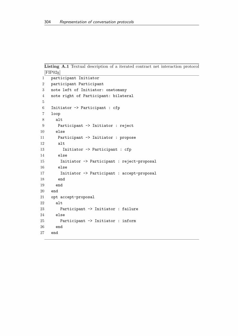
304 Representation of conversation protocols
Listing A.1 Textual description of a iterated contract net interaction protocol[FIP02g]
1 participant Initiator
2 participant Participant
3 note left of Initiator: onetomany
4 note right of Participant: bilateral
56 Initiator -> Participant : cfp
7 loop
8 alt
9 Participant -> Initiator : reject
10 else
11 Participant -> Initiator : propose
12 alt
13 Initiator -> Participant : cfp
14 else
15 Initiator -> Participant : reject-proposal
16 else
17 Initiator -> Participant : accept-proposal
18 end
19 end
20 end
21 opt accept-proposal
22 alt
23 Participant -> Initiator : failure
24 else
25 Participant -> Initiator : inform
26 end
27 end

Representation of conversation protocols 305
Initiator
Initiator
Participant
Participant
onetomany
bilateral
cfp
reject
alt
propose
cfp
alt
reject-proposal
accept-proposal
loop
failure
alt
inform
opt [accept-proposal]
Figure A.1.: Generated sequence diagram of the iterated contract net
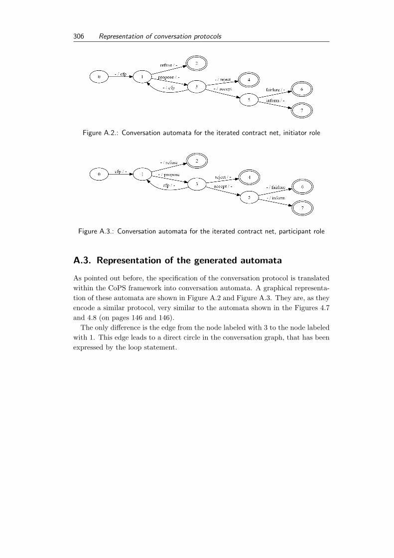
306 Representation of conversation protocols
Figure A.2.: Conversation automata for the iterated contract net, initiator role
Figure A.3.: Conversation automata for the iterated contract net, participant role
A.3. Representation of the generated automata
As pointed out before, the specification of the conversation protocol is translatedwithin the CoPS framework into conversation automata. A graphical representa-tion of these automata are shown in Figure A.2 and Figure A.3. They are, as theyencode a similar protocol, very similar to the automata shown in the Figures 4.7and 4.8 (on pages 146 and 146).
The only difference is the edge from the node labeled with 3 to the node labeledwith 1. This edge leads to a direct circle in the conversation graph, that has beenexpressed by the loop statement.

B. Evaluation Coordination: The SPT
case study
B.1. Task specification
In the following we present the task specification of the practical course “Prak-tikum Wirtschaftsinformatik und Simulation” 1 at the Goethe University, in thewinter term 2009/2010, held by Rene Schumann and Prof. Dr. Ingo J. Timm.
As the teaching language of this course was German, the description is in Ger-man, as well. We give a brief English summary here.
Goods for each order has to be produced, packed and transported. A set oforders is released from the ERP system. For each order the following data isknown name/id, product, quantity, customer location, due date for delivery andcontract penalty per time unit.
For each product a sequence of steps have to be performed. Each step needstime using a resource. For each product it’s volume is known, too. For the givenorders a schedule has to be computed. If a goods has been finished it has to beloaded on loading device. A loading device can store a specific volume of goods.Due to limited space only a limited number of loading devices can be packed inparallel. The loading equipment is transported using trucks for the transport tothe customers. It is possible to spilt an order into partly deliveries. An orderis accomplished if all goods specified in the orders have been delivered to thecustomer. Transportation costs and duraration are linear and known. Truckshave a limited capacity. They start and end their tour in the depot.
These planning systems have to be accessible as web services. Using agenttechnology to implement an integrated planning system.
1Practical course Business Informatics and Simulation
307

Handout
Szenario: Aufträge werden abgearbeitet / produziert und die erstellten Güter anschließend distributiert, d.h. die Waren werden
• Erstellte (Scheduling Problem)
• Verladen (Packproblem)
• Transportiert (TSP)
Eine Menge von Aufträgen wird vom ERP freigegeben. Ein Auftrag umfasst dabei folgende Daten
• Name / ID
• Produkt
• Quantität
• Ziel / Kundenadresse
• Spätester Lieferterim
• Konventionalstrafe per Zeiteinheit
Das ERP kann zu jedem Zeitpunkt weitere Aufträge freigeben. Für jedes Produkt ist die Reihenfolge von Schritten, benötigte Ressourcen und Zeiten sowie dessen Größe als Produktionswissen gegeben. Für die gegebenen Aufträge (Produkt, Quantität) ist ein Plan u erstellen. Ab dem Zeitpunkt der Fertigstellung sind die Waren zu verladen, da keine Bufferfläche zur Verfügung steht. Die Waren werden auf Transporthilfsmittel geladen, die in ausreichender Menge zur Verfügung stehen. Ein Transporthilfsmittel kann zu bis einer fixen Obergrenze beladen werden. DA der Verladeplatz beschränkt ist, können nur eine bestimmte Anzahl an Transporthilfsmitteln parallel beladen werden. Für den Transport stehen eine endliche Zahl von LKWs zur Verfügung. Ist ein Transporthilfsmittel fertig beladen wird es auf einen LKW geladen und der LKW fährt zu den Kunden, die diese Waren geordert haben. Teillieferungen sind möglich. Ein Auftrag ist abgeschlossen, wenn die Waren vollständig ausgeliefert wurden. Die Informationen über die Transportwege liegen als vollständiger Graph vor. Nachdem ein Fahrzeug alle Kunden angefahren hat, kehrt es zum Distributionszentrum zurück und steht für die Durchführung weiterer Transporte zur Verfügung.
Meilensteine Termin Meilenstein 21.10. Vorstellung des Planungsproblem 28.10. Vorstellung der Konzeption für die Lösung des Planungsprobleme 11.11. Abnahmetest des Planungssystems 18.11. Plattformauswahl für WebServices & Dokumentation: Grundlagen WebServices 2.12. Abnahme: Web Service für das Planungssystems

Anschließend werden die WebServices allen Teilnehmern zur Verfügung gestellt. Dies entspricht einem zweiten Projekt bei dem unterschiedliche Ansätze des Integrated Planning realsiert werden sollen. Hierzu wurden unterschiedliche Beratungsfirmen beauftragt, Vorschläge für die Integration der Planungssysteme zu machen und Prototypisch zu realisieren.
Termin Meilenstein 9.12. Vorstellung eines Prototyps eines JADE Agenten 16.12. Vorstellung eines Prototyps für die Nutzung eines Planungs‐ WebServices mittels eines
Agenten 13.1. Vorstellung eines Prototyps für die Agentenkommunikation auf Basis von Ontologien 20.1. Vorstellung der Konzeption des Integrated Planning 10.2. Abnahmetest der Implementierung des Integrated Planning Challange(!)

310 Evaluation Coordination: The SPT case study
B.2. Overview of symbols and formulae for the SPT case
study
In the following the concepts, sets and function definition used in the SPT casestudy are summarized.
Table B.1.: Listing of labels
labels description
r a resourceo = 〈r, d〉 an operationp = 〈we, h,w, o1, . . . , on, <o〉 a productc = 〈x, y〉 a customerd = 〈p, q, c, d, e〉 an orderg = 〈p, d〉 a gooda = 〈o, g, r, s, e〉 an actionf = 〈t, g〉 a finished goodl = 〈m, h,w, d, c〉 a loading devicepl = 〈l,Fpl〉, with l ∈ L packed loading devicerl = 〈rt,Drl〉 ready to ship loading devicest = 〈ca, s, co〉 a trucktl = 〈t,RT tl〉 a truck loadla = 〈s, e, tl, t, tour〉 a loading assignment
Table B.3.: Listing of functions of labelsfunctions description
weight(p) = we weight of an productquan(d) = q quantity of an ordercustomer(d) = c customer of order ddue(d) = d. due of the orderpen(d) = e penalty of the orderorder(g) = d order of a goodproduct(g) = p product of a goodorderD(G, d) = |Gd| number of goods for d

Evaluation Coordination: The SPT case study 311
good(a) = g. good of action a
operation(a) = o operation of action a
start(a) = s start of action a
end(a) = e end of action a
resource(a) = r resource used for agood(f) = g good of a finished goodttime(f) = t time of finishingorder(f) = order(good(f)). order of fcost(l) = c costs of loading deviceitems(pl) = Fpl payload of lmweight(pl) = mw(l) maximal weight of payload of plavailable(pl) = max f∈Fplttime(f) time of availability of plrtime(rl) = rt earliest shipping time of rlcustomer(rl) =
⋃d∈Drl
customer(d) customers contained in rl
costLD(rl) = cost(l) costs of the deviceorders(rl) = Drl orders contained in rl
capa(t) = ca capacity of a truckspeed(t) = s speed of a truckcostspU (t) = co costs per distance of a trucknoelements(tl) = |RT tl| number of elements of tlelements(tl) = RT tl elements of tlrtime(tl) = t time when tl can shippedcustomers(tl) =
⋃rt∈RT tl
customer(rt) customers contained in tl
orders(tl) =⋃
rt∈RT tlorders(rt) orders contained by tl
load(la) = tl truck load of loading assignmenttruck(la) = t truck assigned to lastart(la) = s start of the loading assignmentend(la) = e end of the loading assignmentlength(la) =
∑i=n−1i=1 : dist(ci, ci+1) length of tour
duration(la) = x duration of a tourserviceTime(c, la) = s + duration ′(la) service time of a customerft(d,LAd) = max
la∈LAdserviceTime(c, la) finish time of d
penalty(d,LAd) = x penalty of drtdistance = x distance of round trip for d

312 Evaluation Coordination: The SPT case study
Table B.2.: Listing of used sets
sets description
R set of resourcesO set of all operationsP set of productsC set of customersD set of orderG set of goodsGd set of goods for order dA set of actionsAg partial schedule for gF set of finished goodsL set of types of loading devicesPL package planRL ready for shipment devicesT set of trucksT L set of truck loadsLA set of loading assignmentsLAt plan for a truckLAd lms concerning an element from d
B.3. Data exchange format for the SPT case study

Schnittstellenbeschreibung Version 0.3 Stand: 04.11.09 Bearbeiter: RS
Datenstrukturen: Codierung: <Name:Typ>
Auftragsdaten:
<Name:String>,<Produkt:String>,<Quantität:Int>,<Ziel-x:Int>,<ziel-y:Int>,<due-date:Int>,<penalty:Int>
Produktdaten:
<Name:String>,<Gewicht:Int>,<Hoehe:Int>,<Breite:Int>,<Tiefe:Int>,<op1:String>,<op2:String>,...<opn:String>
Operationsdaten:
<Operations-ID:String>,<Resource:String>,<Dauer:Int>
Resourcendaten:
Die Verfügbarkeit von Ressourcen ist für jeden Tag gleich. Booleans werden mit 1/0 codiert.
<resource-label: String>,<available ze0:Boolean>, .....<available ze95:Boolean>
Ladehilfsmitteldaten
Ladehilfsmittel werden im Folgenden mit Lhm abgekürzt.
<Typ:String>,<maxLoad:Int>,<Hoehe:Int>,<Breite:Int>,<Tiefe:Int>,<Kosten:Int>
Packinformationen
Es gilt das Beladefläche (Fläche für parallel zu bepackende Lhms) + Lagerfläche (Fläche für Warten auf Transport) = Platz für Lhm gesamt
<Platz für Lhm gesamt:Int>,<#beladefläche:Int>,<#lagerfläche:Int>,<kosten pro zwischengelagertem Produkt und Zeiteinheit:Int>
Transporteinheiten (LKW)
In der Entfernungsmatrix ist die Entfernung im Raum angegeben. Die Geschwindigkeit ist notwendig um auf die Zeiteinheiten zu rechnen, die ein Transport benötigt.
<id:String>,<kapazität:Int>,<geschwindigkeit:Int>,<costperkm:Int>

Transportinformationen(Logistik)
<ServiceZeit:Int>, <Anzahl LKW: Int>
Scheduling2Packen
<Zeit:Int>,<produkt1:String>,<Auftrag:String>
Packen2Tour
<Bereitstellungszeit:Int>,<Auftrag1:String>,…,<Auftragn:String>

Evaluation Coordination: The SPT case study 315
B.4. Empirical Evaluation
Inst mean std. dev. # sol. mode min max p-valueInst.1
seq. 595.71 32.27 10 573 560 6602.2e-16
imp. 529.64 62.53 14 485 418 626Inst.2
seq. 3111.36 517.37 9 2736 2701 39132.2e-16
imp. 2124.65 196.68 10 1995 1808 2437Inst.3
seq. 1074.79 69.54 3 1118 963 11202.2e-16
imp. 966.93 41.60 2 955 955 1112Inst.4
seq. 1194.56 119.55 20 1123 986 16092.2e-16
imp. 863.09 57.96 8 805 805 1014Inst.5
seq. 2193.43 78.36 8 2226 1998 24092.2e-16
imp. 1530.56 188.31 17 1558 1249 2284Inst.6
seq. 684 0.0 1 684 684 6840.0
imp. 630 0.0 1 630 630 630Inst.7
seq. 990.35 52.93 3 970 970 11562.2e-16
imp. 901.13 59.35 6 963 832 963Inst.8
seq. 1908.11 658.31 9 1522 1217 41262.2e-16
imp. 1356.15 148.31 13 1217 1217 1730Inst.9
seq. 1507.43 90.21 3 1603 1417 16032.2e-16
imp. 1367.54 128.66 6 1430 1146 1728Inst.10
seq. 1511.43 34.07 2 1534 1460 15342.2e-16
imp. 1115.44 6.14 2 1115 1115 1202Inst.11
seq. 6374.06 2765.46 19 3931 3929 177872.2e-16
imp. 3334.91 813.35 9 3698 2237 4356Inst.12
seq. 1917.79 49.60 3 1959 1834 19592.2e-16
imp. 1689.60 85.75 36 1746 1338 2046Inst.13
seq. 19121.31 19469.86 43 10547 3233 645672.2e-16
imp. 4827.66 4152.75 23 2304 2226 13774Inst.14
seq. 2246.76 80.14 5 2189 2133 23552.2e-16
imp. 1743.11 54.85 4 1722 1722 1903Inst.15
seq. 1808.48 66.38 4 1849 1696 18682.2e-16
imp. 1647.81 132.90 52 1767 1387 1951Inst.16
seq. 5042.80 1183.09 2 4167 4167 66412.2e-16
imp. 2213.45 1033.75 23 1751 1344 3951Inst.17
seq. 10682.27 2848.29 7 7371 7371 140662.2e-16
imp. 3325.09 1234.67 10 4618 2037 4618Inst.18
seq. 1437.20 10.53 10 1444 1355 14452.2e-16
imp. 1263.67 263.27 80 1101 840 1786

316 Evaluation Coordination: The SPT case study
Inst.19
seq. 3471.85 464.77 6 3793 2654 37932.2e-16
imp. 2988.75 179.65 35 3041 2416 4336Inst.20
seq. 9087.10 88.70 3 9132 8883 91322.2e-16
imp. 3132.51 1579.83 8 2380 1923 6246Inst.21
seq. 21005.15 1808.57 21 20609 12567 289570.9269
imp. 21139.91 2305.67 20 21784 13467 22900Inst.22
seq. 13583.39 166.9354 5 13487 13318 13806 9.51e-10imp. 12533.87 5469.62 67 10110 8810 27510
Inst.23
seq. 16309.17 2360.76 4 17562 12491 180712.2e-16
imp. 9756.19 745.83 22 9946 4455 9955Inst.24
seq. 75086.25 6108.25 27 80489 58339 804892.2e-16
imp. 54978.08 4180,80 35 52699 43146 60747Inst.25
seq. 38316.81 22267.95 193 34444 6304 1205102.2e-16
imp. 11607.09 9875.49 115 6456 3949 55403Inst.26
seq. 45653.55 6975.75 57 44860 20491 616822.2e-16
imp. 16626.26 5871,65 54 11117 9836 24139Inst.27
seq. 79522.44 6713.10 4 85396 63423 854152.2e-16
imp. 60376.96 10331,11 8 70452 48239 70452Inst.28
seq. 45937 4046.83 18 44504 36589 526982.2e-16
imp. 35449.65 2895.73 3 37209 24733 37209Inst.29
seq. 48467.67 4836.44 4 47945 29157 479452.2e-16
imp. 16272.82 2804.93 9 16153 10670 22258Inst.30
seq. 53174.97 9858.04 57 65760 15773 664802.2e-16
imp. 16875.16 945,01 59 17910 14692 18452

C. Evaluation Coordination: The SCM
case study
C.1. Overview of symbols and formule for the SCM case
study
Table C.1.: Listing of labels
labels description
t a point in time (pit)a a PAAc a CAnu = 〈An,t, c〉 a networkb a capabilityj = 〈Bj〉 a jobv = 〈Jv, <v〉 a variantp = 〈Vp〉 a producto = 〈ν, p, a, e, d〉 an orderji = 〈o,B,J1,J2e, d〉 an instantiated jobr = 〈ji, a, ν, e, d〉 a proposalm = 〈ji, a1, a2, e, d〉 a commitment
Table C.2.: Listing of used setsset description
A set of PAAC set of CAN set of networksB set of label for capabilitiesBa capabilities of agent aBa,t,ν capabilities offered by a to νBν,t capabilites of ν
317

318 Evaluation Coordination: The SCM case study
Jν jobs of a networkVν variants of a networkJpre,v,j predecessor of j in v
Jsuc,v,j successors of j in v
Pν products of νO set of ordersOν,t orders of network νOa,t orders of agent aJ ia,t instantiated jobs of aJ iν,t instantiated jobs of νACji,t candidates of ji
Rji,t proposals of ji
Ra,t proposals of aM set of commitmentsMa,t commitments of aMRa,t commitments of representative aMa,ν,t commitments of a towards νMν,t commitments of νMo,t commitments belonging to o
Table C.3.: Listing of functionsfunction description
is member(a, ν) = {true, false} is a member of νn c(ν) = c CA of νn active(ν) = {true, false} is ν activeb hasa(Ba, t) = Ba,t capabilities for ab allowa(Ba,t, ν, t) = Ba,t,ν capabilities a offers to νj b(j) = Bj capabilities required for jj pre(v, j) = Jpre,v,j predecessor of jj suc(v, j) = Jsuc,v,j successors of jv j (v) = Jv jobs of vp var(p) = Vp variants of po ν(o) = ν network of oo rep(o) = a representative of oo pro(o) = p product of oo start(o) = e earliest start of oo end(o) = d due date of o

Evaluation Coordination: The SCM case study 319
o active(o) = {true, false} is order activeo ref (o) = v variant for oj inst(j, o) = ji instantiated jobj i o(ji) = o order ji
j i ν(ji) = o ν(j i o(ji)) network of ji
j i rep(ji) = o rep(j i o(ji)) representative of ji
j i b(ji) = B capabilities for ji
j i jd(ji) = J1 jobs ji depends onj i js(ji) = J2 jobs depend on ji
j i start(ji) = e start of ji
j i due(ji) = d due of ji
j i t alc(ji, a, t) = {true, false} can ji allocated at ar cand(p) = a candidate of rr j i(p) = ji instantiated job of rr start(r) = e start of rr due(r) = d due of rr sel(Rji,t, o) = r proposal to realize om pres(m) = a1 commitment presenter of mm rec(m) = a2 commitment receiver of mm j i(m) = ji instantiated job of mm start(m) = e start of mm due(m) = d due of mm active(m) = {true, false} is commitment activem gen(r) = m generates proposal mm find(ji,Mν,t) = m finds m for ji
m comp(Mo,t, o) = {true, false} are commitments for o completeo beg(Mo,t) = x beginning of oo end(M o, t, d) = x end of om con(Mo,t, o) is set of commitments consistento eval(M o, t, o) = x evaluates execution of oν eval(Mν,t,Oν,t) = x evaluates performance of ν

320 Evaluation Coordination: The SCM case study
Table C.4.: Listing of events
event comment
decommit(m) the commitment m is decommitedchange commitment(m,m′) request to change m into m′
task tender(ji) : a commitment for ji is searchedorder new(d) a new order d arrivesorder rem(d) remove order dorder change(d, d′) order d is changed to d′.agent enter(n) agent a enters network nagent leave(n) agent a leaves network n

D. Implementation and evaluation data
The code and its input and resulting output data is included in this thesis inform of a CD. The content of the CD is presented briefly here. On the top leveldirectory of the CD one can find two folders, Implementation and Evaluation.
D.1. Implementation
In the Implementation all code used in the implementation and the CoPS frame-work is provided. All programs are written in Java. The agent-based developmentframework JADE is used for the implementation of agents, expect the agents ofthe ABACO approach, that are implemented as Java threads. The code is at-tached as an Eclipse project. Eclipse is a widely-used IDE, which has been usedhere as well. This allows an easier access and structuring of the attached code.
In the Implementation folder exist three sub-folders CoPS, Case-Study1, andCase-Study2. In the CoPS folder the implementation of the CoPS framework andan additional study for the handling of multiple conversations among agents (inthe folder agent folder) can be found.
In the folder Case-Study1 the implementation of the planning systems forscheduling (SchedulingSource folder), packing (packing-source folder) andtransportation (Tourenplanung-Src-2 folder) can be found. Moreover, the sce-nario generator (SPT-Scenario-Generator folder) and the implementation of thedifferent coordination approaches (newCoordination folder), are attached.
In the folder Case-Study2 the implementation of the ABACO approach (ABACOfolder) and the competing heuristics, the scenario generator, and the generatorfor the MPL files (heuristic folder) can be found. The ABACO approach needsan MySQL database and additional system libraries that can be found in theABACO project folder as well. Detailed instructions for the needed localizationof the ABACO approach can be found in the README file in the project folder.
D.2. Evaluation
In the Evaluation folder on the top-level of the CD the input data and resultingoutputs used in the evaluation are provided. All data is provided in form of
321

322 Evaluation Coordination: The SCM case study
text files. Included are also the R-scripts, diagrams, and Excel files used for thestatistical evaluation of the data. For the second case study the input and outputfiles of the MPL Modeling System are provided, additionally.
For each case study one sub-folder can be found. For the first case study,presented in Section 5 the input and output data is provided in folder eval-part1.Data for the second case study (Section 6) is organized in folder eval-part2.