HAZOP Report.pdf - Environment Agency
29
Hudson Consultants Ltd 511A London Road Davenham Northwich Cheshire CW9 8NA Tel: 07879 608616 E-mail: [email protected] Date: 18 th June 2019 Company no. 5573113 VAT. No. 868395267 To: HAZOP team – Brenntag HAZOP Report – Brenntag Lutterworth – Clorious 2 production project rev 2 – May 2019 This note summarises the discussions and HAZOP for the Brenntag Lutterworth – Clorious project carried out during a Lutterworth site visit in June 15. It has been amended to rev 1 following a visit to Brenntag Duisburg (Germany) on the 21 st July 2015. The visit report has been included as appendix 6. Following an extended delay, the project has restarted in 2019. The intention is to produce Clorious in the site new multi product filling plant. Several meetings have been carried out in April & May 2019 to discuss this. This HAZOP report rev 2 has been updated (in blue) based on the available information and knowledge. It is recommended that the team reconvene in say June/July 19 to review and update as further information becomes available. HAZOP Chairman’s report A multi-disciplinary team carried out the HAZOP over 1 day. The team represented an adequate range of skills and knowledge required for a HAZOP study. The documentation available is listed below. Each document was reviewed along with all previous correspondence. A visit was carried out to Brenntag Duisburg on the 21/7/15 to allow this HAZOP study to be completed – see action 1. The documentation that records the HAZOP is included. All guidewords on the attached HAZOP checklist were considered for each stage. All parameters & associated deviations were recorded. This allows the HAZOP record to be a full reporting method. Actions have been listed below from both the documentation review and the HAZOP. It is important that all actions are formally responded to (i.e. actioned). Therefore, the HAZOP study is not considered complete until all actions have been signed off. The HAZOP record sheet must be completed to demonstrate this.
-
Upload
khangminh22 -
Category
Documents
-
view
0 -
download
0
Transcript of HAZOP Report.pdf - Environment Agency

Hudson Consultants Ltd
511A London Road
Davenham
Northwich
Cheshire
CW9 8NA
Tel: 07879 608616
E-mail: [email protected]
Date: 18th June 2019 Company no. 5573113
VAT. No. 868395267
To: HAZOP team – Brenntag
HAZOP Report – Brenntag Lutterworth – Clorious 2 production project rev 2 – May
2019
This note summarises the discussions and HAZOP for the Brenntag Lutterworth –
Clorious project carried out during a Lutterworth site visit in June 15. It has been
amended to rev 1 following a visit to Brenntag Duisburg (Germany) on the 21st July
2015. The visit report has been included as appendix 6.
Following an extended delay, the project has restarted in 2019. The intention is to
produce Clorious in the site new multi product filling plant. Several meetings have been
carried out in April & May 2019 to discuss this. This HAZOP report rev 2 has been
updated (in blue) based on the available information and knowledge. It is recommended
that the team reconvene in say June/July 19 to review and update as further information
becomes available.
HAZOP Chairman’s report
A multi-disciplinary team carried out the HAZOP over 1 day. The team represented an
adequate range of skills and knowledge required for a HAZOP study.
The documentation available is listed below. Each document was reviewed along with all
previous correspondence.
A visit was carried out to Brenntag Duisburg on the 21/7/15 to allow this HAZOP study
to be completed – see action 1.
The documentation that records the HAZOP is included. All guidewords on the attached
HAZOP checklist were considered for each stage. All parameters & associated deviations
were recorded. This allows the HAZOP record to be a full reporting method.
Actions have been listed below from both the documentation review and the HAZOP. It
is important that all actions are formally responded to (i.e. actioned). Therefore, the
HAZOP study is not considered complete until all actions have been signed off. The
HAZOP record sheet must be completed to demonstrate this.

Documents Considered
1. Brenntag Clorious – Description of production process v4.0 dated 2/5/17
2. P&IDs
a. 21292-07-0001AB01 - 25M3 Multi Product Blending P&ID
b. 21292-07-0003AB01 - Fume & Dust Scrubber P&ID
c. 21292-07-0011AB01 - Multi Product Filling P&ID
3. Brenntag European HSE Manual – Standard Procedure: Handling of Clorious2 ref
HSE_SP2.05_10 rev 0 dated 22/8/14
4. Clorious Material Specifications - Sodium Persulphate, Sodium Chlorite Solutions and
utilities
5. Brenntag MSDS - Sodium Chlorite Solution 10-25% v5.1 dated 6/9/13
6. Brenntag MSDS - Sodium Persulphate v4 dated 6/7/12
Actions (updated following the visit to Brenntag Duisburg on the 21/7/15 – see
appendix 6 for more details)
No. Action Update May 19
1 Visit the Clorious 2 plant at Brenntag Duisburg to gain a greater
understanding of the process, potential hazards and measures in place
to prevent, control & mitigate the hazards. This will then allow this
HAZOP to be completed. Include the following considerations:
• Does overheating of the Sodium Persulphate matter? Is there an
influence on the potential generation of ClO2 within the package?
This will determine the controls/interlocks required for heating.
Overheating is not considered to be a significant factor on the
potential generation of ClO2. It is considered good practice
though to heat the water on addition to the vessel and have a high
temperature trip – see action 9
• The Sodium Chlorite is added first to the drum/pack and then the
Sodium Persulphate. Does it matter if they are added
simultaneously or in reverse order? Is there an influence on the
potential generation of ClO2 within the package? This will
determine the controls/interlocks required for addition (i.e.
interlock between the 2 addition pumps or fill sequence etc).
The order of addition or if they are added together is not
considered to be a significant factor on the potential generation of
ClO2.
• How likely is ClO2 release when a drum is opened? Are exposure
limits likely to be breached without protection?
After the drum is filled, there is negligible generation of ClO2. In
any case, there is extraction. Release of ClO2 is more probable
during sampling – see actions.
• What are the other potential factors that could influence the
release of ClO2? For example:
o Sodium Chlorite concentration
o Sodium Chlorite quantity added
o Sodium Persulphate concentration
o Sodium Persulphate quantity added
Confirm high
temp trip on
multi product
blending tank

The main factor influencing the potential generation of ClO2 is the
concentration of Sodium Chlorite – see actions
2 Consider the Sodium Persulphate powder form and the potential for
dust when transferring into the mixing vessel. If an issue consider
purchasing a form that generates less dust or, if not possible, assess
what personnel protection is required i.e. LEV, RPE etc.
Not considered to be an issue due to the nature of the material used.
Complete
3 Prepare a Functional Design Specification (FDS) for the project
which is to include:
• Design of batch flowmeters to achieve accuracy requirements
(not required as propose to gravity fill)
• Design/location of batch filling systems (including data entry
limitations to minimise human failure)
• Provision of a local temperature gauge on the Sodium Persulphate
vessel to allow the operator to monitor the temperature prior to
adding Sodium Persulphate powder.
• Provision of emergency stops (location and function – LEV to be
kept operational)
• Interlock the agitator operation to a minimum vessel level i.e.
avoid agitator/vessel damage if run dry.
To be reviewed
Confirm high
level trip on
multi product
blending tank
will stop IBC
filling
4 Consider filling the Clorious package (i.e. drum/pack) on weigh
scales to allow overflow protection to be included.
Yes this is confirmed to be required.
Not required as
Permex system
considered
adequate
5 Consider filling the Clorious drum/pack via the dispensing system
(see supporting ref 9). This would have the potential advantage of
eliminating the step of removing the filling system and installing the
dispensing system after the drum/pack has been filled. This is of
significance as there is a potential for operator exposure to Chlorine
Dioxide fumes. It is believed that the DrumQuik Pro system has a
check valve such that when the filling coupler is removed after
filling, fume is prevented from being released whilst the plug is
inserted (to be confirmed).
Not possible – see appendix 6.
Not possible
6 Ensure that the scrubber operation is interlocked with the fill systems
(both Sodium Chlorite & Sodium Persulphate transfer pumps). The
scrubber package needs to be specified however typically the
interlock can be linked to the scrubber fan and the scrubber liquid
recirc (pump/flow).
To be done
7 Consider designing the effluent system to be self-contained (rather
than linking the system to the adjacent alkaline effluent system).
Spillages should be rare and rainwater ingress is minimised by the
use of a canopy. Any contaminated effluent can be collected and
transferred for waste disposal.
To be checked
8 Modify the site emergency plan to incorporate the required response
to potential incidents on this plant. Include the potential for spillage
and the provision of Sodium Bisulphite to ‘neutralise’ ClO2 and the
actions in the event of a ClO2 gas release.
To be done

9 Modify the P&ID to include the following changes (as well as some
of the actions above):
• Remove the lute arrangement on both vessels as they only require
an atmospheric vent.
• Sodium Persulphate vessel – add an air connection to the bottom
outlet in the event of powder build up and potential blockage.
• Heat the Demin water feed to the Sodium Persulphate vessel.
There should be an independent high temperature cut out on the
water (set at approx 45°C). Remove the heating element from the
vessel
• Sodium Chlorite vessel as HDPE
• Gravity feed both Sodium Persulphate & Sodium Chlorite into
the drum/keg on a weigh scale using batch feed systems with auto
close.
• Include both pH monitoring of the scrubber and the monitoring of
the scrubber recirculation flow. If both are out of range (pH < 8.5
and flow < set point to be determined) then the fill systems will
not be operational.
See action 6 re
scrubber
monitoring and
interlock
10 Modify the site layout to include the following changes:
• Sump to be moved away from the area where the operator is
filling the drum/pack.
• Scrubber to be located on opposite side (east rather than west
side) as this is the closest side to the point sources
No longer
relevant
11 Select the Clorious drum/pack storage location. The potential
requirement for refrigerated storage (to extend ‘shelf life’) to be
considered.
To be done
12 Consider the methodology of sampling. There is a potential for ClO2
exposure during this operation. Consider if there is a more inherently
safe option.
To be done
13 Develop a design for drum laundry plant taking into account the
Duisburg experience. Things to consider:
• Sodium Bisulphite IBC to have vapour extraction to scrubber on
vent (just in case the Sodium Bisulphite is consumed)
• Vapour extraction to be provided around where the drum is
handled (as ClO2 may be emitted from the nozzles when opened.
Carry out a HAZOP of this proposed design.
No longer
relevant as no
drum laundry.
Only new drums
to be used.
14 Consider the Sodium Chlorite dilution system design to minimise the
potential for ensuring that a diluted solution of 2.77% is achieved.
This may include the use of a batch dilution system that requires
water to be added prior to allowing the drum fill system to become
active. It will also require sampling and lab analysis to pass off the
batch prior to being used for drum fill.
Consider
controls to
check that
imported IBCs
are correct conc
15 Extraction system – ensure that the capacity is sufficient to withdraw
ClO2 vapours from the drum nozzle which would be generated if a
25% Sodium Chlorite solution was used to fill drums.
To be done

Appendix 1 - HAZOP RECORD SHEET
1. Complete this section before starting the study
Business: Brenntag Location: Lutterworth
HAZOP Ref: rev 2 HAZOP Title: Clorious project
Description (areas included) See below
Senior manager responsible: Rob Bagshaw HAZOP champion Rob Bagshaw
2. Complete this section at the start of the study
Study leader: Andrew Hudson Scribe: Andrew Hudson
Method used for scribing: Typed File name: Brenntag Lutterworth
Clorious project HAZOP report May 19 rev 2
Team members : Job title/function:
Andrew Hudson – Hudson Consultants Ltd – Hazop Chair & scribe
Alistair Hunter – Brenntag Leeds
Rob Bagshaw – Brenntag Lutterworth Ops Mgr.
Andrew Leach – Brenntag Lutterworth
Gareth Dobinson – Brenntag Leeds
Aneeb Chaudhry – Brenntag Leeds
Study dates: 2/6/15 & 21/7/15 & May 19
3. Complete this section when study is finished
Study checked for completion and logic ( )
HAZOP champion (responsible for follow up) Rob Bagshaw
Study approved for issue (signed study leader): ……………….. Date:
Study sheets issued ( ) Action sheets issued ( ) Date:
4. Sign off when ALL actions complete
All actions complete ( )
Signed (HAZOP champion): ……………………….. Date:
Audit complete (if requested): Date:
Signed (Senior manager): …………………………..
Please send a copy of this sheet with Parts 1 and 2 complete to A Hudson

HAZOP Study No. : Brenntag Lutterworth Clorious project HAZOP report May 19 rev
2
Date: 2/6/15 & 21/7/15 & May 19
Meeting No. : As dates
Team:
Andrew Hudson – Hudson Consultants Ltd – Hazop Chair & scribe
Alistair Hunter – Brenntag Leeds
Rob Bagshaw – Brenntag Lutterworth Ops Mgr.
Andrew Leach – Brenntag Lutterworth
Gareth Dobinson – Brenntag Leeds
Aneeb Chaudhry – Brenntag Leeds
Documentation:
1. Brenntag Clorious – Description of production process v4.0 dated 2/5/17
2. P&IDs
a. 21292-07-0001AB01 - 25M3 Multi Product Blending P&ID
b. 21292-07-0003AB01 - Fume & Dust Scrubber P&ID
c. 21292-07-0011AB01 - Multi Product Filling P&ID
3. Brenntag European HSE Manual – Standard Procedure: Handling of Clorious2 ref
HSE_SP2.05_10 rev 0 dated 22/8/14
4. Clorious Material Specifications - Sodium Persulphate, Sodium Chlorite Solutions and
utilities
5. Brenntag MSDS - Sodium Chlorite Solution 10-25% v5.1 dated 6/9/13
6. Brenntag MSDS - Sodium Persulphate v4 dated 6/7/12
Section/Stage:
The system was dealt with as 3 nodes to allow further study to sufficient detail.
Node 1: Sodium Chlorite solution addition to blending tank and filling to drum
Node 2: Sodium Persulphate solution preparation in blending tank
Node 3: Sodium Persulphate solution addition to drum to generate Clorious product
(including LEV/scrubber)
Description of operation:
The purpose of the proposed plant is to produce 0.65% Chlorine Dioxide (ClO2) in
solution by the oxidation of Sodium Chlorite solution using Sodium Persulphate solution.
There are 2 grades of Clorious 2 – 6000ppm & 2000ppm. The most common grade is
6000ppm and the quantities/concentrations quoted are for this grade.
The reaction occurs within the package that is filled (200l drum) i.e. there is no
intermediate reactor. The package is capped and left for a pre-determined period
(typically 4 days) over which the reaction occurs between the two components producing
Clorious solution. There is a unit in operation since December 2012 at Brenntag Duisburg
which was visited on the 21/7/15 to help understand better the process and potential
hazards. The visit report is in appendix 6.
Node 1: Sodium Chlorite solution addition to blending tank and filling to drum
Sodium Chlorite (approx concentration of 2.65%) is transferred from imported IBCs into
the 25m3 Multi product blending tank TK-21-001. The quantity transferred is the required
amount for the final Clorious batch. The tank has high level switching which is
interlocked to a valve in line to prevent tank overfilling. The blending tank is also
equipped with level instrumentation. The vessel is located in a bund sized for at least
110% of the contents. The blending tank is agitated when the minimum level is reached.
Approx 65 Kg of Sodium Chlorite solution is transferred to each drum via the multi-
product package filling system (Permex). This is pumped via pump P-21-001 to the drum
using a totalising mass flow meter. The addition is shutoff automatically when the 65Kg
is completed. There is also independent high level protection which shuts off the filling
system.
Node 2: Sodium Persulphate solution preparation in blending tank
Sodium Persulphate powder is used to manufacture a Sodium Persulphate solution with
warm water. The powder is dissolved in the 25m3 Multi product blending tank TK-21-
001, with agitator into deionised water, heated to 40°C. This process is endothermic with
water temperature lowering to approximately 20°C during the solutionising process. The
blending tank is located in a bund sized for at least 110% of the contents. The vessel has a
platform around the top to allow a pallet of bags to be lifted and located on the platform.
This will then allow the operator to open the manway and ‘rip and tip’.
Deionised water is pumped into the mixing vessel, through a batch meter into the mixing
tank. The blending tank has high level switching which is interlocked to a valve in line to
prevent overfilling. The blending tank is also equipped with level instrumentation.
On completion of the warm water batching, the powder is manually added to the vessel
and the mix agitated for a period of 2 hours or until the solution is clear.
Sodium Persulphate dust is not thought to present a hazard of a dust explosion. It has
been checked for the potential for a dust explosion via the German insurance database:
http://www.dguv.de/ifa/en/gestis/index.jsp and the MSDS. Both sources do not consider a
dust explosion risk to be credible.
Node 3: Sodium Persulphate solution addition to drum to generate Clorious product
(including LEV/scrubber)
Approx 143 Kg of Sodium Persulphate solution is transferred to each drum via the multi-
product package filling system (Permex). This is pumped via pump P-21-001 to the drum
using a totalising mass flow meter. The addition is shutoff automatically when the 65Kg
is completed. There is also independent high level protection which shuts off the filling
system. Only virgin drums/packs are to be used.
LEV is provided at the filling head and used to remove any potential Chlorine Dioxide
fume. Fume is extracted to a scrubber unit filled with Caustic Soda – see actions.
The following quantities are added per drum:
• 65 Kg Sodium Chlorite premix
• 143 Kg Sodium Persulphate premix

Each batch will be sampled and analysed to ensure that the correct quantities/
concentrations are being added (see actions)
Four drums are stored on a pallet and strapped into position – see appendix 4. The storage
location is to be determined – see actions
Any spills / wash down water is collected in a sump in the filling area. LEV is provided
above the sump in the filling area in case of inadvertent mixing of the 2 raw materials and
the generation of chlorine dioxide fume.
Chlorine Dioxide toxicity is quoted within the HSE document EH40/2005 Workplace
exposure limits:
• Long-term exposure limit (8-hr TWA reference period) – 0.1 ppm
• Short-term exposure limit (15 min reference period) – 0.3 ppm

APPENDIX 2 - HAZOP CHECKLIST
Node
See HAZOP Record Parameter Deviation
(Guide word and
parameter)
Flow No flow Less flow More flow Reverse flow Later flow Sooner flow Where else
Pressure More pressure Less pressure
Temperature More temperature Less temperature
Level Greater level Lower/less level
Viscosity More viscous Less viscous
Composition Missing
component
Extra component Different/wrong
stream
Contamination Extra phase
Sequence Step omitted Step shorter Step longer Wrong step/order
Other Start-up Shut-down Relief system Power/service
failure
Corrosion/erosion Materials of
construction
Toxic/asphyxia Maintenance
(isolation etc)
Double valves
(trapped liqs)
Valve access Instruments, trips,
testing
Fire Static electricity Noise Ionising radiations Sampling Thermal radiation Spares
What else

APPENDIX 3 - HAZOP 3 – RECORD
Date 2/6/15 & 21/7/15 & May 19
Team As front sheet
Section/Stage 1 – Sodium Chlorite solution addition to blending tank and filling to drum
Design intention
Sodium Chlorite (approx concentration of 2.65%) is transferred from imported IBCs into the 25m3 Multi product blending tank TK-21-
001. The quantity transferred is the required amount for the final Clorious batch. The tank has high level switching which is interlocked to a
valve in line to prevent tank overfilling. The blending tank is also equipped with level instrumentation. The vessel is located in a bund sized
for at least 110% of the contents. The blending tank is agitated when the minimum level is reached.
Approx 65 Kg of Sodium Chlorite solution is transferred to each drum via the multi-product package filling system (Permex). This is
pumped via pump P-21-001 to the drum using a totalising mass flow meter. The addition is shutoff automatically when the 65Kg is
completed. There is also independent high level protection which shuts off the filling system.
Guide
word
Deviation Cause Consequence Safeguards No Action
FLOW No Sodium
Chlorite
flow
Valves closed
IBC low level/empty
Batch flow meter
error
Lack of addition to
vessel and preparation
of a weak Sodium
Chlorite solution.
Batch flowmeter would
register the lack of Sodium
Chlorite addition
Vessel level would not
increase.
Less As per no flow
More
Sodium
Chlorite
flow
Human error in
adding additional
IBCs
Extra addition to
vessel leading to
overflow
Potential for increased
ClO2 generation &
operator exposure
Vessel level would show a
high level and alarm
3
Consider action of high
LS on blending tank
Reverse Not considered
credible as Sodium
Chlorite added into
the top of the mixing
vessel

Where else Leak from system Spillage to ground.
Potential splash to
operatives in area.
Oxidiser & classified
as dangerous to the
environment.
Bunded area with self -
contained effluent system.
If say spray exited from area
then leak into site surface
water system. This passes
into the site drains to an oil
interceptor before passing
through a Penstock valve pit
and into an offsite drain
7
8
Effluent system design
Emergency Plan
PRESSU
RE
More Transfer pump is
deadheaded
Potential spill – see
flow where else
Line is capable of
withstanding max pressure
Less See no/less flow
TEMP. More No issues envisaged
Less Low ambient
temperature
Potential freezing
albeit Sodium Chlorite
freeze pt. at 10-25% is
-10°C
System would be drained
when not in use and
potential freezing conditions
LEVEL High Vessel overfill due to
too much Sodium
Chlorite addition (see
more flow)
Potential overflow
into bunded area – see
flow where else
Vessel contents level alarm
Independent high level
switch
3 Consider action of high
LS on blending tank
Low See low/no flow Potential damage to
agitator if started
when not immersed
Low level interlock with
agitator
VISCOSI
TY
More No issues envisaged
Less No issues envisaged
COMPOS
ITION
Missing No issues envisaged
Extra comp No issues envisaged
Diff/wrong
stream
Potential for wrong
IBC to be positioned
Generation of ClO2
gas from mixing
vessel if acid added
Site procedures/training to
ensure close control of
incompatibles
Cont. No issues envisaged
Extra phase No issues envisaged

SEQUEN
CE
Step Omitted No issues envisaged
Step Shorter No issues envisaged
Step Longer No issues envisaged
Wrong Step/
Order
No issues envisaged
OTHER Start-up No issues envisaged
Shut-down No issues envisaged
Relief
system
Not applicable
Power/servic
e failure
No issues envisaged
Corrosion/
erosion
Potential for leak Materials considered
appropriate
Materials of
construction
Potential for leak Materials considered
appropriate
Toxic/asphy
xia
See diff/wrong
stream
Maintenance
(isolation
etc)
No issues envisaged
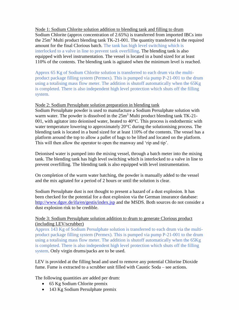
Double
valves
(trapped
liqs)
No issues envisaged
Valve access No issues envisaged
Instruments,
trips, testing
No issues envisaged To be part of site
systems
Fire No issues envisaged As Sodium Chlorite is
an Oxidiser if
decomposed it can
contribute to a fire.
Lack of
flammables/combustibles in
area
Static
electricity
No issues envisaged

Noise No issues envisaged
Ionising
radiations
No issues envisaged
Sampling No issues envisaged
Thermal
radiation
No issues envisaged
Spares No issues envisaged
What else No issues envisaged

Date 2/6/15 & 21/7/15 & May 19
Team As front sheet
Section/Stage 2 – Sodium Persulphate solution preparation in blending tank
Design intention. Sodium Persulphate powder is used to manufacture a Sodium Persulphate solution with warm water. The powder is
dissolved in the 25m3 Multi product blending tank TK-21-001, with agitator into deionised water, heated to 40°C. This process is
endothermic with water temperature lowering to approximately 20°C during the solutionising process. The blending tank is located in a
bund sized for at least 110% of the contents. The vessel has a platform around the top to allow a pallet of bags to be lifted and located on
the platform. This will then allow the operator to open the manway and ‘rip and tip’.
Deionised water is pumped into the mixing vessel, through a batch meter into the mixing tank. The blending tank has high level switching
which is interlocked to a valve in line to prevent overfilling. The blending tank is also equipped with level instrumentation.
On completion of the warm water batching, the powder is manually added to the vessel and the mix agitated for a period of 2 hours or until
the solution is clear.
Sodium Persulphate dust is not thought to present a hazard of a dust explosion. It has been checked for the potential for a dust explosion via
the German insurance database:
http://www.dguv.de/ifa/en/gestis/index.jsp and the MSDS. Both sources do not consider a dust explosion risk to be credible.
Guide
word
Deviation Cause Consequence Safeguards No Action
FLOW No water
flow
No Sodium
Persulphate
flow
Valves closed
Lack of supply
Batch flow meter
error
Operator failed to
add
Lack of water addition
to blending tank and
preparation of a
concentrated Sodium
Persulphate solution
Lack of addition to
blending tank and
preparation of a weak
Sodium Persulphate
solution.
Batch flowmeter would
register the lack of water
addition
Blending tank level would
not increase
Persulphate is in excess
within the drum so not
considered to be a factor on
the rate of generation of
ClO2.
Blending tank level would
not increase.

Less As per no flow
More water
flow
More
Sodium
Persulphate
flow
Batch flow meter
error or human error
in input
Human error in input
i.e. too many bags
added
Additional water
addition to blending
tank and preparation
of a weak Sodium
Persulphate solution
Extra addition to
vessel and preparation
of a concentrated
Sodium Persulphate
solution
Blending tank level would
show a high level
Blending tank level would
show a high level.
Persulphate is in excess
within the drum so not
considered to be a factor on
the rate of generation of
ClO2.
Reverse Not considered
credible water added
into the top of the
mixing vessel
Where else Leak from system Spillage to ground.
Potential splash to
operatives in area.
Oxidiser
Bunded area with self -
contained effluent system.
If say spray exited from area
then leak into site surface
water system. This passes
into the site drains to an oil
interceptor before passing
through a Penstock valve pit
and into an offsite drain
7
8
Effluent system design
Emergency Plan
PRESSU
RE
More No issues envisaged
Less See no/less flow
TEMP. More Water in tank can be
> 40°C if
heater/thermostat
fails
Potential hot solution
of Sodium Persulphate
in vessel
High Persulphate
temperature is not
considered to be a

significant factor on the rate
of generation of ClO2.
Less Lack of heating
Low ambient
temperature
Potential freezing
System would be drained
when not in use and
potential freezing conditions
LEVEL High Vessel overfill due to
too much
water/Sodium
Persulphate addition
(see more flow)
Potential overflow
into bunded area – see
flow where else
Vessel contents level alarm
Independent high level
switch leading to closure of
water addition valve.
Low See low/no flow Potential damage to
agitator if started
when not immersed
3 Prepare a FDS
VISCOSI
TY
More No issues envisaged
Less No issues envisaged
COMPOS
ITION
Missing No issues envisaged
Extra comp No issues envisaged
Diff/wrong
stream
Potential for wrong
bagged powder to be
positioned
Potential Safety &
Quality issues
Site procedures/training to
ensure close control of
incompatibles
Cont. No issues envisaged
Extra phase No issues envisaged
SEQUEN
CE
Step Omitted Potential to not add
water or Sodium
Persulphate
See no/more flow
Step Shorter Potential to add less
water or Sodium
Persulphate
Persulphate is in
excess within the
drum so not
considered to be a
factor on the rate of
generation of ClO2.
Use of a batch meter for
water and procedures

Step Longer Potential to add more
water or Sodium
Persulphate
Persulphate is in
excess within the
drum so not
considered to be a
factor on the rate of
generation of ClO2.
Use of a batch meter for
water and procedures
Wrong Step/
Order
Potential to add
Sodium Persulphate
then water
No issues envisaged
OTHER Start-up No issues envisaged
Shut-down No issues envisaged
Relief
system
Not applicable
Power/servic
e failure
No issues envisaged
Corrosion/
erosion
No issues envisaged Use of Stainless Steel
Materials of
construction
No issues envisaged Use of Stainless Steel
Toxic/asphy
xia
See diff/wrong
stream
Dust exposure
Extreme high
temperature i.e. can
mean Sodium
Persulphate will
decompose and emit
Sulphur oxides gases
Operator exposure can
lead to health issues
Lack of
flammables/combustibles in
area
Operational experience
shows that dust is not an
issue.
Maintenance
(isolation
etc)
No issues envisaged
Double
valves
(trapped
liqs)
No issues envisaged
Valve access No issues envisaged
Instruments,
trips, testing
No issues envisaged To be part of site
systems
Fire No issues envisaged As Sodium
Persulphate is an
Oxidiser if
decomposed it can
contribute to a fire.
Lack of
flammables/combustibles in
area
Sodium Persulphate dust is
not considered to be
flammable and create an
explosion.
Static
electricity
No issues envisaged
Noise No issues envisaged
Ionising
radiations
No issues envisaged
Sampling No issues envisaged
Thermal
radiation
No issues envisaged
Spares No issues envisaged
What else No issues envisaged

Date 2/6/15 & 21/7/15 & May 19
Team As front sheet
Section/Stage 3 – Sodium Persulphate solution addition to drum to generate Clorious product (including LEV/scrubber)
Design intention. Approx 143 Kg of Sodium Persulphate solution is transferred to each drum via the multi-product package filling system
(Permex). This is pumped via pump P-21-001 to the drum using a totalising mass flow meter. The addition is shutoff automatically when
the 65Kg is completed. There is also independent high level protection which shuts off the filling system. Only virgin drums/packs are to be
used.
LEV is provided at the filling head and used to remove any potential Chlorine Dioxide fume. Fume is extracted to a scrubber unit filled
with Caustic Soda – see actions.
The following quantities are added per drum:
• 65 Kg Sodium Chlorite premix
• 143 Kg Sodium Persulphate premix
Each batch will be sampled and analysed to ensure that the correct quantities/ concentrations are being added (see actions)
Four drums are stored on a pallet and strapped into position – see appendix 4. The storage location is to be determined – see actions
Any spills / wash down water is collected in a sump in the filling area. LEV is provided above the sump in the filling area in case of
inadvertent mixing of the 2 raw materials and the generation of chlorine dioxide fume.
Chlorine Dioxide toxicity is quoted within the HSE document EH40/2005 Workplace exposure limits:
• Long-term exposure limit (8-hr TWA reference period) – 0.1 ppm
• Short-term exposure limit (15 min reference period) – 0.3 ppm
Guide
word
Deviation Cause Consequence Safeguards No Action
FLOW No Sodium
Persulphate
flow
No
extraction
system flow
Valves closed
Lack of supply
Batch meter error
Extraction fan failure
Quality issues
Potential for operator
exposure to ClO2
Batch system would register
the lack of addition
6
15
Extraction system
interlocks
Less As per no flow
More
Sodium
Persulphate
flow
Batch meter error or
human error in input
Persulphate is in
excess within the
drum so not
considered to be a
High level trip on filling
system
Extraction system to
scrubber

factor on the rate of
generation of ClO2.
Reverse Not considered
credible as materials
added separately
Where else Leak from system Spillage to ground.
Potential splash to
operatives in area.
Potential for localized
ClO2 generation if
both materials come
into contact
Area with self - contained
effluent system.
If say spray exited from area
then leak into site surface
water system. This passes
into the site drains to an oil
interceptor before passing
through a Penstock valve pit
and into an offsite drain
Sump has LEV to scrubber
system
7
8
6
Effluent system design
Emergency Plan
Scrubber interlocks
PRESSU
RE
More Increased pressure on
transfer pump due to
dead head
Drum pressure
increases
Leak from system –
see flow where else
Potential drum failure
Pump discharge has
spillback to ensure the
material is recycled to the
tank.
Less See no/less flow
TEMP. More Potential hot solution
of Sodium
Persulphate fed to
drum (see node 2)
Storage of Clorious
drums in hot ambient
conditions
Increased rate of
degradation
11
Consider package storage
location & refrigeration

Less Low ambient
temperature
Potential freezing System would be drained
when not in use and
potential freezing conditions
LEVEL High Package overfill due
to too much Sodium
Chlorite/Sodium
Persulphate addition
(see more flow)
Potential overflow
into vent
High level trip on filling
system
Low See low/no flow
VISCOSI
TY
More No issues envisaged
Less No issues envisaged
COMPOS
ITION
Missing Lack of caustic
within scrubbing
system
Release of unscrubbed
air to atmosphere
Regular checking of caustic
strength (as per site
procedures)
6
15
Extraction system
interlocks
Extra comp No issues envisaged
Diff/wrong
stream
Potential for wrong
materials to be made
in vessels
Potential Safety &
Quality issues
Site procedures/training to
ensure close control of
incompatibles
Use of LEV & scrubber
system
6
Design LEV/scrubber
interlocks
Cont. No issues envisaged
Extra phase No issues envisaged
SEQUEN
CE
Step Omitted Potential to not add
Sodium Chlorite or
Sodium Persulphate
Step Shorter Potential to add less
Sodium Chlorite or
Sodium Persulphate
Use of a batch meters
Step Longer Potential to add more
Sodium Chlorite or
Sodium Persulphate
Use of a batch meters

Wrong Step/
Order
Potential to add
Sodium Persulphate
then Sodium Chlorite
OTHER Start-up No issues envisaged
Shut-down No issues envisaged
Relief
system
Not applicable
Power/servic
e failure
No issues envisaged
Corrosion/
erosion
No issues envisaged Use of Stainless Steel
Materials of
construction
No issues envisaged Use of Stainless Steel
Toxic/asphy
xia
See diff/wrong
stream
Generation of ClO2
and release when
changing over from
filling system to
dispensing system
ClO2 generation is
negligible at the end of
drum fill.
Extraction system to
scrubber
Maintenance
(isolation
etc)
No issues envisaged
Double
valves
(trapped
liqs)
No issues envisaged
Valve access No issues envisaged
Instruments,
trips, testing
No issues envisaged To be part of site
systems
Fire No issues envisaged
Static
electricity
No issues envisaged
Noise No issues envisaged
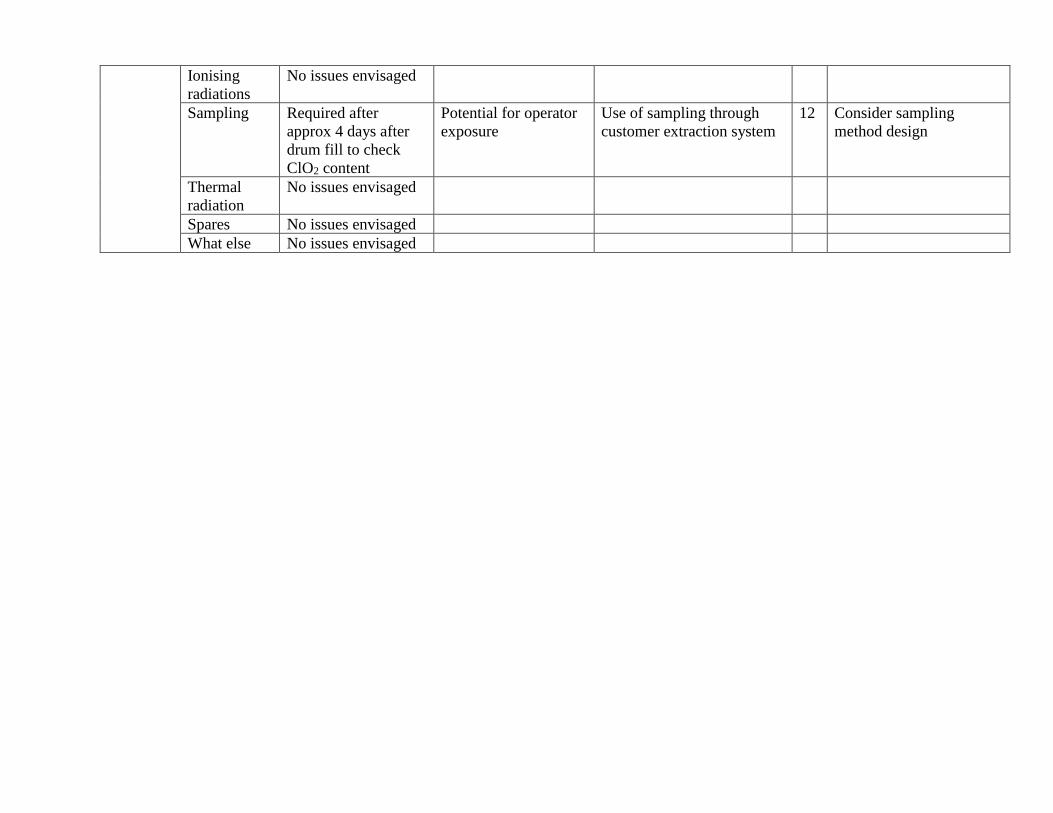
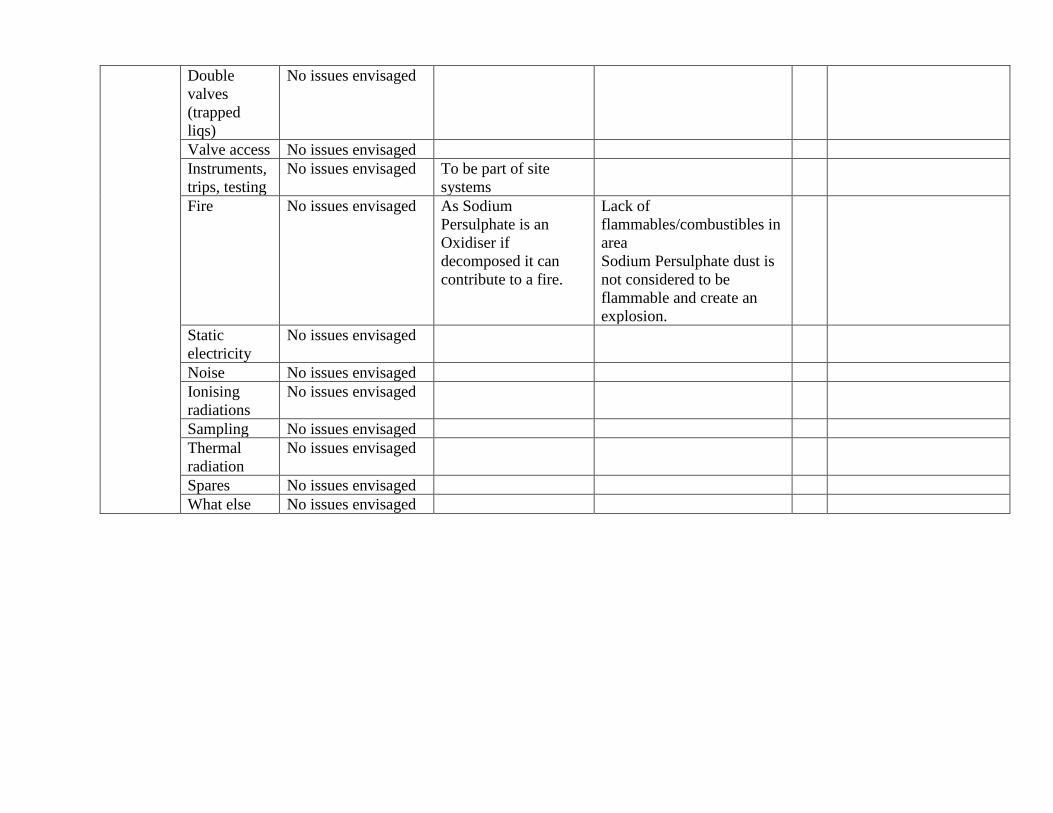
Ionising
radiations
No issues envisaged
Sampling Required after
approx 4 days after
drum fill to check
ClO2 content
Potential for operator
exposure
Use of sampling through
customer extraction system
12 Consider sampling
method design
Thermal
radiation
No issues envisaged
Spares No issues envisaged
What else No issues envisaged

Appendix 4 – Photographs from site visit
Clorious drum showing nozzle that is used for filling/emptying
Pallet with 4 Clorious 2 drums

Appendix 5 – Past Accidents/Incidents
LPB216 Dec 2010 - Walkers fined after man killed by toxic gas
Food giant Walkers Snack Foods Ltd and chemical distributor Omnichem Ltd have been fined a
total of £350,000 after a worker died four years ago following exposure to a cloud of chlorine
dioxide fumes. The Health and Safety Executive (HSE) said that the worker was driving a lorry
containing four steel tanks, two with sodium chlorite and two containing hydrochloric acid, to the
Walkers’ site in Leicester. Both chemicals are used in Walkers’ starch reclamation unit, which
turns waste starch into food-grade material used to make snack foods. The worker inadvertently
mixed up the hoses on the tanks while transferring the two chemicals from the lorry, causing them
to produce chlorine dioxide fumes. When he realised his error, he stopped the transfer and began
to hose the area down, but he was already starting to be affected by the toxic gas. Although the
worker was taken to hospital, his condition gradually deteriorated, and he died from the effects of
the gas a month later.
The investigation uncovered a catalogue of serious failings, including:
• Insufficient written procedures for deliveries and receipt of chemicals, and insufficiently
labelled tanks.
• Employees who had tried to help did not know the type of operation that was being carried out,
nor the nature of the gas being released. They had no appropriate training and they had no idea
what to do.
• It took about an hour after the appearance of the gas cloud for Walkers to realise the severity of
the situation and evacuate employees from the area.
• There were no planned evacuation procedures for a chemical emergency at this location.

Appendix 6 Visit Report – Brenntag Duisburg 21/7/15
Hudson Consultants Ltd
511A London Road
Davenham
Northwich
Cheshire
CW9 8NA
Tel: 07879 608616
e-mail: [email protected]
Date: 24th July 2015
Company no. 5573113
VAT. No. 868395267
To: Chris Gilheaney, Rob Bagshaw,
Cc: Gareth Dobinson, Alistair Hunter
Brenntag Duisburg – Visit Note
A visit was made to the Brenntag Duisburg site on the 21/7/15 to vie the existing Clorious
production facility on the site and discuss with the site team the actions identified from the
HAZOP carried out. In addition, there were delegations from Brenntag Holland and Hungary as
they are looking to install Clorious production facilities as well.
The meeting was hosted by Dominic Schenk – Clorious Commercial Director. The Duisburg site
operational, chemistry and QA staff were also present.
Background
The production of Clorious on the Duisburg site started in December 2012. The method of
production was developed based on existing site equipment.
Summary of learning points from discussion & site visit
1. Sodium Persulphate – grade of product bought is important if the Clorious product is to be
used in drinking water
2. Sodium Persulphate – dust is not an issue. The material is granular in nature. The vessel used
for charging has limited sign of dust deposits.

3. Sodium Persulphate – heated water is added to the vessel (rather than the vessel being heated).
This just aids the dissolution of the solid into water. See actions.
4. The conductivity of the demin water used should be less than 5microS.
5. The grade of stainless steel used for the Sodium Persulphate vessel is not considered to be
important.
6. Sodium Chlorite – the minimum concentration required is 2.77% to achieve 0.65% ClO2 in
the final product.
7. Sodium Chlorite – recommend the use of HDPE as the material of construction for the vessel
– see actions
8. Sodium Persulphate & Sodium Chlorite – vessels are gravity fed into the drum/keg on a weigh
scale using batch feed systems with auto close – see actions
9. Drum customer extraction system – these are added into the drum after the 2 materials are
added. It is not considered possible to fill through this system as there is a one way valve and
also the opening would be too small and would severely limit flow.
The red cap shows the customer extraction system has
been installed.
10. Vapour extraction is used but is only required as a precaution – the filled drum was opened
and only a very faint smell could be detected

The shroud around the Sodium Persulphate fill nozzle is the
vapour extraction system. The vapours are pulled via a fan to an
alkaline scrubber which is kept at a minimum pH of 8.5 – see
actions
11. The reaction between 2.77% Sodium Chlorite and an excess of Sodium Persulphate to form
0.65% Chlorine Dioxide solution (Clorious) is slow. It is not considered to be complete before
3 days. The drums are therefore sampled and analysed on day 4 after fill to ensure reaction
completion.
12. Sampling: Each produced batch is sampled and analysed for ClO2 concentration. The first,
middle and last drums are sampled only. The sample is taken from the customer extraction
system by using a pump into a glass jar. Standard PPE and a gas mask are used during
sampling – see actions.
13. Drum storage – a container is used which is air conditioned to a temperature of 15-20°C – see
actions.
14. Accidents/Incidents – none reported. Only issue has been low batch ClO2 concentration which
has been corrected by aiming for 0.65% rather than 0.6%. Lowest observed was 0.57%.
15. Drums are laundered prior to disposal – procedure has been developed which comprises of
• Pump out residual ClO2 via customer extraction system into IBC of Sodium
Bisulphite solution
• Add water into drum via other nozzle
• Pump out until clear
• IBC starts to discolour to yellow when the Sodium Bisulphite is consumed
See actions
16. Spillage – the filling/laundry areas are contained with any spillage routed to a sump. Sodium
Bisulphite is available to treat any spillage. The effluent would be treated and sent to the site
effluent neutralisation plant.
17. ClO2 generation rate – the main factor that would probably significantly increase the initial
rate of ClO2 generation would be if concentrated Sodium Chlorite was used to feed the drum.
As 25% is imported and diluted to 2.77% then this is a credible cause – see actions.
Agreed Actions

1. Modify the P&ID/Process Description to heat the Demin water feed to the Sodium
Persulphate vessel. There should be an independent high temperature cut out on the water (set
at approx 45°C). Remove the heating element from the vessel.
2. Modify the P&ID/Process Description to show the Sodium Chlorite vessel as HDPE
3. Modify the P&ID/Process Description to gravity feed both Sodium Persulphate & Sodium
Chlorite into the drum/keg on a weigh scale using batch feed systems with auto close. The
batch weighing systems to have maximum set points allowable to limit fill quantity which
could lead to drum/keg quality issue/overfill. To allow gravity feed the vessels will have to be
supported on steelwork to give sufficient head.
4. Modify the P&ID/Process Description to include both pH monitoring of the scrubber and the
monitoring of the scrubber recirculation flow. If both are out of range (pH < 8.5 and flow <
set point to be determined) then the fill systems will not be operational.
5. Consider the methodology of sampling. There is a potential for ClO2 exposure during this
operation. Consider if there is a more inherently safe option.
6. Consider the requirement for cool storage for Clorious drums in summer
7. Develop a design for drum laundry taking into account the Duisburg experience. Things to
consider:
• Sodium Bisulphite IBC to have vapour extraction to scrubber on vent (just in case
the Sodium Bisulphite is consumed)
• Vapour extraction to be provided around where the drum is handled (as ClO2 may
be emitted from the nozzles when opened.
8. Consider the Sodium Chlorite dilution system design to minimise the potential for ensuring
that a diluted solution of 2.77% is achieved. This may include the use of a batch dilution
system that requires water to be added prior to allowing the drum fill system to become active.
It will also require sampling and lab analysis to pass off the batch prior to being used for drum
fill.
9. Extraction system – ensure that the capacity is sufficient to withdraw ClO2 vapours from the
drum nozzle which would be generated if a 25% Sodium Chlorite solution was used to fill
drums.
Conclusion
The visit was extremely useful to answer the preliminary Clorious HAZOP questions. The way
the production method has evolved were explained which will help prevent repeating past
mistakes i.e. using a vessel to store Clorious prior to filling in a drum.