Hardware/software co-design of a real-time kernel based tracking system
10
Hardware/software co-design of a real-time kernel based tracking system Usman Ali * , Mohammad Bilal Malik Department of Electrical Engineering, College of Electrical and Mechanical Engineering, National University of Sciences and Technology, Pakistan article info Article history: Received 30 September 2009 Received in revised form 28 April 2010 Accepted 29 April 2010 Available online 10 May 2010 Keywords: Mean shift Tracking Embedded FPGA Co-design Real-time abstract The probabilistic visual tracking methods using color histograms have been proven to be robust to target model variations and background illumination changes as shown by the recent research. However, the required computational cost is high due to intensive image data processing. The embedded solution of such algorithms become challenging due to high computational power demand and algorithm complex- ity. This paper presents a hardware/software co-design architecture for implementation of the well- known kernel based mean shift tracking algorithm. The design uses color histogram of the target as track- ing feature. The target is searched in the consecutive images by maximizing the statistical match of the color distributions. The target localization is based on gradient based iterative search instead of exhaus- tive search which makes the system capable of achieving frame rate up to hundreds of frames per second while tracking multiple targets. The design, which is fully standalone, is implemented on a low-cost med- ium-size field programmable gate array (FPGA) device. The hardware cost of the design is compared with some other tracking systems. The performance of the system in terms of speed is evaluated and com- pared with the software based implementation. It is expected that the proposed solution will find its util- ity in applications like embedded automatic video surveillance systems. Ó 2010 Elsevier B.V. All rights reserved. 1. Introduction Object tracking is used in various vision based applications such as smart cameras, tracking of potential targets in forward-looking infrared (FLIR) imagery, monitoring of suspicious activities in auto- mated video surveillance systems, guidance of vehicles in auto- mated vehicle control systems, target localization in unmanned aerial vehicles and face tracking etc. Several effective techniques exist that are widely used for vision based tracking applications such as particle filters [1], mean shift [2] and optical flow [3]. Ob- ject tracking is among the computationally most intensive image processing tasks [4]. Researchers have provided personal computer (PC) based solutions for these algorithms but the need of a compact and standalone system employing these algorithms is preferred in many physically deployed systems. The hardware implementation of these algorithms is a non-trivial task that may contain various combinations of sub-modules such as digital signal processors (DSP), graphic processor units (GPU), field programmable gate ar- rays (FPGA) and application specific integrated circuits (ASIC). FPGAs are one of the emerging technologies that provide designers ability to quickly create standalone digital systems. For software implementation within the embedded system, FPGA vendors are now providing configurable soft processor cores that can be synthesized on their FPGAs. Therefore, by taking benefit of both parallel and sequential processing, FPGA’s prove to be a good choice for hardware implementation of real-time tracking applications. In general, visual tracking algorithms are classified into two cat- egories specified as bottom-up and top-down approaches [2,5]. Fil- tering and data association [6] is a top-down approach. The objects detected in each frame are represented by points and object dynamics, e.g., position and motion are encoded as a state vector. The objective is to estimate the object state in current frame by associating the observed points with previous object state. The points association can be deterministic or stochastic. These algo- rithms rely on the object dynamics and are suited for tracking very small objects that can be represented by a single point [5]. The target representation and localization is a bottom-up ap- proach. The target is represented by an appearance or shape based model, known as kernel. The kernel can be rectangular or elliptical with an associated histogram. Objects are tracked in consecutive frames by estimating the motion of the kernel. The kernel motion estimation can be gradient based [2] or dynamical model based [1]. These algorithms are robust to background variations and partial occlusions as they use more descriptive features of the target, e.g., color histogram or texture. Mean shift [2] is a popular tracking algorithm of this category that is computationally efficient [4]. It is a non-parametric kernel based density gradient estimator [7] that iteratively converges to the local maxima of the similarity function. The normalized color histogram of the object is used as appearance 1383-7621/$ - see front matter Ó 2010 Elsevier B.V. All rights reserved. doi:10.1016/j.sysarc.2010.04.008 * Corresponding author. E-mail addresses: [email protected] (U. Ali), [email protected]. pk (M.B. Malik). Journal of Systems Architecture 56 (2010) 317–326 Contents lists available at ScienceDirect Journal of Systems Architecture journal homepage: www.elsevier.com/locate/sysarc
Transcript of Hardware/software co-design of a real-time kernel based tracking system
Journal of Systems Architecture 56 (2010) 317–326
Contents lists available at ScienceDirect
Journal of Systems Architecture
journal homepage: www.elsevier .com/ locate /sysarc
Hardware/software co-design of a real-time kernel based tracking system
Usman Ali *, Mohammad Bilal MalikDepartment of Electrical Engineering, College of Electrical and Mechanical Engineering, National University of Sciences and Technology, Pakistan
a r t i c l e i n f o
Article history:Received 30 September 2009Received in revised form 28 April 2010Accepted 29 April 2010Available online 10 May 2010
Keywords:Mean shiftTrackingEmbeddedFPGACo-designReal-time
1383-7621/$ - see front matter � 2010 Elsevier B.V. Adoi:10.1016/j.sysarc.2010.04.008
* Corresponding author.E-mail addresses: [email protected] (U. A
pk (M.B. Malik).
a b s t r a c t
The probabilistic visual tracking methods using color histograms have been proven to be robust to targetmodel variations and background illumination changes as shown by the recent research. However, therequired computational cost is high due to intensive image data processing. The embedded solution ofsuch algorithms become challenging due to high computational power demand and algorithm complex-ity. This paper presents a hardware/software co-design architecture for implementation of the well-known kernel based mean shift tracking algorithm. The design uses color histogram of the target as track-ing feature. The target is searched in the consecutive images by maximizing the statistical match of thecolor distributions. The target localization is based on gradient based iterative search instead of exhaus-tive search which makes the system capable of achieving frame rate up to hundreds of frames per secondwhile tracking multiple targets. The design, which is fully standalone, is implemented on a low-cost med-ium-size field programmable gate array (FPGA) device. The hardware cost of the design is compared withsome other tracking systems. The performance of the system in terms of speed is evaluated and com-pared with the software based implementation. It is expected that the proposed solution will find its util-ity in applications like embedded automatic video surveillance systems.
� 2010 Elsevier B.V. All rights reserved.
1. Introduction
Object tracking is used in various vision based applications suchas smart cameras, tracking of potential targets in forward-lookinginfrared (FLIR) imagery, monitoring of suspicious activities in auto-mated video surveillance systems, guidance of vehicles in auto-mated vehicle control systems, target localization in unmannedaerial vehicles and face tracking etc. Several effective techniquesexist that are widely used for vision based tracking applicationssuch as particle filters [1], mean shift [2] and optical flow [3]. Ob-ject tracking is among the computationally most intensive imageprocessing tasks [4]. Researchers have provided personal computer(PC) based solutions for these algorithms but the need of a compactand standalone system employing these algorithms is preferred inmany physically deployed systems. The hardware implementationof these algorithms is a non-trivial task that may contain variouscombinations of sub-modules such as digital signal processors(DSP), graphic processor units (GPU), field programmable gate ar-rays (FPGA) and application specific integrated circuits (ASIC).FPGAs are one of the emerging technologies that provide designersability to quickly create standalone digital systems. For softwareimplementation within the embedded system, FPGA vendors arenow providing configurable soft processor cores that can be
ll rights reserved.
li), [email protected].
synthesized on their FPGAs. Therefore, by taking benefit of bothparallel and sequential processing, FPGA’s prove to be a goodchoice for hardware implementation of real-time trackingapplications.
In general, visual tracking algorithms are classified into two cat-egories specified as bottom-up and top-down approaches [2,5]. Fil-tering and data association [6] is a top-down approach. The objectsdetected in each frame are represented by points and objectdynamics, e.g., position and motion are encoded as a state vector.The objective is to estimate the object state in current frame byassociating the observed points with previous object state. Thepoints association can be deterministic or stochastic. These algo-rithms rely on the object dynamics and are suited for tracking verysmall objects that can be represented by a single point [5].
The target representation and localization is a bottom-up ap-proach. The target is represented by an appearance or shape basedmodel, known as kernel. The kernel can be rectangular or ellipticalwith an associated histogram. Objects are tracked in consecutiveframes by estimating the motion of the kernel. The kernel motionestimation can be gradient based [2] or dynamical model based [1].These algorithms are robust to background variations and partialocclusions as they use more descriptive features of the target,e.g., color histogram or texture. Mean shift [2] is a popular trackingalgorithm of this category that is computationally efficient [4]. It isa non-parametric kernel based density gradient estimator [7] thatiteratively converges to the local maxima of the similarity function.The normalized color histogram of the object is used as appearance
318 U. Ali, M.B. Malik / Journal of Systems Architecture 56 (2010) 317–326
model and Bhattacharyya coefficient [8] is used as similaritymeasure between target and candidate models. The experimentalresults presented in Ref. [2] show the efficiency of the algorithmby handling scale changes, target rotation and foreground/back-ground variations.
Color histogram models for target tracking have gained popu-larity in the computer vision community due to its robustness inbackground light and target model varying conditions. However,due to high computational power demand and complexity, itsembedded hardware implementation is rarely addressed. Severalresearchers have provided FPGA embedded solution for real-timetracking based on different tracking algorithms. The authors inRefs. [9,10] have described the FPGA based implementation ofLucas and Kanade’s optical flow algorithm. Kristensen et al. imple-mented the tracking system based on segmentation and morpho-logical operations [11]. Arias-Estrada and Rodriguez-Palacios [12]designed a coprocessor employing a tracking algorithm based onHausdorff distance [13]. Cho et al. presented FPGA based objecttracking system using image subtraction and particle filter [14].Li and Xiao proposed a Graphical Processing Unit (GPU) based par-allel mean shift tracking algorithm that works in conjunction withstandard personal computer (PC) [15]. Cho et al. presented FPGAbased tracking system using adaptive color histograms usingexhaustive search [16].
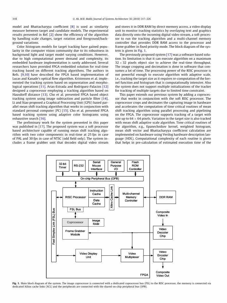
The preliminary work for the system presented in this paperwas published in [17]. The proposed system was a soft processorbased architecture capable of running mean shift tracking algo-rithm with two color components in real-time at 25 fps in caseof PAL and 30 fps in case of NTSC (odd field only). The system in-cludes a frame grabber unit that decodes digital video stream
Fig. 1. Main block diagram of the system. The image coprocessor is connected with a ddedicated Xilinx cache links (XCL) and the peripherals are connected with the shared on
and stores it in DDR RAM by direct memory access, a video displayunit to monitor tracking statistics by overlaying text and graphicsdata directly onto the incoming digital video stream, a soft proces-sor to run the tracking algorithm and a multi-channel memorycontroller that provides DDR RAM access to the processor andframe grabber in fixed priority mode. The block diagram of the sys-tem is given in Fig. 1.
The previously proposed system [17] was a software based solu-tion. Its limitation is that it can execute algorithm on a maximum32 � 32 pixels object size to achieve the real-time throughput.The image cropping and decimation is done in software that con-sumes a lot of time. The processing power of the RISC processor isnot powerful enough to execute algorithm with adaptive scale,i.e., tracking the target size as it requires re-computation of the ker-nel function and histogram that is computationally intensive. Alsothe system does not support multiple initializations of the trackerfor tracking of multiple targets due to limited time constraint.
This paper extends our previous system by adding a coproces-sor that works in conjunction with the soft RISC processor. Thecoprocessor crops and decimates the capturing image in hardwareand accelerates the computation of time critical routines of meanshift tracking algorithm using parallel processing and pipeliningon the FPGA. The coprocessor supports tracking of a target withsize up to 64 � 64 pixels. Variation in the target size is also trackedwith mean shift adaptive scale algorithm. Time critical routines ofthe algorithm, e.g., Epanechnikov kernel, weighted histogram,mean shift vector and Bhattacharyya coefficient calculation areimplemented on hardware using Verilog hardware description lan-guage (HDL). Computational complexity of each routine is giventhat helps in pre-calculation of estimated execution time of the
edicated coprocessor bus (FSL) to the RISC processor, the memory is connected via-chip peripheral bus (OPB).
U. Ali, M.B. Malik / Journal of Systems Architecture 56 (2010) 317–326 319
algorithm per frame. The performance of the system in terms ofspeed and tracking accuracy is evaluated.
2. Design approach
While implementing a hardware/software co-design of a com-plicated algorithm, design partitioning and verification methodol-ogy are crucial steps for the designer. Verification of softwarebased designs is easy but verification of VLSI based designs in chal-lenging because there is hardly any tolerance for bugs in thehardware.
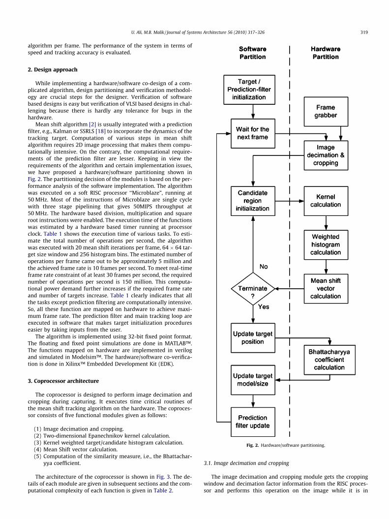
Mean shift algorithm [2] is usually integrated with a predictionfilter, e.g., Kalman or SSRLS [18] to incorporate the dynamics of thetracking target. Computation of various steps in mean shiftalgorithm requires 2D image processing that makes them compu-tationally intensive. On the contrary, the computational require-ments of the prediction filter are lesser. Keeping in view therequirements of the algorithm and certain implementation issues,we have proposed a hardware/software partitioning shown inFig. 2. The partitioning decision of the modules is based on the per-formance analysis of the software implementation. The algorithmwas executed on a soft RISC processor ‘‘Microblaze”, running at50 MHz. Most of the instructions of Microblaze are single cyclewith three stage pipelining that gives 50MIPS throughput at50 MHz. The hardware based division, multiplication and squareroot instructions were enabled. The execution time of the functionswas estimated by a hardware based timer running at processorclock. Table 1 shows the execution time of various tasks. To esti-mate the total number of operations per second, the algorithmwas executed with 20 mean shift iterations per frame, 64 � 64 tar-get size window and 256 histogram bins. The estimated number ofoperations per frame came out to be approximately 5 million andthe achieved frame rate is 10 frames per second. To meet real-timeframe rate constraint of at least 30 frames per second, the requirednumber of operations per second is 150 million. This computa-tional power demand further increases if the required frame rateand number of targets increase. Table 1 clearly indicates that allthe tasks except prediction filtering are computationally intensive.So, all these function are mapped on hardware to achieve maxi-mum frame rate. The prediction filter and main tracking loop areexecuted in software that makes target initialization procedureseasier by taking inputs from the user.
The algorithm is implemented using 32-bit fixed point format.The floating and fixed point simulations are done in MATLAB™.The functions mapped on hardware are implemented in verilogand simulated in Modelsim™. The hardware/software co-verifica-tion is done in Xilinx™ Embedded Development Kit (EDK).
Fig. 2. Hardware/software partitioning.
3. Coprocessor architecture
The coprocessor is designed to perform image decimation andcropping during capturing. It executes time critical routines ofthe mean shift tracking algorithm on the hardware. The coproces-sor consists of five functional modules given as follows:
(1) Image decimation and cropping.(2) Two-dimensional Epanechnikov kernel calculation.(3) Kernel weighted target/candidate histogram calculation.(4) Mean Shift vector calculation.(5) Computation of the similarity measure, i.e., the Bhattachar-
yya coefficient.
The architecture of the coprocessor is shown in Fig. 3. The de-tails of each module are given in subsequent sections and the com-putational complexity of each function is given in Table 2.
3.1. Image decimation and cropping
The image decimation and cropping module gets the croppingwindow and decimation factor information from the RISC proces-sor and performs this operation on the image while it is in
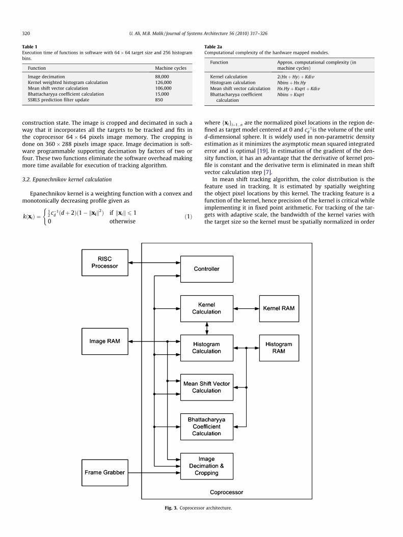
Table 1Execution time of functions in software with 64 � 64 target size and 256 histogrambins.
Function Machine cycles
Image decimation 88,000Kernel weighted histogram calculation 126,000Mean shift vector calculation 106,000Bhattacharyya coefficient calculation 15,000SSRLS prediction filter update 850
Table 2aComputational complexity of the hardware mapped modules.
Function Approx. computational complexity (inmachine cycles)
Kernel calculation 2ðHxþ HyÞ þ KdivHistogram calculation Nbinsþ Hx:HyMean shift vector calculation Hx:Hyþ Ksqrt þ KdivBhattacharyya coefficient
calculationNbinsþ Ksqrt
320 U. Ali, M.B. Malik / Journal of Systems Architecture 56 (2010) 317–326
construction state. The image is cropped and decimated in such away that it incorporates all the targets to be tracked and fits inthe coprocessor 64 � 64 pixels image memory. The cropping isdone on 360 � 288 pixels image space. Image decimation is soft-ware programmable supporting decimation by factors of two orfour. These two functions eliminate the software overhead makingmore time available for execution of tracking algorithm.
3.2. Epanechnikov kernel calculation
Epanechnikov kernel is a weighting function with a convex andmonotonically decreasing profile given as
kðxiÞ ¼12 c�1
d ðdþ 2Þð1� kxik2Þ if kxik 6 10 otherwise
(ð1Þ
Fig. 3. Coprocesso
where fxigi¼1...n are the normalized pixel locations in the region de-fined as target model centered at 0 and c�1
d is the volume of the unitd-dimensional sphere. It is widely used in non-parametric densityestimation as it minimizes the asymptotic mean squared integratederror and is optimal [19]. In estimation of the gradient of the den-sity function, it has an advantage that the derivative of kernel pro-file is constant and the derivative term is eliminated in mean shiftvector calculation step [7].
In mean shift tracking algorithm, the color distribution is thefeature used in tracking. It is estimated by spatially weightingthe object pixel locations by this kernel. The tracking feature is afunction of the kernel, hence precision of the kernel is critical whileimplementing it in fixed point arithmetic. For tracking of the tar-gets with adaptive scale, the bandwidth of the kernel varies withthe target size so the kernel must be spatially normalized in order
r architecture.
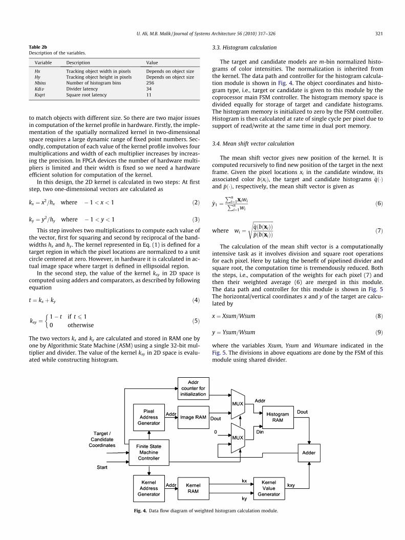
Table 2bDescription of the variables.
Variable Description Value
Hx Tracking object width in pixels Depends on object sizeHy Tracking object height in pixels Depends on object sizeNbins Number of histogram bins 256Kdiv Divider latency 34Ksqrt Square root latency 11
U. Ali, M.B. Malik / Journal of Systems Architecture 56 (2010) 317–326 321
to match objects with different size. So there are two major issuesin computation of the kernel profile in hardware. Firstly, the imple-mentation of the spatially normalized kernel in two-dimensionalspace requires a large dynamic range of fixed point numbers. Sec-ondly, computation of each value of the kernel profile involves fourmultiplications and width of each multiplier increases by increas-ing the precision. In FPGA devices the number of hardware multi-pliers is limited and their width is fixed so we need a hardwareefficient solution for computation of the kernel.
In this design, the 2D kernel is calculated in two steps: At firststep, two one-dimensional vectors are calculated as
kx ¼ x2=hx where � 1 < x < 1 ð2Þ
ky ¼ y2=hy where � 1 < y < 1 ð3Þ
This step involves two multiplications to compute each value ofthe vector, first for squaring and second by reciprocal of the band-widths hx and hy. The kernel represented in Eq. (1) is defined for atarget region in which the pixel locations are normalized to a unitcircle centered at zero. However, in hardware it is calculated in ac-tual image space where target is defined in ellipsoidal region.
In the second step, the value of the kernel kxy in 2D space iscomputed using adders and comparators, as described by followingequation
t ¼ kx þ ky ð4Þ
kxy ¼1� t if t 6 10 otherwise
�ð5Þ
The two vectors kx and ky are calculated and stored in RAM one byone by Algorithmic State Machine (ASM) using a single 32-bit mul-tiplier and divider. The value of the kernel kxy in 2D space is evalu-ated while constructing histogram.
Fig. 4. Data flow diagram of weighte
3.3. Histogram calculation
The target and candidate models are m-bin normalized histo-grams of color intensities. The normalization is inherited fromthe kernel. The data path and controller for the histogram calcula-tion module is shown in Fig. 4. The object coordinates and histo-gram type, i.e., target or candidate is given to this module by thecoprocessor main FSM controller. The histogram memory space isdivided equally for storage of target and candidate histograms.The histogram memory is initialized to zero by the FSM controller.Histogram is then calculated at rate of single cycle per pixel due tosupport of read/write at the same time in dual port memory.
3.4. Mean shift vector calculation
The mean shift vector gives new position of the kernel. It iscomputed recursively to find new position of the target in the nextframe. Given the pixel locations xi in the candidate window, itsassociated color bðxiÞ, the target and candidate histograms qð�Þand pð�Þ, respectively, the mean shift vector is given as
y1 ¼Pn
i¼1xiwiPni¼1wi
ð6Þ
where wi ¼
ffiffiffiffiffiffiffiffiffiffiffiffiffiffiffiffiffiqðbðxiÞÞpðbðxiÞÞ
sð7Þ
The calculation of the mean shift vector is a computationallyintensive task as it involves division and square root operationsfor each pixel. Here by taking the benefit of pipelined divider andsquare root, the computation time is tremendously reduced. Boththe steps, i.e., computation of the weights for each pixel (7) andthen their weighted average (6) are merged in this module.The data path and controller for this module is shown in Fig. 5The horizontal/vertical coordinates x and y of the target are calcu-lated by
x ¼ Xsum=Wsum ð8Þ
y ¼ Ysum=Wsum ð9Þ
where the variables Xsum, Ysum and Wsumare indicated in theFig. 5. The divisions in above equations are done by the FSM of thismodule using shared divider.
d histogram calculation module.
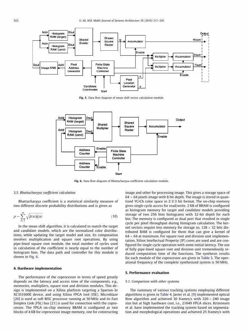
Fig. 5. Data flow diagram of mean shift vector calculation module.
Fig. 6. Data flow diagram of Bhattacharyya coefficient calculation module.
322 U. Ali, M.B. Malik / Journal of Systems Architecture 56 (2010) 317–326
3.5. Bhattacharyya coefficient calculation
Bhattacharyya coefficient is a statistical similarity measure oftwo different discrete probability distributions and is given as
q ¼Xm
u¼1
ffiffiffiffiffiffiffiffiffiffiffiffiffiffiffiffiffiffiffipðuÞqðuÞ
qð10Þ
In the mean shift algorithm, it is calculated to match the targetand candidate models, which are the normalized color distribu-tions, while updating the target model and size. Its computationinvolves multiplication and square root operations. By usingpipe-lined square root module, the total number of cycles usedin calculation of the coefficient is nearly equal to the number ofhistogram bins. The data path and controller for this module isshown in Fig. 6.
4. Hardware implementation
The performance of the coprocessor in terms of speed greatlydepends on the latency and access time of the components, e.g.,memories, multipliers, square root and division modules. This de-sign is implemented on a Xilinx platform targeting a Spartan-3eXC3S1600E device, and using Xilinx FPGA tool (ISE). Microblaze[20] is used as soft RISC processor running at 50 MHz and its FastSimplex Link (FSL) bus [21] is used for connection with the copro-cessor. The FPGA on-chip memory BRAM is configured as twoblocks of 4 KB for coprocessor image memory, one for constructing
image and other for processing image. This gives a storage space of64 � 64 pixels image with 8 bit depth. The image is stored in quan-tized YCrCb color space in 2:3:3 bit format. The on-chip memorygives single cycle access for read/write. 2 KB of BRAM is configuredas histogram memory for target and candidate models providingstorage of two 256 bins histograms with 32-bit depth for eachbin. The memory is configured as dual port that resulted in singlecycle per pixel throughput during histogram calculation. The ker-nel vectors require less memory for storage so, 128 � 32 bits dis-tributed RAM is configured for them that can give a kernel of64 � 64 at maximum. For square root and division unit implemen-tation, Xilinx Intellectual Property (IP) cores are used and are con-figured for single cycle operation with some initial latency. The useof fully pipe-lined square root and division unit tremendously re-duced computation time of the functions. The synthesis resultsfor each module of the coprocessor are given in Table 3. The oper-ational frequency of the complete synthesized system is 50 MHz.
5. Performance evaluation
5.1. Comparison with other systems
The summary of various tracking systems employing differentalgorithms is given in Table 4. Javier et al. [9] implemented opticalflow algorithm and achieved 30 frames/s with 320 � 240 imagesize but at high hardware cost, i.e., 21649 FPGA slices. Kristensenet al. have implemented the tracking system based on segmenta-tion and morphological operations and achieved 25 frames/s with
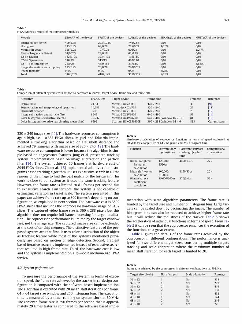
Table 3FPGA synthesis results of the coprocessor modules.
Module Slices/(% of the device) FFs/(% of the device) LUTs/(% of the device) BRAMs/(% of the device) MULTs/(% of the device)
Epanechnikov kernel 400/2.7% 223/0.75% 746/2.5% 0/0% 0/0%Histogram 115/0.8% 69/0.2% 215/0.7% 1/2.7% 0/0%Mean shift vector 325/2.2% 197/0.7% 606/2% 0/0% 1/2.7%Bhattacharyya coefficient 34/0.23% 28/0.1% 63/0.2% 0/0% 0/0%32-bit Divider 1825/12% 3234/10% 1155/3% 0/0% 0/0%32-bit Square root 310/2% 315/1% 480/1.6% 0/0% 0/0%32 � 16 bit multiplier 26/0.2% 48/0.16% 31/0.1% 0/0% 2/5.5%Image decimation and cropping 125/0.9% 73/0.2% 220/0.7 % 0/0% 0/0%Image memory 0/0% 0/0% 0/0% 8/22% 0/0%Total 3160/20% 4187/14% 3516/11% 9/25% 3/8%
Table 4Comparison of different systems with respect to hardware resources, target device, frame size and frame rate.
Algorithm FPGA Slices Target device Frame size Frames/s Reference
Optical flow 21,649 Virtex-E XCV2000E 320 � 240 30 [9]Segmentation and morphological operations 10,683 Virtex-2p XC2VP30 320 � 240 25 [11]Hausdorff distance 3736 Virtex-E XCV1000E 320 � 240 79 [12]Image subtraction and particle filter 8945 Virtex-2 XC2V6000 640 � 480 56 [14]Color histogram (exhaustive search) 35,232 Virtex-4 XC4VLX200 640 � 480 (window 16 � 16) 81 [16]Color histogram (iterative search using mean shift) 6592 Spartan-3E XC3S1600E 360 � 288 (window 64 � 64) 833 Current paper
Table 5Hardware acceleration of coprocessor functions in terms of speed evaluated at50 MHz for a target size of 64 � 64 pixels and 256 histogram bins.
Function Software only(cycles/time)
Hardware/softwareco-design (cycles/time)
Computationalacceleration
Kernel weightedhistogramcalculation
126,000/2520us
4650/93us 27�
Mean shift vectorcalculation
106,000/2120us
4150/83us 26�
Bhattacharyyacoefficientcalculation
15,000/300us 270/5.4us 55�
U. Ali, M.B. Malik / Journal of Systems Architecture 56 (2010) 317–326 323
320 � 240 image size [11]. The hardware resources consumption isagain high, i.e., 10,683 FPGA slices. Miguel and Eduardo imple-mented a tracking algorithm based on Hausdorff distance andachieved 79 frames/s with image size of 320 � 240 [12]. The hard-ware resource consumption is lower because the algorithm is sim-ple based on edge/corner features. Jung et al. presented trackingsystem implementation based on image subtraction and particlefilter [14]. The system achieved 56 frames/s at hardware cost of8945 FPGA slices. Cho et al. [16] implemented adaptive color histo-grams based tracking algorithm. It uses exhaustive search in all theregions of the image to find the best match for the histogram. Thiswork is close to our system as it uses the same tracking feature.However, the frame rate is limited to 81 frames per second dueto exhaustive search. Furthermore, the system is not capable ofestimating variation in target scale. The system presented in thispaper can achieve frame rate up to 800 frames/s depending on con-figuration, as explained in next section. The hardware cost is 6592FPGA slices that includes the coprocessor hardware usage of 3182slices. The captured video frame size is 360 � 288 pixels but thisalgorithm does not require full frame processing for target localiza-tion. The coprocessor performance is limited by the target windowsize, not the image size. The captured image size can be extendedat the cost of on-chip memory. The distinctive features of the pro-posed system are that first, it uses color distribution of the objectas tracking feature while most of the systems mentioned previ-ously are based on motion or edge detection. Second, gradientbased iterative search is implemented instead of exhaustive searchthat resulted in high frame rate. Third, the hardware cost is lowand the system is implemented on a low-cost medium-size FPGAdevice.
Table 6Frame rate achieved by the coprocessor in different configurations at 50 MHz.
Target size(pixels) No. of targets Scale adaptation Frames/s
32 � 32 1 No 83332 � 32 1 Yes 27732 � 32 2 No 41632 � 32 2 Yes 13848 � 48 1 No 43248 � 48 1 Yes 14448 � 48 2 No 21648 � 48 2 Yes 72
5.2. System performance
To measure the performance of the system in terms of execu-tion speed, the frame rate achieved by the tracker in co-design con-figuration is compared with the software based implementation.The algorithm is executed with 20 mean shift iterations per frame,64 � 64 target size window and 256 histogram bins. The executiontime is measured by a timer running on system clock at 50 MHz.The achieved frame rate is 290 frames per second that is approxi-mately 29 times faster as compared to the software based imple-
mentation with same algorithm parameters. The frame rate islimited by the target size and number of histogram bins. Large tar-gets can be scaled down by decimating the image. The number ofhistogram bins can also be reduced to achieve higher frame ratebut it will reduce the robustness of the tracker. Table 5 showsthe acceleration of individual functions in terms of speed. From Ta-ble 5 it can be seen that the coprocessor enhances the execution ofthe functions to a great extent.
Table 6 gives the details of the frame rates achieved by thecoprocessor in different configurations. The performance is ana-lyzed for two different target sizes, considering multiple targetstracking and scale adaptation where the maximum number ofmean shift iteration for each target is limited to 20.
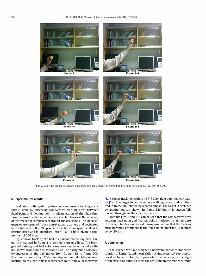
Fig. 7. Ball video sequence showing initializing of a ball as target in frame 1 and tracking in frames 40, 112, 146, 164, 200.
324 U. Ali, M.B. Malik / Journal of Systems Architecture 56 (2010) 317–326
6. Experimental results
Evaluation of the system performance in terms of tracking accu-racy is done by observing comparative tracking error betweenfixed-point and floating-point implementation of the algorithm.Two real-world video sequences are selected to assess the accuracyof the tracker in complex background and occlusions. The video se-quences are captured from a non-stationary camera and decimatedto resolution of 360 � 288 pixels. The YCbCr color space is taken asfeature space and is quantized into 4 � 8 � 8 bins, giving a totalnumber of 256 bins.
Fig. 7 shows tracking of a ball in an indoor video sequence. Tar-get is initialized in frame 1 shown by a green ellipse. The back-ground lighting and ball color variations can be observed as theball moves from frame 40 to frame 112. The background complex-ity increases as the ball moves from frame 112 to frame 200.Position estimated by 32-bit fixed-point and double-precisionfloating-point algorithms is represented by ‘+’ and ‘o’, respectively.
Fig. 8 shows tracking results on PETS 2004 fight and runaway data-set [22]. The target to be tracked is a walking person and is initial-ized in frame 300, shown by a green ellipse. The target is occludedby another person shown in frame 326 but it is successfullytracked throughout the video sequence.
From the Figs. 7 and 8, it can be seen that the comparative errorbetween fixed-point and floating-point simulations is almost zero.However, it has been observed during simulations that the trackingerror becomes prominent if the fixed-point precision is reducedbelow 20-bits.
7. Conclusion
In this paper, we have designed a hardware/software embeddedsolution of kernel-based mean-shift tracking system. A coprocessorbased architecture has been presented that accelerates the algo-rithm execution times to meet the real-time frame rate constraint.

Fig. 8. Fight and runaway video sequence showing initializing of a person as target in frame 300 and tracking in frames 315, 326, 339, 375, 405.
U. Ali, M.B. Malik / Journal of Systems Architecture 56 (2010) 317–326 325
The coprocessor has the capability to track multiple targets at hun-dreds of frames per second depending on the target size. The sys-tem including frame grabber and video display unit isimplemented on a low-cost FPGA device and is fully standalone.The system is reconfigurable which makes the development rapidand makes it flexible for future extensions.
As the algorithm is implemented in 32-bit fixed point numbers,the accuracy of the tracker is an important issue. The accuracy isevaluated by comparing the error between fixed-point and float-ing-point results. The execution speed of the algorithm on the sys-tem is also evaluated by comparing execution time in software andhardware/software co-design. Maximum size of the tracking targetis limited to 64 � 64. The larger target size results in larger widthof multipliers and divider units. The frame rate drops significantlyas the number of targets increases. This problem can be resolved atthe cost of FPGA resources by replicating the coprocessor in hard-ware, separate coprocessor for each target. The maximum achiev-able frame rate by the coprocessor is limited by the designsynthesized frequency. Currently the system is synthesized at50 MHz, but the frequency can be increased by efficient and pipe-lined implementation of the modules. The processing image sizecan be increased by configuring coprocessor image memory to a
larger size but it consumes more FPGA on-chip memory which isa limited resource.
The future extensions of this system includes making the copro-cessor capable of computing more target features such as edge andtexture to make the tracking system more robust.
Acknowledgements
This research was funded by National University of Sciencesand Technology, Pakistan. A video dataset used in the simulationscame from EC Funded CAVIAR project/IST 2001 37540. The authorsalso acknowledge Xilinx University Program for providing develop-ment tools for both hardware and software.
References
[1] P. Perez, C. Hue, J. Vermaak, M. Gangnet, Color-based probabilistic tracking, in:Proc. Eur. Conf. Comput. Vis., vol. 1, Copenhagen, Denmark, May–June 2002,pp. 661–675.
[2] D. Comaniciu, V. Ramesh, P. Meer, Real-time tracking of non-rigid objects usingmean shift, in: Proceedings of the IEEE Conference on Computer Vision andPattern Recognition, vol. 2, Hilton Head, 2000, pp. 142–149.

326 U. Ali, M.B. Malik / Journal of Systems Architecture 56 (2010) 317–326
[3] B.D. Lucas, T. Kanade, An iterative image registration technique with anapplication to stereo vision, in: Proceedings of DARPA Image UnderstandingWorkshop, 1984, pp. 121–130.
[4] F. Porikli, Achieving real-time object detection and tracking under extremeconditions, Journal of Real-Time Image Processing 1 (2006) 33–40.
[5] A. Yilmaz, O. Javed, M. Shah, Object tracking: a survey, ACM ComputingSurveys (CSUR) 38(4) (2006) 13-es.
[6] Y. Bar-Shalom, Tracking and Data Association, Academic Press Professional,Inc., San Diego, CA, 1987.
[7] K. Fukunaga, L. Hostetler, The estimation of the gradient of a density function,with applications in pattern recognition, IEEE Transactions on InformationTheory 21 (1975) 32–40.
[8] T. Kailath, The divergence and Bhattacharyya distance measures in signalselection, IEEE Transactions on Communication Technology 15 (1967) 52–60.
[9] J. Díaz, E. Ros, F. Pelayo, E.M. Ortigosa, S. Mota, FPGA-based real-time opticalflow system, IEEE Transactions on Circuits and Systems on Video Technology16 (2) (2006) 274–279.
[10] J. Schlessman, C.Y. Chen, B. Ozer, K. Fujino, K. Itoh, W. Wolf, Hardware/software co-design of an FPGA based embedded tracking system, in:Proceedings of the IEEE Conference on Computer Vision and PatternRecognition Workshop, 2006, pp. 123–133.
[11] F. Kristensen, H. Hedberg, H. Jianj, P. Nilsson, V. Owall, An embedded real-timesurveillance system: implementation and evaluation, Journal of SignalProcessing Systems 52 (2008) 75–94.
[12] M. Arias, E. Rodriguez-Palacios, FPGA Architecture for a Visual TrackingSystem, FPL 2002 (Field Programmable Logic conference), Lecture Notes inComputer Science 2438, Montpellier (La Grande-Motte), France, September2002, pp. 710–719.
[13] Daniel P. Huttenlocher, J.R. William, A Multi-resolution Technique forComparing Images using the Hausdorff Distance, Technical Report TR92-1321, 1992.
[14] J.U. Cho, X.D. Pham, J.W. Jeon, J.E. Byun, H. Kang, A real-time object trackingsystem using a particle filter, in: IEEE Proceedings of International Roboticsand Systems Conference, 2006, pp. 2822–2827.
[15] P. Li, L. Xiao, Mean shift parallel tracking on GPU, in: Proceedings of 4th IberianPattern Recognition and Image Analysis Conference, Springer-Verlag, Berlin,Heidelberg, 2009. pp. 120–127.
[16] J.U. Cho et al., FPGA-based real-time visual tracking system using adaptivecolor histograms, in: Proceedings of the IEEE International Conference onRobotics and Biomimetics (ROBIO07), December 2007, pp. 172–177.
[17] U. Ali, M.B. Malik, K. Munawar, FPGA/soft-processor based real-time objecttracking system, in: Proceedings of the IEEE, 5th Southern Programmable LogicConference, 2009, pp. 33–37.
[18] M.B. Malik, State-space recursive least-squares: part I, Signal Processing 84(9)(2004) 1709–1718.
[19] M.P. Wand, M.C. Jones, Kernel Smoothing, Monographs on Statistics andApplied Probability, Chapman and Hall, London, 1995.
[20] Microblaze Processor Reference Guide, Xilinx Inc., <http://www.xilinx.com>.[21] Fast Simplex Link (FSL), Xilinx Inc., <http://www.xilinx.com>.[22] Dataset, Two People Meet, Fight and Run Away, in: 6th IEEE International
Workshop on Performance Evaluation of Tracking and Surveillance, 2004, url:<http://www.dai.ed.ac.uk/homes/rbf/CAVIAR/>.
Usman Ali received the B.S. and M.S. degrees both inElectrical Engineering from College of Electrical andMechanical Engineering (E&ME), National University ofSciences and Technology (NUST), Pakistan, in 2005 and2007, respectively. He is currently pursuing his PhD inElectrical Engineering at College of E&ME, NationalUniversity of Sciences and Technology (NUST) under ascholarship from the same university. His researchfocuses on image processing, and embedded systemdesign.
Mohammad Bilal Malik received the B.S. degree in
Electrical Engineering from College of Electrical andMechanical Engineering (E&ME), Pakistan, in 1991. Hereceived his M.S. degree in Electrical Engineering fromMichigan State University (MSU), Michigan, USA in2001. In 2004, he received his PhD degree in ElectricalEngineering from National University of Sciences andTechnology (NUST), Pakistan. He has been teaching atCollege of E&ME, National University of Sciences andTechnology (NUST) since 1991. His research focuses onsignal processing and adaptive filtering for communi-cations and control systems.