Hanger Running Tool - Technical Disclosure Commons
28
Technical Disclosure Commons Technical Disclosure Commons Defensive Publications Series September 2021 Hanger Running Tool Hanger Running Tool Bernd Lienau Follow this and additional works at: https://www.tdcommons.org/dpubs_series Recommended Citation Recommended Citation Lienau, Bernd, "Hanger Running Tool", Technical Disclosure Commons, (September 02, 2021) https://www.tdcommons.org/dpubs_series/4568 This work is licensed under a Creative Commons Attribution 4.0 License. This Article is brought to you for free and open access by Technical Disclosure Commons. It has been accepted for inclusion in Defensive Publications Series by an authorized administrator of Technical Disclosure Commons.
-
Upload
khangminh22 -
Category
Documents
-
view
4 -
download
0
Transcript of Hanger Running Tool - Technical Disclosure Commons
Technical Disclosure Commons Technical Disclosure Commons
Defensive Publications Series
September 2021
Hanger Running Tool Hanger Running Tool
Bernd Lienau
Follow this and additional works at: https://www.tdcommons.org/dpubs_series
Recommended Citation Recommended Citation Lienau, Bernd, "Hanger Running Tool", Technical Disclosure Commons, (September 02, 2021) https://www.tdcommons.org/dpubs_series/4568
This work is licensed under a Creative Commons Attribution 4.0 License. This Article is brought to you for free and open access by Technical Disclosure Commons. It has been accepted for inclusion in Defensive Publications Series by an authorized administrator of Technical Disclosure Commons.
1
A Hanger Running Tool
Introduction
The present disclosure relates to a hanger running tool for installation of a hanger in a
wellbore and a method for installing a hanger in a well.
In the field of subsea oil and gas wells, the installation of a hanger (e.g. a tubing hanger or a 5
casing hanger) is commonplace. The hanger is used in the completion of oil wells and is used
to suspend tubing or casing from the wellhead.
Normally, installation or retrieval of a hanger is performed using a tubular riser inside the
marine riser and Blow Out Preventer (BOP). Installation and retrieval of a hanger is performed
using a hanger running tool, which is able to be connected to the hanger, thereby allowing 10
installation or retrieval.
The control of a Hanger Running Tool (HRT) and associated downhole functions is presently
achieved through a hanger umbilical clamped to the tubular (e.g. subsea riser, control riser
etc.). Such a setup requires a huge investment to establish, as well as a large amount of rig
space and operational expenses. In addition, several activities and processes are required to 15
be carried out during installation, e.g. handling umbilical, clamping umbilical to a riser at
regular intervals etc.
With the necessary equipment in place, the HRT is then required to be positioned and
controlled in a subsea environment. Using the presently available technology, the THRT is
operated by supplying operating fluid via a topside HPU and umbilical or via a subsea control 20
module, both of which require a dedicated power source for providing a supply of hydraulic
fluid as necessary for operation. As well as being expensive and sophisticated to install and
operate (e.g. due to the equipment involved, and/or the need to separately generate a high
pressure source of hydraulic fluid), there is always a risk that the hydraulic line may rupture
and leak hydraulic fluid into the subsea environment, or that some other component may fail. 25
Current systems may give rise to environmental concern, and additional measures may need
to be taken in order to safeguard against this happening.
There is therefore a requirement for a way to control the installation of a hanger in a subsea
environment, which is less cost intensive, requires less complex and sophisticated equipment,
and more environmentally friendly than known methods. 30
2
Lienau: Hanger Running Tool
Published by Technical Disclosure Commons, 2021
2
Summary
According to a first aspect there is provided a hanger running tool for installation of a
hanger in a well, comprising: a central bore; a hanger engagement arrangement configurable
between an engaged position in which the engagement arrangement is coupled to a hanger,
and a disengaged position in which the engagement arrangement is decoupled from a hanger; 5
a pressure-controlled anchoring actuator for actuating an anchoring arrangement, and
comprising an actuation surface; the hanger engagement arrangement being configurable to
the engaged position in response to an increase in pressure at a first pressure source, being
configurable to the disengaged position in response to an increase in pressure inside the
central bore, and the anchoring actuator being actuated in response to an increase in pressure 10
on the actuation surface (e.g. an increase in pressure external to the tubing hanger running
tool, such as an increase in the pressure in the BOP, below the slick joint) so that the
anchoring arrangement anchors the hanger to an anchor point (e.g. which may be located on
the wellhead, the Xmas tree, the BOP, or the like).
The hanger running tool may be a running tool for any type of hanger, for example for 15
a tubing hanger, or for a casing hanger.
According to a second example, the hanger running tool may be configurable to be
located inside at least one of a BOP, a subsea Xmas tree and a wellbore, and the anchoring
actuator may be configurable to be actuated in response to an increase in pressure inside the
BOP, subsea Xmas tree or wellbore, thereby resulting in an increase in pressure on the 20
actuation surface. The anchoring actuator may be located on an external surface of the tool.
According to a third example, the first pressure source may be generated by a pump or
compressor.
According to a fourth example, the first pressure source may be located at a surface
location. 25
According to a fifth example, the hanger engagement arrangement may be
configurable to be disconnected from the first pressure source prior to the hanger running
tool being positioned in a well.
According to a sixth example, the hanger engagement arrangement and the anchoring
actuator may be located external to and around the periphery of the central bore. 30
3
Defensive Publications Series, Art. 4568 [2021]
https://www.tdcommons.org/dpubs_series/4568

3
According to a seventh example, the tool may comprise a valve comprising a valve seat
located in the central bore, the valve being closeable to increase the pressure inside the
hanger running tool.
According to an eighth example, the valve may be at least one of a ball valve or a valve
that is activated by an activation object. 5
According to a ninth example, the valve may be removable from the hanger running
tool.
According to a tenth example, the hanger engagement arrangement may comprise an
actuator comprising a first and a second pressure inlet, the first pressure inlet being in
communication with the first pressure source via the first pressure conduit, and the second 10
pressure inlet being open to the pressure in the central bore via the channel.
According to an eleventh example, the hanger engagement arrangement may comprise
an actuator comprising a piston contained in a hydraulic chamber arrangement divided into an
upper hydraulic chamber and a lower hydraulic chamber, both the first pressure source and
the central bore being in pressure communication with a hydraulic chamber of the hydraulic 15
chamber arrangement.
According to a twelfth example, the first pressure source may be in pressure
communication with the upper hydraulic chamber located at an upper end of the hydraulic
chamber arrangement, and the central bore may be in pressure communication with the
lower hydraulic chamber located at a lower end of the hydraulic chamber arrangement, such 20
that an increase in pressure from the first pressure source may act to move the piston in a first
direction, and such that an increase in pressure from the central bore may act to move the
piston in a second direction.
According to a thirteenth example, the anchoring actuator may be in the form of an
annular piston. 25
According to a fourteenth example, the tool may comprise an anchoring arrangement
comprising an anchor engagement profile, the anchoring actuator configurable to operate the
anchoring arrangement to engage the wellbore.
According to a fifteenth example, the tool may comprise a locking arrangement
configured to lock the hanger engagement arrangement in the engaged position. 30
4
Lienau: Hanger Running Tool
Published by Technical Disclosure Commons, 2021

4
According to a sixteenth example, the tool may be configured to retrieve a hanger from
a well.
According to a seventeenth example, the tool may comprise a detachable retrieval
module for engaging the tool with a hanger for retrieval, the detachable retrieval module
comprising a retrieval profile for engaging a hanger for retrieval. 5
According to an eighteenth example, the central bore may be configurable to have a
retrievable plug run therethrough.
A second aspect relates to a method for installing a hanger in a well, comprising:
providing a hanger running tool comprising a central bore, a hanger engagement
arrangement and an anchoring actuator for actuating an anchoring arrangement; 10
engaging the hanger running tool with a hanger by providing an increase in pressure at
a first pressure source to configure the hanger engagement arrangement to the engaged
configuration;
positioning the hanger and hanger running tool in a well at a desired location;
engaging the hanger with an anchor point by providing an increase in pressure in the 15
well to actuate the anchoring actuator to engage the anchoring arrangement with the anchor
point;
disengaging the hanger running tool from the hanger by providing an increase in
pressure in the central bore to configure the hanger engagement arrangement to the
disengaged configuration; and 20
retrieving the hanger running tool from a well.
According to a second example of the second aspect, the desired location in the well
may be at least one of a desired location inside a BOP, a desired location inside a subsea Xmas
tree and a desired location inside a wellbore.
According to a third example of the second aspect, the method may comprise 25
providing a valve seat in the central bore, and locating an activation object (e.g. a ball or dart)
in the valve seat to restrict fluid flow therethrough, and provide an increase in pressure in the
central bore.
5
Defensive Publications Series, Art. 4568 [2021]
https://www.tdcommons.org/dpubs_series/4568
5
According to a fourth example of the second aspect, the method may comprise
increasing the pressure in the well to move the anchoring actuator from a first to a second
position to engage the anchoring arrangement with the anchor point.
According to a fifth example of the second aspect, the method may comprise attaching
a detachable retrieval module to the tool, and retrieving the hanger from a well by coupling 5
the detachable retrieval module to the hanger.
According to a sixth example of the second aspect, the method may comprise installing
a retrievable plug in the well by running the retrievable plug through the central bore of the
tool.
According to a seventh example of the second aspect, the method may comprise 10
performing a well clean-up operation prior to installation of the retrievable plug.
List of the drawings
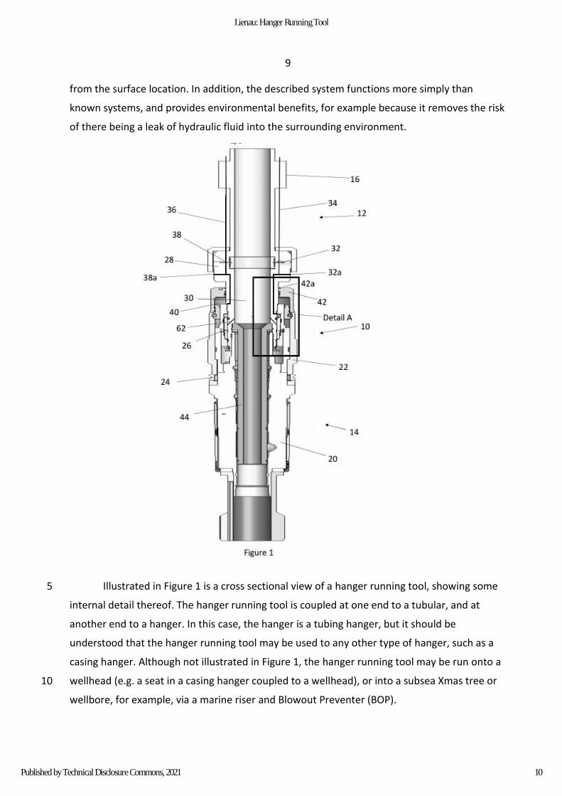
Figure 1 shows a sectional view of an example of the hanger running tool in an
installation configuration. 15
Figure 2 shows Detail A of the hanger running tool in more detail.
Figure 3 illustrates a hanger running tool in a retrieval configuration having a retrieval
module attached.
Figure 4 shows Detail B of the hanger running tool in more detail.
Part list 20
Part number Part name
10 Hanger running tool
12 tubular
14 hanger
16 slick joint
20 main body portion
6
Lienau: Hanger Running Tool
Published by Technical Disclosure Commons, 2021
6
22 actuation sleeve
24 anchor engagement profile
26 hanger engagement arrangement
28 base component
30 central bore
32 first pressure port
32a first auxiliary port
34 first pressure conduit
36 second vent conduit
38 second pressure port
38a second auxiliary port
40 actuation cavity
42 pressure-controlled anchoring actuator
42a actuation surface
44 sleeve
46 valve seat
48 hydraulic chamber arrangement
48a upper hydraulic chamber
48b lower hydraulic chamber
50 upper annular engagement ring
52 abutment surface
54 annular piston
54a thicker end
54b thinner end
56 hanger engagement member
7
Defensive Publications Series, Art. 4568 [2021]
https://www.tdcommons.org/dpubs_series/4568

7
58 lower annular ring
60 lock key
62 channel
64 shear ring
110 hanger running tool
112 tubular
114 hanger
122 actuation sleeve
126 hanger engagement arrangement
130 central bore
132 first pressure port
134 first pressure conduit
136 second vent conduit
138 second pressure port
140 actuation cavity
142 pressure-controlled anchoring actuator
144 sleeve
144a sealing ring
148b lower hydraulic chamber
154 annular piston
156 hanger engagement member
162 port
166 detachable retrieval module
168 biasing member/snap ring
170 lip
8
Lienau: Hanger Running Tool
Published by Technical Disclosure Commons, 2021
8
172 lip
174 sealing arrangement
Description
The present description provides an improved hanger running tool for installation of
hanger in wellbore and method for installing hanger in well. According to one example there is
provided a hanger running tool for installation of a hanger in a well, comprising: a central 5
bore; a hanger engagement arrangement configurable between an engaged position in which
the engagement arrangement is coupled to a hanger, and a disengaged position in which the
engagement arrangement is decoupled from a hanger; a pressure-controlled anchoring
actuator for actuating an anchoring arrangement, and comprising an actuation surface; the
hanger engagement arrangement being configurable to the engaged position in response to 10
an increase in pressure at a first pressure source, being configurable to the disengaged
position in response to an increase in pressure inside the central bore, and the anchoring
actuator being actuated in response to an increase in pressure on the actuation surface (e.g.
an increase in pressure external to the tubing hanger running tool, such as an increase in the
pressure in the BOP, below the slick joint) so that the anchoring arrangement anchors the 15
hanger to an anchor point (e.g. which may be located on the wellhead, the Xmas tree, the
BOP, or the like).
In use, the hanger running tool may be able to be coupled to a hanger, and run into
position on a wellhead, a subsea Xmas tree, a wellbore, or the like, and may be run into
position for example via a Blowout Preventer (BOP) and a marine riser. Once in the desired 20
position, the pressure inside the BOP, marine riser and/or the wellbore may be increased in
order to actuate the hanger running tool and provide engagement between the hanger and a
component such as a casing hanger seat or the wellhead. The pressure inside the central bore
of the hanger running tool may then be increased in order to configure the hanger
engagement arrangement to disengage the hanger from the hanger running tool, thereby 25
permitting the hanger running tool to be retrieved from the wellhead, BOP, wellbore, etc.,
thereby leaving the hanger in place. This setup permits the user to install the hanger in a
desired position without having to have a hydraulic connection between the hanger running
tool and a surface location or a subsea control sub/unit, thereby saving on the time and cost
of providing the additional equipment involved, as well as running the additional equipment 30
9
Defensive Publications Series, Art. 4568 [2021]
https://www.tdcommons.org/dpubs_series/4568
9
from the surface location. In addition, the described system functions more simply than
known systems, and provides environmental benefits, for example because it removes the risk
of there being a leak of hydraulic fluid into the surrounding environment.
Illustrated in Figure 1 is a cross sectional view of a hanger running tool, showing some 5
internal detail thereof. The hanger running tool is coupled at one end to a tubular, and at
another end to a hanger. In this case, the hanger is a tubing hanger, but it should be
understood that the hanger running tool may be used to any other type of hanger, such as a
casing hanger. Although not illustrated in Figure 1, the hanger running tool may be run onto a
wellhead (e.g. a seat in a casing hanger coupled to a wellhead), or into a subsea Xmas tree or 10
wellbore, for example, via a marine riser and Blowout Preventer (BOP).
10
Lienau: Hanger Running Tool
Published by Technical Disclosure Commons, 2021
10
In this example, the tubular may be coupled to the hanger running tool by any
appropriate means, such as by a flanged and bolted connection, via a threaded connection, or
the like. Here, the tubular comprises a slick joint which may seal with a ram or BOP annular
(not illustrated) and may enable the pressure (e.g. the pressure in the wellbore, BOP, Xmas
tree, or the like) to be increased below the slick joint when the ram is in sealing contact 5
therewith.
As will be described in more detail in the following description, the hanger is coupled
to the hanger running tool, and in Figure 1 the tubing hanger is illustrated towards the lower
portion of the figure. A tubing (not illustrated in Figure 1, and located below the tubing
hanger), such as a production tubing, may be hung from the tubing hanger, and the tubing 10
hanger and attached tubing may be run into the desired position in a well with the hanger
running tool. The tubing hanger comprises a main body portion from which the tubing may be
hung, and an actuation sleeve. In this example, the actuation sleeve comprises an anchor
engagement profile, enabling the tubing hanger to engage an anchor point. The anchor point
may be located on, for example, a component such as the Xmas tree, wellhead, or a seat in a 15
casing hanger (not shown).
The hanger running tool, which is located between the tubular and the tubing hanger,
functions to engage the tubing hanger and attached tubing, and permits the tubing hanger to
be run into a desired position, in relation to a well, such as on a wellhead or Xmas tree. A user
may run the hanger running tool into a well through a marine riser and BOP. The hanger 20
running tool is coupled to the tubular via a base component, which also defines a central bore
within the hanger running tool.
In order to attach the tubing hanger to the hanger running tool, the hanger running
tool comprises a hanger engagement arrangement. The hanger engagement arrangement
comprises a number of components, which will be described in more detail in the following 25
paragraphs, and is mounted upon the base component. The hanger engagement arrangement
is in pressure communication with a first pressure source via a first pressure port. In this
example, the first pressure port is located in the base component, the base component
comprising a channel that permits pressure communication between the first pressure port by
linking the first pressure port with the hanger engagement arrangement. The first pressure 30
port is, in this example, coupled to a first pressure conduit, and access to the first pressure
port is possible by linking the first pressure port and the first pressure conduit. Having access
to the first pressure port via the first pressure conduit may provide a user with a degree of
11
Defensive Publications Series, Art. 4568 [2021]
https://www.tdcommons.org/dpubs_series/4568
11
flexibility in the provision of pressure at the first pressure port, as the first pressure conduit
may be routed however necessary in order to provide easy access via a pressure source. The
first pressure conduit may therefore permit communication between a first pressure source
(not shown) and the hanger engagement arrangement via the first pressure port.
As can be seen in this example, the first pressure conduit extends from the pressure 5
port on the base component, and through the slick joint, having one end positioned above the
slick joint. As such, having the first pressure conduit connected to the pressure port may
ensure that, in the case of an increase in pressure below the slick joint, the first pressure port
is not exposed to such a pressure increase. The first pressure conduit may have a valve or
closure on an open end thereof, thereby providing selective pressure communication to the 10
first pressure port. Although illustrated as a single conduit in Figure 1, the first pressure
conduit may be partially defined by the tubular and the slick joint, as is illustrated in Figure 1.
Here, the part of the first pressure conduit that is in direct contact with the first pressure port
is defined by a channel in the tubular (in particular, of a flange connection of the tubular). The
first pressure conduit may be entirely defined by the channel in the tubular, and the channel 15
need not contain any tubing therein. The conduit is then defined by a first section of tubing
between the channel defined in the tubular and the slick joint. The slick joint also comprises a
channel therein which partially defines the first pressure conduit, and in this example a second
section of tubing is connected to the channel in the slick joint to further define the first
pressure conduit. 20
The first pressure source may be located at a surface location, e.g. on the topsides of a
vessel, or on a rig. In some examples, the first pressure source may be a pump or compressor,
which may be attached to the first pressure conduit to provide an increase in pressure at the
first pressure port, and therefore increase the pressure at a location inside the hanger
engagement arrangement. The first pressure source may be attached to the first pressure 25
conduit while the hanger running tool is at a surface location, and then disconnected in order
to run the hanger running tool into a desired position.
In addition to the first pressure conduit, in this example there is also illustrated a
second vent conduit. The second vent conduit connects to a second pressure port that is also
located on an outer surface of the base component (similar to the case with the first pressure 30
port). Again, the base component comprises a channel that provides pressure communication
between the hanger engagement arrangement and the second pressure port. The second vent
conduit is coupled to the second pressure port and extends from the second pressure port to
12
Lienau: Hanger Running Tool
Published by Technical Disclosure Commons, 2021
12
a location above the slick joint, thereby meaning that the second pressure port is not affected
by pressure changes occurring below the slick joint. The second pressure port may function to
allow venting of fluid from inside the hanger engagement arrangement. In particular, the
second pressure port may permit venting of fluid from inside an actuation cavity of the hanger
engagement arrangement. 5
Similar to the first pressure conduit, the second vent conduit is partially defined by
sections of tubing, partially defined by the slick joint, and partially defined by the tubular. For
the sake of brevity, a detailed description will not be repeated.
Illustrated in the example of Figure 1 is a first auxiliary port and a second auxiliary port.
Unlike the first pressure port, the first auxiliary port does not comprise a conduit connected 10
thereto or in communication therewith. In use, the first auxiliary port may serve only as a
testing port, for example to perform pressure tests when the hanger running tool is located at
a surface location. Once in a downhole location, the first auxiliary port may be sealed or
blocked, and may no longer function. This is similarly the case for the second auxiliary port,
which may also serve only as a testing port, and may also be sealed, blocked, plugged during 15
normal operation such that it no longer functions.
In some cases there may be a valve arrangement or removable plug in, or adjacent
either or both of the first and second auxiliary ports, to permit quick access to the port if
required. This access component (e.g. a valve or a removable plug, or an arrangement
comprising a plurality of either or both) may be situated in or between the relevant fluid port, 20
and the relevant conduit.
Additionally illustrated in Figure 1 is a pressure-controlled anchoring actuator for
actuating an anchoring arrangement. As can be seen in Figure 1, the pressure-controlled
anchoring actuator is located on an exterior surface of the hanger running tool, peripheral to
the central bore, and is therefore open to the pressure external to the hanger running tool. 25
The pressure external to the hanger running tool may be the pressure of the wellbore, where
the hanger running tool is located in or adjacent the wellbore and/or wellhead, or may be the
pressure inside the BOP. By providing a seal at the slick joint, a user may be able to increase
the pressure external to the hanger running tool, located below the slick joint, to actuate the
pressure-controlled anchoring actuator. In this example, the anchoring arrangement may be 30
considered to comprise at least the anchoring actuator and the actuation sleeve and the
engagement profile.
13
Defensive Publications Series, Art. 4568 [2021]
https://www.tdcommons.org/dpubs_series/4568

13
The pressure-controlled anchoring actuator has the shape of an annular piston in this
example, and comprises a laterally extending shoulder which defines an actuation surface. The
radially and axially extending shoulder and defined actuation surface may function to provide
an axially directed force on the pressure controlled anchoring actuator when the pressure in
the wellbore, BOP etc. is increased. As illustrated in Figure 1, the axially directed force acts in a 5
downwards direct, towards the tubing hanger, in this example. The pressure controlled
anchoring actuator extends along the exterior of one axial end and along part of the length of
the hanger running tool, and together with the actuation sleeve of the tubing hanger, may
function to provide an outer housing for the hanger running tool.
Illustrated in Figure 1, the anchor engagement profile is in a disengaged position, with 10
the anchoring profile being radially withdrawn, away from an adjacent anchor point, such as a
wellhead, BOP, Xmas tree, or the like, and which may comprise an anchor profile to assist in
providing an anchored connection therewith. In order to move the anchor engagement profile
to an engaged position, the actuation sleeve of the tubing hanger may be axially moveable. In
this example, as the actuation sleeve moves in the direction towards the main body of the 15
tubing hanger, part of the actuation sleeve may be forced underneath (e.g. radially inwards
relative to) the anchor engagement profile, thereby forcing the anchor engagement profile in
a radially outward direction and into engaging contact with the anchor point, thereby holding
the tubing hanger in position in the wellbore, BOP, Xmas tree, or the like. In order to facilitate
such a movement, the actuation sleeve may comprise a mating profile, such as a wedge-20
shaped portion, that is located adjacent the anchor engagement profile, such that axial
movement of the actuation sleeve provides a force incident on the anchor engagement profile
with a force component that is radially outwardly directed. Additionally or alternatively, the
anchor engagement profile may comprise a mating profile, such as a corresponding wedge
shaped portion, equally to assist in providing a radially outwardly directed force on the anchor 25
engagement profile. In the case where both the actuation sleeve and the anchor engagement
profile comprise a wedge shape profile, the profiles may be functional, for example the
profiles may function to ensure that the actuation sleeve is able to exert a radially directed
force component on the engagement profile, thereby moving the engagement profile to a
radially outer position. 30
The anchor engagement profile and/or sleeve may comprise a surface configured to
maximise the level of grip between the anchor engagement profile and the anchor point. For
example, the anchor engagement profile may be roughened, or comprise protrusions such as
ribs, dimples, teeth or the like.
14
Lienau: Hanger Running Tool
Published by Technical Disclosure Commons, 2021

14
As illustrated in Figure 1, the actuation sleeve may be in contact with the pressure-
controlled anchoring actuator, or may be contactable by the pressure-controlled anchoring
actuator. Here, an increase in the external pressure (e.g. the wellbore or BOP pressure)
surrounding the hanger running tool may have the effect of moving the actuator in an axially
downwards direction as in the illustrated orientation, thereby also moving the actuation 5
sleeve of the tubing hanger, and configuring the anchor engagement profile from the
disengaged to the engaged position. In some examples, the actuation sleeve (or at least a part
of the actuation sleeve) may form part of the hanger running tool, while the anchor
engagement profile forms part of the tubing hanger.
Inside the central bore is illustrated a sleeve, comprising a valve seat, which in this 10
example is partially located inside the hanger running tool and partially located inside the
hanger. The sleeve may be run into the well bore with the hanger running tool, or may be
positioned separately in the hanger running tool, for example after the hanger running tool
has been installed in the desired position. The sleeve may be run in on wireline, for example,
and may be able to be replaced if required. In some examples, the sleeve may have a profile 15
different to that illustrated in Figure 1 – for example where the sleeve is run in on wireline into
the tool, the profile may be different to cases where the sleeve is preinstalled. In addition, or
alternatively, a hanger plug may be run into the tubing hanger, for example to restrict or block
pressure surges from below the tubing hanger, by allowing the user to simply run such a plug
through the central bore of the hanger running tool. In some examples, it may be possible to 20
preinstall a plug into the tubing hanger, as the tubing hanger is run downhole, thereby
removing the need to install the plug once the hanger is in position in the BOP or wellhead.
The sleeve may function to facilitate use of the hanger running tool. By providing a
valve seat, the sleeve may be able to provide a seal in the central bore of the hanger running
tool, for example by dropping a ball into the hanger running tool. In doing so, a user may be 25
able to provide an increase in pressure inside the central bore of the hanger running tool,
above the valve seat in the direction towards the surface. An increase in pressure may be
provided by increasing the pressure inside the tubular (e.g. the marine riser, tubular riser,
subsea riser, control riser, or the like), to which the hanger running tool and the tubing hanger
are connected. In addition, the sleeve may function to block and seal a production port (not 30
illustrated) in the tubing hanger, thereby ensuring that operation of the hanger running tool is
not affected by unsealed ports in the tubing hanger, if these ports are not yet in use.
15
Defensive Publications Series, Art. 4568 [2021]
https://www.tdcommons.org/dpubs_series/4568

15
Illustrated in Figure 2 illustrates Detail A of Figure 1, which is a section of internal detail
of the hanger engagement arrangement shown in greater detail.
As can be seen in Figures 1 and 2, a channel extends from the first pressure port, and
through the base component of the hanger running tool to a location inside the hanger 5
running tool (see also Figure 1). Inside the hanger running tool, a hydraulic chamber
arrangement is formed between the base component, a lower annular ring and an upper
annular engagement ring, which may comprise an abutment surface for the purposes of
engaging and/or locating the hanger running tool relative to the tubing hanger. Inside the
hydraulic chamber arrangement is located an annular piston, comprising a thicker end and a 10
thinner end defining two separate (an upper and a lower) hydraulic chambers, inside the
hydraulic chamber arrangement. In this example the thicker end is located above the thinner
end, such that the thicker end is located in an upper hydraulic chamber, while the thinner end
is located in a lower hydraulic chamber. Located immediately below the upper annular
engagement ring is a hanger engagement member, comprising an engagement profile for 15
engaging the hanger running tool with the tubing hanger. The hanger engagement member is
held in place by the lower annular ring. In addition, an upper seal arrangement is provided
16
Lienau: Hanger Running Tool
Published by Technical Disclosure Commons, 2021
16
between the thicker end of the annular piston, the base component and the upper annular
engagement ring, while a lower seal arrangement is provided between the thinner end of the
annular piston, the base component and the lower annular ring. The upper annular
engagement ring additionally comprises a lock key, which may be spring loaded, and which
may engage with the annular piston in order to lock the annular piston. As shown in Detail A, 5
the annular piston is in a position such that the hanger engagement member is in contact with
the tubing hanger, thereby engaging the hanger running tool with the tubing hanger, and
locking it in this position.
In use, the hanger running tool may be coupled (e.g. attached, engaged) to the tubing
hanger at a surface location, for example on a vessel, a rig, in a warehouse etc.. To do so, a 10
first pressure source, which may be in the form of a pump or compressor, is attached to the
first pressure conduit, so as to provide an increase in pressure in the upper– that is, the end of
the hydraulic chamber at which the thicker end of the annular piston is located. The increase
in pressure on in the upper section of the hydraulic chamber causes the annular piston to
move in a downwards direction. As the annular piston moves in a downwards direction, the 15
hanger engagement member changes from being in contact with the thinner end of the
annular piston to being in contact with the thicker end thereof, thereby having the effect of
moving the hanger engagement member from a disengaged position to an engaged position
relative to the tubing hanger.
The hanger engagement member may be biased, for example spring loaded towards 20
the disengaged position, to avoid undesired engagement with the tubing hanger. Once in the
engaged position, the lock key may inhibit movement of the piston, thereby preventing the
hanger engagement arrangement and the hanger running tool from becoming disengaged
from the tubing hanger, for example during handling.
Once the hanger running tool and the tubing hanger have been engaged, both may be 25
run into the desired position in the subsea location (e.g. in the BOP, Xmas tree, wellhead, or
the like), for example via a marine riser and BOP. In order to assist with the positioning of the
tubing hanger, an arrangement of sensors may be used, for example sensors which are able to
convey to a user that the tubing hanger has passed a certain point in the BOP, has come into
engagement with the wellhead, for example direct engagement or indirect engagement (e.g. 30
via a seat on the wellhead, via a casing hanger on the wellhead, via a seat in an Xmas tree
engaged with the wellhead, or the like), or has reached some other desired position.
Additionally or alternatively, the positioning of the tool may be confirmed by hydraulic means,
17
Defensive Publications Series, Art. 4568 [2021]
https://www.tdcommons.org/dpubs_series/4568
17
for example by having a tool in the hanger running tool or the tubing hanger that is able to
measure pressure buildup around the tool as it is lowered into position, thereby giving the
user an indication of the location of the tubing hanger. This information may be passed to a
user at a surface location by any appropriate means, for example by communication wires or
fibres attached to a marine riser, by wireless transmission or the like. 5
With the tubing hanger in the desired position, it may then be necessary to install the
tubing hanger in this position. Initially, the tubing hanger and the hanger running tool will be
in the position shown in Figure 1. In this position, the anchor engagement profile is in a
retracted configuration, and is not engaged with the anchor point or any surrounding
component of the Xmas tree, BOP, wellhead, or the like. In order to engage the tubing hanger 10
with the anchor point (e.g. of the wellhead, BOP, Xmas tree), it is necessary to configure the
tubing hanger and the hanger running tool to the position as shown in Figure 2. Here, the
pressure controlled anchoring actuator is moved in a downward direction. As the anchoring
actuator is in contact with the actuation sleeve, this has the effect of moving the anchor
engagement profile to the engaged, radially expanded, configuration, as previously described, 15
in which it is in engagement with an anchor point. Movement of the anchoring actuator may
be enabled by increasing the pressure in the wellbore, the Xmas tree, the BOP, or the like. This
may be achieved by moving a ram or BOP annular preventer into sealing contact with the slick
joint, and then increasing the pressure below the slick joint.
It can be seen in both Figures 1 and 2 that an actuation cavity exists between the 20
anchoring actuator and the base component. A sealing arrangement may be in place between
the anchoring actuator, the base component and the upper annular ring so as to isolate the
pressure in the actuation cavity from the rest of the hanger actuation arrangement (e.g. from
the hydraulic chamber, as will be described in the following paragraphs).
As illustrated in both Figure 1 and 2, the second pressure port leads to a channel in the 25
base component, that permits pressure communication between the actuation cavity and
second pressure port. Since the second pressure port is coupled to the second vent conduit,
the vent conduit extending to a position located above the slick joint, then the pressure in the
actuation cavity will be equal to the pressure in the region above the slick joint, which may be
equal to the pressure inside the marine riser. Therefore, once the sealing ram is placed in 30
sealing contact with the slick joint, and the pressure below the slick joint is increased, then
there will be an unbalanced force acting upon the anchoring actuator, on the laterally
extending shoulder and actuation surface thereof, as a result of the pressure differential
18
Lienau: Hanger Running Tool
Published by Technical Disclosure Commons, 2021
18
between the actuation cavity and the region external to the anchoring actuator. This causes
the anchoring actuator to move in a downwards direction, causing the anchor engagement
profile to engage the anchor point, and the tubing hanger to be installed in the desired
position. While the term “above” is used to describe relative terms, this term has been
selected to assist the reader in understanding the disclosure in the context of the provided 5
figures. While the described components may be provided in the orientation shown in the
Figures, it may also be possible to provide the described components in other configurations,
for example rotated by degrees, degrees, or some other angle. Therefore, the reader should
understand that in such cases the term “above” (and equally, similarly descriptive relative
terms such as “below”, “upwards” and “downwards”) may differ in meaning from what is 10
conventionally understood.
Once the tubing hanger has been installed in the desired position, it may be necessary
to unlock the hanger running tool from the tubing hanger for retrieval. To perform this
operation, the sleeve (see Figure 1) may be installed (or may be preinstalled) in the hanger
running tool, and an activation object such as a ball or dart may be dropped into the valve seat 15
in the sleeve. The ball (not shown) creates a seal with the valve seat, and the pressure inside
the hanger running tool may be increased above the valve seat. This may be achieved by
increasing the pressure in the tubular attached to the hanger running tool. As can be seen in
Figure 1, a channel (or a plurality of circumferentially arranged channels) is located in the base
component, allowing pressure communication between the central bore and the hydraulic 20
chamber. In particular, the channel permits pressure communication between a lower
hydraulic chamber that is located below (in this example) the upper seal arrangement. As
such, with the activation object (in this example, the ball) engaged in the valve seat, an
increase in pressure of the central bore acts on the lower seal arrangement in the lower
hydraulic chamber, having the effect of pushing the annular piston therein in an upwards 25
direction, and overcoming the locking force of the lock key, provided by a biasing member
such as a spring, biasing the lock key towards the locked configuration. While only one lock
key is illustrated in this position, more than one lock key may be present (e.g. there may be a
circular array of individual lock keys). A simple profile of the lock key is illustrated in Detail A,
although in other examples a differing, more complex profile may be used (e.g. a profile 30
comprising multiple teeth). In this example, the lock key is supported by a spring, such that it
is able to disengage upon application of a laterally directed force. Depending on the differing
operational conditions (e.g. differing depths or operating pressures at which the tubing hanger
running tool is used) the lock key may be differently designed to ensure that accidental
19
Defensive Publications Series, Art. 4568 [2021]
https://www.tdcommons.org/dpubs_series/4568
19
unlatching of the tool from the hanger does not happen given the specific operating
conditions. For example, more or fewer lock keys may be used, the spring stiffness may be
variable, and/or the engagement profile may have a varying shape (e.g. a varying number of
teeth). These variables may be able to be controlled to provide an arrangement requiring a
desired minimum level of laterally directed force to unlatch. 5
As a result of the seal arrangements in the hanger running tool, and the pressure
balance within cavities/chambers in the tool, the tool may be relatively unaffected by external
pressures and/or differential pressures acting across the tool. Additionally, the pressure acting
on both ends of the annular piston will be the same (both ends will be open to the pressure
surrounding the tool), then this will act to prevent accidental actuation of the tubing hanger 10
running tool during installation.
As the annular piston moves in an upwards direction, the hanger engagement member
comes into contact with the thinner end of the piston. As the hanger engagement member is
biased towards the disengaged configuration, the hanger engagement member moves
towards the disengaged configuration, and the hanger running tool is now disengaged from 15
the tubing hanger. The hanger running tool may then be retrieved.
The tool may also have a secondary means of operation, such that the running tool is
able to be released from tubing hanger in the case that the above described process should
fail. In the Example of Figures 1 and 2, the hanger running tool may comprise a shear ring.
Here, the shear ring is located between the base component and the lower annular ring, and 20
immediately above the shear ring on the base component may be a threaded profile
configured to engage with a threaded profile of the lower annular ring.
In order to release the hanger from the running tool, the base component may be
rotated. The lower annular ring may be in engagement with the sleeve located radially
outwardly thereof (e.g. engaged by a key located therebetween), and therefore may not 25
rotate with the base component, thereby causing the shear ring to shear. Once the shear ring
is sheared, then the rotation between the lower annular ring and the base component may
cause the lower annular ring to move in a downwards direction, as a result of the threaded
connection therebetween, until the lower annular ring and the base component are
disengaged. At this point, the base component may be pulled in an upward direction, causing 30
the annular piston to move in an upwards direction and the tool to be disengaged from the
hanger, and allowing retrieval thereof. Using this method, the tool may be able to be retrieved
should the primary method of hydraulic actuation fail.
20
Lienau: Hanger Running Tool
Published by Technical Disclosure Commons, 2021
20
Although one means of secondary operation is described, it should be noted that a
user should not be restricted specifically to this means of secondary operation. Other means
of secondary operation may equally be possible for use in combination with the running tool
and hanger as described.
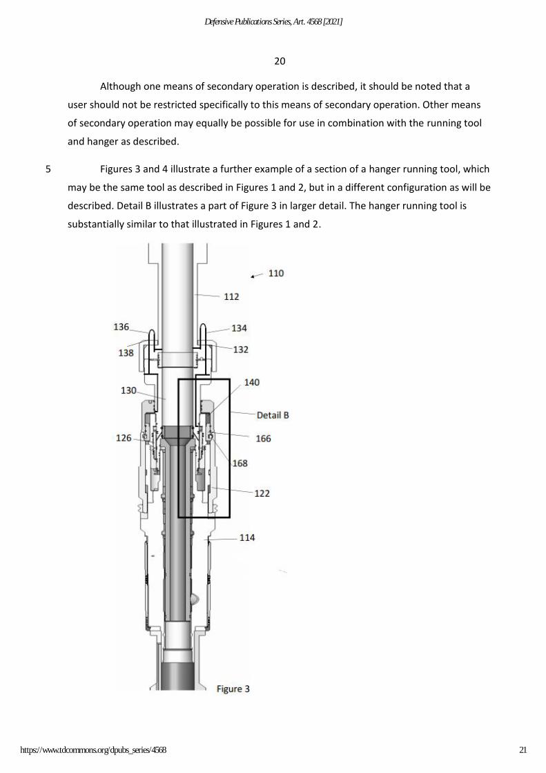
Figures 3 and 4 illustrate a further example of a section of a hanger running tool, which 5
may be the same tool as described in Figures 1 and 2, but in a different configuration as will be
described. Detail B illustrates a part of Figure 3 in larger detail. The hanger running tool is
substantially similar to that illustrated in Figures 1 and 2.
21
Defensive Publications Series, Art. 4568 [2021]
https://www.tdcommons.org/dpubs_series/4568
21
In the example of Figure 3, there is a detachable retrieval module. In this example, the
detachable retrieval module is attached to the hanger running tool between the anchoring
actuator. The detachable retrieval module may be attached to the hanger running tool before
running downhole.
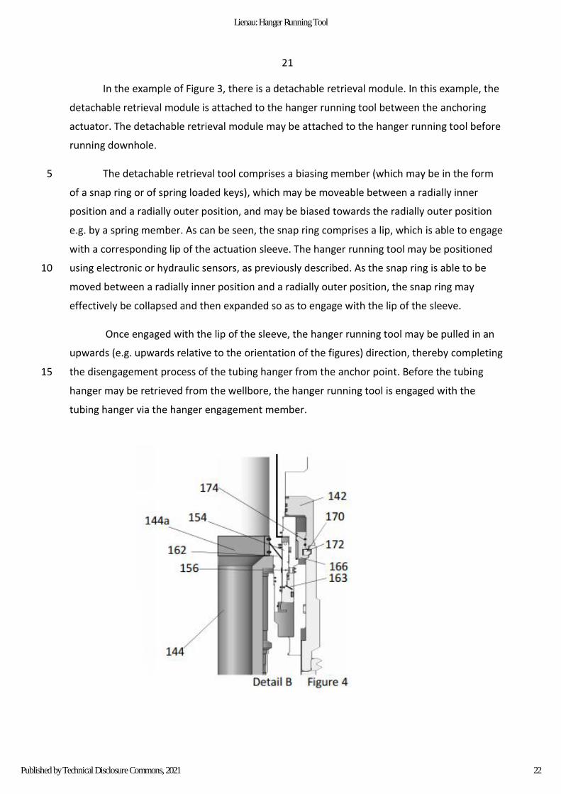
The detachable retrieval tool comprises a biasing member (which may be in the form 5
of a snap ring or of spring loaded keys), which may be moveable between a radially inner
position and a radially outer position, and may be biased towards the radially outer position
e.g. by a spring member. As can be seen, the snap ring comprises a lip, which is able to engage
with a corresponding lip of the actuation sleeve. The hanger running tool may be positioned
using electronic or hydraulic sensors, as previously described. As the snap ring is able to be 10
moved between a radially inner position and a radially outer position, the snap ring may
effectively be collapsed and then expanded so as to engage with the lip of the sleeve.
Once engaged with the lip of the sleeve, the hanger running tool may be pulled in an
upwards (e.g. upwards relative to the orientation of the figures) direction, thereby completing
the disengagement process of the tubing hanger from the anchor point. Before the tubing 15
hanger may be retrieved from the wellbore, the hanger running tool is engaged with the
tubing hanger via the hanger engagement member.
22
Lienau: Hanger Running Tool
Published by Technical Disclosure Commons, 2021
22
It should be noted that, in the examples of Figure 3 and 4, the first pressure conduit
and the second vent conduit have been rerouted, such that they connect the respective part
of the hanger engagement arrangement (as described in relation to the previous Figures) to
the inside of the tubular, which is in pressure and fluid communication with the central bore
of the running tool. As such, the pressure inside the running tool may be increased in order to 5
provide a pressure increase at the first pressure port and the second pressure port, thereby
moving the annular piston in a downwards direction and engaging the hanger engagement
member with the hanger. In order to facilitate downwards movement of the annular piston, a
port is illustrated in Detail B of the retrieval tool to allow venting of the lower hydraulic
chamber. Similarly, the pressure inside the actuation cavity is increased, causing the anchoring 10
actuator to move in an upwards direction and thereby also assisting to disengage the running
tool from the hanger. A sealing arrangement is provided between the detachable retrieval
module and the anchoring actuator in order form the pressure sealed actuation cavity, the
pressure in which may be increased/decreased via the vent conduit (it should be noted that
this sealing arrangement may also be present in the tool in the installation configuration). 15
It should also be noted that the sleeve, when the tool is in the retrieval configuration,
comprises an additional sealing ring, which has the effect of isolating the port from the central
bore. Therefore, when providing a pressure increase at the ports and, there will not be
corresponding pressure increase at the port. The sealing ring may be a separate component or
may be integrally formed with the sleeve, or may be a separate component. The sealing ring 20
may be coupled to the sleeve, e.g. via a mating or threaded profile.
Further upwards movement of the tubing hanger may then have the effect of retrieving the
tubing hanger from the wellbore. Having such a retrieval module provides a straightforward
way of retrieving the tubing hanger, without the need for use of complex positioning
manoeuvres to retrieve the tubing hanger. 25
23
Defensive Publications Series, Art. 4568 [2021]
https://www.tdcommons.org/dpubs_series/4568

23
Useful examples according to the disclosure are described in the following list:
1) A hanger running tool for installation of a hanger in a well, comprising:
a central bore;
a hanger engagement arrangement configurable between an engaged position in
which the engagement arrangement coupled to a hanger, and a disengaged position in which 5
the engagement arrangement decoupled from a hanger;
a pressure-controlled anchoring actuator for actuating an anchoring arrangement, and
comprising an actuation surface;
the hanger engagement arrangement configurable to the engaged position in response
to an increase in pressure at a first pressure source, being configurable to the disengaged 10
position in response to an increase in pressure inside the central bore, and the anchoring
actuator actuated in response to an increase in pressure on the actuation surface that the
anchoring arrangement anchors the hanger an anchor point.
2) The hanger running tool installation of a hanger in a well, wherein the hanger
running tool configurable to be located inside at least one of a BOP, a subsea Xmas tree and a 15
wellbore, and the anchoring actuator configurable to be actuated in response to an increase in
pressure inside the BOP, subsea Xmas tree or wellbore, thereby resulting in an increase in
pressure on the actuation surface.
3) The hanger running tool installation of a hanger in a well, wherein the first pressure
source is generated by a pump or compressor. 20
4) The hanger running tool installation of a hanger in a well, wherein the first pressure
source is located at a surface location.
5) The hanger running tool installation of a hanger in a well, wherein the hanger
engagement arrangement configurable to be disconnected from the first pressure source prior
to the hanger running tool positioned in a well. 25
6) The hanger running tool installation of a hanger in a well, wherein the hanger
engagement arrangement the anchoring actuator located external to and around the
periphery of the central bore.
24
Lienau: Hanger Running Tool
Published by Technical Disclosure Commons, 2021

24
7) The hanger running tool installation of a hanger in a well, comprising a valve a valve
seat in the central bore, the valve closeable to increase the pressure inside the hanger running
tool.
8) The hanger running tool installation of a hanger in a well, wherein the valve at least
one of a ball valve or a valve that is activated by an activation object. 5
9) The hanger running tool installation of a hanger in a well, wherein the valve
removable from the hanger running tool.
10) The hanger running tool installation of a hanger in a well, wherein the hanger
engagement arrangement an actuator a first and a second pressure inlet, the first pressure
inlet being in communication with the first pressure source via the first pressure conduit, and 10
the second pressure inlet being open to the pressure in the central bore via the channel.
11) The hanger running tool installation of a hanger in a well, wherein the hanger
engagement arrangement an actuator a piston contained in a hydraulic chamber arrangement
into an upper hydraulic chamber a lower hydraulic chamber, both the first pressure source
and the central bore in pressure communication with a hydraulic chamber of the hydraulic 15
chamber arrangement.
12) The hanger running tool installation of a hanger in a well, wherein the first pressure
source is in pressure communication with the upper hydraulic chamber at an upper end of the
hydraulic chamber arrangement, and the central bore is in pressure communication with the
lower hydraulic chamber at a lower end of the hydraulic chamber arrangement, such that an 20
increase in pressure from the first pressure source acts to move the piston in a first direction,
and such that an increase in pressure from the central bore to move the piston in a second
direction.
13) The hanger running tool installation of a hanger in a well, wherein the anchoring
actuator in the form of an annular piston. 25
14) The hanger running tool installation of a hanger in a well, wherein the anchoring
arrangement comprises an anchor engagement profile, the anchoring actuator to operate the
anchoring arrangement to engage an anchor point.
15) The hanger running tool installation of a hanger in a well, comprising a locking
arrangement to lock the hanger engagement arrangement the engaged position. 30
25
Defensive Publications Series, Art. 4568 [2021]
https://www.tdcommons.org/dpubs_series/4568

25
16) The hanger running tool installation of a hanger in a well, wherein the tool
configured to retrieve a hanger a well.
17) The hanger running tool installation of a hanger in a well, comprising a detachable
retrieval module engaging the tool a hanger retrieval, the detachable retrieval module a
retrieval profile engaging a hanger retrieval. 5
18) The hanger running tool installation of a hanger in a well, wherein the central
bore configurable to have a retrievable plug run therethrough.
19) A method for installing a hanger a well, comprising:
providing a hanger running tool a central bore,a hanger engagement arrangement an
anchoring actuator actuating an anchoring arrangement; 10
engaging the hanger running tool a hanger providing an increase in pressure at a first
pressure source to configure the hanger engagement arrangement the engaged configuration;
positioning the hanger hanger running tool a well at a desired location;
engaging the hanger an anchor point by providing an increase in pressure in the well to
actuate the anchoring actuator engage the anchoring arrangement with the anchor point; 15
disengaging the hanger running tool the hanger providing an increase in pressure in
the central bore configure the hanger engagement arrangement the disengaged configuration;
and
retrieving the hanger running tool a well.
20) A method for installing a hanger a well, wherein the desired location in the well is 20
at least one of a desired location inside a BOP, a desired location inside a subsea Xmas tree
and a desired location inside a wellbore.
21) A method for installing a hanger a well, comprising providing a valve seat the
central bore,and locating an activation object (e.g. a ball or dart) in the valve seat restrict fluid
flow therethrough, and provide an increase in pressure in the central bore. 25
22) A method for installing a hanger a well, comprising increasing the pressure in the
well to move the anchoring actuator a first to a second position to engage the anchoring
arrangement with the anchor point.
26
Lienau: Hanger Running Tool
Published by Technical Disclosure Commons, 2021

26
23) A method for installing a hanger a well, comprising attaching a detachable retrieval
module the tool, and retrieving the hanger a well by coupling the detachable retrieval module
the hanger.
24) A method for installing a hanger a well, comprising installing a retrievable plug in
the well by running the retrievable plug through the central bore the tool. 5
25) A method for installing a hanger a well, comprising performing a well clean-up
operation prior to installation of the retrievable plug.
27
Defensive Publications Series, Art. 4568 [2021]
https://www.tdcommons.org/dpubs_series/4568

27
28
Lienau: Hanger Running Tool
Published by Technical Disclosure Commons, 2021