Rev 2 to "Effects of Bolt Hole Oversize in Cable Tray Hanger ...
Upload
khangminh22Category
view
0download
0
Apparel and General Merchandise Guideline: Hanger Specifications for Floor-Ready Merchandise
Developed by the GS1 US Apparel and General Merchandise Initiative
Release 7.0, Mar 27 2017

Guideline: Hanger Specifications for Floor-Ready Merchandise
R7.0 MAR 27 2017 © 2017 GS1 US ALL RIGHTS RESERVED Page 2 of 57
Table of Contents
1 Revision Summary............................................................................................ 6
1.1 3rd Edition Summary ........................................................................................................ 6
1.2 4th Edition Summary ........................................................................................................ 7
1.3 5th Edition Summary ........................................................................................................ 7
1.4 6th Edition Summary ........................................................................................................ 7
1.5 7th Edition Summary ........................................................................................................ 7
2 Introduction ..................................................................................................... 8
2.1 Objective ....................................................................................................................... 8
2.2 Overview ....................................................................................................................... 8
2.3 Benefits ......................................................................................................................... 8
2.4 Important Considerations ................................................................................................. 8
3 Recommendations for Hanger Application ........................................................ 9
3.1 General Recommendations and Comments ......................................................................... 9
3.2 Disclaimer – Hanger Drawings and Illustrations .................................................................. 9
3.3 New Hanger Submission Procedure ................................................................................... 9
3.4 Uniform Hanger Numbering ............................................................................................ 10
4 Tests Common Across Hanger Styles .............................................................. 14
4.1 Clarity and Color ........................................................................................................... 14
4.2 High Temperature Creep ................................................................................................ 14
4.3 Low Temperature Impact Resistance ............................................................................... 15
4.4 Fracture/Shatter Resistance ........................................................................................... 15
4.5 Weighted Hanger Illustrations ......................................................................................... 15
4.6 Warp and Distortion ...................................................................................................... 17
4.7 Metal Parts ................................................................................................................... 17
4.7.1 Metal Hook Diameter Specifications ....................................................................... 17
4.7.2 Metal Hook Height Specifications ........................................................................... 18
4.7.3 Metal Hook Strength Specifications ........................................................................ 18
4.8 Plastic Hook Specifications (except for Intimate Apparel hangers) ....................................... 19
4.8.1 Plastic Hook Height Specifications .......................................................................... 19
4.8.2 Plastic Hook Strength Specifications ....................................................................... 19
4.9 Size Indicator ............................................................................................................... 19
4.9.1 Size Indicator Receptacle Location ......................................................................... 19
4.9.2 Size Indicator Testing Guidelines ........................................................................... 19
4.9.3 Size Indicator Information .................................................................................... 20
4.9.4 Side Sizer Indicator Information ............................................................................ 21
4.10 Hanger Marking Guideline .............................................................................................. 23
4.11 Logo Identification ........................................................................................................ 23

Guideline: Hanger Specifications for Floor-Ready Merchandise
R7.0 MAR 27 2017 © 2017 GS1 US ALL RIGHTS RESERVED Page 3 of 57
5 Top Hanger Specifications .............................................................................. 24
5.1 Metal Hook Top Hanger .................................................................................................. 24
5.2 Plastic Hook Top Hanger ................................................................................................ 25
5.3 Top Hanger Dimensions ................................................................................................. 27
5.4 Top Hanger Normal Load Capacity ................................................................................... 27
5.5 Top Hanger Proof Load Capacity ...................................................................................... 27
5.6 Top Hanger Flexibility .................................................................................................... 28
5.7 Top Hanger Thickness .................................................................................................... 28
5.8 Coordinate Loop – Metal Hook Hanger to Metal Hook Hanger .............................................. 28
5.8.1 Feature Dimensions ............................................................................................. 28
5.8.2 Feature Strength ................................................................................................. 29
6 Bottom Hanger Specifications ........................................................................ 29
6.1 Metal Hook Bottom Hanger ............................................................................................. 29
6.2 Plastic Hook/Coordinate Loop Bottom Hangers .................................................................. 31
6.3 Bottom Hanger Dimensions ............................................................................................ 33
6.4 Bottom Hanger Load Capacity ......................................................................................... 33
6.4.1 Short-Jaw Hangers 8” to 14” ................................................................................. 33
6.4.2 Long-Jaw Hangers 8” to 14” ................................................................................. 33
6.4.3 Hanger Load Capacity Fabric Pull Test .................................................................... 33
6.5 Garment Clip Operation ................................................................................................. 34
6.6 Garment Clip Life .......................................................................................................... 34
6.7 Soft Pad ....................................................................................................................... 34
6.8 Plastic Coordinate Loop Bottom Hanger Specifications ........................................................ 34
6.8.1 Plastic Coordinate Loop Hanger Height Specifications ............................................... 34
6.8.2 Plastic Coordinate Loop Hanger Strength Specifications ............................................ 34
7 Metal Hook Knitwear Tops .............................................................................. 35
7.1 Non-Slip Shoulder Surfaces ............................................................................................ 36
8 Outerwear Hangers ........................................................................................ 37
8.1 Metal Hook Outerwear ................................................................................................... 37
8.2 Plastic Hook Outerwear .................................................................................................. 38
9 Suit and Sportcoat (Jacket) ............................................................................ 40
10 Two Piece Set Hangers ................................................................................... 42
10.1 Metal Hook to Metal Hook Hanger ................................................................................... 42
10.2 Plastic Hook Coordinate ................................................................................................. 43
11 Swimwear and Activewear ............................................................................. 43
11.1 Metal Hook - - Swimwear and Activewear ......................................................................... 43
11.2 Plastic Hook - - Swimwear and Activewear ....................................................................... 45
11.3 Swimwear and Activewear Hanger Load Capacity .............................................................. 47
11.3.1 Swimwear and Activewear Bottoms Portion of Hangers ............................................ 47
11.3.2 Swimwear and Activewear Bottoms Portion Hanger Clip Load Capacity Fabric Pull Test . 47

Guideline: Hanger Specifications for Floor-Ready Merchandise
R7.0 MAR 27 2017 © 2017 GS1 US ALL RIGHTS RESERVED Page 4 of 57
12 Women’s Foundations – Intimate Apparel ...................................................... 47
12.1 Intimate Apparel Hanger Dimensions ............................................................................... 49
12.2 Hook Strength .............................................................................................................. 50
12.3 High Temperature Creep ................................................................................................ 50
12.4 Intimate Apparel Hanger Proof Load Capacity ................................................................... 50
12.4.1 Top and Bottom (Horizontal) Clip Performance ........................................................ 50
12.4.2 Vertical End Clip Performance ............................................................................... 51
12.5 Intimate Apparel Wrap Hangers ...................................................................................... 52
12.6 Intimate Hanger Flexibility Test ...................................................................................... 52
13 Intimate Apparel, Sleepwear and Robes ........................................................ 53
14 Children’s Frame Hangers .............................................................................. 53
14.1 Hook Strength .............................................................................................................. 54
15 Domestics/Home Textiles .............................................................................. 54
16 Specialty Hangers .......................................................................................... 54
17 Hanger Reuse ................................................................................................. 54
17.1 Introduction ................................................................................................................. 54
17.2 Plastic Properties........................................................................................................... 55
17.3 Metal Appearance and Finish .......................................................................................... 55
17.4 Hanger Inspections ....................................................................................................... 55
17.5 Reuse Marking Specifications .......................................................................................... 55
17.6 Reuse of Sizers ............................................................................................................. 55

Guideline: Hanger Specifications for Floor-Ready Merchandise
R7.0 MAR 27 2017 © 2017 GS1 US ALL RIGHTS RESERVED Page 5 of 57
About GS1
GS1® is a neutral, not-for-profit, global organization that develops and maintains the most widely-used supply chain standards system in the world. GS1 Standards improve the efficiency, safety, and visibility of supply chains across multiple sectors. With local Member Organizations in over 110 countries, GS1 engages with communities of trading partners, industry organizations, governments, and technology providers to understand and respond to their business needs through the adoption and implementation of global standards. GS1 is driven by over a million user companies, which execute more than six billion transactions daily in 150 countries using GS1
Standards.
About GS1 US
GS1 US®, a member of GS1 global, is a not-for-profit information standards organization that facilitates industry collaboration to improve supply chain visibility and efficiency through the use of GS1 Standards, the most widely-
used supply chain standards system in the world. Nearly 300,000 businesses in 25 industries rely on GS1 US for trading-partner collaboration that optimizes their supply chains, drives cost performance and revenue growth while also enabling regulatory compliance. They achieve these benefits through solutions based on GS1 global unique numbering and identification systems, barcodes, Electronic Product Code-based RFID, data synchronization, and electronic information exchange. GS1 US also manages the United Nations Standard Products and Services Code® (UNSPSC®).

Guideline: Hanger Specifications for Floor-Ready Merchandise
R7.0 MAR 27 2017 © 2017 GS1 US ALL RIGHTS RESERVED Page 6 of 57
1 Revision Summary
Table 1-1 Revision Summary
Date Section Pages Revision
15-Sep-06 All All 2nd Edition published
10-Feb-11 All All 3rd Edition published
22-Mar-11 Turnable Ball End Hook Graphics 9,11,13,16,18, 22 and 28
05-Aug-13 Combine 3.0; 4.0; 5.0 Documents Into One Concise Document
All 4th Edition published (revised to reflect the merger of GS1 US with VICS)
08-Sep-14 All All 5th Edition published (clean-up to adjust for VICS to GS1 US revision)
19-May-16 All All 6th Edition published
27-Mar-17 All All 7th Edition published (addition of hanger styles)
1.1 3rd Edition Summary
The revisions reflected in the 3rd edition include a change from clear to black plastic apparel “Department Store” hangers with metal hooks.
This change does not impact Infantwear and Toddlers or Intimate Apparel hangers, or any hangers that are not clear in color.
Rationale for Change
■ Black hangers lend themselves to sustainable business practices because they enable the use of recycled plastic materials (resins) thereby reducing natural resource requirements.
■ Black hangers can be made from a variety of materials such as polypropylene, polystyrene and other materials, and their raw material sources are not limited to new or recycled resins.
■ Black hangers work well in both recycling and reuse programs.
■ The global market is trending toward black hangers. In fact, the hangers in Europe are almost exclusively black.
■ Black hangers offer an updated selling floor appearance, while being less susceptible to UV and environmental factors, such as scratching that impact the appearance of clear hangers.
As a leader in the industry, the GS1 US Apparel and General Merchandise Initiative (which formed as a result of the GS1 US® merger with Voluntary Interindustry Commerce Solutions® (VICS®) in 2012) provides its membership and the industry with recommendations and guidelines for the use of a more sustainable hanger alternative. We believe that contributing to a more sustainable environment is good
business practice and the right thing to do for future generations. We have the opportunity to make a
meaningful difference in improving the environment. We will do so by using resources more efficiently, providing an “eco-friendly” product that meets expectations, and striving to reduce the overall impact on the environment.

Guideline: Hanger Specifications for Floor-Ready Merchandise
R7.0 MAR 27 2017 © 2017 GS1 US ALL RIGHTS RESERVED Page 7 of 57
1.2 4th Edition Summary
The revisions reflected in the 4th edition are a consolidation of GS1 US Floor-Ready Manual topics 3.0, 4.0, and 5.0. This revision includes the removal of redundancies (e.g., the removal of section 3.1.4
Rationale which basically reiterated section 3.1.3 Benefits; the removal of section 3.2 Pre-Requisites which basically reiterated section 3.3 Requirements; etc.) and the clean-up of terminologies.
Most significant change outside of document clean-up is the removal of beam specification on the metal hook top hanger program (formerly called Department Store) with the exception of the Metal Hook Knitwear Tops and Suit and Sportcoat (Jacket) which remain as a “U” beam specification.
Rationale for Change
The separation of the old revisions into three separate documents (i.e., 3.0 Hanger Application; 4.0 Hanger Performance, Hanger Profiles and Secure-Over-Hook Sizer (SOHS); and 5.0 Hanger Reuse) not
only made using the documents cumbersome, but also inhibited the interpretation and use of the specifications. By placing all information into one document, these items will be more easily addressed in the future.
This version has been revised solely to reflect that the materials herein are proprietary to GS1 US
following the merger of GS1 US with VICS in 2012 and does not contain any other material changes.
1.3 5th Edition Summary
The revisions reflected in the 5th edition were done to reflect uniformity in branding.
1.4 6th Edition Summary
The revisions reflected in the 6th edition include further changes for uniformity in branding as well as better alignment of material within each section to allow for better flow of the material.
Changes include the addition of missing content in Section 6 Hanger Specifications, improved SOHS and Side Sizer information, deletion of the 494 hanger style, and edits to links throughout the document.
Rationale for Change
After the consolidation of guides (4th edition) and rebranding (5th edition), the hangers workgroup
identified core material that was inadvertently omitted from these prior guidelines and the inclusion of the content is important to ensure proper implementation of the guidelines.
1.5 7th Edition Summary
The 7th edition of the guide is intended to offer the users of hangers the ability to more accurately identify the desired hanger styles necessary to meet product specifications and partner
recommendations. The version includes the clarification of styles 62xx, 72xx and 82xx, and the addition of hanger styles in the 64xx, 74xx, and 84xx series which include non-slip surfaces (pads) for
securing garments on the hangers. These clarifications and additions separate 2 and 4 pad hangers to better indicate a specific item being ordered.
Version 7 also includes graphical updates of some images to better support the business partners that are leveraging the guide.
The Version 7 update includes increase clarity on testing procedures.

Guideline: Hanger Specifications for Floor-Ready Merchandise
R7.0 MAR 27 2017 © 2017 GS1 US ALL RIGHTS RESERVED Page 8 of 57
Rationale for Change
The need for greater clarity when ordering bottom hangers has led to the re-numbering of styles in Version 7 of the guide. Hanger users had indicated a need for better clarity in the products that trading partners were purchasing as some had mis-ordered due to a lack of specific hanger identification.
Note: The 7th Edition Guideline document changed all “GS1 US/VICS” references to “GS1 US.”
2 Introduction
2.1 Objective
The Hanger Specifications are intended to increase efficiency in the supplier-to-retailer pipeline by
minimizing order-to-sales floor cycle time. The guideline provides for continuity of presentation within retail stores through color consistency; facilitates supplier application by reducing hanger stock-keeping units (SKUs); and enables those efficiencies associated with mass production, re-use, and application of the hanger.
2.2 Overview
The original benefit of the Hanger Specifications was to aid in the elimination of significant waste in the supply chain process. The specifications enabled apparel manufacturers to eliminate the use of “shipping hangers” and replace them with retailer-requested floor-ready hangers. This also enabled the retailer to display the apparel immediately, as opposed to the previous process of removing a shipping hanger and re-hanging the garment on a floor-display hanger in either distribution or the store. The
specifications also facilitated consolidation of numerous hanger styles and SKUs down to a more manageable and profile-consistent number.
2.3 Benefits
Utilizing these hanger specification guidelines resulted in:
■ A reduction in the order-to-sales floor cycle time
■ A decrease in hanger stock-outs on high selling replenishment items requiring hangers
■ A significant reduction in waste hangers generated by the supplier-retailer pipeline now that the hanger inserted at manufacture was also used for display on the retail floor
■ A reduction of hanger SKUs required to be inventoried by any given supplier
■ Improved "flow through" retail distribution centers and/or direct store shipments
■ Identification of hangers that best display the merchandise
2.4 Important Considerations
These specifications do not attempt to address all types of hanging merchandise. Instead, they address broad categories of merchandise.
The specifications acknowledge that the hangers can be part of recycle, re-use and one-way flow programs that end with the customer. These programs can include third party firms that collect, grade, process, re-package and re-market these hangers.

Guideline: Hanger Specifications for Floor-Ready Merchandise
R7.0 MAR 27 2017 © 2017 GS1 US ALL RIGHTS RESERVED Page 9 of 57
3 Recommendations for Hanger Application
3.1 General Recommendations and Comments
■ Hangers used should be both consumer- and employee-friendly.
■ Hangers used should be shatter resistant to prevent injury and liability.
■ Performance characteristics of all hangers should be suitable to both retailer and supplier processes,
including steam tunnels, automatic sorters, temperature extremes, etc.
■ Size indicators, both side sizer and SOHS, if used, must be child resistant to prevent injury as per the Child Protective Safety Act.
■ Hanger material composition should be recyclable and identified by resin. Hanger performance is the key metric, not the material.
3.2 Disclaimer – Hanger Drawings and Illustrations
The generic drawings and graphic representations used herein are solely for the purpose of illustration and description of the general attributes of hanger styles or for illustrating various performance testing procedures. The hanger illustrations depicted herein are not intended to be used as a means to qualify any hanger for compliance with GS1 US Guidelines.
Plan drawings for the required test garment fixture, and all hanger profiles referenced in these specifications can be acquired by contacting:
GS1 US Customer Care Princeton Pike Corporate Center 1009 Lenox Drive, Suite 202 Lawrenceville, NJ 08648 USA
Main Telephone Number +1 937.435.3870
Fax Number +1 937.435.7317 Email Address [email protected]
3.3 New Hanger Submission Procedure
The GS1 US New Hanger Submission Procedure defines the process for requesting new hanger styles to the GS1 US Hanger Specifications Guideline.

Guideline: Hanger Specifications for Floor-Ready Merchandise
R7.0 MAR 27 2017 © 2017 GS1 US ALL RIGHTS RESERVED Page 10 of 57
3.4 Uniform Hanger Numbering
This chart refers to GS1 US Style # to minimize confusion.
GS1 US Style #
Hanger Size
Hook Material
Section #
Hanger Type Color Garment Weight
Sizer Attach Common Usage
497 10" Metal 5.1 Top Black Medium Hook receptacle Children
498 12" Metal 5.1 Top Black Medium Hook receptacle Children
485 15" Metal 5.1 Top Black Medium Hook receptacle Children –
Teen
484 17" Metal 5.1 Top Black Medium Hook receptacle Teen - Adult
479 19" Metal 5.1 Top Black Medium Hook receptacle Teen - Adult
495 10" Plastic 5.2 Top White Medium Side Children
496 12" Plastic 5.2 Top White Medium Side Children
472 15" Plastic 5.2 Top White Medium Side Children – Teen
467 17" Plastic 5.2 Top White Medium Side Teen – Adult
6008 8" Metal 6.1 Pinch Bottom - Teeth Black Medium Hook receptacle Children
6010 10" Metal 6.1 Pinch Bottom - Teeth Black Medium Hook receptacle Children
6012 12" Metal 6.1 Pinch Bottom - Teeth Black Medium Hook receptacle Teen – Adult
6014 14" Metal 6.1 Pinch Bottom - Teeth Black Medium Hook receptacle Teen – Adult
6208 8" Metal 6.1 Pinch Bottom – 2 Pad Soft Black Medium Hook receptacle Children
6408 8" Metal 6.1 Pinch Bottom – 4 Pad Soft Black Medium Hook receptacle Children
6210 10" Metal 6.1 Pinch Bottom - 2 Pad Soft Black Medium Hook receptacle Children
6410 10" Metal 6.1 Pinch Bottom - 4 Pad Soft Black Medium Hook receptacle Children
6212 12" Metal 6.1 Pinch Bottom - 2 Pad Soft Black Medium Hook receptacle Teen – Adult
6412 12" Metal 6.1 Pinch Bottom - 4 Pad Soft Black Medium Hook receptacle Teen – Adult
6214 14" Metal 6.1 Pinch Bottom - 2 Pad Soft Black Medium Hook receptacle Teen – Adult
6414 14" Metal 6.1 Pinch Bottom - 4 Pad Soft Black Medium Hook receptacle Teen – Adult
7008 8" Metal 6.1 Long Pinch Bottom - Teeth Black Heavy Hook receptacle Children
7010 10" Metal 6.1 Long Pinch Bottom - Teeth Black Heavy Hook receptacle Children
7012 12" Metal 6.1 Long Pinch Bottom - Teeth Black Heavy Hook receptacle Teen – Adult
7014 14" Metal 6.1 Long Pinch Bottom – Teeth Black Heavy Hook receptacle Teen – Adult
7208 8" Metal 6.1 Long Pinch Bottom - 2 Pad Soft Black Heavy Hook receptacle Children
7408 8" Metal 6.1 Long Pinch Bottom - 4 Pad Soft Black Heavy Hook receptacle Children
7210 10" Metal 6.1 Long Pinch Bottom - 2 Pad Soft Black Heavy Hook receptacle Children
7410 10" Metal 6.1 Long Pinch Bottom - 4 Pad Soft Black Heavy Hook receptacle Children
Continued on next page…

Guideline: Hanger Specifications for Floor-Ready Merchandise
R7.0 MAR 27 2017 © 2017 GS1 US ALL RIGHTS RESERVED Page 11 of 57
GS1 US Style #
Hanger Size
Hook Material
Section #
Hanger Type Color Garment Weight
Sizer Attach
Common Usage
7212 12" Metal 6.1 Long Pinch Bottom - 2 Pad Soft Black Heavy
Hook receptacle
Teen – Adult
7412 12" Metal 6.1 Long Pinch Bottom - 4 Pad Soft Black Heavy
Hook receptacle
Teen - Adult
7214 14" Metal 6.1 Long Pinch Bottom – 2 Pad Soft Black Heavy
Hook receptacle
Teen – Adult
7414 14" Metal 6.1 Long Pinch Bottom – 4 Pad Soft Black Heavy
Hook receptacle
Teen - Adult
6108 8" Plastic 6.2 Pinch Bottom - Teeth White Medium Side Children
6110 10" Plastic 6.2 Pinch Bottom - Teeth White Medium Side Children
7108 8" Plastic 6.2 Long Pinch Bottom - Teeth White Heavy Side Children
7110 10" Plastic 6.2 Long Pinch Bottom - Teeth White Heavy Side Children
9408 8" x 4" Drop Plastic Loop 6.2 Pinch Bottom – Coordinate - Teeth White Medium None
Children's Sets
9410 10" x 4" Drop Plastic Loop 6.2 Pinch Bottom - Coordinate - Teeth White Medium None Sets
9412 12" x 4" Drop Plastic Loop 6.2 Pinch Bottom - Coordinate - Teeth White Medium None Sets
9508 8" x 9.5" Drop Plastic Loop 6.2
Pinch Bottom - Coordinate - Teeth White Medium None
Children's Sets
9510 10" x 9.5" Drop Plastic Loop 6.2
Pinch Bottom - Coordinate - Teeth White Medium None Sets
9512 12" x 9.5" Drop Plastic Loop 6.2
Pinch Bottom - Coordinate - Teeth White Medium None Sets
585 15" Metal 7 Top - Knit - Non-slip Shoulders – “U” section Black Medium
Hook receptacle
Children – Teen
584 17" Metal 7 Top - Knit - Non-slip Shoulders – “U” section Black Medium
Hook receptacle
Teen – Adult
579 19" Metal 7 Top - Knit - Non-slip Shoulders – “U” section Black Medium
Hook receptacle
Teen – Adult
3315 15" - 3.75" Hook Metal 8.1 Outerwear Black Heavy
Hook receptacle Children
3328
17" - 3.75" Hook Metal 8.1 Outerwear Black Heavy
Hook receptacle
Teen – Adult
3319 19" - 3.75" Hook Metal 8.1 Outerwear Black Heavy
Hook receptacle
Teen – Adult
3316 15" - 5.25" Hook Metal 8.1 Outerwear Black Heavy
Hook receptacle Children
3329 17" - 5.25" Hook Metal 8.1 Outerwear Black Heavy
Hook receptacle
Teen – Adult
3320 19" - 5.25" Hook Metal 8.1 Outerwear Black Heavy
Hook receptacle
Teen – Adult
Continued on next page…

Guideline: Hanger Specifications for Floor-Ready Merchandise
R7.0 MAR 27 2017 © 2017 GS1 US ALL RIGHTS RESERVED Page 12 of 57
GS1 US Style #
Hanger Size
Hook Material
Section #
Hanger Type Color Garment Weight
Sizer Attach
Common Usage
217 12" Plastic 8.2 Outerwear White Heavy Side Children
210 15" Plastic 8.2 Outerwear White Heavy Side Teen – Adult
225 17" Plastic 8.2 Outerwear White Heavy Side Teen – Adult
229 19" Plastic 8.2 Outerwear White Heavy Side Teen – Adult
3945 15" - 5.25" Hook Metal 9 Jacket - "U" section Black Heavy Hook receptacle
Teen – Adult
3937 17" – 5.25" Hook Metal 9 Jacket - "U" section Black Heavy Hook receptacle Adult
3969 19" - 5.25" Hook Metal 9 Jacket - "U" section Black Heavy Hook receptacle Adult
3944 15" - 3.75" Hook Metal 9 Jacket - "U" section Black Heavy Hook receptacle
Teen – Adult
3936 17" - 3.75” Hook Metal 9 Jacket - "U" section Black Heavy Hook receptacle Adult
3968 19" - 3.75" Hook Metal 9 Jacket - "U" section Black Heavy Hook receptacle Adult
Assembly of two piece set hangers see Section 10
8008 8" Metal 11.1 Swimwear – Smooth surface or Pad Black Light
Hook receptacle Adult
8010 10" Metal 11.1 Swimwear – Smooth surface or Pad Black Light
Hook receptacle Adult
8012 12" Metal 11.1 Swimwear – Smooth surface or Pad Black Light
Hook receptacle Adult
8014 14" Metal 11.1 Swimwear – Smooth surface or Pad Black Light
Hook receptacle Adult
8108 8" Plastic 11.2 Swimwear – Smooth surface or Pad White Light Side Children
8110 10" Plastic 11.2 Swimwear – Smooth surface or Pad White Light Side Children
8208 8" Metal 11.1 Swimwear - 2 Pad Soft Black Light
Hook receptacle Adult
8408 8" Metal 11.1 Swimwear - 4 Pad Soft Black Light
Hook receptacle Adult
8210 10" Metal 11.1 Swimwear - 2 Pad Soft Black Light
Hook receptacle Adult
8410 10" Metal 11.1 Swimwear - 4 Pad Soft Black Light
Hook receptacle Adult
8212 12" Metal 11.1 Swimwear - 2 Pad Soft Black Light
Hook receptacle Adult
8412 12" Metal 11.1 Swimwear - 4 Pad Soft Black Light
Hook receptacle Adult
Continued on next page…
Guideline: Hanger Specifications for Floor-Ready Merchandise
R7.0 MAR 27 2017 © 2017 GS1 US ALL RIGHTS RESERVED Page 13 of 57
GS1 US Style #
Hanger Size
Hook Material
Section #
Hanger Type Color Garment Weight
Sizer Attach Common Usage
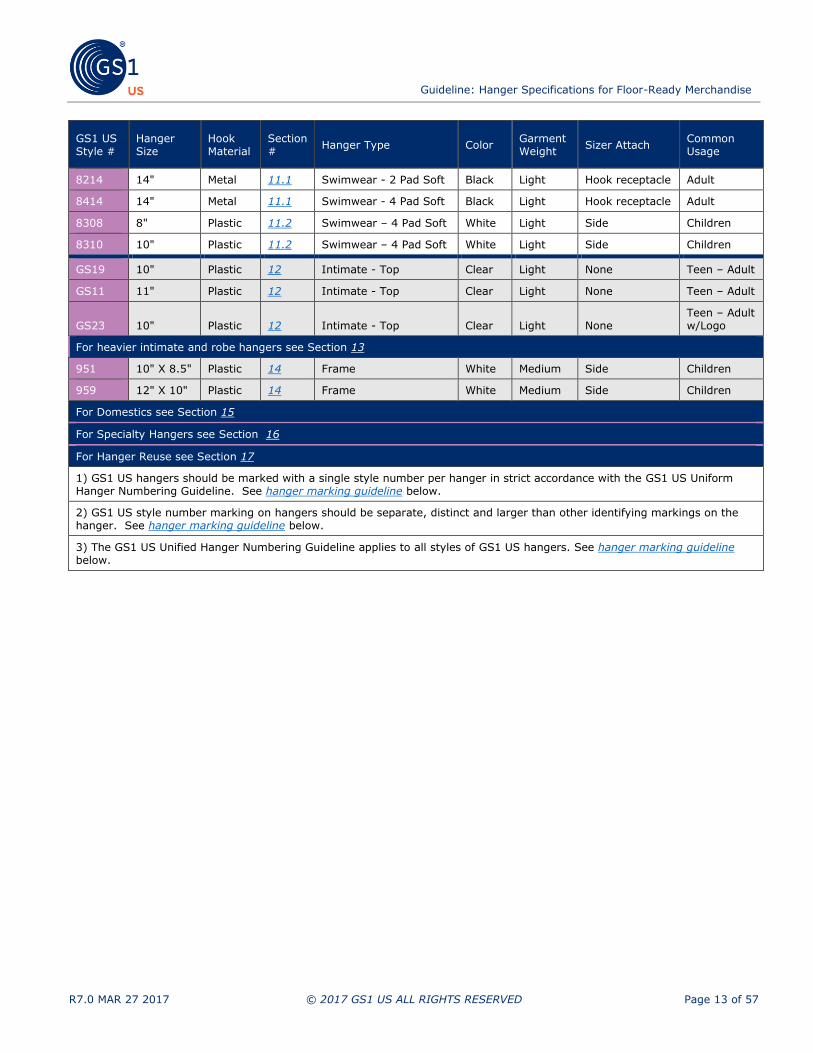
8214 14" Metal 11.1 Swimwear - 2 Pad Soft Black Light Hook receptacle Adult
8414 14" Metal 11.1 Swimwear - 4 Pad Soft Black Light Hook receptacle Adult
8308 8" Plastic 11.2 Swimwear – 4 Pad Soft White Light Side Children
8310 10" Plastic 11.2 Swimwear – 4 Pad Soft White Light Side Children
GS19 10" Plastic 12 Intimate - Top Clear Light None Teen – Adult
GS11 11" Plastic 12 Intimate - Top Clear Light None Teen – Adult
GS23 10" Plastic 12 Intimate - Top Clear Light None Teen – Adult w/Logo
For heavier intimate and robe hangers see Section 13
951 10" X 8.5" Plastic 14 Frame White Medium Side Children
959 12" X 10" Plastic 14 Frame White Medium Side Children
For Domestics see Section 15
For Specialty Hangers see Section 16
For Hanger Reuse see Section 17
1) GS1 US hangers should be marked with a single style number per hanger in strict accordance with the GS1 US Uniform Hanger Numbering Guideline. See hanger marking guideline below.
2) GS1 US style number marking on hangers should be separate, distinct and larger than other identifying markings on the hanger. See hanger marking guideline below.
3) The GS1 US Unified Hanger Numbering Guideline applies to all styles of GS1 US hangers. See hanger marking guideline below.

Guideline: Hanger Specifications for Floor-Ready Merchandise
R7.0 MAR 27 2017 © 2017 GS1 US ALL RIGHTS RESERVED Page 14 of 57
4 Tests Common Across Hanger Styles
The tests and performance standards specified below are intended to provide a degree of confidence to buyers and users of hangers that the hangers will perform as expected. The tests and specifications may be employed in several ways, as agreed upon by trading partners. The most common applications of the tests and specifications include:
■ Use by retailers and/or garment manufacturers to evaluate and qualify hanger suppliers and their products
■ Use by retailers and/or garment manufacturers to audit hanger suppliers and their products on an on-going basis
■ Use by hanger suppliers to evaluate product designs and confirm on-going quality assurance effectiveness
Successful completion of the tests, which apply at the time of purchase/delivery, should provide a
degree of confidence that the hangers will perform as expected when properly applied under normal
display and transportation conditions. Unusual applications may cause excessive loads and result in unexpected failures or other problems. Such applications should be reviewed in advance with the hanger provider to avoid any inconvenience and derive the maximum value from the hanger purchase.
Regardless of which organization conducts the tests, they should be performed on representative samples of the product. Tests should be performed by qualified personnel using calibrated equipment of suitable precision. Test results should be documented and provided upon request to the customer or supplier as appropriate.
Note: While the tests and specifications are useful for evaluating product performance and
appearance on a sample basis, it is the ultimate responsibility of the hanger supplier to exercise
appropriate quality control and ensure that products continue to meet agreed upon expectations on an ongoing basis.
4.1 Clarity and Color
Hangers should be manufactured from material that is black with a matte finish. (Clear and white hangers are acceptable for specified categories (e.g., intimates and children).) The hanger should be evaluated
under cool white fluorescent light. Sample hangers should be viewed individually and compared to the standard. The hanger should be judged acceptable if it is within all of the limits established for color and finish.
4.2 High Temperature Creep
Hangers should be manufactured from materials that retain mechanical integrity at elevated temperatures reasonably expected to be encountered in transit.
All hangers should be tested to that particular hanger specification maximum load with the specified test garment in Section 4.5 uniformly distributed and centered on the hanger. The loaded hanger should then be heated to a temperature of approximately 140°F and maintained at that temperature for
a period of 48 hours. The hanger should be judged acceptable if the load garment is not released by the hanger within the 48 hour test period, and if the total vertical and horizontal deflection of the
hanger is less than one time the dimension of the beam of the hanger.
Flat pack testing should be performed by placing one dozen hangers loaded with the specified test garment loaded to the maximum hanger load, cross stacked in a carton sized to receive the hanger with loaded apparel. The carton and contents should be heated to a temperature of 140°F for a period of 48 hours. The hanger should be deemed acceptable if when hung on a 0.50” test bar after heating, the load garment is not released by the hanger for an additional 48 hours. Additionally, the total vertical

Guideline: Hanger Specifications for Floor-Ready Merchandise
R7.0 MAR 27 2017 © 2017 GS1 US ALL RIGHTS RESERVED Page 15 of 57
and horizontal deflection of the hanger at the end of the test period should be less than one time the dimension of the beam of the hanger.
4.3 Low Temperature Impact Resistance
Hangers should be manufactured from materials that retain shatter resistance at low temperatures reasonably expected to be encountered in transit. Cold impact resistance of the hanger should be evaluated by first refrigerating tops or bottoms hangers to a temperature of approximately 28°F for at least 48 hours. The chilled hanger should then be slid from a table or other suitable surface from a height of approximately 3 feet onto a concrete floor. Separate hangers should be dropped in various orientations so that various parts of the hanger impact the floor. The hanger should be judged
acceptable if it does not fracture (per Section 4.4).
4.4 Fracture/Shatter Resistance
A fracture is defined as a crack propagating throughout the entire thickness of any given section, or a complete separation into two pieces. A shatter is the hanger fracturing into more than two sections.
4.5 Weighted Hanger Illustrations
Hangers should be designed and fabricated to meet the specified normal load capacity as listed in Section 5.4 for top hangers and Section 6.4 for bottom hangers.
Figure 4-1 represents the manner of which the Weighted Test Garments (Figure 4-2 and Figure 4-3) should be placed over the hangers. Weights go in the pockets of vests.
The illustrations shown in this section (Figure 4-2 and Figure 4-3) are blueprints for a “test” garment
that has the ability to receive various weights in specific locations to confirm the hanger will meet normal load capacity.
Figure 4-1 Example of how a weighted test garment should sit over hanger for tests

Guideline: Hanger Specifications for Floor-Ready Merchandise
R7.0 MAR 27 2017 © 2017 GS1 US ALL RIGHTS RESERVED Page 16 of 57
Figure 4-2 Blueprint for how weights should sit on a sample garment for hangers 15” or shorter, and 17” or wider
Guideline: Hanger Specifications for Floor-Ready Merchandise
R7.0 MAR 27 2017 © 2017 GS1 US ALL RIGHTS RESERVED Page 17 of 57
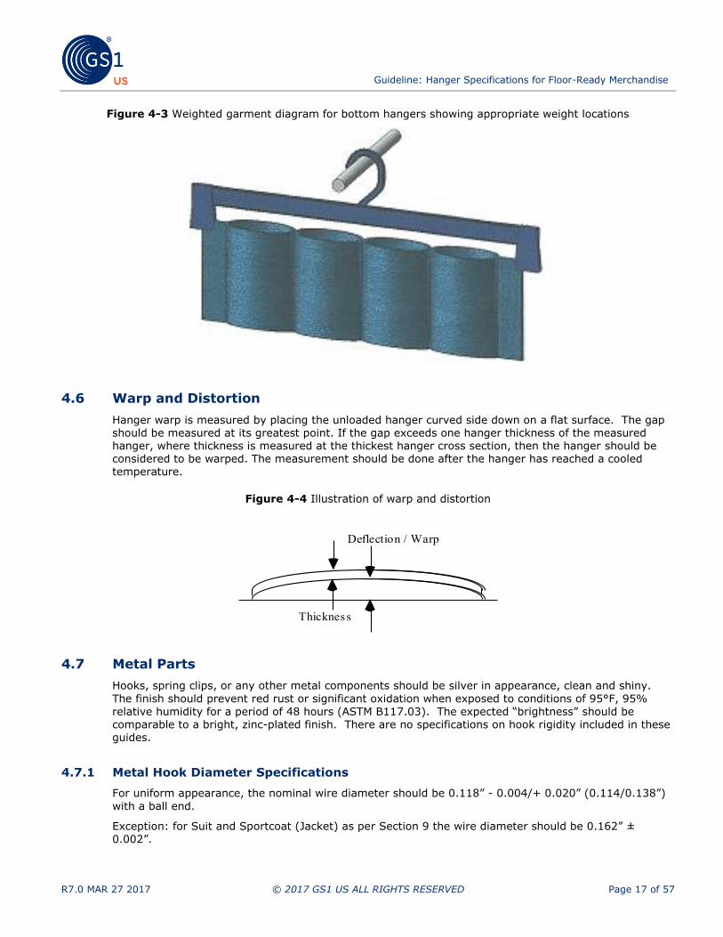
Figure 4-3 Weighted garment diagram for bottom hangers showing appropriate weight locations
4.6 Warp and Distortion
Hanger warp is measured by placing the unloaded hanger curved side down on a flat surface. The gap should be measured at its greatest point. If the gap exceeds one hanger thickness of the measured hanger, where thickness is measured at the thickest hanger cross section, then the hanger should be considered to be warped. The measurement should be done after the hanger has reached a cooled temperature.
Figure 4-4 Illustration of warp and distortion
4.7 Metal Parts
Hooks, spring clips, or any other metal components should be silver in appearance, clean and shiny.
The finish should prevent red rust or significant oxidation when exposed to conditions of 95°F, 95%
relative humidity for a period of 48 hours (ASTM B117.03). The expected “brightness” should be comparable to a bright, zinc-plated finish. There are no specifications on hook rigidity included in these guides.
4.7.1 Metal Hook Diameter Specifications
For uniform appearance, the nominal wire diameter should be 0.118” - 0.004/+ 0.020” (0.114/0.138”)
with a ball end.
Exception: for Suit and Sportcoat (Jacket) as per Section 9 the wire diameter should be 0.162” ± 0.002”.
Deflection / Warp
Thickness
Guideline: Hanger Specifications for Floor-Ready Merchandise
R7.0 MAR 27 2017 © 2017 GS1 US ALL RIGHTS RESERVED Page 18 of 57
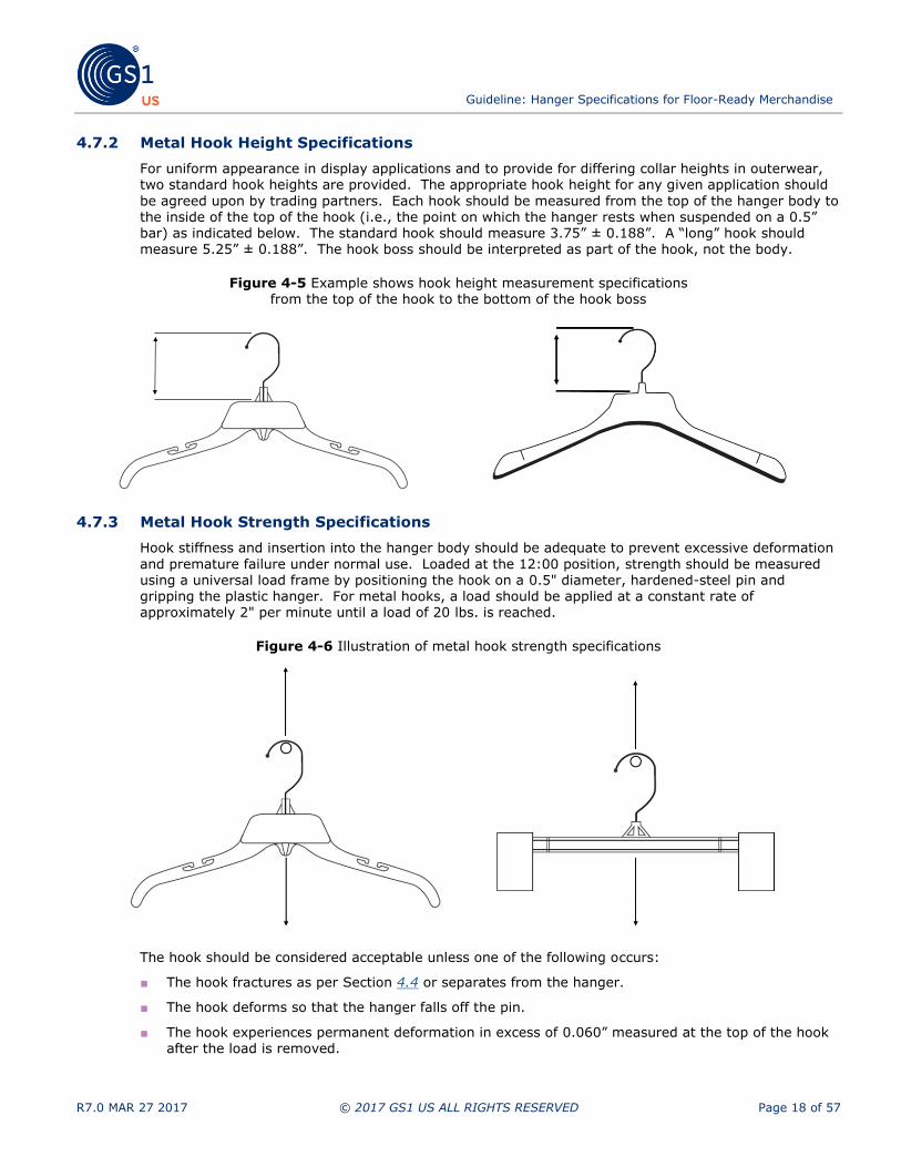
4.7.2 Metal Hook Height Specifications
For uniform appearance in display applications and to provide for differing collar heights in outerwear, two standard hook heights are provided. The appropriate hook height for any given application should
be agreed upon by trading partners. Each hook should be measured from the top of the hanger body to the inside of the top of the hook (i.e., the point on which the hanger rests when suspended on a 0.5” bar) as indicated below. The standard hook should measure 3.75” ± 0.188”. A “long” hook should measure 5.25” ± 0.188”. The hook boss should be interpreted as part of the hook, not the body.
Figure 4-5 Example shows hook height measurement specifications from the top of the hook to the bottom of the hook boss
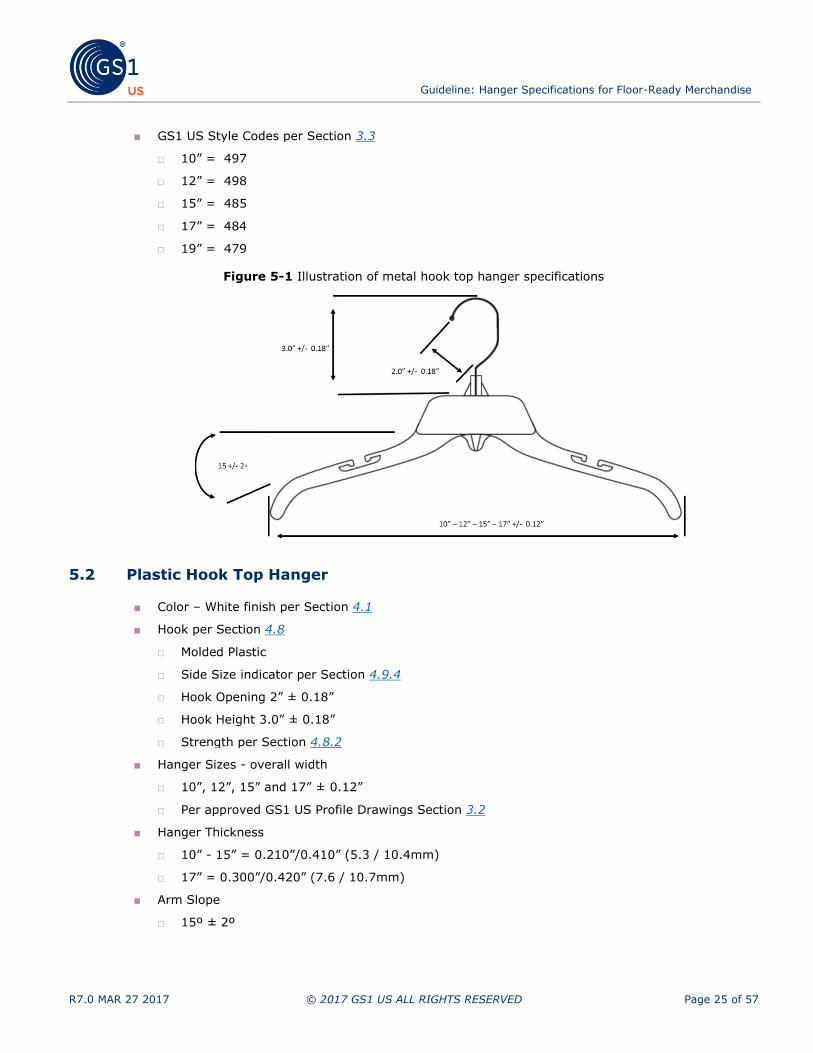
4.7.3 Metal Hook Strength Specifications
Hook stiffness and insertion into the hanger body should be adequate to prevent excessive deformation
and premature failure under normal use. Loaded at the 12:00 position, strength should be measured using a universal load frame by positioning the hook on a 0.5" diameter, hardened-steel pin and gripping the plastic hanger. For metal hooks, a load should be applied at a constant rate of approximately 2" per minute until a load of 20 lbs. is reached.
Figure 4-6 Illustration of metal hook strength specifications
The hook should be considered acceptable unless one of the following occurs:
■ The hook fractures as per Section 4.4 or separates from the hanger.
■ The hook deforms so that the hanger falls off the pin.
■ The hook experiences permanent deformation in excess of 0.060” measured at the top of the hook after the load is removed.

Guideline: Hanger Specifications for Floor-Ready Merchandise
R7.0 MAR 27 2017 © 2017 GS1 US ALL RIGHTS RESERVED Page 19 of 57
4.8 Plastic Hook Specifications (except for Intimate Apparel hangers)
4.8.1 Plastic Hook Height Specifications
Each hook should be measured from the top of the hanger body to the inside of the top of the hook (i.e., the point on which the hanger rests when suspended on a 0.5” bar) as indicated in metal hook drawing in Section 4.7.2. The standard hook should measure 3.0” ± 0.18”. The hook opening should be 2” ± 0.18.
4.8.2 Plastic Hook Strength Specifications
Loaded at the 12:00 position, strength should be measured using a universal load frame by positioning
the hook on a 0.50" diameter, hardened-steel pin and gripping the plastic hanger. For the plastic hook, a load should be applied at a constant rate of approximately 2" per minute until a load of 15 lbs. is
reached. The test should be done in the same manner as is illustrated for the metal hooks in Section 4.7.3.
The hook should be considered acceptable unless one of the following occurs:
■ The hook fractures as per Section 4.4.
■ The hook deforms so that the hanger falls off the pin.
■ The hook experiences permanent deformation in excess of 0.060” measured at the top of the hook after the load is removed.
4.9 Size Indicator
For all GS1 US size standard information, please refer to the Floor Ready Manual sizer charts, which can
be found at www.GS1US.org under the Omni-Channel Ready Merchandise Workgroup page. These Floor-Ready Merchandise Guidelines were developed to promote the effective and efficient practices for
accelerating product movement through various supply chain channels—for the express purpose of enhancing the consumer's in-store shopping experience—ensuring the product delivery and presentation.
Only a sizer that meets GS1 US Guidelines should be used and attached as instructed.
4.9.1 Size Indicator Receptacle Location
When applicable, size indicator should be located on the side of the hook base on a plastic hook hanger, or on the hook receptacle of metal hook hangers.
4.9.2 Size Indicator Testing Guidelines
All size indicators must be designed to meet the Consumer Products Safety Standards as outlined in Subchapter C - Federal Hazardous Substances Act Regulations. Test methods described in parts
1500.51B are applicable for impact testing. Test methods described in parts 1500.51C are applicable
for bite testing. Test methods described in part 1500.53E are applicable for torque testing. Test methods described in part 1500.53F are applicable for tension testing. In the event of a failure in any of these tests, part 1501.1-5 applies for the smallest loose piece.
■ The Toxics in Packaging Clearinghouse (TPCH) maintains the Model Toxics in Packaging Legislation and coordinates implementation of state legislation, based on the Model, on behalf of its member
states, with the goal of promoting consistency across states. TPCH is a resource and single point of contact for companies seeking information on toxics in packaging requirements or an exemption.

Guideline: Hanger Specifications for Floor-Ready Merchandise
R7.0 MAR 27 2017 © 2017 GS1 US ALL RIGHTS RESERVED Page 20 of 57
Note: Each company is individually responsible for meeting all statutory and/or regulatory
requirements for their company and their products. Consult with your company’s legal counsel or compliance team (regulatory or quality) for more specific information about statutory and regulatory requirements.
4.9.3 Size Indicator Information
In addition the industry has developed GS1 US Secure-Over-Hook Sizer (SOHS) Guideline for Apparel Hangers. These guidelines show the formatting of sizes as displayed with apparel hangers specific to Shape, Design, Color / Finish, Font, Nomenclature, and Safety (secure on the hanger).
Figure 4-7 Illustration of size indicator information and min/max information

Guideline: Hanger Specifications for Floor-Ready Merchandise
R7.0 MAR 27 2017 © 2017 GS1 US ALL RIGHTS RESERVED Page 21 of 57
4.9.4 Side Sizer Indicator Information
Side Sizers charts are available at 6.0 Color-to-Size Cross Reference and Color-to-Size Cross Reference
Chart.
Figure 4-8 Illustration of Side Sizer and min/max information

Guideline: Hanger Specifications for Floor-Ready Merchandise
R7.0 MAR 27 2017 © 2017 GS1 US ALL RIGHTS RESERVED Page 22 of 57
Figure 4-9 Side Sizer font illustration

Guideline: Hanger Specifications for Floor-Ready Merchandise
R7.0 MAR 27 2017 © 2017 GS1 US ALL RIGHTS RESERVED Page 23 of 57
4.10 Hanger Marking Guideline
■ GS1 US hanger style numbers should be located on the hanger arm or beam as near to the end as practical. The GS1 US style marking should be separate and apart from any other manufacturer
style markings. The GS1 US style number should be the only numeric characters appearing on that half of the hanger beam.
■ GS1 US style number marking font size should be as large as practical with respect to the size and geometry of the specific hanger.
■ Only one GS1 US style number should be marked on a hanger.
■ Hanger manufacturer I.D. (name and/or logo) and resin type should be clearly marked on all GS1
US compliant hangers.
■ Country of Origin - All companies should review applicable legal/regulatory requirements pertaining to holders designed for or capable of reuse and the need to be marked with a Country of Origin at
the unit level.
Important: Each company is individually responsible for meeting all statutory and/or regulatory
requirements for their company and their products. Consult with your company’s legal counsel or compliance team (regulatory or quality) for more specific information about statutory and regulatory requirements.
Figure 4-10 Images show the location where the markings should be made on the hanger
4.11 Logo Identification
Brand name logo on hangers and additional hanger styles (not covered in this document) are issues to
be agreed upon between trading partners.

Guideline: Hanger Specifications for Floor-Ready Merchandise
R7.0 MAR 27 2017 © 2017 GS1 US ALL RIGHTS RESERVED Page 24 of 57
5 Top Hanger Specifications
5.1 Metal Hook Top Hanger
■ Color – White finish per Section 4.1
■ Hook per Section 4.7
□ Turnable ball end hook
□ Bright plated wire 0.118” +0.020/-0.004”
□ Hook Opening 2” ± 0.18”
□ Hook Height 3.75” ± 0.18”
□ Strength per Section 4.7.3
■ Hanger Sizes - overall width
□ 10”,12”, 15”, 17” and 19” ± 0.12”
□ Per approved GS1 US Profile Drawings in Section 3.2
■ Hanger Thickness
□ 10” - 15” = 0.210”/0.410” (5.3 / 10.4mm)
□ 17” - 19” = 0.300”/0.420” (7.6 / 10.7mm)
■ Arm Slope
□ 15°± 2°
■ Neck Area Profile
□ Per approved GS1 US Profile Drawings
□ Provision for SOHS per Section 4.9.3
■ Shoulder Strap Slots/Ribs
□ Strap slots and/or ribs are optional
■ Coordinate capable per Section 5.8
□ Attachment located on underside of hook
□ Hang height 2.0 / 2.38”
□ Second hanger to hang parallel to Top hanger
■ Normal Load Capacity per Section 5.4
□ 10” - 15” hangers 1.5 lbs.
□ 17” - 19” hangers 2.0 lbs.
■ Warp Under Load per Section 5.4
□ Not to exceed one hanger thickness
■ High Temperature Creep per Section 4.2
■ Low Temperature Impact per Section 4.3
■ Fracture/Shatter Resistance per Section 4.4
Guideline: Hanger Specifications for Floor-Ready Merchandise
R7.0 MAR 27 2017 © 2017 GS1 US ALL RIGHTS RESERVED Page 25 of 57
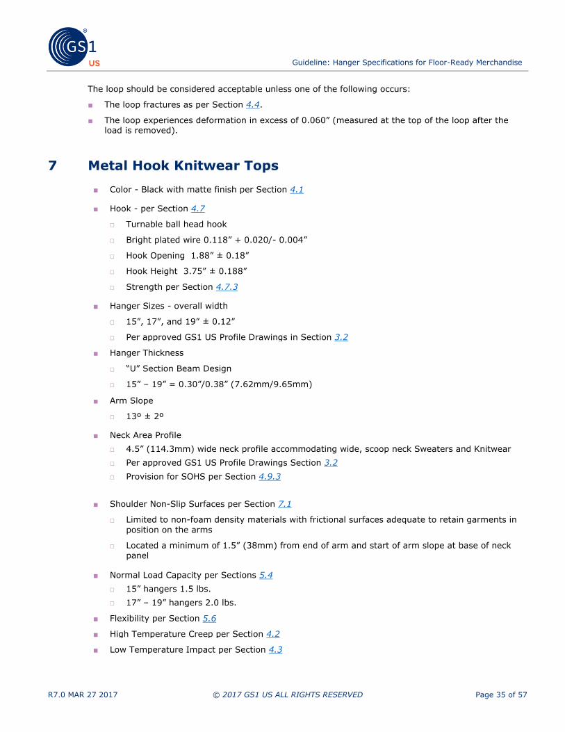
■ GS1 US Style Codes per Section 3.3
□ 10” = 497
□ 12” = 498
□ 15” = 485
□ 17” = 484
□ 19” = 479
Figure 5-1 Illustration of metal hook top hanger specifications
5.2 Plastic Hook Top Hanger
■ Color – White finish per Section 4.1
■ Hook per Section 4.8
□ Molded Plastic
□ Side Size indicator per Section 4.9.4
□ Hook Opening 2” ± 0.18”
□ Hook Height 3.0” ± 0.18”
□ Strength per Section 4.8.2
■ Hanger Sizes - overall width
□ 10”, 12”, 15” and 17” ± 0.12”
□ Per approved GS1 US Profile Drawings Section 3.2
■ Hanger Thickness
□ 10” - 15” = 0.210”/0.410” (5.3 / 10.4mm)
□ 17” = 0.300”/0.420” (7.6 / 10.7mm)
■ Arm Slope
□ 15º ± 2º

Guideline: Hanger Specifications for Floor-Ready Merchandise
R7.0 MAR 27 2017 © 2017 GS1 US ALL RIGHTS RESERVED Page 26 of 57
■ Neck Area Profile
□ Per approved GS1 US Profile Drawings Section 3.2
□ Provision for child resistant size tab indicator
■ Shoulder Strap Slots/Ribs
□ Strap slots and/or ribs are optional
■ Coordinate Capable per Section 6.8.1
□ Attachment over Top hanger hook
■ Normal Load Capacity per Section 5.4
□ 10” - 15” hangers 1.5 lbs.
□ 17” hangers 2.0 lbs.
■ Warp Under Load per Section 5.4
□ Not to exceed one hanger thickness
■ High Temperature Creep per Section 4.2
■ Low Temperature Impact per Section 4.3
■ Fracture/Shatter Resistance per Section 4.4
■ GS1 US Style Codes per Section 3.3
□ 10” = 495
□ 12” = 496
□ 15” = 472
□ 17” = 467
Figure 5-2 Illustration of plastic hook top hanger specifications

Guideline: Hanger Specifications for Floor-Ready Merchandise
R7.0 MAR 27 2017 © 2017 GS1 US ALL RIGHTS RESERVED Page 27 of 57
5.3 Top Hanger Dimensions
Hangers should be consistent in dimensions and outline to provide consistent appearance at the point of sale. Hanger dimensions are specified using the full scale hanger profile drawings as mentioned in
Section 3.2. Hangers that meet the following criteria should be deemed acceptable:
■ Completely enclosed within the outer perimeter of the appropriate size profile
■ Completely cover the appropriate inner profile
5.4 Top Hanger Normal Load Capacity
Top hangers less than or equal to 15” in nominal length should be suitable for use in transporting and
displaying garments weighing up to 1.5 lbs. Top hangers greater than 15” wide and up to 19” wide should be suitable for use in transporting and displaying garments weighing up to 2.0 lbs.
Top hanger capacity testing should be performed using a garment (see Section 4.5) with evenly distributed weights, three in the front and three in the back, hung over the hanger. The hanger should be placed on a 0.5” diameter hardened-steel pin. The hanger and the weight vest should remain hanging on the test fixture, and there should be no warp (per Section 4.6) of the hanger for it to be
considered acceptable.
5.5 Top Hanger Proof Load Capacity
Hangers should be designed and fabricated to meet specified proof or “overload” conditions. Static proof load should be evaluated using a universal load frame. The hook end should be attached to a 1/2" diameter hardened-steel pin. The hanger should be loaded at two points located at the recessed
points through the top of the hanger using a rigid "Y" cable. The length of each leg of the "Y" cable should be 15". The load should be applied at a rate of 2" per minute until any type of failure occurs. Hanger strength should be judged acceptable if the hanger does not fracture at a load of 6.0 lbs. for hangers 15” or shorter, or 12.0 lbs. for hangers 17” or longer.
Figure 5-3 Illustration of top hanger proof load capacity test

Guideline: Hanger Specifications for Floor-Ready Merchandise
R7.0 MAR 27 2017 © 2017 GS1 US ALL RIGHTS RESERVED Page 28 of 57
5.6 Top Hanger Flexibility
Flexibility or resistance to shatter should be confirmed using a “bend test.” Bend testing should be performed using a 3 point bend fixture and a universal load frame. The arms of the hanger should be
supported by 0.50” diameter hardened-steel pins. The support span should be 12" for hangers 14” or more in length, and 8” for hangers less than 14” in length. The center of the hanger should be clamped securely using a 1” wide support plate. A load should be applied at mid-span at a rate of 2" per minute until either failure or yield occurs. The hanger should be considered acceptable if either of the following events occurs:
■ The hanger is pulled through the support bars without fracturing (per Section 4.4), or
■ A load of 20 lbs. is applied without fracturing the hanger (per Section 4.4).
Figure 5-4 Illustration of top hanger flexibility test
5.7 Top Hanger Thickness
Hangers should be consistent in thickness to provide consistent appearance at the point-of-sale. The thickness of the 17” and 19” Top hangers, measured from front to back across the thickest section of the hanger, should fall within the range from 0.300” to 0.420”. The thickness of the 12” and 15” Top hangers, measured from front to back across the thickest section of the hanger, should fall within the range from 0.210” to 0.410”.
5.8 Coordinate Loop – Metal Hook Hanger to Metal Hook Hanger
5.8.1 Feature Dimensions
The coordinate loop should be sized to support the secondary garment at a reasonably consistent height and should be located on the under-side of the hanger, opposite the hook and centered. The loop should support a second hanger hook between 2.0” and 2.38” from the top of the hanger (measured
from the base of the hook boss to the bottom of the coordinate loop). The coordinate loop should allow

Guideline: Hanger Specifications for Floor-Ready Merchandise
R7.0 MAR 27 2017 © 2017 GS1 US ALL RIGHTS RESERVED Page 29 of 57
a hook of diameter specified above to run substantially parallel to the axis of the hanger so that it does not protrude through the front or back planes of the top hanger.
Figure 5-5 Illustration of coordinate loop guideline dimensions (metal to metal)
5.8.2 Feature Strength
Strength of the coordinate loop should be adequate to support the secondary garment under normal
transit and display conditions. It should be evaluated using a universal load frame. The hanger body should be gripped below the hook and the load should be applied through the loop using a hardened-steel pin the same diameter as the hook. Load should be applied at a constant rate of 2" per minute. The loop should be considered acceptable if a load of 15 lbs. does not result in fracture of the loop (per Section 4.4).
Figure 5-6 Illustration of coordinate loop strength test (metal to metal)
6 Bottom Hanger Specifications
6.1 Metal Hook Bottom Hanger
■ Color - Black with matte finish per Section 4.1

Guideline: Hanger Specifications for Floor-Ready Merchandise
R7.0 MAR 27 2017 © 2017 GS1 US ALL RIGHTS RESERVED Page 30 of 57
■ Hook - per Section 4.7
□ Turnable ball end hook
□ Bright plated wire 0.118” + 0.020/- 0.004”
□ Hook Opening 2” ± 0.18”
□ Hook Height 3.75” ± 0.18”
□ Strength per Section 4.7.3
□ Provision for SOHS per Section 4.9.1
■ Hanger Sizes - overall width
□ 8”, 10”, 12”, and 14” ± 0.12”
□ Per approved GS1 US Profile Drawings Section 3.2
■ Arm Slope
□ None – Straight
■ Garment Clips per Sections 4.7, 6.5, and 6.6
□ “Pinch Clip” style only
□ 16 lbs. maximum opening force per Section 6.5
□ Padded (soft) or teeth as required by the application - see Section 6.7
□ Length of clip appropriate to the hanger style
□ Gripping force per Section 6.4.33
■ Load Capacity – per Section 6.4
□ 8” - 12”, Short jaw teeth/Pad = 1.0 lbs. garments
□ 8” - 12”, Long jaw teeth/Pad = 1.2 lbs. garments
□ 14”, Short jaw teeth/Pad = up to 1.0 lbs. garments
□ 14”, Long jaw teeth/Pad = up to 3.0 lbs. garments
■ Warp Under Load per Section 5.4
□ Not to exceed one hanger thickness
■ High Temperature Creep per Section 4.2
■ Low Temperature Impact per Section 4.3
■ Fracture / Shatter Resistance per Section 4.4
■ GS1 US Style Codes per Section 3.3
□ 8 inch:
- 6008/6208/6408 Short jaw with Pinch Bottom teeth/pad 1 lbs. load
- 7008/7208/7408 Long jaw with Pinch Bottom teeth/pad 1.2 lbs. load
□ 10 inch:
- 6010/6210/6410 Short jaw with Pinch Bottom teeth/pad 1 lbs. load
- 7010/7210/7410 Long jaw with Pinch Bottom teeth/pad 1.2 lbs. load
□ 12 inch:
- 6012/6212/6412 Short jaw with Pinch Bottom teeth/pad 1 lbs. load

Guideline: Hanger Specifications for Floor-Ready Merchandise
R7.0 MAR 27 2017 © 2017 GS1 US ALL RIGHTS RESERVED Page 31 of 57
- 7012/7212/7412 Long jaw with Pinch Bottom teeth/pad 1.2 lbs. load
□ 14 inch:
- 6014/6214/6414 Short jaw with Pinch Bottom teeth/pad 1 lbs. load
- 7014/7214/7414 Long jaw with Pinch Bottom teeth/pad 3.0 lbs. load
■ Comments
□ Designed to be suitable for use as a coordinate (set) hanger with GS1 US Metal Hook Top hangers
Figure 6-1 Illustration of metal hook bottom hanger specifications
6.2 Plastic Hook/Coordinate Loop Bottom Hangers
■ Color - White per Section 4.1
■ Hook - per Section 4.8
□ Molded Plastic
□ Side Sizer indicator per Section 4.9.4
□ Hook Opening 2” ± 0.18”
□ Hook Height 3.0” ± 0.18”
□ Strength per Section 4.8.2
■ Loops per Section 6.2
■ Hanger Sizes - overall width
□ 8”, 10”, 12”, 14” ± 0.12”
□ Per approved GS1 US Profile Drawings Section 3.2

Guideline: Hanger Specifications for Floor-Ready Merchandise
R7.0 MAR 27 2017 © 2017 GS1 US ALL RIGHTS RESERVED Page 32 of 57
■ Arm Slope
□ None - Straight
■ Garment Clips per Sections 4.7, 6.5, and 6.7
□ “Pinch Clip” style only
□ 16 lbs. maximum opening force per Section 6.5
□ Padded (soft) or teeth as required by the fabric as per Section 6.7
□ Appropriate clip to the hanger style
□ Gripping force per Section 6.4.33
■ Load Capacity - per Section 6.4
□ 8” - 14”, Short jaw teeth/Pad = 1.0 lbs. garments
□ 8” - 12”, Long jaw teeth/Pad = 1.2 lbs. garments
□ 14”, Long jaw teeth/Pad = up to 3.0 lbs. garments
■ Warp Under Load per Section 5.4
□ Not to exceed one hanger thickness
■ High Temperature Creep per Section 4.2
■ Low Temperature Impact per Section 4.3
■ Fracture/Shatter Resistance per Section 4.4
■ GS1 US Style Codes per Section 3.3
□ 8 inch:
- 6108 Short jaw Pinch Bottom teeth
- 7108 Long jaw Pinch Bottom teeth
□ 10 inch:
- 6110 Short jaw Pinch Bottom teeth
- 7110 Long jaw Pinch Bottom teeth
□ Coordinate Drop Loop Bottom Hangers:
- 8” x 4” Drop = 9408 Pinch Bottom - Coordinate – Teeth
- 10” x 4” Drop = 9410 Pinch Bottom - Coordinate – Teeth
- 12” x 4” Drop = 9412 Pinch Bottom - Coordinate – Teeth
- 8” x 9.5” Drop = 9508 Pinch Bottom - Coordinate – Teeth
- 10” x 9.5” Drop = 9510 Pinch Bottom - Coordinate – Teeth
- 12” x 9.5” Drop = 9512 Pinch Bottom - Coordinate – Teeth
■ Comments
□ Coordinate Drop Loop Hangers designed to fit over the hook of GS1 US Plastic Hook Top Hangers

Guideline: Hanger Specifications for Floor-Ready Merchandise
R7.0 MAR 27 2017 © 2017 GS1 US ALL RIGHTS RESERVED Page 33 of 57
Figure 6-2 Illustration of plastic hook/coordinate loop bottom hanger specifications
6.3 Bottom Hanger Dimensions
Hangers should be consistent in dimensions and outline to provide consistent appearance at the point of
sale. Hanger dimensions are specified using the full scale hanger profile drawings as mentioned in Section 3.2. Hangers that meet the following criteria should be deemed acceptable:
■ Completely enclosed within the outer perimeter of the appropriate size profile
■ Completely cover the appropriate inner profile
6.4 Bottom Hanger Load Capacity
6.4.1 Short-Jaw Hangers 8” to 14”
Short jaw teeth/pad bottoms hangers between 8” and 14” in nominal length should be suitable for use in transporting and displaying garments weighing up to 1.0 lbs.
6.4.2 Long-Jaw Hangers 8” to 14”
■ Long jaw teeth/pad bottoms hangers between 8” and 12” in nominal length should be suitable for use in transporting and displaying garments weighing up to 1.2 lbs.
■ Long jaw teeth/pad bottoms hangers 14” in nominal length should be suitable for use in transporting and displaying garments weighing up to 3.0 lbs.
6.4.3 Hanger Load Capacity Fabric Pull Test
Bottom hanger capacity should be confirmed by a fabric pull test intended to simulate a garment being
pulled from the teeth/pad of the hanger. The hanger should be attached on a stationary fixture by the hook and the fabric should be gripped by the pinch clips. The other end of the fabric should be clamped to a movable fixture. The fabric should be pulled away from the hanger at a rate of 2” per minute until the fabric is pulled from the hanger.
Reference:
■ 8” to 14” Short jaw teeth/pad bottoms hangers = 4.0 lbs. minimum fabric pull-out capacity

Guideline: Hanger Specifications for Floor-Ready Merchandise
R7.0 MAR 27 2017 © 2017 GS1 US ALL RIGHTS RESERVED Page 34 of 57
■ 8” to 12” Long jaw teeth/pad bottoms hangers = 4.8 lbs. minimum fabric pull-out capacity
■ 14” Long jaw teeth/pad bottoms hangers = 12.0 lbs. minimum fabric pull-out capacity
Test fabric shall be untucked/unfolded and protrude a minimum of 1 inch beyond the hanger clips. The length of the fabric should be equal to the width of the fabric.
Table 6-1 Recommended Fabric Types and Weight by Garment Type (additional fabric types/weights are up to individual trading partner relationships):
Garment Type Recommended Test Fabric Type Recommended Test Fabric Weight
Denim 100% cotton 12 oz. ± 4 oz.
Chinos 100% cotton or 100% polyester 10 oz. ± 4 oz.
6.5 Garment Clip Operation
Ease of opening the garment clip should be measured as the maximum pinch force that is required to open the clip to its fully open position. The force should be measured at the center of the thumb
contact area, perpendicular to the hanger hook plane, using a universal load frame. The hanger should be judged acceptable if a load of 16 lbs. is not exceeded at the fully open position.
6.6 Garment Clip Life
Fatigue life to failure of the garment clip should be evaluated using an oscillating drive mechanism that actuates the clip from its fully closed position to fully open position, as limited by the clip design. The
clip should be actuated open and closed at approximately one complete cycle per second. The clip should be judged acceptable if the clip has not fractured or failed within 500 cycles.
6.7 Soft Pad
Non-slip surfaces used for hanger styles 6208, 6408, 6210, 6410, 6212, 6412, 6214, 6414, 7208, 7408,
7210, 7410, 7212, 7412, 7214, 7414, 8208, 8408, 8210, 8410, 8212, 8412, 8214, 8414, 8308, and
8310 should be limited to non-foam density materials with frictional surfaces adequate to retain garments in position on the pads of the hanger.
The configuration of pads used should be adequate enough to maintain the garment’s position on the hanger. Performance of the hangers with either 2 pads or 4 pads should not differ.
Attached pad should be of material quality that will prevent the transfer of residue (color and/or scuff marks) from the pad(s) to the garment.
6.8 Plastic Coordinate Loop Bottom Hanger Specifications
6.8.1 Plastic Coordinate Loop Hanger Height Specifications
Each loop is to be measured from the top of the hanger body to the inside of the bottom of the loop as indicated in plastic loop drawing in Section 6.2. The standard loop should measure 4.0” ± 0.12”, with
the extended measuring 9.5” ± 0.12. The loop opening should be wide enough to accommodate the hanger manufacturer’s plastic hook as defined Section 4.8.
6.8.2 Plastic Coordinate Loop Hanger Strength Specifications
Loaded at the 12:00 position, strength should be measured using a universal load frame by positioning the hook on a 0.5" diameter hardened-steel pin and gripping the plastic hanger. For the plastic hook, a load should be applied at a constant rate of approximately 2" per minute until a load of 15 lbs. is
reached. The test should be done in the same manner as is illustrated for the metal hooks in Section 4.7.3.
Guideline: Hanger Specifications for Floor-Ready Merchandise
R7.0 MAR 27 2017 © 2017 GS1 US ALL RIGHTS RESERVED Page 35 of 57
The loop should be considered acceptable unless one of the following occurs:
■ The loop fractures as per Section 4.4.
■ The loop experiences deformation in excess of 0.060” (measured at the top of the loop after the load is removed).
7 Metal Hook Knitwear Tops
■ Color - Black with matte finish per Section 4.1
■ Hook - per Section 4.7
□ Turnable ball head hook
□ Bright plated wire 0.118” + 0.020/- 0.004”
□ Hook Opening 1.88” ± 0.18”
□ Hook Height 3.75” ± 0.188”
□ Strength per Section 4.7.3
■ Hanger Sizes - overall width
□ 15”, 17”, and 19” ± 0.12”
□ Per approved GS1 US Profile Drawings in Section 3.2
■ Hanger Thickness
□ “U” Section Beam Design
□ 15” – 19” = 0.30”/0.38” (7.62mm/9.65mm)
■ Arm Slope
□ 13º ± 2º
■ Neck Area Profile
□ 4.5” (114.3mm) wide neck profile accommodating wide, scoop neck Sweaters and Knitwear
□ Per approved GS1 US Profile Drawings Section 3.2
□ Provision for SOHS per Section 4.9.3
■ Shoulder Non-Slip Surfaces per Section 7.1
□ Limited to non-foam density materials with frictional surfaces adequate to retain garments in
position on the arms
□ Located a minimum of 1.5” (38mm) from end of arm and start of arm slope at base of neck
panel
■ Normal Load Capacity per Sections 5.4
□ 15” hangers 1.5 lbs.
□ 17” – 19” hangers 2.0 lbs.
■ Flexibility per Section 5.6
■ High Temperature Creep per Section 4.2
■ Low Temperature Impact per Section 4.3

Guideline: Hanger Specifications for Floor-Ready Merchandise
R7.0 MAR 27 2017 © 2017 GS1 US ALL RIGHTS RESERVED Page 36 of 57
■ Fracture/Shatter Resistance per Section 4.4
■ GS1 US Style Codes per Section 3.3
□ 15” = 585
□ 17” = 584
□ 19” = 579
■ Comments
□ “U-beam” Sweater/Knitwear hangers are for use with sweaters, knit tops, and other knitwear
garments as may be determined by the trading partners
Figure 7-1 Illustration of metal hook knitwear top hanger specifications
7.1 Non-Slip Shoulder Surfaces
Location of non-slip surfaces on the top edges of the hanger arms should be a minimum of 1.5” from the end (tip) of the arm and extend to within approximately 1.5” from the start of the arm slope at the base of the neck panel. (Note: non-slip material, if used, should not detach from the hanger.) Non-slip materials should be limited to non-foam density materials with frictional surfaces adequate to retain
garments in position on the arms of the hanger.
Figure 7-2 Illustration of the location of non-slip shoulder surfaces

Guideline: Hanger Specifications for Floor-Ready Merchandise
R7.0 MAR 27 2017 © 2017 GS1 US ALL RIGHTS RESERVED Page 37 of 57
8 Outerwear Hangers
8.1 Metal Hook Outerwear
■ Color - Black with matte finish per Section 4.1
■ Hook - per Section 4.7
□ Turnable ball head hook
□ Bright plated wire 0.118” + 0.020”/- 0.004”
□ Hook Opening 2” ± 0.18”
□ Hook Height 3.75” ± 0.18” and 5.25” ± 0.18”
□ Strength per Section 4.7.3
■ Hanger Sizes - overall width
□ 15”, 17”, and 19” ± 0.12”
□ Per approved GS1 US Profile Drawings Section 3.2
■ Hanger Thickness
□ 15” – 19” = 0.210”/0.500” (5.3mm/12.7mm)
■ Arm Slope
□ 15º ± 2º
□ Warp as per Section 4.6
■ Neck Area Profile
□ Per approved GS1 US Profile Drawings Section 3.2
□ Provision for SOHS per Section 4.9.3
■ Optional Coordinate Capable per Section 5.8
□ Attachment located on underside of hook
□ Hang height 2.0”/2.38”
□ Second hanger to hang parallel to Top hanger
■ Normal Load Capacity test per Section 5.4 except:
□ 15” – 19” hangers 5.0 lbs.
■ High Temperature Creep per Section 4.2
■ Low Temperature Impact per Section 4.3
■ Fracture/Shatter Resistance per Section 4.4
■ GS1 US Style Codes per Section 3.3
□ 15” = 3315 or 3316
□ 17” = 3328 or 3329
□ 19” = 3319 or 3320

Guideline: Hanger Specifications for Floor-Ready Merchandise
R7.0 MAR 27 2017 © 2017 GS1 US ALL RIGHTS RESERVED Page 38 of 57
Figure 8-1 Illustration of metal hook outerwear hanger specifications
8.2 Plastic Hook Outerwear
■ Color - White finish per Section 4.1
■ Hook - per Section 4.8
□ Molded Plastic
□ Side Size indicator per Section 4.9.4
□ Hook Opening 2.0” ± 0.18”
□ Hook Height 3.0” ± 0.18”
□ Strength per Section 4.8.2
■ Hanger Sizes - overall width
□ 12”, 15”, 17”, and 19” ± 0.12”
□ Per approved GS1 US Profile Drawings Section 3.2
■ Hanger Thickness
□ 12” = 0.210”/0.500” (5.3mm/12.7mm)
□ 15” – 19” = 0.210”/0.500” (5.3mm/12.7mm)

Guideline: Hanger Specifications for Floor-Ready Merchandise
R7.0 MAR 27 2017 © 2017 GS1 US ALL RIGHTS RESERVED Page 39 of 57
■ Arm Slope
□ 15º ± 2º
□ Warp as per Section 4.6
■ Neck Area Profile
□ Per approved GS1 US Profile Drawings Section 3.2
■ Coordinate Capable per Section 6.8
□ Attachment over Top hanger hook
■ Normal Load Capacity test per Section 5.4 except:
□ 12” hangers 3.0 lbs.
□ 15” – 19” hangers 5.0 lbs.
■ High Temperature Creep per Section 4.2
■ Low Temperature Impact per Section 4.3
■ Fracture/Shatter Resistance per Section 4.4
■ GS1 US Style Codes per Section 3.3
□ 12” = 217
□ 15” = 210
□ 17” = 225
□ 19” = 229
Figure 8-2 Illustration of plastic hook outerwear hanger specifications

Guideline: Hanger Specifications for Floor-Ready Merchandise
R7.0 MAR 27 2017 © 2017 GS1 US ALL RIGHTS RESERVED Page 40 of 57
9 Suit and Sportcoat (Jacket)
■ Color - Black with matte finish per Section 4.1
■ Hook - per Section 4.7
□ Turnable ball head hook
□ Bright plated wire 0.162” ± 0.002”
□ Hook Opening 2” ± 0.18”
□ Hook Height 3.75” or 5.25” ± 0.18”
□ Strength per Section 4.7.3
■ Hanger Sizes - overall width
□ 15”, 17”, and 19” ± 0.12”
□ Per approved GS1 US Profile Drawings Section 3.2
■ Beam Thickness - contoured U-Beam
□ 15” – 19” = 0.50”/1.37” (12.7/28.2mm)
□ Front to back at thickest section
□ 1.37” (34.8mm) maximum Diameter at end of arm
■ Arm Slope
□ 30º ± 2º (underside)
□ Nominal drop at end:
- 15” = 5.50”
- 17” = 6.15”
- 19” = 6.75”
■ Neck Area Profile
□ Per approved GS1 US Profile Drawings Section 3.2
□ Provision for SOHS per Section 4.9.3
■ Normal Load Capacity per Section 5.4 except:
□ 15” – 19” hangers = 6.0 lbs.
■ High Temperature Creep per Section 4.2
■ Low Temperature Impact per Section 4.3
■ Fracture/Shatter Resistance per Section 4.4
■ GS1 US Style Codes per Section 3.3
□ 15 inch:
- 3944 (3.75” Hook) Jacket-“U” section
- 3945 (5.25” Hook) Jacket-“U” section
□ 17 inch:
- 3936 (3.75” Hook) Jacket-“U” section
- 3937 (5.25” Hook) Jacket-“U” section

Guideline: Hanger Specifications for Floor-Ready Merchandise
R7.0 MAR 27 2017 © 2017 GS1 US ALL RIGHTS RESERVED Page 41 of 57
□ 19 inch:
- 3968 (3.75” Hook) Jacket-“U” section
- 3969 (5.25” Hook) Jacket-“U” section
■ Comments
□ All dimensions are nominal for reference only
□ Approved hanger shapes and sizes per approved GS1 US Profile Drawings
Figure 9-1 Illustration of Suit and Sportcoat (Jacket) hanger specifications

Guideline: Hanger Specifications for Floor-Ready Merchandise
R7.0 MAR 27 2017 © 2017 GS1 US ALL RIGHTS RESERVED Page 42 of 57
10 Two Piece Set Hangers
For hangers use the appropriate GS1 US Metal Hook hangers and the appropriate GS1 US Plastic Hook hangers.
10.1 Metal Hook to Metal Hook Hanger
See Section 5.8
Figure 10-1 Illustration of metal hook to metal hook hanger

Guideline: Hanger Specifications for Floor-Ready Merchandise
R7.0 MAR 27 2017 © 2017 GS1 US ALL RIGHTS RESERVED Page 43 of 57
10.2 Plastic Hook Coordinate
Per Section 6.8
Figure 10-2 Illustration of plastic hook coordinate
11 Swimwear and Activewear
11.1 Metal Hook - - Swimwear and Activewear
■ Color - Black with matte finish per Section 4.1
■ Hook - per Section 4.7
□ Turnable ball head hook
□ Bright plated wire 0.118” + 0.020”/- 0.004”
□ Hook Opening 2” ± 0.18”
□ Hook Height 3.75” ± 0.18”
□ Strength per Section 3.3.7.3
■ Hanger Sizes - overall width
□ 8”, 10”, 12”, and 14” ± 0.12”
□ Per approved GS1 US Profile Drawings Section 3.2
■ Hanger Thickness
□ 0.312” for all sizes

Guideline: Hanger Specifications for Floor-Ready Merchandise
R7.0 MAR 27 2017 © 2017 GS1 US ALL RIGHTS RESERVED Page 44 of 57
■ Arm Slope
□ 15º ± 2º
■ Neck Area Profile
□ Wide profile per 484 style
□ Same for all sizes
□ Per approved GS1 US Profile Drawings Section 3.2
□ Provision for SOHS per Section 4.9.3
■ Shoulder Strap Slots/Ribs
□ Single or double entry (see comments)
□ Horizontal retention per Section 12.4.1
□ 1.75” minimum opening all sizes
■ Pinch Clips (2) per Sections 4.7, 6.5, 6.6, 6.7
□ 0.75” to 1.0” wide x 1.5” to 2.0”
□ Offset from end of arm 0.25” maximum
□ Smooth surface or padded (no teeth)
□ Clip opening 0.62” minimum
□ Clip insertion depth 0.75” minimum
■ Normal Load Capacity per Section 11.3
□ 8” – 14” hangers 1.0 lbs.
■ Warp Under Load per Section 4.6
□ Not to exceed one hanger thickness at full load capacity
■ High Temperature Creep per Section 4.2
■ Low Temperature Impact per Section 4.3
■ Fracture/Shatter Resistance per Section 4.4
■ GS1 US Style Codes per Section 3.3
□ 8 inch:
- 8008 Swimwear - Smooth surface or Pad
- 8208 Swimwear - 2 Pad Soft
- 8408 Swimwear - 4 Pad Soft
□ 10 inch:
- 8010 Swimwear - Smooth surface or Pad
- 8210 Swimwear - 2 Pad Soft
- 8410 Swimwear - 4 Pad Soft
□ 12 inch:
- 8012 Swimwear - Smooth surface or Pad
- 8212 Swimwear - 2 Pad Soft
- 8412 Swimwear - 4 Pad Soft

Guideline: Hanger Specifications for Floor-Ready Merchandise
R7.0 MAR 27 2017 © 2017 GS1 US ALL RIGHTS RESERVED Page 45 of 57
□ 14 inch:
- 8014 Swimwear - Smooth surface or Pad
- 8214 Swimwear - 2 Pad Soft
■ 8414 Swimwear - 4 Pad Soft
■ Comments
□ Shoulder Strap Slot requirements are either single or double entry on all sizes.
Figure 11-1 Illustration of Swimwear & Activewear metal hook hanger specifications
11.2 Plastic Hook - - Swimwear and Activewear
■ Color - Black with matte finish per Section 4.1
■ Hook - per Section 4.8
□ Molded Plastic
□ Side Sizer indicator per Section 4.9.4
□ Hook Opening 2” ± 0.18”
□ Hook Height 3” ± 0.18”
□ Strength per Section 4.8.2
■ Hanger Sizes - overall width
□ 8” and 10” ± 0.12”
□ Per approved GS1 US Profile Drawings Section 3.2
■ Hanger Thickness
□ 0.312” for all sizes

Guideline: Hanger Specifications for Floor-Ready Merchandise
R7.0 MAR 27 2017 © 2017 GS1 US ALL RIGHTS RESERVED Page 46 of 57
■ Arm Slope
□ 15º ± 2º
■ Neck Area Profile
□ Wide profile per 484 style
□ Same for all sizes
□ Provision for SOHS per Section 4.9.3
■ Shoulder Strap Slots
□ Single or double entry (see comments)
□ Horizontal retention per Section 12.4.1
□ 1.0” minimum opening all sizes
■ Pinch Clips (2) per Section 4.7, 6.5, 6.6, 6.7
□ 0.75” to 1.0” wide x 1.5” to 2.0”
□ Offset from end of arm 0.25” maximum
□ Smooth surface or padded (no teeth)
□ Clip opening 0.62” minimum
□ Clip insertion depth 0.75” minimum
■ Normal Load Capacity per Section 11.3
□ 8” - 10” hangers 1.0 lbs.
■ Warp Under Load per Section 4.6
□ Not to exceed one hanger thickness at full load capacity
■ High Temperature Creep per Section 4.2
■ Low Temperature Impact per Section 4.3
■ Fracture/Shatter Resistance per Section 4.4
■ GS1 US Style Codes per Section 3.3
□ 8” = 8108 Swimwear - Smooth surface or Pad; 8308 Swimwear - Pad Soft
□ 10” = 8110 Swimwear - Smooth surface or Pad; 8310 Swimwear - Pad Soft
■ Comments: Shoulder Strap Slot requirements are either single or double entry on all sizes.
Figure 11-2 Illustration of Swimwear & Activewear plastic hook hanger specifications
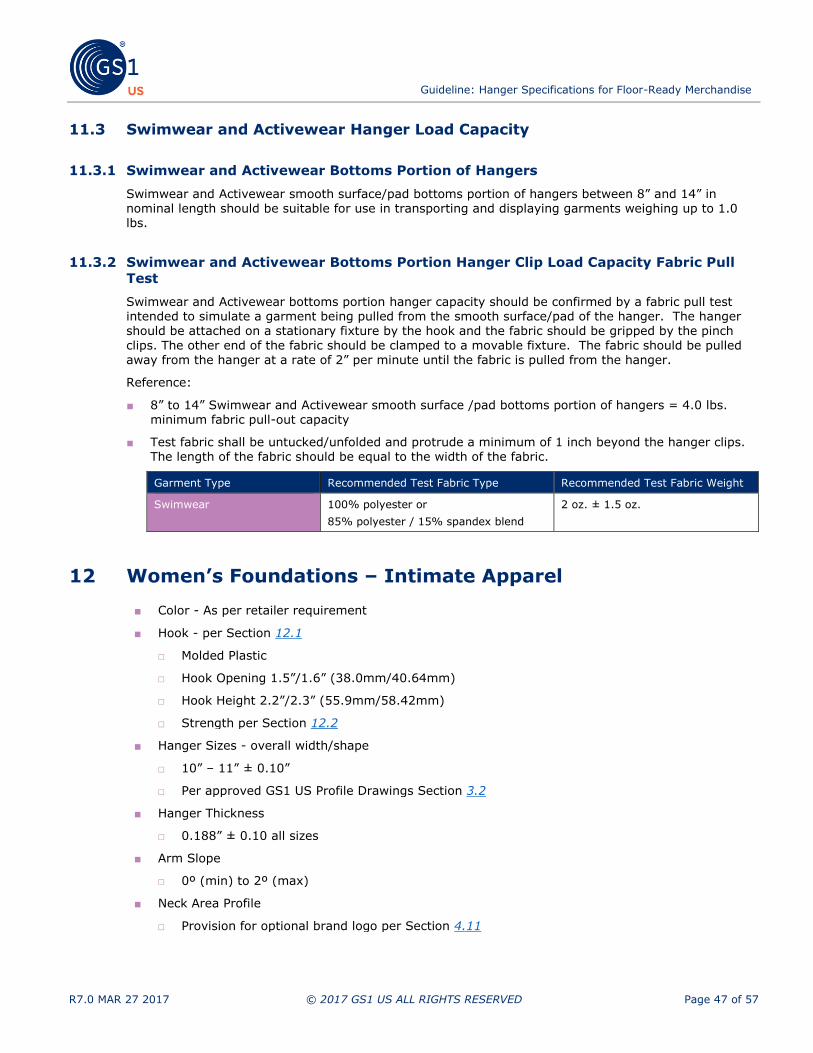
Guideline: Hanger Specifications for Floor-Ready Merchandise
R7.0 MAR 27 2017 © 2017 GS1 US ALL RIGHTS RESERVED Page 47 of 57
11.3 Swimwear and Activewear Hanger Load Capacity
11.3.1 Swimwear and Activewear Bottoms Portion of Hangers
Swimwear and Activewear smooth surface/pad bottoms portion of hangers between 8” and 14” in nominal length should be suitable for use in transporting and displaying garments weighing up to 1.0 lbs.
11.3.2 Swimwear and Activewear Bottoms Portion Hanger Clip Load Capacity Fabric Pull
Test
Swimwear and Activewear bottoms portion hanger capacity should be confirmed by a fabric pull test intended to simulate a garment being pulled from the smooth surface/pad of the hanger. The hanger should be attached on a stationary fixture by the hook and the fabric should be gripped by the pinch
clips. The other end of the fabric should be clamped to a movable fixture. The fabric should be pulled away from the hanger at a rate of 2” per minute until the fabric is pulled from the hanger.
Reference:
■ 8” to 14” Swimwear and Activewear smooth surface /pad bottoms portion of hangers = 4.0 lbs. minimum fabric pull-out capacity
■ Test fabric shall be untucked/unfolded and protrude a minimum of 1 inch beyond the hanger clips. The length of the fabric should be equal to the width of the fabric.
Garment Type Recommended Test Fabric Type Recommended Test Fabric Weight
Swimwear 100% polyester or
85% polyester / 15% spandex blend
2 oz. ± 1.5 oz.
12 Women’s Foundations – Intimate Apparel
■ Color - As per retailer requirement
■ Hook - per Section 12.1
□ Molded Plastic
□ Hook Opening 1.5”/1.6” (38.0mm/40.64mm)
□ Hook Height 2.2”/2.3” (55.9mm/58.42mm)
□ Strength per Section 12.2
■ Hanger Sizes - overall width/shape
□ 10” – 11” ± 0.10”
□ Per approved GS1 US Profile Drawings Section 3.2
■ Hanger Thickness
□ 0.188” ± 0.10 all sizes
■ Arm Slope
□ 0º (min) to 2º (max)
■ Neck Area Profile
□ Provision for optional brand logo per Section 4.11

Guideline: Hanger Specifications for Floor-Ready Merchandise
R7.0 MAR 27 2017 © 2017 GS1 US ALL RIGHTS RESERVED Page 48 of 57
■ Top and Bottom (Horizontal) Clips per Section 12.4.1
□ Maximum slide-on pressure 1.50 lbs.
□ Clip opening to 0.25” (6.4mm)
□ Pull-out force 1.75 lbs.
■ Vertical End Clips per Section 12.4.2
□ Maximum slide on pressure 2.0 lbs.
□ Clip opening to 0.38” (9.7mm)
□ Pull-out force 1.75 lbs.
■ Warp Under Load per Section 4.6
□ Not to exceed one hanger thickness at full load capacity
■ High Temperature Creep per Section 12.3
■ Fracture/Shatter Resistance per Section 12.6
■ GS1 US Style Codes per Section 3.3
□ 10”
- GS19 and GS23 Intimate Top
- CW87 Wrap Bottom as per Section 12.5
□ 11”
- GS19 and GS11 Intimate Top
Figure 12-1 Illustration of women’s foundations – intimate apparel hanger specifications for GS19 and GS11 hanger types

Guideline: Hanger Specifications for Floor-Ready Merchandise
R7.0 MAR 27 2017 © 2017 GS1 US ALL RIGHTS RESERVED Page 49 of 57
Figure 12-2 Illustration of women’s foundations – intimate apparel hanger specifications for GS23 hanger type
Figure 12-3 Illustration of women’s foundations – intimate apparel hanger specifications for CW87
12.1 Intimate Apparel Hanger Dimensions
Hangers should be consistent in dimensions and GS1 US Profile outline to provide a standard appearance at the point-of-sale. Acceptable hangers should be those that meet the following criteria:
■ Hangers comply with the approved GS1 US Profile Outline Drawing
■ Hangers are completely enclosed within the outer perimeter of the GS1 US size profile
■ Hangers completely cover the appropriate inner profile

Guideline: Hanger Specifications for Floor-Ready Merchandise
R7.0 MAR 27 2017 © 2017 GS1 US ALL RIGHTS RESERVED Page 50 of 57
12.2 Hook Strength
The hook strength, loaded at the top contour of the hook (12:00 position of the inside curve) should be measured using a universal load frame by positioning the hook on a 0.50” diameter hardened steel pin
and gripping the plastic hanger. Load should be applied at a constant rate of approximately 1.0” per minute until a load of 1.5 lbs. is reached. The hook should be considered acceptable unless the hook fractures.
Figure 12-4 Illustration of intimate apparel hanger hook strength test
12.3 High Temperature Creep
Intimate apparel hangers should be manufactured from materials that maintain mechanical integrity at
elevated temperatures reasonably expected to be encountered in transit. Evaluation should be deemed
acceptable if a load of 1 lb. remains hanging at a temperature of 140°F for a period of 48 hours.
12.4 Intimate Apparel Hanger Proof Load Capacity
12.4.1 Top and Bottom (Horizontal) Clip Performance
■ Test material: non-elastic bra-strap fabric of the specified dimensions common to applicable garments.
■ Test fabric shall be untucked/unfolded and protrude a minimum of 1 inch beyond the hanger clips. The length of the fabric should be equal to the width of the fabric.
Garment Type Recommended Test Fabric Type Recommended Test Fabric Weight
Intimates 80% nylon/20% elastane 2 oz. ± 1.5x oz.
■ Slide on pressure at top/bottom clip: In order to minimize repetitive motion syndrome in the industry, the maximum allowable pressure to slide a garment into the clip area should be 1.50 lbs. measured using the specified test material 0.75” wide x 0.045” thick.
■ Clip opening: The clip should be able to accept the specified test material at a thickness of 0.250” and in doing so retain its holding power and not mar the garment.
■ Holding power: The top/bottom clip should be capable of holding the specified test material 0.75” wide x 0.045” thick. Clamp the hanger body at the center with the specified test material looped securely through the top and bottom clips at both ends. Using a universal load frame, apply a
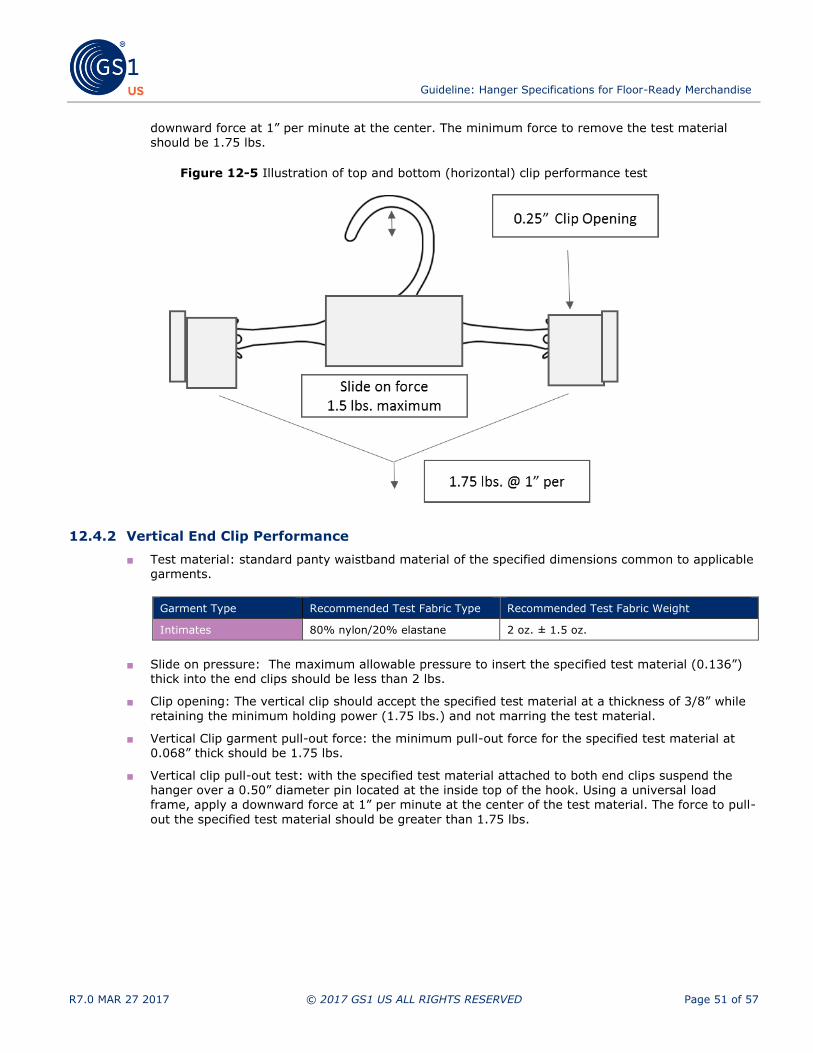
Guideline: Hanger Specifications for Floor-Ready Merchandise
R7.0 MAR 27 2017 © 2017 GS1 US ALL RIGHTS RESERVED Page 51 of 57
downward force at 1” per minute at the center. The minimum force to remove the test material should be 1.75 lbs.
Figure 12-5 Illustration of top and bottom (horizontal) clip performance test
12.4.2 Vertical End Clip Performance
■ Test material: standard panty waistband material of the specified dimensions common to applicable
garments.
Garment Type Recommended Test Fabric Type Recommended Test Fabric Weight
Intimates 80% nylon/20% elastane 2 oz. ± 1.5 oz.
■ Slide on pressure: The maximum allowable pressure to insert the specified test material (0.136”) thick into the end clips should be less than 2 lbs.
■ Clip opening: The vertical clip should accept the specified test material at a thickness of 3/8” while
retaining the minimum holding power (1.75 lbs.) and not marring the test material.
■ Vertical Clip garment pull-out force: the minimum pull-out force for the specified test material at 0.068” thick should be 1.75 lbs.
■ Vertical clip pull-out test: with the specified test material attached to both end clips suspend the hanger over a 0.50” diameter pin located at the inside top of the hook. Using a universal load
frame, apply a downward force at 1” per minute at the center of the test material. The force to pull-
out the specified test material should be greater than 1.75 lbs.
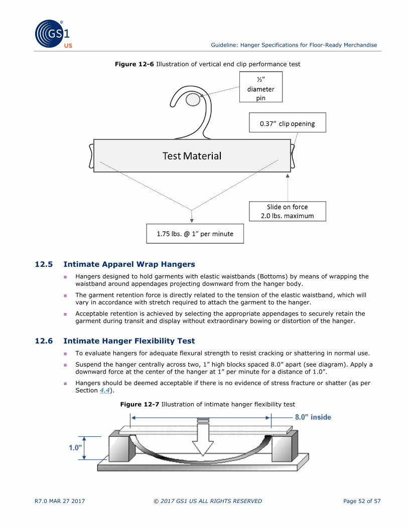
Guideline: Hanger Specifications for Floor-Ready Merchandise
R7.0 MAR 27 2017 © 2017 GS1 US ALL RIGHTS RESERVED Page 52 of 57
Figure 12-6 Illustration of vertical end clip performance test
12.5 Intimate Apparel Wrap Hangers
■ Hangers designed to hold garments with elastic waistbands (Bottoms) by means of wrapping the
waistband around appendages projecting downward from the hanger body.
■ The garment retention force is directly related to the tension of the elastic waistband, which will vary in accordance with stretch required to attach the garment to the hanger.
■ Acceptable retention is achieved by selecting the appropriate appendages to securely retain the garment during transit and display without extraordinary bowing or distortion of the hanger.
12.6 Intimate Hanger Flexibility Test
■ To evaluate hangers for adequate flexural strength to resist cracking or shattering in normal use.
■ Suspend the hanger centrally across two, 1” high blocks spaced 8.0” apart (see diagram). Apply a downward force at the center of the hanger at 1” per minute for a distance of 1.0”.
■ Hangers should be deemed acceptable if there is no evidence of stress fracture or shatter (as per Section 4.4).
Figure 12-7 Illustration of intimate hanger flexibility test

Guideline: Hanger Specifications for Floor-Ready Merchandise
R7.0 MAR 27 2017 © 2017 GS1 US ALL RIGHTS RESERVED Page 53 of 57
13 Intimate Apparel, Sleepwear and Robes
For hangers, use the appropriate GS1 US Metal Hook Hangers and the appropriate GS1 US Plastic Hook hangers. (See Section 3.3)
14 Children’s Frame Hangers
■ Color - White finish per Section 4.1
■ Hook - per Section 4.8
□ Molded Plastic
□ Side Sizer indicator per Section 4.9.4
□ Hook Opening 2.0” ± 0.18”
□ Hook Height 3.0” ± 0.18”
□ Strength per Section 4.8.2
■ Hanger Sizes
□ 10” x 8.5” (254mm x 215.9mm)
□ 12” x 10” (304.8mm x 254mm)
□ Per approved GS1 US Profile Drawings Section 3.2
■ Hanger Thickness
□ 0.188” – 0.25” (4.8mm – 6.4mm) all sizes
■ GS1 US Style Codes per Section 3.3
□ 10” x 8.5” = 951 Frame
□ 12” x 10” = 959 Frame

Guideline: Hanger Specifications for Floor-Ready Merchandise
R7.0 MAR 27 2017 © 2017 GS1 US ALL RIGHTS RESERVED Page 54 of 57
14.1 Hook Strength
Tested per section 4.8.2 with weight limit at 10 lbs.
Figure 14-1 Illustration of children’s frame hanger
15 Domestics/Home Textiles
Retailers desiring hanging displays should determine which hanger they want to use and address insertion within their own logistics network and/or trading partners.
16 Specialty Hangers
Inclusion of specialty hangers should be an issue to be agreed upon between the trading partners.
17 Hanger Reuse
17.1 Introduction
All approved hanger mechanical and design specifications should also apply to the corresponding reused hanger.

Guideline: Hanger Specifications for Floor-Ready Merchandise
R7.0 MAR 27 2017 © 2017 GS1 US ALL RIGHTS RESERVED Page 55 of 57
17.2 Plastic Properties
Hanger should meet the color standard throughout as with new production.
17.3 Metal Appearance and Finish
Metal components should be unacceptable if they do not meet current GS1 US finish and brightness standard per Section 4.7.
17.4 Hanger Inspections
Inspections should be performed on all hangers to determine if all visual, physical and mechanical aspects of the GS1 US reuse hanger performance standards are met.
17.5 Reuse Marking Specifications
The packaging and invoicing of a reused hanger should be appropriately labeled by identifying the product as reused and by whom it was processed.
17.6 Reuse of Sizers
In lieu of documented testing concerning the removal and reapplication of sizers on hangers, GS1 US does not endorse the reuse of a sizer that has been removed from a hanger.

Guideline: Hanger Specifications for Floor-Ready Merchandise
R7.0 MAR 27 2017 © 2017 GS1 US ALL RIGHTS RESERVED Page 56 of 57
Proprietary Statement
This document contains proprietary information of GS1 US. Such proprietary information may not be changed for
use with any other parties for any other purpose without the expressed written permission of GS1 US.
Improvements
Improvement and changes are periodically made to publications by GS1 US. All material is subject to change without notice. Please refer to GS1 US website for the most current publication available.
Disclaimer
Except as may be otherwise indicated in specific documents within this publication, you are authorized to view documents within this publication, subject to the following:
1. You agree to retain all copyright and other proprietary notices on every copy you make.
2. Some documents may contain other proprietary notices and copyright information relating to that
document. You agree that GS1 US has not conferred by implication, estoppels or otherwise any license or right under any patent, trademark or copyright (except as expressly provided above) of
GS1 US or of any third party.
This publication is provided “as is” without warranty of any kind, either express or implied, including, but not limited to, the implied warranties of merchantability, fitness for a particular purpose, or non-infringement. Any GS1 US publication may include technical inaccuracies or typographical errors. GS1 US assumes no responsibility for and disclaims all liability for any errors or omissions in this publication or in other documents which are referred to within or linked to this publication. Some jurisdictions do not allow the exclusion of implied warranties, so the above exclusion may not apply to you.
Several products and company names mentioned herein may be trademarks and/or registered trademarks of their respective companies. GS1 US does not, by promulgating this document on behalf of the parties involved in
the creation of this document, represent that any methods, products, and/or systems discussed or recommended in the document do not violate the intellectual property rights of any third party. GS1 US has not performed a search to determine what intellectual property may be infringed by an implementation of any strategies or suggestions included in this document. GS1 US hereby disclaims any liability for any party’s infringement of
intellectual property rights that arise as a result of any implementation of strategies or suggestions included in this document.
This publication may be distributed internationally and may contain references to GS1 US products, programs and services that have not been announced in your country. These references do not imply that GS1 US intends to announce such products, programs or services in your country.
No Liability for Consequential Damage
In no event shall GS1 US or anyone else involved in the creation, production, or delivery of the accompanying documentation be liable for any damages whatsoever (including, without limitation, damages for loss of business
profits, business interruption, loss of business information, or other loss) arising out of the use of or the results of use of or inability to use such documentation, even if GS1 US has been advised of the possibility of such damages.
IAPMO
In this publication, the letters “U.P.C.” are used solely as an abbreviation for the “Universal Product Code” which is a product identification system. They do not refer to the UPC, which is a federally registered certification mark of the International Association of Plumbing and Mechanical Officials (IAPMO) to certify compliance with a
Uniform Plumbing Code as authorized by IAPMO.

@ 2017 GS1 US All rights reserved.
Copyright © 2022 FDOKUMEN