Hahn-Meitner-lnstitut Berlin
201
Hahn-Meitner-lnstitut Berlin DE04F7195 h mi Ionenstrahllabor 2003 Annual Report r •'• •"* ••?.
-
Upload
khangminh22 -
Category
Documents
-
view
2 -
download
0
Transcript of Hahn-Meitner-lnstitut Berlin
Hahn-Meitner-lnstitutBerlin
DE04F7195
hmi
Ionenstrahllabor
2003Annual Report
r •'• •"* ••?.

ANNUAL REPORT
2003
ISL
IONENSTRAHLLABOR
HAHN-MEITNER-INSTITUT BERLIN GmbH
H.H. Bertschat, J. Rdhrich, G Schiwietz
HMI-Bericht B 596, Berlin, Marz 2004
ISSN 1610-0638

This report was prepared by G I.iar de Martin and M. Bernburg
Cover pictures:
The figures shown on the cover of this report have been selected as typical examples for ion-beamanalysis and materials modification at 1SL. Details can be found in this report.
Upper figure: PIXE analysis of bones from Sauropod dinosaurs (2.13).
Lower left figure: Structure of a vertical nano-wire transistor (3.4).
Lower right figure: Micrograph of a calibrated a-Si sample partly irradiated with gold ions (1.8).
CONTENTS
Preface V
I. Results of Research and Development 1
1. Structure and Dynamics 7
2. Materials Analysis 75
3. Applications 95
4. Nuclear Physics 109
5. Accelerator Operation, Technical Developments 113
6. Eye Tumour Therapy 129
II. Publications and Talks 141
1. Scientific Publications 143
2. Conference Contributions and Talks at other Institutes 153
3. Theses 169
4. Courses at Universities 173
III. Seminars and Workshops at ISL 177
IV. List of Experiments 183
V. Personalia 187
VI. Personnel 191

Preface
This annual report 2003 documents the scientific and technological activities at the ion-beamlaboratory ISL (IonenStrahlLabor) which is run by the department "Structure and Dynamics" of the"Structural Research Division" at the Hahn-Meitner-Institut. In addition to contributions from users ofISL, the report also includes results which were achieved in combination with other large-scalefacilities such as BESSY in Berlin, HASYLAB at DESY in Hamburg using synchrotron radiation andISOLDE at CERN in Geneva applying radioactive beams. The contributions are sorted along thescientific topics "Structure and Dynamics", "Materials Analysis", "Applications", etc. There is nolonger the differentiation between contributions from external and HMI users, the guests' affiliationsare always given in the author compilation.
There are various indicators for the increased success in the past year: We received more excitingcontributions from outside users. The reader will also find many new results obtained with Au ionbeams which have become the users' most favourite option both for ion beam induced modificationsand materials analysis. The number of analysed samples both for ERDA and PIXE has increased. Thecombination of ion beam induced materials modification and the concomitant characterization withsynchrotron radiation (X-ray diffraction and grazing incidence small angle X-ray scattering GISAXS)has also yielded first interesting results.
With the help of the strategy fund project "ion tracks in solids (2000-2003)" ion beam modificationhas developed into the central issue of ISL's research programme. The scientific achievements weresummarised as part of a German-French Summer School "TRACK.S03" - on the evolution of iontracks in matter - From the initial excitation to columnar nano structures - in Miihlhausen, Thuringen,September 8-15, 2003. The scientific objectives of the school were to treat and explore all the aspects,consequences, and applications of the interaction of swift heavy ions with matter, "...an area in whichboth France and Germany excel. Both countries have remarkable installations allowing production ofion beams of very high energy" according to a quotation from Camille Cohen, a senior participant ofthe school. He summarised: "The Tracks 03 school was an unqualified success. I very much hope thatthe organisation of such French-German meetings can be continued, on well-defined themes. "
In the eye tumour therapy programme more than 120 patients were treated in nine therapy sessionsbringing the total number of treated patients above 430 since the start in 1998. Unfortunately, fiscalreasons delayed the full realization of the research programme in precision proton therapy.
Accelerator operations, without major incidents, have strongly contributed to the progress inscience and technology. Intense Au ion beams are offered now very reliably. The total loss of beamtime caused by break-down has been kept significantly below 10% of the operations time. Theinstallation of new ion source platform which will shorten the total tuning times has nearly beencompleted. The new target areas have been installed and await commissioning.
In conclusion, the year 2003 marked essential progress along the strategic line of improving beamproduction and delivery, opening new tools and, in particular, combining methods and instru-mentations of ion beam techniques and synchrotron radiation within the scientific programmes. Thisstrategy will be presented in detail before the PNI (photon-neutron-ion) programme review committeein 2004.
Berlin, March 2004
Heinrich Homeyer

I.
Results of Research and Development
1. Structure and Dynamics 7
2. Materials Analysis 75
3. Applications 95
4. Nuclear Physics 109
5. Accelerator Operation; Technical Developments 113
6. Eye Tumour Therapy 129

1. STRUCTURE AND DYNAMICS
1.1 AMORPHIZATION OF QUASICRYSTALLINE ZR-TI-NI-CU BY 350 MEV AU IONS 9
1.2 ORDER-DISORDER TRANSFORMATION IN NI3AL BY HIGH ENERGETIC AU AND
KRIONS 11
1.3 DEFORMATION OF COBALT NANO-CLUSTERS 13
1.4 GRAIN GROWTH IN HEAVY ION IRRADIATED NANOCRYSTALLINE NICKEL 15
1.5 IRRADIATION INDUCED PHASE TRANSFORMATIONS IN NITI SHAPE MEMORY
ALLOYS AT LOW ELECTRONIC STOPPING POWERS 17
1.6 MODIFICATION OF THE TI TEXTURE USING SWIFT HEAVY IONS 20
1.7 SWIFT HEAVY ION IRRADIATION IN VIRGIN INP 23
1.8 PLASTIC DEFORMATION OF AMORPHOUS SILICON UNDER SWIFT HEAVY IONIRRADIATION 25
1.9 INTERFACE SHARPENING INSTEAD OF BROADENING BY DIFFUSION IN IDEALBINARY ALLOYS 27
1.10 PHASE TRANSITION IN MNAS(OOO1)/GAAS(111) EPITAXIAL FILMS 29
1.11 CALCULATION OF ELASTIC STRAIN ENERGY OF y' RAFTING PROCESS IN SINGLECRYSTAL SUPERALLOYS 31
1.12 MEASUREMENT OF TETRAGONAL LATTICE DISTORTION OF y' PRECIPITATES IN
SINGLE CRYSTAL SUPERALLOY SC16 34
1.13 SURFACE MODIFICATION BY IRRADIATION WITH SWIFT HEAVY IONS 37
1.14 DECOMPOSITION BEHAVIOUR OF AS-RECEIVED AND OXIDIZED TiH2 POWDER 40
1.15 NON-PERTURBATIVE TREATMENT OF MEDIUM-ENERGY PROTON SCATTERINGUNDER SHADOWING-BLOCKING CONDITIONS IN AL(110) 42
1.16 SEMI-EMPIRICAL CHARGE-STATE FORMULA FOR FAST IONS IN SOLIDS 43
1.17 EFFECTIVE SCREENING ENERGY AND NUCLEAR REACTION RATES AT VERY LOWPROJECTILE ENERGIES 45
1.18 COULOMB HEATING OF CHANNELED H2+ AND H3
+ MOLECULES IN SI 47
1.19 EFFECTS OF CHARGE CHANGING PROCESSES IN THE ELECTRON EMISSION FROMMETALS INDUCED BY LIGHT IONS: PLASMON MEDIATED PROCESSES 49
1.20 COMPARISON OF THE ELECTRON TEMPERATURE IN ION TRACKS FOR DIFFERENTCRYSTALLINE STRUCTURES OF ALUMINIUM INDUCED BY SWIFT GOLD IONS 52
1.21 NONTHERMAL MELTING OF BEO FILMS INDUCED BY SWIFT HEAVY IONS 54
1.22 INTERFERENCE EFFECTS IN ELECTRON EMISSION FROM H2 BY 68 MEV/U KR33+
IMPACT: ANALOGY TO YOUNG'S TWO-SLIT EXPERIMENT 56
1.23 FRAGMENTATION OF H2O MOLECULES FOLLOWING THE INTERACTION WITHSLOW, HIGHLY CHARGED NE IONS 58
1.24 GUIDED TRANSMISSION OF NE7+ IONS THROUGH NANOCAPILLARIES IN PET:DEPENDENCE ON THE TILT ANGLE 60
1.25 INVESTIGATIONS ON THE DIFFUSION OF BORON IN SILICON-GERMANIUM MIXED
CRYSTALS 62
1.26 CHARACTERISATION OF VACANCIES IN SEMICONDUCTORS BY THE ELECTRIC
FIELD GRADIENT: MOESSBAUER SPECTROSCOPY VERSUS PERTURBED ANGULAR
CORRELATIONS 64
1.27 MECHANISM OF FRENKEL PAIR FORMATION AND IDENTIFICATION OF VACANCY
AND SELF-INTERSTITIAL IN A III-V SEMICONDUCTOR 66
1.28 LATTICE DISTORTION AROUND IMPURITIES IN CDTE 68
1.29 ASPIC: DYNAMIC VERSUS STATIC MAGNETIC INTERACTIONS AT THE NI/PD
INTERFACE 70
1.30 THE MAGNETIC RESPONSE OF EUROPIUM IMPLANTED IN CERIUM AS
INVESTIGATED BY THE PAC-METHOD 71
1.31 CURRENT TRANSPORT IN SINGLE ION TRACKS IN DIAMOND-LIKE CARBON
FILMS 73
2. MATERIALS ANALYSIS 75
2.1 ION BEAM ANALYSIS WITH ERDA AND RBS 77
2.2 ELASTIC RECOIL DETECTION ANALYSIS OF SILICON, GRAPHITE, AND
TANTALUM NITRIDE FILMS 78
2.3 ERDA MEASUREMENTS ON BORON CARBOMTRIDE LAYERS 79
2.4 ERDA MEASUREMENTS ON MATERIALS INTENDED AS GD-OES HYDROGEN
STANDARDS AT BAM 80
2.5 REACTIVE MAGNETRON SPUTTERING OF PHOTOCATALYTICALLY ACTIVE
TiO2.2xNx FILMS 81
2.6 COMPOSITION AND DEPTH PROFILING OF THE ELEMENTS IN THE CUGASE2 THIN
FILMS AND CDS/CUGASE2 STRUCTURES 83
2.7 DETERMINATION OF THE COMPOSITION OF ILGAR-ZN(O,OH) - LAYERS 84
2.8 INFLUENCE OF IN SITU ANNEALING TEMPERATURE ON THE PROPERTIES OF HIGH
PRESSURE REACTIVELY SPUTTERED TIO 2 THIN FILMS 85
2.9 H I - R B S FOR THE MEASUREMENT OF SPUTTER YIELDS 86
2.10 HIGH-ENERGY PIXE USING 68 MEV PROTONS 87
2.11 ANALYSIS OF SOME INDIAN SAMPLES WITH HIGH ENERGY PIXE BEAM 88
2.12 BRONZETTI VENEZIANI 89
2.13 TENDAGURU SAUROPOD DINOSAURS - CHARACTERIZATION OF DIAGENETIC
ALTERATIONS 90
2.14 THE LATE BRONZE AGE HOARD FROM LEBUS (800 BC) - SPECTROMETRIC
RESEARCH OF A HOARD OF THE LUSATIAN CULTURE IN BRANDENBURG 92
3. APPLICATIONS 95
3.1 ROBOTICS COMPONENT VERIFICATION ON ISS (ROKVISS) 97
3.2 T E M P O S - A UNIVERSAL ION TRACK-BASED ELECTRONIC BUILDING BLOCK 99
3.3 INDEX-GUIDED LASER DIODES BASED ON ZNSE, GAAS AND GAN 102
3.4 NANO-WIRE TRANSISTORS IN FLEXIBLE POLYMER FOILS* 104
3.5 INVESTIGATION OF INTRA-CHANNEL FOUR-WAVE MIXING AT 160 GB/S USING AN
OPTICAL SAMPLING SYSTEM 105
4. NUCLEAR PHYSICS 109
4.1 STRUCTURE STUDIES OF THE VERY NEUTRON-RICH CARBON ISOTOPE I 7C 111
5. ACCELERATOR OPERATION; TECHNICAL DEVELOPMENTS 113
5.1 ISL OPERATIONS AND DEVELOPMENTS 115
5.2 CYCLOTRON-, RFQ- AND RF-OPERATIONS 117
5.3 INJECTOR DEVELOPMENTS 119
5.4 REARRANGEMENT OF THE TARGET AREAS 121
5.5 INSTALLATION OF THE BERLIN ION BEAM EXPOSURE AND RESEARCH FACILITY
(BIBER) " 122
5.6 ION TRACKS: FIRST STEPS INTO NEUTRAL PARTICLE DETECTION 125
5.7 DEVELOPMENT OF THE SAXS EXPERIMENTAL STATION AT 7T WIGGLER AT
BESSY 127
6. EYE TUMOUR THERAPY 129
6.1 5 YEARS OF EXPERIENCE IN PROTON THERAPY FOR OCULAR TUMORS IN
GERMANY 131
6.2 FAST TWO DIMENSIONAL DOSIMETRY IN DAILY EYE TUMOUR THERAPY
QUALITY ASSURANCE 132
6.3 QRT-PCR-BASED DETECTION OF OCCULT MELANOMA CELLS CIRCULATING IN
THE PERIPHERAL BLOOD: A PROGNOSTIC MARKER FOR PATIENTS WITH UVEAL
MELANOMA? 133
6.4 PROTON THERAPY AND STEREOTACTIC PHOTON IRRADIATION OF UVEAL
MELANOMA: A COMPARATIVE PLANNING UNDER FAIR CONDITIONS 134
6.5 CT-BASED PROTON THERAPY PLANNING FOR EYES WITH OCTOPUS:COMPARISON WITH CT-CORRECTED EYEPLAN 136
6.6 PATIENT DATABASE FOR EYE TUMOUR THERAPY 138
6.7 ENDORESECTION FOLLOWING PROTON BEAM IRRADIATION OF LARGE UVEAL
MELANOMAS 139


1. Structure and Dynamics


1.1 Amorphization of quasicrystalline Zr-Ti-Ni-Cu by 350 MeV Au ions
S. Mechler, C. Abromeit, M.-P. Macht [SF3J; G Schumacher, T. Zumkley, S. Klaumunzer
It is well known that quasicrystalline phasescan undergo a quasicrystalline-amorphoustransformation by low energy ion irradiationwhere the local energy deposition is mainly dueto the nuclear energy loss. Up to now little workhas been done in order to investigate the influ-ence of swift heavy ions on the stability ofquasicrystalline phases. Two quasicrystallinealloys with composition Al65Cu2oFei5 andAUsCuisFesVs have been irradiated at 80 Kwith 100 MeV Ni ions and with 835 MeV Krions, respectively. Changes in structure weremonitored in-situ by means of the electricalresistivity. Ex-situ measurements have beenperformed by means of X-ray diffraction priorto and after irradiation. Both measurementsgave no evidence for amorphization. This mightbe due to the moderate energy loss (13 keV/nmfor both, 100 MeV Ni ions and 835 MeV Krions) used in those experiments.
In the present project we used 350 MeV Auions for the irradiation of a quasicrystallinephase obtained by thermal treatment of amor-phous Zr5o.5Ti25.3Ni|i.3Cui2.9 (VI-2). The elec-tronic energy loss in VI-2 was estimated to beabout 40 keV/nm which is appreciably largerthan the value reported for irradiation ofAl65Cu2oFei5 and Al65Cu25Fe5V5 [1,2]. The qua-sicrystalline specimen was irradiated at roomtemperature to a total fluence <|)t = 2-1013 cm"2.The damage caused by the nuclear energy lossat this dose level is estimated to be 3-10"3 dpausing TRIM98 and a displacement thresholdenergy of 40 eV. The latter value represents theTd value of the element with highest amount(Zr). The changes in structure were measuredby means of X-ray diffraction prior to and afterirradiation. During the measurements the anglebetween the X-ray source and the specimen waskept constant at 10 degrees in order to minimizethe influence of specimen volumes far beyondthe surface.
The initially amorphous alloy was heattreated at 643 K for 7200 s. During this treat-ment the amorphous phase has largely crystal-lized into an icosahedral quasicrystalline phase.
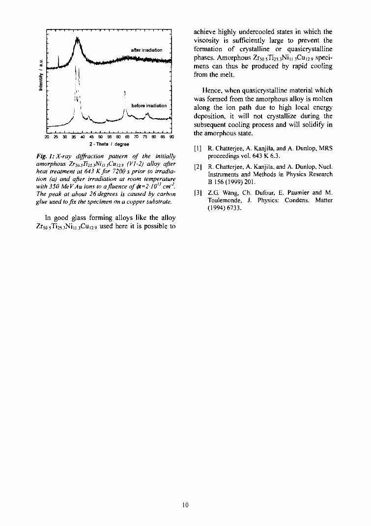
Fig. 1 shows the X-ray diffraction patternprior to (bottom) and after (top) irradiation.
The large width of all peaks indicates thatthe quasicrystalline phase has formed as nano-crystals. The three diffraction peaks of highestintensity are at about 36° , 38° and 64° and canbe assigned to the (100000), (110000) and(101000) orientations, respectively, of the qua-sicrystalline phase. In order to clarify as towhich extend the amorphous phase has trans-formed into the quasicrystalline phase a carefulanalysis of the spectrum is required.
After irradiation all peaks of the quasicrys-talline phase are totally disappeared (Fig. 1).This reflects complete amorphization of thequasicrystalline phase under irradiation. Pre-liminary evaluation of recently performed irra-diation with 350 MeV Au ions hinted to amor-phization of VI-2 to a large extend already at<j)t = 1-1012 cm"2. The actual fluence for com-plete amorphization might, therefore, be appre-ciably smaller than <)>t = 2-1013 cm"2. The dam-age level of 3-1O"3 dpa can thus be regarded asan upper limit for complete amorphizationunder irradiation with 350 MeV Au ions. Suchlow damage levels caused by the nuclear energyloss are generally not sufficient to induce amor-phization. We therefore ascribe the phase trans-formation to the electronic energy loss of theAu ions.
Zirconium and titanium are the main con-stituents of the alloy. Both the elements in purestate are sensitive to the electronic energy loss[3]. The Zr- and Ti-rich quasicrystalline phasein the alloy Zr50.5Ti25.3Niu.3Cu 12.9 seems to besensitive to the electronic energy loss, too. Inthe thermal spike model of Toulemonde [3],two requirements need to be fulfilled in order tocreate a thermal spike along the ion path causedby the electronic energy loss: (i) large electronphonon interaction and (ii) low thermal con-ductivity. Both requirements are obviouslyfulfilled for the combination of alloy and ionused in the present experiment.
•g
after irradiation
2 0 8 3 0 3 5 4 0 4 5 5 0 5 6 6 0 6 5 7 0 7 5 6 0 9 5 9 02 - Theta / degree
Fig. 1: X-ray diffraction pattern of the initiallyamorphous Zrso.5Ti2s.3Niu.3Cui2.9 (Vl-2) alloy afterheat treatment at 643 Kfor 7200 s prior to irradia-tion (a) and after irradiation at room temperaturewith 350 MeVAu ions to afluence offo=210u cm'2.The peak at about 26 degrees is caused by carbonglue used to fix the specimen on a copper substrate.
In good glass forming alloys like the alloyi||3Cui2 9 used here it is possible to
achieve highly undercooled states in which theviscosity is sufficiently large to prevent theformation of crystalline or quasicrystallinephases. Amorphous Zr50.5Ti25.3Nin .3CU12.9 speci-mens can thus be produced by rapid coolingfrom the melt.
Hence, when quasicrystalline material whichwas formed from the amorphous alloy is moltenalong the ion path due to high local energydeposition, it will not crystallize during thesubsequent cooling process and will solidify inthe amorphous state.
[1] R. Chatterjee, A. Kanjila, and A. Dunlop, MRSproceedings vol. 643 K 6.3.
[2] R. Chatterjee, A. Kanjila, and A. Dunlop, Nucl.Instruments and Methods in Physics ResearchB 156(1999)201.
[3] Z.G Wang, Ch. Dufour, E. Paumier and M.Toulemonde, J. Physics: Condens. Matter(1994)6733.
10
1.2 Order-Disorder Transformation in Ni3Al by High Energetic Au and Kr Ions
K Rudychev, G Schumacher, Th. Zumkley, S. Klaumiinzer; C. Abromeit [SF3J
The ordered intermetallic phase NijAl (Ll2
structure) is known to undergo an order-disor-der transformation under irradiation with lowenergy ions or fast electrons at sufficiently lowtemperature [1-4]. For these projectiles damageproduction is dominated by the nuclear energyloss, while the electronic energy loss plays onlya minor role.
In an earlier report [5] it was shown thatpartly ordered Ni3Al also transforms to a moredisordered state, and a nearly disordered speci-men remained disordered under irradiation with350 MeV Au ions where local energy deposi-tion is orders of magnitude larger compared tothe earlier reported experiments [1-4]. We,therefore, studied in more detail the stability ofpartly ordered Ni^Al under high local energydeposition by swift heavy ions. 350 MeV Auions and 200 MeV Kr ions were used for theirradiation experiments. The experiments wereperformed at room temperature at ISL. Thespecimens were produced by rapid quenchingfrom the melt in a splat quench device. Forirradiation the specimens were fixed on acopper plate. Cu-K<, radiation was used for theX-ray scans to determined the long-range orderparameter S. The diffraction spectra wererecorded on the same specimen prior to irradia-tion and after several irradiation doses. As theelectronic energy loss of the projectiles used inthis experiment decreases with increasingdistance from the specimen surface, the scanswere recorded under an angle of incidence of10° in order to reduce influence of specimenvolumes far below the surface. The X-rayintensities of the (001) superlattice reflectionpeak and of the (002) peak as well as the inten-sities of the (011) superlattice reflection peakand of the (022) peak were used to determinethe long-range order parameter S.
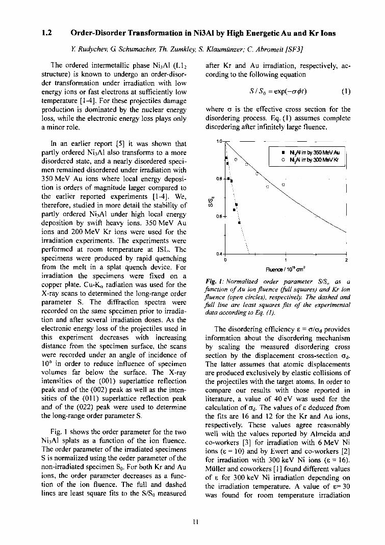
Fig. 1 shows the order parameter for the twoNi3Al splats as a function of the ion fluence.The order parameter of the irradiated specimensS is normalized using the order parameter of thenon-irradiated specimen So. For both Kr and Auions, the order parameter decreases as a func-tion of the ion fluence. The full and dashedlines are least square fits to the S/SQ measured
after Kr and Au irradiation, respectively, ac-cording to the following equation
S/So = (1)
where a is the effective cross section for thedisordering process. Eq. (1) assumes completedisordering after infinitely large fluence.
• N^AIirrby350MeVAuO MjAlirrby300MeVKr
0.4
Ruence/101!W
Fig. I: Normalized order parameter S/So as aJunction of Au ion fluence (full squares) and Kr ionfluence (open circles), respectively. The dashed andfull line are least squares fits of the experimentaldata according to Eq. (1).
The disordering efficiency e = cr/crd providesinformation about the disordering mechanismby scaling the measured disordering crosssection by the displacement cross-section ad.The latter assumes that atomic displacementsare produced exclusively by elastic collisions ofthe projectiles with the target atoms. In order tocompare our results with those reported inliterature, a value of 40 eV was used for thecalculation of ad. The values of e deduced fromthe fits are 16 and 12 for the Kr and Au ions,respectively. These values agree reasonablywell with the values reported by Almeida andco-workers [3] for irradiation with 6 MeV Niions (E = 10) and by Ewert and co-workers [2]for irradiation with 300 keV Ni ions (E = 16).Miiller and coworkers [1] found different valuesof e for 300 keV Ni irradiation depending onthe irradiation temperature. A value of e= 30was found for room temperature irradiation
11
while values of 15 and 10 were reported forirradiation temperatures of 200 K and 100 K,respectively. The values are, however, aboutone order of magnitude larger than the valuesobtained by irradiation with 0.65 MeV electronsat 160 K. In that work values between 1.4 and1.8 have been reported depending on the orien-tation of the electron beam with respect to theNi3Al crystal [4].
The values of e measured for 350 MeV Auions and for 300 MeV Ni ions strongly hint tothe nuclear energy loss as the dominatingreason for disordering. The different values ofe reported for ion irradiation and irradiationwith fast electrons point to dissimilar disorder-ing mechanisms for ion irradiation and irradia-tion with fast electrons. Displacement of singleatoms is the dominating mechanism for fastelectrons. The small values of 1.4-1.8 reportedfor irradiation with 0.6 MeV electrons hint to
the lack of replacement collisions. Every dis-placed atom creates at an average 1.4-1.8 anti-site defects. Contrary to fast electrons, thecreation of disorder by ions seems seems hardlyto depend on the ion energy over a large energyrange.
[1] S. Mttller, C. Abromeit, S. Matsumura, N.Wanderka, H. Wollenberger, J. Nucl. Mater.271&272 (1999)241.
[2] J.C. Ewert, G. Schmitz, F. Harbsmeier. M. Uhr-macher and F. Haider, Appl. Phys. Lett. 73(1998)3363.
[3] P. de Almeida, R. Schaublin, A. Almazouzi andM Victoria and M. Dobeli, Appl. Phys. Lett.77 (2000) 2680.
[4] H.C. Liu and T.E. Mitchell. Acta metall. 31(1983)863.
[5] Y. Rudychev, G. Schumacher. T. Zumkley, S.Klaumiinzer and C. Abromeit, ISL AnnualReport 2002.
12
1.3 Deformation of Cobalt Nano-Clusters
S. Klaumunzer
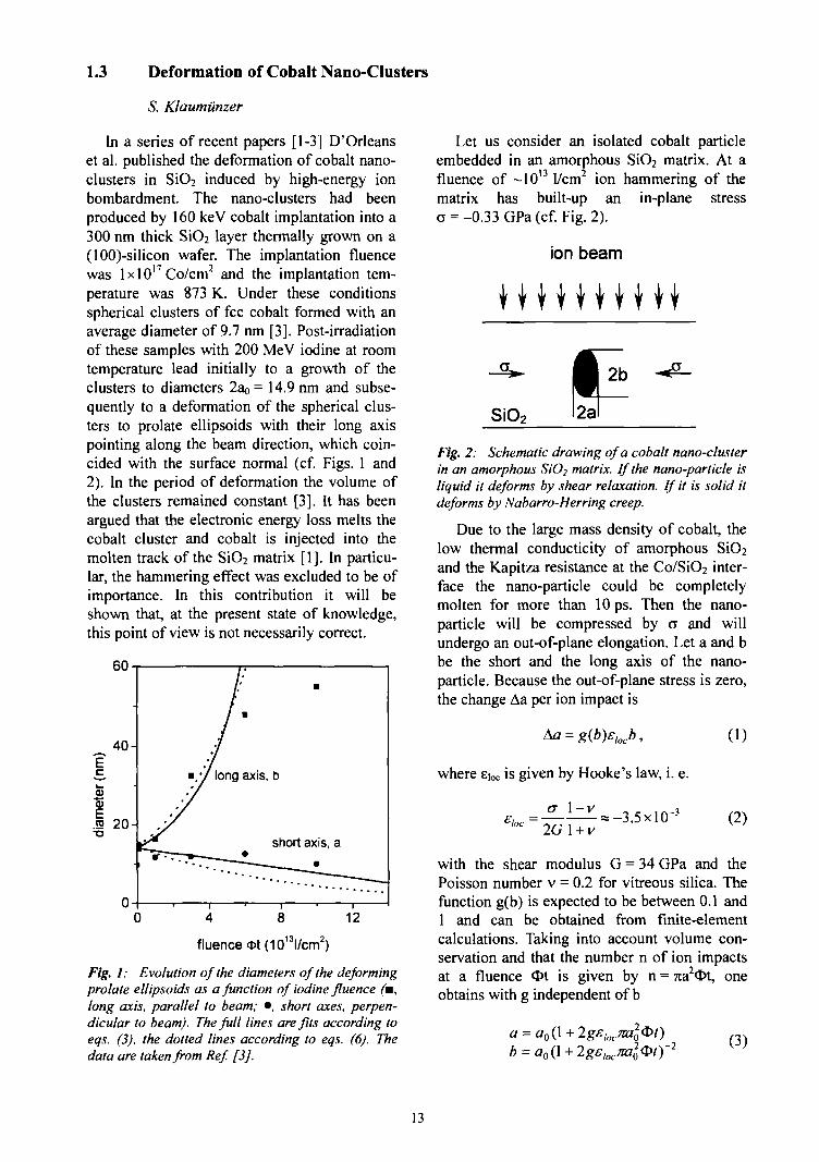
In a series of recent papers [1-3] D'Orleanset al. published the deformation of cobalt nano-clusters in SiO2 induced by high-energy ionbombardment. The nano-clusters had beenproduced by 160 keV cobalt implantation into a300 nm thick S1O2 layer thermally grown on a(lOO)-silicon wafer. The implantation fluencewas lxlO17 Co/cm2 and the implantation tem-perature was 873 K. Under these conditionsspherical clusters of fee cobalt formed with anaverage diameter of 9.7 nm [3]. Post-irradiationof these samples with 200 MeV iodine at roomtemperature lead initially to a growth of theclusters to diameters 2ao = 14.9 nm and subse-quently to a deformation of the spherical clus-ters to prolate ellipsoids with their long axispointing along the beam direction, which coin-cided with the surface normal (cf. Figs. 1 and2). In the period of deformation the volume ofthe clusters remained constant [3]. It has beenargued that the electronic energy loss melts thecobalt cluster and cobalt is injected into themolten track of the SiO2 matrix [1]. In particu-lar, the hammering effect was excluded to be ofimportance. In this contribution it will beshown that, at the present state of knowledge,this point of view is not necessarily correct.
0 4 8 12
fluence Ot(10l3l/cm2)
Fig. I: Evolution of the diameters of the deformingprolate ellipsoids as a function of iodine fluence (m,long axis, parallel to beam; •, short axes, perpen-dicular to beam). The full lines are fits according toeqs. (3), the dotted lines according to eqs. (6). Thedata are taken from Ref [3].
Let us consider an isolated cobalt particleembedded in an amorphous SiO2 matrix. At afluence of — 10'3 I/cm2 ion hammering of thematrix has built-up ana = -0.33 GPa (cf. Fig. 2).
ion beam
in-plane stress
W W W W W W W W W W
SiO2
Fig. 2: Schematic drawing of a cobalt nano-clusterin an amorphous SiO2 matrix. If the nano-particle isliquid it deforms by shear relaxation. If it is solid itdeforms by Nabarro-Herring creep.
Due to the large mass density of cobalt, thelow thermal conducticity of amorphous SiC>2and the Kapitza resistance at the Co/SiO2 inter-face the nano-particle could be completelymolten for more than 10 ps. Then the nano-particle will be compressed by a and willundergo an out-of-plane elongation. Let a and bbe the short and the long axis of the nano-particle. Because the out-of-plane stress is zero,the change Aa per ion impact is
Aa = g(b)£locb,
where eioc is given by Hooke's law, i. e.
2G1 + V
(1)
(2)
with the shear modulus G = 34 GPa and thePoisson number v = 0.2 for vitreous silica. Thefunction g(b) is expected to be between 0.1 and1 and can be obtained from finite-elementcalculations. Taking into account volume con-servation and that the number n of ion impactsat a fluence <I>t is given by n = 7ia2Ot, oneobtains with g independent of b
a = (3)
13

For the full lines drawn in Fig. 1 ga = 0.4and gb-0.8 have been selected. Both numbersare in reasonable accord with the expectation.
Now we take the opposite point of view. Weassume that i) the classical theory of thermalconductivity greatly underestimates the thermalconductance on a nm-scale with large tempera-ture gradients and ii) the interaction betweencobalt and SiO2 is so strong that the Kapitzaresistance does not lead to important tempera-ture differences. In this extreme case the nano-particle does not melt by an ion impact and itsdeformation must be mediated by dislocationmotion or solid-state diffusion. Dislocationmotion can be ruled out due to the Hall-Petcheffect for small particles [4J. Similarly, grainboundary diffusion cannot play a big role for anisolated particle. Therefore, the only significantdeformation mechanism is probably Nabarro-Herring creep with a strain rate [4]
e =KQ.
kjd2(4)
where K is numerical factor between 10 and100, Q is the atomic volume, ku the Boltzmannconstant, T the temperature, d the characteristicparticle size, and D the (radiation-enhanced)diffusion coefficient of cobalt. The latter quan-tity is essentially determined by the concentra-tion of defect sinks and the production of mi-grating defects [5]. Simple estimates show thatfor a nano-particle the dominant defect sink isthe interface and one estimates [5]
(5)
where P= 1.2x10 cm is the displacementcross-section as obtained from SRIM. InsertingEq. (5) into Eq. (4) yields for T = 300 K6 = 4.7xlO"15cm2KOand
a = a0 exp(-2.4 x 10"l5cw2A:O/)b = a0exp(4.7 x \0l5cm2K(&t)
(6)
Agreement with experiment is obtained withK = 5 (see dotted lines in Fig. 1).
Obviously, both alternatives demonstratethat the stress induced by ion hammering canaccount for the experimental results. The majordifference between the mechanisms proposedhere and that in Ref. [1] lies in the shape of thedeformed nano-particles when sample is tiltedrelative to the ion beam. If the mechanism ofRef. [1] is correct, prolate nano-particles formand their long axes always point in beam direc-tion. If one of the mechanisms of this contribu-tion is correct the tensorial character of thestress becomes important. E. g. for a tilt angle9 = 45° well-orientated oblate nano-particlesare predicted.
In both alternatives there are several refine-ments possible which will not be addressedhere. But at a fiuence of about 4x10¹³ I/cm2
there are obvious deviations toward a slowerdeformation. These deviations originate proba-bly from neglecting the capillary stresses at theinterface between SiO2 and cobalt.
Furthermore, when the major length 2b ofthe nano-particle becomes much larger than thediameter 2a the nano-particle is expected tobecome unstable against a decay into smaller,more spherical particles. At a free surface thisRayleigh instability occurs when b becomeslarger than 7ia. It remains to be shown whetherthis result can be transferred to interfaces.
[1] C. D'Orleans, J.P. Stoquert, C. Estournes, C.Cerruti, J.J. Grob. J.L Guille, F. Haas, D. Mul-ler, M. Richard-Plouet. Phys. Rev. B67 (2003)220101.
[2] C. D'Orleans. C. Cerruti. C. Estournes. J.J.Grob, J.L. Guille, F. Haas. D. Muller, M. Ri-chard-Plouet, J.P. Stoquert, Nucl. Instr.&Meth.B209 (2003) 316.
[3] C. D'Orleans, J.P. Stoquert, C. Estournes. J.J.Grob, D. Muller. J.L. Guille, M. Richard-Plouet, F. Haas, Nucl. Instr.&Meth. in print.
[4] H.J. Frost and M.F. Ashby, Deformation Mech-anism Maps, Pergamon Press (Oxford, 1982).
[5] V. Naundorf, Int. J. Modern Physics B6 (1992)2925.
14
1.4 Grain Growth in Heavy Ion Irradiated Nanocrystalline Nickel
Th. Zumkley, G. Schumacher, S. Klaumiinzer
Electronic energy loss induced defect an-nealing was evidenced for the first time byIwata et al. [1] in experiments on f.c.c. metalNi. A similar effect is expected more distinc-tively in nanocrystalline nickel, in which a largefraction of atoms is located in crystallite inter-faces. These grain boundaries are expected toaffect the behavior of radiation-induced defectsand possibly, the time evolution of thermalspikes.
The specimens used in the present experi-ments were electrodeposited Ni foils of 100 and50 jj.m thickness, respectively. Samples of10x10 mm2 size were irradiated uniformly with200 MeV Kr, 230 MeV Xe or 350 MeV Au ionsat room temperature and at 80 K (for Xe and Kronly). The ion fluxes were 4.9x10¹⁰ Kr/cm2 s,7.2xlOIOXe/cm2s and 2.2xlO10 Au/cm2 s. Forthese ions the projected ion ranges are 10.4.10.0 and 10.8 ujn, respectively. Prior to andafter irradiation X-ray scans were recordedusing Cu-Ka (A. = 0.154nm) radiation. Theangle between the target and the incident X-raybeam was kept constant at 10° so that the X-rayinformation depth was limited to 4 fim.
According to SRIM2003 the average electro-nic stopping powers are Se(Kr) = 26 keV/nm,Sc(Xe) = 38 keV/nm and Se(Au) = 52 keV/nmand the total displacement cross-sections are
1 7 2 P(Xe) = 1.7x10p
= 5.5xl0~17cm2, '""cm2
and P(Au) = 3xlO l6cm2. In these calculationsa displacement threshold of 25 eV has beenused.
The distribution of intensity in a X-ray beamdiffracted by a polycrystalline sample is aconvolution of two functions: (a) a functiondescribing the instrumental and spectral effectsin the diffraction line and (b) a function f(x)arising from the specimen imperfection, such ascrystallite size and lattice microstrain. We haveselected the (111) and (200) reflections for theevaluation of the X-ray diffraction data. Theprofiles were fitted by the empirical Pseudo-Voigt function after performing the Rachingercorrection.
S1
0,54
0,52 (a)80 K
300 K
* ° . 5 ° ! V, (111)
i 0,48
~ 0,46
fluence <fct(10'4Xe/cm2)
80 K300 K
on)
1 2 3 4 5 6 7 8
fluence *t(1013Xe/ cm2)
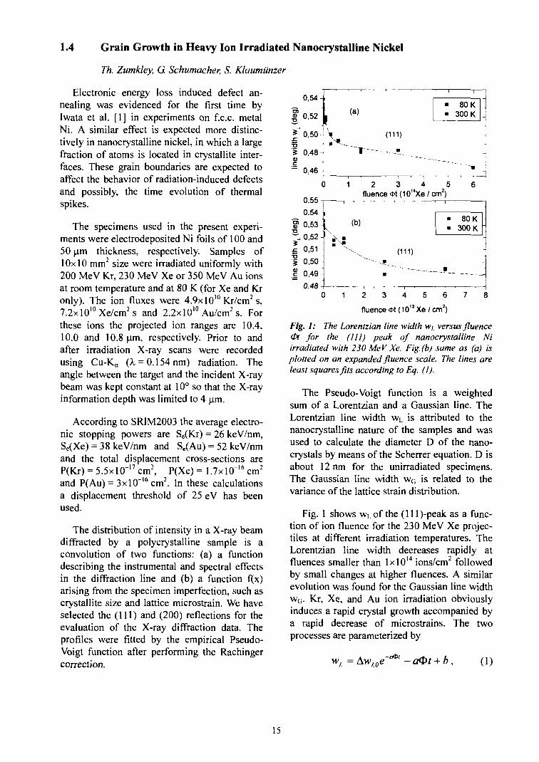
Fig. I: The Lorentzian line width wt. versus fluence<Pt for the (111) peak of nanocrystalline Niirradiated with 230 MeV Xe. Fig.(b) same as (a) isplotted on an expanded fluence scale. The lines areleast squares fits according to Eq. (1).
The Pseudo-Voigt function is a weightedsum of a Lorentzian and a Gaussian line. TheLorentzian line width wL is attributed to thenanocrystalline nature of the samples and wasused to calculate the diameter D of the nano-crystals by means of the Scherrer equation. D isabout 12 nm for the unirradiated specimens.The Gaussian line width wG is related to thevariance of the lattice strain distribution.
Fig. 1 shows wi of the (lll)-peak as a func-tion of ton fluence for the 230 MeV Xe projec-tiles at different irradiation temperatures. TheLorentzian line width decreases rapidly atfluences smaller than lxlO14 ions/cm2 followedby small changes at higher fluences. A similarevolution was found for the Gaussian line widthwG. Kr, Xe, and Au ion irradiation obviouslyinduces a rapid crystal growth accompanied bya rapid decrease of microstrains. The twoprocesses are parameterized by
b, (1)
15
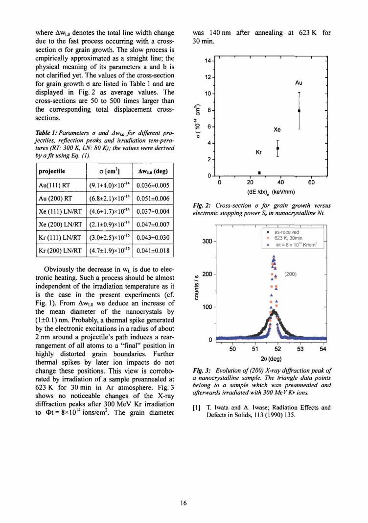
where Aw[.o denotes the total line width changedue to the fast process occurring with a cross-section a for grain growth. The slow process isempirically approximated as a straight line; thephysical meaning of its parameters a and b isnot clarified yet. The values of the cross-sectionfor grain growth a are listed in Table 1 and aredisplayed in Fig. 2 as average values. Thecross-sections are 50 to 500 times larger thanthe corresponding total displacement cross-sections.
Table 1: Parameters a and Awi0 for different pro-jectiles, reflection peaks and irradiation tem-pera-tures (RT: 300 K, LN: 80 K); the values were derivedby a fit using Eq. (1).
projectile
Au(lll)RT
Au (200) RT
Xe(lll)LN/RT
Xe (200) LN/RT
Kr(lll)LN/RT
Kr (200) LN/RT
a [cm2|
(9.1±4.0)xl0"14
(6.8±2.1)xlO"14
(4.6±1.7)xlO-14
(2.1±0.9)*10"14
(3.0±2.5)*10-15
(4.7±1.9)xlO-15
AwL0 (deg)
0.036±0.005
0.051±0.006
0.037±0.004
0.047±0.007
0.043±0.030
0.04U0.018
Obviously the decrease in wL is due to elec-tronic heating. Such a process should be almostindependent of the irradiation temperature as itis the case in the present experiments (cf.Fig. 1). From AwLo we deduce an increase ofthe mean diameter of the nanocrystals by(l±0.1) nm. Probably, a thermal spike generatedby the electronic excitations in a radius of about2 nm around a projectile's path induces a rear-rangement of all atoms to a "final" position inhighly distorted grain boundaries. Furtherthermal spikes by later ion impacts do notchange these positions. This view is corrobo-rated by irradiation of a sample preannealed at623 K. for 30 min in Ar atmosphere. Fig. 3shows no noticeable changes of the X-raydiffraction peaks after 300 MeV Kr irradiationto <l>t = 8><1014 ions/cm2. The grain diameter
was 140 nm after annealing at 623 K for30 min.
o
b
14-
12-
10-
8-
6-
4 -
2 -
0-
1 * 1 ' 1 * 1
Au
i
Xe
•
•
0 20 40 60
(dE/dx)e (keV/nm)
Fig. 2: Cross-section a for grain growth versuselectronic stopping power Se in nanocrystalline Ni.
300-
200-
c
8100-
as-received623 K; 30mm<t>t = 8x 10¹⁴ Kr/crrT
•AA"
•X
(200)
50 51 52
26 (deg)
53 54
Fig. 3: Evolution of (200) X-ray diffraction peak ofa nanocrystalline sample. The triangle data pointsbelong to a sample which was preannealed andafterwards irradiated with 300 MeV Kr ions.
[1] T. Iwata and A. Iwase; Radiation Effects andDefects in Solids, 113 (1990) 135.
16
1.5 Irradiation Induced Phase Transformations in NiTi Shape Memory Alloys atLow Electronic Stopping Powers
T. LaGrange, R. Gotthardt fEcole Polytechnique Federate, Lausanne, Switzerland]; C. Abromeit [SF3J;S. Klaumiinzer, G Schumacher
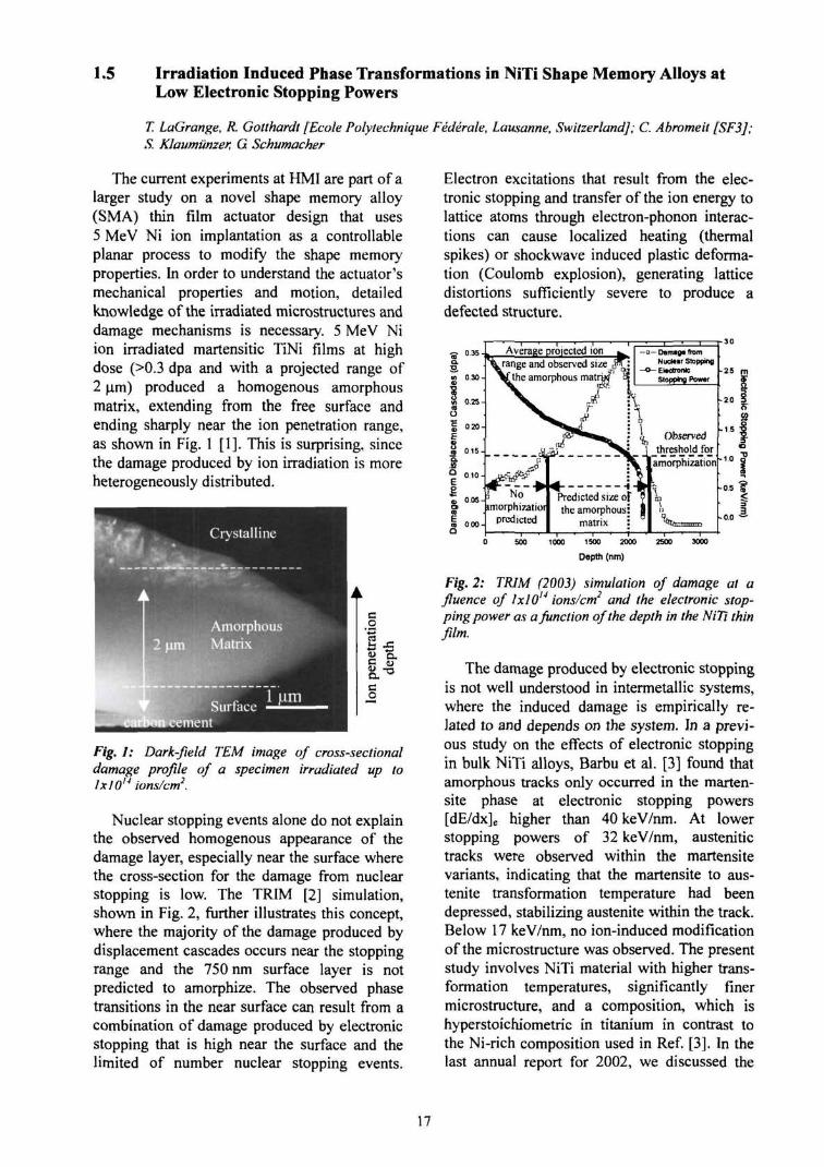
The current experiments at HMI are part of alarger study on a novel shape memory alloy(SMA) thin film actuator design that uses5 MeV Ni ion implantation as a controllableplanar process to modify the shape memoryproperties. In order to understand the actuator'smechanical properties and motion, detailedknowledge of the irradiated microstructures anddamage mechanisms is necessary. 5 MeV Niion irradiated martensitic TiNi films at highdose (>0.3 dpa and with a projected range of2 pm) produced a homogenous amorphousmatrix, extending from the free surface andending sharply near the ion penetration range,as shown in Fig. 1 [1]. This is surprising, sincethe damage produced by ion irradiation is moreheterogeneously distributed.
Fig. 1: Dark-field TEM image of cross-sectionaldamage profile of a specimen irradiated up tolxl014 ions/cm2.
Nuclear stopping events alone do not explainthe observed homogenous appearance of thedamage layer, especially near the surface wherethe cross-section for the damage from nuclearstopping is low. The TRIM [2] simulation,shown in Fig. 2, further illustrates this concept,where the majority of the damage produced bydisplacement cascades occurs near the stoppingrange and the 750 nm surface layer is notpredicted to amorphize. The observed phasetransitions in the near surface can result from acombination of damage produced by electronicstopping that is high near the surface and thelimited of number nuclear stopping events.
Electron excitations that result from the elec-tronic stopping and transfer of the ion energy tolattice atoms through electron-phonon interac-tions can cause localized heating (thermalspikes) or shockwave induced plastic deforma-tion (Coulomb explosion), generating latticedistortions sufficiently severe to produce adefected structure.
Average projected ionk range and observed size ,?
[the amorphous matraj
- a — Damage ftomNuclear Stopping
- o - ElectronicStopping Power
• 2 5
-2.0
icted size ofthe amorphous:
matrix :
1000 2000 2600 3000
Depth (nm)
Fig. 2: TRIM (2003) simulation of damage at afluence of lxlO14 ions/cm2 and the electronic stop-ping power as a function of the depth in the NiTi thinfilm.
The damage produced by electronic stoppingis not well understood in intermetallic systems,where the induced damage is empirically re-lated to and depends on the system. In a previ-ous study on the effects of electronic stoppingin bulk NiTi alloys, Barbu et al. [3] found thatamorphous tracks only occurred in the marten-site phase at electronic stopping powers[dE/dx]e higher than 40 keV/nm. At lowerstopping powers of 32 keV/nm, austenitictracks were observed within the martensitevariants, indicating that the martensite to aus-tenite transformation temperature had beendepressed, stabilizing austenite within the track.Below 17 keV/nm, no ion-induced modificationof the microstructure was observed. The presentstudy involves NiTi material with higher trans-formation temperatures, significantly finermicrostructure, and a composition, which ishyperstoichiometric in titanium in contrast tothe Ni-rich composition used in Ref. [3]. In thelast annual report for 2002, we discussed the
17
damage observed after 350 MeV Au ions(43 keV/nm) and found similar results as [3] forthe undeformed material. This report reviewsthe latest results on irradiation phase transitionswith electronic stopping powers below17 keV/nm threshold of [3] for observabletransformations and those near that of the5 MeV Ni ions (3 keV/nm), using 200 MeV Kr(20keV/nm), 80 MeV Ar (9 keV/nm), and40 MeV Ne (4 keV/nm) ions.
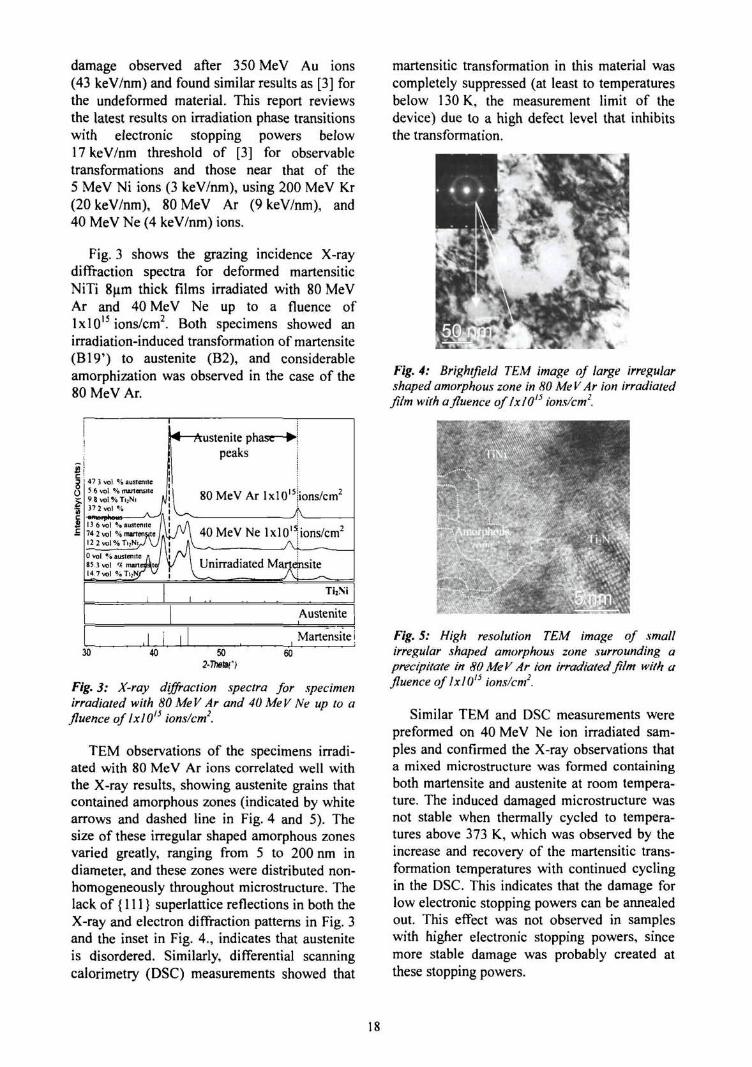
Fig. 3 shows the grazing incidence X-raydiffraction spectra for deformed martensiticNiTi 8um thick films irradiated with 80 MeVAr and 40 MeV Ne up to a fluence oflxlO15 ions/cm2. Both specimens showed anirradiation-induced transformation of martensite(B19') to austenite (B2), and considerableamorphization was observed in the case of the80 MeV Ar.
47 3 vol % austenite5 6 vol % martensite9 8 vol % Ti;Ni f37 2 vol % I
13 6 vol % austenite 1
74 2 vol % martensite / ,
]£2vol%T^Ni^/V7[0 vol % austenite fl /
85 1 vol '( marteJsW14 7 vol %Ti.NT V
i
1
\r-Austenite phase—•;
peaks j
80 MeV Ar lxlOl5!ions/cm2
A\ 40 MeV Ne 1x10'lions/cm2
_. . |\ Unirradiated MartdnsiteV . Ai T̂i,Ni
i . .
Austenite
1 Martensite30 40 50
2-Ttm')60
Fig. 3: X-ray diffraction spectra for .specimenirradiated with 80 MeV Ar and 40 MeV Ne up to afluence of lxl 015 ions/cm2.
TEM observations of the specimens irradi-ated with 80 MeV Ar ions correlated well withthe X-ray results, showing austenite grains thatcontained amorphous zones (indicated by whitearrows and dashed line in Fig. 4 and 5). Thesize of these irregular shaped amorphous zonesvaried greatly, ranging from 5 to 200 nm indiameter, and these zones were distributed non-homogeneously throughout microstructure. Thelack of {111} superlattice reflections in both theX-ray and electron diffraction patterns in Fig. 3and the inset in Fig. 4., indicates that austeniteis disordered. Similarly, differential scanningcalorimetry (DSC) measurements showed that
martensitic transformation in this material wascompletely suppressed (at least to temperaturesbelow 130 K, the measurement limit of thedevice) due to a high defect level that inhibitsthe transformation.
Fig. 4: Brightfield TEM image of large irregularshaped amorphous zone in 80 MeV Ar ion irradiatedfilm with a fluence of/x/Ol:> ions/cm2.
Fig. 5: High resolution TEM image of smallirregular shaped amorphous zone surrounding aprecipitate in 80 MeV Ar ion irradiated film with afluence oflxlO" ions/cm2.
Similar TEM and DSC measurements werepreformed on 40 MeV Ne ion irradiated sam-ples and confirmed the X-ray observations thata mixed microstructure was formed containingboth martensite and austenite at room tempera-ture. The induced damaged microstructure wasnot stable when thermally cycled to tempera-tures above 373 K, which was observed by theincrease and recovery of the martensitic trans-formation temperatures with continued cyclingin the DSC. This indicates that the damage forlow electronic stopping powers can be annealedout. This effect was not observed in sampleswith higher electronic stopping powers, sincemore stable damage was probably created atthese stopping powers.
18
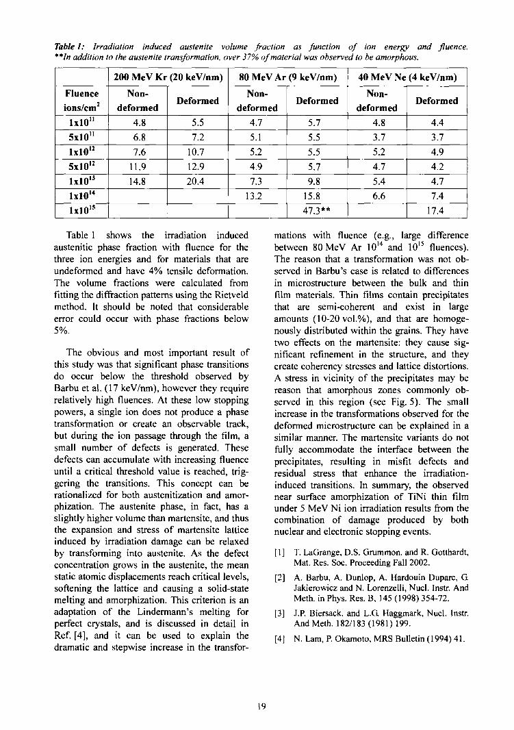
Table I: Irradiation induced austenite volume fraction as function of ion energy and fluence.**In addition to the austenite transformation, over 37% of material was observed to be amorphous.
Fluence
ions/cm2
1x10"
5x10"
lxlO12
5xlO12
lxlO13
lxlO14
ixlO15
200 MeV Kr (20 keV/nm)
Non-
deformed
4.8
6.8
7.6
11.9
14.8
Deformed
5.5
7.2
10.7
12.9
20.4
80MeVAr(9keV/nm)
Non-deformed
4.7
5.1
5.2
4.9
7.3
13.2
Deformed
5.7
5.5
5.5
5.7
9.8
15.8
47.3**
40 MeV Ne (4 keV/nm)
Non-deformed
4.8
3.7
5.2
4.7
5.4
6.6
Deformed
4.4
3.7
4.9
4.2
4.7
7.4
17.4
Table 1 shows the irradiation inducedaustenitic phase fraction with fluence for thethree ion energies and for materials that areundeformed and have 4% tensile deformation.The volume fractions were calculated fromfitting the diffraction patterns using the Rietveldmethod. It should be noted that considerableerror could occur with phase fractions below5%.
The obvious and most important result ofthis study was that significant phase transitionsdo occur below the threshold observed byBarbu et al. (17 keV/nm), however they requirerelatively high fluences. At these low stoppingpowers, a single ion does not produce a phasetransformation or create an observable track,but during the ion passage through the film, asmall number of defects is generated. Thesedefects can accumulate with increasing fluenceuntil a critical threshold value is reached, trig-gering the transitions. This concept can berationalized for both austenitization and amor-phization. The austenite phase, in fact, has aslightly higher volume than martensite, and thusthe expansion and stress of martensite latticeinduced by irradiation damage can be relaxedby transforming into austenite. As the defectconcentration grows in the austenite, the meanstatic atomic displacements reach critical levels,softening the lattice and causing a solid-statemelting and amorphization. This criterion is anadaptation of the Lindermann's melting forperfect crystals, and is discussed in detail inRef. [4], and it can be used to explain thedramatic and stepwise increase in the transfor-
mations with fluence (e.g., large differencebetween 80 MeV Ar 1014 and 1015 fluences).The reason that a transformation was not ob-served in Barbu's case is related to differencesin microstructure between the bulk and thinfilm materials. Thin films contain precipitatesthat are semi-coherent and exist in largeamounts (10-20 vol.%), and that are homoge-nously distributed within the grains. They havetwo effects on the martensite: they cause sig-nificant refinement in the structure, and theycreate coherency stresses and lattice distortions.A stress in vicinity of the precipitates may bereason that amorphous zones commonly ob-served in this region (see Fig. 5). The smallincrease in the transformations observed for thedeformed microstructure can be explained in asimilar manner. The martensite variants do notfully accommodate the interface between theprecipitates, resulting in misfit defects andresidual stress that enhance the irradiation-induced transitions. In summary, the observednear surface amorphization of TiNi thin filmunder 5 MeV Ni ion irradiation results from thecombination of damage produced by bothnuclear and electronic stopping events.
[1] T. LaGrange, D.S. Grummon. and R. Gotthardt,Mat. Res. Soc. Proceeding Fall 2002.
[2] A. Barbu, A. Dunlop, A. Hardouin Duparc, GJakierowicz and N. Lorenzelli, Nucl. Instr. AndMeth. in Phys. Res. B, 145 (1998) 354-72.
[3] J.P. Biersack. and L.G. Haggmark, Nucl. Instr.And Meth. 182/183(1981)199.
[4] N. Lam, P. Okamoto, MRS Bulletin (1994) 41.
19
1.6 Modification of the Ti Texture using swift heavy ions
/. Zizak, N. Darowski, G Schumacher, S. Klaumiinzer; W. Assmann [LMU Miinchen];J. Gerlach [IOM, Leipzig J; I Grofihans [Univ. Augsburg]
Accelerated ions interact with the solidthrough nuclear and electronic interaction. Atvery high energies the nuclear energy loss (Sn)is much smaller than the electronic energy loss(Se), and the interaction between the ions andthe solid leads to excited electrons in the solid.A part of the electronic excitation energy isconverted into atomic motion, e.g. via theelectron-phonon coupling.
Recently, a change in crystallite orientationof the polycrystalline Ti films was detectedafter the irradiation with 200 MeV Au ions [1].In order to study the mechanisms of the texturemodification, a new series of experiments wasstarted. In this contribution variations of theangle of the incoming beam, the irradiationdose, and the grain size of the samples arereported.
A bulk Ti sample with an average grain sizeof approximately 5 urn was compared to thefine-grained Ti films deposited on the Si (001)wafer (grain size of the order of magnitude of100 nm). The thickness of the film was 3 um.All samples were cut into 8x8 mm2 squarepieces and uniformly irradiated at room tem-perature with 350 MeV Au ions up to a fluenceof 5x10¹⁴ ions/cm2. Because the deposited Ti
films already possessed a texture, we irradiatedthe thin samples under two different angles, 20°and 45°, to avoid correlation effects betweenthe ion beam direction and the existing orienta-tion distribution. The textures of irradiatedsamples were studied using the synchrotronradiation beam at the K.MC2 beamline atBESSY [2]. The samples were mounted on asix-circle goniometer (Huber). The built-insample translator was used for the positioningof the sample into the X-ray beam. Used photonenergy was 8 keV. In order to avoid absorptionby the substrate, the diffraction was measuredin reflection geometry. The size of the focusedbeam at the sample position was 200x200 um2.
A pole figure describes the spherical distri-bution of the crystal lattice planes. In a standardBragg experiment the intensity of the diffractedbeam is proportional to the volume of thesample irradiated by X-rays, and to the fractionof the planes which are satisfying the Braggcondition, i.e., the plane normal halves theangle between the incoming and diffractedbeam. If the sample is rotated in two directionsand the measured intensity is mapped versus thesample orientation, the distribution function ofthe selected planes can be measured.
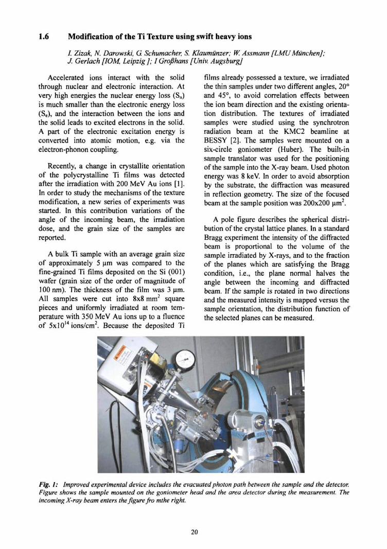
Fig. I: Improved experimental device includes the evacuated photon path between the sample and the detector.Figure shows the sample mounted on the goniometer head and the area detector during the measurement. Theincoming X-ray beam enters the figure fro mthe right.
20
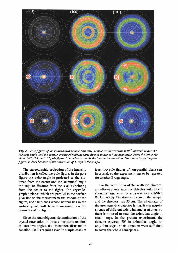
Fig. 2: Pole figures of the unirradiated sample (top row), sample irradiated with 5x10¹⁴ ions/cm2 under 20°incident angle, and the sample irradiated with the samefluence under 45° incident angle. From the left to theright: 002, WO, and 101 pole figure. The red cross marks the irradiation direction. The outer ring of the polefigures is dark because of the absorption of X-rays in the sample.
The stereographic projection of the intensitydistribution is called the pole figure. In the polefigure the polar angle is projected to the dis-tance from the center and the azimuthal anglethe angular distance from the x-axis (pointingfrom the center to the right). The crystallo-graphic planes which are parallel to the surfacegive rise to the maximum in the middle of thefigure, and the planes whose normal lies in thesurface plane will have a maximum on theperimeter of the figure.
Since the unambiguous determination of thecrystal orientation in three dimensions requiresat least two angles, the orientation distributionfunction (ODF) requires even in simple cases at
least two pole figures of non-parallel plane setsin crystal, so the experiment has to be repeatedfor another Bragg angle.
For the acquisition of the scattered photons,a multi-wire area sensitive detector with 12 cmdiameter large sensitive area was used (HiStar,Bruker AXS). The distance between the sampleand the detector was 33 cm. The advantage ofthe area sensitive detector is that it can acquirea range of different azimuthal angles at once, sothere is no need to scan the azimuthal angle insmall steps. In the present experiment, thedetector covered 20° in azimuthal angle, soonly four steps in this direction were sufficientto cover the whole hemisphere.
21
The second advantage of an area detector isthat the whole range of Bragg angles is acquiredin the same frame. In the present experiment thedetector acquired simultaneously (100), (002),and (101) Bragg reflection of Ti at 35.325°,38.68°, and 40.43°, respectively. This methodalso allows for background correction. Thediffuse scattering is estimated by averaging theacquired intensities for 20 values slightly higherand lower than the Bragg reflection so themeasured intensities could be corrected. It wasalso possible to exclude other possible phasesof Ti, which would produce a Bragg reflectionin the measured region, especially the highpressure co-phase which is sometimes seen afterthe irradiation of Ti with swift heavy ions [3,4].
Below 5x10¹⁴ ions/cm2 the textures of filmsshowed no changes. First changes becamevisible after 5x 10¹⁴ ions/cm2 and the resultingtextures depended on the beam direction. Sincea complete coverage with tracks occurs alreadyat the dose of about 1013 ions/cm2, we concludethat texture modification does not occur insingle ion tracks but reorientation of the crys-tallites requires multiple track overlap.
The thick sample showed in unirradiatedstate a texture specific for rolled metal sheets.This texture did not change even after5x1014 ions/cm2. The grain size seems to havean important influence on introduced grainorientation.
The rate of the texture change was similarfor the samples irradiated under different inci-dent angles, both textures showed the firstchanges only after 10!4 ions/cm2. The resultingtextures are different, and depend on the ionbeam direction.
Fig. 2 shows three sets of pole figures, forunirradiated thin film, and for thin films irradi-ated with the maximal dosis, 5x10¹⁴ ions/cm2.There is a maximum in the middle of the (002)and (101) pole figures for all three samples. Wealready showed in our previous experiment [5]that the Ti layer starts to grow with the (101)
plane parallel to the surface, but after somecertain thickness it grows with the (002) planeparallel to the surface. We assume that themaximum in the middle (101) pole figurecomes from the deeper regions of the film.Which are nearer to the substrate, and the (002)maximum from the grains nearer to the surface.We also see that the maximum in the middle ofthe (101) pole figure is not much affected byions.
The angles 20° and 45° are chosen so thatone of them lies below, and one above thedirection of the (101) plane normal in theunirradiated sample (approximately 27° fromsurface). If we look at the (002) pole figures ofthe irradiated sample we can see that the (002)peak in the 20° sample moves to the left, and inthe 45° sample to the right. This behavioursuggests the affinity between the (101) planenormal and the direction of the ion beam. Also,as in the previous experiment [5], a break of thefibre texture into six distinct maxima wasobserved.
A more quantitative combination with theprevious experiment is difficult due to thedifferent qualities of the Ti layers used in ex-periments. Different growing rates and/ortemperature resulted in different beginningstate, and slight difference in the ion energymay cause a variation in the dynamics of thetexture alteration.
[1] H.D. Mieskes, W. Assmann, F. Griiner. H. Ku-cal, Z.Q Wang, and M. Toulemonde. PhysicalReview B67 (2003) 155414.
[2] A. Erko, I. Packe, C. Hellwig, M. Fieber-Erd-mann. O. Pawlitzki, M. Veldkamp, W. Gudat,AIP Conf. Proc. 521 (2000) 421.
[3] H. Dammak. A. Barbu, A. Dunlop, D. Lesueur,Phil. Mag. Lett. 67 (1993) 253.
[4] H. Dammak, A. Barbu, A. Dunlop, D. Lesueur,Phil. Mag. A, 79(1999) 147.
[5] I. Zizak, N. Darowski, J. Gerlach, A. Wenzel,Jahresbericht 2002 der Abteilung SF4 des HMI(2002) 43.
22
1.7 Swift heavy ion irradiation in virgin InP
A. Kamarou, W. Wesch, E. Wendler [Friedrich-Schiller-Universitat Jena]; S. Klaumiinzer
Indium phosphide (InP) is known to haveoutstanding physical properties and, therefore,is a very promising material for different(opto)electronic applications. Swift heavy ion(SHI) implantation into III-V compounds iswidely used to create thick or buried layers withmodified properties (e.g. to form lightwaveguides or electrical isolation) and isknown for its spectacular effects (e.g. newphase and track formation [1-3]).
(100) oriented semi-insulating InP singlecrystals were irradiated with 140 MeV K.r'°\390 MeV Xe2" and 600 MeV AiT1' ions (seeTable 1) either at room temperature (RT) or atliquid nitrogen temperature (LNT) using ionfluences up to 5x1014 cm"2. We also used thin Alfoils with different thickness to decelerate600 MeV Au ions down to lower ion energies(79 MeV and 150 MeV).
Table I: Electronic (sj and nuclear (£„) energydeposition per ion and unit path length at the sur-face of InP for the SHI used (calculated with TRIM-97 [4]).
Ion/Energy
600 MeV Au150 MeV Au79MeVAu
390 MeV Xe140 MeV Kr
£•„ |keV/nm]28.719.713.619.712.5
£„ |keV/nm|0.0850.2780.4720.0450.029
The samples were analysed by means ofRBS/C with 1.4 MeV He ions. Assuming arandom distribution of displaced lattice atomswithin the lattice cell, from the measured RBSspectra the depth distribution of the relativeconcentration of displaced lattice atoms, nja(z),was calculated in the framework of the discon-tinuous model of dechannelling [5].
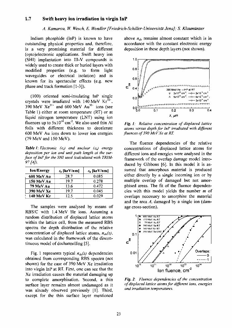
Fig. 1 represents typical nja(z) dependenciesobtained from corresponding RBS spectra (notshown) for the case of 390 MeV Xe irradiationinto virgin InP at RT. First, one can see that theXe irradiation causes the material damaging upto complete amorphisation. Second, a thinsurface layer remains almost undamaged as itwas already observed previously [1]. Third,except for the thin surface layer mentioned
above nja remains almost constant which is inaccordance with the constant electronic energydeposition in these depth layers (not shown).
1.0
0.8
0.6
0.4
0.2
0.0l
HHB5BJ
390 MeV Xe -> InP at RT \V 3x10"cm I
A 9x10"cm'2;3x10"cm!
9x10"cm! i3x10" cmJ
.00.0 0.1 0.2 0.3 0.4
z,
Fig. 1: Relative concentration of displaced latticeatoms versus depth for InP irradiated with differentfluences of 390 MeV Xe at RT.
The fluence dependencies of the relativeconcentrations of displaced lattice atoms fordifferent ions and energies were analysed in theframework of the overlap damage model intro-duced by Gibbons [6]. In this model it is as-sumed that amorphous material is producedeither directly by a single incoming ion or bymultiple overlap of damaged but not amor-phised areas. The fit of the fluence dependen-cies with this model yields the number m ofoverlaps necessary to amorphise the materialand the area A, damaged by a single ion (dam-age cross-section).
10 10"Ion fluence, cm"
Fig. 2: Fluence dependencies of the concentrationof displaced lattice atoms for different ions, energiesand irradiation temperatures.
23

Fig. 2 shows the fluence dependencies of nJa
as well as the corresponding curves fitted withthe overlap damage model. In the case of390 MeV Xe irradiation at LNT the efficiencyof damaging is remarkably reduced as com-pared to the corresponding RT irradiation (seeFig. 2). For all RT irradiations with different ionspecies and beam energies the fluence depend-encies can be fitted with an overlap numberm = 0. This means that each single ion creates aheavily damaged area along its trajectory di-rectly. Contrary, the assumption of one overlapis necessary to fit the experimental curve for thecase of 390 MeV Xe irradiations at LNT. It isalso worth mentioning that the damage cross-section A, for a single Xe ion is very close forboth RT and LNT irradiations (see Table 2).
Table 2: Number of overlaps m, damage cross-section At and resulting diameter d obtained fromGibbons 'modelfor different SHI irradiations oflnP.
Ion-Energy-Temperature600 MeV Au at RT150 MeV Au at RT79 MeV Aii at RT
390 MeV Xe at RT390 MeV Xe at LNTHOMeVKratRT
m
000010
/1/lnm2]31.316.72.93.32.40.05
d |nm]6.34.61.92.11.80.3
Further, the large shift of the curve for the140 MeV Kr as compared with the RT Xeirradiation is also of interest. The extremelysmall resulting damage cross-section area A,probably allows the conclusion that in the caseof the Kr irradiation the electronic energydeposition is almost inefficient to create stabledefect complexes in InP (either because of weakeffects of the primary damage nucleation [2] ordue to a very pronounced in situ damage an-nealing). This is in correlation with the fact that£e for 140 MeV Kr irradiation of InP (seeTable 1) is below the threshold value for trackformation of 13 keV/nm suggested in [1,2].
To obtain additional information about pos-sible integral effects, in Fig. 3 the nlia valuesfrom Fig. 2 are depicted versus the energydensity deposited into electronic processes(product of the electronic energy deposition perion and unit path length, ee, and the ion flu-ence). If the defect concentration remainingafter irradiation would only depend on theelectronic energy deposited in total per unitvolume, all curves in Fig. 5 should fall on the
same line. But this is definitely not the case,indicating that the effects observed are to alarge extent single-ion ones. They should de-pend on the energy se deposited per ion and unitpath length. Similar values of sc were realisedfirst for 150 MeV Au and 390 MeV Xe and,second, for 79 MeV Au and 140 MeV Kr (seeTable 1). However, the curves resulting for thesimilar values of sc also do not fall on the sameline (see Fig. 3), i.e. for a given ion fluence forAu a higher defect concentration is obtainedthan for Xe or Kr.
1 F
. ' 0 . 1
0.01
Irradiation at RT:^4^600 MeV Au—A—150 MeV Au—£— 79MeVAu /,—•— 390 MeV Xe //•—9— 390 MeV Xe / /—*— 140 MeV K r / /
tr 17v //ty'lon flux: 390 MeVXe
JJ —•—1.5x10'° em's'^ -»-3.7x10'° cmV
1x10² 102' 1x10"
Ion energy deposition, eV/cm
Fig. 3: Relative concentration of displaced latticeatoms versus ion energy deposited per unit volumefor different SHI irradiations of InP.
All this allows the conclusions that neitherthe energy deposition per unit path length northe energy deposition per unit volume alone candescribe the SHI effects in virgin InP. There-fore, we believe that besides velocity effectsalso the radial distribution of the energy depo-sition has to be taken into account, whichshould depend on both ion species and ionenergy.
[1] O. Herre, W. Wesch, E. Wendler, P.I. Gaiduk,F.F. Komarov, S. Klaumiinzer and P. Meier,Phys. Rev. B 58 (1998) 4832.
[2] W. Wesch, O. Herre, P.I. Gaiduk, E. Wendler,S. Klaumunzer and P. Meier, Nucl. Instr. andMeth. B 146(1998)341.
[3] P.I. Gaiduk, F.F. Komarov, W. Wesch, Nucl.Instr. and Meth. B164-165 (2000) 377.
[4] J.P. Biersack and J.F. Ziegler, The Stopping andRanges of Ions in Matter, vol. 1, PergamonPress, Oxford, 1985.
K. Gartner, Nucl. Instr. and Meth. B 132 (1997)147.
[5]
[6] J.F. Gibbons, Proc. IEEE 60 (1972) 1062.
24
1.8 Plastic deformation of amorphous silicon under swift heavy ion irradiation
A. Hedler, W. Wesch [Friedrich-Schiller-Universitdt JenaJ; S. Klaumiinzer
All investigated amorphous materials showanisotropic plastic deformation under swiftheavy ion irradiation (SHI) as a consequence ofmultiple anisotropic high electronic energydeposition referred to as ion hammering [1-3].In the past years this effect has been discussedcontroversially [4-7]. The viscoelastic thermalspike theory by Trinkaus et al. [4,5] represents agood description for glasses which show acontinuous transition to the liquid state. How-ever, a verification of the model for amorphoussemiconductors, which show a phase transitionof first order, has not been undertaken. With itswell-known physical properties amorphous Si(a-Si) seems to be a suitable candidate to beinvestigated first.
Single-crystalline, 370 u.m thick, one-sidepolished Si wafers were amorphized by meansof multiple Si implantation at 77 K. with ener-gies of 0.25-9.5 MeV and ion fluences of3-7 x 1015 cm"2 at the Tandetron accelerator ofFSU Jena. Rutherford-backscattering spec-trometry, infrared-reflection spectrometry andcross-sectional transmission electron micros-copy imaging revealed a homogenous amor-phous surface layer with a thickness ofd=5.7 urn. In order to measure surface shiftswith a precision of 1 ̂ m an Au grid layer of40 nm thickness has been produced on thesample surface by subsequent Au evaporationthrough a Ni net.
Swift heavy ion irradiation of the sampleswas carried out at HMI Berlin with the condi-tions described in Table 1.
Table 1: Irradiation conditions: the angle of the ionbeam with respect to the surface normal 0 theirradiation temperature To and the mean value of theelectronic energy deposition in the a-Si layer Se ascalculated by SRIM-2003.
Ion / Energy
390 MeV Xe2l +
350 MeV Au26+
600 MeV Au30*
0
45°
45°
45°
T,\K\
77, 300
77, 300
77, 300
Se |keV/nm]
15.8 ±0.2
18.8 ±1.0
21.3 ±0.3
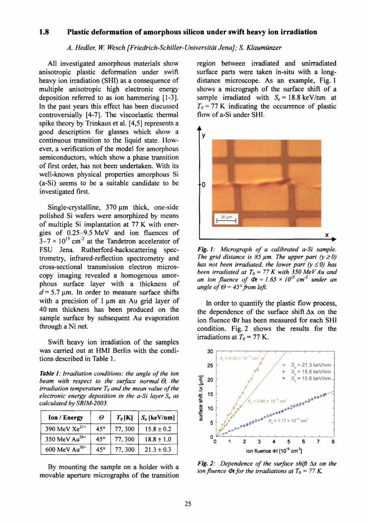
region between irradiated and unirradiatedsurface parts were taken in-situ with a long-distance microscope. As an example, Fig. 1shows a micrograph of the surface shift of asample irradiated with Se= 18.8 keV/nm atTo = 77 K indicating the occurrence of plasticflow of a-Si under SHI.
Fig. 1: Micrograph of a calibrated a-Si sample.The grid distance is 85 fim. The upper part (y > 0)has not been irradiated, the lower part (y <0) hasbeen irradiated at To = 77 K with 350 MeV Au andan ion fluence of <Pt = 1.65 * 1OIS cm'2 under anangle of0= 45°from left.
In order to quantify the plastic flow process,the dependence of the surface shift Ax on theion fluence ct>/ has been measured for each SHIcondition. Fig. 2 shows the results for theirradiations at To = 77 K.
Se = 21.3keV/nm•> s ]= 18.8 keV/nma s"= 15.8keV/nm
By mounting the sample on a holder with amovable aperture micrographs of the transition
1 2 3 4 5 6 7 8
ion fluence * f [1015 cm"2]
Fig. 2: Dependence of the surface shift Ax on theion fluence 0tfor the irradiations at TO = 77 K
25
A linear dependence of Ax(cl>/) and an inten-sified plastic flow with increasing St. have beenobserved. For room-temperature irradiation andsmall fluences the data points lie slightly belowthose in Fig. 2. The linear increase of Ax(O/) isa well-known feature of the ion hammeringeffect of embedded amorphous layers withincrystalline surroundings and can be understoodwith the extended Maxwell model [1-3]
e - +e (1)
which describes the macroscopic deformation eas a superposition of the ion hammering effect,characterized by the deformation yield tensor A,with the elastic and viscous properties of thelayer, characterized by £,te, and evlsc, respec-tively. In case of quasi-static equilibrium andstress-free surfaces this model has a solution farfrom the interfaces, which describes the surfaceshift as a function of the ion fluence
(2)
The tensor A reduces to the scalar An denoted asdeformation yield per ion and determines theslope of the linear dependence Ax(<3?t) and thusthe strength of the anisotropic growth. Trinkauset al. assigned Atl to the ion-solid-interactionand could derive an expression for the depend-ence of An on both the irradiation condition(energy deposition, irradiation temperature) andthe target material properties [4-5].
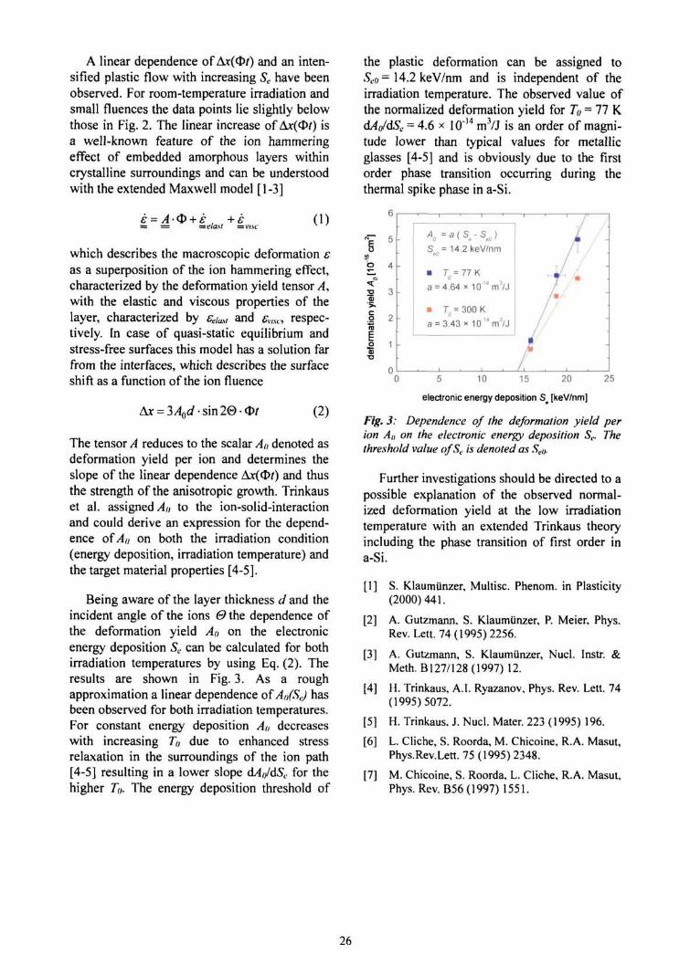
Being aware of the layer thickness d and theincident angle of the ions 0 the dependence ofthe deformation yield Af) on the electronicenergy deposition Se can be calculated for bothirradiation temperatures by using Eq. (2). Theresults are shown in Fig. 3. As a roughapproximation a linear dependence of Ao(SJ hasbeen observed for both irradiation temperatures.For constant energy deposition An decreaseswith increasing T() due to enhanced stressrelaxation in the surroundings of the ion path[4-5] resulting in a lower slope dA(/dSe for thehigher To. The energy deposition threshold of
the plastic deformation can be assigned toSeo= 14.2 keV/nm and is independent of theirradiation temperature. The observed value ofthe normalized deformation yield for Tu = 77 K.dAn/dS,. = 4.6 x 10"14 mVj is an order of magni-tude lower than typical values for metallicglasses [4-5] and is obviously due to the firstorder phase transition occurring during thethermal spike phase in a-Si.
•o
-
-
•
-
1 '
Aa =a(Se-Se0)
Se0= 14.2 keV/nm
• To=77K
a = 4.64 x 10 l 4rn3 /J
• To= 300 K
a = 3.43 x 1O'Mm3/J
/
'-T' •T
/ •5 10 15 20 25
electronic energy deposition Ss [keV/nm]
Fig. 3: Dependence of the deformation yield perion A,, on the electronic energy deposition 5,.. Thethreshold value ofSt. is denoted as Selh
Further investigations should be directed to apossible explanation of the observed normal-ized deformation yield at the low irradiationtemperature with an extended Trinkaus theoryincluding the phase transition of first order ina-Si.
[1] S. Klaumunzer, Multisc. Phenom. in Plasticity(2000)441.
[2] A. Gutzmann. S. Klaumunzer, P. Meier, Phys.Rev. Lett. 74(1995)2256.
[3] A. Gutzmann, S. Klaumunzer, Nucl. Instr. &Meth. B127/128 (1997) 12.
[4] H. Trinkaus, A.I. Ryazanov, Phys. Rev. Lett. 74(1995)5072.
[5] H. Trinkaus, J. Nucl. Mater. 223 (1995) 196.
[6] L. Cliche, S. Roorda, M. Chicoine, R.A. Masut,Phys.Rev.Lett. 75 (1995) 2348.
[7] M. Chicoine, S. Roorda, L. Cliche, R.A. Masut,Phys. Rev. B56 (1997) 1551.
26
1.9 Interface sharpening instead of broadening by diffusion in ideal binary alloys
Z. Erdelyi, D.L. Beke, GA. Longer, M. Kis-Varga [Department of Solid State Physics, Uni-versity of Debrecen, Hungary]; M. Sladecek, L.-M. Stadler, B. Sepiol [Institutfur Material-physik, Universitat Wien, Austria]; I. Zizak, N. Darowski, G Schumacher
The presented project aimed at an astonish-ing new effect, which is in complete contrast tohands-on experience - namely the sharpeningof interfaces in completely miscible binarysystems due to diffusion on nanoscale, i.e., onshort diffusion distances and short time. Usingcomputer simulations based on deterministickinetic equations [1] and Monte Carlo tech-nique [2], we showed that on nanoscale and forstrongly composition dependent D (large diffu-sion asymmetry), an initially diffused A/Binterface can become abrupt even in an idealsystem [3,4]. In the framework of this project,our goal was to prove it experimentally.
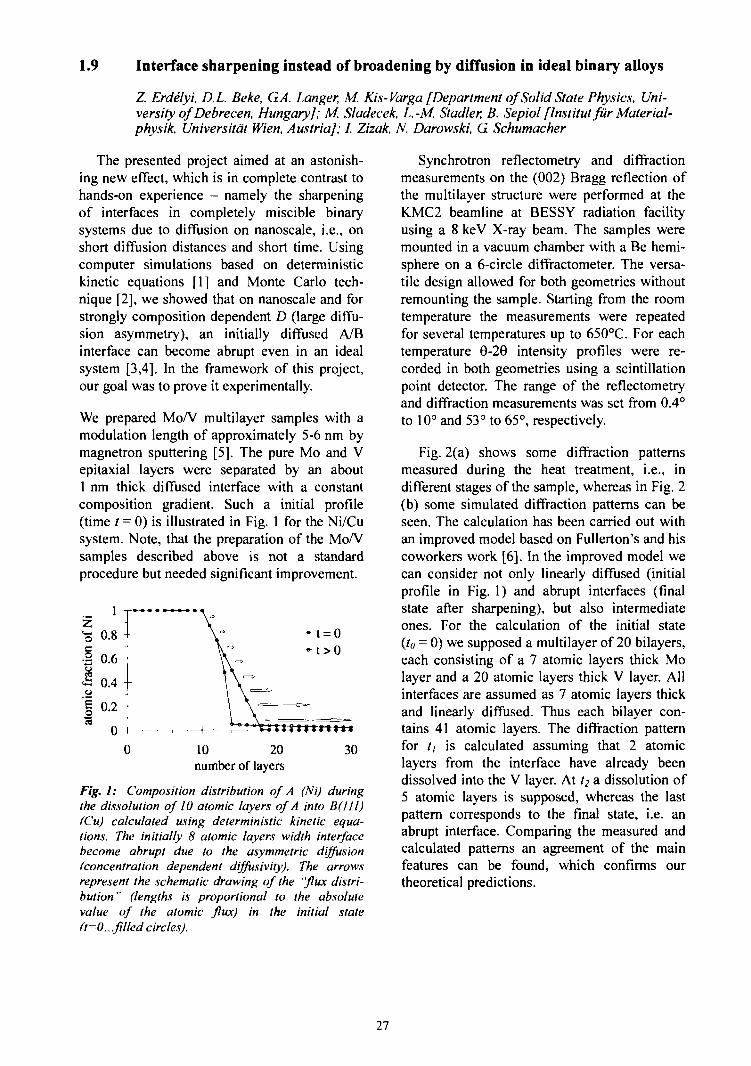
We prepared Mo/V multilayer samples with amodulation length of approximately 5-6 nm bymagnetron sputtering [5]. The pure Mo and Vepitaxial layers were separated by an about1 nm thick diffused interface with a constantcomposition gradient. Such a initial profile(time / = 0) is illustrated in Fig. 1 for the Ni/Cusystem. Note, that the preparation of the Mo/Vsamples described above is not a standardprocedure but needed significant improvement.
10 20number of layers
30
Fig. 1: Composition distribution of A (Ni) duringthe dissolution of 10 atomic layers of A into B(I11)(Cu) calculated using deterministic kinetic equa-tions. The initially 8 atomic layers width interfacebecome abrupt due to the asymmetric diffusion(concentration dependent diffusivity). The arrowsrepresent the schematic drawing of the "flux distri-bution " (lengths is proportional to the absolutevalue of the atomic flux) in the initial state(t=0...filled circles).
Synchrotron reflectometry and diffractionmeasurements on the (002) Bragg reflection ofthe multilayer structure were performed at theKMC2 beamline at BESSY radiation facilityusing a 8 keV X-ray beam. The samples weremounted in a vacuum chamber with a Be hemi-sphere on a 6-circle diffractometer. The versa-tile design allowed for both geometries withoutremounting the sample. Starting from the roomtemperature the measurements were repeatedfor several temperatures up to 650°C. For eachtemperature 9-29 intensity profiles were re-corded in both geometries using a scintillationpoint detector. The range of the reflectometryand diffraction measurements was set from 0.4°to 10° and 53° to 65°, respectively.
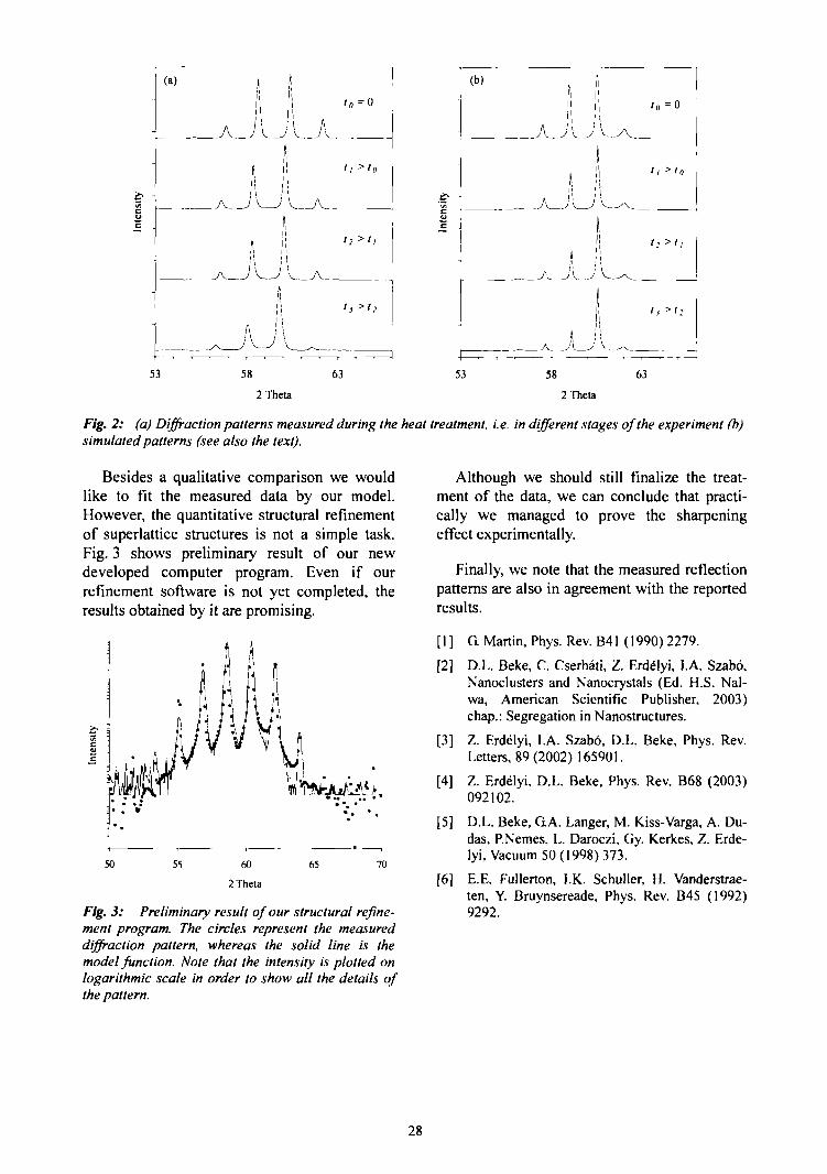
Fig. 2(a) shows some diffraction patternsmeasured during the heat treatment, i.e., indifferent stages of the sample, whereas in Fig. 2(b) some simulated diffraction patterns can beseen. The calculation has been carried out withan improved model based on Fullerton's and hiscoworkers work [6]. In the improved model wecan consider not only linearly diffused (initialprofile in Fig. 1) and abrupt interfaces (finalstate after sharpening), but also intermediateones. For the calculation of the initial state(/« = 0) we supposed a multilayer of 20 bilayers,each consisting of a 7 atomic layers thick Molayer and a 20 atomic layers thick V layer. Allinterfaces are assumed as 7 atomic layers thickand linearly diffused. Thus each bilayer con-tains 41 atomic layers. The diffraction patternfor // is calculated assuming that 2 atomiclayers from the interface have already beendissolved into the V layer. At t2 a dissolution of5 atomic layers is supposed, whereas the lastpattern corresponds to the final state, i.e. anabrupt interface. Comparing the measured andcalculated patterns an agreement of the mainfeatures can be found, which confirms ourtheoretical predictions.
27
Tr.
inic
n
(a)
11 .
53
A
j \
,1iiii
,
fi
\\
AA.r —
58
}
. Jh
1
J—T
i
\
I \J \
1
|1
iV
AA
A
' o = 0
' / ' 0
12 >>l
is >h
-r- - —. 1
63
Inte
nsity
-
(b)
.— . -
53
A
A
58
'i
11
A
-^
i
i
*
i
i
j
J
j
In
h
- ^ • —,
63
= 0
>'»
>ti
> ' :
- - - , —•
2 Theta 2 Theta
F/g. 2: (a) Diffraction patterns measured during the heat treatment, i.e. in different stages of the experiment (b)simulated patterns (see also the text).
Besides a qualitative comparison we wouldlike to fit the measured data by our model.However, the quantitative structural refinementof superlattice structures is not a simple task.Fig. 3 shows preliminary result of our newdeveloped computer program. Even if ourrefinement software is not yet completed, theresults obtained by it are promising.
50 55 60
2 Theta
65 70
Fig. 3: Preliminary result of our structural refine-ment program. The circles represent the measureddiffraction pattern, whereas the solid line is themodel function. Note that the intensity is plotted onlogarithmic scale in order to show all the details ofthe pattern.
Although we should still finalize the treat-ment of the data, we can conclude that practi-cally we managed to prove the sharpeningeffect experimentally.
Finally, we note that the measured reflectionpatterns are also in agreement with the reportedresults.
[ 1 ] G. Martin, Phys. Rev. B41 (1990) 2279.
[2] D.L. Beke, C. Cserhati, Z. Erdelyi, I.A. Szabo,Nanoclusters and Nanocrystals (Ed. H.S. Nal-wa, American Scientific Publisher, 2003)chap.: Segregation in Nanostructures.
[3] Z. Erdelyi, I.A. Szabo, D.L. Beke, Phys. Rev.Letters, 89(2002)165901.
[4] Z. Erdelyi, D.L. Beke, Phys. Rev. B68 (2003)092102.
[5] D.L. Beke, GA. Langer, M. Kiss-Varga, A. Du-das, P.Nemes, L. Daroczi, Gy. Kerkes, Z. Erde-lyi, Vacuum 50 (1998) 373.
[6] E.E. Fullerton, I.K. Schuller, H. Vanderstrae-ten, Y. Bruynsereade, Phys. Rev. B45 (1992)9292.
28
1.10 Phase transition in MnAs(0001)/GaAs(lll) epitaxial films
/. Zizak, N. Darowski; B. Jenichen, V.M. Kaganer, M. Kdstner, C. Herrmann, L Ddweritz,K.H. Ploog [Paul-Drude-Institut fur Festkorperelektronik, Berlin, Germany]
Time-resolved investigation of phase trans-formation is one of the scientific cases of ISL.Therefore the 6-circle diffractometer at K.MC2beamline at BESSY, operated by SF4/ISL, hasbeen optimized for time-resolved diffractionstudies. Utilizing the available vacuum high-temperature scattering chamber structural in-formation can be obtained also temperatureresolved. The KMC2 beamline is open forbeam time applications from other scientific de-partments which also may use the HMI experi-mental station. The investigation we reportabout has been carried out in collaboration withthe Paul-Drude-Institut, Berlin [1].
A combination of magnetic and semi-conducting materials, namely the combinationof ferromagnetic MnAs and semiconductingGaAs, is promising for the development of spininjection devices. MnAs possesses, at a tem-perature of approximately 40°C, a first-orderferromagnetic phase transition. The discontinu-ous change of magnetization is interrelated witha structural transformation.
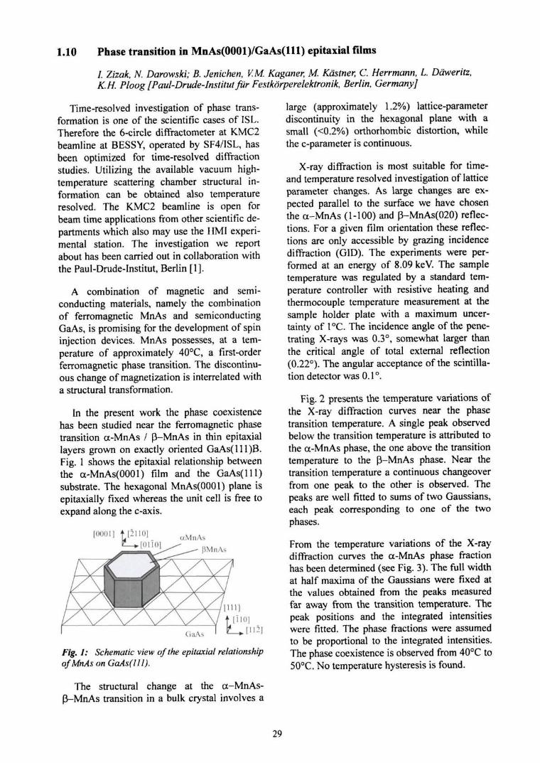
In the present work the phase coexistencehas been studied near the ferromagnetic phasetransition a-MnAs / p-MnAs in thin epitaxiallayers grown on exactly oriented GaAs(lll)B.Fig. 1 shows the epitaxial relationship betweenthe a-MnAs(OOOl) film and the GaAs(lll)substrate. The hexagonal MnAs(OOOl) plane isepitaxially fixed whereas the unit cell is free toexpand along the c-axis.
c/MnAs
Fig. 1: Schematic view of the epitaxial relationshipof MnAs on GaAs(llI).
The structural change at the a-MnAs-P-MnAs transition in a bulk crystal involves a
large (approximately 1.2%) lattice-parameterdiscontinuity in the hexagonal plane with asmall (<0.2%) orthorhombic distortion, whilethe c-parameter is continuous.
X-ray diffraction is most suitable for time-and temperature resolved investigation of latticeparameter changes. As large changes are ex-pected parallel to the surface we have chosenthe a-MnAs (1-100) and p-MnAs(020) reflec-tions. For a given film orientation these reflec-tions are only accessible by grazing incidencediffraction (GID). The experiments were per-formed at an energy of 8.09 keV. The sampletemperature was regulated by a standard tem-perature controller with resistive heating andthermocouple temperature measurement at thesample holder plate with a maximum uncer-tainty of 1°C. The incidence angle of the pene-trating X-rays was 0.3°, somewhat larger thanthe critical angle of total external reflection(0.22°). The angular acceptance of the scintilla-tion detector was 0.1 °.
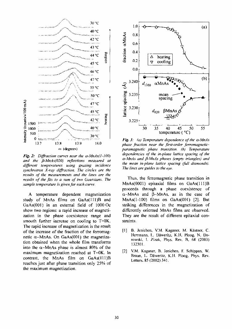
Fig. 2 presents the temperature variations ofthe X-ray diffraction curves near the phasetransition temperature. A single peak observedbelow the transition temperature is attributed tothe a-MnAs phase, the one above the transitiontemperature to the P-MnAs phase. Near thetransition temperature a continuous changeoverfrom one peak to the other is observed. Thepeaks are well fitted to sums of two Gaussians,each peak corresponding to one of the twophases.
From the temperature variations of the X-raydiffraction curves the a-MnAs phase fractionhas been determined (see Fig. 3). The full widthat half maxima of the Gaussians were fixed atthe values obtained from the peaks measuredfar away from the transition temperature. Thepeak positions and the integrated intensitieswere fitted. The phase fractions were assumedto be proportional to the integrated intensities.The phase coexistence is observed from 40°C to50°C. No temperature hysteresis is found.
29
[ i i M i i i r - ' H
• t I J I i • 11 i.i.i») * '
<E
§ 1500 •?'" l""*
•S 500| 0 ^S 13.7 13.8 13.9
o» (degrees)
30 "C
40 °C
42 °C
43 °C
44 °C SO
45 °C 'J
46 °C
47 °C
55 °C
50 °C
47 °C
45 °Ce
42 °C 5• £
40 °C
30 °C
14.0Fig. 2: Diffraction curves near the a-MnAs(J-JOO)and the (}-MnAs(020) reflections measured atdifferent temperatures using grazing incidencesynchrotron X-ray diffraction. The circles are theresults of the measurements and the lines are theresults of the fits to a sum of two Gaussians. Thesample temperature is given for each curve.
A temperature dependent magnetizationstudy of MnAs films on GaAs(lll)B andGaAs(OOl) in an external field of 1000 Oeshow two regions: a rapid increase of magneti-zation in the phase coexistence range andsmooth further increase on cooling to T=0K.The rapid increase of magnetization is the resultof the increase of the fraction of the ferromag-netic a-MnAs. On GaAs(OOl) the magnetiza-tion obtained when the whole film transformsinto the a-MnAs phase is almost 80% of themaximum magnetization reached at T=0K. Incontrast, the MnAs film on GaAs(lll)Breaches just after phase transition only 25% ofthe maximum magnetization.
|
a
_o
1.0
0.8
0.6
0.4
0.2
0.0
3.240
130.£ 3.235ua
3.230
3.225
A heatingV cooling
f/,]00 aMnAs 4
mean -spacing
d020 pMn.
v (a)
\
^ ( b )
• ^ ,*_
/ ^
30 35 40 45 50temperature ( °C)
55
Fig. 3: (a) Temperature dependence of the a-MnAsphase fraction near the first-order ferromagnetic-paramagnetic phase transition, (b) Temperaturedependencies of the in-plane lattice spacing of thea-MnAs and fi-MnAs phases (empty triangles) andthe mean in-plane lattice spacing (full diamonds).The lines are guides to the eye.
Thus, the ferromagnetic phase transition inMnAs(0001) epitaxial films on GaAs(lll)Bproceeds through a phase coexistence ofa-MnAs and p-MnAs, as in the case ofMnAs(l-lOO) films on GaAs(OOl) [2]. Butstriking differences in the magnetization ofdifferently oriented MnAs films are observed.They are the result of different epitaxial con-straints.
fl] B. Jenichen, V.M. Kaganer. M. KSstner, C.Herrmann. L Da'weritz, K..H. Ploog, N. Da-rowski, I. Zizak, Phys. Rev. B. 68 (2003)132301.
[2] V.M. Kaganer, B. Jenichen, F. Schippan, W.Braun, L. Daweritz, K..H. Ploog. Phys. Rev.Letters, 85(2002)341.
30
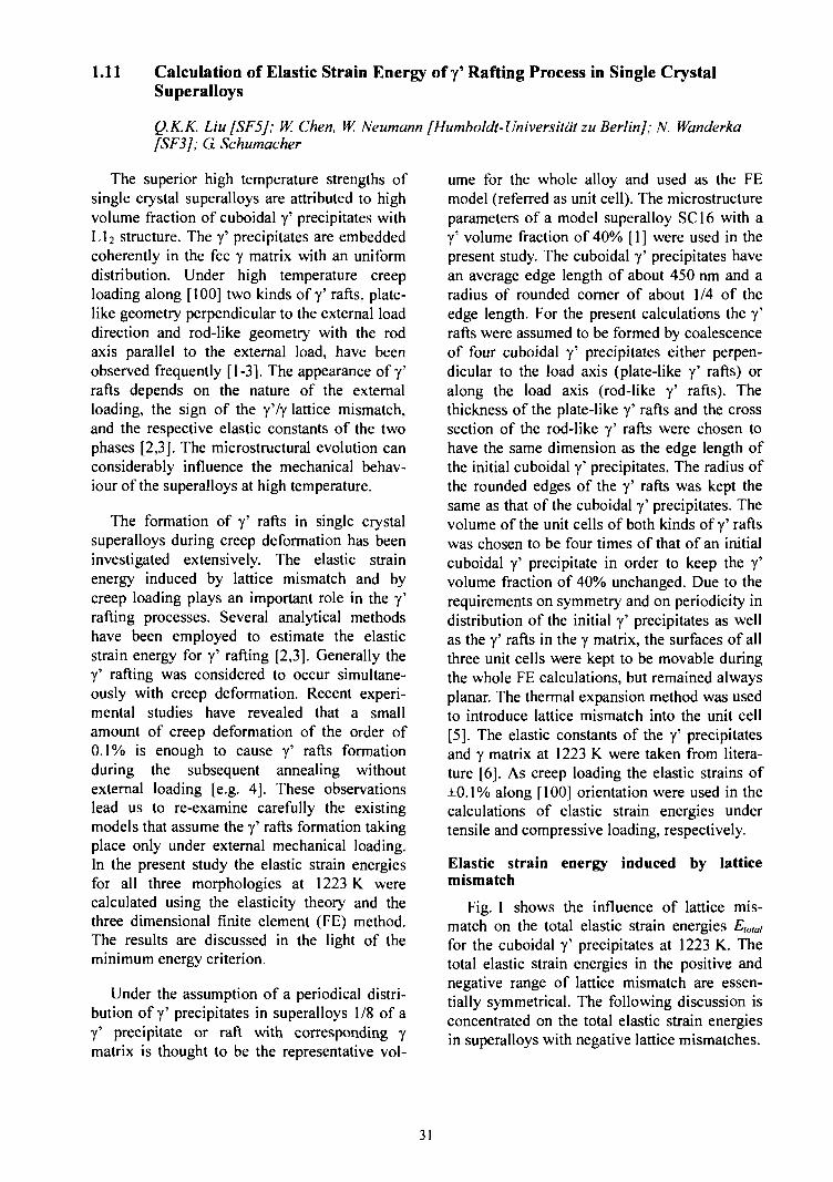
1.11 Calculation of Elastic Strain Energy of y* Rafting Process in Single CrystalSuperalloys
Q.K.K. Liu[SF5]; W. Chen, W. Neumann [Humboldt-Universitat zu Berlin]; N. Wanderka[SF3J; G Schumacher
The superior high temperature strengths ofsingle crystal superalloys are attributed to highvolume fraction of cuboidal y' precipitates withLI2 structure. The y' precipitates are embeddedcoherently in the fee y matrix with an uniformdistribution. Under high temperature creeploading along [ 100] two kinds of y' rafts, plate-like geometry perpendicular to the external loaddirection and rod-like geometry with the rodaxis parallel to the external load, have beenobserved frequently [1-3]. The appearance of y'rafts depends on the nature of the externalloading, the sign of the y'/y lattice mismatch,and the respective elastic constants of the twophases [2,3]. The microstructural evolution canconsiderably influence the mechanical behav-iour of the superalloys at high temperature.
The formation of y' rafts in single crystalsuperalloys during creep deformation has beeninvestigated extensively. The elastic strainenergy induced by lattice mismatch and bycreep loading plays an important role in the y'rafting processes. Several analytical methodshave been employed to estimate the elasticstrain energy for y' rafting [2,3]. Generally they' rafting was considered to occur simultane-ously with creep deformation. Recent experi-mental studies have revealed that a smallamount of creep deformation of the order of0.1% is enough to cause y' rafts formationduring the subsequent annealing withoutexternal loading [e.g. 4]. These observationslead us to re-examine carefully the existingmodels that assume the y' rafts formation takingplace only under external mechanical loading.In the present study the elastic strain energiesfor all three morphologies at 1223 K werecalculated using the elasticity theory and thethree dimensional finite element (FE) method.The results are discussed in the light of theminimum energy criterion.
Under the assumption of a periodical distri-bution of y' precipitates in superalloys 1/8 of ay' precipitate or raft with corresponding ymatrix is thought to be the representative vol-
ume for the whole alloy and used as the FEmodel (referred as unit cell). The microstructureparameters of a model superalloy SC16 with ay' volume fraction of 40% [1] were used in thepresent study. The cuboidal y' precipitates havean average edge length of about 450 nm and aradius of rounded corner of about 1/4 of theedge length. For the present calculations the y'rafts were assumed to be formed by coalescenceof four cuboidal y' precipitates either perpen-dicular to the load axis (plate-like y' rafts) oralong the load axis (rod-like y' rafts). Thethickness of the plate-like y' rafts and the crosssection of the rod-like y' rafts were chosen tohave the same dimension as the edge length ofthe initial cuboidal y' precipitates. The radius ofthe rounded edges of the y' rafts was kept thesame as that of the cuboidal y' precipitates. Thevolume of the unit cells of both kinds of y' raftswas chosen to be four times of that of an initialcuboidal y' precipitate in order to keep the y'volume fraction of 40% unchanged. Due to therequirements on symmetry and on periodicity indistribution of the initial y' precipitates as wellas the y' rafts in the y matrix, the surfaces of allthree unit cells were kept to be movable duringthe whole FE calculations, but remained alwaysplanar. The thermal expansion method was usedto introduce lattice mismatch into the unit cell[5]. The elastic constants of the y' precipitatesand y matrix at 1223 K were taken from litera-ture [6]. As creep loading the elastic strains of±0.1% along [100] orientation were used in thecalculations of elastic strain energies undertensile and compressive loading, respectively.
Elastic strain energy induced by latticemismatch
Fig. 1 shows the influence of lattice mis-match on the total elastic strain energies Emaifor the cuboidal y' precipitates at 1223 K. Thetotal elastic strain energies in the positive andnegative range of lattice mismatch are essen-tially symmetrical. The following discussion isconcentrated on the total elastic strain energiesin superalloys with negative lattice mismatches.
31
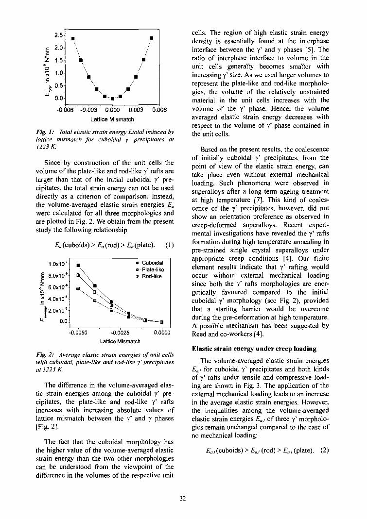
£cZoXc""lUJ
2.5-
2.0-
1.5-
1.0-
0.5-
0.0-
•\
\•I
\
\\
" . . .
•I
m
/
-0.006 -0.003 0.000 0.003
Lattice Mismatch
0.006
Fig. 1: Total elastic strain energy Etotal induced bylattice mismatch for cuboidal y' precipitates at1223 K.
Since by construction of the unit cells thevolume of the plate-like and rod-like y' rafts arelarger than that of the initial cuboidal y' pre-cipitates, the total strain energy can not be useddirectly as a criterion of comparison. Instead,the volume-averaged elastic strain energies Ea
were calculated for all three morphologies andare plotted in Fig. 2. We obtain from the presentstudy the following relationship
Ea (cuboids) > Ea (rod) > Ea (plate). (1)
1.0x10°
8.0x10⁸-
f 6.0x10'8o* 4.0x10*-
h.0x108-Ui 0.0-
• Cuboidala Plate-likea Rod-like
-0.0050 -0.0025
Lattice Mismatch
0.0000
Fig. 2: Average elastic strain energies of unit cellswith cuboidal, plate-like and rod-like y' precipitatesat 1223 K.
The difference in the volume-averaged elas-tic strain energies among the cuboidal y' pre-cipitates, the plate-like and rod-like y' raftsincreases with increasing absolute values oflattice mismatch between the y' and y phases[Fig- 2].
The fact that the cuboidal morphology hasthe higher value of the volume-averaged elasticstrain energy than the two other morphologiescan be understood from the viewpoint of thedifference in the volumes of the respective unit
cells. The region of high elastic strain energydensity is essentially found at the interphaseinterface between the y' and y phases [5]. Theratio of interphase interface to volume in theunit cells generally becomes smaller withincreasing y' size. As we used larger volumes torepresent the plate-like and rod-like morpholo-gies, the volume of the relatively unstrainedmaterial in the unit cells increases with thevolume of the y' phase. Hence, the volumeaveraged elastic strain energy decreases withrespect to the volume of y' phase contained inthe unit cells.
Based on the present results, the coalescenceof initially cuboidal y' precipitates, from thepoint of view of the elastic strain energy, cantake place even without external mechanicalloading. Such phenomena were observed insuperalloys after a long term ageing treatmentat high temperature [7]. This kind of coales-cence of the y' precipitates, however, did notshow an orientation preference as observed increep-deformed superalloys. Recent experi-mental investigations have revealed the y' raftsformation during high temperature annealing inpre-strained single crystal superalloys underappropriate creep conditions [4]. Our finiteelement results indicate that y' rafting wouldoccur without external mechanical loadingsince both the y' rafts morphologies are ener-getically favoured compared to the initialcuboidal y' morphology (see Fig. 2), providedthat a starting barrier would be overcomeduring the pre-deformation at high temperature.A possible mechanism has been suggested byReed and co-workers [4].
Elastic strain energy under creep loading
The volume-averaged elastic strain energiesEaJ for cuboidal y' precipitates and both kindsof y' rafts under tensile and compressive load-ing are shown in Fig. 3. The application of theexternal mechanical loading leads to an increasein the average elastic strain energies. However,the inequalities among the volume-averagedelastic strain energies Eat of three y' morpholo-gies remain unchanged compared to the case ofno mechanical loading:
Eaj (cuboids) > EaJ (rod) > EaJ (plate). (2)
32
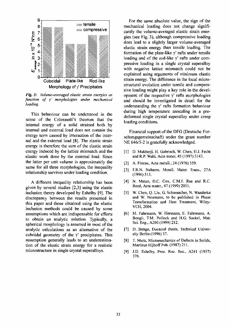
tensilecompressive
Cuboidal Plate-like Rod-likeMorphology of / Precipitates
Fig. 3: Volume-averaged elastic strain energies asfunction of y' morphologies under mechanicalloading.
This behaviour can be understood in thesense of the Colonnetti's theorem that theinternal energy of a solid strained both byinternal and external load does not contain theenergy term caused by interaction of the inter-nal and the external load [8]. The elastic strainenergy is therefore the sum of the elastic strainenergy induced by the lattice mismatch and theelastic work done by the external load. Sincethe latter per unit volume is approximately thesame for all three morphologies, the inequalityrelationship survives under loading condition.
A different inequality relationship has beengiven by several studies [2,3] using the elasticinclusion theory developed by Eshelby [9]. Thediscrepancy between the results presented inthis paper and those obtained using the elasticinclusion methods could be caused by someassumptions which are indispensable for effortsto obtain an analytic solution. Typically, aspherical morphology is assumed in most of theanalytic calculations as an alternative of thecuboidal geometry of the y' precipitates. Thisassumption generally leads to an underestima-tion of the elastic strain energy for a realisticmicrostructure in single crystal superalloys.
For the same absolute value, the sign of themechanical loading does not change signifi-cantly the volume-averaged elastic strain ener-gies (see Fig. 3), although compressive loadingdoes lead to a slightly larger volume-averagedelastic strain energy than tensile loading. Theformation of the plate-like y' rafts under tensileloading and of the rod-like y' rafts under com-pressive loading in a single crystal superalloywith negative lattice mismatch could not beexplained using arguments of minimum elasticstrain energy. The difference in the local micro-structural evolution under tensile and compres-sive loading might play a key role in the devel-opment of the respective y' rafts morphologiesand should be investigated in detail for theunderstanding the y' rafts formation behaviourduring high temperature annealing in a pre-deformed single crystal superalloy under creeploading conditions.
Financial support of the DFG (Deutsche For-schungsgemeinschaft) under the grant numberNE 646/5-2 is gratefully acknowledged.
[1] D. Mukherji, H. Gabrisch, W. Chen, H.J. Fechtand R.P. Wahi, Acta mater, 45 (1997) 3143.
[2] A. Pineau, Acta metall., 24 (1976) 559.
[3] F.R.N. Nabarro, Metall. Mater. Trans., 27A(1996)513.
[4] N. Matan, D.C. Cox, C.M.F. Rae and R.C.Reed, Acta mater., 47 (1999) 2031.
[5] W. Chen, Q. Liu, G Schumacher, N. Wanderkaand W. Neumann, to be published in PhaseTransformation and Heat Treatment, Wiley-VCH, 2004.
[6] M. Fahrmann, W. Hermann, E. Fahrmann, A.Boegli, T.M. Pollock and H.G Sockel, Mat.Sci. Eng., A260 (1999) 212.
[7] D. Bettge, Doctoral thesis, Technical Univer-sity Berlin (1996) 37.
[8] T. Mura, Micromechanics of Defects in Solids,Martinus Hijhoff Pub. (1987)211.
[9] J.D. Eshelby, Proc. Roc. Soc, A241 (1957)376.
33
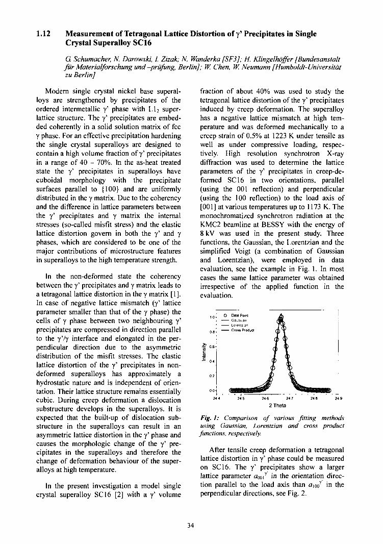
1.12 Measurement of Tetragonal Lattice Distortion of y' Precipitates in SingleCrystal Superalloy SC16
G Schumacher, N. Darowski, I. Zizak; N. Wanderka [SF3J; H. Klingelhoffer [Bundesanstaltfur Materialforschung und-priifung, Berlin]; W. Chen, W. Neumann [Humboldl-Universitdtzu Berlin]
Modern single crystal nickel base superal-loys are strengthened by precipitates of theordered intermetallic y' phase with Ll2 super-lattice structure. The y' precipitates are embed-ded coherently in a solid solution matrix of feey phase. For an effective precipitation hardeningthe single crystal superalloys are designed tocontain a high volume fraction of y' precipitatesin a range of 40 - 70%. In the as-heat treatedstate the y' precipitates in superalloys havecuboidal morphology with the precipitatesurfaces parallel to {100} and are uniformlydistributed in the y matrix. Due to the coherencyand the difference in lattice parameters betweenthe y' precipitates and y matrix the internalstresses (so-called misfit stress) and the elasticlattice distortion govern in both the y' and yphases, which are considered to be one of themajor contributions of microstructure featuresin superalloys to the high temperature strength.
In the non-deformed state the coherencybetween the y' precipitates and y matrix leads toa tetragonal lattice distortion in the y matrix [1].In case of negative lattice mismatch (y' latticeparameter smaller than that of the y phase) thecells of y phase between two neighbouring y'precipitates are compressed in direction parallelto the y'/y interface and elongated in the per-pendicular direction due to the asymmetricdistribution of the misfit stresses. The elasticlattice distortion of the y' precipitates in non-deformed superalloys has approximately ahydrostatic nature and is independent of orien-tation. Their lattice structure remains essentiallycubic. During creep deformation a dislocationsubstructure develops in the superalloys. It isexpected that the built-up of dislocation sub-structure in the superalloys can result in anasymmetric lattice distortion in the y' phase andcauses the morphologic change of the y' pre-cipitates in the superalloys and therefore thechange of deformation behaviour of the super-alloys at high temperature.
In the present investigation a model singlecrystal superalloy SCI6 [2] with a y' volume
fraction of about 40% was used to study thetetragonal lattice distortion of the y' precipitatesinduced by creep deformation. The superalloyhas a negative lattice mismatch at high tem-perature and was deformed mechanically to acreep strain of 0.5% at 1223 K under tensile aswell as under compressive loading, respec-tively. High resolution synchrotron X-raydiffraction was used to determine the latticeparameters of the y' precipitates in creep-de-formed SCI6 in two orientations, parallel(using the 001 reflection) and perpendicular(using the 100 reflection) to the load axis of[001] at various temperatures up to 1173 K. Themonochromatized synchrotron radiation at theKMC2 beamline at BESSY with the energy of8 kV was used in the present study. Threefunctions, the Gaussian, the Lorentzian and thesimplified Voigt (a combination of Gaussianand Lorentzian), were employed in dataevaluation, see the example in Fig. 1. In mostcases the same lattice parameter was obtainedirrespective of the applied function in theevaluation.
24 5 24 6 24 7 248 249
2Theta
Fig. 1: Comparison of various fitting methodsusing Gaussian, Lorentzian and cross productfunctions, respectively.
After tensile creep deformation a tetragonallattice distortion in y' phase could be measuredon SCI6. The y' precipitates show a largerlattice parameter aOoiT in the orientation direc-tion parallel to the load axis than a\ooy in theperpendicular directions, see Fig. 2.
34
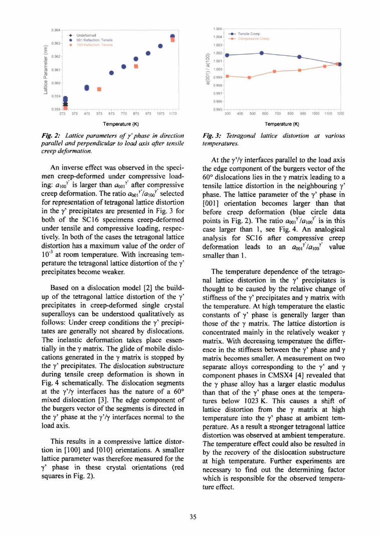
0.363 !
u. 0 362CD0)
ro 0 361 -
Undeformed001 Reflection, Tensile100 Reflection Tensile
I273 373 473 573 673 773 873 973 1073 1173
Temperature (K)
Fig. 2: Lattice parameters off phase in directionparallel and perpendicular to load axis after tensilecreep deformation.
An inverse effect was observed in the speci-men creep-deformed under compressive load-ing: aWo is larger than aOoiY after compressivecreep deformation. The ratio aooir7aioor selectedfor representation of tetragonal lattice distortionin the y' precipitates are presented in Fig. 3 forboth of the SCI6 specimens creep-deformedunder tensile and compressive loading, respec-tively. In both of the cases the tetragonal latticedistortion has a maximum value of the order of10"3 at room temperature. With increasing tem-perature the tetragonal lattice distortion of the y'precipitates become weaker.
Based on a dislocation model [2] the build-up of the tetragonal lattice distortion of the y'precipitates in creep-deformed single crystalsuperalloys can be understood qualitatively asfollows: Under creep conditions the y' precipi-tates are generally not sheared by dislocations.The inelastic deformation takes place essen-tially in the y matrix. The glide of mobile dislo-cations generated in the y matrix is stopped bythe y' precipitates. The dislocation substructureduring tensile creep deformation is shown inFig. 4 schematically. The dislocation segmentsat the y'/y interfaces has the nature of a 60°mixed dislocation [3]. The edge component ofthe burgers vector of the segments is directed inthe y' phase at the y'/y interfaces normal to theload axis.
This results in a compressive lattice distor-tion in [100] and [010] orientations. A smallerlattice parameter was therefore measured for they' phase in these crystal orientations (redsquares in Fig. 2).
400 500 600 700 800 900 1000 1100 120C
Temperature (K)
Fig. 3: Tetragonal lattice distortion at varioustemperatures.
At the y'/y interfaces parallel to the load axisthe edge component of the burgers vector of the60° dislocations lies in the y matrix leading to atensile lattice distortion in the neighbouring y'phase. The lattice parameter of the y' phase in[001] orientation becomes larger than thatbefore creep deformation (blue circle datapoints in Fig. 2). The ratio aOoir /fliooy is in thiscase larger than 1, see Fig. 4. An analogicalanalysis for SCI6 after compressive creepdeformation leads to an aooiy/«iooy valuesmaller than 1.
The temperature dependence of the tetrago-nal lattice distortion in the y' precipitates isthought to be caused by the relative change ofstiffness of the y' precipitates and y matrix withthe temperature. At high temperature the elasticconstants of y' phase is generally larger thanthose of the y matrix. The lattice distortion isconcentrated mainly in the relatively weaker ymatrix. With decreasing temperature the differ-ence in the stiffness between the y' phase and ymatrix becomes smaller. A measurement on twoseparate alloys corresponding to the y' and ycomponent phases in CMSX4 [4] revealed thatthe y phase alloy has a larger elastic modulusthan that of the y' phase ones at the tempera-tures below 1023 K. This causes a shift oflattice distortion from the y matrix at hightemperature into the y' phase at ambient tem-perature. As a result a stronger tetragonal latticedistortion was observed at ambient temperature.The temperature effect could also be resulted inby the recovery of the dislocation substructureat high temperature. Further experiments arenecessary to find out the determining factorwhich is responsible for the observed tempera-ture effect.
35
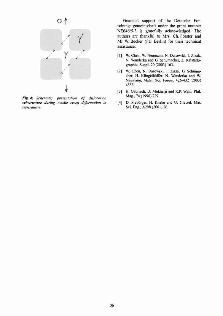
/ Y
Fig. 4: Schematic presentation of dislocationsubstructure during tensile creep deformation insuperalloys.
Financial support of the Deutsche For-schungs-gemeinschaft under the grant numberNE646/5-3 is gratefully acknowledged. Theauthors are thankful to Mrs. Ch. F6"rster andMr. W. Becker (FU Berlin) for their technicalassistance.
[1] W. Chen, W. Neumann, N. Darowski. I. Zizak,N. Wanderka and G Schumacher, Z. Kristallo-graphie, Suppl. 20 (2003) 163.
[2] W. Chen, N. Darowski, I. Zizak. G Schuma-cher, H. Klingelhoffer, N. Wanderka and W.Neumann, Mater. Sci. Forum, 426-432 (2003)4555.
[3] H. Gabrisch, D. Mukherji and R.P. Wahi, Phil.Mag., 74(1996)229.
[4] D. Sieborger, H. Knake and U. Glatzel, Mat.Sci. Eng., A298(2001)26.
36
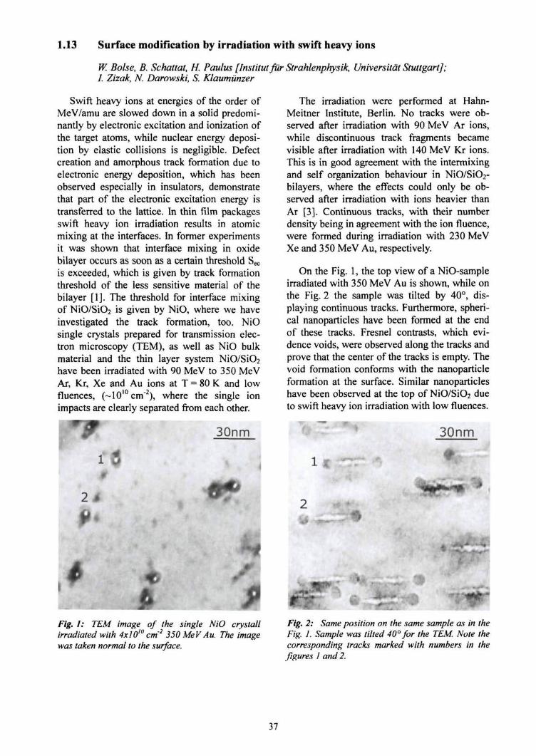
1.13 Surface modification by irradiation with swift heavy ions
W. Boise, B. Schattat, H. Paulus [Institut fur Strahlenphysik, Universitat Stuttgart];I. Zizak, N. Darowski, S. Klaumiinzer
Swift heavy ions at energies of the order ofMeV/amu are slowed down in a solid predomi-nantly by electronic excitation and ionization ofthe target atoms, while nuclear energy deposi-tion by elastic collisions is negligible. Defectcreation and amorphous track formation due toelectronic energy deposition, which has beenobserved especially in insulators, demonstratethat part of the electronic excitation energy istransferred to the lattice. In thin film packagesswift heavy ion irradiation results in atomicmixing at the interfaces. In former experimentsit was shown that interface mixing in oxidebilayer occurs as soon as a certain threshold Sec
is exceeded, which is given by track formationthreshold of the less sensitive material of thebilayer [1]. The threshold for interface mixingof NiO/SiO2 is given by NiO, where we haveinvestigated the track formation, too. NiOsingle crystals prepared for transmission elec-tron microscopy (TEM), as well as NiO bulkmaterial and the thin layer system NiO/SiO2
have been irradiated with 90 MeV to 350 MeVAr, Kr, Xe and Au ions at T = 80 K and lowfluences, (~10 l0cm2), where the single ionimpacts are clearly separated from each other.
30nm
The irradiation were performed at Hahn-Meitner Institute, Berlin. No tracks were ob-served after irradiation with 90 MeV Ar ions,while discontinuous track fragments becamevisible after irradiation with 140 MeV Kr ions.This is in good agreement with the intermixingand self organization behaviour in NiO/SiO2-bilayers, where the effects could only be ob-served after irradiation with ions heavier thanAr [3]. Continuous tracks, with their numberdensity being in agreement with the ion fluence,were formed during irradiation with 230 MeVXe and 350 MeV Au, respectively.
On the Fig. 1, the top view of a NiO-sampleirradiated with 350 MeV Au is shown, while onthe Fig. 2 the sample was tilted by 40°, dis-playing continuous tracks. Furthermore, spheri-cal nanoparticles have been formed at the endof these tracks. Fresnel contrasts, which evi-dence voids, were observed along the tracks andprove that the center of the tracks is empty. Thevoid formation conforms with the nanoparticleformation at the surface. Similar nanoparticleshave been observed at the top of NiO/SiO2 dueto swift heavy ion irradiation with low fluences.
••• V " » ' "" 30nmT "
"i
Fig. I: TEM image of the single NiO crystallirradiated with 4x10lu cm'2 350 MeV Au. The imagewas taken normal to the surface.
Fig. 2: Same position on the same sample as in theFig. 1. Sample was tilted 40° for the TEM. Note thecorresponding tracks marked with numbers in thefigures 1 and 2.
37
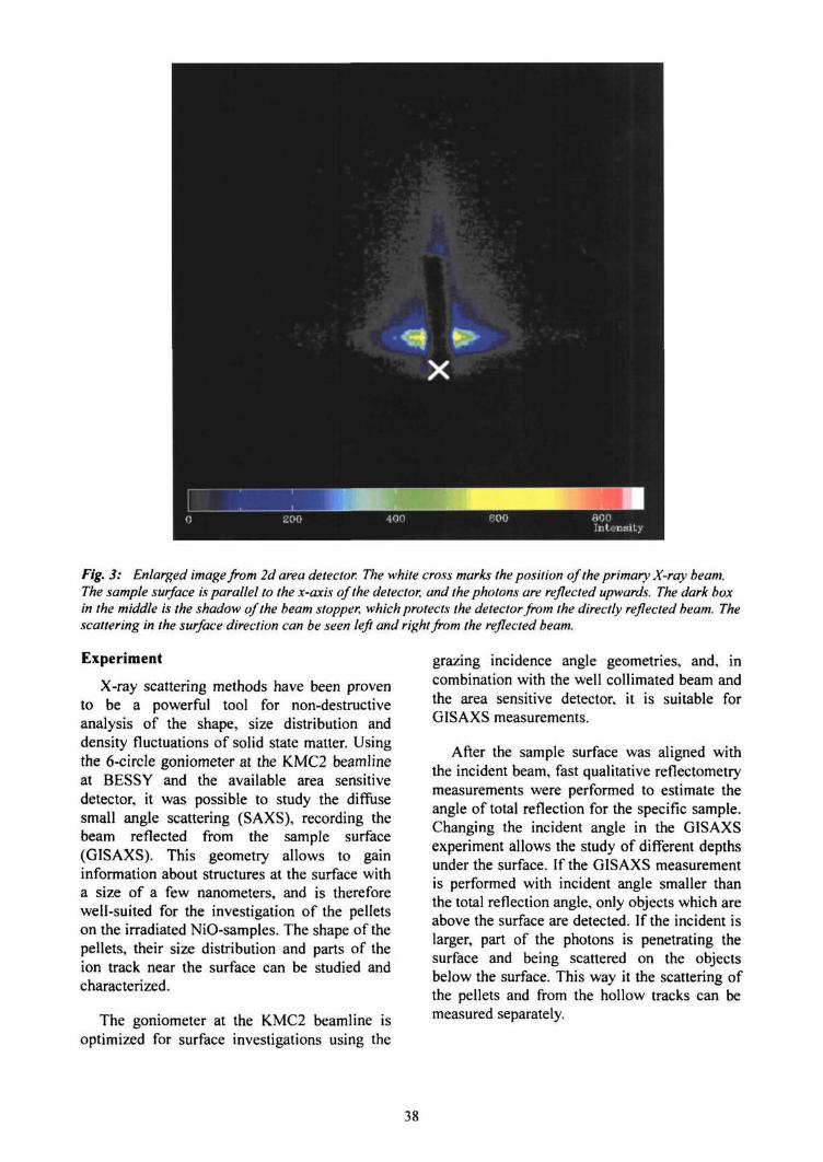
Fig. 3: Enlarged image from 2d area detector. The white cross marks the position of the primary X-ray beam.The sample surface is parallel to the x-axis of the detector, and the photons are reflected upwards. The dark boxin the middle is the shadow of the beam stopper, which protects the detector from the directly reflected beam. Thescattering in the surface direction can be seen left and right from the reflected beam.
Experiment
X-ray scattering methods have been provento be a powerful tool for non-destructiveanalysis of the shape, size distribution anddensity fluctuations of solid state matter. Usingthe 6-circle goniometer at the KMC2 beamlineat BESSY and the available area sensitivedetector, it was possible to study the diffusesmall angle scattering (SAXS), recording thebeam reflected from the sample surface(GISAXS). This geometry allows to gaininformation about structures at the surface witha size of a few nanometers, and is thereforewell-suited for the investigation of the pelletson the irradiated NiO-samples. The shape of thepellets, their size distribution and parts of theion track near the surface can be studied andcharacterized.
The goniometer at the KMC2 beamline isoptimized for surface investigations using the
grazing incidence angle geometries, and, incombination with the well collimated beam andthe area sensitive detector, it is suitable forGISAXS measurements.
After the sample surface was aligned withthe incident beam, fast qualitative reflectometrymeasurements were performed to estimate theangle of total reflection for the specific sample.Changing the incident angle in the GISAXSexperiment allows the study of different depthsunder the surface. If the GISAXS measurementis performed with incident angle smaller thanthe total reflection angle, only objects which areabove the surface are detected. If the incident islarger, part of the photons is penetrating thesurface and being scattered on the objectsbelow the surface. This way it the scattering ofthe pellets and from the hollow tracks can bemeasured separately.
38

100
10
JE
.£
0.1
data >scattering function
•.
-2 -1.5 -0.5 0.5 1.5
a Inrrf'l
Fig. 4: Scattering function in the direction parallel to the surface. The solid line is the fit with the scatteringfunction for the monodisperse solid spheres. The data behind the beam stopper are removed.
Results and Discussion
Since only one half of each sample was ir-radiated, we were able to measure the scatteringfrom the unirradiated part, and use thismeasurements for the background correction.
Fig. 3 shows the detected scattered intensityfrom the thin NiO/SiO2 irradiated with 5x10¹⁰
350 MeV Au ions/cm2. The resolution and thesignal to noise ratio were not very satisfactory,so only part of the planed evaluation wasperformed. The scattering pattern measured onthe unirradiated part of the sample was sub-tracted from the pattern measured on theirradiated part. The resulting scattering patternwas fitted with the model function of mono-disperse spheres laying on the sample surface toobtain the radius of the pellets. The resultingradius of the pellets was 6.2 nm. Thick NiOsingle crystals showed no difference in scat-tering function between the irradiated and theunirradiated part.
Although GISAXS offers more informationon the surface objects, it was not possible toevaluate the measured data with the expected
success. Low intensity of the primary beam andlarge noise made the detection of the hollowtracks impossible. However, we were able todetect and estimate the size of the spheres onthe surface of some irradiated samples. Thisexperiment showed that GISAXS providesinformation on irradiated samples which arevery hard to measure with other methods.
In 2005, a new SAXS experimental station isgoing to be operational at the 7T wiggler atBESSY. The new station is optimized for thesurface scattering, and we plan to continue thisexperiment at the new device. We hope to beable to measure not only the radius of thespheres, but also their radius and the dimen-sions of the hollow track.
[1] W. Boise, B. Schattat, Nucl. Instr. Meth. B 190(2002) 173.
[2] B. Schattat, W. Boise, S. Klaumiinzer, F. Habs-meier, A. Jasenek, Appl. Phys. A 76 (2002)165.
[3] W. Boise, B. Schattat, A. Feyh, Appl. Phys. A77(2003)11.
39
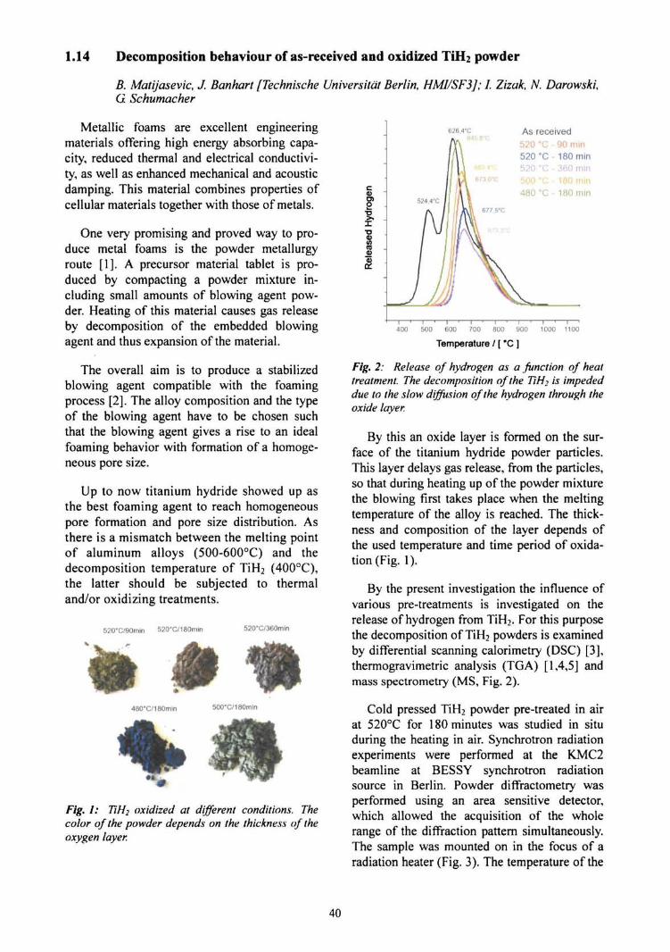
1.14 Decomposition behaviour of as-received and oxidized TiH2 powder
B. Matijasevic, J. Banhart [Technische Universitat Berlin, HMI/SF3J; I. Zizak, N. Darowski,G Schumacher
Metallic foams are excellent engineeringmaterials offering high energy absorbing capa-city, reduced thermal and electrical conductivi-ty, as well as enhanced mechanical and acousticdamping. This material combines properties ofcellular materials together with those of metals.
One very promising and proved way to pro-duce metal foams is the powder metallurgyroute [1]. A precursor material tablet is pro-duced by compacting a powder mixture in-cluding small amounts of blowing agent pow-der. Heating of this material causes gas releaseby decomposition of the embedded blowingagent and thus expansion of the material.
The overall aim is to produce a stabilizedblowing agent compatible with the foamingprocess [2]. The alloy composition and the typeof the blowing agent have to be chosen suchthat the blowing agent gives a rise to an idealfoaming behavior with formation of a homoge-neous pore size.
Up to now titanium hydride showed up asthe best foaming agent to reach homogeneouspore formation and pore size distribution. Asthere is a mismatch between the melting pointof aluminum alloys (500-600°C) and thedecomposition temperature of TiH2 (400°C),the latter should be subjected to thermaland/or oxidizing treatments.
520"C/90min 520"C/180min 520*C/360min
*480"C/180min 500*C/180min
Fig. 1: T1H2 oxidized at different conditions. Thecolor of the powder depends on the thickness of theoxygen layer.
626.4'C As received520 "C - 90 min520 °C -180 min520 °C - 360 mm500 °C - 180 min480 °C- 180 min
0)
400 500 600 700 800 900 1000 1100
Temperature / [ "C ]
Fig. 2: Release of hydrogen as a function of heattreatment. The decomposition of the TiH2 is impededdue to the slow diffusion of the hydrogen through theoxide layer.
By this an oxide layer is formed on the sur-face of the titanium hydride powder particles.This layer delays gas release, from the particles,so that during heating up of the powder mixturethe blowing first takes place when the meltingtemperature of the alloy is reached. The thick-ness and composition of the layer depends ofthe used temperature and time period of oxida-tion (Fig. 1).
By the present investigation the influence ofvarious pre-treatments is investigated on therelease of hydrogen from TiH2. For this purposethe decomposition of TiH2 powders is examinedby differential scanning calorimetry (DSC) [3],thermogravimetric analysis (TGA) [1,4,5] andmass spectrometry (MS, Fig. 2).
Cold pressed TiH2 powder pre-treated in airat 520°C for 180 minutes was studied in situduring the heating in air. Synchrotron radiationexperiments were performed at the KMC2beamline at BESSY synchrotron radiationsource in Berlin. Powder diffractometry wasperformed using an area sensitive detector,which allowed the acquisition of the wholerange of the diffraction pattern simultaneously.The sample was mounted on in the focus of aradiation heater (Fig. 3). The temperature of the
40
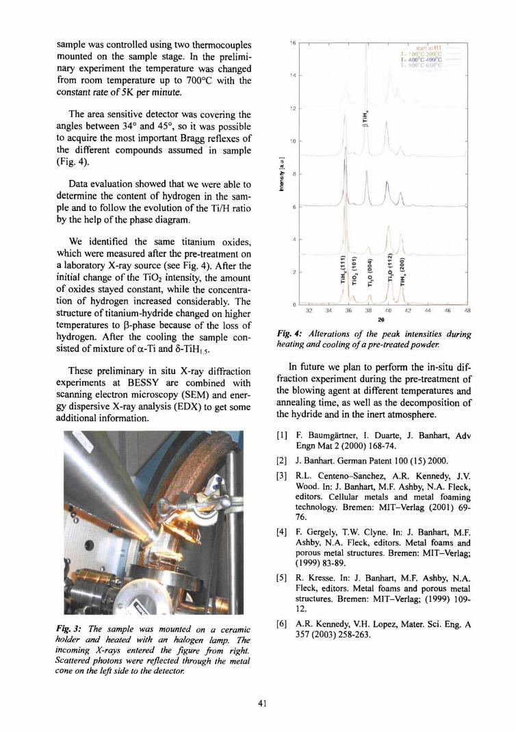
sample was controlled using two thermocouplesmounted on the sample stage. In the prelimi-nary experiment the temperature was changedfrom room temperature up to 700°C with theconstant rate of 5K per minute.
The area sensitive detector was covering theangles between 34° and 45°, so it was possibleto acquire the most important Bragg reflexes ofthe different compounds assumed in sample(Fig. 4).
Data evaluation showed that we were able todetermine the content of hydrogen in the sam-ple and to follow the evolution of the Ti/H ratioby the help of the phase diagram.
We identified the same titanium oxides,which were measured after the pre-treatment ona laboratory X-ray source (see Fig. 4). After theinitial change of the T1O2 intensity, the amountof oxides stayed constant, while the concentra-tion of hydrogen increased considerably. Thestructure of titanium-hydride changed on highertemperatures to (3-phase because of the loss ofhydrogen. After the cooling the sample con-sisted of mixture of a-Ti and 5-TiH, 5.
These preliminary in situ X-ray diffractionexperiments at BESSY are combined withscanning electron microscopy (SEM) and ener-gy dispersive X-ray analysis (EDX) to get someadditional information.
16
Fig. 3: The sample was mounted on a ceramicholder and heated with an halogen lamp. Theincoming X-rays entered the figure from right.Scattered photons were reflected through the metalcone on the left side to the detector.
12
10
stan at HIU 100°C-399''CT= 400°CM99°C1= 500°C 6S0°C
32 34 36 38 40 42 44 46 48
28
Fig. 4: Alterations of the peak intensities duringheating and cooling of a pre-treated powder.
In future we plan to perform the in-situ dif-fraction experiment during the pre-treatment ofthe blowing agent at different temperatures andannealing time, as well as the decomposition ofthe hydride and in the inert atmosphere.
[1] F. Baumgartner, I. Duarte, J. Banhart, AdvEngn Mat 2 (2000) 168-74.
[2] J. Banhart. German Patent 100 (15) 2000.
[3] R.L. Centeno-Sanchez, A.R. Kennedy, J.V.Wood. In: J. Banhart, M.F. Ashby, N.A. Fleck,editors. Cellular metals and metal foamingtechnology. Bremen: MIT-Verlag (2001) 69-76.
[4] F. Gergely, T.W. Clyne. In: J. Banhart, M.F.Ashby, N.A. Fleck, editors. Metal foams andporous metal structures. Bremen: MIT-Verlag;(1999)83-89.
[5] R. Kresse. In: J. Banhart, M.F. Ashby, N.A.Fleck, editors. Metal foams and porous metalstructures. Bremen: MIT-Verlag; (1999) 109-12.
[6] A.R. Kennedy, V.H. Lopez, Mater. Sci. Eng. A357 (2003) 258-263.
41
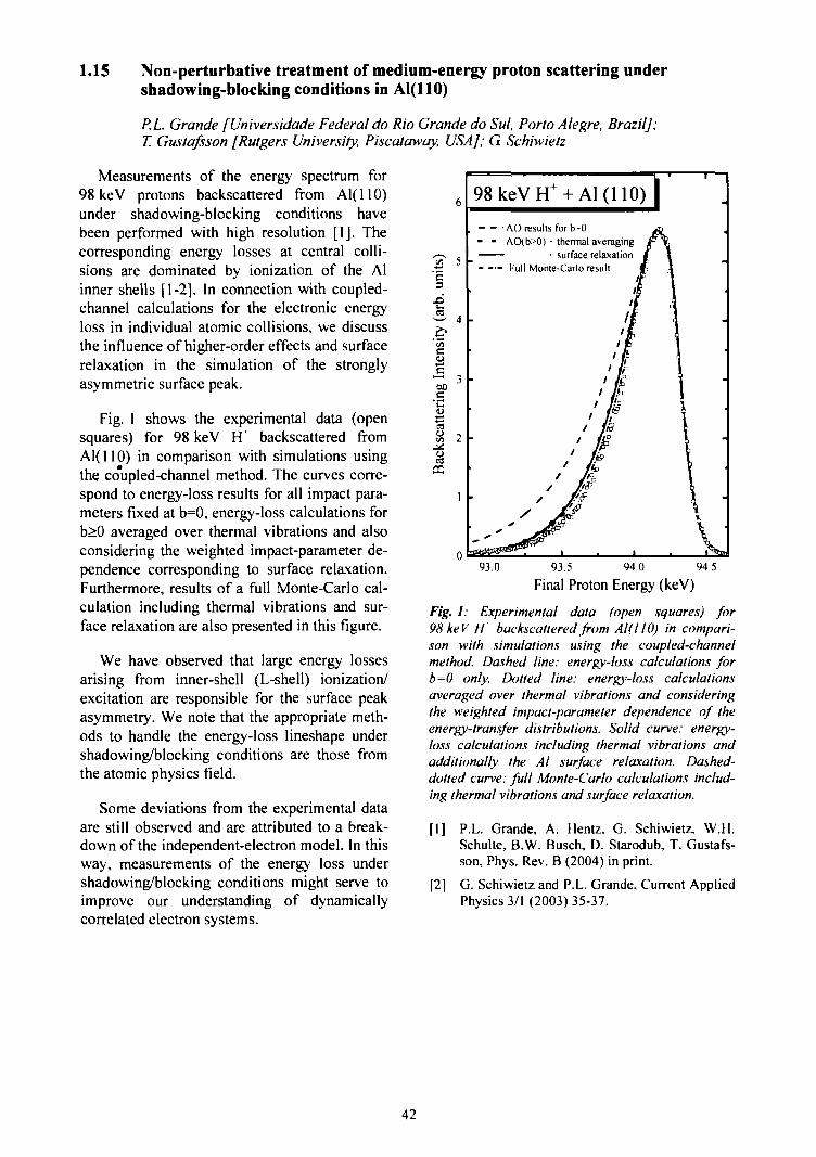
1.15 Non-perturbative treatment of medium-energy proton scattering undershadowing-blocking conditions in Al(UO)
P.L. Grande [Universidade Federal do Rio Grande do Sul, Porto Alegre, BrazilJ;T. Gustafsson [Rutgers University, Piscataway, USA]; G. Schiwietz
Measurements of the energy spectrum for98 keV protons backscattered from Al( 110)under shadowing-blocking conditions havebeen performed with high resolution [1]. Thecorresponding energy losses at central colli-sions are dominated by ionization of the Alinner shells [1-2]. In connection with coupled-channel calculations for the electronic energyloss in individual atomic collisions, we discussthe influence of higher-order effects and surfacerelaxation in the simulation of the stronglyasymmetric surface peak.
Fig. 1 shows the experimental data (opensquares) for 98 keV FT backscattered fromAl(110) in comparison with simulations usingthe co'upled-channel method. The curves corre-spond to energy-loss results for all impact para-meters fixed at b=0, energy-loss calculations forb>0 averaged over thermal vibrations and alsoconsidering the weighted impact-parameter de-pendence corresponding to surface relaxation.Furthermore, results of a full Monte-Carlo cal-culation including thermal vibrations and sur-face relaxation are also presented in this figure.
We have observed that large energy lossesarising from inner-shell (L-shell) ionization/excitation are responsible for the surface peakasymmetry. We note that the appropriate meth-ods to handle the energy-loss lineshape undershadowing/blocking conditions are those fromthe atomic physics field.
Some deviations from the experimental dataare still observed and are attributed to a break-down of the independent-electron model. In thisway, measurements of the energy loss undershadowing/blocking conditions might serve toimprove our understanding of dynamicallycorrelated electron systems.
'23
ca!» 2
CO
98keVH-AC) results for bO
- - AO(b>0) • thermal averaging—— - surface relaxation
Full Monte-Carlo result
93.0 93.5 94.0 94.5
Final Proton Energy (keV)
Fig. 1: Experimental data (open squares) for98 keV H backscattered from Al(llO) in compari-son with simulations using the coupled-channelmethod. Dashed line: energy-loss calculations forb=0 only. Dotted line: energy-loss calculationsaveraged over thermal vibrations and consideringthe weighted impact-parameter dependence of theenergy-transfer distributions. Solid curve: energy-loss calculations including thermal vibrations andadditionally the Al surface relaxation. Dashed-dotted curve: full Monte-Carlo calculations includ-ing thermal vibrations and surface relaxation.
[1] P.L. Grande, A. Hentz, G. Schiwietz, W.H.Schulte, B.W. Busch, D. Starodub, T. Gustafs-son, Phys. Rev. B (2004) in print.
[2] G. Schiwietz and P.L. Grande, Current AppliedPhysics 3/1 (2003) 35-37.
42
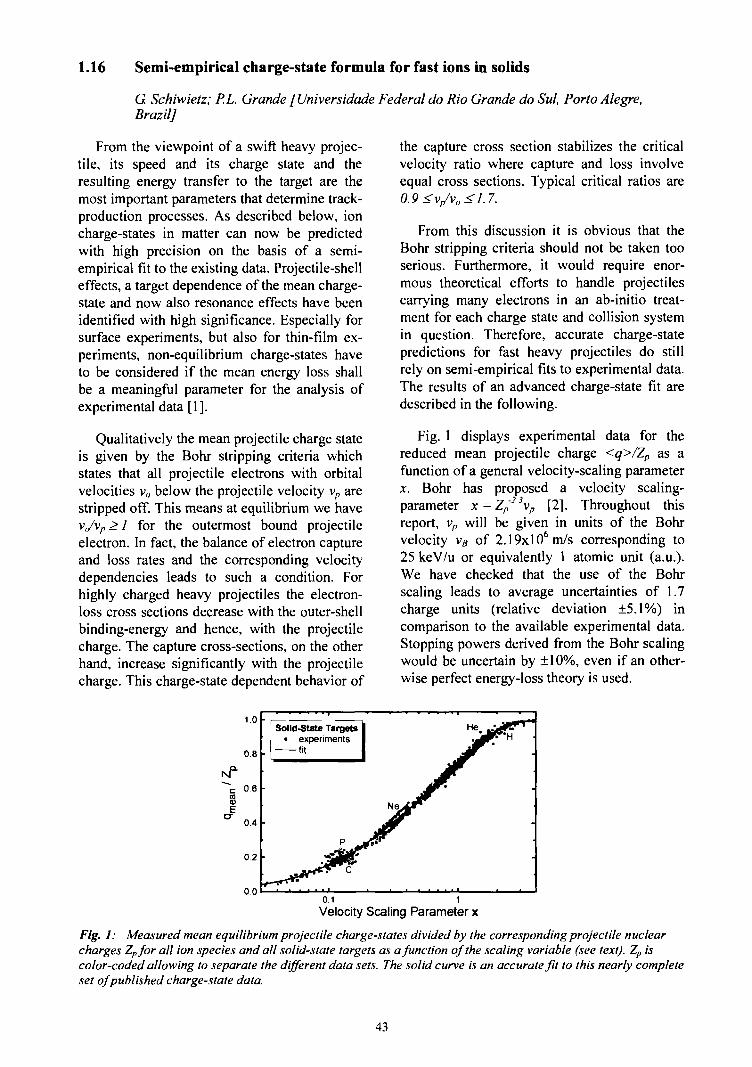
1.16 Semi-empirical charge-state formula for fast ions in solids
G Schiwietz; P.L Grande [Universidade Federal do Rio Grande do Sul, Porto Alegre,Brazil]
From the viewpoint of a swift heavy projec-tile, its speed and its charge state and theresulting energy transfer to the target are themost important parameters that determine track-production processes. As described below, ioncharge-states in matter can now be predictedwith high precision on the basis of a semi-empirical fit to the existing data. Projectile-shelleffects, a target dependence of the mean charge-state and now also resonance effects have beenidentified with high significance. Especially forsurface experiments, but also for thin-film ex-periments, non-equilibrium charge-states haveto be considered if the mean energy loss shallbe a meaningful parameter for the analysis ofexperimental data [1].
Qualitatively the mean projectile charge stateis given by the Bohr stripping criteria whichstates that all projectile electrons with orbitalvelocities vn below the projectile velocity vp arestripped off. This means at equilibrium we havev,/vn > 1 for the outermost bound projectileelectron. In fact, the balance of electron captureand loss rates and the corresponding velocitydependencies leads to such a condition. Forhighly charged heavy projectiles the electron-loss cross sections decrease with the outer-shellbinding-energy and hence, with the projectilecharge. The capture cross-sections, on the otherhand, increase significantly with the projectilecharge. This charge-state dependent behavior of
the capture cross section stabilizes the criticalvelocity ratio where capture and loss involveequal cross sections. Typical critical ratios are0.9 <v/vo <1.7.
From this discussion it is obvious that theBohr stripping criteria should not be taken tooserious. Furthermore, it would require enor-mous theoretical efforts to handle projectilescarrying many electrons in an ab-initio treat-ment for each charge state and collision systemin question. Therefore, accurate charge-statepredictions for fast heavy projectiles do stillrely on semi-empirical fits to experimental data.The results of an advanced charge-state fit aredescribed in the following.
Fig. 1 displays experimental data for thereduced mean projectile charge <q>/Zp as afunction of a general velocity-scaling parameter.T. Bohr has proposed a velocity scaling-parameter x = Zp
2Svp [2]. Throughout thisreport, vp will be given in units of the Bohrvelocity v« of 2.19xl06m/s corresponding to25 keV/u or equivalently 1 atomic unit (a.u.).We have checked that the use of the Bohrscaling leads to average uncertainties of 1.7charge units (relative deviation ±5.1%) incomparison to the available experimental data.Stopping powers derived from the Bohr scalingwould be uncertain by ±10%, even if an other-wise perfect energy-loss theory is used.
1.0
0.8
06
0.4 •
0.2
0.0
Solid-State Targets• experiments
fit
> •
0.1 1Velocity Scaling Parameter x
Fig. 1: Measured mean equilibrium projectile charge-states divided by the corresponding projectile nuclearcharges Zpfor all ion species and all solid-state targets as a function of the scaling variable (see text). Zp iscolor-coded allowing to separate the different data sets. The solid curve is an accurate fit to this nearly completeset of published charge-state data.
43
Thus, we have decided to search for a moreaccurate scaling of the mean charge states. Amulti-parameter least-square fit (see alsoRef. [3]) has been applied to published solid-state data for about 840 experimental datapoints. Protons and helium ions above a veloc-ity of vp = 2vB and all heavier ions abovevp = 0.4vn have been considered. For slowerprojectiles we find significant deviations fromsimple scaling properties and band-structureeffects seem to be of importance. Here wepresent charge-state formulas with asymptoticdependencies that are improved with respect toprevious results [3].
Furthermore, resonance effects and in addi-tion also shell-structure effects have beenconsidered in an iterative fitting procedure,resulting in
ZP(8.29x +(1)
with the general scaling variable x
(2)
the two correction terms
c, = l - 0 . •me 9 , (3)
= 1+ 0.030 Pln(Z,) (4)
and with the scaled projectile velocity
~ ~ -0543 ,(5)
The 4 numerical parameters in Eq. (1) wheredetermined at each step of the optimization byan automatically weighted least-square fit thatminimizes the absolute charge-state deviation.The remaining 7 parameters in the above Eqs.are to a large extend independent of each otherand where varied manually. The power term inEq. (2) serves to adjust the steepness of thecharge-state curves as a function of*. It modi-fies the scaling behavior at small projectilenuclear charges Zp. The correction term c/ ac-counts for resonant electron capture which re-duces the mean charge state <q> or equiva-lently x for symmetrical projectile-target com-binations. The correction c2 accounts for a
target dependent deformation of the charge-state curves at high velocities.
The main deviation of our fit result from theBohr scaling is the exponent -0.543 in Eq. (5).Due to the Zp dependence in Eq. (2) the expo-nent is effectively reduced to about -0.46 in thevicinity of x = 0.5. This exponent is very closeto -0.45 found by Nikolaev and Dmitriev [4] forheavy ions, but far from -2/3 predicted by Bohr[2]. A mean squared deviation of about 0.37charge units is reached with the above formulas.With consideration of shell-structure effects,similar as shown in [3], the mean squared de-viation from the experimental data is reduced to0.28 charge units. Note that our ab-initio stop-ping power code CASP is now based on theabove formulas and yields also charge states forarbitrary projectile/target combinations includ-ing target dependent shell effects [1,5]. Alreadyour previous charge-state results [3] (less cer-tain by roughly a factor of two) have beenshown to yield accurate stopping powers forMeV/u ions in carbon [5,6]. An analysis of 29overlapping data points measured in differentexperiments with carbon targets shows that thepure experimental uncertainty is already 0.21charge units. Considering this experimentalerror, we expect the absolute accuracy of thecurrent fit to be about 0.2 charge units. Thus, itis hardly possible to improve the above fitwithout applying experimental reliability fac-tors. Stopping powers derived from the currentscaling include an error of only about ±2% dueto the charge-state uncertainty.
[1] Version 2.1 of the CASP energy-loss codeincluding charge-state formulas with shell ef-fects may be downloaded from the URLhttp://www.hmi.de/people/schiwietz/casp.html.
[2] N. Bohr, Phys. Rev. 58, 654 (1940); ibid 59(1941)270.
[3] G. Schiwietz and P.L. Grande, NIM B175-177(2001) 125; see references therein.
[4] V.S. Nikolaev and I.S. Dmitriev, Physics Let-ters 28A (1968)277.
[5] P.L. Grande, G. Schiwietz, Phys. Rev. A58(1998) 3796; G. Schiwietz, P.L. Grande, NIMB153 (1999) 1; G.de M. Azevedo, P.L. Grande,G. Schiwietz, NIM B164-165 (2000) 203; P.L.Grande and G. Schiwietz, NIM B195 (2002)55.
[6] A.F. Lifschitz, N.R. Arista , Phys. Rev. A69(2004)012901.
44

1.17 Effective Screening Energy and Nuclear Reaction Rates at Very Low ProjectileEnergies
K. Czerski; P. Heide, A. Huke [Technische Universitdt Berlin]
The electron screening of ions in solids isone of the central issues in investigations ofion-solid interactions. It can be described withinBorn-Oppenheimer limit by a static screeningfunction. This function exhibits deviations ofthe ionic electrostatic field from that producedby a bare nucleus. Most of the solid-state proc-esses, however, are sensible only for thescreening function at distances large comparedto the Bohr radius. Study of nuclear reactions atvery low projectile energies proceeding in solidenvironments provides a unique possibility totest the screening function also at smallerdistances. The reaction cross section is deter-mined by the penetrability through the Cou-lomb barrier and thus strongly influenced byelectrons surrounding the reacting nuclei be-yond the classical turning point. Experimen-tally, the electron screening effect leads to anexponential-like enhancement of the crosssection for decreasing projectile energies. Thisenhancement can be described by a constantscreening energy Ue defined as a difference ofpotential energies of electrons before and afterthe nuclear reaction. The screened cross sectionreads as follows
l
Here £(£) is the astrophysical S-factor de-termined for the bare nuclei taken at the centermass energy, and Ec, denotes the Gamow en-ergy. Recently, we have found [1] that thescreening energy for the 2H(d,p)3H and
1.2-
0.8-
¥ 0.4-
0.0
screening functionexponential function
o.o 0.4 0.8 1.2 1.6 2.0
2H(d,n)3He reactions taking place in metallicmedia is larger by one order of magnitude fromthat obtained in the gas target experiments [2]and could not be explained theoretically.
We report here new theoretical calculationsof the screening function performed in theframe of the dielectric function method. Itallows us to estimate the reaction cross sectionof the d+d reactions in metallic targets at verylow projectile energies, far below the energiesthat presently are reachable by means of aclassic accelerator technique, and to compare tocontroversial results obtained at room tem-perature in the heavy-water electrolysis experi-ments [3,4].
The static polarization of the metallicmedium induced by the positively chargeddeuterons can be expressed by a screenedCoulomb potential K(r) being a solution of thePoisson equation in the momentum space
•H (2)
where ej(q) and £c(q) are the static, wave num-ber dependent, dielectric functions resultingfrom quasi free valence electrons and frombound metallic core electrons, respectively.Unlike our previous calculations [5], the ele-mentary charge e is multiplied by a self-con-sistent charge form-factor <p(q) for deuteronswith the screening electrons in the Thomas-Fermi approximation:
30
screening functionexponential function
0.1 10 100 1000 10000
Deuteron-Deuteron Distance (10'°m) Deuteron Energy in CMS (eV)
Fig. 1: Screening function (left) and effective electron screening energy (right) calculated for Pd.
45
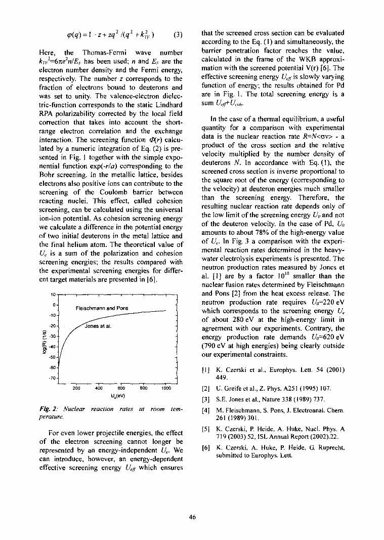
(3)
Here, the Thomas-Fermi wave numberkn?=6ne2n/Ei; has been used; n and £/. are theelectron number density and the Fermi energy,respectively. The number z corresponds to thefraction of electrons bound to deuterons andwas set to unity. The valence-electron dielec-tric-function corresponds to the static LindhardRPA polarizability corrected by the local fieldcorrection that takes into account the short-range electron correlation and the exchangeinteraction. The screening function (Hf) calcu-lated by a numeric integration of Eq. (2) is pre-sented in Fig. 1 together with the simple expo-nential function exp(-r/a) corresponding to theBohr screening. In the metallic lattice, besideselectrons also positive ions can contribute to thescreening of the Coulomb barrier betweenreacting nuclei. This effect, called cohesionscreening, can be calculated using the universalion-ion potential. As cohesion screening energywe calculate a difference in the potential energyof two initial deuterons in the metal lattice andthe final helium atom. The theoretical value ofUe is a sum of the polarization and cohesionscreening energies; the results compared withthe experimental screening energies for differ-ent target materials are presented in [6].
200 400 600 800 1000
U0(eV)
Fig. 2: Nuclear reaction rates at room tem-perature.
For even lower projectile energies, the effectof the electron screening cannot longer berepresented by an energy-independent f/c.. Wecan introduce, however, an energy-dependenteffective screening energy Ue(f which ensures
that the screened cross section can be evaluatedaccording to the Eq. (1) and simultaneously, thebarrier penetration factor reaches the value,calculated in the frame of the WKB approxi-mation with the screened potential V(r) [6]. Theeffective screening energy Ueg is slowly varyingfunction of energy; the results obtained for Pdare in Fig. 1. The total screening energy is asum Ueff*-Ucl)h.
In the case of a thermal equilibrium, a usefulquantity for a comparison with experimentaldata is the nuclear reaction rate R=N<av> - aproduct of the cross section and the relativevelocity multiplied by the number density ofdeuterons N. In accordance with Eq. (1), thescreened cross section is inverse proportional tothe square root of the energy (corresponding tothe velocity) at deuteron energies much smallerthan the screening energy. Therefore, theresulting nuclear reaction rate depends only ofthe low limit of the screening energy £/« and notof the deuteron velocity. In the case of Pd, £/«amounts to about 78% of the high-energy valueof Uc. In Fig. 3 a comparison with the experi-mental reaction rates determined in the heavy-water electrolysis experiments is presented. Theneutron production rates measured by Jones etal. [1] are by a factor 1010 smaller than thenuclear fusion rates determined by Fleischmannand Pons [2] from the heat excess release. Theneutron production rate requires Uo=220 eVwhich corresponds to the screening energy Ue
of about 280 eV at the high-energy limit inagreement with our experiments. Contrary, theenergy production rate demands Uu=620 eV(790 eV at high energies) being clearly outsideour experimental constraints.
[1] K. Czerski et al., Europhys. Lett. 54 (2001)449.
[2] U. Greife et al., Z. Phys. A251 (1995) 107.
[3] S.E. Jones et al., Nature 338 (1989) 737.
[4] M. Fleischmann, S. Pons, J. Electroanal. Chem.261 (1989)301.
[5] K. Czerski, P. Heide, A. Huke, Nucl. Phys. A719 (2003) 52, ISL Annual Report (2002).22.
[6] K. Czerski, A. Huke, P. Heide, G Ruprecht,submitted to Europhys. Lett.
46
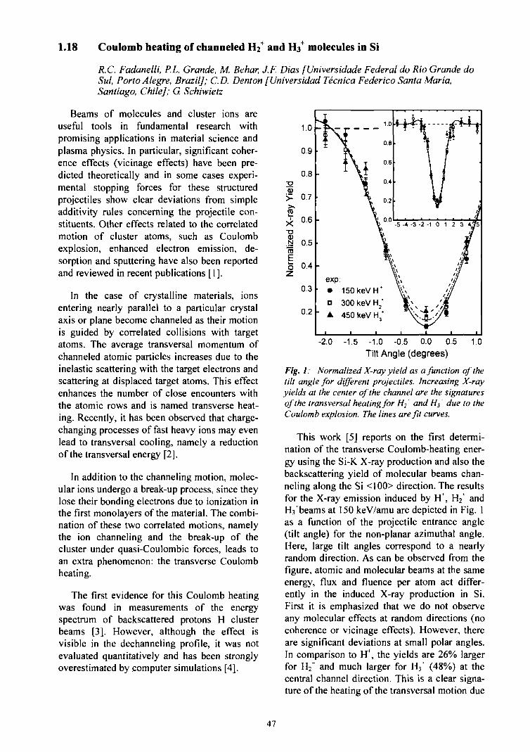
1.18 Coulomb heating of channeled Hh+ and H3+ molecules in Si
-2.0 -1.5 -1.0 -0.5 0.0 0.5Tilt Angle (degrees)
R.C. Fadanelli, P.L. Grande, M. Behar, J.F. Dias [Universidade Federal do Rio Grande doSul, Porto Alegre, Brazil]; CD. Denton [Universidad Tecnica Federico Santa Maria,Santiago, Chile]; G. Schiwietz
Beams of molecules and cluster ions areuseful tools in fundamental research withpromising applications in material science andplasma physics. In particular, significant coher-ence effects (vicinage effects) have been pre-dicted theoretically and in some cases experi-mental stopping forces for these structuredprojectiles show clear deviations from simpleadditivity rules concerning the projectile con-stituents. Other effects related to the correlatedmotion of cluster atoms, such as Coulombexplosion, enhanced electron emission, de-sorption and sputtering have also been reportedand reviewed in recent publications [1].
In the case of crystalline materials, ionsentering nearly parallel to a particular crystalaxis or plane become channeled as their motionis guided by correlated collisions with targetatoms. The average transversal momentum ofchanneled atomic particles increases due to theinelastic scattering with the target electrons andscattering at displaced target atoms. This effectenhances the number of close encounters withthe atomic rows and is named transverse heat-ing. Recently, it has been observed that charge-changing processes of fast heavy ions may evenlead to transversal cooling, namely a reductionof the transversal energy [2].
In addition to the channeling motion, molec-ular ions undergo a break-up process, since theylose their bonding electrons due to ionization inthe first monolayers of the material. The combi-nation of these two correlated motions, namelythe ion channeling and the break-up of thecluster under quasi-Coulombic forces, leads toan extra phenomenon: the transverse Coulombheating.
The first evidence for this Coulomb heatingwas found in measurements of the energyspectrum of backscattered protons H clusterbeams [3]. However, although the effect isvisible in the dechanneling profile, it was notevaluated quantitatively and has been stronglyoverestimated by computer simulations [4].
Fig. 1: Normalized X-ray yield as a function of thetilt angle for different projectiles. Increasing X-rayyields at the center of the channel are the signaturesof the transversal heating for H? and //j due to theCoulomb explosion. The lines are fit curves.
This work [5] reports on the first determi-nation of the transverse Coulomb-heating ener-gy using the Si-K. X-ray production and also thebackscattering yield of molecular beams chan-neling along the Si <100> direction. The resultsfor the X-ray emission induced by H+, H2+ andHi^beams at 150 keV/amu are depicted in Fig. 1as a function of the projectile entrance angle(tilt angle) for the non-planar azimuthal angle.Here, large tilt angles correspond to a nearlyrandom direction. As can be observed from thefigure, atomic and molecular beams at the sameenergy, flux and fluence per atom act differ-ently in the induced X-ray production in Si.First it is emphasized that we do not observeany molecular effects at random directions (nocoherence or vicinage effects). However, thereare significant deviations at small polar angles.In comparison to H\ the yields are 26% largerfor H2~ and much larger for H3' (48%) at thecentral channel direction. This is a clear signa-ture of the heating of the transversal motion due
47
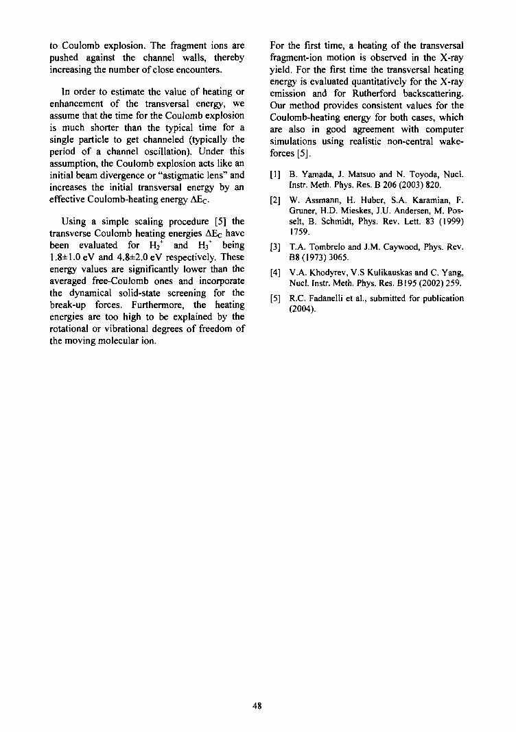
to Coulomb explosion. The fragment ions arepushed against the channel walls, therebyincreasing the number of close encounters.
In order to estimate the value of heating orenhancement of the transversal energy, weassume that the time for the Coulomb explosionis much shorter than the typical time for asingle particle to get channeled (typically theperiod of a channel oscillation). Under thisassumption, the Coulomb explosion acts like aninitial beam divergence or "astigmatic lens" andincreases the initial transversal energy by aneffective Coulomb-heating energy AEC.
Using a simple scaling procedure [5] thetransverse Coulomb heating energies AEc havebeen evaluated for H2+ and H3~ being1.8±1.0eV and 4.8±2.0eV respectively. Theseenergy values are significantly lower than theaveraged free-Coulomb ones and incorporatethe dynamical solid-state screening for thebreak-up forces. Furthermore, the heatingenergies are too high to be explained by therotational or vibrational degrees of freedom ofthe moving molecular ion.
For the first time, a heating of the transversalfragment-ion motion is observed in the X-rayyield. For the first time the transversal heatingenergy is evaluated quantitatively for the X-rayemission and for Rutherford backscattering.Our method provides consistent values for theCoulomb-heating energy for both cases, whichare also in good agreement with computersimulations using realistic non-central wake-forces [5].
[1] B. Yamada, J. Matsuo and N. Toyoda, Nucl.Instr. Meth. Phys. Res. B 206 (2003) 820.
[2] W. Assmann, H. Huber, S.A. Karamian, F.Gruner, H.D. Mieskes, J.U. Andersen, M. Pos-selt, B. Schmidt, Phys. Rev. Lett. 83 (1999)1759.
[3] T.A. Tombrelo and J.M. Caywood, Phys. Rev.B8 (1973) 3065.
[4] V.A. Khodyrev, V.S Kulikauskas and C. Yang,Nucl. Instr. Meth. Phys. Res. B195 (2002) 259.
[5] R.C. Fadanelli et al., submitted for publication(2004).
48
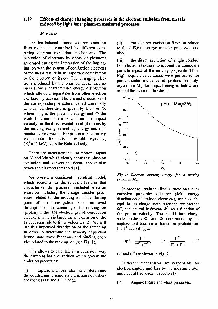
1.19 Effects of charge changing processes in the electron emission from metalsinduced by light ions: plasmon mediated processes
M Rosier
The ion-induced kinetic electron emissionfrom metals is determined by different com-peting electron excitation mechanisms. Theexcitation of electrons by decay of plasmonsgenerated during the interaction of the imping-ing ion with the system of conduction electronsof the metal results in an important contributionto the electron emission. The emerging elec-trons produced by the plasmon decay mecha-nism show a characteristic energy distributionwhich allows a separation from other electronexcitation processes. The energetic position ofthe corresponding structure, called commonlyas plasmon-shoulder, is given by Eps= cop-<I>,where cop is the plasmon energy and <T> thework function. There is a minimum impactvelocity for the direct excitation of plasmons bythe moving ion governed by energy and mo-mentum conservation. For proton impact on Mgwe obtain for this threshold v,h«l.Ovo(E0
th«25 keV). v0 is the Bohr velocity.
There are measurements for proton impacton Al and Mg which clearly show that plasmonexcitation and subsequent decay appear alsobelow the plasmon threshold [1].
We present a consistent theoretical model,which accounts for the relevant features thatcharacterize the plasmon mediated electronemission including the charge transfer proc-esses related to the moving ion. The startingpoint of our investigation is an improveddescription of the screening of the moving ion(proton) within the electron gas of conductionelectrons, which is based on an extension of theFriedel sum rule to finite velocities [2]. We willuse this improved description of the screeningin order to determine the velocity dependentbound state wave functions and binding ener-gies related to the moving ion (see Fig. 1).
This allows to calculate in a consistent waythe different basic quantities which govern theemission properties:
(i) capture and loss rates which determinethe equilibrium charge state fractions of differ-ent species (H° and FT in Mg),
(ii) the electron excitation function relatedto the different charge transfer processes, andalso
(iii) the direct excitation of single conduc-tion electrons taking into account the compositeparticle aspect of the moving projectile (H° inMg). Explicit calculations were performed forperpendicular incidence of protons on poly-crystalline Mg for impact energies below andaround the plasmon threshold.
Fig. 1: Electron binding energy for a movingproton in Mg.
In order to obtain the final expression for theemission properties (electron yield, energydistribution of emitted electrons), we need theequilibrium charge state fractions for protonsO+, and neutral hydrogen cj>°, as a function ofthe proton velocity. The equilibrium chargestate fractions O+ and <D° determined by thecapture and loss cross transition probabilitiesFc , rL according to
(i)- F C + r L '
O" and <I>0 are shown in Fig. 2.
r c + rL
Different mechanisms are responsible forelectron capture and loss by the moving protonand neutral hydrogen, respectively:
(i) Auger-capture and -loss processes.
49
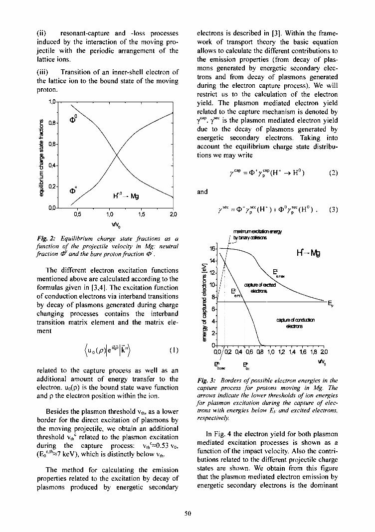
(ii) resonant-capture and -loss processesinduced by the interaction of the moving pro-jectile with the periodic arrangement of thelattice ions.
(iii) Transition of an inner-shell electron ofthe lattice ion to the bound state of the movingproton.
v/v.
Fig. 2: Equilibrium charge state fractions as afunction of the projectile velocity in Mg: neutralfraction &1' and the bare proton fraction 0 .
The different electron excitation functionsmentioned above are calculated according to theformulas given in [3,4]. The excitation functionof conduction electrons via interband transitionsby decay of plasmons generated during chargechanging processes contains the interbandtransition matrix element and the matrix ele-ment
k" (1)
related to the capture process as well as anadditional amount of energy transfer to theelectron. uo(p) is the bound state wave functionand p the electron position within the ion.
Besides the plasmon threshold v,h, as a lowerborder for the direct excitation of plasmons bythe moving projectile, we obtain an additionalthreshold vth° related to the plasmon excitationduring the capture process: vth
c~0.53 v0,(Eo
cth~7 keV), which is distinctly below vth.
The method for calculating the emissionproperties related to the excitation by decay ofplasmons produced by energetic secondary
electrons is described in [3]. Within the frame-work of transport theory the basic equationallows to calculate the different contributions tothe emission properties (from decay of plas-mons generated by energetic secondary elec-trons and from decay of plasmons generatedduring the electron capture process). We willrestrict us to the calculation of the electronyield. The plasmon mediated electron yieldrelated to the capture mechanism is denoted byyap y>ec j g ̂ p | a s m o n rnediated electron yield
due to the decay of plasmons generated byenergetic secondary electrons. Taking intoaccount the equilibrium charge state distribu-tions we may write
Y"" = V Y; (2)
and
y*™ = (
mawum flotation energytytrayoofisicns
0,6 0,8 1,0 12 1,4 1,6 1,8 2,0
Fig. 3: Borders of possible electron energies in thecapture process for protons moving in Mg. Thearrows indicate the lower thresholds of ion energiesfor plasmon excitation during the capture of elec-trons with energies below E). and excited electrons,respectively.
In Fig. 4 the electron yield for both plasmonmediated excitation processes is shown as afunction of the impact velocity. Also the contri-butions related to the different projectile chargestates are shown. We obtain from this figurethat the plasmon mediated electron emission byenergetic secondary electrons is the dominant
50
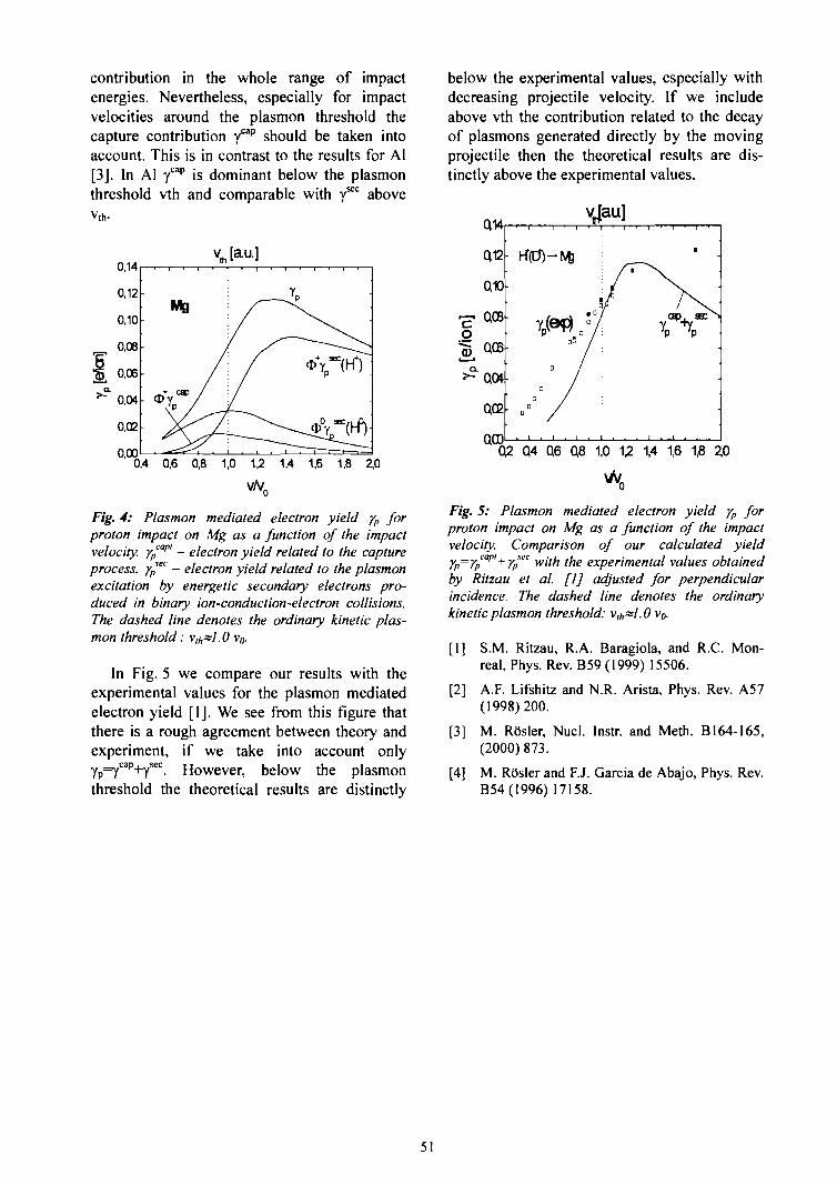
contribution in the whole range of impactenergies. Nevertheless, especially for impactvelocities around the plasmon threshold thecapture contribution ycap should be taken intoaccount. This is in contrast to the results for Al[3]. In Al ycap is dominant below the plasmonthreshold vth and comparable with y1*0 abovev,h.
v• [am]
00,4 0,6 0,8 1,0 1,2 1,4 1,6 1,8 2,0
v/v0
Fig. 4: Plasmon mediated electron yield yp forproton impact on Mg as a function of the impactvelocity. yp
ai" - electron yield related to the captureprocess. yp
ec - electron yield related to the plasmonexcitation by energetic secondary electrons pro-duced in binary ion-conduction-electron collisions.The dashed line denotes the ordinary kinetic plas-mon threshold: vlhs>1.0 Vo.
In Fig. 5 we compare our results with theexperimental values for the plasmon mediatedelectron yield [1]. We see from this figure thatthere is a rough agreement between theory andexperiment, if we take into account onlyYp=ycap+7sec. However, below the plasmonthreshold the theoretical results are distinctly
below the experimental values, especially withdecreasing projectile velocity. If we includeabove vth the contribution related to the decayof plasmons generated directly by the movingprojectile then the theoretical results are dis-tinctly above the experimental values.
oQ2 Q4 Q6 Q8 1,0 12 1,4 1,6 1,8
Fig. 5: Plasmon mediated electron yield yp forproton impact on Mg as a function of the impactvelocity. Comparison of our calculated yieldYP=YpCapl+Y™c with the experimental values obtainedby Ritzau et al. [1] adjusted for perpendicularincidence. The dashed line denotes the ordinarykinetic plasmon threshold: v,t,~1.0 v^
[1] S.M. Ritzau, R.A. Baragiola, and R.C. Mon-real, Phys. Rev. B59 (1999) 15506.
[2] A.F. Lifshitz and N.R. Arista, Phys. Rev. A57(1998)200.
[3] M. R5sler, Nucl. Instr. and Meth. B164-165,(2000) 873.
[4] M. ROsler and F.J. Garcia de Abajo, Phys. Rev.B54(1996) 17158.
51
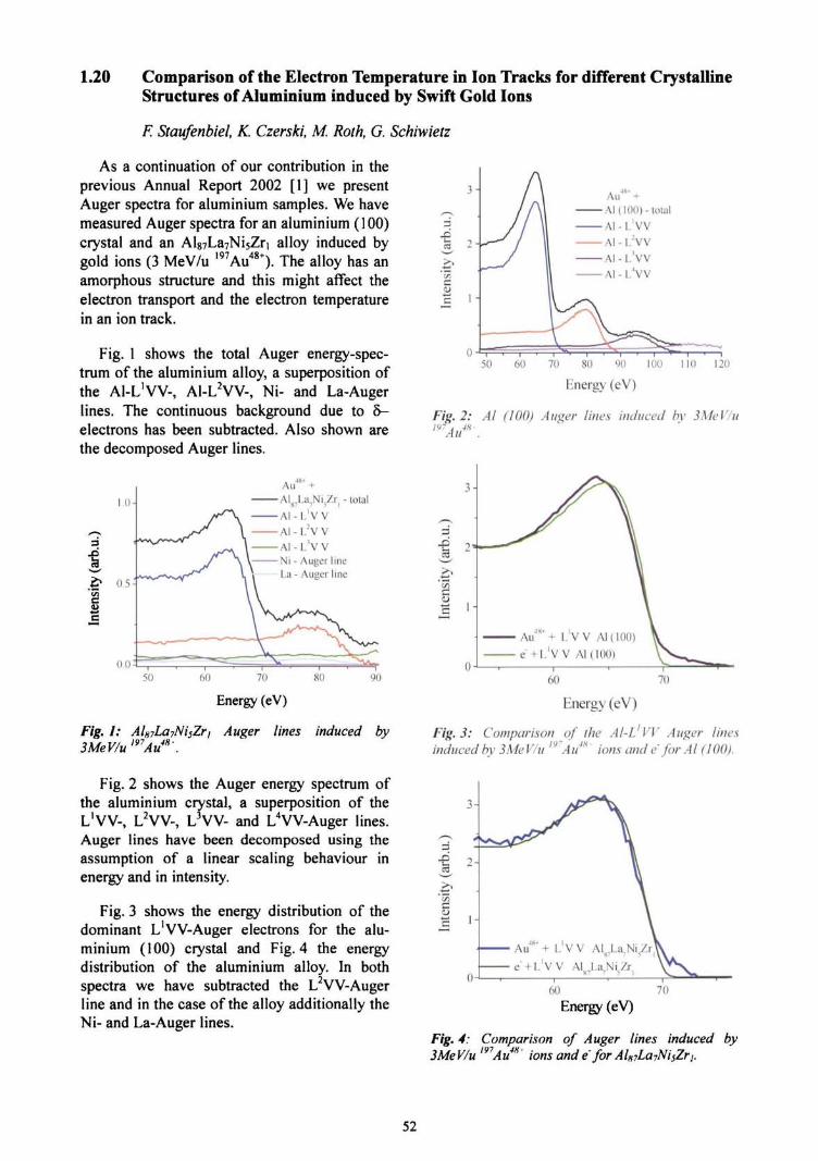
1.20 Comparison of the Electron Temperature in Ion Tracks for different CrystallineStructures of Aluminium induced by Swift Gold Ions
E Staufenbiel, K. Czerski, M. Roth, G. Schiwietz
As a continuation of our contribution in theprevious Annual Report 2002 [1] we presentAuger spectra for aluminium samples. We havemeasured Auger spectra for an aluminium (100)crystal and an Al87La7Ni5Zri alloy induced bygold ions (3 MeV/u I97Au48+). The alloy has anamorphous structure and this might affect theelectron transport and the electron temperaturein an ion track.
Fig. 1 shows the total Auger energy-spec-trum of the aluminium alloy, a superposition ofthe Al-L'VV-, A1-L2VV-, Ni- and La-Augerlines. The continuous background due to 5-electrons has been subtracted. Also shown arethe decomposed Auger lines.
1.0-
i0.5-
Au +AI]17La7Ni,.Zr| - total
AI -L 'V v
Al - L:V VA I - L ' V VNi - Auger lineLa - Auger line
0.0 350 60 70
Energy (eV)
Fig. I: AlH7La7NisZr, Auger lines induced by3MeV/u'97Au4H'.
Fig. 2 shows the Auger energy spectrum ofthe aluminium crystal, a superposition of theL'W-, L2VV-, L3VV- and L4VV-Auger lines.Auger lines have been decomposed using theassumption of a linear scaling behaviour inenergy and in intensity.
Fig. 3 shows the energy distribution of thedominant L'VV-Auger electrons for the alu-minium (100) crystal and Fig. 4 the energydistribution of the aluminium alloy. In bothspectra we have subtracted the L2VV-Augerline and in the case of the alloy additionally theNi- and La-Auger lines.
3-Au
- total3
X)
c
c
50 60 70 80 90 100 110 120
Energy (eV)
Fig. 2: Al (100) Auger lines induced by IMeV/u>97Au4H\
Au + L V V Al (100)
e +L'V V Al (100)
70
Energy (eV)
Fig. 3: Comparison of the Al-h'VV Auger linesinduced by 3MeV/u lv Au* ions and e' for Al (100).
• Au + L V V Al<7La7Ni7.M
• e + L . V V Als iLa,NLZr
60 70
Energy (eV)
Fig. ¥: Comparison of Auger lines induced by3Me V/u mA u* ions and e for AlH7La7Ni5Zr,.
52
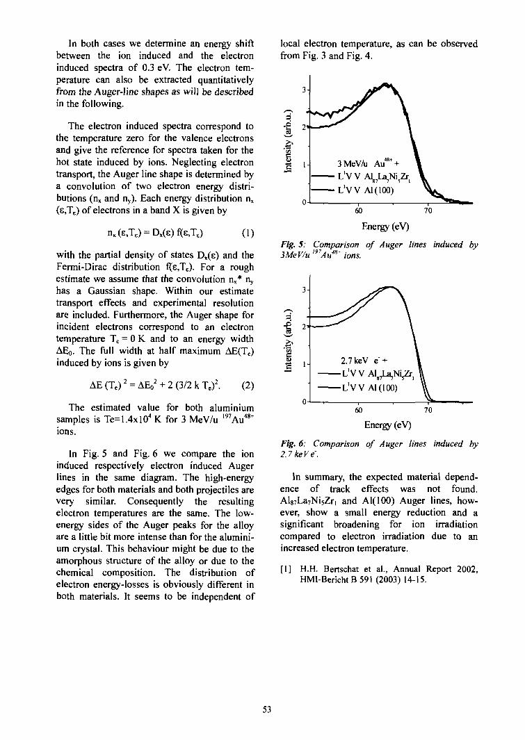
In both cases we determine an energy shiftbetween the ion induced and the electroninduced spectra of 0.3 eV. The electron tem-perature can also be extracted quantitativelyfrom the Auger-line shapes as will be describedin the following.
The electron induced spectra correspond tothe temperature zero for the valence electronsand give the reference for spectra taken for thehot state induced by ions. Neglecting electrontransport, the Auger line shape is determined bya convolution of two electron energy distri-butions (nx and ny). Each energy distribution nx
(e,TE) of electrons in a band X is given by
local electron temperature, as can be observedfrom Fig. 3 and Fig. 4.
= Dx(e)f(e,TE) (1)
with the partial density of states Dx(e) and theFermi-Dirac distribution f(s,Te). For a roughestimate we assume that the convolution nx* ny
has a Gaussian shape. Within our estimatetransport effects and experimental resolutionare included. Furthermore, the Auger shape forincident electrons correspond to an electrontemperature Te = 0 K and to an energy widthAEo. The full width at half maximum AE(Te)induced by ions is given by
AE (Te)2 = AEo2 + 2 (3/2 k Te)
2. (2)
The estimated value for both aluminiumsamples is Te=1.4xlO4 K for 3 MeV/u 197Au48+
ions.
In Fig. 5 and Fig. 6 we compare the ioninduced respectively electron induced Augerlines in the same diagram. The high-energyedges for both materials and both projectiles arevery similar. Consequently the resultingelectron temperatures are the same. The low-energy sides of the Auger peaks for the alloyare a little bit more intense than for the alumini-um crystal. This behaviour might be due to theamorphous structure of the alloy or due to thechemical composition. The distribution ofelectron energy-losses is obviously different inboth materials. It seems to be independent of
3-
LVV Al(100)
~60 " 70
Energy (eV)
Fig. 5: Comparison of Auger lines induced by3MeV/u mAu48' ions.
60 70
Energy (eV)
Fig. 6: Comparison of Auger lines induced by2.7keVe.
In summary, the expected material depend-ence of track effects was not found.Al87La7Ni5Zri and Al(lOO) Auger lines, how-ever, show a small energy reduction and asignificant broadening for ion irradiationcompared to electron irradiation due to anincreased electron temperature.
[1] H.H. Bertschat et al., Annual Report 2002,HMI-Bericht B 591 (2003) 14-15.
53
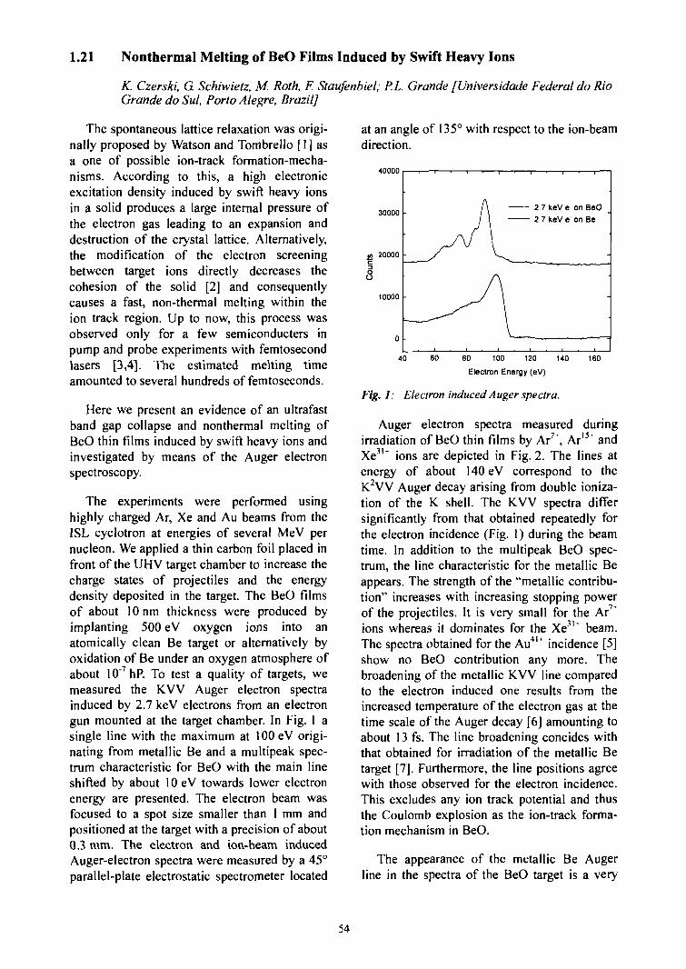
1.21 Nonthermal Melting of BeO Films Induced by Swift Heavy Ions
K. Czerski, G Schiwietz, M. Roth, F. Staufenbiel; P.L Grande [Universidade Federal do RioGrande do Sul, Porto Alegre, Brazil]
The spontaneous lattice relaxation was origi-nally proposed by Watson and Tombrello [1] asa one of possible ion-track formation-mecha-nisms. According to this, a high electronicexcitation density induced by swift heavy ionsin a solid produces a large internal pressure ofthe electron gas leading to an expansion anddestruction of the crystal lattice. Alternatively,the modification of the electron screeningbetween target ions directly decreases thecohesion of the solid [2] and consequentlycauses a fast, non-thermal melting within theion track region. Up to now, this process wasobserved only for a few semiconducters inpump and probe experiments with femtosecondlasers [3,4]. The estimated melting timeamounted to several hundreds of femtoseconds.
Here we present an evidence of an ultrafastband gap collapse and nonthermal melting ofBeO thin films induced by swift heavy ions andinvestigated by means of the Auger electronspectroscopy.
The experiments were performed usinghighly charged Ar, Xe and Au beams from theISL cyclotron at energies of several MeV pernucleon. We applied a thin carbon foil placed infront of the UHV target chamber to increase thecharge states of projectiles and the energydensity deposited in the target. The BeO filmsof about 10 nm thickness were produced byimplanting 500 eV oxygen ions into anatomically clean Be target or alternatively byoxidation of Be under an oxygen atmosphere ofabout 10"7hP. To test a quality of targets, wemeasured the KVV Auger electron spectrainduced by 2.7 keV electrons from an electrongun mounted at the target chamber. In Fig. 1 asingle line with the maximum at 100 eV origi-nating from metallic Be and a multipeak spec-trum characteristic for BeO with the main lineshifted by about lOeV towards lower electronenergy are presented. The electron beam wasfocused to a spot size smaller than 1 mm andpositioned at the target with a precision of about0.3 mm. The electron and ion-beam inducedAuger-electron spectra were measured by a 45°parallel-plate electrostatic spectrometer located
at an angle of 135° with respect to the ion-beamdirection.
40000
30000
20000
10000
0 •
2 7 keV e on BeO
2 7 keV e on Be
40 60 80 100 120
Electron Energy (eV)
140 160
Fig. 1: Electron induced Auger spectra.
Auger electron spectra measured duringirradiation of BeO thin films by Ar7*, Ar15' andXe3l+ ions are depicted in Fig. 2. The lines atenergy of about 140 eV correspond to theK2VV Auger decay arising from double ioniza-tion of the K shell. The KVV spectra differsignificantly from that obtained repeatedly forthe electron incidence (Fig. 1) during the beamtime. In addition to the multipeak BeO spec-trum, the line characteristic for the metallic Beappears. The strength of the "metallic contribu-tion" increases with increasing stopping powerof the projectiles. It is very small for the Ar7*ions whereas it dominates for the Xe11' beam.The spectra obtained for the Au4l+ incidence [5]show no BeO contribution any more. Thebroadening of the metallic KVV line comparedto the electron induced one results from theincreased temperature of the electron gas at thetime scale of the Auger decay [6] amounting toabout 13 fs. The line broadening concides withthat obtained for irradiation of the metallic Betarget [7j. Furthermore, the line positions agreewith those observed for the electron incidence.This excludes any ion track potential and thusthe Coulomb explosion as the ion-track forma-tion mechanism in BeO.
The appearance of the metallic Be Augerline in the spectra of the BeO target is a very
54
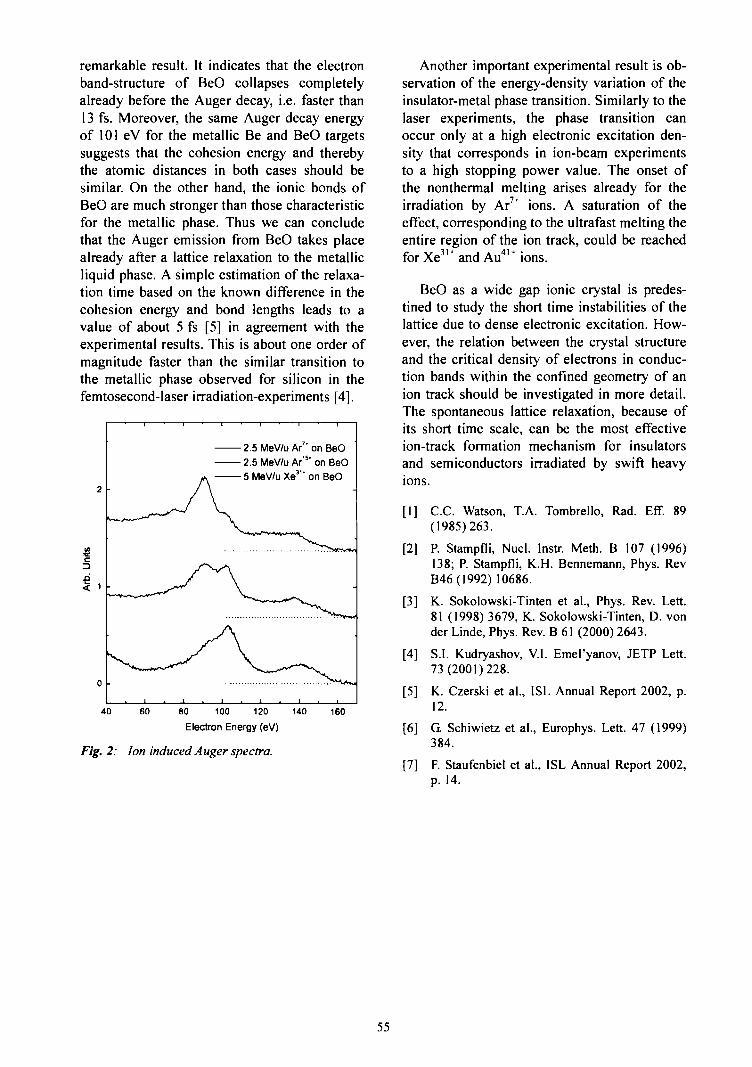
remarkable result. It indicates that the electronband-structure of BeO collapses completelyalready before the Auger decay, i.e. faster than13 fs. Moreover, the same Auger decay energyof 101 eV for the metallic Be and BeO targetssuggests that the cohesion energy and therebythe atomic distances in both cases should besimilar. On the other hand, the ionic bonds ofBeO are much stronger than those characteristicfor the metallic phase. Thus we can concludethat the Auger emission from BeO takes placealready after a lattice relaxation to the metallicliquid phase. A simple estimation of the relaxa-tion time based on the known difference in thecohesion energy and bond lengths leads to avalue of about 5 fs [5] in agreement with theexperimental results. This is about one order ofmagnitude faster than the similar transition tothe metallic phase observed for silicon in thefemtosecond-laser irradiation-experiments [4].
c
2.5 MeV/u Ar7' on BeO
2.5 MeV/u Ar'5* on BeO
5 MeV/u Xe31' on BeO
40 60 80 100 120
Electron Energy (eV)
Fig. 2: Ion induced Auger spectra.
140 160
Another important experimental result is ob-servation of the energy-density variation of theinsulator-metal phase transition. Similarly to thelaser experiments, the phase transition canoccur only at a high electronic excitation den-sity that corresponds in ion-beam experimentsto a high stopping power value. The onset ofthe nonthermal melting arises already for theirradiation by Ar7' ions. A saturation of theeffect, corresponding to the ultrafast melting theentire region of the ion track, could be reachedfor Xe3'" and Au41* ions.
BeO as a wide gap ionic crystal is predes-tined to study the short time instabilities of thelattice due to dense electronic excitation. How-ever, the relation between the crystal structureand the critical density of electrons in conduc-tion bands within the confined geometry of anion track should be investigated in more detail.The spontaneous lattice relaxation, because ofits short time scale, can be the most effectiveion-track formation mechanism for insulatorsand semiconductors irradiated by swift heavyions.
LI] C.C. Watson, T.A. Tombrello, Rad. Eff. 89(1985)263.
[2] P. Stampfli, Nucl. Instr. Meth. B 107 (1996)138; P. Stampfli, K.H. Bennemann, Phys. RevB46(1992)10686.
[3] K. Sokolowski-Tinten et al., Phys. Rev. Lett.81 (1998) 3679, K. Sokolowski-Tinten, D. vonder Linde, Phys. Rev. B 61 (2000) 2643.
[4] S.I. Kudryashov, V.I. Emel'yanov, JETP Lett.73(2001)228.
[5] K. Czerski et al., ISL Annual Report 2002, p.12.
[6] G. Schiwietz et al., Europhys. Lett. 47 (1999)384.
[7] F. Staufenbiel et al., ISL Annual Report 2002,p. 14.
55
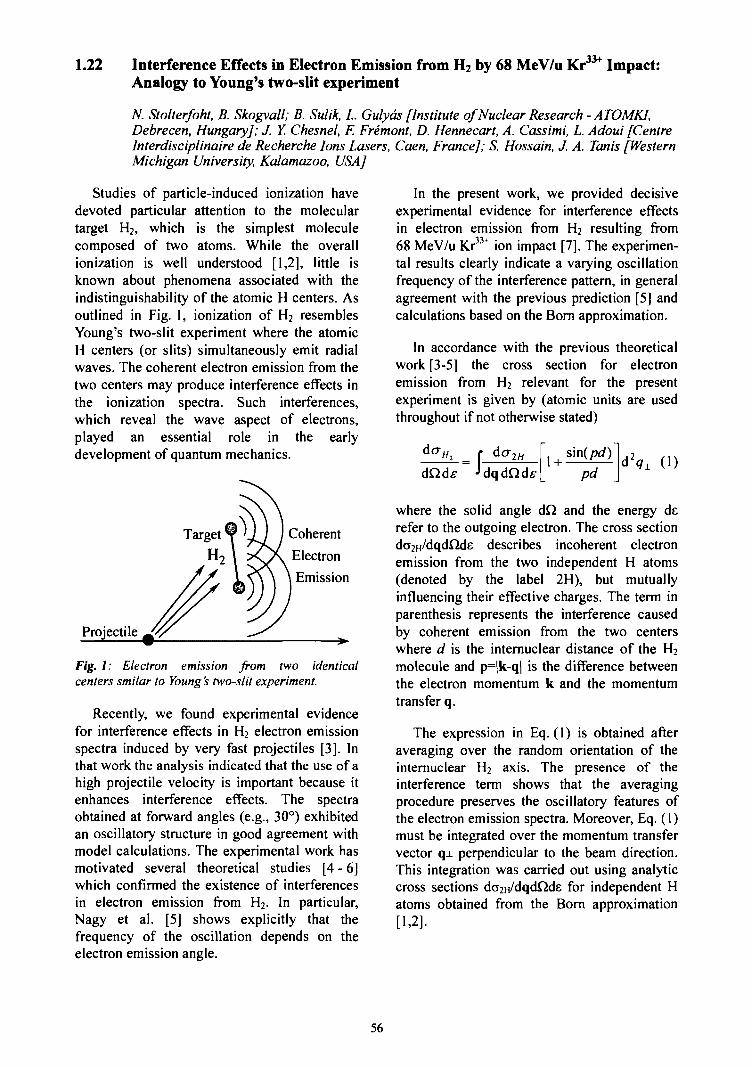
1.22 Interference Effects in Electron Emission from H2 by 68 MeV/u KrAnalogy to Young's two-slit experiment
.33+ Impact:
N. Stolterfoht, B. Skogvall; B. Sulik, L Gulyds [Institute of Nuclear Research - ATOMKI,Debrecen, Hungary]; J. Y. Chesnel, F. Fremont, D. Hennecart, A. Cassimi, L. Adoui [CentreInterdisciplinaire de Recherche Ions Lasers, Caen, France]; S. Hossain, J. A. Tanis [WesternMichigan University, Kalamazoo, USA]
Studies of particle-induced ionization havedevoted particular attention to the moleculartarget H2, which is the simplest moleculecomposed of two atoms. While the overallionization is well understood [1,2], little isknown about phenomena associated with theindistinguishability of the atomic H centers. Asoutlined in Fig. 1, ionization of H2 resemblesYoung's two-slit experiment where the atomicH centers (or slits) simultaneously emit radialwaves. The coherent electron emission from thetwo centers may produce interference effects inthe ionization spectra. Such interferences,which reveal the wave aspect of electrons,played an essential role in the earlydevelopment of quantum mechanics.
Coherent
Electron
Emission
Projectile
Fig. I: Electron emission from two identicalcenters smilar to Young's two-slit experiment.
Recently, we found experimental evidencefor interference effects in H2 electron emissionspectra induced by very fast projectiles [3]. Inthat work the analysis indicated that the use of ahigh projectile velocity is important because itenhances interference effects. The spectraobtained at forward angles (e.g., 30°) exhibitedan oscillatory structure in good agreement withmodel calculations. The experimental work hasmotivated several theoretical studies [4 - 6]which confirmed the existence of interferencesin electron emission from H2. In particular,Nagy et al. [5] shows explicitly that thefrequency of the oscillation depends on theelectron emission angle.
In the present work, we provided decisiveexperimental evidence for interference effectsin electron emission from H2 resulting from68 MeV/u Kr33+ ion impact [7]. The experimen-tal results clearly indicate a varying oscillationfrequency of the interference pattern, in generalagreement with the previous prediction [5] andcalculations based on the Born approximation.
In accordance with the previous theoreticalwork [3-5] the cross section for electronemission from H2 relevant for the presentexperiment is given by (atomic units are usedthroughout if not otherwise stated)
dcr- = f " do-1H 1 + -pd
(1)
where the solid angle dQ and the energy derefer to the outgoing electron. The cross sectionda2H/dqdflde describes incoherent electronemission from the two independent H atoms(denoted by the label 2H), but mutuallyinfluencing their effective charges. The term inparenthesis represents the interference causedby coherent emission from the two centerswhere d is the internuclear distance of the H2
molecule and p=|k-q| is the difference betweenthe electron momentum k and the momentumtransfer q.
The expression in Eq. (1) is obtained afteraveraging over the random orientation of theinternuclear H2 axis. The presence of theinterference term shows that the averagingprocedure preserves the oscillatory features ofthe electron emission spectra. Moreover, Eq. (1)must be integrated over the momentum transfervector q± perpendicular to the beam direction.This integration was carried out using analyticcross sections do2H/dqdQde for independent Hatoms obtained from the Born approximation[1,2].
56

68 MeV/u Kr33* + H
.2
cr
1.6
1.4
1.2
1.0
0.8
cr
B 1 - 4
10CO2O
1.2
1.0
0.8
(c) 90°
i . i . i . i
(d) 150°
I . I . I
0 1 2 3 4 0 1 2 3 4 5Electron Velocity (a. u.)
Fig. 2: Ratios of experimental to theoretical CDW-EIS cross sections for electron emission in 68 MeV/uKr33 + H2 collisions plotted as a function of theejected electron velocity. From (a) to (d) the electronobservation angles are varied as indicated. The solidlines represent Born calculations from Eq. (I) andthe dashed-dot lines are obtained from fits using theanalytic function ofEq. (2).
In Fig. 2 experimental and theoretical resultsare given [7]. The experimental data arenormalized to theoretical CDW-EIS [8] resultsfor atomic hydrogen to remove the stronglyvarying factor da2n/dQde. The adequatelynormalized results from the Born approxi-mation are obtained using Eq. (1) and areplotted as solid lines in Fig. 2. Details are givenin Ref. [7].
To obtain more information from experi-mental data we use the following fit formulareferred to as Bessel function
= F\lsin(kcd)
kcd
where F, G, and c are adjustable parameters.This formula was chosen in view of the theo-retical prediction that the oscillation pattern isgoverned by a frequency parameter c, which inturn, depends on the observation angle asc = cos9 [5]. Since c may differ from thepredicted value cos 9, the quantity c was usedas an adjustable parameter. The functions fittedto the experimental data are shown as dash-dotted lines in Fig. 2.
It is seen that the results from the Born ap-proximation are in good agreement with ex-periment for 30° and 60°. Also, the Born resultsare found to agree well with the modelcalculations by Nagy et al. [5]. Accordingly thefit values of c agree well with cos 8 for 30° and60° confirming the prediction of an angulardependent oscillation frequency. However,discrepancies between the Bom results andexperiment occur for 90° and 150°. In particu-lar, for 150°, the oscillation frequency is ob-served to be enhanced in comparison with theBorn calculations. This finding, which is notfully understood at present, may indicate effectsleading beyond the Born approximation [6].
[1] M.E. Rudd, Y.K. Kim, D.H. Madison, and T.J.Gay, Rev. Mod. Phys. 64 (1992) 441.
[2] N. Stolterfoht, R.D. Dubois, and R.D. Rivarola,Electron emission in heavy ion-atom collisions(Springer Series on Atoms and Plasmas,Heidelberg, 1997).
[3] N. Stolterfoht et al., Phys. Rev. Lett. 87 (2001)023201.
[4] M.E. Galassi et al., Phys. Rev. A 66 (2002)052705.
[5] L. Nagy et al., J. Phys. B 35 (2002) L453.
[6] L. Sarkadi, J. Phys. B 36 (2003) 2153.
[7] N. Stolterfoht et al., Phys. Rev. A 67 (2003)030702.
[8] L. Gulyas, P. D. Fainstein, and A. Salin, J.Phys. B 28 (1995) 245.
+ G , (2)
57
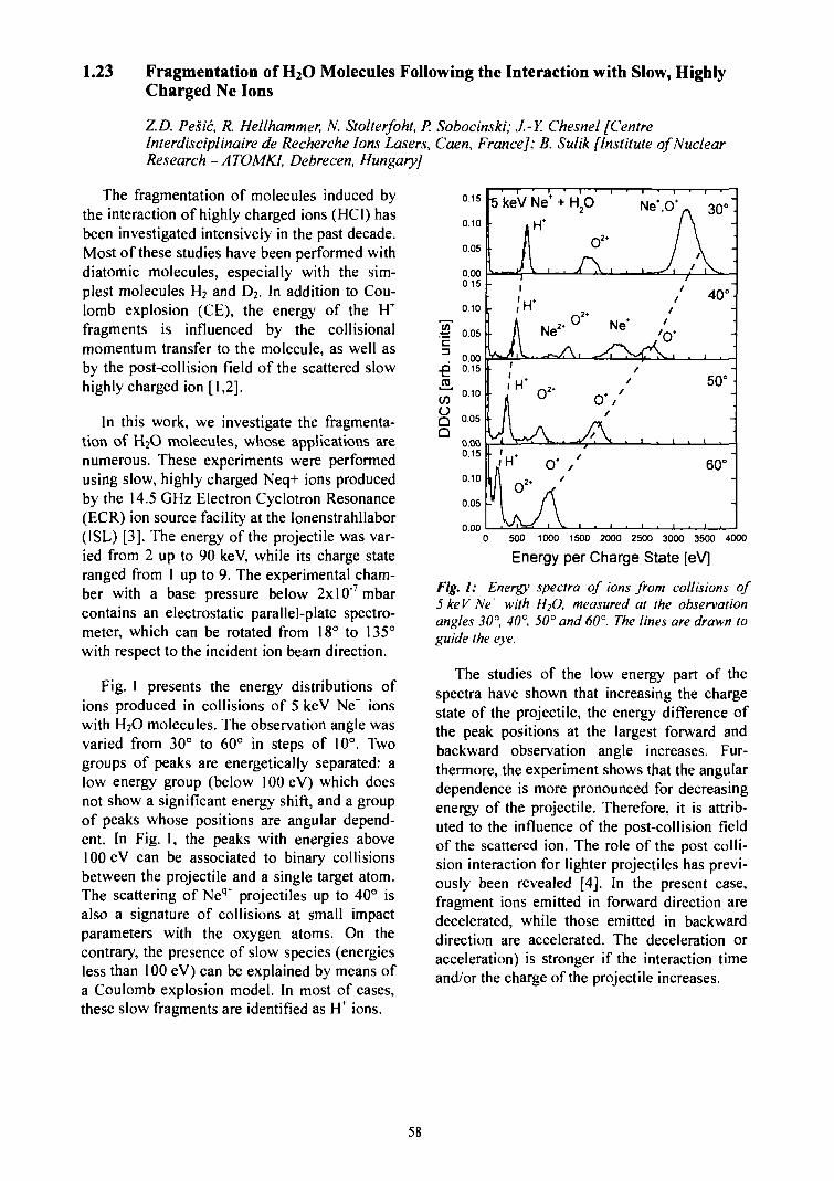
1.23 Fragmentation of H2O Molecules Following the Interaction with Slow, HighlyCharged Ne Ions
Z.D. Pesic, R. Hellhammer, N. Stolterfoht, P. Sobocinski; J.-Y. Chesnel [CentreInterdisciplinaire de Recherche Ions Lasers, Caen, France]; B. Sulik [Institute of NuclearResearch - ATOMKI, Debrecen, Hungary]
The fragmentation of molecules induced bythe interaction of highly charged ions (HCI) hasbeen investigated intensively in the past decade.Most of these studies have been performed withdiatomic molecules, especially with the sim-plest molecules H2 and D2. In addition to Cou-lomb explosion (CE), the energy of the FTfragments is influenced by the collisionalmomentum transfer to the molecule, as well asby the post-collision field of the scattered slowhighly charged ion [1,2].
In this work, we investigate the fragmenta-tion of H2O molecules, whose applications arenumerous. These experiments were performedusing slow, highly charged Neq+ ions producedby the 14.5 GHz Electron Cyclotron Resonance(ECR) ion source facility at the Ionenstrahllabor(ISL) [3]. The energy of the projectile was var-ied from 2 up to 90 keV, while its charge stateranged from 1 up to 9. The experimental cham-ber with a base pressure below 2xlO"7mbarcontains an electrostatic parallel-plate spectro-meter, which can be rotated from 18° to 135°with respect to the incident ion beam direction.
Fig. 1 presents the energy distributions ofions produced in collisions of 5 keV Ne" ionswith H2O molecules. The observation angle wasvaried from 30° to 60° in steps of 10°. Twogroups of peaks are energetically separated: alow energy group (below 100 eV) which doesnot show a significant energy shift, and a groupof peaks whose positions are angular depend-ent. In Fig. 1, the peaks with energies above100 eV can be associated to binary collisionsbetween the projectile and a single target atom.The scattering of Neq* projectiles up to 40° isalso a signature of collisions at small impactparameters with the oxygen atoms. On thecontrary, the presence of slow species (energiesless than 100 eV) can be explained by means ofa Coulomb explosion model. In most of cases,these slow fragments are identified as H' ions.
5keV
1
LiiH*
11,vnI °2
Ne* +
H*
1V , .
Ne2*
O 2 '
A .0*
(\
H20
o2*_ / \ 1
°2* Ne*
t
a/
J\ ./
I . I .
• ' i
Ne*,O*
/i
t/
f
i i
v 30°"
\ :
40°"
• 1 .
50°
60°"
• I •
0.15
0.10
0.05
0.000.15
0 10
£ 0.05c3 o.oo-Q 0.15(0COQ 0.05Q
0.000.15
0.10
0.05
0.000 500 1000 1500 2000 2500 3000 3500 4000
Energy per Charge State [eV]
Fig. I: Energy spectra of ions from collisions of5 keV Ne with H2O, measured at the observationangles 30°, 40°, 50° and 60°. The lines are drawn toguide the eye.
The studies of the low energy part of thespectra have shown that increasing the chargestate of the projectile, the energy difference ofthe peak positions at the largest forward andbackward observation angle increases. Fur-thermore, the experiment shows that the angulardependence is more pronounced for decreasingenergy of the projectile. Therefore, it is attrib-uted to the influence of the post-collision fieldof the scattered ion. The role of the post colli-sion interaction for lighter projectiles has previ-ously been revealed [4]. In the present case,fragment ions emitted in forward direction aredecelerated, while those emitted in backwarddirection are accelerated. The deceleration oracceleration) is stronger if the interaction timeand/or the charge of the projectile increases.
58
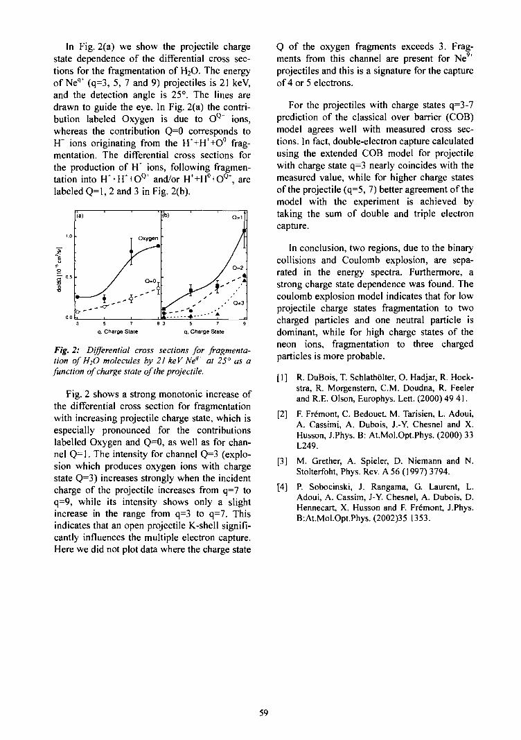
In Fig. 2(a) we show the projectile chargestate dependence of the differential cross sec-tions for the fragmentation of H2O. The energyof Neq+ (q=3, 5, 7 and 9) projectiles is 21 keV,and the detection angle is 25°. The lines aredrawn to guide the eye. In Fig. 2(a) the contri-bution labeled Oxygen is due to OQ ions,whereas the contribution Q=0 corresponds toH* ions originating from the H"+H++O° frag-mentation. The differential cross sections forthe production of H* ions, following fragmen-tation into H+FT+OQ' and/or H++H°+O0+, arelabeled Q=l, 2 and 3 in Fig. 2(b).
T
(a)
• •
<
i r
Oxygen
ft.)
•
•
k - • • ' ,
o - i .
1
/ Q-2
. - ' Q-3
q, Charge State q, Charge State
Fig. 2: Differential cross sections for fragmenta-tion of H2O molecules by 21 keV Neq' at 25° as afunction of charge state of the projectile.
Fig. 2 shows a strong monotonic increase ofthe differential cross section for fragmentationwith increasing projectile charge state, which isespecially pronounced for the contributionslabelled Oxygen and Q=0, as well as for chan-nel Q=l. The intensity for channel Q=3 (explo-sion which produces oxygen ions with chargestate Q=3) increases strongly when the incidentcharge of the projectile increases from q=7 toq=9, while its intensity shows only a slightincrease in the range from q=3 to q=7. Thisindicates that an open projectile K-shell signifi-cantly influences the multiple electron capture.Here we did not plot data where the charge state
Q of the oxygen fragments exceeds 3. Frag-ments from this channel are present for Ne9"projectiles and this is a signature for the captureof 4 or 5 electrons.
For the projectiles with charge states q=3-7prediction of the classical over barrier (COB)model agrees well with measured cross sec-tions. In fact, double-electron capture calculatedusing the extended COB model for projectilewith charge state q=3 nearly coincides with themeasured value, while for higher charge statesof the projectile (q=5, 7) better agreement of themodel with the experiment is achieved bytaking the sum of double and triple electroncapture.
In conclusion, two regions, due to the binarycollisions and Coulomb explosion, are sepa-rated in the energy spectra. Furthermore, astrong charge state dependence was found. Thecoulomb explosion model indicates that for lowprojectile charge states fragmentation to twocharged particles and one neutral particle isdominant, while for high charge states of theneon ions, fragmentation to three chargedparticles is more probable.
[ 1 ] R. DuBois, T. SchlathOlter, O. Hadjar, R. Hoek-stra, R. Morgenstern, CM. Doudna, R. Feelerand R.E. Olson, Europhys. Lett. (2000) 49 41.
[2] F. Fremont, C. Bedouet, M. Tarisien, L. Adoui,A. Cassimi, A. Dubois, J.-Y. Chesnel and X.Husson, J.Phys. B: At.Mol.Opt.Phys. (2000) 33L249.
[3] M. Grether, A. Spieler, D. Niemann and N.Stolterfoht, Phys. Rev. A 56 (1997) 3794.
[4] P. Sobocinski, J. Rangama, G. Laurent, L.Adoui, A. Cassim, J-Y. Chesnel, A. Dubois, D.Hennecart, X. Husson and F. Fremont, J.Phys.B:At.Mol.Opt.Phys. (2002)35 1353.
59
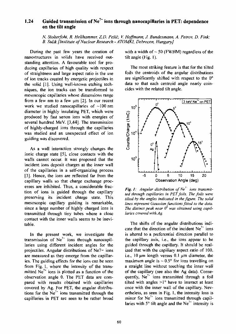
1.24 7+Guided transmission of Ne ions through nanocapillaries in PET: dependenceon the tilt angle
N. Stolterfoht, R. Hellhammer, Z.D. Pesic, V. Hoffmann, J. Bundesmann, A. Petrov, D. Fink;B. Sulik [Institute of Nuclear Research-ATOMKI, Debrecen, Hungary]
During the past few years the creation ofnanostructures in solids have received out-standing attention. A favourable tool for pro-ducing capillaries of high quality with respectof straightness and large aspect ratio is the useof ion tracks created by energetic projectiles inthe solid [1]. Using well-known etching tech-niques, the ion tracks can be transformed tomesoscopic capillaries whose dimensions rangefrom a few nm to a few um [2]. In our recentwork we studied nanocapillaries of -100 nmdiameter in highly insulating PET, which wereproduced by fast xenon ions with energies ofseveral hundred MeV. [3,44]. The transmissionof highly-charged ions through the capillarieswas studied and an unexpected effect of ionguiding was discovered.
As a wall interaction strongly changes theionic charge state [5], close contacts with thewalls cannot occur. It was proposed that theincident ions deposit charges at the inner wallof the capillaries in a self-organizing process[3]. Hence, the ions are reflected far from thecapillary walls so that charge exchange proc-esses are inhibited. Thus, a considerable frac-tion of ions is guided through the capillarypreserving its incident charge state. Thismesoscopic capillary guiding is remarkable,since a large number of highly charged ions istransmitted through tiny tubes where a closecontact with the inner walls seems to be inevi-table.
In the present work, we investigate thetransmission of Ne + ions through nanocapil-laries using different incident angles for theprojectiles. Angular distributions of Ne7+ ionsare measured as they emerge from the capillar-ies. The guiding effects for the ions can be seenfrom Fig. 1, where the intensity of the trans-mitted Ne7+ ions is plotted as a function of theobservation angle 0. The PET data are com-pared with results obtained with capillariescovered by Ag. For PET, the angular distribu-tions for the Ne7+ ions transmitted through thecapillaries in PET are seen to be rather broad
with a width of- 50 (FWHM) regardless of thetilt angle (Fig. 1).
The most striking feature is that for the tiltedfoils the centroids of the angular distributionsare significantly shifted with respect to the 0°data so that each centroid angle nearly coin-cides with the related tilt angle.
O
a><5
O|oO
105
104
103
,. , 1 , , . ,
' /
Ag
-
f
A/' /J/
j
3
A
•7
keV
10°
\
/
f
. , 7+
Ne on
Wi5°
\
PET
-
-
-5 0 5 10 15Observation Angle (deg)
20
Fig. J: Angular distribution of Ne7 ions transmit-ted through capillaries in PET foils. The foils weretilted by the angles indicated in the figure. The solidlines represent Gaussian functions fitted to the data.The distinct peak near (f was obtained using capil-laries covered with Ag.
The shifts of the angular distributions indi-cate that the direction of the incident Ne7+ ionsis altered to a preferential direction parallel tothe capillary axis, i.e., the ions appear to beguided through the capillary. It should be real-ized that with the capillary aspect ratio of 100,i.e., 10 um length versus 0.1 urn diameter, themaximum angle is ~ 0.5° for ions travelling ona straight line without touching the inner wallof the capillary (see also the Ag data). Conse-quently, Ne7+ ions transmitted through a foiltilted with angles >1° have to interact at leastonce with the inner wall of the capillary. Nev-ertheless, as seen in Fig. 1, the intensity loss isminor for Ne7+ ions transmitted through capil-laries with 5° tilt angle and the Ne7+ intensity is
60
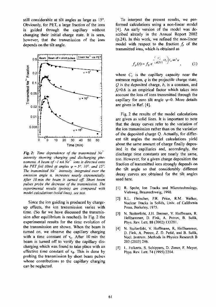
still considerable at tilt angles as large as 15°.Obviously, for PET, a large fraction of the ionsis guided through the capillary withoutchanging their initial charge state. It is seen,however, that the transmission of the ionsdepends on the tilt angle.
0.5
co
ra 0.2
* 0 1T3
$
§ 0.05ci5
0.02
0.01
0.005
Beam Beam off + short pulses 13 KeV Ne7 'via PET
0 0 10 20 30 40 50 60
Time (min)
Fig. 2: Time dependence of the transmitted Ne7'intensity showing charging and discharging phe-nomena. A beam of—I nA Ne ions is directed ontothe PET foil tilted at angles iff = 5° 10°, and 15°.The transmitted Ne intensity, integrated over theemission angle a, increases nearly exponentially.After 10 min the beam is turned off. Short beampulses probe the decrease of the transmission. Theexperimental results (points) are compared withmodel calculations (solid lines), see text.
Since the ion guiding is produced by charge-up effects, the ion transmission varies withtime. (So far we have discussed the transmis-sion after equilibrium is reached). In Fig. 2 theexperimental results for the time evolution ofthe transmission are shown. When the beam isturned on, we observe the capillary chargingwith a time constant of TC. After 10 min thebeam is turned off to verify the capillary dis-charging which was found to take place with aneffective time constant of xa. This is done byprobing the transmission by short beam pulseswhose contributions to the capillary chargingcan be neglected.
To interpret the present results, we per-formed calculations using a non-linear model[4]. An early version of the model was de-scribed already in the Annual Report 2002(p.24). In this work, we refined the non-linearmodel with respect to the fraction fp of thetransmitted ions, which is obtained as
(1)
where Ce is the capillary capacity near theentrance region, q is the projectile charge state,Q is the deposited charge, bs is a constant, andjo~O.6 is an empirical factor which takes intoaccount the loss of ions transmitted through thecapillary for zero tilt angle \|/=0. More detailsare given in Ref. [4].
Fig. 2 the results of the model calculationsare given as solid lines. It is important to notethat the decay curves refer to the variation ofthe ion transmission rather than on the variationof the deposited charge Q. Actually, for differ-ent tilt angles the model calculations yieldabout the same amount of charge finally depos-ited in the capillaries and, accordingly, thedischarge time constants are nearly the same,too. However, for a given charge deposition thefraction of transmitted ions strongly depends onthe tilt angle so that considerably differentdecay curves are obtained for the tilt anglesused here.
[1] R. Spohr, Ion Tracks and Microtechnology,Viehweg, Braunschweig, 1990.
[2] R.L. Fleischer, P.R. Price, R.M. Walker,Nuclear Tracks in Solids, Univ. of CaliforniaPress, Berkeley, 1975.
[3] N. Stolterfoht, J.H. Bremer, V. Hoffmann, R.Hellhammer, D. Fink, A. Petrov, B. Sulik,Phys. Rev. Lett. 88 (2002) 133201.
[4] N. Stolterfoht, V. Hoffmann, R, Hellhammer,D. Fink, A. Petrov, Z. D. PeSic, and B. Sulik,Nucl. Instrum. Methods in Physics Research B203 (2003) 246.
[5] L. Folkerts, S. Schippers, D. Zener, F. Meyer,Phys. Rev. Lett. 74 (1995) 2204.
61
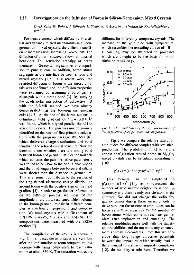
1.25 Investigations on the Diffusion of Boron in Silicon-Germanium Mixed Crystals
W.-D, Zeitz, W. Bohne, J. Rohrich, E. Strub; N. V. Abrosimov [Institutfur KristallziichtungBerlin]
For most elements which diffuse by intersti-tial and vacancy related mechanisms in silicon-germanium mixed crystals, the diffusion coeffi-cient increases with increasing Ge-content. Thediffusion of boron, however, shows an unusualbehaviour. The activation enthalpy of boronincreases in Ge-containing samples in compari-son to pure silicon. In addition, boron atomssegregate at the interface between silicon andmixed crystals [1,2]. In a recent work, theretarded diffusion of boron in the mixed crys-tals was confirmed and the diffusion propertieswere explained by assuming a boron-germa-nium-pair with a strong bond [3]. By studyingthe quadrupolar interaction of radioactive 12Bwith the P-NMR method, we have alreadydemonstrated that the boron-germanium-pairexists [4,5]. At the site of the boron nucleus, acylindrical field gradient of V^ = +3.8V/A2
was found, which is aligned parallel the <111>axis of the crystal. The pair was unambiguouslyidentified on the basis of first principle calcula-tions with the program package WIEN97 [6],which delivered charge distributions and bondlengths in the relaxed crystal structure. Now thequestion arises whether there is a strong bondbetween boron and germanium. For the unit cellwhich contains the pair the lattice parameter cwas found to be close to the one in pure siliconand the bond lengths between boron and siliconwere shorter than the distance to germanium.This arrangement contributes to the surplus ofthe ring-shaped electronic charge distributionaround boron with the positive sign of the fieldgradient [4]. In order to get further informationon the diffusion process, we measured theamplitude of the v_i,_>]-resonance which belongsto the boron-germanium-pair in different sam-ples as function of temperature and composi-tion. We used crystals with a Ge-content of1.7(1)%, 2.7(2)%, 5.3(3)% and 7.5(5)%. Thecompositions were measured with the ERDAmethod [7].
The compilation of the results is shown inFig. 1. In all cases the amplitudes are very lowafter the implantation at room temperature, butincrease with rising temperature to reach satu-ration at about 850 K. The saturation values are
different for differently composed crystals. Theincrease of the amplitude with temperature,which resembles the annealing curves of I2B insilicon [8], may be attributed to processeswhich are thought to be the basis for borondiffusion in silicon [9].
300 400 500 600 700 800 900
Temperature (K)
Fig. 1: The amplitudes of the v./,^-resonance of12 B as function of temperature and composition.
In Fig. 2 we compare the relative saturationamplitudes for different samples with statisticalpredictions. The probability pz
n(x) to find acertain configuration around boron in Si|.xGex
mixed crystals can be calculated according to[10]:
p'n(x) = (z!/n!(z-n)!)xn(l-x)z(1)
This formula can be simplified top4i(x) = 4x(l-x)3 [11], as z represents thenumber of next nearest neighbours in the Td-symmetry and there is only one Ge atom in thecomplex. We did not change the radio fre-quency power during these measurements tomake sure that the resonance amplitudes can betaken as relative measures for the number ofboron atoms which come at rest near germa-nium after implantation and annealing. Therelative amplitudes agree well with the statisti-cal probabilities and do not show any enhance-ment at small Ge-contents. From this we con-clude that long range attractive potentialsbetween the impurities, which usually lead tothe enhanced formation of impurity complexes[12], do not play a role here. Therefore we
62
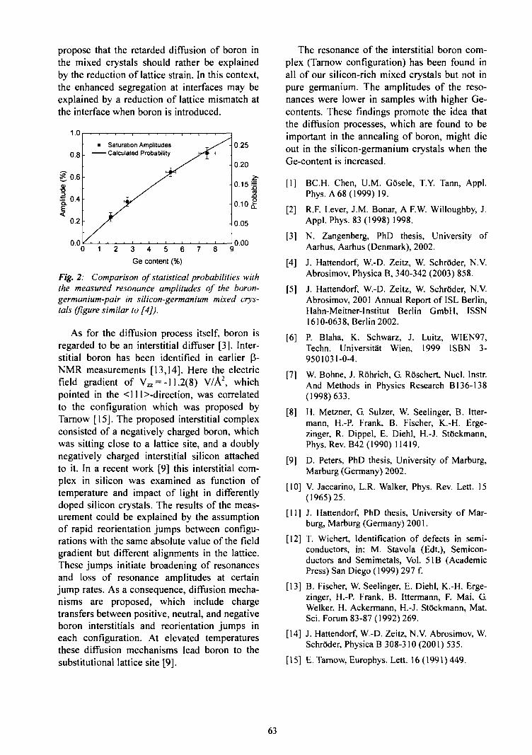
propose that the retarded diffusion of boron inthe mixed crystals should rather be explainedby the reduction of lattice strain. In this context,the enhanced segregation at interfaces may beexplained by a reduction of lattice mismatch atthe interface when boron is introduced.
1.0
0.8
g0.6
Saturation Amplitudes- Calculated Probability
3 4 5 6
Ge content (%)
0.00
Fig. 2: Comparison of statistical probabilities withthe measured resonance amplitudes of the boron-germanium-pair in silicon-germanium mixed crys-tals (figure similar to [4]).
As for the diffusion process itself, boron isregarded to be an interstitial diffuser [3J. Inter-stitial boron has been identified in earlier [3-NMR measurements [13,14]. Here the electricfield gradient of Vzz =-11.2(8) V/A2, whichpointed in the <11 Indirection, was correlatedto the configuration which was proposed byTarnow [15]. The proposed interstitial complexconsisted of a negatively charged boron, whichwas sitting close to a lattice site, and a doublynegatively charged interstitial silicon attachedto it. In a recent work [9] this interstitial com-plex in silicon was examined as function oftemperature and impact of light in differentlydoped silicon crystals. The results of the meas-urement could be explained by the assumptionof rapid reorientation jumps between configu-rations with the same absolute value of the fieldgradient but different alignments in the lattice.These jumps initiate broadening of resonancesand loss of resonance amplitudes at certainjump rates. As a consequence, diffusion mecha-nisms are proposed, which include chargetransfers between positive, neutral, and negativeboron interstitials and reorientation jumps ineach configuration. At elevated temperaturesthese diffusion mechanisms lead boron to thesubstitutional lattice site [9].
The resonance of the interstitial boron com-plex (Tarnow configuration) has been found inall of our silicon-rich mixed crystals but not inpure germanium. The amplitudes of the reso-nances were lower in samples with higher Ge-contents. These findings promote the idea thatthe diffusion processes, which are found to beimportant in the annealing of boron, might dieout in the silicon-germanium crystals when theGe-content is increased.
[I] BC.H. Chen, U.M. GOsele, T.Y. Tann, Appl.Phys. A 68 (1999) 19.
[2] R.F. Lever, J.M. Bonar, A F.W. Willoughby, J.Appl. Phys. 83(1998) 1998.
[3] N. Zangenberg, PhD thesis, University ofAarhus, Aarhus (Denmark), 2002.
[4] J. Hattendorf, W.-D. Zeitz, W. Schroder, N.V.Abrosimov, Physica B, 340-342 (2003) 858.
[5] J. Hattendorf, W.-D. Zeitz, W. Schroder, N.V.Abrosimov, 2001 Annual Report of ISL Berlin,Hahn-Meitner-Institut Berlin GmbH, ISSN1610-0638, Berlin 2002.
[6] P. Blaha, K. Schwarz, J. Luitz, WIEN97,Techn. UniversitSt Wien, 1999 ISBN 3-9501031-0-4.
[7] W. Bohne, J. Rohrich, G. R6schert, Nucl. Instr.And Methods in Physics Research B136-138(1998)633.
[8] H. Metzner, G. Sulzer, W. Seelinger, B. Itter-mann, H.-P. Frank, B. Fischer, K.-H. Erge-zinger, R. Dippel, E. Diehl, H.-J. Stockmann,Phys. Rev. B42 (1990) 11419.
[9] D. Peters, PhD thesis, University of Marburg,Marburg (Germany) 2002.
[10] V. Jaccarino, L.R. Walker, Phys. Rev. Lett. 15(1965)25.
[II] J. Hattendorf, PhD thesis, University of Mar-burg, Marburg (Germany) 2001.
[12] T. Wichert, Identification of defects in semi-conductors, in: M. Stavola (Edt.), Semicon-ductors and Semimetals, Vol. 5IB (AcademicPress) San Diego (1999) 297 f.
[13] B. Fischer, W. Seelinger, E. Diehl, K.-H. Erge-zinger, H.-P. Frank, B. Ittermann, F. Mai, G.Welker, H. Ackermann, H.-J. StOckmann, Mat.Sci. Forum 83-87 (1992) 269.
[14] J. Hattendorf, W.-D. Zeitz, N.V. Abrosimov, W.Schroder, Physica B 308-310 (2001) 535.
[15] E. Tarnow, Europhys. Lett. 16 (1991) 449.
63
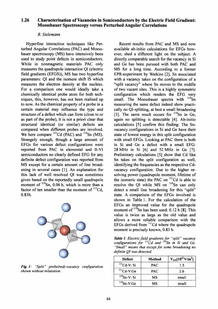
1.26 Characterisation of Vacancies in Semiconductors by the Electric Field Gradient:Moessbauer Spectroscopy versus Perturbed Angular Correlations
R. Sielemann
Hyperfine interaction techniques like Per-turbed Angular Correlations (PAC) and Moess-bauer spectroscopy (MS) have intensively beenused to study point defects in semiconductors.While in nonmagnetic materials PAC onlymeasures the quadrupole interaction QI (electricfield gradients (EFGS)), MS has two hyperfineparameters: QI and the isomere shift IS whichmeasures the electron density at the nucleus.For a comparison one would ideally take achemically identical probe atom for both tech-niques, this, however, has not been realised upto now. As the chemical property of a probe in acertain material may influence the type andstructure of a defect which can form (close to oras part of the probe), it is not a priori clear thatstructural identical (or similar) defects arecompared when different probes are involved.We here compare MICd (PAC) and "9Sn (MS).Strangely enough, though a large amount ofEFGs for various defect configurations werereported from PAC in elemental and II-VIsemiconductors no clearly defined EFG for anydefinite defect configuration was reported fromMS except for a certain amount of line broad-ening in several cases [1]. An explanation forthis lack of well resolved QI was sometimesgiven based on the reportedly small quadrupolemoment of "9Sn, 0.06 b, which is more than afactor often smaller than the moment of ulCd,0.83b.
Fig. 1: "Split" probe(red)-vacancy configurationshown without relaxation.
Recent results from PAC and MS and nowavailable ab-initio calculations for EFGs how-ever, shed a different light on the subject. Adirectly comparable search for the vacancy in Siand Ge has been pursued with both PAC andMS for a long time. According to a formerEPR-experiment by Watkins [2], Sn associatedwith a vacancy takes on the configuration of a"split vacancy" where Sn moves to the middleof two vacant sites. This is a highly symmetricconfiguration which renders the EFG verysmall. The Moessbauer spectra with "9Snmeasuring the same defect indeed show practi-cally no Ql-splitting, at best a small broadening[3]. The same result occurs for "9Sn in Ge,again no splitting is detectable [4]. Ab-initiocalculations [5] confirm this finding: The Sn-vacancy configurations in Si and Ge have theirstate of lowest energy in this split configurationwith small EFGs. Looking at PAC there is bothin Si and Ge a defect with a small EFG:28 MHz in Si [6] and 52 MHz in Ge [7].Preliminary calculations [5] show that Cd likeSn takes on the split configuration as well,identifying the frequencies as the respective Cd-vacancy configuration. Due to the higher re-solving power (quadrupole moment, lifetime ofthe isomeric state) the PAC on '"Cd is able toresolve the QI while MS on 119Sn can onlydetect a small line broadening for this "split"state. A comparison of the EFGs involved isshown in Table 1. For the calculation of theEFGs an improved value for the quadrupolemoment of "9Sn has been used: 0.12 b [8]. Thisvalue is twice as large as the old value andallows a more reliable comparison with theEFGs derived from '"Cd where the quadrupolemoment is precisely known, 0.83 b.
Table 1: Electric field gradients for "split" vacancyconfigurations for nlCd and ' vSn in Si and Ge."Small" means that except for some broadening nodefinite QI was detected.
Defect11'Cd-V: Si
"'Cd-V:Ge
""Sn-V: Si
"9Sn-V:Ge
Method
PAC
PAC
MS
MS
Vz7.|1021V/m2]
1.5
2.6
small
small
64

A comparison between PAC and MS is nowalso possible for single vacancy configurationsin III-V and II-VI semiconductors. In InSb thesingle vacancy (likely VIn) adjacent to the Snprobe has been uniquely identified [9]. A largeQI is observed, A=1.3(l)mm/s, which convertsto an EFG of 17.4V/m2. This large value resultsin a well resolved quadrupole line. The EFGvalue is of similar magnitude as the EFG meas-ured with mCd in CdTe, which presumablycorresponds to the Te vacancy nearest neigh-bour to the Cd probe. Table 2 lists these EFGsof "standard" vacancy configurations.
Fig. 2: Probe-vacancy configuration with the probeatom (red) staying on the lattice site (except for acertain amount of relaxation, not shown here).
Fig. 2 shows a "standard" probe-vacancyconfiguration where the probe atom remains onist lattice site (except for some smaller relaxa-tion). Preliminary data from ab-initio calcula-tions for these standard configuration indeedshow that such large EFGs are to be expectedfor Sn in InSb [5] and for Cd in CdTe [10]. Insome cases the charge state of the defect caninduce considerable changes in these EFGs, soit might not always be easy to distinguish a"split" configuration from a standard geometry.
Summarising, for both mCd and ll9Snprobe-vacancy configurations have been ob-served employing PAC or MS respectively. Thesmall EFGs resulting from the "split"configurations make it difficult to observe theQI with the "9Sn probe, it is at the limits ofresolution and sensitivity. Identification of adefect line in such a case is only possible viathe IS. The "standard" vacancy configuration,however, should be well observable via the QIprovided a sufficiently precise and specificexperiment is performed.
Table 2: Electric field gradients measured for"standard" probe-vacancy configurations with '"Snand '"Cd, see Fig. 2.
Defect
"9Snsb-VIn:InSb
'"Cdcd-VftiCdTe
Method
MS
PAC
VM[1021V/m2|
17.4
22.8
[1] A. Nylandsted-Larsen et al., Phys. Rev. B62(2000)4535.
[2] G.D. Watkins, Phys. Rev. B12 (1975) 4383.
[3] G Weyer et al., Hyperfine Interact. 7 (1980)449.
[4] R. Sieiemann et al., Physica B 273-274 (1999)565; L. Stadler, Dipl.Arbeit HMI 2003.
[5] H. Hoehler, P. Dederichs, K. Schroeder, R. Zel-ler et al., private communication 2003.
[6] Th. Wichert, in: Semiconductors and Semimet-als51B (1999) 297.
[7] H. Haesslein et al., Phys. Rev. Lett. 80 (1998)2626.
[8] A. Svane et al., Phys. Rev. B55 (1997) 12572.
[9] R. Sieiemann et al., Annual report 2003.
[10] S. Lany et al., Physica B308-310 (2001) 958.
65
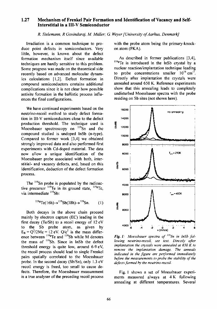
1.27 Mechanism of Frenkel Pair Formation and Identification of Vacancy and Self-Interstitial in a III-V Semiconductor
R. Sielemann, R Govindaraj, M. Miiller; G. Weyer [University ofAarhus, Denmark]
Irradiation is a common technique to pro-duce point defects in semiconductors. Verylittle, however, is known about the defectformation mechanism itself since availabletechniques are hardly sensitive to this problem.Some progress was made on the theoretical siderecently based on advanced molecular dynam-ics calculations [1,2]. Defect formation incompound semiconductors contains additionalcomplications since it is not clear how possibleantisite formation in the ballistic process influ-ences the final configurations.
We have continued experiments based on theneutrino-recoil method to study defect forma-tion in III-V semiconductors close to the defectproduction threshold. The technique used isMoessbauer spectroscopy on "9Sn and thecompound studied is undoped InSb (n-type).Compared to former work [3,4] we obtainedstrongly improved data and also performed firstexperiments with Cd-doped material. The datanow allow a unique identification of theMoessbauer probe associated with both, inter-stitial- and vacancy defects, and, based on thisidentification, deduction of the defect formationprocess.
The "9Sn probe is populated by the radioac-tive precursor ll9Te in its ground state, 119gTe,via intermediate Sb:
1I9 C
119gTe(16h)->"9Sb(38h)->"9Sn. (1)
Both decays in the above chain proceedmainly by electron capture (EC) leading in thefirst decay (Te/Sb) to a recoil energy of 12 eVto the Sb probe atom, as given byER = Q2/2Mc= 12eV. Q/c2 is the mass differ-ence between "9gTe and 119Sb while M denotesthe mass of "9Sb. Since in InSb the defectthreshold energy is quite low, around 6-9 eV,the recoil process should lead to single Frenkelpairs spatially correlated to the Moessbauerprobe. In the second decay (Sb/Sn), only 1.3 eVrecoil energy is freed, too small to cause de-fects. Therefore, the Moessbauer measurementis a true analyser of the preceding recoil process
with the probe atom being the primary-knock-on atom (PK.A).
As described in former publications [3,4],"9gTe is introduced in the InSb crystal by anuclear reaction/implantation technique leadingto probe concentrations smaller 10l4cm'"\Directly after implantation the crystals wereannealed around 650 K. Reference experimentsshow that this annealing leads to completelyundisturbed Moessbauer spectra with the proberesiding on Sb sites (not shown here).
16000
14000
12000
10000
8000
no annealing
8000 •
6000 \
4000
8000
6000
40000
v [mm/8]
Fig. 1: Moessbauer spectra of "vSn in InSb fol-lowing neutrino-recoil, see text. Directly afterimplantation the crystals were annealed at 650 K toremove the implantation damage. The annealsindicated in the figure are performed immediatelybefore the measurements to probe the stability of thedefects formed by the neutrino-recoil.
Fig. 1 shows a set of Moessbauer experi-ments measured always at 4 K followingannealing at different temperatures. Several
66
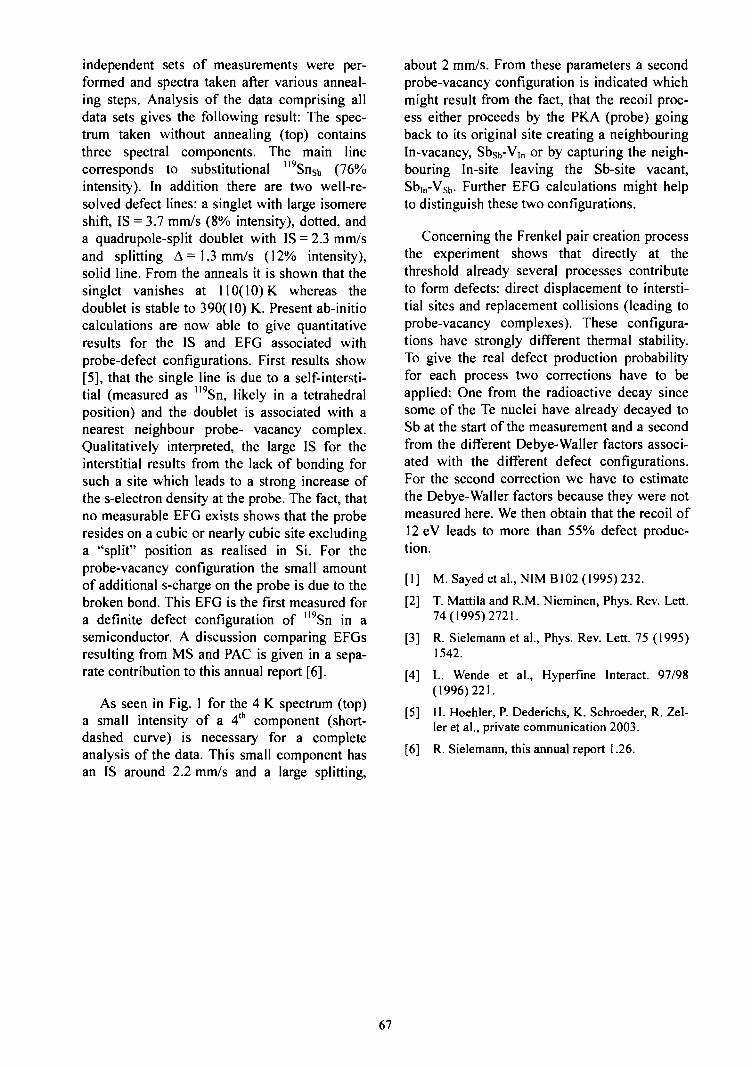
independent sets of measurements were per-formed and spectra taken after various anneal-ing steps. Analysis of the data comprising alldata sets gives the following result: The spec-trum taken without annealing (top) containsthree spectral components. The main linecorresponds to substitutional "9SnSb (76%intensity). In addition there are two well-re-solved defect lines: a singlet with large isomereshift, IS = 3.7 mm/s (8% intensity), dotted, anda quadrupole-split doublet with IS = 2.3 mm/sand splitting A =1.3 mm/s (12% intensity),solid line. From the anneals it is shown that thesinglet vanishes at 110(10) K. whereas thedoublet is stable to 390(10) K. Present ab-initiocalculations are now able to give quantitativeresults for the IS and EFG associated withprobe-defect configurations. First results show[5], that the single line is due to a self-intersti-tial (measured as 119Sn, likely in a tetrahedralposition) and the doublet is associated with anearest neighbour probe- vacancy complex.Qualitatively interpreted, the large IS for theinterstitial results from the lack of bonding forsuch a site which leads to a strong increase ofthe s-electron density at the probe. The fact, thatno measurable EFG exists shows that the proberesides on a cubic or nearly cubic site excludinga "split" position as realised in Si. For theprobe-vacancy configuration the small amountof additional s-charge on the probe is due to thebroken bond. This EFG is the first measured fora definite defect configuration of "9Sn in asemiconductor. A discussion comparing EFGsresulting from MS and PAC is given in a sepa-rate contribution to this annual report [6].
As seen in Fig. 1 for the 4 K spectrum (top)a small intensity of a 4th component (short-dashed curve) is necessary for a completeanalysis of the data. This small component hasan IS around 2.2 mm/s and a large splitting,
about 2 mm/s. From these parameters a secondprobe-vacancy configuration is indicated whichmight result from the fact, that the recoil proc-ess either proceeds by the PKA (probe) goingback to its original site creating a neighbouringIn-vacancy, Sbsb-VIn or by capturing the neigh-bouring In-site leaving the Sb-site vacant,SbIn-Vsb. Further EFG calculations might helpto distinguish these two configurations.
Concerning the Frenkel pair creation processthe experiment shows that directly at thethreshold already several processes contributeto form defects: direct displacement to intersti-tial sites and replacement collisions (leading toprobe-vacancy complexes). These configura-tions have strongly different thermal stability.To give the real defect production probabilityfor each process two corrections have to beapplied: One from the radioactive decay sincesome of the Te nuclei have already decayed toSb at the start of the measurement and a secondfrom the different Debye-Waller factors associ-ated with the different defect configurations.For the second correction we have to estimatethe Debye-Waller factors because they were notmeasured here. We then obtain that the recoil of12 eV leads to more than 55% defect produc-tion.
[ 1 ] M. Saved et al., NIM B102 (1995) 232.
[2] T. Mattila and R.M. Nieminen, Phys. Rev. Lett.74(1995)2721.
[3] R. Sielemann et al., Phys. Rev. Lett. 75 (1995)1542.
[4] L. Wende et al., Hyperfine Interact. 97/98(1996)221.
[5] H. Hoehler, P. Dederichs, K. Schroeder, R. Zel-ler et al., private communication 2003.
[6] R. Sielemann, this annual report 1.26.
67
1.28 Lattice Distortion around Impurities in CdTe
H.-E. Mahnke, H. Haas, E. Holub-Krappe; V. Koteski, N. Ivanovic [VINCA Institute ofNuclear Science, Belgrade, Yugoslavia]
The incorporation of impurity atoms fordoping is often accompanied with lattice dis-tortions and the formation of defect complexes,in some cases drastically influencing electricaland optical properties. Thus the knowledge andunderstanding of lattice relaxations aroundimpurity atoms is of vital interest. We havemeasured the lattice distortion around As as do-pant (acceptor), Se as a 4% admixture in CdTe,and Br as donor on the anion sublattice withfluorescence detected extended X-ray absorp-tion fine structure (EXAFS) at HASYLAB. Theexperimental challenge lies in the necessarycompromise between a concentration highenough for X-ray absorption and low enough toavoid compensation and clustering of thedopants. In the case of As in CdTe, the aim wasfurther to experimentally verify the lattice re-laxation around the impurity atom as deter-mined with the linearised augmented planewave (LAPW) method used to calculate theelectric field gradient in comparison with themeasured value in a PAC experiment [1]. Inorder to understand the driving force for thelattice relaxation we also determined the re-laxation around Se, the neighbouring element toAs and isovalent to Te, for which no dopingeffects in CdTe are known. Finally, we haveextended our calculation to the next-neigh-bouring element, Br, acting as donor whensubstituting Te, and have performed an EXAFSexperiment on Br in CdTe with preliminaryresults.
Arsenic was incorporated into CdTe by ionimplantation at the tandetron of the FZ Rossen-dorf. A total dose of 7xlO15 cm'2 As atoms wasalmost uniformly distributed up to a depth of3 ji.m. The samples, originally from CrystecGmbH [2], were thermally treated before andafter the implantation following standard ap-proaches in which As was predominantlyincorporated as acceptor at the Te site aschecked by photoluminescence (PL). For back-ground reduction, the crystals were thinnedfrom the back to a total thickness of about30 jim. For the case of Se in CdTe we usedmixed CdTei.xSex crystals, provided by M.Fiederle [3], which were powdered, diluted with
graphite and polyethylene, and pressed intopellets. In the case of Br in CdTe, grown crys-tals with a nominal concentration of 5x1019 cm"3
[4] were also powdered and pressed into pellets.The K-edge absorption was measured at theXl-beamline of HASYLAB at DESY, with thesamples being mounted either on a He gas flowcryostat (for As and Se in CdTe) or a liquidnitrogen cryostat (for Br in CdTe). In the caseof As and Br we measured the absorption influorescence mode with a segmented Ge-de-tector, while in the case of Se and of the mainconstituent elements Cd and Te the absorptionwas measured in transmission. The analysis ofthe absorption spectra was done following thestandard FEFF procedure [5].
1.0
— i.'. „/,• /
—^-^ . . —
CdTe:As -expAs,, in CdTeAs^ in CdTeA^g in CdTeA^,, in CdTe
i . i
fu
0.0
11860 11880 11900 11920 11940
Energy (eV)Fig. 1: Comparison of the experimental XAFSsignal of As in CdTe (at 18 K) with XANES spectracalculated for different configurations: (i) As substi-tionally on the Te site (As/J, (ii) As as "antisite " onthe Cd sublattice (Asctt), and As located interstitiallywith (Hi) either Te (Asm,i) or (iiii) Cd (Asm,2) as firstshell neighbours. The theoretical spectra are nor-malized to the experimental edge step and shifted iny-direction.
Since the fluorescence detected EXAFS isnot site selective, we were especially concernedabout the structural uniqueness of the impurityconfiguration. In the case of As in CdTe addi-tional PL measurements confirmed at least theexistence of substitutional As. In addition to theEXAFS spectrum already presented in [9], wehave inspected the XANES (X-ray absorptionnear edge spectroscopy) region of the absorp-tion spectra and compared it to model spectra
68

assuming As in various configurations (seeFig. 1). The modelling was performed accor-ding to [6]. Only the description of As pre-dominantly being substitutionally at the Te sitematches the experimental spectra. We can there-fore adopt the determined bond length as repre-sentative for As in CdTe at the substitional Tesite. Complementing our experimental work wehave performed ab-initio calculations based on
the density functional theory (DFT) with theWIEN97 package [7] which uses the LAPWmethod and with the FHI96md program [8]which uses first-principles pseudo-potentials(PP) and a plane-wave basis set. The latter wasused to investigate the size dependence of thesuper-cells constructed around one substitu-tional impurity atom in CdTe.
Table 1: Comparison of experimentally determined nearest neighbour and next-nearest neighbour distancesaround impurity (dopant) atoms in CdTe with calculated values obtained with LAPW (super-cell size 32 atoms)and with PP methods (super-cell size up to 216 atoms). The calculated values are given for the charged configu-ration in the case of As and Br (further details in Ref.flOJ). (All values are given in A).
System
CdTe
As in CdTe
Se in CdTe
Br in CdTe
Run (exp)
2.806*
2.58(2)
2.67(1)
2.84(4)**
LAPVv"
2.57"
2.66
2.90
heo)PP
2.572
Rnnn (exp)
4.583*
4.50(6)
4.53(1)
Rnnn(theo)LAPW PP
4.52s
4.55
4.574
4.551
values from standard lattice parameter, "preliminary analysis, "values as presented in Ref. [1]
In Table 1 we compare our measured bondlengths with the results obained from the pseu-dopotential calculations as well as the LAPWvalues according to Ref. [1]. Our EXAFS dataon Se and the corresponding calculated valuescan be considered as an additional support tothe good agreement obtained for As in CdTebetween experiment and model calculation. Theextracted values are included in Table 1. Wehave chosen a concentration of x=0.04 whichcomes close to the super-cell size of 32 atoms.The agreement is very good and gives confi-dence to attack more sophisticated configura-tional doping problems both by modelling andby experimental verification of proposed modeldescription. In this context, we include ourresult of bond length calculation for the donorBr in CdTe in Table 1, which seems to be fullyconfirmed by a preliminary result extractedfrom our EXAFS experiment. Contrary to theAs and Se case, it shows a sizeable increase inbond length. This result may be the explanationfor the high tendency of Br to form a Br A-center (Br plus metal vacancy) in CdTe.
Acknowledgement: The authors are gratefulto the HASYLAB staff at DESY, in particular toN. Haack, E. Welter, and J. Wienold. We alsothank H. Rossner and P. Szimkowiak (HMIBerlin), N. Novakovic and B. Cekic (VINCA
Institute, Belgrade), M. Fiederle (FreiburgerMaterialforschungszentrum), O. Panchuk(Chernivtsi University, UA), M. Friedrich (FZRossendorf), S. Lany, F. Wagner, Th. Wichert,and H. Wolf (UniversitSt Saarbriicken), J.Bollmann and J. Weber (TU Dresden), and G.Schwarz (FHI Berlin).
[ 1 ] S. Lany et al., Phys. Rev. B 62, R2259 (2000).
[2] Crystec GmbH, D-12555 Berlin.
[3] M. Fiederle, Freiburger Materialforschungszen-trum, priv. com.
[4] O. Panchuk, Inst. lnorg. Chem., ChernivtsiUniversity, 274012 Chernivtsi, Ukraine, priv.com.
[5] J.J. Rehr et al., J. Am.Chem. Soc.113 (1991)5135; M. Newville et al. Phys. Rev. B 47(1993) 14126.
[6] A. Ankudinov, B. Ravel, J.J. Rehr, S. Conrad-son, Phys. Rev. B 58 (1998) 7565.
[7] P. Blaha, K. Schwarz, J. Luitz, WIEN97(Karlheinz Schwarz, TU Wien, 1999) ISBN 3-9501031-0-4.
[8] M. Bockstedte et al., Comp. Phys. Comm. 107(1997) 187.
[9] V. Koteski et al., Annual report 2002, HMI-B591, ISSN 1610-0638, p.51.
110] V. Koteski et al., accepted for publication inPhysica Scripta.
69
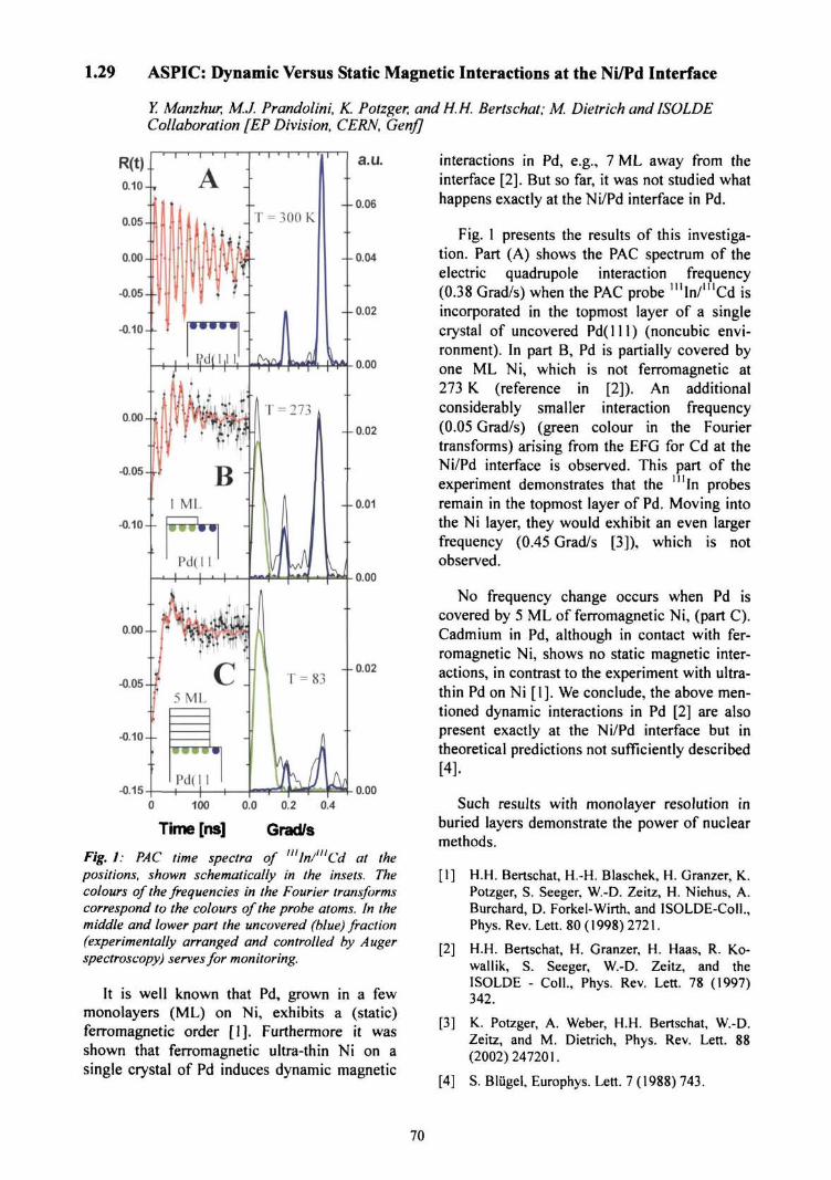
1.29 ASPIC: Dynamic Versus Static Magnetic Interactions at the Ni/Pd Interface
Y. Manzhur, M.J. Prandolini, K. Potzger, and H.H. Bertschat; M. Dietrich and ISOLDECollaboration [EP Division, CERN, GenfJ
a.u.
- - 0.06
- -0 .04
- - 0.02
0.00
- - 0.02
- - 0.01
0.00
0.00
-0.05
-0.10
-0.15
- - 0.02
0.00
100 0.0 0.2 0.4
Time [ns] Grad/s
Fig. 1: PAC time spectra of l"ln/"'Cd at thepositions, shown schematically in the insets. Thecolours of the frequencies in the Fourier transformscorrespond to the colours of the probe atoms. In themiddle and lower part the uncovered (blue) fraction(experimentally arranged and controlled by Augerspectroscopy) serves for monitoring.
It is well known that Pd, grown in a fewmonolayers (ML) on Ni, exhibits a (static)ferromagnetic order [1]. Furthermore it wasshown that ferromagnetic ultra-thin Ni on asingle crystal of Pd induces dynamic magnetic
interactions in Pd, e.g., 7 ML away from theinterface [2]. But so far, it was not studied whathappens exactly at the Ni/Pd interface in Pd.
Fig. 1 presents the results of this investiga-tion. Part (A) shows the PAC spectrum of theelectric quadrupole interaction frequency(0.38 Grad/s) when the PAC probe mIn/mCd isincorporated in the topmost layer of a singlecrystal of uncovered Pd(lll) (noncubic envi-ronment). In part B, Pd is partially covered byone ML Ni, which is not ferromagnetic at273 K. (reference in [2]). An additionalconsiderably smaller interaction frequency(0.05 Grad/s) (green colour in the Fouriertransforms) arising from the EFG for Cd at theNi/Pd interface is observed. This part of theexperiment demonstrates that the '"in probesremain in the topmost layer of Pd. Moving intothe Ni layer, they would exhibit an even largerfrequency (0.45 Grad/s [3]), which is notobserved.
No frequency change occurs when Pd iscovered by 5 ML of ferromagnetic Ni, (part C).Cadmium in Pd, although in contact with fer-romagnetic Ni, shows no static magnetic inter-actions, in contrast to the experiment with ultra-thin Pd on Ni [1]. We conclude, the above men-tioned dynamic interactions in Pd [2] are alsopresent exactly at the Ni/Pd interface but intheoretical predictions not sufficiently described[4].
Such results with monolayer resolution inburied layers demonstrate the power of nuclearmethods.
[1] H.H. Bertschat, H.-H. Blaschek, H. Granzer, K.Potzger, S. Seeger, W.-D. Zeitz, H. Niehus, A.Burchard, D. Forkel-Wirth, and ISOLDE-Coll.,Phys. Rev. Lett. 80 (1998) 2721.
[2] H.H. Bertschat, H. Granzer, H. Haas, R. Ko-wallik, S. Seeger, W.-D. Zeitz, and theISOLDE - Coll., Phys. Rev. Lett. 78 (1997)342.
[3] K. Potzger, A. Weber, H.H. Bertschat, W.-D.Zeitz, and M. Dietrich, Phys. Rev. Lett. 88(2002)247201.
[4] S. Blugel, Europhys. Lett. 7 (1988) 743.
70
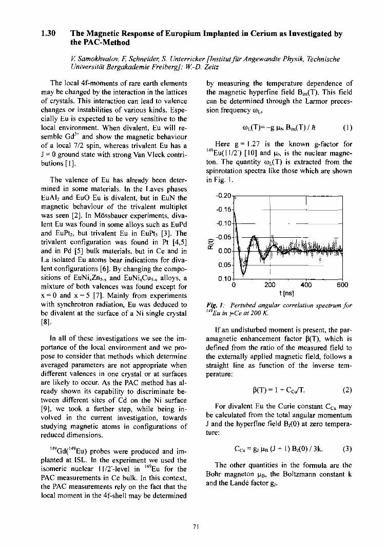
1.30 The Magnetic Response of Europium Implanted in Cerium as Investigated bythe PAC-Method
V. Samokhvalov, F. Schneider, S. Unterricker [lnstitut fur Angewandte Physik, TechnischeUniversitdt Bergakademie Freiberg]; W.-D. Zeitz
The local 4f-moments of rare earth elementsmay be changed by the interaction in the latticesof crystals. This interaction can lead to valencechanges or instabilities of various kinds. Espe-cially Eu is expected to be very sensitive to thelocal environment. When divalent, Eu will re-semble Gd3* and show the magnetic behaviourof a local 7/2 spin, whereas trivalent Eu has aJ = 0 ground state with strong Van Vleck contri-butions [1].
The valence of Eu has already been deter-mined in some materials. In the Laves phasesEuAl2 and EuO Eu is divalent, but in EuN themagnetic behaviour of the trivalent multipletwas seen [2]. In MOssbauer experiments, diva-lent Eu was found in some alloys such as EuPdand EuPt2, but trivalent Eu in EuPt, [3]. Thetrivalent configuration was found in Pt [4,5]and in Pd [5] bulk materials, but in Ce and inLa isolated Eu atoms bear indications for diva-lent configurations [6]. By changing the compo-sitions of EuNixZn5.x and EuNixCu5.x alloys, amixture of both valences was found except forx = 0 and x = 5 [7]. Mainly from experimentswith synchrotron radiation, Eu was deduced tobe divalent at the surface of a Ni single crystal[8].
In all of these investigations we see the im-portance of the local environment and we pro-pose to consider that methods which determineaveraged parameters are not appropriate whendifferent valences in one crystal or at surfacesare likely to occur. As the PAC method has al-ready shown its capability to discriminate be-tween different sites of Cd on the Ni surface[9], we took a further step, while being in-volved in the current investigation, towardsstudying magnetic atoms in configurations ofreduced dimensions.
149Gd(149Eu) probes were produced and im-planted at ISL. In the experiment we used theisomeric nuclear 1 l/2"-level in l49Eu for thePAC measurements in Ce bulk. In this context,the PAC measurements rely on the fact that thelocal moment in the 4f-shell may be determined
by measuring the temperature dependence ofthe magnetic hyperfine field Bint(T). This fieldcan be determined through the Larmor preces-sion frequency COL,
(1)
149Here g = 1.27 is the known g-factor for
Eu(ll/2") [10] and |aN is the nuclear magne-ton. The quantity coL(T) is extracted from thespinrotation spectra like those which are shownin Fig. 1.
200 400t[ns]
600
Fig. 1: Pertubed angular correlation spectrum for149
Eu in y-Ce at 200 K.
If an undisturbed moment is present, the par-amagnetic enhancement factor P(T), which isdefined from the ratio of the measured field tothe externally applied magnetic field, follows astraight line as function of the inverse tem-perature:
P(T) = 1 + (2)
For divalent Eu the Curie constant CCu maybe calculated from the total angular momentumJ and the hyperfine field Bj(0) at zero tempera-ture:
(3)
The other quantities in the formula are theBohr magneton u,B, the Boltzmann constant kand the Lande factor gj.
71
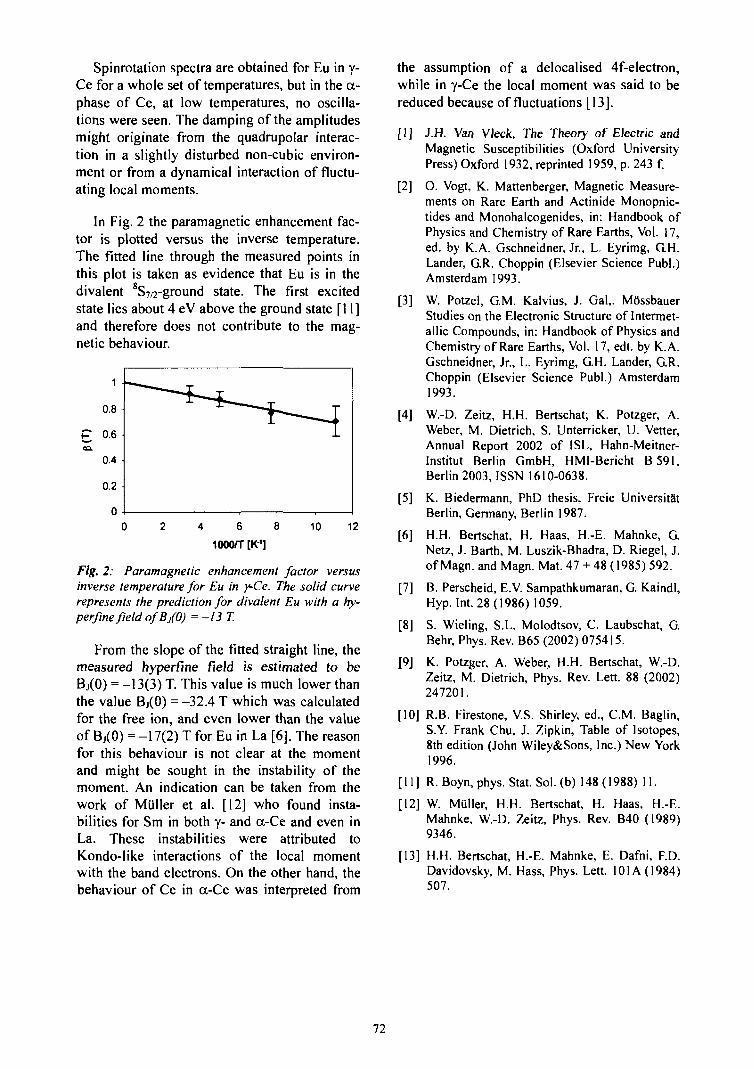
Spinrotation spectra are obtained for Eu in y-Ce for a whole set of temperatures, but in the a-phase of Ce, at low temperatures, no oscilla-tions were seen. The damping of the amplitudesmight originate from the quadrupolar interac-tion in a slightly disturbed non-cubic environ-ment or from a dynamical interaction of fluctu-ating local moments.
In Fig. 2 the paramagnetic enhancement fac-tor is plotted versus the inverse temperature.The fitted line through the measured points inthis plot is taken as evidence that Eu is in thedivalent 8S7/2-ground state. The first excitedstate lies about 4 eV above the ground state [11]and therefore does not contribute to the mag-netic behaviour.
2 4 6 8
1000/T [K"1]
10 12
Fig. 2: Paramagnetic enhancement factor versusinverse temperature for Eu in y-Ce. The solid curverepresents the prediction for divalent Eu with a hy-perfine field ofB/0) = -13 T.
From the slope of the fitted straight line, themeasured hyperfine field is estimated to beBj(0) = -13(3) T. This value is much lower thanthe value Bj(0) = -32.4 T which was calculatedfor the free ion, and even lower than the valueof Bj(0) = -17(2) T for Eu in La [6]. The reasonfor this behaviour is not clear at the momentand might be sought in the instability of themoment. An indication can be taken from thework of Muller et al. [12] who found insta-bilities for Sm in both y- and a-Ce and even inLa. These instabilities were attributed toKondo-like interactions of the local momentwith the band electrons. On the other hand, thebehaviour of Ce in a-Ce was interpreted from
the assumption of a delocalised 4f-electron,while in y-Ce the local moment was said to bereduced because of fluctuations [13].
[I] J.H. Van VJeck, The Theory of Electric andMagnetic Susceptibilities (Oxford UniversityPress) Oxford 1932, reprinted 1959, p. 243 f.
[2] O. Vogt, K. Mattenberger, Magnetic Measure-ments on Rare Earth and Actinide Monopnic-tides and Monohalcogenides, in: Handbook ofPhysics and Chemistry of Rare Earths, Vol. 17,ed. by K.A. Gschneidner, Jr., L. Eyrimg, G.H.Lander, GR. Choppin (Elsevier Science Publ.)Amsterdam 1993.
[3] W. Potzel, G.M. Kalvius, J. Gal,. MSssbauerStudies on the Electronic Structure of Intermet-allic Compounds, in: Handbook of Physics andChemistry of Rare Earths, Vol. 17, edt. by K.A.Gschneidner, Jr., L. Eyrimg, G.H. Lander, G.R.Choppin (Elsevier Science Publ.) Amsterdam1993.
[4] W.-D. Zeitz, H.H. Bertschat; K. Potzger, A.Weber, M. Dietrich, S. Unterricker, U. Verter,Annual Report 2002 of 1SL, Hahn-Meitner-Institut Berlin GmbH, HMI-Bericht B 591,Berlin 2003, ISSN 1610-0638.
[5] K. Biedermann, PhD thesis, Freie UniversitatBerlin, Germany, Berlin 1987.
[6] H.H. Bertschat, H. Haas, H.-E. Mahnke, G.Netz, J. Barth, M. Luszik-Bhadra, D. Riegel, J.of Magn. and Magn. Mat. 47 + 48 (1985) 592.
[7] B. Perscheid, E.V. Sampathkumaran, G. Kaindl,Hyp. Int, 28(1986) 1059.
[8] S. Wieling, S.L. Molodtsov, C. Laubschat, G.Behr, Phys. Rev. B65 (2002) 075415.
[9] K. Potzger, A. Weber, H.H. Bertschat, W.-D.Zeitz, M. Dietrich, Phys. Rev. Lett. 88 (2002)247201.
[10] R.B. Firestone, VS. Shirley, ed., CM. Baglin,S.Y. Frank Chu, J. Zipkin, Table of Isotopes,8th edition (John Wiley&Sons, Inc.) New York1996.
[II] R. Boyn, phys. Stat. Sol. (b) 148 (1988) 11.
[12] W. Muller, H.H. Bertschat, H. Haas, H.-E.Mahnke, W.-D. Zeitz, Phys. Rev. B40 (1989)9346.
[13] H.H. Bertschat, H.-E. Mahnke, E. Dafni, F.D.Davidovsky, M. Hass, Phys. Lett. 101A (1984)507.
72
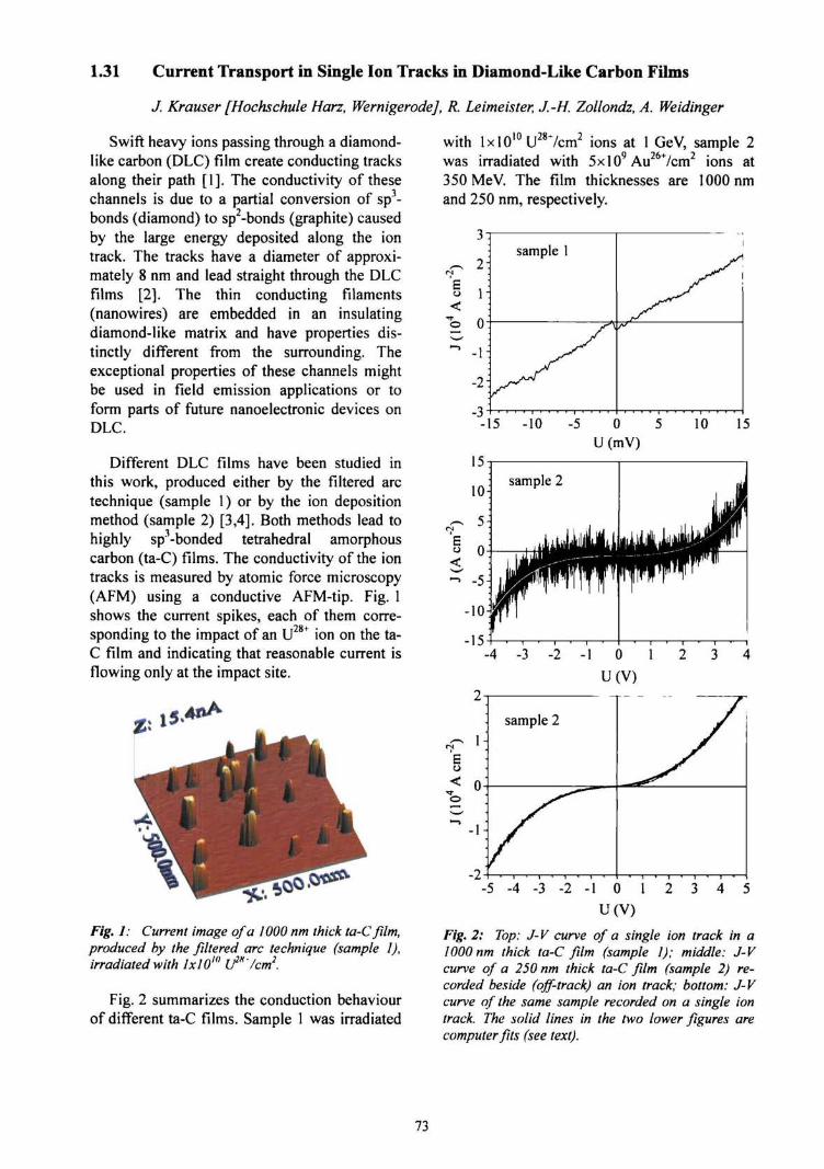
1.31 Current Transport in Single Ion Tracks in Diamond-Like Carbon Films
J. Krauser [Hochschule Harz, Wernigerode], R. Leimeister, J.-H. Zollondz, A. Weidinger
Swift heavy ions passing through a diamond-like carbon (DLC) film create conducting tracksalong their path [1]. The conductivity of thesechannels is due to a partial conversion of sp3-bonds (diamond) to sp2-bonds (graphite) causedby the large energy deposited along the iontrack. The tracks have a diameter of approxi-mately 8 nm and lead straight through the DLCfilms [2]. The thin conducting filaments(nanowires) are embedded in an insulatingdiamond-like matrix and have properties dis-tinctly different from the surrounding. Theexceptional properties of these channels mightbe used in field emission applications or toform parts of future nanoelectronic devices onDLC.
Different DLC films have been studied inthis work, produced either by the filtered arctechnique (sample 1) or by the ion depositionmethod (sample 2) [3,4]. Both methods lead tohighly sp3-bonded tetrahedral amorphouscarbon (ta-C) films. The conductivity of the iontracks is measured by atomic force microscopy(AFM) using a conductive AFM-tip. Fig. 1shows the current spikes, each of them corre-sponding to the impact of an U ion on the ta-C film and indicating that reasonable current isflowing only at the impact site.
Fig. 1: Current image of a 1000 nm thick ta-C film,produced by the filtered arc technique (sample I),irradiated with lxl0w if*'/cm2.
Fig. 2 summarizes the conduction behaviourof different ta-C films. Sample 1 was irradiated
with lxl010U287cm2 ions at 1 GeV, sample 2was irradiated with 5xlO9 Au267cm2 ions at350 MeV. The film thicknesses are 1000 nmand 250 nm, respectively.
.5 .4 .3 - 2 - 1 0 1 4 5
Fig. 2: Top: J- V curve of a single ion track in a1000 nm thick ta-C film (sample 1); middle: J-Vcurve of a 250 nm thick ta-C film (sample 2) re-corded beside (off-track) an ion track; bottom: J-Vcurve of the same sample recorded on a single iontrack. The solid lines in the two lower figures arecomputer fits (see text).
73
The conduction behaviour of sample 1(Fig. 2 top) is ohmic with the current density Jfollowing the equation
0)
From the fit we obtain a value for the con-ductivity of a = 156 S/cm (for bulk graphite thevalue is 727 S/cm). Apparently, a partial con-version of the material in the ion track frominsulating sp3- into conducting sp2-bondedcarbon has occurred. In contrast, the conductionbehaviour of sample 2 is totally different asshown in the two lower curves of Fig. 2. Astrong nonlinearity in the curve progression canbe seen. This shape of the curves is characteris-tic for J-V measurements on unirradiated ta-Cfilms or beside an ion track. We assume that thecurrent transport mechanism in the cases ofpoorly conducting single ion tracks and besidean ion track is dominated by the Frenkel-Pooleeffect [5] where unsaturated bonds in the filmact as trap centres. The current density J is nowexpressed by the equation
J = a^Ee kT (2)
with electrical field E, barrier height 0 andFrenkel-Poole constant
(3)
Eq. (2) can be interpreted as Ohm's law witha field dependent conductivity OQ. The productq® denotes the ionization energy which isnecessary for an electron to escape from thetrap site in the absence of an electrical field. Inpresence of an electrical field the effectivepotential barrier for the trapped electron islowered by fi^E. To approve the foregoingassumptions, we performed computer fits on therespective J-V curves using Eq. (2) [6]. Thesolid lines in the two lower curves in Fig. 2show the results of these simulations. By using(2) it is possible to get very accurate fits to thedata. The values for a0 derived from the fits area0 = 4.5x10"7 S/cm for the off-track site onsample 2 and a0 = 3 x 10"3 S/cm for the singleion track on the same sample.
Another reason for the low conductivity withthe absence of ohmic behaviour might befounded by the existence of a tunnel barrier,e.g., a thin oxide layer between substrate andta-C film, which dominates the current transportmechanism. Fitting our data with an appropriateformula did not lead to satisfying results.Nevertheless, it is possible that the Frenkel-Poole effect not solely determines the conduc-tivity in the films but also effects of smalldiscontinuities in the nanowires influence themeasurements.
It seems that there are two possible reasonsfor the difference in the conductivity: the pro-duction methods of the films and the ion spe-cies and its energy used for irradiation (U28' orAu26'). Otherwise it should be noted that ourmeasurements show that ion tracks with lowconductivity are found in films produced by thefiltered arc technique as well as in films pro-duced by the ion deposition method. As re-cently reported, hydrogen here plays a majorrole. This suggests that the choice of the ionspecies and its energy determine the conductiv-ity of the single ion track, i.e. the ratio of trans-formation from sp3-bonded ta-C to sp2-bondedcarbon. Future experiments at the ISL will helpto verify this assumption.
The authors would like to thank the group ofProf. H. Hofsass (University GOttingen) and Dr.B. Schultrich (FhG-IWS-Dresden) for provid-ing them with the ta-C films, Dr. S. Klau-miinzer for fruitful discussions, B. Mertesackerand the ISL staff for their technical support.
[1] M. Waiblinger, Ch. Sommerhalter, B. Pietzak,J. Krauser, B. Mertesacker, M.Ch. Lux-Steiner,S. Klaumiinzer, A. Weidinger, C. Ronning, H.Hofsass, Appl. Phys. A69 (1999) 239.
[2] J. Krauser, J.-H. Zollondz, A. Weidinger, C.Trautmann, J. Appl. Phys. 94 (2003) 1959.
[3] T. Schiilke, T. Witke, H.-J. Scheibe, P. Siem-roth, B. Schultrich, O. Zimmer, J. Vetter, Surf.Coat. Technol. 120/121 (1999)226.
[4] H. Hofsass, H. Binder, T. Klumpp, E. Reck-nagel, Diam. Relat. Mater. 3 (1994) 137.
[5] J. Frenkel, Phys. Rev. 54 (1938) 647.
[6] R. Leimeister, Diplomarbeit FU Berlin Novem-ber 2003.
74
2. Materials Analysis
75

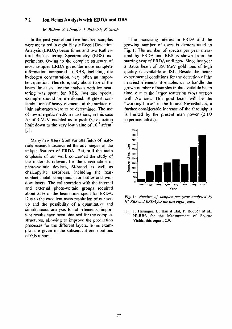
2.1 Ion Beam Analysis with ERDA and RBS
W. Bohne, S. Lindner, J. Rohrich, E. Strut
In the past year about five hundred sampleswere measured in eight Elastic Recoil DetectionAnalysis (ERDA) beam times and two Ruther-ford Backscattering Spectrometry (RBS) ex-periments. Owing to the complex structure ofmost samples ERDA gives the more completeinformation compared to RBS, including thehydrogen concentration, very often an impor-tant question. Therefore, only about 15% of thebeam time used for the analysis with ion scat-tering was spent for RBS. Just one specialexample should be mentioned. Slightest con-tamination of heavy elements at the surface oflight substrates were to be determined. The useof low energetic medium mass ions, in this caseAr of 4 MeV, enabled us to push the detectionlimit down to the very low value of 10" at/cm2
[1].
Many new users from various fields of mate-rials research discovered the advantages of theunique features of ERDA. But, still the mainemphasis of our work concerned the study ofthe materials relevant for the construction ofphoto-voltaic devices, Si-based as well aschalcopyrite absorbers, including the rear-contact metal, compounds for buffer and win-dow layers. The collaboration with the internaland external photo-voltaic groups requiredabout 55% of the beam time spent for ERDA.Due to the excellent mass resolution of our set-up and the possibility of a quantitative andsimultaneous analysis for all elements, impor-tant results have been obtained for the complexstructures, allowing to improve the productionprocesses for the different layers. Some exam-ples are given in the subsequent contributionsof this report.
The increasing interest in ERDA and thegrowing number of users is demonstrated inFig. 1. The number of spectra per year meas-ured by ERDA and RBS is shown from thestarting year of ERDA until now. Since last yeara stable beam of 350 MeV gold ions of highquality is available at ISL. Beside the betterexperimental conditions for the detection of theheaviest elements it enables us to handle thegrown number of samples in the available beamtime, due to the larger scattering cross sectionwith Au ions. This gold beam will be the"working horse" in the future. Nevertheless, afurther considerable increase of the throughputis limited by the present man power (2 1/3experimentalists).
1997 1998 1999 2000 2001
Year2002 2003
Fig. 1: Number of samples per year analysed byHl-RBS and ERDA for the last eight years.
[1] F. Haranger, B. Ban d'Etat, P. Boduch at al.,HI-RBS for the Measurement of SputterYields, this report, 2.9.
77
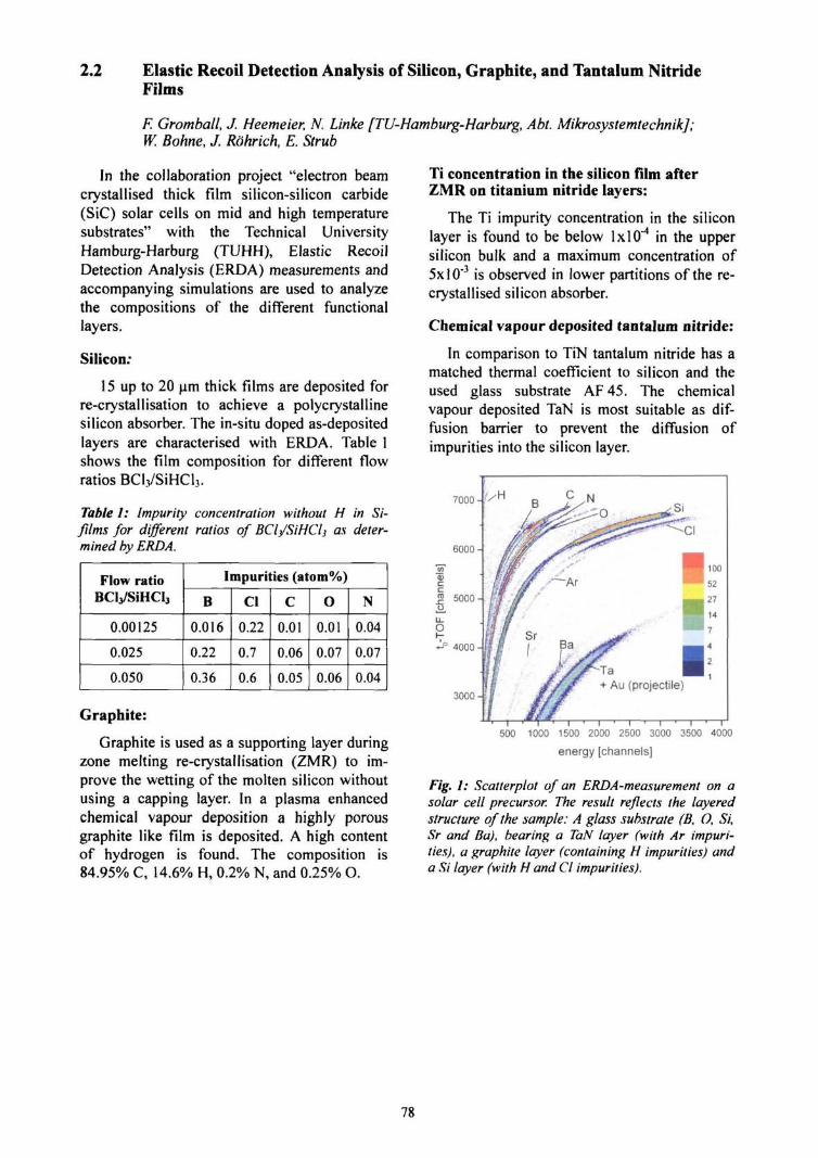
2.2 Elastic Recoil Detection Analysis of Silicon, Graphite, and Tantalum NitrideFilms
F. Gromball, J. Heemeier, N. Linke [TU-Hamburg-Harburg, Abt. Mikrosystemtechnik];W. Bohne, J. Rohrich, E. Strub
In the collaboration project "electron beamcrystallised thick film silicon-silicon carbide(SiC) solar cells on mid and high temperaturesubstrates" with the Technical UniversityHamburg-Harburg (TUHH), Elastic RecoilDetection Analysis (ERDA) measurements andaccompanying simulations are used to analyzethe compositions of the different functionallayers.
Silicon:
15 up to 20 urn thick films are deposited forre-crystallisation to achieve a polycrystallinesilicon absorber. The in-situ doped as-depositedlayers are characterised with ERDA. Table 1shows the film composition for different flowratios BCl3/SiHCl3.
Table I: Impurity concentration without H in Si-films for different ratios of BClj/SiHClj as deter-mined by ERDA.
Flow ratioBClj/SiHCIj
0.00125
0.025
0.050
Impurities (atom%)
B
0.016
0.22
0.36
Cl
0.22
0.7
0.6
C
0.01
0.06
0.05
o0.01
0.07
0.06
N
0.04
0.07
0.04
Graphite:
Graphite is used as a supporting layer duringzone melting re-crystallisation (ZMR) to im-prove the wetting of the molten silicon withoutusing a capping layer. In a plasma enhancedchemical vapour deposition a highly porousgraphite like film is deposited. A high contentof hydrogen is found. The composition is84.95% C, 14.6% H, 0.2% N, and 0.25% O.
Ti concentration in the silicon film afterZMR on titanium nitride layers:
The Ti impurity concentration in the siliconlayer is found to be below \x\Q~4 in the uppersilicon bulk and a maximum concentration of5xl0"3 is observed in lower partitions of the re-crystallised silicon absorber.
Chemical vapour deposited tantalum nitride:
In comparison to TiN tantalum nitride has amatched thermal coefficient to silicon and theused glass substrate AF45. The chemicalvapour deposited TaN is most suitable as dif-fusion barrier to prevent the diffusion ofimpurities into the silicon layer.
7000
500 1000 1500 2000 2500 3000 3500 4000
energy [channels]
Fig. 1: Scatterplot of an ERDA-measurement on asolar cell precursor. The result reflects the layeredstructure of the sample: A glass substrate (B, O, Si,Sr and lia), bearing a TaN layer (with Ar impuri-ties), a graphite layer (containing H impurities) anda Si layer (with H and Cl impurities).
78
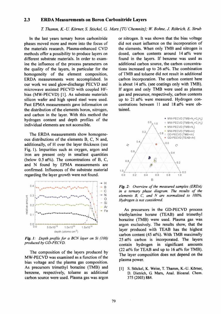
2.3 ERDA Measurements on Boron Carbonitride Layers
T. Thamm, K.-U. Korner, S. Stockel, G. Marx [TUChemnitz]; W. Bohne, J. Rohrich, E. Strub
In the last years ternary boron carbonitridephases moved more and more into the focus ofthe materials research. Plasma-enhanced CVDmethods offer a possibility to produce layers ondifferent substrate materials. In order to exam-ine the influence of the process parameters onthe quality of the layers, in particular for thehomogeneity of the element composition,ERDA measurements were accomplished. Inour work we used glow-discharge PECVD andmicrowave assisted PECVD with coupled HF-bias (MW-PECVD) [1]. As substrate materialssilicon wafer and high speed steel were used.Past EPMA measurements gave information onthe distribution of the elements boron, nitrogen,and carbon in the layer. With this method thehydrogen content and depth profiles of theindividual elements are not accessible.
The ERDA measurements show homogene-ous distributions of the elements B, C, N and,additionally, of H over the layer thickness (seeFig. 1). Impurities such as oxygen, argon andiron are present only in smallest quantities(below 0.5 at%). The concentrations of B, C,and N found by EPMA measurements areconfirmed. Influences of the substrate materialregarding the layer growth were not found.
5.0x10¹⁸ 1.0x10¹⁹
depth (atoms cm"'
5x10n
Fig. 1: Depth profile for a BCN layer on Si (100)produced by GD-PECVD.
The composition of the layers produced byMW-PECVD was examined as a function of thebias voltage and the plasma gas composition.As precursors trimethyl borazine (TMB) andbenzene, respectively, toluene as additionalcarbon source were used. Plasma gas was argon
or nitrogen. It was shown that the bias voltagedid not exert influence on the incorporation ofthe elements. When only TMB and nitrogen isdosed, carbon contents around 14 at% werefound in the layers. If benzene was used asadditional carbon source, the carbon concentra-tions increased up to 26 at%. The combinationof TMB and toluene did not result in additionalcarbon incorporation. The carbon content hereis about 14 at%. (see coatings only with TMB).If argon and only TMB were used as plasmagas and precursor, respectively, carbon contentsup to 21 at% were measured. Hydrogen con-centrations between 11 and 18 at% were ob-tained.
1.0
• MW-PECVD [TMB+N2+C6H6]
• MW-PECVD [TMB+N2+C7He]
• MW-PECVD [TMB+N2]
n MW-PECVD [TMB+Ar]
s° 8 o GD-PECVD [TMB+Ar]• GD-PECVD [TEAB+Ar]
0.6
0.4
0.6 0.8 1.0
B
Fig. 2: Overview of the measured samples (ERDA)in a ternary phase diagram. The results of theelements B, C, and N are normalised to 100%.Hydrogen is not considered.
As precursors in the GD-PECVD processtriethylamine borane (TEAB) and trimethylborazine (TMB) were used. Plasma gas wasargon exclusively. The results show, that thelayer produced with TEAB has the highestcarbon content (45 at%). With TMB maximally25 at% carbon is incorporated. The layerscontain hydrogen in significant amounts(22 at% for TEAB and up to 16 at% for TMB).The layer composition does not depend on theplasma power.
[1] S. Stockel, K. Weise, T. Thamm, K.-U. Korner,D. Dietrich, G. Marx, Anal. Bioanal. Chem.375 (2003) 884.
79
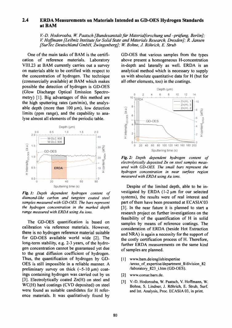
2.4 ERDA Measurements on Materials Intended as GD-OES Hydrogen Standardsat BAM
V.-D. Hodoroaba, W. Paatsch [Bundesanstaltfur Materialforschung und-prufung, Berlin];V. Hoffmann [Leibniz Institute for Solid State and Materials Research, Dresden]; R. Jansen[Surtec Deutschland GmbH, Zwingenberg]; W. Bohne, J. Rohrich, E. Strub
One of the main tasks of BAM is the certifi-cation of reference materials. LaboratoryVI 11.23 at BAM currently carries out a surveyon materials able to be certified with respect tothe concentration of hydrogen. The technique(commercially available) at BAM which makespossible the detection of hydrogen is GD-OES(Glow Discharge Optical Emission Spectro-metry) [1]. Big advantages of this method arethe high sputtering rates (um/min), the analys-able depth (more than 100 um), low detectionlimits (ppm range), and the capability to ana-lyse almost all elements of the periodic table.
oo 0.5
Depth (|jm)
1.0 1.5 2.02.0
1.5-
5 10-
i0) 0.5-
0.0-
-W-DLC 935W-DLC 936
. GD-OES
ERDA—
20 40 60
Sputtering time (s)
30
- CD
-10
l-o80
Fig. / ; Depth dependent hydrogen content ofdiamond-like carbon and tungsten coated steelsamples measured with GD-OES. The bars representthe hydrogen concentration in the marked depthrange measured with ERDA using Au ions.
The GD-OES quantification is based oncalibration via reference materials. However,there is no hydrogen reference material suitablefor GD-OES available world wide [2]. Thelong-term stability, e.g. 2-3 years, of the hydro-gen concentration cannot be guaranteed yet dueto the great diffusion coefficient of hydrogen.Thus, the quantification of hydrogen by GD-OES is still impossible in a reliable manner. Apreliminary survey on thick (-5-10 um) coat-ings containing hydrogen was carried out by us[3]. Electrolytically coated Zn(H) on steel andWC(H) hard coatings (CVD deposited) on steelwere found as suitable candidates for H refer-ence materials. It was qualitatively found by
GD-OES that various samples from the typesabove present a homogeneous H-concentrationin-depth and laterally as well. ERDA is ananalytical method which is necessary to supplyus with absolute quantitative data for H (but forall other elements, too) in the coatings.
Depth (|jm)
6 8 10 12
o6o2CD
6-
4 -
2-
0-M
-10
o
0 20 40 60 80 100 120 140 160 180 200
Sputtering time (s)
Fig. 2: Depth dependent hydrogen content ofelectrolytically deposited Zn on steel samples meas-ured with GD-OES. The small bars represent thehydrogen concentration in near surface regionmeasured with ERDA using Au ions.
Despite of the limited depth, able to be in-vestigated by ERDA (1-2 um for our selectedsystems), the results were of real interest andpart of them have been presented at EC ASIA'03[3]. In the near future it is planned to start aresearch project on further investigations on thefeasibility of the quantification of H in solidsamples by means of reference coatings. Theconsideration of ERDA (beside Hot Extractionand NRA) is again a necessity for the support ofthe costly certification process of H. Therefore,further ERDA measurements on the same kindof samples are planned.
[1] www.bam.de/english/expertise/areas_of_expertise/department_8/division_82/laboratory_823_i.htm (GD-OES).
[2] www.comar.barn.de.
[3] V.-D. Hodoroaba, W. Paatsch, V. Hoffmann, W.Bohne, S. Lindner, J. Rohrich, E. Strub, Surf,and Int. Analysis, Proc. ECASIA 03, in print.
80
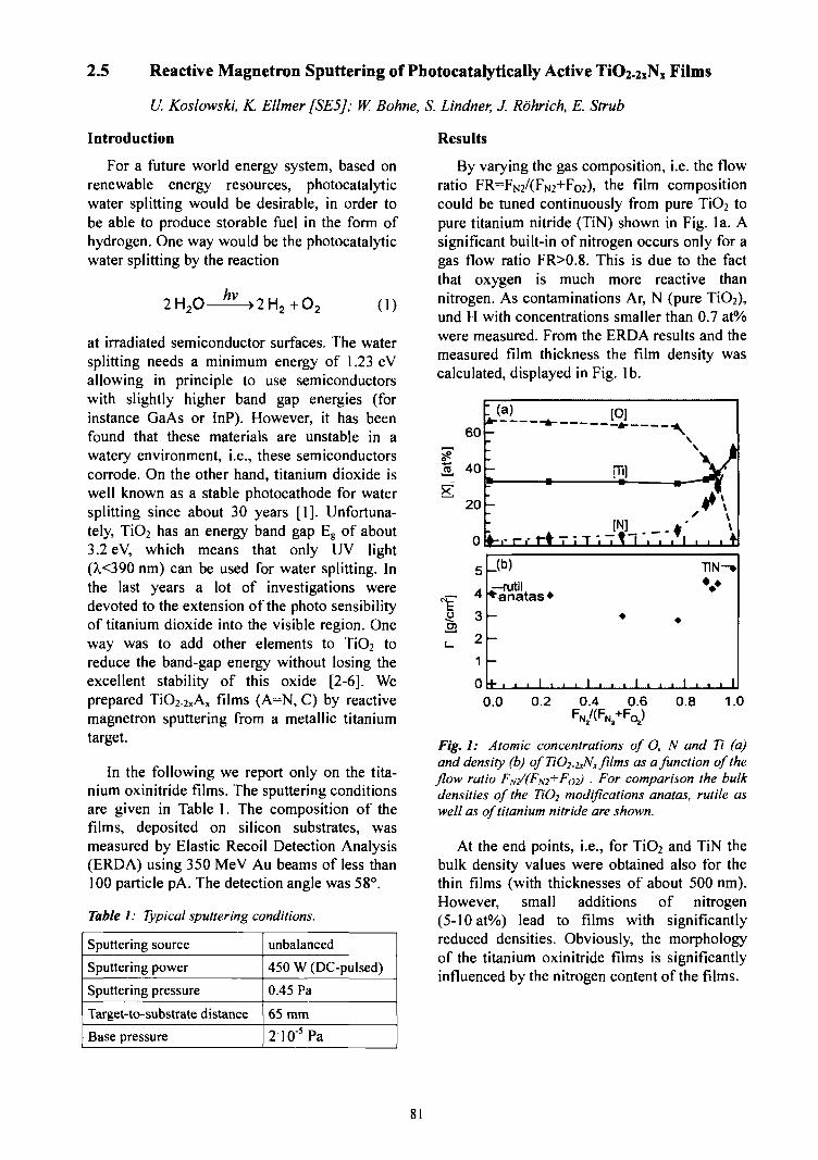
2.5 Reactive Magnetron Sputtering of Photocatalytically Active TiC>2-2xNx Films
U. Koslowski, K. Ellmer [SE5J; W. Bohne, S. Lindner, J. Rohrich, E. Strub
Introduction
For a future world energy system, based onrenewable energy resources, photocatalyticwater splitting would be desirable, in order tobe able to produce storable fuel in the form ofhydrogen. One way would be the photocatalyticwater splitting by the reaction
(1)
at irradiated semiconductor surfaces. The watersplitting needs a minimum energy of 1.23 eVallowing in principle to use semiconductorswith slightly higher band gap energies (forinstance GaAs or InP). However, it has beenfound that these materials are unstable in awatery environment, i.e., these semiconductorscorrode. On the other hand, titanium dioxide iswell known as a stable photocathode for watersplitting since about 30 years [1]. Unfortuna-tely, TiO2 has an energy band gap Eg of about3.2 eV, which means that only UV light(>.<390 nm) can be used for water splitting. Inthe last years a lot of investigations weredevoted to the extension of the photo sensibilityof titanium dioxide into the visible region. Oneway was to add other elements to TiO2 toreduce the band-gap energy without losing theexcellent stability of this oxide [2-6]. Weprepared TiO2-2XAx films (A=N, C) by reactivemagnetron sputtering from a metallic titaniumtarget.
In the following we report only on the tita-nium oxinitride films. The sputtering conditionsare given in Table 1. The composition of thefilms, deposited on silicon substrates, wasmeasured by Elastic Recoil Detection Analysis(ERDA) using 350 MeV Au beams of less than100 particle pA. The detection angle was 58°.
Table I: Typical sputtering conditions.
Sputtering source
Sputtering power
Sputtering pressure
Target-to-substrate distance
Base pressure
unbalanced
450 W (DC-pulsed)
0.45 Pa
65 mm
21Q-5Pa
Results
By varying the gas composition, i.e. the flowratio FR=FN2/(FN2+Fo2), the film compositioncould be tuned continuously from pure TiO2 topure titanium nitride (TiN) shown in Fig. la. Asignificant built-in of nitrogen occurs only for agas flow ratio FR>0.8. This is due to the factthat oxygen is much more reactive thannitrogen. As contaminations Ar, N (pure TiO2),und H with concentrations smaller than 0.7 at%were measured. From the ERDA results and themeasured film thickness the film density wascalculated, displayed in Fig. lb.
60
P"2, 40
20
0
5
•£> 3
" 2
1
0
I (a)-
_
---f-,- r-i- t-i T
_(b)
•anatas •-
-
-
4- . . . I . .
[0]
[Tl]
IN] _ .; T '• i * ~ i • i
•
. i . . . i . .
Vr\
TiN->
v
• 1 . . . 1
0.0 0.2 0.4 0.6 0.8 1.0
Fig. I: Atomic concentrations of O, N and Ti (a)and density (b) of TiO2.2XNx films as a function of theflow ratio Ffj/(Ffj2+Foz) • For comparison the bulkdensities of the TiO2 modifications anatas, rutile aswell as of titanium nitride are shown.
At the end points, i.e., for TiO2 and TiN thebulk density values were obtained also for thethin films (with thicknesses of about 500 nm).However, small additions of nitrogen(5-10 at%) lead to films with significantlyreduced densities. Obviously, the morphologyof the titanium oxinitride films is significantlyinfluenced by the nitrogen content of the films.
81
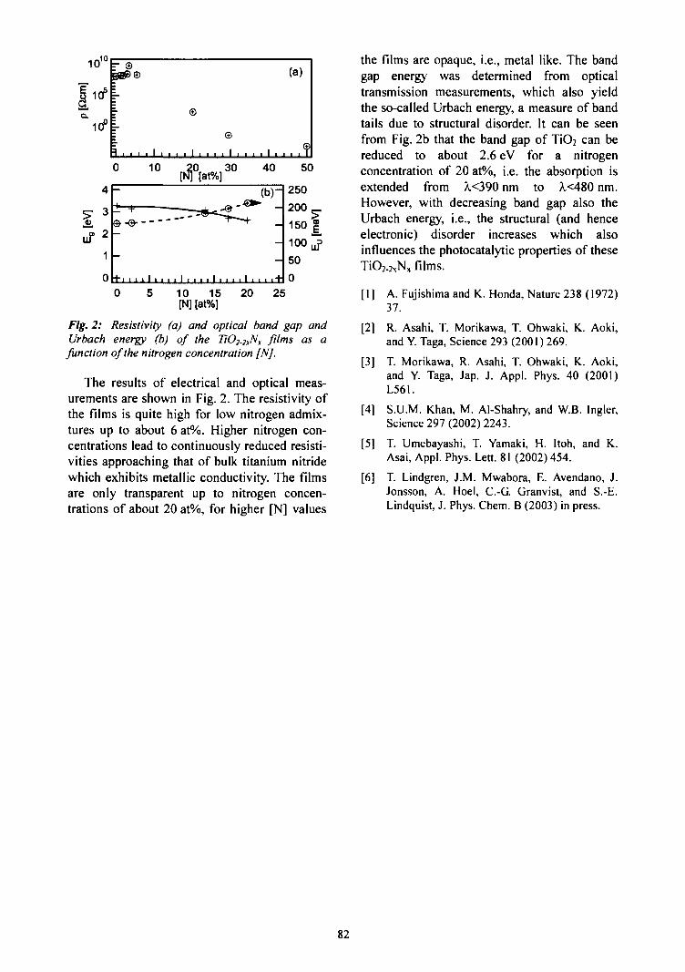
1010
J105
"io°i-
- ©
m
llIf111til
IIII
II
\ , , , , i
©
©
(a)
.....f
4
3
2
1
0
0
•—
- +& -©•—
-
+ i i i
10 20
_ • • ^ —
1 I 1 1 1 1 I 1 1 1
30 40
(b)-
_
—
1 i i i i 1 i i i i "fr1
50
250200^.150 |100 J50
05 10 15
IN] [at%]20 25
Fig. 2: Resistivity (a) and optical band gap andUrbach energy (b) of the TiO2-2xNx films as a
function of the nitrogen concentration [N].
The results of electrical and optical meas-urements are shown in Fig. 2. The resistivity ofthe films is quite high for low nitrogen admix-tures up to about 6 at%. Higher nitrogen con-centrations lead to continuously reduced resisti-vities approaching that of bulk titanium nitridewhich exhibits metallic conductivity. The filmsare only transparent up to nitrogen concen-trations of about 20 at%, for higher [N] values
the films are opaque, i.e., metal like. The bandgap energy was determined from opticaltransmission measurements, which also yieldthe so-called Urbach energy, a measure of bandtails due to structural disorder. It can be seenfrom Fig. 2b that the band gap of TiO2 can bereduced to about 2.6 eV for a nitrogenconcentration of 20 at%, i.e. the absorption isextended from X<390 nm to X<480 nm.However, with decreasing band gap also theUrbach energy, i.e., the structural (and henceelectronic) disorder increases which alsoinfluences the photocatalytic properties of theseTiO2-2XNx films.
[I] A. Fujishima and K. Honda, Nature 238 (1972)37.
[2] R. Asahi, T. Morikawa, T. Ohwaki, K. Aoki,and Y. Taga, Science 293 (2001) 269.
[3] T. Morikawa, R. Asahi, T. Ohwaki, K. Aoki,and Y. Taga, Jap. J. Appl. Phys. 40 (2001)L561.
[4] S.U.M. Khan, M. Al-Shahry, and W.B. Ingler,Science 297 (2002) 2243.
[5] T. Umebayashi, T. Yamaki, H. Itoh, and K.Asai, Appl. Phys. Lett. 81 (2002) 454.
[6] T. Lindgren, J.M. Mwabora, E. Avendano, J.Jonsson, A. Hoel, C.-G. Granvist, and S.-E.Lindquist, J. Phys. Chem. B (2003) in press.
82
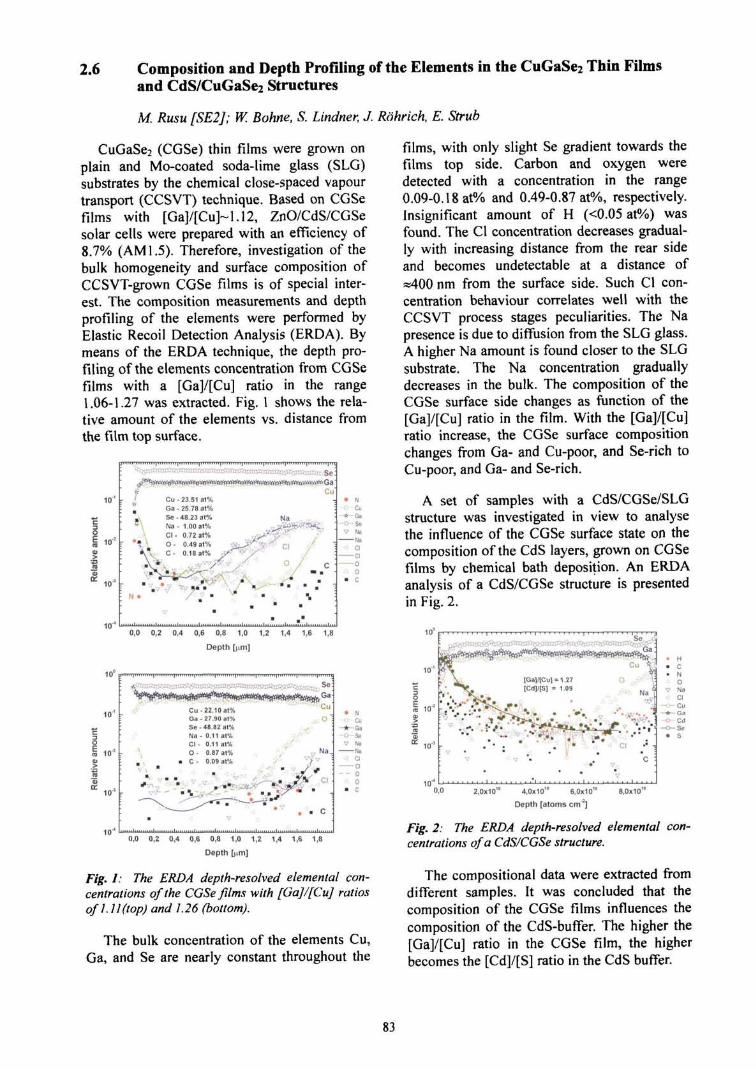
2.6 Composition and Depth Profiling of the Elements in the CuGaSe2 Thin Filmsand CdS/CuGaSe2 Structures
M. Rusu [SE2J; W. Bohne, S. Lindner, J. Rohrich, E. Strub
CuGaSe2 (CGSe) thin films were grown onplain and Mo-coated soda-lime glass (SLG)substrates by the chemical close-spaced vapourtransport (CCSVT) technique. Based on CGSefilms with [Ga]/[Cu]~1.12, ZnO/CdS/CGSesolar cells were prepared with an efficiency of8.7% (AM 1.5). Therefore, investigation of thebulk homogeneity and surface composition ofCCSVT-grown CGSe films is of special inter-est. The composition measurements and depthprofiling of the elements were performed byElastic Recoil Detection Analysis (ERDA). Bymeans of the ERDA technique, the depth pro-filing of the elements concentration from CGSefilms with a [Ga]/[Cu] ratio in the range1.06-1.27 was extracted. Fig. 1 shows the rela-tive amount of the elements vs. distance fromthe film top surface.
101 -
10'
1 0 T
Cu - 23.51 at%Ga - 25.78 at%Se-48.23 at%Na- 1.00 at%Cl - 0.72 at%O - 0.49 at%C- 0.18 at%
, * . ,.,,vv.
10
10°
101 -
Cu
- * - Ga
-o-Se
0,0 0,2 0,4 0,6 0,8 1,0 1,2 1,4
Depth [urn]
1,6 1,8
••
•
C u -Ga -S e -Na -C l -O -
• C -
. ;
22.10 a t *27.90 at%48.82 at%0.11 at%0.11 at%0.87 at%0.09 at%
' . % : • *
a.
' ;
Cu0 1
V NaNa
• : ClCl
- - o0
0,0 0,2 0,4 0,6 0,8 1,0 1,2 1,4 1,6 1,8
Depth [nm]
Fig. 1: The ERDA depth-resolved elemental con-centrations of the CGSe films with [Ga]/[Cu] ratiosof 1.11 (top) and 1.26 (bottom).
The bulk concentration of the elements Cu,Ga, and Se are nearly constant throughout the
films, with only slight Se gradient towards thefilms top side. Carbon and oxygen weredetected with a concentration in the range0.09-0.18 at% and 0.49-0.87 at%, respectively.Insignificant amount of H (<0.05 at%) wasfound. The Cl concentration decreases gradual-ly with increasing distance from the rear sideand becomes undetectable at a distance of=400 nm from the surface side. Such Cl con-centration behaviour correlates well with theCCSVT process stages peculiarities. The Napresence is due to diffusion from the SLG glass.A higher Na amount is found closer to the SLGsubstrate. The Na concentration graduallydecreases in the bulk. The composition of theCGSe surface side changes as function of the[Ga]/[Cu] ratio in the film. With the [Ga]/[Cu]ratio increase, the CGSe surface compositionchanges from Ga- and Cu-poor, and Se-rich toCu-poor, and Ga- and Se-rich.
A set of samples with a CdS/CGSe/SLGstructure was investigated in view to analysethe influence of the CGSe surface state on thecomposition of the CdS layers, grown on CGSefilms by chemical bath deposition. An ERDAanalysis of a CdS/CGSe structure is presentedin Fig. 2.
10°
10"1
10"'
•
[Ga]/[Cu] =[Cd]/[S] =
• • *
v .
•,
1.271.09
o. .-:»
1 Cl
V•
• N a J !
^ .c
* NO
v NaCl
—.- Cu—4—Ga
•"'- Cd
• S
0,0 2,0x10" 4,0x10" 6,0x10" 8,0x10"
Depth [atoms cm'2]
Fig. 2: The ERDA depth-resolved elemental con-centrations of a CdS/CGSe structure.
The compositional data were extracted fromdifferent samples. It was concluded that thecomposition of the CGSe films influences thecomposition of the CdS-buffer. The higher the[Ga]/[Cu] ratio in the CGSe film, the higherbecomes the [Cd]/[S] ratio in the CdS buffer.
83

2.7 Determination of the Composition of ILGAR-Zn(O,OH) - Layers
M. Bar, H.-J. Muffler, Ck-H. Fischer [SE2]; E. Strut, W. Bohne, S. Lindner, J. Rohrich
With Heavy-Ion ERDA (Elastic Recoil De-tection Analysis), concentrations of all chemicalelements in a sample can be investigated si-multaneously. As the ERDA principle [1] isbased on the classical Rutherford scatteringtheory, the area densities of a sample can beexactly determined without using standards.
ZnO layers deposited by the ILGAR proce-dure (Ion Layer Gas Reaction) are used aswindow extension layers in solar cell devicesyielding comparable efficiencies as conven-tional chalcopyrite cells (containing toxic CdS)[2]. Details of the ILGAR process can be foundin [3]. The performance stability of these cellsis very sensitive to the layer composition [2]. Inparticular, the oxide-hydroxide ratio is a crucialparameter, as ILGAR leads primarily toZn(OH)2 which is simultaneously thermallydehydrated to ZnO [4].
Thin layers of ILGAR-ZnO have been pre-pared at different process temperatures. For theanalysis, gold was chosen as the substratematerial to avoid contaminations of O or H atthe ZnO/substrate interface to enable an exactdetermination of the Zn:O:H stoichiometry. Thesamples have been examined with the Time-of-Flight (TOF) ERDA set-up at the Hahn-Meit-ner-Institute [5] using a beam of Au26+ ions at350 MeV with a current of approximately0.1 particle nA. The content of the main ele-ments Zn, O, and H was determined as well askind and concentration of impurities.
Impurities of C and N have been found, es-pecially in the samples prepared at lower tem-peratures. Obviously, these are contaminationsdue to the reagents used in the ILGAR process.If the layer compositions as determined byERDA are plotted in a ternary phase diagram(Fig. 1), most of them can be found close to theZnO/Zn(OH)2 line. The samples which hadbeen prepared at low temperatures were losingH and O during the irradiation. Because theERDA data are collected event-by-event, it ispossible to correct the data for these losses and
to re-extrapolate the H and O content to thebegin of the measurement time. Nevertheless,the samples prepared at room temperature lostmore than 90% of their H content which leadsto a higher uncertainty of the extrapolation.This uncertainty is indicated in the phase dia-gram by the grey circles.
Fig. 1: Ternary phase diagram of ILGAR-ZnOcompositions.
The overall results are in good agreementwith the assumption that the ILGAR layersconsist mainly of a mixture of ZnO andZn(OH)2.
[1] J.R. Tesmer, M. Nastasi, Handbook of ModernIon Beam Materials Analysis, Materials Re-search Society (1995).
[2] M. B3r, Ch.-H. Fischer, H.-J. Muffler, B. Leu-polt, Th.P. Niesen, F. Karg und M.Ch. Lux-Steiner, Proc. 29th IEEE Photovoltaic Specia-lists Conference (2002) 636.
[3] M. Bar, H.-J. Muffler, Ch.-H. Fischer, andM.Ch. Lux-Steiner, Sol. Energy Mater. Sol.Cells 67 (2000) 113.
[4] Ch.-H. Fischer, H.-J. Muffler, M. Bar, S. Fiech-ter, B. Leupolt, and M.Ch. Lux-Steiner, J.Cryst. Growth 241 (2002) 151.
[5] W. Bohne, J. ROhrich, G Roschert, Nucl. Instr.andMeth. B 136-138(1998)633.
84

2.8 Influence of in situ Annealing Temperature on the Properties of High PressureReactively Sputtered TiO2 Thin Films
E. San Andres, A. del Prado, I. Mdrtil, G Gonzalez-Diaz, [Dpto. de Fisica Aplicada III,Universidad Complutense de Madrid, Spain]; W. Bohne, J. Rohrich, E. Strub
At present, there is a strong effort devoted tothe search of a dielectric with high permittivity(high-k) with an excellent interface with Si, inorder to replace the standard SiO2 dielectricused as gate insulator in MOSFET devices.TiO2 is a promising candidate, since its dielec-tric constant is very high, with reported valuesup to 170. In this study we have deposited TiO2
thin films 84 nm thick on Si (100) by highpressure reactive sputtering (HPRS) from acertified TiO2 target. We have used only O2 assputtering gas with a chamber pressure of1 mbar. The substrate temperature was kept aslow as 200°C. However, previous FTIR resultsshowed that a thin SiO2 film was formed spon-taneously at the TiO2/Si interface. MIS deviceswere defined by e-beam evaporation of Al. Inorder to improve the electrical performance ofas-deposited devices, after deposition an in situannealing was performed during 1 h at tem-peratures between 600-900°C in O2 atmosphere.The composition of the films was determinedby HI-ERDA and the electrical performancewas studied by C-V measurements. From thesemeasurements the interface trap density can beobtained.
400
- 1 0 1 2
Gate Voltage (V)
Fig. 1: C-V characteristics of an as-deposited MISdevice (dashed lines) and a device in situ annealedat 900°C (solid lines).
In Fig. 1 the C-V characteristics of an as-deposited device and a device annealed at900°C are depicted. These measurementsshowed that as-deposited devices had poor
electrical characteristics, with Da values aboveH -210 eV c m , and the permittivity of the TiO2
layer was 33. A continuous improvement of thedevices was observed after annealing withincreasing temperature. With a temperature of900°C the optimum devices was obtained. TheC-V characteristics of one of these devices arealso shown in Fig. 1. For these devices theminimum of D,, decreased to 1.2x10" eV'cm"2
and the k value of the TiO2 film increased to 88.These values are among the best ones reportedfor high-k dielectrics.
200 300 400 500 600 700 800 900
In situ annealing temperature (°C)
o.o
Fig. 2: O to Ti ratio (left) and H concentration(right) as a function of in situ annealing tempera-ture.
In order to study whether this improvementmay be linked with a change in composition,the films were measured by HI-ERDA. InFig. 2 it can be observed that the O to Ti ratioremained almost constant when varying theannealing temperature, with a mean value of2.17. This indicates that the films were stoichi-ometric TiO2, and the excess of O originatedfrom the interfacial SiO2 layer. There was also aslight amount of H in the as-deposited samples(Fig. 2), but, it decreases to values close to thedetection limit when annealing at 600°C, so itcannot account for the huge electrical im-provement. Thus, this improvement must belinked to an improvement of the structure andnot to a variation in the composition of thefilms. Further work with the ion-beam analysisgroup at HMI is needed to elucidate this ques-tion.
85
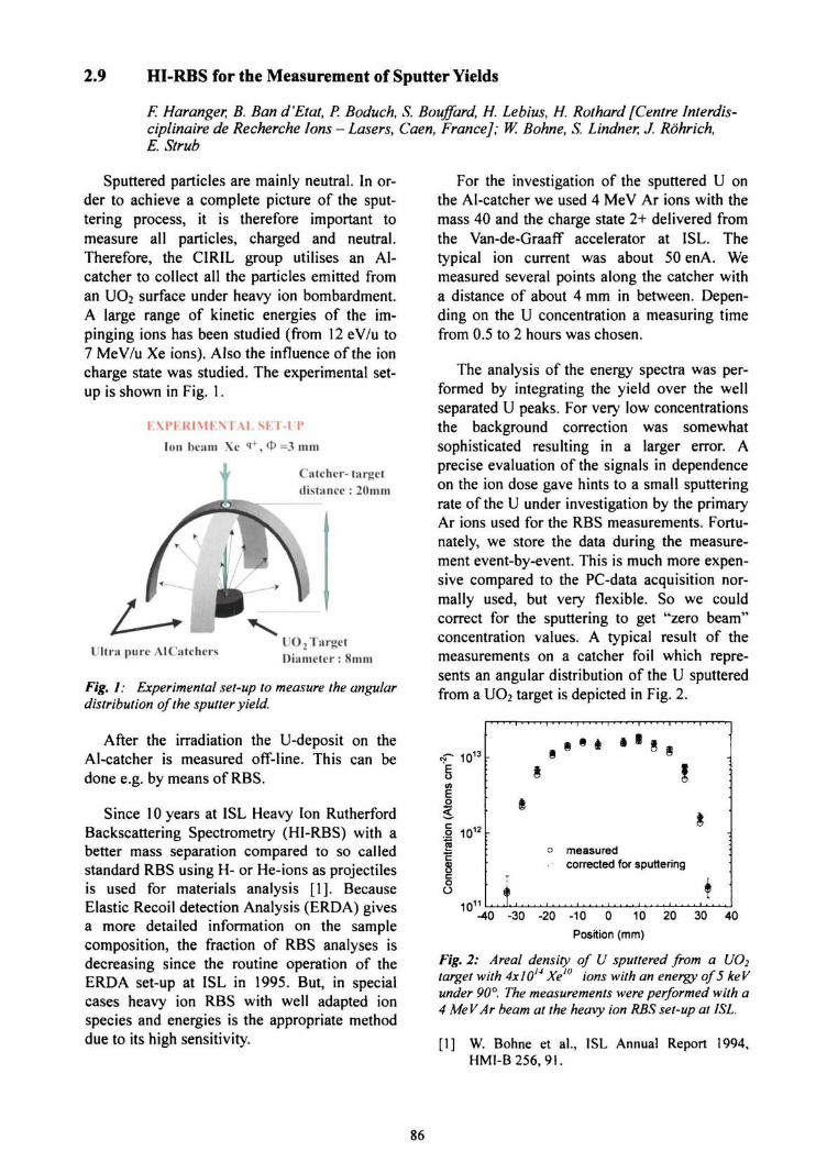
2.9 HI-RBS for the Measurement of Sputter Yields
F. Haranger, B. Ban d'Etat, P. Boduch, S. Bouffard, H. Lebius, H. Rothard [Centre Interdis-ciplinaire de Recherche Ions - Lasers, Caen, France]; W. Bohne, S. Lindner, J. Rohrich,E. Strub
Sputtered particles are mainly neutral. In or-der to achieve a complete picture of the sput-tering process, it is therefore important tomeasure all particles, charged and neutral.Therefore, the C1RIL group utilises an Al-catcher to collect all the particles emitted froman UO2 surface under heavy ion bombardment.A large range of kinetic energies of the im-pinging ions has been studied (from 12 eV/u to7 MeV/u Xe ions). Also the influence of the ioncharge state was studied. The experimental set-up is shown in Fig. 1.
1 ..\I'I:UIMI;NTAI. SFT-IP
Ion beam Xe i+, O =3 mm
Catcher- targetdistance : 20mm
Ultra pure AlCatchcrs UO 2 TargetDiameter : 8mm
Fig. 1: Experimental set-up to measure the angulardistribution of the sputter yield.
After the irradiation the U-deposit on theAl-catcher is measured off-line. This can bedone e.g. by means of RBS.
Since 10 years at ISL Heavy Ion RutherfordBackscattering Spectrometry (HI-RBS) with abetter mass separation compared to so calledstandard RBS using H- or He-ions as projectilesis used for materials analysis [1]. BecauseElastic Recoil detection Analysis (ERDA) givesa more detailed information on the samplecomposition, the fraction of RBS analyses isdecreasing since the routine operation of theERDA set-up at ISL in 1995. But, in specialcases heavy ion RBS with well adapted ionspecies and energies is the appropriate methoddue to its high sensitivity.
For the investigation of the sputtered U onthe Al-catcher we used 4 MeV Ar ions with themass 40 and the charge state 2+ delivered fromthe Van-de-Graaff accelerator at ISL. Thetypical ion current was about 50 enA. Wemeasured several points along the catcher witha distance of about 4 mm in between. Depen-ding on the U concentration a measuring timefrom 0.5 to 2 hours was chosen.
The analysis of the energy spectra was per-formed by integrating the yield over the wellseparated U peaks. For very low concentrationsthe background correction was somewhatsophisticated resulting in a larger error. Aprecise evaluation of the signals in dependenceon the ion dose gave hints to a small sputteringrate of the U under investigation by the primaryAr ions used for the RBS measurements. Fortu-nately, we store the data during the measure-ment event-by-event. This is much more expen-sive compared to the PC-data acquisition nor-mally used, but very flexible. So we couldcorrect for the sputtering to get "zero beam"concentration values. A typical result of themeasurements on a catcher foil which repre-sents an angular distribution of the U sputteredfrom a UO2 target is depicted in Fig. 2.
•r io13io1
(A
O
oO
10'
•
measuredcorrected for sputtering
-40 -30 -20 -10 0 10 20 30 40
Position (mm)
Fig. 2: Area! density of U sputtered from a UO2target with 4x10¹⁴ Xe'° ions with an energy of 5 ke Vunder 90°. The measurements were performed with a4 MeV Ar beam at the heavy ion RBS set-up at ISL.
[1] W. Bohne et al., ISL Annual Report 1994,HMI-B256, 9!.
86
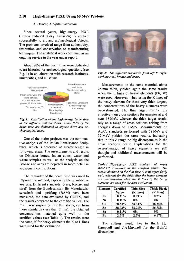
2.10 High-Energy PIXE Using 68 MeV Protons
A. Denker, J. Opitz-Coutureau
Since several years, high-energy PIXE(Proton Induced X-ray Emission) is appliedsuccessfully to art and archaeological objects.The problems involved range from authenticity,restoration and conservation to manufacturingtechniques. The analytical work continued as anongoing service in the year under report.
About 80% of the beam time were dedicatedto art historical or archaeological questions (seeFig. 1) in collaboration with research institutes,universities, and museums.
quantitative analyses,ISL/Uni Guelph
Indian coins, water and
waste samples,Saha Inst. of nuclear
physics, Kolkatta. India
Dinosaur bones, TU
Wien
Bronze age axes,Landesamt furDenkmalpflegeBrandenburg
Italian Renaissance
sculpturesSkulpturensammlung,
Berlin
gold rings, Landesamt
fur DenkmalpflegeBrandenburg
Fig. 1: Distribution of the high-energy beam timeto the different collaborations. About 80% of thebeam time are dedicated to objects d'art and ar-chaeological items.
One of the major projects was the continua-tive analysis of the Italian Renaissance Sculp-tures, which is described at greater length infollowing essay. The measurements and resultson Dinosaur bones, Indian coins, water andwaste samples as well as the analysis on theBronze age axes are depicted in more detail insubsequent contributions.
The reminder of the beam time was used toimprove the method, especially the quantitativeanalysis. Different standards (brass, bronze, andsteel) from the Bundesanstalt fur Materialwis-senschaft und -priifung (BAM) have beenmeasured, the data evaluated by GUPIX, andthe results compared to the certified values. Theresult was surprising: For thin slices, cut fromthese standards (less than 2 mm), the obtainedconcentrations matched quite well to thecertified values (see Table 1). The results werethe same, if for heavy elements the K or L lineswere used for the evaluation.
Fig. 2: The different standards, from left to right:working steel, bronze and brass.
Measurements on the same material, about25 mm thick, yielded again the same resultswhen the L lines of heavy elements (Pb, W)were used. However, when using the K lines ofthe heavy element for these very thick targets,the concentrations of the heavy elements wereoverestimated. The thin target results relyeffectively on cross sections for energies at andnear 68 MeV, whereas the thick target resultsrely on a range of cross sections arising fromenergies down to 8 MeV. Measurements onAg/Cu standards performed with 68 MeV and32 MeV yielded the same results, indicatingthat in this Z range no big discrepancies in thecross sections occur. Explanations for theoverestimation of heavy elements are stillthought and additional measurements will beperformed.
Table 1: High-energy PIXE analysis of brassBAM375 compared to the certified values. Theresults obtained on the thin slice (2 mm) agree fairlywell, whereas for the thick slice the heavy elementsare overestimated when the K lines of the heavyelements are used for the data evaluation.
Element
FeNiCuZnSnPb
CertifiedValue0.21%0.11%
58.32%38.02%
0.21%2.9%
Thin Slice(K lines)0.33%0%
58.34%38.23%
0%2.9%
Thick Block(K lines)
0.2%0%
56.55%36.78%
0%6.17%
The authors would like to thank I.L.Campbell and J.A Maxwell for the fruitfuldiscussions.
87
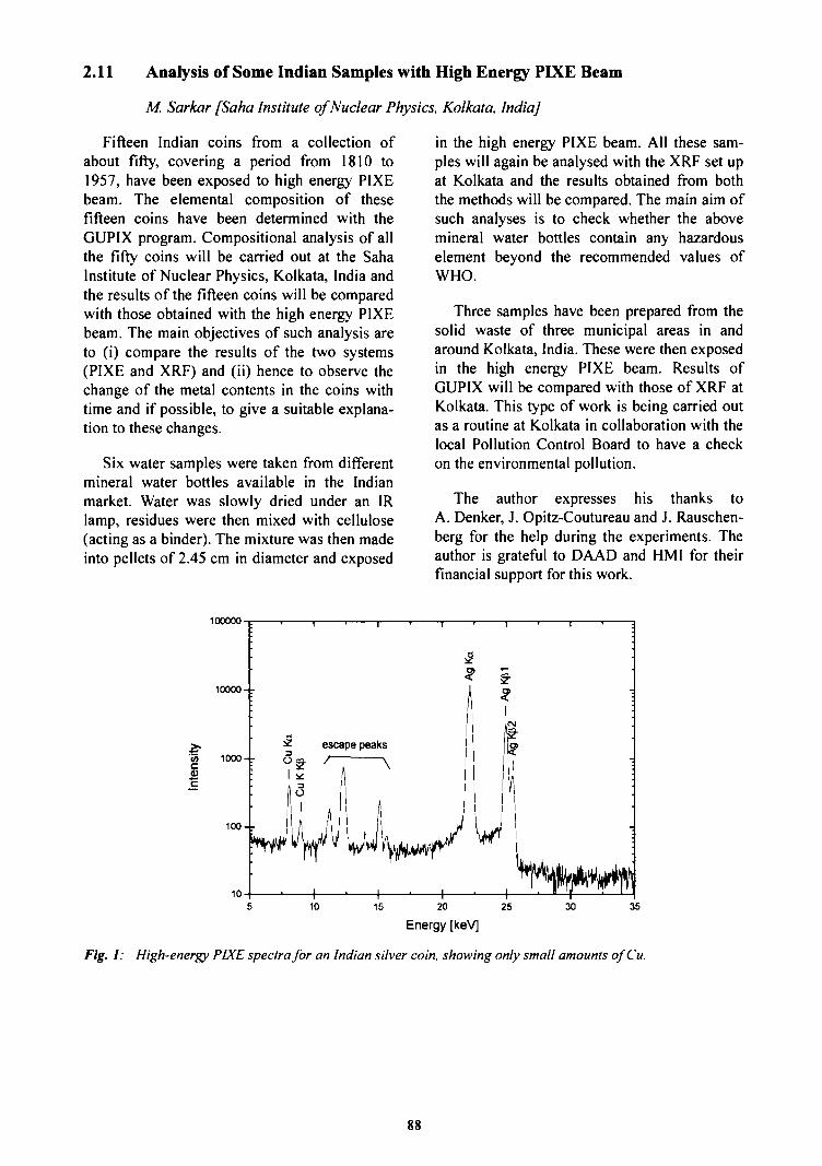
2.11 Analysis of Some Indian Samples with High Energy PIXE Beam
M. Sarkar [Saha Institute of Nuclear Physics, Kolkata, India]
Fifteen Indian coins from a collection ofabout fifty, covering a period from 1810 to1957, have been exposed to high energy PIXEbeam. The elemental composition of thesefifteen coins have been determined with theGUPIX program. Compositional analysis of allthe fifty coins will be carried out at the SahaInstitute of Nuclear Physics, Kolkata, India andthe results of the fifteen coins will be comparedwith those obtained with the high energy PIXEbeam. The main objectives of such analysis areto (i) compare the results of the two systems(PIXE and XRF) and (ii) hence to observe thechange of the metal contents in the coins withtime and if possible, to give a suitable explana-tion to these changes.
Six water samples were taken from differentmineral water bottles available in the Indianmarket. Water was slowly dried under an IRlamp, residues were then mixed with cellulose(acting as a binder). The mixture was then madeinto pellets of 2.45 cm in diameter and exposed
in the high energy PIXE beam. All these sam-ples will again be analysed with the XRF set upat Kolkata and the results obtained from boththe methods will be compared. The main aim ofsuch analyses is to check whether the abovemineral water bottles contain any hazardouselement beyond the recommended values ofWHO.
Three samples have been prepared from thesolid waste of three municipal areas in andaround Kolkata, India. These were then exposedin the high energy PIXE beam. Results ofGUPIX will be compared with those of XRF atKolkata. This type of work is being carried outas a routine at Kolkata in collaboration with thelocal Pollution Control Board to have a checkon the environmental pollution.
The author expresses his thanks toA. Denker, J. Opitz-Coutureau and J. Rauschen-berg for the help during the experiments. Theauthor is grateful to DAAD and HMI for theirfinancial support for this work.
100000
1010 15 20 25
Energy [keV]
30 35
Fig. 1: High-energy PIXE spectra for an Indian silver coin, showing only small amounts ofCu.
88
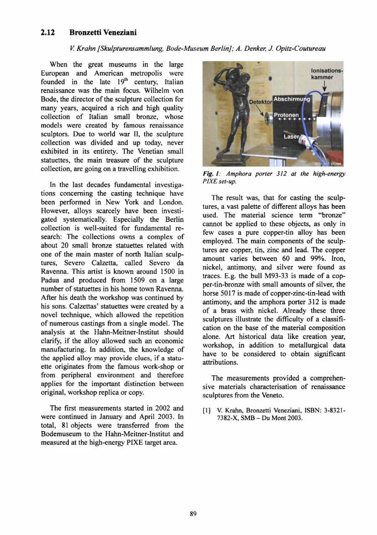
2.12 Bronzetti Veneziani
V, Krahn [Skulpturensammlung, Bode-Museum Berlin]; A. Denker, J. Opitz-Coutureau
When the great museums in the largeEuropean and American metropolis werefounded in the late 19th century, Italianrenaissance was the main focus. Wilhelm vonBode, the director of the sculpture collection formany years, acquired a rich and high qualitycollection of Italian small bronze, whosemodels were created by famous renaissancesculptors. Due to world war II, the sculpturecollection was divided and up today, neverexhibited in its entirety. The Venetian smallstatuettes, the main treasure of the sculpturecollection, are going on a travelling exhibition.
In the last decades fundamental investiga-tions concerning the casting technique havebeen performed in New York and London.However, alloys scarcely have been investi-gated systematically. Especially the Berlincollection is well-suited for fundamental re-search: The collections owns a complex ofabout 20 small bronze statuettes related withone of the main master of north Italian sculp-tures, Severo Calzetta, called Severo daRavenna. This artist is known around 1500 inPadua and produced from 1509 on a largenumber of statuettes in his home town Ravenna.After his death the workshop was continued byhis sons. Calzettas' statuettes were created by anovel technique, which allowed the repetitionof numerous castings from a single model. Theanalysis at the Hahn-Meitner-Institut shouldclarify, if the alloy allowed such an economicmanufacturing. In addition, the knowledge ofthe applied alloy may provide clues, if a statu-ette originates from the famous work-shop orfrom peripheral environment and thereforeapplies for the important distinction betweenoriginal, workshop replica or copy.
The first measurements started in 2002 andwere continued in January and April 2003. Intotal, 81 objects were transferred from theBodemuseum to the Hahn-Meitner-Institut andmeasured at the high-energy PIXE target area.
lonisations-kammer
Fig. 1: Amphora porter 312 at the high-energyPIXE set-up.
The result was, that for casting the sculp-tures, a vast palette of different alloys has beenused. The material science term "bronze"cannot be applied to these objects, as only infew cases a pure copper-tin alloy has beenemployed. The main components of the sculp-tures are copper, tin, zinc and lead. The copperamount varies between 60 and 99%. Iron,nickel, antimony, and silver were found astraces. E.g. the bull M93-33 is made of a cop-per-tin-bronze with small amounts of silver, thehorse 5017 is made of copper-zinc-tin-lead withantimony, and the amphora porter 312 is madeof a brass with nickel. Already these threesculptures illustrate the difficulty of a classifi-cation on the base of the material compositionalone. Art historical data like creation year,workshop, in addition to metallurgical datahave to be considered to obtain significantattributions.
The measurements provided a comprehen-sive materials characterisation of renaissancesculptures from the Veneto.
[1] V. Krahn, Bronzetti Veneziani, ISBN: 3-8321-7382-X, SMB - Du Mont 2003.
89
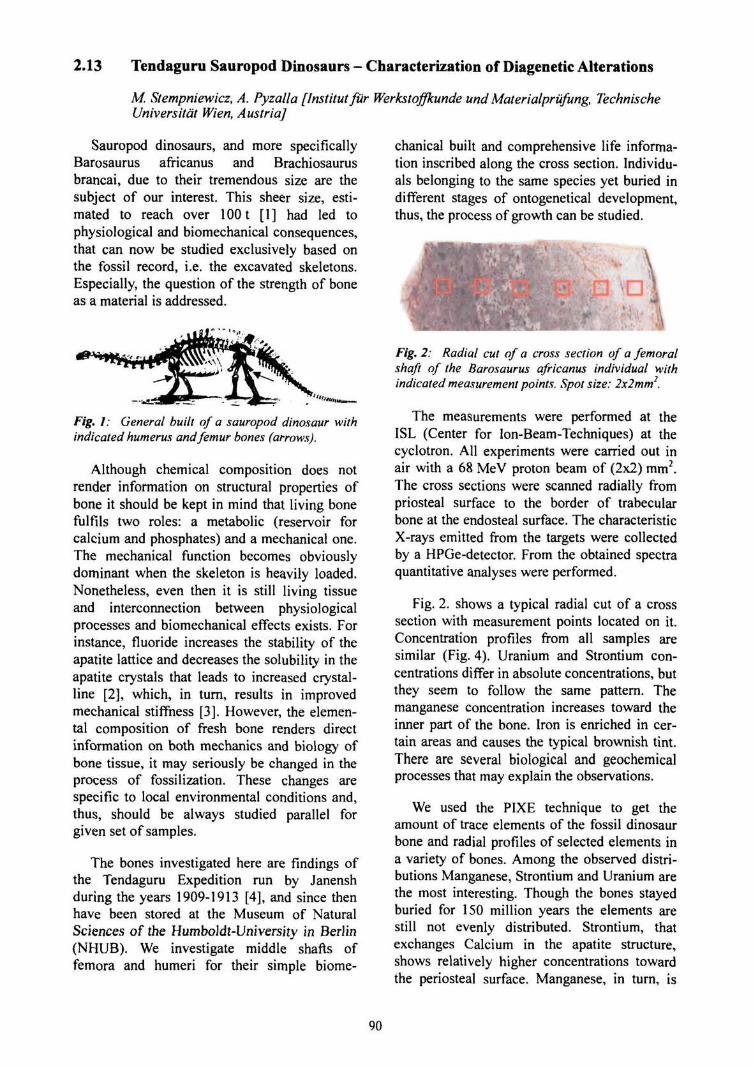
2.13 Tendagum Sauropod Dinosaurs - Characterization of Diagenetic Alterations
M. Stempniewicz, A. Pyzalla [Institutfur Werkstoffkunde und Mater ialprufung, TechnischeUniversitdt Wien, Austria]
Sauropod dinosaurs, and more specificallyBarosaurus africanus and Brachiosaurusbrancai, due to their tremendous size are thesubject of our interest. This sheer size, esti-mated to reach over 1001 [1] had led tophysiological and biomechanical consequences,that can now be studied exclusively based onthe fossil record, i.e. the excavated skeletons.Especially, the question of the strength of boneas a material is addressed.
Fig. 1: General built of a sauropod dinosaur withindicated humerus and femur bones (arrows).
Although chemical composition does notrender information on structural properties ofbone it should be kept in mind that living bonefulfils two roles: a metabolic (reservoir forcalcium and phosphates) and a mechanical one.The mechanical function becomes obviouslydominant when the skeleton is heavily loaded.Nonetheless, even then it is still living tissueand interconnection between physiologicalprocesses and biomechanical effects exists. Forinstance, fluoride increases the stability of theapatite lattice and decreases the solubility in theapatite crystals that leads to increased crystal-line [2], which, in turn, results in improvedmechanical stiffness [3]. However, the elemen-tal composition of fresh bone renders directinformation on both mechanics and biology ofbone tissue, it may seriously be changed in theprocess of fossilization. These changes arespecific to local environmental conditions and,thus, should be always studied parallel forgiven set of samples.
The bones investigated here are findings ofthe Tendaguru Expedition run by Janenshduring the years 1909-1913 [4], and since thenhave been stored at the Museum of NaturalSciences of the Humboldt-University in Berlin(NHUB). We investigate middle shafts offemora and humeri for their simple biome-
chanical built and comprehensive life informa-tion inscribed along the cross section. Individu-als belonging to the same species yet buried indifferent stages of ontogenetical development,thus, the process of growth can be studied.
Fig. 2: Radial cut of a cross section of a femoralshaft of the Barosaurus africanus individual withindicated measurement points. Spot size: 2x2mm2.
The measurements were performed at theISL (Center for lon-Beam-Techniques) at thecyclotron. All experiments were carried out inair with a 68 MeV proton beam of (2x2) mm2.The cross sections were scanned radially frompriosteal surface to the border of trabecularbone at the endosteal surface. The characteristicX-rays emitted from the targets were collectedby a HPGe-detector. From the obtained spectraquantitative analyses were performed.
Fig. 2. shows a typical radial cut of a crosssection with measurement points located on it.Concentration profiles from all samples aresimilar (Fig. 4). Uranium and Strontium con-centrations differ in absolute concentrations, butthey seem to follow the same pattern. Themanganese concentration increases toward theinner part of the bone. Iron is enriched in cer-tain areas and causes the typical brownish tint.There are several biological and geochemicalprocesses that may explain the observations.
We used the PIXE technique to get theamount of trace elements of the fossil dinosaurbone and radial profiles of selected elements ina variety of bones. Among the observed distri-butions Manganese, Strontium and Uranium arethe most interesting. Though the bones stayedburied for 150 million years the elements arestill not evenly distributed. Strontium, thatexchanges Calcium in the apatite structure,shows relatively higher concentrations towardthe periosteal surface. Manganese, in turn, is
90

present only in the endosteal regions (withinpores). The absence of Manganese in the cortexspeaks for minor diagenetical alterations of thebone as this element is not incorporated in thebiological processes during lifetime.
10' F
i
i1" • '
. ji
=2LL
3 i i D 3
i i ' '
,
.....
Baro
? m0 3 i
I
i
o -i ,
X»250-x=258x=266x=274
s
1 ' 1 ~
x=254x=262x=270
§•
i :
••'•'• • ^ %
i , i '10' -
5 10 15 20 25 30 35 40 45
Energy (KeV)
Fig. 3: PIXE spectrum recorded on different pointsof one section (Barosaurus africanus femur).
In our previous studies of the Tendaguruskeletons we have determined the crystallo-graphic structure of the bone mineral, its habitand density [5]. In addition, the application ofPIXE yielded concentrations of various ele-ments and their distribution of those over thesample. From the results we conclude that thechemical alterations occurred (Strontium incor-poration into bone mineral) but they were notheavy (Manganese stays in the pores and doesnot infiltrate the bone cortex). Therefore, thebone mineral particles are not fully recrystal-lized and further analyses of the crystallites canbe interpreted in contexts of individual's lifehistory.
2000
1500 -
1000
2oo
10 20 30Distance from the surface
periosteal endoste
Fig. 4: Representative elemental distributionsobtained by scanning a radial cut of a cross section(Barosaurus africanus femur).
The authors gratefully acknowledge Dr. An-drea Denker from ISL for her invaluable helpduring and after experiments.
[1] J. Peczkis, "Implications of body mass esti-mates for dinosaurs" Journal of Vertebrate Pa-leontology Vol. 14 (1994) 520-533.
12] M.D. Grynpas, "Fluoride Effects on BoneCrystal" Journal of Bone and Mineral ResearchVol. 5(1990)S169-S175.
[3] J.D- Currey, "Bones. Structure and Mechanics"Princeton University Press 2002.
[4] W-D. Heinrich, "The Taphonomy of Dinosaursfrom the Upper Jurrasic of Tendaguru (Tanza-nia) Based on Field Sketches of the GermanTendaguru Expedition (1909-1913)" Mitt. Mus.Nat. kd. Berl., Geowiss. Vol. 2 (1999) 25-61.
[5] M. Stempniewicz, B- Camin, A. Pyzalla,Preliminary Investigation of fossil bone: XRDand XPS study, Proceedings of the 13* Confer-ence of European Society of Biomechanics,Acta of Bioengineering and Biomechanics, Vol4(2002)Suppl.l.
91
2.14 The Late Bronze Age Hoard from Lebus (800 BC) - Spectrometric Research of aHoard of the Lusatian Culture in Brandenburg
F. Schopper [Brandenburgisches Landesamtfur Denkmalpflege und ArchaologischesLandesmuseum, Frankfurt (Oder)]
Element analysis in central European latebronze age archaeology
The question of element composition of thealloys used by prehistoric craftsmen is one ofthe oldest in prehistoric archaeology. Through-out at least the last two centuries there wereseveral attempts to analyse this mainly copperbased alloys, which are in general just calledbronze by archaeologists. In Germany thoseattempts started in the late 18th century andwent on until the 19th and earlier 20th cen-tury [1-3].
Reconsidering older ideas, discussions andproposals [4-8] of the 1950th, 1960th and1970th as well as the now available bettertechniques a lot of metal objects made fromcopper or bronze were analysed during the last15 years. But those objects belonged nearlyexclusively to the later Neolithic and the earlierbronze age periods (3000-1500 BC).
The primary research goal was to identifygroups of raw material by trace elements todefine so called raw-material provinces and tofind the origins of the used ores [9-11]. Espe-cially for the early bronze age it was indeedpossible to define significant alloys and theirareas of distribution.
Metal artefacts from the younger and latebronze age (1300-800 BC) have not beenanalysed up to a greater amount, because theydid not fit in the programs of investigation.Archaeologists believed that in this youngerperiods it would be senseless to look for traceelements. This was due to our theories onmetalwork and metal exchange. The back goingamount of bronze objects especially in the latebronze age graves seems to reflect problems inthe supply of raw material and so it was sup-posed that the bronze was reused by meltingolder objects and casting new modern ones. Thewidely spread scrap hoards seem to proof thistheory [12]. The remelted material was sup-posed to be mixed up to much to give muchsense to element analysis.
Another impediment was and is the probing.Older methods of element analysis on thesurface of the objects seemed to be to inaccu-rate, because of enrichment and diminution ofcertain elements during cooling and withincorrosion process. On the other hand museumdirectors are never fond of drilling ancientobjects to get bronze spans from the metal core,especially if the results are supposed to bemarginal.
Nevertheless single hoards were analysedhere and there by different laboratories applyingdifferent techniques, destructive and non de-structive and dealing with material of differentage. It was always a problem to give strikinginterpretation to this rare in inhomogeneousdata base. Shortly bigger series of data werepublished for Switzerland [13], Slovenia [14]and the Czech Republic [15,16].
The results are quite encouraging. Based onthe elements arsenic, antimony and nickel forSwitzerland seven groups of alloys could beestablished which were used during certainperiods between 1400 and 800. While slightlydifferent in some aspect the results from Slove-nia do confirm this succession of alloy groups.The Czech investigation gives the impression oftwo material groups simultaneously used in onetime by cultural distinguishable groups. Sogroups of copper alloys can be interpreted aswell chronological as regional. On the otherhand the analysis of elements gives us betterideas how the prehistoric craftsmen worked andhow skilled there were creating certain alloyson purpose. Furthermore we can get ideas of thedevelopment of mining skills.
The hoard from Lebus and its archaeologicalcontext
In the summer of 2003 a big depot of latebronze age metal objects was discovered on thehilltop of Lebus. It consists of two heavy rings,a sword fragment, the peace of an plano-convexingot so called "Gusskuchen", 17 winged axesand not less than 87 socket axes. All in allalmost 23 kg, which makes the hoard the
92

biggest metal find from late bronze age period(Period V) not only in Brandenburg but in northeastern Germany and Poland as well.
Fig. 1: The Hoard of Lebus (Photo: D. Sommer,BLDAM).
Fragments of a ceramic vessel with littlepieces of typical green bronze dust sticking toit's inner side show that the bronze was buriedin a storage pot. The majority of the socket axesshows the characteristics of the so called "Lau-sitzer Tiillenbeile" and is therefore part ofregional production. But you can distinguishalso strangers within this group of axes. Deco-ration and form proofs there relation to socketaxes typical in the middle Danubian areas suchas Moravia, Hungaria, Slovakia and it's neigh-bourhoods. In other cases the axes are compa-rable with objects from northwest Europe(Normandy, southern England) or the Balticarea (former Eastern Prussia). The winged axesare of a wide spread form, which is supposed tobe of southern German or Swiss origin. Reallyexceptional is a heavy winged axe with promi-nent shoulders. Those examples are very rareand can be found especially in the alpine area.While the rings are of a form well known in thenorthern parts of central Europe, the sword
fragment is again not indigenous to Branden-burg. It has to be connected with swords fromAuvernier type family (Auvernier, Hostomice,Stolln). Those weapons are a popular importfrom southern areas of central Europe. All in allbeside the majority of bronze objects indige-nous to Lebus and it's cultural context, a lot offoreign forms, probably imports, became appar-ent.
This brings us to the local and cultural con-text of the hoard. It was found in an big forti-fied hilltop settlement. Wherever archaeologicalresearch was done there, typical fragments ofceramic were found. The hillfort seemed tohave a central function in the regional latebronze age settlement pattern, comparable withthe city of Frankfurt in medieval and modemtimes. The foreign bronze objects can be re-garded as results of wide spread trading con-tacts not only along the river Oder. The almost23 kg of metal were of course of considerablewealth, in particular if you take in concern thatthere are no usable metal ores in Brandenburgand it's neighbourhood - in fact in whole north-ern Central Europe and northern Europe at all.
Their deposition in the ground is mostprobably a sacrifice to certain gods or powers.Anyway the hoard of Lebus carries a lot ofinformation of ancient metalwork, trading, widedistant communication and even society organi-sation.
Analysis of the Lebus objects
Concerning the described situation severalgoals can be put forward for analysing thebronze objects from Lebus using high-energyPIXE. The technique was so far not applied onprehistoric research. Although it is able to solvetwo main problems in element analysis ofancient bronzes. First it is non destructive anddiminishes conservatory concerns. Second, theanalytical depth of the technique will reduceproblems of enrichment and diminution ofcertain elements during cooling and withincorrosion on the surface.
107 objects which were buried in one time inone place are a considerable large group and theresults of the analysis can on the first handestablish a data basis for late bronze age Lusa-tian culture objects. This is important to com-
93

pare and combine the results of single objectsand smaller groups [17-19].
On the other hand there are a few questionsto be asked. Do the results fit in the scheme oflate bronze age alloy types as they were definedfor other areas? Are due to the origin of objectsspecial alloy groups used? Are all objects reallyuseable tools or have they got the function ofingots or as a kind of pre money currency?
The measurements on the axes have beencarried out at the end of 2003, hence, the dataare still under evaluation. Surely the data fromLebus will be able to advance the discussion inmany aspects of late bronze age metalwork.
[1] J. Pickel, Beschreibung verschiedener Altertu-mer welche in Grabhtigeln alter Deutscher beyEichstatt sind gefunden worden (1789).
[2] A. Wimmer, Untersuchungen dreier celtischerBeile als Beitrag zur Geschichte der antikenBronce. Kunst- und Gewerbeblatt des poly-technischen Vereins ftir das Konigreich Bayern37(1851)630-636.
[3] H. Gummel, Forschungsgeschichte in Deutsch-land. Die Urgeschichtsforschung und ihrehistorische Entwicklung in den KulturstaatenderErde 1 (Berlin 1938).
[4] H. Otto, W. Witter, Handbuch der altestenvorgeschichtlichen Metallurgie in Mitteleuropa(Leipzig 1952).
[5] S. Junghans, E. Sangmeister, M. Schroder,Metallanalysen kupferzeitlicher und friihbron-zezeitlicher Bodenfunde aus Europa. Studienzu den Anfangen der Metallurgie 1 (Berlin1960).
[6] S. Junghans, E. Sangmeister, M. Schroder,Kupfer und Bronze in der friihen Metallzeit Eu-ropas. Die Metallgruppen beim Stand von12000 Analysen. Studien zu den Anfangen derMetallurgie 2 (Berlin 1968) 1-3.
[7] S. Junghans, E. Sangmeister, M. Schroder,Kupfer und Bronze in der friihen Metallzeit Eu-ropas. Studien zu den Anf&ngen der Metallur-gie 2 (Berlin 1974)4.
[8] R. Krause, Zur Entwicklung der frilhbronze-zeitlichen Metallurgie nordlich der Alpen. In:B. Hansel (Hrsg.), Mensch und Umwelt in derBronzezeit Europas (Kiel 1998) 163-192.
[9] R. Krause, E. Pernicka, Das neue StuttgarterMetallanalyseprojekt "SMAP". Arch. Nach-richtenbl. 1,3(1996)271-291.
[10] J. Lutz, I. Matuschik, E. Pernicka, K. Rass-mann, Die friihesten Metallfunde in Mecklen-burg-Vorpommern im Lichte neuer Metall-analysen. Jahrb. Bodendenkmalpfl. Mecklen-burg- Vorpommern (1997, 1998)41-67.
[11] E. Pernicka, Gewinnung und Verbreitung derMetalle in prahistorischer Zeit. Jahrb. RGZM37(1990)21-129.
[12] A. Jockenhovel, Struktur und Organisation derMetallverarbeitung in urnenfelderzeitlichenSiedlungen Siiddeutschlands. Veroffentlichun-gen des Museums fiir Ur- und FriihgeschichtePotsdam (1986) 213-234.
[13] V. Rychner, Arsenic, nickel et antimoine. lineapproche de la metallurgie du Bronze moyen etfinal en Suisse par l'analyse spectrometrique(avec la collaboration de N. Klantschi). Cahiersd'archeologie romande (1995) 63-64.
[14] N. Trampuz-Orel, Spektrogramicne raziskavedepojskih najdb pozne bronaste dobe. In: B.Terzan (Hrsg.), Depojske in posamezne ko-vinske najdbe bakrene in bronaste dobe na Slo-venskem. Narodni Muzej Catalogi et Mono-graphiae (Ljubljana 1996) 165-242.
[15] J. Frana, L. Jiran, A. Mastalka, V. Moucha,Artefacts of copper an copper alloys in prehis-toric Bohemia from the viewpoint of analysesof element composition. Pamatky Arch. Sup-plementum 3 (1995) 127-296.
[16] J. Frana, L. Jiran, V. Moucha, P. Samkot, Arte-facts of copper an copper alloys in prehistoricBohemia from the viewpoint of analyses ofelement composition II. Pamatky Arch.Supplementum 8 (1997).
[17] J. Riederer, Die Metallanalyse der Schwerterdes Hortfundes von Berlin-Buch. Acta Praehist.et Arch. Berlin 26/27 (1994/1995) 129-131.
[18] J. Riederer, J. Lutz, Zu den Metallanalysen derBronzen des GefUBdepots aus Saalegebiet. ActaPraehist. et Arch. Berlin 29 (1997) 41-67.
[19] M. Gackle, W. Nitzschke, K. Wagner, EinBronzedepotfund von Fienstedt (Saalkreis).Archaologische und spektralanalytische Aus-wertung. Jahresschr. f. Mitteldt. Vorgesch. 71(1988)57-90.
94

3. Applications
95

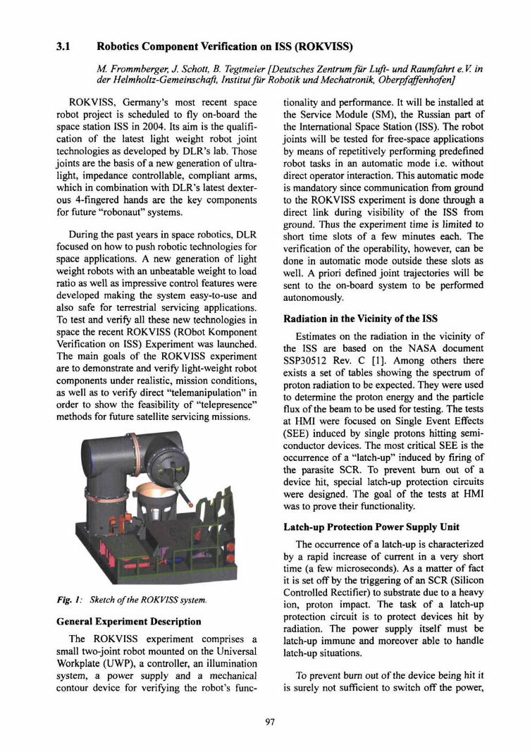
3.1 Robotics Component Verification on ISS (ROKVISS)
M. Frommberger, J. Schott, B. Tegtmeier [Deutsches Zentrumfur Luft- und Raumfahrt e. V. inder Helmholtz-Gemeinschaft, Institutfur Robotik und Mechatronik, OberpfqffenhofenJ
ROKVISS, Germany's most recent spacerobot project is scheduled to fly on-board thespace station ISS in 2004. Its aim is the qualifi-cation of the latest light weight robot jointtechnologies as developed by DLR's lab. Thosejoints are the basis of a new generation of ultra-light, impedance controllable, compliant arms,which in combination with DLR's latest dexter-ous 4-fingered hands are the key componentsfor future "robonaut" systems.
During the past years in space robotics, DLRfocused on how to push robotic technologies forspace applications. A new generation of lightweight robots with an unbeatable weight to loadratio as well as impressive control features weredeveloped making the system easy-to-use andalso safe for terrestrial servicing applications.To test and verify all these new technologies inspace the recent ROKVISS (RObot KomponentVerification on ISS) Experiment was launched.The main goals of the ROKVISS experimentare to demonstrate and verify light-weight robotcomponents under realistic, mission conditions,as well as to verify direct "telemanipulation" inorder to show the feasibility of "telepresence"methods for future satellite servicing missions.
Fig. 1: Sketch of the ROKVISS system.
General Experiment Description
The ROKVISS experiment comprises asmall two-joint robot mounted on the UniversalWorkplate (UWP), a controller, an illuminationsystem, a power supply and a mechanicalcontour device for verifying the robot's func-
tionality and performance. It will be installed atthe Service Module (SM), the Russian part ofthe International Space Station (ISS). The robotjoints will be tested for free-space applicationsby means of repetitively performing predefinedrobot tasks in an automatic mode i.e. withoutdirect operator interaction. This automatic modeis mandatory since communication from groundto the ROKVISS experiment is done through adirect link during visibility of the ISS fromground. Thus the experiment time is limited toshort time slots of a few minutes each. Theverification of the operability, however, can bedone in automatic mode outside these slots aswell. A priori defined joint trajectories will besent to the on-board system to be performedautonomously.
Radiation in the Vicinity of the ISS
Estimates on the radiation in the vicinity ofthe ISS are based on the NASA documentSSP30512 Rev. C [1]. Among others thereexists a set of tables showing the spectrum ofproton radiation to be expected. They were usedto determine the proton energy and the particleflux of the beam to be used for testing. The testsat HMI were focused on Single Event Effects(SEE) induced by single protons hitting semi-conductor devices. The most critical SEE is theoccurrence of a "latch-up" induced by firing ofthe parasite SCR. To prevent burn out of adevice hit, special latch-up protection circuitswere designed. The goal of the tests at HMIwas to prove their functionality.
Latch-up Protection Power Supply Unit
The occurrence of a latch-up is characterizedby a rapid increase of current in a very shorttime (a few microseconds). As a matter of factit is set off by the triggering of an SCR (SiliconControlled Rectifier) to substrate due to a heavyion, proton impact. The task of a latch-upprotection circuit is to protect devices hit byradiation. The power supply itself must belatch-up immune and moreover able to handlelatch-up situations.
To prevent burn out of the device being hit itis surely not sufficient to switch off the power,
97
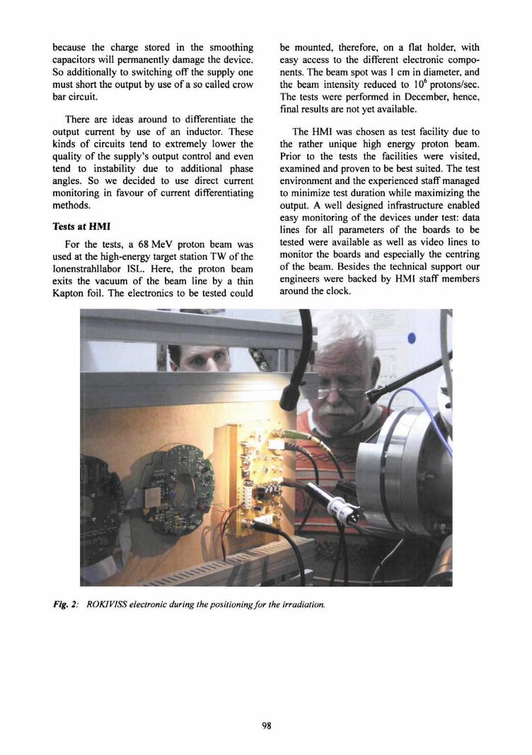
because the charge stored in the smoothingcapacitors will permanently damage the device.So additionally to switching off the supply onemust short the output by use of a so called crowbar circuit.
There are ideas around to differentiate theoutput current by use of an inductor. Thesekinds of circuits tend to extremely lower thequality of the supply's output control and eventend to instability due to additional phaseangles. So we decided to use direct currentmonitoring in favour of current differentiatingmethods.
Tests at HMI
For the tests, a 68 MeV proton beam wasused at the high-energy target station T W of thelonenstrahllabor ISL. Here, the proton beamexits the vacuum of the beam line by a thinKapton foil. The electronics to be tested could
be mounted, therefore, on a flat holder, witheasy access to the different electronic compo-nents. The beam spot was 1 cm in diameter, andthe beam intensity reduced to 106 protons/sec.The tests were performed in December, hence,final results are not yet available.
The HMI was chosen as test facility due tothe rather unique high energy proton beam.Prior to the tests the facilities were visited,examined and proven to be best suited. The testenvironment and the experienced staff managedto minimize test duration while maximizing theoutput. A well designed infrastructure enabledeasy monitoring of the devices under test: datalines for all parameters of the boards to betested were available as well as video lines tomonitor the boards and especially the centringof the beam. Besides the technical support ourengineers were backed by HMI staff membersaround the clock.
Fig. 2: ROK1VISS electronic during the positioning for the irradiation.
98
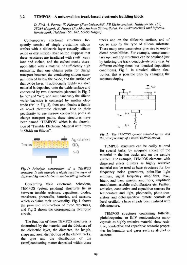
3.2 TEMPOS - A universal ion track-based electronic building block
D. Fink, A. Petrov; W. Fahrner [FernUniversitat, FB Elektrotechnik, Haldener Str. 182,58084 HagenJ; K. Hoppe [Fachhochschule Sudwestfalen, FB Elektrotechnik undlnforma-tionstechnik, Haldener Str. 182, 58095 HagenJ
Contemporary electronic structures fre-quently consist of single crystalline siliconwafers with a dielectric layer (usually siliconoxide or oxy nitride) layer on top. Suppose thatthese structures are irradiated with swift heavyions and etched, and the etched tracks there-upon filled with a material of sufficiently highresistivity, then one obtains paths for chargetransport between the conducting silicon chan-nel induced below the oxide, and the surface ofthat oxide layer. If additionally highly resistivematerial is deposited onto the oxide surface andconnected by two electrodes (denoted in Fig. 2by "o" and "w"), and simultaneously the siliconwafer backside is contacted by another elec-trode ("v" in Fig. 2), then one obtains a familyof novel electronic elements. Due to theirpeculiarity to use narrow conducting pores ascharge transport paths, these structures havebeen named "TEMPOS" which is the abrevia-tion of "Tunable Electronic Material with Poresin Oxide on Silicon".
Agclusterssio2
N-Si
Fig. 1: Principle construction of a TEMPOSstructure. In this example a highly resistive layer ofdispersed Ag nanoclusters is used as filling material.
Concerning their electronic behaviour,TEMPOS (patent pending) structures lie inbetween tunable resistors, capacitors, diodes,transistors, photocells, batteries, and sensors,which explains their universality. Fig. 1 showsthe principle construction of these structures,and Fig. 2 shows the corresponding electroniccircuit.
The function of these TEMPOS structures isdetermined by the material and the thickness ofthe dielectric layer, the diameter, the length,shape and areal distribution of the etched tracks,the type and the distribution of the(semi)conducting matter deposited within these
T r a c k s : : • : : « *
tracks and on the dielectric surface, and ofcourse also by the type of silicon substrate.These many new parameters give rise to unpre-dicted posssibilities. For example, complemen-tary npn and pnp structures can be obtained justby tailoring the track conductivity only (e.g. bydifferent etching times but identical depositionconditions), Fig. 3. In classical silicon elec-tronics, this is possible only by changing thesubstrate doping.
Ji
Vvw
•v
( X )
(v)
Fig. 2: The TEMPOS symbol adopted by us, andthe principle setup of a basicTEMPOS circuit.
TEMPOS structures can be easily tailoredfor special tasks, by adequate choice of thematerial in the ion tracks and on the samplesurface. For example, TEMPOS elements withdispersed silver clusters as highly resistivematerial can be used as base structures for lowfrequency noise generators, point-like lightemitters, signal frequency amplifiers, low-,high-, and band passes, amplifiers, amplitudemodulators, astabile multivibrators etc. Further,resistive, conductive and capacitive sensors fortemperature and light, photocells, photo-tran-sistors and optocapacitive remote controls oflocal oscillators have already been realized withthis structure.
TEMPOS structures containing fullerite,phthalocyanine, or II/IV semiconductor nano-crystals as highly resistive material show resis-tive, conductive and capacitive sensoric proper-ties for humidity and gases such as alcohol oracetone.
99
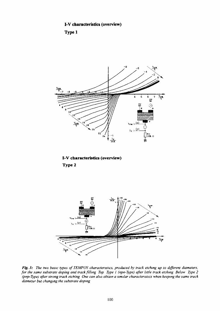
I-V characteristics (overview)
Typel
I-V characteristics (overview)
Type 2
Fig. 3: The two basic types of TEMPOS characteristics, produced by track etching up to different diameters,for the same substrate doping and track filling Top Type I (npn-Type) after little track etching Below Type 2(pnp-Type) after strong track etching One can also obtain a similar characteristics when keeping the same trackdiameter but changing the substrate doping
100
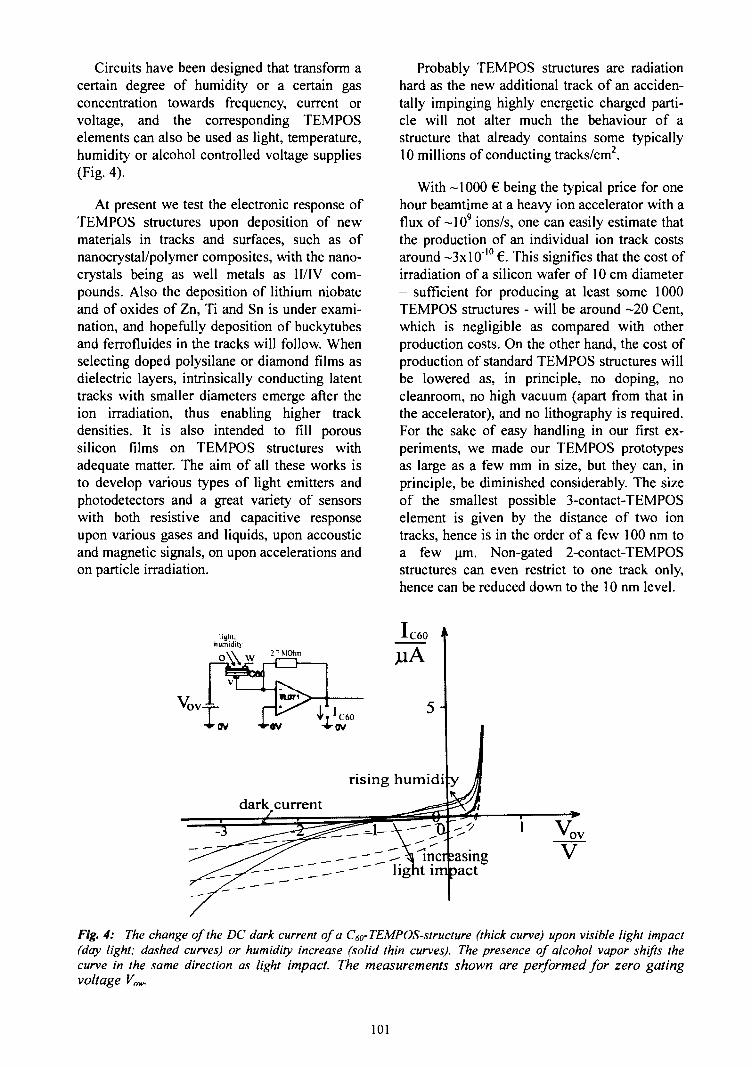
Circuits have been designed that transform acertain degree of humidity or a certain gasconcentration towards frequency, current orvoltage, and the corresponding TEMPOSelements can also be used as light, temperature,humidity or alcohol controlled voltage supplies(Fig. 4).
At present we test the electronic response ofTEMPOS structures upon deposition of newmaterials in tracks and surfaces, such as ofnanocrystal/polymer composites, with the nano-crystals being as well metals as II/IV com-pounds. Also the deposition of lithium niobateand of oxides of Zn, Ti and Sn is under exami-nation, and hopefully deposition of buckytubesand ferrofluides in the tracks will follow. Whenselecting doped polysilane or diamond films asdielectric layers, intrinsically conducting latenttracks with smaller diameters emerge after theion irradiation, thus enabling higher trackdensities. It is also intended to fill poroussilicon films on TEMPOS structures withadequate matter. The aim of all these works isto develop various types of light emitters andphotodetectors and a great variety of sensorswith both resistive and capacitive responseupon various gases and liquids, upon accousticand magnetic signals, on upon accelerations andon particle irradiation.
Probably TEMPOS structures are radiationhard as the new additional track of an acciden-tally impinging highly energetic charged parti-cle will not alter much the behaviour of astructure that already contains some typically10 millions of conducting tracks/cm2.
With -1000 € being the typical price for onehour beamtime at a heavy ion accelerator with aflux of ~109 ions/s, one can easily estimate thatthe production of an individual ion track costsaround ~3xl 0"10 €. This signifies that the cost ofirradiation of a silicon wafer of 10 cm diameter- sufficient for producing at least some 1000TEMPOS structures - will be around -20 Cent,which is negligible as compared with otherproduction costs. On the other hand, the cost ofproduction of standard TEMPOS structures willbe lowered as, in principle, no doping, nocleanroom, no high vacuum (apart from that inthe accelerator), and no lithography is required.For the sake of easy handling in our first ex-periments, we made our TEMPOS prototypesas large as a few mm in size, but they can, inprinciple, be diminished considerably. The sizeof the smallest possible 3-contact-TEMPOSelement is given by the distance of two iontracks, hence is in the order of a few 100 nm toa few urn. Non-gated 2-contact-TEMPOSstructures can even restrict to one track only,hence can be reduced down to the 10 nm level.
Vovi
V
Fig. 4: The change of the DC dark current of a C6a-TEMP OS-structure (thick curve) upon visible light impact(day light; dashed curves) or humidity increase (solid thin curves). The presence of alcohol vapor shifts thecurve in the same direction as light impact. The measurements shown are performed for zero gatingvoltage Vow.
101
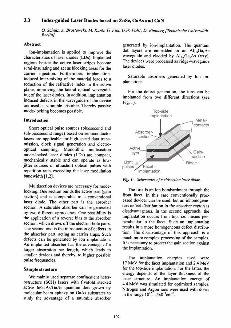
3.3 Index-guided Laser Diodes based on ZnSe, GaAs and GaN
O. Schulz, A. Brostowski, M. Kuntz, G. Fiol, U.W. Pohl, D. Bimberg[Technische UniversitatBerlin]
Abstract
Ion-implantation is applied to improve thecharacteristics of laser diodes (LDs). Implantedregions beside the active laser stripes becomesemi-insulating and act as blocking areas for thecarrier injection. Furthermore, implantation-induced inter-mixing of the material leads to areduction of the refractive index in the activeplane, improving the lateral optical waveguid-ing of the laser diodes. In addition, implantationinduced defects in the waveguide of the deviceare used as saturable absorber. Thereby passivemode-locking becomes possible.
Introduction
Short optical pulse sources (picosecond andsub-picosecond range) based on semiconductorlasers are applicable for high-speed data trans-mission, clock signal generation and electro-optical sampling. Monolithic multisectionmode-locked laser diodes (LDs) are compact,mechanically stable and can operate as low-jitter sources of ultrashort optical pulses withrepetition rates exceeding the laser modulationbandwidth [1,2].
Multisection devices are necessary for mode-locking. One section builds the active part (gainsection) and is comparable to a conventionallaser diode. The other part is the absorbersection. A saturable absorber can be generatedby two different approaches. One possibility isthe application of a reverse bias to the absorbersection, which draws off the electron-hole pairs.The second one is the introduction of defects inthe absorber part, acting as carrier traps. Suchdefects can be generated by ion implantation.An implanted absorber has the advantage of alarger absorbtion per length, which leads tosmaller devices and thereby, to higher possiblepulse frequencies.
Sample structure
We mainly used separate confinement heter-ostructure (SCH) lasers with fivefold stackedactive InGaAs/GaAs quantum dots grown bymolecular beam epitaxy on GaAs substrates tostudy the advantage of a saturable absorber
generated by ion-implantation. The quantumdot layers are embedded in an Al|.xGaxAswaveguide and cladded by Al|.yGayAs (x<y).The devices were processed as ridge-waveguidelaser diodes.
Saturable absorbers generated by Ion im-plantation:
For the defect generation, the ions can beimplanted from two different directions (seeFig. 1).
Top-sideimplantation
Absorber-section
Lightpulses
Metal-contacts
Activelayer Gain-
section
Ridge
implantation
Fig. 1: Schematics of multisection laser diode.
The first is an ion bombardment through thefront facet. In this case conventionally proc-essed devices can be used, but an inhomogene-ous defect distribution in the absorber region isdisadvantageous. In the second approach, theimplantation occurs from top, i.e. means per-pendicular to the facet. Such an implantationresults in a more homogeneous defect distribu-tion. The disadvantage of this approach is amuch more complex processing of the samples.It is necessary to protect the gain section againstthe implantation.
The implantation energies used were17 MeV for the facet implantation and 2.4 MeVfor the top-side implantation. For the latter, theenergy depends of the layer thickness of thelaser structure. An implantation energy of4.4 MeV was simulated for optimised samples.Nitrogen and Argon ions were used with dosesin the range 10l2...5x0l3cm~2.
102

Results and discussion
Comparing the threshold current densities ofunimplanted and implanted devices, we find anincrease by a factor of seven due to the im-plantation. A subsequent slight decrease due toa partial annealing was observed.
25
2.0-
|
0.5-
0.0
unimplanted• - implanted• - implanted after
10min operation
..cj-a-a-o
14
12 ^
10
8
6
4
2
CD
S-a-0
100 150 200
Current [mA]
Fig. 2: L-I- V characteristics of a quantum dot laserdiode before and after implantation with 2.4 Me VAr Ions. The dose was ~1013cm'2.
The annealing effect disappears on a times-cale of hours, eventually leading to a stable
operation. Next studies will focus on optimisingimplantation conditions for effective passivemode-locking. In addition, the approach ofimplantation induced disordering to improvewave- and current-guiding, as already demon-strated in this project with ZnCdSe based lasers,should be applied to the gain section of theInGaAs QD laser [3].
Acknowledgements
The authors like to thank Jorg Opitz-Cou-tureau (Hahn-Meitner-Institute, Berlin) forexpert assistance during ion implantation.
[1] P. Vasil'ev, Ultrafast Diode Lasers, ArtechHouse, Boston-London (1996).
[2] B. Zhu, I.H. White, R.V. Penty, A. Wonfor, E.Lach, and H.D. Summers, IEEE J. QuantumElectron. QE-33, 1(1997)216.
[3] O. Schulz, M. Strassburg, U.W. Pohl, D. Bim-berg, S. Itoh, K. Nakano, A. Ishibashi, M. Klu-de, and D. Hommel, Phys. stat. sol. (a) 180(2000)213.
103

3.4 Nano-wire transistors in flexible polymer foils*
Me Chen, R. Konenkamp [SE 2J; S. Klaumiinzer
Fabrication of flexible electronic devices at anano-scale size are presently among the mostimportant and ambitious development goals inthe semiconductor field. An approach to attainthese goals is based on the use of hybrid struc-tures combining the flexibility of organic mate-rials as substrates with the device functions ofinorganic semiconductors. Because of differentthermal expansion coefficients and elasticstiffnesses finite adhesion limits the robustnessof the overall structure if it is deposited onorganic substrates. We have succeeded in thefabrication of vertical nano-wire transistors inflexible PET films by using ion-beam technol-ogy-
The device structure is illustrated in Fig. 1.The foil stack consists of two polymer layersand an intermediate metal layer. Cylindricalholes are prepared in this stack by using390 MeV Xe20* irradiation and subsequentetching. Well-defined cylindrical openings withdia-meters between 50 and 150 nm are ob-tained. The vertical nano-pores are filled withp-type CuSCN by electro-deposition and are thechannels of the transistor. Top and bottomcontacts are in electrical contact with theCuSCN nano-wire and act as source and drainelectrodes, respectively. The metal layer inbetween the polymer foils works as the gate ofthe transistor. When the channel-diameter issmall enough, the potential induced by the gatecontact reaches radially through the wholechannel and a large conductance variationbetween source and drain contacts can beachieved (cf. Fig. 2). Switching and ampli-fication become possible.
Polyester Source-contact
Drain-contact
30-100 nm
Many of the basic problems encounteredwith layered hybrid structures are alleviated inthis approach. Because the devices are entirelyembedded in the flexible matrix, the resultingstructures are very robust and exhibit stableelectrical characteristics [1].
1200
1000-
800-
< 600-
_p 400-
200-
0-
-200
lDsatVG=-1.0V
lD5atVG=-0.5V
0.00 0.25 0.50 0.75 1.00 1.25 1.50 1.75
Fig. 2: Source-drain current vs. source-drainvoltage of an array of about 1500 vertical field-effect-transistors. Parameter is the gate voltage V(i.
Because this nano-electronic-device can bemass produced without clean room and lithog-raphy, it is a low cost technology. The devicescombine low weight and great flexibility. Apossible application is a matrix of sensors as arobot's skin. By reducing the thickness of thegate, one can expect a single electron operationsystem which has very low power consumption,fast switching and leads to a new type elec-tronic device. In order to extend the prodigiousprogress of the function of nano-wire fieldeffect transistor in flexible substrates, it isessential to investigate the effect of variousnano-wire materials on the electronic parame-ters and to find out the best materials to replaceCuSCN.
[1] J. Chen, R. Konenkamp, Applied Physics Let-ters, 82 (2003) 4782.
* J. Chen, R. Konenkamp, Vertical nano-wirefield effect transistor in polymer foils, Euro-pean patent Nr.: 10142913, International patentNr.:PCT/DE02/03191.
Fig. 1: Structure of a vertical nano-wire transistor.
104

3.5 Investigation of Intra-Channel Four-Wave Mixing at 160 Gb/s using an OpticalSampling System
C. Schmidt, C. Schubert, C. Borner, L Kuller, CM. Weinert, H.-G Weber [FraunhoferInstitutfur Nachrichtentechnik, Heinrich-Hertz-lnstitut, Berlin]; H. Bulow, E. Lach [AlcatelResearch and Innovation, Stuttgart]
Introduction
In high-speed fiber-optic transmission sys-tems (40 Gb/s and above), the maximum fiberinput power which allows for error-free trans-mission is limited due to the nonlinearity of thefiber. The nonlinearity gives rise to mainly twononlinear effects known as intra-channel cross-phase modulation (IXPM) and intra-channelfour-wave mixing (IFWM) [1,2]. While IXPMresults in an increase of the jitter of the datasignal, IFWM is responsible for the generationof so-called "ghost pulses". IFWM has beenstudied extensively using simulations [3,4].However, experimental investigation of IFWMhas been limited to bit-rates of 40 Gb/s up tonow [2,5] due to the limited bandwidth ofphotodetectors and electrical sampling oscillo-scopes. In this paper we present, for the firsttime to our knowledge, a detailed experimentalinvestigation of the generation and dynamics ofghost pulses due to IFWM at a data rate of160 Gb/s. We use an all-optical samplingsystem [6] with an optical bandwidth of210 GHz to measure optical eye diagrams witha picosecond resolution. The eye diagrams wereanalyzed and compared to numerical simula-tions with respect to intensity and temporalposition of the generated ghost pulses.
The investigation presented here are an ap-plication of the optical pulse source developedat the Heinrich-Hertz-lnstitut in cooperationwith the HMI. Using a high energy ion beamfrom the ISL a saturable absorber in a laserdiode is generated, which provides the shortoptical pulses in a modelocked semiconductorlaser. This optical pulse source is used in thedescribed experiments.
Experiment and results
The experimental set-up is shown in Fig. 1.A 10 Gb/s transmitter comprising a mode-locked solid state laser (provided by GigaTera,Switzerland) and a LiNbOj-modulator produceda 10 Gb/s 27-l PRBS RZ data signal (1.5 ps
sech2 pulses). The subsequent passive fiberdelay line multiplexer generated a quasi-160 Gb/s optical test signal, which containedonly two adjacent 160 Gb/s OTDM channels inorder to clearly identify the nonlineardistortions in the eye diagram.
EDFA EDFA
10 Gb/sTransm. - MUX MZ-
DSF
OpticalSamplingSystem
Link Input Power P +4 dBm = const.
Fig. 1: Schematik of experimental set-up.
The test signal was amplified and launchedwith an input peak power P into a fiber link,which consisted of non-zero dispersion-shiftedfiber (NZDSF, L = 84.22 km, loss = 17.6 dB,D = 724 ps/nm, S = 4.33 ps/nm2, y = 1.6 (W*km)"')and dispersion compensating fiber (DCF,L = 7.646 km, loss = 8.0 dB, D = -734.87 ps/nm,S = 4.63 ps/nm2, y = 5.7 (W*km)-').
An additional piece of standard single modefiber (SMF, loss= 02 dB/km, D= 17.0ps/(nm*km),S = 0.06 ps/(nm2*km), y = 2.0 (W*km)"') was inser-ted to achieve 100% dispersion compensation.The output of the fiber link was monitored withan all-optical sampling system [6] incorporatinga clock extraction, a low jitter semiconductormode-locked laser as sampling pulse source anda gain-transparent ultrafast nonlinear interfer-ometer as optical sampling gate. The samplinggate had a gating window width of 2.1 ps whichcorresponds to an optical bandwidth of210 GHz.
Fig. 2a-c shows the measured optical eyediagrams for different peak powers. It can beseen that for high peak powers, ghost pulses aregenerated on each side of the test signal due toIFWM. At P=2.38 W even higher order ghostpulses become visible. We also performednumerical simulations of the measured eyediagrams using a simple split-step Fourieralgorithm to solve the nonlinear SchrOdingerequation and neglecting jitter and noise.
105
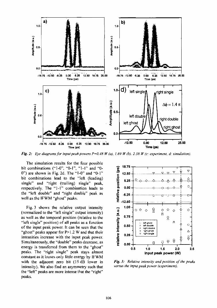
0.0
-18.75 -12.60 -6.26 0.00 6.26 12.60 18.76 26.00Time (ps)
-18.76 -12.60 -6.26 0.00 6.26 12.60 18.76 26.00Time (ps)
A<|>= 1.4Tt
0.0
-18.76 -12.60 -6.26 0.00 6.26 12.60 18.75 25.00 -12.50 0.00 12.50Time(ps)
25.00Time (ps)
Fig. 2: Eye diagrams for input peak powers P=(),48 W (a), 1.69 W(b), 2.38 W (c: experiment, d: simulation).
The simulation results for the four possiblebit combinations ("1-0", "0-1", "1-1" and "0-0") are shown in Fig. 2d. The "1-0" and "0-1"bit combinations lead to the "left (leading)single" and "right (trailing) single" peak,respectively. The "1-1" combination leads tothe "left double" and "right double" peak aswell as the IFWM "ghost" peaks.
Fig. 3 shows the relative output intensity(normalized to the "left single" output intensity)as well as the temporal position (relative to the"left single" position) of all peaks as a functionof the input peak power. It can be seen that the"ghost" peaks appear for P>1.2 W and that theirintensities increase with the input peak power.Simultaneously, the "double" peaks decrease, asenergy is transferred from them to the "ghost"peaks. The "right single" peak stays almostconstant as it looses only little energy by IFWMwith the adjacent zero bit (15 dB lower inintensity). We also find an asymmetry such thatthe "left" peaks are more intense that the "right"peaks.
V 18.75a"JT 12.50-1
1 6.25 Aoo- 0.00 -0)
s -6.25 -(B
2 -12.50---. 1.00-3mT 0.75 -|JP
§ 0.50 -
J 0.25 -
£ 0.00
.v V...V...M...I-—:_
Q. . .Q. . . >....9—°_o cr--n---D---iJi—a—
o o o
,.oA
V
o
left ghostleft doubleright doubleright ghostright single
o o o <>
s
A
o
A
D'V .
0.5 1.0 1.5 2.0input peak power (W)
2.5
Fig. 3: Relative intensity and position of the peaksversus the input peak power (experiment).
106
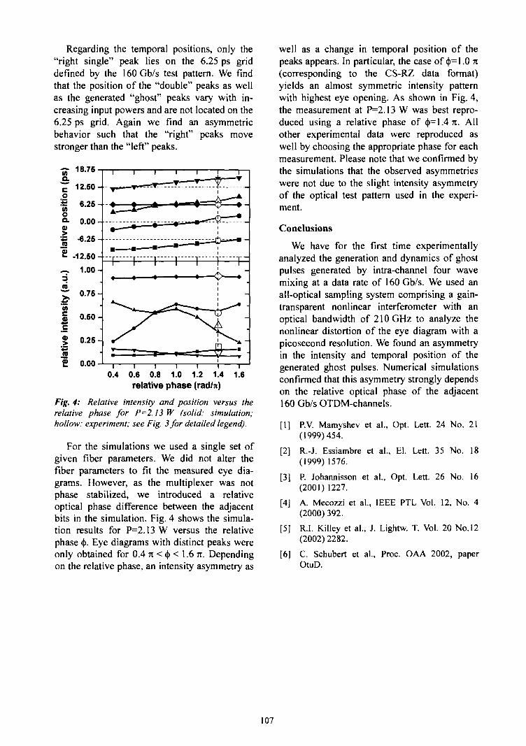
Regarding the temporal positions, only the"right single" peak lies on the 6.25 ps griddefined by the 160Gb/s test pattern. We findthat the position of the "double" peaks as wellas the generated "ghost" peaks vary with in-creasing input powers and are not located on the6.25 ps grid. Again we find an asymmetricbehavior such that the "right" peaks movestronger than the "left" peaks.
~ 18.75
12.50-
0.4 0.6 0.8 1.0 1.2 1.4relative phase (rad/n)
1.6
Fig. 4: Relative intensity and position versus therelative phase for P=2.13 W (solid: simulation;hollow: experiment; see Fig. 3 for detailed legend).
For the simulations we used a single set ofgiven fiber parameters. We did not alter thefiber parameters to fit the measured eye dia-grams. However, as the multiplexer was notphase stabilized, we introduced a relativeoptical phase difference between the adjacentbits in the simulation. Fig. 4 shows the simula-tion results for P=2.13W versus the relativephase <(>. Eye diagrams with distinct peaks wereonly obtained for 0.4 n < <|>< 1.6 n. Dependingon the relative phase, an intensity asymmetry as
well as a change in temporal position of thepeaks appears. In particular, the case of <|>=1.0 n(corresponding to the CS-RZ data format)yields an almost symmetric intensity patternwith highest eye opening. As shown in Fig. 4,the measurement at P=2.13 W was best repro-duced using a relative phase of <t>= 1.4 71. Allother experimental data were reproduced aswell by choosing the appropriate phase for eachmeasurement. Please note that we confirmed bythe simulations that the observed asymmetrieswere not due to the slight intensity asymmetryof the optical test pattern used in the experi-ment.
Conclusions
We have for the first time experimentallyanalyzed the generation and dynamics of ghostpulses generated by intra-channel four wavemixing at a data rate of 160 Gb/s. We used anall-optical sampling system comprising a gain-transparent nonlinear interferometer with anoptical bandwidth of 210 GHz to analyze thenonlinear distortion of the eye diagram with apicosecond resolution. We found an asymmetryin the intensity and temporal position of thegenerated ghost pulses. Numerical simulationsconfirmed that this asymmetry strongly dependson the relative optical phase of the adjacent160 Gb/s OTDM-channels.
[1] RV. Mamyshev et al., Opt. Lett. 24 No. 21(1999)454.
[2] R.-J. Essiambre et al., El. Lett. 35 No. 18(1999) 1576.
[3] P. Johannisson et al., Opt. Lett. 26 No. 16(2001) 1227.
[4] A. Mecozzi et al., IEEE PTL Vol. 12, No. 4(2000) 392.
[5] R.I. Killey et al., J. Lightw. T. Vol. 20 No. 12(2002)2282.
[6] C. Schubert et al., Proc. OAA 2002, paperOtuD.
107

4. Nuclear Physics
109

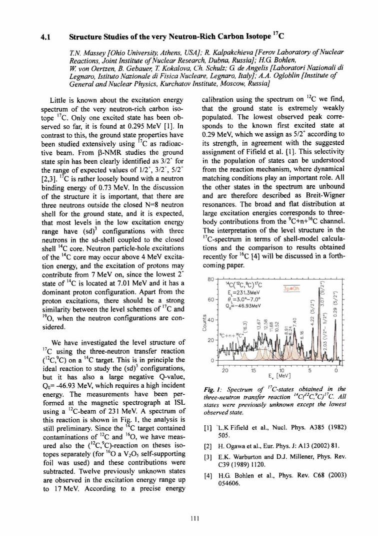
17/4.1 Structure Studies of the very Neutron-Rich Carbon Isotope C
T.N. Massey [Ohio University, Athens, USA]; R. Kalpakchieva [Ferov Laboratory of NuclearReactions, Joint Institute of Nuclear Research, Dubna, Russia]; KG Bohlen,W. von Oertzen, B. Gebauer, T. Kokalova, Ch. Schulz; G de Angel is [Laboratori Nazionali diLegnaro, Istituto Nazionale di Fisica Nucleare, Legnaro, Italy]; A.A. Ogloblin [Institute ofGeneral and Nuclear Physics, Kurchatov Institute, Moscow, Russia]
Little is known about the excitation energyspectrum of the very neutron-rich carbon iso-tope 17C. Only one excited state has been ob-served so far, it is found at 0.295 MeV [1]. Incontrast to this, the ground state properties havebeen studied extensively using I7C as radioac-tive beam. From p-NMR studies the groundstate spin has been clearly identified as 3/2* forthe range of expected values of 1/2\ 3/2", 5/2*[2,3]. 17C is rather loosely bound with a neutronbinding energy of 0.73 MeV. In the discussionof the structure it is important, that there arethree neutrons outside the closed N=8 neutronshell for the ground state, and it is expected,that most levels in the low excitation energyrange have (sd)3 configurations with threeneutrons in the sd-shell coupled to the closedshell 14C core. Neutron particle-hole excitationsof the 14C core may occur above 4 MeV excita-tion energy, and the excitation of protons maycontribute from 7 MeV on, since the lowest 2*state of 14C is located at 7.01 MeV and it has adominant proton configuration. Apart from theproton excitations, there should be a strongsimilarity between the level schemes of 17C and19O, when the neutron configurations are con-sidered.
We have investigated the level structure ofI7C using the three-neutron transfer reaction(12C,9C) on a I4C target. This is in principle theideal reaction to study the (sd)3 configurations,but it has also a large negative Q-value,Qo= -46.93 MeV, which requires a high incidentenergy. The measurements have been per-formed at the magnetic spectrograph at ISLusing a I2C-beam of 231 MeV. A spectrum ofthis reaction is shown in Fig. 1, the analysis isstill preliminary. Since the l4C target containedcontaminations of 12C and I6O, we have meas-ured also the (12C,9C)-reaction on theses iso-topes separately (for 16O a V2O5 self-supportingfoil was used) and these contributions weresubtracted. Twelve previously unknown statesare observed in the excitation energy range upto 17 MeV. According to a precise energy
calibration using the spectrum on I2C we find,that the ground state is extremely weaklypopulated. The lowest observed peak corre-sponds to the known first excited state at0.29 MeV, which we assign as 5/2+ according toits strength, in agreement with the suggestedassignment of Fifield et al. [1]. This selectivityin the population of states can be understoodfrom the reaction mechanism, where dynamicalmatching conditions play an important role. Allthe other states in the spectrum are unboundand are therefore described as Breit-Wignerresonances. The broad and flat distribution atlarge excitation energies corresponds to three-body contributions from the 9C+n+l6C channel.The interpretation of the level structure in thel7C-spectrum in terms of shell-model calcula-tions and the comparison to results obtainedrecently for l6C [4] will be discussed in a forth-coming paper.
80
60-
14C(12C,9C)17CEL=231.3MeV0L=3.O°-7.O°
Q0=-46.93MeV
Fig. 1: Spectrum of C-states obtained in thethree-neutron transfer reaction C( C, C) C. Allstates were previously unknown except the lowestobserved state.
[1] L.KFifield et al., Nucl. Phys. A385 (1982)505.
[2] H. Ogawa et al., Eur. Phys. J: A13 (2002) 81.
[3] E.K. Warburton and D.J. Millener, Phys. Rev.C39(1989) 1120.
[4] H.G Bohlen et al., Phys. Rev. C68 (2003)054606.
Ill


5. Accelerator Operation; Technical Developments
113

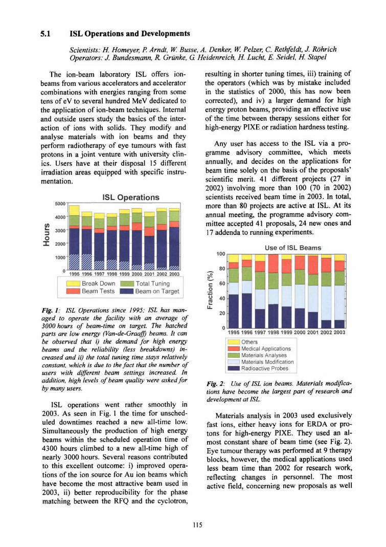
5.1 ISL Operations and Developments
Scientists: H. Homeyer, P. Arndt, W. Busse, A. Denker, W. Pelzer, C. Rethfeldt, J. RohrichOperators: J. Bundesmann, R. Griinke, G. Heidenreich, H. Lucht, E. Seidel, H. Stapel
The ion-beam laboratory ISL offers ion-beams from various accelerators and acceleratorcombinations with energies ranging from sometens of eV to several hundred MeV dedicated tothe application of ion-beam techniques. Internaland outside users study the basics of the inter-action of ions with solids. They modify andanalyse materials with ion beams and theyperform radiotherapy of eye tumours with fastprotons in a joint venture with university clin-ics. Users have at their disposal 15 differentirradiation areas equipped with specific instru-mentation.
5000ISL Operations
1995 1996 1997 1998 1999 2000 2001 2002 2003
Break DownBeam Tests
Total TuningBeam on Target
Fig. I: ISL Operations since 1995: ISL has man-aged to operate the facility with an average of3000 hours of beam-time on target. The hatchedparts are low energy (Van-de-Graaff) beams. It canbe observed that i) the demand for high energybeams and the reliability (less breakdowns) in-creased and ii) the total tuning time stays relativelyconstant, which is due to the fact that the number ofusers with different beam settings increased. Inaddition, high levels of beam quality were asked forby many users.
ISL operations went rather smoothly in2003. As seen in Fig. 1 the time for unsched-uled downtimes reached a new all-time low.Simultaneously the production of high energybeams within the scheduled operation time of4300 hours climbed to a new all-time high ofnearly 3000 hours. Several reasons contributedto this excellent outcome: i) improved opera-tions of the ion source for Au ion beams whichhave become the most attractive beam used in2003, ii) better reproducibility for the phasematching between the RFQ and the cyclotron,
resulting in shorter tuning times, iii) training ofthe operators (which was by mistake includedin the statistics of 2000, this has now beencorrected), and iv) a larger demand for highenergy proton beams, providing an effective useof the time between therapy sessions either forhigh-energy PIXE or radiation hardness testing.
Any user has access to the ISL via a pro-gramme advisory committee, which meetsannually, and decides on the applications forbeam time solely on the basis of the proposals'scientific merit. 41 different projects (27 in2002) involving more than 100 (70 in 2002)scientists received beam time in 2003. In total,more than 80 projects are active at ISL. At itsannual meeting, the programme advisory com-mittee accepted 41 proposals, 24 new ones and17 addenda to running experiments.
100Use of ISL Beams
co
• •§
S
1995 1996 1997 1998 1999 2000 2001 2002 2003
I I Others• • Medical Applications^ H Materials AnalysesI Materials Modification^ H Radioactive Probes
Fig. 2: Use of ISL ion beams. Materials modifica-tions have become the largest part of research anddevelopment at ISL.
Materials analysis in 2003 used exclusivelyfast ions, either heavy ions for ERDA or pro-tons for high-energy PIXE. They used an al-most constant share of beam time (see Fig. 2).Eye tumour therapy was performed at 9 therapyblocks, however, the medical applications usedless beam time than 2002 for research work,reflecting changes in personnel. The mostactive field, concerning new proposals as well
115
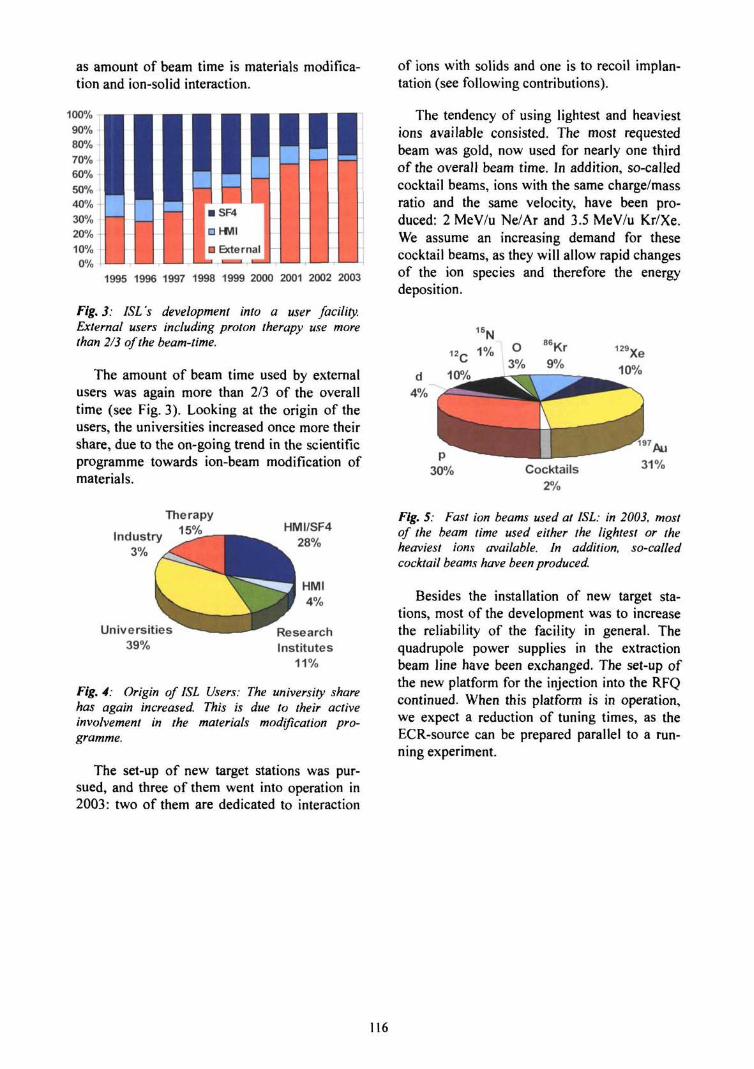
as amount of beam time is materials modifica-tion and ion-solid interaction.
1995 1996 1997 1998 1999 2000 2001 2002 2003
Fig. 3: ISL 's development into a user facility.External users including proton therapy use morethan 2/3 of the beam-time.
The amount of beam time used by externalusers was again more than 2/3 of the overalltime (see Fig. 3). Looking at the origin of theusers, the universities increased once more theirshare, due to the on-going trend in the scientificprogramme towards ion-beam modification ofmaterials.
of ions with solids and one is to recoil implan-tation (see following contributions).
The tendency of using lightest and heaviestions available consisted. The most requestedbeam was gold, now used for nearly one thirdof the overall beam time. In addition, so-calledcocktail beams, ions with the same charge/massratio and the same velocity, have been pro-duced: 2 MeV/u Ne/Ar and 3.5 MeV/u Kr/Xe.We assume an increasing demand for thesecocktail beams, as they will allow rapid changesof the ion species and therefore the energydeposition.
129 Xe10%
Cocktails2%
Industry3%
Therapy15%
Universities39%
HMI/SF428%
ResearchInstitutes
11%
Fig. 4: Origin of ISL Users: The university sharehas again increased. This is due to their activeinvolvement in the materials modification pro-gramme.
The set-up of new target stations was pur-sued, and three of them went into operation in2003: two of them are dedicated to interaction
Fig. 5: Fast ion beams used at ISL: in 2003, mostof the beam time used either the lightest or theheaviest ions available. In addition, so-calledcocktail beams have been produced.
Besides the installation of new target sta-tions, most of the development was to increasethe reliability of the facility in general. Thequadrupole power supplies in the extractionbeam line have been exchanged. The set-up ofthe new platform for the injection into the RFQcontinued. When this platform is in operation,we expect a reduction of tuning times, as theECR-source can be prepared parallel to a run-ning experiment.
I16
5.2 Cyclotron-, RFQ- and RF-operations
W. Pelzer, G Bruning, T. Damerow, G. Heidenreich, M. Przewozny
Operation of the cyclotron and the RFQ-ac-celerator has been as planned during all of theyear, with no extended downtimes. Severalfailures could be repaired swiftly. Maintenancedays could be used for implementation of somemachine improvement.
Cyclotron
The cyclotron vacuum system has been op-erated for years with only one turbopump(Leybold Turbovac 1500) supporting the twocryopumps (Leybold RPK 10000). After twosuccessive failures of the turbopump last year,two new pumps (Leybold Turbovac T1600)have been mounted, one of these serving as abackup. The old interface electronics could beused no longer, therefore a new control inter-face has been built. The cryopumps suffer bywear of compressor-seal ings, which led toseveral warm-ups. Each time this happened, thepumps were switched off from the cyclotronand regenerated or repaired during maintenancedays.
Another major topic was beam diagnostics.The radial injection probe sometimes drove intothe machine by itself without operator com-mand. The cause for this malfunction wasfound to be a damaged component in the driverpower supply. An additional new finger probehas been taken into operation which allows tomeasure the beam turn pattern without completestop of the beam. The finger has a width of1 mm and can be driven radially through thebeam. Each beam turn has a width of severalmm and the turn to turn distance is up to40 mm, therefore the probe is a superior devicefor beam monitoring with minimum loss ofbeam by setting the finger onto the flank of onebeam turn.
Beam extraction was a continued topic formachine studies with the aim of further auto-mation of beam settup. The beam axis wasfound to be less strictly positioned at the cyclo-tron exit than expected, therefore the firstFaraday cup there will be modified for addedposition sensitivity. One incident of beaminstabilities could be traced down to be causedby the first extraction element, the electrostatic
channel El. Septum parts had been burned byhigh beam intensities and needed repair.
Some breakdowns of the cooling systemsoccured due to different causes. A defect filterof our main supply for demineralized water leddebris into the system, which piled up in tightplaces, eventually blocking cooling lines orpressure reducing valves. More severe is awater leak at a connector of one of the lowermain coils, which already exists for a long time,and gets a temporary fix of epoxy every year. Ifit would be necessary to replace that coil by ourspare, the cyclotron must be dismantled com-pletely, meaning about half a year of recon-struction. As a precaution the old cooling hosesof several power supplies have been replaced.
During several months in mid-year occa-sional shutdowns of the RF-systems hamperedbeam operation, without any apparent reason.The cause was found, after all, to be two faultyold components in the RF-control circuitry.Faster to find but more difficult to repair was awater leakage in the coupler-part connecting theanode circuit of one RF-power amplifier to itsresonating cavity. The isolating quartz-windowat the coupling loop, separating the cavityvacuum from air, was damaged and had to bereplaced.
RFQ
At the RFQ-accelerator, the old DOS-oper-ating system was extended for better net-sur-veillance. The vacuum system developed twofailures: One of the two turbopumps stoppeddue to defective bearings, and the cryopump(type Stirling, Leybold Polar SC-7) did not holdlow temperature any more, after just a fewmonths of operation, due to helium leakage.The RFQ-cooling system was equipped withnew hoses, since the old ones showed fabricweakness.
An additional nondestructive beam intensitymeasurement is under construction, using thecapacitive probe behind the RFQ. Up to now,this probe is used only for observation of thebeam pulse shape on a fast scope in the control
117

room. Most of the newly built RFQ-electronicsis delivered but not yet tested.
RF-Systems
For the other RF-systems, the microwavetransmitters for the ECR-sources must bementioned. The one for the RFQ-source andthat for the low energy beam area independ-ently broke down at the end of the year, bothdue to failure of the klystron.
High power tests of the new buncher, whichshall be mounted behind the RFQ, were suc-cessfully completed. The conventional systemworks at frequencies between 10 and 15 MHz,takes up to 1 kW of RF-power, and produces20 kV at the drift tube. The regulation elec-tronics is not yet available. For the bunchers infront of the RFQ, two 300 W broad band RF-amplifiers broke down due to insufficient airconditioning of the building.
118

5.3 Injector Developments
P. Arndu D. Bohm, K. Effland, W. Hahn, U. Mullen J. Rohrich
In 2003, the operation of both injectors, the5.5 MV Van-de-GraafF accelerator and theSupernanogan 2000 ECR ion source on the200 kV high-voltage injector platform for theRFQ, was very reliable and stable. This isclearly a result of the improvements in the lastyears. Besides the regular service, only somerefinements were made and the developmentwas focused on the further set-up of the addi-tional 150 kV platform and experiments on theion source test bench.
Van-de-Graaff Accelerator (CN)
Already in 2003, we reported on the modifi-cation of the Wien filter on the terminal toreduce the damage due to sputtering, especiallyby heavy ions. All stainless steel and tungstenparts, which can be hit by the beam were re-placed by titanium ones with rreat success. Werealized a much lower sputtering of thesecritical parts during maintenance after sevenmonth of operation. There was only a minorremoval of metal visible on the deflectionelectrodes, whereas the output bushing was notsputtered at all. In contrary to this, the previousparts had to be replaced every three month.
200 kV High-Voltage Platform
Due to the still high demand of the users, en-ergetic gold ion beams were again the mostfrequently produced beams at ISL. Nearly 30%of the experiments were performed with goldions, as seen in the ISL statistics of this report[1]. Moreover, the 350 MeV gold beam becamethe standard beam for ERDA measurements.This stands for the high stability, which canensured with the ECR ion source Supernanogan2000.
To simplify the replacement of the microoven used for the evaporation of metals, a newoven holder inside a long bellow was con-structed and installed. The oven can be pre-heated in vacuum outside the plasma chamberfor outgassing during normal gas operation. Forthe production of metal ions a valve can beopened and the oven can be smoothly shiftedinside the plasma tube. This considerablyreduced the time for tuning the source for gold
operation. The position of the oven is continu-ously adjustable and first experiments for theoptimisation of the position in respect to theend of the bias tube have been started.
In order to improve the vacuum in the ex-traction region, the extraction chamber whichholds the puller and the Einzellens was re-placed. The new chamber enables a 30% higherpumping speed of the 500 1/s and 1000 1/s turbopumps into the ion source. Due to a lowerprobability of sparks in the extraction region,the reliability of operation was improved.Furthermore, the chamber is designed for aextraction voltage of 30 kV, which is muchmore than the usual value of 15 kV at present.With higher extraction voltages we want toincrease the ion current out of the source espe-cially for very high charge states of heavy ions.
150 kV High-Voltage Platform
After installation of the utilities such aselectricity, air conditioning and cooling at thenew injector platform for the RFQ-cyclotroncombination in 2002, the set-up of the beamlinewas tackled in 2003.
Fig. 1: View of the injection from the new 150 kVplatform into the vertical beamline on the left. In theforeground the combination of two bending magnetsand the quadrupole singlet inside the grey mountingframe can be seen.
First, the combination of two bending mag-nets and a quadrupole singlet at the injectioninto the existing vertical beamline [2] wasinstalled and aligned with the help of the pre-pared markers. This was one of the most critical
119
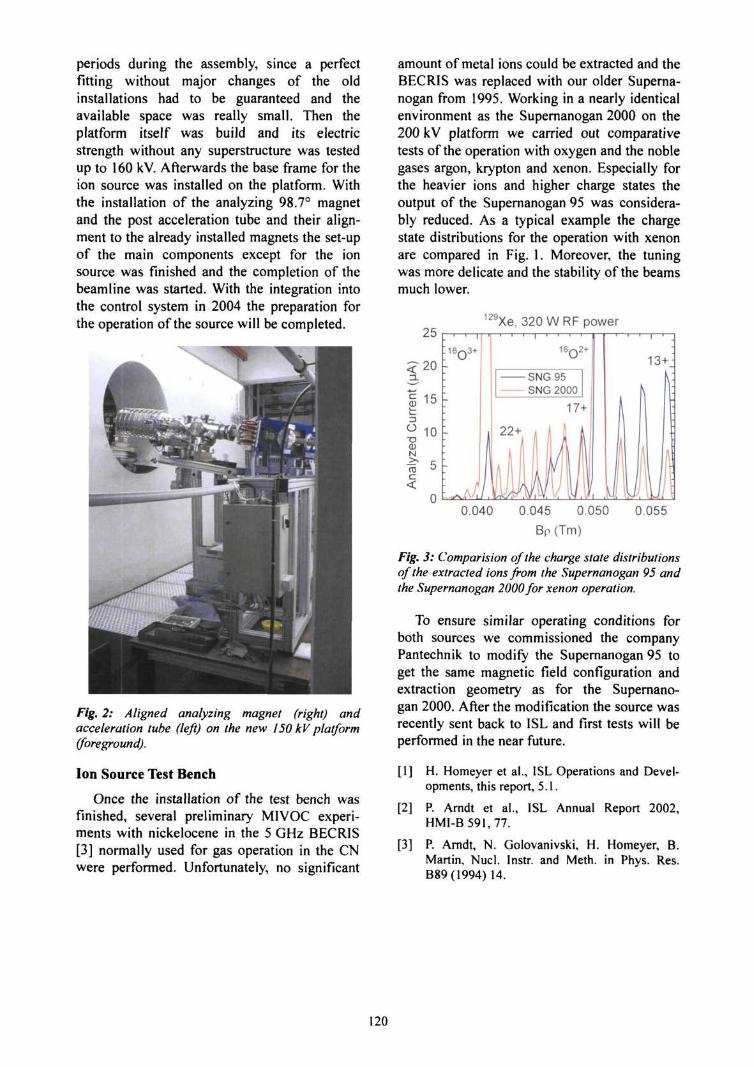
periods during the assembly, since a perfectfitting without major changes of the oldinstallations had to be guaranteed and theavailable space was really small. Then theplatform itself was build and its electricstrength without any superstructure was testedup to 160 kV. Afterwards the base frame for theion source was installed on the platform. Withthe installation of the analyzing 98.7° magnetand the post acceleration tube and their align-ment to the already installed magnets the set-upof the main components except for the ionsource was finished and the completion of thebeamline was started. With the integration intothe control system in 2004 the preparation forthe operation of the source will be completed.
Fig, 2: Aligned analyzing magnet (right) andacceleration tube (left) on the new 150 kV platform(foreground).
Ion Source Test Bench
Once the installation of the test bench wasfinished, several preliminary MIVOC experi-ments with nickelocene in the 5 GHz BECRIS[3] normally used for gas operation in the CNwere performed. Unfortunately, no significant
amount of metal ions could be extracted and theBECRIS was replaced with our older Superna-nogan from 1995. Working in a nearly identicalenvironment as the Supernanogan 2000 on the200 kV platform we carried out comparativetests of the operation with oxygen and the noblegases argon, krypton and xenon. Especially forthe heavier ions and higher charge states theoutput of the Supernanogan 95 was considera-bly reduced. As a typical example the chargestate distributions for the operation with xenonare compared in Fig. 1. Moreover, the tuningwas more delicate and the stability of the beamsmuch lower.
129Xe, 320 W RF power
0.040 0.045 0.050
BP (Tm)
0.055
Fig. 3: Comparision of the charge state distributionsof the extracted ions from the Supernanogan 95 andthe Supernanogan 2000 for xenon operation.
To ensure similar operating conditions forboth sources we commissioned the companyPantechnik to modify the Supernanogan 95 toget the same magnetic field configuration andextraction geometry as for the Supernano-gan 2000. After the modification the source wasrecently sent back to ISL and first tests will beperformed in the near future.
[1] H. Homeyer et al., ISL Operations and Devel-opments, this report, 5.1.
[2] P. Arndt et al., ISL Annual Report 2002,HMI-B591,77.
[3] P. Arndt, N. Golovanivski, H. Homeyer, B.Martin, Nucl. Instr. and Meth. in Phys. Res.B89(1994) 14.
120
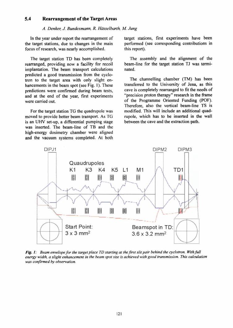
5.4 Rearrangement of the Target Areas
A. Denker, J. Bundesmann, R. Hcisselbarth, M. Jung
In the year under report the rearrangement ofthe target stations, due to changes in the mainfocus of research, was nearly accomplished.
The target station TD has been completelyrearranged, providing now a facility for recoilimplantation. The beam transport calculationspredicted a good transmission from the cyclo-tron to the target area with only slight en-hancements in the beam spot (see Fig. 1). Thesepredictions were confirmed during beam tests,and at the end of the year, first experimentswere carried out.
For the target station TG the quadrupole wasmoved to provide better beam transport. As TGis an UHV set-up, a differential pumping stagewas inserted. The beam-line of TB and thehigh-energy dosimetry chamber were alignedand the vacuum systems completed. At both
target stations, first experiments have beenperformed (see corresponding contributions inthis report).
The assembly and the alignment of thebeam-line for the target station TJ was termi-nated.
The channelling chamber (TM) has beentransferred to the University of Jena, as thiscave is completely rearranged to fit the needs of"precision proton therapy" research in the frameof the Programme Oriented Funding (POF).Therefore, also the vertical beam-line TS ismodified. This will include an additional quad-rupole, which has to be inserted in the wallbetween the cave and the extraction path.
DIPJ1 DIPM2 DIPM3
QuaudrupolesK1 K3 K4 K5 L1
III III I
Start Point:3 x 3 mm2
Beamspot in TD:3.6 x 3.2 mm2
Fig. 1: Beam envelope for the target place TD starting at the first slit pair behind the cyclotron. With fullenergy width, a slight enhancement in the beam spot size is achieved with good transmission. This calculationwas confirmed by observation.
121
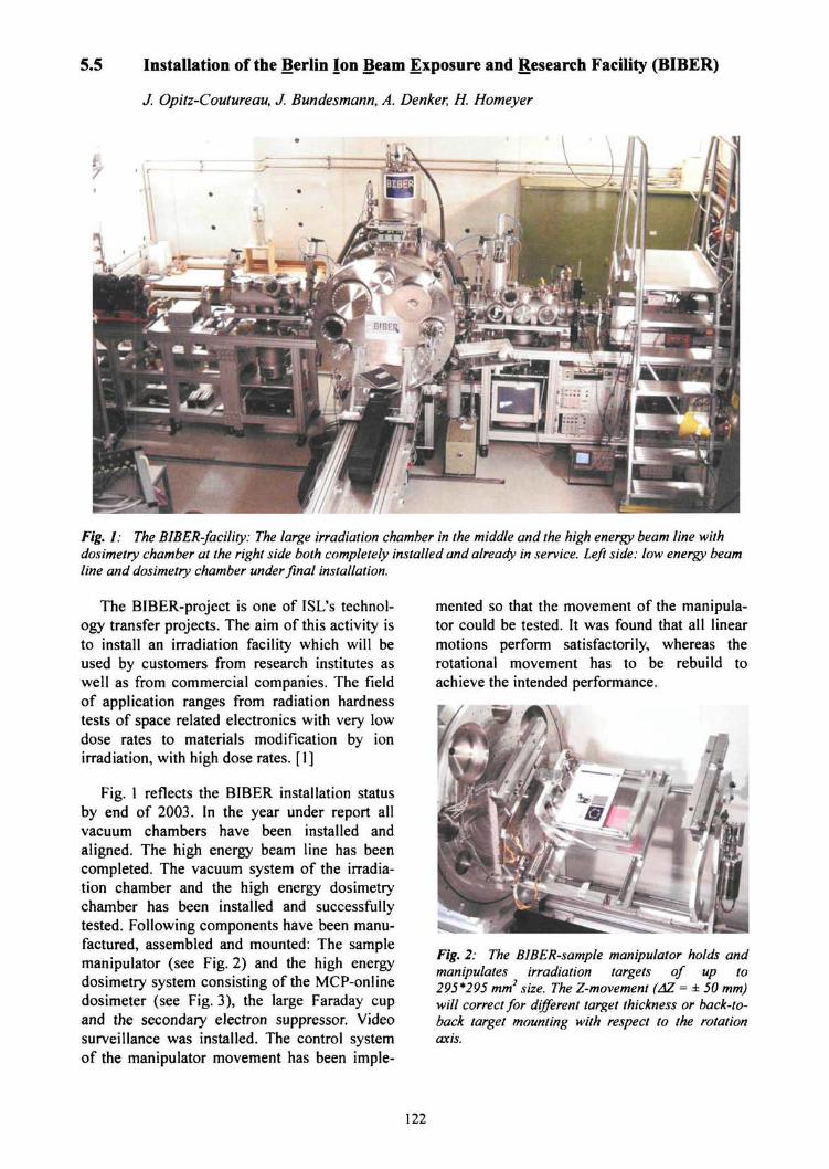
5.5 Installation of the Berlin Ion Beam Exposure and Research Facility (BIBER)
J. Opitz-Coutureau, J. Bundesmann, A. Denker, H. Homeyer
Fig. I: The BIBER-facility: The large irradiation chamber in the middle and the high energy beam line withdosimetry chamber at the right side both completely installed and already in service. Left side: low energy beamline and dosimetry chamber under final installation.
The BIBER-project is one of ISL's technol-ogy transfer projects. The aim of this activity isto install an irradiation facility which will beused by customers from research institutes aswell as from commercial companies. The fieldof application ranges from radiation hardnesstests of space related electronics with very lowdose rates to materials modification by ionirradiation, with high dose rates. [1]
Fig. 1 reflects the BIBER installation statusby end of 2003. In the year under report allvacuum chambers have been installed andaligned. The high energy beam line has beencompleted. The vacuum system of the irradia-tion chamber and the high energy dosimetrychamber has been installed and successfullytested. Following components have been manu-factured, assembled and mounted: The samplemanipulator (see Fig. 2) and the high energydosimetry system consisting of the MCP-onlinedosimeter (see Fig. 3), the large Faraday cupand the secondary electron suppressor. Videosurveillance was installed. The control systemof the manipulator movement has been imple-
mented so that the movement of the manipula-tor could be tested. It was found that all linearmotions perform satisfactorily, whereas therotational movement has to be rebuild toachieve the intended performance.
Fig. 2: The BIBER-sample manipulator holds andmanipulates irradiation targets of up to295*295 mm2 size. The Z-movement (AZ = ± 50 mm)will correct for different target thickness or back-to-back target mounting with respect to the rotationaxis.
122
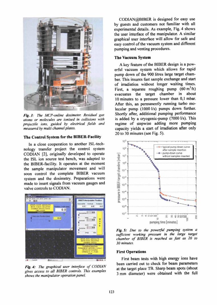
Fig. 3: The MCP-online dosimeter. Residual gasatoms or molecules are ionised in collisions withprojectile ions, guided by electrical fields andmeasured by multi channel plates.
The Control System for the BIBER-Facility
In a close cooperation to another ISL-tech-nology transfer project the control systemCODIAN [2], originally developed to operatethe ISL ion source test bench, was adapted tothe BIBER-facility. It operates at the momentthe sample manipulator movement and willsoon control the complete BIBER vacuumsystem and the dosimetry. Preparations weremade to insert signals from vacuum gauges andvalve controls to CODIAN.
Ptedefmed positionsPERMANENT MOVING (future )
INITIALISE Rotationlialise X-. Y-. Z-axis
STOP
Fig. 4: The graphical user interface of CODIANgives access to all BIBER controls. This examplesshows the manipulator operation panel.
CODIAN@BIBER is designed for easy useby guests and customers not familiar with allexperimental details. As example, Fig. 4 showsthe user interface of the manipulator. A similargraphical user interface will allow for safe andeasy control of the vacuum system and differentpumping and venting procedures.
The Vacuum System
A key feature of the BIBER design is a pow-erful vacuum system which allows for rapidpump down of the 900 litres large target cham-ber. This insures fast sample exchange and startof irradiation without longer waiting times.First, a separate roughing pump (60 m3/h)evacuates the target chamber in about10 minutes to a pressure lower than 0,1 mbar.After this, an permanently running turbo mo-lecular pump (1000 1/s) pumps down further.Shortly after, additional pumping performanceis added by a cryogenic-pump (7000 1/s). Thisregime of stepwise adding more pumpingcapacity yields a start of irradiation after only20 to 30 minutes (see Fig. 5).
103T
102-]
J | 10' -;
£ 10° -i
-1= 10"̂ i
aj
i i i -i
no 10 iEo j
"M 10"4-
10"'
V•— typical pump-down curve
after sample insertion•— pump-down curve
without samples inserted
pumping time [minutes]
Fig. 5: Due to the powerful pumping system asufficient working pressure in the large targetchamber of BIBER is reached as fast as 20 to30 minutes.
First Operations
First beam tests with high energy ions havebeen carried out to check for beam parametersat the target place TB. Sharp beam spots (about3 mm diameter) were obtained with the full
123
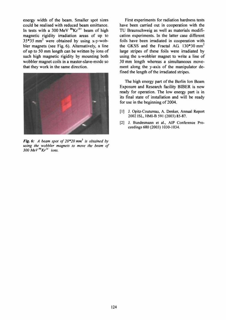
energy width of the beam. Smaller spot sizescould be realised with reduced beam emittance.In tests with a 300 MeV 86Kr14* beam of highmagnetic rigidity irradiation areas of up to35*35 mm2 were obtained by using x-y-wob-bler magnets (see Fig. 6). Alternatively, a lineof up to 50 mm length can be written by ions ofsuch high magnetic rigidity by mounting bothwobbler magnet coils in a master-slave-mode sothat they work in the same direction.
Fig. 6: A beam spot of 20*20 mm2 is obtained byusing the wobbler magnets to move the beam of
First experiments for radiation hardness testshave been carried out in cooperation with theTU Braunschweig as well as materials modifi-cation experiments. In the latter case differentfoils have been irradiated in cooperation withthe GKSS and the Fractal AG 130*30 mm2
large stripes of these foils were irradiated byusing the x-wobbler magnet to write a line of30 mm length whereas a simultaneous move-ment along the y-axis of the manipulator de-fined the length of the irradiated stripes.
The high energy part of the Berlin Ion BeamExposure and Research facility BIBER is nowready for operation. The low energy part is inits final state of installation and will be readyfor use in the beginning of 2004.
[1] J. Opitz-Coutureau, A. Denker, Annual Report2002 ISL, HMI-B 591 (2003) 85-87.
[2] J. Bundesmann et a!., AIP Conference Pro-ceedings 680 (2003) 1030-1034.
,H6300MeVmKr" ions.
124
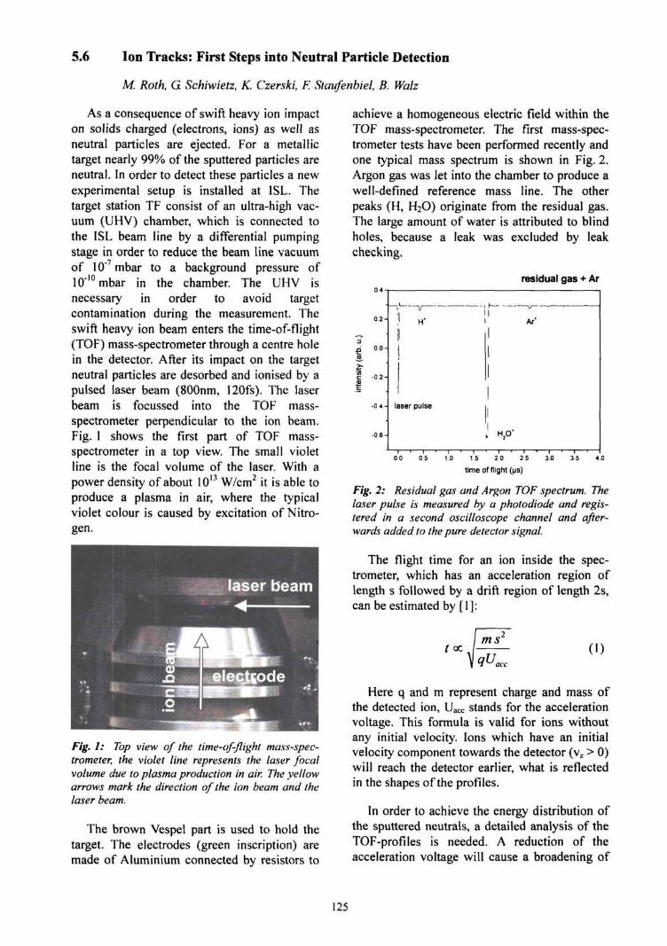
5.6 Ion Tracks: First Steps into Neutral Particle Detection
M. Roth, G Schiwietz, K. Czerski, F. Staufenbiel, B. Walz
As a consequence of swift heavy ion impacton solids charged (electrons, ions) as well asneutral particles are ejected. For a metallictarget nearly 99% of the sputtered particles areneutral. In order to detect these particles a newexperimental setup is installed at ISL. Thetarget station TF consist of an ultra-high vac-uum (UHV) chamber, which is connected tothe ISL beam line by a differential pumpingstage in order to reduce the beam line vacuumof 10"7mbar to a background pressure of10"'°mbar in the chamber. The UHV isnecessary in order to avoid targetcontamination during the measurement. Theswift heavy ion beam enters the time-of-flight(TOF) mass-spectrometer through a centre holein the detector. After its impact on the targetneutral particles are desorbed and ionised by apulsed laser beam (800nm, 120fs). The laserbeam is focussed into the TOF mass-spectrometer perpendicular to the ion beam.Fig. 1 shows the first part of TOF mass-spectrometer in a top view. The small violetline is the focal volume of the laser. With apower density of about 1013 W/cm2 it is able toproduce a plasma in air, where the typicalviolet colour is caused by excitation of Nitro-gen.
Fig. 1: Top view of the time-of-flight mass-spec-trometer, the violet line represents the laser focalvolume due to plasma production in air. The yellowarrows mark the direction of the ion beam and thelaser beam.
The brown Vespel part is used to hold thetarget. The electrodes (green inscription) aremade of Aluminium connected by resistors to
achieve a homogeneous electric field within theTOF mass-spectrometer. The first mass-spec-trometer tests have been performed recently andone typical mass spectrum is shown in Fig. 2.Argon gas was let into the chamber to produce awell-defined reference mass line. The otherpeaks (H, H2O) originate from the residual gas.The large amount of water is attributed to blindholes, because a leak was excluded by leakchecking.
residual gas + Ar
-02-
-0 6-
00 05 1.0 1.5 2.0 2 5
time of flight (ps)
Fig. 2: Residual gas and Argon TOF spectrum. Thelaser pulse is measured by a photodiode and regis-tered in a second oscilloscope channel and after-wards added to the pure detector signal.
The flight time for an ion inside the spec-trometer, which has an acceleration region oflength s followed by a drift region of length 2s,can be estimated by [I]:
(oc (I)
Here q and m represent charge and mass ofthe detected ion, Uacc stands for the accelerationvoltage. This formula is valid for ions withoutany initial velocity. Ions which have an initialvelocity component towards the detector (v2 > 0)will reach the detector earlier, what is reflectedin the shapes of the profiles.
In order to achieve the energy distribution ofthe sputtered neutrals, a detailed analysis of theTOF-profiles is needed. A reduction of theacceleration voltage will cause a broadening of
125

the profiles and a shift of the TOF to larger beam (cyclotron pulse) and detected signal,values (see Eq. (1)). Neutral particles, which are sputtered by the
impinging ion and ionised by the laser, shouldThe next experimental step is the improve- be reflected in twofold coincidences between ion
ment of the residual gas pressure as well as of beam, laser beam and mass spectrometer signals,the ion-detector pulse-shape. In parallel therewill be a search for a correlation between ion [1] W.C. Wiley, l.H. McLaren, Rev. Sci. Instr. 26
(1955) 1150-1157.
126
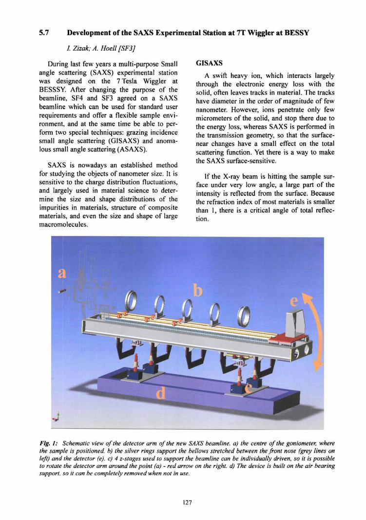
5.7 Development of the SAXS Experimental Station at 7T Wiggler at BESSY
I. Zizak; A. Hoell [SF3]
During last few years a multi-purpose Smallangle scattering (SAXS) experimental stationwas designed on the 7 Tesla Wiggler atBESSSY. After changing the purpose of thebeamline, SF4 and SF3 agreed on a SAXSbeamline which can be used for standard userrequirements and offer a flexible sample envi-ronment, and at the same time be able to per-form two special techniques: grazing incidencesmall angle scattering (GISAXS) and anoma-lous small angle scattering (ASAXS).
SAXS is nowadays an established methodfor studying the objects of nanometer size. It issensitive to the charge distribution fluctuations,and largely used in material science to deter-mine the size and shape distributions of theimpurities in materials, structure of compositematerials, and even the size and shape of largemacromolecules.
GISAXS
A swift heavy ion, which interacts largelythrough the electronic energy loss with thesolid, often leaves tracks in material. The trackshave diameter in the order of magnitude of fewnanometer. However, ions penetrate only fewmicrometers of the solid, and stop there due tothe energy loss, whereas SAXS is performed inthe transmission geometry, so that the surface-near changes have a small effect on the totalscattering function. Yet there is a way to makethe SAXS surface-sensitive.
If the X-ray beam is hitting the sample sur-face under very low angle, a large part of theintensity is reflected from the surface. Becausethe refraction index of most materials is smallerthan 1, there is a critical angle of total reflec-tion.
Fig. 1: Schematic view of the detector arm of the new SAXS beamline. a) the centre of the goniometer, wherethe sample is positioned, b) the silver rings support the bellows stretched between the front nose (grey lines onleft) and the detector (e). c) 4 z-stages used to support the beamline can be individually driven, so it is possibleto rotate the detector arm around the point (a) - red arrow on the right, d) The device is built on the air bearingsupport, so it can be completely removed when not in use.
127
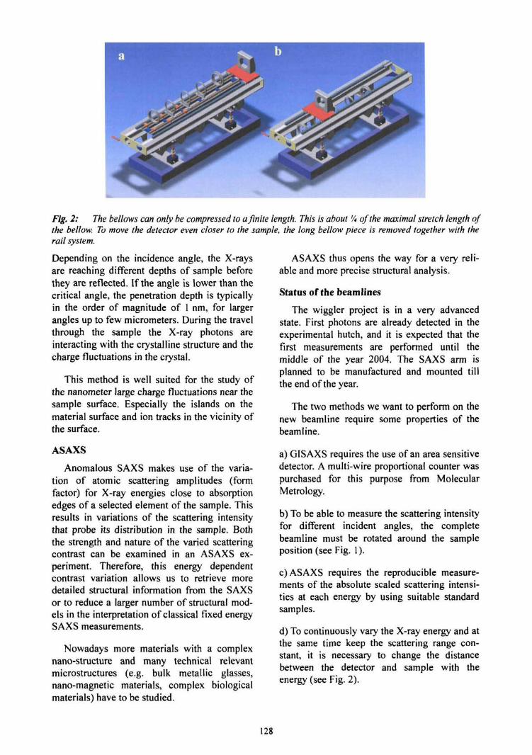
Fig. 2: The bellows can only be compressed to a finite length. This is about '/, of the maximal stretch length ofthe bellow. To move the detector even closer to the sample, the long bellow piece is removed together with therail system.
Depending on the incidence angle, the X-raysare reaching different depths of sample beforethey are reflected. If the angle is lower than thecritical angle, the penetration depth is typicallyin the order of magnitude of 1 nm, for largerangles up to few micrometers. During the travelthrough the sample the X-ray photons areinteracting with the crystalline structure and thecharge fluctuations in the crystal.
This method is well suited for the study ofthe nanometer large charge fluctuations near thesample surface. Especially the islands on thematerial surface and ion tracks in the vicinity ofthe surface.
ASAXS
Anomalous SAXS makes use of the varia-tion of atomic scattering amplitudes (formfactor) for X-ray energies close to absorptionedges of a selected element of the sample. Thisresults in variations of the scattering intensitythat probe its distribution in the sample. Boththe strength and nature of the varied scatteringcontrast can be examined in an ASAXS ex-periment. Therefore, this energy dependentcontrast variation allows us to retrieve moredetailed structural information from the SAXSor to reduce a larger number of structural mod-els in the interpretation of classical fixed energySAXS measurements.
Nowadays more materials with a complexnano-structure and many technical relevantmicrostructures (e.g. bulk metallic glasses,nano-magnetic materials, complex biologicalmaterials) have to be studied.
ASAXS thus opens the way for a very reli-able and more precise structural analysis.
Status of the beamlines
The wiggler project is in a very advancedstate. First photons are already detected in theexperimental hutch, and it is expected that thefirst measurements are performed until themiddle of the year 2004. The SAXS arm isplanned to be manufactured and mounted tillthe end of the year.
The two methods we want to perform on thenew beamline require some properties of thebeam line.
a) GISAXS requires the use of an area sensitivedetector. A multi-wire proportional counter waspurchased for this purpose from MolecularMetrology.
b) To be able to measure the scattering intensityfor different incident angles, the completebeamline must be rotated around the sampleposition (see Fig. 1).
c) ASAXS requires the reproducible measure-ments of the absolute scaled scattering intensi-ties at each energy by using suitable standardsamples.
d) To continuously vary the X-ray energy and atthe same time keep the scattering range con-stant, it is necessary to change the distancebetween the detector and sample with theenergy (see Fig. 2).
128

6. Eye Tumour Therapy
129


6.1 5 Years of Experience in Proton Therapy for Ocular Tumors in Germany
S. Hocht, W. Hinkelbein [Klinikfur Radioonkologie und Strahlentherapie, Charite Univer-sitdtsmedizin Berlin Campus Benjamin Franklin (CCBF)]; N.E. Bechrakis, M.H. Foerster[Augenklinik - CCBF]; P. Martus [Institutfur Medizinische Informatik, Biometrie undEpi-demiologie - CCBF]; D. Cordini, H. Fuchs, J. Heufelder, H. Homeyer, H. Kluge
Background
In June 1998 proton beam therapy of oculartumors started at the Hahn-Meitner-InstitutBerlin, Germany. Purpose of this study is toevaluate treatment outcome for patients withuveal melanomas and to describe the newstrategy of endoresection following neoadju-vant proton beam irradiation for tumors with aprominence of more than 5 mm, which areknown to have an increased rate of side effectsfollowing proton irradiation.
Material and Methods
245 consecutive patients with primary mela-noma of the uvea have been treated fromJune 1998 to April 2003 at HMI-Berlin-Wann-see with a 68 MeV - proton beam. This is thefirst and only proton-beam-facility in Germanysuitable for treatment of malignant and benignocular tumors. Treatment planning and prepa-ration is done in close cooperation by the de-partments of ophthalmology and radiationoncology of Charite medical school, Berlin,Campus Benjamin Franklin.
In 96.2% of all patients a uniform fractiona-tion scheme was applied. It consisted of singledoses of 15 CGE (Cobalt Gray Equivalent), anda total dose of 60 CGE applied on 4 consecutivedays. Follow-up is available in 229 patients.Since May 2000 45 of the patients with largetumors of at least 5 mm prominence have beentreated with an endoresection following protonbeam treatment.
Results
The study population in general and thesubset of those treated with an endoresectionwere comparable in terms of age (median 60.9years vs. 58.7 years) and visual decimal acuity(0.5 vs. 0.5). As expected tumors treated byadditional endoresection were larger (medianprominence 8.8 mm vs. 3.5 mm, median base ofthe tumor 15.4 vs. 10.3 mm) and were not in
direct proximity to critical structures as opticdisc (median 2.3 mm vs. 1.5 mm) and foveacentralis (median 3.4 mm vs. 0.6 mm)
At the time of median follow up(18.4 months) local control is 96.4% and 95.5%at 3 years. Eye retention rate is 92.6% at20 months (median follow-up) and 87.5% at3 years. The subset of patients treated with anendoresection did fairly well: Although thosetumors were larger in volume, their outcomedoes compare favourably with the others. Localcontrol is 98% at 18 months (the time ofmedian follow-up for this parameter is18.1 months) and eye-retention rate is 88.6%after 2 years.
Conclusions
Proton beam irradiation of uveal melanomasat the Hahn-Meitner-Institut after the first5 years of its initiation reveals local tumorcontrol- and eye-retention rates in the range ofother centers with larger experience. Deliveringhigh treatment quality in hadron therapy fromthe beginning has been achieved. As there willbe a learning curve as documented in othercenters, there is hope for a further rise in resultswith increasing experience and a longer follow-up period.
The concept of endoresection after protonbeam irradiation seems promising but will needfurther evaluation with more patients and alonger follow-up period.
Outlook
The promising results achieved in the treatmentof ocular tumors and the growing knowledgegathered over the years would seem a reason-able basis for a large scale proton therapy centerjointly run by HMI and Charite medical school.
131
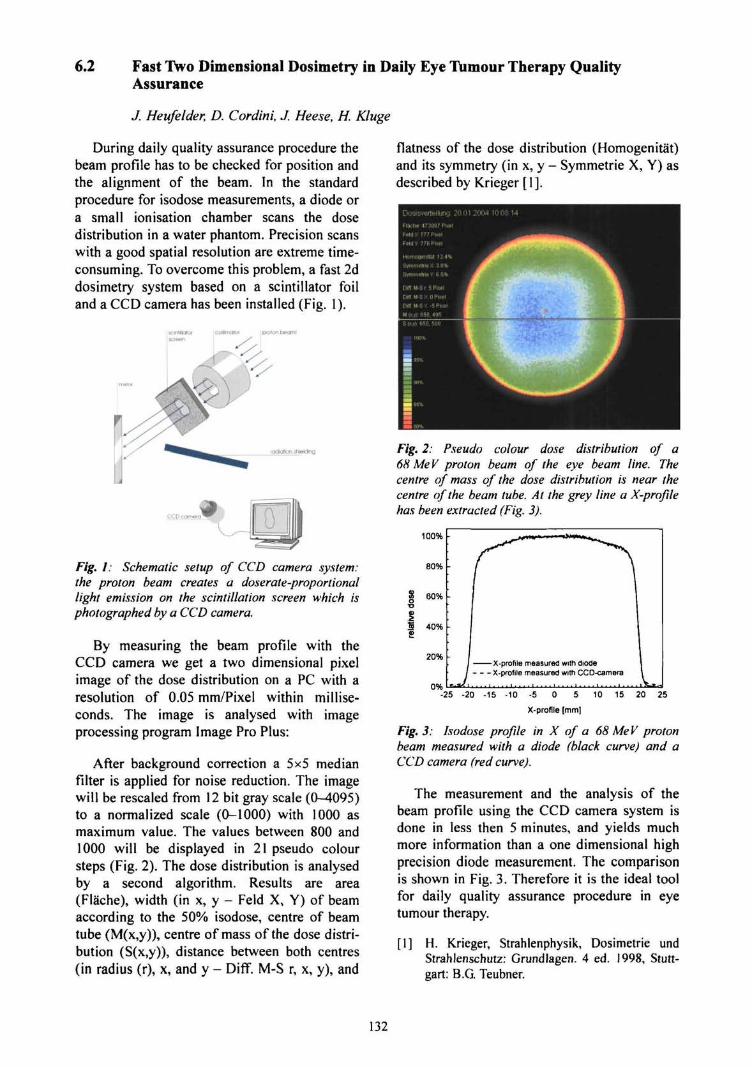
6.2 Fast Two Dimensional Dosimetry in Daily Eye Tumour Therapy QualityAssurance
./. Heufelder, D. Cordini,./. Heese, H. Kluge
During daily quality assurance procedure thebeam profile has to be checked for position andthe alignment of the beam. In the standardprocedure for isodose measurements, a diode ora small ionisation chamber scans the dosedistribution in a water phantom. Precision scanswith a good spatial resolution are extreme time-consuming. To overcome this problem, a fast 2ddosimetry system based on a scintillator foiland a CCD camera has been installed (Fig. 1).
radiation shtekjlng
Fig. I: Schematic setup of CCD camera system:the proton beam creates a doserate-proportionallight emission on the scintillation screen which isphotographed by a CCD camera.
By measuring the beam profile with theCCD camera we get a two dimensional pixelimage of the dose distribution on a PC with aresolution of 0.05 mm/Pixel within millise-conds. The image is analysed with imageprocessing program Image Pro Plus:
After background correction a 5x5 medianfilter is applied for noise reduction. The imagewill be rescaled from 12 bit gray scale (0-4095)to a normalized scale (0-1000) with 1000 asmaximum value. The values between 800 and1000 will be displayed in 21 pseudo coloursteps (Fig. 2). The dose distribution is analysedby a second algorithm. Results are area(FlSche), width (in x, y - Feld X, Y) of beamaccording to the 50% isodose, centre of beamtube (M(x,y)), centre of mass of the dose distri-bution (S(x,y)), distance between both centres(in radius (r), x, and y - Diff. M-S r, x, y), and
flatness of the dose distribution (Homogenitat)and its symmetry (in x, y - Symmetric X, Y) asdescribed by Krieger [1].
Fig. 2: Pseudo colour dose distribution of a68 Me V proton beam of the eye beam line. Thecentre of mass of the dose distribution is near thecentre of the beam tube. At the grey line a X-profilehas been extracted (Fig. 3).
100% •
80%
0%
X-profile measured with diodeX-profile measured with CCD-camera
-25 -20 -15 -10 -5 0 5
X-profile [mm]
10 15 25
Fig. 3: Isodose profile in X of a 68 MeV protonbeam measured with a diode (black curve) and aCCD camera (red curve).
The measurement and the analysis of thebeam profile using the CCD camera system isdone in less then 5 minutes, and yields muchmore information than a one dimensional highprecision diode measurement. The comparisonis shown in Fig. 3. Therefore it is the ideal toolfor daily quality assurance procedure in eyetumour therapy.
[I] H. Krieger, Strahlenphysik, Dosimetrie undStrahlenschutz: Grundlagen. 4 ed. 1998, Stutt-gart: B.G. Teubner.
132
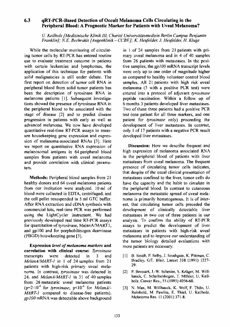
6.3 qRT-PCR-Based Detection of Occult Melanoma Cells Circulating in thePeripheral Blood: A Prognostic Marker for Patients with Uveal Melanoma?
U. Keilholz [Medizinische Klinik HI, Charite Universitdtsmedizin Berlin Campus BenjaminFranklin]; N.E. Bechrakis [Augenklinik - CCBFJ; K. Heufelder, J. Heufelder, H. Kluge
While the molecular monitoring of circulat-ing tumor cells by RT-PCR has entered routineuse to evaluate treatment outcome in patientswith certain leukemias and lymphomas, theapplication of this technique for patients withsolid malignancies is still under debate. Thefirst report on detection of tumor cell RNA inperipheral blood from solid tumor patients hasbeen the description of tyrosinase RNA inmelanoma patients [1]. Subsequent investiga-tions showed the presence of tyrosinase RNA inthe peripheral blood to be associated with thestage of disease [2] and to predict diseaseprogression in patients with early as well asadvanced melanoma. We now have developedquantitative real-time RT-PCR assays to meas-ure housekeeping gene expression and expres-sion of melanoma-associated RNAs [3]. Herewe report on quantitative RNA expression ofmelanosomal antigens in 64 peripheral bloodsamples from patients with uveal melanomaand provide correlation with clinical parame-ters.
Methods: Peripheral blood samples from 21healthy donors and 64 uveal melanoma patientsfrom our institution were analyzed. 10 ml ofblood were collected in EDTA, centrifuged, andthe cell pellet resuspended in 5 ml GTC buffer.After RNA extraction and cDNA synthesis withcommercial kits, real-time PCR was performedusing the LightCycler instrument. We hadpreviously developed real time RT-PCR assaysfor quantitation of tyrosinase, MelanA/MART 1,and gplOO and for porphobilinogen deaminase(PBGD) housekeeping gene [3].
Expression level of melanoma markers andcorrelation with clinical course: Tyrosinasetranscripts were detected in 3 andMelanA/MART-l in 1 of 24 samples from 21patients with high-risk primary uveal mela-noma. In contrast, tyrosinase was detected in24, and MelanA/MART-l in 31 of 40 samplesfrom 26 metastatic uveal melanoma patients(p=210'4 for tyrosinase; p<10'4 for MelanA/-MART-1 compared to disease-free patients).gplOO mRNA was detectable above background
in 1 of 24 samples from 21 patients with pri-mary uveal melanoma and in 4 of 40 samplesfrom 26 patients with metastases. In the posi-tive samples, the gplOO mRNA transcript levelswere only up to one order of magnitude higheras compared to healthy volunteer control bloodsamples. All 21 patients with high risk uvealmelanoma (3 with a positive PCR test) wereentered into a protocol of adjuvant tyrosinasepeptide vaccination. Within a follow up of6 months 3 patients developed liver metastases.Two of these three patients had a positive PCRtest (one patient for all three markers, and onepatient for tyrosinase only) proceeding thedevelopment of liver metastases. In contrast,only 1 of 17 patients with a negative PCR resultdeveloped liver metastases.
Discussion: Here we describe frequent andhigh expression of melanoma associated RNAin the peripheral blood of patients with livermetastases from uveal melanoma. The frequentpresence of circulating tumor cells indicates,that despite of the usual clinical presentation ofmetastases confined to the liver, tumor cells dohave the capacity and the habit to circulate inthe peripheral blood. In contrast to cutaneousmelanoma the metastatic spread of uveal mela-noma is primarily hematogenous. It is of inter-est, that circulating tumor cells preceded thedevelopment of clinically detectable livermetastases in two out of three patients in ouranalysis. To confirm the ability of RT-PCRassays to predict the development of livermetastases in patients with high-risk uvealmelanoma and to improve our understanding ofthe tumor biology detailed evaluations withmore patients are necessary.
[1] B. Smith, P. Selby, J. Southgate, K. Pittman, C.Bradley, G.E. Blair, Lancet 338 (1991) 1227-29.
[2] P. Brossart, J.-W. Schmier, S. KrUger, M. Will-hauck, C. Scheibenbogen, T. MOhler, U. Keil-holz, Cancer Res., 55 (1995) 4056-68.
[3] N. Max, M. Willhauck, K. Wolf, F. Thilo, U.Reinhold, M. Pawlita, E. Thiel, U. Keilholz,Melanoma Res. 11 (2001)371-8.
133

6.4 Proton Therapy and Stereotactic Photon Irradiation of Uveal Melanoma:A Comparative Planning under Fair Conditions
R. Stark, J. Heufelder, D. Cordini; S. Hocht [Radioonkologie und Strahlentherapie, CharlieUniversitatsmedizin Berlin, Campus Benjamin Franklin]
Proton therapy of uveal melanoma (UM) isestablished in clinical routine since more than25 years. Local tumour control probabilities ofover 95% after five years are reported by mostof the treating institutions.
Another form of high-precision irradiation isthe stereotactic radiotherapy with photons. Forthis purpose specially dedicated radiotherapylinear accelerators, or cobalt machinesdeveloped only for this purpose (gamma-knife)are in use. In the treatment of tumours lyingwithin the human brain this form of therapy isestablished since a couple of years.
Most recently also the application to UM isinvestigated by a growing number of groups.The first reports are positive regarding localtumour control, but yet with only short follow-up periods.
However particularly the selection of thetreated patients in these studies varies consid-erably. Therefore there are legitimate doubtswhether stereotactic photon radiotherapy is ableto compete against proton therapy in thosecases, where the physical advantages of theproton beam - the very sharp distal dose drop-off - are fully exploited: tumours at the poste-rior pole of the eye lying in direct proximity tostructures critical for the preservation of visualacuity, i.e., optic nerve, optic disc and macula.
In a study therefore ten UM-patients treatedwith protons shall be comparatively plannedunder "fair conditions" with the proton therapyplanning program Eyeplan, which is the stan-dard planning program for tumours of theocular globe, and the stereotactic radiotherapyplanning program BrainScan. Transversal CTshave been performed twice, without and inaddition with a stereotactic positioning frame.
In order to create identical conditions forcontouring the tumour region and ocular struc-tures, data of the Eyeplan tumour models shallbe redrawn on a slice-to-slice basis in Brain-Scan. This is necessary because in protontherapy of eye tumours some eye-specific
resources are utilised for tumour localisation,which are not available in stereotactic radio-therapy planning programs, e.g. fundus photo-graphies and the positions of tantalum clipssutured on the eye globe only for proton ther-apy (tumour and eye position verification forplanning and during treatment).
In the HMI, tumour outlines of the ten Eye-plan treatment plans were extracted in thecorresponding orientation and location of theCT cuts and were superposed on these.
Extraction of the Eyeplan tumour contoursinto CT slices
Fig. 1: Position of the sample tumour (red) duringCT fixation, location of the uppermost intersectionplane (left figure, horizontal violet line). Tumour inthis case planned on sclera to represent its realubicalion in the flattened eye by the spherical eyemodel. Diameter of model lens (dark blue): 9 mm.
The treatment planning program Eyeplan isnot designed to generate intersection images,the drawing of the eye model can only berestricted to one side of any plane. In generalthe tumour position is oblique to the requiredset of planes (Fig. 1), and for central tumoursections the in-plane "one-side views" that canbe created are of but limited usefulness (Fig. 2).
In such a case the intersection of both "one-side views" of a distinct plane can be formed(logic AND-operation on the images in a suit-able file format, with the software Image-ProPlus). The resulting image contains the set ofline segments penetrating the section plane(Fig. 3).
For the tumour outline in that plane (bottomimage of Fig. 3), the length of the marginal linesegments can be used as error estimate.
134
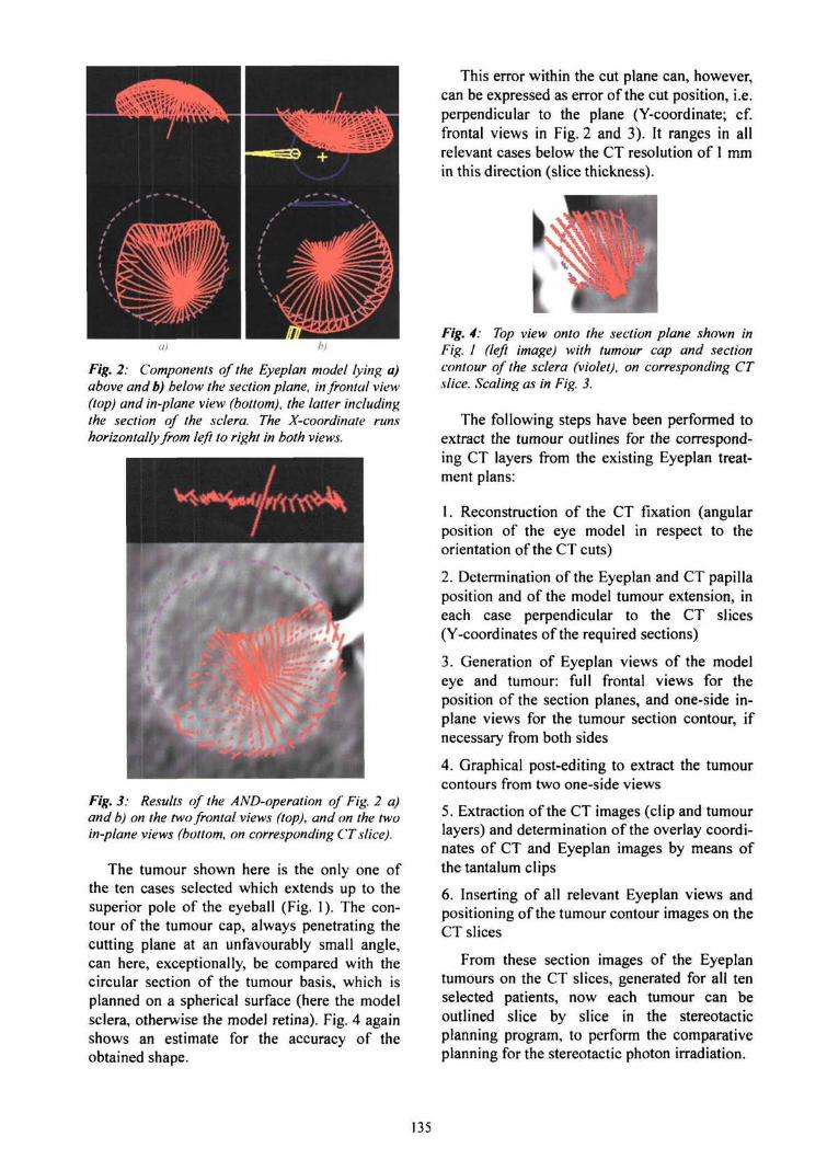
Fig. 2: Components of the Eyeplan model lying a)above and b) below the section plane, in frontal view(top) and in-plane view (bottom), the latter includingthe section of the sclera. The X-coordinatehorizontally from left to right in both views.
runs
Fig. 3: Results of the AND-operation of Fig. 2 a)and b) on the two frontal views (top), and on the twoin-plane views (bottom, on corresponding CT slice).
The tumour shown here is the only one ofthe ten cases selected which extends up to thesuperior pole of the eyeball (Fig. 1). The con-tour of the tumour cap, always penetrating thecutting plane at an unfavourably small angle,can here, exceptionally, be compared with thecircular section of the tumour basis, which isplanned on a spherical surface (here the modelsclera, otherwise the model retina). Fig. 4 againshows an estimate for the accuracy of theobtained shape.
This error within the cut plane can, however,can be expressed as error of the cut position, i.e.perpendicular to the plane (Y-coordinate; cf.frontal views in Fig. 2 and 3). It ranges in allrelevant cases below the CT resolution of 1 mmin this direction (slice thickness).
Fig. 4: Top view onto the section plane shown inFig. I (left image) with tumour cap and sectioncontour of the sclera (violet), on corresponding CTslice. Scaling as in Fig. 3.
The following steps have been performed toextract the tumour outlines for the correspond-ing CT layers from the existing Eyeplan treat-ment plans:
1. Reconstruction of the CT fixation (angularposition of the eye model in respect to theorientation of the CT cuts)
2. Determination of the Eyeplan and CT papillaposition and of the model tumour extension, ineach case perpendicular to the CT slices(Y-coordinates of the required sections)
3. Generation of Eyeplan views of the modeleye and tumour: full frontal views for theposition of the section planes, and one-side in-plane views for the tumour section contour, ifnecessary from both sides
4. Graphical post-editing to extract the tumourcontours from two one-side views
5. Extraction of the CT images (clip and tumourlayers) and determination of the overlay coordi-nates of CT and Eyeplan images by means ofthe tantalum clips
6. Inserting of all relevant Eyeplan views andpositioning of the tumour contour images on theCT slices
From these section images of the Eyeplantumours on the CT slices, generated for all tenselected patients, now each tumour can beoutlined slice by slice in the stereotacticplanning program, to perform the comparativeplanning for the stereotactic photon irradiation.
135
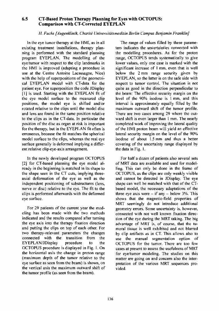
6.5 CT-Based Proton Therapy Planning for Eyes with OCTOPUS:Comparison with CT-Corrected EYEPLAN
H. Fuchs [Augenklinik, Charite Universitatsmedizin Berlin Campus Benjamin Franklin]
In the eye tumor therapy at the HMI, as in allexisting treatment installations, therapy plan-ning is performed with the standard planningprogram EYEPLAN. The modelling of theeye/tumor with respect to the clip landmarks inthe HMI is improved (adapting a procedure inuse at the Centre Antoine Lacassagne, Nice)with the help of superpositions of the geometri-cal EYEPLAN model with CT-data for thepatient eye. For superposition the code JDisplay[1] is used. Starting with the EYEPLAN fit ofthe eye model surface to the measured clippositions, the model eye is shifted and/orrotated relative to the clips until the model discand lens are found in the same position relativeto the clips as in the CT-data. In particular theposition of the disc as organ at risk is importantfor the therapy, but in the EYEPLAN fit often iserroneous, because the fit matches the sphericalmodel surface to the clips, whereas the real eyesurface generally is deformed implying a differ-ent relative clip-eye-axis arrangement.
In the newly developed program OCTOPUS[2] for CT-based planning the eye model al-ready in the beginning is matched in its shape tothe shape seen in the CT cuts, implying three-axial deformation of the eye as well as theindependent positioning of substructures (lens,nerve or disc) relative to the eye. The fit to theclips is performed afterwards with the deformedeye surface.
For 29 patients of the current year the mod-eling has been made with the two methodsindicated and the results compared after turningthe eye axis into the therapy fixation directionand putting the clips on top of each other. Fortwo therapy-relevant parameters the changesconnected with the transition from theEYEPLAN/JDisplay procedure to theOCTOPUS procedure is displayed in Fig. 1. Onthe horizontal axis the change in proton range(maximum depth of the tumor relative to theeye surface as seen from the beam) is shown, onthe vertical axis the maximum outward shift ofthe tumor profile (as seen from the beam).
The range of values filled by these parame-ters indicates the uncertainties connected withthe modelling procedures. As for the protonrange, OCTOPUS tends systematically to givelower values, only one case is marked with thesignificant increase of 1 mm, even that is wellbelow the 2 mm range security given byEYEPLAN, so the latter is on the safe side withrespect to tumor control. The situation is notquite as good in the direction perpendicular tothe beam: The effective security margin on thelevel of the 90% isodose is 1 mm, and thisinterval is approximately equally filled by themaximum outward shift of the tumor profile.There are two cases among 29 where the out-ward shift is even larger than 1 mm. The nearlycompleted work of improving the lateral qualityof the HMI proton beam will yield an effectivelateral security margin on the level of the 90%isodose of about 1.5 mm and thus a bettercovering of the uncertainty range displayed bythe data in Fig. 1.
For half a dozen of patients also several setsof MRT data are available and used for model-ling. This can only be done in the frame ofOCTOPUS, as the clips are only weakly visibleand cannot be detected in JDisplay. The eyeshape can well be matched with that of the CT-based model, the necessary adaptations of thethree eye axis were - if any - below 3%. Thisshows that the magnetic-field properties ofMRT seemingly do not introduce additionalgeometry errors. Some uncertainty is, however,connected with not well known fixation direc-tion of the eye during the MRT taking. The bigadvantage of MRT is, of course, that the tu-moral tissue is well exhibited and not blurredby clip artifacts as in CT. This allows also touse the manual segmentation option ofOCTOPUS for the tumor. There are too fewcases at present to assess the usefulness of MRTfor eye/tumor modeling. The studies on thismatter are going on and concern also the inter-pretation of the various MRT sequences pro-vided.
136
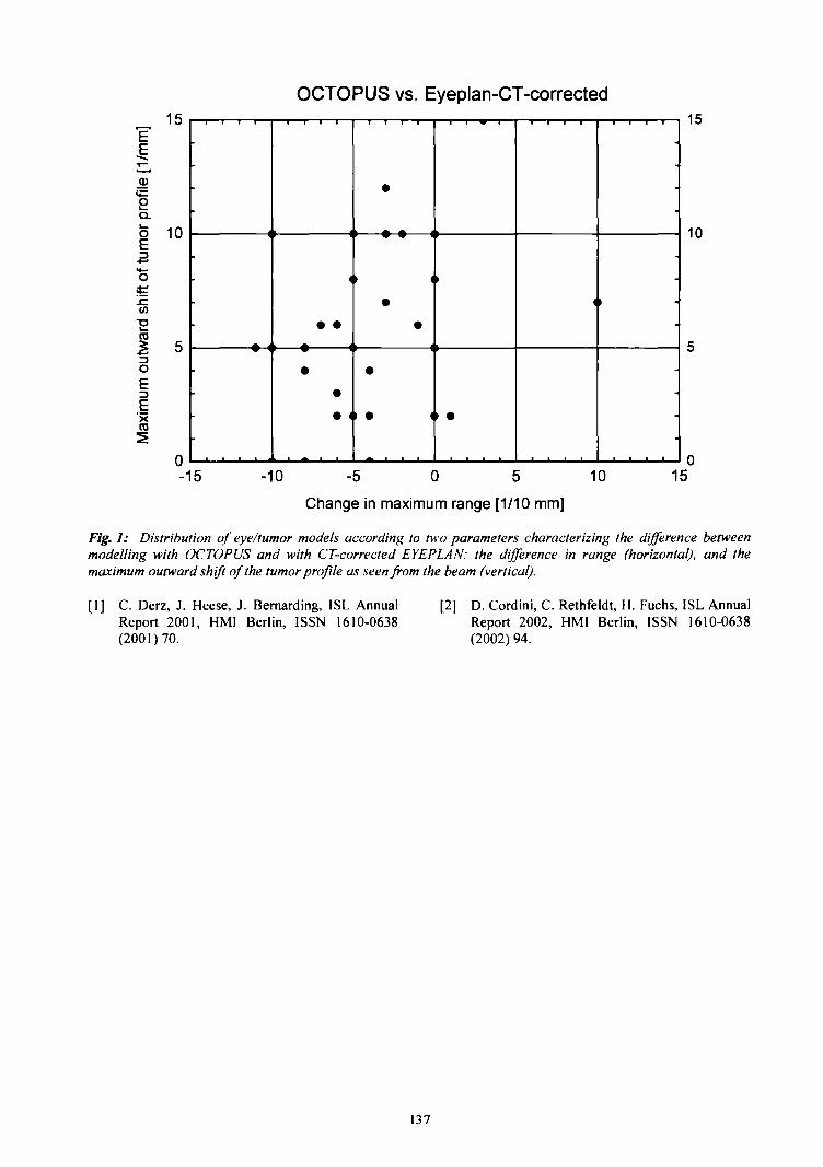
E
b3
IoE'><
15
10
OCTOPUS vs. Eyeplan-CT-corrected
<
• •
••• 4
•
•
•
•
> • 1
t
<
•
fi
ll
• I
I 1
15
10
-15 -10 -5 0 5
Change in maximum range [1/10 mm]
10 15
Fig. 1: Distribution of eye/tumor models according to two parameters characterizing the difference betweenmodelling with OCTOPUS and with CT-corrected EYEPLAN: the difference in range (horizontal), and themaximum outward shift of the tumor profile as seen from the beam (vertical).
[1] C. Derz, J. Heese, J. Bernarding, ISL AnnualReport 2001, HMI Berlin, ISSN 1610-0638(2001)70.
[2] D. Cordini, C. Rethfeldt, H. Fuchs, ISL AnnualReport 2002, HMI Berlin, ISSN 1610-0638(2002) 94.
137
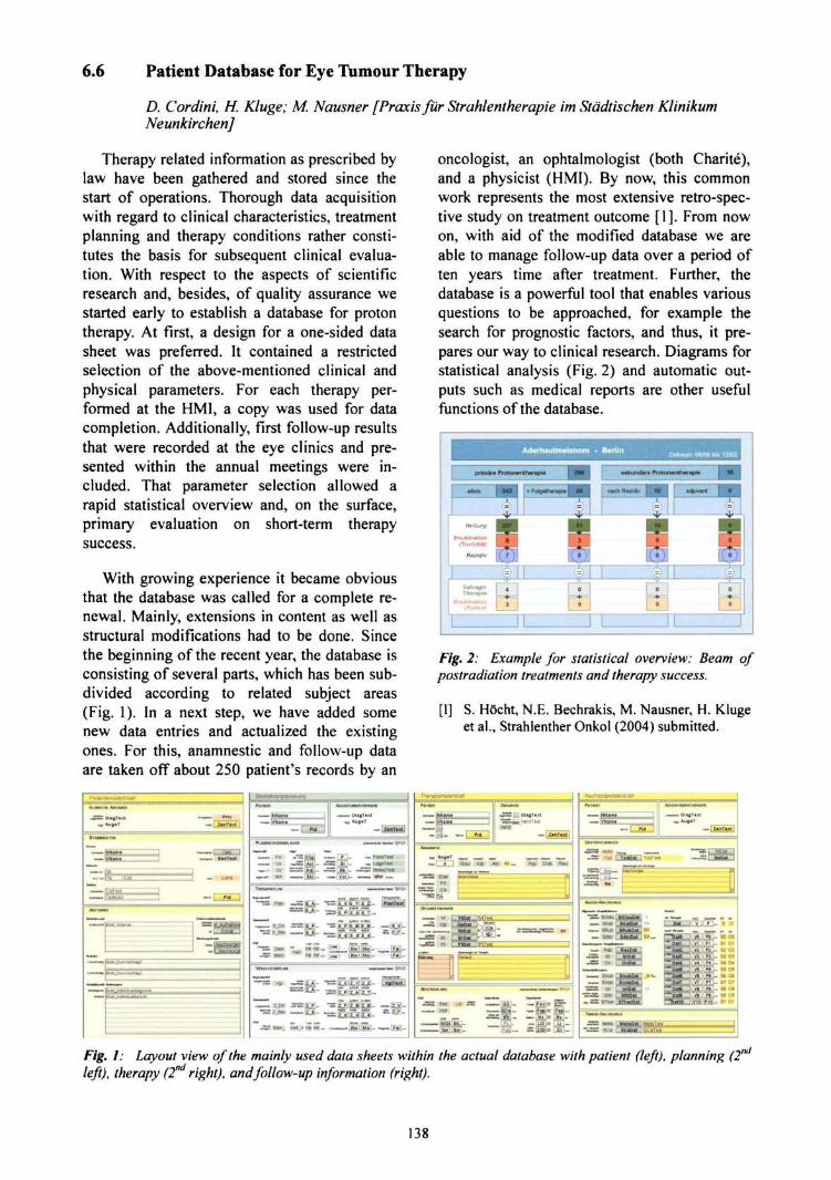
6.6 Patient Database for Eye Tumour Therapy
D. Cordini, H. Kluge; M. Nausner [Praxis fur Strahlentherapie im Stadtischen KlinikumNeunkirchen]
Therapy related information as prescribed bylaw have been gathered and stored since thestart of operations. Thorough data acquisitionwith regard to clinical characteristics, treatmentplanning and therapy conditions rather consti-tutes the basis for subsequent clinical evalua-tion. With respect to the aspects of scientificresearch and, besides, of quality assurance westarted early to establish a database for protontherapy. At first, a design for a one-sided datasheet was preferred. It contained a restrictedselection of the above-mentioned clinical andphysical parameters. For each therapy per-formed at the HM1, a copy was used for datacompletion. Additionally, first follow-up resultsthat were recorded at the eye clinics and pre-sented within the annual meetings were in-cluded. That parameter selection allowed arapid statistical overview and, on the surface,primary evaluation on short-term therapysuccess.
With growing experience it became obviousthat the database was called for a complete re-newal. Mainly, extensions in content as well asstructural modifications had to be done. Sincethe beginning of the recent year, the database isconsisting of several parts, which has been sub-divided according to related subject areas(Fig. 1). In a next step, we have added somenew data entries and actualized the existingones. For this, anamnestic and follow-up dataare taken off about 250 patient's records by an
oncologist, an ophtalmologist (both Charite),and a physicist (HMI). By now, this commonwork represents the most extensive retro-spec-tive study on treatment outcome [1]. From nowon, with aid of the modified database we areable to manage follow-up data over a period often years time after treatment. Further, thedatabase is a powerful tool that enables variousquestions to be approached, for example thesearch for prognostic factors, and thus, it pre-pares our way to clinical research. Diagrams forstatistical analysis (Fig. 2) and automatic out-puts such as medical reports are other usefulfunctions of the database.
Fig. 2: Example for statistical overview: Beam ofpostradiation treatments and therapy success.
[1] S. HOcht, N.E. Bechrakis, M. Nausner, H. Klugeet al., Strahlenther Onkol (2004) submitted.
PaMflWnda/en ai*H
i t iwm »n inn
•£55 DligTm -"••— Prlv"* Aua*T — 1 JWITMI |
llUM
—TNtiuni
Sir«-».|PE IlLJfl
—
tena
TBIMUDU
1 sea 1»«-* »UT«t
«> Land
~~ [ s r ~ i
BnnLOiKwulV U3BHU1I
•' > | * . * J ™ U « I . . . . . . _ _ _ . _ . .
" - —
••"• •
£nir_Duri;itb^nJiBl . _ __ . _ _ . _
BueUndhaOuiltinuiL _. _
Fig. I: Layout view of the mainly used data sheets within the actual database with patient (left), planning (2nd
left), therapy (2nd right), and follow-up information (right).
138
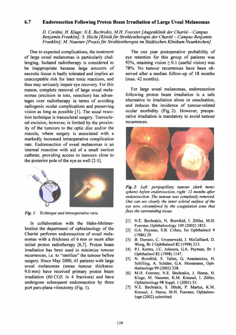
6.7 Endoresection Following Proton Beam Irradiation of Large Uveal Melanomas
D. Cordini, H. Kluge; N.E. Bechrakis, M.H. Foerster [Augenklinik der Char He - CampusBenjamin Franklin]; S. Hocht [Klinikfur Strahlentherapie der Charite - Campus BenjaminFranklin]; M. Nausner [Praxis fur Strahlentherapie im Stadtischen Klinikum Neunkirchen]
Due to expected complications, the treatmentof large uveal melanomas is particularly chal-lenging. Isolated radiotherapy is considered tobe inappropriate because large amounts ofnecrotic tissue is badly tolerated and implies anunacceptable risk for later toxic reactions, andthus may seriously impair eye recovery. For thisreason, complete removal of large uveal mela-nomas (excision in toto, resection) has advan-tages over radiotherapy in terms of avoidingradiogenic ocular complications and preservingvision as long as possible [1]. The usual resec-tion technique is transscleral surgery. Transscle-ral excision, however, is limited by the proxim-ity of the tumours to the optic disc and/or themacula, where surgery is associated with amarkedly increased intraoperative complicationrate. Endoresection of uveal melanomas is aninternal resection with aid of a small suctioncatheter, providing access to tumours close tothe posterior pole of the eye as well [2-5].
Fig. 1: Technique and intraoperative view.
In collaboration with the Hahn-Meitner-Institut the department of ophtalmology of theCharite performs endoresection of uveal mela-nomas with a thickness of 6 mm or more afterinitial proton radiotherapy [6,7]. Proton beamirradiation has been used to minimize tumourrecurrences, i.e. to "sterilize" the tumour beforesurgery. Since May 2000, 45 patients with largeuveal melanomas (mean tumour thickness:9.0 mm) have received primary proton beamirradiation (60 CGE in 4 fractions) and haveundergone subsequent endoresection by threeport pars-plana vitrectomy (Fig. 1).
The one year postoperative probability ofeye retention for this group of patients was95%, retaining vision > 0.1 (useful vision) was78%. No tumour recurrences have been ob-served after a median follow-up of 18 months(max. 42 months).
For large uveal melanomas, endoresectionfollowing proton beam irradiation is a safealternative to irradiation alone or enucleation,and reduces the incidence of tumour-relatedocular morbidity (Fig. 2). However, preope-rative irradiation is mandatory to avoid tumourrecurrences.
Fig. 2: Left: peripapillary tumour (dark hemi-sphere) before endoresection, right: 12 months afterendoresection. The tumour was completely removed.One can see clearly the inner scleral surface of theeye now, circumfered by the coagulation zone thatfixes the surrounding tissue.
[I] N.E. Bechrakis, N. Bornfeld, I. ZSller, M.H.Foerster, Ophthalmology 109 (2002) 1855.
[2] GA. Peyman, S.B. Cohen, Int Ophthalmol 9(1986)29.
[3] B. Damato, C. Groenewald, J. McGalliard, D.Wong, Br J Ophthalmol 82 (1998) 213.
[4] P.J. Kertes, J.C. Johnson, GA. Peyman, Br JOphthalmol 82 (1998) 1147.
[5] N. Bornfeld, S. Talies, G Anastassiou, H.Schilling, A. Schuler, GA. Horstmann, Oph-thalmologe 99 (2002) 338.
[6] M.H. Foerster, N.E. Bechrakis, J. Heese, H.Kluge, M. Nausner, K.M. Kreusel, 1. Z6ller,Ophtalmologe 98 Suppl. 1 (2001) 35.
[7] N.E. Bechrakis, S. Hocht, P. Martus, K.M.Kreusel, J. Heese, M.H. Foerster, Ophtalmo-loge (2002) submitted.
139


II.
Publications and Talks
1. Scientific Publications 143
2. Conference Contributions and Talks at other Institutes 153
3. Theses 169
4. Courses at Universities 173
141


1. Scientific Publications
143

Structure and Dynamics
Beuve, M.; Stolterfoht, N.; Toulemonde, M.;Trautmann, C. and Urbassek, H. M.:Influence of electron dynamics in swift ion-induced sputteringPhys. Rev. B 68 (2003) 125423
Bertschat, H.-K; Manzhur, Y; Potzger, K.;Prandolini, M. J.; Weber, A.; Zeitz, W.-D.;Dietrich, M.:Investigations on Surface and InterfaceMagnetism Using Local ProbesProceedings of the XXXVIII Zakopane Schoolof Physics, Zakopane, Poland, May 10-19,2003;ed. by E. A. GSrlich, K. Kr61as, A. T.P^dziwiatr, Krakow
Bollmann, J.; Knack, S.; Weber, J.; Koteski, K;Mahnke, H.-E.; Welter, E.:Limitations of Electrical Detection of X-rayAbsorption Fine StructurePhys. Rev. B 68 (2003) 125206
Bruno, G; Schumacher, G; Cavalcanti Pinto,H.;Schulze, C:Measurement of the lattice misfit of thenickel-base superalloy SCI6 by high-energysynchrotron radiationMetallurgical and Materials Transactions A 34(2003) 193-197
Bundesmann, J.; Hellhammer, R.; Hoffmann,V; Stolterfoht, N.:Advanced control of ECR-source andbeamline system on high voltage potentialIn: Duggan J.L. [u.a.] [Eds.]: Application ofaccelerators in research and industry : 17thinternational conference. Denton, Texas, 12-16November 2002. Melville, NY: AmericanInstitute of Physics, 2003 (AIP conferenceproceedings ; 680). - ISBN 0-7354-0149-7, p.1030-1033
Chen, W; Darowski, N.; Zizak, L; Schumacher,G; Klingelhoffer, H; Wanderka, N andNeumann, W:Measurement of gamma/gamma' latticemismatch in creep deformed single crystalsuperalloy SC16 using synchrotron X-radiationMaterials Science Forum 426-432 (2003), p.4555-4560
Czerski, K.; Huke, A.; Heide, P.:d+d fusion under astrophysicalpycnoreaction conditionsNucl. Phys. A719 (2003) 52c
Darowski, N.; Zizak, I.; Schumacher, G;Klaumiinzer, S.; Wendler, E.:Surface crystallinity and radiation-amorphization of InP - An X-ray grazingincidence studyNuclear Instruments and Methods in PhysicsResearch B 209 (2003), p. 131-135
Fedotov, A.; Anis Saad, M. H.; Manego, S.;Mazanik, A.; Survilo, L.; Strekal, N.;Franzkevich, A.; Stukalov, O.; Wilhelm, M.;Zollondz, J.-H.; Maskevich, S.; Trofimov, Yu.;Petrov, A.; Fink, D; Chigir, S.:Structure of polycrystalline CdSo.sSeo.2 filmssputtered on dielectric substrates coated withnanosized silver islandsProceedings of III International Symposium"New electrical and electronic technologies andtheir industrial implementation", Zakopane,Poland, May, 13-16, 2003, p. 61-64
Fink, D.; Alegaonkar, P. S.; Petrov, A. V;Berdinsky, A. S.; Rao, V.; Muller, M.; Dwtvedi,K. K; Chadderton, L T.:The Emergence of New Ion TrackApplicationsRadiation Meas. 36 (2003) 605 - 609
Fink, D; Petrov, A. V; Rao, V.; Wilhelm, M.;Demyanov, S.; Szimkowiak, P.; Behar, M.;Alegaonkar, P. S.; Chadderton, L. T.:Production Parameters for the Formation ofMetallic Nanotubules in Etched TracksRadiation Meas. 36 (2003) 751 - 755
Fink,D.; Petrov, A. V; Stolterfoht, N.; WilhelmM.; Hoffmann, V.; Richter, A.; Behar, M.;Farenzena, L; Papaleo, R.; Hirata, K.;Chadderton, L.T.; Schulz, A.; Fahrner, W.R.:Creation of nanoscale electronic devices byswift heavy ion track manipulationsJAERIConf 2003-001 (Proc. of the 3rd Intl.Symp. on Material Chemistry in NuclearEnvironment, March 13-15, 2002, Tsukuba(Japan))
145

Fink, D.; Miiller, M.; Petrov, A.; Farenzena, L;Behar, M.; Papaleo, R.M.:Etching Kinetics of Swift Heavy IonIrradiated Silicone Rubber with InsolubleAdditives or Reaction ProductsNucl. Instr. and Meth. in Phys. Res. B209(2003)310-315
Hattendorf, J.; Zeitz, W.-D.; Schroder, W.;Abrosimov, N. K:On the formation of boron-germanium pairsin silicon-germanium mixed crystalsPhysica B 340 (2003) 858
Hou, M.D.; Klaumiinzer, S.:Heavy ion-induced deformation of radiation-amorphized U3SiNuclear Instruments and Methods in PhysicsResearch B 209 (2003), p. 149-153
Huhe, A.; Czerski, K; Heide, P.:Experimental techniques for theinvestigation of the electron screening effectfor d+d fusion reactions in metallicenvironmentsNucl. Phys. A719 (2003) 279c
Jenichen, B.; Kaganer, V.M.; Kdstner, M.;Herrmann, C; Ddweritz, L; Ploog, K. H;Darowski, N.; Zizak, I.:Structural and magnetic phase transition inMnAs(0001)/GaAs(lll) epitaxial filmsPhysical Review B, 68 (2003) 132301 68(2003), p. 132301/1-4
Juaristi, I.J.; Diez Muino, R.; Dubus, A.;Rosier, M.:Charge-State Dependence of the KineticElectron Emission Induced by SlowMulticharged Ions in MetalsISL Annual Report, 111-113 (ISSN: 1610-0638,2003)
Koteski, V.; Ivanovic, N.; Haas, H; Holub-Krappe, E.; Mahnke, H.-E.:Lattice relaxation around impurity atoms insemiconductors - Arsenic in Si - acomparison between experiment and theoryNucl. Instr.and Meth. in Phys. Res. B 200(2003) 60-65
Liu, Q. K. K; Schumacher, G:Texture evolution during crystallization ofthin amorphous filmsIn: Aziz M.J. [u.a.] [Eds.]: Morphological andcompositional evolution of thin films :symposium held December 2 - 5 , 2002, Boston,Massachusetts, U.S.A.. Warrendale, Pa.:Materials Research Society, 2003 (MaterialsResearch Society symposium proceedings ;749), p. 195-200
Mishra, R.; Tripathy, S. P.; Dwivedi, K K;Khathing, D. T; Ghosh, S.; Miiller, M. andFink, D:Spectroscopic and thermal studies of electronirradiated polyimideRadiation Meas. 36 (2003) 621-624
Mishra, R.; Tripathy, S. P.; Dwivedi, K. K.;Khathing, D. T; Ghosh, S.; Miiller, M. andFink, D.:Modification of PADC through electron-target collisionRadiation Meas. 36 (2003) 639-642
Mishra, R; Tripathy, S. P.; Dwivedi, K. K.;Khathing, D. T; Ghosh, S; Muller, M. andFink, D.:Dose dependent modification in makrofol-nand polyimide by proton irradiationRadiation Meas. 36 (2003) 719-722
Pauly, N.; Dubus, A.; Rosier, M.:Influence of charge changing processes onproton induced electron emission frompolycrystalline aluminumNucl. Instr. Meth. B203, 36-40 (2003)
Pauly, N.; Dubus, A.; Rosier, M.:Influence of charge changing processes onthe forward and backward electron emissionyield ratio for light ions impinging on thinmetallic foilsNucl. Instr. Meth. B212, 391-396 (2003)
Pauly, N.; Dubus, A.; Rosier, M.:Comparison of the potentials used for thecalculation of the resonant coherent electroncapture and loss cross sectionsJ. of Electron Spectroscopy 129, 229-232(2003)
146
Pesic, Z. D.; Anton, J.; Bremer, J. H;Hoffmann, V.; Stolterfoht, N.; Vikor, G andSchuch, R:Inelastic Energy Loss In Large AngleScattering of Ar9* Ions from Au(lll) CrystalNucl. Instrum. Meth. in Phys. Res. B 203, 96 -103 (2003)
Petrov, A. V; Fink, D.; Richter, G; Szimkowiak,P.; Chemseddine, A.; Alegaonkar, P. S.;Berdinsky, A. S.; Chadderton, L. T. andFahrner, W. R:Creation of Nanoscale Electronic Devices bythe Swift Heavy Ion TechnologyProceedings of the 4* Siberian RussianWorkshop and Tutorials EDM'2003, Erlagol,Russia, July 1-4, 2003, p.40 - 45
Pfandzelter, R; Winter, H.,; Urazgildin, I.;Rosier, M.Spin-polarized electron emission duringimpact of fast ions on a magnetized Fe(100)surfacePhys. Rev. B 68, 165415 (2003)
Rangama, J.; Hennecart, D.; Stolterfoht, N.;Tanis, J. A.; Sulik, B.; Fremont, F; Husson, X.andChesnel,J.-Y.:Identification and characterization of thedielectronic process in the formation of twoK-shell vacancies in atomic Li by fastelectron impactPhys. Rev. A 68, 040701(R) (2003)
Robin, A.; Niemann, D.; Stolterfoht, N. andHeiland, W:Highly Charged Ions Impinging on aStepped Metal Surface under GrazingIncidencePhys. Rev. A 67, 052901-1 (2003)
Robin, A.; Niemann, D.; Stolterfoht, N. andHeiland, W.:Image charge and Step effects in theinteraction of highly charged ions (HCI) witha metal surfaceNucl. Instrum. Meth. in Phys. Res. B 205, 719 -724 (2003)
Roth, M.; Schiwietz, G; Czerski, K; Rosier, M.;Staufenbiel, F; and Grande, PL:Desorption from ion tracks24. Arbeitsbericht Energiereiche Atomare StflBe(ISSN 0724-4975, 2003)
Schattat, B.; Boise, W.; Klaumiinzer, S.;Harbsmeier, F; Jasenek, A.:Atomic mixing of Ni2O3/SiO2, NiO/SiO2,and Ni/SiO2 interfaces induced by swiftheavy ion irradationApplied Physics A 76 (2003), p. 165-169
Schiwietz, G; Grande, P. L:The Role of Basic Energy-Loss Processes inLayer-resolved Surface Investigations withIonsCurrent Applied Physics 3/1, 35-37 (2003)
Schiwietz, G; Roth, M.; Czerski, K.;Staufenbiel, F; Rosier, M.; Grande, P. L.:Spectroscopy of Si-Auger Electrons from theCenter of Heavy-Ion TracksNucl. Instr. Meth. B209, 26-31 (2003)
Soarez, M. R F; Behar, M.; Fink, D.; Muller,M.; Petrov, A.:10B+ Ion Implantation Into PhotoresistAppl. Phys. A77 (2003) 891-898
Sobocinski, P.; Allio, G; Martina, D.; James,O.; Dubois, S.; Rangama, J.; Laurent, G;Chesnel, J.-Y.; Adoui, L; Cassimi, A.;Hennecart, D. and Fremont, F; Caillat, J.;Dubois, A.; Bremer, J.-H; Pesic, Z.; Sulik, B.and Stolterfoht, K:Energy distribution of protons followingelectron capture in collisions of N+ ions withH2 at sub keV impact energiesAmerican Institute of Physics (AIP)publication, in print (2003)
Staufenbiel, F; Czerski, K.; Roth, M.;Schiwietz, G.:Angular Distribution and Energy Shifts ofBe Auger Lines Induced by Swift Gold Ions24. Arbeitsbericht Energiereiche Atomare StOBe(ISSN 0724-4975, 2003)
Stolterfoht, N.; Sulik, B.; Gulyds; Skogvall, B.;Chesnel, J. Y.; Fremont, F; Hennecart, D.;Cassimi, A.; Adoui, L; Hossain, H; Tanis, J.A.:Interference Effects in Electron Emissionfrom H2 by 68 MeV/u Kr33* Impact:Dependence on the Emission AnglePhys. Rev. A 67, 030702 (2003)
147
Stolterfoht, N.; Hoffmann, V.; Hellhammer, R.;PeSic, Z. D.; Fink, D.; Petrov, A.; Sulik; B.:Guided transmission of 3 keV Ne7+ ionsthrough nanocapillaries etched in a PETpolymerNucl. Instrum. Meth. in Phys. Res. B 203, 246-253 (2003)
Stolterfoht, N.:Interaction of Hollow Atoms with Surfaces:Auger electron emission and plasmonexcitationThe Physics of Multiply and Highly ChargedIons, Vol. 2, Ed. F.J.Currell (Kluwer AcademicPublishers, 2003) p. 69
Sulik, B.; Stolterfoht, N.; Hellhammer, R.;Pesic, Z. D.; Koncz, Cs.; Tokesi, K. andBerenyi; D.:Fermi-shuttle acceleration of electrons inion-matter interaction.Nucl. Instrum. Meth. in Phys. Res. B 212,32(2003)
Sulik, B.; Koncz, Cs.; Tokesi, K.; Orbdn, A.;Kover, A.; Ricz, S.; Stolterfoht, N.; Hellhammer,R.; Chesnel, J.-Y.; Richard, P.; Tawara, H;Aliabadi, H. and Berenyi, D.:Multiple Electron Scattering in Ion-AtomCollisions: Fermi-Shuttle Acceleration inIonizationAmerican Institute of Physics (AIP),Conference Proceedings 652, 195 (2003)
Tanis, J.A.; Stolterfoht, K:Ionization and Excitation of Atomic Li byFast Ions: Analogies with PhotonsThe Physics of Multiply and Highly ChargedIons, Vol. 2, Ed. FJ.Currell (Kluwer AcademicPublishers, 2003) p. 339
Tripathy, S. P.; Mishra, R.; Dwivedi, K. K.;Khathing, D. T.; Ghosh, S; Fink, D.:Proton dose dependent modification in tracketching response in some polymersRadiation Meas. 36 (2003)107-110
Wanderka, N.; Schumacher, G; Czubayko, U.;Naundorf, V.; Schneider, R.; Neumann, W.:Local chemical and structural gradients inthe creep deformed superalloy SC16Materials Science and Engineering A 353(2003), p. 146-151
Wesch, W.; Kamarou, A.; Wendler, E.; Gartner,K.; Gaiduk, P. I.; Klaumunzer, S.:Ionisation stimulated defect annealing inGaAs and InPNuclear Instruments and Methods in PhysicsResearch B 206 (2003), p. 1018-1023
148
Materials Analysis
Bohne, W.; Denker, A.; Lindner, S.; Opitz-Coutureau, J.; Rohrich, J.; Strub, E.:Materials Analysis Using Fast Ions17th International Conference on Application ofAccelerators in Industry and Research, AIPConference Proceedings 680, Eds. J.L. Duggan,I.L. Morgan, pp 424-427, ISBN 0-7354-0149-7
Denker, A.; Hahn, O.; Kanngiefier, B.; Malzer,W.; Merchel, S.; Radtke, M.; Rohrs, S.; Reiche,I.;Stege.K:Chemie der Kunst - ZerstorungsfreieAnalyse von Kunst- und KulturgiiternMaterialprilfung Jahrg. 45 11-12 (2003) 485-502
Denker, A.; Opitz-Coutureau, J. Campbell, J.L.;Maxwell, J.A.; Hopman, T.:High-energy PIXE: Quantitative AnalysisNuclear Instruments and Methods B
Opitz-Coutureau, J.; Denker, A.; Nagel, E.:Fundmiinzen aus Karakorum -Zerstorungsfreie Hochenergie-PIXE Analyse(Institut ftlr Vor- und FriihgeschichtlicheArcha'ologie, Rheinische Friedrich-Wilhelms-Universitat, Bonn, Regina-Pacis-Weg 7, 53113Bonn), Archaometrie und Denkmalpflege -Kurzberichte 2003, Eds.: Oliver Hahn,Christian Goedicke, Robert Fuchs, Ingo Horn,ISSN 0949-4057, pp 89-91
Opitz-Coutureau, J.; Denker, A.; Couzon, C;Denk, R.; Griesser, M.; Winter, H.; Nagel, E.:Zerstorungsfreie Elementanalyse durchHochenergie-PIXE an mittelalterlichen"Wiener Pfennigen" und altchinesischenMiinzen aus Karakorum (Mongolei)Proceedings of the Symposium Numismatics &Technology: Questions and Answers ISBN 3-85497-074-9 (2003) pp 49 - 61
Prado, A. del; San Andres, E.; Martil, I.;Gonzalez-Diaz, G; Bravo, D.; Lopez, F.J.;Bohne, W.; Rohrich, J.; Selle, B..Martinez, EL:Optical and structural properties ofSiOxNyHz films deposited by electroncyclotron resonance and their correlationwith compositionJournal of Applied Physics 93 (2003), p. 8930-8938
Rusu, M.; Wiesner, S.; Lindner, S.; Strub, E.;Rohrich, J.; Wurz, K; Fritsch, W.; Bohne, W.;Schedel-Niedrig, Th.; Lux-Steiner, M.Ch.;Giesen, Ch.; Heuken, M.:Deposition and characterization of Ga2Se3thin films prepared by a novel chemicalclose-spaced vapour transport techniqueJournal of Physics: Condensed Matter 15(2003), p. 8185-8193
San Andres, E.; del Prado, A.; Mdrtil, L;Gonzalez-Diaz, G; Bravo, D,; Lopez, F.J.;Fernandez, M.; Bohne, W.; Rohrich, J.; Selle,B.; Sieber, I.:Bonding configuration and density of defectsof SiOxHy thin films deposited by theelectron cyclotron resonance plasma methodJournal of Applied Physics 94 (2003), p. 7462-7469
Schwarzkopf, J.; Selle, B.; Bohne, W.; Rohrich,J.; Sieber, /.; Fuhs, W.:Disorder in silicon films grown epitaxially atlow temperatureJournal of Applied Physics 93 (2003), p. 5215-5221
Strub, E.; Bohne, W.; Lindner, S.; Rohrich, J.:Possibilities and limitations of ERDA:examples from the ERDA ToF set-up at theHahn-Meitner-InstitutSurface and Interface Analysis 35 (2003), p.753-756
149

Accelerator Facility, Operations and Developments
Denker, A.; Bohne, W.; Heese, J.; Homeyer, H;Kluge, K; Lindner, S.; Opitz-Coutureau, J.;Rohrich, J.; Strub, E.-Swift Ion Beams for Solid State andMaterials ScienceNukleonika 2003;48 (Supplement 2) pp. 175-180
Hahn-Meitner-Institut Berlin / ISL,Ionenstrahllabor. Bertschat, H.H.; Rohrich, J.;Schiwietz, G [Eds.]:Annual Report 2002Berlin: Hahn-Meitner-Institut, 2003 (HMI-B591)
Homeyer, H.:Status of ISLNukleonika Volume 48 Suppl. 2, 2003, pp 127-130
Homeyer, H:Concluding RemarksNukleonika Volume 48 Suppl. 2, 2003
150
Eye Tumour Therapy
Cordini, D.; Fuchs, H; Heufelder, J. andKluge, H.:Vergleichende CT-gestiitzte Bestrahlungs-planung in der Augentumortherapiein W. Semmler, L. Schad (Hrsg.): MedizinischePhysik 2003, Deutsche Gesellschaft filrMedizinische Physik, Heidelberg, 2003, 238-9
Heufelder, J.; Stiefel, S.; Pfaender, M.;Ludemann, L; Grebe, G; Heese, J.:Use of BANG Polymer Gel for DoseMeasurements in a 68 MeV Proton BeamMed. Phys. 30 (2003) 1235-1240
Heufelder, J.; Bechrakis, N. E..; Cordini, D.;Fuchs, H; Heese, J.; Hocht, S.; Homeyer, H;Kluge, H:Erfahrungen nach fiinf JahrenProtonentherapie von Augentumoren amHahn-Meitner-Institut Berlinin W. Semmler, L. Schad (Hrsg.): MedizinischePhysik 2003, Deutsche Gesellschaft filrMedizinische Physik, Heidelberg, 2003, 246-7
Heufelder, J.; Zink, K; Scholz, M.; Kramer, K.-D.; Welker, K:Eine Methode zur automatisiertenBewertung von CT-basiertenBestrahlungspIMnen in der perkutanenStrahlentherapieZ. Med. Phys. 13 (2003), 231-239
Hocht, S.; Bechrakis, N.E.; Heese, J.; Kluge,H; Nausner, M.; Heufelder, J.; Cordini, D.;Foerster, M.; Hinkelbein, W:Protonentberapie am Hahn-Meitner-InstitutBerlin: Erste Ergebnisse - Aderhautmelanom(AHM)Strahlentherapie und Onkologie 179 Sondernr.1 (2003)54
Kott, P.; Morgenstern, H; Heese, J.; Heufelder,J.;Zink,K:Einfluss des Reichweitenschiebermaterialsauf die ausgedehnten Bragg-Peaks des68 MeV Protonenstrahls am Hahn-Meitner-Institut Berlinin W. Semmler, L. Schad (Hrsg.): MedizinischePhysik 2003, Deutsche Gesellschaft furMedizinische Physik, Heidelberg, 2003, 12-3
Weber, A.; Cordini, D.; Heese, J.; Heufelder, J.;Homey er, H; Kluge, H; Meseck, A.; Pelzer, W.:Designstudie fur ein medizinisches 250 MeV-Protonentberapiezentrum im Raum Berlinin W. Semmler, L. Schad (Hrsg.): MedizinischePhysik 2003, Deutsche Gesellschaft ftlrMedizinische Physik, Heidelberg, 2003, 248-9
151
Guest Activities
Bohlen, H. G; Kalpakchieva, R; Gebauer, B.;Grimes, S. M.; Lenske, H; Lieb, K.P.; Massey,T. N.; Milin, M.; von Oertzen, W.; Schulz, Ck;Kokalova, T; Torilov, S.; Thummerer, S.:Spectroscopy of particle-hole states of 16CPhys. Rev. C 68 (2003) 054606/1-10
Bohlen, H. G; von Oertzen, W.; Kalpakchieva,R.; Gebauer, B.; Grimes, S. M.; Massey, T. N.;Lenske, H; Lenz, A.; Milin, M.; Schulz, Ck;Kokalova, T; Torilov, S.; Thummerer, S.:Structure Studies of Neutron-rich Berylliumand Carbon IsotopesProc. of the Symposium on Nuclear Clusters:From Light Exotic to Superheavy Nuclei,Rauischholzhausen, Germany, August 2002,Eds. R. Jolos and W. Scheid, EP Systema,Debrecen, Hungary, p. 53-58 (2003)
Bohlen, H. G; von Oertzen, W.; Kalpakchieva,R.; Massey, T. N.; Gebauer, B.; Grimes, S. M.;Kokalova, T; Lenz, A.; Milin, M.; Schulz, Ck;Thummerer, S; Torilov, S.; Tumino, A.:Structure studies of neutron-rich Berylliumand Carbon isotopesProc. of the Int. Symposium on Physics ofUnstable Nuclei (ISPUN02), Halong Bay,Vietnam, 20-25 Nov. 2002, Eds. Dao TienKhoa, Nguyen Dinh Dang and Shigeru Kubono,Nucl. Phys. A 722 (2003) 3 - 9
Her bach, C.-M.; Hilscher, D.; Jahnke, U.;Tishchenko, V; Bohne, W.; Galin, J.;Letourneau, A.; Lott, B.; Peghaire, A.;Goldenbaum, E; Pienkowski, L.:A combination of two 4pi-detectors forneutrons and charged particles. Part II. TheBerlin silicon ball BSiB for light- and heavy-ion detectionNuclear Instruments and Methods in PhysicsResearch A 508 (2003) 315 - 336
Kamarou, A.; Wesch, W.; Wenaler,E.;Klaumunzer, S.:Damage Formation and Annealing in InPdue to Swift Heavy Ionssubmitted to Nucl. Instr. and Meth. B.
Krauser, J.; Zollondz, J.-H.; Weidinger, A.;Trautmann, C:Conductivity of Nanometer-Sized Ion Tracksin Diamond-like Carbon FilmsJ. Appl. Phys., Vol. 94, No. 3 (2003) 1959
Pasold, G; Albrecht, E; Grillenberger, J.;Grossner, U.; Hiilsen, C; Witthuhn, W.;Sielemann, R.:Erbium-related band gap states in 4H- and6H-silicon carbideJ. Appl. Phys. 93, 2289 (2003)
Pasold, G; Albrecht, E; Grillenberger, J.;Grossner, U.; Htilsen, C; Witthuhn, W.;Sielemann, R.:A Deep Erbium-related Bandgap State in 4HSilicon CarbideMaterials Science Forum Vols. 433-436 (2003),487-490
von Oertzen, W.; Bohlen, KG:Covalently bound molecular states inberyllium and carbon isotopesComptes Rendus Physique 4 (2003) 465 - 474
Wesch, W; Kamarou, A.; Wendler, E:; Gartner,K.; Gaiduk, P. I.; Klaumunzer, S.:Ionisation Stimulated Defect Annealing inGaAs and InPNucl. Instr. and Meth. B 206 (2003) 1018.
Zollondz, J.-H.; Krauser, J.; Weidinger, A.;Trautmann, C; Schwen, D.; Ronning, C;Hofsaess, H; Schultrich, B.:Conductivity of Ion Tracks in Diamond-likeCarbon FilmsDiamond and Related Materials 12 (2003) 938
152

2. Conference Contributions and
Talks at other Institutes
153

Structure and Dynamics
Conference Contributions
Berdinsky, A. S.; Fink, D.; Chun, H.-G;Chadderton, L I; Alegaonkar, P. S.:Model of conductivity of fullerite tubules inion tracks of polymer foils (Poster)7th Korean-Russian International Symposiumon Science and Technology (KORUS-2003),Ulsan (Korea), 28.6.-6.7.2003
Berdinsky, A. S.; Fink, D.; Petrov, A. V.; Chun,H.-G; Chadderton, L I; Gridchin, V.A.;Alegaonkar, P. S.:Pressure Dependence of Conductivity ofFullerite Structures (Poster)7th Korean-Russian International Symposiumon Science and Technology (KORUS-2003),Ulsan (Korea), 28.6.-6.7.2003
Bertschat, H. H:Investigations on Surface and InterfaceMagnetism Using Local Probes (Invited Talk)XXXVIII Zakopane School of Physics,Erasmus School "Thin Films as Seen by LocalProbes", Condensed Matter Studies withNuclear Methods, May 10-19, 2003, ZakopanePoland
Bollmann, 1; Knack, S.; Weber, J.; Welter, E.;Mahnke, H.-E.; Koteski, V; Sielemann, R:Site Selective Detection of Deep LevelCenters by X-ray Absorption Fine Structure(Poster)DPG-FrUhjahrstagung, Dresden, 24.-28.03.2003
Bollmann, J.; Knack, S.; Weber, J.; Koteski, K;Mahnke, H.-E.; Sielemann, R; Welter, E.:Selective X-ray Absorption Fine Structure ofDeep Level Defect Centers (Poster)12th Intern. Conf. on X-Ray Absorption FineStructure,XAFS-12, Malmoe, 22.-27.6.2003
Chen, W; Liu, Q.KK; Schumacher, G;Wanderka, N.; Neumann, W.:Elastic Strain Energy Study of DirectionalCoarsening of gamma Precipitates in SingleCrystal Superalloys: A 3D Finite ElementAnalysis (Talk)European Congress and Exhibition onAdvanced Materials and Processes: EUROMAT2003 Lausanne, Switzerland, 01.09.2003 -01.09.2003
Czerski, K; Staufenbiel, F; Roth, M.;Schiwietz, G.:Ion-track formation in BeO films by meansof secondary-ion and Auger spectroscopy(Oral Contribution)Summer school "TRACKS03 on the evolutionof ion tracks in matter - From the initialexcitation to columnar nano structures",Miihlhausen, Thtlringen, September 8 -September 15,2003
Darowski, N.;Zizak, I.:Swift heavy ion interraction with matterstudied with synchrotron radiation (Talk)6th Autumn School on X-Ray Scattering fromSurfaces and Thin Layers, Uckley, Slovakia,21.05.2003-23.05.2003
Darowski, N.; Zizak, I.; Assman, W.; Gerlach,J.; Wenzel,A.:Texture modification in Ti layers with swiftheavy ions (Poster)Hard Synchrotron X-rays for Texture and StrainAnalysis Hamburg, 09.04.2003 -11.04.2003
Darowski, N.; Zizak, I; Chen, W.; Schumacher,G; Klingelhqffer, H; Neumann, W;Tetragonal Lattice Distortion of gammaprime precipitates in Single CrystalSuperalloys after Creep Deformation (Poster)BESSY User Meeting 2003 BESSY, Adlershof,Berlin, 04.12.2003 - 04.12.2003
Etissa-Debissa, D.; Feyh, A.; Schattat, B.;Boise, W.; Klaumiinzer, S.:Self-organized restructuring of ceramiclayers during irradiation with swift heavyions (Talk)DPG-Fruhjahrstagung des ArbeitskreisesFestkOrperphysik Dresden, 24.03.2003 -28.03.2003
Fink, D.; Biswas, A.; Petrov, A.; Fahrner, W. R.;Hoppe, K; Demyanov, A.; Faupel, F:Polymer/Metal Nanocomposites and IonTracks (Invited Talk)Intl. Symp. on "Polymer/MetalNanocomposites", Kiel 22.-23.9.03
155
Fink, D.; Petrov, A.; Hoppe, K.; Fakrner, W.R.:Characterization of "TEMPOS": A newTunable Electronic Material with Pores inOxide on Silicon (Oral Presentation)MRS Fall Meeting, Boston (USA), 1.-5.12.2003
Fink, D.; Petrov, A. V; Fahrner, W. R.; Hoppe,K.; Papaleo, R. M.; Berdimky, A. S; Chandra,A.; Zrineh, A.; Chadderton, L. T.:Ion Track Based Nanoelectronics (InvitedTalk)International Conference on Nano-Science andTechnology (INCONSAT) Kolkata (India), 17.-20.12.2003
Fink, D.:Technological applications of ion tracks(Invited Talk)Indo-German Workshop on "Recent Advancesin the Applications of Nano and NuclearScience", Chandigarh (India), 15.-22.2.2003
Fink, D.:Technologische Anwendung vonIonenstrahlen (Invited Talk)Symposium: "Wernigerode Ubermorgen",Wernigerode, 11.5.2003
Fink, D.; Petrov, A.; Fahrner, W. R.; Ulyashin,A. G; Hoppe, K.; Papaleo, R. M.:Novel Ion - Track Based MOS-typeStructures (Oral Presentation)Summer school on the evolution of ion tracks inmatter "TRACKS'03", MUhlhausen (Germany),8.-15.9. 2003
Fink, D.; Alegaonkar, P. S.; Petrov, A. V.;Cervena, J.; Hnatovicz, V.; Vacik, J.;Szimkowiak, P.; Sieber, I.; Wilhelm, M.;Berdinsky, A. S.; Chun, H.-G andChadderton, L. T.:Thermal Behavior of Etched Tracks andEmbedded Metallic Nanotubules (Poster)7th Korean-Russian International Symposiumon Science and Technology (KORUS-2003),Ulsan (Korea), 28.6.-6.7.2003
Fink, D.; Asmus, T.; Hoffmann, V; Sieber, I;Miiller, M.; Berdinsky, A.; Chun, H.-G;Chadderton, L. T.:Polyethylene dithiophene nanotubules(Poster)7th Korean-Russian International Symposiumon Science and Technology (KORUS-2003),Ulsan (Korea), 28.6.-6.7.2003
Fink, D.; Petrov, A.; Fahrner, W. R.; Hoppe, K.:TEMPOS - der neue AHeskonner unter denelektronischen Bauelementen (Poster)Industrietag, HMI Berlin, 28.5.2003
Hellhammer, R.; Pesic, Z.D.; Bundesmann, B.;Hoffmann, V; Fink, D.; Petrov, A.; Sulik, B.;Skuratov, V.A. and Stolterfoht, N.:Guided transmission of highly charged ionsthrough capillaries in insulators (InvitedTalk)XVIII International Seminar on Ion-AtomCollisions, 30. July - I. August, 2003,Stockholm, Sweden
Hellhammer, R.; Pesic, Z D.; Sulik, B.; Petrov,A.; Fink, D. and Stolterfoht, N.:Guided transmission of highly charged ionsthrough capillaries in polymer foils (OralContribution)4th Annual Meeting of the European LEIFNetwork, 28. June - 1 . July 2003, Belfast,Northern Ireland, UK
Hossain, S.; Landers, A.L; Alnaser, A.S.;Steindler, Z.M.; DeBoer, R.; Strohschein, D.;Ferguson, S.M.; Stolterfoht, N. and Tanis, J.A.:Interference Effects in Electron Emissionfrom H2 by 1-10 MeV It Impact (Poster)XXIII International Conference on Photonic,Electronic and Atomic Collisions, 23. - 29. July2003, Stockholm, Sweden.
Hossain, S.; Landers, A.L.; Alnaser, A. S..;Steindler, Z. M..; DeBoer, R; Strohschein, D.;Ferguson, S. M.;. Stolterfoht, N.; Tanis, J. A.:Interferences in electron spectra for H*impact on H2. (Invited Talk)XVIII International Seminar on Ion-AtomCollisions, 30. July - 1. August, 2003,Stockholm, Sweden
156
Klaumunzer, S.:Wellenbildung auf Glasoberflachen (Talk)DPG-Frtlhjahstagung des ArbeitskreisesFestkdrperphysik Dresden, 24.03.2003 -28.03.2003
Klaumunzer, S.:Hochenergie-Ionenstrahlen fiir die Nano-Technologie (Talk)Ionenstrahltreffen Augsburg, 16.06.2003 -16.06.2003
Klaumunzer, S.:Ion track effects in SiO2 (Talk)12th Int. Conf. on Radiation Effects in SolidsGramado/Brazil, 31.08.2003 - 05.09.2003
Klaumunzer, S.:Umformung von Nano-Strukturen durchHochenergie Ionenbestrahlung (Talk)Ionenstrahltreffen Dresden, 10.10.2003 -10.10.2003
Klaumunzer, S.:Prospects for materials science (Talk)2nd Workshop GSI, Darmstadt, 14.10.2003 -17.10.2003
Koteski, V.; Mahnke, H.-E.:Lattice relaxation around Arsenic in Siliconand CdTe (Oral Contribution)41. Workshop Pointdefect, TU Dresden, 21.3.-22.3.2003
Koteski, V.; Haas, H; Holub-Krappe, E.;Ivanovic, N.; Mahnke, H.-E.:Lattice Relaxation around Arsenic andSelenium in CdTe (Oral Contribution)Arbeitstreffen Forschung mit nuklearen Sondenund lonenstrahlen FSI 2003 Berlin, 30.9.-1.10.2003
Koteski, V.; Haas, H.; Ivanovic, N.; Holub-Krappe, E.; Mahnke, H.-E.:Lattice relaxation around impurity atoms inII-VI compounds (Poster)HASYLAB Users' Meeting, EXAFS SatelliteMeeting, DESY, Hamburg, 31.01.2003
Koteski, V; Haas, H; Holub-Krappe, E.;Ivanovic, N.; Mahnke, H.-E.:Lattice relaxation around arsenic andselenium in CDTE (Poster)DPG-FrUhjahrstagung, Dresden, 24.-28.03.2003
Koteski, V; Haas, H; Holub-Krappe, E.;Ivanovic, N.; Mahnke, H.-E.:Lattice relaxation around arsenic andselenium in CDTE (Poster)12th Intern. Conf. on X-Ray Absorption FineStructure XAFS-12, Malmoe, 22.-27.6.2003
Mahnke, H.-E:EXAFS Analysis of phase modifications(Invited Talk)Summerschool "TRACKS03", Muhlhausen, 8.-15.9.2003
Pasold, G;Albrecht, F; Hulsen, C; Zeitz, W.-D.; Sielemann, R.; Witthuhn, W.:Gadoliniuminduzierte Storstellen inhexagonalem SiC (Talk)Arbeitstreffen "Forschung mit nuklearenSonden und Ionenstrahlen", Berlin, 30.09. -01.10.2003
Pesic, Z. D.; Hellhammer, R.; Chesnel, J.Y.;Sulik, B. and Stolterfoht, K:Exploding H2O molecules by highly chargedions (Oral Contribution)4th Annual Meeting of the European LEIFNetwork, 28. June - 1 . July 2003, Belfast,Northern Ireland, UK
Pei/c, Z. D..; Hellhammer, R.; Stolterfoht, N.;Facsko, S.; Kost, D. andMdller, W.:Electron Emission from the Interaction ofSlow Ne9+ Ions with SiO2 (Oral Contribution)Final Meeting of the European LEIF Network,6. - 9. December, 2003, Stockholm
PeMc, Z. D.; Hellhammer, R.; Chesnel, J.Y.;Sulik, B.; and Stolterfoht, N.:Explosive Fragmentation of water molecules(Invited Talk)XVIII International Seminar on Ion-AtomCollisions, 30.7.-1.8.2003, Stockholm, Sweden
Petrov, A.; Fink, D.; Rojas, C. J.; Tributsch, H;Kupers, M.; Wilhelm, M.; Apel, P. Yu.:The "Artificial Oistrich Eggshell" project:sterilizing polymer foils for food industryand medicine (Poster)12th International Conference on RadiationEffects in Insulators, Gramado (Brazil), 31.8.-5.9.2003
157
Petrov, A. V.; Fink, D.; Hoppe, K.; Ulyashin, A.G; Papaleo, R. M.; Berdinsky, A. S. andFahrner, W. R.:Etched Ion Tracks in Silicon Oxide andSilicon Oxynitride as Charge InjectionChannels for Novel Electronic Structures(Oral Presentation)12th International Conference on RadiationEffects in Insulators, Gramado (Brazil), 31.8.-5.9.2003
Petrov, A.; Fink, D.; Fahrner, W; Hoppe, K.;Ulyashin, A.; Demyanov, S.; Fedotov, A.;Berdinsky, A.:Novel Electronic Structures, Based on IonTracks in SiO2 and SiON (Oral Presentation)International Conference on "Actual Problemsof Solid State Physics" Minsk (Belarus), 4.-6.11.2003
Petrov, A.; Fink, D.; Fahrner, W. R; Hoppe, K.;Ulyashin, A.; Demyanov, S.; Fedotov, A.;Berdinsky, A.:Novel Electronic Structures, Based on IonTracks in SiO2 and SiON (Poster)International Conference on "Actual Problemsof Solid State Physics", Minsk, Belarus, 4 -6.11.2003
Petrov, A. V.; Fink, D.; Demyanov, S. E.;Muller, M; Sieber, I.; Berdinsky, A. S.; Chun,H.-G; Chadderton, L. 1:The Conduction Mechanisms of Cu and NiNanotubules at Their Different FormationStages (Poster)7* Korean-Russian International Symposium onScience and Technology (KORUS-2003), Ulsan(Korea), 28,6.-6.7.2003
Petrov, A. V.; Fink, D.; Richter, G; Szimkowiak,P.; Chemseddine, A.; Alegaonkar, P. S.;Berdinsky, A. S.; Chadderton, L. T. andFahrner, W. R.:Creation of Nanoscale Electronic Devices bythe Swift Heavy Ion Technology (OralPresentation)4th Siberian Russian Workshop and TutorialsEDM'2003, Erlagol (Russia) 1.-4.7. 2003
Potzger, K.; Weber, A.; Bertschat, H. H; Zeitz,W.-D. and Dietrich, M.:Surface and Interface Magnetism on anAtomic Scale: Symmetry Independence ofMagnetic Hyperfine Fields ad Cd Probeatoms on Ni Surfaces (Poster)294. WE-Heraeus-Seminar: "Frontiers inNanomagnetism", 6.-8. Jan. 2003, Bad Honnef,Germany
Potzger, K.; Weber, A.; Bertschat, H H; Zeitz,W.-D.; Georg, U. and Dietrich, M.:Isolated Adatoms as Radioactive Probes onIron, Cobalt and Nickel Surfaces (Poster)The XVIII International Colloquium onMagnetic Films and Surfaces, Madrid, Spain22-25 July, 2003
Potzger, K.; Prandolini, M. J.; Manzhur, Y.;Weber, A.;Bertschat, H. H. and Dietrich, M.:Symmetry Independence of MagneticHyperfine Fields (Oral Contribution)DPG-Tagung Festk6rperphysik, Dresden, 24.-28. MSrz 2003, Germany.
Prandolini, M. J.; Manzhur, Y.; Weber, A.;Potzger, K.; Bertschat, H. H; Dietrich, M:Symmetry Independence of MagneticHyperfine Fields at Cd Atoms on Ni Surfaces(Poster)Intern. Conf. on Magnetism, ICM 2003, Rom,Italien, July 27 - August 1, 2003
Rangama, J.; Stolterfoht, N.; Tanis, J. A.; Sulik,B.; Hennecart, D.; Fremont, F; Cassimi, A.;Husson, X. and Chesnel, J.-Y:Identification of Dielectronic Contributionsto the Production of Hollow Lithium by FastElectron Impact (Poster)XXIII International Conference on Photonic,Electronic and Atomic Collisions, 23. - 29. July2003, Stockholm, Sweden.
Renz, T.; Schattat, B.; Paulus, H; Schrempel,F; Klaumunzer, S.:Durchmischung vonFeOx-Diinnschichtsystemen unter HochenergieIonenbestrahlung (Talk)DPG-Friihjahrstagung des ArbeitskreisesFestkOrperphysik Dresden, 24.03.2003 -28.03.2003
158

Rosier, M.:Effects of charge changing processes in theelectron emission from metals induced bylight ions with special attention to plasmonmediated processes (Invited Talk)Conference: Ion-Surface-Interactions ISI 2003,Zvenigorod, Russian Federation, August 25 -August 29, 2003
Rosier, M.:Particle-induced electron emission. Angulardistributions of emitted Auger electrons.Model calculations (Oral Contribution)Summer school "TRACKS03 on the evolutionof ion tracks in matter - From the initialexcitation to columnar nano structures",Mtihlhausen, Thtiringen, September 8 -September 15,2003
Rosier, M.:Fast heavy ion induced angular distributionsof emitted Auger electrons (Oral Contribution)Summer school "TRACKS03 on the evolutionof ion tracks in matter - From the initialexcitation to columnar nano structures",MUhlhausen, Thttringen, September 8 -September 15,2003
Roth, M.; Schiwietz, G:Time-of-flight neutral-particle spectroscopy(Oral Contribution)Summer school "TRACKS03 on the evolutionof ion tracks in matter - From the initialexcitation to columnar nano structures",Muhlhausen, Thtlringen, September 8 -September 15,2003
Roth, M.; Schiwietz, G; Czerski, K.; Rosier, M.;Staufenbiel, F. and Grande, P.L.:Desorption from ion tracks (OralContribution)24. Arbeitstagung Energiereiche AtomareSt6Be, Riezlern, Austria, February 2003
Rumbolz, C; Boise, W.; Klaumiinzer, S.;Schrempel, F:Durchmischung von Metall/SiliziumGrenzflachen mit hochenergetischen Ionen(Talk)DPG-Frilhjahrstagung des ArbeitskreisesFestkOrperphysik Dresden, 24.03.2003 -28.03.2003
Schattat, B.; Boise, W.; Dhar, S.; Lieb, K.P.;Klaumunzer, S.:Hochenergie-Ionenbestrahlung vonNi3N/SiX Dunnschichtsystemen (Talk)DPG-FrUhjahstagung, ArbeitskreisFestkOrperphysik Dresden, 24.03.2003 -28.03.2003
Schattat, B.; Renz, T.; Rumbolz, C; Wiesner, J.;Beuttler, M.; Etissa-Debissa, D.; Elsanonsi, A.;Paulus H.; Klaumunzer, S.; Boise, W.:Grenzflachen unter Beschuss: Hochenergie-Ionenmischen (Poster)DPG-Frilhjahrstagung des ArbeitskreisesFestkSrperphysik Dresden, 24.03.2003 -28.03.2003
Schiwietz, G and Grande, P.L.:Stopping-power: mechanisms and theoryreview (Invited Talk)Ion-beam analysis conference IBA03,Albuquerque, New Mexico, USA, June 29-July4, 2003
Schiwietz, G; Czerski, K; Roth, M.;Staufenbiel, F. and Grande, PL:Femtosecond dynamics - snapshots of theearly ion-track evolution (Invited Talk)Summer school "TRACKS03 on the evolutionof ion tracks in matter - From the initialexcitation to columnar nano structures",MUhlhausen, ThUringen, 8.11.-15.11.2003
Soares, M. R. F; Alegaonkar, P.; Behar, M.;Fink, D.; Miiller, M.:6Li+ ion implantation into polystyrene(Poster)12th International Conference on RadiationEffects in Insulators, Gramado (Brazil), 31.8.-5.9.2003
Soares, M. R. F; Amoral, L; Behar, M. andFink, D.:Diffusion of Bi, Er, and Ez implanted intoS1813 photoresist (Poster)12th International Conference on RadiationEffects in Insulators, Gramado (Brazil), 31.8.-5.9.2003
159
Staufenbiel, E; Schiwietz, G; Czerski, K. andRoth, M:Electronic Ion-Track Effects in Be andAl(lOO) (Talk)Tracks 03 MUhlhausen,Germany, 08.09.2003 -15.09.2003
Staufenbiel, E; Czerski, K.; Roth, M;Schiwietz, G:Auger electron emission from metals inducedby swift heavy ions (Oral Contribution)Summer school "TRACKS03 on the evolutionof ion tracks in matter - From the initialexcitation to columnar nano structures",MUhlhausen, Thtlringen, September 8 -September 15, 2003
Staufenbiel, E; Czerski, K.; Roth, M.;Schiwietz, G:Angular Distribution and Energy Shifts ofBe Auger Lines Induced by Swift Gold Ions(Oral Contribution)24. Arbeitstagung Energiereiche AtomareStOBe, Riezlern, Austria, February 2003
Stolterfoht, N.; Hellhammer, R; Hoffmann, V;PeSic, Z. D.; Sulik, B.; Petrov, A. and Fink, D.:Guiding of 3-keV Ne7+ ions through 100 nmcapillaries in a PET polymer (Invited Talk)The 16th Symposium on Surface Science,30.3.-5.4.2003, La Plagne, Savoie, France
Stolterfoht, N.; Hellhammer, R; Pesic, Z. D.;Hoffmann, V; Sulik, B.:Non - linear model for guided transmissionof 3 keV Ne7+ through nanocapillaries inPET polymers (Invited Talk)23d Werner Brandt Workshop on ElectronicExcitations of Solids, 4. - 6. June 2003, Playadel Carmen, Mexico
Stolterfoht, N.; Hellhammer, R; PeSic, Z. D.;Hoffmann, V.; Bundesmann, J.; Petrov, A.; Fink,D. and Sulik, B.:Guiding of 3 keV Ne+ ions throughnanocapillaries in a PET polymer (InvitedTalk)16th International Conference on Ion-SurfaceInteractions, 25. - 29. August 2003, Zvenigorod(Moscow), Russia
Stolterfoht, N.; Hellhammer, R; Pesic, Z. D.;Hoffmann, V.; Bundesmann, J.; Petrov, A.; Fink,D.; Sulik, B.; Shah, M.; Dunn, K.; Pedregosa,J.; McCullough, R W.:Time evolution of ion guiding throughnanocapillaries in a PET polymer (InvitedTalk)German-French Summer School Track03, 8. -14. September 2003, MUhlhausen, Germany
Stolterfoht, N.; Hellhammer, R; Pesic, Z. D.;Hoffmann, V.; Bundesmann, J.; Petrov, A.; Fink,D. and Sulik, B.:Guiding of 3 keV Ne+ ions throughnanocapillaries in insulating polymers(Invited Talk)13th International Conference on SurfaceModification of Materials by Ion Beams 21. -26. September 2003, San Antonio, Texas, USA
Stolterfoht, N.; Hellhammer, R; PeSic, Z. D.;Hoffmann, V.; Bundesmann, J.; Petrov, A.; Fink,D. and Sulik, B.:Transmission of 3 keV Ne+ ions throughnanocapillaries in insulating PET polymers:Evidence for capillary guiding (Invited Talk)Austrian - Hungarian Workshop on Charged -Particle Transport through Nanostructures andSolids, 14.-16.11.2003, Debrecen, Hungary
Stolterfoht, N.; Hellhammer, R; PeSic, Z D.;Hoffmann, V; Bundesmann, J.; Petrov, A.; Fink,D. and Sulik, B.:Guided transmission of highly charged ionsthrough nanocapillaries in polymers (OralContribution)Arbeitstagung ftir energiereiche StOBe, 16 . -21 .Februar 2003, Riezlern, Osterreich
Stolterfoht, N.; Sulik, B.; Gulyds, L; Skogvall,B.; Chesnel, J.Y.; Fremont, E; Hennecart, D.;Adoui, L; Cassimi, A.; Hossain, S.; Tanis, J.A.:Interference Effects in Electron Emissionfrom H2 by 68 MeV/u Kr impact:Evidence of second Order Effects (OralContribution)Arbeitstagung ftir energiereiche StOBe, 16. - 21.Februar 2003, Riezlern, Osterreich
160
Stolterfoht, N.:Ion scattering through nanocapillaries ininsulators (Oral Contribution)Workshop of the European LEIF Network onthe Interactions of Highly Charged Ions onSurfaces and their Industrial Applications, 2 - 6May 2003, Paris, France
Stolterfoht, N.; Hellhammer, R; Pesic, Z. D.;Hoffmann, V.; Fink, D.; Petrov, A.; Sulik, B.:Scattering of 3-keV Ne7+ throughnanocapillaries etched in thin PET polymers:Evidence for capillary guiding (Poster)4th Annual Meeting of the European LEIFNetwork, 28.6.-1.7.2003, Belfast, NorthernIreland, UK
Stolterfoht, N.; Sulik, B.; Gulyds, L; Skogvall,B.; Chesnel, J. Y; Fremont, F; Hennecart, D.;Cassimi, A.; Adoui, L; Hossain, S.; Tanis, J. A.:Interference Pattern in Electron Emissionfrom H2 by 68 MeV/u Kr33+ Impact:Doubling of the oscillation frequency (Poster)XXIII International Conference on Photonic,Electronic and Atomic Collisions, 23. - 29. July2003, Stockholm, Sweden
Sulik, B.; Skogvall, B.; Hoffmann, V.; Gulyds,L; Chesnel, J. Y; Fremont, F; Hennecart, D.;Cassimi, A.; Adoui, L; Rangama, J.; Tanis,J.A.; Landers, A.; Hossain, S.; Rivarola, R.;Galassi, M. E.; Stolterfoht, N.:Young-type interferences in the ionization ofthe H2 molecule by fast ions (Invited Talk)XXIII International Conference on Photonic,Electronic and Atomic Collisions, 23. - 29. July2003, Stockholm, Sweden
Sulik, B.; Hellhammer, R; Pesic , Z. D.;Stolterfoht, N. andTokesi, K:Fermi-Shuttle acceleration in low andintermediate velocity ion-atom collisions(Poster)XXIII International Conference on Photonic,Electronic and Atomic Collisions, 23. - 29. July2003, Stockholm, Sweden
Sulik, B.; Ricsoka, T; Turdk, O.; Stolterfoht, N.:Search for interference patterns in electronemission from collisions of H2
+ molecule ionswith inert gas targets (Poster)XXIII International Conference on Photonic,Electronic and Atomic Collisions, 23. - 29. July2003, Stockholm, Sweden
Sulik, B.; Koncz, Cs.; Tokesi, K.; Orbdn, A.;Kb'ver, A.; Ricz, S.; Stolterfoht, N.; Hellhammer,R.; Chesnel, J.; Richard, P.; Tawara, H;Aliabadi, H; Berenyi, D.:Multiple electron scattering in ion-atomcollisions: Fermi-Shuttle acceleration inionization (Invited Talk)19th International Conference on X-Ray andInner-Shell Processes, Proceedings, Eds: A.Bianconi et al., Rome, Italy, 24-28 June, 2002
Sulik, B.; Tokesi, K; Hellhammer, R; Pesic, Z.D.; Stolterfoht, N.:Fermi-shuttle ionization: New results (OralContribution)4th Annual Meeting of the European LEIFNetwork, 28. June - 1 . July 2003, Belfast,Northern Ireland, UK
Sulik, B.; Hellhammer, R; Tokesi, K; Pesic, Z.D.; Stolterfoht, N.Hot electrons accelerated by Fermi shuttle inion-atom collisions (Invited Talk)XVIII International Seminar on Ion-AtomCollisions, 30. July - 1. August, 2003,Stockholm, Sweden
Sulik, B.; Koncz, Cs.; Tokesi, K.; Orban, A.;Ko'ver, A.; Ricz, S.; Chesnel, J. -Y; Hellhammer,R.; Stolterfoht, N.; Berenyi, D.:Fermi-Shuttle acceleration of electrons inion-matter interaction (Invited Talk)20th International Conference on AtomicCollisions in Solids. 19 - 24 January 2003,Puri, India
Tanis, J. A.; Skogvall, B.; Hoffmann, V; Sulik,B.; Gulyds, L; Chesnel, J.Y.; Fremont, F;Hennecart, D.; Cassimi, A.; Adoui, L.;Rangama, J.; Hossain, S.; Stolterfoht, N.:First- and second-order interferences in H2
spectra by heavy ion impact (Invited Talk)XVIII International Seminar on Ion-AtomCollisions, 30. July - 1. August, 2003,Stockholm, Sweden
Weber, J.; Bollmann, J.; Mahnke, H.-E.;Koteski, V.; Knack, S; Welter, E.:Grenzen des elektrischen Nachweises vonEXAFS (Oral Contribution)Arbeitstreffen Forschung mit nuklearen Sondenund lonenstrahlen FSI 2003 Berlin, 30.9.-1.10.2003
161

Weber, J.; Bollmann, J.; Knack, S.; Koteski, V.;Mahnke, H.-E.; Sielemann. R., Welter, E.:Capacitance-transient detection of X-rayAbsorption Fine Structure: A possible tool toanalyze the structure of Deep-Level Centers?(Oral Contribution)10th Intern. Conf. on Gettering and DefectEngineering in Semiconductor TechnologyGADEST, Zeuthen, 21.-26.9.2003
Wiesner, J.; Schattat, B.; Elsanousi, A.;Klaumiinzer, S.; Boise, W.:Segegation und Transport von Au-Markerschichten in den Spurenhochenergetischer Ionen (Talk)DPG-Frtihjahstagung des ArbeitskreisesFestkOrperphysik Dresden, 24.03.-28.03.2003
Zeitz, W.-D.:Sind OberflachenzustSnde durch nukleareMethoden messbar? (Talk)Abteilungsseminar Solare Energetik(Solarenergieforschung), 02.05.2003
Zeitz, W.-D.; Bertschat, H. K; Potzger, K.;Weber, A.; Dietrich, M ; Unterricker, S.; Vetter,U. und die Isolde-Kollaboration (EP, CERN)Messung des magnetischen Verhaltens vonU7Eu und U9Eu in Platin und Cer (Talk)Frilhjahrstagung der Deutschen PhysikalischenGesellschaft 2003, Dresden, 27.3.2003
Zeitz, W.-D.; Hattendorf, J.; Schroder, W;Abrosimov, N. K:On the formation of boron-germanium pairsin silicon-germanium mixed crystals (Poster)22nd International conference on defects insemiconductors (ICDS22), Aarhus (DSnemark),28. Juli-I.August 2003
Zizak, I.:Modification of the texture in thin Ti filmsusing high energy ions (Talk)TRACKS03, Summer school on the evolutionof ion tracks in matter MUhlhausen, 08.09.2003-15.09.2003
Zizak, I.:Surface and Interface Physics at BESSY(Talk)3rd Meeting of the Materials Science NetworkValtice, Tschechien, 10.10.2003 - 11.10.2003
Zizak, I.; Darowski, N.; Assmann, W; Gerlach,J.; Wenzel.A.:Texture modification in Ti layers with swiftheavy ions (Talk)BESSY User Meeting Berlin, 04.12.2003 -05.12.2003
Zumkley, T.; Schumacher, G; Klaumunzer, S.:Hochenergiebestrahlung vonnanokristallinem Nickel mit schweren Ionen(Talk)DPG-Fruhjahrstagung des ArbeitskreisesFestkSrperphysik Dresden, 24.03.2003 -28.03.2003
162
Talks at other Institutes
Bertschat, H. K:Dominance of Coordination-NumberDependence in a Zero-Dimensional MagneticSystemUniversitSt Aarhus, DSnemark, 28.04.2003
Czerski, K.:Fast electron dynamics in ion tracks: nano-stuctures in solidsKolloqium, Szczecin University, Szczecin,Poland, 03.12.2003
Czerski, K.:Nuclear reactions in metals: from the coldfusion to brown drawsSeminar, Szczecin University, Szczecin,Poland, 05.12.2003
Czerski, K.:Schnelle Elektronendynamik in IonenspurenSeminar, Technische Universitat Berlin,10.07.2003
Czerski, K.:Kernreaktionen bei ZimmertemperaturSeminar, Technische Universitat Berlin,13.11.2003
Fink, D.:Technologische Anwendungen vonIonenspuren (Invited Talk)Institut filr Physik, Universitat Stuttgart,17.7.2003
Mahnke, H.-E.:Lattice Relaxation around Arsenic in Siliconand CdTeSeminar, AG Brewer, Fachbereich Physik, FUBerlin, 23.10.2003
Rosier, M.:Plasmon effects in the ion-induced electronemission from simple metalsSeminar, UFRGS, Porto Alegre (Brazil),October 8. 2003
Stolterfoht, N.:Interferenzeffekte in der Elektronemissionvon molekularen Wasserstoff durch StoBemit schnellen IonenKolloquium, Institut filr Strahlenschutz (GSF),Neuherberg, 19 May 2003
Stolterfoht, N.:Transmission et guidage des ions lents etmulticharges de nanotubes creuses dans unpolymereKolloquium, Universite Nancy, France, 21 May2003
Stolterfoht, N.:Arbeiten zur Wechsehvirkung von Ionen mitMaterie am HMI in den 60-er Jahren undjetztFestkolloquium zum 75. Geburtstag von Prof.W. Jacobi, Institut filr Strahlenschutz (GSF),Neuherberg, 22 September 2003
Stolterfoht, N.:First- and second-order interferences in H2
electron spectra by fast ion impact.Seminar, University of Florida, Gainesville,USA, 1 October 2003
Stolterfoht, N.:Highly charged ions, a unique tool to probeatoms and surfacesJubilee Colloque en l'honneur de M. Barat,University de Paris-Sud, Orsay, 16 October,2003
Stolterfoht, N.:Time evolution of ion transmission throughnanocapillaries in a PET polymerSeminar, ATOMK.I, Debrecen, Hungary, 2December 2003
163
Materials Analysis
Conference Contributions
Bohne, W.; Lindner, S.; Rohrich, J.; Strub, E.:Calibration of various analytical methodswith Heavy-Ion ERDA (Talk)ECASIA'03 (10th European Conference onApplications of Surface and Interface Analysis),Berlin, 05.10.2003- 10.10.2003
Bundesmann, J.:The CODIAN Program for ECR Sources(Talk)4th Annual LEIF Meeting Belfast, UK,28.06.2003-01.07.2003
Denker, A.:Schneller Wasserstoff als Spiirhund in derKunstanalyse (Invited Talk)Offentliche AbendvortrSge in der Reihe"Chemie der Kunst", 25.04.03,Kunstgewerbemuseum Berlin
Denker, A.:Ions and Art - or: what is the use of fastprotons for scholars? (Invited Talk)Edgar LUscher Seminar, 07.02.03 Serneus,Schweiz
Denker, A.:Nuclear Particles for Art (Invited Talk)Kolloqium, Physik Department, University ofNotre Dame, USA, 26.02.03
Denker, A.; Opitz-Coutureau, J.:High-energy PIXE: Quantitative Analysis(Talk)16th International Conference on Ion BeamAnalysis Albuquerque, NM, USA, 29.06.2003 -04.07.2003
Denker, A.; Bohne, W.; Heese, J.; Homeyer, H;Kluge, H.; Lindner, S.; Opitz-Coutureau, J.;Rohrich,J.; Strub E.:Ion beams for microfilters, tumour therapy,solar cells, and archaeometryWorkshop on the use of ion beams in materialsciences, medicine and archaeometry, 23.05.03,University of Namur, Belgien
Denker, A., Opitz-Coutureau, J.Zerstdrungsfreie Elementanalyse mitHochenergie PIXE (Poster)IGAS 13. Jahrescolloquium, 19.11.2003, Berlin
Denker, A.; Bohne, W.; Heese, J.; Homeyer, H;Kluge, H; Lindner, S.; Opitz-Coutureau, J.;Rohrich, J.; Strub, E.:Energiereiche Ionen in Medizin undMaterialwissenschaften, Schwerionen alsWerkzeug (Invited Talk)13.05.2003, "Wernigerode Ubermorgen",Wernigerode
Hodoroaba, V.-D.; Paatsch, W.; Hoffmann, V;Bohne, W.; Lindner, S; Rohrich, J.; Strub, E.Prelimenary Survey on the Suitability ofCoatings Containing Hydrogen as LayeredCertified Reference Materials for GlowDischarge Optical Emission Spectrometry(GD-OES) (Poster)ECASIA'03 (10th European Conference onApplications of Surface and Interface Analysis),Berlin, 05.10.2003 - 10.10.2003
Opitz-Coutureau, J.; Denker, A.; Couzon, C.;Denk, R.; Griesser, M.; Winter, H; Nagel, E.:Zerstorungsfreie Elementanalyse durchHochenergie-PIXE an mittelalterlichen"Wiener Pfennigen" und altchinesischenMiinzen aus Karakorum (Mongolei) (InvitedTalk)Numismatik & Technologie: Fragen undAntworten Wien, Gsterreich, 25.04.2003 -26.04.2003
Opitz-Coutureau, J.; Bundesmann, J.; Denker,A.; Homeyer, H:BIBER - The Berlin Ion Beam Exposure andResearch Facility (Poster)RADECS 2003: Radiation and Its Effects onComponents and Systems Noordwijk,Niederlande, 15.09.2003 - 19.09.2003
Opitz-Coutureau, J.; Denker, A.; Nagel, E.:Fundmiinzen aus Karakorum -Zerstorungsfreie Hochenergie-PIXE Analyse(Talk)Jahrestagung 2003: Archaometrie undDenkmalpflege, 12.03.2003 Berlin
164

Strub, E., Bohne, W., Lindner, S., Rohrich, J.:Elemental characterization and depthprofiling on thin layers by Heavy-Ion ERDA(Poster)ANAKON Konstanz, 02.04.2003 - 05.04.2003
Strub, K, Bohne, W., Rohrich, J.:Analytik mit Schwerionen-ERDA (Poster)IGAS-Treffen Berlin, 19.11.2003 - 19.11.2003
Strub, E., Bar, M., Bohne, W., Fischer, Ch-K,Leupolt, B., Lindner, S., Rohrich, J. andSchoneich, B.:Characterization of the Stoichiometry ofThin ILGAR-ZnO Layers by Heavy-IonERDA (Poster)DPG-Tagung Dresden, 24.03.2003 - 28.03.2003
Strub, E., Bar, M., Bohne, W., Fischer, Ch.-H.,Leupolt, B., Lindner, S., Rohrich, J. andSchoneich, B.:Calibration of an FT-IR spectrometer byHeavy-Ion ERDA (Poster)IBA Albuquerque, 29.06.2003 - 04.07.2003
Strub, E., Bohne, W., Lindner, S., Rohrich, J.:Konzentrations- undSchichtdickenbestimmung mit Schwerionen-ERDA (Talk)FKA12 Wien, 22.09.2003 - 24.09.2003
Strub, E., Bohne, W., Lindner, S., Rohrich, J.:Elemental depth profiling of thin layers byHeavy-Ion ERDA (Talk)ICCM 14 San Diego, 14.07.2003 - 18.07.2003
165
Accelerator Facility, Operations and Developments
Conference Contributions
Arndt, P.: Homeyer, H.:Progress in Ion Source Injector Development Status of ISL (Talk)at the ISL (Talk) ECPM 2002 Warschau/Krakau, 17.09.2003 -SNEAP 2003 Strasbourg, 13.10.2003 - 21.09.200316.10.2003
Pelzer, W.:Busse, W.; Rethfeldt, C: Operation of the RFQ-injector at the ISL-The ISL-Control-System Upgrade: A Move cyclotron (Talk)from an In-House Implementation to a Nukleonika 2003; 48 (Supplement 2), pp 25Commercial Control-System (Talk) 28International Conference on Accelerator andLarge Experimental Physics Control Systems2003 (ICALEPCS-2003) Gyeongju, Korea,13.10.2003-17.10.2003
166
Eye Tumour Therapy
Conference Contributions
Cordini, D.; Fuchs, H; Heufelder, J. andKluge, H:Comparative CT-aided Planning for ProtonTreatment of Uveal Melanoma (Talk)PTCOG 38, Chester - UK, Mai 2003
Cordini, D.; Fuchs, H; Heufelder, J. andKluge, H:Vergleichende CT-gestutzte Bestrahlungs-planung in der Augentumortherapie (Talk)34. Jahrestagung der Deutschen Gesellschaft furMedizinische Physik, Heidelberg, Oktober 2003
Cordini, D.; Heese, J.; Heufelder, J.; Kluge, H;Bechrakis, N. E.; Fuchs, H.; Nausner, M.:Aktueller Stand und neue Entwicklungen derProtonentherapie von okularen Tumoren amHahn-Meitner-Institut Berlin (Poster)Symposium on Innovation in RadiationOncology - Precision and Effectiveness,MUnchen, Marz 2003
Heufelder, J.; Pfaender, M.; Liidemann, L;Grebe, G; Heese, J.:BANG polymere gel dosimetry in eye tumourtherapy (Talk)PTCOG 38, Chester - UK, Mai 2003
Heufelder, J.; Bechrakis, N. E.; Cordini, D.;Fuchs, H; Heese, J.; Hb'cht, S.; Homeyer, H;Kluge, H:Erfahrungen nach fiinf JahrenProtonentherapie von Augentumoren amHahn-Meitner-Institut Berlin (Talk)34. Jahrestagung der Deutschen Gesellschaft ftlrMedizinische Physik, Heidelberg, Oktober 2003
Hocht, S.; Bechrakis, N. E.; Heese, J.; Kluge,H; Nausner, M.; Heufelder, J.; Cordini, D.;Foerster, M. H.; Hinkelbein, W:Protonentherapie am Hahn-Meitner-InstitutBerlin: Erste Ergebnisse -Aderhautmelanom (AHM) (Talk)9. Jahrekongress der Deutschen GesellschaftFllr Radioonkologie, Essen, Juni 2003
Hocht, S.; Bechrakis, N. E.; Kluge, H;Homeyer, H; Cordini, D.; Fuchs, H;Heufelder, J.; Martus, P.; Foerster, M. H;Hinkelbein, W.:5 years of experience in proton therapy ofocular tumours in Germany (Talk)PTCOG 39, San Francisco - USA, Oktober2003
Kott, P.; Morgenstern, H; Heese, J.; Heufelder,J.;Zink,K:Einfluss des Reichweitenschiebermaterialsauf die ausgedehnten Bragg-Peaks des68 MeV Protonenstrahls am Hahn-Meitner-Institut Berlin (Talk)34. Jahrestagung der Deutschen Gesellschaft furMedizinische Physik, Heidelberg, Oktober 2003
Runge, S.; Heufelder, J.; Bechrakis, N. E.;Hocht, S.; Hinkelbein, W.:Lagerung und Positionierung von Patientenbei der Protonentherapie desAderhautmelanoms (Poster)MTA-Kongress 2003, Berlin, Marz 2003
Weber, A.; Cordini, D.; Heese, J.; Heufelder, J.;Homeyer, H; Kluge, H; Meseck, A.; Pelzer, W.:Designstudie fur ein medizinisches 250 MeV-Protonentherapiezentrum im Raum Berlin(Talk)34. Jahrestagung der Deutschen GesellschaftfUr Medizinische Physik, Heidelberg, Oktober2003
Talks at other Institutes
Heufelder, J.:Entwicklung der Augen-Tumor-Therapie amHMIVortrag am Fachbereich Physik der FreienUniversitSt Berlin (AG Brewer), Berlin,5.6.2003
Weber, A.:Magnetotransport in GalnAs- /AlInAs-SupergitternVortrag am Fachbereich Physik der FreienUniversitat Berlin (AG Brewer), Berlin,22.5.2003
167

Guest Activities
Conference Contributions
Bohlen, H. G; von Oertzen, W; Kalpakchieva,R.; Gebauer, B.; Grimes, S. M.; Massey, T. N.;Lenske, H.; Lenz, A.; Milin, M.; Schulz, Ch.;Kokalova, T; Torilov, S.; Thummerer, S.:Structure Studies of Neutron-rich Berylliumand Carbon IsotopesProc. of the Symposium on Nuclear Clusters:From Light Exotic to Superheavy Nuclei,Rauischholzhausen, Germany, August 2002,Eds. R. Jolos and W. Scheid, EP Systema,Debrecen, Hungary, p. 53-58 (2003)
Bohlen, H. G; von Oertzen, W; Kalpakchieva,R.; Massey, T. N.; Gebauer, B.; Grimes, S. M.;Kokalova, T; Lenz, A.; Milin, M.; Schulz, Ch.;Thummerer, S; Torilov, S.; Tumino, A.:Structure studies of neutron-rich Berylliumand Carbon isotopesProc. of the Int. Symposium on Physics ofUnstable Nuclei (ISPUN02), Halong Bay,Vietnam, 20-25 Nov. 2002, Eds. Dao TienKhoa, Nguyen Dinh Dang and Shigeru Kubono,Nucl. Phys. A 722 (2003) 3 - 9
Hedler.A.:Plastische Deformation von amorphemSilizium unter Hochenergie-Ionenbestrahlung (Talk)30.09.03: FSI-Jahrestreffen 2003 am HMI
Re if, K; Poschmann, H.; Marien, K.-K;Miiller, P.:Performance tests of a DIVA-CCD: beforeand after proton irradiation (Talk)SPIE International Symposium, Optical Scienceand Technology, SPIE's 48th Annual Meeting, 3- 8 August 2003, San Diego, California, USAPoster in: Focal Plane Arrays for SpaceTelescopes Conferences, Conference 5167;Proceedings of SPIE Vol. #5167
von Oertzen, W; Bohlen, KG; Khoa, D. T:Nuclear rainbow and the EOS of coldnuclear matterProc. of the Int. Symposium on Physics ofUnstable Nuclei (ISPUN02), Halong Bay,Vietnam, 20-25 Nov. 2002, Eds. Dao TienKhoa, Nguyen Dinh Dang and Shigeru Kubono,Nucl. Phys. A 722 (2003) 202 - 208
Weidinger, A.:Ion Track Nano-Technology (Talk)Tracks 03 - Summer school on the evolution ofion tracks in matter, Mtlhlhausen, 8.-15.September 2003
Weidinger, A.:Ion Track Nano-Technology. (Talk)Granzer-Workshop: Ion Tracks - Route toMicro- and Nano-Technology, GSI Darmstadt,10./11. November 2003
Zollondz, J.-K; Leimeister, R; Weidinger, A.;Krauser, J.; Schwen, D.; Hofsaess, H.;Trautmann, C.; Schultrich, B.:Conducting Ion Tracks in Diamond-LikeCarbon Films (Talk)Granzer-Workshop: Ion Tracks - Route toMicro- and Nano-Technology, GSI Darmstadt,10./11. November 2003
Zollondz, J.-H.; Krauser, J.:Conducting Ion Tracks in Diamond-likeCarbon Films (Talk)Innovationsforum NanostrukturierteMaterialien, Halle, 24725. November 2003
Talks at other Institutes
Hedler, A.:Plastische Deformation von Halbleiterndurch hohen elektronischen Energieeintrag24.01.03: FSU Jena, Institut filrFestkSrperphysik
Weidinger, A. :Ionenspuren - Ein neuer Weg zurNanotechnologie.Physikalisches Kolloquium an der Ruhr-Universitat Bochum, 14. Juli 2003
168

3. Theses
169


PhD Theses
Koteski, V:Local structures around impurity atoms inthe II-VI compounds ZnTe and CdTePh.D. Thesis, Belgrad University, November2003
171


4. Courses at Universities
173

Summer Term 2003 Winter Term 2003/2004
Czerski, K., Heide, P. Czerski, K., Heide, P.Kernreaktionen bei niedrigen Energien und Kernphysikalische Prozesse derschnelle Elektronendynamik Elementenentstehung im UniversumTU Berlin (2 SWS) TU Berlin (2 SWS)
Mahnke, H.-E. Mahnke, H.-E.Festkorperphysik mit schweren Ionen Festkorperphysik mit schweren IonenFU Berlin (2 SWS) FU Berlin (2 SWS)
Schiwietz, GEinfiihrung PhysikalischesGrundpraktikum 2TU Berlin (2 SWS)
Schiwietz, GKurzzeitdynamik des FestkorpersTU Berlin (2 SWS)
Schumacher, GPhysik der SuperlegierungenTU Berlin (2 SWS)
175


III.
Seminars and Workshops at ISL
177

Seminars 2003
14.01.2003Prof. R. Gupta (Universitat Indore)Ion beam induced magnetic relaxation
21.01.2003Dr. G Zschornack (TU Dresden)Dresden EBIT: Erzeugung hochgeladener lonenin einer Raumtemperatur-EBIT
28.01.2003Dr. B. Jenichen (Paul-Drude-Institut Berlin)Phasenkoexistenz in epitaxialen MnAs-Schichten auf GaAs
03.02.2003Prof. Dr. G Weyer (Universitat Aarhus)57Fe Mossbauer Investigations of IronImpurities in Group IV Semiconductors
04.02.2003Prof. S. Frota-Pessda (Universitat Silo Paulo)3d-Impurities in Copper, Silver and Gold: AreOrbital Moments Really Quenched?
25.02.2003Prof. W. Kutschera (Universitat Wien)VERA, a dedicated AMS facility for "all"isotopes
04.03.2003Prof. J. Banhart (SF3, HMI)Metallschaume - ungewohnliche Werkstoffemit Uberraschenden Eigenschaften
14.03.2003Z. Siwy (GSI Darmstadt)Rectification, pumping and voltage gating ofion currents through asymmetric nanoporesprepared by ion track etching
15.04.2003Dr. H. Rothard (CIRIL/GANIL, Caen)Ion-Surface Interaction Measurements atCIRIL/GANIL: Sputtering by Highly ChargedIons
29.04.2003Prof. Jonder Morais (UFRGS, Brasilien)Surface and Interface Analysis of "High-k"Materials
13.05.2003Prof. Dr. T. Butz (Universitat Leipzig)Rasterionenmikroskopie und -tomographie
27.05.2003Dr. H.-G Boyen (Universitat Ulm)Nanostrukturierung mittels Plasmatechnik -Physik am Ubergang vom Cluster zumFestk8rper
17.06.2003Dr. G Klingelhofer (Universitat Mainz)Mossbauer Effect on Mars
01.07.2003Prof. Dr. W.D. Brewer (FU Berlin)Magnetismus in niederdimensionalenSystemen: Orbitale Momente und Nicht-Kollinearitat
08.07.2003Prof. Dr. R. Krause-Rehberg (UniversitatHalle)Positronen in der Materialforschung
11.11.2003Dr. M. Prandolini (SF4 und FU Berlin)Wechselwirkung verdiinnter 3d-Ionencluster
25.11.2003Dr. K. Hoppe (FHSW Siidwestfalen)Neue Ionenspur-basierende elektronischeSilizium-Bauelemente
02.12.2003Prof. Dr. O. Kester (LMU Munchen)REX-ISOLDE
09.12.2003Dr. U. Vetter (Universitat Gottingen)Optische Spektroskopie an Lanthanid-dotiertenHalbleitern mit groBer BandlUcke
11.12.2003Dr. M. C. Cantone (Universitat Mailand)Activation of stable tracers for biokineticstudies
16.12.2003Prof. Dr. M. Sarkar (Saha-Institut, Kalkutta)Importance of Intra-Shell (IS) effect in themeasurement of L X-rays induced by low ve-locity heavy ions
179
Workshops 2003
30.07.-01.08.2003ISIAC XVIII - International Seminar on lon-Atom-CoIlisions, Stockholm
08.09.- 15.09.2003TRACKS 03 - Summer School on the evolution of ion tracks in matterFrom the initial excitation to columnar nanostructures, Miihlhausen
30.09.-01.10.2003FSI 2003 - "Forschung mit nuklearen Sonden und Ionenstrahlen", Berlin
T. Agne (Universitat des Saarlandes)Nachweis riickstossinduzierter Defekte in ZnOdurch Photolumineszenz-Untersuchungen mitkurzlebigen radioaktiven Isotopen
W. Boise (Universitat Stuttgart)Heisse Spuren - Materietransport imFestkOrper durch elektronischeEnergiedeposition
A. Denker (HMI Berlin)High-energy PIXE: Quantitative Analysis
M. Dietrich (CERN)204inPb in PbTiO3: Der elektrische Feldgradientauf dem A-Platz in Perovskiten
W. Gehlhoff(TU Berlin)Fremd- und Eigendefekte in ZnGeP? undZnSiP2
U.A. Glasmacher (Heidelberger Akademieder Wissenschaften am Max-Planck-Institut)Heavy ion irradiation of solids at extremepressures: Ion track formation and highpressure phases
A. Hedler (Universitat Jena)Plastische Deformation von amorphen Siliziumunter Hochenergie-Ionenbestrahlung
F. Heinrich (Universitat Leipzig)Ab initio-Berechnungen des elektrischenFeldgradienten in Biomolekillen
R. Hellhammer (HMI Berlin)Scattering of 3-keV Ne7* ions through 100 nmcapillaries in PET polymers: Evidence for ionguiding
H. Hoehler (FZ Juelich)Cd-Komplexe in Si und Ge
A. Kamarou (Universitat Jena)MeV ion irradiation effects in GaAs and InP
S. Klaumiinzer (HMI Berlin)Ionenstrahlhammem von Glaskolloiden
H.-H. Klauss (TU Braunschweig)From static magnetic stripes tosuperconductivity-high pressure nSR studies onLai 8-xEu0 2SrxCu04
R. Krause-Rehberg (Universitat Halle)EPOS - Eine hochintensive Positronenquelle ander ELBE-Strahlungsquelle im FZ Rossendorf
M. Lang (GSI Darmstadt)Range and stopping of 300 MeV/u heavy ions innatural diamond
K.-P. Lieb (Universitat Gottingen)Ioneninduzierte magnetische Texturierung
H.-E. Mahnke (HMI Berlin)Lattice Relaxation around Arsenic and Seleniumin CdTe
M. Mader (FZ Rossendorf)HochauflOsende RBS an ultradiinnenMultischichten
R. Nedelec (Universitat Bonn)PAC Untersuchungen an Seltenen Erden Sondenin GaN und ZnO
G Pasold (IFK/PAF der FSU Jena)Radiotracer-DLTS an Gadolinium inhexagonalem SiC
G Schiwietz (HMI Berlin)Spektroskopie geladener Teilchen am ISL-Schwerionenstrahl - neue Aufbauten, neueResultate
180

D. Spemann (Universitat Leipzig) J. Weber (Technische Universitat Dresden)Erzeugung ferromagnetischer Mikrostrukturen Grenzen des elektrischen Nachweises vonin HOPG mittels Protonenbeschuss EXAFS
S. Unterricker (TU Bergakademie H. Wolf (Universitat des Saarlandes)Freiberg,) Einfluss stOchiometrischer Anderungen auf dieHyperfeinwechselwirkungen in ungeordneten Diffusion von Ag und Cu in CdTeSystemen
J.-H. Zollondz (HMI Berlin)U. Vetter (Universitat Gottingen) Leitende IonenspurenKristallfeldanalysen von Gd v (4/7) und Tm3+
(4/12) implantiert in AFN
181


IV.
List of Experiments
183

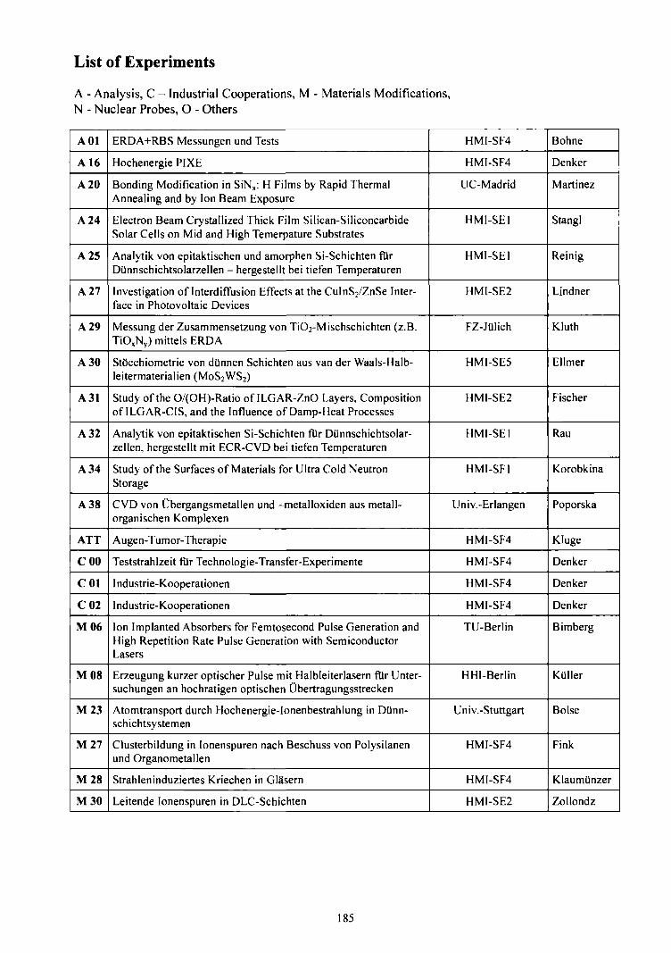
List of Experiments
A - Analysis, C - Industrial Cooperations, M - Materials Modifications,N - Nuclear Probes, O - Others
A01
A 16
A 20
A 24
A 25
A 27
A 29
A 30
A31
A 32
A 34
A 38
ATT
COO
COl
C02
M06
M08
M23
M27
M28
M30
ERDA+RBS Messungen und Tests
Hochenergie PIXE
Bonding Modification in SiNx: H Films by Rapid ThermalAnnealing and by Ion Beam Exposure
Electron Beam Crystallized Thick Film Silican-SiliconcarbideSolar Cells on Mid and High Temerpature Substrates
Analytik von epitaktischen und amorphen Si-Schichten ftirDUnnschichtsolarzellen - hergestellt bei tiefen Temperaturen
Investigation of Interdiffusion Effects at the CuInS2/ZnSe Inter-face in Photovoltaic Devices
Messung der Zusammensetzung von TiO2-Mischschichten (z.B.TiOxNy) mittels ERDA
StOcchiometrie von dtlnnen Schichten aus van der Waals-Halb-leitermaterialien (M0S2WS2)
Study of the O/(OH)-Ratio of ILGAR-ZnO Layers, Compositionof ILGAR-CIS, and the Influence of Damp-Heat Processes
Analytik von epitaktischen Si-Schichten fur Diinnschichtsolar-zellen, hergestellt mit ECR-CVD bei tiefen Temperaturen
Study of the Surfaces of Materials for Ultra Cold NeutronStorage
CVD von Obergangsmetallen und -metalloxiden aus metall-organischen Komplexen
Augen-Tumor-Therapie
Teststrahlzeit fllr Technologie-Transfer-Experimente
I ndustrie-Kooperationen
I ndustrie-Kooperationen
Ion Implanted Absorbers for Femtosecond Pulse Generation andHigh Repetition Rate Pulse Generation with SemiconductorLasers
Erzeugung kurzer optischer Pulse mit Halbleiterlasern fUr Unter-suchungen an hochratigen optischen Ubertragungsstrecken
Atomtransport durch Hochenergie-Ionenbestrahlung in Dtinn-schichtsystemen
Clusterbildung in Ionenspuren nach Beschuss von Polysilanenund Organometallen
Strahleninduziertes Kriechen in Glasern
Leitende Ionenspuren in DLC-Schichten
HMI-SF4
HMI-SF4
UC-Madrid
HMI-SE1
HMI-SE1
HMI-SE2
FZ-JUlich
HMI-SE5
HMI-SE2
HMI-SE1
HMI-SF1
Univ.-Erlangen
HMI-SF4
HMI-SF4
HMI-SF4
HMI-SF4
TU-Berlin
HHI-Berlin
Univ.-Stuttgart
HMI-SF4
HMI-SF4
HMI-SE2
Bohne
Denker
Martinez
Stangl
Reinig
Lindner
Kluth
Ellmer
Fischer
Rau
Korobkina
Poporska
Kluge
Denker
Denker
Denker
Bimberg
Kiiller
Boise
Fink
KlaumUnzer
Zollondz
185

M31
M32
M33
M34
M38
M39
M40
M41
M42
M43
M45
N21
N23
N25
116
126
129
O12
O15
O19
Indexguided Lasers Based on ZnSe, GaAs and GaN
Effects of Swift Heavy Ion Irradiation in Oxide Ceramics Usedfor Nuclear Waste Disposal
Strukturierte Ionenspurverteilungen
Phasentransformation intermetallischer Verbindungen
Surface Amorphization of InP
Wirkung der elektronischen Energiedeponierung auf die Defekt-bildung in kristallinen Halbleitern
Excess Volume for Indium in Iron
Nano-Wire Field-Effect Transistor in Etched Ion Tracks ofFlexible Materials
Phase Transformations in NiTi Shape Memory Alloys Inducedby High Energy Ion Beam
Exploration of Magnetic Materials Modification Effects
Plastische Deformation von amorphen Halbleitern durch hohenelektronischen Energieeintrag
Das Verhalten von 12B in Silizium-Germanium-Mischkristallen
Charakterisierung tiefer StOrstellen von Seltenen Erden in SiCPolytypen
Untersuchung tiefer Seltener Erden in FestkOrpern mit nuklearenMethoden
Electron Temperatures in the Center of Nuclear Tracks
Search for Coulomb Explosion
Sputtered Neutrals - a New Approach to Nuclear TrackFormation
Energy Dependence of Dielectronic Processes Responsible forElectron Capture in Ne10"" + He and N7+ + Ne Collisions at LowEnergies
Molecular Structure of Beryllium, Boron, Carbon Isotopes viaMulti-Nucleon Transfer
Elastic Scattering of 16O on I4C at Small Scattering Angles
TU-Berlin
CSNSM-Orsay
HMI-SF4
HMI-SF4
HMI-SF4
Univ.-Jena
HMI-SF4
HMI-SE2
EPFL-Lausanne
UFRGS-Porto Alegre
Univ.-Jena
HMI-SF4
Univ.-Jena
HMI-SF4
HMI-SF4
HMI-SF4
HMI-SF4
ISMARA-Caen
Univ.-Ohio
KIAE-Moskau
Bimberg
Thome
Fink
Klaumllnzer
Schumacher
Wesch
Haas
Jie Chen
LaGrange
Grande
Wesch
Zeitz
Witthuhn
Zeitz
Schiwietz
Czerski
Roth
Fremont
Massey
Ogloblin
186

V.
Personalia
187

Collaboration with External Scientific Bodies and Committees
Busse, W.Member of the EPCS-Board (EPS Interdivisional Group of Experimental Physics Control Systems)
Busse, W.Member of the International Scientific Advisory Committee of the Conference Series "International Conferenceon Accelerator and Large Experimental Physics Control Systems" (ICALEPCS)
Denker, A.Member of the Centre Europeen d'Archaeometrie Liege
Denker, A.National Representative of the Management Committee of COST G8 (Non-destructive Testing of MuseumObjects)
Fink, D.Member of the Editorial Board of the Journal "Radiation Effects and Defects in Insulators"
Homeyer, H.Member of the TESLA Advisory Committee of the "Information Meetings on the TESLA AcceleratorInstallation"
Homeyer, H.Member of the International Organizing Committee of the Conference Series "International Conference onCyclotrons and their Applications"
Kluge, H.Member of the "Proton Therapy Cooperative Group (PTCOG)"
Mahnke, H.-E.Member of the Committee "Forschung mit Nuklearen Sonden und Ionenstrahlen (KFSI)"
Schiwietz, GMember of the International Committee of the International Conference on Atomic Collisions in Solids (ICACS)
Schrwietz, GMember of the "International Scientific Committee of the Conference on Swift Heavy Ions in Matter (SHIM)"
Schiwietz, QMember of the Editorial Board of the Journal "Nuclear Instruments and Methods in Physics Research, Section B:Beam Interactions with Materials and Atoms (NIM-B)"
Schiwietz, GGerman Spokesman of the PROBRAL-collaboration "Wechselwirkung energiereicher Ionen mit Festkftrpern(DAAD and CAPES, 1999-2003)"
Schiwietz, GProject Manager of the HGF-Strategiefonds "Ionenspuren in FestkOrpem"
Sielemann, R.Member of the Editorial Board of the Journal "Hyperfine Interactions"
Stolterfoht, N.Chairman of the Organizing Committee of the International Seminar for Ion-Atom Collisions 2003, Stockholm,Sweden
189


VI.
Personnel
191

Permanent Research Staff:
H.H. Bertschat, W. Bohne, W. Busse, A. Denker, D. Fink, H. Haas, J. Heese, H. Homeyer, S.Klaumiinzer, H. Kluge, H.-E. Mahnke, H. Morgenstern, W. Pelzer, C. Rethfeldt, J. Rdhrich, G.Schiwietz, G. Schumacher, R. Sielemann, N. Stolterfoht, W.-D. Zeitz
Non-permanent Research Staff:
K. Czerski, N. Darowski, D. Cordini, J. Heufelder, J. Opitz-Coutureau, Z. Pesic, K. Potzger, M.R6sler, M. Roth, I. Simiantonakis, R. Stark, E. Strub, A. Weber, I. Zizak, T. Zumkley
PhD Students:
R. Hellhammer, P. Imielski, V. Koteski, Y. Manzhur, A. Petrov, Y. Rudychev, F. Staufenbiel
Students:
I. Bakowski, V. Beck, O. Demeter, M. Friedrich, I. Hartge, H. Janssen, C. Keil, P. Kott, I. Luthe, S.Martin, E. Meneses Rioseco, D. Reetz, M. Savoca, R. Schulzky, J. Suchogorska, O. TSbel, A.Schwarz, A. Topal, R. Topal, A. Utsch
Technical and Non-Scientific Staff:
P. Arndt, D. Beck, M. Bernburg, C. Beschomer, M. Birnbaum, D. Bohm, G. Briining, J. Bundesmann,T. Damerow, D. Draht, K. Effland, R. Griese, R. Griinke, W. Hahn, R. HaBelbarth, G Heidenreich, D.Hildebrand, M. Jung, G Liar de Martin, A. Mantwill, B. Mertesacker, J. Meseck, W. MittelstSdt, U.Miiller, H. Lucht, M. Przewozny, J. Reinicke, E. Seidel, H. Stapel, H. Stenglein, P. Szimkowiak, T.Winkelmann, U. Zuther
Guest Scientists:
Prof. A. Chandra Panjab University, Chandigarh, IndiaProf. J. Morais UFRGS, Porto Alegre, BrazilProf. R. Meurer Papaleo PUCRS, Porto Alegre, BrazilDr. M. Prandolini Freie Universitat BerlinDr. M. Sarkar Saha Institute of Nuclear Physics, Calcutta, IndiaProf. A. Zrineh University of Rabat, Marocco
193