GUI Based Remote Control of (Gas Reduction System) using PIC Microcontroller
40
GUI Based Remote Control of (Gas Reduction System) using PIC Microcontroller By Essa Faiq Abdallh Supervised by Asst. Prof. Dr. Raghad Zuhair Yousif Professor Dr. Ayad Ghany Ismaeel 2013
-
Upload
independent -
Category
Documents
-
view
0 -
download
0
Transcript of GUI Based Remote Control of (Gas Reduction System) using PIC Microcontroller
GUI Based Remote Control
of (Gas Reduction System)
using PIC Microcontroller
By
Essa Faiq Abdallh
Supervised by
Asst. Prof. Dr. Raghad Zuhair Yousif Professor Dr. Ayad Ghany Ismaeel
2013

Overview of Gas Reduction system
Represents a heart of the Erbil power station.
Responsible for regulating gas pressure and
temperature into desired values.
The power station uses the output of (GRS) as a fuel in
order to operate the station.

Overview of Gas Reduction system
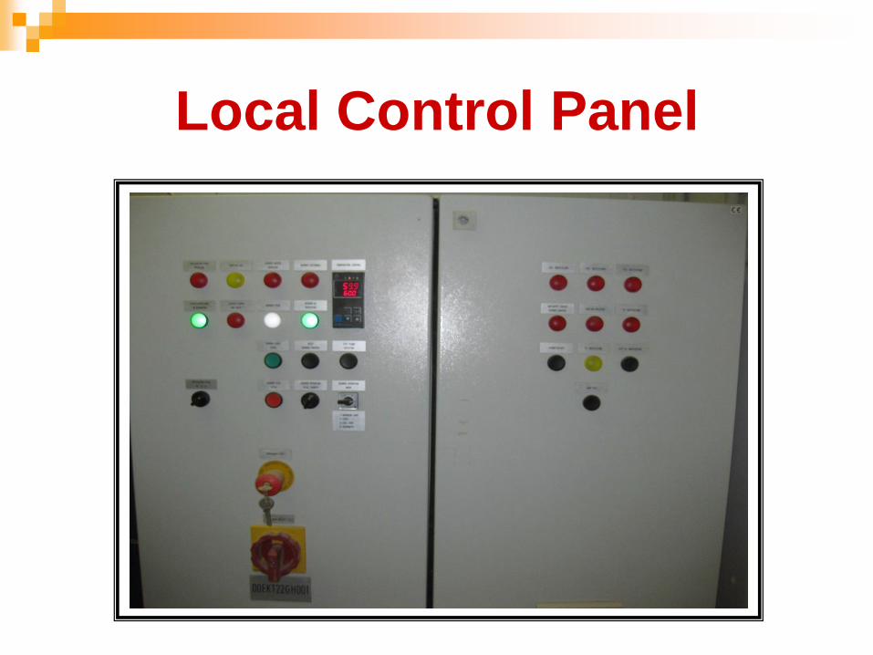
Local Control Panel

Problems of GRS Manual Control
All operations of monitoring and controlling of GRS is handled by human.
The human driven control may include wrong decisions or late response.
The (gas reduction system) is far off from control room about (150)meter,so this distance cause a delay.
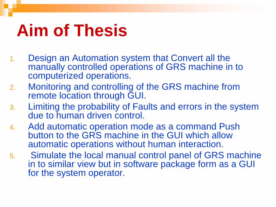
Aim of Thesis
1. Design an Automation system that Convert all the manually controlled operations of GRS machine in to computerized operations.
2. Monitoring and controlling of the GRS machine from remote location through GUI.
3. Limiting the probability of Faults and errors in the system due to human driven control.
4. Add automatic operation mode as a command Push button to the GRS machine in the GUI which allow automatic operations without human interaction.
5. Simulate the local manual control panel of GRS machine in to similar view but in software package form as a GUI for the system operator.

Continue (Aim of Thesis)
6. Prevent the human life from being in hazard in the industrial
environment.
7. Increase the accurate and quick in decision by converting
the manual operations by human into full computerize
activities.

Proposed System
Implementation Tools
Programming Language for the Embedded Software had
been written in (C Language) using MPLAB environment.
Visual Basic will be used for designing the final (GUI).
(PIC) Programmable Interface Controller to load the
final embedded software on it.

Microcontroller & Microprocessor
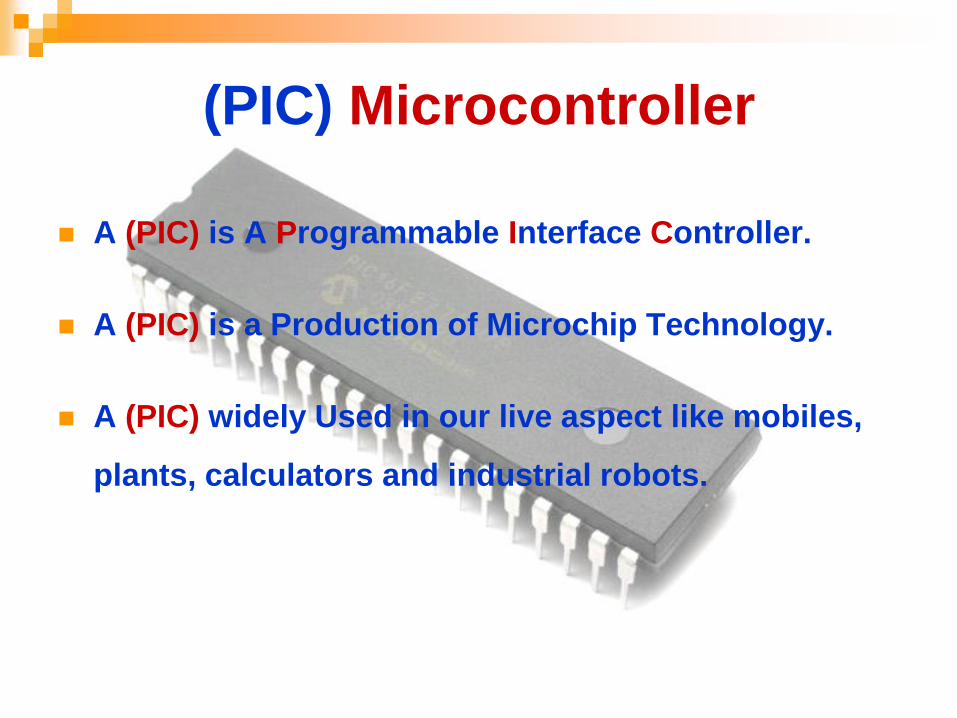
(PIC) Microcontroller
A (PIC) is A Programmable Interface Controller.
A (PIC) is a Production of Microchip Technology.
A (PIC) widely Used in our live aspect like mobiles,
plants, calculators and industrial robots.

Architecture of the PIC
Harvard VS Von-Neumann’s

PIC 3 Families
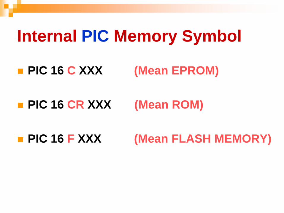
Internal PIC Memory Symbol
PIC 16 C XXX (Mean EPROM)
PIC 16 CR XXX (Mean ROM)
PIC 16 F XXX (Mean FLASH MEMORY)

Selected PIC16F877A
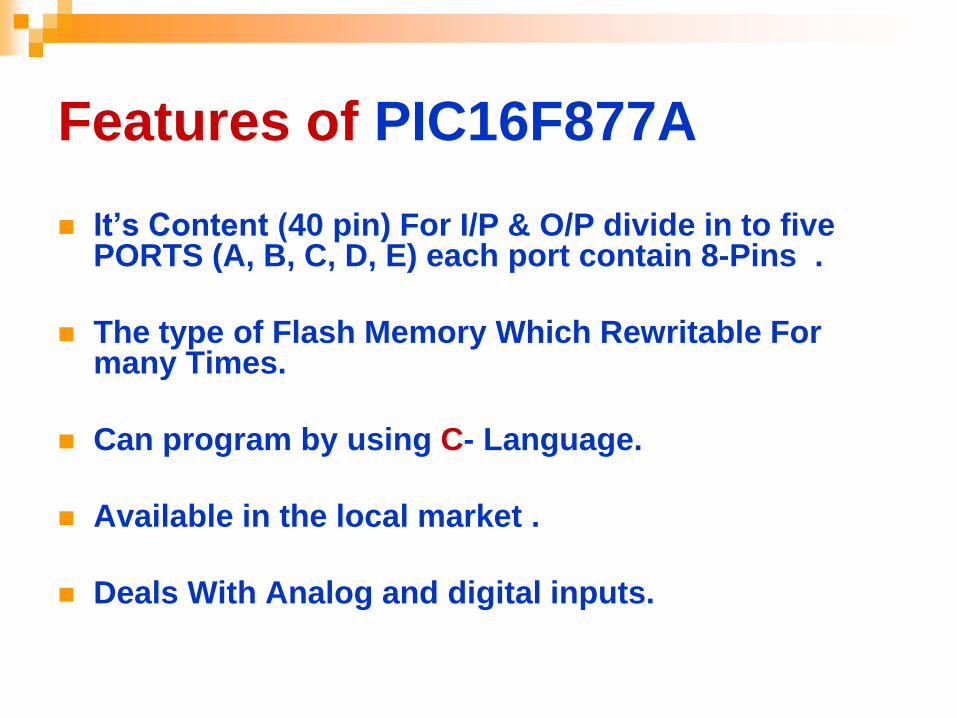
Features of PIC16F877A
It’s Content (40 pin) For I/P & O/P divide in to five PORTS (A, B, C, D, E) each port contain 8-Pins .
The type of Flash Memory Which Rewritable For many Times.
Can program by using C- Language.
Available in the local market .
Deals With Analog and digital inputs.

Proposed System Diagram
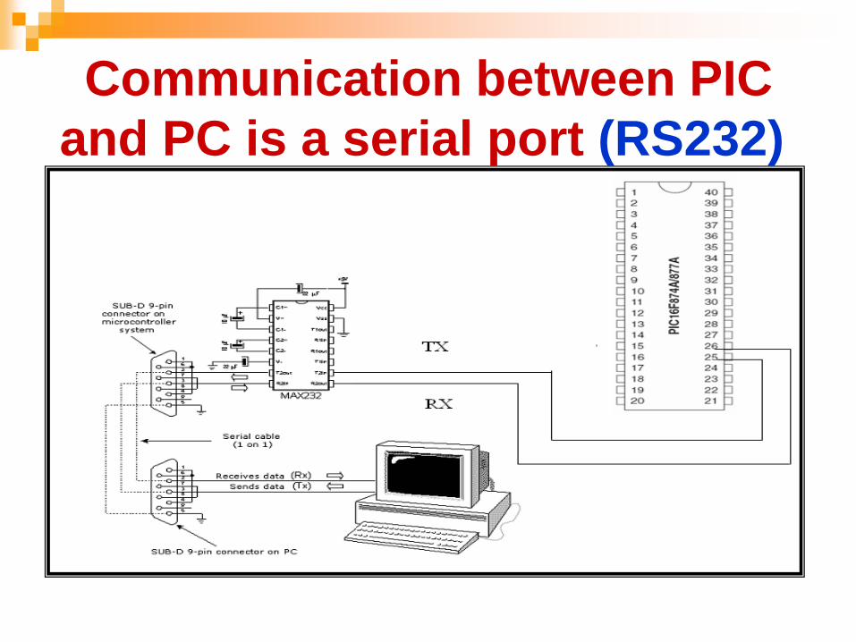
Communication between PIC
and PC is a serial port (RS232)
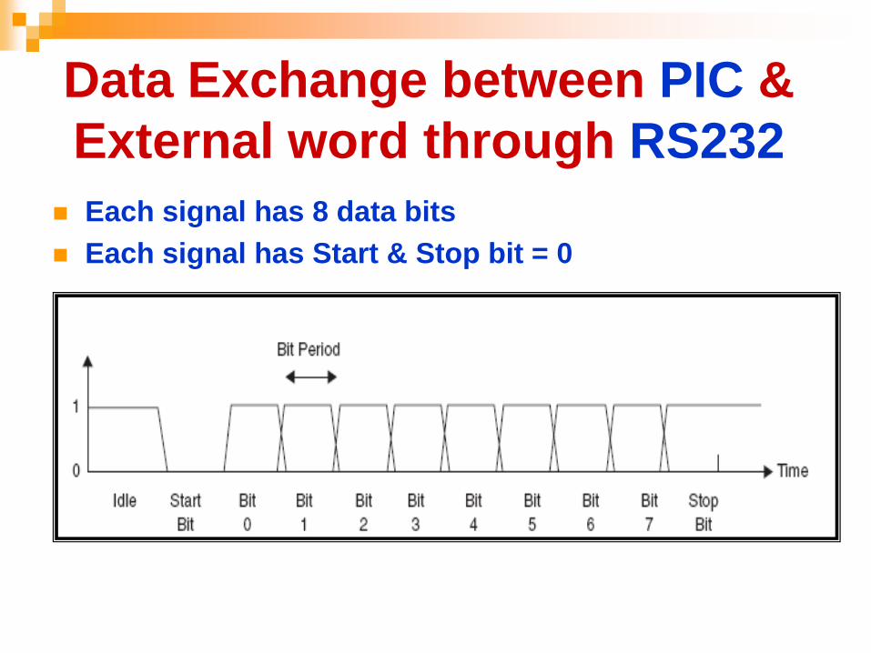
Data Exchange between PIC &
External word through RS232
Each signal has 8 data bits
Each signal has Start & Stop bit = 0

Loading the
Embedded S/W to
the PIC flash
memory through
USB cable
Connect the PIC
with GRS machine
through RS232
Functions of EasyPIC6 Board Kit
for PIC
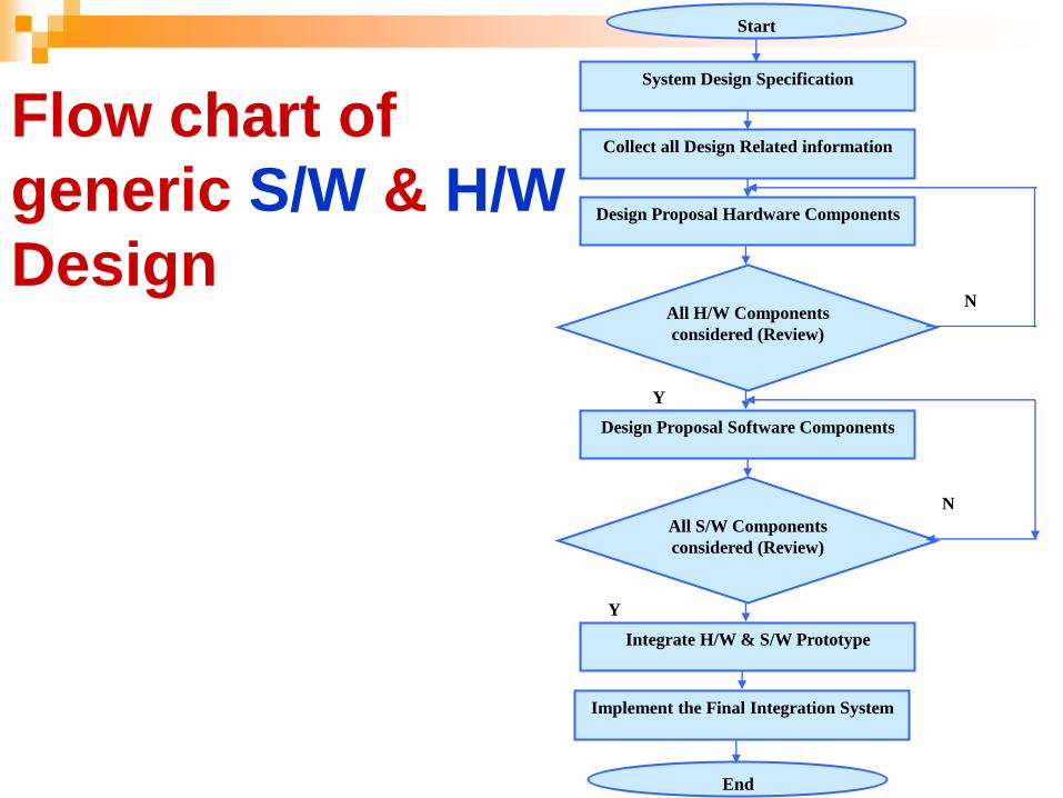
System Design Specification
Collect all Design Related information
Design Proposal Hardware Components
Design Proposal Software Components
All H/W Components
considered (Review)
All S/W Components
considered (Review)
Integrate H/W & S/W Prototype
Implement the Final Integration System
N
N
Y
Y
Start
End
Flow chart of
generic S/W & H/W
Design

Mapping GRS (Input & Output)
signals to PIC Pins No.
#
(PIC)
Pins Label Indication Type Description
1 RA0 LED1 Fault Digital in CIRCULATION PUMP OVERLOAD
2 RA1 LED2 Run OK Digital in CIRCULATION PUMP IN OPERATION
3 RA2 LED4A Run Digital in IGNITION GAS
4 RA3 LED4B Fault Digital in LEAKAGE ALARM GAS VALVE
5 RA4 LED4 Fault Digital in BURNER MOTOR OVERLOAD
6 RA5 LED5 Run Digital in BURNER START
7 RB0 LED6 Fault Digital in BURNER DISTURB
8 RB1 LED7 Run Digital in BURNER IN OPERATION
9 RB2 LED15 Fault Digital in LSA- 00EKT21CL081
10 RB3 LED16 Fault Digital in PSA- 00EKT21CP083
11 RB4 LED17 Fault Digital in PSA+ 00EKT21CP082
12 RB5 LED18 Fault Digital in SAFETY CIRCUIT BURNER CONTROL
13 RB6 LED20 Fault Digital in LOW GAS PRESSURE
14 RB7 LED21 Fault Digital in TS+ 00EKT21CT081
15 RE0 LED22 Fault Digital in TA+ 00EKT21CT082
16 RC0 SWITCH3 SELECTOR Digital out SELECTOR SWITCH LOCAL/REMOTE
17 RC1
18 RC2 Buttom8 start Digital out BURNER START LOCAL
19 RC3 Buttom9 stop Digital out BURNER STOP LOCAL
20 RC4
RESET
Buttom10 RESET Digital out RESET BURNER CONTROL
21 RC5 SWITCH11 SELECTOR Digital out BURNER OPERATION LOCAL REMOTE
22 RC6
23 RC7 Buttom13 TEST Digital out TEST FLAME DETECTOR
24 RD0
SWITCH14 SELECTOR Digital out BURNER OPERATION MODE 25 RD1
26 RD2
27 RD3 Buttom19 RESET Digital out ALARM RECEIPT
28 RD4 Buttom23 TEST Digital out TEST TA+ 00EKT21CT082
29 RD5 Buttom25 TEST Digital out LAMP TEST
30 RD6 SWITCH26
EMERGENC
Y STOP Digital out EMERGENCY STOP
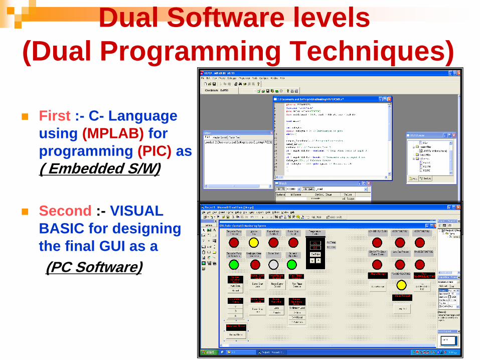
Dual Software levels
(Dual Programming Techniques)
First :- C- Language
using (MPLAB) for
programming (PIC) as
( Embedded S/W)
Second :- VISUAL
BASIC for designing
the final GUI as a
(PC Software)

Identifying ASCII Code Character
for each Input/output
Each input and output signal from the GRS machine
will named and identify as a special ASCII code character in order to recognize each signal alone.

Hardware Design Implementation
Input break down Circuit (24-5)VDC
(zener diode)
Output Switching Circuit (Relay)
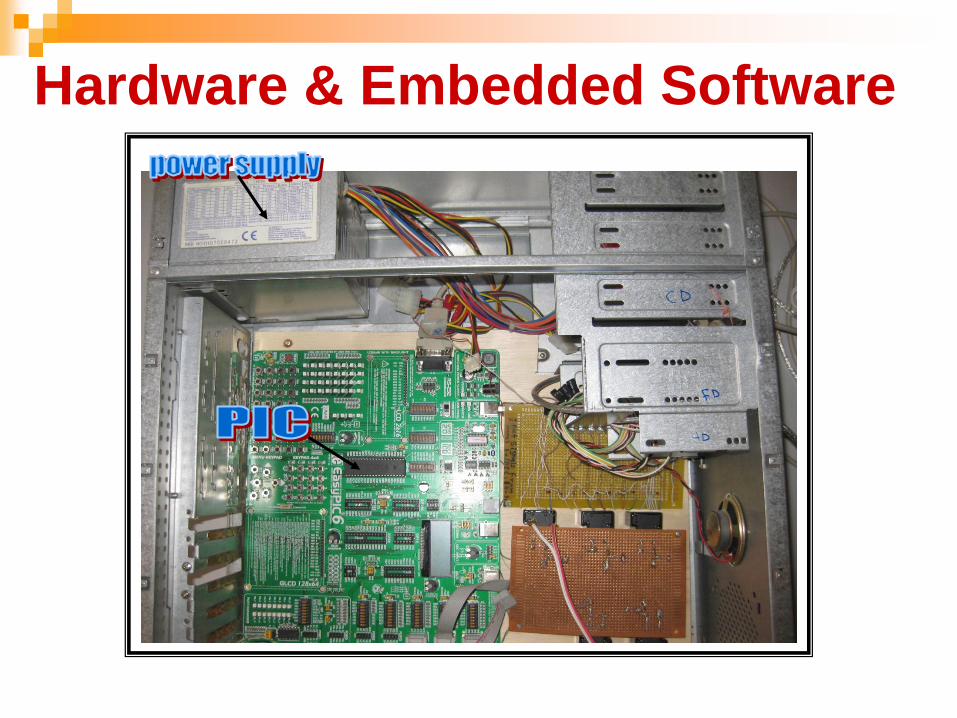
Hardware & Embedded Software
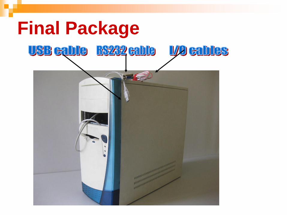
Final Package
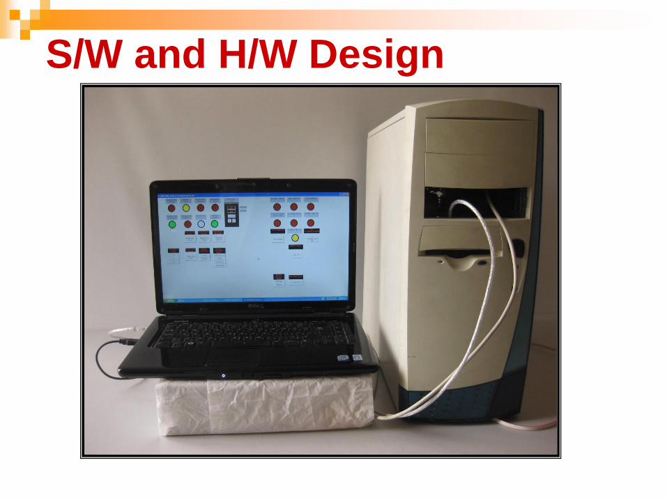
S/W and H/W Design
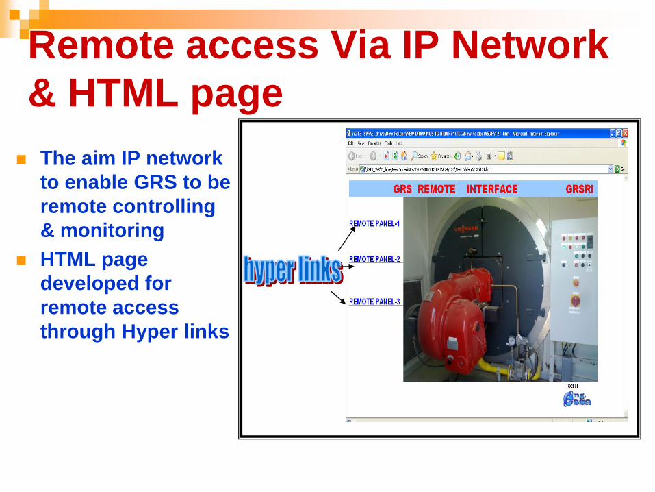
Remote access Via IP Network
& HTML page
The aim IP network
to enable GRS to be
remote controlling
& monitoring
HTML page
developed for
remote access
through Hyper links
Final System Design Algorithm
Initialize Initialize:
Selecting the Programmable Interface Controller = PIC16F877A
Define the Header file for the "PIC16F877A"
Set frequency of Crystal Clock oscillator = 8000000 Hz
Enable Interrupts ( )
Define the (PIC) used Pins:
Define Pins A0-A7
Define Pins B0-B7
Define Pins C0-C7
Define Pins D0-D7
Define Pins E0-E2
Input: A (A0-A5) Read the input signals from GRS to port A of PIC.
B (B0-B7) Read the input signals from GRS to Port B of PIC.
E (E0) Read the input signals from GRS to pin E0 of PIC.
Output: C (C0-C7) Activate Pins of PIC as output Instructions to GRS.
D (D0-D6) Activate Pins of PIC as output Instructions to GRS.

Continue Algorithm
Read Inputs Begin
Set up baud rate speed = 9600/bps for RS232 port
again While there is an input signals from GRS do
If input signal = logic 1
Then
identify the logic 1 signal in to ASCII code character
send the ASCII code Character via RS232 port and
display it on GUI
Read new input signal from GRS
Else
send the (ASCII+1)mode 26 via RS232 port and
display it on GUI
Read new input signal from GRS
Continue Algorithm
Send Outputs Commands
pushbuttons While there is an output signals command instruction from GUI do
If send output signal ASCII from GUI via RS232 port = logic1
Then
Comparing ASCII which send with previous identified ASCII
If both ASCII are matched
Then
Send Output PIC command through output pins and switch ON a specific relay
Else Send Output PIC command through output pins and switch OFF a specific relay
End while
Continue Algorithm
"Auto Operations Mode"
If "Auto Operations Mode" selected
Then
Read fault input signals
Reset all GRS fault by activate output relays
Start GRS system with automatic mode
End while
Return again
End
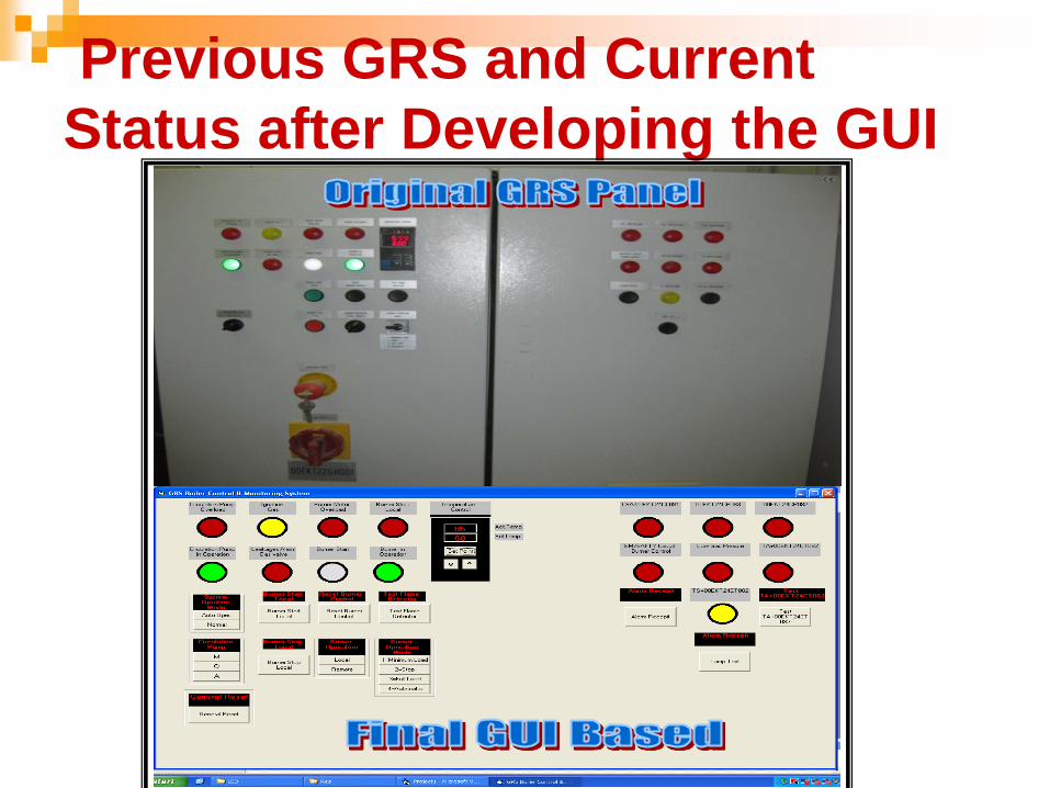
Previous GRS and Current
Status after Developing the GUI

Results
A real operation and testing results for proposed remote controller based on PIC microcontroller with graphical user interface.
The final proposal design (H/W and S/W) is connected with a real GRS machine at Erbil power station.
The GRS successfully responds to all alarm and signals through proposed design.
The ASCII code which assigns to the input or output signals given for each control has been tested by using (oscilloscope) waveform plotter.
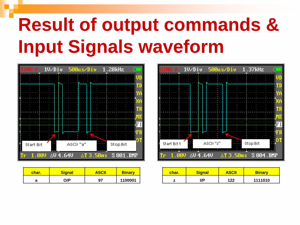
Result of output commands &
Input Signals waveform
char. Signal ASCII Binary
a O/P 97 1100001
char. Signal ASCII Binary
z I/P 122 1111010
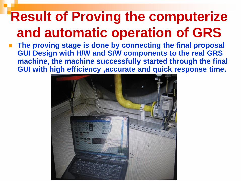
Result of Proving the computerize
and automatic operation of GRS
The proving stage is done by connecting the final proposal GUI Design with H/W and S/W components to the real GRS machine, the machine successfully started through the final GUI with high efficiency ,accurate and quick response time.

Result of Proving the GRS
Operation Performed Remotely
Two PCs are connected through bus LAN IP network one PC
at the GRS machine and the other in the remote location to allow access from remote location.
IP of remote PC
192.168.10.10

Result of operating of GRS
through GUI from remote location
In the final GUI there are two new push buttons added ,the first is
called (Auto operation system mode) which allows a full computerized automatic system mode selection and operation, a second new push button is called (general reset) which allows resetting

1. This thesis presents a dual software programming techniques
that are an embedded software which used for programming and
loading the C-language program to the PIC microcontroller ,while
the other software programming techniques is designing special
graphical user interface (GUI) by using Visual Basic as an
interfacing media between the human and the machine.
2. An embedded system is regarded as a product which contains a
microprocessor programmed to carry out some control functions
which works as a complete computer system.
3. The proposed system contain both of hardware and software
components were implemented and integrated as a complete
compatible system.
4. GUI using the Visual Basic program, performed excellently in
transmitting & receiving data to& from PIC through (RS232) port.
Conclusions

Continue Conclusions
5. The operation and monitoring of the GRS machine huddle and enhance by utilizing the features of (PIC16F877A) microcontroller, which create a better solution for the GRS problems.
6. The PIC microcontroller has been used in this thesis due to its low cost , availability in local market, low power consumption, and easy to program using C-Language .
7. A remote controlling machines via GUI is located on the devices which required a control and observation by the operator from time to time , also if the process control contains hazardous environment for doing some jobs like (power plants, chemical factories).
8. Today, most new technology products consist of a mixture of hardware and software components