
Emb PIC Charles Kim Chap4
31
Chapter 4. Coding Environments Embedded Computing with PIC 16F877 – Assembly Language Approach. Charles Kim © 2006 28 Chapter 4: Coding Environment In the previous chapter, we studied the instruction sets of PIC 16F877 and some tips and tricks of using the instructions are discussed. Even though we met a few example codes, we are not sure where and we physically type the code and not sure if the codes are correct. And we do not know how we if one code is correct or wrong. In this chapter, we introduce a coding environment which allows us to edit an Assembly code, assemble (or compile) the code, simulate the code, and finally download the compiled code to the internal program memory of the PIC chip. The first three involves Microchip's MPLAB (Microchip Assembler) and MPSIM (Microchip Simulator) Integrated Development Environment (IDE), and the last one involves a physical programmer or a burner. Note that the MPLAB explained and demonstrated thoroughly here is MPLAB Version 5.20. Currently, higher version of the IDE is available with version 6.40, therefore, here I add additional section (see section 3) to briefly explain how quickly assemble an Assembly language code under MPLAB v.6.40. The version 6.40 would be more reliable in Windows XP operating condition. I am not 100 percent positive on this but I had experienced some problem of using MPLAB 5.20, and I heard of the problem too, when you try to install it on a tablet PC with Windows XP (or Tablet version of Windows XP). Anyway, one thing you may have to be careful with the version 6.40 is that it is case-sensitive, and nullifying that is not apparently easy. To be in safe side, under MPLAB v.6.40, I suggest you write your code as if the case-sensitive rule is universal in PIC programming. The last subject of the chapter covers a bootloader code which allows the PIC chip to be ready to communicate via serial communication to your PC, and a PIC code downloader which is a Windows based software that actually downloads your hex code to the PIC chip. One problem with this is that you first have to have the bootloader inside your PIC chip. Without this there is no serial communication for the PIC code download software to download your code. An actual PIC programmer, i.e., a burner in a sense, is needed to burn the bootloader to the chip. The PIC burner is also covered in the chapter. 1. MPLAB v5.2 MPLAB is a Windows-based Integrated Development Environment (IDE) for the Microchip Technology’s PICmicro microcontroller families. MPLAB allows you to write, debug, and optimize PICmicro applications for embedded computing product designs. MPLAB includes a text editor, simulator, and project manager. You use the MPLAB Editor to create and edit text files such as source files, code, and linker script files. The MPLAB-SIM Simulator models the instruction execution and I/O of the PICmicro Microcontrollers (MCUs). The project manager is out of scope of this book since our approach is not to make a project file from a code but to quickly build a code to a hex code. The MPASM Assembler allows source code to be assembled without leaving MPLAB. The following minimum configuration is required to run MPLAB: • PC compatible 486 or better class system (Pentium recommended) • Microsoft Windows Operating System • VGA display (Super VGA recommended) • 8 MB memory (32 MB recommended) • 20 MB of hard disk space
-
Upload
independent -
Category
Documents
-
view
2 -
download
0
Transcript of Emb PIC Charles Kim Chap4
Chapter 4. Coding Environments
Embedded Computing with PIC 16F877 – Assembly Language Approach. Charles Kim © 2006
28
Chapter 4: Coding Environment In the previous chapter, we studied the instruction sets of PIC 16F877 and some tips and tricks of using the instructions are discussed. Even though we met a few example codes, we are not sure where and we physically type the code and not sure if the codes are correct. And we do not know how we if one code is correct or wrong. In this chapter, we introduce a coding environment which allows us to edit an Assembly code, assemble (or compile) the code, simulate the code, and finally download the compiled code to the internal program memory of the PIC chip. The first three involves Microchip's MPLAB (Microchip Assembler) and MPSIM (Microchip Simulator) Integrated Development Environment (IDE), and the last one involves a physical programmer or a burner. Note that the MPLAB explained and demonstrated thoroughly here is MPLAB Version 5.20. Currently, higher version of the IDE is available with version 6.40, therefore, here I add additional section (see section 3) to briefly explain how quickly assemble an Assembly language code under MPLAB v.6.40. The version 6.40 would be more reliable in Windows XP operating condition. I am not 100 percent positive on this but I had experienced some problem of using MPLAB 5.20, and I heard of the problem too, when you try to install it on a tablet PC with Windows XP (or Tablet version of Windows XP). Anyway, one thing you may have to be careful with the version 6.40 is that it is case-sensitive, and nullifying that is not apparently easy. To be in safe side, under MPLAB v.6.40, I suggest you write your code as if the case-sensitive rule is universal in PIC programming. The last subject of the chapter covers a bootloader code which allows the PIC chip to be ready to communicate via serial communication to your PC, and a PIC code downloader which is a Windows based software that actually downloads your hex code to the PIC chip. One problem with this is that you first have to have the bootloader inside your PIC chip. Without this there is no serial communication for the PIC code download software to download your code. An actual PIC programmer, i.e., a burner in a sense, is needed to burn the bootloader to the chip. The PIC burner is also covered in the chapter. 1. MPLAB v5.2 MPLAB is a Windows-based Integrated Development Environment (IDE) for the Microchip Technology’s PICmicro microcontroller families. MPLAB allows you to write, debug, and optimize PICmicro applications for embedded computing product designs. MPLAB includes a text editor, simulator, and project manager. You use the MPLAB Editor to create and edit text files such as source files, code, and linker script files. The MPLAB-SIM Simulator models the instruction execution and I/O of the PICmicro Microcontrollers (MCUs). The project manager is out of scope of this book since our approach is not to make a project file from a code but to quickly build a code to a hex code. The MPASM Assembler allows source code to be assembled without leaving MPLAB. The following minimum configuration is required to run MPLAB:
• PC compatible 486 or better class system (Pentium recommended) • Microsoft Windows Operating System • VGA display (Super VGA recommended) • 8 MB memory (32 MB recommended) • 20 MB of hard disk space
faculty
Typewritten Text
Textbook Web: www.mwftr.com/book.html

Chapter 4. Coding Environments
Embedded Computing with PIC 16F877 – Assembly Language Approach. Charles Kim © 2006
29
• Mouse or other pointing device MPLAB may be obtained by contacting any Microchip sales office and requesting the Technical Library CD-ROM or by downloading the files from the Microchip website (www.microchip.com). Version 5.20 of MPLAB can be installed b the file of Mp520ful.exe. The executable file Mp520ful.exe installs the Microchip MPLAB Integrated Development Environment version 5.20 in your computer. Once you downloaded the file, execute the install program. When the .exe file is run, it will start installing MPLAB onto your system. Starting MPLAB Execute MPLAB.EXE or click on the MPLAB icon to start up the system. You will see MPLAB’s desktop as shown below.
Creating a New Source File Click once in the blank space of the empty file window that has been created for you. It is probably titled “Untitled.” Or you open a new file. Use the File>Save As... menu option and save the empty file as ex01.asm. When the standard browse dialog opens, you will find that it is located in the current working directory of the project. If you want to change it to your USB stick, select proper place for your file. Then, enter the file name and press OK.
You will now be presented with the MPLAB desktop and the empty file window, but the name of the file window will reflect its new name. MPASM will always create an output hex file with the same name as the source file, and this cannot be changed.

Chapter 4. Coding Environments
Embedded Computing with PIC 16F877 – Assembly Language Approach. Charles Kim © 2006
30
Now enter (or edit) your first program code. The program we enter here is the LED blinking program we started in the previous two chapters. In the following code, there must be some understanding around hex code download to the internal program memory. This job can be done using a physical programmer. Or you once download a bootloader hex code, then you do not need the physical programmer anymore; you need a PIC downloader program (software) and the hex code for your program. Since this text follows the bootloader direction, in our code, we have to accommodate some space where part of the bootloader code will be occupied. Details of the bootloader will be discussed in the section follows. So now just accept that your program cannot occupy the first 4 addresses of the program memory. Also, from this chapter, we are going to use the banksel directive of MPLAB for easier bank selection of a file register. The directives of MPLAB are discussed later, but one directive deserves an early introduction since this one eases the problems in bank selection using the STATUS<6:5> bits. The bank selection directive is banksel f. The directive will move to a bank where the filer register f is located. So whenever you need to access a file register, either a SFR or a GPR, you worry is now over by using banksel f. When you want to access PORTB, for example, you use a banksel command just before the access attempt:
banksel PORTBmovwf PORTB
By the banksel PORTB instruction, you are now in the bank where PORTB is located. Similarly, banksel TRISB changes to a bank where TRISB is located. One caution you must use is that there should not be a label in front of the banksel directive. When a label is needed in front of a banksel directive, use the label alone at a line and use the banksel directive at the next line. My final words on the directive banksel: it's ok to abuse it! Now let’s get back to our first example code using MPLAB. ;ex01.asm;sample code for a blinking LED (for 100ms)continuously;
list P = 16F877 ;Target processor = 16F877
STATUS EQU 0x03 ;SFR declarationPORTB EQU 0x06TRISB EQU 0x86LED EQU 0x01 ;LED is connected pin 1 of PORTB
CBLOCK 0x20; Variables used in delay routine
Kount100usKount1msKount100ms
ENDC
org 0x0000 ;line 1;The following lines accommodate bootloader
goto START ;line 1 ($0000)org 0x0005
;end of the bootloader accommodation

Chapter 4. Coding Environments
Embedded Computing with PIC 16F877 – Assembly Language Approach. Charles Kim © 2006
31
; IF you do not use bootloader , but use a physical programmer all the; time, you do not need above lines
STARTbanksel TRISB
;As you see here, the label START stands alone;since banksel cannot stand a label on its left
;the above line replaces the two lines we used to use; bcf STATUS, P1; bsf STATUS, P0 ;bank 1;
bcf TRISB, LED ;PORTB<1> as outputbanksel PORTB ;now we are where PORTB is (bank 0)
AGAIN bsf PORTB, LED ;Turn on LEDcall delay100ms ;Keep on for 100msbcf PORTB, LED ;Turn off LEDcall delay100ms ;Keep off for 100msgoto AGAIN ;Keep on blinking
;Subroutine Delay100us ==============;Need 500 instruction cycles since 1 instruction cycles takes 0.2 us;The formula for 500 instruction cycles:; 500 =3*165 + 5; this number (165) must be stored into a file registerdelay100us movlw 0xA5 ;165 in decimal
movwf Kount100usR100us decfsz Kount100us
goto R100usreturn
; ;Subroutine Delay1ms ==============;Need to call delay100us 10 times;delay1ms movlw 0x0A ;10 in decimal
movwf Kount1msR1ms call delay100us
decfsz Kount1msgoto R1msreturn
;Subroutine Delay100ms;Call delay1ms for 100 timesdelay100ms movlw 0x64 ;100 in decimal
movwf Kount100msR100ms call delay1ms
decfsz Kount100msgoto R100msreturn
;end of programEND ; end of program
Now save the file by using the File>Save menu function. Setting up the Development Mode Development Mode is for determining a target device of many PICmicro chips, and clock frequency among others. Once you set this, you do not need this step again. The development mode sets which tool, if any, will execute code. Selecting the Options>Development Mode

Chapter 4. Coding Environments
Embedded Computing with PIC 16F877 – Assembly Language Approach. Charles Kim © 2006
32
menu item, you will find a dialog box that looks something like the figure below. MPLAB is a constantly evolving product, so there may be subtle difference between what you would see and the picture here.
Select the radio button next to MPLAB-SIM Simulator and choose the PIC16F877 from among the pull down list of available processors supported by the simulator. Click PIC16F877. Also, for clock, since the processor we use in the text is with 20 MHz clock, pick HS (indicating High Speed), and type in 20.000 MHz in the ‘desired frequency’ box. Then press the OK button. The simulator will initialize and you should see “PIC16F877” and “Sim” in the status bar on the bottom of the MPLAB desktop. You are now in simulator mode for the PIC16F877 device. Assemble (or Compiling) a Source File Select Project>Build Node from the menu to compile ex01.asm using MPASM. MPLAB brings up an Invoke Build Tool Dialog that looks like this. Verify that MPASM is selected, and set the tool options. Make sure to mark on 'off' box for case sensitivity row. Press OK and exit from this.
Then select Project>Build Node to start the build process. Remember here that we are not building a project from a source code: we just quickly assemble it by the 'build node.' A Build

Chapter 4. Coding Environments
Embedded Computing with PIC 16F877 – Assembly Language Approach. Charles Kim © 2006
33
Results window is generated that shows the command line sent to the assembler and the build output. It should look like this:
You have to see, at the bottom of the result window, the message saying “Build completed Successfully.” Otherwise, your source has errors. Running Your Program Use the Debug>Run>Reset to initialize the system. The program counter will be reset to zero, which is the reset vector on the PIC16F877. The source code line at this address may be highlighted with a dark bar. Also, you may notice that PC is set to 0x00 in the status bar at the bottom of MPLAB. Use the Debug>Run>Step menu item. This causes the program counter to advance to the next instruction location. The dark bar will follow the source code and the program counter displayed in the status bar should advance to “pc:0x04.”
You may notice as you execute the Debug>Run>Step menu item that there is text on the right side of the menu item that says <F7>. This stands for “function key seven” on your keyboard. Many MPLAB functions are assigned to “hot keys.” These keys have the same affect as executing the menu item itself. Press <F7> a few times and watch the program counter and dark bar advance through the program. Execute the Debug>Run>Run menu item or press <F9> to start the program running from the current location counter. The status bar will change colors indicating the program is executing instructions. None of the other fields on the status bar will be updated until the program is halted. Stop the program by executing the Debug>Run>Halt menu item or by pressing <F5>. The status bar will change back to its original color, and the current program counter and other status
Chapter 4. Coding Environments
Embedded Computing with PIC 16F877 – Assembly Language Approach. Charles Kim © 2006
34
information will be updated. Another way to execute functions is to use the tool bar at the top of the screen. If you place the cursor over the items in the tool bar, you can see the name of the function in the status bar at the bottom. The left button is a standard Change Tool bar button that allows you to scroll through the available toolbars. These can be customized. On the debug toolbar, the green light is equivalent to <F9> (Run) and the red light is the same as <F5> (Halt). Creating a Watch Window Execute the Window>New Watch Window menu item. The Add Watch Symbol dialog will appear. You can save the watch window and its settings by executing the Save Watch item under the system menu of the watch window. The system menu button is located in the upper left-hand corner of the watch window. Clicking this button once will cause the menu underneath to cascade down. Select Save Watch and you will be presented with the standard browsing dialog located in the current working directory of the project. Choose any arbitrary name and press OK. The window’s open or closed status and location on the screen is saved with the project so the next time you open your project, your watch windows will be restored as well. You can also edit the watch windows after you’ve created them. Using the system menu, select Add Watch to bring up a dialog to add more items. The <Ins> key will do the same. Highlighting an item and pressing the <Del> key will delete that watch from the window.
Now run your code again and watch how each instruction changes the filer registers and W register. But you do not get much information on the file registers because, during run, most of processor execution is spent calling delay subroutines. Remember delay subroutines have 500, 5000, or 10,000 instructions involved. Therefore, for simulation purposes, you may want to delete the call delay lines and save the file as ex02.asm. Then assemble the code by Build Node. 2. MPSIM v5.2–Asynchronous Stimulation –simulation of inputs The stimulus generates signals for the simulator. You can set pins high or low, and inject values directly into registers. There are four stimulus modes:
• Asynchronous stimulus – An interactive dialog to control signals on input pins • Stimulus Pin File – The contents of a text file describes signals to input pins • Stimulus Register File – The contents of a text file are used to set 8-bit values directly into a register • Clock Stimulus – A regular, programmable, periodic source of stimulus pulses

Chapter 4. Coding Environments
Embedded Computing with PIC 16F877 – Assembly Language Approach. Charles Kim © 2006
35
In this book, we discuss the asynchronous stimulus only. For others, refer to the MPLAB v5 manual. To test the MPLAB-SIM it would be better revised our second program, ex02.asm. The reason is ex02.asm does not have any input to stimulate the output. Therefore, now we will slightly change the program so that PORTD<0> will turn on/off the LED connected to PORTB<1>: PORTD<0>=1 will turn and PORTD<0>=0 turns off. Revise the program as follows and save it as ex03.asm. ;ex03.asm;sample code for LED on and off;based on PORTD<0> value;
list P = 16F877 ;Target processor = 16F877STATUS EQU 0x03 ;SFR declarationPORTB EQU 0x06PORTD EQU 0x08TRISB EQU 0x86TRISB EQU 0x88LED EQU 0x01 ;LED is connected pin 1 of PORTBEXT EQU 0x00 ;EXTernal input is connected to pin 0 of PORTD
org 0x0000 ;line 1;The following 4 lines accommodate bootloader
goto START ;line 1 ($0000)org 0x0005
;end of the bootloader accommodation; IF you do not use bootloader , but use a physical programmer all the; time, you do not need above four linesSTART
banksel TRISBbcf TRISB, LED ;PORTB<1> as outputbsf TRISD, EXT ;PORTD<0> as inputbanksel PORTB ;now we are where PORTB is (bank 0)bcf PORTB, LED ; start with LED off
AGAIN btfss PORTD, EXTgoto LEDOFFgoto LEDON
LEDON bsf PORTB, LEDgoto AGAIN
LEDOFF bcf PORTB, LEDgoto AGAIN
;end of programEND ; end of program
Before simulate the PORTD<0>, you have to compile the code first. Asynchronous Stimulus This stimulus feature provides a dialog button to simulate +5 and 0 volts being applied to input pins. As your program executes with the simulator, you can press buttons on this dialog to change levels on pins. As an example, we’ll set up a signal that will toggle the level on a pin on I/O PORTD.

Chapter 4. Coding Environments
Embedded Computing with PIC 16F877 – Assembly Language Approach. Charles Kim © 2006
36
Select Debug>Simulator Stimulus>Asynchronous Stimulus.... This dialog will be displayed:
Now put the cursor over the button labeled “Stim1 (P)” and click the right mouse button. A dialog will pop up. Scroll down and click on Toggle.
Again put the cursor over the button now labeled “Stim1 (T)” (the “P” was replaced by a “T”, meaning “Toggle”), press the right mouse button and select Assign Pin.... Another dialog will pop up with a list of pins on the PIC16F877.
Put the cursor over “RD0” (for PORTD<0>) and double click. The Asynchronous Stimulus dialog should now look like the figure below. Note that the button now shows “RD0 (T).”

Chapter 4. Coding Environments
Embedded Computing with PIC 16F877 – Assembly Language Approach. Charles Kim © 2006
37
Choose Debug>Run>Animate to get the processor running in a “fast single step” mode. The status bar will alternate run to stop very fast. Press the “RD0 (T)” button on the Asynchronous Stimulus dialog. You should see the value of PORTD in the Watch Window change as you repeatedly click the button to simulate a high signal then a low signal applied to PORTD pin 0. And see if the PORTB<1> changes by the toggle action of PORTD<0>. 3. MPLAB v6.40 MPLAB 6.40 can be similarly installed in to your PC or laptop by downloading and executing the file, MPLAB v6.40.exe from Microchip Technology web site. This file is also available from my web site for the textbook. Starting MPLAB v6.40 After opening (or double clocking) the MPLAB v6.40, we start from a new file by clicking File>New. Of course, once a code is made, the we do File>Open instead for revision of addition.

Chapter 4. Coding Environments
Embedded Computing with PIC 16F877 – Assembly Language Approach. Charles Kim © 2006
38
Typing Your Code In a new window titled Untitled, we type in our code, ex02.asm or 1led.asm as shown in the illustration in the figure.
Then we save by File>Save As and type in your file name to your place of directory (in C or USB stick) as ex02.asm or anyname.asm as illustrated in the figure.
Configuration of MPLAB for 16F877 This process corresponds to the Development Mode setting in MPLAB v5.20. Click Configure>Select Device as illustrated in the figure.

Chapter 4. Coding Environments
Embedded Computing with PIC 16F877 – Assembly Language Approach. Charles Kim © 2006
39
Then, scroll down and select 16F77. Click OK ends the device selection process.
Next, go with Configure>Configuration Bits for oscillation clock speed.

Chapter 4. Coding Environments
Embedded Computing with PIC 16F877 – Assembly Language Approach. Charles Kim © 2006
40
Finally, we select the speed of HS, which is for 20MHz clock, from the scroll down menu as illustrated in the figure.
After end of the configuration process, we may want to save the configuration by File>Save Workspace As. Once it is saved, in the next session, you retrieve your configuration by File>Open Workspace. However this is an optional process. You do not have to do this. But it is a good habit that every time you open your MPLAB v6.40, you make sure your device is 16F877 and the oscillator speed is HS.
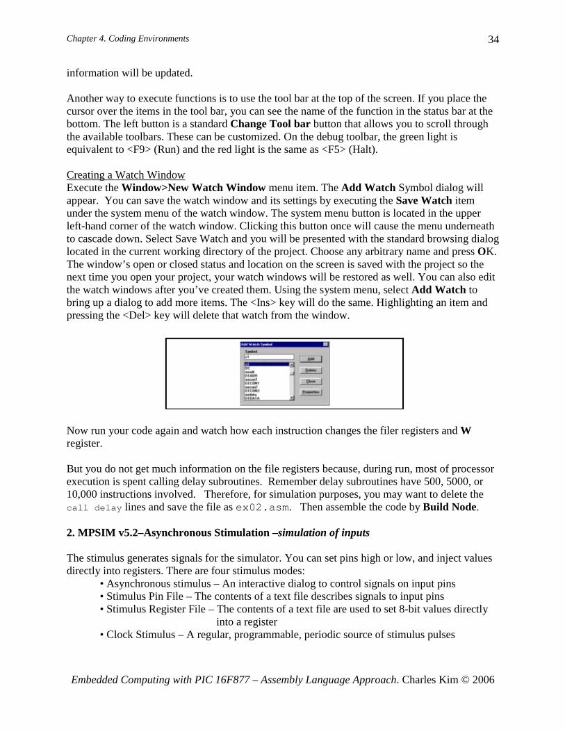
Assembling Your Code Assembling of your code is done by Project>Quick Build. The Quick Build bar, once your
Chapter 4. Coding Environments
Embedded Computing with PIC 16F877 – Assembly Language Approach. Charles Kim © 2006
41
code is saved, has your file name next to the word Quick Build. See illustration figure.
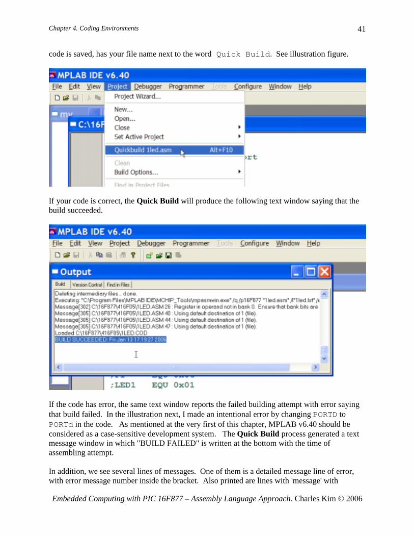
If your code is correct, the Quick Build will produce the following text window saying that the build succeeded.
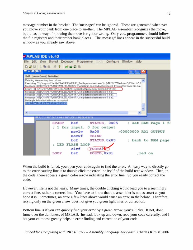
If the code has error, the same text window reports the failed building attempt with error saying that build failed. In the illustration next, I made an intentional error by changing PORTD to PORTd in the code. As mentioned at the very first of this chapter, MPLAB v6.40 should be considered as a case-sensitive development system. The Quick Build process generated a text message window in which "BUILD FAILED" is written at the bottom with the time of assembling attempt. In addition, we see several lines of messages. One of them is a detailed message line of error, with error message number inside the bracket. Also printed are lines with 'message' with
Chapter 4. Coding Environments
Embedded Computing with PIC 16F877 – Assembly Language Approach. Charles Kim © 2006
42
message number in the bracket. The 'messages' can be ignored. These are generated whenever you move your bank from one place to another. The MPLAB assembler recognizes the move, but it has no way of knowing the move is right or wrong. Only you, programmer, should follow the file registers and their proper bank places. The 'message' lines appear in the successful build window as you already saw above.
When the build is failed, you open your code again to find the error. An easy way to directly go to the error causing line is to double click the error line itself of the build text window. Then, in the code, there appears a green color arrow indicating the error line. So you easily correct the code. However, life is not that easy. Many times, the double clicking would lead you to a seemingly correct line, rather, a correct line. You have to know that the assembler is not as smart as you hope it is. Sometimes, an error a few lines above would cause an error in the below. Therefore, relying only on the green arrow does not give you green light in error correction. Bottom line is if you can quickly find your error by a green arrow, you're lucky. If not, don't fume over the dumbness of MPLAB. Instead, look up and down, read your code carefully, and I bet your calmness greatly helps in error finding and correction of your code.

Chapter 4. Coding Environments
Embedded Computing with PIC 16F877 – Assembly Language Approach. Charles Kim © 2006
43
4. Hex Code Downloading Now we are eager to program (or download the hex file of the code to) the 16F877 chip. But we have to have our minimum level of hardware around the 16F877 chip to test the example codes: ex01.asm and ex03.asm. The minimum hardware recommended next is even good for the bootloader option. Once the minimum hardware board for your embedded system is finished, then you will download your hex file via a physical programmer (PIC burner) or PIC downloader program. Note that there are two options for your minimum PIC 16F877 hardware: do-it-yourself approach and buy-a-PIC board approach. The former is recommended if you want to understand more of embedded systems and 16F877 in particular. Of course it takes much more time but your fun would be much more too. You can use either a breadboard or a protoboard to place all the necessary parts. This approach involves online purchase of parts and other necessary accessories. There are two online stores I frequent: Digi-Key (www.digi-key.com) and Mouser Electronics (www.mouser.com). However, there are literally hundreds of such stores you can browse and take advantage of cheaper price. The latter approach is simple enough: buy a board which miraculously consists of everything you

Chapter 4. Coding Environments
Embedded Computing with PIC 16F877 – Assembly Language Approach. Charles Kim © 2006
44
need for the minimum hardware. The commercially available PIC board is discussed after the first approach. Minimum Hardware installation As illustrated in the figure, the suggested minimum hardware board includes a 16F877 chip, a reset button, 20MHz oscillators along with two 20pF ceramic capacitors, one LED, one push button for a stimulation of an input, RS-232 chip and accompanying electrolytic capacitors, and a female DB-9 connector for serial communication. The RS-232 is for communication with PC (for downloading and for displaying data on a PC screen) or serial LCD module. In addition to this minimum hardware elements, you may need a voltage regulator chip (usually MC7805) to convert 5 ~ 18V DC to 5 V DC for the PIC hardware. The voltage source can be a 9V battery or any adapter with 9 - 18V output. Also, you need a serial cable to connect a PC COM port to the PIC board's DB-9 connector. Schematic diagram for the PIC board is shown below. The PIC chip described below is for actual execution of a code. That portion actually must be with a 40-pin socket. When you use a breadboard, you do not have to worry about the socket thing.
Fig. 11 Schematic diagram for the PIC board
Instead of building the minimum hardware, there is an option of purchase of a protoboard for PIC 16F877. As shown in the figure below, Olimex currently sells two types of PIC protoboard: PIC-40B and PIC-40B-USB. When your order one of these, be sure to check if oscillator speed is 20 MHz. PIC-40B, as shown on left, has the traditional 9-PIN serial communication connector with DC 5V voltage regular circuit. One PIC16F877 or 16F877A chip is also included with the board. This board requires a 9V adaptor. The circuit diagram of PIC-40B can be downloaded from the Olimex web site. However, for a reset button (for hex code

Chapter 4. Coding Environments
Embedded Computing with PIC 16F877 – Assembly Language Approach. Charles Kim © 2006
45
downloading to the PIC 16F877 chip), this protoboard needs a slight change: first a reset button (SPST: Single Pole Single Throw) must be added to the extra space of the board, with a wiring.
Fig. 12 PIC-40B Schematic Diagram
Chapter 4. Coding Environments
Embedded Computing with PIC 16F877 – Assembly Language Approach. Charles Kim © 2006
46
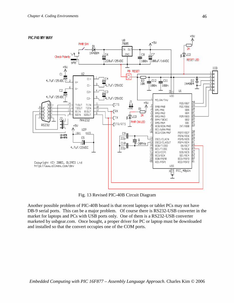
Fig. 13 Revised PIC-40B Circuit Diagram Another possible problem of PIC-40B board is that recent laptops or tablet PCs may not have DB-9 serial ports. This can be a major problem. Of course there is RS232-USB converter in the market for laptops and PCs with USB ports only. One of them is a RS232-USB converter marketed by usbgear.com. Once bought, a proper driver for PC or laptop must be downloaded and installed so that the convert occupies one of the COM ports.

Chapter 4. Coding Environments
Embedded Computing with PIC 16F877 – Assembly Language Approach. Charles Kim © 2006
47
Fig. 14 USB Gear
Once the RS232-USB driver for your operating system is successfully installed, you have to check which COM port (the number) is assigned to the USB converter, as illustrated in the figure. In Windows XP, you go with Start>Control Panel>System to the system properties. In the system properties, select the Device Manager, and select Ports (COM & LPT). Clicking the Ports would give you the COM port number of your USB converter. This COM number you have to select when you use PIC downloader for your hex code downloading.
Even with this annoyance and inconvenience, this board still is good: it can be connected to any PC and the board runs with additional power circuit (while the PIC-40B-USB needs additional DC power supply circuit if it runs with connection to a PC). On the other hand, the PIC-40B-USB does not need any change on the board: all we need is to download a proper driver and install it to your PC or laptop. However, after installing the driver, you sure have to check the serial COM port number by following the procedure I described above. Another good thing of this board is that there is a reset button on the board. Since the board receives DC power from a PC or laptop, it does not have DC power supply circuit. One big problem of this convenience is that you cannot run the board without a PC connected. If you want to run it stand alone, you have to install a DC power supply circuit: with 9V DC battery as indicated in the minimum circuit or with an adaptor. The voltage supply circuit can be borrowed from the schematic diagram of PIC-40B.

Chapter 4. Coding Environments
Embedded Computing with PIC 16F877 – Assembly Language Approach. Charles Kim © 2006
48
Whichever PIC board you use, to test the first PIC code, we need to connect an LED (through a resistor of 1K) to PORTB<1> (RB1), which is pin #34 of PIC 16F877, and a SPST reset button to PORTD<0?(RD0), which is pin #19.. PIC Bootloader A bootloader is used to quickly download a new program into your PIC16F877 in seconds. Bootloading is easily performed in-circuit, with the PIC chip still plugged into your PIC board. No modification, no removal or insertion of your 16F877 chip to or from your PIC board is required. PIC16F877 serial bootloader is currently in use by hundreds of users worldwide. The bootloader explained here is 255 instructions long, and fits into top of the program memory. For downloading, it uses only two wires - TX and RX. This is the reason why in the PIC board, we connect only two pins (except the ground pin) of the DB-9 female connector (See the minimum hardware schematic for this.) A bootloader is a small piece of software by residing on the target microcontroller, which allows user code to be transmitted over a serial cable and written to the device. There are numerous bootloaders for 16F877 are freely available. The bootloader explained here is not different from most bootladers. However, this bootloader hex code must downloaded using a physical programmer. If you cannot afford to a physical programmer, you can ask for a bootloaded PIC 16F877 to the author of the book with a minor extra cost for shipping in addition to the PIC 16F877 chip price. PIC Burner The bootloader must be first downloaded, or burned, into 16F877. This bootloader hex code must be resided inside the program in order to download later another hex code via PC's serial communication port to the chip. The physical programming (burning) is done via a physical programmer (PIC burner), a hardware designed exactly to do the hex code. There are numerous PIC (physical) programmers available. The most simple and cheapest PIC programmer for a 40-pin 16F877 is as of today the Olimex's PIC-PG2C. PIC-PG2C is a serial port programmer for 8/18/28/40 pin PIC microcontrollers. Since PIC-PG2C is programmer takes all necessary signals and power supply from RS232 serial port, there is no need to provide power source to the programmer.
Fig. 15 Olimex's PIC-PG2C
The software to run on a PC is IC-Prog (icprog.exe) which comes with the PIC-PG2C. IC-Prog is copyrighted but free software. It is all right to copy and distribute this software as long as it is not modified in any way, being charged for, or used for illegal purposes.

Chapter 4. Coding Environments
Embedded Computing with PIC 16F877 – Assembly Language Approach. Charles Kim © 2006
49
IC-Prog is Windows based software to control a development programmer for PIC microcontrollers. In order for this software to operate you have to attach a programmer to your PC and set up the hardware & software appropriately. IC-Prog requires Windows 95, 98, ME, NT, 2000, or XP and an internal or external math coprocessor to operate. All processors that are upwardly compatible with the 386 processor with 8Mb of RAM should work. In the PIC, in addition to the program memory, there also is a configuration area as well. This configuration information will configure the microcontroller with some initial settings at boot-up. This configuration information is different and unique for each microcontroller, and specific information can be found in the microcontroller’s datasheet. When you select a device from the menu, IC-Prog will automatically determine the device type and adjust the main view. All devices have a Code area at least, so this part of the main view is always visible. Normally, a user will simply open a file and then program it in the device. To open a file, go to menu File and choose Open File… Now you will get a standard “Open File” dialog. IC-Prog will default to the “Any file (*.*)” filter, so all files can be seen. Simply select the desired file and click open. When you have opened a file, you will see the information from the file displayed in the Code, Data and Configuration area . Check IC-Prog's web site www.icprog.com for installation and further information. Once you install the software IC-Prog and finish with configuration of it, you are now ready to download your hex code, wither ex01.asm or ex02.asm. Insert your 16F877 chip to the socket of the PIC-PG2C programmer, and run IC-Prog, and download. Then, remove the chip from the PIC-PG2C Programmer, and insert it to your PIC board. Give power to the board, and see if the LED blinks. One problem with a PIC physical programmer is that you have to remove 16F877 chip from your PIC board and insert it to the programmer every time you change your code. This causes some troubles in inconvenience and in higher chances of damaging the chip caused by frequent removal and insertion. There is an easier way: bootloader. If you go with a bootloader approach, you download the bootloder hex code to your 16F877 chip using the PIC programmer only once. Once you insert your chip with bootloader downloaded, you can use a PIC downloader program to directly download your hex code to you chip as inserted in your PIC board. Note that the author has the programmer and is willing to burn a bootloader for 16F877 or 16F877A for you. PIC Bootloader and Program Memory Occupation The bootloader hex code, when burned to the 16F877 chip via PIC-PG2C programmer, occupies the first 4 words (address 0000 - 0003) and the last 256 words (1F00h – 1FFFh). Out of 256 words at the bottom addresses, the first 4 words (1F00 – 1F03h) are reserved to store the first four words of user hex code, which would be downloaded by the bootloader program. The first four words are occupied to redirect the program counter (PC) to the very first line of bootloader code at 1F04h. The way the bootloader (after already downloaded and residing) works and the way the internal program memory of PIC16F877 is occupied are illustrated in the

Chapter 4. Coding Environments
Embedded Computing with PIC 16F877 – Assembly Language Approach. Charles Kim © 2006
50
figure.
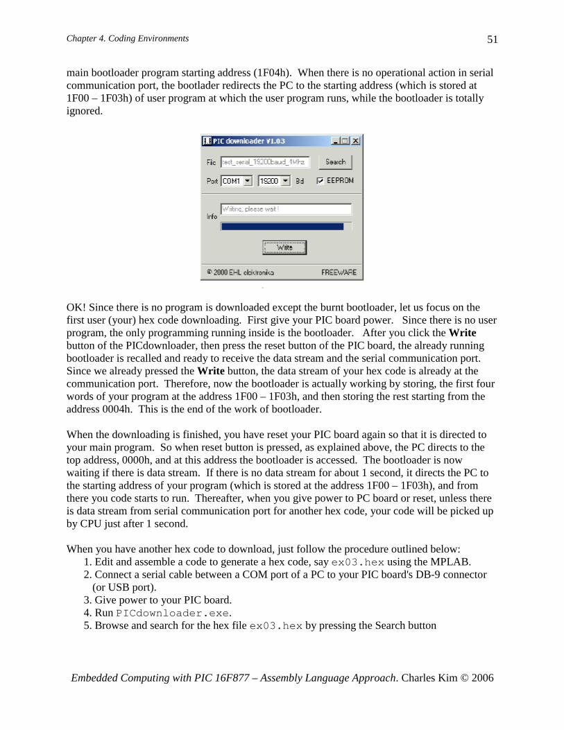
PIC code downloader Now let's move on how to download, via serial communication port of PC to the PIC serial communication port, your hex code without using the burner or physical programmer. Once a bootloader is residing in your 16F877 chip, we can use a program (software) called PIC downloader to download your hex code. The PIC download software, PICdownloader.exe, is freely available to anybody. To use PIC downloader, we connect, via a serial cable, the serial communication port of your PIC board and a COM port of your PC. Run the PIC downloader, PICdownloader.exe. Make sure the EEPROM box is checked and the baud rate of 19200bps is selected1. Make sure your computer physical COM port matches the Port you select in the screen. Find your hex file to download by clicking Search button of the PIC downloader screen. Then press the Write button, then the Info line will say Searching for bootloader. Once you see the message, press the reset button on your PIC board for a few seconds and release it. When the downloading is successful, there will be a progress bar below the Info line. When download is complete, a bell may be heard in most situations. Now let's go back to the bootloader and see what are involved with PIC downloader. This is what's happening when you run the PICdownloader.exe to download a hex code, say ex02.hex, to your PIC 16F877 chip, which was already burned with a bootloader using the PIC-PG2C programmer. As you see above, the bootloader occupies two separate program memory spaces: first 4 addresses and the last 256 addresses. When your power your PIC board, the PC (program counter) will be directed to address 0000h at which the PC is redirected to the 1 When PIC16F887A instead of 16F877 is your target chip and is burned with 16F877A bootloader (instead of 16F877 bootloader), the speed of serial communication must be 56000bps.
Chapter 4. Coding Environments
Embedded Computing with PIC 16F877 – Assembly Language Approach. Charles Kim © 2006
51
main bootloader program starting address (1F04h). When there is no operational action in serial communication port, the bootlader redirects the PC to the starting address (which is stored at 1F00 – 1F03h) of user program at which the user program runs, while the bootloader is totally ignored.
OK! Since there is no program is downloaded except the burnt bootloader, let us focus on the first user (your) hex code downloading. First give your PIC board power. Since there is no user program, the only programming running inside is the bootloader. After you click the Write button of the PICdownloader, then press the reset button of the PIC board, the already running bootloader is recalled and ready to receive the data stream and the serial communication port. Since we already pressed the Write button, the data stream of your hex code is already at the communication port. Therefore, now the bootloader is actually working by storing, the first four words of your program at the address 1F00 – 1F03h, and then storing the rest starting from the address 0004h. This is the end of the work of bootloader. When the downloading is finished, you have reset your PIC board again so that it is directed to your main program. So when reset button is pressed, as explained above, the PC directs to the top address, 0000h, and at this address the bootloader is accessed. The bootloader is now waiting if there is data stream. If there is no data stream for about 1 second, it directs the PC to the starting address of your program (which is stored at the address 1F00 – 1F03h), and from there you code starts to run. Thereafter, when you give power to PC board or reset, unless there is data stream from serial communication port for another hex code, your code will be picked up by CPU just after 1 second. When you have another hex code to download, just follow the procedure outlined below:
1. Edit and assemble a code to generate a hex code, say ex03.hex using the MPLAB. 2. Connect a serial cable between a COM port of a PC to your PIC board's DB-9 connector
(or USB port). 3. Give power to your PIC board. 4. Run PICdownloader.exe. 5. Browse and search for the hex file ex03.hex by pressing the Search button
Chapter 4. Coding Environments
Embedded Computing with PIC 16F877 – Assembly Language Approach. Charles Kim © 2006
52
6. Make sure the EEPROM box is checked and baud rate of 19200bps is selected2. Also make sure to select a proper COM port to which the other end of the serial communication is connected to the PC
7. Press the Write button of the PICdownloader screen. 8. You must see in the Info box of the screen saying "it is searching a bootloader." If the Info box says something like "opening error" or "Port Error," check if your physical
COM port of PC is the same as the COM port selection in the PICdownloader screen. 9. Press and release the reset button of the PIC board. 10. If download in under progress, there must be a progress bar increasing to the right. If
there is no progress bar moving, but instead there is message in the Info box such as "Searching for a bootloader: without a bar change, there may be some connection error around the RS-232 chip (MAX232CPE) and the capacitors attached to the chip. In such a case, check wirings if they are tight and secure (See detail below for troubleshooting).
11. When download is completed, there is message of the finish and a ring sound. 12. Then, press and release the reset button one more time to run your code ex03.hex.
5. Troubleshooting with Bootloaded PIC 16F877 There are many reasons when your first downloading attempt fails. Here are some common errors or causes you can trace to and fix. To do this, you need, preferably, an oscilloscope. But simple problems can be found by using a (digital) multi-meter. Fortunately, if you use one of those commercially available PIC board, you may be able to avoid any of the problems listed. However, you may never be able to taste the joy (but agony comes before) of problem solving (and later pride) in the tinkering with PIC chip and your own board. Power Problem First check if your power source is turned on and all the pins that need +5V have the proper voltage level. For 16F877, pins of #11(Vdd) and #32 (Vdd) must have +5V. For MAX232 chip, pin #16 (Vcc) must have +5V level. Then, check if pins for ground are securely connected to the ground of the power source. The following pins should be grounded: For 16F877, #12 and #31; for MAX2323, #15; from DB-9 connector, #5; for 7805 voltage regulator, #2. Also, check the other end of the ceramic capacitors attached to the crystal oscillator if they are also grounded. Another common problem we face, when we use 9V battery instead of 9V adaptor for the power source, is that the battery power is too low. The voltage may show 9V and the output voltage of the voltage regular may show 5V. But this does not mean that you have enough current to drive the PIC board. Battery is sized by ampere*time. If your PIC board does not work with 9V battery, you should try a 5V power supply to make sure it's because of too much drain in your battery. Reset Button Problem Occasionally, reset button circuit is not properly connected as you think as it supposed to be. Check the voltage level of pin #1 (~MCLR: master clear reset) of 16F877: the level must be +5V when button is not pressed, and the level must be 0V when it is pressed. If you do not see this 2 When PIC16F887A instead of 16F877 is your target chip and is burned with 16F877A bootloader (instead of 16F877 bootloader), the speed of serial communication must be 56000bps.

Chapter 4. Coding Environments
Embedded Computing with PIC 16F877 – Assembly Language Approach. Charles Kim © 2006
53
level change by the push button, your circuit must be checked and corrected. PICdownloader Configuration Problem Now let's see if you properly configured your PICdownloader. In the pop up window of the PICdownloader, make sure you correctly select the Baud rate of 19200 for 16F877 (or 56000 for 16F877A) and the COM port to which the other end of your serial cable is connected in your PC. (By the way, the one of end of the cable must be connected to your DB-9 connector.) Also, the box for EEPROM must be checked. Now, try again your download. Burning problem Check, when you burn (download) your bootloader hex code using the PIC programmer (PIC-2C), if you correctly set the oscillation speed of 20MHz (or HS, high speed). After correction, try to burn again. Now, move your 16F877 to your PIC board, and download again if now it works. If you suspect your problem comes from a burning problem and you do not have your own PIC burner, bring your suspicious 16F877 to me so that I re-burn the chip for you. Serial Communication Level Convert Circuit Problem If all the above steps do not help with your downloading problem, now check the circuit around the MAX232 (the level converter, from RS-232 level to logic level, or vice versa). So first check if all the electrolyte capacitors are correctly connected following the marked polarities. Now, check the MAX232 chip along with 4 capacitors if they are properly working. In this test, you need a good oscilloscope. A storage digital scope would be better but not a must. Run the PICdownloader, then click the Write button. You now see the message of "Searching for Bootloader" in the Info box. As soon as the Write button is clicked, the PICdownloader sends some signal to your PIC board to initiate the hex code transmission. So strings of pulses should be observed at the TxD pin (#2) of the DB-9 connector and the pin # 7 of MAX232 chip to which TxD is wired. Details of the DB-9 and serial communication is discussed in Chapter 5. As illustrated below, if you can observe the pulses of –11 ~ 9.5 V, you can be sure that the PICdownloader is working and your PC COM port is correctly signaling. These pulses are in the RS-232 voltage range.

Chapter 4. Coding Environments
Embedded Computing with PIC 16F877 – Assembly Language Approach. Charles Kim © 2006
54
As mentioned before, the MAX232 chip is to convert the RS-232 level to the logic level (+5 for High and 0 for Low). The converted output at the logic level from the input pulse from the PC comes out at pin# 12 of the chip and is fed to pin #26 of 16F877. Therefore, if you can observe the similar pulses in logic level, like the one illustrated below the RS-232 pulses, you can be sure your MAX232 chip and circuit are working well. If you do not see the logic level pulses, either MAX232 chip is damaged or the polarity of the capacitors is incorrect. Correct them all, and try to download again. PIC 16F877 Problem It is hoped that you do not come this far but, if all the above steps do not solve your problem, the culprit is most likely your 16F877: it is damaged. Take your 16F877 off your PIC board, and try to burn again if it can be burned or not. If you cannot burn it, you need another 16F877. But before jumping to the conclusion and throw away the chip, you may want to check the last point: clock output from the chip. Pin#14 of 16F877 should show a sine-curve like pulsed waveform. If you cannot observe the waveform, it's because either the chip is damaged or the oscillation circuit including two ceramic capacitors are not properly installed. 6. Connection of parts to the PIC16F877 Congratulations on your success through minimum hardware, bootloader burning, hex code downloading. And now you may see your LED blinking. Connecting an LED to a PIC chip pin may be easy a job by soldering or breadboarding, but what if you have additional parts to be connected to your PIC board? For example, as illustrated in the figure, I added an IR receiver I salvaged from a broken VCR to the PIC board. Out of three wires of the IR receiver, one is to be connected to +5V source, second one to the ground, and the third one to a PIC I/O pin.
Fig. 16(a) IR receiver on PIC board Fig. 16(b) Wires soldered to PIC pin

Chapter 4. Coding Environments
Embedded Computing with PIC 16F877 – Assembly Language Approach. Charles Kim © 2006
55
Usually, we cut a wire and solder it to a PIC pin. Of course, when you do solder, you have to take the PIC chip off the socket. Otherwise your soldering would damage the chip. Sometimes, soldering a wire to the small pin is not easy, and moreover, inhaling soldering smoke is not pleasant. Of course, you have to invest some money on your soldering station and solder. My approach and my suggestion instead is to use a wire wrapping in place of soldering. In the illustration of the back side of the board, you can see pins I installed from the top of the board. You can also see thin wires wrapped around pins. The pins are from "wrapping socket." Wrapping sockets are IC sockets with longer and sturdy pins for wire wrapping.
Fig. 17(a) Back of breadboard Fig. 17(b) Wire wrapping
Wire wrapping tools include a wire wrapper and wrapping wires as illustrated in the figure. The price of a wrapping tool is slightly cheaper that that of a soldering kit. But you may need a solder to post wrapping sockets to your PIC board anyway. I hope you can easily borrow and use freely available soldering station nearby. One good thing about using wrapping is that you can take your PIC board anywhere and connect your parts any place. No smoke, no frowned face nearby. 7. Piezoelectric Buzzer Example Since, hopefully, we are successful in bootloader business and have LED blinking example, we may want to expand our time delay application to generate pulses of different frequency, again using only instructions to achieve time delay. Since piezo-buzzer sounds differently when pulses of different frequencies are applied to, it will be a good exercise if we examine a piezo-buzzer and write a sample code to sound it. Piezo-buzzer, shown below as an example for small PCB mount buzzer, is made of piezo-ceramic elements. Piezoelectoric ceramic buzzer has a simple structure in which piezoceramic element is glued to a vibration plate. When alternating voltage is applied to piezoceramic element, the element expands or shrinks diametrically, and in turn bends the vibration plate, which generates sound. We can directly connect an output pin of a microcontroller to the piezo element. By varying the frequency of the output pulse of the pin we can find the frequency or frequencies that a piezo was designed to operate. However, since varying frequencies generate different sounds, we can use this frequency dependency of the sound of the piezo-buzzer to generate different tones,

Chapter 4. Coding Environments
Embedded Computing with PIC 16F877 – Assembly Language Approach. Charles Kim © 2006
56
which would give us some flexibility in indication, signaling, or alarm.
Fig. 18 CS4120 Buzzer connection to PIC16F877
The piezo-buzzer we examine here is CS4120 Buzzer which has the specification of 12VDC/7mA, 4000Hz, 80dB, .30"H x .54"Diameter. Even though the specification of the operating frequency is set as 4000Hz, it can generate different tones in lower frequencies. In our example, let's generate different frequencies (1, 5, 50, 500, and 4000 Hz) and hear how they differently sound by running the following example code. The code is not very different from that of LED blinking with time delay. We can utilize the delay routines we developed for LED example. To generate 1Hz pulse of duty cycle 50% is to have High output for 500ms followed by Low for 500ms. To generate, say, 4 pulses, we send out the High and Low for 4 times. In the following code, the variable TEMP holds the number of pulses we send out through PORTD<PBUZZ>. As you already noticed, PBUZZ is equated 4 since the buzzer is connected to PORTD<4>: movlw 0x04 ;4 pulses of 1 Hz
banksel TEMPmovwf TEMP
LOOPc bsf PORTD, PBUZZ ;Pbuzz is RD4 where the positive terminal;of the buzzer is connected
call delay500msbcf PORTD, PBUZZcall delay500msdecfsz TEMPgoto LOOPccall delay1s ;after 4 pulses,
1 sec delay for another job
Similarly, for 5, 50, 500, and 4000Hz frequencies, we can utilize time delays of 100ms, 10ms, and 1ms we already developed, respectively. The example code shown below omits the time delay subroutines. The code is to generate 3 different tones continuously. Follow closely with comments for better understanding of the code.
Chapter 4. Coding Environments
Embedded Computing with PIC 16F877 – Assembly Language Approach. Charles Kim © 2006
57
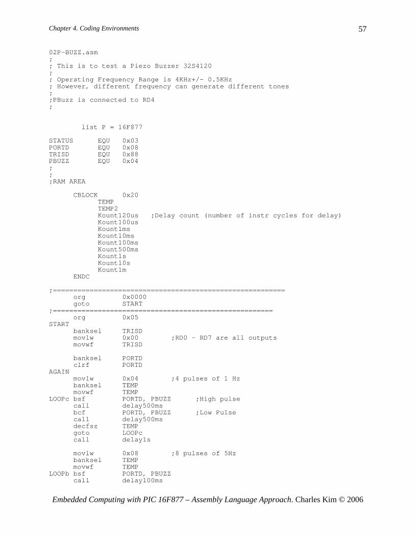
02P-BUZZ.asm;; This is to test a Piezo Buzzer 32S4120;; Operating Frequency Range is 4KHz+/- 0.5KHz; However, different frequency can generate different tones;;PBuzz is connected to RD4;
list P = 16F877
STATUS EQU 0x03PORTD EQU 0x08TRISD EQU 0x88PBUZZ EQU 0x04;;;RAM AREA
CBLOCK 0x20TEMPTEMP2Kount120us ;Delay count (number of instr cycles for delay)Kount100usKount1msKount10msKount100msKount500msKount1sKount10sKount1m
ENDC
;=========================================================org 0x0000goto START
;======================================================org 0x05
STARTbanksel TRISDmovlw 0x00 ;RD0 - RD7 are all outputsmovwf TRISD
banksel PORTDclrf PORTD
AGAINmovlw 0x04 ;4 pulses of 1 Hzbanksel TEMPmovwf TEMP
LOOPc bsf PORTD, PBUZZ ;High pulsecall delay500msbcf PORTD, PBUZZ ;Low Pulsecall delay500msdecfsz TEMPgoto LOOPccall delay1s
movlw 0x08 ;8 pulses of 5Hzbanksel TEMPmovwf TEMP
LOOPb bsf PORTD, PBUZZcall delay100ms

Chapter 4. Coding Environments
Embedded Computing with PIC 16F877 – Assembly Language Approach. Charles Kim © 2006
58
bcf PORTD, PBUZZcall delay100msdecfsz TEMPgoto LOOPbcall delay1s
movlw 0x30 ;25 pulses of 50Hzbanksel TEMPmovwf TEMP
LOOPa bsf PORTD, PBUZZcall delay10msbcf PORTD, PBUZZcall delay10msdecfsz TEMPgoto LOOPacall delay1s
movlw 0xFF ;255 pulses of 500Hzbanksel TEMPmovwf TEMP
LOOP bsf PORTD, PBUZZcall delay1msbcf PORTD, PBUZZcall delay1msdecfsz TEMPgoto LOOP
call delay1s
goto AGAIN
;Your subroutines here
;END ;End of code