GST5000.pdf - CNP
70
-
Upload
khangminh22 -
Category
Documents
-
view
0 -
download
0
Transcript of GST5000.pdf - CNP

GST5000 Intelligent Fire Alarm Control Panel Installation and Operation Manual (Generic Part) The Intelligent Solution
Page I
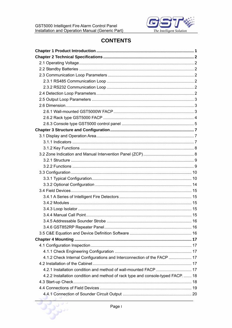
CONTENTS
Chapter 1 Product Introduction ..................................................................................... 1 Chapter 2 Technical Specifications ............................................................................... 2
2.1 Operating Voltage.................................................................................................... 2 2.2 Standby Batteries .................................................................................................... 2 2.3 Communication Loop Parameters ........................................................................... 2
2.3.1 RS485 Communication Loop ............................................................................ 2 2.3.2 RS232 Communication Loop ............................................................................ 2
2.4 Detection Loop Parameters ..................................................................................... 2 2.5 Output Loop Parameters ......................................................................................... 3 2.6 Dimension................................................................................................................ 3
2.6.1 Wall-mounted GST5000W FACP...................................................................... 3 2.6.2 Rack type GST5000 FACP ............................................................................... 4 2.6.3 Console type GST5000 control panel ............................................................... 5
Chapter 3 Structure and Configuration......................................................................... 7 3.1 Display and Operation Area..................................................................................... 7
3.1.1 Indicators .......................................................................................................... 7 3.1.2 Key Functions ................................................................................................... 8
3.2 Zone Indication and Manual Intervention Panel (ZCP) ............................................ 8 3.2.1 Structure ........................................................................................................... 9 3.2.2 Functions .......................................................................................................... 9
3.3 Configuration ......................................................................................................... 10 3.3.1 Typical Configuration....................................................................................... 10 3.3.2 Optional Configuration .................................................................................... 14
3.4 Field Devices ......................................................................................................... 15 3.4.1 A Series of Intelligent Fire Detectors ............................................................... 15 3.4.2 Modules .......................................................................................................... 15 3.4.3 Loop Isolator ................................................................................................... 15 3.4.4 Manual Call Point............................................................................................ 15 3.4.5 Addressable Sounder Strobe .......................................................................... 16 3.4.6 GST852RP Repeater Panel............................................................................ 16
3.5 C&E Equation and Device Definition Software ...................................................... 16 Chapter 4 Mounting ...................................................................................................... 17
4.1 Configuration Inspection........................................................................................ 17 4.1.1 Check Engineering Configuration ................................................................... 17 4.1.2 Check Internal Configurations and Interconnection of the FACP .................... 17
4.2 Installation of the Cabinet ...................................................................................... 17 4.2.1 Installation condition and method of wall-mounted FACP ............................... 17 4.2.2 Installation condition and method of rack type and console-typed FACP. ....... 18
4.3 Start-up Check....................................................................................................... 18 4.4 Connections of Field Devices ................................................................................ 19
4.4.1 Connection of Sounder Circuit Output ............................................................ 20

GST5000 Intelligent Fire Alarm Control Panel Installation and Operation Manual (Generic Part) The Intelligent Solution
Page II
4.4.2 Connection of F.P.E. Output ............................................................................ 21 4.4.3 Connection of Fire Alarm Output..................................................................... 21 4.4.4 Connection of Class A Loop ............................................................................ 22 4.4.5 Connection of Communication Loop ............................................................... 22 4.4.6 Connection of Ring Module............................................................................. 23
4.5 Connection Inspection and Device Registration .................................................... 23 4.5.1 Connection Inspection .................................................................................... 23 4.5.2 Registration of Devices ................................................................................... 23
4.6 Definition of Devices.............................................................................................. 24 4.6.1 Browsing Zone Definition ................................................................................ 25 4.6.2 Browsing Device Information .......................................................................... 26 4.6.3 Viewing C&E ................................................................................................... 28
4.7 Field Devices Commission .................................................................................... 30 Chapter 5 Display and Disposal of System Information............................................ 31
5.1 Normal Information ................................................................................................ 31 5.2 Information of Fire Alarm ....................................................................................... 31
5.2.1 Fire Alarm Screen ........................................................................................... 31 5.2.2 Disposal of Fire Alarm Signal .......................................................................... 34
5.3 Fault Information.................................................................................................... 34 5.3.1 Screen of Fault Information............................................................................. 34 5.3.2 Disposal of Fault Information .......................................................................... 35
5.4 Disable and Enable ............................................................................................... 35 5.4.1 Use of Disable/Enable..................................................................................... 35 5.4.2 Disable/Enable Devices .................................................................................. 35 5.4.3 Browsing Disabled Information ....................................................................... 37
5.5 Manual Start and Stop of Loop Devices................................................................. 38 5.5.1 START/STOP Operation through Keypad ....................................................... 38 5.5.2 Operation of the Devices by ZCP.................................................................... 39 5.5.3 Browsing Started Devices ............................................................................... 39
5.6 Resetting and Silencing of the System .................................................................. 40 5.7 Rules for Information Display................................................................................. 41 5.8 Rules for Sound Indication .................................................................................... 41
Chapter 6 Description of System Operation............................................................... 42 6.1 Keypad .................................................................................................................. 42
6.1.1 Functions ........................................................................................................ 42 6.1.2 Common Method of Data Input ....................................................................... 42 6.1.3 Method of Browsing Information ..................................................................... 42 6.1.4 Keypad Unlock and Lock ................................................................................ 42
6.2 User Operation Instruction..................................................................................... 43 6.2.1 Changing time display..................................................................................... 43 6.2.2 Browsing history records................................................................................. 43
6.3 Instructions for System Operator ........................................................................... 44 6.3.1 Self Test .......................................................................................................... 44

GST5000 Intelligent Fire Alarm Control Panel Installation and Operation Manual (Generic Part) The Intelligent Solution
Page III
6.3.2 Printer Setting ................................................................................................. 44 6.3.3 Security Mode ................................................................................................. 45 6.3.4 Extinguishing Mode......................................................................................... 45 6.3.5 Modification of System Time ........................................................................... 46
6.4 Instructions for System Administrator .................................................................... 47 6.4.1 Password Modification .................................................................................... 47 6.4.2 Communication Setting................................................................................... 49 6.4.3 Working State Setup ....................................................................................... 49 6.4.4 Fire Display Mode ........................................................................................... 50 6.4.5 Zone Browse................................................................................................... 50 6.4.6 C&E Equation Browse .................................................................................... 50 6.4.7 Browsing supervisory data of addressable devices ........................................ 51
Chapter 7 Commissioning Functions.......................................................................... 52 7.1 Getting into Commission Mode.............................................................................. 52 7.2 Exiting Commission Mode ..................................................................................... 53 7.3 Registration at Any Time........................................................................................ 53 7.4 Loop Card Disablement......................................................................................... 53 7.5 Detector Searching................................................................................................ 53 7.6 Protection of C&E Equations ................................................................................. 53
Chapter 8 Troubleshooting and Regular Checks ....................................................... 54 8.1 General Fault Treatment........................................................................................ 54 8.2 Regular Checks and Replacement ........................................................................ 55
Chapter 9 Calculation of Battery Capacity.................................................................. 59 Appendix 1 Internal Connection Diagram................................................................... 60 Appendix 2 Device Type List........................................................................................ 62 Appendix 3 Operation Menu ........................................................................................ 64

GST5000 Intelligent Fire Alarm Control Panel Installation and Operation Manual (Generic Part) The Intelligent Solution
Preface
GST5000 Intelligent Fire Alarm Control Panel Installation and Operation Manual includes two parties: generic part and Fireman’s Control Panel part. This is the generic part. Please refer to relative part for description on Fireman’s Control Panel.
Please assign a specific person to keep this manual for occasional use during operation of the GST5000 Intelligent Fire Alarm Control Panel.

GST5000 Intelligent Fire Alarm Control Panel Installation and Operation Manual (Generic Part) The Intelligent Solution
Page 1
Chapter 1 Product Introduction
GST5000 Intelligent Fire Alarm Control Panel (FACP) is designed by EN 54-2 standard with qualities of simple installation, operation, and easy maintenance. It is used in fire alarm system with the following features:
(1) It controls maximum 60 fire zones. Each zone has Alarm and FLT/Disable LEDs and a zone label separately. It’s expandable to a maximum of 256 zones.
(2) It provides 4 Class A loops as standard, which can be expanded to maximum 28 loops. Each loop can have up to 235 addressable devices. It is compatible with a series of addressable GST products, which are intelligent sounder strobe (I-9403) complying with EN 54-3, photoelectric smoke detector (I-9102) complying with EN 54-7, rate of rise and fixed temperature heat detector (I-9103) complying with EN 54-5, intelligent manual call point (I-9202) complying with EN 54-11, intelligent reflective beam detector (I-9105R) complying with EN 54-12, input and output module (I-9300, I-9301) complying with GEI 1-084, and loop isolator (C-9503) complying with GEI 1-052.
(3) Graphic display can show 320×240 dot matrix, assisting the 15 LEDs to display important information.
(4) The memory does not lose data even if power supply is accidentally removed.
(5) It has manual keys for each zone, which can activate/mute the sounder strobe separately.
(6) Automatically prompting operation steps for every alarm device and for smoke exhaust and fire extinguisher by field programming.
(7) Sounder strobe interface provides 0.5A/24V output, compatible with GST conventional sounder strobe (C-9403) designed according to EN 54-3.
(8) RS232 interface enables communication with PC.
(9) RS485 interface enables networking.

GST5000 Intelligent Fire Alarm Control Panel Installation and Operation Manual (Generic Part) The Intelligent Solution
Page 2
Chapter 2 Technical Specifications
2.1 Operating Voltage
Input Voltage: 220/230VAC
Frequency: 50/60Hz
Input Current: 0.75A
Fuse: 2A delay
Recommended Wiring: 1.5mm2 or above screened cable, complying with local installation codes.
2.2 Standby Batteries
Maximum Charge Current: [email protected] float charge
Type: Sealed lead acid batteries
Maximum Charge Capacity: 38 Ah
Fuse: 8A
Wiring: GST FireCable®2E/1.5 2core and Earth 1.5mm2 CSA (subject to local installation codes).
2.3 Communication Loop Parameters
2.3.1 RS485 Communication Loop
NETWORK (A, B): Communication cable for connecting with up to 32 network control panels of different model.
REPEATER (A, B): Communication cable for connecting with up to 64 repeater panels.
Recommended Wiring: GST FireCable ® 2E/1.0 2core and Earth 1mm2 CSA (subject to local installation codes).
2.3.2 RS232 Communication Loop
RS232 communication loop is connected with CRT system installed in PC through RJ45 plug connector.
Wiring: Cable length should be less than 15m.
2.4 Detection Loop Parameters
LOOP OUT (+, -): Polarized signal bus from GST5000, connecting with 235 addressable devices at most.
LOOP IN (+, -): Polarized signal bus returning to GST5000.
Output Voltage: 24V pulse
Output Current: 0.3A

GST5000 Intelligent Fire Alarm Control Panel Installation and Operation Manual (Generic Part) The Intelligent Solution
Page 3
Recommended Wiring: GST FireCable ® 2E/1.0 2core and Earth 1mm2 CSA
2.5 Output Loop Parameters
Recommended Wiring: GST FireCable ® 2E/1.0 2core and Earth 1mm2 CSA
(1) FIRE ALARM OUTPUT (+, -)
Output Voltage: 21VDC~27VDC
Output Current: 0.5A
Terminal Resistor: 4.7KΩ
(2) F.P.E OUTPUT (+, -)
Output Voltage: 21VDC~27VDC
Output Current: 0.5A
Terminal Resistor: 4.7KΩ
(3) SOUNDER CIRCUIT OUTPUT (+, -)
Output Voltage: 21VDC~27VDC
Output Current: 0.5A
Terminal Resistor: 4.7KΩ
(4) FAULT OUTPUT (NC, COM, NO)
Contact Capacity: 24VDC @1.0A
In fault state, NC and COM open, NO and COM close.
2.6 Dimension
2.6.1 Wall-mounted GST5000W FACP
Dimension (L × W × H): 500mm×170mm×700mm

GST5000 Intelligent Fire Alarm Control Panel Installation and Operation Manual (Generic Part) The Intelligent Solution
Page 4
CLOCK
GST5000 Intelligent Fire Alarm Control Panel
×
Display and operation area
LCD
Printer
Zone indication and manual interventionalpanel
Fireman'scontrol panel
170mm
500mm
700m
m
Fig. 2-1
2.6.2 Rack type GST5000 FACP
Dimension (L × W × H): 580mm×520mm×1715mm

GST5000 Intelligent Fire Alarm Control Panel Installation and Operation Manual (Generic Part) The Intelligent Solution
Page 5
Printer
LCD
PSU24-6RM Intelligent PSU
580mm
1715mm
520mm
3
9
6
×
2
8
5
1
7
4
0*
+
=
GST5000 Intelligent Fire Alarm Control Panel
CLOCK
INTELLIGENT PSU
GST64ZCP Zone Indication and Manual Intervention Panel
GST014FCP Fireman's Switch Panel
TESTSELF
MANUAL
0 1
GST64ZCP Zone Indication and Manual Intervention Panel GST014FCP Fireman's Control Panel
Display and operation area
GST64ZCP Zone Indication and Manual Intervention Panel
Optional units
Optional units
Fig. 2-2
2.6.3 Console type GST5000 control panel
Dimension (L × W × H, single unit ): 555mm × 933mm (with table) × 1350mm
Dimension (L × W × H, double unit): 1045mm × 933mm (with table) × 1350mm

GST5000 Intelligent Fire Alarm Control Panel Installation and Operation Manual (Generic Part) The Intelligent Solution
Page 6
INTELLIGENT PSU
GST64ZCP Zone Indication and Manual Intervention Panel
=
+
* 0
4
7
1
5
8
2
×
6
9
3
GST5000 Intelligent Fire Alarm Control Panel
CLOCK
GST014FCP Fireman's Switch Panel
TESTSELF
10
MANUAL
Display and operation area
LCD
PrinterGST014FCPFireman's Control Panel
Optional Units534mm
370mm
100mm
563mm
750mm
484mm 484mm
1045mm
50mm
1350mm
GST64ZCP Zone Indication and Manual Intervention Panel
PSU24-6RM Intelligent PSU
Fig. 2-3
Note: There are three types of GST5000 FACP: wall-mounted type, rack type and console type. In the following parts of this manual, differences between the three types will be elaborated separately and the similarities described together.

GST5000 Intelligent Fire Alarm Control Panel Installation and Operation Manual (Generic Part) The Intelligent Solution
Page 7
Chapter 3 Structure and Configuration
3.1 Display and Operation Area
The display and operation area is shown in Fig. 3-1, which consists of LCD display, indicators, clock display, keypad and printer.
0
8
54
7
*
9
6
×
=
21 3 +
CLOCK
GST5000 Intelligent Fire Alarm Control Panel
Fig. 3-1
3.1.1 Indicators
FIRE: Red. This LED lit means the FACP has checked fire alarm state of connected detectors. Detailed messages are shown on the LCD. When fire alarm is cleared, press RESET key to turn it off.
COMMON FAULT: Yellow. Lit when any fault occurs.
DISABLED: Yellow. Lit when connected devices, F.P.E. output or SOUNDER output are disabled.
MUTE: Yellow. When the FACP sounds alarm, pressing MUTE key, this LED illuminates, and the speaker stops alarming. If MUTE key is pressed again or there are new alarms, it goes out and the FACP sounds again.
POWER HEALTHY: Green. It illuminates when mains or standby battery of the system works normally.
SYSTEM FAULT: Yellow. Lit when the program fails or the system cannot operate normally.
AC FAULT: Yellow. Lit when mains power is cut off or defected, and goes out when it resumes.
BATTERY FAULT: Yellow. Lit when standby power system is in fault and goes out when it’s cleared.
F.P.E. FLT/DISABLE: Yellow. Lit when F.P.E. output is in fault or is disabled.

GST5000 Intelligent Fire Alarm Control Panel Installation and Operation Manual (Generic Part) The Intelligent Solution
Page 8
SOUNDER FLT/DISABLE: Yellow. Lit when SOUNDER output is in fault or is disabled.
PLANT CONTROL: Green. Action message indication. Lit when there are feedback signal inputs of fire-protective plant.
SECURITY MODE: Green. Lit when there is delay message with the FACP.
EXTINGUISHING SYSTEM RELEASE: Green. Lit when connected extinguishing system has been activated.
EXTINGUISHING SYSTEM REQUEST: Green. Lit when extinguishing system is ready to be activated or in delay state.
EXTINGUISHING SYSTEM PERMIT: Green. Lit when extinguishing system gets permission to be activated.
3.1.2 Key Functions
MUTE: Silencing the panel. RESET: System reset. TAB: Transferring time display mode. ESC: Returning to the previous menu or normal operation screen. VIEW FIRE: Viewing fire alarm messages. VIEW FAULT: Viewing fault messages. VIEW DISABLE: Viewing disabled messages. VIEW PLANT: Viewing messages of started fire suppression devices in the
system. SELF TEST: Self-testing the panel. DISABLE: Disabling a system device. ENABLE: Re-enabling a disabled device. CLOCK: Modifying system time. START: Starting fire suppression devices. STOP: Stopping fire suppression devices. PRINT: Setting printing mode. SECURITY MODE: Setting security mode. EXTNGUISHING MODE: Setting gas extinguishing mode. BROWSE: Viewing system configuration. LOG: Viewing history records. SYSTEM: System menu. ENTER: Confirming an operation.
= and =: Page up and down.
3.2 Zone Indication and Manual Intervention Panel (ZCP)
The zone indication and manual intervention panels of the three types of GST5000 FACP have the same structure and function. The cabinet of wall-mounted GST5000W FACP can connect with only one GST64ZCP zone indication and manual intervention

GST5000 Intelligent Fire Alarm Control Panel Installation and Operation Manual (Generic Part) The Intelligent Solution
Page 9
panel. Rack type and console type can be expanded with more on order.
3.2.1 Structure
The ZCP includes two LED boards and one control board. Control board connects with the two LED boards through pins. Structure of the control board is shown in Fig. 3-2.
Fig. 3-2
Every loop card can drive 4 ZCPs. All of them are connected together with a 10p ribbon cable through XS1 of the control board.
We can use the switch to set a code for each ZCP.
No. 1: 1, 6, 8 at ON, others at OFF.
No. 2: 2, 6, 7 at ON, others at OFF.
No. 3: 3, 5, 8 at ON, others at OFF.
No. 4: 4, 5, 7 at ON, others at OFF.
3.2.2 Functions
Fig. 3-3
Each switch includes a red LED, a yellow LED, a key (which can directly initiate connected devices) and a label (brief description of the start key).
The ZCP can be defined as three operation modes:

GST5000 Intelligent Fire Alarm Control Panel Installation and Operation Manual (Generic Part) The Intelligent Solution
Page 10
a) Zone direction mode [ZoneDir]
When fire occurs in a zone, corresponding red LED is lit and the sounder strobe is automatically initiated; when fault occurs, corresponding yellow LED flashes; when disabling all devices in the zone, corresponding yellow LED is constantly lit.
When pressing the key of the zone, the sounder strobe is initiated; press again, it is stopped.
b) Silence mode [Silence]
Press this key, all connected sounder strobes are silenced and red LED lit; press it again, the silenced sounder strobes sound again, and red LED goes out. In silence mode, when new alarm occurs, all silenced sounder strobes activate again.
c) Point device mode
Single startable devices can also be defined on the ZCP. Press the key, corresponding device is initiated and red LED is lit. Press the key again, corresponding device stops, red LED goes out.
3.3 Configuration
3.3.1 Typical Configuration
(1) Wall-mounted GST5000W FACP
A typical FACP system consists of a control cabinet, a loop interface board, a P.S.U system, display and operation area and a ZCP.
① Control cabinet
Cabinet is the core part of the FACP, mainly consisting of 3 parts: motherboard, main board, and loop card. RS232 and RS485 communication cards can be inserted like in Fig. 3-4.
A: Motherboard Illustration
Fig. 3-4

GST5000 Intelligent Fire Alarm Control Panel Installation and Operation Manual (Generic Part) The Intelligent Solution
Page 11
Fig. 3-4 shows the structure of the motherboard installed on the bottom of the control part. It connects with the AC-DC100W power supply through terminals. There are 4 channel slots for plugging main board, loop card and 232 and 485 communication cards.
XT4: Connecting with AC-DC100W power supply.
XT7: Connecting with switchboard.
B: Illustrations of main board, loop card and communication card
Appearances of main board, loop card and communication card are shown in Fig. 3-5.
Communication LED
Run LED
485 Communication BoardMainboard Circuit Board
To Switch Board
Communication LED
Run LED
To Zone Indication and Manual Intervention Panel
Fault LED
Run LED
Tens degit
Ones degit
232 Communication Board
To CRT
Communication LED
Run LED
Fig. 3-5
There are two code switches on each loop card and communication card respectively, representing tens digit and ones digit. They are used to set the channel number of loop card and communication card. The loop card is of dual-channel. The code switch sets the channel number of the first channel, and automatically adding 1 for the second channel. The numbers of communication card and loop card can be mixed randomly.
Example: On code switch of loop card, tens digit is 0, ones digit is 1. The channel number of the first loop is 1, and that of the second loop is 2.
② Loop interface board
It is signal interface board of the FACP, which has communication port, detecting port, fire alarm output port, fault output port and etc. The loop interface board makes field devices and the FACP compose a whole fire alarm system.
③ Power supply
It provides the control cabinet, loop interface board and printer with voltage. Non-lost electricity ensures that all the registered devices being monitored after commission.
④ Display and operation area
It can indicate and show all kinds of status information resulting from operations from

GST5000 Intelligent Fire Alarm Control Panel Installation and Operation Manual (Generic Part) The Intelligent Solution
Page 12
keypad (such as browsing, setting, and printing).
⑤ Zone indication and manual intervention panel (ZCP)
Indicating fire, and fault/disablement of corresponding devices, and starting or stopping them.
(2) Typical configurations of GST5000 rack type and console type:
Comparing with wall mounted type, the rack and console types can have more loop cards connected to the control cabinet and an intelligent PSU is used.
① Control Cabinet
Main control unit is the core part of the control panel, including motherboard, main board, 232 communication card, 485 communication card and loop card.
A: Motherboard
Fig. 3-6 shows the structure of the motherboard of the control panel installed on the bottom of the control part. It connects with the DC-DC convertor through terminals. There are 10 channel slots for plugging main board, loop card and communication cards. The control panel is expandable to at most two motherboard boxes.
Signal Bus
Channel Slot
Communication Bus in Parallel Communication Bus in Parallel
Fig. 3-6
Communication bus in parallel: Used for system extension
Channel Slot: Used to plug main board, loop card and communication card on.
XP3: Connecting with DC-DC convertor
ZAn, ZBn(n=1~20): 1~10 channel signal bus terminals
Note: When DC-DC convertor is switched off, loop 24V is not cut off. If you want to plug in or pull out the circuit boards in the main unit, please disconnect main and standby power.

GST5000 Intelligent Fire Alarm Control Panel Installation and Operation Manual (Generic Part) The Intelligent Solution
Page 13
B: Main board, loop card, communication card
Appearances of main board, loop card and communication card are the same as GST5000W wall mounted control panel.
C: Illustration of DC-DC Convertor
DC-DC converting module is shown in Fig. 3-7.
GND
ACF
BATTERYFUSE(10A)
BATTERY
+5V1
GND1
BAF+5V2GND2
Battery Fuse
RUN
Battery Switch
Work Switch
1
2BAT
BAT
Battery Terminal
5V
MAIN
5V
24V
COM
Main Power 5V LED
Communication 5V LED
Main power 24V LED
+5V1
+5V1
24V
ACF
GND
Work LED WORK
GND1
GND1
Motherboard XP3
DC-DC CONVERTOR
24V
Battery Check
AC Check
+24V
GND
Switch Board 5V
Display Board 5V
Printer
Fig. 3-7
② PSU24-6RM Intelligent PSU
PSU24-6RM intelligent PSU is used to supply power to modules and corresponding controlled devices.
PSU24-6RM is shown in Fig. 3-8.
INTELLIGENT PSU
Fig. 3-8
A Indicators and switches:
MUTE Key: Pressing MUTE can silence the PSU panel when fault occurs. The sound will resume when new fault occurs.
TEST/RESET Key: Under monitoring state, this is TEST key, testing all display components as pressing it, which should be normally lit; after self-test, press TEST key again, it will self-test again. Under fault state, this is RESET key to clear the fault. RESET key can clear the fault display and fault alarm sound.
POWER ON LED: Green. For AC power indication.
CHARGING LED: Green. Indicating the charging mode.
AC FAULT LED: Yellow. Lit when AC power voltage is higher than 260VAC or

GST5000 Intelligent Fire Alarm Control Panel Installation and Operation Manual (Generic Part) The Intelligent Solution
Page 14
lower than 160VAC. The buzzer will alarm at the same time.
BATTERY FAULT LED: Yellow. Lit when battery voltage is lower than 15VDC or higher than 28VDC. The buzzer will alarm at the same time.
OVERLOAD LED: Red. Lit when battery voltage is higher than 28VDC. The buzzer will alarm at the same time.
OUTPUT FAULT LED: Yellow. Lit when a break or short circuit occurs or output current is higher than 8A. The buzzer will alarm at the same time.
MUTE LED: Red. Lit when in mute state.
Display windows indicate the input AC voltage, output voltage and output current.
B Terminals
Back of the PSU and terminals are shown in Fig. 3-9.
220V
AC
3.15A
INTERNALOUTPUT
BAT. FUSEOFF OFF
BATTERY
BAT.EXTERNALOUTPUT
OUTPUT FUSE
10AON ON
- + GND +24V 10A GND +24V
Fig. 3-9
AC ON/OFF: AC ON applies AC power, and AC OFF disconnects AC power.
BATTERY ON/OFF: BATTERY ON applies battery, and BATTERY OFF disconnects battery.
+, - (BAT.): Battery input.
+24V, GND (EXTERNAL OUTPUT): 24VDC main output.
+24V, GND (INTERNAL OUTPUT): 24VDC multi-wire power output.
AC socket: 220V/230VAC power input (including chassis earth).
3.3.2 Optional Configuration
(1) Fireman’s Control Panel (FCP)
Fireman’s Control Panel is an important device in the system. These devices include fire pump, smoke exhauster and blower. The FCP of GST5000 intelligent fire alarm control panel can control at most 12 equipments by option. For devices needing both start and stop, it can control at most 6. The panel can check short circuit and broken circuit with corresponding audio and visual instruction, which can ensure the reliability of connection between the control panel and important devices as much as possible.
(2) Thermal Printer
The thermal printer adopts special structure to be installed on a small mounting hole

GST5000 Intelligent Fire Alarm Control Panel Installation and Operation Manual (Generic Part) The Intelligent Solution
Page 15
(103mm×57mm) on the front panel of the control panel. The printer is made up of front cover, rack, head, circuit, spindle and scroll. There are “SEL” and “LF” keys and indicators on the right-upper side of the front panel on the control panel, and paper-out slot with cutting saws on lower part. The printer head is installed in the rack, and at the bottom of the head is paper-in slot. Fix the printer on the panel with flexible bars. Place the scroll spindle on the rack. The rack and printer can be simply pulled out or plugged into the control panel for changing paper.
(3) Communication Card
GST5000 Intelligent Fire Alarm Control Panel provides a multi-functional communication port, connecting with network cards to realize networking among GST series fire alarm control panels, to form urban fire alarm supervisory network through public telephone network and to fulfill graphic supervision by connecting with CRT system in the control center of buildings. The control panel watches network cards running in real time, that is, the cards can take effect as inserted.
Note: You need to purchase a CRT card for your first order of GST5000. Only with this CRT card, device definition and C&E equations can be downloaded from PC.
3.4 Field Devices
3.4.1 A Series of Intelligent Fire Detectors
GST 5000 can connect with a series of fire detectors, such as I-9102, I-9103, and I-9105R. The detectors installed in the protected area transmit monitoring message to the FACP through Class A loop. Every detector has its own address with which the FACP can supervise the information of alarm, fault, and normal status of the detectors.
3.4.2 Modules
GST5000 can connect with I-9300 addressable input module and I-9301 addressable single I/O module. I-9300 module receives the signal of normally open switching signal, and transmits the information to the FACP (This type of FACP is able to activate the connected devices). I-9301 single I/O module connects with the devices controlled by the FACP, such as smoke exhauster, fan blower and fire valve. It can also receive the self-answering signal.
3.4.3 Loop Isolator
Loop Isolator can disable the shorted part of loop from the whole system to ensure normal operation of other devices and to ascertain the location of the part in fault. When the fault is repaired, the loop isolator can automatically reset the disabled part and include it into the system.
3.4.4 Manual Call Point
A series of manual call point (such as I-9202) can be connected with the bus of GST5000. When fire is confirmed manually, press the glass on the MCP, alarm signal can be sent to the FACP. After receiving the alarm signal, the FACP will show the number and location of the MCP, and sound alarm.

GST5000 Intelligent Fire Alarm Control Panel Installation and Operation Manual (Generic Part) The Intelligent Solution
Page 16
3.4.5 Addressable Sounder Strobe
Addressable Sounder Strobe is a kind of audible/ visual alarm device installed in field, which can be activated by FACP in fire control center or by manual call point installed in field. A series of GST addressable sounder strobes (such as I-9403) can be connected to the bus of GST5000. Having been activated, it will generate strong audible/ visual alarm signal to warn people in field.
3.4.6 GST852RP Repeater Panel
GST852RP Repeater Panel is designed with a microprocessor. When one or more detectors alarm fire, the repeater panel can display the location numbers and information of the detectors and send out audible and optical signals. Through communication loops, it can be connected with FACPs, disposing and displaying the data transmitted from the FACPs. When monitoring several floors or several zones with one FACP, a repeater panel on each floor or in each zone can replace zonal FACPs.
3.5 C&E Equation and Device Definition Software
The software owns the functions of editing and downloading definition of device and C&E equation. Before the system starts operation, you need to define the device and C&E through configuration software via computer and then download it to the FACP.
GST5000 Intelligent Fire Alarm Control Panel Installation and Operation Manual (Generic Part) The Intelligent Solution
Page 17
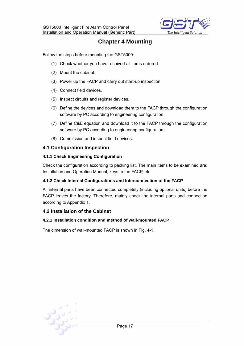
Chapter 4 Mounting
Follow the steps before mounting the GST5000:
(1) Check whether you have received all items ordered.
(2) Mount the cabinet.
(3) Power up the FACP and carry out start-up inspection.
(4) Connect field devices.
(5) Inspect circuits and register devices.
(6) Define the devices and download them to the FACP through the configuration software by PC according to engineering configuration.
(7) Define C&E equation and download it to the FACP through the configuration software by PC according to engineering configuration.
(8) Commission and inspect field devices.
4.1 Configuration Inspection
4.1.1 Check Engineering Configuration
Check the configuration according to packing list. The main items to be examined are: Installation and Operation Manual, keys to the FACP, etc.
4.1.2 Check Internal Configurations and Interconnection of the FACP
All internal parts have been connected completely (including optional units) before the FACP leaves the factory. Therefore, mainly check the internal parts and connection according to Appendix 1.
4.2 Installation of the Cabinet
4.2.1 Installation condition and method of wall-mounted FACP
The dimension of wall-mounted FACP is shown in Fig. 4-1.

GST5000 Intelligent Fire Alarm Control Panel Installation and Operation Manual (Generic Part) The Intelligent Solution
Page 18
Fig. 4-1
4.2.2 Installation condition and method of rack type and console-typed FACP.
Rack (L×W×H): 580mm×520mm×1540mm (or 1715mm)
Console(L×W×H, single unit): 555mm×933mm(with table)×1350mm
Console(L×W×H, double unit):1045mm×933mm (with table)×1350mm
Ambient Temperature: 0~+40
Relative Humidity≤95%, non-condensing
Installation Space: Width of maintenance of the FACP should be more than 1000mm.
4.3 Start-up Check
After mounting GST5000, apply power to it as shown in Fig. 4-2. Turn on the mains and battery switch in the cabinet and check if the FACP can self-test. The procedures are as follows.
(1) Check LCD, digitron and indicators.
(2) Check self-test on the stored running records, disablement information and C&E equations.
(3) Observe whether the indicators, and digitron on the FACP and ZCP can all be lit and whether the speaker gives three continuous alarm sounds and “beep” tone.

GST5000 Intelligent Fire Alarm Control Panel Installation and Operation Manual (Generic Part) The Intelligent Solution
Page 19
N
L
L N1 3
G2
Power
Switch
AC Power220/230VAC
Fig. 4-2
4.4 Connections of Field Devices
Loop interface board combines GST5000 FACP and field devices.
Terminals of loop interface board are shown in Fig. 4-3.
Fig. 4-3
Description:
CLASS CHANGE (XT3): Short it to make the sounders output.
FAULT OUTPUT (XT8): Normally open contact is closed when fault signal
Caution: Do not connect power to your device until you have completed all input and output connections. Fail to do so may result in injury!

GST5000 Intelligent Fire Alarm Control Panel Installation and Operation Manual (Generic Part) The Intelligent Solution
Page 20
occurs, and normally open contact is disconnected when the FACP repairs fault automatically.
SOUNDER CIRCUIT OUTPUT (XT7): It outputs when there is fire alarm. It can be stopped by pressing SILENCE key on ZCP. Output can be disabled, and there is no output in disabled state. The FACP will report fault when connected cable in short or open circuit.
F.P.E. OUTPUT (XT6): It outputs when there is fire alarm. It can be disabled, and does not output when fire alarm occurs in disablement state. The FACP alarms fault when connected cable in short or open circuit.
FIRE ALARM OUTPUT (XT5): It outputs when there is fire alarm and should give fault signals when connected circuit is shorted or opened.
LOOP BUS (XT2, XT4): It can be connected with 235 coded points. With loop isolator in the ring detection loop, the detector protected by loop isolator is not missing when there is short or open circuit. In this case, the FACP reports fault.
RS-485 (XT11, XT12): To be connected with repeater panel and FACP.
earthX8: This terminal is for checking earth fault when there is short circuit.
F.P.E. OUTPUT, SOUNDER CIRCUIT OUTPUT, FIRE ALARM OUTPUT can provide three output modes: 24VDC active output, normally open output and normally closed output. You can set up the three modes through Pin X1~X7. See more details in Table 4-1.
Table 4-1
Output 24VDC Normally Closed Normally Open
F.P.E. Output
Short 1to 2 & 4 to 5 of X3
Short X7
Short 3 to 4 & 5 to of X3
Disconnect X7
Short 2 to 3 & 5 to 6 of X3
Disconnect X7
Sounder Circuit Output
Short 1 to 2 & 4 to 5 of X2
Short X6
Short 3 to 4 & 5 to 6 of X2
Disconnect X6
Short 2 to 3 & 5 to 6 of X2.
Disconnect X6
Fire Alarm Output
Short 1 to 2 & 4 to 5 of X1. Short X5
Short 3 to 4 & 5 to 6 of X1. Disconnect X5
Short 2 to 3 & 5 to 6 of X1 Disconnect X5
4.4.1 Connection of Sounder Circuit Output
Connection of Sounder Circuit Output is shown in Fig. 4-4.

GST5000 Intelligent Fire Alarm Control Panel Installation and Operation Manual (Generic Part) The Intelligent Solution
Page 21
Fig. 4-4
Description:
A 4.7kΩ resistor is connected at the SOUNDER CIRCUIT OUTPUT as factory default. Please remove it and keep it well before connection. After connecting the loop in correct polarity, add the resistor to the end of the line
NOTE: The sounder strobes are polarized. Note polarity in connection. The maximum current of the circuit depends on the number of sounder strobes. Do not overload.
4.4.2 Connection of F.P.E. Output
F.P.E. output is shown in Fig. 4-5.
Fig. 4-5
A 4.7kΩ resistor is connected at the F.P.E. OUTPUT as factory default. Please remove it and keep it well before connection. After connecting the loop in correct polarity, add the resistor to the end of the line.
NOTE: F.P.Es are polarized. Note polarization in connection. The maximum current of the circuit depends on the number of F.P.E. Do not overload.
4.4.3 Connection of Fire Alarm Output
Fire alarm output is shown in Fig. 4-6.
Sounder
Diode End-of-line Resistor 4.7kΩ
SOUNDER CIRCUIT OUTPUT (XT7)
Diode
Sounder
End-of-line Resistor 4.7kΩ F.P.E. OUTPUT
(XT6) F.P.E.
Diode Diode
F.P.E.

GST5000 Intelligent Fire Alarm Control Panel Installation and Operation Manual (Generic Part) The Intelligent Solution
Page 22
Fig. 4-6
A 4.7kΩ resistor is connected at the FIRE ALARM OUTPUT as factory default. Please remove it and keep it well before connection. After connecting the loop in correct polarity, add the resistor to the end of the line.
NOTE: Fire supervisory devices are polarized. Note polarity in connection. The maximum current of the circuit depends on the number of fire supervisory devices. Do not overload.
4.4.4 Connection of Class A Loop
A Class A loop is shown in Fig. 4-7.
Fig. 4-7
Note: Every loop isolator can control maximum 32 detectors.
4.4.5 Connection of Communication Loop
LOOP OUT
(XT4)
LOOP IN
(XT2)
Addressable
field devices
Addressable
field devices
Loop Isolator
Loop Isolator
Diode
Fire Supervisory Device
End-of-line Resistor 4.7kΩ
Diode FIRE ALARM
OUTPUT (XT5) Fire Supervisory Device

GST5000 Intelligent Fire Alarm Control Panel Installation and Operation Manual (Generic Part) The Intelligent Solution
Page 23
Fig. 4-8
4.4.6 Connection of Ring Module
Fig. 4-9
Note: Every loop isolator can control maximum 32 detectors.
4.5 Connection Inspection and Device Registration
4.5.1 Connection Inspection
Check the circuit connected with the FACP. Insulation resistance measured at different circuits and ground should be more than 20MΩ, the resistance in the detection loop should be more than 1kΩ. The resistance among fire alarm output, sounder circuit output, F.P.E. output should be equal to end-of-line resistor.
4.5.2 Registration of Devices
Step One: Set the FACP at commissioning state.
Up to 32 control panels
B
ANetwork
(XT11)
Con
trolP
anel
Con
trolP
anel
Up to 64 repeater panels
B
ARepeater
(XT12)
Rep
eate
rPan
el 火
灾
显
Rep
eate
r Pan
el
Rep
eate
r Pan
el
LOOP OUT
LOOP IN
Addressable
field devices
Addressable
field devices
Loop Isolator
Loop Isolator
LOO
P M
OD
ULE
GST5000 Intelligent Fire Alarm Control Panel Installation and Operation Manual (Generic Part) The Intelligent Solution
Page 24
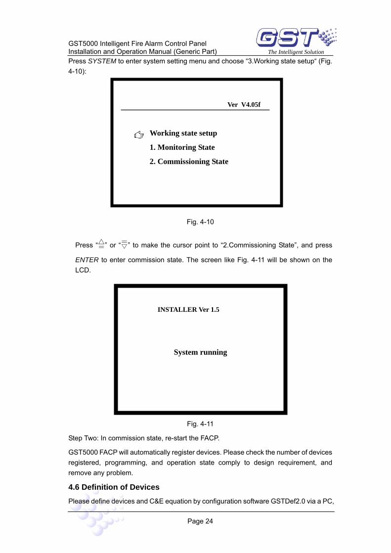
Press SYSTEM to enter system setting menu and choose “3.Working state setup“ (Fig. 4-10):
Fig. 4-10
Press “=” or “=” to make the cursor point to “2.Commissioning State”, and press
ENTER to enter commission state. The screen like Fig. 4-11 will be shown on the LCD.
Fig. 4-11
Step Two: In commission state, re-start the FACP.
GST5000 FACP will automatically register devices. Please check the number of devices registered, programming, and operation state comply to design requirement, and remove any problem.
4.6 Definition of Devices
Please define devices and C&E equation by configuration software GSTDef2.0 via a PC,
Ver V4.05f
Working state setup
1. Monitoring State
2. Commissioning State
INSTALLER Ver 1.5
System running

GST5000 Intelligent Fire Alarm Control Panel Installation and Operation Manual (Generic Part) The Intelligent Solution
Page 25
and download the definitions to the FACP.
Please refer to GSTDef2.0 Defining Tool User’s Manual for the installation, operation and commission of the software.
4.6.1 Browsing Zone Definition
The zone information defined by the definition software can be browsed on the LCD of the FACP following the steps below.
Step 1: Pressing SYSTEM to enter system setting menu, as in Fig. 4-12.
Fig. 4-12
Step 2: Choosing ”5. Zone browse” can browse the zone definition as shown in Fig.4-13.
Fig. 4-13
Notes:
Zone 0001 1floor// Zone number and descriptions.
Ver V4.05f
System setup 1. Modify password 2. Communicate setup 3. Working state setup 4. Fire display mode 5. Zone browse 6. C&E browse 7. Monitoring Device
Ver V4.05f
Display the Zone Name Zone 0001 1floor Zone 0002 2floor Zone 0003 3floor Zone 0004 4floor Zone 0005 5floor Zone 0006 6floor Zone 0007 7floor Zone 0008 8floor

GST5000 Intelligent Fire Alarm Control Panel Installation and Operation Manual (Generic Part) The Intelligent Solution
Page 26
= and = can be used for turning pages.
4.6.2 Browsing Device Information
The device information defined by the definition software can be browsed on the LCD of the FACP following the steps below.
Step 1: Press BROWSE will enter the screen shown in Fig. 4-14. All system configurations will be displayed.
Fig. 4-14
Step 2: Check loop configuration.
Pressing any key in the screen shown in Fig. 4-14 will enter the screen displaying loop
configuration, with the top line highlighted. Pressing TAB, the highlight will disappear
and the FACP will check the loop. Pressing = and = will move the highlight bar on
different loops (Fig. 4-15).
Browse Register info
System Configuration
Total Loops 004 Devices 013 Repeaters 0000 Access 000 Color CRT Installed

GST5000 Intelligent Fire Alarm Control Panel Installation and Operation Manual (Generic Part) The Intelligent Solution
Page 27
Fig. 4-15
Step 3: Checking device information.
Pressing ENTER will display the device information registered by this loop. The top line will be highlighted. Pressing TAB, the highlight disappears, and the FACP will check devices (Fig. 4-16).
Fig. 4-16
Descriptions:
016 Zone 001-016 Gas Det // Message number, user code (zone number + device number), device type
Browse Register info Loop 02 013 Points
016 Zone 001-016 Gas Det 1floor cookroom
017 Zone 002-017 Fix Temp 1 floor bathroom
032 Zone 003-032 Optical 1floor corridor
214 Zone 003-214 Fresh Air 1 floor toilet
Browse Register info
Loop00 000 Repeaters
Loop01 000 points 000 Access
Loop02 013 points 000 Access
Loop03 001 CRT Loop00 000 Repeaters
Loop01 000 points 000 Access
Loop02 013 points 000 Access
Loop03 001 CRT
Browse Register info

GST5000 Intelligent Fire Alarm Control Panel Installation and Operation Manual (Generic Part) The Intelligent Solution
Page 28
1 floor cookroom// Zone description + device description
017 Zone 002-017 Fix Temp// Message number, user code (zone number + device number), device type
1 floor bathroom// Zone description + device description
032 Zone 003-032 Optical// Message number, user code (zone number + device number), device type
1 floor corridor // Zone description + device description
214 Zone 003-214 Fresh Air// Message number, user code (zone number + device number), device type
1 floor toilet// Zone description + device description
In device browsing state, pressing = and = can turn pages. In device selection state,
pressing = and = can change the selected device.
4.6.3 Viewing C&E
The C&E equations defined by the definition software can be browsed on the LCD of the FACP following the steps below.
Step 1: Pressing SYSTEM will enter system setting menu as shown in Fig. 4-12.
Step 2: Choosing “6. C&E browser”, the screen for browsing C&E will show. Pressing “1” can display the C&E for gas extinguishing devices, and pressing “2” will display ordinary C&Es (Fig. 4-17). Pressing ENTER, the screen prompts “Please Input the number”, and you can view the C&E by entering its number.

GST5000 Intelligent Fire Alarm Control Panel Installation and Operation Manual (Generic Part) The Intelligent Solution
Page 29
Fig. 4-17
Meaning of the above C&E:
The part before the "=” refers to the condition, and the part after “=” is the result. “×” means “and” and “+” means or. NO.0001 refers to the first piece of C&E. Composition of the condition part of the C&E.
001 001 03
Device type Device address Zone number of the device
Composition of the result part of the C&E.
001 004 13 00
Delay time Device type Device address Zone number of the device
In the third piece of C&E in the above figure,
No0003004***03+004***02+004***11=004***1300
This is a C&E with foggy devices, in which “*” is an asterisk mark representing any number from 0 to 9. The meaning of this C&E is: If there is any photoelectric smoke detector or any rate of rise and fixed temperature heat detector alarms or any manual call point from Zone No. 4, the sounder strobe of that zone will be started.
Step 3: Viewing spaces for the C&Es.
Ver V4.05f
C&E Formula Browser
1. General C&E 2. Extinguishing C&E
No000100100103×00100203+00100203×00100303+00100103×0100303+00100103×00100203×00100303=00100413 00
No000200200103×00200203+00200203×00200303+00200103×0100303 +00200103×00200203×00200303=00200513 00
No0003004***03+004***02+004***11=004***1300

GST5000 Intelligent Fire Alarm Control Panel Installation and Operation Manual (Generic Part) The Intelligent Solution
Page 30
Pressing “3” in Fig. 3-11 can view the spaces for C&Es, as in Fig. 4-18.
Fig. 4-18
4.7 Field Devices Commission After connection of cables, definition and download of device and C&E equations,
you can power up the FACP and start commission. The following steps are for reference.
1. Enter commission state according to Section 4.5.
2. Check whether the loop devices registered are the same as real connection. If most of devices are found missing, check the power supply and loop isolators first, then come to individual device. Press SELF TEST key to check field device registration.
3. Check whether registration of repeater panels is the same as the actual. If there is any problem, check the communication cable A and B and 24V power supply.
4. Label the ZCP at the correct places.
5. Carry out detector alarm test and repeater panel transmitting test.
6. Check device definition and execute C and E automatic linkage test.
7. Connect important devices (such as gas extinguishing control panel) and train the operators.
Ver V4.05f
The Space of Equations
Used Unused General 0011 4789 Extinguishing 0005 1575
GST5000 Intelligent Fire Alarm Control Panel Installation and Operation Manual (Generic Part) The Intelligent Solution
Page 31
Chapter 5 Display and Disposal of System Information
GST5000 can be started after mounting according to Chapter 4.
5.1 Normal Information
Turn on the external power switch, and main and standby power switch on the FACP, the control panel executes self-test and enters monitoring state. The system displays properly if it is in normal state, or the system displays improperly.
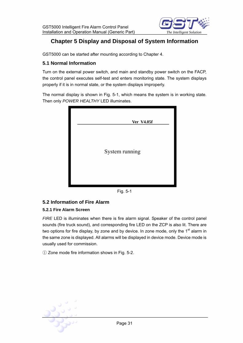
The normal display is shown in Fig. 5-1, which means the system is in working state. Then only POWER HEALTHY LED illuminates.
Fig. 5-1
5.2 Information of Fire Alarm 5.2.1 Fire Alarm Screen
FIRE LED is illuminates when there is fire alarm signal. Speaker of the control panel sounds (fire truck sound), and corresponding fire LED on the ZCP is also lit. There are two options for fire display, by zone and by device. In zone mode, only the 1st alarm in the same zone is displayed. All alarms will be displayed in device mode. Device mode is usually used for commission.
① Zone mode fire information shows in Fig. 5-2.
Ver V4.05f
System running

GST5000 Intelligent Fire Alarm Control Panel Installation and Operation Manual (Generic Part) The Intelligent Solution
Page 32
Fig. 5-2
Description:
Last Fire 16:34 Zone001
6 FLOOR GREEN HOUSE //This is the last alarm. It happens in Zone001, at 16:34, the location is the GREEN HOUSE on the 6th floor.
!Fire! total 008 //Total alarms. Each fire alarm message occupies two lines. You can
view different fire message by pressing "=" and "=".
002 16:34 zone 001 //Time and zone of the second fire alarm
FLOOR COOKROOM //Zone definition (first 8 digits) and device definition (last 32 digits)
003 16:34 zone 002// Time and zone of the third fire alarm
FLOOR DINING ROOM// Zone definition (first 8 digits) and device definition (last 32 digits)
004 16:34 zone 006// Time and zone of the forth fire alarm
FLOOR LIVINGROOM// Zone definition (first 8 digits) and device definition (last 32 digits)
005 16:34 zone 005// Time and zone of the fifth fire alarm
4 FLOOR BATHROOM // Zone definition (first 8 digits) and device definition (last 32 digits)
Press Enter to Select an Item // Press ENTER to view a fire alarm message.
② Device mode fire information shows in Fig. 5-3.
!Last Fire !16:34 Zone001 6 FLOOR GREEN HOUSE !Fire! total 008 002 16:34 zone 001 1 FLOOR COOKROOM 003 16:34 zone 002 2 FLOOR DINING ROOM 004 16:34 zone 006 3 FLOOR LIVINGROOM 005 16:34 zone 005 4 FLOOR BATHROOM Press Enter to Select an Item

GST5000 Intelligent Fire Alarm Control Panel Installation and Operation Manual (Generic Part) The Intelligent Solution
Page 33
Fig. 5-3
Description of fire alarm screen:
Last Fire 16:34 Zone001
6 FLOOR GREEN HOUSE // This is the last alarm. It happened in Zone001, at 16:34, the location is the GREEN HOUSE on the 6th floor.
!Fire! total 100// Total alarms.
002 16:34 zone 001-103 OPTICAL//Time, zone device address and type of the second fire alarm.
1 FLOOR COOKROOM// Zone definition (first 8 digits) and device definition (last 32 digits)
003 16:34 zone 001-101 OPTICAL// Time, zone device address and type of the third fire alarm.
1 FLOOR DINING ROOM// Zone definition (first 8 digits) and device definition (last 32 digits)
004 16:34 zone 002-111 OPTICAL/ Time, zone device address and type of the forth fire alarm.
2 FLOOR LIVINGROOM // Zone definition (first 8 digits) and device definition (last 32 digits)
005 16:34 zone 003-121 OPTICAL// Time, zone device address and type of the fifth fire alarm.
3 FLOOR LIVINGROOM // Zone definition (first 8 digits) and device definition (last
!Last Fire! 16:34 Zone001 6 FLOOR GREEN HOUSE !Fire! total 100 002 16:34 zone 001-103 OPTICAL 1 FLOOR COOKROOM 003 16:34 zone 001-101 OPTICAL 1 FLOOR DINING ROOM 004 16:34 zone 002-111 OPTICAL 2 FLOOR LIVINGROOM 005 16:34 zone 003-121 OPTICAL 3 FLOOR LIVINGROOM Press Enter to Select an Item

GST5000 Intelligent Fire Alarm Control Panel Installation and Operation Manual (Generic Part) The Intelligent Solution
Page 34
32 digits)
Press Enter to Select an Item //Press ENTER to view a fire alarm message.
5.2.2 Disposal of Fire Alarm Signal
When fire alarm occurs, first find out the location according to the information shown on the FACP to verify whether the fire really happened.
If it’s a real fire, please take corresponding measures.
Step One: Evacuate the people in field.
Step Two: Call the fire department.
Step Three: Initiate extinguishers.
If it is a false alarm, please take the following measures.
Step One: Press SILENCE to stop the sound.
Step Two: Remove the factors that caused the false alarm.
Step Three: Press RESET to make the FACP back to the normal state. If the device
still gives false alarm, disable it and inform the installer or manufacturer for repair.
5.3 Fault Information 5.3.1 Screen of Fault Information
When there are fault signals, different LEDs can be lit according to the type of fault. If it is mains fault, AC FAULT LED will be lit; if it is standby power fault, BATTERY FAULT LED will be lit; if it is system fault, SYSTEM FAULT LED will be lit; if it is field device fault, relative LED on the ZCP is lit. Speaker of the FACP gives alarm sound (ambulance sound).
Fault information can only be displayed by device, the screen is shown in Fig. 5-4.
Fig. 5-4
Ver V4.05f
!FAULT! Total 100
001 16:34 zone 002-03 OPTICAL
1 FLOOR COOKROOM
002 16:34 zone 002-101 OPTICAL
1 FLOOR DINING ROOM
003 16:34 zone 002-111 OPTICAL
GST5000 Intelligent Fire Alarm Control Panel Installation and Operation Manual (Generic Part) The Intelligent Solution
Page 35
Description of the fault screen:
Each fault message occupies two lines. You can view different fault message by
pressing = and =.
!FAULT! total 100//Total fault events.
001 16:34 zone 002-03 OPTICAL// Time, zone, device address and type of the fault event.
1 FLOOR COOKROOM// Zone definition (first 8 digits) and device definition (last 32 digits)
002 16:34 zone 002-101 OPTICAL// Time, zone, device address and type of the fault event.
1 FLOOR DINING ROOM// Zone definition (first 8 digits) and device definition (last 32 digits)
003 16:34 zone 002-111 OPTICAL// Time, zone device address and type of the fault event.
2 FLOOR LIVINGROOM // Zone definition (first 8 digits) and device definition (last 32 digits)
5.3.2 Disposal of Fault Information
There are two kinds of fault. One is system fault, such as AC power and battery fault,
loop fault. The other is field device fault, like detector fault, module fault etc.
If it is battery fault, charge storage battery in time to avoid damage. If the battery has powered the system overtime, the FACP will power down for protection.
If it is system fault, check and repair in time. If power-down is needed, make detailed notes.
If it is field device fault, it should be repaired immediately. You can disable it if the fault cannot be cleared for some reason. Then enable it when the device fault is repaired.
5.4 Disable and Enable 5.4.1 Use of Disable/Enable
When some problems happen to the field device, it may be necessary to disable the device for maintenance, and then re-enable it after repairing or replacing.
5.4.2 Disable/Enable Devices
1) Disabling a device

GST5000 Intelligent Fire Alarm Control Panel Installation and Operation Manual (Generic Part) The Intelligent Solution
Page 36
DISABLED LED will be lit if the device is disabled.
Pressing DISABLE key, the screen will show as in Fig. 5-5.
Fig. 5-5
Suppose user code of the optical smoke detector to be disabled is 001016. The steps for disablement are as follows:
Step One: Input zone number “001” of the device.
Step Two: Press TAB, the highlight position moves to next input zone.
Step Three: Input device code number “016”.
Step Four: Referring to “Appendix 2 Device Type List”, input the device type “03”.
Press ENTER to save. If the device has been disabled, the screen will show “Input Err”, if not, the screen will add the device to the disablement information.
2) Enabling the device
Pressing ENABLE, the screen will show like Fig. 5-6.
Fig. 5-6
Ver V4.05f
System running
Enable > 001 Zone 016 Num 03-Optical
Ver V4.05f
System running
Disable> 001 Zone 016 Num 03-Optical

GST5000 Intelligent Fire Alarm Control Panel Installation and Operation Manual (Generic Part) The Intelligent Solution
Page 37
Suppose user code of the optical smoke detector to be enabled is 001016. The operation of disablement should be as follows:
Step One: Input zone number “001” of the device.
Step Two: Press TAB, the highlight position moves to next input zone.
Step Three: Input device code “016”.
Step Four: Referring to “Appendix 2 Device Type List”, input the device type “03”.
Press ENTER to save. If the device has been enabled, the disablement information on the screen will disappear. Otherwise “Input Err” will be shown.
5.4.3 Browsing Disabled Information
Pressing VIEW DISABLE, you can browse disabled information of the device. Pages
are turned by pressing = and =. Disabled information can only be displayed by device
mode. The window is shown in Fig. 5-7.
Fig. 5-7
Description of disabled screen:
!DISABLED! total 100// Total number of the disabled information.
001 16:34 zone 001-106OPTICAL// Zone, device address and type of disabled device.
002 16:34 zone 001-103 OPTICAL// Zone, device address and type of disabled device.
003 16:34 zone 002-101 OPTICAL// Zone, device address and type of disabled device.
004 16:34 zone 003-121 OPTICAL// Zone, device address and type of disabled device.
! DISABLED! total 100 001 16:34 zone 001-106OPTICAL 002 16:34 zone 001-103 OPTICAL 003 16:34 zone 002-101 OPTICAL 004 16:34 zone 003-121 OPTICAL 005 16:34 zone 004-141 OPTICAL 006 16:34 zone 005-155 OPTICAL 007 16:34 zone 006-166 OPTICAL
Press Enter to Select an Item

GST5000 Intelligent Fire Alarm Control Panel Installation and Operation Manual (Generic Part) The Intelligent Solution
Page 38
5.5 Manual Start and Stop of Loop Devices When fire alarm is confirmed, you can manually start extinguishing equipment in short time.
5.5.1 START/STOP Operation through Keypad
1. Starting a loop device
Pressing START can start a loop device, and the screen is shown in Fig. 5-8.
Fig. 5-8
The basic steps are as follows:
Step One: Input the user code of the device to start.
Step Two: Pressing TAB, device type is highlighted.
Step Three: Input the device type referring to “Appendix 2 Device Type List”.
Step Four: Pressing ENTER, the control panel gives start command.
After the device is started, PLANT CONTROL LED and action indicator on the ZCP will be lit.
2. Stopping a loop device
Pressing STOP can stop a loop device. The screen is shown in Fig. 5-9.
Ver V4.05f
start> 001zone 016Num 03 -Undefine

GST5000 Intelligent Fire Alarm Control Panel Installation and Operation Manual (Generic Part) The Intelligent Solution
Page 39
Fig. 5-9
Basic steps are as follows:
Step One: Input the user code of the device to stop.
Step Two: Pressing TAB, device type is highlighted.
Step Three: Input the device type referring to “Appendix 2 Device Type List”.
Step Four: Pressing ENTER, the control panel gives stop command.
After the device is stopped, PLANT CONTROL LED and action indicator on the ZCP will be off.
5.5.2 Operation of the Devices by ZCP
According to definition of the ZCP, press the key corresponding to the device, and input the password by system indication, you can start the device. Corresponding command LED of the key is lit. Press the key and input password again, you can stop the device, and the command LED turns off.
5.5.3 Browsing Started Devices
Pressing VIEW PLANT, you can browse the start information and change pages
through = and =. Start information is only shown by device mode, and its screen is
like in Fig. 5-10.
Ver V4.05f
stop> 001zone 016Num 03 -Undefine

GST5000 Intelligent Fire Alarm Control Panel Installation and Operation Manual (Generic Part) The Intelligent Solution
Page 40
Fig. 5-10
Description of action information:
! ACTION! total 100// Total number of action information
001 16:34 zone 002-03 OPTICAL// Time, zone, device address and type of the action.
1 FLOOR COOKROOM// Zone definition (first 8 digits) and device, definition (last 32 digits).
002 16:34 zone 002-101 OPTICAL// Time, zone, device address and type of the action.
1 FLOOR DINING ROOM// Zone definition (first 8 digits) and device definition (last 32 digits).
003 16:34 zone 002-111 OPTICAL// Time, zone, device address and type of the action.
2 FLOOR LIVINGROOM// Zone definition (first 8 digits) and device definition (last 32 digits).
5.6 Resetting and Silencing of the System First silencing the sound, then pressing RESET can turn off all the control modules, local outputs and all the detectors without changing the state of disabled devices. The LCD displays information of RESET IN SYSTEM, and all LEDs except for POWER HEALTHY,AECURITY MODE and EXTINGUISHING SYSTEM PERMIT will be turned off. The reset information will be written into running log. If there are still some fire alarm, fault and action information not acknowledged after pressing the RESET key, the FACP will remain sound indications. If all information has been acknowledged before pressing RESET key, the system returns to normal display state.
If the FACP alarms, pressing MUTE, you can silence the speaker. Pressing MUTE
!ACTION! total 100 001 16:34 zone 002-03 OPTICAL 1 FLOOR COOKROOM 002 16:34 zone 002-101 OPTICAL 1 FLOOR DINING ROOM 003 16:34 zone 002-111 OPTICAL 2 FLOOR LIVINGROOM Press Enter to Select an Item

GST5000 Intelligent Fire Alarm Control Panel Installation and Operation Manual (Generic Part) The Intelligent Solution
Page 41
again or if there are new alarms, the speaker will sound again.
5.7 Rules for Information Display If there are more than one piece of information, they will be displayed in the following order: fire alarm, action, fault, start, disablement.
① The earliest fire alarm is displayed in priority. The latest action, fault, disabled information is displayed in priority.
② Fire alarm, fault, and disabled information can be displayed by both zone and loop display modes. Start and action can only be displayed by loop mode.
③ In any display mode, the system will return to displaying message of the highest priority if there is no operations within 20s (15s~30s).
5.8 Rules for Sound Indication When there is fire alarm or fault, the speaker of the FACP will give sound indication.
The FACP gives fire truck sound when fire alarm occurs.
The FACP gives action sound when any device is activated.
Module action ――slow “tick” sound.
Gas extinguishing device action ―― police car sound
Delay activation of devices by automatic C&E linkage―― quick “tick” sound.
The FACP gives ambulance sound when fault occurs.
The control panel will give sound of higher priority if two types of information occur simultaneously. Pressing MUTE can stop the sound; pressing MUTE again, the control panel is still in mute state. It will sound by priority when new event appears.

GST5000 Intelligent Fire Alarm Control Panel Installation and Operation Manual (Generic Part) The Intelligent Solution
Page 42
Chapter 6 Description of System Operation
6.1 Keypad 6.1.1 Functions
Most of the keys have double functions. Upper mark is a character and lower mark is command function that is only activated in monitoring state. Most function keys are controlled by password. The characters are only active after entering the menu.
6.1.2 Common Method of Data Input
There is a highlighted area indicating the current position and range of data input. Press a character key, the highlight and original characters disappear and input from that
character. Move the highlight tab to any position for modification by pressing = or =.
Press TAB, the edited text is stored and the highlight moves to the next position and returns to the first after the last position. Wherever the cursor is, Press ENTER key, all the input data will be saved; press ESC to exit present editing state without saving.
6.1.3 Method of Browsing Information
Entering browsing state, press = and = to scroll for information.
Press ENTER, the top piece of information becomes highlighted and the system enters information selection state. Press TAB and exit highlight state.
In selecting state, press = and = to select highlight tab.
Pressing ENTER can print the information or display details of the information. Pressing ESC will exit to the previous menu or normal operation screen.
6.1.4 Keypad Unlock and Lock
The FACP is defaulted as key-locked on start-up. A password needs to be input if you operate any of the function keys (except for SELF TEST, MUTE, LOG, VIEW FIRE, VIEW FAULT, VIEW DISABLE and VIEW PLANT) (refer to Fig. 6-1). Input correct password and press ENTER to continue operation. After one minute without operation, the keys are automatically locked.

GST5000 Intelligent Fire Alarm Control Panel Installation and Operation Manual (Generic Part) The Intelligent Solution
Page 43
Fig. 6-1
6.2 User Operation Instruction 6.2.1 Changing time display
The clock is usually displayed in hour and minute (time mode) by the digitron on the panel. In normal monitoring state, pressing TAB, month and day (date mode) are displayed. Press TAB again or after a minute, time mode is displayed again.
6.2.2 Browsing history records
Pressing LOG, the system enters history information screen. Each piece of information includes the event time, 6-digit user number, event type and brief description of the event.
6-digit user number: If the event refers to an addressable device, the first 3 digits show zone number, the following 3 digits show the user code in this zone. If the information is about loop or bus, this number will be the loop or bus number.
Device type: It shows the device type for device information or the operation type for system operation.
Event description: Provides a brief description on the events, such as fire, start, action, fault, stop, disable, enable, action reset, set and operation etc.
Press ENTER key to highlight an information, press = and = to scroll up and down.
Press ENTER again to print the highlighted information, as shown in Fig. 6-2.
Ver V4.05f
Enter password*****
Password 1-8 digits

GST5000 Intelligent Fire Alarm Control Panel Installation and Operation Manual (Generic Part) The Intelligent Solution
Page 44
Fig. 6-2
6.3 Instructions for System Operator 6.3.1 Self Test
In normal monitoring state, pressing SELF TEST, you can check all the audio and visual components.
6.3.2 Printer Setting
The printer can be set to 3 modes. Pressing PRINT (needing password if the keypad is locked) in monitor state, the system is shown like Fig. 6-3.
Fig. 6-3
History
12//06//10:45 000000 CRTFault Fault 12//06//10:40 000000 Reset 12//06//10:37 000000 AC Fault Back 12//06//10:28 000000 AC Fault Fault 12//06//10:20 010032 CableDet Fire 12//06//10:11 010056 HR Pump Start 12//06//10:05 020011 Sounder Act 12//06//10:01 030124 Heat Det Iso
Press Enter to select an item
History
12//06//10:45 000000 CRTFault Fault 12//06//10:40 000000 Reset 12//06//10:37 000000 AC RCL Back 12//06//10:28 000000 AC Fault Fault 12//06//10:20 010032 CableDet Fire 12//06//10:11 010056 HR Pump Start 12//06//10:05 020011 Sounder Act 12//06//10:01 030124 Heat Det Fire
Press ENTER to print Highlight item
Ver V4.05f
Print mode setup
1. Disable
2. History
3. Only fire

GST5000 Intelligent Fire Alarm Control Panel Installation and Operation Manual (Generic Part) The Intelligent Solution
Page 45
Pressing = and = followed by ENTER can choose different printing modes:
1. Disable printing
2. Print history records while viewing them
3. Only print fire records
6.3.3 Security Mode
Pressing SECURITY MODE (needing password if the keypad is locked), the system will get into security mode setting, as shown in Fig. 6-4.
Fig. 6-4
The system can be set as security enable and disable mode under this screen. In enable mode, the security alarm function is enabled to monitor the protected area by security detectors, and SECURITY MODE LED illuminates.
6.3.4 Extinguishing Mode
Pressing EXTINGUISHING MODE, the system will enter gas extinguishing mode, as shown in Fig. 6-5.
Ver V4.05f
Security Mode
1. Disable
2. Enable

GST5000 Intelligent Fire Alarm Control Panel Installation and Operation Manual (Generic Part) The Intelligent Solution
Page 46
Fig. 6-5
Choosing one from the options can enable or disable gas release function. If it is in Enable mode, the EXTINGUISHING SYSTEM PERMIT indicator will be lit, the gas release device can be started manually or automatically.
6.3.5 Modification of System Time
In monitoring state, pressing CLOCK (needing password if the keypad is locked), the screen will display as in Fig. 6-6. Input the time in the highlight area and then press TAB to move the highlight to next position. Press ENTER to confirm.
Fig. 6-6
Ver V4.05f
System running
Modify system time
Enter time:2001//12//06 16:19
Ver V4.05f
Extinguishing System Mode
1. Disable
2. Enable

GST5000 Intelligent Fire Alarm Control Panel Installation and Operation Manual (Generic Part) The Intelligent Solution
Page 47
6.4 Instructions for System Administrator
Pressing SYSTEM can enter system setup menu. This menu contains password setting and other functions for commissioning, including "Modify password", "Communicate setup", "Working state setup", "Fire display mode", "Zone browser", "C&E browser" and “Monitoring device”. Refer to Fig. 6-7.
Fig. 6-7
6.4.1 Password Modification 1 Access level:
After the function keys (except for SELF TEST, MUTE, LOG, VIEW FIRE, VIEW FAULT, VIEW DISABLE and VIEW PLANT) are pressed, the system will display a screen requiring a password. Only after the correct password is input can a further operation be done.
User password: for printer setting, clock setting, security mode setting, start/stop, disable, enable and the operation on ZCP and FACP reset.
Gas extinguishing control password: for gas release enable control.
System password: Entering SYSTEM menu for setting of system state and data.
Higher-level password can substitute for lower-level password. System password must be entered for system operation. It becomes invalid on exit after certain operations are finished. Input password for other operations.
2 Password Modification
In system setup menu like Fig. 6-7, selecting the first item "Modify password", the screen will display the three levels of password, as shown in Fig. 6-8.
Ver V4.05f
System setup 1. Modify password 2. Communicate setup 3. Working state setup 4. Fire display mode 5. Zone browse 6. C&E browse 7. Monitoring Device

GST5000 Intelligent Fire Alarm Control Panel Installation and Operation Manual (Generic Part) The Intelligent Solution
Page 48
Fig. 6-8
Select the password to be modified, the screen will prompt to enter the old password. Input the password and press ENTER. If the password is correct, the screen will prompt to input the new password (Fig. 6-9). If the password is wrong, the system will exit current operation.
Fig. 6-9
Enter new password and press ENTER.
To prevent mistake, the FACP requires entering the new password again (Fig. 6-10).
If you typed the same password twice, the screen shows a brief password display with a long ‘beep’ sound and the system exits current operation, showing the new password has been entered successfully. If there are any mistakes, the system will exit current operation without any other prompt and the password will not be changed.
Ver V4.05f
Modify password
1. User Password 2. Extinguishing Password 3. System Password
Ver V4.05f
*****
1-8 digits
Enter new password

GST5000 Intelligent Fire Alarm Control Panel Installation and Operation Manual (Generic Part) The Intelligent Solution
Page 49
Fig. 6-10
6.4.2 Communication Setting
In system setup menu shown in Fig. 6-7, select the second item “Communicate setup”, you can enter communication setting menu. Refer to Fig. 6-11.
Fig. 6-11
Inputting 1 is to set CRT system.
Inputting 2 is to set remote telephone network system.
Inputting 3 is to set network system.
6.4.3 Working State Setup
In system setup menu in Fig. 6-7, select 3 "Working state setup" (Fig. 6-12):
Ver V4.05f
*****
Repeat new
Enter new password Confirm password
Ver V4.05f
Communicate setup
1. Color CRT 2. Remote Telephone Network 3. Network Setup

GST5000 Intelligent Fire Alarm Control Panel Installation and Operation Manual (Generic Part) The Intelligent Solution
Page 50
.
Fig. 6-12
Inputting 1, the system enters monitoring state.
Inputting 2, the system enters commissioning state.
6.4.4 Fire Display Mode
Select 4 "Fire display mode" under system setup menu (Fig. 6-7), the screen shows as in Fig. 6-13.
Fig. 6-13
Inputting 1, fire information will be displayed by device.
Inputting 2, fire information will be displayed by zone.
6.4.5 Zone Browse
Refer to section 4.6.3.
6.4.6 C&E Equation Browse
Refer to section 4.7.
Ver V4.05f
Display Mode 1.By Point 2.By Zone
Ver V4.05f
Working state setup
1. Monitoring State
2. Commissioning State

GST5000 Intelligent Fire Alarm Control Panel Installation and Operation Manual (Generic Part) The Intelligent Solution
Page 51
6.4.7 Browsing supervisory data of addressable devices
In the system setup menu as shown in Fig. 6-7, choose item 7 “Monitoring Device”, enter setting mode of fire display, as shown in Fig. 6-14.
Fig. 6-14
Input loop number (Channel NO), code, command, intervals between two commands (Alternation).
In the Item of “Command” of the above screen, inputting different number represents different command. Details are as follows:
“0“ represents “polling”: Display value in “450~650” is normal; display value in “900~1200” is fire alarm; display value in “0~120” is fault.
“1” represents “register”: If display value is 720, it is normal.
“2” represents “viewing dynamic data”: It can read data of detectors in real time. It monitors commissioning state of I-9105R Intelligent Beam Detector, if the return value is between “680~750”, it means the commission is successful.
”3” represents “viewing static data”.
“4” represents “immediate start of gas extinguishing devices”. If the command of “Turn on gas release 24V”, gas-extinguishing devices will be started at once. Please be cautious with this operation.
“5” represents “delay start of gas extinguishing devices”. If the command of “Turn on gas release 24V”, gas-extinguishing devices will be started after a delay of 30s. Please be cautious with this operation.
“6” represents the command of “Turn on gas release 24V”. Please be cautious with this operation.
“7” represents “start ordinary module”, which will cause output of corresponding modules. Please be cautious with this operation.
Ver V4.05f
Monitoring Device
Channel NO:
Code:
Command:
Alternation:

GST5000 Intelligent Fire Alarm Control Panel Installation and Operation Manual (Generic Part) The Intelligent Solution
Page 52
Chapter 7 Commissioning Functions
The commission mode is set for system commissioning, including registering devices, loop card disablement and detector searching functions.
NOTE: Under commission mode, all the registering information will not be saved. When the FACP is restarted, the missing or damaged devices will not be reported. These functions are only for commissioning.
7.1 Getting into Commission Mode Enter system setup menu (Fig. 6-7), select “3.Working state setup” (Fig.7-1):
Fig. 7-1
Press "=" and "=", select 2 "Commissioning State", confirm to enter commissioning
state, the word "Installer" will appear on top of the screen. The screen shows as in Fig. 7-2.
Fig. 7-2
Ver V4.05f
Working state setup
1. Monitoring State
Installer Ver 1.5
System running

GST5000 Intelligent Fire Alarm Control Panel Installation and Operation Manual (Generic Part) The Intelligent Solution
Page 53
Restart the control panel in this mode, it will register all devices again.
7.2 Exiting Commission Mode Getting into the screen in Fig. 7-1 and choosing 1 "Monitoring State", the system will exit commission mode.
7.3 Registration at Any Time In commission state, pressing SELF TEST, the FACP will automatically register all the devices again and display the information on the screen without affecting other information.
7.4 Loop Card Disablement
In commission mode, the loop cards can be disabled with the same method as detectors. The device type is 59. The user number is the loop number.
The disabled loop will stop bus output and stop the communication with the main board.
The “Enable” operation can cancel the disablement to the loop card.
7.5 Detector Searching
Under Commission Mode, the detectors can be forced into alarming state by keypad operation. It will be easy to find the location of a specified detector and test the transmission function of communication part.
The operation is the same as starting a module.
7.6 Protection of C&E Equations There is a three-foot setting pin on the main board, putting its jumper at LEWR end when setting up, modifying or deleting a cause and effect equation. After system commission, you must put it at LDWRProtect end to protect the C&E equations.

GST5000 Intelligent Fire Alarm Control Panel Installation and Operation Manual (Generic Part) The Intelligent Solution
Page 54
Chapter 8 Troubleshooting and Regular Checks
8.1 General Fault Treatment
Table 1 No. Fault Reason Solution 1 No display or
abnormal display
1. Abnormal power supply.
2. The connection with the display board is loose.
1. Check +24 power supply. 2. Check the display
connection cable
2
"AC Fault" is displayed when powered up
1. No AC power supply. 2. AC fuse blown
1. Check mains supply 2. Change the fuse (refer to
the label for specification)
3
"Battery Fault" is displayed when powered up
1. The fuse is blown. 2. Loose connection. 3. The batteries are
deficient in voltage or damaged.
1. Change the fuse (refer to the label for specification)
2. Open the cover of the power box and check relative connection parts.
3. Power up with AC power supply of over 8 hours, if the fault still exists, replace the batteries.
4
The loop cards can’t be registered correctly.
1. The loop cards are not inserted correctly.
2. The addresses of loop cards are wrongly set.
1. Check and insert correctly. 2. Check addresses of the
loop cards.
5 The display panel can’t be registered
The communication cable is not connected correctly
Check the cables for the display panel
6
Not printing 1. Print mode isn’t set. 2. Printer cable is not
connected well. 3. Printer is broken.
1. Set the print mode. 2. Check and connect it well. 3. Replace the printer.
7
When pressing a key on zone indication panel, it doesn’t respond.
1. Manual disable mode2. The cable of the zone
indication panel is not connected well.
1. Set manual enable mode. 2. Check the cable and
connect it well.
8 Device fault 1. The cable is broken. 2. The device is
damaged.
1. Check cable. 2. Replace the device.
9 Loop fault The loop is shorted or broken.
Check the cable.
10 Clock fault, memory fault, loop fault etc.
1. Environment Interference
2. Corresponding parts are ageing.
1. Check whether ground is properly connected.
2. Inform GST.

GST5000 Intelligent Fire Alarm Control Panel Installation and Operation Manual (Generic Part) The Intelligent Solution
Page 55
8.2 Regular Checks and Replacement
The device should be checked regularly:
1. The print paper should be replaced as required prior to running out.
Fig. 8-1
1) Remove the printer front cover as shown in Fig.8-1.
2) Remove the whole printer from the panel. Please nip the movable tongues on the two sides with fingers according to Fig.8-2, remove the whole printer from the panel gently. Note: Before removing the printer, make sure to turn off the power to the printer.
Remove

GST5000 Intelligent Fire Alarm Control Panel Installation and Operation Manual (Generic Part) The Intelligent Solution
Page 56
Fig.8-2
3) Remove the scroll spindle (Fig. 8-3).
Fig. 8-3
4) Put the new scroll on the spindle. And press the scroll spindle into the groove of the printer as in Fig. 8-4. Make sure the scroll spindle is installed firmly.
Press
Press
Pull
Push Up

GST5000 Intelligent Fire Alarm Control Panel Installation and Operation Manual (Generic Part) The Intelligent Solution
Page 57
Fig. 8-4
5) Cut the end of the paper according to Fig.8-5.
Fig. 8-5
6) Turn on the power of the printer. Press “SEL” key to turn off the “SEL” light. Then press LF to move the head. Feed the paper through by hand, the paper will enter slowly until it appears in front of the head. Feed through a suitable length of paper. Press LF or SEL again, or turn off the power. Replace the front cover of the printer. Feed the
Push down

GST5000 Intelligent Fire Alarm Control Panel Installation and Operation Manual (Generic Part) The Intelligent Solution
Page 58
paper through the paper slot.
7) Press the printer into the control panel gently.
8) If, according to engineering configuration, the back of the control panel display part is not covered by other structures, it is easier to take the paper from the back. Replacement of paper can be carried out according to steps 3), 4), 5) and 6).
2. The background light of the LCD has a life range. When any problem is found in its brightness, please inform the supplier.

GST5000 Intelligent Fire Alarm Control Panel Installation and Operation Manual (Generic Part) The Intelligent Solution
Page 59
Chapter 9 Calculation of Battery Capacity
The equation for calculating battery capacity is as follows:
Battery Capacity(Ah)=0.84×T+0.03×N+3.5
In which N is the number of detectors, and T is the time of operation in standby state.
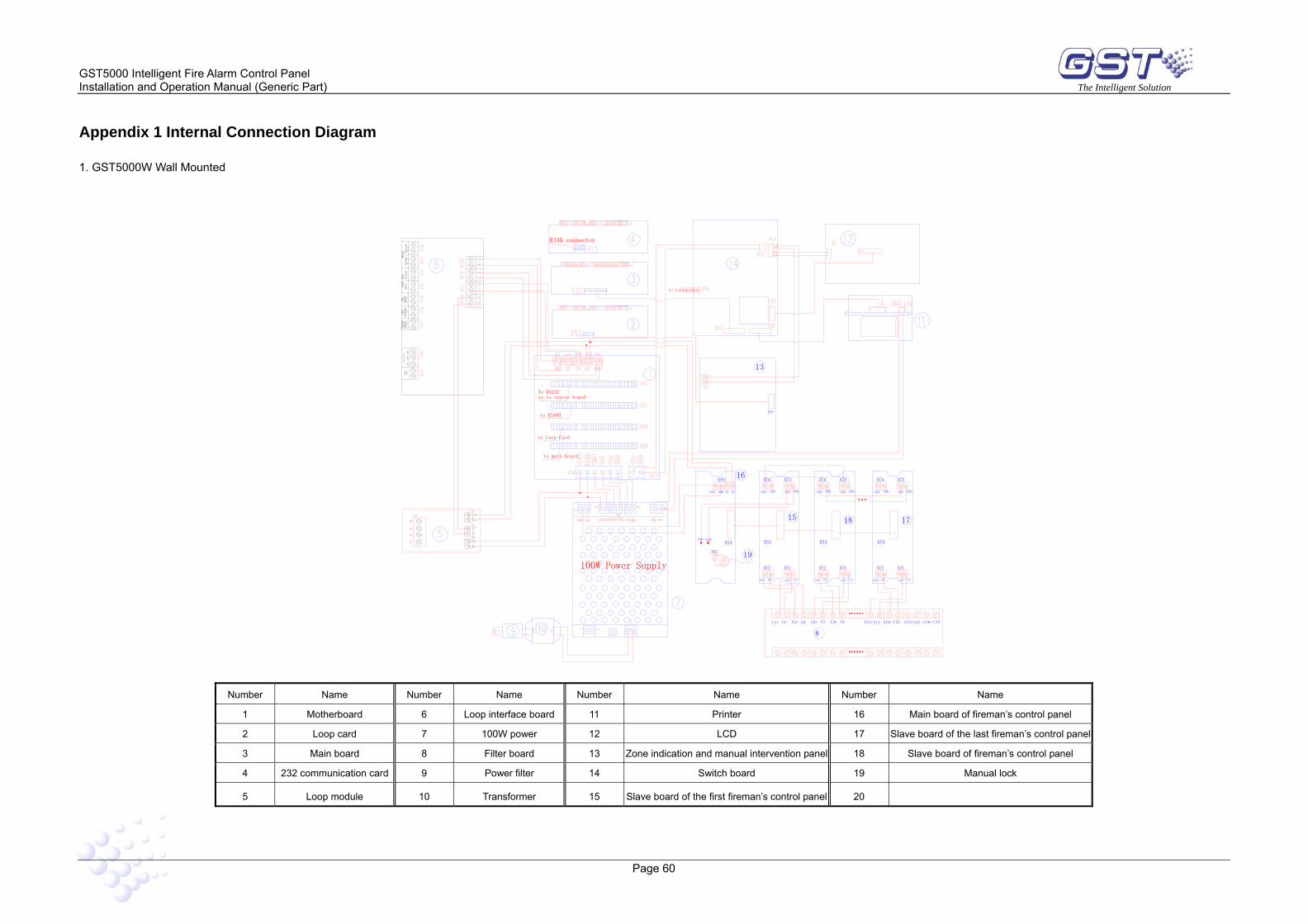
GST5000 Intelligent Fire Alarm Control Panel Installation and Operation Manual (Generic Part) The Intelligent Solution
Page 60
Appendix 1 Internal Connection Diagram
1. GST5000W Wall Mounted
Z1n-
ZI+
ZI-
ZO-
ZO+
XT3
XT4
24-
24+
24-
24+
XT2
XT1
Z1n+
F.
P.E
OU
TPU
T
CLASS
CHANG
E
FAULT OUTPU
T
NC COM
NO
SOU
ND
ER
CIR
CU
I T
POU
TPU
T
-
+N
ETW
ORK
B
A
FI
REA
LAR M
OU
TPU
T -
+
-
+LO
OP
OU
T
-
+LO
OP
IN
+ -
LO
OP
B
US
REP
EATE
R
B
A
RS
-485
C11+C3-C1-C1+ C3+C2+ C2- C4-C4+
8
100W Power Supply
to main board
to Loop Card
1815
C2+ C2-
XS1
XS2
+24VGND
19
XT2
XS1
C2-C1+ C1- C2+ C1-C1+
XT1 XT2
XS1
XT1
16
+24V
XS5
GND Z1 Z2 +24V
XT4
GND GND
XT3
+24V GND
XT4
+24V GND
XT3
+24V
C12+C11- C13-C12- C13+ C14+ C14-
17
C2-C2+ C1-C1+
XT2 XT1
XS1
XT4
GND+24V
XT3
GND+24V
or to router board
to RS485
To RS232
RJ45 connector
to Loudspeaker
13
XS1
Number Name Number Name Number Name Number Name
1 Motherboard 6 Loop interface board 11 Printer 16 Main board of fireman’s control panel
2 Loop card 7 100W power 12 LCD 17 Slave board of the last fireman’s control panel
3 Main board 8 Filter board 13 Zone indication and manual intervention panel 18 Slave board of fireman’s control panel
4 232 communication card 9 Power filter 14 Switch board 19 Manual lock
5 Loop module 10 Transformer 15 Slave board of the first fireman’s control panel 20

GST5000 Intelligent Fire Alarm Control Panel Installation and Operation Manual (Generic Part) The Intelligent Solution
Page 61
2 GST5000 Rack type and console type
A
FUSE(10A)
+5V1
24V
WORK
COM
5V
MAIN
RUN
5V
BATTRY
BATTRY
GND1
GND1
+5V1
~220V
DC-DC CONVERTOR
BAT
BAT 21
2 4V
BAF
ACF
GND
DC24V
OUTPUT OUTPUT
X31
X30
PE
G
B
A
ZI-
ZI+
ZO-
ZO+
XT2
24-
Z1n+
Z1n-
24+
24-
24+
XT4
XT3
XT1
ZO+
ZO-
ZI-
ZI+
XT2
24+
24-
24+
24-
XT4
XT3
Z1n+
XT1
Z1n-
LOO
P BU
S
+24V
XT3
XT1
C14+
BAT.
XS1
OUTPUT FUSEBAT.FUSEEXTERNALOUTPUT
INPUT
INTERNALOUTPUT
C14-
XT2
C2-C2+
+24V GND
XT4
LOO
P OU
T - +
REPEA
TER B
A
RS-485
NETW
OR
K A
B
GND
C1-
XS1XS1
15
C12-C13- C13+ C12+ C11- C11+
C2+C1-C1+ C1+C2-
XT1XT2
C2+C2- C1- C1+
XT2
C2+C1- C1+C2-
XT1
+24VGND+24VGND
14
XT3XT4
+24V +24VGNDGND
XT4 XT3
XS1
XS2
Z1GND+24V Z2
+24VGND
XS5
13
XS1
LOO
P IN + -
- + - +
- +
SOU
ND
ER
CIRC
UIT
POU
TPUT
FIREA
LAR
MO
UTPU
T
F.P.EO
UTPU
T
RJ45 connector
~220V Ground
Battery
Battery
Number Name Number Name Number Name Number Name
1 Motherboard 6 DC-DC converting module 11 Power filter 16 Power filter
2 Loop card 7 Intelligent PSU 12 Front Panel 17 Wiring board
3 Main board 8 Loop interface board 13 Zone indication and manual intervention panel 18
4 232 communication board 9 Ring module 14 Fireman’s Control Panel 19
5 AC Power 10 Air switch 15 Filter board of fireman’s control panel 20

GST5000 Intelligent Fire Alarm Control Panel Installation and Operation Manual (Generic Part) The Intelligent Solution
Page 62
Appendix 2 Device Type List
Abbreviation No. Device type Undefine 00 Undefined ION 01 Ionization detector R+F.Heat' 02 Rate-of-rise and fixed temperature detector Optical 03 Photoelectrical smoke detector Fix Temp 04 Fixed temperature detector Gas Det 05 Gas detector Beam Det 06 Infrared beam detector FlameDet 07 Ultraviolet flame detector CableDet 08 Cable heat detector Heat Det 09 Analogue heat detector Complex 10 Combination detector MCP 11 Manual call point VAModule 12 Voice alarm module Sounder 13 Sounder strobe FTModule 14 Fire telephone module HR MCP 15 Hydrant manual call point HR Pump 16 Hydrant pump SPKR Pmp 17 Sprinkler pump PS.SW 18 Stabilized pressure pump Extract 19 Smoke exhauster Presuriz 20 Blower FreshAir 21 Fresh air Damper 22 Fire damper SM Vent 23 Smoke vent Air Inlet 24 Air inlet SolValve 25 Solenoid valve SM CURT 26 Roller shutter door middle point RSD Clse 27 Shutter screen door close point FireDoor 28 Fire door PS.DIFF 29 Pressure switch Flow SW 30 Water flow indicator Elevator 31 Elevator AHU 32 Air handling unit GENI 33 Diesel generator Light.DB 34 Power for lightning Power.DB 35 Power distribution WTR.CURT 36 Solenoid valve for water curtain Gas Dump 37 Gas start-up GasAbort 38 Gas stop Net unit 39 Net unit Repeater 40 Repeater panel Module 41 Flash-locks valve DryPower 42 Dry powder fire extinguisher FoamPump 43 Foam pump FieldPSU 44 Power supply unit EM Light 45 Emergency light EscapeLT 46 Escape light GasActiv 47 Gas activation Security 48 Security module

GST5000 Intelligent Fire Alarm Control Panel Installation and Operation Manual (Generic Part) The Intelligent Solution
Page 63
ZoneValv 49 Zone valve Cylinder 50 Cylinder DelugePM 51 Deluge pump Undefine 52 Undefined Stop Mod 53 Device stop Silence 54 Mute key SounderA 55 Fire alarm sounder SounderF 56 Fault sounder Loop SW 57 Loop switch CRT Fault 58 CRT Fault Loop 59 Loop PSU.Bat 60 Battery PSU.AC 61 AC power Lock 62 Multi-wire lock PART 63 Part of devices ZoneDir 64 Zone direction F.P.E 65 Fire protection equipment All evac 66 Evacuation Ground.f 67 Ground fault

GST5000 Intelligent Fire Alarm Control Panel Installation and Operation Manual (Generic Part) The Intelligent Solution
Page 64
Appendix 3 Operation Menu
Menu
MUTE To mute the speaker RESET To reset the system [password required] TAB To change time display mode ESC To the previous menu
= and = For changing pages
ENTER: For confirmation VIEW FIRE: Viewing fire information VIEW FAULT: Viewing fault information VIEW DISABLE Viewing disablement information VIEW PLANT Viewing action information SELF TEST For self-test [password required] DISABLE Isolating a device [password required] START To start a device [password required] BROWSE Viewing registration information [password required] CLOCK Modifying the system time [password required] ENABLE To de-disable the disabled device [password required] STOP To stop a started device [password required] LOG Browsing history record SECURITY MODE To set security mode [password required] EXTINGUISHING MODE To set gas-release mode [password required] PRINT To set the printer [password required] SYSTEM System menu [password required] Modify password Modifying password Communicate setup Setting communication mode Working state setup Setting working mode Fire Display Mode Setting fire display mode Zone Browse Viewing zone information C&E Browse Viewing C&E equation Monitoring Device Viewing supervisory data of intelligent
devices

GST China Gulf Security Technology Co., Ltd. No. 80, Changjiang East Road, QETDZ, Qinhuangdao, Hebei, P. R. China 066004 Tel: +86 (0) 335 8502528 Fax: +86 (0) 335 8508942 Email: [email protected] www.gst.com.cn
GST UK Global System Technology PLC Lion Court, Staunton Harold Hall, Melbourne Road, Ashby de la Zouch, Leicestershire, England LE65 1RT Tel: +44 1283 225 478 Fax: +44 1283 220 690 Email: [email protected] www.gst.uk.com
GST Dubai Global System Technology PLC PO Box 17998 Unit ZA04 JEBEL ALI Free Zone, Dubai, UAE Tel: +971 (0) 4 8833050 Fax: +971 (0) 4 8833053 Email: [email protected] www.gst.uk.com