
GltoTki POWER (PVT.) LiMiTEd - NEPRA
202
GltoTki POWER (PVT.) LiMiTEd GPLINEPRA/GM/24/05/2017 May 24, 2017 The Registrar, National Electric Power Regulatory Authority (NEPRA) Attaturk Avenue (East), G-512, Islamabad. Subject: Application for Generation License for a 45 MW Bagasse Based High Pressure Cogeneration Project by Ghotki Power (Private) Limited (uGPL") Dear Sir, I, Munir Ahmad Daha, General Manager being the duly authorized representative of GPL by virtue of board resolution dated 24-05-2017, hereby apply to the National Electric Power Regulatory Authority for the grant of a Generation License, pursuant to Section 15 of the Regulation of Generation, Transmission and Distribution of Electric Power Act, 1997 in the name of: GHOTKI POWER (PRIVATE) LIMITED Incorporated under the Companies Ordinance, 1984 Corporate Universal Identification No. 0104246, dated 15-12 -2016 For its Bagasse Based High Pressure Cogeneration Facility located at Goth Islamabad, Tehsil and District Ghotki, Sindh. (Installed Capacity: 45MW Gross ISO) I certify that the documents-in-support attached with this application are prepared and submitted in conformity with the provisions of the National Electric Power Regulatory Authority licensing (Application and Modification Procedure) Regulations, 1999, and undertake to abide by the terms and provisions of the above-said regulations. I further undertake and confirm that the information provided in the documents-in-support is true and correct to the best of my knowledge and belief. A bank draft no. 2747500 in sum of Rs. 300,336/-(Rupees Three lac three hundred and thirty-six only), being the nonrefundable license application fee calculated in accordance with the Schedule II to the National Electric Power Regulatory Authority (License and Modification Procedure) Regulations, 1999, is also attached herewith. Yours truly, for Ghotki Power (Private) Limited (MUNIR AHMAD DAH General Manager Registered Office: 17-Abid Majeed Road, Lahore Cantt., Lahore. PABX # 042-36664891-95,36602573-74,36677020 Fax: 042-36654490 Email:[email protected]
-
Upload
khangminh22 -
Category
Documents
-
view
1 -
download
0
Transcript of GltoTki POWER (PVT.) LiMiTEd - NEPRA
GltoTki POWER (PVT.) LiMiTEdGPLINEPRA/GM/24/05/2017 May 24, 2017
The Registrar,National Electric Power Regulatory Authority (NEPRA)Attaturk Avenue (East),G-512, Islamabad.
Subject: Application for Generation License for a 45 MW Bagasse Based HighPressure Cogeneration Project by Ghotki Power (Private) Limited (uGPL")
Dear Sir,
I, Munir Ahmad Daha, General Manager being the duly authorized representative ofGPL by virtue of board resolution dated 24-05-2017, hereby apply to the NationalElectric Power Regulatory Authority for the grant of a Generation License, pursuant toSection 15 of the Regulation of Generation, Transmission and Distribution of ElectricPower Act, 1997 in the name of:
GHOTKI POWER (PRIVATE) LIMITEDIncorporated under the Companies Ordinance, 1984
Corporate Universal Identification No. 0104246, dated 15-12 -2016For its Bagasse Based High Pressure Cogeneration Facility located at
Goth Islamabad, Tehsil and District Ghotki, Sindh.(Installed Capacity: 45MW Gross ISO)
I certify that the documents-in-support attached with this application are preparedand submitted in conformity with the provisions of the National Electric PowerRegulatory Authority licensing (Application and Modification Procedure) Regulations,1999, and undertake to abide by the terms and provisions of the above-saidregulations. I further undertake and confirm that the information provided in thedocuments-in-support is true and correct to the best of my knowledge and belief.
A bank draft no. 2747500 in sum of Rs. 300,336/-(Rupees Three lac three hundred andthirty-six only), being the nonrefundable license application fee calculated inaccordance with the Schedule II to the National Electric Power Regulatory Authority(License and Modification Procedure) Regulations, 1999, is also attached herewith.
Yours truly,for Ghotki Power (Private) Limited
(MUNIR AHMAD DAHGeneral Manager
Registered Office: 17-Abid Majeed Road, Lahore Cantt., Lahore. PABX # 042-36664891-95,36602573-74,36677020 Fax: 042-36654490Email:[email protected]

Gho'rki POWER (PVT.) LiMiTEdEXTRACT OF RESOLUTIONS PASSED IN BOARD OF DIRECTORS' MEETINGOF GHOTKI POWER (PRIVATE) LIMITED HELD ON MAY 24, 2017 AT 11:30 A.M.AT 17-ABID MAJEED ROAD, LAHORE CANTT.
AUTHORIZATION OF MR. MUNIR AHMED DAHA TO FILE APPLICTION WITHNATIONAL ELECTRIC POWER REGULATORY AUTHORITY ("NEPRA") FORGENERATION LICENSE:
"RESOL VED THAT Mr. Munir Ahmad Daha, General Manager (the "Authorized
Officer") having CNIC No. 35202-6489539-3, be and is hereby authorized and
empowered on behalf of Ghotki Power (Pvt.) Limited (the "Company") to deal with
National Electric Power Regulatory Authority (the "NEPRA"), connected with
obtaining approval for Generation License of 45 MW Bagasse / Biomass Based Co-
Generation Power Plant at JDW Sugar Mills Limited (Unit-III), Near Goth Islamabad,
District Ghotki and to sign all required Agreements/Applications and other documents
for this purpose and to do and take all necessary actions, things as deemed necessary to
give effect to this resolution".
Registered Office: 17-Abid Majeed Road, Lahore Cantt., Lahore. PABX # 042-36664891-95, 36602573-74, 36677020 Fax: 042-36654490Email:[email protected]

GHOTKI POWER (PRIVATE) LIMITEDLOCATED AT JDW (UNIT-III),
NEAR GOTH ISLAMABAD,DISTRICT GHOTKI, SINDH
Annexure - 6
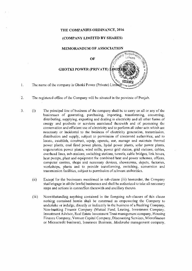
THE COMPANIES OlIDINANCE, 2016
(COMP ANY LIMITED BY SHARES)
MEMORANDUM OF ASSOCIATION
1.
2. The registered office of the Company will he situated in the province of Punjab.
3. (i) The principal line of business of the company shall be to carryon all or any of thebusinesses of generating, purchasing, importing, transforming, converting,distributing, supplying, exporting and dealing in electricity and all other forms ofenergy and products or services associated therewith and of promoting theconservation and efficient use of electricity and to perform all other acts which arenecessary or incidental to the business of electricity generation, transmission,distribution and supply, subject to permission of concerned authorities; and tolocate, establish, construct, equip, operate, use, manage and maintain thermalpower plants, coal fired power plants, hydal power plants, solar power plants,cogeneration power plants, wind mills, power grid station, grid stations, cables,overhead lines, sub-stations, switching stations, tunnels, cable bridges, link boxes,heat pumps, plant and equipment for combined heat and power schemes, offices,computer centres, shops and necessary devices, showrooms, depots, factories,workshops, plants and to provide transforming, switching, conversion andtransmission facilities, subject to permission of relevant authorities.
(ii) Except for the businesses mentioned in sub-clause (iii) hereunder, the Companyshall engage in all the lawful businesses and shall be authorized to take all necessarysteps and actions in connection therewith and ancillary thereto.,
(iii) Notwithstanding anything contained in the foregoing sub-clauses of this clausenothing contained herein shall be construed as empowering the Company toundertake or indulge, directly or indirectly in the business of a Banking Company,Non-banking Finance Company (Mutual Fund, Leasing, Investment Company,Investment Advisor, Real Estate Investment Trust management company, HousingFinance Company, Venture Capital Company, Discounting Services, Microfinanceor Microcredit business), Insurance Business, Modaraba management company,
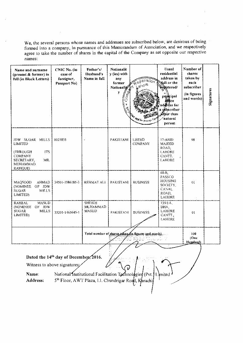
We, the several persons whose names and addresses are subscribed below, are desirous of beingformed into a company, in pursuance of this Memorandum of Association, and we respectivelyagree to take the number of shares in the capital of the Company as set opposite our respectivenames:
Usualresidential
Number ofshares
taken byeach
subscriber
Nationality (ies) with
anyformer
Father'slHusband's
Name in full
CNIC No. (incase of
foreigner,Passport No)
Name and surname(present & former) infull (in Block Letters)
y (in figuresand words)
JDW SUGAR MILLS 0021835 PAKISTANI LISTED 17-ABlD 98LIMITED COMPANY MAJEED
ROAD,(THROUGH ITS LAHORECOMPANY CANTT.SECRETARY, MR. LAHOREMUHAMMADRAFI UE)
68-B,PASS CO
MAQSOOD AHMAD 34501-1986185-3 REHMAT ALI PAKISTANI BUSINESS HOUSING 01(NOMINEE OF JDW SOCIETY,
SUGAR MILLS CANAL
LIMITED) ROAD,LAHORE
RAHEAL MASUD SHEIKH 135/I-L,(NOMINEE OF JDW MUHAMMAD DHA,SUGAR MILLS 35201-1465645-1 MASUD PAKISTANl BUSINESS LAHORELIMITED) CANTT,
01
LAHORE
10.0.
Witness to above signatures' ;, \(iIName: National nstitutional Facilitation T~nolAddress: 5th Floor, A WT Plaza, I.l. Chundrigar Ro
gieJ(pvt .2rJ-,1rachi

THE COMPANIES ORDINANCE, 2016
(Private Company Limited by Shares)
ARTICLES OF ASSOCIATION
OF
GHOTKI POWER '(PRIVATE) LIMITED
1.
I.
2.
II. The number of the members of the Company (exclusive of persons in theemployment of the Company), shall be limited to fifty, provided that for thepurpose of this provision, where two or more persons hold one or moreshares in the company jointly, they shall be treated as single member; and
III. The right to transfer shares of the Company is restricted in the manner andto the extent herein appearirig.
TRANSFER OF SHARES
3, A member desirous to transfer any of his shares shall first offer such shares for saleor gift to the existing members and in case of their refusal to accept the offer, suchshares may be transferred to any other person, as proposed by the transferormember, with the approval of the Board of Directors.
DIRECTORS
4. The number of directors shall not be less than two or a higher number as fixed underthe provisions of Section 154 of the Ordinance. The following persons shall be thefirst directors ofthe Company and shall hold the office upto the date of First AnnualGeneral Meeting:
I. MR. MAQSOOD AHMAD2. MR. RAHEAL MASUD

GHOTKI POWER (PRIVATE) LIMITEDLOCATED AT JDW (UNIT-III),
NEAR GOTH ISLAMABAD,DISTRICT GHOTKI, SINDH
Annexure - 7

Page 1 0[2
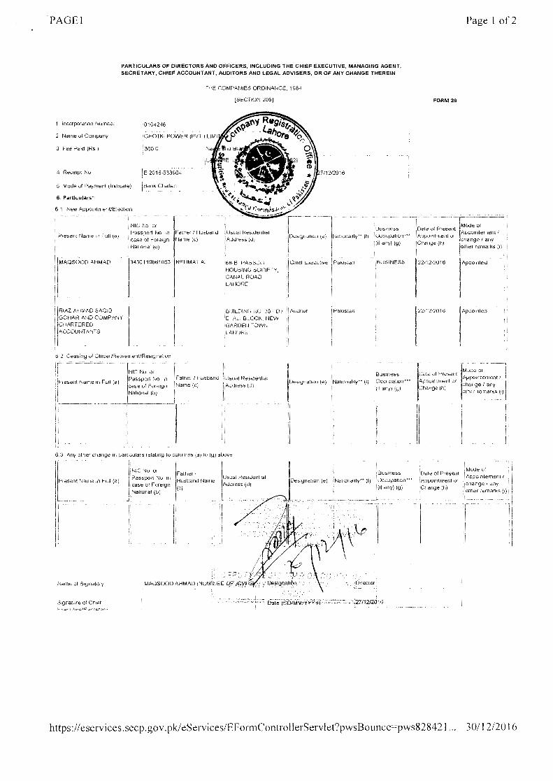
PARTICULARS OF DIRECTORS AND OFFICERS, INCLUDING THE CHIEF EXECUTIVE, MANAGING AGENT,SECRETARY, CHIEF ACCOUNTANT, AUDITORS AND LEGAL ADVISERS, OR OF ANY CHANGE THEREIN
THE COMPANIES ORDINANCE, 2016
[SECTION 197]
FORM 29
L _ J
-----~3 Fee Paid (Rs)
4 Receipt No
jI;
[496]
[14/12/2016
~ Business Date of Mode of -----'l11DeSigna:Jlon . Nationality" 0 t Present Appomtement /ccupa Ion. I
(e) (f) ••• (if an ) ( ) Appointment change / any .my! lQI lor Change (h) other remarks (I) .,i
L_ IL_ ~L-----~L-------~_____ L_ ~-------jL_ _L ___
~.~'''~NIC No or ,.~ Father /
Present Name in Full Passport No. In Husband Name Usual Residential(a) case of Foreign (C) Address jd)
National (b)
1--:l'-=·J68.B, PASSCO I-----J::--r Ee--,----lr·MAQSOOD AHMAD HOUSING SOCIETY(NOMINEE 0:JDW 50119861853 S/O REHMAT CANAL ROAD, . Director Pakistan BUSI~IESSSUGAR MILL::; ALI LAHORE Punjab rporationLIMITED) Pakistan 54000 IL_______ . 1 _~ .___ _ .__ .. j
;;~~~U~W j---------l S/O SHEIK~~J~!~~~ED;:NTT r.'-- I---~_F:-'---~Ince--'-- 1'1 --. ---! ikNUGAIRMILLS J 3520114656451 I MUHAMMAD LAHORE Punjab Director Pakistan BUSI~IESS Incorporation ! ILIMITED) IMASUD Pakistan 54810 II!__________________ , _ _ J _ . ._ l. . _jl
.__ . J
62. Ceasing of Officer/Retirement/Resignation
I ----------_ .._------------_. _.
NIC No. or [Father /
0<"'""""_i. IIBusiness~ Date of Mode of
rresent Name rn Full (a)Passport No. in Husband Usual Residential Nationality" IOccupation Present Apporntement /
case of Foreign Name (c) Address (d) Ie)(f) r'(If any) (g)
Appointment change / any
National (b) or Change (h) other remarks (
II
I [~lC[_Il,---I -I j I _ _ __ J_____
6.3. Any other change In particulars relating to columns (a) to (g) above
IF II
NIC No or II Date ofFather / I Usual Residential D" .. BUSiness P APPointemeynti I
Present Name in Full (a) Passport No. in Husband eSlgnatlon Nationality" Occupation resent change / anL____ ~:~i~~!I~~;eign Name (c) JAd~~ess ~~ __ .__ . : J (~ ... (if any)~)J~;~~~~~:~~)~~herremar~~
l-----III-r -----r- --1---"[-'--'- T--T-----.__L___j__ L L___I___ _ L__L I
Mode of
https:lleservices.secp.gov. pk/eServices/EFormControllerServlel?mode=html&action=ope... 30/01/2017

Page 2 of2
https://eservices.secp.gov.pkieServices/EFormControllerServlet?mode=htmI&action=ope... 30/0 J /20 17
PAGEl
PARTICULARS OF DIRECTORS AND OFFICERS, INCLUDING THE CHIEF El<ECUTIVE, MANAGING AGENT,SECRETARY, CHIEF ACCOUNTANT, AUDITORS AND LEGAL ADVISERS, OR OF ANY CHANGE THEREIN
mcorporanon t.Jl.JInOOr '0104246
GHO fKI POWER (PVT 1 LlMI
1300.0
Recerpr No IE 2016.533904
I~~_nk Cballan _Mode of Payment (IndicatE;!)
6. Partkulars":
6 1 New ApPolntnlentJElectlon
IL! /Jresent Name III Furl \Q)
IlM~QSOOD AHMAD
I[IRIAl AHMAD SAOIB
I· GOHAR A~ID COMPANY
ICHARTERED
I A,:COUNTANTS
1--------'Passport No In 1 rdlht::1 I f-!u6udllU'case of FOfl3lgn t'Jame (C)'r-JatiOfli:::l1 (0)
1'3450119861';53 : REIIMAT All
L
TIlE COMPANIES OROINAI-ICE, 1984
ISECTION :.i051
[---
II~'".".",.:I!C'hll3f Executive
I,
II
[bUdl Hel::ildenllcd
AJur~::;s (u)
loti B "'''';:,Sl:,)HOUSING SOCI~ fYCANil.L ROAO
.ILAIIORE
BUILDINCi i'K) :35· [J 1E. ALI BLOCK NEW
, (iARDEI'j TOWI'I.LAfIURf::
Auditor
Usuol R~SldentlalAJdfess (d)
6.3 Any other cnauqe in parucutar s lelallng to columns (d) to 19) above:
It'~·"Na n re in C." (a)
I HIC No 01 F(JI)1l;f!, Pass POll No II! HU:;UoIIV Ni:II[IC!
case at Foreign' (e)1 Nallonal (b)
jL_-' ...---_'--' .... I
Name ol SIYrldtory
Signature of ChiefC"""',·,.t,,,""c:. ..."rot-:>r"
Usual RestdeunalAuci ess (ui
. l
If'IIIII
7/12/2016
Pakistan
Nattonahtv " (t)BusinessOccupation?"(If any) (U)
22/12/2016
~... _. '-'
Date cf PresentIAPPu,nlll\t~lIt 01
Chang" (h)
I
iI IBuslness
, .._)
Ndllo.. rICllltY•• (t) !l)CGUpation .••(II dny) (9)
. J._
Date or Present Appomtement iAppomtment or : change I .i:lnyCI)ange (h) , other remarks (I)
-Drrector
Page 1 01'2
FORM 29
Appomteo
.__ ._ .. ------,jMU(J€ of ilAfJPOlflte!Tlent I I
1
"I)aIlge I any 1
.other remark.~.(I) I
f.,Ilude or
https://eservices,secp,gov.pkJeServices/EFormControllerServlet?pwsBoUllCe===pws82842I", 3011 2/20 16
1-- -'11
- -·---~l-- -----l~Od::-~1[,l:juSlneSs Date of Present Apporntement ? )
rJi:1llulli::lllly·· (f) IOCCIIPdllon··· Appcnumeru 01 I'-. change I any 1
I,(It any) (91 ,"hdllge (h)! other remarks (I) I!!BUSINESS 22/12/2016 Apponueu -[
1 i,I

GHOTKI POWER (PRIVATE) LIMITEDlOCATED AT JDW (UNIT-IIIL
NEAR GOTH ISLAMABAD,DISTRICT GHOTKI, SINDH
Annexure - 8
1
GHOTKI POWER (PRIVATE) LIMITEDLOCATED AT JDW (UNIT-III),
NEAR GOTH ISLAMABAD,DISTRICT GHOTKI, SINDH
Company Profile
Project Company
The generation facility is being developed by Ghotki Power (Pvt.) Limited ("GPL"), a privatelimited company incorporated under the Companies Ordinance, 1984 for the purpose ofsetting up, owning and operating the planned 45 MW bagasse based high pressure co-generation power project as an independent power producer (IPP).
Project Sponsors
The sponsor of GPL and the project is JDW Sugar Mills Limited (" JDW"). JDW is one of theprogressive sugar groups in Pakistan. JDW owns and operates four sugar mills which accountfor 12%-15%of Pakistan's total sugar production and constitutes one of the largest group inthe sugar sector. JDW manages one of the largest corporate farming operations in Pakistanspanning sugarcane farming of over 20,000 acres of land.
JDW has extensive and first-hand power sector experience. JDW pioneered the high-pressurecogeneration in the sugar industry by developing, constructing, commissioning and operatingapproximately 2 x 26.5 MW (53 MW total) bagasse-based power projects at JDW Unit-II andUnit-III. The projects were the first to materialize under NEPRA's upfront bagasse tariffregime. The first power plant at JDW Unit-II was commissioned in June 2014 whereas thesecond at JDW Unit-III was commissioned in October 2014. Both projects are selling electricityto the Central Power Purchasing Agency ("CPPA") under thirty-year Energy PurchaseAgreements.
The management of JDW has hands-on experience in power project development (e.g. design,financing, licensing, tariff development, grid studies, and security documents) as well asproject tendering, construction, installation and operation. JDW is uniquely positioned toleverage their experience towards the successful commissioning and operation of theproposed 45 MW bagasse based high pressure cogeneration project.
Financial Capacity of the Sponsor
The latest financial statements of JDW Sugar Mills Limited are attached with the applicationshowing the financial capacity of the sponsor for setting up of the proposed 45 MW HighPressure Cogeneration Plant. Summary of financials for previous years of operations are asbelow:
GHOTKI POWER (PRIVATE) LIMITEDLOCATED AT JDW (UNIT·III),
NEAR GOTH ISLAMABAD,DISTRICT GHOTKI, SINDH
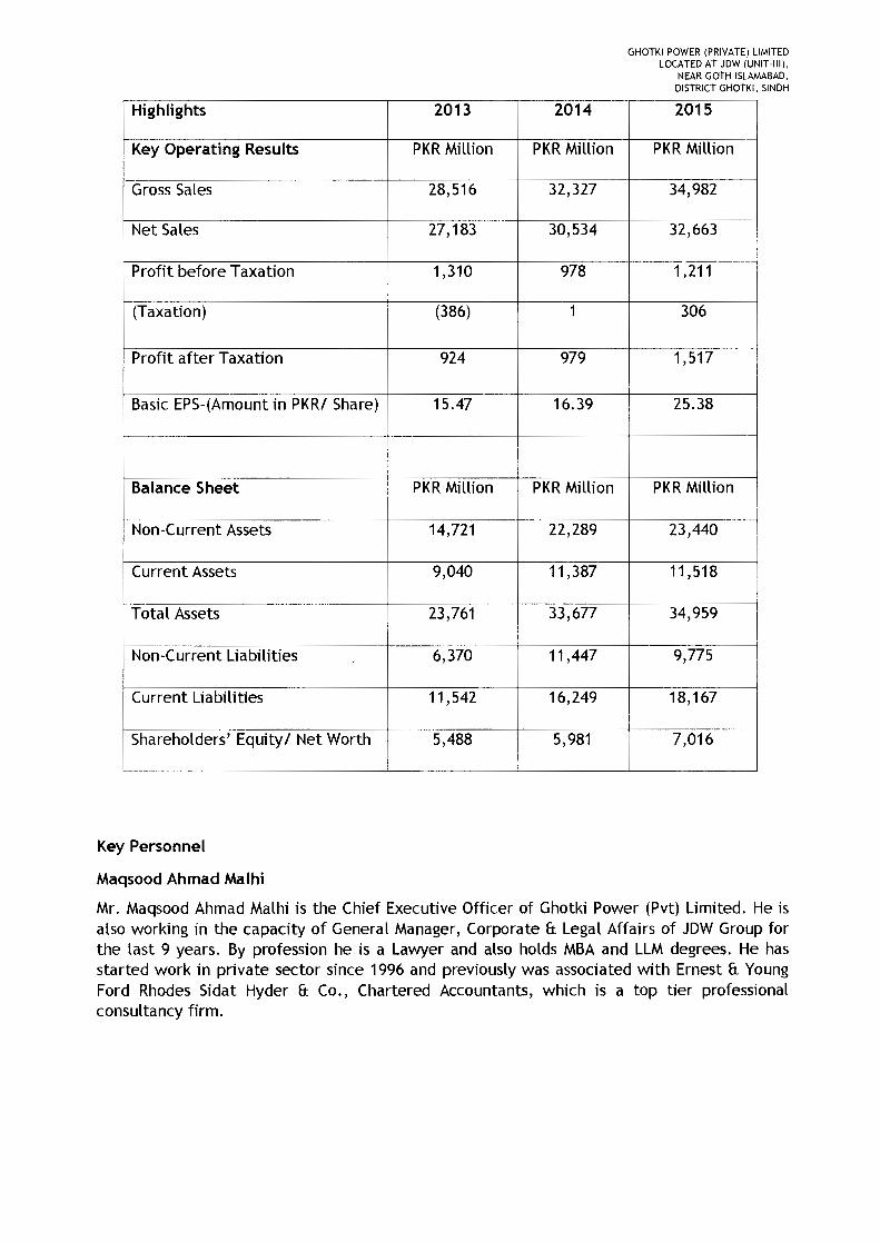
Highlights 2013 2014 2015
Key Operating Results PKRMillion PKRMillion PKRMillion
Gross Sales 28,516 32,327 34,982
Net Sales 27,183 30,534 32,663
Profit before Taxation 1,310 978 1,211
(Taxation) (386) 1 306
Profit after Taxation 924 979 1,517
Basic EPS-(Amount in PKRI Share) 15.47 16.39 25.38
Balance Sheet PKRMillion PKRMillion PKRMillion
Non-Current Assets 14,721 22,289 23,440i
I
Current Assets 9,040 11,387 11,518 ,
Total Assets 23,761 33,677 34,959
Non-Current Liabilities , 6,370 11,447 9,775I
Current Liabilities 11,542 16,249 18,167
Shareholders' Equity I Net Worth 5,488 5,981 7,016
Key Personnel
Maqsood Ahmad Malhi
Mr. Maqsood Ahmad Malhi is the Chief Executive Officer of Ghotki Power (Pvt) Limited. He isalso working in the capacity of General Manager, Corporate & Legal Affairs of JDW Group forthe last 9 years. By profession he is a Lawyer and also holds MBAand LLMdegrees. He hasstarted work in private sector since 1996 and previously was associated with Ernest & YoungFord Rhodes Sidat Hyder & Co., Chartered Accountants, which is a top tier professionalconsultancy firm.
GHOTKI POWER (PRIVATE) LIMITEDLOCATED AT JDW (UNIT·III),
NEAR GOTH ISLAMABAD,DISTRICT GHOTKI, SINDH
Rana Nasim Ahmed
Mr. Rana Nasim Ahmed has served as the Chief Operating Officer I Resident Director of JDWSugar Mills Limited since 2001. He is responsible for operations spanning corporate farming,sugarcane milling and power generation. He has helped transform JDW over the period intoone of the largest and most efficient sugar sector enterprises in Pakistan.
Mr. Ahmed has directly overseen JDW's diversification into the power sector over the lastseveral years by successfully developing first of their kind 2 x 26.5 MW (53 MW total) high-pressure cogeneration IPPs at JDW Unit-II and Unit-III. Set up at a total cost of approximatelyUS$ 60 million, these pioneering projects are the only ones in recent times to have been setup through direct procurement and supervision without an EPC contractor. Both plants arefully operational since 2014. Besides managing various aspects related to the projects'conceptualization, development, regulatory affairs, tendering, construction andcommissioning, Mr. Ahmed now also supervises their operations & maintenance.
Mr. Ahmed holds an MBA from Saint Louis University, USA and MA and BA degrees in Economicsfrom the University of Punjab, Pakistan.
Muhammad Rafique
Mr. Muhammad Rafique is a Chartered Accountant by profession. He is the Group FinanceDirector for JDW. He completed his graduation in Commerce from Hailey College ofCommerce, Punjab University, Lahore in 1982. He completed his articles from A.F. Fergusonand Company, Chartered Accountants, Lahore and remained associated with this firm till hisqualification as CA in 1988. He worked in Audit, Tax and Management & Consultancydepartments of A.F. Ferguson & Co. He has worked in private sector since his qualification in1988 out of which most of his association is with JDW Group. He established expertise inarranging financing I funding for establishment of new projects.
Muhammad Abid
Designated as the Plant Manager, Mr. Muhammad Abid has 20 years of energy sectorexperience in Plant Operations, Maintenance, Performance Monitoring and security contractslike PPA, lA, PSA and PWPA Management. He has been worked in AES Corporation USA forLalpir Power Project, Marubani Power Asset Management for TAPCO Abu Dhabi a 2000MWPower and 160MIGD Water project on different key positions. He has Graduation inMechanical and Masters in Coal Technology along with Master in Business Administration.
Shafqat Mustafa
He is working in the capacity of Manage Operations & Performance. Mr. Mustafa is a MarineEngineer with 20 years of experience in different power generation projects and looking afterthe operations of the plant. He has 5 shift engineers having a rich experience of plantoperations and troubleshooting and a team of 30 trained operators under his supervision.
GHOTKI POWER (PRIVATE) LIMITEDLOCATED AT JDW (UNIT-III),
NEAR GOTH ISLAMABAD,DISTRICT GHOTKI, SINDH
Ghulam Rasool
He is looking after all the matters related to Mechanical Maintenance. Mr. Rasool has 20 yearsof experience in the field of Power Generation. He is a Mechanical Engineer. He has a team of6 experienced energy sector professionals under his supervision
BilalYaqoob
Designated as Manager Electrical and Instrumentation Mr. Yaqoob is looking after theElectrical and Instrumentation maintenance of plant. He Graduated in Electrical PowerTechnology and has 15 years of experience in Power Generation field. He has worked for IPPsin Pakistan and UAE. He leads a team of 10 experienced and professional E&I engineers.
Saqib Bashir
He is designated as the Chief Chemist. Mr. Bashir Graduated in Chemical Technology and has15 years experience in industrial water treatment. He is responsible of Water testing andquality assurance as per standards. A Team of 8 experienced Water Chemistry Professionalsare working under his supervision.
GHOTKI POWER (PRIVATE) LIMITEDLOCATED AT JDW (UNIT-III),
NEAR GOTH ISLAMABAD,DISTRICT GHOTKI, SINDH
PROJECT TECHNICAL, FINANCIAL 8: OTHER INFORMATION
1) Location and Land Detai Is
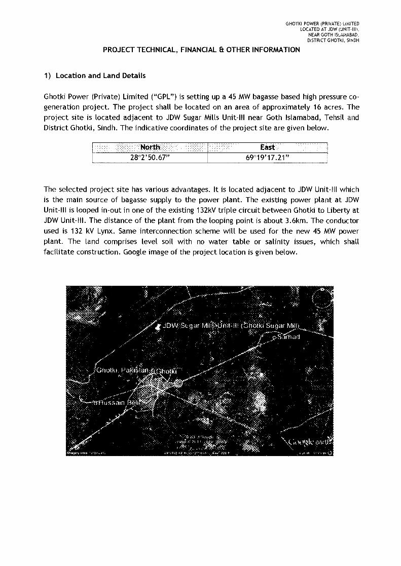
Ghotki Power (Private) Limited (uGPL") is setting up a 45 MWbagasse based high pressure co-generation project. The project shall be located on an area of approximately 16 acres. Theproject site is located adjacent to JDW Sugar Mills Unit-III near Goth Islamabad, Tehsll andDistrict Ghotki, Sindh. The indicative coordinates of the project site are given below.
The selected project site has various advantages. It is located adjacent to JDW Unit-III whichis the main source of bagasse supply to the power plant. The existing power plant at JDWUnit-III is looped in-out in one of the existing 132kV triple circuit between Ghotki to Liberty atJDW Unit-III. The distance of the plant from the looping point is about 3.6km. The conductorused is 132 kV Lynx. Same interconnection scheme will be used for the new 45 MW powerplant. The land comprises level soil with no water table or salinity issues, which shallfacilitate construction. Google image of the project location is given below.
GHOTKI POWER (PRIVATE) LIMITEDLOCATED AT JDW (UNIT·III),
NEAR GOTH ISLAMABAD,DISTRICT GHOTKI, SINDH
2) Technology & Plant Details
a) Proposed Scheme
It is proposed to install a 45.0 MW capacity bagasse based high pressure co-generationpower plant. The Cogeneration scheme for GPL proposes 1x220 TPH capacity boiler of 110bar and 540 degrees centigrade parameters and 1x45 MW extraction cum condensing turbogenerators. The plant will use Bagasseas fuel made available from the adjacent JDW Unit-III.
b) Bagasse Fired Boiler
The Boiler shall be single drum, natural circulation, radiant furnace with water cooledmembrane wall, three stage super-heater with two stage attemperator, balanced draftand travelling grate bagasse fired boiler. The boiler is capable of a peak generation of110%of the MCR for a period of half an hour in eight-hour shift. The boiler shall be topsupported, outdoor type, with adequate provisions for the thermal expansion of theboilers in all directions.
Design Parameters:• BagasseFired Boiler: 220 TPH• Steam pressure at the Main Steam stop valve outlet: 110 bar(a)• Steam temperature at the Main steam stop valve outlet at MCR: 540 ± 5 OC• Boiler feed water temperature at the inlet to the Deaerator: 110 DC.• Maximum noise level at 1.0 m distance for the boiler: 85 dB(A)
The Bagasse through drum feeders, screw feeders and pneumatic spreaders will be fedinto the furnace. The travelling grate is selected for efflcient combustion system and toavoid heating of grates. The Ash is collected by the continuous movement of travellinggrate.
The control philosophy, boilers interlock and protection logic shall be implemented inDistributed Control System (DCS)for safe operation of boiler.
c) Steam Turbine
The turbine of the cogeneration power plant will be multistage nozzle governed,horizontal spindle, two bearings, and extraction cum condensing type with 02 number ofuncontrolled extractions and 01 number of control extractions. The exhaust from theturbine will be condensed in the surface condenser at 0.101 bar (a) pressure during off-season operation.

GHOTKI POWER (PRIVATE) LIMITEDLOCATED AT JDW (UNIT-III).
NEAR GOTH ISLAMABAD.DISTRICT GHOTKI. SINDH
The Medium pressure steam at 4 Bar(a) and low pressure steam at 2.5 bar (a), wHl besupplied to the sugar plant. 98% condensate of the supplied Low Pressure steam will bereturned from the sugar mill.
d) AC Generator
AC Generator shall comprise of the following:
• Brush-less exciter with PMG• Air coolers• Twin bearings• AVR cum Excitation panel• Anti-condensation heaters• Water leakage detector- 1 per cooler• Lube oil flow regulator - 1 per bearing
Generator electrical output rating shall be as follow:
• [56.25] MVA rated capacity at [50]0 C ambient.• [11]±[10]%KV• [50] ± [5]% Hz• 3 Phase• Power factor ([0.8] lag to [0.95] lead)• ± [0.5]% Accuracy Control for Excitation system
e) Bagasse Handling System
The bagasse handling system comprising of chain conveyors & belt conveyors to transportthe required quantity of bagasse from sugar mill to cogeneration shall be provided.Bagasse from the sugar mill shall be fed to the boiler from a front mounted chainconveyor. Excess bagasse shall be returned to the bagasse storage yard. During off-season/non availability of bagasse from mill, the cogeneration boiler shall use savedbagasse from the storage yard.
f) Ash Handling system
The ash handling system envisaged for the cogeneration boiler shall consist of SubmergedAsh Belt Conveyor System and Dense Phase Ash Handling System.
Submerged Ash Belt Handling System:
Submerged Ash Belt Handling System consists of conveyor belts, drive assembly, all typeof pulleys, all type of idlers, bearing assembly, inlet / outlet chutes, take-up assembly,trough assembly, support frames, cross over, walkway, structural safety switches, waterinlet / outlet / drain nozzles etc. The bottom ash at the discharge of travelling grate shallbe conveyed by submerged ash conveyor system.
GHOTKI POWER (PRIVATE) LIMITEDLOCATED AT JDW (UNIT-III),
NEAR GOTH ISLAMABAD,DISTRICT GHOTKI, SINDH
Dense Phase Ash Handling System:
This system will handle fly ash from boiler ash hopper (other than traveling grate &plenum ash hopper) and ESP hoppers. Surge hopper (water cooled for boiler ash hopperand non-water cooled for ESPhopper) arrangement shall be provided below the boiler andESPhopper. Two air compressors with built in PLC control system and 1x10001o air receivershall be provided near the dense phase equipment. The required conveying air for densephase ash system will be supplied by these compressors through air receivers. The ash silostorage capacity shall be enough to store 12 hours' ash generation from both the boilerand ESPsystem
g) Electrical Network:
The Plant shall consist of one generator and associated auxiliaries for smooth plantoperation. A synchronous alternator for the proposed co-generation power plant withgeneration at 11 kV will be connected to 132kV system through 11kV switchboard andstep-up Power Transformers.
The connection between generator and 11kV switchboard shall be through 11kV phasesegregated Bus Duct and between 11kV switchboard and 11/132kV power transformer shallbe through 11kV HT XLPE cables.
The surplus power, after meeting the power requirement of cogeneration plant auxiliariesand sugar plant auxiliaries, shall be exported to the grid through 11/132kV powertransformer. There shall be total of 2 numbers of step-up power transformers (oneworking + one standby) to meet N-1 condition of NTDC.
Entire power evacuation system and associated equipment shall be designed so as toexport the entire power from cogeneration plant (total generation less auxiliary powerconsumption), when the sugar plant is not in operation.
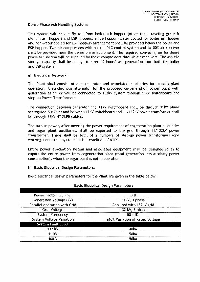
h) Basic Electrical Design Parameters:
Basic electrical design parameters for the Plant are given in the table below:
Basic Electrical Design Parameters
Grid Voltage
0.8Power Factor (lagging)Generation Voltage (kV) 11kV, 3 phase
Parallel operation with Grid Required with 132kV grid132 kV, 3 phase
50 ± 5%System Voltage Variation ±10% Variation of Rated Voltage
System Fault Level132 kV 40kA11 kV
.-
50kA400 V 50kA
GHOTKI POWER (PRIVATE) LIMITEDLOCATED AT JDW (UNIT-III),
NEAR GOTH ISLAMABAD,DISTRICT GHOTKI, SINDH
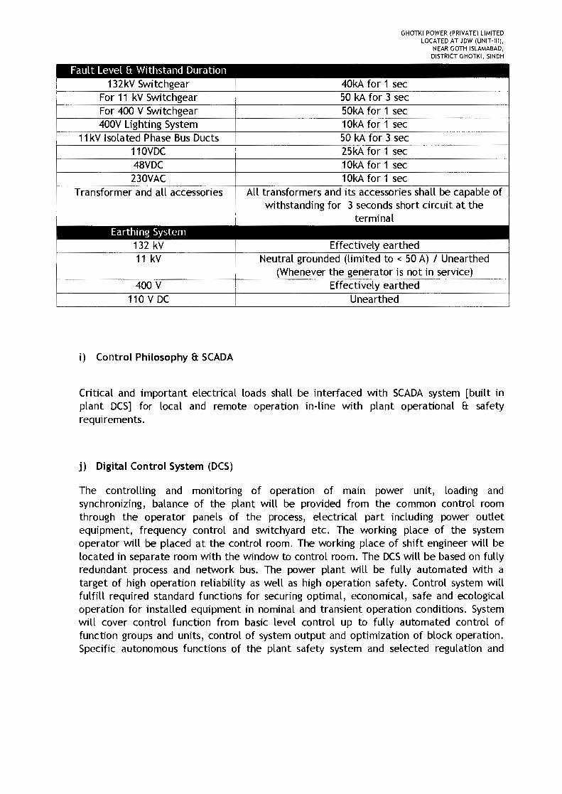
Fault Level & Withstand Duration132kV Switchgear 40kA for 1 sec
For 11 kV Switchgear 50 kA for 3 secFor 400 V Switchgear 50kA for 1 sec400V Lighting System 10kA for 1 sec
11kV Isolated Phase Bus Ducts 50 kA for 3 sec110VDC 25kA for 1 sec48VDC 10kA for 1 sec230VAC 10kA for 1 sec
Transformer and all accessories All transformers and its accessories shall be capable ofwithstanding for 3 seconds short circuit at the
terminalEarthing System
132 kV Effectively earthed11 kV Neutral grounded (limited to < 50 A) / Unearthed
(Whenever the generator is not in service)400 V Effectively earthed
110 V DC Unearthed
i) Control Philosophy & SCADA
Critical and important electrical loads shall be interfaced with SCADA system [built inplant DCS] for local and remote operation in-line with plant operational & safetyrequirements.
j) Digital Control System (DCS)
The controlling and monitoring of operation of main power unit, loading andsynchronizing, balance of the plant will be provided from the common control roomthrough the operator panels of the process, electrical part including power outletequipment, frequency control and switchyard etc. The working place of the systemoperator will be placed at the control room_ The working place of shift engineer will belocated in separate room with the window to control room. The DCSwill be based on fullyredundant process and network bus. The power plant will be fully automated with atarget of high operation reliability as well as high operation safety. Control system willfulfill required standard functions for securing optimal, economical, safe and ecologicaloperation for installed equipment in nominal and transient operation conditions. Systemwill cover control function from basic level control up to fully automated control offunction groups and units, control of system output and optimization of block operation.Specific autonomous functions of the plant safety system and selected regulation and
GHOTKI POWER (PRIVATE) LIMITEDLOCATED AT JDW (UNIT-III),
NEAR GOTH ISLAMABAD.DISTRICT GHOTKI. SINDH
control functions will be realized by special subsystems in a hierarchical model. From aviewpoint of control, these items will create an integrated part of the DCScontrol system.
Hardware and software will enable realization of loop control, binary control, datafunctions, monitoring, remote control and emergency manual control. Communicationwithin the system will be handled by bus routing connected to the standard bus system RS485, Ethernet etc.
3) Interconnection with National Grid
Ghotki Power (Private) Limited intends to sell electricity generated by the project to theCentral Power Purchasing Agency (CPPA) pursuant to the NEPRA(Sale of Electric Power byRenewable Energy Companies) Guidelines, 2015.
The power generated from the Generation Facility I Power Plant of Ghotki Power(Private) Limited shall be dispersed to the load center of SEPCO.
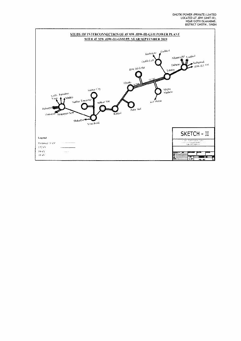
The 45 MW power plant is located adjacent to JDW Sugar Mills Unit-III, Goth Islamabad,District Ghotki, Sindh. The existing power plant at JDW Unit-III is looped in-out in one ofthe existing 132kV triple circuit between Ghotki to Liberty at JDW Unit-III. The distance ofthe plant from the looping point is about 3.6km. The conductor used is 132 kV Lynx. Sameinterconnection scheme will be used for the new 45 MW power plant.
Any change in the above interconnection arrangement shall be communicated to theAuthority in due course. The sketch of the proposed scheme is provided below.
GHOTKI POWER (PRIVATE) LIMITEDLOCATED AT JDW (UNIT-III),
NEAR GOTH ISLAMABAD,DISTRICT GHOTKI, SINDH
ST1'OY Of INI'IRCONl'}:Cl'ION OF 45 MW JDW-Ill-GSM POWER "LA1'TWITH 4$ '1\\ JI)' .. -Hl-GS.1\1 J'P. YEAR SU'TE"UJER 21119
Sii.JkfJl...~i.\;ow_n-tS't
SKETCH - II
~,.k\
HIS
GHOTKI POWER (PRIVATE) LIMITEDLOCATED AT JDW (UNIT-III).
NEAR GOTH ISLAMABAD,DISTRICT GHOTKI, SINDH
4) Project Cost, Sources and amounts of Equity and Debt
a) Project Cost
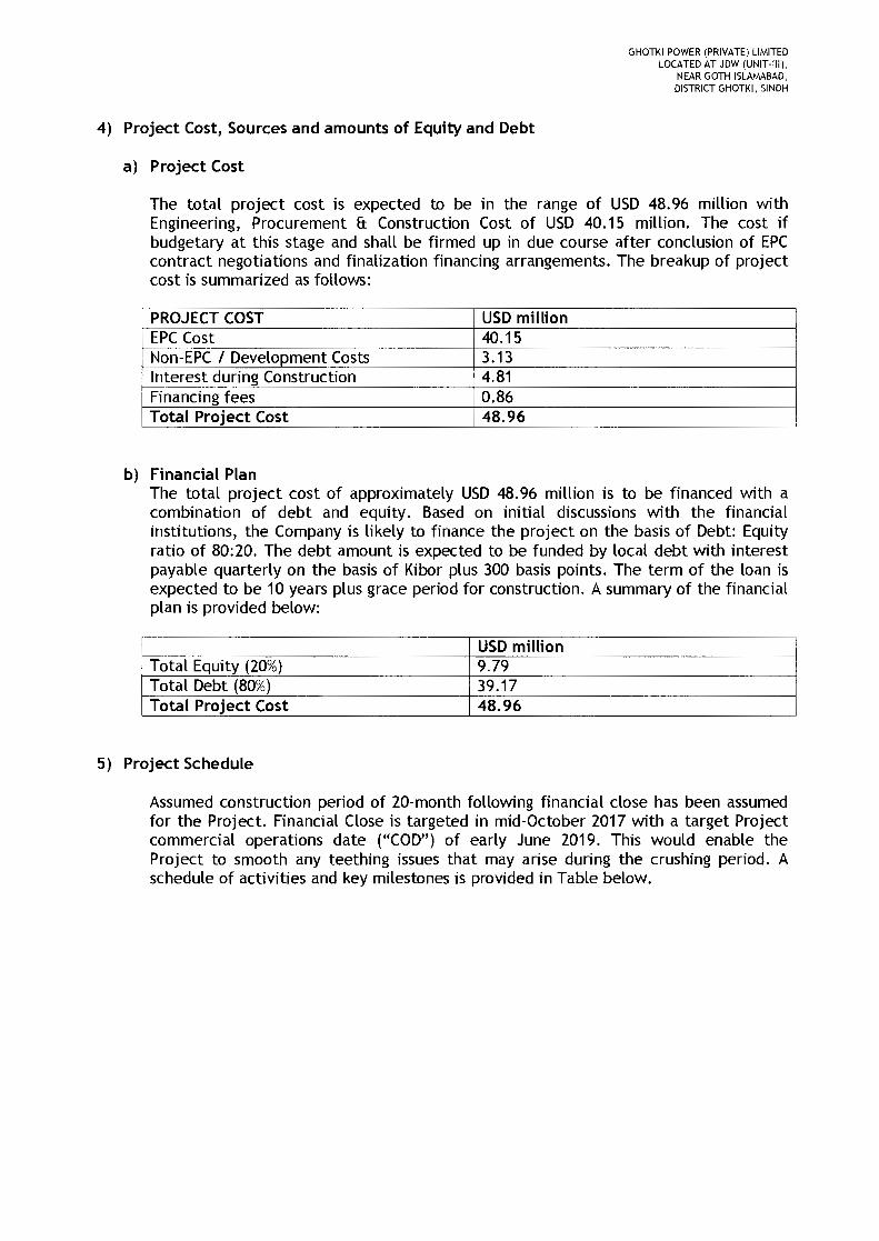
The total project cost is expected to be in the range of USD 48.96 million withEngineering, Procurement & Construction Cost of USD 40.15 million. The cost ifbudgetary at this stage and shall be firmed up in due course after conclusion of EPCcontract negotiations and finalization financing arrangements. The breakup of projectcost is summarized as follows:
PROJECT COST USDmillionEPC Cost 40.15Non-EPC I Development Costs 3.13Interest during Construction 4.81Financing fees 0.86Total Project Cost 48.96
b) Financial PlanThe total project cost of approximately USD 48.96 million is to be financed with acombination of debt and equity. Based on initial discussions with the financialinstitutions, the Company is likely to finance the project on the basis of Debt: Equityratio of 80;20. The debt amount is expected to be funded by local debt with interestpayable quarterly on the basis of Kibor plus 300 basis points. The term of the loan isexpected to be 10 years plus grace period for construction. A summary of the financialplan is provided below:
USDmillionTotal Equity (20%) 9.79Total Debt (80%) 39.17Total Project Cost
--48.96
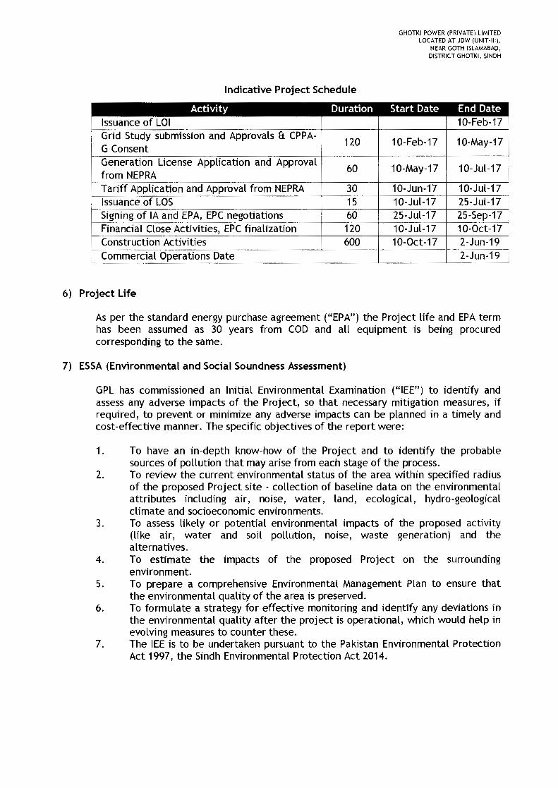
5) Project Schedule
Assumed construction period of 20-month following financial close has been assumedfor the Project. Financial Close is targeted in mid-October 2017 with a target Projectcommercial operations date ("COD") of early June 2019. This would enable theProject to smooth any teething issues that may arise during the crushing period. Aschedule of activities and key milestones is provided in Table below.
GHOTKI POWER (PRIVATE) LIMITEDLOCATED AT JDW (UNIT-III),
NEAR GOTH ISLAMABAD,DISTRICT GHOTKI, SINDH
Indicative Project Schedule
Activity Duration Start Date End DateIssuance of LOI 10-Feb-17Grid Study submission and Approvals & CPPA-
120 10-Feb-17 10-May-17G ConsentGeneration License Application and Approval
60 10-May-17 10-Jul-17from NEPRATariff Application and Approval from NEPRA 30 10-Jun-17 10-Jul-17Issuance of LOS 15 10-Jul-17 25-Jul-17Signing of IA and EPA, EPC negotiations 60 25-Jul-17 25-Sep-17Financial Close Activities, EPCfinalization 120 10-Jul-17 10-0ct-17Construction Activities 600 10-0ct-17 2-Jun-19Commercial Operations Date 2-Jun-19
6) Project Ufe
As per the standard energy purchase agreement ("EPA") the Project life and EPA termhas been assumed as 30 years from COD and all equipment is being procuredcorresponding to the same.
7) ESSA (Environmental and Social Soundness Assessment)
GPL has commissioned an Initial Environmental Examination ("lEE") to identify andassess any adverse impacts of the Project, so that necessary mitigation measures, ifrequired, to prevent or minimize any adverse impacts can be planned in a timely andcost-effective manner. The specific objectives of the report were:
1. To have an in-depth know-how of the Project and to identify the probablesources of pollution that may arise from each stage of the process.
2. To review the current environmental status of the area within specified radiusof the proposed Project site - collection of baseline data on the environmentalattributes including air, noise, water, land, ecological, hydro-geologicalclimate and socioeconomic environments.
3. To assess likely or potential environmental impacts of the proposed activity(like air, water and soil pollution, noise, waste generation) and thealternatives.
4. To estimate the impacts of the proposed Project on the surroundingenvironment.
5. To prepare a comprehensive Environmental Management Plan to ensure thatthe environmental quality of the area is preserved.
6. To formulate a strategy for effective monitoring and identify any deviations inthe environmental quality after the project is operational, which would help inevolving measures to counter these.
7. The lEE is to be undertaken pursuant to the Pakistan Environmental ProtectionAct 1997, the Sindh Environmental Protection Act 2014.
GHOTKI POWER (PRIVATE) LIMITEDLOCATED AT JDW (UNIT-III),
NEAR GOTH ISLAMABAD,DISTRICT GHOTKI, SINDH
8) Social Impact
The project will generate direct and indirect employment opportunities for the localpopulation. The project will improve the basic infrastructure, which can be used bypeople of nearby villages. GPL will give priority to skilled, un-skilled labor of thenearby villages. Overall it is anticipated that there will be marginal impact on thesocio-economic conditions of the locality and the impact will be positive.
9) Safety Plans 1 Emergency Plans
a) Health, Safety and Environment (HSE) Protection
The Company will be committed to ensuring the highest standard when it comes to thehealth and safety of people and protection of the environment. This shall apply to alllocations of the office space as well as the construction site. Commitment will remainin place to continuously improve HSE at the workplace, and contractors will berequired to follow such an example by adopting the Company's policy or developingtheir own equivalent.
b) Safety Plans
A comprehensive safety plan would be implemented to provide a safe and protectedworking environment to the staff working at the facility. All staff working at thefacilities would be briefed regarding different types of safety measures which includethe following:
• Moral obligations• Hazard recognition• Importance of Personal Protective Equipment (PPE)• Accident prevention• Fire prevention and protection etc.
All working staff shall be provided with the necessary safety gear and protectiveequipment and trainings shall be conducted regarding the use of safety equipment andPPE. Safety procedures and policies regarding all operational and maintenance jobswould be developed to prevent unforeseen accidents.
Furthermore, automatic fire alarm systems shall be installed along with firesuppression equipment at all fire hazardous locations of the plant site (details of thefirefighting systems can be found in the attached feasibility study).
Emergency help call numbers for different emergency services e.g. fire brigade,medical center, ambulance service and administrations shall be displayed in boldthroughout the facility. First Aid facilities shall also be provided at the facility. Thestaff working would be trained in detail through mock drills and would be made awareof the emergency escape routes and procedures for quick and safe escape. Pictorialsand diagrams of the same shall be pasted at different locations through the facility.
GHOTKI POWER (PRIVATE) LIMITEDLOCATED AT JDW (UNIT-III).
NEAR GOTH ISLAMABAD,DISTRICT GHOTKI, SINDH
An emergency control team shall be in place to oversee all the Safety and Emergencyplans and would be responsible for taking all the necessary actions and decisions totackle and control any type of emergency. The team would also be responsible forshutting down the facilities if required during the emergency situation.
c) Environment
An Environmental Management Plan (EMP) and Environmental Monitoring Plan (EMtP),will be implemented as legal requirement under the Punjab Environmental Protection(amendment 2012) Act. This will ensure the power plant operation in environmentallysustainable fashion.
Concrete measures are to be adopted to ensure the quality of environment throughthe running of project in complete accordance with the 5RS Principles- Reducing,Recycling, Reusing, Refurbishing and Retrofitting. Good housekeeping will be the orderof the day. Tree plantation on the project site and its vicinity will be carried out.
10) System studies: Load Flow, Short circuit, Stability, Reliability
An interconnection study for the project has been conducted by Power PlannersInternational and approval from SEPCO has already been received. Theinterconnection study has also been submitted to NTDC for its vetting.
Detail of Load Flow, Short Circuit, Stability and Reliability can be found in theinterconnection connection study, which has been attached with this application.
11) Plant Characteristics
Please refer to the Technical Feasibility attached with the application.
12) Control, Metering, Instrumentation and Protection
Please refer to the Technical Feasibility attached with the application.
13)Training and Development
Training is part of the scope of works to be conducted under Engineering, Procurementand Construction ("EPC") Contractor. The EPCcontractor shall also carry out thetraining of the Employer's Personnel in the operation and maintenance of thecomplex.

GHOTKI POWER (PRIVATE) LIMITEDLOCATED AT JDW (UNIT-III),
NEAR GOTH ISLAMABAD,DISTRICT GHOTKI, SINDH
Annexure - 14
GHOTKI POWER (PRIVATE) LIMITEDLOCATED AT JDW (UNIT-III),
NEAR GOTH ISLAMABAD,DISTRICT GHOTKI, SINDH
PROSPECTUS
1. Introduction:
Ghotki Power (Private) Limited is a special purpose company incorporated under theCompanies Ordinance of 1984 for the purpose of setting up a green field 45 MW (Gross) high-pressure bagasse based co-generation power plant under the provisions of the Framework forPower Cogeneration 2013 and Policy for Development of Renewable Energy for PowerGeneration 2006. The Project shall be located adjacent to JDW Sugar Mills Limited (JDWUnit-III) located near Goth Islamabad Tehsil and District Ghotki, Sindh, Pakistan.
Ghotki Power (Private) Limited was issued an LOIby AEDBdated February 10, 2017.
The Project will sell power to the national grid through sale of energy to the Central PowerPurchasing Agency Guarantee Limited under a 30-year Energy Purchase Agreement as wellpartially meet the steam and power requirements of JDW Unit-III during the crushing season.
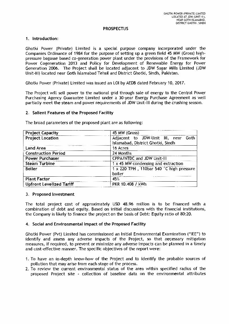
2. Salient Features of the Proposed Facility
The broad parameters of the proposed plant are as following:
Project Capacity 45 MW(Gross)Project Location Adjacent to JDW-Unit III, near Goth
Islamabad, District Ghotki, SindhLand Area 16 AcresConstruction Period 24 MonthsPower Purchaser CPPA/NTDCand JDW Unit-IIISteam Turbine 1 x 45 MWcondensing and extractionBoiler 1 x 220 TPH , 110bar 540 0 C high pressure
boilerPlant Factor 45%Upfront Levelized Tariff PKR10.408 I kWh
3. Proposed Investment
The total project cost of approximately USD 48.96 million is to be financed with acombination of debt and equity. Based on initial discussions with the financial institutions,the Company is likely to finance the project on the basis of Debt: Equity ratio of 80:20.
4. Social and Env;ronmentallmpact of the Proposed Facility
Ghotki Power (Pvt) Limited has commissioned an Initial Environmental Examination ("lEE") toidentify and assess any adverse impacts of the Project, so that necessary mitigationmeasures, if required, to prevent or minimize any adverse impacts can be planned in a timelyand cost-effective manner. The specific objectives of the report were:
1. To have an in-depth know-how of the Project and to identify the probable sources ofpollution that may arise from each stage of the process.
2. To review the current environmental status of the area within specified radius of theproposed Project site - collection of baseline data on the environmental attributes

GHOTKI POWER (PRIVATE) LIMITEDLOCATED AT JDW (UNIT-III),
NEAR GOTH ISLAMABAD,DISTRICT GHOTKI, SINDH
including air, noise, water, land, ecological, hydro-geological climate and socioeconomicenvi ronments.
3. To assess likely or potential environmental impacts of the proposed activity (like air, waterand soil pollution, noise, waste generation) and the alternatives.
4. To estimate the impacts of the proposed Project on the surrounding environment.5. To prepare a comprehensive Environmental Management Plan to ensure that the
environmental quality of the area is preserved.6. To formulate a strategy for effective monitoring and identify any deviations in the
environmental quality after the project is operational, which would help in evolvingmeasures to counter these.
7. The lEE is to be undertaken pursuant to the Pakistan Environmental Protection Act 1997,the Sindh Environmental Protection Act 2014.
Further details are also provided in Annex-13 of the application.

GHOTKI POWER (PRIVATE) LIMITEDLOCATED AT JDW (UNIT·III),
NEAR GOTH ISLAMABAD,DISTRICT GHOTKI, SINDH
Annexure - 15

GHOTKI POWER (PRIVATE) LIMITEDLOCATED AT JDW (UNIT-III),
NEAR GOTH ISLAMABAD,DISTRICT GHOTKI, SINDH
Table of Contents
1 Project Background 312 Power Market 31
2.1 Structure of Power Sector in Pakistan 312.2 Electricity Generation 322.3 Demand and Supply of Electricity 342.4 Key Organizations 35
2.4.1 National Electric Power Regulatory Authority ("NEPRA") 352.4.2 Private Power and Infrastructure Board ("PPIB") 352.4.3 Alternate Energy Development Board ("AEDB") 352.4.4 Central Power Purchasing Authority Guarantee Limited ("CPPA-G") 352.4.5 Sukkur Electric Supply Company ("SEPCO") 36
3 Applicable Framework & Policy 364 Cogeneration 36
4.1 Bagasse Based Cogeneration 365 The Project _.. 37
5.1 Project Site and Location 376 Plant Type and Technology 38
6.1 General Design 386.2 Technology 39
7 Design and Specifications of the Plant 397.1 Bagasse Fired Boiler 397.2 Steam Turbine and Auxiliaries 40
7.2.1 Steam Turbine 407.2.2 Gear Box 417.2.3 Couplings 417.2.4 Condensing System 41
7.3 AC Generator 417.3.1 Generator Protection and Control System: 42
7.4 Governing System 427.5 Lubrication and Control System _.. 427.6 Control Oil System 427.7 Main Cooling Water Pumps 43
7.7.1 Main Cooling Water Pumps 437.7.2 Auxiliary Cooling Water Pumps 437.7.3 Cooling Tower System 43
7.8 Raw Water System 437.8.1 Cooling Water Makeup Pump 437.8.2 Raw Water Transfer Pumps 44
7.9 Compressed Air System 447.10 Bagasse Handling System 447.11 Ash Handling System 44
7.11.1 Submerged Ash Belt Handling System 147.11.2 Dense Phase Ash Handling System 15
7.12 Water Treatment System _ 457.13 Firefighting System _ 45
7.13.1 Stand Pipe and Hose System: _.45

GHOTKI POWER (PRIVATE) LIMITEDLOCATED AT JDW (UNIT·III),
NEAR GOTH ISLAMABAD,DISTRICT GHOTKI, SINDH
7.13.2 Fire Hydrant and Water Monitoring System 457.13.3 Portable Fire Extinguishers: 457.13.4 Automatic High Velocity Water Spray Nozzle System: 457.13.5 Fire Alarm & Detection System 45
7.14 Effluent Handling System 467.14.1 Neutralizing Pit 467.14.2 Neutralized Effluent Re-circulation cum Transfer Pumps 467.14.3 Effluent Pit 467.14.4 Effluent Transfer Pump 46
7.15 Service Water System 467.16 Electric Overhead Travelling (EOT) Cranes 46
8 Electrical Design 478.1 Electrical Network 47
8.1.1 Ambient Conditions for Electrical Equipment 478.2 Plant Operating Voltage 488.3 Basic Electrical Design Parameters 488.4 132kV Switchyard 498.5 Steam Generator 508.6 Segregated Phase Bus Duct 508.7 11kV Switchboard 518.8 400 V Switchboard 518.9 Transformers 518.10 AC & DC UPS System 518.11 Control Philosophy & Interfacing 528.12 Energy Management System 528.13 RTDs & Thermistors 528.14 System Earthing 528.15 Cable Installation 538.16 Cable Trench 538.17 Lighting & Small Power 538.18 Plant Communication System 538.19 Enclosure Ratings 548.20 Plant Startup 548.21 Instrumentation and Control (I&C) Systems 548.22 Digital Control System (DCS) 558.23 Field Instrumentation 55
9 Grid Interconnection 5610 Environmental Impact Assessment 5711 Operations and Maintenance (O&M) 63
11.1 Periodic Maintenance 6412 Key Operating Assumptions 64
12.1 Plant Generation Parameters 6412.2 Project Timeline 6512.3 Project Life 6512.4 Project Cost 6512.5 Project Financing 6612.6 Project Tariff 6612.7 Project Revenue 6812.8 General 6812.9 Projected Financial Statements 68

GHOTKI POWER (PRIVATE) LIMITEDLOCATED AT JDW (UNIT-III),
NEAR GOTH ISLAMABAD,DISTRICT GHOTKI, SINDH
12.10 Projected Income Statement 6912.11 Projected Balance Sheet 7012.12 Projected Cash Flows 7112.13 Financial I Economic Analysis 72
13 Annexure-1: Plant Layout 7314 Annexure- 2: HMBD Diagram 7415 Annexure-3: Water Balance Diagram 7516 Annexure-4: Sketch-1 _ 7617 Annexure-5: Sketch-2 _ 77

GHOTKI POWER (PRIVATE) LIMITEDLOCATED AT JDW (UNIT-III),
NEAR GOTH ISLAMABAD,DISTRICT GHOTKI, SINDH
1 Project Background
Ghotki Power (Private) Limited ("GPL") is a special purpose company incorporated under theCompanies Ordinance of 1984 for the purpose of setting up a green field 45 MW (Gross) high-pressure bagasse based co-generation power plant ("the Project") under the provisions ofthe Framework for Power Cogeneration 2013 ("Framework") and Policy for Development ofRenewable Energy for Power Generation 2006 ("RE Policy" or "Policy"). The Project shallbe located adjacent to JDW Sugar Mills Limited (JDW Unit-III") located near Goth IslamabadTehsil and District Ghotki, Sindh, Pakistan. JDW Unit-III is engaged in the manufacturing/saleof sugar and it operates as one of the modern sugar mills in the country with adequatecrushing capacity to generate approximately 71.35 MW power by development of PowerPlants based on High Pressure boiler technology. JDW Unit-III has already been operating andmaintaining a 26.35 MW power plant with 67 bar boiler and is smoothly supplying electricityto the national grid since 2014.
The Project will sell power to the national grid through sale of energy to the Central PowerPurchasing Agency Guarantee Limited ("CPPA-G") under a 30-year Energy PurchaseAgreement ("EPA") as well partially meet the steam and power requirements of JDW Unit-IIIduring the crushing season. The Project will enable GPL to play its role in the provision ofmuch-need indigenous and renewable energy to the national grid and shall continue theprocess of diversification of its sponsor into the power sector through incentives offered bythe Government of Pakistan ("GoP") under the Framework and RE Policy.
The objective of this feasibility study ("Feasibility") is to assist GPL in assessing the technicaland financial viability of the Project.
2. Power Market
2..1 ucture of Power
Historically, the power sector in Pakistan has been owned and operated by governmententities, primarily the Water and Power Development Authority ("WAPDA") until the drive tounbundle started in the early 1990s. Since then the sector has evolved much with privatesector involvement primarily in generation and more recently on the model of a fullyvertically integrated utility company. The generation, transmission, distribution and retailsupply of electricity in Pakistan is presently undertaken by a number of public and privatesector entities cornpristng of one (1) national transmission company; nine (9) regional publicsector-owned distribution companies; four (4) public sector thermal generation companies;one (1) public sector hydropower generation company and several Independent PowerProducers ("IPPs"). These entities enable the supply of power to the entire country exceptfor Karachi. The metropolitan city of Karachi and some of its surrounding areas are suppliedpower K-Electric, which is a vertically integrated utility owned by the private sectorresponsible for the generation, transmission and distribution of electricity in its region. Thetotal installed capacity of the entire country in 2015 was 24,823 MW of which 16,814 MW(67.74%) was thermal, 7,116 (28.67%) was hydroelectric, 787 MW (3.17%) was nuclear and106 MW (0.43%) was wind.
GHOTKI POWER (PRIVATE) LIMITEDLOCATED AT JDW (UNIT-III),
NEAR GOTH ISLAMABAD,DISTRICT GHOTKI, SINDH
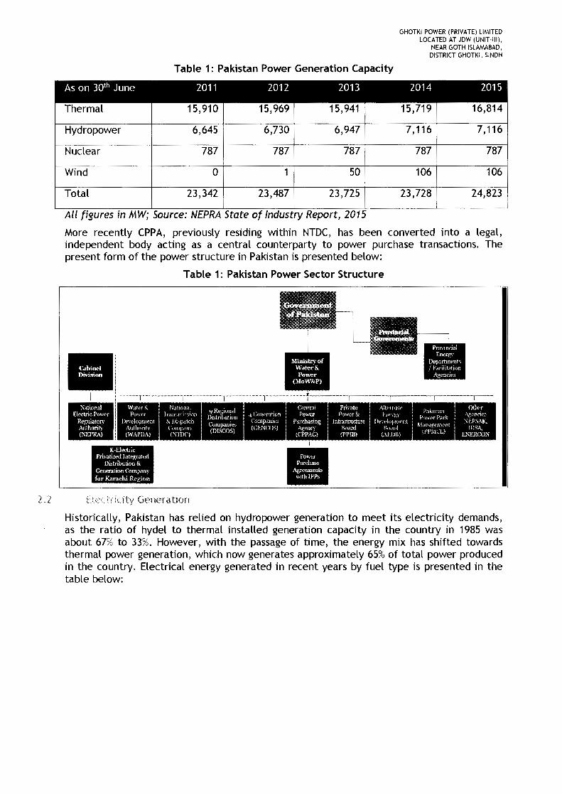
Table 1: Pakistan Power Generation Capacity
As on 30th June 2011 2012 2013 2014 2015I
Thermal 15,910 15,969 15,941 15,719 16,814
Hydropower 6,645 6,730 6,947 7,116 7,116
Nuclear 787 787 787 787 787
Wind 0 1 50 106 106
Total 23,342 23,487 23,725 23,728 24,823i
All figures In MW; Source: NEPRAState of Industry Report, 2015
More recently CPPA, previously residing within NTDC, has been converted into a legal,independent body acting as a central counterparty to power purchase transactions. Thepresent form of the power structure in Pakistan is presented below:
Table 1: Pakistan Power Sector Structure
\Vatt'r '\: NationalPO\\('x i Tr.rru.rui sion
[)(>\e!oplllent' ,\ liispatchAuthoritv {·tltlip.lrJ\
(WAPD_-\) (~rlllC)
K-E1ertricPrivatized Integrated
Distribution &Generation Companyfor Karachi Region
2.2 Electricity Generation
Historically, Pakistan has relied on hydropower generation to meet its electricity demands,as the ratio of hydel to thermal installed generation capacity in the country in 1985 wasabout 67% to 33%. However, with the passage of time, the energy mix has shifted towardsthermal power generation, which now generates approximately 65% of total power producedin the country. Electrical energy generated in recent years by fuel type is presented in thetable below:

GHOTKI POWER (PRIVATE) LIMITEDLOCATED AT JDW (UNIT·tll),
NEAR GOTH ISLAMABAD,DISTRICT GHOTKI, SINDH
Table 2: Pakistan Energy Generation by Source
As on 30th June 2010-11 2011-12 2012-13 2013-14 2013-14
Thermal 65,169 64,478 64,034 68,082 69,988
% Share 64.79 65.94 64.91 64.41 64.17
Hydel 31,990 28,643 30,033 32,239 32,979
% Share 31.80 28.85 30.44 30.50 30.24
Nuclear 3,220 4,872 4,181 4,695 5,349
% Share 3.11 4.91 4.24 4.44 4.90
Import 295 296 375 419 443
% Share 0.29 0.30 0.38 0.40 0.41
Wind 0 6 32 453 300
% Share 0.00 0.01 0.03 0.25 0.27
Total 100,584 99,295 98,655 105,698 109,059
All [igures In GWh; Source: NEPRAState of Industry Report, 2015
Given the acute gas shortage in the country, thermal generation has relied mostly onexpensive fuels such as Furnace Oil and High Speed Diesel. Increased dependence onexpensive thermal fuel sources has not only led to high cost of generation but has alsoresulted in large amounts of foreign reserves to be spent on the import of fuel. Thermalgeneration breakdown in the country in recent years is given in the table below:
Table 3: Pakistan Energy Generation by Source (Thermal Fuel Mix)
2010-11 2011-12 2012-13 2013-14 2014-15
Gas 37,076 30,162 28,190 30,769 31,196
% share of thermal generation 56.89 46.06 44.02 45.19 44.57
Fa + HSD 27,984 35,250 35,804 37,201 38,690
% share of thermal generation 42.94 53.83 55.91 54.64 55.28
Coal 109 66 40 112 102
% share of thermal generation 0.17 0.10 0.06 0.16 0.15
Total 65,169 65,478 64,034 68,082 69,988
All fIgures In GWh; Source: PSSINTDCIKEL
Due to this skewed energy mix, it has now become imperative upon the power sector inPakistan to move towards generation technologies that are sustainable and rely onindigenous resources.

GHOTKI POWER (PRIVATE) LIMITEDLOCATED AT JDW (UNIT-III),
NEAR GOTH ISLAMABAD,DISTRICT GHOTKI, SINDH
L2_3.4.5.
Demand and Supply of Electncitv
For the past decade or so, Pakistan has been suffering from an acute energy crisis due torising demand exacerbated by structural flaws within the sector. Some of the major reasonscontributing to this crisis include:
Inefficient transmission and distributionIncreasing demandInefficient use of energyExpensive energy mix andImproper pricing.
Installed capacity in the country grew at an average rate of 5.51% during the period 1990-2015. However, this increase in capacity has been unable to meet the demand of electricityleading to a demand-supply gap, which can go as high as 6,600 MW during peak hours. In2015, the maximum generation capability remained at 19,132 MW, while the maximum peakdemand reached 24,757 MW, resulting in a 5,625 MW gap between supply and demand.Projections by government agencies depict that this shortfall is not going to end till 2018_The tables below show the actual and projected surplus/deficit in demand during systempeak hours:
Table 4: Pakistan Historical Supply and Demand of Power
Year Generation Capacity Peak Demand Surplus/ (Deficit)
2011 15,430 21,086 -5,656
2012 14,483 21,536 -7,053
2013 16,846 21,605 -4,759
2014 18,771 23,505 -4,734
2015 19,132 24,757 -5,625
All figures In MW; Source: NTDC
Table 5: Pakistan Projected Supply and Demand of Power
Year Planned Generation Projected Peak Surplus/ (Deficit)Demand
2016 20,303 25,666 -5,363
2017 23,445 27,185 -3,740
2018 28,751 28,678 73
2019 33,545 30,154 3,391
2020 35,590 31,625 3,965
Source: NTDC
Shortage of electricity has become the most critical challenge by not only causing socialdisruption, but also affecting the economic growth of the country. According to estimates,
GHOTKI POWER (PRIVATE) LIMITEDLOCATED AT JDW (UNIT-III),
NEAR GOTH ISLAMABAD,DISTRICT GHOTKI, SINDH
energy shortages in the country have resulted in approximately 2% reduction in the annualGDPof the country. Therefore, resolving the energy crisis is amongst the top priorities of thegovernment and steps are being taken to attract new investment in the power sector.Moreover, steps are being taken to optimize the generation mix by adding renewable andindigenous energy sources.
2,4 Key Organizations
2.4.1 National Electric Power Regulatory Authority ("NEPRA")
In order to promote fair competition in the industry and to protect the rights of consumers aswell as producers/sellers of electricity, the GOP enacted the Regulation of Generation,Transmission and Distribution of Electric Power Regulation Act, 1997 ("NEPRA Act"). Underthis Act, the NEPRA Policy for Power Generation Projects was established for regulatingelectric power generation, transmission and distribution in Pakistan. In performing itsfunctions under this Act, NEPRAis required to, as far as reasonably possible, protect theinterests of consumers and companies providing electric power services in accordance withthe guidelines laid down by the government. One of NEPRA's most prominent roles is tariffapproval for the Project.
NEPRA's role in the power business, inter alia, is to issue licenses for companies and toregulate their operations according to NEPRA rules and regulations. The prospectiveapplicants will be required to comply with all NEPRArules/procedures, inter alia, for grantof license before security agreements are concluded for any project.
2.4.2 Private Power and Infrastructure Board ("PPIB")
PPIB provides a one-window facility to IPPs for implementation of projects above 50 MWcapacity and issues the Letter of Interest ("LOI") and Letter of Support ("LOS"), preparespre-qualification and bid documents, pre-qualifies the sponsors, evaluates the bids of pre-qualified sponsors, assists the sponsors/project companies in seeking necessary consents /permissions from various governmental agencies, carries out negotiations on theImplementation Agreement ("IA"), assists the power purchaser, fuel supplier, governmentauthorities in the negotiations, execution and administration of the EPA, fuel supplyagreement and water use license respectively, issues and administers the GOP guaranteebacking up the power purchaser, fuel supplier and follows up on implementation andmonitoring of projects.
2.4.3 Alternate Energy Development Board ("AEDB")
AEDB has been designated as one-window facility for processing all alternative andrenewable energy projects in the private sector projects such as wind, biodiesel,bagasse/biomass/waste to energy, small/mini/micro hydro and solar power projects. AEDBalso issues bankable lA, EPA, LOI and LOSto alternative energy producers. AEDBshall be therelevant GoP facilitation agency for the issuance of the LOI and LOS as well negotiation ofthe IA and provision of the GoP guarantee as applicable for the Project.
2.4.4 Central Power Purchasing Authority Guarantee Limited ("CPPA-G")
CPPA-G, a company created by Government of Pakistan, is a non-profit independentcompany established under the Companies Ordinance, 1984 and solely responsible forimplementing and administering the "Single Buyer Plus" market mechanism (ultimatelyleading to competitive market operations). CPPA-Gpurchases power on behalf of DistributionCompanies ("DISCOS") from IPPs. The Project shall be entering into negotiations with CPPA-G for the sale of energy to the national grid and shall enter into an EPAin this regard.
GHOTKI POWER (PRIVATE) LIMITEDLOCATED AT JDW (UNIT-III).
NEAR GOTH ISLAMABAD.DISTRICT GHOTKI. SINDH
2.4.5 Sukkur ELectric SuppLy Company ("SEPCO")
The distribution company SEPCO (Sukkur Electric Power Company) has been formed bybifurcating Hyderabad electric suppLy company (HESCO) so that the areas of operation thatwere entirely under the jurisdiction of SEPCO have now been divided between the twoDISCOs. SEPCOis a newLy created company and started functioning with effect from 16-08-2010. SEPCO has surrendered its historicaL Limits which now faLL under the jurisdiction ofSEPCO. The areas that are now under the distribution system of the SEPCOconsist of threeoperation circles nameLy, Sukkur, Larkana and Dadu.
3 Applicable Framework (t Policy
The Project is being set up under the Framework for Power Cogeneration 2013 pursuant tothe Policy for DeveLopment of RenewabLe Energy for Power Generation 2006 beingadministered by the AEDB. Under the terms of the Framework and Policy, electricitypurchase by the CPPA-G from bagasse-based projects has been made mandatory.
The conditions of the Framework/Policy envisage JDW Unit-IIIIGPL seeking an LOI from AEDBfor the Project which has already been issued to the company on 10th Feb 2017. In May 2013,NEPRAannounced an upfront tariff ("Upfront Tariff") for high-pressure boiler based bagasseprojects being set up under the Framework. The Upfront Tariff has subsequently beenextended up to May 2017 - proceedings are underway by NEPRA for a new upfront BagasseTariff. The Company shall appLy for applicabLe tariff in vogue upon compLetion of pre-requisites.
Upon receipt of the Upfront Tariff approval from NEPRA the Project Company shall seek anLOS from AEDB; following which the Company shall enter into negotiations of the EPA and IAwith CPPA-G and AEDB respectively, which shall be followed by the financial close of theProject. Under the terms of the Upfront Tariff (and LOS) the Company is required to achievethe commerciaL operations date of the Project within 24 months from date of approvaL of theUpfront Tariff for the Company.
In paraLLel, the Company shall also apply to NEPRAfor the issuance of the Generation Licensefor the Project. The application for the Generation License shall be made following theissuance of the LOI and will be issued, amongst others, after submission of an approved gridinterconnection study from SEPCOand an environmental study from the relevant authority.
11 Cogenera tion
<1.1 13dgassc Based Cogeneration
Cogeneration refers to generation of electricity and usefuL heat from use of a singLe fuel athigh efficiency. Cogeneration is a weLL-known process in sugar industry as every sugar millrequires steam for sugar manufacturing while suppLy of eLectricity is also necessary tooperate machinery. The steam provides thermal energy which is used in heating andconcentrating the juice into syrup. This process of juice concentration to syrup involves theevaporation of water in the juice by using low pressure steam as the heating medium. Withthe large quantum of low pressure steam usage, the sugar industry stands as an idealcandidate for cogeneration. Historically, most sugar mill boilers and the power houses weredesigned primarily to meet the process steam and electricity requirements of the sugar mill.Therefore, the boilers and turbo-generators employed are mostLy of low pressure and lowtemperature styLe.

GHOTKI POWER (PRIVATE) LIMITEDLOCATED AT JDW (UNIT-III),
NEAR GOTH ISLAMABAD,DISTRICT GHOTKI, SINDH
There has been, of late, increasing awareness of the advantages of installation of highpressure, high efficiency bagasse based systems. With installation of high pressure boilersand separate investment in steam economy of the sugar mill, electricity over and aboveinternal use can also be produced and sold to national grid. Exports of electricity can makecogeneration an attractive and cost-efficient means of cutting production costs, reducingpollution and generating additional revenues depending on the ratio between the price ofelectricity secured and production cost of electricity generated in the sugar industry.
5 The Project
The Project comprises the installation of a high pressure cogeneration power plantcomprising of one high pressure (110 bar) traveling grate boiler, having a steam generationcapacity of 220 tons per hour, with other electro-mechanical equipment along with civilworks as balance of the plant ("Plant") and one condensing/extraction steam turbinegenerator having a capacity of 45 MW. It is planned that, during the crushing period steamand power for JDW Unit-III operations will be partially provided from the existing 67 bar highpressure system and the balance steam/power requirement of JDW Unit-III will be metthrough the 110 bar high pressure system of the Plant. During the crushing period, bagassefrom JDW Unit-III will be utilized both in the 67 and 110 bar systems to generate steam andpower. During the off-season either only 110 bar plant or both the 67 and 110 bar plant shalloperate, using the saved bagasse available with JDW Unit-III as well as procured bagassefrom other sugar mills as and when available.
5.1 Pi ecrSite and Location
The Project Site is adjacent to JDW Sugar Mills Limited Unit-III located near Goth IslamabadTehsil and District Ghotki, Sindh.

GHOTKI POWER (PRIVATE) LIMITEDLOCATED AT JDW (UNIT-III),
NEAR GOTH ISLAMABAD,DISTRICT GHOTKI, SINDH
The location map of the Project site map is given below and Project Layout has beenattached as Annexure 1:
The design of the Facility is typical for a biomass-fired cogeneration facility which also isspecific to the use of bagasse and to the cogeneration requirements.
The boilers will consist of tall water wall furnace with platen generators located at the topof the furnace. The super heater will have three stages. The first stage is a horizontal tubeconvective super heater located in the boiler second pass. The second stage consists ofplatens located at the top of the furnace adjacent to the generator section. The third stageconsists of pendants located above the furnace arch between the second and first stages.Following the super heater will be three horizontal tube economizer sections and fourtubular air heater sections.
The steam cycle consists of two high pressure feed water heaters and a Deaerator for eachunit. The high pressure feed water heaters take steam from the two uncontrolled extractionsof the steam turbine. Steam for the Deaerator is to be supplied from the controlledextraction of the steam turbine.
The Facility has two modes of operation defined by steam needs of JDW Unit-III. During thecrushing season, JDW Unit-III needs steam and electricity to crush the sugar cane andproduce sugar. Steam for JDW Unit-III will be supplied from the controlled extraction of thesteam turbine which is at approximately 2.5 bar (ab) pressure. The expected steam demand

GHOTKI POWER (PRIVATE) LIMITEDLOCATED AT JDW (UNIT·III),
NEAR GOTH ISLAMABAD,DISTRICT GHOTKI, SINDH
for JDW Unit-III is 155 TPH from Cogeneration High Pressure Power Plant. Total electricitydemand of sugar mill during the crushing season is 15 MW which will be supplied fromCogeneration High Pressure Power Plants. During the off-season, the electricity demand is0.5MW.
(;.2 'Technology
Combustion technology based on the Rankine Cycle will be utilized in this project which isproven latest technology. The bagasse will be combusted in a high pressure boiler and thesteam generated will be fed to the steam turbine to generate power. The turbine will bedifferent from the conventional thermal power plants as the turbine will be provided with acontrolled extraction for extracting the process steam required for the sugar mill. Toenhance the efficiency of operation, regenerative heaters are used in the feed water circuit.For the cogeneration power plant proposed for GPL, the cogeneration cycle is based on theparameters of 110 bar(a) and 540 degrees centigrade at the boiler outlet, currently beingused in many countries for the cogeneration projects. The cycle chosen with the aboveparameters is the latest used in many of the bagasse fired installations around the world.These above selected parameters make the cycle more efficient and help in the generationof more units for the same quantum of the fuel.
There are already many Cogeneration plants operating in Pakistan & India with theseparameters and the operating experience of those plants, in synchronization with the sugarmill operation, has been smooth and without any hitch. The Cogeneration scheme for GPLproposes 1x220 TPH capacity boiler and 1x45 MW extraction condensing turbo generators.Considering the offseason operation of the plant, the Cogeneration power plant boilers willbe designed to fire a few other compatible bio-mass fuels.
Design and Specifications Plant
7.1 Fired Boiler
The Boiler shall be single drum, natural circulation, radiant furnace with water cooledmembrane wall, three stage super-heater with two stage attemperator, balanced draft andtravelling grate bagasse fired boiler. The boiler is capable of a peak generation of 110% ofthe MCR for a period of half an hour in eight hour shift. The boiler shall be top supported,outdoor type, with adequate provisions for the thermal expansion of the boilers in alldirections.
Design Parameters:
• Bagasse Fired Boiler; 220 TPH• Steam pressure at the Main Steam stop valve outlet: 110 bar(a)• Steam temperature at the Main steam stop valve outlet at MCR: 540 ± 5 °c• Boiler feed water temperature at the inlet to the Deaerator: 110 0(.
• Maximum noise level at 1.0 m distance for the boiler: 85 dB(A)
The Bagasse through drum feeders, screw feeders and pneumatic spreaders will be fed intothe furnace. The travelling grate is selected for efficient combustion system and to avoidheating of grates. The Ash is collected by the continuous movement of travelling grate.
GHOTKI POWER (PRIVATE) LIMITEDLOCATED AT JDW (UNIT-Illj.
NEAR GOTH ISLAMABAD,DISTRICT GHOTKI, SINDH
The air will be supplied by primary Forced Draft (FD) fans & secondary air fans. The airtowards Bagasse will be controlled by the fuel air control system in order to guarantee safeand optimum combustion. The air supplied from FD fan will be heated up in air pre-heater.The pressure in the furnace will be controlled by the Induced Draft (ID) fans installed atoutlet of boiler. These fans will be provided with Variable Frequency Drive (VFD) in order tooptimize the power consumption. ID fans will discharge flue gases.
After complete combustion in furnace the flue gases shall enter the super heater sectioninstalled in the upper portion of the furnace. From the super heaters the flue gases will flowdownwards into modular bank. The evaporator section of the boiler will be designed for alarge circulation ratio. Even during quick plant load changes the water circulation will bestable and thus prevent steam blockage in the evaporator sections.
From evaporator section, the flue gas shall enter the bare tube economizer from the top andleave at the bottom to Air Flue Gas Pre-heater. The economizer tubes will be supported inthe structure of the economizer casing and will be bottom supported. The economizer willbe fully drainable.
Thereafter, the Fly Ash Arrestor installed at the outlet of the Air Pre-heater. From Fly AshArrestor most of the fly ash will be separated from the flue gases.
The condensate from the sugar mill shall be directly fed into the condensate tank fromwhere it will be pumped to the Deaerator via sugar plant exhaust condensate pumps througha level control system.
Demineralized (DM) water will be supplied to the boiler for makeup. The makeup water willbe pumped to the overhead surge tank via DM water distribution pumps. The makeup waterwill be added in the condenser hot well from the overhead surge tank by gravity through alevel control system. The condensate from the condenser and makeup water added to thecondenser hot well will be pumped to the Deaerator by condensate extraction pumps.
4 x 42% Boiler Feed Water (BFW) pumps shall be provided. BFW pumps are multistage,centrifugal type with low voltage 400V drive motors with Variable Frequency Drives (VFDs).The condensate and make-up water lines will have level control valve to control Deaeratorlevel.
The control philosophy, boilers interlock and protection logic shall be implemented inDistributed Control System (DCS) for safe operation of boiler.
7,( Stcdrn Turbine and Auxiliaries
7.2.1 Steam Turbine
The turbine of the cogeneration power plant will be multistage nozzle governed, horizontalspindle, two bearings, and extraction cum condensing type with 02 number of uncontrolledextractions and 01 number of control extractions. The exhaust from the turbine will becondensed in the surface condenser at 0.101 bar (a) pressure during off-season operation.The Medium pressure steam at 4 Bar(a) and low pressure steam at 2.5 bar (a), will besupplied to the sugar plant. 98% condensate of the supplied Low Pressure steam will bereturned from the sugar mill.
GHOTKI POWER (PRIVATE) LIMITEDLOCATED AT JDW (UNIT·III).
NEAR GOTH ISLAMABAD,DISTRICT GHOTKI, SINDH
7.2.2 Gear Box
Heavy duty reduction gear box of Double helical type with hardened & ground gears will beinstalled, capable of transmitting maximum power generated by turbine and able towithstand 20%over speed over a period of minimum 5 minutes.
The gear box will be designed with a service factor of 1.3 as per AGMA requirements.
7.2.3 Couplings
High speed coupling between the turbine & the gear box will be non-lubricating, steellaminated, flexible type. The coupling between the gear box and the alternator will be lowspeed. Both the couplings will have coupling guards and acoustic covers. Power rating of thecouplings shall be in accordance with AGMA 514
7.2.4 Condensing System
Condensing system shall comprise of the following:
• Shell & Tube horizontal type surface condenser with integral hot well, thermal reliefvalve and atmospheric relief valve.
• Steam Ejector system consisting of:• Twin stage main ejectors (1 working + 1 standby) with two surface type inter and
after condensers.
• Startup hogging type ejector with silencer.
• Vertical canister type Condensate extraction pumps (CEP's), with a 3 x 50%capacitywith LT motors and suction valves.
• Rupture disc for condenser protection.
• Expansion bellow with spool piece between turbine exhaust and condenser inlet
• Dry air Ivapor line within specified battery limit
7.3 ;\C Generator
AC Generator shall comprise of the following:
• Brush-less exciter with PMG
• Air coolers
• Twin bearings
• AVR cum Excitation panel
• Anti-condensation heaters
• Water leakage detector- 1 per cooler
• Lube oil flow regulator - 1 per bearing
Generator electrical output rating shall be as follow:
• [56.25] MVA rated capacity at [50),C ambient.
• [11]±[10]%KV
• [50] ± [5]% Hz

GHOTKI POWER (PRIVATE) LIMITEDLOCATED AT JDW (UNIT·llll,
NEAR GOTH ISLAMABAD,DISTRICT GHOTKI, SINDH
• 3 Phase• Power factor ([0.8] lag to [0.95] lead)
• ± [0.5]% Accuracy Control for Excitation system
7.3.1 Generator Protection and Control System:
Generation protection and control system will consist of the following equipment:
• Generator protection (Relay) Panel
• Metering & Synchronizing Panel
• MCC Panel
• Lightning arrestor, Surge capacitor and Potential transformer (LA, SC & PT) Panel
• Neutral grounding resistor (NGR) Panel
• DC Distribution
/,.4 Governing System
The governor system provided will control the acceleration of the turbo generator andprevent over speed without tripping the unit under any operating condition or in the event ofmaximum load rejection.
The governor system will have the following important functions:
• Speed control
• Over speed control
• Load control
• Inlet steam pressure control
• Extraction pressure control
7.. Lubrication and Control
A single forced feed lubrication system will be installed for Turbine, Gearbox & Alternatorcomprising of the following major components:
• Lube oil tank
• Oil Vapor extractor
• AC Electric Main Oil Pump (MOP) driven by gearbox low speed shaft
• AC electric Motor driven Auxiliary Oil Pump (AOP)
• DC Motor driven Emergency lube Oil Pump (EOP) with auto cut-in & cut-out facility
• Lube oil coolers (1working + 1 standby)
• Lube oil filters (1working + 1 standby)
• AC motor driven oil mist separator mounted on oil tank
/',6 Control on System
Control oil system will comprise of the following:

GHOTKI POWER (PRIVATE) LIMITEDLOCATED AT JDW (UNIT-III),
NEAR GOTH ISLAMABAD,DISTRICT GHOTKI, SINDH
• AC electric Motor driven Auxiliary Control Oil Pump (ACOP) (1 working + 1 standby) tosupply oil to Control system.
• Control Oil filter (COF) (1 working + 1 standby)
7.7 Main Cooling Water Pumps
The cooling water system shall be designed to provide cooling water to the following area ofthe plant:
• Surface Condenser• Auxiliary cooling water coolers
The cooling water system includes the following major components:
7.7.1 Main Cooling Water Pumps
Three (3) Main Cooling Water Pumps (two working and one standby) each of capacityapproximately 3200 m3/hr shall be provided. Pumps will be horizontal centrifugal type,driven by electric motors.
7.7.2 Auxiliary Cooling Water Pumps
Two (2) Auxiliary Cooling Water Pump (One working and one standby) will be provided.Pumps will be horizontal centrifugal type driven by electric motors.
7.7.3 Cooling Tower System
The Cooling Tower System shall have the following specifications:
• One (1) R.C.C structure mechanically induced draft, counter flow type cooling tower• Capacity of cooling tower will be approximately 10,500 m3/hr and is combined and
common for the whole cogeneration power plant.• There shall be 3 cells each having a capacity of approximately 3500 m3/hr.• The cooling tower will be designed for cooling of water from 41'C to 33'C, and an
approach of 5-6'C while operating under the atmospheric wet bulb temperature of about30C.• Each cell of cooling tower gear box will be equipped with vibration switches, oil
temperature and oil level controls.• The source of cooling water will be Bore Well Water.• Cooling water supply and return temperature is 33'C and 41'C respectively.
7.S System
Raw water system consists off the following components:
7.B.1 Cooling Water Makeup Pump
Two (2) Cooling Tower make up Water Pumps for season and off-season operation will beprovided.

GHOTKI POWER (PRIVATE) LIMITEDLOCATED AT JDW (UNIT·III),
NEAR GOTH ISLAMABAD,DISTRICT GHOTKI, SINDH
7.8.2 Raw Water Transfer Pumps
Two (2) Raw Water Transfer Pumps (one working and one standby) each of capacity 200m3/hr will be provided to ensure raw water supply to Water Treatment Plant.
7,9 Compressed Air System
The function of this system is to provide service and instrument air for cogeneration plantoperations. Compressed air system provides air to following users:
• Instrument Air Users: Instrument air will be required for the operation of pneumaticinstruments like I/P converters, purge instruments, pneumatic actuation of control valves,dampers etc.
• Service Air Users: Service air will be required for cleaning of filters, strainers andgeneral purpose.
The bagasse handling system comprising of chain conveyors & belt conveyors to transport therequired quantity of bagasse from sugar mill to cogeneration shall be provided. Bagasse fromthe sugar mill shall be fed to the boiler from a front mounted chain conveyor. Excess bagasseshall be returned to the bagasse storage yard. During off-season/non availability of bagassefrom mill, the cogeneration boiler shall use saved bagasse from the storage yard.
7.11 /\5h Handling System
7.11.1
The ash handling system envisaged for the cogeneration boiler shall consist of Submerged AshBelt Conveyor System and Dense Phase Ash Handling System.
Submerged Ash Belt Handling System
Submerged Ash Belt Handling System consists of conveyor belts, drive assembly, all type ofpulleys, all type of idlers, bearing assembly, inlet / outlet chutes, take-up assembly, troughassembly, support frames, cross over, walkway, structural safety switches, water inlet /outlet / drain nozzles etc. The bottom ash at the discharge of travelling grate shall beconveyed by submerged ash conveyor system.
The ash shall be quenched in the water trough of submerged ash conveyor before conveying.The submerged ash conveyor shall discharge the ash directly to a trolley mounted tractor forfurther disposal.
7.11.2 Dense Phase Ash Handling System
This system will handle fly ash from boiler ash hopper (other than traveling grate & plenumash hopper) and ESP hoppers. Surge hopper (water cooled for boiler ash hopper and non-water cooled for ESP hopper) arrangement shall be provided below the boiler and ESPhopper. Two air compressors with built in PLC control system and 1x100% air receiver shallbe provided near the dense phase equipment. The required conveying air for dense phaseash system will be supplied by these compressors through air receivers. The ash silo storagecapacity shall be enough to store 12 hours ash generation from both the boiler and ESPsystem.
GHOTKI POWER (PRIVATE) LIMITEDLOCATED AT JDW (UNIT-Illl,
NEAR GOTH ISLAMABAD,DISTRICT GHOTKI, SINDH
.1 \Vd [('1 Trea trnent System
The existing water treatment system at the existing 67 bar High Pressure Cogen Plant shallbe expanded as required to meet the requirements of the new 110 bar High PressureCogeneration plant.
7.13 Ftrefighting System
The function of fire-fighting system is to supply water to the main risk areas of thecogeneration power plant.
The fire protection system is required for early detection, containment and suppression offires. A comprehensive fire protection system shall be provided to meet the above objectiveand all statutory and insurance requirements of National Fire Protection Association (NFPA).
The fire-fighting system shall consist of the following:
Stand Pipe and Hose System:7.13.1
Stand pipe and hose system shall be provided to cover the building and structures of thecogeneration plant. The system shall be designed as per the NFPA 14.
Standpipe shall have a hose of 65mm diameter with connection to a large supply of water.The hose connection shall be not less than 0.9m or more than 1.5m above the floor.
7.13.2 Fire Hydrant and Water Monitoring System
The hydrant system shall be provided to cover all areas. The system shall be designed as perNFPA 24. The system shall consist of over ground hydrant mains laid in rings, isolation valves,and stand pipes with hydrant valves (outdoor). A Hydrant shall be placed after every 40m.
7.13.3 Portable Fire Extinguishers:
Dry Chemical Powder, C02 and foam type extinguisher system shall be provided. Theequipment shall be designed as per NFPA 10.
7.13.4 Automatic High Velocity Water Spray Nozzle System:
Automatic High Velocity Water Spray Nozzle System shall be provided along with delugevalve assembly for outdoor transformers in switchyard, generator & Turbine lube oil systemarea. The system shall be designed as per NFPA 15. The deluge valve assembly shall beULlFM listed.
7.13.5 Fire Alarm & Detection System
Fire detection system for the power plant will provide early detection of fire and raisealarm. A comprehensive fire protection system shall be planned to meet the above objectiveand meet all statutory and insurance requirements of National Fire Protection Association(NFPA). A multitude of systems will be provided to combat various types of fires in differentareas of the plant and all such systems for various areas shall form a part of a centralizedprotection system for the entire plant. Fire alarm system detection system shall be providedin following areas:
• Firm alarm and signaling in all electrical/instrumentation panel rooms in TG building
• Manual call points and Electric Horns in outdoor areas.
GHOTKI POWER (PRIVATE) LIMITEDLOCATED AT JDW (UNIT·llll,
NEAR GOTH ISLAMABAD,DISTRICT GHOTKI, SINDH
7.14 Effluent Handling System
Effluent handling system consists of the following main components:
7.14.1
7.14.2
7.14.3
7.14.4
Neutralizing Pit
Acid/caustic produced (if any) from Water Treatment Plant will be collected inneutralization pit. This effluent will be transferred to effluent pit after neutralization.
Neutralized Effluent Re-circulation cum Transfer Pumps
Two (2) Neutralized Effluent Re-circulation cum Transfer Pumps (One working & onestandby) shall be installed at Neutralization pit to transfer effluents from Neutralization pitto Effluent pit in water treatment plant area.
Effluent Pit
Effluents like Boiler blow down, cooling tower blow down, RO reject, MGF backwash, sidestream filter flushing, RO flushing, neutralized effluent from neutralization pit, etc. shall becollected in the separate effluent pit near Water Treatment Plant area.
Effluent Transfer Pump
Two (2) Effluent Transfer Pumps (One working and one standby) will be installed on Effluentpit to transfer effluents. The pumps will also be used to re-circulate the effluent with inNeutralization pit for effective neutralization. The pump capacity shall be minimum 100m'zhr.
7.15 Sef vlce Water System
7.16
Two (2) service water pumps (One working and one standby) will be installed to provideservice water to plant users. One (1) expansion vessel will be installed to keep service waterheader pressurized.
Overhead Travelling Cranes
EOT cranes shall be provided in the following buildings:
TG Hall
An Electrically operated EOT crane shall be provided for the erection and maintenancerequirements of turbo generator and its auxiliaries.
The main hook capacity shall be 90 Tons and suitable for lifting single heaviest component inTurbo Generator. The auxiliary hook lifting capacity shall be of 5 Tons. The crane travel willcover the entire length of the TG building. The crane shall be electrically operated, bridgetype and shall be designed and equipped for indoor operations complete with all accessories.The crane bridge shall consist of bridge girders each carrying a rail on which a wheeledtrolley is to run. Operation of crane shall be by pendant type push button station fromground level.
Workshop and Store
An Electrically operated EOT crane shall also be provided for routine maintenance activitiesand store material handling to be carried out in the building.
GHOTKI POWER (PRIVATE) LIMITEDLOCATED AT JDW (UNIT-III),
NEAR GOTH ISLAMABAD,DISTRICT GHOTKI, SINDH
The single hook crane capacity shall be 90 Tons. The crane travel will cover the entire lengthof maintenance bay of workshop. Operation of crane shall be by pendant type push buttonstation from ground level.
8.1 Electrical Network
The Plant shall consist of one generator and associated auxiliaries for smooth plantoperation. A synchronous alternator for the proposed co-generation power plant withgeneration at 11 kV will be connected to 132kV system through 11kV switchboard and step-up Power Transformers.
The connection between generator and 11kV switchboard shall be through 11kV phasesegregated Bus Duct and between 11kV switchboard and 11/132kV power transformer shallbe through 11kV HT XLPE cables.
The generator will operate in parallel with NTDC I DISCO National grid. A portion of thepower generated in the turbo-generator will meet the power requirements of theCogeneration plant auxiliary loads and the sugar plant loads through step down transformers.
The surplus power, after meeting the power requirement of cogeneration plant auxiliariesand sugar plant auxiliaries, shall be exported to the grid through 11/132kV powertransformer. There shall be total of 2 numbers of step-up power transformers (one working +
one standby) to meet N-1 condition of NTDC.
Entire power evacuation system and associated equipment shall be designed so as to exportthe entire power from cogeneration plant (total generation less auxiliary powerconsumption), when the sugar plant is not in operation.
All the existing sugar plant loads shall be fed through existing 11kV cogen switchboard.Proposed 11kV cogen switchboard shall be interconnected with the existing 11kV cogenswitchboard.
Proposed 11kV cogen switchboard and existing 11kV cogen switchboard shall beinterconnected through HT cables via reactor.
8.1 .1 Ambient Conditions for Electrical Equipment
Ambient conditions and design temperatures for electrical equipment are given in Table 7below:
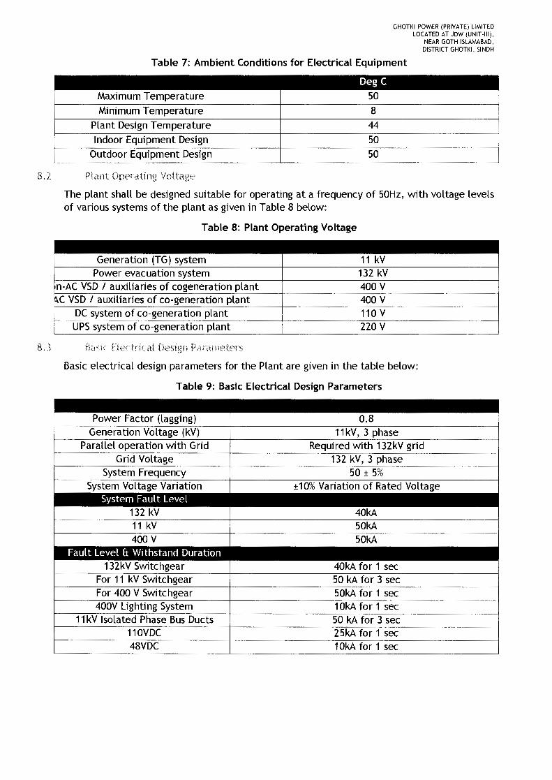
GHOTKI POWER (PRIVATE) LIMITEDLOCATED AT JDW (UNIT·III),
NEAR GOTH ISLAMABAD,DISTRICT GHOTKI, SINDH
Table 7: Ambient Conditions for Electrical Equipment
Deg CMaximum Temperature 50Minimum Temperature 8
Plant Design Temperature 44Indoor Equipment Design 50
Outdoor Equipment Design 50
8.2 Plant Operating Voltage
The plant shall be designed suitable for operating at a frequency of 50Hz, with voltage levelsof various systems of the plant as given in Table 8 below:
Table 8: Plant Operating Voltage
8. Basic Electrical Design Parameters
Basic electrical design parameters for the Plant are given in the table below:
Table 9: Basic Electrical Design Parameters
G Voltage
0.8Power Factor (lagging)Generation Voltage (kV) 11kV, 3 phase
Parallel operation with Grid Required with 132kV
System FrequencySystem Voltage Va on ±10% Variation of Rated Voltage
System Fault Level132 kV11 kV
40kA50kA
400 V 50kAFault Level & Withstand Duration
132kV Switchgear 40kA for 1 secFor 11 kV Switchgear 50 kA for 3 secFor 400 V Switchgear 50kA for 1 sec400V Lighting System 10kA for 1 sec
11kV Isolated Phase Bus Ducts 50 kA for 3 sec110VDC 25kA for 1 sec48VDC 10kA for 1 sec
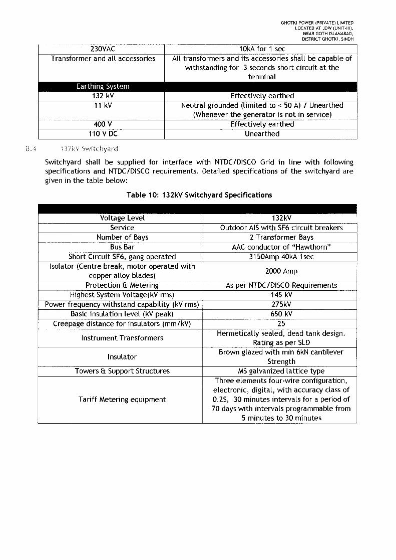
GHOTKI POWER (PRIVATE) LIMITEDLOCATED AT JDW (UNIT-III),
NEAR GOTH ISLAMABAD,DISTRICT GHOTKI, SINDH
230YAC 10kA for 1 sec
8A 132kV SV.fHchyard
Switchyard shall be supplied for interface with NTDC/DISCO Grid in line with followingspecifications and NTDC/DISCO requirements. Detailed specifications of the switchyard aregiven in the table below:
Table 10: 132kY Switchyard Specifications
Transformer and all accessories All transformers and its accessories shall be capable ofwithstanding for 3 seconds short circuit at the
terminalEarthing System
132 kY Effectively earthed11 kY Neutral grounded (limited to < 50 A) I Unearthed
(Whenever the generator is not in service)400 Y Effectively earthed
110 Y DC Unearthed
Short Circuit SF6, gang operated 3150Amp 40kA 1secIsolator (Centre break, motor operated with
copper alloy blades) 2000 Amp
Hermetically sealed, dead tank design.Rating as per SLD
Instrument Transformers
InsulatorBrown glazed with min 6kN cantilever
Strength
Three elements four-wire configuration,electronic, digital, with accuracy class of0.25, 30 minutes intervals for a period of70 days with intervals programmable from
5 minutes to 30 minutes
Tariff Metering equipment
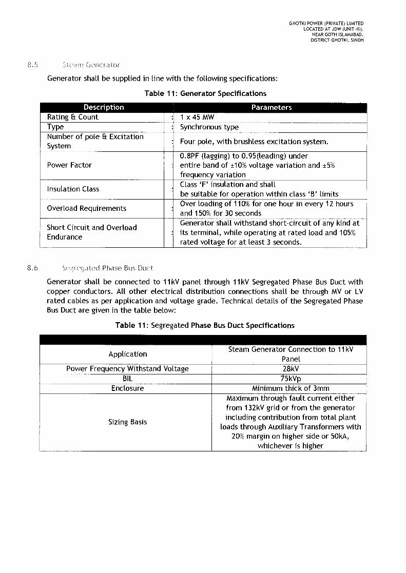
8.S Generator
GHOTKI POWER (PRIVATE) LIMITEDLOCATED AT JDW (UNIT-llll,
NEAR GOTH ISLAMABAD,DISTRICT GHOTKI, SINDH
Generator shall be supplied in line with the following specifications:
Table 11: Generator Specifications
pole & Excitation Four pole, with brushless excitation system.
Power Factor0.8PF (lagging) to 0.9S(leading) underentire band of ±10%voltage variation and ±S%frequency variation
Insulation Class Class 'F' insulation and shallbe suitable for operation within class 'B' limits
Overload Requirements Over loading of 110%for one hour in every 12 hoursand 1S0%for 30 seconds
Short Circuit and OverloadEndurance
Generator rt-circuit any atits terminal, while operating at rated load and 10S%rated voltage for at least 3 seconds.
8.6 Phase Bus
Generator shall be connected to 11kY panel through 11kY Segregated Phase Bus Duct withcopper conductors. All other electrical distribution connections shall be through MYor LYrated cables as per application and voltage grade. Technical details of the Segregated PhaseBus Duct are given in the table below:
Table 11: Segregated Phase Bus Duct Specifications
Application
Enclosure
Sizing Basis
Steam Generator Connection to 11Panel28kYSkYp
Minimum thick of 3mmMaximum through fault current eitherfrom 132kY grid or from the generatorincluding contribution from total plant
loads through Auxiliary Transformers with20%margin on higher side or SOkA,
whichever is higher

GHOTKI POWER (PRIVATE) LIMITEDLOCATED AT JDW (UNIT-III),
NEAR GOfH ISLAMABAD,DISTRICT GHOTKI, SINDH
8,7 11 kV Switchboard
11 kV switchgear shall be of indoor, metal clad, fully draw out truck type with vacuumcircuit breaker. The switchgear shall be suitable for maximum system voltage of 12 kV. Thepower frequency voltage of the board shall be 28kV and BIL of the panel shall be 75kV(peak). The circuit breakers and switchgear assembly shall withstand the rated short circuitcurrent for not less than three seconds. The breakers shall also be rated for peakasymmetrical current with a rating of 2.5 times symmetrical rated current. The switchboardshall have incomer, Tie, Bus coupler and outgoing feeders of rating (3150A/4000A)/3150A 12000A 1 1250A for distribution of power to cogen and sugar plant and power export.
[3,8 4()(J Switchboard
All the cogeneration plant auxiliary loads of proposed plant shall be segregated into ACVariable Speed Drive (AC VSD) driven loads and non-AC VSDdriven loads.
All AC VSD loads pertaining to cogeneration plant shall be connected to two (2) numbers of1110.415/0.415kV AC VSD transformer and non-VSD loads shall be connected to one (1)number of 11/0.415/0.415 kV AC VSD transformer. Both the VSD and non-VSD switchboardsshall be interconnected through tie ACB feeders. DG incomer shall be provided in the non -VSD switchboard to meet the plant emergency loads. These switchboards shall be designedfor 50 kA for 1 sec. The bus bar material of the panel shall be of copper.
8,. ; anstormers
Technical specifications of the different transformers to be installed in the Project are givenin the table below:
Table 12: Specifications of Transformers
Description ParametersGenerator transformer (GT) 1 Power 45/57.5MVA, 11kV1132kV, YNd1
TransformerVSDtransformers [Three winding transformer] 3 x 3.15 MVA, 11kV/0.415/0.415 kV,
for co-generation plant Dyn11DznOLighting Transformer 150kVA, 415V/400V, 50Hz, Dyn11,dry
type, Three Phase, Two WindingsNeutral Grounding Transformer ZnOwindings, 50A for 10Sec & 500A for
3Sec, 11KV, ONAN
UPS System
AC and DC UPS system will be supplied for loads that require un-interrupted power.Following UPS shall be supplied for this purpose:
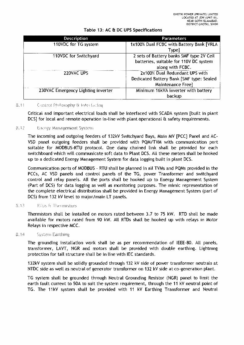
GHOTKI POWER (PRIVATE) LIMITEDLOCATED AT JDW (UNIT-III),
NEAR GOTH ISLAMABAD,DISTRICT GHOTKI, SINDH
Table 13: AC 6: DC UPS Specifications
Description Parameters110VDC for TG system 1x100% Dual FCBCwith Battery Bank [VRLA
Type]110VDC for Switchyard 2 sets of Battery banks SMFtype 2V Cell
batteries, suitable for 110V DC systemalong with FCB('
nOVAC UPS 2x100% Dual Redundant UPSwithDedicated Battery Bank [SMF type: Sealed
Maintenance Free]230VAC Emergency Lighting inverter Minimum 16kVA inverter with battery
backup
8.1 Control Philosophy ti I
Critical and important electrical loads shall be interfaced with SCADA system [built in plantDCS] for local and remote operation in-line with plant operational & safety requirements.
3.12 Energy Management System
The incoming and outgoing feeders of 132kV Switchyard Bays, Main MV [PCC] Panel and AC-VSD panel outgoing feeders shall be provided with PQM/TVM with communication portsuitable for MODBUS-RTU protocol. One daisy chained link shall be provided for eachswitchboard which will communicate soft data to Plant DCS. All these meters shall be hookedup to a dedicated Energy Management System for data logging built in plant DCS.
Communication ports of MODBUS- RTU shall be planned in all TVMs and PQMs provided in thePCCs, AC VSD panels and control panels of the TG, power Transformer and switchyardcontrol and relay panels. All the ports shall be hooked up to Energy Management System(Part of DCS) for data logging as well as monitoring purposes. The mimic representation ofthe complete electrical distribution shall be provided in Energy Management System (part ofDCS) from 132 kV level to major Imain LT panels.
8.1 h Thermistors
Thermistors shall be installed on motors rated between 3.7 to 75 kW. RTD shall be madeavailable for motors rated from 90 kW. All RTDs shall be hooked up with relays in MotorRelays in respective MC('
8. '14 Sys tern Ea rtlu ng
The grounding installation work shall be as per recommendation of IEEE-80. All panels,transformer, LAVT, NGR and motors shall be provided with double earthing. Lightningprotection for tall structure shall be in line with IEC standards.
132kV system shall be solidly grounded through 132 kV side of power transformer neutrals atNTDC side as well as neutral of generator transformer on 132 kV side at co-generation plant.
TG system shall be grounded through Neutral Grounding Resistor (NGR) panel to limit theearth fault current to 50A to suit the system requirement, through the 11 kV neutral point ofTG. The 11kV system shall be provided with 11 kV Earthing Transformer and Neutral
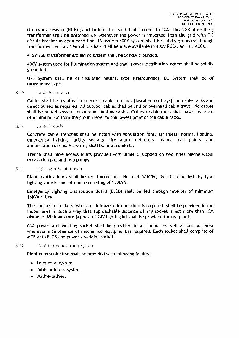
GHOTKI POWER (PRIVATE) LIMITEDLOCATED AT JDW (UNIT·III),
NEAR GOTH ISLAMABAD,DISTRICT GHOTKI, SINDH
Grounding Resistor (NGR) panel to limit the earth fault current to 50A. This NGR of earthingtransformer shall be switched ON whenever the power is imported from the grid with TGcircuit breaker in open condition. LV system 400V system shall be solidly grounded throughtransformer neutral. Neutral bus bars shall be made available in 400V PCCs, and all MCCs.
415V VSD transformer grounding system shall be Solidly grounded.
400V system used for illumination system and small power distribution system shall be solidlygrounded.
UPS System shall be of insulated neutral type (ungrounded). DC System shall be ofungrounded type.
!ns ta! la tion
Cables shall be installed in concrete cable trenches [installed on trays], on cable racks anddirect buried as required. All outdoor cables shall be laid on overhead cable trays. No cablesshall be buried, except for outdoor lighting cables. Outdoor cable racks shall have clearanceof minimum 6 M from the ground level to the lowest point of the cable racks.
3.16 Cable Trench
Concrete cable trenches shall be fitted with ventilation fans, air inlets, normal lighting,emergency lighting, utility sockets, fire alarm detectors, manual call points, andannunciation sirens. All wiring shall be in GI conduits.
Trench shall have access inlets provided with ladders, slopped on two sides having waterexcavation pits and two pumps.
8.17 1'1 Small Power
Plant lighting loads shall be fed through one No of 415/400V, Dyn11 connected dry typelighting transformer of minimum rating of 150kVA.
Emergency Lighting Distribution Board (ELDB) shall be fed through inverter of minimum16kVA rating.
The number of sockets [where maintenance & operation is required] shall be provided in theindoor area in such a way that approachable distance of any socket is not more than 10Mdistance. Minimum four (4) nos. of 24V lighting kit shall be provided for the plant.
63A power and welding socket shall be provided in all indoor as well as outdoor areawherever maintenance of mechanical equipment is required. Each socket shall comprise ofMCB with ELCB and power / welding socket.
Communication
Plant communication shall be provided with following facility:
• Telephone system• Public Address System• Walkie-talkies.

GHOTKI POWER (PRIVATE) LIMITEDLOCATED AT JDW (UNIT-III),
NEAR GOTH ISLAMABAD,DISTRICT GHOTKI, SINDH
8.1 Enclosure Ratings
Enclosure IP ratings for different applications shall be as below:
Table 14: Enclosure Ratings
Switchgears located outdoors
Motors IP55Control Panels
Push Button Stations4 (i
IP55 (outdoor)
Segregated Phase Bus ducts IP54 (indoor)IP55 (outdoor)
8.20 Plant Startup
The co-generation plant shall be with one (1) number of 400V Emergency DG set(EDG). ThisDG set shall be connected to DG panel with AMF facility, which shall be planned withincoming and outgoing feeders.
Plant startup can also be managed either from Grid supply or existing Cogeneration plant. Ineither case power shall be available at the main 11kV MV Panel. Through respective stepdown VSD transformers, power shall be fed to desired STG auxiliaries and common co-generation plant loads.
The DG set shall be with radiator cooled type. Proposed rating of EDG set shall be minimum500kVA at Prime duty.
8.21 instrumentation (111(i Control ) Systems
I&C System will ensure control and monitoring of operations of both the technological andelectrical part of Cogen Power Plant including balance of plant (auxiliary operations) and 132kV switchyard. Control room and its auxiliary equipment will be located in an outbuilding(CCR) adjacent to the Turbine Hall. I&C System will be designed as a complex systemcapable to control the whole Cogen unit both in standard conditions and transient operatingconditions (start-up, shutdown, etc.). Specific autonomous functions of protections andcontrol for steam turbines will be performed by their dedicated control system, neverthelessthis dedicated control system will be an integral part of the whole I&C System from theviewpoint of operation, monitoring and control. I&C System, as a whole, will ensure controland monitoring of the following equipment:
• Boiler and its Auxiliaries• Fuel Handling System• Ash Handling System• Steam turbine with accessories• Balance of plant• Electric equipment of Switchyard
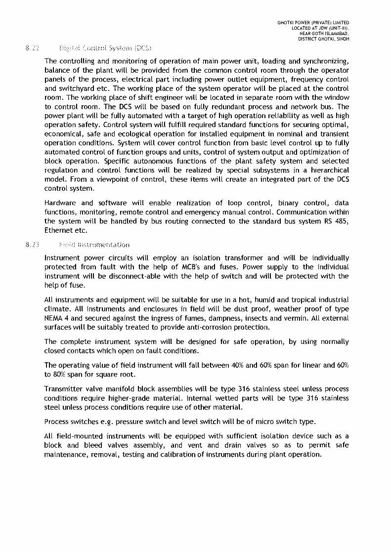
GHOTKI POWER (PRIVATE) LIMITEDLOCATED AT JDW (UNIT-III),
NEAR GOTH ISLAMABAD,DISTRICT GHOTKI, SINDH
Control System (DeS)
The controlling and monitoring of operation of main power unit, loading and synchronizing,balance of the plant will be provided from the common control room through the operatorpanels of the process, electrical part including power outlet equipment, frequency controland switchyard etc. The working place of the system operator will be placed at the controlroom. The working place of shift engineer will be located in separate room with the windowto control room. The OCS will be based on fully redundant process and network bus. Thepower plant will be fully automated with a target of high operation reliability as well as highoperation safety. Control system will fulfill required standard functions for securing optimal,economical, safe and ecological operation for installed equipment in nominal and transientoperation conditions. System will cover control function from basic level control up to fullyautomated control of function groups and units, control of system output and optimization ofblock operation. Specific autonomous functions of the plant safety system and selectedregulation and control functions will be realized by special subsystems in a hierarchicalmodel. From a viewpoint of control, these items will create an integrated part of the DCScontrol system.
Hardware and software will enable realization of loop control, binary control, datafunctions, monitoring, remote control and emergency manual control. Communication withinthe system will be handled by bus routing connected to the standard bus system RS 485,Ethernet etc.
8.2 d instrumentation
Instrument power circuits will employ an isolation transformer and will be individuallyprotected from fault with the help of MCB's and fuses. Power supply to the individualinstrument will be disconnect-able with the help of switch and will be protected with thehelp of fuse.
All instruments and equipment will be suitable for use in a hot, humid and tropical industrialclimate. All instruments and enclosures in field will be dust proof, weather proof of typeNEMA4 and secured against the ingress of fumes, dampness, insects and vermin. All externalsurfaces will be suitably treated to provide anti-corrosion protection.
The complete instrument system will be designed for safe operation, by using normallyclosed contacts which open on fault conditions.
The operating value of field instrument will fall between 40% and 60%span for linear and 60%to 80%span for square root.
Transmitter valve manifold block assemblies will be type 316 stainless steel unless processconditions require higher-grade material. Internal wetted parts will be type 316 stainlesssteel unless process conditions require use of other material.
Process switches e.g. pressure switch and level switch will be of micro switch type.
All field-mounted instruments will be equipped with sufficient isolation device such as ablock and bleed valves assembly, and vent and drain valves so as to permit safemaintenance, removal, testing and calibration of instruments during plant operation.
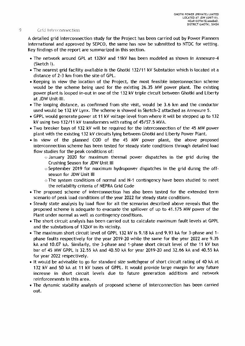
GHOTKI POWER (PRIVATE) LIMITEDLOCATED AT JDW (UNIT-III),
NEAR GOTH ISLAMABAD,DISTRICT GHOTKI, SINDH
9 Grid Interconnection
A detailed grid interconnection study for the Project has been carried out by Power PlannersInternational and approved by SEPCO, the same has now be submitted to NTDC for vetting.Key findings of the report are summarized in this section.
• The network around GPL at 132kV and 11kV has been modeled as shown in Annexure-4(Sketch I).
• The nearest grid facility available is the Ghotki 132111 kV Substation which is located at adistance of 2-3 km from the site of GPL.
• Keeping in view the location of the Project, the most feasible interconnection schemewould be the scheme being used for the existing 26.35 MW power plant. The existingpower plant is looped in-out in one of the 132 kV triple circuit between Ghotki and Libertyat JDW Unit-III.
• The looping distance, as confirmed from site visit, would be 3.6 km and the conductorused would be 132 kV Lynx. The scheme is showed in Sketch- 2 attached as Annexure 5.
• GPPL would generate power at 11 kV voltage level from where it will be stepped up to 132kV using two 132111 kV transformers with rating of 45/57.5 MVA.
• Two breaker bays of 132 kV will be required for the interconnection of the 45 MW powerplant with the existing 132 kV circuits lying between Ghotki and Liberty Power Plant.
• In view of the planned COD of the 45 MW power plant, the above proposedinterconnection scheme has been tested for steady state conditions through detailed loadflow studies for the peak conditions of:
o January 2020 for maximum thermal power dispatches in the grid during theCrushing Season for JDW Unit III
o September 2019 for maximum hydropower dispatches in the grid during the off-season for JDW Unit III
o The system conditions of normal and N-1 contingency have been studied to meetthe reliability criteria of NEPRAGrid Code
• The proposed scheme of interconnection has also been tested for the extended termscenario of peak load conditions of the year 2022 for steady state conditions.
• Steady state analysis by load flow for all the scenarios described above reveals that theproposed scheme is adequate to evacuate the spillover of up to 41.175 MW power of thePlant under normal as well as contingency conditions.
• The short circuit analysis has been carried out to calculate maximum fault levels at GPPLand the substations of 132kV in its vicinity.
• The maximum short circuit level of GPPL 132 kV is 9.18 kA and 9.93 kA for 3-phase and 1-phase faults respectively for the year 2019-20 while the same for the year 2022 are 9.35kA and 10.07 kA. Similarly, the 3-phase and t-phase short circuit level of the 11 kV busbar of 45 MW GPPL is 32.55 kA and 40.50 kA for year 2019-20 and 32.66 kA and 40.55 kAfor year 2022 respectively.
• It would be advisable to go for standard size switchgear of short circuit rating of 40 kA at132 kV and 50 kA at 11 kV buses of GPPL. It would provide large margin for any futureincrease in short circuit levels due to future generation additions and networkreinforcements in this area.
• The dynamic stability analysis of proposed scheme of interconnection has been carriedout.
GHOTKI POWER (PRIVATE) LIMITEDLOCATED AT JDW (UNIT-III),
NEAR GOTH ISLAMABAD,DISTRICT GHOTKI, SINDH
• The stability checks for the worst case of three phase fault right on the 132 kV bus bar ofGPPL substation followed by the final trip of 132 kV circuits emanating from thissubstation, has been performed for fault clearing of 5 cycles (100 ms) as understood to bethe normal fault clearing time of 132 kV protection system. Also the worst case of stuckbreaker (breaker failure) has been studied where the fault clearing time is assumed 9cycles i.e. 180 ms. In all events, the system is found strong enough to stay stable andrecovered with fast damping .
• The proposed scheme of interconnection has no technical constraints or problems, itfulfills all the criteria of reliability and stability under steady state load flow, contingencyload flows, short circuit currents and dynamic/transient conditions; and is thereforerecommended to be adopted.
o ronmental Impact
GPL has commissioned an Initial Environmental Examination ("lEE") to identify and assessany adverse impacts of the Project, so that necessary mitigation measures, if required, toprevent or minimize any adverse impacts can be planned in a timely and cost-effectivemanner. The specific objectives of the report were:
1. To have an in-depth know-how of the Project and to identify the probable sources ofpollution that may arise from each stage of the process.
2. To review the current environmental status of the area within specified radius of theproposed Project site - collection of baseline data on the environmental attributes includingair, noise, water, land, ecological, hydro-geological climate and socioeconomicenvironments.
3. To assess likely or potential environmental impacts of the proposed activity (like air, waterand soil pollution, noise, waste generation) and the alternatives.
4. To estimate the impacts of the proposed Project on the surrounding environment.
5_ To prepare a comprehensive Environmental Management Plan to ensure that theenvironmental quality of the area is preserved.
6. To formulate a strategy for effective monitoring and identify any deviations in theenvironmental quality after the project is operational, which would help in evolvingmeasures to counter these.
7. The lEE is to be undertaken pursuant to the Pakistan Environmental Protection Act 1997, theSindh Environmental Protection Act 2014.
Summarily the lEE report has identified the following impact on the environment, suggestedactivities to cushion the impact and consequences thereof:

GHOTKI POWER (PRIVATE) LIMITEDLOCATED AT JDW (UNIT-III),
NEAR GOTH ISLAMABAD,DISTRICT GHOTKI, SINDH
Impact on the Suggested cushion Level ofResidual impacts residual
environment activities impacts
None of activities areImpact on the suggested, as the Insignificantlandscape and the surrounding landscape is No positiveexterior view the industrial one. The impacts
time of construction islimited.
Development ofprocedures on irrigation ofroad surface before theconstruction work begins; Dusting in the InsignificantImpact on the material storage in piles to
atmospheric air minimize dusting. As far as course of construction negativework The impact is impactsnecessary use closed trucks significantly reducedto transport discrete
materials from the site inorder to prevent dispersionby transportation.
Water pollution as To allot a speciala result of possible ground with a protectionleakage of fuels from leakages for theand lubricants and purpose of stori ng Impact risk is Insignificantchemical potentially polluting significantly negative
substances. Development reduced impactssubstances in the of working instructions tocourse of the guarantee the right
construction work. treatment of thesematerials.
Development ofprocedures of waste Generation of
Waste generation control and storage to construction Insignificantby the guarantee the right Waste Reducing negativeidentification of waste, waste volumes whichconstruction work rules of storage safety, are to be buried in the impacts
reuse or recycling, where course of the assumedthe transportation to the activities.special site is possible.
Development of theplan to control noise. It Insignificantmay include:
Noise Switch off plants and Reducing the level negative
facilities when they do not of noise impact. impactswork.
Determine the site
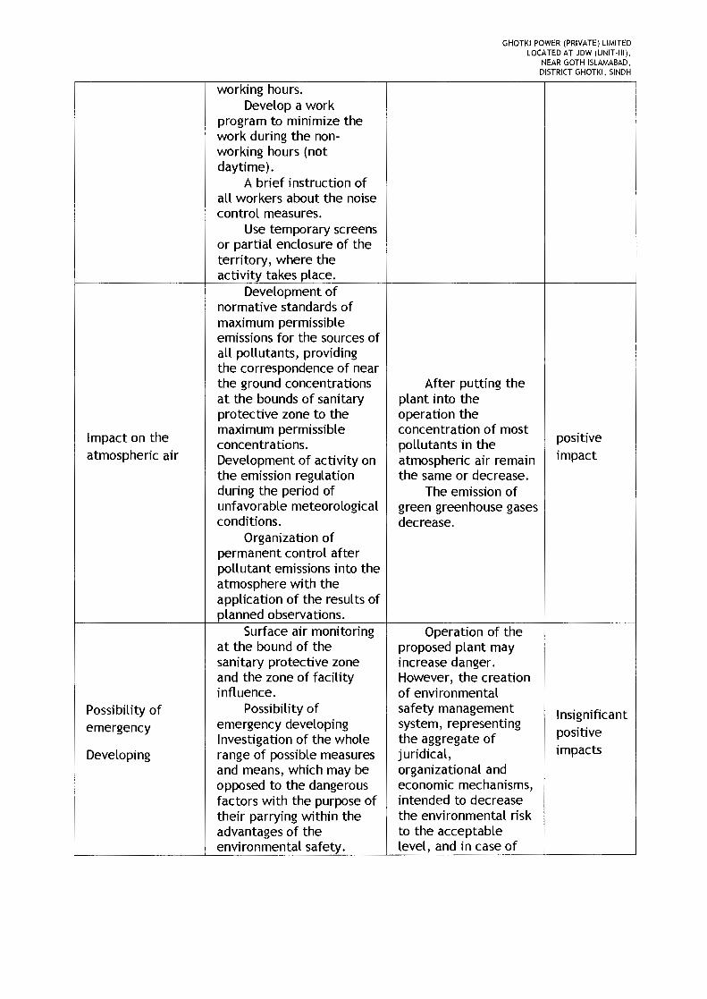
GHOTKI POWER (PRIVATE) LIMITEDLOCATED AT JDW (UNIT-III),
NEAR GOTH ISLAMABAD,DISTRICT GHOTKI, SINDH
working hours.Develop a work
program to minimize thework during the non-working hours (notdaytime).
A brief instruction ofall workers about the noisecontrol measures.
Use temporary screensor partial enclosure of theterritory, where theactivity takes place.
Development ofnormative standards ofmaximum permissibleemissions for the sources ofall pollutants, providingthe correspondence of nearthe ground concentrations After putting theat the bounds of sanitary plant into theprotective zone to the operation the
Impact on themaximum permissible concentration of most
positiveconcentrations. pollutants in theatmospheric air Development of activity on atmospheric air remain impact
the emission regulation the same or decrease.during the period of The emission ofunfavorable meteorological green greenhouse gasesconditions. decrease.
Organization ofpermanent control afterpollutant emissions into theatmosphere with theapplication of the results ofplanned observations.
Surface air monitoring Operation of theat the bound of the proposed plant maysanitary protective zone increase danger.and the zone of facility However, the creationinfluence. of environmental
Possibility of Possibility of safety management Insignificantemergency emergency developing system, representing
positiveInvestigation of the whole the aggregate ofDeveloping range of possible measures juridical, impacts
and means, which may be organizational andopposed to the dangerous economic mechanisms,factors with the purpose of intended to decreasetheir parrying within the the environmental riskadvantages of the to the acceptableenvironmental safety. level, and in case of

GHOTKI POWER (PRIVATE) LIMITEDLOCATED AT JDW (UNIT·III),
NEAR GOTH ISLAMABAD,DISTRICT GHOTKI, SINDH
Quantitative analysis emergency with anof the possibilities for one impact on theor another situation to environment to provideappear, of effectiveness of security to people anddifferent measures and to the environment,means of their parrying. will help to achieve the
Creating the system of maximum reduction ofa complex monitoring and possible damage andmanagement of compensation of theenvironmental safety. caused loss.
Taking a complex ofdecisions, that excludesdepressurization offacilities and preventingemergency emissions of
I
dangerous substances aswell as reducing corrosiveattacks of pipelines andshut-off-and-regulatingfixtures.
Proving disclosuremeans to controlemergencies.
Development of fireprevention activities.
Having a plan of workon liquidation emergencyspill of fuel, lubricants andmazut.
Development ofprocedures on preventingemergencies (includingfire, spills, etc.)
Provide the respectivetraining for personnel andgive out the necessaryequipment.
Application ofseparate system of sewagedisposal
Application of modern
Impact on surface- systems of water The impact onInsignificant
waterstreatment, grounded on surface-water is positivethe analysis of sewage minimized impactsquality.
Monitoring thecondition of water fromthe surface sources.
Quality control of

GHOTKI POWER (PRIVATE) LIMITEDLOCATED AT JDW (UNIT-III),
NEAR GOTH ISLAMABAD,DISTRICT GHOTKI, SINDH
entering and exporting ofsewage.
Liquidation plancorrection of oil productoverflows and its approval.
Mechanical removal,storage into piles and Soil qualityclamps as well as soil improvement at thereplacement with a expense of thequalitative one. replacement of
Organization of degraded soil with a Insignificantspecialized places to qualitatively new one.
Impact on soils exclude the soil contact The possibility of positive
with the substances of potential soil pollution impactshigher danger. being a result of oil
Development of the spill is insignificant duecomplex of activities which to the application ofexclude the possibility for preventive measuresoil products to leak on the complex.soil surface.
Permanent monitoringof the waste disposalplaces.
Approval (renewal)licenses and permissions onwaste treatment.
Having approvedinstructions on collecting, Insignificantstoring and transporting change of qualitativethe production waste. and qualitative
Making records of all composition of wastedata about the delivered Waste impact onand recycled waste and the environment isproviding the respective assessed as Minimum
Waste generation reports. insignificant under the positiveWaste sorting out and condition of realizing impact
storage with account of the the developeddirection of its finale projected decisionsusage. concerning the rules of
Marking of containers, temporary storage andused for waste collection established frequencyand storage, as well as of their removal toregistration in respective recycling and disposal.documents of such data asa source of waste products,their quantity, a dangerclass, a collection date anda date of disposal at theproduction facility with thepurpose of storage.

GHOTKI POWER (PRIVATE) LIMITEDLOCATED AT JDW (UNIT-III),
NEAR GOTH ISLAMABAD
Maximum possibleDISTRICT GHOTKI, SINDH
replacement of toxicmaterials with lessdangerous.
Sorting out accordingto the classes of dangerwith the subsequent wasteseparation depending onthe type.
Activities on reducingthe amount of generatedwaste.
Development ofmeasures against leakage
Impact on groundfrom reservoirs and from Minimum
watersthe underground water- The possibility of
bearing communications. the impact on the positive
Development of the ground waters is small. impact
system of hydrogeologicalmonitoring.
Impact on floraMinimum
and FaunaAccomplishment of the Landscaping work
works on landscaping. will allow to extend positive
the area of greenery. impact
Speeding up the The subsidence of
construction terms and buildings in the course
Impact on theobserving the of use of buildings and
recommendations of the constructions is
geological lEE (EMP) section, which expected to beExtremely
~xclude pollutants enteringminimum and short- insignificant
Environment into the open trenches and term. negative
pits. The impact of Impact
Monitoring of the vibrations and
impact on the geological impoundment of areas
environment. is extremely I
insignificant.Creating additional
jobs.Increase of
Social impacts
employee incomes andpopulation purchasing Positiveactivity due to impactprocurement ofmaterials and supply ofservices forconstructionnecessities.
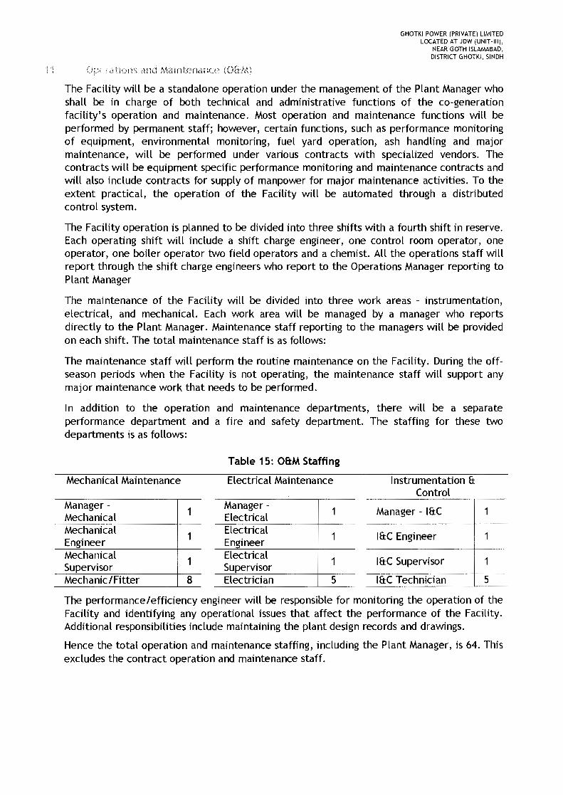
GHOTKI POWER (PRIVATE) LIMITEDLOCATED AT JDW (UNIT-III),
NEAR GOTH ISLAMABAD,DISTRICT GHOTKI, SINDH
11 Opcr ations and Maintenance (OhM)
The Facility will be a standalone operation under the management of the Plant Manager whoshall be in charge of both technical and administrative functions of the co-generationfacility's operation and maintenance. Most operation and maintenance functions will beperformed by permanent staff; however, certain functions, such as performance monitoringof equipment, environmental monitoring, fuel yard operation, ash handling and majormaintenance, will be performed under various contracts with specialized vendors. Thecontracts will be equipment specific performance monitoring and maintenance contracts andwill also include contracts for supply of manpower for major maintenance activities. To theextent practical, the operation of the Facility will be automated through a distributedcontrol system.
The Facility operation is planned to be divided into three shifts with a fourth shift in reserve.Each operating shift will include a shift charge engineer, one control room operator, oneoperator, one boiler operator two field operators and a chemist. All the operations staff willreport through the shift charge engineers who report to the Operations Manager reporting toPlant Manager
The maintenance of the Facility will be divided into three work areas - instrumentation,electrical, and mechanical. Each work area will be managed by a manager who reportsdirectly to the Plant Manager. Maintenance staff reporting to the managers will be providedon each shift. The total maintenance staff is as follows:
The maintenance staff will perform the routine maintenance on the Facility. During the off-season periods when the Facility is not operating, the maintenance staff will support anymajor maintenance work that needs to be performed.
In addition to the operation and maintenance departments, there will be a separateperformance department and a fire and safety department. The staffing for these twodepartments is as follows:
Table 15: OB:MStaffing
Mechanical Maintenance Electrical Maintenance Instrumentation &Control
Manager -1
Manager - Manager - I&CMechanical ElectricalMechanical 1 Electrical 1 I&C EngineerEngineer EngineerMechanical 1 Electrical 1 I&C Supervisor 1Supervisor SupervisorMechanic/Fitter 8 Electrician 5 I&C Technician 5
The performance/efficiency engineer will be responsible for monitoring the operation of theFacility and identifying any operational issues that affect the performance of the Facility.Additional responsibilities include maintaining the plant design records and drawings.
Hence the total operation and maintenance staffing, including the Plant Manager, is 64. Thisexcludes the contract operation and maintenance staff.
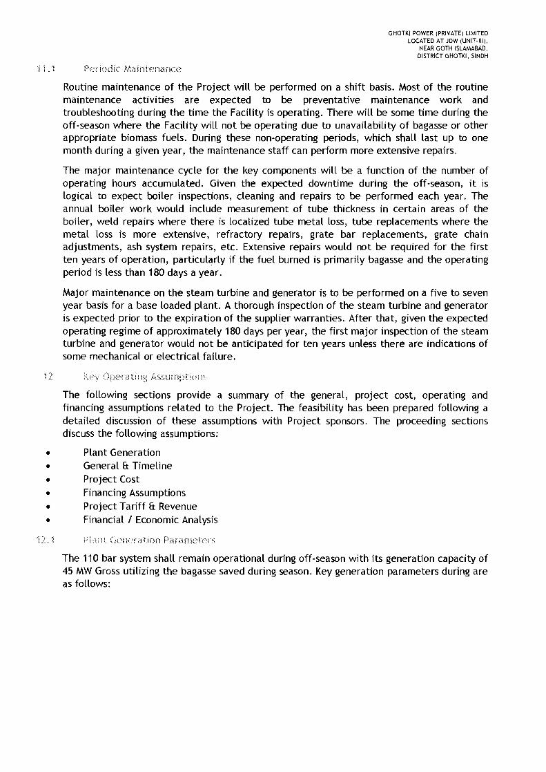
GHOTKI POWER (PRIVATE) LIMITEDLOCATED AT JDW (UNIT-III),
NEAR GOTH ISLAMABAD,DISTRICT GHOTKI, SINDH
11 _1 Periodic Maintenance
Routine maintenance of the Project will be performed on a shift basis. Most of the routinemaintenance activities are expected to be preventative maintenance work andtroubleshooting during the time the Facility is operating. There will be some time during theoff-season where the Facility will not be operating due to unavailability of bagasse or otherappropriate biomass fuels. During these non-operating periods, which shall last up to onemonth during a given year, the maintenance staff can perform more extensive repairs.
The major maintenance cycle for the key components will be a function of the number ofoperating hours accumulated. Given the expected downtime during the off-season, it islogical to expect boiler inspections, cleaning and repairs to be performed each year. Theannual boiler work would include measurement of tube thickness in certain areas of theboiler, weld repairs where there is localized tube metal loss, tube replacements where themetal loss is more extensive, refractory repairs, grate bar replacements, grate chainadjustments, ash system repairs, etc. Extensive repairs would not be required for the firstten years of operation, particularly if the fuel burned is primarily bagasse and the operatingperiod is less than 180 days a year.
Major maintenance on the steam turbine and generator is to be performed on a five to sevenyear basis for a base loaded plant. A thorough inspection of the steam turbine and generatoris expected prior to the expiration of the supplier warranties. After that, given the expectedoperating regime of approximately 180 days per year, the first major inspection of the steamturbine and generator would not be anticipated for ten years unless there are indications ofsome mechanical or electrical failure.
Operating Assumptions
The following sections provide a summary of the general, project cost, operating andfinancing assumptions related to the Project. The feasibility has been prepared following adetailed discussion of these assumptions with Project sponsors. The proceeding sectionsdiscuss the following assumptions:
• Plant Generation• General & Timeline• Project Cost• Financing Assumptions• Project Tariff & Revenue• Financial I Economic Analysis
12,; Generation Parameters
The 110 bar system shall remain operational during off-season with its generation capacity of45 MWGross utilizing the bagasse saved during season. Key generation parameters during areas follows:
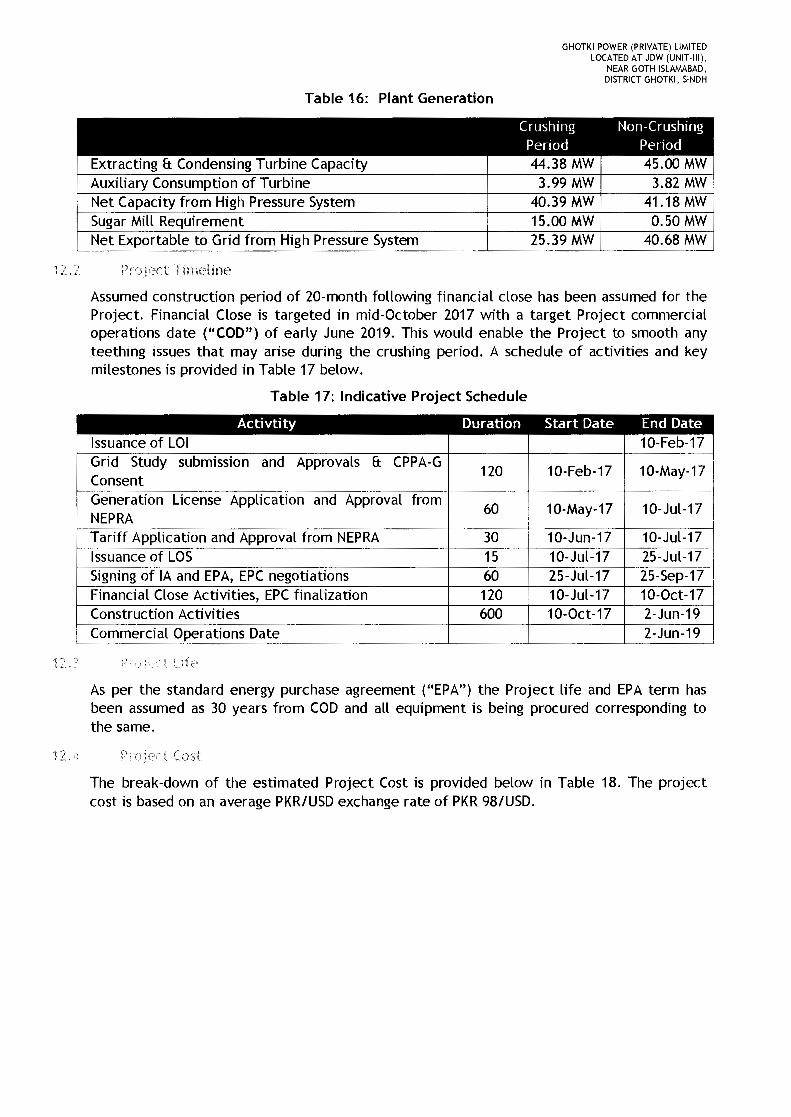
GHOTKI POWER (PRIVATE) LIMITEDLOCATED AT JDW (UNIT-III),
NEAR GOTH ISLAMABAD,DISTRICT GHOTKI, SINDH
Table 16: Plant Generation
Crushing Non-CrushingPeriod Period
Extracting f:t Condensing Turbine Capacity 44.38 MW 45.00 MWAuxiliary Consumption of Turbine 3.99 MW 3.82 MWNet Capacity from High Pressure System 40.39 MW 41.18MWSugar Mill Requirement 15.00 MW 0.50 MWNet Exportable to Grid from High Pressure System 25.39 MW 40.68 MW
12.2 Project Iimeline
Assumed construction period of 20-month following financial close has been assumed for theProject. Financial Close is targeted in mid-October 2017 with a target Project commercialoperations date (flCOD") of early June 2019. This would enable the Project to smooth anyteething issues that may arise during the crushing period. A schedule of activities and keymilestones is provided in Table 17 below.
Table 17: Indicative Project Schedule
Activtity Duration Start Date End DateIssuance of LOI 10-Feb-17Grid Study submission and Approvals f:t CPPA-G
120 10-Feb-17 10-May-17ConsentGeneration License Application and Approval from
60 10-May-17 10-Jul-17NEPRATariff Application and Approval from NEPRA 30 10-Jun-17 10-Jul-17Issuance of LOS 15 10-Jul-17 25-Jul-17Signing of IA and EPA, EPC negotiations 60 25-Jul-17 25-Sep-17Financial Close Activities, EPCfinalization 120 10-Jul-17 10-0ct-17Construction Activities 600 10-0ct-17 2-Jun-19Commercial Operations Date 2-Jun-19
12. PrOle'LL Ljfp
As per the standard energy purchase agreement ("EPA") the Project life and EPA term hasbeen assumed as 30 years from COD and all equipment is being procured corresponding tothe same.
12.4 Project Cost
The break-down of the estimated Project Cost is provided below in Table 18. The projectcost is based on an average PKR/USD exchange rate of PKR 98/USD.

GHOTKI POWER (PRIVATE) LIMITEDLOCATED AT JDW (UNIT·III),
NEAR GOTH ISLAMABAD,DISTRICT GHOTKI, SINDH
Table 18: Estimated Project Cost
Estimated Project Cost" USD million PKR millionEPCCost 40.15 3,935.1Non-EPC Cost 3.13 306.5Financing Fee & Charges 0.86 84.77Interest during Construction (IDC) 4.81 465.1Total 48.96 4,798.1fPC Cost per MW (USD million) 0.8923Project Cost per MW (USD million) 1.0879
t Fjnancmg
The Project financing will be based on a debt to equity ratio of 80:20. Under the base casefinancial projections debt is assumed to be repaid 10 years after COD with debt beingamortized over the period through fixed annuity based installments.
Key parameters of the Project funding are provided in Table 19 below:
Table 19: Project Funding
Lending Rate
12 t, P 1 L Tariff
NEPRA had announced a 30-year Upfront Tariff for high pressure boiler based bagasse powerprojects in May 2013 which was valid for a period of 2 years. Subsequently, the UpfrontTariff was extended up to May 2017. The existing upfront tariff is being used for forecasting.
The Upfront Tariff is calculated on notional capacity of 1.00 MW with appropriate indexing ofdifferent tariff determining components. This tariff structure is generic in nature and isapplicable for various sizes of new bagasse based co-generation power plants of 60 bar orhigher pressure boilers. The critical assumptions upon which the tariff is based appear in thetable below:
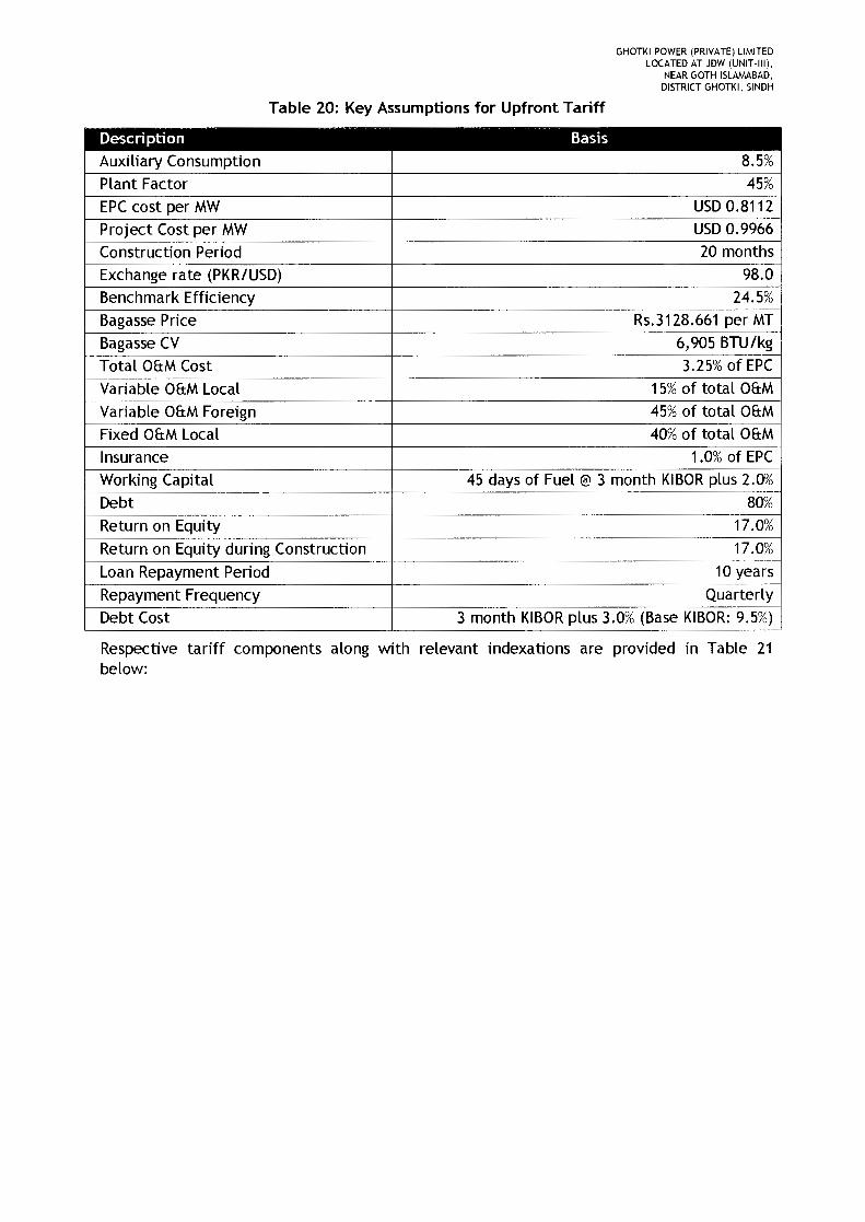
GHOTKI POWER (PRIVATE) LIMITEDLOCATED AT JDW (UNIT-III).
NEAR GOTH ISLAMABAD.DISTRICT GHOTKI. SINDH
Table 20: Key Assumptions for Upfront Tariff
Description BasisAuxiliary Consumption 8.5%Plant Factor 45%EPCcost per MW USD0.8112Project Cost per MW USD0.9966Construction Period 20 monthsExchange rate (PKR/USD) 98.0Benchmark Efficiency 24.5%Bagasse Price Rs.3128.661 per MTBagasse CV 6,905 BTU/kgTotal OfrM Cost 3.25% of EPCVariable OfrM Local 15%of total OfrMVariable OfrM Foreign 45% of total OfrMFixed OfrM Local 40% of total OfrMInsurance 1.0% of EPCWorking Capital 45 days of Fuel @ 3 month KIBORplus 2.0010Debt 80%Return on Equity 17.0%Return on Equity during Construction 17.0%Loan Repayment Period 10 yearsRepayment Frequency QuarterlyDebt Cost 3 month KIBOR plus 3.0% (Base KIBOR: 9.5%)
Respective tariff components along with relevant indexations are provided in Table 21below:
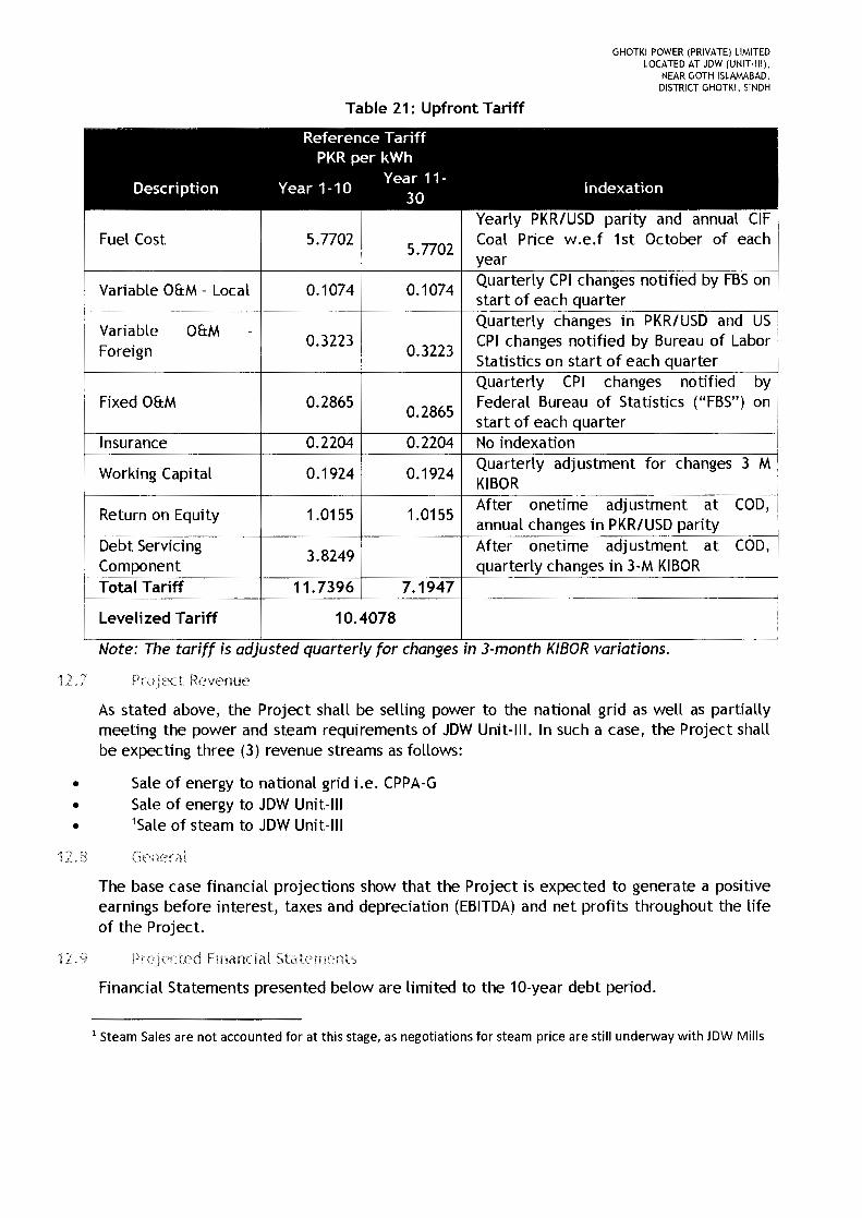
GHOTKI POWER (PRIVATE) LIMITEDLOCATED AT JDW (UNIT·III),
NEAR GOTH ISLAMABAD,DISTRICT GHOTKI, SINDH
Table 21: Upfront Tariff
Reference TariffPKR per kWh
Description Year 1-10Year 11- Indexation
30Yearly PKR/USD parity and annual CIF
Fuel Cost 5.77025.7702
Coal Price w.e.f 1st October of eachyear
Variable O&M - Local 0.1074 0.1074Quarterly CPI changes notified by FBSonstart of each quarter
~---Quarterly changes in PKR/USD and USVariable O&M -
Foreign0.3223
0.3223CPI changes notified by Bureau of LaborStatistics on start of each quarterQuarterly CPI changes notified by
Fixed O&M 0.28650.2865
Federal Bureau of Statistics ("FBS" ) onstart of each quarter
Insurance 0.2204 0.2204 No indexation
Working Capital 0.1924 0.1924Quarterly adjustment for changes 3 MKIBOR
Return on Equity 1.0155 1.0155After onetime adjustment at COD,annual changes in PKR/USD parity
Debt Servicing3.8249
After onetime adjustment at COD,Component quarterly changes in 3-M KIBORTotal Tariff 11.7396 7.1947
Levelized Tariff 10.4078
Note: The tariff IS adjusted quarterly for changes In 3-month KIBOR voriations.
12.. I' Project Revenue
As stated above, the Project shall be selling power to the national grid as well as partiallymeeting the power and steam requirements of JDW Unit-III. In such a case, the Project shallbe expecting three (3) revenue streams as follows:
• Sale of energy to national grid i.e. CPPA-G• Sale of energy to JDW Unit-III• 'Sale of steam to JDW Unit-III
The base case financial projections show that the Project is expected to generate a positiveearnings before interest, taxes and depreciation (EBITDA) and net profits throughout the lifeof the Project.
ted Financial Statements
Financial Statements presented below are limited to the 10-year debt period.
1 Steam Sales are not accounted for at this stage, as negotiations for steam price are still underway with JDW Mills

GHOTKI POWER (PRIVATE) LIMITEDLOCATED AT JDW (UNIT-III),
NEAR GOTH ISLAMABAD,DISTRICT GHOTKI, SINDH
lL1G Projected income Statement
PKR Millions 1 2 3 4 5 6 7 8 9 10
Power Sale to CPPA 1,600 1,600 1,600 1,600 1,600 1,600 1,600 1,600 1,600 1,~Power Sale to JDW Unit-III 516 516 516 516 516 516 516 516 516 51~Steam Sale to JDW Unit-III
Total Revenue 2,117 2,117 2,117 2,117 2,117 2,117 2,117 2,117 2,117 2,1
Fuel cost 1,040 1,040 1,040 1,040 1,040 1,040 1,040 1,040 1,040 1,C
Fixed O&M 52 52 52 52 52 52 52 52 52 52
Var. Foreign O&M 58 58 58 58 58 58 58 58 58 58
Var. Local O&M 19 19 19 19 19 19 19 19 19 19
Total O&M Cost 129 129 129 129 129 129 129 129 129 12~
Insurance 40 40 40 40 40 40 40 40 40 40
Depreciation 160 160 160 160 160 160 160 160 160 16(
EBIT 748 748 748 748 748 748 748 748 748 74f
Interest on LT Debt 470 443 412 378 338 294 244 187 123 50
Working capital Cost 35 35 35 35 35 35 35 35 35 35
Net Income 243 270 301 335 375 419 469 526 590 66~
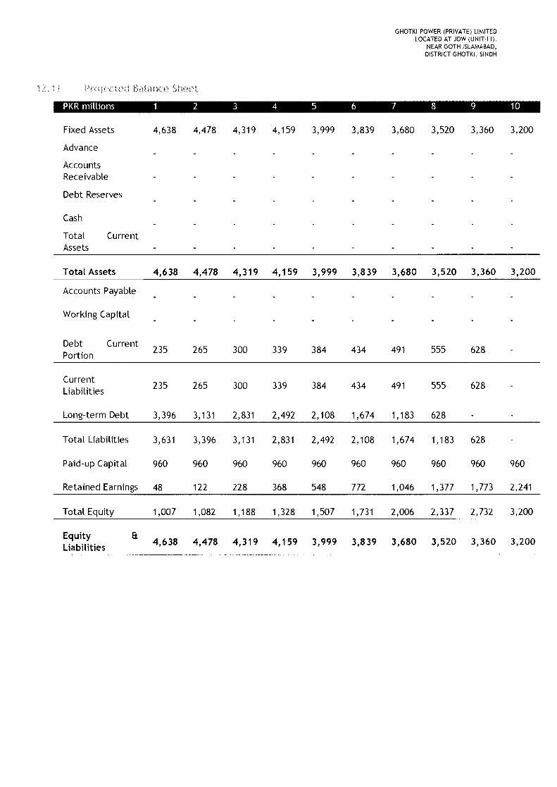
GHOTKI POWER (PRIVATE) LIMITEDLOCATED AT JDW (UNIT-III),
NEAR GOTH ISLAMABAD,DISTRICT GHOTKI, SINDH
Balance Sheet
PKRmillions 1 2 3 4 5 6 7 8 9 10
Fixed Assets 4,638 4,478 4,319 4,159 3,999 3,839 3,680 3,520 3,360 3,200
Advance
AccountsReceivable
Debt Reserves
Cash
Total CurrentAssets
Total Assets 4,638 4,478 4,319 4,159 3,999 3,839 3,680 3,520 3,360 3,200
Accounts Payable
Working Capital
Debt Current235 265 300 339 384 434 491 555 628Portion
Current235 265 300 339 384 434 491 555 628Liabilities
Long-term Debt 3,396 3,131 2,831 2,492 2,108 1,674 1,183 628
Total Liabilities 3,631 3,396 3,131 2,831 2,492 2,108 1,674 1,183 628
Paid-up Capital 960 960 960 960 960 960 960 960 960 960
Retained Earnings 48 122 228 368 548 772 1,046 1,377 1,773 2,241
Total Equity 1,007 1,082 1,188 1,328 1,507 1,731 2,006 2,337 2,732 3,200
Equity a 4,638 4,478 4,319 4,159 3,999 3,839 3,680 3,520 3,360 3,200Liabilities
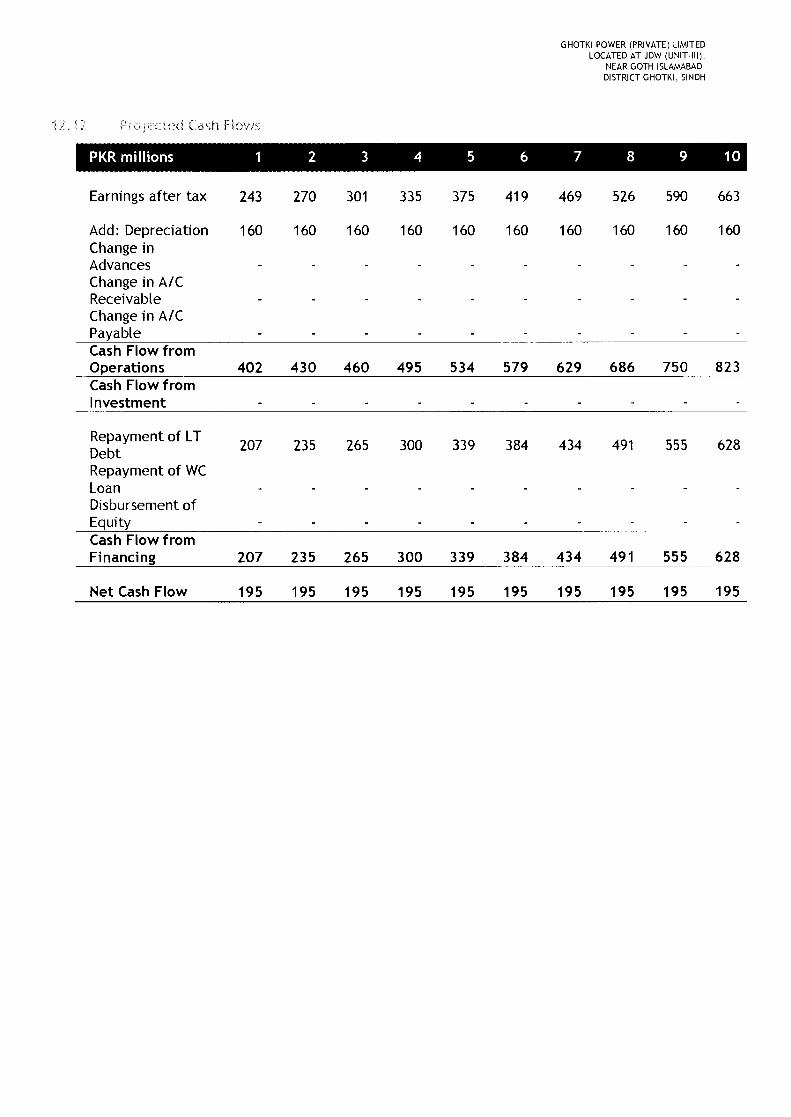
GHOTKI POWER (PRIVATE) LIMITEDLOCATED AT JDW (UNIT·III),
NEAR GOTH ISLAMABAD.DISTRICT GHOTKI, SINDH
12 .. Cash Flows
PKR millions 1 2 3 4 5 6 7 8 9 10
Earnings after tax 243 270 301 335 375 419 469 526 590 663
Add: Depreciation 160 160 160 160 160 160 160 160 160 160Change inAdvancesChange in AICReceivableChange in AICPayableCash Flow fromOperations 402 430 460 495 534 579 629 686 750 823Cash Flow fromInvestment
Repayment of LT 207 235 265 300 339 384 434 491 555 628DebtRepayment of WCLoanDisbursement ofEquityCash Flow fromFinancing 207 235 265 300 339 384 434 491 555 628
Net Cash Flow 195 195 195 195 195 195 195 195 195 195
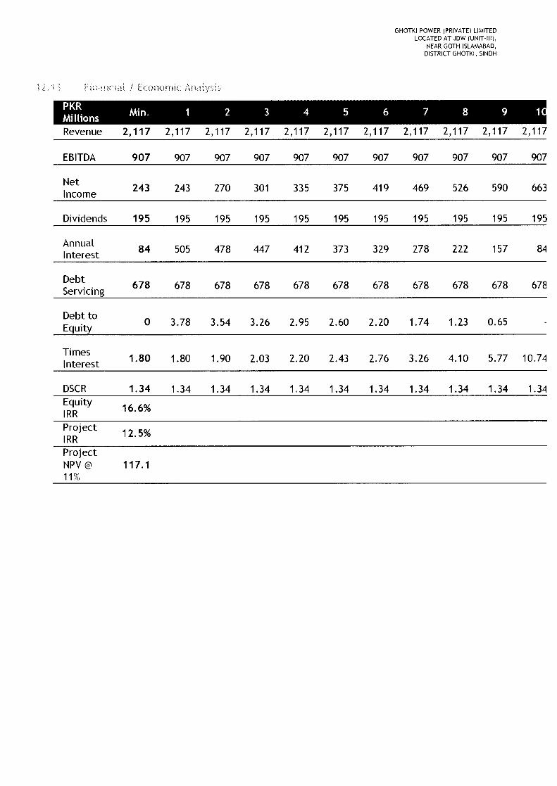
GHOTKI POWER (PRIVATE) LIMITEDLOCATED AT JDW (UNIT-III),
NEAR GOTH ISLAMABAD,DISTRICT GHOTKI, SINDH
ncial i Economic
MP~IRI' Min. 1 2 3 4 5 6 7 8 9 1I IonsRevenue 2,117 2,117 2,117 2,117 2,117 2,117 2,117 2,117 2,117 2,117 2,117
EBITDA 907 907 907 907 907 907 907 907 907 907 907
Net 243 243 270 301 335 375 419 469 526 590 663Income
Dividends 195 195 195 195 195 195 195 195 195 195 195
Annual 84 505 478 447 412 373 329 278 222 157 84Interest
Debt 678 678 678 678 678 678 678 678 678 678 678Servicing
Debt to 0 3.78 3.54 3.26 2.95 2.60 2.20 1.74 1.23 0.65Equity
Times 1.80 1.80 1.90 2.03 2.20 2.43 2.76 3.26 4.10 5.77 10.74Interest
DSCR 1.34 1.34 1.34 1.34 1.34 1.34 1.34 1.34 1.34 1.34 1.34Equity 16.6%IRRProject 12.5%IRRProjectNPV@ 117.111%
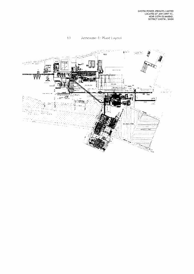
GHOTKI POWER (PRIVATE) LIMITEDLOCATED AT JDW (UNIT-III),
NEAR GOTH ISLAMABAD,DISTRICT GHOTKI, SINDH
Plant
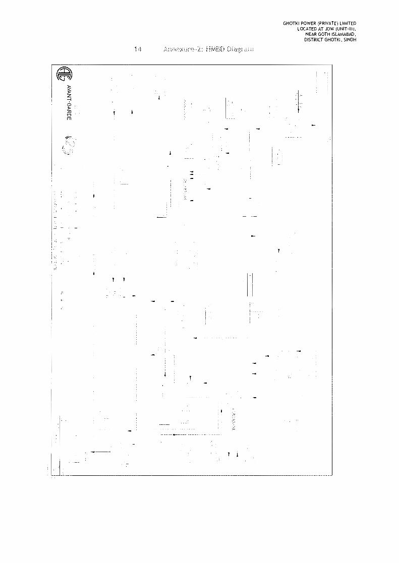
14
~:P'Z-;-IQ»;:00'm
Annexure 2: HA,mD Diagram
r: ..,
GHOTKI POWERLOCATED ~:I~ATE) LIMITEDNEAR GOTDW (UNIT,III).
DISTRICT G~gTLAMABAD.KI. SINDH
:'1;-··'00 .
...·1 'IT

15
GHOTKI POWER (PRIVATE) LIMITEDLOCATED AT JDW (UNIT·III),
NEAR GOTH ISLAMABAD,DISTRICT GHOTKI, SINDH
.c:c :=_.=_=_._::::._=._:::: "' :c:.. ==_:::l.O:O,.===_ __.
:"'-"--------r-'_I
,.~--~
i
r]I
. '.::.~I.
T~'i·I1
_ .. -------'------- ~ _._ L_ _
.-··~r;··.'j
Ir-III
r-:. ,
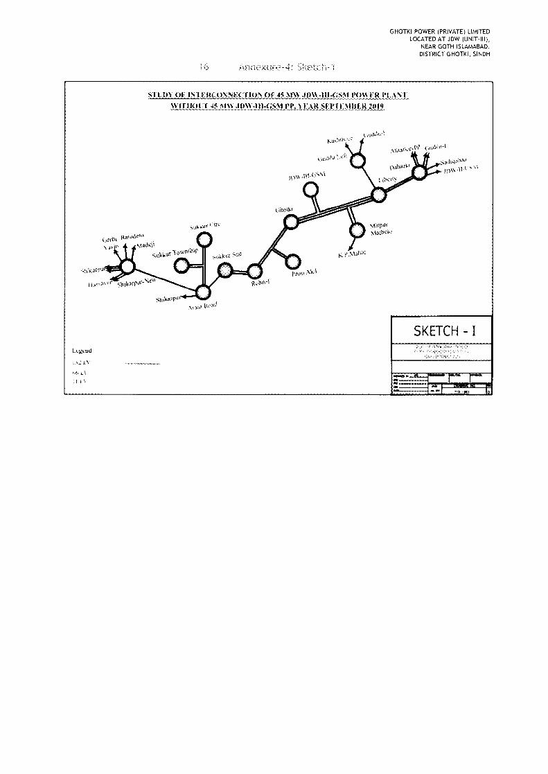
GHOTKI POWER (PRIVATE) LIMITEDLOCATED AT JDW (UNIT·tll),
NEAR GOTH ISLAMABAD,DISTRICT GHOTKI, SINDH
6
SJ'J:Jty (Jr ..I.N1··1.~!{('O'N f:('TIQ, ..or. 4~ ~JW JnW~.I.I.I,,(1'i~tJ·()Wf[{J·I.!\NT~I[!l~lLU5t\m:.1Jn~:,:!Il-(~Lt~'fEAR1;it~,tIJ;~UU~R2019
';;'3,-,<hG~\\,ad.]l)\\ -\H ~'c,
SKETCH - I
....... "' ....-I k \ ---._-_ .....--...__-_ ..

GHOTKI POWER (PRIVATE) LIMITEDLOCATED AT JDW (UNIT-III),
NEAR GOTH ISLAMABAD,DISTRICT GHOTKI, SINDH
STl'b" OF INTEkCO!'..: ...:r:CnON (U: 4:: M\\ JI)\\-IH-GSM NmER ['1•..\:'\"1'WI1.11 45 Ill" .Il)\V-Ul·-{;Sl\t "P. YEAR SE."TE'\IBER 2019
SKETCH - II1.~1::t<nd
_.-- .._---...
I
IIIIIII)IIIII,j
IIIIIII
Report No. PPI-233.2-FinaI1l7
T.Ii••~.,PPI
INTERCONNECTION STUDYFor
45 MW Ghotki Power (Pvt) Limited PowerPlant District Ghotki, Sindh
II
Final Report(March 2017)
POWER PLANNERS INTERNATIONAL
UK Office:3-Sylvester Road,Sudbury Town, Middlesex,HAO 3AQ UKPhone & Fax:+44-(0)208-9223219
Pakistan Office:64-F/1, Wapda Town,lahore 54770, PakistanPhone: +92-42-35968118;Fax: + 92-42-35183166
Email: [email protected]
•

II'
Subject: REPLY OF COMMENTS ON GRID INTERCONNECTION STUDY OF45 MW BAGASSE BASED POWER PROJECT BY GHQTKI POWERPRIVATE LlMIIED, UNIT-Ill, DISTRICT GHOTKI, SINDH,
PPI reply to all the comments received from:
SEPCO vide letter No. CTO/SEPCO/SUKlM(P&E)/JDW/675-77 dated 17-02-2017
I. In PSS/E case, Plant has been shown at a Incorporated in the study report.distance of approx. 5 km from loopingpoint on Ghotki - Liberty circuit withlynx conductor whereas In Executivesummary the same arrangement in shown
Ion rail conductor which may be corrected
2. A double circuit line from 132 kV Incorporated in the study cases.Hamayon-132 kV Jacobabad has beenshown in the study whereas at site thereis only single circuit line between the twogrids.
3. A single circuit line is from Thu I I to Incorporated in the study cases.lacobabad·1I but in study it has beenshown from Thull to Jacobabad gridwhich may be correcLed.
4. A single circuit line is from Guddu-I to Incorporated in the study cases.Guddu Left has been shown in the study.There IS no such line In SEPCONetwork.
S. Tangwani grid In SEPCO plan IS Incorporated in the study cases.proposed on kandhkot - Thull singlecircuit. An extra line has been shownfrom kandhkot to Thull In the studywhich may be switched off
6. There is no any line from Moro to Incorporated in the study cases.Naushahro Feroze which may beswitched off
7. There is no any line from New Jatoi to Incorporated in the study cases.Naushahro Feroze which may beswitched off
_ .. _-- __ . .. .
8. In the study Tharu Shah Grid has been Incorporated in the study cases.shown between Bhiria Road andNaushahro Feroze whereas it is betweenKnndiaro and New Jatoi, which may becorrected

II' ~--------------'---------r---------'------ __ ..--
9. Similarly Bhiria Road grid has wrongly Incorporated in the study cases.
been simulated in the study, actually thisgrid is proposed between Kandiaro andNaushahro Feroze which may becorrected.
10. A second circuit line has been proposed Incorporated in the study cases.
from New Dadu to Old Dadu in SEPCOexpansion plan which has not beenincluded in the study. I
II. A single circuit line has been proposed Incorporated in the study cases. Ifrom Daulatpur to Moro In SEPCO II
expansion plan which has not been
included in the study j---l-:----~~---.
12. A capacitor bank of 20.22 MV AR has Incorporated in the study cases.
been proposed at Mehar Grid station to Iaddress the issue of low voltage. Thesame may be Include in the study. I
13. There are two 40 MV A transformers at Incorporated in the study cases.
Khairpur Grid Station whereas in study a26 MVA transformer is shown whichmay be corrected
14. There are two c-a-p-a-c-it-ie-s-o-f-4-0-&--2-6-+-:-'n-c-o-r-po-r-a-te-dC-:-in-th-e-s-tu-d-y-ca-s-·e-s-.---lMVA transformers at Kandhkot GridStation whereas in study 40 & 13 MV Atransformers are shown which may becorrected
15. There are three 26 MVA transformers at Incorporated in the study cases.
Gambat Grid Station whereas in study 1326 & 40 MV A transformers are shownwhich may be corrected.
f---------------------+----------- ------.-----16. There are two 26 MV A transformers at Incorporated in the study cases.
Shahdadkot Grid Station whereas In
study 13 & 26 MV A transformers are i____ s_h_o_w_n_w_h_ic_h_m_a_y_b_e_co_r_r_ec_t_e_d_._j----------------------------__j

• ,-----------------------~~ .-~ ---- ---17. There are two 26 MV A transformers at Incorporated in the study cases.
Mehar Grid Station whereas in study 13& 26 MV A transformers are shownwhich may be corrected.
1----------------------1-----.---- ....------------118. There are 13,5,2.5 MVA transformers at Incorporated in the study cases.
Nara-Il Grid Station whereas in study 13,5 & 5 MV A transformers are shownwhich may be corrected
1-------------------+---- ..-----------------119. There is 26 MVA transformer at Radhan Incorporated in the study cases.
Grid Station where as in study 13 MV Atransformer IS shown which may becorrected
1------------ --------+------~-----~.--.----.---~~.~20. Above omissions show that the SEPCO Incorporated in the study cases.
expansion/future plans has not been fullyincluded In the study which may beincorporated accordingly.
21. Besides the case of short circuit and Incorporated in the study cases.stability may also be revised in view ofabove observations.
22. SEPCO Grid wise PMS load forecast Attached in Appendix - A(Peak and Off Peak) has not beenincluded in the report, therefore the loadscannot be verified on the gridsindividually.
23. A letter has been sent to Project Director(GSC) SEPCO vide this office letterNo.M(P&D)/ A.D(PSS)/JDW /566-70dated 07/02/2017 for his comments ona. Construc:tion of proposedtransmission line before COD.b. Availability of Line Bay/Lineentry at 132 kV GS Daharkic. Availability of Right of Way(ROW)d. Practical ImplementationThe comments of PD (GSC) SEPCO arestill awaited which will be communicatedas and when received.
Not included III the scope of ourwork

• ---_._------for I Not included In the scope of our
work24. The proposed protection scheme
Power Plant may please be provided-.,----------------l
25. NOC from Environmental Protection Not included in the scope of ourAgency (EPA), Sindh may please be workprovided
•IIII1II)IIII1-JIIIIIII
Executive Summary.:. The Final Report of 45 MW Cogeneration Power Plant for Ghotki Power (Pvt)
Ltd, which is an extension of the existing 26 MW power plant, is submitted
herewith .
•:. All the comments raised by SEPCO planning department vide letter no.
CTO/SEPCO/SUK/M(P&E)/JOW-675-77 dated 17-02-2017 have been
incorporated in this final report.
.:. Electrical Grid Studies by Ghotki Power (Pvt) Ltd for the Total 26 MW capacity
has already been approved and vetted by NTOC.
.:. Ghotki Power (Pvt) Ltd would like to go for high pressure cogeneration in the
sugar mill with the aim of exporting power nearly 41 MW to the national grid, in
addition to the existing 24.5 MW export, during both the crushing season
(November to March) and Off-Season (April to October).
.:. The study objective, approach and methodology have been described and the
plant's data received from the Client is validated.
.:. The network around Ghotki Power (Pvt) Ltd PP (referred to as JOW -Il l PP in the
remainder of the report) at 132 kV and II kV has been modeled as shown in
Appendix-B (Sketch-2) .
•:. The existing power plant is looped in-out in one of the existing 132. kV triple
circuit between Ghotki to Liberty at JOW-lIr-PP. The distance of the plant from
the looping point is about 3.6 km. The conductor used is 132 kV Lynx. Same
interconnection scheme will be used for the upcoming 45 MW power plant.
.:. Two breaker bays of 132 kV being used for existing 26 MW power plant at JOW-
[[[-PP will suffice for the connection of the 45 MW power plant with the existing
132 kV circuits lying between Ghotki and Liberty.
.:. With the gross capacity of 45 MW, the spillover from JDW-[[[-PP would be
40.9358 MW in Crushing Season and 41.175 MW in the Off-Season.
.:. In view of planned COD of the JDW-[[[-PP in June 2019, the above proposed
interconnection scheme has been tested for steady state conditions through
detailed load flow studies for the peak conditions of
(fj•• •,.,~ POWER PLANNERS INTERNATIONAL PAGE 20F 31
•
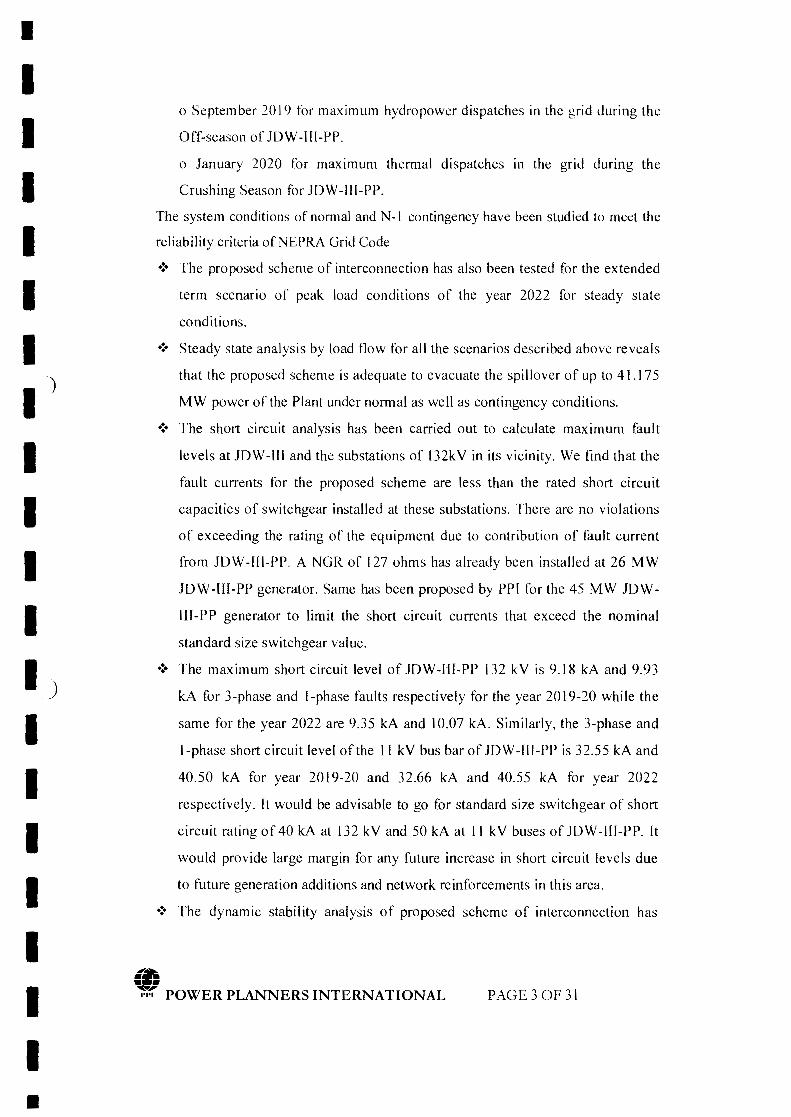
•IIIIIII
')
IIIII__)
IIIIIII•
o September 2019 for maximum hydropower dispatches in the grid during the
Off-season of JDW -Ill-PP.
o January 2020 for maximum thermal dispatches In the grid during the
Crushing Season for JOW-Ill-PP.
The system conditions of normal and N-I contingency have been studied to meet the
reliability criteria ofNEPRA Grid Code
.:. The proposed scheme of interconnection has also been tested for the extended
term scenario of peak load conditions of the year 2022 for steady state
conditions.
.:. Steady state analysis by load flow for all the scenarios described above reveals
that the proposed scheme is adequate to evacuate the spillover of up to 41.175
MW power of the Plant under normal as well as contingency conditions .
•:. The short circuit analysis has been carried out to calculate maximum fault
levels at JOW-[11 and the substations of 132kV in its vicinity. We find that the
fault currents for the proposed scheme are less than the rated short circuit
capacities of switchgear installed at these substations. There are no violations
of exceeding the rating of the equipment due to contribution of fault current
from JOW-[[I-PP. A NGR of 127 ohms has already been installed at 26 MW
JOW-Ill-PP generator. Same has been proposed by PP[ for the 45 MW JOW-
IH-PP generator to limit the short circuit currents that exceed the nominal
standard size switchgear value.
.:. The maximum short circuit level of JOW-lU-PP 132 kV is 9.18 kA and 9.93
kA for 3-phase and I-phase faults respectively for the year 2019-20 while the
same for the year 2022 are 9.35 kA and 10.07 kA. Similarly, the 3-phase and
l-phase short circuit level of the II kV bus bar of JOW-[I[-PP is 32.55 kA and
40.50 kA for year 2019-20 and 32.66 kA and 40.55 kA for year 2022
respectively. [t would be advisable to go for standard size switchgear of short
circuit rating of 40 kA at 132 kV and 50 kA at II kV buses of JDW -[([-PP. [t
would provide large margin for any future increase in short circuit levels due
to future generation additions and network reinforcements in this area .
•:. The dynamic stability analysis of proposed scheme of interconnection has
(fJ•••,.:: POWER PLANNERS INTERNATIONAL PAGE 3 OF 31
•IIIIIII)IIIII)IIIIIII
been carried out. The stability check for the worst case of three phase fault
right on the 132 kV bus bar of JOW-IIJ-PP substation followed by the final
trip of l32 kV circuits emanating from this substation, has been performed for
fault clearing of 5 cycles (100 ms) as understood to be the normal fault
clearing time of 132 kV protection system. Also the worst case of stuck
breaker (breaker failure) has been studied where the fault clearing time is
assumed 9 cycles i.e. 180 ms. In all events, the system is found strong enough
to stay stable and recovered with fast damping. The stability of system for far
end faults of 3-phase occurring at Ghotki 132 kV bus bar and Liberty 132kV
bus bar have also been checked. The proposed scheme successfully passed the
dynamic stability checks for near and far faults even for the most stringent
cases .
•:. The proposed scheme of interconnection has no technical constraints or
problems, it fulfills all the criteria of reliability and stability under steady state
load flow, contingency load flows, short circuit currents and dynamic/transient
conditions; and is therefore recommended to be adopted.
.. POWER PLANNERS INTERNATIONAL PAGE40F 31
•
•IIIIII
-JI···IIIII)IIIIIII
Report Contents
1. Introduction
1.1. Background
1.2. Objectives
1.3. Planning Criteria
2. Assumptions of Data
2.1 JDW -Ill-PP Data
2.2 Network Data
3. Study Approach & Methodology
3.1 Understanding of the Problem
3.2 Approach to the Problem
4. Development of Scheme of Interconnection
4.1 The Existing and Ongoing Network
4.2 The Scheme of Interconnection of JDW-Ill-PP
5. Detailed Load Flow Studies.:.. -..
5.1. Peak Case Load Flow September 2019, without JDW -III-PP
5.2. Peak Case Load Flow September 2019, with JDW-III-PP
5.3. Peak Case Load Flow January 2019, with JDW-IU-PP
5.4. Peak Load Case Year 2022: Extended Term Scenario
5.5. Conclusion of Load Flow Analysis
6. Short Circuit Analysis
6.1 Methodology and assumptions
6.2 Fault current calculations without JDW-rtl-PP - Year 2019-20
6.3 Fault current calculations with JDW -II[-PP - Year 2019-20
6.4 Fault current calculations with JDW-[[[-PP - Year 2022
6.5 Conclusion of short circuit analysis
7. Dynamic Stability Analysis
7.1 Assumptions & Methodology
7.1.1 Dynamic Models
7.1.2 System Conditions
.. POWER PLANNERS INTERNATIONAL PAGES OF 31
•

•IIIIIII)IIIII)IIIIIII
7.1.3 Presentation of Results
7.1.4 Worst Fault Cases
7.2 Dynamic stability simulations
7.2.1 Fault at 132 kV near JDW-fU-PP
7.2.2 Fault at 132 kV near JDW-Ill-PP (Stuck Breaker)
7.2.3 Fault at 132 kV Ghotki (Far-End Fault)
7.2.4 Fault at 132 kV Liberty (Far-End Fault)
7.3 Conclusion of Dynamic Stability Analysis
8. Conclusions
Appendices
Appendix -A:
• NTDC Generation Plan
• NTDC Transmission Plan
• NTDC Load Forecast
• SEPCO PMS Load Forecast
Appendix -B:
• Sketches and Maps for Chapter-s
• Technical Data provided by the Sponsor
Appendix -C: Plotted Results of Load Flow for Chapter - 5
Appendix -0: Results of Short Circuit Analysis for Chapter - 6
Appendix -E: Plotted Results of Stability Analysis for Chapter - 7
Appendix -F: Dynamic Data used for Stability Analysis
(fj•• •,.:; POWER PLANNERS INTERNATIONAL PAGE60F31
•
•IIIIIII)IIIII)IIIIIII
l. Introduction
1.1 Background
Ghotki Power (Pvt) Ltd would like to go for high pressure cogeneration in the
sugar mill with the aim of exporting power nearly 41 MW to the national grid, in
addition to the existing 24.5 MW export, during both the crushing season
(November to March) and Off-Season (April to October). There exists a triple
circuit of 132 kV at a distance of about 3.6 km from JOW Unit-Ill GSM that goes
from Ghotki 132 kV to Liberty Power Plant 132 kV having one circuit looped in-
out at Mir Pur Mathelo 132 kV and one circuit at JOW-ILI 132 kV as shown in
Sketch-2 in Appendix-B. The maximum output planned to be generated from the
site is about 45 MW, in addition to 26 MW already installed at the moment, of
electrical power. The project is expected to start commercial operation by June
2019. The electricity generated from this project would be supplied to the grid
system of SEPCO through 132 kV grid available in the vicinity of this project.
1.2 Ob jectives
The overall objective of the Study is to evolve an interconnection scheme between
JOW-lII-GSM Power Plant and SEPCO network, for stable and reliable
evacuation of 45 MW of electrical power generated from this plant, fulfilling N-I
reliability criteria. The specific objectives of this report are:
I. To develop scheme of interconnections at 132 kV for which right of way
(ROW) and space at the terminal substations would be available.
2. To determine the performance of interconnection scheme during steady
state conditions of system, normal and N-I contingency, through load-
flow analysis.
3. To check if the contribution of fault current from this new plant
increases the fault levels at the adjoining substations at 132 kV voltage
levels to be within the rating of equipment of these substations, and also
determine the short circuit ratings of the proposed equipment of the
(fj•• •,.:; POWER PLANNERS INTERNATIONAL PAGE 70F31
•
•IIIIII
--)I
IIIII-
)
IIIIIII•
substation at JDW-[([-PP.
4. To check if the interconnection withstands dynamic stability criteria of
post fault recovery with good damping.
1.3 Planning Criteria
The planning criteria required to be fulfilled by the proposed interconnection IS as
follows:
Steady State:
Voltage
Frequency
± 5 %, Normal Operating Condition
± 10 %, Contingency Conditions
50 Hz Nominal
49.8 Hz to 50.2 Hz variation in steady state
49.4 - 50.5Hz, MiniMax Contingency Freq.
Band
0.8 Lagging; 0.90 LeadingPower Factor
Short Circuit:
132 kV Substation Equipment Rating 40 kA
I I kV Substation Equipment Rating 50 kA
Dynamic/T ransien t:
The system should revert back to normal condition after dying out of transients
without losing synchronism with good damping after permanent three-phase fault on
any primary transmission element; including: transmission circuit, substation bus
- section, transformer, or circuit breaker. It is assumed that such a fault shall be cleared
by the associated circuit breaker action in 5 cycles.
In case of failure of primary protection (stuck breaker case), the total fault clearing
time from the instant of initiation of fault current to the complete interruption of
current to isolate the faulted element, including the primary protection plus the
backup protection to operate and isolate the fault, is equal to 180 ms (9 cycles) for
132 kV and higher voltage levels.
PAGE80F31
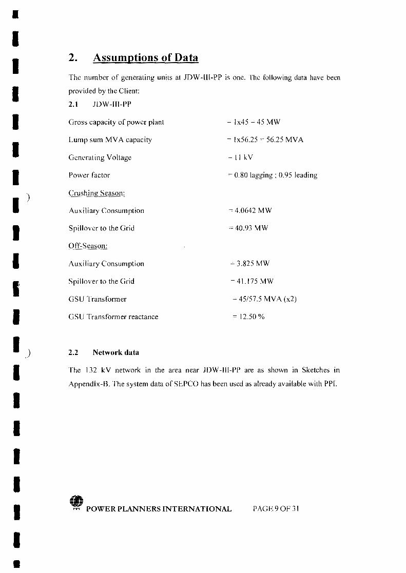
•IIIIIII')III'IIJ
IIIIIII
2. Assumptions of Data
The number of generating units at lOW -Ill-Pl' is one. The following data have been
provided by the Client:
2.1 lOW-IlI-PP
Gross capacity of power plant
Lump sum MV A capacity
= Ix45 = 45 MW
= Ix56.25 = 56.25 MV A
Generating Voltage =11 kY
Power factor = 0.80 lagging; 0.95 leading
Crushing Season:
Auxiliary Consumption
Spillover to the Grid
= 4.0642 MW
=40.93 MW
Off-Season:
Auxiliary Consumption
Spillover to the Grid
= 3.825 MW
GSU Transformer
=41.175MW
= 45/57.5 MV A (x2)
GSU Transformer reactance = 12.50 %
2.2 Network data
The 132 kV network in the area near lOW -[[[-PP are as shown in Sketches in
Appendix-B. The system data of SEPCO has been used as already available with PPI.
(fj•• •,.,~ POWER PLANNERS INTERNATIONAL PAGE90F31
•

•IIIIIII')IIII
3. Study Approach and Methodology
3 .1 Understanding of the Problem
Ghotki Power (Pvt) Ltd intends to increase generating capacity in the same region as
that of JDW-1fI GSM 26 MW Power Plant, by adding a 45 MW unit of its own. The
maximum spillover to the National Grid from the site will be about 41.175 MW of
electrical power during the Off-season.
The location of the JDW-IB-PP is in accordance with already installed JDW-Ill 26
MW PP. Interconnection has already been done, Transmission Lines to evacuate the
power has already been laid. The distance of the plant from the looping point is about
3.6 km. The conductor used is 132 kV Lynx. JDW-III-PP added to the existing
network is shown in Sketch-2 in Appendix-B.
The adequacy of SEPCO network of 132 kV in and around the proposed site of JDW-
IlI-PP would be investigated in this study for absorbing and transmitting this power
fulfilling the reliability criteria.
3.2 Approach to the problem
IJ
IIIIIII
The consultant has applied the following approaches to the problem:
• A base case network model has been prepared for September 2019 (Off-
Season) and January 2020 (Crushing Season) after the commissioning of
JDW-II1-PP in June 2019, comprising all 500 kV, 220 kV and 132 kV system,
envisaging the load forecast, the generation additions and transmission
expansions for that year particularly in SEPCO.
• Month of January 2020 and September 2019, while representing Crushing
Season and Off-Season respectively, also represent low water and high water
conditions respectively in the grid system. Thus both the high water and low
water flow patterns can be observed allowing us to judge the maximum impact
of the plant on the transm ission system in its vicinity. In addition, case for
extended term scenario of the year 2022 has also been studied.
• Interconnection scheme without any physical constraints, like right of way or
(fj•• •,.~ POWER PLANNERS INTERNATIONAL PAGE IOOF3l
•
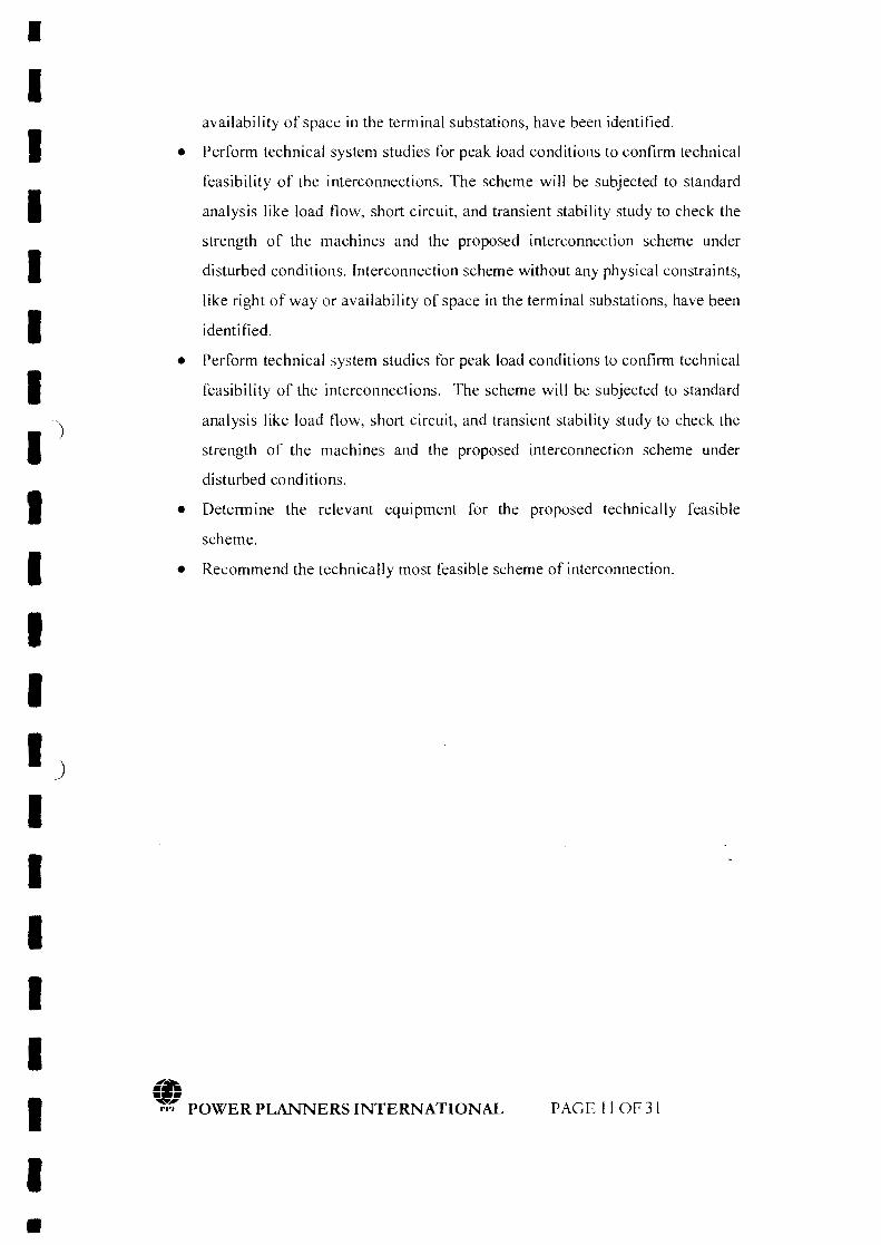
•II
availability of space in the terminal substations, have been identified.
• Perform technical system studies for peak load conditions to confirm technical
feasibility of the interconnections. The scheme will be subjected to standard
analysis like load flow, short circuit, and transient stability study to check the
strength of the machines and the proposed interconnection scheme under
disturbed conditions. Interconnection scheme without any physical constraints,
like right of way or availability of space in the terminal substations, have been
identified.
IIII
.)
II
• Perform technical system studies for peak load conditions to confirm technical
feasibility of the interconnections. The scheme will be subjected to standard
analysis like load flow, short circuit, and transient stability study to check the
strength of the machines and the proposed interconnection scheme under
disturbed conditions.
• Determine the relevant equipment for the proposed technically feasible
scheme.
IIII)II
• Recommend the technically most feasible scheme of interconnection.
IIIII
(8•••,.:; POWER PLANNERS INTERNATIONAL PAGE II OF31
•

•IIIIIIIIIIIII)IIIIIII
4. Development of Scheme of Interconnection
4.1 The Existing and Ongoing Network
The existing 132 kY network available around Ghotki 132 kY grid station is shown in
Sketch-I in Appendix-B.
lOW -Ill GSM is in District Ghotki embedded in the distribution network of SEPCO.
Network is being fed from the sources substation of Guddu 500/220/132 kY,
Shikarpur 2201132 kY and Sibbi 220 kY grid station.
These are multiple feeding points in the vicinity which provides reliability and voltage
support to the system. All these substations provide a strong 220 kY and 500 kY
network around the proposed plant. A strong system helps in stable operation of a
power plant.
4.2 The Scheme of Interconnection of JDW-III GSM PP
Keeping in view of the above mentioned 132 kY network available in the vicinity of
the site of the lDW-llI-PP, the interconnection scheme has already been developed
and the 132 kY transmission lines have also been constructed. The interconnection
scheme has been developed by looping in-out the existing Ghotki-Liberty 132 kY
triple Circuit at lOW-Ill GSM. The distance of the plant from the looping point would
be about 3.6 km. The conductor used will be 132 kY Lynx. This proposed
interconnection scheme is shown in Sketch-2 of Appendix-B.
.r&~;r;!; POWER PLANNERS INTERNATIONAL PAGE 120F31
•
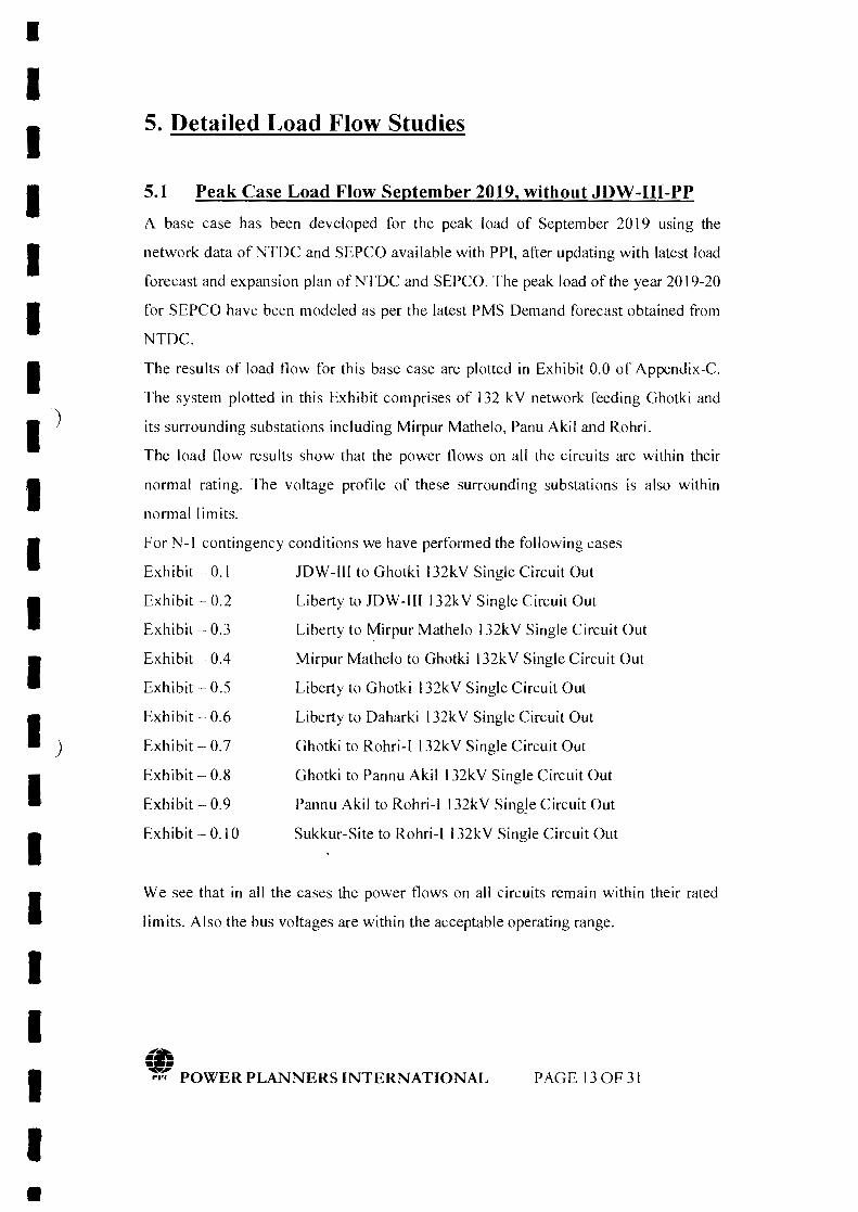
•IIIIII
)IIIIII' .)
IIIIIII
5. Detailed Load Flow Studies
5.1 Peak Case Load Flow September 2019, without JDW-Ill-PPA base case has been developed for the peak load of Septem ber 2019 using the
network data of NTDC and SEPCO available with PPl, after updating with latest load
forecast and expansion plan ofNTOC and SEPCO. The peak load of the year 2019-20
for SEPCO have been modeled as per the latest PMS Demand forecast obtained from
NTDC.
The results of load flow for this base case are plotted in Exhibit 0.0 of Appendix-C.
The system plotted in this Exhibit comprises of 132 kV network feeding Ghotki and
its surrounding substations including Mirpur Mathelo, Panu Akil and Rohri.
The load flow results show that the power flows on all the circuits are within their
normal rating. The voltage profile of these surrounding substations is also within
normal limits.
For N-I contingency conditions we have performed the following cases
Exhibit - 0.1 JOW-ill to Ghotki l32kV Single Circuit Out
Exhibit - 0.2 Liberty to JOW-ill 132kV Single Circuit Out
Exhibit - 0.3 Liberty to Mirpur Mathelo 132kV Single Circuit Out
Exhibit - 0.4 Mirpur Mathelo to Ghotki 132kV Single Circuit Out
Exhibit - 0.5 Liberty to Ghotki l32kV Single Circuit Out
Exhibit - 0.6 Liberty to Oaharki 132kV Single Circuit Out
Exhibit - 0.7 Ghotki to Rohri-[ 132kV Single Circuit Out
Exhibit - 0.8 Ghotki to Pannu Akil 132kV Single Circuit Out
Exhibit - 0.9 Pannu Akil to Rohri-l 132kV Single Circuit Out
Exhibit - 0.10 Sukkur-Site to Rohri-I 132kV Single Circuit Out
We see that in all the cases the power flows on all circuits remain within their rated
limits. Also the bus voltages are within the acceptable operating range.
(IJ•• •rr. POWER PLANNERS INTERNATIONAL PAGEI30F31
•
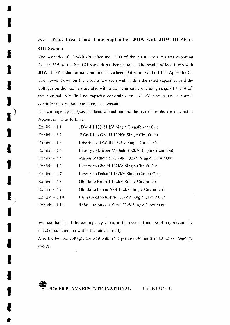
•IIIIIII
')
IIIII,
J
IIIIIII•
5.2 Peak Case Load Flow September 2019, with JDW-IH-PP in
Off-Season
The scenario of lOW -Ill-PP after the COD of the plant when it starts exporting
41.175 MW to the SEPCO network has been studied. The results of load flows with
lOW -IJI-PP under normal conditions have been plotted in Exhibit 1.0 in Appendix-C.
The power flows on the circuits are seen well within the rated capacities and the
voltages on the bus bars are also within the permissible operating range of ± 5 % off
the nominal. We find no capacity constraints on 132 kV circuits under normal
conditions i.e. without any outages of circuits.
N-I contingency analysis has been carried out and the plotted results are attached in
Appendix - C as follows:
Exhibit - 1.1 lOW-I[[ 132111 kV Single Transformer Out
Exhibit - 1.2
Exhibit - 1.3
Exhibit - 1.4
Exhibit - 1.5
Exhibit - 1.6
Exhibit-1.7
Exhibit - 1.8
Exhibit - 1.9
Exhibit - 1.10
Exhibit - 1.11
lOW-fIl to Ghotki 132kV Single Circuit Out
Liberty to lOW-IU 132kV Single Circuit Out
Liberty to Mirpur Mathelo 132kV Single Circuit Out
Mirpur Mathelo to Ghotki 132kV Single Circuit Out
Liberty to Ghotki 132kV Single Circuit Out
Liberty to Oaharki 132kV Single Circuit Out
Ghotki to Rohri-I 132kV Single Circuit Out
Ghotki to Pannu Akil 132kV Single Circuit Out
Pannu Akil to Rohri-I 132kV Single Circuit Out
Rohri-I to Sukkur-Site 132kV Single Circuit Out
We see that in all the contingency cases, in the event of outage of any circuit, the
intact circuits remain within the rated capacity.
Also the bus bar voltages are well within the permissible limits in all the contingency
events.
-•• •,.r. POWER PLANNERS INTERNATIONAL PAGE 140F 31

I
IIIIII
)
IIIIII)
IIIIIII
5.3 Peak Case Load Flow January 2020, with JDW-IH-PP in
Crushing Season
The scenario of JOW -Ill-PP during the Crushing season, for the month of January
with maximum thermal dispatches, has been studied. The results of load flows with
JOW-III-PP under normal conditions have been plotted in Exhibit 2.0 in Appendix-C.
The power flows on the circuits are seen well within the rated capacities and the
voltages on the bus bars are also within the permissible operating range of ± 5 % off
the nominal. We find no capacity constraints on 132 kV circuits under normal
conditions i.e. without any outages of circuits.
N-I contingency analysis has been carried out and the plotted results are attached in
Appendix - C as follows:
Exhibit - 2.1 JOW-If[ 132/11 kV Single Transformer Out
Exhibit - 2.2 JOW-I([ to Ghotki 132kV Single Circuit Out
Exhibit - 2.3 Liberty to JOW-III 132kV Single Circuit Out
Exhibit - 2.4
Exhibit - 2.5
Exhibit - 2.6
Exhibit - 2.7
Exhibit - 2.8
Exhibit - 2.9
Exhibit - 2.10
Exhibit - 2.11
Liberty to Mirpur Mathelo 132kV Single Circuit Out
Mirpur Mathelo to Ghotki 132kV Single Circuit Out
Liberty to Ghotki 132kV Single Circuit Out
Liberty to Daharki 132kV Single Circuit Out
Ghotki to Rohri-I 132kV Single Circuit Out
Ghotki to Pannu Akil 132kV Single Circuit Out
Pannu Akil to Rohri-I 132kV Single Circuit Out
Sukkur-Site to Rohri-I 132kV Single Circuit Out
We see that in all the contingency cases, in the event of outage of any circuit, the
intact circuits remain within the rated capacity.
Also the bus bar voltages are well within the permissible limits in all the contingency
events.
.r&~.J',.,'1; POWER PLANNERS INTERNATIONAL
•
PAGE ISOF31
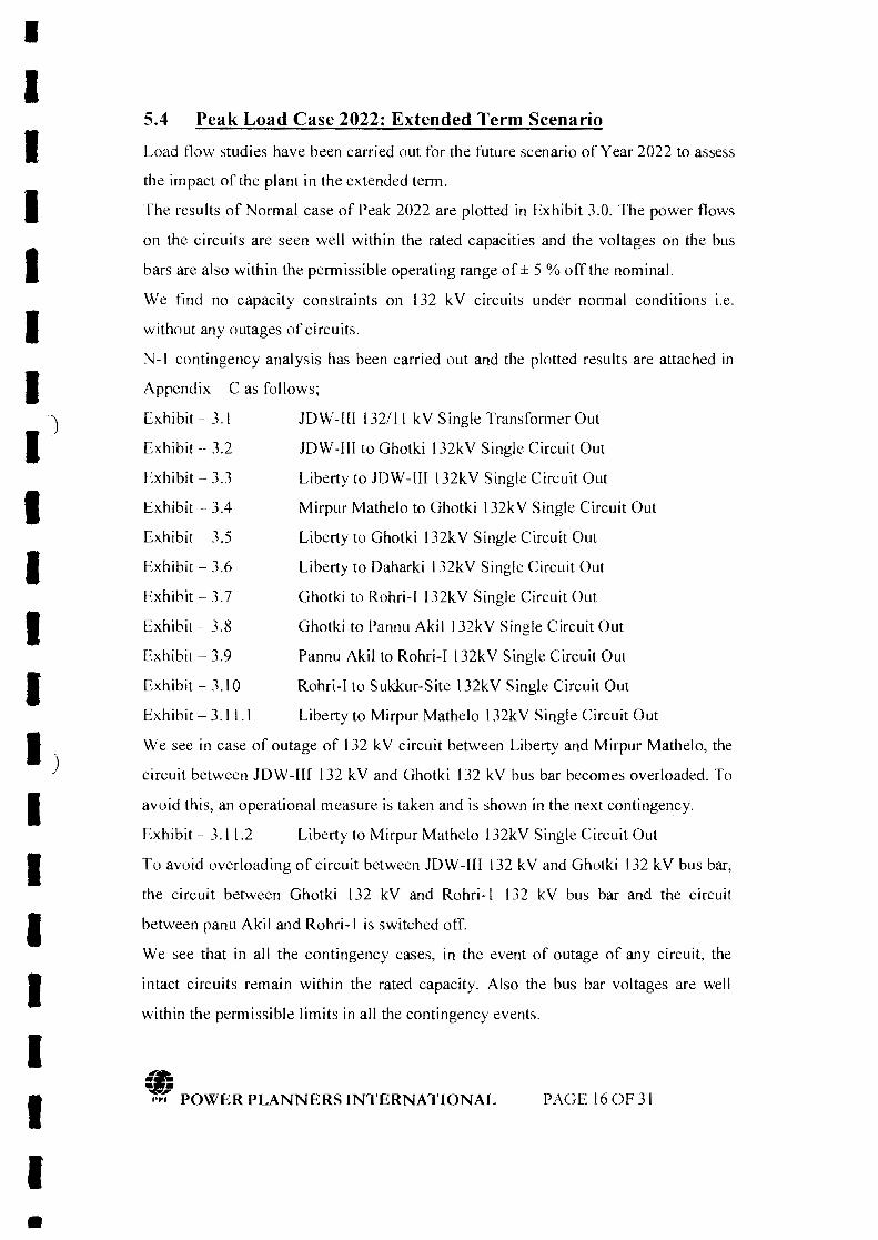
•IIIIII
')
IIIIII)IIIIIII
5.4 Peak Load Case 2022: Extended Term Scenario
Load flow studies have been carried out for the future scenario of Year 2022 to assess
the impact of the plant in the extended term.
The results of Normal case of Peak 2022 are plotted in Exhibit 3.0. The power flows
on the circuits are seen well within the rated capacities and the voltages on the bus
bars are also within the permissible operating range of ± 5 % off the nominal.
We find no capacity constraints on 132 kV circuits under normal conditions i.e.
without any outages of circuits.
N-I contingency analysis has been carried out and the plotted results are attached in
Appendix - C as follows;
Exhibit-3.t lOW-[[I132/11 kVSingleTransformerOut
Exhibit - 3.2 lOW-III to Ghotki 132kV Single Circuit Out
Exhibit - 3.3 Liberty to lDW-UI 132kV Single Circuit Out
Exhibit - 3.4 Mirpur Mathelo to Ghotki 132kV Single Circuit Out
Exhibit - 3.5 Liberty to Ghotki 132kV Single Circuit Out
Exhibit - 3.6 Liberty to Daharki 132kV Single Circuit Out
Exhibit - 3.7 Ghotki to Rohri-I 132kV Single Circuit Out
Exhibit - 3.8 Ghotki to Pannu Akil 132kV Single Circuit Out
Exhibit - 3.9 Pannu Akil to Rohri-I 132kV Single Circuit Out
Exhibit - 3.10 Rohri-I to Sukkur-Site 132kV Single Circuit Out
Exhibit - 3.11.1 Liberty to Mirpur Mathelo 132kV Single Circuit Out
We see in case of outage of 132 kV circuit between Liberty and Mirpur Mathelo, the
circuit between lOW-ll£ 132 kV and Ghotki 132 kV bus bar becomes overloaded. To
avoid this, an operational measure is taken and is shown in the next contingency.
Exhibit - 3.11.2 Liberty to Mirpur Mathelo 132kV Single Circuit Out
To avoid overloading of circuit between lOW-III 132 kV and Ghotki 132 kV bus bar,
the circuit between Ghotki 132 kV and Rohri-I 132 kV bus bar and the circuit
between panu Akil and Rohri-I is switched off.
We see that in all the contingency cases, in the event of outage of any circuit, the
intact circuits remain within the rated capacity. Also the bus bar voltages are well
within the permissible limits in all the contingency events.
((;•• •,.:; POWER PLANNERS INTERNATIONAL PAGE 160F 31
•

•IIIIIII)
IIIII.)
IIIIIII
5.5 Conclusion of Load Flow Analysis
The proposed interconnection scheme of JDW-lIl-PP is adequate to evacuate the
spillover electrical power from JOW-UI-PP under normal and contingency conditions
tested for peak load conditions of September 2019, January 2020 and extended term
scenario of the Year 2022. In extended term scenario case, we see in case of outage of
132 kV circuit between Liberty and Mirpur Mathelo, the circuit between JDW-Ilf 132
kV and Ghotki 132 kV bus bar becomes overloaded. To avoid this, the circuit
between Ghotki 132 kV and Rohri-I 132 kV bus bar and the circuit between panu
Akil and Rohri-I is switched off.
In all the normal and contingency cases, we find that the loading on the circuits
remain within the rated capacity. Also the bus bar voltages are well within the
permissible limits in all the normal and contingency events. Hence the proposed
interconnection scheme of JDW-III-PP has no constraints according to the Load Flow
Analysis.
.. POWER PLANNERS INTERNATIONAL PAGE 170F31
•

I
IIIIII
'j
IIIIII)
IIIIIII•
6. Short Circuit Analysis
6.1 Methodology and Assumptions
The methodology of IEC 909 has been applied in all short circuit analyses in this
report for which provision is available in the PSSfE software used for these studies,
The maximum fault currents have been calculated with the following assumptions
under IEC 909:
• Set tap ratios to unity
• Set line charging to zero
• Set shunts to zero in positive sequence
• Desired voltage magnitude at bus bars set equal to l.10 P,LL i.e. 10 % higher
than nominal, which is the maximum permissible voltage under contingency
condition,
For evaluation of maximum short circuit levels we have assumed contribution in the
fault currents from all the installed generation capacity of hydal, thermal and nuclear
plants in the system in the year 2019-20 i.e. all the generating units have been
assumed on-bar in fault calculation's simulations,
The assumptions about the generator and the transformers data are the same as
mentioned in Ch.2 of this report.
6.2 Fault Current Calculations without JDW-III-PP. 2019-20
In order to assess the short circuit strength of the network of 132 kV and II kV
without JDW -III-PP for the grid of SEPCO in the vicinity of the site of the Plant, fault
currents have been calculated for balanced three-phase and unbalanced single-phase
short circuit conditions. These levels will give us the idea of the fault levels without
JDW-Ill-PP and later on how much the contribution of fault current from JDW-£II-PP
may add to the existing levels.
The results are attached in Appendix - D.
A NGR of value 127 ohms has already been installed at 26 MW JDW-l[[ MW PP
generator which we have included in our study. The short circuit levels have been
calculated and plotted on the bus bars of 132 kV substations lying in the electrical
vicinity of our area of interest i.e. Ghotki, Mirpur Mathelo, Liberty, Rohri-I and
(fj•• •,.;1( POWER PLANNERS INTERNATIONAL PAGE 180F31
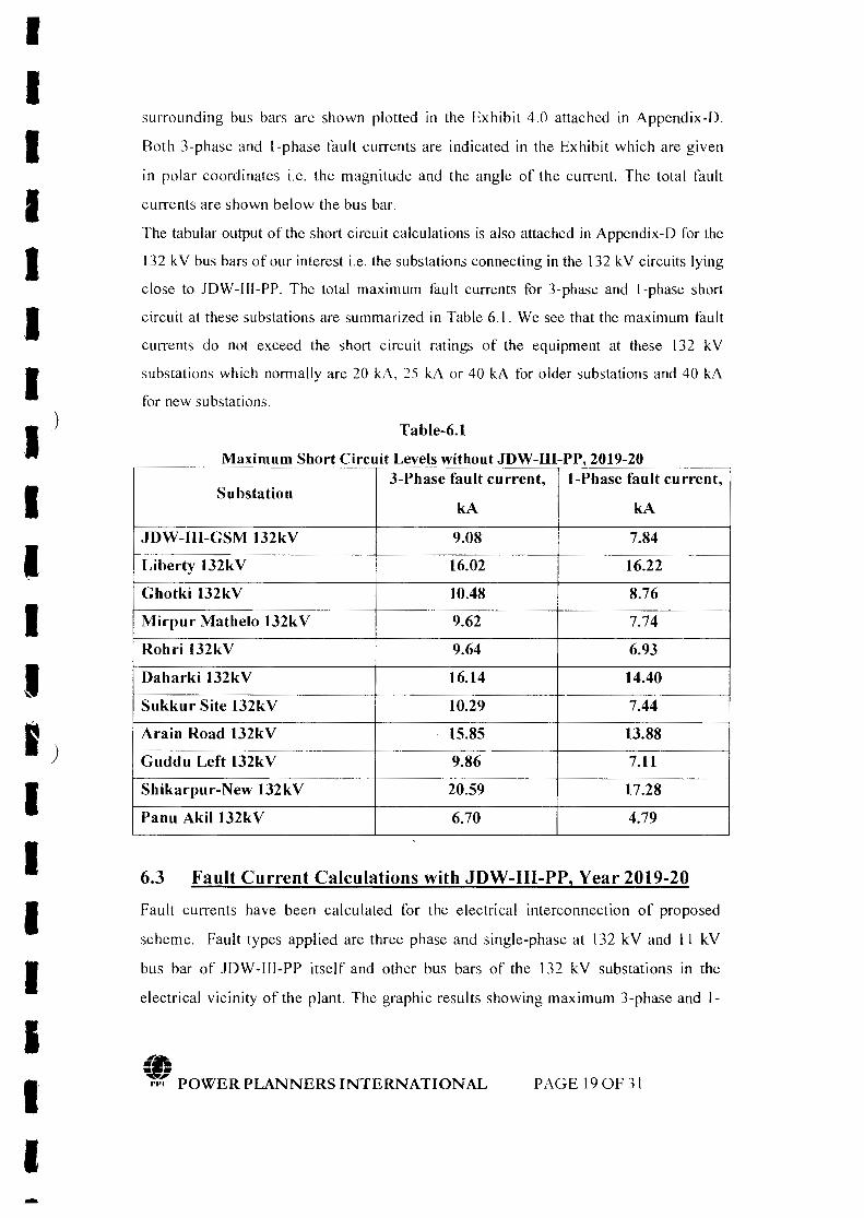
IIIIIIII
)
IIIII)
IIIIIIII-
surrounding bus bars are shown plotted in the Exhibit 4.0 attached in Appendix-D.
Both J-phase and I-phase fault currents are indicated in the Exhibit which are given
in polar coordinates i.e. the magnitude and the angle of the current. The total fault
currents are shown below the bus bar.
The tabular output of the short circuit calculations is also attached in Appendix-D for the
132 kV bus bars of our interest i.e. the substations connecting in the 132 kV circuits lying
close to lDW-IlI-PP. The total maximum fault currents for 3-phase and l-phase short
circuit at these substations are summarized in Table 6.1. We see that the maximum fault
currents do not exceed the short circuit ratings of the equipment at these 132 kV
substations which normally are 20 kA, 25 kA or 40 kA for older substations and 40 kA
for new substations.
Table-6.1
,3-Phase fault current, l-Phase fault current,
SubstationkA kA
IDW-lII-GSM 132kV 9.08 7.84
Liberty 132kV 16.02 16.22
Ghotki 132kV 10.48 8.76
Mirpur Mathelo 132kV 9.62 7.74
Rohri 132kV 9.64 6.93
Daharki 132kV 16.14 14.40
Sukkur Site 132kV 10.29 7.44
Arain Road 132kV 15.85 13.88
Guddu Left 132kV 9.86 7.11
Shikarpur-New 132kV 20.59 17.28
Panu Akil 132kV 6.70 4.79
Maximum Short Circuit Levels without JDW-III-PP 2019-20
6.3 Fault Current Calculations with JDW-III-PP, Year 2019-20
Fault currents have been calculated for the electrical interconnection of proposed
scheme. Fault types appl ied are three phase and single-phase at 132 kV and I I kV
bus bar of JDW-[l[-PP itself and other bus bars of the 132 kV substations in the
electrical vicinity of the plant. The graphic results showing maximum 3-phase and 1-
.t"&~;,.:; POWER PLANNERS INTERNATIONAL PAGE 190F31
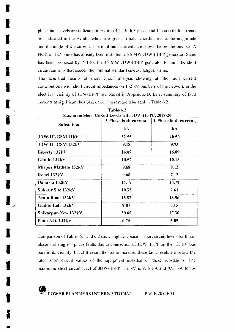
I
IIIIIII
)
IIIII__)
IIIIIII-
phase fault levels are indicated in Exhibit 4.1. Both 3-phase and I-phase fault currents
are indicated in the Exhibit which are given in polar coordinates i.e, the magnitude
and the angle of the current. The total fault currents are shown below the bus bar. A
NGR of 127 ohms has already been installed at 26 MW lOW -IIf-PP generator. Same
has been proposed by PPI for the 45 MW lOW-lll-PP generator to limit the short
circuit currents that exceed the nominal standard size switchgear value.
The tabulated results of short circuit analysis showing all the fault current
contributions with short circuit impedances on 132 kV bus bars of the network in the
electrical vicinity of lDW-III-PP are placed in Appendix-D. Brief summary of fault
currents at significant bus bars of our interest are tabulated in Table 6.2
3-Phase fault current, I-Phase fault current,Substation
kA kA
JDW-[(I-GSM IlkV 32.55 40.50
JDW-III-GSM 132kV 9.18 9.93
Liberty 132kV 16.09 16.89
Ghotki 132kV 10.57 10.15
Mirpur Mathelo 132kV 9.68 8.13
Rohri 132kV 9.68 7.13-Daharki 132kV 16.19 14.72
Sukkur Site 132kV 10.32 7.61
Arain Road 132kV 15.87 13.96
Guddu Left 132kV 9.87 7.15
Shikarpur-New 132kV 20.60 17.30
Panu Akil132kV 6.75 5.05
Table-6.2Maximum Short Circuit Levels with JDW-III-PP, 2019-20
Comparison of Tables 6.1 and 6.2 show slight increase in short circuit levels for three-
phase and single - phase faults due to connection of lOW-III-PP on the 132 kV bus
bars in its vicinity, but still even after some increase, these fault levels are below the
rated short circuit values of the equipment installed on these substations. The
maximum short circuit level of lOW-lII-PP 132 kV is 9.18 kA and 9.93 kA for 3-
(fj•• •,.,~ POWER PLANNERS INTERNATIONAL PAGE200F 31
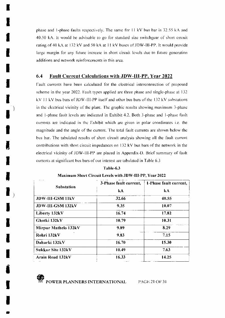
I
IIIIIII
)
IIIII)IIIIIII•
phase and I-phase faults respectively. The same for II kY bus bar is 32.55 kA and
40.50 kA. It would be advisable to go for standard size switchgear of short circuit
rating of 40 kA at 132 kV and 50 kA at II kV buses of JDW-III-PP. It would provide
large margin for any future increase in short circuit levels due to future generation
additions and network reinforcements in this area.
6.4 Fault Current Calculations with JDW-III-PP, Year 2022
Fault currents have been calculated for the electrical interconnection of proposed
scheme in the year 2022. Fault types applied are three phase and single-phase at 132
kY II kY bus bars of JDW-III-PP itself and other bus bars of the 132 kY substations
in the electrical vicinity of the plant. The graphic results showing maximum 3-phase
and l-phase fault levels are indicated in Exhibit 4.2. Both 3-phase and l-phase fault
currents are indicated in the Exhibit which are given in polar coordinates i.e. the
magnitude and the angle of the current. The total fault currents are shown below the
bus bar. The tabulated results of short circuit analysis showing all the fault current
contributions with short circuit impedances on 132 kY bus bars of the network in the
electrical vicinity of JDW-III-PP are placed in Appendix-D. Brief summary of fault
currents at significant bus bars of our interest are tabulated in Table 6.3
Table-6.3
Maximum Short Circuit Levels with JDW-III-PP, Year 2022
3-Phase fault current, l-Phase fault current,Substation
kA kA
JDW-III-GSM llkV 32.66 40.55
JDW-Ill-GSM 132kV 9.35 10.07
Liberty 132kV 16.74 17.82
Ghotki 132kV 10.79 10.31
Mirpur Mathelo 132kV 9.89 8.29
Rohri 132kV 9.83 7.15
Daharki 132kV 16.70 15.30
Sukkur Site 132kV 10.49 7.63
Arain Road 132kV 16.33 14.25
.ra,,~1'1'1:" POWER PLANNERS INTERNATIONAL PAGE210F31
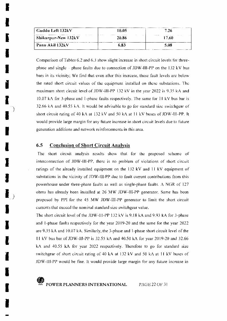
IIIIIIII
)
IIIIIJIIIIIII-
--Guddu Left 132kV lO.05 7.26
----_--- ------Shikarpur-New l32kV 20.86 17.60
Panu Akil132kV 6.83 5.08
Comparison of Tables 6.2 and 6.3 show slight increase in short circuit levels for three-
phase and single - phase faults due to connection of JOW -Ill-PP on the 132 kV bus
bars in its vicinity; We find that even after this increase, these fault levels are below
the rated short circuit values of the equipment installed on these substations. The
maximum short circuit level of JOW-I1I-PP 132 kV in the year 2022 is 9.35 kA and
10.07 kA for 3-phase and l-phase faults respectively. The same for II kV bus bar is
32.66 kA and 40.55 kA. It would be advisable to go for standard size switchgear of
short circuit rating of 40 kA at 132 kV and 50 kA at II kV buses of JOW -III-PP. It
would provide large margin for any future increase in short circuit levels due to future
generation additions and network reinforcements in this area.
6.5 Conclusion of Short Circuit Analysis
The short circuit analysis results show that for the proposed scheme of
interconnection of JOW-IIl-PP, there is no problem of violations of short circuit
ratings of the already installed equipment on the 132 kV and II kV equipment of
substations in the vicinity of JOW-llI-PP due to fault current contributions from this
powerhouse under three-phase faults as well as single-phase faults. A NGR of 127
ohms has already been installed at 26 MW JOW-[I[-PP generator. Same has been
proposed by PPI for the 45 MW JOW-UI-PP generator to limit the short circuit
currents that exceed the nominal standard size switchgear value.
The short circuit level of the JOW-Ul-PP 132 kV is 9.18 kA and 9.93 kA for .l-phase
and I-phase faults respectively for the year 2019-20 and the same for the year 2022
are 9.35 kA and 10.07 kA. Similarly, the J-phase and l-phase short circuit level of the
I ( kV bus bar of JOW-Ill-PP is 32.55 kA and 40.50 kA for year 2019-20 and 32.66
kA and 40.55 kA for year 2022 respectively. Therefore to go for standard size
switchgear of short circuit rating of 40 kA at 132 kV and 50 kA at II kV buses of
JOW-ll[-PP would be fine. It would provide large margin for any future increase in
PAGE220F 31
IIIIIII
.. -)
IIIIII.)
IIIIIII-
short circuit levels due to future generation additions and network reinforcements in
this area.
7. Dynamic Stability Analysis
7.1 Assumptions & Methodology
7.1.1 Dynamic Models
The assumptions about the generator and its parameters are the same as mentioned in
Ch.2 of this report.
We have employed the generic dynamic models available in the PSS/E model library
for dynamic modeling of the generator, exciter and the governor as follows;
Generator GENROU
EXSTl
TGOVI
H = 2.622 MW-sec/MV A
Excitation System
Speed Governing System
Inertia Constant
7.1.2 System Conditions
The proposed scheme of looping in-out the existing Liberty to Ghotki 132 kV triple
circuit at JDW-II1 GSM has been modeled in the dynamic simulation.
All the power plants of WAPDAIPEPCO and Il'Ps from Tarbela to Hub have been
dynamically represented in the simulation model.
7.1.3 Presentation of Results
The plotted results of the simulation runs are placed in Appendix-E. Each simulation
is run for its first one second for the steady state conditions of the system prior to fault
or disturbance. This is to establish the pre fault/disturbance conditions of the network
under study were smooth and steady. Post fault recovery has been monitored for nine
seconds. Usually all the transients due to non-linearity die out within 4-5 seconds after
disturbance is cleared in the system.
7.1.4 Worst Fault Cases
Three phase faults are considered as the worst disturbance in the system. We have
considered 3-phase fault in the closest vicinity of lDW -HI-PP i.e. right at the [32 kV
(0•••,.:; POWER PLANNERS INTERNATIONAL PAGE 23 OF 31
IIIIIII
"
I J
IIIII)
IIIIIII-
bus bar of JDW-III-PP substation, cleared in 5 cycles, as normal clearing time for
132 kV i.e. 100 ms, followed by a permanent trip of a 132 kV single circuit emanating
from this substation. Fault at [32 kV bus bar of JOW-III-PP has also been simulated for
9 cycles.
7.2 Dynamic Stability Simulations' Results with JDW-Ill-PP,
Year September 2019
7.2.1 Fault at 132 kV Near JDW-Ill-PP
We applied three-phase fault on JDW-Ill-PP 132 kV bus bar, cleared fault in 5 cycles
(100 ms) followed by trip of a 132 kV single circuit between JDW-[[I and Ghotki 132
kV substation. We monitored different quantities for one second pre-fault and nine
cycles after clearance of fault (post-fault) conditions and plotted the results attached in
Appendix - E and discussed as follows;
Fig. 1.1 Bus Voltages
The bus voltages of 132 kV bus bars of JDW-Ul, Ghotki, Rohri, Liberty, Daharki and
Mirpur Mathelo are plotted. The results show quick recovery of the voltages after
clearing of fault.
Fig. 1.2 Frequency
We see the system frequency recovers back to normal quickly after fault clearance.
Fig. 1.3 MWfMVAR Output of Generators of JDW-IH-PP
The pre-fault output of JDW-[[[-PP was 45 MW and it gets back to the same output
quickly after fast damping of the oscillations in its output. However MVAR output
acquires equilibrium at a new value.
Fig. 1.4 Speed and mechanical power of Generators at JDW-I1I-PP
The speed deviation of the generator, after clearing fault, damps down quickly
returning to normal speed as of before fault. The transients in mechanical power also
damp quickly and settle to a new equilibrium.
Fig. 1.5 MW Flow on JDW-lIl to Liberty 132 kV circuit
Followed by clearing of fault, the trip of a 132 kV single circuit from JDW-[([-PP to
Ghotki causes the entire output of JDW -IH-PP to flow on the intact 132 kV circuit
(t;•• •,.~ POWER PLANNERS INTERNATIONAL PAGE 24 OF 31

IIIIIIII
')
IIIIIJIIIIIII-
between lOW-III-PP and Liberty. This causes significant loading on the lOW-III to
Liberty 132 kV circuit. We plotted the flows of MW and MV AR on this intact circuit
and see that the power flows on this circuit attains to steady state level with power
swings damping down fast.
Fig. 1.6 Rotor Angles
The rotor angles of the generators of lOW-1fI 26 MW PP, lOW-1If 45 MW PP
Liberty-Pi', Alliance-PP and lOW-£[ 45 MW PP are plotted relative to machines at
Mangla 220 kV. The results show that the rotor angle of lOW -lIl-PP gets back after
the first swing and damps down quickly. Similarly the rotor angles of other machine
swing little after the fault and damp fast after clearing of fault. The system is strongly
stable and very strong in damping the post fault oscillations.
7.2.2 Fault at 132kV Near JDW-lII-PP (Stuck Breaker)
We applied three-phase fault on lOW-I1I-PP 132 kV bus bar, cleared fault in 9 cycles
(180 ms), to simulate a stuck breaker case, followed by trip of a 132 kV single circuit
between lOW-!11 and Ghotki 132 kV substation. We monitored different quantities
for one second pre-fault and nine seconds after clearance of fault (post-fault)
conditions and plotted the results attached in Appendix - E and discussed as follows;
Fig. 2.1 Bus Voltages
The bus voltages of 132 kV bus bars of lOW-II[, Ghotki, Rohri, Liberty, Oaharki and
Mirpur Mathelo are plotted. The results show quick recovery of the voltages after
clearing of fault.
Fig. 2.2 Frequency
We see the system frequency recovers back to normal quickly after fault clearance.
Fig. 2.3 MWIMV AR Output of Generators of JDW-IU-PP
The pre-fault output of lOW -lII-PP was 45 MW and it gets back to the same output
quickly after fast damping of the oscillations in its output. However MVAR output
acquires equilibrium at a new value.
Fig. 2.4 Speed and mechanical power of Generators at JDW-III-PP
The speed deviation of the generator, after clearing fault, damps down quickly
returning to normal speed as of before fault. The transients in mechanical power also
•••,.:; POWER PLANNERS INTERNATIONAL PAGE 25 OF 31

•IIIIII.JIIIIII._)
IIIIIII•
damp quickly and settle to a new equilibrium.
Fig. 2.5 MW Flow on JDW-UI-PP to Liberty 132 kV circuit
Followed by clearing of fault, the trip of a 132 kV single circuit from lDW -lII-PP to
Ghotki causes the entire output of JDW-JI[-PP to flow on the intact 132 kV circuit
between lDW-IlI-PP and Liberty. This causes significant loading on the lDW-[[[ to
Liberty 132 kV circuit. We plotted the flows of MW and MVAR on this intact circuit
and see that the power flows on this circuit attains to steady state level with power
swings damping down fast.
Fig. 2.6 Rotor Angles
The rotor angles of the generators of lDW-[l\ 26 MW PP, lDW-1I1 45 MW PP
Liberty-PP, Alliance-PP and lDW-II 45 MW PP are plotted relative to machine at
Mangla 220 kV. The results show that the rotor angle of lDW-[[(-PP gets back after
the first swing and damps down quickly. Similarly the rotor angles of other machines
swing little after the fault and damp fast after clearing of fault. The system is strongly
stable and very strong in damping the post fault oscillations.
7.2.3 Fault at 132 kV Liberty (Far-End Fault)
We applied three-phase fault on far 132 kV bus bar of Liberty to study the impact of a
disturbance in the grid on the performance of the plant. The fault is cleared in 9 cycles
(100 ms) as standard clearing time for 132kV systems, followed by trip of 132 kV
single circuit between Liberty and lDW-[[L We monitored different quantities for one
second pre-fault and nine seconds after clearance of fault (post-fault) conditions and
plotted the results attached in Appendix - E and discussed as follows;
Fig. 3.1 Bus Voltages
The bus voltages of 132 kV bus bars of lDW -HI, Ghotki, Rohri, Liberty, Daharki and
Mirpur Mathelo are plotted. The results show quick recovery of the voltages after
clearing of fault.
Fig. 3.2 Frequency
We see the system frequency recovers back to normal quickly after fault clearance.
Fig. 3.3 MW/MV AR Output of Generators of JDW-Ill-PP
The pre-fault output of JDW -llI-PP was 45 MW and it gets back to the same output
PAGE260F 31

•IIIIII
')IJ
IIIIIJIIIIIII
quickly after fast damping of the oscillations in its output. However MVAR output
acquires equilibrium at a new value.
Fig. 3.4 Speed and mechanical power of Generators at JDW-IU-PP
The speed deviation of the generator, after clearing fault, damps down quickly
returning to normal speed as of before fault. The transients in mechanical power also
damp quickly and settle to a new equilibrium.
Fig. 3.5 MW Flow on Liberty to JDW-I[[ 132 kV circuit
Followed by clearing of fault, the trip of a 132 kV single circuit from Liberty to
Mirpur Mathelo causes significant loading on the intact 132 kV circuit Liberty to
lOW-ill. We plotted the flows of MW and MVAR on this intact circuit and see that
the power tlows on this circuit attains to steady state level with power swings
damping down fast.
Fig. 3.6 Rotor Angles
The rotor angles of the generators of lOW-lII 26 MW PP, lOW-Ul 45 MW PP
Liberty-Pi', Alliance-PP and lOW-U 45 MW PP are plotted relative to a machine at
Mangla 220 kV. The results show that the rotor angle of lOW-III-PP gets back after
the first swing and damps down quickly. Similarly the rotor angles of other machines
swing little after the fault and damp fast after clearing of fault. The system is strongly
stable and very strong in damping the post fault oscillations.
7.2.4 Fault at 132 kV Ghotki (Far-End Fault)
We applied three-phase fault on far 132 kV bus bar of Ghotki to study the impact of a
disturbance in the grid on the performance of the plant. The fault is cleared in 9 cycles
(180 ms) as standard clearing time for 132kV systems, followed by trip of 132 kV
single circuit between Liberty and Mirpur Mathelo. We monitored different quantities
for one second pre-fault and nine seconds after clearance of fault (post-fault)
conditions and plotted the results attached in Appendix - E and discussed as follows;
Fig. 4.1 Bus Voltages
The bus voltages of 132 kV bus bars of lOW-III, Ghotki, Rohri, Liberty, Panu Akil
and Mirpur Mathelo are plotted. The results show quick recovery of the voltages after
clearing of fault.
(I•• •..::- POWER PLANNERS INTERNATIONAL PAGE 27 OF 31
•
•IIIIIII
)
IIIII,
_)
I1IIIII•
Fig. 4.2 Frequency
We see the system frequency recovers back to normal quickly after fault clearance.
Fig. 4.3 MWIMVAR Output of Generators of JDW-III-PP
The pre-fault output of JDW-[[l-PP was 45 MW and it gets back to the same output
quickly after fast damping of the oscillations in its output. However MVAR output
acquires equilibrium at a new value.
Fig. 4.4 Speed and mechanical power of Generators at JDW-IIJ-PP
The speed deviation of the generator, after clearing fault, damps down quickly
returning to normal speed as of before fault. The transients in mechanical power also
damp quickly and settle to a new equilibrium.
Fig. 4.5 MW Flow on Ghotki to Liberty 132 kV circuit
Followed by clearing of fault, the trip ofa 132 kV single circuit from Ghotki to JDW-
III causes significant loading on the intact 132 kV circuit between Liberty and Ghotki.
We plotted the flows of MW and MVAR on this intact circuit and see that the power
flows on this circuit attains to steady state level with power swings damping down
fast.
Fig. 4.6 Rotor Angles
The rotor angles of the generators of JDW-II1 26 MW PP, JDW-1I1 45 MW PP
Liberty-PP, Alliance-PP and JDW-l[ 45 MW PP are plotted relative to machine at
Mangla 220 kV. The results show that the rotor angle of JDW -Ul-PP gets back after
the first swing and damps down quickly. Similarly the rotor angles of other machines
swing little after the fault and damp fast after clearing of fault. The system is strongly
stable and very strong in damping the post fault oscillations.
7.3 Conclusion of Dynamic Stability Analysis
The results of dynamic stability show that the system is very strong and stable for
the proposed scheme for the severest possible faults of 132 kV systems near to and far
of JDW -{((-PP. Therefore there is no problem of dynamic stability for interconnection
of JDW -[([-PP; it fulfills all the criteria of dynamic stabilit
PAGE280F31
•IIIIII.)IIIIIJIIIIIIII
8. Conclusions
.:. The Final Report of 45 MW Cogeneration Power Plant for Ghotki Power (Pvt)
Ltd, which is an extension of the existing 26 MW power plant, is submitted
herewith.
.:. All the comments raised by SEPCO planning department vide letter no.
CTO/SEPCO/SUKlM(P&E)/JDW-675-77 dated 17-02-2017 have been
incorporated in this final report .
•:. Ghotki Power (Pvt) Ltd would like to go for high pressure cogeneration in the
sugar mill with the aim of exporting power nearly 41 MW to the national grid,
in addition to the existing 24.5 MW export, during both the crushing season
(November to March) and Off-Season (April to October) .
•:. The study objective, approach and methodology have been described and the
plant's data received from the Client is validated .
•:. The existing power plant is looped in-out in one of the existing L32 kV triple
circuit between Ghotki to Liberty at JDW-III-PP. The distance of the plant
from the looping point is about 3.6 km. The conductor used is 132 kV Lynx.
Same interconnection scheme will be used for the upcoming 45 MW power
plant.
.:. Two breaker bays of 132 kV being used for existing 26 MW power plant at
JDW-III-PP will suffice for the connection of the 45 MW power plant with the
existing 132 kV circuits lying between Ghotki and Liberty.
.:. In view of planned COD of the JDW-IIl GSM PP in June 2019, the above
proposed interconnection scheme has been tested for steady state conditions
through detailed load flow studies for the peak conditions of
o September 2019 for maximum Hydropower dispatches In the grid
during the Off-season of JDW-llI-PP.
o January 2020 for maximum thermal power dispatches In the grid
during the Crushing Season for JDW -Ill-PP.
.:. The system conditions of normal and N-l contingency have been studied to
••,.:; POWER PLANNERS INTERNATIONAL PAGE290F31
•IIIIIII
)
IIIIIJ
IIIIIIII
meet the reliability criteria of NEPRA Grid Code.
.:. The proposed scheme of interconnection has also been tested for the extended
term scenario of peak load conditions of the year 2022 for steady state
conditions .
•:. Steady state analysis by load flow for all the scenarios described above reveals
that the proposed scheme is adequate to evacuate the spillover up to 41.175
MW power of the Plant under normal as well as contingency conditions.
.:. The short circuit analysis has been carried out to calculate maximum fault
levels at JOW-Ill and the substations of 132kV in its vicinity. We find that the
fault currents for the proposed scheme are much less than the rated short
circuit capacities of switchgear installed at these substations. There are no
violations of exceeding the rating of the equipment due to contribution of fault
current from JOW-[l[-PP. A NGR of 127 ohms has already been installed at
26 MW JOW-Ill-PP generator. Same has been proposed by PPI for the 45
MW JOW-([l-pp generator to limit the short circuit currents that exceed the
nominal standard size switchgear value .
•:. The short circuit level of the JOW-I[I-PP 132 kV is 9.18 kA and 9.93 kA for
3-phase and l-phase faults respectively for the year 2019-20 and the same for
the year 2022 are 9.35 kA and 10.07 kA. Similarly, the 3-phase and I-phase
short circuit level of the II kV bus bar of JOW-II1-PP is 32.55 kA and 40.50
kA for year 2019-20 and 32.66 kA and 40.55 kA for year 2022 respectively.
Therefore to go for standard size switchgear of short circuit rating of 40 kA at
132 kV and 50 kA at II kV buses of JOW-II[-PP would be fine. It would
provide large margin for any future increase in short circuit levels due to
future generation additions and network reinforcements in this area .
•:. The dynamic stability analysis of proposed scheme of interconnection has
been carried out. The stability check for the worst case of three phase fault
right on the 132 kV bus bar of JOW-lII-PP substation followed by the final
trip of 132 kV circuits emanating from this substation, has been performed for
fault clearing of 5 cycles (100 ms) as understood to be the normal fault
clearing time of 132 kV protection system. Also the worst case of stuck
••,.:; POWER PLANNERS INTERNATIONAL PAGE300F 31

•IIIIIII)IIIII.)
IIIIIIII
breaker (breaker failure) has been studied where the fault clearing time is
assumed 9 cycles i.e. 180 ms. In all events, the system is found strong enough
to stay stable and recovered with fast damping. The stability of system for far
end faults of 3-phase occurring at Ghotki 132 kY bus bar and Liberty 132 kY
bus bar have also been checked. The proposed scheme successfully passed the
dynamic stability checks for near and far faults even for the most stringent
cases.
.:. The proposed scheme of interconnection has no technical constraints or
problems, it fulfills all the criteria of reliability and stability under steady state
load flow, contingency load flows, short circuit currents and dynamic/transient
conditions; and is therefore recommended to be adopted.
(0••,.:; POWER PLANNERS INTERNATIONAL PAGE310F31
•III~
Installation of 45 MW High Pressure Co-Generation Power Plant at
JDW Sugar Mills Unit-III, Ghotki.
Prepared by:
Suite 4, 2nd Floor, Link Arcade, Model Town Link Road, Lahore-Pakistan
Phone: + 924235887517,35925693; Fax: +924235855508
Email: [email protected]
May-2017
•IIIIIIIIIIIIIIIIIIII
Installation of 45 MW High Pressure Co-Generation Power Plant at
JDW Sugar Mills Unit-III, Ghotki.
INITIAL ENVIRONMENTAL EXAMINATION
(lEE)
Prepared by:
Suite 4, 2ndFloor, Link Arcade, Model Town Link Road, Lahore-Pakistan
Phone: + 92 42 35887517, 35925693; Fax: +924235855508
Email: [email protected]
May-20t7

•IIIIIIIIIIIIIIIIIIII
11.11.21.31.41.51.61.71.8
2.02.12.22.2.12.2.22.32.42.4.12.4.2
3.03.13.23.33.43.53.63.73.83.93.103.10.1
lEE of Installation of 45 MW High Pressure Co-Generation Power Plant at lOW Sugar Mills Unit·1I1. Ghotki
TABLE OF CONTENT
PAGEEXECUTIVE SUMMARY
Executive Summary iTitle and Location of the project iName of Proponent iName of organization preparing the Report iA brief Outline of the Proposal iNeed of Environmental Assessment iiThe major Impacts iiRecommendations for mitigation measures iiiPurposed Monitoring v
INTRODUCTIONGeneral Introduction 02Purpose of the Report 04Identification of project and the proponent 05Identification of the Project 05Contact Person 06Consultants who prepared this EIA 06Brief description of Nature, Size and location of the project 13Nature and size of the Project 13Location of the Project 13
DESCRIPTION OF THE PROJECTDescription of the project 16Type and category of the project 16Objectives of the project 16Alternatives considered, and reasons for their rejection 17Location and Site Layout 19Land use in Project Area 19Road access 19Vegetative features of the Site 19Cost and magnitude of the operation 20Schedule for implementation 20Description of the Project 20Raw Material 22
3.10.1.1 Bagasse Characteristics 223. 10.1.2Water 243.11 Technology Review and Selection 273.11.1 MajorEquipment's 273.11.2 Plant Technology Suppliers 293.11.3 Process Details 293.12 Details of Restoration and Rehabilitation 313.13 Government approvals 31
~ECTECH

•IIIIIIIIIIIIIIIIIIII
Ghotki Power (Pvt.) Limited Installation of 45 MW High Pressure Co-Generation Power Plant at JDW Sugar Mills Unit-III, Ghotki
DESCRIPTION OF ENVIRONMENT4.1 Physical Resources 33
Topography and Geology .35Soil 36Climate 37Temperature 37Rainfall. 37Seismology 38Water 38Biodiversity 39Forestry 39Wildlife 39Flora 43Fauna 45Socio-Economic 45Cultural and Other Heritage 46Existing Socio-Economic Baseline Conditions .47Populations and Communities 47
SCREENING OF POTENTIAL ENVIRONMENTAL IMPACTS AND MITIGATIONMEASURES
5 Screening of Potential Environmental Impacts and Mitigation Measures 505.1 Baseline/Zero Environmental Monitored Data 505.2 Environmental Problems During Construction and Mitigation Measures 505.3 Environmental Management PlanlMeasuresduring Construction Phase 545.4 Environmental Management Plan/ mitigationmeasuresduring operation phase 595.5 Potential Environmental EnhancementMeasures 615.6 Occupational health and safety and Environmental Management.. 625.7 Disaster management plan 62
ENVIRONMENT AL MONITORING PROGRAM AND INSTITUTIONAL REQUIREMENT6 Environmental Management and Monitoring Program 656.1 Assigning Responsibility for Implementation 656.1.1 Institutional Capacity 656.2 Monitoring Program to Asses Performance 676.3 Reporting and Reviewing Procedures 686.4 Training Schedule 686.5 Environmental Monitoring 686.6 Environmental Quality Monitoring Laboratory 696.7 Summary of Impacts and Mitigation measures 696.8 Equipment Maintenance Details 706.9 Environmental Budget 70
PUBLIC CONSULTATION7 Public Consultation 72
CONCLUSION8 Conclusions 75
@ECTECH
•IIII
lEE of Installation of 45 MW High Pressure Co-Generation Power Plant at JDW Sugar Mills Unit-III. Ghotki
ANNEXURES
ANNEXURE-ILetter of intent vides issues by Alternative Energy Development Board (AEDB), No.B/3/21/2017lBagasse-Biomass/GPL dated 10102/2017.
ANNEXURE-IIOverall plant layout, MIS Ghotki Power (Pvt.) Limited Pakistan
I ANNEXURE-IIICogeneration HMBD-Season operation, MIS Ghotki Power (Pvt.) Limited Pakistan
IIII
ANNEXURE-IVWater Balance Diagram MIS Ghotki Power (Pvt.) Limited Pakistan
ANNEXURE-VLab reports of Noise level monitoring, ambient air and surface water analysis
ANNEXURE- VIHSE management system
I ANNEXURE-VIIEnvironmental Management Plan
II
ANNEXURE-VIIIPublic Consultation
IIIIIII ~ECTECH
I

•II Acronyms
AEDB
I CO
EA
I EIA
EMP
I EMtP
EPA
I EPO
GPPL
I IDA
IlEE
IUCN
IMBTu
MW
I NEPRA
NO
I NOC
PCs
I SEPA
SEQS
I SEQSAA
PEQSN
I PM
PPC
I SMART
TL
I WAPDA
IIII
lEE of Installation of 45 MW High Pressure Co-Generation Power Plant at JDW Sugar Mills Unit-II I. Ghotki
Alternative Energy Development Board
Carbon Monoxide
Environmental approval
Environmental Impact Assessment
Environmental Management Plan
Environmental Monitoring Plan
Environmental protection agency
Environmental Protection Order
Ghotki Power Pvt. Limited
Initial depreciation allowance
Initial environmental Examination
International Union for Conservation of Nature
One Million British Thermal Units
Mega Watt
National Electric Power Regulatory Authority
Nitrogen Oxide
No objection certificate
Public consultations
Sindh environmental protection act
Sindh Environmental quality standard
Sindh Environment Quality Standards for Ambient Air
Punjab Quality Standards for Noise
Particulate Matter
Pakistan panel code
Self-Monitoring and Reporting
Transmission Line
Water and power development authority
t:::;;JECTECH

•IIIIIIIIIIIIIIIIIIII
lEE of Installation of 45 MW High Pressure Co-Generation Power Plan! at JDW Sugar Mills Unit-III, Ghotki.
1.0 EXECUTIVE SUMMARY
@pCTt£tl

•IIIIIIIII 1.4
III
1.5
IIIIIIII
lEE of lnstallauon of 45 MW High Pressure Co-Generation Power Plant at JDW Sugar Mills Unit-III. Ghotki.
1.1 Project Title
Installation of 45 MW High Pressure Co-Generation Power Plant at JDW Sugar Mills
Unit-III, Ghotki.
Location of the project
The Project Site is adjacent to JDW Sugar Mills Limited Unit III located near Goth
Islamabad, Tehsil and District Ghotki , Sindh. The adjacent area is owned by JDW Unit-
III and approximately 28.2 acres will be allocated to Ghotki Power (Pvt.) Limited.
1.2
1.3 Name of the Proponent
Munir Ahmed DahaGeneral ManagerMIS Sadiqabad Power (pvt.) Limited17 Abid Majeed Road, Lahore, Cantt.Phone:04236664891-92Email:[email protected]
Consultants who prepared the report
ECTECH-Environment Consultants,Suite No.4, 2nd Floor, Link Arcade,Model Town Link Road, Lahore-PakistanPhone: +924235887517,35925693,35841688Fax: +92 42 35855508E-mail: [email protected].
Breif outline of proposal
MIS Ghotki Power (Pvt.) Limited has planned for installation of Phase-II bagasse based
high pressure co-generation power plant having capacity 45 MW, adjacent to JDW Sugar
Mills Unit-III, Goth Islamabad, Tehsil & District Ghotki. Project investments belong to
JDW group.
JDW Sugar Mills Unit-III is already having a Cogeneration plant operating for the last
three seasons. The existing Cogeneration plant is based on the cycle parameters of 67 bar
and 485 Deg.C and the plant capacity is 26.5 MW. JDW Unit-III is installing a new High
11
@fCTEC~
•IIIIIIIIIIIIIIIIIIII
1.6
lEE of Installation of 45 MW High Pressure Co-Generation Power Plant at JDW Sugar Mills Unit-Ill. Ghotki
Pressure Cogeneration plant, based on 110 bar and 540 Oeg.C steam parameters, which
would phase out the existing low pressure systems completely. With the implementation
of the new High Pressure Cogeneration, lOW Unit-III will be operating with two
Cogeneration Units, one based on 67 bar and 485 Oeg.C cycle parameters and the other
based on 110 bar and 540 Oeg.C cycle parameters. The process of power production will
be based on the technology of direct combustion of bagasse in the boiler to produce
steam and this steam will be provided to the turbo generators to convert thermal energy in
the electrical energy.
As per SEPA 2014 and the IEE/EIA Regulations, 2014 it is mandatory for the proponent
of any development project to accord Environmental Approval from EPA Sindh by filing
an lEE or EIA as the case may be, before the Agency. The said project is proposed to
meet energy demands in era of power shortage by the proponent. This Report presents the
Initial Environmental Examination (lEE) for this proposed Power Plant of 45MW
capacity. For this purpose, the proponent has decided to engage environmental
��nsultants, MIS Ectech Environment Consultants. The purpose of this study is to
identify the environmental baseline i.e. physical, biological and socio-economic/cultural
conditions and assess all possible impacts arising during the construction and operation
phase of the project with the aim to find out appropriate measures for their mitigation, to
either eliminate those impacts or to bring them to acceptable level and formulate
Environmental Management Plan (EMP) for implementation of the project in
environment-friendly manner.
The Major Impacts
Environmental problems due to project location
Environmental Management Plan (EMP) as described hereunder is to be followed
covering all activities during construction phase; therefore, no environmental problems
are envisaged due to the project location.
iii
@ECTECH
•IIIIIIIIIIIIIIIIIIII
lEE of Installation of 45 MW High Pressure Co-Generation Power Plant at JDW Sugar Mills Unit-III. Ghotki.
Environmental problems related to design
The plant is to be designed in a way that it complies with the required limiting values as
set under the SEQS.
Under the conditions no environmental problem relating to design are envisaged.
Environmental problems resulting from construction
The most likely environmental problems to occur during construction phase could due to:
- Construction machinery,
- Compaction of soil activity,
- leveling of land,
- moving vehicles,
- Construction of building and associated civil work.
The pollution from these activities could be in the form of the following emissions from
the exhaust of vehicles and from fuel burning in the operation of machines to be used for
several of construction activities:
- Gaseous emission of S02, NOx and CO, hydrocarbons etc.
- Particulate Matter (PM).
- Noise.
- Effluent.
In the first place, construction activity is going to be on very limited scale and for short
duration, therefore, magnitude of emissions/pollutants will not be very big.
IV
•IIIIIIIIIIIIIIIIIIII
1.7
1.8
lEE of Installation of 45 MW High Pressure Co-Generation Power Plant at lDW Sugar Mills Unit-III. Ghotki
Secondly, the scheduled traffic plan of vehicles visiting plant regularly will further ensure
that the environmental pollution does not adversely affect the people and environment.
The scale of erection and commissioning will also be small. thus the potential
contribution of noise and dust_as pollutants will also be very small and will be curtailed
within the plant boundaries.
Recommendation and mitigation measures
A comprehensive details on Environment Management Plan /Mitigation I Compensation
Measures is present in report
Third party quarterly monitoring will further ensure compliance with the required
standards.
Conclusion
On the basis of the facts summarized as above, the project merits for issuing
Environmental Approval by the Environmental Protection Agency, Government of
Sindh, Karachi.
v
•IIIIIIIIIIIIIIIIIIII
lEE of Installation of 45 MW High Pressure Co-Generation Power Plant at JDW Sugar Mills Unit-Ill, Ghotki
2.0 INTRODUCTION
1 0ECTECH
•IIIIIIIIIIIIIIIIIIII
lEE of Installation of 45 MW High Pressure Co-Generation Power Plant at JDW Sugar Mills Unit-III, Ghotki.
+:..
2.0 INTRODUCTION
Considering the strong correlation between economic growth and energy demand growth,
there is an imperative need for sustained increases in energy supply not only to sustain
the growth momentum but also to protect the economy from disruptions caused by
energy deficits reflected in demand management, popularly known as load shedding. Per
capita energy consumption in Pakistan currently stands at 14 MBtu as compared to 92
MBtu in Malaysia and 34 MBtu in China.
The demand and supply of electricity was balanced in 1997 with the commissioning of
private sector Independent Power Projects (IPPs) established under the Private Power
Policy, 1994. Generation capacity has increased since 1997, and it was expected that
demand and supply would remain in equilibrium by 2020. However, faster economic
activity, rising disposable income, higher availability of consumer finance, double-digit
growth of large-scale manufacturing, and higher agricultural production have all resulted
in higher demand for power.
The current power installed capacity is about 17,000 MW, peak demand is 22,000 MW
and the average shortfall is around 5,000 MW. Electricity demand is growing at a rate of
10% annually while the capacity addition is increasing at 7% only. This shows that by
2030, the power requirement will be greater than 45,000 MW in the country. In the year
2000-2001, the national energy consumption was 25.26 million TOE which was 0.11%
less than the previous year. During the period from late 1990s to 2004-2005, the country
had an extraordinary period with abundant electricity availability. The current energy
shortage started in 2006-2007 with gradual widening gap between the demand and
supply of electricity. Since then this gap has worsened and has reached a stage which is
considered to be the worst of all such power crises in the history of the nation.
Power Development Plan
To sustain growth, Pakistan needs an integrated National Energy Plan. The Government
of Pakistan is making concerted efforts to ensure development of energy resources. The
government has encouraged the private sector to meet this additional demand. In order to
bridge the gap between power demand and supply, Pakistan Government liberalized its
2 ~ECTECH

•IIIIIIIIIIIIIIIIIIII
lEE of Installation of 45 MW High Pressure Co-Generation Power Plant at JDW Sugar Mills Unit-III, Ghotki.
investment policies. The policy has resulted in not only investments in power production
sector from local resources, but also foreign investments are pouring in large amounts.
The government has encouraged the private and public sector meet this additional
demand and have a plan to reform power structure and reducing delivery cost.
Pakistan has set key targets in terms of the demand-supply gap, affordability, efficiency,
financial viability and governance of the system. The Government of Pakistan has
initiated the following targets for electricity sector.
~ Decrease supply demand gap from present 3800 MW to 0;
~ Decrease transmission and distribution losses from 23-25% to 16%
~ Decrease decision making processing time at the Ministry, related departments
and regulators from long to short durations
With increasingly more disparity between energy supply and demand, and keener
attention of the Government to environmental protection, use of non-conventional energy
resources i.e. use of Bagasse as a primary fuel for power generation could win favor from
the governments' policies.
Fragile economy of Pakistan cannot afford to continue importing fossil fuels spending so
much hard earned foreign exchange. Under these circumstances, there is an immediate
need to find a practical solution whereby, the dire need for electricity of the country could
be met with minimum pressure on the national exchequer.
One among other solutions to the present state is to use locally available cheaper sources
of energy production
It is with this background that MIS Ghotki Power (Pvt.) Limited has planned for
installation of Phase-II bagasse based high pressure co-generation power plant having
capacity 45 MW, adjacent to JDW Sugar Mills Unit-III, Goth Islamabad, Tehsil &
District Ghotki. Project investments belong to JDW group.
JDW Sugar Mills Unit-III is already having a Cogeneration plant operating for the last
three seasons. The existing Cogeneration plant is based on the cycle parameters of 67 bar
3 @ECTECH
•IIIIIIIIIIIIIIIIIIII
lEE of Installation of 45 MW High Pressure Co-Generation Power Plant at JDW Sugar Mills Unit-III. Ghotki
and 485 Oeg.C and the plant capacity is 26.5 MW. lOW Unit-III is installing a new High
Pressure Cogeneration plant, based on 110 bar and 540 Oeg.C steam parameters, which
would phase out the existing low pressure systems completely. With the implementation
of the new High Pressure Cogeneration, lOW Unit-III will be operating with two
Cogeneration Units, one based on 67 bar and 485 Oeg.C cycle parameters and the other
based on 110 bar and 540 Deg.C cycle parameters. The process of power production will
be based on the technology of direct combustion of bagasse in the boiler to produce
steam and this steam will be provided to the turbo generators to convert thermal energy in
the electrical energy.
As per SEPA 2014 and the IEEIEIA Regulations, 2014 it is mandatory for the proponent
of any development project to accord Environmental Approval from EPA Sindh by filing
an lEE or EIA as the case may be, before the Agency. The said project is proposed to
meet energy demands in era of power shortage by the proponent. This Report presents the
Initial Environmental Examination (lEE) for this proposed Power Plant of 45MW
capacity. For this purpose, the proponent has decided to engage environmental
consultants, MIS Ectech Environment Consultants. The purpose of this study is to
identify the environmental baseline i.e. physical, biological and socio-economic/cultural
conditions and assess all possible impacts arising during the construction and operation
phase of the project with the aim to find out appropriate measures for their mitigation, to
either eliminate those impacts or to bring them to acceptable level and formulate
Environmental Management Plan (EMP) for implementation of the project in
environment-friendly manner.
The report provides relevant information, as required under the officially approved
format, to help the decision makers i.e. EPA Sindh before issuing for the Environmental
Approval.
2.1 Purpose of the report:
Main purpose of the report is;
~ To determine and document the state of the environment of the project area to establish a
baseline in order to assess the suitability of the Proposed Project in that area.
4 @ECTECH

•IIIIIIIIIIIIIIIIIIII
lEE of Installation of 45 MW High Pressure Co-Generation Power Plant at JDW Sugar Mills Unit-III, Ghotki.
,. To identify pre-construction, construction and operation activities and to assess their
impacts on environment.
;- Provide assistance to the proponent for planning, designing and implementing the project
in a way that would eliminate or minimize the negative impact on the biophysical and
socio-economic environment and maximizing the benefits to all parties in cost effective
manner.
., To present Mitigation and Monitoring Plan to smoothly implement the suggested
mitigation measures and supervise their efficiency and effectiveness.
.,. To provide opportunity to the public for understanding the project and its impacts on the
community and their environment in the context of sustainable development.
This Initial Environmental Examination (lEE) report is being submitted to the
Environmental Protection Agency (EPA», Government of the Sindh, Karachi for getting
No Objection Certificate (NOC) /EA (Environmental Approval).
The project is being run on fast track so as to make it operational within 20 months from
the financial close. Major part of this electric power generated will be exported to the
national grid, after fulfilling its own needs.
2.2 Identification of the project & the proponent
2.2.1 Identification of project
MIS Ghotki Power (Pvt.) Limited is in the process of installing a 45 MW Bio Mass
(Bagasse) based Co-generation power plant for the generation of electricity. The project
is very adjacent to the Ghotki sugar mills so that raw material i.e. Bagasse could easily
available for the power plant. The cane being crushed by the sugar mill has high fiber
content and cane bagasse percentage on the average is 30%. The sugar mill crushes for a
period of 120 days/year, and proponent will get raw material in the form of bagasse from
JDW Unit-III and other sugar mills.
The proposed Power Plant aims at installing power plant with new High Pressure Boilers
and Extraction cum Condensing Turbo Generators. Approximately 26 MW during season
5 t::;;JECTECH

•II
lEE of Installation of 45 MW High Pressure Co-Generation Power Plant at lOW Sugar Mills Unit-JII, Ghotki.
and 40.5 MW during off-season will be exported to the national grid, providing much-
needed indigenous and renewable electricity to help reduce the acute power shortage.
I Alternative Energy Development Board (AEDB), Government of Pakistan, issued letter
of intent vides its No. B/3/21120 17IBagasse- Biomass/GPL dated 10102/2017 to Mis
Ghotki Power (Pvt.) Limited for 45 MW BagasselBiomass Based High Pressure
Cogeneration Power Plant in the province of Sindh. Annexure- IIIII
2.2.2 Identification of the proponent
Munir Aluned DahaGeneral ManagerMIS Ghotki Power (pvt.) Limited17 Abid Majeed Road, Karachi, Cantt.Phone:04236664891-92Email:[email protected]
I 2.3 Consultants who prepared the report
III
ECTECH-Envirorunent Consultants,Suite No.4, 2ndFloor, Link Arcade,Model Town Link Road, Karachi-PakistanPhone: +924235887517,35925693,35841688Fax: +92 4235855508E-mail: [email protected].
Names, qualification, experience and position of the persons involved in this lEE study
are given as below
IIII
A-Qualifications:
Team Leader.
-Principal
Position in
the lEEName of the EIA[IEEQualification and brief experience
Team andteam
role*
Dr. Muhammad Hanif
(Chief Executive) -1- M.Sc. (Chern. Tech.) Sindh Uni; Karachi; Project
ECTECH-Environment 1962.
ConsultantsI (Chemistry) Charles University,author of the
2-Ph.D.And APEX
II 6 @ECTECH
I
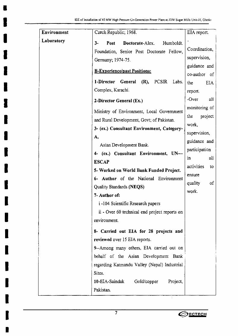
•IIIIIIIIIIIIIIIIIIII
lEE of Installation of 4S MW High Pressure Co-Generation Power Plant at JDW Sugar Mills Unit-Ill, Ghotki.
Environment
Laboratory
Czech Republic; 1968. EIA report.
-3- Post Doctorate-Alex. Humboldt.
Foundation, Senior Post Doctorate Fellow, Coordination,
Germany; 1974-75. supervision,guidance and
B-Experience/past Positions:
L-Director General (R), PCSIR
Complex, Karachi.
co-author of
Labs. the EIA
work,3- (ex.) Consultant Environment, Category-
I supervision,
guidance and
2-Director General (Ex.)
Ministry of Environment, Local Government
and Rural Development, Govt; of Pakistan.
A,
Asian Development Bank,
report.
-Over all
monitoring of
the project
partici pation4- (ex.) Consultant Environment, UN-
in allESCAP
activities to5- Worked on World Bank Funded Project.
6- Author of the National Environment
Quality Standards (NEQS)
7- Author of:
i -104 Scientific Research papers
ii - Over 60 technical end project reports on
environment.
8- Carried out EIA for 28 projects and
reviewed over 15 EIA reports.
9--Among many others, EIA carried out on
behalf of the Asian Development Bank
regarding Katmandu Valley (Nepal) Industrial
Sites.
IO-EIA-Saindak Gold/copper Project,
ensure
quality
work.
of
Pakistan.
7 @1ECTECH
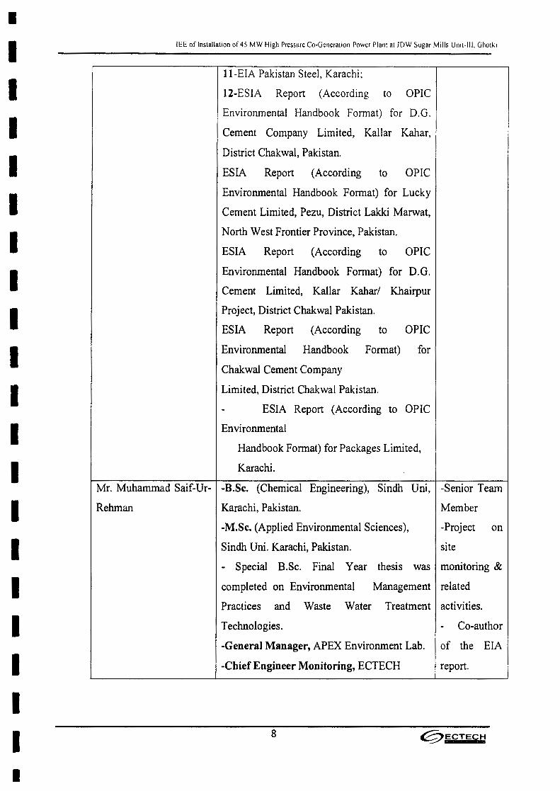
•IIIIIIIIIIIIIIIIIIII
lEE of Installation of 45 MW High Pressure Co-Generation Power Plant at lDW Sugar Mills Unit-III. Ghotki
ll-EIA Pakistan Steel, Karachi;
12-ESIA Report (According to OPIC
Environmental Handbook Format) for D.G.
Cement Company Limited, Kallar Kahar,
District Chakwal, Pakistan.
ESIA Report (According to OPIC
Environmental Handbook Format) for Lucky
Cement Limited, Pezu, District Lakki Marwat,
North West Frontier Province, Pakistan.
ESIA Report (According to OPIC
Environmental Handbook Format) for D.O.
Cement Limited, Kallar Kahar/ Khairpur
Project, District Chakwal Pakistan.
ESIA Report (According to OPIC
Environmental Handbook Format) for
Chakwal Cement Company
Limited, District Chakwal Pakistan.
- ESIA Report (According to OPIC
Environmental
Handbook Format) for Packages Limited,
Karachi.
Mr. Muhammad Saif-Ur- -B.Sc. (Chemical Engineering), Sindh Uni, -Senior Team
Rehman Karachi, Pakistan. Member
-M.Sc. (Applied Environmental Sciences), -Project on
Sindh Uni. Karachi, Pakistan. site
- Special B.Sc. Final Year thesis was monitoring &
completed on Environmental Management related
Practices and Waste Water Treatment activities.
Technologies. Co-author
-General Manager, APEX Environment Lab. of the EIA
-Chief Engineer Monitoring, ECTECH report.
8 @ECTECH

•IIIIIIIIIIIIIIIIIIII
lEE of Installation of 45 MW High Pressure Co-Generation Power Plant at JDW Sugar Mills Unit-Ill. Ghotki
-Experience in Environment: - Collection
For the last over 10 years working in the field of
of environment on the following subjects: demographic
- Prepared 10 EIA reports, in the field of data.
cement, textile, oil & gas, power generation, - Preparation
fertilizer, power alcohol and chemical industry. of
-Designing, fabrication, installation and environmenta
operation of Waste Water Treatment I
Plants; So far three plants have been installed. management
- Carrying out environmental Audit: Around plan.
18 industrial units have been completed so far.
- Lab. Testing of effluents and water: For the
last 5 years lab. testing services have been
provided.
-Full time participation in the assignments
under serial 12 - under Dr. M. Hanif' s
contributions.
Mr. Muhammad Anees.
- Full time participation in the assignments various
under serial 12 - under Dr. M. Hanif's aspects of
B.A; L.L.B; Expert on Environment Law
contributions (legal aspects).
Guidance on
Environment
al Law as
applicable to
EIA.
Environment
alist.
Preparation
of
Environment
al
management
9 @ECTECH
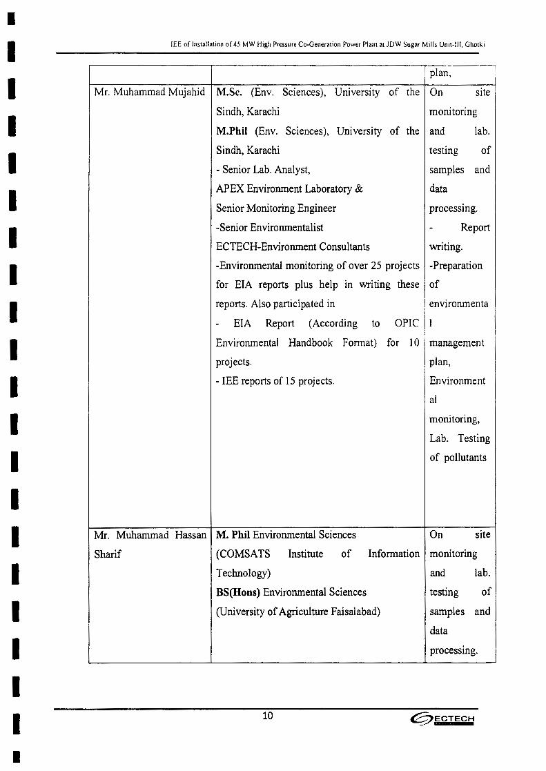
•IIIIIIIIIIIIIIIIIIII
lEE of Installation of 45 MW High Pressure Co-Generation Power Plant at lDW Sugar Mills Unit-Ill. Ghotki
plan,
of
Mr. Muhammad Mujahid M.Sc. (Env. Sciences), University of the On site
Sindh, Karachi monitoring
M.Phii (Env. Sciences), University of the and lab.
Sindh, Karachi
- Senior Lab. Analyst,
APEX Environment Laboratory &
Senior Monitoring Engineer
-Senior Environmentalist
ECTECH-Environment Consultants
testing
samples and
data
processing.
- Report
writing.
-Environmental monitoring of over 25 projects -Preparation
for EIA reports plus help in writing these of
reports. Also participated in environmenta
- EIA Report (According to OPIC I
Environmental Handbook Format) for 10 management
projects. plan,
- lEE reports of IS projects. Environment
al
monitoring,
Lab. Testing
of pollutants
Mr. Muhammad Hassan M. Phil Environmental Sciences
Sharif (COMSATS Institute of
Technology)
On site
Information monitoring
and lab.
BS(Hons) Environmental Sciences
(University of Agriculture Faisalabad)
testing of
samples and
data
processmg.
10 ~ECTECH
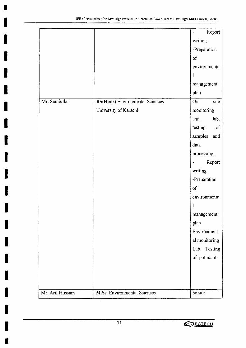
•IIIIIIIIIIIIIIIIIIII
lEE of Installation of 45 MW High Pressure Co-Generation Power Plant at lOW Sugar Mills Unit-III. Ghotki.
- Report
writing.
-Preparation
of
environmenta
I
management
plan
Mr. Samiullah BS(Hons) Environmental Sciences On site
University of Karachi monitoring
and lab.
testing of
samples and
data
processing.
- Report
writing.
-Preparati on
of
environmenta
I
management
plan
Environment
al monitoring
Lab. Testing
of pollutants
Mr. Arif Hussain M.Sc. Environmental Sciences Senior
11 ~ECTECH
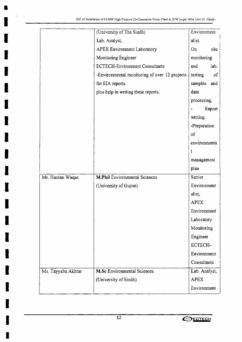
•IIIIIIIIIIIIIIIIIIII
lEE or Installation of 45 MW High Pressure Co-Generation Power Plant at JDW Sugar Mills Unit-III. Ghotki
(University of The Sindh) Environment
Lab. Analyst, alist.
APEX Environment Laboratory On site
Monitoring Engineer monitoring
ECTECH-Environment Consultants and lab.
-Environmental monitoring of over 12 projects testing of
for EIA reports samples and
plus help in writing these reports. data
processing.
- Report
writing.
-Preparation
of
environmenta
1
management
plan
Mr. Hassan Waqas M.Phi) Environmental Sciences
(University of Gujrat)
Senior
Environment
alist,
APEX
Environment
Laboratory
Monitoring
Engineer
ECTECH-
Ms. Tayyaba Akhtar
Environment
Consultants
M.Sc Environmental Sciences
(University of Sindh)
Lab. Analyst,
APEX
Environment
12 0ECTECH

•IIIIIIIIIIIIIIIIIIII
lEE of Installation of 45 MW High Pressure Co-Generation Power Plant at JDW Sugar Mills Unit-III. Ghotki.
Laboratory
ECTECH-
Envirorunent
Consultants
2.4 Brief description of nature, size and location of the project
2.4.1 Nature and size of the plant
The project is waste to energy or energy recovery in nature. By-product of sugar cane i.e.
bagasse will used as fuel to produce electricity. Bagasse is a valuable resource which can
be consumed more effectively. In framework for power Co-Generation 2013 (Bagasse /
Biomass) opportunity is provided to sugar mill to export the electricity to grid under the
scope of Renewable Energy Policy of 2006. NEPRA has prepared upfront tariff for
bagasse based high pressure power plants. The power portion (high grade energy) of
combined heat and power mix can be increased by adopting higher pressures.
45 MW high pressure Co-Generation power plant will be installed. The proposed power
plant will cover a total area of28.2 acres.
2.4.2 Location of the project
The Project Site is adjacent to JDW Sugar Mills Limited Unit III located near Goth
Islamabad, Tehsil and District Ghotki , Sindh. The adjacent area is owned by JDW Unit-
III.
The location map of the Project site map and Project Layout is provided below:
13 ~ECTECH
•IIIIIIIIIIIIIIIIIIII
lEE of Installation of 45 MW High Pressure Co-Generation Power Plant at lOW Sugar Mills Unit-III, Ghotki.
Figure 2.1: Location of tbe Project Courtesy: Google
14 tC;jECTECH
•II II IIIIIIIIIIIIIIIIII
lEE of Installation of 45 MW High Pressure Co-Generation Power Plant at JDW Sugar Mills Unit-III. Ghotki.
3.0 DESCRIPTION OF THE PROJECT
15 @ECTECH
•IIIIIIIIIIIIIIIIIIII
lEE of Installation of 45 MW High Pressure Co-Generation Power Plant at JDW Sugar Mills Unit-III. Ghotki
3.0
3.1
3.2
DESCRIPTION OF THE PROJECT
Type and category of the project
This Project is of energy generation project and falls in Schedule-I of The Sindh
Environmental Protection Agency (Review of Initial Environmental Examination and
Environmental Impact Assessment) Regulations, 2014 List of Projects Requiring an lEE,
Subsection-B Article-II "Thermal power generation less than 200 MW"
The plant site is situated within the legal jurisdiction of the Environmental Protection
Agency, Government of the Sindh, Karachi. Therefore, this lEE report will be submitted
to this EPA for getting Environmental Approval/No Objection Certificate as required
under the Sindh Environment Protection Act, 2014, Part-VI, Section-17 to fulfill the
mandatory legal condition.
Objectives of the project
The main objective of the project is to contribute indigenous source of electricity to the
national grid with minimal impact on the environmental conditions of the surrounding
area while aiding local employment and socio-economic development.
Bagasse based Cogeneration Power production facility in sugar industry, provides a lot of
advantages both to the sugar industry as well as to the country. Some of the advantages
using Bagasse as fuel are highlighted as below:
i- Reduces gap between demand and supply in the national grid with Bagasse as fuel
available at very low cost
ii- The Bagasse based cogeneration is environment friendly
iii- Cutting upon foreign exchange bills outflow from the country for the purchase of
the fossil fuels
iv- Improving financial status of sugar sector and its downstream products, by the use
of Bagasse as fuel for power production, which can also be called value addition
16 ~ECTECH

•IIIIIIIIIIIIIIIIIIII
lEE of Installation of 4S MW High Pressure Co-Generation Power Plant at JDW Sugar Mills Umt-lll, Ghotki
3.3 Alternatives considered for Site Selection
Hereunder, alternatives considered for the site selection for installation of the
cogeneration power plant are highlighted.
a- Availability of Land for the Power Plant
Ghotki Power (Pvt.) Limited, would be located on land available adjacent to lOW Unit-
III.
b- Availability of Bagasse as Fuel from In Sourcing
The power plant is adjacent to the JDW Sugar Mills Unit-III. Bagasse from lDW Unit-III
will be available for Cogeneration plant within the premises of Ghotki Power (Pvt.)
Limited as the sugar mill also belongs to the proponents of the Cogeneration Power Plant.
c- Availability of Bagasselbio mass from Out Sourcing
Bagasse can also be purchased from external sugar mills during off-season operations, as
and when available.
d- Basic infrastructure
Basic Infrastructure like roads, plentifully availability of underground water of good
quality, cheap labor, telephone, Internet, transportation etc. are available and well
developed.
e- Interconnection with Grid
Keeping in view the location of the Project, the most feasible interconnection scheme
would be the scheme being used for the existing 67 bar power plant. The existing power
plant is looped in-out in 132 kV double circuit at JDW Unit III. Ghotki Power (Pvt.)
Limited would generate power at 11 kV voltage level from where it will be stepped up
to l32 kV using 132/11 kV transformers.
17 ~ECTECH
•IIIIIIIIIIIIIIIIIIII
lEE of Installation of 45 MW High Pressure Co-Generation Power Plant at lOW Sugar Mills Unit·111. Ghotki
f- Transportation cost of Bagasse as raw material
To meet the requirement of steam for the 45 MW High Pressure Cogeneration project at
Ghotki Power (Pvt.) Limited, Bagasse from the adjacent JDW Unit-III would be
transported through conveyer belts. Bagasse from external sources shall be transported by
trucks.
g- Environment
Environmental consideration for industrial sitting is of utmost importance. The plant is to
operate according to the Environment Management Plan (EMP) as provided under
section 6. Under this EMP necessary safeguards have been provided to minimize all type
of pollutants to the level as required under the Sindh Environment Quality Standards
(SEQS)a.
The present site for installation of the power plant is not situated within or near to any
sensitive environment around. Accordingly, the site selected for the power plant is quite
suitable.
h- Waste water disposal facility
Effluent generated from Co-generation power plant will be neutralized and will be let
into the existing sugar effluent treatment plant. The treated water will be used for the
irrigation purpose inside the plant boundary walls and left over if any, will be discharged
into the nearby farms.
i- Labor availability
All categories of the labor required for the project operation are available conveniently
and plentifully at affordable cost at the project site. This factor too supports siting of the
project at the present site.
Estimated 100-150 labour will be engaged during construction phase while 50 persons in
three (03) shifts during regular operation of the power plant.
18 @ECTECH
•IIIIIIIIIIIIIIIIIIII
lEE of Installation of 45 MW High Pressure Co-Generation Power Plant at JDW Sugar Mills Unit-III, Ghotki.
3.5
3.6
3.7
On the basis of the above facts, the selected site for the new cogeneration power plant
project is the most suitable.
3.4 Location and site layout of the project (May be annexed at the end of report)
Location map is given in chapter-l
Overall plant layout, MIS Ghotki Power (Pvt.) Limited Pakistan, is attached as Annexure-
II.
Cogeneration HMBD-Season operation, MIS Ghotki Power (Pvt.) Limited Pakistan, is
attached as Annexure-III
Water Balance Diagram MIS Ghotki Power (Pvt.) Limited Pakistan, is attached as
Annexure-IV
Land use in the project area
The project site is within the Premises of Ghotki Power (Pvt.) Limited. Most of the area
around the project is in agricultural use. Sugarcane is one among the major cash crop of
the project area.
Road access
Project is at 2 Ian off from National Highway (NS) Ghotki toward Goth Islamabad,
district Ghotki , the district head quarter of the project area is connected with other parts
of the country by roads, railway and even airport. These facilities provide good
opportunities to the people to mix up with the public of the other parts of the country. The
airport even provides good air link to other countries. The economy of the district is
growing quite rapidly.
Vegetation features of the site
The area around the project site is vegetated and cultivation is mostly depends upon rain,
canals and the water obtained from tube wells. Wheat, sugarcane and corn are the main
crops and almost all the vegetables are grown. Fruit orchards are numerous and the main
fruit are Dates, Mango, lokat, Jaman, and guava.
19 ~ECTECH

•IIIIIIIIIIIIIIIIIII
lEE of Installation of 45 MW High Pressure Co-Generation Power Plant at JDW Sugar Mills Unit-III, Ghotki
3.8
3.9
3.10
The fauna and flora of the area include: Kikar, PipIe, Bohar, Eucalyptus, Popular and
Sharin. There is very little of wild life in the area. Karil (Capparis aphylla) is commonly
met with but is no-where bigger than shrub. Jand a much-prized tree for its firewood and
charcoal is becoming a Varity. Shisham Kikar along canal banks has developed into fine
big trees. There is no locality without a rich growth of trees mainly Piple, Bohar,
Eucalyptus, Popular and Sharin.
Cost and magnitude of the operation
As above mentioned 45 MW Co-generation power plant using Bagasse as fuel is going to
be installed at Ghotki Power (Pvt.) Limited, District Ghotki. The estimated cost of the
project is US$ 48.96 Million. The total area required for the project is 28.2 Acres. There
will not any other activity except the generation of power.
Schedule of Implementation
The complete Cogeneration plant could be implemented within a period of Twenty (20)
months from the date of purchase order to the boiler/TG contractor. In the proposed
cogeneration plant the boiler and the steam turbine are the long lead items and the
selection and implementation of the same require adequate time frames. The turbine is
likely to be imported from Japan. China or Europe, where as boiler maybe manufactured
locally or imported from China.
Description of the Project (process flow charts/ steps)
JDW Sugar Mills Unit-III is already having a Cogeneration plant operating for the last
three seasons under the same name. The existing Cogeneration plant is based on the cycle
parameters of 67 bar and 485 Deg.C and the plant capacity is 26.5 MW
Now, MIS Ghotki power (Pvt.) Limited has planned for phase-II of the bagasse based co-
generation program based on 110 bar and 540 Deg.C steam parameters, which would
phase out the existing low pressure systems completely. With the implementation of
Phase II Cogeneration, the proponent will be operating with two Cogeneration Units, one
based on 67 bar and 485 Deg.C cycle parameters and the other based on 110 bar and 540
Deg.C cycle parameters.
•20 ~ECTECH

•IIIIIIIIIIIIIIIIIII•
lEE of Installation of 45 MW High Pressure Co-Generation Power Plant at lOW Sugar Mills Unit-III, Ghotki
The proposed project capacity is 45 MW and will install adjacent to lOW Sugar Mills
Unit-III, Goth Islamabad, Tehsil & District Ghotki.
Table 3.1: Existing Power Plant Operation Energy Audit report
GROSS GENERATION OF STG MW 25.600
AUXILIARY LOAD MW 1.985
SUGAR MILL CONSUMPTION MW 3.923
MWEXPORT TO WAPDA 19.692
PROCESS STEAM TO SUGAR TPH 114.0
GROSS GENERATION OF STG MW 26.350
AUXILIARY LOAD MW 1.95
SUGAR MILL CONSUMPTION MW 0.432
EXPORT TO WAPDA MW 24
NILTPHPROCESS STEAM TO SUGAR
The power plant will be connected to the national grid through a loop in, loop out
arrangement at the 132-kV double circuit between Liberty and Ghotki grid stations that is
located at a distance of about 43.4km from the sugar mill.
As the fuel for power generation is Bagasse and power plant is going to be installed
adjacent to JDW Sugar Mills Unit-III, therefore, sufficient of bagasse will be available
21 @ECTECH
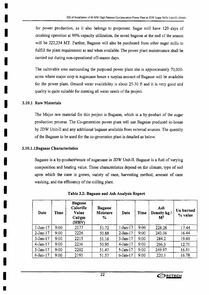
I
IIIIIIIIIIIIIIIIIII•
lEE of Installation of 45 MW High Pressure Co-Generation Power Plant at JDW Sugar Mills Unit-III, Ghotki.
for power production, as it also belongs to proponent. Sugar mill have 120 days of
crushing operation at 90% capacity utilization, the saved bagasse at the end of the season
will be 222,234 MT. Further, Bagasse will also be purchased from other sugar mills to
fulfill the plant requirement as and when available. The power plant maintenance shall be
carried out during non-operational off-season days.
The cultivable area surrounding the purposed power plant site is approximately 70,000-
acres where major crop is sugarcane hence a surplus amount of Bagasse will be available
for the power plant. Ground water availability is about 25-30 ft and it is very good and
quality is quite suitable for meeting all water needs of the project.
3.10.1 Raw Materials
The Major raw material for this project is Bagasse, which is a by-product of the sugar
production process. The Co-generation power plant will use Bagasse produced in-house
by JDW Unit-II and any additional bagasse available from external sources. The quantity
of the Bagasse to be used for the co-generation plant is detailed as below.
3.10.1.1Bagasse Characteristics
Bagasse is a by-product/waste of sugarcane in JDW Unit-II. Bagasse is a fuel of varying
composition and heating value. These characteristics depend on the climate, type of soil
upon which the cane is grown, variety of cane, harvesting method, amount of cane
washing, and the efficiency of the milling plant.
Table 3.2: Bagasse and Ash Analysis Report
BagasseCalorific Bagasse Ash Un burnedDate Time Value Moisture Date Time Density kg I % valueCaVgm % MJ(HHV)
I-Jan-17 9:00 2177 51.72 I-Jan-17 9:00 228.28 17.442-Jan-17 9:00 2226 50.88 2-Jan-17 9:00 243.06 16.443-Jan-17 9:00 2215 51.16 3-Jan-17 9:00 284.2 19.604-Jan-17 9:00 2236 50.95 4-Jan-17 9:00 296.3 12.715-Jan-17 9:00 2202 51.47 5-Jan-17 9:00 249.97 16.916-Jan-17 9:00 2193 51.57 6-Jan-17 9:00 220.3 16.78
22 ~ECTECH
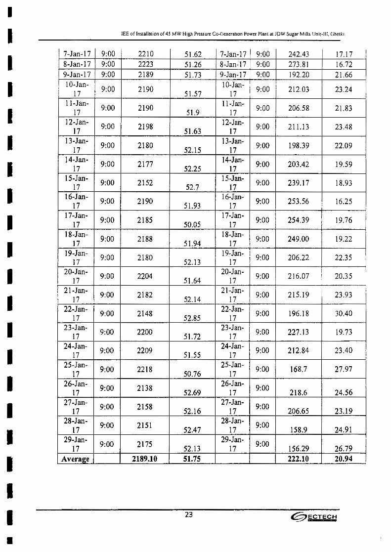
I
IIIIIIIIIIIIIIIIIII•
lEE of Installation of 45 MW High Pressure Co-Generation Power Plant at lOW Sugar Mills Unit-III. Ghotki.
7-Jan-17 9:00 2210 51.62 7-Jan-17 9:00 242.43 17.178-Jan-17 9:00 2223 51.26 8-Jan-17 9:00 273.81 16.729-Jan-17 9:00 2189 51.73 9-Jan-17 9:00 192.20 21.6610-Jan- 9:00 2190 10-Jan- 9:00 212.03 23.2417 51.57 17I1-Jan- 9:00 2190 II-Jan- 9:00 206.58 21.8317 51.9 1712-Jan- 9:00 2198 12-Jan- 9:00 211.13 23.4817 51.63 1713-Jan- 9:00 2180 13-Jan- 9:00 198.39 22.0917 52.15 1714-Jan- 9:00 2177 14-Jan- 9:00 203.42 19.5917 52.25 1715-Jan- 9:00 2152 15-Jan- 9:00 239.17 18.9317 52.7 1716-Jan- 9:00 2190 16-Jan- 9:00 253.56 16.2517 51.93 1717-Jan- 9:00 2185 17-Jan- 9:00 254.39 19.7617 50.05 1718-Jan- 9:00 2188 18-Jan- 9:00 249.00 19.2217 51.94 1719-Jan- 9:00 2180 19-Jan- 9:00 206.22 22.3517 52.13 1720-Jan- 9:00 2204 20-Jan- 9:00 216.07 20.3517 51.64 1721-Jan- 9:00 2182 21-Jan- 9:00 215.19 23.9317 52.14 1722-Jan- 9:00 2148 22-Jan- 9:00 196.18 30.4017 52.85 1723-Jan- 9:00 2200 23-Jan- 9:00 227.13 19.7317 51.72 1724-Jan- 9:00 2209 24-Jan- 9:00 212.84 23.4017 51.55 1725-Jan- 9:00 2218 25-Jan- 9:00 168.7 27.9717 50.76 1726-Jan- 9:00 2138 26-Jan- 9:0017 52.69 17 218_6 24.5627-Jan- 9:00 2158 27-Jan- 9:0017 52.16 17 206.65 23.1928-Jan- 9:00 2151 28-Jan- 9:0017 52.47 17 158.9 24.9129-Jan- 9:00 2175 29-Jan- 9:0017 52.13 17 156.29 26.79
Average 2189.10 51.75 222.10 20.94
23 @ECTECH
•IIIIIIIIIIIIIIIIIIII
lEE of Installation of45 MW High Pressure Co-Generation Power Plant at lDW Sugar Mills Unit-III, Ghotki.
3.10.2.2 Water
All requirements of water are given as:
The site will require make up and cooling water for the operation. The water requirement
of the proposed power plant is to be met from tube-wells. The ground water availability is
good and reliable. However, there is plenty of surface water available from nearby
irrigation canal system. Water from the canal could be utilized in case of emergency,
Due to plentiful availability of water, it has been decided to go with water cooled
condensing system for the cogeneration plant. The raw water supply has been planned to
be provided by tube-wells installed within the proposed plant boundary.
The raw water will be used as a source for makeup water for the losses in the process
steam, boiler blow down, cooling tower blow down, service water, etc. It has been
proposed to provide totally independent raw water and treated water system for the
proposed cogeneration project. The new system will include the storage reservoir,
clarifier, reverse osmosis and de-mineralization system and storage tanks. The proposed
plant will be located in the area which is being fed by an elaborate irrigation canal
system; with the result that ground water aquifer is being regularly replenished. Shortage
of ground water is not expected,
Cooling Tower
Induced draft counter flow RCC cooling tower of capacity 10,200 m31hr. Three (3) cells
each of capacity 3400 m31hr.
Reverse Osmosis (RO) Plant
The RO plant shall be designed to have two streams of 38 rrr' each. Adequately sized
neutralizing pit shall be provided near the RO plant for collecting the discharges from the
RO plant and effectively neutralizing the same before pumping the waste to the sugar
plant's effluent treatment system.
The water requirement for different processes during construction and operation phase
are fulfill by underground water.
24 ~ECTECH
•IIIIIIIIIIIIIIIIIIII
lEE of Installation of 45 MW High Pressure Co-Generation Power Plant at JDW Sugar Mills Unit-III. Ghotki
Demineralized (OM)
Water Plant DM water plant will be installed for complete demineralization of raw water
for use as boilers makeup water. Regeneration effluents after neutralization will be sent to
the wastewater treatment plant.
Wastewater Treatment Plant
Liquid effluents from all sources will be treated according to required levels of the
National Environmental Quality Standards as well as those by the World Bank, before
pumping the waste to the sugar plant's effluent treatment system. It is estimated that 50 to
60% of the liquid effluents will be recycled thus reducing the requirement of raw makeup
water by 40 to 50%. Thus, there is no possibility of any damage to the agriculture crops
in the least.
a. Boiler feed water total requirement 220 Tonlh
h. The raw water will be made available from the deep 3 Well turbine pumps. 2
turbines are reserved if there is problem in anyone. Cooling water for extraction /
condensing turbine total requirement is 10,200 m' Ih. All the water will be re-
circulated. Drift Losses 0.005 % will be met from underground water.
Evaporation loss 1.56 %. All cooling water requirement will be met through
cooling tower.
• Water requirements during construction phase =100 - 150 cum/day
• Water requirements during operational phase (during season) =5400 cum/day
• Water requirements during operation phase (during off season) = 7200 cum/day
• Coolant water requirement = 10200 cum/hr Approx.(circulation)
25 ~ECTECH
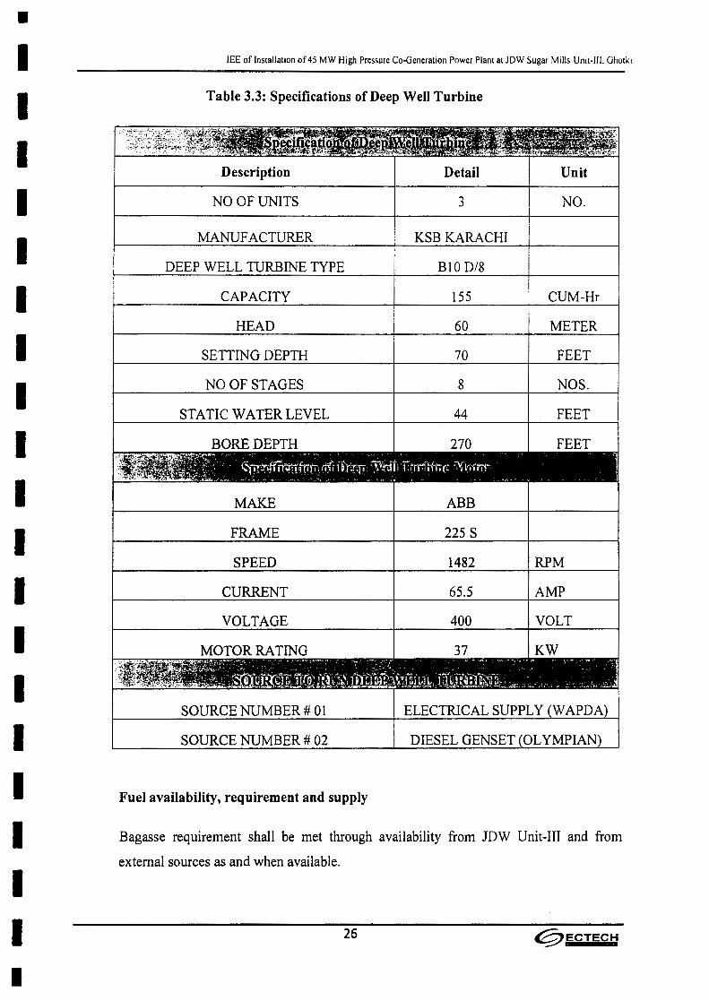
•IIIIIIIIIIIIIIIIIIII
lEE of Installation of45 MW High Pressure Co-Generation Power Plant at JDW Sugar Mills Unit-Ill. Ghotki
Table 3.3: Specifications of Deep Well Turbine
Description Detail Unit
NO OF UNITS 3 NO.
MANUF ACTURER KSB KARACHI
DEEP WELL TURBINE TYPE BI0 D/8
CAPACITY 155 CUM-Hr
HEAD 60 METER
SETTING DEPTH 70 FEET
NO OF STAGES 8 NOS.
STATIC WATER LEVEL 44 FEET
BORE DEPTH 270 FEET
MAKE ABB
FRAME 225 S
SPEED 1482 RPM
65.5 AMPCURRENT
VOLTAGE 400 VOLT
KWMOTOR RATING 37
SOURCE NUMBER # 01 ELECTRICAL SUPPLY
DIESEL GENSETSOURCE NUMBER # 02
Fuel availability, requirement and supply
Bagasse requirement shall be met through availability from JDW Unit-III and from
external sources as and when available.
26 ~ECTECH

•IIIIIIIIIIIIIIIIIIII
lEE of Installation of 45 MW High Pressure Co-Generation Power Plant at JDW Sugar Mills Unit-III. Ghotki
3.11 Technology Review & Selection
3.11.1 Major Equipment: (Layouts and details)
The following gives the major equipment and systems involved in the proposed new
Cogeneration plant. It is important that the new equipment or the system is properly
optimized and integrated with the existing equipment and systems associated with the 67
bar Cogeneration plant. Brief commentary is given, wherever required, to highlight the
requirement regarding the integration of the systems.
Steam generator and Auxiliaries
New standalone system, to be located on the southern side in new vicinity adjacent to the
existing boiler.
Steam Turbine and Auxiliaries
New extraction condensing steam turbine, to be located in new vicinity adjacent to the
existing setup.
Fuel & grate bottom ash Handling system
The bagasse handling system comprising of chain conveyors & belt conveyors to
transport the required quantity of bagasse from sugar mill to cogeneration shall be
provided. Bagasse from the sugar mill shall be fed to the boiler from a front mounted
chain conveyor. Excess bagasse shall be returned to the bagasse storage yard. During off-
season/non-availability of bagasse from mill, the cogeneration boiler shall use saved
bagasse from the storage yard.
The ash handling system envisaged for the cogeneration boiler shall consist of
Submerged Ash Belt Conveyor System and Dense Phase Ash Handling System
Cooling Tower
Will be new and stand alone for the new plant. The location will be by the side of the
existing cooling tower of the 67-bar plant. Side stream filters to be added.
27 @ECTECH

•IIIIIIIIIIIIIIIIIIII
lEE of Installation of 45 MW High Pressure Co-Generation Power Plant at JDW Sugar Mills Unit-III, Ghotki.
Water treatment plant and other associated systems
The existing water treatment system at the existing 67 bar High Pressure Cogen Plant
shall be expanded as required to meet the requirements of the new 110 bar High Pressure
Cogeneration plant.
EDT crane
An Electrically operated EOT crane shall be provided for the erection and maintenance
requirements of turbo generator and its auxiliaries.
The main hook capacity shall be 90 Tons and suitable for lifting single heaviest
component in Turbo Generator. The auxiliary hook lifting capacity shall be of 5 Tons.
The crane travel will cover the entire length of the TG building. The crane shall be
electrically operated, bridge type and shall be designed and equipped for indoor
operations complete with all accessories. The crane bridge shall consist of bridge girders
each carrying a rail on which a wheeled trolley is to run. Operation of crane shall be by
pendant type push button station from ground level.
Compressed Air System
The function of this system is to provide service and instrument air for cogeneration plant
operations. Compressed air system provides air to following users:
• Instrument Air Users: Instrument air will be required for the operation of
pneumatic instruments like lIP converters, purge instruments, pneumatic actuation
of control valves, dampers etc .
• Service Air Users: Service air will be required for cleaning of filters, strainers and
general purpose.
Firefighting System
The function of fire-fighting system is to supply water to the main risk areas of the
cogeneration power plant.
The fire protection system is required for early detection, containment and suppression
of fires. A comprehensive fire protection system shall be provided to meet the above
objective and all statutory and insurance requirements of National Fire Protection
28 @ECTECH
•IIIIIIIIIIIIIIIIIIII
lEE of Installation of 45 MW High Pressure Co-Generation Power Plant at JDW Sugar Mills Unit-III, Ghotki
Association (NFPA),
3.11.2 Plant Technology Suppliers
Tentative manufacturers of plant and equipment are provided below, which are subject to
change after the detailed design process and submission of financial and technical
proposal
a. Boiler - Heavy Mechanical Complex (HMC) , Descon Engineering, imported
from China.
b. Steam Turbine - Imported from Japan, China or Europe.
c. Switchyard and transformers - Siemens Pakistan.
d. Fuel & Ash handling system - Same as boiler manufacturers.
e. EaT Crane - Kuhnezug, Germany
f. Water Treatment plant - WEMS Pakistan
g. Cooling Towers - Truwater, Malaysia
h. Drivers I Motors I Instrumentations - ABB I Siemens I Yokogawa I Emerson.
3.11.3 Process details
This proposed Cogeneration plant is configured with a travelling grate multi fuel fired
boiler, of 220 TPH capacity. The boiler outlet steam parameters will be 110 bar (a) and
540 Deg.C. The steam from the boiler will be supplied to an extraction condensing type
turbogenerator with a nominal capacity of 45 MW and with the turbine inlet steam
parameters of 105 bar(a) and 535 Deg.C. The turbine and generator will be coupled
through a gear box. The turbine will be designed with a controlled extraction port at 2.5
bar (a), for supplying the 2.5 bar(a) process steam and two uncontrolled extraction ports,
one at lObar (a) and the other at 22 bar (a).
There will be two stages of high pressure feed water heating to a final feed water
temperature of 210 Deg.C. The total process steam and the regenerative heating steam
will be drawn from the turbine extractions. The condenser of the turbine will be water
29 ~ECTECH
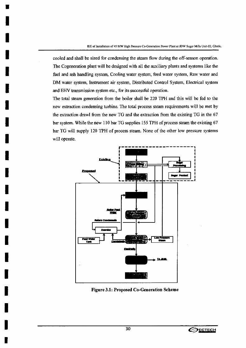
•II
IEE of Installation of 45 MW High Pressure Co-Generation Power Plant at JDW Sugar Mills Unit-III, Ghotki.
II
cooled and shall be sized for condensing the steam flow during the off-season operation.
The Cogeneration plant will be designed with all the auxiliary plants and systems like the
fuel and ash handling system, Cooling water system, feed water system, Raw water and
DM water system, Instrument air system, Distributed Control System, Electrical system
and EHV transmission system etc., for its successful operation.
The total steam generation from the boiler shall be 220 TPH and this will be fed to the
new extraction condensing turbine. The total process steam requirements will be met by
the extraction drawl from the new TG and the extraction from the existing TG in the 67
bar system. While the new 110 bar TG supplies 155 TPH of process steam the existing 67
bar TG will supply 120 TPH of process steam. None of the other low pressure systems
will operate.
IIIIIIIIIIIII Figure 3.1: Proposed Co-Generation Scheme
II 30 ~ECTECH
I

•IIIIIIIIIIIIIIIIIIII
3.12
lEE of Installation of 45 MW High Pressure Co-Generation Power Plant at JDW Sugar Mills Unit-Ill, Ghotki
3.13
Details of restoration and rehabilitation at the end of the project life
The co-generation power plant is expected to have a project life of about 30 years. Once
the useful life of the new plant will be over, it will be refurbished completely. A
comprehensive mechanical, electrical and civil structural overhaul will be carried out. To
bring the plant to-date with the then technology available, all necessary equipment
replacements will also be done. In this way, the plant will be revived for another term of
its useful life. The redundant parts and equipment will be sold in the market for recycling.
In fact, the replacement / up gradation of damage / obsolete components of all the major
equipment's will be carried out as and when needed. However, if the restoration!
rehabilitation of any component! equipment will be deemed imperative and that will be
carried out with the most modern technology available at that time.
This all will be done conforming to the environmental management and controls so as to
avoid any damage to any segment of environment or human health. Good part of the civil
works, specially the digging of the soil, has already been completed therefore for
restoration and rehabilitation of the site at the end of the project shall be one month.
Government approvals and leases required by the project
No objection certificate (NOC)lEnvironmental Approval (EA) from the EPA, Sindh, is
the major requirement to start work on the project.
31 ~ECTECH

•IIIIIIIIIIIIIIIIIIII
lEE of Installation of 45 MW High Pressure Co-Generation Power Plant at JDW Sugar Mills Unit-III, Ghotki.
4.0 DESCRIPTION OF THE ENVIRONMENT
32 @ECTECH

•IIIIIIIIIIIIIIIIIIII
lEE of Installation of 45 MW High Pressure Co-Generation Power Plant at JDW Sugar Mills Unit-III, Ghotki.
4.0 DESCRIPTION OF THE ENVIRONMENT
(AREA AFFECTED BY THE PROJECT)
4.1 Spatial and temporal boundaries adopted for the various aspects of
The study
While carrying out the present study, factors including present environmental settings
and likely future trends around the project site were taken into consideration.
Availability of basic infrastructure, water, raw materials, and markets for the product,
labor, transport and electricity were the major among other factors considered in the
project area. Socio-economic conditions were also considered during the course of the
study,
a) Existing (baseline) condition of the biophysical and socio-economic
environment, trends and anticipated future environmental conditions should
the project not go ahead.
Canals and tube wells provides water for the irrigation in the project. There are
mango orchards spread over long distances, Wheat, cotton, sugarcane and pulses
are the major cash crops.
Many people rear especially cows and buffalos for producing milk even on semi
commercial scale. It will not be out of place to say that the area is one among the
other food baskets of the Sindh province.
The awareness about the importance of education is now developing in the area.
Some people of the area are playing an important role in the politics of the
country even at higher levels. Fairly reasonable proportion of the people in cities
is educated. While in villages, like in other parts of the Sindh province, % of
educated people is low. Modem means of communication including television,
radio, telephone, fax, e-mail and newspapers are within the reach of majority of
the people especially in the cities. The socio-economic values are subject to
change in cities specifically under the influence of media especially television.
Goth Islamabad, which is a small town, has infrastructure and basic facilities of
life available for the peoples of the area. High Schools, Hospital, Vocational
training institutes, Police Station and Post Offices etc. are present in the area.
(iiwlk i Power (PI'I.) Ltd.
33 0ECTECH

•IIIIIIIIIIIIIIIIIIII
lEE of Installation of 45 MW High Pressure Co-Generation Power Plant at JDW Sugar Mills Unit-III, Ghotki
Ghotki, the district head quarter of the project area is connected with other parts
of the country by roads, railway and even airport. These facilities provide good
opportunities to the people to mix up with the public of the other parts of the
country. The airport even provides good air link to other countries. The economy
of the district is growing quite vastly.
There also exists a highly educated and well placed segment of society, this
segment is quite affluent and socially and politically well off also. Their way of
life is comparable with that of any developed segment of the society in Pakistan.
This segment of the society is playing leadership role for the people of the area.
Mostly, villagers follow old traditions in almost every walk of their life. Elderly
people command respect and play deciding role in decision making. A large cross
section of the older generation is uneducated. But due to awareness about
education younger generation of both sexes, is now trying to get education in
almost every department including science and technology on preferential basis.
There is a rising trend in the society to change their old traditional socioeconomic
pattern of life. Print and electronic media are playing great role in bringing
tangible change in the old pattern of life.
Environmentally speaking the carrying capacity of the environment is not utilized.
The project activity, under the proposed strict operational environmental controls,
is not going to leave adverse impacts on all out environment. The operational
Environmental Management Plan and Environmental Monitoring Plan further
provide protection to the environment around. Legal compliance of environmental
monitoring with NEQS standards is to doubly ensure environmental protection of
all the segments of the environment. '
b) Environmentally sensitive areas of special or unique value
(Physical resources of the project area: Topography and geology; Soils and
Climate; water; Ecological resources: Fisheries and aquatic biology,
Biodiversity, Forestry, Wildlife, scientific institutions, Socio-economic and
Cultural and other heritage)
• Physical Resources of the Project Area:
The physical resources of the project area are described below:
Ghotk i Power (Pvt.) LId.
34 @ECTECH

•IIIIIIIIIIIIIIIIIIII
lEE of Installation of 45 MW High Pressure Co-Generation Power Plant at JDW Sugar Mills Unit-if I. Ghotki
Topography and Geology:
Pakistan lying in the northwestern part of the Southern Asian Subcontinent,
occupies the western end of the Indo-Genetic Plain, which is beyond bounded in
the north by mountain wall of the Great Himalayas and their offshoots.
Physiology of the earth is description of the behavior of the upper crust.
Accordingly, some knowledge of the geology is desirable.
Of the six Physiographic Divisions of Upper Indus Plain namely:
i- Bari Doab- 2.9 million hectares,
ii- Rechna Doab-2.8 million hectares,
iii- The Chaj Doab- 1.3 million hectares,
iv- The Sindh Sagar Doab/Thal Desert, 3.2 million hectares,
v- The Bahawalpur Plain and
vi- The DerajatiSuleman Piedmont, 2 million hectares.
The land in this area consists of the alluvial soil deposited by the waters of the
river Indus, so it is naturally very fertile. Almost 60% of the land is cultivated
while the rest is under forest. Major crops are wheat, cotton and sugarcane.
Sunflower and a variety of vegetable are also grown. In addition to the river Indus
a number of canals including Ghotki Feeder provide the necessary irrigation
system. Hand pumps and tube wells are also common in this area because of a
very shallow water table which may rise as high as 1.5 feet below ground in some
Katcha area.
The area is classified as hot arid on overall basis; however, canals are available
for irrigation purpose. December and January are the coolest months of the year
while June and July are the hottest. Total annual rainfall is in the range of 125 to
250 mm.
More than 65% of the land is owned by the farmers themselves and around 35% is
cultivated by the tenant farmers. Land holding range from as low as 2.5 acres to
well over 1000 acres. Farmers in the area keep small cattle herds of poultry,
35 @ECTECH
•IIIIIIIIIIIIIIIIIIII
lEE of Installation of 45 MW High Pressure Co-Generation Power Plant at JDW Sugar Mills Unll-1I1. Ghotki
sheep, goats, buffalos and cows to supplement their income and to obtain milk
and other dairy products.
• Soils:
Soils form major part of environment. Their fertility and other special
characteristics have great relationship with environment. Climate has great
influence on the formation of soils; therefore, study of these factors is of great
importance. Soil is dynamic layer in which many complex physical, chemical
and biological activities are taking place. Therefore, soil is a dynamic
changing body. Soil scientists restrict the word soil or solum to the surface
materials which over the ages have adopted the distinctive layers or horizon.
Soils are made up of solids, liquids and gases. The solid part of the soil is
made up of both inorganic and organics. While weathering of rocks make
inorganic particles, the organic solids consist of living and decayed plants. In
order to classify the entire soils in Pakistan, the Soil Survey of Pakistan has
divided the entire country into nine ecological zones.
The fertile land of the Goth Islamabad falls in the Sub Recent River Plains and
consists of areas between Old River Terraces and the recent times floodplains
of the rivers. There is a great similarity in the nature of sediments,
depositional pattern and their configuration to that of the "BAR" areas. As
regards their age, they far too younger and have been deposited only during
Sub recent times. It is this age difference which is responsible for weaker
development in these soils. Because of illuviation or eluviation of clay, calcic
horizon, vertices characteristic and features are absent in the soils of this area.
The soils are developed to only moderate depths. Orchicepipedon and cambic
horizon are found in the soils. In local language, these soils are called "Bangar
Soils"
• Climate:
Pakistan is situated on the western margin of one of the main regions of the
world-the monsoon region. Due to this, the climate of the country is more
Continental than that of the other parts of Subcontinent. Annual Rain fall in
the project area is 50-70 mm. Pakistan has four seasons namely:
(iIH'I~i Power (PHi LId
36 @FCTEC~

•IIIIIIIIIIIIIIIIIIII
lEE of Installation of 45 MW High Pressure Co-Generation Power Plant at JDW Sugar Mills Unit-III, Gnotki
.., Cold Weather Season-December to March .
..,. Hot Weather Season-April to June.
>- Monsoon Season -- July to September
Temperature:
Mean monthly temperature during July =Mean monthly temperature during January =Mean monthly temperature (July and January):
i- Hottest Month:
• M.Min. = 29.0 0 C
• M.Max. =41.1 °C
ii-Coldest month:
• M.Min. = 4.7 °C
• M.Max. = 20.0oC
Rainfall:
Rainfall (July to December)
Rainfall (December to March)
Mean annual rainfall
= 100 -150 mm
= 50-80 mm
= 100 - 160mm
Seismicity:
Zone category: III Moderate Hazard
Seismic factor ground g/l S - gl20
acceleration:
Possible damage: Minor
• Water:
Canal water and underground sweet water are the two main sources of water
for irrigation.
a) Underground Water:
This underground water available in large quantities will be used for the
entire needs of the project. Extraction of water for project needs will not be at
the cost of its availability for irrigation or other uses.
(ih"lk I Pl1I1Cr (PVI.) Lid
37 ~ECTECH
•IIIIIIIIIIIIIIIIIIII
lEE of Installation of 45 MW High Pressure Co-Generation Power Plant at lOW Sugar Mills UnJl·III. Ghotk:
Ecological Resources fisheries, aquatic biology, wildlife, forests, rare or
endangered species:
Fishery and Aquatic Biology:
The Indus River flowing at a distance of about 20 Km contains fish which is sold on
yearly basis to private contracors for its commercial exploitation. The famous fish
varieties in the IndusRiver water include Roho (Labeorohita), Thaila (catlacatla),
Mallri and Singara.
There are no fish farms at least within 15 km radius of the project site or any other
source of fish in the entire area.
Biodiversity:
Natural capital of a country mainly includes all of a country's wilderness areas and
scenic landscapes, including the associated flora and fauna.
Pakistan has a total of nine major ecological zones. The contribution of the "Natural
capital" is recognized at three distinct levels: species, genera, and communities
(habitat and ecosystem). Both collectively and within each level, the range or variety
of the resources is referred to as the "Biological Diversity". The term has relevance
for each of Pakistan's administrative units-district, province, and particularly
country. The more the number of species, genera and habitats and ecosystems
present within these units, the greater is said to be the Biodiversity. The biodiversity
of the area, with this background, is discussed as under:
Forestry:
There are no forests within about 30 km radius of the project site.
Plantation, grasses and shrubs along road, rail, canal and river sides
exist. Similarly, in general trees, grasses and shrubs exist on the
cultivable land. For detailed account of important trees, grasses and
shrubs of the area refer to under caption "Flora".
Wildlife:
Ghotki project area is quite rich in wildlife due to its diversity of habitat. The species
of birds are especially common, a number of reptiles and amphibian species are
(ihCI[ki Power (Pvr.) Ltd.
38 @ECTECH
•IIIIIIIIIIIIIIIIIIII
lEE of Installation of 45 MW High Pressure Co-Generation Power Plant at JDW Sugar Mills Umt-IIl, Ghotki
also found here. There is a long list of mammals, birds and reptiles which are
found here.
Mammals
.:. Tatera indica (Antilope rat)
.:. Lepus nigricollis (Black napedhare)
.:. Herpestes edwardsi (Grey mongoose)
.:. Hemiechinus auritus (Hedgehog)
.:. Axis procinus (Hog deer)
.:. Mus musculus (House mouse)
.:. Ratus ratus (House rat)
.:. Platanista indio (Indus dolphin)
.:. Canis aureus (Jackal)
.:. Felis chaus (Jungle cat)
.:. Funanbulus fennanti (Northern palm squirrel)
.:. Lutra perspicillata (Otter)
.:. Hystrix indica (Procupine)
.:. Vulpes vulpes (Res fox)
.:. Nesokia indica (Short tailed mole rat)
.:. Sus scrofa (Wild boar)
• Birds
.:. Acridotheres gingianus (Bank myna)
Gl1ll1ki Power (Pvt.) Ltd,
39 @ECTECH
•IIIIIIIIIIIIIIIIIIII
lEE of Installation of 45 MW High Pressure Co-Generation Power Plant at JDW Sugar Mills Unit-III, Ghotki
.:. Lanius vittatus (Bay backed shrike)
.:. Dicrurus adsimilis (Black drongo)
.:. Francolinus francolinus (Black partridge)
.:. Larus ridibundus (Black headed gull)
.:. Podiceps nigricollis (Black necked grebe)
.:. Elanus caeruleus (Black winged kite)
.:. Himantopus himantopus (Black winged stilt)
.:. Bueto bueto (Buzzard)
.:. Bubulcus ibis (Cattle egret)
.:. Corvus splendens (Common crow)
.:. Trunga hypoleucus (Common sandpiper)
.:. Haliaetus leucoryphus (Fish eagle)
.:. Anas querquedula (Gargany)
.:. Francolinus pondicerianus (Grey partridge)
.:. Saxicoloides fulicata (Indian robbin)
.:. Torgos calvus (King vulture)
.:. Vanellus indicus (Lapwing)
.:. Phalacrocorax niger (Little cormorant)
.:. Egretta garzetta (Little egret)
.:. Egretta intermedia (Median egret)
Ghork: POII'l!r (I'vr.) LId40 @ECTECH
•IIIIIIIIIIIIIIIIIIII
lEE of Installation of 45 MW High Pressure Co-Generation Power Plant at lDW Sugar Mills Unit-III. Ghotki
.:. Ceryle rudis (Pied kingfisher)
.:. Anas acuta (Pintail)
.:. Ardea purpurea (Purple heron)
.:. Neophron peromopterus (Scavenger vulture)
.:. Alcedo atthis (Small blue kingfisher)
.:. Aquila rapax (Tawny eagle)
.:. Halcyon smyrnensis (White breasted kingfisher)
.:. Amaurornis phoenicurus (Whtie breasted waterhen)
• Amphibians and Reptiles:
.:. Hardella thurgi (Crown turtle)
.:. Trionyx gangeticus (Giant soft shelled turtle)
.:. Kachuga smithii (Hard shelled turtle)
.:. Chitra indica (Soft shelled turtle)
.:. Natrix piscator (Water snake)
• Protected Animals:
Sindh Wildlife Department promulgated an ordinance in 1972 for protection of
Wildlife in the province which contains a list of protected animals, some of which
are found in the vicinity of project area: Indus Dolphin and Hog Deer are of special
importance as they are endangered animals.
• Protected Birds:
.:. All members of the family Ardeidae: i.e., all Herons, Night Herons, Paddy
.:. Birds, Egrets or Bitterns.
41 ~ECTECH

•IIIIIIIIIIIIIIIIIIII
lEE of Installation of 45 MW High Pressure Co-Generation Power Plant al JD W Sugar Mills Unil-III. Ghotk I
.:. All members of the f
.:. amily Pelecanidae: i.e., all Pelicans.
.:. All members of the family Ciconidae: i.e., all Strokes .
•:. All members of the genus Cygnus: i.e., all Swans.
.:. All members of the family Phasianidae: i.e., all Pheasants, Partridges,
.:. Quails, Supurfowls, Jungle fowls and Peafowls.
.:. All members of the genus Heliopais: i.e., all Finfoots .
•:. All members of the family Otidiae: i.e., all Bustards.
.:. Pterocles alchata. - Large Pin-tailed Sandgrouse.
Protected Mammals:
.:. Macaca speciosa. - Stump-tailed Macaque .
•:. Presbytis obscurus. - Dusky Leaf Monkey.
.:. Vulpes cana. - Boanford's Fox.
.:. Felis viverrina. - Fishing Cat or Marsh Billi, Mach Bagral.
.:. Azis axis. - Spotted Deer or Chittal, Chitra, Jhank, Pagal, Hiran, Boro,
.:. Khetiya .
•:. Axis porcinus. - Hog Deer or Para.
.:. Boselaphus tragocamelus. - Blue Bull or Nilgai, Gond, Bain, Ranjh, Rojra .
•:. Platanista gangetica. - River Dolphin or sus, Susu, Susuk, Sishuk,
.:. Bhulan, Sunsar.
Protected Reptiles:
.:. Crocidilus palustris. - Marsh Crocodile or Muggar, Magar Mach .
•:. Crocodilus porosus. - Estuarine Crocodile or Maggar.
.:. All Snakes pfthe genus Python: i.e., all Pythons, Azdha or Arar .
•:. All marinr turtles of the genera Dermochelys, Chelone, Caretta and
.:. Eretomichelys i.e., all Leather back, Green or edible, Hawks bill, Logger head
and Tortoise-shell Turtles.
Flora:
The land is fertile. Major cash crops include sugar cane, cotton, wheat and pulses.
Trees, grasses and shrubs found are listed as below:
lihColl;i Power (Pvt.) LId.
42 @ECTECH
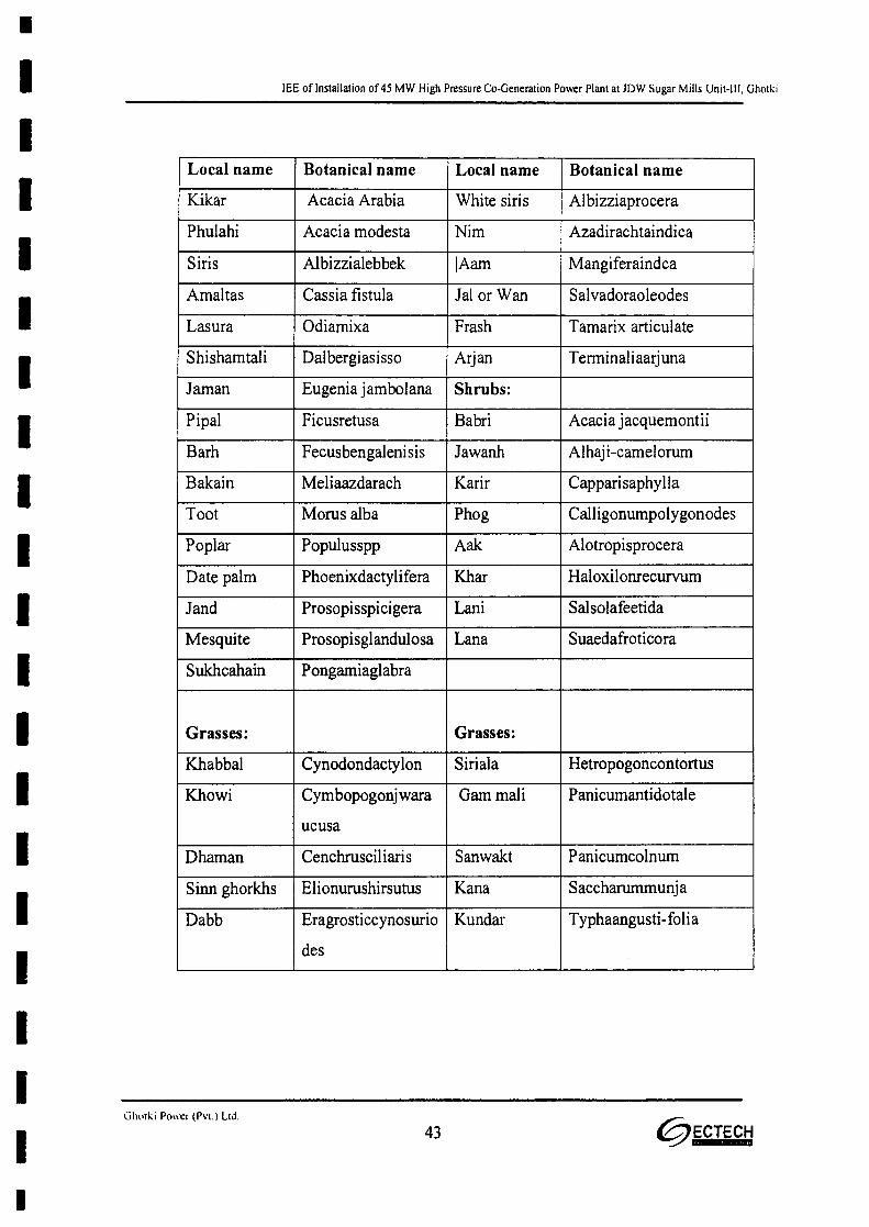
•IIIIIIIIIIIIIIIIIIII
lEE of Installation of 45 MW High Pressure Co-Generation Power Plant at JDW Sugar Mills Unit-III, Ghotki
Local name Botanical name Local name Botanical name
Kikar Acacia Arabia White siris Albizziaprocera
Phulahi Acacia modesta Nim Azadirachtaindica
Siris Albizzialebbek [Aam Mangiferaindca
Amaltas Cassia fistula Jal or Wan Salvadoraoleodes
Lasura Odiamixa Frash Tamarix articulate
Shishamtali Dalbergiasisso Arjan Terminal iaarjuna
Jaman Eugenia jambolana Shrubs:
Pipal Ficusretusa Babri Acacia jacquemontii
Barh Fecusbengalenisis Jawanh Alhaj i-camelorum
Bakain Meliaazdarach Karir Capparisaphylla
Toot Morus alba Phog Calligonurnpolygonodes
Poplar Populusspp Aak Alotropisprocera
Date palm Phoenixdactylifera Khar Haloxilonrecurvum
Jand Prosopisspicigera Lani Salsolafeetida
Mesquite Prosopisglandulosa Lana Suaedafroticora
Sukhcahain Pongamiaglabra
Grasses: Grasses:
Khabbal Cynodondactylon Siriala Hetropogoncontortus
Khowi Cymbopogonjwara Gam mali Panicumantidotale
ucusa
Dhaman Cenchrusciliaris Sanwakt Panicumcolnurn
Sinn ghorkhs Elionurushirsutus Kana Saccharummunj a
Dabb Eragrosticcynosurio Kundar Typhaangusti- folia
des
Gh(.[j.;j Power (Pvt.) Ltd,
43 @ECTECH
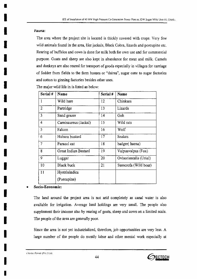
•IIIIIIIIIIIIIIIIIIII
lEE of Installation of 45 MW High Pressure Co-Generation Power Plant at JDW Sugar Mills Unit-III, Ghotk:
Fauna:
The area where the project site is located is thickly covered with crops. Very few
wild animals found in the area, like jackals, Black Cobra, lizards and porcupine etc.
Rearing of buffalos and cows is done for milk both for own use and for commercial
purpose. Goats and sheep are also kept in abundance for meat and milk. Camels
and donkeys are also reared for transport of goods especially in villages for carriage
of fodder from fields to the farm houses or "dairas", sugar cane to sugar factories
and cotton to ginning factories besides other uses.
The major wild life in is listed as below:
Serial # Name Serial # Name
1 Wild hare 12 Chinkara
2 Partridge 13 Lizards
3 Sand grazer 14 Goh
4 Camisaureus (Jackal) 15 Wild rats
5 Falcon 16 Wolf
6 Hubara bustard 17 Snakes
7 Paracol cat 18 badger( haena)
8 Great Indian Bustard 19 Valpusvalpus (Fox)
9 Luggar 20 Ovisorientalis (Urial)
10 Black buck 21 Susscrofa (Wild boar)
11 Hystrixindica
(Porcupine)
• Socio-Economic:
The land around the project area is not arid completely as canal water is also
available for irrigation. Average land holdings are very small. The people also
supplement their income also by rearing of goats, sheep and cows on a limited scale.
The people of the area are generally poor.
Since the area is not yet industrialized, therefore, job opportunities are very less. A
large number of the people do mostly labor and other menial work especially at
(Jh(llk i Power (P\'[') Ltd
44 @ECTECH
•IIIIIIIIIIIIIIIIIIII
lEE of Installation of 45 MW High Pressure Co-Generation Power Plant at lOW Sugar Mills Unit-Ill, Ghotki.
Islamabad, Faisalabad, Lahore and Karachi. However, some are working in Middle
East. Fairly over 10% of the younger generation is in Pakistan Army.
There is also a highly educated, affluent and well placed segment of the society in
the area. Their way of life can be compared with that of any developed segment of
the society of Pakistan. They provide leadership role for development of other
classes of the society. They are quite helpful to the people of their areas. They serve
as Beacon house for the other low placed class. Their role in the development of the
area and society is quite important.
People mostly follow old traditions in almost all walks of their life. Elders are very
much respected and play vital role in decision-making. Old people are mostly
illiterate. Old customs are being practiced. Arranged marriage system is followed
and it is quite successful. People are proud of their traditions and customs. Joint
family system prevails and people reap the fruits of this system. Families are quite
coherent. Guests are welcome as a tradition from the old past. Life style is simple.
Due to awareness about the importance of education most of younger generation,
including both sexes, is now trying to get education. There is a rising trend in the
society to change their old traditional socioeconomic pattern of life. Print and
electronic media are playing great role in bringing tangible change in the old pattern
of life.
• Cultural and Other Heritage:
There is no worth mentioning cultural or other heritage around. However, Bhong
Mosque is really a wonder of the present times in the area. Religious harmony is also
a major character of these communities. The industrial set up in the area may have a
diversified impact on the socio-economic environment of the area.
lii10lKi Power (Pvt.) LId.
45 @ECTECH
•IIIIIIIIIIIIIIIIIIII
lEE of Installation of 45 MW High Pressure Co-Generation Power Plant at JDW Sugar Mills Unit-III. Ghotki
• Existing Socio-Economic Baseline Conditions:
-, Population and Communities
The project site is situated at Ghotki city close to the Goth Islamabad. There are
many small and big villages around which are given here under:
Available school and health facilities are basic. Model School JDW Sugar Mills is
present near the project site. In some of the villages there are primary or high
schools. For intermediate onward education students have to go to Rahim Yar city
mostly.
Medical facilities in most of the villages are lacking and those available are of
very preliminary nature. Social Security Dispensary is present within Mill's
premises.
Peoples belonging to the different castes and religious sects live in complete
harmony with each other. People belonging to the different tribal origins are
Khore, Balochi, Kanjan, Sheikh, Vadher, Bochrey, Jholan, Khumbney, ChaCher,
Solangi, Larr, Mothey, and Chogley in the area.
Underground water through tube wells and hand pumps and canal water is used
for drinking and other house hold purposes. Approximate population of the
villages near the project site, their approximate distances from the project site,
availability of health and education facilities are given here under.
46 @ECTECH

- - - - - - - - - - - - - - - - - - - - •.&..... ..... "' ...... ~ ..... I...~.V'•• ""0 .....,.J '''I'' ••• t:- .. I I~ .. ""'I'" ...........- ....."' •• "' .... ,'\. ... I \........ I .UII\ Ul.lLl'" ~'\tE-al IVI))I;) \.1)1"-'1'. \.nl\I, ....
Number of App.Education Medical care Gas Electricity Potable water
Name of the Village Houses Population
(Nos.) (Approximates)facility availability availability a va ila bility availability
(approxima tel
t-Jagger Kacha 416 2500 Primary No - Yes YesSchool
z-Pakku miran Pur 428 3000 Primary JOW Dispensary - Yes YesSchool
3-Sohinyan 250 2000 Primary OaOCL Yes Yes YesSchool Dispensary
4-Jageer Pakko 500 4000 - - - Yes Yes
s-Hussan Khan 350 2000 - - - Yes Yes
Sandhar
6-Sundrani Kachoo 570 4,000 - - - - Yes
7-Kham 800 500 Primary - - - Yes
8-Muhammad 16 100 - - - - Yes
Ibrahim Goto
Ghotki Power (Pvt.) l.td
47

•IIIIIIIIIIIIIIIIIIII
lEE of Installation of 45 MW High Pressure Co-Generation Power Plant at JDW Sugar Mills Unit-III, Ghotki.
5.0 SCREENING OF POTENTIAL ENVIRONMENTAL IMPACTS AND
MITIGATION MEASURES
48 @ECTECH
•IIIIIIIIIIIIIIIIIIII
lEE of Installation of 45 MW High Pressure Co-Generation Power Plant at JDW Sugar Mills Unit-III. Ghotki.
5.0 SCREENING OF POTENTIAL ENVIRONMENTAL IMPACTS AND MITIGATION
MEASURES
5.1 Baseline/ Zero Environmental Monitored Data:
In order to assess the existing status of the envirorunent as baseline, on site envirorunental
monitoring was carried out. Results of this monitored data are shown in the Annexures- V
5.2 Environmental problems during construction and mitigation measures:
i- Environmental problems due to project location
The project aims at installation of new Cogeneration Power Plant under the name "Ghotki
Power (Private) Limited, 45 MW High Pressure Cogeneration Power Plant" using Bagasse
as fuel. The power plant will be installed adjacent to already installed 26 MW cogeneration
power plant near the Bagasse storage facility, Surplus quantity of Bagasse required to run
the power plant will be available from JDW Unit-III.
Environmental Management Plan (EMP) as described hereunder is to be followed covering
all activities during construction phase; therefore, no environmental problems are envisaged
due to the project location.
Environmental problems related to design
The plant is to be designed in a way that it complies with the required limiting values as set
under the SEQS.
Under the conditions no envirorunental problem relating to design are envisaged.
Third party quarterly monitoring
Third party quarterly monitoring will further ensure compliance with the required standards.
49 ~ECTECH
•IIIIIIIIIIIIIIIIIIII
lEE of Installation of 45 MW High Pressure Co-Generation Power Plant at JDW Sugar Mills Unit-III, Ghotki.
iv- Environmental problems resulting from construction:
The most likely environmental problems to occur during construction phase could due to;
- Construction machinery,
- Compaction of soil activity,
- leveling of land,
- moving vehicles,
- Construction of building and associated civil work.
The pollution from these activities could be in the form of the following emissions from the
exhaust of vehicles and from fuel burning in the operation of machines to be used for several
of construction activities:
- Gaseous emission ofS02, NOx and CO, hydrocarbons etc.
- Particulate Matter (PM).
- Noise.
- Effluent.
In the first place, construction activity is going to be on very limited scale and for short
duration, therefore, magnitude of emissions/pollutants will not be very big.
Secondly, the scheduled traffic plan of vehicles visiting plant regularly will further ensure
that the environmental pollution does not adversely affect the people and environment.
The scale of erection and commissioning will also be small, thus the potential contribution
of noise and dust_as pollutants will also be very small and will be curtailed within the plant
boundaries.
50

•IIIIIIIIIIIIIIIIIIII
lEE of Installation of 45 MW High Pressure Co-Generation Power Plant at JDW Sugar Mills Unit-III. Ghotki
And lastly, a dedicated Environmental Management Plan (EMP) to be operational during
construction will further ensure that environmental problems to accrue during construction
are well managed within the required limits of the SEQS Pakistan.
v- Environmental problems resulting from project operations:
The technology suppliers/designers and fabricators enjoy international reputation. The boiler
will be designed in a way that all sort of emissions from them meet the required levels of the
SEQS Pakistan.
)or Noise levels:
Since most of the machinery will be placed within the built up area thus ensuring noise level
compliance with the required standards. Wherever necessary, double housing to the rattling
parts of the machinery, is to be provided for reduction of noise levels. This is to be
incorporated at the design stage of the plant. The maximum noise levels will not increase
from 75 dB (A) during day time and 65 dB (A) during night time at the plant boundary thus
will remain in compliance with the limits of the SEQS
State of the art technology (if and wherever required) to reduce CO, NOx and S02 and
Particulate Matter (PM) emissions will be used. Hereunder, more details are given.
» Boiler Stack Emissions
Boiler stack emissions of concern are primarily nitrogen oxides (NOx), carbon monoxide
(CO) and particulate matter (PM) and sulphur dioxide (S02).
Since CO emissions are a function of plant operations such as the level of excess air and
maintenance of combustion temperature and residence time, therefore, its concentrations can
be easily controlled while controlling these factors.
» Ash Handling
The ash handling system envisaged for the cogeneration plant is of two types and shall be
provided for two boilers individually:
51 @ECTECH

•IIIIIIIIIIIIIIIIIIII
lEE of Installation of 45 MW High Pressure Co-Generation Power Plant at lDW Sugar Mills Unit-III, Ghotki.
- Sub-merged scrapper conveyor system for grate ash
- Dense phase handling system for fly ash
The fly ash from Electrostatic precipitator (EP) (Fly Ash Arrestor) will be dry and powdery
in nature and occasionally with hot solids. Since the fly ash is to be collected though EP,
therefore for the fly ash from the stack gas emission will be trapped in the system up to
99.9%. This ensures that the main emission of PM will be conveniently controlled to the
desired levels as set by the SEQS.
The fly ash will be collected in storage yard having a suitable capacity & will be disposed-
off by trucks I trailers suitably covered to avoid any spillage on the way. This ash may be
disposed off according to anyone of the following methods, individually of collected:
• Supply to cement factory. In case of using this method both fly ash and bottom ash can
be mixed and dispose off together.
• Landfills. In case of using this method both fly ash and bottom ash can be mixed and
dispose off together.
• For making bricks for face lifting,
• Used as manure in field,
• making bricks for paving
• Supply of the fly ash to agriculture use as rich source of Potassium, (K) being cheaper
substitute of costly potassium fertilizer. It is to remember that since the ash comes
from Bagasse an agree product therefore it will not harm to soil.
~ Bottom ash
The furnace bottom ash is collected by water impounded scrapper conveyers, and as the
quantity of ash discharge is less, the same is collected in trolleys parked near the scraper
conveyor. This ash can be disposed of in variety of methods like:
52 @ECTECH
•IIIIIIIIIIIIIIIIIIII
lEE of Installation of 45 MW High Pressure Co-Generation Power Plant at JDW Sugar Mills Unit-III. Ghotki.
• In cement as aggregate
• Manufacturing of tiles for face lifting of buildings, flooring of paths etc.
• Landfill
>- S02 emissions
After the plant startup, S02 emissions will be lowas the sulphur content in the fuel is very
less.
>- NOx emissions
After the plant startup, NOx emissions will be low due to the very low level of nitrogen
content in Bagasse. The maximum stack emissions of S02 and NOx will not exceed the
permissible limits of the SEQS Pakistan.
};> Particulate Matter (PM) emissions:
Particulate matter emissions will be emitted and will be controlled with Electrostatic
Precipitator (EP) to remain within the prescribed limits of the Sindh Environmental Quality
Standards (SEQS)-Pakistan limits.
~ Effluents:
The Effluent generated from Co-generation power plant lagoon treatment process will be
used as effluent will be neutralized and will be let into the proposed effluent treatment plant
of sugar mill. The treated water from the power plant will be used for agriculture purpose
and for sprinkling inside the plant boundary wall.
5.3 Environment Management Plan /Mitigation / Compensation Measures during
Construction Phase
Potential Mitigation/ Compensation Measures Impact
Air Quality 1. Vehicles transporting loose construction material to be
Covered with tarpaulins.
53 @ECTECH

•IIIIIIIIIIIIIIIIIIII
lEE of Installation of 45 MW High Pressure Co-Generation Power Plant at JDW Sugar Mills Unit-III, Ghotki.
2, Limit on speed and movement of vehicles, where
considered appropriate speed-breakers should be installed
3. Use low emissions trucks/vehicles for material transport
where possible.
4. Routine service and maintenance of vehicles and machines
to reduce engine emissions.
5. During periods with abnormal wind speeds, in particular
during dry weather conditions, workers on the construction
site should be provided with adequate inhalation and eyes
protection gears. In case particulates in air hamper a clear
view over the site completely, so that safety is impaired, the
construction should be interrupted until weather conditions
improve.
6. To reduce generation of dust in the construction process,
onsite roads and parking areas, as far as possible, would be
constructed with asphalt over a compacted sub base.
7. Spraying exposed soil with water to reduce PM emissions.
Water to be applied at a rate to maintain a moist surface,
but not create surface water runoff or erosion conditions.
8. Provide wheel washers to remove particulate matter that
would otherwise be carried offsite by vehicles that would
decrease deposition of particulate matter on area roads and
subsequent entrainment from those roads.
9. Routing and scheduling construction trucks to reduce
delays to traffic during peak travel times would reduce
secondary air quality impacts caused by a reduction In
traffic speeds while waiting for construction trucks.
54 ~ECTECH
•IIIIIIIIIIIIIIIIIIII
lEE of Installation of 4S MW High Pressure Co-Generation Power Plant at JDW Sugar Mills Urut-Ill. Ghotki.
10. As far as possible planting vegetative cover (matching the
local climate), as soon as possible after grading, would
reduce windblown particulate matter in the area.
Water Supply 1. During construction, non-potable water would be supplied
by trucks to provide dust control.
2. Potable drinking water for construction workers would be
provided by a water service to be contracted by the site
contractor.
Ground Water 1. Water and wastewater that accumulate during the
construction phase should not infiltrate into the soil that have a
direct contact to the ground water. Septic tanks shall be used
for any waste water collection. Each tank, when filled and
closed, should be brought to the closest wastewater treatment
plant for further treatment.
2. Closed tanks should be removed from the site as soon as
possible and should not be allowed to remain on the
construction site as an interim storage until the end of the
construction phase.
3. Monitoring of the characteristic of waste water collected in
the septic or other tanks should be carried out on routine
basis.
4. Maintenance and washing of all mobile machinery &
vehicles should be carried out at adequate service stations.
Good and regular maintenance of all vehicles and machines
used on site is mandatory.
55 @ECTECH
•IIIIIIIIIIIIIIIIIII•
lEE of Installation of 45 MW High Pressure Co-Generation Power Plant at JDW Sugar Mills Unit·III, Ghotki.
5. Maintenance and re-fueling (if necessary) of any
construction equipment shall be done at a decent distance
from the excavation area and only be undertaken on sealed
area. Any re-fuelling must be handled carefully taking
particular attention to not spilling any fuel.
6. On site storage of fuel, engine oil and lubricants (if any)
shall be in locked tanks, sealed and shadow-roofed area.
7. On site storage of fuel, engine oil and lubricants that might
be stored shall be collected at the end of construction phase
and brought to either a disposal point as hazardous waste
or be brought back for re-use to the place it was rented for
the purpose of this construction.
Solid Waste 1. All solid wastes shall be disposed off according to a set
Procedure and record of sales will be kept to track
at any time when it is required.
2. The contractors to whom any waste is to be sold shall be
fully made aware of the environmental impacts and health
effects of the waste to be sold to him. He shall be provided
instructions for reuse / handling of such wastes in
environmentally sustainable way.
Soil 1. Construction activities must be limited to the designated
areas.
2. Refilling of excavated soil should be done as far as
possible. Where possible reuse of excavated soil should be
done.
56 @ECTECH
•IIIIIIIIIIIIIIIIIII•
lEE of Installation of 45 MW High Pressure Co-Generation Power Plant at JDW Sugar Mills Unit-Ill, Ghotki
3. Prevention measures should be developed in the event of an
accident or threat (e.g. massive, uncontrolled leakage of
waste water into unsealed soil on-site).
Fauna and flora 1. Planting of indigenous grass, trees and bushes between the
edge of the site and the adjacent un-utilized area should be
carried out. If not earlier practical, such measures should be
implemented after the completion of all construction activities
2. Develop green strips of suitable vegetation, along the
access road to improve the landscape shape.
Noise 1. Power mechanical equipment like bulldozers, air
compressors, Concrete pumps, excavators, concrete mixers
etc. shall only be used with low sound power, whenever
possible.
2. Optimize transportation management to avoid needless
truck trips; avoidance of truck movements in residential
areas at least during night time.
3. The building machinery equipment shall be well-
maintained and serviced regularly during construction
phase.
4. Silencers or mufflers on construction equipment shall be
used.
5. Whenever possible, mass construction material and
excavated soil shall be stored in direction of the nearest
habitat as noise barrier.
57 ~ECTECH

•IIIIIIIIIIIIIIIIIII•
lEE of Installation of 45 MW High Pressure Co-Generation Power Plant at JDW Sugar Mills Unit-III, Ghotki.
6. Construction activities shall be scheduled in such a way
that noise intensive operations side by side with an
increased net noise level will be avoided.
7. Workers on the construction site should be equipped with
ear protection in particular those directly exposed to higher
noise levels.
5.4 Environment Management Plan /Mitigation I Compensation Measures During
Operation Phase
Potential Mitigation ICompensation measures Impact
Landscape 1. To the extent possible, develop a green belt along
the facilities boundary area and other open spaces,
to create to some extent a natural landscape. The
flora to be used for such green belt should be
tolerant to the local climate.
Ambient Air Quality 2. Continuous monitoring of ambient air for S02,
NOx, and PM to be carried. Sindh Ambient Air
Quality Standards (SAAQS) -2016 will also be
applicable Standards.
Surface Water 3. Waste water treatment, as described in this report,
to be carried out continuously and monitored.
Ground Water 4. Regular inspection of facilities for intercepting
leaking and spilled liquids.
58 @ECTECH
•IIIIIIIIIIIIIIIIIII•
lEE of Installation of 45 MW High Pressure Co-Generation Power Plant at JDW Sugar Mills Unit-III. Ghotki
Hazardous chemicals shall be handled only in
appropriate segregated, sealed and bundled areas at
site.
Solid Waste 1. All solid wastes shall be disposed offaccording to a
set procedure and record of sales will be kept to
track at any time when it is required.
2. The contractors to whom any waste is to be sold
shall be fully made aware of the environmental
impacts and health effects of the waste to be sold to
him. He shall be provided instructions for
reuse/handling of such wastes in environmentally
sustainable way.
Noise 1. Equipment will be acoustically shielded and lor
lagged as far as possible.
2. A noise measurement campaign during full
operation at operation start should be implemented
to verify the real noise levels are in line with
SEQSN.
3. Workers should be obliged to use ear protection in
areas within the plant and for specific work that
exceed the tolerable maximum noise limits.
4- Double housing of the rattling parts will be
incorporated at the design stage in the area
59 @ECTECH
•I I
I II II II II II II II II II II II I
I !
IIIII•
lEE of Installation of 45 MW High Pressure Co-Generation Power Plant at JDW Sugar Mills Unit-III. Ghotki.
wherever necessary to ensure noise level reduction
to the SEQS.
Ash handling 1. Bottom Ash and fly ash generated by burning
Bagasse in the boiler will be used as manure I Fertilizer
and disposed to the farmers and also made available to
other growers in the region. The ash will be stored in
enclosed silos on site. Transportation of the ash from
the site will be done through trucks to be completely
covered with tarpaulin to avoid any ash being spread on
the roads during transportation.
With all these arrangements in place Environmental Management Plan (EMP) and
Environmental Monitoring Plan (EMtP), as recommended in this report will also be
operational as legal requirement under the Sindh Environmental Protection Act, 2014. This
will further ensure the power plant operation in environmentally sustainable fashion.
Besides the concrete measures to be adopted as described above, the quality of environment
will further be enhanced through the running of project in complete accordance with the 5RS
Principles- Reducing, Recycling, Reusing, Refurbishing and Retrofitting. Good
housekeeping will be the order of the day. Tree plantation on the project site and its vicinity
will be carried out.
5.5 Potential Environmental enhancement measures
Besides the concrete measures to be adopted as described above, the quality of environment
will further be enhanced through the running of project in complete accordance with the 5RS
Principles- Reduce, Reuse, Recycle, Refurbish and Retrofit. Good housekeeping will be the
order of the day. Tree plantation on the project site, the quarries and on roads in the project
vicinity will be carried out.
60 0ECTECH

I
I I
I II II II II II II II II II I
I I
IIIIIII•
lEE of Installation of 45 MW High Pressure Co-Generation Power Plant at JDW Sugar Mills Unit-III. Ghorki.
In fact, a lot of environmental enhancement measures including also tree plantation over a
vast stretch of the project area boundary wall have been adopted.
During construction and regular operation of the project activity large number of the persons
will be employed. Local people will be preferred for employment as per employment policy
of Ghotki Power Private Limited. It is estimated that about 100 - 150 people of all categories
will get employment during construction phase of the project while 50 regular employees
are required for the smooth running of the plant.
5.6 Occupational Health and Safety and Environmental Management
The HSE management system will be implemented and attach as Annexure-VI
Environmental Management Plan is attached as Annexure-VII
5.7 Disaster Management Plan
Emergency prevention through good design, operation, maintenance and inspection are
essential to reduce the probability of occurrence and consequential effect of such
eventualities. However, it is not possible to totally eliminate such eventualities and random
failures of equipment or human errors, omissions and unsafe acts cannot be ruled out. An
essential part of major hazard control has therefore, to be concerned with mitigating the
effects of such Emergency and restoration of normalcy at the earliest. The overall objective
of a disaster management plan is to make use of the combined resources at the site and
outside services to achieve the following:
1. To localize the emergency and if possible eliminate it.
2. To minimize the effects of the accident on people and property.
3. Effect the rescue and medical treatment of casualties.
4. Safeguard other people.
5. Evacuate people to safe areas.
61 ~ECTECH

I
II II II II II II II II II II II I
I II II I
I I
I III I
I•
IlEE of Installation of 45 MW High Pressure Co-Generation Power Plant at JDW Sugar Mills Unit-III. Ghotki.
6. Informing and collaborating with statutory authorities.
7. Provide authoritative information to news media.
8. Initially contain and ultimately bring the incident under control.
9. Preserve relevant records and equipment for the subsequent enquiry into the Cause and
circumstances of the emergency.
10. Investigating and taking steps to prevent reoccurrence.
62 @ECTECH
I
I I
I II II II II II II II II I 6.0
I II II I
I I
I I
IIII•
lEE of Installation of 45 MW High Pressure Co-Generation Power Plant at lDW Sugar Mills Unit-III, Ghotki
ENVIRONMENTAL MONITORING PROGRAM AND INSTITUTIONAL
REQUIREMENTS
63 ~~CTECH

I
II II II I
I !
IIIIIIIIIIIIII•
6.1.1
lEE of Installation of 45 MW High Pressure Co-Generation Power Plant at JDW Sugar Mills Unit-ll I. Ghotki.
6.0 ENVIRONMENT AL MONITORING PROGRAM AND INSTITUTIONAL
REQUIREMENTS
The project aims at installation of 45 MW Bagasse based Cogeneration power plant using
Bagasse as fuel adjacent to lOW Sugar Mills Unit-III, Ghotki. Environmental Management
Plan (EMP) and Environmental Monitoring Programme (EMtP) as recommended for the
project will ensure that all type of pollutants from the projects remain within the prescribed
limiting values of the Sindh Environmental Protection Act, 2014- Pakistan.
6.1 Assigning responsibility for implementation (by name or position)
Institutional capacity
The project will be implemented and monitored by the Project Proponent that will be
executed as Implementing Agency, which will be supported by Design and Supervision
Consultant (Engineer). Ghotki Power (Pvt.) Ltd. will be the Implementing Agency.
Ghotki Power (Pvt.) Ltd. shall be responsible for ensuring compliance to environmental
requirements as well as central/ state governments. An Environmental Management Plan
(EMP) will be a part of contract with the civil works contractors engaged for execution of
the works. The supervision and implementation of EMP shall be the responsibility of
contractors and Engineers with SPPL as implementing agency (with assistance of HSE
officer).
64 0ECTECH
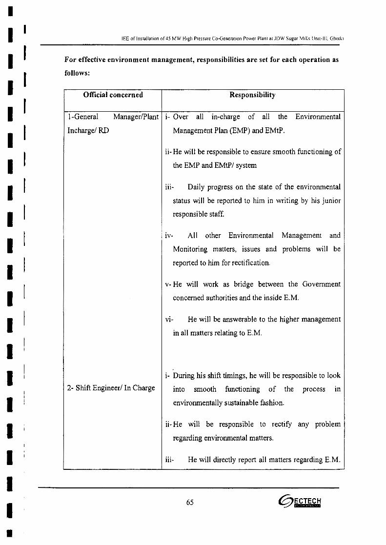
II I
I II II II II II II II II II I
I I
IIIIIII
lEE of Installation of 45 MW High Pressure Co-Generation Power Plant at JDW Sugar Mills Unit-III, Ghotki.
For effective environment management, responsibilities are set for each operation as
follows:
Official concerned Responsibility
l-General Manager/Plant i- Over all in-charge of all the Environmental
Incharge/ RD Management Plan (EMP) and EMtP.
ii- He will be responsible to ensure smooth functioning of
the EMP and EMtP/ system
lll- Daily progress on the state of the environmental
status will be reported to him in writing by his junior
responsible staff.
IV- All other Environmental Management and
Monitoring matters, issues and problems will be
reported to him for rectification.
v- He will work as bridge between the Government
concerned authorities and the inside E.M.
vi- He will be answerable to the higher management
in all matters relating to E.M.
i- During his shift timings, he will be responsible to look
2- Shift Engineer/ In Charge into smooth functioning of the process in
environmentally sustainable fashion.
ii- He will be responsible to rectify any problem
regarding environmental matters.
in- He will directly report all matters regarding E.M.
•65 ~ECTECH
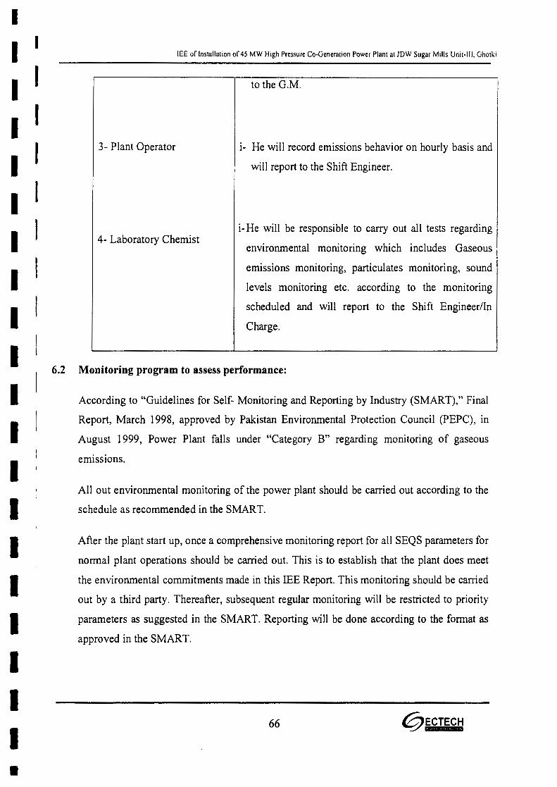
II I
I II II II II II II II I
I I
I I
IIIIIIII
lEE of Installation of 45 MW High Pressure Co-Generation Power Plant at JDW Sugar Mills Unit-III. Ghotki
to the G.M.
3- Plant Operator i- He will record emissions behavior on hourly basis and
will report to the Shift Engineer.
i- He will be responsible to carry out all tests regarding
environmental monitoring which includes Gaseous
emissions monitoring, particulates monitoring, sound
levels monitoring etc. according to the monitoring
scheduled and will report to the Shift Engineer/In
Charge.
4- Laboratory Chemist
6.2 Monitoring program to assess performance:
According to "Guidelines for Self- Monitoring and Reporting by Industry (SMART)," Final
Report, March 1998, approved by Pakistan Environmental Protection Council (PEPC), in
August 1999, Power Plant falls under "Category B" regarding monitoring of gaseous
emissions.
All out environmental monitoring of the power plant should be carried out according to the
schedule as recommended in the SMART.
After the plant start up, once a comprehensive monitoring report for all SEQS parameters for
normal plant operations should be carried out. This is to establish that the plant does meet
the environmental commitments made in this lEE Report. This monitoring should be carried
out by a third party. Thereafter, subsequent regular monitoring will be restricted to priority
parameters as suggested in the SMART. Reporting will be done according to the format as
approved in the SMART.
66 @ECTECH
•

-II II II II II II II II II II I
I I
IIIIIIII
lEE of Installation of 45 MW High Pressure Co-Generation Power Plant at JDW Sugar Mills Unit-III, Ghotki.
Even though all effluent generated through the entire project activities along with sewage
will be treated in the designed waste water treatment plant and all relevant data regarding
generation, treatment and disposal mode of the effluent will be duly recorded.
A track record of all solid wastes and their disposal shall also be regularly maintained for its
use as and when required.
All monitoring data should be reviewed and analyzed regularly in comparison with the
SEQS limiting values. In case of any deviation/violation of the required standards,
immediate necessary corrective actions should be taken. All the monitored data should be
reported to the EPA Sindh.
6.3 Reporting and reviewing procedures
Monitoring schedule, as explained above will be adhered to and all the data to be monitored
will be scrutinized at the level of Shift Engineer/ In Charge and on monthly basis at the
G.M. level. The data will be documented according to appropriate format. Discrepancies
will be duly addressed to. For presentation of the data to the Government Agencies,
approved data recording to the SMART format.
6.4 Training Schedules
In order to effectively operate the EMP all the staff to be engaged in this activity should be
trained extensively.
All the environment management staff to be engaged for operating effluents treatment plant,
monitoring and testing should be duly trained. Laboratory chemist should be trained in all
operations of laboratory testing of the effluents and other relevant materials/samples. He
should be trained in applying analytical methods/techniques of testing, data processing,
interpretation and reporting. He should know the local laws, rules and regulations as
applicable to the testing of effluents.
6.5 Environmental Monitoring
Environmental monitoring will be carried out by the staff to be engaged for the purpose.
67 ~ECTECH

-II II II I
I II I
I I
IIIIIIIIIIIII
lEE of Installation of 4S MW High Pressure Co-Generation Power Plant at JDW Sugar Mills Unit-III, Ghotki
The person to monitor gaseous emissions, PM and noise levels should be extensively trained
to handle his job capably. Training program should include use of monitoring instruments,
data generation, processing, interpretation, recording and presentation.
6.6 Environment quality monitoring laboratory
The existing laboratory will be upgraded and furbished with required equipment to also act
as environmental monitoring laboratory.
6.7 Summary ofImpacts and mitigation measures
The most significant pollutant emitted by Bagasse-fired boilers is ash. As JDW Unit-III is
already using High pressure boilers and ash is in very little quantity, the high pressure
boilers will produce minor quantity of ash which will be controlled by the use of
Electrostatic Precipitator separator (fly as arrestor) to meet the permitted dust concentration
as required by SEQS Pakistan. Both of these technologies have the ability to remove up to
99.9% of ash (PM) in stack exhausts.
Gaseous Emissions of sulfur dioxide (S02) and nitrogen oxides (NOx) are lower than
conventional fossil fuels due to the characteristically very low levels of sulfur and nitrogen
associated with Bagasse, therefore, they will remain within the prescribed limiting values of
the SEQS Pakistan.
The noise levels of 75 dB (A) and 65 dB (A) indicated are at the plant boundary, as the
maximum noise level shall be 85dB (A) at 3.0 m from the equipment.
Bottom ash
• Supply to cement factory. In case of using this method both fly ash and bottom ash can
be mixed and dispose off together.
• Landfills. In case of using this method both fly ash and bottom ash can be mixed and
dispose off together.
• For making bricks for face lifting,
68 ~ECTECH
•IIIIIIIIIIIIIIIIIIII
lEE of Installation of 45 MW High Pressure Co-Generation Power Plant at JDW Sugar Mills Unit-Ill, Ghotki
• Used as manure in field,
• making bricks for paving
• Supply of the fly ash to agriculture use as rich source of Potassium, (K) being cheaper
substitute of costly potassium fertilizer. It is to remember that since the ash comes
from Bagasse an agree product therefore it will not harm to soil.
The furnace bottom ash is collected by water impounded scrapper conveyers, and as the
quantity of ash discharge is less, the same is collected in trolleys parked near the scraper
conveyor. The bottom ash of ash during transportation. This ash can be disposed of in
variety of methods like:
• In cement as aggregate
• Manufacturing of tiles for face lifting of buildings, flooring of paths etc,
• Landfill
6.8 Equipment maintenance details
Predictive maintenance and preventive maintenance will be managed as per
recommendation of OEM.
6.9 Environmental budget
The cost for environmental management and monitoring will be the part of contract of
Contractor and Consultants respectively. However, an appropriate budget will be allocated
by the project proponent towards environmental training and monitoring during construction
and operation of the project.
69 @ECTECH

•II II II II II II II III II IIIII I
IIIII
lEE of Installation of 45 MW High Pressure Co-Generation Power Plant at JDW Sugar Mills Unit-III, Ghotkr
7.0 PUBLIC CONSULTATIONS
70 @ECTECH

•II II II II II II II I
II I
IIIIIIIIII
lEE of Installation of 45 MW High Pressure Co-Generation Power Plant at JDW Sugar Mills Unit-ill, Ghotki
7.0 PUBLIC CONSULTATIONS
Public consultations were held with the people from the project area. They are very much in
favor of the project installation for the reasons and advantages to accrue to them directly as
well as indirectly as described below.
Written comments/views of the public consultations are attached as Annexure-VIII
Community Awareness and Perception about the Project:
• By and large, a large proportion of the people of the project area are aware of the
planned project implementation.
• Among the people consulted as a part of the Public Consultations, virtually all of
them welcome the project.
• The people have clear perception that there will at least some addition to the shortfall
of power.
• People foresee all out positive impacts like employment opportunities, business
development, operating small hotels/tea stalls, tires and tubes repairing shops along
with other vending services for the vehicles.
• Study findings depict that the people of the study area perceive overall positive
impacts as a result of installation of the power plant. Therefore, their attitude towards
the project installation is quite positive.
• As far as the Social Impact Assessment (SIA) is concerned, positive social impacts
are dominant over any negative social impacts observed during the study.
• They correlate their positive attitude towards the plant with many socio-economic
opportunities and benefits to restart.
• The people believe that installation of the plant in the area will not only help to restart
earning opportunities but also, it will open up vast employment new opportunities
which in tum follow a chain of indirect socio-economic benefits.
71 @ECTECH

•I I
I II II II II II II II II II II II I
I I
I II II I
I II II !
lEE of Installation of 45 MW High Pressure Co-Generation Power Plant at JDW Sugar Mills Unit-III, Ghotki
• They also perceive accelerated economic activity due to the business opportunities
likely to emerge in the area. Directly or indirectly, some reasonable number of the
local people will get employment and business from the installation of the plant e.g.:
shop keepers, traders, suppliers, contractors, transporters, technicians etc.
• They feel that the plant and its related activities will provide a strong base for positive
financial and social change.
• They foresee improvement in the quality of life of the people.
From the above facts one can conclude that many positive economic and social impacts will
reappear in the quality of the lives of the people of the Study Area due to the plant
installation.
72 @ECTECH

•II II II II II II II II II I
I II IIIIIIII I
I
lEE of Installation of 45 MW High Pressure Co-Generation Power Plant at JDW Sugar Mills Unit-III. Ghotki
8.0 CONCLUSIONS
73 ~ECTECH

•II I
I I
I I
IIIIIIIIIIIIIIII
lEE of Installation of 45 MW High Pressure Co-Generation Power Plant at JDW Sugar Mills Unit-Ill. Ghotki.
8.0 CONCLUSIONS
MIS Ghotki power (Pvt.) Limited has planned for installation bagasse based high pressure
cogeneration power plant having capacity 45 MW adjacent to lOW Sugar Mills Unit-III,
Goth Islamabad, Tehsil & District Ghotki.
Bagasse based Cogeneration is being considered by many countries as an environment
friendly way of augmenting the generation capacity. The Government of Pakistan has
estimated a potential of 2800 MW of Cogeneration power from the existing sugar mills. The
Government of Pakistan is treating these projects on "fast track basis".
The proposed new Cogeneration plant, on commissioning will export a substantial quantum
of power to the national grid. The proposed Cogeneration cycle is already proven and
implementation of this project will benefit the project in itself and the country.
It has been found that the project has inbuilt mechanism to:
• Treat the effluents, control stack gases emissions and PM, control Noise to the
prescribed limits of the SEQS- Pakistan.
• Solid wastes disposal will be done according to the environmentally sustainable
order.
• EMP and EMtP as recommended in this lEE Report are to be put in place during
operations of the project.
On the basis of the major facts summarized as above, the project merits for issuing No
Objection Certificate (NOC)lEnvironmental Approval (EA) by the Environmental
Protection Agency, Government of Sindh, Karachi.
RECOMMENDATION:
On the basis of the facts summarized as above, the project merits for issuing Environmental
Approval by the Environmental Protection Agency, Government of Sindh, Karachi.
74 @ECTECH