D-11058 24-06-2021 KAPCO.pdf - NEPRA
299
June24,2021 — Reference No. KAPCO/CEO/2021/423 , ;d dL PC)1/i c rr - ny Lir ci 5 B/3, Gulberg III Lahore 54660, Pakistan UAN +92 42 111152 726 PABX +9242 3577 2912-21 Fax +92 42 3577 2922 The Registrar National ElectricalPower Regulatory Authority ( c.i NEPRA Tower, Attaturk Avenue (East) — ALA (1c, G-5/1, Islamabad SUBJECT: APPLICATION FOR GENERATION LICENSE EXTENSION PROPOSED FOR GENERATION LICENSE NO. IPGL/020/2004 RELATING To 1600MW (GROSS) KAPCO Complex LOCATED AT KOT ADDU DISTRICT MUZAFFARGRAH, PUNJAB, PAKISTAN Dear Sir, 1. Pursuant to the applicable laws of Pakistan, including the Regulation of Generation, Transmission and Distribution of Electric Power Act, 1997 and the rules and regulations made thereunder (including regulation 10(2) of the National Electric Power Regulatory Authority Licensing (Application -. Modification Procedure) Regulations,...1 and the National Electric Power Regulatory Authority Licensing (Generation) Rules, 2000) we submit before the National Electric Power Regulatory Authority (the Authority) an Application for Generation License Extension (together with the documents annexed thereto) (the Generation License Extension Application) for the extension of the Licensee's Generation License No. lPGL/020/2004 read with its Extension dated June 24, 2021 (the Generation License). 2. The Application for Generation License Extension (including its annexures) are beingsubmitted in triplicate, together with: (a) a Bank Draft No.24765036 dated 22-6-2021 amounting to PKR 1,456,455 (Pakistani Rupees One million four hundred fifty six thousand four hundred Only) drawn in favour of NEPRA, as the application fee for a License Proposed Extension of Generation License (as communicated to us by NEPRA) has been directly sent to NEPRA; (b) Board resolution of the Company dated June 22, 2021; and Kot Addu Power Complex Kot Addu, District Muzaffargarh Punjab - Pakistan PABX+9266230 1041-49 Fax +92 66230 1025 Office No. 309, 3" Floor Evacuee Trust Complex Agha Khan Road, F 5/1 Islamabad, Pakistan [email protected] www.kapco.com.pk
-
Upload
khangminh22 -
Category
Documents
-
view
1 -
download
0
Transcript of D-11058 24-06-2021 KAPCO.pdf - NEPRA
June24,2021 — Reference No. KAPCO/CEO/2021/423
,
;d dL PC)1/i c rr - ny Lir ci
5 B/3, Gulberg III Lahore 54660, Pakistan
UAN +92 42 111152 726 PABX +9242 3577 2912-21
Fax +92 42 3577 2922
The Registrar National ElectricalPower Regulatory Authority ( c.i
NEPRA Tower, Attaturk Avenue (East) — ALA (1c, G-5/1, Islamabad
SUBJECT: APPLICATION FOR GENERATION LICENSE EXTENSION PROPOSED
FOR GENERATION LICENSE NO. IPGL/020/2004 RELATING To
1600MW (GROSS) KAPCO Complex LOCATED AT KOT ADDU
DISTRICT MUZAFFARGRAH, PUNJAB, PAKISTAN
Dear Sir,
1. Pursuant to the applicable laws of Pakistan, including the Regulation of Generation, Transmission and Distribution of Electric Power Act, 1997 and the
rules and regulations made thereunder (including regulation 10(2) of the National Electric Power Regulatory Authority Licensing (Application -. Modification Procedure) Regulations,...1 and the National Electric Power
Regulatory Authority Licensing (Generation) Rules, 2000) we submit before
the National Electric Power Regulatory Authority (the Authority) an
Application for Generation License Extension (together with the documents
annexed thereto) (the Generation License Extension Application) for the
extension of the Licensee's Generation License No. lPGL/020/2004 read with its Extension dated June 24, 2021 (the Generation License).
2. The Application for Generation License Extension (including its annexures) are beingsubmitted in triplicate, together with:
(a) a Bank Draft No.24765036 dated 22-6-2021 amounting to PKR 1,456,455
(Pakistani Rupees One million four hundred fifty six thousand four hundred
Only) drawn in favour of NEPRA, as the application fee for a License Proposed
Extension of Generation License (as communicated to us by NEPRA) has been directly sent to NEPRA;
(b) Board resolution of the Company dated June 22, 2021; and
Kot Addu Power Complex Kot Addu, District Muzaffargarh
Punjab - Pakistan PABX+9266230 1041-49
Fax +92 66230 1025
Office No. 309, 3" Floor Evacuee Trust Complex Agha Khan Road, F 5/1
Islamabad, Pakistan
[email protected] www.kapco.com.pk
(c) Affidavit/Statements of Authorized Representative of Company, Mr. Aftab Mahmood Butt, Chief Executive.
3. In light of the submissions set out in the Application for Generation 'L ice n s e Extension and the information attached to the same, the Authority is kindly requested to process the License Proposed Ext ens i o n of Generation License Application at the earliest.
Thanking you,
Yours faithfully,
For Kot Addu Power Company Limited
Aftab Mahmood Butt Chief Executive
Enclosures: As stated
KAP Co
June 24, 2021 Reference No. KAPCO/CEO/2021/423
Kot Addu Power Company Limited
5 B13, Gulberg Ill Lahore 54660, Pakistan
UAN +92 42 111152 726 PABX +92423577 2912-21
Fax +9242 3577 2922
The Registrar National Electrical Power Regulatory Authority NEPRA Tower, Attaturk Avenue (East) G-5/1, Islamabad
SUBJECT: APPLICATION FOR GENERATION LICENSE EXTENSION PROPOSED
FOR GENERATION LICENSE NO. IPGL/020/2004 RELATING To
1600MW (GROSS) KAPCO Complex LOCATED AT KOT ADDU
DISTRICT MUZAFFARGRAH, PUNJAB. PAKISTAN
Dear Sir,
1. Pursuant to the applicable laws of Pakistan, including the Regulation of Generation, Transmission and Distribution of Electric Power Act, 1997 and the rules and regulations made thereunder (including regulation 10(2) of the National Electri Pow eulatory Authority Licensing (Application & Modification, Proc dure) Regu'ations, and the National Electric Power Regulatory Authority Licensing (Generation) Rules, 2000) we submit before the National Electric Power Regulatory Authority (the Authority) an Application forGeneration License Extension (together with the documents annexed thereto) (the Generation License Extension Application) for the extension of the Licensee's Generation License No. IPGL/020/2004 read with its Extension dated June 24, 2021 (the Generation License).
2. The Application for Generation License Extension (including its annexures) are beingsubmitted in triplicate, together with:
(a) a Bank Draft No. 24765036 dated 22-6-2021 amounting to PKR 1,456,455 (Pakistani Rupees One million four hundred fifty six thousand four hundred Only) drawn in favour of NEPRA, as the application fee for a License Proposed Extension of Generation License (as communicated to us by NEPRA) has been directly sent to NEPRA;
(b) Board resolution of the Company dated June 22, 2021; and
Power Project Kot Addu Power Complex
Kot Addu, District Muzaffargarh Punjab -Pakistan
PABX +9266230 1041 -49 Fax +92 66 230 1025
Registered Office Office No. 309, 3d Floor Evacuee Tnist Complex Agha Khan Road, F 511
Islamabad, Pakistan
hifo®kapco.com.pk www.kapco.com.pk
KAP Co
(c) Affidavit/Statements of Authorized Representative of Company, Mr. Aftab Mahmood Butt, Chief Executive.
3. In light of the submissions set out in the Application for Generation
License Extension and the information attached to the same, the Authority is kindlyrequestedto processthe License Proposed Extension of Generation License Application at the earliest.
Thanking you,
Yours faithfully,
For Kot Addu Power Company Limited
Afta i,i'od Btitt Chief Executive
Enclosures: As stated

B145608
AFFIDAVIT
I, Aftab Mabmood Butt son of Arshad Mahmood Butt (late), adult do hereby solemnly affirm and state as under;
I. That I am the Chief Executive of Kot Addu Power Company Limited, Lahore and I am welt conversant with the affairs of the Company.
2. The contents of the application for Extension of Generation Licence of the Company dated June 24, 2021 are true and correct to the best of my knowledge and belief.
DEPONENT
•KAp[i) Kot &ddu Povt'er Compa -iy Lrt&d
5 B/3, Gulberg ifi Lahore 54660, Pakistan
UAN +9242111 152726 PABX +9242 3577 2912-21
Fax +92 42 3577 2922
Certified True Copy of the extracts of the Resolutions passed at the 132u Meeting of the Board
of Directors of Kot Addu Power Company held at Lahore on June 9, 2021.
RESOLVED UNANAMOUSLY that Kot Addu Power Company Limited
be and is hereby permitted:
(I) to prepare, deliver, file, apply and submit, pursuant to the
applicable laws of Pakistan, including the Regulation of
Generation, Transmission and Distribution of Electric Power
Act, 1997 and the Rules and Regulations made thereunder
(including regulation 10(2) of the National Electric Power
Regulatory Authority Licensing (Application & Modification
Procedure) Regulations, 1999 and the National Electric
Power Regulatory Authority Licensing (Generation) Rules,
2000), an application (together with all documents
attached thereto) before the National Electric Power
Regulatory Authority (NEPRA) for NEPRA's approval of the
e x t e n s i o n of the Companys generation license No.
I PGL/020/2004 to cater, inter for the remaining useful
life and, as a result, the PPA Term Extension, enter into and
execute all required documents, make all filings, attend all
hearings, provide all required information and pay all
applicable fees, in each case, of any nature whatsoever.
(ii) Mr. Aftab Mahmood Butt (Chief Executive); and Mr.
i<halid Pervaiz Bajwa (General Manager
E n g i n e e ring) be and are singly and/or jointly
'authorised as representatives of the Company to address,
perform, negotiate, decide, execute, implement and/or
undertake all matters of any nature whatsoeverin relation to
the Generation License Extension Application including,
without limitation to review, execute, submit, and deliver the
Generation License Extension Application and any related
documentation required by the NEPRA for its approval of
the Generation License Ext e n sb n including any
contracts, documents, powers of Attorney, affidavits,
statements, letters, forms, applications, deeds,
guarantees, undertakings, approvals, memorandum,
amendments, letters, communications, notices, certificates,
request statements and any other instruments of any nature
whatsoever.
Power Project Kot Addu Power Complex
Kot Addu, District Muzaffargarh Puajab - Pakistan
PABX +9266230 1041 -49 Fax +9266230 1025
Regtstered Office Office No. 309, 3' Floor Evacuee Trust Complex Agha Khan Road, F 5/1
Islamabad, Pakistan
infokapco.com.pk www.kapco.com.pk
IKAP'
(iii) affix the Common Seal of the Company including on any document/application for the Generation License Extension subject to the same being done in the presence of the Chief
Executive and the Company Secretary.
Certified True Copy
A. Anthony Rath
Dated: June 22, 2021 (Company Secretary)

Pay to
HBL HABIB BANK
KAPCO MOUZA FLA, KO 477 KOT ADU DISh. MUZAFFAEGARJI
HABIB BANK Banker's Cheque Customer Advice
24765O6 22/06/21
Cheque No. Date 24765036 KAPC) MOU7.A WLA, KO 0477
KOI AOL DSTT. PJZAFFARGARH
41iF10$f*L aECTR•ICPfER
B.C. No. 2476503( - Stationary No: 24765036
I 2 1 2041 2 1 11
or Order
ullion Four lndred FifW.Sit TJsand Four irided
Fifty rie Only.
Payable at any HBL Branch In Pakistan Centralised Cheque Payable Account 30019903902586
Please do riot write below this line.
oj:T4
WE CONFIRM HAVING ISSUED THE FOLLOWING hANKER'S CHEQUE Al YOUR REQUEST
FavouringNATIONAL ELECTRIC POWER REGULATY AUTHORITY
The Sum of:Rupee - One Miflion Four Hundred Fifty Sit Thousand Four Hundred
Fifty Fivo Only.
Cheque Anoent Coniriion Total ttnount Funding Account No WHT Recovered
PKFI ***1,4S6,4S.0o PKR Z****tt*435.O PKR *z***1,4S6,89O.00 l242401l86870
THIS IS SYSTIM GENERAIW ADVECEANO DOES NOT REQUIRE A SIGNATURE
BEFORE
THE NATIONAL ELECTRIC POWER REGULATORY
AUTHORITY (NEPRA)
APPLICATION FOR
GENERATION LICENSE EXTENSION
Kot Addu Power Company Limited (KAPCO)
FOR NEPRA's APPROVAL FOR EXTENSION OF KAPCO's GENERATION
LICENSE No. IPGL/020/2004
RELA11NGTO A THERMAL POWER GENERATION FACILITY OF 1600
MW (GROSS) LOCATED AT
KOT ADDU DISTRICT MUZAFFARGRAH, PUNJAB, PAKISTAN
June 24, 2021

KAP Co Kot Addu Power Company Limited Generation License Extension Application
Table of Contents
1. INTRODUCTION TO THE LICENSEE AND THE PROJECT 3
2. BACKGROUND TO THIS GENERATION LICENSE EXTENSION APPLICATION 9
3. MERITS OF THE PROJECT AND JUSTIFICATION FOR PROPOSED GENERATION LICENSE EXTENSION---12
4. PROPOSED TEXT FOR GENERATION LICENSE EXTENSION 18
5. A STATEMENT OF IMPACT ON THE QUALITY OF SERVICE AND PERFORMANCE BY THE LICENSEE OF
ITS OBLIGATIONS UNDER THE GENERATION LICENSE 20
6. CONCLUSION AND SUBMISSION 24
1 Page

KAP Co Kot Addu Power Company Limited
Annexures
Annexure A
Generation License Extension Application
Shareholding Pattern
Annexure B Memorandum and Articles of Association
Annexure C Certificate of Incorporation
Annexure D Site Map
Annexure E Plant and Colony Lay -out
Annexure F Single Line Key Diagram
Annexure G Generation License
Annexure H Master Agreement
Annexure I GM NPCC Letter no 15373-77/GM (SO)
Annexure J Ramboll Brochure
Annexure K RULA Report
Annexure L Plant KPI Graphs
Annexure M Technical Limits & Unit start- up Times
Annexure N IMS Certificates
Annexure 0 Environment Monitoring Reports
Annexure P Certificate of Appreciation from National Forum
21 Page
KAP Co Kot Addu Power Company Limited Generation License Extension Application
SECTION 1
INTRODUCTION TO THE LICENSEE AND THE PROJECT
3Page
KAP Co Kot Addu Power Company Limited Generation License Extension Application
1.1 INTRODUCTION
Kot Addu Power Company Limited (the "Licensee", "Company" or "KAPCO") having its corporate office at 5B/3, Gulberg III, Lahore 54660 is the applicant for proposed
extension to Generation License. The Licensee was incorporated on April 25,
1996 as a public limited company under the Companies Ordinance, 1984 with
the object of acquiring the Kot Addu Power Plant from the Pakistan Water and
Power Development Authority ("WAPDA"). The principal activities of the
Licensee include the ownership, operation and maintenance of the Kot Addu
Power Plant.
The Privatization Corn mission Government of Pakistan following international
competitive bidding privatized the Licensee on June 27, 1996. WAPDA in two
transactions divested 36% of its shareholding in the Licensee to the strategic
investor (National Power (Kot Addu) Limited) along with management control.
In February 2005, the Privatization Commission (on behalf of WAPDA) sold
another 18% of WAPDA's shareholding in the Licensee to the general public
under An Offer for Sale; and on April 18, 2005 the Licensee was formally listed
on the Karachi Stock Exchange, the Lahore Stock Exchange and the Islamabad
Stock Exchange, which have since been demutualized in the Pakistan Stock
Exchange.
In August 2013, the strategic investor sold its entire shareholding in the
Licensee to several local corporate entities and individuals.
The following supporting documents relating to the Licensee are attached
herewith:
(a) Annexure A (Shareholding Pattern);
(b) Annexure B (Memorandum and Articles of Association); and
(c) Annexure C (Certificate of Incorporation).
1.2 THE POWER PLANT "COMPLEX"
KAPCO Power Plant (the "Complex") was built by WAPDA in five phases
between 1985 and 1996 in District Muzaffargarh, Punjab, 90 K.M. north-west
of Multan site map attached as Annexure D. The Complex was transferred to
the Licensee under the Transfer Agreement between WAPDA and Licensee
dated June 27, 1996.
The salient features of the Complex are as under:
> Plant name plate capacity is 1600 MW whereas guaranteed net capacity
under IDC is 1345 MW.
Complex total area is 385 acres. Power Plant Complex is developed on 174
acres and Residential Colony on 211 acres. There are 836 houses of different
categories in the Residential Colony with recreation facilities, guest houses and
hostels. The Power Plant Complex and Residential Colony lay out is attached as
41 Page
KAP Co Kot Addu Power Company Limited Generation License Extension Application
Annexure-E.
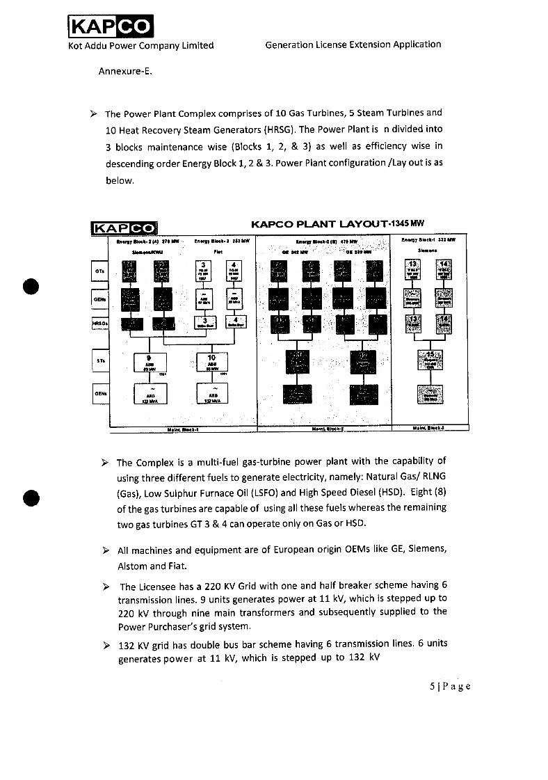
> The Power Plant Complex comprises of 10 Gas Turbines, 5 Steam Turbines and
10 Heat Recovery Steam Generators (HRSG). The Power Plant is n divided into
3 blocks maintenance wise (Blocks 1, 2, & 3) as well as efficiency wise in
descending order Energy Block 1, 2 & 3. Power Plant configuration fLay out is as
below.
KAPCO PL..ANT LAYOUT-1345 MW KAP co
oO.2lA) 27$ N gy 5M 3 213MW In..$J
Ot $1! NW
uei ii uw
0! 222 NW
£n$7
:13:
$Ik4 332 NW
- 3 4
GENI
. 112 . 10 *2 H
ONI P1 P1
> The Complex is a multi-fuel gas-turbine power plant with the capability of
using three different fuels to generate electricity, namely: Natural Gas! RLNG
(Gas), Low Sulphur Furnace Oil (LSFO) and High Speed Diesel (HSD). Eight (8)
of the gas turbines are capable of using all these fuels whereas the remaining
two gas turbines GT 3 & 4 can operate only on Gas or HSD.
> All machines and equipment are of European origin OEMs like GE, Siemens,
Alstom and Fiat.
> The Licensee has a 220 KV Grid with one and half breaker scheme having 6 transmission lines. 9 units generates power at 11 kV, which is stepped up to
220 kV through nine main transformers and subsequently supplied to the
Power Purchaser's grid system.
> 132 KV grid has double bus bar scheme having 6 transmission lines. 6 units
generates power at 11 kV, which is stepped up to 132 kV
5 Page
KAP Co Kot Addu Power Company Limited Generation License Extension Application
Six 220 kV feeders supply power to the following areas:
• Four feeders to New Multan 220 KV grid.
• One feeder to Muzaffargarh.
• One feeder to PakGen.
> Six 132 KV feeders supply power to following areas:
• One feeder to Industrial estate Multan.
• One feeder to Shandan Lund.
• Two feeders to Kot Addu.
• One feeder to Muzaffargarh.
• One feeder to Qasba Gujrat.
Both 220 KV and 132 KV grid are interconnected with Auto Transformers Auto
T-1, T2 & T5 (100 MVA each), 200 MVA Auto T-6 newly installed in April 2021
to replace T3 & T4 and to support the grid system. Single Line Key Diagram is
attached as Annexure F.
> The Complex has 3 MW capacity Black Start Diesel Generator set to recover in
case of country wide blackout, which has been adequately demonstrated in
recent black outs.
Largest oil storage capacity in the up country area (around 200,000 Tonnes)
and also the largest oil storage capacity of any plant. Fuel storage setup
consists of 22 LSFO storage tanks having storage capacity of 156 K tonnes and
5 HSD storage tanks can store 40 million litres.
A 32 km dedicated 10 inch diameter oil pipeline from P50's Lalpir Depot to the
Licensee's premises with capacity of 3,800 Tonnes per day. The pipeline has
pig facility which enables it to supply both LSFO and HSD through the same
pipeline.
> The Complex has 20 bays decantation facility to take direct LSFO and HSD
through tank Lorries. 20 tankers can be decanted at a time.
Six Fuel oil treatment plants (largest facility in Pakistan) to treat furnace oil for
plant operation.
> The Licensee receives gas through three (3) pipelines. Two 16 inch pipelines
from main SNGPL network have a capacity of 400 MMSCFD; and one 12 inch
pipeline from Dhodak has capacity of 80 MMSCFD.
> Raw water is sourced from two sources:
(i) Canal water is fed from Muzaffargarh Canal from the River Indus via Taunsa
Barrage; and
61 Page
KAP Co Kot Addu Power Company Limited Generation License Extension Application
(ii) Ground water through tube wells.
Water taken from the canal system is treated through clarifiers. In addition to demineralization plants where dissolved salts are removed, RO Plant is also
installed to meet the Complex water needs.
The Complex is equipped with a firefighting system: Two fire water storage
tanks each of 700 m3 capacity are supplied from well water. Automatic CO2
system is available for GT enclosure. Automatic water deluge system is
available for main transformer.
> The most important factor of the Licensee's twenty-five years excellent
performance is its highly skilled, professional and dedicated work force, which
is demonstrated year after year through successful Annual
Dependability Tests (ADC). The Licensee has maintained the Initial
Dependability Test (lDC) capacity. The Authority has allowed
degradation for both capacity and heat rate to other IPPs. However,
the Licensee with its excellent in-house team has proven their skills by
maintaining the IDC parameters without seeking for any degradation.
The Licensee is one of the few combined cycle plants in the world which operates on LSFO. Two other combined cycle plants in Pakistan tried to burn
furnace oil but then had to switch to Gas as primary fuel due to complex and
difficult operation on LSFO.
1.3 THE CONTRACI1JAL ARRANGEMENTS
For the purposes of the Complex, various contractual arrangements and assurances
were put in place, which include the following:
Principal Agreements Effective Date
Facilitation Agreement and GoP Guarantee 27 June, 1996
Transfer Agreement between the Licensee and WAPDA 27 June, 1996
Power Purchase Agreement ("PPA") with the Power Purchaser 27 June, 1996
Oil Supply Agreement between the Licensee and P50 27 June, 1996
Gas Supply Agreement (GSA) between the Licensees and SNGPL 27 June, 1996
1.4 THE GENERATION LICENSE
Following promulgation of the Regulation of Generation, Transmission and
Distribution of Electric Power Act, 1997 (the "NEPRA Act") and the rules and regulations made thereunder, the Licensee applied to the National Electric Power Regulatory Authority (the "Authority") for procurement of a generation license
7IPage
KAP Co Kot Addu Power Company Limited Generation License Extension Application
for its Complex and on September 22, 2004, and the Authority granted the Licensee a Generation License No. IPGL/020/2004 (the "Generation License"). A copy of the Generation License is attached as Annexure G for the Authoritys
reference.
8Page
KAP Co Kot Addu Power Company Limited Generation License Extension Application
SECTION 2 BACKGROUND TO THIS GENERATION
LICENSE EXTENSION APPLICATION
9Page
KAP Co Kot Addu Power Company Limited Generation License Extension Application
2.1 BACKGROUND
The Generation License was issued on September 22, 2004 and is expiring on September 21, 2021. The Licensee's Power Purchase Agreement ("PPA") was signed on June 27, 1996 was for a term of 25 years.
The Licensee was in arbitration with Power Purchaser on the imposition of unjustified liquidated damages on account of non-availability of Complex due to fuel shortage during the period 2008-2015. The sole cause of non-availability of fuel was the consistent failure of the Power Purchaser to make timely payments to the Licensee. The Government of Pakistan formed a Negotiation Committee
notified by the GoP vide notification II F.No.lPPs-1(12)/2019-20 dated June 3, 2020 to discuss with lPPs reduce tariff and resolve major issues like arbitration
etc.
The Licensee, in the larger national interest, entered into discussions with the GoP Negotiation Committee following which it agreed to alter some existing
contractual arrangements to the extent of, and strictly with respect to, the matters contained in the Memorandum of Understanding dated August 19, 2020 (the "MoU"). Subsequently, GoP constituted the Implementation Committee (the "GoP Implementation Committee") to, inter alia, convert the MoUs singed by the
IPPs binding agreements.
Following negotiations with GoP Implementation Committee, and the Power Purchaser, it was agreed to settle the outstanding arbitration dispute (ICC Case
No. 23521/PTA/ASB/HTG relating to liquidated damages due to fuel shortage as a result of non-payments by the Power Purchaser, amicably and in good faith in
accordance with the Settlement Terms (the "Settlement").
As per the Settlement, it has been agreed to treat the outage period due to non-availability of fuel as an Other Force Majeure Event (OFME) under the PPA. The
Master Agreement and Third Amendment to the PPA (the 3 PPA Amendment")
were both signed on February 11, 2021. As per the 3d PPA Amendment, the Term
of the PPA has been extended by another 485 days with effect from June 27,2021
and will now expire on October 24, 2022.
2.2 THE PPA RENEWAL
The PPA contemplates a mechanism for renewal of the PPA prior to its expiry in
terms of Section 4.1(c), which is as follows:
Renewals. Following the end of the twenty-third (23rd) Agreement Year, at the
request of either Party, the Company and WAPDA agree to enter into good faith
negotiations for a renewal of this Agreement for an additional term or terms of
years, on terms and conditions mutually agreed to by the Parties, such term or
terms of years to reflect the remaining useful lives of the various Units, and such
terms and conditions similarly to reflect the extent to which some Units may have
minimal or no remaining useful lives. If the Parties cannot agree to terms and
conditions for the renewal of this Agreement, the Company will be permitted to
contract with any other party for the sale of dependable capacity and electrical
101 Page

KAP Co Kot Addu Power Company Limited Generation License Extension Application
energy from the Complex and WAPDA shall deliver to the Company any necessary
consents for such sale, including any consent required by Section 28 of the
Electricity Act, 1910; provided, however, that WAPDA shall have no obligation to
assist in such sale (other than, if then permitted by law, the transmission of
electrical energy at an appropriate tariff for reasonable compensation acceptable
to WAPDA) unless otherwise required by law.
At the commencement of the 24I year of the Term of the PPA, the Licensee
wrote to CPPA-G vide letter no KAPCO/CEO/358 dated July 15, 2019 and
requested to enter into good faith negotiations for the renewal of the PPA for
another term(s) since the expected useful life of the Power Plant is over 10 years.
The Licensee also sent reminders on this respect from time to time.
Unfortunately, due to busy schedule of CPPA-G impacted by arbitration
proceedings and later on negotiation with lPPs, and Covid-19, discussions for the
extension of the Term of the PPA were not progressed as hoped. However, the
matter did come up before the GoP Negotiation Committee and the GoP
Implementation Committee, and was discussed with CPPA-G, WAPDA and the
Ministry of Energy (Power Division) during IPPs negotiations. Acknowledging the
continued requirement of the Licensee, the Master Agreement (section 3.4)
stipulated that the Power Purchaser shall consent to the extension of PPA. The
Master Agreement is attached as Annexure H.
A few other organizations also approached the Licensee to acquire power from it
after the expiry of the Term of the PPA, however, section 4.1(c) supra states that
the first right of refusal is with the Power Purchaser.
11 Page
KAP Co Kot Addu Power Company Limited Generation License Extension Application
SECTION 3
MERITS OF THE PROJECT AND
JUSTIFICATION FOR PROPOSED
GENERATION LICENSE EXTENSION
12Page

KAP Co Kot Addu Power Company Limited Generation License Extension Application
3.1 A STATEMENT OF THE REASONS IN SUPPORT OF THE PROPOSED
GENERATION LICENSE EXTENSION
Without in any manner limiting the submissions made in other sections of this Generation License Extension Application, which shall mutatis mutandis form
part of this Section 3 for the benefit of the Authority, it is re-emphasized that:
The Licensee has successfully operated its Complex; has catered for the Power Purchaser's requirements by generating around 6,427 GWH per annum; and has met its obligations under the PPA for around twenty-five (25) years (commencing from Commercial Operations Date' (as defined in the PPA), the Licensee and the
Power Purchaser, in pursuance of the provisions of section 4.1 (c) of the PPA, will be engaged in negotiations for the extension of the PPA beyond the 485 days
OFME period.
The Licensee's request for the Generation License Extension aims to ensure that
the terms of the Generation License caters to:
(a) Extension in the Term of the PPA after completion of its 25th Agreement Year
for 485 days under OFME settlement as agreed in 3d PPA Amendment
"As a result of the OFME Period the 25th Agreement Year is extended for
purposes of the definition of Agreement Year in Section 1.1. of the PPA"
(b) The Remaining Useful Life of the Complex
The Licensee (as part of performance of its obligations under the PPA) has an important, significant and strategic role in the supply of power to the MEPCO
local region of Multan, Muzaffargarh, DG Khan, Layyah Districts through the
Licensee's 220 KV and 132 KV feeders.
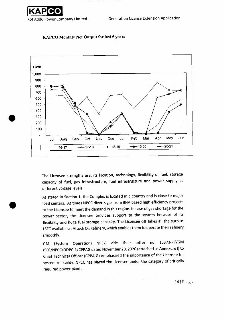
It is highlighted that during the summer months generally and especially in the peak summer months, the Complex runs as a base load plant. The monthly load
pattern of dispatch from the Power Plant is set out below for the Authority's reference and the same evidences the Complex's contribution during the peak summer months and again during canal closure and the Licensee's role as part
of the embedded generation projects connected to the National Grid:
131 Page
Jul Aug Sep Oct Nov Dec Jan Feb Mar Apr May Jun
KAP Co Kot Addu Power Company Limited Generation License Extension Application
KAPCO Monthly Net Output for last 5 years
The Licensee strengths are, its location, technology, flexibility of fuel, storage
capacity of fuel, gas infrastructure, fuel infrastructure and power supply at
different voltage levels.
As stated in Section 1, the Complex is located mid country and is close to major
load centers. At times NPCC diverts gas from 9HA based high efficiency projects
to the Licensee to meet the demand in this region. In case of gas shortage for the
power sector, the Licensee provides support to the system because of its
flexibility and huge fuel storage capacity. The Licensee off takes all the surplus
LSFO available at Attock Oil Refinery, which enables them to operate their refinery
smoothly.
GM (System Operation) NPCC vide their letter no 15373-77/GM
(SO)/NPCC/DDPC-1/CPPAG dated November 20, 2020 (attached as Annexure I) to
Chief Technical Officer (CPPA-G) emphasized the importance of the Licensee for
system reliability. NPCC has placed the Licensee under the category of critically
required power plants.
141 Page

KAP Co Kot Addu Power Company Limited Generation License Extension Application
The Licensee's Grid of 132KV and 220KV is very important for NPCC to manage in
areas stipulated above. NTDC has to spend huge money to supply areas where 12
feeders are supplying power and it will take time to implement that arrangement.
3.2 USEFUL LIFE OF THE FACILITY
Rule 5(1) of the National Electric Power Regulatory
Authority Licensing (Generation) Rules, 2000 (the "Rules") that states as follows:
"Except where an applicant for a generation license consents to a shorter term,
the term of a generation license shall be commensurate with the "maximum
expected useful life of the units comprised in a generation facility demonstrated
to the satisfaction of the Authority."
To ascertain the remaining useful life of the Complex, a study was awarded by
Licensee to a renowned consultant M/s Ramboll of UK/Denmark. Ramboll has a team of around 15000 experts and have 300 offices in 35 countries. Ramboll's
brochure is attached as Annexure J.
Ramboll has conducted detailed analysis of overhauling / inspection and test reports by OEMs and other reports based on tests conducted by third party
consultants. Based on their worldwide experience on different technologies, Ramboll have carried out a comprehensive analysis and their report on the Remaining Useful Life Assessment (RULA) is attached as Annexure K.
For the Authority's benefit and reference, without in any way limiting the comprehensive analysis presented in the RULA Study Report, part of section
8 (Conclusion & Recommendation) is set out below:
"Operating life before retirement of CCGT5 has been observed 40-50 years around
the World. This study has assumed a 40-year extended operating life based on a nominal 8,000 operating hours per year, which equates to lifetime operating hours
of 320,000. The operating hours of the Units at KAPCO range between 94,000 to
180,000 indicating that the remaining life of the KAPCO units could be in the range
17-28 years, thus demonstrating that a life extension of 10 years being considered
by KAPCO should be achievable with resulting good reliability and performance."
It is duly noted that Ramboll has concluded, based on its extensive analysis (as
contained in the RULA Study Report), that the overall condition of Complex is 'Good' and the expected remaining life is more than Ten (10) years. In view of the
RULA Study Report and the conclusions drawn in the RULA Study Report, the Licensee submits to the Authority that in view of the afore-stated criteria laid out
by rule 5(1) of the Rules and for the purposes of conclusively evidencing
compliance with the same this Generation License Extension Application primarily aims to extend the term of its Generation License so as to match it with the
Remaining Useful Life of the Facility i.e. September 21, 2031 (the "Proposed
Generation License Expiry Date").
The Authority's approval of the Proposed Generation License Extension and the
subsequent implementation by CPPA-G and the Licensee of the PPA Term Extension will ensure continued supply of reliable electricity to the consumers of
151 Page
KAP Co Kot Addu Power Company Limited Generation License Extension Application
CPPA-G. Alternatively, the Licensee will provide reliable and cheap power to other
entities / bulk power consumers under CTBCM Regime.
3.3 MAJOR UPGRADES AND MODIFICATIONS The Licensee has made significant upgrades and/or modifications as detailed below:
Gas Turbines
• Gas Turbine GT-1 & 2: The third and fourth stage disc and rear hollow shafts were replaced and new, modified, blades and vanes were installed to these rows. Row 4 blades were of the latest free standing blade design.
• Gas Turbine GT-5'8: Stage 1, 2 & 3 buckets, nozzles & shrouds replaced with the latest design having improved material & better rupture strength.
Honeycomb seals were installed.
• Gas Turbine GT-13 &14: Si3D upgradation was carried out and Blades and
Vanes of Stages 1 & 2 replaced with new design.
Steam Turbines
• On STG-1O, Installed upgraded 1st stage rotating blades and Installation of new LP turbine erosion protection rings of last 3 stages.
Generators
• GT-7 and GT8 Replacement of Insulation under Retaining Rings of Generator
Rotors during 2015.
• GT-8 Full Stator Rewinding of Generator during 2015.
• STG-11 Full Stator Rewinding of Steam Turbine Generator with new set of bars
during 2017.
• STG-12 Full Stator Rewinding of Generators during 2015.
Control Systems
• GT-1 ISKAMATIC obsolete control system replaced with Siemens SPPA T3000
DCS and obsolete analogue type SFC / SEE system replaced with GE (Conver-
team) Version D4 during 2016.
• GT-2 ISKAMATIC control system replaced with Siemens SPPA T3000 DCS and obsolete analogue type SFC / SEE system replaced with GE (Conver-team)
Version D4 during 2013.
• GT-3 excitation control system was replaced during financial year 2016/17.
• GT-5 and GT-6 Control system upgraded to Mark VIe during the 2015 Hot Gas
Path Inspections (GT-7 and GT-8 remains with Mark IV control system).
• GT-13 and GT-14 Replacement of Obsolete Control System with Siemens SPPA
T 3000 during 2021.
• STG-9 ABB Procontrol Decontic K obsolete control system replaced with
Siemens SPPA T3000 OCS during 2016.
161 Page
KAP Co Kot Addu Power Company Limited Generation License Extension Application
• STG-11 and STG-12 control/protection systems replaced by a new control/
protection system CONTROSTEAM V3.
• ST-15 Steam Turbine Controls system (TELEPERM-ME) and protection system (Iskamatic) replaced by Siemens SPPA-T3000 (Release 7)
Other Modifications
• Fuel Oil Treatment Plant 6 (FOTP-6) was installed / commissioned to enhance
Fuel Treatment Capacity during 2015.
• RO plant was installed, commissioned & taken in Operation in order to save
the chemical for water treatment.
• Installation of waste water treatment plant
17Page
KAP Co Kot Addu Power Company Limited Generation License Extension Application
SECTION 4
PROPOSED TEXT FOR GENERATION LICENSE EXTENSION
181 Page
KAP Co Kot Addu Power Company Limited Generation License Extension Application
4.1 THE PROPOSED TEXT
In view of the matters set out in this Generation License Extension Application,
including, without limitation, to ensure that the term of the Generation License caters to ensure its term is valid until the Proposed Generation License Expiry Date, the Proposed Generation License Extension amends Article 4 of the
Generation License as follows:
(1) Pursuant to Rule 5 of the Rules, this License is granted for a further term of ten (10) years and the total term of this license is twenty seven (27) years i.e. until
September 21, 2031."
19Page
KAP Co Kot Addu Power Company Limited Generation License Extension Application
SECTION 5
A STATEMENT OF IMPACT ON THE QUALITY
OF SERVICE AND PERFORMANCE BY THE
LICENSEE OF ITS OBLIGATIONS UNDER THE
GENERATION LICENSE
20 I P a g e

KAP Co Kot Addu Power Company Limited Generation License Extension Application
5.1 A STATEMENT OF IMPACT ON THE QUALITY OF SERVICE AND PERFORMANCE
BY THE LICENSEE OF ITS OBLIGATIONS UNDER THE GENERATION LICENSE
The Licensee confirms that the Licensees quality of service and its performance under the Generation License will not be affected during the period relating to
the Remaining Useful Life. The Licensee, over almost two and half decades, has been fully diligent and has dedicated itself to providing the highest quality
services - setting a benchmark for exceptional performance and excellence in the power generation sector of Pakistan. The Licensee aims to continue with such performance and anticipates to play a continued pivotal role providing reliable energy to the National Grid. Complex Availability, Fuel Mix, Net Output and Load
Factor graphs are attached as Annexure-L.
Licensee's Technical Key Performance Indicators are given below;
Year
Net Electrical
Output
Plant Load
Factor
Plant
Availability
Commercial
Availability
GWh % % %
2016-17 7,335 62.4 84.3 96.0
2017-18 7,437 63.3 86.0 96.7
2018-19 4,961 42.2 91.8 95.6
2019-20 3,477 29.5 88.9 96.8
2020-21 3,496 29.7 84.7 95.1
Last 5 Years 26,705 45.4 87.1 96.0
5.2 ANCILLARY SERVICES
200 MVA Auto Transformers #6 has been installed which will increase reliability
of 132 KV system and quality of service to DISCOS feeders. (This addition
demonstrate the Licensee commitment towards system support that it made
investment in the last years of its PPA.)
The Licensee has medium size units and start-up timing is to meet demand for peak hours. The Licensee units have provision of partial loading, therefore, the
Complex can provide ancillary support to National Grid in the next 10-15 years. (The importance of such machines will increase after installation of more
renewable energy projects.)
Technical Limits & Unit start up times are attached as Annexure-M.
2llPage
KAP Co Kot Addu Power Company Limited Generation License Extension Application
5.3 ENVIRONMENT MANAGEMENT SYSTEM
The Licensee has developed well established Policy Guidelines and Procedures Integrated Management System (IMS certificates attached as Annexure-N for Quality, Health & Safety and Environment.)
The Licensee is accredited and complying with the standards of ISO 14001:2015 Environmental Management System. Environment Performance Monitoring is
being conducted on regular basis by EPA Certified Independent Consultant, in compliance with Pakistan Environment Protect Act (1997) and Punjab
Environment Protection Agency standards.
Environment Monitoring at the Complex includes, monitoring of air, water and
noise emissions generated from Operations of Gas Turbines, Steam Turbines,
Boilers, Fuel Oil Treatment Plants etc.
Recent Report submitted to Punjab Environment Protection Agency (PEPA) as per
statutory requirement is in compliance to the requirements, and is attached as
Annexure —0.
In acknowledgement of accomplishment achieved for Environment Protection,
the Licensee received "Certificate of Appreciation from National Forum for Environment and Health" in 2020, which is attached as Annexure —P.
5.4 HUMAN RESOURCE
A highly skilled Human Resource is one of its key strengths of the Licensee which
gives it a competitive advantage. One of the reasons behind this high skill set is
the continuous learning culture, which provides that employees undergo a variety
of learning programs throughout the year. These opportunities range from self-paced learning, like book reading from a variety of books available at the OD Book club to online training programs. Class room training ranges from in-house training sessions to experiential learning programmes being conducted in the
remote locations to ensure a deeper level of learning associated with such
programs.
The Licensee takes keen interest in the development of its Human Resource using
a blended learning approach, including face to face as well an online programmes.
The training encompasses both functional as well as soft skills training programs
to address the developmental needs from a holistic perspective. This approach
focuses on the development of the individual as a person. As a result, the
individuals experience a transformation in their lives and an up-gradation of their
skill set, which positively effects the business results. The Licensee will continue
to remain focused in its developmental efforts for its Human Resource for the
future, as continuous improvement and development is the only way to thrive in
a rapidly changing world.
22 I P a g e
KAP Co Kot Addu Power Company Limited Generation License Extension Application
5.5 IMPACT ON THE OBLIGATIONS OF THE LICENSEE UNDER THE LICENSE
The approval of the Proposed Generation License Extension would enable the
Licensee in fulfilling its obligations under the PPA by implementing the PPA Term
Extension and, beyond that, until the Proposed Generation License Expiry Date. It
is highlighted that the Licensee has to-date ensured strict compliance with the
terms of the Generation License and commits to continue to do the same in
future.
23 I P a g e
KAP Co Kot Addu Power Company Limited Generation License Extension Application
SECTION 6
CONCLUSION AND SUBMISSION
24 I P a g e
KAP Co Kot Addu Power Company Limited Generation License Extension Application
6.1 CONCLUSION
The study carried out to assess the condition of the gas turbines and steam turbines and critical electrical components covering generator concluded with ratings Good and Satisfactory and power transformer Satisfactory condition. It is
pertinent to mention that the qualitative condition assessment and expected life is ba5ed on good O&M management practices and condition monitoring, well maintained inspection, maintenance and other monitoring records, timely execution of inspection and maintenance work order, up gradations / replacement of obsolete control system, replacement of component as per preventive spares and follow instructions of troubleshooting as per OEM
practices.
6.2 SUBMISSION
PURSUANT TO the applicable laws of Pakistan, including the NEPRA Act and the
rules and Regulations made thereunder, including the National Electric Power Regulatory Authority Licensing (Application, Modification, Extension &
Cancellation) Procedure Regulations, 2021and the National Electric Power Regulatory Authority Licensing {Generation) Rules, 2000 '): the Licensee HEREBY SUBMITS, for the Authority's kind and gracious consideration, this Generation
License Extension Application for approval of the Proposed Generation License
Extension to ensure that the Generation License is valid until the Proposed Generation License Expiry Date to reasonably utilize the useful life of the
Complex.
This Generation License Extension Application is submitted in triplicate.
This Generation License Extension Application is being submitted with the required generation license extension fee banker's cheque has been issued in
the amount of 1,456,455 I- (One million four hundred fifty six thousand, four
hundred fifty five PKR Only) dated June 23, 2021 in favor of the NEPRA (copy
attached), which has been sent directly to NEPRA.
In light of the submissions, the relevant analysis and information contained in this
Generation License Extension Application, along with the Annexures attached hereto, this Generation License Extension Application is submitted (pursuant to
the applicable laws of Pakistan
PROVISIONS OF NEPRA ACT 1997, READ WITH ENABLING PROVISIONS OF RULES & REGULATIONS MADE THEREUNDER, INCLUDING THE NATIONAL ELECTRIC
POWER REGULATORY AUTHORITY LICENSING (APPLICATION, MODIFICATION, EXTENSION & CANCELLATION) PROCEDURE REGULATIONS, 2021 & THE
NATIONAL ELECTRIC POWER REGULATORY AUTHORITY LICENSING (GENERATION)
RULES 2000
25 p a g e

KAP Co Kot Addu Power Company Limited Generation License Extension Application
For the Authority's kind consideration and approval of the Proposed Generation License Extension.
Respectfully submitted,
FOR AND ON BEHALF OF:
KOT ADDU POWER COMPANY LIMITED
LQ Aftab Mahmood Butt
CHIEF EXCUTIVE & AUTHORIZED REPRESENTATIVE
26 I P a g e
ANINEXURE A
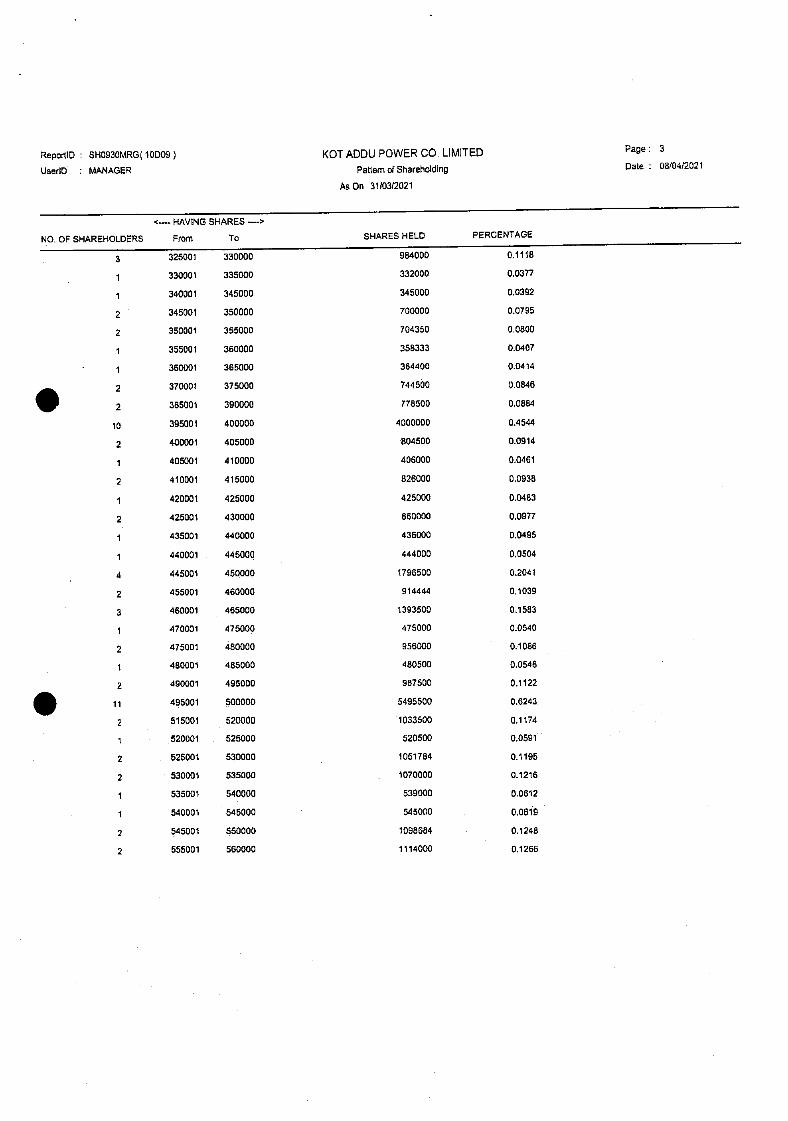
SHAREHOLDING PATTERN

ReportiD : SHOD35MRG (10009) KOT ADDU POWER CO. LIMITED Page: 1
UserlO MANAGER Category of Shareholders Date : 08/04/2021
A On 31/03/2021
particulrs No of Folio Balance Share Percentage
DIRECTORS. CEO, SPOUSE & CHILDREN 8 86005. 0.0098
ASSOCIATED COMPANIES 2 402563562 45.7327
BANKS, OFI & NBFI 19 136947047 15.5577
INSURANCE COMPANIES 16 20156706 2.2899
MUTUAL FUNDS 46 22168352 2.5184
GENERAL PUBLIC (LOCAL) 56203 185632678 21.0886
GENERAL PUBLIC (FOREIGN) 2863 25545880 2.9021
OTHERS 201 34988705 3.9748
• IGN COMPANIES 25 37013825 4.2049
APPROVED FUND 60 15150468 1.7211
Company Total 59'3 880253228 100.0000
Certified True Copy
A. Anth"ny Rath Company Secretary
KOT ADDU POWER COMPANY LTD,
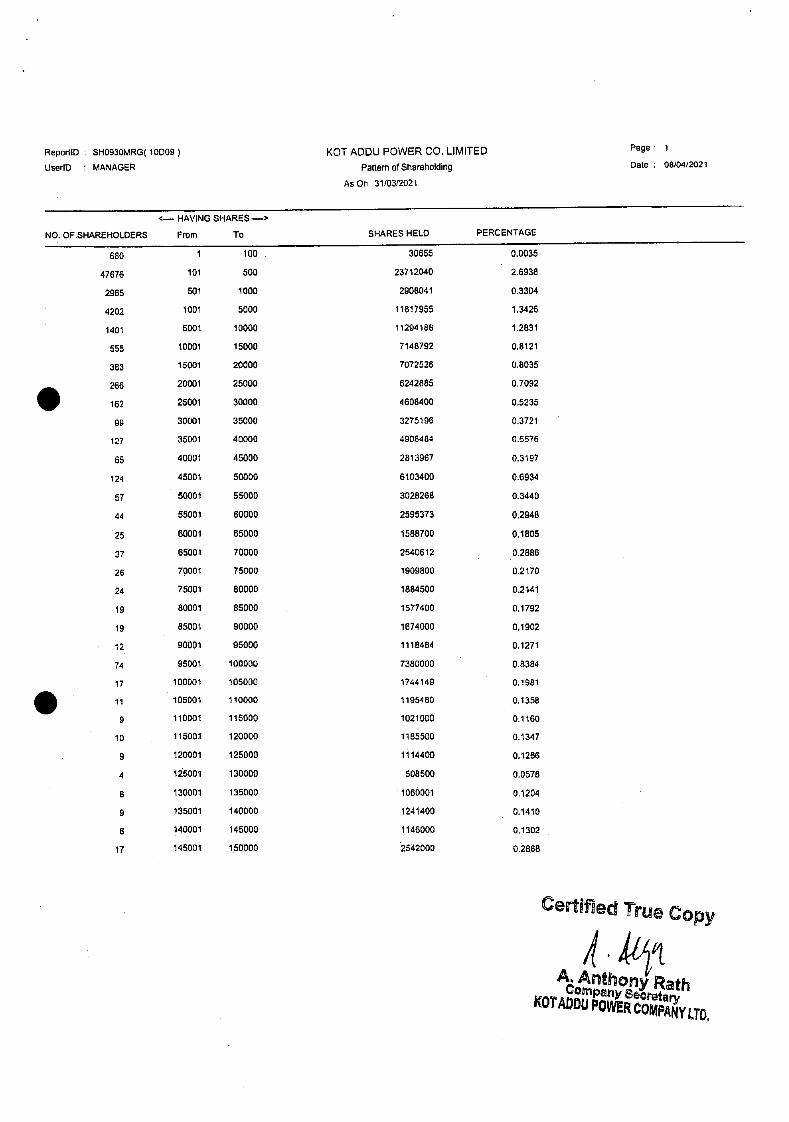
ReportiD SHO93OMRG( 10D09 KOT ADDU POWER CO. LIMITED Page: 1
UserlO MANAGER Pattern of Srlareholding Date 0810412021
As On 3110312021
NO. OF SI-IAREIIOLDERS
HAVING SHARES—'
From To SHARES HELD PERCENTAGE
680 100 30655 0.0035
47676 101 500 23712040 2.6938
2965 501 1000 2908041 0.3304
4202 1001 5000 11817955 1.3426
1401 5001 10000 11294188 1.283 1
555 10001 15000 7148792 0.8121
383 15001 20000 7072526 0.8035
266 20001 25000 6242885 0.7092
162 25001 30000 4608400 0.5235
99 30001 35000 3275196 0.372 1
127 35001 40000 4908484 0.5576
65 40001 45000 2813967 0.3 197
124 45001 50000 6103400 0.6934
57 50001 55000 3028268 0.3440
44 55001 60000 2595373 0.2948
25 60001 65000 1588700 0.1805
37 65001 70000 2540612 0.2886
26 70001 75000 1909800 0.2 170
24 75001 80000 1884500 0.2 14 1
19 80001 85000 1577400 01792
19 85001 90000 1674000 0.1902
12 90001 95000 1118484 0.127 1
74 95001 100000 7380000 0.8384
17 100001 105000 1744149 0.198 1
•11 105001 110000 1195480 0.1358
9 110001 115000 1021000 0.1160
10 115001 120000 1185500 0.1347
9 120001 125000 1114400 0.1266
4 125001 130000 508500 0.0578
8 130001 135000 1060001 0.1204
9 135001 140000 1241400 0.14 10
8 140001 145000 1146000 0.1302
17 145001 1.50000 2542000 0.28.88
Certified True Copy
A. Antho' Rath Comp, Secretary
KOTADDU POWER COMPANY LTD.

ReportiD SHO93OMRG( 10D09) KOTADDU POWER CO. LIMITED Page: 2
UseriD MANAGER Pattern olShareholding Dale 08/0412021
As On 31/03/2021
NO. OF SHAREHOLDERS
HAVING SHARES --'
From To SHARES HELD PERCENTAGE
3 150001 155000 453750 0.0515
7 155001 160000 1113500 0.1265
160001 165000 816000 0.0927
165001 170000 675470 0.0767
170001 175000 689626 0.0783
6 175001 180000 1076100 0.1222
5 180001 185000 918826 0.1044
1 185001 190000 189500 0.0215
190001 195000 773677 0.0879
16 195001 200000 3199761 0.3635
7 200001 205000 1416662 0.1609
4 205001 210000 831500 0.0945
1 210001 215000 214500 0.0244
2 215001 220000 440000 0.0500
5 220001 225000 1111800 0.1263
5 225001 230000 1140500 0.1296
230001 235000 232000 0.0264
4 235001 240000 950500 0.1080
3 240001 245000 730000 0.0629
7 245001 250000 1742500 0.1980
250001 255000 254519 0.0289
4 255001 260000 1033500 0.1174
2 260001 265000 527000 0.0599
1 265001 270000 268000 0.0304
1 270001 275000 274500 0.0312
3 27500.1 280000 833000 0.0946
.1 280001 285000 .280500 0.0319
1 290001 295000 293000 0.0333
9 295001 300000 2696500 0.3063
3 300001 305000 910001 0.1034
3 310001 315000 936500 0.1064
1 315001 320000 320000 0.0364
3 320001 325000 974000 0.1106
ReportiD SHO93OMRG( 10D09) KOT ADDU POWER CO. UMITED Page: 3
UseriD MANAGER Pattern of Shareholding Date : 0810412021
As On 3110312021
-- HAVING SHARES ->
NO. OF SHAREHOLDERS From To SHARES HELD PERCENTAGE
3 325001 330000 984000 0.1118
1 330001 335000 332000 0.0377
1 340001 345000 345000 0.0392
2 345001 350000 700000 0.0795
2 350001 355000 704350 0.0500
1 355001 360000 358333 0.0407
1 360001 365000 364400 0.0414
2 370001 375000 744500 0.0546
2 355001 390000 778500 0.0884
10 395001 400000 4000000 0.4544
2 400001 405000 804500 0.0914
1 405001 410000 406000 0.0461
2 410001 415000 826000 0.0938
1 420001 425000 425000 0.0483
2 425001 430000 860000 0.0977
435001 440000 436000 0.0495
1 440001 446000 444000 0.0504
4 445001 460000 1796500 0.2041
2 455001 460000 914444 0.1039
3 460001 465000 1393500 0.1583
1 470001 475000 475000 0.0540
2 475001 480000 956000 0.1086
480001 455000 480500 0.0546
2 490001 495000 987500 0.1122
ii 495001 500000 5495500 0.6243
2 515001 520000 1033500 0.1174
520001 525000 520500 0.0591
2 525001 530000 1051784 0.1195
2 530001 535000 1070000 0.1216
1 535001 540000 539000 0.0612
1 540001 545000 545000 0.0619
2 545001 550000 1098684 0.1248
2 555001 560000 1114000 0.1266

Reporl ID SHO93OMRG( 10009) KOT ADDU POWER CO. LIMITED Page 4
UseriD MANAGER Pattern of Sliarefiolding Dale 05/0412021
As On 3110312021
NO. OF SHAREHOLDERS
c--- HAVING SHARES --'
F,orn To SHARES HELD PERCENTAGE
570001 575000 573000 0.0651
2 595001 600000 1200000 0,1363
1 605001 610000 610000 0.0693
¶ 650001 655000 653000 0.0742
1 660001 685000 665000 0.0755
2 685001 690000 1375500 0.1563
1 705001 710000 710000 0.0807
720001 725000 725000 0.0824
1 745001 750000 750000 0.0852
1 750001 755000 753000 0.0855
1 760001 765000 764500 0.0868
2 770001 775000 1542500 0.1752
2 795001 800000 1600000 0.1818
1 810001 815000 812000 0.0922
1 835001 840000 635500 0.0949
1 845001 850000 849000. 0,0964
1 860001 865000 855000 0.0983
1 890001 895000 893473 0.1015
2 930001 935000 1565500 0.2119
1 945001 950000 950000 0.1079
2 955001 960000 1916500 0.2177
4 995001 1000000 4000000 0.4544
1 1010001 1015000 1012000 0.1150
1 . 1020001 1025000 1024500 0.1154
1 1045001 1050000 1050000 0.1193
1095001 1100000 1100000 0.1250
1 1105001 1110000 1106000 0.1256
1 1145001 1150000 1146530 0.1302
1 1150001 1155000 1151400 0.1308
1165001 1170000 1166500 0.1325
2 1170001 1175000 2349500 0.2669
1 1180001 1185000 1181944 0.1343
2 1245001 1250000 2500000 0.2840
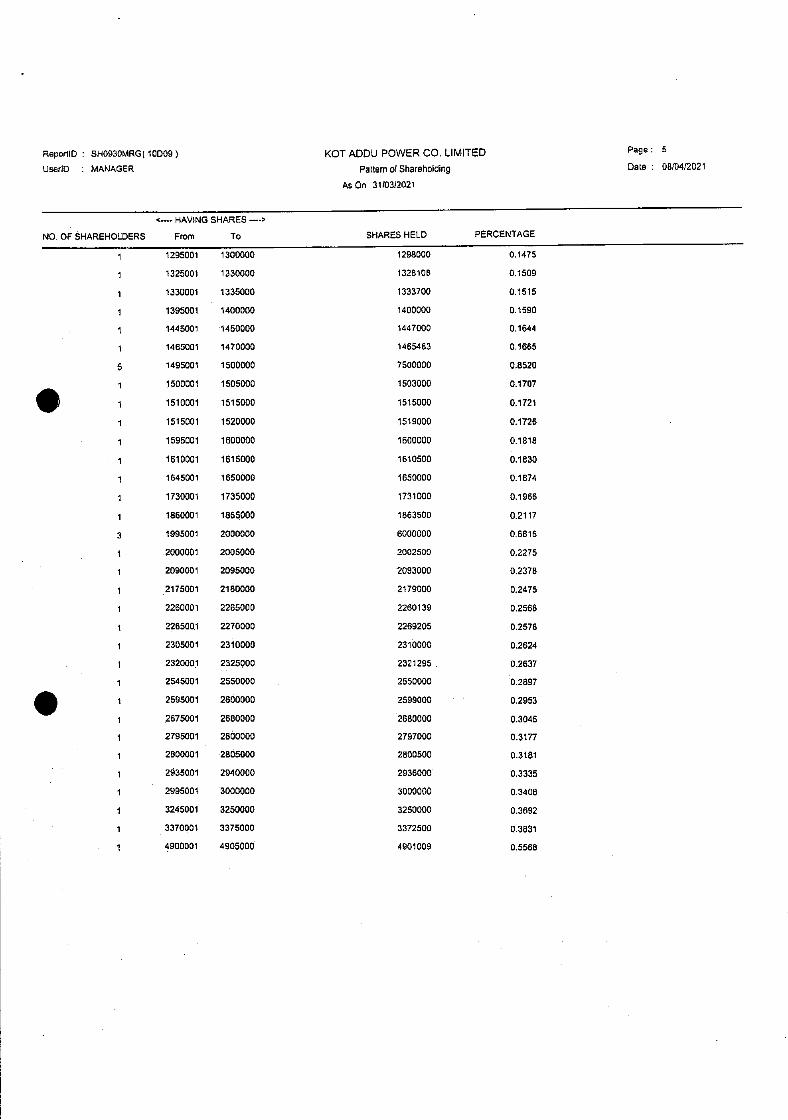
ReporilD SHO93OMRG( 10D09) KOT ADDU POWER CO. LIMITED Page: 5
UserlO S MANAGER Pattern of Shareholding Date : 08f0412021
AsOn 3110312021
NO. OF SHAREHOLDERS
'-.. HAVING SHARES -.'
From To SHARES HELD PERCENTAGE
1 1295001 1300000 1298000 0.1475
1 1325001 1330000 1325105 0.1509
1 1330001 1335000 1333700 0.1515
1 1395001 1400000 1400000 0.1590
1445001 1450000 1447000 0.1644
1 1465001 1470000 1465463 0.1665
5 1495001 1500000 7500000 0.8520
1 1500001 1505000 1503000 0.1707
1 1510001 1515000 1515000 0.1721
1 1515001 1520000 1519000 0.1726
1 1595001 1600000 1600000 0.1818
1 1610001 1615000 1610500 0.1830
1 1645001 1650000 1650000 0.1874
1 1730001 1735000 1731000 0.1966
1 1860001 1665000 1663500 0.2117
3 1995001 2000000 6000000 0.6816
1 2000001 2005000 2002500 0.2275
1 2090001 2095000 2093000 0.2378
1 2175001 2180000 2179000 0.2475
1 2260001 2266000 2260139 0.2568
1 226500.1 2270000 2269205 0.2578
1 2305001 2310000 2310000 0.2624
1 2320001 2325000 2321295 0.2637
1 2545001 2550000 2550000 0.2897
1 2595001 2600000 2599000 0.2953
1 2675001 2680000 2680000 0.3045
1 2795001 2800000 2797000 0.3177
1 2800001 2805000 2500500 0.3181
1 2935001 2940000 2936000 0.3335
1 2995001 3000000 3000000 0.3406
1 3245001 3250000 3250000 0.3692
1 3370001 3375000 3372500 0.3831
1 4900001 4905000 4901009 0.5568

ReportlD SHO93OMRG( 10009) KOT ADDU POWER CO. LIMITED Page: 6
UseriD MANAGER Pattern of Shareholding Date 08/04/2021
As On. 31/0312021
NO.Q SHAREHOLDERS
...HAVINGSHARE$--.>
From To SHARES HELD PERCENTAGE
4940001 4945000 4941500 0.5614
5530001 5535000 5531500 0.6284
5730001 5735000 5731000 0.6511
5800001 5505000 5804000 0.6594
5995001 6000000 6000000 0.6816
6590001 6595000 6593094 0.7491
7045001 7050000 7046000 0.8005
7465001 7470000 7469500 0.8486
7660001 7665000 7660721 0.8703
7695001 7700000 7697500 0.8745
15660001 15665000 15662000 1.7793
15995001 16000000 16000000 1.8177
48250001 48255000 48252429 5.4817
69475001 69460000 69476500 7.8928
354310001 354315000 354311133 40.2510
59443 Comp3ny Total 880253228 100.0000
Certified True Copy
A. Anthony Rath Company Secretary
KOTADDU POWER COIPANY LTD.
ANNEXURE B
MEMORANDUM AND
ARTICLES OF ASSOCIATION

TIlE COMPANIES ORDINANCE, 1984
COMPANY I Th1JY SHAR ES
p : . .,-iP :..,:--:'
'A ,.. ..
2O2
forandum
and
Articles of Association Certified True Copy
A. Anthony Rath Company Secrotary
KOT ADDU POWER COMPANY LTD.
KOT ADDU POWER 'COMPANY LIMITED

machinery, equipment and works ancillary thereto and plan, survey, design, supply equipment and carry out the cnnstruction of grid stations and transmission ti.ncs of aJJ voltages and to do all such atts, deeds and Wings, without limjtauon whatsoever as may be necessary or desirable in that connection.
(4) Electrification. To plan, survey,.design, supply equipment and carry out the electrification o:f cities, towns, villages. uns nod oil refineries, workshops, building, rube-wells, highways bridges, culverts, aiq.)orts, air-euninals, sea ports. harbors and whe-well project.
(5) enovaUon and Auncntn1ion. To carry nut overall planning of ,:,'electricadon, augmentation and renovation of electrical systems and to
design and supervise the electrification of all types of buildings and factories.
• . Schemes. To plan and frame schemes for irrigation, \v3ter supply and d rainage, recreational use of water resources rnland na'rgduon flood control, prevention of \viiter Jogging and reclainaLioti of waterlogged and salted lands and to placc wire, poles, k'al) brackets, stays, apparatus and appliances For tlic transmission of electricity or for the transmission of telegraphic and telephonic coiwnunicarions necessary for the proper execution of a scheme.
Engineerine and Consirltancv. To cany on the business of electrical (7) engineers, rndchanical engineers, civil enneers, eleciñcians, contractors, con.sultants, agents nod manufacturers of elecc plant machinery, equipment and apparatus, and of generating, producing and supplyittg light, heat, sound and power by electricity, galvanism, magnetism or otherwise, whether for the purpo.se of light., heat, motive power, telephonic, telegraphic, indusnial or other purposes, and generally of installing, executing, providing, working and maintaining all necessary plant, machinery, equipment. cables, wires accurnulriturs, lamps, exchanges, telephones and apparatus.
(8) '!'echnical Assistance. To render technical assistance to foreign countries in connection with power resource development and utilization and to receive assistance from foreign countries in such matters.
(9) Worksho, To establish all sorts of woiksliops for mi.urofacrure and maintenance of all types of electrical equipments, tools and matedal.s.
2
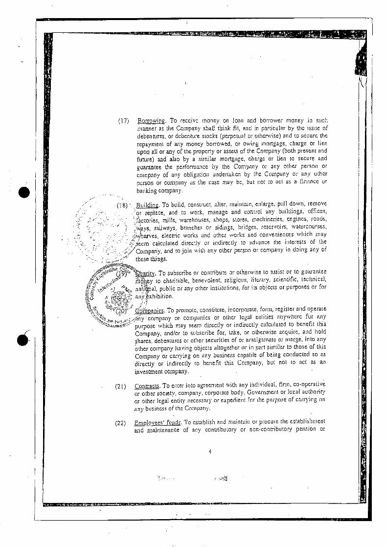
I (1.7) Borrowing. To receive money on loan and borrower money in such
manlier as the Company sbalJ think fit, and in particular by the issue of debentures, or debenture stocks (perpetual or otherwise) and to sccwe the repayment of any money borrowed, or owing inortage, charge. or lien upon all or any of the propcy or assets of the. Company (both present and euture) and aJso by a similar mortgage, chargc or lien to secure and guarantee the performance by the Company ni any other person or company of any obligation undertaken by lhc Company or any other person or company as the case may be, but not to act as a finance or
banking company.
(18) . Building, To build, consLruct. alter. riiaiirtnin, enlarge, pull down, remove .or replace, and to work, manage and control any buildings. offices,
fctorres, millS warehouses chops, stores inachmenes engines roath ys, raiJwa)'S, branches or sidings, bridges. reservoirs, watercourses,
./hfl'C5 elecc cvorks and other works and convenience's wInch may em calculated o,reLth or Indirect)) o ad ,ne the interests of tue
..:/cornpan'y, and to join with any other person or company in doing any of
:,Jrr:' these things.
baxity. To subscribe or contribute ar otherwise to assist or to guarantee hey to charilable, benevolent, religious, library, scientific, iecihnica),
-, - <"b natiia], public or any other institutions for its obicctc or purposes or for
.,, nny:exhibitron.
:'r2Oy'(oi)panic.s. To promote, constitOle, incorporate form, regisler and operate company or companies or other legal eolities rwywherc for any
'" purpose which may seem directly or indirectly calculated to benefit this
Company and/or 10 .sub.scribe for, take, or otherwise acquire, and hold
shares, debentures or other Securities of or amalgamate or merge, into any other company having objects altogether or in part similar to those of Uris Company or carrying on any business capable of being conducted so as directly or indirectly to benefit this Company, but not to act as an
invesent company.
(21) Con acts. To enter into agreement with any individual, firm, co-operalive or other society, company, corporate body, Government or local authoriry
or other legal entir1' necessary or expe4ient For the purpose of carrying mm
any business of the Company.
(22) Employees' 1nds. To establish and maintriirm or procure the establishment and maintenance of ally contribuLory or non-contributory pension or
4
or for extending any of the powers of the Company or for effecting any modification of the constitution of the Company or for any other purpose which may seem expedient, and to oppose any proceedings or applications which may seem calculated, directly or indirectly 10 prejudice the interesLs of the Company, and to enter into arrangements With Ofl Government or authoribes, cenoat, provincial, municipal, local or otherwise, public or quasi-public bodies, or with any other persons, in any place where the Company may have intercsts that may seem conducive to the objects of
the Company or any of them uid to obtain from any such Government, authorities or persons any rights, privileges and concessions which the Company may think fit to obtain, and to carry out, exercise and comply therewith,
Import and .Exporl. To carry on all or any of the husiness of importers, exporters, ship owner, shipbuilders, charterer of ships and other vessels, warehouscsmncn, wharFingers, merchants, ship and insurance brokers. cam ems and forwarding agents.
--. .-' 29) nsurance. To insure the property, assets, and employees of the Company
any nianner deemed fit by the Company, and to create any reserve fond, ldng lurid, insurance fund or any other special fund whether for
:preeiation or for repairing, insuring, improving, extending or ,i'maintaining any of the property of the Company or for any other purpose
- conducive to the interests of t.he Company but not to act a', an jnurance company.
(30) Investment. To invest the surplus moneys of the Company not immediately required in any manner but not to ct as an investment
company.
(31) Lcndi.ng. To advance money or give credit to such persons or compan.ie.s and on such terms mis may seem expedient and iii particular to customers and others having dealings with the Company, and to gonrantee the performance of any contract or oh]igabon and the payment of money by
the Company.
(32) Other.Eusines.s. To carry eu any other, business, wlmcthar agricultural. imidustrial, commercial. engineering, consultaucy, construction, nning, manufacturing or trading which may seem to the Company capable of being conveniently cartied on in connection with (lie above, calculated directly or indirectly to enhance die value of or render profitable. any of the Company's property or rights and to acquire and undertake the whole
6
Company may think neccssary o.r convenicot for the purpose of its business,
(37) Registration/Tees. To file or register any docun cnts re.qnired to be filed or registered under law, and to pay any fees, charges, expenses, rents, taxes, duties and other dues payable in connection with the business or operation of the Company.
(381 Regulations. To make. rules or regulations not inconsistent with this Memorandum, to provide for all matters for which provision is necessary or expedient fm the puipose of giving effect ro the provisions of this Memorandum and the efficient conduct of the affairs of the Company.
/ Research and De.velognienL. To improve, niunage, develop, grant rights or privileges in respect of, or orhcise deal with, all or any part of the propey and rights of the. Company and to establish laboratories, research and development centres to perform such research and development as the Company may deem advisable or feasible, and to expend money on
Iii" nmenting upon and testing and improving or .sccuring any process, or cesses patent or protec(Jng any nventJOO or InventIOns vhich the
. -.' .mpany may acquire or propose to acquire or deal with.
and Purchase, To accept, buy, sell, market, supply, transfer (including ransfcr of actionable claims) or deliver any and ever)' kind of moveable proper' for such price and subject to such tenns, conditions and warmnties as the Company may think fit.
(41) Sale of Undertak.i.ne. To sell, improve, manage, develop, exchange, lease, mortgage, enfranchise, dispose, of, Euro to account, or otherwise deal with, all or any part of t.h property, assets or undertaking of the Company for such consideration as the Compony may think fit, and in pailicular for shares, debentures, or other securities of any other company whether or not having objects altogether or in part similar to those of this Company, and to distribute among the members in specie any property of the Company, or any proceeds of sale or disposal of any property of the Company.
(42) Security. To accept or give secu', including but not Umiled to promissory notes, indemnity bonds, guarantees. assignments, receipts, hailmenis, pledges. iwpoLhecatiolmS, liens, mortg;ige and charges, against the credit extcnde.d or moneys borrowed in connection with the business of the Company.
8
-

• •1: 1 1i JViji
the headings used in each of the paragraphs of this clause are. for con;eoiencc onjy and are not intended to affect the construction thereof in airy way;
notwithstanding anything contained in the foregoing object clauses of this Memorandum of Association, nothinn herein shall be construed as enipovering the Company to undertake or irdulge iii the business of banking, finance, leasing, invstwent or insurance, directly or indirectly, as restricted tinder Jaw or any unlawful
operations
IV. LIABIlITY:
e liability of We member's is imicd.
SHARE CAPITAL:
.'-- su,r' •, • he share capital of the Company is Rs, 36,000,000,000.00 (Rupees thirty six
i,hon) divided into 3600 000 000 (three billion six hundred million) ordinary
) -i skres of Rs JO (Rupees tell) each with power to 1ncrc05c or reduce the cajiiaJ and to djudc LIne chares in the cipital for the time being into several
" cces and to attach Lheieto respectively such rights privileges or conditions Ii may be determined by or in accoroance with the reguJttrons of the
, ..<'Company, and to vary modify or abrogate an such rights, privileges or conditions in such manner as may for the lime being be provided by the regulations of the Company in accordance ',vitlr law provided, however, that rights as between various classes of ordinary shares, if any, as tO profits, votes and other benefits shall be strictly pi'oporlionate to the paid up value olshnres.
(Cl
(d)
10
The Companies Ordinance, 1984
(Company Limited By Shares)
ARTICLES OF ASSOCIATION
OF
KOT ADDU POWER COMPANY LIMITED
I. PRELIMINARY
I. Table 'A' Not to Aoplv
The regulations in Table A in the First Schedule to the ompanies Ordinance, 1984 shall not apply to the Company
except as reproduced herein.
Interpretation
I.ij/these Articles, unless the context or the subject matter otherwise requires:
(a) "Affiliate" means, as to any specified person, any other person owning and controlling, owned and controlled by, or under common ownership and control with such specified person.
(b) "Articles" means these Articles as originally framed and as from time to time altered in accordance with law.
(c) "Board" means a meeting of the Directors duly called and constituted or as the case may be, the Directors assembled at a Board.
(d) "Company" means Kot Addu Power Company Limited.
(e) "Chief Executive" means the chief executive of the Company appointed from time to time by the Directors.
(f) "Debt" means, as to the Company, any obligation for borrowed money (and any notes payable and drafts accepted representing extensions of credit whether or not representing obligations for borrowed money) which
Certified True Copy
1
k Anthony Rath ConWaI1Y SecretarY
KOT ADDU POWER COMPANY LTD.
(k) Deleted
(1) "Lien" means any mortgage, pledge, lien, interest, conditional or instalment sales agreement, option agreement, claim, charge or encumbrance of any kind.
(m) "Member" has the meaning assigned thereto in Section 2(1)(21).
(n) "Month" means a calendar month according to the Gregorian calendar.
(o) "Note" means the Note issued by the Company to WAPDA pursuant to the Note Agreement.
(p) "Note Agreement" means the Note Agreement dated 26 June 1996 between WAPDA and the Company.
(q) Deleted
Deleted
"Office" means the registered office for the time being of the Company.
(t) "Oil Supply Agreement" means the Oil Supply Agreement dated as of 27 June 1996 between Pakistan State Oil Company Limited and the Company.
(u) "Ordinary Resolution" means a resolution passed at a general meeting of the Company when the votes cast (whether on a show of hands or on a poll) in favour of a resolution by Members who, being entitled to vote in person or by proxy, do so vote, exceed the number of votes, if any cast against the resolution by Members so entitled and voting.
(v) "Ordinance" means The Companies Ordinance, 1984 or any modification or re-enactment thereof for the time being in force.
(w) "Power Purchase Agreement" means the Power Purchase Agreement dated 27 June 1996 between WAPDA and the Company.
(x) "Public Offering" means a sale or transfer of shares generally to the public involving a listing of shares on the Karachi Stock Exchange or any other applicable stock
3
(kk) "WAPDA Nominee Directors" means Directors nominated for election by WAPDA.
(II) Words importing the masculine gender include all other genders.
(mm) Words importing the singular number include the plural number and vice versa.
(nn) Expressions referring to writing shall unless the contrary intention appears, be construed as including references to printing, lithography, photography and other modes of representing or reproducing words in a visible form.
(oo) Words importing persons shall include individuals, corporations, bodies corporate, partnerships, Joint ventures, trusts, unincorporated organisations, governments or governmental authorities or agencies or 'any other legal entities.
The head notes are inserted for convenience and shall Mt affect the construction of these Articles. I
Unless the context otherwise requires words or expressions contained in these Articles shall bear the same meaning as in the Ordinance and, in relation to bodies corporate incorporated outside Pakistan, shall apply so that such terms shall be construed in accordance with the meaning of the nearest equivalent term under the laws of the place of incorporation of such body corporate.
(rr) a reference to any agreement or document is to that agreement or document (and, where applicable, any of its provisions) as amended, novated, restated or replaced from time to time.
II. BUSINESS
3. Public Combany
The Directors shall have regard to the restrictions on the commencement of business imposed by Section 146 if and so far as, those restrictions are binding upon the Company.
5
the Directors in such manner and form as the Directors may from time to time prescribe. The Seal shall be duly affixed to every share certificate issued by the Company. The signature(s) on the certificate of title to shares may be affixed by any mechanical or electronic method.
9. Issuance of new Certificate
If a share certificate is defaced, lost or destroyed, it may be renewed on payment of such fee, if any, not exceeding Rs. 10/- (Rupees ten), and on such terms, if any, as to evidence, indemnity and payment of expenses incurred by the Company in investigating title as the Directors think fit.
10... Joint Holders
The Company shall not be bound to register more than four persons as the joint holders of any share.
T(ists Not Recognized
"xcept as required by law, no person shall be recognized by the Company as holding any shares upon any trust, and the Company shall not be bound by or be compelled in any way to recognize (even when having notice thereof) any equitable, contingent, future or partial interest in any share or any interest in any fractional part of a share or (except oriiy as b' these Articles or by law otherwise provided) any other rights in respect of any share except an absolute right to the entirety thereof in the registered holder.
12. Payment of Commission
The Company may at any time pay a commission to any person for subscribing/agreeing to subscribe (whether absolutely or conditionally) for any shares, debentures or debenture-stock in the Company, but so that if the commission in respect of shares shall be paid or payable out of capital, the statutory requirements and conditions shall be observed and complied with, and the amount or rate of commission shall not exceed such percentage on the shares, debentures, debenture-stock in each case subscribed or to be subscribed, as may be determined by the Board subject to any limits required by law. The commission may be paid or satisfied, either wholly or partly, ir cash or in shares, debentures or debenture-stock. The Company may also on any issue of shares pay such brokerage as may be lawful; provided that such brokerage shall not exceed such percentage on the shares, debentures or debenture-stock, as may be determined by the Board subject to any limits required by law.
7
Witnesses: Full Name, Father's! Husband's Name
Signature Nationality
Full Address: Occupation
Full address of transferee 2.
Signature
Full Address:
l-& Non-Refusal of Transfer of Shares
The Directors shall not refuse to transfer any fully paid shares unless the transfer deed is defective or invalid. The Directors may decline to recognize any instrument of transfer unless:
(a) a fee not exceeding two rupees as may be • determined by the Directors is paid to the Company in respect thereof and
(b) the duly stamped instrument of transfer is accompanied by the certificate of the share to which it relates, and such other evidence as the Directors may reasonably require to show the right of the transferor to make the transfer.
If the Directors refuse to register a transfer of shares, they shall within thirty (30) days after the date on which the instrument of transfer deed was lodged with the Company, notify the defect or invalidity to the transferee, who shall, after removal of such defect or invalidity be entitled to re-lodge the transfer deed with the Company.
17. Closure of Register
On giving,seven (7) days previous notice in the maimer provided in the Ordinance, the Register may be closed for such period or periods not exceeding forty-five (45) days in any one (1) year as the Directors may
9
D. Alteration of Capital
21. Power to Increase Authorized Capital
The Company may, from time to time, by Special Resolution increase the authorized share capital by such sum, to be divided into shares of such amount, as the resolution shall prescribe.
22. Further Issue of Capital
Where the Directors decide to increase the capital of the Company by issue of further shares, such shares shall be offered to the Members in
• proportion to the existing shares held by each Member unless a Special ResoJution is passed.
Provisions Applicable to New Shares
The new shares shall be subject to the same provisions with reference to transfer, transmission and otherwise as the shares in the original share capital.
24. Consolidation and Sub-division
The Company may, by Ordinary Resolution:
(a) consolidate and divide its share capital into shares of larger amount than its existing shares;
(b) sub-divide its existing shares or any of them into shares of smaller amount than is fixed by the Company's memorandum of association, subject, nevertheless, to the provisos to Section 92(1)(d);
(c) cancel any shares which, at the date of the passing of resolution, have not been taken or agreed to be taken by any person.
25. Reduction of Share Capital
The Company may, by Special Resolution, reduce its share capital in any manner and with, and subject to, any incident authorized and. consent required by law.
11
give notice to, or the non-receipt of notice by, any Member shall not invalidate the proceedings at any general meeting.
31. Special Business
Al! business shall be deemed special that is transacted at an extraordinary general meeting, and also all that is transacted at an annual general meeting with the exception of declaring a dividend, the consideration of the accounts, balance sheet and the reports of the Directors and auditors, the election of directors, the appointment of, and the fixing of the remuneration of, the auditors.
32. Quorum
No usiness shall be transacted at any general meeting unless a quorum of Members is present at that time when the meeting poceeds to business. The quorum for general meetings shall be rot less than ten Members present in person or by proxy who
- between them hold shares representing at least twenty five percent (25%) of the total issued shares; provided that that number must include at least one of WAPDA's representatives or proxies for so long as WAPDA continues to hold not less than twenty five per cent (25%) of the total issued shares.
33. Effect ofOuorum Not Being Present
If within half an hour from the time appointed for the meeting a quorum is not present, the meeting, if called upon the requisition of Members, shall be dissolved; in any other case, it shall stand adjourned to the same day in the next week at the same time and place, and, if at the adjourned meeting a quorum is not present within half an hour from the time appointed for the meeting, the Members present, being not less than two, shall be a quorum.
34. Chairman of Meeting
The chairman of the Board of Directors, if any, shall preside as chairman at every general meeting of the Company, but if there is no such chairman, or if at any meeting he is not present within fifteen (15) minutes after the time appointed for the meeting, or is unwilling to act as chairman, any one of the Directors presents may be elected to be chairman, and if none of the Directors is present, or willing to act as chairman, the Members present shall choose one of their number to be chairman.
35. Adjournment
13
In the case of an equality of votes, whether on a show of hands or on a poll, the Chairman of the meeting at which the show of hands takes place, or at which the poll is demanded, shall not have or exercise a second or casting vote.
38.1 Right Of Directors To Attend General Meetings
Every Director of the Company shall have the right to attend any general meeting of the Company and also to take part in the discussion thereat.
39. Resolutions at General Meetings
Special Resolution Matters will require a Special Resolution at a general meeting.
40. Resolution Passed at Adjourned Meeting.
.Where a resolution is passed at an adjourned meeting of:
.(a) the Company;
-. (b) the holders of any class of shares in the Company;
(c) the directors of the Company; or
(d) the creditors of the Company;
the resolution shall, for all purposes, be treated as having been passed on the date on which it was in fact passed, and shall not be deemed to have been passed on any earlier date.
41. Special Resolution Matters
The following matters require a Special Resolution:
(a) any change in the authorised ordinary share capital of the Company, or the issuance of any additional ordinary share capital or of any option or right to subscribe to additional ordinary share capital of the Company; provided, however, that the Company may issue (i) additional shares of ordinary share capital in a pre-emptive rights offering to all Members, (ii) debenture stock and (iii) in the event that the applicable laws of Pakistan authorise the issuance of non-voting ordinary share capital, shares of non-voting ordinary share capital to WAPDA in exchange for its shares of voting ordinary share capital.
(b) sale or issuance of any interest in the Company giving any right to participate in the profits of the Company or in respect of profits relating to any asset of the Company or
15

Company under any of the Relevant Basic Agreements, or the initiation, conduct, defence, compromise or settlement of any claim by or against the Company under any of the Relevant Basic Agreements;
(I) the removal of any Director, or any other change in the number or composition of the Board of Directors;
C) any Public Offering
(k) fixing the dividend policy or any change to the dividend policy of the Company;
Tb replacement of the Company's auditors shall be a Special Reslution Matter, unless the firm to be appointed to replace th existing firm is either one of the following leading
rntrnational accountants, namely PriceWaterhouseCoopers, :.Ernst & Young, Deloittes and KPMG (the "Big 4 Firms"), or
the associate firm in Pakistan of one of the Big 4 Firms in which case a Special Resolution will not be required.
C. Votes of Members
43. Rightto Vote
Subject to any rights or restrictions for the time being attached to any class or classes of shares, on a show of hands every Member present in person shall have one vote except for election of directors in which case the provisions of Section 178 shall apply. On a poll every Member shall have voting rights as laid down in Section 160.
44. Voting By Joint Holders
In case of joint-holders the vote of the senior who tenders a vote, whether in person or by proxy shall be accepted to the exclusion of the votes of the other joint-holders and for this purpose seniority shall be determined by the order in which the names stand in the Register.
45. Member Of Unsound Mind
A Member of unsound mind or in respect of whom an order has been made by any court having jurisdiction in lunacy, may vote, whether on show of hands or on a poll, by his committee or other legal guardian, and any such committee or guardian may, on a poll, vote by proxy.
17

49 A E-Voting
Members opting for e-voting shall communicate their intention to opt for e-voting and demand of poll for resolutions through an instrument of e-voting to the Company at least ten (10) days before holding of the general meeting, through regular mail or electronic mail at the registered address/email of the Company provided in the notice of the genera] meeting. The instrument of e-voting and demand of poll for resolution shall be in the following form or a form as near thereto as may be:
KOTADDU POWER COMPANY LIMITED
Optión.l Appointin Other person as Proxy
--
of being member of Kot Addu Power Company Limited, holder of share(s) as per Register Folio No. hereby Appoint , Folio No. (if member) of or failing him/her
Folio No. (if member) of as my / our proxy in my / our absence to attend and vote
for me / us, and on my / our behalf at the Annual General Meeting / Extraordinary General Meeting of the Company to be held on and at any adjournment thereof. Signed under my / our hand this
date of
Signature should agree with the specimen signature
registered with the Company
Signed in the presence of:
Signature of witness Signature of witness CNIC CNJC
I/We,
19
V. MANAGEMENT AND ADMINISTRATION
A. Board of Directors
51. Directors
The first Directors of the Company shall be:
(1) Mr. Khalid Jawed (2) Mr. Bashir Ahmed Abbasi (3) Mr. Javed As]am Callea (4) Mr. Khalid Mohtadullah (5) Mr. Akbar Khan (6) .lvlr. Justice (Retd) Ch. Khalid Mehmood (7). Mr. Arshad Zaman
and tw other persons who shall be nominated by a majority of the S,ubscribers to the Memorandum within a period ending sLx ioorfths from the date of incorporation and in any case not later than thirty five (35) days prior to the first annual general meeting of the Company (hereinafter collectively referred to as the "First Directors"). The First Directors shall hold office until the first annual general meeting of the Company.
52. Number of Elected Directors
52.1 The number of elected Directors shall be seven (or such other number as may be specified through a Special Resolution) and shall be not less than the minimum number required from time to time by applicable laws of Pakistan for a company of the type which the Company is.
52.2 Deleted
52.3 Directors nominated for election by WAPDA are herein referred to as "WAPDA Nominee Directors".
52.4 The Directors shall be elected in accordance with the provisions of Section 178 (5).
52.5 In addition to the Directors elected or deemed to have been elected under Article 52, the Company may have up to one (1) Director nominated by the Company's creditors or other special interests by virtue of contractual arrangements.
21
meeting as aforesaid, the appointment of the alternate Director shall be deemed to have been approved by the Board.
56.3 Such an alternate Director shall be entitled to notice of meetings of the Directors and to attend and vote thereat accordingly and generally to exercise all the rights of such absent Director subject to any limitations in the instrument appointing him. For the purposes of the proceedings at such meetings, the provisions of these Articles shall apply as if any alternate Director (instead of his appointer) were a Director.
56.4 An alternate Director shall ipso facto vacate office as and when his appointer (a) vacates office as a Director; (b) removes the appointee from office; or (c) returns to Pakistan. Provided upon each occasion upon which the appointer thereafter leaves
Pakistan again, and unless the appo inter shall have informed the Company to the contrary, he shall be deemed to have reappointed the appointee as his alternate Director and no .furthr approval of the Board shall be required unless the appointer desires to approve another person not previously appioved by the Board as his alternate and takes the necessary sreps to do so pursuant to this Article 56.
56.5 If an alternate Director shall be himself a Director, his voting rights shall be cumulative but he shall not be counted more than once for the purposes of quorum.
B Powers and Duties of Directors
57. General Management Powers
The business of the Company shall be managed by the Directors, who may pay all expenses incurred in promoting and registering the Company, and may exercise all such powers of the Company as are not by the Ordinance or by these regulations, required to be exercised by the Company in general meeting, subject nevertheless to the provisions of the Ordinance or to any of these regulations, and such regulations being not inconsistent with the aforesaid provisions, as may be prescribed by the Company in general meeting but no regulation made by the Company in general meeting shall invalidate any prior act of the Directors which would have been valid if that regulation had not been made.
58. Borrowing Powers
23
(b) if he suffers from any of the other disabilities or disqualifications mentioned in Section 187;
(c) if, in the case of a WAPDA Nominee Director, he is not an officer of WAPDA or any Affiliate of WAPDA.
61.2 A Director shall cease to hold office as a Director:
(a) if he becomes disqualified or disabled from being a Director on any of the grounds mentioned in Section 187; or
(b) if he is removed by a resolution of the Members as hereinafter provided; or
(c).. if by notice in writing given to the Company he resigns his office; or
(d)if he fails to acquire his qualification shares within two (2) / Months of his appointment; or
(e) if, in the case of a WAPDA Nominee Director, he ceases to be an officer of WAPDA or any Affiliate of WAPDA: or
(1) if he accepts a loan or guarantee from the Company ii't
contravention of Section 195
Provided, however, that no Director shall vacate his office by reason only of his being a Member of any company which has entered into contracts with, or done any work for, the Company but such Director shall not vote in respect of any such contract or work, and if he does so vote, his vote shall not be counted.
D. Proceedings of Directors
62. Meetings of Directors
62.1 The Directors may meet together for the despatch of business, adjourn and otherwise regulate their meetings, as they think fit. A Director may and the secretary on the requisition of a Director shall, at any time, summon a meeting of Directors. Seven (7) days notice at the least (exclusive of the day on which the notice is served or deemed to be served, but inclusive of the day for which notice is given) shall be given for a meeting of Directors provided that, if all the Directors entitled to attend and vote at any such meeting so agree, in writing, a meeting may be held of which less than seven (7) days notice has been
25

delegated, conform to any restrictions that may be imposed on it by the Directors.
66.2 A committee may elect a chairman of its meetings, but, if no such chairman is elected, or if at any meeting the chairman is not present within ten (10) minutes after the time appointed for holding the same or is unwilling to act as chairman, the members present may choose one of their number to be chairman of the meeting.
66.3 A committee may meet and adjourn as it thinks proper. Questions arising at any meeting shall be determined by a majority of votes of the members present. In case of an equality of votes, the chairman shall have and exercise a second or casting vote.
.67....Validity of Directors' Acts
All acts done by any meeting of the Directors or of a committee of Directors, or by any person acting as a Director, shall, notwithstanding that it be afterwards discovered that there was some defect in the appointment of such Directors of persons acting as aforesaid, or that they or any of them were disqualified; be as valid as if every such person had been duly appointed and was qualified to be a Director.
68 Resolution in Writing
Except for the matters specified in Section 196(2), a Resolution in writing signed by all the Directors for the time being in office shall be as valid and effectual as if it had been passed at a meeting of the Board duly called and constituted. For this purpose, it shall be permissible to circulate the text of the proposed resolution duly signed by the Chief Executive and obtain the signatures of all the other Directors thereon separately by fax (the signed original whereof shall be sent in due course by mail or courier to the Company for its record) and such resolution shall be effective as soon as the text of the resolution signed by each of the other Directors shall have been faxed•to and received by the Company.
E. Election and Removal of Directors
69. First Election ofDirectors
At the first annual general meeting of the Company, all the Directors shall stand retired from office, and Directors shall be
27
75. Official Seal
The Directors may provide for the use in any territory, district or place not situated in Pakistan, of an official seal which shall be a facsimile of the common seal of the Company, with the addition on its face of the name of every territory, district or place where it is to be used. The provisions of Section 213 shall apply to the use of the official seal.
VII. DIVIDENDS AND RESERVE
76.--- Declaration of Dividends
/The Company in general meeting may declare dividends but no dividend shall exceed the amount recommended by the Directors.
Interim thividends
• 1 The,irectors may from time to time pay to the Members such interim —tilvidends as appear to the Director to be justified by the profits of the
Company.
78. Dividends Payable Out of Profits
No dividends shall be paid otherwise than out of profits of the year or any other undistributed profits. No unpaid dividend shall bear interest against the Company.
79. Dividends Payable on Amount Paid on Shares
All dividends shall be declared and paid according to the amounts paid on the shares.
80. Reserve Fund
The Directors may, before recommending any dividend, set aside out of the profits of the Company such sums as they think proper as a reserve or reserves which shall, at the discretion Of the Directors, be applicable for meeting contingencies, or for equalizing dividends, or for any other purpose to which the profits of the Company may be properly applied, and pending such application may, at the like discretion, either be employed in the business of the Company or be invested in such investments (other than shares of the Company) as the Directors may, subject to the provisions of the Ordinance, from time to time think fit.
81. Profit Carried Forward
29

88. Inspection by Members
The Directors shall from time to time determine whether and to what extent and at what time and places and under what conditions or regulations the accounts and books or papers of the Company or any of them shall be open to the inspection of Members not being Directors, and no Member (not being a Director) shall have any right of inspecting of any account and book or papers of the Company except as conferred by law or authorized by the Directors or by the Company in genera! meeting.
89. Annual Accounts and Balance Sheet
The Directors sha!l as required by Sections 233 and 236 cause to be prepared and to be laid before the Company in general meeting such profit and loss accounts and balance sheets duly audited and reports as are referred to in those Sections.
90.. Comp!iance with Ordinance
Thé Directors shall in all respects comply with the provisions of Sections 230 tb 247 as may be applicable.
91. Capitalizatib of Profits
The Company in general meeting may upon the recommendation of the Directors, resolve that it is desirable to capitalize any part of the amount for the time being standing to the credit of any of the Company's reserve accounts or to the credit of the profit and loss account or otherwise available for distribution, and accordingly that such sum be set free for distribution among the Members who would have been entitled thereto if distributed by way of dividend and in the same proportions, on condition that the same be not paid in cash but be applied in or towards paying up in full un-issued shares or debentures of the Company to be allotted and distributed, credited as fully paid up to and amongst such Members in the proportion aforesaid, and the Directors shall give effect to such resolution.
92. Audit
Auditors shall be appointed and their duties regulated in accordance with Sections 252 to 255.
31

of the property of the Company, and the Directors (if the profits of the Company permit), or the liquidators (in a winding up), may distribute such shares or securities, or any other properties of the Company amongst the Members without realization, or vest the same in trustees for them, and any Special Resolution may provide for the distribution or appropriation of the cash, shares or other securities, benefits or property, otherwise than in accordance with the strict legal rights of the Members or contributories of the Company, and for the valuation of any such securities or property at such price and in such manner as the meeting may approve, and all holders of shares shall be bound to accept and shall be bound by any valuation or distribution so authorized, and waive all rights in relation thereto save only such statutory rights (if any) as are, in case the Company is proposed to be or is in the course of being wound up, incapable of being varied or excluded by these presents.
XIL. WINDING UP
Division and Distribution of Assets Upon Dissolution
I the Company is wound up, the liquidator may, with the sanction of a Special Resolution of the Company and any other sanction required by law, divide amongst the Members in specie or kind the whole or any part of the assets of the Company (whether they shall consist of property of same kind or not) and may, for such purpose, set SUCh value as he deems fair upon any property to be divided as aforesaid and may determine how such division shall be carried out as between the Members or different classes of Members. The liquidator may, with the like sanction, vest the whole or any part of such assets in trustees upon such trust for the benefit of the contributories, as the liquidator with the like sanction, shall think fit, but so that no Member shall be compelled to accept any shares or other securities whereon there is any liability.
XIII. INDEMNITY
98. Indenmification
Subject to the provisions of Section 194, every Director, Chief Executive and other officer or agent for the time being of the Company shall be indemnified by the Company against (and the Board shall out of
funds of the Company pay) all costs, losses and expenses which any officer or servant may incur or become liable to pay by reason of any contract entered into or act or thing done by him as such officer or agent or in any way in the proper discharge of his duties including travel expenses and in particular and so as not to limit the generality of the foregoing provisions against all liabilities incurred by him in defending
33

I hereby certify. thatK0T ADDU PW ONPANY LIMITM
is this day incorporated under the Companies Ordinance, 1984
(XLVII of 1984) and that the company is limited by
(Ujider section 32 of the Conipanes Ordince, 1984 (XL VII of)984)
FtJE
Duty R
Lcompany RegstratiO
( BISXUJ1 ) I Regis liar
/ of Co rnparlies
(,-LANi
/2Z /7g-
'(o( (po strr ifice Iaibad
A AnthorY Rat Company 8rzrY
KOT ADDU POWER CO?PANY Lib.
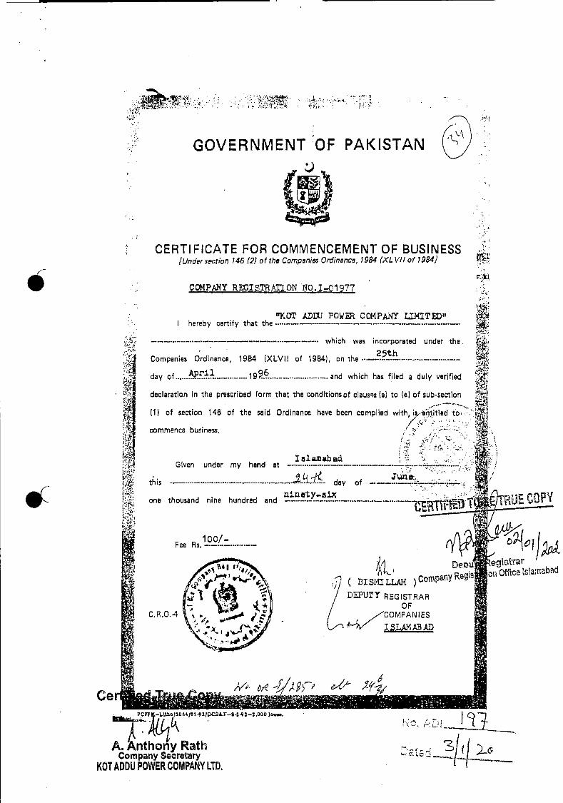
100/— Fee Rs.
C.R.O.4
'•
DU' egtGtrr
( BISL'Z jjjj.( ) ComaflY R8g j;OI Office iclaniabad
DUTT REGISTRAR F
,v'. jr -1'r'
e-" ? 6
—i.Lto)2ofei 91fDCs1.F-5-a.2—t.00O io.. I I A i
GOVERNMENT OF PAKISTAN
CERTIFiCATE FOR COMMENCEMENT OF BUSINESS [Under secrion 746 (2) of the Cornpanie Ordinance, 1984 (XL VII of 79841
COMPANY REOISTRATON NO.I—Q1977
'9cOT .DLU PO COMPANY LI14IT" hereby certify that the
— which was incorporated under the.
Companies Ordinance, 1984 (XLVII of 19B4), on the25th
day of April ig96 and which ha! filed a duly verified
declaration in the prescribed form that the conditlonsof clausa (a) to (el of sub•section
(1) of section 146 of the said Ordinance have been complied with, ie.eii itled ..............
mmence business,
lelamabad Given under my hand at —
this ................ . ............. day of
ninrty-.5ix one thousand nine hundred and .......... .—..—_. BJE COPY
A. Anthony Rath Company Secretary
1(01 ADDIJ POWER COMPANY LTD.

• ANNE XURE D
SIT• . MAP

.

ANNEXURE E
PLANT AND COLONY LAY -OUT
S
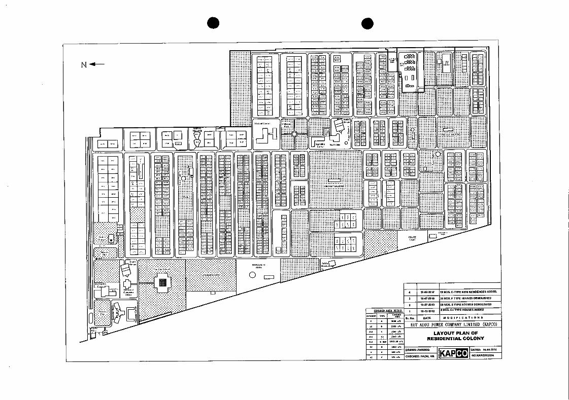
KAP DRAWN: 1040000
CHECKED: FAZAL SB. Co DATED: 04.01.2010
NO.KAPIORGUM
flu ln=
0
:0
H
15-01.2017 IT SOS. C.UPE NEW RESIDENCES ADDED.
19 .07.2015 DO SOS. F TYPE HOUSES DEMOLISHED
ILOT.2013 SD NOSE flPE HOUSES DEMOUSIIED
COVEUD AREA DETAIl. 11.12.2012 4 NOS. CO TAPE HOUSES ADDED
Sr. NO. DATE MODIFICATIONS * T000TO
KOT ADDU PO%CR COMPANY LIMITED (KAPCO) • 0100 Oft
LAYOUT PLAN OF RESIDENTIAL COLONY
C. ODD lit
RADiO
L
II
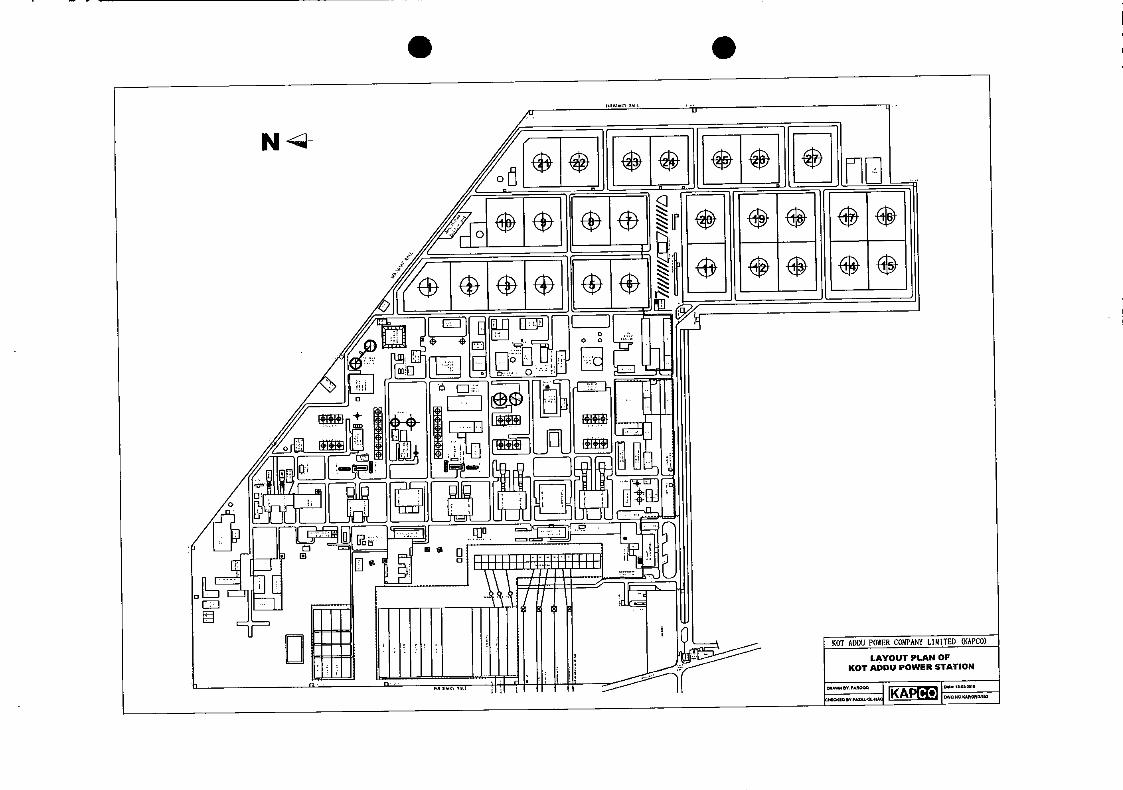
a'
U
a' 'V 1Il
F 'I, 'I,,
a' 'F
a' 'F
N- /
a'
IIIIIIIll!liulllll "I' 0
KOT ADDU POWER COMPANY LIMITED (KAPCO)
LAYOUT PLAN OF KOT ADDU POWER STATION
0
Co wWSY.FAROOQ
IKAP SWO NO.I4APdOflW252 CHEC$IObflAZAL4t.$AC
.1 n . n
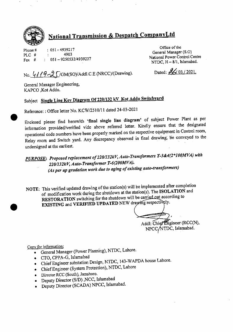
National Transmission & Despatch CompanvLtd
Phone# : 051-4939217 PLC # : 4903 Fax : 051-9250532/4939227
Office of the General Manager (S.0)
National Power Control Centre NTDC, H — 8/i, Islamabad.
No. /./9f/GM(SO)/Addl.C.E (NRCC)/(Drawiflg). Dated:
General Manager Engineering, KAPCO ,Kot Addu.
Subject Si.nIe Line Key Diaaram Of 220/132 kV Kot Addu Switchvard
Reference: : Office letter No. KCW/25 10/Il dated 24-03-2021
Enclosed please find herewith fina1 single line diagram' of subject Power Plant as per
information provided/verified vide above referred letter. Kindly ensure that the desigiated operational codenumbers have been properly marked on the respective equipment in Control room, Relay room and Switch yard. Any discrepancy observed in final drawing, be conveyed to the
undersigned at the earliest.
PURPOSE: Proposed replacement of 22 0/132kV, Auto-Transformers T-3&4(2 *1oQMvA). with
220/132kV, Auto-Transformer :T-6'2O0MVA..). (As per up gradation work due to aging of existing auto-transformers)
NOTE: This verified updated drawing of thc station(s) will be implemented after completion of modifia.tion workduring the shutdown at the station(s).. The ISOLATION and
RESTORATION switching for the.shutdown will be carri- ' sut according to
EXISTING and VERIFIED UPDATED NEW 4ra g respecti Iy
Add!: Chie ' ngi.neer RCC(N), NPCC TDC, Jslamabad..
Copy for information: • General Manager (Power Planning), NTDC, Lahore.
• CTO, CPPA-G, Islarnabad • Chief Engineer substation Design, NTDC, I 4-WAPDA house Lahore.
• Chief Engineer (System Protection), NTDC, Lahore
• Director RCC (South), Jamshoro. • Deputy Director (S/D) ,NCC, Islamabad
• Deputy Director (SCADA) NPCC, Islamabad.
03 /2021.
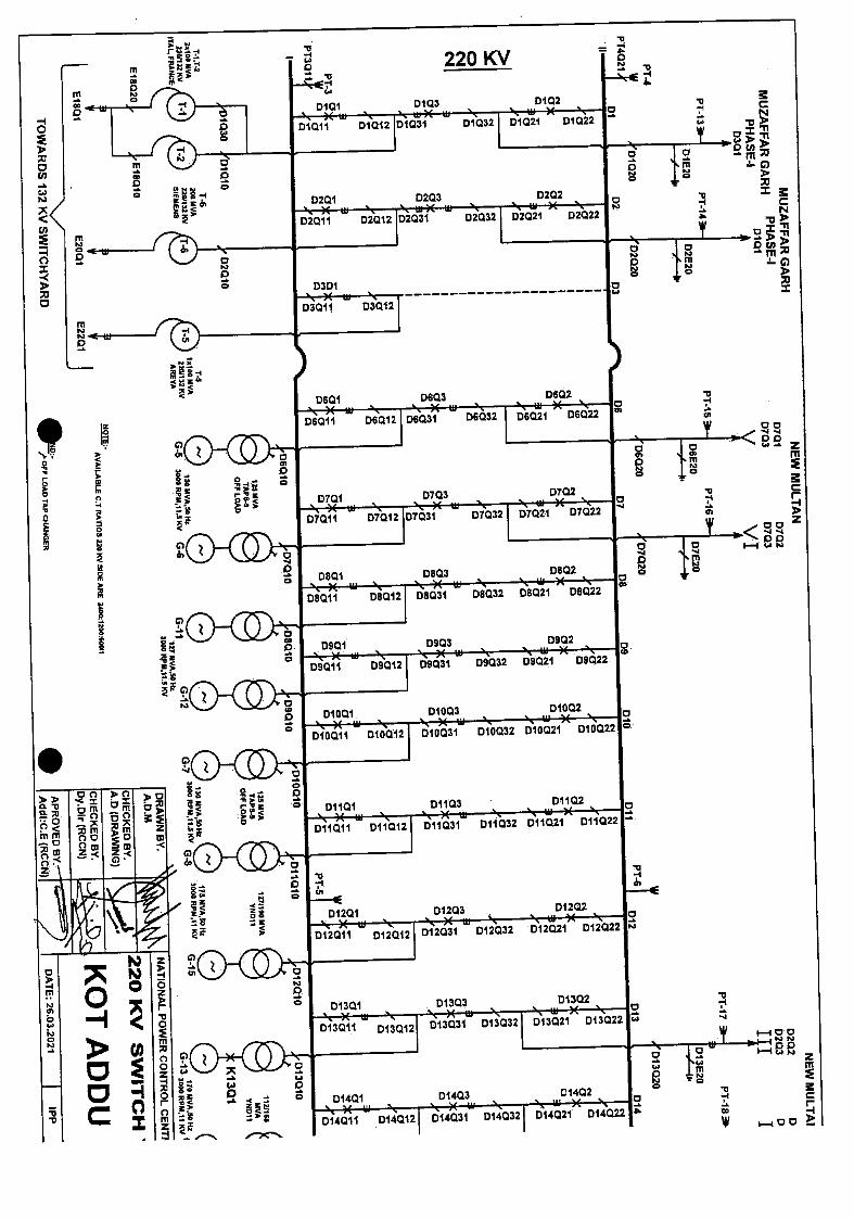
ZCI S
OH
VM
OI
GH
VA
HQ
IIM
SI
0201 \Xw \ 02011 02012
0301 \X \
03011 D3Q12
0 '4 0 0
D1012 \ Xu
DIQII
m 0101
TI'
0 (4 0
0 0
0 C
0
. 0901 0903 0902
\Xth \ \)(W \ \W)(.\.
09011 090121 09031 D9032 09021 08022
C) z -I
0
Tn z
01001 01003 01002
\)(i \ \XW \ \WX \ 010011 D10012 I DIOQ3I 010032 010021 010022
0
0
a
0 0
0 01101 D1103 01102
\Xt \ \)(W \ \W)( \
DIIQII 011012 011031 011032 D11021 011022 -.
0
0 C"
0
D12Q1 01203 01202
\XW \ \XiJ \ \w)( \
D12011 012012 012031 D12032 012021 012022
0 -S pa
z
p.,
° DI3QI 01303 \XW \ \XW \
D13011 D13012 013031 013032
C
La
01401 D1403 01402
\XW \ \XW \ \WX \
014011 014012 014031 014032 014021 014022
p)
z
I-C 00 'at., 0
I-C • -
i-n' - p4 • 0
C
>0 >0
z
01302 I \w)( \ I 013021 013022 I"
MO
d 1Y
NO
I
220 KV
DiQ3 0102 \.XW \
C '4
I,'
-'rn OCh
O
I 0 0203 D202 I \XW \ \w)( \ ,
\ 0
02031 02032 02021 02022
- TN
o N
0 L.1 I
01031 01032 I D1UZI LJIt9
0601 0603 D602 \)(w\ \XW \ \th)( \
U. 00 06011 06012 D6031 06032 06021 06022
00
a, 2 0 C
\X \ \)(W \ \WX \ 0 r
- -1
01011 07012 107031
D7032 D7021 07022 - a,
l
00
0701 0703 0702 c
0 0801 0803 0802
\X\ \XW\ \X \ 0 °
08011 08012 I 08031 08032 08021 08Q22
r
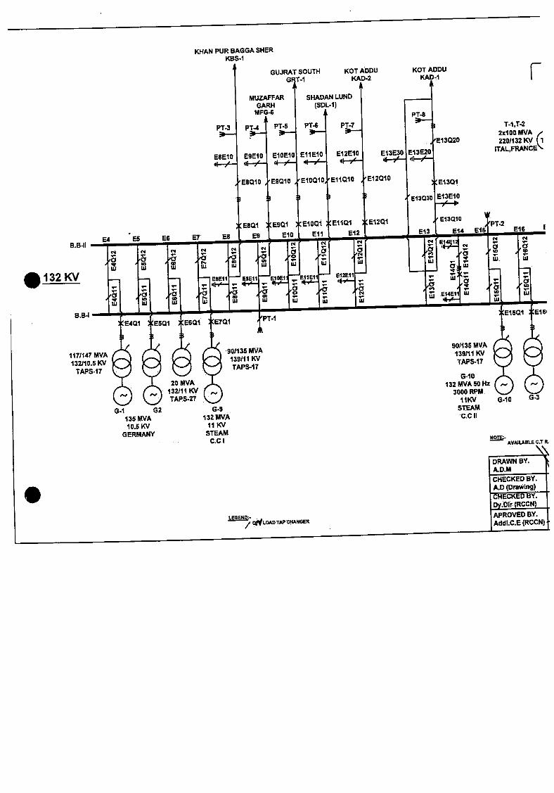
KOT ADDU KAD-1
P14
•E13Q20
B B.B-II
E8Q1 XEBQI XEIQQI EIiQi Ei2QI EI3QIQ /PT-2
ES E9 EIO Eli E12 E13 E14 E15 BIB
N N E4!!CI
N — _ .- a a a
a a
a N I', / 0) — Ui UI Iii U — 03111
EIOEIIE IEII E1ZE11 UI — II.,'— _
— _ V - - a '-
. ,g g , , a, N E14E1lU
U 4-'—
• 132
w
8.94 /PT-I XETQI
90/135 MVA 139/11 KV TAPS-Il
90/135 lAVA 139/1.1 KV TAPS-Il
G-10 132 MVA 50Hz
3000 RPM. 11KV
STEAM C.0 II
G-i G2 135 MVA 10.5 KV
GERMANY AVAILABLE C.T R
6-S 132 MVA
11KV STEAM
C.0 I
6-IC 6-3
117/147 MVA 132110.5KV
TAPS-17
20 MVA 132)11KV TAPS27
KNAN PUR BAGGA SHER KBS-1
GUJRAT SOUTH KOT ADDU GRT-1 KAD-2
A
MUZAFFAR SHADAN LUND GARH (SDL.1)
MFG-6 A
PT-3 PT-4 P1-5 P74 .PT-7 ,— ,—
ESEIO E9EIO EIOEIO EIIEIO E12E10 E13E30 E13E20
_•
r
1-1,1-2 IxIODUVA ,-2201132KV (1
ITAL,FRANCE"
EBQIO /E9Q10 /EIOQIQ EIIOIO E12010
3 3 E13030
E1301
EI3EIO
DRAWN BY. A.D.M
CHECKED BY. A.D(Drawlflg)
LEGENDS ONLOAD TAP
CHECKED BY. Dy.blr (RCCN) APROVED BY. AddLC.E (RCCN)
ANNEXURE G
GENERATION LICENSE
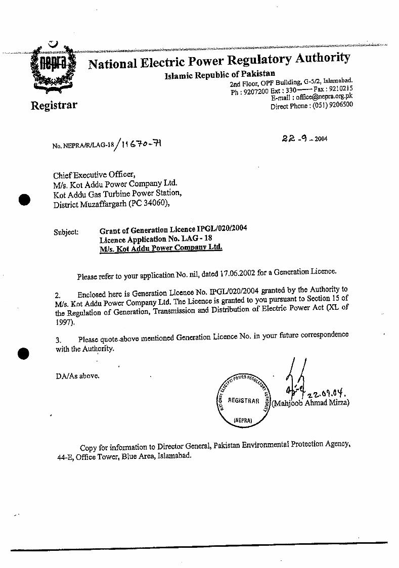
'i 0
(
C Mahj'oob Ahmad Mirza)
(NEPRA)
National Electric Power Regulatory Authority Islamic Republic of Pakistan
2nd Floor, OPF Bul1dng, Q-5/2, isiamabad.
Ph: 920fl00 Ext 330— Fax:9210215 E-mail : officenepra.org.pk Direct Phone: (051) 9206500 Registrar
No. NEPRA/RJLAG4S/ ii ,• -O —
Chief Executive Officer, MIs. Rot Addu Power Company Ltd. Rot Addu Gas Turbine Power Station, District Muzaffargarh (PC 34060),
Subject: Grant of Generation Licence IPGL/02012004 Licence Application No. LAG - 18
Mis. Kot Addu Power Company Ltd.
Please refer to your applicatioiiNo. nil, dated 17.06.2002 for a Generation Licence.
2. Enclosed here is Generation Licence No. IPGL/C}2012004 granted by the Authority to MIs. Kot Addu Power Compally Ltd. The Licence is granted to you pursuant to Section 15 of the Regulation of Generation, Transmission and Distribution of Electric Power Act (XL of
1997).
3. Please quote.above mentioned Generation Licence No. in your future correspondence
with the Authority.
DA/As above.
Copy for information to Director General, Pakistan Environmental Protection Agency, 44-B, Office Tower, Blue Area, Islaniabad.

National Electric Power RegulatorY AuthoritY (NEPRA)
Islantahad — Pakistan
GENERATION LICENCE
No.
In exercise of the Powers conferred upon the National Electric Power Regulatory
Authority (NEPRA) under Section 15 of the Regulation of Generation,
Transmission and Distribution of Electric Power Act, I 997 (XL of 1997), the
Authority hereby grants a Generation Licence to:
Kot Mdu Power Coinnaflv Limited
Incorporated under the Companies Ordinance, 1984 °
Under Certificate of incorporation
No. 1-01977 Dated 25(h Apr11 1996
to engage in generation business subject to and in accordance with the
Articles of this Licence.
Gnien under my hand this day of plfmbt Two Thousand
& Four, and expires on - 21 — day of 9,tM4 1o./v , Two Thousand
& Twenty One.
Registrar

ANNEXURE H
MASTER AGREEMENT
utfl 111 1 iiThIIU;I1 li11fl I1
This Agreement is made and entered into as of this day f ]jth Februaiy 2021 by
between:
PAKISTAN WATER AND POWER DEVELOPNT AUTEORITY a statutory corpOraOfl established pursuant to Pakistan Water and. Power Development AuthotitY Act of 195L with its principal office located atLahore (the 'Tower Purchaser").
Kor Au PoWEa CorNY LIMITED, a company incorporated under the laws of Pakistan whose corporate office is located at 5B13, Gulberg 111, Lahore Pakistan (the
"Company").
/t-. -'f ph,' Pnwr Purchci -- " "n' hin.frr referred to. individually
RECrrALS:
A. Whereas, the Committee for negotiations with Independent Piivate Power Producers ("IPPs"), notified by the Government of Pakistan through notification number F.No IPFs4(12)/2019-20 dated 03.06 2020, and the IPPs incluling the Company representmg the 1994 Power Policy projects, had several rounds of discussions and agreed to aiter their existing contractual arrangements to the extent of, and strictly with respect to, the matters contained in the Memorandum of UnderstanLThg dated 12 08 2020 (the "MoTJ")
B. Whereas, the Company has, at the request of the GOP, in the larger na nal interest, voluntarily agreed to alter its contractual rights for the sustainability • the power sector;
tESTED P\'(I7.MUMTAZ
Mvo Lafl0
-
= anu tALC ¼.ULLiysL&J .... as a "Party" and collectively as the "Parties".)
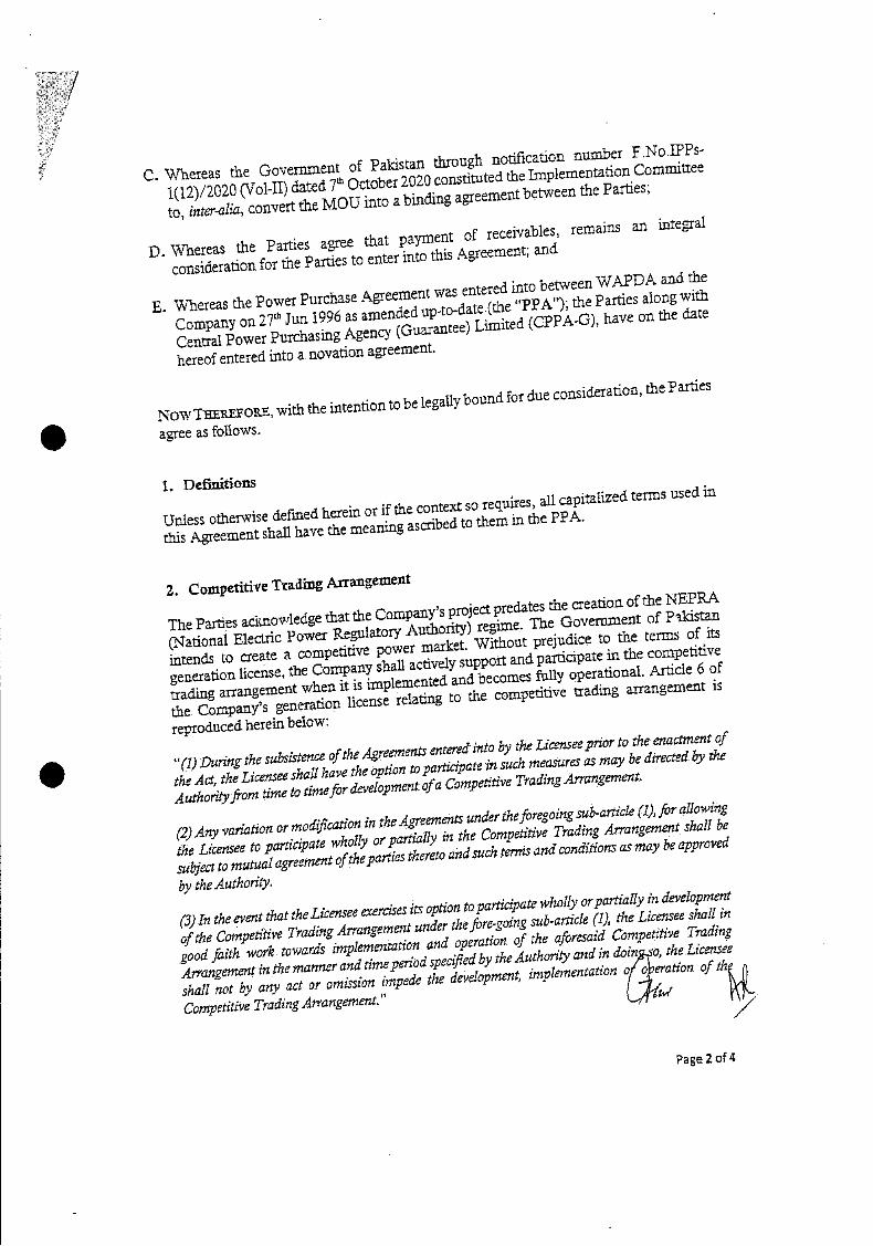
S
C. Whereas the Government of Pakistan through notification number P.NoIPPS
l(12)/2020 (Vol-il) dated 7th October 2020 constituted the Implemeflt.tb0t Committee
to, inter-alia, convert the MOU into a binding agreement btweefl the Parties;
P. WhereaS the Parties agree that payment of receivables, remains an integral consideration for the Parties to enter into this Agreement; asid-
E.1ereaS the Power Purchase Agreement was entered into beeefl WAPDA and the
CompanY on 27th Jun 1996 as amended upto-date (the "PPA"); the Parties along with Central Power Purchasing Agency (Guarantee) Limited (CPPA-G), have on the date
hereof entered into a novation agreement.
NOW TREPO, with the 1tUn to be legally bound for due
considerat1ohi, the P aides
agree as follows.
i. Definitions
Unless otherwise defined herein or if the context so requires, all capitalized terms used in
this Agreement shail have the meaning ascribed to them in the PPA.
2. Coinpetidve Trading Arrangement
The Parties acknoWledge that the Company's project predates the creation of the NEPP.A
(National ElednC Power RegulatorY Authority) regime. The GoVertlnt of P-ldstafl intends to create a competitive power market. Without prejudice to the terms of its generation license, the Company shall actively support and participate in the competitive
trading a55angeme11t when it is implemented and becomes fully operations.l. Article 6 of
the CompanY's generation license relating to the competitive ttading arrangement is
reproduced herein be1oW
"(1) During the subsistence of the Agreements entered into by the Licensee prior to the enactment of the Act, the Licensee shall have the Option to participate in such measures as may be directed by the Authority from time to time for development ofa Competitive Trading Arrangement.
(2) Any variatiOn ormodficatiOfl in theAgreemt under theforegoing sub-article (1), for allowing
the Licensee to participate wholly or partially in the Competitive Trading Arrangement shall be subject to mutual agreement ofthe parties thereto and such trias and conditions as may be approved
by the Authority.
(3) In the event that the Licensee exercises its option to participate wholly or partially in development
of the Competitive Trading Arrangement under tiw fore-going sub-article (I), the Licensee shall in
good faith work towards 1mp1emenUth0fl and operation of the aforesaid Competitive Trading Arrangement in the manner andtim.e periOd specfled by the Authority and in doin so, the Licensee shall not by any act or omission impede the development, impleiflentad0n o o eration of th
Competitive Trading Arrangement."
page 2 of 4
7
3. FacilitatiO11
3.1 The Power Purchaser shall assist and support the CompanY in Tax issues with Federal Board of Revenue for early and positive resolutiOn of all ongoing cases including
apportionment oinput tax on CapacitY Purchase Price invoice, 3.2 The Power Purchaser shall assist and support the CompanY in getting tax exemption
similar to other lPPs, after the initial Term of the PPA or any extensiOn thereof. 3.3 The Power Purchaser shall assist and suppOrt the Company in removing the
reuement of 'Approval of GOP for Additional Debt' and bar on 'Creation of Security' by the Company for making any investment under clauseS 7.2 and 7.3 of the
Facilitation Agreement. 3.4 Subject tO agreement on the terms and conditionS and completion of legal and
corporate formalities, the Power Purchaser shall consent to the extenSI0 of the PPA for an additional term following the expiry of the Tem' of the PPA.
4. Governing Law
The rights and obligations of the Parties nnder or pursuant to this Agreemel1t shall be governed and construed according to the Laws of Pakistan.
5. MiscellaneoUs
The Parties agree that nothing contained. in this Agreement construed as an admission of liability, wrongdoing or improper
Company.
Nothing contained herein shall prejudice any other rights of and
Parties under the PPA.
shall be deemed or be action on the part of the
remedies available to the
6. ConditiOnS Precedent
0twithStafldmg anything to the conflarY in this Agreement the Power Purchaser agrees
to the following conditiOns precedent to the effectiveness of this Agreement
(I)the CompaliY'S shareholder approval at general meeting in accordance with the Articles of Association of the CompanY and the Company shall promptly notiy the Power Purchaser once approval has been obtained or refused by its
sbareholders. and.
the execution of the amendment tO the facilitation Agreement and the execution of the amendment to the GoP Guarantee in form and substanc annexed. to this Agreement The effectiveness and. validity of this Agreement is s b ect to fu1t1lmen of this condition to the satisfaction or waiver by the Company.
Page.3 of 4
TIlE IflPS LOW d
fi at
4 4
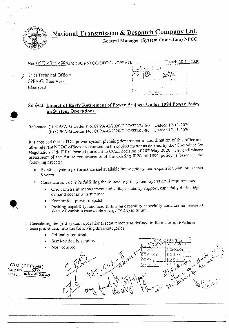
National Transmission & Despatch Company LtcL General Manager (System Operation) NPCC
No: L, ?377/GM (SO)/NPOC/DDPC-l/CAG1'. Dated: 20-11-2020
Chief Technical Officer
CPPA-G. Blue Area,
I.slarnabad
Subject: Impact of Early Retirement of Power Projects Under 1994 Power Policy
on System Operations.
Rei:èrence: (i) CPPA-G Letter No. CPPA-G/2020/CT0122275-80 Dated: 17-I 1-2020. (ii)CPPA-G Letter No. CPPA-012020/CTO/2228 1-86 Dated: 17-11-2020.
It is apprised that NTDC power system planning department in coordination of this office and other relevant N1'DC offices has worked on the subject matter as desired by the Committcc for Negotiation with IPPs' formed pursuant to CCoE decision of
20th May 2020. The preliminary
assessment of the future requirements of the existing IPPS of 1994 policy is based on the
following aspects:
a. Existing system performance and available future grid system expansion plan for ihe ne>1.
5 years.
h. Consideration of IPPs fulfilling the following grid system operational requirements:
• Grid constraint management and voltage stability support, especially during high
demand scenario in summer
• Economical power dispatch
• Peaking capability, and load following capability especially considering increased sharc of variable renewable energy (VRE) in future
I. Considering the grid system operational requirements as defined in Item a & b, !PPs have been prioritized, into the following three categories:
• Critically required
• Semi-critically required
• Not required
I
CT (CPPA-G) )iary
Lfi' __ - _ ( I
DCM(I
I ocr-it , - (
• -. .::--7
-

2. It is important to highlight that tills preliminary assessment has been prepared based on the professional knowledge, experience and system understanding on the part of NTDC engineers coupled with in-house deliberations. Consequently, in the absence of detailed studies, recommendations made through this report are indicative.
3. This report gives an insight of 1PP requirements in consideration of grid system operational requirements for the next 5 years only and does not include generation capacity analysis. It is reiterated that for more accurate future need assessment of 1PPs, detailed analyses would be required in medium to long term perspectives; such analyses would be based on hourly production simulation (generation capacity analysis) and grid system operational support studies. The detailed assessment would also include (i) technical examination/iflspeCtiOfl/tcst of the generation facilities to ascertain their current health, emissions, efficiency and longevity
and (u) assessment of potential capacity and/or energy to DISCOs in the bilateral contract market envisaged under the CTBCM.
4. l'he results of the preliminary assessment by NTDC regarding IPP requirements under 1994 Policy is provided in the attached table.
Submitted for your information and further analysis.
(Engr. Muhamma. .b)
General Manager(SyStCm Operation) NPCC, NTDC, Islamabad
C.C. I. Managing Director NTDC, 414-Wapda House Lahore.
2. Dy: Managing Director (P&E), NTDC, WAPDA House Lahore.
3. Dy: Managing Director (AD&M), NTDC, 413-WAPDA House Lahore.
4. General Manager (Power System Planning) ITDC, PIA Tower Lahore

-
-
--,;--;. .
Ddab
124
±;
Rt:me1t
ç
.i.
ctall;. RequrC4 .----.-
-.;-_ '
- - . :- - .-,'
..--.----•-.
., NI:;
Rqihed
• Required till the completion of Lahore North
500/220/132 kV grid station (expected in 2023)
• This plant is candidate for consideration as
merchant plant after expiry of its PPA, in view
of systeIT operational support capability when
needed.
-- ._.._•
RFO 2027 / KEL
HCPC 129 GAS 2030
• Provides grid system operational support to
feed QESCO
• Plant is unavailable since October 2019 due to
expiry of gas contract between the complex &
SSGC. RLNG contract between the parties has
notyet finalized.
UCH 549 GAS 2030 / • Low cost dedicated gas plant.
FKPCL 151 RLNG 2030
. Requiredforgrid CO nstraintmanagemefltduriflg
sumnier season m future, especially in case of
reduction in dispatch of Trimmu power plant
(expected COD in Dec. 2020) which may be
eitherdqe to generator outages or unavailability
of RLNG.;
L AES LALPIR 350 REQ 2028
• \Aiideoperatingrange of generation.
• May be considered as a merchant plant after
expiry of PPA.
• Its dependable capacity may also help to
evacuate additional ARE generation in the NTDC
-system which needs further exploration.
Page 3of 4
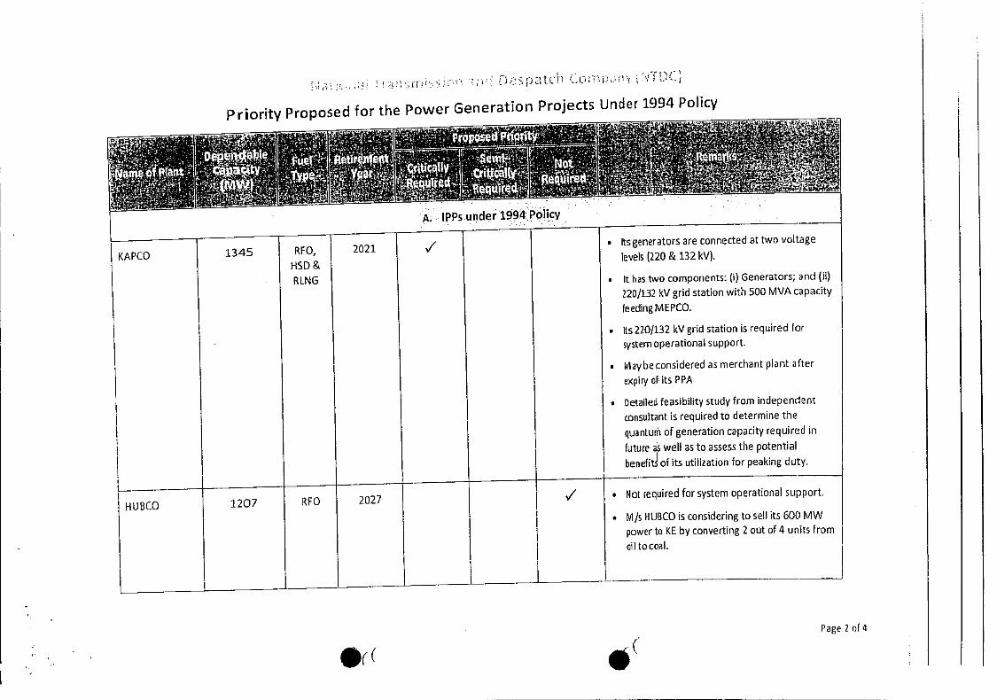
Priority Proposed for the Power Generation Projects Under 1994 Policy
• Its generators are connected at two voltage
levels (220 & 132 ky)
• it has two components: (I) Generators; and (ii)
220)132 kV grid station with 500 MVA capacity
feeding MEPCO.
• Its 220/132 kV grid station is required for
system operational support.
• taybe considered as merchant plant after
expiry of its PPA
• Detailed feasibility study from independent
consultant is required to determine the
quantum of generation capacity required in
future a well as to assess the potential
benefits of its utilization for peaking duty.
RFO,
HSD &
RLNG
1207 RFO 2027 VI • Not required for system operational support.
• MIS HUBCO is considering to sell its 600 MW
power to KE by converting 2 out of 4 units from
oil to coal.
H U BCO
p'tc Co
Page 2 of 4
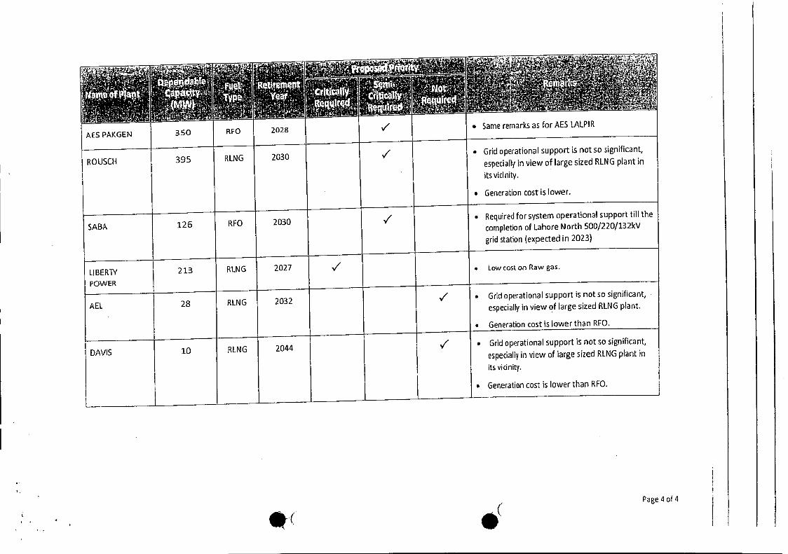
: • ' ,i' •• '.- dabte
(M1N
350 RFO
RUrerne!t
2028
Crtafly RequitCd
NQ - cu1rcd
• Same remarks as for AES IALPIR / AES PAKGEN
/ • Grid operational support is not so significant,
especially in view of large sized RLNG plant in
its vicinity.
• Generation cost is lower.
ROUSCI-I 395 RLNG 2030
SABA 126 RFO 2030 7 • Required for system operational support till the
completion of Lahore North 5001220/132kv
grid station {expected in 2023)
LIBERT' POWER
213 RING 2027 V1 . Lowcoston Raw gas.
AEL 28 RLNG 2032 / • Grid operational support is not so significant,
especially in view of large sized RLNG plant.
• Generation cost is lower than RFO.
DAVIS 10 RING 2044 I V • Grid op.rational support is not so significant,
especially in view of large sized RING plant irm
its vicinity.
• Generation cost is lower than RFO.
Page 4 of 4
-
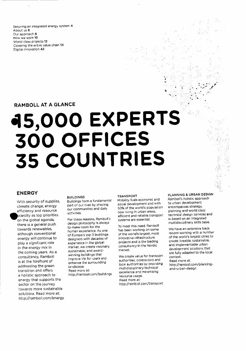
Securing en integrated energy system 4 About us 6 Our approach 8 How we work 10 World class projeCts 12 Covering the entire value chain 14 Digital innovation 42
RAMBOLL AT A GLANCE
45,000 EXPERTS 300 OFFICES 35 COUNTRIES
BUILDINGS Buildings form a fundamental part of our lives by shaping our communities and daily activities.
For these reasons, Ramboll's design philosophy is always to make room for the human experience. As one of Europe's top 3 buildings designers with decades of experience in the global market, we create visionary. sustainable and award-winning buildings that improve life for users and enhance the surrounding landscape. Read more at: http://ramboll.Corn/buildings
TRANSPORT I1obility fuels economic and social development and with 50% of the world's population now living in urban areas, efficient and reliable transport systems are essential.
To meet this need, Ramboll has been working on some of the world's largest, most innovative infrastructure proiects and is the leading consultancy in the Niordic market.
We create value for transport authorities, contractors and local authorities by providing multidisciplinary technical excellence and minimising resource usage. Read more at: http://ra mboll.com/tran$POrt
PLANNING & URBAN DESIGN Ramboll's holistic approach to urban development encompasses strategy, planning and world class technical design services and is based on an integrated multidisciplinary skills base.
We have an extensive track record working with a number of the world's largest cities to create liveable. sustainable, and implementable urban development solutions that are fully adapted to the local context. Read more at: http://ramboll.cOm/Plannifl9 and-urban-design
ENERGY
With security of supplies,
climate change, energy efficiency and resource
•carcitY as top priorities
on the global agenda,
there is a general push
towards renewables, although conventional
energy will continue to
play a significant role
in the energy mix in the coming years. As a
consultancy, Ramboll is at the forefront of
addressing the green
transition and offers a holistic approach to
energy that supports the
sector on the journey
towards more sustainable
solutions. Read more at: http://ramboll,com/energy
COUNTRIES WITH PERMANENT OFFICES NORDIC REGION: Denmark - Copenhagen, company head office. Finland, Greenland. Norway, Sweden EUROPE: Belgium, cyprus. France, Germany Italy, Netherlands Poland. Rornania, Russia, Spain. Switzerland united Kingdom MIDDLE EAST: Kingdom of Saudi Arabia, Qatar, United Arab Emirates ASIA-PACIFIC: Australia, china, India. Indonesia. Malaysia, Myanmar. New Zealand, SingaporeTHE AMERICAS: Brazil, Canada, Mesico, USA AFRICA: South Africa
WATER Water is essential to life and one of our most precious resources. Working with .municipalities utilities. and industrial clients, Ramboll draws on proven multidisciplinary expertise to manage the most challenging water resources, wastewater, and storm water issues.
We integrate treatment process selection and engineering, operational services, and regulatory management and planning to deliver innovative solutions that benefit both industries and society. Read more at: http://ramboll.com/Water
ENVIRONMENT & HEALTH As a globally recognised environmental and health consultancy, we have earned a reputation for technical and scientific excellence, innovation and client service.
Advances in science and technology and evolving regulatory, legal and social pressures create increasingly complex challenges for our clients. We evolve to keep pace with these changes - by adding new services. contributing to scientific advances or expanding geographically. Read more at: http://remboll.cOm/ environment-a nd-health
MANAGEMENT CONSULTING National, regional and local authorities are responsible for issues that affect us all; from healthcare, education and day care to strategic planning of infrastructure
and climate initiatives. Drawing on 500 management experts, Ramboll acts as a trusted partner to public administrations, creating the insights needed to make informed strategic decisions that promote stronger
societies.
With unprecedented levels of competition in the global economy. Ramboll focuses on empowering private sector customers with expertise and powerful management tools.
Read more at: http://ramboll.cOm/ management-consulting


6
ENERGY ABOUT US REVENUE IN 2018
EUR 165 MILLION
NUMBER OF EMPLOYEES
Ramboll Energy has approx.
,8OO specialists working
dedicatedly with renewable
and conventional energy.
GEOGRAPHICAL SPREAD
RernbOli has 55 energy offices
in 14 countrieS, including .nrnark, Sweden, Norway, UK,
rrneriy, Poland, Switzerland,
LISA, Can5da. Qatar, UAE,
India, Singapore arid China.
RANKINGS
Pamboll is ranked no.1
in CogeneratiOn. no.1 in
Towers & antennae, no.2 in
Hazardous waste, no.3 in
Wind generation and no.8
in Offshore and underwater
facilities in the ENR survey
of top international design
firms (Dec. 2018 rankings).
NE OF THE LARGEST
WASTE-TO-ENERGY
FACILITIES ON EARTH IN
ONE OF THE WORLD'S
SMALLEST COUNTRIES
Ramboll is part of a
multidisciplinary consultancy
technical teem for the planning,
design and construction
management of one of the
world's largest waste-to-
energy facilities, which will
er,able Singapore to reap the
benefits of energy and resource
recovery maximisation for.
years to come (image p.7).
Ramboll has more than 50 years of experience in the planning, design and implementation of energy solutions and is among the ten leading energy consultancies in Europe. We focus on adding maximum value both to our clients and society at large through an integrated and multidisciplinary offering that cuts across the whole value chain.
The projects that we carry out for our clients typically provide the overall society benefits of securing the supply of energy, reducing climate impact, improving energy efficiency and countering resource scarcity. In this way, we contribute to a sustainable development of the energy sector.
As a people-based company, we believe that the key to our success lies in the motivation, persistence, skills and commitment of our employees. With offices around the world, we combine global knowledge with local presence. Being an international company enables us to mobilise large project teams across geographies and disciplines.
Our services are based on integrity, deep specialist insights and absolute independence of
third party providers.

8
OUR APPROACH A PARTNER FOR CHANGE
The energy sector is shifting from a system based on fossil fuels to one exploiting renewable energy. As sustainable society consultants, we bring our clients one or more steps closer to a renewable energy system, and we optimise energy efficiency, systems, technologies and processes.
We enable people and organisations to design and implement sustainable change with a lasting impact - for both business and society.
Driving green energy transition should always be built on a holistic understanding as well as in-depth expertise and experience. And it should be built on close engagement between us and our clients because no change encounter is the same, and each initiative, challenge and dialogue therefore calls for depth, creativity and perspective.
We seek long-term relationships with our clients and have worked for many of them for more than 30 years.
We are committed to guiding our clients and their organisations into a better state and to always delivering sustainable energy solutions that are innovative, integrated and flexible to suit the unique
challenge at hand.
WHAT OUR CLJENTS GET
A change partner who
helps our clients think,
design end implement the,r
green energy transition
A committed partner
who takes end-to-
Send responsibility of
our clients projects
A partner who listens to
our clients' needs and
challenges before designing
the best solutions
• Proactive out-of-the-box
and innovative thinking.
translating ideas into
pragmatic solutions
• A partner of integrity,
offering independent
expert cortsultancy
• Integrated energy solutions
based on n understanding
of the interaction between
the different sectors and
technologiet, technical
insight and multidisciplinary
competerncies
• Access to strong technical
capabilities and best practice

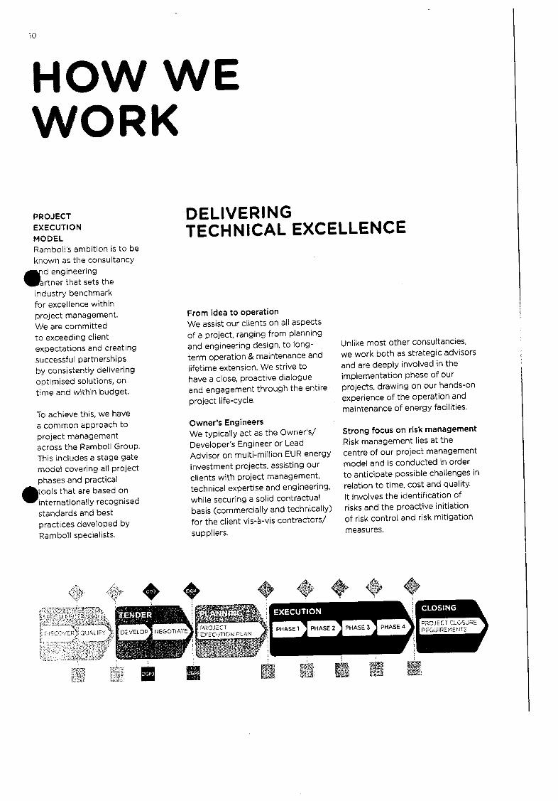
2O.ECT CLOSJRE EUREMNT5 rRojEc1.
1 EYEC.T!ON 'L
10
HOW WE WORK
DELIVERING TECHNICAL EXCELLENCE
PROJECT
EXECUTION
MODEL Ramboll's ambition is to be
known as the consultancy
d engineering
artner that sets the industry benchmark
for excellence within project management.
We are committed
to exceeding client
expectations and creating successful partnerships
by consistently delivering optimised solutions, on
time and within budget.
To achieve this, we have a common approach to
project management across the Ramboll Group.
This includes a stage gate model covering all project
phases and practical
Stools that are based on
internationally recognised
standards and best practices developed by
Ramboll specialists.
From idea to operation We assist our clients on all aspects
of a project, ranging from planning
and engineering design, to long-
term operation & maintenance and
lifetime extension. We strive to have a close, proactive dialogue and engagement through the entire
project life-cycle.
Owner's Engineers We typically act as the Owner's! Developer's Engineer or Lead Advisor on multi-million EUR energy
investment projects. assisting our clients with project management.
technical expertise and engineering, while securing a solid contractual
basis (commercially and technically) for the client vis-à-vis contractors!
suppliers.
Unlike most other consultancies, we work both as strategic advisors
and are deeply involved in the
implementation phase of our projects, drawing on our hands-on experience of the operation and
maintenance of energy facilities.
Strong focus on risk management
Risk management lies at the centre of our project management
model and is conducted in order
to anticipate possible challenges in
relation to time, cost and quality. It involves the identification of
risks and the proactive initiation
of risk control and risk mitigation
measures.
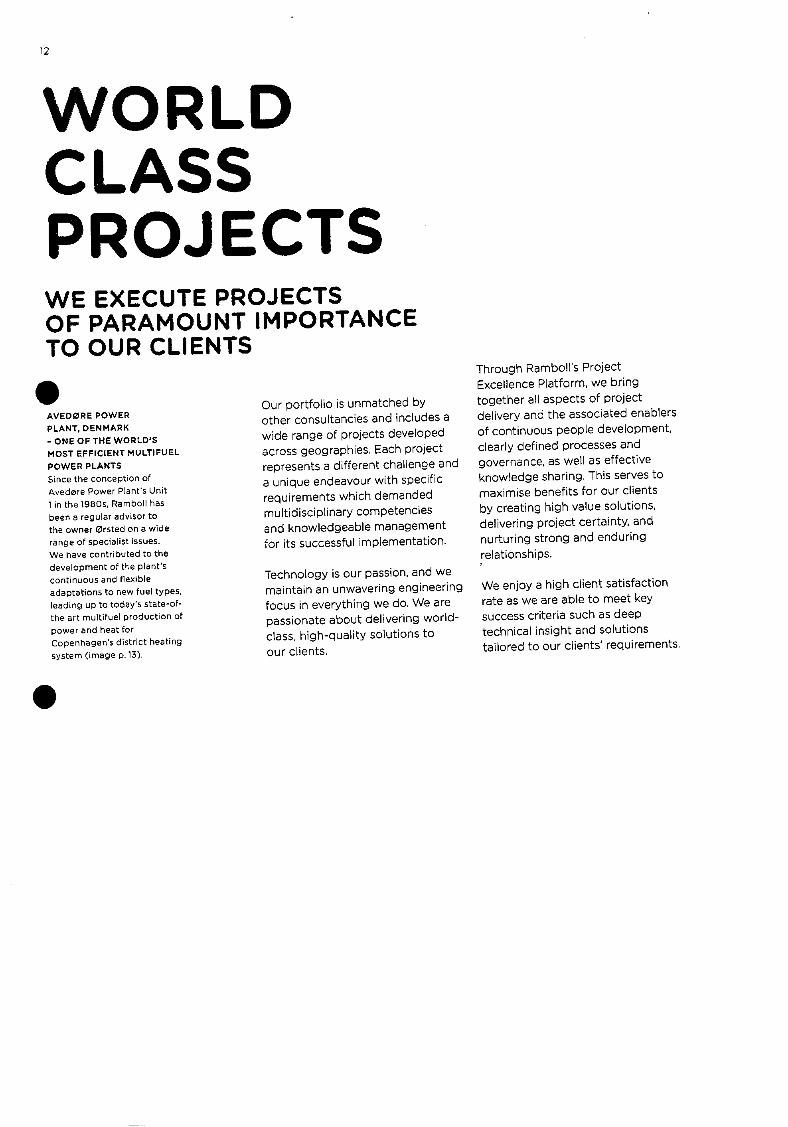
12
WORLD CLASS PROJ ECTS WE EXECUTE PROJECTS OF PARAMOUNT IMPORTANCE TO OUR CLIENTS
. AVEDØRE POWER PLANT, DENMARK
- ONE OF THE WORLD'S
MOST EFFICIENT MULTIFUEL POWER PLANTS
Since the conception of
Avedøre Power Plants Unit
1 in the 19805, Ramboll has
been a regular advisor to the owner ørsted on a wide range of specialist issues.
We have contributed to the development of the plants
Continuous and flexible
adaptations to new fuel types leading up to todays state-of-the art multifuel production of
power and heat for Copenhagen's district heating
system (image p.13).
Our portfolio is unmatched by other consultancieS and includes a wide range of projects developed across geographies. Each project represents a different challenge and a unique endeavour with specific requirements which demanded
multidisciplinary competeriCieS and knowledgeable management for its successful implementation.
Technology is our passion, and we maintain an unwavering engineering focus in everything we do. We are passionate about delivering world-class, high-quality solutions to
our clients.
Through Ramboll's Project Excellence Platform, we bring together all aspects of project delivery and the associated enablers of continuous people development,
clearly defined processes and governance, as well as effective knowledge sharing. This serves to maximise benefits for our clients by creating high value solutions, delivering project certainty, and nurturing strong and enduring relationships.
We enjoy a high client satisfaction rate as we are able to meet key success criteria such as deep technical insight and solutions tailored to our clients' requirements.


wne 9U4PU AOuODe s.c uflO
o; AI1u3u5S u4qwo rdrO pus I!O
S'4°O 4° %O pUflO ipoid uqsq!V Ao
pue $95J2I PJ!p SPIJOM t4
spoq I?O 9515 'iflUJ JSAO 6U!4eIdWOD
suoppp9t sep pijq jooiqsLct- j sa,c ue,S O4
eeu!6u
, opsid eu SI ew k.
sq J04
.iduoDsqI p'J ucxpn4
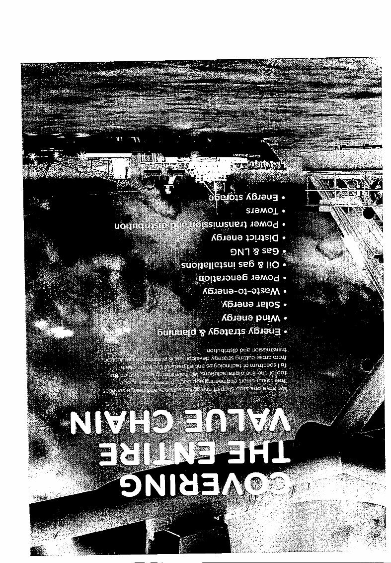
a.wosA6iau. SjeMO.L.
uôissiW.SUeJ3 .l9MOd. ,c6jeua P!AIS!Q •
SN1 ' S9 suoeUesuI se6 '2 110 • uO!4EloUe6 jaMOd.
A6Aeua-o-eSeM. 'ic6aua ielos. A6i8U9pU!M.
ueld ' A6e3i4s IU3.
.1 uoqnqIAsp puc2 uo;SSIWSLiI2J.
jailcialaAap T6ans 6uinD-SsOJ woi
pu2 soIOU1pa o wnipdS In 2/SUoiflOS It2!P ouiq-o-dO1
c,lcl 6uueü6ue 3Jiw;Ar,o o
iric K&iui jo do dos-üC ati a/\
ENERGY STRATEGY & PLANNING DRAWING ON CROSS-SECTOR AND MULTIDISCIPLINARY CAPABILITIES STRATEGY DOCUMENTS
• Enerçtysupply& demand forecast
• Energy supply strategies
• Energy delivery
planning and design
• Storage solutions
• Smart energy
SEnergy efficiency & demand
aide nienagement
BUSINESS CASES
• Investment planning
• Circular economy
• CAPEX.OPEX& ABEX assessments
• Lifecyle assessment
15055000
• CBA - international
best practice
POLICY -
• Regulatory arialysi & compliance
• Security of supply
• Market models
• Subsidies and frameworks
DUE DILIGENCE
Commercial & financial
• Technical & operational
Environmental assessment
• Risk assessment
Rarnboll is a strategic partner to international and domestic clients offering proven commercial, financial and engineering consulting capabilities to assist our clients with the development of strategy documents, business cases, policy and due diligence studies.
We add value to projects by having
full local knowledge across Europe, North America. Middle East and Asia to provide understanding of the energy lifecycle and the interaction of the different elements in the energy system.
We provide solutions to the Challenges of our Client: Cities. universities, governments and the Eu; investors; generators; transmission system operators; distribution system operators; and
large consumers.
We offer a core energy strategy and planning team as the single point of contact within Ramboll for
the development, execution and implementation of projects globally.
The core team draws on Ramboll expertise in 300 offices in 35 countries to offer our clients the advantage of a global platform with leading energy sector experts and local knowledge across Europe, North America, Middle East and Asia to provide the right knowledge for the right geography.
The team draws on Ramboll's multidisciplinary capabilities, e.g.
within buildings, environment & health, management consulting and
transport.
17
ENERGY MASTER PLANNING
AT THE CITY UNIVERSITY
OF NEW YORK, US
The City University of New York
(CUNY) is the nation's leading
urban public university. It serves
over 500,000 students from
25 campuses, 300 buildings
and almost 2.5 million square
metres of building space, and
it has an annual energy spend
of nearly USD90 million. OBG,
now Ramboll, has been assisting
CUNY with their New York City
Carbon Challenge since 2007,
having developed climate action
plans that identify CUNY'S
strategy to reduce carbon
intensity by 40% by 2030,
CARLSBERG - NEW URBAN
DISTRICT IN COPENHAGEN
In 2009, Carlsberg'S production
moved to a new Site in Denmark,
leaving a 330.000 m' industrial
Site in Copenhagen open for
development. It was the vision to
create a new sustainable district
in Copenhagen with housing,
shops and office buildings in
harmony with the historical old
buildings and the neighbouring
districts. Ramboll planned the
infrastructure with a focus on
sustainable energy supply.
With the rapid growth of wind
energy production worldwide,
Ramboll offers our clients international, multidisciplinary
and wind specific competencies. We offer expert services for the
different project phases from early feasibility, business case and impact assessment studies to planning, engineering, implementation,
commissioning and the subsequent operation & maintenance and
eventually life-time extension or
decommissioning.
We can effectively manage the entire project or contribute with our
expertise in different sub-projects
according to our client's needs. Ramboll is a full-service consultancy and wind energy leader with global
kny.vledge and a network of offices and resources that serve
clients locally.
18
WIND ENERGY WORKING WITH WIND ENERGY SINCE 1986
OFFSHORE
Over 60% of the worlds
offshore W!flO turb:nes roe
from foundations engineered
by Ramboll.
ONSHORE
We have provided espert
input to onshore wind farms
With a nominal output of more
than 60GW in 6O countries.
ONSHORE WINO FARM
RASKIFTET, NORWAY
The public utility of Munich in
Germany. Stadtwerke MUnchen
GrnbH (SWM), intends to
generate sufficient green energy
ta plants to cover all energy
nsumpbon in Munich by
2025. As part of this endeavour,
SWM has invested in several
onshore and offshore wind
farms in recent years, including
Raskiftet Onshore Wind Farm
in Norway. On behalf of SWM,
Ramboll provided technical due
dihgence services including
yield calculations and was
subsequently commissioned
for the supervision of the
construction process as
the Owners Engineer.
OFFSHORE WINO FARM
BORKUM RIFFGRUND I
Ramboll contributed to
ørsted's successful installation
of the worlds first offshore
wind turbine foundation
based on the Suction Bucket
Jacket (SBJ) technology. The
Scope of our work included
he design of the SBJ for the
offshore wind farm Borkum
Riffgrund 1,37km off the German
island of Borkum. The SBJ
was designed with three cup
foundations that are slipped into
the seabed through suction, It
can be installed in a single lifting
and assembly process, which
reduces installation time and
its associated costs. It also has
a quieter installation, meeting
the new noise restrictions set
to protect local ecosystems
(image p. 19).
'spI0..SSrIOq U0flI0 ul4 uq4 0.10W 0
I0U0 UIM ,c1ddns II!M SW.10J pUIM 0I.4
eo UI 'M9 '2 40 c D2d0 O4 LIIM
5u000P0004 0iqn puI' 0.1045110009
40 0M 4514 044 p0U6IS0P EUO100.lq
0 5014 IIoqwd 0H S0!3 0440!
UO!4flhlocl .110 9flp5) o4 puewep U86)fl .1)2
so uem so A6ieuo o4 pueUlop 6uSe0i0U
1.105! 2.12144 114005 J244)fl4 6UOP60200
UI SuoMe6au) 00040 A4!oodoo 2
sou!qfl'!1 00110 S4SISU0 W)04 pU!M 2111 'H
114.oN OqUIO DIdS 5w)e4 pUIM e)014S440
4506)21 S,SU!11D 40 BUO 6u!U6!sop cuedwoD
0S0t.lI!.ITj-UOU 44)1401.1450 'SI flOqWOU
eNIH aNIM
3dOHSd.O ,NOa9Nvflo GN IVHNffl
22
SOLAR ENERGY SOLAR HEATING The best managed end
ontimised solar heating facility
can utilise more than 45%
of the annual solar radiation
and convert this to district
heating. Our experience
includes consultancy services
provided to both large-scale
and small-scale solar heating
plants, ranging from 20Dm'
to more than 75,000 m5.
CAPITALISING ON THE LARGEST SOURCE OF ENERGY ON EARTH
SOLAR PV
Rarnboll has over 15 years of
experience working with solar
energy. We have contributed
to the success of more than
coo small to utility scale
PV power prolects, ned out in more than 25
countries around the world.
With smart engineering at the core of our work, Ramboll is a world leading consultant and auditor, providing a full range of solar services. We assist our clients with comprehensive advice and future-
proof solutions based on expert knowledge and state-of-the-art
technology.
Solar PV Our multidisciplinary structure enables us to offer holistic services covering every aspect of a solar PV project worldwide. Specialised teams are assembled from across the entire Ramboll group to ensure that the strongest expertise is applied to each individual project.
Our services within solar PV range from expert planning, engineering and project management to resource and financial assessments, as well as other specialist studies including ESIA, grid impact studies,
and performance monitoring.
As a one-stop-shop of energy services, we offer singular, modular
and tailor-made solutions for individual project requirements throughout the entire project life. With our multidisciplinary approach
we provide innovative, efficient
and cost-effective solutions for all kinds of solar PV projects, including
solar PV power plants for lPPs and utilities, solar PV for commercial clients with self-consumption
and sobr PV as a substantial part of hybrtd energy systems. For every project, we always strive for sustainability and with that in mind, we place the focus on designing
long-lasting solutions.
Solar heating Large-scale plants are a special Scandinavian concept for solar
heating, supplying energy to the local district heating network through a heat accumulator. Ramboll has participated actively
in the development of these solar heating plants and performed research into the latest technologies
and underground storage systems.
We also provide consultancy services relating to their integration into existing heating and combined
heat and power plants.
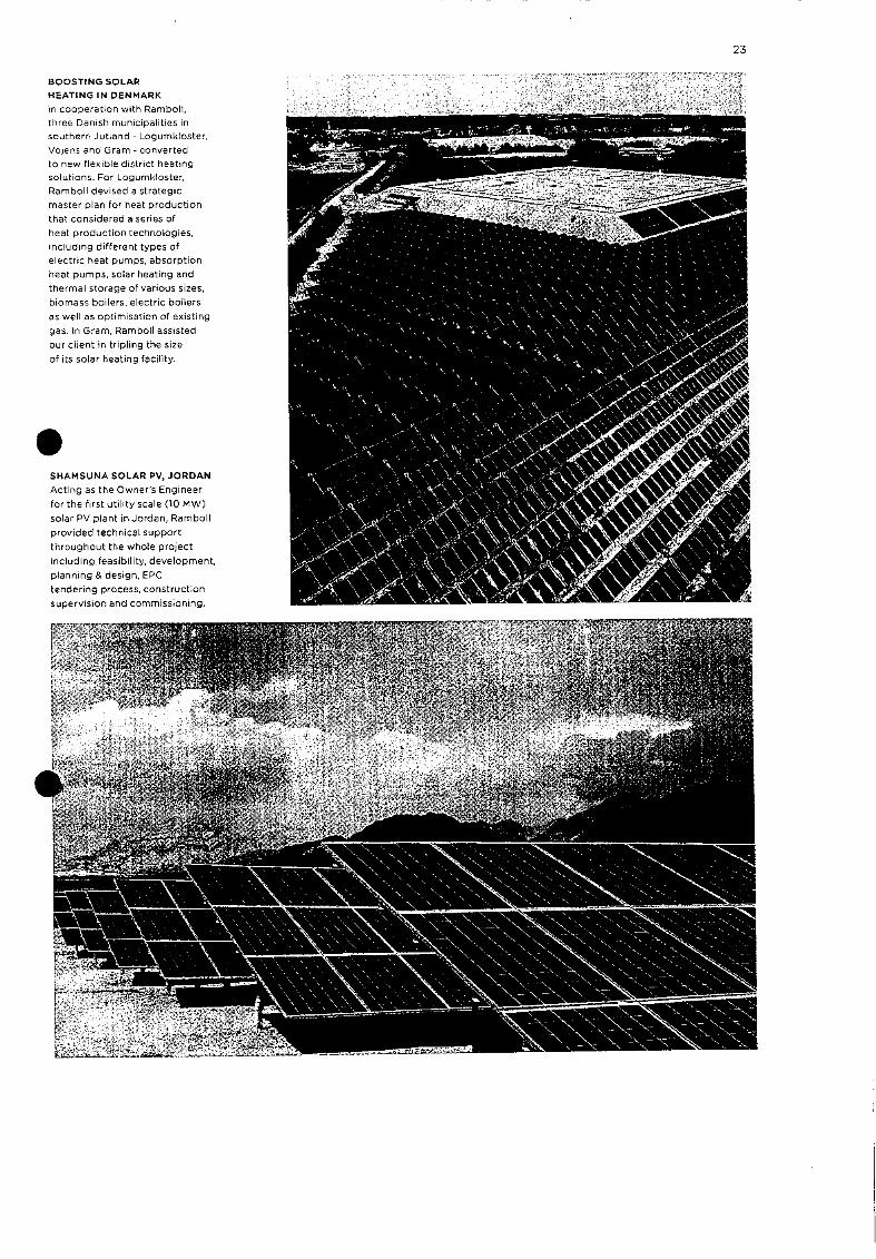
BOOSTING SOLAR
HEATING IN DENMARK
In cooperation with Rambolt,
three Danish municipalities in
southern Jutlend - Logunikloster,
Vojens end Gram - converted
to new flexible dwtrict heaDng
solutions. For Logumklosten,
Ramboll devised a strategic
master plan for heat production
that considered a series of
heat production technologies,
including different types of
electric heat pumps, absorption
heat pumps, solar heating end
thermal storage of various sizes,
biornass boilers, electric boilers
as well as optimisation of existing
gas. In Gram, Ramboll assisted
our client ri tripling the size
of its solar heating facility.
23
,s--:r., r - -=
S SHAMSUNA SOLAR PV, JORDAN
Acting as the Owner's Engineer
for the first utihty scale (10 MW)
solar PV plant irs Jordan, Ramboll
provided technical support
throughout the whole project
including feasibility, development,
planning & design, EPC
tendering process, constructon
supervision and commissioning.

24
wASTE-TO-EN ERGY LEADING WASTE-TO-ENERGY CONSULTANT
EX PC RICH CE
Rarnbofl has worked on
waste-to-energy projects
in 45 countries, providing
consulting services for 55
new units and retrofits.
WASTE•TO-ENERGY
FACILITY
IN LONDON, UK
Rarnboll is acting as Technical
Advisor to North London
Waste Authority (NLWA)
he delivery of its North
ndon Heat & Power
Project. Pamboll is leading
the design development
of a new state-of-the-art
700k5pa waste-to-energy
facility with combined semi-
dry/wet flue gas treatment
to meet Best Environmental
Practice. We have also
conducted thorough technical
assessments of the existing
waste-to-energy facility to
establish its condition and
future expected performance,
preparing recommendations
for investment requirements
and costs over short-term
and medium-term horizons.
ICONIC AMAGER BAKKE,
DENMARK
Arnager Bakke is one of the
most efficient waste-to-
ergy facilities in the world.
the Owners Engineer
Ramboll has assisted in the
planning and implementation
of the 560000 tpa facility,
which produces 20% more
energy per tonne of waste
compared to the plant that
it replaces and has emission
levels far below limit values.
The facility is fully integrated
into the urban setting.
surrounded by high-end flats,
and features a ski slope and
other recreational facilities
on the roof (image p.25).
As the world population and energy consumption increase there is a pressing need for the reduction of waste generation, high-quality recycling and the use of residual
waste for efficient and clean energy
generation.
Recovering energy from waste Ramboll is the world's leading
waste-ta-energy consultant with unmatched technical insight.
We have art extensive portfolio of successfully completed projects that involved the planning, engineering, procurement and
contract management of waste management facilities. We assist our clients through all phases of the project - from idea to operation - and the combination of our experience and expertise means that we can provide no-learning-
curve client support.
Our holistic specialist knowledge covers all aspects of asset management, including upgrades and retrofits, and always with
a focus on cost and process
optimisation.
Biogas from waste Organic waste has become an important raw material for boosting biogas production from both manure and sewage sludge. Biogas can be used locally for the generation of electricity and heat or it can be upgraded for injection
into the natural gas network or utilised as a transport fuel. Ramboll has many years of experience in the successful implementation of biogas projects. Our technical expertise enables us to handle the specific challenges that arise when using organic waste for the production of
biogas.

26
POWER GENERATION
INCREASING ENERGY EFFICIENCY WHILE REDUCING CLIMATE IMPACTS
EXPERIENCE
Rarobof has designed and
constructed niore than 100
major power plants, including
some of the most energy
efficient plants in the world
and has been instrumental
in the ongoinc conversion
from fossil fuels rd biomass.
TECHNICAL ADVISOR
FOR POWER PLANT IN
SALALAH, OMAN
Ramboll was selected by
Oman Power and Water
Procurement Company SAOC
to be the technical advisor to
the electricity off-taker of the
Salalah II IPP Power Plant. The
project resulted in a highly
efficient plant with an energy
conversion that went from
32% in the existing plant to
54% in the new plant. The
new plant has a lower
fuel consumption and
reduced emissions.
As the world shifts towards a sustainable energy mix, there is a need for thermal power generation plants to reduce emissions, by maximising efficiency or alternatively by switching to the use of renewable fuels such as biomass. Similarly, there is a need for plants to operate more flexibly as the level of intermittent energy sources
increases.
Ramboll has pioneered the development of innovative power
plants worldwide, having particular expertise in high efficiency power plants, biomass and bioconversionS,
and cogeneration (CHP).
We have extensive experience in the design and implementation of flexible, fuel efficient combined
cycle and major thermal power
plants, including expertise in supercritical and ultra-supercritical
boiler plants.
Our unique position has been
acquired through our contribution to the detailed development and implementation processes of some
of the world's most efficient power
plants.
Our specialist knowledge covers the full project life-cycle, from early
feasibility study stages through to implementation and subsequent operations and maintenance support, failure investigation, and
power plant rehabilitation and upgrades. Throughout all phases we always strive to set and achieve the highest standards of health and safety of a project and subsequent
plant operation.
LYNEMOUTH POWER
PLANT CONVERSION
0 BIOMASS, UK
Remboll provided engineering
consultancy services to the
conversion of Lynemouth
Power Plant from coal to
biomass. The converted plant
exports around 390MW of
low-carbon electricity to the
national grid. Wood pellets
are imported to the plant from
global fuel supply markets, via
a newly constructed biomass
import terminal at the Port of
Tyne (Newcastle UK), which
along with the power plant
and site fuel storage and
handling, alsO fell within the
scope of Rambolls
work (image p. 27).
s4elled pue sdiip POOM 'MeI4S S2-l4DflS
sseuoiq fl!M peneni siun MDL! 4JflJSUO)
O pUE UOiSJDnUOD e4eIdLUO3 io 6uiuqo3jO
seej6Op noue, o sueid iemod peii;- eo
PDAUOD O PDP9 6PDIMO ;o e6U?!
II!4 DL sassPduJOuD esq.edxe s1Ioqued
JoJe ,c6eUe Dq u euufl uoJ4 e s'
e1dWitemlOr l
28
OIL & GAS INSTALLATIONS RAMBOLL IS INTERNATIONALLY KNOWN FOR OUR OPTIMISED OIL & GAS DESIGN SOLUTIONS
RECORD BREAKER
Rambot broke the world
record for deep water
installatron of 36" pipeline.
As global energy consumption continues to grow, oil and gas will continue to play an important role in the world's energy mix for many
years to come.
modifications, maintenance and lifetime extension to decommissioning.
To make it in today's fast-paced and competitive oil and gas market,
companies depend on advanced technical solutions that combine economic efficiency with stringent health, safety and environmental standards in the production and distribution processes. These elements form an integral part of Ramboll's independent and
multidisciplinary consultancy service, which covers the entire asset life cycle - from early phase studies, FEED, detailed engineering,
We excel in consultancy and have designed offshore structures for industry giants such as Total, ConocoPhillips, INEOS and Equinor
since the 1970s.
Ramboll works across the oil and
gas sector, covering engineering services within energy & infrastructure consulting, offshore production facilities, onshore production & refining, pipelines, and
Gas & LNG.
• EMARKABLE CULZEAN The Cuizean held was
discovered in 2008 and is
one of the largest fields in
the British North Sea. With
temperatures reaching 170
degrees C and the pressure
being three times higher than
average fields, a platform
optimised for these conditions
is paramount. Rarnboll
carried out the detailed
design of three jackets for
I'laersk Oil (now Total).

Heidrun
•
Zidane
Fo5eIrg
YAasta Hansteen
-1300 rs
— Arcj Circle Tee(futore) — — — —
36
Vc1ori? -,
• : • Tee (future)
Harstad
Bodø
66.5
MoiRana
- Sandnkssjaen
RECORD-BREAKING
POLARLED PIPELINE
This unprecedented 482 km
pipeline crossing the Arctic
Circle on an extremely uneven
seabed Connects new fields in the
Norwegian Sea with existing
infrastructures to secure future
energy supply in Europe. The
pipeline was installed at water
depths reaching 1.265 m, setting
a world record for deep water
installation of a 36" pipeline.
Ramboll was instrumental in
designing the pioneering technical
solution for the pipeline, mci. FEED.
detailed design, route optimisation,
pipeline tie-in, geotechnical
foundation design, risk and safety,
EIA, and interface coordination.
29
'-300 n'r
Linnorm
jjDraugen
36•
INVESTIGATING TWO CONCEPTS
FOR THE TYRA FIELD, NORTH SEA
The Tyra Field in the North Sea
has been in production for thirty
years, and the facilities are suffering
from seabed subsidence, old age
and increasing operating expense,
Maersk Oil (now Total) was
assessing several lifetime extension
options to make continued
operation feasible. For the Tyra
Future redevelopment project, TFU,
Ramboll carried out two pre-FEED
(conceptual) studies. Concept 1
focused on examining the rebuild
of Tyre East into an unmanned
satellite producer, while concept 2
investigated an option to rebuild
Tyra East as a field centre with new
topsides for several of the existing
welihead and riser platforms.
I Kristiansund
Nyhamna • I Molde

30
GAS & LNG GLOBAL FOOTPRINT
Rarnboiis pas & LNG portfolio
includes a worldwidC
georaphical footprint,
from Europe to Morocco,
Uganda, Iraq, Qatar,
Yemen arid Venezuela.
BRIDGING THE GREEN TRANSITION
TECHNICAL ADVISOR
FOR GAS-TO-POWER
ROJECT, MOROCCO
Narnboll was selected by
Morocco's state power
and water utility ONEE
to act as the technical
advisor to a gas-to-
power project, in a joint
venture with French partner
Sofregaz. The gas-to-power
project is part of a programme
NEE to add 6 GW of
.ible, largely gas-fired,
power generation capacity,
4 GW of interconnectors
with neighbouring countries,
and 2Gw of pumped hydro,
all by 2030. The planned
LNG infrastructure and
gas-fired power plants
will enable Morocco to
manage interrnittenCy
as it expands renewable
capacity to over half of the
installed mix in 2030.
With modern society relying heavily on energy for its continuance and development, governments and energy companies alike are concerned with finding the
right energy mix that will meet the demand while allowing the integration of renewable energy. As a future-driven consultancy, our expertise within energy and renewables can successfully be applied to gas projects, bridging the
transition to cleaner energy forms.
Gas forms a substantial part of the energy mix that keeps modern
society running today, and will continue to do so in the ftture.
With origins in a gas-producing
country, Ramboll perfectly understands energy providers' challenges and opportunities. Our holistic approach to gas & LNG solutions considers the socioeconomic, the environmental and the public and political factors that influence the market in order to provide the most profitable and efficient energy solutions in all the projects we are involved in.
Ramboll has provided the gas sector with multidisciplinary
engineering solutions for the past four decades. Our expert know-how and unique experience
range from onshore and offshore gas production to infrastructure
projects.

31
B5fcWp DEVELOPING A GAS
SECTOR MASTERPLAN
FOR BANGLADESH
Rarnboll was awarded the
World Bank sponsored project
for the development of the
Bangladesh Gas Sector Master
Plan, aimed at providing
Bangladeshi authorities and
state companies with a strategic
and technical plan for the
long-term development of the
gas sector in the country.
4ORTK EA '
BALTIC PIPE
4 1
'RANCE
TECHNICAL ADVISOR
FOR THE BALTIC PIPE
Since finalising a feasibility
study in 2016 and the EPII
terminal feasibility study
in 2017, Ramboll has been
the technical advisor for
the Baltic Pipe project. The
Baltic Pipe is recognised
as one of EU'S projects of
common interest (PCI) and
aims to further strengthen the
European internal energy
market. The Baltic Pipe will
provide affordable, secure
and sustainable reliable energy
not only in Denmark, Poland
and Sweden, but also in Central
and Eastern European countries
and Baltic countries. - SLOVAiCIA

32
DISTRICT ENERGY EXPERIENCE
Based on 40 years ot
experience, Ramboll has
provided consultency
services to more than 200
district heating systems
worldwide, ranging from
small vIIage schemes to city-
wide transmission networks.
DELIVERING OPTIMAL SOLUTIONS FOR DISTRICT HEATING AND COOLING SYSTEMS
District energy systems have several
benefits including improved energy efficiency, enhanced environmental protection, ease of operation and maintenance, as well as reliability, comfort and superior convenience
for consumers.
With our decades of experience, Ramboll is globally regarded as one of the most experienced district
energy consultants in the world. We are also one of the very few consultants that offer our clients a full range of services on district energy projects from feasIbility studies and planning to folow-up on operation and maintenance.
Based on our interdisciplinary approach, our district energy,
waste-to-energy, CHP, renewable energy and building installation teams work closely together to provide optimal use of heating and
cooling sources.
We use our expertise to offer our clients more sustainable solutions based on the most advanced renewable technologies including
biomass plants, geothermal and solar thermal. By use of large heat pumps - which enable the co-production of heating and cooling
by reusing surplus heat from facilities like data centres - we also work with electricity integration in the district energy systems.
COPENHAGEN DISTRICT
HEATING SYSTEM, DENMARK
Copenhagen's district
heating system is one of the
est in the world, and the
ociated networks supply
low-carbon heat to a city of
one million people. For more
than 30 years, Ramboll has
been the Metropolitan
Copenhagen Heating
Transmission Company's
main consultant, providing
consultancy assistance
during all stages of the
project from planning and
design to operation and
maintenance of the city-wide
system.
REPLACEMENT OF DISTRICT
ENERGY SYSTEM AT STONY
BROOK UNIVERSITY, US
The new district energy
system supports all the
thermal needs of Stony
Brook University. which is the
largest research University
in the State University of
New York system, The work
was performed on an active
university campus and phased
to minimise interruptions of
academic work and to avoid
the use of temporary systems.
S DATA CENTRE SURPLUS
NEAT RECOVERY, DENMARK
Ramboll has provided
consultancy services for the
district heating company
Fjernvarme Fyn on an energy
centre with large heat pumps,
utilising excess heat from the
servers of a mega data centre
in Cdense. The heat pumps
increase the temperature of
the .vaste heat, so that it can
be used in the local district
heating network, It will be
Denmark's largest heat pump
to date, and utilisation of
data centre excess heat has
not been done in this scale
before anywhere in the world.
33

'uoii1io Mp -o e ajn9:
pu pn2ssuodo
peutAUe selOuqpatcJ plppue
(6Wf) 4UeUp u!w'jq
6UES,SUO, tJ4U IM uoq OMO U UOLUa1dUM Oft
ioj.panb ir'o 6upVUth O4
a1qsu0ds0i 04GM G, Goeds GIDJOUJWOD
pue SaWol 000.01 ueq G10W90 pasodWo
't4OMGN M340U 0IflU!UGd IMUG0 04 Jo uouJdoIG0p ep 01 peiiqj0U0 iioquiea
OMi3NA3N
Y1flSNINd H3tMN33
36
POWER TRANSMISSION AND DISTRIBUTION
ENABLING THE INTEGRATION OF RENEWABLE ENERGY INTO THE ELECTRICITY GRID
PEOPLE
parnboll has 125 specialistS
in power transmission and
distnbution providing services
that range from specialised
technical advice to full
engineering design 501U5i0fl5
and project management.
UPGRADE OF POWER
TRANSMISSION SYSTEM
IN NORWAY, STATNETT
Due to the age and technical
condition of existing power .es, the electricity demand
-owth in Cities and the
push for integration of
renewables, the transmission
grid capacity in Norway
needed reinforcement.
Ramboll acted as the
project manager for this
reinforcement including a
new 420kv transmission
line arid the upgrading of
existing lines. This has made
it possible to connect new
wind power to the main grid
and provide a secure supply
of energy in Central Norway
(image p.37 bottom left).
ELECTRIC DISTRIBUTION
UPGRADES AT ITHACA
COLLEGE, NY, USA
Over the past 25 years,
086, now Ramboll. has
•
performed electrical studies,
design and construction
administration for new and
upgraded medium voltage
electrical distribution projects
throughout the campus of
Ithaca College. The purpose
of these projects was to
provide power reliability to 58
buildings on campus working
closely with the campus
administration to minimise
disruption of daily operations
(image p. 37 bottom right).
In a world where energy and power
demands are rapidly changing, and where the power generation mix is
moving from thermal to renewable
sources, Ramboll's holistic approach enables us to identify the changing demands on the power transmission
and distribution networks while our in-depth knowledge of such
networks enables us to provide effective long-term solutions for the networks of the future. The power
networks of the future will need
to provide security and reliability with changing generation profiles
and higher levels of intermittency.
With its knowledge and expertise Ramboll is well placed to advise
clients on the impact of new generation connections and the
needs of future networks.
We tailor our services to meet
our clients' needs. Our services
range from specialised technical
advice and power system studies (steady state and transient studies)
to techno-economic feasibility
studies, technical due diligence, front end engineering design and
project management. We offer
full Owner's Engineer services
for project delivery as well as
detailed engineering design when
appropriate.
We have a wealth of expertise
and experience in power system studies, grid connections for
thermal and renewable generation
and large industrial loads, offshore transmission systems, transmission
lines and towers, cables, AIS and GIS substations, switchgear, transformers and reactors,
protection, control and automation and HVDC interconnections. Our capability is at voltages up to and
including 500kV.
Our power transmission and
distribution skills are complemented by Ramboll's expertise in thermal and renewable power generation,
offshore substation platform design,
civil and structural engineering and environmental impact studies.

TECHNICAL DUE
DILIGENCE FOR OFFSHORE
TRANSMISSION (OFTO)
ACQUISITION, UK
Reroboll provided
technical due diligence
services to Diamond
Transmission Corporation (part of the Mits5bishi Group)
in connection with the
acquisition process for the UI<
orfshore transmission (OPTO)
schemes. These schemes
provide the transmission
l,rtk between the offshore
wind farms and the onshore
grid system.
37
38
TOWERS COST-EFFICIENT DESIGN PHILOSOPHY
RANKING
Rambollis ranked the no, 1
design company globally by
ENR within Towers &
Ante rinae'.
FOOTPRINT
lor than 130,000 mastS
and towers around the world
beer the Raniboll stamp.
SN INNOVATIVE SOLUTION
FOR OVERHEAD
TRANSMISSION LINE
TOWERS TO ENERGINET
Together with the architect
Di5singWeitling, Rarnboll
was appointed to design
the innovative Thor towers
for the 2x400 kV grid for
Energinet. The transmission
line will establish high voltage
connection in the southern
end western pert of Jutland,
Denmark. Compared to
traditional transmission line
towers made of steel angle
bars, the new tower is made of
steel tube elements to obtain
an elegant design, which
is installed and maintained
with less effort, compared
to existing power pylons.
ON MAST FOR LUND
NIVERSITY, SWEDEN
Ramboll entered into a full
turnkey-contract with Lund's
University for the engineering,
procurement and construction
(EPC) of a 150m guyed met-
mast. After completion of
the detailed design, Ramboll
handled the manufacturing
and delivery of mast and
accessories before completing
the installation of mast and
foundations. Installation of the
mast-sections was performed
by helicopter (image p.39).
Rarnboll has been working with towers since the company was
founded in 1945. We offer our clients
a broad spectrum of consultancy services from analysis, technical
due diligence, measurement and
design to construction of masts and
towers,
Ramboll focuses on reducing the
total site costs for our clients, without compromising on sustainability and high quality.
Our global presence and extensive
engagement in international
standardisation and R&D ensures
that we can continue to provide
world class solutions to our clients,
Based on our cost-efficient
philosophy, our masts and towers
are optimised by minimising wind
load, foundations, logistics and
installation time.
Supply and installation
In selected business segments
Ramboll offers a full
turn-key towers solution to our clients, from engineering,
and procurement to
construction (EPC).


40
ENERGY STORAGE WORLD RECORD BREAKER Ramboil broke the world
record for largest heat storage
pit with the design and
construction of 200,000r&
heat storage iacility.
KEY TO LOW-CARBON COMMUNITIES
USING SURPLUS ENERGY The challenge for energy
storage facilities is not only
to increase the market share
of surplus energy from wind,
solar and hydro, but rather
to use it cost-effectively.
Ramboll offers our clients the
smartest solutions for their projects and society based on expertise in analysing the energy infrastructure
and its energy carriers for electricity, gas and thermal energy.
We take into account quality and
time - ranging from seasonal storage to frequency stabilisatiort. Our solutions cover electricity, gas.
district heating (hot water) and district cooling (cold water), and
encompass a wide range of storage solutions including heat storage tanks and pits, cold storage tanks.
natural gas storage, compressed
air in caverns, electric batteries, frequency stabilisation, hydro power and pump stores, and steam
stotage tanks.
Cities acting as a virtual battery A smart energy system that relies
on fluctuating energy sources such
as wind and solar power requires new, flexible energy usage and
storage solutions. The water-based integrated energy system in the cities can be exploited as a cost-effective means of using and storing
electricity.
With its large thermal storage
facilities for hot and cold water in combination with large heat pumps,
compressor chillers and electric
boilers, the system can use a lot of electricity while the prices are low
and avoid electricity consumption in times of high prices. Compared
to individual solutions without
storage capacity, i.e. small heat pumps and compressor units that need electricity every day or even every hour, the water-based energy
system is equivalent to a virtual
battery.
Ramboll has been involved in a wide
range of projects for planning and
designing all components of the
integrated energy system in cities,
e.g. the district heating system in Greater Copenhagen.
Electrical storage As emerging technologies, chemistries, and platforms (mobile,
EV & stationary) mature, the future for electrical storage is very promising. These assets allow for
great potential to dynamically, act as a load or a resource, balancing in real time the many requirements of our critical infrastructure.
With our simulation tools, we support and design all kinds of
battery storage and assist our
clients in the implementation phase. Our services include both the electrotechnical design and the economic optimisation of the
capacity and power. Depending
on the application, battery storage today has several different functions
and business models. They enable peak shaving, equalise the
fluctuating feed-in of electricity
from renewable energy plants and
save the energy in times with excess
renewable generation.

\
41
HEAT STORAGE PIT
RECORD IN VOJENS, DENMARK As a consultant for Vojens
District Heating in Jutland,
Denmark Ramb011 designed
and constructed a 200000 m5
heat storage facility in an old
gravel pit. It was driven by an
extension of the existing solar
heating plant from 17,500 m
to 70,000 In5 - breaking the
world record in the process.
The entire project was carried
out without subsidy and has
reduced the cost of heat
production substantially.
CUP ACCUMULATOR TANKS, AVEDØRE PLANT,
DEN MAR K Rarnboll designed large-scale
heat accumulators, allowing the
Avedore CHP plant - one of the
world's most efficient multi-
fuel power plants - to decouple
heat and power production.
optirnise demand economics
and supports system with
high wind power generation.
42
DIGITAL INNOVATION DRIVING INNOVATIVE THINKING THROUGH SMART ENGINEERING
Innovation is at the heart of
Ramboll's approach. We see creative thinking and innovation as key
drivers for success and with that in
mind, we continuously invest in the development of new engineering
methods and techniques that
harvest the full potential of new and existing technologies to create .offer more efficient and cost-
ctive services to our clients. Below are some examples of how
we use the latest technologies to help our clients solve their problems
and advance their projects.
True Digital Twin Offshore structures such as platforms and wind turbines are billion dollar investments. With the
True Digital Twin technology the operation and maintenance costs
can be reduced and decisions on lifetime extension can be made on the basis of a genuine
understanding of the structures.
Ramboll's True Digital Twin continuously monitors the structure
digital model updated with
al-time information about the loads affecting the structure, using an innovative structural health
monitoring system combined with
digitalisation. This intelligent asset management technology can be
used for assets in other parts of
the energy sector where structural
behaviour can be monitored.
ROSAP/cloud computing The Ramboll Offshore Structural
Analysis Program - ROSAP - has been developed over the past 30-f
years to meet the ever-increasing demands for structural design, optimisation and lifetime extension
of offshore structures. ROSAP provides indispensable tools for new design, modification work and
lifetime extension assessments of onshore and offshore steel
structures, covering all phases from transport and lifting to in-service.
To further optimise the design, Ramboll has worked with several cloud vendors to improve its in-house software in this area through
cloud computing, providing our engineers with a platform with faster, more robust and cloud-based
storage and execution.
yR/AR visualisation As our energy projects and designs
become increasingly more complex,
new solutions are required to visualise our projects, both in the design phase and during operation.
Virtual Reality (VR) presents itself as a powerful technology that delivers more realistic and interactive visualisations of our
engineering designs and models, while simultaneously enhancing
the communication process with project stakeholders. Unlike yR.
which requires an entirely virtual
environment, Augmented Reality
(AR) simply adds computer-generated images to the existing
natural environment to enhance the
current perception of reality. This is a strong project planning and
implementation tool.
3D laser scanning and survey Ramboll has worked with 3D laser
scanning and surveying since the late 1990s. 3D laser technology
facilitates the capture of physical objects such as structures, pipe
work and mechanical components. Through survey analysis this is converted to a virtual but true to life
as-built 3D model. With the 3D laser technology, errors can be prevented and new designs can be precisely
tailored to fit existing layouts.
INVALUABLE SOFTWARE Rarnboll Offshore Structural Analysis
Program (ROSAP) has been used for more
than 3,100 individual foundation designs
for wind turbines for 62 offshore wind
farms around the world, accounting for a
total nameplate capacity of 13,800MW.
C
- fl1_Efls_
MONO BUCKET CONCEPT
FOR OFFSHORE WIND
TURBINE FOUNDATIONS
Ramboll has established
a close collaboration with
Universal Foundation on an
on-going joint development
project concerning the
design and certification of
the Mono Bucket concept,
including load iterations with
MHI Vestss Offshore Wind.
We assisted our client with
the design basis, design
briefs, collision analysis,
load calculations and
structural verifications of the
structures. The designs were
subsequently turned into
real-scale 3D models able to
be visualised and interacted
with using VP technology.
SIRI A TRUE DIGITAL TWIN
(SHMS), NORTH SEA
For the Sin Offshore Platform
located in the North Sea,
cracks were observed in
the structure. This required
extensive repair and
reinforcement, and analysis
and re-certification for
keeping the facility in
production. Ramboll assisted
the client by creating a
True Digital Twin of the
platform based on real-life
measurement data from an
installed Structural Health
Monitoring System (SHMS).
The purpose of the True
Digital Twin was to improve
and control the structural
safety of the platform during
all phases of the project from
the time of observation of
the crack development, during
the re-assessment analysis
and to final repair of the
platform. The project resulted
in the minirnisatiOn of co5tly
shut-downs and platform
evacuations, while maintaining
a high safety level.
43
- 6Aep AcH3o IU rpu.-spir
eqi suo11os.6Ui1wxap&4
!4'd 9u aI!3WV °N• ->iñ• P°N
4M r'qor , ue.Jci AIt

APPOINTMENT DOCUMENT FOR
KAPCO POWER PLANT REMAINING UFE ASSESSMENT - REPORT REVAUDATION
APPENDIX C: RAMBOLL POWER GENERATION BROCHURE
S
S


CONTENTS
WHAT WE CAN DO FOR YOU 3 OUR ROLE IN THERMAL POWER PROJECTS 4
BIOMASS 6 HIGH-EFFICIENCY POWER PLANTS 10 CO-GENERATION 14 SPECIAL COMPETENCIES 16 FURTHER REFERENCES 18
RAMBOLL ENERGY
Ramboll has more than 45 years of experience in the planning, design and implementation of energy solutions.
Our energy team provides expertise on the full spectrum of technologies and all parts of the value chain from production through to transmission and
distribution.
Our special competencies lie within thermal power, wind energy, waste-to-energy and district energy. Within these four areas, we provide a one-Stop shop of services based on know-how and experience gained from a large number
of projects, unmatched by other
RAMBOLL 3
WHAT WE CAN DO FOR YOU Modern energy systems face increasingly complex challenges. Global power demand is rising as societies develop, whilst we must also reduce climate change impacts. Growth in wind, solar and other renewable generation, along with the development of higher efficiency and flexible fossil fuel plants are increasingly seen as the key to delivering these reliable lower carbon
solutions.
. Sustainable solutions The projects that we carry out for our clients typically provide the overall societal benefits of securing the supply of energy, reducing climate
INDEPENDENT ADVICE • Owner's Engineer
• Lender's Engineer
• Prolect and programme manager
• Environmental advisor
S
LARGE RESOURCES
• Group 13,000 staff
• Energy 1,500 staff
• Power experts >240 staff
FULL SCOPE SUPPORT
• Feasibility & costing
• Specification, tendering
& contracting
• construction
• commissioning
• O&M
• Life extension & upgrade
• Decommissioning & redevelopment
KEY EXPERTISE
F-ugh efficiency power plants
Dr rc nr1ki.-,rr.n,,otr'?'C
impact, improving energy efficiency and countering resource scarcity.
We assist our clients in all project phases, ranging from planning and engineering design, to long-term operation and maintenance.
Special energy competency areas
Besides thermal power, we offer world leading competencies within offshore wind, waste-to-energy and
district energy.
More than 65% of the world's offshore wind turbines rise from foundations engineered by Ramboll, and we have provided expert services to onshore wind farms with a nominal output of +60.000 MW in more than 60
countries.
We have worked on waste-tO-energy projects in 45 countries, providing consulting services for 145 new units and retrofits.
We have provided consulting services to more than 200 district heating and cooling systems worldwide, ranging
from small village schemes to city-wide transmission networks.
Thermal power services Ramboll offers a 'one-stop shop' of services based on a multidisciplinary approach to power generation.
Our unique strength stems from the acquisition in 2011 of DONG Energy's in-house thermal engineering team, responsible for the project development and implementation stages of world leading high efficiency power plant projects right through to operations and maintenance support, failure investigation and power plant rehabilitation and upgrades.
Unlike many other consultants we are able to bring expert plant operational insight into new power project developments. Our power group has continued to strengthen with strategic recruitment of staff with extensive international power generation engineering consulting
experience.
Thermal power experience On behalf of our clients, we have designed and constructed more than 90 major power plants. including some of the most energy-efficient plants in the world, and are instrumental in the ongoing conversion from fossil fuels to
biomass.
For our clients, working with Ramboll means that they will benefit from our long-term experience and know-how, and together we can transform complex challenges into solutions that are future proof, energy efficient,
cost effective and practical.
PROJECT DEVELOPMENT FeasibilIty studies Conceptual actiOn & FEED Contracting strategy Tender document preparation Tender evaluation
OWNER'S ENGINEER & EPCM PrOject management Design Review Interlace manegamant Factory inspections Site a, ,r,iIe inn
Environmental selvicas Due diligence
0* and insp.ctinnl Health & Safety
Detailed design/FEW SpecialiUms
LIFE EXTENSION Remnant lit. ass•grnent
Life extension & plant upgrade ectlUft;Ofl Tendering
Project management Site sUpervisiOn
OeM SUPPORT Specialist technical suppt Online prncesS OPtimiSat,On
Outage planning & management Tee ining
4 POWERING THE FUTURE
OUR ROLE IN THERMAL POWER PROJECTS
.
S
Ramboll has pioneered the development of innovative power plants with worldwide highest efficiencies and have particular expertise in: • High efficiency power plants • Biomass and bioconversions • Cogeneration (CHP)
The Ramboll mind-set is to set and achieve the highest standards for health and safety throughout all stages of a project and subsequent plant operation.
Full project lifecycle services We provide a comprehensive range of project lifecycle services ranging from strategic level to highly expert engineering specialisms.
Where projects involve wider infrastructure such as LNG facilities, ports etc. Ramboll is also able to deliver and integrate a complete range of project services.
Project development The project development stage is of vital importance. It is at this time when key decisions are made on a project: this is the time to optimise to ensure the site selection, fuel type, technology and subsequent contracting methods considered are best aligned with the overall project objectives. If not addressed fully at the outset, subsequent optimisation and changes ri later stages of a project can have significant cost and programme implications.
Owner's Engineer & EPCM During project execution Ramboll provide Owner's Engineer and EPCM services to make sure the client's interests are best served. We ensure the appointed contractor(s) progress the plant design, manufacturing and subsequent construction and commissioning stages in line with the contract specification, programme and budget with the highest regard for health and safety.
O&M support Ramboll has strong competericies within operation and maintenance, which enables our clients to make their operations more efficient and hence optimise the operating economy of their plant. Ramboll can assist with trouble-shooting on the entire power plant, from the inlet of the fuel through the delivery of power, steam and heating as well as the handling of residual products and
flue gas.
Life extension Lifetime extension of existing power plants can present an efficient way of meeting power generation needs whilst keeping investments at a manageable level. Ramboll's highly experienced experts identify how to extend the lifetime of power plants and seek out all possible improvements leading to increased plant efficiency, flexibility and availability and reduction of operational costs.
Full project lifecycle services
offered by Ramboll.


01
6 POWERING THE FUTURE
BIOMASS Sustainable biomass offers a ron ewable low carbon alternative to fossil fuels for thermal power and heat generation.
Common fuels include manufactured wood pellets, grown crops, recovered
residues, straw and various wastes.
Global leading experience Ramboll has delivered biomass plants
of all types and is a global leader in
this area.
As well as developing multiple
new biomass power and CHP
plants, Ramboll staff pioneered the
conversion of coal plants to biomass
firing - at a time when there was no experience in the contracting supply
chain.
Our experience of coal to biomass
conversion is unparalleled. Our references are famous world-wide,
and we continue to take a leading role
globally.
Services Ramboll offers all engineering
services with respect to the planning,
design, tendering, construction and operational phases for new build
or upgraded power or CHP plants,
fuelled by all types of biomass.
1. Manufactured wood pellets are globally traded and used for power and heat generation
2. Straw handling at a
Optimising combustion Biomass combustion can lead to fouling and corrosion of boiler
heating surfaces as well as placing new demands on flue gas treatment
systems and the disposal of the ash. Ramboll's expertise can help our clients to optimise the fuels
and power generation systems that
are critical for good efficiency and
availability.
Delivering fire safety Fuel system changes require
consideration of fire safety (ATEX)
and other health and safety issues.
Ramboll provides advice, risk
management support and design
solutions for all challenges arising.
Storage facilities
The main challenges in storage facilities stem from fire and explosion
hazards.
Ramboll is internationally recognised
as the leading expert in the area of
biomass related fire safety. We have invented and have a patent pending
on a fire fighting concept which is highly suited for large wood pellets
inventories.
Designing innovative solutions
Ramboll has designed highly
automated bio fuelled power
plants comprising automated straw reception and transport systems
that only require man-power during
receipt of straw.
.
S
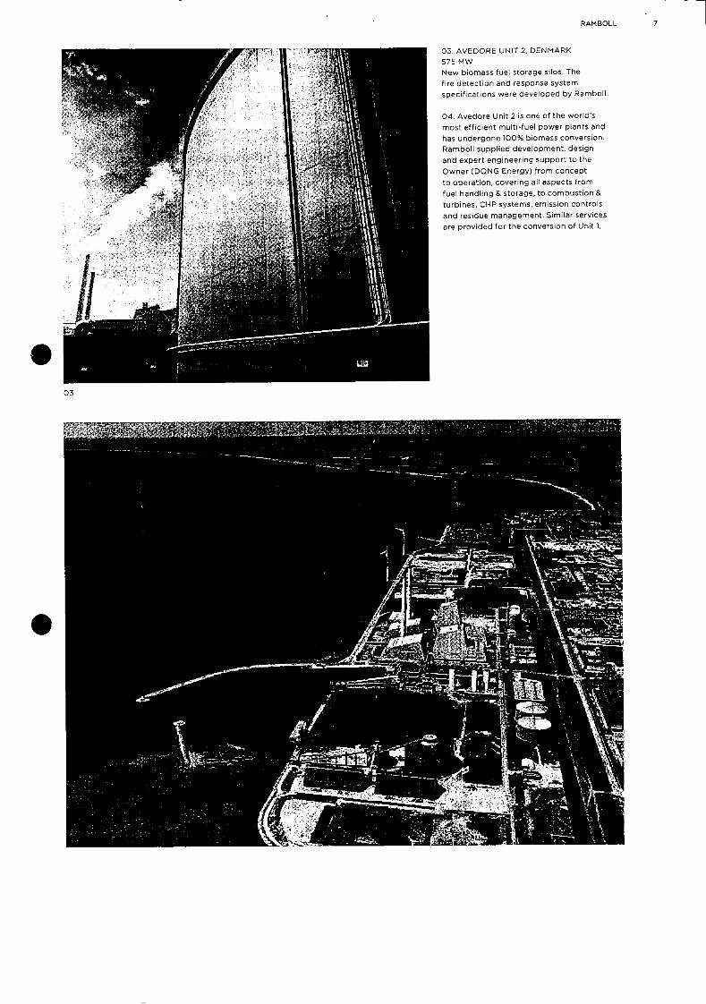
RAMBOLL 7
03. AVEDORE UNIT 2, DENMARK
575 MW
New biomass fuel storage silos. The
fire detection and response system
specifications were developed by Rarnboll.
04, Avedore Unit 2 is one of the world's
most efficient multi-fuel power plants and
has undergone 100% biomess conversion.
Ramboll supplied development, design
and expert engineering support to the
Owner (DONG Energy) from concept
to operation, covering all aspects from
fuel handling & storage, to combustion &
turbines, CI-IP systems, emission controls
and residue management. Similar services
are provided for the conversion of Unit).
03
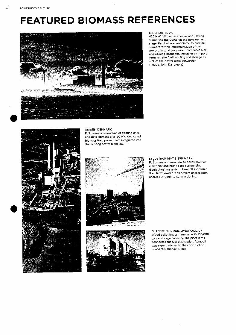
ASNIES, DENMARK Full biomass conversion of existing units and development of a 180 MW dedicated biomasS fired power plant integrated into the existing power plant site.
8 POWERING THE FUTURE
FEATURED BIOMASS REFERENCES
.
LYNEMOUTI-4, UK 420 MW full biomass conversion. Having supported the Owner at the development stage. Ramboll was appointed to provide support for the implementation of the project. In total the project comprises nine engineering packages, including an import terminal, Site fuel handling and storage as well as the power plant conversion (Image: John Dalrymple).
STUDSTRUP UNIT 3, DENMARK FuIi biomass conversion. Supplies 350 MW electricity and heat to the surrounding district heating system. Ramboll supported theplants owner in all project phases from analysis through to commissioning.
GLADSTONE DOCK, LIVERPOOL, UK Wood pellet import terminal with 100,000 tonne storage capacity. The plant is rail connected for fuel distribution. Ramboll was expert adviser to the construction contractor (Image: Drax).


2 GAS TURBINES
10 POWERING THE FUTURE
HIGHEFFICIENCV POWER PLANTS RAM BOLL OFFERS EXPERTISE IN:
• Ultra super critical plants
• Combined cycle
and open cycle
gas turbine plants
• Integrated solar
thermal
• Multi-fuel applications
• Carbon capture
and storage
• Advanced technologies
such as gasification and
oxyfuel
Thermal efficiency Fossil fuel fired power plants continue to play a significant role in providing secure and affordable energy. Ramboll has specialist expertise Which can reduce the carbon impact of fossil fuel power plants through the optimisation ofthermal efficiency and deployment of state-of-the-art emissions abatement technology.
Efficient coal utilisation The Nordjylland 3 Ultra Super Critical (USC) Power Plant, engineered by Ramboll, indeed holds the world record for most efficient coal utilisation, with an efficiency of over 47%. Ramboll achieved this through extensive insight and optimisation of the steam cycle and overall plant design,
Plant flexibility Equally important for modern thermal plants is to operate highly flexibly. with a need to rapidly balance energy demands resulting from an increase in intermittent renewable energy sources. Ramboll has successfully engineered plant modifications which
enable faster start-up times and
greater cyclic operation.
USC plants Ramboll has designed and realised some of the most efficient and fuel flexible thermal power plants in the world, applying the most advanced USC steam parameters and steam cycles. The plants are typically designed for coal, heavy fuel oil and/
or natural gas.
Combined cycle plants Our knowledge of Combined Cycle Gas Turbine (CCGT) plant concepts is extensive. Ramboll has realised some of the most efficient arid flexible CCGT power plants in the world to
date.
We can handle both relatively standardised CCGT projects and
highly advanced CCGT projects involving customisation to fit specific requirements such as process steam supply for an industry, district heating supply or integration of a CCGT into an industrial process plant.
Our specialists have a combined working experience of realising more than 25,000 MW of CCGT plant
capacities worldwide.
Multi fuel applications Our ability to develop innovative power generation projects is ably demonstrated by our role in engineering and implementing the Avedore Unit 2 project which incorporates within an optimised thermal cycle:
• USC multi fuel fired boiler
• Stiaw boiler
• Gas fired turbines in feed water cycle
• Energy storage heat accumulators AVEDORE 2— MULTI FUEL CONCEPT
STRAW BOILER
(SALES)105 MW
575 MW_/ 0 Mi/S
49S NW.L / Mi/S
PLSURAL ___
IL
WOOD s... PELLETS
NATURAL
MAIN BOILER (USC)
800 MW,,,
5B0C/600C
1' 300 BAR
• .:.• ELECTRICAL STEAM TURBINE P ) POWER
L ELECTRICAL DISTRICT
MEAT ACCUMULATOR

:0
0 0 r r

MONOSTAD CCGT CHP PLANT, NORWAY 280 MWe 350 MWth heat. Refinery integrated high efficiency CHP plant supplying high pressure steam and power. Ramboll staff acted as EPC Manager for the Owner during the plant development and construction.
*1
SALALAH II, OMAN 440 MW dual fuel CCGT natural gas/fuel oil. Ramboll was appointed to monitor construction and commissioning and to provide project co-ordination services.
ENECOGEN, ROTTERDAM, NL 870 MW high efficiency gas CCGT. Ranibolls Owner's Engineer services included engineering design review, KAZOP, witness of testing, and review of
O&M.
S
KAPCO, PAKISTAN Muzaffagarh 660 MW coal fired power plant. Ramboll was appointed to deliver the plant feasibility study. ESIA and EPC Contractor tender evaluation.
12 POWERING THE FUTURE
HIGHEFFICIENCY POWER PLANT REFERENCES
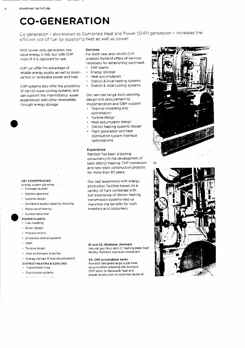
14 POWERING THE FUTURE
CO-GENERATION L.o-gerleration - also knowr as Combined Heat arId Power (CHP) generation - increases the
efficient use of fuel by supplying heat as well as power.
With power-only generation, low
value energy is lost, but with CHIP
most of it is captured for use.
CHIP can offer the advantage of
reliable energy supply as well as lower-
carbon or renewable power and heat.
CHP systems also offer the possibility
of district scale cooling systems, and
can support the intermittency issues
experienced with other renewables
through energy storage.
KEY COMPETENCIES: Energy system planning: • Strategic studies
• Options appraisal
• Systems de5ign
• Darnand & supply capacity mapping
• Resource efficiency
• carbon reduction
POWER PLANTS: • FueL handling
• Boiler design
Process control
• Emissions control systems
• O&N
• Turbine design
• Heat exchangers & pumps
• Energy storage & heat accumulators
DISTRICT HEATING & COOLING: • Transmission lines
Distribution sy5tems
Services
For both new and retrofit CHP
projects Ramboll offers all services
necessary for establishing optimised:
• CHP plants
• Energy storage
• Heat accumulators
• District & local heating systems
• District & local cooling systems
Our services range from planning,
design and procurement to
implementation and O&M support:
Thermal modelling and
optimisation
• Turbine design
Heat accumulator design
• District heating systems design
• Plant generation and heat
distribution system interface
optimisations
Experience
Ramboll has been a leading
consultancy in the development of
both district heating, CHP conversion
and new plant construction projects
for more than 40 years.
Our vast experience with energy
production facilities based on a
variety of fuels combined with
our experience of district heating
transmission systems help us
maximise the benefits for both
investors and consumers,
01 and 02. Gladsaxe, Denmark Natural gas fired district heating peak load facility. Ramboll was lead consultant.
03. CHP accumulator tanks Ramboll designed large-scale heat accumulators allowing the Avedore CHP plant to decouple heat and power production to optimise demand
01
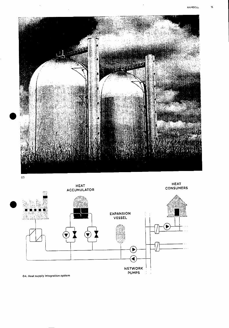
H EAT CONSUMERS
H EAT ACCUMULATOR
A
EXPANSION VESSEL
RAMBOLL 15
03
NETWORK PUMPS
04. 1eat supply integration system
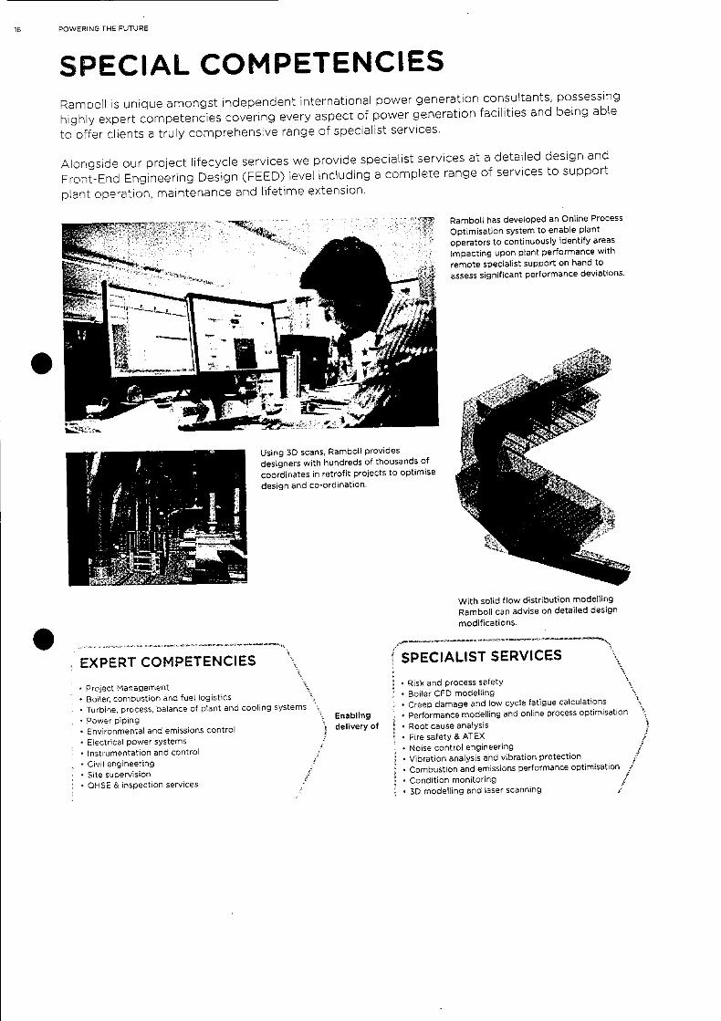
Ramboll has developed an Online Process OptimisatiOn system to enable plant operators to continuously identify areas impacting upon plant performance with remote specialist support on hand to assess significant performance deviations.
Using 3D scans, Rarnboll provides designers with hundreds of thousands of coordinates in retrofit projects to optimise design and co-ordination,
16 POWERINC' THE FUTURE
SPECIAL COMPETENCIES Ramboll is unique amongst independent international power generation consultants possessing highly expert competencies covering every aspect of power generation facilities and being able
to offer clients a truly comprehensive range of specialist services.
Alongside our project lifecycle services we provide specialist services at a detailed design and Front-End Engineering Design (FEED) level including a complete range of services to support
plant operation, maintenance and lifetime extension.
With solid flow distribution modelling Ramboll can advise on detailed design
modifications.
Enabling delivery of
EXPERT COMPETENCIES
• Project ManagerTent
• Boiler, combustion and fuel logistics Turbine, process, balance of plant and cooling systems
Power piping
• Environmental and emissions control • Electrical power systems
• Instrumentation and control Civil engineering
• Site supervision • QHSE & inspection services
SPECIALIST SERVICES
• Risk and process safety • Boiler CFD modelling
Creep damage and low cycle fatigue calculations
• Performance modelling and online process optimisation
• Root cause analysis • Fire safety & ATEX
• Noise control engineering • Vibration analysis and vibration protection
• Combustion and emissions performance optimisation
• Condition monitoring
• 3D modelling and laser scanning
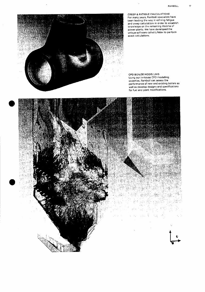
RAMBOLL 17
CREEP & FATIGUE CALCULATIONS For many years. Ramboll specialists have been leading the way in refining fatigue and creep calculations in order to establish knowledge on the remaining lifetime of power plants. We have developed the unique software called Lifetex to perform exact calculations.
CED BOILER MODELLING Using our in-house CFD modelling expertise. Ramboll can assess the performance of new and existing boilers as well as develop designs and specifications for fuel and plant modifications.
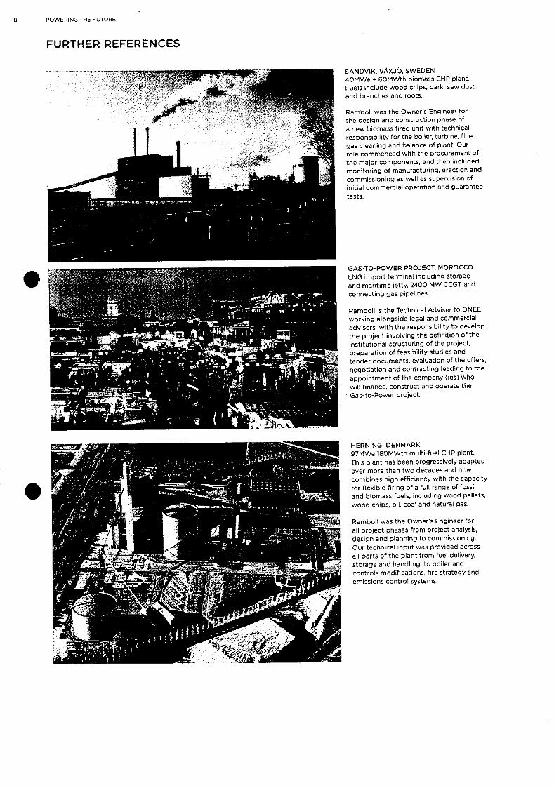
18 POWERING THE FUTURE
FURTHER REFERENCES
SANDVIK, VAXJQ, SWEDEN 4OMWe * 6OMWth biomass CHP plant. Fuels include wood chips, bark, saw dust and branches and roots.
Ramboll was the Owner's Engineer for the design and construction phase of a new biomasS fired unit with technical responsibility for the boiler, turbine, flue gas cleaning and balance of plant. Our role commenced with the procurement of the major components, and then included monitoring of manufacturing, erection and commissioning as well as supervision of initial commercial operation and guarantee
tests.
GAS-TO-POWER PROJECT, MOROCCO
LNG import terminal including storage and maritime jetty, 2400 MW CCGT and connecting gas pipelines.
Ramboll is the Technical Adviser to ONEE, working alongside legal and commercial advisers, with the responsibility to develop the project involving the definition of the institutional structuring of the project, preparation of feasibility studies and tender documents, evaluation of the offers, negotiation and contracting leading to the
appointment of the company (ies) who will finance, construct and operate the
Gas-to-Power project.
HERI"JING. DENMARK 97MWe 180MWth multi-fuel CHP plant. This plant has been progressively adapted
over more than two decades and now combines high efficiency with the capacity for flexible firing of a full range of fossil and biomass fuels, including wood pellets, wood chips, oil, coal and natural gas.
Ramboll was the Owner's Engineer for all project phases from project analysis, design and planning to commissioning. Our technical input was provided across all parts of the plant from fuel delivery, storage and handling, to boiler and controls modifications, fire strategy and emissions control systems.
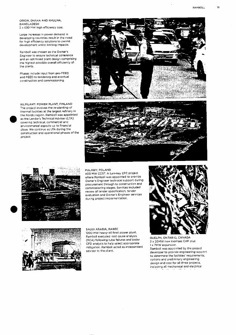
RAMBOLL 19
ORION, DHAKA AND KNULNA, BANGLADESH 2 x 630 MW high efficiency coal.
Large increases in power demand in developing countries result iii the need for high efficiency solutions to permit development whilst limiting impacts.
Ramboll was chosen as the Owner's Engineer to ensure technical coherence and an optimised plant design comprising the highest possible overall efficiency of. the plants.
Phases include input from pre-FEED and FEED to tendering and eventual construction and commissioning.
KILPILAHTI POWER PLANT, FINLAND The project involves the re-planting of thermal facilities at the largest refinery in the Nordic region. Ramboll was appointed as the Lender's Technical Adviser (LTA) covering technical, commercial and environmental aspects up to financial close. We continue as LTA during the construction and operational phases of the
project.
PUtAWY, POLAND 400 MW CCGT. A turn-key EPC project where Ramboll was appointed to provide Owner's Engineer technical support during procurement through to construction and commissioning stages, Services included review of tender specification, tender evaluation and Owner's Engineer services during project implementation.
SAUDI ARABIA, RABEC 1200 MW heavy-oil fired power plant. Ramboll executed root cause analysis (RCA) following tube failures and boiler CFD analysis to help select appropriate mitigation. Ramboll acted as independent
adviser to the client.
GUELPH, ONTARIO, CANADA 2 x 20MW new biornass CHP plus
1 x 7MW expansion. Rarnboll was appointed by the project developer to provide engineering support to determine the facilities' requirements. options and preliminary engineering design and cost for all three projects. including all mechanical and electrical
ANNEXURE K
REMAINING USEFUL LIFE ASSESMENT (RULA) REPORT
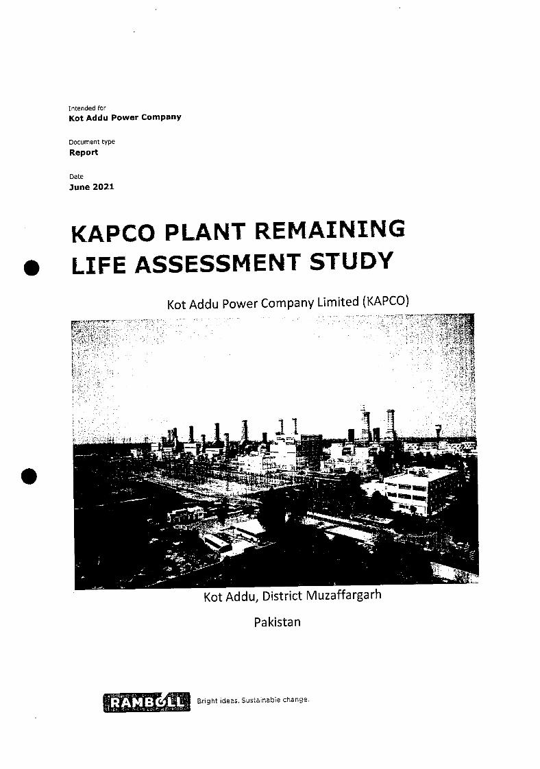
Kot Addu, District Muzaffargarh
Intended for
Kot Addu Power Company
Document type
Report
Date
)une 2021
KAPCO PLANT REMAINING
S LIFE ASSESSMENT STUDY
Kot Addu Power Company Limited (KAPCO)
Pakistan
rigbt ideas. Sustainable change.

Co KAP KAPCO Plant Remaining Life Assessment Study
KAPCO PLANT REMAINING LIFE ASSESSMENT STUDY
Project name KAPCO Plant Remaining Life Assessment Study
Project no. 1620012420
Recipient Kot Addu Power Company Limited
Document type Report
Version 1.
Date 2021-06-22
Prepared by )TOM
Checked by SLOYD
Approved by TOM
This report is produced by P.amboll at the request of the client for the purposes detailed herein. This report and accompanying documents are intended solely for the use and benefit of the client for this purpose only and may not be used by or disclosed to, in
whole or in part, any other person without the express written consent of Ramboll. Ramboll neither owes nor accepts any duty to any third party and shall not be liable for any loss, damage or expense of whatsoever nature which is caused by their reliance on
the information contained in this report.
R1JK2021N00226-RAM-RP-00001
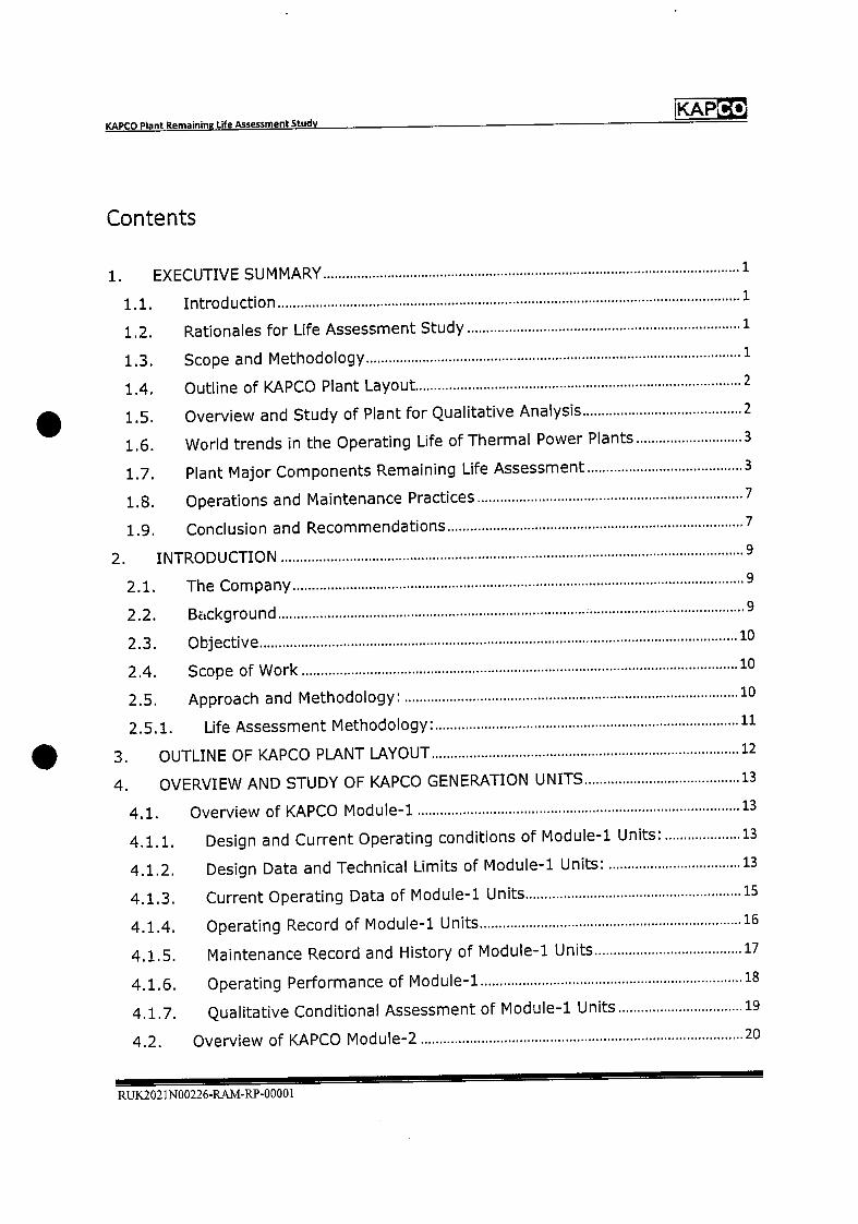
KAPCO Plant Remaining Life Atsessment Study
IKAP
Contents
1. EXECUTIVE SUMMARY 1
1.1. Introduction 1
1.2. Rationales for Life Assessment Study 1
1.3. Scope and Methodology 1
1.4. Outline of KAPCO Plant Layout 2
1.5. Overview and Study of Plant for Qualitative Analysis 2
1.6. World trends in the Operating Life of Thermal Power Plants 3
1.7. Plant Major Components Remaining Life Assessment 3
1.8. Operations and Maintenance Practices 7
1.9. Conclusion and Recommendations 7
2. INTRODUCTION 9
2.1. The Company 9
2.2. Background 9
2.3. Objective 10
2.4. Scope of Work 10
2.5. Approach and Methodology: 10
2.5.1. Life Assessment Methodology 11
3. OUTLINE OF KAPCO PLANT LAYOUT 12
4. OVERVIEW AND STUDY OF KAPCO GENERATION UNITS 13
4.1. Overview of KAPCO Module-i 13
4.1.1. Design and Current Operating conditions of Module-i Units: 13
4.1.2. Design Data and Technical Limits of Module-i Units: 13
4.1.3. Current Operating Data of Module-i Units 15
4.1.4. Operating Record of Module-i Units 16
4.1.5. Maintenance Record and History of Module-i Units 17
4.1.6. Operating Performance of Module-i 18
4.1.7. Qualitative Conditional Assessment of Module-i Units 19
4.2. Overview of KAPCO Module-2 20
RUK2021N00226-RAM-RP-0000I
KAP KAPCO Plant Remaining Life Assessment Study
4.2.1. Design and Current Operating conditions of Module-2 Units: 20
4.2.2, Design Data and Technical Limits of Module-2 Units 20
4.2.3. Current Operating Data of Module-2 Units: 22
4.2.4. Operating Record of Module-2 Units 23
4.2.5. Maintenance Record and History of Mod ule-2 Units 23
4.2.6. Operating Performance of Module-2 25
4.2.7. Qualitative Conditional Assessment of Module-2 Units 26
4.3. Overview of KAPCO Mod ule-3 27
4.3.1. Design and Current Operating conditions of Module-3 Units: 27
4.3.2. Design Data and Technical Limits of Module-3 Units 27
4.3.3. Current Operating Data of Mod ule-3 29
4.3.4. Operating Record of Module-3 Units 30
4.3.5. Maintenance Record and History of Module-3 Units 30
4.3.6. Operating Performance of Module-3 31
4.3.7. Qualitative Conditional Assessment of Module-3 Units 32
4.4. Overview of KAPCO Module-4 33
4.4.1. Design and Current Operating conditions of Module"4 Units: 33
4.4.2. Design Data and Technical Limits of Module-4 Units 33
4.4.3. Current Operating Data of Module-4 Units 35
4.4.4. Operating Record of Module-4 Units 36
4.4.5. Maintenance Record and History of Module-4 Units 36
4.4.6. Operating Performance of Module-4 37
4.4.7. Qualitative Conditional Assessment of Module-4 Units 38
4.5. Overview of KAPCO Module-5 39
4.5.1. Design and Current Operating conditions of Module-5 39
4.5.2. Design Data arid Technical Limits of Module-5 Units 39
4.5.3. Current Operating Data of Module-5 Units 41
4.5.4. Operating Record of Module-5 Units 42
4.5.5. Maintenance Record and History of Module-5 Units 42
4.5.6. Operating Performance of Module-5 43
4.5.7. Qualitative Conditional Assessment of Module-5 Units 44
5. WORLD TRENDS IN OPERATING LIFE OF THERMAL POWER PLANTS 45
RUK2021N00226-RAM-RP-00001
IKAPCO KAPCO Plant Remaining Life Assessment Study
5.1. Definitions45
5.1.1. Operating life 45
5.1.2. Economic life45
5.1.3. Design life45
5.1.4. Heat rate45
5.2. Factors influencing the plant life46
5.2.1. General46
5.2.2. Life limiting factors46
5.3. World trends of life of coal and gas power stations 46
5.3.1. USA46
5.3.2. Europe47
5.3.3. Other49
5.3.4. Power Project Age of Recent and Planned Retirements in US 50
5.4. Recap52
6. PLANT COMPONENTS RESIDUAL LIFE ASSESSMENT 53
6.1. Module-i Plant Component Residual Life Assessment 53
6.1.1. Gas Turbine Unit 1, 3 and Steam Turbine Unit-9 53
6.1.2. Module-i HRSG 1 and 3 54
6.1.4. Module-i Unit's Step-Up Transformer 1, 3 and 9 56
6.1.5. Control System of Module-i Units 59
6.1.6. Cooling Tower System for STG-9 of Module-i 60
6.1.7. Water Treatment Plant Module-i and 2 60
6.2. Module-2 Plant Components' Residual Life Assessment 61
6.2.1. Gas Turbine Unit 2, 4 and Steam Turbine Unit-lO 61
6.2.2. Module-2 HRSG 2 and 4 62
6.2.4. GT-2 Unit Generator62
6.2.5. Module-2 Unit's Step-Up Transformer 2, 4 and 10 64
6.2.6. Control System of Module-2 Units 66
6.2.7. Cooling Tower System for STG-10 of Module-2 67
6.3. Module-3 Plant Components' Residual Life Assessment 68
6.3.1. Gas Turbine Unit 5, 6 and Steam Turbine Unit-il 68
6.3.2. Module-3 HRSG hA and 11B 70
RUK2021N00226-RAM-RP-00001
Co KAP KAPCO Plant Remaining Life Assessment Study
6.3.4. Module-3 Unit's Step-Up Transformer 5, 6 and 11 74
6.3.5. Control System of Module-3 Units 76
6.3.6. Cooling Tower System for STG-11 of Module-3 76
6.4. Module-4 Plant Components' Residual Life Assessment 77
6.4.1. Gas Turbine Unit 7, 8 and Steam Turbine Unit-12 77
6.4.2. Module-4 HRSG 12A and 12B 79
6.4.4. Module-4 Unit's Step-Up Transformer 7, 8 and 12 82
6.4.5. Control System of Module-4 Units 83
6.4.6. Cooling Tower System for STG-12 of Module-4 84
6.5. Module-5 Plant Components' Residual Life Assessment 85
6.5.1. Gas Turbine Unit 13, 14 and Steam Turbine Unit-15 85
6.5.2. Module-5 HRSG 13 and 14 87
6.5.4. Module-5 Unit's Step-Up Transformer 13, 14 and 15 90
6.5.5. Control System of Module-5 Units 92
6.5.6. Cooling Tower System for STG-15 of Module-5 93
6.5.7. Water treatment plant Block-3 Module-S 94
6.6. Buildings and Civil Structure Integrity Assessment 94
7. OPERATIONS AND MAINTENANCE PRACTICES 96
7.1. Process Safety Management Systems 96
7.2. Maintenance Management System 96
7.3. Integrated Management System 98
7.4. Environment Management System 98
7.5. Historic Major Modification Summary 99
7.6. Spares Management 99
8. CONCLUSION AND RECOMMENDATIONS 100
RI.JK202 1N00226-RAM-RP-0000l

Co KAP KAPCO Plant Remaining Life Assessment Study
APPENDICES
Appendix 1
REMAINING LIFE ASSESSMENT OF HRSGs
Appendix 2
UNIT TRANSFORM ERs CONDITION MONITORING
Appendix 3
BUILDING & CIVIL STRUCTURE INTEGRITY ASSESSMENT
Appendix 4
ENVIRONMENTAL COMPLIANCE REPORT
Appendix 5
HISTORIC MAJOR MODIFICATION SUMMARY
Appendix 6
STRATEGIC SPARES LIST
RUK2021N00226-RAM-RP-00001

IKAP KAPCO Plant Remaining Life Assessment Study
Abbreviations
ADC Annual Dependable Capacity Test
bar Bars (pressure)
Bar(a) Bars (absolute pressure)
Bar(g) Bars (gauge pressure)
CDP Compressor Discharge Pressure
CDI Compressor Discharge Temperature
CW Cooling water
CV Calorific value
CCR Central Control Room
CCGT Combined cycle gas turbine
Degrees Centigrade
COD Commercial Operation Date
DPI Dye Penetrant Test
EE Exciter End
EOH Equivalent Operating hours
FSR Full Stator Rewind
Gas Natural Gas
GI Gas Turbine
HP High pressure
LP Low Pressure
HV High voltage
HHV Higher heating value
HSD High Speed Diesel
HRSG Heat Recovery Steam Generator
IDC Initial Dependable Capacity Test 1996
IPP Independent Power Producer
IEC International Electro technical Commission
ISO International Organization for Standardization
KAPCO Kot Addu Power Company
kV Kilovolt
km Kilometer
kWh Kilowatt hour
kW Killowatt
KKS Kraftwerk-Kennzeichefl System
kJ Kilojoules
LV Low voltage
LHV Lower heating value
LTSA Long Term Supply Agreement
LSFO Low Sulphur Furnace oil
MW Megawatts
m Meter
RJJK.2021N00226-RAM-RP-00001

KAPCO KAPCO Plant Remaining Life Assessment Study
mm Millimeter
mm WC Millimeter of Water Column
MCR Maximum continuous rating
rn/S Meters per second
m3 Cubic meter
MV Medium voltage
MW Megawatts
m2 Square meter
mbar Mull bar
Mi Mega joule
MPI Magnetic Particle Inspection
MVA Mega volt-amp
NDE Non Destructive Examination
NDT Non Destructive Testing
OH Operating Hour(s)
OCGT Open cycle gas turbine
O&M Operating and maintenance
OEM Original equipment manufacturer
OTC Outlet Temperature Corrected
PM Preventive Maintenance
PPA Power Purchase Agreement
P50 Pakistan State Oil
RUL Remaining Useful Life
S13D Siemens Innovative 3-Dimensional design
SNGPL Sul Northern Gas Pipelines Ltd
STG Steam Turbine Generation Unit
sec Second
TE Turbine End
TET Turbine Exhaust Temperature
TMCR Turbine continuous maximum rating
t/h Tones per hour
Unit Gas Turbine or Steam Turbine Generation Unit
UT Ultrasonic Testing
UTG Ultrasonic thickness gauging
WAPDA Water and Power Development Authority
Definitions
Commercial Availability: Availability of Plant excluding weighted Unscheduled Outages
Commercial Availability= ((Com plex Capacity-Weighted Unscheduled Outage) xlOO)/( Complex Capacity)
Plant Availability: Availability of Plant excluding Schedule and Unscheduled Outages
Plant Availability = ((Complex Capacity- Scheduled Outages-Unscheduled Outages) xlOO)/(Complex Capacity)
RUK.2021N00226-RAM-RP-00001
lKAP KAPCO Plant Remaining Life Assessment Study
1. EXECUTIVE SUMMARY
1.1. Introduction
Ramboll has been contracted by Kot Addu Power Company (KAPCO) to undertake a technical
assessment of the remaining life of the KAPCO combined cycle power plant located at Kot Addu, District
Muzaffargarh, Punjab in Pakistan. This assessment has been based on data provided to Ramboll by
KAPCO which included plant O&M records and other 3d party condition assessment reports, equipment
inspections and NOT studies previously commissioned by KAPCO.
1.2. Rationales for Life Assessment Study
KAPCO combined cycle power Plant was built in phases from 1985 to 1996 by Water and Power
Development Authority ("WAPDA"). It is the largest IPP operating in the mid country and supplying
electricity through Six (6) 132 KV and Six (6) 220 KV feeders. KAPCO is the only CCGT power plant
capable of operating on 3 types of fuel i.e. Gas, Low Sulphur Furnace Oil (LSFO) and High Speed Diesel
(HSD). This multifuel capability makes KAPCO plant a backbone for the national grid.
Combined cycle power plant are typically constructed using a design life of 25-30 years. However, a
specified Design Life does not necessarily dictate a finite life expectancy or mandatory retirement of the
plant. Experience shows that the operating life can be enhanced by a further 15-20 years with the
requisite capital expenditure and excellent maintenance practices.
KAPCO has an agreement of 25 years with power purchaser WAPDA that is expiring on 25 June 2021.
KAPCO units has been operating since past 25 to 30 years. It is necessary to assess iging impacts and to
determine residual useful life of KAPCO generating units and auxiliaries so that for the same term PPA
(Power Purchase Agreement) extension may be granted in sake of national interest as per clauses of
extension within current PPA.
1.3. Scope and Methodology
Scope of study included residual life assessment of major equipment of CCGT plant e.g. Gas Turbine,
Steam Turbine, HRSG, Generator, Unit Transformer, Instrumentation and Control System, Auxiliaries and
Buildings and Structures.
This Life Assessment study has been conducted on the basis of Plant design data, Current Operating
parameters, Units Operations and Maintenance History, Current operating performance, Life
Assessment and NOT reports, condition monitoring test reports, Operator's own assessment in view of
O&M challenges for the plant, World' Thermal Power plants Operating life trends and Ramboll's
experience of power plant life extension projects.
Units have been studied Module wise (in configuration 2~1 i.e. two gas turbines and one steam turbine)
for design data, technical limits, current operating conditions and parameters, past and current unit
performance to develop a qualitative base line. World trends for plant life have been discussed.
The key aspects from recent major inspections, modifications, upgradations and condition monitoring
test results have been reviewed.
RUK2021N00226-RAM-RP-00001 Page 1
KAP Co KAPCO Plant Remaining Life Assessment Study
Electrical major components e.g. Generator, Unit transformers healthiness and residual life has been
assessed based on current offload/on load test results, NDTs and test results conducted during major
inspections.
Important Auxiliaries and BOP equipment prone to aging, healthiness has been checked for residual life
assessment.
Buildings and Civil structure integrity assessment reports has been reviewed for checking healthiness
and fitness for units' future operations.
The main Plant components remaining life has been assessed based on design life, operating hours,
NDTs and test results conducted during major outages and current unit conditions and with
consideration to the experience of other life extension projects, globally.
The study has been concluded with remaining useful life assessment of the units along with
recommendations.
1.4. Outline of KAPCO Plant Layout
KAPCO power plant comprises 10 Gas Turbines, 10 Heat Recovery Steam Generators (HRSG) and 5 Steam
turbines. The Plant has been divided into 3 blocks, maintenance wise (Blocks 1, 2, 3) as well as efficiency
wise in descending order Energy Blocks 1,2 and 3. The Plant has been further subdivided into five modules
with each module comprising two Gas turbines, two HRSGs and one Steam turbine. The five modules are
Module-i; GT-1, GT-3 and STG-9; Module-2; GT-2, GT-4 and STG-10; Module-3; GT-5, GT-6 and STG-11;
Module-4; GT-7, GT-3 and STG-12 and Module-5; GT-13, GT-14 and STG-15
1.5. Overview and Study of Plant for Qualitative Analysis
The design data and technical limits of the gas turbines, HRSGs and STG in each of the five modules have
been discussed in regard to current O&M history and expected remaining life.
Units' current operating parameters have been investigated and compared with IDC parameters.
Comparison has shown that all units are operating near to, or better, than IDC parameters. In spite of
aging impacts on the units, all units' loading capacity in MW has been well maintained compared to IDC
(Initial Dependable Capacity 1996). That is considered a direct consequence of excellent Operations and
Maintenance strategy and Upgrades.
All Gas Turbine units can operate on all 3 fuels, Natural Gas, F-ISD and LSFO except GT-3 and 4 which can
operate only on Gas and HSD.
GT-1, 2, 5, 6, 13, 14 and STG-9, 11, 12, 15 have undergone midlife control change.
GT-1, and GT-2 have undergone upgrade of the Inlet Guide Vanes (lGVs) from fixed to modulating to
reduce stresses on turbine hot gas path components and to avoid compressor surge.
GT-3 has undergone replacement of the Excitation system with a new one. GT-3 and 4 HMI and
Information system has been upgraded to Siemens Win CC.
GT-5 and GT-8 have undergone Hot Gas path up-gradation which has improved their exhaust
temperature control curves i.e. increase in Turbine inlet temperature hence maintaining and improving
loading Capacity.
RUK.2021N00226-RAM-RP-00001 Page 2
KAPCO Plant Remaining Life Assessment Study KAP
GT-13 and GT-14 have undergone Siemens Si3D upgrades of the 1st two stages of the turbine. STG-1O
has undergone installation of modified 1st stage moving blades for heat rate improvement and new LP
turbine erosion protection rings of the last 3 stages.
All units' schedule outages e.g. MOH, HGPI and Cl are being performed well in time as per OEM
recommended intervals and/or criteria of OH, EOH and no. of starts.
Module wise average Plant Availability has been approximately 85% over the past five years which is
excellent.
1.6. World trends in the Operating Life of Thermal Power Plants
World trends has been discussed in regard to thermal power plants, life cycle, deterioration impacts,
maintenance strategies, World operating power plants life and age before retirements.
Operating life of a power station before decommissioning can be extended 20to 25 years over the
original design life in account of conservative design assumptions and well-managed repair and
maintenance schedules including necessary capital expenditure to replace worn components.
In Europe, about 25000 MW of thermal power plants are in age range 30 to 60 years that is exceeding
their design life of 30 years. The capacity-weighted average age of operating coal facilities in US is 39
years. In US, the most common age of recently retired Coal units is 50-60 years, Natural Gas Steam units
40-50 years, and for Combustion Turbine units it is 40-50 years.
The actual operating hours of a plant also needs to be considered as high-pressure, high temperature,
components such as the heat recovery steam generators, main steam pipework, steam turbine are
subject to material creep over an extended period of operation, in addition to the usual life limiting
aspects of fatigue, erosion corrosion etc.
Whether thermal power plants are kept in operation, refurbished, placed on standby or
decommissioned at their design life remains primarily an economic decision for the owner depending
upon the unit condition and maintenance cost. More stringent environmental legislation may also be a
deciding factor to retire a power plant if the environmental upgrade costs are too prohibitive. This has
been the case for many of the coal-fired power plants in Europe.
1.7. Plant Major Components Remaining Life Assessment
Remaining life assessment has been discussed module wise for all major components of the units. Gas
Turbine, Steam Turbine, HRSG5 including main electrical equipment e.g. Generator, Transformers,
condition monitoring tests has been discussed.
For all Gas turbine units, hot gas path components e.g. combustors, fuel nozzles, GT blades and vanes etc
are being replaced periodically on HGPI and MOH as per OEM recommendation. One complete set of
turbine blade/bucket and vane/nozzle is available in store as a strategic spare for each model of Gas
Turbine at KAPCO.
Module-i units: GT-1 last MOH was performed in Feb-March 2021. GT-3 last major inspection was
performed in Feb-March 2018. STG-9 major overhaul was performed recently in Feb-March 2021. The
overall condition of GT-1, GT-3 and STG-9 is satisfactory as analyzed from visual inspections, NDTs
conducted during these outages e.g. DPT, Hardness testing, MPI and UT.
RUK2021N00226-RAM-RP-00001 Page 3
KAPCO Plant Remaining Life Assessment Study
KAP
GT-1, GT-3 and STG-9 remaining life is assessed to be 10, 19 and 11 years respectively based on the current
operating hours of each unit.
HRSG-i and 3 expected remaining life is assessed to be 12-15 years based on recent boiler inspection,
NDTs and life assessment conducted by SGS in March 2021 for HRSG-01. The condition of HRSG-01 is
considered to be representative of HRSG-03 as HRSG-03 has much lesser operating hours.
GT-1 Generator was overhauled in Feb-March 2021. Overall Generator condition is considered to be Good
based on test reports e.g. ELCID, IR, and P1 etc. During the inspection findings were observed on Generator
rotor J Straps which were replaced with new. GT-3 Generator electrical tests and inspections conducted
in October 2020 have shown healthy condition. It is considered that GT-1, and GT-3 Generators may be
satisfactorily kept in operation for the next 10 years with condition monitoring.
GT-1 Unit Transformer life assessment tests were conducted on a sample basis in Block-i and the test
results are satisfactory. GT-3 Unit Transformers oil analysis reports are showing some paper aging.
However, the overall condition of the Unit transformers is considered Acceptable to Satisfactory.
GT-i is operating with a new control system with remaining life of 17 years. GT-3 control system is old yet
operating satisfactorily with spares availability in KAPCO Stores.
ST-9 is of ABB design and manufacture, having a single flow HP and double flow LP cylinder. The steam
turbine is rated at a nominal 112 MW with steam conditions of 46.9 bar and 495C. The ST is directly
coupled to an ABB air cooled generator of rating 132 MVA at 11 kV. A major turbine overhaul was
performed recently in Feb-March 2021. The overall condition of the ST is considered to be Satisfactory as
analyzed from visual inspections and NDTs conducted during these outages e.g. DPT, Hardness testing,
MPI and UT. STG-9 control system was replaced with new SPPA-3000 in 2016. Generator overhauling was
carried out in Feb-Mar 2021 and its condition is considered Satisfactory and may be kept in operation for
next 10-15 years. Although the ST Unit Transformers oil analysis reports indicated some paper aging, the
overall condition of the Unit transformers is considered Acceptable to Satisfactory.
Module-2 units: GT-2 and GT-4 minimum remaining life is assessed to be ii and 19 years based on
current operating hours and overall Satisfactory condition as observed from recent inspection reports.
HRSG-2 and HRSG-4 expected remaining life is assessed to be 12-15 years based on the above mentioned
HRSG-01 sample inspections, NDT and life assessment reports. HRSGs-i, 2, 3 and 4 are the same design
from the same supplier.
GT-2 Generator was overhauled in Feb 2018. Siemens reported 'No thermal or thermo mechanical aging
phenomena were detected". It is considered GT-2 and GT-4 Generators may be satisfactorily kept in
operation for next 10-12 years with scheduled condition monitoring checks.
GT-2 Unit Transformer life assessment tests were conducted in 2016 by ABB on a sample basis in Block-i
and test results were satisfactory. GT-4 Unit Transformer oil analysis report is showing satisfactory results.
STG-10 Transformer oil analysis report is showing some degassing which will be tested again. However,
operating parameters and electrical test results are normal and overall condition of the Unit transformers
is considered to be Satisfactory.
GT-2 is operating with latest control system Siemens SPPAT3000 with minimum remaining life of 13 years. GT-4 and STG-10 control system is old yet operating satisfactorily with spares availability in KAPCO Stores.
Moreover, control system spares obtained from STG-9 control system replacement are available for STG-
10.
ST-b is of ABB design and manufacture, having a single flow HP and double flow LP cylinder. The steam
turbine is rated at a nominal 112 MW with steam conditions of 46.9 bar and 495C. ST-b is directly
RUK2021N00226-RAM-RP-00001Page 4
KAP Co KAPCO Plant Remaining Life Assessment Study
coupled to an ABB air cooled generator of rating 132 MVA at 11 kV. A major overhaul of ST-b was performed in Sep-Oct 2013. Modified l stage moving blades and Installation of new LP turbine erosion
protection rings of the last 3 stages were installed during 2013. Overall condition is considered satisfactory
based on a minor inspection carried out in 2016. Generator overhauling was carried in Feb-Mar 2016 and
its condition is considered Good and the Generators may be kept in operation for the next 10-15 years
with condition monitoring. STG-10 Unit Transformer oil analysis report is showing some degassing which
will be tested again. However, operating parameters and electrical test results are normal and the overall
condition of the ST-10 Unit transformer is satisfactory.
Module-3 units GT-5, GT-6 and STG-11 remaining life is assessed to be 14, 13 and 15 years based on the
current operating hours and overall Good condition as observed from recent inspection reports of
HGPI/MOH 2017 and Combustion Inspection March 2021.
HRSG5-11A, 11B, 12A and 12B are of same model. Life assessment of HRSG-11A and biB has been
conducted on sample basis in Nov 2020 and the same condition is predicted for the other two HRSGs.
Based on life assessment report, routine maintenance inspections; HRSG-11A and 11B expected
remaining life is greater than 15 years.
GT-5 and GT-6 Generators have been in service since commissioning. Based on monitoring test
recommendation, conductive paint activity on stator winding has been carried out. Generator rotor flux report for GT-5 and 6 found Satisfactory. Full Stator rewind (FSR) material is available on site as strategic
spare for GT-5, 6 and 7 Stators.
Generator rotorfiux report indicates no significant fault and can continue its normal operation. Expected
remaining life of the newly rewound STG-11 generator is considered greater than 15 years.
GT-5, 6 and STG-11 Unit TF Oil analysis reports indicate no internal fault and the condition is considered
Satisfactory.
GT-5 and GT-6 are operating with GE's latest control system Mark VIe with remaining life of 17 years. The
STG-11 control system ALSIOM ALSPA Controsteam V3 was upgraded in 2009 and the minimum
remaining life is considered greater than 10 years.
ST-li is of GEC Alstom design and manufacture, having a single cylinder (combined HP/LP). The steam
turbine is rated at a nominal 103 MW with steam conditions of 40 bar and 511C. The steam turbine is
directly coupled to a GEC Alstom air-cooled generator of rating 121.64 MVA at ii kV. A major overhaul
of the turbine was performed in 2017. Overall condition is considered Satisfactory based on a minor
inspection carried out in Feb-Mar 2020. A full Stator rewind was done in 2017 and its condition is
considered Very Good. Generators may be kept in operation for next 15 years with regular condition
monitoring checks. STG-11 Unit Transformer oil analysis report indicates the analyzed winding paper
ageing markers (furans, methanol) have no significant paper ageing and thus quality of winding paper can
be assessed as Very Good.
Module-4 units: GT-7, GT-8 and STG-12 remaining life is assessed to be 13, 12 and 14 years based on the
current operating hours and the Good overall condition as observed from recent inspection reports 2021,
2019 and 2017 respectively.
GT-7 and GT-8 hot gas path upgradation was performed during outages in Sep-Oct 2010 and 2011
respectively.
R1JK2021N00226-RAM-RP-00001Page 5
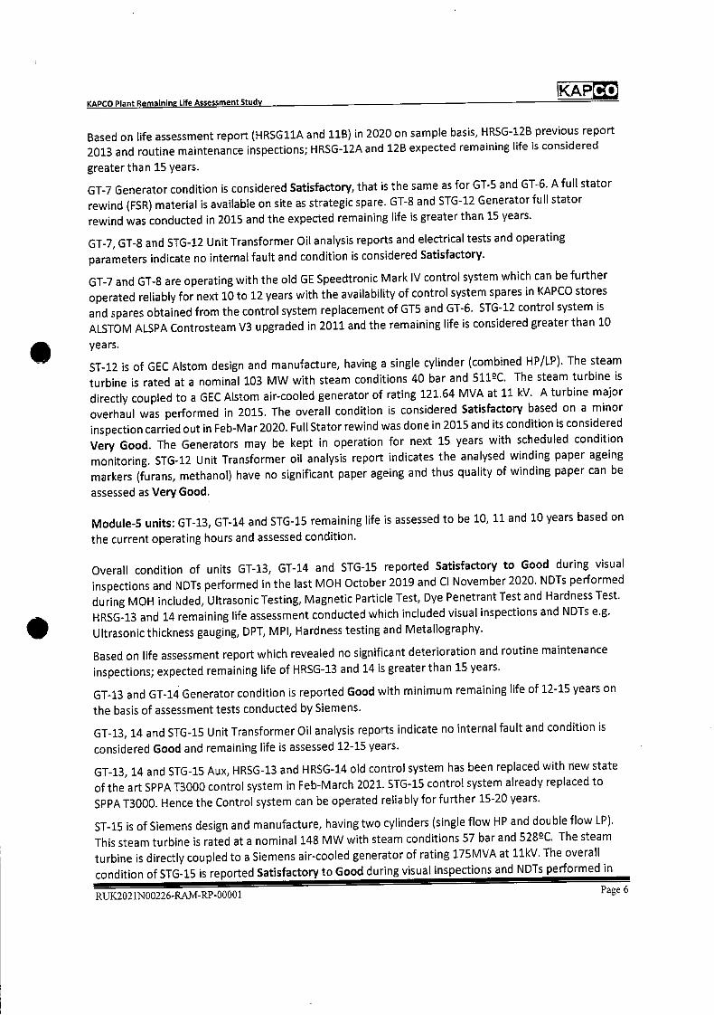
Co KAP KAPCO Plant Remaining Life Assessment Study
Based on life assessment report (HRSG11A and 11B) in 2020 on sample basis, HRSG-12B previous report 2013 and routine maintenance inspections; HRSG-12A and 12B expected remaining life is considered
greater than 15 years.
GT-7 Generator condition is considered Satisfactory, that is the same as for GT-5 and GT-6. A full stator
rewind (FSR) material is available on site as strategic spare. GT-8 and STG-12 Generator full stator
rewind was conducted in 2015 and the expected remaining life is greater than 15 years.
GT-7, GT-8 and STG-12 Unit Transformer Oil analysis reports and electrical tests and operating
parameters indicate no internal fault and condition is considered Satisfactory.
GT-7 and GT-8 are operating with the old GE Speedtronic Mark IV control system which can be further
operated reliably for next 10 to 12 years with the availability of control system spares in KAPCO stores
and spares obtained from the control system replacement of GT5 and GT-6. STG-12 control system is
ALSTOM ALSPA Controsteam V3 upgraded in 2011 and the remaining life is considered greater than 10
years.
ST-12 is of GEC Aistom design and manufacture, having a single cylinder (combined HP/LP). The steam
turbine is rated at a nominal 103 MW with steam conditions 40 bar and 511C. The steam turbine is
directly coupled to a GEC Alstom air-cooled generator of rating 121.64 MVA at 11 kV. A turbine major
overhaul was performed in 2015. The overall condition is considered Satisfactory based on a minor
inspection carried out in Feb-Mar 2020. Full Stator rewind was done in 2015 and its condition is considered
Very Good. The Generators may be kept in operation for next 15 years with scheduled condition
monitoring. STG-12 Unit Transformer oil analysis report indicates the analysed winding paper ageing
markers (furans, methanol) have no significant paper ageing and thus quality of winding paper can be
assessed as Very Good.
Module-5 units: GT-13, GT-14 and STG-15 remaining life is assessed to be 10, 11 and 10 years based on
the current operating hours and assessed condition.
Overall condition of units GT-13, GT-14 and STG-15 reported Satisfactory to Good during visual
inspections and NDTs performed in the last MOH October 2019 and Cl November 2020. NDTs performed
during MOH included, Ultrasonic Testing, Magnetic Particle Test, Dye Penetrant Test and Hardness Test.
HRSG-13 and 14 remaining life assessment conducted which included visual inspections and NDTs e.g.
Ultrasonic thickness gauging, DPT, MPI, Hardness testing and Metallography.
Based on life assessment report which revealed no significant deterioration and routine maintenance
inspections; expected remaining life of HRSG-13 and 14 is greater than 15 years.
GT-13 and GT-14 Generator condition is reported Good with minimum remaining life of 12-15 years on
the basis of assessment tests conducted by Siemens.
GT-13, 14 and STG-15 Unit Transformer Oil analysis reports indicate no internal fault and condition is
considered Good and remaining life is assessed 12-15 years.
GT-13, 14 and STG-15 Aux, HRSG-13 and HRSG-14 old control system has been replaced with new state
of the art SPPA T3000 control system in Feb-March 2021. STG-15 control system already replaced to
SPPA 13000. Hence the Control system can be operated reliably for further 15-20 years.
ST-15 is of Siemens design and manufacture, having two cylinders (single flow HP and double flow LP).
This steam turbine is rated at a nominal 148 MW with steam conditions 57 bar and 528C. The steam
turbine is directly coupled to a Siemens air-cooled generator of rating 17SMVA at 11kV. The overall
condition of STG-15 is reported Satisfactory to Good during visual inspections and NDTs performed in
RUX.2021N00226-RAM-RP-00001 Page 6

KAPCO Plant Remaining Life Assessment Study KAP
the last minor / major overhauling. STG-15 control system was replaced with new SPPA-3000 in 2015.
STG-15 Generator condition is reported Good with minimum remaining life of 12-15 years on the basis
of assessment tests conducted by Siemens. STG-15 Unit Transformer Oil analysis reports indicate no
internal fault and condition is considered Good and remaining life is assessed 12-15 years. There is no
indication of thermal or electrical faults reported in the transformer.
Cooling tower and Water treatment plant for all units are in healthy condition and can be kept in
service for next 12-15 years. For cooling tower structure of the STGs water proofing and repairs have
been performed.
Buildings and Civil structure integrity life assessment has been conducted for all units. Visual inspections
and NDTs were conducted which included concrete compressive strength measurement by Rebound
Hammer and Crack Depth Measurement by Ultrasonic Pulse Velocity Test and ultrasonic method.
Identified cracks were repaired as recommended. Overall condition of civil structures and buildings is
observed Satisfactory. We envisage remaining useful life of 20 years on the basis of a typical 50 years
expected design life but assuming on-going condition assessment and maintenance being required.
1.8. Operations and Maintenance Practices
The Operations and Maintenance practices at the KAPCO Plant have been studied. Well established
Local Procedures and Safety Rules are implemented at site to ensure safe and smooth operations of
plant and safety of employees at work.
Maintenance management is working effectively through usage of Computerized Maintenance
management system (CMMS).
Integrated Management system is implemented with accreditations of lSO9001 for Quality, 1S014001
for Environment and OHSAS1BOO1 for Occupational Health and Safety.
KAPCO is complying all regulatory requirements in regard to Environment management system. All
emissions of air, water and noise relating to plant operations are within limits established by Punjab
Environment Protection agency.
Historic major modifications, upgrades and improvement projects are summarized which has ensured
safe, reliable and efficient operations of plant along with human safety.
Spares inventory has been maintained in KAPCO stores for routine maintenance of units as well as for
strategic spares for replacement of equipment if breakdown occurs.
Above 30,000 spare parts are stored in KAPCO Stores for Gas Turbines, Steam Turbines and Auxiliaries
relating to Mechanical, Instrument and Electrical Equipment. This large volume of spares will help
ensure the KAPCO Plant continues to achieve reliable operation and high Plant Availability in coming
years.
1.9. Conclusion and Recommendations
Based on the O&M records, 3 party condition assessment reports, qualitative and analytical study and
life extension experience from other projects, it is Ramboll's opinion that the KAPCO Plant could
continue to operate for a minimum further 10 years on the basis that the Plant continues to be operated
as previous i.e. baseload and is maintained as per statutory and OEM requirements and the
recommendations from recent, and future, plant inspections reports are implemented.
RUX2021N00226-RAM-RP-00001 Page 7
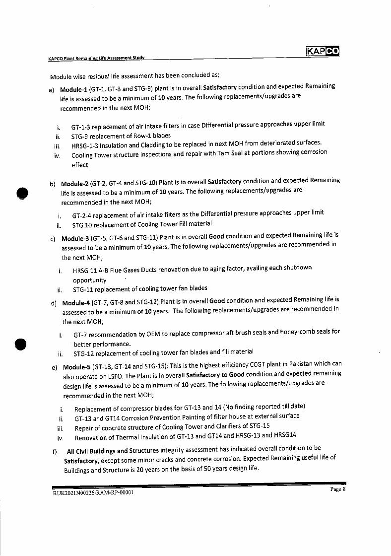
KAPCO KAPCO Plant Remaining Life Assessment Study
Module wise residual life assessment has been concluded as;
a) Module-i (GT-1, GT-3 and STG-9) plant is in overall Satisfactory condition and expected Remaining
life is assessed to be a minimum of 10 years. The following replacements/upgrades are
recommended in the next MOH;
i. GT-1-3 replacement of air intake filters in case Differential pressure approaches upper limit
ii. STG-9 replacement of Row-i blades
iii. HRSG-1-3 Insulation and Cladding to be replaced in next MOH from deteriorated surfaces.
iv. Cooling Tower structure inspections and repair with Tam Seal at portions showing corrosion
effect
b) Module-2 (GT-2, GT-4 and STG-10) Plant is in overall Satisfactory condition and expected Remaining
life is assessed to be a minimum of 10 years. The following replacements/upgrades are
recommended in the next MOH;
i. GT-2-4 replacement of air intake filters as the Differential pressure approaches upper limit
ii. STG 10 replacement of Cooling Tower Fill material
c) Module-3 (GT-5, GT-6 and STG-11) Plant is in overall Good condition and expected Remaining life is
assessed to be a minimum of 10 years. The following replacements/upgrades are recommended in
the next MOH;
i. HRSG ii A-B Flue Gases Ducts renovation due to aging factor, availing each shutdown
opportunity
ii. STG-11 replacement of cooling tower fan blades
d) Module-4 (GT-7, GT-8 and STG-12) Plant is in overall Good condition and expected Remaining life is
assessed to be a minimum of 10 years. The following replacements/upgrades are recommended in
the next MOH;
i. GT-7 recommendation by OEM to replace compressor aft brush seals and honey-comb seals for
better performance.
ii. STG-12 replacement of cooling tower fan blades and fill material
e) Module-5 (GT-13, GT-14 and STG-15): This is the highest efficiency CCGT plant in Pakistan which can
also operate on LSFO. The Plant is in overall Satisfactory to Good condition and expected remaining
design life is assessed to be a minimum of 10 years. The following replacements/upgrades are
recommended in the next MOH;
i. Replacement of compressor blades for GT-13 and 14 (No finding reported till date)
ii. GT-13 and GT14 Corrosion Prevention Painting of filter house at external surface
Hi. Repair of concrete structure of Cooling Tower and Clarifiers of STG-15
iv. Renovation of Thermal Insulation of GT-13 and GT14 and HRSG-13 and HRSG14
f) All Civil Buildings and Structures integrity assessment has indicated overall condition to be
Satisfactory, except some minor cracks and concrete corrosion. Expected Remaining useful life of
Buildings and Structure is 20 years on the basis of 50 years design life.
RUK2021N00226-RAM-RP-0000lPage 8

KAPCO Plant Remaining Life Assessment Study KAP
2. ENTRODUCTION
2.1. The Company
Kot Addu Power Company limited (KAPCO) Pakistan is the largest IPP of Pakistan with name plate capacity
of 1600 MW. Kot Addu Power Plant (the 'Power Plant") was built by the Pakistan Water and Power
Development Authority ("WAPDA") in five phases between 1985 and 1996 at its present location in Kot
Addu, District Muzaffargarh, Punjab. In April 1996, Kot Addu Power Company Limited ("KAPCO") was
incorporated as a public limited company under the Companies Ordinance, 1984 with the objective of
acquiring the Power Plant from WAPDA. The principal activities of Kot Addu Power Company limited
(KAPCO) Pakistan are the ownership, operation and maintenance of the 1600 MW power plant at Kot
Addu, Punjab Pakistan. The Company sells the electrical energy produced from its power plant to its
customer, Central Power Purchasing Authority CPPA-G Pakistan.
The KAPCO power plant is Pakistan's largest combined cycle power plant and comprises 10 gas turbines,
10 heat recovery steam generators and 5 steam turbines. The power plant has the capability of using
three different fuels to generate electricity, namely: Natural Gas, Low Sulphur Furnace Oil (LSFO) and High
Speed Diesel (HSD).
2.2. Background
Combined cycle power plants are typically constructed using a design life of 25-30 years, with the design
of civil structures up to 50-60 years. A number of hot, warm and cold starts are also specified together
with the expected number of operating hours per year, typically 8,000 hours, which equates to a typical
design life of 200,000-240,000 operating hours.
The hot gas path components need repair and replacing according to the OEM maintenance program
several times during this plant design life calendar period.
Most combined-cycle power plants - regardless of scheduled gas turbine, steam turbine, and other major
equipment O&M practices - display signs of aging and fatigue beyond 20 to 25 years of age after their
initial commercial operation date.
Gas turbine, heat recovery steam generator and steam turbine components are exposed to stress caused
by temperature or static and dynamic loading, low-cycle fatigue (LCF) and high-cycle fatigue (HCF),
erosion, oxidation and high temperature corrosion as well as mechanical stress and wear. The high-
pressure, high temperature, components also experience material creep over time.
Operating life can be enhanced further 15-20 years beyond design life with periodic replacements of
major components as per ongoing maintenance schedule and refurbishment of equipment. Therefore 40-
50 years is not an unusual operating life for a combined-cycle power plant.
A specified Design Life does not necessarily or inherently dictate a finite life expectancy or mandatory re
tirement of the plant and hundreds of power plants around the World have demonstrated economic
operating life 15-20 years in excess of typical design life.
Replacement of control and instrumentation systems with new one, during midlife of power plant is
typical refurbishment. Such new control and instrumentation equipment generally results from the
obsolescence of much of hardware and the consequent lack of spares availability.
RUK2021N00226-RAM-RP-0000lPage 9
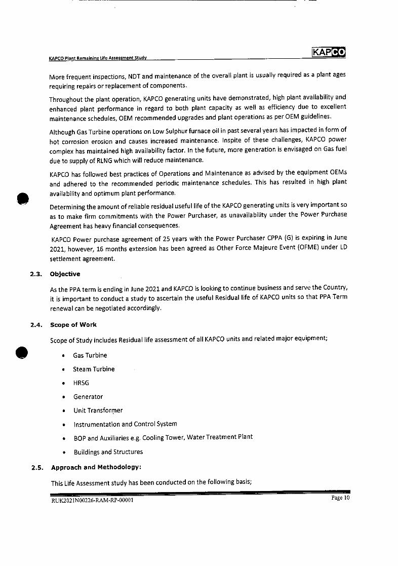
KAP KAPCO Plant Remaining Life Assessment Study
More frequent inspections, NDT and maintenance of the overall plant is usually required as a plant ages
requiring repairs or replacement of components.
Throughout the plant operation, KAPCO generating units have demonstrated, high plant availability and
enhanced plant performance in regard to both plant capacity as well as efficiency due to excellent
maintenance schedules, OEM recommended upgrades and plant operations as per OEM guidelines.
Although Gas Turbine operations on Low Sulphur furnace oil in past several years has impacted in form of
hot corrosion erosion and causes increased maintenance. Inspite of these challenges, KAPCO power
complex has maintained high availability factor. In the future, more generation is envisaged on Gas fuel
due to supply of RLNG which will reduce maintenance.
KAPCO has followed best practices of Operations and Maintenance as advised by the equipment OEMs
and adhered to the recommended periodic maintenance schedules. This has resulted in high plant
availability and optimum plant performance.
Determining the amount of reliable residual useful life of the KAPCO generating units is very important so
as to make firm commitments with the Power Purchaser, as unavailability under the Power Purchase
Agreement has heavy financial consequences.
KAPCO Power purchase agreement of 25 years with the Power Purchaser CPPA (G) is expiring in June
2021, however, 16 months extension has been agreed as Other Force Majeure Event (OFME) under LD
settlement agreement.
2.3. Objective
As the PPA term is ending in June 2021 and KAPCO is looking to continue business and serve the Country,
it is important to conduct a study to ascertain the useful Residual life of KAPCO units so that PPA Term
renewal can be negotiated accordingly.
2.4. Scope of Work
Scope of Study includes Residual life assessment of all KAPCO units and related major equipment;
• Gas Turbine
• Steam Turbine
• HRSG
• Generator
• Unit Transformer
• Instrumentation and Control System
• BOP and Auxiliaries e.g. Cooling Tower, Water Treatment Plant
• Buildings and Structures
2.5. Approach and Methodology:
This Life Assessment study has been conducted on the following basis;
RUK2021N00226-RAM-RP-00001 Page 10
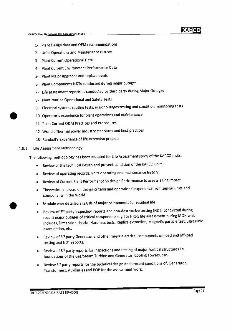
KAP Co
KAPCO Plant Remaining Life Assessment Study
1- Plant Design data and OEM recommendations
2- Units Operations and Maintenance History
3- Plant Current Operational Data
4- Plant Current Environment Performance Data
5- Plant Major upgrades and replacements
6- Plant Components NDTs conducted during major outages
7- Life assessment reports as conducted by third party during Major Outages
8- Plant routine Operational and Safety Tests
9- Electrical systems routine tests, major outages testing and condition monitoring tests
10- Operator's experience for plant operations and maintenance
11- Plant Current O&M Practices and Procedures
12- World's Thermal power industry standards and best practices
13- Ramboll's experience of life extension projects
2.5.1. Life Assessment Methodology:
The following methodology has been adopted for Life Assessment study of the KAPCO units;
• Review of the technkal design and present condition of the KAPCO units.
• Review of operating records, units operating and maintenance history
• Review of Current Plant Performance vs design Performance to assess aging impact
• Theoretical analyses on design criteria and operational experience from similar units and
components in the World
• Module wise detailed analysis of major components for residual life
• Review of 3rd party inspection reports and non-destructive testing (NDT) conducted during
recent major outages of critical components e.g. for HRSG life assessment during MOH which
includes, Dimension checks, Hardness tests, Replica extraction, Magnetic particle test, ultrasonic
examination, etc.
• Review of 3 party Generator and other major electrical components on-load and off-load
testing and NDT reports.
• Review of 3rd party reports for inspections and testing of major fcritical structures i.e.
foundations of the Gas/Steam Turbine and Generator, Cooling Towers, etc.
• Review 3rd party reports for the technical design and present conditions of, Generator,
Transformers, Auxiliaries and BOP for the assessment work.
RUK.2021N00226-RAM-RP-00001Page 11
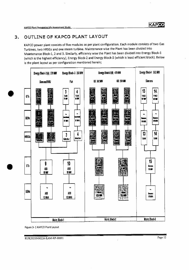
Co KAP KAPCO Plant Remaining Life Assessment Study
OUTLINE OF KAPCO PLANT LAYOUT
KAPCO power plant consists of five modules as per plant configuration. Each module consists of two Gas
Turbines, two HRSGs and one steam turbine. Maintenance wise the Plant has been divided into
Maintenance Block-i, 2 and 3. Similarly, efficiency wise the Plant has been divided into Energy Block-i
(which is the highest efficiency), Energy Block-2 and Energy Block-3 (which is least efficient block). Below
is the plant layout as per configuration mentioned herein;
EnergyBlock.2(A) 2flUW EnergyBlock•3 153MY1
Siernens!XWU Fiat
EnergyBlock.2(B) 419MV4
GE 242 MY GE 29 MN
Energy Block•1 332Mw
Siemens
,L JJ ij,J JJ' ywi vu
.VIL2
vu 1G Is
T4 TGII GTs
Tri -r1
- rr —
H rr muvA IThIVA
-
GENs
F; __ __ __ __
I - •••i•" I I -
- 15 IIeIMSS
9 89ItiY
10 A8
95M',V
132A I32MVA
6lIS
-
Maint Block•1 Maint BlocK2 Maint Block
Figure 3-1 KAPCO Plant Layout
RUK2021N00226-RAM-RP-0000 1 Page U
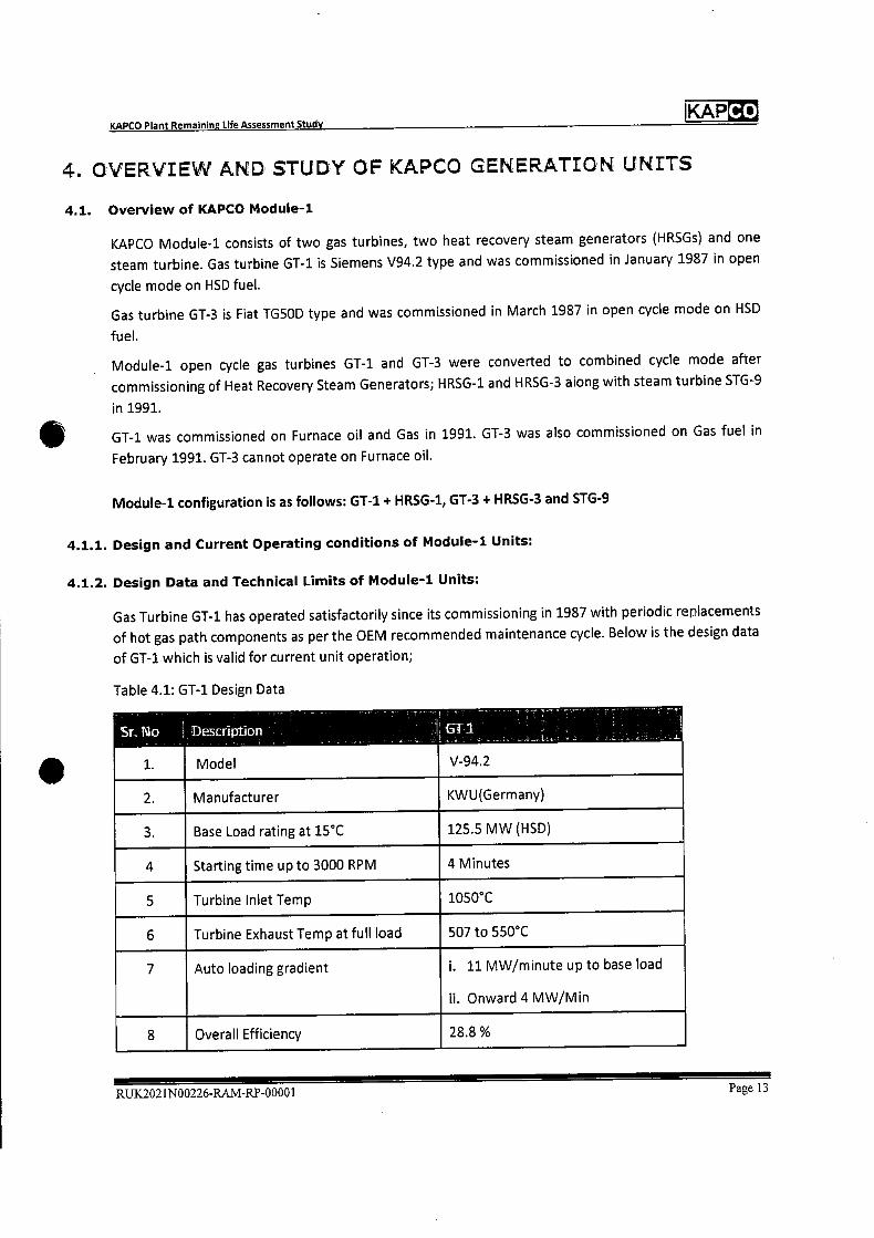
KAP KAPCO Plant Remaining Life Assessment Study
4. OVERVIEW AND STUDY OF KAPCO GENERATLON UNtTS
4.1. Overview of KAPCO Module-i
KAPCO Module-i consists of two gas turbines, two heat recovery steam generators (HRSGs) and one
steam turbine. Gas turbine GT-1 is Siemens V94.2 type and was commissioned in January 1987 in open
cycle mode on HSD fuel.
Gas turbine GT-3 is Fiat TG5OD type and was commissioned in March 1987 in open cycle mode on HSD
fuel.
Module-i open cycle gas turbines GT-i and GT-3 were converted to combined cycle mode after
commissioning of Heat Recovery Steam Generators; HRSG-1 and HRSG-3 along with steam turbine STG-9
in 1991.
GT-1 was commissioned on Furnace oil and Gas in 1991. GT-3 was also commissioned on Gas fuel in
February 1991. GT-3 cannot operate on Furnace oil.
Module-i configuration is as follows: GT-1 + HRSG-1, GT-3 + HRSG-3 and STG-9
4.1.1. Design and Current Operating conditions of Module-i Units:
4.1.2. Design Data and Technical Limits of Module-i Units:
Gas Turbine GT-1 has operated satisfactorily since its commissioning in 1987 with periodic replacements
of hot gas path components as per the OEM recommended maintenance cycle. Below is the design data
of GT-1 which is valid for current unit operation;
Table 4.1: GT-1 Design Data
Sr T3o
1.
Description
Model
(ii I
V-94.2
2. Manufacturer KWU(Germany)
3. Base Load rating at 15CC 125.5 MW (HSD)
4 Starting time up to 3000 RPM 4 Minutes
5 Turbine Inlet Temp 1050°C
6 Turbine Exhaust Temp at full load 507 to 550°C
7 Auto loading gradient . 11 MW/minute up to base load
ii. Onward 4 MW/Mm
8 Overall Efficiency 28.8 %
RUX2021N00226-RAM-RP-00001 Page 13
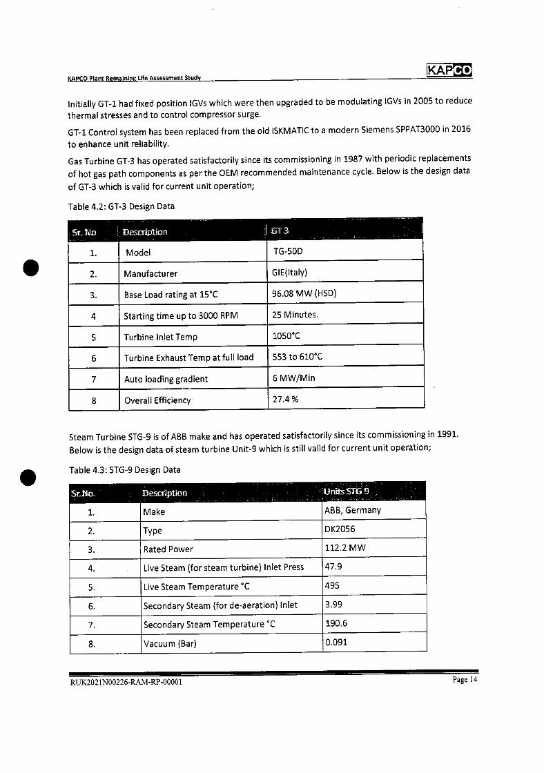
Co KAP KAPCO Plant Remaining Life Assessment Study
Initially GT-1 had fixed position lGVs which were then upgraded to be modulating lGVs in 2005 to reduce
thermal stresses and to control compressor surge.
GT-1 Control system has been replaced from the old ISKMATIC to a modern Siemens SPPAT3000 in 2016
to enhance unit reliability.
Gas Turbine GT-3 has operated satisfactorily since its commissioning in 1987 with periodic replacements
of hot gas path components as per the OEM recommended maintenance cycle. Below is the design data
of GT-3 which is valid for current unit operation;
Table 4.2: GT-3 Design Data
Sr..No i3escrØtion
Model TG-50D 1.
2. Manufacturer GIE(ltaly)
3. Base Load rating at 15°C 96.08 MW (HSD)
4 Starting time up to 3000 RPM 25 Minutes.
5 Turbine Inlet Temp 1050°C
6 Turbine Exhaust Temp at full load 553 to 610°C
7 Auto loading gradient 6 MW/Mm
8 Overall Efficiency 27.4%
Steam Turbine STG-9 is of ABB make and has operated satisfactorily since its commissioning in 1991.
Below is the design data of steam turbine Unit-9 which is still valid for current unit operation;
Table 4.3: STG-9 Design Data
Sr T\lo
1.
Description
Make
Units STG 9
ABB, Germany
2. Type DK2056
3. Rated Power 112.2 MW
4. Live Steam (for steam turbine) Inlet Press 47.9
5. Live Steam Temperature °C 495
6. Secondary Steam (for de-aeration) Inlet 3.99
7. Secondary Steam Temperature °C 190.6
8. Vacuum (Bar) 0.091
RUK2021N00226-RAM-RP-0000 1 Page 14

Reading Real Load
Reactive
Load CD P CDT OTC Inlet Loss
MW MVAR bar Pascal
ADC-2020 94 19 8 342 488 500
I DC-1996 90.0 -7.4 8 340.0 488 600
mbar
21
21.0
5s Turbrne10 1. a 6CIiDC & ( Camb iiS — Exhaust
Loss
KAPCO KAPCO Plant Remaining Life Assessment Study
9. Generator rating 132 MVA @ 50 Cold Air
Tern p
10. Unit Transformer rating 135 MVA
Heat Recovery steam generators HRSG-1 and HRSG-3 are in operation since COD 1991 without any
major problems. Below is the design data for HRSG-1 and HRSG-3 which are operating at design
capacity.
Table 4.4: HRSG-1 and HRSG-3 Design Data
iHlS&i' Ba1k DutT
208 t/h Steam Flow
Design Pressure 62 bar(g)
Superheater Outlet Pressure 47.1 bar(g)
Superheated Steam temperature 505CC
Total Heating Surface
-RSG-3: a1ke Dijri
58180 m
180.8 t/h Steam Flow
Design Pressure 62 bar(g)
Superheater Outlet Pressure 48 bar(g)
Superheated Steam temperature 500CC
Total Heating Surface 54182 m2
4.1.3. Current Operating Data of Module-i Units
Following data of Annual Dependable Capacity Test performed on dated 01-07-2020 shows that
Module-i units are operating near to or better than IDC parameters (lDC Initial dependable Capacity
Test 1996) owing to prudent operating procedures and excellent maintenance strategy;
Table 4.5: Module-i Operating Data
RUK2021N00226-RAM-RP-0000 1 Page 15

KAPCO Plant Remaining Life Assessment Study
KAPCO
Reading
Real Load Reactive
Load CDP CDT TET Inlet Loss
Exhaust
Loss
MW MVAR bar C mbar
ADC-2020 77 25 10 399 582 122 19
IDC-1996
Reading
80
Real Load
17
Reactive
StTiithrneNo
9
HP Inlet
397
HP Inlet
576
Ex Press
71
CW Inlet
13
Cooling
Tower
Fans
MW MVAR Temp °C bar Temp °C in service
ADC-2020 101 23 41 493 0.11 32 6
IDC-1996
Reading
92
HP
Steam Steam
2
HP
1iRSG-1
FW
Inlet
42
Flue
Gas
480
HP
Steam
0.235
HP
Steam
32
FW
Inlet
6
Flue
Gas
Press
bar Temp C
Temp Temp
C
Press
bar Temp C
Temp Temp
ADC-2020 42 487 119 181 42 498 117 147
lDC-1996 41 480.6 130 192 42 497.8 132 160
4.1.4. Operating Record of Module-i Units
Following data shows operating hours, No. of starts, trips of module-i units since commissioning till 31
March 2021.
No. of starts are higher for GT-3 in regard to its total Operating hours <100,000.
Table 4.6: Operating Record Module-i
Module-i Operatrng Record since Commssrnning to March1O21
STG-9 GT-1 61-3
Date of commissioning 18-Jan-87 12-Mar-87 28-Jan-91
Total No. of Starts 3862 4612 2600
Operating Hours (OH) 171801 93920 165469
No. of Trips 311 113 180
RI.JK.2021N00226-RAM-RP-0000 1 Page 16
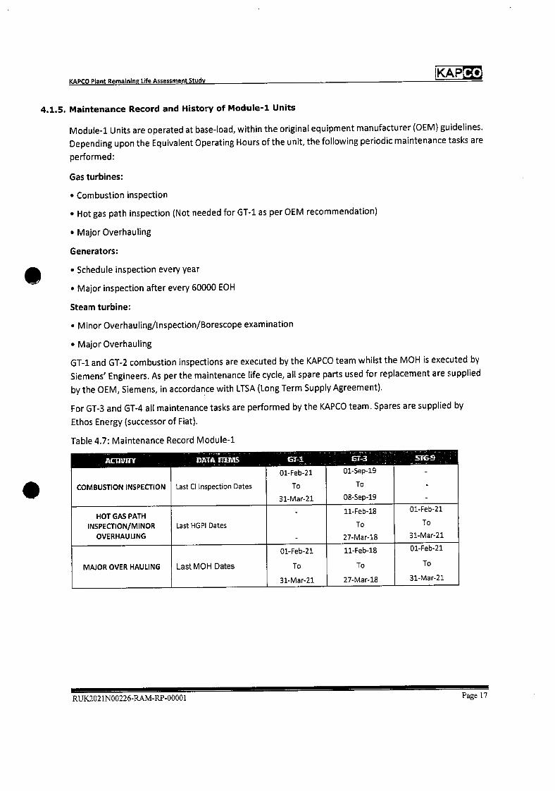
KAP Co KAPCO Plant Remaining Life Assessment Study
4.1.5. Maintenance Record and History of Module-i Units
Module-i Units are operated at base-load, within the original equipment manufacturer (OEM) guidelines.
Depending upon the Equivalent Operating Hours of the unit, the following periodic maintenance tasks are
performed:
Gas turbines:
• Combustion inspection
• Hot gas path inspection (Not needed for GT-i as per OEM recommendation)
• Major Overhauling
Generators:
• Schedule inspection every year
• Major inspection after every 60000 EOH
Steam turbine:
• Minor Overhauling/Inspection/BoreSCOPe examination
• Major Overhauling
GT-1 and GT-2 combustion inspections are executed by the KAPCO team whilst the MOH is executed by
Siemens' Engineers. As per the maintenance life cycle, all spare parts used for replacement are supplied
by the OEM, Siemens, in accordance with LTSA (Long Term Supply Agreement).
For GT-3 and GT-4 all maintenance tasks are performed by the KAPCO team. Spares are supplied by
Ethos Energy (successor of Fiat).
Table 4.7: Maintenance Record Module-i
ACTiVITY
COMBUSTION INSPECTION
DATA IIThTI715
Last CI Inspection Dates
El-I
01-Feb-21
To
31-Mar-21
GT-3
01-Sep-19
To
08-Sep-19
516-9
-
-
HOT GAS PATH INSPECTION/MINOR
OVERHAULING
Last HGPI Dates
-
-
11-Feb-18
To
27-Mar-18
01-Feb-21
To
31-Mar-21
MAJOR OVER HAULING Last MOH Dates
01-Feb-21
To
31-Mar-21
11-Feb-18
To
27-Mar-18
01-Feb-21
To
31-Mar-21
RUK2021N00226.RAM-RP.00001 Page 17
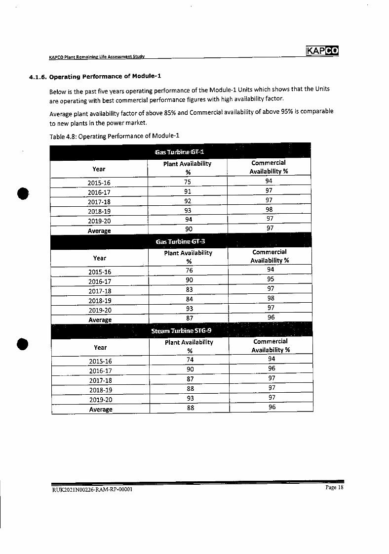
KAP KAPCO Plant Remaining Life Assessment Study
4.1.6. operating Performance of Module-i
Below is the past five years operating performance of the Module-i Units which shows that the Units
are operating with best commercial performance figures with high availability factor.
Average plant availability factor of above 85% and Commercial availability of above 95% is comparable
to new plants in the power market.
Table 4.8: Operating Performance of Module-i
GsTurbineGT-i
Year Plant Availability Commercial
Availabili %
2015-16 75 94
2016-17 91 97
2017-18 92 97
2018-19 93 98
2019-20 . 94 97
Average
Year
90
Gas Tur] me GT-3
Plant Availability %
97
Commercial
Availability %
2015-16 76 94
2016-17 90 95
2017-18 83 97
2018-19 84 98
2019-20 93 97
Average
Year
87
Steam Turbine STG-9
Plant Availability Commercial
Availability %
2015-16 74 94
2016-17 90 96
2017-18 87 97
2018-19 88 97
2019-20 93 97
Average 88 96
RUK2021N00226-RAM-RP-00001 Page 18
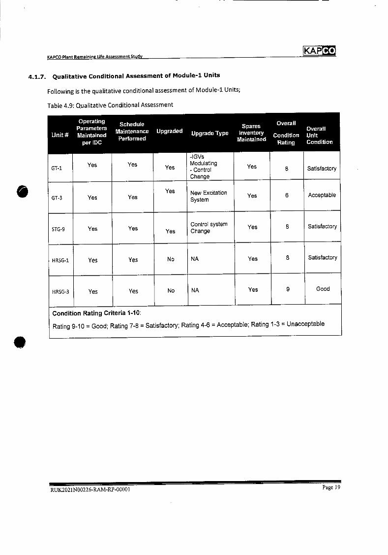
KAP KAPCO Plant Remaining Life Assessment Study
4.1.7. Qualitative Conditional Assessment of Module-i Units
Following is the qualitative conditional assessment of Module-i Units;
Table 4.9: Qualitative Conditional Assessment
Unit
Operating Parameters Maintained
per IDC
Yes
Schedule Maintenance Performed
Yes
Upgraded
Yes
Upgrade Type
-IGVs Modulating - Control Change
Spares Inventory
Maintained
Yes
Overall
Condition Rating
8
Overall Unit Condition
Satisfactory GT-1
GT-3 Yes Yes Yes New Excitation
System Yes 6 Acceptable
STG-9 Yes Yes Yes Control system Change
Yes 8 Satisfactory
HRSG-1 Yes Yes No NA Yes 8 Satisfactory
HRSG-3 Yes Yes No NA Yes 9 Good
Condition Rating Criteria 1-10:
Rating 9-10 = Good; Rating 7-8 = Satisfactory; Rating 4-6 = Acceptable; Rating 1-3 = Unacceptable
RUK2021N00226-RAIVI-RP-00001 Page 19
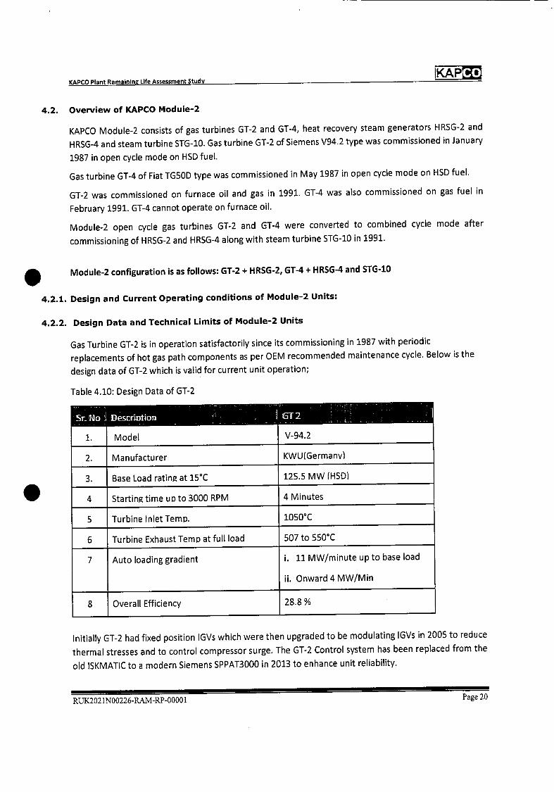
KAPCO Plant Remaining Life Assessment Study KAP
4.2. Overview of KAPCO Module-2
KAPCO Module-2 consists of gas turbines GT-2 and GT-4, heat recovery steam generators HRSG-2 and
HRSG-4 and steam turbine STG-1O. Gas turbine GT-2 of Siemens V94.2 type was commissioned in January
1987 in open cycle mode on HSD fuel.
Gas turbine GT-4 of Fiat TGSOD type was commissioned in May 1987 in open cycle mode on HSD fuel.
GT-2 was commissioned on furnace oil and gas in 1991. GT-4 was also commissioned on gas fuel in
February 1991. GT-4 cannot operate on furnace oil.
Module-2 open cycle gas turbines GT-2 and GT-4 were converted to combined cycle mode after
commissioning of HRSG-2 and HRSG-4 along with steam turbine STG-1O in 1991.
Module-2 configuration is as follows: GT-2 + HRSG-2, GT-4 ~ HRSG-4 and STG-1O
4.2.1. Design and Current Operating conditions of Module-2 Units:
4.2.2. Design Data and Technical Limits of Module-2 Units
Gas Turbine GT-2 is in operation satisfactorily since its commissioning in 1987 with periodic
replacements of hot gas path components as per OEM recommended maintenance cycle. Below is the
design data of GT-2 which is valid for current unit operation;
Table 4.10: Design Data of GT-2
Sr No Descrintion 1 i2
V-94.2 1. Model
2. Manufacturer KWU(Germanv)
3. Base Load rating at 15CC 125.5 MW (HSD)
4 Starting time up to 3000 RPM 4 Minutes
5 Turbine Inlet Temp. 1050CC
6 Turbine Exhaust TemD at full load 507 to 550CC
7 Auto loading gradient I. 11 MW/minute up to base load
ii. Onward 4 MW/Mm
8 Overall Efficiency 28.8%
Initially GT-2 had fixed position IGVs which were then upgraded to be modulating lGVs in 2005 to reduce
thermal stresses and to control compressor surge. The GT-2 Control system has been replaced from the
old ISKMATIC to a modern Siemens SPPAT3000 in 2013 to enhance unit reliability.
RUK2021N00226-RAM-RP-0000 1 Page 20

KAPCO Plant Remaining Life Assessment Study IKAPCO
Gas Turbine GT-4 has operated satisfactorily since its commissioning in 1987 with periodic replacements
of hot gas path components as per the OEM recommended maintenance cycle. Below is the design data
of GT-4 which is valid for current unit operation;
Table 4.11: Design Data of GT-4
SL 1\]o Dsciiintioii I
Model TG-50D 1.
2. Manufacturer GlEltalv)
3. Base Load rating at 15°C 96.08 MW (I-ISD)
4 Starting time uo to 3000 RPM 25 Minutes.
5 Turbine Inlet Temo 1050°C
6 Turbine Exhaust Temo at full load 553 to 610°C
7 Auto loading gradient 6 MW/Mm
8 Overall Efficiency 27.4%
Steam Turbine STG-10 is of ABB make and has operated satisfactorily since its commissioning in 1991.
Below is the design data of steam turbine unit-lO which is still valid for current unit operation;
Table 4.12: Design Data of STG-10
SrNo
1.
Descriptioi
Make
Units SIG 10
ABB, Germany
2. Type DK2056
3. Rated Power 112.2 MW
4. Live Steam (for steam turbine) Inlet Press
(Bar)
47.9
5. Live Steam Temperature °C 495
6. Secondary Steam (for de-aeration) Inlet Press
(Bar)
3.99
7. Secondary Steam Temperature °C 190.6
8. Vacuum (Bar) 0.091
9. Generator rating 132 MVA @ 50 C Cold Air
Tern p
RUK2021N00226-RAM-RP-00001 Page 21
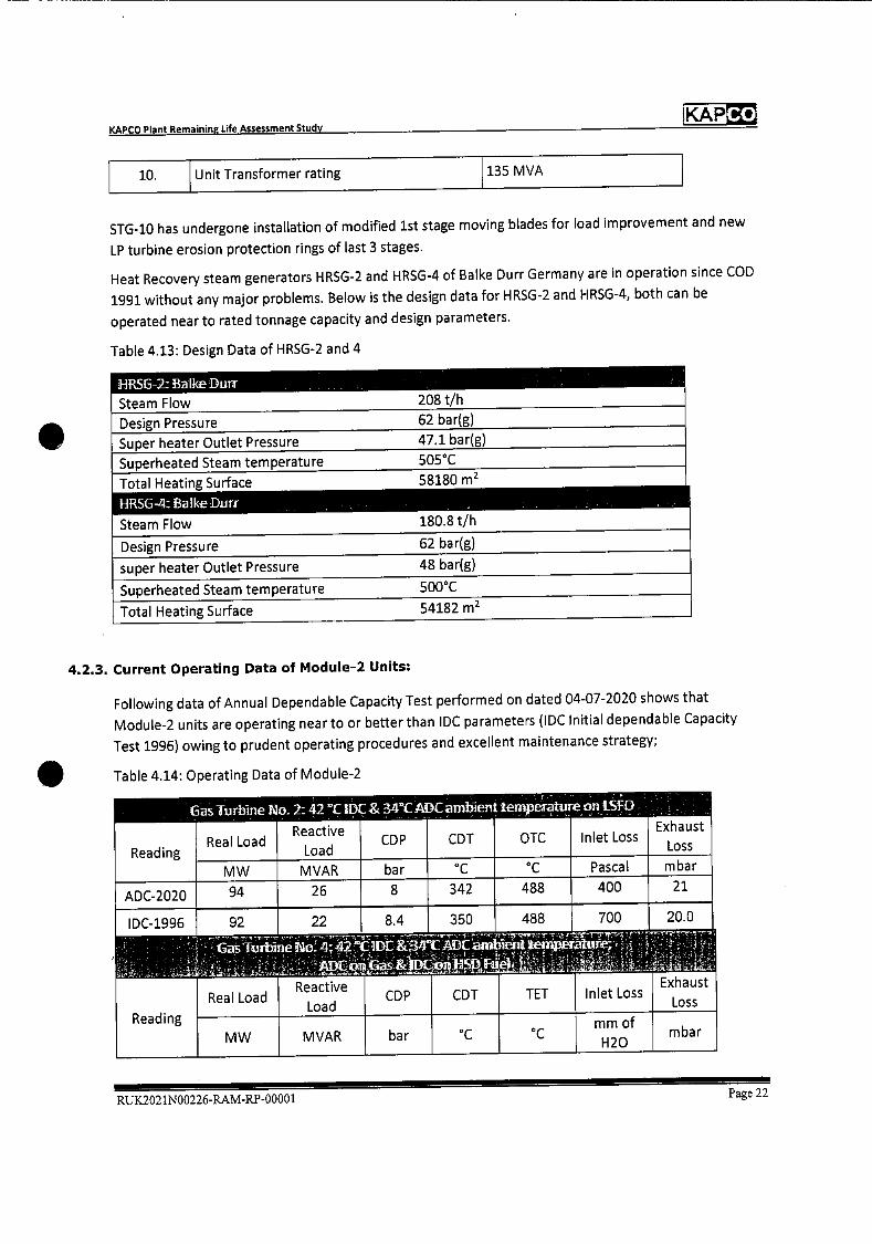
Pascal mbar
21
20.0
400
700
CD P Reactive
Load
MVAR bar
8 26
350 488
Girbine 1o42
COP
bar
CDT
OC
Exhaust
Loss CDT OTC Inlet Loss
342 488
as Turbine No 2 42°C DC & 34'C ADC ambient temperature on LSFO
Reading
ADC-2020
I DC-1996
Reading
22
Reactive
Load
MVAR
Inlet Loss Exhaust
Loss TET
Real Load
MW
94
92 8.4
Real Load
MW mm of
H 20 mba r
KAP KAPCO Plant Remaining life Assessment Study
10. Unit Transformer rating 135 MVA
STG-10 has undergone installation of modified 1st stage moving blades for load improvement and new
LP turbine erosion protection rings of last 3 stages.
Heat Recovery steam generators HRSG-2 and HRSG-4 of Balke Durr Germany are in operation since COD
1991 without any major problems. Below is the design data for HRSG-2 and HRSG-4, both can be
operated near to rated tonnage capacity and design parameters.
Table 4.13: Design Data of HRSG-2 and 4
J-IRSG-2: Balke Duff 208 t/h Steam Flow
Design Pressure 62 bar(g)
Super heater Outlet Pressure 47.1 bar(g)
Superheated Steam temperature 505°C
Total Heating Surface
HRSG-4:BalkeDu1T
58180 m2
180.8 t/h Steam Flow
Design Pressure 62 bar(g)
super heater Outlet Pressure 48 bar(g)
Superheated Steam temperature 500°C
Total Heating Surface 54182 m2
4.2.3. Current Operating Data of Module-2 Units:
Following data of Annual Dependable Capacity Test performed on dated 04-07-2020 shows that
Module-2 units are operating near to or better than IDC parameters (IDC Initial dependable Capacity
Test 1996) owing to prudent operating procedures and excellent maintenance strategy;
Table 4.14: Operating Data of Module-2
RUX2021N00226.RAM-RP-00001 Page 22
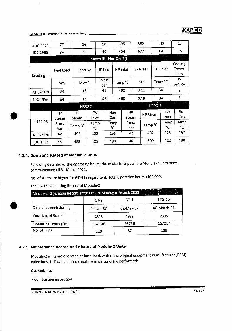
KAPCO Plant Remaining Life Assessment Study IKAP
ADC-2020 77 26 10 395 582 113 17
IDC-1996
Reading
74
Real Load
9
Reactive
5rbIneD
10
HP Inlet
404
]1L1
HP Inlet
577
Ex Press
64
CW Inlet
15
Cooling
Tower
Fans
MW MVAR Press
bar Temp C bar Temp C
in.
servIce
ADC-2020 98 15 41 490 0.11 6
IDC-1996
Reading
94
HP
Steam Steam
13
HP
'HRSG-2
FW
Inlet
43
Flue
Gas
456
HP
Steam
0.18
HP Steam
HRS&4
34
FW
Inlet
6
Flue
Gas
Press
bar ,- . 1emp
Temp
C
Temp
°C
Press
bar T emp
Temp
C
Temp
ADC-2020 42 492 122 165 42 497 123 157
IDC-1996 44 499 125 190 40 500 122 160
4.2.4. Operating Record of Module-2 Units
Following data shows the operating h'urs, No. of starts, trips of the Module-2 Units since
commissioning till 31 March 2021.
No. of starts are higher for GT-4 in regard to its total Operating hours <100,000.
Table 4.15: Operating Record of Module-2
ffVlodule-2 Opeitin.g Reco si.ce Conmissionrn,g10 flasth 2321
STG-10 GT-2 GT-4
Date of commissioning 14-Jan-87 02-May-87 08-March-91
Total No. of Starts 4315 4987 2905
Operating Hours (OH) 162106 93756 157017
No. of Trips 218 87 188
4.2.5. Maintenance Record and History of Module-2 Units
Module-2 units are operated at base-load, within the original equipment manufacturer (OEM)
guidelines. Following periodic maintenance tasks are performed:
Gas turbines:
• Combustion inspection
RUX.2021N00226-RAM-RP-00001 Page 23
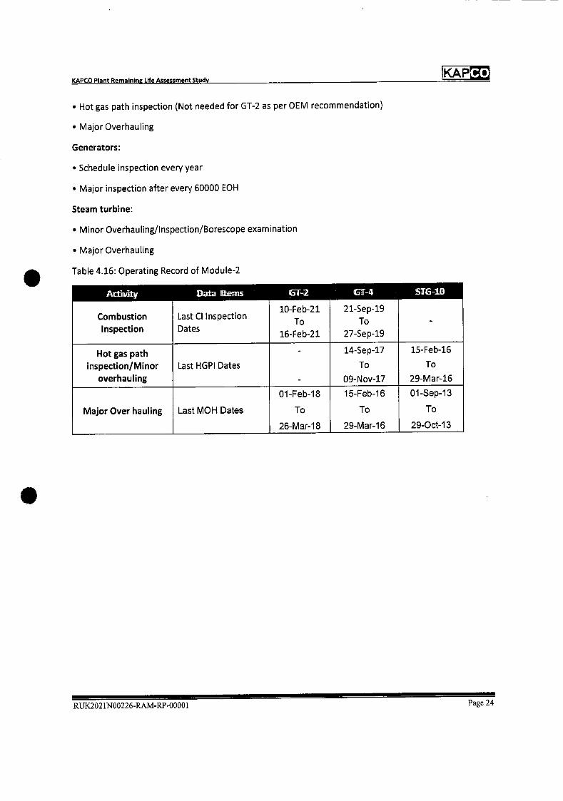
KAPCO Plant Remaining Life Assessment Study KAP
• Hot gas path inspection (Not needed for GT-2 as per OEM recommendation)
• Major Overhauling
Generators:
• Schedule inspection every year
• Major inspection after every 60000 EOH
Steam turbine:
• Minor Overhauling/Inspection/Borescope examination
• Major Overhauling
Table 4.16: Operating Record of Module-2
Attivity
Combustion Inspection
Data Items
Last Cl Inspection
Dates
(5T-2
10-Feb-21
To 16-Feb-21
ET-4
21-Sep-19 To
27-Sep-19
SITE-ID
-
Hot gas path inspection/Minor
overhauling
Last HGPI Dates
-
-
14-Sep-17
To
09-Nov-17
15-Feb-16
To
29-Mar-16
Major Over hauling Last MOH Dates
01-Feb-18
To
26-Mar-18
15-Feb-16
To
29-Mar-16
01-Sep-13
To
29-Oct-13
RUK2021N00226-RAM-RP-0000 1 Page 24
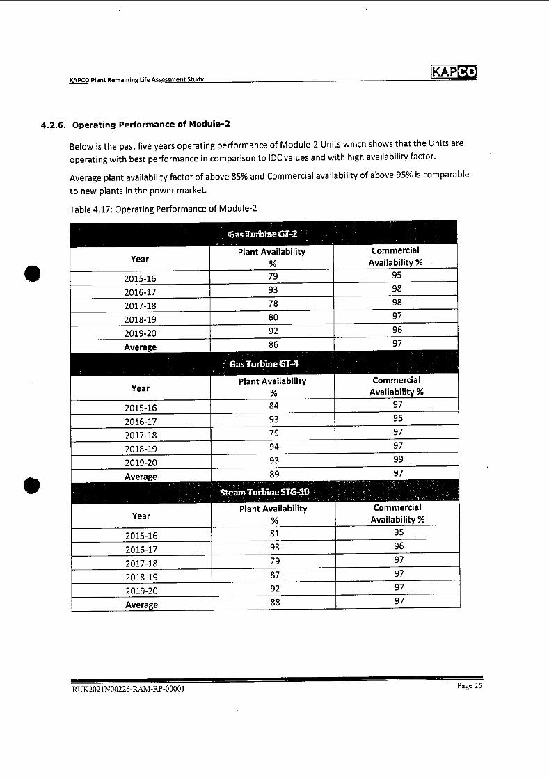
Co KAP KAPCO Plant Remaining Life Assessment Study
4.2.6. Operating Performance of Module-2
Below is the past five years operating performance of Module-2 Units which shows that the Units are
operating with best performance in comparison to IDC values and with high availability factor.
Average plant availability factor of above 85% and Commercial availability of above 95% is comparable
to new plants in the power market.
Table 4.17: Operating Performance of Module-2
Year
Gas Turbine ET-2
Plant Availability
%
Commercial Availability %
2015-16 79 95
2016-17 93 98
2017-18 78 98
2018-19 80 97
2019-20 92 96
Average 86 97
Gas Turbine CT-4
Year Plant Availability
%
Commercial
Availability %
2015-16 84 97
2016-17 93 95
2017-18 79 97
2018-19 94 97
2019-20 93 99
Average 89 97
Steam Turbine STG-i1
Year Plant Availability
%
Commercial
Availability %
2015-16 81 95
2016-17 93 96
2017-18 79 97
2018-19 87 97
2019-20 92 97
Average 88 97
RUK2021N00226-RAM-RP-0000 1 Page 25
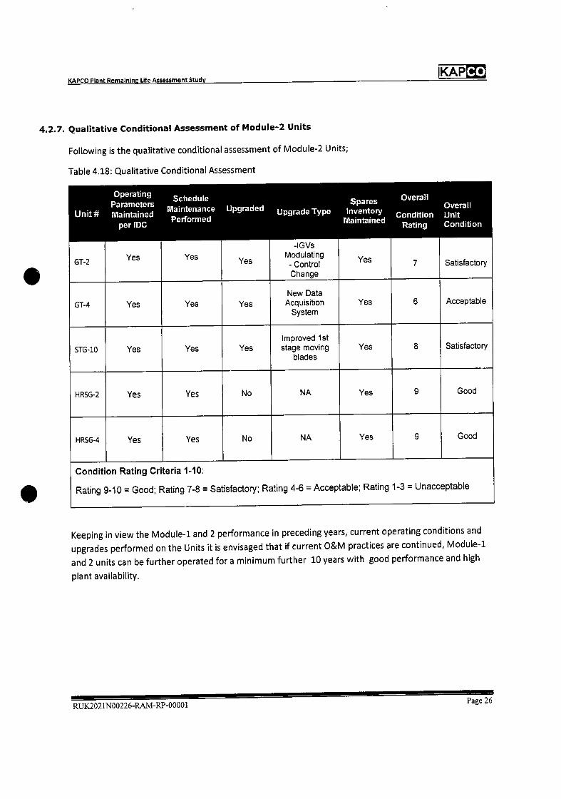
KAPCO Plant Remaining Life Assessment Study IKAPCO
4.2.7 Qualitative Conditional Assessment of Module-2 Units
Following is the qualitative conditional assessment of Module-2 Units;
Table 4.18: Qualitative Conditional Assessment
Unit
GT-2
Operating Parameters Maintained
per lDC
Yes
Schedule Maintenance Performed
Yes
Upgraded
Yes
Upgrade Type
-IGVs Modulating - Control Change
Spares Inventory
Naintained
Yes
Overall
Condition Rating
7
OvelI Unit Condition
Satisfactory
GT-4 Yes Yes Yes New Data
Acquisition System
Yes 6 Acceptable
STG-1O Yes Yes Yes Improved 1st stage moving
blades Yes 8 Satisfactory
HRSG-2 Yes Yes No NA Yes 9 Good
HRSG-4 Yes Yes No NA Yes 9 Good
Condition Rating Criteria 1-10:
Rating 9-10 = Good; Rating 7-8 = Satisfactory; Rating 4-6 = Acceptable; Rating 1-3 = Unacceptable
Keeping in view the Module-i and 2 performance in preceding years, current operating conditions and
upgrades performed on the Units it is envisaged that if current O&M practices are continued, Module-i
and 2 units can be further operated for a minimum further 10 years with good performance and high
plant availability.
RUK2021N00226-RAM-RP-0000lPage 26
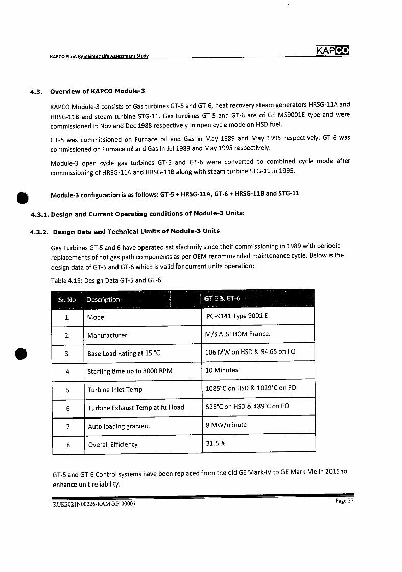
Co KAP KAPCO Plant Remaining Life Assessment Study
4.3. Overview of KAPCO Module-3
KAPCO Module-3 consists of Gas turbines GT-5 and GT-6, heat recovery steam generators HRSG-11A and
HRSG-11B and steam turbine STG-11. Gas turbines GT-5 and GT-6 are of GE MS9001E type and were
commissioned in Nov and Dec 1988 respectively in open cycle mode on HSD fuel.
GT-5 was commissioned on Furnace oil and Gas in May 1989 and May 1995 respectively. GT-6 was
commissioned on Furnace oil and Gas in Jul 1989 and May 1995 respectively.
Module-3 open cycle gas turbines GT5 and GT-6 were converted to combined cycle mode after
commissioning of HRSG-11A and HRSG-11B along with steam turbine STG-11 in 1995.
Module-3 configuration is as follows: GT-5 + HRSG-11A, GT-6 + HRSG-11B and STG-11
4.3.1. Design and Current Operating conditions of Module-3 Units:
4.3.2. Design Data and Technical Limits of Module-3 Units
Gas Turbines GT-5 and 6 have operated satisfactorily since their commissioning in 1989 with periodic
replacements of hot gas path components as per OEM recommended maintenance cycle. Below is the
design data of GT-5 and GT-6 which is valid for current units operation;
Table 4.19: Design Data GT-5 and GT-6
Sr No
1.
DescrIption
Model
T-5>-6
PG-9141 Type 9001 E
2. Manufacturer M/S ALSTHOM France.
3. Base Load Rating at 15 °C 106 MW on I-ISD & 94.65 on FO
4 Starting time up to 3000 RPM 10 Minutes
5 Turbine Inlet Temp 1085°C on HSD & 1029°C on FO
6 Turbine Exhaust Temp at full load 528°C on HSID & 489°C on FO
7 Auto loading gradient 8 MW/minute
8 Overall Efficiency 31.5%
GT-5 and GT-6 Control systems have been replaced from the old GE Mark-IV to GE Mark-Vie in 2015 to
enhance unit reliability.
RUK2021N00226-RAM-RP-00001Page 27
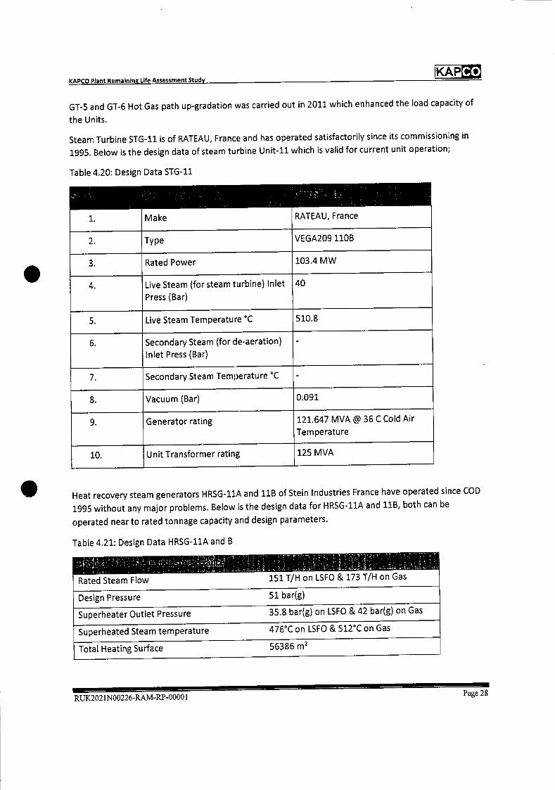
Co KAP KAPCO Plant Remaining Life Assessment Study
GT-5 and GT-6 Hot Gas path up-gradation was carried out in 2011 which enhanced the load capacity of
the Units.
Steam Turbine STG-11 is of RATEAU, France and has operated satisfactorily since its commissioning in
1995. Below is the design data of steam turbine Unit-li which is valid for current unit operation;
Table 4.20: Design Data STG-li
•
1. Make RATEAU, France
2. Type VEGA209110B
3. Rated Power 103.4 MW
4. Live Steam (for steam turbine) Inlet
Press (Bar)
40
5. Live Steam Temperature C 510.8
6. Secondary Steam (for de-aeration)
Inlet Press (Bar)
-
7. Secondary Steam Temperature °C -
8. Vacuum (Bar) 0.091
9. Generator rating 121.647 MVA @ 36 C Cold Air
Temperature
10. Unit Transformer rating 125 MVA
Heat recovery steam generators HRSG-llA and 11B of Stein Industries France have operated since COD
1995 without any major problems. Below is the design data for HRSG-11A and 11B, both can be
operated near to rated tonnage capacity and design parameters.
Table 4.21: Design Data HRSG-liA and B
.•
151 T/H on LSFO & 173 T/H on Gas Rated Steam Flow
Design Pressure 51 bar(g)
Superheater Outlet Pressure 35.8 bar(g) on LSFO & 42 bar(g) on Gas
Superheated Steam temperature 476°C on LSFO & 512°C on Gas
Total Heating Surface 56386 rn2
RUK2021N00226-RAM-RP-0000 IPage 28
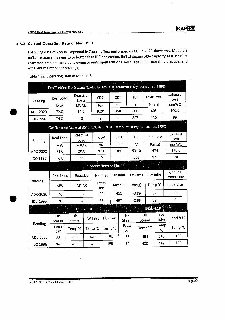
Co KAP KAPCO Plant Remaining Life Assessment Study
4.3.3. Current Operating Data of Module-3
Following data of Annual Dependable Capacity Test performed on 06-07-2020 shows that Module-3
units are operating near to or better than IDC parameters (Initial dependable Capacity Test 1996) at
corrected ambient conditions owing to units up-gradations, KAPCO prudent operating practices and
excellent maintenance strategy;
Table 4.22: Operating Data of Module-3
I
Reading
I, - . 'W.. - ,- - -
Reactive Real Load CDP CDT
Load
-
TET Inlet Loss Exhaust
Loss
MW MVAR bar °C °C Pascal mmWC
ADC-2020 72.0 14.0 9.20 358 500 603 140.0
IDC-1996
Reading
74.0 10 9 -
Gas Turbine 1'.Io 6 at 39°t ADC & 37T 1DC ambient
Reactive Real Load CDP CDT
Load
507
temperature,
TET
130
n LSfO
Inlet Loss
69
Exhaust
Loss
MW MVAR bar °C C Pascal mmWC
ADC-2020 72.0 20.0 9.10 360 504.0 474 140.0
IDC-1996 76.0 11 9
S1:eam Turbine
Real Load Reactive HP Inlet
-
No 11
HP Inlet
506
Ex Press
176
CW Inlet
64
cooling
Tower Fans Reading
P MW MVAR Temp C bar(g) Temp C in service
ADC-2020 76 13 32 411 -0.89 39 6
lDC-1996
.
76
HP
Steam
......•.;__.-_ :..
9
HP
Steam
WS&11A ......- _..5-:-i
FW Inlet
33
Flue
.-
Gas
467
I ,-.-:
HP
Steam
. 1.I_1:
-0.88
-I
HP
Steam
..:.- •.
39
•I:-.s,I~jI - .•,
FW
Inlet
...::;I;;.;.V_II;;i
6
-.,
Flue Gas
Reading Press
bar Temp C Temp C Temp C
Press
bar Temp °C
Temp Temp C
ADC-2020 33 473 140 158 32 484 140 159
lDC-1996 34 472 141 165 34 469 142 163
RUK2021N00226-RA.M-RP-00001 Page 29
'I

Co KAP KAPCO Plant Remaining Life Assessment Study
4.3.4. operating Record of Module-3 Units
Following data shows operating hours, No. of starts, trips of Module-3 units since commissioning till 31
March 2021.
Table 4.23: Operating Record of Module-3
MDdUi3 Cpting Jet&rd S1flC flm On tO ff1aTdII 2021.
STG-11 GT-5 GT-6
Date of commissioning 14-Nov-88 29-Dec-88 04-Mar-95
Total No. of Eq Starts 4,240 4,413 2761
Operating Hours (OH) 144150 152072 128560
No. of Trips 201 179 239
4.3.5. Maintenance Record and History of Module-3 Units
Module-3 units are operated at base-load, within the original equipment manufacturer (OEM)
guidelines. As per OEM recommendations, following periodic maintenance tasks are performed:
Gas turbines:
• Combustion inspection
• Hot gas path inspection
• Major Overhauling
Generators: • Minor inspection after every 15000 Generator EON
• Major Overhaul after every 46000 Generator EOH
Steam turbine:
• Minor Overhauling/Inspection/Borescope examination
• Major Overhauling
Table 4.24: Maintenance Record of Module-3
Activity
Combustion
Inspection
Data Items
Last Cl Inspection
Dates
GT-5
01-Mar-21
To
05-Mar-21
GT-5
01-Mar-21
To
05-Mar-21
516-U
-
Hot Gas Path
Inspection/Minor
Overhauling
Last HGPI Dates
11-Sep-17
To
30-Oct-17
11-Sep-17
To
30-Oct-17
01-Feb-20
To
31-Mar-20
Major Over Hauling Last MOH Dates
16-Oct-il
To
03-Dec-li
16-Oct-il
To
03-Dec-li
11-Sep-17
To
30-Oct-17
RUK2021N00226-RAM-RP-00001 Page 30
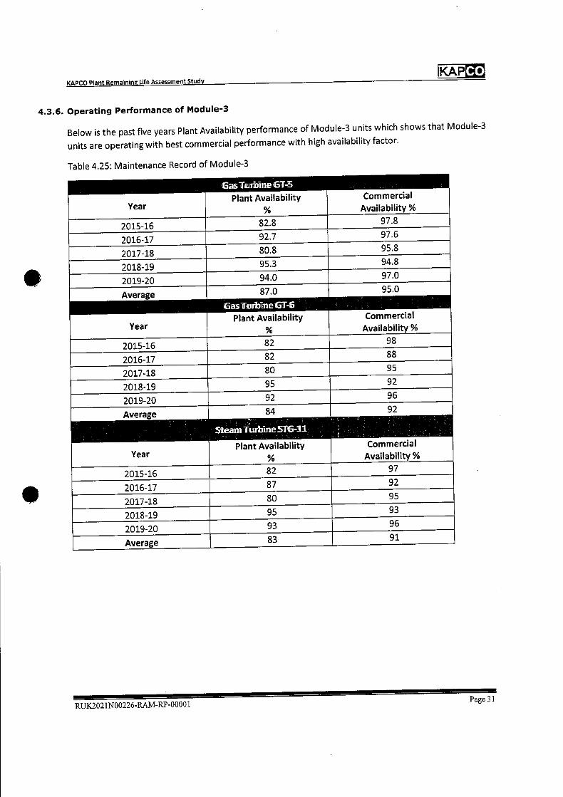
Co KAP KAPCO Plant Remaining Life Assessment Study
4.3.6. Operating Performance of Module-3
Below is the past five years Plant Availability performance of Module-3 units which shows that Module-3
units are operating with best commercial performance with high availability factor.
Table 4.25: Maintenance Record of Module-3
Year
asTtirbineT-5
Plant Availability
%
Commercial
Availability %
2015-16 82.8 97.8
2016-17 92.7 97.6
2017-18 80.8 95.8
2018-19 95.3 94.8
2019-20 94.0 97.0
87.0 95.0 Average
as Turbine GT-
Year Plant Availability
%
Commercial
Availability %
2015-16 82 98
2016-17 82 88
2017-18 80 95
2018-19 95 92
2019-20 92 96
Average
Year
84
Steam Turbine 516-11
Plant Availability
%
92
Commercial Availability %
2015-16 82 97
2016-17 87 92
2017-18 80 95
2018-19 95 93
2019-20 93 96
Average 83 91
Page 31 RUK2O2 1N00226-RAM-RP-0000I

IKAP KAPCO Plant Remaining Life Assessment Study
4.3.7. Qualitative Conditional Assessment of Module-3 Units
Following is the qualitative conditional assessment of Module-3 Units;
Table 4.26: Qualitative Conditional Assessment
Unit#
Operating Parameters Maintained
per IDC
Yes
Schedule Maintenance Performed
Yes
Upgraded
Yes
UpgradeType
-Hot Gas Path Upgrade - Control System Change
Spares Inventory
Tglaintained
Yes
Overall
Condition Rating
8
Overall Unit Condition
Satisfactory GT-5
GT-6 Yes Yes Yes
-Hot Gas Path Upgrade - Control System Change
Yes 8 Satisfactory
STG-11 Yes Yes Yes
-Generator Rewind - Control System Change
Yes 8 Satisfactory
HRSG- hA
Yes Yes No NA Yes 9 Good
HRSG- 11B
Yes Yes Nc NA Yes 9 Good
Condition
Rating
Rating Criteria 1-10:
9-10 = Good; Rating 7-8 = Satisfactory; Rating 4-6 = Acceptable; Rating 1-3 = Unacceptable
RTJK2O21NOO226RAM-RP-O0001Page 32
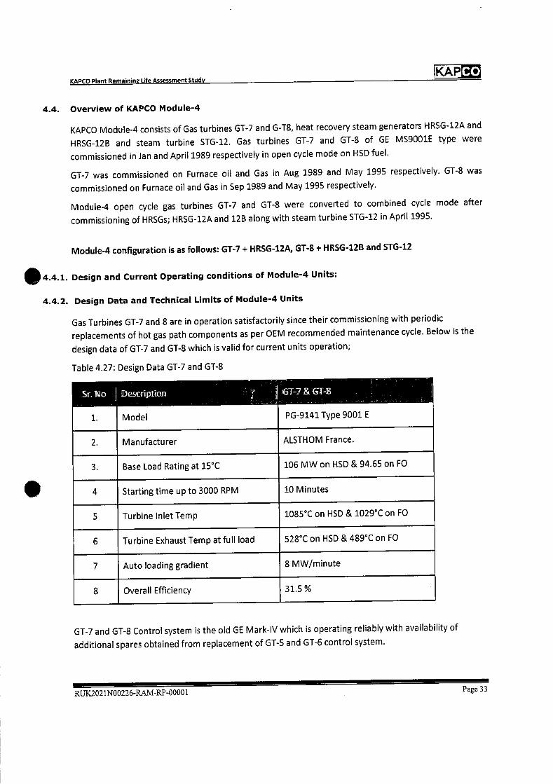
Co KAP KAPCO Plant Remaining Life Assessment Study
4.4. Overview of KAPCO Module-4
KAPCO Module-4 consists of Gas turbines GT-7 and G-T8, heat recovery steam generators HRSG-12A and
HRSG-12B and steam turbine STG-12. Gas turbines GT-7 and GT-8 of GE MS9001E type were
commissioned in Jan and April 1989 respectively in open cycle mode on HSD fuel.
GT-7 was commissioned on Furnace oil and Gas in Aug 1989 and May 1995 respectively. GT-8 was
commissioned on Furnace oil and Gas in Sep 1989 and May 1995 respectively.
Module-4 open cycle gas turbines GT-7 and GT-8 were converted to combined cycle mode after
commissioning of HRSGs; HRSG-12A and 12B along with steam turbine STG-12 in April 1995.
Module-4 configuration is as follows: GT-7 + HRSG-12A GT-8 + HRSG-12B and STG-12
S4.4.1. Design and Current Operating conditions of Module-4 Units:
4.4.2. Design Data and Technical Limits of Module-4 Units
Gas Turbines GT-7 and 8 are in operation satisfactorily since their commissioning with periodic
replacements of hot gas path components as per OEM recommended maintenance cycle. Below is the
design data of GT-7 and GT-8 which is valid for current units operation;
Table 4.27: Design Data GT-7 and GT-8
Sr No
1.
Description
Model PG-9141 Type 9001 E
2. Manufacturer ALSTHOM France.
3. Base Load Rating at 15°C 106 MW on HSD & 94.65 on FO
4 Starting time up to 3000 RPM 10 Minutes
5 Turbine Inlet Temp 1085°C on HSD & 1029°C on FO
6 Turbine Exhaust Temp at full load 528°C on HSD & 489°C on FO
7 Auto loading gradient 8 MW/minute
8 Overall Efficiency 31.5%
GT-7 and GT-8 Control system is the old GE Mark-IV which is operating reliably with availability of
additional spares obtained from replacement of GT-5 and GT-6 control system.
RUK2021N00226-RAM-RP-00001 Page 33
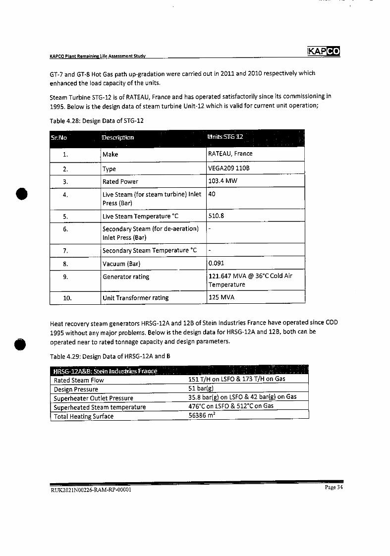
Co KAP KAPCO Plant Remaining life Msessment Study
GT-7 and GT-8 Hot Gas path up-gradation were carried out in 2011 and 2010 respectively which
enhanced the load capacity of the units.
Steam Turbine STG-12 is of RATEAU, France and has operated satisfactorily since its commissioning in
1995. Below is the design data of steam turbine Unit-12 which is valid for current unit operation;
Table 4.28: Design Data of STG-12
Sr'No Desci1irn
Make
ThiEtsS]ITGI2
RATEAU, France 1.
2. Type VEGA2O911OB
3. Rated Power 103.4 MW
4. Live Steam (for steam turbine) Inlet
Press (Bar)
40
5. Live Steam Temperature °C 510.8
6. Secondary Steam (for de-aeration)
Inlet Press (Bar)
-
7. Secondary Steam Temperature °C -
8. Vacuum (Bar) 0.091
9. Generator rating 121.647 MVA @ 36°C Cold Air
Temperature
10. Unit Transformer rating 125 MVA
Heat recovery steam generators HRSG-12A and 12B of Stein Industries France have operated since COD
1995 without any major problems. Below is the design data for HRSG-12A and 12B, both can be
operated near to rated tonnage capacity and design parameters.
Table 4.29: Design Data of HRSG-12A and B
IRSG-I2A&B Stern Industnes Fiance 151T/H on LSFO & 173 T/H on Gas Rated Steam Flow
Design Pressure 51 bar(g)
Superheater Outlet Pressure 3S.8 bar(g) on LSFO & 42 bar(g) on Gas
Superheated Steam temperature 476°C on LSFO & 512°C on Gas
Total Heating Surface 56386 m2
RUK2021N00226-RAM-RP-00001 Page 34
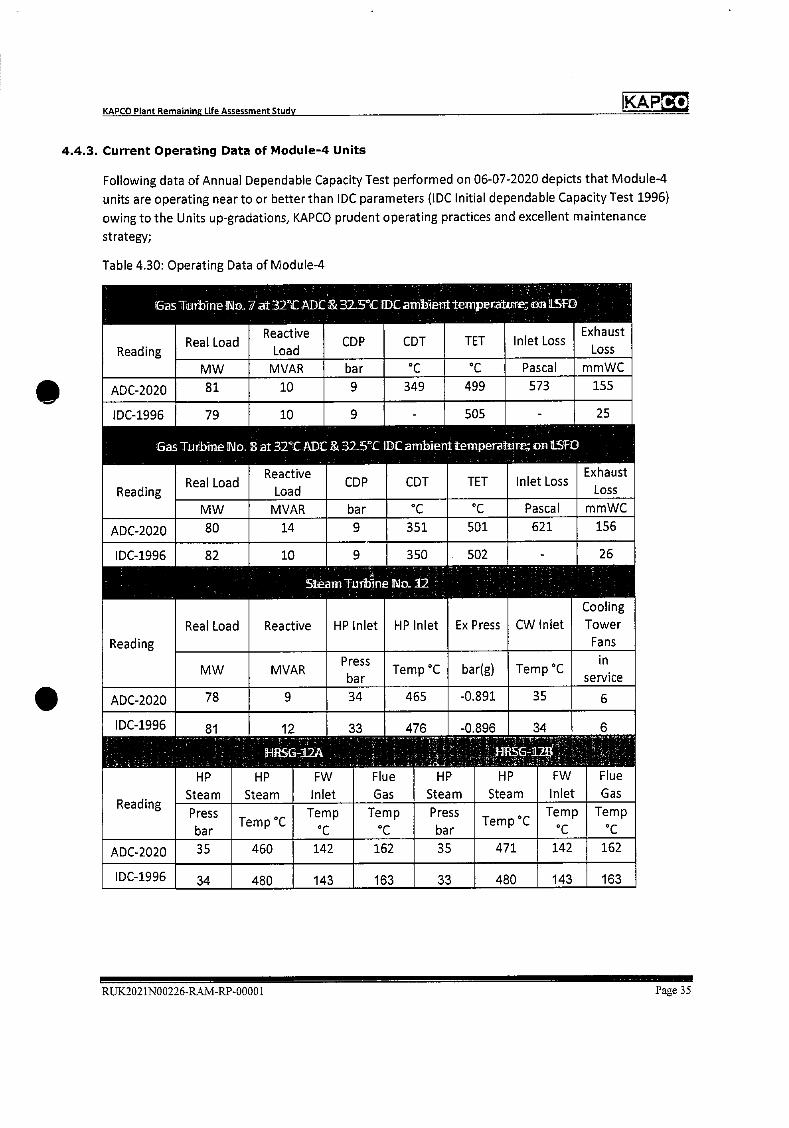
KAPCO Plant Remaining Life Assessment Study KAP
4.4.3. Current Operating Data of Module-4 Units
Following data of Annual Dependable Capacity Test performed on 06-07-2020 depicts that Module-4
units are operating near to or better than lDC parameters (lDC Initial dependable Capacity Test 1996)
owing to the Units up-gradations, KAPCO prudent operating practices and excellent maintenance
strategy;
Table 4.30: Operating Data of Module-4
Gas
Reading
Thrbine No
Real Load
7 at 32°C ADC & 32.5°C 1DCambtent
Reactive CDP
Load
temperatur;
CDT TET
nn LSFD
Exhaust Inlet Loss
Loss
MW MVAR bar °C °C Pascal mmWC
ADC-2020 81 10 9 349 499 573 155
lDC-1996
Gas
Reading
79
Tu rbme No
Real Load
10 9
B at 32°C ADC & 32.5°C IDC
Reactive CDP
Load
- 505
am1ien1 temperature
CDT TEl
- 25
on 1LSfD
Exhaust Inlet Loss
Loss
MW MVAR bar °C °C Pascal mmWC
ADC-2020 80 14 9 351 501 621 156
lDC-1996
Reading
82
Real Load
10
Reactive
SteamTuiineNo
9
HP Inlet
350 . 502
12
HP Inlet Ex Press
- 26
Cooling
CW Inlet Tower
Fans
MW MVAR Press
bar Temp °C bar(g) Temp °C
in
service
ADC-2020 78 9 34 465 -0.891 35 6
IDC-1996 81 12 33 476 -0.896 34 6
Reading
HP
Steam Steam
HP
HRSG-121\
FW
Inlet
Flue
Gas
HP
Steam Steam
HP FW
Inlet
Flue
Gas
Press
bar Temp C
Temp Temp
C
Press
bar Temp C
Temp
°C
Temp
ADC-2020 35 460 142 162 35 471 142 162
IDC-1996 34 480 143 163 33 480 143 163
RUK.2021N00226-RAM-RP-0000 I Page 35
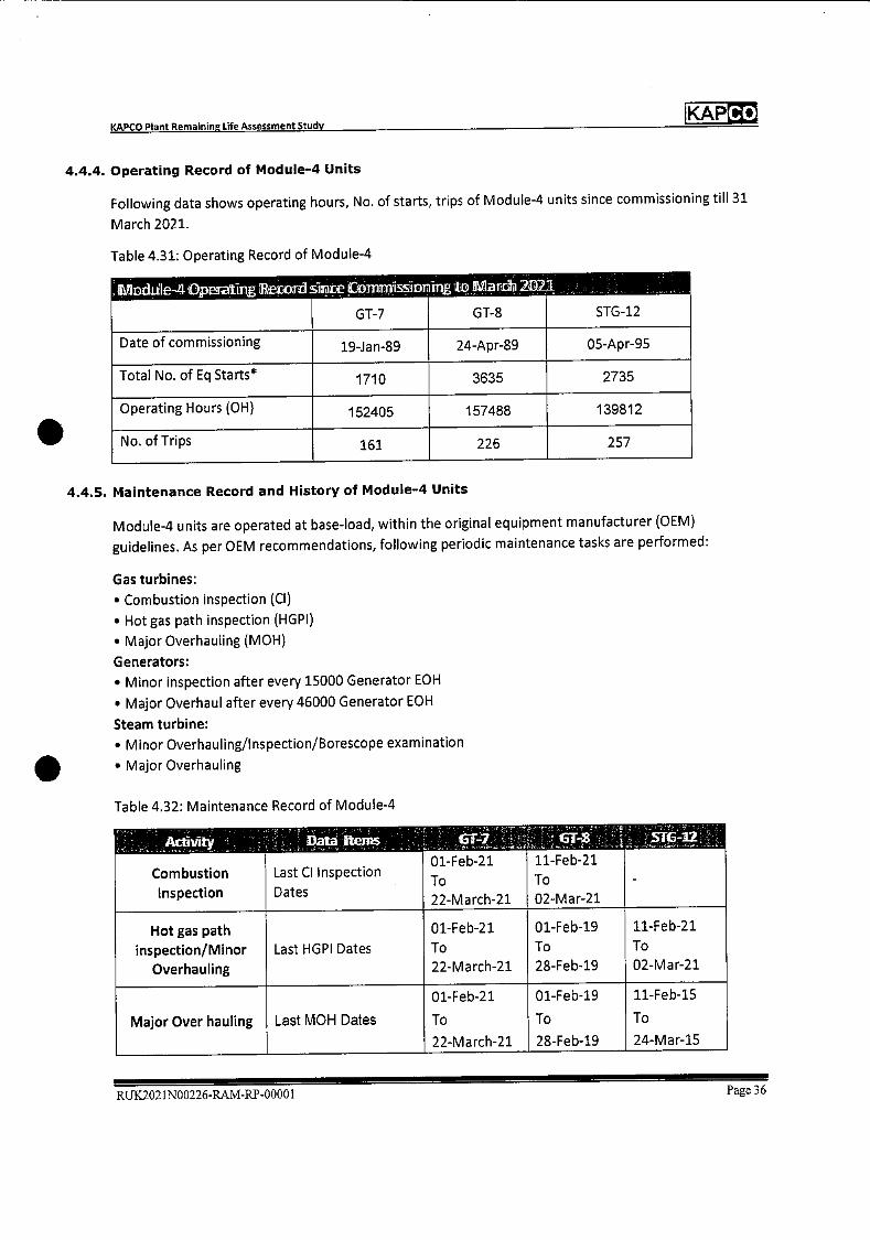
KAPCO KAPCO Plant Remaining Life Assessment Study
4.4.4. Operating Record of Module-4 Units
Following data shows operating hours, No. of starts, trips of Module-4 units since commissioning till 31
March 2021.
Table 4.31: Operating Record of Module-4
lMDdu le-4 O1peiIing wrd s1nte Cvmmission ing to 21arcfB 2D21
STG-12 GT-7 GT-8
Date of commissioning 19-Jan-89 24-Apr-89 05-Apr-95
Total No. of Eq Starts* 1710 3635 2735
Operating Hours (OH) 152405 157486 139812
No. of Trips 161 226 257
4.4.5. Maintenance Record and History of Module-4 Units
Module-4 units are operated at base-load, within the original equipment manufacturer (OEM)
guidelines. As per OEM recommendations, following periodic maintenance tasks are performed:
Gas turbines:
• Combustion inspection (Cl)
• Hot gas path inspection (HGPI)
• Major Overhauling (MOH)
Generators:
• Minor inspection after every 15000 Generator EOH
• Major Overhaul after every 46000 Generator EOH
Steam turbine:
• Minor Overhauling/Inspection/Borescope examination
• Major Overhauling
Table 4.32: Maintenance Record of Module-4
Activity
Combustion
Inspection
Data Items
Last CI Inspection
Dates
61-1 01-Feb-21
To
22-March-21
11-Feb-21
To
02-Mar-21
ST-2
-
Hot gas path
inspection/Minor
Overhauling
Last HGPl Dates
01-Feb-21
To
22-March-21
01-Feb-19
To
28-Feb-19
11-Feb-21
To
02-Mar-21
Major Over hauling Last MOH Dates
01-Feb-21
To
22-March-21
01-Feb-19
To
28-Feb-19
11-Feb-15
To
24-Mar-15
RUK2021N00226-RAM-RP-0000 I Page 36
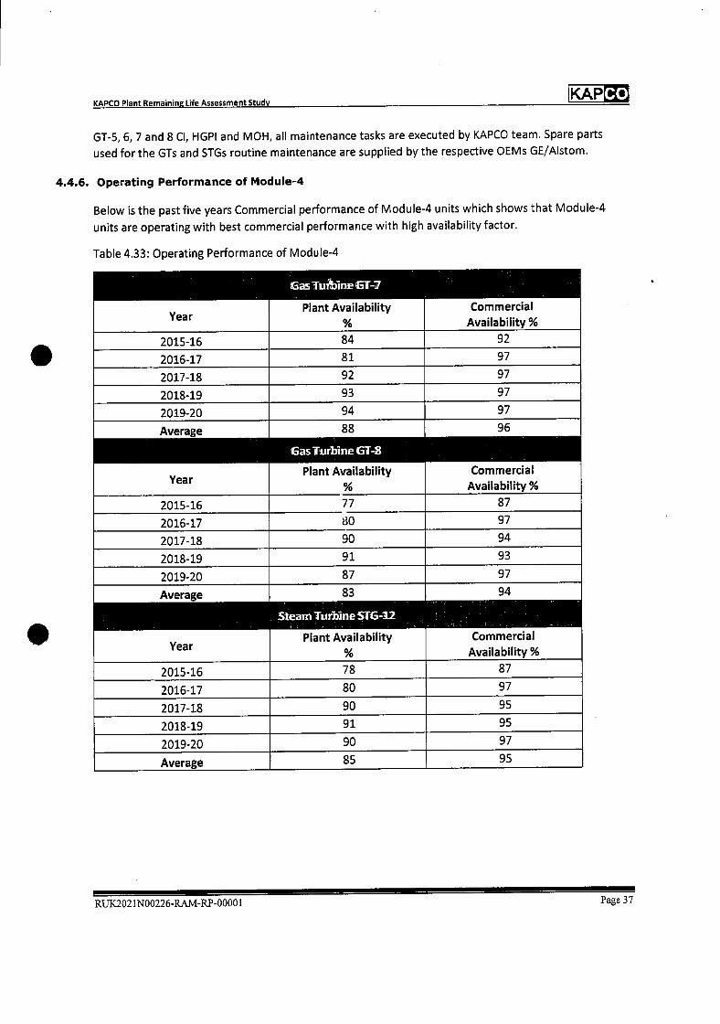
KAPCO Plant Remaining Life Assessment Study KAP Co
GT-5, 6, 7 and 8 Cl, HGPI and MOH, all maintenance tasks are executed by KAPCO team. Spare parts
used for the GTs and STGs routine maintenance are supplied by the respective OEMs GE/Alstom.
4.4.6. Operating Performance of Module-4
Below is the past five years Commercial performance of Module-4 units which shows that Module-4
units are operating with best commercial performance with high availability factor.
Table 4.33: Operating Performance of Module-4
Year
6asTiiine6T-7
Plant Availability
%
Commercial Availability%
2015-16 84 92
2016-17 81 97
2017-18 92 97
2018-19 93 97
2019-20 94 97
Average
Year
88
asTurbineGT-B
Plant Availability %
96
Commercial Availability %
2015-16 77 87
2016-17 80 97
2017-18 90 94
2018-19 91 93
2019-20 87 97
Average 83 94
Steam Turbine 516-12
Year Plant Availability
%
Commercial
Availability %
2015-16 78 87
2016-17 80 97
2017-18 90 95
2018-19 91 95
2019-20 90 97
Average 85 95
RUX2021N00226-RAM-RP-00001 Page 37
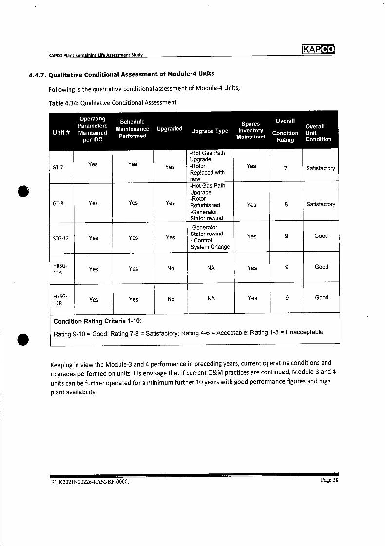
Co KAP KAPCO Plant Remaining Life Assessment Study
4.4.7. Qualitative Conditional Assessment of Module-4 Units
Following is the qualitative conditional assessment of Module-4 Units;
Table 4.34: Qualitative Conditional Assessment
Operating Parameters
Unit Maintained per IDC
Schedule Maintenance Upgraded Performed
Spares Upgrade Type Inventoly
Iglaintained
Overall Overall
Condition Unit Rating Condition
GT-7 Yes Yes Yes
-Hot Gas Path Upgrade -Rotor Replaced with new
Yes 7 Satisfactory
GT-8 Yes Yes Yes
-Hot Gas Path Upgrade -Rotor Refurbished -Generator Stator rewind
Yes 8 Satisfactory
STG-12 Yes Yes Yes
-Generator Stator rewind - Control System Change
Yes 9 Good
HRSG- 12A
Yes Yes No NA Yes 9 Good
HRSG- 128
Yes Yes No NA Yes 9 Good
Condition Rating Criteria 1-10:
Rating 9-10 = Good; Rating 7-8 = Satisfactory; Rating 4-6 = Acceptable; Rating 1-3 = Unacceptable
Keeping in view the Module-3 and 4 performance in preceding years, current operating conditions and
upgrades performed on units it is envisage that if current O&M practices are continued, Module-3 and 4
units can be further operated for a minimum further 10 years with good performance figures and high
plant availability.
RUK2021N00226-RAM-RP-0000 1 Page 38
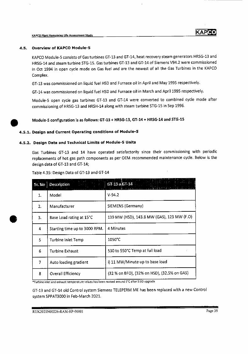
Co KAP KAPCO Plant Remainine Life Assessment Study
4.5. Overview of KAPCO Module-5
KAPCO Module-S consists of Gas turbines GT-13 and GT-14, heat recovery steam generators HRSG-13 and
HRSG-14 and steam turbine STG-15. Gas turbines GT-13 and GT-14 of Siemens V94.2 were commissioned
in Oct 1994 in open cycle mode on Gas fuel and are the newest of all the Gas Turbines in the KAPCO
Complex.
GT-13 was commissioned on liquid fuel HSD and Furnace oil in April and May 1995 respectively.
GT-14 was commissioned on liquid fuel HSD and Furnace oil in March and April 1995 respectively.
Module-5 open cycle gas turbines GT-13 and GT-14 were converted to combined cycle mode after
commissioning of HRSG-13 and HRSH-14 along with steam turbine STG-15 in Sep 1996.
Module-5 configuration is as follows: GT-13 + HRSG-13, GT-14 + HRSG-14 and STG-15
4.5.1. Design and Current Operating conditions of Module-5
4.5.2. Design Data and Technical Limits of Module-5 Units
Gas Turbines GT-13 and 14 have operated satisfactorily since their commissioning with periodic
replacements of hot gas path components as per OEM recommended maintenance cycle. Below is the
design data of GT-13 and GT-14;
Table 4.35: Design Data of GT-13 and GT-14
St No]
1.
Descnption
Model
T-13 T-14
V-94.2
2. Manufacturer SIEMENS (Germany)
3. Base Load rating at 15CC 139 MW (HSD), 143.8 MW (GAS), 123 MW (F.0)
4 Starting time up to 3000 RPM. 4 Minutes
5 Turbine Inlet Temp 1050CC
6 Turbine Exhaust 530 to 550CC Temp at full load
7 Auto loading gradient i) 11 MW/Minute up to base load
8 Overall Efficiency (32 % on BFO), (32% on HSD), (32.5% on GAS)
*Tu rbine inlet and exhaust temperature values has been revised around 5C after Si3D upgrade
GT-13 and GT-14 old Control system Siemens TELEPERM ME has been replaced with a new Control
system SPPAT3000 in Feb-March 2021.
RUX2021N00226-RAM-RP-00001 Page 39
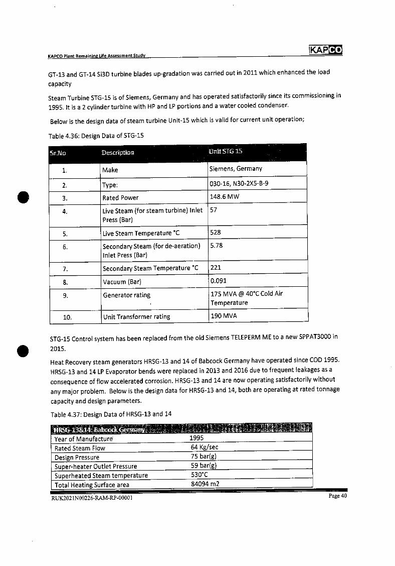
Co KAP
Year of Manufacture 1995
Rated Steam Flow 64 Kg/sec
Design Pressure
75 bar(g)
Super-heater Outlet Pressure 59 bar(g)
Superheated Steam temperature 530°C
Total Heating Surface area 84094 m2
KAPCO Plant Remaining Life Assessment Study
GT-13 and GT-14 Si3D turbine blades up-gradation was carried out in 2011 which enhanced the load
capacity
Steam Turbine STG-15 is of Siemens, Germany and has operated satisfactorily since its commissioning in
1995. It isa 2 cylinder turbine with HP and LP portions and a water cooled condenser.
Below is the design data of steam turbine Uriit-15 which is valid for current unit operation;
Table 4.36: Design Data of STG-15
rS.Io
1.
Desct1ptior
Make
thiitSTP35
Siemens, Germany
2. Type: 030-16, N30-2X5-B-9
3. Rated Power 148.6 MW
4. Live Steam (for steam turbine) Inlet
Press (Bar)
57
5. Live Steam Temperature C 528
6. Secondary Steam (for de-aeration)
Inlet Press (Bar)
5.78
7. Secondary Steam Temperature °C 221
8. Vacuum (Bar) 0.091
9. Generator rating 175 MVA @ 40CC Cold Air
Temperature
10. Unit Transformer rating 190 MVA
STG-15 Control system has been replaced from the old Siemens TELEPERM ME to a new SPPAT3000 in
2015.
Heat Recovery steam generators HRSG-13 and 14 of Babcock Germany have operated since COD 1995.
HRSG-13 and 14 LP Evaporator bends were replaced in 2013 and 2016 due to frequent leakages as a
consequence of flow accelerated corrosion. HRSG-13 and 14 are now operating satisfactorily without
any major problem. Below is the design data for HRSG-13 and 14, both are operating at rated tonnage
capacity and design parameters.
Table 4.37: Design Data of HRSG-13 and 14
RUK2O2 1N00226-RAM-RP-00001 Page 40

KAPCO Plant Remaining Life Assessment Study KAP
4.5.3. Current Operating Data of Module-5 Units
Following data of Annual Dependable Capacity Test performed on dated 03-07-2020 depicts that
Module-S units are operating near to or better than IDC parameters corrected to same ambient
conditions (IDC Initial dependable Capacity Test Aug 1997) owing to units up-gradations, KAPCO prudent
operating practices and excellent maintenance strategy;
Table 4.38: Operating Data of Module-5
Gas Turbine No.13 t 3rcADC & 37°C lDCmbieniternperatuTe; on .S()
Reading Real Load
Reactive CDP
Load CDT OTC
Exhaust Inlet Loss
Loss
MW MVAR bar °C °C mbar mbar
ADC-2020 115 25 9 347 506 0.96 23
IDC-1997
Gas
Reading
105
Turbine No.
Real Load
28 9
i4at 31°CADC & 37°C 1DC
Reactive CDP
Load
353
ambient
CDT
505
temperature;
OTC
5 21
on t.SFO
Exhaust Inlet Loss
Loss
MW MVAR bar C C mbar mmWC
ADC-2020 112 25 9 345 503 1.3 18
IDC-1997
Reading
106
Real Load
19
Steam
Reactive
9
Turbine
HP Inlet
352
To 15
HP Inlet
504
Ex Press
6 21
Cooling
CW Inlet Tower
Fans
MW MVAR Press
bar Temp °C bar(g) Temp C
service
ADC-2020 115 28 47 502 -0.88 34 6
lDC-1997 113
HP
Steam Steam
33
3-iRS&13
HP FW
Inlet
47
Flue
Gas
484
HP
Steam
-0.88
HP
Steam
HlSG-14
34
FW
Inlet
6
Flue
Gas Reading
Press
bar Temp C
Temp
°C
Temp Press
bar Temp C
Temp Temp
ADC-2020 47 509 128 165 47 509 128 166
IDC-1997 48 494 147 180 47 488 147 182
RUK2021N00226-RAM-RP-00001 Page 41
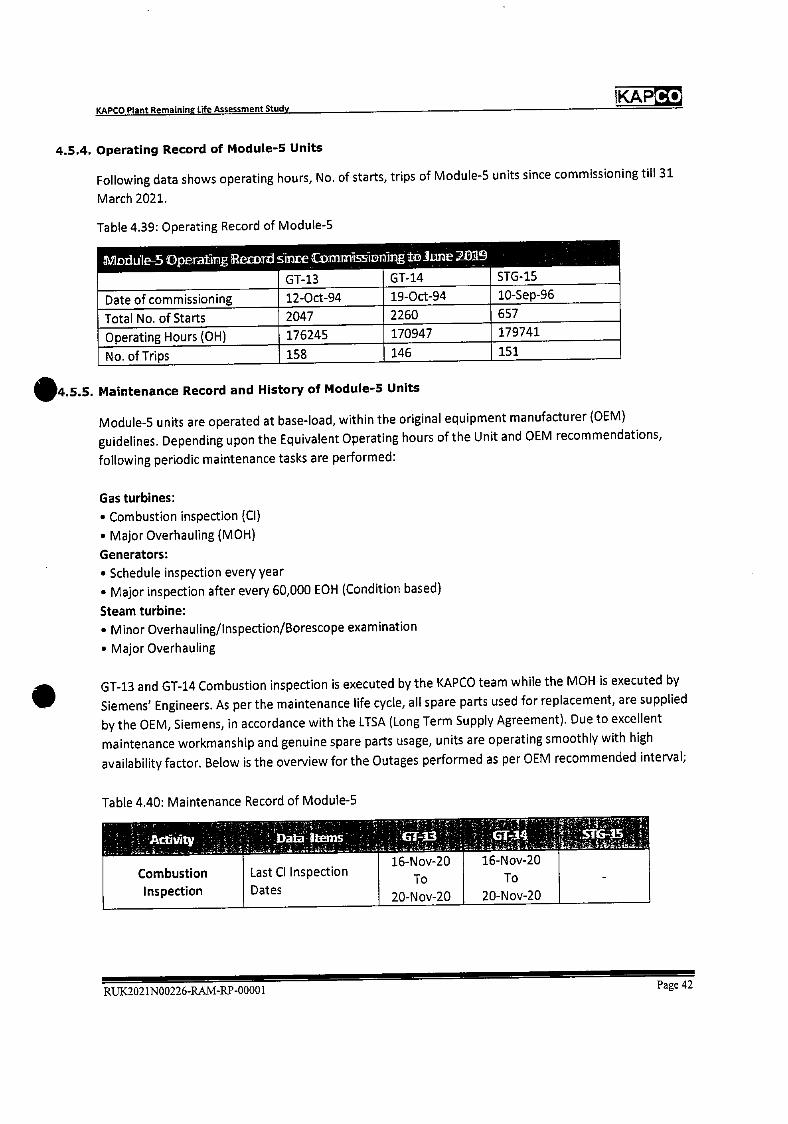
Combustion
Inspection
Last Cl Inspection
Dates
16-Nov-20
To
20-Nov-20
16-Nov-20
To
20-Nov-20
KAP Co KAPCO Plant Remaining Life Assessment Study
4.5.4. Operating Record of Module-5 Units
Following data shows operating hours, No. of starts, trips of Module-S units since commissioning till 31
March 2021.
Table 4.39: Operating Record of Module-S
fflo&ile-5 Ope.rB1in.g rnrd s9nie mssflfl i
STG-15 GT-13 GT-14
Date of commissioning 12-Oct-94 19-Oct-94 10-Sep-96
Total No. of Starts 2047 2260 657
Operating Hours (OH) 176245 170947 179741
No. of Trips 158 146 151
Maintenance Record and History of Module-5 Units
Module-S units are operated at base-load, within the original equipment manufacturer (OEM)
guidelines. Depending upon the Equivalent Operating hours of the Unit and OEM recommendations,
following periodic maintenance tasks are performed:
Gas turbines:
• Combustion inspection (Cl)
• Major Overhauling (MOH)
Generators:
• Schedule inspection every year
• Major inspection after every 60,000 EOH (Condition based)
Steam turbine:
• Minor Overhauling/lnspection/BOreScoPe examination
• Major Overhauling
GT-13 and GT-14 Combustion inspection is executed by the KAPCO team while the MOH is executed by
Siemens' Engineers. As per the maintenance life cycle, all spare parts used for replacement, are supplied
by the OEM, Siemens, in accordance with the LTSA (Long Term Supply Agreement). Due to excellent
maintenance workmanship and genuine spare parts usage, units are operating smoothly with high
availability factor. Below is the overview for the Outages performed as per OEM recommended interval;
Table 4.40: Maintenance Record of Module-S
RUK2021N00226-RAM-RP-00001 Page 42
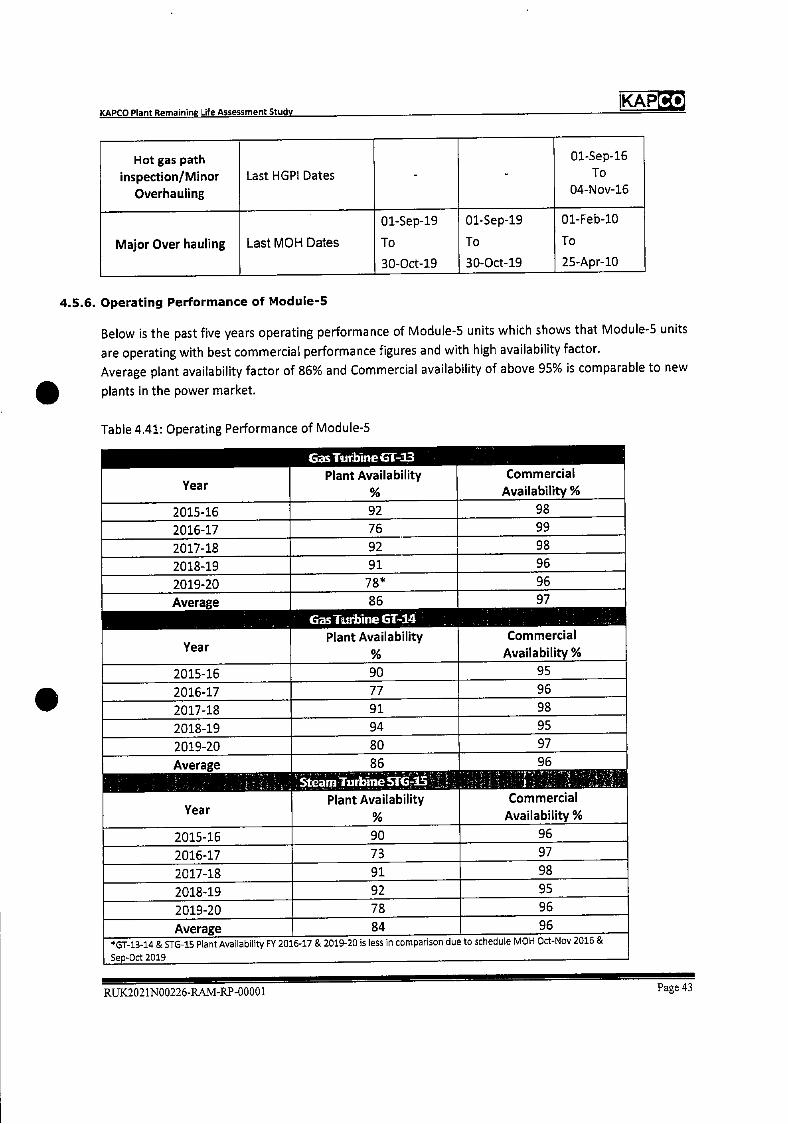
Co KAP KAPCO Plant Remaining Life Assessment Study
Hot gas path inspection/Minor
Overhauling
Last HGPI Dates - - 01-Sep-16
To 04-Nov-16
Major Over hauling Last MON Dates
01-Sep-19
To
30-Oct-19
01-Sep-19
To
30-Oct-19
01-Feb-10
To
25-Apr-10
4.5.6. Operating Performance of Module-5
Below is the past five years operating performance of Module-5 units which shows that Module-S units
are operating with best commercial performance figures and with high availability factor.
Average plant availability factor of 86% and Commercial availability of above 95% is comparable to new
plants in the power market.
Table 4.41: Operating Performance of Module-S
Year
Gas Turbine ET-13 Plant Availability
%
Commercial Availability %
2015-16 92 98
2016-17 76 99
2017-18 92 98
2018-19 91 96
2019-20 78* 96
Average 86 97
EasTuthineGl-14
Year Plant Availability
%
Commercial Availability %
2015-16 90 95
2016-17 77 96
2017-18 91 98
2018-19 94 95
2019-20 80 97
Average 86 96
SteamluthineSTG-15 -
Year Plant Availability
%
Commercial Availability %
2015-16 90 96
2016-17 73 97
2017-18 91 98
2018-19 92 95
2019-20 78 96
Average 84 96 *GT4344 & STG-15 Plant Availability FY 2016-17 & 2019-20 is less in comparison due to schedule MOH Oct-Nov 2016 &
Sep-Oct 2019
RUK2021N00226-RAM-RP-00001 Page 43
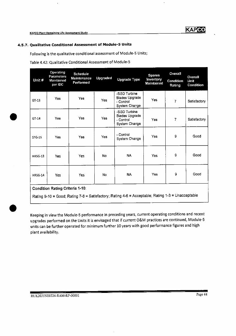
Co KAP KAPCO Plant Remaining Life Assessment Study
4.5.7. Qualitative Conditional Assessment of Module-5 Units
Following is the qualitative conditional assessment of Module-5 Units;
Table 4.42: Qualitative Conditional Assessment of Module-5
Unit#
GT-13
Operating Parameters Maintained
per IDC
Yes
Schedule Maintenance Performed
Yes
Upgraded
Yes
Upgrade Type
-Si3D Turbine Blades Upgrade - Control System Change
Spares inventory
Maintained
Yes
Overall
Condition iting
7
Overall Unit Condition
Satisfactory
GT-14 Yes Yes Yes
-Si3D Turbine Blades Upgrade - Control System Change
Yes 7 Satisfactory
STG-15 Yes Yes Yes - Control System Change
Yes 9 Good
HRSG-13 Yes Yes No NA Yes 9 Good
HRSG-14 Yes Yes No NA Yes 9 Good
Condition Rating Criteria 1-10:
Rating 9-10 = Good; Rating 7-8 = Satisfactory; Rating 4-6 = Acceptable; Rating 1-3 = Unacceptable
Keeping in view the Module-5 performance in preceding years, current operating conditions and recent
upgrades performed on the Units it is envisaged that if current O&M practices are continued, Module-S
units can be further operated for minimum further 10 years with good performance figures and high
plant availability.
RUK.2021N00226-RAM-RP-00001 Page 44

Co KAP KAPCO Plant Remainine Life Assessment Study
5. WORLD TRENDS IN OPERATING LIFE OF ThERMAL POWER PLANTS
5.1. Definitions
In order to discuss how long a plant will operate for it is important to discuss the following widely used
phrases.
5.1.1. Operating life
The operating life of a power station can be defined as the length of time in years after commissioning
that a plant will generate, or has been generating electricity before being decommissioned.
5.1.2. Economic life
The economic life of a plant refers to a prediction of how long it will be generating based on specific
economic criteria such as remaining profitable. The economic life is usually discussed within the context
of a forecast of certain financial factors such as future electricity prices, fuel costs and investment
required to extend the life of the plant. A plant reaching the end of its economic life suggests it would
then be decommissioned, however there are situations where the plant may be retained in an
operational state, a state of readiness to return to service, or mothballed.
5.1.3. Design life
The design life refers to the length of time used in engineering design and manufacture specifications for
the plant. Design life is typically defined in terms of operating hours which are then translated into an
expected calendar lifetime depending on the operating regime — base load, peaking etc. A plant could
be designed to operate for 25-30 years in a specific operating regime which, for example, dictates the
use of specific alloys or thickness of heat shielding equipment. A change in operating regime can affect
the assets calendar lifetime.
5.1.4. Heat rate
When forecasting plant life, it is useful to consider impacts of time and operating regime on the heat
rate or efficiency of the power station. Heat rate is usually measured as Id/Kwh, and indicates the
amount of fuel energy (ki) required to generate a unit of electricity (kwh). Therefore, the lower the
heat rate the higher the efficiency of the plant.
Plant heat rate or efficiency will degrade over time with use due to the wearing of components. Routine
maintenance and overhauls are designed to minimize the effects of degradation and maintain the heat
rate as close to the original design criteria as possible over the life of the plant. Restoring the heat rate
back to the original design or better, requires significant investment and often involves replacement of
the majority of components with technically superior equivalents.
Plant heat rate can be one of the major factors influencing plant life, as efficiency ultimately impacts
economic viability. If the heat rate has degraded to the extent that significant capital investment is
required to restore the heat rate and the benefits of such investment do not provide a positive
economic return, a decision can be made to decommission the plant.
RUK2021N00226.RAM-RP.00001 Page 45
Co KAP KAPCO Plant Remaining Life Aasessment Study
5.2. Factors influencing the plant life
5.2.1. General
In most cases power plant can have its life extended by a factor of 50-100% over the original design life.
This arises in part from the conservative assumptions made in the original design process and in part is a
consequence of well-managed repair and maintenance in these plants. In addition, the civil works of a
plant are generally designed with a longer design life than the equipment, which means it is possible to
replace equipment without having to build new civil works.
These factors have resulted in many power plants the world over operating well beyond their nominal
25-30 year design life.
5.2.2. Life limiting factors
For an operating power plant, the main technological life limiting issues are:
• The creep life of high temperature components. This is typically limited to boiler pressure parts,
high temperature pipework and the heavy wall thickness and/or non-symmetrical high pressure
(HP) steam turbine components (e.g. emergency stop valves, bypass valves, governor valves,
steam chests, HP cylinder casings, HP nozzle rings). It may include the HP turbine rotor, both
shaft and disks. Fatigue life of rotating components, components subject to repeated
temperature change, and components subject fluctuating loads and vibration.
• Erosion — primarily related to gas side solid particle erosion of the boiler pressure parts.
However, water and steam side erosion can also be an issue, particularly in low pressure steam
turbines.
• Corrosion
• Technological obsolescence — primarily an issue with controls and instrumentation and electrical
systems.
• Environmental compliance — environmental consents are only granted for limited periods and
emission compliance, particularly if the environment is subsequently degraded or regulations
become more stringent, may require major emissions control equipment (e.g. Low NOx Burners,
flue gas desulfurization (FGD), carbon capture etc).
5.3. World trends of life of coal and gas power stations
5.3.1. USA
Coal-fired electricity generators accounted for 25% of operating electricity generating capacity in the
United States and generated about 30% of U.S. electricity in 2016. Most coal-fired capacity (88%) was
built between 1950 and 1990,
Approximately 70% of the existing USA coal fueled power plant fleet is greater than 30 years old, as
shown in the below Figure 5.1. The capacity-weighted average age of operating coal facilities is 39 years.
RUX2021N00226-RAM-RP-00001 Page 46

Co KAP KAPCO Plant Remaining Life Assessment Study
US. utility-scale electric generating capacity by initial operating year (as of Dec 2016) gigawaffs
60 petroleum
50 hydro
40 nuclear n:ura s
30
20
10
1coa1 25% otol capac average age: 39 years
I1•
0 1930 and 1940 1950 1960 1970 1980 1990 2000 2010
before ef
Figure: 5. 1: US Power Generating Capacity
hfls://www.eia .gov/todavi nenery/detaiI .h ?id=308 12
5.3.2. Europe
European power plants are also maintained well beyond the original design life as shown in the below
Figure 5.2;
RUK2021N00226-RAM-RP-00001 Page 47

Co KAP
40 20
AGEyears ID
10.0 -
60 U
a
40-50
30-40 -
20-30
10-20
• <10 2.5- 10-
0-
0
U
&
U
30-
20-
.
KAPCO Plant Remaining Life Assessment Study
EUROPEAN UNION Coal Power Plant Unit Ae
Age years
z 'V U
Figure: 5. 2: European Union Coal Power Plant Unit age
Ref: A Stress Test for Coal in Europe Feb 2017
About capacity 25000 MW of thermal power plants are in age range 30 to 60 years that is exceeding
their design life of 30 years.
15705
OS 35
19935
23335
30 20 10 0 10 20 30 0 50
Instefled capecity 1GW)
Source: E25e3 :r °;t1s 2Ci132
Figure: 5. 3: European Power PIants age by fuel
RUK2021N00226-RAM-RP-00001 Page 48
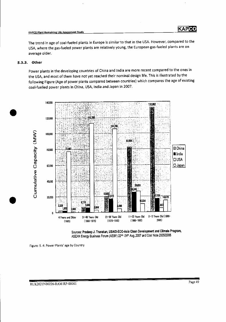
Co KAP
D China
lindia
USA
0 Japan
-
4lYears nd Older (1965)
3fr40 Years Old 21-30 Yeirs Old 11-20 Years Old 0- 0 Years Old (19 6-
(1966-1915) (1976-1985) (1986-1995) 2005)
KAPCO Plant Remaining Life Assessment Study
The trend in age of coal-fueled plants in Europe is similar to that in the USA. However, compared to the USA, where the gas-fueled power plants are relatively young, the European gas-fueled plants are on
average older.
5.3.3. Other
Power plants in the developing countries of China and India are more recent compared to the ones in the USA, and most of them have not yet reached their nominal design life. This is illustrated by the following Figure (Age of power plants compared between countries) which compares the age of existing
coal-fuelled power plants in China, USA, India and Japan in 2007.
140.000
120,000
100,000
>. 80,000 C)
a ( o
U) >
40.000
E
(.) 20,000
Sources: Pradeep J. Tharakan, USAlD-ECOAsia Clean Development and Climate Program, ASEAN Energy Business Forum (AEBF) 22nd 24th Aug.,2007 and Coal Note 2005/2006
Figure: 5.4: Power Plants' age by Country
RUK2021N00226-RAM-RP-0000lPage 49
KAPCO KAPCO Plant Remaining Life Assessment Study
5.3.4. Power Project Age of Recent and Planned Retirements in US
The below charts present histograms of project age of recent and planned retirements for US coal
plants, natural-gas steam (NGST) plants, combustion turbine (CT) plants, and combined-cycle gas turbine
(CCGT) plants.
Several observations are apparent from these charts:
Recently retired plants have been relatively old, across all generation types
• The most common age of recently retired coal units is 50-60 years
• The most common age of recently retired NGST units is 40-50 years
• The most common age of recently retired CI units is 40-50 years
• The most common age of recently retired nuclear units is 30-40 years
Plants with announced retirement dates are also relatively old, based on expected age at retirement
• Nuclear and NGST plants planned for retirement will be older than recently retired plants
• Coal, CT and CCGT plants planned for retirement will be slightly younger than recently retired
plants
RUK2021N00226-RAM-RP-00001 Page 50
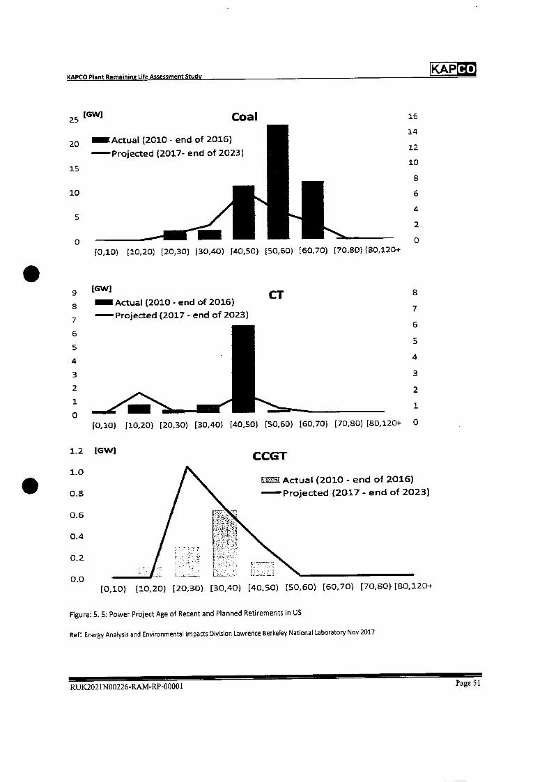
KAPCO Plant Remainina Life Assessment Study KAPCO
16
14
12
10
8
6
4
2
0
25 (GWJ Coal
20 Actual (2010 - end of 2016)
—Projected (2017- end of 2023)
15
10
S
0 1Q10) [10,20) [20,30) (30,40) [40,50) [50,60) (60,70) [70,80) [80,120+
a 7
6
5
4
3
2
1
[0,10) (10,20) [20,30) f 30,40) (40,50) [50,60) [60,70) [70,80) [80,120+ 0
1.2 LGWI CCGT 1.0
LL Actual (2010 - end of 2016)
0.8 — Projected (2017 - end of 2023)
0.6
0.4
0.2
0.0
[0,10) [10,20) [20,30) [30,40) [40,50) [50,60) [60,70) [70,80) [80,120+
Figure: 5.5: Power Project Age of Recent and Planned Retirements in US
Ref Energy Analysis and Environmental Impacts Division Lawrence Berkeley National Laboratory Nov 2017
RUX2021N00226-RA1t4-RP-00001 Page 51
9
8
7
6
5
4
3
2
1
0
1GW]
Actual (2010 - end of 2016)CT
—Projected (2017- end of 2023)
Co KAP KAPCO Plant Remaining Life Assessment Study
5.4. Recap
As observed some coal fueled steam and natural gas turbines are 40-50 years old and still in operation
20 years beyond the original nominal calendar design life.
Traditionally, a calendar design life is equated to operating hours based on a nominal 8,000 per year to
take account of scheduled and unscheduled outages and the fact that the plant will not usually operate
8,760 hours per year. Therefore a 30-year plant life equates to 240,000 operating hours.
Whilst the original design life of a CCGT plant is typically 25-30 years, the average life ofretirementfor
CCGT plant is 40-50 years, or 320,000 hours based on 40 years and 8,000 operating hours per year.
Notwithstanding that plants can operate for an age of 40-50 years, the equipment operating design life
usually means replacements and upgrades are required throughout that period and the frequency of
maintenance generally increases as the plants ages.
Whether thermal power plants are kept in operation, refurbished, placed on standby or
decommissioned at their design life remains primarily an economic decision for the owner depending
upon the unit condition and maintenance cost. The introduction of more stringent Environmental
regulations may also be a factor in whether it is cost effective to upgrade a plant to meet latest
emissions criteria.
RUK2021N00226-RAM-R.P-00001 Page 52
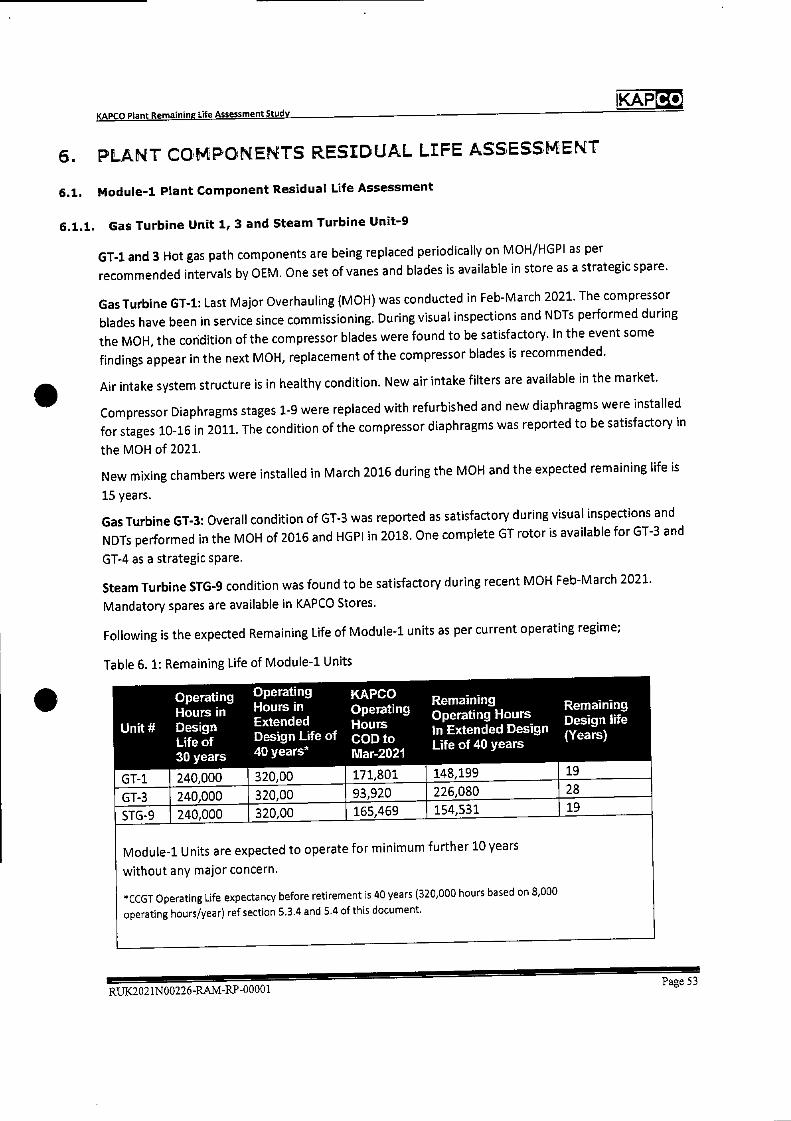
Unit #
Operating Hours in Design Life of 30 years
240,000
Operating Hours in Extended Design Life 40 years*
320,00
'
KAPCO Operating Hours COD to Mar-2021
171,801
Remaining Operating Hours In Extended Design Life of 40 years
148,199
Remaining Design life (Years)
19 GT-i
GT-3 240,000 320,00 93,920 226,080 28
STG-9 240,000 320,00 165,469 154,531 19
Module-i Units are expected to operate for minimum further 10 years
without any major concern.
*CCGT Operating Life expectancy before retirement is 40 years (320,000 hours based on 8,000
operating hours/year) ref section 5.3.4 and 5.4 of this document.
.
IKAPCO KAPCO Plant Remaining Life Assessment Study
6. PLANT COtPONENTS RESIDUAL LIFE ASSESSPENT
6.1. Module-i Plant Component Residual Life Assessment
6.1.1. Gas Turbine Unit 1, 3 and Steam Turbine Unit-9
GT-i and 3 Hot gas path components are being replaced periodically on MOH/HGPI as per
recommended intervals by OEM. One set of vanes and blades is available in store as a strategic spare.
Gas Turbine GT-1: Last Major Overhauling (MOH) was conducted in Feb-March 2021. The compressor
blades have been in service since commissioning. During visual inspections and NDTs performed during
the MOH, the condition of the compressor blades were found to be satisfactory. In the event some
findings appear in the next MOH, replacement of the compressor blades is recommended.
Air intake system structure is in healthy condition. New air intake filters are available in the market.
Compressor Diaphragms stages 1-9 were replaced with refurbished and new diaphragms were installed
for stages 10-16 in 2011. The condition of the compressor diaphragms was reported to be satisfactory in
the MOH of 2021.
New mixing chambers were installed in March 2016 during the MOH and the expected remaining life is
15 years.
Gas Turbine GT-3: Overall condition of GT-3 was reported as satisfactory during visual inspections and
NDTs performed in the MOH of 2016 and HGPI in 2018. One complete GT rotor is available for GT-3 and
GT-4 as a strategic spare.
Steam Turbine STG-9 condition was found to be satisfactory during recent MON Feb-March 2021.
Mandatory spares are available in KAPCO Stores.
Following is the expected Remaining Life of Module-i units as per current operating regime;
Table 6. 1: Remaining Life of Module-i Units
RUK2021N00226.RAM-RP-00001 Page 53
KAPCO KAPCO Plant Remaining Life Assessment Study
6.1.2. Module-i HRSG 1 and 3
HRSG-1 to 4 are of same model and make of Balke Durr, Germany. All four heat recovery steam
generators have operated satisfactorily since their commissioning.
Life assessment of HRSG-1 was conducted by SGS Pakistan on sample basis among all four HRSGs of
Block-i (Module-i and 2). The same condition about life assessment is predicted for the other three
HRSGs i.e. HRSG-2, 3 and 4 as these HRSG5 have fewer operating hours and have generally been
operated and maintained the same.
HRSG-1 inspections relating to life assessment have been conducted during the recent major
overhauling of STG-9 Feb- March 2021 and no significant deterioration observed.
(see Appendix-i: Remnant Life assessment of HRSG-1).
High pressure parts of HRSG 1, were inspected by SGS. The purpose of inspection was to evaluate the
present conditions of high-pressure parts and assess their reliability for further use on the basis of their
microstructure and wall-thickness.
Following inspection techniques were used for life assessment study of HRSG-1.
• Visual Inspections
• Ultrasonic Thickness Measurement
• Ultrasonic Flaw Detection
• Dye Penetrant Testing
• Magnetic Particle Inspection
• Hardness Testing
• MetaUographic examination
Scope of work for complete inspection and remaining life assessment of HRSG 1 included following
inspections and NDTs;
• Visual inspection of HP and LP drums, tubes, headers, for localized and uniform corrosion,
deposits, erosion, pitting etc.
• Visual inspection of protective coating/insulation for damages
• Visual inspection for corrosion under insulation (CUI)
• Visual inspection of all structural steel parts including ducts, platforms, handrails and structural
steel supports for ducts/piping for any visual defects.
• Visual inspection of tube bends and headers
• Visual inspection and DPT of steam header pipe welds for cracks
• Visual inspection of all accessible weld joints of HP Drum/LP separator, like shell, heads and
nozzles.
RUK2O2 1N00226-RAM-RP-0000 1 Page 54

Co KAP KAPCO Plant Remaining Life Assessment Study
• Hardness testing of HP drum, LP drum and headers.
• Ultrasonicflaw detection of suspected weld joints of HP drum, LP drum.
• MPI/DPT of selected weld joints
• Metallographic testing of boiler pressure parts.
• Ultrasonic thickness gauging of HP drum, headers, tubes, soot blowers, as per ASME codes to
find out overall view of current metal condition for fitness.
Remaining Life of HRSG-1 was calculated, comparing component's thickness at installation and current
thickness gauging 2021 using remaining corrosion allowance. All major components' life is calculated
greater than 20 years.
Also, HRSG-1 and 3 mandatory inspections are carried out in every schedule outage of GT-1 and GT-3 by
the Boiler Engineer, Mechanical Engineer and Plant Chemist.
Inspections were also performed in Feb 2021 and both HRSGs condition found satisfactory.
Based on life assessment reports, and routine maintenance inspections, it is expected that with the
current operating regime, HRSG-1 and 3 may be operated reliably for next 10-15 years.
6.1.3. Module-i Unit's Generator 1, 3 and 9
Following are the technical specifications for Module-]. and 2 Units' Generators
Table 6.2: technical specifications of Module-i and 2 Generators
Technical Specifications GT-1-2
TLRI 108/41
GT-3-4
SGTIC 243704
S1G-9-1O
WX 21L-064LL Type:
Make: KWU ERCOLEMARELLI ABB
Rated Out Put (MVA): 135 87 132
Power Factor: 0.85 0.85 0.85
Rated Voltage (Ky): 10.5 11.0 11.0
Rated Current (A): 7423 4567 6928
Frequency (HZ): 50 50 50
Gen Cooling System Air Cooled Air Cooled Air Cooled
Cold air temp 55°C 55°C 33.3°C
6.1.3.1. GT-1 Unit Generator
GT-1 Unit Generator of Siemens make has operated satisfactorily since its commissioning. Routine
offload, on load, test results showed its healthy condition.
Unit-i Generator major overhauling has been conducted in Feb-March 2021. During inspection, findings
were observed on the Generator rotor J Straps which were then replaced with new. Generator
inspections during the outage showed overall Generator condition as Good.
All operating parameters e.g. winding temperature, cold air temperature are in normal range.
RUK2021N00226-RA.M-RP-00001 Page 55
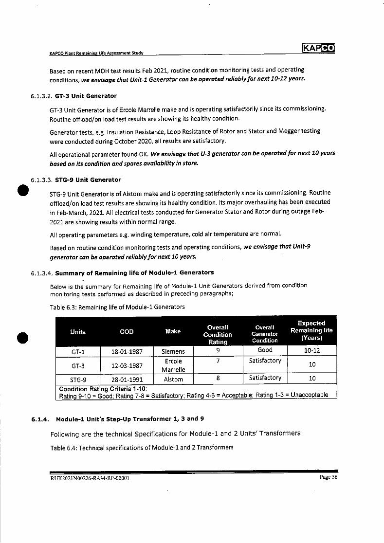
Co KAP
Expected Overall Overall
Units COD Make Remaining life Condition Generator
Rating Condition (Years)
GT-1 18-01-1987 Siemens 9 Good 10-12
GT-3 12-03-1987 Ercole
Marrelle
7 Satisfactory 10
STG-9 28-01-1991 Alstom 8 Satisfactory 10
Condition Rating Criteria 1-10: Ratin. 9-10 = Good; Ratin. 7-8 = Satisfacto ; Ratin. 4-6 = Acce.table; Ratin. 1-3 = Unacce.table
KAPCO Plant Remaining Life Assessment Study
Based on recent MOH test results Feb 2021, routine condition monitoring tests and operating
conditions, we envisage that Unit-i Generator can be operated reliably for next 10-12 years.
6.1.3.2. GT-3 Unit Generator
GT-3 Unit Generator is of Ercole Marrelle make and is operating satisfactorily since its commissioning.
Routine offload/on load test results are showing its healthy condition.
Generator tests, e.g. Insulation Resistance, Loop Resistance of Rotor and Stator and Megger testing
were conducted during October 2020, all results are satisfactory.
All operational parameter found OK. We envisage that U-3 generator can be operated for next 10 years
based on its condition and spares availability in store.
6.1.3.3. STG-9 Unit Generator
STG-9 Unit Generator is of Aistom make and is operating satisfactorily since its commissioning. Routine
offload/on load test results are showing its healthy condition. Its major overhauling has been executed
in Feb-March, 2021. All electrical tests conducted for Generator Stator and Rotor during outage Feb-
2021 are showing results within normal range.
All operating parameters e.g. winding temperature, cold air temperature are normal.
Based on routine condition monitoring tests and operating conditions, we envisage that Unit-9
generator can be operated reliably for next 10 years.
6.1.3.4. Summary of Remaining life of Module-i Generators
Below is the summary for Remaining life of Module-i Unit Generators derived from condition monitoring tests performed as described in preceding paragraphs;
Table 6.3: Remaining life of Module-i Generators
6.1.4. Module-i Unit's Step-Up Transformer i, 3 and 9
Following are the technical Specifications for Module-i and 2 Units' Transformers
Table 6.4: Technical specifications of Module-i and 2 Transformers
RUK2021N00226-RAM-RP-00001 Page 56
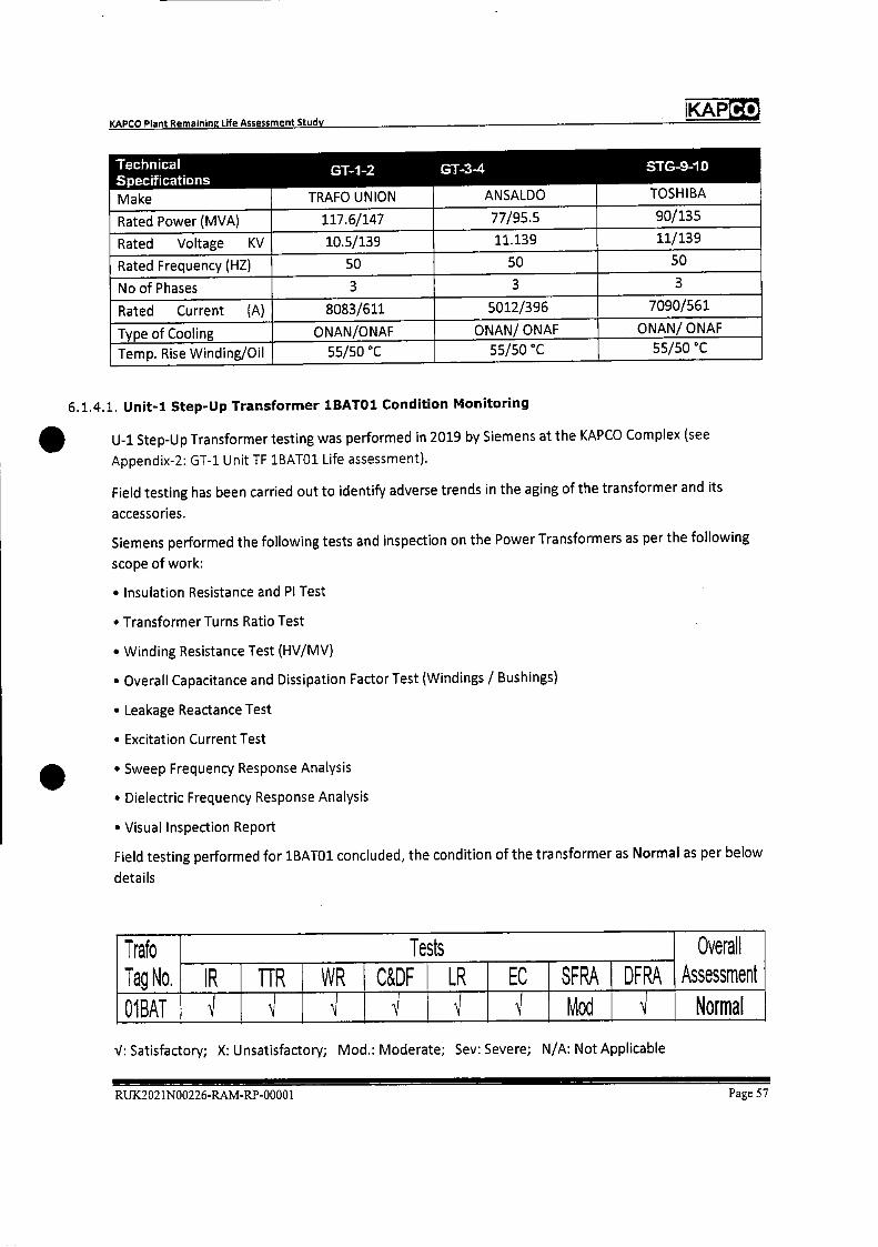
Co KAP KAPCO Plant Remaining Life Assessment Study
Technical GT-i-2 GT-3-4 STG-9-1D S
Make TRAFO UNION ANSALDO TOSHIBA
Rated Power (MVA) 117.6/147 77/95.5 90/135
Rated Voltage KV 10.5/139 11.139 11/139
Rated Frequency (HZ) 50 50 50
NoofPhases 3 3
Rated Current (A) 8083/611 5012/396 7090/561
Type of Cooling ONAN/ONAF ONAN/ ONAF ONAN/ ONAF
Temp. Rise Winding/Oil 55/50 C 55/50 C 55/50 C
6.1.4.1. Unit-i Step-Up Transformer 1BATO1 Condition Monitoring
U-i Step-Up Transformer testing was performed in 2019 by Siemens at the KAPCO Complex (see
Appendix-2: GT-1 Unit TF 1BATO1 Life assessment).
Field testing has been carried out to identify adverse trends in the aging of the transformer and its
accessories.
Siemens performed the following tests and inspection on the Power Transformers as per the following
scope of work:
• Insulation Resistance and P1 Test
* Transformer Turns Ratio Test
• Winding Resistance Test (HV/MV)
• Overall Capacitance and Dissipation Factor Test (Windings / Bushings)
• Leakage Reactance Test
• Excitation Current Test
• Sweep Frequency Response Analysis
• Dielectric Frequency Response Analysis
• Visual Inspection Report
Field testing performed for 1BAT01 concluded, the condition of the transformer as Normal as per below
detai Is
Trafo Tag No.
Tests Overall Assessment IR fIR WR C&DF LR EC SFRA DFRA
U1BAT Mod Normal
': Satisfactory; X: Unsatisfactory; Mod.: Moderate; Sev: Severe; N/A: Not Applicable
RUX2021N00226-RAM-RP-0000 1 Page 57
KAP Co
KAPCO Plant Remaining Life Assessment Study
Oil Analysis report for the test conducted in May 2020 has also verified the satisfactory condition of TF.
Following is the conclusion from oil analysis report (Appendix-2: Unit-i TF 1BATO1 Oil Analysis Report);
• "The evolution of the dissolved gases can be considered as normal. There is no indication of
thermal or electrical faults in the transformer.
• The water content and relative saturation of the oil can be considered as normal.
• The analysis of paper ageing markers does indicate significant winding paper ageing. Based on
the furans concentration the DP can be estimated between 350 and 550. When a DP-value lower than 200 is reached, the winding paper is considered as end-of-life.
• The next sample according to normal frequency. No other action needed"
Operating parameters of transformer e.g. Oil temperature, winding temperature etc. all are in normal
range.
Thus, the overall condition of Unit-i Step Up transformer is Satisfactory; that is code-i for healthy
equipment operating normally.
6.1.4.2. Unit-3 Step-Up Transformer 3BATO1 Condition Monitoring
Transformer Oil analysis tests were performed in May 2020 by LABORELEC Belgium (Appendix-2 Unit-3
TF 3BATO1 Oil Analysis Report).
Following is the conclusion from the oil analysis;
"The evolution of the dissolved gases can be considered as normAl. There is no indication of thermal or
electrical faults in the transformer. The oil properties that were investigated indicate severe oil
degradation (high tan delta, high color, acidity). The analysis of paper ageing markers does also indicate
significant winding paper ageing. The oil tests potentially corrosive."
Al! electrical tests conducted for Transformers are showing satisfactory results.
Operating parameters of transformer e.g. Oil temperature, winding temperature etc all are in normal
range.
Thus, the overall condition of Unit-3 Step Up transformer is Acceptable; that is code-2 i.e. equipment
can keep operating normally with increased frequency of condition monitoring test.
6.1.4.3. Unit-9 Step-Up Transformer D1BATO1 Condition Monitoring
Transformer Oil analysis tests were performed in May 2020 by M/S LABORELEC Belgium (Appendix-2
Unit-9 TF D1BATO1 Oil Analysis Report). Following is the conclusion from oil analysis;
"The evolution of the dissolved gases can be considered as relatively stable. The water content and
relative saturation of the oil can be considered as normal. The analysed winding paper ageing markers
(alcohols) indicate beginning of paper ageing and quality of winding paper can be assessed as still good
(DP-value >600). The next sample according to normal frequency. No other action needed."
Operating parameters of transformer e.g. Oil temperature, winding temperature etc all are in normal
range. Thus, the overall condition of Unit-9 Step Up transformer is Satisfactory; that is code-i i.e. that is
code-i for healthy equipment operating normally.
RUK.2021N00226-RAJvI-RP-0000 1 Page 58
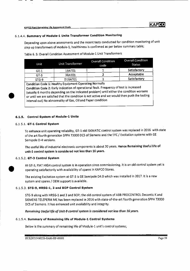
Unit Unit Transformer Overall Condition
code
Overall Condition
Status
GT-i
GT-3
1BATO1
3BATO1
1
2
Satisfactory
Acceptable
STG-9 D1BATO1 1 Satisfactory
Condition Code 1: Healthy Equipment Operating Normally
Condition Code 2: Early indication of operational fault. Frequency of test is increased
(usually 6 months depending on the indicated problem) until either the condition worsens
or until we are satisfied that the condition is not active and we would then push the testing
interval out) No abnormality of Gas, Oil and Paper condition
KAPCO Plant Remaining Life Assessment Study IKAPCO
6.1.4.4. Summary of Module-i Units Transformer Condition Monitoring
Depending upon above assessments and the recent tests conducted for condition monitoring of unit
step up transformers of module-i, healthiness is confirmed as per below summary table;
Table 6. 5: Overall Condition Assessment of Module-i Unit Transformers
6.1.5. Control System of Module-i Units
6.1.5.1. GT-1 Control System
To enhance unit operating reliability, GT-1 old ISKMATIC control system was replaced in 2016 with state
of the art fourth generation SPPA T3000 DCS of Siemens and the SFC / Excitation systems with GE
Semipole D-4 versions.
The useful life of industrial electronic components is about 20 years. Hence Remaining Useful life of
unit-i control system is considered not less than 16 years.
6.1.5.2. GT-3 Control System
At GT-3, FIAT HIGH control system is in operation since commissioning. It is an old control system yet is
operating satisfactorily with availability of spares in KAPCO Stores.
The existing Excitation system at GT-3 is GE Semipole D4.0 which was installed in 2017. It is a new
system and spares / OEM support is available.
6.1.5.3. STG-9, HRSG-1, 3 and BOP Control System
STG-9 along with HRSG-1 and 3 and BOP; the old control system of ABB PROCONTROL Decontic K and
SIEMENS TELEPERM ME has been replaced in 2016 with state-of-the-art fourth generation SPPA T3000
DCS of Siemens. It has enhanced unit availability and integrity.
Remaining Useful life of Unit-9 control system is considered not less than 16 years.
6.1.5.4. Summary of Remaining life of Module-i Control Systems
B&ow is the summary of remaining life of Module-i unit's control systems;
RUX2O2 1N00226-RAM-RP-00001 Page 59
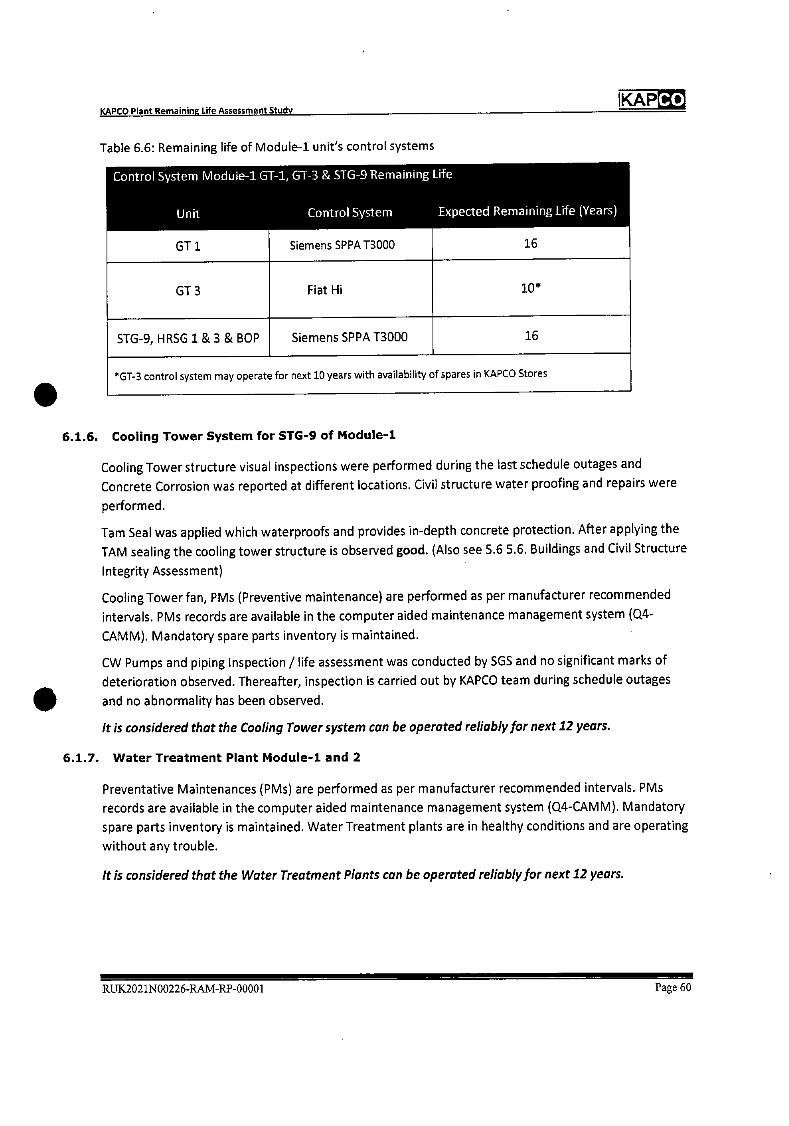
Co KAP
Control System Module-i GT-i, GT-3 & STG-9 Remaining life
Unit Control System Expected Remaining Life (Years)
GT 1
GT 3
STG-9, HRSG 1 & 3 & BOP
Siemens SPPAT3000
Fiat Hi
Siemens SPPA T3000
16
10*
16
*GT..3 control system may operate for next 10 years with availability of spares in KAPCO Stores
KAPCO Plant Remaining Life Assessment Study
Table 6.6: Remaining life of Module-i unit's control systems
6.1.6. Cooling Tower System for STG-9 of Module-i
Cooling Tower structure visual inspections were performed during the last schedule outages and
Concrete Corrosion was reported at different locations. Civil structure water proofing and repairs were
performed.
Tam Seal was applied which waterproofs and provides in-depth concrete protection. After applying the
TAM sealing the cooling tower structure is observed good. (Also see 5.6 5.6. Buildings and Civil Structure
Integrity Assessment)
Cooling Tower fan, PMs (Preventive maintenance) are performed as per manufacturer recommended
intervals. PMs records are available in the computer aided maintenance management system (0.4-
CAMM). Mandatory spare parts inventory is maintained.
CW Pumps and piping Inspection / life assessment was conducted by SGS and no significant marks of
deterioration observed. Thereafter, inspection is carried out by KAPCO team during schedule outages
and no abnormality has been observed.
it is considered that the Cooling Tower system can be operated reliably/or next 12 years.
6.1.7. Water Treatment Plant Module-i and 2
Preventative Maintenances (PMs) are performed as per manufacturer recommended intervals. PMs
records are available in the computer aided maintenance management system (0.4-CAMM). Mandatory
spare parts inventory is maintained. Water Treatment plants are in healthy conditions and are operating
without any trouble.
it is considered that the Water Treatment Plants can be operated reliably for next 12 years.
RUK2021N00226-RAM-RP-00001 Page 60
Co KAP KAPCO Plant Remaining Life Assessment Study
6.2. Module-2 Plant Components' Residual Life Assessment
6.2.1. Gas Turbine Unit 2, 4 and Steam Turbine Unit-jO
Gas Turbine GT-2: Hot gas path components are being replaced periodically on MOH as per
recommended EOH by the OEM Siemens. One complete set of turbine vanes and blades is available as a
strategic spare.
The overall condition of GT-2 was observed as Satisfactory during visual inspections and NDTs
performed in the last MOH/eHGPl Feb-March 2018.
Scope of visual inspection and NDTs included;
• Ultrasonic Testing of Compressor bearing, Turbine bearing, Gas Burner, Compressor vanes,
• Magnetic Particle Test of Compressor vane carrier, Compressor blades, Rotor, Compressor and
Turbine wheel discs, Intermediate shaft, Front Hollow shaft, Compressor and Turbine vane carriers,
Bearings, etc.
• Dye Penetrant Test was performed for Compressor and Turbine bearing, Compressor vane rings, Gas
Premix Burners, Mixing chamber of combustion chambers, Inner Casing, Turbine stator vanes stage-
4, Compressor and Turbine vane carriers, exhaust casing etc.
Overall NDT results were categorized Acceptable except few observations which were addressed in
MOH activities e.g. Inner Casing ground out and build-up welding.
Air intake system structure is in healthy condition. New air intake filters are available in the market.
The compressor blades stages 1-12 have been in service since commissioning. New compressor blades
stages 13-16 were installed in 2002 and are in service since then. During inspection in the last MOH Feb-
March 2018, no recordable indication was reported in NDT report March 2018 and the condition of
compressor blades were found to be satisfactory. In case if some findings appear in the next MOH,
compressor blades are recommended to be replaced.
New IGVs were installed in 2009 and expected remaining useful life is 10-15 years henceforth.
All stages of GT-2 compressor diaphragms were replaced during the 2002 MOH with new ones. The
condition of the compressor diaphragms was found satisfactory in the MON 2018.
Gas Turbine GT-4: Hot gas path components are being replaced periodically with each MOH as per
recommended EOH by OEM. One set of vanes and blades is available in store as a strategic spare.
New Compressor blades were installed in 1999 and are in service without any findings.
The overall condition of GT-4 was found to be satisfactory during the MOH 2016 and HGPI 2017. One
complete GT rotor is available for GT-3 and GT-4 as a strategic spare.
Steam Turbine STG-1O condition found satisfactory during last Minor Inspection Feb-April 2016. Last
MOH was performed in Sep-Oct 2013. During the MOH, modified 1st stage moving blades and new LP
turbine erosion protection rings of the last 3 stages were installed which enhance turbine performance
and integrity.
Mandatory spares are maintained for the steam turbine and are available in store.
RUX2021N00226-RAM-RP-00001 Page 61

Co KAP
Operating Operating KAPCO Remaining
Hours in Hours in Operating Operating Hours Remaining
Unit 41 Design Extended Hours In Extended Design life
Life of Design Life of COD to Design Life of 40 (Years)
30 years 40 years TQlar-2021 years
GT-2 240,000 320,00 162,106 157,894 20
GT-4 240,000 320,00 93,756 226,244 28
STG-10 240,000 320,00 157,017 162,983 20
Module-2 Units are expected to operate for minimum further 10 years
without any major concern.
*ccGT Operating Life expectancy before retirement is 40 years (320,000 hours based on 8,000 operating hours/year) ref section 5.3.4 and 5.4 of this document.
KAPCO Plant Remaining Life Assessment Study
Following is the expected Remaining Life summary of Module-2 units as per current operating regime;
Table 6. 7: Remaining Life of Module-2 Units
6.2.2. Module-2 HRSG 2 and 4
HRSG-1 to 4 are of same model and make of Balke Durr Germany. MI four Heat Recovery steam
generators have operated satisfactorily since their commissioning.
Life assessment of HRSG-1 was conducted on sample basis among ai four HRSGs of Block-i (Module-i
and 2). No major deterioration was reported with remaining life of all major components greater than
20 years. The same condition about life assessment is predicted for the other three HRSGs i.e. HRSG-2, 3
and 4 as these HRSGs have fewer operating hours and have generally been operated and maintained the
same.
Also, HRSG-2 and 4 mandatory inspections are carried out in every schedule outage of GT-2 and GT-4 by
the Boiler Engineer, Mechanical Engineer and Plant Chemist.
Last inspection was performed in Feb 2021 and both HRSGs condition were found to be satisfactory.
Based on life assessment reports and routine maintenance inspections; it is expected that with the
current operating regime, HRSG-2 and 4 may be operated reliably for next 12-15 years.
6.2.3. Module-2 Unit's Generators
6.2.4. GT-2 Unit Generator
GT-2 Unit Generator is of Siemens make and is operating satisfactorily since its commissioning. Its
overhauling has been performed in Feb. 2018 under Siemens' Engineers supervision.
The following inspections and major tests were conducted:
. Visual inspection of generator end windings in accessible area
RUK.2021N00226-RAM-RP-00001 Page 62
KAP Co KAPCO Plant Remaining Life Assessment Study
• Visual inspection of bar connections
• Visual inspection of Z brackets
• Partial discharge test
• Rotor Insulation Resistance Test
• Stator insulation Resistance test
• ELCID
• RSO
Siemens' Engineers reported "No thermal or thermo mechanical aging phenomena were detected.
Reliability is not currently limited for the next operating period"
Overall condition of Generator is Good. It is considered that Unit-2 Generator can be operated for the
next 10 years.
6.2.4.1. GT-4 Unit Generator
GT-4 Unit Generator is of Ercole Marrelle make and has operated satisfactorily since its commissioning.
Aging impacts were evident on a few parts e.g. cooler leakages etc which were addressed. Generator
tests, e.g. Insulation Resistance, Loop Resistance of Rotor and Stator and Megger tests were conducted
during Sep 2019, all results are satisfactory.
All operational parameter found OK. Overall condition of Generator. is Satisfactory. We envisage that U-
4 generator can be operated for next 10 years based on its condition and with spares availability in
store.
6.2.4.2. STG-1O Unit Generator
STG-10 Unit Generator is of Aistom make and is operating satisfactorily since its commissioning in
January 1991. Alstom overhauled the Generator in 2016. Overall condition of Generator is considered
Good.
However, Aistom stated for displaced U-channels of the rotor "The current state of displacement
doesn't require immediate actions, since the cooling gas-inlets are still free and the insulation distance is
still sufficient for the operating voltage. The displacement is likely to get bigger with further operation,
eventually blocking the cooling gas-inlets or dccreasing the insulation distance (creep age path) to a
point were an earth-fault (contact of rotor winding with rotor body) is possible. Alstom recommended;
1)10 monitor the displacement of the slot channels regularly at least once a year. 2) To measure and
protocol (trend) the insulation resistance at least once a year. 3) The rotor earth fault protection should
be checked and kept in good working order.
All operational parameter found OK. Recent electrical tests conducted are showing results normal.
Based on routine condition monitoring tests and operating conditions, we envisage that U-b
Generator can be operated reliably for next 10 years.
RUK2021N00226-RAJv1-RP-00001 Page 63

Units COD Make Overall
Condition Rating
8
Expected Overall Remaining life Generator
Condition (Years)
GT-2 14-01-1987 Siemens Satisfactory 10
GT-4 02-05-1987 Ercole
Marrelle
7 Satisfactory 10
STG-10 08-01-1991 Alstom 9 Good 10
Condition Rating Criteria 1-10: Rating 9-10 = Good; Rating 7-8 = Satisfactory; Rating 4-6 = Acceptable; Rating 1-3 = Unacceptable
KAP Co KAPCO Plant Remaining Life Assessment Study
6.2.4.3. Summary for Remaining life of Module-2 Generators
Below is the summary for Remaining life of Module-2 Unit's Generator derived from condition
monitoring tests performed as described in preceding paragraphs;
Table 6. 8: Remaining life of Module-2 Generators
6.2.5. Module-2 Unit's Step-Up Transformer 2, 4 and 10
6.2.5.1. Unit-2 Step-Up Transformer 2BATO1 Condition Monitoring
GT-2 Unit Step-Up Transformer testing was performed for life assessment by ABB in 2016 on a sample
basis in Block-i units.
ABB performed the following tests along with visual inspection of the Power Transformers as per the
specified scope of work:
• Winding Turn Ratio Test
• Vector Group Check
• Excitation Current Test
• Winding DC Resistance Test
• Winding Insulation Resistance Test
• Winding Tan Delta Test
• Winding Tan Delta Test
• FRA Frequency Response Analysis
All tests results were observed acceptable.
Also, the Transformer Oil analysis tests were performed in May 2020 by LABORELEC Belgium (Appendix-
2 Unit-2 TF 2BATO1 Oil Analysis Report). Following is the conclusion from the oil analysis;
"The evolution of the dissolved gases (DGA) shows decreased concentrations. No indication of any
specific evolving internal transformer fault.
The water content and relative saturation of the oil can be considered as normal.
RUX2021N00226-RAM-RP-00001 Page 64

Co KAP KAPCO Plant Remaining Life Assessment Study
S
The analysis of paper ageing markers does indicate significant winding paper ageing. Based on the
furans concentration the DP can be estimated between 375 and 575. When a DP-value lower than 200 is
reached, the winding paper is considered as end-of-life.
The next sample according to normal frequency. No other action needed."
Furan Analysis report results are similar for test report 2019 and 2020 which shows no immediate
concern for future operations.
Operating parameters of transformers e.g. Oil temperature, winding temperature all are in normal
range.
Field testing performed for 2BAT01 concluded, condition of transformer as Satisfactory that is code-i
for healthy equipment operating normally.
6.2.5.2. Unit-4 Step-Up Transformer 4BATO1 Condition Monitoring
Transformer Oil analysis tests were performed in May 2020 by M/S LABORELEC Belgium (Appendix-2
Unit-4 TF 4BATO1 Oil Analysis Report). Following is the conclusion from the oil analysis;
"The evolution of the dissolved gases can be considered as stable. The water content and relative
saturation of the oil can be considered as normal. The oil properties that were investigated indicate
minor oil degradation.
The analysis of paper ageing markers does indicate limited winding paoer ageing. Based on the furans
and methanol concentration the DP can be estimated as >600 and the paper can still be considered as in
good condition.
The next sample according to normal frequency. No other action needed at this stage."
Operating parameters of transformers e.g. Oil temperature, winding temperature all are in normal
range.
Thus, the overall condition of Unit-3 Step-Up transformer is Satisfactory; that is code-i i.e. for healthy
equipment operating normally.
6.2.5.3. Unit-lO Step-Up Transformer D2BATO1 Condition Monitoring
Transformer Oil analysis tests were performed in May 2020 by M/S LABORELEC Belgium (Appendix-2
Unit-iD TF D2BA101 Oil Analysis Report). Following is the conclusion from oil analysis;
"The evolution of the dissolved gases shows an increase compared to the previous sample (01/20i9)
and shows similar gas pattern the sample of 05/2018 which can indicate that the previous sample was
not from this transformer! the right place. Nevertheless, the concentrations are also increased
compared to the sample of 05/2018. Laborelec recommends to send a new sample within 3 - 6 months
in order to follow-up the evolution. The concentrations of the gases can indicate the presence of
overheating fault type (insufficient cooling or overloading) or possible stray gassing.
The water content and relative saturation of the oil can be considered as normal." New sample for oil
analysis will be sent in 2021.
All electrical tests conducted are showing results in normal range.
RUX2021N00226-RAM-RP-00001 Page 65
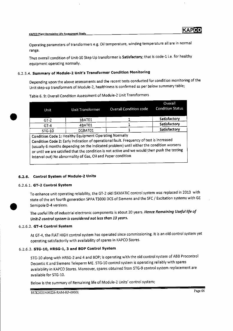
Co KAP
Unit Unit Transformer
1BATOi
Overall Condition code
1
Overall
Condition Status
Satisfactory GT-2
GT-4 4BATO1 1 Satisfactory
STG-10 D1BATO1 1 Satisfactory
Condition Code 1: Healthy Equipment Operating Normally Condition Code 2: Early indication of operational fault. Frequency of test is increased
(usually 6 months depending on the indicated problem) until either the condition worsens
or until we are satisfied that the condition is not active and we would then push the testing
interval out) No abnormality of Gas, Oil and Paper condition
KAPCO Plant Remaining Life Assessment Study
Operating parameters of transformers e.g. Oil temperature, winding temperature all are in normal
range.
Thus overall condition of Unit-lO Step Up transformer is Satisfactory; that is code-i i.e. for healthy
equipment operating normally.
6.2.5.4. Summary of Module-2 Unit's Transformer Condition Monitoring
Depending upon the above assessments and the recent tests conducted for condition monitoring of the
Unit step-up transformers of Module-2, healthiness is confirmed as per below summary table;
Table 6. 9: Overall Condition Assessment of Module-2 Unit Transformers
6.2.6. Control System of Module-2 Units
6.2.6.1. GT-2 Control System
To enhance unit operating reliability, the GT-2 old ISKMATIC control system was replaced in 2013 with
state of the art fourth generation SPPA 13000 DCS of Siemens and the SFC / Excitation systems with GE
Semipole D-4 versions.
The useful life of industrial electronic components is about 20 years. Hence Remaining Useful life of
Unit-2 control system is considered not less than 13 years.
6.2.6.2. GT-4 Control System
At GT-4, the FIAT HIGH control system has operated since commissioning. It is an old control system yet
operating satisfactorily with availability of spares in KAPCO Stores.
6.2.6.3. STG-1O, HRSG-1, 3 and BOP Control System
STG-10 along-with HRSG-2 and 4 and BOP; is operating with the old control system of ABB Procontrol
Decontic K and Siemens Teleperm ME. STG-10 control system is operating reliably with spares
availability in KAPCO Stores. Moreover, spares obtained from STG-9 control system replacement are
available for STG-10.
Below is the summary of Remaining life of Module-2 Units' control system;
RUK2021N00226-RAM-RP-00001 Page 66

Co KAP
GT 2
Control System lvlodule-2 GT-2, GT-4 & STG-10 Remaining Life
Unit Control System Expected Remaining Life
(Years)
Siemens SPPA T3000 13
GT 4 Fiat I-li 10*
STG-10, HRSG 2 & 4 & BOP ABB Procontrol Decontic K &
Siemens Teleperm ME 10* *
*61.4 control system may operate for next 10 years with availability of spares in KAPCO Stores **STG_1O control system may operate for next 10 years with availability of spares in KAPCO Stores and additional spares obtained from Control System replacement of STG-9.
KAPCO Plant Remaining Life Assessment Study
Table 6. 10: Remaining life of Module-2 Unit's control systems
6.2.7. cooling Tower System for STG-1O of Module-2
Cooling Tower structure visual inspections were performed during the last schedule outage. Concrete
Corrosion was observed at different locations. Civil structure water proofing and repairs were
performed.
Tam Seai was applied which waterproofs and provides in-depth concrete protection. After applying the
TAM sealing cooling tower structure is observed good. (Also see 5.6 5.6. Buildings and Civil Structure
Integrity Assessment)
RUK2021N00226-RAM-RP-00001 Page 67
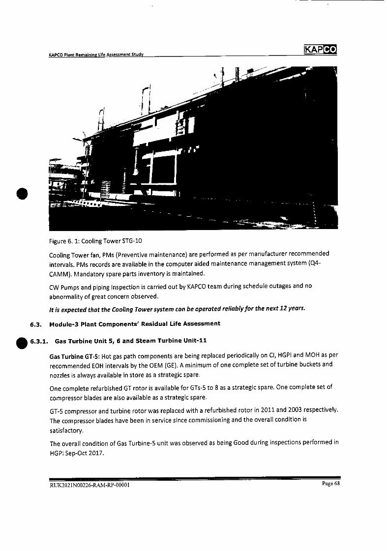
KAPCO Plant Remaining Life Assessment Study
KAPCO
S
Figure 6. 1: cooling Tower STG-lO
Cooling Tower fan, PMs (Preventive maintenance) are performed as per manufacturer recommended
intervals. PMs records are available in the computer aided maintenance management system (04-
CAMM). Mandatory spare parts inventory is maintained.
CW Pumps and piping Inspection is carried out by KAPCO team during schedule outages and no
abnormality of great concern observed.
It is expected that the Cooling Tower system can be operated reliably for the next 12 years.
6.3. Module-3 Plant Components' Residual Life Assessment
5 6.3.1. Gas Turbine Unit 5, 6 and Steam Turbine Unit-li
Gas Turbine GT-5: Hot gas path components are being replaced periodically on Cl, HGPI and MOH as per
recommended EOH intervals by the OEM (GE). A minimum of one complete set of turbine buckets and
nozzles is always available in store as a strategic spare.
One complete refurbished GT rotor is available for GTs-5 to 8 as a strategic spare. One complete set of
compressor blades are also available as a strategic spare.
GT-5 compressor and turbine rotor was replaced with a refurbished rotor in 2011 and 2003 respectively.
The compressor blades have been in service since commissioning and the overall condition is
satisfactory.
The overall condition of Gas Turbine-S unit was observed as being Good during inspections performed in
HGPI Sep-Oct 2017.
RUX2021N00226-RAM-RP-00001 Page 68
KAPCO Plant Remaining Life Assessment Study
KAPCO
The compressor casings have been in operation since commissioning. During inspections performed, no
major observations were noted. Therefore, compressor casings may be kept in operation for next 10
years satisfactorily.
No major observations were noted for the Compressor Stator/Diaphragms, so keeping in view the
present condition, these may also be kept in operation for next 10 years.
Gas Turbine GT-6: Hot gas path components are being replaced periodically on Cl, HGPI and MOH as per
recommended EOH intervals by the OEM (GE).
GT-6 compressor and turbine rotor was replaced with new and refurbished rotors in 1996 and 2006
respectively. The compressor blades have been in service since commissioning.
The overall condition of Gas Turbine-6 unit was observed as being Good during inspections performed in
HGPI Sep-Oct 2017.
For Compressor Casings, during inspections performed in HGPI Sep-Oct 2017, no major observation has
been noted. Therefore, it is considered that the compressor casings may be kept in operation for the
next 10 years satisfactorily.
No major observations were noted for Compressor Stator/Diaphragms, so keeping in view the present
condition, these may also be kept in operation for the next 10 years.
GT-5 and 6 hot gas path up-gradation was performed during the outage in Oct-Nov 2011, replacing
components with improved metallurgy and design supplied by the OEM which also improved the Units'
performance and enhanced the plant life.
Steam Turbine STG-11 schedule maintenance is performed as per OEM recommendations. Spares
inventory is maintained in KAPCO Stores (See Appendix-6 for Strategic Spares)
STG-11 last Overhauling was conducted in Feb-March 2020.
The Turbine upper casing was removed. No cracks in the casing and other abnormalities were observed.
DPT of Turbine diaphragms was performed by Jiacco, Pakistan and no major abnormality was observed.
Minor observation on the lower half diaphragm of Stage # 13 was addressed.
The Turbine rotor was removed and the corrosion condition of the blades was found to be found
normal. Minor scaling was observed on the lower pressure side of rotor. Last stage blading was
observed to be in good condition and all brazed leading edges were found to be intact. All blades were
cleaned with sand-papers. Magnetic particle testing of all rotor stages was carried out. No cracks or
other abnormalities were observed. Some of the gland seal packing was found to be bent, which were
straightened. Gland seals were also found in good condition. Condition of the rotor was found
satisfactory.
The overall condition of Steam Turbine Unit-il, including condenser, was observed to be satisfactory
during inspections performed in MOH Sep-Oct 2017 and last Minor Overhauling Feb-March 2020.
Following is the expected Remaining Life Assessment summary of Module-3 units as per unit's condition
and current operating regime;
RUK2021N00226-RAM-RP-00001 Page 69
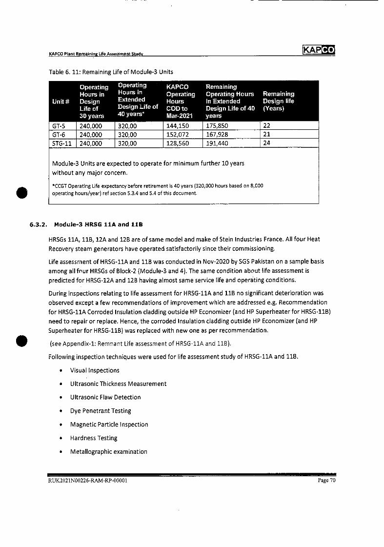
Co KAP
Operating Operating KAPCO Remaining Hours in •Hours in Operating Operating Hours Remaining
Unit Design Extended Hours In Extended Design life Life of Design Life of COD to Design Life of 40 (Years) 30 years 40 years* lVlar-2021 years
GT-5 240,000 320,00 144,150 175,850 22
GT-6 240,000 320,00 152,072 167,928 21
STG-11 240,000 320,00 128,560 191,440 24
Module-3 Units are expected to operate for minimum further 10 years
without any major concern.
*CCGT Operating Life expectancy before retirement is 40 years (320,000 hours based on 8,000
operating hours/year) ref section 5.3.4 and 5.4 of this document.
KAPCO Plant Remaining Life Assessment Study
Table 6. 11: Remaining Life of Module-3 Units
6.3.2. Module-3 HRSG hA and 11B
HRSGs hA, 11B, 12A and 12B are of same model and make of Stein Industries France. All four Heat
Recovery steam generators have operated satisfactorily since their commissioning.
Life assessment of HRSG-11A and 118 was conducted in Nov-2020 by SGS Pakistan on a sample basis
among all four HRSG5 of Block-2 (Module.3 and 4). The same condition about life assessment is
predicted for HRSG-12A and 12B having almost same service life and operating conditions.
During inspections relating to life assessment for HRSG-11A and 11B no significant deterioration was
observed except a few recommendations of improvement which are addressed e.g. Recommendation
for HRSG-11A Corroded Insulation cladding outside HP Economizer (and HP Superheater for HRSG-11B)
need to repair or replace. Hence, the corroded Insulation cladding outside HP Economizer (and HP
Superheater for HRSG-11B) was replaced with new one as per recommendation.
(see Appendix-i: Remnant Life assessment of HRSG-11A and 11B).
Following inspection techniques were used for life assessment study of HRSG-11A and 11B.
• Visual Inspections
• Ultrasonic Thickness Measurement
• Ultrasonic Flaw Detection
• Dye Penetrant Testing
• Magnetic Particle Inspection
• Hardness Testing
• Metallographic examination
RUX2021N00226-R.AM-RP-00001 Page 70

Co KAP KAPCO Plant Remaining Life Assessment Study
Scope of work for complete inspection and remaining life assessment of HRSG-11A and 11B included
following inspections and NDTs;
• Visual inspection of HP drum, tubes, headers, for localized and uniform corrosion, deposits,
erosion, pitting etc.
• Visual inspection of protective coating/insulation for damages
• Visual inspection for corrosion under insulation (CUI)
• Visual inspection of all structural steel parts including ducts, platforms, handrails and structural
steel supports for ducts/piping for any visual defects.
• Visual inspection of tube bends and headers
• Visual inspection and DPT of steam header pipe welds for cracks
• Visual inspection of all accessible weld joints of HP Drum/LP separator, like shell, heads and
nozzles.
• Hardness testing of HP drum, LP Separator and headers. 14 Locations from tube, 2 from each
header, 4 locations from inside the drums
• Ultrasonic flaw detection of suspected weld joints of HP drum, LP Separator.
• MPi/DPlofselectedweldjoints
• Metallographic testing of boiler pressure parts like 2 from each HP drum, 1 for each LP
Separator, ifrom each headerto study the metallurgical changes, degradation and evaluation
for its fitness for service.
• Ultrasonic thickness gauging was carried out from accessible locations, on the recommendations
of API-Sb inspector to find out overall metal loss in different equipment for remaining life
calculations.
Remaining Life of HRSG-11A and 11B was calculated, comparing component's thickness at installation
and current thickness gauging 2020 using remaining corrosion allowance.
For HRSG-11A all major components' remaining life is calculated greater than 40 years while HP Super
Heater Outlet Header remaining life is calculated as 19.7 years.
For HRSG-11B all major components' remaining life is calculated greater than 45 years.
Also, HRSG-11A and 11B mandatory inspections are carried out in every schedule outage of GT-5 and
GT-6 by the Boiler Engineer, Mechanical Engineer and Plant Chemist.
Last inspection was performed in March 2020 and both HRSGs condition found to be satisfactory.
Based on life assessment report and routine maintenance inspections; we expect that with the current
operating regime, HRSG-11A and 11B can be operated reliably for next 10-15 years.
6.3.3. Module-3 Unit's Generators
Following are the technical Specifications for Module-3 and 4 Units' Generators
RUX.2021N00226-RAM-RP-00001 Page 71
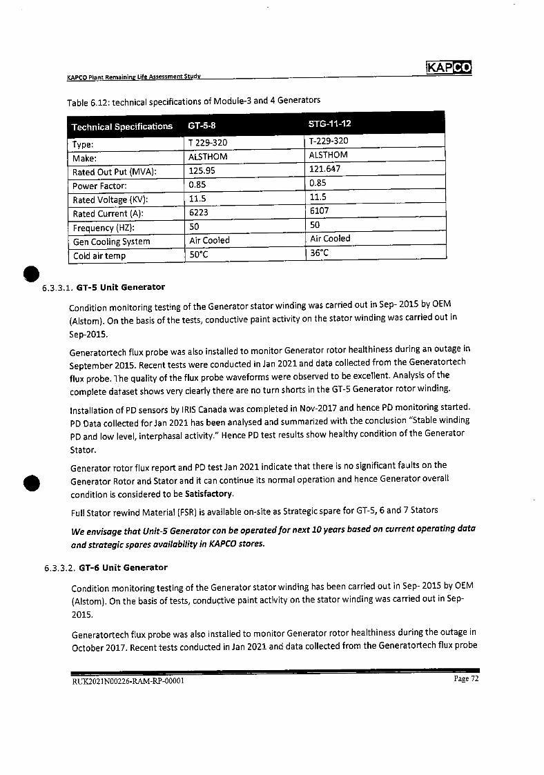
Co KAP KAPCO Plant Remaining Life Assessment Study
Table 6.12: technical specifications of Module-3 and 4 Generators
Technical Specifications GT-5-8
T 229-320
STG-1 1-12
T-229-320 Type:
Make: ALSTHOM ALSTHOM
Rated Out Put (MVA): 125.95 121.647
Power Factor: 0.85 0.85
Rated Voltage (Ky): 11.5 11.5
Rated Current (A): 6223 6107
Frequency (HZ): 50 50
Gen Cooling System Air Cooled Air Cooled
Cold air temp 50°C 36°C
6.3.3.1. GT-5 Unit Generator
Condition monitoring testing of the Generator stator winding was carried out in Sep- 2015 by OEM
(Alstom). On the basis of the tests, conductive paint activity on the stator winding was carried out in
Sep-2015.
Generatortech flux probe was also installed to monitor Generator rotor healthiness during an outage in
September 2015. Recent tests were conducted in Jan 2021 and data collected from the Generatortech
flux probe. The quality of the flux probe waveforms were observed to be excellent. Analysis of the
complete dataset shows very clearly there are no turn shorts in the GT-5 Generator rotor winding.
Installation of PD sensors by IRIS Canada was completed in Nov-2017 and hence PD monitoring started.
PD Data collected for Jan 2021 has been analysed and summarized with the conclusion "Stable winding
PD and low level, interphasal activity." Hence PD test results show healthy condition of the Generator
Stator.
Generator rotor flux report and PD test Jan 2021 indicate that there is no significant faults on the
Generator Rotor and Stator and it can continue its normal operation and hence Generator overall
condition is considered to be Satisfactory.
Full Stator rewind Material (FSR) is available on-site as Strategic spare for GT-5, 6 and 7 Stators
We envisage that Unit-5 Generator can be operated for next 10 years based on current operating data
and strategic spares availability in K.4PCQ stores.
6.3.3.2. GT-6 Unit Generator
Condition monitoring testing of the Generator stator winding has been carried out in Sep- 2015 by OEM
(Alstom). On the basis of tests, conductive paint activity on the stator winding was carried out in Sep-
2015.
Generatortech flux probe was also installed to monitor Generator rotor healthiness during the outage in
October 2017. Recent tests conducted in Jan 2021 and data collected from the Generatortech flux probe
RUX2021N00226-RAM-RP-00001 Page 72
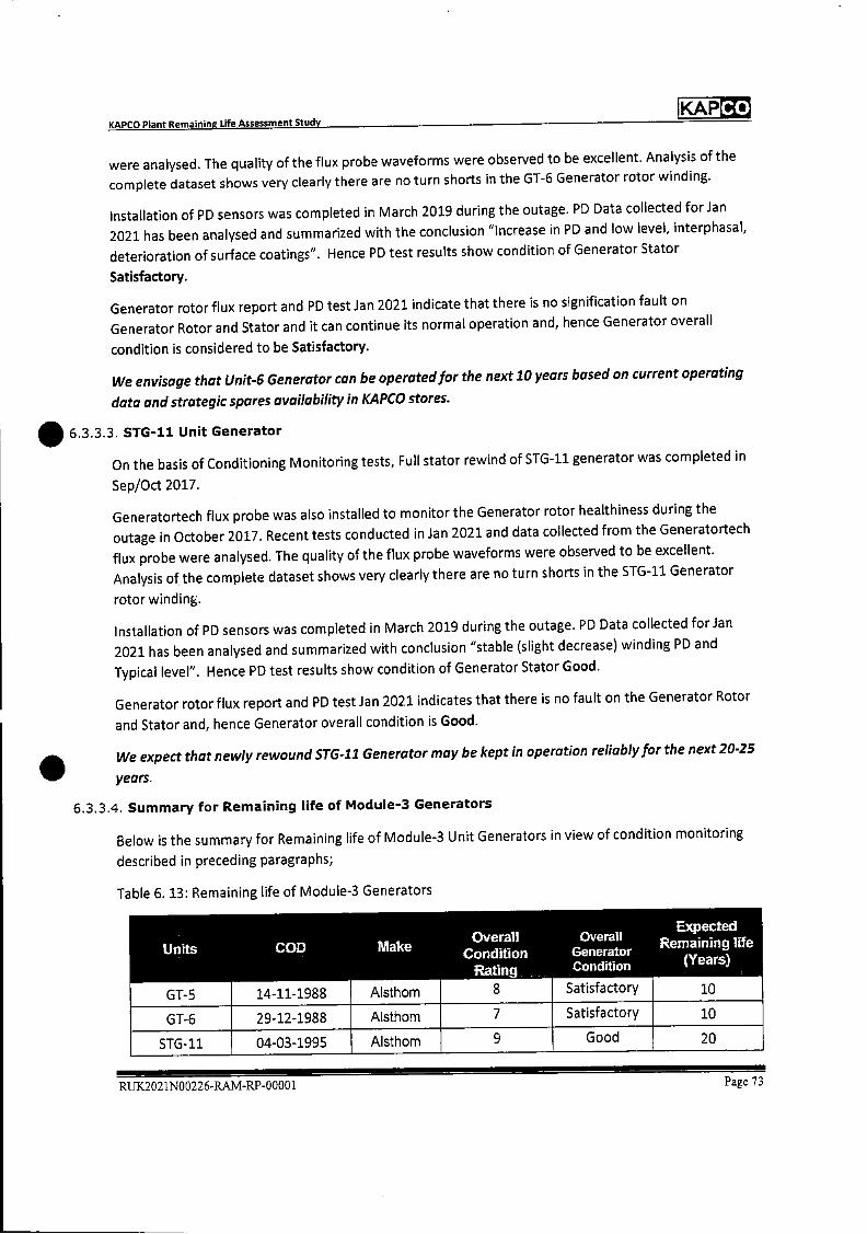
KAPCO KARCO Plant Remaining Life Assessment Study
were analysed. The quality of the flux probe waveforms were observed to be excellent. Analysis of the
complete dataset shows very clearly there are no turn shorts in the GT-6 Generator rotor winding.
Installation of PD sensors was completed in March 2019 during the outage. PD Data collected for Jan
2021 has been analysed and summarized with the conclusion "Increase in PD and low level, iriterphasal,
deterioration of surface coatings". Hence PD test results show condition of Generator Stator
Satisfactory.
Generator rotor flux report and PD test Jan 2021 indicate that there is no signification fault on
Generator Rotor and Stator and it can continue its normal operation and, hence Generator overall
condition is considered to be Satisfactory.
We envisage that Unit-S Generator can be operated for the next 10 years based on current operating
data and strategic spares availability in KAPCO stores.
6.3.3.3. STG-11 Unit Generator
On the basis of Conditioning Monitoring tests, Full stator rewind of STG-11 generator was completed in
Sep/Oct 2017.
Generatortech flux probe was also installed to monitor the Generator rotor healthiness during the
outage in October 2017. Recent tests conducted in Jan 2021 and data collected from the Generatortech
flux probe were analysed. The quality of the flux probe waveforms were observed to be excellent.
Analysis of the complete dataset shows very clearly there are no turn shorts in the STG-11 Generator
rotor winding.
Installation of PD sensors was completed in March 2019 during the outage. PD Data collected forian
2021 has been analysed and summarized with conclusion "stable (slight decrease) winding PD and
Typical level". Hence PD test results show condition of Generator Stator Good.
Generator rotor flux report and PD test Jan 2021 indicates that there is no fault on the Generator Rotor
and Stator and, hence Generator overall condition is Good.
We expect that newly rewound STG-11 Generator may be kept in operation reliably for the next 20-25
years.
6.3.3.4. Summary for Remaining life of Module-3 Generators
Below is the summary for Remaining life of Module-3 Unit Generators in view of condition monitoring
described in preceding paragraphs;
Table 6. 13: Remaining life of Module-3 Generators
Expected Overall Overall Remaining life Units COD Make Condition Generator
Ratin9 Condition (Years)
GT-5 14-11-1988 Aisthom 8 Satisfactory 10
GT-6 29-12-1988 Alsthom 7 Satisfactory 10
STG-11 04-03-1995 Alsthom 9 Good 20
RUX2021N00226-RAM-RP-0000 1 Page 73
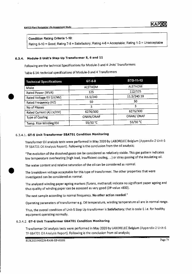
KAP Co
KAPCO Plant Remaining Life Assessment Study
Condition Rating Criteria 1-10:
Rating 9-10 = Good; Rating 7-8 = Satisfactory; Rating 4-6 = Acceptable; Rating 1-3 = Unacceptable
6.3.4. Module-3 Unit's Step-Up Transformer 5, 6 and 11
Following are the technical Specifications for Module-3 and 4 Units' Transformers
Table 6.14: technical specifications of Module-3 and 4 Transformers
Technical Specifications GT-5-B
ALSTHOM
STG-1 1-12
ALSTHOM Make
Rated Power (MVA) 125 112/125
Rated Voltage KV (LV/HV) 11.5/240 11.5/240. 18
Rated Frequency (Hz) 50 50
NoofPhases 3 3
Rated Current (A) LV/HV) 6276/300 6276/300
Type of Cooling ONAN/ONAF ONAN/ ONAF
Temp. Rise Winding/Oil 55/50°C 55/50°C
6.3.4.1. GT-5 Unit Transformer 5BATO1 Condition Monitoring
Transformer Oil analysis tests were performed in May 2020 by LABORELEC Belgium (Appendix-2 Unit-5
TF SBATQ1 Oil Analysis Report). Following is the conclusion from the oil analysis;
"The evolution of the dissolved gases can be considered as relatively stable. This gas pattern indicates
low temperature overheating (high load, insufficient cooling, ...) or stray gassing of the insulating oil.
The water content and relative saturation of the oil can be considered as normal.
The breakdown voltage acceptable for this type of transformer. The other properties that were
investigated can be considered as normal.
The analysed winding paper ageing markers (furans, methanol) indicate no significant paper ageing and
thus quality of winding paper can be assessed as very good (DP-value >800).
The next sample according to normal frequency. No other action needed."
Operating parameters of transformer e.g. Oil temperature, winding temperature all are in normal range.
Thus, the overall condition of Unit-5 Step Up transformer is Satisfactory; that is code-i i.e. for healthy
equipment operating normatly.
6.3.4.2. GT-6 Unit Transformer 6BATO1 Condition Monitoring
Transformer Oil analysis tests were performed in May 2020 by LABORELEC Belgium (Appendix-2 Unit-6
TF 6BATO1 Oil Analysis Report). Following is the conclusion from oil analysis;
RUK2O2 1N00226-RAM-RP-00001 Page 74
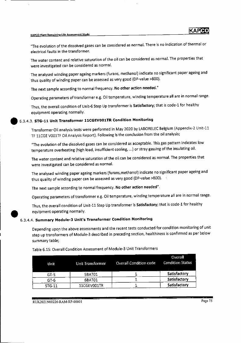
Co KAP KAPCO Plant Remaining Life Assessment Study
S
"The evolution of the dissolved gases can be considered as normal. There is no indication of thermal or
electrical faults in the transformer.
The water content and relative saturation of the oil can be considered as normal. The properties that
were investigated can be considered as normal.
The analysed winding paper ageing markers (furans, methanol) indicate no significant paper ageing and
thus quality of winding paper can be assessed as very good (DP-value >800).
The next sample according to normal frequency. No other action needed."
Operating parameters of transformer e.g. Oil temperature, winding temperature all are in normal range.
Thus, the overall condition of Unit-6 Step Up transformer is Satisfactory; that is code-i for healthy
equipment operating normally.
6.3.4.3. STG-11. Unit Transformer 11CGEVOO1TR Condition Monitoring
Transformer Oil analysis tests were performed in May 2020 by LABORELEC Belgium (Appendix-2 Unit-il
TF 11CGE VOO1TF Oil Analysis Report). Following is the conclusion from the oil analysis;
"The evolution of the dissolved gases can be considered as acceptable. This gas pattern indicates low
temperature overheating (high load, insufficient cooling, ...) or stray gassing of the insulating oil.
The water content and relative saturation of the oil can be considered as normal. The properties that
were investigated can be considered as normal.
The analysed winding paper ageing markers (furans,methanol) indicate no significant paper ageing and
thus quality of winding paper can be assessed as very good (DP-value >800).
The next sample according to normal frequency. No other action needed".
Operating parameters of transformer e.g. Oil temperature, winding temperature all are in normal range.
Thus, the overall condition of Unit-il Step Up transformer is Satisfactory; that is code-i for healthy
equipment operating normally.
6.3.4.4. Summary Module-3 Unit's Transformer Condition Monitoring
Depending upon the above assessments and the recent tests conducted for condition monitoring of unit
step up transformers of Module-3 described in preceding section, healthiness is confirmed as per below
summary table;
Table 6.15: Overall Condition Assessment of Module-3 Unit Transformers
Overall
Unit Unit Transformer Overall Condition code Condition Status
GT-5 SBATO1 1 Satisfactory
GT-6 6BAT01 1 Satisfactory
STG-11 1iCGEV00iTR 1 Satisfactory
RUX2021N00226-RAM-RP-00001 Page 75
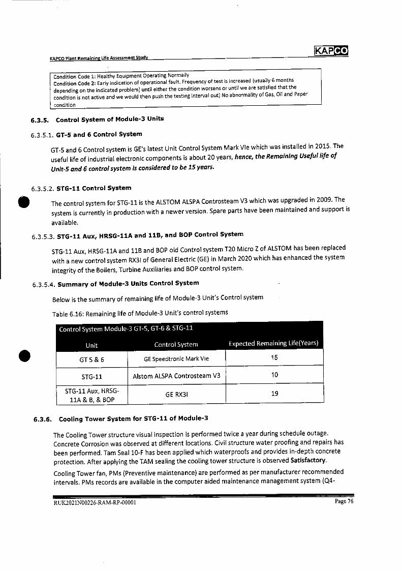
Co JKAP
Control System lVlodule-3 GT-5, GT-6 & STG-11
Unit Control System Expected Remaining Life(Years)
GE Speedtronic Mark Vie 15 GT S & 6
STG-11
STG-11 Aux, HRSG-
hA & B, & BOP
Aistom ALSPA Controsteam V3 10
GE RX31 19
KAPCO Plant Remaining Life Assessment Study
Condition Code 1: Healthy Equipment Operating Normally Condition Code 2: Early indication of operational fault. Frequency of test is increased (usually 6 months
depending on the indicated problem) until either the condition worsens or until we are satisfied that the
condition is not active and we would then push the testing interval out) No abnormality of Gas, Oil and Paper
condition
6.3.5. Control System of Module-3 Units
6.3.5.1. GT-5 and 6 Control System
GT-5 and 6 Control system is GE's latest Unit Control System Mark Vie which was installed in 2015. The
useful life of industrial electronic components is about 20 years, hence, the Remaining Useful life of
Unit-S and 6 control system is considered to be 15 years.
6.3.5.2. STG-11 Control System
The control system for STG-11 is the ALSTOM ALSPA Coritrosteam V3 which was upgraded in 2009. The
system is currently in production with a newer version. Spare parts have been maintained and support is
available.
6.3.5.3. STG-11 Aux, HRSG-11A and 11B, and BOP Control System
STG-11 Aux, HRSG-11A and 11B and BOP old Control system T20 Micro Z of ALSTOM has been replaced
with a new control system RX3l of General Electric (GE) in March 2020 which has enhanced the system
integrity of the Boilers, Turbine Auxiliaries and BOP control system.
6.3.5.4. Summary of Module-3 Units Control System
Below is the summary of remaining life of Module-3 Unit's Control system
Table 6.16: Remaining life of Module-3 Unit's control systems
6.3.6. Cooling Tower System for STG-11 of Module-3
The Cooling Tower structure visual inspection is performed twice a year during schedule outage.
Concrete Corrosion was observed at different locations. Civil structure water proofing and repairs has
been performed. Tam Seal 10-F has been applied which waterproofs and provides in-depth concrete
protection. After applying the TAM sealing the cooling tower structure is observed Satisfactory.
Cooling Tower fan, PMs (Preventive maintenance) are performed as per manufacturer recommended
intervals. PMs records are available in the computer aided maintenance management system (Q4-
RUK2021N00226-RAM-RP-00001 Page 76
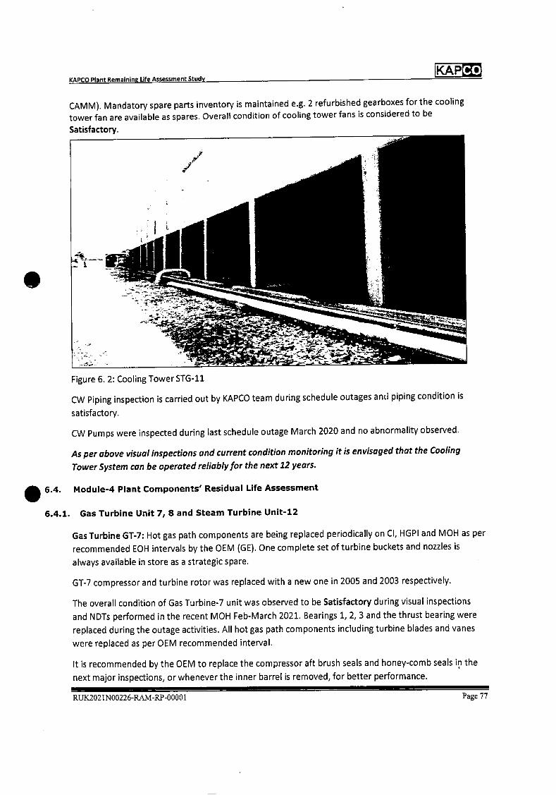
KAPCO Plant Remaining Life Assessment Study KAP
CAMM). Mandatory spare parts inventory is maintained e.g. 2 refurbished gearboxes for the cooling
tower fan are available as spares. Overall condition of cooling tower fans is considered to be
Satisfactory.
Figure 6. 2: Cooling Tower STG-11
CW Piping inspection is carried out by KAPCO team during schedule outages and piping condition is
satisfactory.
CW Pumps were inspected during last schedule outage March 2020 and no abnormality observed.
As per above visual inspections and current condition monitoring it is envisaged that the Cooling
Tower System can be operated reliably for the next 12 years.
S 6.4. Module-4 Plant Components' Residual Life Assessment
6.4.1. Gas Turbine Unit 7, 8 and Steam Turbine Unit-U
Gas Turbine GT-7: Hot gas path components are being replaced periodically on Cl, HGPI and MOH as per
recommended EOH intervals by the OEM (GE). One complete set of turbine buckets and nozzles is
always available in store as a strategic spare.
GT-7 compressor and turbine rotor was replaced with a new one in 2005 and 2003 respectively.
The overall condition of Gas Turbine-7 unit was observed to be Satisfactory during visual inspections
and NDTs performed in the recent MOH Feb-March 2021. Bearings 1, 2, 3 and the thrust bearing were
replaced during the outage activities. All hot gas path components including turbine blades and vanes
were replaced as per OEM recommended interval.
It is recommended by the OEM to replace the compressor aft brush seals and honey-comb seals in the
next major inspections, or whenever the inner barrel is removed, for better performance.
RUX2021N00226-RAM-RP-00001 Page 77
KAPCO KAPCO Plant Remaining Life Assessment Study
The Compressor Casings are the original installed. During inspections performed in the recent MOH, no
major observation has been noted. Therefore, it is anticipated that the compressor casings may be kept
in operation for the next 10-12 years satisfactorily.
No major observation has been noted for the Compressor Stator/Diaphragms, Turbine Vane carriers etc.
so keeping in view the present condition, these may also be kept in operation for next 10-12 years.
Gas Turbine GT-8: Hot gas path components are being replaced periodically on Cl, HGPI and MOH as per
recommended EOH intervals by the OEM (GE).
The GT-8 Compressor and turbine rotor were in service since 2002 and 2007 but were replaced in Feb
2019 with a refurbished, compressor and turbine rotor. Expected life of the GT rotor is assessed to be 15
years.
The Compressor Casings are the original installed. During inspections performed, no major observation
has been noted. Therefore, it is anticipated that the compressor casings may be kept in operation for
next 10 years satisfactorily.
No major observation has been noted for the Compressor Stator/Diaphragms, so keeping in view the
present condition, these may also be kept in operation for next 10 years.
Overall condition of Gas Turbine-8 unit was observed to be Good during visual inspections and NDTs
performed in the Major Outage Feb 2019.
GT-7 and 8 hot gas path up-gradation was performed in the Outages Sep-Oct 2010 and 2011
respectively, repl'cing components with improved metallurgy and design supplied by the OEM, which
also improved the Units' performance and enhanced the plant life.
Steam Turbine STG-12 Turbine Rotor was found satisfactory during the last major inspection in Feb-
March, 2017. Also, the same is noted by the GE Inspection Engineer in the Major Overhaul report of Feb-
Mar, 2015.
Turbine Diaphragms were inspected and repaired through welding by the company, KPS, in the last
outage of Feb-March, 2017. Last stage blading's stellite strips were also replaced.
The overall condition of Steam Turbine Unit-12 and condenser was observed to be Good in visual
inspections and NDTs performed during the last outages in 2017 and 2018.
In Feb 2021, Minor Inspection of STG-12 was conducted, the condition of Turbine and Turbine bearings
were assessed and found normal.
Following is the expected Remaining Life Assessment summary of Module-4 units as per the current
operating regime;
RUK.2021N00226-RAM-RP-00001 Page 78

Co KAP
Operating Operating KAPCO Remaining Hours in Hours in Operating Operating Hours Remaining
iJnit Design Extended Hours In Extended Design life
Life of Design Life of CODlo Design Life of 40 (Years)
30 years 40 years* Mar-2021 years
GT-7 240,000 320,00 152,405 167595 21
GT-8 240,000 320,00 157,488 162512 20
STG-12 240,000 320,00 139,812 180188 23
Module-4 Units are expected to operate for minimum further 10 years
without any major concern.
*CCGT Operating Life expectancy before retirement is 40 years (320,000 hours based on 8,000 operating hours/year) ref section 5.3.4 and 5.4 of this document.
KAPCO Plant Remaining Life Assessment Study
Table 6.17: Remaining Life of Module-4 Units
6.4.2. Module-4 HRSG 12A and 12B
HRSG-11A, HRSG41B, HRSG-12A and HRSG12-B are of the same model and make of Stein Industries. All
four Heat Recovery steam generators have operated satisfactorily since their commissioning in 1995.
Life assessment of HRSG-11A and B has been conducted in Nov 2020 on a sampk basis among all four
HRSG5 of Module-:3 and 4. No major deterioration was reported with remaining life of all major
components greater than 20 years. The same condition about life assessment is predicted for the other
two HRSGs HRSG-12A and 12B having almost same service life and operating conditions.
HRSG-12B inspections relating to life assessment were also conducted by the company, lnspectest, in
2013 which shown similar results.
Also, HRSG-12A and 12B mandatory inspections are carried out in every schedule outage of GT-7 and
GT-8 by the Boiler Engineer, Mechanical Engineer and Plant Chemist.
The last inspection was performed in October 2020 and both HRSG5 condition were found to be
satisfactory.
Based on life assessment reports and routine maintenance inspections; we expect that with the current
operating regime, HRSG-12A and 128 may be operated reliably for the next 12-15 years.
6.4.3. Module-4 Unit's Generators
6.4.3.1. 61-7 Unit Generator
Condition monitoring test of the Generator stator winding was carried out during the MOH of Feb-2015
by OEM (Aistom).
The following visual inspections and tests were performed for the stator;
RUK2021N00226-RAM-RP-00001 Page 79
Co KAP KAPCO Plant Remaining Life Assessment Study
• Visual Inspection for cleanliness and healthiness check of Overhang supports, Phase rings and
leads, Generator terminals, Overhang insulation, Corona protection, Coil end-insulation /
Insulating caps and stator core
• Boroscopic inspection of stator bars (4 NDE rings, 4 DE rings, 4 middle rings
• Continuity and insulation resistance check of stator temperature probes
• Stator bar - core Alpha Coefficient measurement
• ELCID
• Slot wedging test
• Winding resistance measurement
And for rotor;
• Visual Inspection of rotor after removing rotor retaining ring
• Insulation resistance measurement
• Winding resistance measurement
• RSO measurement
On the basis of tests, conductive paint activity on the stator winding was carried out during the outage
in Feb-2017.
Generatortech flux probe was also installed to monitor Generator rotor healthiness during the outage in
Sep 2015. Recent tests conducted in Jan 2021 and data collected from the Generatortech flux probe
were analysed. The quality of the flux probe waveforms were observed to be excellent. Analysis of the
complete dataset shows the previously detected turn short in Coil lB has remained clear. The turn short
in Coil 7B (first detected in December 2018) continues to be seen in the current test. When active, Coil
7B turn short woud not be creating a measurable increase in rotor vibration and will not increase
heating significantly.
Installation of PD sensors were completed in March 2019 during the outage. PD Data collected for Jan
2021 has been analysed and summarized with the conclusion "Stable (slight decrease) winding PD and
low level". Hence PD test results show condition of Generator Stator Good.
The Generator rotor flux report and the PD test Jan 2021 indicate that there is no significant fault on the
Generator Rotor and Stator and it can continue its normal operation and, hence Generator overall
condition is Satisfactory.
Additionally, Full Stator Rewind (FSR) material is available onsite as strategic spare for GT-5, 6 and 7 to
perform FSR as and when required.
We envisage that Unit-7 Generator can be operated for the next 10 years based on current operating
data and strategic spares availability in KAPCO stores.
6.4.3.2. GT-8 Unit Generator
On the basis of conditioning monitoring tests, Full stator rewind (FSR) of the Generator was carried out
in Oct / Nov-2015.
Generatortech flux probe was also installed to monitor the Generator rotor healthiness during the
outage in October 2017.
Recent tests conducted in Jan 2021 and data collected from the Generatortech flux probe were
analysed. The quality of the flux probe waveforms were observed to be excellent. Analysis of the
RUK.2021N00226-RAM-RP-00001 Page 80
KAPCO Plant Remaining Life Assessment Study
KAPCO
complete dataset shows that the previously detected turn short in Coil 7A turn short has remained clear
and the Coil 6B short was constant in all loads that could have seen a turn short in the #6 coils. The
highest recorded loads did not show the Coil 6B turn short, but they would not be expected to see a turn
short in the #6 coils. When active, Coil GB turn short would not be creating a measurable increase in
rotor vibration and will not increase heating significantly.
Installation of PD sensors were completed in March 2019 during the outage. PD Data collected for Jan
2021 has been analysed and summarized with conclusion "Fluctuations in winding PD and Negligible
level, normal voids". Hence PD test results show condition of Generator Stator Good.
Generator rotor flux report and PD test Jan 2021 indicates that there is no fault on Generator Rotor and
Stator and, hence Generator overall condition is Good.
We expect that the newly rewound GT-8 Generator may be kept in operation reliably for next 20-25
years without any major concern.
6.4.3.3. STG-12 Unit Generator
On the basis of conditioning monitoring tests, Full stator rewind (FSR) of the Generator was carried out
in Oct / Nov-2015.
Generatortech flux probe was also installed to monitor the Generator rotor healthiness during the
outage in October 2017.
Recent tests conducted in Jan 2021 and data collected from the Generatortech flux probe have been
analysed. The quality of the flux probe waveforms were observed to be excellent. "Analysis of the
complete dataset shows the previously detected turn short in Coil 6A is still in effect. When active, Coil
6A turn short would not be creating a measurable increase in rotor vibration and will not increase
heating significantly."
Installation of PD sensors was completed in March 2019 during the outage. PD Data collected for Jan
2021 has been analysed and summarized with conclusion "Stable winding PD and Low level. Voids in
ground-wall insulation." Hence PD test results show condition of Generator Stator Good.
The Generator rotor flux report and PD test Jan 2021 indicates that there is no fault on the Generator
Rotor and Stator and, hence;the Generator overall condition is Good.
We expect that the newly rewound STG-12 Generator maybe kept in operation reliably for next 20-25
years without any major concern.
6.4.3.4. Summary for Remaining life of Module-4 Generators
Below is the summary for Remaining life of Module-4 Unit Generators in view of condition monitoring
described in preceding paragraphs;
RUX2021N00226-RA.M-RP-00001 Page 81
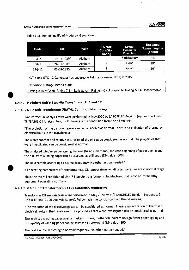
Make COD U flits
Expected Remaining life
(Years)
Overall Overall Condition Generator
Rating Condition
Aisthom
Aisthom
Alsthom
Good
Good
Satisfactory GT-7
GT-8
STG-12
20*
20*
10
9
8
9
19-01-1989
24-01-1989
05-04-1995
*GT..8 and STG-12 Generator has undergone Full stator rewind (FSR) in 2015.
Condition Rating Criteria 1-10:
Ratin. 9-10 = Good; Ratin. 7-8 = Satisfacto ; Ratin. 4-6 =Acce.table; Ratin. 1-3 = Unacce.table
KAPCO Plant Remaining Life Assessment Study
KAPCO
Table 6.18: Remaining life of Module-4 Generators
6.4.4. Module-4 Unit's Step-Up Transformer 7, 8 and 12
6.4.4.1. GT-7 Unit Transformer 7BATOI. Condition Monitoring
Transformer Oil analysis tests were performed in May 2020 by LABORELEC Belgium (Appendix-2 Unit-7
TF 7BATO1 Oil Analysis Report). Following is the conclusion from the oil analysis;
"The evolution of the dissolved gases can be considered as normal. There is no indication of thermal or
electrical faults in the transformer.
The water content and relative saturation of the oil can be considered as normal. The properties that
were investigated can be considered as normal.
The analysed winding paper ageing markers (furans, methanol) indicate beginning of paper ageing and
the quality of winding paper can be assessed as still good (DP-value >600).
The next sample according to normal frequency. No other action needed."
. All operating parameters of transformer e.g. Oil temperature, winding temperature are in normal range.
Thus, the overall condition of Unit-7 Step-Up transformer is Satisfactory; that is code-i for healthy
equipment operating normally.
6.4.4.2. GT-8 Unit Transformer SBATO1 Condition Monitoring
Transformer Oil analysis tests were performed in May 2020 by M/S LABORELEC Belgium (Appendix-2
Unit-S TF SBATO1 Oil Analysis Report). Following is the conclusion from the oil analysis;
"The evolution of the dissolved gases can be considered as normal. There is no indication of thermal or
electrical faults in the transformer. The properties that were investigated can be considered as normal.
The analysed winding paper ageing markers (furans, methanol) indicate no significant paper ageing and
thus quality of winding paper can be assessed as very good (DP-value >800).
The next sample according to normal frequency. No other action needed."
RUK.2021N00226-RAM-RP-00001 Page 82
S
Co KAP
Overall Unit Unit Transformer Overall Condition code Condition Status
GT-7 7BA101 1
1
Satisfactory
Satisfactory GT-8 8BATO1
STG-12 12CGEV001TR :1. Satisfactory
condition Code 1.: Healthy Equipment Operating Normally Condition Code 2: Early indication of operational fault. Frequency of test is increased (usually 6 months
depending on the indicated problem) until either the condition worsens or until we are satisfied that the
condition is not active and we would then push the testing interval out) No abnormality of Gas, Oil and Paper
condition
KAPCO Plant Remaining Life Assessment Study
All operating parameters of transformer e.g. Oil temperature, winding temperature are in normal range.
Thus, the overall condition of Unit-8 Step-Up transformer is Satisfactory; that is code-i for healthy
equipment operating normally.
6.4.4.3. STG-12 Unit Transformer 11CGEVOO1TR Condition Monitoring
Transformer Oil analysis tests were performed in May 2020 by M/S LABORELEC Belgium (Appendix-2
Unit-12 TF 12CGE VOO1TF Oil Analysis Report). Following is the conclusion from the oil analysis;
"The evolution of the dissolved gases can be considered as relatively stable and acceptable. This gas
pattern indicates low temperature overheating (high load, insufficient cooling, ...) or stray gassing of the
insulating oil. The water content and relative saturation of the oil can be considered as normal. The
properties that were investigated can be considered as normal. The analysed winding paper ageing
markers (furans, methanol) do not indicate any paper ageing and thus quality of winding paper can be
assessed as very good (DP-value >800). The next sample according to normal frequency. No other action
needed".
All operating parameters of transformer e.g. Oil temperature, winding temperature are in normal range.
Thus, the overall condition of Unit-12 Step Up transformer is Satisfactory; that is code-i for healthy
equipment operating normally.
6.4.4.4. Summary Module-4 Unit's Transformer Condition Monitoring
Depending upon above assessments and the recent tests conducted for condition monitoring of unit
step-up transformers of Module-4 described in preceding section, healthiness is confirmed as per below
summary table;
Table 6. 19: Overall Condition Assessment of Module-4 Unit Transformers
6.4.5. Control System of Module-4 Units
6.4.5.1. GT-7 and 8 Control System
The control system installed on GT-7 and 8 is GE Speedtronic Mark IV which is old yet operating
satisfactorily. This Control system can be further operated reliably for the next 12 to 15 years with the
availability of control system spares in KAPCO stores and spares obtained from control system
replacement of GT-5 and 6.
RUK2O2 1N00226-RAM-RP-00001 Page 83
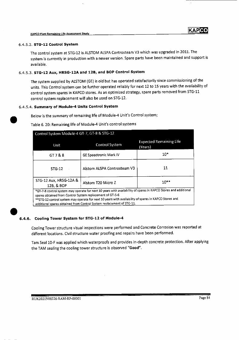
Co KAP
GE Speedtronic Mark IV
Control System Module-4 GT-7, GT-8 & STG-12
Unit Control System Expected Remaining Life
(Years)
GT7&8
STG-12 Alstom ALSPA Controsteam V3
10*
11
STG-12 Aux, HRSG-12A &
12B, & BOP Aistom T20 Micro Z 10* *
*GT_7_s control system may operate for next 10 years with availability of spares in KAPCO Stores and additional
spares obtained from Control System replacement of GT-5-6 **STG..12 control system may operate for next 10 years with availability of spares in KAPCO Stores and
additional spares obtained from Control System replacement of STG-11.
KAPCO Plant Remaining Life Assessment Study
6.4.5.2. STG-12 Control System
The control system at STG-12 is ALSTOM ALSPA Controsteam V3 which was upgraded in 2011. The
system is currently in production with a newer version. Spare parts have been maintained and support is
available.
6.4.5.3. STG-12 Aux, HRSG-12A and 12B, and BOP Control System
The system supplied by ALSTOM (GE) is old but has operated satisfactorily since commissioning of the
units. This Control system can be further operated reliably for next 12 to 15 years with the availability of
control system spares in KAPCO stores. As an optimized strategy, spare parts removed from STG-11
control system replacement will also be used on STG-12.
6.4.5.4. Summary of Module-4 Units Control System
Below is the summary of remaining life of Module-4 Unit's Control system;
Table 6. 20: Remaining life of Module-4 Unit's control systems
6.4.6. Cooling Tower System for STG-12 of Module-4
Cooling Tower structure visual inspections were performed and Concrete Corrosion was reported at
different locations. Civil structure water proofing and repairs have been performed.
Tam Seal 10-F was applied which waterproofs and provides in-depth concrete protection. After applying
the TAM sealing the cooling tower structure is observed "Good".
RU1K2021N00226.RAM-RP-00001 Page 84
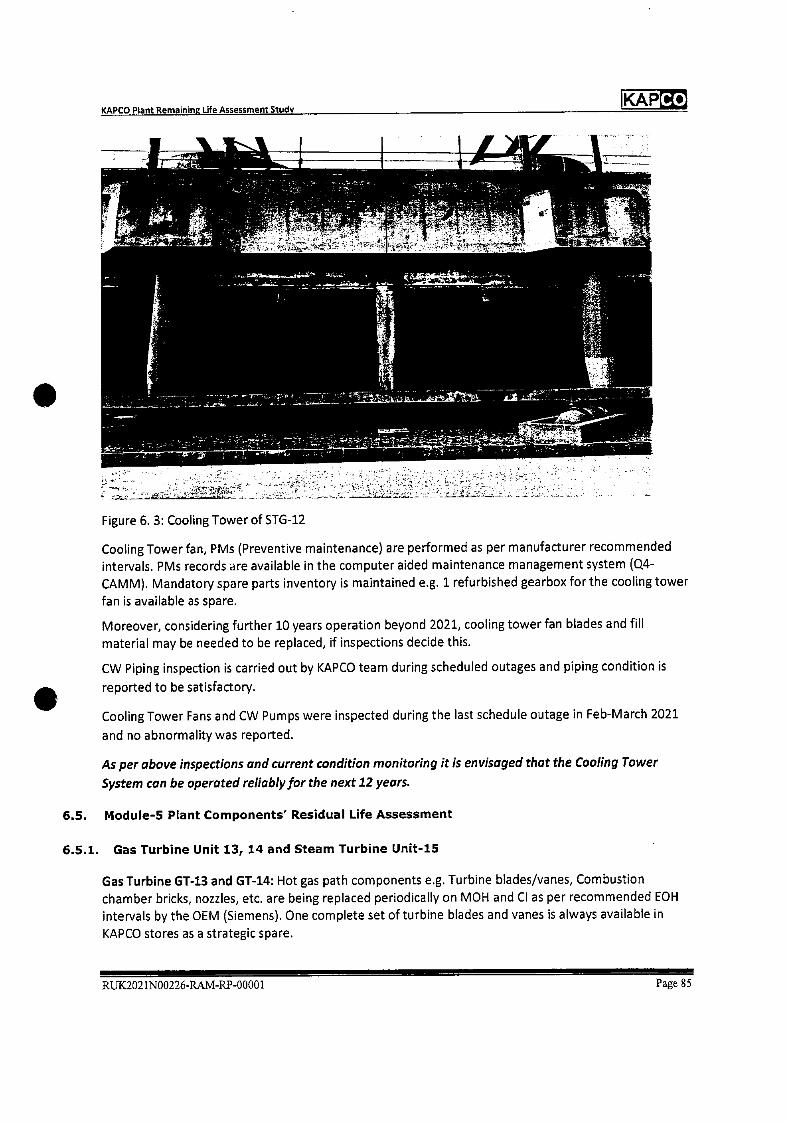
Co KAP KAPCO Plant Remaining Life Assessment Study
Figure 6. 3: Cooling Tower of STG-12
Cooling Tower fan, PMs (Preventive maintenance) are performed as per manufacturer recommended
intervals. PMs records are available in the computer aided maintenance management system (Q4-
CAMM). Mandatory spare parts inventory is maintained e.g. 1 refurbished gearbox for the cooling tower
fan is available as spare.
Moreover, considering further 10 years operation beyond 2021, cooling tower fan blades and fill
material may be needed to be replaced, if inspections decide this.
CW Piping inspection is carried out by KAPCO team during scheduled outages and piping condition is
reported to be satisfactory.
Cooling Tower Fans and CW Pumps were inspected during the last schedule outage in Feb-March 2021
and no abnormality was reported.
As per above inspections and current condition monitoring it is envisaged that the Cooling Tower
System can be operated reliably for the next 12 years.
6.5. Module-5 Plant Components' Residual Life Assessment
6.5.1. Gas Turbine Unit 13, 14 and Steam Turbine Unit-15
Gas Turbine GT-i.3 and GT-14: Hot gas path components e.g. Turbine blades/vanes, Combustion
chamber bricks, nozzles, etc. are being replaced periodically on MOH and CI as per recommended EOH
intervals by the OEM (Siemens). One complete set of turbine blades and vanes is always available in
KAPCO stores as a strategic spare.
RUK2021N00226-RAM-RP-00001 Page 85
KAP KAPCO Plant Remaining Life Assessment Study
GT-13 and 14 Si3D blades up-gradation was performed in the Outage Sep 2011 for the 1st two stages of the turbine (keeping last 2 stages the same). Installation of Siemens (innovative 3-dimensional) Si3D
blades with new Nickel based material, improved cooling air path and optimized aerodynamic aerofoil
design improved the Units' performance.
Last Major Overhauling (MOH) was conducted in Sep-October 2019. Turbine blades/vanes were
replaced as per recommended EOH.
GT-13 and 14 compressor vanes were replaced with new ones in 2010 and 2013 respectively.
The compressor blades have been in service since commissioning. During visual inspections and NDTs
performed in the MOH 2019, no findings were reported and the condition of the compressor blades was
found to be satisfactory. In the event some findings appear in the next MOH, the compressor blades are
recommended to be replaced.
Air Intake filters are to be replaced in 2021.
Following NDTs were performed in the MON 2019 for condition assessment of Gas Turbine parts after
dismantling;
• Ultrasonic Testing
• Magnetic Particle Test
• Dye Penetrant Test
• Hardness Test
The scope of the visual inspection and extended NDTs for LTE included;
• Ultrasonic Testing of Compressor bearing, Turbine bearing, Gas Burner, Mixing Chamber Casing,
Inner casing, Compressor Discs, Turbine Discs, Tie Rod, Intermediate shaft, Front, centre and rear
hollow shaft, Burner carrier, Premix Burner, Combustion chamber shell, dome, Fuel Oil piping,
cooling air-line, Blow off air-line, Fuel Gas piping etc.
• Magnetic Particle Test of Compressor vane carrier, Compressor vanes, Compressor blades,
Combustion chamber shell, Compressor and Turbine wheel discs, Intermediate shaft, Front, centre
and rear hollow shaft, Tie-rod, Compressor and Turbine vane carriers, etc.
• Dye Penetrant Test was performed for Compressor and Turbine bearing, Burner Gas Distributor,
Mixing chamber of combustion chambers, Inner Casing, Tie-rod, Exhaust casing liner, Turbine
exhaust diffuser, Fuel Oil piping, cooling airline, Blow off airline, Fuel Gas piping etc.
• Hardness Test for Centre Casing and Front Hollow shaft
The overall NDT results were categorized as acceptable except for a few minor observations which were
addressed in the MON 2019 activities e.g. indications on Mixing casing and Exhaust casing liner which
were ground out and rewelding work performed as corrective measure etc.
The overall condition of both units Gas Turbine-13 and 14 observed "Good" during visual inspections
and NDTs performed in last MON Sep-Oct 2019 and recent schedule outages.
Steam Turbine STG-15 last major overhauling was performed from Feb to April 2010. During the MOH
visual inspections and NDTs, Turbine HP/LP rotor and casings were found in good condition except for a
few minor indications which were attended as a part of the MOH activities.
Afterwards, Minor Overhauling inspection has been performed in Oct 2016.
R1JK2021N00226-RAM-RP-00001 Page 86
Co KAP
Operating - Operating KAPCO Remaining
Hours in Hours in Operating Operating Hours Remaining
Unit# Design Extended Hours In Extended Design life
Life of Design Life of COD to Design Life of 40 (Years)
30 years 40 years* Mar-2021 years
GT-13 240,000 320,00 176,245 143755 18
GT-14 240,000 320,00 170,947 149053 19
STG-15 240,000 320,00 179,741 140259 18
Module-S Units are expected to operate for minimum further 10 years
without any major concern.
*ccGT Operating Life expectancy before retirement is 40 years (320,000 hours based on 8,000
operating hours/year) ref section 5.3.4 and 5.4 of this document.
KAPCO Plant Remaining Life Assessment Study
Following NDE techniques were applied by the Siemens' NDE Specialist;
• Ultrasonic Testing
• Dye Penetrant Test
Scope of visual inspection and NDEs included;
• Ultrasonic Testing of turbine bearings, bearing pads, and turbine foundation bolts
• Dye Penetrant Test of turbine bearings, bearing pads, Steam Turbine Emergency Stop Valve,
Control Valve, HP Bypass valve, turbine casing drain valves etc.
Overall NDT results were categorized as acceptable except for a few minor observations on the HP
Bypass control valve spindle but it was categorized as useable. Also, the Steam turbine casing drain valve
cone was replaced as per Dye Penetrant Test indication.
Boroscopy inspection of the HP and LP steam turbine Last Stages and Cross over pipe were performed
by Siemens' Engineers. During the Boroscopy inspections no abnormality was observed.
The overall condition of Steam Turbine Unit-iS and condenser is reported as "Good" in visual
inspections and NDTs performed during the outages in 2010 to 2016.
STG-15 HP Steam stop and control valve actuators were overhauled during the GT-13 and 14 MOH in
2019.
Following is the expected Remaining Life Assessment summary of Module-5 Units as per the Units'
condition assessment and operating regime;
Table 6.21: Remaining Life of Module-5 Units
6.5.2. Module-5 HRSG 13 and 14
HRSG-13 and 14 complete inspection and remaining life assessment was carried out from Sep-Oct 2019
by SGS, Pakistan (Appendix-i: Remaining Life Assessment HRSG-13 and 14).
During inspections relating to life assessment for HRSG-13 and 14 no significant deterioration was
reported except a few recommendations of improvement which have been addressed e.g.
RUX2021N00226-R.AM-RP-00001 Page 87
Co KAP KAPCO Plant Remaining Life Assessment Study
Recommendation for HRSG-13 Sulphur deposition should be cleaned/washed out from tube fins to
optimize efficiency, HRSG-13 and 14 are washed keeping in view the increased stack temperature, which
indicates washing is required, as per recommendation. Observed cracks in the cyclone drum (LP Drum)
were welded for both HRSG-13 and 14 and recommended to keep monitoring in every following outage.
Scope of work for complete inspection and remaining life assessment of HRSG-13 and 14 included the
following inspections and NDTs;
• Visual inspection of HP and LP drums, tubes, headers, for localized and uniform corrosion,
deposits, erosion, pitting etc.
• Visual inspection of economizer regarding fins condition
• Visual inspection of protective coating/insulation for damages
• Visual inspection regarding internal corrosion and pitting including evaluation of pitting /
• corrosion for fitness
• Visual inspection of all structural steel parts including ducts, platforms, handrails and structural
steel supports for ducts/piping for any visual defects.
• Visual inspection of tube bends and headers
• Visual inspection and DPT of steam header pipe welds for cracks
• Visual inspection of all accessible weld joints of HP Drum/LP separator, like shell, heads and
nozzles.
• Hardness testing of HP drum, LP drum tubes and headers, 28 location from tubes, 2 from each
header, 4 locations from inside the drums.
• Ultrasonic flaw detection of suspected weld joints of HP drum, LP drum.
• MPI/DPT of selectd weld joints
• Metallographic testing of boiler pressure parts like 3 from each drum, one from each header to
study the metallurgical changes, degradation and evaluation for its fitness for service.
• Ultrasonic thickness gauging of HP drum, headers, tubes, soot blowers, as per ASME codes to
find out overall view of current metal condition for fitness.
No major anomalies were observed in the microstructure of pressure parts observed through Reflected
Light Microscopy.
Remaining Life of HRSG-13 and 14 was calculated for the available data, comparing each component's
thickness at installation and the current thickness gauging in 2019, then using the remaining corrosion
allowance to assess remaining life. Major components' life was calculated greater than 30 years for
HRSG-13 and 20 years for HRSG-14.
On the basis of above inspections, it was concluded that HRSG 13 and 14 is in satisfactory condition as
tube modules, HP and LP drums and Header NDT inspection resulted in no major deficiency.
Also, HRSG-13 and 14 mandatory inspections are also carried out in scheduled outages of GT-13 and GT-
14 by the Boiler Engineer, Mechanical Engineer and Plant Chemist.
Both HRSG5 condition was found satisfactory during an inspection performed in Feb 2021.
Based on the life assessment report which revealed no significant deterioration and routine
maintenance inspections; we expect that with the current operating regime, HRSG-13 andl4 may be
operated reliably for the next 10-15 years.
RUK2021N00226-RAM-RP-00001 Page 88
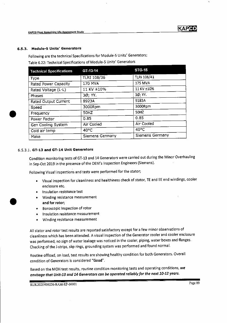
Co KAP KAPCO Plant Remaining Life Assessment Study
6.5.3. Module-5 Units' Generators
Following are the technical Specifications for Module-S Units' Generators;
Table 6.22: Technical Specifications of Module-S Units' Generators
Technical Specifications GT-13-14
TLRI 108/36
STG-15
TLRI 108/41 Type
Rated Power Capacity 170 MVA 175 MVA
Rated Voltage (L-L) 11KV ±10% 11 Ky ±10%
Phases 30; VY. 30; YY.
Rated Output Current 8923A 9185A
Speed 3000Rpm 3000Rpm
Frequency 50HZ 50HZ
Power Factor 0.85 0.85
Gen Cooling System Air Cooled Air Cooled
Cold air temp 40°C 40°C
Make Siemens Germany Siemens Germany
6.5.3.1. GT-13 and GT-14 Unit Generators
Condition monitoring tests of GT-13 and 14 Generators were carried out during the Minor Overhauling
in Sep-Oct 2019 in the presence of the OEM's Inspection Engineers (Siemens).
Following Visual inspections and tests were performed for the stator;
• Visual Inspection for cleanliness and healthiness check of stator, TE and EE end windings, cooler
enclosure etc.
• Insulation resistance test
• Winding resistance measurement
and for rotor;
• Boroscopic Inspection of rotor
• Insulation resistance measurement
• Winding resistance measurement
All stator and rotor test results are reported satisfactory except for a few minor observations of
cleanliness which has been attended. A visual inspection of the Generator cooler and cooler enclosure
was performed, no sign of water leakage was noticed in the cooler, piping, water boxes and flanges.
Checking of the i-strips, slip rings, grounding system was performed and found normal.
Routine offload, on load, test results are showing healthy condition for both Generators. Overall
condition of Generators is considered "Good".
Based on the MOH test resUlts, routine condition monitoring tests and operating conditions, we
envisage that Unit-13 and 14 Generators can be operated reliably for the next 10-12 years.
RUX2021N00226-RAM-RP-00001 Page 89
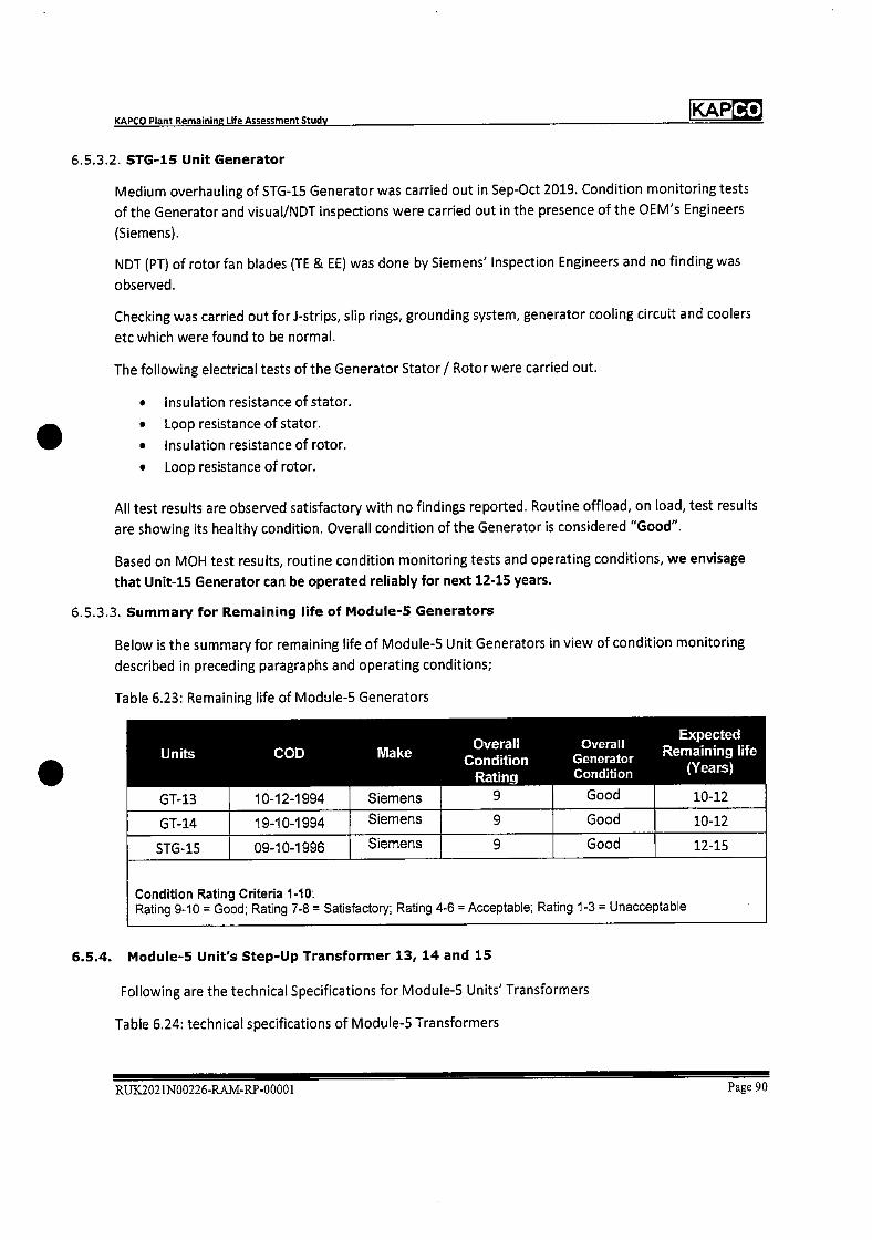
Co KAP
Units COD Make Expected
Overall Overall Condition Generator
Remaining life
Rating Condition (Years)
GT-13 10-12-1994 Siemens 9 Good 10-12
GT-14 19-10-1994 Siemens 9 Good 10-12
STG-15 09-10-1996 Siemens 9 Good 12-15
Condition Rating Criteria 1-10: Rating 9-10 = Good; Rating 7-8 = Satisfactory; Rating 4-6 = Acceptable; Rating 1-3 = Unacceptable
KAPCO Plant Remaining Life Assessment Study
6.5.3.2. STG-15 Unit Generator
Medium overhauling of STG-15 Generator was carried out in Sep-Oct 2019. Condition monitoring tests
of the Generator and visual/NDT inspections were carried out in the presence of the OEM's Engineers
(Siemens).
NJDT (PT) of rotor fan blades (TE & EE) was done by Siemens' Inspection Engineers and no finding was
observed.
Checking was carried out for i-strips, slip rings, grounding system, generator cooling circuit and coolers
etc which were found to be normal.
The following electrical tests of the Generator Stator / Rotor were carried out.
• Insulation resistance of stator.
• Loop resistance of stator.
• Insulation resistance of rotor.
• Loop resistance of rotor.
All test results are observed satisfactory with no findings reported. Routine offload, on load, test results
are showing its healthy condition. Overall condition of the Generator is considered "Good".
Based on MOH test results, routine condition monitoring tests and operating conditions, we envisage
that Unit-iS Generator can be operated reliably for next 12-15 years.
6.5.3.3. Summary for Remaining life of Module-S Generators
Below is the summary for remaining life of Module-S Unit Generators in view of condition monitoring
described in preceding paragraphs and operating conditions;
Table 6.23: Remaining life of Module-S Generators
6.5.4. Module-5 Unit's Step-Up Transformer 13, 14 and 15
Following are the technical Specifications for Module-S Units' Transformers
Table 6.24: technical specifications of Module-S Transformers
RUX2021N00226-RAM-RP-00001 Page 90
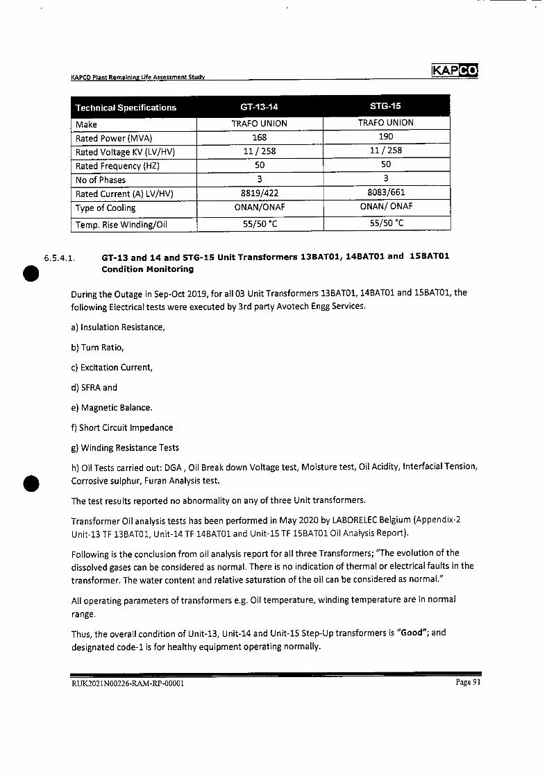
Co KAP KAPCO Plant Remaining Life Assessment Study
Technical Specifications GT-13-14
TRAFO UNION
STG-15
TRAFO UNION Make
Rated Power (MVA) 168 190
Rated Voltage KV (LV/HV) 11/258 11/258
Rated Frequency (HZ) 50 50
Noof Phases 3 3
Rated Current (A) LV/HV) 8819/422 8083/661
Type of Cooling ONAN/ONAF ONAN/ ONAF
Temp. Rise winding/Oil 55/50 C 55/50 C
6.5.4.1. GT-13 and 14 and STG-15 Unit Transformers 13BATO1, 14BAT01 and 15BATO1
S Condition Monitoring
During the Outage in Sep-Oct 2019, for all 03 Unit Transformers 13BATO1, 14BATO1 and 1SBATO1, the
following Electrical tests were executed by 3rd party Avotech Engg Services.
a) Insulation Resistance,
b) Turn Ratio,
c) Excitation Current,
d) SFRA and
e) Magnetic Balance.
f) Short Circuit Impedance
g) Winding Resistance Tests
h) Oil Tests carried out: DGA, Oil Break down Voltage test, Moisture test, Oil Acidity, Interfacial Tension,
S Corrosive sulphur, Furan Analysis test.
The test results reported no abnormality on any of three Unit transformers.
Transformer Oil analysis tests has been performed in May 2020 by LABORELEC Belgium (Appendix-2
Unit-13 TF 13BATO1, Unit-14 TF 14BA101 and Unit-15 TF 1SBATO1 Oil Analysis Report).
Following is the conclusion from oil analysis report for all three Transformers; "The evolution of the
dissolved gases can be considered as normal. There is no indication of thermal or electrical faults in the
transformer. The water content and relative saturation of the oil can be considered as normal."
All operating parameters of transformers e.g. Oil temperature, winding temperature are in normal
range.
Thus, the overall condition of Unit-13, Unit-14 and Unit-15 Step-Up transformers is "Good"; and
designated code-i is for healthy equipment operating normally.
RUK2021N00226-RAM-RP-00001 Page 91
Co KAP
Unit Unit Transformer Overall Condition code
1
Overall
Condition Status
GT-13 13 BATO1 Good
GT-14 14BATO1 1 Good
STG-15 15BATO1 3. Good
Condition Code 1: Healthy Equipment Operating Normally
Condition Code 2: Early indication of operational fault. Frequency of test is increased
(usually 6 months depending on the indicated problem) until either the condition worsens
or until we are satisfied that the condition is not active and we would then push the testing
interval out) No abnormality of Gas, Oil and Paper condition
KAPCO Plant Remaining Life Assessment Study
6.5.4.2. Summary of Module-5 Unit Transformers Condition Monitoring
Depending upon above assessments and the recent tests conducted for condition monitoring of unit
step up transformers of Module-5 described in preceding section, healthiness is confirmed as per below
summary table;
Table 6.25: Overall Condition Assessment of Module-5 Unit Transformers
6.5.5. Control System of Module-5 Units
6.5.5.1. GT-13 and 14 Control System
The GT-13 and 14 old Siemens TELEPERM ME Control system, operating since commissioning, was
replaced with a state-of-the-art Siemens SPPA T3000 system in March 2021, which has enhanced the
system integrity. Thus, the newly installed control system can be expected to operate reliably for the
next 20 years.
6.5.5.2. STG-15 Control System
The STG-15 old control system was replaced with a state-of-the-art new control system (Siemens SPPA
T3000) in Feb 2015. Its remaining life is expected to be about 15 years.
6.5.5.3. STG-15 Aux, HRSG13 and 14, and BOP Control System
The old Siemens TELEPERM ME Control system, operating since commissioning, was replaced with a
state-of-the-art Siemens SPPA T3000 in March 2021, which has enhanced the system integrity. Thus, the
newly installed control system can be expected to operate reliably for the next 20 years.
6.5.5.4. Summary of Module-5 Units Control System
Below is the summary of remaining life of Module-S unit's control system;
Table 6.26: Remaining life of Module-S unit's control systems
Control System Module-5 GT-13, 61-14 & STG-15 Remaining Life
RUX2021N00226-RAM-RP-0000 1 Page 92
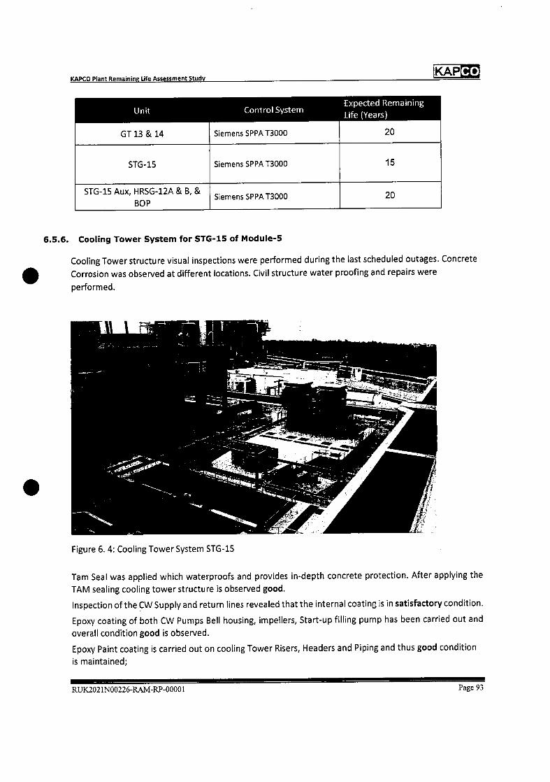
KAPCO Plant Remaining Life Assessment Study
KAPCO
Unit
GT 13 & 14
Control System
Siemens SPPA 13000
fxpected Remaining
Life (Years)
20
51G-15 Siemens SPPA 13000 15
STG-15 Aux, HRSG-12A & B, &
BOP Siemens SPPA 13000 20
6.5.6. Cooling Tower System for STG-15 of Module-5
Cooling Tower structure visual inspections were performed during the last scheduled outages. Concrete
Corrosion was observed at different locations. Civil structure water proofing and repairs were
performed.
Figure 6. 4: Cooling Tower System STG-15
Tam Seal was applied which waterproofs and provides in-depth concrete protection. After applying the
TAM sealing cooling tower structure is observed good.
Inspection of the CW Supply arid return lines revealed that the internal coating is in satisfactory condition.
Epoxy coating of both CW Pumps Bell housing, impellers, Start-up filling pump has been carried out and
overall condition good is observed.
Epoxy Paint coating is carried out on cooling Tower Risers, Headers and Piping and thus good condition
is maintained;
RUK.2021N00226-RAM-RP-00001 Page 93
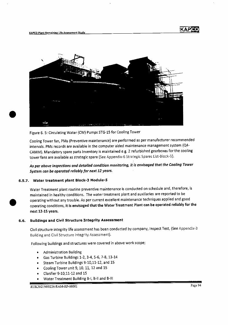
KAPCO KAPCO Plant Remaining Life Assessment Study
Figure 6. 5: Circulating Water (CW) Pumps STG-15 for Cooling Tower
Cooling Tower fan, PMs (Preventive maintenance) are performed as per manufacturer recommended
intervals. PMs records are available in the computer aided maintenance management system (0.4-
CAMM). Mandatory spare parts inventory is maintained e.g. 2 refurbished gearboxes for the cooling
tower fans are available as strategic spare (See Appendix-6 Strategic Spares List-Block-3).
As per above inspections and detailed condition monitoring, it is envisaged that the Cooling Tower
System can be operated reliably for next 12 years.
6.5.7. Water treatment plant Block-3 t4odule-5
Water Treatment plant routine preventive maintenance is conducted on schedule and, therefore, is
maintained in healthy conditions. The water treatment plant and auxiliaries are reported to be
operating without any trouble. As per current excellent maintenance techniques applied and good
operating conditions, it is envisaged that the Water Treatment Plant can be operated reliably for the
next 12-15 years.
6.6. Buildings and Civil Structure Integrity Assessment
Civil structure integrity life assessment has been conducted by company, Inspect Test, (See Appendix-3
Building and Civil Structure Integrity Assessment).
Following buildings and structures were covered in above work scope;
• Admiristration Building
• Gas Turbine Buildings 1-2, 3-4, 5-6, 7-8, 13-14
• Steam Turbine Buildings 9-10,11-12, and 15
• Cooling Tower unit 9, 10,11,12 and 15
• Clarifier 9-10,11-12 and 15
• Water Treatment Building B-I, B-Il and B-Ill
RUK2021N00226-RAM-RP-00001 Page 94
KAPCO KAPCO Plant Remaining Life Assessment Study
• Black Start Diesel Engine Building
• Central Control Room Building CCR-1, 2, 3
Scope of work included visual inspections and NDTs as outlined below;
• Visual inspections of all buildings and civil structure for corrosion,
• Identification of points of main load bearing areas of civil structure
• Identification cracks in the main structure
• Complete structure analysis of all damaged areas
• Concrete compressive strength measurement by Rebound Hammer! Compressive Strength
Test.
• Crack Depth Measurement by Ultrasonic Pulse Velocity Test and ultrasonic method.
The following observations and recommendations were made;
o Number of horizontal, vertical and critical shear cracks were found which are to be repaired as
per recommended procedure.
o All Damaged, rusted and Exposed Steel rebar to be repaired by the recommended procedure.
o Cooling tower and clarifier buildings should be repaired as rusted steel rebar were found and it
is recommended that these buildings should be properly coated for water proofing and
inspected periodically.
o Water Treatment! Pre-Treatment / Demin Plants were found in impaired condition. It is
recommended that these buildings must apply acid resistance flooring with Epoxy Novolac
which is ideal for harsh chemical and solvent resistant applications.
o Control of Water Treatment / Pre-Treatment i' Demin Plants buildings impairment by avoiding
leakage and accumulation of chemicals.
o Water seepage should be controlled as it may weaken the structure overtime, by rusting the
steel rebar. This can be done by applying a water-proof coating.
o It was advised that all repairs should be performed by recommended procedures.
Keeping in view above recommendations, civil structures and buildings have been repaired, or are in the
process, as per suggested procedure. Overall Condition of civil structures and buildings is observed
Satisfactory.
Power station buildings and structures are designed to have a minimum life of 50 years for general
building design code compliance.
Keeping in view the current condition of buildings and structure we envisage remaining useful life 15-
20 years with on-going checks and necessary repairs as and when needed.
RUX.2021N00226-RAMRP-00001 Page 95

Co KAP KAPCO Plant Remaining Life Assessment Study
7. OPERATIONS AND MAINTENANCE PRACTICES
7.1. Process Safety Management Systems
KAPCO Management has well established Local Procedures and Rules for Safety Management covering
the below aspects;
1. KAPCO Safety Rules
2. Incidents Preparedness Reporting Response Investigation
3. Electrical Safety Procedure
4. Overhead Travelling cranes hoists and other lifting-devices
5. General Confined Spaces
6. Hot Work Procedure
7. Safety Documents Procedure
8. Health and Safety Hazards Identifications and-Risk Assessment
9. LV and MV Apparatus
10. Plant Emergency Shutdown
11. working at height
12. Behaviour Based Safety Fresh-Eyes
13. High Voltage Apparatus
14. etc.
And for Chemical Control and Environment management the following Local Procedures are developed
and are being followed;
1. Guidelines and rules for management of bulk chemicals
2. Air Emission control procedure
3. Effluent Water Control Procedure
4. Solid Waste Management Procedure
5. Environment Aspects Identification Procedure
6. etc.
7.2. Maintenance Management System
Operations and Maintenance activities are being planned, controlled and executed using Computerized
Maintenance Management System Q4CAMM of Engica UK.
All Preventive Maintenance, Condition based Maintenance and Corrective Maintenance is managed
through CMMS (O.4CAMM).
All Plant Equipment Preventive Maintenance work orders are raised as per set frequency i.e. Monthly, 3
Monthly, Yearly etc. according to OEM recommendations for the relevant section and are executed well
in time in an effective and efficient manner.
The Work Orders are serially pre-numbered in the system and classified as under;
' Fault Work Order
RUK2021N00226-RAM-RP-00001Page 96

Co KAP KAPCO Plant Remaining Life Assessment Study
Represents only those work orders relating to breakdown! failure of any equipment and/or
system leading to loss of generation, efficiency, safety and/or adverse impact to the environment.
Ad-hoc Work Order
Ad-hoc work order represents all those activities that relate to general services required, non-
critical jobs and are not covered under Fault and PM work orders.
PM Work Order
PM work orders are those that represent preventive maintenance activities only.
Operations Team initiates work order Fault or Adhoc in view of breakdown/failure of any equipment
and improvement work required at the Plant. That work is planned and executed by the Maintenance
Team in accordance to set Priority of work order to avoid Generation and Plant Performance Loss.
After completion of work, the Maintenance Team closes the work order recording.
• Effort (personnel) and Work Duration (hours) as man-hours
• Work undertaken in work done field
Some work orders are specialized e.g. SIMs, TILs, Risk Matrix and Plant Modifications as defined below;
Safety Information Memorandum (SIM) based work orders are raised to improve the conditions that
caused the incidents.
Technical Information Letter (TIL) based work orders reflect a desired knowledge enhancement
approach including safety and plant integrity as these relate to specialized information about the Units
received from the OEM.
Risk Matrix is a periodic assessment of each section's equipment to determine criticality on the basis of
being obsolete, health, life assessment, non-availability of spares and/or back-up, etc. In CAMM PMs are
developed to initiate monthly Risk Matrices review.
Plant Modification means;
• A change in Reference Design datum, geometry, or materials; or
• Permanent change of setting, modes of operation, components in a control, interlock or
protection system (which may include computer software); or
• The addition or permanent removal of components in a system or a complete system whereby a
'system' or 'component' includes plant, electrical apparatus, or load bearing structure or any
combination of these.
All specialized Work Orders SIMs, IlLs, Risk Matrix and Plant Modifications are raised by the
planning section. After completion of work all specialized Work Orders are closed by the Sectional
head only.
RUK2021N00226-RAIVI-RP-0000 I Page 97
KAPCO Plant Remaining Life Assessment Study
KAP
7.3. Integrated Management System
Since July 2004, KAPCO has been compliant with the following accreditations to the Integrated
Management System:
ISO 9001:2015 Quality Management System
ISO 14001:2015 Environmental Management System
OHSAS 18001:2007 Occupational Health and Safety Assessment Series (Occupational Health and Safety
Management System)
7.4. Environment Management System
KAPCO has developed well established Policy Guidelines and Procedures for Environment Management
system.
KAPCO is accredited and complying standard ISO 14001:2015 Environmental Management System.
Environment Performance Monitoring is being conducted on regular basis by EPA Certified Independent
Consultant, in compliance with Pakistan Environment Protect Act (1997) and Punjab Environment
Protection Agency standards.
Environment Monitoring at KAPCO Complex includes, monitoring of Air, Water and Noise Emissions
generated from Operations of Gas Turbines, Steam Turbines, Boilers, Fuel Oil Treatment Plants etc.
Samples of Air emissions are taken at the stack of HRSGs and Boil&s for checking NOX, SOx, and CO
emissions in flue gases being disposed to the Environment.
Noise checking is conducted inside and outside the Plant boundary at different points.
Quality of waste-water being disposed is checked at the point of generation source and is controlled for
disposal in compliance to Punjab EPA standards.
For Solid waste management collection and segregation is done for hazardous and non-hazardous
waste. Hazardous waste stored in the Toxic/hazardous storage area is disposed off through
EPA approved contractor for final incineration.
Recent Report submitted to Punjab Environment Protection Agency (PEPA) as per statutory
requirements is found in compliance, attached asAppendix-4 Environmental Compliance Report
All emissions relating to air, water and noise are well within limits set by Punjab Environment Quality
Standards.
Ambient Air quality measured at 1.2 Km from Plant site is observed well within Air Quality Standard of
PEPA.
In acknowledgement to accomplishment achieved for Environment protection, KAPCO has been
awarded in 2020, Certificate of Appreciation from National Forum for Environment and Health.
RUX2021N00226-RAM-RP-00001 Page 98
Co KAP KAPCO Plant Remaining Life Assessment Study
7.5. Historic Major Modification Summary
Major Upgrades and Improvement Projects relating to Generation units, Environment and Health and
Safety are documented as Appendix-S Historic Major Modification Summary.
7.6. Spares Management
KAPCO has maintained adequate spares inventory for all generating units to ensure maximum Plant
Availability and to reduce Unit down times.
Stock management is ensured through the Computerized Stock Management System Q4-Stock of Engica
U K.
Each spare part is given a stock number, stock description, owning team, Re-Order Level and Re-Order
quantity in the Computerized Stock Management System. When a spare part reaches Re-order level, the
procurement process is initiated.
Above 30,000 spare parts are stored in the KAPCO Stores for the Gas Turbines, Steam Turbines and
Auxiliaries relating to Mechanical, Instrument and Electrical Equipment.
List of Strategic spares is documented as Appendix-6 Strategic Spares List.
It is concluded that the large volume of spares inventory at KAPCO Complex is more than adequate for
reliable operation of the KAPCO Plant to achieve maximum Plant Availability in coming years.
RUX2021N00226-RAM-RP-00001 Page 99
Co KAP KADCO Plant Remaining Life Assessment Study
8 CONCLUSION AND RECO4MENDATtONS
The study has been conducted to assess the residual useful life of the KAPCO Plant main mechanical,
civil, electrical and control equipment based on design criteria, current operating parameters, design
and current performance, upgrades and major replacements, operation procedures and maintenance
practices, major outage inspection reports, life assessment reports and condition monitoring test
reports.
Each of the Module's 1-5 major equipment condition has been categorized as Good, Satisfactory or
Acceptable.
Operating life before retirement of CCGT5 has been observed 40-50 years around the World. This study
has assumed a 40-year extended operating life based on a nominal 8,000 operating hours per year,
which equates to lifetime operating hours of 320,000. The operating hours of the U flits at KAPCO range
between 94,000 to 180,000 indicating that the remaining life of the KAPCO units could be in the range
17-28 years, thus demonstrating that a life extension of 10 years being considered by KAPCO should be
achievable with resulting good reliability and performance.
Significant inventory of strategic and mandatory spares has been maintained by KAPCO as per next 10
years operating plan which is of great sustenance in achieving the expected Remaining plant life.
Currently well-established policies and procedures are intact for Safety, Environment and Maintenance
Management system along with implementation of Integrated management system which shall ensure
safe and reliable operations of Plant for coming years as well.
Based on this qualitative and analytical study, module wise residual life assessment has been concluded
as below;
a) Module-i (GT-i, GT-3 and STG-9) plant is in overall Satisfactory condition and expected Remaining
life is assessed to be a minimum 10 years maintaining current best O&M practices and conducting
mandatory upgrades, repairs/replacement as recommended time to time by OEM in major outages.
Plant load (MW), has been well maintained since IDC 1996. Average plant availability of last 5 years is
above 85% which is excellent.
GT-1 Generator is in Good condition while GT-3 and STG-9 Generator condition is Satisfactory with
expected Remaining life of 10 years.
The condition of Unit Transformers has been found to be Satisfactory to Acceptable.
Cooling Tower and Water Treatment system is in satisfactory condition and can be operated reliably for
next 10 years.
The following repairs/replacements/upgrades are recommended for Module-i Units in the next MOH;
i. GT-1-3 replacement air intake filters when Differential pressure approaches upper limit
ii. STG-9 replacement of Row-i blades
iii. HRSG-1-3 Insulation and Cladding to be replaced from deteriorated surfaces.
RUX2021N00226-RAM-RP-00001 Page 100
Co KAP KAPCO Plant Remaining Life Assessment Study
iv. Cooling Tower structure inspections and repair with Tam Seal at portions showing corrosion
effect.
b) Module-2 (GT-2, GT-4 and STG-1O) plant is in overall Satisfactory to Acceptable condition and
expected Remaining life is assessed to be a minimum 10 years maintaining current best O&M
practices and conducting mandatory upgrades, repairs/replacement as recommended time to time
by OEM in major outages.
Plant Load and other operating parameters are well maintained since IDC 1996. Average plant
availability of last 5 years is above 86% which is excellent.
GT-2 and GT-4 Generator are in Satisfactory condition while STG-10 Generator condition is Good with
expected Remaining life of 10-12 years.
The condition of Unit Transformers has been found to be Satisfactory for module-2 units.
The following repairs/replacements/upgrades are recommended for Module-2 Units in the next MOH;
i. GT-2 and GT-4 replace air intake filters when Differential pressure approaches upper limit
ii. STG 10 replacement of Cooling Tower Fill material.
c) Module-3 (GT-5, GT-6 and STG-11) plant is in overall Good condkion and expected Remaining life is
assessed to be a minimum of 10 years maintaining current best O&M practices and conducting
mandatory upgrades, repairs/replacements as recommended in major outages.
Plant load and other Performance indicators are well maintained since IDC. Hot Gas Path Up-gradation
has been conducted to maintain ADC load. Average plant availability of last 5 years is 84%, which is
good.
GT-5 and GT-6 Generators are in Satisfactory condition. STG-11 Generator is newly rewound and its
overall condition is Good. Expected remaining life of the Generators is assessed to be above 10 years
for GT-5 and 6 and around 20 years for STG-11.
The condition of Unit Transformers for all module-3 Units' is Satisfactory. GT-5 and GT-6 control systems
have been replaced with new GE Mark VI.
Cooling Tower and Water Treatment systems are in Satisfactory condition and can be operated reliably
for next 12 years with routine Preventive maintenance schedules.
The following repairs/replacements/upgrades are recommended for Module-3 Units in the next Major
Outages;
i. HRSG 11 A-B Flue Gases Ducts renovation due to aging factor, availing each shutdown
opportunity
ii. STG-11 replacement of cooling tower fan blades.
RUX2021N00226-RAM-RP-00001 Page 101
Co KAP KAPCO Plant Remaining Life Assessment Study
d) Module-4 (GT-7, GT-8 and STG-12) plant is in overall Satisfactory to Good condition and expected
Remaining life is assessed to be a minimum 10 years maintaining current best O&M practices.
Plant Load and other operating parameters are well maintained since IDC. Gas Turbines Hot Gas Path
Up-gradation has been conducted to maintain ADC load. Average plant availability of last 5 years is
around 85% which is excellent.
GT-7 Generator is in Satisfactory condition with expected remaining life of above 10 years. GT-8 and
STG-12 Generators are newly rewound and their overall condition is Good. GT-8 and STG-12 expected
remaining life is excess of 20 years.
The condition of Unit Transformers for all module-4 Units' is Satisfactory.
The following repa i rs/replacements/upgrades are recommended for Module-4 Units in the next Major
Outages;
I. GT-7 recommendation by OEM to replace compressor aft brush seals and honey-comb seals in
next major inspections for better performance.
ii. STG-12 replacement of cooling tower fan blades and fill material.
e) Module-5 {GT-13, GT-14 and STG-15): This is the highest efficiency CCGT plant not only in KAPCO
Complex but all over the Pakistan which can operate on 3 types of fuel e.g. LSFO, Natural Gas and
HSD. Plant is in overall Satisfactory to Good condition and expected remaining design life is assessed
to be a minimum 10 years maintaining current best O&M practices and conducting mandatory
upgrades/repairs/replacement as recommended.
Plant has always demonstrated higher loading capacity than IDC due to excellent maintenance strategy.
Gas Turbines have undergone turbine blades Si3d Up-gradation. Control system has been replaced
recently with state-of-the-art Siemens SPPA-T3000. Average plant availability of last 5 years is 84%,
which is good.
GT-13, 14 and STG-15 Generators and Unit Transformers overall condition is considered Good that is
healthy equipment operating normally. Expected Remaining useful life is assessed 12-15 years.
Cooling Tower system and Water Treatment Plant is in Satisfactory condition and can be operated
reliably for next 12 years with routine preventive and corrective maintenance
The following repairs/replacements/upgrades are recommended for Module-S Units in the next Major
Outages;
i. Replacement of compressor blades for GT-13 and 14 (No finding reported till date)
RUX2021N00226-RAM-RP-00001 Page 102
Co KAP KAPCO Plant Remaining Life Assessment Study
ii. GT-13-14 Corrosion Prevention Painting of filter house at external surface.
iii. Repair of concrete structure of Cooling Tower and Clarifiers of STG-15
iv. Renovation of Thermal Insulation of GT-13 and 14 and HRSG-13 and 14.
f) All Civil buildings and structures integrity assessment has been carried out which has indicated
overall condition to be Satisfactory, except some minor cracks and concrete corrosion at various
sections e.g. cooling tower concrete corrosion. Recommendations of this integrity assessment must
be adhered for safe and reliable operation of plant.
RUX2021N00226-RA1vI-RP-00001 Page 103

Complex Availability 100.0
95.0
90.0
85.0
80.0
75.0
70.0
65.0
60.0
55.0 16-17 17-18 18-19 19-20 20-21 YTD

OGAS uFO iHSD
I--- -.
_ I
66
H 26_____
16-17 17-18 18-19 19-20 20-21 YTD
100%
80%
60%
40%
20%
0%
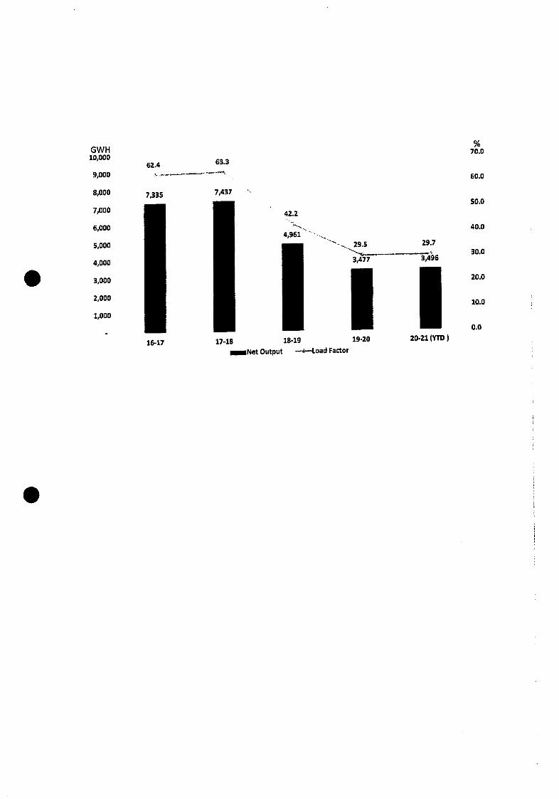
% GWH 70.0 10,000
62.4 63.3
9,000 60.0
8,000 7,335 7,437 50.0
7,000 42.2
6,000 40.0 4,961
5,000 29.5 29.7 30.0
4,000 3,477 3,496
3,000 20.0
2,000 10.0
1,000
0.0
16-17 17-18 18-19 19-20 20-21 (YTD)
Net Output ---4.oad Factor
S
ANNE XURE M
TECHNICAL LIMITS & UNIT START- UP TIMES
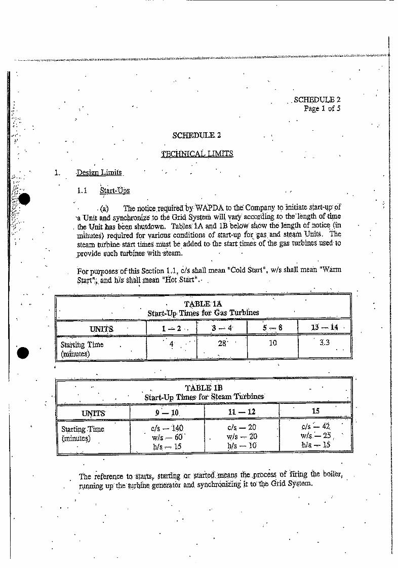
• .SCHEDULE2 Page 1 of 5
SCHEDULE. 2
ThCHNICAU LIMITS
1.. •esign Limits
Li Start-Ups
• (a) The iotie .r it by WAPDA to th Company to initiate start-up of a Unit and synthronize to the Gnd System will vary according to the length of tune tle Unit has been shutdown Tables 1A and lB below show the length of notice (in minutes) required for vanous conditions of start-up for gas arid stani Units The tearn tiithine stt tithes .must be added to the start times of the gas turbines used to
provide such turbfnes with steam.
For pupoesof this Sectitin 1 v.1, c! shall mean "Cold Start", w/s shall mn "Warm St;. aUd h/s hII ;Xi1eai "IOt .Sthrt" -
• • TABLE; lA Start-Up Tunes for Gas Turbines
UN1T 1-2. 5-8 -t4
Startthg Time (ijiiutes)
4. • • 28 • • 10 3•3
TAB.LE1B - • Start-Up Times for Steam 1Eb1e
UNITS 9—iO. 11-12 15
Starting Tune (minutes)
•
c/s — 140 w/s.— 6 h/s—iS
c/s — 20 wIs 20 hfs-10
c/ — 42
The referenc:e to arts) tatthig ;or temana the .procss of firirg he boilr.,
• u)ning up *urbfn generator aiid. sythQnizing it to ile Grid.

TABLE 3
UNITS . . •9_•io 11-12
c/s —•8 WYS •—. 8. h/s.— 365
t5
No manuftttr tinilts coiended
Starts/Year c/s .—.
wls —. 50 h1_t**1
SCHEDULE, Page 2 o. 5
(b) Startp of a Steam Turbine Unit shall be elassified as set forth in Table 2
below:
TABLE 2
-Il 12 15 UNITS 9-10
flnml PrCSSUre** (bar)
Steam Ternperatur
Classification has beiiprovidc4 othe:basis of DrumPressure or Steam Tinpeature depending on the Classification ptoVided. by the. nanufacü1rer.
(e) The nunber of yearly steani turbine Unit start-ups shaU be subject to
the limits set.forth in Table 3 below:
To be agreed by the Engineer,. WAPDA and the Ptirchaser prior to the omp1eUoa
of the ID.0 Test arid the. Fiiiictiora1 Tests.
L2 Complex loadin,g
(a The Unit toad ramping rates ar steady rates at which the lOad catibe
raised. The maximum. .designlo d ramping rates are shown below in WtmirxClte) In Table 4. The rnaximm design load ramping rates shown below are subject to. th resits of the Functional Test described in SeCtion 2.1(t) of Schedule 4.
Time after Shutdown
c/a— <12 w/s — 12-20 his—>20
N/A
N/A.
NIA
C's — <100°C wls — 1O25O0 C. b/S >250eC
N/A
N/A
N/A
c/s - >60 - 6-60 s
Ws63iäUrS
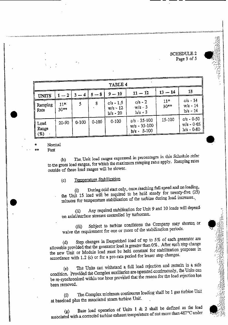
SCHEDULE. 2 Page 3 of 5
TABLE 4
9-10 11-12.. 13-14 15
c/s. - 2 11* wls -3 30** h/s' - 3
15-100 c/s - 0-50 wi's - b/s - 0-80••
Nortal Fast
(b) The, Unit load ranges expressed in pecentageS in this. Schedule .rfer to the gross load ranges,. for which the maximum ramping ratts apply. Ramping rates outside of these load ranges will be slower.
(c) Temperature Stabilization
During ôld start ouy, nc .ieacbing full speed and no,loadiiig,
the Unit i. laad will be teuired to he. held steady for twentyflve; (25) 'minutes fortemperatUre stabWzation o.f the tutbine dtiring 1Qa4 increases..
(ii) Any required: stablliz tiori for Unit 9 atid '10 loads' will depend
'On adai/sUrface' 'stresses controlled by turb,omax.
(ill) Shject. to. turbine con.ditiOii5 the Company rny shorten, r waive the requfrement for ore or tnore of the tabiiiaitiOn perIods.'
(4) Stp. changes in pespa.tcbed load 'of up to 5% of' each. generator are
allowable proided.tha.t the generator Jpad s greater thafl 0%., Afters,p'Cnge
the new Unit or Module load must be held constait for stabilization purposes in accordance with 1.2 (e) or for a pro-rata period for 'Lesser step change.
(e) Th Units ar ithstand a. full load .tejeetiôn and rexiain in a condition Provided the Complex auxiliaries are operated continuouslY, the Units can be re-synchronized within one hour provided that the reason for the load iejectl'on has
been removed.
(f) The :coniplex mi,hniuii continws 1ading shall he I gas turbine Unit
at baseload plus the associated steam turbine Unit
(g) Bate' load operation of Units .1 & 2 shall be defined as the Load associated with a. orrectbd turbine exhaust tempeatue. of not more than 4g7°C.undet
UNITS ,1-2' 3-4' 5 -SI
Raning I 1•' 5 S Rate 3Q*
Load 20-0 0-100 0-100
Range
c/s - 1.'5 w/s - 12 his - 20
0-100 efs - 5-i00 w/s - 35-tOO b/s -I0O
c/s - 1,4 w/s - 14 'his 14
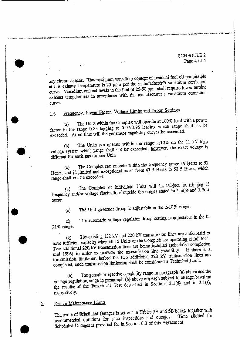
SCHEDULE 2 Page 4 of 5
any ciEcumstances. The. maximum vanadurn co$ent of residual fuel oil permissible at this exhaust temperature is 25 ppm per the mánufacturer vwndiUflt conet•iOn curve. Vanadium content ivels in the fuel. of 25'5.0 ppm shall require lower turbine exhaust tempratures in accordance with the nianufacturer'S vanadium correetion
crve.
1.3 Frequency. Power Factor. Voltage LimIts and Droop settings
(a) The Units witbinthe Complex will, operate at 10% load with a power
factor in the range 0.85 lagging to 0.97/0.95 leading which range chail not be exceeded. At no time will the generator capability curves be exceeded.
(b) The Uxilta can optate within the range ±10% on the it kv bil' voltage systei whih range shall, not be exceeded however, the exact voltage is.
different for each gas turbine Unit4
(c) The Complex cn operate within the frequency rnge 49 flertz to. 51
Herz4 and là limited and exceptional, cases from 47,. 5 Hertz: to 52.5 Hertz,: wlrih
range shall not be exceeded.
The Complex or individual Units will b.e subject to. .trippg. If
frequency and/or voltage fluctuations outside the ranges stated in 1 3(b) and 1 3(c)
occur.
(1) 21% range.
(g)Th.xisiiflg 132 kV and 220 kV transmission lines are anticipated to
have sufficient caftcity Mien.. all 1.5 Units of the Coinpiet are operating, at full load. Two additional 220 kV ttamission lines are being snatalled (shedU1ed completion mid 1996) in 'order to increase 'the transniissiOfl 1in telibi1ity. If there is a. ttansmiiOti' limithiibii before the two 'additithial 220. kY tr'aiismisSiofl lines are completed, such. trattsrnissinit limitation shall be çonidered a Technical Lithit.
(h). The: generator reactive..cspabiUy range inparagraph (a) abQve end the 'voltage eg1,1la.tiQr& range in par.agaph (b) above are each subject, to chang.baSc1 on
the results: of the Functional Test described in Sections 2.1(d) and in 2.1(a),
respectively..
2 Desinn Maintenance Limits
The cyole of'Sche'duled Outage's is set out in Tables 5A and ~belo'. tag'ether with
recornrnepded durations for si.ich inspections iand. outages. 'Thie aiItted for Scheduled Outagt' is provIded fOr in Section 6.3 of this Agreement..
(e) The Unit governor droop is adjustable in the 240% range
The automatic voltage regulator droop setting is adjustb1e th the -
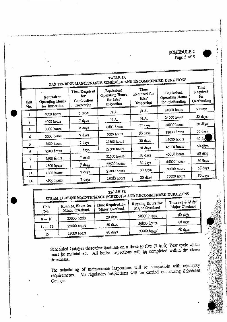
SCHEDULE 2 Page 5 of 5
GAS TUI1JIINE MAINTENAC SC1EDOLE AND IECOMMENDED .DIJRATIONS
Ui No.
Eqiivalent Operating Hours
for Inspedion
Time Required for
Conibustion Inspection
Equivalent Operating Hours
for HGP Inspection
Time Required for
EGP ectiQu
Equivalent. Operating Hours for o'?erhauling.
Time Required.
for Overhauling
1 '4000 hours 7 days N .A. N.A. 24000 hours. 50 'days
4000 hours 7 days N.A. A. 4000 hours '50 days. 2
3 9000 hours 7 days 6O00 hours .0 days .18000 hours 50 days
'days 18000 hours •0 'days 4 3000 hours 1 days 6000 hours
5 7500 hours 7 days 22500 hours O days 45000 hours
7500 hours 7 days 22500 hours 30. days 45000 hours 50.4a's.
6
7. 70Q hours I days 22500 hours Si days 45000 hours, 50-days.
B 75QO hours 7.day, 2±qOhdurs 30 days - 45000 houn .5, dya
13 4000 hours 7 days 25000 hourS 30.dzys 50000 hours 50 days
14 4000 hours 7 4ays 25000 hoirs 30. days 50000 ho .014ays
TABLE SB
STEA TURBTh M.INTENMCE SCHEDULE AN) RCOMM1iNDED ]YUBATIONS
Running Hours.'fo,r Major\Overhaul
Tini qiiired fpr Msjor Q'er'haui
20 days 50purs O4ays, 9'—'lO 250.QQ iurs
20 Lays
20 days
,ouxs
50Q'hqw.S
6 'days
'0 dsys U —12 250.00 hows
15 25000 iro
Scheduled Outages thereafter 4Qx1tiflti a. three' ive (3 tQ.-) Year 'cipl wCli
imst be maintained All boi1r nspectionS will be completed within the above
timescaleS,
The scheduling of maintenance inspections 'will be compatible with regulaiOr requirements. AU rgula1OrY 'insectionS will be 'carried out' during Scheduled
Outages.
RunnLflg.OUr for. Minor )yerhapi
Time Retufreri.f01 t1inor Overhaul
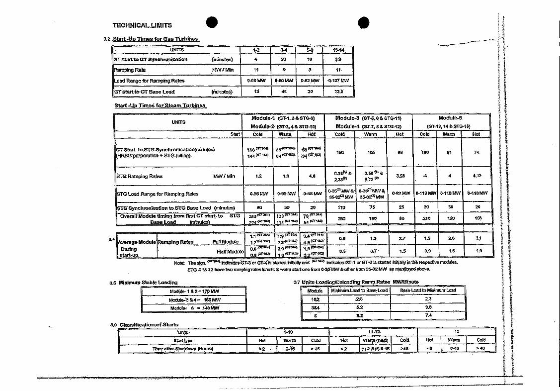
as Minimum Stable LGadIr
I
Module- I 82 = 17P MW
M1le-3&4 165MW
Moduls. 6 .18MW
-. 3.9 Classilicaltonof Starts .
- s-to - ii-iz is-
Hot Warm Cold Hot Wa1m-(1)&) Cold 1 Hot WaitS Cold
Tn. Sluitdown(Hou?5) . . '-16 2 128)8-48 '48. <6 . .- >40.
TCHNICAL.UMITS
3;2 Start 4jflmesfor Gas Turbiñe
-- UP4IT$ 3- 5-8 13-14
Gtso.GTsynchroflaatiefl .(udnutes) 4 2 10
.RngRto MWiMin 11 5 3. tI
Load Range lbr Ramping: Rates 0-96MW 0-80 t.W 0.82Mw -107MW
tartteGTBase Load (thinutes) 1 44 20 13.0
Start -Ut, Tirneé forSteam Turl,iiie&
Module-I T-1,.3&s1ô..9
Module-a (GT.24& Sm-to)
Module4 T-,6&STG.1)
Module-4 (GT-7, S &STG.42)
Modul
(GT13, i4&Tl5-1$)
S1a1 Cold Wamt Hot Cold Warm Hot Cold Warm Hot.
GTStart th$1ncbronlSation(minutes) Q1RSpmp2ratton-StG.rolli8g.
iss °
' as °
54 •3 GT1 ISO 1(15 .65 B0 91 74.
STGRampingRatas MWIMln 1.2 tO . 4.12
STG Load RangeforRarnpingRate5 0,95MW 0-95MW .0-25 MW C-82MW 0-118 MW 0,118MW tl-11BMW
STGSynclirmatIontoT Base mad (minuteS) 80 50 20 110 . ° I ° OvealoduletimingfromllottGrstart•tó STI3
Base Load (minutez'
245tr
oj (GTi)
18(=Ta.) r3
IV1) —
.21
I -
AveraeModule Dürin
Ramping Rates Full Module
- . .9(OT358.
- 3 4.9
Half Module .0&°' 0 ari,.
09 (G34
s':
•. g(T4
s.z' 0.5- 07 1.5 .0.9 1.6 to
3..
Note: Tbegn. -k s3T.3or GT4 Hyadd (ST 1&Z dicatesGT-i otstad ln1álinihrspedive modules.. SG 41& 12I1avat mmpiflgTataeinI4 &wsnn ate-tone om 0-35MW &otherfiom35-82 MW as nedBbaue.
.3.7 U -loadng0eoag.Rarnp..Rataa MW!Mte
lOdui Mnlnón. Basei.oad Base.LoadMinimwnLoad
1&t 2&. 2.2
384 . 3.6.
8.2 .,

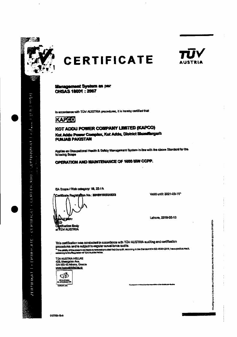
TUV AUSTt* CERTIFICATE
_f S p.r OAS 1$GGt ; 7
i usir ***
KOT ADOU POW QAKV LTEC IK*PGO) KMU P.r 1 P1UAB PiQSTNl
OPAT1 OF N
tgjjffK: 111
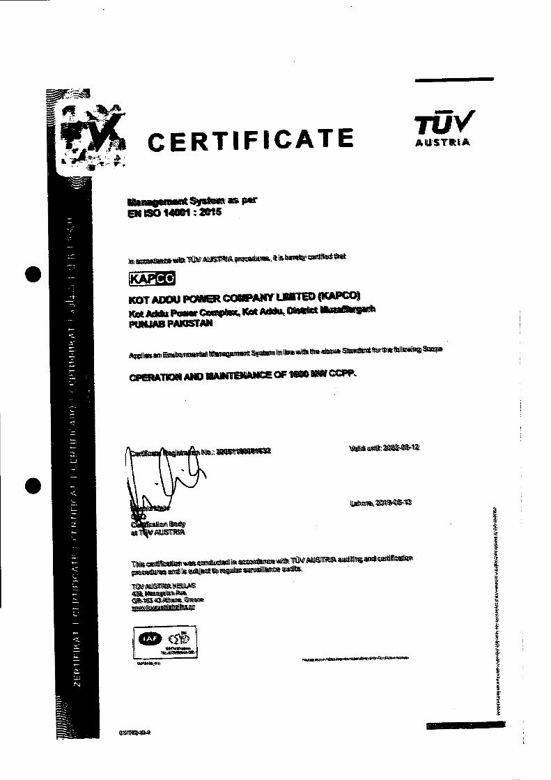
rUv' AUSTRIA CERTIFICATE
gsnart S ENO141*1:lS
lJ az iU11 piWi
[cO
KOT ADOJ P cOSJW LTED (1(APcO)
KfrK P Kt M.. O m PRIJAB P$1Nl
OF.•flO'I AI t9AN OF 1 IPN P.
e1Iltj ni1JL:Z

TU%' AUSTLA CERTIFICATE
M.n.gsuit Sy EN ISO 9001 : an
. i J
IKA
KOT AOOU R OAKY LMTB UcO) K*? P.mt C rk PUNJAB PMUSIMI
OPATION *I W1TBWIE C 1S00 5R cPP.
wMI: Z24e-1
1Iff dIgiIt
4Oi9s.
• U
U U 4 U! U!! 4 U4UU!U!_ U ! U, U ! !
U
:: U U!U U, .U4
U!
U !! U!
U !U
U U UU
UU! :U
!iU U,4U
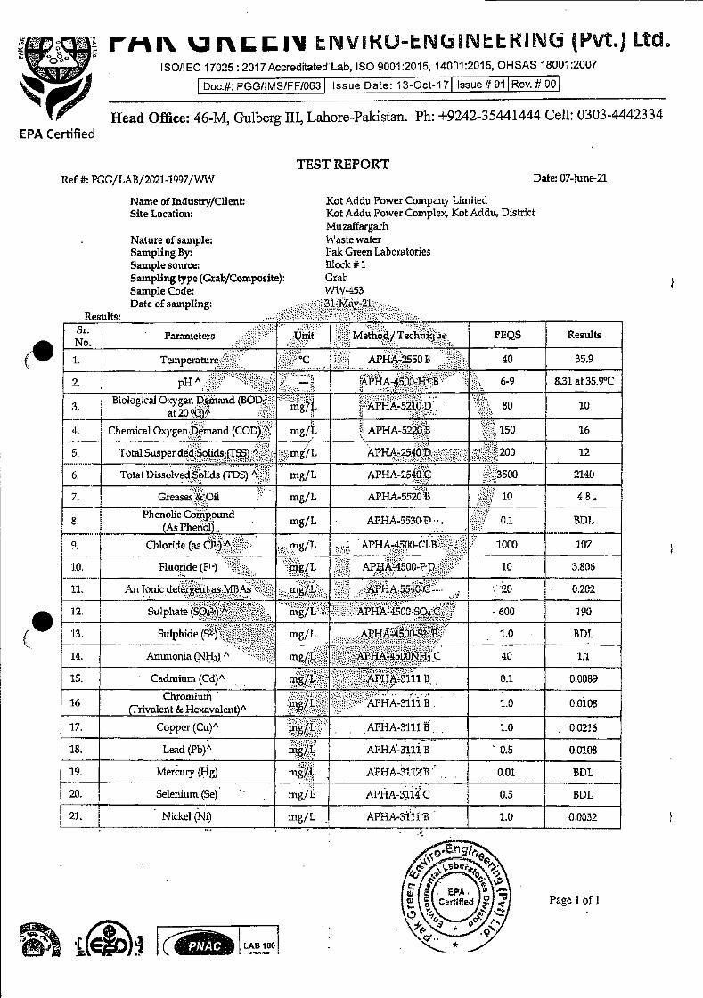
Rev. # 00 Issue # 01 Issue Date: 13-Oct-17 Doc.#: PGGflMS/FF/063
LAB 180
Page I of I
ri-a'. ]rLII LNVKUN(INLLKIN(i(PVt.)Ltd ISO/IEC 17025: 2017AccreditatedLab, ISO 9001:2015, 14001:2015, OHSAS 18001:2007
Head Office: 46-M, Gulberg Ill, Lahore-Pakistan. Ph: +9242-35441444 Cell: 0303-4442334
TEST REPORT Ref #: PGG/LAB/2021-1997/WW
Name of Industry/Client: Site Location:
Nature of sample: Sampling By Sample source; Sampling type (Grab/Composite): Sample Code: Date of sampling;
Results:
Kot Addu Power Company Limited Kot Addu Power Complex, Kot Addu, District Muzaffargarh Waste water Pak Green Laboratories Block #1 Grab WW-453
Date: 07-June-21
EPA Certified
Parameters Unit Method/ Techrn.jue FEQS Results
1 Te.inperature C APHA-2550 B 40 359
A — APHA-45Q)-I-t B 69 8.31 at 359°C
Biologiai O.ygen Demand BODs mglL APHA-21OD 80 10
4 Chemical Oxygen Demand (COD) A mg/L APHA-5220 B 150 16
5 fotal Suspended Solids (TSS) 6 ing/L APHA-2540D 200 12
6 Total thssohed Solids (TDS) A ntg/L APHA-2540 C 3500 2140
7 Greases & Oil mgjL APHA-520 B 10 4 8
8 Phenolic Compound mg/L APIIA-5330 1) 01 BDL
0 Qiloride (as (Ll1) A mg/L APHA-4500-C.l B - 1000 107
JO Fluoride (F') ng/L APHA-450fl Pt) 10 3806
ii An Tonic detergLtt as M1 As mg/I. APHA 5540 C 20 02C2
12 Sulphate (SO4) rngfL APHA 4500-604C 600 190
13 Sulpludu (5') mg/L AA45004i i 10 BDL
14 Ammonia (NH3) A mg/L - APHP-45O0Ns C 40 ii
15 Cadmium (Cd)" mg/L APH 3111 B 01 0 0089
16 crrivale.'alezit)" g/L APHA-31fl B 10 00108
17 Copper (Cu)" mg/L APHA 3111 B 10 0 0216
18 Lead (Pb)" mg/L APHA-3111 B 05 00108
19 Mercury (Fig) mg/L APHA. 3112 B 001 BDL
20. Selenium (Se) mg/E. APHA-3.i C 0.5 BDL
21. Nickel (Ni) mg/L APHA-3lflli 1.0 00(132

MR 3ru i Iv II'JVIKUN(NKIN((F'Vt)LtcL
ISO/IEC 17025 : 2017Accreditated Lab, ISO 9001:2015, 14001:2015, Ol-ISAS 18001:2007
.iA i
'I.oOQo
Doc.#: PGG/I MS/FF/063 Issue Date: 13-Oct-17 Issue #01 Rev. # 00
Head Office: 46-M, Gulberg ifi, Lahore-Pkistan. Ph: +9242-35441444 Cell: 0303-4442334 EPA Certified
Ref #: PGG/ LAB/2021-1997/WW Date: 07-June-21
Results:
Parameters Unit Method / Technique PEQS Results
22. Silver (Ag) mg/L APFIA-3111 B 1.0 0.0113
23. Total Toxic Metals (Cd, Cr. Cu, Pb, . Hg, Sc, Ni. Ag, As, Ba, B) mg L - 2.0 0,0758
24. Zinc (Zn)" mg/L APHA-3111 8 5.0 0.0223
25. Arsenic (As) ing/L Al'HA-3114 C 1.0 0.0092
26 Barium (Ba) mg/L APHA-3111 D 15 BDL
27 lion (Fe)" ing/L APHA-3111 $ 8 0 0 0886
28 Manganese (Mn)" ing/L APHA 3111 B 15 0 0171
29 Boion (B) ingfL APHA-31fl D 60 BDL
30 Chlorine (C12) mg/p APJiA-4500 Cl 'B 10 06
31 Pesticide, herbicides, fungicides andmsecticides mgfL ASTM-D5125
, 015 BDL
'2. Cyanide (as CN' ) Total mg/L PHA 45CXJ-CN F 1 0 BDL End of Reporl.;',i
PEQS Funjab Env1ronmntal Quality Standards "PNAC Accreditei Remarks All parameters ie in complianLe with PEQS Limits Terms & Conditions
• This report sho4Lbe reproduced as a whole and not in parts. . • Analysis was coniticted on the request of proponent for his own use or PEQS compliance • Report cannot be used regardmg compliance of any complaint, EPO ci any othr ccnirt case • The iesponsibility of the ethical use of the results reported in this report lies with the client Consequently,
the laboratory is absolved, of its responsibthty for any claim that may result tluough the use by the client or others of the iesults appearing m this xepoi
• The leftover sample (if so available) shall be retained for tifteen days after the issuance of the report unless otherwise negotiated 'between the client and the iborntory
• The report is not valid for any negotiations
Lab. Ana1ys Chief Analyl.. Laborø &\
(P QURAT-UL-AIN
-
I1DJAZULLA .A 4 .
BD..Bèj4v Detection Limit
Page 1 of]
LAB 180
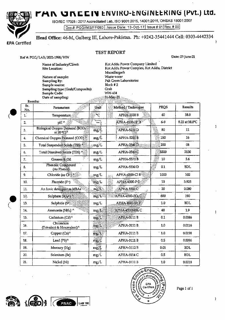
rMi' NVIKO-N( NILKIN( (PVt.) Ltd. ISO/IEC 17025: 2017Accreditated Lab, SO 9001:2015, 14001:2015,OHSAS 18001:2007
Doc.#: PGG/IMS/FF/063 ;Issue Date: 13-Oct-17 Issue #01 Rev. # 00
Head Office: 46-M, Gulberg Ill, Lahore-Pakistan. Ph: +9242-35441444 Cell: 0303-4442334 EPA Certified
TEST REPORT Ref #: PGG/LAB/2021-1998/WW
Name of Industry/Clieiit Site Locatioru
Nature of sample: Sampling By: Sample source: Sampling type (Grab/Composite): Sample Code: Date of sampling:
Results:
Date: 07-June-21
Kot Addu Power Company Limited Kot Addu Power Complex, Kot Addu.. District Muzaffargarh Waste water Pak Green Laboratories Block #2 Grab WW454
Parameters Unit Method/Tecimique PEQS Results
1 Temperature °C APHA-2550 B 40 380
2. pH" .- APHA-4500-W 'B 6-9 8.22 at 38 0°C
Biological Oxygen Demand (BOD5 mg/L APHA-5210 D 80 11
4 Chemical Oxygen Demand (COD)" m8/L APHA-5220 B 150 16
S Tota1SuspendedSo1idsç1" mg/L APHA-2540D 200 08
6 Total Dissolved Solids (D" mg/L APHA-2540 C 3500 2130
7 Greases 4 Oil mg/L APHA 550 B 10 56
8 PhenolicConWound mg/L APHA 5530 D 01. BDL
9 Chloride (asCii) A mg/L APHA-4500-CI B 1000 102
10 Fluoride (F') mg/L APHA-4500-F D 10 3925
11 AnlorucdeteigentasMBAs rng/L MH455DC 20 0080
12 Sulphate (SO4'-) ' rng/L APHA-4500-O C 600 190
13 bulphide(S2 ) mg/L AA4500S'-- F-' 10 BDL
14 Ammonia (NH3) A mgi L. APHA-4500NH C 40 19
15 Cadmium (Cd)' ing/L. APHA-3111 B 01 00086
16 (Fnvalent&Hexava1ent iJj. APHA3111 B 10 0 0116
17 Copper (Cu)" mg/L APHA-3111 13 10 00198
18 Lead (Pb)" mg/T. APHA-3111 B 05 00096
19 Mercuiy (Hg) rng/L APHA.3112 B 001 BDL
20. Selenium (Se) mg/L APHA-3114 C 0.5 BDL
21. Nickel (Ni) mg/L APHA-3111 11 1.0 0.0018
Page 1 of 1
.PNAC: LAB 1O
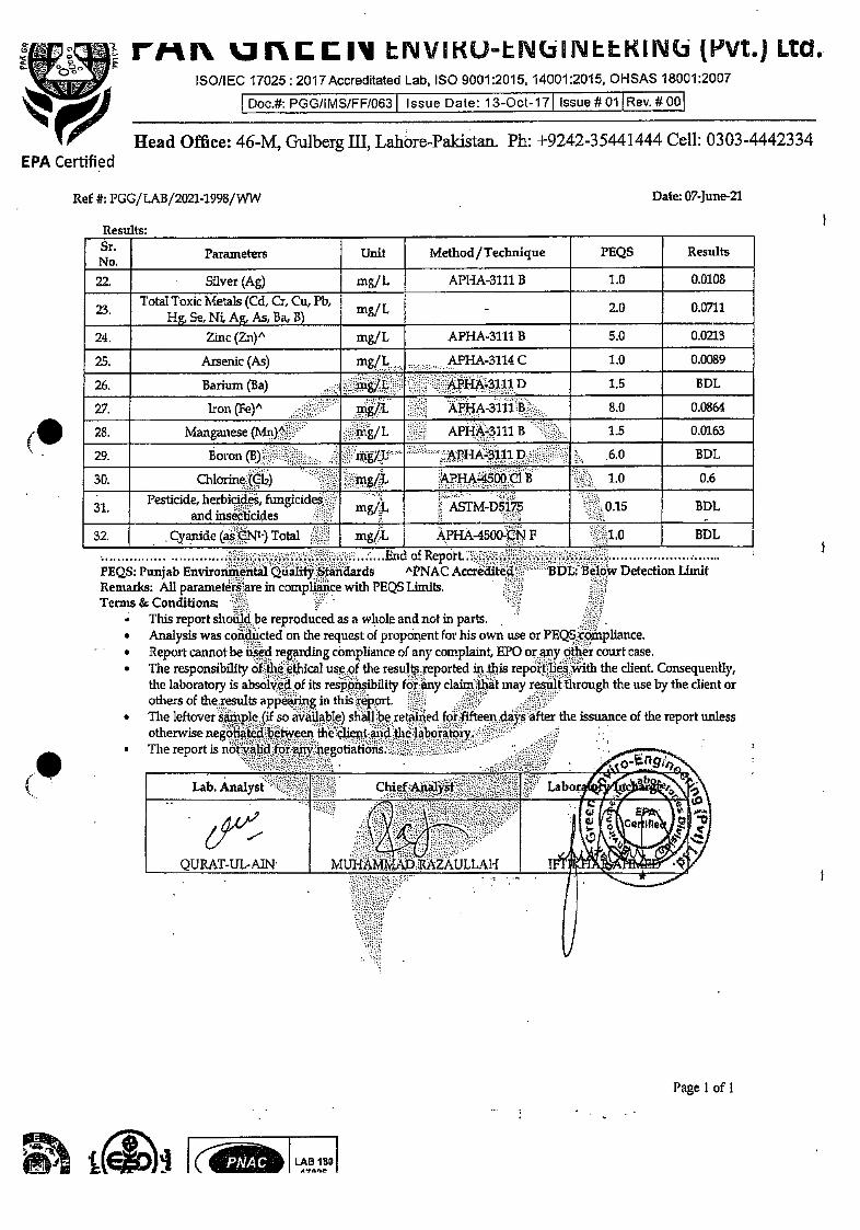
MR UR111V LNVIKU-N NUKIN(. (I"Vt.) Ltd.. ISO/IEC 17025: 2017 Accreditated Lab, ISO 9001:2015, 14001:2015, OHSAS 18001:2007
Doc.#: PGG/IMS/FF/063 Issue Date: 13-Oct17 Issue #01 Rev. #00
Head Office: 46-M, Gulberg III, Lahore-Pi1dstan Ph: +9242-35441444 Cell: 0303-4442334 EPA Certified
Ref #: PGG/LAB/2021-1998/WW Date: 07-June-21
Results:
Parameters Unit Method/Technique PEQS Results
22. Silver (Ag) ing/L APHA-3111 B 1.0 0.0108
23. Total Toxic Metals (Cd, Cr, Cu, Pb, . Hg, Se, N Ag, As, Ba, B) mg/L - 2.0 0.0711
24. Zinc (Zn)' mg/L APHA-3111 B 5.0 0.0213
25. Arsenic (As) mg/L. ..,.•
APHA-3fl4 C 1.0 0.0089
26 Barium (Ba) - mg/L APRA-3111 D 15 EDL
27 Iron (Fe)" mg/L APHA-3111 B 80 00864
28 Manganese (Mn)" mg/L APHA-3111 B 1 5 00163
29 Bojon (B) mg/iL APHA3111 1) 60 BDL.
30 Chlorine (Cb) m/L APHA-4500 Cl B 10 06
31 Pesticide, herbicides, fungicides and insecticides mg/i. AM-D5l75 015 BDL
32 Cyanide (as CNI) Total ni/L 'PHA-4500-CN F -10 BDL
..............End of Report. FEQS Punjab Environmental Qualify Standards "PNAC Acereditea BDL Below Detection Limit Remarks All parameters are in compliance with PEQS Limits Terms & Conditions
• This report sho.be reproduced as a whole and not in parts. • Analysis was conducted on the request of proponent lot his own use or PEQS compliance • Report cannot be used reardung comhance of any complaint, EPO or any other court case • The responsibility of the ethical use of the resul reported in this repoit lies with the client Consequently,
the labotatory is absolved of its respqnsibihty for any claim that may result through the use by the client or others of the results appearing in this xeport
• The leftover sample (if so available) shall be retaued for fifteen days after the issuance of the report unlEss otherwise negotiated between the thent and the laboratoxy
• The report us notvalid for-any.egotiations
Page 1 of I
t i)i k'jr
LAB 180
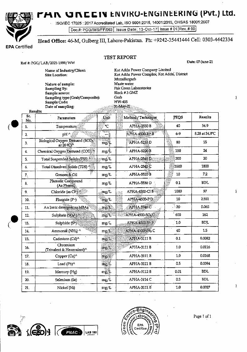
LAB 180
Page 1 of 1
rMI JflIV LNVIKO-IN(NEEKIN(i (Pvt.J Ltd. ISO/IEC 17025 : 2ol7Accreditated Lab, ISO 9001:2015, 14001:2015,OHSAS 18001:2007
Head Office: 46-M, Gulberg III, Lahore-Paldstan. Ph: +9242-35441444 Cell: 0303-4442334
TEST REPORT Ref #: PGG/LAB/2021-1999/WW
Name of lndustry/Client Site Location:
Nature of sample: Sampling By: Sample source: Sampling type (Grab/Composite): Sample Code: Date of sampling
Kot Addu Power Company Limited Kot Addu Power Complex, Kot Addii, District Mu7ffargarh Waste water Pak Green Laboratories Block #3 GMZ Grab WW-455
Date: 07-June-21
EPA Certified
Parameters Umt Methodj Technique PEQS Results
1 Temperature APHA-2550 B 40 349
2 pH" — APHA-4500.}IB 6-9 828 at34.9°C
Biological Oxygen Demand (BOD5 mg/L APHA 5210D 80 15
4 Chemical Oxygen Demand (COD)" mg/L APHA 5220 B 150 24
5 Total SuspendedShds(T5S) A mg/L APHA-2540D 200 20
6 Total Dissolved 5lids (JD" , mg/L APHA-2541) 3500 1800
7 Greases&Oii mg/L APHA-5520 , 10 7.2
8 Phenohc Compound mgfL APHA-5530 D 01 BDL
9 Chloride (as Cli) - mg/L APHA-4500 Cl B 1000 97
10 fluoride (Fl) mg/L APHA-40O-F D 10 2.551
11 AiilonicdetergentasMBAs mgfL APHA55Ø4)C 20 0065
12 Sulphate (SO4i)" mg/L APHA-4500 SO4 C 600 162
13 Suiphide (S mg/L API A-4500-F 10 BDL
14 Ammonia (NH3)" mg/J.. APHA4500NHi C 40 15
15 Cadmium (Cd)" infL AP1-T.A-111 B 01 00082
16 (rnvalent&Hexavalenty' ni/L APHA 3111 B 10 00116
17 Copper (Cu)" x/L APHA-3111 B 10 0 0168
18. Lead (Pb)" APHA-3111 B 0.5 0.0094
19. Mercury (Hg) rnL APHA-3112 B 0.01 BDL
20. Selenium (Se) mg/L APHA-3114 C 0.5 -
BDL
21. Nickel (Ni) mg/L APHA-31flB 1.0 0.0027
Doc.#: PGG/I MS/FF1063 Issue Date: 13-Oct-17 Issue #01 Rev. # 00

Rev. # 00 Issue #01 Issue Date: 13-Oct-17 Doc.#: PGG/IMS/FF/063
EPA Certified
Ref #: PGG/LAB/2021-1999/WW
Results:
Date: 07-June-21
LAS 180
MR UIU11V ENVJKU-IIThINLlKINL (I'Vt0) Ltd. ISO/IEC 17025: 2017Accreditated Lab. ISO 9001:2015, 14001:2015, OHSAS 18001:2007
Head Office: 46-M, Gulberg Ill, Lahore-Pakistan. Ph: +9242-35441444 Cell: 0303-4442334
Parameters Unit Method/Technique PEQS Results
22. Silver (Ag) mg/L APHA-3111 B 1.0 0.0144
23. Total Toxic Metals (Cd, Cr, Cu, Pb,
. Hg, Se, Ni, Ag, As, Ba, B) mg/I. - 2.0 0.0709
24. Zinc (Zn)" mg/L APHA-3111 B 5.0 0.0193
25. Arsenic (As) mg/I . APFIA-3114C 1.0 0.0078
26 Barium (Ba) mgfL APi-A-3111 D 1 5 BDL
27 lron(Fe)" mg/L APHA-3111 80 00818
28 Manganese (Mn)' nig/ L APHA-3fl1 B 1 5 0 0119
29 Boron (B) - mg/I. I AHA-M11 D ' 6 0 BDL
30 Chlon.neCli) mg/L M'HA-4500C1B 10 07
31 Pesticide, heibic.tes, fungicides andmsecticides :.;;;;
mg/L ASTM-D515 0 15 BDL
32 Cyanide (as CN1 ) Total mg/L APHA-4500-CN F 10 BDL ..:. . .End of Report..
PEQS Punjab Enviromnent1 Quality Standards "PNAC Accredte Remarks All parameters are in compliance with PEQS Limits Terms & Conditions -
This report shou14.be reproduced as a whole and not in parts. Analysis was conducted on the request of proponent for his own use oi PEQS compliance Report cannot be used regarding compliance of any comp1aint E or aiy other court case. The responsibility olthe ethical use of the results reported in this reportlies' with tliedi...Coiisequently, the laboratory is absolved of its responsibility for any claim that may resültthrough the use by the client or others of the results appearing in this report. . . . - . . - The leftover sample (if so available) shall be retained for fifteen days after the issuance of the report unless otherwise negotiated between the client and the laboratoi
. The report is nbt 'lidforany negotiations.. -.
Lab Analyst Chief Analyst .
QTJRAT-UL-AIN MUHAMMAD RAZAULLAH '. 1k t
Page 1 of 1
w Detection Limit
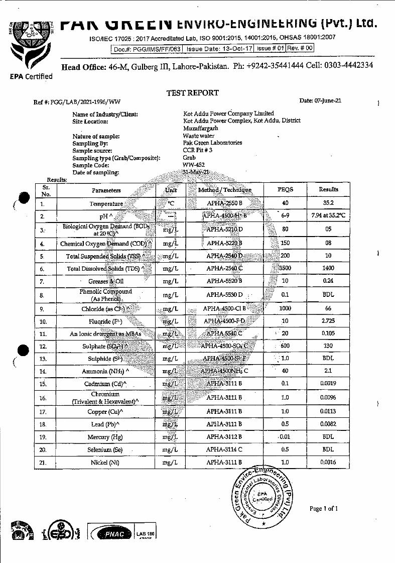
LAB 180
Page 1 of I
rr 'JRIl IJVIKUN( NIKIN(i (F'Vt.) Ltd.
ISO/lEG 17025 2017Accreditated Lab, ISO 9001:2015, 14001:2015, OHSAS 18001:2007
Head Office: 46-M, Gulberg Ill, Lahore-Pakistan. Ph: +9242-35441444 Cell: 0303-4442334
TEST REPORT Ref #: PGG/LAB/2021-1996/WW
Name of industry/Client: Site Location:
Nat-ure of sample: Sampling By: Sample source: Sampling type (Grab/Composite): Sample Code: Date of sampling:
Kot Addu Power Company Limited Kot Addu Power Complex, Kot Addu, District Muzaffargarh Waste water Pak Green Laboratories CCR Pit #3 Grab WW-452 31-May-21
Date: 07-June-21
Parameters T.Jnxt Method/Techmue PEQS Results
I Temperature QC APHA-2550B 40 35.2
2 pH" - — APHA-4500-H B 6-9 794 at 352°C
Biological Oxygen Demajid (BOD5 mg/L APHA-5210 D 80 05
4 Chemical Oxygen Demand (COD) " mg/L APHA-522 150 08
5 Total Suspended Sohds S) A mg/L APEtA-2540 1) '200 10
6 Total DissolvedSohds (TDS)" mg/L APHA-2540 C 500 1400
7 Greases&Oil mg/L APHA-552tiB 10 024
8 rngfL APHA-5530 D 01 BDL
9 Chloride(asCll)A ntg/L APHA-4500-CIB 1000 66
10 Fluoride (Fl) mg/L APHA.4500-F D 10 2 725
11 An Ionic th'terZentasMBAs mg/'L APHA 54O C 20 0105
12 Sulphate (s042)" - mg/L APHA-4500-SO4 C 600 130
13 Su1phiie (S2) mg/L A..PHA45o0.S2 P 1 0 BDL
14 Ammonia (NHi)" mg/L iM-4500NH C 40 21
15 Cadmium (Cd)" mg/L AI'H.A-3111 B 0 1 0 0019
16 Chromium
(Trivalent & Hexavalent) mg/L APHA-3111 B 1 0 00096
17 Copper (Cu)" mg/L APHA-3111 B 10 00113
18 Lead (Pb)" mg/L APHA-3111 B 05 00082
19. Mercuiy (Hg) mg/i. APHA-3112B .0.01 BDL
20. Selenium (Be) mg/L APHA-3114 C 0.5 BDL
21. Nickel (Ni) mg/L APHA-3111 B 1.0 0.0016
EPA Certified
Doc.#: PGGJIMS/FF/063 Issue Date: 13-Oct-17 Issue # 01 Rev. # 00

riii JRLLI tIJVIKU-LJ\i(.II'JttKITh (F'Vt.) Ltd. ISOIIEC 17025: 2017Accreditated Lab, ISO 9001 :2015, l40O1:2015 OHSAS 18001:2007
Doc.#: P00/I MS/F F1063 Issue Date: 13-Oct-17 Issue # 01 Rev. # 00
Head Office: 46-M, Gulberg Ill, Lahore-Pakistan. Ph: +9242-35441444 Cell: 0303-4442334 EPA Certified
Ref 4!: PGG/LAB/2021-1996/WW Date: 07-June-21
Results:
Parameters Unit Method/Technique PEQS Results
22. Silver (Ag) mg/L APHA-3111 B 1.0 0.0094
23. Total Toxic Metals (Cd, Cr, Cu, Pb, . Hg, Se, Ni, Ag, As, Ba,. B) mg/L - 2.0 0,0467
24. Zinc (Zn)" rng/L Al'HA-3111 B 5.0 0.0182
25. Arsenic (As). mg/L . ....APHA-3114 C 1.0 0.0047
26 Barium (Ba) ing/L APHA-3111 D 15 BDL
27 Iron (Fe)" n/L APHA-31tt B 8 0 0 0413
28 Manganese (Mn)A mg/ L APHA-3111 B 15 00110
29 Boron (B) m.g/L AI!HA-S111 1) 60 BDL 30 Chlorine (Cli) m/t APHA45O() Cl B 10 05
31 Pesticide herbicides, hzngicides nig/L ASTM-D5175 015 BDL
32. Cyamde (asCNi ) Total mg/L APHA-4500-CN F 1 0 BDL .. End of Repoi1. .
PEQS 1'unjab Enviroxunentil Quality Standards "PNAC Accredited BDL Below Detection Limit Remarks 11paranietesaie in compliance with PEQS Lmuts Terms & Conditions
This report should be repioduced as a whole and notrn parts Analysis was conducted on the request of proponent for his owp use or PEQS cmphance Report cannot be used regarding compliance of any complaint EPO oi any other cotut case The responsibility of the etlucal use of the results reported in this i eportJies with the dient. Consequently, the laboratoiy is absolvd of ts iespoxisibility for any claim that may result through the use by the client oi others of the iesults appearing m tlusreport The leftover sample if so available) shall be retaued for fifteen days after the issuance of the report unless otherwise negotiated between the client and lte laborafozy The report is flOtv0yleg
Lab Analyst Chief.Ana1ys e
QIJRAT-UL-AIN MIJHAMM MZAULLM-I
if
Page 1 cf I
LAB 180 4?flOt
ANNEXURE P
CERTIFICATE OF APPRECIATION
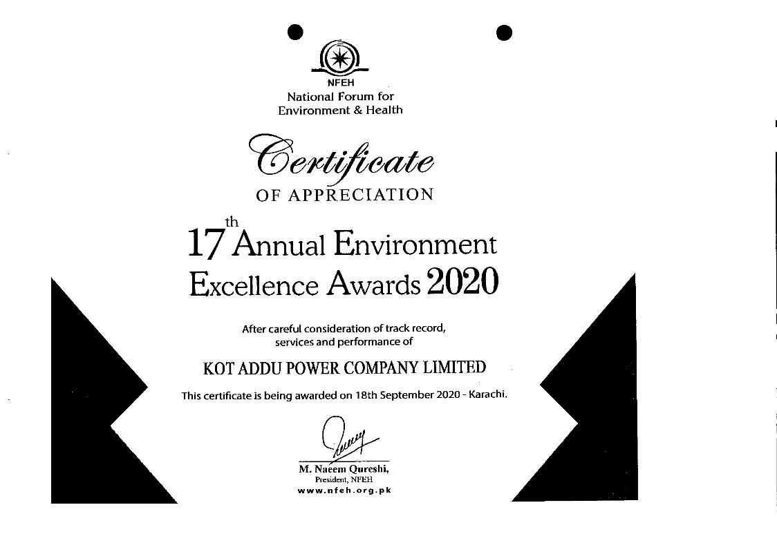
._ . NFEH
National Forum for Environment & Health
OF APPRECIATION
17 Annual Environment Excellence Awards 2020
After careful consideration of track record, services and performance of
KOT ADDU POWER COMPANY LIMITED This certificate is being awarded on 18th September 2020 - Karachi.
M. Naéem Qureshi, President, NFEH
www.nfeh.org.pk