siemens simatic wincc flexible 2008 security hardening guide ...
Upload
khangminh22Category
view
2download
0
1Siemens NC 62 · 2016
GlossaryFunctions and terms
SINUMERIK 840D sl
1D/3D clearance control in position control cycle with free direction, Run MyCC /CLC-FD
Option; order code M65Article No.: 6FC5800-0AM65-0YB0
Available as a supplement to the function SINUMERIK Integrate Run MyCC /CLC, the function SINUMERIK Integrate Run MyCC /CLC-FD can be used to specify the spatial direction of the controlled motion with 3 simulated axes. It is then possible to program the control direction independently of the tool orientation (laser beam orientation) specified by the 5-axis transformation.
1D/3D clearance control in position control cycle, Run MyCC /CLC
Option; order code M40Article No.: 6FC5800-0AM40-0YB0
1D/3D clearance control in the position control cycle Run MyCC /CLC controls one machine axis (or 3 machine axes in conjunction with 5-axis transformation) plus a maximum of one gantry axis and makeSiemens NC 62 · 2016s it possible to automatically maintain the constant clearance between the head and the workpiece that is technologically required for the machining process. The clear-ance information is read in via a high-speed analog input.
The most important application for this option is laser cutting of flat or spatially formed metal sheets or tubes. The function can also be used with a force sensor in order to implement force control (friction welding).
Restricted functionality of export versions: Clearance control can be applied to only one axis because 5-axis transformation is not available. The number of interpolating axes is restricted to 4 without Run MyCC /CLC and to 3 with Run MyCC /CLC.
1D clearance control in the IPO cycle
1D clearance control in the IPO cycle can be used, for example, to evaluate sensor signals via a high-speed analog input. 1D clearance control in the IPO cycle can also be used to compute a position offset $AA_OFF for an axis via a synchronized action.
2D representation of 3D protection areas/working areas
You can use protection areas to protect various elements at the machine, their components and the workpiece against incorrect movements. The 3-dimensionally programmed protection areas are displayed in 2D. This display also applies to the programmed working area limitations.
→ Working area limitation
→ Protection areas 2D/3D
3D simulation 1 (finished part)
Option; order code P25Article No.: 6FC5800-0AP25-0YB0
The simulation can be extended to 3D representation by means of the 3D simulation 1 (finished part) option. This extension also applies to the simultaneous recording.
© Siemens AG 2015

2 Siemens NC 62 · 2016
GlossaryFunctions and terms
SINUMERIK 840D sl
Acceleration with jerk limitation
To achieve an optimum acceleration pattern with reduced wear on the machine's mechanical parts, you can select SOFT in the part program to ensure a continuous, jerk-free acceleration profile. When you select acceleration with jerk limitation, the speed characteristic over the path is generated as a bell-shaped curve.
Access MyMachine /Ethernet
Article No.: 6FC5864-4AP41-0YB0
SINUMERIK Integrate Access MyMachine /Ethernet enables worldwide, secure remote operation and monitoring of a machine tool automated with SINUMERIK. Remote access is always established via a secure connection based on TLS (previously SSL) via the Internet (worldwide). The technical implementation of access to the Internet depends on the local conditions at the machine. Access to the Internet can be implemented in different ways.
Access MyMachine /P2P
Option; order code P30Article No.: 6FC5800-0AP30-0YB0
The function SINUMERIK Integrate Access MyMachine /P2P permits remote access to the SINUMERIK HMI to quickly diagnose the machine's condition. It supports data uploads and downloads, analog and ISDN telephone links as well as access via the Internet.
Access MyMachine /P2P increases machine availability as it can quickly go online. Furthermore, it enables users to prepare essential service callouts more effectively.
Access protection
Access to programs, data and functions is protected in a user-oriented hierarchical system of 7 access levels.
• 3 password levels (protection levels 1 to 3) for machine manufacturers and end users, and
• 4 keyswitch positions (protection levels 4 to 7) for end users (keyswitch positions can also be evaluated via PLC)
SINUMERIK CNCs thus have a multistage concept for controlling access rights.
Protection level 1 has the highest access rights and protection level 7 the lowest. A higher protection level automatically includes all protection levels below it.
Access rights for protection levels 1 to 3 are preprogrammed by Siemens (default setting). An entered password has priority over a keyswitch position, and machine manufacturers or end users can change access rights for protection levels 4 through 7. Subprograms can be completely protected against unauthorized reading and display.
Passwords should be regularly changed from an industrial security perspective.
Action log
The action log records all operator actions and pending alarms for diagnostics purposes.
Advanced Position Control APC
Option; order code M13Article No.: 6FC5800-0AM13-0YB0
The natural frequency of the machine can have a detrimental effect on the maximum speed of the machine and the surface charac-teristics. The Advanced Position Control APC function raises the kv factor, improves the surface and therefore increases productivity without requiring any changes to the mechanical components.
Protection level
Type PLC DB10 DBB 56 bit...
User
1 Password – Machine manufacturer: Development2 Password – Machine manufacturer: Commissioning engineer3 Password – End user: Service4 Red key switch
position 37 End user:
Programmer, machine setter5 Green key switch
position 26 End user:
Qualified operator who does not program6 Black key switch
position 15 End user:
Trained operator who does not program7 Switch position 0 4 End user:
Semi-skilled operator
© Siemens AG 2015

3Siemens NC 62 · 2016
GlossaryFunctions and terms
SINUMERIK 840D sl
Advanced Surface
Option; order code S07Article No.: 6FC5800-0AS07-0YB0
The Advanced Surface function is used to optimize the motion control. Accurate contours and perfect surfaces can be achieved even at high machining speeds. With optimized speed management, Advanced Surface delivers better workpiece surfaces with a higher workpiece yield.
Alarms and messages • Alarms and messages:
All messages and alarms are output separately on the operator panel in plain text with date and time as well as the appropriate symbol for the delete criterion. All alarms are saved in an alarm log that can be configured according to size.
• Alarms and messages in the part program:Messages can be programmed to provide the user with information about the current machining situation during program execu-tion. Message texts may be up to 124 characters long, and are displayed in 2 lines (2 × 62 characters). The contents of variables can also be displayed in message texts.
Example 1:
N10 G1 F2000 B=33.333
N15 MSG ("Rotary table position:" "$AA_IW[B]" "Degrees")
Display in message line following traversal of block N10
Rotary table position: 33.333 degrees
Example 2:
N20 MSG ("Check" "$AA_IW[X]" "X position!")
Display: Check ... X position!
In addition to programming messages, alarms can also be set in a CNC program. An alarm always goes hand in hand with a response from the CNC according to the alarm category. The alarm text must be configured, alarm numbers 65000 to 67999 are available. A description of the responses to the various alarms can be found in the Commissioning Manual.
Example 3:
N100 SETAL (65001) Effect:
Display interlocking CNC start
Deletion: with reset• Alarms and messages from the PLC:
Machine-specific alarms and messages can be displayed directly from the PLC program in plain text. Messages comprise status messages and error messages. In the case of status messages, the display is immediately deleted when the condition is no longer active, error messages must be acknowledged. User-specific alarm numbers from 40000 to 89999 can be assigned to general, channel-specific, axis-specific and spindle-specific user alarms and messages. The response of the CNC to alarms or messages can be configured. The configured alarm and message texts are saved in application-specific text files.
• Specific evaluation of alarms:A channel-specific signal can be used to decide whether other channels may continue to be used when an alarm is issued.
Analog value control
System variable $A_OUTA(n) enables values from up to 8 analog outputs to be directly entered in the part program. The value specified by the NCK can be changed by the PLC before it is output to the hardware of a SIMATIC DP ET 200 analog module. The hardware outputs are written in the interpolation cycle.
Analyze MyCondition
Article No.: 6FC5684-7AP41-0YB0Article No.: 6FC5684-7BP41-0YB0Article No.: 6FC5684-7CP41-0YB0
SINUMERIK Integrate Analyze MyCondition provides test cycles for testing synchronized axes and universal axes and for performing circularity tests; it also offers functionality for continuous data acquisition during production. It also supports the reporting of key parameters regarding the wear of mechatronic components.
A condition-oriented maintenance routine keeps production machines running longer and reduces downtimes and outages.
Animated elements
Using short film sequences, animated elements provide support by allowing the user to look ahead during operation and programming, especially in processes where the motion sequence is the primary consideration.
© Siemens AG 2015

4 Siemens NC 62 · 2016
GlossaryFunctions and terms
SINUMERIK 840D sl
Asynchronous subprograms ASUB
An asynchronous subprogram is a CNC program which can be started in response to an external event (e.g. a digital input) or from the PLC. Inputs are allocated to subprograms and activated by programming SETINT.
If the relevant event occurs, the CNC block currently being processed is immediately interrupted. The CNC program can be con-tinued later at the point of interruption. Multiple asynchronous subprograms must be assigned different priorities PRIO so that they can be processed in a certain order. Asynchronous subprograms can be disabled and re-enabled in the CNC program (DISABLE/ENABLE).
→ Interrupt routines with fast retraction from the contour
Auto Servo Tuning AST
Auto Servo Tuning AST automates the process of adapting parameters to the control equipment, which controls the axes of a CNC machine. The parameters are adapted according to the frequency response measurement of the machine dynamics. One of the benefits of Auto Servo Tuning AST is that it facilitates the measuring process.
The axis control loops are individually optimized according to the target parameters selected by the user for an adaptive strategy. In a second step, the control loop parameter settings are adjusted for axes that are identified as being involved in an interpolation path, with the result that the correct dynamic response is obtained for all axes. This adaptation ensures coordinated movement of all the axes along the interpolation path.
→ Auto Servo Tuning AST Call
Auto Servo Tuning AST Call
Option; order code S10 Article No.: 6FC5800-0AS10-0YB0
AST Call allows machines to be optimized again automatically from the part program. The AST Call function is thus particularly useful for processes involving a wide range of different workpiece weights and clamping operations, and for machines driven by linear/torque motors.
→ Auto Servo Tuning AST
Auxiliary function output
Auxiliary function output informs the PLC when the part program wants the PLC to handle certain machine switching operations. This is accomplished by transferring the appropriate auxiliary functions and their parameters to the PLC interface. The transferred values and signals must be processed by the PLC user program.
The following functions can be transferred to the PLC:• Tool selection T • Tool offset D/DL • Feedrate F/FA • Spindle speed S • H functions • M functions
Auxiliary function output may be carried out either with velocity reduction and PLC acknowledgement up to the next block, or before and during travel without velocity reduction and without block change delay. Following blocks are then traversed without a time-out.
Axes, coupled motion
When a defined leading axis moves, the coupled-motion axes (following axes) assigned to it travel the traverse paths derived from the leading axis, taking into account a coupling factor (setpoint coupling). Together, the leading axis and the following axes form a coupled-axis grouping.
Definition and activation of a coupled-axis grouping take place simultaneously with the modal instruction TRAILON. A coupled-axis grouping can consist of any desired combinations of linear and rotary axes. A coupled-motion axis can be assigned up to 2 leading axes (in different coupled-axis groupings). A simulated axis can also be defined as the leading axis, in which case the real axis actually does the traveling, taking into account the coupling factor. Another application for coupled-motion axes is the use of 2 coupled-axis groupings to machine the 2 sides of a workpiece.
© Siemens AG 2015

5Siemens NC 62 · 2016
GlossaryFunctions and terms
SINUMERIK 840D sl
Axes/spindles
Option; order codes A01 ... A28Article No.: 6FC5800-0AA00-0YB0
An additional interpolating axis/spindle can extend the number of axes/spindles in the basic configuration.
Functions:• POS/SPOS/M3, M4, M5 (from CNC block)• POSA/SPOSA (from CNC block, modally)• FC18/POS/SPOS/M3, M4, M5 (PLC axes)• PLC-VDI interface (M3, M4, M5 directly)• OSCILL (asynchronous oscillation)• OSCILL (synchronous oscillation)• do POS/SPOS/M3, M4, M5 (synchronized actions)• Couplings (TRAIL, LEAD, EG, CP, ...)• Path/geometry/additional path axes/GEOAX()• Spindles for thread cutting, tapping and thread cutting with compensating chuck• Setpoint output and actual values are available• Commissioning with SINUMERIK Operate
→ Positioning axes/auxiliary spindles
→ Simulation axis/spindle
→ Virtual axis
→ Internal/external drives
Axial coupling in the machine coordinate system MCS
The subfunction "Axis collision protection" is implemented by SINUMERIK Integrate Run MyCC /PROT.
The subfunction "Axial coupling in the machine coordinate system" is implemented by the generic couplings.
→ Axis collision protection, Run MyCC /PROT
→ Generic couplings
Axis collision protection, Run MyCC /PROT
Option; order code N06Article No.: 6FC5800-0AN06-0YB0
SINUMERIK Integrate Run MyCC /PROT supports collision protection of up to 20 axis pairs that, for example, move along a common guide rail and that could collide with each other. The axes concerned can also be active in different channels. The traversing directions of the axes of an axis pair can differ. A maximum spacing can also be monitored.
Restricted functionality of export versions: Not possible.
© Siemens AG 2015

6 Siemens NC 62 · 2016
GlossaryFunctions and terms
SINUMERIK 840D sl
Axis container
On rotary indexing machines/multi-spindle machines, the axes holding the workpiece move from one machining unit to the next. Since the machining units are handled through different NCU channels, the axes holding the workpiece must be dynamically reassigned to the corresponding NCU channel if there is a change in station/position. Axis containers are used for this purpose.
Only one workpiece clamping axis/spindle is active on the local machining unit at a time. The axis container combines the possible connections to all clamping axes/spindles, of which only one is active at a time for the machining unit.
The available axes that are defined in the axis container can be changed by shifting the entries in the axis container. Shifting can be triggered by the part program or synchronized actions: Keyword AXCTSWE(CT1).
Example of an axis container: Following rotation of the axis container through 1, the channel axis Z is assigned to axis AX5 on NCU 1 instead of axis AX1.
Axis data output via PROFIBUS, Run MyCC /ADAS
Option; order code N07Article No.: 6FC5800-0AN07-0YB0
SINUMERIK Integrate Run MyCC /ADAS enables axis and spindle data to be output to a special PROFIBUS or PROFINET device module. This function can be used, for example, for process or machine monitoring functions in real time outside the CNC.
The required axis and signal type are selected by transferring a selection command (length: 8 bytes) to the CNC. SINUMERIK Integrate Run MyCC /ADAS in the NC kernel then sends up to 30 axis data items (of 4 bytes each) to the slave in each PROFIBUS cycle.
The transfer cycle can be equal to the position controller cycle, or a multiple thereof. Consistent receipt of data from each cycle can be guaranteed only when the slave is operating in isochronous mode (or with PROFINET IRT).
Axis limitation from the PLC
The preactivation of protection areas with specification of a position offset is programmed in the part program. You can put the preactivated protection areas into effect in the PLC user program via the PLC interface. As a result, the relevant protection area is activated, for example, before a tool probe is swiveled into position in the working area, to see whether the tool or a workpiece is in the path of the swiveling part.
The PLC can put another axis limitation into effect by activating the 2nd software limit switch via a PLC interface signal. This reduction of the working area may become necessary, for example, when a tailstock is swiveled into position. The change is immediately effective, and the 1st software limit switch plus/minus is no longer valid.
→ Protection areas 2D/3D
Axis/spindle replacement
An axis/a spindle is permanently assigned to a specific channel via machine data. The axis/spindle replacement function can be used to release an axis/a spindle (RELEASE) and to assign it to another channel (GET), i.e. to replace the axis/spindle. The relevant axes/spindles are determined via machine data.
AXCTSWE(CT1)
Channelaxis name
XYZS1
Number in the logic machine axis image
1267
Logic machine axisimage
AX2 1 local maschine axis 2AX3 2 local maschine axis 3
CT1_SL1 Axis Container 1, entry 1
Axis container 1NC1_AX1NC2_AX2NC2_AX1NC1 AX5
Axis container 1NC1_AX5NC1_AX1NC2_AX2NC2 AX1 G
_NC
01_E
N_0
0157
a
© Siemens AG 2015
7Siemens NC 62 · 2016
GlossaryFunctions and terms
SINUMERIK 840D sl
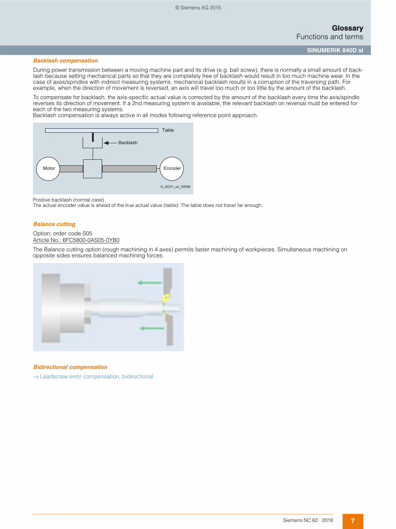
Backlash compensation
During power transmission between a moving machine part and its drive (e.g. ball screw), there is normally a small amount of back-lash because setting mechanical parts so that they are completely free of backlash would result in too much machine wear. In the case of axes/spindles with indirect measuring systems, mechanical backlash results in a corruption of the traversing path. For example, when the direction of movement is reversed, an axis will travel too much or too little by the amount of the backlash.
To compensate for backlash, the axis-specific actual value is corrected by the amount of the backlash every time the axis/spindle reverses its direction of movement. If a 2nd measuring system is available, the relevant backlash on reversal must be entered for each of the two measuring systems. Backlash compensation is always active in all modes following reference point approach.
Positive backlash (normal case)The actual encoder value is ahead of the true actual value (table): The table does not travel far enough.
Balance cutting
Option; order code S05Article No.: 6FC5800-0AS05-0YB0
The Balance cutting option (rough machining in 4 axes) permits faster machining of workpieces. Simultaneous machining on opposite sides ensures balanced machining forces.
Bidirectional compensation
→ Leadscrew error compensation, bidirectional
Motor Encoder
Table
Backlash
G_NC01_en_00098
© Siemens AG 2015

8 Siemens NC 62 · 2016
GlossaryFunctions and terms
SINUMERIK 840D sl
Block search
The block search function allows any point in the part program to be selected where machining should start or be continued. The function is provided for the purpose of testing part programs or to continue machining after it was canceled. Cascaded block search is also possible.
Search variants:• With calculation on the contour
During the block search, the same calculations are performed as in normal program operation. The target block is then traversed true-to-contour until the end position is reached. Using this function it is possible to approach the contour again from any situation.
• With calculation at block end pointThis function allows a target position to be approached (such as tool change position). All calculations are also executed here as during normal program operation. The end point of the target block or the next programmed position is approached based on the interpolation valid in the target block.
• Without calculationThis method enables high-speed searches in the main program. No calculations are carried out during the search. The internal control values remain the same as before the block search.
• External block search without calculationIn the menus "Search position" and "Search pointer", the softkey "External without calculation" can be used to start an accelerated block search for programs which are executed from an external device (local hard disk or network drive).
• Specify the search target by:- Directly positioning the cursor on the target block - Specifying a block number, a jump label, any character string, a program name, or a line number
© Siemens AG 2015

9Siemens NC 62 · 2016
GlossaryFunctions and terms
SINUMERIK 840D sl
Cartesian PTP travel
For handling and robot-related tasks, 2 types of movement are required: either in the Cartesian coordinate system Continuous Path CP, or as a Point-to-Point PTP motion. With PTP, the shortest way to reach the end point is with activated TRAORI transformation. PTP generates a linear interpolation in the axis space of the machine axis.
By smoothing from PTP to CP movement, it is possible to switch from fast infeed to a mounting or positioning movement with optimum timing. PTP travel does not result in an axis overload when traveling through a singularity, such as changing an arm position during handling. PTP travel is also possible in the JOG CNC operating mode and does not require Cartesian positions (e.g. from CAD systems) to be converted into machine axis values.
Cartesian PTP travel is also used for cylindrical grinding machines with an inclined axis: With active transformation, the infeed axis can be moved either according to Cartesian coordinates or at the angle of the inclined axis.
Cartesian travel to fixed stop, Run MyCC /FXSC
Option; order code N38Article No.: 6FC5800-0AN38-0YB0
SINUMERIK Integrate Run MyCC /FXSC cartesian travel to fixed stop is used as a substitute for the standard travel to fixed stop function for machine kinematics with OEM transformation. With this function, tailstocks or sleeves, for example, can be traversed to a fixed stop in order to clamp workpieces. The clamping torque and a fixed stop monitoring window can be programmed in the part program and set in the machine data. The function regulates the force to an adjustable value in the approach direction. In this case, it can be utilized simultaneously in several channels.
Restricted functionality of export versions: Not possible.
CCG compiler (cam contour grinding, non-circular grinding)
Option; order code P10Article No.: 6FC5800-0AP10-0YB0Requirements: TRANSMIT option, order code M27 and polynomial interpolation option, order code M18.
This option is required for SINUMERIK 840D sl to allow the execution of part programs that have been generated with the CCG com-piler tool. The OEM can either integrate the corresponding tool into the user interface on the PCU 50 or use it on an external PC.
The latest version of the tool is made available once on request, the option (runtime) must be ordered for each CNC. The CCG compiler generates CNC programs in the polynomial format to allow the machining of non-circular contours on a cylindrical grinding machine. The lift curves commonly used today, which describe the desired final contour in polar coordinates, are used as the input data for programming and generating a complete CNC program.
The technology data, i.e. the number of infeed revolutions, allowance, sparking-out revolutions, angle of infeed and velocities, are parameterized and taken into account when the part program is generated. The generated contour is not dependent on the tool (grinding wheel) radius, because radius compensation (G41/G42) is active in the CNC.
Circle via center point and end point
Circular interpolation causes the tool to move along a circular path in a clockwise or counter-clockwise direction.
The required circle is described by:• Starting point of circular path (actual position in the block before the circle) • Direction of rotation of circle • Circle end position (target defined in circular block) • Circle center
The circle center can be programmed as an absolute value with reference to the current zero point or as an incremental value with reference to the starting point of the circular path. If the opening angle is apparent from the drawing, then it can be directly programmed. In many cases, the dimensions from a drawing are taken so that it is more convenient to program the radius in order to define the circular path. In the case of a circular arc of more than 180 degrees, the radius specification is given a negative sign.
Circle via intermediate point and end point
If a circle is to be programmed, which does not lie in a paraxial plane but obliquely in space, an intermediate point can be used to program it instead of the circle center. Three points are required to program the circle: the starting point, the intermediate point and the end point.
© Siemens AG 2015
10 Siemens NC 62 · 2016
GlossaryFunctions and terms
SINUMERIK 840D sl
Clamping monitoring
Clamping monitoring is one of the many extensive axis monitoring mechanisms implemented in SINUMERIK CNCs. When an axis is to be clamped on completion of the positioning action, you can activate clamping monitoring using the PLC interface signal clamping in progress. This may become necessary because it is possible for the axis to be pushed beyond the standstill tolerance from the position setpoint during the clamping procedure.
The amount of deviation from the position setpoint is set via the machine data. During the clamping procedure, clamping monitoring replaces standstill monitoring, and is effective for linear axes, rotary axes, and position-controlled spindles. Clamping monitoring is not active in follow-up mode. When the monitoring function responds, its reactions are the same as those of the standstill monitoring.
→ Position monitoring → Standstill monitoring
CNC high-level language
To meet the various technological demands of modern machine tools, a CNC high-level language has been implemented in SINUMERIK CNCs that provides a high degree of programming freedom.
System variables
The system variables ($.) can be processed in the CNC program (read, partially write). System variables allow access to, for example, machine data, setting data, tool management data, programmed values, and current values.
User variables
If a program is to be used flexibly, variables and parameters are used instead of constant values. SINUMERIK CNCs give you the option of executing all CNC functions and addresses as variables. The names of the variables can be freely defined by the user. Read and write access protection can also be assigned using attributes. This means that part programs can be written in a clear and neutral fashion and then adapted to the machine as required, for example, free selection of axis and spindle address designa-tions.
User variables are either global GUD or local LUD. LUD can also be redefined via machine data to make them into global program user variables (PUD). They are displayed in the Parameters operating area under the user data softkey, where they can also be changed. Global user variables GUD are CNC variables that are set up by the machine manufacturer. They apply in all programs.
Local user variables LUD are available to the user for parameterizing CNC programs. These data can be redefined in every CNC program. These variables make programming more user-friendly and allow the users to integrate their own programming philosophy.
Indirect programming
Another option for the universal use of a program is indirect programming. Here, the addresses of axes, spindles, R parameters, etc., are not programmed directly, but are addressed via a variable in which their required address is then entered.
Program jumps
The inclusion of program jumps allows extremely flexible control of the machining process. Conditional and unconditional jumps are available as well as program branches that depend on a current value. Labels that are written at the beginning of the block are used as jump destinations. The jump destination can be before or after the exit jump block.
Program coordination in several channels
Program coordination makes it possible to control the time-related execution in parallel operation of several CNC channels using plain text instructions in the part program. Programs can be loaded, started and stopped in several channels. Channels can be synchronized.
Arithmetic and trigonometric functions
Extensive arithmetic functions can be implemented with user variables and arithmetic variables.
In addition to the 4 basic arithmetic operations, there are also:• Sine, cosine, tangent • Arc sine, arc cosine, arc tangent • 2. Power of 2 (squaring), square root • Absolute value • Integer component, round to integer • Exponential function, natural logarithm • Offset, rotation, mirroring • Scale modification
© Siemens AG 2015

11Siemens NC 62 · 2016
GlossaryFunctions and terms
SINUMERIK 840D sl
Comparison operations and logic combinations
Comparison operations with variables can be used to formulate jump conditions.
The comparison functions that can be used are: • Equal to, not equal to • Greater than, less than • Greater than or equal to • Less than or equal to • Concatenation of strings
The following logic combinations are also available: AND, OR, NOT, EXOR (EXclusive OR). These logic operations can also be performed bit by bit.
Macro techniques
Using macros, single instructions from a programming language can be grouped together to form a complex instruction. This shortened instruction sequence is given a freely definable name and can be called in the CNC program. The macro command is executed in the same way as the single instructions.
Control structures
The CNC normally processes the CNC blocks in the order in which they are programmed. Control structures allow the programmer to define additional alternatives and program loops as well as program jumps.
The commands make structured programming possible, and make the programs much easier to read:• Choice of 2 alternatives IF-ELSE – ENDIF• Continuous loop control LOOP• Counting loop FOR• Program loop with start condition WHILE• Program loop with end condition REPEAT
CNC operating modes
3 CNC operating modes can be selected in the Machine operating area:• JOG
JOG CNC operating mode (jogging) is intended for the manual movement of axes and spindles, as well as for setting up the machine. The set-up functions are reference point approach, repositioning, traveling with the handwheel or in the predefined incremental mode, and redefinition of the CNC zero point (preset/set actual value).
• MDIIn MDI (Manual Data Input) CNC operating mode, it is possible to enter individual program blocks or sequences of blocks for immediate execution via CNC Start. These blocks can then be saved in part programs. With the Teach In function, motion sequences are transferred to a program by returning and storing positions. The Teach In function can be used in the MDI CNC operating mode.
• AUTOIn AUTO (automatic) CNC operating mode, the part programs are executed fully automatically once they have been selected in the workpiece, part program or subprogram directory (normal operation). During AUTO mode it is possible to generate and correct another part program.
In the MDI and AUTO CNC operating modes, the sequence of a program can be modified using the following program control functions:• SKP Skip block (up to 8 skip levels)• DRY Dry run feedrate• ROV Rapid traverse override• SBL1 Single block with stop after sets of machine functions• SBL2 Single block with stop after every block• SBL3 Stop in cycle• M01 Programmed stop• DRF Differential resolver function• PRT Program test
© Siemens AG 2015

12 Siemens NC 62 · 2016
GlossaryFunctions and terms
SINUMERIK 840D sl
CNC program messages
All messages programmed in the part program and all alarms recognized by the system are displayed on the operator panel in plain text. Alarms and messages are displayed separately. Messages can be programmed to provide the user with information about the current machining situation during program execution.
→ Alarms and messages
CNC program transfer
→ Manage MyPrograms
CNC user memory
All programs and data, such as part programs, subprograms, comments, tool offsets, and zero offsets/frames, as well as channel and program user data, can be stored in the shared CNC user memory. The CNC user memory is buffered with a battery.
CNC user memory, additional
Option; order codes D01 ... D06Article No.: 6FC5800-0AD00-0YB0
The CNC user memory on the NCU can be expanded by 2 MB in each case using this option.
→ HMI user memory
CNC user memory, expanded
Option; order code P77Article No.: 6FC5800-0AP77-0YB0
The function "CNC user memory expanded" increases the CNC user memory to 100 MB. With option P12 "HMI user memory, in addition on CF card of NCU", it is possible to increase the size of the CNC user memory up to 6 GB.
→ HMI user memory, additional on CF card of NCU
COA interface for compiled OEM cycles, Run MyCCI /COOC
Option; order code M67Article No.: 6FC5800-0AM67-0YB0
SINUMERIK Integrate Create MyCCI /COOC is an interface for the OEM's own developments relating to the CNC interpreter. Special calculations that are too complex to implement in the CNC language (e.g. intensive matrix algebra) can be programmed in C++ with a mathematics library to be provided by the user. CNC commands cannot be executed at C++ level.
The development of customized compile cycles in the interpreter is dependent upon a COA agreement and one-off purchase of the option SINUMERIK Integrate Create MyCCI /INT.
Collision avoidance
→ Collision avoidance in real time
Collision avoidance in real time
Option; order code S02Article No.: 6FC5800-0AS02-0YB0
The SINUMERIK collision avoidance option provides reliable protection against undesirable collisions between moving and non-moving machine components in the machine's working area. The protection is effective in all operating situations.
SINUMERIK collision avoidance is focused on critical situations encountered in practice, e.g. during machine setup or machining interruptions – in other words, when the operator intervenes in the process.• 3D collision detection in real time• Monitoring non-moving and moving machine components• Efficient modeling of collision objects in SINUMERIK Operate on the PC with NX SINUMERIK Collision Avoidance
Requirements:• SINUMERIK CNC software version 4.5 SP2 and higher• 1-channel machine with one NCU• SINUMERIK NCU 720.3B PN or NCU 730.3B PN (recommended)• Simultaneous recording• 3D simulation 1 (finished part)
© Siemens AG 2015

13Siemens NC 62 · 2016
GlossaryFunctions and terms
SINUMERIK 840D sl
Communication interface to a robot, Run MyCC /RODI
Option; order code N65Article No.: 6FC5800-0AN65-0YB0
SINUMERIK Integrate Run MyCC /RODI is the communication interface to a KUKA robot that is operated using interpolation in the SINUMERIK.
→ Machining with robot, Run MyRobot /Machining
Restricted functionality of export versions: Not possible.
Compensation of a forced mechanical coupling in the machine coordinate system, Run MyCC /AXCO
Option; order code M81Article No.: 6FC5800-0AM81-0YB0
SINUMERIK Integrate Run MyCC /AXCO allows movement of an axis that occurs due to mechanical coupling of an axis to a following axis, to be compensated such that the axis remains mechanically stationary despite the coupling. The motor of the coupled axis is rotated according to the set coupling ratio.
Restricted functionality of export versions: Not possible.
Compile cycles interface, Run MyCCI /xy
SINUMERIK Integrate Run MyCCI /xy are loadable compile cycles and offer special interfaces for customized developments. This software (interface) is produced with versions of the development tools which are identical to those used for the NCK basic software of the SINUMERIK 840D sl.
For this special application, the customer uses software (GNU compiler/linker) in a Cygwin software shell on a Windows PC. This concept of loadable interfaces therefore allows the OEM to develop real-time applications in C/C++ and to load them as customized compile cycles.
→ Develop compile cycles, Create MyCC→ Integrated tool monitoring and diagnostics IMD BASE, Run MyCCI /IMD→ Universal spatial compensation interface, Run MyCCI /UCI→ COA interface for compiled OEM cycles, Run MyCCI /COOC
Concatenated transformations
Two transformations can be concatenated using the TRACON command: TRAANG (inclined axis), as the basetransformation, can be linked with TRAORI (5-axis transformation), TRANSMIT (face machining of turned parts) and TRACYL (cylinder surface transformation).
Applications:• Turning-milling with mechanical non-orthogonal Y axis to X, Z (inclined-bed turning milling machine) • Grinding contours programmed with TRACYL (cylinder processing) • Finishing an out-of-center contour created with TRANSMIT.
Grinding a TRANSMIT contour with inclined axis
Y
X
Z
U
TRAANG
TRANSMIT
G_NC01_en_00129
Workpiece
Inclinedaxis
© Siemens AG 2015

14 Siemens NC 62 · 2016
GlossaryFunctions and terms
SINUMERIK 840D sl
Continue machining at the contour (retrace support), Run MyCC /RESU
Option; order code M24Article No.: 6FC5800-0AM24-0YB0
When using 2D flat bed cutting procedures, e.g. laser, oxygen or water jet cutting, the machine operator can return to the program continuation point (selected solely from the view of the workpiece) following an interruption in machining without exact knowledge of the part program in order to continue machining the workpiece from that particular location.
The Continue machining at the contour function (retrace support) contains a ring buffer for the geometric information of the blocks already executed. A new part program is generated from this for reverse travel.
Continue machining is used, for example, when the machine operator only notices the interruption in a 2D laser or water jet cutting operation a few blocks after the actual interruption. The head has usually already progressed further in the machining process, and must, therefore, be returned to continue machining.
Continuous dressing (parallel dressing)
With the continuous dressing function, the form of the grinding wheel can be dressed in parallel with the machining process. The grinding wheel compensation resulting from dressing the wheel takes immediate effect as tool length compensation.
When the tool radius compensation is programmed to machine the contour and the tool radius changes because of the dressing of the grinding wheel, the CNC computes the dressing amount online as a true tool radius compensation.
Continuous dressing (parallel dressing)
Continuous-path mode with programmable rounding clearance
The aim of the continuous-path mode is to avoid excessive deceleration at the block boundaries and to achieve as constant a tool path velocity as possible during tangential transitions from one block to the next. Because the tool does not stop at block boundaries, no undercuts are made on the workpiece.
If continuous-path mode G64 is selected, reduction in velocity takes place and contour corners are rounded at non-tangential transitions. A soft contour transition without a jump in acceleration can be programmed with G641 ADIS=...
Continuous-path mode with programmable rounding clearance
Contour definition programming
Contour definition programming allows you to input simple contours quickly. With the aid of help displays in the editor, you can program 1-point, 2-point or 3-point definitions with transition elements chamfer or corner easily and clearly by entering Cartesian coordinates and/or angles.
Dressingroll
Grindingwheel
Grindingwheel
Profiledressingroll
Workpiece Workpiece
G_NC01_EN_00107
X
G641 ADIS=2
P2G64
P3
P1
G_NC01_XX_00105
ADIS=2
© Siemens AG 2015
15Siemens NC 62 · 2016
GlossaryFunctions and terms
SINUMERIK 840D sl
Contour handwheel
Option; order code M08Article No.: 6FC5800-0AM08-0YB0
When the contour handwheel function is activated, the handwheel has a velocity-generating effect in AUTO and MDI CNC operating modes on all programmed traversing movements of the path and synchronized axes.
A feedrate specified via the CNC program becomes ineffective and a programmed velocity profile is no longer valid. The feedrate, in mm/min, results from the handwheel pulses as based on pulse weighting (machine data) and the active increment.
The handwheel's direction of rotation determines the direction of travel:• Clockwise:
In the programmed direction of travel (even beyond block boundaries) • Counter-clockwise:
Opposite to the programmed direction of travel (continuation beyond the start of the block is prevented).
→ Feedrate interpolation (feed characteristic)
Contour monitoring
The following error is monitored within a definable tolerance band as a measure of contour accuracy. An impermissibly high following error might be caused by a drive overload, for example. If an error occurs, the axes/spindles are stopped. Contour monitoring is always enabled when a channel is active and in position-controlled mode. If the channel is interrupted or in the reset state, contour monitoring is not active. Contour monitoring is also deactivated during execution of the travel to fixed stop function.
→ Travel to fixed stop
Contour monitoring with tunnel function
Option; order code M52Article No.: 6FC5800-0AM52-0YB0
With contour monitoring with tunnel function, the absolute movement of the tool tip in space can be monitored in 5-axis machining or when complex workpieces are being machined. This function provides optimum protection for high-quality workpieces. A cylindrical tunnel (tolerance field) with a definable diameter is placed around the programmed path.
If during machining the deviation from the path caused by axis errors is greater than the defined tunnel diameter, the axes are brought to a standstill immediately. The deviation from the path can be written simultaneously to an analog output.
Coupling, transformation and sensor technology, Run MyCC /PCTS
Option; order code N21Article No.: 6FC5800-0AN21-0YB0
SINUMERIK Integrate Run MyCC /PCTS is a package for coupling, transformation and sensor technology.
No general application.
Restricted functionality of export versions: Not possible.
Crank interpolation, Run MyCC /CRIP
Option; order code N04Article No.: 6FC5800-0AN04-0YB0
The SINUMERIK Integrate Run MyCC /CRIP crank interpolation function supports simple programming and machining of pin bearing seats on a crankshaft. The function can be utilized in more than one channel, which means that a single workpiece can be machined simultaneously with several grinding units. The function calculates the compensating movement of the grinding wheel in relation to the rotating workpiece surface. As with normal cylindrical grinding, the pin bearing journal is programmed as a radial distance X between the workpiece and the grinding wheel.
Restricted functionality of export versions: Not possible.
© Siemens AG 2015

16 Siemens NC 62 · 2016
GlossaryFunctions and terms
SINUMERIK 840D sl
Cross-mode actions
Option; order code M43Article No.: 6FC5800-0AM43-0YB0
Asynchronous subprograms ASUB make it possible to respond immediately to high-priority events not only during program execu-tion, but in all CNC operating modes and program states. In the case of such an interrupt, it is possible to start an asynchronous subprogram in JOG. The asynchronous subprogram can be used, for example, to bring the grinding wheel to a safe position to avoid collision.
This option also enables statically effective IDS synchronized actions, which are active in all CNC operating modes.
→ Interrupt routines with fast retraction from the contour
Cycle protection
→ Lock MyCycles
Cycle support
The technology cycles for drilling, milling and turning and the measuring cycles are supported by cycle screens. Similar input screens are also available to program contours. Users can also define their own softkeys, input fields and displays using "SINUMERIK Operate runtime license OA Easy Screen".
→ Use HMI applications, Run MyScreens
© Siemens AG 2015

17Siemens NC 62 · 2016
GlossaryFunctions and terms
SINUMERIK 840D sl
Cycles, overview (couplings)
Cycles, overview (couplings)Coupled-motion axes (TRAIL) Basic scope CYCLE700 generic coupling: TRAILON
CYCLE701 generic coupling: TRAILOFSynchronous spindle/multi-edge turning (COUP) replaced by → Generic coupling
Shell cycle for program compatibility with 6FC5800-0AM14-0YB0
CYCLE704 generic coupling: COUPDEFCYCLE705 generic coupling: COUPONCYCLE706 generic coupling: COUPONCCYCLE707 generic coupling: COUPOFCYCLE708 generic coupling: COUPOFSCYCLE709 generic coupling: COUPDELCYCLE710 generic coupling: COUPRES
Master value coupling and curve table interpolation (LEAD) replaced by → Generic coupling
Shell cycle for program compatibility with 6FC5800-0AM20-0YB0
CYCLE702 generic coupling: LEADONCYCLE703 generic coupling: LEADOF
Electronic gear function (EG) replaced by → Generic coupling
Shell cycle for program compatibility with 6FC5800-0AM22-0YB0
CYCLE711 generic coupling: EGDEFCYCLE712 generic coupling: EGONCYCLE713 generic coupling: EGONSYNCYCLE714 generic coupling: EGONSYNECYCLE715 generic coupling: EGOFCCYCLE716 generic coupling: EGOFSCYCLE717 generic coupling: EGDEL
Generic coupling CP-Standard Basic scope CYCLE700 generic coupling: TRAILONCYCLE701 generic coupling: TRAILOF
Generic coupling CP-Static 6FC5800-0AM75-0YB0 CYCLE700 generic coupling: TRAILONCYCLE701 generic coupling: TRAILOF
Generic coupling CP-Basic 6FC5800-0AM72-0YB0 CYCLE702 generic coupling: LEADONCYCLE703 generic coupling: LEADOFCYCLE704 generic coupling: COUPDEFCYCLE705 generic coupling: COUPONCYCLE706 generic coupling: COUPONCCYCLE707 generic coupling: COUPOFCYCLE708 generic coupling: COUPOFSCYCLE709 generic coupling: COUPDELCYCLE710 generic coupling: COUPRES
Generic coupling CP-Comfort 6FC5800-0AM73-0YB0 CYCLE700 generic coupling: TRAILONCYCLE701 generic coupling: TRAILOF
Generic coupling CP-Expert 6FC5800-0AM74-0YB0 CYCLE702 generic coupling: LEADONCYCLE703 generic coupling: LEADOFCYCLE704 generic coupling: COUPDEFCYCLE705 generic coupling: COUPONCYCLE706 generic coupling: COUPONCCYCLE707 generic coupling: COUPOFCYCLE708 generic coupling: COUPOFSCYCLE709 generic coupling: COUPDELCYCLE710 generic coupling: COUPRESCYCLE711 generic coupling: EGDEFCYCLE712 generic coupling: EGONCYCLE713 generic coupling: EGONSYNCYCLE714 generic coupling: EGONSYNECYCLE715 generic coupling: EGOFCCYCLE716 generic coupling: EGOFSCYCLE717 generic coupling: EGDEL
© Siemens AG 2015

18 Siemens NC 62 · 2016
GlossaryFunctions and terms
SINUMERIK 840D sl
Cycles, overview (interpolation, measurement)
Cycles, overview (programming language)
Overview of cycles (interpolation, measurement)Advanced Surface 6FC5800-0AS07-0YB0 CYCLE832 high-speed settingsMeasuring cycles 6FC5800-0AP17-0YB0 CYCLE150 Measurement: Measurement result (measurement result display and
selection/deselection of log)CYCLE961 milling measurement: Corner – right-angled corner/any cornerCYCLE971 milling measurement: Measure toolsCYCLE971 milling measurement: Measure tools – calibrate tool probeCYCLE973 turning measurement: Calibrate probe – length/radius at surface/radius in slotCYCLE974 turning measurement: Inner/outer diameterCYCLE976 milling measurement: Calibrate probe – length/radius in ring/radius at edge/calibrate on sphereCYCLE977 milling measurement: Hole/rectangular pocketCYCLE977 milling measurement: Edge distance – slot/webCYCLE977 milling measurement: Circular/rectangular spigotCYCLE978 milling measurement: Edge distance – set edgeCYCLE979 milling measurement: Hole/inner circle segmentCYCLE979 milling measurement: Spigot/outer circle segmentCYCLE982 turning measurement: Measure tools (turning tools, milling tools, drills)CYCLE982 turning measurement: Measure tools – calibrate tool probeCYCLE994 turning measurement: Inner/outer diameterCYCLE995 milling measurement: Measure 3D - angular deviation spindleCYCLE997 milling measurement: Measure 3D – 1 sphere/3 spheresCYCLE998 milling measurement: Measure 3D – align planeCYCLE998 milling measurement: Edge distance – align edgeCUST_MEACYC Manufacturer cycle for measuring cycles (formerly CYCLE198 and CYCLE199)
Measure kinematics 6FC5800-0AP18-0YB0 NoCYCLE996 milling measurement: Measure 3D – measure kinematics
Overview of cycles (programming language)Online ISO dialect Interpreter
Basic scope CYCLE301 ISO internal subprogram: Data conversion inch/metricCYCLE305 ISO high-precision contour control (G05)CYCLE308 ISO-M look-ahead control (G08)CYCLE3106 ISO lift rapid (G10.6)CYCLE322 ISO working area limitation set (G22)CYCLE323 ISO working area limitation cancel (G23)CYCLE328 ISO first reference point return (G28/G27/G30.1)CYCLE330 ISO 2.3.4. reference point return (G30)CYCLE3512 ISO-T polygonal turning (G50.2/G51.2)CYCLE370T ISO-T finishing (G70)CYCLE371T ISO-T longitudinal turning (G71/G77)CYCLE3721 ISO-M contour repeating (G72.1/G72.2)CYCLE372T ISO-T face turning (G72/G79)CYCLE373T ISO-T pattern repeating (G73)CYCLE374T ISO-T deep hole drilling and recessing (G74/G75)CYCLE375T ISO-T deep hole drilling and recessingCYCLE376T ISO-T thread cutting (G78/G76)CYCLE381M ISO-M drilling (G81/G82/G85/G86/G89)CYCLE383M ISO-M drilling (G73/G83)CYCLE383T ISO-T deep hole drilling (G83/G87)CYCLE3841 ISO-M rigid tappingCYCLE384M ISO-M tapping (G74/G84)CYCLE384T ISO-T tapping (G84/G88)CYCLE385T ISO-T drilling (G85/G89)CYCLE387M ISO-M drilling (G76/G87)CYCLE395 ISO-T roughingCYCLE396 ISO interrupt program call (M96)CYCLE398 ISO-T threadingCYCLE861 ISO-M back boring
© Siemens AG 2015

19Siemens NC 62 · 2016
GlossaryFunctions and terms
SINUMERIK 840D sl
Cycles, overview (programming support)
Overview of cycles (programming support)Technological cycles drilling/milling/turning
Basic scope CUST_800 Manufacturer cycle for swiveling (formerly TOOLCARR)CUST_832 Manufacturer cycle for high speed settings (formerly CYC_832T)CUST_M6 Manufacturer cycle for tracking tool changes with SERUPROCUST_MULTICHAN Manufacturer cycle for multi-channel editorCUST_T Manufacturer cycle for tracking tool changes with SERUPROCUST_TECHCYC Manufacturer cycle for technology cycles (formerly ST_CUST)CYCLE60 milling: EngravingCYCLE61 milling: Face millingCYCLE62 contour turning and milling: Contour - contour callCYCLE63 contour milling: Pocket, spigot, all with residual materialCYCLE64 contour milling: PredrillingCYCLE70 milling: Thread millingCYCLE71 milling compatibility with 802D sl: Face millingCYCLE72 contour milling: PathCYCLE76 milling: Spigot – rectangular spigotCYCLE77 milling: Spigot – circular spigotCYCLE78 drilling: Thread – drill thread millingCYCLE79 milling: Multi-edge spigotCYCLE800 milling: Swivel plane, align toolCYCLE801 drilling: Positions – grid or frameCYCLE802 drilling: Positions – any positionsCYCLE81 drilling: CenteringCYCLE82 drilling: Drilling reaming – drillingCYCLE83 drilling: Deep-hole drilling 1CYCLE830 drilling: Deep-hole drilling 2CYCLE832 milling: High-speed settingsCYCLE84 drilling: Thread – rigid tappingCYCLE840 drilling: Thread – tapping with compensating chuckCYCLE85 drilling: Drilling reaming – reamingCYCLE86 drilling: BoringCYCLE87 drilling compatibility with 802D sl: Boring pass 3CYCLE88 drilling compatibility with 802D sl: Boring with stopCYCLE89 drilling compatibility with 802D sl: Boring pass 5CYCLE899 milling: Slot - open slotCYCLE90 milling compatibility with 802D sl: Thread millingCYCLE92 turning: PartingCYCLE93 turning compatibility with 802D sl: GroovingCYCLE930 turning: GroovingCYCLE94 turning compatibility 802D sl: Undercut form E and FCYCLE940 turning: Undercut – form E, form F, undercut thread DIN, undercut threadCYCLE95 turning compatibility stock removal (with SW 2.5 and 802D sl)CYCLE951 turning: Stock removalCYCLE952 contour turning: Stock removal, plunging, plunge cutting, all with residual materialCYCLE96 turning compatibility 802D sl: Thread undercut form A, B, C, DCYCLE97 turning compatibility 802D sl: Thread cuttingCYCLE98 turning: Thread – thread chainCYCLE99 turning: Thread – longitudinal, taper, faceHOLES1 drilling: Positions – row of holesHOLES2 drilling: Positions – circle of holesLONGHOLE milling: Slot – elongated holePOCKET3 milling: Pocket – rectangular pocketPOCKET4 milling: Pocket – circular pocketPROG_EVENT ASUB for supporting special modesSLOT1 milling: Slot – longitudinal grooveSLOT2 milling: Slot – circumferential groove
Pocket milling with free contour definition and islands
Basic scope CYCLE63 milling contour pocket: Residual material detectionCYCLE64 predrilling contour pocket: Residual material detection
Residual material detection and machining for contour pockets and stock removal
6FC5800-0AP13-0YB0 CYCLE63 milling contour pocket: Residual material detectionCYCLE64 predrilling contour pocket: Residual material detectionCYCLE952 stock removal along contour: Residual material detection
© Siemens AG 2015

20 Siemens NC 62 · 2016
GlossaryFunctions and terms
SINUMERIK 840D sl
ShopMill/ShopTurn machining step programming (ShopMill)
6FC5800-0AP17-0YB0 E_CALL subprogramE_CI_CO contour spigotE_CI_RE contour spigot residual materialE_CLAMP multiple clampingE_CON contourE_CONFIG settingsE_CP_CE centering a contour pocketE_CP_CO solid machining a contour pocketE_CP_DR predrilling a contour pocketE_CP_RE contour pocket residual materialE_CR_HEL helixE_DR drillingE_DR_BGF drill and thread millingE_DR_BOR boringE_DR_PEC deep-hole drilling 1E_DR_PEC2 deep-hole drilling 2E_DR_REA reamingE_DR_SIN countersinkingE_DR_TAP tappingE_END end of programE_HEAD program headerE_MC_LP calibrate workpiece probe: Length on surfaceE_MC_MPT calibrate tool probe calibrate (tool probe)E_MC_RC calibrate workpiece probe radius at edgeE_MC_RR calibrate workpiece probe radius in ringE_MC_RSP calibrate workpiece probe radius on sphereE_MI_CON path millingE_MI_EDG multi-edgeE_MI_PL face millingE_MI_TR thread millingE_MI_TXT engraving cycle
ShopMill/ShopTurn machining step programming (ShopTurn)
6FC5800-0AP17-0YB0 F_BARLO bar loaderF_CI_CO contour spigotF_CI_RE contour spigot residual materialF_CON contourF_CONFIG settingsF_CP_CE centering a contour pocketF_CP_CO solid machining a contour pocketF_CP_DR predrilling a contour pocketF_CP_RE contour pocket residual materialF_DR drillingF_DR_BGF drill thread millingF_DR_BOR boringE_DR_PEC deep-hole drilling 1F_DR_PEC2 deep-hole drilling 2F_DR_REA reamingF_DR_SIN countersinkingF_DR_TAP tappingF_DRILL deep-hole drilling centeredF_END end of programF_GROOV groovingF_HEAD program headerF_HOME tool change pointF_MC_FCE measurement: Front edgeF_MC_L calibrate workpiece probe: LengthF_MC_LP calibrate workpiece probe: Length on surfaceF_MC_MPT calibrate tool probe calibrate (tool probe)F_MC_R calibrate workpiece probe: RadiusF_MC_RC calibrate workpiece probe radius at edgeF_MC_RR calibrate workpiece probe: Radius in ring
Overview of cycles (programming support)
© Siemens AG 2015

21Siemens NC 62 · 2016
GlossaryFunctions and terms
SINUMERIK 840D sl
ShopMill/ShopTurn machining step programming (ShopTurn)(continued)
6FC5800-0AP17-0YB0 F_MC_RSP calibrate workpiece probe: Radius on sphereF_MC_SL measure workpiece slotF_MP_3SP measurement: 3 spheresF_MP_BAR measurement: WebF_MP_C90 measurement: Right-angled cornerF_MP_COR measurement: Any cornerF_MP_CSI measurement: Inner circle segmentF_MP_CSO measurement: Outer circle segmentF_MP_DMI measurement: Inner diameterF_MP_DMO measurement: Outer diameterF_MP_DR measurement: Bore holeF_MP_EDG measurement: EdgeF_MP_LIN measurement: Align edgeF_MP_PIC measurement: Circular spigotF_MP_PIR measurement: Rectangular spigotF_MP_PL measurement: Align planeF_MP_POR measurement: Rectangular pocketF_MP_SL measurement: SlotF_MP_SPH measurement: SphereF_MT_DR measurement: Drilling toolsF_MT_MIL measurement: Milling toolsF_MT_TUR measurement: Turning toolsF_MI_CON path millingF_MI_EDG multi-edgeF_MI_PL face millingF_MI_TR thread millingF_MI_TXT engraving cycleF_PARTOF partingF_PI_CIR circular spigotF_PI_REC rectangular spigotF_PO_CIR circular pocketF_PO_REC rectangular pocketF_PS_CIR position circleF_PS_FRA position frameF_PS_MRX position matrixF_PS_ROW position rowF_PS_SEQ position sequenceF_REL_BC retraction with swivelF_RELEAS retractionF_ROT_C C translationF_ROU_Z extended stock removalF_ROUGH stock removal cornerF_SL_CIR circumferential grooveF_SL_LON longitudinal grooveF_SL_OPN open slotF_SUB_SP counterspindleF_SWIV_H swivelingF_TAP tapping centeredF_TCARR swivelingF_TCTOOL setting toolF_TR_CHN thread cutting thread chainF_TR_CON cutting taper threadF_TR_LON cutting longitudinal threadF_TR_PLA face thread cuttingF_TS toolF_UCUT_D undercut DINF_UCUT_E undercut form EF_UCUT_F undercut form FF_UCUT_T undercut threadF_TR_LON cutting longitudinal thread
Overview of cycles (programming support)
© Siemens AG 2015

22 Siemens NC 62 · 2016
GlossaryFunctions and terms
SINUMERIK 840D sl
Overview of cycles (commissioning functions)Friction compensation with adaptive characteristics
6FC5800-0AS06-0YB0 CYCLE790
Automatic servo tuning 6FC5800-0AS10-0YB0 CYCLE750 AST command: Internal cycleCYCLE751 AST command: Open / perform / close an optimization sessionCYCLE752 AST command: Add axis to an optimization sessionCYCLE753 AST command: Select optimization modeCYCLE754 AST command: Add / remove data setCYCLE755 AST command: Back up / restore dataCYCLE756 AST command: Activate optimization resultsCYCLE757 AST command: Save optimization informationCYCLE758 AST command: Change parameter valueCYCLE759 AST command: Read parameter value
© Siemens AG 2015
23Siemens NC 62 · 2016
GlossaryFunctions and terms
SINUMERIK 840D sl
Data exchange between machining channels
In the program coordination function, variables shared by the channels (NCK-specific global variables) can be used for data exchange between the programs. The program message itself is separate for each channel.
→ CNC high-level language
Develop compile cycles, Create MyCC
Article No.: on request
The openness in the NC kernel permits the user to expand the real-time area of the SINUMERIK CNC through the development of customized compile cycles using SINUMERIK Integrate Create MyCC.
Restricted functionality of export versions: Not possible.
→ Execute compile cycles, Run MyCC
Develop compile cycles on a user-specific interface, Create MyCCI
Article No.: 6FC5863-1YP00-0YB8
SINUMERIK Integrate Create MyCCI supports the development of loadable compile cycles based on application-specific interfaces with a predefined development environment. For this special application, the customer uses development tools (GNU com-piler/linker) in a Cygwin software shell on a Windows PC. The concept allows OEMs to develop their own applications in C/C++ and to load them as their own compile cycles.
→ Run MyCCI /xy
Diagnostic functions
For service purposes, a self-diagnostics program and testing aids have been integrated in the CNCs. The status of the following can be displayed on the operator panel:• Interface signals between the CNC and the PLC and between the PLC and the machine • Data blocks • PLC bit memories, timers and counters • PLC inputs and outputs
For test purposes, output signals, input signals, and bit memories can be set. All alarms and messages are displayed in plain text on the operator panel along with the corresponding delete criterion. Alarms and messages are displayed separately.
In the Service display menu, it is possible to call up important information about the axis and spindle drives, such as:• Absolute actual position • Position setpoint • Following error • Speed setpoint • Actual speed value • Trace of CNC and drive variables
Differential tower transformation, Run MyCC /DTOW
Option; order code N68Article No.: 6FC5800-0AN68-0YB0
SINUMERIK Integrate Run MyCC /DTOW is a specific function and is not intended for general use.
Restricted functionality of export versions: Not possible.
Display external positions, Run MyCC /EXPD
Option; order code N64Article No.: 6FC5800-0AN64-0YB0
SINUMERIK Integrate Run MyCC /EXPD can be used to display external positions of a robot coupled via a command interface in SINUMERIK Operate. The WCS and MCS positions of the robot are displayed in the machine basic screen of the robot channel. The target positions to be approached by the robot are programmed in the NC part program as parameters of a cycle call. The cycle writes the commands to the communications buffer variables $A_DBR and $A_DBD between the NC and PLC. The PLC transfers them to the robot control.
→ Operate robot, Run MyRobot
© Siemens AG 2015

24 Siemens NC 62 · 2016
GlossaryFunctions and terms
SINUMERIK 840D sl
Display functions
All current information can be displayed on the operator panel's screen:• Block currently being executed • Previous and following block • Actual position, distance-to-go • Current feedrate • Spindle speed • G functions • Auxiliary functions • Workpiece name • Main program name • Subprogram name • All data entered, such as part programs, user data and machine data • Help texts, tooltips
Important operating states are displayed in plain text, for example:• Alarms and messages • Position not yet reached • Feedrate stop • Program is running
DRF offset (differential resolver function)
The differential resolver function generates an additional incremental work offset in Automatic mode via the electronic handwheel. This function can be used, for example, to correct tool wear within a programmed block.
→ Handwheel override
Drive current measurement, Run MyCC /KPXT
Option; order code M82Article No.: 6FC5800-0AM82-0YB0
SINUMERIK Integrate Run MyCC /KPXT is a specific function and is not intended for general use.
→ Auto Servo Tuning AST
Restricted functionality of export versions: Not possible.
DXF Reader
Option; order code P56Article No.: 6FC5800-0AP56-0YB0
The DXF Reader option allows DFX files to be opened directly on the CNC within SINUMERIK Operate so that contours and points can be extracted from the files.
© Siemens AG 2015

25Siemens NC 62 · 2016
GlossaryFunctions and terms
SINUMERIK 840D sl
Electronic counterweight
With weight-loaded axes without mechanical or hydraulic weight counterbalance, the vertical axis drops when the brake is released and the servo enable is switched on. The undesired lowering dZ of the axis can be compensated by activating electronic weight counterbalance. After releasing the brake, the constant weight counterbalance torque maintains the position of the vertical axis.
Sequence:
1. Brake holds Z axis
2. Brake is released; controller enable on; pulse enable on.
3. Z axis does not drop, but holds its position.
Electronic counterweight
Electronic gear
The electronic gear function allows highly accurate kinematic coupling of axes with programmable gear ratio. Linking can be specified and selected for any CNC axes via program or operator panel.
The electronic gear function makes it possible to control the movement of a following axis, depending on up to 5 leading axes. The relations between the leading axis and the following axis are defined for each leading axis by a fixed gear ratio (numerator/denominator) or as a linear or non-linear coupling using a curve table. The following axis can be a leading axis for another gear system (cascading).
Real as well as simulated linear and rotary axes can be used as the leading and following axes. Master input values can be setpoints generated by the interpolator (setpoint linkage) or actual values delivered by the measuring system (actual-value linkage). Using the electronic gear with non-linear coupling, it is possible to create convex tooth faces during gear cutting and also to compensate the non-linear properties of the process, for example.
Restricted functionality of export versions: The number of simultaneously traversing axes is restricted to 4.
→ Generic couplings
Electronic handwheels
Using electronic handwheels, it is possible to move selected axes simultaneously in manual mode. The handwheel clicks are analyzed by the increment analyzer. If coordinate offset or coordinate rotation is selected, it is also possible to move the axes manually in the transformed workpiece coordinate system.
The maximum input frequency of the handwheel inputs is 100 kHz. A third handwheel can also be operated as a contour handwheel. The Contour handwheel function permits use of a handwheel on conventional turning machines (for ShopTurn applications, for example) and also during grinding for traversing on a contour.
Once the Contour handwheel function has been activated, the handwheel has a velocity-generating effect in AUTO and MDI CNC operating modes, i.e. a feedrate specified via the CNC program is no longer effective and a programmed velocity profile is no longer valid. The feedrate, in mm/min, results from the handwheel pulses as based on pulse evaluation via machine data and the active increment INC1, INC10, ....
The handwheel's direction of rotation determines the direction of travel: clockwise in the programmed direction, even over block boundaries, and counter-clockwise up to the block start.
t
+Z
dZ
dZ
-Z
t
Z
G_NC01_EN_00109
Path
Feeddrive
Brake
Torque
Weight
Electronic weight counterbalance With electronic weight Without electronic weight counterbalance counterbalance
© Siemens AG 2015
26 Siemens NC 62 · 2016
GlossaryFunctions and terms
SINUMERIK 840D sl
Electronic Key System EKS
Option; order code P53Article No.: 6FC5800-0AP53-0YB0
Support of the Electronic Key System (EKS) in SINUMERIK MPPs (Machine Pushbutton Panels)
Electronic transfer CP
Option; order code M76Article No.: 6FC5800-0AM76-0YB0
In presses with transfer step tools as well as in large-part transfer presses, a modern transfer system handles part transport. Positioning drives are controlled in step with the press's main motion. The Electronic transfer CP makes it possible to control motion sequences in transfer systems, such as gripper rails or suction systems, etc., depending on a master value which corresponds to the current ram position of the press.
The electronic transfer CP includes the options:• Position switching signals/cam controller • Polynomial interpolation • Generic coupling Comfort: CP-Comfort • Cross-mode actions • I/O interfacing via PROFIBUS DP • Synchronized actions stage 2 • Pairs of synchronous axes (gantry axes)
Combinations of these individual options satisfy all requirements for highly dynamic and positionally accurate transfer controls.
When using the Electronic transfer CP option, the spindle and tool offset functions cannot be activated.
Restricted functionality of export versions: The number of simultaneously traversing axes is restricted to 4.
→ Position switching signals/cam controller
→ Polynomial interpolation
→ Generic coupling Comfort: CP-Comfort
→ Cross-mode actions
→ I/O interfacing via PROFIBUS DP and PROFINET
→ Synchronized actions stage 2
→ Pair of synchronous axes (gantry axes)
Engineered motion control, Run MyCC /EMC
Option; order code N47Article No.: 6FC5800-0AN47-0YB0
SINUMERIK Integrate Run MyCC /EMC optimizes the feedforward control of axes by application of a mechatronic model.
Mechatronic support provided by Siemens assists with calculation of the axis model and parameterization of the filters that will act on the position setpoint and the feedforward control branches in real time.
The improved vibration behavior exhibited by the machine axes results in greater machining precision and often makes it possible to increase the jerk limitation settings in order to boost machine productivity.
Restricted functionality of export versions: Not possible.
Engineering: Automated commissioning, Create MyConfig
SINUMERIK Integrate Create MyConfig supports the automated commissioning of machines with SINUMERIK CNCs. Thanks to the modular concept, the software allows different machines of a series to be commissioned and upgraded with only a single software module.
The benefits to the user are a reduction in the time taken to perform commissioning and upgrades, avoidance of associated errors thanks to simplified commissioning and upgrade procedures and automated process sequences.
© Siemens AG 2015

27Siemens NC 62 · 2016
GlossaryFunctions and terms
SINUMERIK 840D sl
Engineering: Commissioning series machines
Files called series start-up files can be generated to enable transfer of a particular configuration, in its entirety, to other CNCs that use the exact same software version, for example, CNCs that are to be used for the same machines.
Series start-up means bringing a series of CNCs to the same initial state as regards their data. You can archive/read selected CNC, PLC and PCU data for series start-up. Compensation data can be optionally saved. The drive data are stored as binary data, and cannot be modified.
Series start-ups can even be easily performed without a programming device: Simply create a startup file in the PCU, save it on a PC card in the CNC, insert this card in the next CNC, and begin the series start-up procedure. Series start-ups can also be performed via a network drive or a USB stick.
Engineering: Configure, start up, optimize, service
Preferred tools for configuring, start-up, optimization and service
Engineering: Starting up drives and backing up drive data
Options for starting up drives and backing up drive data. As a general rule, SIMATIC STEP 7 must be installed in the CNC in order to start up drives (hardware configuration, PLC user program and basic program)
SINUMERIK Operate SINUMERIK IntegrateCreate MyConfig
SINUMERIK IntegrateAccess MyMachine
SIMATIC STEP 7 SinuCom NCAuto Servo Tuning
Configure (without machine)
Optimize individual or grouped axes retrospectively offline using customer data
Modular machines, series machines with variations
Adapt user alarms, integrate user screens, tool management, bootstick
Configure, e.g. tool management
–
Commissioning(at the machine)
1. Axes, axis-drive assign-ment, compensa-tions 2. Safety Integrated incl. acceptance test and DB-SI
Edit data with UPDiff. Axis-drive assign-ment, adapt topology directly
Access SINUMERIK Operate and the active file system
Read in HW configuration, PLC, e.g. configure DB18, transfer user program
SinuCom NC-SI acceptance test
Optimize Optimize axes manually, current, speed and position controller. Filter settings,trace, …
Automatically optimize individual or grouped axes
Adapt optimization data, possibly by remote access
SinuCom NC Trace
Service Troubleshoot Automatically optimize individual or grouped axes retrospectively
Expand machine Remote access via TS Adapter
Troubleshoot, optimize processes
SinuCom NC Trace → Diagnostics
With SINUMERIK Operate Internal drives (NCU,NX) and external drives (DP,PN) (with bus system)
Via terminals (without bus system)
NCK drives PLC axes (FC18)
PLC axes (FB283)
Traversing commands via terminal I/Os
Commissioning ✔ ✔ ✔ –Back up drive data in drive archive ✔ ✔ ✔ –
With Starter Internal drives (NCU,NX) and external drives (DP,PN) (with bus system)
Via terminals (without bus system)
NCK drives PLC axes (FC18)
PLC axes (FB283)
Traversing commands via terminal I/Os
Commissioning ✔ (current/speed controller level only)
✔ (current/speed controller level only)
✔ ✔
Back up drive data in drive archive ✔ ✔ ✔ ✔
© Siemens AG 2015

28 Siemens NC 62 · 2016
GlossaryFunctions and terms
SINUMERIK 840D sl
Evaluation of internal drive variables
Option; order code M41Article No.: 6FC5800-0AM41-0YB0
The evaluation of internal drive variables can be used to control, i.e. by adaptive control, a second process variable (such as a path-specific or axis-specific feedrate) depending on a measured process variable, e.g. spindle current. This permits, for example, the cutting volume to be kept constant when grinding, or closing the grinding gap faster when scratching (first touch).
Evaluation of these drive variables also permits machines and tools to be protected from overload; this evaluation also facilitates shorter machining times and an improved surface quality of the workpiece. Evaluation of internal drive variables is a requirement for implementing adaptive control (AC). Adaptive control can be parameterized within the part program as follows:• Additive influence:
The programmed value (F word) is corrected by adding. • Multiplicative influence:
The F word is multiplied by a factor (override).
The following real-time variables can be evaluated as internal drive variables:
$AA_LOAD drive capacity utilization in %
$AA_POWER drive active power in W
$AA_TORQUE drive torque setpoint in Nm
$AA_CURR actual axis/spindle current in A
Execute compile cycles, Run MyCC
Option; order code M04Article No.: 6FC5800-0AM04-0YB0
SINUMERIK Integrate Run MyCC enables users to execute compile cycles which they have developed themselves.
→ Develop compile cycles, Create MyCC
Restricted functionality of export versions: Not possible.
Execution from external storage EES
Option; order code P75Article No.: 6FC5800-0AP75-0YB0
When option "Execution from external storage" (EES) is installed, it is possible to execute part programs from external memories without EXTCALL. A machine with several NCUs can use a common part program memory. The size of the part program memory is virtually unlimited.
Extended stop and retract ESR (CNC-controlled + drive-autonomous)
Option; order code M61Article No.: 6FC5800-0AM61-0YB0
A safe position is assumed from the machining level without any collision between tool and workpiece. As well as the drive-autono-mous stop and retract function, the CNC-controlled stop and retract function is also available. To permit gentle interpolated retraction along the path or contour, the path interpolation can be processed further for a definable period following the trigger event.
The retraction axes are subsequently traversed in synchronism to an absolute or incremental position as programmed. These functions are primarily used for gearing and grinding technologies.
Extended stop and retract ESR, drive-autonomous
Option; order code M60Article No.: 6FC5800-0AM60-0YB0
The drive-autonomous extended stop and retract function can be used to separate the workpiece from the tool quickly and without risk of damage in the event of a fault. This is distinguished from the control-based ESR function by the autonomous, purely axial stop and retraction motion of the drive, which do not take into account any CNC coupling rules.
Drive-autonomous reactions are enabled by the user only in specific machining phases, which are critical for the tool and the workpiece.
© Siemens AG 2015

29Siemens NC 62 · 2016
GlossaryFunctions and terms
SINUMERIK 840D sl
Extrapolated switching signals, Run MyCC /XOUT
Option; order code N51Article No.: 6FC5800-0AN51-0YB0
Composite components are finding wider application, especially in the aerospace domain. The production of these components by fiber placement machines requires highly accurate output of the path-related switching positions required to cut and place fiber strands. SINUMERIK Integrate Run MyCC /XOUT switches up to 128 output signals as a function of the path.
The outputs switch as soon as the machine axis reaches the preprogrammed switching positions. Different modules can be used depending on the level of accuracy required. • The TMC 2040PN PROFINET module supports switching signal output with micro-second precision• The ET 200S PROFIBUS module supports switching signal output in the PROFIBUS DP cycle (position control cycle)
It is not possible to combine different modules for use in the same application.
Restricted functionality of export versions: Not possible.
© Siemens AG 2015
30 Siemens NC 62 · 2016
GlossaryFunctions and terms
SINUMERIK 840D sl
Faster braking during grinding, Run MyCC /FABS
Option; order code N81Article No.: 6FC5800-0AN81-0YB0
SINUMERIK Integrate Run MyCC /FABS uses the edge of an input signal to decelerate the feed axis at a faster rate when grinding if the grinding wheel touches the workpiece. The input signal can be generated by an acoustic emission sensor, for example.
The motion sequence programming must be adapted for use of this function.
Restricted functionality of export versions: Not possible.
Feedforward control
Axial following errors can be reduced to almost zero with feedforward control. This feedforward control is therefore also called following error compensation. Particularly during acceleration in contour curvatures, e.g. circles and corners, this following error leads to undesirable, velocity-dependent contour violations.• Velocity-dependent speed feedforward control
In velocity-dependent feedforward control, the following error can be reduced almost to zero at constant velocity. • Acceleration-dependent torque feedforward control
You can use torque feedforward control to achieve precise contours even when the highest dynamic response is demanded. If the settings are right, you can compensate the following error almost completely, even during acceleration. The result is excellent machining precision even at high path velocities.
© Siemens AG 2015

31Siemens NC 62 · 2016
GlossaryFunctions and terms
SINUMERIK 840D sl
Feedrate interpolation (feed characteristic)
In accordance with DIN 66025, a constant feedrate over the part program block can be defined via address F. For a more flexible definition of the feedrate profile, programming to DIN 66025 is expanded to include linear and cubic profiles over the path. The cubic profiles can be programmed directly or as an interpolating spline.
This makes it possible, depending on the curvature of the workpiece to be machined, to program continually smooth velocity profiles, which in turn allow jerk-free acceleration changes and thus the production of uniform workpiece surfaces.
You can program the following feedrate profiles:• FNORM
Response according to DIN 66025 (default setting). An F value programmed in the CNC block is applied over the entire path of the block, and is subsequently regarded as a fixed modal value.
• FLINAn F value programmed in the block can be traversed linearly (rising or falling) over the path from the actual value at the beginning of the block to the end of the block, and is subsequently regarded as a modal value.
• FCUBThe non-modally programmed F values (relative to the end of the block) are connected through a spline. The spline starts and ends tangentially to the previous or following feedrate setting.
• FPOThe feedrate profile can also be programmed directly via a polynomial. The polynomial coefficients are specified analogous to polynomial interpolation.
Programming example: Feedrate interpolation
N1 Constant feedrate profile F1000: FNORM N2 Abrupt setpoint velocity change F2000: FNORM N3 Feedrate profile via polynomial : F = FPO (4000, 6000, -4000) N4 Polynomial feedrate 4000 as modal value N5 Linear feedrate profiles F3000: FLIN N6 Linear feedrate 2000 as modal value N7 Linear feedrate, as modal value N8 Constant feedrate profile with abrupt acceleration change F1000: FNORM N9 All subsequent F values are linked by splines F1400: FCUB N13 Switch off spline profile N14 FNORM
→ Polynomial interpolation
Feedrate override
The programmed velocity is overridden by the actual velocity setting via the machine control panel or by the PLC (0 % to 200 %). In order for the cutting velocity along the contour to be kept constant, the feedrate calculation is referred to the operating point or tool end point.
The feedrate can also be corrected by a programmable percentage factor (1 % to 200 %) in the machining program. This factor is overlaid (multiplication) on the setting made at the machine control panel. The velocity setting from the PLC is axis-specific.
Follow-up mode
In follow-up mode, an axis/a spindle can be moved independently, while the actual value continues to be detected. The traversing paths are updated in the display. Standstill, clamping and positioning monitoring functions are not effective in the follow-up mode. Once follow-up mode is cancelled, reference-point approach of the axis does not have to be repeated.
5000
4000
3000
2000
1000N1
N2
N3
N4 N5
N6
N8
N11
N7
N9
N10
N12
N13
N14
G_NC01_en_00131
Path
Feed-rate
© Siemens AG 2015

32 Siemens NC 62 · 2016
GlossaryFunctions and terms
SINUMERIK 840D sl
Frame concept
Frame is the common term for a geometric expression describing an arithmetic operation, for example, translation or rotation.
For SINUMERIK CNCs, the frame in the CNC program transfers from one Cartesian coordinate system to another, and represents the spatial description of the workpiece coordinate system.
The following are possible:• Basic frames: Coordinate transformation from basic coordinate system BCS into basic zero system BZS • Settable frames: Work offsets using G54 to G57/G505 to G599 • Programmable frames: Definition of workpiece coordinate system WCS
The frame concept makes it possible to transform Cartesian coordinate systems very simply by offsetting, rotating, scaling and mirroring.
The following instructions are used to program these options:• TRANS programmable work offset • ROT rotation in space or in a plane • ROTS rotation referred to the solid angle projected into the planes • SCALE scaling (scale factor) • MIRROR mirroring • TOFRAME frame according to tool orientation • TOROT rotary component of programmed frame • PAROT frame for workpiece rotation (table rotation) • MEAFRAME frame calculation from 3 measuring points in space (for measuring cycles).
The instructions can also be used several times within one program. Existing offsets can either be overwritten or new ones can be added.
Additive frame instructions:• ATRANS additive programmable work offset• AROT additive rotation in space or in a plane• ASCALE scale factor (multiplication)• AMIRROR repeated mirroring• AROTS additive rotation referred to the solid angle projected into the planes
If swivel-mounted tools or workpieces are available, machining can be implemented very flexibly, for example:• By machining several sides of a workpiece by rotating and swiveling the machining plane • By machining inclined surfaces using tool length and tool radius compensation
Friction compensation, Run MyCC /FRIC
Option; order code N67Article No.: 6FC5800-0AN67-0YB0
Replaced by:
→ Optimized friction compensation
Restricted functionality of export versions: Not possible.
© Siemens AG 2015

33Siemens NC 62 · 2016
GlossaryFunctions and terms
SINUMERIK 840D sl
Generator operation
With the generator operation function, brief power outages can be buffered or power provided for retraction. To make this possible, the energy stored during spindle rotation or axis movement is fed back into the DC link, following the same principle as that used by generators.
Generic coupling
We offer 5 different performance levels for generic (general) coupling (CP) of axes/spindles. The functionality is scalable via the number of leading axes to one following axis, via coupling characteristics ranging from simple functionality through to technological innovations and via the simultaneously activatable coupling types.
The options CP-Static, CP-Basic, CP-Comfort and CP-Expert are available. These options can be combined as required. The number of coupled objects actively in use at the same time is monitored, i.e. if multi-edge machining and synchronous spindle are not simultaneously in use, for example, CP-Basic is sufficient. However, if these two functions need to be used simultaneously, CP-Static will be required additionally (or, depending on the number of additional coupling functions, CP-Comfort).
Restricted functionality of export versions: See the functional restrictions for each of the above-mentioned functions.
Generic coupling Basic: CP-Basic
Option; order code M72Article No.: 6FC5800-0AM72-0YB0
• 4 axis pairs in simultaneous coupled motion and • 1 × synchronous spindles/multi-edge turning and/or master value coupling/curve table interpolation and/or axial coupling in the
machine coordinate system
Restricted functionality of export versions: The number of simultaneously interpolating axes is restricted to 4.
Generic coupling Comfort: CP-Comfort
Option; order code M73Article No.: 6FC5800-0AM73-0YB0
• 4 axis pairs in simultaneous coupled motion and • 4 × synchronous spindles/multi-edge turning and/or master value coupling/curve table interpolation and/or axial coupling in the
machine coordinate system
Also:• 1 × electronic gear for 3 leading axes
without curve table interpolation and without cascading
Restricted functionality of export versions: The number of simultaneously interpolating axes is restricted to 4.
→ Electronic gear
Spindle 1 Spindle 2
G_N
C01
_EN
_005
75n1n2
© Siemens AG 2015

34 Siemens NC 62 · 2016
GlossaryFunctions and terms
SINUMERIK 840D sl
Generic coupling Expert: CP-Expert
Option; order code M74Article No.: 6FC5800-0AM74-0YB0
• 8 axis pairs in simultaneous coupled motion and • 8 × synchronous spindles/multi-edge turning and/or master value coupling/curve table interpolation and/or axial coupling in the
machine coordinate system
Also:• 8 × electronic gear for 3 leading axes
without curve table interpolation and without cascading• 5 × electronic gear for 5 leading axes
without curve table interpolation and without cascading
Restricted functionality of export versions: The number of simultaneously interpolating axes is restricted to 4.
→ Electronic gear
Generic coupling Standard: CP-Standard
• Up to 4 × simple coupled motion with one leading axis and not used in synchronized actions
Generic coupling Static: CP-Static
Option; order code M75Article No.: 6FC5800-0AM75-0YB0
One simple synchronous spindle with coupling ratio 1:1, no multi-edge machining
Geometrically redundant axes, Run MyCC /GRED
Option; order code N73Article No.: 6FC5800-0AN73-0YB0
SINUMERIK Integrate Run MyCC /GRED is a specific function and is not intended for general use.
Restricted functionality of export versions: Not possible.
Spindle 1 Spindle 2
G_N
C01
_EN
_005
76
n1 n2
© Siemens AG 2015

35Siemens NC 62 · 2016
GlossaryFunctions and terms
SINUMERIK 840D sl
Geometry axes, switchable online in the CNC program
In the CNC, geometry axes form axis groupings per channel for the interpolation of path motion in space. Channel axes are assigned to geometry axes via machine data.
With the switchable geometry axes function, it is possible, from the part program, to assemble the geometry axis grouping from other channel axes. This makes problem-free operation of machine kinematics with parallel axes possible.
Geometry axes, switchable online
Geometry monitoring interface, Run MyCCI /GPM
Option; order code M83Article No.: 6FC5800-0AM83-0YB0
SINUMERIK Integrate Run MyCC /GPM is a specific function and is not intended for general use.
Restricted functionality of export versions: Not possible.
For general use, refer to:
→ Collision avoidance in real time
Grinding wheel surface speed, constant
Automatic conversion of the grinding wheel surface speed to a speed of rotation as a function of the current grinding wheel diameter. This function can be active for several grinding wheels simultaneously in one CNC channel. The grinding wheel surface speed is monitored.
A constant grinding wheel surface speed is not only useful when processing a part program in AUTO and MDI CNC operating modes, but it can also be effective immediately after power-up of the CNC, on reset, and at the end of the part program, and remain in force across all mode changes (depending on the machine data).
X1Y1
X2Y2
X
Y
Z
G_NC01_en_00111
Table 1
Geometry axes
Online-switchablechannel axes
Table 2
© Siemens AG 2015
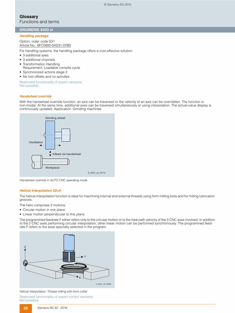
36 Siemens NC 62 · 2016
GlossaryFunctions and terms
SINUMERIK 840D sl
Handling package
Option; order code S31Article No.: 6FC5800-0AS31-0YB0
For handling systems, the handling package offers a cost-effective solution:• 3 additional axes • 3 additional channels • Transformation Handling
Requirement: Loadable compile cycle • Synchronized actions stage 2 • No tool offsets and no spindles
Restricted functionality of export versions: Not possible
Handwheel override
With the handwheel override function, an axis can be traversed or the velocity of an axis can be overridden. The function is non-modal. At the same time, additional axes can be traversed simultaneously or using interpolation. The actual-value display is continuously updated. Application: Grinding machines
Handwheel override in AUTO CNC operating mode
Helical interpolation 2D+6
The helical interpolation function is ideal for machining internal and external threads using form milling tools and for milling lubrication grooves.
The helix comprises 2 motions:• Circular motion in one plane • Linear motion perpendicular to this plane
The programmed feedrate F either refers only to the circular motion or to the total path velocity of the 3 CNC axes involved. In addition to the 2 CNC axes performing circular interpolation, other linear motion can be performed synchronously. The programmed feed-rate F refers to the axes specially selected in the program.
Helical interpolation: Thread milling with form cutter
Restricted functionality of export control versions: Not possible.
G_NC01_en_00113
Infeed via handwheel
Grinding wheel
Oscillation
Workpiece
G_NC01_XX_00099
Z
X
Y
© Siemens AG 2015

37Siemens NC 62 · 2016
GlossaryFunctions and terms
SINUMERIK 840D sl
High-speed CNC inputs/outputs
With the high-speed CNC inputs/outputs function, it is possible to read in or output signals in the position control/interpolation cycle. High-speed CNC inputs/outputs can be used for machines, such as those used for grinding and laser machining, as well as in SINUMERIK Safety Integrated.
Input signals are possible for the following:• Several feedrate values in one block (caliper function)
The function allows modification of the feedrate through external signals. 6 digital inputs can be combined with 6 different feedrate values in a CNC block. There is no feed interruption in this case. An additional input can be used to terminate the infeed (starting a dwell time), and another input can be used to start immediate retraction. Depending on the input, the retraction of the infeed axis (or axes) is initiated by a previously specified absolute value in the IPO cycle. The remaining distance-to-go is deleted.
• Several auxiliary functions in one blockSeveral auxiliary functions can be programmed in one CNC block. These functions are transferred to the PLC depending on a comparison operation or an external signal.
• Axis-specific delete distance-to-goThe high-speed inputs cause conditional stopping and delete distance-to-go for the path or positioning axes.
• Program branchesThe high-speed inputs make program branches within a user program possible.
• Rapid CNC startMachining can be enabled conditionally in the CNC program depending on an external input.
• Analog calipersVarious feedrates, a dwell time and a retraction path can be activated depending on an external analog input (threshold values are specified via machine data).
• Safety-related signals such as emergency stop
Output signals are possible for the following:• Position switching signals
The position switching signals can be output with the position switching signals/cam controller function. • Programmable outputs • Analog value output • Safety-related signals such as protective door interlock
→ Position switching signals/cam controller
HMI user memory, additional on CF card of NCU
Option; order code P12Article No.: 6FC5800-0AP12-0YB0
The memory for part programs and expansions to the operator interface can be extended using the additional HMI user memory on the CF card in systems without a SINUMERIK PCU. With CNC software version 4.5 SP1 or higher (on an 8 GB CF card), the memory is extended by 6 GB.
→ CNC user memory, additional
© Siemens AG 2015

38 Siemens NC 62 · 2016
GlossaryFunctions and terms
SINUMERIK 840D sl
I/O interfacing via PROFIBUS DP and PROFINET
PROFIBUS DP represents the protocol profile for distributed I/Os. It enables high-speed cyclic communication. Advantages of PROFIBUS DP: very short bus cycle times, high degree of availability, data integrity, and standard message frame structure.
Like PROFIBUS, PROFINET as a real-time bus system supports all I/Os.
→ PROFINET
Inclined axis
Option; order code M28Article No.: 6FC5800-0AM28-0YB0
The inclined axis function is used for fixed-angle interpolation using an oblique infeed axis. This is used primarily in conjunction with cylindrical grinding machines. The axes are programmed and displayed in the Cartesian coordinate system. Tool offsets and work offsets are also entered in the Cartesian system and transformed to the real machine axes.
For oblique plunge-cutting with G05, it is necessary to program the start position with G07. In the JOG CNC operating mode, the grinding wheel can be traversed either in the Cartesian coordinate system or in the direction of inclined axis U (selection via the channel DB).
Oblique plunge-cut grinding: machine with non-Cartesian X axis (U)
ZW
X
G05 X70 F100
G07 X70 Z40 F4000
U
JOG "X"
JOG "U"
100
70
040
G_NC01_XX_00121
© Siemens AG 2015

39Siemens NC 62 · 2016
GlossaryFunctions and terms
SINUMERIK 840D sl
Inclined-surface machining with frames
Drilling and milling operations on workpiece surfaces that do not lie in the coordinate planes of the machine can be performed easily with the aid of inclined-surface machining. The position of the inclined surface in space can be defined by coordinate system rotation.
Inclined-surface machining with frames
→ Frame concept
Industrial security
Industrial security includes all measures taken to plan, implement and monitor security in products and networks. The risk of hacking and other security breaches increases as more and more machine networks are implemented via the Internet. Threats of this type need to be warded off by appropriate precautions such as firewalls, encrypted connections, virus scanners, whitelisting and organizational measures/policies.
→ www.siemens.com/industrialsecurity
Integrate CNC into production, Create MyInterface
Article No.: 6FC6000-7AC00-0AA8
With SINUMERIK Integrate Create MyInterface, it is possible to easily integrate SINUMERIK CNCs into the customer's manufacturing network using defined interfaces. All essential machine data (such as status information, piece counts, alarms, messages, CNC pro-grams, tool service life) can be exchanged between a central control system and the CNC, helping to reduce machine downtimes and increase machine capacity utilization.
Integrate screens into the user interface
→ Use HMI applications, Run MyScreens
Integrated process monitoring, Run MyCC /IPM
Option; order code M70Article No.: 6FC5800-0AM70-0YB0
SINUMERIK Integrate Run MyCC /IPM is a specific function and is not intended for general use.
Restricted functionality of export versions: Not possible.
Z W Y W
X W
Z
X
F
+
G_NC01_en_00122
Y Basis
X Basis
Z Basis
© Siemens AG 2015

40 Siemens NC 62 · 2016
GlossaryFunctions and terms
SINUMERIK 840D sl
Integrated spindle monitor (S-Monitor)
Option; order code P55Article No.: 6FC5800-0AP55-0YB0
The integrated spindle monitor (S-Monitor) is designed to allow fast, easy monitoring of additional information about the condition of a WEISS motor spindle from the WEISS Spindle Sensor Module within SINUMERIK Operate:• Clamping status and diagnostics• Historical spindle data relating to speed, torque• Motor temperature• Bearing temperature• Additional temperature sensor (KTY)• Spindle operating time in various control modes• Number of tool changes• Logistics data of spindle
Integrated tool monitoring and diagnostics, IMD
The Integrated Monitoring and Diagnostics IMD is a software package with easy access to drive data (drive torque, encoder values, setpoint speed, etc.) and program data (programmed path, programmed velocity, programmed interpolation type, etc.) directly in the real-time part of the control. The function offers interfaces to the part program (language commands), to the PLC (fast I/O) and to the HMI (files, GUD).
Integrated tool monitoring and diagnostics IMD BASE, Run MyCC /IMD
Option; order code N13Article No.: 6FC5800-0AN13-0YB0
SINUMERIK Integrate Run MyCC /IMD integrated tool monitoring and diagnostics BASE supports the 'missing tool' monitoring function as well as programming of a maximum permissible overload for a tool. The parameters are taught on program setup as for the 'missing tool' monitoring function, and saved in the function-specific global user data (GUD). For all subsequent program runs, the taught signals will be compared with the current ones and tool overload is avoided. Language command in the part program: CC_START_TASK ("Fixed_Overload", …, ...).
SINUMERIK Integrate Run MyCC /IMD is also the prerequisite (interface) for customized add-ons in the field of process monitoring and diagnostics. The openness in the real-time part of the SINUMERIK 840D sl is utilized, for example, by SINUMERIK Solution Partners.
Integrated tool monitoring and diagnostics IMD LIGHT, Run MyCC IMD-L
Option; order code N12Article No.: 6FC5800-0AN12-0YB0
SINUMERIK Integrate Run MyCC /IMD-L supports a 'missing tool' monitoring function within the IMD package. For this purpose, cuts (transition from rapid traverse to creep feed) must be selected and parameterized (CC_START_TASK( "MissingTool", …, ...)) in the part program. For example, select torque of spindle or torque of a specific axis. The torque can be learned in an initial program run (teach-in).
In productive operation, the tool is assumed to be present when the actual signal is equal to the taught signal. If not, an individually parameterized alarm response is triggered (RESET, CANCEL, Stop Spindle, Stop Axes, etc.).
Intermediate blocks for tool radius compensation
Traversing motion with selected tool offset can be interrupted by a limited number of intermediate blocks (block without axis motion in the compensating plane). The permissible number of intermediate blocks can be set using system parameters.
→ Tool radius compensation
© Siemens AG 2015

41Siemens NC 62 · 2016
GlossaryFunctions and terms
SINUMERIK 840D sl
Internal/external drives
Internal drives are connected to an NCU/NX via DRIVE-CLiQ. External drives are connected via PROFIBUS/PROFINET.
All internal and external drives are supported by SINUMERIK Operate: • Parameter lists• Diagnostics (alarms with time synchronization, traffic lights images, drive servicing)• Series start-up
Third-party drives and SINAMICS G110/G120 are not supported by SINUMERIK Operate.
→ Axes/spindles
Interrupt routines with fast retraction from the contour
Option; order code M42Article No.: 6FC5800-0AM42-0YB0
Interrupt routines are special subprograms which can be started on the basis of events (external signal) in the machining process. Any part program block currently in progress is interrupted. The positions of the axes at the time of interruption are saved automati-cally. It is also possible to save such things as the current states of G functions and the current offsets (SAVE mechanism) in buffer storage, making it possible to resume the program at the point of interruption later without difficulty.
Four additional program levels are available for interrupt routines, that is, an interrupt routine can be started in the 8th program level and lead as high as the 12th program level. An interrupt such as the switching of a high-speed CNC input can trigger a movement via the special subprogram, which allows fast retraction of the tool from the workpiece contour currently being machined.
The retraction angle and the distance retracted can also be parameterized. An interrupt routine can also be executed following the fast retraction.
Inverse-time feedrate
For CNC's, it is possible to program the time required to traverse the path of a block (rpm) instead of programming the feedrate for the axis movement with G93. If the path lengths differ greatly from block to block, a new F value should be determined in every block when using G93.
When machining with rotary axes, the feedrate can also be specified in degrees/revolution.
Involute interpolation
Option; order code M21Article No.: 6FC5800-0AM21-0YB0
Using involute interpolation, it is possible to program a spiral contour with the shape of a circular involute in one CNC block instead of many approximated individual blocks. The exact mathematical description of the contour enables a higher path velocity to be achieved, together with a shorter machining time. Undesirable facets, which could result from coarse polygon functions, are thus avoided.
Furthermore, it is unnecessary to define the end point for the involute interpolation exactly on the involute defined by the start point; it is possible to enter a maximum permissible deviation using machine data.
© Siemens AG 2015

42 Siemens NC 62 · 2016
GlossaryFunctions and terms
SINUMERIK 840D sl
Job list
This can be used to create a job list (loading list) for each workpiece.
This job list contains instructions on making the following preparations for executing part programs, even when multiple channels are involved:• Parallel setup (LOAD/COPY):
Load or copy main programs and subprograms and associated data such as initialization programs INI, R parameters RPA, user data GUD, work offsets UFR, tool/magazine data TOA/TMA, setting data SEA, protection areas PRO, and sag/angularity CEC from the PCU's hard disk into the CNC's work memory.
• Preparations for the CNC Start SELECT:Select programs in different channels and make initial preparations for processing them
• Parallel clearing, reversed LOAD/COPY:Remove/unload main programs, subprograms and associated data from the CNC's work memory to the hard disk
Users can also save their own templates for job lists. Following loading and job list selection, CNC start initiates the processing of all programs and data required for workpiece production.
© Siemens AG 2015

43Siemens NC 62 · 2016
GlossaryFunctions and terms
SINUMERIK 840D sl
Laser switching signal, high-speed, Run MyCC /HSLC
Option; order code M38Article No.: 6FC5800-0AM38-0YB0
For high-speed laser machining, e.g. of aperture plates, the laser is switched on and off automatically and with a very high positional accuracy relating to the path. Under the prerequisite that all movements for which the laser must be switched off are made in rapid traverse mode G0, it is possible to logically combine the switching signal for the laser with the rising or falling edge of G0. The laser switching signal can also be coupled to an adjustable G1 feedrate threshold value, if required. To achieve the fastest possible responses, the switching on and off of the digital laser signal is controlled by a hardware timer with microsecond precision depending on the actual axis position. No programming measures are required for switching the laser itself on and off, as these procedures are directly linked to the programmed G functions. It is only necessary to program a release with CC_FASTON (DIFF1, DIFF2) for the path section in which the laser is switched on or off. Together with this release, the two offset values, which can offset the switching on and off of the laser by a specific path differential in relation to the position setpoint are entered.
Leadscrew error compensation / measuring system error compensation
On SINUMERIK CNCs, interpolating compensation is divided into two categories:• Leadscrew error compensation (LEC) or measuring system error compensation (MSEC) as axial compensation (basic axis and
compensating axis are always identical) and • Sag error and angularity error compensation as cross-axis compensation (basic axis affects other compensation axis).
The principle of "indirect measuring" on CNC-controlled machines is based on the assumption that the leadscrew pitch is constant at every point within the traversing range, so that the actual position of the axis can be derived from the position of the drive spindle (ideal situation).
Tolerances in ball screw production, however, result in large dimensional deviations to a lesser or greater extent (referred to as leadscrew error). These are complemented by dimensional deviations caused by the measuring system as well as its installation tolerances on the machine (measuring system errors), plus any machine-dependent error sources. Because these dimensional deviations directly affect the accuracy of workpiece machining, they must be compensated for by the relevant position-dependent compensation values.
The compensation values are derived from measured error curves and entered in the CNC in the form of compensation tables during commissioning. The relevant axis is compensated using linear interpolation between the intermediate points.
Leadscrew error compensation, bidirectional
Option; order code M54Article No.: 6FC5800-0AM54-0YB0
Bidirectional compensation is an expansion of the leadscrew error compensation function (LEC) or the measuring system error compensation function (MSEC). By contrast with the LEC and MSEC, bidirectional compensation acts in both directions.
Restricted functionality of export versions: The correctable tolerance band is restricted to 1 mm (0.039 in).
Limit-switch monitoring
Preceding the emergency stop switch, hardware limit switches, which take the form of digital inputs controlled via the PLC interface, limit the traversing range of the machine axes. Deceleration is realized either as rapid deceleration with setpoint zero or along a braking characteristic. The axes must be retracted in the opposite direction in the JOG CNC operating mode.
Software limit switches precede the hardware limit switches, are not passed, and are not active until reference point approach has been completed. Following preset, software limit switches are no longer effective. A second pair of plus/minus software limit switches can be activated via the PLC.
Travel limits
G_NC01_en_00110
Work arealimitation(geometricaxes only) 2nd
SW limit switch(can be activated via PLC)
1st
SW limit switch
Hardwarelimit switches
EMERGENCYSTOPswitch Mechanical
traversing limit
© Siemens AG 2015

44 Siemens NC 62 · 2016
GlossaryFunctions and terms
SINUMERIK 840D sl
Linear interpolation
Linear interpolation is understood to be the CNC-internal calculation of points on a straight path between the programmed starting and end points.
Restricted functionality of export control versions: The number of simultaneously interpolating axes is restricted to 4.
Link control system
→ Create MyInterface
→ Master computer interface, Access MyMachine /OPC UA
Lock MyCycles
Option; order code P54Article No.: 6FC5800-0AP54-0YB0
With SINUMERIK Integrate Lock MyCycles (cycle protection), cycles can be encrypted and then saved in the CNC where they are protected. Execution in the CNC is possible without restrictions, but it is not possible to view the cycle. This protects the internal company know-how.
The cycle can, however, be copied in an encrypted form. It can, therefore, be used on other machines. If use of the cycle on other machines is to be prevented, it can be permanently linked to a particular CNC hardware unit by means of an addition to the program.
Lock MyPLC
The PLC machine program can be comprehensively protected by the know-how protection functionality provided by SIMATIC STEP 7 software version 5.5 SP3. This software guards technological knowledge against unauthorized access and modification. It prevents the reverse engineering of machines, thus safeguarding the investments you have made.
Look Ahead
During the machining of complex contours, most of the resulting program blocks have very short paths with sharp transitions. If a contour of this type is processed with a fixed programmed path velocity, an optimum result cannot be obtained. In short traversing blocks with tangential block transitions, the drives cannot attain the required final velocity because of the short path distances. Contours are rounded when traveling around corners.
The Look Ahead function is a means of optimizing the machining speed by looking ahead over a parameterizable number of travers-ing blocks. For tangential block transitions, the axis is accelerated and decelerated beyond block boundaries, so that no drops in velocity occur. For sharp path transitions, rounding of the contour is reduced to a programmable path dimension.
Comparison of velocity response with exact stop G60 and continuous-path mode G64 with look ahead for short distances.
→ Continuous-path mode with programmable rounding clearance
N1 N2 N3 N4 N5 N6 N7 N8 N9 N10 N11 N12
F1
G_NC01_en_00159
Block path
programmed
Feed
G64: Look ahead velocity control
G60: Constand velocity phase
© Siemens AG 2015

45Siemens NC 62 · 2016
GlossaryFunctions and terms
SINUMERIK 840D sl
Look-ahead detection of contour violations
With collision detection CDON on and active tool radius compensation, the CNC monitors tool paths through look-ahead contour calculation. Potential collisions are promptly identified in this way and actively prevented by the CNC.
For example, for an excessively large tool radius, the CNC identifies critical machine situations, which it compensates for by modifying the tool paths.• Bottleneck detection
Because the tool radius is too large to produce a narrow inside contour, the bottleneck is bypassed and an alarm output. • Contour path shorter than tool radius
The tool bypasses the workpiece corner along a transition circle, then continues precisely on the programmed path. • Tool radius too large for inside machining
In such cases, the contours are machined only as much as is possible without causing a contour violation.
Behavior when tool radius > circle radius
R
G_NC01_en_00130
Not machined(but no contourviolation)
© Siemens AG 2015

46 Siemens NC 62 · 2016
GlossaryFunctions and terms
SINUMERIK 840D sl
Machining channels (Basic configuration: 1 machining channel)
Option; order codes C11 ... C19Article No.: 6FC5800-0AC10-0YB0
Idle times can be shortened via a channel structure using parallel motion sequences, such as moving a loading gantry during machining. A machining channel must be regarded as a separate CNC with decoding, block preparation and interpolation.
The channel structure makes it possible to process the individual channels' part programs simultaneously and asynchronously. The relevant channel with the associated images is selected with the channel switchover button on the operator panel. Part programs can then be chosen and started for that specific channel. Each possible channel can run in a separate mode group.
With the options with order codes C11 ... C19, the number can be increased to up to 10 machining channels.
→ Mode group
Machining package 5 axes (Basic configuration: 3 axes/spindles)
Option; order code M30Article No.: 6FC5800-0AM30-0YB0
With the machining package 5 axes, 5-axis machining tasks, such as the milling of free-form surfaces, can be simply implemented. To this end, the machining package 5 axes provides the following functions:• 5-axis transformation with tool orientation TRAORI
In 5-axis machining, geometric axes X/Y/Z are supplemented by additional axes such as rotary axes for swiveling the tool. The machining task can be completely defined in Cartesian spatial coordinates with Cartesian position and orientation. The path vector is converted in the control into the machine axes, including position and orientation, via 5-axis transformation.
• 5-axis tool length compensation for 5-axis machining When machining with the 4th/5th axis, the lengths of the selected tool are automatically included and compensated in the axis movement.
• Oriented tool retraction If machining is interrupted because of tool breakage, for example, a program command can be used to carry out defined, oriented tool retraction.
• Tool-oriented RTCP With the remote tool center point RTCP function, the tool swivel axes can be positioned in the manual mode, as long as there is compliance with the tool center point marked by the tool tip. The RTCP function simplifies the inclusion of program interpolation points in manual mode with orientation of the tool.
• Cardan milling head/nutating head Requirements: Machining package 5 axes with 5-axis transformation. Using a cardan milling head in conjunction with the Nutating head function, it is possible to machine outside contours of spatially formed parts at high feedrates. To do this, the CNC performs a 5-axis transformation. 3 translatory main axes X/Y/Z determine the tool operating point; 2 rotary axes, one of which is an inclined axis (angle can be set in the machine data), permit virtually any orientation in the working area. Version 1 and version 2 of the cardan milling heads are supported. In the case of version 2, the position of the operating point does not change when the tool is swiveled; the compensating movements required for orientation changes are minimal. Includes multi-axis interpolation (> 4 interpolating axes). The machining package 5 axes does not include any additional axes/spindles which might be required.
Cardan milling head
Restricted functionality of export versions: Not possible.
→Multi-axis interpolation (> 4 interpolating axes)
→ Axes/spindles
C
A'
C
A'
Z Y
X
j
G_NC01_en_00106
Nutating headversion 1
Nutating headversion 2
© Siemens AG 2015

47Siemens NC 62 · 2016
GlossaryFunctions and terms
SINUMERIK 840D sl
Machining package 5 axes, additional function 7th axis
Option; order code S01Article No.: 6FC5800-0AS01-0YB0
In combination with the machining package 5 axes or SINUMERIK MDynamics 5 axes, this option supports 7-axis interpolation. This means that redundant rotation of a workpiece is possible in the work space, with 5th/6th axis tool kinematics active at the same time. Application example: Fiber placement machines in the aerospace industry.
Restricted functionality of export versions: Not possible.
Machining with robot, Run MyRobot /Machining
Option; order code P73Article No.: 6FC5800-0AP73-0YB0
SINUMERIK Integrate Run MyRobot /Machining includes the options:• Run MyCC /RODI (communication)• Multi-axis interpolation (> 4 interpolating axes) • Run MyHMI /3GL (for diagnostics)
SINUMERIK Integrate Run MyRobot /Machining allows a KUKA robot to be utilized, for example, as a milling robot, in combination with a SINUMERIK 840D sl as the CNC. SINUMERIK Integrate Run MyRobot /Machining includes all the options required for this purpose.
→ Communication interface to a robot, Run MyCC /RODI
→ Multi-axis interpolation (> 4 interpolating axes)
→ Use HMI applications, Run MyHMI /3GL
Restricted functionality of export versions: Not possible.
Magnetic cogging torque compensation, Run MyCC /COCO
Option; order code N46Article No.: 6FC5800-0AN46-0YB0
This compensation function is used particularly for electric direct drives where it is necessary to reduce the torque ripple at low speeds in order to an obtain a better machining quality.
Restricted functionality of export versions: Not possible.
Main program call from main program and subprogram
If machining operations recur frequently, it is advisable to store them in a subprogram. The subprogram is called from a main program (number of passes ≤ 9999). Eleven subprogram levels (including 3 levels for interrupt routines) are possible in a main program. A main program can also be called from within another main program or subprogram.
Manage MyPrograms
Article No.: 6FC5864-1AP41-0YB0
SINUMERIK Integrate Manage MyPrograms provides a central system of management and archiving for CNC programs and auto-matic backup of SINUMERIK CNC data. For example, CNC programs can simply be transferred from Teamcenter. The advantage of this feature is that it supports simple, centralized organization of CNC data into which CNC programmers can be integrated, as well as fast access to CNC programs via networks.
It can be linked into the SINUMERIK Operate user interface without requiring the addition of supplementary external equipment on the CNC.
Manage MyTools
Article No.: 6FC5864-2AP41-0YB0
SINUMERIK Integrate Manage MyTools provides users with a comprehensive overview of actual tool data including statistics and planning for the entire production process. It supports a variety of different code carrier systems.
It offers the advantage of a closed tool data circuit - from procurement to use of the tool (procurement > tool setting > loading > setup). It illuminates potential for rationalization, e.g. achieved by cost cutting, optimization and availability.
© Siemens AG 2015

48 Siemens NC 62 · 2016
GlossaryFunctions and terms
SINUMERIK 840D sl
Manual machine
We offer the manual machine function for beginners switching over from conventional machines, but also for experienced CNC machine operators who often only use individual machining steps. The MANUAL basic screen is displayed immediately after booting the machine offering the direct machining options without having to create a part program.
→ ShopMill/ShopTurn
Master computer interface, Access MyMachine /OPC UA
Option; order code P67Article No.: 6FC5800-0AP67-0YB0
The SINUMERIK Integrate Access MyMachine /OPC UA function enables the communication channel for the OPC UA server on the SINUMERIK PCU or the SINUMERIK NCU. The OPC UA data access method permits the reading and writing of CNC and PLC variables. OPC Unified Architecture OPC UA is a standardized, industrial communication protocol for the access to control data, e.g. by control systems.
www.opcfoundation.org
Master/slave for drives
Option; order code M03Article No.: 6FC5800-0AM03-0YB0
The master/slave for drives function is required when 2 electrical drives are mechanically linked to an axis. With this link, a torque controller ensures that both drives produce the exact same amount of torque, so that the motors do not work in opposition. In order to attain tensioning between the master and slave drives, a tension torque specifiable via machine data can be applied to the torque controller.
Application examples:• Increasing the power rating and (occasional) mechanical linking of drives • Drive with 2 motors that operate on a gear rack • Remachining of wheel sets for rail vehicles • Zero backlash reversing of mutually tensioned drives
An axis can also be a leading axis for multiple links.
Axis 1 is simultaneously the master axis for axis 2 and axis 3
G_NC01_EN_00116
Torque controller
Master
SlaveAxis 3
Axis 1Link 2Link 1
Speed setpoint link
Speed setpoint link
Slave
Torque controller
Axis 2
© Siemens AG 2015

49Siemens NC 62 · 2016
GlossaryFunctions and terms
SINUMERIK 840D sl
Master-value coupling and curve table interpolation
For special technologies (presses, transfer lines, printing machines, etc.), the replacement of mechanical, cyclic transport tasks with electronic functionality in AUTOMATIC mode requires constant coupling and decoupling functions between leading and following axes. To this end, the synchronous spindle function has been expanded to include the master value coupling function, which makes it possible for linear guide and following axes to be coupled via curve tables in the CNC program.
Any function relations between axis positions can be approximated. Soft coupling avoids the sudden change in velocity that occurs when the guide axis is activated. Offsets (e.g. 12°), scalings (e.g. 1.00023) and mirroring using frame instructions are possible.
Electronic curve table interpolation replaces the cam disks that were once required for the computerized numerical control of cyclic machines. Complex sequences of motion can be easily defined using familiar CNC language elements. The external reference variable (e.g. "line shaft") is formed by the CNC's master value. The functional relation between leading and following axis can be subdivided into segments of the leading axis (curve segments). In these curve segments, the link between master value and following value is described using mathematical functions (normally through 3rd degree polynomials).
Cyclic machines are distinguished by constantly repeated cyclic operations with high throughput and high productivity in machining, transport, packaging and parts handling (for example, packaging machines, presses, woodworking machines, printing machines).
With the SINUMERIK CNC, technological functions such as synchronism, electronic transfer and positioning for cyclic machines can be implemented. Mechanical systems (line shaft, gearing, cam disks, couplings and cams) are replaced by an electronic solution (master value coupling, curve tables, synchronized actions, and electronic cams).
In addition, the electronic functionality permits fast, axis-specific optimization, high-speed phase and path compensation, fast re-sponses to faulty or missing parts, and fast synchronization and resynchronization, as well as decoupling from the leading axis and execution of autonomous movements. Axis cycles and synchronization calculations are carried out in the IPO cycle.
Measuring from synchronized actions, for example, is used for detecting edges on continuous workpieces and for measuring print marks (on continuous film, for example).
Example for cyclic machines: Flying saw
Restricted functionality of export control versions: The number of simultaneously traversing axes is restricted to 4.
→ Generic couplings
→ Measuring stage 2
→ Synchronous spindles, multi-edge turning
Measure kinematics
Option; order code P18Article No.: 6FC5800-0AP18-0YB0
The Measure kinematics function supports the calibration of kinematic structures of 5-axis machines. The SINUMERIK 840D sl is able to determine the parameters of kinematic transformations of the digitally or manually alignable rotary axes quickly and automatically.
The function is ideal for initial startup, because a dimension drawing of the machine is not required. The function can also be used for regular checking of the production process where high precision is required.
+ +++
X
G_NC01_en_00114
Top roller Saw
Saw carriage
© Siemens AG 2015

50 Siemens NC 62 · 2016
GlossaryFunctions and terms
SINUMERIK 840D sl
Measuring cycles
Option; order code P28Article No.: 6FC5800-0AP28-0YB0
In the case of tool measuring, the loaded tool (typically in the revolver on turning machines) is moved towards the probe, which is either in a fixed position or swiveled into the working range by a mechanical device. The automatically derived tool geometry is entered in the relevant tool offset data record.
In the case of workpiece measuring, a probe is moved towards the clamped workpiece like a tool. The flexible structure of the measuring cycles means that it is possible to handle virtually every measuring task associated with turning or milling.
The flying measurement principle is used in SINUMERIK CNCs. The advantage of this principle is that the probe signal is processed directly in the CNC. The measuring parameters and the results of the measurements are output extremely clearly in separate displays, which are either automatically deselected at the end of the cycle or can be acknowledged when starting the CNC.
The result of the workpiece measurement can either include automatic offset of the zero point or a correction of the tool wear by the difference between the actual value and the setpoint. The measurement results can be logged in a file. Siemens measuring cycles offer a standard log, which can be freely configured by the user.
In order to measure tool and workpiece dimensions, a touch-trigger probe is required that supplies a constant signal (rather than a pulse) when deflected. The probe should switch without any bounce, and mechanical adjustment may be necessary. Multidirectional probes can be used for all tool and workpiece measurements on turning and milling machines. Bidirectional probes are treated like a mono probe for workpiece measurements on milling and machining centers, but are not suitable for tool measurements.
Monodirectional probes can be used on milling machines and machining centers with slight restrictions in workpiece measurements, but are not suitable for tool measurements or for workpiece measurements on turning machines.
Milling measurement: • Corner/right-angled corner/any corner• Calibrate probe: length/radius in ring/radius at edge/calibrate on sphere• Hole/rectangular pocket• Hole/inner circle segment• Edge distance – slot/web• Edge distance – set edge• Edge distance – align edge• Circular/rectangular spigot• Spigot/outer circle segment• Measure 3D – align plane• Measure 3D – 1 sphere/3 spheres• Measure tools• Measure tools – calibrate tool probe
Turning measurement: • Calibrate probe – length/radius at surface/radius in slot• Inner/outer diameter• Measure tools – turning tools/milling tools/drills• Measure tools – calibrate tool probe
© Siemens AG 2015

51Siemens NC 62 · 2016
GlossaryFunctions and terms
SINUMERIK 840D sl
The use of high-precision probes such as those from Renishaw's Rengage range is recommended.
Example: Measuring a hole (programGUIDE) Example: Measuring an outer diameter (programGUIDE)
Example: Align edge (programGUIDE) Example: Align edge (ShopMill)
Measuring functions/measuring cycles
Measuring functions can execute either channel-specifically including all axes programmed in the measuring block as well as axially from the part program or from synchronized actions beyond CNC block limits. Measuring cycles are subprograms for implementing specific measuring tasks on tools or workpieces.
They are easy to use and simply require the input of values in predefined parameters.• Measuring in JOG• 2 probes can be connected simultaneously• Measurement in space with frame• Adaptable measuring modes with/without deletion of distance-to-go• Display and logging of measuring parameters and results (with measuring cycles)• Results can be read in the machine or workpiece coordinate system• Cyclic measurement with synchronized actions parallel to workpiece machining
With the advantages of the measuring functions and measuring cycles, the machining accuracy is assured, unproductive time is reduced, sources of error are eliminated and further production processes are automated.
© Siemens AG 2015

52 Siemens NC 62 · 2016
GlossaryFunctions and terms
SINUMERIK 840D sl
Measuring inputs, expanded (16) for axial measurements, Run MyCC /PROX
Option; order code N57Article No.: 6FC5800-0AN57-0YB0
SINUMERIK Integrate Run MyCC /PROX is a specific function and is not intended for general use.
Restricted functionality of export versions: Not possible.
Measuring stage 1
Up to 2 switching probes can be connected simultaneously to the CNC. In the case of channel-specific measuring, the measuring process for a CNC channel is always activated from the part program running in the relevant channel. All of the axes programmed in the measuring block take part in the measuring process.
It is possible to program a trigger event (rising or falling edge) and a measuring mode with or without deletion of distance-to-go for each measuring process. The results of measurements can be read in the part program or with synchronized actions in both the machine and the workpiece coordinate system. You can test the deflection of the probe by scanning a variable and outputting it to the PLC interface and deriving responses in the part program.
Measuring stage 2 (option, order code M32) provides expanded functionality (for example for axial measuring, evaluation of up to 4 trigger events, and cyclic measuring).
Measuring stage 2
Option; order code M32Article No.: 6FC5800-0AM32-0YB0
While the measuring function in motion blocks in the part program is limited to one block, you can activate measuring functions from synchronized actions at any time, independent of the part program. The measuring events can be assigned to the axes in the CNC block. In the case of simultaneous measuring, up to 4 trigger events can be evaluated per position control cycle. Measured values are read as a function of the 3 parameters: probe, axis and measuring edge.
In the case of continuous (cyclic) measuring, the measurement results are written to a FIFO variable. Endless measuring can be achieved by reading out the FIFO values cyclically. Measurement results can be logged in the form of a file. The measuring cycles (option, order code P28) contain a standard log, which can be configured as the user wishes.
Measuring system error compensation
→ Leadscrew error compensation/measuring system error compensation
Measuring systems 1 and 2, selectable
For special applications, 2 encoders can be assigned to one axis, such as for a direct measuring system for the machining process with high demands on accuracy, and an indirect measuring system for high-speed positioning tasks. The switchover between measuring systems 1 and 2 is performed via the PLC.
Metal spinning protection area, Run MyCC /MSPZ
Option; order code N42Article No.: 6FC5800-0AN42-0YB0
SINUMERIK Integrate Run MyCC /MSPZ is a specific function and is not intended for general use.
Restricted functionality of export versions: Not possible.
© Siemens AG 2015

53Siemens NC 62 · 2016
GlossaryFunctions and terms
SINUMERIK 840D sl
Metric/inch dimensions
Depending on the measuring system used in the production drawing, it is possible to program workpiece-related geometrical data in either metric units (G71) or inches (G70). The CNC is set to a basic system regardless of the dimension system that has been programmed.
You can enter the following geometrical data directly and let the CNC convert them into the other dimension system (examples):• Position data X, Y, Z, etc. • Interpolation parameters I, J, K and circle radius CR • Pitch • Programmable work offset (TRANS) • Polar radius RP
With the G700/G710 programming expansion, all feedrates are also interpreted in the programmed measuring system (inch/min or mm/min). In the Machine operating area, the operator can switch back and forth between inch and metric dimensions using a softkey.
Milling technology package SINUMERIK MDynamics 3 axes
Option; order code S32Article No.: 6FC5800-0AS32-0YB0
SINUMERIK MDynamics 3 axes contains the options:
→ ShopMill/ShopTurn
→ Residual material detection and machining for contour pockets and stock removal
→ 3D simulation 1 (finished part)
→ Simultaneous recording (real-time simulation of the current machining operation)
→ Advanced Surface
→ Spline interpolation (A, B and C splines)
→ TRANSMIT/cylinder surface transformation
→ Measuring cycles
Milling technology package SINUMERIK MDynamics 5 axes
Option; order code S33Article No.: 6FC5800-0AS33-0YB0
SINUMERIK MDynamics 5 axes contains the options:
→ ShopMill/ShopTurn
→ Residual material detection and machining for contour pockets and stock removal
→ 3D simulation 1 (finished part)
→ Simultaneous recording (real-time simulation of the current machining operation)
→ Advanced Surface
→ Spline interpolation (A, B and C splines)
→ TRANSMIT/cylinder surface transformation
→ Measuring cycles
→ Machining package 5 axes
→ Tool radius compensation, 3D
→ Measure kinematics
Restricted functionality of export versions: Not possible.
Mode group (Basic configuration: 1 mode group)
Option; order codes C01 ... C09Article No.: 6FC5800-0AC00-0YB0
A mode group combines CNC channels with axes and spindles to form a machining unit. A mode group contains channels that must always operate in the same CNC operating mode at the same time during the machining sequence. Within a mode group, every axis can be programmed in every channel. A mode group can be regarded as an independent, multi-channel CNC. The number can be increased to include up to 10 mode groups using the option.
© Siemens AG 2015

54 Siemens NC 62 · 2016
GlossaryFunctions and terms
SINUMERIK 840D sl
Monitoring for maximum tool speed/acceleration
Option; order code S08Article No.: 6FC5800-0AS08-0YB0
Two new parameters within the tool data can be used to specify the maximum speed and the maximum acceleration of a tool. If the tool is in the spindle, the speed or the acceleration of the spindle is limited to these values.
The limits can be separately activated and set. The speed is limited to the permissible value, even if the specified setpoint speed were to be exceeded by > 100 % by using the override switch.
Monitoring functions
The CNCs have integrated monitoring functions that are always active. These monitoring functions detect faults in the CNC, PLC or machine early on to prevent damage to the workpiece, tool or machine. When a fault occurs, machine operation is interrupted and the drives brought to a standstill. The cause of the fault is saved and displayed as an alarm. At the same time, the PLC is notified that a CNC alarm has been triggered.
Monitoring functions exist for the following areas:• Read in • Format • Encoder and drive • Contour • Position • Standstill • Clamping • Speed setpoint • Actual velocity • Enabling signals • Voltage • Temperatures • Microprocessors • Serial interfaces • Transfer between CNC and PLC • Backup battery voltage • System memory and user memory
Motion-synchronous actions
→ Synchronized actions
Multi-axis interpolation (> 4 interpolating axes)
Option; order code M15Article No.: 6FC5800-0AM15-0YB0
The number of interpolating axes can be expanded and is limited by option and machine data as well as by the number of axes available in the channel.
Restricted functionality of export versions: Not possible.
Multi-axis package
Option; order code M10Article No.: 6FC5800-0AM10-0YB0
The multi-axis package axes/spindles and channels is a low-cost package for multi-axis machines. It includes all axes/spindles/positioning axes/auxiliary spindles and channels.
© Siemens AG 2015

55Siemens NC 62 · 2016
GlossaryFunctions and terms
SINUMERIK 840D sl
Multi-channel display
In the machine operating area, the M key can be used to select either single-channel or multi-channel display. In the multi-channel display, only channel information is displayed; the channel can be operated or influenced in the single-channel display. Focus switch-ing, scroll bars and window selection can be operated in the multi-channel display, but it is not possible to change the CNC channel data. The same windows are always displayed together in all channels.
The softkeys for switching the windows, therefore, always affect all the channels that are on display. In the multi-channel display, the axis actual values are displayed in the top window and the selection menus (T/F/S values, program blocks) in the bottom window, depending on which of the softkeys is activated.
Multiple clamping of identical/different workpieces
Several identical workpieces can be clamped onto the machine table. With the multiple clamping function, an entire program is gen-erated from the graphic program of the relevant single machining operation. The machining steps are sorted in this program so that the number of tool changes (and thus idle times) is reduced to a minimum.
This function allows identical and different workpieces to be finished on multiple vises or gripping yokes in a time-saving process.
→ ShopMill/ShopTurn
Multiple feedrates in one block
Depending on external digital and/or analog CNC inputs, this function can be used for motion-synchronous activation of up to 6 different feedrates, a dwell time, and a retraction in a single CNC block. The input signals are combined in an input byte with a permanently assigned function. The retraction is initiated by an amount defined in advance within an IPO cycle. Retraction movement or dwell time (e.g. sparking-out time during grinding) lead to deletion of the distance-to-go.
Typical applications involve analog or digital calipers or a change from infeed feedrate to machining feedrate via proximity switches. During internal grinding of a ball bearing ring, for instance, in which calipers are used to measure the actual diameter, the feedrate value required for roughing, finishing or smooth-finishing can be activated depending on threshold values.
G_NC02_XX_00381
© Siemens AG 2015
56 Siemens NC 62 · 2016
GlossaryFunctions and terms
SINUMERIK 840D sl
Nodding compensation, Run MyCC /NOCO
Option; order code N63Article No.: 6FC5800-0AN63-0YB0
SINUMERIK Integrate Run MyCC /NOCO allows workpieces to be machined with greater precision by compensating for mechanical crosstalk effects between axes. SINUMERIK Integrate Run MyCC /NOCO is a useful function for column milling machines, for example, when the acceleration and braking of other axes can lead to "nodding" motion of the tower, causing the tool tip to make marks in the material as it is lowered into the workpiece. The nodding compensation function monitors the other axes and models the nodding behavior. Since the acceleration levels of all axes are known, the effects of nodding motion can be compensated by feedforward control of the other axes. Compensation thus increases machining precision and improves surface quality.
Restricted functionality of export versions: Not possible.
Number of subprogram passes
In order to execute a subprogram several times in succession, the desired number of program repetitions can be programmed in the block with the subprogram call at address P: value range 1 to 9999. Parameters are transferred only when the program is called or in the first pass.
The parameters remain the same for all repetitions. If you want to change the parameters between passes, you should make the relevant declarations in the subprogram.
© Siemens AG 2015

57Siemens NC 62 · 2016
GlossaryFunctions and terms
SINUMERIK 840D sl
Online ISO dialect Interpreter
In general, part programs for SINUMERIK CNCs are programmed according to DIN 66025 and relevant expansions. Part programs created according to the ISO standard (e.g. G codes from other manufacturers) can be read in, edited and executed on SINUMERIK CNCs using the online ISO dialect interpreter.
Operate robot, Run MyRobot
Option; order code P74 Article No.: 6FC5800-0AP74-0YB0
SINUMERIK Integrate Run MyRobot includes the options:• 1 additional machining channel• Run MyCC /EXPD• Run MyHMI /3GL• Run MyScreens
The runtime license SINUMERIK Integrate Run MyRobot allows integration of KUKA robots into the SINUMERIK 840D sl. Robots can then be operated, programmed and diagnosed on the operator panel of the SINUMERIK 840D sl by users who have no specialist robot knowledge. Machine operating times are increased by this simple automation, or by the simple, flexible setup of machine tool and robot.
You can find an application example on the Internet by entering the search term: Run MyRobot.
→ Machining channels
→ Run MyCC /EXPD
→ Use HMI applications, Run MyHMI /3GL
→ Use HMI applications, Run MyScreens
→ www.siemens.com/automation/support
Operating modes
→ CNC operating modes
Operating software languages
Option; order code N00Article No.: 6FC5800-0AN00-0YB0
The operating software supports the following languages as standard for user interface display texts: English, French, German, Italian, Simplified Chinese, and Spanish.
Further additional languages can be ordered with the option, order code N00.
© Siemens AG 2015

58 Siemens NC 62 · 2016
GlossaryFunctions and terms
SINUMERIK 840D sl
Operator panel management
The SINUMERIK Thin Client Unit TCU for distributed installation allows the spatial separation of SINUMERIK OP/TP operator panel fronts and SINUMERIK PCUs, as well as the connection of up to 4 operator panel fronts to a PCU with one TCU each. To this end, the user interface of a PCU 50.5 is copied to several OPs/TPs with one TCU each.
Benefits:• Low-vibration installation of the PCU in the control cabinet• Effective operation of larger machines using up to 5 identical operator panels• Signal transmission between PCU and operator panel front via Industrial Ethernet• Operation at the active operator panel with the option to enable the passive operator panel on request• Mixed operation of operator panel fronts on a TCU or with an integrated TCU and an operator panel front directly connected to the
PCU possible • Distance between PCU and operator panel fronts of up to 100 m (max. distance between two network nodes).
Optimized friction compensation
Option; order code S06Article No.: 6FC5800-0AS06-0YB0
This option is designed to achieve optimum friction compensation. The required setting parameters are calculated automatically by a cycle.
NCU CNC SW
PCU SINUMERIK Operate
Operator panel management2/4 TCUs with interlocking of simultaneous operation using the Veto mode and PLC (4 × T : 1 × M)
✔(2/4)
✔(4)
TCU suppression with more than 2/4 TCUs (n × T : 1 × M) ✔ ✔
External HMIs (n × M : n × N) – ✔(1 × M: 4 × N)
One external HMI which can be switched over via several NCUs (1 × M : n × N) – ✔(4 × N)
One internal and one external HMI connected simultaneously to one NCU ✔TM
✔TM
DisplayDown-zoom – –Dynamic resolution switchover ✔ ✔
Activate/deactivate MCPMCP PROFIBUS – –MCP IE (IE mode) ✔ ✔
MCP PN (PN mode) – –One or several TCUs, which can be switched over via several NCUs and PCUs (1 × T : n × M)Using 2-key operation ✔ ✔
Using the channel menu ✔ ✔
Options for multi-user operation (n × T : M : N)T = Number of TCUsM = Number of HMIsN = Number of NCUs✔ = Possible– = Not possible
© Siemens AG 2015

59Siemens NC 62 · 2016
GlossaryFunctions and terms
SINUMERIK 840D sl
Oscillation functions
Option; order code M34Article No.: 6FC5800-0AM34-0YB0
With this function, an axis oscillates at the programmed feedrate between 2 reversal points. A possible application is a grinding machine.
Asynchronous oscillation across block boundaries
Several reciprocating axes may be active. During reciprocating movement, other axes can interpolate at will. The reciprocating axis can be the input axis for the dynamic transformation or the guide axis for gantry or coupled-motion axes.
Block-related oscillation• Oscillation with infeed in both or only in the left or right reversal point. Infeed is possible along a programmable path prior to the
reversal point. • Sparking-out strokes after oscillation are possible.
Behavior of the reciprocating axis in the reversal point: • A change of direction is initiated
- Without reaching the exact stop limit (soft reversal) - After reaching the programmed position or - After reaching the programmed position and expiration of the dwell time
• The following manipulations are possible: - Cancelation of the reciprocating movement and infeed by deletion of distance-to-go - Modification of the reversal points via CNC program, PLC, handwheel or direction keys - Manipulation of the reciprocating axis feedrate via CNC program, PLC or override - Control of the reciprocating movement via the PLC
The spindles can also perform reciprocating movement.
Oscillation functions
A
EE
A
E
A
G_NC01_EN_00117
A Starting point of the blockE End point of the block
Oscillating motion with continuous infeed
Oscillation with infeed in the reversal points
Oscillation with infeed in the left reversal point and distance specification
© Siemens AG 2015

60 Siemens NC 62 · 2016
GlossaryFunctions and terms
SINUMERIK 840D sl
Pair of synchronous axes (gantry axes)
Option; order code M02Article No.: 6FC5800-0AM02-0YB0
The gantry axes function can be used to traverse the axes of up to 3 pairs of mechanically-coupled axes simultaneously without mechanical offset. The actual values are continuously compared and even the smallest deviations corrected.
During both operation and programming, the axes defined in a gantry grouping are treated like machine axes. A gantry grouping consists of a guide axis and up to 2 synchronous axes. 2 guide axes can be coupled using curve table inter-polation.
Gantry axes (pair of synchronous axes X/X1)
Path length evaluation
Option; order code M53Article No.: 6FC5800-0AM53-0YB0
With path length evaluation, data in the CNC can be buffered so that conclusions can be drawn with respect to the maintenance state of the machine.
In the first stage, the following data are acquired:• Total travel path for each axis• Total travel time for each axis• Number of traversing actions per axis (stop - traverse - stop)• Total sum of jerks per axis
This data is stored in the SRAM and is not affected by power on/off. As a consequence, using an external service, consistent data can be achieved for the complete life cycle of a machine. This data can also be read through system variables in the part program and in synchronized actions.
→ Synchronized actions
Path velocity-dependent analog output (laser power control)
Option; order code M37Article No.: 6FC5800-0AM37-0YB0
Using the path-velocity-dependent analog output, the actual path velocity can be output in the interpolation cycle via a SIMATIC DP ET 200 analog module. The function is programmed via synchronized actions.
One application is laser power control.
X1
X
Y
Z
G_NC01_XX_00112
© Siemens AG 2015

61Siemens NC 62 · 2016
GlossaryFunctions and terms
SINUMERIK 840D sl
Path-related pulse output, Run MyCC /PRIG
Option; order code N76Article No.: 6FC5800-0AN76-0YB0
SINUMERIK Integrate Run MyCC /PRIG is used in the non-destructive testing of composite components using ultrasound transmis-sion. The number of pulses of an output signal (max. 256 kHz) supplies precise information about the traversed path. It is possible to program the required distance per pulse.
The pulses are output via connector X520 of the SINAMICS TM41 technology module.
Plain text display of user variables
In addition to the predefined variables, programmers can define their own variables and assign values to them.
The variables are displayed in plain text format, e.g. Definition: DEF INT NUMBER – Display: NUMBER Definition: DEF REAL DEPTH – Display: DEPTH.
→ CNC high-level language
Plastics package IME
Option; order code S40 Article No.: 6FC5800-0AS40-0YB0
Plastic parts can be produced quickly and easily with the support of the IME plastics package.
The option includes:• 3 additional axes as option, order code A03• Travel to fixed stop as option, order code M01• Pair of synchronized axes (gantry axes) as option, order code M02• Master/slave for drives as option, order code M03• Position switching signals/cam controller as option, order code M07• Polynomial interpolation as option, order code M18• Transformation: Handling as option, order code M31• Synchronized actions stage 2 as option, order code M36• No spindle function• No tool offsets
Restricted functionality of export versions: Not possible.
© Siemens AG 2015
62 Siemens NC 62 · 2016
GlossaryFunctions and terms
SINUMERIK 840D sl
PLC
SIMATIC STEP 7
The PLC on the SINUMERIK is programmed using the user-friendly SIMATIC STEP 7 software.
The STEP 7 programming software is based on the Windows operating system and makes it convenient and easy for the user to utilize the full performance of the PLC. The statement list STL, function block diagram FBD and ladder diagram LAD programming languages are available. The user can switch from one to the other using STEP 7 pull-down menus.
The following blocks are available for structured programming:• Organization blocks OB • Function blocks FB and function calls FC • Data blocks DB
In addition, system function blocks SFB and system functions SFC integrated in the operating system can also be called. The STEP 7 software package for SIMATIC S7-300 is a standard component of SIMATIC programming devices, e.g. Field PG. A software package for standard industrial PCs is also available. The PLC can also be programmed in other SIMATIC S7 high-level languages, such as S7 Graph or Structured Control Language SCL.
NCK/PLC interface
A large number of functions can be executed via the NCK and PLC interface, ensuring excellent machining flexibility. Some of these are:• Controlling positioning axes • Executing synchronized actions (auxiliary functions) • Reading and writing NCK system variables by the PLC • Reading and writing NCK user variables by the PLC
The PLC basic program, which is part of the toolbox, organizes the exchange of signals and data between the PLC user program and the NCK, PCU and machine control panel areas.
In the case of signals and data, a distinction is made between the following groups:• Cyclic signal exchange:
Commands from the PLC to the NCK (such as start, stop) and NCK status information, e.g. program running. The basic program carries out cyclic signal transfer at the beginning of the PLC cycle (OB 1). This ensures, for example, that the signals from the NCK remain constant throughout a PLC cycle.
• Event-driven signal exchange NCK → PLCPLC functions that have to be executed as a function of the workpiece program are triggered by auxiliary functions in the workpiece program. If a block with auxiliary functions is executed, the type of auxiliary function determines whether the NCK has to wait for this function to execute (e.g. tool change) or whether the function will be executed together with the workpiece machining process (e.g. tool loading on milling machines with chain magazine). In order for CNCmachining to be affected as little as possible, data transfer must be as fast as possible, yet reliable. It is therefore alarm and acknowledgment-controlled. The basic program evaluates the signals and data, sends an acknowledgment to the NCK, transfers some of the data to OB40 and the rest to the user interface at the beginning of the cycle. CNC machining is not affected if the data do not require an acknowledgment from the user.
• Event-driven signal exchange PLC → NCKAn event driven signal exchange PLC → NCK takes place whenever the PLC transfers a request to the NCK (e.g. traversing an auxiliary axis). Here again, the data transfer is acknowledgment-controlled. This type of signal transfer is initiated by the user program via an FB or FC. The associated FBs and FCs are provided together with the basic program.
• MessagesUser messages are acquired and conditioned by the basic program. The message signals are transferred to the basic program via a specified bit array. Here, the signals are evaluated, then transferred to the PLC diagnostic buffer when one of the message events occurs. If an OP is available, the messages are transferred to the OP and displayed on it.
© Siemens AG 2015

63Siemens NC 62 · 2016
GlossaryFunctions and terms
SINUMERIK 840D sl
PLC axes
PLC axes/spindles (PLC drives) are controlled by the PLC. No license is required for these axes/spindles in the CNC. NCK drives are controlled by the NCK. A license is required for these axes/spindles/positioning axes/auxiliary spindles in the CNC.
→ Axes/spindles
→ Simulation axis/spindle
→ Positioning axes/auxiliary spindles
→ Virtual axis
→ Internal/external drives
PLC status
The user can check and modify PLC status signals in the Diagnostics operating area via the operator panel. This can be done locally without a programming device:• Check the input and output signals from the PLC's I/Os • Carry out limited troubleshooting • Check the NCK/PLC and PCU/PLC interface signals for diagnostic purposes
The status of the following data items can be displayed separately on the operator panel:• Interface signals from/to the machine control panel • NCK/PLC and PCU/PLC interface signals • Data blocks, bit memories, timers, counters, inputs and outputs
The status of the above signals can be changed for tests. Signal combinations are also possible, and up to 10 addresses can be modified simultaneously.
PLC user memory
In the PLC user memory of the PLC CPU, the PLC user program and the user data are stored together with the PLC basic program. The memory of the PLC CPU is segmented according to load memory, work memory and system memory.
Load memory is retentive, and takes the form of either integrated RAM or a RAM module (plug-in memory card). It contains data and program and decompiling information. The load memory and the high-speed work memory for execution-relevant program tests provide sufficient space for user programs.
PLC user memory, expanded
Option; order codes D11 ... D18Article No.: 6FC5800-0AD10-0YB0
The PLC user memory can be expanded by 128 KB in each case with this option.
Polar coordinates
By programming in polar coordinates, it is possible to define positions with reference to a defined center point by specifying the radius and angle. The center point can be defined by an absolute dimension or incremental dimension.
© Siemens AG 2015

64 Siemens NC 62 · 2016
GlossaryFunctions and terms
SINUMERIK 840D sl
Polynomial interpolation
Option; order code M18Article No.: 6FC5800-0AM18-0YB0
Curves can be interpolated using polynomial interpolation, whereby the CNC axes follow the function:
f(p) = a0 + a1p + a2p2 + a3p3 + a4p4 + a5p5 (max. 5th degree polynomial)
Coefficient a0 is the end point of the previous block, a1 is calculated as the end point of the current block, a2, a3, a4 and a5 must be calculated externally and then programmed. With polynomial interpolation, it is possible to generate many different curve character-istics, such as straight line, parabolic and exponential functions.
Polynomial interpolation primarily serves as an interface for programming externally generated spline curves. 5th degree polynomials can be optimally used if the coefficients are obtained directly from a CAD/CAM system (closer to the surface).
A prerequisite for efficient utilization of this polynomial interpolation is, therefore, a corresponding CAD/CAM system. Tool radius compensation can be used as in linear and circular interpolation.
Polynomial interpolation
Position monitoring
SINUMERIK CNCs provide extensive monitoring mechanisms for axis monitoring:• Motion monitoring functions:
Contour monitoring, position monitoring, standstill monitoring, clamping monitoring, speed setpoint monitoring, actual speed monitoring, encoder monitoring
• Static limit monitoring:Limit switch monitoring, working area limitation
Position monitoring is always activated after termination of motion blocks according to the setpoint. To ensure that an axis is in position within a specified period of time, the timer configured in the machine data is started when a traversing block terminates; when the timer expires, a check is made to ascertain whether the following error fell below the limit value (machine data).
When the specified fine exact stop limit has been reached or following output of a new position setpoint other than zero (e.g. after positioning to coarse exact stop and subsequent block change), position monitoring is deactivated and replaced by standstill monitoring. Position monitoring is effective for linear and rotary axes as well as for position-controlled spindles. Position monitoring is not active in the follow-up mode.
Y
P
(PL)
X
P
Y
2
1
4
3
2
1
0 1 2 3 4
3
2
1
N9 X0 Y0 G90 F100
X
0 1 2 3 4
0 1 2 3 4G_NC01_en_00118
Example:
N10 POLY PO[Y] = 2 PO[X] = (4.025) PL = 4
© Siemens AG 2015

65Siemens NC 62 · 2016
GlossaryFunctions and terms
SINUMERIK 840D sl
Position switching signals/cam controller
Option; order code M07 Article No.: 6FC5800-0AM07-0YB0
Position-dependent interface signals for the PLC can be set using position switching signals. The position values at which the signal output and a derivative action/hold up time are to be set can be programmed in the part program and entered via the setting data. The function can be controlled via the PLC.
Although position switching signals are output in the IPO cycle, they can also be output as switching outputs in the position control cycle using the high-speed CNC inputs/outputs function.
The function is used for applications such as activating protection areas or position-dependent triggering of movements (e.g. hydraulic reciprocating axes during grinding).
→ High-speed CNC inputs/outputs
Positioning axes/auxiliary spindles
Option; order codes B01 ... B28Article No.: 6FC5800-0AB00-0YB0
Positioning axes can execute movements simultaneously with machining, thus reducing non-productive times considerably. They can be used to advantage when controlling workpiece and tool feeders or tool magazines. They can be programmed with an axis-specific feedrate in the part program.
Axis movement beyond block boundaries is also possible. Positioning axes can also be controlled by the PLC. This means that axis movements can be started independently of the part program without requiring an additional machining channel.
Auxiliary spindles are speed-controlled spindle drives without an actual-position sensor, e.g. for tool drives.
Possible functions:• POS/SPOS/M3, M4, M5 (from CNC block) • POSA/SPOSA (from CNC block, modally)• FC18/POS/SPOS/M3, M4, M5 (PLC axes)• PLC-VDI interface (M3, M4, M5 directly)• OSCILL (asynchronous oscillation)• OSCILL (synchronous oscillation)• do POS/SPOS/M3, M4, M5 (synchronized actions)• Couplings (TRAIL, gantry and master/slave (positioning axis as slave axis), LEAD, EG, CP, etc.)• Setpoint and actual value available• Commissioning with SINUMERIK Operate
Functions that are not possible:• Path axes/geometry axes/additional path axis/GEOAX()• Spindles for thread cutting, tapping and thread cutting with compensating chuck• An additional positioning axis/auxiliary spindle cannot interpolate with other axes.
→ Axes/spindles
→ Simulation axis/spindle
→ Virtual axis
→ PLC axes
Positioning axes/spindles via synchronized actions
Axes/spindles can be positioned depending on conditions (e.g. the actual values of other axes, high-speed inputs) with a special feedrate or speed to a specific setpoint via synchronized actions. Synchronized actions are executed in the interpolation cycle, are carried out in parallel with the actual workpiece machining procedure, and are not limited to CNC block boundaries.
These so-called command axes and command spindles can be started in the IPO cycle directly from the main program. The path to be traversed is either predefined or is calculated from real-time variables (with expanded arithmetic functions) in the IPO cycle. Spindles can be started, stopped or positioned asynchronously depending on input signals without PLC intervention.
© Siemens AG 2015

66 Siemens NC 62 · 2016
GlossaryFunctions and terms
SINUMERIK 840D sl
Preprocessing buffer, dynamic (FIFO)
The traversing blocks are prepared prior to execution and stored in a preprocessing memory (FIFO = first in/first out), whose size can be parameterized. In contour sections that are machined at high velocities with short path lengths, blocks can be executed from this preprocessing memory at very high speed.
The preprocessing buffer is constantly reloaded during execution. Block execution can be interrupted with the STARTFIFO command until the preprocessing memory has been filled, or STOPFIFO (start high-speed machining section) or STOPRE (stop preprocessor) can be programmed.
Preset
The Preset function can be used to redefine the zero in the machine coordinate system of the CNC. The preset values act on machine axes. Axes do not move when Preset is active, but a new position value is entered for the current axis positions. Once the actual values have been reset, a new reference point approach is required before protection areas and software limit switches can be reactivated.
PROFIBUS tool and process monitoring, Run MyCC /TPM-PB
Option; order code M62Article No.: 6FC5800-0AM62-0YB0
Identifying errors before they happen. This is the motto for our SINUMERIK CNCs, which allow you to implement tool and process monitoring. Active power monitoring can identify issues such as breakage, wear and missing tools. Precise operating status recognition and process optimization are also possible.
Using the PROFIBUS tool and process monitoring function, the digital drive data for torque, active power and actual current are directly transferred to a special PROFIBUS slave module via the PROFIBUS DP interface. This hardware and the software for evaluation is offered, for example, by SINUMERIK Solution Partners.
PROFINET
PROFINET helps businesses to operate more successfully. Thanks to its outstanding flexibility, it gives you greater freedom to implement tailored machine and plant concepts. Its high-level efficiency allows you to make optimum use of available resources. High precision and product quality are assured by the unique performance of this Industrial Ethernet standard. You benefit from a sustained increase in your productivity.
PROFINET is the open Industrial Ethernet standard of PROFIBUS International for automation systems. PROFINET is based on Industrial Ethernet and uses TCP/IP and IT standards.
Two versions are available:• PROFINET CBA (Component Based Automation) for networking distributed plants, component engineering • PROFINET IO (Input Output) for controlling drives, sensors and actuators using one or several central controllers
PROFINET is supported by PROFIBUS International and has been included in standards IEC 61158 and IEC 61784 since 2003.
PROFINET includes:• A multi-level real-time concept • Simple field devices, which operate IOs directly on Ethernet • Design of modular systems with a high degree of reusability • Simple integration of existing PROFIBUS or Interbus systems
→ www.siemens.com/profinet
© Siemens AG 2015
67Siemens NC 62 · 2016
GlossaryFunctions and terms
SINUMERIK 840D sl
PROFINET CBA
PROFINET CBA is an automation system for plants with distributed intelligence. The key attributes of this model, inspired by standard IEC 61499, include:• Structuring of logical plant sections into clearly organized subunits and their re-usability • Clearly defined engineering of the plant • Seamless integration of existing field bus systems • Ethernet-based communication
Therefore, a PROFINET CBA system always comprises a variety of intelligent automation devices (components). A component includes all mechanical, electrical and IT variables (PLC program). Each individual component is created with its own manufacturer-specific, standard programming tools. A graphic, non-proprietary component connection editor (iMAP) is available for linking individual components to a higher-level system, i.e. for engineering the system as a whole.
In this context, "engineering" means:• Configuring the system • Defining the exchange of data • Loading configuring data to the components
A standardized PROFINET Component Description (PCD) file is created in XML to describe a component. The component connection editor loads these descriptions and uses them to set up logical connections between individual components.
A PROFINET component always consists of:• Exactly one Physical Device PDev, with MAC and IP address • One or several logical devices LDev • One ACCO per LDEV • One or several runtime automation objects per LDEV (RT-Auto)
The Active Control Connection Object ACCO functions as a consumer and provider and is the heart of the communication system. The RT-Auto includes the technological functionality, i.e. the executable program.
PROFINET IO
A PROFINET IO system comprises the following devices:• An IO controller is an automation control system, typically a PLC, CNC, robot control or motion controller.
When compared to PROFIBUS, an IO controller is a master. • An IO device is a distributed field device which is linked via PROFINET IO. It is controlled by an IO controller. An IO device can
consist of several modules and submodules. All data to be exchanged are assigned slots and subslots for the purpose of addressing. These are defined in the General Station Description (GSD) file.ET200 distributed I/O or a SINAMICS drive are examples of PROFINET IO devices. When compared to PROFIBUS, an IO device is a slave.
• An IO Supervisor is typically a programming device, a PC or an HMI unit for commissioning or diagnostics. It features an engineer-ing tool, which can be used to parameterize and diagnose individual IO devices. When compared to PROFINET, this would be a class 2 master in terms of function.
PROFINET IO provides protocol definitions for the following functions:• Cyclical transmission of IO data • Acyclical transmission of alarms that require acknowledgement • Acyclical transmission of data (parameters, detailed diagnostic information, commissioning data, I&M data)
An application relation (AR) is formed between an IO controller and an IO device. The communication relationships, diagnostic options and potential useful data exchange are determined by the communication view. Communication relationships (CR) with varying properties are specified for the transfer of parameters, cyclic data communication and alarm handling based on this AR.
Communication channels are set up to handle the data exchange between each IO controller and the IO device. It is possible to form more than one application relationship between different devices. Isochronous drive controls can be implemented with PROFINET IO and the PROFIdrive profile for motion control applications.
In the GSD file, the device manufacturer must exactly describe how the device functions are specifically mapped to the PROFINET IO model, i.e. the properties of the IO device. GSDML (GSD Markup Language), an XML-based language, is used for this purpose. The GSD file is read in by the engineering tool and forms the basis for planning the configuration of a PROFINET IO system.
© Siemens AG 2015

68 Siemens NC 62 · 2016
GlossaryFunctions and terms
SINUMERIK 840D sl
Program preprocessing
The execution time of a CNC program is reduced considerably by preprocessing cycles. The programs in the directories for standard and user cycles are preprocessed with set machine data at power on.
In particular in the case of programs containing sections written in a high-level language and in the case of calculation-intensive programs, e.g. programs containing control structures, motion-synchronous actions or cutting cycles, execution times can be reduced by up to 1/3.
Program screens, operating areas and user interfaces, Create MyHMI
With Create MyHMI we are offering scalable HMI openness for SINUMERIK Operate and the option to add programming or con-figuring in high-level languages. Create MyHMI is available for the different programming languages currently in use (Qt/C++, .net).
The user benefits from the availability of specific operating screens in SINUMERIK Operate and is therefore able to create customized user interfaces thanks to the unique openness of the SINUMERIK system.
→ Program screens, operating areas and user interfaces, Create MyHMI /3GL
→ Use HMI applications, Run MyHMI /3GL
Program screens, operating areas and user interfaces, Create MyHMI /3GL
The SINUMERIK Integrate Create MyHMI /3GL programming package allows machine manufacturers to design their own user interfaces that contain either machine-manufacturer or end-user functional expansions or their own screen form layouts.
This function is realized in a high-level language development environment based on Qt/C++ that can generate a platform-indepen-dent execution code for Windows 7 (SINUMERIK PCU 50 or enabled IPC) and Linux (SINUMERIK NCU). The screen forms are created independent of the particular platform in the development environment Visual Studio. The compiled program parts are trans-ferred to the corresponding user directories of the PCU 50 or NCU.
Furthermore, specific user interfaces can be generated on Windows platforms via a .net or C++ communication interface.
Programming examples for new screen forms, which can also be used as the basis for the user's own screen forms, can be found on the product DVD of the SINUMERIK Integrate Create MyHMI /3GL programming package.
Listed below are some of the functions that can be implemented with the SINUMERIK Integrate Create MyHMI /3GL programming package:• Display screen forms and provide softkeys, variables, tables, texts, help texts, graphics, and help screens • Start actions when screen forms are displayed and exited, when softkeys are pressed, and values (variables) are entered • Dynamic restructuring of screen forms, including changing softkeys, designing arrays, displaying, replacing and deleting display
texts and graphics • Read and write variables, combine with mathematical, comparative or logical operators • Execute subprograms, file functions, program instance services (PI services) or external functions (SINUMERIK Operate) • Enable data exchange between screen forms
Use of the Create MyHMI /3GL package requires an OEM agreement.
The SINUMERIK Integrate Run MyHMI /3GL runtime license is required to run the programmed user screens.
→ Use HMI applications, Run MyHMI /3GL
Program screens, operating areas and user interfaces, Run MyHMI /WinCC
Option; order code P61Article No.: 6FC5800-0AP61-0YB0
SINUMERIK Integrate Run MyHMI /WinCC permits an operating area to be added to SINUMERIK Operate on a PCU/PC. This additional operating area can be simply created using the SIMATIC WinCC ES Advanced engineering system and the add-on SINUMERIK Integrate Create MyHMI /WinCC.
programGUIDE
The programGUIDE, with animated elements and cursor text, provides perfect support for integrating cycles into part programs. Users can define their own softkeys, input fields and displays using SINUMERIK Integrate Run MyScreens.
→ Use HMI applications, Run MyScreens
© Siemens AG 2015

69Siemens NC 62 · 2016
GlossaryFunctions and terms
SINUMERIK 840D sl
Programmable acceleration
With the programmable acceleration function, it is possible to modify the axis acceleration in the program in order to limit mechanical vibration levels in critical program sections. The path or positioning axis is then accelerated at the programmed value. The acceleration value set in the machine data can be exceeded by up to 100 %.
This limitation is active in the Automatic mode and in all interpolation modes. As part of intelligent motion control, this function provides a more precise workpiece surface.
Programming language
The CNC programming language is based on DIN 66025. The new functions of the CNC high-level language also contain macro definitions (combination of individual instructions).
Programming package
→ Program screens, operating areas and user interfaces, Create MyHMI /3GL
programSYNC
Option; order code P05Article No.: 6FC5800-0AP05-0YB0
The programs are split into individual machining steps (blocks) in the dual editor which are then filled with G code or ShopTurn cycles. They provide the basis for multi-channel programming. These program sections can be expanded and collapsed, providing a program structure which is clearly organized.
The programSYNC function is an additional special feature: The individual blocks of the channels are time-synchronized by so-called wait markers. The programSYNC function synchronizes the machining steps with one another and an automatic time evaluation function enables the user to optimize the multi-channel program in the dual editor. In this way it is possible to transfer individual machining steps to other channels where required in order to create a time-optimized program.
Dual editor
© Siemens AG 2015
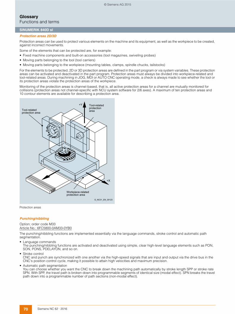
70 Siemens NC 62 · 2016
GlossaryFunctions and terms
SINUMERIK 840D sl
Protection areas 2D/3D
Protection areas can be used to protect various elements on the machine and its equipment, as well as the workpiece to be created, against incorrect movements.
Some of the elements that can be protected are, for example:• Fixed machine components and built-on accessories (tool magazines, swiveling probes) • Moving parts belonging to the tool (tool carriers) • Moving parts belonging to the workpiece (mounting tables, clamps, spindle chucks, tailstocks)
For the elements to be protected, 2D or 3D protection areas are defined in the part program or via system variables. These protection areas can be activated and deactivated in the part program. Protection areas must always be divided into workpiece-related and tool-related areas. During machining in JOG, MDI or AUTO CNC operating mode, a check is always made to see whether the tool or its protection areas violate the protection areas of the workpiece.
Monitoring of the protection areas is channel-based, that is, all active protection areas for a channel are mutually monitored for collisions (protection areas not channel-specific with NCU system software for 2/6 axes). A maximum of ten protection areas and 10 contour elements are available for describing a protection area.
Protection areas
Punching/nibbling
Option; order code M33Article No.: 6FC5800-0AM33-0YB0
The punching/nibbling functions are implemented essentially via the language commands, stroke control and automatic path segmentation.• Language commands
The punching/nibbling functions are activated and deactivated using simple, clear high-level language elements such as PON, SON, PONS, PDELAYON, and so on.
• Stroke controlCNC and punch are synchronized with one another via the high-speed signals that are input and output via the drive bus in the CNC's position control cycle, making it possible to attain high velocities and maximum precision.
• Automatic path segmentationYou can choose whether you want the CNC to break down the machining path automatically by stroke length SPP or stroke rate SPN. With SPP, the travel path is broken down into programmable segments of identical size (modal effect). SPN breaks the travel path down into a programmable number of path sections (non-modal effect).
+Y
–B
+X
G_NC01_EN_00123
Tool-related protection area
Tool-related protection area
Workpiece-relatedprotection area
© Siemens AG 2015
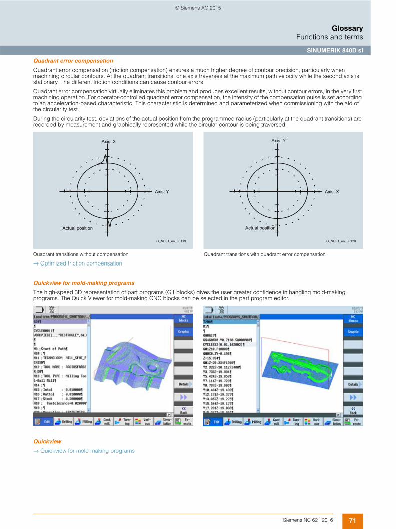
71Siemens NC 62 · 2016
GlossaryFunctions and terms
SINUMERIK 840D sl
Quadrant error compensation
Quadrant error compensation (friction compensation) ensures a much higher degree of contour precision, particularly when machining circular contours. At the quadrant transitions, one axis traverses at the maximum path velocity while the second axis is stationary. The different friction conditions can cause contour errors.
Quadrant error compensation virtually eliminates this problem and produces excellent results, without contour errors, in the very first machining operation. For operator-controlled quadrant error compensation, the intensity of the compensation pulse is set according to an acceleration-based characteristic. This characteristic is determined and parameterized when commissioning with the aid of the circularity test.
During the circularity test, deviations of the actual position from the programmed radius (particularly at the quadrant transitions) are recorded by measurement and graphically represented while the circular contour is being traversed.
Quadrant transitions without compensation Quadrant transitions with quadrant error compensation
→ Optimized friction compensation
Quickview for mold-making programs
The high-speed 3D representation of part programs (G1 blocks) gives the user greater confidence in handling mold-making programs. The Quick Viewer for mold-making CNC blocks can be selected in the part program editor.
Quickview
→ Quickview for mold making programs
G_NC01_en_00119
Axis: X
Actual position
Axis: Y
G_NC01_en_00120
Axis: Y
Actual position
Axis: X
© Siemens AG 2015
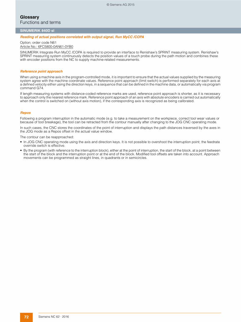
72 Siemens NC 62 · 2016
GlossaryFunctions and terms
SINUMERIK 840D sl
Reading of actual positions correlated with output signal, Run MyCC /COPA
Option; order code N61Article No.: 6FC5800-0AN61-0YB0
SINUMERIK Integrate Run MyCC /COPA is required to provide an interface to Renishaw's SPRINT measuring system. Renishaw's SPRINT measuring system continuously detects the position values of a touch probe during the path motion and combines these with encoder positions from the NC to supply machine-related measurements.
Reference point approach
When using a machine axis in the program-controlled mode, it is important to ensure that the actual values supplied by the measuring system agree with the machine coordinate values. Reference point approach (limit switch) is performed separately for each axis at a defined velocity either using the direction keys, in a sequence that can be defined in the machine data, or automatically via program command G74.
If length measuring systems with distance-coded reference marks are used, reference point approach is shorter, as it is necessary to approach only the nearest reference mark. Reference point approach of an axis with absolute encoders is carried out automatically when the control is switched on (without axis motion), if the corresponding axis is recognized as being calibrated.
Repos
Following a program interruption in the automatic mode (e.g. to take a measurement on the workpiece, correct tool wear values or because of tool breakage), the tool can be retracted from the contour manually after changing to the JOG CNC operating mode.
In such cases, the CNC stores the coordinates of the point of interruption and displays the path distances traversed by the axes in the JOG mode as a Repos offset in the actual value window.
The contour can be reapproached:• In JOG CNC operating mode using the axis and direction keys. It is not possible to overshoot the interruption point; the feedrate
override switch is effective. • By the program (with reference to the interruption block), either at the point of interruption, the start of the block, at a point between
the start of the block and the interruption point or at the end of the block. Modified tool offsets are taken into account. Approach movements can be programmed as straight lines, in quadrants or in semicircles.
© Siemens AG 2015

73Siemens NC 62 · 2016
GlossaryFunctions and terms
SINUMERIK 840D sl
Residual material detection and machining for contour pockets and stock removal
Option; order code P13Article No.: 6FC5800-0AP13-0YB0
Contour ranges that cannot be machined with large tools are automatically recognized by the cycle for contour pockets or the stock removal cycle. The operator can rework these regions using a smaller tool.
Contour turning offers:• Contour/axis-parallel cutting with residual material detection • Contour cutting with residual material detection • Plunge-turning with residual material detection
Contour milling offers: • Contour spigot with residual material detection • Contour pocket with residual material detection • Machining, e.g. in the steps: centering, predrilling, rough machining and rough machining residual material, smoothing,
edge/base, chamfering
Rotary axis, turning endlessly
Depending on the application, the working area of a rotary axis can be limited using software limit switches (e.g. working area between 0° and 60°), to a corresponding number of rotations (e.g. 1000°) - or it can be unlimited (endlessly turning in both directions).
This function can also be used with absolute encoders.
Run MyVNCK
With VNCK we are offering a virtual NC kernel which is implemented at the machine level with the machine OEM directly or in a CAM system. This offers machine OEMs the flexibility they need to implement customized machine applications.
© Siemens AG 2015

74 Siemens NC 62 · 2016
GlossaryFunctions and terms
SINUMERIK 840D sl
Safety Integrated
SINUMERIK Safety Integrated involves integrated safety functions that support the implementation of highly effective personnel and machine protection. The safety functions meet the requirements of DIN EN 61508 for use up to and including SIL2 and Category 3, and PL d according to DIN EN ISO 13849. This allows the main requirements for functional safety to be implemented easily and cost-effectively.
The range of functions includes, for example:• Functions for safely monitoring velocity and standstill • Functions for establishing safe boundaries in working areas and protected areas, and for range recognition • Direct connection of all safety-related signals and their internal logical linking
Safety Integrated – axis/spindle package, 15 additional axes/spindles
Option; order codes C61 ... C62Article No.: 6FC5800-0AC60-0YB0
An additional 15 SINUMERIK Safety Integrated SI-axes/spindles.
Safety Integrated – axis/spindle, additional axis/spindle
Option; order codes C71 ... C78Article No.: 6FC5800-0AC70-0YB0
One additional SINUMERIK Safety Integrated SI-axis/spindle.
Safety Integrated, SI-Basic
Option; order code M63Article No.: 6FC5800-0AM63-0YB0
SINUMERIK Safety Integrated SI-Basic for one NCU including 1 axis/spindle, 4 SPL inputs and 4 SPL outputs.
Safety Integrated, SI-Comfort
Option; order code M64Article No.: 6FC5800-0AM64-0YB0
SINUMERIK Safety Integrated SI-Comfort for one NCU including 1 axis/spindle, 64 SPL inputs and 64 SPL outputs.
Safety Integrated, SI-Connect
Option; order code S67Article No.: 6FC5800-0AS67-0YB0
The Safety Integrated SI-Connect option provides additional safe communication for up to 16 connections.
Safety Integrated, SI-High Feature
Option; order code S68Article No.: 6FC5800-0AS68-0YB0
Requirement: NCU 720.xB PN/NCU 730.xB PN
SINUMERIK Safety Integrated SI-High Feature for one NCU including 1 axis/spindle, 192 SPL inputs and 192 SPLoutputs.
© Siemens AG 2015

75Siemens NC 62 · 2016
GlossaryFunctions and terms
SINUMERIK 840D sl
Sag compensation, multi-dimensional
Option; order code M55Article No.: 6FC5800-0AM55-0YB0
Multidimensional compensation is also possible for the effects of physical influences and manufacturing tolerances such as sag or leadscrew pitch errors. The compensation tables can be switched over from the PLC. When the reference axis and the compensating axis are identical, leadscrew pitch errors can be compensated. By transferring weighting factors (PLC interface), stored compen-sating characteristics can be adapted to different conditions, e.g. tools.
The most important features of interpolation and compensation using tables are as follows:• Independent error characteristics can be defined, in number twice the maximum number of axes • Freely selectable compensating positions, the number of which is configurable
(dependent on the configuration of CNC user memory) • Interpolating inclusion of the compensation values • Weighting factor for compensation of tool weights • Reference axis and compensating axis are selectable
The tolerance band that can be corrected is 10 mm (0.39) for standard versions.
Sag compensation
Restricted functionality of export versions: The correctable tolerance band is restricted to 1 mm (0.039 in).
Scalable analog setpoint, Run MyCC /SANS
Option; order code N48Article No.: 6FC5800-0AN48-0YB0
SINUMERIK Integrate Run MyCC /SANS implements isochronous switchover of analysis of an analog setpoint in the position controller via a high-speed digital output of the NCU. This function has been developed for the operation of spindles supplied by Fischer.
Restricted functionality of export versions: Not possible.
Scratching, determining work offset
A work offset can also be determined through scratching, taking into consideration an (active) tool and, where applicable, the base offset, by moving the axis to the workpiece and entering the desired setpoint position (e.g. 0); the CNC then calculates the work offset.
Screen blanking
When screen blanking is activated, both the screen and backlighting of the operator panel go blank under PLC control or after a programmable period of time has elapsed. This increases the service life of the screens.
G_NC01_XX_00108
Z
-Y
-Y
X
Z
© Siemens AG 2015

76 Siemens NC 62 · 2016
GlossaryFunctions and terms
SINUMERIK 840D sl
Security
→ Industrial Security
Separate path feed for corners and chamfers
To optimize solutions for machining tasks, a separate path feed can be programmed with FRCM (modal) or FRC (non-modal) for the corner and chamfer contour elements. Feed reduction thus makes it possible to achieve the desired geometrically precise definition of corners and chamfers.
Set actual value
The Set actual value function is provided as an alternative to the Preset function: To use this function, the control must be in the work-piece coordinate system (WCS). With set actual value, the workpiece coordinate system is set to a defined actual coordinate and the resulting offset between the previous and a newly entered actual value computed in the WCS as 1st basic offset. The reference points remain unchanged.
Setpoint exchange
Option; order code M05Article No.: 6FC5800-0AM05-0YB0
Setpoint exchange is used on milling machines with special milling heads on which, for example, the spindle motor is used both for driving the tool and for orientation of the milling head. In this case, the spindle and the milling head axes are defined as independent axes in the CNC, but are powered by the same motor one after the other.
It is possible to connect up to 4 axes to one motor. The axes, between which the setpoint is switched, can be assigned to different channels or mode groups.
ShopMill/ShopTurn
Option; order code P17Article No.: 6FC5800-0AP17-0YB0
The ShopMill/ShopTurn option includes the functions: • Multiple clamping of identical/different workpieces• Manual machine
Machining step programming
Processes such as drilling, centering, plunging or pocket milling are represented as machining steps in a simple and clear manner. In this way part programs – even for complex machining operations – are very compact and easily read. Associated sequences are automatically interlinked and can be assigned any position patterns. This unique programming convenience allows you to achieve the shortest programming times even for highly demanding machining tasks.
ShopMill: Machining step programming
© Siemens AG 2015

77Siemens NC 62 · 2016
GlossaryFunctions and terms
SINUMERIK 840D sl
Simulation axis/spindle
The speed control loop of an axis can be simulated for test purposes. The axis traverses with a following error, similar to a real axis. Setpoint output and actual values are not available. For simulated axes, the program is executed exactly the same as for real axes, i.e. no functional restrictions apply to simulated axes.
Functions:• POS/SPOS/M3, M4, M5 (from CNC block)• POSA/SPOSA (from CNC block, modally)• FC18/POS/SPOS/M3, M4, M5 (PLC axes)• PLC-VDI interface (M3, M4, M5 directly)• OSCILL (asynchronous oscillation)• OSCILL (synchronous oscillation)• do/POS/SPOS/M3, M4, M5 (synchronized actions)• Couplings (TRAIL, LEAD, EG, CP, ...)• Path axes/geometry axes/additional path axes/GEOAX()• Spindles for thread cutting, tapping and thread cutting with compensating chuck• Commissioning with SINUMERIK Operate
→ Axes/spindles
→ Positioning axes/auxiliary spindles
→ Virtual axis
→ PLC axes
© Siemens AG 2015

78 Siemens NC 62 · 2016
GlossaryFunctions and terms
SINUMERIK 840D sl
Simulation SINUMERIK Operate
Simulation is supported by an autonomous program interpreter (SNCK) and a separate simulation data environment in SINUMERIK Operate. The SNCK considers the entire syntax of the SINUMERIK CNC family, including the possibility of incorporating special user options on the machine by comparing data with the NCK environment.
The simulation data can be matched statically as required with the NCK environment (initialization data, macros, user data, tool data, machining cycles) or also dynamically when tool data or machining cycles are changed. Machining simulations, with emphasis on the drilling, milling and turning technologies, can be performed in the workpiece coordinate system for certain machine kinematics on the user interface of the CNC.
Simulation of the finished part is performed with the real CNC data. The CNC data are automatically matched at each change of the part program.• The simulation allows a dynamic representation of the machining operation, even when 5-axis transformation TRAORI is active and
with swiveled planes. • Simulation of up to 4 machining channels for turning machines with B axis• Turning on milling machines• Simulation of a machining channel for conventional milling machines• Simulation of up to 12 axes• Intelligent determination of the block times and the program execution time.• Very fast graphical representation through continuous refinement of the workpiece • Optimum resolution for each selected display section• Any section can be selected• While one workpiece is being machined, the machining of another workpiece can be simulated in parallel (from NCU 720.x and
higher)
The simulation can be extended to 3D representation by means of the 3D simulation 1 (finished part) option. This extension also applies to the simultaneous recording.
Turning/drilling simulation Milling simulation
Notes:• Very fast simulation result, but consequently low dynamic resolution• Fine recording is too slow for complex displays/fine recording fails to run for very complex parts• Quickview for mold-making part programs• Simulation of special kinematics not available when compile cycles are used• Blank CAD data cannot be imported, e.g. for castings • Couplings cannot be simulated
- Coupled motion: TRAILON(<following axis>, <leading axis>, <coupling factor>)- Axial master-value coupling: LEADON(Faxis, LAxis, curve table n) actual value and setpoint coupling- Electronic gear: EGDEF(FA, LA1, coupl.1, LA2, coupl.2, .. LA5, coupl.5), EGON, EGONSYN, EGONSYNE
• Reference point approach G74 is not operative during simulation• The following is not supported:
- Axis container- Dependencies on part programs and PLC- Multiple clamping- CNC function synchronized actions for safe programmable logic (SPL) in the CNC
• Different technologies in different channels with different axis coordinate systems are not fully supported.• Threads with variable pitch are shown with a constant pitch.
→ 3D simulation 1 (finished part)
© Siemens AG 2015

79Siemens NC 62 · 2016
GlossaryFunctions and terms
SINUMERIK 840D sl
Simultaneous recording (real-time simulation of the current machining operation)
Option; order code P22Article No.: 6FC5800-0AP22-0YB0
During machining, the tool paths can be simultaneously recorded on the CNC screen in 3-side view or 3D view. Workpiece graphics and views correspond to the graphic simulation
Note:
Activate simultaneous recording prior to CNC start in order to obtain a complete display.
→ Simulation SINUMERIK Operate
SINUMERIK extended touch
Option; order code P80Article No.: 6FC5800-0AP80-0YB0
The SMART Operation option expands SINUMERIK Operate to include multi-touch functionality at SINUMERIK black line panels. SINUMERIK Operate then offers state-of-the art gesture-based operation to allow leading-edge user interface designs.
SINUMERIK Grinding Advanced
Option; order code S35Article No.: 6FC5800-0AS35-0YB0
The SINUMERIK Grinding Advanced option provides an extended scope of grinding functions such as an axis-parallel dressing/pre-profiling cycle, for example.
SINUMERIK MDynamics
Technology packages for 3-axis and 5-axis milling.
The SINUMERIK MDynamics function ensures perfect surfaces through innovative motion control and an optimized CNC data compressor, rapid adaptation to the workpiece, tool and program handling, optimum machining thanks to the flexible programming of programGUIDE and ShopMill and consequently very short programming times.
SINUMERIK Operate /NCU
Option; order code S00Article No.: 6FC5800-0AS00-0YB0
The option SINUMERIK Operate /NCU permits activation of SINUMERIK Operate in the CNC software for the NCU. SINUMERIK Operate makes machine tool operation extremely easy. SINUMERIK Operate therefore sets the standard for the efficient operation of machine tools.
→ www.siemens.com/sinumerik-operate
SINUMERIK Operate /PC
Option; order code P87Article No.: 6FC5800-0AP87-0YB0
The option SINUMERIK Operate /PC permits activation of SINUMERIK Operate in the CNC software for a connected PC. SINUMERIK Operate makes machine tool operation extremely easy. SINUMERIK Operate therefore sets the standard for the efficient operation of machine tools.
→ www.siemens.com/sinumerik-operate
SINUMERIK Operate /PCU
Option; order code P88Article No.: 6FC5800-0AP88-0YB0
The option SINUMERIK Operate /PCU permits activation of SINUMERIK Operate in the CNC software for a connected PCU. SINUMERIK Operate makes machine tool operation extremely easy. SINUMERIK Operate therefore sets the standard for the efficient operation of machine tools.
→ www.siemens.com/sinumerik-operate
© Siemens AG 2015

80 Siemens NC 62 · 2016
GlossaryFunctions and terms
SINUMERIK 840D sl
SINUMERIK PCU base software /IPC
Option; order code P86Article No.: 6FC5800-0AP86-0YB0
The SINUMERIK PCU base software /IPC option provides SINUMERIK PCU functionality on defined SIMATIC IPCs.
TCU support then becomes available for connecting SINUMERIK HT8, SINUMERIK OP and SIMATIC ITC andSINUMERIK Operate /PCU can be used on SIMATIC IPCs.
Skip blocks
CNC blocks that are not to be executed in every program run, e.g. execute a trial program run, can be skipped. Skip blocks are identified by placing a "/" character in front of the block number. The instructions in the skip blocks are not executed and the program resumes with the next block that is not skipped.
As many as 8 skip levels (level 0 to level 7) may be programmed. The individual skip levels are activated via a data block in the PLC interface.
Spatial compensation for kinematic transformations, Run MyCC /SEC-KT
Option; order code M57Article No.: 6FC5800-0AM57-0YB0
SINUMERIK Integrate Run MyCC /SEC-KT is a specific function and is not intended for general use.
For Cartesian machines, refer to: • Spatial compensation VCS-A3 • Spatial compensation VCS-A5 • Spatial compensation VCS A5 plus
Restricted functionality of export versions: Not possible.
Spatial compensation for rotary axes, Run MyCC /VCS-ROT
Option; order code N31Article No.: 6FC5800-0AN31-0YB0
This static compensation function enables the user to achieve more accurate tool orientation. The two swivel axes in the head need to be measured once in the working area. The compensation function then uses the table values to perform a real-time calculation of the offsets for the 3 linear axes referred to the current tool center point.
Restricted functionality of export versions: Not possible.
Spatial compensation interface, Run MyCCI /VCI
Option; order code N74Article No.: 6FC5800-0AN74-0YB0
For new applications, use SINUMERIK Integrate Run MyCCI /UCI.
→ Universal spatial compensation interface Run MyCCI /UCI
Restricted functionality of export versions: Not possible.
Spatial compensation, Run MyCC /VCS-A3
Option; order code N15Article No.: 6FC5800-0AN15-0YB0
This option implements compensation on Cartesian machines with 3 linear axes in cases where the tool orientation is fixed and the tool lengths are effective in parallel to the coordinates of the linear axes. Gantry axes can be active in parallel to the 3 linear axes.
Restricted functionality of export versions: Not possible.
© Siemens AG 2015

81Siemens NC 62 · 2016
GlossaryFunctions and terms
SINUMERIK 840D sl
Spatial compensation, Run MyCC /VCS-A5
Option; order code N16Article No. 6FC5800-0AN16-0YB0
This option implements compensation on 5-axis Cartesian machines on which the tool can be oriented relative to the workpiece using 2 rotary axes. Compensation of the measured errors of the linear axes is computed with reference to the tool center point as a function of the current position of the tool.
The machine kinematics can be implemented as pure head kinematics, or as table kinematics with both swivel axes in the table, or as mixed kinematics with one swivel axis in the table – generic transformation types 24, 40 and 56.
Restricted functionality of export versions: Not possible.
Spatial compensation, Run MyCC /VCS-A5 plus
Option; order code N17Article No. 6FC5800-0AN17-0YB0
SINUMERIK Integrate Run MyCC /VCS-A5 plus is designed for use on large machines (3-axis and 5-axis gantry milling machines). The requirements for positioning accuracy of these machines over the entire working area (= volumetric accuracy) increases constantly and has become impossible to achieve by mechanical means in many cases.
SINUMERIK Integrate Run MyCC /VCS-A5 plus implements volumetric compensation of all 21 aspects of freedom from errors that the 3 basic axes of a Cartesian machine tool can demonstrate (per axis: linearity, 2 degrees of error, rolling, pitching, yawing as well as deviations from the perpendicular between axes). These geometrical machine errors result in offset of the tool center point and an orientation error in the tool.
On a 5-axis machine, the tool center point and the orientation error of the tool are compensated with Run MyCC /VCS-A5 plus with TRAORI active. In comparison to leadscrew error compensation LEC and circle error compensation CEC, Run MyCC /VCS-A5 plus supports the total compensation of the geometric errors of a Cartesian machine tool. Run MyCC /VCS-A5 plus can be superimposed on existing LEC and CEC compensations.
The geometric error of a machine tool is measured with external laser-based instruments that determine these errors as effectively as possible. The measured results are supplied to the SINUMERIK CNC as a file in the specified readable VCS format. Measuring machine errors is the responsibility of the OEM or machine operator. Several SINUMERIK Solution Partners offer support and measurement as a service and they can generate the machine-specific VCS files necessary for VCS.
Restricted functionality of export versions: Not possible.
© Siemens AG 2015

82 Siemens NC 62 · 2016
GlossaryFunctions and terms
SINUMERIK 840D sl
Spindle functions
Spindle modes are:• Open-loop control mode, constant spindle speed S or constant cutting rate G96 • Oscillation mode • Positioning mode • Synchronous mode (synchronous spindle) • Thread cutting/tapping
Functions of the spindle modes:• Spindle speed with spindle override • 5 gear stages, specified in the
- Part program (commands M41 to M45) - Automatically via programmed spindle speed M40 or - PLC function block FC18
• Oriented spindle stop (positioning mode) with SPOS 1) • Spindle monitoring with the functions 1):
- Axis/spindle stationary (n < nmin) - Spindle in setpoint range - Spindle speed, max. - Programmable lower (G25) and upper (G26) spindle speed limitation - Speed of the gear stage, min./max. - Encoder limit frequency, max. - End point monitoring for SPOS
• Constant cutting speed with G96 (in m/min or inch/min) at the tool tip for uniform turning finish and thus better surface quality. Spindle control via PLC for oscillation (so that it is easier to engage a new gear stage) and positioning
• Changeover to axis mode:For machining with a position-controlled spindle (e.g. face machining of turned parts), the main spindle drive can be switched to the axis mode using a program command. A common encoder can be used for both axis and spindle modes. The zero mark of the spindle is also the reference mark of the C axis, so there is no longer any need to home the C axis (synchronize C axis on the fly).
• Thread cutting with constant pitch 1): The following thread types can be produced with G33: cylindrical, taper and face thread, single-start or multiple-start, as left-hand or right-hand thread. In addition, multiple-block threads can be produced by concatenating threading blocks.
• Thread cutting with variable lead 1): Threads can also be programmed with linearly progressive (G34) or linearly degressive (G35) lead.
• Programmable thread run-in and run-out path:When thread cutting, DITS/DITE (displacement thread start/end) can be used to program the path ramp for the acceleration or deceleration process as a distance. This makes it possible, for example, to adjust the acceleration on the thread shoulder when the tool run-in or run-out is too short and initiate smoothing at the next CNC start.
• Tapping with compensating chuck/rigid tapping: When tapping with compensating chuck (G63), the compensating chuck equalizes differences between spindle movement and drilling axis. A prerequisite for rigid tapping (G331/G332) is a position-controlled spindle with position measuring system. The traversing range of the drilling axis is therefore not restricted. By using the method where the spindle, as a rotary axis, and the drilling axis interpolate, threads can be cut to a precise final drilling depth, e.g. for blind hole threads.
1) Requirement: actual-position sensor (measuring system) with corresponding resolution (mounted directly on the spindle).
Spindle speed limitation
→ Spindle functions
© Siemens AG 2015

83Siemens NC 62 · 2016
GlossaryFunctions and terms
SINUMERIK 840D sl
Spline interpolation (A, B and C splines)
Option; order code S16Article No.: 6FC5800-0AS16-0YB0
Using spline interpolation it is possible to obtain a very smooth curve from just a few defined interpolation points along a set contour. The interpolation points are connected by polynomials. The compressor converts linear movements, e.g. from CAD, at block transitions to splines of constant speed COMPON or splines of constant acceleration COMPCURV.
This yields soft transitions that reduce wear on the mechanical parts of the machine tool. However, if the interpolation points are placed close together, quite sharp edges can also be programmed. Spline interpolation also considerably reduces the number of program blocks required.
Extremely smooth workpiece surfaces are often very important in mold and tool making, both optically and technologically, e.g. for rubber gaskets. Tool radius compensation is also possible in spline interpolation, just the same as for linear or circular interpolation.Every polynomial can represent a spline.
Only the algorithm determines the type of spline.• A spline is only true to the tangents. • B spline is true to the tangents and the curvature, but does not run through the nodes (interpolation points). • C spline is true to the tangents and the curvature and runs through the nodes.
With the COMPCAD compressor, smooth curves of this kind can be approximated within the boundaries of compressor tolerance (parallel tool paths) so that surfaces of a high optical quality can also be obtained even in the case of increased tolerances.
Spline interpolation for 3-axis machining is suitable for simple applications and for the JobShop area.
Standstill monitoring
Standstill monitoring represents one of the most comprehensive mechanisms for monitoring axes. This monitoring function checks to see whether the following error has reached the standstill tolerance limit after a parameterizable time has elapsed. After positioning has been completed, standstill monitoring takes over from position monitoring, and checks to see whether the axis moves further from its position than specified in the machine data's standstill tolerance field.
The standstill monitoring function is always active following expiration of the zero speed delay time or when reaching the fine exact stop limit as long as no new traversing command is pending. When the monitoring function responds, an alarm is generated and the relevant axis/spindle brought to standstill with rapid stop along a speed setpoint ramp. Standstill monitoring is effective for linear and rotary axes as well as for position-controlled spindles.
Standstill monitoring is inactive in the follow-up mode.
→ Position monitoring
Subprogram levels and interrupt routines
Subprograms can be called in the main program as well as in other subprograms. Subprograms can be nested to a maximum depth of 12 levels, including the main program level. That means that a main program may contain as many as 11 nested subprogram calls.
When working with Siemens cycles, 3 levels are required. If such a cycle is to be called from a subprogram, the call can be nested at a depth of no more than 9.
Programs can also be called on the basis of events following reset, part program start or end, or after the CNC has booted. Users can then make the basic function settings or can initialize functions using a part program command. A system variable can be used to scan the event, which activated the associated program.
© Siemens AG 2015

84 Siemens NC 62 · 2016
GlossaryFunctions and terms
SINUMERIK 840D sl
Synchronized actions
Even in their basic configuration, SINUMERIK CNCs allow up to 24 actions to be initiated in synchronism with axis and spindle move-ments. These actions run in parallel with workpiece machining; specific conditions are used to define when they become active. The starting of such motion-synchronized actions – or synchronized actions for short is, therefore, not restricted to CNC block boundaries. Synchronized actions are an excellent programming tool for supporting very quick responses to events in the interpolation cycle.
Synchronized actions are executed in the interpolation cycle. Multiple actions can be processed in the same IPO cycle. Synchro-nized actions without validity identifier are active non-modally only in the automatic mode. In the automatic mode, synchronized actions with validity identifier ID are modal in the subsequently programmed blocks. Statically effective synchronized actions with the identifier IDS remain active in all CNC operating modes: Cross-mode actions.
Typical applications include:• Comparison operation-dependent or external signal-dependent transfer of auxiliary functions M and H to the PLC user software
and derived machine responses • Fast, axis-specific deletion of the distance-to-go in response to input signals • Manipulation of the read-in disable for the CNC block using external signals• Monitoring of system variables such as velocity, power and torque • Control of process variables such as velocity, speed and distance
Restricted functionality of export versions: Only 1 active synchronous function SYNFCT is possible at a time. The number of axes that can be simultaneously traversed is restricted to 4 (path and positioning axes).
→ Cross-mode actions
Synchronized actions stage 2
Option; order code M36Article No.: 6FC5800-0AM36-0YB0
More than 24 synchronized actions can be active in the CNC block. As many as 255 parallel actions can be programmed in each channel. Technology cycles can be combined into programs using synchronized actions, stage 2, making it possible, for example, to start axis programs in the same IPO cycle by scanning digital inputs.
Restricted functionality of export control versions: The number of axes that can be simultaneously traversed is restricted to 4 (path and positioning axes).
Synchronous motion, RUN MyCC /SYMO
Option; order code N66Article No.: 6FC5800-0AN66-0YB0
SINUMERIK Integrate Run MyCC /SYMO synchronous motion can be used to synchronize the traversing motion of 2 separate machines (e.g. 2 robots for testing components based on ultrasound transmission). In this case, each of the machines is configured in a separate channel. The part program is executed in the master channel. The TCP and orientation of the second machine in the slave channel are coupled in real time to the motion of the machine in the master channel.
Restricted functionality of export versions: Not possible.
© Siemens AG 2015

85Siemens NC 62 · 2016
GlossaryFunctions and terms
SINUMERIK 840D sl
Synchronous spindles, multi-edge turning
Precise angular synchronization between one leading and one or more following spindles enables on-the-fly workpiece transfer, particularly for turning machines, from spindle 1 to spindle 2, for example for the purpose of finishing, without experiencing the non-productive times normally associated with rechucking.
In addition to the speed synchronism, the relative angular position of the spindles to one another, e.g. on-the-fly, position-oriented transfer of skewed workpieces, is also specifiable.
On-the-fly transfer:• n1 = n2 • Angle 1 = angle 2 or • Angle 2 = angle 1 + angle Δ
Finally, specification of an integer speed ratio between the main spindle and a tool spindle provides the prerequisites for multi-edge machining (polygon turning).
Multi-edge turning:
n2 = T × n1
Configuring and selection take place either via the CNC program or operator panel. Several pairs of synchronous spindles can be implemented.
Examples for synchronous spindles/multi-edge turning
→ Generic couplings
n1 n2
n1n2
G_NC01_en_00124
Spindle 1
On-the-fly-transfer
Multi-edge turning
Counter-spindle
Spindle 2
© Siemens AG 2015

86 Siemens NC 62 · 2016
GlossaryFunctions and terms
SINUMERIK 840D sl
Tangential control
Option; order code M06Article No.: 6FC5800-0AM06-0YB0
Tangential control makes it possible to correct a rotary axis in the direction of the tangents of two path axes. The two guide axes and the corrected axis lie in the same channel. Tangential control is effective in all interpolation modes.
Applications:• Tangential setting of a rotatable tool during punching/nibbling • Correction of the workpiece alignment for a belt saw • Setting of a dressing tool on a grinding wheel • Tangential feed of a wire for 5-axis welding • Setting a cutting wheel for cutting glass or paper
On punching and nibbling machines with a rotatable punching tool and associated lower tool, the following functions may be used to ensure that the tool can be no universally used:• Tangential control
TANGON/TANGOF for vertical rotary axis alignment of the punching tools to the direction vector of the programmed path • Coupled motion
TRAILON/TRAILOF for synchronous rotation of upper and lower tools (stamp and die)
Representation of a rotatable tool axis and die during punching/nibbling
Tapping with/without compensating chuck
→ Spindle functions
Technological functions with compressor, Run MyCC /COTE
Option; order code N50Article No.: 6FC5800-0AN50-0YB0
SINUMERIK Integrate Run MyCC /COTE is a special function and has not been approved for general use.
Restricted functionality of export versions: Not possible.
C1
C
G_NC01_en_00125
Rotatabletool axis
Stamp
Die
Stamp
© Siemens AG 2015

87Siemens NC 62 · 2016
GlossaryFunctions and terms
SINUMERIK 840D sl
Technology cycles
For frequently repeated machining tasks, technology cycles are available for the drilling/milling and turning technologies. Technology cycles are generally applicable technology subprograms, with which specific machining processes can be implemented, such as tapping a thread or milling a pocket.
The cycles are adapted to a concrete machining task using parameters. The parameterization can also be implemented using graphically supported input screens.• Drilling technology:
Drilling/centering, drilling/counterboring, deep-hole drilling, tapping with and without compensating chuck, boring 1 ... 5, row of holes, circle of holes, grid of holes, machining on inclined surfaces
• Milling technology:Thread milling, elongated holes in a circle, grooves in a circle, circumferential groove, rectangular/circular pocket, face milling, path milling, rectangular/circular spigot, machining on inclined surfaces, high-speed settings for optimized HSC machining, engraving cycle
• Turning technology:Groove, undercut, cutting with relief cut, thread undercut, thread cutting, chaining of threads, thread recutting
Example: Swiveling Example: Milling the circular pocket
Temperature compensation
Heat causes machine parts to expand. This expansion depends, among other things, on the temperature and on the thermal con-ductivity of the machine parts. The actual positions of the individual axes, which change on the basis of variations in temperature, have a negative effect on the precision with which workpieces are machined. These actual value changes can be corrected using temperature compensation.
At a specific temperature, measure the actual-value offset over the positioning range of the axis to obtain the error curve for this temperature value. Error curves for different temperatures can be defined for each axis. In order to ensure proper compensation of thermal expansion at all times, the temperature compensation value, reference position and gradient (angle) parameters must be transferred from the PLC to the CNC via function blocks each time the temperature changes. Abrupt changes in these parameters are automatically smoothed by the CNC in order to prevent machine overload and avoid unnecessarily triggering monitoring functions.
Thread cutting
→ Spindle functions
© Siemens AG 2015

88 Siemens NC 62 · 2016
GlossaryFunctions and terms
SINUMERIK 840D sl
Tool carrier with orientation capability
For machine tools which have tool carriers with settable tool orientation, these kinematics can be freely configured without a 5-axis transformation when the SINUMERIK CNC is used.
The tool carrier with orientation capability function enables 2½D/3D machining with fixed spatial orientation of the tool/workpiece table. Vectors l1 to l4 represent the geometrical dimensions of the machine. The rotary axes need not move in parallel to the Cartesian axes, but instead can be inclined at any angle (e.g. cardan milling head with 45° inclination). The angles α1 and α2 can be either specified or computed from the active frame and assigned to the tool carrier with orientation capability or to the workpiece table.
The following kinematics can be configured flexibly:• Rotatable tool: type T (tool) • Rotatable tool/rotatable workpiece table: type M (mixed) • Rotatable workpiece table: type P (part)
Kinematics type T Kinematics type M
Kinematics type P
Tool change via T number
In chain, rotary-plate and box magazines, a tool change normally takes place in 2 stages: A T command locates the tool in the magazine, and an M command inserts it in the spindle.
In circular magazines on turning machines, the T command carries out the entire tool change, that is, locates and inserts the tool. The tool change mode can be set using machine data.
I2
α2
I1
α1
I3
G_NC01_EN_00133
Tool carrier reference point
Resulting tool vector
2nd rotary axis
Tool length andtool wear
1st rotary axis
α2
a1
I3
I1
I2
I4
G_NC01_EN_00134
Resulting tool vector
Machine reference point
Workpiece table reference point
2nd rotary axis
Tool length and tool wear
1st rotary axisTool carrierreference point
I2
I3I4 α1
G_NC01_EN_00135
Resulting tool vector
Machine reference point
Workpiece table reference point
1st rotary axis
2nd rotary axis α2
© Siemens AG 2015

89Siemens NC 62 · 2016
GlossaryFunctions and terms
SINUMERIK 840D sl
Tool Ident Connection
Option; order code P52Article No.: 6FC5800-0AP52-0YB0
The Tool Ident Connection function allows tool identification systems such as SIMATIC Ident (see Catalog ID 10) to be linked to SINUMERIK CNCs for operation in conjunction with the standard tool management system, and also supports the transfer of tool data. It therefore eliminates the need for manual entries that are susceptible to errors.
→ Tool identification systems
Tool identification systems
The tool load and unload dialog of the Siemens tool management system provides a link to an automatic tool identification system, e.g. SIMATIC Ident (see Catalog ID10). This means that you can automatically read and write to the tool code carrier, instead of having to manually enter tool data. When unloading, the data block for the tool is saved; when loading, it is read via the code carrier and entered in the tool management.
In the interim, the tool data can be subsequently edited the same as when the tool is selected from the tool catalog, e.g. offset data. Using an editable description file containing precisely defined tool and cutting data, when loading, the code carrier data is converted into dialog data that can be read by the tool management. When unloading, the dialog data is converted back into code carrier data using the description file.
→ Tool Ident Connection
Tool management
Tool management ensures that the correct tool is in the correct location on the machine at any given time and that the data assigned to the tool are up to date. Tool management is used on machine tools with circular magazines, chain magazines or box magazines. It also allows fast tool changes and avoids both scrap by monitoring the tool service life and machine downtimes by using spare tools.
The most important functions of tool management are:• Tool selection across all magazines and turrets for active tools and spare tools• Determining a suitable empty location depending on tool size and location type• Tool-dependent location coding (fixed and variable)• Initiation of tool changes with T or M command• Axis movements during a tool change with automatic synchronization at the next D number • Quantity, tool life and wear monitoring with prewarning limit monitoring function • Support when using multi-tools
Missing tools can be loaded based on a decision made by the operator. Tools with similar wear characteristics can be combined into wear groups.
Tool management also takes into account tool length compensations for adapters that are permanently mounted at certain magazine locations and fitted with different tools.
Tool management with more than 4 magazines
Option; order code M88Article No.: 6FC5800-0AM88-0YB0
4 magazines are included in the basic version of SINUMERIK 840D sl: • Magazine• Spindle• Tool buffer• With the option with order code M88, the number can be increased to a maximum of 64 magazines.
© Siemens AG 2015

90 Siemens NC 62 · 2016
GlossaryFunctions and terms
SINUMERIK 840D sl
Tool offsets
You can select the tool by programming a T function (5-digit integer number or identifier) in the block. Every tool can be assigned up to 12 cutting edges (D addresses). The number of tools to be managed in the CNC is set when configuring.
A tool offset block comprises 25 parameters, e.g.:• Tool type• Up to 3 tool length offset values• Radius compensation• Wear dimension for length and radius• Tool base dimension
The wear and the tool base dimension are added to the corresponding offset. When writing the program, you do not have to take tool dimensions such as cutter diameter, cutter position or tool length into account. You program the workpiece dimensions directly, following the production drawing, for example.
When a workpiece is machined, the tool paths, depending on the relevant tool geometry, are controlled so that the programmed contour can be produced with every tool used. The tool data are entered separately in the tool table of the CNC, and only the required tool with its offset data is called in the program. During program execution, the CNC retrieves the required offset data from the tool files and automatically corrects the tool path for various tools.
Tool offset D always has a reference to tool number T when Siemens tool management is active, e.g. with monitoring functions and management of sister tools.
Up to 32000 D values can be defined per CNC. When programming, D numbers can be freely assigned, checked, renamed, determined with the associated T number, invalidated and activated on a site-dependent basis.
Tool offsets
Tool offsets, grinding-specific
Grinding-specific tool offsets are available for grinding technology:• Minimum wheel radius• Maximum speed• Maximum surface speed
When cutting edges are created for grinding tools (tool type 400 to 499), these are stored automatically for the tool in question.
The TMON command activates geometry and speed monitoring for grinding tools, types 400 to 499 in the CNC part program. Monitoring remains active until deactivated in the part program with TMOF. The actual wheel radius and the actual wheel width are monitored.
The speed setpoint is monitored cyclically in relation to the speed limit value, taking into consideration the spindle override. The speed limit value is the smaller of the values resulting from comparison of the maximum speed with the speed computed from the maximum grinding wheel surface speed and the current wheel radius.
→ Grinding wheel surface speed
Tool type400 Surface grinding wheel401 Surface grinding wheel with monitoring403 Surface grinding wheel with monitoring and without tool base dimensions for grinding wheel surface speed410 Facing wheel411 Facing wheel with monitoring413 Facing wheel with monitoring and without tool base dimensions for grinding wheel surface speed490 ... 499 Dresser
F
L1
F
L1
FL2L3
L1
G_NC01_en_00100
RadiusRadius
© Siemens AG 2015

91Siemens NC 62 · 2016
GlossaryFunctions and terms
SINUMERIK 840D sl
Tool orientation interpolation
Interpolations of tool orientations supplement generic transformation. The tool orientation can be programmed in a plane as large circle interpolation ORIVECT, on the outside surface of a taper in the clockwise or counterclockwise direction ORICONCW/ORICONCCW, or even with free definition of the tool curve orientation ORICURVE.
→ Transformation, generic
Tool radius compensation
When tool radius compensation is active, the CNC automatically calculates the equidistant tool paths for different tools. To do so, it requires the tool number T, the tool offset number D (with cutting edge number), the machining direction G41/G42, and the relevant working plane G17 to G19. The path is corrected in the programmed level depending on the selected tool radius.
The approach and retract paths can be adapted to the required contour profile or unmachined part (blank) forms, for example:
• NORMThe tool travels in a straight line directly to the contour and is positioned perpendicular to the path tangent at the starting point.
• KONTIf the starting point is behind the contour, the corner point P1 of the contour is bypassed. If the starting point is in front of the contour, the normal position at the starting point P1 is approached in the same way as with NORM.
In the part program it is also possible to select the strategy with which the outside corners of the contour are to be bypassed:
• Transition radii: Circle or ellipse
• Intersection of equidistant paths
You can implement various strategies spatially or in the plane to achieve soft approach to/retraction from the contour, i.e. tangential approach and retraction irrespective of the position of the starting point:
• Approach and retraction from left or right
• Approach and retraction along a straight line
• Approach and retraction along a quadrant or semicircle
The CNC can also automatically insert a circle or a straight line in the block with the tool radius compensation when no intersection with the previous block is possible. The offset process of tool radius compensation may only be interrupted by a certain number of successive blocks or M commands containing no motion commands or positional data in the compensating plane. The number of successive blocks or M commands can be set using machine data (standard 3, max. 5).
KONT for selection behind the contour Bypassing the outside corners with transition circle/transition ellipse
Tool radius compensation, 3D
Option; order code M48Article No.: 6FC5800-0AM48-0YB0
Inclined surfaces can be machined with 3D tool radius compensation or tool offset in space. This function supports circumferential milling and face milling with a defined path. The inclined tool clamping position on the machine can be entered and compensated.
The CNC automatically computes the resulting positions and movements. The radius of a cylindrical milling cutter at the tool insertion point is included in the calculation. The insertion depth of a cylindrical milling cutter can be programmed. The milling cutter can be rotated not only in the X, Y and Z planes, but also around the lead or camber angle and the side angle.
G_NC01_en_00102
Transition circle Transitionellipse
Equidistant
P0
R
G42
P* RP1
G_NC01_en_00132
Behindcontour
In frontof contour
Transition circleR = Tool radius
© Siemens AG 2015

92 Siemens NC 62 · 2016
GlossaryFunctions and terms
SINUMERIK 840D sl
Tool types
The tool type determines the geometry specifications required for the tool offset memory, and how they are to be used. Entries are made for the relevant tool type in tool parameter DP. The CNC combines these individual components to produce a result variable, e.g. total length, total radius.
The relevant overall dimension goes into effect when the offset memory is activated. The use of these values in the axes is determined by the tool type and current machining plane G17, G18 or G19.
Input screen forms can be used to save all of the tool offsets.
Geometry of turning tool Geometry of slotting saw
Tooltips
Tooltips are provided as a simple user help in all screens – also displayed in red when input errors are made.
Top Surface
Option; order code S17Article No.: 6FC5800-0AS17-0YB0
The Top Surface function offers a motion control quality that has been improved even further. It allows machining of highly precise contours and perfect surfaces. By contrast with Advanced Surface, Top Surface is useful for large machining tolerances (e.g. 100 µm in the HSC screen, cycle 832).
Transformation, generic
Generic transformation is used to define any tool orientation in space with the initial state of the axes, and not just according to the Z direction. The transformation can then be used much more flexibly and universally. It is then also possible to control machine kinematics by the CNC, where the orientation of the rotary axes is not precisely in parallel to the linear axes.
Generic 5-axis transformation is an extension of the 3-axis and/or 4-axis transformation, i.e. it can also be used for machines with only one rotary axis, e.g. rotatable tool or workpiece.
Restricted functionality of export versions: Not possible.
Tool types, parameterizableGroup 1xy Milling tools From spherical head cutters to bevel cuttersGroup 2xy Drills From twist drills to reamersGroup 4xy Grinding tools From surface grinding wheels to dressersGroup 5xy Turning tools From roughing tools to threading toolsGroup 700 Slotting saw Wood technologyGroup 900 Special tools
d/2 → L1b/2 → L2
k
bL2
L1
d
G_NC01_en_00136
Tool holder(reference point)
XF R S
P
ZG_NC01_en_00101
Turning toole.g. G18: Z/X plane F - Tool holder
reference point
Tool tip P(cutting edge 1 = Dn)
R - Radius of the cutting edge (tool radius)S - Location of the cutting edge center pointLength 2 (Z)
Leng
th 1
(X)
© Siemens AG 2015

93Siemens NC 62 · 2016
GlossaryFunctions and terms
SINUMERIK 840D sl
Transformation: Additional function 6th axis, Run MyCC /TR-6A
Option; order code M66Article No.: 6FC5800-0AM66-0YB0
SINUMERIK Integrate Run MyCC /TR-6A is a specific function and is not intended for general use.
Restricted functionality of export versions: Not possible.
Transformation: Double Generic, Run MyCC /DGEN
Option; order code N34Article No.: 6FC5800-0AN34-0YB0
With the SINUMERIK Integrate Run MyCC /DGEN double generic transformation it is possible to couple two 5-axis kinematics for a machining task.
The axes of both 5-axis machines must be programmed in one channel. Programming coupled 5-axis kinematics is subject to certain restrictions that do not apply to normal 5-axis programming. The application is used in 5-axis milling operations on thin structures (e.g. outer shells of aircraft) that require simultaneous movement of 5-axis kinematics as a counter-support immediately beneath the tool center point.
Restricted functionality of export versions: Not possible.
Transformation: Double slide, Run MyCC /SKID
Option; order code M80Article No.: 6FC5800-0AM80-0YB0
The purpose of the SINUMERIK Integrate Run MyCC /SKID transformation is to traverse a platform that can move in the Z and X directions using two slides that can move only in the X direction. The platform that supports the spindle is mechanically coupled to the two X slides using slideways arranged at an oblique angle.
Restricted functionality of export versions: Not possible.
© Siemens AG 2015
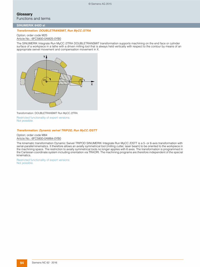
94 Siemens NC 62 · 2016
GlossaryFunctions and terms
SINUMERIK 840D sl
Transformation: DOUBLETRANSMIT, Run MyCC /2TRA
Option; order code M25Article No.: 6FC5800-0AM25-0YB0
The SINUMERIK Integrate Run MyCC /2TRA DOUBLETRANSMIT transformation supports machining on the end face or cylinder surface of a workpiece in a lathe with a driven milling tool that is always held vertically with respect to the contour by means of an appropriate swivel movement and compensation movement in X.
Transformation: DOUBLETRANSMIT Run MyCC /2TRA
Restricted functionality of export versions: Not possible.
Transformation: Dynamic swivel TRIPOD, Run MyCC /DSTT
Option; order code M84 Article No.: 6FC5800-0AM84-0YB0
The kinematic transformation Dynamic Swivel TRIPOD SINUMERIK Integrate Run MyCC /DSTT is a 5- or 6-axis transformation with serial-parallel kinematics. It therefore allows an axially symmetrical tool (milling cutter, laser beam) to be oriented to the workpiece in the machining space. The restriction to axially symmetrical tools no longer applies with 6 axes. The transformation is programmed in the Cartesian coordinate system including orientation via TRAORI. The machining programs are therefore independent of the special kinematics.
Restricted functionality of export versions: Not possible.
© Siemens AG 2015

95Siemens NC 62 · 2016
GlossaryFunctions and terms
SINUMERIK 840D sl
Transformation: Eccentric axis, Run MyCC /ECCA
Option; order code N44Article No.: 6FC5800-0AN44-0YB0
SINUMERIK Integrate Run MyCC /ECCA supplies adjustments to the position controller that are needed for the high-precision dynamic traversal of a rotary axis which is driven eccentrically by linear motion (threaded rod) in the range < 180 degrees.
Eccentric axis kinematics ECCA
Restricted functionality of export versions: Not possible.
Transformation: Eccentric, Run MyCC /ECCE
Option; order code N41Article No.: 6FC5800-0AN41-0YB0
SINUMERIK Integrate Run MyCC /ECCE transformation eccentric uses an eccentric gear to convert the rotation of an axis into a one-dimensional linear slide motion. The motion component perpendicular to the direction of the moving slide is absorbed by a journal bearing.
Restricted functionality of export versions: Not possible.
Transformation: GRINDING, Run MyCC /GRIN
Option; order code N40Article No.: 6FC5800-0AN40-0YB0
SINUMERIK Integrate Run MyCC /GRIN is a specific function and is not intended for general use.
Restricted functionality of export versions: Not possible.
© Siemens AG 2015

96 Siemens NC 62 · 2016
GlossaryFunctions and terms
SINUMERIK 840D sl
Transformation: Handling, Run MyCC /RCTRA
Option; order code M31Article No.: 6FC5800-0AM31-0YB0
The handling transformation SINUMERIK Integrate Run MyCC /RCTRA contains the so-called standard transformation block, with whose help typical 2-axis to 4-axis handling devices such as gantries or Scara kinematics can be implemented. This coordinate transformation converts programmed Cartesian setpoints (e.g. X, Y, Z, A) into axis positions (e.g. A1 to A4) for the handling device.
Thanks to this coordinate transformation, it becomes significantly easier and more convenient to move the handling device. The handling device can be set up, that is, manually traversed not only in the axis-specific coordinate system, but also in the Cartesian coordinate system, using, for example, the jog keys on the handheld programming unit. Adaptation of the respective kinematics is carried out via machine data.
The function Run MyCC /ROBX is available for applications with more than 4 axes.
Transformation: Handling
Restricted functionality of export versions: Not possible.
Transformation: HEXAPOD, Run MyCC /HEX
Option; order code M71Article No.: 6FC5800-0AM71-0YB0
SINUMERIK Integrate Run MyCC /HEX is a 6-axis transformation with parallel kinematics. The tool platform is moved in all 6 spatial degrees of freedom.
Two versions of the transformation are available:• 6 variable-length, parallel struts, or• 6 linear guides, which move the base points of 6 articulated rods.
It therefore allows a tool (e.g. milling cutter, laser beam) to be oriented to the workpiece in the machining space. The path and path velocity are programmed in the same way as for 3-axis systems. The tool orientation is programmed additionally in the traversing blocks. The transformation SINUMERIK Integrate Run MyCC /HEX calculates the resulting motion of all 6 axes. The generated machining programs are therefore not machine-specific. CNC functions such as tool radius and tool length compensation, and the selection of coordinate systems, are available without any restriction.
Restricted functionality of export versions: Not possible.
A1 A 2 A 3
A 4
Z
A
X
Y
G_NC01_EN_00126
Cartesianactual valuesX, Y, Z, A
Axis-spec.actual valuesA1 to A4
Forward trans-
formation
Cartesian setpoint valuesX, Y, Z, A
Axis-spec.setpoint values A1 to A4
Reverse trans-
formation
© Siemens AG 2015

97Siemens NC 62 · 2016
GlossaryFunctions and terms
SINUMERIK 840D sl
Transformation: Machining with virtual Y axis, Run MyCC /MAVY
Option; order code N56Article No.: 6FC5800-0AN56-0YB0
SINUMERIK Integrate Run MyCC /MAVY transformation machining with virtual Y axis allows users to perform milling and drilling operations on a lathe. This transformation replaces the missing Y axis of a lathe so that milling and drilling operations can be performed on the peripheral surface of turned parts. The user can use a Cartesian coordinate system, machining operations are performed in the X-Y plane (G17).
Restricted functionality of export versions: Not possible.
Transformation: Pantograph kinematics, Run MyCC /SCIS
Option; order code M51Article No.: 6FC5800-0AM51-0YB0
The SINUMERIK Integrate Run MyCC /SCIS transformation Pantograph kinematics is a type of 2/4-axis transformation with parallel kinematics. The transformation can work with variable-length rods, or with movable base points of fixed-length rods.
The SINUMERIK CNC calculates the required motion of the machine axes online. Therefore, the programmer can create part programs in the same way as on a conventional machine, and does not have to take the special kinematics of the machine into account. Workpieces can be programmed in the usual way in Cartesian coordinates.
Restricted functionality of export versions: Not possible.
Transformation: PARACOP 3 axes, Run MyCC /PACO
Option; order code M44Article No.: 6FC5800-0AM44-0YB0
PARACOP kinematic transformations and pantograph kinematics are used on parallel-kinematics machines PKM. Parallel kinematics means that the drive forces engage on the spindle head (Stewart platform) simultaneously (in parallel). PARACOP machines are tripod systems on which the Stewart platform is moved by 3 actuators. Design measures are used to ensure that the Stewart platform cannot move in an undefined manner on these tripod types.
On PARACOP machines, 2 parallel rods run on a slide for each actuator. These machines are suitable for 3-axis machining. When using kinematic transformations, workpieces can be programmed in Cartesian coordinates as usual. The SINUMERIK CNC calcu-lates the required motion of the machine axes online. Therefore, the programmer can create part programs in the same way as on a conventional machine, and does not have to take the special kinematics of the machine into account.
PARACOP
Restricted functionality of export versions: Not possible.
→ Transformation: Pantograph kinematics, Run MyCC /SCIS
© Siemens AG 2015

98 Siemens NC 62 · 2016
GlossaryFunctions and terms
SINUMERIK 840D sl
Transformation: Redundant axes at workpiece, Run MyCC /RDCC
Option; order code N26Article No.: 6FC5800-0AN26-0YB0
The SINUMERIK Integrate Run MyCC /RDCC kinematic transformation Redundant axes at workpiece is a multi-axis transformation. This function is used particularly for the purpose of assembling large aircraft components which need to be positioned and orientated in a working area. The component is aligned by programming 3 Cartesian coordinates and 3 orientation angles. The function can move up to 31 axes in such a way that the contact points on the component, to each of which up to 3 axes are assigned, do not change their reciprocal positions relative to the moving part.
In combination with the additional function Run MyCC /AMOV, axes of another NCU coupled by means of NCU-Link can also be included in the interpolation with the result that the motion of more than 31 axes in total can be synchronized.
Restricted functionality of export versions: Not possible.
→ Variable-based axis movement, Run MyCC /AMOV
Transformation: Robotic extended, Run MyCC /ROBX
Option; order code N54Article No.: 6FC5800-0AN54-0YB0
The SINUMERIK Integrate Run MyCC /ROBX transformation supports robot kinematics with between 4 and 6 axes.
A 6-axis robot can orientate the tool in any desired relationship to the workpiece in every point of the machining space. In order to improve accessibility to machining points on large workpieces, up to 3 additional linear axes, which move the robot or the workpiece, can be included in the transformation. The workpiece can be turned in space by an additional 3 rotary axes that are also included in the transformation. Tool motion and orientation are still programmed with reference to the workpiece.
Restricted functionality of export versions: Not possible.
Transformation: Rotating eccentric, Run MyCC /ROTE
Option; order code N37Article No.: 6FC5800-0AN37-0YB0
SINUMERIK Integrate Run MyCC /ROTE transformation rotating eccentric is a 4-axis transformation. The path and path velocity are programmed in the same way as for 3-axis systems. The SINUMERIK Integrate Run MyCC /ROTE transformation calculates the resultant motion of the 4 machine axes. The generated machining programs are therefore not machine-specific. The Y coordinate is converted to a corresponding position of axis 4. Compensating motion of axes 1 and 2 are then calculated as a function of axis 3.
Restricted functionality of export versions: Not possible.
© Siemens AG 2015
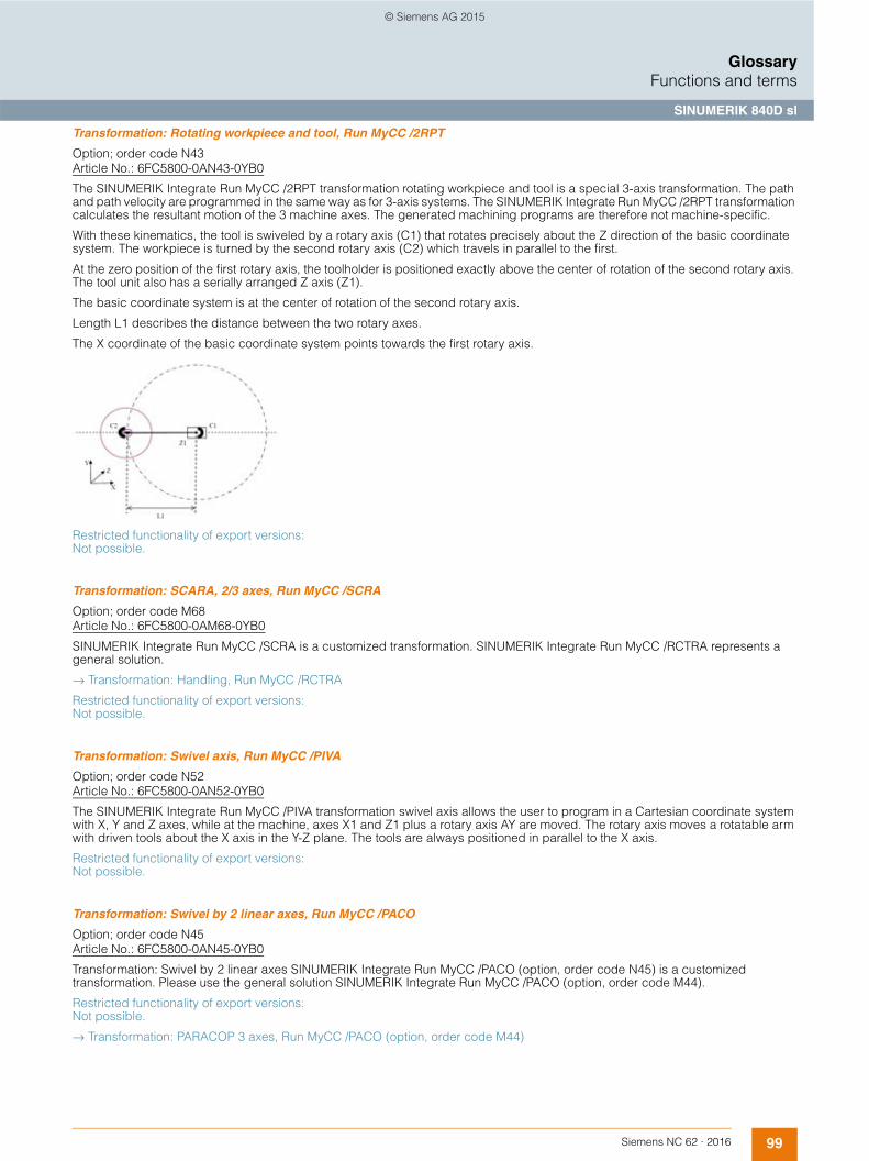
99Siemens NC 62 · 2016
GlossaryFunctions and terms
SINUMERIK 840D sl
Transformation: Rotating workpiece and tool, Run MyCC /2RPT
Option; order code N43Article No.: 6FC5800-0AN43-0YB0
The SINUMERIK Integrate Run MyCC /2RPT transformation rotating workpiece and tool is a special 3-axis transformation. The path and path velocity are programmed in the same way as for 3-axis systems. The SINUMERIK Integrate Run MyCC /2RPT transformation calculates the resultant motion of the 3 machine axes. The generated machining programs are therefore not machine-specific.
With these kinematics, the tool is swiveled by a rotary axis (C1) that rotates precisely about the Z direction of the basic coordinate system. The workpiece is turned by the second rotary axis (C2) which travels in parallel to the first.
At the zero position of the first rotary axis, the toolholder is positioned exactly above the center of rotation of the second rotary axis. The tool unit also has a serially arranged Z axis (Z1).
The basic coordinate system is at the center of rotation of the second rotary axis.
Length L1 describes the distance between the two rotary axes.
The X coordinate of the basic coordinate system points towards the first rotary axis.
Restricted functionality of export versions: Not possible.
Transformation: SCARA, 2/3 axes, Run MyCC /SCRA
Option; order code M68Article No.: 6FC5800-0AM68-0YB0
SINUMERIK Integrate Run MyCC /SCRA is a customized transformation. SINUMERIK Integrate Run MyCC /RCTRA represents a general solution.
→ Transformation: Handling, Run MyCC /RCTRA
Restricted functionality of export versions: Not possible.
Transformation: Swivel axis, Run MyCC /PIVA
Option; order code N52Article No.: 6FC5800-0AN52-0YB0
The SINUMERIK Integrate Run MyCC /PIVA transformation swivel axis allows the user to program in a Cartesian coordinate system with X, Y and Z axes, while at the machine, axes X1 and Z1 plus a rotary axis AY are moved. The rotary axis moves a rotatable arm with driven tools about the X axis in the Y-Z plane. The tools are always positioned in parallel to the X axis.
Restricted functionality of export versions: Not possible.
Transformation: Swivel by 2 linear axes, Run MyCC /PACO
Option; order code N45Article No.: 6FC5800-0AN45-0YB0
Transformation: Swivel by 2 linear axes SINUMERIK Integrate Run MyCC /PACO (option, order code N45) is a customized transformation. Please use the general solution SINUMERIK Integrate Run MyCC /PACO (option, order code M44).
Restricted functionality of export versions: Not possible.
→ Transformation: PARACOP 3 axes, Run MyCC /PACO (option, order code M44)
© Siemens AG 2015

100 Siemens NC 62 · 2016
GlossaryFunctions and terms
SINUMERIK 840D sl
Transformation: TRICEPT 5-axis transformation, Run MyCC /TRIC
Option; order code M46Article No.: 6FC5800-0AM46-0YB0
SINUMERIK Integrate Run MyCC /TRIC is a kinematic transformation for a TRICEPT (tripod with center tube). TRICEPT kinematic transformations are used on parallel-kinematic machines PKM. Parallel kinematics means that the drive forces engage on the spindle head (Stewart platform) simultaneously (virtually in parallel). TRICEPT machines are TRIPOD systems on which the Stewart platform is moved by 3 actuators. Design measures are used to ensure that the Stewart platform cannot move in an undefined manner. On TRICEPT, an additional passive telescope (center tube) is used.
On TRICEPT, 2 additional rotary axes are required to define the tool orientation in space. These axes can be arranged like the fork head of a 5-axis machine, for example, thus allowing the machine to carry out 5-axis machining.
The SINUMERIK CNC calculates the required motion of the machine axes online. Therefore, the programmer can create part pro-grams in the same way as on a conventional machine, and does not have to take the special kinematics of the machine into account.
TRICEPT
Restricted functionality of export versions: Not possible.
Transformation: TRIPOD hybrid kinematics, Run MyCC /THYK
Option; order code N36Article No.: 6FC5800-0AN36-0YB0
The kinematic transformation TRIPOD hybrid kinematics THYK is a 5-axis transformation for 3 parallel linear axes and 2 rotary axes. The tool movements are programmed complete with their orientation in the same manner as the Cartesian 5-axis machine. The real-time transformation calculates the necessary paths and speeds for the real machine axes.
Parallel kinematic type Exechon
Restricted functionality of export versions: Not possible.
© Siemens AG 2015

101Siemens NC 62 · 2016
GlossaryFunctions and terms
SINUMERIK 840D sl
Transformation: W-Z Tracking, Run MyCC /WZTR
Option; order code N22Article No.: 6FC5800-0AN22-0YB0
SINUMERIK Integrate Run MyCC /WZTR is a specific function and is not intended for general use.
Restricted functionality of export versions: Not possible.
TRANSMIT/cylinder surface transformation
Option; order code M27Article No.: 6FC5800-0AM27-0YB0
The TRANSMIT function is used for milling external contours on turned parts, e.g. square parts – linear axis with rotary axis. As a result, the programming process becomes much more simple, and complete machining increases machine efficiency: Turning and milling can be performed on one machine without rechucking.
3D interpolation with 2 linear axes and one rotary axis is possible. The two linear axes are mutually perpendicular and the rotary axis lies at right angles to one of the linear axes. TRANSMIT can be called up in different channels simultaneously. The function can be selected and deselected with a preparatory function (straight line, helix, polynomial and activating tool radius compensation) in the part program or MDI.
With TRANSMIT, the area of the transformation pole is reached when the tool center can be positioned at least to the turning center of the rotary axis entering the transformation.
TRANSMIT through the pole is implemented in different ways:• When traveling through the pole, the rotary axis is turned automatically through 180° when the turning center is reached and the
remaining block is then executed. • When traversing close by the pole, the CNC automatically reduces the feedrate and the path acceleration. • If the path contains a corner in the pole, the position jump in the rotary axis is compensated by the control through automatic block
insertion.
Cylinder surface transformation is used on turning machines and milling machines, and enables cylinder surface machining, e.g. for turned parts. The cylinder surface transformation or TRACYL cylinder surface transformation can be used to manufacture grooves of any shape on the surface of cylindrical bodies with or without groove side offset. The shape of the grooves is programmed in reference to the unwound plane cylinder surface.
Face machining with TRANSMIT Tool-center-point path through the pole
C
X
Y
ZG_NC01_XX_00127
Y'
Y
X'
X
C
G_NC01_en_00128
Workpiece
Pole (center)
Tool
Rotary table
© Siemens AG 2015

102 Siemens NC 62 · 2016
GlossaryFunctions and terms
SINUMERIK 840D sl
Travel to fixed stop
With this function, tailstocks or sleeves, for example, can be traversed to a fixed stop in order to clamp workpieces. The pressure applied can be defined in the part program.
Several axes can be traversed to a fixed stop simultaneously and while other axes are traversing.
Travel to fixed stop with Force Control
Option; order code M01Article No.: 6FC5800-0AM01-0YB0
The extended travel to fixed stop function can be used to adapt torque or force on a modal or non-modal basis; travel with limited torque/limited force (force control, FOC) can be initiated, or synchronized actions can be used at any time to program traversing functions.
Traversing range
The range of values for the traversing ranges depends on the selected computational resolution. When the default value is specified in the machine data field "Computational resolution for linear or angular position" (1000 increments per mm or degree), the ranges of values specified in the table can be programmed with this resolution:
If the computational resolution is increased/decreased by a factor of 10, then the value ranges change accordingly. The traversing range can be restricted by software limit switches and working areas.
Trial license
The trial license allows functions, which require a license, to be used for a limited period of time.
G70 [inches, degrees] G71 [inches, degrees]Linear axes X, Y, Z, .... ± 399999,999 ± 999999,999Rotary axes A, B, C, ... ± 999999,999 ± 999999,999Interpolation parameters I, J, K ± 399999,999 ± 999999,999
Program end position Start position
Actual position after"travel to fixed stop"
Fixed stopmonitoringwindows
G_N
C01
_EN
_005
93
© Siemens AG 2015

103Siemens NC 62 · 2016
GlossaryFunctions and terms
SINUMERIK 840D sl
Universal interpolator NURBS
Internal motion control and path interpolation are performed on the basis of non uniform rational B splines NURBS. This provides a uniform method for all internal interpolations that can also be used for future complex interpolation tasks.
The following input formats are available irrespective of the internal structure:• Linear interpolation• Circular interpolation• Helical interpolation• Involute interpolation• Splines (A, B, C)• Polynomial
Universal spatial compensation interface, Run MyCCI /UCI
Option; order code N75 Article No.: 6FC5800-0AN75-0YB0
SINUMERIK Integrate RunMy CCI /UCI provides an interface for customized compensation algorithms.
Restricted functionality of export versions: Not possible.
Use HMI applications, Run MyHMI /3GL
Option; order code P60Article No.: 6FC5800-0AP60-0YB0
SINUMERIK Integrate Run MyHMI /3GL is used to execute programmed HMI applications. The applications are programmed with either Qt/C++, .net (C#, VB) or C++.
This option is also needed if third-party software or background functions with data communication (application without HMI components) are to be integrated in SINUMERIK Operate.
→ Program screens, operating areas and user interfaces, Create MyHMI /3GL
Use HMI applications, Run MyScreens
Option; order code P64Article No.: 6FC5800-0AP64-0YB0
The SINUMERIK Integrate Run MyScreens functionality allows SINUMERIK users to design their own screen forms in order to visualize either machine-manufacturer or end-user functional expansions.
This function is implemented via an integrated interpreter and via configuring files containing the description of the user interface. The screen forms can be designed directly on the CNC itself. Users can also write their own cycle forms that can also be called from the part program editor.
Configuring examples for new screen forms, which can also be used as the basis for the user's own new screen forms, can be found in the supplied toolbox.
The following functions can be implemented with the SINUMERIK Integrate Run MyScreens option:• Display screen forms and provide softkeys, variables, tables, texts, help texts, graphics, and help screens • Start actions when screen forms are displayed and exited, when softkeys are pressed, and values (variables) are entered • Dynamic restructuring of screen forms, including changing softkeys, designing arrays, displaying, replacing and deleting display
texts and graphics • Read and write variables, combine with mathematical, comparative or logical operators • Subprograms, file functions or program instance services (PI services) • Enable data exchange between screen forms
SINUMERIK Integrate Run MyScreens is configured using ASCII files that can be stored on the PCU 50 or the NCU. Files that contain ASCII descriptions for the layout of interactive screen forms, softkey functions and display texts and graphics are interpreted. These configuring files are created with the ASCII editor, taking into account certain special rules of syntax.
The user interface can be expanded even in the basic version by up to 5 screen forms using predefined softkeys with the integrated editor. The option with order code P64 is required to add more than 5 screen forms with SINUMERIK Integrate Run MyScreens.
© Siemens AG 2015
104 Siemens NC 62 · 2016
GlossaryFunctions and terms
SINUMERIK 840D sl
Use standardized and freely configurable operating screens, Run MyHMI /PRO
Option; order code P47Article No.: 6FC5800-0AP47-0YB0
The runtime license SINUMERIK Integrate Run MyHMI /PRO allows users to run configurations on the PCU 50 or the NCU that have been created with the HMI PRO CS configuration software. The software option includes the standardized operating screens within HMI PRO as well as the freely configurable user screens that have been created using the variable layout.
User interface
The user interface has a clear layout with 8 horizontal and 8 vertical softkeys. The specific use of windows-type technology permits simple and user-friendly machine operation.
The user interface is subdivided into 6 operating areas:• Machine • Parameters • Program• Program Manager • Diagnosis • Commissioning
This means that in parallel with part machining, for example, another part program can be created. The last active menu is always stored when changing the operating area.
User interface on SIMATIC Panel, Run MyHMI /SIMATIC OP for SIMATIC Comfort and Mobile Panels
Option; order code P03Article No.: 6FC5800-0AP03-0YB0
SINUMERIK Integrate Run MyHMI /SIMATIC OP allows operation of the SINUMERIK NCU with its own user interface on SIMATIC Comfort Panels. The user interface required on the SIMATIC Comfort Panel can be created simply using the SIMATIC WinCC ES Advanced engineering system and the add-on SINUMERIK Integrate Create MyHMI /WinCC.
User machine data
The NC kernel makes machine data available for configuring the PLC user program. These user machine data are stored in the NCK-PLC interface during CNC power-up, prior to PLC power-up.
The PLC basic program reads these data from the NCK-PLC interface during its initialization phase. This means that specific machine configurations, machine expansions and user options can be activated.
Utility programs for the servo, Run MyCC /SUTI
Option; order code N10 Article No.: 6FC5800-0AN10-0YB0
SINUMERIK Integrate Run MyCC /SUTI includes a number of special functions in the position controller: Position controller gain factor in real time influences the position of the slave encoder taking into account the master-slave speed coupling.
© Siemens AG 2015

105Siemens NC 62 · 2016
GlossaryFunctions and terms
SINUMERIK 840D sl
Variable-based axis movement, Run MyCC /AMOV
Option; order code N62Article No.: 6FC5800-0AN62-0YB0
SINUMERIK Integrate Run MyCC /AMOV is a specific function and is not intended for general use.
Restricted functionality of export versions: Not possible
Variables and arithmetic parameters
Using variables instead of constant values allows flexible programs to be developed. Variables make it possible to respond to signals, e.g. measured values. If variables are used as a setpoint value, the same program can be used for different geometries.
The CNC uses 3 sorts of variables:• User-defined variables
Variables defined by the user with name and type, e.g. arithmetic parameters• Arithmetic parameters
Special, predefined arithmetic variables whose address is R plus a number. The predefined arithmetic variables are of the REAL type
• System variablesVariables provided by the CNC that can be processed in the program (write, read). System variables enable access to work offsets, tool offsets, actual values, measured axis values, CNC conditions, etc.
Velocity
The maximum path and axis velocity and spindle speed are affected by the machine and drive dynamic response and the limit frequency of actual-value acquisition (encoder limit frequency and limit frequency of the input circuit). The resulting velocity from the programmed path lengths in the CNC block and IPO cycle is always limited to the maximum velocity or, in the case of short path lengths, reduced to the velocity that can be travelled during one IPO cycle.
The minimum velocity must not go below 10-3 units/IPO cycle. The minimum and maximum axis velocities are dependent on the selected computational resolution. The maximum velocity of the axis is generally limited by the mechanics or by the limit frequency of the encoder or actual-value acquisition.
The velocity value range is not limited by the CNC (max. 300 m/s).
Velocity adaptation for water jet cutting, Run MyCC /VADA
Option; order code N05Article No.: 6FC5800-0AN05-0YB0
Velocity adaptation for water jet cutting SINUMERIK Integrate Run MyCC /VADA
For 2D water jet cutting applications, it is possible to reduce the path velocity at corners and along circular contours as a function of the corner angle or circle radius. NC commands in the part program activate and deactivate the function and parameterize the velocity reduction.
Restricted functionality of export versions: Not possible.
Variable type Meaning Value rangeINT Integers with sign ±(231 - 1)REAL Real numbers (fractions with decimal point,
LONG REAL in acc. with IEEE)±(10-300 ... 10+300)
BOOL Boolean values: TRUE (1) and FALSE (0) 1.0CHAR ASCII character specified by the code 0 ... 255STRING Character string, number of characters in [...],
maximum of 200 charactersSequence of values with 0 ... 255
AXIS Axis names (axis addresses) only All axis identifiers in the channelFRAME Geometrical parameters for moving, rotation, scaling, and mirroring
© Siemens AG 2015

106 Siemens NC 62 · 2016
GlossaryFunctions and terms
SINUMERIK 840D sl
Vibration extinction, Run MyCC /VIBX
Option; order code N11Article No.: 6FC5800-0AN11-0YB0
The SINUMERIK Integrated Run MyCC /VIBX vibration extinction function supports axis-specific damping of machine vibrations. Up to 8 axes can be parameterized in the CNC, each with 2 machine data for the filter frequency and the required damping factor.
The function significantly reduces disturbing oscillations that follow positioning.
Restricted functionality of export versions: Not possible.
Virtual axis
A virtual axis is one that is interpolated in the follow-up mode. Virtual axes are used in master value couplings. Typical examples are electronic transfer CP, master value coupling with curve tables or flying shears.
→ Axes/spindles
→ Positioning axes/auxiliary spindles
→ Simulation axis/spindle
© Siemens AG 2015

107Siemens NC 62 · 2016
GlossaryFunctions and terms
SINUMERIK 840D sl
Work offsets
According to DIN 66217, clockwise, rectangular (Cartesian) coordinate systems are used in machine tools.
The following coordinate systems are defined:• Machine coordinate system MCS
The machine coordinate system is made up of all physically available machine axes. • Basic coordinate system BCS
The basic coordinate system consists of 3 Cartesian axes (geometry axes), as well as other non-geometric axes (special axes). • BCS and MCS are always in conformance when the BCS can be mapped to the MCS without kinematic transformation (e.g.
TRANSMIT/interfacial transformation, 5-axis transformation and max. 3 machine axes). • Basic zero system BZS
DRF offsets, external work offsets and basic frames map the BCS on the BZS. • Settable zero system SZS
An activated settable work offset G54 to G599 transfers the BZS to the SZS. • Workpiece coordinate system (WCS)
The programmable frame determines the WCS, which is the basis for programming.
Work offsets are therefore used to transform the machine zero point into the workpiece zero point in order to simplify programming.
The following work offsets are possible:• Settable work offsets:
It is possible to enter up to 100 work offsets (G54 to G57, G505 to G599), offset coordinates, angles and scaling factors in order to call zero points program-wide for various fixtures or clamping operations, for example. The work offsets can be suppressed block-by-block.
• Programmable work offsets:Work offsets can be programmed with TRANS (substitution function, basis G54 to G599) or ATRANS (additive function). This allows you, for example, to work with different work offsets for repetitive machining operations at different positions on the workpiece. G58/G59 make previously programmed work offsets axially replaceable.
• External work offsets:Axis-related linear work offsets can also be activated via the PLC user software (function blocks) with assignment of system variable $AA_ETRANS [axis].
Coordinate system
→ Frame concept
Working area limitation
Working area limitations define the area in which machining is permitted. These limitations refer to the basic coordinate system BCS. The tool tip is monitored to determine whether it is inside the protected working area (taking into account the tool radius).
One value pair per axis (±) may be used to describe the protected working area. The upper and lower working area limits, which can be set and activated via setting data, may be modified using the G25/G26 commands.
Working area limitations restrict the traversing range of the axes in addition to the limit switches. Protection areas in which tool motion is inhibited and which protect equipment such as tool turrets, measuring stations, etc., against damage, are thus set up in the machine's working area.
→ Work offsets
X
X
X
X
X
Y Y Y Y Y
G_NC01_EN_00115
WCS Current
Programmable FRAMEs
G54 ... G599 settable FRAMEs
Basic offset (basic frame)
DRF offset, external work offset
Kinematic transformation
Axial preset offset
SZS
BZS
BCS
MCS
WCS
SZS
BZS
BCS
MCS
MCS BCS BZS SZS WCS
© Siemens AG 2015

108 Siemens NC 62 · 2016
GlossaryFunctions and terms
SINUMERIK 840D sl
Working plane
When specifying the working plane in which the desired contour is to be machined, the following functions are defined at the same time:• Plane for the tool radius compensation • Infeed direction for the tool length compensation depending on the type of tool • Plane for the circle interpolation
When calling the tool path correction G41/G42, the working plane must be defined so that the CNC can correct the tool length and radius.
In the basic setting, the working plane G17 (X/Y) is preset for drilling/milling, and G18 (Z/X) for turning.
→ Tool radius compensation
Workpiece-related actual value system
The workpiece-related actual value system of the SINUMERIK CNC enables the user to do the following:• After the CNC has powered up, start machining in a workpiece coordinate system defined via machine data in JOG and
AUTO CNC operating modes without any additional operator actions • Retain the valid settings relating to the active plane, settable frames (G54 ... G57), kinematic transformations, and active tool offset
at the end of the part program for use in the next part program • Toggle between the workpiece coordinate system WCS and the machine coordinate system MCS • Change the workpiece coordinate system, e.g. by changing the settable frames or the tool offset.
© Siemens AG 2015
Copyright © 2022 FDOKUMEN