
Getting started with the Statox 502 Control Module - Compur ...
10
Statox 502 Control Module Issue 1/2015 Page 1 of 10 Getting started with the Statox 502 Control Module Safety notes Read and observe this manual prior to installation and start-up. The Statox 502 Control Module must not be operated out of the specified ambient conditions (see Technical Data). In particular, it must not be operated in potentially explosive atmosphere! The Statox 502 Control Module must exclusively be operated, maintained and repaired by trained and authorized personnel. Use only Compur Monitors original parts for repair and maintenance. Do not connect the module directly to mains! Do not modify the product. Do not use if damaged or incomplete. When installing this product observe all local standards and regulations. Disregarding of the above instructions may cause danger to people and property. Detailed manuals in several languages are available on our homepage www.compur.com Product description The Statox 502 Control Module works together with 4-20 mA transmitters and the complete line of Statox 501 sensor heads. It provides a 4-20 mA analog output, 3 alarm relays, a display and LEDs for visible alarms. It can also be operated as Common Alarm Module to collect alarm signals via communication bus. Set with 2 bus adapters, obligatory for each module in bus operation, Art.# 557002 Connection set for bus adapter (Bus plug left and right), optional, Art.# 557003 DIN rail TS 35 Figure 1: Requirements for bus operation, sample installation Control Module, Art.# 557000 Control Module, Art.# 557000, configured as Common Alarm Module Power supply 24 VDC
-
Upload
khangminh22 -
Category
Documents
-
view
2 -
download
0
Transcript of Getting started with the Statox 502 Control Module - Compur ...
Statox 502 Control Module
Issue 1/2015 Page 1 of 10
Getting started with the Statox 502 Control Module
Safety notes
� Read and observe this manual prior to installation and start-up.
� The Statox 502 Control Module must not be operated out of the specified ambient conditions (see Technical
Data). In particular, it must not be operated in potentially explosive atmosphere!
� The Statox 502 Control Module must exclusively be operated, maintained and repaired by trained and
authorized personnel. Use only Compur Monitors original parts for repair and maintenance.
� Do not connect the module directly to mains!
� Do not modify the product. Do not use if damaged or incomplete.
� When installing this product observe all local standards and regulations.
� Disregarding of the above instructions may cause danger to people and property.
� Detailed manuals in several languages are available on our homepage www.compur.com
Product description
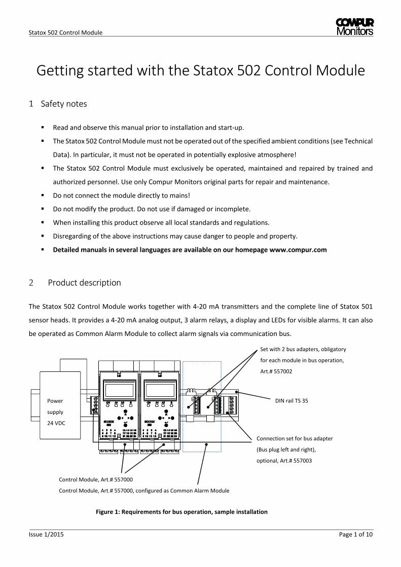
The Statox 502 Control Module works together with 4-20 mA transmitters and the complete line of Statox 501
sensor heads. It provides a 4-20 mA analog output, 3 alarm relays, a display and LEDs for visible alarms. It can also
be operated as Common Alarm Module to collect alarm signals via communication bus.
Set with 2 bus adapters, obligatory
for each module in bus operation,
Art.# 557002
Connection set for bus adapter
(Bus plug left and right),
optional, Art.# 557003
DIN rail TS 35
Figure 1: Requirements for bus operation, sample installation
Control Module, Art.# 557000
Control Module, Art.# 557000, configured as Common Alarm Module
Power
supply
24 VDC
Statox 502 Control Module
Page 2 of 10 Issue 1/2015
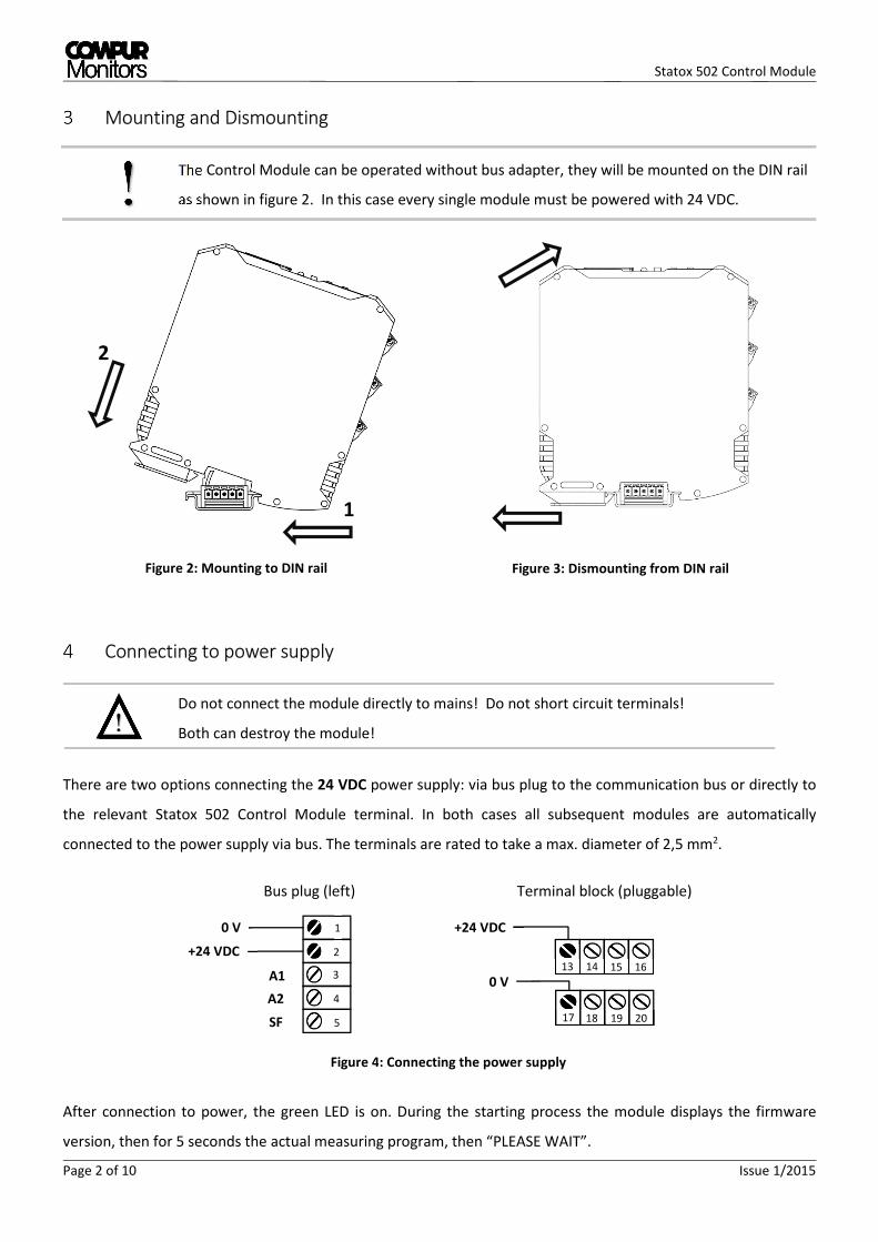
Figure 2: Mounting to DIN rail
Mounting and Dismounting
The Control Module can be operated without bus adapter, they will be mounted on the DIN rail
as shown in figure 2. In this case every single module must be powered with 24 VDC.
Connecting to power supply
Do not connect the module directly to mains! Do not short circuit terminals!
Both can destroy the module!
There are two options connecting the 24 VDC power supply: via bus plug to the communication bus or directly to
the relevant Statox 502 Control Module terminal. In both cases all subsequent modules are automatically
connected to the power supply via bus. The terminals are rated to take a max. diameter of 2,5 mm2.
After connection to power, the green LED is on. During the starting process the module displays the firmware
version, then for 5 seconds the actual measuring program, then “PLEASE WAIT”.
!
13 14 15 16
+24 VDC
0 V
17 18 19 20
Bus plug (left) Terminal block (pluggable)
5
4
3
2
1 0 V
+24 VDC
1
2
!
Figure 3: Dismounting from DIN rail
Figure 4: Connecting the power supply
A1
A2
SF
Statox 502 Control Module
Issue 1/2015 Page 3 of 10
Main menu structure
Push ◄- and ► -button together for 2 s. Select each digit of the password 1994 with the arrow keys and confirm
with ENTER. Correct your inputs with the R key.
General time-out: if no button is pushed within 30 seconds, the module returns to measuring mode.
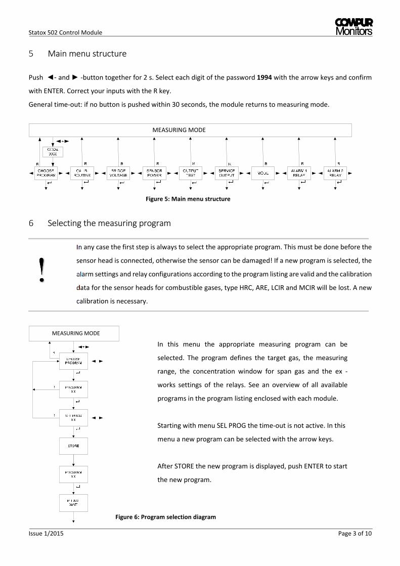
Selecting the measuring program
In any case the first step is always to select the appropriate program. This must be done before the
sensor head is connected, otherwise the sensor can be damaged! If a new program is selected, the
alarm settings and relay configurations according to the program listing are valid and the calibration
data for the sensor heads for combustible gases, type HRC, ARE, LCIR and MCIR will be lost. A new
calibration is necessary.
!
MEASURING MODE
MEASURING MODE
Figure 5: Main menu structure
In this menu the appropriate measuring program can be
selected. The program defines the target gas, the measuring
range, the concentration window for span gas and the ex -
works settings of the relays. See an overview of all available
programs in the program listing enclosed with each module.
Starting with menu SEL PROG the time-out is not active. In this
menu a new program can be selected with the arrow keys.
After STORE the new program is displayed, push ENTER to start
the new program.
Figure 6: Program selection diagram

Statox 502 Control Module
Page 4 of 10 Issue 1/2015
Calibration
After connecting the sensor heads type Statox 501 HRC, ARE, LCIR, MCIR and PID to the Control Module a calibration
is mandatory. Exception: a line calibration has been done ex works. The test gas concentration must be within the
permitted range, see program listing.
Figure 7: Calibration menu diagram
CALIB.
ROUTINE
ZERO
ADJUSTM.
000
APPLY
SPAN GAS
GAS
R
R
CALIB.
FINISHED
GAS CONC
(value) (unit)
FACTOR
x.yy
DONE
R
CALIBR.
FAILED
GAS
(value) (unit)
R
R
GAS CONC
ERROR
R
+
Change menu item
MEASURING MODE
Flashing, searching zero point.
No time-out from here on!
Flashing, turn test gas on.
Displayed if zero point is adjusted.
Signal is stable, turn test gas off.
Input: gas concentration (value)
Start zeroing
Input: reference factor (value)
Correction
Confirmation
Displayed for 2 s after
successful calibration.
Actual measuring value and unit

Statox 502 Control Module
Issue 1/2015 Page 5 of 10
Programming the alarm relays
In this menu you can set parameters of the alarm relays A1 and A2:
� Alarm thresholds
� High or low alarm
� Latching (HOLD) or not latching (AUTO RESET)
� Coil active (ACTIVE) or not active (PASSIVE) in case of alarm
Figure 8: Alarm relay setting
Current output in Service Mode
If you operate the module as a SIL device EN 50402 or IEC 61508, 2 mA output in the service mode
is mandatory.
!
MEASURING MODE
MEASURING MODE
Change menu item
Selection of current value
Figure 9: Diagram current output
Statox 502 Control Module
Page 6 of 10 Issue 1/2015
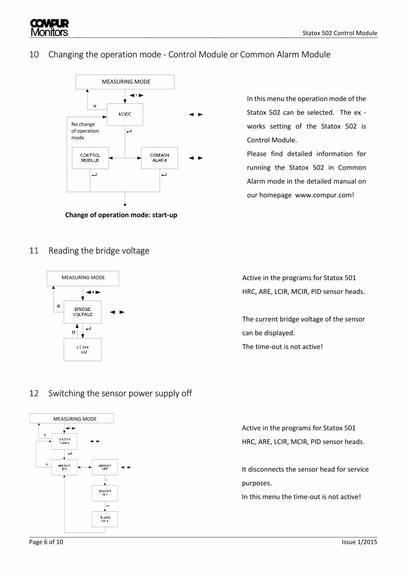
Changing the operation mode - Control Module or Common Alarm Module
Reading the bridge voltage
Switching the sensor power supply off
No change
of operation
mode
MEASURING MODE
Change of operation mode: start-up
In this menu the operation mode of the
Statox 502 can be selected. The ex -
works setting of the Statox 502 is
Control Module.
Please find detailed information for
running the Statox 502 in Common
Alarm mode in the detailed manual on
our homepage www.compur.com!
MEASURING MODE Active in the programs for Statox 501
HRC, ARE, LCIR, MCIR, PID sensor heads.
The current bridge voltage of the sensor
can be displayed.
The time-out is not active!
MEASURING MODE
Active in the programs for Statox 501
HRC, ARE, LCIR, MCIR, PID sensor heads.
It disconnects the sensor head for service
purposes.
In this menu the time-out is not active!

Statox 502 Control Module
Issue 1/2015 Page 7 of 10
Connecting the sensor head
The sensor head power supply must be OFF before connecting a sensor head!
Short circuits on the terminals or selection of a wrong program may destroy the sensor head.
!
Figure 10: Connections sensor heads Statox 501/S
and Statox 505
5 6 7 8
9 10 11 12
5 6 7 8
9 10 11 12
3 3 1 2 5 4 5 o. 4 1 o. 2
Figure 12: Connections sensor heads
Statox 501 HRC, ARE, LCIR, MCIR and PID
2 wire mode
9 10 11 12
19 V
IINP
5 6 7 8
9 10 11 12
IINP
5 6 7 8
19 V
GND
3 wire mode Statox 505
9 10 11 12
IINP
24 V
GND
Figure 11: Connections sensor head Statox 501 Infratox
5 wire mode 3 wire mode
The sensor heads Statox 501/S and Statox
505 for toxic gases and oxygen are operated
as 4 – 20 mA transmitters in 2 wire mode.
The Statox 505 sensor head can
alternatively be operated in 3 wire mode.
This way you can differentiate between
service mode (2 mA) and system failure (0
mA).
The standard application of sensor heads
running in voltage mode is 3 wire mode.
Starting with 750 m length of cable,
Compur recommends to generally operate
in the 5 wire mode. The two additional
“sense” lines measure the sensor supply
voltage and compensate for voltage drops
due to long cable or extreme
temperatures.
The sensor head Statox 501 Infratox for
combustible gases and CO2 requires 3 or
4 wires (2 ground wires) for proper
operation.

Statox 502 Control Module
Page 8 of 10 Issue 1/2015
The sensor heads Statox 501/S and Statox 505 must be operated in connection with an intrinsically safe repeater
if they are installed in classified area, zone 1 or zone 2. Detailed information regarding the operation with an
intrinsically safe repeater can be found in the manuals of the corresponding sensor heads. Connect the shield of
the sensor head cable to the grounding bar. Both, grounding bar and DIN Rail must be grounded.
Control Module – Status diagram
Input from Sensor
or transmitter
System
Status
Current
output
Bus
signal Display
LEDs Relays
A1 A2 S ON A1 1) A2 1) SF
4-20 mA or
bridge voltage Normal 4 – 20 mA --- Measuring value OFF OFF OFF ON active active active
4-20 mA or
bridge voltage Alarm 1 4 - 20 mA A1 Measuring value ON OFF 2) OFF ON passive active 2) active
4-20 mA or
bridge voltage Alarm 2 4 - 20 mA A2 Measuring value OFF 2) ON OFF ON active 2) passive active
22 mA or
mV over range Over Range 22 mA 2)
Full scale
flashing 2) 2) OFF ON 2) 2) active
0 mA or
Error status System failure 0 mA SF Error code OFF OFF ON ON active active passive
2 mA or
Service Mode
Service
Mode 3) 2 mA 1) ---
SERVICE MODE
or menu OFF OFF flashing ON active active active
1) Ex-works setting, can be changed by user.
2) Depending on actual alarm status.
3) Priority ranking: Service Mode > SF > (A1 / A2 / Over range)
Common Alarm Module – Status diagram
Bus
input
System
status
Current
output Display
LEDs 4) Relays 4)
A1 A2 S ON A1 1) A2 1) SF
--- Normal 4 mA COMMON
OK OFF OFF OFF ON active active active
A1 Alarm 1 12 mA COMMON
ALARM 1 ON OFF OFF ON passive active active
A2 Alarm 2 16 mA COMMON
ALARM 2 OFF ON OFF ON active passive active
SF System
failure 0 mA
COMMON
FAILURE OFF OFF ON ON active active passive
--- Service 4) 2 mA 1) Menu OFF OFF flashing ON active active active
1) Ex-works setting, can be changed by user.
4) The listed LED and relay status describes an isolated alarm event. In case of multiple alarm events
combinations are possible.
The priority ranking for display and current output is: Service Mode > A2 > A1 > SF
Statox 502 Control Module
Issue 1/2015 Page 9 of 10
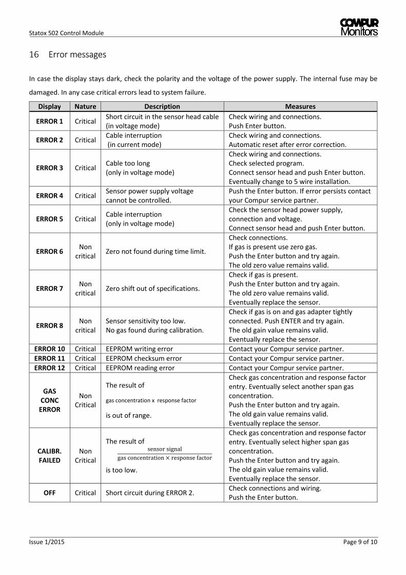
Error messages
In case the display stays dark, check the polarity and the voltage of the power supply. The internal fuse may be
damaged. In any case critical errors lead to system failure.
Display Nature Description Measures
ERROR 1 Critical Short circuit in the sensor head cable
(in voltage mode)
Check wiring and connections.
Push Enter button.
ERROR 2 Critical Cable interruption
(in current mode)
Check wiring and connections.
Automatic reset after error correction.
ERROR 3 Critical Cable too long
(only in voltage mode)
Check wiring and connections.
Check selected program.
Connect sensor head and push Enter button.
Eventually change to 5 wire installation.
ERROR 4 Critical Sensor power supply voltage
cannot be controlled.
Push the Enter button. If error persists contact
your Compur service partner.
ERROR 5 Critical Cable interruption
(only in voltage mode)
Check the sensor head power supply,
connection and voltage.
Connect sensor head and push Enter button.
ERROR 6 Non
critical Zero not found during time limit.
Check connections.
If gas is present use zero gas.
Push the Enter button and try again.
The old zero value remains valid.
ERROR 7 Non
critical Zero shift out of specifications.
Check if gas is present.
Push the Enter button and try again.
The old zero value remains valid.
Eventually replace the sensor.
ERROR 8 Non
critical
Sensor sensitivity too low.
No gas found during calibration.
Check if gas is on and gas adapter tightly
connected. Push ENTER and try again.
The old gain value remains valid.
Eventually replace the sensor.
ERROR 10 Critical EEPROM writing error Contact your Compur service partner.
ERROR 11 Critical EEPROM checksum error Contact your Compur service partner.
ERROR 12 Critical EEPROM reading error Contact your Compur service partner.
GAS
CONC
ERROR
Non
Critical
The result of
gas concentration x response factor
is out of range.
Check gas concentration and response factor
entry. Eventually select another span gas
concentration.
Push the Enter button and try again.
The old gain value remains valid.
Eventually replace the sensor.
CALIBR.
FAILED
Non
Critical
The result of sensorsignal
gasconcentration responsefactor
is too low.
Check gas concentration and response factor
entry. Eventually select higher span gas
concentration.
Push the Enter button and try again.
The old gain value remains valid.
Eventually replace the sensor.
OFF Critical Short circuit during ERROR 2. Check connections and wiring.
Push the Enter button.

Statox 502 Control Module
Page 10 of 10 Issue 1/2015
Technical Data
Product name: Statox 502 Control Module
Manufacturer: COMPUR Monitors GmbH & Co. KG, D-81539 Munich
Power supply: 24 ± 2 VDC max. 200 mA
Power consumption: max. 5 W
Current rating: max. 8 A on communication bus
Operating temperature: -10° C to +60° C (14°F to 140°F)
Storage temperature: -30°C to +60°C (-22°F to 140°F)
Pressure: 900 to 1100 hPa
Humidity: 0% to 99% r. H. (non-condensing)
Display: 2 lines, 16 segments
Housing: Polyamide, protection class IP 20
Connections: 24 terminals, can take cable diameters up to 2.5 mm2
Relays: 2 x alarm, 1 x system failure
Relays contact: 250 VAC, 8A
min. burden ≥ 12V, 10 mA (contact material: silver-nickel 90/10)
System failure relay: In normal operation active (coil active), make contact (NO) is closed
Analog output: 0 mA in case of system failure
2 or 4 mA in service mode, programmable
4 - 20 mA in measuring mode, tolerance ± 2 % at -10°C to + 50°C
22 mA at over range
Max. Burdon: 700 Ohm
Installation: 35 mm DIN-Rail
CE-Marking: EN 61326-1:2013
Functional safety: according to IEC 61508
Dimension: 45 x 103 x 115 mm (1.77 x 4.06 x 4.52 “)
Weight: 260 g
Specifications are subject to change without notice, and are provided only for comparison of products. The conditions, under which our products are
used, are beyond our control. Therefore, the user must fully test our products and/or information to determine suitability for any intended use,
application, condition or situation. All information is given without warranty or guarantee. Compur Monitors disclaims any liability, negligence or
otherwise, incurred in connection with the use of the products and information. Any statement or recommendation not contained herein is unauthorized
and shall not bind Compur Monitors. Nothing herein shall be construed as a recommendation to use any product in conflict with patents covering any
material or device or its use. No license is implied or in fact granted under the claims of any patent. Instruments are manufactured by Compur Monitors
GmbH & Co. KG, Munich. The General Conditions of Supply and Service of Compur Monitors GmbH & Co. KG are applicable.
5378 000 998 07 00 556814
45 mm (1.77 ")
10
3 m
m (
4.0
6 "
)