
GENERATOR SET ELECTRIC, PORTABLE DIESEL-DRIVEN ...
262
J) /o/.//: 5-5oo9 tvti kl> DEPARTMENT OF THE ARMY TECHNICAL MAHUAL GENERATOR SET ELECTRIC, PORTABLE DIESEL-DRIVEN SKID-MOUNTED, 30 KW 60-CYCLE, 120/208- OR 240/416- VOLT, 3-PHASE CONVERTIBLE TO 50-CYCLE, 120/208- OR 240/416-VOLT, 3-PHASE STEWART AND STEVENSON MODEL WGD-3012 (LESS ENGINE) UNlVERSlTY OF VlRGINlA LlBRARY X0048 15881 DEPARTMENT OF THE ARMY • DECEMBER 1954
-
Upload
khangminh22 -
Category
Documents
-
view
1 -
download
0
Transcript of GENERATOR SET ELECTRIC, PORTABLE DIESEL-DRIVEN ...

J) /o/.//:
5-5oo9
tvti
kl>
DEPARTMENT OF THE ARMY TECHNICAL MAHUAL
GENERATOR SET
ELECTRIC, PORTABLE
DIESEL-DRIVEN
SKID-MOUNTED, 30 KW
60-CYCLE, 120/208- OR
240/416-VOLT, 3-PHASE
CONVERTIBLE TO
50-CYCLE, 120/208- OR
240/416-VOLT, 3-PHASE
STEWART AND STEVENSON
MODEL WGD-3012
(LESS ENGINE)
UNlVERSlTY OF VlRGINlA LlBRARY
X004815881
DEPARTMENT OF THE ARMY • DECEMBER 1954

SUMMARY OF SAFETY PRECAUTIONS
The power generated by the generator set is dangerous and can kill. Never
touch any uninsulated line or bus bar while the unit is in operation.
Do not work on any part of the electrical equipment or the generator service
lines while the set is in operation.
In case a person comes in contact with a live conductor, shut off the power
at once. If impossible to do this without delay, free the victim from contact with
the live conductor by using a dry board, dry clothing or other nonconductor.
Avoid direct contact with either the live conductor or the victim's body. An axe
may be used to cut the conductor. If, after release from contact, the victim is
unconscious, commence artificial respiration without delay.
Do not perform other than routine maintenance work on the engine without
first disconnecting the battery.
Do no operate the generator set in a closed building unless the exhaust gas
is piped to the outside. The exhaust gases contain carbon monoxide, which is a
colorless and odorless deadly poison.
If the winterization heater fails to ignite or goes out during starting proce
dure, the air ducts must be cleared of gasoline fumes to prevent an explosion.
Turn the HIGH-LOW valve to OFF position ; the heater control switch to RUN,
and the blower switch to HIGH. Permit at least one minute to elapse before
an attempt is made to ignite the heater again.
Never run a cold engine at full load or high speed.
Under no circumstances exceed the maximum permissible speed.
Keep the cooling system filled with clean coolant. Never add coolant to an
overheated engine.
Stop the engine immediately if the oil pressure gage reading is less than 20 psi.
Use only the specified filter elements in the diesel and lubricating oil filters.
When handling fuel, provide a metallic contact between the fuel container
and tank to prevent the generation of a static spark.
Do not add water to a battery in below freezing temperatures unless the bat
tery is to be charged immediately. If water is added and the battery not
charged, the added water will remain at the cell tops and freeze before having a
chance to mix with the acid. Continuous use of water with a high mineral
content will damage the battery.
Never use emery cloth or metal surfaced grinding or polishing stones to service
the commutator or slip rings, as these abrasive particles will conduct electricity.
When operating generator sets in parallel, ascertain that the load does not
exceed the remaining available power before removing any of the generator sets
from the line.
Devices such as governors to control the engine speed, air cleaners, oil filters,
circuit breakers, and similar fixtures are installed to protect and prolong the
life of the equipment. Failure to maintain them in operating condition or to
replace them when they become faulty will result in greatly increased wear and
may lead to serious damage. If trouble develops, correct it or report it before
it becomes serious. Do not run equipment that is not operating properly.
^M

TM 5-5C
Technical Manual} DEPARTMENT OF THE ARMY
No. 6-5009 J Washington 25, D. C, 27 December 196.
GENERATOR SET, ELECTRIC, PORTABLE, DIESEL DRIVEN, SK
MOUNTED, 30 KW, 60 CYCLE, 120/208 OR 240/416 VOI
3 PHASE, CONVERTIBLE TO 50 CYCLE, 1 20/208 OR 240/4
VOLT, 3 PHASE, STEWART AND STEVENSON MOD
WGD-3012 (LESS ENGINE)
Chapter 1, INTRODUCTION Paraerapk
Section I. General 1,2
II. Description and data 3-5
Chapter 2. OPERATING INSTRUCTIONS
Section I. Service upon receipt of equipment 6,7
II. Controls and instruments 8-48
III. Operation under usual conditions 49-54
IV. Operation of materiel used in conjunction with gen
erator set \.i * .'. 55-57
V. Operation under unusual conditions 58-62
Chapter 3. ORGANIZATIONAL MAINTENANCE IN
STRUCTIONS
Section I . Organizational tools and equipment 63-65
II. Lubrication and painting 66-68
III. Preventive maintenance services 69-72
IV. Troubleshooting 73-91
V. Radio suppression 92-97
VI. Housing 98-102
VII. Controls and instruments 103-143
VIII. Cooling system 144-147
IX. Fuel and exhaust system 148-153
X. Engine electrical system 154-158
XL Main generator assembly 159-162
XII. Winterization kit 163-165
Chapter 4. FIELD AND DEPOT MAINTENANCE
Section I. Introduction 166,167
II. Tools and equipment 168,169
III. Engine 170-175
IV. Controls and instruments 176, 177
V. Hydraulic governor 178-185
VI. Starting motor 186-190
VII. Battery charging generator 191-194
VIII. Battery voltage regulator 195-199
32212S O-

Chapter 4. FIELD AND DEPOT MAINTENANCE—Con. Paragraph
Section IX. Main generator assembly 200-208
X. Winterization kit 209-212
XI. Engineering data 213-219
Chapter 5. SHIPMENT, LIMITED STORAGE, AND DEM
OLITION TO PREVENT ENEMY USE
Section I . Shipment and limited storage 220, 22 1
II. Demolition of generator set to prevent enemy use. 222-225
Appendix I. REFERENCES
II. IDENTIFICATION OF REPLACEABLE PARTS
III. ON-EQUIPMENT TOOLS
Index
Page
186
196
206
212
214
217
219
243
244

CHAPTER 1
INTRODUCTION
Section I. GENERAL
1. Scope
a. These instructions are published for the information and guidance
of the personnel to whom this generator set is issued. They contain
information on the operation, organizational maintenance, and field
and depot maintenance, as well as a description of the major units and
their functions in relation to other components of the materiel. They
apply only to the Stewart and Stevenson Model WGD-3012 gen
erator set.
b. Supply manuals, technical manuals, and other publications appli
cable to the equipment covered by this manual are listed in appendix I.
Appendix II tabulates the replaceable parts available for the equip
ment. Appendix III lists the tools issued with and carried on or with
the equipment.
2. Record and Report Forms
Maintenance record forms listed and briefly described in a through
I below will be used in the maintenance of this equipment.
a. DA Form 5-13, Spot Check Inspection Report of Organisational
Maintenance of Engineer Equipment. Organizations having engineer
field maintenance responsibility use this form for reporting the results
of semiannual spot check inspections.
b. DA Form 5-14-, Annual Technical Inspection Report of Engineer
Equipment. Organizations having engineer field maintenance respon
sibility use this form for reporting the results of annual technical
inspections.
c. DD Form 110, Vehicle and Equipment Operational Record. This
form is used by equipment operators for reporting the accomplishment
of daily preventive maintenance services, and for reporting any equip
ment deficiencies observed during operation.
d. DA Form 285, Accident {Report of Personal or Property Dam
age) . DA Form 285 is used by supervisors for reporting all accidents
3

causing serious injury or death to personnel or damage to property and
equipment, including Army aircraft accidents, non-Army motor ve
hicle accidents, and Army fires.
e. DA Form ]fi4, Work Sheet for Preventive Maintenance and Tech
nical Inspection of Engineer Equipment. This form is used by person
nel of the using organization and higher echelons for reporting the
results of preventive maintenance services and technical inspections.
/. DA Form 460, Preventive Maintenance Roster. This form is used
for scheduling preventive maintenance services at prescribed intervals.
g. DA Form 478, Organizational Equipment File. Major repairs or
rebuilding, replacement of major unit assemblies, and accomplishment
of equipment modifications are recorded on this form.
h. DA Form 468, Unsatisfactory Equipment Report. This form is
used for reporting manufacturing, design, or operational defects in the
materiel, with a view to correcting such defects; it is also used for
recommending modifications of the materiel. Form 468 is not used for
reporting failures, isolated materiel defects, or malfunctions of mate
riel resulting from fair wear and tear or accidental damage. Form 468
is not used to report issue of parts and equipment, or for reporting
replacements or repairs.
i. DD Form 6, Report of Damaged or Improper Shipment. This
form is used for reporting damages incurred in shipment.
j. DA Form 9-81, Exchange Part or Unit Identification Tag. This
form is used to accomplish the direct exchange of unserviceable for
serviceable parts.
k. DA Form 811, Work Request and Job Order. This form is used
to request work done by higher echelon organizations.
I. DA Form 867, Status of Modification Work Order. This form is
used to maintain records of all modification work performed on
equipment.
Section II. DESCRIPTION AND DATA
3. Description
a. General Information. Stewart and Stevenson Services generator
set Model WGD-3012 is a self-contained, weather-resistant, winter
ized, skid-mounted unit (figs. 1 to 4), complete with all controls,
switches, and indicators necessary for normal operation. A three-
cylinder diesel engine (24, fig. 3) is direct-coupled to the a-c generator
(33) and to the d-c exciter (38) by means of a common drive shaft. All
parts of the unit are readily accessible through hinged side and rear
access doors (19 and 8, fig. 2) located in the canopy.
6. Engine. The generator assembly (33, fig. 3) is driven by Gen
eral Motors Model 3-7lRC55(3045C) (24). The engine is a three

cylinder, 2-cycte, valve-in-head, liquid-cooled diesel engine develop
ing 45 hp at 1200 rpm. Refer to the applicable engine manual for
complete information.
1 Fuel tank cap 14 Automatic shutter control access
2 Diesel fuel indicator plate
3 Rear canopy 15 Radiator screen
4 Bolt, hex hd, %-16 x 1% (46 16 Side panel access doors
req'd) 17 Bolt, hex hd, %e-18 x 1 (52
5 A-frame req'd)
6 Lifting eyebolt 18 Front skid towing tube
7 Front canopy 19 Generator set anchor points
8 Exhaust muffler 20 Winterization heater blower inlet
9 Wi nteriza t ion heater exhaust pipe 21 Rear skid towing tube
10 Radiator shutter manual control 22 Battery charging connection
11 Radiator filler cap access 23 Rear cowl assembly
12 Front cowl assembly 24 Rear right side access door
13 Front right side access door
Figure 1. Generator set, right front three-quarter view.
c. Main Generator. The Kato Engineering Company a-c generator
Model 5MSSS (33) is a 50/60 cycle, Y-connected, 4-wire, 3-phase
rotating field alternator. It is rated at 30 kw at 0.8 power factor. The
following 60-cycle voltages may be obtained by the use of the proper
bar position on the voltage changeover board.

(1) For single-phase loading, either 120 or 240 volts line-to-
neutral.
(2) For 3-phase loading, either 208 or 416 volts line-to-line.
1 Exhaust muffler guard 11
2 Exhaust muffler 12
3 Lifting eyebolt 13
4 Fuel tank cap 14
5 Generator set identification plate 15
6 Generator control panel 16
7 Engine control panel 17
8 Upper rear access door 18
9 Load terminal board assembly 19
10 Winterization heater air inlet
Figure 2. Generator set, left rear three-quarter view with rear access doors open.
d. Exciter. The Kato Engineering Company Model 24XUGS
exciter (38) is a shunt-wound, 4-pole, d-c generator mounted on the
rear of the main generator and direct-connected to the main generator
Battery charging plug box
Flexible fuel hoses
Toolbox
Winterization kit blower
Door pocket for manuals
Bolt, hex hd, %6-18 x 1 (52 req'd)
Load terminal board guard
Crankcase drain plug
Left side access doors

shaft. It provides direct current for energizing the six poles of the
main generator rotating field. The exciter is equipped with a fan
which provides induced cooling for the exciter and forced cooling for
the generator.
e. Control Panel. The control panel (6, fig. 2) is enclosed in the
rear cowl assembly. It contains all the meters, indicators, switches,
and controls necessary for normal operation of the generator set.
/. Fuel Tank (fig. 5). A spill-proof fuel tank (11) with a capacity
of 30 gallons is located in the rear cowl assembly above the control
cabinet. The fuel system is governed by two, three-way fuel control
valves (9) and (10) which permit normal operation in which engine
fuel is supplied from the tank; outside drum operation which sup
plies fuel to the engine from a drum ; or a combination which permits
filling the tank from a drum while the engine is running.
g. Winterization Kit. The winterization kit (19) is a self-con
tained gasoline-flame air-heating unit. A 4.5-gallon tank (6, fig. 3)
provides the gasoline fuel, and flexible tubes (9, 29, and 30) channel
the heated air to the various components.
h. Canopy. The front and rear canopies (3 and 7, fig. 1) are fab
ricated from sheet metal with a coat of insulating material on the
inner surfaces. The hinged side access doors afford ventilation dur
ing warm weather operation as well as providing access for main
tenance requirements.
i. Skid-Frame Base. The skid-frame base (31, fig. 3) is a steel
frame braced and reinforced by crossmembers. It is designed to
support the fully assembled generator set. Provisions are made for
bolting down the base and for the attachment, of a towing cable.
An A-frame (10) with lifting eye (11) provides the means for han
dling the generator set with a lifting device.
4. Identification
(%• 6)
The generator set has four identification plates. The Corps of
Engineers identification plate (A), located on the rear cowl, specifies
the official nomenclature, the model number, and the serial number of
the equipment. The engine identification plate (B) located on the
right flywheel housing specifies the manufacturer, model, and unit
number of the engine. The generator assembly nameplate (C)
located on the right generator housing specifies the manufacturer,
rating, and serial number of the generator assembly. The options
and accessories identification plate (D) located on the right side of
the valve rocker cover specifies all nonstandard groups of parts used
on the engine.


9 1 1211
239 1
26 279 1 1
311
Rearcowlassembly
Fueltankcap
Dieselfuelindicator
Fuelsupplyvalve Fuelreturnvalve
Heaterfueltank
Batterybox
Batteryboxcover
Batteryboxairtubeelbow
A-frame
A-frameliftingeye
Enginerearlifterbracket
FuelpressuresafetyswitchEngineexhaustconnection
Aircleaner
Enginefrontlifterbracket
Radiatorbrace
1 1 1 1 5 1 1 1 T1 1 1 9 9 9 1 1
Heaterexhaustpipe9
Radiatorfillercapaccess11
Frontcowlassembly1
Radiatormanualshuttercontrol1Bolt,hexhd,%A1x%(1req'd)11
Auxiliarystartingpanelsc
Model1511RC55(115C)diesel9
engine1
Gasolinesupplylinetoairheater
pumpassembly5
Lowerradiatorhose
Shroudelbowoutletw,
Shroudedengineoilpan
Heaterairoutlettube1
Starterairtube9
Skidbase
Bolt,hexhd,%5llxiy8(1
req'd)
Generatorassembly
Dieselfuelsupplyline
Generatorcoverpad
Generatorpad
Batteryboxsupport
Exciter
Bolt,hexhd,%51x1(1req'd)Externalbatterychargingrecep-
Bolt,hexhd,%51x1%'
req'd)
Bolt,hexhd,%51x1%'
req'd)
Throttlecontrolrod
Bolt,hexhd,%51x1%(1
req'd)
FigureS.Generatorset,rightside,canopyremoved.

10

1Bolt,hexhd,%A1x%(Ireq'd)
1Radiatorbrace
1spperwatertube
1spperradiatorhose
5Coolantthermostathousing
1Coolantthermostatsafetyswitch
1 9 9 9 I17
Flexibleexhaustconnection
Lowoilpressuresafetyswitch
Fuelvalvelinetowinterization
heater
5ieselfueltank
Batteryboxairtube
1 1 T 101
Commutatorendbellshield
Fireextinguisher
Cableopening
Winterizationheater
Regulatorbracket
Oildrainhose
Figure4.Generatorset,leftside,canopyremoved.

12

1 1 1 1 1 9 1 9 1
5ieselfuelreturnshutoffvalve
5ieselfueltank
Slipringinspectionpiate
Exciter
Exciterendbellshield
Blowermotor
CapsAsc,hexhd,%5.x1%
(1req'd)
Bolt,hexhd,%511x1(1req'd)
A-Cgeneratorassembly
101 1 9 1 9 1 1 9
spperradiatorhose
Coolantthermostatassembly
Coolantthermostatsafetyswitch
Wateroutletmanifold
Airheaterassembly
Rockercoverknob
Lubricatingoilfilter
Capscreshexhd&5.x1s
(1req'd)
5ieselfuelsupplyshutoffvalve
1 1 1 1 5 1 1 1 T
Winterizationkit
Airboxdraintubeassembly
Winterizationkitcombustion
chamber
Airjacketedoilpan
Oildrainhose
Batterycharginggenerator
Bolt,hexhd,%5.x1(1req'd)
Batteryvoltageregulator
Coolingfan
FigureS.Generatorset,leftside,"A"frameandradiatorremoved.
W

©\
~-SV/. ?,?
128447-1001
7v rrUTR u.s
* 100
f-kff f, frQ l 15400-; 3 S |-
f7rtU(rt^o^.o(,-(,(,(,
A
DETROU DIESEL ENGINE DIVISION
Ism. »m. coir, otmir, kick i.s.i.
crammsa hp k» « tmmm
mum:v\?m hp ^i »r tmmm
. Ml R.P.IK. NO LOAOHHEB
B
KATO-LIGHT
AC. GENERATOR
MODEL
"" MJKM ' f UM '
D.C. EXCITER
WITTS KSWMHBS mil
NATO ENGINEERING CO.
MANKATO, M|NN, U.S.A.
cs.i. *rr. no. iisi 0
Figure 6. Identification plates.
14

5. Tabulated Data
a. Dimensions and Weight.
Dry weight 4910 lb.
Operating weight 53801b.
Center of gravity of unit Lifting eye on A-frame
Center of gravity of engine Mid-point between two lifting eyes on
engine.
Center of gravity of generator as- Mid-point between two lifting eyes on
sembly. generator assembly.
Overall length 110 in.
Overall width 35 in.
Overall height 76.5 in.
Dimensions to which generator set See figure 7
can be conveniently disassembled
for shipment.
75 1/2"
I K
3
-tft
0
y
END VIEW
110"
SIDE VIEW
Figure 7. Shipping dimensions of generator set.
b. Classification and Eatings.
A-C Generator.
Manufacturer Kato Engineering Co., Mankato, Minn.
50 cycles 60 cycles
Rated kw 25 30
Rated speed, rpm 1000 1200
Voltage 120/208-240/416
Phase land 3
Amperes full load 104-57
Power factor 0.8
Temperature rise 40s C.
Method of cooling Air cooled
Type lubrication Sealed bearing
Duty classification Continuous
Degree of enclosure Dripproof
Drive Direct
Excitation Separate
Mounting 4 bolts to skid
15

Exciter.
Manufacturer Kato Engineering Co., Mankato, Minn.
Volts 125 d-c
Amperes 10
Rated kw 1.5
Winding Shunt interpole
Engine.
Manufacturer General Motors, Detroit Diesel Div.
No. of cylinders 3
Bore 4% in.
Stroke 5 in.
Total displacement 212.69 cu in.
Maximum hp at 2000 rpm 83
Continuous hp at 1200 rpm 45
Maximum torque at 1000 rpm 262 ft-lb.
c. Capacities.
Cooling system including radiator 9 gal.
Lubrication system 15 qt.
Diesel fuel tank 30 gal.
Heater gasoline tank 4.5 gal.
d. Engine Equipment.
Air intake system.
Emergency shutdown solenoid Delco-Remy model 1118191
Air cleaner General Motors oil bath type
Fuel system.
Fuel oil strainer General Motors cleanable-type element
Fuel oil filters General Motors replaceable-type element
Fuel oil pressure safety switch Unit Electric Controls No. IPE-O, 0-50
psi, normally open, closing position 20
psi.
Engine electrical system.
Storage battery Four 6-volt units, series connected
Battery charging generator Delco-Remy model 1106867, 24-volt, 10-
amp at 1700 rpm.
Battery voltage regulator Delco-Remy model 1118346, 3-unit type
Starting motor Delco-Remy model 1108857, 24-volt, Dyer
drive.
Starting solenoid Delco-Remy model 1118099
Battery box overheat solenoid ther- Unit Electric Control Co. 0-220s F. Nor-
mostat. mally closed. Opens at 180s F. % in.
IPS connection.
Governors.
Hydraulic Woodward, constant speed droop adjust
ment—full load setting 1200 rpm.
Overspeed Synchrostart overspeed trip, Model GKG,
ratio 195 : 1, contact setting normally
open, contacts close at 1320 rpm.
16

Cooling system.
Water circulating pump General Motors centrifugal type
Radiator Young Radiator Co., uniflow, vertical
tube.
Thermostat General Motors bypass. Starts opening
at 158s F., fully opened at 185s F.
Cooling fan Blower type, 26 in., 4 blades
Shutter unit Manual and automatic control. Cadillac
Co.
Inlet hose 1% in. ID x 3% in.
Outlet hose 2 in. ID x 4% in.
Coolant safety thermostat United Electric Co. 0-220s F. Normally
open, closes at 208s F., % in. IPS con
nection.
Lubricating system.
Oil filter General Motors replaceable element type.
Low oil pressure safety switch United Electric Controls Co. No. IPB-0,
0-50 psi, normally closed, contacts open
at 10 psi.
Coupling assembly Flange type, engine and generator side,
Kato Engineering Co.
e. Main Generator Assembly Equipment.
Generator brushes %-in. thick, %-in. wide, 1% in. long.
Exciter brushes %-in. thick, %-in. wide, 1% in. long.
Voltage regulator Electric Regulator Corporation No.
C-115-2515-1 and C-115-2539-1.
/. Winterization Kit.
Burner Modified aircraft heater, porous brick
burner.
Fuel filter Autopulse %-in.
Safety solenoid heater fuel supply Minneapolis Honeywell Regulator Co. 24-
valve. volt.
Heater safety thermostat George Ulanet Co. strip type, normally
closed, opens at 100s F.
Battery box overheat solenoid George H. Leland Inc. No. 15ESR95-30-
X4-X8.
Blower motor Lamb Electric Co. No. 46718-A 24-volt
d-c, Vn hp, 2500 rpm.
g. Fire Extinguisher. Chemical, carbon tetrachloride, hand
operated.
322125 O—55-17

h. Foundation Plan.
86 -
r-
i_.•4-
K*=
TOP VIEW
*
£'dia bolts
udIT
h-12"-+- 86"- -H-12'i
SIDE VIEW
Figure 8. Foundation plan for generator set.
18

CHAPTER 2
OPERATING INSTRUCTIONS
Section I. SERVICE UPON RECEIPT OF EQUIPMENT
6. New Equipment
a. General. New generator sets which are boxed and processed to
meet military requirements for domestic and oversea shipment must
be given definite services before being put into operation. Generator
sets received uncrated will arrive blocked and tied to the carrier as
illustrated in figure 9.
b. Unloading.
(1) If the generator set is shipped uncrated, as illustrated in fig
ure 9, the following procedure is to be followed.
1 %-inch cable 5 Carrier
2 %-inch cable clamps 6 Heavy thimbles
3 Chock block, 6 inch x 8 inch 7 Towing tube
4 Generator set
Figure 9. Method of securing generator set to carrier.
19

(a) Remove the cables (1) from the front and rear towing
tubes and the blocking (3) from the base of the set.
(b) Using a crane with a minimum lifting capacity of 10 tons,
attach the crane lifting hook to the lifting eye on the top
of the generator set and take a light strain on the cable.
(c) Check to see that all blocking, holddown straps, and retain
ing cables have been removed.
Note. Before lifting the set from the carrier, secure guide lines
to the front and rear towing tubes to prevent the set from swaying
while being removed.
(d) Lift the set slowly from the carrier and move it to the point
of installation.
(2) If the generator set is shipped crated, as illustrated in figure
10, the following unloading procedure is to be followed,
(a) Place loop slings around the ends of the crate so that they
fit into the lifting sling notches (10) provided at the ends
of the skid base.
l
2
3
4
5
6
7
8
Side of crate
Top of crate
Strap
Drive screw
Anchor plate
Strap
Muffler assembly
Electrolyte case
9 Battery case
10 Skid notches for sling placement
11 Floating vapor-moisture-proof bag
12 Center of balance mark
13 Skid
14 Frame
15 Barrier paper
16 Hydrotector plug-in terminals
Figure 10. Generator set, cutaway view showing packing.
20

(6) Draw the two slings together over the top of the crate and
attach a lifting hook to the slings.
Note. Before lifting the crate take a light strain on the cables
and adjust them so that the lifting hook of the crane is directly
over the center of balance (12) marked on the crate.
(c) Lift the crate slowly from the carrier and move it to the
point of installation.
c. Uncrating (fig. 10).
(1) Unpack the crate as close as possible to the point of installa
tion.
(2) Remove the drive screws (4) from the anchor plates (5) and
straps (3) which hold the top (2) of the packing crate. Lift
the top from the crate.
Caution: Do not drive a crowbar into the crate, as this
may damage the generator set.
(3) Cut the cable assembly connecting the hydrotector plug-in
terminals (16) to the sensing element in the floating vapor-
moistureproof bag (11).
Note. Be careful not to puncture or break the seal on the vapor-
moistureproof bag barrier until ready for use.
(4) Remove the drive screws from the anchor plates (5) and
straps (3) at the corners of the crate. Remove the nails
holding the sides of the case to the platform and lift away
the sides.
(5) Cut the straps (6) holding the muffler assembly (7), the
wooden electrolyte case (8), and the wooden battery case (9).
Remove these items and the remaining ends from the pack
ing crate platform.
Note. If the muffler assembly is not fastened to the inside of the
crate it will be found in an available space in the generator set within
the floating bag. For example : within the battery box.
(6) Cut the floating bag, peel it down over the generator set and
remove the desiccant. Remove the four nuts from the hold-
down bolts in the platform.
(7) By means of a sling in the lifting eyebolt (6, fig. 1), lift the
generator set clear of the platform.
d. Remove Barriers and Preservatives.
(1) Remove all barrier material and preservatives from un-
painted and threaded surfaces of the generator set. Unpack
muffler and wipe clean, using dry cloths. Wipe hinges, fas
teners, handles, and other hardware.
(2) Open doors (13 and 24, fig. 1). Remove four screws and
washers and lift end bell shield (14, fig. 5) from exciter.
Remove any barrier material from commutator. Do not wipe
or attempt to clean commutator as it is not coated. Exam
21

ine brushes for cracks or chips caused in transit. Check free
dom of brushes in brush holder, see that brushes seat prop
erly on commutator, and that curve of brush face fits the
commutator surface. See paragraph 1616(6) for seating
brushes. Position brushes carefully and install end bell
shield.
(3) Remove the inspection plate (12, fig. 5) from the generator.
Remove any barrier material from the collector rings. Do not
attempt to clean collector rings as they are not coated. Ex
amine brushes for cracks or chips caused in transit. Check
freedom of brushes in brush holders, see that brushes seat
properly on slip rings, and that curve of brush face fits the
slip ring surface. See paragraph 160i(6) for seating
brushes. Carefully position brushes and replace inspection
plate.
(4) Remove fire extinguisher (13, fig. 4) and unseal openings,
wipe clean, and place in bracket ready for use.
(5) Remove barrier material from air cleaner (15, fig. 3) and
flexible exhaust connection (7, fig. 4) .
(6) Unpack fuel hoses ( 12, fig 2) .
(7) Open toolbox located in generator assembly compartment.
Check and clean the tools. A list of the tools supplied with
the generator will be found in appendix III. Place them in
the toolbox ready for use.
(8) Remove all loose packing material and wiping rags from the
generator set in order to have it ready for immediate use.
e. Assembling.
(1) Muffler. Mount the muffler on the exhaust flange on top of
the canopy, and the mating flanges with four %- by 1%-inch
hex head bolts, lockwashers, and hex nuts. Attach the front
foot of the muffler to the canopy with a ^4-inch hex head bolt,
lockwasher, and nut.
(2) New batteries; preparing for use.
(a) The batteries are shipped fully charged and dry. Remove
them from the shipping container and remove seals from
each battery. Open filler caps and break any sealing device
used. Make sure vents in caps are open.
(b) Check each battery casing for any signs of cracking. Check
for lost or broken vent caps. Uncrate the four cartons of
electrolyte and remove the bottles from the cartons. If the
batteries are in satisfactory condition, fill each cell with
electrolyte to approximately three-eighths of an inch above
the plates. Watch for leaks. Wipe up all spilled electro
lyte. Keep batteries clean and dry.
(c) Place the hard rubber supports (4, fig. 11) in the battery
box (2) and position the batteries (1) in the box.
22

1 Batteries
2 Battery box
3 Battery box thermostat
Hard rubber battery supports
Connector
Figure 11. Batteries mounted in battery box.
(d) Connect the batteries in series in the following manner.
The negative terminal of the first battery is connected to
the positive terminal of the second battery, the negative
terminal of the second battery is connected to the positive
terminal of the third battery, and the negative terminal of
the third battery is connected to the positive terminal of
the fourth battery. The positive terminal of the first bat-
ery and the negative terminal of the fourth battery are free
and become the output terminals of the batteries. The nega
tive terminal is then connected to the starter solenoid, and
the positive terminal (plus 24 volts) is connected to the bat
23

tery system ground lug. Cover terminals with a light coat
ing to grease to retard corrosion,
(e) Check specific gravity and voltage of each cell. Charge bat
teries if specific gravity is less than 1.270 or if voltage is
less than 2.2 volts per cell. If batteries are not to be used
within 12 hours after filling, charge them.
/. Inspection.
(1) Make a complete inspection of the generator set, visually
checking for any loss or damage which may have occurred
during shipment.
(2) Inspect the control panel, throttle linkage, fuel lines, over-
speed governor trip and cooling system connections.
(3) Check the tensions of the fan and generator belts. Correct
tension permits the belts to be pushed in at a point midway
between the pulleys to a distance of ly^ inches on the fan
belts and y% and % inch on the generator belt. Refer to para
graphs 1466 and 1556 for proper adjustment.
(4) Tighten any loose screws, nuts, or bolts. Check oil drain plug
for tightness and see that cooling system drains are closed.
(5) Check all accessible wires and connections. See that wires
and cables are not frayed, that insulation is sound, and that
wires do not touch or rub on rotating sections of the generator
set. Check all terminals and connections, and tighten where
necessary. Check all external, visible connections for proper
polarity and wiring.
g. Service.
( 1 ) Lubricate generator set ; refer to paragraph 67.
(2) Perform the before-operation services set out in para
graph 70c.
(3) Fill the radiator with clean water or, if it is below freezing,
with antifreeze solution (par. 58a) .
(4) Remove plugs from tops of fuel oil filters and fill falters witn
clean fuel oil.
(5) Fill the diesel fuel tank with fuel oil. Remove ana ciean
filter bowl; see paragraph 149a. Replace bowl (par. 1496).
( 6 ) Fill the heater fuel tank ( 6, fig. 3 ) with gasoline.
h. Installation.
(1) Location recommendations. If the unit is to be operated out
doors, locations exposed to high humidity or dust must be
avoided. Moisture condenses on generator, engine, and con
trols, causing corrosion which seriously affects operation and
efficiency. Dust and dirt cause extra wear on all moving
parts. Use care to locate the machine so that there will be as
little opportunity as possible for excess moisture, dust, or cor
rosive fumes to be drawn into the unit. Use a carpenter's or
24

mason's bubble level and level up the generator set. Place
bubble level along left skid. Raise or lower front or back as
required, using blocks, until bubble indicates that the unit is
level. Block up skid in this position. Repeat procedure with
opposite side and on ends in order to level the set. Drive
stakes into the ground alongside the blocking to prevent the
unit from shifting when in operation. Where possible the
unit should be located close to existing power service lines.
(2) Indoor installation requirements. If the unit is to be oper
ated indoors or within a vehicle, make sure there is adequate
ventilation to carry off escaping exhaust fumes and provide
an ample supply of air. Locate the unit so that a minimum
number of bends are required in the exhaust line which car
ries the fumes out of the building. All exhaust connections
must be gastight. Provide at least 3 feet of space around the
unit to permit opening of access doors.
Warning: Prior to making any line connections or
changes, be sure generator set is not running and that main
circuit breaker is open.
(3) Voltage changeover board connections. The main load ter
minal board assembly (9, fig. 2) is located in the compartment
below the control cabinet. It is marked T-l, T-2, T-3, and
T-0, and is Y-connected, 3-phase, 4-wire. T-0 is the neutral
terminal. The single-phase load should be divided equally,
as near as possible, among the three phases. That is: one-
third of the single-phase load should be connected between
T-0 and T-l ; one-third between T-0 and T-2 ; and one-third
between T-0 and T-3. When the 3-phase voltage is 208 volts
as indicated on the a-c voltmeter, the single-phase voltage is
120 volts. Likewise, when the 3-phase voltage is 416 volts,
the single-phase voltage is 240 volts. The voltage change
over board is located inside the control cabinet and voltage
changes are made by altering the positions of the connecting
bars on the terminals.
(a) For 120/208-volt, 60-cycle output, connect the T-l and T-7
terminals, the T-2 and T-8 terminals, the T-3 and T-9 ter
minals, and the T-4, T-5, T-6, and T-0 terminals
terminals (fig. 12®).
(b) For 240/416-volt, 50/60-cycle output, connect the T-7 and
T-4 terminals, the T-8 and T-5 terminals, the T-9 and T-6
terminals (fig. 12®).
7. Used Equipment
Used generator sets which have been stored and shipped in accord
ance with Army specifications are ready for use on arrival after a brief
25

1 20/208V- 60 CYCLES
©@© ©
©@© ©
©
@
©@©
240/416 V-50/60 CYCLES
©@© ©
©@© ©
©<@© ©
©
A B
Figure 12. Voltage changeover-board connections.
check. Unload, uncrate, and assemble the used generator sets as out
lined in paragraph 6.
Section II. CONTROLS AND INSTRUMENTS
8. General
This section describes, locates, illustrates, and furnishes the operator
sufficient information about the various controls and instruments for
the proper operation of the WGD-3012 generator set.
9. Radiator Manual Shutter Control
a. Location. The radiator manual shutter control (21, fig. 3) is
located on the right top of the front cowl assembly.
b. Description. A mechanical linkage to the radiator shutter vanes.
c. Purpose. To control the radiator shutter vane position.
10. Fuel Pressure Safety Switch
a. Location. The fuel pressure safety switch (13, fig. 3) is located
at the right upper side of the engine block.
b. Description. This is a pressure switch, set to close at 20 psi.
c. Purpose. To render other safety devices inoperative during
starting procedure, until diesel fuel pressure has been built up.
11. Low Oil Pressure Safety Switch
a. Location. The low oil pressure safety switch (8, fig. 4) is located
on the upper left rear side of the engine block.
b. Description. A pressure switch, normally open, set to close
when oil pressure drops to 20 psi.
26

c. Purpose. To shut down the engine when the lubricating oil pres
sure falls to 20 psi.
12. Engine Coolant Thermostat Safety Switch
a. Location. The engine coolant thermostat safety switch (3, fig.
5) is located on top of the water outlet manifold.
b. Description. A thermostat and a normally open switch set to
close at 208A F.
c. Purpose. To shut down the engine when the coolant reaches
208A F.
13. Fuel Control Valves
a. Location. The supply valve (9, fig. 5) and the return valve (10)
are located at the right front side of the fuel tank (11).
b. Description. These valves are three-way angle cock valves.
c. Purpose. To control the flow of diesel fuel as indicated in table
I. Refer to figure 26 for a diagram of the fuel oil flow.
Table I. Fuel Control Valve Positions
Operation Valve position Effect
Normal Both handles in TANK posi Engine fuel from fuel tank
tion. and fuel return to fuel
tank.
From external sup Both handles in DRUM posi Engine fuel from external
ply- tion. supply and fuel return
to external supply.
Filling tank while SUPPLY valve handle in Engine fuel from external
operating. DRUM position, RETURN supply and fuel return
valve handle in TANK to fuel tank.
position.
14. Heater Safety Thermostat Switch
a. Location. The heater safety thermostat switch (14, fig. 13) is
located at the coolant outlet from the lubricating oil cooler (15).
b. Description. A thermostat and a normally closed switch designed
to open at 180A F.
c. Purpose. To shut off the fuel to the heater when the engine coolant
reaches 180A F.
15. Diesel Engine Auxiliary Starting Button
a. Location. The diesel engine auxiliary starting button (7, fig. 13)
is located on the auxiliary control panel.
b. Description. This switch is a single-pole, single-throw, normally
open pushbutton type switch.
c. Purpose. To energize the diesel engine auxiliary starting button
when using the air heater for starting purposes.
27

28

1Generatorassemblynameplate1Airheatervalveassembly
1Overspeedgovernor1
1Enginesafetyshutdownrelay1Secondaryfuelfilterassembly9
5Airboxshutoffsolenoid9
1Airinlethousingassembly11Auxiliarystartingbutton1
1Optionsandaccessoryplate1
TAirheaterpumpassembly11 1Governorcontrolrodknob1
Watersupplytubetoshutterop
eratingcylinder
Waterpump
Heatersafetythermostatswitch
Oilcooler
Coolantinlettooilcooler
Airshutoffro.Startingmotor
Startingmotorsolenoid
1Primaryfuelfilterassembly
1Fuelpump
1Fuelstrainerassembly
1"A"frameattachmentangle
95ieselfuelsupplyline
1Enginemodelandserialnumber
plate
9Generatorconnectionbox,cover
removedFigureIS.Generatorset,rightside,"A"frameandradiatorremoved.
1

16. Air Heater Fuel Valve
a. Location. The air heater fuel valve (11, fig. 13) is located on the
auxiliary control panel.
o. Description. The air heater fuel valve is a needle type valve.
c. Purpose. To control the gasoline fuel supply to the air heater.
17. Air Heater Pump Control
a. Location. The air heater pump control (9, fig. 13) is located on
the auxiliary control panel.
b. Description. A hand-operated plunger-type pressure pump.
c. Purpose. To supply gasoline under pressure to the burner unit
of the air heater assembly for cold weather starting.
18. Overspeed Governor
a. Location. The overspeed governor (2, fig. 13) is mounted on the
rear end of the blower shaft.
b. Description. A centrifugal circuit-closing device, capable of
adjustment.
c. Purpose. To shut down the engine when the speed exceeds a pre
set value (1320 rpm).
19. Air-Box Shutoff Solenoid
a. Location. The air-box shutoff solenoid (5, fig. 13) is located on
the right side of the engine near the air inlet housing (6) .
b. Description. A plunger type solenoid.
c. Purpose. To actuate the air shutoff rod (17) and consequently
close the valve to the air inlet, thus cutting off the engine air supply and
stopping the engine in case of an emergency.
20. Engine Safety Shutdown Relay
a. Location. The engine safety shutdown relay (3, fig. 13) is located
at the right rear of the cylinder head.
b. Description. A 24-volt coil-actuated contact type relay with a
contact capacity of 25 amperes.
c. Purpose. To relay the action of safety switches and thermo
stats, and to energize the air-box shutoff solenoid (5) .
21. Battery Box Thermostat
a. Location. The battery box thermostat (3, fig. 11) is located
inside the right end of the battery box (2) .
b. Description. A strip type thermostat with switch normally
closed and designed to open at 100s F.
c. Purpose. To control the rotary solenoid on the winterization
kit, thereby controlling the position of the vane in the battery box
heating tube.
30

22. Voltage Regulator Switch
a. Location. The voltage regulator switch (2, fig. 14) is located
on the control panel.
b. Description. A double-pole, double-throw toggle switch rated
3 amperes at 250 volts, 6 amperes at 125 volts.
c. Purpose. To electrically connect the voltage regulator or to
short-circuit it from the system when using the exciter field rheostat.
23. Cross-Current Switch
a. Location The cross-current switch (6, fig. 14) is located on the
control panel.
b. Description. A single-pole, single-throw toggle switch.
c. Purpose. To connect the cross-current compensation resistor
when the generator set is being operated in parallel with one or more
units.
24. Exciter Field Rheostat
a. Location. The exciter field rheostat (9, fig. 14) is located on the
control panel.
b. Description. A plate type with a contact arm moving over taps
from the resistance unit to provide a variable resistance.
c. Purpose. To be used when the voltage regulator switch is in the
OFF position, to manually control the exciter field and, hence, its out
put voltage. The output of the main generator is dependent upon the
voltage impressed across the rotating field (rotor) by the exciter.
25. Ammeter-Voltmeter Phase Switch
a. Location. The ammeter-voltmeter phase switch (11, fig. 14) is
located on the control panel.
b. Description. A rotary selector switch of the snap action type.
c. Purpose. To provide ammeter and voltmeter readings of each
generator phase independently.
26. Voltage Regulator Adjusting Rheostat
a. Location. The voltage regulator adjusting rheostat (13, fig. 14)
is located on the control panel.
b. Description. A rotary, vitreous-enameled, 100-ohm type.
c. Purpose. To provide a means of adjusting the value of the regu
lated voltage when the voltage regulator switch (2) is in the ON
position.
27. Contactor Pushbutton
a. Location. The contactor pushbutton (14, fig. 14) is located on
the control panel.
b. Description. An ON-OFF, pushbutton type switch.
c. Purpose. To open or close the load contactor.
31

«N *>•
32

9 1!) 1 1 1 1 9 1
Ammeter-voltmeterphaseswitchVoltageregulatoradjustingrheo
FigureH.Controlpanel.
Voltmeter
A-cammeter
stat
Contactorpushbutton
Vernierthrottlecontrol
Contactorindicatinglight Coolanttemperaturegage
1 112 13
9 9 1 1
Enginehour-meter
Voltageregulatorswitch
Panellights
Panellightshields
Synchronizinglights Cross-currentswitch
Frequencymeter
11-voltd-creceptacle Exciterfieldrheostat
1 1 1 1 5 1 1 1 T
Engineoilpressuregage
BatterychargingammeterEmergencyoverloadswitch Enginemainstarterbutton
11-volta-Creceptacle
11-volta-cpolarizedreceptacle
Panellightswitch
Synchronizinglightswitch

28. Vernier Throttle Control
a. Location. The vernier throttle control (15, fig. 14) is located on
the lower right section of the control panel.
b. Description. A device designed to give fine adjustment to throttle
movement.
c. Purpose. To permit final adjustment of engine speed within fine
limits.
29. Emergency Overload Switch
a. Location. The emergency overload switch (20, fig. 14) is lo
cated on the control panel.
b. Description. A single-pole, single-throw, normally open push
button type.
c. Purpose. To permit overloading of the generator set for short
periods, for reasons such as starting large induction motors which
require high initial starting power.
30. Diesel Engine Main Starter Button
a. Location. The diesel engine main starter button (21, fig. 14) is
located on the control panel.
b. Description. A single-pole, single-throw, normally open push
button type switch.
c. Purpose. To close the circuit to the engine starting motor which
cranks over the engine for starting.
31. Panel Light Switch
a. Location. The panel light switch (24, fig. 14) is located on the
control panel.
b. Description. A single-throw toggle switch.
c. Purpose. To control the panel illuminating lights (3).
32. Synchronizing Light Switch
a. Location. The synchronizing light switch (25, fig. 14) is located
on the control panel.
b. Description. A three-pole, single-throw toggle type switch.
c. Purpose. To energize the synchronizing lights (5).
33. Engine Hour-Meter
a. Location. The engine hour-meter (1, fig. 14) is located on the
control panel.
b. Description. An electrically operated, direct-reading indicator,
with a five-place set of figure wheels.
c. Purpose. To record the elapsed operating time of the generator
set for operational checks and periodic inspections.
34

34. Synchronizing Lights
a. Location. The synchronizing lights (5, fig. 14) are located on the
control panel.
b. Description. 10-watt, 110-125-volt,type Sll, intermediate screw
base types.
c. Purpose. To indicate, during the paralleling procedure of two
generators, when the speeds are equal and the generators may be
interconnected.
35. Frequency Meter
a. Location. The frequency meter (7, fig. 14) is located on the con
trol panel.
b. Description. A vibrating reed type which enables the operator
to read the frequency directly from the reed which is vibrating at its
maximum amplitude.
c. Purpose. To indicate the alternating current output frequency.
36. Voltmeter
a. Location. The voltmeter (10, fig. 14) is located on the control
panel.
b. Description. A direct-reading, double-scale type; the top scale
is graduated from 0 to 300 volts and the lower scale from 220 to 600
volts.
c. Purpose. The instrument is wired across a selector switch which
enables the operator to read the voltage across the lines of each phase,
and the voltage from T-3 to T-0.
37. Ammeter
a. Location. The a-c ammeter (12, fig. 14) is located on the control
panel. .
b. Description. A direct-reading, double-scale ammeter (0-75
amperes and 0-150 amperes) .
c. Purpose. To indicate the amperage of each phase.
38. Contactor Indicating Light
a. Location. The contactor indicating light (16, fig. 14) is located
on the control panel.
b. Description. A 115-volt neon lamp mounted back of a red lens.
c. Purpose. To indicate the open and closed positions of the main
load contactor. When the light shows red it indicates that the main
load contactor is in a closed position.
39. Coolant Temperature Gage
a. Location. The coolant temperature gage (17, fig. 14) is located
on the lower section of the control panel.
35

b. Description. A direct-reading gage calibrated from 0A F. to
220A F. A danger zone of operation is indicated on the dial in red for
temperatures above 212A F.
c. Purpose. To indicate the coolant temperature.
40. Engine Lubricating Oil Pressure Gage
a. Location. The engine oil pressure gage (18, fig. 14) is located
on the lower section of the control panel.
b. Description. A direct-reading gage, calibrated from 0 to 80
pounds. A danger zone of operation is indicated on the dial in red
for pressure below 12 psi.
41. Battery Charging Ammeter
a. Location. The battery charging ammeter (19, fig. 14) is located
on the lower section of the control panel.
b. Description. A direct-reading ammeter having the neutral
position of the pointer in the center of the dial scale, thus permitting
two polarity readings.
c. Purpose. To indicate the rate of battery charge or discharge,
thus giving a rough check on both the state of charge in the battery
and the charging condition of the generator.
1 Front cowl assembly
2 Inlet tube from engine
3 Radiator shutter vane
4 Outlet tube to lubrication
cooler
5 Thermostat housing
6 Spring
7 Plunger
8 Clevis pin
9 Vane position control rod
oil 10 Automatic shutter control lever
arms
11 Adjusting nut and locknut
Figure 15. Automatic shutter control, access plate removed.
36

42. Automatic Shutter Control
a. Location. The automatic shutter control (fig. 15) is located to
the right of the radiator shutter inside the front cowl assembly.
b. Description. A bellows type thermostat and plunger actuated
by a flow of radiator coolant.
c. Purpose. To open automatically the shutters in direct propor
tion to the radiator coolant temperature.
43. Battery Thermal Overload Circuit Breaker
a. Location. The battery ( thermal overload circuit breaker (14,
fig. 16) is located at the extreme left-hand side of the heater control
panel.
b. Description. A thermostat type circuit breaker.
c. Purpose. To remove automatically from the engine control cir
cuit any overload imposed by the winterization kit blower motor or
igniter.
44. Heater Fuel Supply Solenoid Valve
a. Location. The heater fuel supply solenoid valve (6, fig. 16) is
located to the right of the heater control panel.
b. Description. A solenoid designed to operate the heater gasoline
fuel supply valve.
c. Purpose. To close the heater fuel supply solenoid valve to prevent
the engine from overheating.
45. Battery Box Overheat Solenoid
a. Location. The battery box overheat solenoid (5, fig. 16) is lo
cated on the left side of the winterization heater combustion chamber.
b. Description. A 24-volt rotary solenoid.
c. Purpose. To close the vane on the battery box air tube (11, fig. 4) ,
when de-energized by action of the battery box thermostat.
46. Winterization Heater "High-Low" Fuel Valve
a. Location. The winterization heater HIGH-LOW fuel valve (2,
fig. 16) is mounted on a bracket which is secured to the winterization
heater burner plate.
b. Description. A three-way bronze cock with %-inch connection.
c. Purpose. To control the gasoline fuel flow to the winterization
heater.
47. Winterization Heater Control Switch
a. Location. The heater control switch (13, fig. 16) is located on
the winterization heater control panel.
37

38

1Gasolinefloatchamber
1Fuel"HIGH-LOW"valve
1Heaterobservationwindow
1Heateroutletducttostarter
gearbox
5Batteryboxoverheatsolenoid
111 9 9
15
Heaterfuelsupplysolenoidvalve
Gasolinefuelconnection
Heateroutletducttobattery
Blowerhousing
Blowermotor
duct
1 1 1 T1
Heaterblowerjunctionbox
Blowermotorcontrolswitch
Heatercontrolswitch
Batterythermaloverloadcircuit
breaker
1Heateroutletducttoengineoil
p1
Figure16.Winterizationkit.
•o

b. Description. A double-pole, double-throw toggle switch having
three positions OFF, START, and RUN.
c. Purpose. To control the ignition system of the winterization
heater (par. 55).
48. Winterization Kit Blower Motor Control Switch
a. Location. The blower motor control switch (12, fig.16) is located
on the winterization heater control panel.
b. Description. A double-pole, double-throw switch having three
positions OFF, HIGH, and LOW.
c. Purpose. To control the blower motor speed.
Section III. OPERATION UNDER USUAL CONDITIONS
49. General
a. The instructions in this section are published for the information
and guidance of the personnel responsible for the operation of this gen
erator set.
b. It is essential that the operator thoroughly understand the proper
operation of the generator set. This section gives instructions on start
ing and stopping the generator set and placing it in service, paralleling
two or more units, and the general operation of the unit under normal
operating and weather conditions.
50. Starting
a. Starting (Above 32A F.)
(1) Refer to paragraph 70c for before-operation services to be
performed.
(2) Press starter button (21, fig. 14) to start engine. Release
starter button when engine starts.
Caution: Do not operate starter over 30 seconds at a time
to avoid overheating.
(3) Check engine oil pressure on gage (18) immediately after
starting. If pressure is less than 16 psi, stop engine and check
lubricating system.
(4) Observe coolant temperature gage (17). Temperature
should not exceed 205A F.
(5) Allow engine to run at approximately 900 rpm or slightly
above idling speed for about 5 minutes. In an emergency
this warmup period may be disregarded and the load may be
applied as soon as oil pressure reaches 20 psi or over.
(6) Turn throttle (15) counterclockwise to RUN position, as in
dicated by panel marking.
40

b. Starting in Cold Weather (0A F. to 32A F.)
(1) Refer to paragraph 70c for before-operation services to be
performed.
(2) Open air heater fuel valve (11, fig. 13) and operate air heater
pump (9) on auxiliary starting panel while pressing the
auxiliary starter button (7). As soon as engine starts, re
lease starter button (7), stop pumping, and close air heater
fuel valve (11).
(3) Proceed as directed in a (3) through (6) above.
51. Stopping
a. Momentarily press the contactor pushbutton (14, fig. 14) in the
OFF position.
b. Adjust throttle (15) to reduce engine speed to approximately
900 rpm or slightly above idling speed.
c. Turn the throttle counterclockwise to the STOP position.
52. Operating Details
a. General. Two or more generators may be operated in parallel
where greater generator capacity is required. The following instruc
tions cover both single unit and parallel operation.
b. Single Unit Operation.
(1) Check terminal box and connect for required voltage, and
start unit as instructed in paragraph 50a.
(2) Turn vernier knob on throttle and adjust the engine speed
until the desired frequency is indicated on the frequency
meter (7, fig. 14). An engine speed of 1040 rpm will give 52
cycles, and a speed of 1240 rpm will give 62 cycles.
(3) Check a-c voltmeter for desired output voltage (generator
rated voltage of 120/208 or 240/416 volts at 60 cycles, or
240/416 volts at 50 cycles) .
(4) Adjust voltage by turning voltage regulator rheostat (13)
clockwise to lower the voltage, or counterclockwise to raise
the voltage.
(5) Apply load by momentarily pressing the contactor push
button ( 14) in the ON position.
(6) For emergency overloading of generator, such as for starting
large induction motors, press emergency overload switch (20)
and hold for approximately 5 seconds after load has
stabilized.
(7) Refer to paragraph 70a' for during-operation services.
c. Parallel Operation.
Warning: Generator sets operating in parallel must have bars or
voltage changeover-boards positioned for the same output voltage.
41

(1) The main load terminals on the load terminal board assembly
(9, fig. 2) of both generator sets are marked T-l, T-2, T-3,
and T-0. When setting up two generator sets for parallel
operation connect the like main load terminals; T-l on one
set to T-l on the other set. Repeat this procedure, connecting
T-2 to T-2, T-3 to T-3, and T-0 to T-0.
Warning: Before making line connections be sure neither
generator set is running and both main load contactors are
open.
(2) Start one unit according to instructions in paragraph 50a.
(3) Start the other unit according to instructions in b above.
This is the unit to be paralleled.
(4) Check voltmeters of each unit to be certain they read the
same. If necessary, adjust voltages according to 6(4) above
so that they read the same.
(5) Check the frequencies of the units to be paralleled. They
must be operating at the same frequency. Adjust frequency
according to 6 (2) above.
(6) On the unit to be paralleled, perform the following opera
tions.
(a) Place synchronizing light switch (25, fig. 14) in the ON
position.
(6) Place cross-current switch (6) in the ON position.
(c) Observe synchronizing lights (5) when fluctuations of the
lights become very slow (about one in 2 or 3 seconds) , wait
until they are completely dark, and close main contactor
by momentarily pressing the ON contactor pushbut
ton (14).
Warning: The contactor may be closed only when the
synchronizing lights are completely dark.
( 7 ) Divide the ampere load between the two units.
(a) Turn vernier throttle control knob (15) counterclockwise
on the unit having the low ammeter reading until both
ammeters read the same.
(6) Correct cross-currents if they exist. For example, if the
two machines are operated across a 100-ampere load and
the total reading of the equalized ammeters is 120 amperes,
it indicates cross-currents between generators, with a loss
in generator output capacity of 20 amperes. Correct by
adjusting voltage regulator adjusting rheostat (13) until
both ammeters (12) read 50 amperes, or fall to their lowest
point and start to rise to the required correct current.
(c) Correct the voltage of the paralleled generator sets, if
necessary, by adjusting the voltage regulator adjusting
rheostat (13) of each unit the same amount and direction.
42

(d) To raise or lower the frequency of paralleled units, adjust
the vernier throttle control (15) of each unit the same
amount and direction.
(8) Place the synchronizing light switch (25) in the OFF
position.
(9) Refer to paragraph 70d for during-operation services.
Caution: When operating generator sets in parallel, ascer
tain that the load does not exceed the remaining available
power before removing one generator from the line.
53. Manual Voltage Control
In the event of voltage regulator failure, the voltage of the gen
erator may be controlled manually by placing the voltage regulator
switch (2, fig. 14) in the OFF position and adjusting the exciter field
rheostat (9) to obtain the desired voltage.
54. Movement to New Location
a. Disconnect power lines from main load terminals.
b. Start engine and run at 60 cycles under no load for 15 minutes.
Shut down engine.
c. Thoroughly drain all fuel lines, fuel filters, fuel pump, and
injectors. Drain fuel tank.
d. Drain gasoline tank.
e. Drain lubricating oil system.
/. Disconnect exhaust piping if used.
g. Disconnect battery terminals.
h. Close and latch all access doors.
i. Place generator set on truck or other carrier as follows :
(1) Lift by a sling attached to lifting eyebolt (6, fig. 1).
(2) Loop the ends of a towing cable bridle over a rod placed in
the towing tube at either end of the skid. Tow up the ramp
by means of a winch or other tractive power.
j. Nail chock blocks (3, fig. 9) to floor of carrier at each end and
sides of the skid to prevent movement of the generator set on carrier
during travel. Further secure skid by means of i^-inch cables (1)
through towing tubes (7) , lashed to carrier at each end. This method
is applicable to trailer carrier or a railroad car.
k. At new location, remove generator set from carrier by lifting or
by winching down ramp.
I. Service engine as directed in paragraph 6^.
m. Reinstall as directed in paragraph 6A.
43

Section IV. OPERATION OF MATERIEL USED IN CONJUNCTION
WITH GENERATOR SET
55. Winterization Heater
a. Starting.
(1) Open winterization heater fuel valve at the left of the gaso
line supply tank on line (9, fig. 4) .
(2) Turn the heater fuel HIGH-LOW valve (2, fig. 16) to the
HIGH position.
(3) Place the blower motor control switch (12) in the HIGH
position.
(4) Place the heater control switch (13) in the START position.
(5) Observe through heater observation window (3) when heater
fires (time required for heater to fire, approximately 1
minute).
Warning: If the heater fails to ignite or goes out during
starting procedure, the air ducts must be cleared of gasoline
fumes to prevent an explosion. Turn the HIGH-LOW valve
(2) to OFF, the heater control switch (13) to RUN, and the
blower motor control switch (12) to HIGH. Permit at least
1 minute to elapse before an attempt is made to ignite the
heater again.
(6) Place the heater control switch (13) in the RUN position.
(7) When the engine coolant temperature gage (17, fig. 14) in
dicates 50A F., the generator set is ready for starting. With
an ambient temperature of —65s F., 1 hour will be required
from the time of firing the heater until the 50A F. reading will
be obtained.
b. Stand-By Heater Operation.
(1) Open winterization heater fuel valve at the left of the gaso
line supply tank on line (9, fig. 4) .
(2) Turn the heater fuel HIGH-LOW valve (2, fig. 16) to the
LOW position.
(3) Place blower motor control switch (12) in the LOW position.
(4) Place heater control switch (13) in the START position.
(5) Observe through window (3) when the heater fires (time re
quired, 3 minutes).
(6) Place the heater control switch (13) in the RUN position.
Note. When the heater is on stand-by operation, operate the engine
several hours dally to maintain battery charge.
c. Stopping.
(1) Turn heater fuel HIGH-LOW valve (2) to the OFF
position.
Note. Fire in heater will continue to burn for approximately 15
minutes because of fuel still in vaporizer.
44

(2) After about 15 minutes, turn heater control switch (13) to
the OFF position.
(3) Turn winterization heater fuel valve on line (9, fig. 4) to the
OFF position.
56. Fire Extinguisher
a. Operation. Remove fire extinguisher (13, fig. 4) from rack and
unlock by turning handle to the left. Using the handle as a pump,
direct the stream of liquid to the base of the flames.
b. Refilling. Refer to TM 5-687 and TM 9-1799 for refilling in
structions.
57. Auxiliary Fuel Lines
a. General. Two lengths of flexible fuel hose ( 12, fig. 2) are supplied
with the unit for connecting an outside drum to the fuel valves. They
are used for filling or draining the engine fuel tank, or for receiving
the fuel supply from an outside source.
b. Use. Connect one hose to the fuel supply valve (4, fig. 3) and
the other hose to the fuel return valve (5) . Connect the other ends of
the two hoses to an external diesel fuel source.
Section V. OPERATION UNDER UNUSUAL CONDITIONS
58. Operation in Extreme Cold (Below 0A F.)
a. Cooling System Protection.
(1) Drain all water from cooling system and flush until water
running from system is clear.
(2) Check system for leaks and make necessary repairs.
(3) Fill cooling system with antifreeze solution. Refer to table
II for the amount of antifreeze solution required.
b. Heating Prior to Starting. The generator set is equipped with
special winterization heating equipment to facilitate the engine start
ing operation by heating the crankcase and starting motor housing and
batteries. For starting and standby procedures using the winteriza
tion kit, see paragraph 55a.
c. Heater Fuel Tank. Fill the heater fuel tank with gasoline.
To each full tank, add 4 ounces of denatured alcohol.
d. Special Lubrication. Refer to LO 5-5009 for special lubrica
tion procedure.
e. Dry Alternator. Keep the alternator dry and free from foreign
material. Wipe any condensed moisture from alternator prior to
starting.
45

*3<*3
S
s
C3
£
Pintsofantifreeze compoundtobe includedin9gallonofantifreeze
solution
^ ^ ^ ^
TTsF T1AF.. ScscF T1sF.....
S
a
3
go
Pintsofantifreeze compoundtobe includedin9gallonofantifreeze
solution
H CN CN M M
1AF 1sFscF
T1AF T1sF
o
ao
I
°0
s
CO
£
sc
lO IO IO IO U) lO lO
O - CN M ■* iO CB
CN CN CN CN CN CN CNo
g+
O ffi OS OS 00 CO 00
O H CN M * iO ffl
O
O
+
M « M M CN CN CN
^h CN CO Tt< lO CO N
<N CN CN CN CN CN CNo
s
+
o o o o o o on M 'f m e n oo
o CNINfl CN ««CN
S
+
OS OS OS OS OS OS OS
o
cn cw ^ m co r- co
CNCNCNCNCNCNCN
s+
CO CO CO CO CO CO CO
co -* m co r- co o>
o CN O « « « CN CN
s+
CO CO CO M CO ^ ^i
1 io « n co o) o
o CN CN CN CN CN CN CO
8
+i—i .—i i—i f* i—i i—i ^H
l—i ^H 1—i i-l i—i W CN
o
lO CO t- 00 OS o —-
CN CN CN CN CN CO CO
o
lO iO iO iO ifl lO CO
ici co r- oo o> o «-h
©
CN CN CN CN CN CO CO
T
OS OS OS OS OS OS ©
m to n oo o> o oi
o CN CN CN CN CN CO CO
8
1
N N r» N i^ N oo
o
O r- 00 oi O H CN
CN CN CN CN CO CO CO
9
1
r- r- r- r- t- r- cc
o
t- 00 OS O *- CN CO
CN CN CN CO CO CO CO
i
Availablecrankingpower
(percent)
] CO CO | CO CO p
o co si io w ^ om mco mo o> H
46

/. Use of Exciter Field Rheostat to Control Field. The generator
has been designed to operate through a wide range of temperatures.
Sufficient field control may be obtained by using the exciter field
rheostat to operate the generator from minus 60s F. to plus 120A F.
without the addition of external resistors in series with the exciter
field.
g. Extend Stabilization Period to 15 Minutes. In operating the
generator in extreme cold, it is advisable to allow a stabilization
period of about 15 minutes if possible prior to making any load con
nections, or paralleling generator sets.
h. Care of Wiring Harness. The wiring harness will become brit
tle in extreme cold and should be warmed before bending or rewiring.
i. Batteries (fig. 11). %
(1) Keep batteries fully charged. Hydrometer readings for a
fully charged battery should be between 1.275 and 1.300 at
80A F. A fully charged battery will withstand severe low
temperatures, whereas a partially charged battery will
freeze, with consequent cell rupture. A fully charged bat
tery will not freeze at temperatures as low as — 65s F.
Caution: Do not add water to a battery in subzero tem
peratures unless battery is to be charged immediately. If
water is added and battery not charged, the added water will
stay at the top and freeze before it has had a chance to mix
with the acid.
(2) The specific gravity readings of batteries change with tem
perature, and should be corrected to compare with a fully
charged cell at 80A F. Table III gives the specific gravity
readings over a wide range of temperatures for convenience
in checking batteries.
59. Operation in Extreme Heat
a. Check coolant level frequently and maintain at proper level.
b . Be sure radiator shutters are open wide.
c. See that end bell screens and cooling grilles are exposed to the
surrounding air and kept free of any obstruction, in order to allow free
circulation of cooling air through the generator set.
d. When operating indoors, allow sufficient space around generator
set for circulation of air. Ventilate the room as well as possible to
carry waste heat outside.
e. When operating in relatively dust-free air, remove the canopy
and side shields to allow maximum cooling effect. Where sand or dust
is present in large quantities, the canopy must remain in place.
/. If required, control the generator field by the exciter field rheo
stat. For procedure, refer to paragraph 53.
47

60. Operation Under Sandy or Dusty Condiitons
a. General. When operating the generator set in conditions of ex
treme dust, locate the unit in a sheltered area if possible. Take advan
tage of any natural barriers which may offer protection from blowing
dust. If installation is more than temporary, erect a protective shield
or shelter. When water is plentiful, wet down the area immediately
surrounding the generator set.
Caution: If area has been wet down, take extreme care when serv
icing generator. Provide a dry wooden platform for operators or
service personnel.
b. Engine Operation.
( 1 ) Wipe down engine immediately upon shutting down. Do not
allow dirt to accumulate. Blow out with compressed air.
(2) Clean air cleaner and renew oil in sump daily.
c. Generator Operation.
(1) Keep side doors to generator set closed if temperature condi
tions will allow.
(2) Clean end bell screens and cooling grilles to prevent openings
from filling.
61. Operation in High Humidity and Salt Water Areas
a. Keep the generator set dry. Wipe all condensed moisture from
surfaces.
b. Check carefully for signs of possible corrosive action on unpainted
parts. Sandpaper all corroded external surfaces and repaint imme
diately.
c. Operation in these areas requires more frequent lubrication of the
generator set than specified on the lubrication order. The oil filter,
starting motor, and engine generator should be serviced weekly. Serv
ice the air cleaner twice a week.
62. Operation in High Altitudes
The generator set is capable of satisfactory performance under con
tinuous full load at altitudes to 5,000 feet. Above 5,000 feet the engine
will deliver approximately 80 percent of its sea level output. As the
altitude at which the set is operated increases, the load capacity of
the generator set decreases. Service the air cleaner daily. Reduce the
load requirements of the generator set to compensate for the efficiency
loss of the engine.
48

CHAPTER 3
ORGANIZATIONAL MAINTENANCE INSTRUCTIONS
Section I. ORGANIZATIONAL TOOLS AND EQUIPMENT
63. General
The tools and equipment listed in this section are those that are
required to perform organizational maintenance on the generator set
WGD-3012. Standard mechanic's handtools are not enumerated in
this section.
64. On-Equipment Tools
The on-equipment tools normally supplied with this equipment for
the use of the operator are listed in appendix III.
65. Special Organizational Maintenance Tools and Equipment
No special organization maintenance tools and equipment are
required.
Section II. LUBRICATION AND PAINTING
66. General Lubrication Information
a. LO 5-5009 prescribes first and second echelon lubrication main
tenance for the Model WGD-3012 generator set.
b. A lubrication order is published for each item of equipment.
The lubrication order shown in figure 17 is a reproduction of an ap
proved lubrication order for this generator set. For the current
LO 5-5009, refer to SR 310-20-4.
c. Lubrication orders prescribe the approved first and second eche
lon lubrication procedures. The instructions contained therein are
mandatory.
67. Detailed Lubrication Information
a. Lubrication Equipment. Keep lubricating equipment where it
will be safe from damage and free from dust and dirt. Clean the
equipment both before and after use.
b. Points of Application. Lubrication fittings, grease cups, and oil
holes are readily located by reference to the lubrication order. Wipe
these devices and surrounding surfaces clean before applying lubricant.
322125 O—55- 49

o
0
LUBRICATION ORDER
l3 Novembtr 1953
GENERATOR SET, ELECTRIC, PORTABLE, DIESEL
DRIVEN, SKID MOUNTED, 30 KW, 60 CYCLE,
120/208 OR 240/416 VOLT, 3 PHASE, CON
VERTIBLE TO 50 CYCLE, 120/208 OR
240/416 VOLT, 3 PHASE, STEWART
AND STEVENSON MODEL WGD-3012
lntervals given are maximums for normal 8-hour
day operation. For abnormal conditions or activi
ties, intervals 'should be shortened to compensate.
Clean fittings, before lubricating.
Relubricate after washing.
Clean parts with SOLVENT, dry-cleaning, or OIL,
fuel, Diesel. Dry before lubricating.
Drain crankcase only when hot after operation;
replenish and check level when cool.
LUBRICANT CAPACITY EXPECTED TEMPERATURES INTERVALS
Above i 32 F 132 F to-10°F -10 Fto-65°F
OE-OlL, Engine. Heavy
Duty
OE 30 or OE lOor
9110
D— Daily
W-Weokly
2W—Two Week
M—Monthly
A—Annually
Crankcase 17Vi qts
9250 See Note 1
Air Cleaner 2 qts.OE 30 or
9250
OE 10 or
9110OHA
Other Points
OE 50 or
3100
OE 30 or
9250
OHA
M—LUBRlCANT, Ball and Roller Bearing.
OHA—OlL, Hydraulic, Aircraft, Petroleum Base.
LUBRICANT • INTERVAL
Fan Hub Bearings BR A
(Grease sealed
bearings) \ Qrt
(Disassemble, clean
and inspect all parts,
renew damaged or
worn parts; repack
bearings and
reassemble)
—Engine Generator OE 2W
Bearings (Sparingly)
(When equipped with
Life-Seal bearings
or oil impregnated
bushings, no
lubrication required)
■Crankcase Drain Plug
(Drain and refill)
Crankcase Filler OE
(See Key)
INTERVAL • LUBRICANT
Oil Filter
(Disassemble,
clean, and renew
element)
BR Generator Bearings
(See Note 4)
0
2W
Crankcase Level
Gage (Check Level)
Starting Motor OE
Bearings (Sparingly)
(When equipped with
Life-Seal bearings
or oil-impregnated
bushings, no
lubrication required)
OE Air Cleaner
(Disassemble,
clean all parts,
re-oil and replace)
OI Air Cleaner Sump—
(Clean and refill
oil Sump)
OE Over speed Governor-
Oil Cup (Sparingly)
-0
-0
CONTlNUED ON
FOLLOWlNG PAGE
Figure 17. Lubrication order.
50

CONTlNUED FROM
PRECEDlNG PAGE
NOTES;
1. COLD WEATHER (Whan winterization kit is not
available)—Every 3 days, drain crankcase and re
fill to "full" mark with OE 10. Add 4% qts. of
gasoline and run engine 5 minutes to mix. Mark
the new level on the oil gage for future ref
erence.
CAUTION: Every Vt day check level and fill to
"Full" mark with OE 10. lf engine is to be shut
down for Vi day or more, add Vh qts. of gasoline
to reach new level mark and run engine 5 minutes
to mix.
NOTE: OlL, fuel, Diesel may be used as a tem
porary diluent only when sufficient gasoline is
not available.
WARNlNG: Diluent used is inflammable: do not
service equipment near heater or open flame.
2. OlL CAN POlNTS: Weekly, lubricate all control
linkages and clevises with OE.
3. DO NOT LUBRlCATE: Blower motor.
4. GENERATOR BEARlNGS-Generator is pro
vided with Norma-Hoffman bearings which should
operate satisfactorily for several years without
attention. After 3 years of operation, remove
seals, remove bearings and wash them carefully
in carbon tetrachloride. Bearings should be re
placed if any trace of wear or damage is ob
served. When dry, pack bearings carefully in
grease, replace, install new seals and reassemble
generator. Once bearings have been repacked,
they should be inspected without fail each year.
Copy of this Lubrication Order will remain with
the equipment at all times; instructions contained
herein are mandatory and supersede all conflict
ing lubrication instructions dated prior to the date
of this Lubrication Order.
BY ORDER OF THE SECRETARY OF THE ARMY
M. B. RlDGWAY
Chief of Staff
United States Army
OFFlClAL:
WM. E. BERGlN
Major General,U S A
The Adjutant General
Figure 11—Continued.
51

ft!
REFERENCE 1: Clean and repack. REFERENCE 2: lubricate sparingly every
two weeks.
REFERENCE 3: Drain. REFERENCE 4: Refill.
REFERENCE 5: Check level.
REFERENCE 6: lubricate sparingly
monthly.
Figurel7—Continued.
c. Cleaning. Use cleaning solvent to wash all parts. After wash
ing, dry parts thoroughly before applying lubricant.
d. Operation Immediately After Lubrication. Start the unit and
run it for 15 minutes at idling speed to distribute the oil throughout the
engine.
52

I HOUSING
T'^f
Msum'bjmg>
REFERENCE 7: Disassemble, clean and
renew element.
REFERENCE 8: Disassemble, clean,
re-oil, replace. Refill sump.
f~"1
OIL CUP
REFERENCE 9: Oil sparingly.
Figure 11—Continued.
Air Cleaner (fig. 18).
(1) Removal. Loosen the air cleaner wingbolt assembly (1)
which secures the air cleaner to the air inlet housing flange,
and lift off the air cleaner and shell gasket (6) .
(2) Disassembly. Separate the housing (2) and cup assembly
(5) . Lift the baffle snap ring (3) and baffle (4) from the cup
assembly (5).
(3) Cleaning and inspection. Remove dirty oil and sludge from
cup assembly. Wash reservoir in cleaning solvent. Clean
metal-wool element by immersing in cleaning solvent. Air-
blow dry. Inspect parts for mechanical damage. Replace
any damaged parts.
(4) Reassembly and installation. Refill cup to level mark with
oil as specified on LO 5-5009. Install baffle (4) and snap
ring (3). Mount with gasket on air intake housing flange.
Slip the housing (2) down on cup assembly and secure with
53

1 Wingbolt assembly
2 Housing
3 Baffle snap ring
Figure 18.
4 Baffle
5 Cup assembly
6 Shell gasket
Air cleaner, disassembled.
wingbolt (1). Make sure that connection between air inlet
housing a*nd air cleaner is tight.
Caution: Do not add oil above level mark.
/. Starting Motor. Lubricate the starting motor. Gain access to
the drive end oil plug on the starting motor by removing the V&-mch
pipe plug from the flywheel housing.
Caution: Avoid excessive lubrication of the starting motor, par
ticularly at the commutator end. If lubricant is forced out onto the
commutator, it will cause poor commutation with a resulting decrease
in starting motor performance. Never attempt to lubricate the start
ing motor while it is being operated.
g. Lubricating Oil Filter (fig. 19). Remove drain plug (18) at
the bottom of the filter, and drain. Unscrew center stud (9) and re
move gasket (8). Withdraw shell (7) and filtering element (5). Re
move two flat washers (3), two felt gaskets (4), and spring (6). Dis
card oil filtering element (5) and oil filter cover gasket (2). Wash
shell (7) and oil filter base (15) with cleaning solvent, and dry thor
oughly. Reassemble using new oil filter cover gasket (2) and new
filtering element (5). Install gasket (2) in oil filter base (15). Place
gasket (8) over center stud (9) in shell (7), and slide the spring (6),
54

one flat washer (3), and one felt gasket (4) over center stud. Insert
center stud (9) in new filtering element (5), and place one felt gasket
(4) and one flat washer (3) over the end of center stud (9). Place
assembly on base (15) and secure with center stud (9). Replace drain
plug (18).
68. Painting
a. General. Any metal surface showing signs of rust or corrosion
or evidence of chipped, cracked or broken paint must be repainted.
The surface to be painted must be free from rust, dirt, grease, kero
sene, alkali, and moisture. Paint will not adhere properly to an
unprepared surface.
b. Cleaning.
(1) Remove rust and loose scale, if any, by wire-brushing, phos
phoric acid metal conditioner or other means of descaling
such as abrasive paper, cloth, or steel wool. Various grain
and grade sizes available are listed in ORD 3 SNL K-l.
Caution: Do not use emery paper or steel wool near the
generator, fan motor, or switchgear, as the abrasive particles
will conduct electricity.
(2) Wash and prepare metal surfaces according to standard
military procedures as given in TM 9-2851.
(3) Mask all nameplates, as well as generator vents, motor vents,
electrical terminal connections, and engine openings to be
sure that no paint is applied to these surfaces.
Section III. PREVENTIVE MAINTENANCE SERVICES
69. General
The operator of the generator set and the organizational mainte
nance personnel must perform their preventive maintenance services
regularly to make sure the generator set operates well and to lessen
the chances of mechanical failure.
70. Operator Maintenance
a. Inspections. Inspections must be made before-operation, dur-
ing-operation, at-halt, and after-operation, as described in this sec
tion. All inspections of assemblies, subassemblies, or parts must in
clude any supporting members or connections and must determine
whether the unit is in good condition, correctly assembled, secure, or
excessively worn. Any mechanical condition which may result in fur
ther damage to the unit must be corrected before the equipment is
operated.
(1) The inspection for "good condition" is usually an external,
visual inspection to determine whether the unit is damaged
beyond safe or serviceable limits, or if it is in such a condi-
55

C2B-—52
I—
56

1Valve
1Oilfiltercovergasket1Flatwasher(1req'd)1Feltgasket(1req'd)
5Filteringelement
1Spring1Shell
1Centerstudgasket
TCenterstud
1Capscreshexhd,%51h,'
(1req'd)
11Lockwasher,%(1req'd)
1Capscrsc,%51xs(1req'd)
9Lockwasher,%(1req'd)
Figure19.Lubricatingoilfilter,disassembled.
9Mountingbracket
9Oilfilterbase
1Plug,%inch(1req'd)
1Connector
95rainplug,%1nch(1req'd)
7

tion that damage will result from its operation. The term
"good condition" is further defined as : not bent or twisted ;
not chafed or burned; not broken or cracked; not bare or
frayed ; not dented or collapsed ; not torn or cut ; adequately
lubricated.
(2) Inspection of a unit to see that it is "correctly assembled" is
usually an external, visual inspection to determine whether
it is in its normal assembled position in the equipment.
(3) Inspection of a unit to determine if it is "secure" is usually
an external inspection ; a hand-feel, or a pry-bar or wrench
check for looseness in the unit. Such an inspection should
include brackets, lockwashers, locknuts, locking wires, or cot
ter pins used in the assembly.
(4) "Excessively worn" means worn close to or beyond service
able limits, a condition likely to result in failure of the units,
unless affected parts are replaced before the next scheduled
inspection.
b. Reporting Deficiencies. The operator will report all deficiencies
on DD Form 110.
Warning: Before attempting to perform any services or inspec
tions be sure the engine is stopped and that the contactor switch
button is in the OFF position.
c. Before-Operation Services. The following services will be per- .
formed to determine if the condition of the generator set has changed
since it was last operated, and to make sure the equipment is ready for
operation. Any deficiencies must be corrected or reported to the
proper authority before the generator set is put into operation.
(1) Fuel. Check fuel supply. See that fuel tank is full. Check
reserve supply of fuel and replenish if necessary. In cold
weather, check winterization heater fuel supply.
(2) Water. Check coolant level in radiator to see that it is up to
the proper level. Add coolant if necessary. When filling a
cold radiator containing antifreeze allow room for expansion.
When draining or refilling cooling system, open vent at top of
thermostat housing. Close vent after filling.
(3) Instruments. Check all gage readings. Normal oil pressure
is 20 to 50 psi. Pressure will be above normal when engine is
cold, or may drop below normal at idling speed after engine
has warmed up. If oil pressure gage shows an unusual drop
or no pressure, stop engine immediately and report condition
to proper authority. Coolant temperatu re gage should show a
gradual rise during the warmup period until it reaches the
maximum of 160A to 205A F. Allow engine to warm up at fast
idling speed ; do not race a cold engine. The ammeter read
ing should be in the charge range.
58

(4) Oil. Check level of engine lubrication oil. Add oil if
necessary.
(5) Leaks, general. Check for leaks. Pay particular attention to
engine cooling system, oil lines, fuel lines, and connections.
Keep winterization heater fuel line shutoff valve closed when
heater is not in use.
(6) Visual inspection. Make a visual inspection of the entire unit
for cracks, breaks, and loose or missing bolts and nuts.
(7) Starting. Before starting engine : check connections in the
voltage changeover board for desired voltage; place voltage
regulator control switch in the ON position ; turn voltage reg
ulator adjusting rheostat clockwise to the reduced voltage
position; make sure that fuel transfer valves are in proper
position ; see that generator is clear of tools and other obstruc
tions; and turn throttle control to a position halfway between
STOP and RUN position. Start engine, and allow it to
warm up.
d. During-Operation Services. The operator is responsible for cor
recting or reporting unusual sounds or odors, deficiencies in perform
ance, or other signs of abnormal operation. He will perform the
following specific duties :
(1) Instruments. Check all gage and meter readings frequently.
At normal operating speeds temperature and load readings
should be as follows :
Engine oil pressure 20 to 50 psi
Coolant temperature 160s to 205s F.
Battery charging ammeter in charge range
Generator frequency meter 60 cycles at 1200 rpm
A-C voltmeter 208 or 416 volts
A-C ammeter 0 to 104 amperes at 208 volts
0 to 57 amperes at 416 volts
(2) Unusual operation. Check for unusual operation such as
excessive vibration, brush sparking, overheating, and smok
ing. Report any irregularity immediately to proper
authority.
(3) Unusual noises. Check for any unusual engine noise. Stop
engine immediately if any unusual noise is noted and report
same to proper authority.
e. At-Halt Services. During halts, even if only for short intervals,
the operator should make a general check for the generator set and
correct or report any deficiencies noticed, in addition to performing
the following specific duties.
(1) Fuel. Check fuel supply. Add fuel if necessary.
(2) Oil. Check oil level in crankcase. Add oil if necessary.
(3) Water. Check coolant level. Add coolant if necessary.
59

Caution: If the engine overheats because of lack of cool
ant allow it to cool before filling the radiator; otherwise,
there is danger of cracking the cylinder head and block. If
it is necessary to fill the radiator before the engine has
cooled, be sure to fill it very slowly, with the engine running
at slightly faster than idling speed.
(4) Leaks general. Check for fuel, oil, and coolant leaks.
(5) Visual inspection. Inspect for general condition of all parts.
Looking for loose parts, worn belts, broken parts, and dirt,
including external radiator obstructions.
/. After-Operation Services. To insure that the equipment is
ready to operate at any time, the following services must be per
formed by the operator or crew immediately after any operating
period. All deficiencies must be corrected or reported to the proper
authority.
(1) Shutdown precautions. Press the contactor switch button
in the OFF position. Allow engine to idle for a few minutes
before stopping to prevent warping of valves and to allow
even cooling of engine.
(2) Fuel, oil, and water. Check and refill all tanks. Inspect
coolant and change if contaminated. Check coolant freezing
point if antifreeze is used. If antifreeze is added, mix solu
tion thoroughly by running the engine until it reaches nor
mal temperature.
(3) Clean equipment. See that control cabinet and generator
housings, screens, and louvers are free from dust and dirt.
Clean exterior of engine, removing all oil and grease. Clean
battery connections and see that caps are tight.
(4) Electrical wiring. Check all wiring for worn, cracked, or
frayed insulation, broken wires, and loose connections.
(5) Tools and equipment. See that all tools and equipment as
signed to the unit are in serviceable condition, clean, and
properly stowed or mounted.
(6) Lubrication. Lubricate as required by the current lubrica
tion order.
(7) Belts. Check tension of fan belts and battery charging
generator belts. Adjust as necessary.
(8) Fuel oil filters. Remove plugs from bottom of primary and
secondary fuel oil filters, and drain sediment. Replace plugs.
(9) Fire extinguisher. Check condition of fire extinguisher and
inspect for full charge, proper working order, and secure
mounting. The amount of charge in the carbon tetrachloride
type can be judged by shaking the extinguisher and deter
mining by sound and weight whether it is full.
60

(10) Visual inspection. Check for fuel, oil, and water leaks;
loose or missing bolts and nuts; bent or damaged hoods,
doors, and panels.
(11) Protection. Close and fasten front and rear doors on sides.
Close and fasten all access doors on side panels. Close and
fasten rear hood doors. Make sure that cover is over bat
tery charging receptacle. Place weatherhead in position on
muffler.
71. Maintenance and Safety Precautions
a. Always report or correct any mechanical deficiencies that may
result in further damage to the generator if operation is continued.
Warning: This equipment generates high voltages that are dan
gerous to life. Always press the contactor switch button in the OFF
position and stop the engine before making repairs on generator
assembly, wiring, or control cabinet equipment.
b. When operating units in parallel, before shutting down one or
more of the units be sure remaining units on the line can carry the
load.
c. Keep governors, fuel oil filters, lubricating oil filter, air cleaner,
and emergency shutdown units in proper operating condition to pro
vide equipment protection and decrease wear.
d. After replacing oil filter elements and replenishing oil in crank-
case, run engine until it reaches operating temperature, stop the en
gine, then when engine is cool check the oil level. Replenish to FULL
mark on oil level gage.
e. Check for adequate ventilation for operation and personnel
safety.
/. For cleaning collector rings or seating brushes, use sandpaper or
brush seating stone. Do not use emery cloth or emery paper.
g. If a unit in service suddenly stops due to action of one of the
emergency shutdown devices, correct condition causing stoppage
before restarting.
h. Make- sure containers used for handling fuel and lubricating oil
are absolutely clean and dry.
72. Organizational Maintenance
a. Organizational preventive maintenance is performed by organi
zational maintenance personnel, with the aid of the operator, at
weekly and monthly intervals. The weekly interval will be equivalent
to 4 weeks, or 240 hours of use, whichever occurs first.
b. The technical inspection column is provided for the information
and guidance of personnel performing technical inspection, and con
stitutes the minimum inspection requirements for the equipment.
c. The preventive maintenance services to be performed at these
regular intervals are listed and described below. The numbers
61

appearing in the columns opposite each service refer to a correspond
ing number appearing on DA Form 464, and indicate that a report
of the service should be made at that particular number on Form 464.
These numbers appear in either the second, third, or both columns, as
an indication of the interval at which the service is to be performed.
GENERAL
Before-operation services. Check equipment and perform
services as listed in paragraph 70c.
Lubrication. Inspect the entire machine for damaged
lubrication lines, and for indications of insufficient
lubrication. Lubricate if necessary. Refer to LO 5-
5009.
Tools and equipment. Inspect condition of all tools and
equipment assigned to the generator. Check condition
and mounting of toolboxes or compartments.
See that all tools and equipment assigned to the machine
are clean, serviceable, and properly stowed or mounted.
See that toolboxes or compartments are in good condi
tion and that they close and fasten properly.
Fire extinguisher. Check condition of fire extinguisher and
inspect for full charge, proper working order, and secure
mounting. The amount of charge in the carbon tetra
chloride type can be judged by shaking the extinguisher
and determining by sound and weight whether it is full.
See that any deficiencies noted are corrected or reported
to the proper authority.
Publications. See that this technical manual, TB 5—
5009-1, LO 5-5009 and Standard Form 91 are on the
machine and in serviceable condition.
Appearance. Inspect the general appearance of the ma
chine, paying special attention to cleanness, legibility of
identification markings, and condition of paint.
See that deficiencies noted are corrected or reported to the
proper authority.
Modifications. See if all available modification work
orders applying to this generator have been completed
and recorded on DA Form 478 (Organizational Equip
ment File).
ENGINE AND ACCESSORIES
Cylinder heads, manifold, and gaskets. Inspect cylinder
head, manifold, and flexible exhaust pipe for leaks, loose
bolts and nuts, and defective gaskets.
Tighten any loose manifold and exhaust pipe mounting
bolts and nuts. Replace any defective gaskets. On
new or reconditioned engines, check all cylinder head
stud nuts for tightness at the first weekly service. The
correct torque-wrench pull is 150 to 175 foot-pounds.
Tech
nical
Service
inspec
tion Monthly Weekly
1 1 1
2 2 2
3 3 3
3 3
4 4 4
4 4
5 5 5
6 6 6
6 6
7 7
11 11 11
11 11
62

Tech
nical
Service
inspec
tion Monthly Weekly
12 12 12
12 12
15 15 15
15 15
16 16 16
16 16
17 17 17
17 17
18 18 18
18 18
ENGINE AND ACCESSORIES—Continued
Valve mechanism. Check the valve adjustment if exces
sive tappet noise or loss of power is noticed. The
approximate valve-tappet clearance with the engine
cold is 0.013 inch. Valve tappet clearance with the
engine hot is 0.009 inch.
Adjust the valve-tappet clearance if necessary. Be sure
the valve-cover gasket is in good condition and that the
cover fits securely.
Oil filter and oil cooler. Inspect the oil filter, oil cooler,
and oil lines and connections for leaks while the engine
is running.
Service the oil filter as specified in LO 5-5009. After
servicing, check carefully for leaks while engine is
running.
Radiator. Inspect radiator for leaks, obstructions in core
air passages, and for loose mounting bolts. Check all
cooling system hoses for leaks, excessive deterioration,
and loose connections. Check operating temperature
and condition of coolant. If coolant temperature
remains below 160s F. or rises above 205A F. during
operation, thermostats or shutter control may be defec
tive. If antifreeze is used, check the freezing point of
the coolant. Check the valves in the pressure cap for
free operation.
Drain, flush, and refill the cooling system if coolant is con
taminated with rust or dirt. See that core air passages
are clean. Replace any damaged or defective cooling
system hose, lines, and gaskets. See that all mounting
bolts and connections are tight. Protect the coolant
from freezing, and record its freezing point on DA Form
464.
Water pump, fan, and shroud. Inspect the water pump
for leaks and for loose mounting and assembly bolts.
Check the condition and mounting of fan blades and
shrouds.
Tighten or replace loose or missing bolts and screws. Re
port deficiencies not corrected to the proper authority.
Belts and pulleys. Inspect for excessively worn, cracked,
or frayed belts. Check belt tension, condition and
alinement of pulleys. Fan belts should deflect \){ inches
midway between pulleys. Generator belt should deflect
one-half to three-fourths of an inch midway between
pulleys.
Adjust the tension of the belts if necessary. To adjust
the belt, loosen the two hex head bolts in the slot of the
fan shaft swivel bracket. Adjust the bracket position
with a wrench on the lug and then tighten bolts. Re
place belts in sets. Never install new belts with worn
pulleys, or new pulleys with worn or frayed belts.
63

Tech- Service
inspec
tion Monthly Weekly
20 20 20
20 20
21 21 21
21 21
22 22
22
23 23
23
24 24
38 38 38
38 38
40 40 40
40 40
40
41 41 41
41 41
43 43 43
ENGINE AND ACCESSORIES—Continued
Hydraulic governor and linkage. Check the adjustment
of the hydraulic governor. If the engine surges when
running at top speed without load, the governor is out
of adjustment.
Report any deficiencies to the proper authority.
Overspeed governor. Check the operation of the overspeed
governor. Run the engine up to 1320 rpm with no load,
at which point the governor should shut down the
engine. Reset the trip lever at the blower outlet.
Adjust the overspeed governor if necessary. With the
engine at operating temperature, run the engine at 1,320
rpm. Loosen the two clamp screws on either side of the
adjusting ring and the two lockscrews on either side of
the cap. Hold the cap and turn the knurled adjusting
ring counterclockwise slowly until the governor actuates
the emergency shutdown system. Retighten the clamps
and lockscrews.
Piston rings. Inspect condition of piston rings through
ports in cylinder liners.
Report broken rings, scores, or stuck rings to the proper
authority.
Cylinder liner ports. Inspect cylinder liner ports for car
bon accumulation.
Clean ports if necessary, using compressed air. If carbon
cannot be blown out with compressed air, report con
dition to the proper authority.
Airbox drains. Check airbox drains while the engine is
running to see if they are open. Air coming through
drains indicates that they are open. Remove and clean
airbox drain lines when blocked.
FUEL SYSTEM
leaks.Fuel pump. Inspect fuel pump and lines for
Check for loose mounting and assembly screws.
Tighten any loose screws and connections. Replace de
fective pump with a new or reconditioned one.
Filters. Check filters for dirt and sludge. Check for
leaks and loose connections.
Open draincock at bottom of filters and drain off any
water or sediment.
Replace primary and secondary fuel oil filter elements if
necessary. After servicing check for leaks while engine
is running.
Air cleaner. Inspect air cleaner for loose connections.
Check condition and level of oil in bowl.
Service air cleaner as specified in lubrication order.
Fuel tank, cap and gasket. Inspect condition and mount
ing of fuel tank. Check tank, fuel lines and connections
for leaks.
64

Tech
nical
Service
inspec
tion Monthly Weekly
43 43
44 44 44
44 44
47 47 47
47 47
48 48 48
48 48
50 50 50
50 50
FUEL SYSTEM—Continued
See that tank is mounted securely, air vent open, and that
filler cap is clean and tight fitting. Replace leaky or
damaged fuel lines and connections.
Fuel lines. Check the fuel lines for leaks, loose connec
tions, and damage. Inspect flexible fuel lines used for
connection to outside fuel source for excessive deteriora
tion and leaks.
Repair or replace defective fuel lines. Tighten loose con
nections. Report all uncorrected deficiencies to the
proper authority.
ELECTRICAL SYSTEM
Batteries. Inspect batteries for cracked or leaky cases,
loose holddown blocks, and for dirt and corrosion on top
of batteries. Check for loose, corroded, or damaged
terminals and cables. Check level of electrolyte.
Proper level is approximately three-eighths of an inch
above plates. Check specific gravity and record reading
on DA Form 464. Readings from 1.275 to 1.300 indi
cate a fully charged battery. A reading of 1.225 or
below indicates battery should be recharged or replaced.
Clean all dirt and corrosion off top of batteries, posts,
cables, and cable terminals. Replace damaged cables.
Apply a thin film of grease over terminals after they are
clamped tight. Add distilled water if needed to bring
solution up to proper level, but do not overfill. If
freezing temperatures prevail, batteries must be charged
for a period long enough to mix solution thoroughly.
Where possible, water should be added just before
beginning operation. See that batteries are mounted
securely, that filler caps are tight, and that vent holes
are open.
Generator and starter. Inspect generator and starting
motor for loose mounting bolts and loose electrical
connections. Inspect commutators and brushes for
excessive wear, dirt, and oil deposits. See if brushes
are free in their holders and if brush wires are secure.
Replace brushes when worn to one-half their original
length.
Tighten any loose mounting bolts and electrical connec
tions. Replace or free brushes, and clean commutators,
if necessary.
Wiring and switches. Inspect wiring for oil-soaked, cracked,
or frayed insulation, broken wires, and loose or corroded
connections. Check operation of starting switch
buttons.
Tighten any loose mounting screws and connections.
Replace defective switches and wires, or report to proper
authority.
322125 O—515 565

Tech
nical
Service
inspec
tion Monthly Weekly
51 51 51
51 51
53 53 53
53 53
57 57 57
57 57
58 58 58
58 58
59 59 59
59 59
71 71 71
71 71
80 80 80
80 80
ELECTRICAL SYSTEM—Continued
Voltage regulator. Check the battery voltage regulator for
proper operation and secure mounting. See that
electrical connections are tight. Regulator must allow
an appreciable charge to go into the battery after the
starting motor is used. After the battery is fully
charged, battery charging ammeter should show only
a slight charge.
Tighten any loose mounting screws or replace any missing.
Replace the regulator if it is defective.
Air heater. Check the air heater for proper operation.
See that electrode air gap is approximately one-eighth
of an inch and that porcelain insulator is not cracked
or dirty. See that spray nozzle openings are clear.
Report defective condition to the proper authority.
CONTROL SYSTEM
Gages. Inspect temperature and oil pressure gages on
control panel for cracked or broken glass, insecure
mounting, and defective operation.
See that gages are mounted securely. Replace damaged
or defective gages.
Meters and switches. Inspect a-c ammeter, a-c voltmeter,
battery charging ammeter, engine hour-meter, and
frequency meter for cracked or broken glass, loose
mounting screws, and defective operation. Check
condition, mounting, and operation of contactor push
button, synchronizing light switch, panel light switch,
voltage regulator switch, cross-current switch, and
ammeter-voltmeter phase switch.
Tighten or replace loose or missing mounting screws.
Replace damaged or defective meters. Replace defec
tive switches. Report all uncorrected deficiencies to
the proper authority.
Rheostats. Inspect exciter field rheostat and voltage
regulator rheostat for insecure mounting and defective
operation.
Tighten or replace loose or missing mounting screws.
Replace defective rheostats.
Vernier throttle control. Inspect vernier throttle control
for insecure mounting and defective operation.
Tighten or replace loose or missing mounting screws.
Report all uncorrected deficiencies to the proper
authority.
FRAMES AND MOUNTINGS
Frame (skid base). Inspect for cracks, breaks, broken
welds, and for loose and missing bolts.
Tighten or replace all loose or missing bolts. See that
cracks, breaks, and broken welds are repaired before
further damage results.
66

Tech
nical
Service
inspec
tion Monthly Weekly
172 172
172
172
172 172
173 173 173
173 173
174 174
174
174
175 175 175
175 175
GENERATOR
Commutator, collector rings and brushes. Inspect commu
tator, collector rings, and brush ring assembly for dust,
dirt, and oil deposits. Checkscbrushes for wear and loose
wire connections. Brushes should be renewed before
brush springs contact brush holder. See if brushes are
free in holders, and make contact with commutator and
collector rings.
Inspect collector rings and commutator for wear, rough
spots, and pitting, and for high mica between the com
mutator segments. The mica should be below the sur
face of the segments. If the mica is at or above the
surface, excessive sparking will result during operation.
The length of a new brush for the main generator is 1%
inch, and for the exciter, 1% inch.
Blow dust and dirt from the inside of the generator if
necessary, using compressed air of not over 25 pounds
pressure. Air must be fiee of oil and water. See that
brushes, commutator, and collector rings are clean.
Replace brushes if worn beyond one-half of their original
length. Be sure that brushes are in good condition and
that connections are tight. If collector rings or com
mutator are rough or pitted or if mica is high between
commutator segments, report condition to proper
authority.
Controls, instruments, wiring. Check for loose connections,
cracked or frayed wire insulation, corroded terminals,
and for loose or missing mounting bolts and nuts.
Check control cabinet for condition and secure
mounting.
Replace or report any damaged or inoperative instru
ments and controls. Tighten any loose mounting bolts
and connections. Replace damaged wiring and
terminals.
Drive coupling and ventilating fan. Inspect the driving
disk and ventilating fan for any signs of insecure
mounting or for damage. Check the fan for an accumu
lation of grease and dirt. See that the driving disk and
ventilating fan are securely mounted.
Clean the fan if necessary. If any damage to the disk
or fan is noted, report the deficiency to the proper
authority.
Housing. Inspect housing for loose or missing mounting
and assembly bolts and nuts and for bent and damaged
doors, panels, and frame members.
Tighten or replace any loose or missing bolts and nuts.
Correct or report any other deficiencies.
67

Section IV. TROUBLESHOOTING
73. Use of Troubleshooting Section
This section provides information useful in diagnosing and cor
recting unsatisfactory operation or failure of the generator set or any
of its components. Each trouble symptom stated is followed by a
list of probable causes of the trouble. The possible remedy recom
mended is described opposite the probable cause.
Note. All references in this section to paragraphs in chapter 4 (pars. 166 to
219) pertain to operations that are the responsibility of the field and depot main
tenance personnel. Organizational maintenance personnel should not proceed
without proper authority.
74. Starting Motor Fails to Operate
Probable cause Possible remedy
Poor electrical connections Clean and tighten battery cables and
other electrical connections.
Starter button defective Replace button (par. 112).
Battery discharged Replace batteries or charge batteries for
ones that are charged (par. 6e).
Starter commutator dirty Clean starter commutator with cleaning
solvent. Blow dry with compressed air.
Starter brushes worn Replace starter brushes (par. 157c).
75. Engine Fails to Start
Probable cause Possible remedy
Battery too low to turn engine over Charge batteries or install batteries that
fast enough to start. will crank engine at least 80 rpm.
Throttle not in starting position Set vernier throttle control in control
or improperly adjusted. panel in the STOP position. Check at
governor and make sure the control
lever at the governor has turned the
speed adjusting shaft to its maximum
NO FUEL (counterclockwise when
looking at the exposed end of the shaft)
position (par. 1846). See Note in para
graph 73.
Insufficient fuel to injectors Refill fuel tank, clean fuel shutoff valve,
fuel filters and lines.
Air-box shutoff solenoid burned Remove and replace air shutoff solenoid
out. (par. 129).
Cold weather Use air heater or winterization kit to aid
in starting (par. 55).
76. Engine Lacks Power
Probable cause Possible remedy
Improper fuel Obtain proper fuel.
Insufficient fuel Refill fuel tank. Clean fuel shutoff valve,
fuel filters, fuel pump, and lines.
Fuel filters clogged ,. Remove and clean element from primary
filter (par. 151c). Remove and clean
element from secondary filter (par.
152c).
68

Probable cause Possible remedy
Air cleaner clogged Service air cleaner (par. 67).
Air in fuel system Tighten all fuel line connections on suc
tion side of fuel pump. Replace primary
filter gaskets and vent valves.
Improper governor adjustment Adjust governor (par. 185). See Note in
paragraph 73.
Fuel tank air vent plugged Clean air vent.
77. Engine Misses or Vibrates Excessively
Probable cause Possible remedy
Hunting governor Remove bind in injector rack operating
mechanism, in linkage between governor
and injector control tube, and in the
governor itself (pars. 184 and 185).
See Note in paragraph 73.
Cooling water temperature too low. Replace thermostat (par. 147).
78. Engine Stalls Frequently
Probable cause Possible remedy
Idling speed too low Adjust idling speed to a minimum of 400
rpm.
Cooling water temperature too low. Replace water thermostat in water mani
fold (par. 1476 and d). Renew auto
matic shutter operating mechanism
(par. 143).
Hunting governor Remove bind in injector rack operating
mechanism, in linkage between governor
and injector control tube, and in the
governor itself (par. 185). See Note in
paragraph 73.
Fuel supply insufficient Refill fuel tank. Clean shutoff valve, fuel
filters, and lines.
Improper governor adjustment and Adjust governor and check linkage. Refer
governor linkage incorrectly set. to paragraphs 110 and 185. See Note in
paragraph 73.
Air or water in fuel system Bleed fuel system.
Engine overloaded Remove excess load.
79. Excessive Black Smoke From Exhaust
Probable cause Possible remedy
Poor grade of fuel Obtain proper fuel.
Air cleaner clogged Clean air cleaner (par. 67).
Too much or too heavy oil in air Fill with proper weight and amount of oil
cleaner. (par. 67).
Air box handhole cover gaskets Replace air box handhole gasket.
leaking.
80. Excessive Blue Smoke From Exhaust
Probable cause Possible remedy
Oil level too high in air cleaner Correct air cleaner sump oil level.
Engine temperature too low Ignore blue smoke until engine warms up
to at least 140" F.
69

81. Engine Detonates (Knocks)
Probable cause Possible remedy
Oil pullover from air cleaners See that oil in air cleaner sump is of prop
er viscosity and not above line.
Plugged air box Open drains, remove handhole covers, and
clean air box with clean dry rags.
82. Excessive Oil Consumption
Probable cause Possible remedy
Engine overheating Add coolant to cooling system.
Oil level too high Maintain proper oil level In crankcase.
Leaking gaskets Replace pan and valve cover gaskets.
83. Lack of Lubricating Oil Pressure
Probable cause Possible remedy
Oil supply in crankcase too low, Fill crankcase to proper level.
allowing pump to suck air.
Crankcase oil diluted with fuel oil.. Drain and refill crankcase. Check and
tighten all fuel oil connections at cyl
inder head.
Oil cooler choked Clean oil cooler.
84. Generator Fails to Build Up A-C Voltage
Probable cause Possible remedy
Voltmeter not indicating Check voltmeter, voltmeter switch, and
connections. Replace voltmeter if found
affected (par. 48).
Open circuit in external wiring of Check all wiring and tighten connections.
a-c generator exciter. Repair or replace faulty wiring.
Open circuit in exciter field rheo- Check continuity with d-c test lamps. If
stat. open circuit is indicated, repair or re
place defective part.
Open or short circuit in field or Check for continuity and rewind If neces-
armature windings of exciter or sary (par. 203).
d-c generator.
Loss of residual magnetism in ex- Raise exciter brushes and connect to a 6-
citer. or 12-volt storage battery for a few
moments.
Caution: Be sure to observe proper
polarity when making this connection.
Exciter field connections reversed- Reverse exciter field connections.
Dirty commutator or collector Clean commutator or collector rings.
rings.
High mica on commutator Machine commutator if necessary and un
dercut mica (par. 188& (2) ) .
Exciter brushes not making proper See that brushes move freely in holder.
contact. Fit brushes to contour.
Exciter or generator brushes worn Replace brushes (par. 160).
excessively.
Insufficient brush spring tension— Adjust or replace brush springs (par.
160).
Too much resistance in field circuit. Adjust rheostat.
Low speed due to improper gover- Adjust governor (par. 185).
nor adjustment.
70

Probable cause Possible remedy
Short circuit in radio suppression Locate and replace faulty capacitor or
system. grounded cable.
Loose electrical connections Tighten electrical connection.
85. Generator Voltage too
Probable cause
Excessive speed.
Improper governor adjustment
Field rheostat not adjusted
Voltage regulator switch in OFF
position with little or no rheostat
resistance in exciter field circuit.
Voltage regulator switch in ON
position, but regulator not op
erating.
86. Erratic Voltage
Probable cause
Loose switchboard wiring connec
tions.
Voltage regulator contacts stuck or
pitted.
Antihunt dashpot not properly
adjusted.
Regulator resistor open
Brushes not set in neutral plane on
exciter.
Exciter brushes not seated to con
tour of commutator.
Improper type of brushes
High mica on exciter commutator.
High commutator bar or rough-
commutator and slip-ring sur
faces.
Loose brush holder
Burned out mica between commu
tator segments.
Loose exciter circuit connection
High
Possible remedy
Reduce speed.
Readjust governor. Refer to paragraph
185.
Adjust rheostat.
Throw voltage regulator switch to ON
position. Adjust rheostat.
Check for open circuit or short circuit in
regulator coil circuit and antihunt dash-
pot, and correct.
Possible remedy
Clean and tighten switchboard wiring con
nections.
Clean or replace contacts.
Correct adjustment.
Replace regulator (par. 108).
Move exciter brush ring back and forth
until commutation is improved. Volt
age is maximum when brushes are in
correct plane.
Sand brushes to contour (par. 161).
Replace with brushes of proper size and
material.
Undercut mica between commutator bars.
Machine and burnish commutator (par.
204).
Re-aline and tighten brush holder (par.
160).
Scrape out the burned mica and fill the
space with a solution of sodium silicate
(waterglass), or other suitable insulat
ing cement.
Tighten all connections in exciter circuit.
87. Overheating of Engine and Generator Assembly
Probable cause Possible remedy
Generator overloaded Reduce load.
Generator stator windings short- Replace or repair windings (pars. 202-
circuited. 206).
Air passages obstructed in genera- Clean air passages.
tor and engine.
Poor ventilation in operating area. Improve ventilation.
Voltage too high Adjust rheostat.
71

88. Generator Noisy
Probable cause Possible remedy
Defective bearing Replace bearing (pars. 202 and 206).
Rotor rubbing on stator Replace bearing (pars. 202 and 206).
89. Flickering Lights on Load Line
Probable cause Possible remedy
Short-circuited field coil Test field coils (par. 208) for short circuit.
Replace or repair shorted coil (pars.
202-205).
Defective bearing causing uneven Replace worn bearing (pars. 202 and 206).
air gap.
90. Load Contactor Continues to Trip
Probable cause Possible remedy
Short circuit in load line Locate short circuit and remove.
Defective trip unit Replace trip unit.
Defective contactor pushbutton Replace load contactor pushbutton.
91. Load Contactor Overheats
Probable cause Possible remedy
Loose or defective contact Check for defect. Probable cause is a
loose terminal connection. Tighten or
replace contact (par. 124).
Dirty contacts Clean contact surfaces using a fine file.
Blow all dirt out of load contactor in-
closure (par. 124).
Section V. RADIO SUPPRESSION
92. Definition of Suppression
Radio noise suppression is the elimination or minimizing of electri
cal disturbances within the generator set which interfere with radio
reception and disclose the location of the generator set and its associ
ated equipment to sensitive electrical detectors.
93. Source of Interference
The a-c and d-c generators and starting motor, poor electrical joints
between adjacent parts on the engine generator frame, and poor electri
cal contacts are sources of radio interference.
94. Methods Used to Suppress Interference
a. Shielding. Cables and wires are encased in braided metal sheath
ing which is grounded to the frame. This prevents radiation from any
of the shielded parts.
b. Bonding. Electrical connections are maintained at minimum
resistance level by the use of internal- and external-tooth lockwashers.
The frames of various components are bonded together electrically by
connections to the metallic cable sheathing of the wiring harness.
Bonding straps conduct any radio frequencies to ground.
72

c. Bypass to Ground. Low series resistance, low series inductance,
a-c capacitors for use within medium and high frequency ranges are
placed at various points in the electrical circuit. The capacitors act to
bypass radio frequencies to ground and prevent them from being
radiated.
95. Effects of Suppression
There is no interference from equipment which is satisfactorily
suppressed for radiated and conducted interference over the frequency
range of 0.55 through 156.0 megacycles at a distance of 25 feet from
the unit.
96. Suppression System Testing
a. Install a battery-powered radio receiver in good operating condi
tion not more than 10 feet from the generator set. A wide-band re
ceiver covering the frequency range of 0.55 to 156.0 megacycles is
preferred.
o. Start generator set and tune receiver. Turn receiver volume con
trol to maximum, and select three widely separated frequencies for
listening. Use frequencies that are free from signals with strong car
riers so that the receiver will be in its most sensitive operating
condition.
c. Operate engine throttle, and listen to receiver speaker or headset.
A. whining sound, which varies with engine speed and continues a few
seconds after engine throttle has been turned to STOP position, indi
cates there is no effective suppression.
d. Systematically check each circuit as follows :
(1) Inspect all internal- and external-tooth washers, bonding
straps, and shielded cables. See that washers bite into the
metal surfaces, forming positive connections. Be sure to
reinstall washers of this type in their original positions.
Make sure that bonding straps are clean and that both ends
are securely fastened, making good connections.
Warning: The power generated by the generator set is
dangerous and can kill. Never touch any uninsulated line or
bus bar while the unit is in operation. Never service the set
unless another person is present to render emergency aid.
(2) Clean and tighten battery terminals. Replace cables if
damaged or corroded.
(3) Clean and adjust battery charging generator and battery
voltage regulator (pars. 193 and 199).
(4) Inspect all switches for faulty contacts. Replace if faulty.
97. Suppression Component Replacement
a. General. If the radio suppression system is found to be ineffec
tive, each suppression capacitor should be replaced. Test after each
73

replacement to see if the trouble has been eliminated. Replacement
of suppression components must be exact, with the replacement com
ponents having the same characteristics as those replaced.
b. Removal of Suppression Capacitors.
(1) Disconnect leads from two capacitors (2, fig. 33) from gen
erator armature terminal (16) and battery terminal (17).
Withdraw two capacitors (2) from retaining clips.
(2) Disconnect battery charging generator capacitors (2) from
stud terminal (14) and withdraw capacitor (2) from re
taining clip.
(3) Unscrew nut (9, fig. 20) releasing clip (8) and remove
capacitor (7) from battery charging ammeter (10).
(4) Unscrew lead on capacitor (32, fig. 76) from junction box
(33) and remove capacitor (32).
(5) Disconnect leads from three capacitors (11, fig. 20). Un
screw nut (13), releasing clip (12), and remove three capaci
tors (11).
(6) Disconnect lead from capacitor (7, fig. 70) from inside bear
ing bracket (6) and withdraw capacitor (7) from retaining
clip.
(7) Disconnect lead from capacitor attached to voltage regu
lator (1, fig. 22) and remove capacitor.
c. Installation of Suppression Components.
(1) Install two capacitors (2, fig. 33) in retaining clips on base
of battery voltage regulator (4). Attach leads from capaci
tors (2) to generator armature terminal (16) and battery
terminal (17).
(2) Install capacitor (2) in retaining clip on battery charging
generator (13) and fasten lead to stud terminal (14).
(3) Position clip (8, fig. 20) and capacitor (7) on the left-hand
side of battery charging ammeter (10) and secure to control
panel with nut ( 9 ) .
(4) Attach lead of capacitor (32, fig. 76) to junction box (33)
and install capacitor (32) in retaining clip.
(5) Connect leads from three capacitors (11, fig. 20) and posi
tion clip (12) and three capacitors (11) against side plate
of control panel and secure with nut ( 13 ) .
(6) Attach lead from capacitor (7, fig. 70) to the inside of bear
ing bracket (16) and install capacitor (7) in retaining clip.
(7) Connect and install capacitor attached to voltage regulator
(1, fig. 21).
d. Bonds and Shields. When replacing a bonding strap or shield,
remove all dirt and grease from the end of the strap or shield, then
scrape it thoroughly so that it will make a good electrical connection
with the grounded portion.
74

Section VI. HOUSING
98. General
The housing consists of a front cowl, assembly (12, fig. 1), a front
canopy (7), a rear canopy (3), four side panels, an A frame (5),
and a rear cowl assembly (23). The front cowl assembly includes the
radiator shutter and control while the rear cowl assembly houses the
generator control panel (6, fig. 2), the load terminal board assembly
(9), and the diesel fuel tank ( 10, fig. 4) .
99. Housing Removal
a. Remove Muffler Assembly. Remove four nuts, lockwashers, and
bolts which attach the flanged sections of the flexible exhaust con
nection (7, fig. 4) and the muffler (2, fig. 2). Remove nut, lockwasher,
and bolt which attach front foot of muffler (2) and front support
yoke, through canopy. Lift off the muffler, being careful not to dam
age gasket at mating flanges.
b. Remove Front Canopy. Remove two nuts, lockwashers, and
bolts which hold top of front canopy (7, fig. 1) to drain gutter chan
nel. Remove 23 nuts, lockwashers, and bolts which attach front
canopy to A frame (5) and front cowl (12). Lift off front canopy.
c. Remove Rear Canopy. Remove 22 nuts, lockwashers and bolts
(4, fig. 1) which attach rear canopy (3) to A frame (5) and rear
cowl (23). Lift off rear canopy.
d. Remove Side Panels. Unscrew crankcase drain plug (18, fig. 2)
from the crankcase oil drain hose (23, fig. 5) to the left front side
panel, and drain crankcase. Remove four nuts, lockwashers, and bolts
which secure the heater blower inlet (20, fig. 1) to the right rear side
panel. Remove the 13 attachment nuts, lockwashers and bolts, and
lift off the side panels. Remove oil hose (23, fig. 5) from oil pan (22) .
e. Remove Front Coiol Assembly. Remove the automatic shutter
control access plate ( 14, fig. 1 ) . Drain the cooling system. Discon
nect the inlet and outlet tubes (2) and (4, fig. 15). Remove the cowl-
to-skid attachment nuts, lockwashers, and bolts. Lift off the front
cowl assembly.
/. Remove A-Frame and Battery Box Support Frame.
(1) Remove battery box, heater fuel tank, and support frame.
Remove the battery air tube (11, fig. 4). Remove the bat
teries. Disconnect the leads from battery box thermostat
(3, fig. 11). Lift battery box (7, fig. 3) out of battery box
support (37). Drain the heater fuel tank. Disconnect the
fuel lines (25, fig. 3) and (9, fig. 4) from the heater fuel
tank (6, fig. 3). Pull these lines clear of the A-frame. Re
move the four nuts and bolts securing battery box support
(37) to the A-frame (10) and the generator support. Lift
out the battery box support together with the heater fuel tank
and fire extinguisher.
75


1SetsAes%51x%(1req'd)
1Coupling
1SetsAes%A1x%(1req'd)
1Stepbracket
5Nut,hex,No.11(1req'd)
6Coolanttemperaturegage
1Capacitor
1Clip
TNut,hex,No.11(1req'd)1Batterychargingammeter
Figure20.Controlpanelbase,interiorview.
1Capacitors
1Clip
9Nut,hex,No.11(1req'd)

(2) Remove A-frame. Disconnect the throttle control rod (43,
fig. 3) as described in paragraph 110a. Disconnect the fuel
return line from the fuel return valve (5) and clear the line
from the A-frame. Disconnect the oil pressure indicator
tube from the fitting below the oil pressure safety switch (8,
fig. 4) and pull tube clear. Remove four bolts, nuts, and
lockwashers (32, fig. 3) attaching the A-frame sheathing to
the skid (31). Remove the bolts and nuts (32) attaching
each side of the A-frame to the attachment angles on the skid
frame. Lift the A-frame clear of the generator set.
g. Remove Rear Cowl Assembly. Drain the diesel fuel tank com
pletely. Remove cover from generator connection box (26, fig. 13)
and disconnect all wires leading to control panel (6, fig. 2) and load
terminal board assembly (9). Disconnect the diesel fuel supply line
(34, fig. 3) from the fuel supply valve (4) . Remove nuts, lockwashers,
and bolts (39) which attach rear cowl assembly (1) to skid (31).
Lift off the rear cowl assembly.
100. Housing Disassembly
a. Diassemble Front Cowl Assembly (fig. 21). Remove six bolts
(15) and lockwashers (14) which attach shutter guard (16) to front
cowl (19). Lift off shutter guard (16). Unscrew shutter control
knob (10) from shutter control rod (11). Unscrew control rod (11)
from shutter. Remove eight attachment screws (13) with lockwash
ers (12) and lift shutter (17) away from cowl (19).
b. Disassemble Rear Cowl Assembly.
(1) Remove load terminal board assembly. Disconnect all wir
ing leads from the load terminal board assembly (9, fig. 2).
Remove the nuts, lockwashers and bolts (41, fig. 3) which se
cure the terminal board to each side of the rear cowl (1).
Slide the terminal board assembly from the rear cowl.
(2) Remove control panel. Make certain all wiring has been
disconnected, either at the control panel (fig. 14) or other
end of the wire. Make sure the throttle control rod (43,
fig. 3) has been removed. Remove the nuts, lockwashers and
bolts (42) which secure the control panel to each side of rear
cowl assembly (1). Pry the sides of the cowl apart slightly
and slide out the control panel.
(3) Remove diesel fuel tank. Remove the nuts, lockwashers, and
bolts (44, fig. 3) which secure the fuel tank to each side of
cowl (1). Pry the sides of the cowl apart slightly and slide
out the diesel fuel tank (10, fig. 4) .
101. Housing Inspection and Repair
Thoroughly clean all components of the housing. Use cleaning
solvent to remove all grease, grime, dirt, or corrosion. Remove any
78

rust with a wire brush. Inspect for cracks, breaks, damaged sheet
metal, and defective door or side panel hinges, and defective latches,
retainer chains, assembly bolts, nuts and lockwashers. Repair or re
place all damaged parts. Repaint after repairing to avoid corrosion
of exposed metal.
102. Housing Reassembly and Installation
a. Reassemble Rear Cowl.
(1) Install diesel fuel tank. Pry the sides of the cowl (1, fig. 3)
apart slightly, and slide the diesel fuel tank (10, fig. 4) into
place. Install three bolts, lockwashers, and nuts (44, fig. 3)
on each side of cowl (1), securing the fuel tank in position.
(2) Install control panel. Pry the sides of the cowl (1, fig. 3)
apart slightly, and slide the control panel (6, fig. 2) into
place. Install the bolts, lockwashers, and nuts (42, fig. 3)
on each side of cowl (1), securing the control panel in
position.
(3) Install load terminal board assembly. Slide the terminal
board assembly (9, fig. 2) into position and secure it by in
stalling the bolts, lockwashers, and nuts (41, fig. 3) on each
side of the cowl.
b. Install Rear Cowl Assembly. Position the rear cowl assembly
(1, fig. 3) on skid (31) and secure it with the bolts, lockwashers, and
nuts (39). Connect the diesel fuel supply line (34) to the fuel supply
valve (4). Fill diesel fuel tank. Make necessary connections to the
load terminal board assembly (9, fig. 2) and to the generator con
nection box (26, fig. 13). Replace the cover on the generator connec
tion box.
c. Install A Frame and Battery Box Support Frame.
(1) Install A frame. Position the A-frame over the skid and
secure each side by replacing the bolts and nuts on the at
tachment angles (23, fig. 13) on the skid frame. Replace
the four bolts, nuts and lockwashers (32, fig. 3), attaching
the A-frame sheathing to skid (31). Reinstall the engine lu
bricating oil indicator tube between the gage (18, fig. 14)
and the fitting below the oil pressure safety switch (8, fig. 4).
Reconnect the fuel return line to the fuel return valve (5,
fig. 3). Install the throttle control rod (par. HOe).
(2) Install battery box support frame. Position the battery box
support (37, fig. 3), together with heater fuel tank (6) and
fire extinguisher (13, fig. 4) on the skid. Secure to the A-
frame and the generator support with four bolts and nuts.
Reinstall and connect fuel lines (9) and (25, fig. 3) to gaso
line tank (6). Lift the battery box (7) into place on the
79

80

•a
si
3 -O
w - on «
:l a*BB *^ O rf
0) n h 03 o S
aSSfSao ja a g rn «££ ^ rt/. <! * M
lO 50 t-00 0S ©
rH iH t-l y-i iH 01
#
S'-o>h .a
oC■4->
oS
«6y
*Ss
.a «
3*
O 02
■d
s
, C M K
i k*2 "*g ai fl oj
b 03 H c3
3 u C u
fl«uo
» >J a J
ooa ohn co ■*
£
#
o _
4 S
if *Bass"glM" . ** 03
-50 o
tf oa >-J
s
o
So a *
HH 5 0303 03 -M 0}
■d « 3 ?J
03 03 jg o
P5 SSco <J
hn co -i<io eo t-
322125 O—55-
81

battery box support (37) and reconnect the leads to the bat
tery box thermostat (3, fig. 11). Install the air tube (11,
fig. 4) . Install the batteries. Fill heater fuel tank.
d. Assemble Front Cowl. Position shutter (17, fig. 21) on cowl
(19) and secure in place with screws (13) and lockwashers (12).
Screw control rod (11) into shutter and attach knob (10). Place
shutter guard (16) on cowl (19) and secure with bolts (15) and lock-
washers (14).
e. Install Front Cowl Assembly. Position cowl (20, fig. 3) on skid
(31) and secure it in place with the attachment bolts, lockwashers, and
nuts. Connect the inlet and outlet tubes (2) and (4, fig. 14). Install
the automatic shutter control access plate (14, fig. 1). Install oil
drain hose (23, fig. 5) .
/. Install Side Panels. Place side panels in position and secure
with the attachment bolts, lockwashers, and nuts. Secure the heater
blower inlet (20, fig. 1) to the right rear side panel with the bolts, nuts,
and lockwashers. Insert the oil drain hose (23, fig. 5) through the left
front side panel and secure it in place with the threaded collar. In
stall crankcase drain plug (18, fig. 2) .
g. Install Rear Canopy. Position rear canopy (3, fig. 1) and at
tach to A frame (5) and rear cowl assembly (23) with bolts (4), lock
washers, and nuts.
h. Install Front Canopy. Position front canopy (7, fig. 1) and at
tach to A frame (5) and front cowl assembly (12) with bolts, lock
washers, and nuts. Attach to rain gutter channel with two bolts,
lockwashers, and nuts.
i. Install Mwffller Assembly. Place gasket on mounting flange (7,
fig. 4) and attach muffler (2, fig. 2) with four bolts, lockwashers, and
nuts. Attach front door of muffler to front support yoke through
canopy with a bolt, lockwasher, and nut. Fill cooling system. Refill
crankcase with lubricating oil. Refer to LO 5-5009.
Section VII. CONTROLS AND INSTRUMENTS
103. General
a. Wire and Cable Marking. All wires and cables are marked or
tagged for identification. When removing a control or an instrument,
be sure that wiring is marked properly in order to simplify reinstalla
tion or replacement. Refer to table IV for proper wiring of instru
ments and controls.
6. Care of Wiring. Electrical wiring must be kept clean, dry, and
tightly connected at all times. Keep wiring free of grease, oil, or other
lubricants which in time will destroy the insulation.
82

Note. Special care must be taken when handling wiring in extreme cold, as
insulation becomes brittle and may crack or break if bent, causing short circuits.
c. Instrument Handling. Many controls and instruments are of
delicate construction, and must be handled with extreme care.
Table IV. Wiring Key to Instruments and Controls
Text
reference
(pax.)
Instrument or control Wire No.
10
11
12
14
15
18
19
20
21
22
23
24
25
26
27
29
30
31
32
33
34
35
36
37
38
41
43
44
45
47
48
Fuel pressure safety switch
Low oil pressure safety switch
Engine coolant thermostat safety switch.
Heater safety thermostat switch
Diesel engine auxiliary starting button
Overspeed governor safety switch
Air box shutoff solenoid
Engine safety shutdown relay
Battery box thermostat
Voltage regulator switch
Cross-current switch
Exciter field rheostat
Ammeter-voltmeter phase switch
Voltage regulator adjusting rheostat
Contactor pushbutton
Emergency overload switch
Diesel engine starting button
Panel light switch
Synchronizing light switch
Engine hour-meter
Synchronizing lights
Frequency meter
Voltmeter
Ammeter
Contactor indicating light
Battery charging ammeter
Batter thermal overload circuit breaker. .
Fuel solenoid valve
Battery box overheat solenoid
Winterization heater control switch
Winterization kit blower motor control
switch.
H2, J4
H4, H5, H4
H4, H5
F, G
B, S2
H4, H5
Ml
Ml, H5, B+ , HI, X2, X3
B
Al, Fl, F3
C, X2
F3, F3, Fi; Fl
Cl, C2, C3, C4, C5, VI, V2,
V3, V4, V5
X3, X4
P4, P4, T8S, P5
E2, El
SI, S2
R, Bl, PL
SI, S2, S3, S4, S5, S7
El, TO, Y4, T8
S5, S6
Y4, El
V4, V5
B, Bl
C4, C5
V4, El, V4
J2, M5, B, B
F
B, B
G, B, H
F
Warning: Never check wiring or attempt to make any replacement
while the generator set is operating. When repair is necessary, dis
connect the battery to insure that generator set will not be started
accidentally. Place a large sign on the control panel indicating that
replacement or servicing is being done.
83

104. Voltage Regulator Switch
a. Removal.
(1) Eemove hex collar holding voltage regulator switch
(2, fig. 14) to panel.
(2) Disconnect wires from voltage regulator switch (21, fig. 22)
at the rear of panel, and remove switch from panel.
i. Installation. Connect wires to the switch and place it in position
through rear of panel. Install hex collar on voltage regulator switch
(2, fig. 14) at front of the panel.
105. Cross-Current Switch
a. Removal.
(1) Loosen and remove the threaded, knurled collar on the front
of the panel which holds the cross-current switch (6, fig. 14)
in place.
(2) Disconnect wires from the cross-current switch (17, fig. 22)
at the rear of the panel and remove switch.
o. Installation. Connect wires to the switch and place it in posi
tion through the rear of the panel. Lock switch in place by installing
the threaded, knurled collar on the cross-current switch (6, fig. 14) at
the front of the panel.
106. Exciter Field Rheostat
a. Removal.
(1) Turn the adjusting knob on exciter field rheostat (9, fig. 14)
fully clockwise. Loosen the setscrew holding the knob to the
rheostat shaft, and remove knob.
(2) Eemove the three nuts and screws holding exciter field rheo
stat (14, fig. 22) to the panel.
(3) Disconnect wiring leads from rheostat terminals at the rear
of the panel.
(4) Remove rheostat from rear of the panel.
6. Installation.
(1) Position the rheostat (9, fig. 14) on the rear of the panel.
(2) Connect the wiring leads to the rheostat terminals.
(3) Insert the three screws through the front of the panel and the
feet of the rheostat, and secure the rheostat to the panel with
three nuts.
(4) Place the adjusting knob over the end of the rheostat shaft,
with the setscrew position matching the corresponding flat on
the shaft. Tighten setscrew, and check the rheostat for full
rotation.
84

107. Ammeter-Voltmeter Phase Switch
a. Removal.
(1) Turn the indicator knob on the ammeter-voltmeter phase
switch (11, fig. 14) to position 1.
(2) Loosen the setscrew in the knob, and pull the knob off the
shaft.
(3) Remove the four panel screws holding the switch to the panel.
(4) Disconnect the wiring from the ammeter-voltmeter phase-
switch (12, fig. 22) terminals at the rear of the panel.
(5) Lift off the phase switch from the rear of the panel.
b. Installation.
(1) Place the phase switch (11, fig. 14) in position at the rear of
the panel, with the switch shaft extending through the panel.
(2) Connect the wiring to the phase-switch terminals.
(3) Attach the phase switch to the panel with four screws extend
ing from the front to the rear of the panel.
(4) Slide the knob over the ammeter-voltmeter phase-switch (11,
fig. 14) shaft at the front of the panel. Make sure that the
knob pointer is at position 1 when the switch is in position 1.
Tighten the setscrew on the knob.
108. Voltage Regulator Adjusting Rheostat
a. Removal.
(1) Turn the adjusting knob of the voltage regulator adjusting
rheostat (13, fig. 14) fully clockwise. Loosen the setscrew
holding the knob to the rheostat shaft and remove the knob.
(2) Eemove hex nut collar from rheostat at front of panel.
(3) Disconnect leads from voltage regulator adjusting rheostat
(7, fig. 22) at rear of panel.
(4) Lift off rheostat from rear of panel.
6. Installation.
(1) Place rheostat in position at rear of panel, with shaft extend
ing through panel from the rear.
(2 ) Connect leads to rheostat terminals.
(3) Install hex nut collar on rheostat from front of panel and
draw up tight.
(4) Make sure the rheostat is turned fully clockwise, then slide
knob over shaft. Tighten setscrew.
109. Contactor Pushbutton
a. Removal.
(1) Remove the wires from the terminals of the contactor push
button (9, fig. 22) at the rear of the panel.
(2) Remove the nuts from the two attachment screws for the
contactor pushbutton (14, fig. 14), which extend through the
plate from the front of the panel.
85

86

1Maingeneratorvoltageregulator9Contactorpushbutton
1Contactoractuatingrelay
1Panellights
1Cross-currenttransformer5Voltagechangeoverboard
1Loadcontactor.
1Voltageregulatoradjustingrhea-
stat
1Contactor1ndicatinglights
1A-cammeter
1Synchronizinglights
1Ammeter-voltmeterphaseswitch
9A-cvoltmeter
9Exciterfieldrheostat
9Frequencymeter
1Emergencyoverloadswitch
1 1 1 1211 1 9
Cross-currentswitch
Enginehour-meter
Synchronizinglightswitch
Panellightswitch
1oltageregulatorswitch
121-volta-creceptacle
111-volta-cpolarizedreceptacle
11-voltd-creceptacle
Figure22.Controlpanel,interiorview.
OB
7

(3) Lift off the front plate at the front of the panel, and lift the
pushbutton switch away from the rear of the panel.
b. Installation.
(1) Position the front plate on the panel with the two screws.
(2) Mount the pushbutton switch over the two screws, which
extend to the rear of the panel, and secure with the two nuts.
Be sure that the ON button is uppermost on the panel.
(3) Connect the wires to the switch terminals.
1 1 0. Vernier Throttle Control Mechanism
a. Removal.
(1) Turn vernier throttle control (15, fig. 14) clockwise to STOP
position. Working at the rear of the control panel, remove
two setscrews (1 and 3, fig. 20) releasing coupling (2) from
shafts and (29 and 4, fig. 23) from coupling (30).
(2) Slide coupling (30) off shaft (4) and withdraw throttle con
trol from front of control panel.
b. Disassembly.
(1) Lift lockbutton (7) and lockbutton pin spring (6) from
housing (5).
(2) Remove cover (1) by prying with screwdriver at slot in
bottom of housing.
(3) Remove worm gear (2) and shaft (4) by tapping shaft
with a brass hammer.
(4) Separate worm gear from shaft by clamping hub of gear in
in a vise and driving shaft through gear with drift pin. Re
move Woodruff key (3).
(5) Remove two screws (11) and remove vernier throttle control
lock spring (35) from housing.
(6) Remove nut (32). Lockwasher (33) and throttle knob shaft
bushing (34) will fall free of housing.
( 7 ) Pull vernier knob ( 8 ) straight out of housing.
(8) The worm (10) is a press fit on the tapered shaft of the
vernier knob. If damaged, it can be removed by pressing
shaft through worm.
(9) Remove nut (18) and lockwasher (17) from bolt (16) re
leasing throttle control lever (28) from shaft (29).
(10) Remove clevis pin (27) and cotter pin (25) from link (26)
releasing link from throttle control lever and governor con
trol lever (24).
c. Cleaning and Inspection. Wash all parts in cleaning solvent
and blow dry with compressed air. Inspect worm gear (2) for
chipped, peened, or broken teeth. Make sure lockbutton pin spring
(6) is not broken or fatigued. Replace if necessary. Examine shafts
(4) and (29) to make sure that they are not bent.
88

d. Reassembly.
(1) Install worm (10) by pressing vernier knob shaft (8) into
worm.
(2) Position vernier knob (8) in throttle control housing. In
sert throttle knob shaft bushing (34) from bottom and se
cure in place with lockwashers (33) and nut (32) .
(3) Fasten vernier throttle control lock spring (35) to housing
(5) with two screws (11).
(4) Place Woodruff key (3) in keyway of shaft (4) and aline
worm gear (2) with key. Press worm gear on shaft until
hub touches shoulder on shaft.
(5) Insert shaft and worm gear into housing, meshing teeth of
worm (10) with worm gear (2).
(6) Drive lockbutton pin (9) about one-eighth of an inch into
lockbutton (7). Place lockbutton pin spring (6) and lock-
button (7) in housing (5) and continue driving pin (9) until
it is flush with rear face of housing (5) .
(7) Aline slit in cover (1) with slot in housing and tap cover in
place.
(8) Position link (26) in governor control lever (24) and attach
with cotter pin (25). Secure throttle control lever (28) to
shaft (29) with bolt (16), lockwasher (17), and nut (18).
Slide shaft (29) through rear of control panel and attach
bracket (19) to governor (20).
(9) Secure throttle control lever (28) to link (26) by clevis pin
(27).
e. Installation. Position reassembled throttle control housing (5)
on the front of control panel, with shaft (4) extending through
panel. Working at the rear of the panel, insert shaft (29) and shaft
(4) in coupling (2, fig. 20) and secure coupling to shafts with two
setscrews (1 and 3). Turn throttle control knob, to the RUN and
STOP positions several times to check for loose or binding links.
111. Emergency Overload Switch
a. Removal.
( 1 ) Remove threaded and knurled circular collar holding emer
gency overload pushbutton switch (20, fig. 14) to panel.
(2) Disconnect the electrical leads from the overload switch ter
minals (16, fig. 22) at the rear of the panel.
( 3 ) Remove the switch from the rear of the panel.
b. Installation.
(1) Place the emergency overload switch (16) in position at the
rear of the panel.
(2) Connect the electrical leads to the overload switch terminals.
Refer to table IV.
89

90

. 9 9161 9 1 1 1 1 1 9
Cover
Wormgear
Woodruffkey,feili
Shaft
Throttlecontrolhousing
Lockbuttonpinspring
Lockbutton
1ernierknob
Lockbuttonpin
Worm
SAsc,rdhd,151x%6(1req'd)
SAeSHoLOlhd,Scottma,1T9x%
(1req'd)
1 1 1 1 5 1 1 1 T1 1
12
Washer,plain,No.1(1req'd)1
Plate9
Bracketassembly1
Bolt,hexhd,%59x%(1req'd)9
Lockwasher,%(1req'd)1 Nut,hex,%A1(1req'd)1
BracketP
Governor1
Bolt,hexhd,%A1x%(1req'd)9
Lockwasher,%(1req'd)9 Nut,hex,%11(1req'd)1 Governorcontrollever
Cotterpin,Hex%(1req'd)
Link
Clevispin,%xB%4(1req'd)
Throttlecontrollever
Shaft
Coupling
SetsAsc,%A1x%(1req'd)
Nut,hex,159(1req'd)
Lockwasher,No.1(1req'd) Throttleknobshaftbushing
Vernierthrottlecontrollock
spring
Figure23.Vernierthrottlecontrol,explodedview.

(3) At the front of the panel secure the switch (20, fig. 14) in
place with the threaded and knurled circular collar.
112. Engine Starting Motor Button
a. Removal.
( 1 ) Remove threaded and knurled circular collar holding engine
main starting button (21, fig. 14) to panel. Loosen hex nut
at rear of panel.
(2) Disconnect electrical leads from starting motor button
terminals.
( 3 ) Remove button from rear of panel.
b. Installation.
( 1 ) Place hex nut on button assembly and run down on to switch
collar allowing sufficient thread in front of nut to pass
through the control panel from rear of panel.
(2) Place collar through control panel and hold in place with
threaded and knurled circular collar. Tighten hex nut at
rear of panel so that switch is held securely against panel.
(3) Connect the electrical leads to each side of the starting but
ton, and tighten and secure. Refer to table IV.
113. Panel Light Switch
a. Removal.
(1) Loosen and remove the threaded knurled collar on the front
of the panel which holds the switch (24, fig. 14) in place.
(2) Disconnect the wires from the panel light switch (20, fig. 22)
at the rear of the panel and remove the switch.
o. Installation. Connect wires to the switch at the rear of the
panel. Refer to table IV. Lock the switch in place by installing the
threaded knurled collar on the panel light switch (24, fig. 14) body
at the front of the panel.
114. Synchronizing Light Switch
a. Removal.
( 1 ) Loosen and remove the threaded knurled collar on the front
of the panel which holds the synchronizing light switch (25,
fig. 14) in place.
(2) Disconnect the wires from the switch (19, fig. 22) at the rear
of the panel and remove the switch.
b. Installation. Connect wires to the switch at the rear of the
panel (20). Refer to table IV. Lock the switch in place by install
ing the threaded knurled collar on the panel light switch (24, fig. 14)
body at the front of the panel.
92

115. Engine Hour-Meter
a. Removal.
(1) At the rear of panel, remove three nuts and lockwashers
holding the engine hour-meter (18, fig. 22) to control panel.
Remove screws from front of panel. Disconnect the wiring
leads from the meter terminals, and mark the leads.
(2) Remove engine hour-meter (1, fig. 14) from front of panel
by pulling forward away from the panel.
b. Installation.
( 1 ) Insert hour-meter ( 1 ) from front of panel, carefully match
ing the meter mounting holes to those of panel.
(2) Insert screws holding meter body to panel and secure with
lockwashers and nuts.
(3) At rear of panel, connect wiring leads to meter terminals.
Refer to table IV.
116. Synchronizing Lights
a. Removal.
(1) Disconnect wiring leads to the synchronizing lights (11,
fig. 22) at rear of panel. Unscrew retaining collar holding
light socket to panel.
(2) Remove socket and synchronizing lights (5, fig. 14) from
front of panel.
b. Installation.
( 1 ) Insert socket from front of panel.
(2) Screw retaining collar on socket from rear of panel secur
ing socket to panel. Connect wiring leads to light socket
terminals.
117. Frequency Meter
a. Removal.
(1) At rear of panel disconnect wiring leads from frequency
meter (15, fig. 22) terminals. Remove three nuts and lock
washers holding meter body to control panel. Remove re
taining screws from front of panel.
(2) Remove frequency meter (7, fig. 14) from front of panel
by pulling forward away from panel.
b. Installation.
(1) Insert meter body from front of panel, carefully matching
the meter mounting holes to those of the panel. Insert
screws holding meter body to panel.
(2) Secure screws with lockwashers and nuts at rear of panel.
Connect wiring leads to meter terminals. Refer to table IV.
93

118. Voltmeter
a. Removal.
( 1 ) At rear of panel disconnect wiring leads from a-c voltmeter
(13, fig. 22) terminals. Remove three nuts and lockwashers
holding meter body to control panel. Remove screws from
front of panel.
(2) Remove voltmeter (10, fig. 14) from front of panel by pull
ing forward away from panel.
b. Installation.
(1) Insert meter body from front of panel carefully matching
the meter mounting holes to those of the panel. Insert
screws holding meter to panel.
(2) Secure screws with lockwashers and nuts at rear of panel.
Connect wiring leads to meter terminals. Refer to table IV.
1 19. Ammeter
a. Removal.
(1) At rear of panel disconnect wiring leads from a-c ammeter
(10, fig. 22) terminals. Remove three nuts and lockwashers
holding meter body to control panel. Remove screws from
front of panel.
(2) Remove meter body from front of panel by pulling forward
away from panel.
b. Installation.
(1) Insert ammeter (12, fig. 14) body from front of panel care
fully matching the meter mounting holes to those of the
panel. Insert screws holding meter to panel.
(2) Secure screws with lockwashers and nuts at rear of panel.
Connect wiring leads to meter terminals. Refer to table IV.
120. Contactor Indicating Light
a. Removal.
(1) Remove the screws and nuts holding the contactor indicat
ing light (8, fig. 22) to rear of panel. Disconnect wiring
from socket.
(2) Remove socket from panel.
b. Installation. Install socket in panel and connect wiring. Install
screws, lockwashers, and nuts holding socket to panel.
121. Coolant Temperature Gage
a. Removal.
(1) Withdraw temperature bulb and tube into the control panel
box.
(2) Remove the two nuts (5, fig. 20) securing the coolant tempera
ture gage (6) to the step bracket (4). Remove the gage con
necting tube and bulb through the front of the panel.
94

b. Installation.
(1) Insert the temperature bulb through the control panel from
the front.
(2) Press the gage into place, and secure it with two nuts (5) on
the screws extending through the step bracket (4).
122. Engine Lubricating Oil Pressure Gage
a. Removal.
(1) Disconnect engine oil pressure gage (18, fig. 14) feed line
from the gage at rear of panel. Drain the oil into a receptacle.
(2) Remove the nuts from the threaded studs which hold the gage
to the step bracket at the rear of the panel.
(3) Slide the gage out through the front of the panel.
6. Installation.
(1) Insert the engine oil pressure gage (18) through the front
of the panel.
(2) Secure the gage in place with two nuts on the threaded studs
which extend through the step bracket at the rear of the
panel.
(3) Connect the feed line to the oil pressure gage at the rear of
the panel. Make sure that the oil connection is tight and does
not leak.
123. Battery Charging Ammeter
a. Removal.
(1) Disconnect the wiring leads from the battery charging am
meter (19, fig. 14) terminals at the rear of the panel.
(2) Remove the two nuts from the threaded studs which hold the
ammeter (19) to the step bracket at the rear of the panel.
(3) Remove the ammeter (19) by pulling it through at the front
of the control panel.
b. Installation.
(1) Insert the battery charging ammeter (19) through the front
of the panel.
(2) Secure the ammeter in place with two nuts on the threaded
studs extending through the step bracket at the rear of the
panel.
(3) Connect the wiring leads to the ammeter terminals. Refer to
table IV.
124. Main Load Contactor
a. Description. The main load contactor ( 6, fig. 22 ) applies the load
to the generator or removes the load from it. It is a magnetically held
remote control switch and is operated by the contactor pushbutton
(14, fig. 14).
95

b. Removal.
(1) Disconnect all cables to the load contactor (6, fig. 22) .
(2) Remove the mounting screws from the front of the contactor
mounting panel. Lift contactor mounting panel (8, fig. 24)
from the control cabinet.
c. Cleaning and Inspection.
(1) Use compressed air at a maximum pressure of 25 psi to re
move dust or other foreign matter from contactor assembly.
Wipe arc deflector shields (3, fig. 24) with clean rags damp
ened with carbon tetrachloride. Use fine sandpaper or an
ignition file to dress contacts which are slightly pitted or
burned.
(2) Examine movable contacts (4) and stationary contacts (5)
for pitting, burning, or arcing. Replace badly burned con
tacts.
(3) Inspect the arc deflector shields (3). Replace them if they
are cracked or badly marred. Inspect all springs visually
and by hand compression. Replace any that have lost
tension.
(4) Inspect the flexible connectors (14) for loose terminals and
cracked or frayed insulation. Replace if defective.
(5) Check all bearing points for signs of wear. Lubricate them
with a small amount of light oil. Wipe all excess oil or dust
from the contactor or mounting panel.
d. Repair. To replace damaged contacts remove three nuts hold
ing the flexible connectors (14) to connector terminals (17). Remove
spring retaining nuts and locknuts (1) and contact springs (2). Re
new movable contacts (4) attaching them with contact springs (2) and
spring retaining nuts and locknuts ( 1 ) .
Note. No adjustment is required unless the main load contactor has been
disassembled.
e. Adjustment.
(1) Disconnect three flexible connectors (14) from outgoing
power terminal (13).
(2) Manually close main load contactor and measure the gap
between the movable contact (4) and the insulating block
on which the movable contact is mounted. The clearance
should be approximately one-sixteenth of an inch.
(3) If the clearance is more than one-sixteenth of an inch, turn
the hex nut on stationary contact (5) counterclockwise, and
turn spring retaining nut and locknut (1) clockwise until
the recommended gap is attained.
(4) If the clearance is less than one-sixteenth of an inch, reverse
this procedure.
96

(5) When a main load contactor is in closed position, check to
see that auxiliary contact short-circuiting disk (15) is in
contact with auxiliary contacts (9). If auxiliary contact
short-circuiting disk (15) does not contact auxiliary contacts
(9) loosen the nut which secures the auxiliary contact short-
circuiting disk (15) and short-circuiting disk spring (16)
to the insulating bar which mounts the movable contact (4).
This will bring the disk into contact with the auxiliary con
tacts (9).
(6) Connect three flexible connectors (14) to outgoing power
terminals (13).
/. Installation.
(1) Position the contactor mounting panel in the control cabi
net and secure in place with the four mounting screws.
(2 ) Connect the wiring to the contactor terminals.
125. Engine Starting Motor Auxiliary Button
a. Removal.
(1) Disconnect electrical leads from auxiliary starter button
(7, fig. 13) at the rear of the auxiliary panel.
(2) Remove threaded and knurled circular collar holding start
ing auxiliary button (7) to panel. Remove button from rear
of panel.
b. Installation.
(1) Place hex nut on button assembly and run down on to switch
collar allowing sufficient thread in front of nut to pass
through the auxiliary control panel from the rear.
(2) Place collar through panel and hold in place with threaded
and knurled circular collar. Tighten hex nut at rear of
panel so that switch is held securely against panel.
(3) Connect the electrical leads to each side of the auxiliary
starting button (7) , tighten and secure. Refer to table IV.
126. Air Heater Fuel Valve
a. Removal.
(1) Close fuel valve at gasoline heater fuel tank (6, fig. 3).
(2) Disconnect fuel inlet and outlet lines from air heater fuel
valve assembly (11, fig. 13) at rear of auxiliary control
panel.
(3) Back out flat head screw attaching knob to valve spindle and
remove knob.
(4) Remove valve panel nut from front of panel.
(5) Remove two bolts with nuts and lockwashers. Lift valve
( 11 ) away from rear of auxiliary control panel.
322125 O—55 7 97

Figure 2-}. Main load contactor.
98

b. Installation.
(1) Position air heater fuel valve (11, fig. 13) at rear of panel
and secure with two bolts, lockwashers, and nuts.
(2) Install panel nut and draw up tight. Place knob on spindle
and secure valve (11) with flathead screw.
(3) Connect the fuel inlet and outlet lines to the valve at the
rear of the panel.
(4) Open the fuel valve at the gasoline heater fuel tank (6, fig. 3) .
127. Air Heater Pump Control
a. Removal.
( 1 ) Close fuel valves at heater fuel tank.
(2) Disconnect the fuel inlet and outlet lines from the pump
valves.
(3) Unscrew plunger nut and withdraw air heater pump plunger
assembly (9, fig. 13) from pump.
(4) Loosen locknut at the rear of the panel.
(5) Lift pump body assembly (9) out of rear of panel.
( 6 ) Remove locknut from pump body.
b. Installation.
(1) Screw locknut onto outer end of air heater pump body as
sembly (9).
(2) Insert threaded end of pump body through hole in auxiliary
control panel from rear.
(3) Slide piston cups and plunger assembly into pump body,
being careful not to damage lips of piston cups. Screw
plunger nut on to end of pump body and tighten locknut
against rear face of panel.
(4) Attach fuel lines to inlet and outlet connections.
( 5 ) Open fuel valves at heater fuel tank.
128. Fuel Control Valves
a. Removal.
( 1 ) Drain the diesel fuel tank ( 10, fig. 4) .
(2) Disconnect the fuel lines from the supply (4, fig. 3) and re
turn valves (5).
1 Spring retaining nut and locknut 10 Contactor coil
2 Contact spring 11 Armature
3 Arc deflector shield 12 Release spring
4 Movable contact 13 Outgoing power terminal
5 Stationary contact 14 Flexible connector
6 Blowout coil 15 Auxiliary contact short-circuiting
7 Incoming power terminal disk
8 Contactor mounting panel 16 Short-circuiting disk spring
9 Auxiliary contacts 17 Connector terminal
Figure 24.—Continued
99

(3) Unscrew each of the valves from the fuel tank fitting.
b. Installation.
( 1 ) Screw each valve tightly into the fuel tank fitting.
(2) Connect the fuel lines to the supply and return valves (4)
and ( 5 ) . Fill the fuel tank.
129. Air Box Shutoff Solenoid
a. Removal.
(1) Disconnect the two wiring leads from air-box shutoff sole
noid (5, fig. 13).
(2) Remove cotter pin from clevis pin attaching the air-box
shutoff solenoid shutoff rod (17) to the air inlet housing as
sembly (6) shutdown valve lever. Slide out clevis pin and
release rod from lever.
(3) Remove the two hex head bolts and two lockwashers holding
the air shutoff solenoid bracket to the air inlet housing as
sembly (6). Lift off the air-box shutoff solenoid (5) and
bracket.
b. Installation.
(1) Position the solenoid and bracket to the air inlet housing
assembly (6, fig. 13) and secure in place with two hex head
bolts and two lockwashers.
(2) Connect the solenoid air shutoff rod (17) to the air inlet hous
ing (6) shutdown valve lever by means of a clevis pin. Se
cure the clevis in place with a cotter pin.
( 3 ) Connect the two wiring leads. Refer to table IV.
130. Engine Safety Shutdown Relay
a. Removal.
(1) Remove the four screws and lift the cover from the engine
safety shutdown relay (3, fig. 13) box.
(2) Disconnect the four wiring leads from the relay terminals.
Loosen the cable clamps and release the two wiring cables
from the relay box.
(3) Remove the hex head bolt and lockwasher which fasten the
relay box to the flywheel housing assembly. Lift off the relay
box.
b. Installation.
(1) Mount the engine safety shutdown relay (3, fig. 13) box in
place on the flywheel housing assembly with one hex head
bolt and one lockwasher.
(2) Insert the cables in the relay box and clamp in place with
the terminal screw clamps.
(3) Connect the wiring leads to the relay terminals. Refer to
table IV. Attach the cover to the box with the four screws.
100

131. Engine Coolant Thermostat Safety Switch
a. Removal.
(1) Remove the three screws holding the cover of the engine
coolant thermostat safety switch (6, fig. 4) to the box and
lift off the cover. Disconnect the two wire leads from the
switch terminals, and remove the cable.
(2) Unscrew the entire switch box and thermostat plug from the
boss in the water manifold.
i. Installation.
(1) Screw the switch box and thermostat plug into the water
manifold boss.
(2) Install the cables, and connect the wiring leads to the safety
switch terminals. Refer to table IV.
( 3 ) Secure the cover to the switch box with three screws.
132. Engine Lubrication Low Oil Pressure Safety Switch
a. Removal.
(1) Remove the three screws holding the cover to the low oil
pressure safety switch (8, fig. 4) box and lift off the cover.
Disconnect the two wire leads from the switch terminals, and
remove the cable from the box.
(2) Unscrew the entire switch box and thermostat plug from the
oil tube assembly.
6. Installation.
(1) Screw the switch box and thermostat plug into the oil tube
assembly.
(2) Install the cables, and connect the wiring leads to the safety
switch terminals.
(3) Secure the cover to the switch box with three screws.
133. Diesel Fuel Pressure Safety Switch
a. Removal.
(1) Remove the three screws holding the cover to the fuel pres
sure safety switch (13, fig. 3) and lift off the cover. Discon
nect the two wire leads from the switch terminals, and remove
the cable from the box.
(2) Unscrew the entire switch box and thermostat plug from the
upper fuel filter connection.
b. Installation.
(1) Screw the switch box and thermostat plug into the upper fuel
filter.
(2) Install the cable, and connect the wiring leads to the safety
switch terminals. Refer to table IV.
(3) Secure the cover to the switch box with three screws.
101

134. Heater Safety Thermostat Switch
a. Removal.
(1) Remove the three screws holding the cover to the heater
thermostat safety switch (14, fig. 13) box and lift off the cover.
Disconnect the two wire leads from the switch terminals, and
remove the cable. Refer to table IV.
(2) Unscrew the entire switch box and thermostat plug from the
bushing in the water pump cover.
b. Installation.
(1) Screw the heater thermostat safety switch (14) box and
thermostat plug into the water pump cover bushing.
(2) Install the cables, and connect the wiring leads to the thermo
stat switch terminals. Refer to table IV.
(3) Secure the cover on the switch box with three screws.
135. Battery Box Thermostat Switch
a. Removal. Disconnect the wiring and ground leads. Remove the
two screws from the battery box thermostat (3, fig. 11) attachment
ears, and lift out the thermostat.
b. Installation. Secure the thermostat to the side of the battery box
with two screws. Connect the wiring and the ground leads to the
thermostat. Refer to table IV.
136. Battery Thermal Overload Circuit Breaker
a. Removal. Loosen the two screws holding the box cover in place
and slide the box cover off and out of the box. On the inner side of
the cover, disconnect the two wires from the battery thermal over
load circuit breaker (14, fig. 16) and remove the two screws fasten
ing the circuit breaker (14) to the inside of the cover.
b. Installation. Fasten the circuit breaker (14) to the inside of
the heater control box cover with two machine screws. Connect the
two wires to the circuit breaker terminals. Refer to table IV. Install
the cover.
137. Heater Fuel Supply Solenoid
a. Removal.
(1) Close the heater fuel supply valve on fuel valve line to
winterization heater (9, fig. 4) .
(2) Disconnect the inlet and outlet fuel lines from the heater
fuel supply solenoid valve (6, fig. 16) .
(3) Disconnect the two wiring leads from the solenoid valve
(6). Refer to table IV.
(4) Remove the six screws holding the solenoid to the support.
Lift out the solenoid.
102

6. Installation.
(1) Position the solenoid on the support, and secure it with six
screws.
(2) Attach the two wiring leads to the solenoid. Refer to
table IV.
(3) Connect the inlet and outlet fuel lines to the solenoid
valve (6).
(4) Open the winterization heater fuel supply valve at the gaso
line tank connection (9, fig. 4) .
138. Battery Box Overheat Solenoid
a. Removal.
(1) Loosen the clamp screw in the solenoid arm and remove
arm from shaft of the battery box overheat solenoid (5,
fig. 16).
(2) Disconnect taped and bolted wiring connections to solenoid
(5). Refer to table IV.
(3) Remove the two nuts from the solenoid studs, and slide sole
noid (5) away from mounting bracket.
b. Installation.
(1) Mount the battery box overheat solenoid (5) on the bracket
and secure in place with two nuts on the threaded studs.
(2) Make the two electrical connections with bolts and nuts,
and tape the connections. Refer to table IV.
( 3 ) Connect arm to solenoid ( 5 ) and tighten screw.
Note. The solenoid arm should move through approximately 90s
of arc when 24 volts are applied. If this requirement is not met,
replace the solenoid.
139. Winterization Heater "High-Low" Fuel Valve
a. Removal.
(1) Close the winterization heater fuel supply valve on fuel valve
line to winterization heater (9, fig. 4).
(2) Disconnect the three fuel lines from the fuel HIGH-LOW
valve (2, fig. 16).
(3) Remove the two hex head bolts and nuts attaching the bracket
and float chamber. Remove the two roundhead screws at
taching the bracket to the burner plate. Lift away the valve
and bracket.
b. Installation.
(1) Position the fuel HIGH-LOW valve (2) and bracket on the
burner plate and secure with two roundhead screws. Attach
the float chamber to the bracket with the two hex head bolts
and nuts.
(2) Connect the inlet tube and the two outlet tubes to the valve
(2).
103

(3) Open the heater fuel supply valve on fuel valve line to win-
terization heater (9, fig. 14) .
140. Winterization Heater Control Switch
a. Removal.
(1) Remove the hex panel nut from the heater control switch (13,
fig. 16).
(2) Loosen the two screws holding the box cover in place and
slide the cover away from the box.
(3) Disconnect the four wiring leads from the switch terminals.
Lift the switch (13) out and away from the cover.
b. Installation.
(1) Connect the four wiring leads to the switch terminals. Re
fer to table IV.
(2) Mount the heater control switch (13) in place on the box
cover and secure it with the hex panel nut. Install the cover
on the panel box and tighten the two holding screws.
141. Winterization Heater Blower Motor Control Switch
a. Removal.
(1) Remove the hex panel nut from the blower motor control
switch (12, fig. 16).
(2) Loosen the two screws holding the box cover in place and
slide the cover away from the box.
(3) Disconnect the three wiring leads from the switch terminals.
Lift the switch (12) out and away from the cover.
b. Installation.
(1) Connect the three wiring leads to the switch terminals. Re
fer to table IV.
(2) Mount the switch (12) in place on the box cover and secure
it with the hex panel nut. Install the cover on the panel box
and tighten the two holding screws.
142. Manual Shutter Control
a. Removal.
(1) Unscrew the shutter control knob (10, fig. 21) from the shut
ter control rod (11).
(2) Remove the screws attaching each end of the shutter control
bracket (6) to the front cowl (19). Unscrew the control
rod (11) and remove it together with the bracket. Slide the
control rod from the bracket.
b. Installation.
(1) Slide the control rod (11 ) through the hole in the bracket (6)
and secure the bracket to the front cowl (19) with two screws.
(2) Screw the control rod onto the shutter actuating rod. Screw
the knob (10) on the control rod (11).
104

143. Automatic Shutter Control
a. Removal.
(1) Drain the cooling system.
(2) Disconnect inlet tube (2, fig. 15) and outlet tube (4) from
thermostat housing (5).
(3) Remove sheet metal screw and release spring (6).
(4) Remove cotter pin from clevis pin (8). Slide out clevis pin
(8) and disconnect automatic shutter control lever arm (10)
from vane position control rod (9) .
(5) Remove two bolts attaching the control to the shutter frame,
and lift out the control.
b. Installation.
( 1 ) Place control in position on the shutter frame and fasten with
two bolts.
(2) Connect automatic shutter control lever arm (10) to vane
position control rod (9) with the clevis pin (8) and a cotter
pin.
(3) Attach spring (6) with sheet metal screw.
(4) Connect inlet (2) and outlet (4) tubes to thermostat hous
ing (5).
(5) Fill the cooling system.
Section VIII. COOLING SYSTEM
144. Description
a. The generator set cooling system consists of a blower type cool
ing fan (27, fig. 5), a radiator assembly (4, fig. 21), a centrifugal
water pump (13, fig. 13), and a fan type oil cooler assembly (15).
b. The centrifugal pump draws the coolant through the oil cooler
and discharges it into the lower part of the engine cylinder block.
The coolant circulates around the cylinder bores, passes up through
openings into the water jacket of the cylinder head where it circu
lates around the valves and fuel injectors, then flows into the radiator.
Here the temperature of the coolant is reduced by giving up its heat
to the air stream from the fan.
o. The coolant temperature is automatically controlled by a spring
thermostat, mounted in a housing (5, fig. 4), between the water mani
fold and the radiator.
d. The radiator shutter ( 17, fig. 21 ) is controlled thermostatically.
The shutter remains closed during the warmup period and opens for
ventilation when the engine has reached operating temperature. Any
drop in temperature of the engine to less than normal will cause the
shutter to close until the proper temperature is attained.
105

145. Fan Guard and Radiator
a. Removal.
( 1 ) Remove muffler assembly (par. 99a ) .
( 2 ) Remove front canopy (par. 99Z> ) .
( 3 ) Remove front side panels (par. 99«? ) .
(4) Remove front cowl assembly (par. 99e).
(5) Loosen hose clamps and disconnect lower radiator hose (26,
fig. 3). Loosen hose clamps and disconnect upper radiator
hose (4, fig. 4) .
(6) Remove bolts (22, fig. 3) and (1, fig. 4) and washers holding
right and left fan guards to radiator assembly (4, fig. 21).
Slide fan guards out away from fan and radiator.
(7) Remove the cap screws attaching the radiator braces (17,
fig. 3) and (2, fig. 4) to the radiator.
(8) Remove the two cap screws, nuts, and washers attaching the
radiator to the skid supports. Lift off the radiator
(4, fig. 21).
b. Cleaning and Inspection. Engine overheating is often the result
of poor air circulation through the radiator core. If the spaces be
tween the radiator fins become clogged, clean them with air or water
under pressure. Straighten bent fins, being careful not to injure the
tubes or to break the bond between the fins and the tubes. Flush radi
ator with hot water under pressure after first opening radiator and
cylinder-block drains. Allow flushing to continue until water runs
clear. Use a wire brush and cleaning solvent to remove any dirt or
grease in the screening of the fan guards. Inspect the fan guard
screens for breaks or bent frame members.
c. Installation.
(1) Secure the radiator in position on the skid supports with two
cap screws, washers, and nuts.
(2) Attach the radiator braces (17, fig. 3) and (2, fig. 4) to the
radiator with a cap screw holding each brace.
(3) Slide the lower radiator hose (26, fig. 3) into place over the
radiator outlet tube. Slide the upper radiator hose (4, fig. 4)
in place over the radiator inlet tube. Secure both hoses with
hose clamps.
(4) Install the right fan guard (1, fig. 21) in place and secure it
to the radiator with bolts (22, fig. 3) and washers. Install the
left fan guard (20, fig. 21) in place and secure it to the radi
ator with bolts ( 1, fig. 4) and washers.
(5) Assemble and install front cowl assembly (par. 102d, e) .
( 6 ) Install front side panels ( par. 102/ ) .
( 7 ) Install front canopy (par. 102A ) .
(8) Install muffler assembly (par. 102z) .
106

146. Fan Belts
a. Replacement (fig. 25).
( 1 ) Periodic replacement of fan belts is a good insurance against
damaged radiators and emergency shutdowns. Always re
place both fan belts at the same time.
8Fan bracket support
Fan bracket
Bolt, hex hd, %-13 x 1% (2 req'd)
Fan pulley
Fan belt
Crankshaft pulley
Bolt, hex hd, %-16 x 1% (2 req'd)
Figure 25. Fan belts installed.
!)
10
11
Flange, attachment, radiator shut
ter control to oil cooler
Bolt, hex hd, %6-18 x 6% (6
req'd)
Oil cooler housing
Water pump connector
(2) To replace the belts, remove the fan guards (par. 145a), then
loosen the two adjusting bolts (3) and permit the fan bracket
support ( 1 ) to slide down and release the tension from the fan
belts. Remove the old belts and install the new ones over the
fan blades. Replace fan guards (par. 1456) and adjust fan
belt tension (b below) .
Note. Always use the fan belt tension adjustment when installing
belts. Attempting to force the belts over the pulley while under tension
is almost certain to damage the belts.
b. Tension Adjustment (fig. 25). With two adjusting bolts (3)
loosened, place an adjustable open end wrench over the fan bracket (2)
and move up the adjustment swivel bracket until the fan belts deflect
about l1/^ inches from a straight line between pulleys (4 and 6) when
depressed with the thumb. Tighten the two adjusting bolts (3).
107

147. Thermostat Assembly
a. Operation. At the front end of the water outlet manifold (4, fig.
5) , a coolant thermostat (2) acts to direct the coolant to a water bypass
line (7, fig. 26), until it has warmed up to approximately 170A F. On
reaching normal operating temperature, the thermostat opens and
allows the coolant to flow through the radiator inlet hose (1) to the
radiator.
o. Removal. Thermostats will seldom need replacement in the field ;
however, they should be checked periodically.
(1) Drain the cooling system.
(2) Remove radiator inlet hose (1, fig. 26) from the upper radi
ator tank.
(3) Remove four cap screws (8) and lockwashers (9), releasing
thermostat housing cover (2) from thermostat housing (4).
(4) Withdraw thermostat (3) from the thermostat housing (4)
in the manner illustrated in figure 26. Thermostats damaged
by corrosion or other causes are not repairable, but must be
replaced.
1 Radiator inlet hose
2 Thermostat housing cover
3 Thermostat
4 Thermostat housing
5 Thermostat housing gasket
Figure 26.
6 Water outlet manifold
7 Water bypass line
8 Cap screw, hex hd, %-16 x 1% (4
req'd)
9 Lockwasher, % (4 req'd)
Thermostat assembly.
108

c. Testing. Test thermostats in hot water for proper opening. Fill
a bucket or other container with sufficient water to cover the thermo
stat and suspend a good quality thermometer in the water so that the
sensitive bulb portion does not rest on the bucket bottom or side. Use
a stove or torch to bring the water to the heat range of 165A F. Stir
the water for even heating. As the temperature passes the 165A F. to
170A F. range, the thermostat should start to open. When the tempera
ture has risen between 185A F. and 190s F. it should be completely open.
Lifting the thermostat into the colder temperature of the surrounding
air should cause a pronounced closing action and the unit should close
entirely within a short time.
d. Installation.
(1) Install thermostat (3) carefully in thermostat housing (4).
(2) Position thermostat housing cover (2) on thermostat housing
(4) and secure with four cap screws (8) and lockwashers (9).
(3) Attach radiator inlet hose (1) to upper radiator tank.
(4) Fill the cooling system.
Section IX. FUEL AND EXHAUST SYSTEMS
148. Description
a. Diesel Fuel System.
(1) As shown in the diagram (fig. 27), fuel passes from the
diesel fuel tank (10, fig. 4), through a three-way valve (4,
fig. 3), a strainer (22, fig. 13), and a primary fuel filter (20)
to the fuel pump (21). The fuel is then forced through the
secondary fuel filter (4) and inlet manifold to the injector
filters and finally to the fuel chambers within the injectors.
(2) The capacity of the fuel supply pump is considerably in ex
cess of that required for engine operation. The injectors are
set to allow the surplus fuel to flow through them and act as
a coolant. The surplus fuel then leaves the injectors and
flows through an outlet pipe to the return manifold and then
through a return pipe and three-way valve back to the fuel
tank (10, fig. 4).
(3) The two three-way fuel control valves allow the system to be
operated entirely from the fuel tank, entirely from an ex
ternal supply tank, or allow the engine to operate while filling
or draining the fuel tank.
b. Gasoline Fuel System. A heater fuel tank (6, fig. 3) stores the
gasoline for the air heater and winterization heater systems. A cop
per line (25) carries the gasoline to the air heater while another line
(9, fig. 4) supplies gasoline to the winterization heater (15).
c. Exhaust System. The exhaust system consists of a muffler
(8, fig. 1) and a flexible exhaust connection (7, fig. 4) which joins the
muffler and the exhaust manifold. Exhaust gases from the combus-
109

RETURN FUEL MANIFOLD
■SUPPLY FUEL MANIFOLD
INJECTOR
SECONDARY FUEL FILTER
FUEL OIL PUMP
PRIMARY
FUEL
FILTER
3-WAY
RETURN
VALVE
HANDLE POSITION DETAIL
DRUM DRUM
OFFOFF
TANK
Or.-
TANK
Figure 27. Schematic diagram of fuel oil flow,
tion chamber of each cylinder leave through the valve ports and thence
to the manifold, through the connection, and out through the muffler.
149. Diesel Fuel Tank
a. Removal.
( 1 ) Eemove rear canopy (par. 99c ) .
(2) Remove rear side panels (par. 99rf) .
(3) Remove rear cowl assembly (par. 99^).
(4) Disassemble rear cowl assembly (par. 1006).
b. Disassembly (fig. 28). Remove fuel tank cap (1) and withdraw
fuel tank strainer (9). Remove the filler tube rubber grommet (8)
from the top of the tank. Unscrew and withdraw fuel gage stick (2) .
Remove the gage stick tube rubber grommet (3) from the top of the
tank. Unscrew and remove the return three-way valve (6) and the
supply three-way valve (7) from the front of the tank.
c. Cleaning, Inspection, and Repair.
(1) Plug all outlets and inlets. Partly fill the tank with cleaner
gasoline through filler opening, and thoroughly shake the
110

Diesel fuel tank cap 6
Diesel fuel gage stick 7
Gage stick tube rubber grommet 8
Diesel fuel tank 9
Drain valve
Return three-way valve
Supply three-way valve
Filler tube rubber grommet
Diesel fuel tank strainer
Figure 28. Diesel fuel tank.
tank to loosen any sediment present. Empty the tank
through the filler opening. Repeat this operation to rinse
out any remaining dirt. Use clean, dry air to blow out the
connecting fuel lines. Disconnect fuel lines before blowing
air through them. Flush and steam-clean the tank semi
annually.
Check the threads on the fuel tank cap and gage stick. Re
place cap or gage stick if threads are stripped. Examine the
seams of the tank for any signs of leaks. Check the strainer
for breaks in the wire mesh. Replace mesh if necessary. Ex
amine the rubber grommets for signs of decomposition. Re
place them if necessary.
d. Reassembly. Screw fuel supply three-way valve (7, fig. 28)
and return three-valve (6) into the front of the fuel tank. Replace
(2)
111

rubber grommet (3) on the gage stick table and rubber grommet (8)
on the tank filler tube. Insert fuel tank strainer (9) in filler tube
opening and replace fuel tank cap (1). Insert fuel gage stick (2) in
gage stick tube.
e. Installation.
( 1 ) Reassemble rear cowl assembly ( par. 102a ) .
(2) Install rear cowl assembly (par.l02ft).
(3) Install rear side panels (par. 102/).
(4) Install rear canopy (par. 102^) .
150. Diesel Fuel Strainer
a. Removal.
(1) Disconnect the diesel fuel supply line (24, fig. 13) and outlet
line from the strainer (22) .
(2) Remove the nuts (4, fig. 29) and lockwashers (5) from the
attachment bolts (12), and lift the strainer away from the
supporting bracket.
b. Cleaning. With the engine stopped, remove the plug (1) from
the top of the shell (13). Open draincock (11) at bottom of strainer
and with a suitable container, catch drainings until strainer is empty.
Loosen wingnut on cover retaining bracket. Move bracket aside and
remove cover (10) and slide out screen assembly (8). Wash all items
thoroughly in clean fuel oil. Inspect screen assembly and replace
screen if torn. Install screen assembly, close draincock (11) and fill
strainer with fuel oil through pipe plug (1) hole. When strainer is
full of oil, install pipe plug (1). Set cover (10) on top of shell (13)
and secure with cover bracket and wingnut.
c. Installation.
(1) Attach the strainer to the supporting bracket with the bolts
(12) and tighten up the nuts (4) over the lockwashers (5)
to hold the strainer (22, fig. 13) securely in place.
(2) Connect the diesel fuel supply line (24) and the outlet line
to the strainer.
151. Diesel Fuel Primary Filter
a. Removal.
(1) Disconnect the inlet and outlet fuel lines from the fuel filter
(20, fig. 13).
(2) Remove the two attachment nuts (11, fig. 30) and lock-
washers (12) from the bolts (3) and lift the fuel filter away
from the mounting plate.
b. Installation.
(1) Position the filter on the attachment plate and secure it with
the two nuts (11, fig. 30) and lockwashers (12) on the mount
ing bolts (3). Tighten the nuts to secure the filter in place
(20, fig. 13).
112

(2) Connect the inlet and outlet oil tubes to the primary fuel
filter.
c. Maintenance.
(1) Description. The primary fuel filter (fig. 30) has a clean-
able element (7) which consists of an assembly plate to which
are riveted two evenly spaced rods. Upon these rods,
stamped metal filter disks, 0.002-inch thick, are loosely
stacked and squeezed together by a spring (8) on the shell
(9) stud when the element is installed.
(2) Operation. Unfiltered fuel enters through the inlet passage
and flows into the strainer shell (9) and surrounds element
(7). Suction created by the fuel pump draws the fuel
through the laminations of the element (7) into the inner
passage where it passes through the cover (15) and out to
the pump.
(3) Cleaning.
(a) With engine stopped, open draincock (10, fig. 30), and
drain fuel from filter. Close draincock.
(b) Remove strainer shell (9) by backing out on cover screw
(1). Remove cover screw (1) and cover gasket (2) and
withdraw shell (9) and element (7) from strainer cover
(15).
(<?) Remove element from shell and wash in cleaning solvent
or fuel oil until the disks are clean and loose. Take care to
prevent damage to the disks.
Caution: Under no circumstances should the disks be
scraped or scrubbed. Such treatment will bend the disks,
making the filter noneffective.
(d) Wash the strainer shell (9) with clean fuel oil, and if nec
essary replace gaskets (5 and 6) .
(e) Position element (7) and spring (8) in strainer shell (9).
Fill the shell with clean fuel oil and install on cover (15).
Secure shell (9) in place with cover screw (1) and gas
ket (2).
152. Diesel Fuel Secondary Filter
a. Removal.
(1) Disconnect the inlet and outlet fuel lines from the fuel filter
(4, fig. 13).
(2) Remove the two cap screws attaching the fuel filter cover
(6, fig. 31) and mounting bracket to the cylinder block. Lift
off the fuel filter.
b. Installation.
(1) Attach the fuel filter cover and mounting bracket in place on
the cylinder block with two cap screws.
322125 0—55 8 113

Figure 29. Fuel oil strainer, exploded view.
114

1 Plug, %-inch pipe 8 Screen assembly
2 Connector fitting 9 Seal gasket
3 Bushing 10 Cover
4 Nut, hex, %-16 (2 req'd) 11 Draincock, % inch
5 Lockwasher, % (2 req'd) 12 Bolt, hex hd, %-lti x 2 (2 req'd)
6 Connector fitting 13 Strainer shell
7 Elbow
Figure 29—Continued.
(2) Connect the inlet and outlet fuel lines to the fuel filter
(4, fig. 13).
c. Maintenance.
(1) Description. The secondary fuel filter (fig. 31) has a replace
able element (7) which consists of soft cotton string tightly
wound on a wire mesh core. Once this element has become
l
2
3
4
5
6
7
8
9
Fuel strainer cover screw
Fuel strainer cover screw gasket
Bolt, hex hd, %-24 x % (2 req'd)
Pipe plug, % in. NPTF
Fuel strainer cover gasket
Fuel strainer element cup gasKet
Fuel strainer element
Fuel strainer spring
Fuel strainer shell
10 Draincock, >4 inch
11 Nut, hex, %-24 (2 req'd)
12 Lockwasher, % (2 req'd)
13 Inlet, fuel line connection
14 Fuel supply check valve
15 Fuel strainer cover
16 Outlet, fuel line connection
17 Fuel strainer cover plug gasket
18 Fuel strainer cover plug
Figure 30. Primary fuel filter, exploded view.
115

H—
Figure 31. Secondary fuel filter, exploded view.
116

saturated with impurities, it cannot be cleaned, but must be
replaced.
(2) Operation. Fuel enters through the inlet port of the mount
ing bracket (5) to that area of the filter shell (8) outside the
filter element (7). The fuel is forced by the pump through
the filter element where impurities are removed, up the cen
tral passage of the element, through the filter outlet to the
inlet manifold on the engine.
(3) Element replacement.
(a) With engine stopped, open draincock (9) and drain fuel
from filter. Close draincock.
(b) Remove cover nut (2), gasket (3) and gasket retainer (4)
holding filter shell (8) to cover and bracket (5). Lift fil
ter shell (8) away from bracket (5).
(c) Remove element (7) from shell (8) and wash shell
thoroughly with clean fuel oil. Set new element into place,
and fill area surrounding element with clean fuel oil until
shell (8) is about two-thirds full.
(d) Using a new gasket (6) set shell (8) into place under
bracket (5) and secure with cover nut (2), gasket (3), and
gasket retainer (4).
(e) Remove small pipe plug (1) in top surface of bracket, and
using a small funnel, fill remaining space in shell with clean
fuel oil. When the engine has run for a few minutes,
inspect filter for leaks.
153. Heater Fuel Tank and Filter
a. Fuel Tank Removal.
( 1 ) Remove rear canopy ( par. 99c ) .
(2) Remove rear side panels (par. 99d) .
(3) Disconnect the gasoline lines (25, fig. 3) and (9, fig. 4) from
the heater fuel tank (6, fig. 3). Remove the two nuts and
bolts from the retaining straps that secure the heater fuel tank
to the cradle. Bend back the straps and lift the fuel tank from
the supporting frame.
b. Fuel Filter Removal and Service.
(1) Remove the cap screw (19, fig. 32) and remove the bowl (15)
from the fuel filter base (11). Slide the retainer spring (13)
and fine mesh screen (12) away from filter base (11). With
1 Filler pipe plug, % inch 6 Filter cover to shell gasket
2 Cover nut 7 Filter element
3 Cover nut gasket 8 Fuel filter shell
4 Gasket retainer 9 Draincock, % inch
5 Mounting bracket
Figure SI—Continued.
117

1918 17 16 15 14 13 12
17 6 5
1 Plug, % inch 11 Fuel filter
2 Heater, fuel tank 12 Fine mesh screen
3 Strainer 13 Screen retainer spring
4 Tank cap 14 Base gasket
5 Elbow 15 Steel bowl
6 Cutoff valve 16 Felt washer
7 Nipple 17 Cap screw gasket
8 Elbow 18 Washer, % (1 req'd)
9 Nipple 19 Cap screw, hex hd, %-20 x 2 (1
10 Elbow req'd)
Figure 32. Heater fuel tank.
the base gasket (14) in place, install the bowl (15) and secure
in place with cap screw (19) , gaskets and washer.
(2) Wash parts thoroughly in cleaning solvent and air dry. In
spect fine mesh screen for defects; replace if damaged.
c. Fuel Tank Gleaning and Inspection. After tank (2, fig. 32) has
been removed pour about % gallon of clean gasoline into tank. Shake
the tank so that the clean gasoline will loosen any sediment which may
be on the bottom of the tank. Drain gasoline from the tank. Keep tank
free of any foreign matter which may enter and contaminate the fuel.
Check the cap (4) for clogged air vent or stripped threads. Inspect
strainer ( 3 ) for breaks in the wire mesh. Replace defective items.
118

d. Fuel Filter and Tank Installation.
(1) Remove cap screw (19) previously installed, releasing bowl
(15) and base gasket (14).
(2) With cap screw (19) extending through steel bowl (15), place
screen retainer spring (13) and fine mesh screen (12) into
steel bowl (15).
(3) Position base gasket (14) and steel bowl (15) against fuel
filter base (11) and secure with cap screw (19).
(4) Position the heater fuel tank (6, fig. 3) in the cradle support,
and secure it in place with the retaining straps secured by two
nuts and bolts. Connect the gasoline lines (25 and 9, fig. 4)
to the gasoline tank.
Warning: The fine mesh screen strainer must be intact
and in place in the heater fuel tank during heater operation
or when refueling.
(5) Install rear side panels (par. 102/) .
(6) Install rear canopy (par. 102^).
Section X. ENGINE ELECTRICAL SYSTEM
154. Battery Charging Receptacle
a. Description. A 24-volt receptacle (22, fig. 1) is located in a recess
at the lower section of the right rear cowl. The receptacle provides a
connection for charging the battery from an external source.
b. Removal. Open the lower rear access doors and disconnect the
wiring from the back of the battery charging plug box (11, fig. 2).
The positive wire is secured under one mounting nut; the negative
wire goes to the battery box. Remove four machine screws and nuts
and remove external battery charging receptacle (40, fig. 3) from the
recess in the outside of the lower right rear cowl.
c. Installation. Replace receptacle (40) in recess in rear cowl from
the outside. Secure with four mounting screws and nuts. Connect
the positive wire under one of the mounting nuts and the negative wire
to the battery box (2, fig. 11).
155. Battery Charging Generator
a. Removal.
(1) Disconnect field and armature leads from generator stud ter
minals (14, fig. 33).
(2) Remove the belt tension adjusting screw (23) and lockwasher
(22) from the drive end frame at front of generator. Slip
belt (21) from drive pulley (20) and drop generator away
from adjusting strap (24) .
(3) Remove nuts (2, fig. 34) and shakeproof washers (4) from
cap screws (5) attaching generator to bracket (3). Remove
generator.
119

1 Ground wire 12
2 Capacitor, 0.1 microfarad 13
3 Voltage regulator mounting nuts, 14
hex, %-28 (4 req'd) 15
4 Battery voltage regulator 16
5 Cutout relay 17
6 Current regulator 18
7 Voltage regulator 19
8 Air heater cover 20
9 Air heater pump pressure switch 21
10 Wire, air heater ignition coil to 22
pressure switch 23
11 Air heater to pressure switch tube
assembly 24
Commutator cover band
Battery charging generator
Stud terminals
Generator field terminal
Generator armature terminal
Battery terminal
Drive and shaft nut
Cotter key
Generator drive pulley
Generator drive belt
Lockwasher
Generator belt tension adjusting
screw
Generator adjusting strap
Figure 33. Battery charging generator and relay.
Installation.
(1) Place generator (6, fig. 34) on bracket (3) and secure to
bracket hinge with cap screws (5), shakeproof washers (4),
and nuts (2).
(2) Slip generator drive belt (21, fig. 33) over generator drive
pulley (20).
(3) Attach generator adjusting strap (24) to generator (6,
fig. 34) with adjusting screw (23, fig. 33) and lockwasher
(22). Adjust tension of belt so that belt may be moved
with thumb and forefinger 1 inch to either side.
(4) Connect armature and field leads to terminals (14, fig. 33).
Note. After the generator has been installed, or at any time
after leads have been disconnected and then reconnected to the gen
120

erator, connect a jumper momentarily between the battery terminal
(17, fig. 33) and the armature terminal (16) of the battery voltage
regulator (4). This will allow a momentary surge of current from
the battery to the generator to correctly polarize the generator with
respect to the battery it is to charge.
Caution : Never operate the generator on open circuit. To
do so will allow it to build up a high voltage which will
result in complete generator failure.
1 Open end wrench 4 Shakeproof washer, % (4 req'd)
2 Nut, hex, %-ll (2 req'd) 5 Cap screw, hex, %-ll x 1% (2
3 Bracket req'd)
6 Generator
Figure 34. Removing battery charging generator.
c. Brush Inspection and Replacement.
(1) Remove the cover band (12, fig. 33) and inspect the brushes,
commutator, and connections. If the commutator is dirty,
clean with No. 00 sandpaper.
Caution: Do not use emery or carborundum cloth on
brushes or commutator.
(2) Remove terminal screws holding brush leads to the brush
holders.
(3) Lift spring arm and pull out one brush. If oil soaked,
replace them all. Compare length of old brush with a new
one. If worn to one-half, replace them all.
121

(4) To install, place brushes in holders, see that they move
freely in holders, and connect with terminal screws.
(5) Shape brushes to curve of commutator by drawing a piece
of No. 00 sandpaper back and forth under the brush, grit-
side to brush, with tension on brush. Finish with final
stroke in direction that the shaft turns. Blow out carbon
dust.
156. Battery Voltage Regulator
a. Removal (fig. 33).
(1) Remove three screws and shakeproof washers from field
terminal (15), armature terminal (16), and battery ter
minal (17). Remove one screw and washer from ground
terminal. Tag and remove wire.
(2) Remove attachment nuts (3) from base of regulator.
Remove regulator.
b. Installation.
(1) Mount regulator, and secure in place with the attachment
nuts (3).
(2) Attach ground terminal wire with cap screw and washer.
Connect field terminal (15), armature terminal, and bat
tery terminal ( 17) .
157. Starter
a. Removal.
(1) Remove the oil cooler housing (10, fig. 25) for access
purposes.
(a) Drain cooling system and oil cooler.
(b) Disconnect water connection from radiator to lower end
of oil cooler by removing two bolts (7) .
(c) Remove two bolts and lift away flange connection (8) to
radiator shutter control thermostat.
(d) Remove the connector (11) attaching the oil cooler water
outlet to the water pump.
(e) Remove the eight bolts (9) which attach the oil cooler
housing (10) to the adapter assembly, and remove the hous
ing and core assembly.
Note. Be careful not to drop or damage the core assembly.
(2) Disconnect all leads attached to the starter or starter frame.
Pull starter air tube (30, fig. 3) from air inlet (5, fig. 35) on
starter (2).
(3) Using an open end wrench, remove three cap screws (1)
which attach the starter (2) to the flywheel housing (7).
Withdraw the starter.
122

1 Cap screw, %-ll x 1*4 (3 req'd) 5
2 Starter 6
3 Solenoid 7
4 Cover band
Figure 35. Removing starter and solenoid.
Air inlet
Flexible air tube from heater
Flywheel housing
6. Installation.
(1) Place the starter (2, fig. 35) in position on the flywheel hous
ing (7) and secure it in place with three cap screws (1).
(2) Connect electric leads to starter. Refer to table IV. Con
nect flexible air tube (6, fig. 35) to air inlet tube (5) on
starter (2).
(3) Install oil cooler housing.
(a) Clean the old gasket material from both sides of the cooler
element flange and from the finished face of the adapter
and the finished face of the oil cooler. Shellac a new gas
ket to each flange of the cooler element.
(b) Put the cooler element into position inside the housing
(10, fig. 25), then set housing with element against adapter
and secure with lockwashers and bolts (9) .
(c) Connect the water outlet to the water pump with the con
nector (11).
123

(d) Using a new gasket, attach the radiator shutter control
thermostat outlet flange connection to the oil cooler, an>l
secure it in place with the two bolts (9) .
(e) Using a new gasket, make the water connection from the
radiator to the lower end of oil cooler housing, and secure
in place with two bolts (7) .
(/) Fill the cooling system.
Brush Inspection and Replacement.
(1) Remove cover band (4, fig. 35) from starting motor housing.
(2) Lift brush springs (3, fig. 36) off brushes and withdraw
brushes (5) from brush holders (2).
(3) Inspect brushes for chipped or cracked surfaces. Check the
brush faces for pitting. Chipped, cracked, or pitted brushes
must be replaced. Replace brushes less than three-eighths
of an inch in length.
(4) To remove brush, unscrew brush lead terminal screw (4) and
raise brush spring (3) off the top of the brush. Withdraw
brush from brush holder (2) .
(5) To install brush, raise brush spring (3) and insert brush in
brush holder. Secure brush leads with brush lead terminal
screw (4) . Lower brush spring onto top of brush.
1 Starter housing
2 Brush holder
3 Brush spring
Brush lead terminal screw-
Brush
Figure 36. Replacing brushes on starter.
124

(6) Shape brushes to curve of commutator by drawing a piece of
No. 00 sandpaper back and forth under the brush, grit-side to
brush, with tension on brush. Finish with final stroke in
direction that the shaft turns. Blow out carbon dust.
158. Batteries
a. Description. The batteries are four arctic-type, heavy-duty,
6-volt, lead-acid storage batteries connected in series to provide 24
volts. They are contained in the battery box (7, fig. 3 ) .
6. Servicing. Keep battery and terminals clean with brush or
dampened cloth. Apply thin coat of cup grease to terminals. Check
electrolyte with hydrometer. Charged batteries should give a reading
of 1.275 to 1.300. Add distilled water, if needed, to maintain level
of electrolyte three-eighths of an inch above plates. See that caps are
in place and tight.
c. Removal. Open the right rear access door (24, fig. 1) and the
left rear access door (19, fig. 2). Remove battery box cover (8, fig. 3).
Disconnect the battery cables and the connectors (5, fig. 11). Remove
the hard rubber battery supports (4, fig. 11) and lift out the batteries
( 1 ) using a battery carrying strap.
d. Installation. Place the batteries (1, fig. 11) in the battery box
(2) with the positive and negative terminals of two batteries adja
cent to their respective cables. Alternate the polarity of the termi
nals so that the connectors (5) will reach from the positive of one bat
tery to the negative terminal of the next battery. Connect all cables,
and coat the terminals lightly with grease. Position the rubber bat
tery supports (4) and close the cover of the battery box. Close the
right and left rear access doors.
Section XI. MAIN GENERATOR ASSEMBLY
159. Description
The generator assembly consists of the main generator (33, fig. 3)
with direct-connected exciter (38). The assembly is coupled directly
to the diesel engine through a diaphragm coupling. The exciter com
mutator supplies direct current to the alterator rotating field coils
through the generator collector rings. Alternating current output
from the main generator is taken from the stationary armature leads
to the voltage changeover board (5, fig. 21). On the voltage change
over board, movable links can be bolted in either of two positions to
supply 120/208 volts or 240/416 volts output (fig. 12) .
160. Main Generator Brushes
(fig. 37)
a. Description. Dual brushes are used on the collector rings (4).
They are in pairs to lessen the chances of current interruption.
125

b. Cleaning and Inspection.
(1) Remove inspection covers from main generator end bell (3).
(2) Lift tension arms (1) and pull out brushes (7) .
(3) Blow out dust from area with air at not over 25 psi.
1 Brush tension arm 7
2 Spring tension adjustment lever 8
3 Generator end bell
4 Slip ring 9
5 Brush holder post 10
6 Brush holder 11
Brush
Cap screw, hex hd, %-12 x 1% (4
req'd )
Generator frame
Brush terminal screw
Stator winding
Figure 37. Main generator, inspection cover removed.
126

Clean grease and oil from brushes and holders (6) with non
linting material such as canvas or duck moistened with clean
ing solvent.
(4) Check lengths of brushes. If worn to less than half of the
original length (1% in.) remove pigtail from terminal screw
(10) and replace all four brushes. If a brush is badly
chipped, replace all four. Be sure pigtails are attached
firmly to the brushes and that terminal screws are tight. See
that brushes move freely in holders.
(5) Check tension on arms (1). Pressure should be maintained
at iy2 pounds. Measure with spring scale and move spring
adjustment to next notch if necessary. Replace burned or
brittle springs.
(6) Check "set" of brushes on collector rings. If they do not
conform to the curve of the collector rings, slip a strip of
No. 00 sandpaper under brushes, one at a time, grit to brush
and work back and forth with tension on brush. Pull the
last stroke in the direction collector ring rotates. Blow out
carbon dust with air at not over 25 psi.
Caution: Do not use emery or carborundum paper or
cloth on brushes, collector rings, or commutator.
(7) Examine lead wires. See that none touch any moving part
of the machine. Clean with carbon tetrachloride. If insula
tion is cracked or frayed report the condition to the proper
authority.
c. Replacement. If brushes are cracked, pitted, burned, or chipped
they must be replaced. When replacing main generator brushes use
brushes conforming to the following dimensions : % x % x 1% inches,
No. 443. To replace brushes unscrew brush terminal screw (10, fig.
37) releasing brush lead wires. Raise the spring tension adjustment
lever (1) and withdraw the brush (7) from the brush holder (6). In
sert a new brush in the brush holder and secure the brush lead wires
with terminal brush screw (10). Lower the spring tension adjust
ment lever onto the top of the brush. Raise and lower brush in brush
holder to see that it moves freely.
161. Exciter Brushes
(fig. 38)
a. Description. Four carbon brushes (8) are set in brush holders
(2) which are mounted on a brush mounting ring (3) . The mounting
ring is secured to the inside of the commutator end bell casting (6).
The exciter brushes are held against the commutator ( 1 ) by the brush
tension adjusting spring (4). The exciter brushes serve to take off
d-c current generated in the exciter field coils.
127

7 Brush terminal screw
8 Brush
9 Attachment cap screw, end bell
to frame
10 Spring tension adjustment arm
11 Pole cap screw and washer
1 Commutator
2 Brush holder
3 Brush mounting ring assembly
4 Brush tension adjusting spring
5 Commutator end bearing inspec-
tion plate
6 Commutator end bell casting
Figure 38. Exciter, inspection covers removed.
b. Cleaning and Inspection.
(1) Remove inspection covers from commutator end bell casting
(6).
(2) Remove brush terminal screws (7), lift brush tension arm,
and withdraw brushes (8) from brush holders (2).
128

(3) Blow out carbon dust from commutator (1) and end bell
casting (6). Do not use over 25 psi pressure on the com
pressed air hose. Clean the commutator, brush holders, and
brush mounting ring with clean cloth and cleaning solvent.
(4) Check the length of brushes. If worn to less than half of the
original length (1% inches) remove pigtail from terminal
screw (7) and replace all four brushes. Be sure pigtails are
attached firmly to the brushes and that terminal screws are
tight. See that brushes move freely in holders.
(5) Check tension on adjustment arms. Pressure should be main
tained at l1^ pounds. Measure with spring scale and move
spring tension adjustment (10) to next notch if necessary.
(6) Check "set" of brushes on commutator. If they do not con
form to the curve of the commutator, slip a strip of number
00 sandpaper under brushes (3, fig. 39). With the grit side
of the sandpaper next to the brush, work the paper back and
forth with tension on the brush. Pull the last stroke in the
direction the commutator rotates. Blow out the carbon dust
with air at not over 25 psi.
1 Tension adjusting lever
2 Direction of rotation
3 Brush
4 Brush holder
Figure 39.
5 Adjusting notches
6 Sandpaper
7 Brush tension arm
Sanding exciter brushes.
322125 0—55129

c. Replacement. Chipped, cracked, pitted, burned, or worn brushes
must be replaced. To replace exciter brushes unscrew brush terminal
screw (7, fig. 38), lift the tension adjustment arm, and withdraw the
old brush from the brush holder. Replace the exciter brushes with
brushes conforming to the following dimensions : % x % x iys inches,
No. 460. See that brushes move freely in clean holders. See that they
conform to the curvature of the commutator. Insert new brush in
brush holder pigtail with brush terminal screw (7, fig. 38).
162. Collector Rings and Commutator
a. Description. The two collector rings receive direct current from
the exciter through the brushes and pass it on to the rotor windings.
The commutator receives direct current induced by the exciter field
and passes it to the collector rings.
b. Gleaning and Inspection.
(1) Remove inspection covers from main generator end bell (3,
fig. 37). Remove inspection covers from commutator end bell
casting (6, fig. 38) .
(2) Raise brushes and hold them by resting tension arms against
side of brushes (8, fig. 38) .
(3) Clean open area with compressed air at a maximum pressure
of 25 psi.
(4) Clean rings and armature with carbon tetrachloride.
(5) Check the collector rings for pitting, burning, glazing, or dis
coloration. If these conditions exist report it to the proper
authority.
(6) Check commutator for condition of mica between the copper
bars. If mica can be felt above bars report the condition to
the proper authority.
Section XII. WINTERIZATION KIT
163. Description
The winterization kit (19, fig. 5) is a self-contained gasoline-flame
air heating unit. It is designed to heat the lubricating oil, batteries,
and starting motor pinion housing in order to facilitate starting at
temperatures to —65A F. The winterization kit heater includes a mo
tor operated blower (15), a gasoline combustion chamber (21), and
necessary valves and controls.
164. Winterization Kit Removal
a. To remove side panels unscrew crankcase drain plug (18, fig. 2)
from the oil drain hose (23, fig. 5) releasing the hose from the left
front side panel. Remove four nuts, lockwashers and bolts securing
winterization heater blower inlet (20, fig. 1) to the right rear side
130

Rear access doors
Rear cowl
Cover, output connection board
Winterization kit
Air pipe to combustion chamber
6 Blower motor
7 Blower housing
8 Motor junction box
9 Skid frame
Figure Ifi. Winterization hit, removal.
panel. Remove 13 attachment nuts, lockwashers, and bolts, and lift
off the side panels. Open rear access doors ( 1, fig. 40) .
b. Remove leads from starter motor solenoid (3, fig. 35). Remove
leads from winterization kit to battery box thermostat (3, fig. 11).
Remove leads from heater safety thermostat switch (14, fig. 13).
c. Shut off fuel supply at heater fuel tank (6, fig. 3). Remove fuel
supply line at connection (7, fig. 9) .
d. Remove four cap screws and washers securing winterization kit
(4, fig. 39) to skid frame (9).
e. Working through the left side of the housing remove the heater
outlet duct to the engine oil pan (15, fig. 16) and the heater outlet
duct to the starter gear box (4) from the winterization kit. Working
through the right side of the housing remove the heater outlet duct
to the battery box ( 8 ) .
/. Refer to figure 40 and withdraw kit from beneath terminal board
in the manner illustrated.
131

165. Winterization Kit Installation
a. Position kit through the rear access doors (1, fig. 40). Secure
heater to skid frame with four cap screws and washers. Attach the
heater fuel supply line at connection (7, fig. 9) .
b. Replace the heater outlet duct to the engine oil pan (15) and
the heater outlet duct to the starter gear box (4). Replace the heater
outlet duct to the battery box ( 8 ) .
c. Connect leads to battery box thermostat (3, fig. 11) , heater safety
thermostat switch (14, fig. 13), and starter motor solenoid (3, fig. 38).
Turn on fuel supply at heater fuel tank (6, fig. 3) .
d. Place side panels in position and secure with the attachment bolts,
lockwashers, and nuts. Secure the heater blower inlet (20, fig. 1) to
the right rear side panel with bolts, nuts, and lockwashers. Insert the
crankcase oil drain hose (23, fig. 5) through the left front side panel
and secure it in place with the threaded collar on drain plug ( 18, fig. 2) .
Operate winterization kit to check operation. Refer to paragraph 55«.
132

CHAPTER 4
FIELD AND DEPOT MAINTENANCE
Section I. INTRODUCTION
166. General
Instructions in this section and in succeeding sections of this chap
ter are published for the information and guidance of maintenance
personnel responsible for third and higher echelons of maintenance of
the Generator Set, Stewart and Stevenson model WGD-3012 (less
engine). They contain information on maintenance which is beyond
the scope of the tools, equipment, or supplies normally available to
using organizations.
167. Procedure
The following sections describe the complete disassembly, repair,
and reassembly of each major unit or system comprising the genera
tor set. Before proceeding with overhaul, check to see that replace
ment parts are available.
Section II. TOOLS AND EQUIPMENT
168. General
The tools and equipment as listed in this section are those that are
required to perform field and depot maintenance on the Generator Set,
Stewart and Stevenson model WGD-3012. Tools and equipment
issued as on-equipment tools and common mechanic's handtools have
not been enumerated in this section. Specially designed tools and
equipment have been listed in paragraph 169 to enable field and depot
maintenance organizations to fabricate the tools and equipment. The
tools and equipment in this listing are not available through normal
supply channels.
169. Specially Designed Tools and Equipment
Tools and equipment in table V are for the use of field and depot
maintenance personnel performing major overhaul work on the gen
erator set. The tools and equipment are required by maintenance
organizations engaged in rebuilding or overhauling a large number
133

NOTE:
WELD ALL PARTS
Figure 4l. Engine support frames.
of identical components. The tools and equipment listed in table V
are not available for issue. The list of tools, equipment, and illus
trations is furnished for information only.
Table V. Specially Designed Tools and Equipment
ItemReferences,
fig., par.Use
Engine support frame 41 To support engine when main generator
is disconnected.
Section Ml. ENGINE
170. Description
a. The engine is a three-cylinder, 2-cycle, liquid-cooled diesel
engine, developing 45 hp at 1200 rpm.
b. The engine is secured at the front end of the engine support
bracket (2, fig. 42) which is welded to the skid frame. The generator
end is supported by the generator assembly.
171. Preparation for Engine Removal
a. Remove housing (par. 99 through 99<2) .
b. Remove front cowl assembly (par. 99e) including radiator brace
(17, fig. 3).
c. Remove heater exhaust pipe ( 18 ) .
d. Remove A-frame, battery box, heater fuel tank, and battery box
bracket (par. 99/).
134

1 Radiator brackets
2 Engine support bracket, front
3 Balance weight cover
4 Lifting eyes
5 Chain sling
6 Flywheel housing
7 Cap screw, hex hd, V2-33 x % (8
req'd )
8 Engine support frame
9 Generator supports
10 Skid
11 A-frame bracket
Figure 42. Engine removal or installation, left side.
135

e. Remove auxiliary engine starter panel assembly (23, fig. 3).
/. Remove fuel strainer assembly (20, fig. 7) .
g. Remove flexible exhaust connection (7, fig. 4).
h. Do not remove main generator or rear cowl.
i. Remove winterization kit, heat ducts, and wiring leads (par. 162) .
172. Disconnecting Engine and Main Generator
a. Description. The generator assembly (6, fig. 43) is bolted to the
adapter frame (2) , and the frame is bolted to the engine flywheel hous
ing (11). The generator shaft is coupled directly to the engine fly
wheel by the drive flange coupling (3). This flange coupling is
bolted to a keyed hub on the generator shaft.
b. Engine Support Frame. Construct the engine support frame
in accordance with figure 41.
(1) Place the engine support (9, fig. 43) under the engine on the
skid frame, and attach each leg to the flywheel housing (11)
with cap screws ( 10 ) .
(2) Remove the ventilating screens from the adapter frame (2).
(3) Block up rotor shaft with 2- by 4-inch timber, placing the
timber through the adapter frame and under the hub.
(4) Straighten lock clips (5) and remove cap screws (4), releas
ing flange coupling (3) from engine flywheel.
(5) Remove 12 cap screws (1) releasing the adapter frame (2)
from the engine flywheel housing (11).
173. Engine Removal
a. Remove housing and accessories, and disconnect the engine and
generator in accordance with paragraphs 171 and 172.
b. Fabricate the engine support frame in accordance with figure 41.
c. Attach chain sling ( 5, fig. 42) to the lifting eyes (4) .
d. Remove engine holddown bolts.
e. Lift engine slowly away from the generator adapter frame.
/. Secure the engine support frame to the engine with the engine
support bolts.
174. Engine Installation
a. Attach chain sling (5, fig. 42) to lifting eyes (4) .
b. Position engine against generator adapter frame.
c. Using drift pins to aline holes, insert the engine holddown bolts
fingertight.
d. Using drift pins to aline holes, insert the flange-attachment cap
screws (4, fig. 43) and lock clips (5).
e. Secure the adapter frame (2) to the engine flywheel housing with
cap screws and lockwashers ( 1 ) .
/. Jack over engine through five revolutions to assure correct aline-
ment. Then tighten the flange-attachment cap screws (4) with a
136

1 Cap screw, hex hd, y2-33 x 1%
(12 req'd)
2 Adapter frame
3 Flange coupling
4 Cap screw, %-ll x 1% (6 req'd)
5 Lock clip
6 Main generator assembly
7 Nut, hex, %-10
8 Ventilator attachment screw point
9 Engine support legs
10 Cap screw, hex hd, %-12 x 1%
(8 req'd)
11 Engine flywheel housing
Figure If3. Adapter bracket and drive flange coupling.
137

torque wrench, to a reading 120 foot-pounds. Using a blunt-nose
chisel, bend up tangs on the lock clips (5) around heads of cap screws
(4).
175. Engine Run-in Schedule
After a major overhaul, requiring the removal of either the genera
tor or the engine, the assembled set must be operated in accordance
with the following schedule.
Table VI. Engine Run-in Schedule
Load
(percent)RPM Time
0 1200
1200
1200
1200
1 hr
25 1 hr
lhr
lhr
50
75
Section IV. CONTROLS AND INSTRUMENTS
176. Control Panels
a. The main control panel (6, fig. 2) is enclosed in the rear cowl. It
contains meters, indicators, and switches necessary for the operation
of the generator set. These are all electrically actuated except the
throttle (15, fig. 14), which is a manual control. In the cabinet (fig.
22) at rear of panel are relays, contactors, transformers, and lead
wires to engine and generator.
b. The auxiliary starting control panel is mounted on the upper
part of the engine (23, fig. 3) at the fan end and contains the emer
gency starter button (7, fig. 13), air-heater valve (11), and the air-
heater pump assembly (9) .
c. The winterization heater control panel is attached to the winter-
ization kit (19, fig. 5) at the burner end. It has three switches con
trolling the heater unit.
177. Main Generator Voltage Regulator
a. Description (fig. 44). The voltage regulator acts as an auto
matic field rheostat to maintain constant output voltages. Fingers
(8) on the pushbar (7) move off their contacts in sequence, one at a
time. The fingers are connected by means of prongs (6) to tapped
resistors in the base. The voltage regulator is used in conjunction
with the voltage adjusting rheostat and the voltage regulator switch.
The voltage regulator is located in rear of control board (1, fig. 22).
The voltage regulator will operate within a wide range of tempera
tures and is constructed to withstand both vibration and shock. Two
138

19-
-16 IS 14 13 12
1 Control resistors 11 Cover clamp screw
2 Element cover 12 Terminals
3 Dashpot adjusting screw 13 Cover spacer
4 Control element 14 Element socket
5 Control coll 15 Cover clamp arm
6 Prongs 16 Mounting nut and lockwasher
7 Pushbar 17 Chassis spacer
8 Fingers 18 Voltage adjusting resistor
9 Dashpot 19 Chassis assembly
10 Reference spring
Figure 44- Main generator voltage regulator.
main components comprise the assembly: the chassis (19, fig. 44) and
the plug-in control element (4) .
(1) Voltage regulator chassis. The control resistors (1) are
mounted on the chassis and wired in series with the exciter
field. The shifting contactor fingers control the resistance.
A dropping resistor wired in series with the voltage control
coil (5), is marked on the chassis (19).
(2) Control element. The control element (4) is self-contained
under the cover (2) and consists principally of a voltage-
sensitive control coil (5), an armature, and a set of contact
fingers (8).
(3) Terminals. There are four terminals (12) on the chassis,
marked A, B, C, and D. Terminals A and B are connected
to the exciter field rheostat. Terminals C and D are con
nected to the terminals of the generator, in series with the
voltage adjusting rheostat. See figure 80, control panel wir
ing diagram.
b. Removal of Voltage Regulator.
(1) Remove wires from four terminals; A, B, C, and D (12,
fig. 44).
(2) Remove four nuts and lockwashers (16) that mount chassis
to control panel. Lift away regulator.
139

(3) Remove cover clamp arm (15) and cover (2) from control
element.
(4) Remove element from chassis by prying out the prong base
from socket in chassis.
c. Cleaning. Blow out dust from around control resistors (1) and
control element (4) with air at a pressure of not over 25 psi. Wipe the
chassis panel with lintless cloth moistened with cleaning solvent.
d. Installation.
(1) Insert the control element (4) in the socket (14). Position
the element cover (2), and secure the cover clamp arm (15)
across it.
(2) Secure the voltage regulator to the control panel with four
nuts and lockwashers (16).
(3) Make terminal connections (refer to table IV) .
e. Adjustment. If the regulator is sluggish in response, or if hunt
ing occurs, adjust the dashpot screw (3) by turning it one-eighth turn
in either direction to obtain correct response.
Caution: Do not adjust springs or contact fingers. Replace the
voltage regulator or control element if defective.
Section V. HYDRAULIC GOVERNOR
178. Description
(fig. 45)
The hydraulic governor is mounted on the front end of the blower
housing and is operated by a right angle drive which is connected to
the upper rotor shaft of the blower. The governor is linked mechani
cally to the fuel injectors. The fuel injectors control the amount of
fuel required, thus holding the engine at a constant speed during load
fluctuation. Oil from the engine lubricating system which is admitted,
under pressure, to an auxiliary oil pump actuates the governor. Aside
from holding the engine speed constant under load fluctuation, the
hydraulic governor acts as an automatic engine shutdown device in
case of failure of lubricating oil pressure. If the engine fails to supply
oil to the governor, the fuel rod (13, fig. 47) will return to the NO
FUEL position, thus shutting down the engine.
179. Governor Removal
a. Remove the valve rocker cover and the link pin (6, fig. 45) which
holds the governor link (8) to the injector control tube assembly (7).
b. Disconnect the oil line from the governor.
c. Lift end of governor lever retracting spring (17) from the clevis
pin in throttle control shaft lever link (1). Then remove clevis pin.
d. Remove two bolts (15) and lockwashers holding governor sub-
cap (19) to cylinder head (10). Remove three cover screws and two
lockwashers holding governor cover (20) and subcap to governor
140

housing (14). Lift up on the subcap assembly until a definite snap
indicates that governor link (8) has been released from the terminal
lever within the governor housing. Then remove subcap, pulling gov
ernor link out of the hole in the cylinder head. Remove gaskets be
tween subcap and governor bracket ( 16) .
Note. When replacing both the governor and drive assemblies, do not separate
these two assemblies as directed in e below, but remove them intact from the
engine by performing the operations as directed in / below.
e. Remove four stud nuts (13) holding governor housing (14) to
governor drive housing (12), and lift governor from studs. Remove
gasket located between governor and governor drive.
Caution: Use extreme care in handling and setting down the gov
ernor. Especially avoid striking the end of the drive shaft. Such
treatment might move the collar on the drive shaft and result in exces
sive end play of the ballhead and shaft.
/. Back out six governor-to-blower bolts and pull governor drive
housing straight forward until drive shaft is free of the blower shaft.
180. Governor Disassembly
a. Governor Drive (fig. 46) .
(1) Remove the drive shaft and bearing retaining bolts (9) with
lockwashers (10). As the bearing (8) is slip-fitted into the
housing, the drive shaft (7) and the bearing may be with
drawn.
(2) Pull bearing from drive shaft.
Note. If bearing is tight, apply pressure to the inner race of the
bearing by means of a gear puller or arbor press.
(3) Remove two screws (17), nuts (16), and washers (15), and lift
driven gear (5), bearing (4), sleeve (3), and groove pin (2)
from the housing.
(4) Drive the groove pin (2), releasing sleeve (3), and bearing
(4) from the driven gear (5).
b. Subcap.
(1) Unscrew shutdown knob (60, fig. 47) and locknut (61) from
fuel rod ( 13) . Remove fuel rod spacer (59) .
( 2 ) Pull shutdown rod from subcap ( 9 ) thus separating shutdown
rod from large fuel rod collar (1), short spring (2), small
fuel rod collar (7), and long spring (8).
(3) Remove fuel rod seal (58) from the counter bore at the
outer face of subcap (9).
(4) If bushing (57) is worn more than 0.005 inch, replace it
by pressing it from the subcap, using a %6-inch diameter
bar on the outer edge of the bushing.
(5) Loosen jam nut (10) and remove maximum fuel adjusting
screw (11).
141

142

1ThrottlecontrolshaftleverlinkTExhaustvalve
1Governorbracket
1Pushrodlocknut1
1Rightvalverockerarmassembly11Leftvalverockerarmassembly1
5Injectorrockerarmassembly91Injectorcontroltubelinkpin
1Injectorcontroltubeassembly9
1Hydraulicgovernorlink1
Cylinderhead
Bolt,hexhd,%A1x1(1req'd)
Governordrivehousing
Governorstudnut,hex"A1
(1req'd)
Hydraulicgovernorhousing
Bolt,hexhd,%A1x1(1req'd)
111
1 1
GovernorleverretractingspringGovernorcoversAsc,sELhd,
1•1x1%(1req'd)
Sub-cap
Governorcover
Figure4S.Hydraulicgovernorandlinkage.
CO

1 Collar
2 Groove pin
3 Sleeve
4 Bearing
5 Driven gear
6 Gasket
7 Drive shaft
8 Bearing
9 Bolt, hex hd, %6-18 x % (2 req'd)
10 Lockwasher, %6 (2 req'd)
11 Washer, %6 (2 req'd)
12 Drive housing
13 Lockwasher, % (6 req'd)
14 Bolt, hex hd, %-20 x 1 (6 req'd)
15 Washer, %6 (2 req'd)
16 Nut, hex, %6-24 (2 req'd)
17 Screw, %6-24 (2 req'd)
Figure 46. Governor drive, exploded view.
c. Control Mechanism.
(1) Remove the limit pin (17) from speed adjusting lever (20).
(2) Remove nut, lockwasher, and clamp bolt which holds gov
ernor control lever (29) to the speed adjusting shaft (30),
and pull the lever from the shaft.
144

(3) Unscrew speed adjusting sleeve (32) and remove it to
gether with copper washer. Remove spacer cap (46) and
copper washer.
(4) Remove speed droop adjusting screw (56) and plain washer
(55), releasing the droop adjusting bracket assembly (54)
terminal lever (52).
(5) Remove cotter pin (19) releasing speed adjusting lever
(20) from speed adjusting shaft (30).
(6) Remove two cottter pins (51), which lock terminal lever
(52) to short terminal shaft (27) and long terminal shaft
(48).
(7) Remove speed adjusting shaft (30) from speed adjusting
lever (20).
(8) Lift the pilot valve assembly, including plunger (23),
spring fork (21), lever (20), floating lever (53), spring
fork pins (18), and lockwire (16) straight up out of gov
ernor case (36) and ball head (24).
(9) If speeder spring (22) or plunger (23) are to be changed,
unscrew the spring from the plunger and from spring
fork (21).
(10) Remove lockwire (16) from speed adjusting lever (20),
and floating lever (53). Remove two pins (18), separat
ing speed adjusting lever (20), floating lever (53) and
spring fork (21).
(11) Clamp the governor case (36) in a soft-jawed vise as shown
in figure 48. Place a short piece of i/2-mcn round brass
stock against the opening in the terminal lever, and tap it
with a hammer to drive terminal sleeve (26, fig. 47) flush
with the inner wall of the governor case (36).
(12) Using a blunt nose chisel, drive it against the shoulder of
the terminal sleeve (26, fig. 47), as shown in figure 48 to the
terminal sleeve and welch plug (28, fig. 47). Remove the
opposite sleeve (49) and welch plug (47) in the same man
ner. Shafts (27) and (48) may now be removed from the
case.
(13) Withdraw servo piston (50) from the case (36).
(14) Remove relief valve assembly (34) and copper gasket (35)
from case (36).
Note. Do not attempt to disassemble or repair the relief valve as
sembly. If the valve is inoperative or faulty, it must be replaced.
( 15) Set governor case, top side down, on a bench. Using a ham
mer and a brass rod, drive the shaft of the ball head (24)
out of the drive shaft collar. Remove ball head and collar
from case.
(16) Remove three screws (40) releasing the base (38) from the
322125 O—55 10 1 45

Figure 47. Governor, exploded view.
146

governor case. Oil pump drive gear (37) an idler gear (41)
may now be withdrawn from the case.
Note. The base is doweled to the case ; it must be tapped and pried
away from the case carefully, to avoid damaging the dowels.
(17) Remove plug (43) and copper gasket (42) to assist in clean
ing the case.
181. Governor; Cleaning , Inspection, and Repair
a. Wash all parts in clean fuel oil and inspect for wear.
b. Replace all parts that are worn, bent, or damaged.
c. If the relief valve assembly (34, fig. 47) does not function prop
erly, replace the entire relief valve assembly.
d. Make sure that the servo piston (50) moves freely in the cylin
der, without excessive clearance.
e. Make sure that the pilot valve plunger (23) moves freely in the
governor ball head shaft. If the plunger is scratched, it may be
dressed with crocus cloth. Do not round off the sharp edges at the
lower end of the plunger.
1 Fuel rod collar, large* 31 Oil seals
2 Short spring 32 Speed adjusting sleeve
8 Gasket 33 Gasket
4 Governor cover 34 Relief valve assembly
5 Screw, hex, soc hd, No. 10-32x1% 35 Gasket
(3 req'd) 36 Governor case
6 Lockwasher, No. 10 (3 req'd) 37 Pump drive gear
7 Fuel rod collar, small 38 Base
8 Long spring 39 Gasket
9 Subcap 40 Screw
10 Jam nut 41 Pump idler gear
11 Maximum fuel adjusting screw 42 Gasket
12 Gasket 43 Plug
13 Fuel rod 44 Pipe plug
14 Cotter pin 45 Gasket
15 Fuel rod clevis 46 Spacer cap
16 Lockwire 47 Welch plug
17 Limit pin 48 Long terminal shaft
18 Spring fork pin 4!) Terminal sleeve
19 Cotter pin, %6 x % (2 req'd) 50 Servo piston
20 Speed adjusting lever 51 Cotter pin
21 Spring fork 52 Terminal lever
22 Speeder spring 53 Floating lever
23 Plunger 54 Droop adjusting bracket
24 Ball head 55 Washer
25 Gasket 56 Droop adjusting screw
26 Terminal sleeve 57 Bushing
27 Short terminal shaft 58 Fuel rod seal
28 Welch plug 59 Fuel rod spacer
29 Governor control lever 60 Shutdown knob
30 Speed adjusting shaft 61 Locknut, hex, No. 10-32 (1 req'd)
Figure 47--Continued.
147

OPERATION 1
A
Ym-M
P^1 vS PI^s^Un i 2
m
. v^?^Mi|P^^Hil
^SKMia \ rt
4^
3^
^^j 1 ^
^U-IH
Lk^i
OPERATION 2
B
Figure 48. Removing terminal shaft sleeve and taper plug from governor
housing.
148

/. Make sure that the ball head (24) rotates freely in the governor
body, after the governor base (38) and oil pump are installed. Bind
ing can be caused by misalinement of the governor base with the gov •
ernor housing, or by the drive shaft collar rubbing against the bot
tom of the governor base. This condition is corrected by tapping the
lower end of the shaft with a block of wood. The collar should be
pressed onto the shaft far enough to provide free shaft movement
without shaft end play.
g. See that flyweights work freely on their supporting pins.
h. See that all joints and bearings for the floating lever (53) and
speed adjusting shaft (30) move freely.
182. Governor Reassembly
a. Case.
(1) Position gears (37, fig. 47) and (41) in the governor base
(38). Position base (38) and a new gasket against case (36).
Aline the parts by positioning ball head (24). Secure base
(38) to the case (36) with three screws (40).
Note. Revolve the ball head while tightening the screws to assure
free rotation.
(2) Support a piece of i^-inch rod in a bench vise. Then, with
ball head (24) in the governor case, invert the governor so
that the upper end of the ball head shaft rests on the rod.
Install collar (1, fig. 46) by tapping into position, using a con
venient hollow sleeve.
Caution: Do not permit ball head to bind.
(3) Moisten the servo piston (50, fig. 47) with oil and drop it into
position with the small end down.
(4) Place terminal lever (52) in the governor case, with the con
vex bearing surface for the servo piston next to the piston,
and the holes for the terminal shafts in alinement with the
holes in the case.
(5) Position the short terminal shaft (27) and the long terminal
shaft (48) , with cotter pin holes alined as shown in figure 49.
(6) Place the governor case on the bed of an arbor press, and press
terminal sleeve (26, fig. 47) and welch plug (28) on the short
terminal shaft (27) .
(7) Install terminal sleeve (49) and welch plug (47) over long
terminal shaft (48) in the same manner.
(8) Place tines of spring fork (21) over floating lever (53), with
holes for fork pin in line, and insert the first pin (18).
1 Governor case 1 Terminal lever
2 Terminal lever 2 Adjusting sleeve
3 Adjusting sleeve (short) 3 Governor case
4 Terminal sleeve 4 Terminal sleeve
A Operation 1 B Operation 2
Figure 48—Continued.
149

(9) Place the tines of speed adjusting lever (20) over the non-
slotted end of floating lever (53) and insert the second pin
(18).
(10) Secure pins (18) withlockwire (16).
(11) Screw the small end of speeder spring (22) onto the lower
end of spring fork (21) . Screw the large end of the speeder
spring onto plunger (23).
(12) Lubricate stem of plunger (23). Set plunger and thrust
bearing assembly down into the case, with the plunger enter
ing the opening in the ball head (24).
Note. Hold the flyweights In the extended position to facilitate
assembly.
1 Terminal lever 3 Governor housing
2 Terminal lever shaft (short) 4 Pin holes
5 Terminal lever shaft (long)
Figure !$■ Positioning the terminal lever.
150

(13) With the undercut in the nonserrated end of the speed ad
justing shaft (30, fig. 47) down, and the hole in the serrated
end of the shaft in alinement with the hole in the speed ad
justing lever (20), install shaft through case and secure to the
speed adjusting lever (20) with cotter pin (19).
(14) With the flat face of droop adjusting bracket (54) next
to the bolting surface of the terminal lever (52), and with
pin on the opposite face in the slot of floating lever (53),
attach bracket to terminal lever with droop adjusting screw
(56) and washer (55).
(15) Position copper gasket (33), and secure speed adjusting
sleeve (32) over speed adjusting shaft (30). Install two neo-
prene oil seals (31).
(16) Position copper gasket (45) and install spacer cap (46).
(17) Insert limit pin (17) in speed adjusting lever (20), with
head of pin toward cover.
(18) Position copper gasket (42) and secure plug (43).
(19) Position copper gasket (35) and secure relief valve assem
bly (34).
b. Subcap.
(1) Insert long fuel rod long spring (8) inside the neck of the
subcap ; flared end first. Insert the threaded end of the fuel
rod (13) through the spring until one-half of an inch of the
rod extends beyond the spring. Place the fuel rod collar
(7) over the threaded end of the fuel rod (13) with
its flat face next to the spring (8). Insert the large fuel rod
collar (1) inside of the short spring (2) and pilot this assem
bly over the fuel rod thus compressing the long spring until
the flat face of the large collar (1) rests against the boss on
the inside of the subcap (9) .
(2) Install fuel rod seal (58) over the threaded end of the fuel
rod (13) and into the subcap (9).
(3) Place the fuel rod spacer (59), locknut (61), and shutdown
knob (60) on the threaded end of the fuel rod.
Note. The shutdown knob need not be correctly positioned until the
governor is installed.
(4) Screw jam nut (10) on maximum fuel adjusting screw (11)
and insert the screw into the back face of the subcap.
Note. This adjustment will be made after the governor is installed.
(5) Position a new gasket (25) and place the subcap assembly
on the case by pressing it on the fuel rod knob so that collar
(1) will rest against the front working face of the terminal
lever (52).
c. Governor Drive.
(1) Press bearing (4, fig. 46) onto the driven gear (5) and slip
sleeve (3) into position over the gear shaft against the bear
151

ing; aline pin holes in sleeve and shaft and tap groove pin (2)
in place.
(2) Position the driven gear assembly in the housing and secure
with two conical pointed screws (17) with nuts (16) and
washers (15).
Note. Draw screws up just tight enough to strike the outer race of
the bearing.
( 3 ) Press bearing ( 8 ) onto the drive shaft ( 7 ) .
(4) Position the drive shaft bearing in the housing so that the
beveled gears engage the bevel gears at the bottom of the
driven shaft and secure with two drive shaft and bearing
retaining bolts (9) and lockwashers (10).
183. Governor Installation
Note. If the governor assembly less the drive assembly is to be replaced and
the drive is attached to the blower, remove the drive, then attach the governor to
the drive before installing the governor. The governor must be attached to the
drive before the governor is attached to the engine to make sure the splined drive
shaft of the governor ball head is in exact alinement with the coupling sleeve of
the drive.
a. When attaching the governor to drive, place a gasket down over
studs of the drive housing flange, then set governor assembly down
onto drive flange with opening for oil line into governor pointing in
the same direction as the drive shaft of the drive housing. Secure
governor assembly to drive housing with a lockwasher and nut
(13, fig. 45) on each of the four studs. Draw nuts down uniformly
and after tightening, revolve the drive shaft of the governor drive and
the ball head of the governor. They must move freely without
binding.
i. Place governor drive to blower gasket on drive housing, and
start shaft of drive into place in upper blower rotor shaft. Rotate
shaft slightly to match serrations. Set housing in position against
blower and plate cover and attach with six bolts (11) and lock-
washers. Tighten bolts handtight until after governor assembly has
been attached to cylinder head.
c. Holding governor bracket (16) in place with throttle shaft in
bearing of bracket and a gasket each side of the bracket, insert the
governor link (8) through the bracket (16), gaskets, and cylinder
head (10). Line up the holes for subcap to cylinder-head bolts and
then, using lockwashers, turn bolts into place fingertight.
d. Pour about one-half of a pint of engine oil all over the governor
mechanism for initial lubrication.
e. Place a gasket in position on the subcap (19), and set governor
cover (20) down on subcap. Start three attaching screws (18)
through cover and subcap and into governor housing. Use lock
washers on the two rear screws only. Tighten screws, holding cover
152

and subcap to housing. Also tighten bolts holding subcap to cylinder
head and bolts holding governor drive to blower.
/. Slip the throttle control shaft lever link over the governor con
trol lever and push clevis pin into place. Secure pin with a cotter
pin. Stretch out governor lever retracting spring (17) and insert
spring end through hole in clevis pin.
g. Connect the oil line to the governor.
A._ Connect the injector control tube assembly (7) and the governor
link (8) by means of the injector control tube link pin (8) and cotter
pin. Install the valve rocker cover.
184. Throttle Control Adjustments
a. General. Before starting the engine, the throttle control mech
anism must be adjusted to insure proper action of the engine when
the throttle is placed in the NO FUEL and FULL FUEL positions.
While the shafts and levers of the throttle control mechanism on most
installations are flatted to assure assembly in only one position the
system must be checked.
i. Adjustment.
(1) Set vernier throttle control (15, fig. 14) on control panel in
the STOP position. Check at governor and make sure the
control lever at the governor has turned the speed adjusting
shaft to its maximum NO FUEL (counterclockwise when
looking at the exposed end of the shaft) position. Make nec
essary changes in linkage until this condition is established.
(2) Set throttle in RUN position, thus moving the speed adjust
ing shaft in the opposite direction. With the throttle in this
position, make sure that the throttle control shaft lever link
(1, fig. 45) has not moved into or over a dead center position.
185. Governor Adjustment
a. General. After installation the governor must be adjusted for
maximum fuel, speed droop, and maximum speed, in the order named.
Before adjusting the governor check the injector racks, injector con
trol tube, and governor linkage for freedom of movement or exces
sive play.
b. Maximum Fuel Adjustment.
(1) With engine shut down, remove governor cover.
(2) Loosen the load limit screw locknut (7, fig. 50) and back out
the load limit screw (8) with its boss (6).
(3) Remove cover assembly from the terminal shaft lever hous
ing and loosen screw (1, fig. 51).
(4) Loosen the injector rack control tube lever adjusting screws
(1 and 5, fig. 52) at all cylinders.
(5) Adjust the screws (1) and (5) on No. 1 rack control lever (6)
so that they are the same height when tight.
153

1 Subcap long spring
2 Spring retainer seat
3 Governor subcap
4 Governor bousing
Figure 50.
5 Speed adjusting terminal lever
6 Boss
7 Load limit screw locknut
8 Load limit screw
Setting load limit screw.
(6) Hold the injector control tube (2) in FULL FUEL position,
using lever (3). See that the No. 1 injector rack control lever
(6) touches the injector body.
(7) At No. 2 injector tighten the inner adjusting screw (5) until
the injector rack control lever (6) touches the injector body,
but does not move the No. 1 rack control lever away from the
No. 1 injector. Tighten outer adjusting screw (1).
(8) At No. 2 injector, check the space between the injector rack
control lever (4, fig. 53) and the injector body with a 0.0O2
inch feeler gage (3) . If the gage passes between the lever and
injector body the adjusting screws must be further tightened.
(9) Adjust the remaining control levers in the same way, check
ing each setting with the feeler gage.
154

1 Terminal shaft screw
2 Terminal lever
3 Long terminal shaft
4 Governor control link
Figure 51. Positioning terminal shaft lever on terminal shaft.
Caution: The No. 1 injector rack control lever must be
held tight against the injector body while adjusting all the
control levers.
(10) Release injector control tube (5, fig. 53) from the FULL
FUEL position.
(11) Hold speed adjusting terminal lever (5, fig. 50) in the NO
FUEL position. Turn the terminal shaft lever (2, fig. 51)
on the long terminal shaft (3) until the injector control tube
(5, fig. 53) is in the NO FUEL position. Tighten the ter
minal shaft screw (1, fig. 50) to lock lever (2) in position.
(12) Install cover on the terminal shaft lever housing.
(13) Move injector control tube lever (3, fig. 52) to the FULL
FUELposition(fig.53).
(14) Turn the load limit screw (8, fig. 50) until a 0.005 inch
feeler gage will just pass between the body of No. 1 injector
and its rack control lever. Tighten the load limit screw
locknut (7).
( 15 ) Replace governor housing cover.
155

1 Rack control lever adjusting screw 4
(outer) 5
2 Injector control tube
3 Injector control tube lever 6
Governor control link
Rack control lever adjusting screw
(inner)
Injector rack control lever
Figure 52. Positioning injector control racks.
Injector rack control lever
Injector control tube
1 Governor control link 4
2 Injector control tube lever 5
3 Feeler gage
Figure 53. Checking position of Xo. 2 control rack.
156

c. Speed Droop Adjustment. The droop is adjusted to obtain a
full load speed of 1200 rpm and a no load speed of 1240 rpm with
the same throttle setting. Speed droop adjustment is necessary only
when the governor is reinstalled after removal or disassembly.
Note. When two or more generators are paralleled the speed droop on the
governors of alt engines must be the same. If not the electrical load will not
be divided equally between the generators.
(1) Check the no load and full load speeds with an accurate
tachometer.
(2 ) Stop engine and remove governor cover.
(3) Loosen bracket bolt (4, fig. 54) and move droop adjusting
1 Droop adjusting lever bracket 5 Governor housing
2 Operating lever 6 Locknut
3 Terminal lever 7 Hi-speed stop screw
4 Bracket bolt
Figure 54. Speed droop and maximum speed adjustment points.
157

lever bracket (1) toward engine to decrease droop and away
from engine to increase droop.
Caution: The droop adjusting lever bracket rides on a
shoulder of the terminal lever (3). Hold droop adjusting
bracket (1) firmly in place on the shoulder when tightening
the bracket bolt (4). If the bracket is not properly posi
tioned it will bend when the bolt is tightened.
d. Maximum Speed Adjustment. The high-speed stop screw (7)
limits the travel of the governor speed adjusting shaft.
(1) Start engine and warm to operating temperature.
(2) Loosen locknut (6, fig. 54) on stop screw (7). Set throttle
to run at 62 cycles with no load and turn hi-speed stop screw
(7) in until the frequency meter shows a slight decrease in
speed. Then back off screw (7) until 62 cycles is again ob
tained. Tighten locknut (6).
Section VI. STARTING MOTOR
186. Description
The starting motor is a 24-volt, four-pole, eight-brush, Dyer drive
motor with a solenoid operated switch and shift lever. The motor
draws a maximum of 100 amperes at 23 volts at 8000 rpm (no load).
With the armature locked it draws 525 amperes, maximum, at 3.0
volts, and develops a minimum torque of 32 foot-pounds.
187. Disassembly of Starting Motor
a. Removal. Refer to paragraph 157a.
b. Disassembly Into Main Subassemblies.
(1) Unscrew terminal nuts on starting motor and solenoid switch
and remove cable (5, fig. 55) .
(2) Remove four screws (10) and lockwashers (9), releasing the
solenoid switch (8) from the field frame (7). Remove cotter
pin (12) and pin (11) disconnecting the link assembly (13).
Withdraw solenoid switch (8) .
(3) Remove two cover band screws (2) releasing the cover band
(1) from field frame (7) , and remove the brushes (par. 157c) .
(4) Mark adjacent surfaces of the end plate (6) and field frame
(7), also of the field frame and drive housing (16), to facili
tate reassembly.
(5) Bend tangs on lockwasher (18) and remove screws (17) hold
ing drive housing (16). Grasp drive housing (16) and pull
away from field frame (7) . Twist back and forth to free the
stud on the Dyer drive shift lever from the slot in the shift
sleeve and remove drive and housing with shift lever at
tached. Remove gasket ( 15 ) .
(6) Withdraw armature, center bearing, and drive from drive
end of field frame.
158

11
1Coverband
1CoverbandsAsc
1SAew
1Lockwasher
5Cable
1Endplateassembly
in •O
1Fieldframeandcolls
1Solenoidswitch
TLockwasher
1SAe.1Pin
1Cotterpin
Figure55.Startingmotor,partiallydisassembled.
.Linkassembly
9Armatureanddrive
1Gasket
15rivehousing
1SAsc
9Lockwasher

(7) Disconnect field coil terminals from brush holders.
(8) Bend back tangs on lockwashers (4) and remove screws (3),
lockwashers (4), and commutator end frame (6, fig. 56).
c. Disassemble Brush Plate and Commutator End Plate.
(1) Remove stud nut (28, fig. 56), terminal stud washers (2, 3,
and 4) , and terminal stud bushing (5) .
(2) Remove three brush plate insulator attaching screws (23)
with attaching screw lockwashers (24). Separate brush
plate insulator (7) from end frame (6) and remove terminal
stud washer (4) and brake fiber washer (26).
(3) For two grounded brushes, remove screws (18 and 19). Re
move four brush holder screw lockwashers (16), two brush
holders (15), two insulated holder space plates (10), and
brush holder insulator (9). Remove two springs (17) from
each of the long screws ( 18) .
(4) For two insulated brushes, remove two screws (20 and 21).
Remove four lockwashers (16), two brush holders (15), and
grounded holder space plates (11). Remove two brush
springs (17) from each insulated brush holder screw (20).
(5) Remove brush plate and stud (8) and pull out eight insula
tion bushing washers (22). Separate brush holder screw
support plate (25) from brush plate insulator (7).
(6) If unserviceable, remove brake shoe washer (27) from com
mutator end frame (6) .
(7) Remove pipe plug, oil wick, and expansion plug from com
mutator end frame. Press out bushing if it requires replace
ment.
(8) Remove brush lead attaching screw (13) and lockwasher
(14). Remove brush (12).
d. Disassemble the Drive Housing.
( 1 ) Remove end of shift lever spring ( 1, fig. 57) from slot in shift
lever (5).
(2) Remove four cover attaching screws (2) and four cover screw
lockwashers (3). Remove cap (4) and shift lever (5).
(3) Remove oiler (7) and oil wick (8). Press bushing (9) from
drive housing (6).
e. Disassemble Field Frame. Mark adjacent surfaces of coil and in
side of field frame to aid in reassembly. Disconnect wires from field
terminal studs (2, fig. 58). Unscrew eight pole shoe screws (1), and
pull out pole shoes (5), being careful not to distort the field frame. Re
move field coils (4 and 6) and insulation strips (3). Remove two field
terminal studs (2).
/. Disassemble Dyer Drive.
(1) Remove pinion stop cotter pin (11, fig. 59). Rotate the stop
collar (12) until the notches register with the shaft splines,
and remove the stop collar.
160

(2) Grasp shift sleeve (7), pull, and turn counterclockwise to re
move drive pinion (10), meshing spring (9), pinion guide
(8) , and sleeve (7) from shaft. Slip off cupped space washer
(6) and space washer (5).
(3) Grasp center bearing plate (3), and pull away from arma
ture. Slip off space collar (2). Remove oil seal (4) from
center bearing plate.
g. Disassemble Solenoid Switch.
(1) Unscrew link assembly (13, fig. 55) from solenoid switch.
(2) Remove four terminal plate attaching nuts (10, fig. 60) with
lockwashers (11) and pull out plate assembly to expose lead
support (25).
(3) Remove coil screw (26) holding terminal of solenoid wind
ing wire, and remove plate assembly ( 9) .
(4) Remove contact nut cotter pin (8) and contact attaching
nut (12). Remove contact disk (7), cupped washer (6), con
tact cushion spring (5), plain washer (4), and cupped and
slotted washer (3), and withdraw plunger (1).
(5) Remove two terminal screws (13) with terminal clamps (14)
and one ground strap (15).
(6) Remove two terminal nuts (16) with plain washers (17).
Remove two nuts (18) with plain washers (17) and insula
tion washers (19, 20, and 21). Pull out MOTOR terminal
stud (27), BAT terminal stud (28), and separate terminal
plate (22), terminal plate gasket (23), and insulator (24).
1 88. Inspection and Repair of Starting Motor Components
a. Cleaning. Clean metal parts with fuel oil. Clean armature,
coils, and solenoid switch parts with low pressure compressed air and
a dry cloth.
b. Armature.
(1) Check the armature for open circuits, short circuits, and
grounds.
(a) Open circuits are indicated by arcing and burning of the
commutator bars. If not badly damaged resolder the wires
in the riser bars using rosin core solder. Turn the com
mutator down in a lathe to remove burned material.
(b) Locate short circuits with a growler. Revolve the arma
ture in the growler while holding a steel strip, such as a
hacksaw blade, above it. The steel strip will vibrate above
the part of the armature that is short-circuited. Clean
copper or brush dust from the slots between commutator
bars with low pressure compressed air. If cleaning does
not eliminate short circuit, replace or rebuild armature.
(c) Test for grounds with a test rig consisting of a 6-volt bat
tery in series with a 3- or 4-candlepower lamp, two test
322125 0—55 11 161


1Terminalstudnut
1Terminalstudlockwasher
1Terminalstudplainwasher
1Terminalstudinsulationwasher 5Terminalstudinsulatingbushing 1Commutatorendframeassembly
1Brushplateinsulator
1Plateandstud
TBrushholderinsulator
1Insulatmaholderspaceplate
1 123
9 1 9279
BrushholdersAewlockwasherFigure56.Startingmotorendplate.
Groundedholderspaceplate
Brush
Brushleadattachingscrew
BrushsAewlockwasher
Brushholder Brushspring
GroundedbrushholdersAew
Groundedholderscrsc
InsulatedbrushholdersAew
111 9 9
151 1 9 1 1
Insulatedholderscrsc
Insulationbushingwasher
Brushplateinsulatorattaching
sAscs
Attachingscrewlockwasher
Supportplate
Brakefiberwasher BrakeshoewasherTerminalstudnut
w

k:
a
1 Shift lever spring
2 Cover attaching screw
3 Cover screw lockwasher
4 Cap
5 Shift lever
6
7
8
9
Drive housing
Oiler
Wick
Bushing
(2)
(3)
Figure 57. Starting motor drive housing, disassembled.
probes, and connecting wire. In using test probes be sure
that good electrical connection is made at points of con
tact. If the lamp lights when one test point is placed on
an unpolished part of the commutator with the other point
on the core or shaft, the armature is grounded. Replace
or rebuild grounded armatures.
Inspect commutator for wear. If necessary, smooth with a
commutator stone or turn down in a lathe and undercut the
mica. Inspect the undercuts to see that the profile is correct
(5 or 6, fig. 61).
Examine spiral on shaft for burs and wear. Remove burs
or replace armature as necessary.
164

3
1 Pole shoe screw
2 Field terminal stud
3 Insulation strip
4 Right hand field coil
Figure 58.
5 Pole shoe
6 Left hand field coil
7 Field frame
Starting motor field frame, exploded view.
(4) Inspect shaft journals for wear. If worn or scratched, replace
the armature.
c. Field Coil and Frame. Field coils can be checked without remov
ing them from the field frame.
(1) Check for open circuits with the test rig. Place one point on
each field terminal. If the lamp does not light, there is an
open circuit. Check each coil separately to locate the defective
coil. Replace defective coil. Resolder connections with rosin
core solder.
(2) Check for grounded coils with test rig. Place one point on a
coil terminal and the other on the field frame. If the lamp
lights, a coil is grounded. Check each coil separately to lo
cate the defective coil. Replace defective coil.
(3) Inspect field coils for frayed insulation. Eepair if it is pos
sible to do so without adding bulk. Otherwise replace coil.
(4) Inspect field coil terminals for corrosion and replace if
necessary.
(5) Inspect field coil insulation strips and remove if damaged.
(6) Inspect pole shoes. Replace if damaged.
(7) Examine screw holes. Holes must have full, clean threads.
Use a tap to repair slightly damaged threads. Pole shoes
must fit accurately and securely.
d. Commutator End Frame Assembly.
(1) Inspect brushes and brush terminals. Eenew brushes if they
are oil soaked, worn to less than one-half of original length,
or if terminals are burned or corroded.
(2) Inspect brush springs for broken coils. Replace defective
spring.
165

9Commutator
Pinionstopcotterpin
5rivepinionStopcollar
101
12
1Shiftsleeve1Pinionguide
TMeshingspring
1Oilseal
5Spacewasher
1Cuppedspacewasher
1Armature
1Collar
1Centerbearingplate
Figure59.Startingmotorarmatureanddrive,explodedview.
s

17 tt
1 Plunger 15
2 Case and coil 16
3 Cupped and slotted washer 17
4 Plain washer 18
5 Contact cushion spring 19
6 Cupped washer 20
7 Contact disk 21
8 Contact nut cotter pin 22
9 Plate assembly 23
10 Terminal plate attaching nut 24
11 Lockwasher 25
12 Contact attaching nut 26
13 Terminal screw 27
14 Terminal clamp 28
Ground strap
Terminal nut
Plain washer
Terminal nut
Insulation washer
Insulation washer
Insulation washer
Terminal plate
Terminal plate gasket
Insulator
Lead support
Coil screw
MOTOR terminal stud
BAT terminal stud
Figure 60. Starting motor solenoid switch, exploded view.
(3) Inspect commutator end frame for cracks. Replace if de
fective.
(4) Inspect bushing in commutator end frame. Replace if de
fective or worn.
(5) Inspect brake washer. If badly worn or damaged, cement
new washer in place.
(6) Replace all broken insulation plates and washers.
(7) Replace brush plate if it is not smooth and flat or if stud is
damaged.
e. Center Bearing Plate.
(1) Inspect bushing in center bearing plate. Replace if exces
sively worn.
(2) Inspect oil seal. Replace if defective.
/. Dyer Drive Assembly.
(1) Inspect bushing in housing. Replace if worn.
167

INCORRECTLY
UNDERCUT
MICA
High mica
Square tool, incorrectly cut
V cut, not deep enough
CORRECTLY
UNDERCUT
MICA
V cut, not centered
Correctly cut with square tool
V cut, centered
Figure 61. Mica undercutting.
(2) Inspect housing for cracks and breaks. Replace if defective.
(3) Inspect pinion for broken or damaged teeth. Replace if
defective.
(4) Inspect shift sleeve. Remove burs. Replace if worn.
(5) Inspect shift lever spring for cracks. Both ends of spring
should be parallel and point in the same direction. Replace
spring if weak.
(6) Replace washer if worn.
(7) Inspect pinion guide. It should slip freely on shaft. Lugs
should not be bent or grooved. Replace if worn.
g. Solenoid Switch.
(1) Examine all insulating strips and washers for charring, oil,
grease, dirt, or moisture. Replace parts as necessary.
(2) Clean contacts of studs with a stiff wire brush. Do not grind.
Remove scale and dirt only. If deeply pitted, replace termi
nal studs.
(3) Clean contactor disk with a wire brush. Do not grind. Re
place if excessively worn.
(4) If wires from coil in case are damaged, replace case and coil.
189. Reassembly of Starting Motor Components
a. Reassemble Solenoid Switch.
(1) Reassemble plate assembly by placing MOTOR terminal
stud (27, fig. 60) through lead support (25), insulator (24),
terminal plate gasket (23), and terminal plate (22). Place
BAT terminal stud (28) through same parts omitting lead
support (25). On each stud assemble three insulation wash
168

ers (21, 20, 19), plain washer (17), and terminal nut (18).
Then loosely install washer ( 17) and nut ( 16) .
(2) Position ground strap (15) and terminal clamps (14) and
secure with screws (13) .
(3) Insert plunger (1) in case, and assemble cupped and slotted
washer (3), plain washer (4), contact cushion spring (5),
cupped washer (6), and contact disk (7). Install nut (12)
and contact nut cotter pin (8) on end of shaft.
(4) With plate assembly (9) near case, attach coil terminal to
lead support (25) with coil screw (26) .
(5) Place plate assembly on case and fasten with four lock-
washers (11) and terminal plate attaching nuts (10).
( 6 ) Screw link assembly (13, fig. 55 ) on plunger.
b. Reassemble Dyer Drive.
(1) Place collar (2, fig. 59) on armature shaft.
(2) Install oil seal (4) in center bearing.
( 3 ) Place center bearing plate ( 3 ) on armature shaft.
(4) Install space washer (5) and cupped space washer (6) with
cupped side away from armature core.
( 5 ) Install shift sleeve (7 )
(6) Twist pinion guide (8) half way up shaft. Slide meshing
spring (9) and drive pinion (10) on shaft. Compress spring
inside pinion and assemble pinion (10) and pinion guide (8)
with lugs of guide in slots of pinion. Hold together and twist
it up the shaft and into the shift sleeve. A click will indi
cate that the assembly is locked in place.
(7) Turn the pinion stop onto the shaft until it hits the under
cut. Rotate the stop to aline the holes in the shaft and pinion
stop. Replace pinion stop cotter pin (11) in lined up holes.
c. Reassemble Field Frame.
(1) Place a pole shoe (5, fig. 58) into each field coil (4) and (6)
from the inside.
(2) Install two insulating strips (3) in the commutator end of
the field frame.
(3) Place the coils (4 and 6) and shoes (5) inside field frame (7),
with marks on coil and inside field frame lined up.
(4) Attach with pole shoe screws (1). Draw screws tight.
(5) Install field terminal studs (2) and connect field coil wire
to studs.
d. Reassemble Drive Housing.
(1) Press new bushing (9, fig. 57) into cap (4) .
(2) Place oil wick (8) in oil wick channel, and install oiler (7).
(3) Locate shift lever (5) with long end inside drive housing (6) .
(4) Using a cover screw lockwasher (3) on each cover attaching
screw (2), install cap (4) and tighten screws.
169

(5) Replace shift lever spring (1) on shaft on shift lever (5)
with bent end of spring in slot of shaft and straight end
touching boss of housing. Tension of spring must hold lower
end of lever toward field frame.
e. Reassemble Commutator End Frame and Brush Plate.
(1) Press in new bushing, if removed, and cement new brake shoe
washer (27, fig. 56) in end frame (6) .
(2) Replace oil wick and pipe plug over wick. Press expansion
plug in place.
(3) Aline support plate (25), brush plate insulator (7), and
brush plate and terminal stud (8) so that stud passes through
stud opening in insulator (7).
(4) Place eight insulation bushing washers (22) in four large
holes of brush plate (8).
(5) Place insulated holder space plate (10) and insulator (9)
against brush holder (15) with holes of the three pieces
lined up. Place these parts against brush plate (8) with
holes in line with insulating washers (22) .
(6) Place brush holder screw lockwasher (16) on grounded
holder screw (19), and thread screw through lined up parts
and into support plate (25). Attach other grounded brush
holder in the same way.
(7) Place lockwasher (16) on grounded brush holder screw (18)
and place two brush springs (17) over body of screw. Posi
tion springs on screw so straight end of spring bears on flat
face of brush holder (15). Thread screw into support plate
(25) in the same manner as screw (19). Repeat with other
grounded brush holder.
(8) Attach two insulated brush holders in the same way except
that insulator (9) and insulation washers (22) are omitted
and the brush holder screws thread into the plate (8).
(9) Place two insulating washers (4) over stud on brush plate
(8) and brake fiber washer (26) in center of support plate
(25).
(10) Assemble plate and stud (8) to the end frame (6) and at
tach with screws (23) and lockwashers (24).
(11) Place insulating bushing (5), two insulating washers (4),
one plain washer (3), and one lockwasher (2) on terminal
stud and install terminal stud nut (28) finger-tight only.
(12) Lift brush springs and slide each brush into brush holder
so that grooves in brushes aline with track in holder. Keep
brushes raised until assembly is complete. Attach each
brush terminal to its brush holder with lockwasher (14) and
screw (13).
170

/. Reassemble Subassemblies.
(1) Aline reference marks on the field frame (7, fig. 55) and
commutator end frame plate (6), and assemble the two parts.
Attach the two field coil terminals to brush holders with
lockwashers (14, fig. 56) and screws (13).
(2) Lubricate bearings and armature journals lightly (see LO
5-5009) and slide armature into field frame.
(3) Replace lockwashers (4, fig. 55) on the screws (3) and at
tach the commutator end plate (6) to the field frame (7).
Tighten screws and bend ears of lockwashers.
(4) Place gasket (15) against center bearing plate (3, fig. 59).
Slip drive housing (16, fig. 55) over end of armature shaft
and against center bearing plate, guiding finger of shift
lever into slot of shift sleeve.
(5) Aline reference marks on drive housing and center bearing
plate. Replace lockwasher (18) over each screw (17) and
attach drive housing and center bearing to field frame. Bend
tangs of lockwashers ( 18) .
(6) Push brushes into place against commutator with ends of
springs resting on top faces of brushes.
(7) Install cover band (1) around field frame (7).
( 8 ) Attach solenoid switch to starting motor.
(9) Install cable (5) between solenoid switch and starting motor
stud.
(10) Adjust Dyer drive (par. 190) .
(11) Seat brushes ( par. 157c ) .
(12) Install starting motor (par. 1576) .
190. Adjustment of Dyer Drive
When the shift lever is in cranking position it should be possible to
push the pinion back against spring pressure one-eighth to three-six
teenths of an inch. Check it with the starting motor off the engine.
Disconnect the cable from the solenoid to the starting motor and use
battery current through the solenoid to hold the shift lever in cranking
position. If the plunger does not pull in, move it in by hand. Battery
current will then hold it in cranking position. Adjust by disconnect
ing the shift lever from the plunger linkage and turning the stud in or
out as necessary.
Section VII. BATTERY CHARGING GENERATOR
191. Description
a. The battery charging generator (13, fig. 33) maintains the battery
in a charged condition. It is an insulated 24-volt, 20-ampere, two-pole,
two-brush shunt wound generator.
171

b. The armature shaft is supported at both ends by ball bearings.
Brush holders are noncorrosive and brushes are under a spring tension
of about 20 ounces.
192. Disassembly of Generator
a. Remove Generator From Engine. Refer to paragraph 155a.
b. Disassemble Into Major Subassemblies. Disassemble only as far
as necessary to repair, to replace defective parts, or to test component
parts.
(1) Remove cover band (8, fig. 62) .
(2) Remove brush lead attaching screws (7, fig. 63) and with
draw brushes (5).
(3) Remove two bolts (25, fig. 62) with lockwashers (27).
(4) Remove commutator end frame (7) .
(5) Withdraw armature (24) from generator field frame, with
drive end frame attached.
(6) Place armature vertically in a vise and grip lightly with soft
jaws. Remove shaft nut (23) and washer (11).
(7) Hold a brass rod against shaft end of armature and tap with
hammer to loosen pulley (12) and fan (13). Remove pulley,
fan, and Woodruff key (26) from shaft.
(8) Remove the drive end frame (18) with attached parts.
(9) Remove the four screws (28) with lockwashers (29) holding
the fan (13) to the pulley (12) and separate the two parts.
(10) Remove the outside collar (15) from the shaft.
c. Disassemble Drive End Frame. Remove six screws with lock
washers and nuts. Remove outer retaining plate (17), inner re
taining plate (22, fig. 62), and retainer plate gasket (21). Tap end
frame on a block of wood to remove ball bearing (20) from inside
face of frame.
d. Disassemble Commutator End Frame. Remove three cover plate
attaching screws (1, fig. 62) with lockwashers (2) holding commuta
tor and cover plate (3), and remove cover plate, cover plate gasket
(4), space washer (5), and ball bearing (6).
e. Disassemble Field Frame.
(1) Remove two screws (3, fig. 63) and lockwashers (6). Re
move insulated brush holders (1) .
(2) Detach and remove brush spring (4) from brush holders (1).
(3) Mark positions of pole pieces, field coils, and studs in the
field frame.
(4) From the three terminal studs (13 and 17) on outside of
frame, remove terminal stud nut (8), lockwasher (9), plain
washer (10), and terminal stud insulating washer (11).
Press the studs into the field frame and remove terminal
bushing (12) from terminal stud on inside of field frame.
172

(5) Remove pole shoe screws (14) using a pole shoe screwdriver
and pole shoe spreader. Remove pole shoes (15) and field
coils (16 and 18).
193. Battery Charging Generator Inspection and Repair
a. General. The generator when cold should produce 20 amperes
at 26 volts. If this amperage is not produced, make the following
checks and repairs.
I. Tests With No Output.
(1) If the generator produces no voltage, remove the cover band
and check the commutator, brushes, and internal connections.
Sticking brushes, a dirty commutator, or poor connections
may be the cause. Clean, replace, and repair as necessary.
(2) If the brushes are seated satisfactorily and the generator is
clean, use a test rig to locate the trouble. See paragraph
1886. Disconnect all leads from the generator terminals.
Raise the brushes and insulate them from the commutator
with a piece of cardboard. Check for grounds with test
probes from brushes to generator frame. If the lamp lights,
the generator is grounded internally. Disassemble the gen
erator to locate the ground.
(3) If the generator is not grounded, check the field for an open
circuit with test rig. The lamp should light when one test
probe is placed on the field terminal and the other on the
brush holder to which the field is connected. If the open
circuit is due to a broken lead or bad connection, repair the
part. If the trouble is inside a field coil, replace the defective
coil.
(4) If no open circuit is found, check for a short circuit by con
necting a 6-volt battery and an ammeter in series with the
field circuit. The field should draw 0.83 to 0.80 ampere.
Proceed with care since a shorted field may draw excessive
current which can damage the ammeter.
Note. If a shorted field is found, check the battery voltage regula
tor contact points. Excessive current from a shorted field may have
burned them.
(5) Check the armature for open and short circuits. Open-cir
cuited armature bars will be burned. If the trouble is appar
ent, repair and refinish commutator whenever possible. If
the commutator is burned badly, replace the armature.
Check the battery voltage regulator so that the trouble will
not reoccur. Locate short circuits by revolving the armature
in a growler. A thin strip of steel held over the armature
while it is revolved will vibrate about a short-circuited area.
Repair or replace the armature if short-circuited.
173

®
®^—-,

BallbearingplatesAe.
Outsidecollar
Outerretainerplate
5riveendframe
Figure62.Batterycharginggenerator,\
Washer
Pulley
Fan
Lockwasher
Dowelpin
Ballbearing
1 1 9 1 9 1 118 19
1
CoverplateattachingsAew
LockwasherCoverplate
Coverplategasket
Spacer
Ballbearing
Commutatorendframe
Coverband
GeneratorField
Shaftnut
1 1 1 1 5 1 1 1 T1
11Retainerplategasket
1Innerretainerplate
1Shaftnut 9Armature
1Bolt
9Woodruffkey1Lockwasher
9SAesrdhd,No.1A1x%(1
req'd)
1Lockwasher,No.1(1req'd)
in

• 1
2
3
4
5
6
7
8
9
10
Insulated brush holder
Nut
Screw
Brush spring
Brush
Lockwasher
Screw
Terminal stud nut
Lockwasher
Washer
11 Terminal stud insulating washer
12 Terminal bushing
13 Terminal stud
14 Pole shoe screw
15 Pole shoe
16 Right hand field coil
17 Terminal stud
18 Left hand field coil
19 Field frame
Figure 63. Battery charging generator field frame, disassembled.
c. Tests for Unsteady or Low Output.
(1) Check the generator drive belt for proper tension. Refer to
paragraph 146.
(2) Check for sticking or worn brushes and brush spring tension
of less than 20 ounces. Replace brushes, clean, and refinish
commutator as necessary.
(3) Check the commutator to see if it is out-of-round or has
high mica. Turn the commutator in a lathe, and undercut
mica as necessary. Refer to figure 61.
d. Tests for Excessive Output. Test for a shorted field (6(2)
above). Internal grounding will prevent the regulator from work
ing and thus produce excessive output. Repair insulation on field
leads as needed. If pole shoes are grounded remove field coils, rein-
sulate, and reinstall them. A ground at the terminal studs can be
repaired by installing new insulating washers or bushings.
e. Repair of Noisy Generator. Noise may be caused by a loose
mounting or bracket, loose drive pulley, worn or dirty bearings, or
improperly seated brushes. Replace defective parts, and tighten loose
parts. Seat brushes. If the brush holder is bent, replace it.
176

/. Inspection of End Frames. Inspect end frames for cracks. Re
place frame if cracked. Inspect ball bearing for wear and damage.
If bearing is noisy or feels rough when rotated, replace it. Inspect
retainer plates and bearing washer for distortion and cracks. Replace
if defective.
g. Inspection of Field Frame. Inspect brush springs for tension
and breaks. Replace discolored, broken, or weak brush springs. In
spect field coils and leads for condition of insulation. Reinsulate if
necessary. Replace if beyond repair. All soldered connections must
be made with rosin flux solder.
194. Generator Reassembly
a. Assemble Field Frame.
(1) Place pole shoes (15, fig. 63) in field coils (16 and 18) and
insert in field frame. Locate according to marking made
when disassembling. Fasten each pole shoe in place with
two pole shoe screws (14). Tap field frame with a mallet
to seat pole shoes and tighten screws.
(2) Place terminal bushings (12) on three terminal studs (13
and 17) and draw studs through holes in field frame. Place
terminal stud insulating washers (11), plain washers (10),
and lockwashers (9) on terminal studs (13). Secure with
terminal stud nuts (8) .
(3) Hook brush springs (4) on insulated brush holders (1), in
stall brush holders in field frame with two screws (3) and
lockwashers (6).
b. Assemble Drive End Frame. Position outer retainer plate (17,
fig. 62), ball bearing (20), new retainer plate gasket (21), and inner
retainer plate (22) in drive end frame. Secure with six screws (14)
and lockwashers (16). Replace dowel pin (19), if removed.
c. Assemble Commutator End Frame. Position ball bearing (6),
spacer (5), new cover plate gasket (4), and cover plate (3) in com
mutator end frame (7). Fasten in place with three cover plate at
taching screws (1) and lockwashers (2). Replace dowel pin (19).
if removed.
d. Assemble Main Assemblies.
(1) Grip armature carefully in soft jaws of vise and place drive
end frame (18, fig. 62) and outside collar (15) on armature.
Fasten fan (13) to pulley (12) with four screws (28) and
lockwashers (27). Insert Woodruff key (26) in slot in arma
ture shaft. Aline slot in pulley with key and press pulley
and fan on shaft. Place washer (11) on shaft and install
shaft nut (23).
(2) Install armature in field frame with dowel entering dowel
hole in field frame.
(3) Position commutator end frame assembly with dowel in end
frame entering hole in field frame.
322125 O—55 12 1 ^7

(4) Install two bolts (25) with lockwashers (27).
e. Install and Seat Brushes.
(1) See paragraph 155c.
(2) Replace commutator cover band.
/. Install Generator. Refer to paragraph 1556.
Section VIII. BATTERY VOLTAGE REGULATOR
195. Description
Current and voltage in the engine electrical system are controlled
by a three-unit regulator. The regulator contains a cutout relay, a
voltage regulator, and a current regulator, mounted on one base.
196. Locating Battery Regulator Troubles
a. Fully Charged Battery and Low Charging Rate. A low charging
rate with a fully charged battery means normal generator and regu
lator action.
b. Fully Charged Battery and a High Charging Rate.
(1) A high charging rate with a fully charged battery is caused
by one of the following conditions.
(a) Improper voltage regulator setting.
(i) Defective voltage regulator.
(c) Grounded circuit, in generator, regulator, or wiring.
(d) Poor ground connection at regulator.
(e) An overheated battery which permits the battery to accept
a high charging rate although the voltage regulator setting
is normal.
(2) Open the battery box and allow the batteries to cool. If
charging rate does not slow down, run the battery charging
generator at medium speed and disconnect the lead from the
regulator F terminal. If the output remains high, there is
a ground in the generator or wiring harness. If the output
drops the regulator is at fault.
c. Low Battery and High Charging Rate. This indicates normal
generator and regulator operation.
d. Low Battery and Low or no Charging Rate.
(1) A discharged battery with low or no charging rate is caused
by one of the following conditions.
(a) Loose connections, frayed, or damaged wires.
(6) Defective battery.
(c) High circuit resistance.
(d) Low regulator setting.
(e) Oxidized regulator contact points.
(/) Defective generator.
(2) Look for and correct loose connections, frayed, or damaged
wires. If trouble persists locate cause by proceeding as de
tailed in (3) below.
178

(3) Momentarily ground the F terminal of the regulator and
increase generator speed. If the output does not increase, the
generator is at fault. If the generator output increases, the
trouble is due to one of the following conditions.
(a) A low voltage (or current) regulator setting.
( b ) Oxidized regulator contact points.
(c) An open circuit at the connections inside the regulator or
in the regulator winding.
e. Burned Resistances, Windings, or Contacts. Burned resistances,
windings, or contacts are caused by open circuits, open resistance units,
or high resistance in the charging circuit. Locate the trouble and cor
rect it before replacing regulator.
/. Burned Relay Contact Points. Burned relay contact points may
be due to reversed generator polarity. Polarize generator as de
scribed in paragraph 1556 (4) .
197. Disassembly of Battery Voltage Regulator
a. Remove the battery voltage regulator. Refer to paragraph 156a.
b. Remove two screws (1, fig. 64), plain washer (2), cover (3), and
gasket (4).
c. Remove adjusting screw (21) from relay.
d. Remove two screws (8), lockwasher (7), and relay armature
(22).
e. Remove two springs (9) by inserting a screwdriver blade
between the turns and lifting them off the supports. Do not bend the
supports.
/. Remove two adjustment screws (10) from voltage and current
regulators.
g. Remove two contact attaching screws (18) with lockwashers (17)
from current and voltage regulators. Remove washer (15) from volt
age regulator. Remove connector (19). Remove washer (15) from
current regulator. Remove four insulated contact screw bushings
16). Remove contact and support (20) from current and voltage
regulators.
h. Remove three grommets (14) from frame.
i. Remove one ground screw (13) with lockwasher (12).
j. Remove resistors (11) only if they require replacement. Drill
out rivets to remove.
198. Reassembly of Battery Voltage Regulator
a. Install three grommets ( 14, fig. 64) in frame.
b. Position voltage and current regulator contact and supports (20)
with new insulated washers (15), four bushings (16), and connector
(19), and fasten in place with four contact attaching screws (18) and
two-hole lockwasher (17). Note that the connector (19) is insulated
from the voltage regulator contact mounting screws, whereas it is not
insulated from the current regulator contact mounting screws.
179

1 Screw
2 Plain washer
3 Cover
4 Gasket
5 Terminal screw
6 Terminal clamp
7 Lockwasher
8 Screw
!) Spring
10 Adjustment screw
11 Resistor, 500 ohms
12 Lockwasher
13 Ground screw
14 Grommet
15 Washer
16 Bushing
17 Lockwasher
18 Contact attaching screw
19 Connector
20 Contact and support
21 Adjustment screw
22 Armature
Figure 64. Battery voltage regulator, disassembled.
180

c. Install two adjustment screws (10) in voltage and current
regulators.
d. Install springs (9) in current and voltage regulators. Hook
spring (9) on lower spring support. Insert a screwdriver between
spring coils and spread coils to attach spring to upper support. Be
careful not to bend the supports.
e. Install relay armature (22) with two screws (8) and lock-
washers (7).
/. Install relay adjusting screw (21)
g. Install ground screw (13) and lockwasher (12).
h. Adjust the regulator (par. 196).
199. Battery Voltage Regulator Checks, Adjustments, and
Cleaning
a. General.
(1) Mechanical checks and adjustments must be made with the
battery disconnected, with the regulator off the engine.
Pitted or oxidized points must be cleaned with an ignition
file.
Caution: Cutout relay contact points must never be closed
by hand or with feeler gage when battery is connected.
This will damage the regulator.
(2) Electrical checks and adjustments may be made either on or
off the engine. The regulator must always be operated with
the type generator for which it is designed.
(3) The regulator must be mounted in the operating position and
at operating temperature when electrical settings are checked
and adjusted. Operating temperature is reached after 15
minutes of operation.
(4) Perform the checks in b below to find trouble in the electrical
system.
b. Cutout Relay.
(1) Air gap.
(a) Disconnect battery.
( b ) Remove voltage regulator cover.
(c) Move armature (22, fig. 64) by hand until points just close.
See that both contacts close together. If they do not, bend
contact springs until they do.
(d) Measure air gap (9, fig. 65) between armature and center
core with a feeler gage. Air gap should measure 0.017
inch.
(e) To adjust air gap loosen the two relay armature attaching
screws (10) at the back of the relay and set the armature
as required. Tighten the screws.
(/) Replace cover and connect battery.
181

Relay contact points 6
Relay adjusting screw 7
Relay upper armature Stop 8
Voltage regulator contact mount- 9
ing screws 10
Current regulator contact mount- 11
ing screws
Voltage regulator adjusting screw
Voltage regulator contact points
Current regulator contact points
Relay armature air gap
Relay armature attaching screws
Current regulator adjusting screw
Figure 65. Battery voltage regulator, adjustment points.
182

(2) Point opening.
(a) Disconnect battery.
(b) Remove voltage regulator cover.
(c) Measure the air gap between contact points (1). The gap
should measure 0.032 inch.
(d) To set the air gap, bend the upper armature stop (3) as
required.
(e) Replace cover and connect battery.
(3) Closing voltage.
(a) Remove cover.
(b) Connect a voltmeter between the regulator GEN terminal
and ground screw (fig. 66) .
(c) Slowly increase generator speed and note the voltage at
which the relay closes. It should close between 24.0 and
27.0 volts.
(d) To set the closing voltage, decrease generator speed and
with contact points open, turn the relay adjusting screw
(2, fig. 65) until the points close at 25.5 volts. Turn the
screw counterclockwise to decrease closing voltage.
( e ) Replace cover and disconnect voltmeter.
Current Regulator.
(1) Air gap.
(a) Remove cover.
(b) Push armature in until the contact points just close.
(c) Measure the air gap between the armature and core. It
should measure 0.075 inch.
REGULATOR
./~*I\
r
VOLTMETER GENERATOR
Figure 66. Checking cutout relay adjustment.
183

d,
(d) To set the air gap, loosen the contact mounting screws
(5), and raise or lower the contact bracket as required.
(e) Aline the points and tighten the mounting screws.
(/) Replace the cover.
(2) Current setting.
(a) Remove the cover.
(b) Put a load of approximately 20 amperes across the bat
tery during the test.
(c) Connect an ammeter in series with the BAT terminal
(% 67).
(d) Operate the engine at a speed of 1120 rpm. The fre
quency meter on the main control panel will read 56 cycles.
( e ) The test ammeter should read 18 to 22 amperes.
(/) Adjust the setting by turning current regulator adjusting
screw (11, fig. 65) clockwise to increase the current set
ting or counterclockwise to decrease the setting. Adjust to
20 amperes making the final setting by increasing spring
tension.
(g) Remove the test ammeter and replace cover.
Voltage Regulator.
(1) Air gap. See c(\) above.
(2) Voltage setting. These tests must be made with the voltage
regulator cover in place.
(a) Fixed resistance method.
1. JDbtain a resistance of 7 ohms, capable of carrying 10 am
peres without changing resistance. Disconnect the BAT
.Z3X
jL F
TO BATTERY AMMETER GENERATOR
Figure 67. Checking current regulator setting.
184

lead at the regulator and connect the 7-ohm resistance
between the regulator BAT terminal and the ground
screw. Connect a test voltmeter across the resistance.
Refer to figure 68.
X~@"X
ry i i i i / > 3 j i i i i >
[Tr/ i i t t t i i / > > *
FIXED
RESISTANCE
7 OHMS
240 WATTS
VOLTMETER GENERATOR
/®x
VARIABLE
RESISTANCE
AMMETER
TO BATTERY
VOLTMETER
B
GENERATOR
Figure 68. Checking voltage regulator setting.
185

2. Operate the engine at a speed of 960 rpm. The frequency
meter on the main control panel will read 48 cycles. The
test voltmeter should read 52.5 to 54.5 volts.
3. To adjust tfye voltage setting, remove the cover and turn
the voltage regulator adjusting screw (6, fig. 65) clock
wise to increase voltage and counterclockwise to de
crease the voltage. Set to 53.5 volts, making the final
adjustment by increasing the spring tension.
( b ) Variable resistance method.
1. Connect an ammeter and a 14-ohm variable resistance in
series between the BAT terminal and the battery. Con
nect a volt-meter from the BAT terminal to the ground
screws. Refer to figure 68.
2. Operate the engine at a speed of 960 rpm, (the frequency
meter on the main control panel will read 48 cycles)
and read the test ammeter. If less than 8 amperes is ob
tained, place a load across the battery to permit increased
generator output. Cut in the resistance, using the vari
able resistor, until 8 to 10 amperes are obtained. Oper
ate for approximately 15 minutes.
3. Retard engine speed until the points open, then increase
speed and note the voltage setting.
4-. Adjust the regulator, if necessary, as explained in
d(2) (a)3 above. -When using this method readjust the
variable resistance after each voltage adjustment, then
reduce and increase speed before taking the next voltage
reading.
e. Installation. Refer to paragraph 1566.
Section IX. MAIN GENERATOR ASSEMBLY
200. Description
a. The generator assembly consists of an alternator (33, fig. 3), or
revolving field generator, and a direct current exciter (38) which
supplies field current to the alternator.
b. In the revolving field generator, the armature windings are sta
tionary and are called the stator. The revolving field, which is
basically revolving electromagnets, rotates inside the stator windings.
The 3-phase a-c supply is taken off these stator windings. The re
volving field is supplied with a d-c excitation current to produce the
required magnetic field. This excitation current is supplied by the
d-c exciter, which is a conventional a-c generator.
0. When the generator attains about three-fourths normal running
speed, a voltage is generated in the exciter armature due to residual
186

magnetism in the pole pieces. This causes a current to flow through
the exciter field coils. The d-c exciter brushes are connected to the
revolving field brushes which conduct direct current to the collector
rings on the alternator shaft causing excitation current to flow in the
main alternator rotor field windings. Alternating current is gen
erated in the stator windings, with a-c voltages available at the load
terminals.
201. Removal of Main Generator
a. Remove housing (par. 99) .
b. Remove rear cowl, including the control cabinet and fuel oil
tank.
c. Remove battery box, heater ducts, fuel tank, battery box support
frame, and A frame (par. 99) .
d. Disconnect all leads in generator connection box (26, fig. 7).
Attach numbered tabs on lead ends to assure correct replacement.
Warning: Do not attempt to remove leads in the junction box
while the engine is running.
e. Insert a 3^-foot length of 2- by 4-inch lumber through the
adapter bracket (4, fig. 69) and under the generator coupling hub
(12) to support the generator shaft when the generator assembly is
removed from the engine. Refer to figure 69.
/. Fabricate engine rear support legs (9, fig. 43) in accordance with
figure 41. Bolt rear support legs to flywheel housing with four
bolts (10).
g. Open the locking clips (5) and remove eight bolts (4) holding
the drive disk to the engine flywheel while prying under the shaft to
relieve the weight of the rotor.
h. Attach a hoisting sling to the generator eyebolts (5, fig. 69) and
take a sufficient strain on the lifting sling to hold the weight of the
generator.
i. Remove 24 cap screws (1, fig. 43) with lockwashers holding the
generator adapter to the engine flywheel housing.
j. Remove the four generator holddown bolts, nuts, and cotter
pins (7).
k. Jack the generator assembly straight back about 2 inches to clear
the engine flywheel housing, then lift it clear.
202. Disassembly of Main Generator
a. Remove Exciter Field Frame.
(1) Remove exciter end bell shield ( 1, fig. 70) .
(2) Remove exciter brushes (par. 161).
(3) Disconnect field coil lead wires (13) from two brush ter
minals behind brush ring assembly (8).
(4) Remove cap screws (3), plates (4), and spacers (5) from
bearing bracket (6).
187
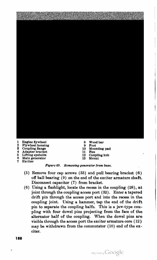
1 Engine flywheel
2 Flywheel housing
3 Coupling flange
4 Adapter bracket
5 Lifting eyebolts
fi Main generator
7 Exciter
Figure 69. Removing generator from hose.
8 Wood bar
9 Foot
10 Mounting pad
11 Fan
12 Coupling hub
13 Mount
(5) Remove four cap screws (33) and pull bearing bracket (6)
off ball bearing (9) on the end of the exciter armature shaft.
Disconnect capacitor (7) from bracket.
(6) Using a flashlight, locate the recess in the coupling (28), at
joint through the coupling access port (32) . Enter a tapered
drift pin through the access port and into the recess in the
coupling joint. Using a hammer, tap the end of the drift
pin to separate the coupling halfs. This is a jaw-type cou
pling with four dowel pins projecting from the face of the
alternator half of the coupling. When the dowel pins are
visible through the access port the exciter armature core ( 12 )
may be withdrawn from the commutator (10) end of the ex
citer.
188

ï§ * #rH
H M MM
S S Î 3
* * * 3*
.s s*f13
•M
g §S g illA MA «
fe* «6e*
psAe
■eq'd)
action pscre
-ea'd)
« bu oj ^ os j; M> a) _
O 3 sg, u » 3 » 2es " 3 cj "
hO«k Q O) O CS H
O P-sO ooo ►3>oo
•« lOeO t-00Ç» OHtNCO
«•*»85 t- 00 OS © r-l N M
HHHH HHH OMMM
8
J* #
-D» \
1SE•o
.2.3
-S te*
a « M
HO
.M
05
H
laQQ
m.S3
m esB h g B3S
, sgUa « oo sps a
O fe k « o « M O «] «J
03 03
a a
lHlN co ■* ia » t- 00 « O iH IN
189

(7) Remove alternator brushes (par. 160).
(8) Remove and tag wiring connections to alternator.
(9) Remove four bolts (17) releasing the exciter field frame (15)
from main generator frame (20).
b. Disassemble Exciter Field Frame. Remove field coils only when
tests reveal a defective coil. Removal damages the coils.
(1) To remove a single field coil, unwrap the taped connections
from the defective coils and melt or cut the connections. Re
move two pole bolts (6, fig. 71) and pole clamp plate (1), and
pole piece (2).
(2) To remove the field coil assembly (4), remove eight cap
screws (6). Wash assembly with cleaning solvent and dry
thoroughly before reassembling.
c. Disassemble Alternator.
(1) Remove four cap screws (19, fig. 72), releasing the adapter
bracket (20) and gasket (18) from the frame (1).
(2) Remove 12 nuts (10) and bolts (17) releasing the drive disk
(16) from the coupling hub (12).
(3) Remove setscrew (11) from the coupling hub (12) and pull
coupling hub and key (13) from shaft (7).
1 Pole clamp plate 9
2 Pole piece 10
3 Insulation strips 11
4 Field coil assembly
5 Exciter housing 12
6 Pole bolt, hex hd, %-13 x 1% (8 13
req'd) 14
7 Brush access cover
8 Cap screw, hex hd, #-20 x % (8
req'd)
Figure 11. Exciter field assembly, exploded view.
Attachment point
Ventilating screen
Cap screw, hex hd, Vi-20 x %
req'd)
Coupling access port
Harness to alternator
Coil terminal
(8
190

Note. Using an acetylene torch, heat the outside of the hub (12)
to facilitate removal.
(4) Remove six cap screws (9) and lockwashers releasing fan (8) .
(5) Position a loop sling around coupling (4) and place a 4-foot
length of 4-inch pipe over end of armature shaft (7).
(6) Lift armature with pipe and sling. Withdraw armature
from the exciter end of generator frame ( 1 ) .
203. Inspection and Testing of Generator Parts
a. General. To test the generator use a test rig, consisting of a
6-volt battery in series with a 2- or 4-candlepower lamp, two test
probes, and connecting wire. In using test probes be sure that good
electrical connection is made at points of contact. Do not place probe
points on polished commutator or collector ring surfaces. A growler
and ohmeter are also required.
b. Exciter Armature.
(1) Inspect the armature for wear. Inspect the coils, insulation,
and soldered connections for electrical and mechanical
defects.
(2) Check the armature coils for grounds. Touch one probe to
the armature shaft and the other to the end of each commuta
tor segment. Select a noninsulated point where the winding
is soldered to the segment. A grounded coil, or commutator
segment, is indicated if the lamp lights. If the ground is
noticeable and accessible, it should be corrected, otherwise
replace the armature.
(3) Check the exciter armature on a growler for internal short
circuits, and repair or replace if necessary.
(4) Check for open-circuited windings. Touch the test probes
to each adjacent pair of commutator bars. If the windings
are sound the lamp will light. Check for thrown solder.
Resolder if joint is loose. Replace armature if soldering does
not correct defect.
(5) Check the physical condition of the commutator. Check
for high mica, rough commutator surfaces, burned, or pit
ted bars. Check to see if commutator is out-of-round.
c. Exciter Field.
(1) Inspect the insulation of the field coils and leads; repair as
needed. If beyond repair, replace with a new coil. Inspect
the leads and connections for burned or frayed insulation
or poorly soldered connections. Repair or replace faulty
leads.
(2) Check the field coils for grounds. Touch one test probe to
a field output terminal and the other to an unpainted por
tion of the exciter frame. If a field coil is grounded, the
lamp will light.
191

a *
^
I
J3
J3
VMH
+J w i—i c 03 Mid, °3
I
lO5Dt- 0005
^
•a
st
•a
2
s
•s t
££•3 2
5 i&
.O
13
a
•a
MO
09 ©rjCN(O-tf
S
V g M
sv a
si9 3 33 8
1-ltN(O-tfWSDt-aO
192

(3) If a ground is discovered, disconnect coils and test each one
separately. Replace grounded field coil. When disconnect
ing field coil note position of inner and outer turns of wire
and tag accordingly. Connect wires according to tags when
replacing coil.
(4) Check the field coils for open circuits or hidden breaks by
placing the test probes in series with the field coils. The
lamp will not light if there is an open circuit. Unless the
break is at a connection and easily repaired, replace the coil.
(5) Test for short circuits within coils by measuring the resist
ance of each coil separately, using a low-reading ohmmeter.
The resistance of all coils should be the same within 10 per
cent.
d. Main Generator Rotor.
(1) Test rotor winding for open circuit. Touch test probes to
each collector ring. If lamp does not light, winding circuit
is open. Replace rotor.
(2) Test rotor windings for short circuit. Use a growler ex
citer with alternating current. If there is a short-circuited
wire, layer, or coil, magnetizing current in growler winding
will build up. If current is maintained for a short time, in
sulation on short-circuited section will become sufficiently
warm to indicate defective coil. If there is a short circuit,
replace rotor.
(3) Test rotor winding for ground. Place one test probe on
rotor shaft and the other on a collector ring. If lamp lights,
a collector ring or rotor winding is grounded. Replace
grounded rotor.
e. Main Generator Stator Windings.
(1) Test main generator stator windings for grounds. Place
one test probe on bare metal surface of generator frame, the
other on the terminal of each stator lead. If lamp lights,
stator winding is grounded. Inspect to see if ground is
caused by poor insulation of leads. Re-insulate leads. If
leads are not defective, field coils are short-circuited and gen
erator frame must be replaced.
(2) Test main generator stator for open circuit. Place test
probes on terminals in the junction box. Test terminals Tl
and T4, T7 and TO, T2 and T5, T8 and TO, T3 and T6, T9
and TO in turn. Refer to figure 79 for the wiring diagram.
If lamp does not light, winding circuit is open. Inspect sol
dered connection between terminals and wires. If open cir
cuit is not caused by loose terminals, replace main generator
frame.
322125 O—55 13 ' '^

/. Main Generator Bearing.
(1) Wipe the bearing with a clean cloth dampened in kerosene,
light engine oil, or gasoline. Do not use solvent or carbon
tetrachloride for this purpose.
(2) Test the bearing by hand for free rolling action. If rough,
sticking, or excessively loose, press off the defective bearing
and replace.
Caution: Protect the bearing against dirt and rust. Keep
the bearing oiled and covered.
g. Radio Interference Suppression Capacitor. To test capacitor,
disconnect one end of capacitor and place test probes across capacitor
terminals. If lamp lights, capacitor is short-circuited and must be
replaced. Replace any capacitor that is burned or out of shape.
h. Generator Assembly Metal Parts. Inspect all metal parts. Re
place bent, distorted, cracked or broken parts, paying particular at
tention to generator blower fan, coupling, adapter, brush rig, and
bearing bracket. Examine studs, bolts, and screws for damaged
threads. Replace any that are bent or damaged.
204. Machining Commutator and Collector Rings
a. Center the armature or rotor shaft on a lathe.
b. Take a succession of light cuts over the entire surface of the
commutator or collector ring. When a smooth concentric surface
has been obtained, undercut the mica between commutator segments.
c. Support an undercutting tool on the tool rest, and carefully force
it along the mica between the commutator segments. The tool should
be square and slightly wider than the mica. Center it carefully so
that an edge of mica does not remain at the level of the commutator
surface. Remove rough edges by beveling slightly.
d. After the commutator bars or collector rings are machined and
the mica undercut, polish the commutator or collector rings. Use a
commutator polishing stone or several layers of canvas attached to a
piece of wood. Hold canvas or stone against revolving surface until
a high polish is obtained.
205. Cleaning Generator Assembly Parts
a. Cover generator bearing.
b. Blow off loose dirt and dust from the generator parts with dry
compressed air not over 25 psi pressure.
c. Do not use solvents of any kind on the generator bearing. Do
not attempt to lubricate the bearing. Keep the outside of the bearing
lightly oiled.
d. Wipe off grime on windings with a clean cloth moistened with
cleaning solvent.
e. Clean metal parts with cleaning solvent.
194

206. Main Generator Reassembly
a. Alternator Rotor Installation.
(1) Place rotor in line with alternator housing with shaft (7,
fig. 72) entered in alternator housing.
(2) Slide a 4-foot length of 4-inch pipe over shaft (7), and lift
rotor using pipe and loop sling over coupling end of rotor
shaft.
(3) Pilot rotor through housing until rotor coils are entered
completely in stator coils. Remove sling and pipe.
(4) Position fan (8) and secure to shoulder on shaft (7) with
six cap screws (9) and lockwashers.
(5) Heat coupling hub (12) and position it on shaft (7) and
immediately insert key (13) andsetscrew (11).
(6) Secure drive disk (16) to the coupling hub (12) with 12
bolts (17) and nuts (10).
(7) Position gasket (18) and adapter bracket (20) and secure
to the frame ( 1 ) with four cap screws ( 19) .
b. Assemble Exciter Field Frame.
(1) To install new field coil, assemble coil (4, fig. 71), pole piece
(2), and pole clamp plate (1). Position insulation strips
(3) at the points of contact between the exciter housing (5)
and the field coil assembly (4). Secure with two pole bolts
(6) and lockwashers.
(2 ) Connect the coil ends to adjacent coil ends.
(3) Verify correctness of connections by applying a direct cur
rent at low voltage to the field terminals and testing polarity
of coils with a magnet or compass. Polarity of the coils
should alternate.
(4) Solder coil connections and wrap with varnished cambric
tape and friction tape.
(5) Coat the coils and wires with air-drying insulating varnish.
( 6 ) Test the coils for shorts or grounds.
(7) Installing a complete coil assembly is similar to single coil
installation except that coil connections are made before
installing coils in frame.
c. Install Exciter Field Frame.
(1) Secure exciter field frame (15, fig. 70) to the generator
frame (20) with four bolts (17).
( 2 ) Connect wiring connections to alternator.
(3) Install alternator brushes (par. 160) .
(4) Position the exciter armature core (12) and aline the cou
pling dowels so that the recesses in the coupling halves meet.
Tap the end of the armature shaft to seat the coupling.
(5) Secure capacitor (7) to the bearing bracket (6) and posi
tion the bracket over the ball bearing (9) and secure it to
the exciter field frame (15) with four screws (33).
195

(6) TnstaH spacers (5) to limit end play of the exciter shaft to
0.020 inch and secure plate (4) with four screws (2) .
(7) Connect the field coil lead wires (13) to the two brush ter
minals behind the brush ring (8) .
(8) Install the exciter brushes (par. 161 ) .
(9) Install the end bell shield ( 1 ) .
207. Installation of the Main Generator
a. Insert a 31/^-foot length of 2- by 4- inch lumber through the
adapter bracket (4, fig. 69) and under the generator coupling hub
( 12 ) to support the generator shaft.
b. Attach a hoisting sling to the generator lifting eyebolts (5) and
lift the generator assembly into position behind the engine. Move
the generator forward and aline it with the flywheel. Insert four
tapered drift pins through the mounting pads (10) and generator
feet.
c. Secure the engine flywheel and driving disk in accordance with
paragraph l74e and /.
Note. Observe that the air gaps between the alternator rotor and stator and
the exciter armature and field are uniform. This indicates that the rotor is
correctly centered in the stator windings.
d. Eemove drift pins through generator feet and mounting pads.
Secure the generator to mounting pads ( 10) .
208. Testing Generator Assembly After Overhauling
a. Start the engine and run the unit at rated speed. Listen for
unusual noises. Read the voltmeter. See that rated voltage is ob
tained at rated speed.
b. Test for proper phasing by connecting a 3-phase a-c induction
motor to the generator output and noting the direction of rotation.
Connect the motor to a similar generator set making the same con
nections from Tl, T2, and T3. If the rotation is opposite, check the
terminal connections of the overhauled machine with the wiring
diagram.
Section X. WINTERIZATION KIT
209. Description
The winterization kit supplies hot air to vital parts of the genera
tor set to assist in starting at low temperatures. A gasoline burner
heats a metal air chamber through which air is blown and conveyed
through ducts to the battery box and the starter pinion gear. Com
bustion exhaust is conveyed through a jacket enclosing the engine oil
pan to heat lubricating oil and is then discharged through an exhaust
stack. Circulating air is blown by a squirrel cage rotary blower which
is electrically driven from batteries.
196

210. Burner
a. Removal (fig. 73).
(1) Remove the winterization heater from the generator set. Re
fer to paragraph 164.
(2) Disconnect fuel line (7) from the fuel valve (14).
(3) Disconnect igniter lead (5).
(4) Remove eight nuts (1) releasing the burner plate (12) from
studs (6) , and withdraw the burner from the kit.
b. Disassembly.
(1) Remove eight screws (1, fig. 74) and washers (2), releasing
plate (3).
(2) Remove three screws (10) and nuts (9) . Remove combustion
chamber (4) and vaporizer chamber (8).
(3) Remove three screws (18) with nuts (13). Remove support
brackets (12) and burner plate (17).
(4) Remove roundhead screws (27 and 30) from front and side
of vaporizer chamber. With an offset screwdriver remove
screw (32) and washer (31). Remove vaporizer chamber
cover (28).
(5) Remove nut (16) with washer (15) and insulator (14) from
igniter retainer stud (34). Withdraw igniter retainer stud
(34) from vaporizer (29).
(6) Remove nut (23) with washer (24), Fahnestock clip (25),
and igniter stud inner insulator (26) from igniter stud (33).
Withdraw stud (33) from vaporizer.
(7) Remove vaporizer (29) from vaporizer chamber (8).
(8) Remove screw (5) and igniter (6). Remove igniter insula
tion pieces (7) from igniter wire.
(9) Unscrew fuel tube (11) from valve assembly.
(10) Remove two screws (19) holding fuel valve and float chamber
assembly (21) to burner plate (17), and separate the parts.
c. Inspection and Repair.
(1) Examine all parts and replace broken parts, burned out
igniter, or cracked insulators.
(2) Examine vaporizer. Replace vaporizer if cracked or brittle.
d. Assembly.
(1) Install fuel valve and float chamber assembly (21) on burner
plate (17) with two screws (19).
(2 ) Screw fuel tube (11) into float chamber.
(3) Slip igniter insulation pieces (7) over igniter (6) to center
of wire. Place igniter in groove in vaporizer (29) and fas
ten with screw (5) at one end.
(4) Insert vaporizer (29) in vaporizer chamber (8).
(5) Insert igniter stud (33) through igniter end loop and
through vaporizer. On end of stud, assemble igniter stud
197

198

1Nut,hex,%6511(1req'd)
1Floatbowl
1Flame1nspectionwindow
4Combustionchamber
5Igniterlead
1Stud,%e59x1%(1req'd)
1Fuelline
1Blowermotorcontrolswitch
THeatercontrolswitch
1Circuitbreakerresetbutton
Figure13.Removalofburner.
11Controlbox
1Burnerplate
.Tube
9Fuelvalve
1Tube
*o

_-ri
200

1SAsc,mac'rdhd,%A1x%(11
req'd)9
1Washer,%(1req'd)1
1Plate1
1Combustionchamber1
5SAesScc'rdhd,%A1x%(11
req'd)11 1Igniter
1Igniterinsulationpieces1
1Vaporizerchamber
TNut,seSclUkird,hex,UA1(11
req'd)11
1SAesmacTErdrd,%A1xrd
(1req'd)1 1Fueltube1
Supportbracket9
Nut,hex,}45.(1req'd)1
Insulator9
Washer,%e(1req'd)1
Nut,hex,%e511(1req'd)
Burnerplate1
SAsc,rdcTErdhdU11x1%1
(1req'd)T
SAsc,macTErdhd,%A1xs(1
req'd)1
1enttube1
Fuelvalveandfloatchamberas
sembly9
Igniterstudouterinsulator11
Nut,hex,%6511(1req'd)
Washer,%8(1req'd)
Fahnestockclip
Igniterstudinnerinsulator
SAeSHmacTErdrd,<fte511x%
(1req'd)
1aporizerchambercover
1aporizer
SAsc,macTErdhd,%e511xy±
(1req'd)
Washer,No.1(1req'd)
SAsc,macTErdhd,111x%(1
req'd)
Igniterstud
Igniterretainerstud
Figure14.Winterizationheaterburner,disassembled.
IO

inner insulator (26), Fahnestock clip (25), and washer (24).
Fasten with nut (23) .
(6) Put igniter retainer stud (34) through vaporizer so that hook
engages insulation pieces on igniter. Install insulator (14)
and washer (15) on stud and secure with nut (16).
(7) Place vaporizer chamber cover (28) on vaporizer chamber
and secure with screws (27) and (30). Use an offset screw
driver to install screw (32) with washer (31)
(8) Fasten three support brackets (12) to burner plate (17)
and vaporizer chamber (8) with screws (10) and (18) and
nuts (9) and (13).
(9) Fasten plate (3) to combustion chamber (4) with eight
screws (1) and washers (2).
e. Installation.
(1) Thread igniter wire through hole in burner plate and fasten
to Fahnestock clip (25). Secure wiring elbow to burner
plate with four screws.
(2) Slide burner into heater and position on stud (6, fig. 73).
(3) Install eight nuts ( 1 ) on studs.
(4) Connect fuel line (7) to the float bowl (2) .
211. Fuel Float Chamber
a. Removal. Refer to paragraph 2106.
b. Disassembly.
(1) Disconnect tubes (8 and 12, fig. 75). Remove two bolts (11)
with nuts (7) and separate fuel valve from float chamber.
(2) Remove tube and valve nut (1) from float chamber cover
(3) and remove the two steel balls (2) .
(3) Remove three screws (15) with plain washers (14) and lift
off cover (3). Remove float chamber cover gasket (4).
(4) Lift float (5) and valve (13) from float chamber body (6).
(5) Unscrew and remove pin (9).
(6) If replacement is necessary remove remaining fittings on
bottom of float chamber.
g. Inspection and Repair. Examine all parts. Replace worn parts.
Replace valve if grooved. Replace float if punctured.
d. Assembly.
(1) Install pin (9).
(2) Slip valve (13) on float (5) and insert both in float cham
ber body (6).
(3) Install cover (3) with gasket (4) and secure with three
screws (15) and washers (14).
(4) Place steel balls (2) in cover opening, and install tube and
valve nut ( 1 ) .
(5) Install all tubes or pipe fittings which were removed.
e. Installation. Refer to paragraph 210d.
202

1 Tube and valve nut
2 Steel balls
3 Float chamber cover
4 Float chamber cover gasket
5 Float
6 Float chamber body
7 Nut, hex, %-16 (2 req'd)
8 Fuel tube
9 Pin
10 Heater fuel valve and bracket
11 Bolt, mach, hex hd, %-16 x 1%
(2 req'd)
12 Fuel tube
13 Valve
14 Plain washer
15 Screw, mach, fll hd, %-20 x 2%
(2 req'd)
Figure 75. Winterization heater fuel bowl, disassembled.
212. Blower and Motor
a. Removal.
(1) Remove eight screws (20, fig. 76) with lockwashers, releas
ing the air intake flange (21) and gasket (22).
(2) Remove setscrew (23) releasing the rotor fan (24).
(3) Remove four bolts (17) with nuts (30) and two bolts (28)
with nuts (19) releasing the motor bracket (14) and the
motor.
b. Disassembly.
(1) Remove four screws (29) releasing motor and mounting
mechanism (13) from the motor bracket (14).
203

204

ft
a> Mo"*
a .a ^3 ja i*-
61
0
!» « 02 pq pq « ob £ u o
* 2« 5
O ci
o
t
ao
"I
CCTt<lf)eOt-COC»©tHCN05-*
-—^ ■a ^ o
^ srrH
a,
hH
to
M■*
~cofck
lN T3rH 5
Wo
S
•s * c^ CNT3 ■e
OS >o
fsjie 5
Oi Qi -
N*.53
to
s-g-S•a <s
i9 ft a
03 *
Kg.
0)
— cS 03
Mounti
Motor SAeSH
req'd AirpipBolt,h<
BlowerNut,h< Capso reqa Airint Gasket
SO
to
05 ■* «550 I- 00 0S © 1-l £*
a
P-e
OJ
a
g-
2 2
is
Is*P a! S « osa
bo bx.fi 3U5.2.0
B
ft S1
o a)
02 05 02 « O ■«) P3 H
iHCNM"*lOCOt-CCC»©r-llN
205

(2) Remove brush spring holders (27) and withdraw the brush
assemblies (26).
(3) Remove two nuts (12) and split washers (11) releasing end
bell (10).
(4) Slip two springs (4) from studs (3). Withdraw armature
(8) and spring washer (5) from the motor frame (1).
c. Inspection and Repair.
(1) Inspect field coil insulation for breaks. Inspect the field
coils and frame as detailed in paragraph 188c.
(2) Inspect the armature for open, short, or grounded circuits
and for wear as detailed in paragraph 1885.
(3) Replace the brushes if they are worn less than one-half their
original length. Inspect the brush springs for any signs of
corrosion or fatigue. Replace if defective.
d. Reassembly.
(1) Position spring washer (5) against ball bearing (6) and
insert the armature (8) in the motor frame (1).
(2) Place springs (4) over the studs (3) and position the end
bell (10). Secure the end bell with two nuts (12) and
split washers (11).
(3) Insert brush assemblies (26) and retain with brush spring
holders (27) .
(4) Secure the motor and mounting mechanism (13) to the motor
bracket (14) with four screws (29).
e. Installation.
(1) Install motor and bracket (14) with four bolts (17) and nuts
(30) and two bolts (28) with nuts (19).
(2) Position rotor fan (24) on the motor shaft and secure with
setscrew (23).
(3) Secure gasket (22) and air intake flange (21) with eight
screws (20) and lockwashers.
(4) Spin blower by hand to check clearance.
( 5 ) Connect motor current plug ( 34 ) .
(6) Connect a 24-volt direct current source to the motor and
check that air is blown from the top opening of the blower
housing. Direction of motor rotation is changed by reversing
the motor lead connections in the junction box (33).
Section XI. ENGINEERING DATA
213. Fan and Generator Belts
a. Fan belt slack midway between pulleys 1*4 in.
b. Generator belt slack midway between pulleys-. y2 to % in.
206

214. Injectors
a. Valve opening pressure - 1000 psi
b. Minimum pressure drop used injection valve_. 200 lb 35 seconds
c. Spray tip orifice 0.007 in.
d. Copper tube, hole tip diameter 0.175-0.185 in.
215. Standard Nut and Bolt Torque Specifications
Size nut
or bolt
Torque
(ft-lbs)
Size nut
or bolt
Torque
(ft-lbs)
K-20 7-9
8-10
13-17
15-19
30-35
35-39
46-50
57-61
71-75
83-93
tfe-12
Mo-18
90-100
107-117
137-147
168-178
240-250
290-300
410-420
475-485
580-590
685-695
K-28
Mcr-18 %-u
M«-24 %-18
^-16
H-24 tf-16
Kr-14 Jf-9
%-14
1-8
1-14
Me-20
#-13
#-20
216. Nonstandard Nut and Bolt Torque Specifications
Part
Air inlet elbow to blower housing ■
Air outlet flange to blower
Exhaust manifold nut
Fuel oil tube assembly to cylinder
Governor buffer screw nut
Governor low speed adjusting screw nut
Lube oil tube assembly to cylinder head adapter
Starting motor to flywheel housing bolt
Special water plug
Injector clamp nuts
Cylinder head stud nuts
Connecting rod cap nuts
Main bearing cap nuts
Flywheel-to-crankshaft bolts
Flywheel housing-to-cylinder block bolts
Camshaft and balancer shaft locknuts
Blower rotor gear retainer bolts
Torque In
foot-pounds
25-30
25-30
35-40
40-45
17-21
50-55
40-45
35-40
35-40
20-25
150-175
65-75
155-185
150-160
90-100
300-325
55-65
217. Alternator
a. Rotor.
(1) End play 0.020
(2) Shake 0.015
207

(3) Field winding tape %-inch fiber, 0.025 Dural
paper and varnished
cambric, used on pole.
(4) Number of poles 6
(5) Winding Series
(6) Wire insulation Single cotton enamel
(7) Varnish treatment 4 dips, 4 bakes
(8) Coil enclosure Welded copper and brass,
squirrel cage.
(9) Fit, bearing to shaft 0.002-inch press
(10) Radial play between bearing 0.005
races.
(11) Axial play between bearing races 0.010
b. Stutor.
(1) Number of poles 6
(2) Number of slots 54
(3) Number of leads 10
(4) Minimum resistance value 1.4 megohms with 500-volt
megger.
(5) Air gap 0.125 inch
c. Brushes.
(1) Material Carbon
(2) Length l%in.
Width 6/8 in.
Thickness % in.
218. Exciter
a. Bars 77
6. Slots 39
c. Poles 4
d. Air gap 0.125
219. Wiring Diagrams
The wiring diagrams of the control panel, engine control and
heater control are shown in figures 79, 80, and 81.
208

6POLET54SLOTSTATOR
-ROTATIONCOUNTERCLOCKWISE5SLIPRINGEND
Figure1.Statorwiringdi'gram.
1o

ID
O
I
oQ.
o>
to
of<CD
210

W--
322125 O - 55 (Face p. 210)


HEATER,
CONTROL
SWITCH
BATTERY
THERMAL
OVERLOAD
CIRCUIT
BREAKER
BATTERY
BOX
overheat;
solenoid
BLOWER CONTROL
SWITCH BLOWER
MOTOR
RESISTOR
5c
TH2
BATTERY
BOX
OVERHEAT
THERMOSTAT
HEATER
BLOWER
JUNCTION
H^BOX
-^-SUP
CAPACITOR
CA442
FROM ENGINE
CONTROL
HEATER
BLOWER
MOTOR
HEATER
IGNITOR
GASOLINE
SOLENOID VALVE
Figure 80. Engine control wiring diagram.
FROM
CONTROL PANELOVERSPEED
GOVERNOR
SAFETY
SWITCH
-H4
LOW OIL
PRESSURE
SAFETY .SWITCH
H4 In I-H4-
AUXILIARY
STARTER BUTTON
ST
ENGINE
AUXILIARY.
PANEL £*
FUEL PRESSURE ENGINE '
SWITCH COOLANT
SAFETY
BATTERY THERMOSTAT
SB
SJ»
THI
STARTING
MOTOR
"a+
starting +
MOTOR f
SOLENOID
>SP AIR HEATER
k SPARK PLUG
>SP
f ENGINE
± BATTERY
CHARGING
GENERATOR
^EXTERNAL i
-BATTERY
CHARGING '
RECEPTACLE
ENGINE
BATTERY-
CHARGING
REGULATOR
Figure 81. Heater control wiring diagram.
=^C2
e
BATTERY
24 VOLT
1C2 3
feiGRLEA
D N Tj
-A+
«/>g
o
(rtO
\f
211

CHAPTER 5
SHIPMENT, LIMITED STORAGE, AND DEMOLITION
TO PREVENT ENEMY USE
Section I. SHIPMENT AND LIMITED STORAGE
220. Limited Storage
a. General. Generator sets not intended for immediate use must
be prepared for storage to protect metal parts from corrosion and to
enable moving parts to operate freely next time the set is put into
service. Sets prepared in this manner can be used at any time by
removing all seals and checking fuel, water, and lubricant.
b. Inspection. Prior to preparing the generator set for limited
storage, inspect it in accordance with the monthly procedure set forth
in paragraph 72. Tighten, repair, or replace parts as necessary to put
the generator set in first-class condition.
c. Cleaning and Painting.
(1) Clean the housing and metal parts of dirt and grease.
Remove corrosion and repaint corroded spots. Follow paint
ing instructions given in paragraph 68.
(2) Remove grease and dirt from exterior of the engine and gen
erator with brush or rags. Keep cleaning fluid out of open
ings in main generator, exciter, and heater generator.
d. Lubrication. Drain lubricating oil from diesel engine and
heater. engine. Refill crankcase. Lubricate other points in accord
ance with LO 5-5009.
e. Protection in Storage.
(1) Engines. With exterior of engines clean and dry, spray or
brush the exterior of engines and accessories with preserva
tive compound. Seal openings into the engines with a water
proof and vaporproof material. Sealing material must be
strong enough to resist damage due to expansion of trapped
air.
(2) Generators. With exterior surfaces of generator clean and
dry, spray or brush the exterior of the generator with sealing
212

compound. Cover generator to prevent water from falling
into openings, but do not seal openings.
(3) Diesel fuel system. Drain the fuel tank. Fill tank com
pletely with preservative fuel. Operate engine for 5 minutes
at 60 cycles, no load.
(4) Heater fuel system. Drain the fuel system. Clean the fuel
strainer.
(5) Cooling system. Fill radiator with solution consisting of one
ounce of soluble oil to each gallon of water. If freezing
weather is expected during the storage period add antifreeze
compound in correct proportion and omit oil.
(6) Batteries.
(a) Remove batteries from unit. Check each cell with a
hydrometer. The specific gravity should not be less than
1.270 per cell. If readings are low, fill batteries with dis
tilled water to three-eighths of an inch above plates.
Charge batteries until readings are 1.270 per cell.
(b) Clean ports and terminals with a strong solution of wash
ing soda. Wipe dry. Keep the soda solution out of the
cells.
(c) Coat the terminals heavily with vaseline (petroleum jelly) .
(d) Store batteries in a warm, dry place. Be sure filler plugs
are tight, and tops of the batteries are dry and clean.
(7) Air cleaners. Remove and service air cleaner bowls. Refer
to LO 5-5009.
221. Domestic Shipment
a. General. Information in this section is published for the guid
ance of personnel responsible for the packaging and shipment of the
generator set.
b. Hoisting and Handling. The uncrated generator set should
be hoisted by a crane with sling or hook attached to the generator set
lifting eye (6, fig. 1) . The boxed generator should be lifted by slings
placed in the sling notches ( 10, fig. 10) .
c. Packaging and Blocking.
(1) Check the generator set (par. 6/), and tighten, repair, or
replace as necessary to put the generator set in first-class
condition.
(2) Drain cooling system. Leave valves open.
(3) Drain fuel tanks.
(4) Seal all engine openings.
( 5 ) Drain lubricating oil.
(6) Remove muffler.
(7) Cover generator to prevent water from falling into open
ings. Do not seal generator.
213

(8) Remove electrolyte from the batteries and prepare them for
shipment in accordance with TB 5-9711-1.
(9) Tag the generator set, indicating that it is being shipped
dry, with dry charged batteries in place.
(10) Wrap in moistureproof paper and seal with pressure-sensi
tive tape.
(11) Build a solid wooden case around unit, wholly enclosing it
(fig. 10).
(12) Block and secure generator set in flatcar of truck (fig. 16) .
Note. If being shipped for short distances, the set may be left
unboxed. In this case, cover generator set with tarpaulin on truck
or flatcar.
Section II. DEMOLITION OF GENERATOR SET TO PREVENT
ENEMY USE
222. General
When capture or the abandonment of the generator set to an enemy
is imminent, the responsible unit commander makes the decision either
to destroy the unit or to render it inoperative. Based on this decision,
orders are issued which cover the desired extent of destruction.
Whatever method of demolition is employed, it is essential to destroy
the same vital parts of all generator sets and all corresponding repair
parts.
223. Preferred Demolition Methods
Explosives and mechanical means, either alone or in combination,
are the most effective methods to employ. Listed below are the vital
parts in order of priority of demolition for each preferred method.
In each case, completion of the first two steps will render the unit
inoperative. Completion of the additional steps listed will further
destroy the unit.
a. Explosives. Place as many of the following charges as the situ
ation permits and detonate them simultaneously with detonating cord
and suitable detonator.
(1) A 2-pound charge on the valve and injector rocker cover.
(2) A 4-pound charge inside the rear of the main generator.
(Bemove one of the brush inspection covers.)
Note. The above charges are the minimum requirement for this
method.
( 3 ) A 2-pound charge on the diesel engine blower.
(4) A y2-pound charge behind starting motor.
b. Mechanical Means. Use sledge hammers, crowbars, picks, axes,
or any other heavy tools which may be available, to destroy the fol
lowing :
214

(1) The engine hydraulic governor, fuel pump, fuel filters, and
valve and injector rockers.
(2) The commutator, collector rings, brush holders, and wind
ings of the main generator and exciter.
Note. The above steps are the minimum requirements for this
method.
2 POUND CHARGE
BLOWER
-5- POUND CHARGE
* STARTER
4 POUND CHARGE
IN REAR OF MAIN
GENERATOR
Figure 82. Placement of charges.
215
(3) All switches and instruments on the control panel.
(4) The radiator core and the batteries.
( 5 ) The winterization heater and the heating ducts.
224. Other Demolition Methods
If the situation prohibits employing either of the preferred meth
ods, use the following, either singly or in combination :
a. Weapons Fire. Fire on the generator set with the heaviest
weapons available.
o. Scattering and Concealment. Remove all easily accessible vital
parts such as the hydraulic governor, fuel pump, overspeed governor,
generator and exciter brushes, and scatter them through dense foliage,
bury them in dirt or sand, or throw them in a lake, stream, well, or
other body of water.
c. Burning. Pack rags, clothing, or canvas under and around tha
equipment and inside the main generator at front and rear. Saturate
this packing with gasoline, oil, or diesel fuel, and ignite.
d. Submersion. Ttotally submerge the unit in a body of water to
provide some water damage and concealment. Salt water will do the
greatest damage to metal parts.
e. Misuse. Perform the steps listed below to make the unit inop
erative.
(1) Pull out the hand throttle knob on the auxiliary control
panel, and wedge it so that it remains out during engine
operation. Cut the wires to the emergency shutdown sole
noid at the blower outlet.
(2) Drain the radiator and diesel engine crankcase.
(3) Remove the covers from the rear of the main generator.
(4) Start the engine.
(5) Drop small tools, bolts, nuts or metal scraps into the main
generator.
(6) Run the engine at maximum speed until failure occurs.
225. Training
All operators should receive thorough training in the destruction
of the generator set. Simulated destruction, using all the methods
listed above, should be included in the operator training program. It
must be emphasized in training that demolition operations are usu
ally necessitated by critical situations, when the time available for
destruction is limited. For this reason, it is necessary that operators
be thoroughly familiar with all methods of destruction and be able
to carry out demolition instructions without reference to this or any
other manual.
216

APPENDIX I
REFERENCES
1. Dictionaries of Terms and Abbreviations
SR 320-5-1 Dictionary of United States Army Terms.
SR 320-50-1 Authorized Abbreviations.
2. Lubrication and Painting
LO 5-5009 Generator Set, Electric, Portable, Diesel
Driven, Skid Mounted, 30 KW, 60 Cycle
120/208 or 240/416 Volt, 3 Phase, Con
vertible to 50 Cycle 120/208 or 240/416
Volt, 3 Phase, Stewart and Stevenson
Model WGD-3012.
TM 9-2851 Painting Instructions for Field Use.
3. Preparation for Export Shipment
TB 5-9711-1 Preparation of Corps of Engineers Equip
ment for Oversea Shipment.
TB 5-9713-1 Preparation for Export, Spare Parts for
Corps of Engineers Equipment.
Preventive Maintenance
TB 5-5009-1 Preventive
TM 5-505
5. Publication Indexes
DA Pam 108-1
Maintenance Services : Gen
erator Set, Electric, Portable, Diesel
Driven, Skid-Mounted, 30-KW, 60 Cycle
120/208 or 240/416 Volts, 3 Phase, Con
vertible to 25 KW, 50 Cycle, 120/208 or
240/416 Volts, 3 Phase, Stewart and
Stevenson, Model WGD-3012.
Maintenance of Engineer Equipment.
SR 310-20-3
DA Pam 310^
Index of Army Motion Pictures, Television
Recordings and Filmstrips.
Index of Training Publications.
Index of Technical Manuals, Technical
Regulations, Technical Bulletins, Supply
Bulletins, Lubrication Orders, and Mod
ification Work Orders.
217

SR 310-20-5 Index of Administrative Publications.
SR 310-20-6 Index of Blank Forms.
SR 310-20-25 Index of Supply Manuals—Corps of Engi
neers.
6. Supply Publications
DA Supply Manual Organizational Allowances, Field and De-
ENG 7 & 8-5009 pot Maintenance Initial Stock Guide, and
Depot Stock Guide for Repair Parts;
Generator Set, Electric : Portable ; Diesel-
Driven ; Skid-Mounted Liquid-Cooled ;
MIL-G-10327; Type II; Class A; 60
Cycles; 120-208 240-416 Volts; 3-Phase,
4-Wire ; Convertible to 50 Cycles 240-416
Volts; 3-Phase, 4-Wire; at 83 Percent of
60 Cycles Full Load Capacity 30 Kilo
watts; Stewart and Stevenson Model
W-GD-3012 (Engineer Stock No. 17-
4665.750.800) (Federal Stock No. 6115-
235-8673).
218

APPENDIXII
IDENTIFICATIONOFREPLACEABLEPARTS
Vote.Thisappendixisforidentificationpurposesonlyandisnottobeusedasabasisforrequisitioning.
1.StandardHardware
Manufacturer'spartNo.CodeNo.PartNo
Federalsupplyclass andItemidentifica
tionNo.
Description
BOLT,hexhd,#A1x#__ BOLT,hexhd,#51x%.. BOLT,hexhd,#A1x%.. BOLT,hexhd,#A1x%.. BOLT,hexhd,#A1x1__BOLT,hexhd,#659x#_ BOLT,hexhd,Mo59x#_ BOLT,hexhd,Ke59x1.. BOLT,hexhd,yle511x1# BOLT,hexhd,Me59x1% BOLT,hexhd,^651x1. BOL9,hexhd,Ko59x1# BOL9,hexhd,#859x%.
BOLT,hexhd,#51x1.. BOLT,hexhd,#51x1#_
Quantity perunit
9 11 11 1 1 91 191 1 1 9 9 .'51 11

N^CNCNOS^CNWrtHHM O ■* ■* •* O CO^H CO CO U5
i CN
X£
ijx i JK i ~N. ^ ^ H Ol
.1 CN CN 1 i JSx H
XXXXXXX**
CStOCOOO^^HH
H H Hfl« CNCN i l
l L L L L L I » ■\0O X«> X00 X?0 x?o x?o XOO V" X-*
MX MX MX rt\ n\ MX MX t-X. i—,
fix
* X
©
CN M
:ix
^5? ~x?^X MX
H CN
X X
CO M
7 7-Kiix
i CN
X X
n 00
i 7,"5x ujx
a a
3xi)x
x x
a s
jR
CN O
x}» |
jS ,«
'OscOscO'nTJ'OTJ'OscO'OTJ
xxxxxxxxxxxOJC0OJOOOC0^OOiO
■a T3
J5 J3
•a -a
J3 J3
J3 J3 J5 J3
3 sf a
4. .S *
as o .fc< •= o
ca x« ca
« * o
.i" -2 —o ; »
c8 > &
jo g ■
C XM J^
—' e a
C0 be ••
s C SB
a ■ ?
a
m?;
MX
bO . . £3 •= C
COO—' » —■a £ 1? -* ^x s^
_ ... cus s 0, a,
-^ -*^> -fJ -*^> -»^>
i i i i i
-*J +3 -*J *J -i-3
a o s s 1 s a,•^ *^< m no m m m
OOOOOOOOOOOOOOOOOD
iZ 5 rS
PQ M W
15
W O
/. X w X
« pf pf pf
w w w w
CO CO CO CO
££££
M M M Mo o o uo o o o
■3 a
bi ■
2SS
t- •* o
N CN N
00 U5 CN
CN CO lO
H H 1IJ H H
CN ^H
oo mOS t-
h. CO
rH o
!
220

1151T1 1151T1 11591115111
11591 11591 11591115115 11U1A
511591591T
195 11T1191T 1111
191 1911111 1115
191 11111111
1A11
11 11 11 11 11 11 11 11 11 19 19 11
LLOKWASHER,split-type,%,inLLOKWASHER,split-type,Hin LLOKWASHEA,split-type,%in LOCKWASHER,split-type,1in LLOKWASHER,ex-tooth,%6in
LLOKWASHER,ex-tooth,%inLLOKWASHER,ex-tooth,%»in
LLOKWASHER,ex-tooth,%in LLOKWASHER,ex-tooth,%inLLOKWASHER,int-tooth,%in LLOKWASHER,int-tooth,%in LLOKWASHER,int-tooth,Hin
LLOKWASHER,int-tooth,%6in
LLOKWASHER,split-type,No.1 LLOKWASHER,split-type,No.1
LLOKWASHER,springsteel;regular;stdwt;SAE;bright;sizeNo.1-. LLOKWASHER,springsteel;regular;stdwt;SAE;bright;sizeNo.11.
LLOKWASHER,springsteel;regular;stdwt;SAE;bright;J4inLLOKWASHER,springsteel;regular;stdwt;SAE;bright;M«in
LLOKWASHER,springsteel;regular;stdwt;SAE;bright;Y»inLLOKWASHER,springsteel;regular;stdwt;SAE;bright;Vmin
LLOKWASHER,springsteel;regular;stdwt;SAE;bright;Kin LLOKWASHER,springsteel;regular;stdwt;SAE;bright;%in LLOKWASHER,springsteel;regular;stdwt;SAE;bright;%in
N5,jam:regular;steel;finshed;FSFF5B591,grSHe1;NF;hex;TypeA;rdhd
Y%in.;9threadsperin.
N5,regular:steel;black;semifinshed;FSFF5B591;NC;hex;9ypeA1;rdhd
%in.;1threadsperin.
N5,regular:steel;black;semifinshed;FSFF5B591;NC;hex;TypeA1;rdhd
%in.;1threadsperin.
1

>•*>
b
Q
CN
<
s
CN
<
0)
a
J3
CN
a
J3
CN
■<
V
s
CN
73
CN
<
so
s>>
H
<4 th
p!, &
1
X X X X X
0) tu Oi CD
J3 J3 J3 ^ -C
tin En PE, 1 En
» 9 9 9 £
b- CO H Tf< M 00
•* rt ^H
-C .3.
04 04
9 9 11
«
03
CO no
1 1
T1■a
0i sJ3 .G
B3
C cCG <c
■o
I
«I
En
En
CO
En
>ra
piI
En
En
CO
En
I
m
En
En
CO
En
pi) pi
s.s3 —
s
3? a
En
En
CO
En
En
Pn
CO
En
3
o. .S a T I
0) . a)
s fe s3 s 3
1 .3 J
g £ g
—- -^ .—i
» _ »
■a
0)
J3
"S. « cc
c
■a
a
P5 PQ
o 0)
s ft►> >,
^ —, .17 CN —
0)
s>>
H
0)
s
■a
J3
a
cc
4J ^ CN ■t3
0) rfl
s
m Jd•n
U
ti a)
£ -Q
.fi+J —
CO CO
00 00
CO co
I J
3 s; 3
CO sc - 0)
£ 73 u
. J3 -
£■«£
Nr- 3
.- 0)■a n
3 If
Jd
.5 *
n 3
& —
! CO CC
1 3 \oo -3
« g>T K
3 .
H
a ^ Jtf
n Xi
a
siT
■a *
■a y
00 2,iH be
a ■- s •-
ll-slOJ co afl co
t- CD.C •• ft ••
93 -*a 05
~ 3 •* 3
" beCN »
CO CO
En En
o o
£^
OS •«
. soo so
z «'
o En■«5 rv.CO w
o En
.. ^ .*
' 3 X
*•— a) T3 ta
. » ..
IS=3 Oto o
.. o
pq ®
8.2P< oo
>» 00
H to
,fc I CO
S "* I
• - o> .5
CO
* ^ S
En^.S
S? ►. vS
.•a § «
•• .£ ••
» a £
M J3
« en co
S 7
CN -O
CO
03 £
•3 -a
73 .-
bo-1
n Ph
fli
£prt En
d g
fH 3
. S5o cs
T3
a
Pn
l
CO
En
o
o
o
CO
» ..2 Xi
m ^^
.. >o£ CN
a •-■8 g
3 S
cn a
3 5
Ph Ph PL, pL, pu, pL, Ph
oo o3
O
*-i CD
ft.& .
HhJH
Ph Ph
o
0i
T3
c
3
■a
OJ
so a
.& . 3
s.c &
& •-&►J M J
Ph Ch
■as
Ill
■Sis
00
ira
CO
t-
00
CO
CN
oo
o
CN
CO
CN
J,CO
CN
i
CO
CN
CN
1
o
CN
I
OS CO CN
t- CO O
i-i © o>
CO l^ i-l
CN rH CN
CO
CO
o
CO
o
CO
COCNCOiOiOiOOo0N
CNNNNo0MTfNN
NconmmtOMiooo
CNCOCOCOCO00i-lcOCO
-<ooooo-*oo
COi-l^Hi—li—t^Ht-HrH^H
CN-*-*T)<Tl<'*TtlTj<Tt<
cotocOcOcOcococoto
00
t^00
CO
o
CN
CO
222

»1K>
CO
115111EL1A15P9
511559111
5T5591A11 5T5591A11 5T5591A19 5T5591A151
5T5591A1U 5T5591A1rd 5T5591AA51
5T5591A15
1P5151
5T5T911111
5T5591A115
1111
51191111T
911 91T9111 9115 911T 1T1T
9119111
911
1T19
1915115151 1T1EL
1T15A
1T111
9111T19T 9115
999
1T11 1T11
15151 9111 91P
1T19
11 19 11 19 19 19 11 19 11 11 11 11 11 11 19 19 19 11 11 11 11 19 11 19 11 19 19 11
PLsG,pipe:castiron;15lb.pressure;FSWW5P5111;threaded;sqhd;black;Type
I;%in.
PLUG,pipe:castiron;15lb.pressure;FSWW5P51A1;threaded;sqhd;black;Type
I;Hin.
PLUG,pipe:castiron;15lb.pressure;FSWW5P51A1;threaded;sqhd;black;Type
I;%in.
PLUG,pipe:castiron;115lb.pressure;FSWW5P5EL1;threaded;sqhd;black;1in.;
CraneCo.orequal.
SCREW,cap:steel;NC;hexhd;heattreated;Kin.dia.%in.long;1threadsperin.. SCREW,cap:steel;NC;hexhd;heattreated;%in.dia%in.long;1threadsperin.. SCAEW,cap:steel;NC;hexhd;heattreated;Y™in.dia.%in.long;9threadsperin.. SCAEW,cap:steel;NC;hexhd;heattreated;%6in.dia.1in.long;9threadsperin._ SCAEW,cap:steel;NC;hexhd;heattreated;%in.dia.1in.long;1threadsperin.. SCREW,cap:steel;NC;hexhd;heattreated;%in.dia.1%in.long;1threadsperin_.SCREW,cap:steel;NC;hexhd;heattreated;%india.\%in.long;1threadsperin. SCREW,cap:steel;NC;hexhd;heattreated;%in.dia.1%in.long;11threadsperin. SCREW,cap:steel;NC;hexhd;heattreated;%in.dia.1%in.long;1threadsperin. SCREW,cap:steel;NC;hexhd;heattreated;%in.dia.1%in.long;1threadsperin.
SCREW(suppliedunderStockNo.T9115111.91.11).
SCAEW,cap:steel;NC;hexhd;heattreated;%in.dia.1in.long;1threadsperin.
SCREW(suppliedunderStockNo.T9115111.11.11).
SCREW,cap:steel;NC;hexhd;heattreated;%in.dia.1%in.long;1threadsperin. SCREW,cap:steel;NC;hexhd;heattreated;Ysin.dia.1Kin.long;1threadsperin. SCREW,cap:steel;NC;hexhd;heattreated;%in.dia.1%in.long;1threadsperin. SCREW,cap:steel;NC;hexhd;heattreated;Ysin.dia.1in.long;1threadsperin_ SCREW,cap:steel;NC;hexhd;heattreated;Yiein.dia.1in.long;9threadsperin. SCREW,cap:steel;NC;hexhd;heattreated;Yi&in.dia.lYtin.long;9threadsperin. SCREW,cap:steel;NC;hexhd;heattreated;Yinin.dia.1in.long;9threadsperin. SCAEW,cap:steel;NC;hexhd;heattreated;Yiein.dia.V/iin.long;9threadsperin. SCAEW,cap:steel;NC;hexhd;heattreated;Kin.dia.1%in.long;11threadsperin. SCREW,cap:steel;NC;hexhd;heattreated;%in.dia.1Ytin.long;11threadsperin. SCREW,cap:steel;NC;hexhd;heattreated;%in.dia.1%in.long;9threadsperin.

Quantity1 1 11 1 1 1
T1 1 1 1 1 1 1 1 1
perunit
SCREW,cap:steel;NC;hexhd;heattreated;%in.dia.1in.long;1threadsperin- SCREW,cap:steel;NC;hexhd;heattreated;%in.dia.V/%in.long;1threadsperin_
SCREW,cap:steel;NC;hexhd;NS11S5,class1,freefit;Xain.dia.%in.long;11
threadsperin.
SCREW,cap:steel;NC;hexhd;NS11S5,class1,freefit;Mein.dia.%in.long;11
threadsperin.
SCREW,cap:steel;NC;hexhd;NS11S5,class1,freefit;%&in.dia.1%in.long;9
threadsperin.
SCREW,cap:steel;NC;hexhd;NS11S5,class1,freefit;Vmin.dia.1%in.long;9
threadsperin.
SCAEW,cap:steel;NC;hexhd;NS11S5,class1,freefit;%in.dia.%in.long;1
threadsperin.
SCREW,cap:steel;NC;hexhd;NS11S5,class1,freefit;Kein.dia.1%in.long;9
threadsperin.
SCREW,cap:steel;NC;hexhd;NSw,S5,class1,freefit;Kain.dia.1%in.long;9
threadsperin.
SCAEW,cap:steel;NC,hexhd;NS11S5,class1,freefit;%in.dial1%in.long;1
threadsperin.
SCREW,cap:steel;NC;hexhd;NS11S5,class1,freefit;%in.dia.1in.long;1
threadsperin.
SCAEW,cap:steel;NC;hexhd;NS11S5,class1,freefit;%in-dia.1in.long;1SCAEW,cap:steel;NF;hexhd;heattreated;%in.dia.%in.long;9threadsperin
SCAEW,cap:steel;NF;hexhd;heattreated;%in.dia.%in.long;9threadsperin.. SCREW,cap:steel;NF;hexhd;heattreated;%in.dia.1in.long;9threadsperin._ SCREW,cap:steel;NF;hexhd;heattreated;%in.dia.1%in.long;9threadsperin..
Description
threadperin.
Federalsupplyclass audItemidentifica
tionNo.
5T5591511T
5T559199 5T55915111
5T5A15911
5T55915111
5T559151T1
5T5591911
511559151515115591511
5T5591111
Manufacturer'spartNo.PartNo.
1TT11
119A111
1T11 1T11
919
1T11
119A 1TU1A 1T9T
1TT11 1TT9
11111511 1111 911A1
CodeNo. 11 11 11 19 11 11 11 11 11 11 11 11 11 11 11 11
11

TJ< 1-l ^H CO tO■* 00 CN 00 O
b- Tt< rt
CN
OJ
oCN
be
c
oto —•
■o .
g.2
be .
§.5
^h be
.2 «
IS
2?
OJ .1
J3 W
-E
Z (X,
G Q
i •*
c cm
e i. ,,"• £ s>- s ■""
5 co jo
~ * a■a
a 5 a.
E h-= -*^
3 ■* s£ CN «oo .^ ...
w be be
be
a a
an
o
■a
q03
01
5
«*cn 03
_o
.5 -2 -2
be "
1*
•— w\ «5n ^> cC
* 2 * SR.2 -« ■« 3 *
1 -2 •- .2 «"
lllsi£ *> +> .Jj "*-» US « -e !»
|aji
S to
23 ^i
h •«
..^s- -.X!
•O ^ ^ T3 J3
K K K * *
h h A h "
Es gf & W &
£ £ £ £ >f
$ <j d I If « §J3 .a n
A 03
g S
*>s
w w
« Ph
o o02 02
1-
be
ao
of
d
.c
be
X!
T3
5 -a
o
02
00
.21
e 2- & 2* & &a. * * s? oj S
P
o
0J
o
.a
oj
h
be
W
<CO
3o
.2 -a
o
P
o
X ^
OJ
O
J2
aT
Ho
0
J3
W
<;02
-2OQ
-aOJ
=2
o»h
■a
3
o
OJ
o■ £
o
do
d
oo
0S
J2
bC•c
3 ri S
o
W
<w
S 03 OJ OJ CJ U CJ
P
o
^ X
a?
o
■5b
c
be•c
02
1 Ito to
oj _0J
.2 .2
£ W w W W W
5 p? rt rt Ph tf
* o o o o o02 02 02 02 03
CO
-Sis
02
co Ph
ISoj K
' 02
W -202 •
■o -O .=
o m o 44 J! ^2 v, sS
CO 0
o o
d do ou5 in
CO CO
CO CO
O 0i
CO CO■* t)<
CO CO
o o
o o
02 02
OJ OJ
T3 T3
a a
3 3
73 T3
OJ OJ
ftfts s3 3
* *
tf Ph
a a02 02
■5 pi !3 Ph Ph Ph Ph
. W . W W W W
.2 x .2 a a a a« 02 n 02 02 02 02
^< ^«3 <! << <!
^ ££££
«R ^S. v£
pf Ph Ph
WWW
a a aOS 02 02
■<■«!•<
r»
3
00 »H
SO OS
CN 0S
^?O <H
CO "H
lO O
00 o
« CO
0S 00
Ift Ift
00 00
CO to
CN CN
o oCO CO
>ft lO
CM ©
CO t^
oo m
»o to
00 00
to to
CN CN
o oCO CO
to o INCO t l
t^ Tt<•* ■* Hjl i i
t- CO CO COCO l '
o CO CO COCO i t
A A A 6 A ; :
o o o o O ' |
■* 0S
§0i
CO
O T-l
h(< CO IO >0 ^H
rt MOSrtN
CO CO lO O CO
^H ^H t-H O ^H
oo oo oo o oo
to
CO
oCN
CO
o
—t CN
Tf< ■*CO CO
CO CO
o o
CO
"*l
CO
CO
o
—t CN
CN CO
O CO
<N O
to to to to to to to to 3
322125 O—55- -15
225

i
03
S « 6SO.-
- H ^0J << Ph
.. l-H Z
60•S rtS
* 2
a s& .2
g-a
5 ^ 0)—< «*h
Ispa £.
-5
O 2 H2 'S <H
= H^
Spq £
<: w 5
rt t» o
^ h *
03
°2ph
1
OS >H
mti> be S
I 1 WO O rr>
WW" j
BBS
# * o
3
o
03
« Oa y
s
a.
p
s all
•a"
o <
o p
P o
■a
^ 03
s —i
ft—U
3 B• • a
03
O
X!
-a «" -a -.
•8 1
Ph Ph
■ a5 Oi
03 '"
^ tf Q Bw o 8 «
<J Q O &
Ph » PO 0
<D oo
a 3
p<
a8
P PQ ™p6SS;
00 CO o "2 S ooto io H r o io
<n co co Ei co <n
CN n CN 2^ H cn
p6psp6
o ■*<J> ©
« co
CN CN
6tk
oo oo
o oCO CO
oo oo
o oCO CO
00 00 00 00 00
o o © © oCO CO CO CO CO
00 00 00 i 00 00
© © © ■* © ©CO CO CO to CO CO
oo oo
© oco co
CO ~
i *a
CN
to oo
n
r- cm
as
Ppq
£3 CN g CO CO
7 <? § 7 7
"floss^
oo co © 2 S ooCO io H r^ o w
CN CO CO r- CO CM
p6p sp6
© ■*
01 ©
CN CO
CN CM
6 pi
o
H«COiOCOMi00>1CNMiliOO00HMTtiHiOCOMI001N
C<t
226

C519 D5111 D519 C5111
55115 IPE5O51/1
B5111
59111 55951
B519 B519
5AT1
C511
1T11
A5115
115A11
C5111 B511 D511 B511
B511A
B51151 C515
9XsGS5111
11159C11511TT
511
AA151PE51
11 1111 11
11
11T1
11 11
T111
T1
1111
T1
11 301 30111
T111
T1 T111
9111 11 11
T1
C519
55111
D519 C519
1PE5O51/1
B511 B519 B519
5111
C511
1T11
5115
11
5511
C5111 B511
5511
B511 B5111 B51151 C515
11159C1151AT
5115115
11 1 1 T
n119 9 1 1 9 1 9 1 9 1 9 A 1 P
111 1
11sc 1
1 1 1
♦5O9,access:leftside
TANK,heaterfuel
BOX,battery
COTEA,batterybox
ELBOW,batteryboxairtube BR9KET,lifter:rearengine SW1CH,safety:fuelpressure
CONNECTION,exhaust:engine
CLEANEA,air
BR9KET,lifter:enginefront
BR9E,radiator
PIPE,exhaust:heater
COWLASSEMBLY,front1NEL,auxiliarystarting
L1NE,gasolinesupplytoairheaterpump
HOSE,radiator:lowerO5LET,shroudelbow
1N,engineoil
1BE,heaterairoutlet
1BE,air:starter
BASE,skid„
LINE,supply;dieselfuel
15,generatorcover
15,generator
SUPP9T,batterybox
EXC1ER
RECEPT9LE,external:batterycharging
1BE,water:upper
HOSE,radiator:upper
SW1CH,safety:lowoilpressure
'Theseitemscoveredbyanassemblynumber.
11

Fig.No.
Index
No.
EngineerStockNo.
PartNo.
Manufacturer'spartNo.
CodeNo.
PartNo.
Description
Quan
tityper
unit
SH
T1
111 1
1 1 1 5 1 19 9 1 1 9 9 1
1 1 1 5 1
B5111 B511 B511
511
11
A195A
C5111
5511
1911 1191
T111
91
T111 11
11 11 11 11 11 91
T111 11
T111
11
T1 T111 11
11
B5111 B511
15C5X1TT
B511
511
11 51T9
51951 511115115
59911
E1511
A195A
C5111
5511
1911191EL 1111
GKG
11159
Ml51/1
1911
5111
LINE,fuelvalve:winterizationheater.
1BE,air:batterybox
SHIELD,commutatorendbell
BR9KET,regulator.,
HOSE,oildrain
1ERMOST9ASSEMBLY,coolant
SW1CH,safety:coolantthermostat-_
MANIFOL5,wateroutlet
HE9ERASSEMBLY,air
KNOB,rockercover
FILTER,lubricatingoil
SHIEL5,exciterendbell
MOT9,blower
1BEASSEMBLY,airboxdrain
1N,oil:airjacketed
GENER99,batterycharging
REGsL99,batteryvoltage
FAN,cooling
GOTERN9,overspeed
RELAY,shutdown:enginesafety
FILTERASSEMBLY,fuel:secondary
SOLENOI5,airboxshutoff
HOUSINGASSEMBLY,airinlet
S300

STB5151T51
1T11T
51SH1
B519
5919
11
15111 511T1T1119
191TT
M151/1
59151
551151
55111
511
E1H
19K1
T1
191P111
115151111
rd1UUR 1151591
15
1151AS1
51511
911 911995
1111 11 11
T1
11
T1
11 11 11 30111
11
T1 T1 T111
T111 1T1
T1
151
T1
151
T1 T1
11
T1 T1
11
E1H
19519V
11T1T111
1151511
1 T1 1
11SH 9 1 1 9 1 1 1 1 1 9
1 1 1 A T1 1
11SH 9 9 1 9 1
9
B59N,auxiliarystarter
PsMPASSEMBLY,airheater
KNOB,governorcontrolrod
11TEASSEMBLY,airheater
1BE,watersupply-to-operatingcylinder-
PsMP,water
1ERMOST9,heatersafetyswitch
COOLER,oh
RO5,airshutoffMOT9,starting
SOLENOI5,startingmotor
FILTERASSEMBLY,fuel:primary
PUMP,fuel
STRA1NERASSEMBLY,fuelANGLE,"A"frameattachment
BOX,generatorcounection:coverremoved
HO1-METEA,engineU
SW1CH,voltageregulator
LIGHTS,panel
METER,frequency
RHEOST9,exciterfield(11v)
1OLTMETER
SW1CH,phase:ammeter-voltmeter
AMMETER,a-c
RHEOST9,voltageregulatoradjusting...
PsSHB59N,contactorCONTROL,vernierthrottle GAGE,coolanttemperature GAGE,pressure:engineoil
AMMETER,batterycharging
22

Index
No. 1 1 1 9 925
1511 5 1 1 5 1 1 1 5 1 1 1
9 11 1
1 1
Fift.No.
9 9 1 91T
1
EngineerStockNo.
PartNo.
Manufacturer'spartNo.PartNo.
19STB51
115 115
111K1 111K1111
B11
9ES195Tx1x1
5T19T 5T19T
5T191
911115 19115919
599151119
591159111 511T1 91111
C11
591
1A
C19
CodeNo.
T1 T1 T1 T1 T1 T1 T111 5T
11 11 11 11 11 11 11 11 11 11 11 11-11
T1 T1 T1
Description
Quantityper
unit
SW1CH,emergencyoverloadmainstarter._
B59N,enginestartingmotor
RECEPT9LE,11-volta-c
RECEPT9LE,11-volta-cpolarized
SW1CH,panellight
SW1CH,synchronizinglight
♦CONTROLASSEMBLY,automaticshutter
BOX,heateroutletducttostartergear
SOLENO15,batteryboxoverheat
RING,snap:baffle
BAFFLE
CsPASSEMBLY
GASKET,shell
11TE
GASKET,oilfiltercover
ELEMENT,filtering
SPRING.
SHE9
GASKET,covernut
BR9KET,mounting
CONNEC99
GU15,fan:right
RA5199
SH59ER
GU15,fan:left
CO
o

1 124
1 ?, 1 1 T 911 I 1 9
9 1 1 R 1 1 1 T in9 1 9 9 1
1T 111
?, 1 5 1
C5l951951
SH1
11BK
W5
1151AS1
rd1UUR
TFXEZH
111K5
1SH 1T11
11151 11915
1T111
11151 11911
1191
119111191 1T1A1
551111951
11EL911A1
511111A9
1T11
115119191T1A
9TT1T1A
95151
11T1 T1 T1
11
T1 T1 T1 T1 T1
11 11 11 11 11 11 11 11 11 11 11 11 11 11 11 11 11 11 11 11 11
REGsL99,voltage:maingenerator
RELAY,contactoractuating
LIGHTS,panel
TRANSF9MER,Aoss-current
PUSHB59N,contactor
SW1CH,ammeter-voltmeterphase
METER,frequency
HO1-METER,engine
SW1CH,panellight
RECEPT9LE,21-voltd-e
COTER
GE1,worm
SHAFT
HOUSING,throttlecontrol
SPRING,lockbuttonpin
LLOKB59NKNOB,vernier
PIN,lockbutton
W9M PLATE
BA9KET
LETER,governorcontrol
LINK
LETER,throttlecontrol
SHAFT
BUSHING,throttleknobshaft
SPRING,lock:vernierthrottlecontrol..
SPRING,contact
CONT9T,movable
CONT9T,stationary
COIL,blowout
•Itemsreferencedbyindexnumbers2-91arecoveredbytheassemblynumber.

Fig. No.
Index
No.
EngineerStockNo.
PartNo.
Manufacturer'spartNo.
CodeNo.
PartNo.
Description
Quan
tityper
unit
9 1 9 9 A 1
T91 1 5 1 <S
111 1 5 8 1 1 1 1 T T
1 SH1 1 1
11 11 11 11 11 11 11 11 11 11 11 11 1T
T111 11
T1
11 11 11 1111
11 11 11 11
9511 151T 5111 5111511T11
51EL1
51115 5911 51119 5111T1 511151951
B519
511
51
591T
551151
5919
SH111
9911 9951
51
59T1
5T11
59T11 511T1
CONT9TS,auxiliary
CONNECT9S,flexible
BR9KET,fan
Ps9EY,fan_•
BELT,fan
PU9EY,Aankshaft
FLANGE,attachment:radiatorshuttercontroltooilcooler
HOUSING,oilcooler
CONNECT9,waterpump COTER,thermostathousing
GASKET,thermostathousing
MANIFOL5,wateroutlet
LINE,waterbypass
TANK,dieselfuel
V1TE,1-wayreturn V1TE,1-waysupply
STRAINEA,dieselfueltank
STRAINER,fueloil
F1TING,connectorSCREENASSEMBLY
GASKET,seal
DRAINCLOK,sAewtype
SHE9,strainer
GASKET,fuelstrainercoversAewGASKET,fuelstrainerelementcup
ELEMENT,fuelstrainer
1CO

HHHHiHHHkOi-tHHHC4INHC)C4^HHC4CN<-tC4C4CllHHiHr-l i—i
;o2ticd
H i-f ^-i ^H i—t ,—i 00
Tp TP ^^ ^< ^* ^^ I j
CO CO CO CO CO CO CO
MMHHCNCN««CN
CO CO CO cB CO CO CO CO CO
lOiOiOiOfliOiOOOfOCN
BOtCCOOOHMMOMO
CM
O
1-*iOCCMiO«CNNCNOTtl'HCNMTticot-OH«)'jltB00OHCNCOM1< U5
l-Hl-ll-Hl-t H f) « l-l _
■I CN CO
CO
00
w
O CM CO T!<■* ^i ^ ^
233

Fig.No.
Index
No.
EngineerStockNo.
PartNo.
Manufacturer'spartNo.
CodeNo.
PartNo.
Description
Quan
tityper
unit
9 EL EL
11T 1 1 5 1 1 1 1 1 1 1 1 T 11 11
9 1 1 9 1 1 1 1 915
11 11 11 11 11 641 11 11 19 11 11 11 11 11 11 11 11 11 11 11 11 11 11 11 11
115119
995111115
911111111 55191 1111
911T
19T11 19T11 19T11 19T11 19T11 19T91
5519T
1T115
55195
19T91 19T11119TSH1
59111
19T95
1T1sc 5911
5T11519T11
SPRING,reference
CHASSISASSEMBLY
SLEETE
BE1ING
GE1,driven
GASKET
SHAFT,drive
BE11NG
CO91,fuelrod(large)
SPRING,short
GASKET,governorcover CO91,fuelrod(small)
SPRING,long
SsB-9P
GASKET,governor-to-cylinderhead
RO5,fuelcontrol:governortoinjector.
CLE1IS,fuelrod
LLOK1RE
PIN,limit
PIN,springfork
LETER,speedadjusting
F9K,spring
SPRING,speeder
PLsNGER
BA9HEA5ASSEMBLY
GASKET,governorcover:sub-cap
1CO

CN CN ■* .-h CM
«ffl«HH^rllH
2°
>H
W »
03 oq
be
c
T3
a
T3
a
.rh -
P •< <!
J WWPh CO »2
d
> w
w«w 22
So
pq
SW
co
CO
W W
> «J as
T3
O.
|
■< COW ■<
>ooo
a
S
< 03
w <
be
a
be
Ph ■<
^W
O .H
& P
»8a
i*.
C > > < CO
2 w w « pa. _; J pa, K
T) ,O O)
^ 3
^_0.)
3 cd
i-J u
w
< <W Phoa DC
9~2 >
PS £
WW
O o
O 02
8 I.. o
be u
.2 «?
oa HH
-*^ Ph
wW
o o02 h4
be
C
eg
05 be
■* S
o
£ * jaco w «
Sal
J W W W
B 3 O A >£
O CO J 02 Ph
CNNN-*HooMo>M<s«o!>«oiNCNMo>M'(i«ioo n oo oo co o> to
lflM)COMHlOHiO.HHNHH^lI)MlOMMHHCOu)CONO^NOiOCN
HHHHHHOHOHhHOSHHNHHHHHHlOflQ0OwHaDOSQD
(OCNCNDCNMH«HCNt(CNHCN«C^CNCNCNCNCNCN01Ci)00NOHCN0000
t-H^H^H^Hi—l^H^H^Hi—l^Hi—| ,—i ^H i—t ^H 1—tHHHHHHC0C99]COCOMCOMM
to r- 00 o _ CM m ■* lO r^ c-» _ CM cr> 00 O IN CO■* t^ on OS _ CM CO ■* lO on c; o ^H
CM CM CM w CO m co co w co CO■* "# ■* ■* >o •a iO IC lO it) >o
235

to«)'*Tf^MTt(HHHCNCNeq'jiiiii'*^^««
^ -3
< J .§
« ■< o
9 *
| So <s
» -a
tab * -§
2 Ph » Ph M
I w -a « 3
t; co '3 co
^ £-<
o o g oCO l-H 9 |J
T)Q
3 O
as
Is Pi
a W
1 am
0)<S
c*
03 o
a 9i—:
pj H
K <1
wh-1
rri
CO<
i§S3 P
.15
■is
a w.5 03
-GO
O <
CO •<
& PS
Ph Pe,
■5°
■° CO
P5Q
2*
co <!
i-4 Ph
» JJ
o 2
J3 J=
co 2
3 2
■a T3
:» .2
* c
•S Sb
O o
os ca
a aco co
W W W
H H S•< -< 2
|J hj Ph
Ph Ph PQ
OS £
0i V
2 ■*
X> 3
.. ^i
c
03
Ph
W
WCO
Ph O
ooCO hJ
Ph-°
T3
«■a
c
3
2-P
so0)
O S
W <!
W ^
2°Ph O
Ph hJ
2 -S
73
« 52 8o so
■sl5
a h wPS Ph Ph
Ph O O
CO CO CO
to t- to us oo oo
« «)-*« OO
N Q OS o oo o
<N O O H o ©
rH 0S OS d 0S OS
00 ■* rt to * M N
©t--*i-lt>©iOW-*
I^OOrtOOOOOOt-t^O-^HOOCO«CN
oonos—l00oaOioioiciooooo>NeMO>CNooooeo
t-HHrt00Hi-lrHrtH^H^t^H^HrtHHHrtH^H
OS 00 i—t CS ^H lO ^
HTtooCNHeqNooooio
COC003COCOCQCOC00)P3COCOCOCOCQCQCOC9MCOCOCOCCCQCOCQ
0COCOCOCOfflCO<0COCOCOCOCOCOt00tOtOt00COCOCOOC0C0
I 'd
CNCO^iolOMlOHClCOtlOOMl0OSOHCNMTlnOCONtl0OS
EllO
iO
CO
iO
236

CN^^■*'tfHHH^lH■*^HHHH00HTtTjiil
T3
<0
o .5J3 ..
£ o
J2 J3
*>U
« «o aco co
•2 >
■ fln
•S ■* c
3 3 J3
J2 b 2
co
scU5
.fl *
a .,-Hs .5 -- 1-1
3 -3 n •<
.5 5 wS
K W W CL
3«o£
P- O3 hJ CO
£> J2
£ «
(H Pi
WWCO CO
■3 e
.5 2
s "
eg
Pi
w
W
CO
WW
go
ooco >-;
a0)
*-. a;
S3 >
co ^
ff «"
w Sj o
°£
WWOco
" "* ' a PS
££
eo
£d -rt 3
&1 s- to —
O H H
CO CO CO
-aa03
J3
W
T3 O
"& w03 CO
ooO Ph
1p
PJPh
o a
cj c3 :
•2 ~ Pi Pi „-— a tf
Ph !_f hh Dm^ n cq cc
3^Oh^oSS^^SS
co
'c
'ft
w
Q
N N N to M 00CM —l —t t- ■* •*
■i co co CN O t-
OOSMO CN '*eNOaHCNt-TfiD00O00OOCN
0SHP)CNONHQ0»0CNMOP)CN00HH0S^Oi010DOS0000
^ooMOiOMorotOooocnoOCNTt<cqmiooO^^o>ooo
obcoMT]iC^co^oio>tOiOHXHNHac3SoS0>o}tOCOcoO
^lOMOCNHO^OiO00etOHOHOOHOOOOOP
OS0000COOS0000000000C0CS00HOi000000WOSOSOSOSCnOSOSOiOaCftOSOS
MMMCi)MMMMMMMMMMlOMMMMMMC0MMMMMMMO>(0
CNCNCNCNc>)CNC^eclCN«C^C^C^CNCqCN«cqC^CClCNC^CNCNCNCNCClCNCNCNCq
C0COCO{0C0C0COCOCOCOCOCOCOCOCO<OCOC00COCOCOC0 CO CO CO CO CO CO CO CO
OHCNMilieOMl0HCNMiON 00OSH«CQiliOCONHflt0^iOCON<10
00 0S
237

3*9
CNC<IC^-*'*'-lC<ICNCNlNCNC<)H
C
2*£ o
^ ITl
02 Pw
.a aa. o.. -*^
S « w
o << O
S O J
PL, u Pk
J T3
O a
o
9 Sa, .3
a
0 .9 tf tf .„•
«! « W O
Stem S
w o
ssg «
g£
■ • CO
fe CO
b£
a
53
sP;
-^3 *3
iP
o h
hH |—J
PL, Cm
a w
5°
3
a d ■as a
& 3
5 "3
as*
O m 9
a
s c
H |
W .02 Ph
£^
w a02 02
X 0
Ih
\ta
tn Ph OHCNOCNiO00iOiO00H CO O CO O •■h 00 O 1<
00MniO*tOMMOO00rt1>iiN«J*OCN(OCN00O>iOaO>
OH^ffltoofflCNoto*00iiHrt0>oe00NHM1iO'|ii|
OOt^t-00hTj<Tti«0O>O0iOOOt^00t»OO'-iOlOOiOO
COMMcOMMMMMCOCOMCOCOMMMMMMMC0MMMCO
OCOCOOCOCOCOCOCOCOOCOtOCOCOCO<OCOCOCOCOtOCOCOffiCO
bi, o
EZ g
238

-233
0.
■a
c
£ £
■g-3
«3§* -
O m co aa oo aa
p.
o
T3
C
OJ
si)
5 DO"S m
WW
p» a
oo02 hJ
T3
C
OJ
S •>
M0S
8 |
o-*1
03
-^3
6 £
ifjg•■ sg —i G
« olci
-rj Oh m
p-5 < d■ •<
P-i O cc PQ
3
£
s
. OS
^j GO
-a
a
C. cM a,
03 >
■3 "Cco -a
T3
a
-a
Ph E*
J5 sc55
_^ -*>3 303 O
A .
w J
o oas O
a
■3 ep. a
t. '3
.9 £03i-3 5 t, xi
o PQ
T3S w
02 <<
fn Pm pq o Pm
a^1
3 -a w
J3 O <
*>*
pq W .J
CO i«H « iooi
io ■* m M o ooo o o to ■* ■*CO CO O O CO IO
1 o o ^< o m01 O) CS 00 CS 00
con ^H _
r^ CN r^ to m ©lO M< t» oo >o
OJ■* lO oo to ^l
o CO oo ■* i-i
IN o> coo 00 lO OO
i—i ^H <-H ^H O _
00MOOCNiO COCO ■* W ^Hi-H
HioooooMNo0HMioHrt^tBHoooo
coi-iotooi-iC^Ocooooooco^Tfco
INOOOOCNOOHCOOOCOHCMiOCO
NNHOHOHHOflOHHlflHts^O
00HOSOOSCNfflOSOOCJUSCNOUCCNCN
HIQHHHHHHQDTHHHH|>i H H
cocowwcococococowcococococoMcowcococowcocococoMcocococo
totototocototototototototototototototototototototototototototo
CO^iOCON00HCNCO
CN « CN « CN CN
-*iOCOt-OHCNM^iOCOM)30SOHC)(t)^iOCON
'-iHrtrtrti-iH^Hi-irtCNCNC^CNCNCNeNCN
CO
239

g&2
M^^CNCNCNCN^^CNCNCNrt^CNHCNHHCNOHHHHfl
&03
A xu co
01 Si■P
o3A!
« tf
o
U Pn
oa OQ
-2 -O3 3
:*= to -|
S « £0 g 0J@1 rt
w
Ph o
P5 J
.9 -^| ■
si
00 S
C c<j■^ .a
i 13 S
ffl w
o
oj tK
.S e
Si
Q H
& «
H O
c
bL
« J" Q
osp
c 2
.. -«•a «3
O Pi
a fa
s s
is
1 P3
" H
. w
W W W « W S M
rt 3 > °s « < oo 5 o s o h o02 > O 0 03 0 hJ
01 ^ M i—t
OSCOiOOOSHOiO
O CN O >-i O O IN
OS ^H IN
i—t lO
OStN^OS001O00iO00KJ
t-OOOi-i00OiOi
0SoiCNcoCO00oi010S0100oiOS0S01
t- oo M o MN
01 OS O H oi o N
co co ^ m r- m wH H H CO CO 00 -J
rf HHNH NO
OS OS O 00 Oi 00 OS
cococococococococococowcococococowMcococococococo
CICNCNCNCICNCNCICNCNCItlCNtlCICNClCNflCNCNCNCNCICNCN
COCOOOtotOCotoOOtOcOCOCOCOtoCOCOCOtDCOCOtOCOtOCO
~£
a
0*
Wo
HCNCO^il)ON00O)1H«CO^OC5NCOO>HCNMiliOCBN
CO
240

911
1 T1 1
11 119 9
161 9 1 1 1 1
1 1 1 1 5 1 1 1 T11 1 1 1 T
9
1911
1T1151 1T119 1T191
19111
1T111
9111 915119159
91515 9151
1T111
1T1sc5
1119T
1T115
111EL19111
191EL 191EL 191EL19111
191EL 191EL 191EL 191EL
EL51T1
991
Y11
99
A91
11 11 11 11 11 11 11 11 11 11 11 11 11 11 11
TE TE TE TE TE TE TE TE TE TE
91 91 11 91 91 91
SCREW,attaching:relayarmature
SPRING
SCREW,adjustment
RES1ST9,59ohms
LLOKWASHER,groundsAew
SCREW,ground
TEOMMET
WASHER,attachingsAew:insulatedcontact,.
BsSHING,insulatedcontactsAsc
LLOKWASHER,contactattachingsAew
SCREW,contactattaching
CONNECT9
CONT9TAN5SsPP9T
SCREW,adjustment
1M91E
PO1NTS,contact:relay
SCREW,adjusting:relay
S9P,upperarmature:relay
SCREWS,mounting:voltageregulatorcontact SCREWS,mounting:currentregulatorcontact
SCREW,adjusting:voltageregulator
PO1NTS,contact:voltageregulator POINTS,contact:currentregulator SCAEWS,attaching:relayarmatureSCAEW,adjusting:currentregulator
SHIEL5,endbell
BR9KET,bearing
9P919
BRsSHAINGASSEMBLY
BA9BE11NG
FIEL5COILS,exciter
I

I
1
£>
■V
c
2 *
^ : *•S si » , be
so.HCI —
o P
fl fill*8 a w -2. pf
Oj<100
pq pl, > pq o
m g io »OS .-h
°g >o n Ag © tm ■*
°? ?<■ C3 o> «~- >h CN
CN 00 00 Nj O Oi O N H
CN00CNCNCNCN0O00X00M0000
coMeototoMMMM«coM
55
*
1 1
& S3 0S --l ! I
S * io oo « cc co ! !
I—i —i ocs oi | |
H
i i "-i CN '* -m CO CO CO
1 \xcipq^pqeipq : :i ! w
H u)H^riO00CNNHC^^CQH
■§5 in i HriH«ee
aZ
»d © ^H eq CO to
££ N t- t- t- t*.
242

APPENDIX III
ON-EQUIPMENT TOOLS
Item
No.Engineer stock No. Nomenclature Unit
Quan
tity
1 41-9587-500-400 Wrench, adj, bres type, single head, open
end, FS GGG-W-631, Type I, Class B,
heavy duty, l^i« in. opening x 12 in. lg.
ea
2 41-5976-300-060 Pliers, comb, slip joint, FS GGG-P-471,
Type F, 6 inch.
ea
3 41-7165-080-040 Screwdriver, common, plastic handle, 8
in. lg. x Y> in. wide blade.
ea
4 99-1999-000-010 Mod. kit, MWO ENG-1999-1 for lubri
cation order holder.
ea
5 13-5496-050-400 Oiler, steel, rnd ){ pt. cap., FSRR-0-376,
Type I, 4 in. spout.
ea
Figure 83. On-equipment tools.
243


INDEX
Paragraph Page
After-operation services 70/ 60
Air box shutoff solenoid 1 19 30
Description 19b 30
Installation 129b 100
Removal 129a 100
Air cleaner 67e 53
Cleaning and inspection 67e (3) 53
Disassembly 67e (2) 53
Reassembly and installation 67e (4) 53
Removal 67e (1) 53
Air heater:
Fuel valve 16, 126 30, 97
Pump control 17, 127 30, 99
Safety switch 134 102
Alternator 159 125
Ammeter. (See Battery charging ammeter.)
Ammeter, a-c 37, 119 35, 94
Description 37b 35
Installation 119b 94
Location 37a 35
Removal 119b 94
Ammeter-voltmeter phase switch 25, 105 31, 84
Description 25b 31
Installation 107b 85
Removal 107a 85
At-halt services 70e 59
Automatic shutter control. (See shutter control, automatic.)
Batteries 6e(2) 221
Service 158 125
Battery box overheat solenoid 138 103
Battery box thermostat switch:
Description 21 30
Installation 135b 102
Removal 135a 102
Battery charging ammeter 123 95
Battery charging generator. (See Generator, battery charging.)
Battery thermal overload circuit breaker 136 102
Installation 136b 102
Removal 136& 102
Battery voltage regulator. (See Voltage regulator, battery.)
Belt, fan, and generator 146 107
Brushes:
Exciter 161 127
Main generator 160 125
245

Paragraph Page
Canopy Sh 7
Capacities 5e 16
Cleaning 686 55
Collector rings and commutator 162 130
Machining. (See Generator assembly, main.)
Contactor indicating light. (See tight, contactor indicating.)
Contactor, main load 124 95
Contactor, pushbutton 27, 109 31, 85
Control panels 176 138
Auxiliary starting 1766 138
Main 176a 138
Winterization heater 176c 138
Controls and instruments 8, 102 26, 79
Coolant temperature gage 39, 121 35, 94
Cooling system:
Description 144 105
Protection 60a 48
Tabulated data hd 16
Cross current switch:
Description 23a 31
Installation 1056 84
Removal 105a 84
Data, tabulated 5 15
Demolition 223, 224 214
Description of unit 3 4
Diesel fuel tank 3/, 149 7, 110
During-operation services 70d 59
Dyer driver adjustment 188 161
Emergency overload switch 29 34
Description 296 34
Installation 1116 89
Removal 1116 89
Engine:
Description 36, 170 4, 134
Installation 174 136
Removal 173 136
Engine electrical system 5d lo
Engine fails to start 75 68
Engine stalls 78 69
Exhaust, smoke. (See Smoke, exhaust.)
Exhaust system 148c 109
Exciter 218 208
Brushes 161 127
Description 3d 6
Tabulated data 56 15
Exciter field rheostat 24 31
Description 246 31
Installation 1066 84
Removal 106a 84
Fan belt. (See Belt, fan and generator.)
Fan guard 145 106
Filter, fuel, primary 151 112
Installation 1516 112
Maintenance 151c 113
Removal 151a 112
246
Paragraph Page
Filter, fuel, secondary 15 27
Installation 1526 113
Maintenance 152c 115
Removal 152a 113
Fire extinguisher 56 45
Forms, record and report 2 3
Frequency meter 117 93
Description 356 35
Installation 1176 93
Removal 117a 93
Fuel control valves 13 27
Fuel filter, primary. (See Filter, fuel, primary.)
Fuel filter, secondary. (See Filter, fuel secondary.)
Fuel lines, auxiliary 57 45
Fuel oil pressure switch 133 101
Fuel strainer. (See Strainer, fuel.)
Fuel supply solenoid 137 102
Fuel system:
Description 148 109
Tabulated data 5d 16
Fuel tank, diesel. (See Diesel fuel tank.)
Fuel tank, gasoline. (See Gasoline fuel tank.)
Gasoline fuel tank 153 117
Generator:
Main, description 3c 5
Tabulated data 56 15
Fails to build up a-c voltage 84 70
Noisy operation 88 72
Voltage erratic 86 71
Voltage too high 85 71
Generator, battery charging 155 119
Brush inspection and replacement 155c 121
Description 191 171
Disassembly 192 172
Inspection and repair 193 173
Installation 1556 120
Reassembly 194 177
Removal 155a 119
Generator assembly, main:
Cleaning 205 194
Description 159, 200 125, 186
Disassembly 202 187
Inspection and testing 203 191
Installation 207 196
Machining commutator and collector rings 204 194
Reassembly 206 195
Removal 201 187
Testing after overhaul 208 196
Generator, uncrating. (See Uncrating generator.)
Generator, unloading. (See Unloading generator.)
Generator, used. (See Used generator.)
247

Paragraph Page
Governor, hydraulic:
Adjustment 185 153
Cleaning, inspection, and repair 181 147
Description - 186 158
Disassembly 180 141
Installation 183 152
Reassembly 182 149
Removal 179 140
Tabulated data 5d 16
Governor, overspeed:
Tabulated data 5d 16
Heater safety switch 14 27
Hour-meter 33 34
Description 336 34
Installation 1156 93
Removal 115a 93
Housing 98 75
Assembly and installation 102 79
Disassembly 100 78
Inspection and repair 101 78
Removal 99 75
Hydraulic governor. (See Governor, hydraulic.)
Identification plates 4 7
Injectors 214 207
Inspection 6/ 24
Technical 72 61
Installation 6h 24
Leveling 6fc( 1) 24
Light, contactor indicating:
Description 386 35
Installation 1206 94
Removal 120a 94
Lights, synchronizing. (See Synchronizing lights.)
Lubrication oil:
Excessive consumption 82 70
Lack of pressure 83 70
Lubricating oil filter 67a 54
Lubricating system :
Information 66,67 49
Safety switch 11, 132 26, 101
Tabulated data 5d 16
Main generator assembly. (See Generator assembly main.)
Main generator voltage regulator. (See Voltage regulator, main
generator.)
Maintenance:
Field and depot 166-219 133
Operator 70 55
Safety precautions 71 61
Manual shutter control. (See Shutter control, manual.)
Manual voltage control 53 43
Meter, frequency. (See Frequency meter.)
Motor, starting. (See Starting motor.)
Movement to a new location 54 43
248

Paragraph Page
Nut and bolt torque data 215, 216 207
Oil filter, lubricating. (See Lubricating oil filter.)
Oil, lubricating (See Lubricating oil).
Oil pressure gage 40, 122 36,95
Operating conditions:
Extreme cold 58 45
Extreme heat 59 47
High altitudes 62 48
High humidity and salt water areas 61 48
Sandy or dusty 60 48
Operation maintenance 70 55
Overheat solenoid. (See Battery box overheat solenoid.)
Overheating 87 71
Overload switch 29 34
Overspeed governor. (See Governor, overspeed.)
Painting 68 55
Panel light switch 31 34
Description 316 34
Installation 1136 92
Removal 113a 92
Panels, control. (See Control panels.)
Parallel operation 52c 41
Pressure gage, oil. (See Oil pressure gage.)
Preventive maintenance 67-72 49
Pushbotton contactor. (See Contractor, pushbutton.)
Radiator 145 109
Radio suppression:
Definition 92 72
Effects of suppression 95 73
Replacement of suppression material 97 73
Source of interference 93 72
Suppression methods 94 72
Testing suppression methods 96 73
Record and report forms. (See Forms, record and report.)
Relay, shutdown. (See Shutdown relay.)
Rheostat, adjusting. (See Adjusting rheostat.)
Rheostat, exciter field. (See Exciter field rheostat.)
Safety precautions Inside cover
Service upon receipt of equipment 6 19
Shipment, domestic 221 213
Shutdown relay 20, 130 30, 100
Shutoff solenoid. (See Air box shutoff solenoid.)
Shutter control, automatic 42 37
Description 426 37
Installation 1436 105
Removal 143a 105
Shutter control, manual 142 104
Skid-frame base 3t 7
Smoky exhaust 79,80 69
Solenoid, fuel supply. (See Fuel supply solenoid.)
249

Paragraph Page
Starter 157 122
Brush inspection and replacement 157c 124
Installation 1576 123
Removal 157a 122
Starting motor 186 158
Disassembly 187 158
Inspection and repair 188 161
Reassembly 189 168
Tabulated data 5d 16
Starter failure 74 68
Starting 50 40
Starting motor button 30 34
Description 306 34
Installation 1126 92
Removal * 112a 92
Starting motor button, auxiliary 15 27
Description 156 27
Installation 1256 97
Removal 125a 97
Stopping 51 41
Strainer, fuel 150 112
Switch, cross current. (See Cross current switch.)
Switch, emergency overload. (See Emergency overload switch.)
Switch, fuel oil pressure. (See Fuel oil pressure switch.)
Switch, heater safety. ((See Heater safety switch.)
Switch, overload. (See Overload switch.)
Switch, panel light. (See Panel light switch.)
Switch, synchronizing light. (See Synchronizing light switch.)
Switch, voltage regulator. (See Voltage regulator switch.)
Synchronizing light switch 32 34
Description 326 34
Installation 1146 92
Removal 114a 92
Synchronizing lights * 34 35
Description 346 35
Installation 1166 93
Removal 116a 93
Tabulated data 5 15
Temperature gage. (See Coolant temperature gage.)
Thermostat:
Assembly 147 108
Installation 147d 109
Removal 1476 108
Safety switch 12, 131 27, 101
Testing 147c 109
Thermostat switch. (See Battery box thermostat switch.)
Tools and equipment 169 133
Specially designed 169 133
Throttle control adjustment 184 153
Throttle control, vernier. (See Vernier throttle control.)
Troubleshooting 73-9 1 68
Uncrating generator set , 6c 21
Unloading generator set 66 19
Used generator set 7 25
250

Paragraph Page
Valves, fuel control. (See Fuel control valves.)
Vernier throttle control 28; 110 34,88
Description 286 34
Installation HOe 89
Removal 110a 88
Vibration 77 69
Voltage regulator:
Adjusting rheostat 26, 108 31, 85
Voltage control, manual. (See Manual voltage control.)
Voltage regulator, battery 156 122
Assembly 198 179
Checks, adjustments, and cleaning 199 181
Description 195 178
Disassembly 197 179
Installation 1566 122
Locating troubles 196 178
Removal 156a 122
Voltage regulator, main generator 177 138
Description 177a 138
Voltage regulator switch 22 31
Description 226 31
Installation 1046 84
Removal 104a 84
Voltmeter 36 35
Description 366 35
Installation 1186 94
Removal 118a 94
Winterization kit 3# 7
Blower and motor 212 203
Blower switch 141 104
Burner 210 197
Control switch 47, 140 37, 104
Description 209 196
Fuel float chamber 211 202
Fuel supply solenoid 44 37
Fuel valve 139 103
Removal and. installation 164, 165 130, 132
Starting 55a 44
Tabulated data 5/ 17
251

[AG 412.41 (13 Sep £4)]
By order of the Secretary of the Army:
Official:
JOHN A. KLEIN,
Major General, United States Army,
The Adjutant General.
M. B. RIDGWAY,
General, United States Army,
Chief of Staff.
Distribution:
Active Army:
Tec Svc, DA (1)
Engr Bd (1)
AFF (3)
Army AA Comd (1)
OS Maj Comd (2)
OS Base Comd (2)
Log Comd (2)
MDW (1)
Armies (3)
Corps (3)
Div (2)
Engr Brig (1)
Engr Gp (1)
Engr Bn (1)
Ft & Cp (1)
CGSC (2)
USMA (2)
Engr Sch (50)
Gen Depots (2)
Engr Sec, Gen Depots (10)
Engr Depots (10)
Fid Maint Shops (2)
Army Hosp (1)
POE (2)
OS Sup Agencies (2)
Arsenals (2)
Engr Div (1)
Engr Dist (1)
Mil Dist (1)
Units organized under following
TOE's:
5-48A, Engr Sup Point Co (2)
5-157, Engr Fid Maint Co (2)
5-262, Hq & Hq Co, Engr
Maint-Sup Gp (2)
5-267, Engr Depot Co (2)
5-278A, Engr Depot Maint
Co (2)
5-279A, Engr Parts Depot
Co (2)
NG: Same as Active Army except allowance is one copy to each unit.
U8AR: None.
Unless-.otherwise noted, distribution applies to ConUS and overseas.
For explanation of abbreviations used, see SR 320-50-1.
U- S. GOVERNMENT PRINTING OFFlCE: 1955 -322125
252


i
(


I