Generator Protection Unit, GPU-3 Gas
20
DEIF A/S · Frisenborgvej 33 · DK-7800 Skive Tel.: +45 9614 9614 · Fax: +45 9614 9615 [email protected] · www.deif.com DATA SHEET Generator Protection Unit, GPU-3 Gas ● Generator protection (ANSI) ● Busbar protection (ANSI) ● M-Logic (Micro PLC) ● Display ● General Document no.: 4921240399F SW version: 3.0x.x or later
-
Upload
khangminh22 -
Category
Documents
-
view
1 -
download
0
Transcript of Generator Protection Unit, GPU-3 Gas

DEIF A/S · Frisenborgvej 33 · DK-7800 Skive · Tel.: +45 9614 9614 · Fax: +45 9614 9615 · [email protected] · www.deif.com
DEIF A/S · Frisenborgvej 33 · DK-7800 Skive · Tel.: +45 9614 9614 · Fax: +45 9614 9615 · [email protected] · www.deif.com
DEIF A/S · Frisenborgvej 33 · DK-7800 Skive · Tel.: +45 9614 9614 · Fax: +45 9614 9615 · [email protected] · www.deif.com
DATA SHEET
Generator Protection Unit, GPU-3 Gas● Generator protection (ANSI)● Busbar protection (ANSI)● M-Logic (Micro PLC)● Display● General
Document no.: 4921240399FSW version: 3.0x.x or later

1. Contents1.1. General information................................................................................................................................3
1.1.1. Application..................................................................................................................................... 31.1.2. Display unit.................................................................................................................................... 31.1.3. Self-test..........................................................................................................................................31.1.4. M-Logic (Micro PLC)......................................................................................................................31.1.5. Setup............................................................................................................................................. 31.1.6. Synchronisation............................................................................................................................. 31.1.7. Engine control and protection........................................................................................................31.1.8. Options.......................................................................................................................................... 41.1.9. Approvals.......................................................................................................................................4
1.2. Display layouts....................................................................................................................................... 51.3. Application examples............................................................................................................................. 71.4. Hardware overview.................................................................................................................................81.5. Technical information and dimensions................................................................................................. 10
1.5.1. Technical specifications .............................................................................................................. 101.5.2. Unit dimensions in mm (inches)...................................................................................................14
1.6. Available variants................................................................................................................................. 151.7. Available options.................................................................................................................................. 161.8. Available accessories...........................................................................................................................191.9. Order specifications and disclaimer..................................................................................................... 20
1.9.1. Order specifications.....................................................................................................................201.9.2. Disclaimer....................................................................................................................................20
GPU-3 Gas data sheet 4921240399 UK
DEIF A/S Page 2 of 20
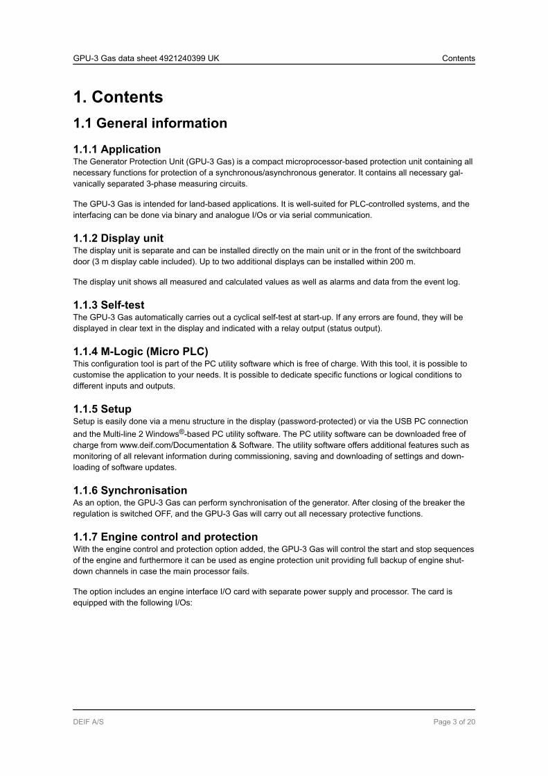
1. Contents1.1 General information
1.1.1 ApplicationThe Generator Protection Unit (GPU-3 Gas) is a compact microprocessor-based protection unit containing allnecessary functions for protection of a synchronous/asynchronous generator. It contains all necessary gal-vanically separated 3-phase measuring circuits.
The GPU-3 Gas is intended for land-based applications. It is well-suited for PLC-controlled systems, and theinterfacing can be done via binary and analogue I/Os or via serial communication.
1.1.2 Display unitThe display unit is separate and can be installed directly on the main unit or in the front of the switchboarddoor (3 m display cable included). Up to two additional displays can be installed within 200 m.
The display unit shows all measured and calculated values as well as alarms and data from the event log.
1.1.3 Self-testThe GPU-3 Gas automatically carries out a cyclical self-test at start-up. If any errors are found, they will bedisplayed in clear text in the display and indicated with a relay output (status output).
1.1.4 M-Logic (Micro PLC)This configuration tool is part of the PC utility software which is free of charge. With this tool, it is possible tocustomise the application to your needs. It is possible to dedicate specific functions or logical conditions todifferent inputs and outputs.
1.1.5 SetupSetup is easily done via a menu structure in the display (password-protected) or via the USB PC connectionand the Multi-line 2 Windows®-based PC utility software. The PC utility software can be downloaded free ofcharge from www.deif.com/Documentation & Software. The utility software offers additional features such asmonitoring of all relevant information during commissioning, saving and downloading of settings and down-loading of software updates.
1.1.6 SynchronisationAs an option, the GPU-3 Gas can perform synchronisation of the generator. After closing of the breaker theregulation is switched OFF, and the GPU-3 Gas will carry out all necessary protective functions.
1.1.7 Engine control and protectionWith the engine control and protection option added, the GPU-3 Gas will control the start and stop sequencesof the engine and furthermore it can be used as engine protection unit providing full backup of engine shut-down channels in case the main processor fails.
The option includes an engine interface I/O card with separate power supply and processor. The card isequipped with the following I/Os:
GPU-3 Gas data sheet 4921240399 UK Contents
DEIF A/S Page 3 of 20
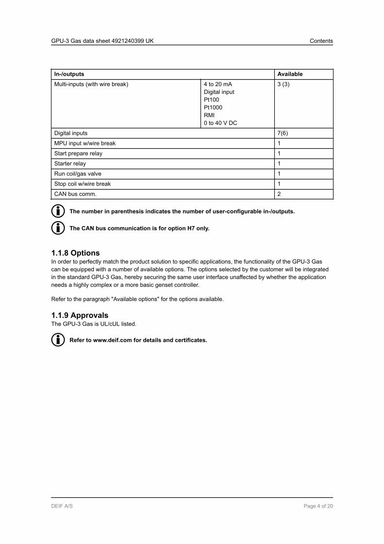
In-/outputs Available
Multi-inputs (with wire break) 4 to 20 mADigital inputPt100Pt1000RMI0 to 40 V DC
3 (3)
Digital inputs 7(6)
MPU input w/wire break 1
Start prepare relay 1
Starter relay 1
Run coil/gas valve 1
Stop coil w/wire break 1
CAN bus comm. 2
The number in parenthesis indicates the number of user-configurable in-/outputs.
The CAN bus communication is for option H7 only.
1.1.8 OptionsIn order to perfectly match the product solution to specific applications, the functionality of the GPU-3 Gascan be equipped with a number of available options. The options selected by the customer will be integratedin the standard GPU-3 Gas, hereby securing the same user interface unaffected by whether the applicationneeds a highly complex or a more basic genset controller.
Refer to the paragraph "Available options" for the options available.
1.1.9 ApprovalsThe GPU-3 Gas is UL/cUL listed.
Refer to www.deif.com for details and certificates.
GPU-3 Gas data sheet 4921240399 UK Contents
DEIF A/S Page 4 of 20

1.2 Display layoutsStandard delivery
Generator Protection Unit
multi-line GPU
Self check
Ready
JUMP
INFO
Alarm
VIEW
LOG
BACK
Power
GB control (option Y5)
Generator Protection Unit
multi-line GPU
Self check
Ready
Regulator on
JUMP
INFO
Alarm
VIEW
LOG
REMOTE
LOCAL
BACK
Open Closed
Power
Engine control (option Y7)
Generator Protection Unit
multi-line GPU
Self check
Ready
JUMP
START
INFO
STOP
Alarm
VIEW
LOG
REMOTE
LOCAL
BACK
G
Run
Power
GPU-3 Gas data sheet 4921240399 UK Contents
DEIF A/S Page 5 of 20

Engine and GB control (option Y1)
Generator Protection Unit
multi-line GPU
Self check
Ready
Regulator on
JUMP
START
INFO
STOP
Alarm
VIEW
LOG
REMOTE
LOCAL
BACK
G
Open ClosedRun
Power
Additional operator panel - AOP-1 (option X3)
AOP-1
Additional operator panel - AOP-2 (option X4)
AOP-2
GPU-3 Gas data sheet 4921240399 UK Contents
DEIF A/S Page 6 of 20

1.3 Application examples
Generator protection
G
Gas engine generator set
Controller
Display
Generator/mains protection
G
Generator
breaker
(GB)
Gas engine generator set
Controller
Display
Generator protection and synchronisation
G
Gas engine generator set
Controller
Display
PLC-controlled system
G
Generator
breaker
(GB 1)
Gas engine generator set
Busbar
Controller
Display 1
G
Generator
breaker
(GB 2)
Gas engine generator set
Controller
Display 2
G
Generator
breaker
(GB 3)
Gas engine generator set
Controller
Display 3
Modbus
PLC
Load sharing line
The GPU-3 Gas can be used in simple or complex applications. The above shows very simpleapplications only, but due to the flexibility, the GPU-3 Gas can be used in all types of applica-tions.
GPU-3 Gas data sheet 4921240399 UK Contents
DEIF A/S Page 7 of 20

1.4 Hardware overview
Ethernet
787776757473 96 979594929190 9389888785 8683 8482818079
727169 70686765 6662 6359 60 615856 575553 54 645251504947464443 45 4841403837 39 42
Service port Display
Ethernet
CAN BCAN A
Power
Self check okAlarm inhibit
1
4
9
5
10
6
3
7 8
2
USB Memory
1 : The numbers in the drawing above refer to the slot numbers indicated in the table below.
Slot # Option/stand-ard
Description
1 Terminal 1-28, power supply
Standard 8 to 36 V DC supply, 11 W; 1 × status output relay; 5 × relay outputs; 2 × pulseoutputs (kWh, kvarh); 5 × digital inputs
2 Terminal 29-36, communication
H2 Modbus RTU (RS-485)
H3 Profibus DP
H8.2 External I/O modules
H9.2 Modbus RTU/ASCII (RS-232)
3 Terminal 37-64, inputs/outputs
M12 13 × digital inputs; 4 × relay outputs
4 Terminal 65-72, GOV/AVR/transducer outputs
M14.4 4 × relay outputs
E1 2 × +/-20 mA outputs
E2 2 × 0(4) to 20 mA outputs
GPU-3 Gas data sheet 4921240399 UK Contents
DEIF A/S Page 8 of 20

Slot # Option/stand-ard
Description
EF2 1 × +/-20 mA output; 1 × 0(4) to 20 mA output
EF4 1 × +/-20 mA output; 2 × relays
EF5 1 × PWM output; 1 × +/-20 mA output; 2 × relays
5 Terminal 73-89, AC measuring
Standard 3 × generator voltage; 3 × generator current; 3 × busbar/mains voltage
6 Terminal 90-97, inputs/outputs
F1 2 × 0(4) to 20 mA outputs
M13.6 7 × digital inputs
M14.6 4 × relay outputs
M15.6 4 × 4 to 20 mA inputs
7 Terminal 98-125, engine I/F
M4 8 to 36 V DC supply, 5 W; 1 × magnetic pickup (MPU); 3 × multi-inputs; 7 × digi-tal inputs, configurable; 4 × relay outputs
H7 CAN bus J1939 (requires M4)
8 Terminal 126-133, engine communication, inputs/outputs
H5 MTU (MDEC) + J1939
H6 Cummins GCS
H8.8 External I/O modules
M13.8 7 × digital inputs
M14.8 4 × relay outputs
M15.8 4 × 4 to 20 mA inputs
9 LED & I/F
Standard Display connection; service port (USB); power LED; self check LED; alarm in-hibit LED; EtherNet (option N) LED
10 EtherNet
N Modbus TCP/IP; EtherNet/IP; SMS/e-mail alarms
There can only be one hardware option in each slot. For example, it is not possible to selectoption H2 and option H3 at the same time, because both options require a PCB in slot #2.
Besides the hardware options shown above, it is possible to select the software options men-tioned in the paragraph "Available options".
GPU-3 Gas data sheet 4921240399 UK Contents
DEIF A/S Page 9 of 20

1.5 Technical information and dimensions
1.5.1 Technical specifications
Accuracy Class 1.0-25 to 15 to 30 to 70 °CTemperature coefficient: +/-0.2 % of full scale per 10 °C
Positive, negative and zero sequence alarms: class 1 within 5 % voltage unbalanceClass 1.0 for negative sequence currentFast over-current: 3 % of 350 %*InAnalogue outputs: class 1.0 according to total rangeOption EF4/EF5: class 4.0 according to total rangeTo IEC/EN 60688
Operatingtempera-ture
-25 to 70 °C (-13 to 158 °F)With option N: -25 to 60 °C (-13 to 140 °F)(UL/cUL Listed: max. surrounding air temperature: 55 °C/131 °F)
Storagetempera-ture
-40 to 70 °C (-40 to 158 °F)
Climate 97 % RH to IEC 60068-2-30
Operatingaltitude
0 to 4000 m above sea levelDerating 2001 to 4000 m above sea level:Max. 480 V AC phase-phase 3W4 measuring voltageMax. 690 V AC phase-phase 3W3 measuring voltage
Measuringvoltage
100 to 690 V AC +/-20 %(UL/cUL Listed: 600 V AC phase-phase)Consumption: max. 0.25 VA/phase
Measuringcurrent
-/1 or -/5 A AC(UL/cUL Listed: from CTs 1-5 A)Consumption: max. 0.3 VA/phase
Currentoverload
4 × In continuously20 × In, 10 sec. (max. 75 A)80 × In, 1 sec. (max. 300 A)
Measuringfrequency
30 to 70 Hz
Aux. sup-ply
Terminals 1 and 2: 12/24 V DC (8 to 36 V continuously, 6 V 1 sec.). Max. 11 W consumptionBattery voltage measurement accuracy: ±0.8 V within 8 to 32 V DC, ±0.5 V within 8 to 32 VDC @ 20 °CTerminals 98 and 99: 12/24 V DC (8 to 36 V continuously, 6 V 1 sec.). Max. 5 W consump-tionThe aux. supply inputs are to be protected by a 2 A slow-blow fuse(UL/cUL Listed: AWG 24)
GPU-3 Gas data sheet 4921240399 UK Contents
DEIF A/S Page 10 of 20

Digital in-puts
Optocoupler, bi-directionalON: 8 to 36 V DCImpedance: 4.7 kΩOFF: <2 V DC
Analogueinputs
0(4) to 20 mAImpedance: 50 Ω. Not galvanically separatedRPM (MPU): 2 to 70 V AC, 10 to 10000 Hz, max. 50 kΩ
Multi-in-puts
0(4) to 20 mA: 0 to 20 mA, +/-1 %. Not galvanically separatedBinary: max. resistance for ON detection: 100 Ω. Not galvanically separatedPt100/1000: -40 to 250 °C, +/-1 %. Not galvanically separated. To IEC/EN 60751RMI: 0 to 1700 Ω, +/-2 %. Not galvanically separatedV DC: 0 to 40 V DC, +/-1 %. Not galvanically separated
Relay out-puts
Electrical rating: 250 V AC/30 V DC, 5 A. (UL/cUL Listed: 250 V AC/24 V DC, 2 A resistiveload)Thermal rating @ 50 °C: 2 A: continuously. 4 A: ton = 5 sec., toff = 15 sec.(Unit status output: 1 A)
Open col-lector out-puts
Supply: 8 to 36 V DC, max. 10 mA
Analogueoutputs
0(4) to 20 mA and +/-25 mA. Galvanically separated. Active output (internal supply). Loadmax. 500 Ω. (UL/cUL Listed: max. 20 mA output)Update rate: transducer output: 250 ms. Regulator output: 100 ms
Galvanicseparation
Between AC voltage and other I/Os: 3250 V, 50 Hz, 1 min.Between AC current and other I/Os: 2200 V, 50 Hz, 1 min.Between analogue outputs and other I/Os: 550 V, 50 Hz, 1 min.Between binary input groups and other I/Os: 550 V, 50 Hz, 1 min.
GPU-3 Gas data sheet 4921240399 UK Contents
DEIF A/S Page 11 of 20

Responsetimes(Delay setto min.)
Busbar:Over-/under-voltage: <50 msOver-/under-frequency: <50 msVoltage unbalance: <200 ms
Generator:Reverse power: <200 msOver-current: <200 msFast over-current: <40 msOver-/under-voltage: <200 msOver-/under-frequency: <300 msOverload: <200 msCurrent unbalance: <200 msVoltage unbalance: <200 msReact. power import: <200 msReact. power export: <200 msOverspeed: <400 msDigital inputs: <250 msEmergency stop: <200 msMulti-inputs: <800 msWire failure: <600 ms
Mains:df/dt (ROCOF): <130 ms (4 periods)Vector jump: <40 msPositive sequence: <60 ms
Mounting DIN-rail mount or base mount with six screws
Safety To EN 61010-1, installation category (over-voltage category) III, 600 V, pollution degree 2To UL 508 and CSA 22.2 no. 14-05, over-voltage category III, 600 V, pollution degree 2
EMC/CE To EN 61000-6-2, EN 61000-6-4, IEC 60255-26
Vibration 3 to 13.2 Hz: 2 mmpp. 13.2 to 100 Hz: 0.7 g. To IEC 60068-2-6 & IACS UR E1010 to 60 Hz: 0.15 mmpp. 60 to 150 Hz: 1 g. To IEC 60255-21-1 Response (class 2)10 to 150 Hz: 2 g. To IEC 60255-21-1 Endurance (class 2)
Shock(basemount)
10 g, 11 ms, half sine. To IEC 60255-21-2 Response (class 2)30 g, 11 ms, half sine. To IEC 60255-21-2 Endurance (class 2)50 g, 11 ms, half sine. To IEC 60068-2-27
Bump 20 g, 16 ms, half sine. To IEC 60255-21-2 (class 2)
Material All plastic materials are self-extinguishing according to UL94 (V1)
Plug con-nections
AC current: 0.2 to 4.0 mm2 stranded wire. (UL/cUL Listed: AWG 18)AC voltage: 0.2 to 2.5 mm2 stranded wire. (UL/cUL Listed: AWG 20)Relays: (UL/cUL Listed: AWG 22)Terminals 98-116: 0.2 to 1.5 mm2 stranded wire. (UL/cUL Listed: AWG 24)Other: 0.2 to 2.5 mm2 stranded wire. (UL/cUL Listed: AWG 24)Display: 9-pole Sub-D femaleService port: USB A-B
GPU-3 Gas data sheet 4921240399 UK Contents
DEIF A/S Page 12 of 20

Protection Unit: IP20. Display: IP40 (IP54 with gasket: option L). (UL/cUL Listed: Type Complete De-vice, Open Type). To IEC/EN 60529
Governors Multi-line 2 interfaces to all governors including GAC, Barber-Colman, Woodward and Cum-mins. See interfacing guide at www.deif.com
Approvals Marine-approved by all major classification societies. UL/cUL Listed to UL508. UL/cUL Rec-ognized to UL2200
UL mark-ings
Wiring: use 60/75 °C copper conductors onlyMounting: for use on a flat surface of type 1 enclosureInstallation: to be installed in accordance with the NEC (US) or the CEC (Canada)
AOP-2:Maximum ambient temperature: 60 °CWiring: use 60/75 °C copper conductors onlyMounting: for use on a flat surface of type 3 (IP54) enclosure. Main disconnect must be pro-vided by installerInstallation: to be installed in accordance with the NEC (US) or the CEC (Canada)
DC/DC converter for AOP-2:Tightening torque: 0.5 Nm (4.4 lb-in)Wire size: AWG 22-14
Weight Base unit: 1.6 kg (3.5 lbs.)Option J1/J3/J6: 0.2 kg (0.4 lbs.)Option J2: 0.4 kg (0.9 lbs.)Display: 0.4 kg (0.9 lbs.)
GPU-3 Gas data sheet 4921240399 UK Contents
DEIF A/S Page 13 of 20

1.5.2 Unit dimensions in mm (inches)
Display or AOP
20.0 (0.787)
230 (9.055)
215(8.465)
115 (4.528)
15 (0.59)
16
5 (
6.4
86
)
115 (4.528)
14
4 (
5.6
69
)
220 (8.661)
11
5 (
4.5
28
)
119(4.689)
Tightening torques
220.0 (8.661)
11
5.0
(4.5
28
)
Display
20.0 (0.787)
0.7 NmScrew M3
Bossard BN5687
or similar
0.2 Nm
9P Female
Sub 0
connector
Max. 10 mm
Min. 6 mm
GPU-3 Gas data sheet 4921240399 UK Contents
DEIF A/S Page 14 of 20

1.6 Available variants
Type Variant no. Description Item no. Note
GPU-3 Gas 01 GPU-3 Gas with display 2912120220-01 + A1
GPU-3 Gas data sheet 4921240399 UK Contents
DEIF A/S Page 15 of 20

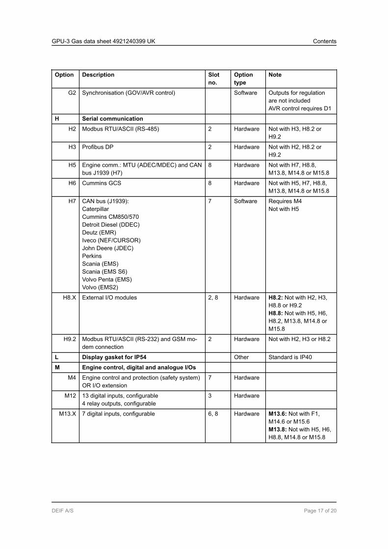
1.7 Available options
Option Description Slotno.
Optiontype
Note
A Mains protection package
A1 Time-dependent under-voltage (27t)Under-voltage and reactive power low (27Q)Vector jump (78)df/dt (ROCOF) (81)
Software
A4 Positive sequence (mains voltage low) (27D) Software
A5 Directional over-current (67) Software
C Generator add-on protection package
C2 Negative sequence voltage high (47)Negative sequence current high (46)Zero sequence voltage high (59)Zero sequence current high (50)Power-dependent reactive power import/export (40)Inverse time over-current (51)
Software
D Voltage control
D1 Voltage control Software Requires G2
E and F Analogue controller and transducer out-puts
E1 2 × +/-25 mA (GOV/AVR or transducer) 4 Hardware Not with E2, EF2, EF4,EF5 or M14.4AVR output requires D1
E2 2 × 0(4) to 20 mA (GOV/AVR or transducer) 4 Hardware Not with E1, EF2, EF4,EF5 or M14.4AVR output requires D1
EF2 1 × +/-25 mA (GOV/AVR or transducer)1 × 0(4) to 20 mA (GOV/AVR or transducer)
4 Hardware Not with E1, E2, EF4,EF5 or M14.4AVR output requires D1
EF4 1 × +/-25 mA (GOV/AVR or transducer)2 × relay outputs (GOV/AVR or configurable)
4 Hardware Not with E1, E2, EF2,EF5 or M14.4AVR output requires D1
EF5 1 × PWM (Pulse Width Modulated) output forCAT GOV1 × +/-25 mA (GOV/AVR or transducer)2 × relay outputs (GOV/AVR or configurable)
4 Hardware Not with E1, E2, EF2,EF4 or M14.4AVR output requires D1
F1 2 × 0(4) to 20 mA (transducer) 6 Hardware Not with M13.6, M14.6or M15.6
G Synchronisation
GPU-3 Gas data sheet 4921240399 UK Contents
DEIF A/S Page 16 of 20
Option Description Slotno.
Optiontype
Note
G2 Synchronisation (GOV/AVR control) Software Outputs for regulationare not includedAVR control requires D1
H Serial communication
H2 Modbus RTU/ASCII (RS-485) 2 Hardware Not with H3, H8.2 orH9.2
H3 Profibus DP 2 Hardware Not with H2, H8.2 orH9.2
H5 Engine comm.: MTU (ADEC/MDEC) and CANbus J1939 (H7)
8 Hardware Not with H7, H8.8,M13.8, M14.8 or M15.8
H6 Cummins GCS 8 Hardware Not with H5, H7, H8.8,M13.8, M14.8 or M15.8
H7 CAN bus (J1939):CaterpillarCummins CM850/570Detroit Diesel (DDEC)Deutz (EMR)Iveco (NEF/CURSOR)John Deere (JDEC)PerkinsScania (EMS)Scania (EMS S6)Volvo Penta (EMS)Volvo (EMS2)
7 Software Requires M4Not with H5
H8.X External I/O modules 2, 8 Hardware H8.2: Not with H2, H3,H8.8 or H9.2H8.8: Not with H5, H6,H8.2, M13.8, M14.8 orM15.8
H9.2 Modbus RTU/ASCII (RS-232) and GSM mo-dem connection
2 Hardware Not with H2, H3 or H8.2
L Display gasket for IP54 Other Standard is IP40
M Engine control, digital and analogue I/Os
M4 Engine control and protection (safety system)OR I/O extension
7 Hardware
M12 13 digital inputs, configurable4 relay outputs, configurable
3 Hardware
M13.X 7 digital inputs, configurable 6, 8 Hardware M13.6: Not with F1,M14.6 or M15.6M13.8: Not with H5, H6,H8.8, M14.8 or M15.8
GPU-3 Gas data sheet 4921240399 UK Contents
DEIF A/S Page 17 of 20

Option Description Slotno.
Optiontype
Note
M14.X 4 relay outputs, configurable 4, 6, 8 Hardware M14.4: Not with E1, E2,EF2, EF4 and EF5M14.6: Not with F1,M13.6 or M15.6M14.8: Not with H5, H6,H8.8, M13.8 or M15.8
M15.X 4 analogue inputs, configurable, 4 to 20 mA 6, 8 Hardware M15.6: Not with F1,M13.6 or M14.6M15.8: Not with H5, H6,H8.8, M13.8 or M14.8
N Ethernet TCP/IP communication
N Modbus TCP/IPEtherNet/IPSMS/e-mail alarms
Hardware/software
Q Measurement accuracy
Q1 Verified class 0.5 Other
Y Display layout
Y1 Engine and GB control Other Requires G2 and M4
Y5 GB control Other Requires G2
Y7 Engine control Other Requires M4
(ANSI# as per IEEE Std. C37.2-1996 (R2001) in parenthesis).
Notice that not all options can be selected for the same unit. Refer to the paragraph "Hardwareoverview" in this data sheet for further information about the location of the HW options in theunit.
GPU-3 Gas data sheet 4921240399 UK Contents
DEIF A/S Page 18 of 20

1.8 Available accessories
Type Description Item no. Note
Accessory for GPU-3 Gas Additional standard display (X2) with CAN bus 2912890030 Max. 2
Accessory for GPU-3 Gas Operator panel AOP-1 (X3) 16 LEDs, eight but-tons, one status relay, configurable
2912411070 One only
Accessory for GPU-3 Gas Operator panel AOP-2 (X4) 16 LEDs, eight but-tons, one status relay, configurable. CAN bus
2912411060 Max. 5
Accessory for GPU-3 Gas 3 m display cable (J1) 1022040076 1 pc. al-ways inclu-ded
Accessory for GPU-3 Gas 6 m display cable (J2) 1022040057
Accessory for GPU-3 Gas Crossed Ethernet cable for option N program-ming (J4)
1022040055
Accessory for GPU-3 Gas 1 m display cable (J6) 1022040064
Accessory for GPU-3 Gas 3 m USB programming cable (J7) 1022040065
Accessory for GPU-3 Gas Designer’s Reference Handbook (hard copy)(K1)
4189340584
Accessory for GPU-3 Gas CD-ROM complete documentation (K2) 2304230002
GPU-3 Gas data sheet 4921240399 UK Contents
DEIF A/S Page 19 of 20

1.9 Order specifications and disclaimer
1.9.1 Order specificationsVariants
Mandatory information Additional options to the standard variant
Item no. Type Variant no. Option Option Option Option Option
Example:
Mandatory information Additional options to the standard variant
Item no. Type Variant no. Option Option Option Option Option
2912120220-01 GPU-3 Gas 01 M4 Y1 H2
Accessories
Mandatory information
Item no. Type Accessory
Example:
Mandatory information
Item no. Type Accessory
1022040076 Accessory for GPU-3 Gas 3 m display cable (J1)
1.9.2 DisclaimerDEIF A/S reserves the right to change any of the contents of this document without prior notice.
The English version of this document always contains the most recent and up-to-date information about theproduct. DEIF does not take responsibility for the accuracy of translations, and translations might not be up-dated at the same time as the English document. If there is a discrepancy, the English version prevails.
GPU-3 Gas data sheet 4921240399 UK Contents
DEIF A/S Page 20 of 20