Generating IFC models from heterogeneous data using semantic web
17
Generating IFC models from heterogeneous data using semantic web Ebrahim Karan Department of Applied Engineering, Safety, and Technology, Millersville University, Millersville, Pennsylvania, USA Javier Irizarry Department of Building Construction, Georgia Institute of Technology, Atlanta, Georgia, USA, and John Haymaker Schools of Architecture and Building Construction, Georgia Institute of Technology, Atlanta, Georgia, USA Abstract Purpose – This paper aims to develop a framework to represent semantic web query results as Industry Foundation Class (IFC) building models. The subject of interoperability has received considerable attention in the construction literature in recent years. Given the distributed, semantically heterogeneous data sources, the problem is to retrieve information accurately and with minimal human intervention by considering their semantic descriptions. Design/methodology/approach – This paper provides a framework to translate semantic web query results into the XML representations of IFC schema and data. Using the concepts and relationships in an IFC schema, the authors first develop an ontology to specify an equivalent IFC entity in the query results. Then, a mapping structure is defined and used to translate and fill all query results into an ifcXML document. For query processing, the proposed framework implements a set of predefined query mappings between the source schema and a corresponding IFC output schema. The resulting ifcXML document is validated with an XML schema validating parser and then loaded into a building information modeling (BIM) authoring tool. Findings – The research findings indicate that semantic web technology can be used, accurately and with minimal human intervention, to maintain semantic-level information when transforming information between web-based and BIM formats. The developed framework for representing IFC-compatible outputs allows BIM users to query and access building data at any time over the web from data providers. Originality/value – Currently, the results of semantic web queries are not supported by BIM authoring tools. Thus, the proposed framework utilizes the capabilities of semantic web and query technologies to transform the query results to an XML representation of IFC data. Keywords Semantic web, BIM, Construction management, Interoperability, IFC, Query mapping Paper type Research paper Introduction A typical construction project requires integration and information sharing among different project participants and stakeholders across the various phases of the project The current issue and full text archive of this journal is available on Emerald Insight at: www.emeraldinsight.com/1471-4175.htm Generating IFC models 219 Received 18 May 2014 Revised 20 October 2014 9 December 2014 17 December 2014 Accepted 23 December 2014 Construction Innovation Vol. 15 No. 2, 2015 pp. 219-235 © Emerald Group Publishing Limited 1471-4175 DOI 10.1108/CI-05-2014-0030 Downloaded by Texas A&M University At 06:56 30 March 2015 (PT)
-
Upload
samhoustonstate -
Category
Documents
-
view
1 -
download
0
Transcript of Generating IFC models from heterogeneous data using semantic web
Generating IFC models fromheterogeneous data using
semantic webEbrahim Karan
Department of Applied Engineering, Safety, and Technology,Millersville University, Millersville, Pennsylvania, USA
Javier IrizarryDepartment of Building Construction, Georgia Institute of Technology,
Atlanta, Georgia, USA, and
John HaymakerSchools of Architecture and Building Construction,
Georgia Institute of Technology, Atlanta, Georgia, USA
AbstractPurpose – This paper aims to develop a framework to represent semantic web query results asIndustry Foundation Class (IFC) building models. The subject of interoperability has receivedconsiderable attention in the construction literature in recent years. Given the distributed, semanticallyheterogeneous data sources, the problem is to retrieve information accurately and with minimal humanintervention by considering their semantic descriptions.Design/methodology/approach – This paper provides a framework to translate semantic webquery results into the XML representations of IFC schema and data. Using the concepts andrelationships in an IFC schema, the authors first develop an ontology to specify an equivalent IFC entityin the query results. Then, a mapping structure is defined and used to translate and fill all query resultsinto an ifcXML document. For query processing, the proposed framework implements a set ofpredefined query mappings between the source schema and a corresponding IFC output schema. Theresulting ifcXML document is validated with an XML schema validating parser and then loaded into abuilding information modeling (BIM) authoring tool.Findings – The research findings indicate that semantic web technology can be used, accurately andwith minimal human intervention, to maintain semantic-level information when transforminginformation between web-based and BIM formats. The developed framework for representingIFC-compatible outputs allows BIM users to query and access building data at any time over the webfrom data providers.Originality/value – Currently, the results of semantic web queries are not supported by BIMauthoring tools. Thus, the proposed framework utilizes the capabilities of semantic web and querytechnologies to transform the query results to an XML representation of IFC data.
Keywords Semantic web, BIM, Construction management, Interoperability, IFC, Query mapping
Paper type Research paper
IntroductionA typical construction project requires integration and information sharing amongdifferent project participants and stakeholders across the various phases of the project
The current issue and full text archive of this journal is available on Emerald Insight at:www.emeraldinsight.com/1471-4175.htm
GeneratingIFC models
219
Received 18 May 2014Revised 20 October 2014
9 December 201417 December 2014
Accepted 23 December 2014
Construction InnovationVol. 15 No. 2, 2015
pp. 219-235© Emerald Group Publishing Limited
1471-4175DOI 10.1108/CI-05-2014-0030
Dow
nloa
ded
by T
exas
A&
M U
nive
rsity
At 0
6:56
30
Mar
ch 2
015
(PT
)
life cycle. This can be seen in the widespread use of different computer programs (e.g.building information modeling [BIM] tools, 4D simulation applications, etc.), which relyon a wide range of distributed data sources to model construction information. Becauseof the various domains involved in the building and construction industry, researchershave evolved the development and standardization of integrated data models over thepast 20 years, from electronic data interchange systems using a common data format tothe current sophisticated Internet services. At the lowest level of integration, users arenow able to connect to a host and publish and download project information on the web,enabling project participants to transfer data files in their native formats without theneed for specialist intervention. Such web services, which can be viewed as data orapplication interfaces, provide opportunities for exposing real-time and up-to-datebuilding information to other project participants (Underwood and Isikdag, 2011). In thenext level, which is called syntactic interoperability, users are able to directly accessdata and methods from a different software program and exchange project informationbetween heterogeneous platforms (Underwood and Watson, 2003). Syntacticheterogeneity describes the difference in representation format of data among differentdata sources. In the various models developed at this level, syntactic interoperabilityemphasizes the integration of two or more data models into a single model (Irizarry andKaran, 2012; Irizarry et al., 2013; Karimi and Akinci, 2009; Laat and Berlo, 2011).
Semantic interoperability, which makes model data sharable and understandable acrossmultiple design disciplines and heterogeneous computer systems (Yang and Zhang, 2006),provides integration at the highest level. In the construction domain, the semantic web canbe viewed as an interoperable framework for integration of data from diverse sources, whichmakes it possible for computers to manage and search project information without humanintervention (Karan and Irizarry, 2014). Publishing the construction information in asemantic web format would allow computer applications to easily discover, query and sharethe information (Karshenas and Niknam, 2013). BIM applications in modeling andinteroperability have evolved from unmanaged computer-aided design (CAD) with 2D dataexchange (the lowest level of integration) to a fully integrated, web-based process andcompliant with Industry Foundation Class (IFC) standard (iBIM or integrated BIM).Semantic interoperability allows the data providers and the users to access, relate andcombine information from multiple, heterogeneous sources and therefore increases the valueof information (Cheng et al., 2008).
Once a building is modeled in a BIM authoring tool and the result is formattedaccording to the semantic web standard, the building model can be enriched byintegrating domain-specific ontologies (Abanda et al., 2013). Thus, the enriched BIMmodel can be consumed in a variety of ways by humans and machines. Given theoverwhelming quantity of data available from multiple sources, the BIM is only one siloof project data. The use of other relevant information, which may also exist in silos,becomes increasingly difficult with a lack of interoperability (Curry et al., 2013). Instead,it is worthwhile to expose these data in a format that can be shared throughout thebuilding’s life cycle and among various professional domains. By exposing such data inone of the fundamental standards of the semantic web, it is possible to create linksbetween them and provide a cloud of interconnected data (Corry et al., 2013).
The decision-making process in a construction project is based on availableinformation (usually extracted from different sources) coupled with the domainknowledge possessed by an individual. Each representation of an object or input in the
CI15,2
220
Dow
nloa
ded
by T
exas
A&
M U
nive
rsity
At 0
6:56
30
Mar
ch 2
015
(PT
)

individual’s mind can be tagged with a meaning. When making a decision, it is often notenough to merely access information; rather, it is necessary to understand the meaningof the acquired information. Figure 1 illustrates the current problem with a simpleexample in which the data captured by a 3D laser scanner are brought into a BIM tool,namely, Autodesk© Revit Architecture. Obviously, the transferring of the scanned datain their native formats, which is the lowest level of integration, is not efficient at all. Thedata are transferred by CSV (comma-separated values) data format including x, y andz-coordinate of each captured point; however, their precise meaning is not understood bythe BIM platform. At this level of integration (i.e. syntactic interoperability), differentclasses (e.g. light pole, terrain and tree) in the point cloud model are considered identicalin a building information model (terrain model in this example). A higher level ofintegration (i.e. semantic interoperability) is needed to share information and theirmeanings with the BIM data set.
Fu et al. (2007) demonstrated the importance of interoperability in life cycle costing,especially when dealing with building components in a BIM environment. McGraw Hillreleased a report in 2009 that stated a lack of interoperability between softwareapplications at the top of the list of areas that need to be addressed to fully realize thebenefits of BIM (Young et al., 2009). The use of ontologies that are developedsemantically (i.e. constructed with semantic data formats) enables BIM users to accessthe content of these distributed data sources and incorporate them into their buildingmodel. The ontologies provide a rich set of semantics about the particular domain ofinterest Balachandar et al. (2013a, 2013b). The semantics from the data provider and thedata user must be captured and understood to exchange data between them (Venugopalet al., 2012). As this study mainly focuses on achieving interoperability at the semanticlevel, it is assumed that data are provided in the semantic web data format. An ontologymapping approach is proposed to define the relationships between two sets of semanticsand depict the similarity of a pair of concepts. The research targets academic andindustry groups as well as software developers working with BIM models, and enablesmore precise representations of building-related information in BIM environments toenable better decision-making.
Query-based approaches for information retrievalA query language is needed to retrieve and manipulate data stored in semantic web dataformat. SPARQL (Protocol and RDF Query Language, pronounced “sparkle”) is thestandardized query language for semantic web, which retrieves and manipulates the
Figure 1.Data transfer with
possible loss ofsemantics (identicalmodels for different
objects)
221
GeneratingIFC models
Dow
nloa
ded
by T
exas
A&
M U
nive
rsity
At 0
6:56
30
Mar
ch 2
015
(PT
)

data stored in data models that are formatted using semantic web standards. Althoughthere are several formats to represent the SPARQL query results, there is no universallyaccepted standard that is compatible with existing BIM tools to represent theinformation. The results of SPARQL queries can be displayed as HTML (HyperTextMarkup Language), CSV, Spreadsheet or JSON (an acronym for JavaScript ObjectNotation and as a lightweight data-interchange format), none of which is compatiblewith existing BIM tools. To overcome this limitation, this paper focuses on thedevelopment of a process for query and access to ontology-based web services thatconverts query results from SPARQL into ifcXML, to allow BIM users to query andretrieve building data at any time over the web from heterogeneous data providers.
Although query-based approaches have received considerable attention, very littleresearch has been conducted in the construction industry for extracting and retrievingbuilding-related information for BIM applications. Figure 2 shows the gap in theexisting literature, the researchers have focused mostly on the extraction and queryingof information from BIM. Examples of these efforts include the Partial Model QueryLanguage (Adachi, 2003) and the Product Model Query Language of the EuroStepModel Server, both provide query support for the retrieval of IFC properties and spatialrelationships. Borrmann et al. (2006) provided formal definitions for 3D spatial datatypes as well as the directional, topological, metric and Boolean operators to outline theimplementation of spatial query language for BIMs. Nepal et al. (2012) described theprocess and methods of extracting spatial data directly from a BIM model andrepresenting it in a common Extensible Markup Language (XML) format. Mazairac andBeetz (2013) introduced BIMQL (Building Information Model Query Language), anextendable, open, domain-specific query language for building information models toallow the selection and partial modification of model instances. But a question remains:How to bring the query results into the BIM model? The next section gives a briefoverview of common interoperable formats for exchanging building andconstruction-related data. This is followed by a description of the research methodologyadopted in carrying out the study.
Interoperable formats for exchanging dataIFC is the most well-known interoperable format for the uniform representation andexchange of project information throughout the construction community. Developed byBuildingSMART®, the IFC facilitates software interoperability for buildings and
Figure 2.Query-basedapproaches andtrends in the existingBIM literature
CI15,2
222
Dow
nloa
ded
by T
exas
A&
M U
nive
rsity
At 0
6:56
30
Mar
ch 2
015
(PT
)

architecture (Yang, 2003). It provides methods to define building objects (beam, column,wall, slab, etc.), with associated attributes, properties and other information in a publiclyavailable data schema (Eastman et al., 2009). The IFC has become a de facto standard forthe industry during the recent period of widespread adoption of BIM. In addition tonormal attributes that are used to define an IFC element, there are attributes that giveadditional information about the element but whose value is optional (not alwaysneeded and can be assigned a null value). The IFC was designed and written using theEXPRESS schema that includes building objects and relationships between them.These building objects are defined by a hierarchical entity structure, in which objects (orentities) are related by subtype/supertype relationships and/or by attributes. Anattribute is declared by a name and a data type. The data type defines the format of theattribute value. The attribute values are used to further specify the semantics ofthe properties assigned to the IFC entities. These explicit attributes along with theconstraints and structure of IFC document are defined in a schema.
Although IFC is a versatile standard, it has been developed to support the frequentexchange of data between interrelated participants within the building constructionprocess. There might be the need for the exchange of large volumes of data over widearea networks, such as the Internet. The use of XML and its related technologies canovercome the aforementioned problems by exchanging large volumes of data in astandardized structure (Bakis et al., 2007). The construction industry has recognized theimportance of XML technology applications in sharing and exchanging structured databetween different parties. AecXML to cover resource and activity-related datainterchange, TransXML for the transportation data exchange, LandXML for survey androad design schemas and DiggsML as a geotechnical construction data interchangestandard are some of the standards developed by national/international consortiums toprovide the industry with international data interchange standards (Agdas and Ellis,2010). In the XML schema, data types are used to classify a variable, or object, and itsattributes (e.g. Boolean, integer, etc.) and constraints (expressed by axioms) are used fordescribing the structure and contents of XML documents.
Similar to the role of IFC in the construction industry to exchange and share databetween BIM applications, the semantic web uses the Resource Description Framework(RDF) and Web Ontology Language (OWL) as standard data exchange formats torepresent and share information in machine- and human-readable form. The RDF datamodel represents a relationship (or a predicate that donates a relationship) between asubject and an object. These three statements are often referred to as “RDF triples”. Asan example, “The light pole is made of steel” can be represented in RDF as this collectionof triples; a subject defines “light pole”, a predicate specifies “is made of” and an objectspecifies “steel”. The RDF schema, or ontology, adds the semantics and RDF triples(even from other ontologies) to data. In addition, each concept (subject or object) andrelation may be labeled with a short string, a Unique Resource Identifier (URI), therebymaking the RDF graph explicitly labeled. The usage of URIs in RDF enables thedescription of information in very diverse and disparate groups while preserving itsoriginal interrelations (Pauwels et al., 2011) and makes it possible to identify thingsuniquely and globally. This is in contrast to syntax (e.g. XML) where the uniqueidentifiers are unique within the document. These two primary strengths of RDF/OWLaid in supporting information integration and facilitating interoperability. Thus, theproposed framework utilizes the capabilities of ontology languages to represent RDF
223
GeneratingIFC models
Dow
nloa
ded
by T
exas
A&
M U
nive
rsity
At 0
6:56
30
Mar
ch 2
015
(PT
)

query results as IFC building models. Some researchers have used RDF/OWL notationof IFC in the Architecture Engineering and Construction (AEC) domain context. Forinstance, Beetz et al. (2006) demonstrated a use-case for the application of semantic webin the AEC domain. Similarly, Schevers et al. (2007) developed a prototype frameworkfor automated converting of IFC semantic objects to OWL forms. Even with furtherimprovements in these prototypes, a key question remains unanswered: How to retrievethe data available in RDF/OWL forms into a BIM model? To answer this question, thefocus of this paper is on translating data available in RDF/OWL forms into the XMLrepresentations of the IFC schema and data.
Research methodologyThis research aims to bridge the heterogeneity gap between semantic data available asOWL or RDF graphs and BIM tools by developing an interoperable framework thattranslates SPARQL queries to semantically equivalent IFC entities. Current approachesto meet the needs of information exchange and sharing among the various professionalsinvolved in a construction project require multiple levels of data translation andinterpretation. In addition to the loss of information when a translation is performed,there is also human intervention required to convert the data and then interpret thesemantics of acquired data. Although keywords in a query still play an important role inthe proposed framework, as the users need to formulate queries, the methodautomatically converts the query results into the ifcXML schema.
This research builds on and extends the previous studies on semanticinteroperability between BIM and geographic information system (GIS). The overallframework of semantic web application for BIM and GIS integration involves ontologyconstruction (compatible with IFC schema), mapping between XML and IFC schema,selecting equivalent ontology constructs and representing query results information asifcXML building models. Figure 3 demonstrates the process of translating SPARQLqueries to their equivalent IFC entities and the activities supported by each stage. Themain focus of this paper is on Steps 3-5; however, a brief description of the first two stepsis described.
Step Process Output
Describing the semantics of building data and their relations based on IFC.
Determining correspondences between BIM and GIS concepts and depict whether they are similar or not.
Retrieving the heterogeneity data stored in the standard data models.
Translating query results into the XML representations of the IFC schema and data.
Validating the completeness of the framework through use case examples.
OntologyConstruction
OntologyMapping
SPARQL Query
Manipulation
BIM Ontology
Evaluation
Shared BIM-GIS Ontology
XML Query Results
IFC-Compatible Query Results
BIM Data with their Semantics
Figure 3.Components of theframework and theiroutputs
CI15,2
224
Dow
nloa
ded
by T
exas
A&
M U
nive
rsity
At 0
6:56
30
Mar
ch 2
015
(PT
)
In addition to syntax and structure, there might be major differences in meaning (orsemantics) between RDF or OWL data and IFC data models. Therefore, decision makersneed to have domain knowledge and be able to interpret the semantics from the dataprovider to use them in a BIM environment. For instance, two schemas may contain a“Vegetation” object, but the data provider’s definition of “Vegetation” can be different fromits meaning in the target schema (e.g. IFC schema). In addition to the concepts with similarname but different meaning, they may have the similar meaning but different names such asElevation and Altitude. In many cases, semantics used by the data providers do notnecessarily match those used by BIM tools. To achieve this, the proposed framework asksdecision makers to define a set of mappings between OWL/RDF ontologies and the IFCEXPRESS schema to transform the original SPARQL query results to a set of outputs whichare semantically meaningful in terms of the BIM application.
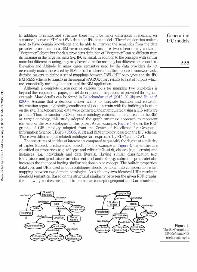
Although a complete discussion of various tools for mapping two ontologies isbeyond the scope of this paper, a brief description of the process is provided through anexample. More details can be found in Balachandar et al. (2013, 2013b) and Hu et al.(2005). Assume that a decision maker wants to integrate location and elevationinformation regarding existing conditions of jobsite terrain with the building’s locationon the site. The topographic data were extracted and manipulated using a GIS softwareproduct. Thus, to transform GIS or source ontology entities and instances into the BIMor target ontology, this study adopted the graph structure approach to representelements of the two ontologies in this paper. As an example, Figure 4 shows the RDFgraphs of GIS ontology adopted from the Center of Excellence for GeospatialInformation Science (CEGIS) (USGS, 2013) and BIM ontology, based on the IFC schema.These two different (but related) ontologies are expressed by RDF(s) and OWL.
The structures of entities of interest are compared to quantify the degree of similarityof triples (subject, predicate and object). For the example in Figure 4, the entities areclassified as properties (e.g. rdf:type and rdfs:subClassOf), classes (e.g. Terrain) andinstances (e.g. individuals and data literals). Having similar classification (e.g.RefLatitude and geo:latitude are class entities) and role (e.g. subject or predicate) alsoincreases the chance of having similar relationship or concept. The built-in properties,datatypes and URIs used in both ontologies should be taken into consideration whenmapping between two domain ontologies. As such, any two identical URIs results inidentical semantics. Based on the structural similarity between the given RDF graphs,the following entities are found to be similar concepts: geopoint and CartesianPoint,
Figure 4.The RDF graphs of
BIM (left) and GIS(right) ontologies
225
GeneratingIFC models
Dow
nloa
ded
by T
exas
A&
M U
nive
rsity
At 0
6:56
30
Mar
ch 2
015
(PT
)
GeoNames and GlobalId, geo:latitude and RefLatitude, geo:longitude and Ref Longitudeand geo:altitude and RefElevation.
Developing the target ontology instances is a necessary step for ontology mappingand integration. At this stage, Protégé 4.3 is used to create and visualize the ontologylanguages and, therefore, define how classes or entities are associated with each other.Protégé is one of the oldest and most widely deployed ontology editing tools that is nowwidely used for RDF modeling. This study developed the ontology based on theEXPRESS schema to capture the contextual information of each IFC element, as well asattributes and properties. For each IFC element in EXPRESS, a corresponding OWLclass is generated. Accordingly, the attributes and properties are converted into theappropriate OWL attributes and properties.
An example of this transformation is shown in Figure 5, where an IFC element inEXPRESS schema is transformed into ontology format written in OWL and presentedas RDF graph. As shown in the EXPRESS data model in Figure 5, “Subject” is used forthe modeling of a physical element such as building, “Property” is used to assignattribute (e.g. Name, CompositionType) to the subject (i.e. building) and “Value” or“Individual” is used to further specify the property’s value. A corresponding owl:Classshould be created in the ontology for each ENTITY definition in the EXPRESS schema.The proposed methodology used datatype properties to describe the relations betweenindividuals and literal data (e.g. string, numbers, datatypes) and object properties torelate individuals to other individuals. For instance, the “CompositionType” propertyrelates “IfcBuilding” to string values. This study introduced “hasAttribute” property,which relates an “IfcBuilding” to a “CompositionType”. There are some properties thatshould be defined as an IFC entity. Thus, “rdfs:isDefinedBy” is used to state that aresource (e.g. BuildingAddress) is defined by an IFC entity (e.g. IfcPostalAddress). Apart of IFC ontology and its RDF graph is displayed in Figure 5.
A target ontology enables us to generate IFC values and individuals as RDFinstances. It is assumed that the intended meanings of building data and properties arespecified through ontological definitions in a semantic web’s formal language, such asOWL or RDF schema. Therefore, one can use an OWL/RDF query language (i.e.SPARQL) to access distributed OWL/RDF data sources. XML is perhaps the mostreadable format for the SPARQL query results that is compatible with the BIM tools.This paper adopted the concept of integrity constraints in the query translationtechnique to guarantee consistency of data during query processing and return correctresults to BIM users. For instance, a “PRIMARY key” constraint is represented asfunctional property axiom, because a functional property can have only one (unique)value for each instance. A NOT NULL constraint is used to ensure that an ifcXML entitycannot have NULL value for normal attributes. A UNIQUE Constraint is used to ensurethat all property’s values (or individuals) are different.
A SPARQL query consists of a set of triples like RDF triples except that each of the subject,predicate and object may be a variable. A typical SPARQL query looks something like:
“select DISTINCT ?subject ?property ?value WHERE {?subject rdfs:subClassOfSpatialStructureElement. ?subject ?property ?value.}.
This query would return the property and value components of subjects defined assubclass of SpatialStructureElement class in the data set. A SPARQL query’s WHEREclause describes the data to pull out of a data set, and the URIs in RDF triples are
CI15,2
226
Dow
nloa
ded
by T
exas
A&
M U
nive
rsity
At 0
6:56
30
Mar
ch 2
015
(PT
)

necessary to identify which data to retrieve. The DISTINCT keyword prevents theSPARQL processor from showing duplicate answers. Other SPARQL query keywords,such as CONSTRUCT, FILTER and OPTIONAL, may also be used for giving the querythe flexibility to retrieve data that may or may not match every single triple pattern.This step of the framework requires users to formulate appropriate queries. Forinstance, the user should formulate queries such as:
Select * WHERE { ?supplier spatial:nearby (construction site location goes here “distancegoes here”) ?supplier rdfs:label ?label }, to retrieve the location information of supplierswithin specific distance from the construction site. If the user does not know how toformulate the query, the user can use a general query like:
<owl:Classrdf:about = "IfcBuilding">
<rdfs:subClassOfrdf:resource = "IfcSpatialStructureElement"/>
</owl:Class>
… <owl:DatatypePropertyrdf:about = "CompositionType">
<rdfs:domainrdf:resource = "IfcBuilding"/>
<rdfs:rangerdf:resource = "&xsd;string"/>
</owl:DatatypeProperty>
<owl:ObjectPropertyrdf:ID = "hasAttribyte">
<rdfs:domainrdf:resource = "IfcBuilding"/>
<rdfs:rangerdf:resource = "CompositionType">
</owl:ObjectProperty>
<owl:DatatypePropertyrdf:about = "BuildingAddress">
<rdfs:domainrdf:resource = "IfcBuilding"/>
<rdfs:isDefinedByrdf:resource = "IfcPostalAddress"/>
</owl:DatatypeProperty>
ENTITY Building;
SUBTYPE OF (SpatialStructureElement);
Name :OPTIONAL STRING;
CompositionType:STRING;
BuildingAddress:OPTIONAL IfcPostalAddress; …
END_ENTITY;END_ENTITY;
Subject
Property (Attribute)
Data Type
Data Type
SubjectPredicate
Object
Figure 5.EXPRESS entity
(top) transformationinto OWL ontology
(middle) and RDFgraph (bottom)
227
GeneratingIFC models
Dow
nloa
ded
by T
exas
A&
M U
nive
rsity
At 0
6:56
30
Mar
ch 2
015
(PT
)

SELECT ?subject ?property ?object WHERE{ ?subject ?property ?object. }, to list allsubject–property– object triples. Obviously, if the query does not retrieve the appropriateinformation, the translation approach would be impractical. The results of SPARQLqueries should be displayed as XML. In this section, a description of the frameworkdeveloped for converting the query results from SPARQL into ifcXML is provided.
Regardless of the form in which query results may be presented, an ifcXML documentshall contain header information and pre-defined information structure (e.g. unit(s) ofserialization, EXPRESS entities and attributes for the ifcXML documents, etc.). Thus, asingle root element (i.e. �ifc:uos […]�) is defined at the top level of an ifcXML documentthat contains other elements. This root element defines the XML namespace, schemaand other configurations. Each element should be written between its opening andclosing angle brackets, marking the beginning and ending of the element. For instance,IfcOrganization that is defined by a “Name” attribute (as a normal attribute) should bewritten as �IfcOrganization� �Name� […] �/Name� �/IfcOrganization�. XMLelements can have attributes that provide additional information about the elements.Each of the XML attributes can be defined as a Property in an IFC document. However,IFC attributes are represented as elements in XML. Thus, �Name� element in theabove example is an attribute for the IfcOrganization entity. One way to differentiate anentity and its attributes in the ifcXML is to assign a unique identifier code to the XMLelement. This is done by using an id attribute. An attribute has a label and a value inquotes. Therefore, the IfcOrganization entity can be represented as �IfcOrganizationid�“[…]”� �Name� […] �/Name� �/IfcOrganization�. It is possible to referenceanother element that is declared elsewhere by using a ref or href attribute. In this case, theelement should also have the xsi:nil�“true” attribute to show that the element does not haveany content (e.g. �IfcOrganization xsi:nil�“true” ref�“[…]”/�). Any id value referenced bya ref (or even href) attribute should exist in the same document. All the values for an IFCentity should be declared as the XML element’s content. If the string value for the Nameattribute is “Autodesk Revit”, it should be declared like �Name�AutodeskRevit�/Name�. The ifcXML files should be checked for consistency against such grammarand syntax.
To perform the conversion between XML results and ifcXML, this research dividedthe IFC attributes into three groups, according to their properties: leaf node, simple typeand complex type. A leaf node attribute is an attribute of the IFC hierarchy/tree structurethat has zero child nodes or attributes. The “value” is the only parameter required todefine the leaf node attribute. Continuing with the above example, the IfcOrganizationentity has two leaf node attributes: name and description. The values (e.g. AutodeskRevit as a string value) are the only parameters needed for defining these two leaf nodeattributes. A simple type attribute is defined by an IFC entity. In this way, the IFC entityacts as an attribute value. For instance, IfcPersonAndOrganization has two simple-typeattributes, ThePerson and TheOrganization, which are defined by IFCPerson andIFCOrganization entities, respectively. If the IFC entity is declared elsewhere, thesimple-type attribute should be declared like �TheOrganization� �IfcOrganizationxsi:nil�“true” ref�“[…]”/� �/TheOrganization�. A complex-type attribute has one ormore sub-attributes that describe the properties and values. In addition, the distinct listor ordered sequence of sub-attributes is declared by “Concept Type” or “C-Type”. Forinstance, IfcCartesianPoint has one complex type attribute, Coordinates, which isdefined with a list of 1 to 3 sub-attributes (i.e. IfcLengthMeasure). Having the values of
CI15,2
228
Dow
nloa
ded
by T
exas
A&
M U
nive
rsity
At 0
6:56
30
Mar
ch 2
015
(PT
)
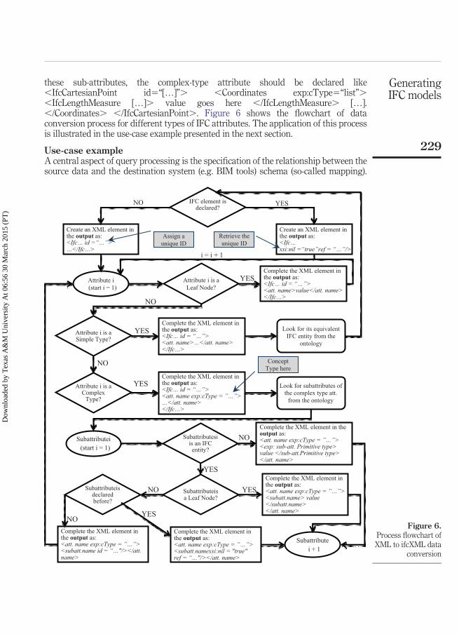
these sub-attributes, the complex-type attribute should be declared like�IfcCartesianPoint id�“[…]”� �Coordinates exp:cType�“list”��IfcLengthMeasure […]� value goes here �/IfcLengthMeasure� […].�/Coordinates� �/IfcCartesianPoint�. Figure 6 shows the flowchart of dataconversion process for different types of IFC attributes. The application of this processis illustrated in the use-case example presented in the next section.
Use-case exampleA central aspect of query processing is the specification of the relationship between thesource data and the destination system (e.g. BIM tools) schema (so-called mapping).
IFC element is declared?
Create an XML element in the output as: <Ifc… id =“…”> …</Ifc…>
Create an XML element in the output as:<Ifc…xsi:nil =“true”ref = “…”/>
Assign a unique ID
Retrieve the unique ID
NO YES
Attribute i (start i = 1)
Attribute i is a Leaf Node?
Complete the XML element in the output as: <Ifc… id = “…”><att. name>value</att. name></Ifc…>
i = i + 1
YES
Attribute i is a Simple Type?
NO
Complete the XML element in the output as: <Ifc… id = “…”><att. name>…</att. name></Ifc…>
YESIFC entity from the
ontology
Attribute i is a Complex
Type?
NO
Complete the XML element in the output as: <Ifc… id = “…”><att. name exp:cType = ”…”> …</att. name></Ifc…>
YES
Concept Type here
Look for subattributes ofthe complex type att.
from the ontology
Subattributei (start i = 1)
Subattributesiis an IFC entity?
Complete the XML element in the output as: <att. name exp:cType = ”…”> <exp: sub-att. Primitive type> value </sub-att.Primitive type> </att. name>
NO
Subattributeisa Leaf Node?
YESComplete the XML element in the output as: <att. name exp:cType = ”…”><subatt.name> value </subatt.name></att. name>
YESSubattributeisdeclared before?
NO
Complete the XML element in the output as: <att. name exp:cType = ”…”><subatt.namexsi:nil = "true" ref = “…"/></att. name>
Complete the XML element in the output as: <att. name exp:cType = ”…”><subatt.name id = “…"/></att. name>
NOYES
Subattributei + 1
Look for its equivalent
Figure 6.Process flowchart ofXML to ifcXML data
conversion
229
GeneratingIFC models
Dow
nloa
ded
by T
exas
A&
M U
nive
rsity
At 0
6:56
30
Mar
ch 2
015
(PT
)

Once an equivalent IFC entity is specified, its required attributes and related entities areadded to a predefined container structure including header information and unit(s) ofserialization. Then, each set of query results is converted into the XML equivalent to theEXPRESS-based specification, called ifcXML. A mapping process between the XMLquery results and the ifcXML data structure is designed and documented. The proposedmapping model specifies the relationships between XML and ifcXML data models in acomputer-interpretable form.
Table I shows the query results in XML formats and their equivalent ifcXML entities.Entity IFCPerson has two leaf node attributes (FamilyName and GivenName) and it isnot declared. Thus, an XML element is created in the output as �IfcPersonid�“i1000”� […] �/IfcPerson�. As the entity is not previously declared, it is given aunique identifier (i.e. id�“i1000”). The conversion process starts with the first attribute(i.e. FamilyName) that is a leaf node attribute. Therefore, the XML element is completedin the output as �IfcPerson id�“i1000”� �FamilyName� Karan �/FamilyName��/IfcPerson�, where FamilyName is the attribute name and Karan is the attributevalue. Entity IFCPerson can be specified once this process is repeated for all attributes.Although not shown in Table I, the GivenName attribute can be similarly converted andadded to the IFCPerson entity.
Entity IfcPersonAndOrganization has two simple type attributes (ThePerson isdefined by IFCPerson and TheOrganization is defined by IfcOrganization) and it is notdeclared elsewhere. Thus, an XML element is created in the output as�IfcPersonAndOrganization id�“i1100”� […] �/ IfcPersonAndOrganization�. Asthe entity is not declared before, it is given a unique identifier (i.e. id�“i1100”). Theconversion process starts with the first attribute (i.e. ThePerson) that is a simple-typeattribute. Therefore, the XML element is completed in the output as�IfcPersonAndOrganization id�“i1100”� �ThePerson� […] �/ThePerson��/ IfcPersonAnd-Organization�, where ThePerson is the attribute name. EntityIFCPerson is already declared, so the previously declared id is returned (i.e. �IfcPersonxsi:nil�“true” ref�“i1000”/�). Although not shown in Table I, the TheOrganizationattribute can be similarly converted and added to the IfcPersonAndOrganization entity.The only difference is that, in the TheOrganization attribute, the IfcOrganization entityand its two leaf node attributes (i.e. Name and Description) should be defined within theTheOrganization attribute itself, as they are not declared previously.
Entity IfcDirection has one complex-type attribute, DirectionRatios, which is definedwith a list of two to three sub-attributes. As the IFC entity is not declared elsewhere, anXML element is created in the output as �IfcDirection id�“i1200”� […]�/ IfcDirection� and assign a unique identifier (i.e. id�“i1200”). The DirectionRatiosattribute is a complex-type attribute with Concept Type (cType) of list, so the XMLelement was completed in the output as �IfcDirection id�“i1200”� �DirectionRatiosexp:cType�“list”� […] �/DirectionRatios� �/IfcDirection�. It has twosub-attributes, none of them is IFC entity and their primitive type is “double”. Therefore,the XML element is completed in the output as �IfcDirection id�“i1200”��DirectionRatios exp:cType�“list”� �exp:double pos�“0”�6.12E-17�/exp:double� �exp:double pos�“1”�1. �/exp:double� �/DirectionRatios��/IfcDirection�, where double is the sub-attribute primitive type and 6.12E-17 (or 1.) isthe sub-attribute value. Also, each sub-attribute may have a position attribute. Asexplained earlier, IfcCartesianPoint is another example of an IFC entity with a
CI15,2
230
Dow
nloa
ded
by T
exas
A&
M U
nive
rsity
At 0
6:56
30
Mar
ch 2
015
(PT
)

complex-type attribute that can be similarly converted and added to the ifcXML output.The only difference is that, in the Coordinates attribute, the sub-attributes are lead nodeattributes defined by IfcLengthMeasure entity.
All of the above IFC attributes are used to retrieve the parameters associated with atopographical model of a construction site (e.g. such as the latitude/longitude properties,
Table I.Query results in
XML formats andtheir equivalentifcXML entities
Query results in XML format ifcXML output
�result��binding name�“value”�
�literal�Karan�/literal��/binding��binding name�“subject”�
�literal�FamilyName�/literal��/binding��binding name�“predicate”�
�literal�rdfs:domain�/literal��/binding��binding name�“object”�
�uri�. . .#IfcPerson�/uri��/binding�
�/result�
�IfcPerson id�“i1000”��FamilyName�Karan�/FamilyName��GivenName�Ebrahim�/GivenName�
�/IfcPerson�
. . .�binding name�“subject”�
�literal�ThePerson�/literal��/binding��binding name�“predicate”�
�literal�rdfs:domain�/literal��/binding��binding name�“object”�
�uri�. . .#IfcPersonAndOrganization�/uri�. . .�binding name�“subject”�
�literal�ThePerson�/literal�. . .
�literal�rdfs:isDefinedBy�/literal�. . .
�uri�. . .#IfcPerson�/uri�. . .
�IfcPersonAndOrganization id�“i1100”��ThePerson�
�IfcPerson xsi:nil�“true” ref�“i1000”/��/ThePerson��TheOrganization�
�IfcOrganization id�“i1050”��Name�Autodesk Revit 2014 �/Name��Description��/Description�
�/IfcOrganization��/TheOrganization�
�/IfcPersonAndOrganization�
�result��binding name�“value”�
�literal� 6.12E-17�/literal��/binding�. . .�binding name�“predicate”�
�literal�rdfs:subPropertyOf�/literal��/binding��binding name�“object”�
�literal� DirectionRatios�/literal��/binding�
�/result�. . .
�IfcDirection id�“i1200”��DirectionRatios exp:cType�“list”�
�exp:double pos�“0”�6.12E-17�/exp:double��exp:double pos�“1”�1.�/exp:double�
�/DirectionRatios��/IfcDirection�
231
GeneratingIFC models
Dow
nloa
ded
by T
exas
A&
M U
nive
rsity
At 0
6:56
30
Mar
ch 2
015
(PT
)

physical quantities, axioms) (Figure 7). A query like SELECT DISTINCT ?classWHERE {?class rdfs:subClassOf Bare Ground} would return the property and valuecomponents of subjects defined as subclass of Bare Ground class in the data set. Theoriginal semantic web content would look like:
�Bare Ground rdf:type owl:Class; […] rdfs:subClassOf owl: Topography� […]�rdfs:domain rdf:resource� […]; owl:Topography”/� […]�owl:Class rdf:about� […];IfcCartesianPoint“� […]
�rdfs:isDefinedBy rdf:resource� […] #Point”� […]�geo:latitude� latitude of the point �/geo:latitude� […]
The SPARQL query results were exported as XML files and then translated into the ifcXMLusing the proposed framework. After converting and translating the query results intoifcXML, the resulted documents were validated using the XML schema validating parser atwww.validator.w3.org. Thus, all the syntactic mistakes and missing elements or improperorder of elements were corrected (e.g. a missing or an extra “�” in the document,un-terminated element attribute value, special character typo). During a validating XMLparse, the ifcXML files were checked for consistency against the grammar and the syntax(e.g. header information, XML elements and attributes and configurations). Although theifcXML documents were carefully verified and validated using the validator tool, the resultsof the query need to be used to ensure its quality and conformance to standards. That is, thestudy should be able to verify and validate the models based on the query output in the BIMenvironment. The ifcXML files of the use-case examples were successfully imported anddisplayed in Autodesk© Revit Architecture.
LimitationsThe following limitations should be noted in the framework described in this paper. Thetranslation framework only works when data are provided in the semantic web dataformat. In other cases, translation of XML results may be infeasible. Although theuse-case examples were successfully validated and loaded in a BIM tool, when there isno equivalent of a concept in the IFC schema, the proposed framework cannot fullycapture the semantics of the concept. For instance, there is no equivalent concept for
Figure 7.Importing atopographical modelof a construction siteas an ifcXML file
CI15,2
232
Dow
nloa
ded
by T
exas
A&
M U
nive
rsity
At 0
6:56
30
Mar
ch 2
015
(PT
)

“surface water” in the IFC schema; therefore, there is no way to identify thecorresponding IFC output schema. However, these limitations will be overcome in thevery near future when more users publish their data in semantic web standards andIFC/BIM models will be enriched with different concepts.
ConclusionOver the past 20 years, the construction community (BIM users in particular) hasrecognized the need for effective information sharing through the evolution ofinteroperability specification and integrated data models. Beyond three-dimensional visualizations and other basic functions, many BIM applications need toaccess multiple heterogeneous data sources. These data sources may come fromdifferent domains, each with their own set of terminologies and modeling tools. Toestablish efficient information sharing, it is not enough to merely access information;rather, it is necessary to understand the meaning of the acquired information. Semanticweb technology is used in this study to overcome several semantic heterogeneityproblems in traditional methods of heterogeneous data sharing.
This paper shows how state-of-the-art semantic web technology can be used in theBIM community, in particular to generate IFC models from semantic web query results.Defining application ontology is a key issue for any successful information exchange atthe semantic level. Thus, the first step is ontology construction. As no applicationontology exists for the building and construction domain that encompasses all IFCclasses with different attributes, a new ontology (i.e. target ontology in this study) isconstructed based on the EXPRESS schema. Second, the similarities between a pair ofsource and target ontologies entities must be determined. Ontology mapping is used toidentify semantically corresponding terms among such ontologies, e.g. which terms aresemantically equal or similar. Once the information has been gathered from differentsources and transformed into an appropriate semantic web format (e.g. OWL or RDF),the SPARQL query language is used to retrieve this information.
A gap exists between the existing formats of the SPARQL query results and the formatscompatible with BIM software. In this regard, XML is found to be the most appropriateformat for the SPARQL query results. Because the XML language is extensible, it is possibleto exchange data among various incompatible platforms (e.g. BIM and GIS). Additionally,XML files are text files that contain many elements and attribute tags describing thecontents and context of data. The construction industry has recognized the importance ofXML technology applications by sharing and implementing the IFC standard using XMLtechnologies (i.e. ifcXML). As such, the demand of syntax translation between semantic webqueries and ifcXML becomes more and more evident.
The framework developed in this study considers the structure and context informationas well as the semantics of both the source and target elements to translate query results intothe ifcXML file. Once the equivalent IFC entity is specified, the proposed mapping structureis used to translate and fill all query results into an ifcXML document. The presentedframework is capable of converting the semantics of XML results into the ifcXML schemaaccording to the IFC attribute type. A set of case examples demonstrates the structure (entitytype and relationships) and classification of the ifcXML files, and, more importantly, theability to enable BIM users to translate different types of IFC attributes. The convertedifcXML document was validated with an XML schema validating parser and, as finalvalidation, loaded into a BIM authoring tool.
233
GeneratingIFC models
Dow
nloa
ded
by T
exas
A&
M U
nive
rsity
At 0
6:56
30
Mar
ch 2
015
(PT
)

ReferencesAbanda, F., Zhou, W., Tah, J. and Cheung, F. (2013), “Exploring the relationships between
linked open data and building information modelling”, Proceedings of the SustainableBuilding Conference, Department of Built Environment, Coventry University, Coventry,pp. 176-185.
Adachi, Y. (2003), “Overview of partial model query language”, Proceedings of the 10th ISPEInternational Conference on Concurrent Engineering, A. Balkema Publishers, Madeira,ISBN: 90-5809-623-8, pp. 549-555.
Agdas, D. and Ellis, R.D. (2010), “The potential of XML technology as an answer to the datainterchange problems of the construction industry”, Construction Management andEconomics, Vol. 28 No. 7, pp. 737-746.
Bakis, N., Aouad, G. and Kagioglou, M. (2007), “Towards distributed product data sharingenvironments – Progress so far and future challenges”, Automation in Construction, Vol. 16No. 5, pp. 586-595.
Balachandar, K., Thirumagal, E., Aishwarya, D. and Rajkumar, R. (2013a), “Ontology mappingtechniques and approaches”, International Journal of Computer Applications, Vol. 65No. 24, pp. 13-20.
Balachandar, K., Thirumagal, E., Aishwarya, D. and Rajkumar, R. (2013b), “Ontology mappingtechniques and approaches”, International Journal of Computer Applications, Vol. 65 No. 24.
Beetz, J., Van Leeuwen, J. and De Vries, B. (2006), “Towards a topological reasoning service forIFC-based building information models in a semantic web context”, Joint InternationalConference on Computing and Decision Making in Civil and Building Engineering, SpringerBerlin Heidelberg, Montréal, pp. 3426-3435.
Borrmann, A., Van Treeck, C. and Rank, E. (2006), “Towards a 3D spatial query language for buildinginformation models”, Proceedings of the International Conference of Computing and DecisionMaking in Civil and Building Engineering (ICCCBE-XI), Montreal, pp. 1374-1385.
Cheng, C.P., Lau, G.T., Law, K.H., Pan, J. and Jones, A. (2008), “Regulation retrieval using industryspecific taxonomies”, Artificial Intelligence and Law, Vol. 16 No. 3, pp. 277-303.
Corry, E., Coakley, D., O’Donnell, J., Pauwels, P. and Keane, M. (2013), “The role of linked data andthe semantic web in building operation”, Proceedings of the 13th annual InternationalConference for Enhanced Building Operations (ICEBO), Montreal.
Curry, E., O’Donnell, J., Corry, E., Hasan, S., Keane, M. and O’Riain, S. (2013), “Linking buildingdata in the cloud: integrating cross-domain building data using linked data”, AdvancedEngineering Informatics, Vol. 27 No. 2, pp. 206-219.
Eastman, C., Jeong, Y.S., Sacks, R. and Kaner, I. (2009), “Exchange model and exchange objectconcepts for implementation of national BIM standards”, Journal of Computing in CivilEngineering, Vol. 24 No. 1, pp. 25-34.
Fu,C.,Kaya,S.andAouad,M.K.G. (2007), “ThedevelopmentofanIFC-basedlifecyclecostingprototypetoolfor building construction and maintenance: integrating lifecycle costing to nD modelling”,Construction Innovation: Information, Process, Management, Vol. 7 No. 1, pp. 85-98.
Hu, W., Jian, N., Qu, Y. and Wang, Y. (2005), “GMO: a graph matching for ontologies”, Proceedingsof K-CAP Workshop on Integrating Ontologies, Banff, ACM (Association for ComputingMachinery), Banff, ISBN: 1-59593-163-5, pp. 41-48.
Irizarry, J. and Karan, E.P. (2012), “Optimizing location of tower cranes on construction sitesthrough GIS and BIM integration”, Journal of Information Technology in Construction(ITcon), Vol. 17, pp. 351-366.
CI15,2
234
Dow
nloa
ded
by T
exas
A&
M U
nive
rsity
At 0
6:56
30
Mar
ch 2
015
(PT
)

Irizarry, J., Karan, E.P. and Jalaei, F. (2013), “Integrating BIM and GIS to improve the visualmonitoring of construction supply chain management”, Automation in Construction,Vol. 31, pp. 241-254.
Karan, E.P. and Irizarry, J. (2014), “Developing a spatial data framework for facility managementsupply chains”, Construction Research Congress 2014 – Construction in a Global Network,ASCE, Atlanta, GA, pp. 2355-2364.
Karimi, H.A. and Akinci, B. (2009), CAD and GIS integration, Auerbach Publications, Boca Raton, FL.Karshenas, S. and Niknam, M. (2013), “Ontology-based building information modeling”, ASCE
International Workshop on Computing in Civil Engineering, ASCE, Los Angeles, CA, pp. 476-483.Laat, R. and Berlo, L. (2011), “Integration of BIM and GIS: the development of the CityGML
GeoBIM extension”, in Kolbe, T.H.K.G. and Nagel, C. (Eds), Advances in 3DGeo-Information Sciences, Springer Berlin Heidelberg, Berlin, pp. 211-225.
Mazairac, W. and Beetz, J. (2013), “BIMQL – An open query language for building informationmodels”, Advanced Engineering Informatics, Vol. 27 No. 4, pp. 444-456.
Nepal, M.P., Staub-French, S., Pottinger, R. and Webster, A. (2012), “Querying a buildinginformation model for construction-specific spatial information”, Advanced EngineeringInformatics, Vol. 26 No. 4, pp. 904-923.
Pauwels, P., Van Deursen, D., Verstraeten, R., De Roo, J., De Meyer, R., Van de Walle, R. andVan Campenhout, J. (2011), “A semantic rule checking environment for buildingperformance checking”, Automation in Construction, Vol. 20 No. 5, pp. 506-518.
Schevers, H., Mitchell, J., Akhurst, P., Marchant, D., Bull, S., McDonald, K., Drogemuller, R. andLinning, C. (2007), “Towards digital facility modelling for Sydney opera house using IFCand semantic web technology”, ITcon, Vol. 12, pp. 347-362.
Underwood, J. and Isikdag, U. (2011), “Emerging technologies for BIM 2.0”, ConstructionInnovation: Information, Process, Management, Vol. 11 No. 3, pp. 252-258.
Underwood, J. and Watson, A. (2003), “An XML metadata approach to seamless projectinformation exchange between heterogeneous platforms”, Engineering, Construction andArchitectural Management, Vol. 10 No. 2, pp. 128-145.
USGS (2013), “United states geological survey (USGS): geospatial semantics and ontology”,available at: http://cegis.usgs.gov/ontology.html (accessed 5 April 2014).
Venugopal, M., Eastman, C.M., Sacks, R. and Teizer, J. (2012), “Semantics of model views forinformation exchanges using the industry foundation class schema”, AdvancedEngineering Informatics, Vol. 26 No. 2, pp. 411-428.
Yang, Q. (2003), “IFC-compliant design information modelling and sharing”, Journal ofInformation Technology in Construction (ITcon), Vol. 8, pp. 1-14.
Yang, Q. and Zhang, Y. (2006), “Semantic interoperability in building design: methods and tools”,Computer-Aided Design, Vol. 38 No. 10, pp. 1099-1112.
Young, N., Jones, S., Bernstein, H.M. and Gudgel, J. (2009), The Business Value of BIM-Getting BuildingInformation Modeling to the Bottom Line, McGraw-Hill Construction, Bedford, MA.
Corresponding authorEbrahim Karan can be contacted at: [email protected]
For instructions on how to order reprints of this article, please visit our website:www.emeraldgrouppublishing.com/licensing/reprints.htmOr contact us for further details: [email protected]
235
GeneratingIFC models
Dow
nloa
ded
by T
exas
A&
M U
nive
rsity
At 0
6:56
30
Mar
ch 2
015
(PT
)