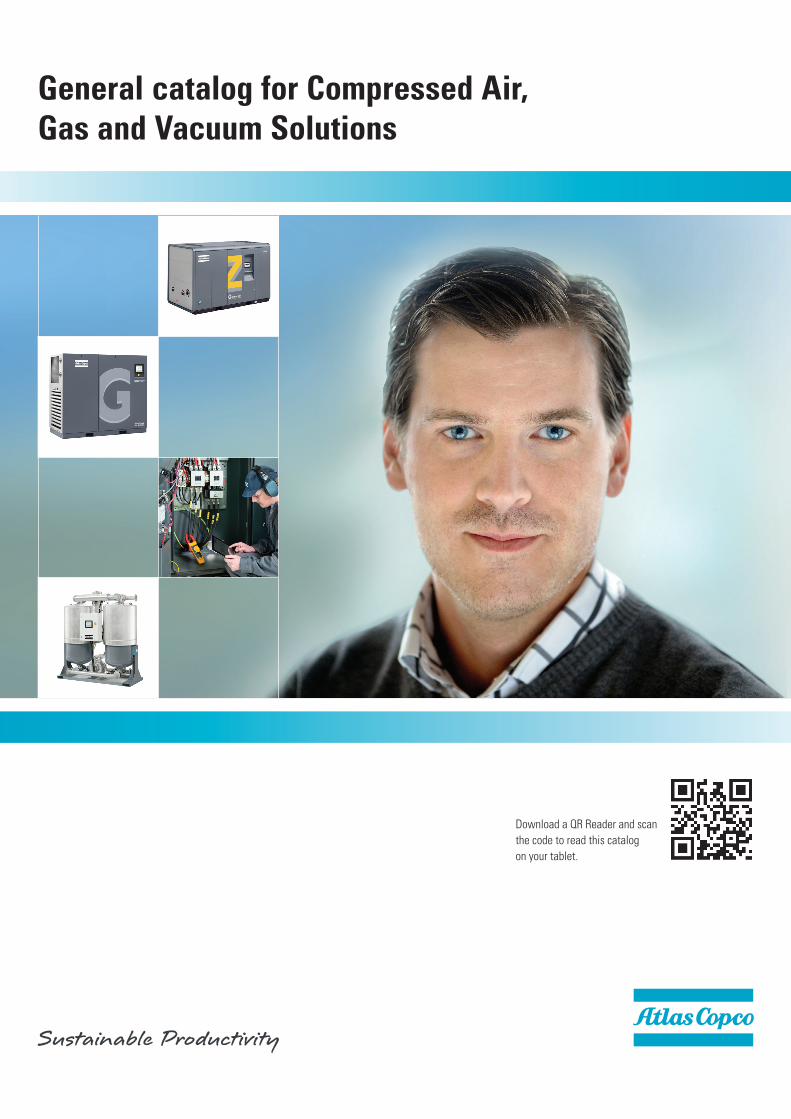
General catalog for Compressed Air, Gas and Vacuum Solutions
184
General catalog for Compressed Air, Gas and Vacuum Solutions Download a QR Reader and scan the code to read this catalog on your tablet.
-
Upload
khangminh22 -
Category
Documents
-
view
4 -
download
0
Transcript of General catalog for Compressed Air, Gas and Vacuum Solutions
General catalog for Compressed Air,Gas and Vacuum Solutions
Download a QR Reader and scanthe code to read this catalogon your tablet.
FoR 140 yeaRs, We HaVe INCReaseD oUR CUsToMeR's PRoDUCTIVITy.Atlas Copco is an industrial group with world-leading position in products and services that deliver sustainable productivity. The company was founded in Sweden in 1873, celebrating 140 years of successful business in 2013.
Today, we have sale and service operations in more than 170 countries. The voices of our customers around the world are very important to us. By listening to customers we learn about what we do well and what we need to improve.
Each year, we open new customer centers in emerging markets, always with a long-term commitment to local customers and partners.
Atlas Copco Compressor Technique provides gas and process compressors, expanders, air and gas treatment equipment as well as air management systems and service for industrial applications.
In this catalogue you will find our comprehensive offering of energy efficient compressed air, gas and vacuum solutions to help improve customers sustainable productivity.

3
Committed to Sustainable Productivity
Drivers of innovation -from idea to customer benefit
ISO 9001We have the quality leading rolein the Industry.We trust the customerintroduced.
ISO 14001The environmental Management system is an integrated partof any business process atatlas Copco airpower.
OHSAS 18001:1999International Labour and Health and safety Management system
Sustainable developmentatlas Copco has set very high environmental targets for our opera-tions as well as for our equipment.
By making our equipment as energy efficient as possible, we help our customers to reduce their impact on the environment. This can help them to promote their products as sustainable solutions in the marketplace.
For our operations, we are continuously reducing the environmental impact in key areas such as energy consumption, water consumpti-on, Co2 emissions, and waste.
a large majority of our employees already work in companies that are triple certified (Iso 9001, Iso 14001 and oHsas 18001). By the end of 2013 Compressor Technique is committed to having triple certifications for all of our operations.
We want to put our customers ahead of their competition. For atlas Copco, energy efficiency is always a top priority and a strong incentive to seek new and better solutions.
our continuous drive to further reduce the carbon footprint, to find new and better ways of utilizing materials and to minimize waste has resulted in numerous innovations.
a lot of new opportunities relate to the development of intelligent controls and monitoring systems. Further development of oil-free and low pressure technology will open up opportunities to reach new heights in air efficiency.
For the oil-injected technology, continuous innovations and new solutions make this technology a strong contributor to customer efficiency and energy savings for the future.
An industry benchmarkour achievements are also recognized externally and we are perceived as an industry benchmark in many areas.
For example, we are listed in the Dow Jones sustainability index as one of the world’s most innovative companies. and at the World economic Forum in Davos in switzerland we were listed as the 10th most sustainable company in the world. We have been on that list six times.
4
Committed to Sustainable Productivity
Wir wollen bei unseren Kunden und Geschäftspartnern First in Mind – First in Choice® sein. Dieses Ziel verfolgen wir, in-dem wir ses Ziel verfolgen wir, indem wir uns unseren unseren unseren von unseren wichtigs-ten Werten leiten la uns von unseren wichtigsten Werten leiten lassen: Interaktion, Enga-gement und Innovation.
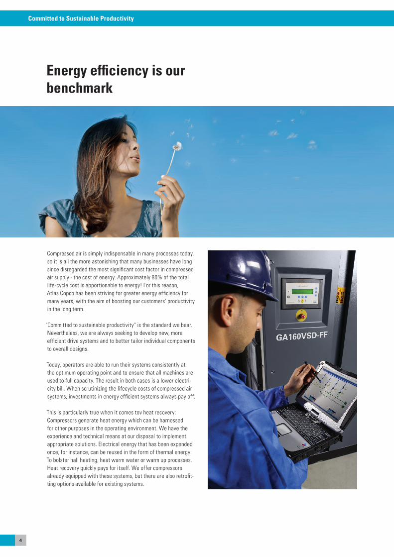
Energy efficiency is ourbenchmark
Compressed air is simply indispensable in many processes today, so it is all the more astonishing that many businesses have long since disregarded the most significant cost factor in compressed air supply - the cost of energy. approximately 80% of the total life-cycle cost is apportionable to energy! For this reason, atlas Copco has been striving for greater energy efficiency for many years, with the aim of boosting our customers' productivity in the long term.
"Committed to sustainable productivity" is the standard we bear. Nevertheless, we are always seeking to develop new, moreefficient drive systems and to better tailor individual components to overall designs.
Today, operators are able to run their systems consistently at the optimum operating point and to ensure that all machines are used to full capacity. The result in both cases is a lower electri-city bill. When scrutinizing the lifecycle costs of compressed air systems, investments in energy efficient systems always pay off.
This is particularly true when it comes tov heat recovery: Compressors generate heat energy which can be harnessed for other purposes in the operating environment. We have the experience and technical means at our disposal to implement appropriate solutions. electrical energy that has been expended once, for instance, can be reused in the form of thermal energy: To bolster hall heating, heat warm water or warm up processes. Heat recovery quickly pays for itself. We offer compressors already equipped with these systems, but there are also retrofit-ting options available for existing systems.
5
Committed to Sustainable Productivity
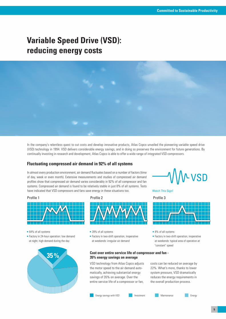
In almost every production environment, air demand fluctuates based on a number of factors (time of day, week or even month). extensive measurements and studies of compressed air demand profiles show that compressed air demand varies considerably in 92% of all compressor and fan systems. Compressed air demand is found to be relatively stable in just 8% of all systems. Tests have indicated that VsD compressors and fans save energy in these situations too.
Fluctuating compressed air demand in 92% of all systems
Profile 1 Profile 2 Profile 3
64% of all systems Factory in 24-hour operation: low demand
at night, high demand during the day
28% of all systems Factory in two-shift operation, inoperative
at weekends: irregular air demand
8% of all systems Factory in two-shift operation, inoperative
at weekends: typical area of operation at "constant" speed
35 %
Watch This Sign!
Variable Speed Drive (VSD):reducing energy costs
In the company's relentless quest to cut costs and develop innovative products, atlas Copco unveiled the pioneering variable speed drive (VsD) technology in 1994. VsD delivers considerable energy savings, and in doing so preserves the environment for future generations. By continually investing in research and development, atlas Copco is able to offer a wide range of integrated VsD compressors.
VsD technology from atlas Copco adjusts the motor speed to the air demand auto-matically, achieving substantial energy savings of 35% on average. over the entire service life of a compressor or fan,
costs can be reduced on average by 22%. What's more, thanks to lowersystem pressure, VsD dramaticallyreduces the energy requirements inthe overall production process.
Cost over entire service life of compressor and fan - 35% energy savings on average
energyInvestmentenergy savings with VsD Maintenance

6
Committed to Sustainable Productivity
The leader in oil-free compressed air technology
oil-free air is used in all kinds of industries where air quality is paramount for the production process and end product. These applicationsinclude food and beverage processing, the pharmaceutical industry (manufacturing and packaging), wastewater treatment, chemical and petrochemical processing, semiconductor and electronics manufacturing, the medical sector, automotive paint spraying, textile manufacturing and many more.Contamination by even the smallest quantities of oil can result in costly production downtime and product spoilage, makingClass 0 an industry standard.
First in oil-free air technologyover the past sixty years atlas Copco has pioneered the development of oil-free air technology, resulting in a range of air compressors and blowers that provide 100% pure, clean air. Through continuous research and development, atlas Copco achieved a new milestone, setting the standard for air purity as the first manufacturer to be awarded Iso 8573-1 CLass 0 certification.
Eliminating any riskas the industry leader committed to meeting the needs of the most demanding customers, atlas Copco requested the renowned TÜV institute to type-test its range of oil-free compressors and blowers. Using the most rigorous testing methodologies available, all possible oil forms were measured across a range of temperatures and pressures. The TÜV found no traces of oil at all in the output air stream. Thus atlas Copco is not only the first compressor and blower manufacturer to receive CLass 0 certification, but also exceeds Iso 8573-1 CLass 0 specifications.
CLASS 0 means:
Zero risk of contamination.
Zero risk of damaged or unsafe products.
Zero risk of losses from operational downtime.
Zero risk of damaging your company’s hard-won
professional reputation.
CLASS Concentration total oil(aerosol, liquid, vapor) mg/m3
0 As specified by the equipment user or supplier and more stringent than class 1
1 < 0.01
2 < 0.1
3 < 1
4 < 5Current ISO 8573-1 (2010) classes (the five main classes and the associated maximumconcentration in total oil content).
Download a QR Reader and scanthe code for more infomationabout www.classzero.com.

7
Committed to Sustainable Productivity
sustainable economic performance, reduced energy costs and improved profitability: our services get you there faster. opera-tors' unique requirements for servicing and maintenance are just as varied as the range of compressed air systems available. These requirements range from original replacement parts and premium maintenance agreements to system optimization and remote monitoring. With our perfectly tailored and extendable aftermarket products, we have the ideal solutions for worry-free compressed air systems and high availability.
our range of services and our experienced, qualified service team are at your disposal regardless of whether you have purchased a compressor or dryer from us: Let us optimize your energy consump-tion, boost your availability and safeguard the reliability and ef-ficient operation of your compressed air system for many years, or even decades, to come. We can perform regular inspections of your systems, enable you to take advantage of the technical progress made and help you to steadily boost your efficiency. If required, we can also remotely monitor your compressed air system centrally via the Internet, 24 hours a day, 365 days a year, allowing you to de-pend on the productivity and availability of your system at all times.
Service and optimization for your compressed air system
Bottlenecks quickly eliminatedatlas Copco Rental delivers 100% oil-free compressed air to companies in industry. Where additional demandexists for power or air, or where processes cannot beinterrupted for the maintenance or repair of internalsystems, atlas Copco Rental provides support with itscomplete rental solutions. our solutions guarantee theleast possible disruption to your production process. our growing portfolio of services built on expert knowl-edge and experience, which is widely recognized as "industry leading", also includes other special ap-plications, such dehydration, pressure tests, clean-ing of oil and gas pipelines at sea, and much more.
INDUSTRY RENTAL
8
Committed to Sustainable Productivity
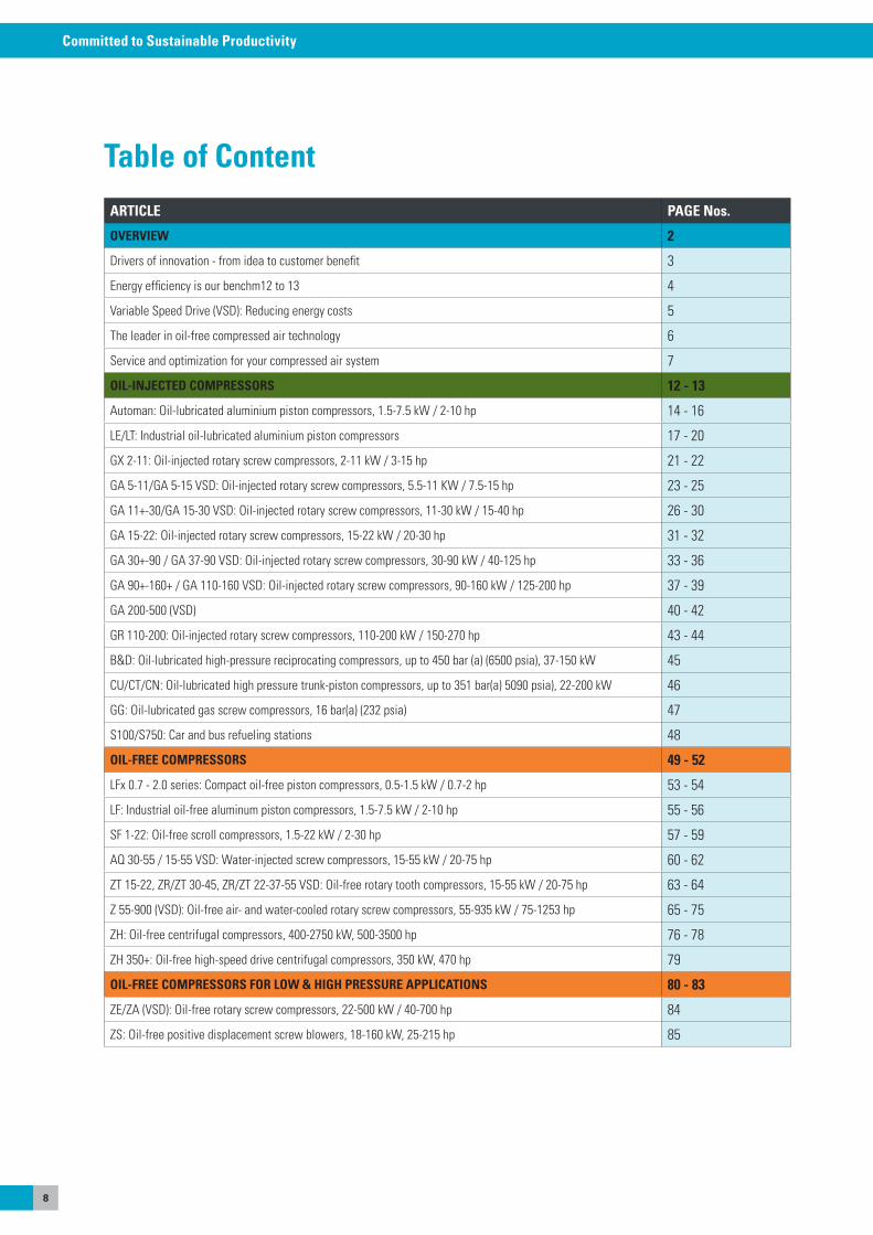
Table of ContentARTICLE PAGE Nos.
OVERVIEW 2
Drivers of innovation - from idea to customer benefit 3
energy efficiency is our benchm12 to 13 4
Variable speed Drive (VsD): Reducing energy costs 5
The leader in oil-free compressed air technology 6
service and optimization for your compressed air system 7
OIL-INJECTED COMPRESSORS 12 - 13
automan: oil-lubricated aluminium piston compressors, 1.5-7.5 kW / 2-10 hp 14 - 16
Le/LT: Industrial oil-lubricated aluminium piston compressors 17 - 20
GX 2-11: oil-injected rotary screw compressors, 2-11 kW / 3-15 hp 21 - 22
Ga 5-11/Ga 5-15 VsD: oil-injected rotary screw compressors, 5.5-11 KW / 7.5-15 hp 23 - 25
Ga 11+-30/Ga 15-30 VsD: oil-injected rotary screw compressors, 11-30 kW / 15-40 hp 26 - 30
Ga 15-22: oil-injected rotary screw compressors, 15-22 kW / 20-30 hp 31 - 32
Ga 30+-90 / Ga 37-90 VsD: oil-injected rotary screw compressors, 30-90 kW / 40-125 hp 33 - 36
Ga 90+-160+ / Ga 110-160 VsD: oil-injected rotary screw compressors, 90-160 kW / 125-200 hp 37 - 39
Ga 200-500 (VsD) 40 - 42
GR 110-200: oil-injected rotary screw compressors, 110-200 kW / 150-270 hp 43 - 44
B&D: oil-lubricated high-pressure reciprocating compressors, up to 450 bar (a) (6500 psia), 37-150 kW 45
CU/CT/CN: oil-lubricated high pressure trunk-piston compressors, up to 351 bar(a) 5090 psia), 22-200 kW 46
GG: oil-lubricated gas screw compressors, 16 bar(a) (232 psia) 47
s100/s750: Car and bus refueling stations 48
OIL-FREE COMPRESSORS 49 - 52
LFx 0.7 - 2.0 series: Compact oil-free piston compressors, 0.5-1.5 kW / 0.7-2 hp 53 - 54
LF: Industrial oil-free aluminum piston compressors, 1.5-7.5 kW / 2-10 hp 55 - 56
sF 1-22: oil-free scroll compressors, 1.5-22 kW / 2-30 hp 57 - 59
aQ 30-55 / 15-55 VsD: Water-injected screw compressors, 15-55 kW / 20-75 hp 60 - 62
ZT 15-22, ZR/ZT 30-45, ZR/ZT 22-37-55 VsD: oil-free rotary tooth compressors, 15-55 kW / 20-75 hp 63 - 64
Z 55-900 (VsD): oil-free air- and water-cooled rotary screw compressors, 55-935 kW / 75-1253 hp 65 - 75
ZH: oil-free centrifugal compressors, 400-2750 kW, 500-3500 hp 76 - 78
ZH 350+: oil-free high-speed drive centrifugal compressors, 350 kW, 470 hp 79
OIL-FREE COMPRESSORS FOR LOW & HIGH PRESSURE APPLICATIONS 80 - 83
Ze/Za (VsD): oil-free rotary screw compressors, 22-500 kW / 40-700 hp 84
Zs: oil-free positive displacement screw blowers, 18-160 kW, 25-215 hp 85
9
Committed to Sustainable Productivity
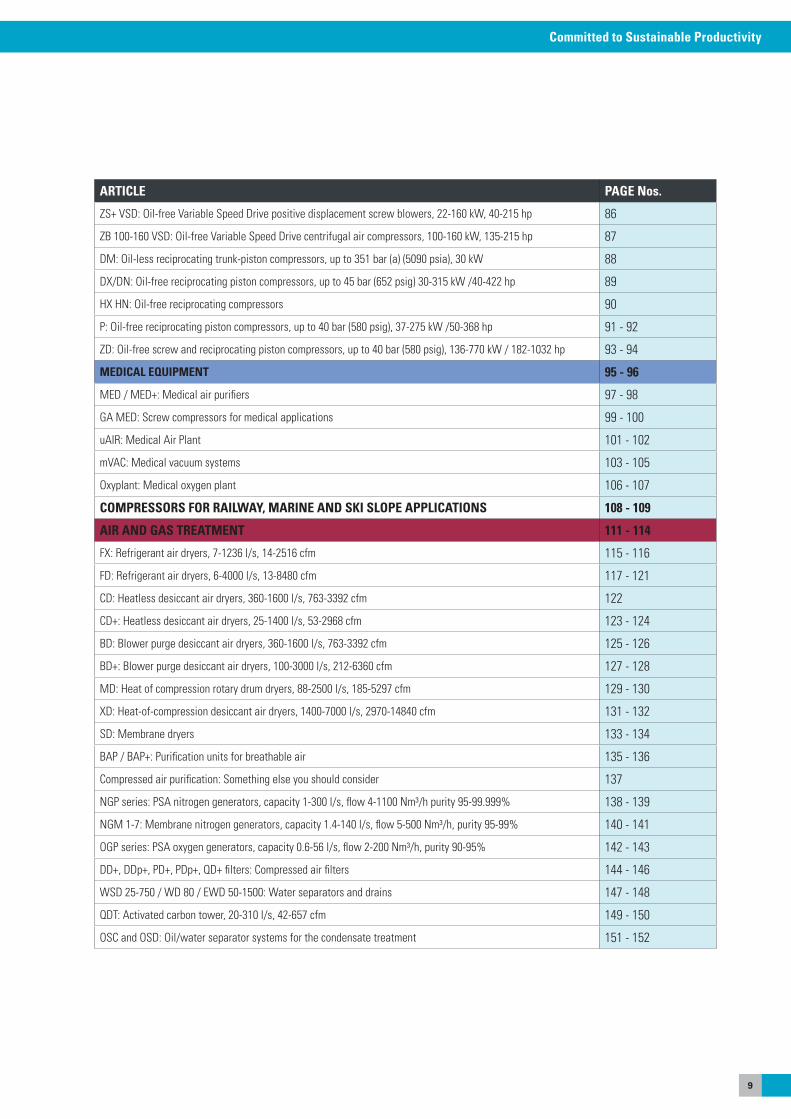
ARTICLE PAGE Nos.
Zs+ VsD: oil-free Variable speed Drive positive displacement screw blowers, 22-160 kW, 40-215 hp 86
ZB 100-160 VsD: oil-free Variable speed Drive centrifugal air compressors, 100-160 kW, 135-215 hp 87
DM: oil-less reciprocating trunk-piston compressors, up to 351 bar (a) (5090 psia), 30 kW 88
DX/DN: oil-free reciprocating piston compressors, up to 45 bar (652 psig) 30-315 kW /40-422 hp 89
HX HN: oil-free reciprocating compressors 90
P: oil-free reciprocating piston compressors, up to 40 bar (580 psig), 37-275 kW /50-368 hp 91 - 92
ZD: oil-free screw and reciprocating piston compressors, up to 40 bar (580 psig), 136-770 kW / 182-1032 hp 93 - 94
MEDICAL EQUIPMENT 95 - 96
MeD / MeD+: Medical air purifiers 97 - 98
Ga MeD: screw compressors for medical applications 99 - 100
uaIR: Medical air Plant 101 - 102
mVaC: Medical vacuum systems 103 - 105
oxyplant: Medical oxygen plant 106 - 107
COMPRESSORS FOR RAILWAY, MARINE AND SKI SLOPE APPLICATIONS 108 - 109
AIR AND GAS TREATMENT 111 - 114
FX: Refrigerant air dryers, 7-1236 l/s, 14-2516 cfm 115 - 116
FD: Refrigerant air dryers, 6-4000 l/s, 13-8480 cfm 117 - 121
CD: Heatless desiccant air dryers, 360-1600 l/s, 763-3392 cfm 122
CD+: Heatless desiccant air dryers, 25-1400 l/s, 53-2968 cfm 123 - 124
BD: Blower purge desiccant air dryers, 360-1600 l/s, 763-3392 cfm 125 - 126
BD+: Blower purge desiccant air dryers, 100-3000 l/s, 212-6360 cfm 127 - 128
MD: Heat of compression rotary drum dryers, 88-2500 l/s, 185-5297 cfm 129 - 130
XD: Heat-of-compression desiccant air dryers, 1400-7000 l/s, 2970-14840 cfm 131 - 132
sD: Membrane dryers 133 - 134
BaP / BaP+: Purification units for breathable air 135 - 136
Compressed air purification: something else you should consider 137
NGP series: Psa nitrogen generators, capacity 1-300 l/s, flow 4-1100 Nm³/h purity 95-99.999% 138 - 139
NGM 1-7: Membrane nitrogen generators, capacity 1.4-140 l/s, flow 5-500 Nm³/h, purity 95-99% 140 - 141
oGP series: Psa oxygen generators, capacity 0.6-56 l/s, flow 2-200 Nm³/h, purity 90-95% 142 - 143
DD+, DDp+, PD+, PDp+, QD+ filters: Compressed air filters 144 - 146
WsD 25-750 / WD 80 / eWD 50-1500: Water separators and drains 147 - 148
QDT: activated carbon tower, 20-310 l/s, 42-657 cfm 149 - 150
osC and osD: oil/water separator systems for the condensate treatment 151 - 152
10
Committed to Sustainable Productivity
Table of ContentARTICLE PAGE Nos.
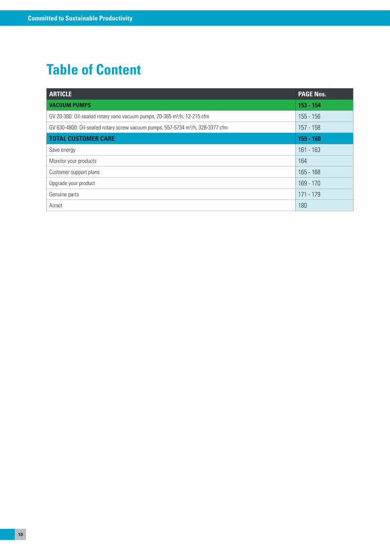
VACUUM PUMPS 153 - 154
GV 20-300: oil-sealed rotary vane vacuum pumps, 20-365 m³/h, 12-215 cfm 155 - 156
GV 630-4800: oil-sealed rotary screw vacuum pumps, 557-5734 m³/h, 328-3377 cfm 157 - 158
TOTAL CUSTOMER CARE 159 - 160
save energy 161 - 163
Monitor your products 164
Customer support plans 165 - 168
Upgrade your product 169 - 170
Genuine parts 171 - 179
airnet 180
oIL-INJeCTeD CoMPRessoRsOur oil-lubricated compressors are the best choice for all industrial applications which require a general compressed air quality.
12
Committed to Sustainable Productivity
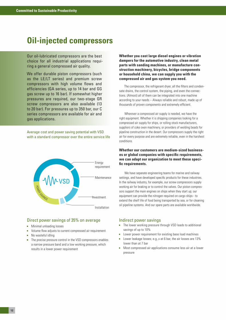
Average cost and power saving potential with VSDwith a standard compressor over the entire service life
energyrequirement
Installation
Maintenance
Investment
PoWeR saVINGs
Our oil-lubricated compressors are the best choice for all industrial applications requi-ring a general compressed air quality.
We offer durable piston compressors (such as the LE/LT series) and premium screw compressors with high volume flows and efficiencies (GA series, up to 14 bar and GG gas screw up to 16 bar). If somewhat higher pressures are required, our two-stage GR screw compressors are also available (13 to 20 bar). For pressures up to 350 bar, our C series compressors are available for air and gas applications.
Whether you cast large diesel engines or vibration dampers for the automotive industry, clean metal parts with sanding machines, or manufacture con-struction machinery, bicycles, bridge components or household china, we can supply you with the compressed air and gas system you need.
The compressor, the refrigerant dryer, all the filters and conden-sate drains, the control system, the piping, and even the connec-tions. (almost) all of them can be integrated into one machine according to your needs – always reliable and robust, made up of thousands of proven components and extremely efficient.
Wherever a compressed air supply is needed, we have the right equipment. Whether it is shipping companies looking for a compressed air supply for ships, or rolling stock manufacturers, suppliers of coke oven machinery, or providers of welding beads for pipeline construction in the desert. our compressors supply the right air for every purpose and are extremely reliable, even in the harshest conditions.
Whether our customers are medium-sized business-es or global companies with specific requirements, we can adapt our organization to meet these speci-fic requirements.
We have separate engineering teams for marine and railway settings, and have developed specific products for these industries. In the railway industry, for example, our screw compressors supply working air for braking or to control the valves. our piston compres-sors support the main engines on ships when they start up; our equipment can provide the nitrogen required on cargo ships - to extend the shelf life of food being transported by sea, or for cleaning oil pipeline systems. and our spare parts are available worldwide.
Direct power savings of 35% on average Minimal unloading losses Volume flow adjusts to current compressed air requirement No wasteful idling The precise pressure control in the VsD compressors enables
a narrow pressure band and a low working pressure, which results in a lower power requirement
Oil-injected compressors
Indirect power savings The lower working pressure through VsD leads to additional
savings of up to 10% Lower power requirement for existing base load machines Lower leakage losses; e.g.,v at 6 bar, the air losses are 13%
lower than at 7 bar Most compressed air applications consume less air at a lower
pressure
13
Committed to Sustainable Productivity
Oil
- inj
ecte
d co
mpr
esso
rs
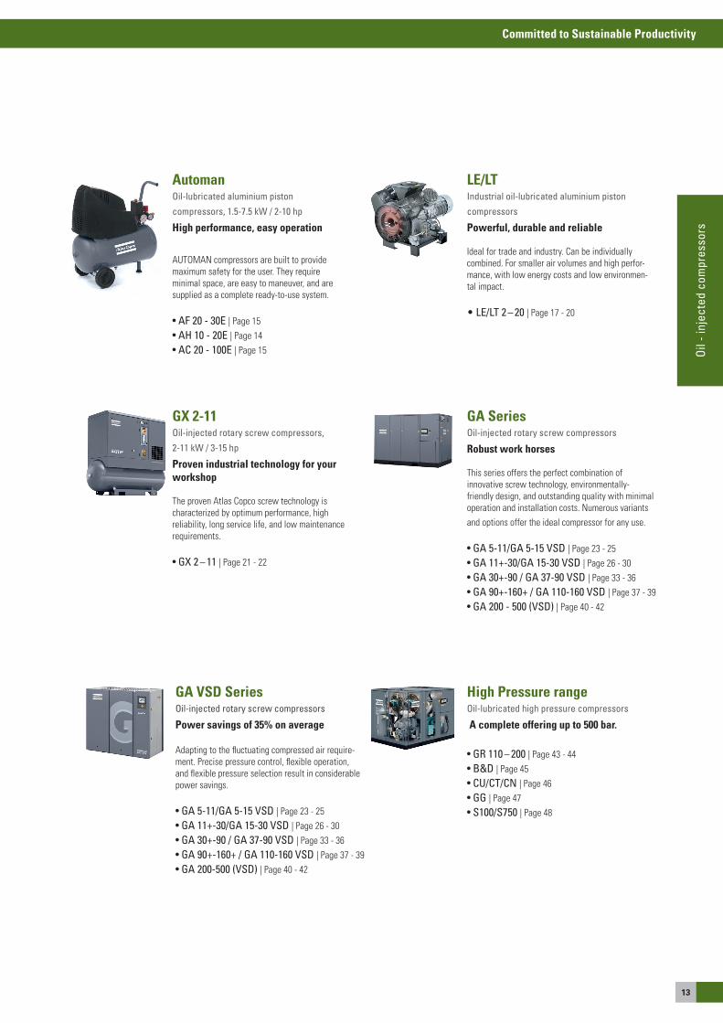
AutomanOil-lubricated aluminium piston
compressors, 1.5-7.5 kW / 2-10 hp
High performance, easy operation
aUToMaN compressors are built to provide maximum safety for the user. They require minimal space, are easy to maneuver, and are supplied as a complete ready-to-use system.
• AF 20 - 30E | Page 15• AH 10 - 20E | Page 14• AC 20 - 100E | Page 15
LE/LTIndustrial oil-lubricated aluminium piston
compressors
Powerful, durable and reliable
Ideal for trade and industry. Can be individually combined. For smaller air volumes and high perfor-mance, with low energy costs and low environmen-tal impact.
• LE/LT 2 – 20 | Page 17 - 20
GA SeriesOil-injected rotary screw compressors
Robust work horses
This series offers the perfect combination ofinnovative screw technology, environmentally-friendly design, and outstanding quality with minimal operation and installation costs. Numerous variants and options offer the ideal compressor for any use.
• GA 5-11/GA 5-15 VSD | Page 23 - 25• GA 11+-30/GA 15-30 VSD | Page 26 - 30• GA 30+-90 / GA 37-90 VSD | Page 33 - 36• GA 90+-160+ / GA 110-160 VSD | Page 37 - 39• GA 200 - 500 (VSD) | Page 40 - 42
High Pressure rangeOil-lubricated high pressure compressors
A complete offering up to 500 bar.
• GR 110 – 200 | Page 43 - 44• B&D | Page 45• CU/CT/CN | Page 46• GG | Page 47• S100/S750 | Page 48
GA VSD SeriesOil-injected rotary screw compressors
Power savings of 35% on average
adapting to the fluctuating compressed air require-ment. Precise pressure control, flexible operation, and flexible pressure selection result in considerable power savings.
• GA 5-11/GA 5-15 VSD | Page 23 - 25• GA 11+-30/GA 15-30 VSD | Page 26 - 30• GA 30+-90 / GA 37-90 VSD | Page 33 - 36• GA 90+-160+ / GA 110-160 VSD | Page 37 - 39• GA 200-500 (VSD) | Page 40 - 42
GX 2-11Oil-injected rotary screw compressors,
2-11 kW / 3-15 hp
Proven industrial technology for yourworkshop
The proven atlas Copco screw technology ischaracterized by optimum performance, highreliability, long service life, and low maintenancerequirements.
• GX 2 – 11 | Page 21 - 22
14
Committed to Sustainable Productivity
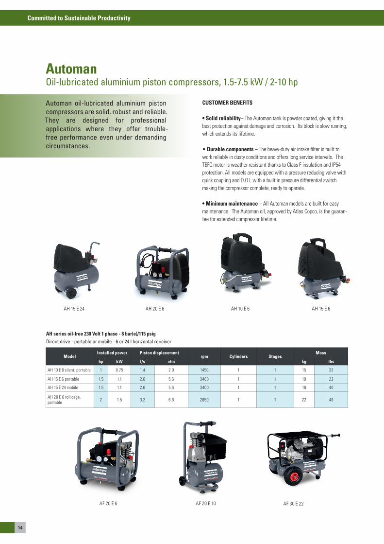
Automan oil-lubricated aluminium pistoncompressors are solid, robust and reliable.They are designed for professionalapplications where they offer trouble-free performance even under demandingcircumstances.
AutomanOil-lubricated aluminium piston compressors, 1.5-7.5 kW / 2-10 hp
CUSTOMER BENEFITS
• Solid reliability– The automan tank is powder coated, giving it the best protection against damage and corrosion. Its block is slow running, which extends its lifetime.
• Durable components – The heavy-duty air intake filter is built to work reliably in dusty conditions and offers long service intervals. The TeFC motor is weather resistant thanks to Class F insulation and IP54 protection. all models are equipped with a pressure reducing valve with quick coupling and D.o.L with a built in pressure differential switch making the compressor complete, ready to operate.
• Minimum maintenance – all automan models are built for easy maintenance. The automan oil, approved by atlas Copco, is the guaran-tee for extended compressor lifetime.
aH 10 e 6 aH 15 e 6 aH 15 e 24 aH 20 e 6
aF 20 e 6 aF 20 e 10
AH series oil-free 230 Volt 1 phase - 8 bar(e)/115 psig Direct drive - portable or mobile - 6 or 24 l horizontal receiver
ModelInstalled power Piston displacement
rpm Cylinders StagesMass
hp kW l/s cfm kg lbs
aH 10 e 6 silent, portable 1 0.75 1.4 2.9 1450 1 1 15 33
aH 15 e 6 portable 1.5 1.1 2.6 5.6 3400 1 1 10 22
aH 15 e 24 mobile 1.5 1.1 2.6 5.6 3400 1 1 18 40
aH 20 e 6 roll cage, portable 2 1.5 3.2 6.8 2850 1 1 22 48
aF 30 e 22
15
Committed to Sustainable Productivity
Oil
- inj
ecte
d co
mpr
esso
rs
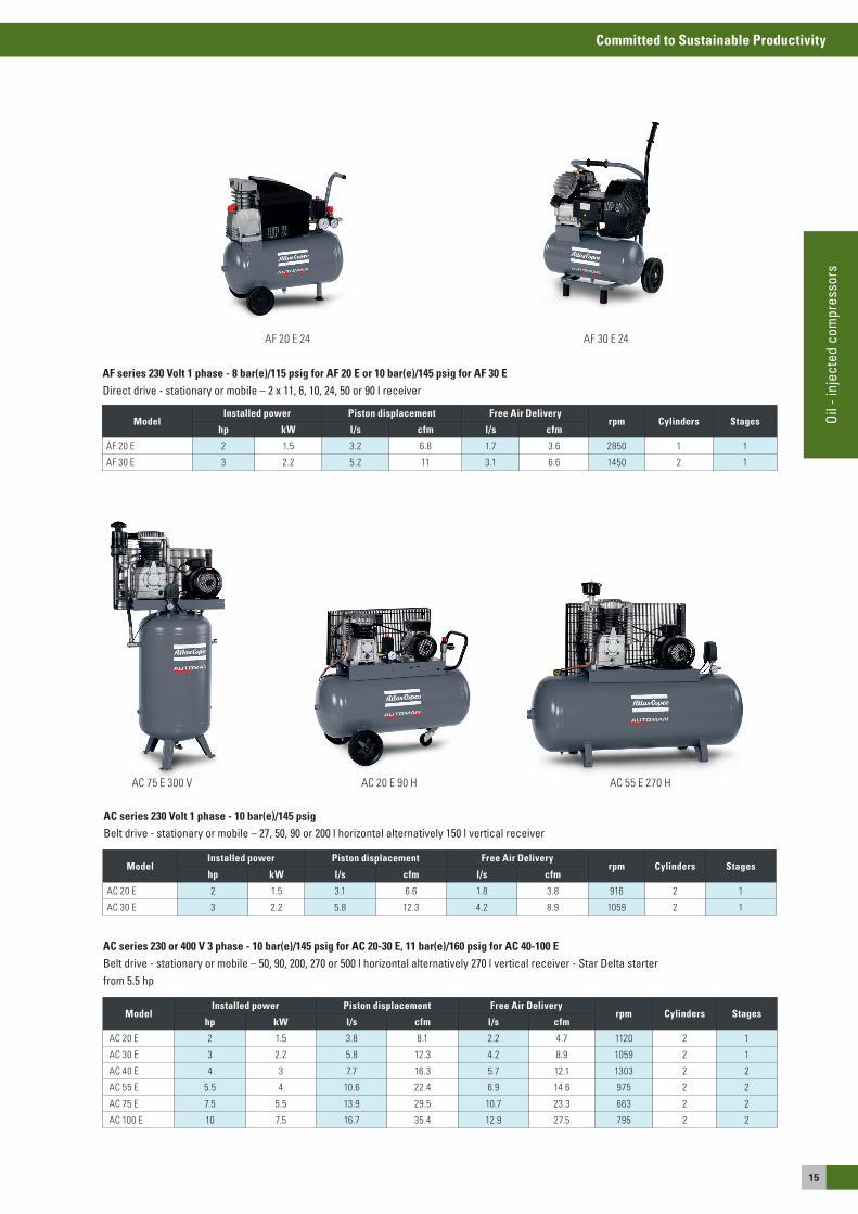
AF series 230 Volt 1 phase - 8 bar(e)/115 psig for AF 20 E or 10 bar(e)/145 psig for AF 30 E Direct drive - stationary or mobile – 2 x 11, 6, 10, 24, 50 or 90 l receiver
ModelInstalled power Piston displacement Free Air Delivery
rpm Cylinders Stageshp kW l/s cfm l/s cfm
aF 20 e 2 1.5 3.2 6.8 1.7 3.6 2850 1 1
aF 30 e 3 2.2 5.2 11 3.1 6.6 1450 2 1
AC series 230 Volt 1 phase - 10 bar(e)/145 psig Belt drive - stationary or mobile – 27, 50, 90 or 200 l horizontal alternatively 150 l vertical receiver
AC series 230 or 400 V 3 phase - 10 bar(e)/145 psig for AC 20-30 E, 11 bar(e)/160 psig for AC 40-100 E Belt drive - stationary or mobile – 50, 90, 200, 270 or 500 l horizontal alternatively 270 l vertical receiver - Star Delta starter from 5.5 hp
aC 20 e 90 H aC 55 e 270 HaC 75 e 300 V
ModelInstalled power Piston displacement Free Air Delivery
rpm Cylinders Stageshp kW l/s cfm l/s cfm
aC 20 e 2 1.5 3.1 6.6 1.8 3.8 916 2 1
aC 30 e 3 2.2 5.8 12.3 4.2 8.9 1059 2 1
ModelInstalled power Piston displacement Free Air Delivery
rpm Cylinders Stageshp kW l/s cfm l/s cfm
aC 20 e 2 1.5 3.8 8.1 2.2 4.7 1120 2 1
aC 30 e 3 2.2 5.8 12.3 4.2 8.9 1059 2 1
aC 40 e 4 3 7.7 16.3 5.7 12.1 1303 2 2
aC 55 e 5.5 4 10.6 22.4 6.9 14.6 975 2 2
aC 75 e 7.5 5.5 13.9 29.5 10.7 23.3 663 2 2
aC 100 e 10 7.5 16.7 35.4 12.9 27.5 795 2 2
aF 30 e 24aF 20 e 24
16
Committed to Sustainable Productivity
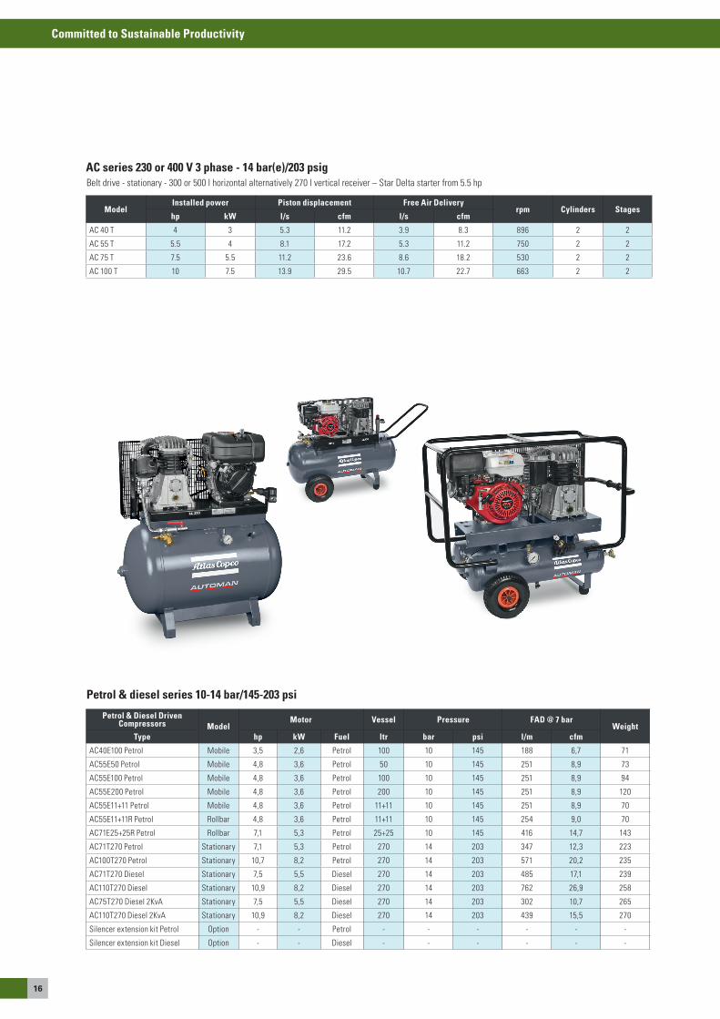
AC series 230 or 400 V 3 phase - 14 bar(e)/203 psig Belt drive - stationary - 300 or 500 l horizontal alternatively 270 l vertical receiver – star Delta starter from 5.5 hp
ModelInstalled power Piston displacement Free Air Delivery
rpm Cylinders Stageshp kW l/s cfm l/s cfm
aC 40 T 4 3 5.3 11.2 3.9 8.3 896 2 2
aC 55 T 5.5 4 8.1 17.2 5.3 11.2 750 2 2
aC 75 T 7.5 5.5 11.2 23.6 8.6 18.2 530 2 2
aC 100 T 10 7.5 13.9 29.5 10.7 22.7 663 2 2
Petrol & diesel series 10-14 bar/145-203 psi
Petrol & Diesel Driven Compressors Model
Motor Vessel Pressure FAD @ 7 barWeight
Type hp kW Fuel ltr bar psi l/m cfm
aC40e100 Petrol Mobile 3,5 2,6 Petrol 100 10 145 188 6,7 71
aC55e50 Petrol Mobile 4,8 3,6 Petrol 50 10 145 251 8,9 73
aC55e100 Petrol Mobile 4,8 3,6 Petrol 100 10 145 251 8,9 94
aC55e200 Petrol Mobile 4,8 3,6 Petrol 200 10 145 251 8,9 120
aC55e11+11 Petrol Mobile 4,8 3,6 Petrol 11+11 10 145 251 8,9 70
aC55e11+11R Petrol Rollbar 4,8 3,6 Petrol 11+11 10 145 254 9,0 70
aC71e25+25R Petrol Rollbar 7,1 5,3 Petrol 25+25 10 145 416 14,7 143
aC71T270 Petrol stationary 7,1 5,3 Petrol 270 14 203 347 12,3 223
aC100T270 Petrol stationary 10,7 8,2 Petrol 270 14 203 571 20,2 235
aC71T270 Diesel stationary 7,5 5,5 Diesel 270 14 203 485 17,1 239
aC110T270 Diesel stationary 10,9 8,2 Diesel 270 14 203 762 26,9 258
aC75T270 Diesel 2Kva stationary 7,5 5,5 Diesel 270 14 203 302 10,7 265
aC110T270 Diesel 2Kva stationary 10,9 8,2 Diesel 270 14 203 439 15,5 270
silencer extension kit Petrol option - - Petrol - - - - - -
silencer extension kit Diesel option - - Diesel - - - - - -
17
Committed to Sustainable Productivity
Oil
- inj
ecte
d co
mpr
esso
rs
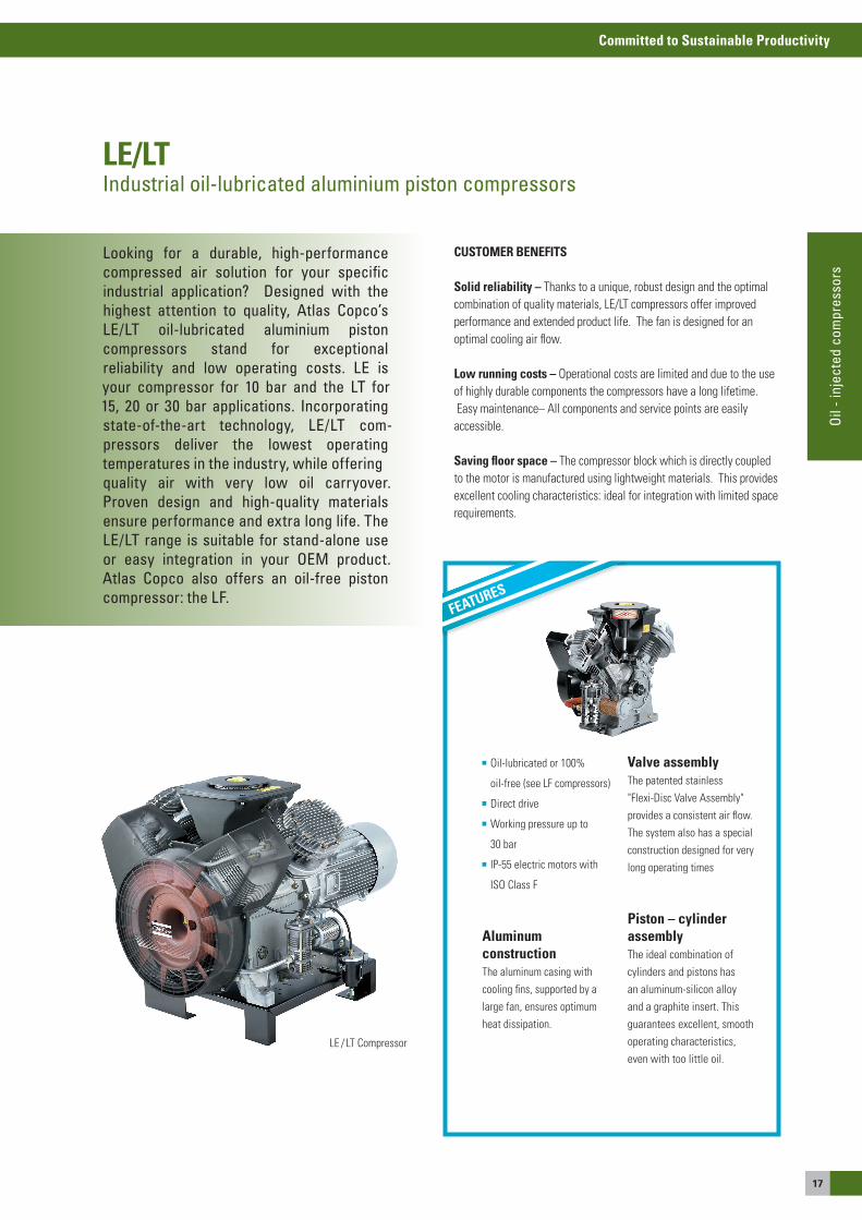
Le / LT Compressor
Looking for a durable, high-performance compressed air solution for your specific industrial application? Designed with the highest attention to quality, Atlas Copco’s LE/LT oil-lubricated aluminium pistoncompressors stand for exceptionalreliability and low operating costs. LE isyour compressor for 10 bar and the LT for15, 20 or 30 bar applications. Incorporatingstate-of-the-art technology, LE/LT com-pressors deliver the lowest operatingtemperatures in the industry, while offeringquality air with very low oil carryover.Proven design and high-quality materialsensure performance and extra long life. TheLE/LT range is suitable for stand-alone useor easy integration in your OEM product.Atlas Copco also offers an oil-free pistoncompressor: the LF.
CUSTOMER BENEFITS
Solid reliability – Thanks to a unique, robust design and the optimal combination of quality materials, Le/LT compressors offer improved performance and extended product life. The fan is designed for an optimal cooling air flow.
Low running costs – operational costs are limited and due to the use of highly durable components the compressors have a long lifetime. easy maintenance– all components and service points are easily accessible.
Saving floor space – The compressor block which is directly coupled to the motor is manufactured using lightweight materials. This provides excellent cooling characteristics: ideal for integration with limited space requirements.
LE/LTIndustrial oil-lubricated aluminium piston compressors
oil-lubricated or 100%
oil-free (see LF compressors)
Direct drive
Working pressure up to
30 bar
IP-55 electric motors with
Iso Class F
AluminumconstructionThe aluminum casing with cooling fins, supported by a large fan, ensures optimum heat dissipation.
Valve assemblyThe patented stainless "Flexi-Disc Valve assembly" provides a consistent air flow. The system also has a special construction designed for very long operating times
Piston – cylinderassemblyThe ideal combination of cylinders and pistons has an aluminum-silicon alloy and a graphite insert. This guarantees excellent, smooth operating characteristics, even with too little oil.
FEATURES
18
Committed to Sustainable Productivity
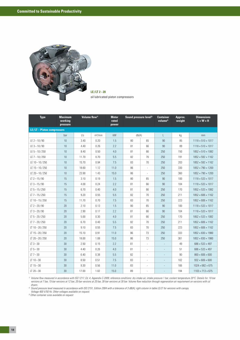
LE / LT 2 – 20
oil lubricated piston compressors
Type Maximum working pressure
Volume flow1) Motor rated
power
Sound pressure level2) Container volume3)
Approx. weight
Dimensions L × W × H
LE / LT – Piston compressors
bar l/s m³/min kW db(a) L kg mm
Le 2 – 10 / 90 10 3.40 0.20 1.5 80 65 90 85 1118 × 510 × 1017
Le 3 – 10 / 90 10 4.40 0.26 2.2 81 66 90 89 1118 × 510 × 1017
Le 5 – 10 / 250 10 8.40 0.50 4.0 81 66 250 150 1852 × 510 × 1082
Le 7 – 10 / 250 10 11.70 0.70 5.5 82 70 250 191 1852 × 592 × 1162
Le 10 – 10 / 250 10 15.70 0.94 7.5 83 70 250 203 1852 × 592 × 1162
Le 15 – 10 / 250 10 18.60 1.12 11.0 86 - 250 330 1852 × 790 × 1200
Le 20 – 10 / 250 10 23.90 1.43 15.0 86 - 250 360 1852 × 790 × 1200
LT 2 – 15 / 90 15 3.10 0.19 1.5 80 65 90 100 1118 × 533 × 1017
LT 3 – 15 / 90 15 4.00 0.24 2.2 81 66 90 104 1118 × 533 × 1017
LT 5 – 15 / 250 15 6.70 0.40 4.0 81 66 250 170 1852 × 533 × 1082
LT 7 – 15 / 250 15 9.20 0.55 5.5 82 70 250 211 1852 × 606 × 1162
LT 10 – 15 / 250 15 11.70 0.70 7.5 83 70 250 223 1852 × 606 × 1162
LT 2 – 20 / 90 20 2.10 0.13 1.5 80 65 90 100 1118 × 533 × 1017
LT 3 – 20 / 90 20 2.90 0.17 2.2 81 66 90 104 1118 × 533 × 1017
LT 5 – 20 / 250 20 5.00 0.30 4.0 81 66 250 170 1852 × 533 × 1082
LT 7 – 20 / 250 20 6.70 0.40 5.5 82 70 250 211 1852 × 606 × 1162
LT 10 – 20 / 250 20 9.10 0.55 7.5 83 70 250 223 1852 × 606 × 1162
LT 15 – 20 / 250 20 15.10 0.91 11.0 86 73 250 333 1852 × 830 × 1980
LT 20 – 20 / 250 20 18.00 1.08 15.0 86 73 250 361 1852 × 830 × 1980
LT 3 – 30 30 2.50 0.15 2.2 81 - - 49 686 × 533 × 497
LT 5 – 30 30 4.40 0.26 4.0 81 - - 51 686 × 533 × 497
LT 7 – 30 30 6.40 0.38 5.5 82 - - 90 860 × 606 × 600
LT 10 – 30 30 8.50 0.51 7.5 83 - - 102 932 × 606 × 600
LT 15 – 30 30 9.30 0.56 11.0 83 - - 166 1024 × 682 × 675
LT 20 – 30 30 17.00 1.02 15.0 89 - - 194 1103 × 713 × 675
1) Volume flow measured in accordance with ISO 1217, Ed. 4, Appendix C-2009, reference conditions: dry intake air, intake pressure 1 bar, coolant temperature 20°C. Details for: 10-bar versions at 7 bar, 15-bar versions at 12 bar, 20-bar versions at 20 bar, 30-bar versions at 30 bar. Volume flow reduction through regeneration air requirement on versions with cd dryers.
2) Sound pressure level measured in accordance with ISO 2151, Edition 2004 with a tolerance of 3 dB(A); right column in table LE/LT for versions with canopy. Voltage 400 V/50 Hz. Other voltages available on request.
3) Other container sizes available on request
19
Committed to Sustainable Productivity
Oil
- inj
ecte
d co
mpr
esso
rs
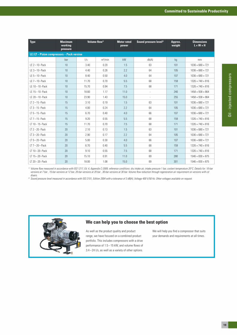
Type Maximum workingpressure
Volume flow1) Motor rated power
Sound pressure level2) Approx. weight
Dimensions L × W × H
LE / LT – Piston compressors – Pack version
bar l/s m³/min kW db(a) kg mm
Le 2 – 10 - Pack 10 3.40 0.20 1.5 63 101 1036 × 680 × 721
Le 3 – 10 - Pack 10 4.40 0.26 2.2 64 105 1036 × 680 × 721
Le 5 – 10 - Pack 10 8.40 0.50 4.0 64 107 1036 × 680 × 721
Le 7 – 10 - Pack 10 11.70 0.70 5.5 68 159 1326 × 740 × 816
Le 10 – 10 - Pack 10 15.70 0.94 7.5 68 171 1326 × 740 × 816
Le 15 – 10 - Pack 10 18.60 1.17 11.0 - 240 1458 × 938 × 864
Le 20 – 10 - Pack 10 23.90 1.43 15.0 - 255 1458 × 938 × 864
LT 2 – 15 - Pack 15 3.10 0.19 1.5 63 101 1036 × 680 × 721
LT 3 – 15 - Pack 15 4.00 0.24 2.2 64 105 1036 × 680 × 721
LT 5 – 15 - Pack 15 6.70 0.40 4.0 66 107 1036 × 680 × 721
LT 7 – 15 - Pack 15 9.20 0.55 5.5 68 159 1326 × 740 × 816
LT 10 – 15 - Pack 15 11.70 0.70 7.5 68 171 1326 × 740 × 816
LT 2 – 20 - Pack 20 2.10 0.13 1.5 63 101 1036 × 680 × 721
LT 3 – 20 - Pack 20 2.90 0.17 2.2 64 105 1036 × 680 × 721
LT 5 – 20 - Pack 20 5.00 0.30 4.0 66 107 1036 × 680 × 721
LT 7 – 20 – Pack 20 6.70 0.40 5.5 68 159 1326 × 740 × 816
LT 10 – 20 - Pack 20 9.10 0.55 7.5 68 171 1326 × 740 × 816
LT 15 – 20 - Pack 20 15.10 0.91 11.0 69 280 1546 × 830 × 875
LT 20 – 20 - Pack 20 18.00 1.08 15.0 69 301 1546 × 830 × 875
1) Volume flow measured in accordance with ISO 1217, Ed. 4, Appendix C-2009, reference conditions: dry intake air, intake pressure 1 bar, coolant temperature 20°C. Details for: 10-bar versions at 7 bar , 15-bar versions at 12 bar, 20-bar versions at 20 bar , 30-bar versions at 30 bar. Volume flow reduction through regeneration air requirement on versions with cd dryers.
2) Sound pressure level measured in accordance with ISO 2151, Edition 2004 with a tolerance of 3 dB(A) ,Voltage 400 V/50 Hz. Other voltages available on request.
as well as the product quality and product range, we have focused on a combined product portfolio. This includes compressors with a drive performance of 1.5 – 15 kW, and volume flows of 3.4 – 24 l/s, as well as a variety of other options.
We will help you find a compressor that suits your demands and requirements at all times.
We can help you to choose the best option
20
Committed to Sustainable Productivity
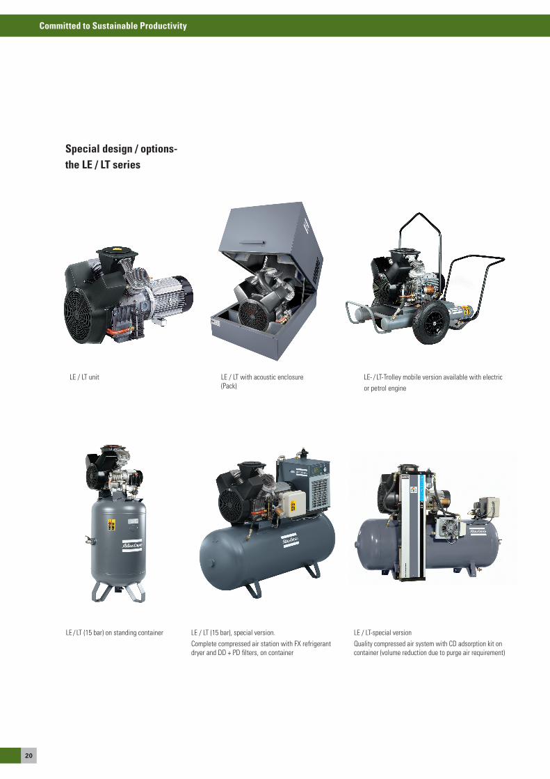
Le- / LT-Trolley mobile version available with electricor petrol engine
Le / LT unit Le / LT with acoustic enclosure (Pack)
Le / LT (15 bar) on standing container Le / LT-special versionQuality compressed air system with CD adsorption kit on container (volume reduction due to purge air requirement)
Le / LT (15 bar), special version.Complete compressed air station with FX refrigerant dryer and DD + PD filters, on container
Special design / options-the LE / LT series
21
Committed to Sustainable Productivity
Oil
- inj
ecte
d co
mpr
esso
rs
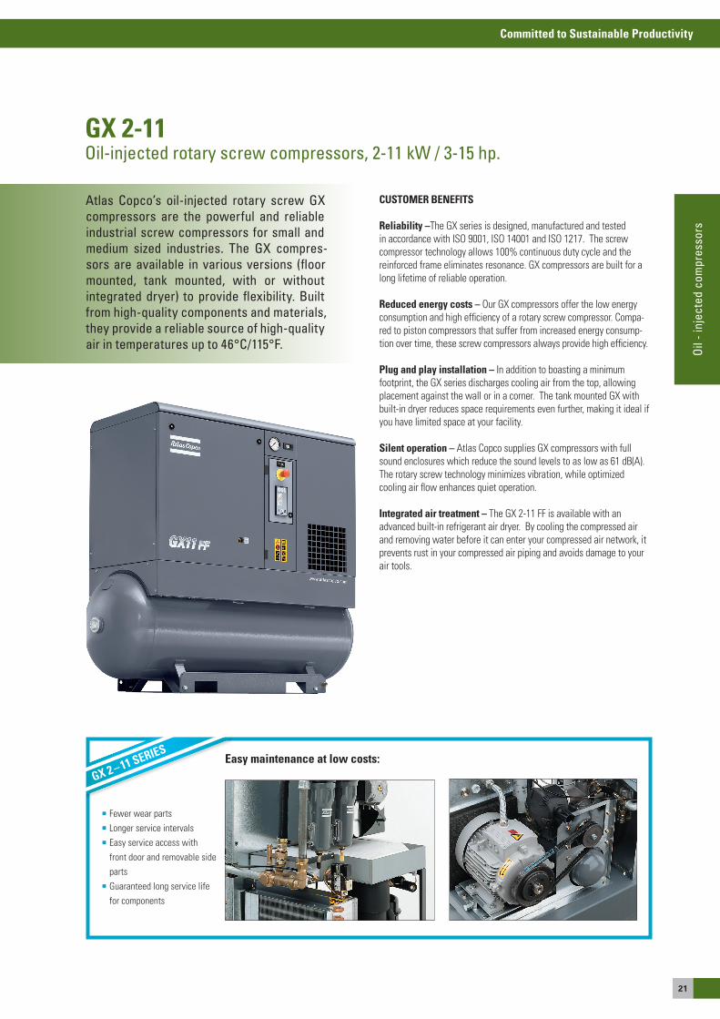
GX 2-11Oil-injected rotary screw compressors, 2-11 kW / 3-15 hp.
Easy maintenance at low costs:
Fewer wear parts Longer service intervals easy service access with
front door and removable side parts Guaranteed long service life
for components
GX 2 – 11 SEriES
Atlas Copco’s oil-injected rotary screw GX compressors are the powerful and reliable industrial screw compressors for small and medium sized industries. The GX compres-sors are available in various versions (floor mounted, tank mounted, with or without integrated dryer) to provide flexibility. Built from high-quality components and materials, they provide a reliable source of high-quality air in temperatures up to 46°C/115°F.
CUSTOMER BENEFITS
reliability –The GX series is designed, manufactured and tested in accordance with Iso 9001, Iso 14001 and Iso 1217. The screw compressor technology allows 100% continuous duty cycle and the reinforced frame eliminates resonance. GX compressors are built for a long lifetime of reliable operation.
reduced energy costs – our GX compressors offer the low energy consumption and high efficiency of a rotary screw compressor. Compa-red to piston compressors that suffer from increased energy consump-tion over time, these screw compressors always provide high efficiency.
Plug and play installation – In addition to boasting a minimum footprint, the GX series discharges cooling air from the top, allowing placement against the wall or in a corner. The tank mounted GX with built-in dryer reduces space requirements even further, making it ideal if you have limited space at your facility.
Silent operation – atlas Copco supplies GX compressors with full sound enclosures which reduce the sound levels to as low as 61 dB(a). The rotary screw technology minimizes vibration, while optimized cooling air flow enhances quiet operation.
integrated air treatment – The GX 2-11 FF is available with an advanced built-in refrigerant air dryer. By cooling the compressed air and removing water before it can enter your compressed air network, it prevents rust in your compressed air piping and avoids damage to your air tools.
22
Committed to Sustainable Productivity
W
H
L
GX 2-7 eP Floor Mounted
GX 7-11 eL FF Tank Mounted
H
W
L
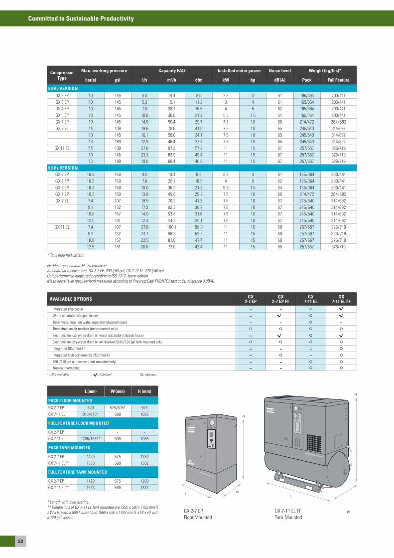
* Tank mounted variant.
EP: Electropneumatic, EL: Elektronikon.Standard air receiver size, GX 2-7 EP: 200 l/60 gal, GX 7-11 EL: 270 l/80 gal. Unit performance measured according to ISO 1217, latest edition.Mean noise level (pack variant) measured according to Pneurop/Cagi PN8NTC2 test code; tolerance 3 dB(A).
* Length with inlet grating.** Dimensions of GX 7-11 EL tank mounted are 1935 x 590 x 1463 mm (L x W x H) with a 500 l vessel and 1880 x 590 x 1463 mm (L x W x H) with a 120 gal vessel.
Compressor Type
Max. working pressure Capacity FAD Installed motor power Noise level Weight (kg/lbs)*
bar(e) psi l/s m³/h cfm kW hp dB(A) Pack Full Feature
50 Hz VERSION GX 2 eP 10 145 4.0 14.4 8.5 2.2 3 61 165/364 200/441GX 3 eP 10 145 5.3 19.1 11.2 3 4 61 165/364 200/441GX 4 eP 10 145 7.8 28.1 16.5 4 5 62 165/364 200/441GX 5 eP 10 145 10.0 36.0 21.2 5.5 7.5 64 165/364 200/441GX 7 eP 10 145 14.0 50.4 29.7 7.5 10 66 214/472 264/582GX 7 eL 7.5 109 19.6 70.6 41.5 7.5 10 65 245/540 314/692
10 145 16.1 58.0 34.1 7.5 10 65 245/540 314/69213 189 12.9 46.4 27.3 7.5 10 65 245/540 314/692
GX 11 eL 7.5 109 27.0 97.2 57.2 11 15 67 257/567 326/71910 145 23.3 83.9 49.4 11 15 67 257/567 326/71913 189 19.0 68.4 40.3 11 15 67 257/567 326/719
60 Hz VERSION GX 2 eP 10.3 150 4.0 14.4 8.5 2.2 3 61 165/364 200/441GX 4 eP 10.3 150 7.8 28.1 16.5 4 5 62 165/364 200/441GX 5 eP 10.3 150 10.0 36.0 21.2 5.5 7.5 64 165/364 200/441GX 7 eP 10.3 150 13.8 49.6 29.2 7.5 10 66 214/472 264/582GX 7 eL 7.4 107 19.5 70.2 41.3 7.5 10 67 245/540 314/692
9.1 132 17.3 62.3 36.7 7.5 10 67 245/540 314/69210.8 157 14.9 53.6 31.6 7.5 10 67 245/540 314/69212.5 181 12.3 44.3 26.1 7.5 10 67 245/540 314/692
GX 11 eL 7.4 107 27.8 100.1 58.9 11 15 68 257/567 326/7199.1 132 24.7 88.9 52.3 11 15 68 257/567 326/719
10.8 157 22.5 81.0 47.7 11 15 68 257/567 326/71912.5 181 20.0 72.0 42.4 11 15 68 257/567 326/719
AVAILABLE OPTIONS GX 2-7 EP
GX 2-7 EP FF
GX 7-11 EL
GX 7-11 EL FF
Integrated aftercooler - -
Water separator (shipped loose) -
Timer water drain on water separator (shipped loose) - - -Timer drain on air receiver (tank mounted only)
electronic no loss water drain on water separator (shipped loose) -
electronic no loss water drain on air receiver (500 l/120 gal tank mounted only)
Integrated DDx filter kit - - -
Integrated high performance PDx filter kit - -
500 l/120 gal air receiver (tank mounted only) - -
Tropical thermostat - -
- : Not available : Standard : Optional
L (mm) W (mm) H (mm)
PACK FLOOR MOUNTED
GX 2-7 eP 620 575/605* 975
GX 7-11 eL 810/840* 590 1085
FULL FEATURE FLOOR MOUNTED
GX 2-7 eP - - -
GX 7-11 eL 1205/1235* 590 1085
PACK TANK MOUNTED
GX 2-7 eP 1420 575 1280
GX 7-11 eL** 1533 590 1332
FULL FEATURE TANK MOUNTED
GX 2-7 eP 1420 575 1280
GX 7-11 eL** 1533 590 1332
23
Committed to Sustainable Productivity
Oil
- inj
ecte
d co
mpr
esso
rs
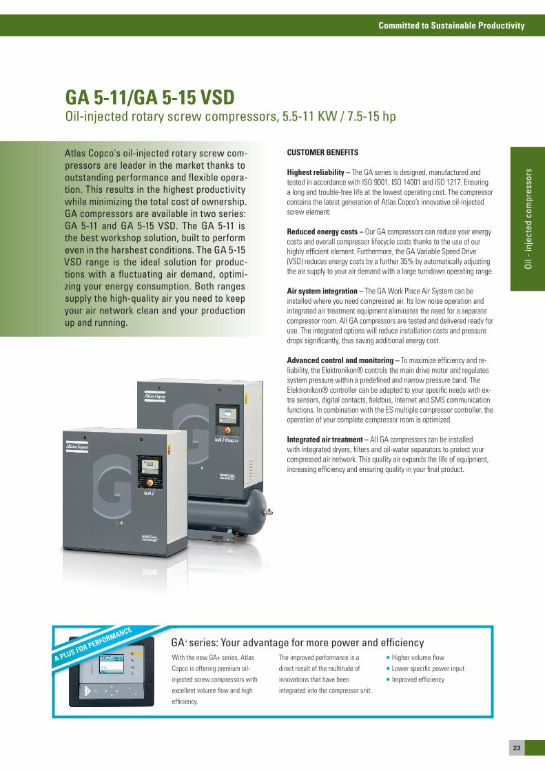
GA 5-11/GA 5-15 VSDOil-injected rotary screw compressors, 5.5-11 KW / 7.5-15 hp
Atlas Copco's oil-injected rotary screw com-pressors are leader in the market thanks to outstanding performance and flexible opera-tion. This results in the highest productivity while minimizing the total cost of ownership. GA compressors are available in two series: GA 5-11 and GA 5-15 VSD. The GA 5-11 is the best workshop solution, built to perform even in the harshest conditions. The GA 5-15 VSD range is the ideal solution for produc-tions with a fluctuating air demand, optimi-zing your energy consumption. Both ranges supply the high-quality air you need to keep your air network clean and your production up and running.
With the new Ga+ series, atlas Copco is offering premium oil-injected screw compressors with excellent volume flow and high efficiency.
The improved performance is a direct result of the multitude ofinnovations that have beenintegrated into the compressor unit.
Higher volume flow Lower specific power input Improved efficiency
GA+ series: Your advantage for more power and efficiencyA PLUS FOR PERFORMANCE
CUSTOMER BENEFITS
Highest reliability – The Ga series is designed, manufactured and tested in accordance with Iso 9001, Iso 14001 and Iso 1217. ensuring a long and trouble-free life at the lowest operating cost. The compressor contains the latest generation of atlas Copco’s innovative oil-injected screw element.
reduced energy costs – our Ga compressors can reduce your energy costs and overall compressor lifecycle costs thanks to the use of our highly efficient element. Furthermore, the Ga Variable speed Drive (VsD) reduces energy costs by a further 35% by automatically adjusting the air supply to your air demand with a large turndown operating range.
Air system integration – The Ga Work Place air system can be installed where you need compressed air. Its low noise operation and integrated air treatment equipment eliminates the need for a separate compressor room. all Ga compressors are tested and delivered ready for use. The integrated options will reduce installation costs and pressure drops significantly, thus saving additional energy cost.
Advanced control and monitoring – To maximize efficiency and re-liability, the elektronikon® controls the main drive motor and regulates system pressure within a predefined and narrow pressure band. The elektronikon® controller can be adapted to your specific needs with ex-tra sensors, digital contacts, fieldbus, Internet and sMs communication functions. In combination with the es multiple compressor controller, the operation of your complete compressor room is optimized.
integrated air treatment – all Ga compressors can be installed with integrated dryers, filters and oil-water separators to protect your compressed air network. This quality air expands the life of equipment, increasing efficiency and ensuring quality in your final product.
24
Committed to Sustainable Productivity
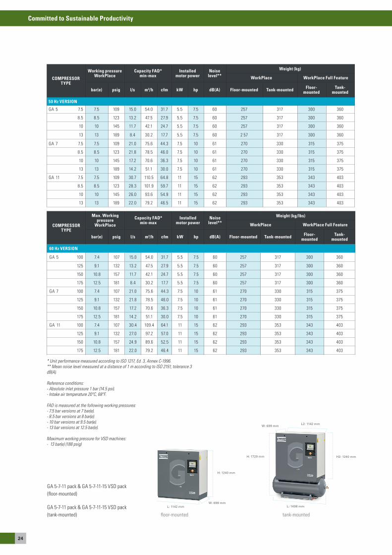
COMPRESSOR TYPE
Working pressure WorkPlace
Capacity FAD* min-max
Installed motor power
Noise level**
Weight (kg)
WorkPlace WorkPlace Full Feature
bar(e) psig l/s m3/h cfm kW hp dB(A) Floor-mounted Tank-mounted Floor-mounted
Tank-mounted
50 Hz VERSION
Ga 5 7.5 7.5 109 15.0 54.0 31.7 5.5 7.5 60 257 317 300 360
8.5 8.5 123 13.2 47.5 27.9 5.5 7.5 60 257 317 300 360
10 10 145 11.7 42.1 24.7 5.5 7.5 60 257 317 300 360
13 13 189 8.4 30.2 17.7 5.5 7.5 60 2 57 317 300 360
Ga 7 7.5 7.5 109 21.0 75.6 44.3 7.5 10 61 270 330 315 375
8.5 8.5 123 21.8 78.5 46.0 7.5 10 61 270 330 315 375
10 10 145 17.2 70.6 36.3 7.5 10 61 270 330 315 375
13 13 189 14.2 51.1 30.0 7.5 10 61 270 330 315 375
Ga 11 7.5 7.5 109 30.7 110.5 64.8 11 15 62 293 353 343 403
8.5 8.5 123 28.3 101.9 59.7 11 15 62 293 353 343 403
10 10 145 26.0 93.6 54.9 11 15 62 293 353 343 403
13 13 189 22.0 79.2 46.5 11 15 62 293 353 343 403
COMPRESSOR TYPE
Max. Working pressure
WorkPlace
Capacity FAD* min-max
Installed motor power
Noise level**
Weight (kg/lbs)
WorkPlace WorkPlace Full Feature
bar(e) psig l/s m3/h cfm kW hp dB(A) Floor-mounted Tank-mounted Floor-mounted
Tank-mounted
60 Hz VERSION
Ga 5 100 7.4 107 15.0 54.0 31.7 5.5 7.5 60 257 317 300 360
125 9.1 132 13.2 47.5 27.9 5.5 7.5 60 257 317 300 360
150 10.8 157 11.7 42.1 24.7 5.5 7.5 60 257 317 300 360
175 12.5 181 8.4 30.2 17.7 5.5 7.5 60 257 317 300 360
Ga 7 100 7.4 107 21.0 75.6 44.3 7.5 10 61 270 330 315 375
125 9.1 132 21.8 78.5 46.0 7.5 10 61 270 330 315 375
150 10.8 157 17.2 70.6 36.3 7.5 10 61 270 330 315 375
175 12.5 181 14.2 51.1 30.0 7.5 10 61 270 330 315 375
Ga 11 100 7.4 107 30.4 109.4 64.1 11 15 62 293 353 343 403
125 9.1 132 27.0 97.2 57.0 11 15 62 293 353 343 403
150 10.8 157 24.9 89.6 52.5 11 15 62 293 353 343 403
175 12.5 181 22.0 79.2 46.4 11 15 62 293 353 343 403
* Unit performance measured according to ISO 1217, Ed. 3, Annex C-1996. ** Mean noise level measured at a distance of 1 m according to ISO 2151; tolerance 3 dB(A).
Reference conditions:- Absolute inlet pressure 1 bar (14.5 psi).- Intake air temperature 20ºC, 68ºF.
FAD is measured at the following working pressures:- 7.5 bar versions at 7 bar(e).- 8.5 bar versions at 8 bar(e).- 10 bar versions at 9.5 bar(e).- 13 bar versions at 12.5 bar(e).
Maximum working pressure for VSD machines: - 13 bar(e) (188 psig)
Ga 5-7-11 pack & Ga 5-7-11-15 VsD pack (floor-mounted)
Ga 5-7-11 pack & Ga 5-7-11-15 VsD pack (tank-mounted)
L: 1498 mm
H2: 1240 mmH: 1729 mm
L: 1142 mm
H: 1240 mm
W: 699 mm
tank-mountedfloor-mounted
W: 699 mmL2: 1142 mm
25
Committed to Sustainable Productivity
Oil
- inj
ecte
d co
mpr
esso
rs
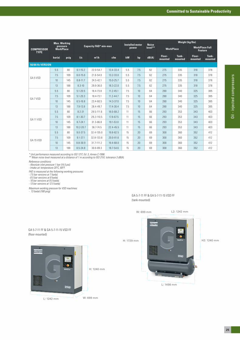
* Unit performance measured according to ISO 1217, Ed. 3, Annex C-1996. ** Mean noise level measured at a distance of 1 m according to ISO 2151; tolerance 3 dB(A).Reference conditions:- Absolute inlet pressure 1 bar (14.5 psi).- Intake air temperature 20ºC, 68ºF.FAD is measured at the following working pressures:- 7.5 bar versions at 7 bar(e).- 8.5 bar versions at 8 bar(e).- 10 bar versions at 9.5 bar(e).- 13 bar versions at 12.5 bar(e).
Maximum working pressure for VSD machines: - 13 bar(e) (188 psig)
Ga 5-7-11 FF & Ga 5-7-11-15 VsD FF (floor-mounted)
Ga 5-7-11 FF & Ga 5-7-11-15 VsD FF (tank-mounted)
L: 1498 mm
H2: 1240 mm
W: 699 mm
H: 1729 mm
L2: 1242 mm
L: 1242 mm
H: 1240 mm
W: 699 mm
COMPRESSOR TYPE
Max. Working pressure
WorkPlaceCapacity FAD* min-max Installed motor
powerNoise
level**
Weight (kg/lbs)
WorkPlace WorkPlace Full Feature
bar(e) psig l/s m3/h cfm kW hp dB(A) Floor-mounted
Tank-mounted
Floor-mounted
Tank-mounted
50/60 Hz VERSION
Ga 5 VsD
5.5 80 6.1-15.2 22.0-54.7 13.4-33.4 5.5 7.5 62 275 335 318 378
7.5 109 6.0-15.0 21.6-54.0 13.2-33.0 5.5 7.5 62 275 335 318 378
10 145 6.8-11.7 24.5-42.1 15.0-25.7 5.5 7.5 62 275 335 318 378
13 188 8.3-10 29.9-36.0 18.3-22.0 5.5 7.5 62 275 335 318 378
Ga 7 VsD
5.5 80 5.1-20.5 18.4-73.8 11.2-45.1 7.5 10 64 280 340 325 385
7.5 109 5.1-20.3 18.4-73.1 11.2-44.7 7.5 10 64 280 340 325 385
10 145 6.5-16.8 23.4-60.5 14.3-37.0 7.5 10 64 280 340 325 385
13 188 7.9-13.8 28.4-49.7 17.4-30.4 7.5 10 64 280 340 325 385
Ga 11 VsD
5.5 80 8.2-31 29.5-111.6 18.0-68.2 11 15 66 293 353 343 403
7.5 109 8.1-30.7 29.2-110.5 17.8-67.5 11 15 66 293 353 343 403
10 145 8.7-24.1 31.3-86.8 19.1-53.0 11 15 66 293 353 343 403
13 188 10.2-20.7 36.7-74.5 22.4-45.5 11 15 66 293 353 343 403
Ga 15 VsD
5.5 80 9.0-37.5 32.4-135.0 19.8-82.5 15 20 69 300 360 352 412
7.5 109 9.1-37.1 32.8-133.6 20.0-81.6 15 20 69 300 360 352 412
10 145 8.8-30.9 31.7-111.2 19.4-68.0 15 20 69 300 360 352 412
13 188 8.5-24.8 30.6-89.3 18.7-54.6 15 20 69 300 360 352 412
26
Committed to Sustainable Productivity
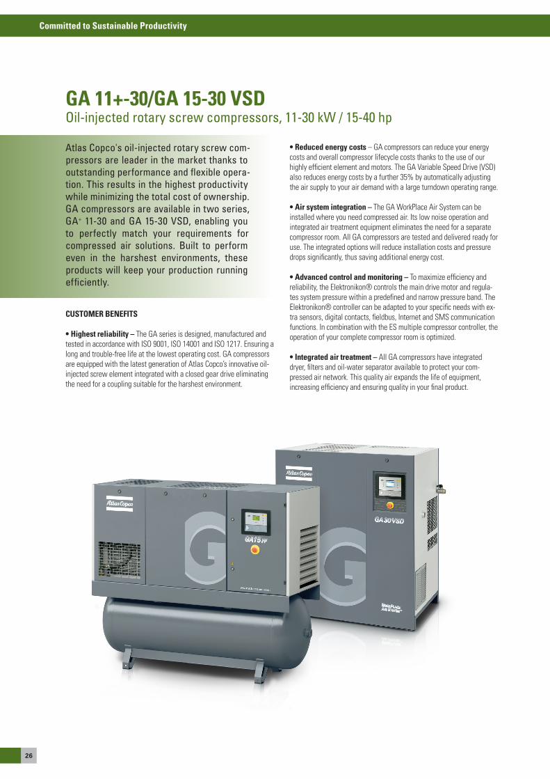
GA 11+-30/GA 15-30 VSDOil-injected rotary screw compressors, 11-30 kW / 15-40 hp
Atlas Copco's oil-injected rotary screw com-pressors are leader in the market thanks to outstanding performance and flexible opera-tion. This results in the highest productivity while minimizing the total cost of ownership. GA compressors are available in two series, GA+ 11-30 and GA 15-30 VSD, enabling you to perfectly match your requirements for compressed air solutions. Built to perform even in the harshest environments, these products will keep your production running efficiently.
CUSTOMER BENEFITS
• Highest reliability – The Ga series is designed, manufactured and tested in accordance with Iso 9001, Iso 14001 and Iso 1217. ensuring a long and trouble-free life at the lowest operating cost. Ga compressors are equipped with the latest generation of atlas Copco’s innovative oil-injected screw element integrated with a closed gear drive eliminating the need for a coupling suitable for the harshest environment.
• reduced energy costs – Ga compressors can reduce your energy costs and overall compressor lifecycle costs thanks to the use of our highly efficient element and motors. The Ga Variable speed Drive (VsD) also reduces energy costs by a further 35% by automatically adjusting the air supply to your air demand with a large turndown operating range.
• Air system integration – The Ga WorkPlace air system can be installed where you need compressed air. Its low noise operation and integrated air treatment equipment eliminates the need for a separate compressor room. all Ga compressors are tested and delivered ready for use. The integrated options will reduce installation costs and pressure drops significantly, thus saving additional energy cost.
• Advanced control and monitoring – To maximize efficiency and reliability, the elektronikon® controls the main drive motor and regula-tes system pressure within a predefined and narrow pressure band. The elektronikon® controller can be adapted to your specific needs with ex-tra sensors, digital contacts, fieldbus, Internet and sMs communication functions. In combination with the es multiple compressor controller, the operation of your complete compressor room is optimized.
• integrated air treatment – all Ga compressors have integrated dryer, filters and oil-water separator available to protect your com-pressed air network. This quality air expands the life of equipment, increasing efficiency and ensuring quality in your final product.
27
Committed to Sustainable Productivity
Oil
- inj
ecte
d co
mpr
esso
rs
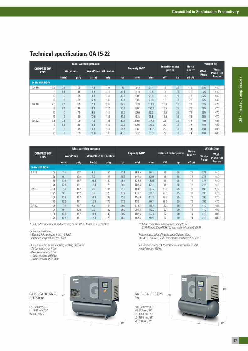
* Unit performance measured according to ISO 1217, Annex C, latest edition.
Reference conditions: - Absolute inlet pressure 1 bar (14.5 psi)- Intake air temperature 20°C, 68°F
FAD is measured at the following working pressures:- 7.5 bar versions at 7 bar- 8 bar versions at 7.5 bar- 10 bar versions at 9.5 bar - 13 bar versions at 12.5 bar
** Mean noise level measured according to ISO 2151/Pneuro/Cagi PN8NTC2 test code; tolerance 2 dB(A).
Pressure dew point of integrated refrigerant dryer of GA 15 - GA 18 - GA 22 at reference conditions 5°C, 41°F.
Air receiver size of GA 15-22 tank-mounted variants: 500L. Added weight: 125 kg.
Technical specifications GA 15-22
Ga 15 - Ga 18 - Ga 22 Pack
H1: 1558 mm, 61”H2: 932 mm, 37”L1: 1853 mm, 73”L2: 1285 mm, 51”W: 680 mm, 27”
H1
H2
L1
L2
W
Ga 15 - Ga 18 - Ga 22 Full Feature
H: 1558 mm, 61”L: 1853 mm, 73”W: 680 mm, 27”
H
WL
COMPRESSOR TYPE
Max. working pressure
Capacity FAD* Installed motor power
Noise level**
Weight (kg)
WorkPlace WorkPlace Full Feature Work-Place
Work- Place Full
Featurebar(e) psig bar(e) psig l/s m³/h cfm kW hp dB(A)
50 Hz VERSION
Ga 15 7.5 7.5 109 7.3 105 43 154.8 91.1 15 20 72 375 4408 8.5 116 8.3 120 39.4 141.8 83.5 15 20 72 375 440
10 10 145 9.8 141 36.3 130.7 76.9 15 20 72 375 44013 13 189 12.8 185 30.1 108.4 63.8 15 20 72 375 440
Ga 18 7.5 7.5 109 7.3 105 52.5 189 111.2 18.5 25 73 395 4708 8.5 116 8.3 120 50.2 180.7 106.4 18.5 25 73 395 470
10 10 145 9.8 141 43.5 156.6 92.2 18.5 25 73 395 47013 13 189 12.8 185 37.2 133.9 78.8 18.5 25 73 395 470
Ga 22 7.5 7.5 109 7.3 105 60.2 216.7 127.6 22 30 74 410 4858 8.5 116 8.3 120 58.3 209.9 123.5 22 30 74 410 485
10 10 145 9.8 141 51.7 186.1 109.5 22 30 74 410 48513 13 189 12.8 185 45.0 162 95.3 22 30 74 410 485
COMPRESSOR TYPE
Max. working pressure
Capacity FAD* Installed motor power Noise level**
Weight (kg)
WorkPlace WorkPlace Full Feature Work- Place
Work- Place Full
Featurebar(e) psig bar(e) psig l/s m³/h cfm kW hp dB(A)
60 Hz VERSION
Ga 15 100 7.4 107 7.2 104 42.5 153.0 90.1 15 20 72 375 440125 9.1 132 8.9 128 39.6 142.6 83.9 15 20 72 375 440150 10.8 157 10.3 149 35.8 128.9 75.9 15 20 72 375 440175 12.5 181 12.3 178 29.3 105.5 62.1 15 20 72 375 440
Ga 18 100 7.4 107 7.2 104 51.3 184.7 108.7 18.5 25 73 395 470125 9.1 132 8.9 128 47.7 171.7 101.1 18.5 25 73 395 470150 10.8 157 10.3 149 43.3 155.9 91.7 18.5 25 73 395 470175 12.5 181 12.3 178 37.8 136.1 80.1 18.5 25 73 395 470
Ga 22 100 7.4 107 7.2 104 60.6 218.2 128.4 22 30 74 410 485125 9.1 132 8.9 128 56.0 201.6 118.7 22 30 74 410 485150 10.8 157 10.3 149 50.7 182.5 107.4 22 30 74 410 485175 12.5 181 12.3 178 46.5 167.4 98.5 22 30 74 410 485

28
Committed to Sustainable Productivity
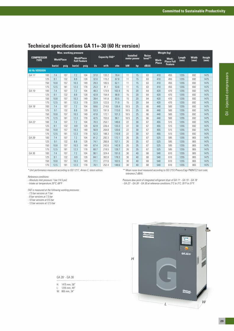
Technical specifications GA 11+-30 (50 Hz version)
* Unit performance measured according to ISO 1217, Annex C, latest edition. Reference conditions: - Absolute inlet pressure 1 bar (14.5 psi)- Intake air temperature 20°C, 68°F
FAD is measured at the following working pressures:- 7.5 bar versions at 7 bar - 8 bar versions at 7.5 bar- 10 bar versions at 9.5 bar - 13 bar versions at 12.5 bar
** Mean noise level measured according to ISO 2151/Pneuro/Cagi PN8NTC2 test code; tolerance 2 dB(A).
Pressure dew point of integrated refrigerant dryer of GA 11+ - GA 15+ - GA 18+ - GA 22+ - GA 26+ - GA 30 at reference conditions 2°C to 3°C, 36°F to 37°F.
Ga 11+ - Ga 15+ - Ga 18+ - Ga 22+
H: 1475 mm, 58”L: 1255 mm, 49”W: 692 mm, 27”
H
L W
COMPRESSOR TYPE
Max. working pressure
Capacity FAD* Installed motor power
Noise level**
Weight (kg)
Length(mm)
Width(mm)
Height(mm)WorkPlace WorkPlace
Full Feature WorkPlace WorkPlace Full Feature
bar(e) psig bar(e) psig l/s m³/h cfm kW hp dB(A)
50 Hz VERSION
Ga 11+ 7.5 7.5 109 7.3 105 35.8 128.9 75.9 11 15 63 410 455 1255 692 1475 8.5 8.5 116 8.3 120 33.8 121.7 71.7 11 15 63 410 455 1255 692 1475
10 10 145 9.8 141 30.3 109.1 64.2 11 15 63 410 455 1255 692 147513 13 189 12.8 185 25.2 90.7 53.4 11 15 63 410 455 1255 692 1475
Ga 15+ 7.5 7.5 109 7.3 105 46.9 168.8 99.4 15 20 64 420 470 1255 692 1475 8.5 8.5 116 8.3 120 43.8 157.7 92.9 15 20 64 420 470 1255 692 1475
10 10 145 9.8 141 39.8 143.3 84.4 15 20 64 420 470 1255 692 147513 13 189 12.8 185 32.8 118.1 69.5 15 20 64 420 470 1255 692 1475
Ga 18+ 7.5 7.5 109 7.3 105 58.1 209.2 123.2 18.5 25 65 440 500 1255 692 1475 8.5 8.5 116 8.3 120 54.3 195.5 115.1 18.5 25 65 440 500 1255 692 1475
10 10 145 9.8 141 48.7 175.3 103.2 18.5 25 65 440 500 1255 692 147513 13 189 12.8 185 41.1 148.0 87.1 18.5 25 65 440 500 1255 692 1475
Ga 22+ 7.5 7.5 109 7.3 105 68.2 245.5 144.6 22 30 66 455 515 1255 692 1475 8.5 8.5 116 8.3 120 64.5 232.2 136.7 22 30 66 455 515 1255 692 1475
10 10 145 9.8 141 58.1 209.2 123.2 22 30 66 455 515 1255 692 147513 13 189 12.8 185 50.7 182.5 107.5 22 30 66 455 515 1255 692 1475
Ga 26+ 7.5 7.5 109 7.3 105 79.8 287.3 169.2 26 35 67 525 595 1255 865 1475 8.5 8.5 116 8.3 120 76.2 274.3 161.5 26 35 67 525 595 1255 865 1475
10 10 145 9.8 141 69.3 249.5 146.9 26 35 67 525 595 1255 865 147513 13 189 12.8 185 60.1 216.4 127.4 26 35 67 525 595 1255 865 1475
Ga 30 7.5 7.5 109 7.3 105 90.0 324.0 190.8 30 40 68 540 610 1255 865 1475 8.5 8.5 116 8.3 120 86.4 311.0 183.2 30 40 68 540 610 1255 865 1475
10 10 145 9.8 141 79.8 287.3 169.2 30 40 68 540 610 1255 865 147513 13 189 12.8 185 68.7 247.3 145.6 30 40 68 540 610 1255 865 1475
29
Committed to Sustainable Productivity
Oil
- inj
ecte
d co
mpr
esso
rs
* Unit performance measured according to ISO 1217, Annex C, latest edition. Reference conditions: - Absolute inlet pressure 1 bar (14.5 psi)- Intake air temperature 20°C, 68°F
FAD is measured at the following working pressures:- 7.5 bar versions at 7 bar - 8 bar versions at 7.5 bar- 10 bar versions at 9.5 bar - 13 bar versions at 12.5 bar
** Mean noise level measured according to ISO 2151/Pneuro/Cagi PN8NTC2 test code; tolerance 2 dB(A).
Pressure dew point of integrated refrigerant dryer of GA 11+ - GA 15+ - GA 18+ - GA 22+ - GA 26+ - GA 30 at reference conditions 2°C to 3°C, 35°F to 37°F.
Ga 26+ - Ga 30
H: 1475 mm, 58”L: 1255 mm, 49”W: 865 mm, 34”
H
WL
Technical specifications GA 11+-30 (60 Hz version)
COMPRESSOR TYPE
Max. working pressure
Capacity FAD* Installed motor power
Noise level**
Weight (kg)
Length(mm)
Width(mm)
Height(mm)WorkPlace WorkPlace
Full Feature Work-Place
Work-Place Full
Featurebar(e) psig bar(e) psig l/s m³/h cfm kW hp dB(A)
60 Hz VERSION
Ga 11+ 100 7.4 107 7.2 104 37.0 133.2 78.4 11 15 63 410 455 1255 692 1475125 9.1 132 8.9 128 32.0 115.2 67.8 11 15 63 410 455 1255 692 1475150 10.8 157 10.3 149 29.3 105.5 62.1 11 15 63 410 455 1255 692 1475175 12.5 181 12.3 178 25.3 91.1 53.6 11 15 63 410 455 1255 692 1475
Ga 15+ 100 7.4 107 7.2 104 48.3 173.9 102.4 15 20 64 420 470 1255 692 1475125 9.1 132 8.9 128 42.9 154.4 90.9 15 20 64 420 470 1255 692 1475150 10.8 157 10.3 149 39.4 141.8 83.5 15 20 64 420 470 1255 692 1475175 12.5 181 12.3 178 33.9 122.0 71.9 15 20 64 420 470 1255 692 1475
Ga 18+ 100 7.4 107 7.2 104 59.6 214.6 126.4 18.5 25 66 440 500 1255 692 1475125 9.1 132 8.9 128 53.3 191.9 113.0 18.5 25 66 440 500 1255 692 1475150 10.8 157 10.3 149 47.8 172.1 101.3 18.5 25 66 440 500 1255 692 1475175 12.5 181 12.3 178 42.5 153.0 90.1 18.5 25 66 440 500 1255 692 1475
Ga 22+ 100 7.4 107 7.2 104 70.3 253.1 149.0 22 30 67 455 515 1255 692 1475125 9.1 132 8.9 128 62.9 226.4 133.3 22 30 67 455 515 1255 692 1475150 10.8 157 10.3 149 56.9 204.8 120.6 22 30 67 455 515 1255 692 1475175 12.5 181 12.3 178 52.3 188.3 110.9 22 30 67 455 515 1255 692 1475
Ga 26+ 100 7.4 107 7.2 104 81.2 292.3 172.1 26 35 67 525 595 1255 865 1475125 9.1 132 8.9 128 74.1 266.8 157.1 26 35 67 525 595 1255 865 1475150 10.8 157 10.3 149 67.4 242.6 142.9 26 35 67 525 595 1255 865 1475175 12.5 181 12.3 178 60.7 218.5 128.7 26 35 67 525 595 1255 865 1475
Ga 30 100 7.4 107 7.2 104 90.1 324.4 191.0 30 40 68 540 610 1255 865 1475125 9.1 132 8.9 128 84.1 302.8 178.3 30 40 68 540 610 1255 865 1475150 10.8 157 10.3 149 77.1 277.6 163.5 30 40 68 540 610 1255 865 1475175 12.5 181 12.3 178 70.1 252.4 148.6 30 40 68 540 610 1255 865 1475

30
Committed to Sustainable Productivity
Ga 15 VsD - Ga 18 VsD - Ga 22 VsD - Ga 30 VsD
H: 1400 mm, 55”L: 1380 mm, 66”W: 650 mm, 26”
H
WL
Technical specifications GA 15-30 VSD
* Unit performance measured according to ISO 1217, Annex C, latest edition.
Reference conditions: - Absolute inlet pressure 1 bar (14.5 psi) - Intake air temperature 20°C, 68°F
** Mean noise level measured according to ISO 2151/Pneuro/Cagi PN8NTC2 test code; tolerance 2 dB(A).
Pressure dew point of integrated refrigerant dryer at reference conditions: 2°C to 3°C, 35°F to 37°F.
Maximum working pressure for VSD machines: 13 bar(e) (188 psig)
COMPRESSOR TYPE
Max. working pressure Capacity FAD Min.-Max.
Installed motor power
Noise level
50/60 Hz
Weight (kg)
Length(mm)
Width(mm)
Height(mm)WorkPlace l/s m3/h cfm Work-
Place
WorkPlace Full
Featurebar(e) psig Min. Max. Min. Max. Min. Max. kW hp dB(A)
Ga 15 VsD 4 58 16.0 48.7 57.6 175.3 33.9 103.2 15 20 66 480 530 1255 865 14757 102 15.9 48.5 57.2 174.6 33.7 102.8 15 20 66 480 530 1255 865 147510 145 18.0 41.6 64.8 149.8 38.2 88.2 15 20 66 480 530 1255 865 147513 188 20.4 32.8 73.4 118.1 43.2 69.5 15 20 65 480 530 1255 865 1475
Ga 18 VsD 4 58 16.0 60.1 57.6 216.4 33.9 127.4 18 25 67 490 550 1255 865 14757 102 15.9 60.0 57.2 216.0 33.7 127.2 18 25 67 490 550 1255 865 147510 145 18.0 52.0 64.8 187.2 38.2 110.2 18 25 67 490 550 1255 865 147513 188 20.4 42.0 73.4 151.2 43.2 89.0 18 25 66 490 550 1255 865 1475
Ga 22 VsD 4 58 16.0 70.5 57.6 253.8 33.9 149.5 22 30 68 500 560 1255 865 14757 102 15.9 70.3 57.2 253.1 33.7 149.5 22 30 68 500 560 1255 865 147510 145 18.0 61.4 64.8 221.0 38.2 130.2 22 30 68 500 560 1255 865 147513 188 20.4 50.2 73.4 180.7 43.2 106.4 22 30 67 500 560 1255 865 1475
Ga 26 VsD 4 58 16.0 81.5 57.6 293.4 33.9 172.8 26 35 70 520 590 1255 865 14757 102 15.9 81.2 57.2 292.3 33.7 172.1 26 35 70 520 590 1255 865 147510 145 18.0 72.4 64.8 260.6 38.2 153.5 26 35 70 520 590 1255 865 147513 188 20.4 59.7 73.4 214.9 43.2 126.6 26 35 69 520 590 1255 865 1475
Ga 30 VsD 4 58 16.0 93.3 57.6 335.9 33.9 197.8 30 35 70 530 600 1255 865 14757 102 15.9 93.0 57.2 334.8 33.7 197.2 30 35 70 530 600 1255 865 147510 145 18.0 82.7 64.8 297.7 38.2 175.3 30 35 70 530 600 1255 865 147513 188 20.4 70.8 73.4 254.9 43.2 150.1 30 35 69 530 600 1255 865 1475
31
Committed to Sustainable Productivity
Oil
- inj
ecte
d co
mpr
esso
rs
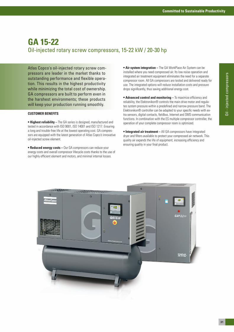
Atlas Copco's oil-injected rotary screw com-pressors are leader in the market thanks to outstanding performance and flexible opera-tion. This results in the highest productivity while minimizing the total cost of ownership. GA compressors are built to perform even in the harshest environments; these products will keep your production running smoothly.
GA 15-22Oil-injected rotary screw compressors, 15-22 kW / 20-30 hp
CUSTOMER BENEFITS
• Highest reliability – The Ga series is designed, manufactured and tested in accordance with Iso 9001, Iso 14001 and Iso 1217. ensuring a long and trouble-free life at the lowest operating cost. Ga compres-sors are equipped with the latest generation of atlas Copco’s innovative oil-injected screw element.
• reduced energy costs – our Ga compressors can reduce your energy costs and overall compressor lifecycle costs thanks to the use of our highly efficient element and motors, and minimal internal losses.
• Air system integration – The Ga WorkPlace air system can be installed where you need compressed air. Its low noise operation and integrated air treatment equipment eliminates the need for a separate compressor room. all Ga compressors are tested and delivered ready for use. The integrated options will reduce installation costs and pressure drops significantly, thus saving additional energy cost.
• Advanced control and monitoring – To maximize efficiency and reliability, the elektronikon® controls the main drive motor and regula-tes system pressure within a predefined and narrow pressure band. The elektronikon® controller can be adapted to your specific needs with ex-tra sensors, digital contacts, fieldbus, Internet and sMs communication functions. In combination with the es multiple compressor controller, the operation of your complete compressor room is optimized.
• integrated air treatment – all Ga compressors have integrated dryer and filters available to protect your compressed air network. This quality air expands the life of equipment, increasing efficiency and ensuring quality in your final product.
32
Committed to Sustainable Productivity
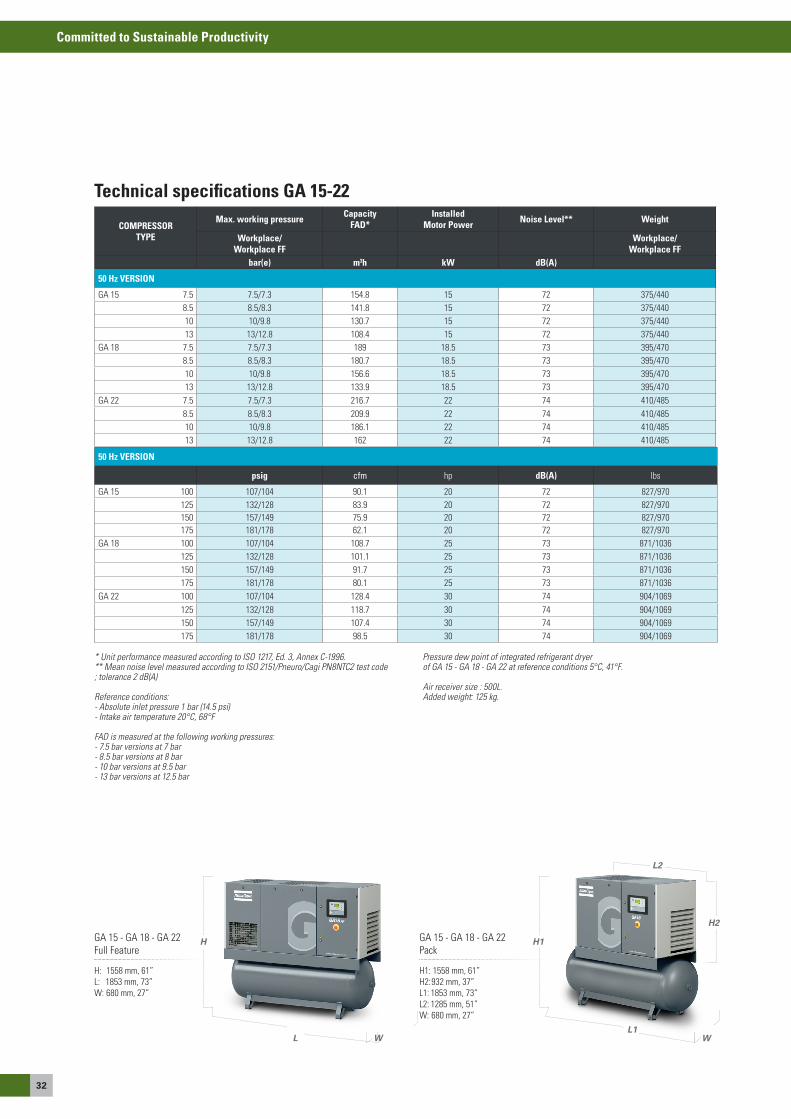
Technical specifications GA 15-22
COMPRESSOR TYPE
Max. working pressure Capacity FAD*
InstalledMotor Power Noise Level** Weight
Workplace/Workplace FF
Workplace/Workplace FF
bar(e) m3h kW dB(A)
50 Hz VERSION
Ga 15 7.5 7.5/7.3 154.8 15 72 375/4408.5 8.5/8.3 141.8 15 72 375/44010 10/9.8 130.7 15 72 375/44013 13/12.8 108.4 15 72 375/440
Ga 18 7.5 7.5/7.3 189 18.5 73 395/4708.5 8.5/8.3 180.7 18.5 73 395/47010 10/9.8 156.6 18.5 73 395/47013 13/12.8 133.9 18.5 73 395/470
Ga 22 7.5 7.5/7.3 216.7 22 74 410/4858.5 8.5/8.3 209.9 22 74 410/48510 10/9.8 186.1 22 74 410/48513 13/12.8 162 22 74 410/485
* Unit performance measured according to ISO 1217, Ed. 3, Annex C-1996. ** Mean noise level measured according to ISO 2151/Pneuro/Cagi PN8NTC2 test code; tolerance 2 dB(A)
Reference conditions: - Absolute inlet pressure 1 bar (14.5 psi)- Intake air temperature 20°C, 68°F
FAD is measured at the following working pressures:- 7.5 bar versions at 7 bar- 8.5 bar versions at 8 bar - 10 bar versions at 9.5 bar - 13 bar versions at 12.5 bar
Pressure dew point of integrated refrigerant dryer of GA 15 - GA 18 - GA 22 at reference conditions 5°C, 41°F.
Air receiver size : 500L. Added weight: 125 kg.
50 Hz VERSION
psig cfm hp dB(A) lbs
Ga 15 100 107/104 90.1 20 72 827/970125 132/128 83.9 20 72 827/970150 157/149 75.9 20 72 827/970175 181/178 62.1 20 72 827/970
Ga 18 100 107/104 108.7 25 73 871/1036125 132/128 101.1 25 73 871/1036150 157/149 91.7 25 73 871/1036175 181/178 80.1 25 73 871/1036
Ga 22 100 107/104 128.4 30 74 904/1069125 132/128 118.7 30 74 904/1069150 157/149 107.4 30 74 904/1069175 181/178 98.5 30 74 904/1069
H1
H2
L1
L2
W
Ga 15 - Ga 18 - Ga 22 Pack
Ga 15 - Ga 18 - Ga 22 Full Feature
H1: 1558 mm, 61”H2: 932 mm, 37”L1: 1853 mm, 73”L2: 1285 mm, 51”W: 680 mm, 27”
H: 1558 mm, 61”L: 1853 mm, 73”W: 680 mm, 27”
H
WL
33
Committed to Sustainable Productivity
Oil
- inj
ecte
d co
mpr
esso
rs
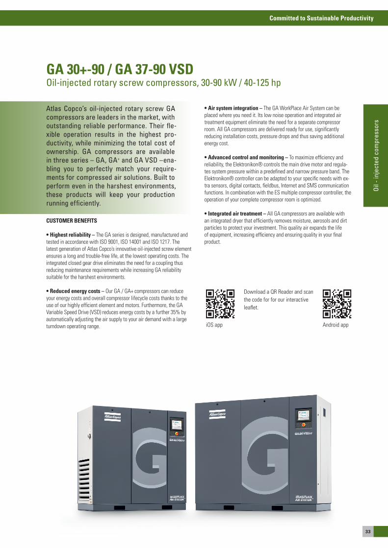
Atlas Copco’s oil-injected rotary screw GA compressors are leaders in the market, with outstanding reliable performance. Their fle-xible operation results in the highest pro-ductivity, while minimizing the total cost of ownership. GA compressors are available in three series – GA, GA+ and GA VSD –ena-bling you to perfectly match your require-ments for compressed air solutions. Built to perform even in the harshest environments, these products will keep your production running efficiently.
GA 30+-90 / GA 37-90 VSDOil-injected rotary screw compressors, 30-90 kW / 40-125 hp
CUSTOMER BENEFITS
• Highest reliability – The Ga series is designed, manufactured and tested in accordance with Iso 9001, Iso 14001 and Iso 1217. The latest generation of atlas Copco’s innovative oil-injected screw element ensures a long and trouble-free life, at the lowest operating costs. The integrated closed gear drive eliminates the need for a coupling thus reducing maintenance requirements while increasing Ga reliability suitable for the harshest environments.
• reduced energy costs – our Ga / Ga+ compressors can reduce your energy costs and overall compressor lifecycle costs thanks to the use of our highly efficient element and motors. Furthermore, the Ga Variable speed Drive (VsD) reduces energy costs by a further 35% by automatically adjusting the air supply to your air demand with a large turndown operating range.
• Air system integration – The Ga WorkPlace air system can be placed where you need it. Its low noise operation and integrated air treatment equipment eliminate the need for a separate compressor room. all Ga compressors are delivered ready for use, significantly reducing installation costs, pressure drops and thus saving additional energy cost.
• Advanced control and monitoring – To maximize efficiency and reliability, the elektronikon® controls the main drive motor and regula-tes system pressure within a predefined and narrow pressure band. The elektronikon® controller can be adapted to your specific needs with ex-tra sensors, digital contacts, fieldbus, Internet and sMs communication functions. In combination with the es multiple compressor controller, the operation of your complete compressor room is optimized.
• integrated air treatment – all Ga compressors are available with an integrated dryer that efficiently removes moisture, aerosols and dirt particles to protect your investment. This quality air expands the life of equipment, increasing efficiency and ensuring quality in your final product.
Download a QR Reader and scanthe code for for our interactiveleaflet.
ios app android app
34
Committed to Sustainable Productivity
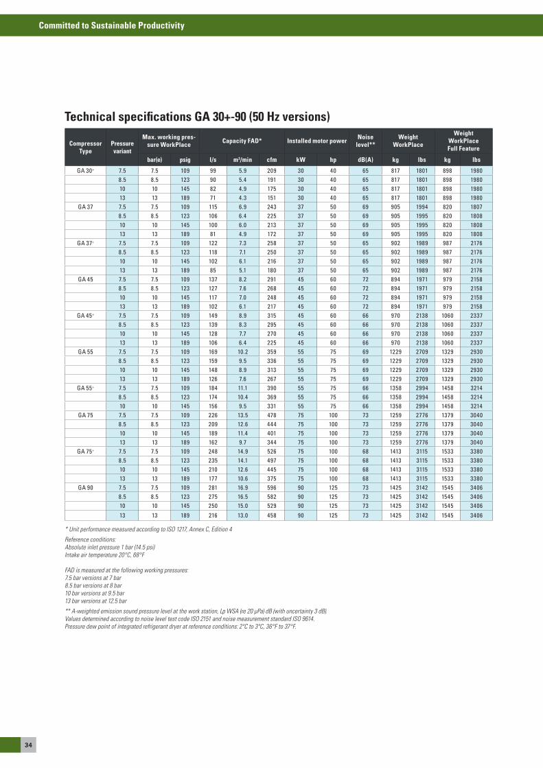
* Unit performance measured according to ISO 1217, Annex C, Edition 4
Reference conditions:Absolute inlet pressure 1 bar (14.5 psi)Intake air temperature 20°C, 68°F
FAD is measured at the following working pressures:7.5 bar versions at 7 bar8.5 bar versions at 8 bar10 bar versions at 9.5 bar13 bar versions at 12.5 bar
** A-weighted emission sound pressure level at the work station, Lp WSA (re 20 μPa) dB (with uncertainty 3 dB).Values determined according to noise level test code ISO 2151 and noise measurement standard ISO 9614.Pressure dew point of integrated refrigerant dryer at reference conditions: 2ºC to 3ºC, 36°F to 37°F.
Technical specifications GA 30+-90 (50 Hz versions)
Compressor Type
Pressure variant
Max. working pres-sure WorkPlace Capacity FAD* Installed motor power Noise
level**Weight
WorkPlace
Weight WorkPlace Full Feature
bar(e) psig l/s m3/min cfm kW hp dB(A) kg lbs kg lbs
GA 30+ 7.5 7.5 109 99 5.9 209 30 40 65 817 1801 898 19808.5 8.5 123 90 5.4 191 30 40 65 817 1801 898 198010 10 145 82 4.9 175 30 40 65 817 1801 898 198013 13 189 71 4.3 151 30 40 65 817 1801 898 1980
GA 37 7.5 7.5 109 115 6.9 243 37 50 69 905 1994 820 18078.5 8.5 123 106 6.4 225 37 50 69 905 1995 820 180810 10 145 100 6.0 213 37 50 69 905 1995 820 180813 13 189 81 4.9 172 37 50 69 905 1995 820 1808
GA 37+ 7.5 7.5 109 122 7.3 258 37 50 65 902 1989 987 21768.5 8.5 123 118 7.1 250 37 50 65 902 1989 987 217610 10 145 102 6.1 216 37 50 65 902 1989 987 217613 13 189 85 5.1 180 37 50 65 902 1989 987 2176
GA 45 7.5 7.5 109 137 8.2 291 45 60 72 894 1971 979 21588.5 8.5 123 127 7.6 268 45 60 72 894 1971 979 215810 10 145 117 7.0 248 45 60 72 894 1971 979 215813 13 189 102 6.1 217 45 60 72 894 1971 979 2158
GA 45+ 7.5 7.5 109 149 8.9 315 45 60 66 970 2138 1060 23378.5 8.5 123 139 8.3 295 45 60 66 970 2138 1060 233710 10 145 128 7.7 270 45 60 66 970 2138 1060 233713 13 189 106 6.4 225 45 60 66 970 2138 1060 2337
GA 55 7.5 7.5 109 169 10.2 359 55 75 69 1229 2709 1329 29308.5 8.5 123 159 9.5 336 55 75 69 1229 2709 1329 293010 10 145 148 8.9 313 55 75 69 1229 2709 1329 293013 13 189 126 7.6 267 55 75 69 1229 2709 1329 2930
GA 55+ 7.5 7.5 109 184 11.1 390 55 75 66 1358 2994 1458 32148.5 8.5 123 174 10.4 369 55 75 66 1358 2994 1458 321410 10 145 156 9.5 331 55 75 66 1358 2994 1458 3214
GA 75 7.5 7.5 109 226 13.5 478 75 100 73 1259 2776 1379 30408.5 8.5 123 209 12.6 444 75 100 73 1259 2776 1379 304010 10 145 189 11.4 401 75 100 73 1259 2776 1379 304013 13 189 162 9.7 344 75 100 73 1259 2776 1379 3040
GA 75+ 7.5 7.5 109 248 14.9 526 75 100 68 1413 3115 1533 33808.5 8.5 123 235 14.1 497 75 100 68 1413 3115 1533 338010 10 145 210 12.6 445 75 100 68 1413 3115 1533 338013 13 189 177 10.6 375 75 100 68 1413 3115 1533 3380
GA 90 7.5 7.5 109 281 16.9 596 90 125 73 1425 3142 1545 34068.5 8.5 123 275 16.5 582 90 125 73 1425 3142 1545 340610 10 145 250 15.0 529 90 125 73 1425 3142 1545 3406
13 13 189 216 13.0 458 90 125 73 1425 3142 1545 3406
35
Committed to Sustainable Productivity
Oil
- inj
ecte
d co
mpr
esso
rs
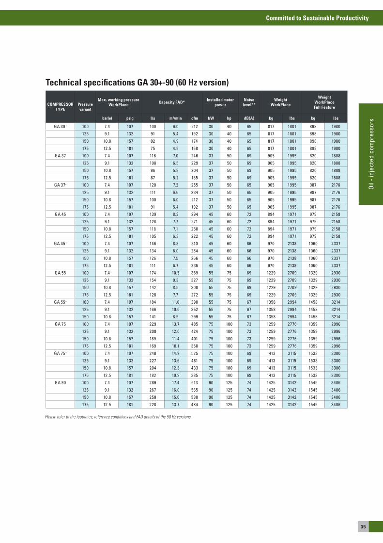
Technical specifications GA 30+-90 (60 Hz version)
COMPRESSOR TYPE
Pressure variant
Max. working pressure WorkPlace Capacity FAD* Installed motor
powerNoise
level**Weight
WorkPlace
Weight WorkPlace Full Feature
bar(e) psig l/s m3/min cfm kW hp dB(A) kg lbs kg lbs
GA 30+ 100 7.4 107 100 6.0 212 30 40 65 817 1801 898 1980
125 9.1 132 91 5.4 192 30 40 65 817 1801 898 1980
150 10.8 157 82 4.9 174 30 40 65 817 1801 898 1980
175 12.5 181 75 4.5 158 30 40 65 817 1801 898 1980
GA 37 100 7.4 107 116 7.0 246 37 50 69 905 1995 820 1808
125 9.1 132 108 6.5 229 37 50 69 905 1995 820 1808
150 10.8 157 96 5.8 204 37 50 69 905 1995 820 1808
175 12.5 181 87 5.2 185 37 50 69 905 1995 820 1808
GA 37+ 100 7.4 107 120 7.2 255 37 50 65 905 1995 987 2176
125 9.1 132 111 6.6 234 37 50 65 905 1995 987 2176
150 10.8 157 100 6.0 212 37 50 65 905 1995 987 2176
175 12.5 181 91 5.4 192 37 50 65 905 1995 987 2176
GA 45 100 7.4 107 139 8.3 294 45 60 72 894 1971 979 2158
125 9.1 132 128 7.7 271 45 60 72 894 1971 979 2158
150 10.8 157 118 7.1 250 45 60 72 894 1971 979 2158
175 12.5 181 105 6.3 222 45 60 72 894 1971 979 2158
GA 45+ 100 7.4 107 146 8.8 310 45 60 66 970 2138 1060 2337
125 9.1 132 134 8.0 284 45 60 66 970 2138 1060 2337
150 10.8 157 126 7.5 266 45 60 66 970 2138 1060 2337
175 12.5 181 111 6.7 236 45 60 66 970 2138 1060 2337
GA 55 100 7.4 107 174 10.5 369 55 75 69 1229 2709 1329 2930
125 9.1 132 154 9.3 327 55 75 69 1229 2709 1329 2930
150 10.8 157 142 8.5 300 55 75 69 1229 2709 1329 2930
175 12.5 181 128 7.7 272 55 75 69 1229 2709 1329 2930
GA 55+ 100 7.4 107 184 11.0 390 55 75 67 1358 2994 1458 3214
125 9.1 132 166 10.0 352 55 75 67 1358 2994 1458 3214
150 10.8 157 141 8.5 299 55 75 67 1358 2994 1458 3214
GA 75 100 7.4 107 229 13.7 485 75 100 73 1259 2776 1359 2996
125 9.1 132 200 12.0 424 75 100 73 1259 2776 1359 2996
150 10.8 157 189 11.4 401 75 100 73 1259 2776 1359 2996
175 12.5 181 169 10.1 358 75 100 73 1259 2776 1359 2996
GA 75+ 100 7.4 107 248 14.9 525 75 100 69 1413 3115 1533 3380
125 9.1 132 227 13.6 481 75 100 69 1413 3115 1533 3380
150 10.8 157 204 12.3 433 75 100 69 1413 3115 1533 3380
175 12.5 181 182 10.9 385 75 100 69 1413 3115 1533 3380
GA 90 100 7.4 107 289 17.4 613 90 125 74 1425 3142 1545 3406
125 9.1 132 267 16.0 565 90 125 74 1425 3142 1545 3406
150 10.8 157 250 15.0 530 90 125 74 1425 3142 1545 3406
175 12.5 181 228 13.7 484 90 125 74 1425 3142 1545 3406
Please refer to the footnotes, reference conditions and FAD details of the 50 Hz versions.
36
Committed to Sustainable Productivity
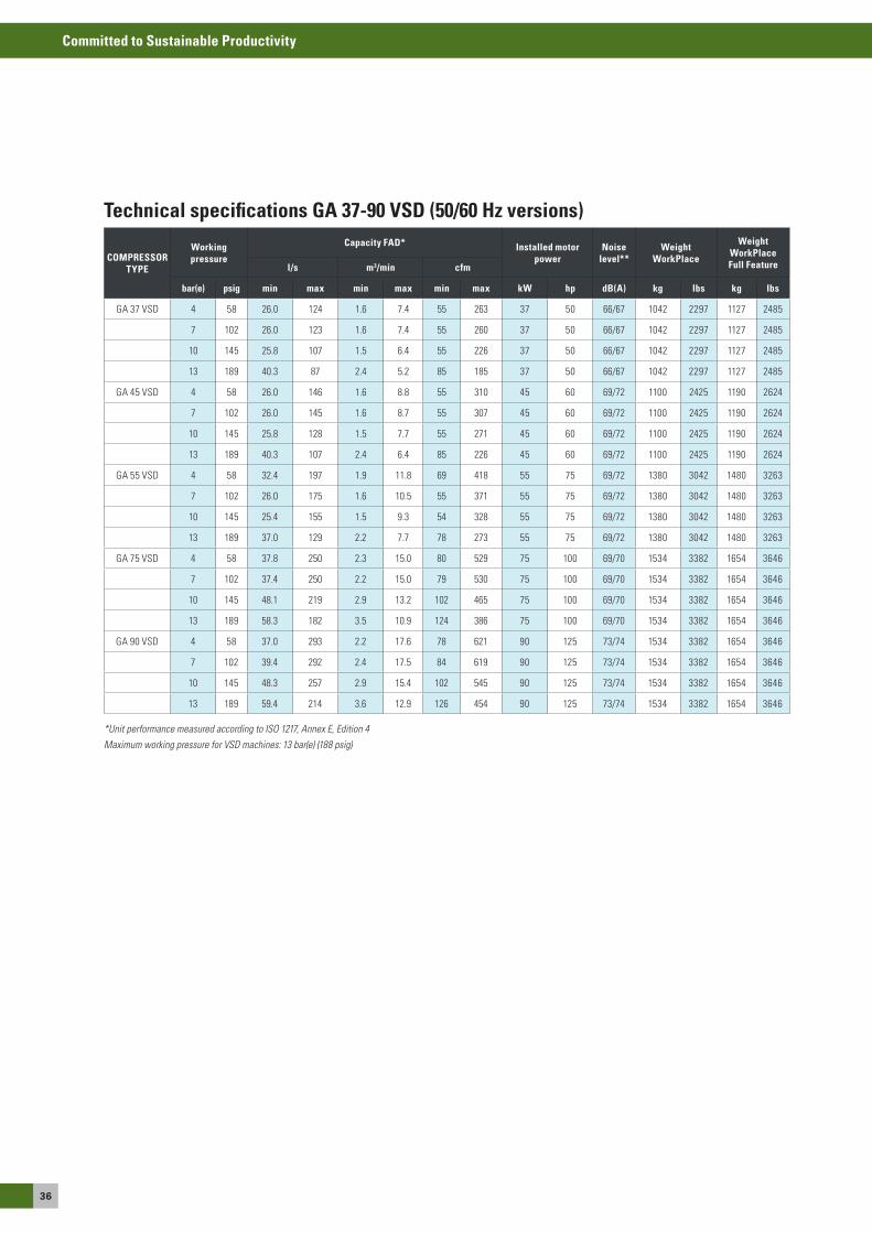
Technical specifications GA 37-90 VSD (50/60 Hz versions)
*Unit performance measured according to ISO 1217, Annex E, Edition 4
Maximum working pressure for VSD machines: 13 bar(e) (188 psig)
COMPRESSOR TYPE
Working pressure
Capacity FAD* Installed motor power
Noise level**
Weight WorkPlace
Weight WorkPlace Full Featurel/s m3/min cfm
bar(e) psig min max min max min max kW hp dB(A) kg lbs kg lbs
Ga 37 VsD 4 58 26.0 124 1.6 7.4 55 263 37 50 66/67 1042 2297 1127 2485
7 102 26.0 123 1.6 7.4 55 260 37 50 66/67 1042 2297 1127 2485
10 145 25.8 107 1.5 6.4 55 226 37 50 66/67 1042 2297 1127 2485
13 189 40.3 87 2.4 5.2 85 185 37 50 66/67 1042 2297 1127 2485
Ga 45 VsD 4 58 26.0 146 1.6 8.8 55 310 45 60 69/72 1100 2425 1190 2624
7 102 26.0 145 1.6 8.7 55 307 45 60 69/72 1100 2425 1190 2624
10 145 25.8 128 1.5 7.7 55 271 45 60 69/72 1100 2425 1190 2624
13 189 40.3 107 2.4 6.4 85 226 45 60 69/72 1100 2425 1190 2624
Ga 55 VsD 4 58 32.4 197 1.9 11.8 69 418 55 75 69/72 1380 3042 1480 3263
7 102 26.0 175 1.6 10.5 55 371 55 75 69/72 1380 3042 1480 3263
10 145 25.4 155 1.5 9.3 54 328 55 75 69/72 1380 3042 1480 3263
13 189 37.0 129 2.2 7.7 78 273 55 75 69/72 1380 3042 1480 3263
Ga 75 VsD 4 58 37.8 250 2.3 15.0 80 529 75 100 69/70 1534 3382 1654 3646
7 102 37.4 250 2.2 15.0 79 530 75 100 69/70 1534 3382 1654 3646
10 145 48.1 219 2.9 13.2 102 465 75 100 69/70 1534 3382 1654 3646
13 189 58.3 182 3.5 10.9 124 386 75 100 69/70 1534 3382 1654 3646
Ga 90 VsD 4 58 37.0 293 2.2 17.6 78 621 90 125 73/74 1534 3382 1654 3646
7 102 39.4 292 2.4 17.5 84 619 90 125 73/74 1534 3382 1654 3646
10 145 48.3 257 2.9 15.4 102 545 90 125 73/74 1534 3382 1654 3646
13 189 59.4 214 3.6 12.9 126 454 90 125 73/74 1534 3382 1654 3646
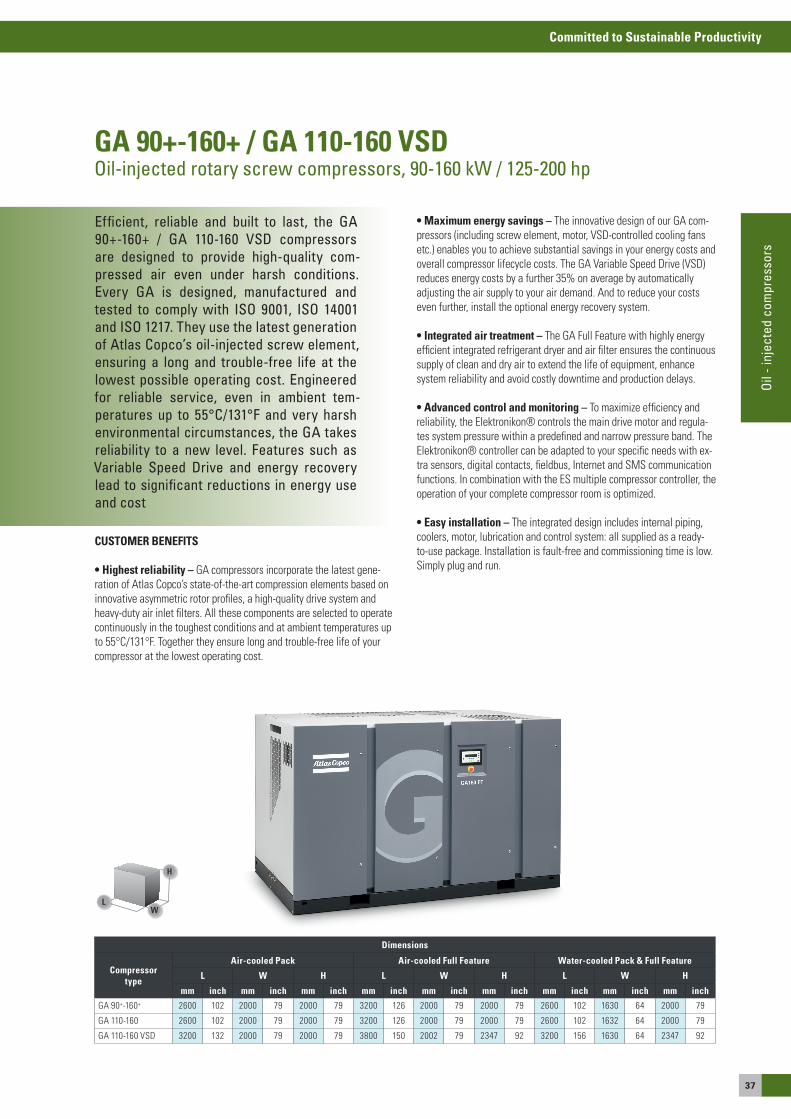
37
Committed to Sustainable Productivity
Oil
- inj
ecte
d co
mpr
esso
rs
Efficient, reliable and built to last, the GA 90+-160+ / GA 110-160 VSD compressors are designed to provide high-quality com-pressed air even under harsh conditions. Every GA is designed, manufactured and tested to comply with ISO 9001, ISO 14001 and ISO 1217. They use the latest generation of Atlas Copco’s oil-injected screw element, ensuring a long and trouble-free life at the lowest possible operating cost. Engineered for reliable service, even in ambient tem-peratures up to 55°C/131°F and very harsh environmental circumstances, the GA takes reliability to a new level. Features such as Variable Speed Drive and energy recovery lead to significant reductions in energy use and cost
GA 90+-160+ / GA 110-160 VSDOil-injected rotary screw compressors, 90-160 kW / 125-200 hp
CUSTOMER BENEFITS
• Highest reliability – Ga compressors incorporate the latest gene-ration of atlas Copco’s state-of-the-art compression elements based on innovative asymmetric rotor profiles, a high-quality drive system and heavy-duty air inlet filters. all these components are selected to operate continuously in the toughest conditions and at ambient temperatures up to 55°C/131°F. Together they ensure long and trouble-free life of your compressor at the lowest operating cost.
Dimensions
Compressor type
Air-cooled Pack Air-cooled Full Feature Water-cooled Pack & Full Feature
L W H L W H L W H
mm inch mm inch mm inch mm inch mm inch mm inch mm inch mm inch mm inch
Ga 90+-160+ 2600 102 2000 79 2000 79 3200 126 2000 79 2000 79 2600 102 1630 64 2000 79
Ga 110-160 2600 102 2000 79 2000 79 3200 126 2000 79 2000 79 2600 102 1632 64 2000 79
Ga 110-160 VsD 3200 132 2000 79 2000 79 3800 150 2002 79 2347 92 3200 156 1630 64 2347 92
LW
H
• Maximum energy savings – The innovative design of our Ga com-pressors (including screw element, motor, VsD-controlled cooling fans etc.) enables you to achieve substantial savings in your energy costs and overall compressor lifecycle costs. The Ga Variable speed Drive (VsD) reduces energy costs by a further 35% on average by automatically adjusting the air supply to your air demand. and to reduce your costs even further, install the optional energy recovery system.
• integrated air treatment – The Ga Full Feature with highly energy efficient integrated refrigerant dryer and air filter ensures the continuous supply of clean and dry air to extend the life of equipment, enhance system reliability and avoid costly downtime and production delays. • Advanced control and monitoring – To maximize efficiency and reliability, the elektronikon® controls the main drive motor and regula-tes system pressure within a predefined and narrow pressure band. The elektronikon® controller can be adapted to your specific needs with ex-tra sensors, digital contacts, fieldbus, Internet and sMs communication functions. In combination with the es multiple compressor controller, the operation of your complete compressor room is optimized.
• Easy installation – The integrated design includes internal piping, coolers, motor, lubrication and control system: all supplied as a ready-to-use package. Installation is fault-free and commissioning time is low. simply plug and run.

38
Committed to Sustainable Productivity
COMPRESSOR TYPE
Maximum working pressure Capacity FAD(1)Installed
motor powerNoise Level(2)
Weight
Pack Full Feature(3) Pack Full Feature Pack Full Feature
bar(e) psig bar(e) psig l/s m3/min cfm l/s m3/min cfm kW HP dB(A) kg lb kg lb
GA 50 HzGA 90+ - 5.5 5.5 80 5.3 77 330 19.8 699 333 20.0 706 90 125 68 2917 6417 3310 7282GA 90+ - 7.5 7.5 109 7.3 106 292 17.5 619 293 17.6 621 90 125 68 2917 6417 3310 7282GA 90+ - 8.5 8.5 123 8.3 120 274 16.4 581 275 16.5 583 90 125 68 2897 6373 3290 7238GA 90+ - 10 10 145 9.8 142 244 14.6 517 244 14.6 517 90 125 68 2709 5960 3102 6824GA 90+ - 14 14 203 13.8 200 196 11.8 415 204 12.2 432 90 125 68 2709 5960 3102 6824GA 110 - 7.5 7.5 109 7.3 106 342 20.5 725 343 20.6 727 110 150 69 2779 6114 3172 6978GA 110 - 8.5 8.5 123 8.3 120 324 19.4 687 326 19.6 691 110 150 69 2779 6114 3172 6978GA 110 - 10 10 145 9.8 142 297 17.8 629 297 21.4 754 110 150 69 2759 6070 3152 6934GA 110+ - 5.5 5.5 80 5.3 77 401 24.1 850 404 24.2 856 110 150 69 2967 6527 3360 7392GA 110+ - 7.5 7.5 109 7.3 106 356 21.4 754 357 21.4 756 110 150 69 2967 6527 3360 7392GA 110+ - 8.5 8.5 123 8.3 120 337 20.2 714 338 20.3 716 110 150 69 2967 6527 3360 7392GA 110+ - 10 10 145 9.8 142 306 23.8 839 306 18.4 648 110 150 69 2947 6483 3340 7348GA 110+ - 14 14 203 13.8 200 245 14.7 519 252 15.1 534 110 150 69 2759 6070 3152 6934GA 132 - 7.5 7.5 109 7.3 106 405 24.3 858 406 24.4 860 132 175 70 3134 6895 3527 7759GA 132 - 8.5 8.5 123 8.3 120 385 23.1 816 386 23.2 818 132 175 70 3134 6895 3527 7759GA 132 - 10 10 145 9.8 142 356 21.4 754 356 21.4 754 132 175 70 3114 6851 3507 7715GA 132+ - 5.5 5.5 80 5.3 77 471 28.3 998 475 28.5 1006 132 175 70 3271 7196 3644 8017GA 132+ - 7.5 7.5 109 7.3 106 424 25.4 898 425 25.5 901 132 175 70 3251 7152 3644 8017GA 132+ - 8.5 8.5 123 8.3 120 401 24.1 850 402 24.1 852 132 175 70 3251 7152 3644 8017GA 132+ - 10 10 145 9.8 142 368 22.1 780 368 22.1 780 132 175 70 3237 7121 3630 7986GA 132+ - 14 14 203 13.8 200 295 17.7 625 301 18.1 638 132 175 70 3049 6708 3442 7572GA 160 - 7.5 7.5 109 7.3 106 505 30.3 1070 506 30.4 1072 160 215 71 3361 7394 3754 8259GA 160 - 8.5 8.5 123 8.3 120 480 28.8 1017 481 28.9 1019 160 215 71 3341 7350 3734 8215GA 160 - 10 10 145 9.8 142 443 26.6 939 443 26.6 939 160 215 71 3341 7350 3734 8215GA 160+ - 10 10 145 9.8 142 443 26.6 939 443 26.6 939 160 215 71 3341 7350 3734 8215GA 160+ - 14 14 203 13.8 200 362 21.7 767 369 22.1 782 160 215 71 3327 7319 3720 8184
COMPRESSOR TYPE
Maximum working pressure(4) Capacity FAD(1) Installed motor power
Noise Level(2)
Weight
Pack Full Feature(3) Pack / Full Feature Pack Full Feature
bar(e) psig bar(e) psig l/s m3/min cfm kW HP dB(A) kg lb kg lb
GA VSD 50 HzGA 110 VSD - 8.5 3.5 72.5 5 72.5 96 - 412 5.8 - 24.7 203 - 873 110 150 71 3894 8585 4154 9158
7 102 7 102 93 - 369 5.6 - 22.1 198 - 782 110 150 71 3894 8585 4154 91588 116 8 116 92 - 348 5.5 - 20.9 194 - 737 110 150 71 3894 8585 4154 9158
GA 110 VSD - 10 6 87 6 87 95 - 389 5.7 - 23.3 201 - 824 110 150 71 3894 8585 4154 91588 116 8 116 92 - 348 5.5 - 20.9 194 - 813 110 150 71 3894 8585 4154 9158
9.5 138 9.5 138 88 - 322 5.3 - 19.3 187 - 682 110 150 71 3894 8585 4154 9158GA 110 VSD - 14 9 131 9 131 90 - 330 5.4 -19.8 190 - 699 110 150 71 3894 8585 4154 9158
10 145 10 145 87- 314 5.2 - 18.8 184 - 665 110 150 71 3894 8585 4154 915813.5 196 13.5 196 74 - 256 4.5 - 15.4 157 - 542 110 150 71 3894 8585 4154 9158
GA 132 VSD - 8.5 3.5 51 3.5 51 97 - 539 5.8 - 32.3 206 - 1142 132 175 68 3930 8646 4248 93467 102 7 102 93 - 457 5.6 - 27.4 197 - 968 132 175 68 3930 8646 4248 93468 116 8 116 91 - 435 5.5 - 26.1 193 - 922 132 175 68 3930 8646 4248 9346
GA 132 VSD - 10 6 87 6 87 94 - 481 5.6 - 28.9 199 - 1019 132 175 68 3930 8646 4248 93468 116 8 116 91 - 435 5.5 - 26.1 193 - 922 132 175 68 3930 8646 4248 9346
9.5 138 9.5 138 89 - 403 5.3 - 24.2 189 - 854 132 175 68 3930 8646 4248 9346GA 132 VSD - 14 9 131 9 131 90 - 412 5.4 - 24.7 191 - 873 132 175 68 3930 8646 4248 9346
10 145 10 145 88 - 393 5.3 - 23.5 186 - 828 132 175 68 3930 8646 4248 934613.5 196 13.5 196 81 - 325 4.9 - 19.5 172 - 689 132 175 68 3930 8646 4248 9346
GA 160 VSD - 8.5 3.5 51 3.5 51 97 - 572 5.8 - 34.3 206 - 1212 160 215 69 3930 8646 4248 93467 102 7 102 93 - 540 5.6 - 32.4 197 - 1144 160 215 69 3930 8646 4248 93468 116 8 116 91 - 515 5.5 - 30.9 193 - 1091 160 215 69 3930 8646 4248 9346
GA 160 VSD - 10 6 87 6 87 94 - 566 5.5 - 34.0 199 - 1199 160 215 69 3930 8646 4248 93468 116 8 116 91 - 515 5.5 - 30.9 193 - 1091 160 215 69 3930 8646 4248 9346
9.5 138 9.5 138 89 - 480 5.3 - 28.8 189 - 1017 160 215 69 3930 8646 4248 9346GA 160 VSD - 14 9 131 9 131 90 - 492 5.4 - 29.5 191 - 1042 160 215 69 3930 8646 4248 9346
10 145 10 145 88 - 469 5.3 - 28.1 186 - 994 160 215 69 3930 8646 4248 934613.5 196 13.5 196 82 - 394 4.9 - 23.6 174 - 835 160 215 69 3930 8646 4248 9346
(1) Unit Performance Measured according to ISO 1217, Ed. 3, Annex C - 1996
Reference conditions:
• Absolute inlet pressure 1 bar (14.5 psi)• Intake air temperature 20ºC (68ºF) • Cooling medium temperature 20ºC (68ºF)
(2) Noise level:
Measured according to ISO 2151: 2004 using ISO 9614/2
(3) Maximum working pressure is reduced by 0.2 bar when integrated DD filter option is selected
(4) Maximum working pressure for GA VSD - 8.5; 10; 14 bar (e)/GA VSD FF - 8.3; 9.8 ; 13.8 bar(e)
Integrated dryer: Compressed air pressure dewpoint at dryer reference conditions 3°C
Integrated DD filter: Particle removal down to 1 micron and maxium remaining aerosol 0.1 mg/m³
FAD is measured at the following working pressures:
• 5.5 bar variants at 5 bar• 7.5 bar variants at 7 bar• 8.5 bar variants at 8 bar• 10 bar variants at 9.5 bar• 14 bar variants at 13.5 bar
Technical specifications GA 90+-160+/GA 110-160/GA 110-160 VSD – 50 Hz
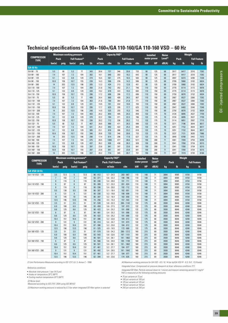
39
Committed to Sustainable Productivity
Oil
- inj
ecte
d co
mpr
esso
rs
COMPRESSOR TYPE
Maximum working pressure Capacity FAD(1) Installed motor power
Noise Level(2)
Weight
Pack Full Feature(3) Pack Full Feature Pack Full Feature
bar(e) psig bar(e) psig l/s m3/min cfm l/s m3/min cfm kW HP dB(A) kg lb kg lb
GA 60 HzGA 90+ - 75 5.5 80 5.3 77 343 20.6 727 346 20.8 733 90 125 68 2917 6417 3310 7282GA 90+ - 100 7.4 107 7.2 104 302 18.1 640 303 18.2 642 90 125 68 2917 6417 3310 7282GA 90+ - 125 9.1 132 8.9 129 274 16.4 581 275 16.5 583 90 125 68 2897 6373 3290 7238GA 90+ - 150 10.9 158 10.7 155 239 14.3 506 239 14.3 506 90 125 68 2709 5960 3102 6824GA 90+ - 200 14 203 13.5 196 205 12.3 434 213 12.8 451 90 125 68 2709 5960 3102 6824GA 110 - 100 7.4 107 7.2 104 350 21.0 742 352 21.1 746 110 150 69 2779 6114 3172 6978GA 110 - 125 9.1 132 8.9 129 320 19.2 678 322 19.3 682 110 150 69 2779 6114 3172 6978GA 110 - 150 10.9 158 10.7 155 286 17.2 606 286 17.2 606 110 150 69 2759 6070 3152 6934GA 110+ - 75 5.5 80 5.3 77 406 24.4 860 409 24.5 867 110 150 69 2967 6527 3360 7392GA 110+ - 100 7.4 107 7.2 104 363 21.8 769 364 21.8 771 110 150 69 2967 6527 3360 7392GA 110+ - 125 9.1 132 8.9 129 331 19.9 701 332 19.9 703 110 150 69 2967 6527 3360 7392GA 110+ - 150 10.9 158 10.7 155 295 17.7 625 295 17.7 625 110 150 69 2947 6483 3340 7348GA 110+ - 200 14 203 13.5 196 248 14.9 525 255 15.3 540 110 150 69 2759 6070 3152 6934GA 132 - 100 7.4 107 7.2 104 403 24.2 854 405 24.3 858 132 175 70 3134 6895 3527 7759GA 132 - 125 9.1 132 8.9 129 370 22.2 784 371 22.3 786 132 175 70 3134 6895 3527 7759GA 132 - 150 10.9 158 10.7 155 336 20.2 712 336 20.2 712 132 175 70 3114 6851 3507 7715GA 132+ - 75 5.5 80 5.3 77 467 28.0 990 471 28.3 998 132 175 70 3271 7196 3644 8017GA 132+ - 100 7.4 107 7.2 104 421 25.3 892 422 25.3 894 132 175 70 3251 7152 3644 8017GA 132+ - 125 9.1 132 8.9 129 385 23.1 816 386 23.2 818 132 175 70 3251 7152 3644 8017GA 132+ - 150 10.9 158 10.7 155 346 20.8 733 346 20.8 733 132 175 70 3237 7121 3630 7986GA 132+ - 200 14 203 13.5 196 290 17.4 614 296 17.8 627 132 175 70 3049 6708 3442 7572GA 160 - 100 7.4 107 7.2 104 475 28.5 1006 477 28.6 1011 150 200 71 3361 7394 3754 8259GA 160 - 125 9.1 132 8.9 129 437 26.2 926 438 26.3 928 150 200 71 3341 7350 3734 8215GA 160 - 150 10.9 158 10.7 155 397 23.8 841 397 23.8 841 150 200 71 3341 7350 3734 8215GA 160+ - 150 10.9 158 10.7 155 397 23.8 841 397 23.8 841 150 200 71 3341 7350 3734 8215GA 160+ - 200 14 203 13.5 196 337 20.2 714 345 20.7 731 150 200 71 3327 7319 3720 8184
COMPRESSOR TYPE
Maximum working pressure(4) Capacity FAD(1) Installed motor power
Noise Level(2)
Weight
Pack Full Feature(3) Pack / Full Feature Pack Full Feature
bar(e) psig bar(e) psig l/s m3/min cfm kW HP dB(A) kg lb kg lb
GA VSD 60 HzGA 110 VSD - 125 3.5 72.5 5 72.5 96 - 412 5.7 - 24.5 203 - 867 110 148 71 3894 8585 4154 9158
7 102 7 102 93 - 371 5.6 - 22.2 198 - 786 110 148 71 3894 8585 4154 91588 116 8 116 90 - 336 5.4 - 20.0 191 - 711 110 148 71 3894 8585 4154 9158
GA 110 VSD - 150 6 87 6 87 95 - 389 5.7 - 23.3 201 - 824 110 148 71 3894 8585 4154 91588 116 8 116 90 - 336 5.4 - 20.0 192 - 712 110 148 71 3894 8585 4154 9158
9.5 138 9.5 138 86 - 307 5.1 - 18.4 182 - 651 110 148 71 3894 8585 4154 9158GA 110 VSD - 200 9 131 9 131 90 - 330 5.3 - 19.8 190 - 699 110 148 71 3894 8585 4154 9158
10 145 10 145 86 - 307 5.2 - 18.4 182 - 650 110 148 71 3894 8585 4154 915813.5 196 13.5 196 74 - 256 4.4 - 15.3 157 - 543 110 148 71 3894 8585 4154 9158
GA 132 VSD - 125 3.5 51 3.5 51 97 - 539 5.8 - 32.3 206 - 1142 132 175 68 3930 8646 4248 93466.9 100 6.9 100 93 - 459 5.6 - 27.5 197 - 973 132 175 68 3930 8646 4248 93468.6 125 8.6 125 90 - 422 5.4 - 25.2 191 - 890 132 175 68 3930 8646 4248 9346
GA 132 VSD - 150 6 87 6 87 94 - 481 5.4 - 25.2 191 - 890 132 175 68 3930 8646 4248 93468.6 125 8.6 125 90 - 422 5.4 - 25.2 191 - 890 132 175 68 3930 8646 4248 9346
10.4 151 10.4 151 87 - 386 5.2 - 23.0 184 - 812 132 175 68 3930 8646 4248 9346GA 132 VSD - 200 9 131 9 131 90 - 414 5.4 - 24.7 191 - 873 132 175 68 3930 8646 4248 9346
10.4 151 10.4 151 87 - 386 5.2 - 23.0 184 - 812 132 175 68 3930 8646 4248 934613.5 196 13.5 196 81 - 325 4.9 - 19.5 172 - 689 132 175 68 3930 8646 4248 9346
GA 160 VSD - 125 3.5 51 3.5 51 97 - 579 5.8 - 34.3 206 - 1212 160 215 69 3930 8646 4248 93466.9 100 6.9 100 93 - 543 5.6 - 32.6 197 - 1151 160 215 69 3930 8646 4248 93468.6 125 8.6 125 90 - 501 5.4 - 30.1 191 - 1062 160 215 69 3930 8646 4248 9346
GA 160 VSD - 150 6 87 6 87 94 - 566 5.6 - 34.0 199 - 1199 160 215 69 3930 8646 4248 93468.6 125 8.6 125 90 - 501 5.4 - 30.1 191 - 1062 160 215 69 3930 8646 4248 9346
10.4 151 10.4 151 87 - 461 5.2 - 27.7 184 - 977 160 215 69 3930 8646 4248 9346GA 160 VSD - 200 9 131 9 131 90 - 492 5.4 - 29.5 191 - 1042 160 215 69 3930 8646 4248 9346
10.4 151 10.4 151 87 - 461 5.2 - 27.7 184 - 977 160 215 69 3930 8646 4248 934613.5 196 13.5 196 82 - 394 4.9 - 23.6 174 - 835 160 215 69 3930 8646 4248 9346
(1) Unit Performance Measured according to ISO 1217, Ed. 3, Annex C - 1996
Reference conditions:
• Absolute inlet pressure 1 bar (14.5 psi)• Intake air temperature 20ºC (68ºF) • Cooling medium temperature 20ºC (68ºF)
(2) Noise level:Measured according to ISO 2151: 2004 using ISO 9614/2
(3) Maximum working pressure is reduced by 0.2 bar when integrated DD filter option is selected
(4) Maximum working pressure for GA VSD - 8.5; 10; 14 bar (e)/GA VSD FF - 8.3; 9.8 ; 13.8 bar(e)
Integrated dryer: Compressed air pressure dewpoint at dryer reference conditions 3°C
Integrated DD filter: Particle removal down to 1 micron and maxium remaining aerosol 0.1 mg/m³FAD is measured at the following working pressures:
• 75 psi variants at 73 psi• 100 psi variants at 100 psi• 125 psi variants at 125 psi• 150 psi variants at 150 psi• 200 psi variants at 200 psi
Technical specifications GA 90+-160+/GA 110-160/GA 110-160 VSD – 60 Hz
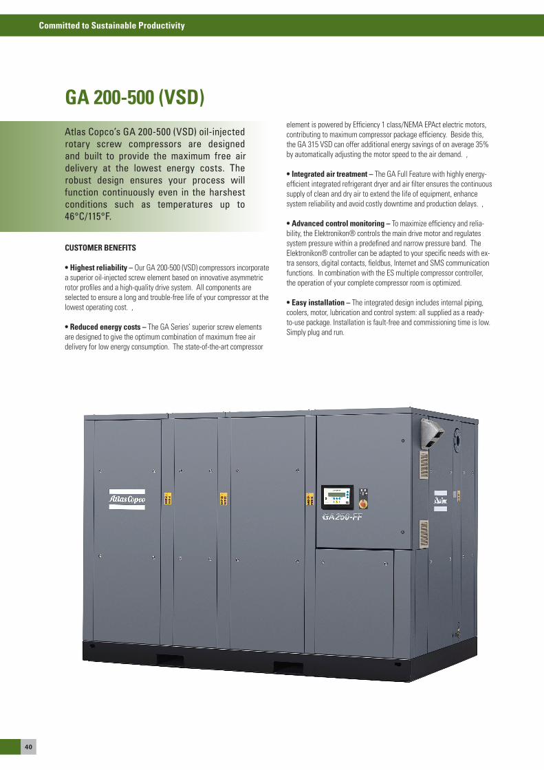
40
Committed to Sustainable Productivity
Atlas Copco’s GA 200-500 (VSD) oil-injected rotary screw compressors are designed and built to provide the maximum free airdelivery at the lowest energy costs. Therobust design ensures your process will function continuously even in the harshest conditions such as temperatures up to 46°C/115°F.
GA 200-500 (VSD)
CUSTOMER BENEFITS
• Highest reliability – our Ga 200-500 (VsD) compressors incorporate a superior oil-injected screw element based on innovative asymmetric rotor profiles and a high-quality drive system. all components are selected to ensure a long and trouble-free life of your compressor at the lowest operating cost. ,
• reduced energy costs – The Ga series’ superior screw elements are designed to give the optimum combination of maximum free air delivery for low energy consumption. The state-of-the-art compressor
element is powered by efficiency 1 class/NeMa ePact electric motors, contributing to maximum compressor package efficiency. Beside this, the Ga 315 VsD can offer additional energy savings of on average 35% by automatically adjusting the motor speed to the air demand. ,
• integrated air treatment – The Ga Full Feature with highly energy-efficient integrated refrigerant dryer and air filter ensures the continuous supply of clean and dry air to extend the life of equipment, enhance system reliability and avoid costly downtime and production delays. ,
• Advanced control monitoring – To maximize efficiency and relia-bility, the elektronikon® controls the main drive motor and regulates system pressure within a predefined and narrow pressure band. The elektronikon® controller can be adapted to your specific needs with ex-tra sensors, digital contacts, fieldbus, Internet and sMs communication functions. In combination with the es multiple compressor controller, the operation of your complete compressor room is optimized.
• Easy installation – The integrated design includes internal piping, coolers, motor, lubrication and control system: all supplied as a ready-to-use package. Installation is fault-free and commissioning time is low. simply plug and run.
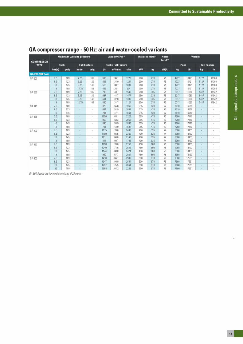
41
Committed to Sustainable Productivity
Oil
- inj
ecte
d co
mpr
esso
rs
GA compressor range - 50 Hz: air and water-cooled variants
COMPRESSOR TYPE
Maximum working pressure Capacity FAD (1) Installed motor Noise level (2)
Weight
Pack Full Feature Pack / Full Feature Pack Full Feature
bar(e) psig bar(e) psig l/s m3/ min cfm kW hp dB(A) kg lb kg lb
GA 200-500 Twin
Ga 200 7.5 109 7.25 105 603 36.1 1278 200 270 75 4727 10421 5127 113038.5 123 8.25 120 568 34.0 1204 200 270 75 4727 10421 5127 1130310 145 9.75 141 513 30.7 1087 200 270 75 4727 10421 5127 1130313 189 12.75 185 436 26.1 924 200 270 75 4727 10421 5127 11303
Ga 250 7.5 109 7.25 105 730 43.7 1548 250 335 75 5017 11060 5417 119428.5 123 8.25 120 697 41.7 1477 250 335 75 5017 11060 5417 1194210 145 9.75 141 631 37.8 1338 250 335 75 5017 11060 5417 1194213 189 12.75 185 530 31.7 1124 250 335 75 5017 11060 5417 11942
Ga 315 7.5 109 - - 928 55.8 1966 315 420 72 7510 16559 - -8.5 123 - - 864 51.9 1831 315 420 72 7510 16559 - -10 145 - - 784 47.1 1661 315 420 72 7510 16559 - -
Ga 355 7.5 109 - - 1050 63.1 2225 355 475 73 7760 17110 - -8.5 123 - - 969 58.2 2053 355 475 73 7760 17110 - -10 145 - - 890 53.5 1886 355 475 73 7760 17110 - -13 189 - - 731 43.9 1549 355 475 73 7760 17110 - -
Ga 400 7.5 109 - - 1175 70.6 2490 400 535 74 8360 18433 - -8.5 123 - - 1109 66.6 2350 400 535 74 8360 18433 - -10 145 - - 1011 60.8 2142 400 535 74 8360 18433 - -13 189 - - 844 50.7 1788 400 535 74 8360 18433 - -
Ga 450 7.5 109 - - 1298 78.0 2750 450 600 75 8360 18433 - -8.5 123 - - 1240 74.5 2628 450 600 75 8360 18433 - -10 145 - - 1144 68.8 2424 450 600 75 8360 18433 - -13 189 - - 960 57.7 2034 450 600 75 8360 18433 - -
Ga 500 7.5 109 - - 1410 84.7 2988 500 670 76 7960 17551 - -8.5 123 - - 1347 80.9 2854 500 670 76 7960 17551 - -10 145 - - 1257 75.5 2664 500 670 76 7960 17551 - - 13 189 - - 1068 64.2 2263 500 670 76 7960 17551 - -
GA 500 figures are for medium voltage IP 23 motor
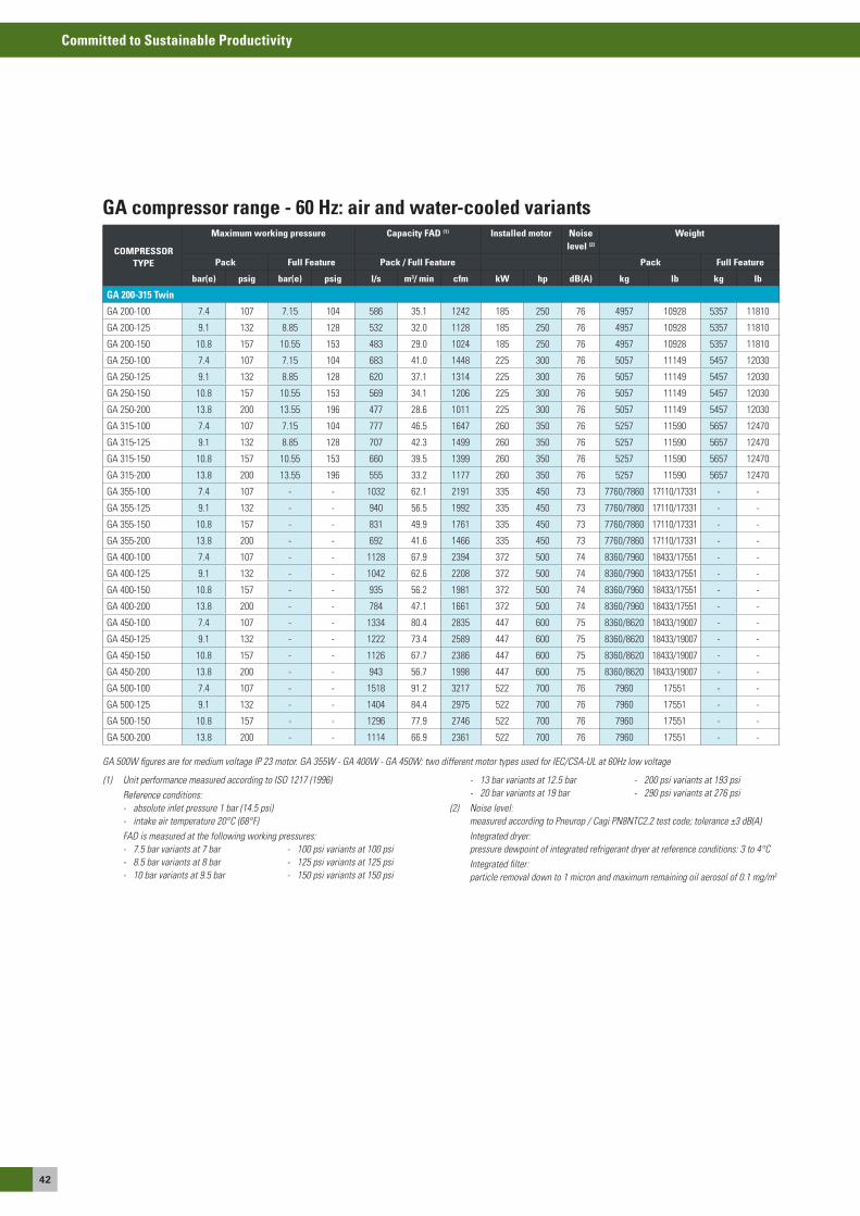
42
Committed to Sustainable Productivity
COMPRESSOR TYPE
Maximum working pressure Capacity FAD (1) Installed motor Noise level (2)
Weight
Pack Full Feature Pack / Full Feature Pack Full Feature
bar(e) psig bar(e) psig l/s m3/ min cfm kW hp dB(A) kg lb kg lb
GA 200-315 Twin
Ga 200-100 7.4 107 7.15 104 586 35.1 1242 185 250 76 4957 10928 5357 11810
Ga 200-125 9.1 132 8.85 128 532 32.0 1128 185 250 76 4957 10928 5357 11810
Ga 200-150 10.8 157 10.55 153 483 29.0 1024 185 250 76 4957 10928 5357 11810
Ga 250-100 7.4 107 7.15 104 683 41.0 1448 225 300 76 5057 11149 5457 12030
Ga 250-125 9.1 132 8.85 128 620 37.1 1314 225 300 76 5057 11149 5457 12030
Ga 250-150 10.8 157 10.55 153 569 34.1 1206 225 300 76 5057 11149 5457 12030
Ga 250-200 13.8 200 13.55 196 477 28.6 1011 225 300 76 5057 11149 5457 12030
Ga 315-100 7.4 107 7.15 104 777 46.5 1647 260 350 76 5257 11590 5657 12470
Ga 315-125 9.1 132 8.85 128 707 42.3 1499 260 350 76 5257 11590 5657 12470
Ga 315-150 10.8 157 10.55 153 660 39.5 1399 260 350 76 5257 11590 5657 12470
Ga 315-200 13.8 200 13.55 196 555 33.2 1177 260 350 76 5257 11590 5657 12470
Ga 355-100 7.4 107 - - 1032 62.1 2191 335 450 73 7760/7860 17110/17331 - -
Ga 355-125 9.1 132 - - 940 56.5 1992 335 450 73 7760/7860 17110/17331 - -
Ga 355-150 10.8 157 - - 831 49.9 1761 335 450 73 7760/7860 17110/17331 - -
Ga 355-200 13.8 200 - - 692 41.6 1466 335 450 73 7760/7860 17110/17331 - -
Ga 400-100 7.4 107 - - 1128 67.9 2394 372 500 74 8360/7960 18433/17551 - -
Ga 400-125 9.1 132 - - 1042 62.6 2208 372 500 74 8360/7960 18433/17551 - -
Ga 400-150 10.8 157 - - 935 56.2 1981 372 500 74 8360/7960 18433/17551 - -
Ga 400-200 13.8 200 - - 784 47.1 1661 372 500 74 8360/7960 18433/17551 - -
Ga 450-100 7.4 107 - - 1334 80.4 2835 447 600 75 8360/8620 18433/19007 - -
Ga 450-125 9.1 132 - - 1222 73.4 2589 447 600 75 8360/8620 18433/19007 - -
Ga 450-150 10.8 157 - - 1126 67.7 2386 447 600 75 8360/8620 18433/19007 - -
Ga 450-200 13.8 200 - - 943 56.7 1998 447 600 75 8360/8620 18433/19007 - -
Ga 500-100 7.4 107 - - 1518 91.2 3217 522 700 76 7960 17551 - -
Ga 500-125 9.1 132 - - 1404 84.4 2975 522 700 76 7960 17551 - -
Ga 500-150 10.8 157 - - 1296 77.9 2746 522 700 76 7960 17551 - -
Ga 500-200 13.8 200 - - 1114 66.9 2361 522 700 76 7960 17551 - -
GA compressor range - 60 Hz: air and water-cooled variants
GA 500W figures are for medium voltage IP 23 motor. GA 355W - GA 400W - GA 450W: two different motor types used for IEC/CSA-UL at 60Hz low voltage
(1) Unit performance measured according to ISO 1217 (1996) Reference conditions: - absolute inlet pressure 1 bar (14.5 psi) - intake air temperature 20°C (68°F) FAD is measured at the following working pressures: - 7.5 bar variants at 7 bar - 100 psi variants at 100 psi - 8.5 bar variants at 8 bar - 125 psi variants at 125 psi - 10 bar variants at 9.5 bar - 150 psi variants at 150 psi
- 13 bar variants at 12.5 bar - 200 psi variants at 193 psi - 20 bar variants at 19 bar - 290 psi variants at 276 psi(2) Noise level: measured according to Pneurop / Cagi PN8NTC2.2 test code; tolerance ±3 dB(A) Integrated dryer: pressure dewpoint of integrated refrigerant dryer at reference conditions: 3 to 4°C Integrated filter: particle removal down to 1 micron and maximum remaining oil aerosol of 0.1 mg/m3
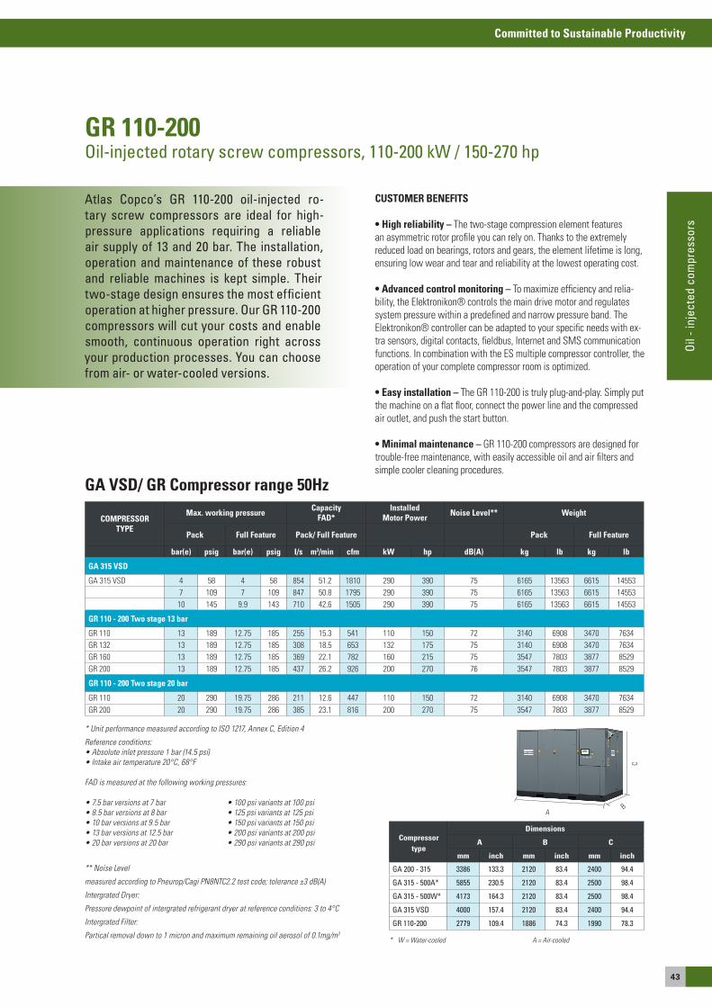
43
Committed to Sustainable Productivity
Oil
- inj
ecte
d co
mpr
esso
rs
Atlas Copco’s GR 110-200 oil-injected ro-tary screw compressors are ideal for high-pressure applications requiring a reliable air supply of 13 and 20 bar. The installation, operation and maintenance of these robust and reliable machines is kept simple. Their two-stage design ensures the most efficient operation at higher pressure. Our GR 110-200 compressors will cut your costs and enable smooth, continuous operation right across your production processes. You can choose from air- or water-cooled versions.
GR 110-200Oil-injected rotary screw compressors, 110-200 kW / 150-270 hp
CUSTOMER BENEFITS
• High reliability – The two-stage compression element features an asymmetric rotor profile you can rely on. Thanks to the extremely reduced load on bearings, rotors and gears, the element lifetime is long, ensuring low wear and tear and reliability at the lowest operating cost. • Advanced control monitoring – To maximize efficiency and relia-bility, the elektronikon® controls the main drive motor and regulates system pressure within a predefined and narrow pressure band. The elektronikon® controller can be adapted to your specific needs with ex-tra sensors, digital contacts, fieldbus, Internet and sMs communication functions. In combination with the es multiple compressor controller, the operation of your complete compressor room is optimized.
• Easy installation – The GR 110-200 is truly plug-and-play. simply put the machine on a flat floor, connect the power line and the compressed air outlet, and push the start button.
• Minimal maintenance – GR 110-200 compressors are designed for trouble-free maintenance, with easily accessible oil and air filters and simple cooler cleaning procedures.
COMPRESSOR TYPE
Max. working pressure Capacity FAD*
InstalledMotor Power Noise Level** Weight
Pack Full Feature Pack/ Full Feature Pack Full Feature
bar(e) psig bar(e) psig I/s m3/min cfm kW hp dB(A) kg lb kg lb
GA 315 VSD
Ga 315 VsD 4 58 4 58 854 51.2 1810 290 390 75 6165 13563 6615 145537 109 7 109 847 50.8 1795 290 390 75 6165 13563 6615 1455310 145 9.9 143 710 42.6 1505 290 390 75 6165 13563 6615 14553
GR 110 - 200 Two stage 13 bar
GR 110 13 189 12.75 185 255 15.3 541 110 150 72 3140 6908 3470 7634GR 132 13 189 12.75 185 308 18.5 653 132 175 75 3140 6908 3470 7634GR 160 13 189 12.75 185 369 22.1 782 160 215 75 3547 7803 3877 8529GR 200 13 189 12.75 185 437 26.2 926 200 270 76 3547 7803 3877 8529
GR 110 - 200 Two stage 20 bar
GR 110 20 290 19.75 286 211 12.6 447 110 150 72 3140 6908 3470 7634GR 200 20 290 19.75 286 385 23.1 816 200 270 75 3547 7803 3877 8529
GA VSD/ GR Compressor range 50Hz
** Noise Level
measured according to Pneurop/Cagi PN8NTC2.2 test code; tolerance ±3 dB(A)
Intergrated Dryer:
Pressure dewpoint of intergrated refrigerant dryer at reference conditions: 3 to 4°C
Intergrated Filter:
Partical removal down to 1 micron and maximum remaining oil aerosol of 0.1mg/m3
* Unit performance measured according to ISO 1217, Annex C, Edition 4
Reference conditions:• Absolute inlet pressure 1 bar (14.5 psi)• Intake air temperature 20°C, 68°F
FAD is measured at the following working pressures:
• 7.5 bar versions at 7 bar• 8.5 bar versions at 8 bar• 10 bar versions at 9.5 bar• 13 bar versions at 12.5 bar• 20 bar versions at 20 bar
• 100 psi variants at 100 psi• 125 psi variants at 125 psi• 150 psi variants at 150 psi• 200 psi variants at 200 psi• 290 psi variants at 290 psi
aB
C
Compressortype
Dimensions
A B C
mm inch mm inch mm inch
GA 200 - 315 3386 133.3 2120 83.4 2400 94.4
GA 315 - 500A* 5855 230.5 2120 83.4 2500 98.4
GA 315 - 500W* 4173 164.3 2120 83.4 2500 98.4
GA 315 VSD 4000 157.4 2120 83.4 2400 94.4
GR 110-200 2779 109.4 1886 74.3 1990 78.3
* W = Water-cooled A = Air-cooled
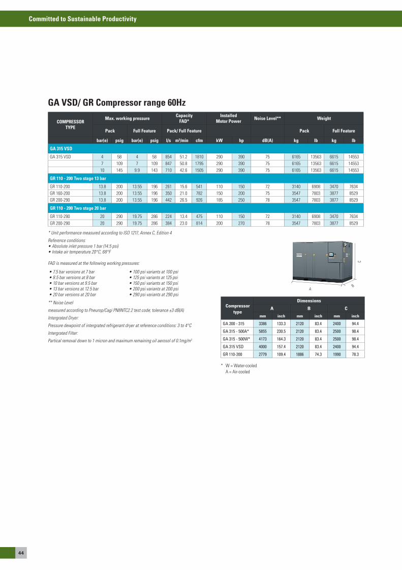
44
Committed to Sustainable Productivity
COMPRESSOR TYPE
Max. working pressure Capacity FAD*
InstalledMotor Power Noise Level** Weight
Pack Full Feature Pack/ Full Feature Pack Full Feature
bar(e) psig bar(e) psig I/s m3/min cfm kW hp dB(A) kg lb kg lb
GA 315 VSD
Ga 315 VsD 4 58 4 58 854 51.2 1810 290 390 75 6165 13563 6615 145537 109 7 109 847 50.8 1795 290 390 75 6165 13563 6615 1455310 145 9.9 143 710 42.6 1505 290 390 75 6165 13563 6615 14553
GR 110 - 200 Two stage 13 bar
GR 110-200 13.8 200 13.55 196 261 15.6 541 110 150 72 3140 6908 3470 7634GR 160-200 13.8 200 13.55 196 350 21.0 782 150 200 75 3547 7803 3877 8529GR 200-290 13.8 200 13.55 196 442 26.5 926 185 250 78 3547 7803 3877 8529
GR 110 - 200 Two stage 20 bar
GR 110-290 20 290 19.75 286 224 13.4 475 110 150 72 3140 6908 3470 7634GR 200-290 20 290 19.75 286 384 23.0 814 200 270 78 3547 7803 3877 8529
GA VSD/ GR Compressor range 60Hz
** Noise Level
measured according to Pneurop/Cagi PN8NTC2.2 test code; tolerance ±3 dB(A)
Intergrated Dryer:
Pressure dewpoint of intergrated refrigerant dryer at reference conditions: 3 to 4°C
Intergrated Filter:
Partical removal down to 1 micron and maximum remaining oil aerosol of 0.1mg/m3
* Unit performance measured according to ISO 1217, Annex C, Edition 4
Reference conditions:• Absolute inlet pressure 1 bar (14.5 psi)• Intake air temperature 20°C, 68°F
FAD is measured at the following working pressures:
• 7.5 bar versions at 7 bar• 8.5 bar versions at 8 bar• 10 bar versions at 9.5 bar• 13 bar versions at 12.5 bar• 20 bar versions at 20 bar
• 100 psi variants at 100 psi• 125 psi variants at 125 psi• 150 psi variants at 150 psi• 200 psi variants at 200 psi• 290 psi variants at 290 psi
* W = Water-cooled a = air-cooled
aB
C
Compressortype
Dimensions
A B C
mm inch mm inch mm inch
GA 200 - 315 3386 133.3 2120 83.4 2400 94.4
GA 315 - 500A* 5855 230.5 2120 83.4 2500 98.4
GA 315 - 500W* 4173 164.3 2120 83.4 2500 98.4
GA 315 VSD 4000 157.4 2120 83.4 2400 94.4
GR 110-200 2779 109.4 1886 74.3 1990 78.3
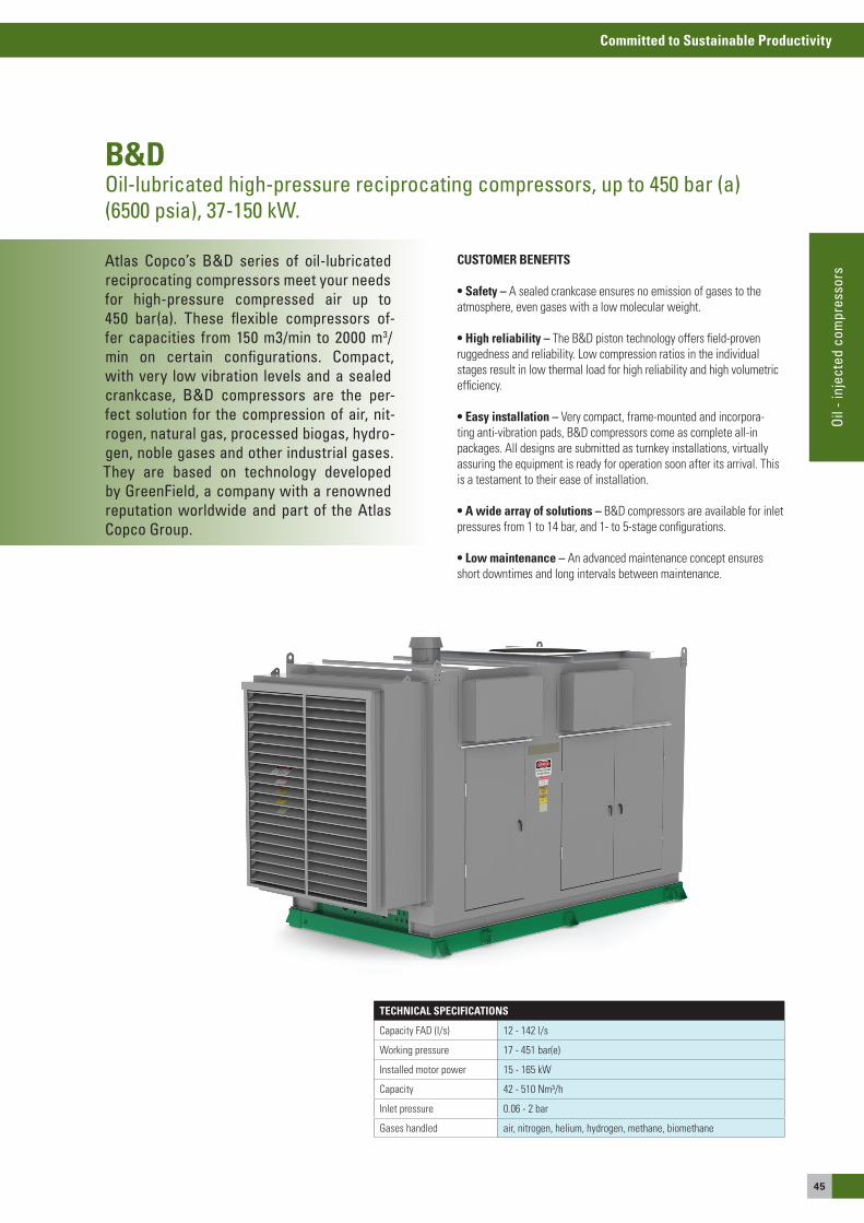
45
Committed to Sustainable Productivity
Oil
- inj
ecte
d co
mpr
esso
rs
Atlas Copco’s B&D series of oil-lubricated reciprocating compressors meet your needsfor high-pressure compressed air up to450 bar(a). These flexible compressors of-fer capacities from 150 m3/min to 2000 m3/min on certain configurations. Compact, with very low vibration levels and a sealed crankcase, B&D compressors are the per-fect solution for the compression of air, nit-rogen, natural gas, processed biogas, hydro-gen, noble gases and other industrial gases. They are based on technology developed by GreenField, a company with a renowned reputation worldwide and part of the Atlas Copco Group.
B&DOil-lubricated high-pressure reciprocating compressors, up to 450 bar (a) (6500 psia), 37-150 kW.
CUSTOMER BENEFITS
• Safety – a sealed crankcase ensures no emission of gases to the atmosphere, even gases with a low molecular weight. • High reliability – The B&D piston technology offers field-proven ruggedness and reliability. Low compression ratios in the individual stages result in low thermal load for high reliability and high volumetric efficiency.
• Easy installation – Very compact, frame-mounted and incorpora-ting anti-vibration pads, B&D compressors come as complete all-in packages. all designs are submitted as turnkey installations, virtually assuring the equipment is ready for operation soon after its arrival. This is a testament to their ease of installation.
• A wide array of solutions – B&D compressors are available for inlet pressures from 1 to 14 bar, and 1- to 5-stage configurations.
• Low maintenance – an advanced maintenance concept ensures short downtimes and long intervals between maintenance.
TECHNICAL SPECIFICATIONS
Capacity FaD (l/s) 12 - 142 l/s
Working pressure 17 - 451 bar(e)
Installed motor power 15 - 165 kW
Capacity 42 - 510 Nm³/h
Inlet pressure 0.06 - 2 bar
Gases handled air, nitrogen, helium, hydrogen, methane, biomethane
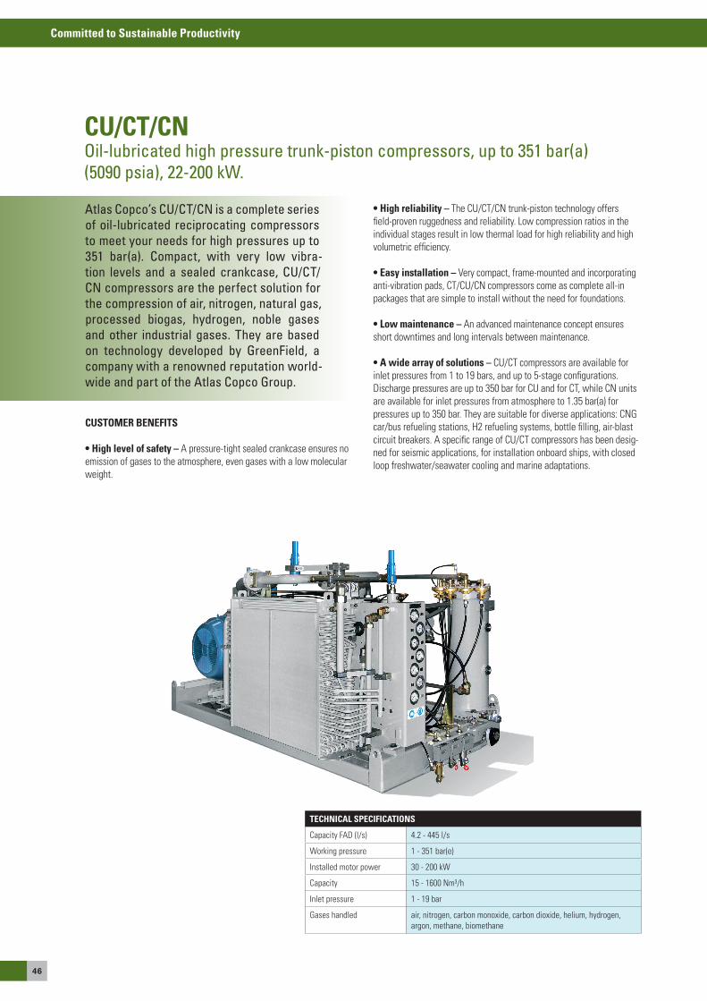
46
Committed to Sustainable Productivity
Atlas Copco’s CU/CT/CN is a complete series of oil-lubricated reciprocating compressors to meet your needs for high pressures up to 351 bar(a). Compact, with very low vibra-tion levels and a sealed crankcase, CU/CT/CN compressors are the perfect solution for the compression of air, nitrogen, natural gas, processed biogas, hydrogen, noble gases and other industrial gases. They are based on technology developed by GreenField, a company with a renowned reputation world-wide and part of the Atlas Copco Group.
CU/CT/CNOil-lubricated high pressure trunk-piston compressors, up to 351 bar(a)(5090 psia), 22-200 kW.
CUSTOMER BENEFITS
• High level of safety – a pressure-tight sealed crankcase ensures no emission of gases to the atmosphere, even gases with a low molecular weight.
TECHNICAL SPECIFICATIONS
Capacity FaD (l/s) 4.2 - 445 l/s
Working pressure 1 - 351 bar(e)
Installed motor power 30 - 200 kW
Capacity 15 - 1600 Nm³/h
Inlet pressure 1 - 19 bar
Gases handled air, nitrogen, carbon monoxide, carbon dioxide, helium, hydrogen, argon, methane, biomethane
• High reliability – The CU/CT/CN trunk-piston technology offers field-proven ruggedness and reliability. Low compression ratios in the individual stages result in low thermal load for high reliability and high volumetric efficiency.
• Easy installation – Very compact, frame-mounted and incorporating anti-vibration pads, CT/CU/CN compressors come as complete all-in packages that are simple to install without the need for foundations.
• Low maintenance – an advanced maintenance concept ensures short downtimes and long intervals between maintenance.
• A wide array of solutions – CU/CT compressors are available for inlet pressures from 1 to 19 bars, and up to 5-stage configurations. Discharge pressures are up to 350 bar for CU and for CT, while CN units are available for inlet pressures from atmosphere to 1.35 bar(a) for pressures up to 350 bar. They are suitable for diverse applications: CNG car/bus refueling stations, H2 refueling systems, bottle filling, air-blast circuit breakers. a specific range of CU/CT compressors has been desig-ned for seismic applications, for installation onboard ships, with closed loop freshwater/seawater cooling and marine adaptations.

47
Committed to Sustainable Productivity
Oil
- inj
ecte
d co
mpr
esso
rs
Atlas Copco’s lubricated gas screw com-pressors meet your needs for methane and biomethane applications for pressures up to 16 bar(a) (232 psia). Single-stage, water-cooled and directly-driven, these compres-sors benefit from the latest technologies with exclusive bearing arrangements and variable speed drive. They comply with ATEX design requirements.
GGOil-lubricated gas screw compressors, 16 bar(a) (232 psia)
CUSTOMER BENEFITS
• Efficient capacity control – Variable speed Drive can regulate the capacity of the compressor to keep inlet and outlet pressures constant, depending on the application.
TECHNICAL SPECIFICATIONS
Capacity FaD (l/s) 136 - 278 l/s
Capacity FaD (m³/h, cfm) 102 - 900 m³/h
Working pressure 1.55 - 17 bar(e)
Installed motor power 90 - 132 kW
Capacity 450 - 920 Nm3/h
Inlet pressure 1.4 bar (a)
Gases handled processed biomethane
• High efficiency and consistent performance – The GG’s highly efficient rotor profile maximizes the flow and minimizes the horsepower. Direct drive through a flexible coupling means no gear losses or wasted energy.
• Sturdy design – a triplex bearing arrangement has an L-10 calcula-ted life of 130,000 hours. superior shaft seal design and unparalleled precision manufacturing combine to ensure durable quality year after year. This makes the sG gas compressor the optimal solution for gas applications.
• Compact and easy to install – This single stage compressor takes up minimal floor space. Frame-mounted, the GG gas compressor comes as a complete all-in package which can easily be integrated in your process.

48
Committed to Sustainable Productivity
Atlas Copco’s S100/S750 car and bus mo-dular refueling stations are compact high-performance installations designed for the refueling of passenger cars, indoor and light-duty vehicles, buses, heavy-duty trucks, fer-ries and special vehicles with natural gas (CNG/NGV), biogas and H2. They are based on technology developed by GreenField, a company with a renowned reputation world-wide and part of the Atlas Copco Group
S100/S750Car and bus refueling stations.
CUSTOMER BENEFITS
• High level of safety – a pressure-tight sealed crankcase ensures no emission of gases to the atmosphere, even gases with a low molecular weight.
• Total solution – With atlas Copco you get total customer service, from a comprehensive study of the station layout to the delivery of the complete units
TECHNICAL SPECIFICATIONS
Type of vehicle buses, cars, others
Filling time (cars) 150 to 450 cars per day
Filling time (buses) 15 to 45 buses per day
Filling time (others) 30 to 90 trucks per day
Type of vehicle Bus
• A wide array of solutions – We provide fast-fill, low-fill or mother-daughter systems to meet your needs for standard to customized stations
• Based on our high-performance compressors: - CU/CT series – Lubricated trunk-piston technology, air- or water-cooled, with sealed crankcase – gas-tight up to 19 bar(a) (260 psig) – for capacities up to 1600 Nm3/h (1000 scfm).
- DM series – oil-less, hermetically sealed compressors – gas-tight up to 40 bar(a) (570 psig) – for capacities up to 210 Nm3/h (125 scfm).
• Compact – Available in concrete or sheet metal housing, their com-pact design is an asset on site
• Modular – Our standard stations are adapted to: - Up to 250 cars, 50 trucks or 25 buses per day - Up to 150 cars, 30 trucks or 15 buses per day - Up to 450 cars, 90 trucks or 45 buses per day

Inhaltsverzeichnis
oIL-FRee CoMPRessoRsIf you require oil-free compressed air for sensitive processes within the food and drink industries, in a dairy or a brewery, in medical technology or electronic manufacturing, then compromises are not an option. Many processes in the pharmaceutical industry, surface refinement or the textile industry are also completely dependent on oil-free compressed air.

50
Committed to Sustainable Productivity
If you require oil-free compressed air for sensitive processes within the food and drink industries, in a dairy or a brewery, in medical technology or electronic manufac-turing, then compromises are not an opti-on. Many processes in the pharmaceutical industry, surface refinement or the textile industry are also completely dependent on oil-free compressed air.
Oil-free compressed air
Atlas Copco is the first manufacturer of oil-free com-pressors that have achieved a compressed air quality of Class 0 in accordance with DiN-iSO 8573-1 – certified by the TÜV. This is because the air never comes into contact with oil throughout the compression stages of the Z compressors from
atlas Copco. Therefore, it does not have to be laboriously filtered again with a high power input. There is also no residual risk of con-taminating the product during its contact with the compressed air.
We can provide a suitable oil-free solution for any application, any volume flow and (almost) any working pressure; from 0.4 bar, for example, for aerating sewage plants, up to 40 bar for producing PeT bottles. Potential options include:
our ZR/ZT compressors, for the most popular applications andpressures (up to 13 bar), are available with rotary technology formedium volume flows or with screw compression for improved performance. air or water-cooled. They are available with speed regulation (VsD - Variable speed Drive), if required, allowing you to save up 35% power on average, and the additional costs for the inte-grated frequency converter usually pay for themselves within one to two years. If you want, you can choose the Full Feature version (FF), which also has an integrated refrigerant or desiccant dryer.
or our ZB Turbos and Zs blower for applications with low pressure (from 0.4 to 1.7 bar working pressure). If you want to use pneumatic feed, ventilate biological clarifiers, or clean filters in power plants, these machines are the perfect solution. With the Zs+ blowers you can lower your power consumption, in comparison to conventional, belt-driven rotary piston blowers, by up to 40%, and the ZB centrifu-gal compressors with speed regulation save as much as 60% power compared to normal full-load/idle machines. This is because the turbo impellers are a very special patented development from atlas Copco – with extremely high efficiency.
our ZH Turbos are hard to beat when it comes to efficiency. They are suitable for heavy industry, where an extremely high amount of air with working pressures between 3.5 and 10.4 bar is continually required; for example, a few thousand to tens of thousands cubic meters per hour.
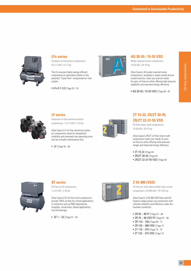
51
Committed to Sustainable Productivity
Oil-f
ree
com
pres
sion
LFx seriesCompact oil-free piston compressors,
0.5-1.5 kW / 0.7-2 hp
The LFx ensures highly energy-efficient compressed air generation thanks to thepatented “super-flow” compressed air inlet system.
• LFx 0.7-2.0 | Page 53 - 54
AQ 30-55 / 15-55 VSDWater-injected screw compressors,
15-55 kW / 20-75 hp
atlas Copco’s aQ water-injected screwcompressors, available in water-cooled and air-cooled versions, meet your precise needsfor pure, oil-free air while offering high-pressure capability and improved energy efficiency.
• AQ 30-55 / 15-55 VSD | Page 60 - 62
LF seriesIndustrial oil-free aluminum piston
compressors, 1.5-7.5 kW / 2-10 hp
atlas Copco’s LF oil-free aluminium pistonair compressors stand for exceptionalreliability and extremely low operating costsand are virtually maintenance-free.
• LF | Page 55 - 56
SF seriesoil-free scroll compressors,
1.5-22 kW / 2-30 hp
atlas Copco’s sF oil-free scroll compressors provide 100% oil-free for critical applicationsin industries such as R&D laboratories,hospitals, universities, dental applications,food & beverage .
• SF 1 – 22 | Page 57 - 59
ZT 15-22, ZR/ZT 30-45,ZR/ZT 22-37-55 VSDoil-free rotary tooth compressors,
15-55 kW / 20-75 hp
atlas Copco’s ZR/ZT oil-free rotary toothcompressors meet your needs for pureoil-free air while offering wide pressureranges and improved energy efficiency.
• ZT 15-22 | Page 64• ZR/ZT 30-45 | Page 64• ZR/ZT 22-37-55 VSD | Page 64
Z 55-900 (VSD)oil-free air- and water-cooled rotary screw
compressors, 55-935 kW / 75-1253 hp
atlas Copco’s Z 55-900 VsD Pack and FullFeature ranges power your production with ultimate reliability and efficiency under the harshest conditions.
• ZR 55 – 90 FF | Page 67 - 68• ZR 75 – 90 VSD FF | Page 67 - 68• ZR 110 – 750 | Page 69 - 72• ZR 132 – 900 VSD | Page 72• ZT 110 – 275 | Page 73 - 75• ZT 132 – 315 VSD | Page 75
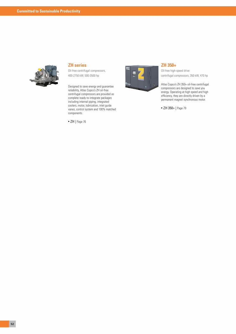
52
Committed to Sustainable Productivity
ZH seriesoil-free centrifugal compressors,
400-2750 kW, 500-3500 hp
Designed to save energy and guaranteereliability, atlas Copco’s ZH oil-free centrifugal compressors are provided as complete ready-to-integrate packages including internal piping, integrated coolers, motor, lubrication, inlet guide vanes, control system and 100% matched components.
• ZH | Page 76
ZH 350+oil-free high-speed drive
centrifugal compressors, 350 kW, 470 hp
atlas Copco’s ZH 350+ oil-free centrifugal compressors are designed to save youenergy. operating at high speed and high efficiency, they are directly driven by apermanent magnet synchronous motor.
• ZH 350+ | Page 79
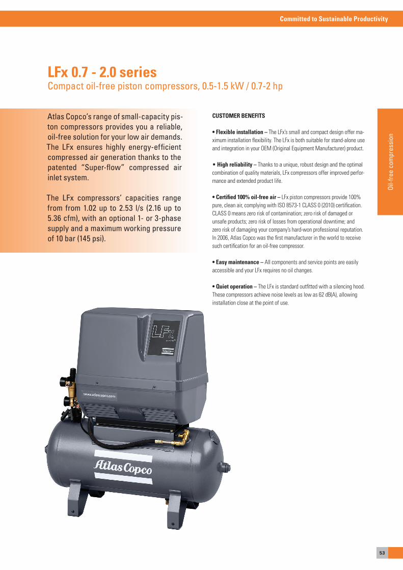
53
Committed to Sustainable Productivity
Oil-f
ree
com
pres
sion
Atlas Copco’s range of small-capacity pis-ton compressors provides you a reliable, oil-free solution for your low air demands. The LFx ensures highly energy-efficient compressed air generation thanks to the patented “Super-flow” compressed air inlet system.
The LFx compressors’ capacities range from from 1.02 up to 2.53 l/s (2.16 up to 5.36 cfm), with an optional 1- or 3-phase supply and a maximum working pressure of 10 bar (145 psi).
LFx 0.7 - 2.0 seriesCompact oil-free piston compressors, 0.5-1.5 kW / 0.7-2 hp
CUSTOMER BENEFITS
• Flexible installation – The LFx’s small and compact design offer ma-ximum installation flexibility. The LFx is both suitable for stand-alone use and integration in your oeM (original equipment Manufacturer) product.
• High reliability – Thanks to a unique, robust design and the optimal combination of quality materials, LFx compressors offer improved perfor-mance and extended product life.
• Certified 100% oil-free air – LFx piston compressors provide 100% pure, clean air, complying with Iso 8573-1 CLass 0 (2010) certification. CLass 0 means zero risk of contamination; zero risk of damaged or unsafe products; zero risk of losses from operational downtime; and zero risk of damaging your company’s hard-won professional reputation. In 2006, atlas Copco was the first manufacturer in the world to receive such certification for an oil-free compressor.
• Easy maintenance – all components and service points are easily accessible and your LFx requires no oil changes.
• Quiet operation – The LFx is standard outfitted with a silencing hood. These compressors achieve noise levels as low as 62 dB(a), allowing installation close at the point of use.
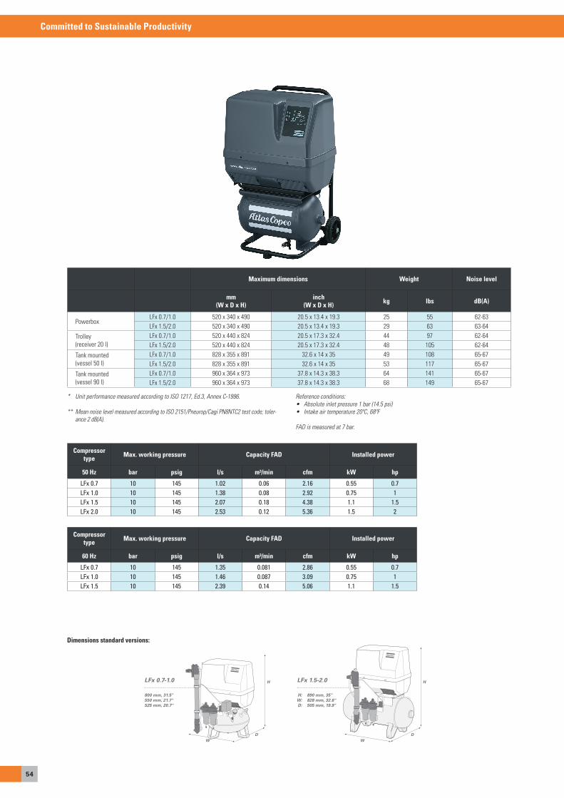
54
Committed to Sustainable Productivity
Dimensions standard versions:
* Unit performance measured according to ISO 1217, Ed.3, Annex C-1996.
** Mean noise level measured according to ISO 2151/Pneurop/Cagi PN8NTC2 test code; toler-ance 2 dB(A).
Reference conditions:• Absolute inlet pressure 1 bar (14.5 psi)• Intake air temperature 20ºC, 68ºF
FAD is measured at 7 bar.
LFx 0.7-1.0
800 mm, 31.5"550 mm, 21.7"525 mm, 20.7"
D
H
WD
W
HLFx 1.5-2.0
890 mm, 35"828 mm, 32.6"505 mm, 19.9"
H:W: D:
Compressor type Max. working pressure Capacity FAD Installed power
50 Hz bar psig l/s m³/min cfm kW hp
LFx 0.7 10 145 1.02 0.06 2.16 0.55 0.7LFx 1.0 10 145 1.38 0.08 2.92 0.75 1LFx 1.5 10 145 2.07 0.18 4.38 1.1 1.5LFx 2.0 10 145 2.53 0.12 5.36 1.5 2
Compressor type Max. working pressure Capacity FAD Installed power
60 Hz bar psig l/s m³/min cfm kW hp
LFx 0.7 10 145 1.35 0.081 2.86 0.55 0.7LFx 1.0 10 145 1.46 0.087 3.09 0.75 1LFx 1.5 10 145 2.39 0.14 5.06 1.1 1.5
Maximum dimensions Weight Noise level
mm(W x D x H)
inch(W x D x H) kg lbs dB(A)
PowerboxLFx 0.7/1.0 520 x 340 x 490 20.5 x 13.4 x 19.3 25 55 62-63LFx 1.5/2.0 520 x 340 x 490 20.5 x 13.4 x 19.3 29 63 63-64
Trolley (receiver 20 l)
LFx 0.7/1.0 520 x 440 x 824 20.5 x 17.3 x 32.4 44 97 62-64LFx 1.5/2.0 520 x 440 x 824 20.5 x 17.3 x 32.4 48 105 62-64
Tank mounted (vessel 50 l)
LFx 0.7/1.0 828 x 355 x 891 32.6 x 14 x 35 49 108 65-67LFx 1.5/2.0 828 x 355 x 891 32.6 x 14 x 35 53 117 65-67
Tank mounted (vessel 90 l)
LFx 0.7/1.0 960 x 364 x 973 37.8 x 14.3 x 38.3 64 141 65-67LFx 1.5/2.0 960 x 364 x 973 37.8 x 14.3 x 38.3 68 149 65-67
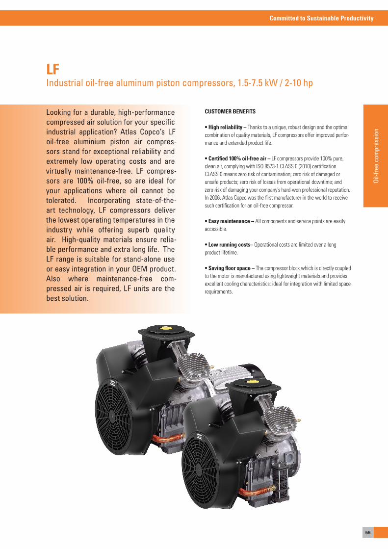
55
Committed to Sustainable Productivity
Oil-f
ree
com
pres
sion
Looking for a durable, high-performance compressed air solution for your specific industrial application? Atlas Copco’s LF oil-free aluminium piston air compres-sors stand for exceptional reliability and extremely low operating costs and are virtually maintenance-free. LF compres-sors are 100% oil-free, so are ideal for your applications where oil cannot be tolerated. Incorporating state-of-the-art technology, LF compressors deliver the lowest operating temperatures in the industry while offering superb quality air. High-quality materials ensure relia-ble performance and extra long life. The LF range is suitable for stand-alone use or easy integration in your OEM product. Also where maintenance-free com-pressed air is required, LF units are the best solution.
LFIndustrial oil-free aluminum piston compressors, 1.5-7.5 kW / 2-10 hp
CUSTOMER BENEFITS
• High reliability – Thanks to a unique, robust design and the optimal combination of quality materials, LF compressors offer improved perfor-mance and extended product life.
• Certified 100% oil-free air – LF compressors provide 100% pure, clean air, complying with Iso 8573-1 CLass 0 (2010) certification. CLass 0 means zero risk of contamination; zero risk of damaged or unsafe products; zero risk of losses from operational downtime; and zero risk of damaging your company’s hard-won professional reputation. In 2006, atlas Copco was the first manufacturer in the world to receive such certification for an oil-free compressor.
• Easy maintenance – all components and service points are easily accessible.
• Low running costs– operational costs are limited over a long product lifetime.
• Saving floor space – The compressor block which is directly coupled to the motor is manufactured using lightweight materials and provides excellent cooling characteristics: ideal for integration with limited space requirements.

56
Committed to Sustainable Productivity
LF Trolleymobile versions with either electric or gasoline engine
LF unittank mounted
LF Pack–VersionBase frame with acoustic hood, especially in low noise
LF basic unit
Reference conditions:• Absolute inlet pressure 1 bar (14.5 psi).• Intake air and coolant temperature 20ºC, 68ºF.
FAD is measured at the following working pressures:• 10 bar versions at 7 bar.• 15 bar versions at 12 bar.• 20 bar versions at 20 bar.• 30 bar versions at 30 bar.
COMPRESSORTYPE
Maximum working pressure*
FAD at normal workingpressure and 1,500 rpm
(50 Hz)
FAD at normal workingpressure and 1,800 rpm
(60 Hz)
Installed recommended power Noise level dB(A)**
bar(e) psig l/s m3/min cfm l/s m3/min cfm kW hp Unsilenced Base-mount-ed, silenced
10 BAR LFLF 2-10 10 145 3.1 0.19 6.6 3.6 0.22 7.6 1.5 2 82/84 67/69LF 3-10 10 145 4 0.24 8.5 4.6 0.28 9.7 2.2 3 83/85 68/70LF 5-10 10 145 8.2 0.49 17.4 9.1 0.55 19.3 4 5.5 83/85 68/70LF 7-10 10 145 11 0.66 23.3 12 0.72 25.4 5.5 7.5 84/86 72/74LF 10-10 10 145 15.5 0.93 32.8 18.2 1.1 38.9 7.5 10 86/88 74/76
Receiver size 10, 15 & 20 bar (218, 290or 435 psi) versions: 90, 250 & 475 l (24, 66 & 125 US gallon)
Standard voltages available:
50 Hz: 1 ph 230 V, 3 ph 230, 400, 500 V 60 Hz: 1 ph 230 V, 3 ph 230, 460, 380, 575 V
* Unit performance measured according to ISO 1217, Ed. 3, Annex C-1996. ** Mean noise level measured at a distance of 1 m according to ISO 2151/Pneurop/Cagi
PN8NTC2 test code; tolerance 3 dB(A).
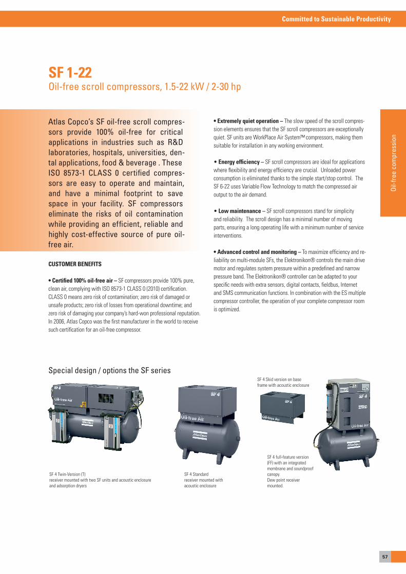
57
Committed to Sustainable Productivity
Oil-f
ree
com
pres
sion
Atlas Copco’s SF oil-free scroll compres-sors provide 100% oil-free for criticalapplications in industries such as R&Dlaboratories, hospitals, universities, den-tal applications, food & beverage . TheseISO 8573-1 CLASS 0 certified compres-sors are easy to operate and maintain, and have a minimal footprint to save space in your facility. SF compressors eliminate the risks of oil contamination while providing an efficient, reliable and highly cost-effective source of pure oil-free air.
SF 1-22Oil-free scroll compressors, 1.5-22 kW / 2-30 hp
CUSTOMER BENEFITS
• Certified 100% oil-free air – sF compressors provide 100% pure, clean air, complying with Iso 8573-1 CLass 0 (2010) certification. CLass 0 means zero risk of contamination; zero risk of damaged or unsafe products; zero risk of losses from operational downtime; and zero risk of damaging your company’s hard-won professional reputation. In 2006, atlas Copco was the first manufacturer in the world to receive such certification for an oil-free compressor.
sF 4 standardreceiver mounted with acoustic enclosure
sF 4 full-feature version (FF) with an integrated membrane and soundproof canopy.Dew point receiver mounted.
Special design / options the SF seriessF 4 skid version on base frame with acoustic enclosure
sF 4 Twin-Version (T)receiver mounted with two sF units and acoustic enclosure and adsorption dryers
• Extremely quiet operation – The slow speed of the scroll compres-sion elements ensures that the sF scroll compressors are exceptionally quiet. sF units are WorkPlace air system™ compressors, making them suitable for installation in any working environment.
• Energy efficiency – sF scroll compressors are ideal for applications where flexibility and energy efficiency are crucial. Unloaded power consumption is eliminated thanks to the simple start/stop control. The sF 6-22 uses Variable Flow Technology to match the compressed air output to the air demand.
• Low maintenance – sF scroll compressors stand for simplicity and reliability. The scroll design has a minimal number of moving parts, ensuring a long operating life with a minimum number of service interventions.
• Advanced control and monitoring – To maximize efficiency and re-liability on multi-module sFs, the elektronikon® controls the main drive motor and regulates system pressure within a predefined and narrow pressure band. The elektronikon® controller can be adapted to your specific needs with extra sensors, digital contacts, fieldbus, Internet and sMs communication functions. In combination with the es multiple compressor controller, the operation of your complete compressor room is optimized.

58
Committed to Sustainable Productivity
SF Multicore 6 / 8 / 11 / 15 / 17 / 22 FFoil-free scroll compressors
sF 15 FF
The Scroll Multicore concept further enhances the performance of the Scroll technology. Two to four compressor modules (PM version) are integrated into one unit and offer all the advantages of a modular system. For dry compressed air, a refrigerant dryer can be integrated as well as 2 – 4 compressor modules (PM/FF versions).
SF Multicore – flexibility through modular design
The specially designed software makes optimal use of the additional advantages which result from the Multi-core concept: sequential operation, stage-less volume flow regulation for low power consumption – while the individual modules are controlled by software like a single SF aggregate.
sF 8 FF
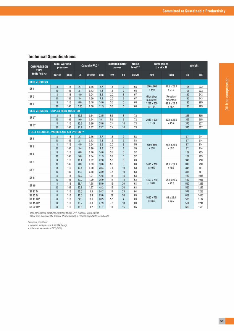
59
Committed to Sustainable Productivity
Oil-f
ree
com
pres
sion
COMPRESSOR TYPE
50 Hz / 60 Hz
Max. working pressure Capacity FAD* Installed motor
powerNoise
level**Dimensions
L x W x H Weight
bar(e) psig l/s m3/min cfm kW hp dB(A) mm inch kg lbs
SKID VERSIONS
SF 18 116 2.7 0.16 5.7 1.5 2 65 800 x 600
x 540
(Receiver mounted)1267 x 600
x 1154
31.5 x 23.6 x 21.3
(Receiver mounted)49.9 x 23.6
x 45.4
105 23210 145 2.1 0.13 4.4 1.5 2 65 105 232
SF 28 116 4.0 0.24 8.5 2.2 3 67 110 243
10 145 3.4 0.20 7.2 2.2 3 67 110 243
SF 48 116 6.6 0.40 14.0 3.7 5 68 120 265
10 145 5.60 0.30 11.9 3.7 5 68 120 265
SkiD VErSiONS – DuPLEX TANk MOuNTED
SF 6T8 116 10.6 0.64 22.5 5.9 8 72
2043 x 600 x 1154
80.4 x 23.6 x 45.4
365 80510 145 9.0 0.54 19.1 5.9 8 72 365 805
SF 8T8 116 13.2 0.80 28.0 7.4 10 73 375 827
10 145 11.2 0.67 23.7 7.4 10 73 375 827
FuLLy SiLENCED – WOrkPLACE Air SySTEM™
SF 18 116 2.7 0.16 5.7 1.5 2 53
590 x 600 x 850
23.2 x 23.6 x 33.5
97 21410 145 2.1 0.13 4.4 1.5 2 53 97 214
SF 28 116 4.0 0.24 8.5 2.2 3 55 97 214
10 145 3.4 0.20 7.2 2.2 3 55 97 214
SF 48 116 6.6 0.40 14.0 3.7 5 57 102 225
10 145 5.6 0.34 11.9 3.7 5 57 102 225
SF 68 116 10.4 0.62 22.0 5.9 8 63
1450 x 750 x 1040
57.1 x 29.5 x 40.9
340 75010 145 8.8 0.53 18.6 5.9 8 63 340 750
SF 88 116 13.4 0.80 28.4 7.4 10 63 345 761
10 145 11.3 0.68 23.9 7.4 10 63 345 761
SF 118 116 20.2 1.21 42.8 11 15 63
1450 x 750 x 1844
57.1 x 29.5 x 72.6
480 105810 145 17.0 1.00 36.0 11 15 63 480 1058
SF 158 116 26.4 1.58 55.0 15 20 63 560 1235
10 145 22.8 1.37 48.3 15 20 63 560 1235SF 17 M 8 116 30.6 1.8 64.7 17 23 64
1630 x 750 x 1850
64 x 29.4 x 72.7
572 1258SF 22 M 8 116 40.6 2.4 85.6 22 30 65 662 1456SF 11 DM 8 116 9.7 0.6 20.5 5.5 7 63 503 1107SF 15 DM 8 116 13.2 0.8 27.9 7.5 10 63 564 1241SF 22 DM 8 116 19.5 1.2 41.1 11 15 65 683 1503
* Unit performance measured according to ISO 1217, Annex C, latest edition.** Noise level measured at a distance of 1m according to Pneurop/Cagi PN8NTC2 test code.
Reference conditions:• absolute inlet pressure 1 bar (14.5 psig)• intake air temperature 20°C (68°F)
Technical Specifications:
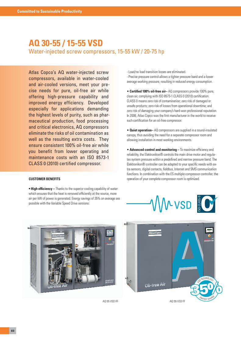
60
Committed to Sustainable Productivity
Atlas Copco’s AQ water-injected screw compressors, available in water-cooled and air-cooled versions, meet your pre-cise needs for pure, oil-free air while offering high-pressure capability and improved energy efficiency. Developed especially for applications demanding the highest levels of purity, such as phar-maceutical production, food processing and critical electronics, AQ compressors eliminate the risks of oil contamination as well as the resulting extra costs. They ensure consistent 100% oil-free air while you benefit from lower operating and maintenance costs with an ISO 8573-1 CLASS 0 (2010) certified compressor.
AQ 30-55 / 15-55 VSDWater-injected screw compressors, 15-55 kW / 20-75 hp
CUSTOMER BENEFITS
• High efficiency – Thanks to the superior cooling capability of water which ensures that the heat is removed efficiently at the source, more air per kW of power is generated. energy savings of 35% on average are possible with the Variable speed Drive versions:
- Load/no load transition losses are eliminated.- Precise pressure control allows a tighter pressure band and a lower average working pressure, resulting in reduced energy consumption.
• Certified 100% oil-free air– aQ compressors provide 100% pure, clean air, complying with Iso 8573-1 CLass 0 (2010) certification. CLass 0 means zero risk of contamination; zero risk of damaged or unsafe products; zero risk of losses from operational downtime; and zero risk of damaging your company’s hard-won professional reputation. In 2006, atlas Copco was the first manufacturer in the world to receive such certification for an oil-free compressor.
• Quiet operation– aQ compressors are supplied in a sound-insulated canopy, thus avoiding the need for a separate compressor room and allowing installation in most working environments.
• Advanced control and monitoring – To maximize efficiency and reliability, the elektronikon® controls the main drive motor and regula-tes system pressure within a predefined and narrow pressure band. The elektronikon® controller can be adapted to your specific needs with ex-tra sensors, digital contacts, fieldbus, Internet and sMs communication functions. In combination with the es multiple compressor controller, the operation of your complete compressor room is optimized.
aQ 55 VsD FFaQ 55 VsD FF
VS
D-TECHNOLOGY
ENERGY SAVING35%
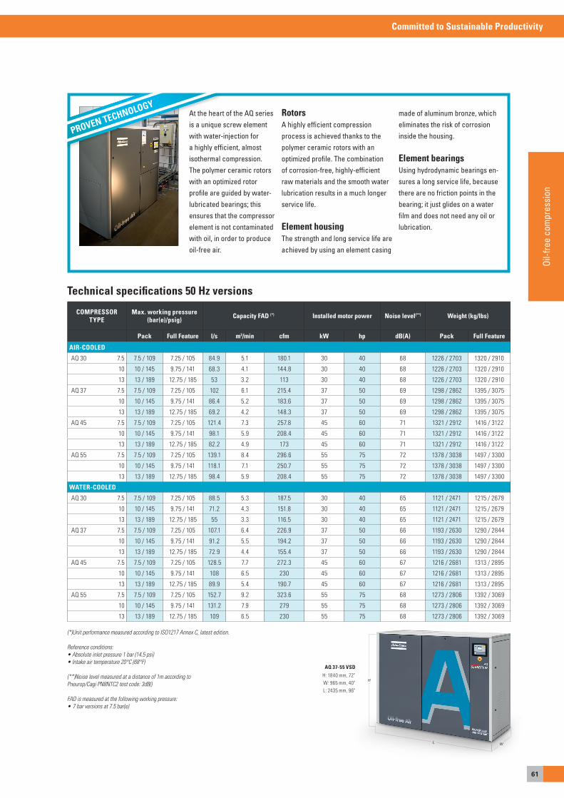
61
Committed to Sustainable Productivity
Oil-f
ree
com
pres
sion
At the heart of the AQ series is a unique screw element with water-injection for a highly efficient, almost isothermal compression. The polymer ceramic rotors with an optimized rotor profile are guided by water-lubricated bearings; this ensures that the compressor element is not contaminated with oil, in order to produce oil-free air.
RotorsA highly efficient compression process is achieved thanks to the polymer ceramic rotors with an optimized profile. The combination of corrosion-free, highly-efficient raw materials and the smooth water lubrication results in a much longer service life.
Element housingThe strength and long service life are achieved by using an element casing
made of aluminum bronze, which eliminates the risk of corrosion inside the housing.
Element bearingsUsing hydrodynamic bearings en-sures a long service life, because there are no friction points in the bearing; it just glides on a water film and does not need any oil or lubrication.
PROVEN TECHNOLOGY
COMPRESSOR TYPE
Max. working pressure (bar(e)/psig) Capacity FAD (*) Installed motor power Noise level(**) Weight (kg/lbs)
Pack Full Feature l/s m3/min cfm kW hp dB(A) Pack Full Feature
AIR-COOLED
aQ 30 7.5 7.5 / 109 7.25 / 105 84.9 5.1 180.1 30 40 68 1226 / 2703 1320 / 2910
10 10 / 145 9.75 / 141 68.3 4.1 144.8 30 40 68 1226 / 2703 1320 / 2910
13 13 / 189 12.75 / 185 53 3.2 113 30 40 68 1226 / 2703 1320 / 2910
aQ 37 7.5 7.5 / 109 7.25 / 105 102 6.1 215.4 37 50 69 1298 / 2862 1395 / 3075
10 10 / 145 9.75 / 141 86.4 5.2 183.6 37 50 69 1298 / 2862 1395 / 3075
13 13 / 189 12.75 / 185 69.2 4.2 148.3 37 50 69 1298 / 2862 1395 / 3075
aQ 45 7.5 7.5 / 109 7.25 / 105 121.4 7.3 257.8 45 60 71 1321 / 2912 1416 / 3122
10 10 / 145 9.75 / 141 98.1 5.9 208.4 45 60 71 1321 / 2912 1416 / 3122
13 13 / 189 12.75 / 185 82.2 4.9 173 45 60 71 1321 / 2912 1416 / 3122
aQ 55 7.5 7.5 / 109 7.25 / 105 139.1 8.4 296.6 55 75 72 1378 / 3038 1497 / 3300
10 10 / 145 9.75 / 141 118.1 7.1 250.7 55 75 72 1378 / 3038 1497 / 3300
13 13 / 189 12.75 / 185 98.4 5.9 208.4 55 75 72 1378 / 3038 1497 / 3300
WATER-COOLED
aQ 30 7.5 7.5 / 109 7.25 / 105 88.5 5.3 187.5 30 40 65 1121 / 2471 1215 / 2679
10 10 / 145 9.75 / 141 71.2 4.3 151.8 30 40 65 1121 / 2471 1215 / 2679
13 13 / 189 12.75 / 185 55 3.3 116.5 30 40 65 1121 / 2471 1215 / 2679
aQ 37 7.5 7.5 / 109 7.25 / 105 107.1 6.4 226.9 37 50 66 1193 / 2630 1290 / 2844
10 10 / 145 9.75 / 141 91.2 5.5 194.2 37 50 66 1193 / 2630 1290 / 2844
13 13 / 189 12.75 / 185 72.9 4.4 155.4 37 50 66 1193 / 2630 1290 / 2844
aQ 45 7.5 7.5 / 109 7.25 / 105 128.5 7.7 272.3 45 60 67 1216 / 2681 1313 / 2895
10 10 / 145 9.75 / 141 108 6.5 230 45 60 67 1216 / 2681 1313 / 2895
13 13 / 189 12.75 / 185 89.9 5.4 190.7 45 60 67 1216 / 2681 1313 / 2895
aQ 55 7.5 7.5 / 109 7.25 / 105 152.7 9.2 323.6 55 75 68 1273 / 2806 1392 / 3069
10 10 / 145 9.75 / 141 131.2 7.9 279 55 75 68 1273 / 2806 1392 / 3069
13 13 / 189 12.75 / 185 109 6.5 230 55 75 68 1273 / 2806 1392 / 3069
Technical specifications 50 Hz versions
AQ 37-55 VSD
H: 1840 mm, 72"W: 965 mm, 40"L: 2435 mm, 96"
H
WL
(*)Unit performance measured according to ISO1217 Annex C, latest edition.
Reference conditions:• Absolute inlet pressure 1 bar (14.5 psi)• Intake air temperature 20°C (68°F)
(**)Noise level measured at a distance of 1m according toPneurop/Cagi PN8NTC2 test code: 3dB()
FAD is measured at the following working pressure:• 7 bar versions at 7.5 bar(e)
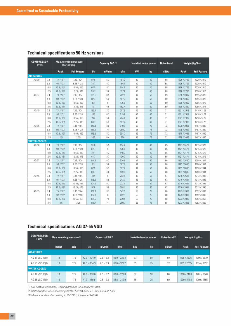
62
Committed to Sustainable Productivity
COMPRESSOR TYPE
Max. working pressure (bar(e)/psig) Capacity FAD (1) Installed motor power Noise level Weight (kg/lbs)
Pack Full Feature l/s m3/min cfm kW hp dB(A) Pack Full Feature
AIR-COOLEDaQ 30 7.4 7.4 / 107 7.15 / 104 87.8 5.3 187.2 30 40 68 1226 / 2703 1320 / 2910
9.1 9.1 / 132 8.85 / 128 78.7 4.7 166.1 30 40 68 1226 / 2703 1320 / 2910
10.8 10.8 / 157 10.55 / 153 67.5 4.1 144.8 30 40 68 1226 / 2703 1320 / 2910
12.5 12.5 / 181 12.25 / 178 59.2 3.6 127.1 30 40 68 1226 / 2703 1320 / 2910
aQ 37 7.4 7.4 / 107 7.15 / 104 105.5 6.3 222.5 37 50 69 1298 / 2862 1395 / 3075
9.1 9.1 / 132 8.85 / 128 87.7 5.3 187.2 37 50 69 1298 / 2862 1395 / 3075
10.8 10.8 / 157 10.55 / 153 83 5 176.6 37 50 69 1298 / 2862 1395 / 3075
12.5 12.5 / 181 12.25 / 178 76.1 4.6 162.4 37 50 69 1298 / 2862 1395 / 3075
aQ 45 7.4 7.4 / 107 7.15 / 104 122.4 7.3 257.8 45 60 71 1321 / 2912 1416 / 3122
9.1 9.1 / 132 8.85 / 128 103 6.2 219.1 45 60 71 1321 / 2912 1416 / 3122
10.8 10.8 / 157 10.55 / 153 96 5.8 204.8 45 60 71 1321 / 2912 1416 / 3122
12.5 12.5 / 181 12.25 / 178 88.7 5.3 187.2 45 60 71 1321 / 2912 1416 / 3122
aQ 55 7.4 7.4 / 107 7.15 / 104 146.8 8.8 310.8 55 75 72 1378 / 3038 1497 / 3300
9.1 9.1 / 132 8.85 / 128 118.2 7.1 250.7 55 75 72 1378 / 3038 1497 / 3300
10.8 10.8 / 157 10.55 / 153 119.6 7.2 254.3 55 75 72 1378 / 3038 1497 / 3300
12.5 12.5 12.25 106 6.4 226 55 75 72 1378 / 3038 1497 / 3300
WATER-COOLEDaQ 30 7.4 7.4 / 107 7.15 / 104 91.8 5.5 194.2 30 40 65 1121 / 2471 1215 / 2679
9.1 9.1 / 132 8.85 / 128 82.7 5 176.6 30 40 65 1121 / 2471 1215 / 2679
10.8 10.8 / 157 10.55 / 153 70.4 4.2 148.3 30 40 65 1121 / 2471 1215 / 2679
12.5 12.5 / 181 12.25 / 178 61.7 3.7 130.7 30 40 65 1121 / 2471 1215 / 2679
aQ 37 7.4 7.4 / 107 7.15 / 104 111.3 6.7 236.6 37 50 66 1193 / 2630 1290 / 2844
9.1 9.1 / 132 8.85 / 128 93 5.6 197.8 37 50 66 1193 / 2630 1290 / 2844
10.8 10.8 / 157 10.55 / 153 87.5 5.3 187.2 37 50 66 1193 / 2630 1290 / 2844
12.5 12.5 / 181 12.25 / 178 80.7 4.8 169.5 37 50 66 1193 / 2630 1290 / 2844
aQ 45 7.4 7.4 / 107 7.15 / 104 134 8 282.5 45 60 67 1216 / 2681 1313 / 2895
9.1 9.1 / 132 8.85 / 128 115.2 6.9 243.7 45 60 67 1216 / 2681 1313 / 2895
10.8 10.8 / 157 10.55 / 153 104.2 6.3 222.5 45 60 67 1216 / 2681 1313 / 2895
12.5 12.5 / 181 12.25 / 178 97.8 5.9 208.4 45 60 67 1216 / 2681 1313 / 2895
aQ 55 7.4 7.4 / 107 7.15 / 104 161.7 9.7 342.6 55 75 68 1273 / 2806 1392 / 3069
9.1 9.1 / 132 8.85 / 128 132.7 8 282.5 55 75 68 1273 / 2806 1392 / 3069
10.8 10.8 / 157 10.55 / 153 131.5 7.9 279.1 55 75 68 1273 / 2806 1392 / 3069
12.5 12.5 12.25 118.7 7.1 250.7 55 75 68 1273 / 2806 1392 / 3069
COMPRESSOR TYPE Max. working pressure (1) Capacity FAD (2) Installed motor power Noise level (3) Weight (kg/lbs)
bar(e) psig l/s m3/min cfm kW hp dB(A) Pack Full Feature
AIR-COOLED
aQ 37 VsD 13(1) 13 175 42.0 – 104.0 2.5 – 6.2 89.0 – 220.4 37 50 69 1195 / 2635 1306 / 2879
aQ 55 VsD 13(1) 13 175 42.3 – 154.9 2.5 – 9.3 89.6 – 328.2 55 75 72 1195 / 2635 1314 / 2897
WATER-COOLED
aQ 37 VsD 13(1) 13 175 42.0 – 108.0 2.5 – 6.2 89.0 – 228.8 37 50 66 1090 / 2403 1201 / 2648
aQ 55 VsD 13(1) 13 175 41.9 – 160.9 2.5 – 9.3 88.8 – 340.9 55 75 69 1090 / 2403 1209 / 2665
Technical specifications AQ 37-55 VSD
(1) Full-Feature units max. working pressure 12.5 bar(e)/181 psig.
(2) Stated performance according ISO1217 ed 04 Annex E, measured at 7 bar.
(3) Mean sound level according to ISO2151, tolerance 3 dB(A).
Technical specifications 50 Hz versions

63
Committed to Sustainable Productivity
Oil-f
ree
com
pres
sion
Atlas Copco’s ZR/ZT oil-free rotary tooth compressors meet your needs for pure oil-free air while offering wide pressure ranges and improved energy efficiency. Developed especially for applications demanding the highest levels of purity, such as pharmaceutical production, food processing and critical electronics, ZR/ZT compressors eliminate the risks of oil contamination as well as the resulting extra costs. These ISO 8573-1 CLASS 0 certified compressors are easy to opera-te and are available with Variable Speed Drive for further energy savings.
ZT 15-22, ZR/ZT 30-45, ZR/ZT 22-37-55 VSDOil-free rotary tooth compressors, 15-55 kW / 20-75 hp
CUSTOMER BENEFITS
• Certified 100% oil-free air – ZR/ZT compressors provide 100% pure, clean air, complying with Iso 8573-1 CLass 0 (2010) certification. CLass 0 means zero risk of contamination; zero risk of damaged or unsafe products; zero risk of losses from operational downtime; and zero risk of damaging your company’s hard-won professional reputation. In 2006, atlas Copco was the first manufacturer in the world to receive such certification for an oil-free compressor.
• VSD for direct energy savings – energy savings of 35% on average are possible with the Variable speed Drive versions:- Unload losses are reduced to a minimum.- No blow-off of compressed air to the atmosphere.- Load/no load transition losses are eliminated.- Precise pressure control allows a tighter pressure band and a lower average working pressure, resulting in reduced energy consumption.
• Quiet operation – The vertical layout of the coolers reduces the noise levels from the fan, motor and element. Moreover, ZR/ZT com-pressors are supplied in a sound-insulated canopy, thus avoiding the need for a separate compressor room and allowing installation in most working environments.
• Advanced control and monitoring – To maximize efficiency and reliability, the elektronikon® controls the main drive motor and regula-tes system pressure within a predefined and narrow pressure band. The elektronikon® controller can be adapted to your specific needs with ex-tra sensors, digital contacts, fieldbus, Internet and sMs communication functions. In combination with the es multiple compressor controller, the operation of your complete compressor room is optimized.
• Easy maintenance – The robust air inlet filter offers a long lifetime and high reliability for long service intervals and low maintenance needs.
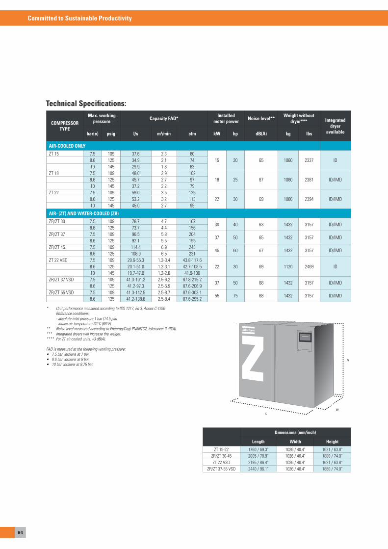
64
Committed to Sustainable Productivity
Dimensions (mm/inch)
Length Width Height
ZT 15-22 1760 / 69.3" 1026 / 40.4" 1621 / 63.8"ZR/ZT 30-45 2005 / 78.9" 1026 / 40.4" 1880 / 74.0"ZT 22 VsD 2195 / 86.4" 1026 / 40.4" 1621 / 63.8"
ZR/ZT 37-55 VsD 2440 / 96.1" 1026 / 40.4" 1880 / 74.0"
* Unit performance measured according to ISO 1217, Ed 3, Annex C-1996 Reference conditions: - absolute inlet pressure 1 bar (14.5 psi) - intake air temperature 20°C (68°F)** Noise level measured according to Pneurop/Cagi PN8NTC2, tolerance: 3 dB(A).*** Integrated dryers will increase the weight.**** For ZT air-cooled units: +3 dB(A).
FAD is measured at the following working pressure:• 7.5 bar versions at 7 bar. • 8.6 bar versions at 8 bar.• 10 bar versions at 9.75 bar.
H
LW
Technical Specifications:
COMPRESSORTYPE
Max. working pressure Capacity FAD* Installed
motor power Noise level** Weight without dryer*** Integrated
dryer availablebar(e) psig l/s m3/min cfm kW hp dB(A) kg lbs
AIR-COOLED ONLY
ZT 15 7.5 109 37.6 2.3 8015 20 65 1060 2337 ID8.6 125 34.9 2.1 74
10 145 29.9 1.8 63ZT 18 7.5 109 48.0 2.9 102
18 25 67 1080 2381 ID/IMD8.6 125 45.7 2.7 9710 145 37.2 2.2 79
ZT 22 7.5 109 59.0 3.5 12522 30 69 1086 2394 ID/IMD8.6 125 53.2 3.2 113
10 145 45.0 2.7 95
AIR- (ZT) AND WATER-COOLED (ZR)
ZR/ZT 30 7.5 109 78.7 4.7 16730 40 63 1432 3157 ID/IMD
8.6 125 73.7 4.4 156ZR/ZT 37 7.5 109 96.5 5.8 204
37 50 65 1432 3157 ID/IMD8.6 125 92.1 5.5 195
ZR/ZT 45 7.5 109 114.4 6.9 24345 60 67 1432 3157 ID/IMD
8.6 125 108.9 6.5 231ZT 22 VsD 7.5 109 20.6-55.3 1.3-3.4 43.8-117.6
22 30 69 1120 2469 ID8.6 125 20.1-51.0 1.2-3.1 42.7-108.510 145 19.7-47.0 1.2-2.8 41.9-100
ZR/ZT 37 VsD 7.5 109 41.3-101.2 2.5-6.2 87.8-215.237 50 68 1432 3157 ID/IMD
8.6 125 41.2-97.3 2.5-5.9 87.6-206.9ZR/ZT 55 VsD 7.5 109 41.3-142.5 2.5-8.7 87.6-303.1
55 75 68 1432 3157 ID/IMD8.6 125 41.2-138.8 2.5-8.4 87.6-295.2
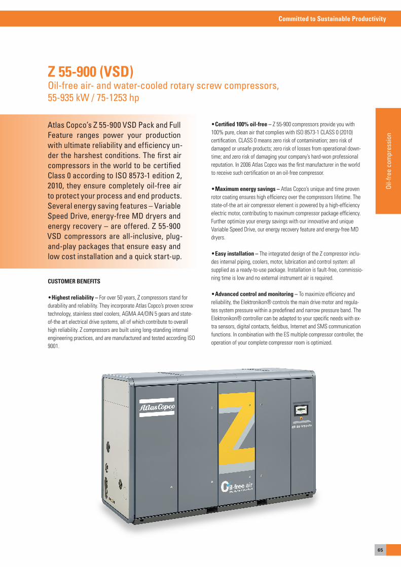
65
Committed to Sustainable Productivity
Oil-f
ree
com
pres
sion
Atlas Copco’s Z 55-900 VSD Pack and Full Feature ranges power your production with ultimate reliability and efficiency un-der the harshest conditions. The first air compressors in the world to be certified Class 0 according to ISO 8573-1 edition 2, 2010, they ensure completely oil-free air to protect your process and end products. Several energy saving features – Variable Speed Drive, energy-free MD dryers and energy recovery – are offered. Z 55-900 VSD compressors are all-inclusive, plug-and-play packages that ensure easy and low cost installation and a quick start-up.
Z 55-900 (VSD)Oil-free air- and water-cooled rotary screw compressors,55-935 kW / 75-1253 hp
CUSTOMER BENEFITS
• Highest reliability – For over 50 years, Z compressors stand for durability and reliability. They incorporate atlas Copco’s proven screw technology, stainless steel coolers, aGMa a4/DIN 5 gears and state-of-the art electrical drive systems, all of which contribute to overall high reliability. Z compressors are built using long-standing internal engineering practices, and are manufactured and tested according Iso 9001.
• Certified 100% oil-free – Z 55-900 compressors provide you with 100% pure, clean air that complies with Iso 8573-1 CLass 0 (2010) certification. CLass 0 means zero risk of contamination; zero risk of damaged or unsafe products; zero risk of losses from operational down-time; and zero risk of damaging your company’s hard-won professional reputation. In 2006 atlas Copco was the first manufacturer in the world to receive such certification on an oil-free compressor.
• Maximum energy savings – atlas Copco’s unique and time proven rotor coating ensures high efficiency over the compressors lifetime. The state-of-the art air compressor element is powered by a high-efficiency electric motor, contributing to maximum compressor package efficiency. Further optimize your energy savings with our innovative and unique Variable speed Drive, our energy recovery feature and energy-free MD dryers.
• Easy installation – The integrated design of the Z compressor inclu-des internal piping, coolers, motor, lubrication and control system: all supplied as a ready-to-use package. Installation is fault-free, commissio-ning time is low and no external instrument air is required.
• Advanced control and monitoring – To maximize efficiency and reliability, the elektronikon® controls the main drive motor and regula-tes system pressure within a predefined and narrow pressure band. The elektronikon® controller can be adapted to your specific needs with ex-tra sensors, digital contacts, fieldbus, Internet and sMs communication functions. In combination with the es multiple compressor controller, the operation of your complete compressor room is optimized.
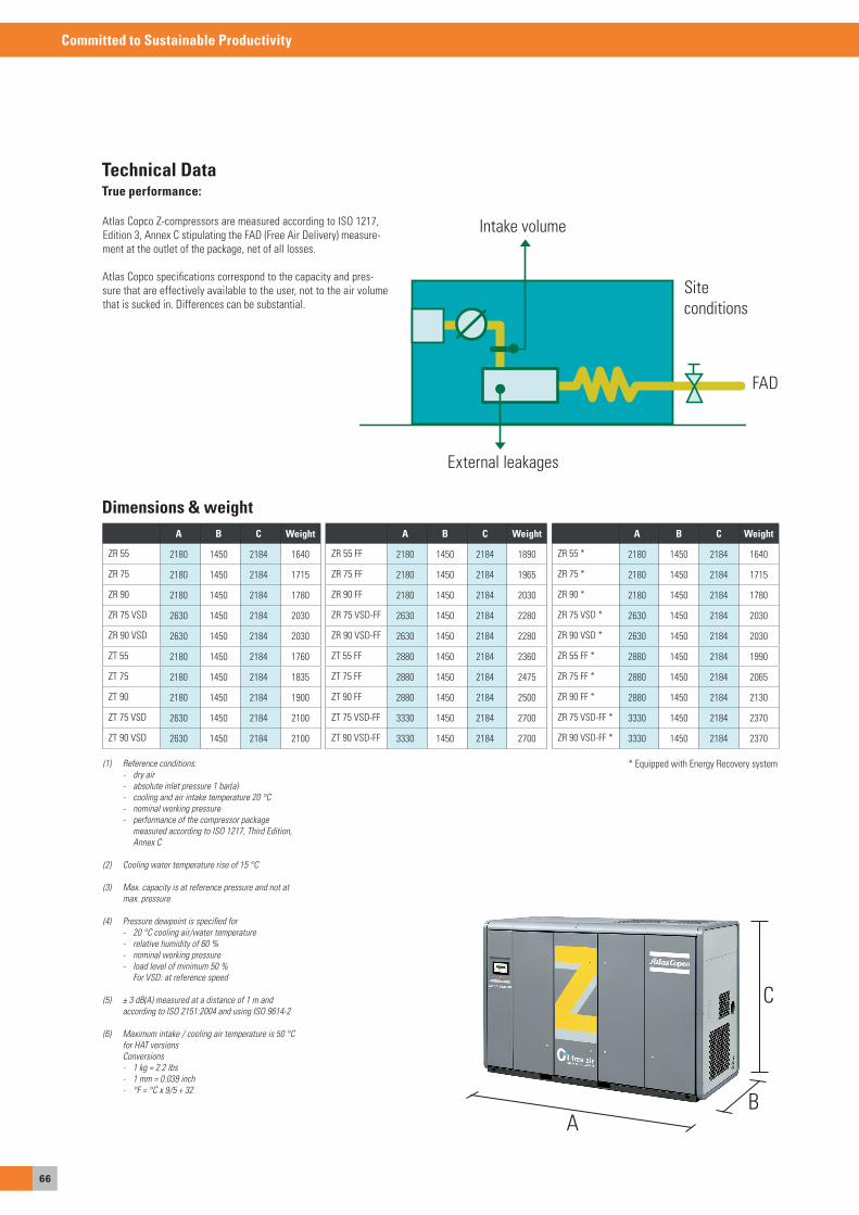
66
Committed to Sustainable Productivity
Dimensions & weight
(1) Reference conditions: - dry air - absolute inlet pressure 1 bar(a) - cooling and air intake temperature 20 °C - nominal working pressure - performance of the compressor package measured according to ISO 1217, Third Edition, Annex C
(2) Cooling water temperature rise of 15 °C
(3) Max. capacity is at reference pressure and not at max. pressure
(4) Pressure dewpoint is specified for - 20 °C cooling air/water temperature - relative humidity of 60 % - nominal working pressure - load level of minimum 50 % For VSD: at reference speed
(5) ± 3 dB(A) measured at a distance of 1 m and according to ISO 2151:2004 and using ISO 9614-2
(6) Maximum intake / cooling air temperature is 50 °C for HAT versions Conversions - 1 kg = 2.2 lbs - 1 mm = 0.039 inch - °F = °C x 9/5 + 32
* equipped with energy Recovery system
aB
C
True performance:
atlas Copco Z-compressors are measured according to Iso 1217, edition 3, annex C stipulating the FaD (Free air Delivery) measure-ment at the outlet of the package, net of all losses.
atlas Copco specifications correspond to the capacity and pres-sure that are effectively available to the user, not to the air volume that is sucked in. Differences can be substantial.
FaD
siteconditions
external leakages
Intake volume
Technical Data
A B C Weight
ZR 55 2180 1450 2184 1640
ZR 75 2180 1450 2184 1715
ZR 90 2180 1450 2184 1780
ZR 75 VsD 2630 1450 2184 2030
ZR 90 VsD 2630 1450 2184 2030
ZT 55 2180 1450 2184 1760
ZT 75 2180 1450 2184 1835
ZT 90 2180 1450 2184 1900
ZT 75 VsD 2630 1450 2184 2100
ZT 90 VsD 2630 1450 2184 2100
A B C Weight
ZR 55 FF 2180 1450 2184 1890
ZR 75 FF 2180 1450 2184 1965
ZR 90 FF 2180 1450 2184 2030
ZR 75 VsD-FF 2630 1450 2184 2280
ZR 90 VsD-FF 2630 1450 2184 2280
ZT 55 FF 2880 1450 2184 2360
ZT 75 FF 2880 1450 2184 2475
ZT 90 FF 2880 1450 2184 2500
ZT 75 VsD-FF 3330 1450 2184 2700
ZT 90 VsD-FF 3330 1450 2184 2700
A B C Weight
ZR 55 * 2180 1450 2184 1640
ZR 75 * 2180 1450 2184 1715
ZR 90 * 2180 1450 2184 1780
ZR 75 VsD * 2630 1450 2184 2030
ZR 90 VsD * 2630 1450 2184 2030
ZR 55 FF * 2880 1450 2184 1990
ZR 75 FF * 2880 1450 2184 2065
ZR 90 FF * 2880 1450 2184 2130
ZR 75 VsD-FF * 3330 1450 2184 2370
ZR 90 VsD-FF * 3330 1450 2184 2370
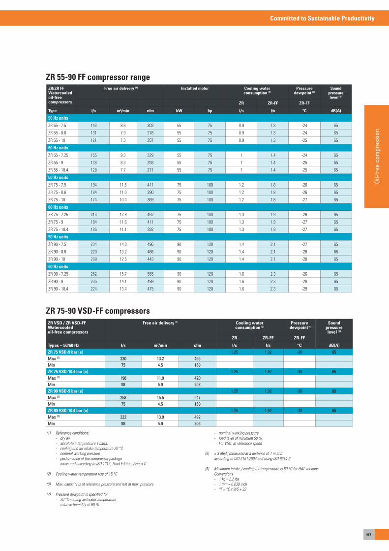
67
Committed to Sustainable Productivity
Oil-f
ree
com
pres
sion
(1) Reference conditions: - dry air - absolute inlet pressure 1 bar(a) - cooling and air intake temperature 20 °C - nominal working pressure - performance of the compressor package measured according to ISO 1217, Third Edition, Annex C
(2) Cooling water temperature rise of 15 °C
(3) Max. capacity is at reference pressure and not at max. pressure
(4) Pressure dewpoint is specified for - 20 °C cooling air/water temperature - relative humidity of 60 %
- nominal working pressure - load level of minimum 50 % For VSD: at reference speed
(5) ± 3 dB(A) measured at a distance of 1 m and according to ISO 2151:2004 and using ISO 9614-2
(6) Maximum intake / cooling air temperature is 50 °C for HAT versions Conversions - 1 kg = 2.2 lbs - 1 mm = 0.039 inch - °F = °C x 9/5 + 32
* equipped with energy Recovery system
FaD
ZR 55-90 FF compressor rangeZR/ZR FFWatercooledoil-freecompressors
Free air delivery (1) Installed motor Cooling waterconsumption (2)
Pressuredewpoint (4)
Sound pressurelevel (5)
ZR ZR-FF ZR-FF
Type l/s m3/min cfm kW hp l/s l/s °C dB(A)
50 Hz units
ZR 55 - 7.5 143 8.6 303 55 75 0.9 1.3 -24 65
ZR 55 - 8.6 131 7.9 278 55 75 0.9 1.3 -24 65
ZR 55 - 10 121 7.3 257 55 75 0.9 1.3 -25 65
60 Hz units
ZR 55 - 7.25 155 9.3 329 55 75 1 1.4 -24 65
ZR 55 - 9 138 8.3 293 55 75 1 1.4 -25 65
ZR 55 - 10.4 128 7.7 271 55 75 1 1.4 -25 65
50 Hz units
ZR 75 - 7.5 194 11.6 411 75 100 1.2 1.8 -26 65
ZR 75 - 8.6 184 11.0 390 75 100 1.2 1.8 -26 65
ZR 75 - 10 174 10.4 369 75 100 1.2 1.8 -27 65
60 Hz units
ZR 75 - 7.25 213 12.8 452 75 100 1.3 1.9 -26 65
ZR 75 - 9 194 11.6 411 75 100 1.3 1.9 -27 65
ZR 75 - 10.4 185 11.1 392 75 100 1.3 1.9 -27 65
50 Hz units
ZR 90 - 7.5 234 14.0 496 90 120 1.4 2.1 -27 65
ZR 90 - 8.6 220 13.2 466 90 120 1.4 2.1 -28 65
ZR 90 - 10 209 12.5 443 90 120 1.4 2.1 -28 65
60 Hz units
ZR 90 - 7.25 262 15.7 555 90 120 1.6 2.3 -26 65
ZR 90 - 9 235 14.1 498 90 120 1.6 2.3 -28 65
ZR 90 - 10.4 224 13.4 475 90 120 1.6 2.3 -29 65
ZR 75-90 VSD-FF compressorsZR VSD / ZR VSD-FFWatercooled oil-free compressors
Free air delivery (1) Cooling waterconsumption (2)
Pressure dewpoint (4)
Soundpressurelevel (5)
ZR ZR-FF ZR-FF
Types – 50/60 Hz l/s m3/min cfm l/s l/s °C dB(A)
ZR 75 VSD-9 bar (e) 1.25 1.92 -30 65Max (3) 220 13.2 466Min 75 4.5 159ZR 75 VSD-10.4 bar (e) 1.25 1.92 -30 65Max (3) 198 11.9 420Min 98 5.9 208ZR 90 VSD-9 bar (e) 1.25 1.92 -30 65Max (3) 258 15.5 547Min 75 4.5 159ZR 90 VSD-10.4 bar (e) 1.25 1.92 -30 65Max (3) 232 13.9 492Min 98 5.9 208
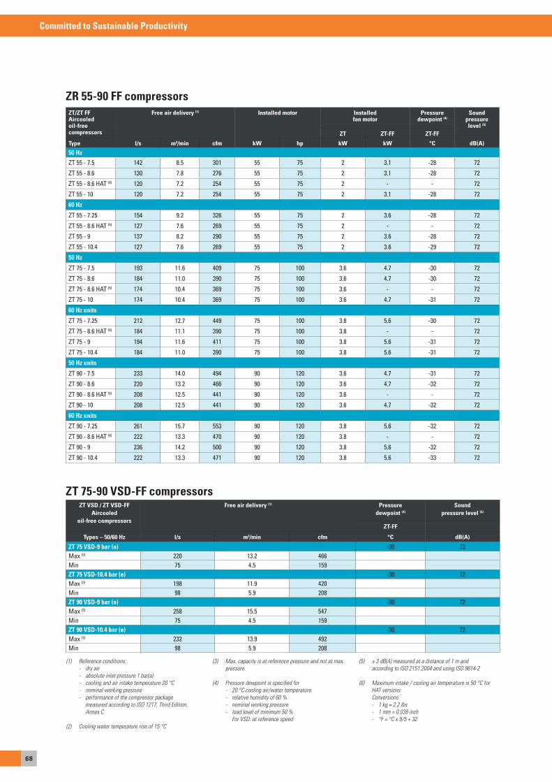
68
Committed to Sustainable Productivity
ZT 75-90 VSD-FF compressors
ZR 55-90 FF compressorsZT/ZT FFAircooledoil-freecompressors
Free air delivery (1) Installed motor Installedfan motor
Pressuredewpoint (4)
Soundpressure level (5)
ZT ZT-FF ZT-FF
Type l/s m3/min cfm kW hp kW kW °C dB(A)
50 Hz
ZT 55 - 7.5 142 8.5 301 55 75 2 3.1 -28 72
ZT 55 - 8.6 130 7.8 276 55 75 2 3.1 -28 72
ZT 55 - 8.6 HAT (6) 120 7.2 254 55 75 2 - - 72
ZT 55 - 10 120 7.2 254 55 75 2 3.1 -28 72
60 Hz
ZT 55 - 7.25 154 9.2 326 55 75 2 3.6 -28 72
ZT 55 - 8.6 HAT (6) 127 7.6 269 55 75 2 - - 72
ZT 55 - 9 137 8.2 290 55 75 2 3.6 -28 72
ZT 55 - 10.4 127 7.6 269 55 75 2 3.6 -29 72
50 Hz
ZT 75 - 7.5 193 11.6 409 75 100 3.6 4.7 -30 72
ZT 75 - 8.6 184 11.0 390 75 100 3.6 4.7 -30 72
ZT 75 - 8.6 HAT (6) 174 10.4 369 75 100 3.6 - - 72
ZT 75 - 10 174 10.4 369 75 100 3.6 4.7 -31 72
60 Hz units
ZT 75 - 7.25 212 12.7 449 75 100 3.8 5.6 -30 72
ZT 75 - 8.6 HAT (6) 184 11.1 390 75 100 3.8 - - 72
ZT 75 - 9 194 11.6 411 75 100 3.8 5.6 -31 72
ZT 75 - 10.4 184 11.0 390 75 100 3.8 5.6 -31 72
50 Hz units
ZT 90 - 7.5 233 14.0 494 90 120 3.6 4.7 -31 72
ZT 90 - 8.6 220 13.2 466 90 120 3.6 4.7 -32 72
ZT 90 - 8.6 HAT (6) 208 12.5 441 90 120 3.6 - - 72
ZT 90 - 10 208 12.5 441 90 120 3.6 4.7 -32 72
60 Hz units
ZT 90 - 7.25 261 15.7 553 90 120 3.8 5.6 -32 72
ZT 90 - 8.6 HAT (6) 222 13.3 470 90 120 3.8 - - 72
ZT 90 - 9 236 14.2 500 90 120 3.8 5.6 -32 72
ZT 90 - 10.4 222 13.3 471 90 120 3.8 5.6 -33 72
ZT VSD / ZT VSD-FFAircooled
oil-free compressors
Free air delivery (1) Pressuredewpoint (4)
Soundpressure level (5)
ZT-FF
Types – 50/60 Hz l/s m3/min cfm °C dB(A)
ZT 75 VSD-9 bar (e) -30 72Max (3) 220 13.2 466Min 75 4.5 159ZT 75 VSD-10.4 bar (e) -30 72Max (3) 198 11.9 420Min 98 5.9 208ZT 90 VSD-9 bar (e) -30 72Max (3) 258 15.5 547Min 75 4.5 159ZT 90 VSD-10.4 bar (e) -30 72Max (3) 232 13.9 492Min 98 5.9 208
(1) Reference conditions: - dry air - absolute inlet pressure 1 bar(a) - cooling and air intake temperature 20 °C - nominal working pressure - performance of the compressor package measured according to ISO 1217, Third Edition, Annex C
(2) Cooling water temperature rise of 15 °C
(3) Max. capacity is at reference pressure and not at max. pressure
(4) Pressure dewpoint is specified for - 20 °C cooling air/water temperature - relative humidity of 60 % - nominal working pressure - load level of minimum 50 % For VSD: at reference speed
(5) ± 3 dB(A) measured at a distance of 1 m and according to ISO 2151:2004 and using ISO 9614-2
(6) Maximum intake / cooling air temperature is 50 °C for HAT versions Conversions - 1 kg = 2.2 lbs - 1 mm = 0.039 inch - °F = °C x 9/5 + 32
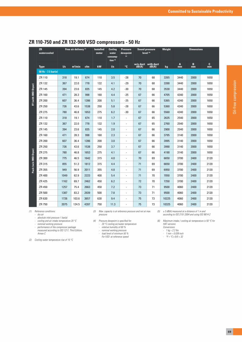
69
Committed to Sustainable Productivity
Oil-f
ree
com
pres
sion
ZR 110-750 and ZR 132-900 VSD compressors - 50 HzZR watercooled
Free air delivery (1) Installed motor
Cooling water
consump-tion (2)
Pressure dewpoint
(3)
Sound pressure level (4)
Weight Dimensions
Type l/s m3/min cfm kW l/s °Cw/o duct
dB(A)with duct
dB(A) kgA
mmB
mmC
mm
50 Hz - 7.5 bar(e)
FF (w
ith IM
D D
ryer
)
ZR 110 318 19.1 674 110 3.5 -28 70 68 3265 3440 2000 1650
ZR 132 367 22.0 778 132 4.1 -29 70 68 3390 3440 2000 1650
ZR 145 394 23.6 835 145 4.2 -30 70 68 3530 3440 2000 1650
ZR 160 471 28.3 998 160 4.4 -25 67 66 4705 4340 2000 1650
ZR 200 607 36.4 1286 200 5.1 -25 67 66 5365 4340 2000 1650
ZR 250 726 43.6 1538 250 5.8 -28 67 66 5360 4340 2000 1650
ZR 275 780 46.8 1653 275 6.2 -30 67 66 5560 4340 2000 1650
Pac
k (w
/o IM
D D
ryer
)
ZR 110 318 19.1 674 110 1.7 - 67 65 2635 2540 2000 1650
ZR 132 367 22.0 778 132 1.9 - 67 65 2760 2540 2000 1650
ZR 145 394 23.6 835 145 2.0 - 67 66 2900 2540 2000 1650
ZR 160 471 28.3 998 160 2.3 - 67 66 3795 3140 2000 1650
ZR 200 607 36.4 1286 200 3.0 - 67 66 3995 3140 2000 1650
ZR 250 726 43.6 1538 250 3.7 - 67 66 3990 3140 2000 1650
ZR 275 780 46.8 1653 275 4.1 - 67 66 4190 3140 2000 1650
ZR 300 775 46.5 1642 315 4.0 - 70 69 6650 3700 2400 2120
ZR 315 855 51.3 1812 315 4.4 - 71 69 6650 3700 2400 2120
ZR 355 949 56.9 2011 355 4.8 - 71 69 6950 3700 2400 2120
ZR 400 1049 62.9 2223 400 5.4 - 71 70 7050 3700 2400 2120
ZR 425 1162 69.7 2462 450 6.2 - 72 70 7250 3700 2400 2120
ZR 450 1257 75.4 2663 450 7.2 - 73 71 9500 4060 2400 2120
ZR 500 1387 83.2 2939 500 7.8 - 73 71 9500 4060 2400 2120
ZR 630 1726 103.6 3657 630 9.4 - 75 73 10225 4060 2400 2120
ZR 750 2075 124.5 4397 750 11.3 - 75 73 10325 4060 2400 2120
(1) Reference conditions: - dry air - absolute inlet pressure 1 bar(a) - cooling and air intake temperature 20 °C - nominal working pressure - performance of the compressor package measured according to ISO 1217, Third Edition, Annex C
(2) Cooling water temperature rise of 15 °C
(3) Max. capacity is at reference pressure and not at max. pressure
(4) Pressure dewpoint is specified for - 20 °C cooling air/water temperature - relative humidity of 60 % - nominal working pressure - load level of minimum 50 % For VSD: at reference speed
(5) ± 3 dB(A) measured at a distance of 1 m and according to ISO 2151:2004 and using ISO 9614-2
(6) Maximum intake / cooling air temperature is 50 °C for HAT versions Conversions - 1 kg = 2.2 lbs - 1 mm = 0.039 inch - °F = °C x 9/5 + 32
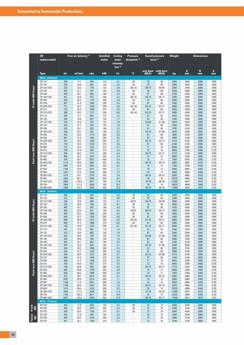
70
Committed to Sustainable Productivity
ZR watercooled
Free air delivery (1) Installed motor
Cooling water
consump-tion (2)
Pressure dewpoint (3)
Sound pressure level (4)
Weight Dimensions
Type l/s m3/min cfm kW l/s °Cw/o duct
dB(A)with duct
dB(A) kgA
mmB
mmC
mm
50 Hz - 8.6 bar(e)
FF (w
ith IM
D D
ryer
)
ZR 110 285 17.1 604 110 3.1 -28 70 68 3265 3440 2000 1650ZR 132 326 19.6 691 132 3.5 -29 70 68 3390 3440 2000 1650ZR 132 VSD 372 22.3 778 132 3.9 -28/-32 68-72 66-69 3500 3440 2000 1650ZR 145 362 21.7 767 145 3.9 -30 70 68 3530 3440 2000 1650ZR 160 435 26.1 922 160 4.2 -25 67 66 4705 4340 2000 1650ZR 160 VSD 431 25.9 913 160 4.2 -28/-32 68-74 66-71 3500 3440 2000 1650ZR 200 553 33.2 1172 200 4.8 -25 67 66 5365 4340 2000 1650ZR 250 691 41.5 1464 250 5.6 -28 67 66 5360 4340 2000 1650ZR 250 VSD 721 43.3 1528 250 5.8 -25/-30 63-73 62-71 6080 4340 2000 1650ZR 275 723 43.4 1532 275 5.8 -30 67 66 5560 4340 2000 1650ZR 315 VSD 836 50.2 1771 299 6.8 -25/-30 63-73 62-71 6080 4340 2000 1650
Pac
k (w
/o IM
D D
ryer
)
ZR 110 285 17.1 604 110 1.5 - 67 65 2635 2540 2000 1650ZR 132 326 19.6 691 132 1.7 - 67 65 2760 2540 2000 1650ZR 132 VSD 376 22.6 797 132 1.9 - 62-68 61-66 2870 2540 2000 1650ZR 145 362 21.7 767 145 1.9 - 67 66 2900 2540 2000 1650ZR 160 435 26.1 922 160 2.2 - 67 66 3795 3140 2000 1650ZR 160 VSD 436 26.1 922 160 2.2 - 62-70 61-66 2870 2540 2000 1650ZR 200 553 33.2 1172 200 2.8 - 67 66 3995 3140 2000 1650ZR 250 691 41.5 1464 250 3.5 - 67 66 3990 3140 2000 1650ZR 250 VSD 721 43.3 1528 250 3.7 - 63-73 62-71 4710 3140 2000 1650ZR 275 723 43.4 1532 275 3.8 - 67 66 4190 3140 2000 1650ZR 300 723 43.4 1532 315 4.1 - 71 70 6650 3700 2400 2120ZR 315 798 47.9 1691 315 4.5 - 72 70 6650 3700 2400 2120ZR 315 VSD 836 50.2 1771 299 4.3 - 63-73 62-71 4710 3140 2000 1650ZR 355 886 53.2 1877 355 4.9 - 72 72 6950 3700 2400 2120ZR 400 978 58.7 2072 400 5.4 - 72 71 7050 3700 2400 2120ZR 400 VSD 1114 66.9 2361 425 6.4 - 68-75 66-73 8350 4060 2470 2120ZR 425 1081 64.9 2291 450 6.2 - 73 71 7250 3700 2400 2120ZR 450 1166 70.0 2471 450 7.1 - 74 72 9500 4060 2400 2120ZR 500 1291 77.5 2735 500 7.7 - 74 72 9500 4060 2400 2120ZR 500 VSD 1318 79.1 2793 525 7.6 - 68-76 66-74 8350 4060 2470 2120ZR 630 1602 96.1 3394 630 9.3 - 76 74 10225 4060 2400 2120ZR 700 VSD 2063 123.8 4371 700 11.6 - 70-78 68-76 11850 4675 2470 2120ZR 750 1850 111.0 3920 750 10.7 - 76 74 10325 4060 2400 2120ZR 900 VSD 2456 147.4 5204 935 13.2 - 68-78 68-76 11850 4675 2470 212050 Hz - 10 bar(e)
FF (w
ith IM
D D
ryer
)
ZR 110 265 15.9 562 110 3.3 -28 70 68 3265 3440 2000 1650ZR 132 313 18.8 663 132 3.8 -29 70 68 3390 3440 2000 1650ZR 132 VSD 330 19.8 699 132 4.1 0,875 68-72 66-69 3500 3440 2000 1650ZR 145 334 20.0 708 145 4.1 -30 70 68 3530 3440 2000 1650ZR 160 402 24.1 852 160 4.3 -25 67 66 4705 4340 2000 1650ZR 160 VSD 392 23.5 831 160 4.4 0,875 68-74 66-71 3500 3440 2000 1650ZR 200 504 30.2 1068 200 4.9 -25 67 66 4905 4340 2000 1650ZR 250 629 37.7 1333 250 5.6 -28 67 66 5360 4340 2000 1650ZR 250 VSD 648 38.9 1373 250 5.8 -25/-30 67-73 65-71 6080 4340 2000 1650ZR 275 689 41.3 1460 275 6.0 -30 67 66 5560 4340 2000 1650ZR 315 VSD 746 44.8 1581 299 6.7 -25/-30 67-73 65-71 6080 4340 2000 1650
Pac
k (w
/o IM
D D
ryer
)
ZR 110 265 15.9 562 110 1.6 - 67 65 2380 2540 2000 1650ZR 132 313 18.8 663 132 1.8 - 67 65 2440 2540 2000 1650ZR 132 VSD 333 20.0 706 132 1.9 - 62-68 61-66 2590 2540 2000 1650ZR 145 334 20.0 708 145 1.9 - 67 66 2580 2540 2000 1650ZR 160 402 24.1 852 160 2.3 - 67 66 3795 3140 2000 1650ZR 160 VSD 394 23.6 835 160 2.1 - 62-70 61-66 2590 2540 2000 1650ZR 200 504 30.2 1068 200 2.9 - 67 66 3995 3140 2000 1650ZR 250 629 37.7 1333 250 3.6 - 67 66 3990 3140 2000 1650ZR 250 VSD 648 38.9 1373 250 3.7 - 64-70 65-68 4710 3140 2000 1650ZR 275 689 41.3 1460 275 4.0 - 67 66 4190 3140 2000 1650ZR 300 689 41.3 1460 315 4.2 - 71 70 6650 3700 2400 2120ZR 315 765 45.9 1621 315 4.5 - 72 70 6650 3700 2400 2120ZR 315 VSD 746 44.8 1581 299 4.3 - 63-73 62-71 4710 3140 2000 1650ZR 355 846 50.8 1793 355 4.9 - 73 71 6950 3700 2400 2120ZR 400 939 56.3 1990 400 5.4 - 73 71 7050 3700 2400 2120ZR 400 VSD 979 58.7 2074 425 5.7 - 69-76 66-73 8350 4060 2470 2120ZR 450 1047 62.8 2218 450 7.1 - 74 72 9500 4060 2400 2120ZR 500 1199 71.9 2541 500 7.9 - 74 72 9500 4060 2400 2120ZR 500 VSD 1150 69.0 2437 525 7.6 - 69-77 66-74 8350 4060 2470 2120ZR 630 1474 88.4 3123 630 9.3 - 76 74 10225 4060 2400 2120ZR 700 VSD 1859 111.5 3939 700 11.4 - 70-78 68-76 11850 4675 2470 2120ZR 750 1704 102.2 3611 750 10.5 - 76 74 10325 4060 2400 2120ZR 900 VSD 2057 123.4 4359 935 12.5 - 68-79 68-77 11850 4675 2470 212050 Hz - 13 bar(e)
FF (w
ith
IMD)
ZR 145 297 17.8 629 145 4.2 -30 75 72 3530 3440 2000 1650ZR 250 505 30.3 1070 250 5.4 -28 72 70 5360 4340 2000 1650ZR 275 550 33.0 1165 275 5.7 -30 72 70 5560 4340 2000 1650
Pack
(w/o
IMD)
ZR 145 297 17.8 629 145 2.0 - 75 72 2900 2540 2000 1650ZR 250 505 30.3 1070 250 3.4 - 72 70 3990 3140 2000 1650ZR 275 551 33.1 1168 275 3.7 - 72 70 4190 3140 2000 1650
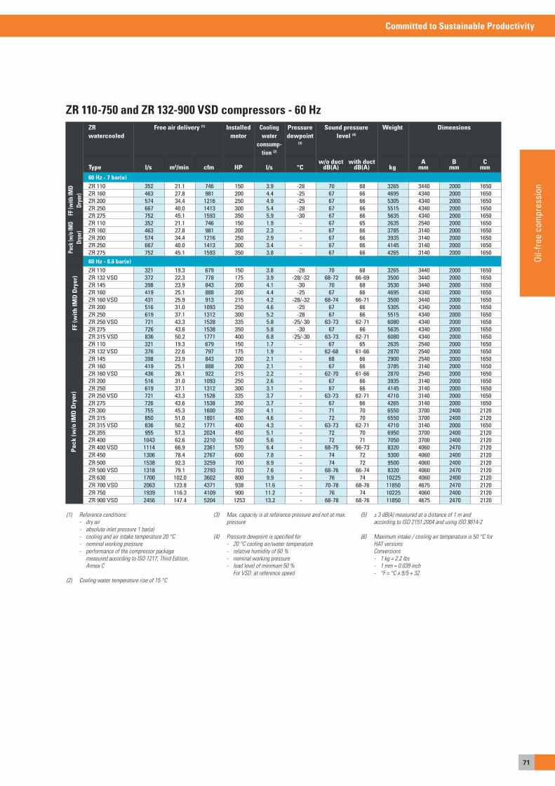
71
Committed to Sustainable Productivity
Oil-f
ree
com
pres
sion
ZR 110-750 and ZR 132-900 VSD compressors - 60 HzZR watercooled
Free air delivery (1) Installed motor
Cooling water
consump-tion (2)
Pressure dewpoint
(3)
Sound pressure level (4)
Weight Dimensions
Type l/s m3/min cfm HP l/s °Cw/o duct
dB(A)with duct
dB(A) kgA
mmB
mmC
mm
60 Hz - 7 bar(e)
FF (w
ith IM
D Dr
yer)
ZR 110 352 21.1 746 150 3.9 -28 70 68 3265 3440 2000 1650ZR 160 463 27.8 981 200 4.4 -25 67 66 4695 4340 2000 1650ZR 200 574 34.4 1216 250 4.9 -25 67 66 5305 4340 2000 1650ZR 250 667 40.0 1413 300 5.4 -28 67 66 5515 4340 2000 1650ZR 275 752 45.1 1593 350 5.9 -30 67 66 5635 4340 2000 1650
Pack
(w/o
IMD
Drye
r)
ZR 110 352 21.1 746 150 1.9 - 67 65 2635 2540 2000 1650ZR 160 463 27.8 981 200 2.3 - 67 66 3785 3140 2000 1650ZR 200 574 34.4 1216 250 2.9 - 67 66 3935 3140 2000 1650ZR 250 667 40.0 1413 300 3.4 - 67 66 4145 3140 2000 1650ZR 275 752 45.1 1593 350 3.8 - 67 66 4265 3140 2000 165060 Hz - 8.6 bar(e)
FF (w
ith IM
D D
ryer
)
ZR 110 321 19.3 679 150 3.8 -28 70 68 3265 3440 2000 1650ZR 132 VSD 372 22.3 778 175 3.9 -28/-32 68-72 66-69 3500 3440 2000 1650ZR 145 398 23.9 843 200 4.1 -30 70 68 3530 3440 2000 1650ZR 160 419 25.1 888 200 4.4 -25 67 66 4695 4340 2000 1650ZR 160 VSD 431 25.9 913 215 4.2 -28/-32 68-74 66-71 3500 3440 2000 1650ZR 200 516 31.0 1093 250 4.6 -25 67 66 5305 4340 2000 1650ZR 250 619 37.1 1312 300 5.2 -28 67 66 5515 4340 2000 1650ZR 250 VSD 721 43.3 1528 335 5.8 -25/-30 63-73 62-71 6080 4340 2000 1650ZR 275 726 43.6 1538 350 5.8 -30 67 66 5635 4340 2000 1650ZR 315 VSD 836 50.2 1771 400 6.8 -25/-30 63-73 62-71 6080 4340 2000 1650
Pac
k (w
/o IM
D D
ryer
)
ZR 110 321 19.3 679 150 1.7 - 67 65 2635 2540 2000 1650ZR 132 VSD 376 22.6 797 175 1.9 - 62-68 61-66 2870 2540 2000 1650ZR 145 398 23.9 843 200 2.1 - 68 66 2900 2540 2000 1650ZR 160 419 25.1 888 200 2.1 - 67 66 3785 3140 2000 1650ZR 160 VSD 436 26.1 922 215 2.2 - 62-70 61-66 2870 2540 2000 1650ZR 200 516 31.0 1093 250 2.6 - 67 66 3935 3140 2000 1650ZR 250 619 37.1 1312 300 3.1 - 67 66 4145 3140 2000 1650ZR 250 VSD 721 43.3 1528 335 3.7 - 63-73 62-71 4710 3140 2000 1650ZR 275 726 43.6 1538 350 3.7 - 67 66 4265 3140 2000 1650ZR 300 755 45.3 1600 350 4.1 - 71 70 6550 3700 2400 2120ZR 315 850 51.0 1801 400 4.6 - 72 70 6550 3700 2400 2120ZR 315 VSD 836 50.2 1771 400 4.3 - 63-73 62-71 4710 3140 2000 1650ZR 355 955 57.3 2024 450 5.1 - 72 70 6950 3700 2400 2120ZR 400 1043 62.6 2210 500 5.6 - 72 71 7050 3700 2400 2120ZR 400 VSD 1114 66.9 2361 570 6.4 - 68-75 66-73 8320 4060 2470 2120ZR 450 1306 78.4 2767 600 7.8 - 74 72 9300 4060 2400 2120ZR 500 1538 92.3 3259 700 8.9 - 74 72 9500 4060 2400 2120ZR 500 VSD 1318 79.1 2793 703 7.6 - 68-76 66-74 8320 4060 2470 2120ZR 630 1700 102.0 3602 800 9.9 - 76 74 10225 4060 2400 2120ZR 700 VSD 2063 123.8 4371 938 11.6 - 70-78 68-76 11850 4675 2470 2120ZR 750 1939 116.3 4109 900 11.2 - 76 74 10225 4060 2400 2120ZR 900 VSD 2456 147.4 5204 1253 13.2 - 68-78 68-76 11850 4675 2470 2120
(1) Reference conditions: - dry air - absolute inlet pressure 1 bar(a) - cooling and air intake temperature 20 °C - nominal working pressure - performance of the compressor package measured according to ISO 1217, Third Edition, Annex C
(2) Cooling water temperature rise of 15 °C
(3) Max. capacity is at reference pressure and not at max. pressure
(4) Pressure dewpoint is specified for - 20 °C cooling air/water temperature - relative humidity of 60 % - nominal working pressure - load level of minimum 50 % For VSD: at reference speed
(5) ± 3 dB(A) measured at a distance of 1 m and according to ISO 2151:2004 and using ISO 9614-2
(6) Maximum intake / cooling air temperature is 50 °C for HAT versions Conversions - 1 kg = 2.2 lbs - 1 mm = 0.039 inch - °F = °C x 9/5 + 32
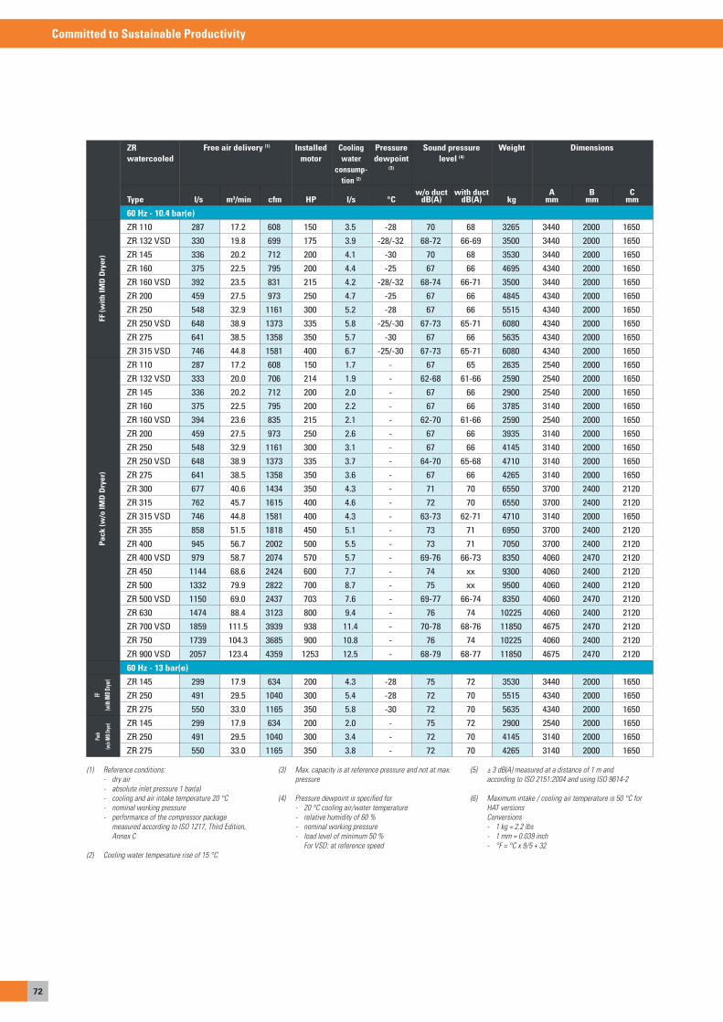
72
Committed to Sustainable Productivity
ZR watercooled
Free air delivery (1) Installed motor
Cooling water
consump-tion (2)
Pressure dewpoint
(3)
Sound pressure level (4)
Weight Dimensions
Type l/s m3/min cfm HP l/s °Cw/o duct
dB(A)with duct
dB(A) kgA
mmB
mmC
mm
60 Hz - 10.4 bar(e)
FF (w
ith IM
D D
ryer
)
ZR 110 287 17.2 608 150 3.5 -28 70 68 3265 3440 2000 1650
ZR 132 VSD 330 19.8 699 175 3.9 -28/-32 68-72 66-69 3500 3440 2000 1650
ZR 145 336 20.2 712 200 4.1 -30 70 68 3530 3440 2000 1650
ZR 160 375 22.5 795 200 4.4 -25 67 66 4695 4340 2000 1650
ZR 160 VSD 392 23.5 831 215 4.2 -28/-32 68-74 66-71 3500 3440 2000 1650
ZR 200 459 27.5 973 250 4.7 -25 67 66 4845 4340 2000 1650
ZR 250 548 32.9 1161 300 5.2 -28 67 66 5515 4340 2000 1650
ZR 250 VSD 648 38.9 1373 335 5.8 -25/-30 67-73 65-71 6080 4340 2000 1650
ZR 275 641 38.5 1358 350 5.7 -30 67 66 5635 4340 2000 1650
ZR 315 VSD 746 44.8 1581 400 6.7 -25/-30 67-73 65-71 6080 4340 2000 1650
Pac
k (w
/o IM
D D
ryer
)
ZR 110 287 17.2 608 150 1.7 - 67 65 2635 2540 2000 1650
ZR 132 VSD 333 20.0 706 214 1.9 - 62-68 61-66 2590 2540 2000 1650
ZR 145 336 20.2 712 200 2.0 - 67 66 2900 2540 2000 1650
ZR 160 375 22.5 795 200 2.2 - 67 66 3785 3140 2000 1650
ZR 160 VSD 394 23.6 835 215 2.1 - 62-70 61-66 2590 2540 2000 1650
ZR 200 459 27.5 973 250 2.6 - 67 66 3935 3140 2000 1650
ZR 250 548 32.9 1161 300 3.1 - 67 66 4145 3140 2000 1650
ZR 250 VSD 648 38.9 1373 335 3.7 - 64-70 65-68 4710 3140 2000 1650
ZR 275 641 38.5 1358 350 3.6 - 67 66 4265 3140 2000 1650
ZR 300 677 40.6 1434 350 4.3 - 71 70 6550 3700 2400 2120
ZR 315 762 45.7 1615 400 4.6 - 72 70 6550 3700 2400 2120
ZR 315 VSD 746 44.8 1581 400 4.3 - 63-73 62-71 4710 3140 2000 1650
ZR 355 858 51.5 1818 450 5.1 - 73 71 6950 3700 2400 2120
ZR 400 945 56.7 2002 500 5.5 - 73 71 7050 3700 2400 2120
ZR 400 VSD 979 58.7 2074 570 5.7 - 69-76 66-73 8350 4060 2470 2120
ZR 450 1144 68.6 2424 600 7.7 - 74 xx 9300 4060 2400 2120
ZR 500 1332 79.9 2822 700 8.7 - 75 xx 9500 4060 2400 2120
ZR 500 VSD 1150 69.0 2437 703 7.6 - 69-77 66-74 8350 4060 2470 2120
ZR 630 1474 88.4 3123 800 9.4 - 76 74 10225 4060 2400 2120
ZR 700 VSD 1859 111.5 3939 938 11.4 - 70-78 68-76 11850 4675 2470 2120
ZR 750 1739 104.3 3685 900 10.8 - 76 74 10225 4060 2400 2120
ZR 900 VSD 2057 123.4 4359 1253 12.5 - 68-79 68-77 11850 4675 2470 2120
60 Hz - 13 bar(e)
FF
(with
IMD D
ryer) ZR 145 299 17.9 634 200 4.3 -28 75 72 3530 3440 2000 1650
ZR 250 491 29.5 1040 300 5.4 -28 72 70 5515 4340 2000 1650
ZR 275 550 33.0 1165 350 5.8 -30 72 70 5635 4340 2000 1650
Pack
(w/o
IMD D
ryer) ZR 145 299 17.9 634 200 2.0 - 75 72 2900 2540 2000 1650
ZR 250 491 29.5 1040 300 3.4 - 72 70 4145 3140 2000 1650
ZR 275 550 33.0 1165 350 3.8 - 72 70 4265 3140 2000 1650
(1) Reference conditions: - dry air - absolute inlet pressure 1 bar(a) - cooling and air intake temperature 20 °C - nominal working pressure - performance of the compressor package measured according to ISO 1217, Third Edition, Annex C
(2) Cooling water temperature rise of 15 °C
(3) Max. capacity is at reference pressure and not at max. pressure
(4) Pressure dewpoint is specified for - 20 °C cooling air/water temperature - relative humidity of 60 % - nominal working pressure - load level of minimum 50 % For VSD: at reference speed
(5) ± 3 dB(A) measured at a distance of 1 m and according to ISO 2151:2004 and using ISO 9614-2
(6) Maximum intake / cooling air temperature is 50 °C for HAT versions Conversions - 1 kg = 2.2 lbs - 1 mm = 0.039 inch - °F = °C x 9/5 + 32
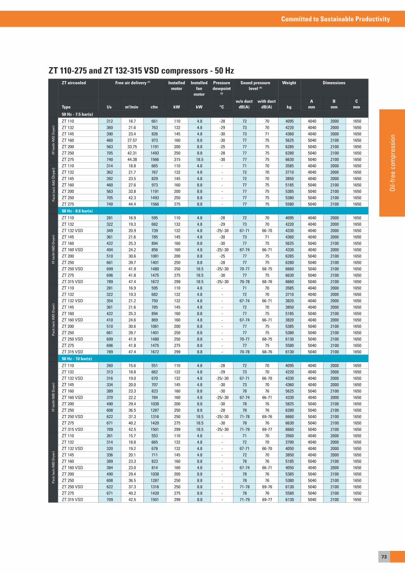
73
Committed to Sustainable Productivity
Oil-f
ree
com
pres
sion
ZT 110-275 and ZT 132-315 VSD compressors - 50 HzZT aircooled Free air delivery (1) Installed
motorInstalled
fan motor
Pressure dewpoint
(3)
Sound pressure level (4)
Weight Dimensions
Type l/s m3/min cfm kW kW °Cw/o duct
dB(A)with duct
dB(A) kgA
mmB
mmC
mm
50 Hz - 7.5 bar(e)
FF (w
ith IM
D D
ryer
)
ZT 110 312 18.7 661 110 4.8 -28 72 70 4095 4040 2000 1650ZT 132 360 21.6 763 132 4.8 -29 73 70 4220 4040 2000 1650ZT 145 390 23.4 826 145 4.8 -30 73 71 4360 4040 2000 1650ZT 160 460 27.57 973 160 8.8 -30 77 75 5625 5040 2100 1650ZT 200 563 33.75 1191 200 8.8 -25 77 75 6285 5040 2100 1650ZT 250 705 42.31 1493 250 8.8 -28 77 75 6280 5040 2100 1650ZT 275 740 44.38 1566 315 18.5 -30 77 75 6630 5040 2100 1650
Pack
(w/o
IMD
Dry
er) ZT 110 314 18.8 665 110 4.8 - 71 70 3585 4040 2000 1650
ZT 132 362 21.7 767 132 4.8 - 72 70 3710 4040 2000 1650ZT 145 392 23.5 829 145 4.8 - 72 70 3850 4040 2000 1650ZT 160 460 27.6 973 160 8.8 - 77 75 5185 5040 2100 1650ZT 200 563 33.8 1191 200 8.8 - 77 75 5385 5040 2100 1650ZT 250 705 42.3 1493 250 8.8 - 77 75 5380 5040 2100 1650ZT 275 740 44.4 1566 275 8.8 - 77 75 5580 5040 2100 1650
50 Hz - 8.6 bar(e)
FF (w
ith IM
D D
ryer
)
ZT 110 281 16.9 595 110 4.8 -28 72 70 4095 4040 2000 1650ZT 132 322 19.3 682 132 4.8 -29 73 70 4220 4040 2000 1650ZT 132 VSD 349 20.9 739 132 4.8 -25/-30 67-71 66-70 4330 4040 2000 1650ZT 145 361 21.6 785 145 4.8 -30 73 71 4360 4040 2000 1650ZT 160 422 25.3 894 160 8.8 -30 77 75 5625 5040 2100 1650ZT 160 VSD 404 24.2 856 160 4.8 -25/-30 67-74 66-71 4330 4040 2000 1650ZT 200 510 30.6 1081 200 8.8 -25 77 75 6285 5040 2100 1650ZT 250 661 39.7 1401 250 8.8 -28 77 75 6280 5040 2100 1650ZT 250 VSD 699 41.9 1480 250 18.5 -25/-30 70-77 68-75 6660 5040 2100 1650ZT 275 696 41.8 1475 275 18.5 -30 77 75 6630 5040 2100 1650ZT 315 VSD 789 47.4 1672 299 18.5 -25/-30 70-78 68-76 6660 5040 2100 1650
Pack
(w/o
IMD
Dry
er)
ZT 110 281 16.9 595 110 4.8 - 71 70 3585 4040 2000 1650ZT 132 322 19.3 682 132 4.8 - 72 70 3710 4040 2000 1650ZT 132 VSD 354 21.2 750 132 4.8 - 67-74 66-71 3820 4040 2000 1650ZT 145 361 21.6 785 145 4.8 - 72 70 3850 4040 2000 1650ZT 160 422 25.3 894 160 8.8 - 77 75 5185 5040 2100 1650ZT 160 VSD 410 24.6 869 160 4.8 - 67-74 66-71 3820 4040 2000 1650ZT 200 510 30.6 1081 200 8.8 - 77 75 5385 5040 2100 1650ZT 250 661 39.7 1401 250 8.8 - 77 75 5380 5040 2100 1650ZT 250 VSD 699 41.9 1480 250 8.8 - 70-77 68-75 6130 5040 2100 1650ZT 275 696 41.8 1475 275 8.8 - 77 75 5580 5040 2100 1650ZT 315 VSD 789 47.4 1672 299 8.8 - 70-78 68-76 6130 5040 2100 1650
50 Hz - 10 bar(e)
FF (w
ith IM
D D
ryer
)
ZT 110 260 15.6 551 110 4.8 -28 72 70 4095 4040 2000 1650ZT 132 313 18.8 662 132 4.8 -29 73 70 4220 4040 2000 1650ZT 132 VSD 316 19.0 670 132 4.8 -25/-30 67-71 66-70 4330 4040 2000 1650ZT 145 334 20.0 707 145 4.8 -30 73 70 4360 4040 2000 1650ZT 160 389 23.3 823 160 8.8 -30 78 76 5625 5040 2100 1650ZT 160 VSD 370 22.2 784 160 4.8 -25/-30 67-74 66-71 4330 4040 2000 1650ZT 200 490 29.4 1038 200 8.8 -30 78 76 5825 5040 2100 1650ZT 250 608 36.5 1287 250 8.8 -28 78 76 6280 5040 2100 1650ZT 250 VSD 622 37.3 1316 250 18.5 -25/-30 71-78 69-76 6660 5040 2100 1650ZT 275 671 40.2 1420 275 18.5 -30 78 76 6630 5040 2100 1650ZT 315 VSD 709 42.5 1501 299 18.5 -25/-30 71-79 69-77 6660 5040 2100 1650
Pack
(w/o
IMD
Dry
er)
ZT 110 261 15.7 553 110 4.8 - 71 70 3560 4040 2000 1650ZT 132 314 18.8 665 132 4.8 - 72 70 3700 4040 2000 1650ZT 132 VSD 320 19.2 678 132 4.8 - 67-71 66-70 4050 4040 2000 1650ZT 145 336 20.1 711 145 4.8 - 72 70 3850 4040 2000 1650ZT 160 389 23.3 823 160 8.8 - 78 76 5185 5040 2100 1650ZT 160 VSD 384 23.0 814 160 4.8 - 67-74 66-71 4050 4040 2000 1650ZT 200 490 29.4 1038 200 8.8 - 78 76 5385 5040 2100 1650ZT 250 608 36.5 1287 250 8.8 - 78 76 5380 5040 2100 1650ZT 250 VSD 622 37.3 1316 250 8.8 - 71-78 69-76 6130 5040 2100 1650ZT 275 671 40.2 1420 275 8.8 - 78 76 5580 5040 2100 1650ZT 315 VSD 709 42.5 1501 299 8.8 - 71-79 69-77 6130 5040 2100 1650
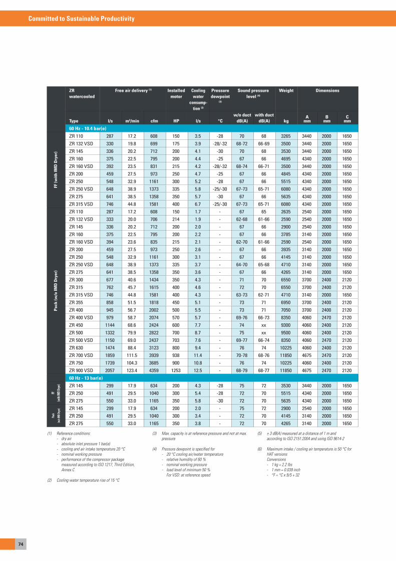
74
Committed to Sustainable Productivity
ZR watercooled
Free air delivery (1) Installed motor
Cooling water
consump-tion (2)
Pressure dewpoint
(3)
Sound pressure level (4)
Weight Dimensions
Type l/s m3/min cfm HP l/s °Cw/o duct
dB(A)with duct
dB(A) kgA
mmB
mmC
mm
60 Hz - 10.4 bar(e)
FF (w
ith IM
D D
ryer
)
ZR 110 287 17.2 608 150 3.5 -28 70 68 3265 3440 2000 1650
ZR 132 VSD 330 19.8 699 175 3.9 -28/-32 68-72 66-69 3500 3440 2000 1650
ZR 145 336 20.2 712 200 4.1 -30 70 68 3530 3440 2000 1650
ZR 160 375 22.5 795 200 4.4 -25 67 66 4695 4340 2000 1650
ZR 160 VSD 392 23.5 831 215 4.2 -28/-32 68-74 66-71 3500 3440 2000 1650
ZR 200 459 27.5 973 250 4.7 -25 67 66 4845 4340 2000 1650
ZR 250 548 32.9 1161 300 5.2 -28 67 66 5515 4340 2000 1650
ZR 250 VSD 648 38.9 1373 335 5.8 -25/-30 67-73 65-71 6080 4340 2000 1650
ZR 275 641 38.5 1358 350 5.7 -30 67 66 5635 4340 2000 1650
ZR 315 VSD 746 44.8 1581 400 6.7 -25/-30 67-73 65-71 6080 4340 2000 1650
Pac
k (w
/o IM
D D
ryer
)
ZR 110 287 17.2 608 150 1.7 - 67 65 2635 2540 2000 1650
ZR 132 VSD 333 20.0 706 214 1.9 - 62-68 61-66 2590 2540 2000 1650
ZR 145 336 20.2 712 200 2.0 - 67 66 2900 2540 2000 1650
ZR 160 375 22.5 795 200 2.2 - 67 66 3785 3140 2000 1650
ZR 160 VSD 394 23.6 835 215 2.1 - 62-70 61-66 2590 2540 2000 1650
ZR 200 459 27.5 973 250 2.6 - 67 66 3935 3140 2000 1650
ZR 250 548 32.9 1161 300 3.1 - 67 66 4145 3140 2000 1650
ZR 250 VSD 648 38.9 1373 335 3.7 - 64-70 65-68 4710 3140 2000 1650
ZR 275 641 38.5 1358 350 3.6 - 67 66 4265 3140 2000 1650
ZR 300 677 40.6 1434 350 4.3 - 71 70 6550 3700 2400 2120
ZR 315 762 45.7 1615 400 4.6 - 72 70 6550 3700 2400 2120
ZR 315 VSD 746 44.8 1581 400 4.3 - 63-73 62-71 4710 3140 2000 1650
ZR 355 858 51.5 1818 450 5.1 - 73 71 6950 3700 2400 2120
ZR 400 945 56.7 2002 500 5.5 - 73 71 7050 3700 2400 2120
ZR 400 VSD 979 58.7 2074 570 5.7 - 69-76 66-73 8350 4060 2470 2120
ZR 450 1144 68.6 2424 600 7.7 - 74 xx 9300 4060 2400 2120
ZR 500 1332 79.9 2822 700 8.7 - 75 xx 9500 4060 2400 2120
ZR 500 VSD 1150 69.0 2437 703 7.6 - 69-77 66-74 8350 4060 2470 2120
ZR 630 1474 88.4 3123 800 9.4 - 76 74 10225 4060 2400 2120
ZR 700 VSD 1859 111.5 3939 938 11.4 - 70-78 68-76 11850 4675 2470 2120
ZR 750 1739 104.3 3685 900 10.8 - 76 74 10225 4060 2400 2120
ZR 900 VSD 2057 123.4 4359 1253 12.5 - 68-79 68-77 11850 4675 2470 2120
60 Hz - 13 bar(e)
FF
(with
IMD D
ryer) ZR 145 299 17.9 634 200 4.3 -28 75 72 3530 3440 2000 1650
ZR 250 491 29.5 1040 300 5.4 -28 72 70 5515 4340 2000 1650
ZR 275 550 33.0 1165 350 5.8 -30 72 70 5635 4340 2000 1650
Pack
(w/o
IMD D
ryer) ZR 145 299 17.9 634 200 2.0 - 75 72 2900 2540 2000 1650
ZR 250 491 29.5 1040 300 3.4 - 72 70 4145 3140 2000 1650
ZR 275 550 33.0 1165 350 3.8 - 72 70 4265 3140 2000 1650
(1) Reference conditions: - dry air - absolute inlet pressure 1 bar(a) - cooling and air intake temperature 20 °C - nominal working pressure - performance of the compressor package measured according to ISO 1217, Third Edition, Annex C
(2) Cooling water temperature rise of 15 °C
(3) Max. capacity is at reference pressure and not at max. pressure
(4) Pressure dewpoint is specified for - 20 °C cooling air/water temperature - relative humidity of 60 % - nominal working pressure - load level of minimum 50 % For VSD: at reference speed
(5) ± 3 dB(A) measured at a distance of 1 m and according to ISO 2151:2004 and using ISO 9614-2
(6) Maximum intake / cooling air temperature is 50 °C for HAT versions Conversions - 1 kg = 2.2 lbs - 1 mm = 0.039 inch - °F = °C x 9/5 + 32

75
Committed to Sustainable Productivity
Oil-f
ree
com
pres
sion
ZT 110-275 and ZT 132-315 VSD compressors - 50 HzZT aircooled Free air delivery (1) Installed
motorInstalled
fan motor
Pressure dewpoint
(3)
Sound pressure level (4)
Weight Dimensions
Type l/s m3/min cfm kW kW °Cw/o duct
dB(A)with duct
dB(A) kgA
mmB
mmC
mm
50 Hz - 7.5 bar(e)
FF (w
ith IM
D D
ryer
)
ZT 110 312 18.7 661 110 4.8 -28 72 70 4095 4040 2000 1650ZT 132 360 21.6 763 132 4.8 -29 73 70 4220 4040 2000 1650ZT 145 390 23.4 826 145 4.8 -30 73 71 4360 4040 2000 1650ZT 160 460 27.57 973 160 8.8 -30 77 75 5625 5040 2100 1650ZT 200 563 33.75 1191 200 8.8 -25 77 75 6285 5040 2100 1650ZT 250 705 42.31 1493 250 8.8 -28 77 75 6280 5040 2100 1650ZT 275 740 44.38 1566 315 18.5 -30 77 75 6630 5040 2100 1650
Pack
(w/o
IMD
Dry
er) ZT 110 314 18.8 665 110 4.8 - 71 70 3585 4040 2000 1650
ZT 132 362 21.7 767 132 4.8 - 72 70 3710 4040 2000 1650ZT 145 392 23.5 829 145 4.8 - 72 70 3850 4040 2000 1650ZT 160 460 27.6 973 160 8.8 - 77 75 5185 5040 2100 1650ZT 200 563 33.8 1191 200 8.8 - 77 75 5385 5040 2100 1650ZT 250 705 42.3 1493 250 8.8 - 77 75 5380 5040 2100 1650ZT 275 740 44.4 1566 275 8.8 - 77 75 5580 5040 2100 1650
50 Hz - 8.6 bar(e)
FF (w
ith IM
D D
ryer
)
ZT 110 281 16.9 595 110 4.8 -28 72 70 4095 4040 2000 1650ZT 132 322 19.3 682 132 4.8 -29 73 70 4220 4040 2000 1650ZT 132 VSD 349 20.9 739 132 4.8 -25/-30 67-71 66-70 4330 4040 2000 1650ZT 145 361 21.6 785 145 4.8 -30 73 71 4360 4040 2000 1650ZT 160 422 25.3 894 160 8.8 -30 77 75 5625 5040 2100 1650ZT 160 VSD 404 24.2 856 160 4.8 -25/-30 67-74 66-71 4330 4040 2000 1650ZT 200 510 30.6 1081 200 8.8 -25 77 75 6285 5040 2100 1650ZT 250 661 39.7 1401 250 8.8 -28 77 75 6280 5040 2100 1650ZT 250 VSD 699 41.9 1480 250 18.5 -25/-30 70-77 68-75 6660 5040 2100 1650ZT 275 696 41.8 1475 275 18.5 -30 77 75 6630 5040 2100 1650ZT 315 VSD 789 47.4 1672 299 18.5 -25/-30 70-78 68-76 6660 5040 2100 1650
Pack
(w/o
IMD
Dry
er)
ZT 110 281 16.9 595 110 4.8 - 71 70 3585 4040 2000 1650ZT 132 322 19.3 682 132 4.8 - 72 70 3710 4040 2000 1650ZT 132 VSD 354 21.2 750 132 4.8 - 67-74 66-71 3820 4040 2000 1650ZT 145 361 21.6 785 145 4.8 - 72 70 3850 4040 2000 1650ZT 160 422 25.3 894 160 8.8 - 77 75 5185 5040 2100 1650ZT 160 VSD 410 24.6 869 160 4.8 - 67-74 66-71 3820 4040 2000 1650ZT 200 510 30.6 1081 200 8.8 - 77 75 5385 5040 2100 1650ZT 250 661 39.7 1401 250 8.8 - 77 75 5380 5040 2100 1650ZT 250 VSD 699 41.9 1480 250 8.8 - 70-77 68-75 6130 5040 2100 1650ZT 275 696 41.8 1475 275 8.8 - 77 75 5580 5040 2100 1650ZT 315 VSD 789 47.4 1672 299 8.8 - 70-78 68-76 6130 5040 2100 1650
50 Hz - 10 bar(e)
FF (w
ith IM
D D
ryer
)
ZT 110 260 15.6 551 110 4.8 -28 72 70 4095 4040 2000 1650ZT 132 313 18.8 662 132 4.8 -29 73 70 4220 4040 2000 1650ZT 132 VSD 316 19.0 670 132 4.8 -25/-30 67-71 66-70 4330 4040 2000 1650ZT 145 334 20.0 707 145 4.8 -30 73 70 4360 4040 2000 1650ZT 160 389 23.3 823 160 8.8 -30 78 76 5625 5040 2100 1650ZT 160 VSD 370 22.2 784 160 4.8 -25/-30 67-74 66-71 4330 4040 2000 1650ZT 200 490 29.4 1038 200 8.8 -30 78 76 5825 5040 2100 1650ZT 250 608 36.5 1287 250 8.8 -28 78 76 6280 5040 2100 1650ZT 250 VSD 622 37.3 1316 250 18.5 -25/-30 71-78 69-76 6660 5040 2100 1650ZT 275 671 40.2 1420 275 18.5 -30 78 76 6630 5040 2100 1650ZT 315 VSD 709 42.5 1501 299 18.5 -25/-30 71-79 69-77 6660 5040 2100 1650
Pack
(w/o
IMD
Dry
er)
ZT 110 261 15.7 553 110 4.8 - 71 70 3560 4040 2000 1650ZT 132 314 18.8 665 132 4.8 - 72 70 3700 4040 2000 1650ZT 132 VSD 320 19.2 678 132 4.8 - 67-71 66-70 4050 4040 2000 1650ZT 145 336 20.1 711 145 4.8 - 72 70 3850 4040 2000 1650ZT 160 389 23.3 823 160 8.8 - 78 76 5185 5040 2100 1650ZT 160 VSD 384 23.0 814 160 4.8 - 67-74 66-71 4050 4040 2000 1650ZT 200 490 29.4 1038 200 8.8 - 78 76 5385 5040 2100 1650ZT 250 608 36.5 1287 250 8.8 - 78 76 5380 5040 2100 1650ZT 250 VSD 622 37.3 1316 250 8.8 - 71-78 69-76 6130 5040 2100 1650ZT 275 671 40.2 1420 275 8.8 - 78 76 5580 5040 2100 1650ZT 315 VSD 709 42.5 1501 299 8.8 - 71-79 69-77 6130 5040 2100 1650

76
Committed to Sustainable Productivity
• Maximum energy savings – all components of the ZH, such as the backward leaning impeller, carbon ring air seals and inlet guide vanes, are designed to lower the pressure drops and provide the highest air volume with the lowest energy requirement.
• Easy installation – The design of the ZH includes internal piping, coolers, motor, lubrication, inlet guide vanes and control system: all ready for integration on site.
• Advanced control monitoring – To maximize efficiency and relia-bility, the elektronikon® controls the main drive motor and regulates system pressure within a predefined and narrow pressure band. The elektronikon® controller can be adapted to your specific needs with ex-tra sensors, digital contacts, fieldbus, Internet and sMs communication functions. In combination with the es multiple compressor controller, the operation of your complete compressor room is optimized.
• Certified 100% oil-free – ZH compressors provide you with 100% pure, clean air that complies with Iso 8573-1 CLass 0 (2010) certifica-tion. CLass 0 means zero risk of contamination; zero risk of damaged or unsafe products; zero risk of losses from operational downtime; and zero risk of damaging your company’s hard-won professional reputation. In 2006 atlas Copco was the first manufacturer in the world to receive such certification on an oil-free compressor.
Designed to save energy and guaran-tee reliability, Atlas Copco’s ZH oil-free centrifugal compressors are provided as complete ready-to-integrate packages including internal piping, integrated coo-lers, motor, lubrication, inlet guide vanes, control system and 100% matched com-ponents. They are just what you need for large compressor rooms of 1-20 MW and for processes with a fluctuating or cons-tant air demand. Choose the ZH and put your mind at rest: air is 100% certified oil-free according to ISO 8573-1 CLASS 0 (2010), and the compressors operate reliably even in extremes of temperature and humidity.
ZHOil-free centrifugal compressors, 400-2750 kW, 500-3500 hp
CUSTOMER BENEFITS
• Maximum uptime – all ZH components are easy to maintain, dis-mantle and re-assemble if required, thus reducing downtime. advanced control and monitoring possibilities ensure that production interruptions are minimized. In addition, easily accessible major components, minimal service interventions and long overhaul intervals reduce maintenance time and costs.
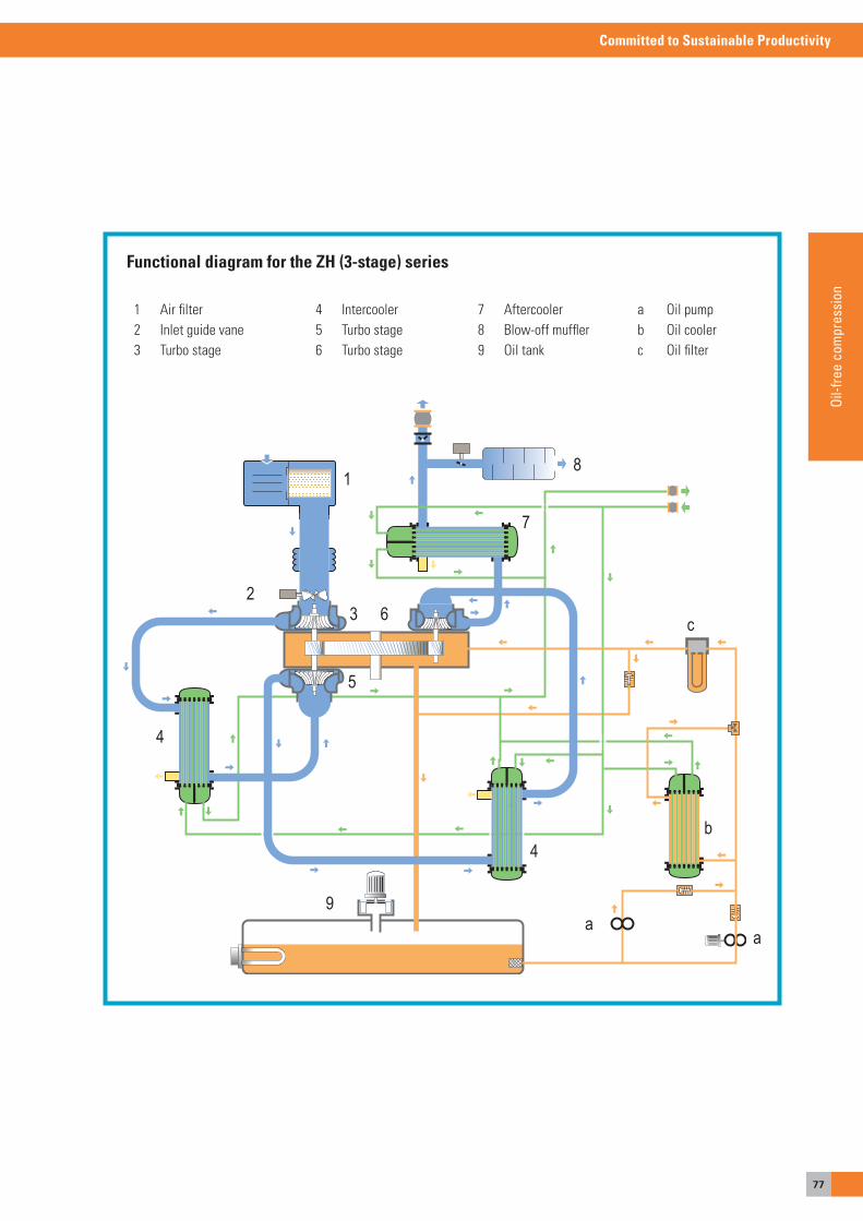
77
Committed to Sustainable Productivity
Oil-f
ree
com
pres
sion
5
3 6
1
7
8
b
aa
9
4
4
c2
1 air filter 2 Inlet guide vane3 Turbo stage
Functional diagram for the ZH (3-stage) series
4 Intercooler5 Turbo stage6 Turbo stage
7 aftercooler8 Blow-off muffler9 oil tank
a oil pumpb oil coolerc oil filter
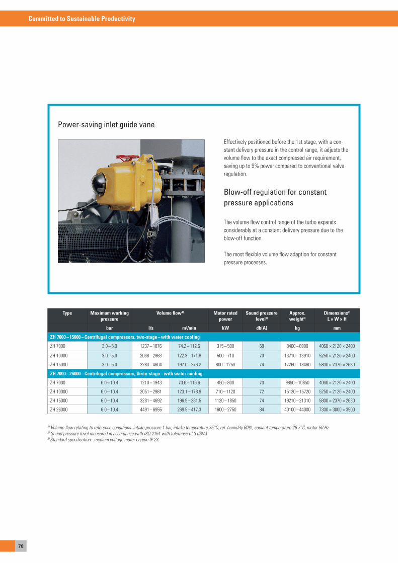
78
Committed to Sustainable Productivity
Power-saving inlet guide vane
effectively positioned before the 1st stage, with a con-stant delivery pressure in the control range, it adjusts the volume flow to the exact compressed air requirement, saving up to 9% power compared to conventional valve regulation.
Blow-off regulation for constantpressure applications
The volume flow control range of the turbo expands considerably at a constant delivery pressure due to the blow-off function.
The most flexible volume flow adaption for constant pressure processes.
Type Maximum working pressure
Volume flow1) Motor rated power
Sound pressure level2)
Approx. weight3)
Dimensions3) L × W × H
bar l/s m³/min kW db(A) kg mm
ZH 7000 – 15000 – Centrifugal compressors, two-stage – with water cooling
ZH 7000 3.0 – 5.0 1237 – 1876 74.2 – 112.6 315 – 500 68 8400 – 8900 4060 × 2120 × 2400
ZH 10000 3.0 – 5.0 2038 – 2863 122.3 – 171.8 500 – 710 70 13710 – 13910 5250 × 2120 × 2400
ZH 15000 3.0 – 5.0 3283 – 4604 197.0 – 276.2 800 – 1250 74 17260 – 18460 5800 × 2370 × 2630
ZH 7000 – 26000 – Centrifugal compressors, three-stage – with water cooling
ZH 7000 6.0 – 10.4 1210 – 1943 70.6 – 116.6 450 – 800 70 9850 – 10850 4060 × 2120 × 2400
ZH 10000 6.0 – 10.4 2051 – 2981 123.1 – 178.9 710 – 1120 72 15120 – 15720 5250 × 2120 × 2400
ZH 15000 6.0 – 10.4 3281 – 4692 196.9 – 281.5 1120 – 1850 74 19210 – 21310 5800 × 2370 × 2630
ZH 26000 6.0 – 10.4 4491 – 6955 269.5 – 417.3 1600 – 2750 84 40100 – 44000 7300 × 3000 × 3500
1) Volume flow relating to reference conditions: intake pressure 1 bar, intake temperature 35°C, rel. humidity 60%, coolant temperature 26.7°C, motor 50 Hz2) Sound pressure level measured in accordance with ISO 2151 with tolerance of 3 dB(A)3) Standard specification - medium voltage motor engine IP 23
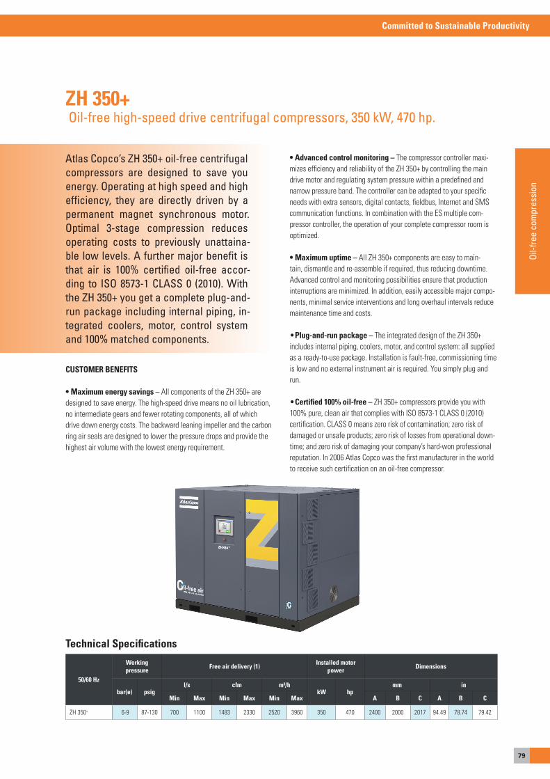
79
Committed to Sustainable Productivity
Oil-f
ree
com
pres
sion
Atlas Copco’s ZH 350+ oil-free centrifugal compressors are designed to save you energy. Operating at high speed and high efficiency, they are directly driven by a permanent magnet synchronous motor. Optimal 3-stage compression reduces operating costs to previously unattaina-ble low levels. A further major benefit is that air is 100% certified oil-free accor-ding to ISO 8573-1 CLASS 0 (2010). With the ZH 350+ you get a complete plug-and-run package including internal piping, in-tegrated coolers, motor, control system and 100% matched components.
ZH 350+ Oil-free high-speed drive centrifugal compressors, 350 kW, 470 hp.
CUSTOMER BENEFITS
• Maximum energy savings – all components of the ZH 350+ are designed to save energy. The high-speed drive means no oil lubrication, no intermediate gears and fewer rotating components, all of which drive down energy costs. The backward leaning impeller and the carbon ring air seals are designed to lower the pressure drops and provide the highest air volume with the lowest energy requirement.
• Advanced control monitoring – The compressor controller maxi-mizes efficiency and reliability of the ZH 350+ by controlling the main drive motor and regulating system pressure within a predefined and narrow pressure band. The controller can be adapted to your specific needs with extra sensors, digital contacts, fieldbus, Internet and sMs communication functions. In combination with the es multiple com-pressor controller, the operation of your complete compressor room is optimized.
• Maximum uptime – all ZH 350+ components are easy to main-tain, dismantle and re-assemble if required, thus reducing downtime. advanced control and monitoring possibilities ensure that production interruptions are minimized. In addition, easily accessible major compo-nents, minimal service interventions and long overhaul intervals reduce maintenance time and costs.
• Plug-and-run package – The integrated design of the ZH 350+ includes internal piping, coolers, motor, and control system: all supplied as a ready-to-use package. Installation is fault-free, commissioning time is low and no external instrument air is required. you simply plug and run.
• Certified 100% oil-free – ZH 350+ compressors provide you with 100% pure, clean air that complies with Iso 8573-1 CLass 0 (2010) certification. CLass 0 means zero risk of contamination; zero risk of damaged or unsafe products; zero risk of losses from operational down-time; and zero risk of damaging your company’s hard-won professional reputation. In 2006 atlas Copco was the first manufacturer in the world to receive such certification on an oil-free compressor.
50/60 Hz
Workingpressure Free air delivery (1) Installed motor
power Dimensions
bar(e) psigl/s cfm m³/h
kW hpmm in
Min Max Min Max Min Max A B C A B C
ZH 350+ 6-9 87-130 700 1100 1483 2330 2520 3960 350 470 2400 2000 2017 94.49 78.74 79.42
Technical Specifications

80
Committed to Sustainable Productivity
Inhaltsverzeichnis
oIL-FReeCoMPRessoRsFoR LoW & HIGHPRessURe aPPLICaTIoNsAtlas Copco has special solutions in its range for applications which require very low or very high pressure. Whether you use them to handle granulate gently, aerate clarifiers evenly, or inflate PET bottles with high pressure, a lot of thought has gone into designing our compressors and they provide the required working pressure for each application in an energy-efficient way.
82
Committed to Sustainable Productivity
Atlas Copco has special solutions in its range for applications which require very low or very high pressure. Whether youuse them to handle granulate gently,aerate clarifiers evenly, or inflate PET bottles with high pressure, a lot of thought has gone into designing our com-pressors and they provide the required working pressure for each application in an energy-efficient way.
Solutions for low andhigh pressures
For operations which require a lot of air but with a low over-pressure, it is worth using special low-pressure systems.
They provide stable system pressure and an efficient air supply without disruptive pulsations or power drops, which occur when the compressed air diverts from the normal air network and the demand is controlled by a buffer container and a blow-off system. our low-pressure systems are suitable for pressure increases of just above 0, up to 4 bar. so you can supply powders and granules, for example, gently cool and dry products, or aerate sewage plants.
oil-free screw compressors, screw blowers and centrifugal com-pressors are available.
We have recently removed the previous ZL rotary piston blowers from our range, because we could no longer represent them in terms of energy efficiency, especially not compared to our new Zs+ screw blowers. The internal compression and a more efficient drive concept of the Zs+ series are significantly more efficient than the rotary piston blowers.
The design of our ZB centrifugal compressors is particularlyefficient. With the contactless electromagnetic position of themotor, which is located on the motor shaft itself along with the impeller, they achieve efficiencies of over 90%. The gearlessmachines are non-wearing and keep maintenance costs low.
a precise analysis of the requirements will show which solution is best for the application in question. Investing more in an expensive system often pays for itself in the first one to two years due to the improved energy efficiency.
We also offer efficient compressors for high pressures from 20 to 40 bar. We would even go so far as to say that, with our Class 0certificate for oil-free machines and some constructive subtleties, our ZD high pressure compressor is a safe and energy-efficient compressed air solution for manufacturing PeT bottles!
The risk of bottle manufacturers and bottlers contaminating their products with traces of oil due to unclean compressed air is reduced to zero. you'll find details of these and other machines for high and low pressure on the following pages.

83
Committed to Sustainable Productivity
Oil-f
ree
com
pres
sion
ZS+ VSDoil-free Variable speed Drive positive displacement
screw blowers, 22-160 kW, 40-215 hp.
Page 86
ZE/ZA (VSD)oil-free rotary screw compressors, 22-500 kW /
40-700 hp.
Page 84
DMoil-less reciprocating trunk-piston
compressors, up to 351 bar (a)
(5090 psia), 30 kW.
Page 88
HX / HNoil-free reciprocating compressors
Page 90
ZB 100-160 VSDoil-free Variable speed Drive centrifugal air
compressors, 100-160 kW,135-215 hp.
Page 87
ZSoil-free positive displacement screw
blowers, 18-160 kW, 25-215 hp.
Page 85
DX / DNoil-free reciprocating piston compressors,
up to 45 bar (652 psig) 30-315 kW / 40-422 hp.
Page 89
ZDoil-free screw and reciprocating piston
compressors, up to 40 bar (580 psig),
136-770 kW / 182-1032 hp.
Page 93 - 94
Poil-free reciprocating piston compressors,
up to 40 bar (580 psig), 37-275 kW /
50-368 hp.
Page 91 - 92
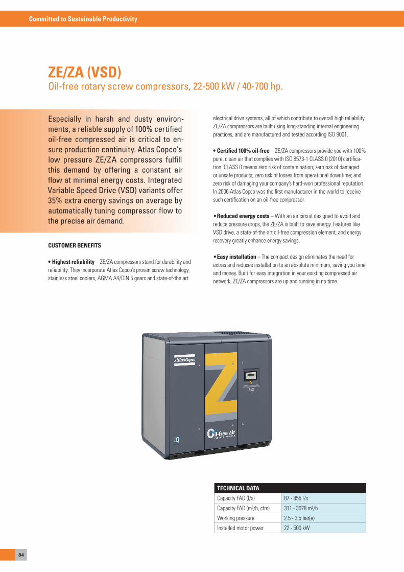
84
Committed to Sustainable Productivity
Especially in harsh and dusty environ-ments, a reliable supply of 100% certified oil-free compressed air is critical to en-sure production continuity. Atlas Copco's low pressure ZE/ZA compressors fulfill this demand by offering a constant air flow at minimal energy costs. Integrated Variable Speed Drive (VSD) variants offer 35% extra energy savings on average by automatically tuning compressor flow to the precise air demand.
ZE/ZA (VSD)Oil-free rotary screw compressors, 22-500 kW / 40-700 hp.
TECHNICAL DATA
Capacity FaD (l/s) 87 - 855 l/s
Capacity FaD (m³/h, cfm) 311 - 3078 m³/h
Working pressure 2.5 - 3.5 bar(e)
Installed motor power 22 - 500 kW
electrical drive systems, all of which contribute to overall high reliability. Ze/Za compressors are built using long-standing internal engineering practices, and are manufactured and tested according Iso 9001. • Certified 100% oil-free – Ze/Za compressors provide you with 100% pure, clean air that complies with Iso 8573-1 CLass 0 (2010) certifica-tion. CLass 0 means zero risk of contamination; zero risk of damaged or unsafe products; zero risk of losses from operational downtime; and zero risk of damaging your company’s hard-won professional reputation. In 2006 atlas Copco was the first manufacturer in the world to receive such certification on an oil-free compressor.
• Reduced energy costs – With an air circuit designed to avoid and reduce pressure drops, the Ze/Za is built to save energy. Features like VsD drive, a state-of-the-art oil-free compression element, and energy recovery greatly enhance energy savings.
• Easy installation – The compact design eliminates the need for extras and reduces installation to an absolute minimum, saving you time and money. Built for easy integration in your existing compressed air network, Ze/Za compressors are up and running in no time.
CUSTOMER BENEFITS
• Highest reliability – Ze/Za compressors stand for durability and reliability. They incorporate atlas Copco’s proven screw technology, stainless steel coolers, aGMa a4/DIN 5 gears and state-of-the art
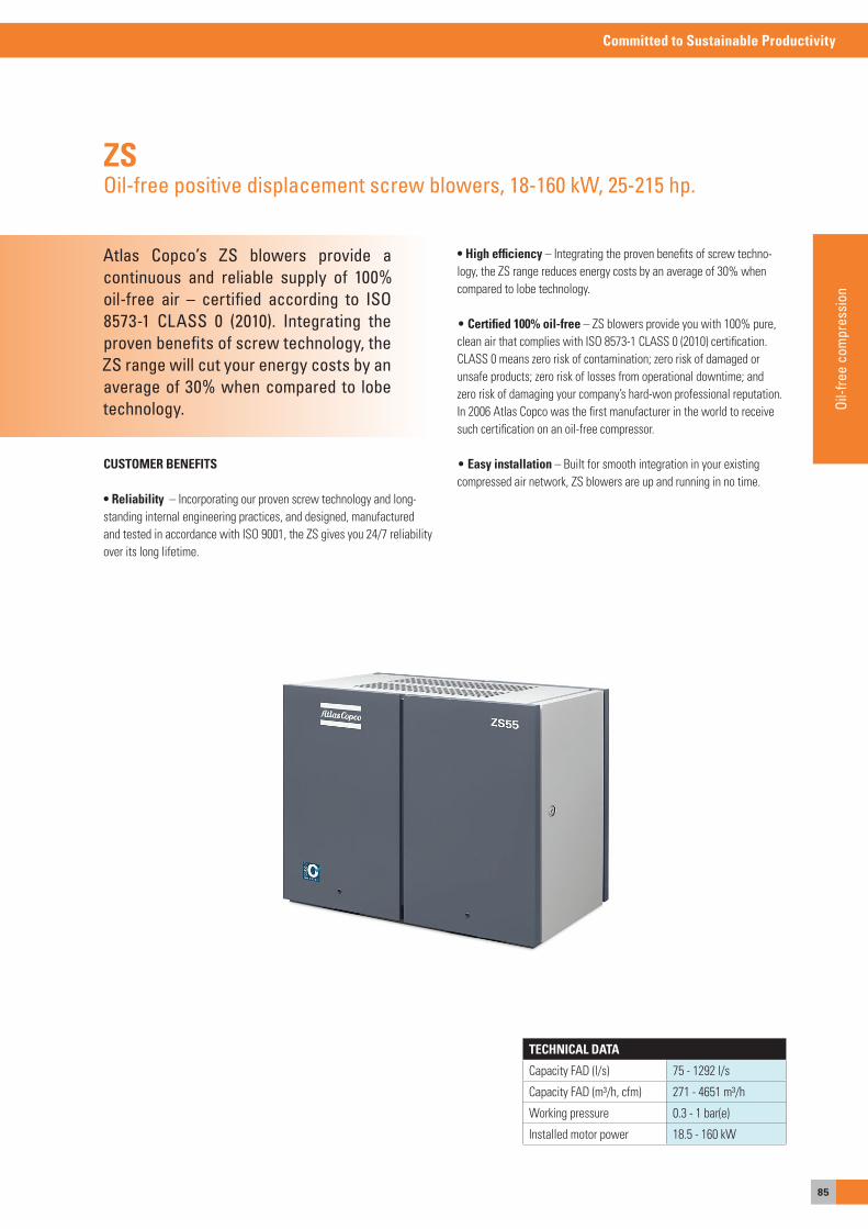
85
Committed to Sustainable Productivity
Oil-f
ree
com
pres
sion
Atlas Copco’s ZS blowers provide a continuous and reliable supply of 100% oil-free air – certified according to ISO 8573-1 CLASS 0 (2010). Integrating the proven benefits of screw technology, the ZS range will cut your energy costs by an average of 30% when compared to lobe technology.
ZSOil-free positive displacement screw blowers, 18-160 kW, 25-215 hp.
CUSTOMER BENEFITS
• reliability – Incorporating our proven screw technology and long-standing internal engineering practices, and designed, manufactured and tested in accordance with Iso 9001, the Zs gives you 24/7 reliability over its long lifetime.
• High efficiency – Integrating the proven benefits of screw techno-logy, the Zs range reduces energy costs by an average of 30% when compared to lobe technology.
• Certified 100% oil-free – Zs blowers provide you with 100% pure, clean air that complies with Iso 8573-1 CLass 0 (2010) certification. CLass 0 means zero risk of contamination; zero risk of damaged or unsafe products; zero risk of losses from operational downtime; and zero risk of damaging your company’s hard-won professional reputation. In 2006 atlas Copco was the first manufacturer in the world to receive such certification on an oil-free compressor.
• Easy installation – Built for smooth integration in your existing compressed air network, Zs blowers are up and running in no time.
TECHNICAL DATA
Capacity FaD (l/s) 75 - 1292 l/s
Capacity FaD (m³/h, cfm) 271 - 4651 m³/h
Working pressure 0.3 - 1 bar(e)
Installed motor power 18.5 - 160 kW
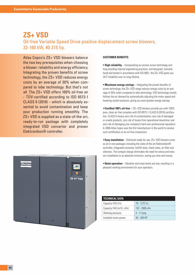
86
Committed to Sustainable Productivity
Atlas Copco’s ZS+ VSD blowers balance the two key prerequisites when choosing a blower: reliability and energy efficiency. Integrating the proven benefits of screw technology, the ZS+ VSD reduces energy costs by an average of 30% when com-pared to lobe technology. But that’s not all. The ZS+ VSD offers 100% oil-free air – TÜV-certified according to ISO 8573-1 CLASS 0 (2010) – which is absolutely es-sential to avoid contamination and keep your production running smoothly. The ZS+ VSD is supplied as a state-of-the-art, ready-to-run package with completely integrated VSD convertor and proven Elektronikon® controller.
ZS+ VSDOil-free Variable Speed Drive positive displacement screw blowers, 22-160 kW, 40-215 hp.
CUSTOMER BENEFITS
• High reliability – Incorporating our proven screw technology and long-standing internal engineering practices, and designed, manufac-tured and tested in accordance with Iso 9001, the Zs+ VsD gives you 24/7 reliability over its long lifetime. • Maximum energy savings – Integrating the proven benefits of screw technology, the Zs+ VsD range reduces energy costs by an ave-rage of 30% when compared to lobe technology. VsD technology closely follows the air demand by automatically adjusting the motor speed and lowering system pressure, giving you even greater energy savings.
• Certified 100% oil-free – Zs+ VsD blowers provide you with 100% pure, clean air that complies with Iso 8573-1 CLass 0 (2010) certifica-tion. CLass 0 means zero risk of contamination; zero risk of damaged or unsafe products; zero risk of losses from operational downtime; and zero risk of damaging your company’s hard-won professional reputation. In 2006 atlas Copco was the first manufacturer in the world to receive such certification on an oil-free compressor.
• Easy installation – Delivered ready for use, Zs+ VsD blowers come as all-in-one packages including the state-of-the art elektronikon® controller, integrated converter, forklift slots, check valve, air filter and silencers. The compact design eliminates the need for extras and redu-ces installation to an absolute minimum, saving you time and money.
• Quiet operation – Vibration and noise levels are low, resulting in a pleasant working environment for your operators.
TECHNICAL DATA
Capacity FaD (l/s) 79 - 1272 l/s
Capacity FaD (m³/h, cfm) 152 - 2695 cfm
Working pressure 4 - 17 psig
Installed motor power 30 - 200 HP
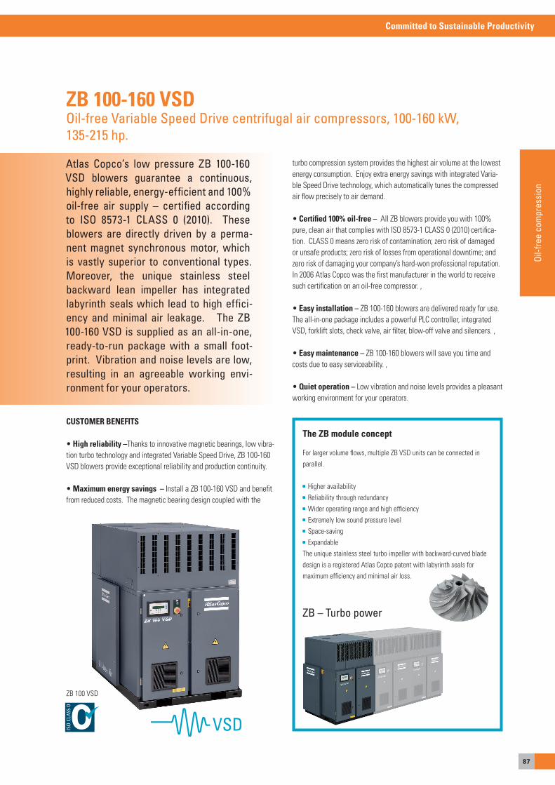
87
Committed to Sustainable Productivity
Oil-f
ree
com
pres
sion
turbo compression system provides the highest air volume at the lowest energy consumption. enjoy extra energy savings with integrated Varia-ble speed Drive technology, which automatically tunes the compressed air flow precisely to air demand.
• Certified 100% oil-free – all ZB blowers provide you with 100% pure, clean air that complies with Iso 8573-1 CLass 0 (2010) certifica-tion. CLass 0 means zero risk of contamination; zero risk of damaged or unsafe products; zero risk of losses from operational downtime; and zero risk of damaging your company’s hard-won professional reputation. In 2006 atlas Copco was the first manufacturer in the world to receive such certification on an oil-free compressor. ,
• Easy installation – ZB 100-160 blowers are delivered ready for use. The all-in-one package includes a powerful PLC controller, integrated VsD, forklift slots, check valve, air filter, blow-off valve and silencers. ,
• Easy maintenance – ZB 100-160 blowers will save you time and costs due to easy serviceability. ,
• Quiet operation – Low vibration and noise levels provides a pleasant working environment for your operators.
Atlas Copco’s low pressure ZB 100-160 VSD blowers guarantee a continuous, highly reliable, energy-efficient and 100% oil-free air supply – certified according to ISO 8573-1 CLASS 0 (2010). These blowers are directly driven by a perma-nent magnet synchronous motor, which is vastly superior to conventional types. Moreover, the unique stainless steel backward lean impeller has integrated labyrinth seals which lead to high effici-ency and minimal air leakage. The ZB 100-160 VSD is supplied as an all-in-one, ready-to-run package with a small foot-print. Vibration and noise levels are low, resulting in an agreeable working envi-ronment for your operators.
ZB 100-160 VSDOil-free Variable Speed Drive centrifugal air compressors, 100-160 kW,135-215 hp.
CUSTOMER BENEFITS
• High reliability –Thanks to innovative magnetic bearings, low vibra-tion turbo technology and integrated Variable speed Drive, ZB 100-160 VsD blowers provide exceptional reliability and production continuity.
• Maximum energy savings – Install a ZB 100-160 VsD and benefit from reduced costs. The magnetic bearing design coupled with the
For larger volume flows, multiple ZB VsD units can be connected in parallel.
Higher availability Reliability through redundancy Wider operating range and high efficiency extremely low sound pressure level space-saving expandable
The unique stainless steel turbo impeller with backward-curved blade design is a registered atlas Copco patent with labyrinth seals for maximum efficiency and minimal air loss.
The ZB module concept
ZB – Turbo power
ZB 100 VsD

88
Committed to Sustainable Productivity
Atlas Copco’s DM oil less reciprocat-ing compressors will meet your needs for high pressure compression up to 351 bar(a). Compact, with very low vibration levels and a sealed crankcase, DM com-pressors are ideal for the compression of natural gas, processed biogas, hydro-gen. They are based on technology de-veloped by GreenField, a company with a renowned reputation worldwide and part of the Atlas Copco Group.
DMOil-less reciprocating trunk-piston compressors, up to 351 bar (a) (5090 psia), 30 kW.
CUSTOMER BENEFITS
• High degree of safety – Its revolutionary “oil-less” technology gu-arantees that oil does not contaminate the gas. Its hermetically sealed crankcase ensures no emission of gases to the atmosphere, even gases with a low molecular weight.
• High reliability – Low compression ratios in the individual stages result in low thermal load and high reliability. The scotch yoke principle means balanced forces and minimal vibration.
• Easy installation – Very compact, frame-mounted and incorporating anti-vibration pads, DM compressors come as complete all-in packages with a small footprint and are simple to install without the need for complex piping arrangements.
• Low cost of ownership due to no water consumption and high efficiency.
• Low maintenance – an advanced maintenance concept ensures short downtimes.
• A wide array of solutions – DM compressors are available for inlet pressures of 1 to 40 bars, and 2 to 5 stage configurations. They are suitable for diverse applications such as CNG refueling stations and gas applications (e.g. ex-zone 2 or optionally ex-zone 1).
TECHNICAL DATA
Capacity FAD (l/s) 7.5 - 61.4 l/s
Working pressure 1 - 350 bar(e)
Installed motor power 30 kW
Capacity 27 - 203 Nm³/h
Inlet pressure 1 - 40 bar
Gases handled natural gas, processed biogas, hydrogen
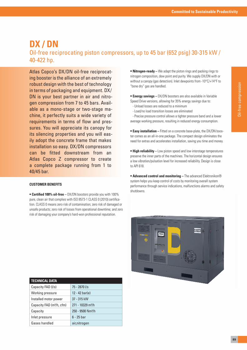
89
Committed to Sustainable Productivity
Oil-f
ree
com
pres
sion
Atlas Copco’s DX/DN oil-free reciprocat-ing booster is the alliance of an extremely robust design with the best of technology in terms of packaging and equipment. DX/DN is your best partner in air and nitro-gen compression from 7 to 45 bars. Avail-able as a mono-stage or two-stage ma-chine, it perfectly suits a wide variety of requirements in terms of flow and pres-sures. You will appreciate its canopy for its silencing properties and you will eas-ily adopt the concrete frame that makes installation so easy. DX/DN compressorscan be fitted downstream from anAtlas Copco Z compressor to create a complete package running from 1 to 40/45 bar.
DX / DNOil-free reciprocating piston compressors, up to 45 bar (652 psig) 30-315 kW / 40-422 hp.
CUSTOMER BENEFITS
• Certified 100% oil-free – DX/DN boosters provide you with 100% pure, clean air that complies with Iso 8573-1 CLass 0 (2010) certifica-tion. CLass 0 means zero risk of contamination; zero risk of damaged or unsafe products; zero risk of losses from operational downtime; and zero risk of damaging your company’s hard-won professional reputation.
TECHNICAL DATA
Capacity FAD (l/s) 75 - 2870 l/s
Working pressure 12 - 42 bar(e)
Installed motor power 37 - 315 kW
Capacity FAD (m³/h, cfm) 271 - 10329 m³/h
Capacity 250 - 9500 Nm³/h
Inlet pressure 6 - 25 bar
Gases handled air,nitrogen
• Nitrogen-ready – We adapt the piston rings and packing rings to nitrogen composition, dew point and purity. We supply DX/DN with or without a canopy (gas detection). Inlet dewpoints from -10°C/+14°F to “bone dry” gas are handled.
• Energy savings – DX/DN boosters are also available in Variable speed Drive versions, allowing for 35% energy savings due to: - Unload losses are reduced to a minimum - Load/no load transition losses are eliminated - Precise pressure control allows a tighter pressure band and a lower average working pressure, resulting in reduced energy consumption.
• Easy installation – Fitted on a concrete base-plate, the DX/DN boos-ter comes as an all-in-one package. The compact design eliminates the need for extras and accelerates installation, saving you time and money.
• High reliability – Low piston speed and low interstage temperatures preserve the inner parts of the machines. The horizontal design ensures a low vibration/pulsation level for increased reliability. Design is close to aPI 618.
• Advanced control and monitoring – The advanced elektronikon® system helps you keep control of costs by monitoring overall system performance through service indications, malfunctions alarms and safety shutdowns.
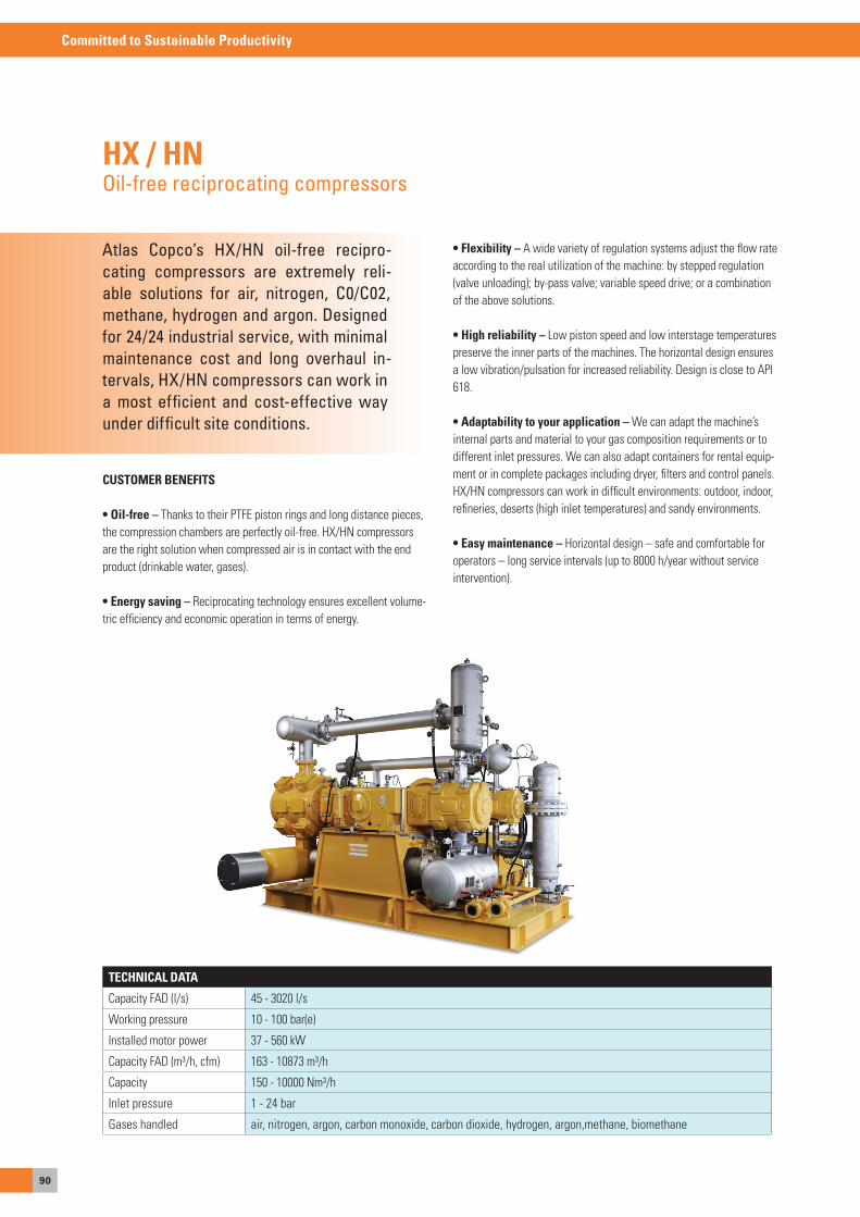
90
Committed to Sustainable Productivity
Atlas Copco’s HX/HN oil-free recipro-cating compressors are extremely reli-able solutions for air, nitrogen, C0/C02, methane, hydrogen and argon. Designed for 24/24 industrial service, with minimal maintenance cost and long overhaul in-tervals, HX/HN compressors can work in a most efficient and cost-effective way under difficult site conditions.
HX / HNOil-free reciprocating compressors
CUSTOMER BENEFITS
• Oil-free – Thanks to their PTFe piston rings and long distance pieces, the compression chambers are perfectly oil-free. HX/HN compressors are the right solution when compressed air is in contact with the end product (drinkable water, gases).
• Energy saving – Reciprocating technology ensures excellent volume-tric efficiency and economic operation in terms of energy.
TECHNICAL DATA
Capacity FaD (l/s) 45 - 3020 l/s
Working pressure 10 - 100 bar(e)
Installed motor power 37 - 560 kW
Capacity FaD (m³/h, cfm) 163 - 10873 m³/h
Capacity 150 - 10000 Nm³/h
Inlet pressure 1 - 24 bar
Gases handled air, nitrogen, argon, carbon monoxide, carbon dioxide, hydrogen, argon,methane, biomethane
• Flexibility – a wide variety of regulation systems adjust the flow rate according to the real utilization of the machine: by stepped regulation (valve unloading); by-pass valve; variable speed drive; or a combination of the above solutions.
• High reliability – Low piston speed and low interstage temperatures preserve the inner parts of the machines. The horizontal design ensures a low vibration/pulsation for increased reliability. Design is close to aPI 618.
• Adaptability to your application – We can adapt the machine’s internal parts and material to your gas composition requirements or to different inlet pressures. We can also adapt containers for rental equip-ment or in complete packages including dryer, filters and control panels. HX/HN compressors can work in difficult environments: outdoor, indoor, refineries, deserts (high inlet temperatures) and sandy environments.
• Easy maintenance – Horizontal design – safe and comfortable for operators – long service intervals (up to 8000 h/year without service intervention).
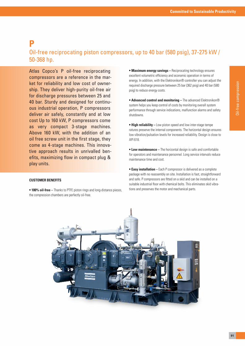
91
Committed to Sustainable Productivity
Oil-f
ree
com
pres
sion
Atlas Copco’s P oil-free reciprocating compressors are a reference in the mar-ket for reliability and low cost of owner-ship. They deliver high-purity oil-free air for discharge pressures between 25 and 40 bar. Sturdy and designed for continu-ous industrial operation, P compressors deliver air safely, constantly and at low cost Up to 160 kW, P compressors come as very compact 3-stage machines. Above 160 kW, with the addition of an oil free screw unit in the first stage, they come as 4-stage machines. This innova-tive approach results in unrivalled ben-efits, maximizing flow in compact plug & play units.
POil-free reciprocating piston compressors, up to 40 bar (580 psig), 37-275 kW / 50-368 hp.
CUSTOMER BENEFITS
• 100% oil-free – Thanks to PTFe piston rings and long-distance pieces, the compression chambers are perfectly oil-free.
• Maximum energy savings – Reciprocating technology ensures excellent volumetric efficiency and economic operation in terms of energy. In addition, with the elektronikon® controller you can adjust the required discharge pressure between 25 bar (362 psig) and 40 bar (580 psig) to reduce energy costs.
• Advanced control and monitoring – The advanced elektronikon® system helps you keep control of costs by monitoring overall system performance through service indications, malfunction alarms and safety shutdowns.
• High reliability – Low piston speed and low inter-stage temperatures preserve the internal components. The horizontal design ensures low vibration/pulsation levels for increased reliability. Design is close to aPI 618.
• Low maintenance – The horizontal design is safe and comfortable for operators and maintenance personnel. Long service intervals reduce maintenance time and cost.
• Easy installation – each P compressor is delivered as a complete package with no reassembly on site. Installation is fast, straightforward and safe. P compressors are fitted on a skid and can be installed on a suitable industrial floor with chemical bolts. This eliminates skid vibra-tions and preserves the motor and mechanical parts.
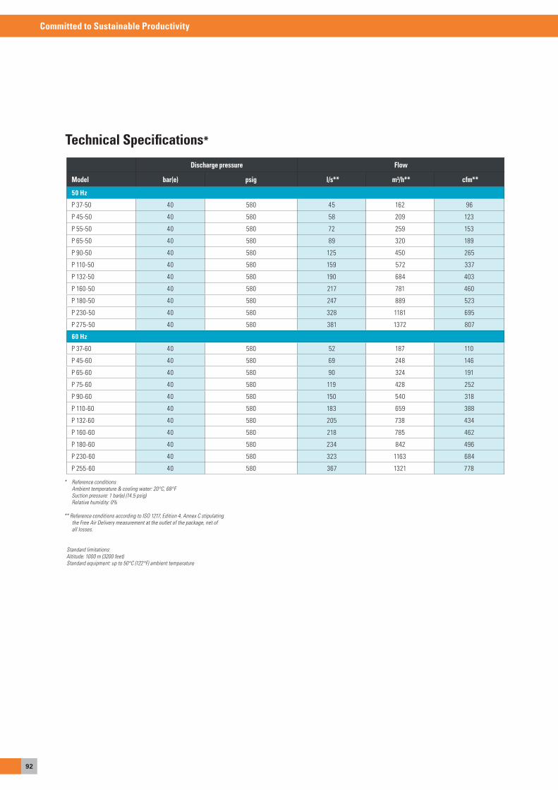
92
Committed to Sustainable Productivity
Technical Specifications*
* Reference conditions Ambient temperature & cooling water: 20°C, 68°F Suction pressure: 1 bar(e) (14.5 psig) Relative humidity: 0%
** Reference conditions according to ISO 1217, Edition 4, Annex C stipulating the Free Air Delivery measurement at the outlet of the package, net of all losses.
Standard limitations:Altitude: 1000 m (3200 feet)Standard equipment: up to 50°C (122°F) ambient temperature
Discharge pressure Flow
Model bar(e) psig l/s** m³/h** cfm**
50 Hz
P 37-50 40 580 45 162 96
P 45-50 40 580 58 209 123
P 55-50 40 580 72 259 153
P 65-50 40 580 89 320 189
P 90-50 40 580 125 450 265
P 110-50 40 580 159 572 337
P 132-50 40 580 190 684 403
P 160-50 40 580 217 781 460
P 180-50 40 580 247 889 523
P 230-50 40 580 328 1181 695
P 275-50 40 580 381 1372 807
60 Hz
P 37-60 40 580 52 187 110
P 45-60 40 580 69 248 146
P 65-60 40 580 90 324 191
P 75-60 40 580 119 428 252
P 90-60 40 580 150 540 318
P 110-60 40 580 183 659 388
P 132-60 40 580 205 738 434
P 160-60 40 580 218 785 462
P 180-60 40 580 234 842 496
P 230-60 40 580 323 1163 684
P 255-60 40 580 367 1321 778
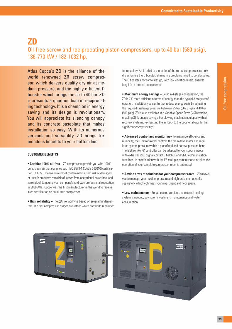
93
Committed to Sustainable Productivity
Oil-f
ree
com
pres
sion
Atlas Copco’s ZD is the alliance of the world renowned ZR screw compres-sor, which delivers quality dry air at me-dium pressure, and the highly efficient D booster which brings the air to 40 bar. ZD represents a quantum leap in reciprocat-ing technology. It is a champion in energy saving and its design is revolutionary. You will appreciate its silencing canopy and its concrete baseplate that makes installation so easy. With its numerous versions and versatility, ZD brings tre-mendous benefits to your bottom line.
ZDOil-free screw and reciprocating piston compressors, up to 40 bar (580 psig), 136-770 kW / 182-1032 hp.
CUSTOMER BENEFITS
• Certified 100% oil-free – ZD compressors provide you with 100% pure, clean air that complies with Iso 8573-1 CLass 0 (2010) certifica-tion. CLass 0 means zero risk of contamination; zero risk of damaged or unsafe products; zero risk of losses from operational downtime; and zero risk of damaging your company’s hard-won professional reputation. In 2006 atlas Copco was the first manufacturer in the world to receive such certification on an oil-free compressor.
• High reliability – The ZD’s reliability is based on several fundamen-tals. The first compression stages are rotary, which are world renowned
for reliability. air is dried at the outlet of the screw compressor, so only dry air enters the D booster, eliminating problems linked to condensates. The D booster’s horizontal design, with low vibration levels, ensures long life of internal components.
• Maximum energy savings – Being a 4-stage configuration, the ZD is 7% more efficient in terms of energy than the typical 3-stage confi-guration. In addition you can further reduce energy costs by adjusting the required discharge pressure between 25 bar (362 psig) and 40 bar (580 psig). ZD is also available in a Variable speed Drive (VsD) version, enabling 35% energy savings. For blowing machines equipped with air recovery systems, re-injecting the air back to the booster allows further significant energy savings.
• Advanced control and monitoring – To maximize efficiency and reliability, the elektronikon® controls the main drive motor and regu-lates system pressure within a predefined and narrow pressure band. The elektronikon® controller can be adapted to your specific needs with extra sensors, digital contacts, fieldbus and sMs communication functions. In combination with the es multiple compressor controller, the operation of your complete compressor room is optimized.
• A wide array of solutions for your compressor room – ZD allows you to manage your medium pressure and high pressure networks separately, which optimizes your investment and floor space.
• Low maintenance – For air-cooled versions, no external cooling system is needed, saving on investment, maintenance and water consumption.
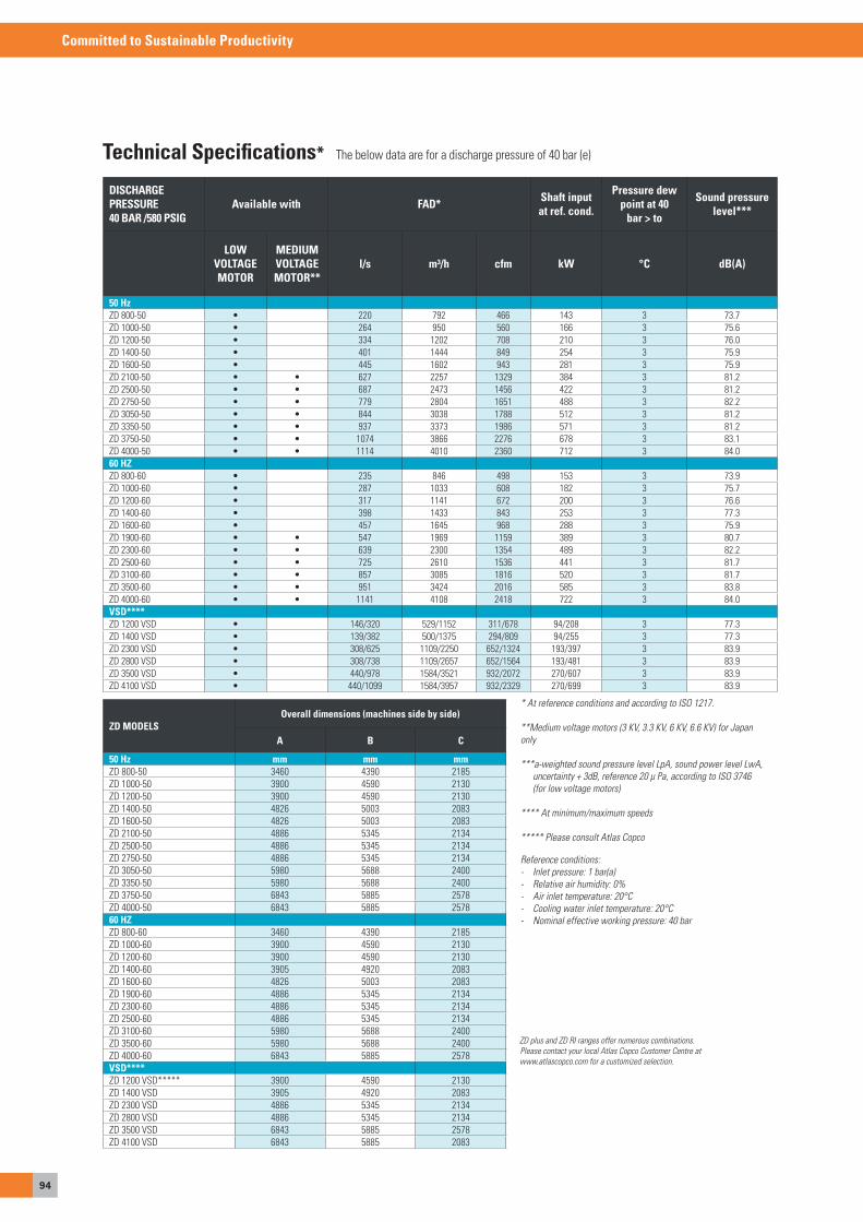
94
Committed to Sustainable Productivity
Technical Specifications* The below data are for a discharge pressure of 40 bar (e)
DISCHARGE PRESSURE 40 BAR /580 PSIG
Available with FAD* Shaft input at ref. cond.
Pressure dew point at 40
bar > to
Sound pressure level***
LOW VOLTAGE MOTOR
MEDIUM VOLTAGE MOTOR**
l/s m³/h cfm kW °C dB(A)
50 HzZD 800-50 • 220 792 466 143 3 73.7ZD 1000-50 • 264 950 560 166 3 75.6ZD 1200-50 • 334 1202 708 210 3 76.0ZD 1400-50 • 401 1444 849 254 3 75.9ZD 1600-50 • 445 1602 943 281 3 75.9ZD 2100-50 • • 627 2257 1329 384 3 81.2ZD 2500-50 • • 687 2473 1456 422 3 81.2ZD 2750-50 • • 779 2804 1651 488 3 82.2ZD 3050-50 • • 844 3038 1788 512 3 81.2ZD 3350-50 • • 937 3373 1986 571 3 81.2ZD 3750-50 • • 1074 3866 2276 678 3 83.1ZD 4000-50 • • 1114 4010 2360 712 3 84.060 HZ ZD 800-60 • 235 846 498 153 3 73.9ZD 1000-60 • 287 1033 608 182 3 75.7ZD 1200-60 • 317 1141 672 200 3 76.6ZD 1400-60 • 398 1433 843 253 3 77.3ZD 1600-60 • 457 1645 968 288 3 75.9ZD 1900-60 • • 547 1969 1159 389 3 80.7ZD 2300-60 • • 639 2300 1354 489 3 82.2ZD 2500-60 • • 725 2610 1536 441 3 81.7ZD 3100-60 • • 857 3085 1816 520 3 81.7ZD 3500-60 • • 951 3424 2016 585 3 83.8ZD 4000-60 • • 1141 4108 2418 722 3 84.0VSD****ZD 1200 VsD • 146/320 529/1152 311/678 94/208 3 77.3ZD 1400 VsD • 139/382 500/1375 294/809 94/255 3 77.3ZD 2300 VsD • 308/625 1109/2250 652/1324 193/397 3 83.9ZD 2800 VsD • 308/738 1109/2657 652/1564 193/481 3 83.9ZD 3500 VsD • 440/978 1584/3521 932/2072 270/607 3 83.9ZD 4100 VsD • 440/1099 1584/3957 932/2329 270/699 3 83.9
ZD MODELSOverall dimensions (machines side by side)
A B C
50 Hz mm mm mmZD 800-50 3460 4390 2185ZD 1000-50 3900 4590 2130ZD 1200-50 3900 4590 2130ZD 1400-50 4826 5003 2083ZD 1600-50 4826 5003 2083ZD 2100-50 4886 5345 2134ZD 2500-50 4886 5345 2134ZD 2750-50 4886 5345 2134ZD 3050-50 5980 5688 2400ZD 3350-50 5980 5688 2400ZD 3750-50 6843 5885 2578ZD 4000-50 6843 5885 257860 HZZD 800-60 3460 4390 2185ZD 1000-60 3900 4590 2130ZD 1200-60 3900 4590 2130ZD 1400-60 3905 4920 2083ZD 1600-60 4826 5003 2083ZD 1900-60 4886 5345 2134ZD 2300-60 4886 5345 2134ZD 2500-60 4886 5345 2134ZD 3100-60 5980 5688 2400ZD 3500-60 5980 5688 2400ZD 4000-60 6843 5885 2578VSD****ZD 1200 VsD***** 3900 4590 2130ZD 1400 VsD 3905 4920 2083ZD 2300 VsD 4886 5345 2134ZD 2800 VsD 4886 5345 2134ZD 3500 VsD 6843 5885 2578ZD 4100 VsD 6843 5885 2083
* At reference conditions and according to ISO 1217.
**Medium voltage motors (3 KV, 3.3 KV, 6 KV, 6.6 KV) for Japanonly
***a-weighted sound pressure level LpA, sound power level LwA, uncertainty + 3dB, reference 20 µ Pa, according to ISO 3746 (for low voltage motors)
**** At minimum/maximum speeds
***** Please consult Atlas Copco
Reference conditions:- Inlet pressure: 1 bar(a)- Relative air humidity: 0%- Air inlet temperature: 20°C- Cooling water inlet temperature: 20°C- Nominal effective working pressure: 40 bar
ZD plus and ZD RI ranges offer numerous combinations.Please contact your local Atlas Copco Customer Centre atwww.atlascopco.com for a customized selection.
Inhaltsverzeichnis
MeDICaLeQUIPMeNTWhether we like it or not, we all wind up in a hospital from time to time. When we do, we want to be sure that we receive the best possible care… and the purest possible air. That is where Atlas Copco lends a helping hand by supplying the reliable technology and global service.

96
Committed to Sustainable Productivity
MED / MED+Medical air purifiersPage 97 - 98
mVACMedical vacuum systemsPage 103 - 105
GA MEDscrew compressors for medicalapplicationsPage 99 - 100
uAIRMedical air PlantPage 101 - 102
OxyplantMedical oxygen plantPage 106 - 107
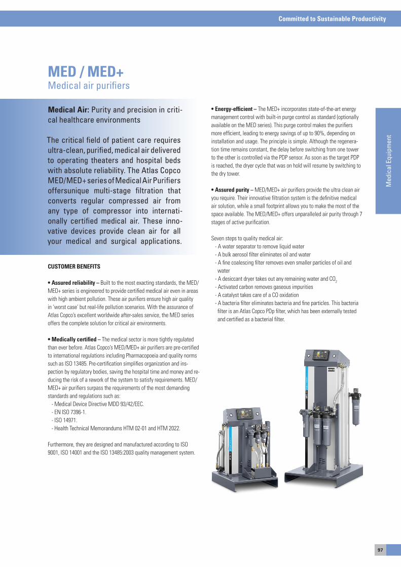
97
Committed to Sustainable Productivity
Med
ical
Equ
ipm
ent
Medical Air: Purity and precision in criti-cal healthcare environments
The critical field of patient care requires ultra-clean, purified, medical air deliveredto operating theaters and hospital beds with absolute reliability. The Atlas CopcoMED/MED+ series of Medical Air Purifiersoffersunique multi-stage filtration that converts regular compressed air from any type of compressor into internati-onally certified medical air. These inno-vative devices provide clean air for all your medical and surgical applications.
MED / MED+Medical air purifiers
CUSTOMER BENEFITS
• Assured reliability – Built to the most exacting standards, the MeD/MeD+ series is engineered to provide certified medical air even in areas with high ambient pollution. These air purifiers ensure high air quality in ‘worst case’ but real-life pollution scenarios. With the assurance of atlas Copco’s excellent worldwide after-sales service, the MeD series offers the complete solution for critical air environments.
• Medically certified – The medical sector is more tightly regulated than ever before. atlas Copco’s MeD/MeD+ air purifiers are pre-certified to international regulations including Pharmacopoeia and quality norms such as Iso 13485. Pre-certification simplifies organization and ins-pection by regulatory bodies, saving the hospital time and money and re-ducing the risk of a rework of the system to satisfy requirements. MeD/MeD+ air purifiers surpass the requirements of the most demanding standards and regulations such as: - Medical Device Directive MDD 93/42/eeC. - eN Iso 7396-1. - Iso 14971. - Health Technical Memorandums HTM 02-01 and HTM 2022.
Furthermore, they are designed and manufactured according to Iso 9001, Iso 14001 and the Iso 13485:2003 quality management system.
• Energy-efficient – The MeD+ incorporates state-of-the-art energy management control with built-in purge control as standard (optionally available on the MeD series). This purge control makes the purifiers more efficient, leading to energy savings of up to 90%, depending on installation and usage. The principle is simple. although the regenera-tion time remains constant, the delay before switching from one tower to the other is controlled via the PDP sensor. as soon as the target PDP is reached, the dryer cycle that was on hold will resume by switching to the dry tower.
• Assured purity – MeD/MeD+ air purifiers provide the ultra clean air you require. Their innovative filtration system is the definitive medical air solution, while a small footprint allows you to make the most of the space available. The MeD/MeD+ offers unparalleled air purity through 7 stages of active purification.
seven steps to quality medical air: - a water separator to remove liquid water - a bulk aerosol filter eliminates oil and water - a fine coalescing filter removes even smaller particles of oil and water - a desiccant dryer takes out any remaining water and Co2
- activated carbon removes gaseous impurities - a catalyst takes care of a Co oxidation - a bacteria filter eliminates bacteria and fine particles. This bacteria filter is an atlas Copco PDp filter, which has been externally tested and certified as a bacterial filter.

98
Committed to Sustainable Productivity
PurifierType Inlet pressure Max. inlet flow Puge Pressure dropbar(e) psig l/s m3/h cfm % dP, mbar psi
MED / MED+
MeD7 / MeD7+ 7 102 7.0 25.2 14.8 19.0 510 7.4 10 145 8.4 30.2 17.8 15.8 510 7.4 13 188 9.4 33.8 19.9 14.1 510 7.4
MeD13 / MeD13+ 7 102 13.0 46.8 27.5 19.0 530 7.7 10 145 15.6 56.2 33.1 15.8 530 7.7 13 188 17.5 63.0 37.1 14.1 530 7.7
MeD25 / MeD25+ 7 102 25.0 90.0 53.0 18.0 560 8.1 10 145 30.0 108.0 63.6 15.0 560 8.1 13 188 33.8 121.7 71.6 13.3 560 8.1
MeD35 / MeD35+ 7 102 35.0 126.0 74.2 18.0 600 8.7 10 145 42.0 151.2 89.0 15.0 600 8.7 13 188 47.3 170.3 100.2 13.3 600 8.7
MeD50 / MeD50+ 7 102 50.0 180.0 106.0 19.0 820 11.9 10 145 60.0 216.0 127.1 15.8 820 11.9 13 188 67.5 243.0 143.0 14.1 820 11.9
MeD70 / MeD+70+ 7 102 70.0 252.0 148.3 18.0 660 9.6 10 145 84.0 302.4 178.0 15.0 660 9.6 13 188 94.5 340.2 200.2 13.3 660 9.6
MeD80 / MeD80+ 7 102 80.0 288.0 169.5 18.0 700 10.2 10 145 96.0 345.6 203.4 15.0 700 10.2 13 188 108.0 388.8 228.9 13.3 700 10.2
MeD100 / MeD100+ 7 102 100.0 360.0 211.9 19.0 820 11.9 10 145 120.0 432.0 254.3 15.8 820 11.9 13 188 135.0 486.0 286.1 14.1 820 11.9
MeD145 / MeD145+ 7 102 145.0 522.0 307.3 19.0 800 11.6 10 145 174.0 626.4 368.7 15.8 800 11.6 13 188 195.8 704.9 414.9 14.1 800 11.6
MED MED+ Weight, kg
Length, mm Width, mm
Height, mm
NTP connection Weight, kg Length, mm Width, mm
Height, mm NTP connec-tion
MeD7 / MeD7+ 184 950 650 885 1/2" 214 950 650 1851 1/2"MeD13 / MeD13+ 201 950 650 1075 1/2" 231 950 650 1851 1/2"MeD25 / MeD25+ 245 950 650 1300 1/2" 275 950 650 1851 1/2"MeD35 / MeD35+ 271 950 650 1545 1/2" 301 950 650 1851 1/2"MeD50 / MeD50+ 315 950 650 1915 1" 345 950 650 1858 1"MeD70 / MeD+70+ 446 1250 850 1545 1" 476 1250 850 1840 1"MeD80 / MeD80+ 494 1250 850 1915 1 1/2" 524 1250 850 1840 1"MeD100 / MeD100+ 502 1250 850 1915 1 1/2" 532 1250 850 1840 1"MeD145 / MeD145+ 620 1250 850 1915 1 1/2" 650 1250 850 1856 1"
Description MED MED+
eWD on filters and water drain o o
Inlet solenoid for remote control - o
NPT connection o o
QDT quality indicator o o
Catalyst(Co to Co2) o o
Co sensor o o
Co2 sensor o o
o2 sensor o -
overflow protection(nozzle) o o
airContact and Combox-e with visualisation - o
Gateway(Profibus, Modbus) - o
Technical specifications MED/ MED+ 060313

99
Committed to Sustainable Productivity
Med
ical
Equ
ipm
ent
Whether you work at a hospital, dentalpractice, veterinary lab or clinicallaboratory, maximum reliability is your main priority. To successfully perform your work and make sure your equipmentfunctions effectively, you rely on ultra-clean air. Designed precisely for these applications, GA MED oil-injected com-pressors bring you proven reliability and Atlas Copco’s latest high-efficiency compression element. You benefit from outstanding performance, flexible ope-ration and the highest productivity, along with minimal total cost of ownership.
GA MEDScrew compressors for medical applications
CUSTOMER BENEFITS
• Highest reliability – Three premium compressor series – Ga 5-11 MeD, Ga 5-15 VsD MeD and Ga 15-22 MeD are designed, manu-factured and tested in accordance with Iso 9001, Iso 14001 and Iso 1217, ed. 3, annex C. ensuring a long and trouble-free life at the lowest operating cost, each Ga MeD contains the latest generation of atlas Copco’s innovative oil-injected screw element.
• Peace of mind – all Ga MeD compressors are equipped with additi-onal safety protections. even in case of a single fault condition, the air demand is always assured.
• VSD – Driving down energy costs. energy typically represents over 80% of a compressor’s life cycle cost. Looking continuously to innovate and reduce customer costs, atlas Copco pioneered Variable speed Drive (VsD) technology in 1994. The Ga 5-11 VsD MeD range is the ideal solution for a fluctuating air demand. By monitoring the outlet pressure, the air flow is adjusted to the demand. energy savings of 35% on average become a reality thanks to the high turndown ratio and the new fan saver cycle.
• Air system integration – The Ga MeD can be placed where youneed it. Its low noise operation and dedicated air treatment equipment ensure a healthier environment in the plant room. Moreover, all GaMeD compressors are delivered ready for use, significantly reducing installation costs.
• Advanced control and monitoring – To maximize efficiency and re-liability, the elektronikon® controls the main drive motor and regulatessystem pressure within a predefined and narrow pressure band. The elektronikon® controller can be adapted to your specific needs with ex-tra sensors, digital contacts, fieldbus, Internet and sMs communication functions. In combination with the es multiple compressor controller, theoperation of your complete compressor room is optimized.
• integrated purity – When partnered with a dedicated MeD+ or MeD air purifying system, the Ga MeD generates compressed air into pure breathing quality air. you rest assured at all times that the air quality delivered by the system accords to what the doctor ordered.
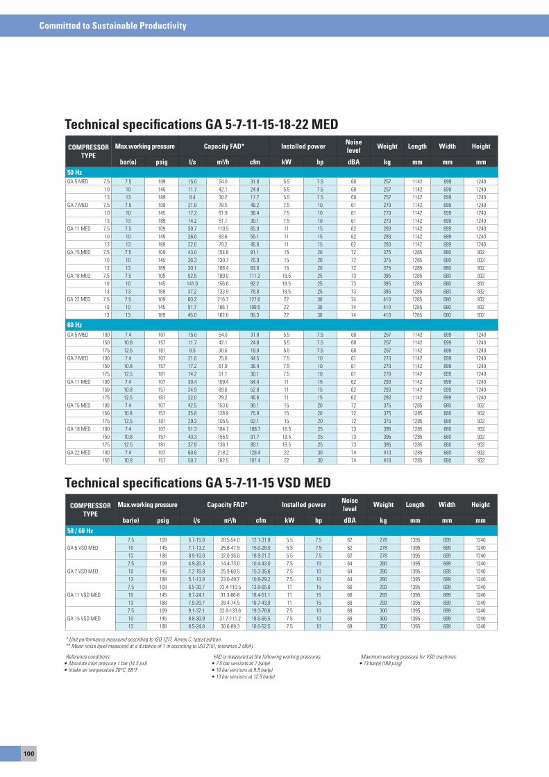
100
Committed to Sustainable Productivity
COMPRESSOR TYPE
Max.working pressure Capacity FAD* Installed power Noise level Weight Length Width Height
bar(e) psig l/s m³/h cfm kW hp dBA kg mm mm mm50 HzGa 5 MeD 7.5 7.5 109 15.0 54.0 31.8 5.5 7.5 60 257 1142 699 1240
10 10 145 11.7 42.1 24.8 5.5 7.5 60 257 1142 699 124013 13 189 8.4 30.2 17.7 5.5 7.5 60 257 1142 699 1240
Ga 7 MeD 7.5 7.5 109 21.8 78.5 46.2 7.5 10 61 270 1142 699 124010 10 145 17.2 61.9 36.4 7.5 10 61 270 1142 699 124013 13 189 14.2 51.1 30.1 7.5 10 61 270 1142 699 1240
Ga 11 MeD 7.5 7.5 109 30.7 110.5 65.0 11 15 62 293 1142 699 124010 10 145 26.0 93.6 55.1 11 15 62 293 1142 699 124013 13 189 22.0 79.2 46.6 11 15 62 293 1142 699 1240
Ga 15 MeD 7.5 7.5 109 43.0 154.8 91.1 15 20 72 375 1285 680 93210 10 145 36.3 130.7 76.9 15 20 72 375 1285 680 93213 13 189 30.1 108.4 63.8 15 20 72 375 1285 680 932
Ga 18 MeD 7.5 7.5 109 52.5 189.0 111.2 18.5 25 73 395 1285 680 93210 10 145 141.0 156.6 92.2 18.5 25 73 395 1285 680 93213 13 189 37.2 133.9 78.8 18.5 25 73 395 1285 680 932
Ga 22 MeD 7.5 7.5 109 60.2 216.7 127.6 22 30 74 410 1285 680 93210 10 145 51.7 186.1 109.5 22 30 74 410 1285 680 93213 13 189 45.0 162.0 95.3 22 30 74 410 1285 680 932
60 HzGa 5 MeD 100 7.4 107 15.0 54.0 31.8 5.5 7.5 60 257 1142 699 1240
150 10.8 157 11.7 42.1 24.8 5.5 7.5 60 257 1142 699 1240175 12.5 181 8.5 30.6 18.0 5.5 7.5 60 257 1142 699 1240
Ga 7 MeD 100 7.4 107 21.0 75.6 44.5 7.5 10 61 270 1142 699 1240150 10.8 157 17.2 61.9 36.4 7.5 10 61 270 1142 699 1240175 12.5 181 14.2 51.1 30.1 7.5 10 61 270 1142 699 1240
Ga 11 MeD 100 7.4 107 30.4 109.4 64.4 11 15 62 293 1142 699 1240150 10.8 157 24.9 89.6 52.8 11 15 62 293 1142 699 1240175 12.5 181 22.0 79.2 46.6 11 15 62 293 1142 699 1240
Ga 15 MeD 100 7.4 107 42.5 153.0 90.1 15 20 72 375 1285 680 932150 10.8 157 35.8 128.9 75.9 15 20 72 375 1285 680 932175 12.5 181 29.3 105.5 62.1 15 20 72 375 1285 680 932
Ga 18 MeD 100 7.4 107 51.3 184.7 108.7 18.5 25 73 395 1285 680 932150 10.8 157 43.3 155.9 91.7 18.5 25 73 395 1285 680 932175 12.5 181 37.8 136.1 80.1 18.5 25 73 395 1285 680 932
Ga 22 MeD 100 7.4 107 60.6 218.2 128.4 22 30 74 410 1285 680 932150 10.8 157 50.7 182.5 107.4 22 30 74 410 1285 680 932
Technical specifications GA 5-7-11-15-18-22 MED
COMPRESSOR TYPE
Max.working pressure Capacity FAD* Installed power Noise level Weight Length Width Height
bar(e) psig l/s m³/h cfm kW hp dBA kg mm mm mm50 / 60 Hz
Ga 5 VsD MeD7.5 109 5.7-15.0 20.5-54.0 12.1-31.8 5.5 7.5 62 278 1395 699 124010 145 7.1-13.2 25.6-47.5 15.0-28.0 5.5 7.5 62 278 1395 699 124013 188 8.9-10.0 32.0-36.0 18.9-21.2 5.5 7.5 62 278 1395 699 1240
Ga 7 VsD MeD7.5 109 4.9-20.3 14.4-73.0 10.4-43.0 7.5 10 64 280 1395 699 124010 145 7.2-16.8 25.9-60.5 15.3-35.6 7.5 10 64 280 1395 699 124013 188 5.1-13.8 23.0-49.7 10.8-29.2 7.5 10 64 280 1395 699 1240
Ga 11 VsD MeD7.5 109 6.5-30.7 23.4-110.5 13.8-65.0 11 15 66 293 1395 699 124010 145 8.7-24.1 31.3-86-8 18.4-51.1 11 15 66 293 1395 699 124013 188 7.9-20.7 28.4-74.5 16.7-43.9 11 15 66 293 1395 699 1240
Ga 15 VsD MeD7.5 109 9.1-37.1 32.8-133.6 19.3-78.6 7.5 10 69 300 1395 699 124010 145 8.8-30.9 31.7-111.2 18.6-65.5 7.5 10 69 300 1395 699 124013 188 8.5-24.8 30.6-89.3 18.0-52.5 7.5 10 69 300 1395 699 1240
Technical specifications GA 5-7-11-15 VSD MED
Reference conditions:• Absolute inlet pressure 1 bar (14.5 psi)• Intake air temperature 20°C, 68°F
FAD is measured at the following working pressures:• 7.5 bar versions at 7 bar(e) • 10 bar versions at 9.5 bar(e) • 13 bar versions at 12.5 bar(e)
Maximum working pressure for VSD machines:• 13 bar(e) (188 psig)
* Unit performance measured according to ISO 1217, Annex C, latest edition.** Mean noise level measured at a distance of 1 m according to ISO 2151; tolerance 3 dB(A).
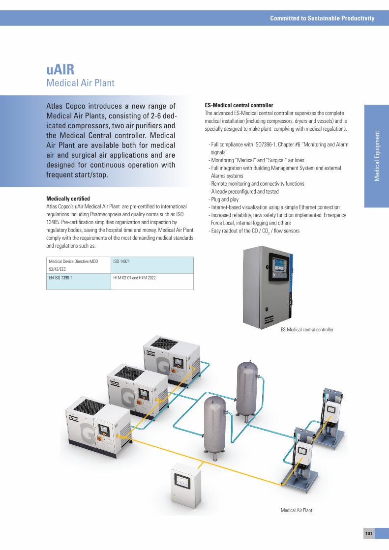
101
Committed to Sustainable Productivity
Med
ical
Equ
ipm
ent
Atlas Copco introduces a new range of Medical Air Plants, consisting of 2-6 ded-icated compressors, two air purifiers and the Medical Central controller. Medical Air Plant are available both for medical air and surgical air applications and are designed for continuous operation with frequent start/stop.
uAIRMedical Air Plant
Medically certifiedatlas Copco’s uair Medical air Plant are pre-certified to international regulations including Pharmacopoeia and quality norms such as Iso 13485. Pre-certification simplifies organization and inspection by regulatory bodies, saving the hospital time and money. Medical air Plant comply with the requirements of the most demanding medical standards and regulations such as:
Medical Device Directive MDD
93/42/eeC
Iso 14971
eN Iso 7396-1 HTM 02-01 and HTM 2022.
ES-Medical central controllerThe advanced es-Medical central controller supervises the complete medical installation (including compressors, dryers and vessels) and is specially designed to make plant complying with medical regulations.
- Full compliance with Iso7396-1, Chapter #6 “Monitoring and alarm signals” - Monitoring “Medical” and “surgical” air lines - Full integration with Building Management system and external alarms systems - Remote monitoring and connectivity functions - already preconfigured and tested - Plug and play - Internet-based visualization using a simple ethernet connection - Increased reliability, new safety function implemented: emergency Force Local, internal logging and others - easy readout of the Co / Co2 / flow sensors
es-Medical central controller
Medical air Plant
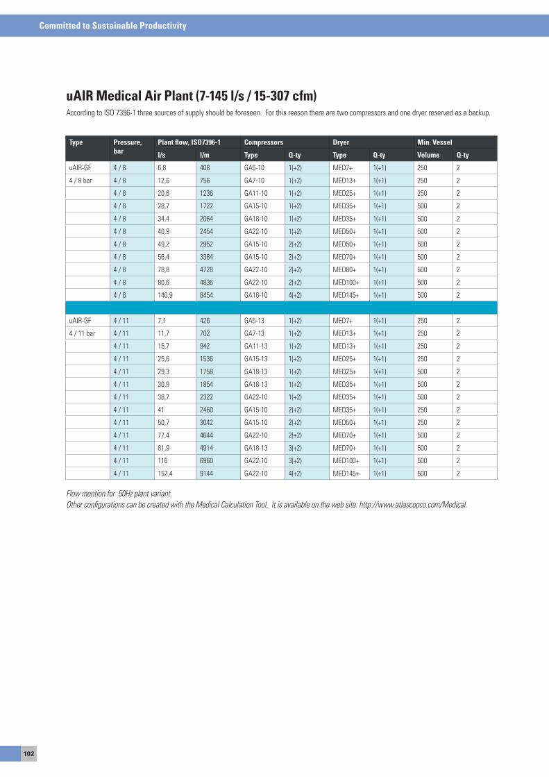
102
Committed to Sustainable Productivity
Type Pressure, bar
Plant flow, ISO7396-1 Compressors Dryer Min. Vessel
l/s l/m Type Q-ty Type Q-ty Volume Q-ty
uaIR-GF 4 / 8 6,8 408 Ga5-10 1(+2) MeD7+ 1(+1) 250 2
4 / 8 bar 4 / 8 12,6 756 Ga7-10 1(+2) MeD13+ 1(+1) 250 2
4 / 8 20,6 1236 Ga11-10 1(+2) MeD25+ 1(+1) 250 2
4 / 8 28,7 1722 Ga15-10 1(+2) MeD35+ 1(+1) 500 2
4 / 8 34,4 2064 Ga18-10 1(+2) MeD35+ 1(+1) 500 2
4 / 8 40,9 2454 Ga22-10 1(+2) MeD50+ 1(+1) 500 2
4 / 8 49,2 2952 Ga15-10 2(+2) MeD50+ 1(+1) 500 2
4 / 8 56,4 3384 Ga15-10 2(+2) MeD70+ 1(+1) 500 2
4 / 8 78,8 4728 Ga22-10 2(+2) MeD80+ 1(+1) 500 2
4 / 8 80,6 4836 Ga22-10 2(+2) MeD100+ 1(+1) 500 2
4 / 8 140,9 8454 Ga18-10 4(+2) MeD145+ 1(+1) 500 2
uaIR-GF 4 / 11 7,1 426 Ga5-13 1(+2) MeD7+ 1(+1) 250 2
4 / 11 bar 4 / 11 11,7 702 Ga7-13 1(+2) MeD13+ 1(+1) 250 2
4 / 11 15,7 942 Ga11-13 1(+2) MeD13+ 1(+1) 250 2
4 / 11 25,6 1536 Ga15-13 1(+2) MeD25+ 1(+1) 250 2
4 / 11 29,3 1758 Ga18-13 1(+2) MeD25+ 1(+1) 500 2
4 / 11 30,9 1854 Ga18-13 1(+2) MeD35+ 1(+1) 500 2
4 / 11 38,7 2322 Ga22-10 1(+2) MeD35+ 1(+1) 500 2
4 / 11 41 2460 Ga15-10 2(+2) MeD35+ 1(+1) 250 2
4 / 11 50,7 3042 Ga15-10 2(+2) MeD50+ 1(+1) 250 2
4 / 11 77,4 4644 Ga22-10 2(+2) MeD70+ 1(+1) 500 2
4 / 11 81,9 4914 Ga18-13 3(+2) MeD70+ 1(+1) 500 2
4 / 11 116 6960 Ga22-10 3(+2) MeD100+ 1(+1) 500 2
4 / 11 152,4 9144 Ga22-10 4(+2) MeD145+ 1(+1) 500 2
uAIR Medical Air Plant (7-145 l/s / 15-307 cfm)according to Iso 7396-1 three sources of supply should be foreseen. For this reason there are two compressors and one dryer reserved as a backup.
Flow mention for 50Hz plant variant.Other configurations can be created with the Medical Calculation Tool. It is available on the web site: http://www.atlascopco.com/Medical.
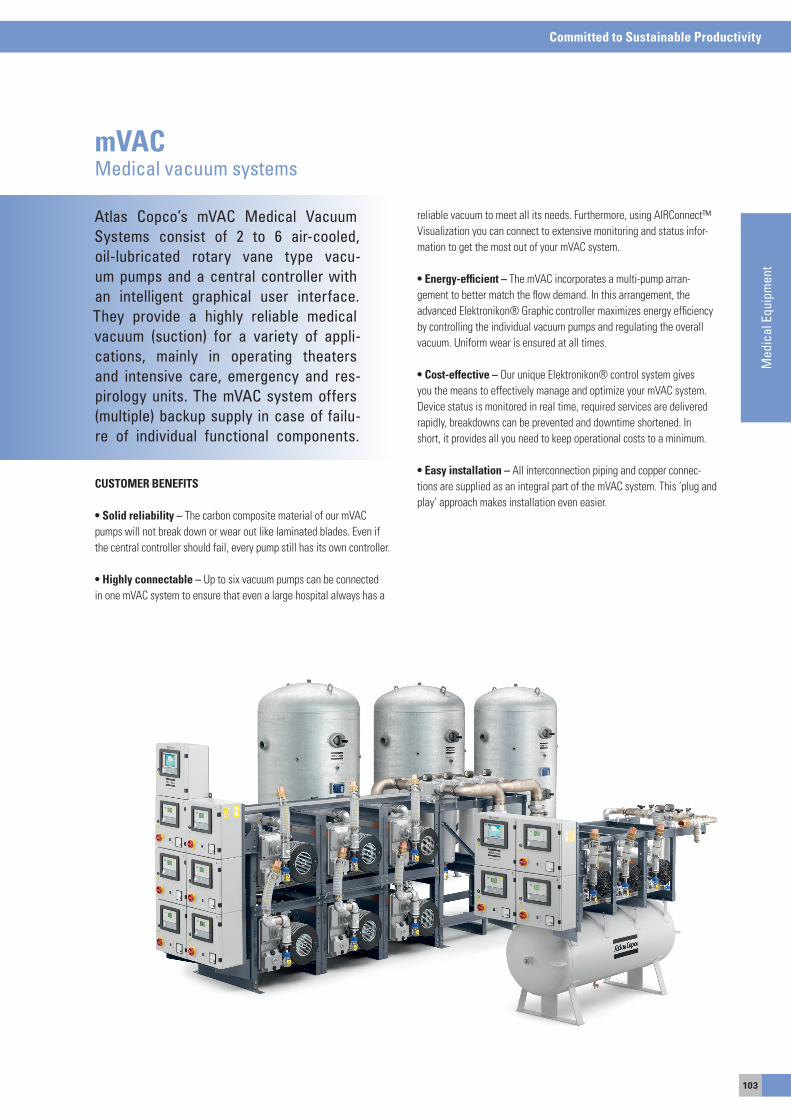
103
Committed to Sustainable Productivity
Med
ical
Equ
ipm
ent
Atlas Copco’s mVAC Medical Vacuum Systems consist of 2 to 6 air-cooled, oil-lubricated rotary vane type vacu-um pumps and a central controller with an intelligent graphical user interface. They provide a highly reliable medical vacuum (suction) for a variety of appli-cations, mainly in operating theaters and intensive care, emergency and res-pirology units. The mVAC system offers (multiple) backup supply in case of failu-re of individual functional components.
mVACMedical vacuum systems
CUSTOMER BENEFITS
• Solid reliability – The carbon composite material of our mVaC pumps will not break down or wear out like laminated blades. even if the central controller should fail, every pump still has its own controller.
• Highly connectable – Up to six vacuum pumps can be connected in one mVaC system to ensure that even a large hospital always has a
reliable vacuum to meet all its needs. Furthermore, using aIRConnect™ Visualization you can connect to extensive monitoring and status infor-mation to get the most out of your mVaC system.
• Energy-efficient – The mVaC incorporates a multi-pump arran-gement to better match the flow demand. In this arrangement, the advanced elektronikon® Graphic controller maximizes energy efficiency by controlling the individual vacuum pumps and regulating the overall vacuum. Uniform wear is ensured at all times.
• Cost-effective – our unique elektronikon® control system gives you the means to effectively manage and optimize your mVaC system. Device status is monitored in real time, required services are delivered rapidly, breakdowns can be prevented and downtime shortened. In short, it provides all you need to keep operational costs to a minimum.
• Easy installation – all interconnection piping and copper connec-tions are supplied as an integral part of the mVaC system. This ‘plug and play’ approach makes installation even easier.
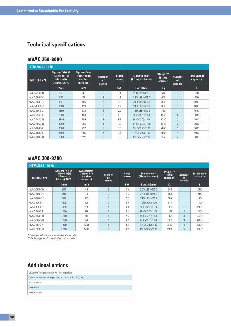
104
Committed to Sustainable Productivity
Technical specifications
HTM 2022 - 50 Hz
MODEL TYPE
System FAA @ -600 mbar(e) referred to
0 bar(e), 20°C
System flow (referred to
suction pressure)
Number of
pumps
Pump power
Dimensions* (filters included)
Weight** (filters
included)Number
of vessels
Total vessel capacity
l/min m³/h kW LxWxH (mm) Kg L
mVaC-250-DH 250 40 2 1.1 2040x980x1650 540 1 500
mVaC-500-TH 500 79 3 1.1 2300x980x1650 650 1 500
mVaC-660-TH 660 105 3 1.5 2400x980x1900 800 1 1000
mVaC-1000-TH 1000 159 3 2.2 2400x980x1900 860 1 1000
mVaC-1500-Q 1500 238 4 2.2 1830x980x1700 750 1 1500
mVaC-2560-T 2560 406 3 5.5 2600x1200x1600 1365 2 3000
mVaC-3840-Q 3840 609 4 5.5 2600x1200x1990 1700 2 4000
mVaC-4950-Q 4950 786 4 7.5 3400x1250x1700 1800 3 6000
mVaC-6000-P 6000 952 5 7.5 4100x1250x1700 2050 3 6000
mVaC-6600-P 6600 1047 5 7.5 4100x1250x1700 2050 4 8000
mVaC-8000-H 8000 1270 6 7.5 4100x1250x1990 2360 4 8000
mVAC 250-8000
airConnect™ Visualization and Notification package
Customized software setting for different norms (HTM / Iso / as)
oil level switch
synthetic oil
Painted vessels
Additional options
HTM 2022 - 60 Hz
MODEL TYPE
System FAA @ -600 mbar(e) referred to
0 bar(e), 20°C
System flow (referred to
suction pressure)
Number of
pumps
Pump power
Dimensions* (filters included)
Weight** (filters
included)Number
of vessels
Total vessel capacity
l/min m³/h kW LxWxH (mm) Kg L
mVaC-300-DH 300 48 2 1.5 2040x980x1650 540 1 500
mVaC-500-TH 500 79 3 1.5 2300x980x1650 650 1 500
mVaC-800-TH 800 127 3 2.2 2400x980x1900 800 1 1000
mVaC-1200-T 1200 190 3 3.0 1910x980x1700 610 1 1500
mVaC-1860-Q 1860 295 4 3.0 2200x1200x1700 1050 1 2000
mVaC-3000-T 3000 476 3 7.5 2600x1200x1600 1365 2 3000
mVaC-4500-Q 4500 714 4 7.5 3400x1250x1990 1825 3 4500
mVaC-5850-Q 5850 928 4 9.2 3400x1250x1990 1800 3 6000
mVaC-7800-P 7800 1238 5 9.2 4100x1250x1990 2160 4 8000
mVaC-9200-H 9200 1460 6 9.2 4100x1250x1990 2360 5 10000
mVAC 300-9200
* When available, horizontal vessels are included.** Packaging included, vertical vessels excluded.
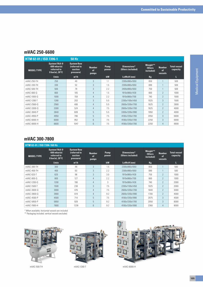
105
Committed to Sustainable Productivity
Med
ical
Equ
ipm
ent
HTM 02-01 / ISO 7396-1 50 Hz
MODEL TYPE
System FAA @ -600 mbar(e) referred to
0 bar(e), 20°C
System flow (referred to
suction pressure)
Number of
pumps
Pump power
Dimensions* (filters included)
Weight** (filters
included)Number
of vessels
Total vessel capacity
l/min m³/h kW LxWxH (mm) Kg L
mVaC-250-TH 250 40 3 1.1 2300x980x1650 650 1 500
mVaC-330-TH 330 52 3 1.5 2300x980x1650 690 1 500
mVaC-500-TH 500 79 3 2.2 2400x980x1650 750 1 500
mVaC-660-Q 660 105 4 1.5 1910x980x1430 660 2 1000
mVaC-1000-Q 1000 159 4 2.2 1910x980x1700 740 2 1000
mVaC-1280-T 1280 203 3 5.5 2200x1100x1450 1025 3 1500
mVaC-2560-Q 2560 406 4 5.5 2600x1200x1700 1625 2 3000
mVaC-3300-Q 3300 524 4 7.5 2600x1200x1700 1625 2 4000
mVaC-3840-P 3840 609 5 5.5 3300x1200x1990 1950 2 4000
mVaC-4950-P 4950 786 5 7.5 4100x1250x1700 2050 3 6000
mVaC-6000-H 6000 952 6 7.5 4100x1250x1700 2250 3 6000
mVaC-6600-H 6600 1047 6 7.5 4100x1250x1700 2250 4 8000
HTM 02-01 / ISO 7396-160 Hz
MODEL TYPE
System FAA @ -600 mbar(e) referred to
0 bar(e), 20°C
System flow (referred to
suction pressure)
Number of
pumps
Pump power
Dimensions* (filters included)
Weight** (filters
included)Number
of vessels
Total vessel capacity
l/min m³/h kW LxWxH (mm) Kg L
mVaC-300-TH 300 48 3 1.5 2300x980x1650 650 1 500
mVaC-400-TH 400 63 3 2.2 2300x980x1650 690 1 500
mVaC-620-T 620 98 3 3.0 1910x980x1430 750 2 1000
mVaC-800-Q 800 127 4 2.2 1910x980x1700 660 2 1000
mVaC-1200-Q 1200 190 4 3 1910x980x1430 740 2 2000
mVaC-1500-T 1500 238 3 7.5 2200x1100x1450 1025 2 2000
mVaC-3000-Q 3000 476 4 7.5 2600x1200x1700 1640 2 3000
mVaC-3900-Q 3900 619 4 9.2 2600x1200x1990 1700 2 4000
mVaC-4500-P 4500 714 5 7.5 4100x1250x1990 2075 3 4500
mVaC-5850-P 5850 928 5 9.2 4100x1250x1700 2050 3 6000
mVaC-7800-H 7800 1238 6 9.2 4100x1250x1990 2360 4 8000
mVAC 300-7800
mVAC 250-6600
mVaC-500-TH mVaC-1280-T mVaC-6000-H
* When available, horizontal vessels are included.** Packaging included, vertical vessels excluded.
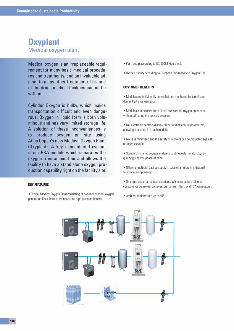
106
Committed to Sustainable Productivity
OxyplantMedical oxygen plant
Medical oxygen is an irreplaceable requi-rement for many basic medical procedu-res and treatments, and an invaluable ad-junct to many other treatments. It is one of the drugs medical facilities cannot be without.
Cylinder Oxygen is bulky, which makes transportation difficult and even dange-rous. Oxygen in liquid form is both volu-minous and has very limited storage life. A solution of these inconveniences isto produce oxygen on site usingAtlas Copco’s new Medical Oxygen Plant (Oxyplant). A key element of Oxyplant is our PSA module which separates the oxygen from ambient air and allows the facility to have a stand alone oxygen pro-duction capability right on the facility site.
KEY FEATURES
• Typical Medical Oxygen Plant consisting of two independent oxygen generation lines, bank of cylinders and high pressure booster.
• Plant setup according to ISO10083 Figure A.5.
• Oxygen quality according to European Pharmacopeia Oxygen 93%.
CUSTOMER BENEFITS
• Modules are individually controlled and monitored for simplex or duplex Psa arrangements.
• Modules can be operated at ideal pressure for oxygen production without affecting the delivery pressure.
• Full electronic controls display output and all control parameters, allowing you control of each module.
• Noise is minimized and the safety of workers can be protected against nitrogen exhaust.
• Standard installed oxygen analyzers continuously monitor oxygen quality giving you peace of mind.
• Offering (multiple) backup supply in case of a failure in individual functional components
• One-stop-shop for medical solutions. We manufacture all main components ourselves( compressors, dryers, filters and Psa generators).
• Ambient temperature up to 45°
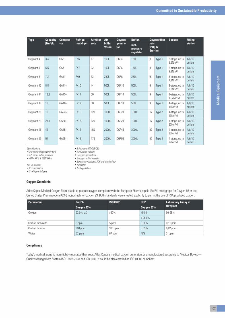
107
Committed to Sustainable Productivity
Med
ical
Equ
ipm
ent
Oxygen Standards
atlas Copco Medical oxygen Plant is able to produce oxygen compliant with the european Pharmacopeia (eurPh) monograph for oxygen 93 or the United states Pharmacopeia (UsP) monograph for oxygen 93. Both standards were created explicitly to permit the use of Psa produced oxygen.
Compliance
Today’s medical arena is more tightly regulated than ever. atlas Copco’s medical oxygen generators are manufactured according to Medical Device—Quality Management system Iso 13485:2003 and Iso 9001. It could be also certified as Iso 10083 compliant.
Type Capacity [Nm3/h]
Compres-sor
Refrige-rant dryer
Air filtersets
Air buffer Vessel
Oxygen genera-tor
Buffer, Oxygen filter sets(PDp & Sterile)
Booster Filling stationincl.
pressure regulator
oxyplant 4 3,4 Ga5 FX6 17 150L oGP4 150L 9 Type 1 2-stage, up to 3,2Nm³/h
4/6/10 outlets
oxyplant 6 5,5 Ga7 FX7 32 150L oGP6 150L 9 Type 1 2-stage, up to 3,2Nm³/h
4/6/10 outlets
oxyplant 8 7,2 Ga11 FX9 32 280L oGP8 280L 9 Type 1 3-stage, up to 7,2Nm³/h
4/6/10 outlets
oxyplant 10 8,8 Ga11+ FX10 44 500L oGP10 500L 9 Type 1 3-stage, up to 8,8Nm³/h
4/6/10 outlets
oxyplant 14 13,2 Ga15+ FX11 60 500L oGP14 500L 9 Type 1 3-stage, up to 13,2Nm³/h
4/6/10 outlets
oxyplant 18 18 Ga18+ FX12 60 500L oGP18 500L 9 Type 1 4-stage, up to 18Nm³/h
4/6/10 outlets
oxyplant 20 19 Ga22+ FX15 120 1000L oGP20 1000L 17 Type 2 4-stage, up to 19Nm³/h
4/6/10 outlets
oxyplant 29 27,1 Ga30+ FX16 120 1000L oGP29 1000L 17 Type 2 4-stage, up to 27Nm³/h
4/6/10 outlets
oxyplant 45 42 Ga45+ FX18 150 2000L oGP45 2000L 32 Type 2 4-stage, up to 27Nm³/h
4/6/10 outlets
oxyplant 55 51 Ga55+ FX19 175 2000L oGP55 2000L 32 Type 2 4-stage, up to 27Nm³/h
4/6/10 outlets
Specifications:•Unit outlet oxygen purity 93%• 4-5 bar(e) outlet pressure• 400V 50Hz & 380V 60Hz Set-up include:• 2 compressors• 2 refrigerant dryers
• 2 filter sets (PD/DD/QD)• 2 air buffer vessels• 2 oxygen generators,• 2 oxygen buffer vessels• 2 pressure regulator, PDP and sterile filter• 1 booster• 1 filling station
Parameters Eur Ph ISO10083 USP Laboratory Assay ofOxyplantOxygen 93% Oxygen 93%
oxygen 93.0% ± 3 >90% >90.0 90-95%
< 96.0%
Carbon monoxide 5 ppm 5 ppm 0.00% 0,11 ppm
Carbon dioxide 300 ppm 300 ppm 0.03% 0,82 ppm
Water 67 ppm 67 ppm N/s 3 ppm
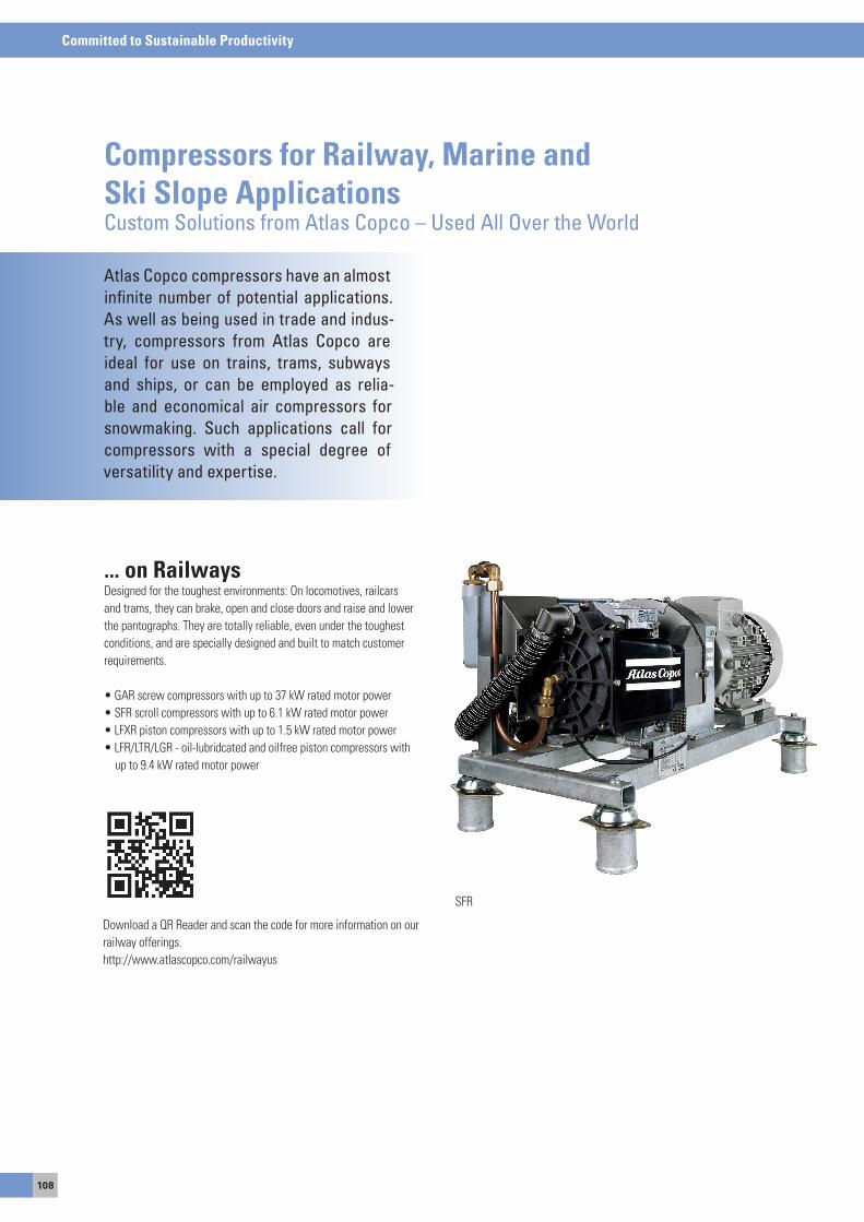
108
Committed to Sustainable Productivity
Atlas Copco compressors have an almost infinite number of potential applications. As well as being used in trade and indus-try, compressors from Atlas Copco are ideal for use on trains, trams, subways and ships, or can be employed as relia-ble and economical air compressors for snowmaking. Such applications call for compressors with a special degree of versatility and expertise.
Compressors for Railway, Marine and Ski Slope ApplicationsCustom Solutions from Atlas Copco – Used All Over the World
... on RailwaysDesigned for the toughest environments: on locomotives, railcars and trams, they can brake, open and close doors and raise and lower the pantographs. They are totally reliable, even under the toughest conditions, and are specially designed and built to match customer requirements.
• GAR screw compressors with up to 37 kW rated motor power• SFR scroll compressors with up to 6.1 kW rated motor power• LFXR piston compressors with up to 1.5 kW rated motor power• LFR/LTR/LGR - oil-lubridcated and oilfree piston compressors with up to 9.4 kW rated motor power
Download a QR Reader and scan the code for more information on our railway offerings.http://www.atlascopco.com/railwayus
sFR
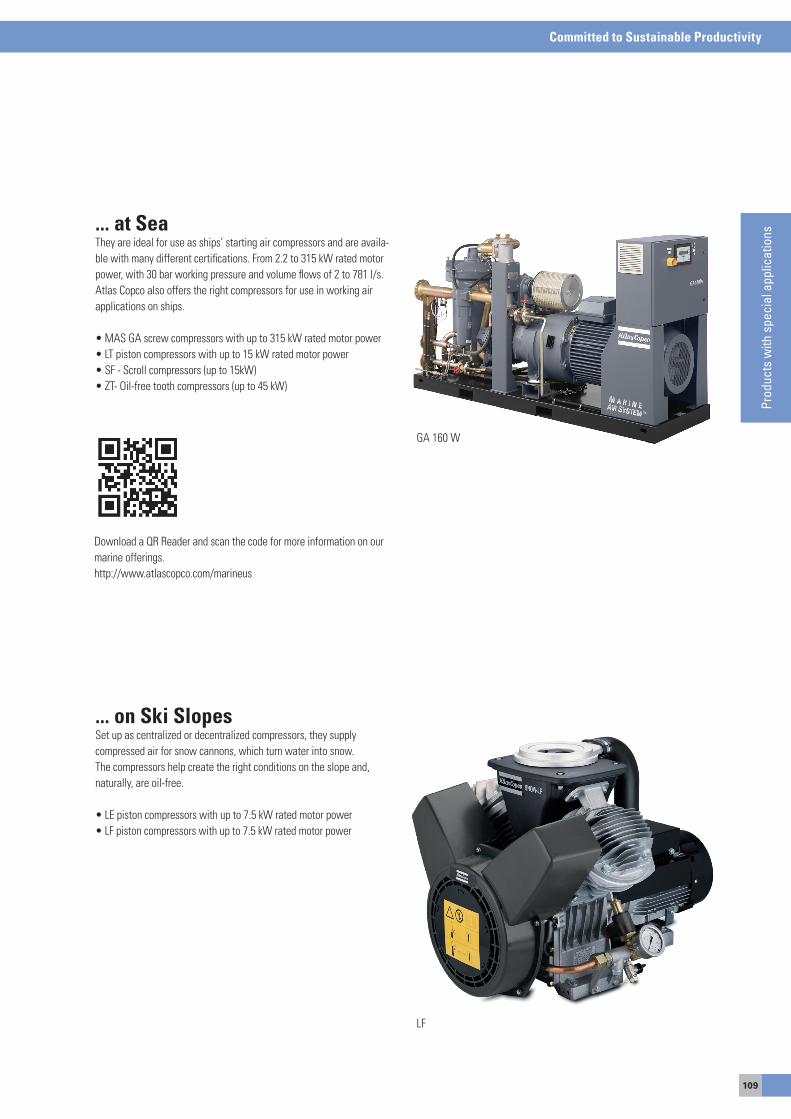
109
Committed to Sustainable Productivity
Med
ical
Equ
ipm
ent
... at SeaThey are ideal for use as ships’ starting air compressors and are availa-ble with many different certifications. From 2.2 to 315 kW rated motor power, with 30 bar working pressure and volume flows of 2 to 781 l/s. atlas Copco also offers the right compressors for use in working air applications on ships.
• MAS GA screw compressors with up to 315 kW rated motor power• LT piston compressors with up to 15 kW rated motor power• SF - Scroll compressors (up to 15kW)• ZT- Oil-free tooth compressors (up to 45 kW)
Download a QR Reader and scan the code for more information on our marine offerings.http://www.atlascopco.com/marineus
Ga 160 W
... on Ski Slopesset up as centralized or decentralized compressors, they supplycompressed air for snow cannons, which turn water into snow.The compressors help create the right conditions on the slope and, naturally, are oil-free.
• LE piston compressors with up to 7.5 kW rated motor power• LF piston compressors with up to 7.5 kW rated motor power
LF
Prod
ucts
with
spe
cial
app
licat
ions
110
Committed to Sustainable Productivity

Inhaltsverzeichnis
aIR aND GasTReaTMeNTTears of joy because of the low power consumption! We don't just offer refrigerant and desiccant dryers tailored to your needs - our compressed air processing systems are actually designed and constructed so thought-fully that they will reduce your utility bills in the coming years. Whether you work with a pressure dewpoint of 3°C or need air in which the residual moisture only condenses below −70°C.
Committed to Sustainable Productivity
112
Do you already know which compressoryou want, but you're just missing theappropriate processing systems? Adryer for example? On the following pa-ges you'll find a wide selection to suitevery requirement, partly adapted toour compressors, to make your wholesystem more efficient. This is particularlysensible if the refrigerant or desiccantdryer is directly integrated in thecompressor casing. This saves you timeand floor space, and you'll have lessinstallation expenditure.
Compressed air treatment
Intake air from the compressor always contains moisture. With the compression and subsequent cooling, the compressed air is always saturated to 100% with moisture. anyone who sends compressed air through a pipe network needs to protect against corrosion in order to prevent machine failures or production waste.
as a result, each compressed air system includes atleast one dryer and/or other processing components, such as filters or condensate separators. Different drying technologies are available: refrigerant dryers for simple applications and desiccant dryers for high to extremely high standards.
Refrigerant dryers are very reliable and economical. They work with built-in refrigerant compressors, which cool the air via heat exchangers, separate the resulting condensate and produce dry air with a pressure dewpoint of 3°C, so your systems are reliably protected from corrosion.
For industries, in which – for example – products have to be supplied or dried with compressed air, desiccant dryers are recommended and may even be indispensable. The air is not just cooled, the moisture is actively withdrawn via a desiccant, the so-called adsorption material. as soon as the desiccant is saturated, no more moisture can be withdrawn and it must be regenerated.
In order to guarantee a continuous air supply, rather than interrupting your manufacturing processes, desiccant dryers work with two con-tainers or atleast one container, which is separated into two sections.
The air is dried in one, and the dessicant is regenerated in the other. Desiccant dryers are available with pressure dewpoints of −20°C, −40°Cand even −70°C.This means the residual moisture of the processed air only condenses below the specified temperatures, such as, for example, below −70°C. This type of dry air is required in the production ofelectronic components, such as computer hard drives, etc.
obviously, these applications have a higher energy requirement than simple applications, and, just like compressors, this also applies to dryers: The biggest cost factor in the lifecycle is power, not the initial investment. But whatever your requirements, and whether you choose a refrigerant or desiccant dryer, we can assure you that all of our com-pressed air processing systems are so well designed and so efficient, that your utility bills will be less of an issue in the coming years.
Water is a problem for your compressed air system. It can corrode and freeze compressed air pipes and tools, disturb your production process, and contaminate products. Thus, it cansignificantly increase maintenance costs and reduceproductivity.
The drying process is the only way to remove almost all the moisture from the compressed air.
DRYING PROCESS
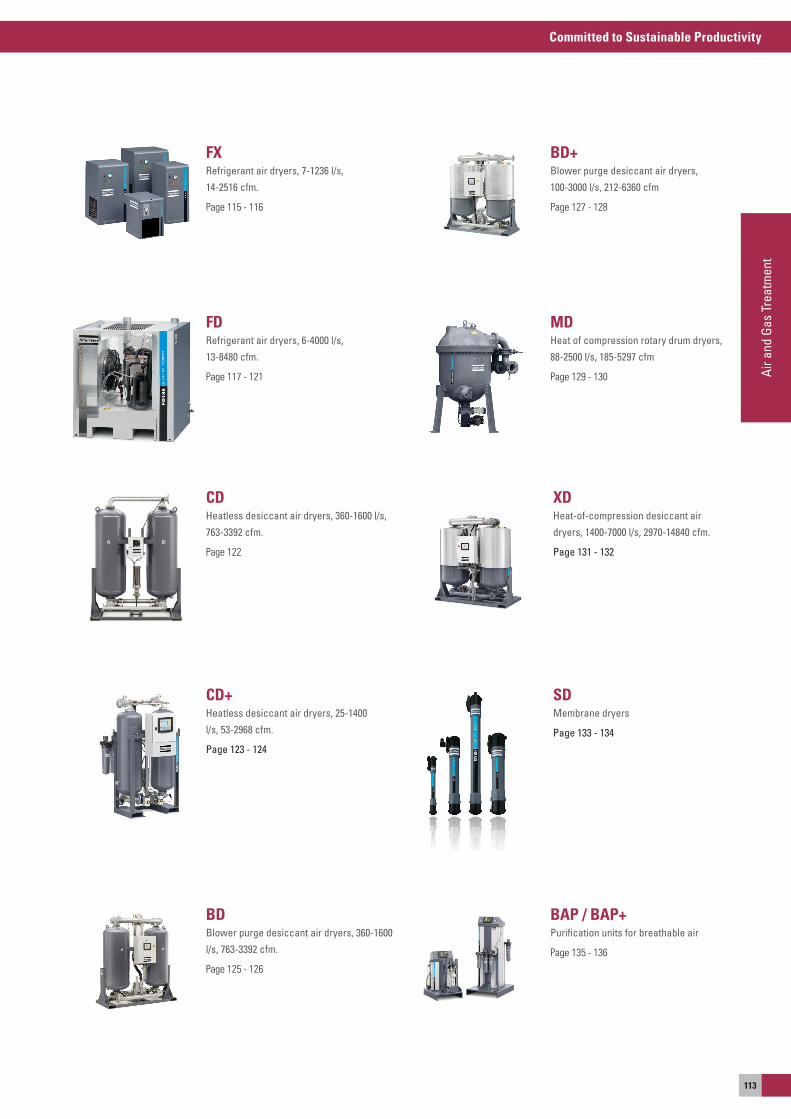
Committed to Sustainable Productivity
Air a
nd G
as T
reat
men
t
113
FXRefrigerant air dryers, 7-1236 l/s,
14-2516 cfm.
Page 115 - 116
BDBlower purge desiccant air dryers, 360-1600
l/s, 763-3392 cfm.
Page 125 - 126
BD+Blower purge desiccant air dryers,
100-3000 l/s, 212-6360 cfm
Page 127 - 128
FDRefrigerant air dryers, 6-4000 l/s,
13-8480 cfm.
Page 117 - 121
SDMembrane dryers
Page 133 - 134
CD+Heatless desiccant air dryers, 25-1400
l/s, 53-2968 cfm.
Page 123 - 124
MDHeat of compression rotary drum dryers,
88-2500 l/s, 185-5297 cfm
Page 129 - 130
CDHeatless desiccant air dryers, 360-1600 l/s,
763-3392 cfm.
Page 122
XDHeat-of-compression desiccant air
dryers, 1400-7000 l/s, 2970-14840 cfm.
Page 131 - 132
BAP / BAP+Purification units for breathable air
Page 135 - 136
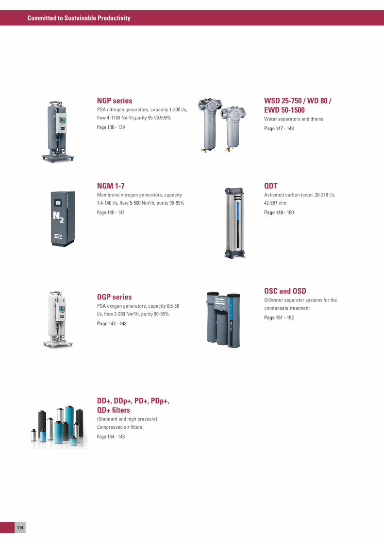
Committed to Sustainable Productivity
114
NGP seriesPSA nitrogen generators, capacity 1-300 l/s,
flow 4-1100 Nm³/h,purity 95-99.999%
Page 138 - 139
QDTActivated carbon tower, 20-310 l/s,
42-657 cfm
Page 149 - 150
OSC and OSDOil/water separator systems for the
condensate treatment
Page 151 - 152
OGP seriesPSA oxygen generators, capacity 0.6-56
l/s, flow 2-200 Nm³/h, purity 90-95%
Page 142 - 143
DD+, DDp+, PD+, PDp+, QD+ filters(Standard and high pressure)
Compressed air filters
Page 144 - 146
NGM 1-7Membrane nitrogen generators, capacity
1.4-140 l/s, flow 5-500 Nm³/h, purity 95-99%
Page 140 - 141
WSD 25-750 / WD 80 / EWD 50-1500Water separators and drains
Page 147 - 148
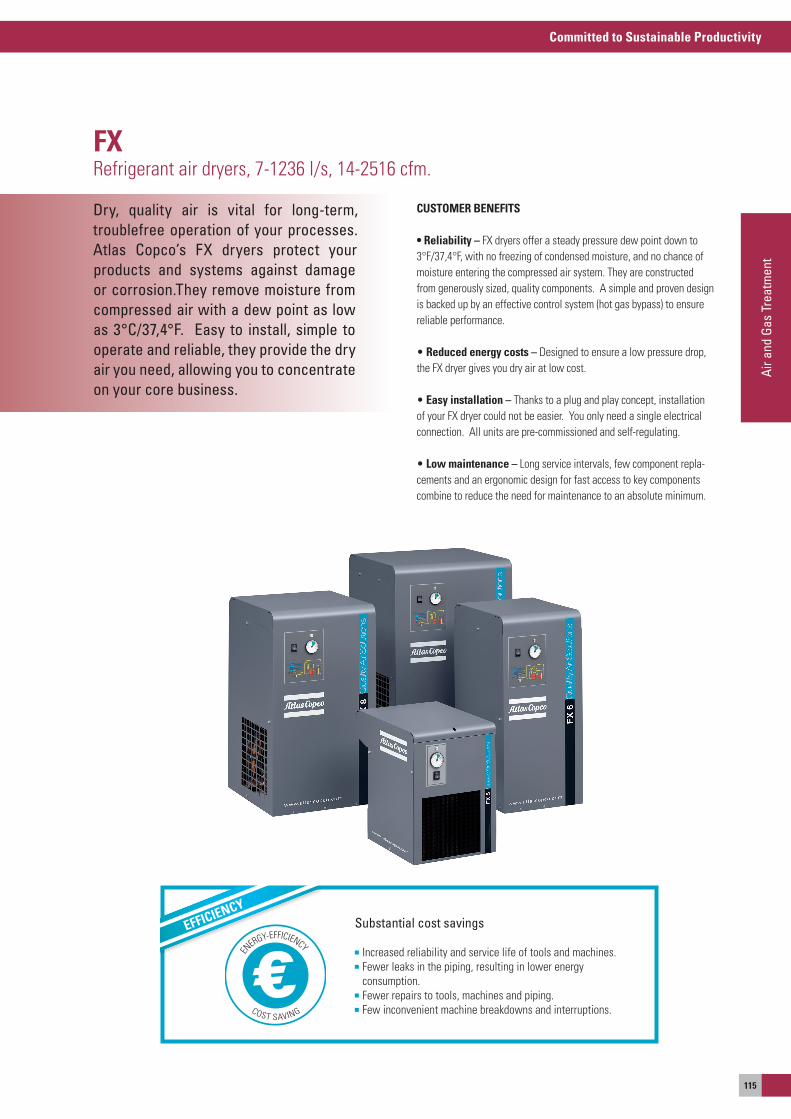
Committed to Sustainable Productivity
Air a
nd G
as T
reat
men
t
115
Dry, quality air is vital for long-term,troublefree operation of your processes. Atlas Copco’s FX dryers protect yourproducts and systems against damageor corrosion.They remove moisture fromcompressed air with a dew point as lowas 3°C/37,4°F. Easy to install, simple tooperate and reliable, they provide the dryair you need, allowing you to concentrate on your core business.
FXRefrigerant air dryers, 7-1236 l/s, 14-2516 cfm.
Substantial cost savings
Increased reliability and service life of tools and machines. Fewer leaks in the piping, resulting in lower energy
consumption. Fewer repairs to tools, machines and piping. Few inconvenient machine breakdowns and interruptions.
EFFICIENCY
EN
ERGY-EFFICIENCY
COST SAVING
CUSTOMER BENEFITS
• reliability – FX dryers offer a steady pressure dew point down to 3°F/37,4°F, with no freezing of condensed moisture, and no chance of moisture entering the compressed air system. They are constructed from generously sized, quality components. a simple and proven design is backed up by an effective control system (hot gas bypass) to ensure reliable performance.
• reduced energy costs – Designed to ensure a low pressure drop, the FX dryer gives you dry air at low cost.
• Easy installation – Thanks to a plug and play concept, installation of your FX dryer could not be easier. you only need a single electrical connection. all units are pre-commissioned and self-regulating.
• Low maintenance – Long service intervals, few component repla-cements and an ergonomic design for fast access to key components combine to reduce the need for maintenance to an absolute minimum.
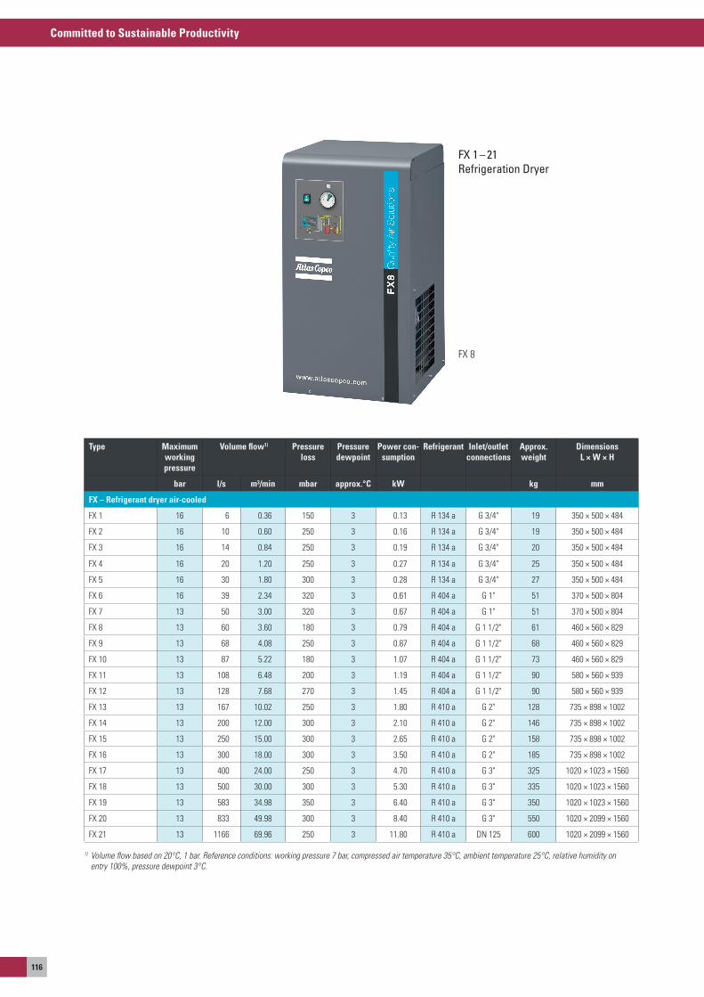
Committed to Sustainable Productivity
116
FX 1 – 21 Refrigeration Dryer
Type Maximum working pressure
Volume flow1) Pressure loss
Pressure dewpoint
Power con-sumption
Refrigerant Inlet/outlet connections
Approx. weight
Dimensions L × W × H
bar l/s m³/min mbar approx.°C kW kg mm
FX – refrigerant dryer air-cooled
FX 1 16 6 0.36 150 3 0.13 R 134 a G 3/4" 19 350 × 500 × 484
FX 2 16 10 0.60 250 3 0.16 R 134 a G 3/4" 19 350 × 500 × 484
FX 3 16 14 0.84 250 3 0.19 R 134 a G 3/4" 20 350 × 500 × 484
FX 4 16 20 1.20 250 3 0.27 R 134 a G 3/4" 25 350 × 500 × 484
FX 5 16 30 1.80 300 3 0.28 R 134 a G 3/4" 27 350 × 500 × 484
FX 6 16 39 2.34 320 3 0.61 R 404 a G 1" 51 370 × 500 × 804
FX 7 13 50 3.00 320 3 0.67 R 404 a G 1" 51 370 × 500 × 804
FX 8 13 60 3.60 180 3 0.79 R 404 a G 1 1/2" 61 460 × 560 × 829
FX 9 13 68 4.08 250 3 0.87 R 404 a G 1 1/2" 68 460 × 560 × 829
FX 10 13 87 5.22 180 3 1.07 R 404 a G 1 1/2" 73 460 × 560 × 829
FX 11 13 108 6.48 200 3 1.19 R 404 a G 1 1/2" 90 580 × 560 × 939
FX 12 13 128 7.68 270 3 1.45 R 404 a G 1 1/2" 90 580 × 560 × 939
FX 13 13 167 10.02 250 3 1.80 R 410 a G 2" 128 735 × 898 × 1002
FX 14 13 200 12.00 300 3 2.10 R 410 a G 2" 146 735 × 898 × 1002
FX 15 13 250 15.00 300 3 2.65 R 410 a G 2" 158 735 × 898 × 1002
FX 16 13 300 18.00 300 3 3.50 R 410 a G 2" 185 735 × 898 × 1002
FX 17 13 400 24.00 250 3 4.70 R 410 a G 3" 325 1020 × 1023 × 1560
FX 18 13 500 30.00 300 3 5.30 R 410 a G 3" 335 1020 × 1023 × 1560
FX 19 13 583 34.98 350 3 6.40 R 410 a G 3" 350 1020 × 1023 × 1560
FX 20 13 833 49.98 300 3 8.40 R 410 a G 3" 550 1020 × 2099 × 1560
FX 21 13 1166 69.96 250 3 11.80 R 410 a DN 125 600 1020 × 2099 × 1560
1) Volume flow based on 20°C, 1 bar. Reference conditions: working pressure 7 bar, compressed air temperature 35°C, ambient temperature 25°C, relative humidity on entry 100%, pressure dewpoint 3°C.
FX 8
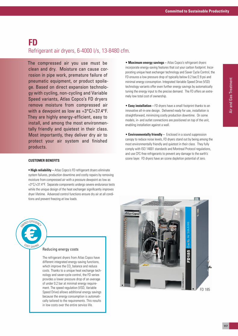
Committed to Sustainable Productivity
Air a
nd G
as T
reat
men
t
117
The compressed air you use must be clean and dry. Moisture can cause cor-rosion in pipe work, premature failure of pneumatic equipment, or product spoila-ge. Based on direct expansion technolo-gy with cycling, non-cycling and Variable Speed variants, Atlas Copco’s FD dryers remove moisture from compressed air with a dewpoint as low as +3°C/+37.4°F. They are highly energy-efficient, easy to install, and among the most environmen-tally friendly and quietest in their class. Most importantly, they deliver dry air toprotect your air system and finishedproducts.
FDRefrigerant air dryers, 6-4000 l/s, 13-8480 cfm.
CUSTOMER BENEFITS
• High reliability – atlas Copco’s FD refrigerant dryers eliminate system failures, production downtime and costly repairs by removing moisture from compressed air with a pressure dewpoint as low as +3°C/+37.4°F. separate components undergo severe endurance tests while the unique design of the heat exchanger significantly improves dryer lifetime. advanced control functions ensure dry air at all condi-tions and prevent freezing at low loads.
• Maximum energy savings – atlas Copco’s refrigerant dryers incorporate energy-saving features that cut your carbon footprint. Incor-porating unique heat exchanger technology and saver Cycle Control, the FD ensures a low pressure drop of typically below 0.2 bar/2.9 psi and minimal energy consumption. Integrated Variable speed Drive (VsD) technology variants offer even further energy savings by automatically tuning the energy input to the precise demand. The FD offers an extre-mely low total cost of ownership.
• Easy installation – FD dryers have a small footprint thanks to an innovative all-in-one design. Delivered ready for use, installation is straightforward, minimizing costly production downtime. on some models, in- and outlet connections are positioned on top of the unit, enabling installation against a wall.
• Environmentally friendly – enclosed in a sound suppression canopy to reduce noise levels, FD dryers stand out by being among the most environmentally friendly and quietest in their class. They fully comply with Iso 14001 standards and Montreal Protocol regulations, and use CFC-free refrigerants to prevent any damage to the earth’s ozone layer. FD dryers have an ozone depletion potential of zero.
Reducing energy costs
The refrigerant dryers from atlas Copco have different integrated energy-saving functions, which improve the Co2 balance and reduce costs. Thanks to a unique heat exchange tech-nology and saver-cycle control, the FD series provides a lower pressure drop of an average of under 0.2 bar at minimal energy require-ment. The speed regulation (VsD, Variable speed Drive) allows additional energy savings because the energy consumption is automati-cally tailored to the requirements. This results in low costs over the entire service life.
EN
ERGY-EFFICIENCY
COST SAVING
FD 185
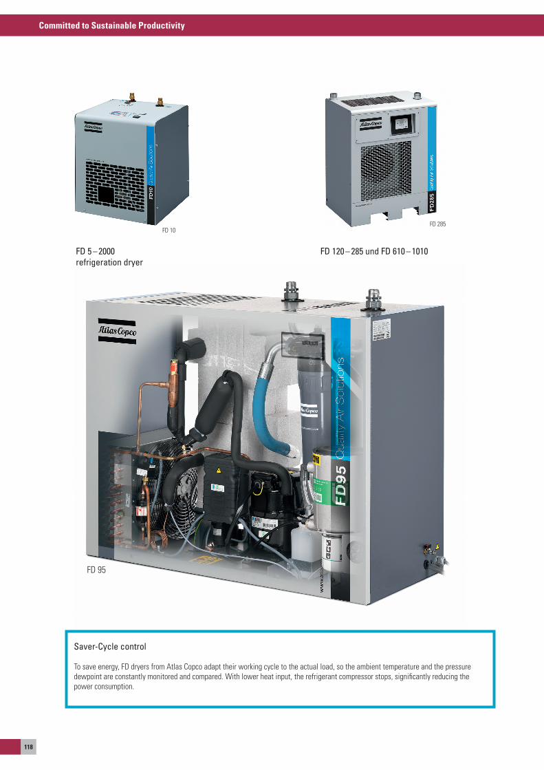
Committed to Sustainable Productivity
118
FD 285FD 10
FD 95
Saver-Cycle control
To save energy, FD dryers from atlas Copco adapt their working cycle to the actual load, so the ambient temperature and the pressure dewpoint are constantly monitored and compared. With lower heat input, the refrigerant compressor stops, significantly reducing the power consumption.
FD 120 – 285 und FD 610 – 1010FD 5 – 2000refrigeration dryer
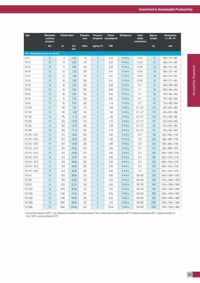
Committed to Sustainable Productivity
Air a
nd G
as T
reat
men
t
119
Type Maximum working pressure
Volume flow1) Pressure loss
Pressure dewpoint
Powerconsumption
Refrigerant Inlet/outlet
connections
Approx. weight
Dimensions L × W × H
bar l/s m³/min
mbar approx.°C kW kg mm
FD – refrigerant dryer, air-cooled
FD 5 16 6 0.36 70 3 0.20 R 134 a G 3/4" 27 496 × 377 × 461
FD 10 16 10 0.60 110 3 0.20 R 134 a G 3/4" 27 496 × 377 × 461
FD 15 16 15 0.90 120 3 0.33 R 134 a G 3/4" 32 496 × 377 × 461
FD 20 16 20 1.20 120 3 0.41 R 134 a G 3/4" 34 496 × 377 × 461
FD 25 16 25 1.50 170 3 0.41 R 134 a G 3/4" 34 496 × 377 × 461
FD 30 16 30 1.80 250 3 0.41 R 134 a G 3/4" 34 496 × 377 × 461
FD 40 16 40 2.40 200 3 0.48 R 134 a G 1" 57 688 × 389 × 604
FD 50 16 50 3.00 200 3 0.69 R 134 a G 1" 58 688 × 389 × 604
FD 60 13 60 3.60 220 3 0.63 R 134 a G 1" 80 726 × 482 × 804
FD 70 13 70 4.20 220 3 0.87 R 134 a G 1" 81 726 × 482 × 804
FD 95 13 95 5.70 220 3 1.18 R 134 a G 1" 87 726 × 482 × 804
FD 120 14 120 7.20 110 3 1.00 R 410 a G 1 1/2" 170 836 × 661 × 982
FD 150 14 150 9.00 150 3 1.00 R 410 a G 1 1/2" 170 836 × 661 × 982
FD 185 14 185 11.10 220 3 1.40 R 410 a G 2 1/2" 185 916 × 802 × 982
FD 220 14 220 13.20 120 3 1.70 R 410 a G 2 1/2" 197 916 × 802 × 982
FD 245 14 245 14.70 180 3 1.90 R 410 a G 2 1/2" 197 916 × 802 × 982
FD 285 14 285 17.10 220 3 2.10 R 410 a G 2 1/2" 197 916 × 802 × 982
FD 310 – 40°C 14 310 18.60 230 3 2.80 R 410 a G 3" 198 850 × 986 × 1190
FD 310 – 46°C 14 310 18.60 230 3 2.80 R 410 a G 3" 200 850 × 986 × 1190
FD 310 – 50°C 14 310 18.60 230 3 2.90 R 410 a G 3" 202 850 × 986 × 1190
FD 410 – 40°C 14 410 24.60 210 3 3.00 R 410 a G 3" 220 850 × 986 × 1375
FD 410 – 46°C 14 410 24.60 210 3 4.60 R 410 a G 3" 240 850 × 1250 × 1375
FD 410 – 50°C 14 410 24.60 210 3 4.80 R 410 a G 3" 290 850 × 1525 × 1375
FD 510 – 40°C 14 510 30.60 200 3 4.50 R 410 a G 3" 260 850 × 1250 × 1375
FD 510 – 46°C 14 510 30.60 200 3 6.40 R 410 a G 3" 310 850 × 1525 × 1375
FD 510 – 50°C 14 510 30.60 200 3 6.90 R 410 a G 3" 315 850 × 1525 × 1375
FD 610 14 610 36.60 170 3 4.80 R 410 a DN 100 320 1040 × 1060 × 1580
FD 760 14 760 45.60 170 3 5.30 R 410 a DN 100 380 1245 × 1060 × 1580
FD 870 14 870 52.20 150 3 6.60 R 410 a DN 150 400 1245 × 1060 × 1580
FD 1010 14 1010 60.60 170 3 7.40 R 410 a DN 150 460 1580 × 1060 × 1580
FD 1250 13 1250 75.00 240 3 8.30 R 404 a DN 150 860 1350 × 1640 × 1880
FD 1400 13 1400 84.00 240 3 8.50 R 404 a DN 200 940 1350 × 1640 × 1880
FD 1600 13 1600 96.00 130 3 13.6 R 404 a DN 200 1280 1350 × 1640 × 1880
FD 2000 13 2000 120.00 220 3 20.00 R 404 a DN 200 1345 1350 × 1640 × 1880
1) Volume flow based on 20°C, 1 bar. Reference conditions: working pressure 7 bar, compressed air temperature 35°C, ambient temperature 25°C, relative humidity on entry 100%, pressure dewpoint 3°C.

Committed to Sustainable Productivity
120
Type Maximum working pressure
Volume flow1) Pressure loss
Pressure dewpoint
Power con-sumption
Refrigerant Inlet/outlet connections
Approx. weight
Dimensions L × W × H
bar l/s m³/min mbar approx.°C kW kg mm
FD – refrigerant dryer, air-cooled, 20-bar versions
FD 5 – 20 20 7.3 0.44 40 3 0.20 R 134 a G 3/4" 27 496 × 377 × 461
FD 10 – 20 20 14.4 0.87 90 3 0.20 R 134 a G 3/4" 27 496 × 377 × 461
FD 15 – 20 20 21.8 1.31 100 3 0.33 R 134 a G 3/4" 32 496 × 377 × 461
FD 20 – 20 20 27.6 1.65 100 3 0.41 R 134 a G 3/4" 34 496 × 377 × 461
FD 25 – 20 20 34.8 2.09 140 3 0.70 R 134 a G 3/4" 34 496 × 377 × 461
FD 30 – 20 20 43.5 2.61 200 3 0.70 R 134 a G 1" 34 496 × 377 × 461
FD 40 – 20 20 58.0 3.48 160 3 0.70 R 134 a G 1" 57 688 × 389 × 604
FD 50 – 20 20 72.5 4.35 160 3 0.70 R 134 a G 1" 58 688 × 389 × 604
FD – refrigerant dryer, water-cooled
FD 310W 14 310 18.6 230 3 2.00 R 410 a G 3" 180 850 × 986 × 1190
FD 410W 14 410 24.6 210 3 2.40 R 410 a G 3" 240 850 × 1250 × 1375
FD 510W 14 510 30.6 200 3 4.10 R 410 a G 3" 260 850 × 1250 × 1375
FD 610W 14 610 36.6 170 3 3.10 R 410 a DN 100 350 1245 × 1060 × 1580
FD 760W 14 760 45.6 170 3 3.60 R 410 a DN 100 360 1245 × 1060 × 1580
FD 870W 14 870 52.2 150 3 4.50 R 410 a DN 150 370 1245 × 1060 × 1580
FD 1010W 14 1010 60.6 170 3 5.10 R 410 a DN 150 380 1245 × 1060 × 1580
FD 1250W 13 1250 75.0 240 3 8.30 R 404 a DN 150 860 1350 × 1640 × 1880
FD 1400W 13 1400 84.0 200 3 8.50 R 404 a DN 200 940 1350 × 1640 × 1880
FD 1600W 13 1600 96.0 200 3 13.60 R 404 a DN 200 1280 1350 × 1640 × 1880
FD 2000W 13 2000 120.0 250 3 20.00 R 404 a DN 200 1345 1350 × 1640 × 1880
1) Volume flow based on 20°C, 1 bar. Reference conditions: working pressure 7 bar, compressed air temperature 35°C, ambient temperature 25°C, relative humidity on entry 100%, pressure dewpoint 3°C.
FD Refrigerant air dryers, 6-4000 l/s, 13-8480 cfm
FD 4000 W VsD
Integrated speed regulation (VSD)
some FD refrigerant dryers have a built-in VsD control, which adapts the energy consumption to the actual used compressed air, significantly reducing energy consumption. Compared to conventional dryers, this saves up to 70%. The compressor runs with variable speeds to maintain a stable dewpoint. The speed of the refrigerant compressor is adapted to the inlet conditions, so less energy is needed for lower loads.
b
3
5
7
86
a94
1 Liquid separator2 Refrigerant compressor3 Condenser4 Refrigerant dryer/filter5 Control device6 air/refrigerant heat exchanger
7 Water separator8 air heat exchanger9 outlet for dried aira Inlet for moist airb elektronikon®
(control and regulating unit)
Functional diagram for the FD-VSD series
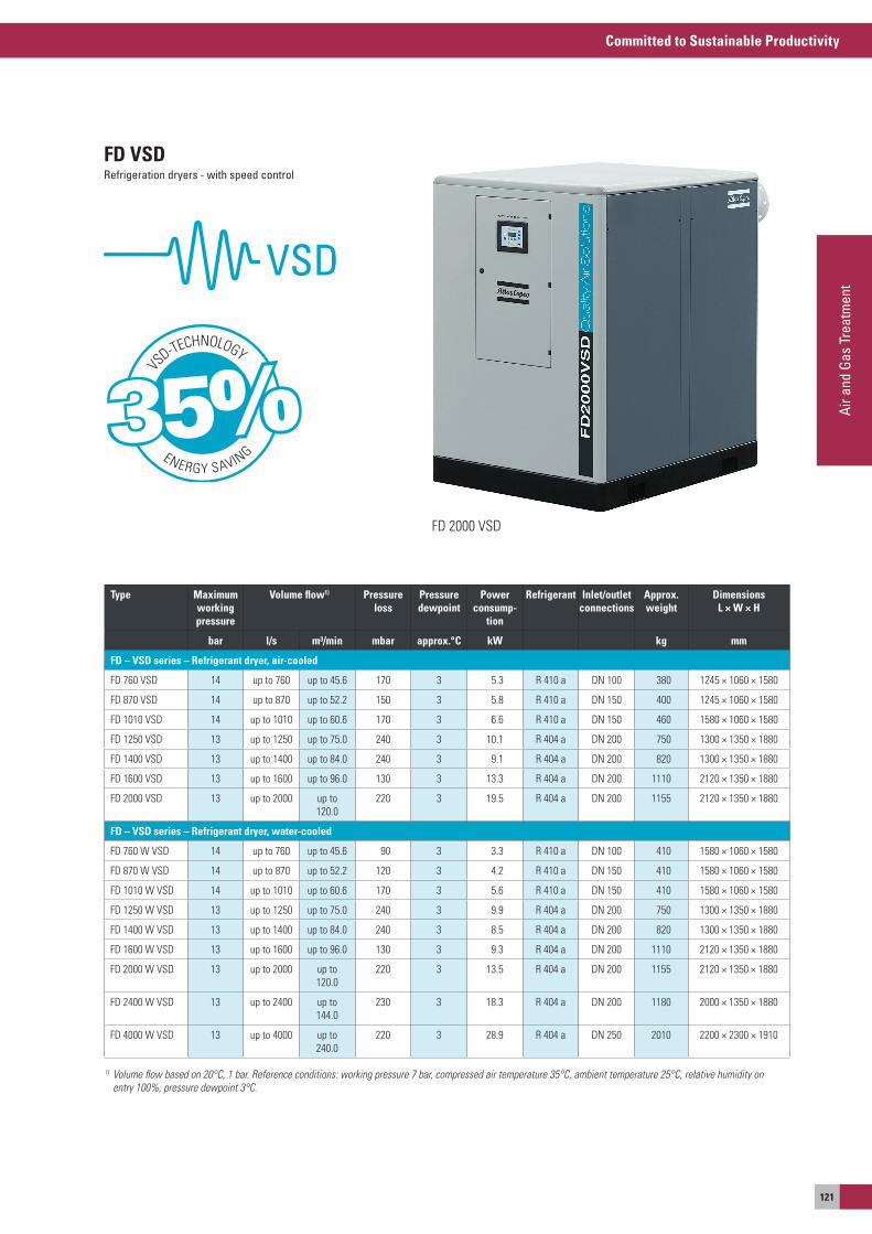
Committed to Sustainable Productivity
Air a
nd G
as T
reat
men
t
121
FD 2000 VsD
Type Maximum working pressure
Volume flow1) Pressure loss
Pressure dewpoint
Powerconsump-
tion
Refrigerant Inlet/outlet connections
Approx. weight
Dimensions L × W × H
bar l/s m³/min mbar approx.°C kW kg mm
FD – VSD series – refrigerant dryer, air-cooled
FD 760 VsD 14 up to 760 up to 45.6 170 3 5.3 R 410 a DN 100 380 1245 × 1060 × 1580
FD 870 VsD 14 up to 870 up to 52.2 150 3 5.8 R 410 a DN 150 400 1245 × 1060 × 1580
FD 1010 VsD 14 up to 1010 up to 60.6 170 3 6.6 R 410 a DN 150 460 1580 × 1060 × 1580
FD 1250 VsD 13 up to 1250 up to 75.0 240 3 10.1 R 404 a DN 200 750 1300 × 1350 × 1880
FD 1400 VsD 13 up to 1400 up to 84.0 240 3 9.1 R 404 a DN 200 820 1300 × 1350 × 1880
FD 1600 VsD 13 up to 1600 up to 96.0 130 3 13.3 R 404 a DN 200 1110 2120 × 1350 × 1880
FD 2000 VsD 13 up to 2000 up to 120.0
220 3 19.5 R 404 a DN 200 1155 2120 × 1350 × 1880
FD – VSD series – refrigerant dryer, water-cooled
FD 760 W VsD 14 up to 760 up to 45.6 90 3 3.3 R 410 a DN 100 410 1580 × 1060 × 1580
FD 870 W VsD 14 up to 870 up to 52.2 120 3 4.2 R 410 a DN 150 410 1580 × 1060 × 1580
FD 1010 W VsD 14 up to 1010 up to 60.6 170 3 5.6 R 410 a DN 150 410 1580 × 1060 × 1580
FD 1250 W VsD 13 up to 1250 up to 75.0 240 3 9.9 R 404 a DN 200 750 1300 × 1350 × 1880
FD 1400 W VsD 13 up to 1400 up to 84.0 240 3 8.5 R 404 a DN 200 820 1300 × 1350 × 1880
FD 1600 W VsD 13 up to 1600 up to 96.0 130 3 9.3 R 404 a DN 200 1110 2120 × 1350 × 1880
FD 2000 W VsD 13 up to 2000 up to 120.0
220 3 13.5 R 404 a DN 200 1155 2120 × 1350 × 1880
FD 2400 W VsD 13 up to 2400 up to 144.0
230 3 18.3 R 404 a DN 200 1180 2000 × 1350 × 1880
FD 4000 W VsD 13 up to 4000 up to 240.0
220 3 28.9 R 404 a DN 250 2010 2200 × 2300 × 1910
1) Volume flow based on 20°C, 1 bar. Reference conditions: working pressure 7 bar, compressed air temperature 35°C, ambient temperature 25°C, relative humidity on entry 100%, pressure dewpoint 3°C.
FD VSDRefrigeration dryers - with speed control
VS
D-TECHNOLOGY
ENERGY SAVING35%
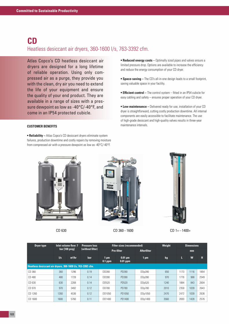
Committed to Sustainable Productivity
122
Atlas Copco’s CD heatless desiccant air dryers are designed for a long lifetime of reliable operation. Using only com-pressed air as a purge, they provide you with the clean, dry air you need to extend the life of your equipment and ensure the quality of your end product. They are available in a range of sizes with a pres-sure dewpoint as low as -40°C/-40°F, and come in an IP54 protected cubicle.
CDHeatless desiccant air dryers, 360-1600 l/s, 763-3392 cfm.
CUSTOMER BENEFITS
• reliability – atlas Copco’s CD desiccant dryers eliminate system failures, production downtime and costly repairs by removing moisture from compressed air with a pressure dewpoint as low as -40°C/-40°F.
• reduced energy costs – optimally sized pipes and valves ensure a limited pressure drop. options are available to increase the efficiency and reduce the energy consumption of your CD dryer.
• Space-saving – The CD’s all-in-one design leads to a small footprint, saving valuable space in your facility.
• Efficient control – The control system – fitted in an IP54 cubicle for easy cabling and safety – ensures proper operation of your CD dryer.
• Low maintenance – Delivered ready for use, installation of your CD dryer is straightforward, cutting costly production downtime. all internal components are easily accessible to facilitate maintenance. The use of high-grade desiccant and high-quality valves results in three-year maintenance intervals.
CD 360 – 1600CD 630 CD 1+ – 1400+
Dryer type Inlet volume flow: 7 bar [100 psig]
Pressure loss (without filter)
Filter sizes (recommended) Weight Dimensions
Pre-filter Afterfilter mm
l/s m³/hr bar 1 μm 0.1 ppm
0.01 μm 0.01 ppm
1 μm kg L W H
Heatless desiccant air dryers, 360-1600 l/s, 763-3392 cfm.
CD 360 360 1296 0.19 DD280 PD280 DDp280 650 1173 1116 1854
CD 480 480 1728 0.14 DD390 PD390 DDp390 970 1776 988 2549
CD 630 630 2268 0.14 DD520 PD520 DDp520 1240 1884 843 2604
CD 970 970 3492 0.12 DD780 PD780 DDp780 2010 2359 1039 2643
CD 1260 1260 4536 0.12 DD1050 PD1050 DDp1050 2470 2472 1039 2636
CD 1600 1600 5760 0.11 DD1400 PD1400 DDp1400 3560 2693 1428 2576
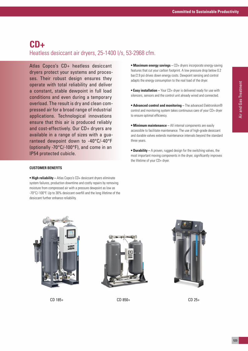
Committed to Sustainable Productivity
Air a
nd G
as T
reat
men
t
123
Atlas Copco’s CD+ heatless desiccant dryers protect your systems and proces-ses. Their robust design ensures they operate with total reliability and deliver a constant, stable dewpoint in full load conditions and even during a temporary overload. The result is dry and clean com-pressed air for a broad range of industrial applications. Technological innovations ensure that this air is produced reliably and cost-effectively. Our CD+ dryers are available in a range of sizes with a gua-ranteed dewpoint down to -40°C/-40°F (optionally -70°C/-100°F), and come in an IP54 protected cubicle.
CD+Heatless desiccant air dryers, 25-1400 l/s, 53-2968 cfm.
CUSTOMER BENEFITS
• High reliability – atlas Copco’s CD+ desiccant dryers eliminate system failures, production downtime and costly repairs by removing moisture from compressed air with a pressure dewpoint as low as -70°C/-100°F. Up to 30% desiccant overfill and the long lifetime of the desiccant further enhance reliability.
• Maximum energy savings – CD+ dryers incorporate energy-saving features that cut your carbon footprint. a low pressure drop below 0.2 bar/2.9 psi drives down energy costs. Dewpoint sensing and control adapts the energy consumption to the real load of the dryer.
• Easy installation – your CD+ dryer is delivered ready for use with silencers, sensors and the control unit already wired and connected.
• Advanced control and monitoring – The advanced elektronikon® control and monitoring system takes continuous care of your CD+ dryer to ensure optimal efficiency.
• Minimum maintenance – all internal components are easily accessible to facilitate maintenance. The use of high-grade desiccant and durable valves extends maintenance intervals beyond the standard three years.
• Durability – a proven, rugged design for the switching valves, the most important moving components in the dryer, significantly improves the lifetime of your CD+ dryer.
CD 185+ CD 850+ CD 25+
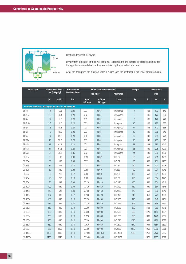
Committed to Sustainable Productivity
124
Heatless desiccant air dryers
Dry air from the outlet of the dryer container is released to the outside air pressure and guided through the saturated desiccant, where it takes up the adsorbed moisture.
after the desorption the blow-off valve is closed, and the container is put under pressure again.
Dry air
Moist air
Heatless desiccant air dryers, 25-1400 l/s, 53-2968 cfm.
CD 1+ 1 3.6 0.20 DD3 PD3 integrated 7 106 172 540
CD 1.5+ 1.5 5.4 0.20 DD3 PD3 integrated 8 106 172 590
CD 2+ 2 7.2 0.20 DD3 PD3 integrated 9 106 172 720
CD 2.5+ 2.5 9.0 0.20 DD3 PD3 integrated 10 106 172 835
CD 3+ 3 10.8 0.20 DD3 PD3 integrated 11 106 172 855
CD 5+ 5 18.0 0.20 DD3 PD3 integrated 19 149 295 640
CD 7+ 7 25.2 0.20 DD3 PD3 integrated 22 149 295 725
CD 10+ 10 36.0 0.20 DD3 PD3 integrated 25 149 295 875
CD 12+ 12 43.2 0.20 DD3 PD3 integrated 29 149 295 1015
CD 17+ 17 61.2 0.20 DD3 PD3 integrated 35 149 295 1270
CD 22+ 22 79.2 0.35 DD3 PD3 integrated 44 149 295 1505
CD 25 + 25 90 0.06 DD32 PD32 DDp32 50 550 201 1233
CD 30 + 30 108 0.09 DD32 PD32 DDp32 50 550 201 1233
CD 35 + 35 126 0.10 DD32 PD32 DDp32 60 550 201 1478
CD 50 + 50 180 0.32 DD60 PD60 DDp60 80 550 201 1846
CD 60 + 60 216 0.12 DD60 PD60 DDp60 100 550 364 1233
CD 70 + 70 252 0.16 DD60 PD60 DDp60 120 550 364 1479
CD 80 + 80 288 0.33 DD120 PD120 DDp120 160 550 364 1846
CD 100 + 100 360 0.35 DD120 PD120 DDp120 160 550 364 1846
CD 145 + 145 522 0.43 DD150 PD150 DDp150 240 550 526 1846
CD 110 + 107 385 0.12 DD120 PD120 DDp120 340 950 728 1695
CD 150 + 150 540 0.16 DD150 PD150 DDp150 415 1089 848 1731
CD 185 + 185 666 0.20 DD175 PD175 DDp175 445 1089 848 1731
CD 250 + 250 900 0.14 DD280 PD280 DDp280 600 1106 960 1816
CD 300 + 300 1080 0.19 DD280 PD280 DDp280 650 1173 1116 1854
CD 330 + 330 1188 0.10 DD390 PD390 DDp390 950 1088 1776 2537
CD 400 + 400 1440 0.10 DD390 PD390 DDp390 1030 1088 1776 2537
CD 550 + 550 1980 0.10 DD520 PD520 DDp520 1310 1091 1884 2592
CD 850 + 850 3060 0.10 DD780 PD780 DDp780 2120 1259 2359 2655
CD 1100 + 1100 3960 0.10 DD1050 PD1050 DDp1050 2600 1259 2472 2637
CD 1400 + 1400 5040 0.11 DD1400 PD1400 DDp1400 1428 2693 2576
Dryer type Inlet volume flow: 7 bar [100 psig]
Pressure loss (without filter)
Filter sizes (recommended) Weight Dimensions
Pre-filter Afterfilter mm
l/s m³/hr bar 1 μm 0.1 ppm
0.01 μm 0.01 ppm
1 μm kg L W H
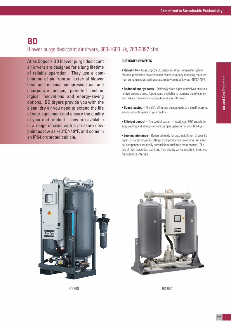
Committed to Sustainable Productivity
Air a
nd G
as T
reat
men
t
125
Atlas Copco’s BD blower purge desiccantair dryers are designed for a long lifetimeof reliable operation. They use a com-bination of air from an external blower,heat and minimal compressed air, andincorporate unique, patented techno-logical innovations and energy-saving options. BD dryers provide you with theclean, dry air you need to extend the lifeof your equipment and ensure the qualityof your end product. They are availablein a range of sizes with a pressure dew-point as low as -40°C/-40°F, and come in an IP54 protected cubicle.
BDBlower purge desiccant air dryers, 360-1600 l/s, 763-3392 cfm.
CUSTOMER BENEFITS
• reliability – atlas Copco’s BD desiccant dryers eliminate system failures, production downtime and costly repairs by removing moisture from compressed air with a pressure dewpoint as low as -40°C/-40°F.
• reduced energy costs – optimally sized pipes and valves ensure a limited pressure drop. options are available to increase the efficiency and reduce the energy consumption of your BD dryer.
• Space-saving – The BD’s all-in-one design leads to a small footprint, saving valuable space in your facility.
• Efficient control – The control system – fitted in an IP54 cubicle for easy cabling and safety – ensures proper operation of your BD dryer.
• Low maintenance – Delivered ready for use, installation of your BD dryer is straightforward, cutting costly production downtime. all inter-nal components are easily accessible to facilitate maintenance. The use of high-grade desiccant and high-quality valves results in three-year maintenance intervals.
BD 360 BD 970
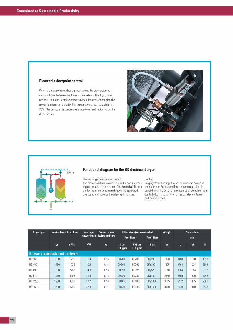
Committed to Sustainable Productivity
126
Electronic dewpoint control
When the dewpoint reaches a preset value, the dryer automati-cally switches between the towers. This extends the drying time and results in considerable power savings, instead of changing the tower functions periodically. The power savings can be as high as 70%. The dewpoint is continuously monitored and indicated on the dryer display.
Dryer type Inlet volume flow: 7 bar Average power input
Pressure loss (without filter)
Filter sizes (recommended) Weight Dimensions
Pre-filter Afterfilter mm
l/s m³/hr kW bar 1 μm 0.1 ppm
0.01 μm 0.01 ppm
1 μm kg L W H
Blower purge desiccant air dryersBD 360 360 1296 8.4 0.16 DD280 PD280 DDp280 1160 1100 1028 1829
BD 480 480 1728 10.4 0.16 DD390 PD390 DDp390 1275 1764 1024 2558
BD 630 630 2268 14.8 0.16 DD520 PD520 DDp520 1560 1884 1024 2612
BD 970 970 3492 21.8 0.16 DD780 PD780 DDp780 2540 2359 1175 2702
BD 1260 1260 4536 27.7 0.16 DD1050 PD1050 DDp1050 3035 2472 1175 2681
BD 1600 1600 5760 35.3 0.11 DD1400 PD1400 DDp1400 4100 2720 2199 2548
Functional diagram for the BD desiccant dryer
Blower purge desiccant air dryersThe blower sucks in ambient air and blows it across the external heating element. The heated air is then guided from top to bottom through the saturated desiccant and absorbs the adsorbed moisture.
CoolingPurging: after heating, the hot desiccant is cooled in the container. For the cooling, dry compressed air is passed from the outlet of the adsorption container from top to bottom through the hot reactivated container, and thus released.
Dry air
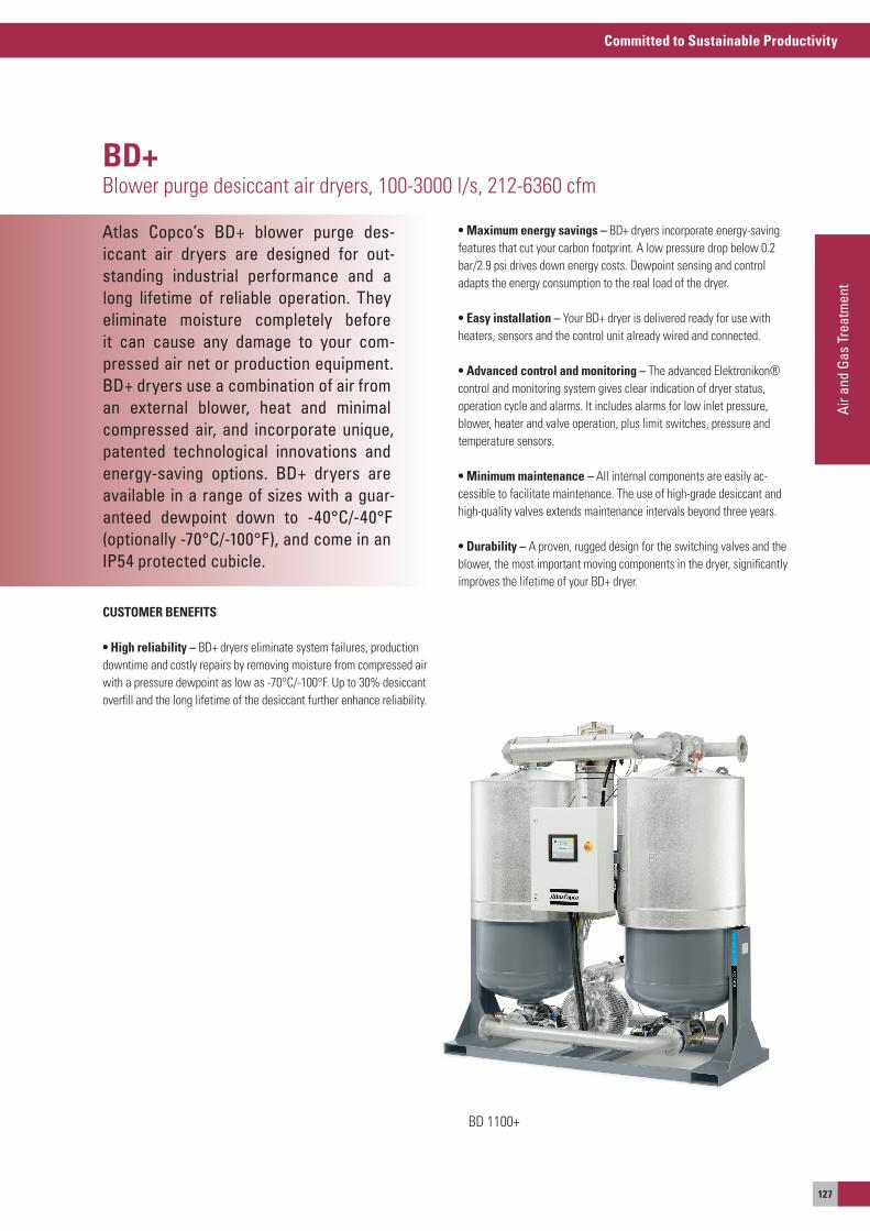
Committed to Sustainable Productivity
Air a
nd G
as T
reat
men
t
127
Atlas Copco’s BD+ blower purge des-iccant air dryers are designed for out-standing industrial performance and a long lifetime of reliable operation. They eliminate moisture completely before it can cause any damage to your com-pressed air net or production equipment.BD+ dryers use a combination of air from an external blower, heat and minimal compressed air, and incorporate unique, patented technological innovations and energy-saving options. BD+ dryers are available in a range of sizes with a guar-anteed dewpoint down to -40°C/-40°F (optionally -70°C/-100°F), and come in an IP54 protected cubicle.
BD+Blower purge desiccant air dryers, 100-3000 l/s, 212-6360 cfm
CUSTOMER BENEFITS
• High reliability – BD+ dryers eliminate system failures, production downtime and costly repairs by removing moisture from compressed air with a pressure dewpoint as low as -70°C/-100°F. Up to 30% desiccant overfill and the long lifetime of the desiccant further enhance reliability.
• Maximum energy savings – BD+ dryers incorporate energy-saving features that cut your carbon footprint. a low pressure drop below 0.2 bar/2.9 psi drives down energy costs. Dewpoint sensing and control adapts the energy consumption to the real load of the dryer.
• Easy installation – your BD+ dryer is delivered ready for use with heaters, sensors and the control unit already wired and connected.
• Advanced control and monitoring – The advanced elektronikon® control and monitoring system gives clear indication of dryer status, operation cycle and alarms. It includes alarms for low inlet pressure, blower, heater and valve operation, plus limit switches, pressure and temperature sensors.
• Minimum maintenance – all internal components are easily ac-cessible to facilitate maintenance. The use of high-grade desiccant and high-quality valves extends maintenance intervals beyond three years.
• Durability – a proven, rugged design for the switching valves and the blower, the most important moving components in the dryer, significantly improves the lifetime of your BD+ dryer.
BD 1100+
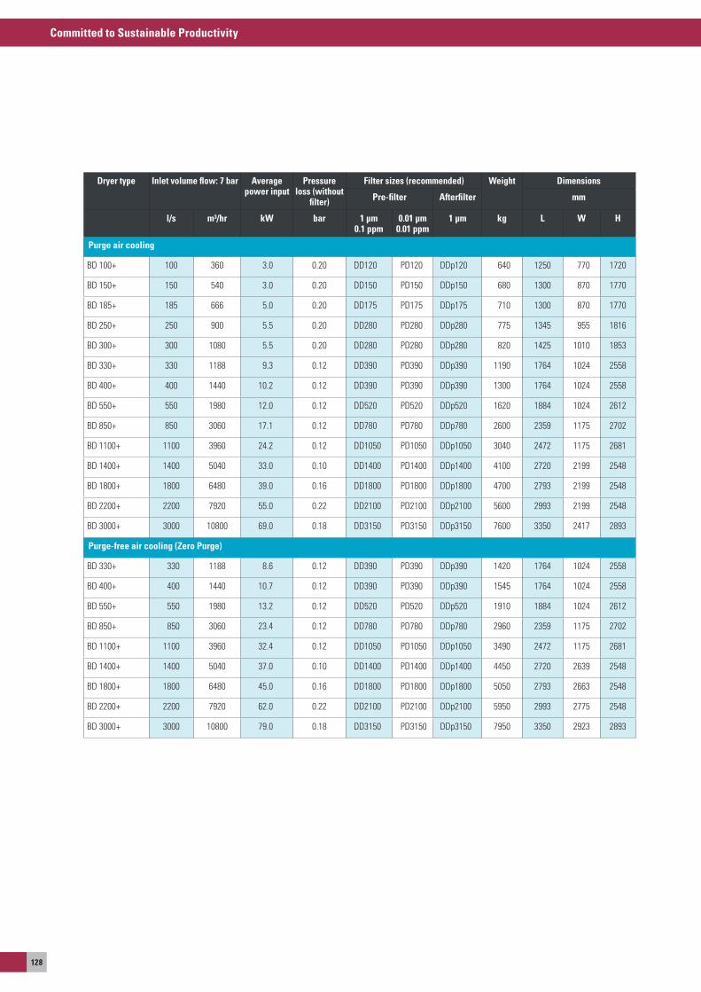
Committed to Sustainable Productivity
128
Dryer type Inlet volume flow: 7 bar Average power input
Pressure loss (without
filter)
Filter sizes (recommended) Weight Dimensions
Pre-filter Afterfilter mm
l/s m³/hr kW bar 1 μm 0.1 ppm
0.01 μm 0.01 ppm
1 μm kg L W H
Purge air cooling
BD 100 + 100 360 3.0 0.20 DD120 PD120 DDp120 640 1250 770 1720
BD 150 + 150 540 3.0 0.20 DD150 PD150 DDp150 680 1300 870 1770
BD 185 + 185 666 5.0 0.20 DD175 PD175 DDp175 710 1300 870 1770
BD 250 + 250 900 5.5 0.20 DD280 PD280 DDp280 775 1345 955 1816
BD 300 + 300 1080 5.5 0.20 DD280 PD280 DDp280 820 1425 1010 1853
BD 330 + 330 1188 9.3 0.12 DD390 PD390 DDp390 1190 1764 1024 2558
BD 400 + 400 1440 10.2 0.12 DD390 PD390 DDp390 1300 1764 1024 2558
BD 550 + 550 1980 12.0 0.12 DD520 PD520 DDp520 1620 1884 1024 2612
BD 850 + 850 3060 17.1 0.12 DD780 PD780 DDp780 2600 2359 1175 2702
BD 1100 + 1100 3960 24.2 0.12 DD1050 PD1050 DDp1050 3040 2472 1175 2681
BD 1400 + 1400 5040 33.0 0.10 DD1400 PD1400 DDp1400 4100 2720 2199 2548
BD 1800 + 1800 6480 39.0 0.16 DD1800 PD1800 DDp1800 4700 2793 2199 2548
BD 2200 + 2200 7920 55.0 0.22 DD2100 PD2100 DDp2100 5600 2993 2199 2548
BD 3000 + 3000 10800 69.0 0.18 DD3150 PD3150 DDp3150 7600 3350 2417 2893
Purge-free air cooling (Zero Purge)
BD 330 + 330 1188 8.6 0.12 DD390 PD390 DDp390 1420 1764 1024 2558
BD 400 + 400 1440 10.7 0.12 DD390 PD390 DDp390 1545 1764 1024 2558
BD 550 + 550 1980 13.2 0.12 DD520 PD520 DDp520 1910 1884 1024 2612
BD 850 + 850 3060 23.4 0.12 DD780 PD780 DDp780 2960 2359 1175 2702
BD 1100 + 1100 3960 32.4 0.12 DD1050 PD1050 DDp1050 3490 2472 1175 2681
BD 1400 + 1400 5040 37.0 0.10 DD1400 PD1400 DDp1400 4450 2720 2639 2548
BD 1800 + 1800 6480 45.0 0.16 DD1800 PD1800 DDp1800 5050 2793 2663 2548
BD 2200 + 2200 7920 62.0 0.22 DD2100 PD2100 DDp2100 5950 2993 2775 2548
BD 3000 + 3000 10800 79.0 0.18 DD3150 PD3150 DDp3150 7950 3350 2923 2893
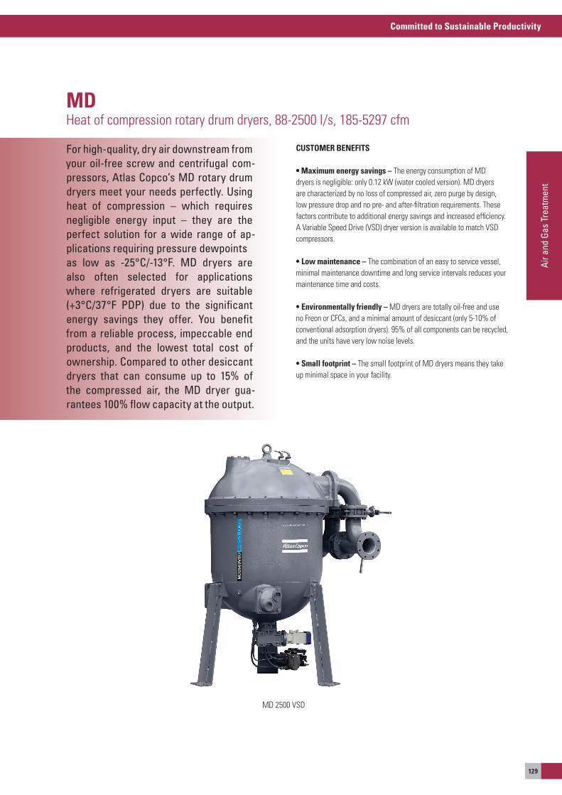
Committed to Sustainable Productivity
Air a
nd G
as T
reat
men
t
129
For high-quality, dry air downstream from your oil-free screw and centrifugal com-pressors, Atlas Copco’s MD rotary drum dryers meet your needs perfectly. Usingheat of compression – which requiresnegligible energy input – they are the perfect solution for a wide range of ap-plications requiring pressure dewpointsas low as -25°C/-13°F. MD dryers arealso often selected for applicationswhere refrigerated dryers are suitable (+3°C/37°F PDP) due to the significant energy savings they offer. You benefit from a reliable process, impeccable end products, and the lowest total cost of ownership. Compared to other desiccant dryers that can consume up to 15% of the compressed air, the MD dryer gua-rantees 100% flow capacity at the output.
MDHeat of compression rotary drum dryers, 88-2500 l/s, 185-5297 cfm
CUSTOMER BENEFITS
• Maximum energy savings – The energy consumption of MD dryers is negligible: only 0.12 kW (water cooled version). MD dryers are characterized by no loss of compressed air, zero purge by design, low pressure drop and no pre- and after-filtration requirements. These factors contribute to additional energy savings and increased efficiency. a Variable speed Drive (VsD) dryer version is available to match VsD compressors. • Low maintenance – The combination of an easy to service vessel, minimal maintenance downtime and long service intervals reduces your maintenance time and costs.
• Environmentally friendly – MD dryers are totally oil-free and use no Freon or CFCs, and a minimal amount of desiccant (only 5-10% of conventional adsorption dryers). 95% of all components can be recycled, and the units have very low noise levels.
• Small footprint – The small footprint of MD dryers means they take up minimal space in your facility.
MD 2500 VsD
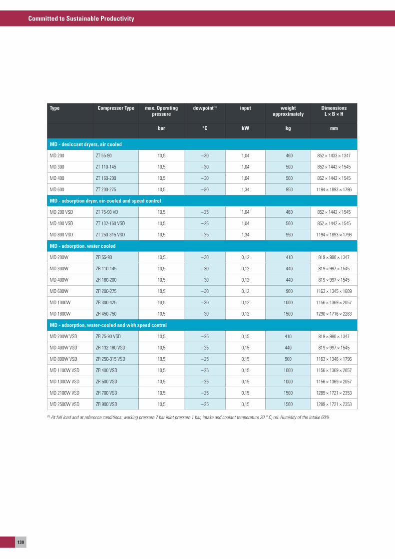
Committed to Sustainable Productivity
130
Type Compressor Type max. Operating pressure
dewpoint(1) input weightapproximately
Dimensions L × B × H
bar °C kW kg mm
MD - desiccant dryers, air cooled
MD 200 ZT 55-90 10,5 – 30 1,04 460 852 × 1433 × 1347
MD 300 ZT 110-145 10,5 – 30 1,04 500 852 × 1442 × 1545
MD 400 ZT 160-200 10,5 – 30 1,04 500 852 × 1442 × 1545
MD 600 ZT 200-275 10,5 – 30 1,34 950 1194 × 1893 × 1796
MD - adsorption dryer, air-cooled and speed control
MD 200 VsD ZT 75-90 VD 10,5 – 25 1,04 460 852 × 1442 × 1545
MD 400 VsD ZT 132-160 VsD 10,5 – 25 1,04 500 852 × 1442 × 1545
MD 800 VsD ZT 250-315 VsD 10,5 – 25 1,34 950 1194 × 1893 × 1796
MD - adsorption, water cooled
MD 200W ZR 55-90 10,5 – 30 0,12 410 819 × 990 × 1347
MD 300W ZR 110-145 10,5 – 30 0,12 440 819 × 997 × 1545
MD 400W ZR 160-200 10,5 – 30 0,12 440 819 × 997 × 1545
MD 600W ZR 200-275 10,5 – 30 0,12 900 1163 × 1345 × 1609
MD 1000W ZR 300-425 10,5 – 30 0,12 1000 1156 × 1369 × 2057
MD 1800W ZR 450-750 10,5 – 30 0,12 1500 1290 × 1716 × 2283
MD - adsorption, water-cooled and with speed control
MD 200W VsD ZR 75-90 VsD 10,5 – 25 0,15 410 819 × 990 × 1347
MD 400W VsD ZR 132-160 VsD 10,5 – 25 0,15 440 819 × 997 × 1545
MD 800W VsD ZR 250-315 VsD 10,5 – 25 0,15 900 1163 × 1346 × 1796
MD 1100W VsD ZR 400 VsD 10,5 – 25 0,15 1000 1156 × 1369 × 2057
MD 1300W VsD ZR 500 VsD 10,5 – 25 0,15 1000 1156 × 1369 × 2057
MD 2100W VsD ZR 700 VsD 10,5 – 25 0,15 1500 1289 × 1721 × 2353
MD 2500W VsD ZR 900 VsD 10,5 – 25 0,15 1500 1289 × 1721 × 2353
(1) At full load and at reference conditions: working pressure 7 bar inlet pressure 1 bar, intake and coolant temperature 20 ° C, rel. Humidity of the intake 60%
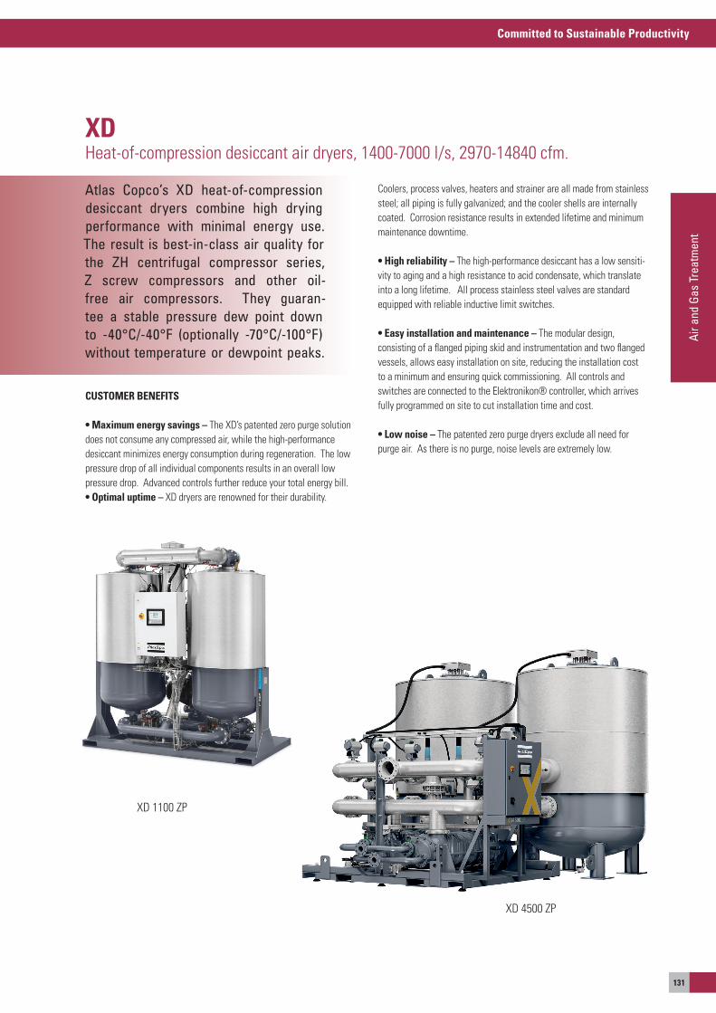
Committed to Sustainable Productivity
Air a
nd G
as T
reat
men
t
131
Atlas Copco’s XD heat-of-compression desiccant dryers combine high drying performance with minimal energy use. The result is best-in-class air quality forthe ZH centrifugal compressor series,Z screw compressors and other oil-free air compressors. They guaran-tee a stable pressure dew point down to -40°C/-40°F (optionally -70°C/-100°F) without temperature or dewpoint peaks.
XDHeat-of-compression desiccant air dryers, 1400-7000 l/s, 2970-14840 cfm.
CUSTOMER BENEFITS
• Maximum energy savings – The XD’s patented zero purge solution does not consume any compressed air, while the high-performance desiccant minimizes energy consumption during regeneration. The low pressure drop of all individual components results in an overall low pressure drop. advanced controls further reduce your total energy bill.• Optimal uptime – XD dryers are renowned for their durability.
Coolers, process valves, heaters and strainer are all made from stainless steel; all piping is fully galvanized; and the cooler shells are internally coated. Corrosion resistance results in extended lifetime and minimum maintenance downtime.
• High reliability – The high-performance desiccant has a low sensiti-vity to aging and a high resistance to acid condensate, which translate into a long lifetime. all process stainless steel valves are standard equipped with reliable inductive limit switches.
• Easy installation and maintenance – The modular design, consisting of a flanged piping skid and instrumentation and two flanged vessels, allows easy installation on site, reducing the installation cost to a minimum and ensuring quick commissioning. all controls and switches are connected to the elektronikon® controller, which arrives fully programmed on site to cut installation time and cost.
• Low noise – The patented zero purge dryers exclude all need for purge air. as there is no purge, noise levels are extremely low.
XD 4500 ZP
XD 1100 ZP
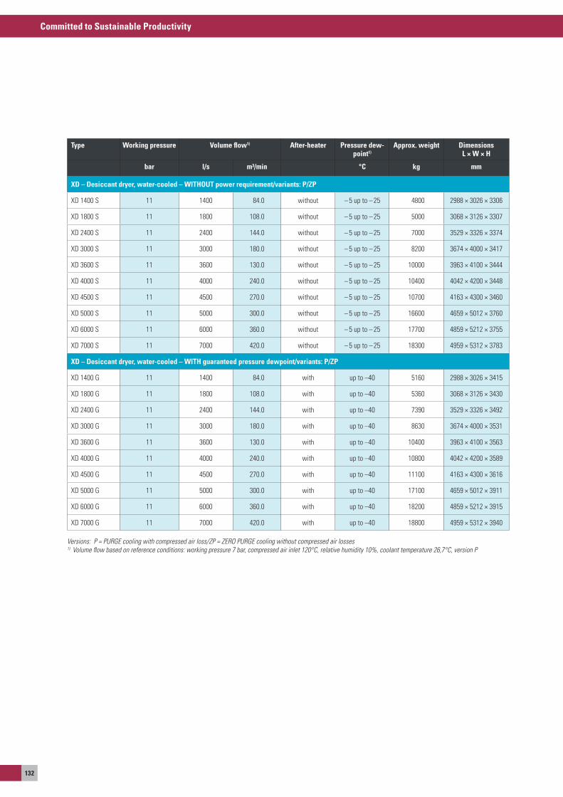
Committed to Sustainable Productivity
132
Type Working pressure Volume flow1) After-heater Pressure dew-point1)
Approx. weight DimensionsL × W × H
bar l/s m³/min °C kg mm
XD – Desiccant dryer, water-cooled – WiTHOuT power requirement/variants: P/ZP
XD 1400 s 11 1400 84.0 without – 5 up to – 25 4800 2988 × 3026 × 3306
XD 1800 s 11 1800 108.0 without – 5 up to – 25 5000 3068 × 3126 × 3307
XD 2400 s 11 2400 144.0 without – 5 up to – 25 7000 3529 × 3326 × 3374
XD 3000 s 11 3000 180.0 without – 5 up to – 25 8200 3674 × 4000 × 3417
XD 3600 s 11 3600 130.0 without – 5 up to – 25 10000 3963 × 4100 × 3444
XD 4000 s 11 4000 240.0 without – 5 up to – 25 10400 4042 × 4200 × 3448
XD 4500 s 11 4500 270.0 without – 5 up to – 25 10700 4163 × 4300 × 3460
XD 5000 s 11 5000 300.0 without – 5 up to – 25 16600 4659 × 5012 × 3760
XD 6000 s 11 6000 360.0 without – 5 up to – 25 17700 4859 × 5212 × 3755
XD 7000 s 11 7000 420.0 without – 5 up to – 25 18300 4959 × 5312 × 3783
XD – Desiccant dryer, water-cooled – WiTH guaranteed pressure dewpoint/variants: P/ZP
XD 1400 G 11 1400 84.0 with up to –40 5160 2988 × 3026 × 3415
XD 1800 G 11 1800 108.0 with up to –40 5360 3068 × 3126 × 3430
XD 2400 G 11 2400 144.0 with up to –40 7390 3529 × 3326 × 3492
XD 3000 G 11 3000 180.0 with up to –40 8630 3674 × 4000 × 3531
XD 3600 G 11 3600 130.0 with up to –40 10400 3963 × 4100 × 3563
XD 4000 G 11 4000 240.0 with up to –40 10800 4042 × 4200 × 3589
XD 4500 G 11 4500 270.0 with up to –40 11100 4163 × 4300 × 3616
XD 5000 G 11 5000 300.0 with up to –40 17100 4659 × 5012 × 3911
XD 6000 G 11 6000 360.0 with up to –40 18200 4859 × 5212 × 3915
XD 7000 G 11 7000 420.0 with up to –40 18800 4959 × 5312 × 3940
Versions: P = PURGE cooling with compressed air loss/ZP = ZERO PURGE cooling without compressed air losses1) Volume flow based on reference conditions: working pressure 7 bar, compressed air inlet 120°C, relative humidity 10%, coolant temperature 26,7°C, version P
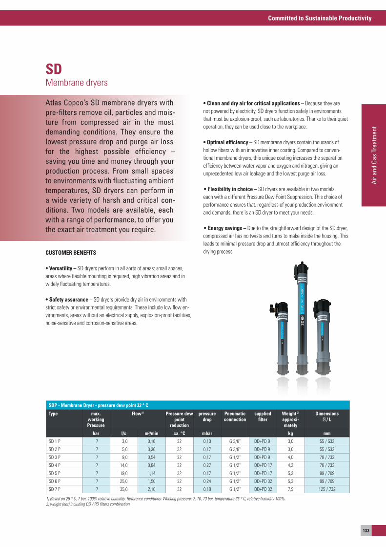
Committed to Sustainable Productivity
Air a
nd G
as T
reat
men
t
133
Atlas Copco’s SD membrane dryers with pre-filters remove oil, particles and mois-ture from compressed air in the most demanding conditions. They ensure the lowest pressure drop and purge air lossfor the highest possible efficiency –saving you time and money through your production process. From small spaces to environments with fluctuating ambient temperatures, SD dryers can perform in a wide variety of harsh and critical con-ditions. Two models are available, each with a range of performance, to offer you the exact air treatment you require.
SDMembrane dryers
CUSTOMER BENEFITS
• Versatility – sD dryers perform in all sorts of areas: small spaces, areas where flexible mounting is required, high vibration areas and in widely fluctuating temperatures.
• Safety assurance – sD dryers provide dry air in environments with strict safety or environmental requirements. These include low flow en-vironments, areas without an electrical supply, explosion-proof facilities, noise-sensitive and corrosion-sensitive areas.
• Clean and dry air for critical applications – Because they are not powered by electricity, sD dryers function safely in environments that must be explosion-proof, such as laboratories. Thanks to their quiet operation, they can be used close to the workplace.
• Optimal efficiency – sD membrane dryers contain thousands of hollow fibers with an innovative inner coating. Compared to conven-tional membrane dryers, this unique coating increases the separation efficiency between water vapor and oxygen and nitrogen, giving an unprecedented low air leakage and the lowest purge air loss.
• Flexibility in choice – sD dryers are available in two models, each with a different Pressure Dew Point suppression. This choice of performance ensures that, regardless of your production environment and demands, there is an sD dryer to meet your needs.
• Energy savings – Due to the straightforward design of the sD dryer, compressed air has no twists and turns to make inside the housing. This leads to minimal pressure drop and utmost efficiency throughout the drying process.
SDP - Membrane Dryer - pressure dew point 32 ° C
Type max. working Pressure
Flow1) Pressure dew point
reduction
pressuredrop
Pneumaticconnection
suppliedfilter
Weight 2)
approxi-mately
Dimensions∅ / L
bar l/s m³/min ca. °C mbar kg mm
sD 1 P 7 3,0 0,16 32 0,10 G 3/8" DD+PD 9 3,0 55 / 532
sD 2 P 7 5,0 0,30 32 0,17 G 3/8" DD+PD 9 3,0 55 / 532
sD 3 P 7 9,0 0,54 32 0,17 G 1/2" DD+PD 9 4,0 78 / 733
sD 4 P 7 14,0 0,84 32 0,27 G 1/2" DD+PD 17 4,2 78 / 733
sD 5 P 7 19,0 1,14 32 0,17 G 1/2" DD+PD 17 5,3 99 / 709
sD 6 P 7 25,0 1,50 32 0,24 G 1/2" DD+PD 32 5,3 99 / 709
sD 7 P 7 35,0 2,10 32 0,18 G 1/2" DD+PD 32 7,9 125 / 732
1) Based on 25 ° C, 1 bar, 100% relative humidity. Reference conditions: Working pressure: 7, 10, 13 bar, temperature 35 ° C, relative humidity 100%.2) weight (net) including DD / PD filters combination
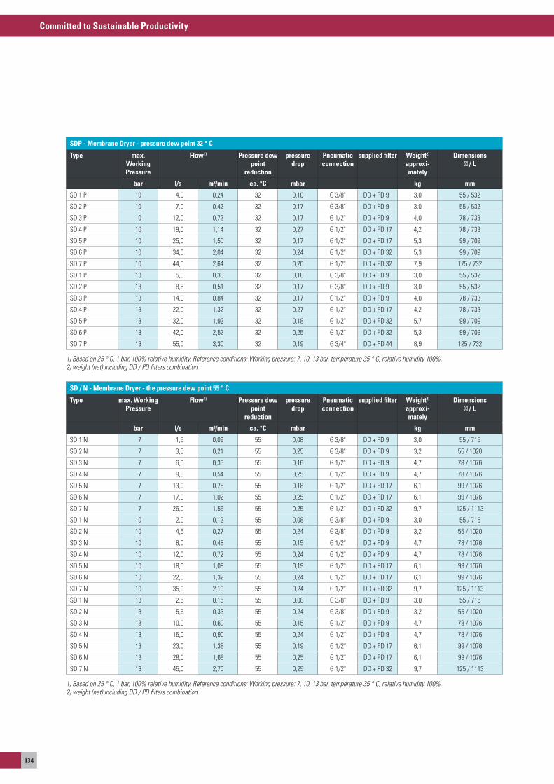
Committed to Sustainable Productivity
134
SDP - Membrane Dryer - pressure dew point 32 ° C
Type max. Working Pressure
Flow1) Pressure dew point
reduction
pressuredrop
Pneumaticconnection
supplied filter Weight2) approxi-mately
Dimensions ∅ / L
bar l/s m³/min ca. °C mbar kg mm
sD 1 P 10 4,0 0,24 32 0,10 G 3/8" DD + PD 9 3,0 55 / 532
sD 2 P 10 7,0 0,42 32 0,17 G 3/8" DD + PD 9 3,0 55 / 532
sD 3 P 10 12,0 0,72 32 0,17 G 1/2" DD + PD 9 4,0 78 / 733
sD 4 P 10 19,0 1,14 32 0,27 G 1/2" DD + PD 17 4,2 78 / 733
sD 5 P 10 25,0 1,50 32 0,17 G 1/2" DD + PD 17 5,3 99 / 709
sD 6 P 10 34,0 2,04 32 0,24 G 1/2" DD + PD 32 5,3 99 / 709
sD 7 P 10 44,0 2,64 32 0,20 G 1/2" DD + PD 32 7,9 125 / 732
sD 1 P 13 5,0 0,30 32 0,10 G 3/8" DD + PD 9 3,0 55 / 532
sD 2 P 13 8,5 0,51 32 0,17 G 3/8" DD + PD 9 3,0 55 / 532
sD 3 P 13 14,0 0,84 32 0,17 G 1/2" DD + PD 9 4,0 78 / 733
sD 4 P 13 22,0 1,32 32 0,27 G 1/2" DD + PD 17 4,2 78 / 733
sD 5 P 13 32,0 1,92 32 0,18 G 1/2" DD + PD 32 5,7 99 / 709
sD 6 P 13 42,0 2,52 32 0,25 G 1/2" DD + PD 32 5,3 99 / 709
sD 7 P 13 55,0 3,30 32 0,19 G 3/4" DD + PD 44 8,9 125 / 732
1) Based on 25 ° C, 1 bar, 100% relative humidity. Reference conditions: Working pressure: 7, 10, 13 bar, temperature 35 ° C, relative humidity 100%.2) weight (net) including DD / PD filters combination
SD / N - Membrane Dryer - the pressure dew point 55 ° C
Type max. Working Pressure
Flow1) Pressure dew point
reduction
pressuredrop
Pneumaticconnection
supplied filter Weight2) approxi-mately
Dimensions ∅ / L
bar l/s m³/min ca. °C mbar kg mm
sD 1 N 7 1,5 0,09 55 0,08 G 3/8" DD + PD 9 3,0 55 / 715
sD 2 N 7 3,5 0,21 55 0,25 G 3/8" DD + PD 9 3,2 55 / 1020
sD 3 N 7 6,0 0,36 55 0,16 G 1/2" DD + PD 9 4,7 78 / 1076
sD 4 N 7 9,0 0,54 55 0,25 G 1/2" DD + PD 9 4,7 78 / 1076
sD 5 N 7 13,0 0,78 55 0,18 G 1/2" DD + PD 17 6,1 99 / 1076
sD 6 N 7 17,0 1,02 55 0,25 G 1/2" DD + PD 17 6,1 99 / 1076
sD 7 N 7 26,0 1,56 55 0,25 G 1/2" DD + PD 32 9,7 125 / 1113
sD 1 N 10 2,0 0,12 55 0,08 G 3/8" DD + PD 9 3,0 55 / 715
sD 2 N 10 4,5 0,27 55 0,24 G 3/8" DD + PD 9 3,2 55 / 1020
sD 3 N 10 8,0 0,48 55 0,15 G 1/2" DD + PD 9 4,7 78 / 1076
sD 4 N 10 12,0 0,72 55 0,24 G 1/2" DD + PD 9 4,7 78 / 1076
sD 5 N 10 18,0 1,08 55 0,19 G 1/2" DD + PD 17 6,1 99 / 1076
sD 6 N 10 22,0 1,32 55 0,24 G 1/2" DD + PD 17 6,1 99 / 1076
sD 7 N 10 35,0 2,10 55 0,24 G 1/2" DD + PD 32 9,7 125 / 1113
sD 1 N 13 2,5 0,15 55 0,08 G 3/8" DD + PD 9 3,0 55 / 715
sD 2 N 13 5,5 0,33 55 0,24 G 3/8" DD + PD 9 3,2 55 / 1020
sD 3 N 13 10,0 0,60 55 0,15 G 1/2" DD + PD 9 4,7 78 / 1076
sD 4 N 13 15,0 0,90 55 0,24 G 1/2" DD + PD 9 4,7 78 / 1076
sD 5 N 13 23,0 1,38 55 0,19 G 1/2" DD + PD 17 6,1 99 / 1076
sD 6 N 13 28,0 1,68 55 0,25 G 1/2" DD + PD 17 6,1 99 / 1076
sD 7 N 13 45,0 2,70 55 0,25 G 1/2" DD + PD 32 9,7 125 / 1113
1) Based on 25 ° C, 1 bar, 100% relative humidity. Reference conditions: Working pressure: 7, 10, 13 bar, temperature 35 ° C, relative humidity 100%.2) weight (net) including DD / PD filters combination
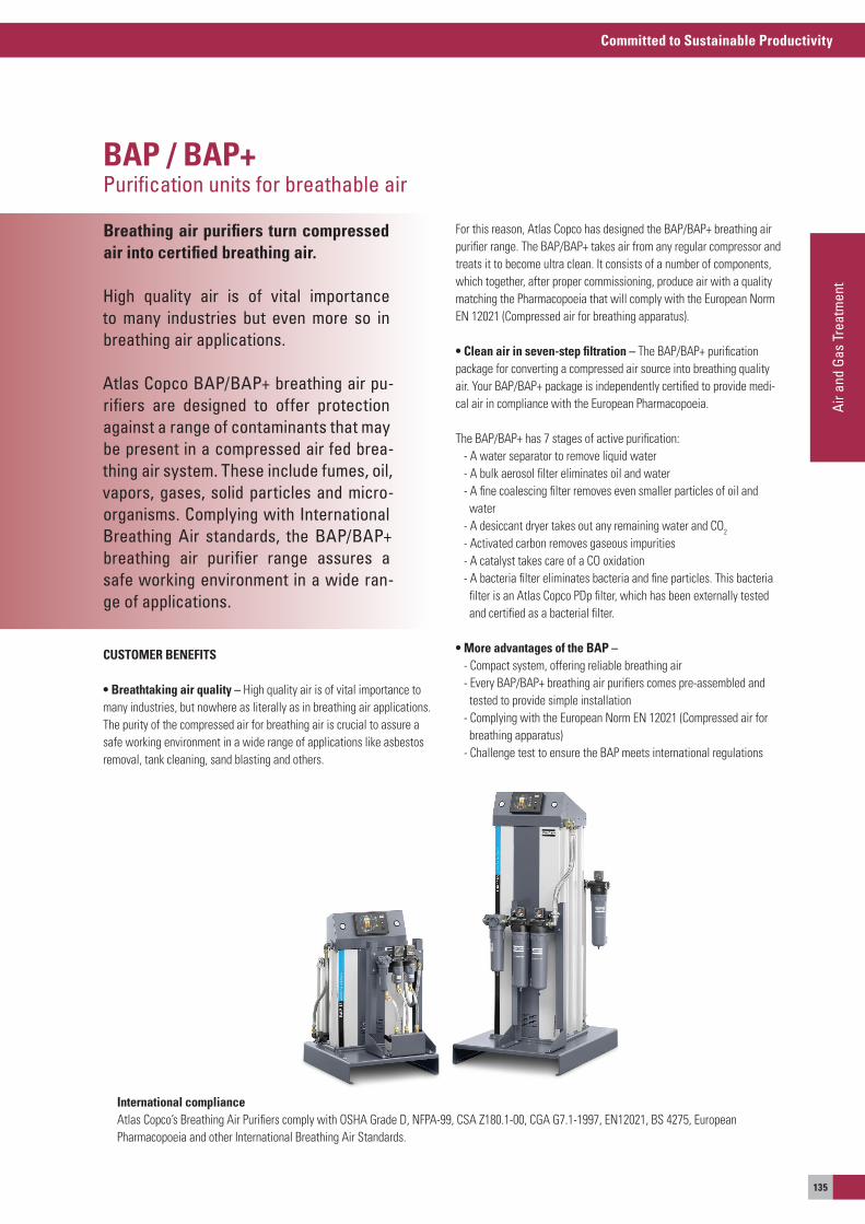
Committed to Sustainable Productivity
Air a
nd G
as T
reat
men
t
135
Breathing air purifiers turn compressed air into certified breathing air.
High quality air is of vital importance to many industries but even more so in breathing air applications.
Atlas Copco BAP/BAP+ breathing air pu-rifiers are designed to offer protection against a range of contaminants that may be present in a compressed air fed brea-thing air system. These include fumes, oil, vapors, gases, solid particles and micro-organisms. Complying with International Breathing Air standards, the BAP/BAP+ breathing air purifier range assures a safe working environment in a wide ran-ge of applications.
BAP / BAP+Purification units for breathable air
CUSTOMER BENEFITS
• Breathtaking air quality – High quality air is of vital importance to many industries, but nowhere as literally as in breathing air applications. The purity of the compressed air for breathing air is crucial to assure a safe working environment in a wide range of applications like asbestos removal, tank cleaning, sand blasting and others.
For this reason, atlas Copco has designed the BaP/BaP+ breathing air purifier range. The BaP/BaP+ takes air from any regular compressor and treats it to become ultra clean. It consists of a number of components, which together, after proper commissioning, produce air with a quality matching the Pharmacopoeia that will comply with the european Norm eN 12021 (Compressed air for breathing apparatus).
• Clean air in seven-step filtration – The BaP/BaP+ purificationpackage for converting a compressed air source into breathing quality air. your BaP/BaP+ package is independently certified to provide medi-cal air in compliance with the european Pharmacopoeia.
The BaP/BaP+ has 7 stages of active purification: - a water separator to remove liquid water - a bulk aerosol filter eliminates oil and water - a fine coalescing filter removes even smaller particles of oil and water - a desiccant dryer takes out any remaining water and Co2
- activated carbon removes gaseous impurities - a catalyst takes care of a Co oxidation - a bacteria filter eliminates bacteria and fine particles. This bacteria filter is an atlas Copco PDp filter, which has been externally tested and certified as a bacterial filter.
• More advantages of the BAP – - Compact system, offering reliable breathing air - every BaP/BaP+ breathing air purifiers comes pre-assembled and tested to provide simple installation - Complying with the european Norm eN 12021 (Compressed air for breathing apparatus) - Challenge test to ensure the BaP meets international regulations
International complianceatlas Copco’s Breathing air Purifiers comply with osHa Grade D, NFPa-99, Csa Z180.1-00, CGa G7.1-1997, eN12021, Bs 4275, europeanPharmacopoeia and other International Breathing air standards.
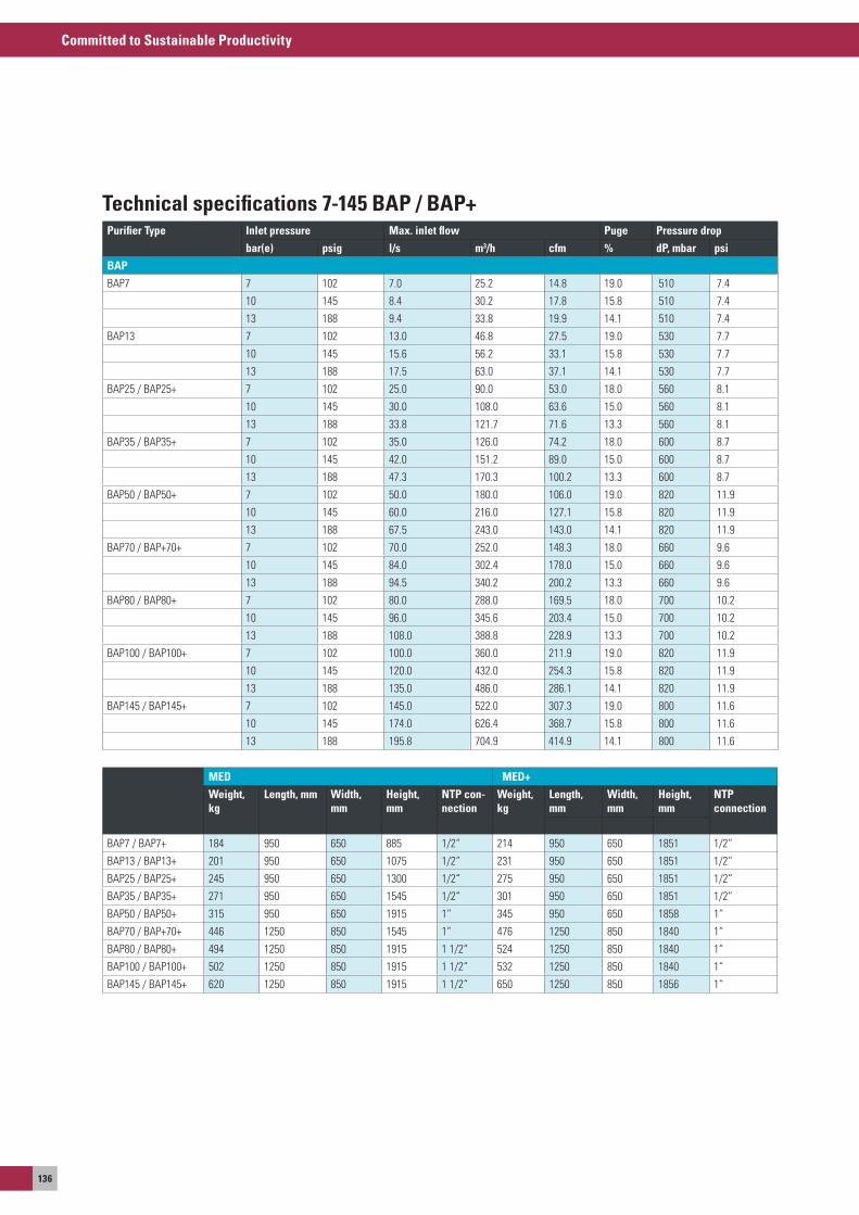
Committed to Sustainable Productivity
136
Purifier Type Inlet pressure Max. inlet flow Puge Pressure drop
bar(e) psig l/s m3/h cfm % dP, mbar psi
BAP
BaP7 7 102 7.0 25.2 14.8 19.0 510 7.4
10 145 8.4 30.2 17.8 15.8 510 7.4
13 188 9.4 33.8 19.9 14.1 510 7.4
BaP13 7 102 13.0 46.8 27.5 19.0 530 7.7
10 145 15.6 56.2 33.1 15.8 530 7.7
13 188 17.5 63.0 37.1 14.1 530 7.7
BaP25 / BaP25+ 7 102 25.0 90.0 53.0 18.0 560 8.1
10 145 30.0 108.0 63.6 15.0 560 8.1
13 188 33.8 121.7 71.6 13.3 560 8.1
BaP35 / BaP35+ 7 102 35.0 126.0 74.2 18.0 600 8.7
10 145 42.0 151.2 89.0 15.0 600 8.7
13 188 47.3 170.3 100.2 13.3 600 8.7
BaP50 / BaP50+ 7 102 50.0 180.0 106.0 19.0 820 11.9
10 145 60.0 216.0 127.1 15.8 820 11.9
13 188 67.5 243.0 143.0 14.1 820 11.9
BaP70 / BaP+70+ 7 102 70.0 252.0 148.3 18.0 660 9.6
10 145 84.0 302.4 178.0 15.0 660 9.6
13 188 94.5 340.2 200.2 13.3 660 9.6
BaP80 / BaP80+ 7 102 80.0 288.0 169.5 18.0 700 10.2
10 145 96.0 345.6 203.4 15.0 700 10.2
13 188 108.0 388.8 228.9 13.3 700 10.2
BaP100 / BaP100+ 7 102 100.0 360.0 211.9 19.0 820 11.9
10 145 120.0 432.0 254.3 15.8 820 11.9
13 188 135.0 486.0 286.1 14.1 820 11.9
BaP145 / BaP145+ 7 102 145.0 522.0 307.3 19.0 800 11.6
10 145 174.0 626.4 368.7 15.8 800 11.6
13 188 195.8 704.9 414.9 14.1 800 11.6
MED MED+
Weight, kg
Length, mm Width, mm
Height, mm
NTP con-nection
Weight, kg
Length, mm
Width, mm
Height, mm
NTPconnection
BaP7 / BaP7+ 184 950 650 885 1/2“ 214 950 650 1851 1/2“
BaP13 / BaP13+ 201 950 650 1075 1/2“ 231 950 650 1851 1/2“
BaP25 / BaP25+ 245 950 650 1300 1/2“ 275 950 650 1851 1/2“
BaP35 / BaP35+ 271 950 650 1545 1/2“ 301 950 650 1851 1/2“
BaP50 / BaP50+ 315 950 650 1915 1“ 345 950 650 1858 1“
BaP70 / BaP+70+ 446 1250 850 1545 1“ 476 1250 850 1840 1“
BaP80 / BaP80+ 494 1250 850 1915 1 1/2“ 524 1250 850 1840 1“
BaP100 / BaP100+ 502 1250 850 1915 1 1/2“ 532 1250 850 1840 1“
BaP145 / BaP145+ 620 1250 850 1915 1 1/2“ 650 1250 850 1856 1“
Technical specifications 7-145 BAP / BAP+
Committed to Sustainable Productivity
Air a
nd G
as T
reat
men
t
137
Could the finest oil drops or mois-ture or the smallest dust grain af-fect your manufac-turing processes?Or even affect the quality of your pro-ducts; in the worst case scenario,destroying your products or rende-ring them useless? Then you need to process the compressed air accor-dingly. Suitable dust filters, activa-ted carbon absorbers, condensatedrains, oil-water separators, and even thecomponents of an efficient pipingnetwork – you'll find them all onthe following pages.
Compressed air purificationsomething else you should consider
your compressed air system will include diverse processing components; particularly if you produce your compressed air with oil-lubricated or oil-injected compressors. But even if you are using oil-free compressors, you may need filters, a modern piping system or other accessories. The following pages present a variety of solu-tions for the most varied requirements.
our dust, fine, ultra-fine and activated carbon filters eliminate even the smallest foreign particles or aerosols. you no longer need to worry about impurities when you pass your compressed air through these processing components, as we can effectively and safely sepa-rate out dust particles up to 0.01 µm in diameter and oil carry-over up to 0.003 mg/m3 of air.
you can use our oil-water separators to process your condensate from oil-injected compressors, because this condensate always structurally contains a proportion of oil, which you must remove before you can guide water into the public sewage network. you'll also save disposal costs. you should install oil-water separators when you order a compressor.
To remove the condensate itself from the compressed air network, we provide reliable condensate drains – with electronic measuring of the level in the reservoir and automatic discharge.
you'll find a very special "separation technology" in our nitrogen gen-erators: these units retain the oxygen from the (compressed) air us-ing a carbon molecular sieve, producing nitrogen with purity levels of up to 99.999%. The machines pay for themselves quickly compared to the widespread way of working with hired bottle bundles.
at the end of this chapter you'll find information about our aIRnet™-piping system; there is no easier, quicker or more flexible way of installing a piping network! as all the components are reusable, you'll save a lot of money if you only have to change the piping once for new operating conditions.
No more throwing out bent (steel) pipe pieces, as you can now easily plug together connectors, outlets and pipe pieces. The system permanently maintains the compressed air in your network, works without losses, and prevents leakages - reducing your energy costs.

Committed to Sustainable Productivity
138
Atlas Copco’s NGP nitrogen generation systems provide a cost-effective, reli-able and secure supply of nitrogen. The nitrogen generator’s working principle is based on Pressure Swing Adsorption technology, which entails carbon mo-lecular sieves that selectively separate oxygen from nitrogen. The NGP nitrogen generator is perfect for applications such as food and beverage, metal processing, electronics, etc.
NGP seriesPsa nitrogen generators, capacity 1-300 l/s, flow 4-1100 Nm³/h purity 95-99.999%
CUSTOMER BENEFITS
• Cost savings – our NGP systems are characterized by low operating expenses, operating expenses, and the absence of additional costs such as order processing, refills and delivery charges. Maintenance costs are kept to a minimum too.
• Convenience – NGP systems are continuously available, 24/7, to eliminate the risk of a production breakdown due to gas running out.
• High purity – We guarantee the nitrogen supply according to your needs, from 95 to 99.999% nitrogen purity.
• Plug-and-play – The NGP is delivered ready to use, you only need a supply of dry compressed air.
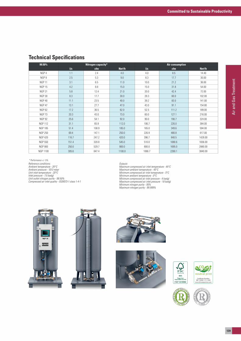
Committed to Sustainable Productivity
Air a
nd G
as T
reat
men
t
139
Certi�cate Number887-10506-1111-1028
www.climatepartner.com
99.50% Nitrogen capacity* Air consumptionl/s cfm Nm³/h l/s cfm Nm³/h
NGP 4 1.1 2.4 4.0 4.0 8.5 14.40
NGP 9 2.5 5.3 9.0 8.3 17.7 30.00
NGP 11 3.1 6.5 11.0 10.0 21.2 36.00
NGP 15 4.2 8.8 15.0 15.0 31.8 54.00
NGP 21 5.8 12.4 21.0 20.0 42.4 72.00
NGP 30 8.3 17.7 30.0 28.3 60.0 102.00
NGP 40 11.1 23.5 40.0 39.2 83.0 141.00
NGP 47 13.1 27.7 47.0 43.0 91.1 154.80
NGP 62 17.2 36.5 62.0 52.5 111.2 189.00
NGP 73 20.3 43.0 73.0 60.0 127.1 216.00
NGP 92 25.6 54.1 92.0 90.0 190.7 324.00
NGP 112 31.1 65.9 112.0 106.7 226.0 384.00
NGP 185 51.4 108.9 185.0 165.0 349.6 594.00
NGP 250 69.4 147.1 250.0 226.9 480.8 817.00
NGP 420 116.7 247.2 420.0 396.7 840.5 1428.00
NGP 550 151.4 320.8 545.0 510.0 1080.6 1836.00
NGP 900 250.0 529.7 900.0 800.0 1695.0 2880.00
NGP 1100 305.6 647.4 1100.0 1066.7 2260.1 3840.00
* Performance +/- 5%.
Technical Specifications
Reference conditions:Ambient temperature - 20°CAmbient pressure - 1013 mbarUnit inlet temperature - 20°CInlet pressure - 7.5 bar(g)Unit outlet nitrogen purity - 99.50%Compressed air inlet quality - ISO8573-1 class 1-4-1
Outputs:Maximum compressed air inlet temperature - 45°CMaximum ambient temperature - 45°CMinimum compressed air inlet temperature - 5°CMinimum ambient temperature - 0°CMinimum compressed air inlet pressure - 4 bar(g)Maximum compressed air inlet pressure - 10 bar(g)Minimum nitrogen purity - 95%Maximum nitrogen purity - 99.999%
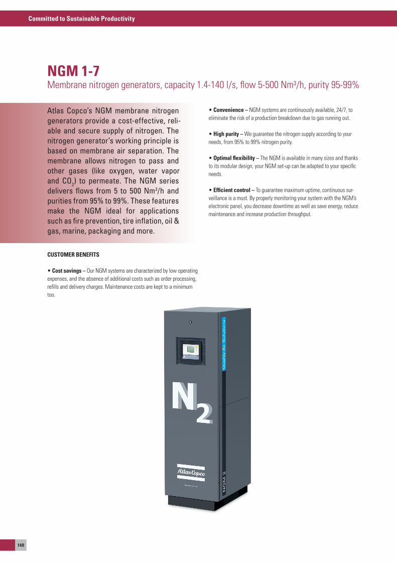
Committed to Sustainable Productivity
140
NGM 1-7Membrane nitrogen generators, capacity 1.4-140 l/s, flow 5-500 Nm³/h, purity 95-99%
CUSTOMER BENEFITS
• Cost savings – our NGM systems are characterized by low operating expenses, and the absence of additional costs such as order processing, refills and delivery charges. Maintenance costs are kept to a minimum too.
• Convenience – NGM systems are continuously available, 24/7, to eliminate the risk of a production breakdown due to gas running out.
• High purity – We guarantee the nitrogen supply according to your needs, from 95% to 99% nitrogen purity.
• Optimal flexibility – The NGM is available in many sizes and thanks to its modular design, your NGM set-up can be adapted to your specific needs.
• Efficient control – To guarantee maximum uptime, continuous sur-veillance is a must. By properly monitoring your system with the NGM’s electronic panel, you decrease downtime as well as save energy, reduce maintenance and increase production throughput.
Atlas Copco’s NGM membrane nitrogen generators provide a cost-effective, reli-able and secure supply of nitrogen. The nitrogen generator’s working principle is based on membrane air separation. The membrane allows nitrogen to pass and other gases (like oxygen, water vapor and CO2) to permeate. The NGM series delivers flows from 5 to 500 Nm3/h and purities from 95% to 99%. These featuresmake the NGM ideal for applicationssuch as fire prevention, tire inflation, oil & gas, marine, packaging and more.
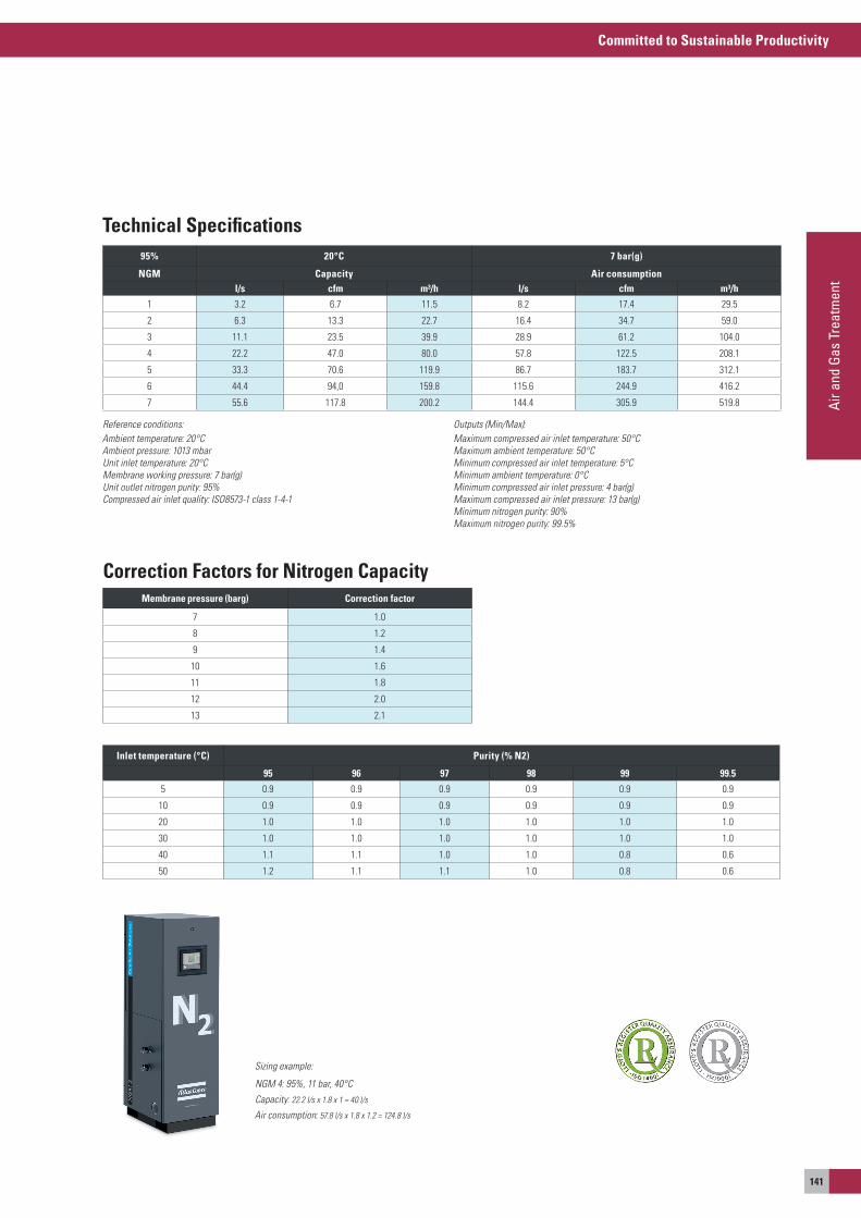
Committed to Sustainable Productivity
Air a
nd G
as T
reat
men
t
141
Inlet temperature (°C) Purity (% N2)
95 96 97 98 99 99.5
5 0.9 0.9 0.9 0.9 0.9 0.9
10 0.9 0.9 0.9 0.9 0.9 0.9
20 1.0 1.0 1.0 1.0 1.0 1.0
30 1.0 1.0 1.0 1.0 1.0 1.0
40 1.1 1.1 1.0 1.0 0.8 0.6
50 1.2 1.1 1.1 1.0 0.8 0.6
Membrane pressure (barg) Correction factor
7 1.0
8 1.2
9 1.4
10 1.6
11 1.8
12 2.0
13 2.1
Correction Factors for Nitrogen Capacity
Sizing example:
NGM 4: 95%, 11 bar, 40°C
Capacity: 22.2 l/s x 1.8 x 1 = 40 l/s
Air consumption: 57.8 l/s x 1.8 x 1.2 = 124.8 l/s
95% 20°C 7 bar(g)
NGM Capacity Air consumptionl/s cfm m³/h l/s cfm m³/h
1 3.2 6.7 11.5 8.2 17.4 29.5
2 6.3 13.3 22.7 16.4 34.7 59.0
3 11.1 23.5 39.9 28.9 61.2 104.0
4 22.2 47.0 80.0 57.8 122.5 208.1
5 33.3 70.6 119.9 86.7 183.7 312.1
6 44.4 94,0 159.8 115.6 244.9 416.2
7 55.6 117.8 200.2 144.4 305.9 519.8
Reference conditions:Ambient temperature: 20°CAmbient pressure: 1013 mbarUnit inlet temperature: 20°CMembrane working pressure: 7 bar(g)Unit outlet nitrogen purity: 95%Compressed air inlet quality: ISO8573-1 class 1-4-1
Outputs (Min/Max):Maximum compressed air inlet temperature: 50°CMaximum ambient temperature: 50°CMinimum compressed air inlet temperature: 5°CMinimum ambient temperature: 0°CMinimum compressed air inlet pressure: 4 bar(g)Maximum compressed air inlet pressure: 13 bar(g)Minimum nitrogen purity: 90%Maximum nitrogen purity: 99.5%
Technical Specifications
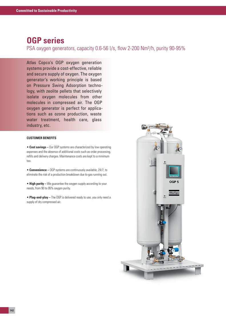
Committed to Sustainable Productivity
142
Atlas Copco’s OGP oxygen generation systems provide a cost-effective, reliable and secure supply of oxygen. The oxygengenerator’s working principle is basedon Pressure Swing Adsorption techno-logy, with zeolite pellets that selectively isolate oxygen molecules from othermolecules in compressed air. The OGP oxygen generator is perfect for applica-tions such as ozone production, wastewater treatment, health care, glassindustry, etc.
OGP seriesPsa oxygen generators, capacity 0.6-56 l/s, flow 2-200 Nm³/h, purity 90-95%
CUSTOMER BENEFITS
• Cost savings – our oGP systems are characterized by low operating expenses and the absence of additional costs such as order processing, refills and delivery charges. Maintenance costs are kept to a minimum too.
• Convenience – oGP systems are continuously available, 24/7, to eliminate the risk of a production breakdown due to gas running out.
• High purity – We guarantee the oxygen supply according to your needs, from 90 to 95% oxygen purity.
• Plug-and-play – The oGP is delivered ready to use, you only need a supply of dry compressed air.
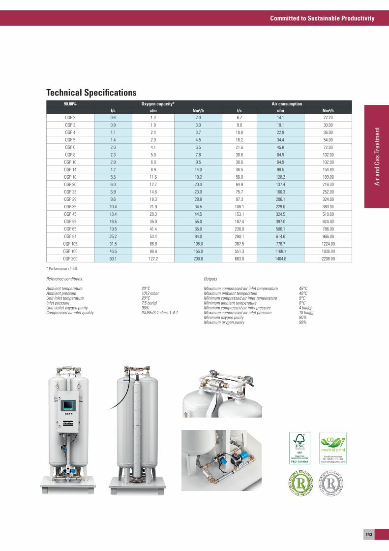
Committed to Sustainable Productivity
Air a
nd G
as T
reat
men
t
143
90.00% Oxygen capacity* Air consumptionl/s cfm Nm³/h l/s cfm Nm³/h
oGP 2 0.6 1.3 2.0 6.7 14.1 22.20
oGP 3 0.9 1.9 3.0 9.0 19.1 30.00
oGP 4 1.1 2.4 3.7 10.8 22.9 36.00
oGP 5 1.4 2.9 4.5 16.2 34.4 54.00
oGP 6 2.0 4.1 6.5 21.6 45.8 72.00
oGP 8 2.3 5.0 7.8 30.6 64.9 102.00
oGP 10 2.9 6.0 9.5 30.6 64.9 102.00
oGP 14 4.2 8.9 14.0 46.5 98.5 154.80
oGP 18 5.5 11.6 18.2 56.8 120.2 189.00
oGP 20 6.0 12.7 20.0 64.9 137.4 216.00
oGP 23 6.9 14.6 23.0 75.7 160.3 252.00
oGP 29 8.6 18.3 28.8 97.3 206.1 324.00
oGP 35 10.4 21.9 34.5 108.1 229.0 360.00
oGP 45 13.4 28.3 44.5 153.1 324.5 510.00
oGP 55 16.5 35.0 55.0 187.4 397.0 624.00
oGP 65 19.5 41.4 65.0 236.0 500.1 786.00
oGP 84 25.2 53.4 84.0 290.1 614.6 966.00
oGP 105 31.5 66.8 105.0 367.5 778.7 1224.00
oGP 160 46.5 98.6 155.0 551.3 1168.1 1836.00
oGP 200 60.1 127.2 200.0 663.0 1404.8 2208.00
* Performance +/- 5%.
Reference conditions:
Ambient temperature 20°CAmbient pressure 1013 mbarUnit inlet temperature 20°CInlet pressure 7.5 bar(g)Unit outlet oxygen purity 90%Compressed air inlet quality ISO8573-1 class 1-4-1
Outputs
Maximum compressed air inlet temperature 45°CMaximum ambient temperature 45°CMinimum compressed air inlet temperature 5°CMinimum ambient temperature 0°CMinimum compressed air inlet pressure 4 bar(g)Maximum compressed air inlet pressure 10 bar(g)Minimum oxygen purity 90%Maximum oxygen purity 95%
Certi�cate Number887-10506-1111-1028
www.climatepartner.com
Technical Specifications
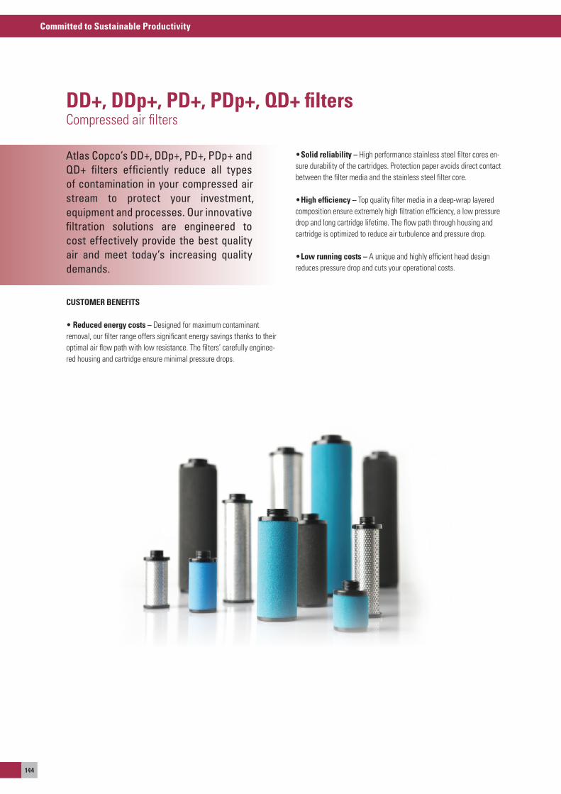
Committed to Sustainable Productivity
144
Atlas Copco’s DD+, DDp+, PD+, PDp+ and QD+ filters efficiently reduce all types of contamination in your compressed airstream to protect your investment,equipment and processes. Our innovativefiltration solutions are engineered to cost effectively provide the best quality air and meet today’s increasing qualitydemands.
DD+, DDp+, PD+, PDp+, QD+ filtersCompressed air filters
CUSTOMER BENEFITS
• reduced energy costs – Designed for maximum contaminant removal, our filter range offers significant energy savings thanks to their optimal air flow path with low resistance. The filters’ carefully enginee-red housing and cartridge ensure minimal pressure drops.
• Solid reliability – High performance stainless steel filter cores en-sure durability of the cartridges. Protection paper avoids direct contact between the filter media and the stainless steel filter core.
• High efficiency – Top quality filter media in a deep-wrap layered composition ensure extremely high filtration efficiency, a low pressure drop and long cartridge lifetime. The flow path through housing and cartridge is optimized to reduce air turbulence and pressure drop.
• Low running costs – a unique and highly efficient head design reduces pressure drop and cuts your operational costs.
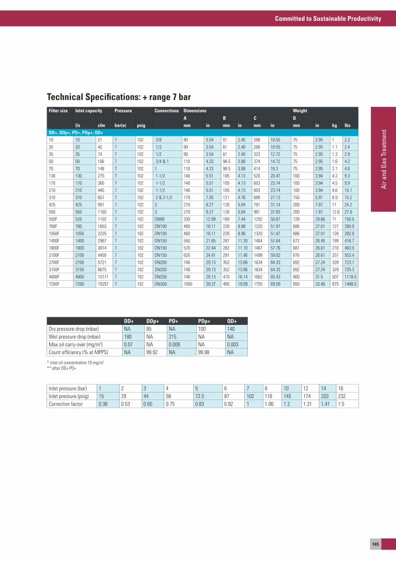
Committed to Sustainable Productivity
Air a
nd G
as T
reat
men
t
145
Filter size Inlet capacity Pressure Connections Dimensions Weight
A B C Dl/s cfm bar(e) psig mm in mm in mm in mm in kg lbs
DD+, DDp+, PD+, PDp+, QD+10 10 21 7 102 3/8 90 3.54 61 2.40 268 10.55 75 2.95 1 2.220 20 42 7 102 1/2 90 3.54 61 2.40 268 10.55 75 2.95 1.1 2.435 35 74 7 102 1/2 90 3.54 61 2.40 323 12.72 75 2.95 1.3 2.950 50 106 7 102 3/4 & 1 110 4.33 98.5 3.88 374 14.72 75 2.95 1.6 4.270 70 148 7 102 1 110 4.33 98.5 3.88 414 16.3 75 2.95 2.1 4.6130 130 275 7 102 1-1/2 140 5.51 105 4.13 520 20.47 100 3.94 4.2 9.3170 170 360 7 102 1-1/2 140 5.51 105 4.13 603 23.74 100 3.94 4.5 9.9210 210 445 7 102 1-1/2 140 5.51 105 4.13 603 23.74 100 3.94 4.6 10.1310 310 657 7 102 2 & 2-1/2 179 7.05 121 4.76 689 27.13 150 5.91 6.9 15.2425 425 901 7 102 3 210 8.27 128 5.04 791 31.14 200 7.87 11 24.2550 550 1165 7 102 3 210 8.27 128 5.04 961 37.83 200 7.87 12.6 27.8550F 520 1102 7 102 DN80 330 12.99 189 7.44 1292 50.87 728 29.66 71 156.5780F 780 1653 7 102 DN100 460 18.11 228 8.98 1320 51.97 686 27.01 127 280.01050F 1050 2225 7 102 DN100 460 18.11 228 8.98 1320 51.97 686 27.01 128 282.01400F 1400 2967 7 102 DN150 550 21.65 287 11.30 1464 57.64 672 26.46 189 416.71800F 1800 3814 7 102 DN150 570 22.44 282 11.10 1467 57.76 681 26.81 210 463.02100F 2100 4450 7 102 DN150 620 24.41 291 11.46 1499 59.02 676 26.61 251 553.42700F 2700 5721 7 102 DN200 740 29.13 352 13.86 1634 64.33 692 27.24 328 723.13150F 3150 6675 7 102 DN200 740 29.13 352 13.86 1634 64.33 692 27.24 329 725.34800F 4800 10171 7 102 DN250 740 29.13 410 16.14 1662 65.43 800 31.5 507 1118.07200F 7200 15257 7 102 DN300 1000 39.37 485 19.09 1755 69.09 850 33.46 675 1488.0
Inlet pressure (bar) 1 2 3 4 5 6 7 8 10 12 14 16Inlet pressure (psig) 15 29 44 58 72.5 87 102 116 145 174 203 232Correction factor 0.38 0.53 0.65 0.75 0.83 0.92 1 1.06 1.2 1.31 1.41 1.5
DD+ DDp+ PD+ PDp+ QD+Dry pressure drop (mbar) Na 85 Na 100 140Wet pressure drop (mbar) 180 Na 215 Na NaMax oil carry-over (mg/m3) 0.07 Na 0.008 Na 0.003Count efficiency (% at MPPs) Na 99.92 Na 99.98 Na
* inlet oil concentration 10 mg/m3
** after DD+ PD+
Technical Specifications: + range 7 bar
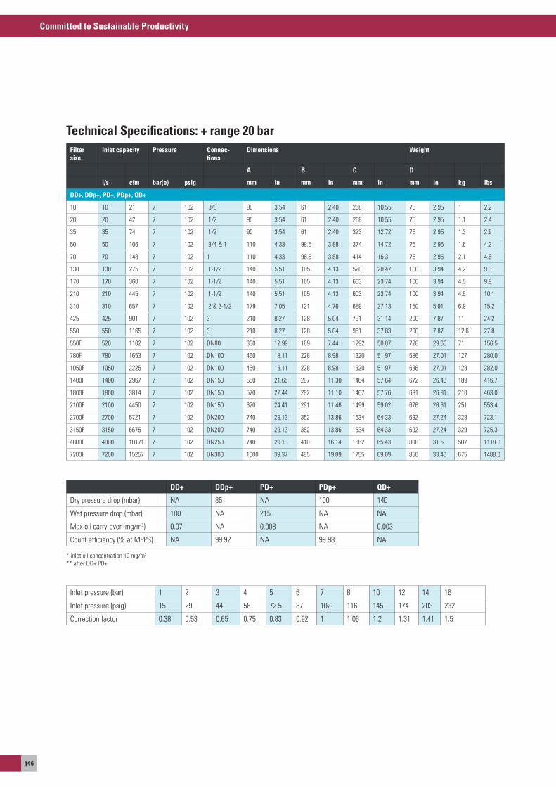
Committed to Sustainable Productivity
146
Filter size
Inlet capacity Pressure Connec-tions
Dimensions Weight
A B C D
l/s cfm bar(e) psig mm in mm in mm in mm in kg lbs
DD+, DDp+, PD+, PDp+, QD+
10 10 21 7 102 3/8 90 3.54 61 2.40 268 10.55 75 2.95 1 2.2
20 20 42 7 102 1/2 90 3.54 61 2.40 268 10.55 75 2.95 1.1 2.4
35 35 74 7 102 1/2 90 3.54 61 2.40 323 12.72 75 2.95 1.3 2.9
50 50 106 7 102 3/4 & 1 110 4.33 98.5 3.88 374 14.72 75 2.95 1.6 4.2
70 70 148 7 102 1 110 4.33 98.5 3.88 414 16.3 75 2.95 2.1 4.6
130 130 275 7 102 1-1/2 140 5.51 105 4.13 520 20.47 100 3.94 4.2 9.3
170 170 360 7 102 1-1/2 140 5.51 105 4.13 603 23.74 100 3.94 4.5 9.9
210 210 445 7 102 1-1/2 140 5.51 105 4.13 603 23.74 100 3.94 4.6 10.1
310 310 657 7 102 2 & 2-1/2 179 7.05 121 4.76 689 27.13 150 5.91 6.9 15.2
425 425 901 7 102 3 210 8.27 128 5.04 791 31.14 200 7.87 11 24.2
550 550 1165 7 102 3 210 8.27 128 5.04 961 37.83 200 7.87 12.6 27.8
550F 520 1102 7 102 DN80 330 12.99 189 7.44 1292 50.87 728 29.66 71 156.5
780F 780 1653 7 102 DN100 460 18.11 228 8.98 1320 51.97 686 27.01 127 280.0
1050F 1050 2225 7 102 DN100 460 18.11 228 8.98 1320 51.97 686 27.01 128 282.0
1400F 1400 2967 7 102 DN150 550 21.65 287 11.30 1464 57.64 672 26.46 189 416.7
1800F 1800 3814 7 102 DN150 570 22.44 282 11.10 1467 57.76 681 26.81 210 463.0
2100F 2100 4450 7 102 DN150 620 24.41 291 11.46 1499 59.02 676 26.61 251 553.4
2700F 2700 5721 7 102 DN200 740 29.13 352 13.86 1634 64.33 692 27.24 328 723.1
3150F 3150 6675 7 102 DN200 740 29.13 352 13.86 1634 64.33 692 27.24 329 725.3
4800F 4800 10171 7 102 DN250 740 29.13 410 16.14 1662 65.43 800 31.5 507 1118.0
7200F 7200 15257 7 102 DN300 1000 39.37 485 19.09 1755 69.09 850 33.46 675 1488.0
Inlet pressure (bar) 1 2 3 4 5 6 7 8 10 12 14 16
Inlet pressure (psig) 15 29 44 58 72.5 87 102 116 145 174 203 232
Correction factor 0.38 0.53 0.65 0.75 0.83 0.92 1 1.06 1.2 1.31 1.41 1.5
DD+ DDp+ PD+ PDp+ QD+
Dry pressure drop (mbar) Na 85 Na 100 140
Wet pressure drop (mbar) 180 Na 215 Na Na
Max oil carry-over (mg/m3) 0.07 Na 0.008 Na 0.003
Count efficiency (% at MPPs) Na 99.92 Na 99.98 Na
* inlet oil concentration 10 mg/m3
** after DD+ PD+
Technical Specifications: + range 20 bar
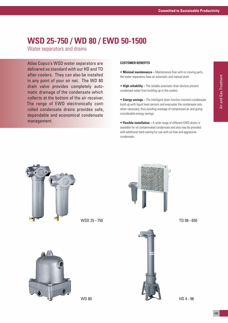
Committed to Sustainable Productivity
Air a
nd G
as T
reat
men
t
147
Atlas Copco’s WSD water separators are delivered as standard with our HD and TD after-coolers. They can also be installed in any point of your air net. The WD 80 drain valve provides completely auto-matic drainage of the condensate which collects at the bottom of the air receiver. The range of EWD electronically cont-rolled condensate drains provides safe, dependable and economical condensate management.
WSD 25-750 / WD 80 / EWD 50-1500Water separators and drains
CUSTOMER BENEFITS
• Minimal maintenance – Maintenance-free with no moving parts, the water separators have an automatic and manual drain.
• High reliability – The reliable automatic drain devices prevent condensed water from building up in the coolers.
• Energy savings – The intelligent drain function monitors condensate build-up with liquid level sensors and evacuates the condensate only when necessary, thus avoiding wastage of compressed air and giving considerable energy savings.
• Flexible installation – a wide range of different eWD drains is available for oil contaminated condensate and also may be provided with additional hard coating for use with oil-free and aggressive condensate.
TD 08 – 650
WD 80
WSD 25 – 750
HD 4 – 96
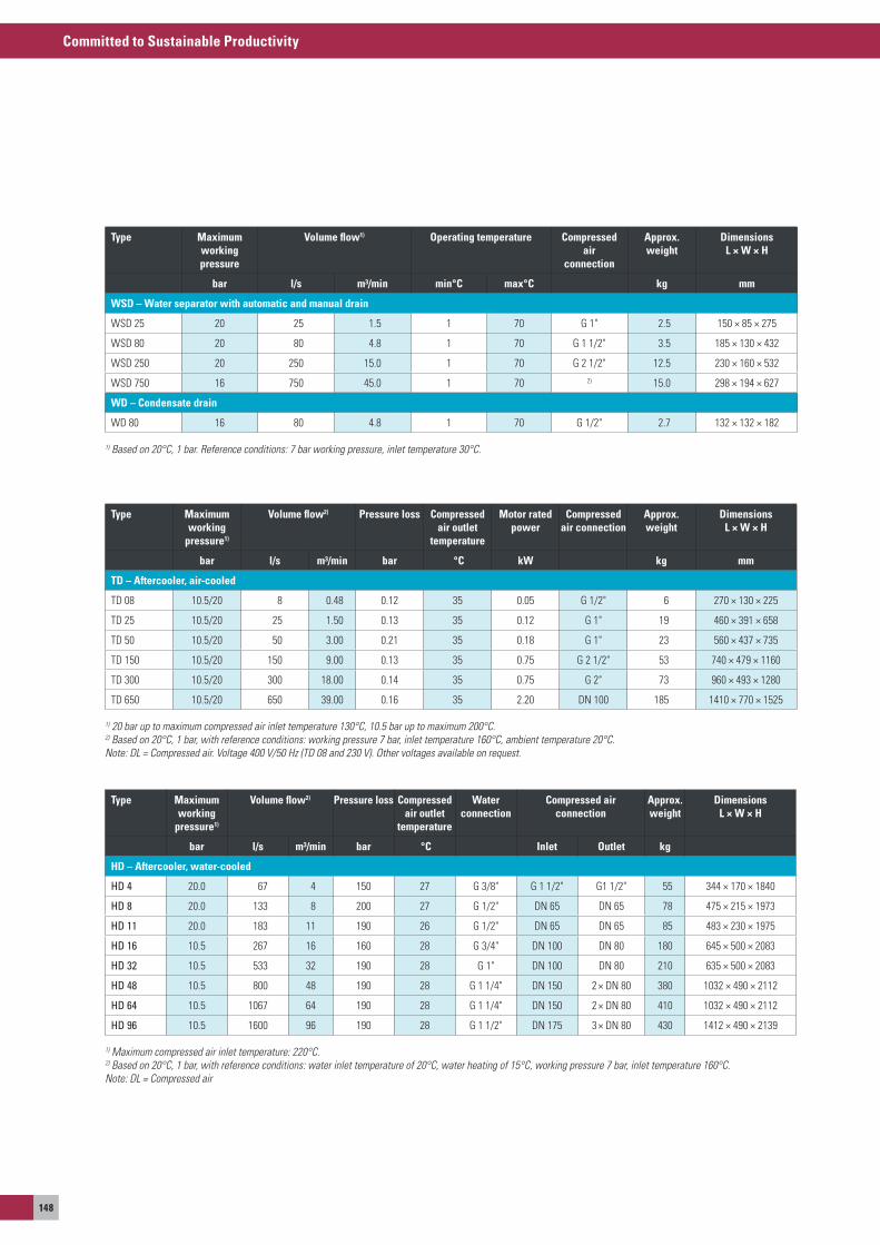
Committed to Sustainable Productivity
148
Type Maximum working
pressure1)
Volume flow2) Pressure loss Compressed air outlet
temperature
Waterconnection
Compressed airconnection
Approx. weight
Dimensions L × W × H
bar l/s m³/min bar °C Inlet Outlet kg
HD – Aftercooler, water-cooled
HD 4 20.0 67 4 150 27 G 3/8" G 1 1/2" G1 1/2" 55 344 × 170 × 1840
HD 8 20.0 133 8 200 27 G 1/2" DN 65 DN 65 78 475 × 215 × 1973
HD 11 20.0 183 11 190 26 G 1/2" DN 65 DN 65 85 483 × 230 × 1975
HD 16 10.5 267 16 160 28 G 3/4" DN 100 DN 80 180 645 × 500 × 2083
HD 32 10.5 533 32 190 28 G 1" DN 100 DN 80 210 635 × 500 × 2083
HD 48 10.5 800 48 190 28 G 1 1/4" DN 150 2 × DN 80 380 1032 × 490 × 2112
HD 64 10.5 1067 64 190 28 G 1 1/4" DN 150 2 × DN 80 410 1032 × 490 × 2112
HD 96 10.5 1600 96 190 28 G 1 1/2" DN 175 3 × DN 80 430 1412 × 490 × 2139
1) Maximum compressed air inlet temperature: 220°C. 2) Based on 20°C, 1 bar, with reference conditions: water inlet temperature of 20°C, water heating of 15°C, working pressure 7 bar, inlet temperature 160°C.Note: DL = Compressed air
Type Maximum working
pressure1)
Volume flow2) Pressure loss Compressed air outlet
temperature
Motor rated power
Compressed air connection
Approx. weight
Dimensions L × W × H
bar l/s m³/min bar °C kW kg mm
TD – Aftercooler, air-cooled
TD 08 10.5/20 8 0.48 0.12 35 0.05 G 1/2" 6 270 × 130 × 225
TD 25 10.5/20 25 1.50 0.13 35 0.12 G 1" 19 460 × 391 × 658
TD 50 10.5/20 50 3.00 0.21 35 0.18 G 1" 23 560 × 437 × 735
TD 150 10.5/20 150 9.00 0.13 35 0.75 G 2 1/2" 53 740 × 479 × 1160
TD 300 10.5/20 300 18.00 0.14 35 0.75 G 2" 73 960 × 493 × 1280
TD 650 10.5/20 650 39.00 0.16 35 2.20 DN 100 185 1410 × 770 × 1525
1) 20 bar up to maximum compressed air inlet temperature 130°C, 10.5 bar up to maximum 200°C. 2) Based on 20°C, 1 bar, with reference conditions: working pressure 7 bar, inlet temperature 160°C, ambient temperature 20°C.Note: DL = Compressed air. Voltage 400 V/50 Hz (TD 08 and 230 V). Other voltages available on request.
Type Maximum workingpressure
Volume flow1) Operating temperature Compressed air
connection
Approx. weight
Dimensions L × W × H
bar l/s m³/min min°C max°C kg mm
WSD – Water separator with automatic and manual drain
WsD 25 20 25 1.5 1 70 G 1" 2.5 150 × 85 × 275
WsD 80 20 80 4.8 1 70 G 1 1/2" 3.5 185 × 130 × 432
WsD 250 20 250 15.0 1 70 G 2 1/2" 12.5 230 × 160 × 532
WsD 750 16 750 45.0 1 70 2) 15.0 298 × 194 × 627
WD – Condensate drain
WD 80 16 80 4.8 1 70 G 1/2" 2.7 132 × 132 × 182
1) Based on 20°C, 1 bar. Reference conditions: 7 bar working pressure, inlet temperature 30°C.
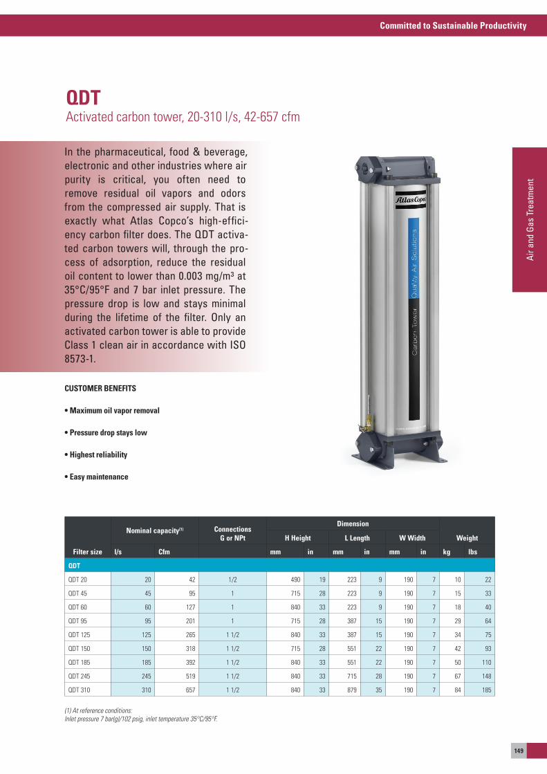
Committed to Sustainable Productivity
Air a
nd G
as T
reat
men
t
149
In the pharmaceutical, food & beverage, electronic and other industries where airpurity is critical, you often need toremove residual oil vapors and odors from the compressed air supply. That is exactly what Atlas Copco’s high-effici-ency carbon filter does. The QDT activa-ted carbon towers will, through the pro-cess of adsorption, reduce the residual oil content to lower than 0.003 mg/m³ at 35°C/95°F and 7 bar inlet pressure. The pressure drop is low and stays minimal during the lifetime of the filter. Only an activated carbon tower is able to provide Class 1 clean air in accordance with ISO 8573-1.
CUSTOMER BENEFITS
• Maximum oil vapor removal
• Pressure drop stays low
• Highest reliability
• Easy maintenance
QDTactivated carbon tower, 20-310 l/s, 42-657 cfm
Filter size
Nominal capacity(1) Connections G or NPt
Dimension
WeightH Height L Length W Width
l/s Cfm mm in mm in mm in kg lbs
QDT
QDT 20 20 42 1/2 490 19 223 9 190 7 10 22
QDT 45 45 95 1 715 28 223 9 190 7 15 33
QDT 60 60 127 1 840 33 223 9 190 7 18 40
QDT 95 95 201 1 715 28 387 15 190 7 29 64
QDT 125 125 265 1 1/2 840 33 387 15 190 7 34 75
QDT 150 150 318 1 1/2 715 28 551 22 190 7 42 93
QDT 185 185 392 1 1/2 840 33 551 22 190 7 50 110
QDT 245 245 519 1 1/2 840 33 715 28 190 7 67 148
QDT 310 310 657 1 1/2 840 33 879 35 190 7 84 185
(1) At reference conditions:Inlet pressure 7 bar(g)/102 psig, inlet temperature 35°C/95°F.
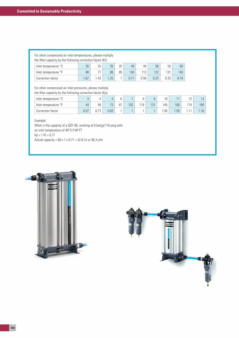
Committed to Sustainable Productivity
150
For other compressed air inlet temperatures, please multiplythe filter capacity by the following correction factor (Kt):
Inlet temperature °C 20 25 30 35 40 45 50 55 60
Inlet temperature °F 68 77 86 95 104 113 122 131 140
Correction factor 1.67 1.43 1.25 1 0.71 0.56 0.37 0.25 0.19
For other compressed air inlet pressures, please multiply the filter capacity by the following correction factor (Kp):
Inlet temperature °C 3 4 5 6 7 8 9 10 11 12 13
Inlet temperature °F 44 58 73 87 102 116 131 145 160 174 189
Correction factor 0.57 0.77 0.83 1 1 1 1 1.05 1.05 1.11 1.18
example:What is the capacity of a QDT 60, working at 8 bar(g)/116 psig withan inlet temperature of 40°C/104°F?Kp = 1 Kt = 0.71actual capacity = 60 x 1 x 0.71 = 42.6 l/s or 90.3 cfm
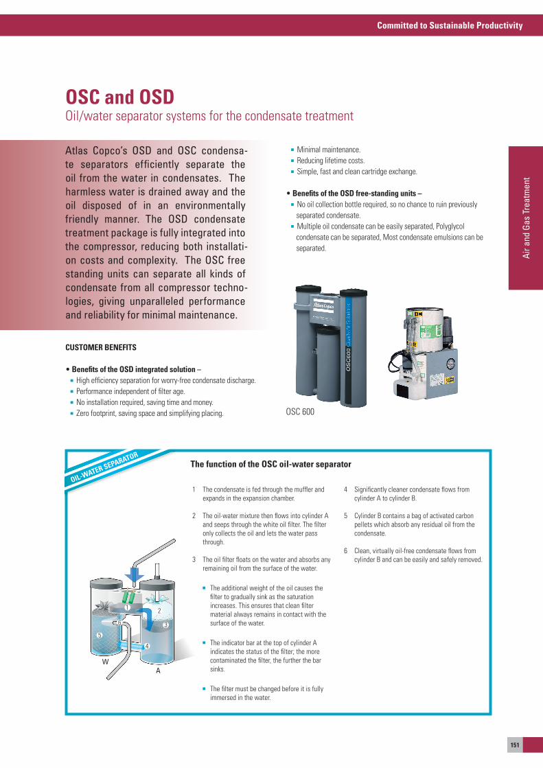
Committed to Sustainable Productivity
Air a
nd G
as T
reat
men
t
151
Atlas Copco’s OSD and OSC condensa-te separators efficiently separate the oil from the water in condensates. The harmless water is drained away and the oil disposed of in an environmentally friendly manner. The OSD condensate treatment package is fully integrated into the compressor, reducing both installati-on costs and complexity. The OSC free standing units can separate all kinds of condensate from all compressor techno-logies, giving unparalleled performance and reliability for minimal maintenance.
OSC and OSDoil/water separator systems for the condensate treatment
osC 600
AW
1 2
3
4
5
6
OIL-WATER SEPARATOR
1 The condensate is fed through the muffler and expands in the expansion chamber.
2 The oil-water mixture then flows into cylinder a and seeps through the white oil filter. The filter only collects the oil and lets the water pass through.
3 The oil filter floats on the water and absorbs any remaining oil from the surface of the water.
The additional weight of the oil causes the filter to gradually sink as the saturation increases. This ensures that clean filter material always remains in contact with the surface of the water.
The indicator bar at the top of cylinder a indicates the status of the filter; the more contaminated the filter, the further the bar sinks.
The filter must be changed before it is fully immersed in the water.
4 significantly cleaner condensate flows from cylinder a to cylinder B.
5 Cylinder B contains a bag of activated carbon pellets which absorb any residual oil from the condensate.
6 Clean, virtually oil-free condensate flows from cylinder B and can be easily and safely removed.
CUSTOMER BENEFITS
• Benefits of the OSD integrated solution – High efficiency separation for worry-free condensate discharge. Performance independent of filter age. No installation required, saving time and money. Zero footprint, saving space and simplifying placing.
Minimal maintenance. Reducing lifetime costs. simple, fast and clean cartridge exchange.
• Benefits of the OSD free-standing units – No oil collection bottle required, so no chance to ruin previously separated condensate. Multiple oil condensate can be easily separated, Polyglycol condensate can be separated, Most condensate emulsions can be separated.
The function of the OSC oil-water separator
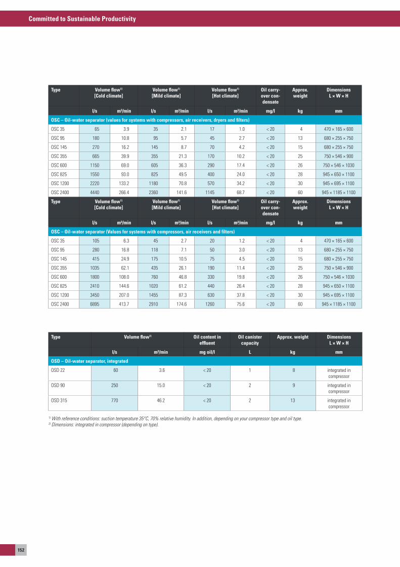
Committed to Sustainable Productivity
152
Type Volume flow1) [Cold climate]
Volume flow1) [Mild climate]
Volume flow1) [Hot climate]
Oil carry-over con-densate
Approx. weight
Dimensions L × W × H
l/s m³/min l/s m³/min l/s m³/min mg/l kg mm
OSC – Oil-water separator (values for systems with compressors, air receivers, dryers and filters)
osC 35 65 3.9 35 2.1 17 1.0 < 20 4 470 × 165 × 600
osC 95 180 10.8 95 5.7 45 2.7 < 20 13 680 × 255 × 750
osC 145 270 16.2 145 8.7 70 4.2 < 20 15 680 × 255 × 750
osC 355 665 39.9 355 21.3 170 10.2 < 20 25 750 × 546 × 900
osC 600 1150 69.0 605 36.3 290 17.4 < 20 26 750 × 546 × 1030
osC 825 1550 93.0 825 49.5 400 24.0 < 20 28 945 × 650 × 1100
osC 1200 2220 133.2 1180 70.8 570 34.2 < 20 30 945 × 695 × 1100
osC 2400 4440 266.4 2360 141.6 1145 68.7 < 20 60 945 × 1185 × 1100
Type Volume flow1) [Cold climate]
Volume flow1) [Mild climate]
Volume flow1) [Hot climate]
Oil carry-over con-densate
Approx. weight
Dimensions L × W × H
l/s m³/min l/s m³/min l/s m³/min mg/l kg mm
OSC – Oil-water separator (Values for systems with compressors, air receivers and filters)
osC 35 105 6.3 45 2.7 20 1.2 < 20 4 470 × 165 × 600
osC 95 280 16.8 118 7.1 50 3.0 < 20 13 680 × 255 × 750
osC 145 415 24.9 175 10.5 75 4.5 < 20 15 680 × 255 × 750
osC 355 1035 62.1 435 26.1 190 11.4 < 20 25 750 × 546 × 900
osC 600 1800 108.0 760 46.8 330 19.8 < 20 26 750 × 546 × 1030
osC 825 2410 144.6 1020 61.2 440 26.4 < 20 28 945 × 650 × 1100
osC 1200 3450 207.0 1455 87.3 630 37.8 < 20 30 945 × 695 × 1100
osC 2400 6895 413.7 2910 174.6 1260 75.6 < 20 60 945 × 1185 × 1100
Type Volume flow1) Oil content in effluent
Oil canistercapacity
Approx. weight Dimensions L × W × H
l/s m³/min mg oil/l L kg mm
OSD – Oil-water separator, integrated
osD 22 60 3.6 < 20 1 8 integrated in compressor
osD 90 250 15.0 < 20 2 9 integrated in compressor
osD 315 770 46.2 < 20 2 13 integrated in compressor
1) With reference conditions: suction temperature 35°C, 70% relative humidity. In addition, depending on your compressor type and oil type.2) Dimensions: integrated in compressor (depending on type).

VaCUUMPUMPsFor more than 20 years, Atlas Copco has been providing reliable vacuum solutions to the industry. We were the pioneers in bringing the oil-sealed screw technology to many vacuum customers. Years of innovation carried alongside our compressed air range, has led to extremely reliable and robust solutions.
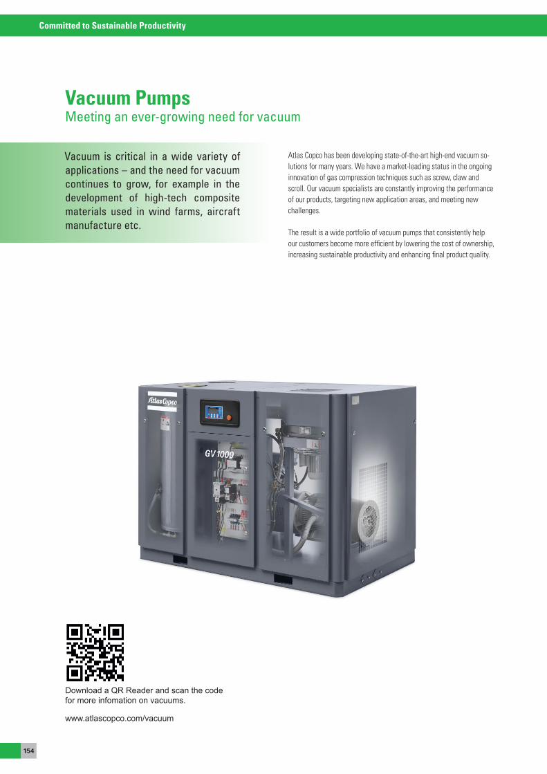
154
Committed to Sustainable Productivity
Vacuum is critical in a wide variety ofapplications – and the need for vacuumcontinues to grow, for example in thedevelopment of high-tech compositematerials used in wind farms, aircraftmanufacture etc.
Vacuum PumpsMeeting an ever-growing need for vacuum
atlas Copco has been developing state-of-the-art high-end vacuum so-lutions for many years. We have a market-leading status in the ongoing innovation of gas compression techniques such as screw, claw and scroll. our vacuum specialists are constantly improving the performance of our products, targeting new application areas, and meeting new challenges.
The result is a wide portfolio of vacuum pumps that consistently help our customers become more efficient by lowering the cost of ownership, increasing sustainable productivity and enhancing final product quality.
www.atlascopco.com/vacuum
Download a QR Reader and scan the code for more infomation on vacuums.
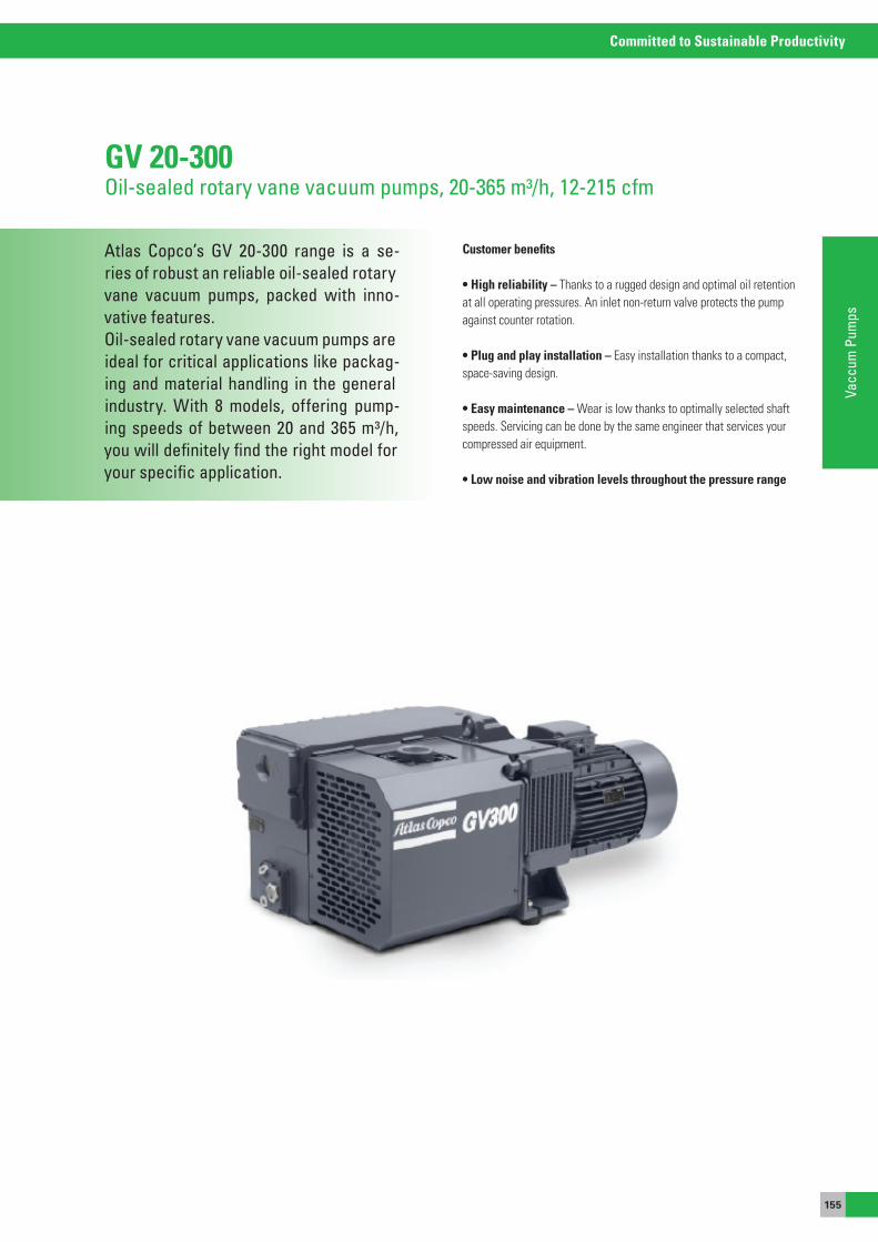
155
Committed to Sustainable Productivity
Vacc
um P
umps
Atlas Copco’s GV 20-300 range is a se-ries of robust an reliable oil-sealed rotary vane vacuum pumps, packed with inno-vative features.Oil-sealed rotary vane vacuum pumps are ideal for critical applications like packag-ing and material handling in the general industry. With 8 models, offering pump-ing speeds of between 20 and 365 m³/h, you will definitely find the right model for your specific application.
Customer benefits
• High reliability – Thanks to a rugged design and optimal oil retention at all operating pressures. an inlet non-return valve protects the pump against counter rotation.
• Plug and play installation – easy installation thanks to a compact, space-saving design.
• Easy maintenance – Wear is low thanks to optimally selected shaft speeds. servicing can be done by the same engineer that services your compressed air equipment.
• Low noise and vibration levels throughout the pressure range
GV 20-300Oil-sealed rotary vane vacuum pumps, 20-365 m³/h, 12-215 cfm
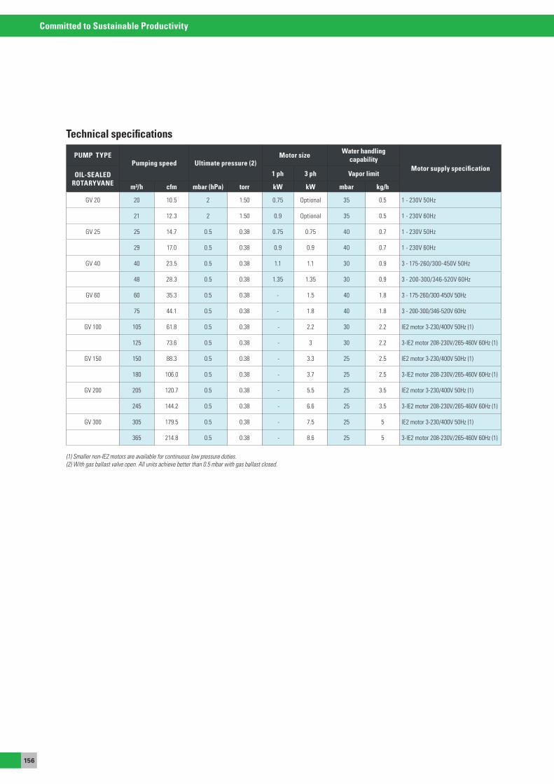
156
Committed to Sustainable Productivity
PUMP TYPEPumping speed Ultimate pressure (2)
Motor size Water handling capability
Motor supply specificationOIL-SEALED
ROTARYVANE1 ph 3 ph Vapor limit
m³/h cfm mbar (hPa) torr kW kW mbar kg/h
GV 20 20 10.5 2 1.50 0.75 optional 35 0.5 1 - 230V 50Hz
21 12.3 2 1.50 0.9 optional 35 0.5 1 - 230V 60Hz
GV 25 25 14.7 0.5 0.38 0.75 0.75 40 0.7 1 - 230V 50Hz
29 17.0 0.5 0.38 0.9 0.9 40 0.7 1 - 230V 60Hz
GV 40 40 23.5 0.5 0.38 1.1 1.1 30 0.9 3 - 175-260/300-450V 50Hz
48 28.3 0.5 0.38 1.35 1.35 30 0.9 3 - 200-300/346-520V 60Hz
GV 60 60 35.3 0.5 0.38 - 1.5 40 1.8 3 - 175-260/300-450V 50Hz
75 44.1 0.5 0.38 - 1.8 40 1.8 3 - 200-300/346-520V 60Hz
GV 100 105 61.8 0.5 0.38 - 2.2 30 2.2 Ie2 motor 3-230/400V 50Hz (1)
125 73.6 0.5 0.38 - 3 30 2.2 3-Ie2 motor 208-230V/265-460V 60Hz (1)
GV 150 150 88.3 0.5 0.38 - 3.3 25 2.5 Ie2 motor 3-230/400V 50Hz (1)
180 106.0 0.5 0.38 - 3.7 25 2.5 3-Ie2 motor 208-230V/265-460V 60Hz (1)
GV 200 205 120.7 0.5 0.38 - 5.5 25 3.5 Ie2 motor 3-230/400V 50Hz (1)
245 144.2 0.5 0.38 - 6.6 25 3.5 3-Ie2 motor 208-230V/265-460V 60Hz (1)
GV 300 305 179.5 0.5 0.38 - 7.5 25 5 Ie2 motor 3-230/400V 50Hz (1)
365 214.8 0.5 0.38 - 8.6 25 5 3-Ie2 motor 208-230V/265-460V 60Hz (1)
Technical specifications
(1) Smaller non-IE2 motors are available for continuous low pressure duties.(2) With gas ballast valve open. All units achieve better than 0.5 mbar with gas ballast closed.
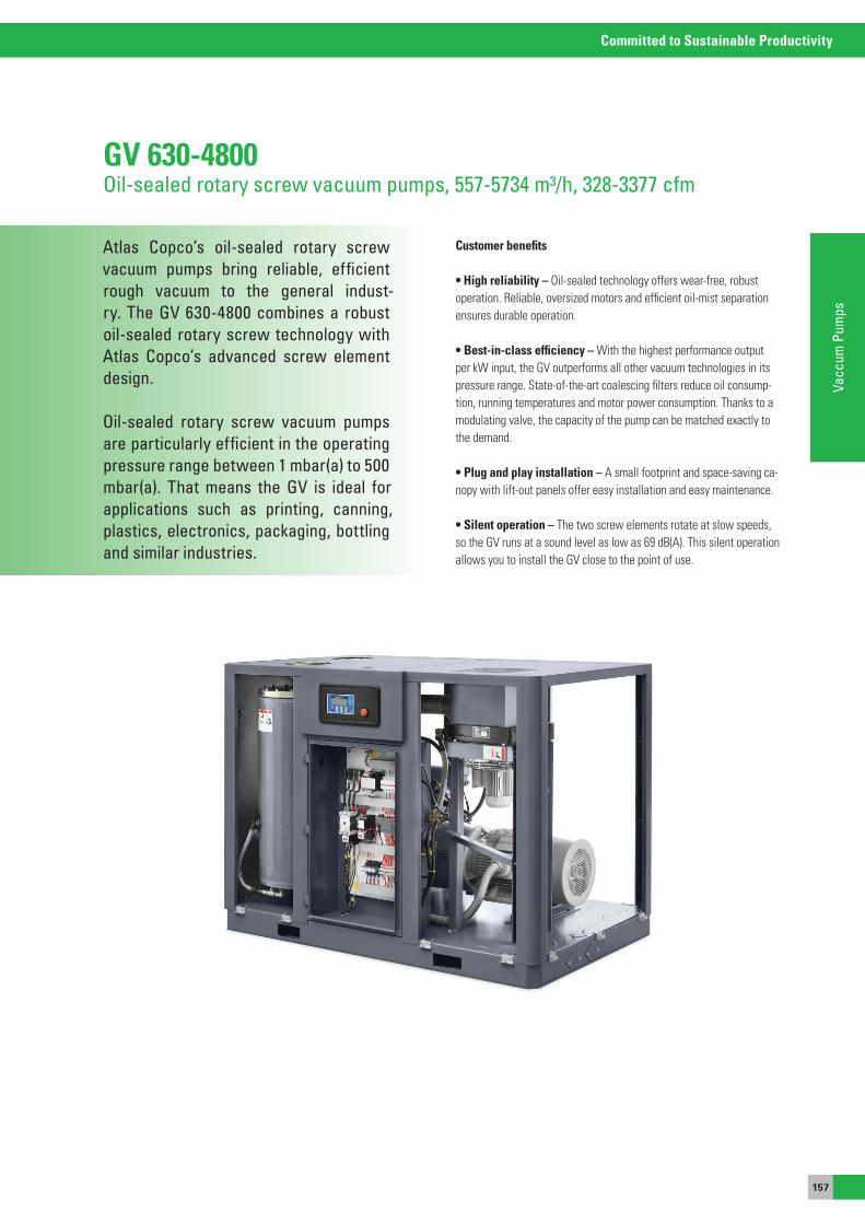
157
Committed to Sustainable Productivity
Vacc
um P
umps
Atlas Copco’s oil-sealed rotary screw vacuum pumps bring reliable, efficient rough vacuum to the general indust-ry. The GV 630-4800 combines a robust oil-sealed rotary screw technology with Atlas Copco’s advanced screw element design.
Oil-sealed rotary screw vacuum pumps are particularly efficient in the operating pressure range between 1 mbar(a) to 500 mbar(a). That means the GV is ideal for applications such as printing, canning, plastics, electronics, packaging, bottling and similar industries.
GV 630-4800Oil-sealed rotary screw vacuum pumps, 557-5734 m³/h, 328-3377 cfm
Customer benefits
• High reliability – oil-sealed technology offers wear-free, robust operation. Reliable, oversized motors and efficient oil-mist separation ensures durable operation.
• Best-in-class efficiency – With the highest performance output per kW input, the GV outperforms all other vacuum technologies in its pressure range. state-of-the-art coalescing filters reduce oil consump-tion, running temperatures and motor power consumption. Thanks to a modulating valve, the capacity of the pump can be matched exactly to the demand.
• Plug and play installation – a small footprint and space-saving ca-nopy with lift-out panels offer easy installation and easy maintenance.
• Silent operation – The two screw elements rotate at slow speeds, so the GV runs at a sound level as low as 69 dB(a). This silent operation allows you to install the GV close to the point of use.
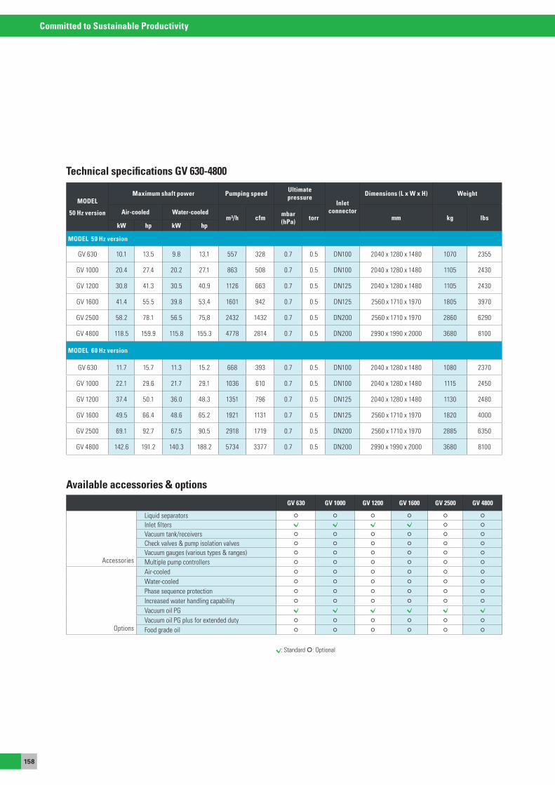
158
Committed to Sustainable Productivity
: standard : optional
GV 630 GV 1000 GV 1200 GV 1600 GV 2500 GV 4800
accessories
Liquid separators
Inlet filters
Vacuum tank/receivers
Check valves & pump isolation valves
Vacuum gauges (various types & ranges)
Multiple pump controllers
options
air-cooled
Water-cooled
Phase sequence protection
Increased water handling capability
Vacuum oil PGVacuum oil PG plus for extended duty
Food grade oil
Available accessories & options
MODEL
50 Hz version
Maximum shaft power Pumping speed Ultimate pressure
Inlet connector
Dimensions (L x W x H) Weight
Air-cooled Water-cooledm³/h cfm mbar
(hPa) torr mm kg lbskW hp kW hp
MODEL 50 Hz version
GV 630 10.1 13.5 9.8 13.1 557 328 0.7 0.5 DN100 2040 x 1280 x 1480 1070 2355
GV 1000 20.4 27.4 20.2 27.1 863 508 0.7 0.5 DN100 2040 x 1280 x 1480 1105 2430
GV 1200 30.8 41.3 30.5 40.9 1126 663 0.7 0.5 DN125 2040 x 1280 x 1480 1105 2430
GV 1600 41.4 55.5 39.8 53.4 1601 942 0.7 0.5 DN125 2560 x 1710 x 1970 1805 3970
GV 2500 58.2 78.1 56.5 75,8 2432 1432 0.7 0.5 DN200 2560 x 1710 x 1970 2860 6290
GV 4800 118.5 159.9 115.8 155.3 4778 2814 0.7 0.5 DN200 2990 x 1990 x 2000 3680 8100
MODEL 60 Hz version
GV 630 11.7 15.7 11.3 15.2 668 393 0.7 0.5 DN100 2040 x 1280 x 1480 1080 2370
GV 1000 22.1 29.6 21.7 29.1 1036 610 0.7 0.5 DN100 2040 x 1280 x 1480 1115 2450
GV 1200 37.4 50.1 36.0 48.3 1351 796 0.7 0.5 DN125 2040 x 1280 x 1480 1130 2480
GV 1600 49.5 66.4 48.6 65.2 1921 1131 0.7 0.5 DN125 2560 x 1710 x 1970 1820 4000
GV 2500 69.1 92.7 67.5 90.5 2918 1719 0.7 0.5 DN200 2560 x 1710 x 1970 2885 6350
GV 4800 142.6 191.2 140.3 188.2 5734 3377 0.7 0.5 DN200 2990 x 1990 x 2000 3680 8100
Technical specifications GV 630-4800
Inhaltsverzeichnis
ToTaLCUsToMeRCaReOur organization and people are committed to the maximum operational availability and efficiency of your compressed air network.
160
Committed to Sustainable Productivity
Your bottom line, maximum availability of our equipment at minimum total opera-ting cost, is the top priority for all of us at Atlas Copco. Our way of achieving that builds on interaction, on long-term relati-onships and involvement in your proces-ses, needs and objectives.
Total customer care
SAVE ENERGY Page 161 - 163
CUSTOMER SUPPORT PLANSPage 165 - 168
UPGRADE YOUR PRODUCT Page 169 - 170
MONITOR YOUR PRODUCTSPage 164
GENUINE PARTSPage 171 - 179
AIR DISTRIBUTIONPage 180
Total customer care is our goal at any level of service interaction with you; from standardized genuine parts over tailormade service plans to remote monitoring and optimization.
We want you to see atlas Copco as a real performance partner that can contribute to the productivity of your processes. The best way of taking care of your interest is by taking the best care of your equipment.
Download a QR Reader and scanthe code for:"Atlas Copco Service solutions tooptimize the Compressor room"

161
Committed to Sustainable Productivity
Tota
l Cus
tom
er C
are
Compressed air is one of the most impor-tant utilities in the industry. It is also one of the largest consumers of energy.
With their detailed and extensive know-ledge of compressed air, our energy and air consultant engineers will be able to determine an acceptable operating ba-lance, that is both within the capabilities of your compressors and also adequate to satisfy your production with minimized operational running costs.
Save energyAtlas Copco logical sequence towards sustainable energy savings:
1. Pre-assessmentto estimate savings potentials
2. AIRScan energy assessments/auditsto identify savings potentials through measurement andsimulations
3. Recommendationsto prepare your system for the optimization by exchanging thelatest, most efficient components
4. Optimizeto achieve the savings by implementation of energy savingaccessories and solutions
5. Online monitoringto ensure the solution implemented is delivering the savings asprescribed
6. Regular AIRScan energy assessments/auditsto validate after the improvements and find further savingpotentials
Maximize the performance of your compressor
Based on an audit of your production processes atlas Copco consultants can suggest a more performing set-up for your compressed air installation, with an eye on maximum availability at lowest possible cost.
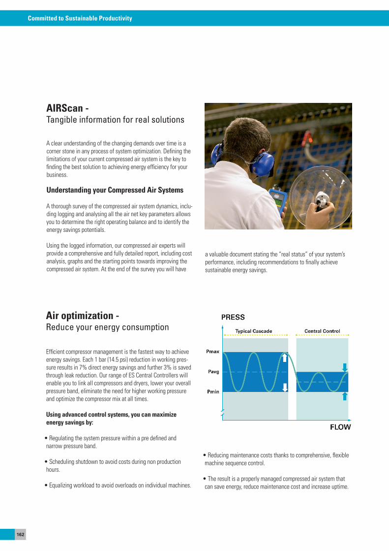
162
Committed to Sustainable Productivity
a clear understanding of the changing demands over time is a corner stone in any process of system optimization. Defining the limitations of your current compressed air system is the key to finding the best solution to achieving energy efficiency for your business.
Understanding your Compressed Air Systems
a thorough survey of the compressed air system dynamics, inclu-ding logging and analysing all the air net key parameters allows you to determine the right operating balance and to identify the energy savings potentials.
Using the logged information, our compressed air experts will provide a comprehensive and fully detailed report, including cost analysis, graphs and the starting points towards improving the compressed air system. at the end of the survey you will have
AIRScan -Tangible information for real solutions
a valuable document stating the “real status” of your system’s performance, including recommendations to finally achieve sustainable energy savings.
efficient compressor management is the fastest way to achieve energy savings. each 1 bar (14.5 psi) reduction in working pres-sure results in 7% direct energy savings and further 3% is saved through leak reduction. our range of es Central Controllers will enable you to link all compressors and dryers, lower your overall pressure band, eliminate the need for higher working pressure and optimize the compressor mix at all times.
Using advanced control systems, you can maximize energy savings by:
• Regulating the system pressure within a pre defined and narrow pressure band.
• Scheduling shutdown to avoid costs during non production hours.
• Equalizing workload to avoid overloads on individual machines.
Air optimization -Reduce your energy consumption
• Reducing maintenance costs thanks to comprehensive, flexible machine sequence control.
• The result is a properly managed compressed air system that can save energy, reduce maintenance cost and increase uptime.
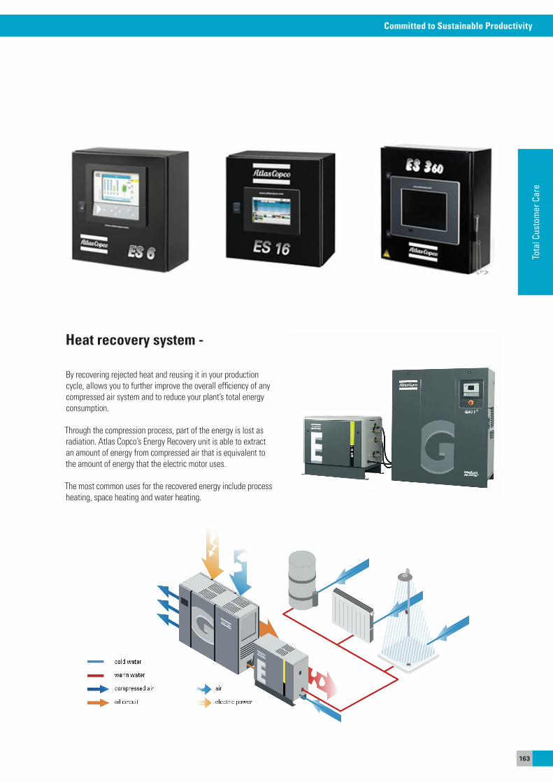
163
Committed to Sustainable Productivity
Tota
l Cus
tom
er C
are
By recovering rejected heat and reusing it in your production cycle, allows you to further improve the overall efficiency of any compressed air system and to reduce your plant’s total energy consumption.
Through the compression process, part of the energy is lost as radiation. atlas Copco’s energy Recovery unit is able to extract an amount of energy from compressed air that is equivalent to the amount of energy that the electric motor uses.
The most common uses for the recovered energy include process heating, space heating and water heating.
Heat recovery system -
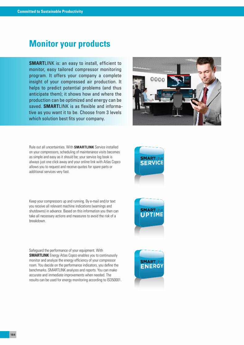
164
Committed to Sustainable Productivity
SMARTLINK is: an easy to install, efficient to monitor, easy tailored compressor monitoring program. It offers your company a complete insight of your compressed air production. It helps to predict potential problems (and thus anticipate them); it shows how and where the production can be optimized and energy can be saved. SMARTLINK is as flexible and informa-tive as you want it to be. Choose from 3 levels which solution best fits your company.
Monitor your products
Rule out all uncertainties. With SMARTLINK service installed on your compressors, scheduling of maintenance visits becomes as simple and easy as it should be; your service log book is always just one click away and your online link with atlas Copco allows you to request and receive quotes for spare parts or additional services very fast.
Keep your compressors up and running. By e-mail and/or text you receive all relevant machine indications (warnings and shutdowns) in advance. Based on this information you then can take all necessary actions and measures to avoid the risk of a breakdown.
safeguard the performance of your equipment. WithSMARTLINK energy atlas Copco enables you to continuously monitor and analyze the energy efficiency of your compressor room. you decide on the performance indicators, you define the benchmarks. sMaRTLINK analyzes and reports. you can make accurate and immediate improvements when needed. The results can be used for energy monitoring according to Iso50001.
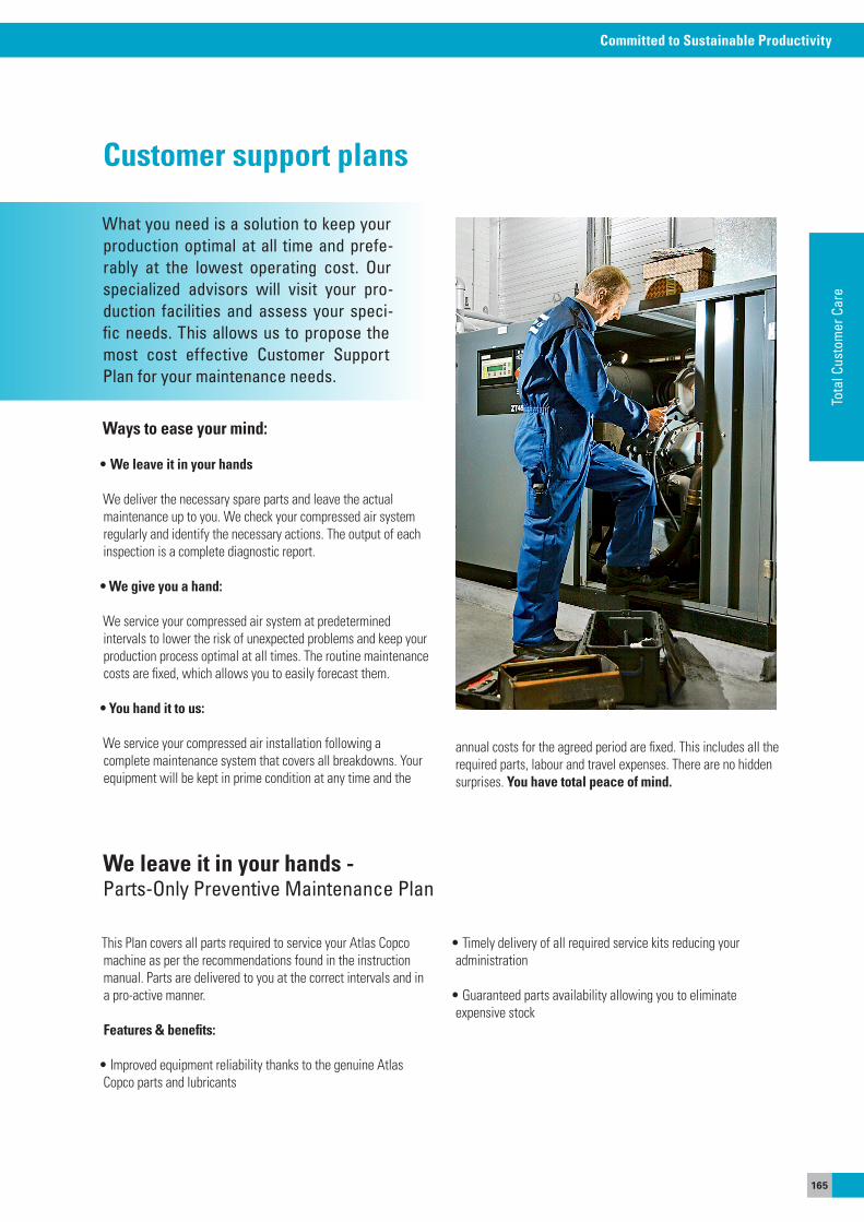
165
Committed to Sustainable Productivity
Tota
l Cus
tom
er C
are
What you need is a solution to keep your production optimal at all time and prefe-rably at the lowest operating cost. Our specialized advisors will visit your pro-duction facilities and assess your speci-fic needs. This allows us to propose the most cost effective Customer Support Plan for your maintenance needs.
Customer support plans
Ways to ease your mind:
• We leave it in your hands
We deliver the necessary spare parts and leave the actual maintenance up to you. We check your compressed air system regularly and identify the necessary actions. The output of each inspection is a complete diagnostic report.
• We give you a hand:
We service your compressed air system at predetermined intervals to lower the risk of unexpected problems and keep your production process optimal at all times. The routine maintenance costs are fixed, which allows you to easily forecast them.
• you hand it to us:
We service your compressed air installation following a complete maintenance system that covers all breakdowns. your equipment will be kept in prime condition at any time and the
annual costs for the agreed period are fixed. This includes all the required parts, labour and travel expenses. There are no hidden surprises. You have total peace of mind.
This Plan covers all parts required to service your atlas Copco machine as per the recommendations found in the instruction manual. Parts are delivered to you at the correct intervals and in a pro-active manner.
Features & benefits:
• Improved equipment reliability thanks to the genuine Atlas Copco parts and lubricants
We leave it in your hands - Parts-Only Preventive Maintenance Plan
• Timely delivery of all required service kits reducing youradministration
• Guaranteed parts availability allowing you to eliminateexpensive stock
166
Committed to Sustainable Productivity
Benefits:
• Improved equipment reliability thanks to genuine parts and expert technicians
• Stable costs up front helping you balance your maintenance budget
• Eliminate stock and administration by letting the experts take care of it
Inspection Plan:
a compressed air system can only be managed efficiently if the right data is available. atlas Copco’s Inspection Plan consists of regular inspection visits to identify any actions required to keep your compressed air system in prime operating condition. The output of the Inspection Plan is a complete diagnostic report , from which any work related to subsequent improvements can be quoted separately, allowing you to follow separate approval flows.
Benefits:
• No surprises, fixed yearly fee to perform the inspectionsincluding all labour and travel costs
• Improved equipment reliability thanks to regular follow-upsby the experts
• Comprehensive diagnostic report after each inspection visit
Preventative Maintenance Plan
This Plan covers all regular maintenance for your compressed air equipment in a proactive manner. Certified and trainedatlas Copco service technicians use genuine parts andlubricants to maintain your installation as it should be.This is the best way to lower the risk of unexpected problems allowing you to optimize your production process. The plan can be customized and adjusted at any time.
We give you a hand -Service at predetermined intervals
167
Committed to Sustainable Productivity
Tota
l Cus
tom
er C
are
Fixed Price Services for Regular Maintenance:
From machine inspections to labour intensive recommended visits, Fixed Price services offer you a clear path to maintaining your compressed air installation. atlas Copco’s trained technici-ans arrive at your door with all required parts to get the job done. They ensure that your machine runs in it's most effiecient way, with lower energy consumption and less risk of unexpected costs due to failures.
Benefits:
• No surprises, one fixed price to perform the work including all travel, material and labour costs
• All manufacturer recommended service activity list done and comprehensive diagnostics report after each visit
• Reduce administration and inventory by letting Atlas Copco take care of it
Fixed Price Services for Overhaul
as the owner of atlas Copco equipment, you are already familiar with its unique design features that help to achieve high reliabi-lity and the lowest total cost of ownership. overhaul performed after years of equipment operation helps to keep initial reliability and efficiency. atlas Copco’s trained technicians arrive at your door with all required parts to get the job done, and leave you knowing that your machine is in nearly brand new condition.
Benefits:
• All manufacturer recommended service activity list to keep reliability and efficiency as from day one
• Competent Atlas Copco technicians to perform such a crucial work
• No surprises, one fixed price to perform the overhaul to avoid subsequent downtime and production lost
168
Committed to Sustainable Productivity
Total Responsibility Plan
This Plan lives up to its name – total peace-of-mind with full coverage of the unit including: air ends, motor, electrical and electronic systems, coolers. The program consists of certified atlas Copco technicians providing you with all regularmaintenance, engineering improvements, breakdownrepairs and machine overhauls . It is a complete maintenance system with fixed annual costs for the agreed period.
Benefits:
• Use of genuine parts and expert technicians for complete coverage including overhauls and unfortunate breakdowns
• Stable costs removing all surprises as you balance your maintenance budget
• Eliminate stock and administration by letting the experts take care of it
AIRXtend
atlas Copco’s aIRXtend program is a five (5) year protection plan to maintain your system with fixed annual costs. This warranty extension is supported by the use of certified atlas Copco tech-nicians to perform all preventative maintenance for your system at the correct interval and in a proactive manner. Relax knowing that only the highest quality spare parts and consumables are used, originating from the same factories as your equipment.
Benefits:
• Use of genuine parts and expert technicians extending your warranty to five years
• Stable costs up front helping you balance your maintenance budget
• Eliminate stock and administration by letting the experts take care of it
You hand it to us - Complete maintenance system
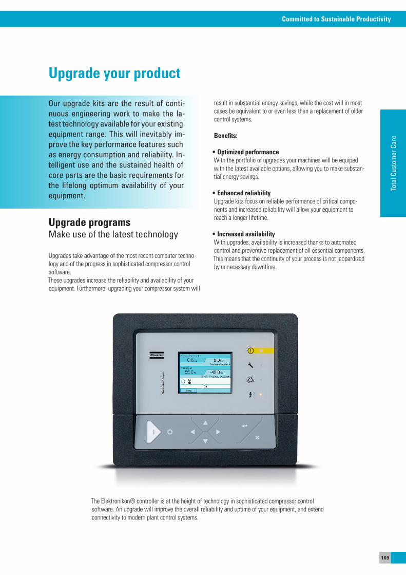
169
Committed to Sustainable Productivity
Tota
l Cus
tom
er C
are
Upgrades take advantage of the most recent computer techno-logy and of the progress in sophisticated compressor control software. These upgrades increase the reliability and availability of your equipment. Furthermore, upgrading your compressor system will
Upgrade programsMake use of the latest technology
Our upgrade kits are the result of conti-nuous engineering work to make the la-test technology available for your existing equipment range. This will inevitably im-prove the key performance features such as energy consumption and reliability. In-telligent use and the sustained health of core parts are the basic requirements for the lifelong optimum availability of your equipment.
Upgrade your product
Elektronikon controller:
The elektronikon® controller is at the height of technology in sophisticated compressor control software. an upgrade will improve the overall reliability and uptime of your equipment, and extend connectivity to modern plant control systems.
result in substantial energy savings, while the cost will in most cases be equivalent to or even less than a replacement of older control systems.
Benefits:
• Optimized performance With the portfolio of upgrades your machines will be equiped with the latest available options, allowing you to make substan-tial energy savings.
• Enhanced reliabilityUpgrade kits focus on reliable performance of critical compo-nents and increased reliability will allow your equipment to reach a longer lifetime.
• Increased availability With upgrades, availability is increased thanks to automated control and preventive replacement of all essential components. This means that the continuity of your process is not jeopardized by unnecessary downtime.
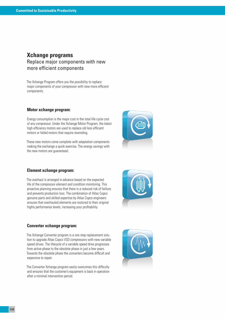
170
Committed to Sustainable Productivity
The Xchange Program offers you the possibility to replace major components of your compressor with new more efficient components.
Motor xchange program:
energy consumption is the major cost in the total life cycle cost of any compressor. Under the Xchange Motor Program, the latest high efficiency motors are used to replace old less efficient motors or failed motors that require rewinding.
These new motors come complete with adaptation components making the exchange a quick exercise. The energy savings with the new motors are guaranteed.
Element xchange program:
The overhaul is arranged in advance based on the expected life of the compressor element and condition monitoring. This proactive planning ensures that there is a reduced risk of faillure and prevents production loss. The combination of atlas Copco genuine parts and skilled expertise by atlas Copco engineers ensures that overhauled elements are restored to their original highly performance levels, increasing your profitability.
Converter xchange program:
The Xchange Converter program is a one step replacement solu-tion to upgrade atlas Copco VsD compressors with new variable speed drives. The lifecycle of a variable speed drive progresses from active phase to the obsolete phase in just a few years. Towards the obsolete phase the converters become difficult and expensive to repair.
The Converter Xchange program easily overcomes this difficulty and ensures that the customer’s equipment is back in operation after a minimal intervention period.
Xchange programsReplace major components with newmore efficient components
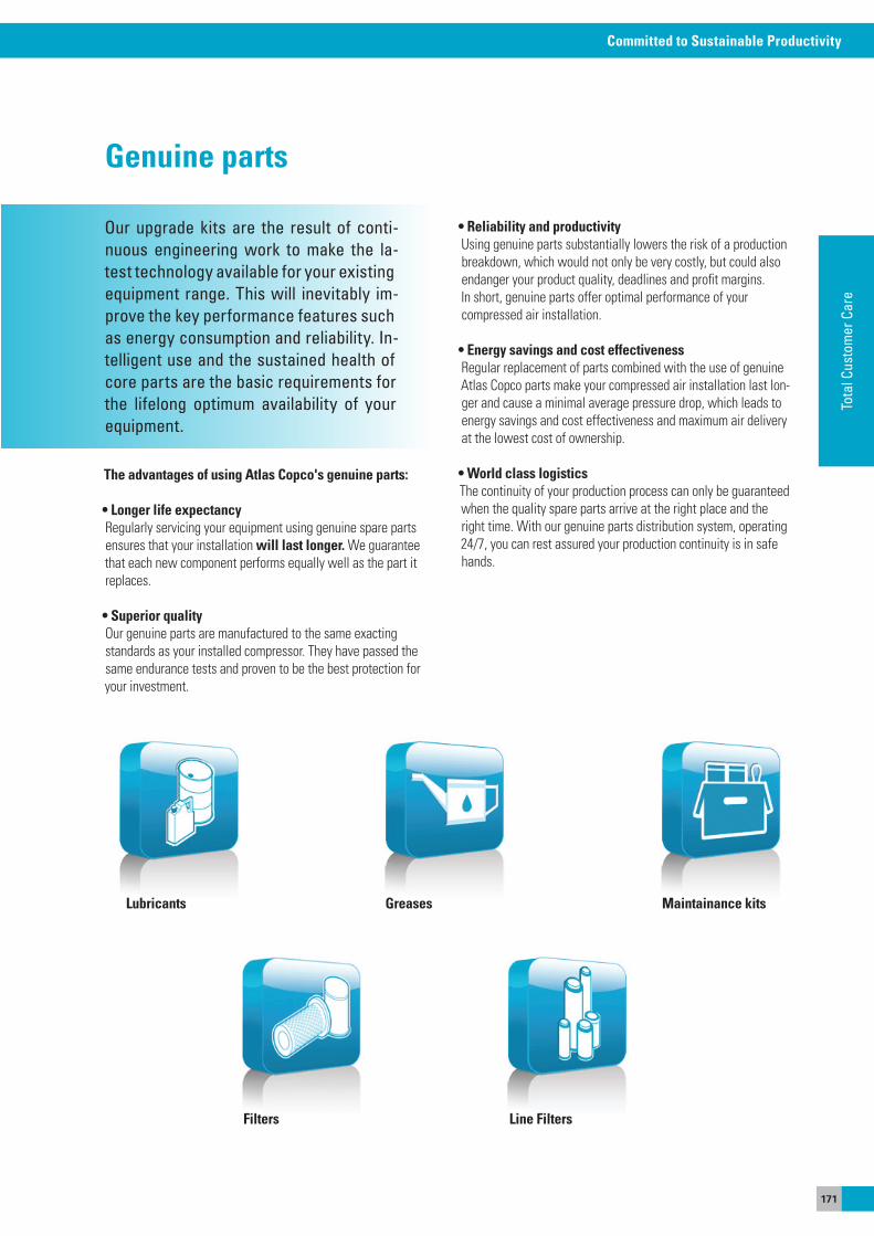
171
Committed to Sustainable Productivity
Tota
l Cus
tom
er C
are
Our upgrade kits are the result of conti-nuous engineering work to make the la-test technology available for your existing equipment range. This will inevitably im-prove the key performance features such as energy consumption and reliability. In-telligent use and the sustained health of core parts are the basic requirements for the lifelong optimum availability of your equipment.
Genuine parts
The advantages of using Atlas Copco's genuine parts:
• Longer life expectancy Regularly servicing your equipment using genuine spare parts ensures that your installation will last longer. We guarantee that each new component performs equally well as the part it replaces.
• Superior quality our genuine parts are manufactured to the same exacting standards as your installed compressor. They have passed the same endurance tests and proven to be the best protection for your investment.
• reliability and productivityUsing genuine parts substantially lowers the risk of a production breakdown, which would not only be very costly, but could also endanger your product quality, deadlines and profit margins.In short, genuine parts offer optimal performance of yourcompressed air installation.
• Energy savings and cost effectiveness Regular replacement of parts combined with the use of genuine atlas Copco parts make your compressed air installation last lon-ger and cause a minimal average pressure drop, which leads to energy savings and cost effectiveness and maximum air delivery at the lowest cost of ownership.
• World class logisticsThe continuity of your production process can only be guaranteed when the quality spare parts arrive at the right place and the right time. With our genuine parts distribution system, operating 24/7, you can rest assured your production continuity is in safe hands.
Lubricants Greases
Filters Line Filters
Maintainance kits

172
Committed to Sustainable Productivity
LubricantsEngineered to protect
atlas Copco lubricants are engineered with the exact right selec-tion of additives that interact in just the right proportion to obtain optimal performance. The additives not only support the base lubrication requirements, they also interact in multi processes in the compressor.
The properties of quality:
all our efforts are aimed at optimizing the performance of your atlas Copco compressor for the longest lifetime at the lowest operating cost.
The experts in our laboratories are uniquely skilled in specifying lubricant properties for atlas Copco compressors to operate op-timally in a wide range of settings and conditions, during several thousands of hours.
atlas Copco lubricants are a unique blend of chemical proper-ties, engineered for optimal performance in their dedicated functions.
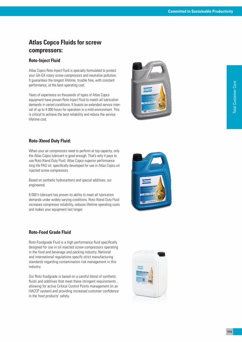
173
Committed to Sustainable Productivity
Tota
l Cus
tom
er C
are
Atlas Copco Fluids for screwcompressors:Roto-Inject Fluid
atlas Copco Roto-Inject Fluid is specially formulated to protect your Ga-GX rotary screw compressors and neutralize pollution. It guarantees the longest lifetime, trouble free, with constant performance, at the best operating cost.
years of experience on thousands of types of atlas Copco equipment have proven Roto-Inject Fluid to match all lubrication demands in varied conditions. It boasts an extended service inter-val of up to 4 000 hours for operation in a mild environment. This is critical to achieve the best reliability and reduce the service lifetime cost.
Roto-Xtend Duty Fluid:
When your air compressors need to perform at top capacity, only the atlas Copco lubricant is good enough. That’s why it pays to use Roto-Xtend Duty Fluid. atlas Copco superior performance long life Pao oil, specifically developed for use in atlas Copco oil injected screw compressors.
Based on synthetic hydrocarbons and special additives, our engineered.
8 000 h lubricant has proven its ability to meet all lubrication demands under widely varying conditions. Roto-Xtend Duty Fluid increases compressor reliability, reduces lifetime operating costs and makes your equipment last longer.
Roto-Food Grade Fluid
Roto-Foodgrade Fluid is a high performance fluid specifically designed for use in oil injected screw compressors operating in the food and beverage and packing industry. National and international regulations specify strict manufacturing standards regarding contamination risk management in this industry.
our Roto foodgrade is based on a careful blend of synthetic fluids and additives that meet these stringent requirements , allowing for active Critical Control Points management (in an HaCCP system) and providing increased customer confidence in the food products' safety.
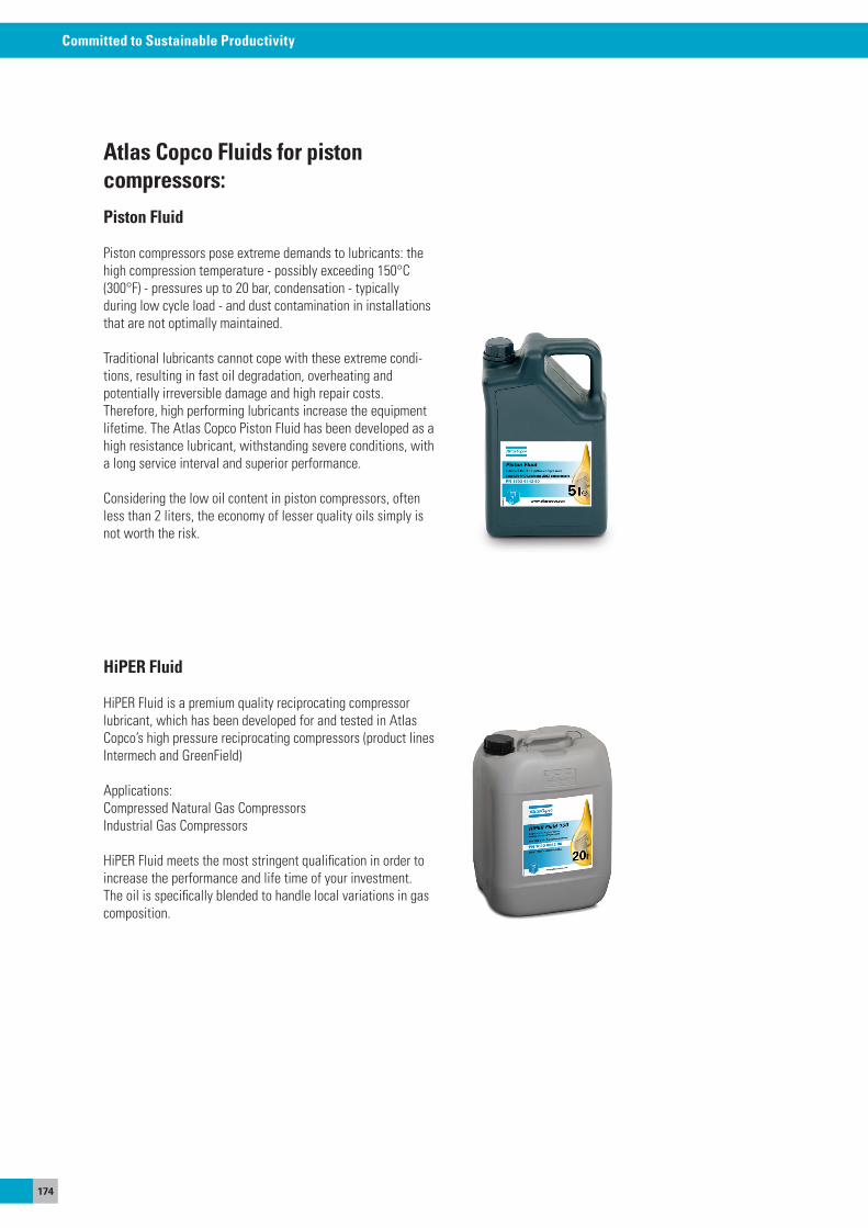
174
Committed to Sustainable Productivity
Atlas Copco Fluids for pistoncompressors:Piston Fluid
Piston compressors pose extreme demands to lubricants: the high compression temperature - possibly exceeding 150°C (300°F) - pressures up to 20 bar, condensation - typically during low cycle load - and dust contamination in installations that are not optimally maintained.
Traditional lubricants cannot cope with these extreme condi-tions, resulting in fast oil degradation, overheating andpotentially irreversible damage and high repair costs.Therefore, high performing lubricants increase the equipment lifetime. The atlas Copco Piston Fluid has been developed as a high resistance lubricant, withstanding severe conditions, with a long service interval and superior performance.
Considering the low oil content in piston compressors, often less than 2 liters, the economy of lesser quality oils simply is not worth the risk.
HiPER Fluid
HiPeR Fluid is a premium quality reciprocating compressor lubricant, which has been developed for and tested in atlas Copco’s high pressure reciprocating compressors (product lines Intermech and GreenField)
applications: Compressed Natural Gas Compressors Industrial Gas Compressors
HiPeR Fluid meets the most stringent qualification in order to increase the performance and life time of your investment. The oil is specifically blended to handle local variations in gas composition.
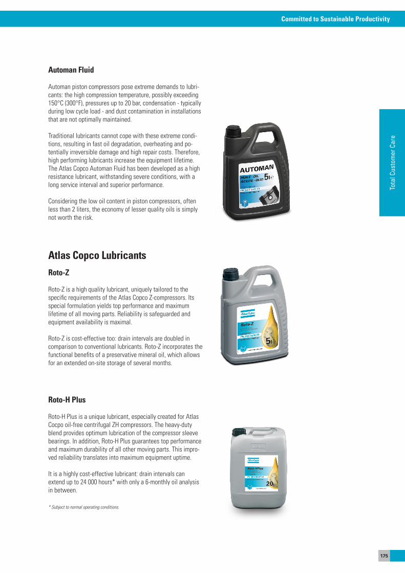
175
Committed to Sustainable Productivity
Tota
l Cus
tom
er C
are
Automan Fluid
automan piston compressors pose extreme demands to lubri-cants: the high compression temperature, possibly exceeding 150°C (300°F), pressures up to 20 bar, condensation - typically during low cycle load - and dust contamination in installations that are not optimally maintained.
Traditional lubricants cannot cope with these extreme condi-tions, resulting in fast oil degradation, overheating and po-tentially irreversible damage and high repair costs. Therefore, high performing lubricants increase the equipment lifetime. The atlas Copco automan Fluid has been developed as a high resistance lubricant, withstanding severe conditions, with a long service interval and superior performance.
Considering the low oil content in piston compressors, often less than 2 liters, the economy of lesser quality oils is simply not worth the risk.
Atlas Copco LubricantsRoto-Z
Roto-Z is a high quality lubricant, uniquely tailored to the specific requirements of the atlas Copco Z-compressors. Its special formulation yields top performance and maximum lifetime of all moving parts. Reliability is safeguarded and equipment availability is maximal.
Roto-Z is cost-effective too: drain intervals are doubled in comparison to conventional lubricants. Roto-Z incorporates the functional benefits of a preservative mineral oil, which allows for an extended on-site storage of several months.
Roto-H Plus
Roto-H Plus is a unique lubricant, especially created for atlas Cocpo oil-free centrifugal ZH compressors. The heavy-duty blend provides optimum lubrication of the compressor sleeve bearings. In addition, Roto-H Plus guarantees top performance and maximum durability of all other moving parts. This impro-ved reliability translates into maximum equipment uptime.
It is a highly cost-effective lubricant: drain intervals can extend up to 24 000 hours* with only a 6-monthly oil analysis in between.
* Subject to normal operating conditions.
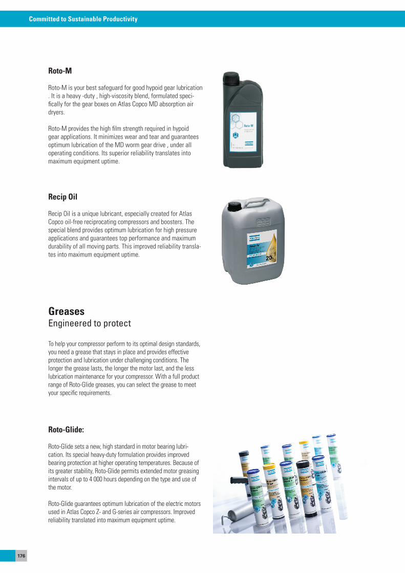
176
Committed to Sustainable Productivity
Roto-M
Roto-M is your best safeguard for good hypoid gear lubrication . It is a heavy -duty , high-viscosity blend, formulated speci-fically for the gear boxes on atlas Copco MD absorption air dryers.
Roto-M provides the high film strength required in hypoid gear applications. It minimizes wear and tear and guarantees optimum lubrication of the MD worm gear drive , under all operating conditions. Its superior reliability translates into maximum equipment uptime.
Recip Oil
Recip oil is a unique lubricant, especially created for atlas Copco oil-free reciprocating compressors and boosters. The special blend provides optimum lubrication for high pressure applications and guarantees top performance and maximum durability of all moving parts. This improved reliability transla-tes into maximum equipment uptime.
GreasesEngineered to protect
To help your compressor perform to its optimal design standards, you need a grease that stays in place and provides effective protection and lubrication under challenging conditions. The longer the grease lasts, the longer the motor last, and the less lubrication maintenance for your compressor. With a full product range of Roto-Glide greases, you can select the grease to meet your specific requirements.
Roto-Glide:
Roto-Glide sets a new, high standard in motor bearing lubri-cation. Its special heavy-duty formulation provides improved bearing protection at higher operating temperatures. Because of its greater stability, Roto-Glide permits extended motor greasing intervals of up to 4 000 hours depending on the type and use of the motor.
Roto-Glide guarantees optimum lubrication of the electric motors used in atlas Copco Z- and G-series air compressors. Improved reliability translated into maximum equipment uptime.
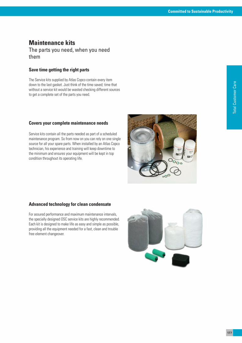
177
Committed to Sustainable Productivity
Tota
l Cus
tom
er C
are
Covers your complete maintenance needs
service kits contain all the parts needed as part of a scheduled maintenance program. so from now on you can rely on one single source for all your spare parts. When installed by an atlas Copco technician, his experience and training will keep downtime to the minimum and ensures your equipment will be kept in top condition throughout its operating life.
Advanced technology for clean condensate
For assured performance and maximum maintenance intervals, the specially designed osC service kits are highly recommended. each kit is designed to make life as easy and simple as possible, providing all the equipment needed for a fast, clean and trouble free element changeover.
Maintenance kitsThe parts you need, when you need them
Save time getting the right parts
The service kits supplied by atlas Copco contain every item down to the last gasket. Just think of the time saved; time that without a service kit would be wasted checking different sources to get a complete set of the parts you need.
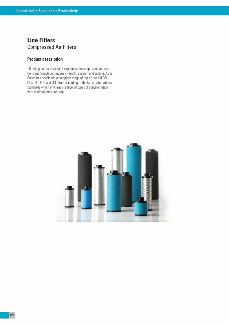
178
Committed to Sustainable Productivity
Line FiltersCompressed Air Filters
Product description
TBuilding on many years of experience in compressed air solu-tions and trough continuous in-depth research and testing, atlas Copco has developed a complete range of top-of-the-bill DD, DDp, PD, PDp and QD filters according to the latest international standards which efficiently reduce all types of contamination with minimal pressure drop.
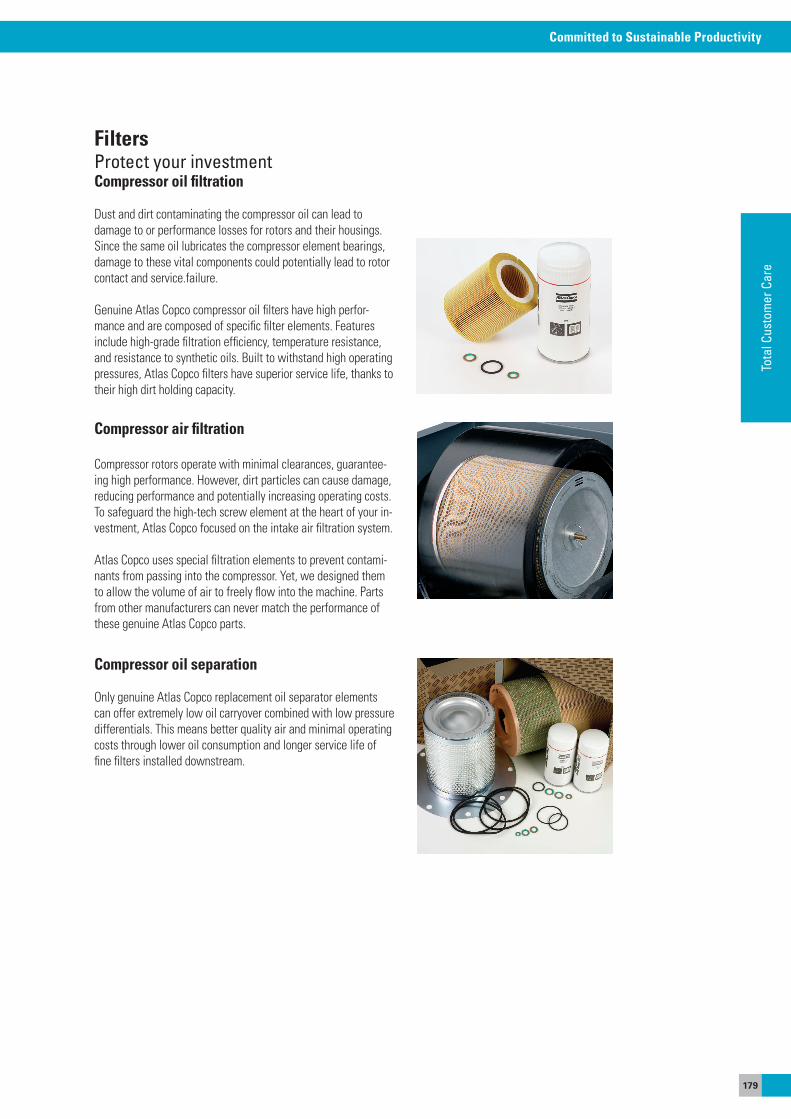
179
Committed to Sustainable Productivity
Tota
l Cus
tom
er C
are
FiltersProtect your investmentCompressor oil filtration
Dust and dirt contaminating the compressor oil can lead to damage to or performance losses for rotors and their housings. since the same oil lubricates the compressor element bearings, damage to these vital components could potentially lead to rotor contact and service.failure.
Genuine atlas Copco compressor oil filters have high perfor-mance and are composed of specific filter elements. Features include high-grade filtration efficiency, temperature resistance, and resistance to synthetic oils. Built to withstand high operating pressures, atlas Copco filters have superior service life, thanks to their high dirt holding capacity.
Compressor air filtration
Compressor rotors operate with minimal clearances, guarantee-ing high performance. However, dirt particles can cause damage, reducing performance and potentially increasing operating costs. To safeguard the high-tech screw element at the heart of your in-vestment, atlas Copco focused on the intake air filtration system.
atlas Copco uses special filtration elements to prevent contami-nants from passing into the compressor. yet, we designed them to allow the volume of air to freely flow into the machine. Parts from other manufacturers can never match the performance of these genuine atlas Copco parts.
Compressor oil separation
only genuine atlas Copco replacement oil separator elements can offer extremely low oil carryover combined with low pressure differentials. This means better quality air and minimal operating costs through lower oil consumption and longer service life of fine filters installed downstream.
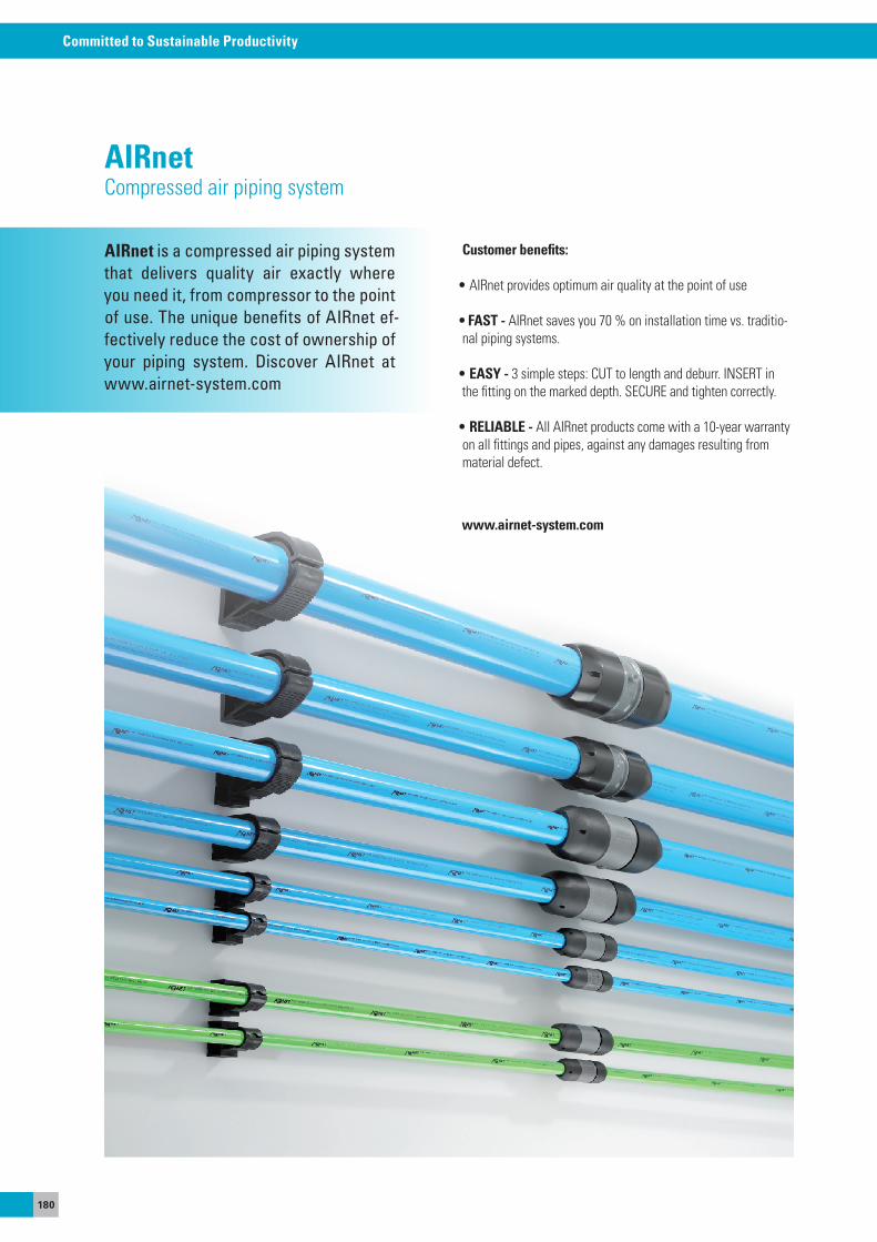
180
Committed to Sustainable Productivity
AIRnetCompressed air piping system
Customer benefits:
• AIRnet provides optimum air quality at the point of use
• FAST - aIRnet saves you 70 % on installation time vs. traditio-nal piping systems.
• EASY - 3 simple steps: CUT to length and deburr. INseRT in the fitting on the marked depth. seCURe and tighten correctly.
• RELIABLE - all aIRnet products come with a 10-year warranty on all fittings and pipes, against any damages resulting from material defect.
www.airnet-system.com
AIRnet is a compressed air piping system that delivers quality air exactly where you need it, from compressor to the point of use. The unique benefits of AIRnet ef-fectively reduce the cost of ownership of your piping system. Discover AIRnet at www.airnet-system.com

181
Committed to Sustainable Productivity
Tota
l Cus
tom
er C
are
182
Committed to Sustainable Productivity
Committed to Sustainable Productivity
www.atlascopco.com
6996
0010
00 B
elgi
um, 2
013
Des
ign:
Bra
nd S
tudi
o