GEL-5261 Web Management Guide
570
GEL-5261 52-Port L2 Managed Gigabit Switch User Manual V1.0 Digital Data Communications Asia Co., Ltd. http://www.level1.com
-
Upload
khangminh22 -
Category
Documents
-
view
4 -
download
0
Transcript of GEL-5261 Web Management Guide
GEL-5261
52-Port L2 Managed Gigabit Switch
User Manual
V1.0
Digital Data Communications Asia Co., Ltd.
http://www.level1.com

User Manual
GEL-5261
L2 Managed Gigabit Ethernet Switch with 48 10/100/1000BASE-T (RJ-45) Ports and 4 Gigabit SFP Ports
E062017/ST-R01

How to Use This Guide
– 3 –
This guide includes detailed information on the switch software, including how to operate and use the management functions of the switch. To deploy this switch effectively and ensure trouble-free operation, you should first read the relevant sections in this guide so that you are familiar with all of its software features.
Who Should Read this Guide?
This guide is for network administrators who are responsible for operating and maintaining network equipment. The guide assumes a basic working knowledge of LANs (Local Area Networks), the Internet Protocol (IP), and Simple Network Management Protocol (SNMP).
How this Guide is Organized
This guide provides detailed information about the switch’s key features. It also describes the switch’s web browser interface. For information on the command line interface refer to the CLI Reference Guide.
The guide includes these sections:
◆ Section I “Getting Started” — Includes an introduction to switch management, and the basic settings required to access the management interface.
◆ Section II “Web Configuration” — Includes all management options available
through the web browser interface.
◆ Section III “Appendices” — Includes information on troubleshooting switch management access.
Related Documentation
This guide focuses on switch software configuration through the web browser.
For information on how to manage the switch through the command line interface, see the following guide:
CLI Reference Guide
Note: For a description of how to initialize the switch for management access via the CLI, web interface or SNMP, refer to “Initial Switch Configuration” in the CLI Reference Guide.
How to Use This Guide
– 4 –
For information on how to install the switch, see the following guide:
Quick Start Guide
For all safety information and regulatory statements, see the following documents:
Quick Start Guide Safety and Regulatory Information
Conventions The following conventions are used throughout this guide to show information:
Note: Emphasizes important information or calls your attention to related features or instructions.
Revision History This section summarizes the changes in each revision of this guide.
Revision Date Change Description
v1.1.10a.171 01/2017 Initial release
– 5 –
Contents
How to Use This Guide 3
Contents 5
Figures 15
Tables 27
Section I Getting Started 29
1 Introduction 31
Key Features 31
Description of Software Features 33
Address Resolution Protocol 37
System Defaults 38
Section II Web Configuration 41
2 Using the Web Interface 43
Connecting to the Web Interface 43
Navigating the Web Browser Interface 44
Dashboard 44
Configuration Options 46
Panel Display 46
Main Menu 47
3 Basic Management Tasks 63
Displaying System Information 64
Displaying Hardware/Software Versions 65
Configuring Support for Jumbo Frames 66
Displaying Bridge Extension Capabilities 67
– 6 –
Contents
Managing System Files 69
Copying Files via FTP/SFTP/TFTP or HTTP 69
Saving the Running Configuration to a Local File 71
Setting the Start-up File 72
Showing System Files 73
Automatic Operation Code Upgrade 73
Setting the System Clock 77
Setting the Time Manually 78
Setting the SNTP Polling Interval 79
Configuring NTP 79
Configuring Time Servers 80
Setting the Time Zone 84
Configuring Summer Time 85
Configuring the Console Port 87
Configuring Telnet Settings 89
Displaying CPU Utilization 90
Configuring CPU Guard 91
Displaying Memory Utilization 92
Resetting the System 93
4 Interface Configuration 97
Port Configuration 98
Configuring by Port List 98
Configuring by Port Range 100
Displaying Connection Status 101
Showing Port or Trunk Statistics 102
Displaying Statistical History 106
Displaying Transceiver Data 110
Configuring Transceiver Thresholds 111
Performing Cable Diagnostics 113
Trunk Configuration 115
Configuring a Static Trunk 116
Configuring a Dynamic Trunk 119
Displaying LACP Port Counters 125
Displaying LACP Settings and Status for the Local Side 126
– 7 –
Contents
Displaying LACP Settings and Status for the Remote Side 128
Configuring Load Balancing 129
Saving Power 131
Configuring Local Port Mirroring 132
Configuring Remote Port Mirroring 134
Sampling Traffic Flows 138
Configuring sFlow Receiver Settings 139
Configuring an sFlow Polling Instance 141
Traffic Segmentation 143
Enabling Traffic Segmentation 143
Configuring Uplink and Downlink Ports 144
5 VLAN Configuration 147
IEEE 802.1Q VLANs 147
Configuring VLAN Groups 149
Adding Static Members to VLANs 152
IEEE 802.1Q Tunneling 156
Enabling QinQ Tunneling on the Switch 160
Creating CVLAN to SPVLAN Mapping Entries 161
Adding an Interface to a QinQ Tunnel 163
Protocol VLANs 164
Configuring Protocol VLAN Groups 165
Mapping Protocol Groups to Interfaces 166
Configuring MAC-based VLANs 168
6 Address Table Settings 171
Displaying the Dynamic Address Table 171
Clearing the Dynamic Address Table 172
Changing the Aging Time 173
Configuring MAC Address Learning 174
Setting Static Addresses 176
Issuing MAC Address Traps 178
7 Spanning Tree Algorithm 181
Overview 181
Configuring Loopback Detection 183

– 8 –
Contents
Configuring Global Settings for STA 185
Displaying Global Settings for STA 190
Configuring Interface Settings for STA 191
Displaying Interface Settings for STA 196
Configuring Multiple Spanning Trees 199
Configuring Interface Settings for MSTP 203
8 Congestion Control 205
Rate Limiting 205
Storm Control 206
9 Class of Service 209
Layer 2 Queue Settings 209
Setting the Default Priority for Interfaces 209
Selecting the Queue Mode 210
Layer 3/4 Priority Settings 213
Setting Priority Processing to DSCP or CoS 214
Mapping CoS Priorities to Per-hop Behavior 215
Mapping DSCP Priorities to Per-hop Behavior 216
10 Quality of Service 219
Overview 219
Configuring a Class Map 220
Creating QoS Policies 223
Attaching a Policy Map to a Port 226
11 VoIP Traffic Configuration 229
Overview 229
Configuring VoIP Traffic 230
Configuring Telephony OUI 231
Configuring VoIP Traffic Ports 232
12 Security Measures 235
AAA (Authentication, Authorization and Accounting) 236
Configuring Local/Remote Logon Authentication 237
Configuring Remote Logon Authentication Servers 238
Configuring AAA Accounting 243
– 9 –
Contents
Configuring AAA Authorization 249
Configuring User Accounts 253
Web Authentication 255
Configuring Global Settings for Web Authentication 255
Configuring Interface Settings for Web Authentication 256
Network Access (MAC Address Authentication) 257
Configuring Global Settings for Network Access 260
Configuring Network Access for Ports 261
Configuring a MAC Address Filter 263
Displaying Secure MAC Address Information 264
Configuring HTTPS 266
Configuring Global Settings for HTTPS 266
Replacing the Default Secure-site Certificate 268
Configuring the Secure Shell 270
Configuring the SSH Server 272
Generating the Host Key Pair 273
Importing User Public Keys 275
Access Control Lists 277
Showing TCAM Utilization 278
Setting the ACL Name and Type 280
Configuring a Standard IPv4 ACL 282
Configuring an Extended IPv4 ACL 283
Configuring a Standard IPv6 ACL 286
Configuring an Extended IPv6 ACL 287
Configuring a MAC ACL 290
Configuring an ARP ACL 292
Binding a Port to an Access Control List 293
Showing ACL Hardware Counters 294
Filtering IP Addresses for Management Access 296
Configuring Port Security 298
Configuring 802.1X Port Authentication 300
Configuring 802.1X Global Settings 302
Configuring Port Authenticator Settings for 802.1X 302
Displaying 802.1X Statistics 306
DoS Protection 308
– 10 –
Contents
DHCP Snooping 310
DHCP Snooping Global Configuration 313
DHCP Snooping VLAN Configuration 315
Configuring Ports for DHCP Snooping 316
Displaying DHCP Snooping Binding Information 317
IPv4 Source Guard 318
Configuring Ports for IPv4 Source Guard 318
Configuring Static Bindings for IPv4 Source Guard 320
Displaying Information for Dynamic IPv4 Source Guard Bindings 323
ARP Inspection 324
Configuring Global Settings for ARP Inspection 325
Configuring VLAN Settings for ARP Inspection 327
Configuring Interface Settings for ARP Inspection 329
Displaying ARP Inspection Statistics 330
Displaying the ARP Inspection Log 331
13 Basic Administration Protocols 333
Configuring Event Logging 334
System Log Configuration 334
Remote Log Configuration 336
Sending Simple Mail Transfer Protocol Alerts 337
Link Layer Discovery Protocol 339
Setting LLDP Timing Attributes 339
Configuring LLDP Interface Attributes 341
Configuring LLDP Interface Civic-Address 345
Displaying LLDP Local Device Information 347
Displaying LLDP Remote Device Information 351
Displaying Device Statistics 359
Simple Network Management Protocol 362
Configuring Global Settings for SNMP 364
Setting the Local Engine ID 365
Specifying a Remote Engine ID 366
Setting SNMPv3 Views 367
Configuring SNMPv3 Groups 370
Setting Community Access Strings 375
– 11 –
Contents
Configuring Local SNMPv3 Users 376
Configuring Remote SNMPv3 Users 379
Specifying Trap Managers 382
Creating SNMP Notification Logs 386
Showing SNMP Statistics 388
Remote Monitoring 390
Configuring RMON Alarms 390
Configuring RMON Events 393
Configuring RMON History Samples 395
Configuring RMON Statistical Samples 398
Switch Clustering 400
Configuring General Settings for Clusters 401
Cluster Member Configuration 402
Managing Cluster Members 404
Setting a Time Range 405
Ethernet Ring Protection Switching 408
ERPS Global Configuration 412
ERPS Ring Configuration 412
ERPS Forced and Manual Mode Operations 428
LBD Configuration 432
Configuring Global Settings for LBD 433
Configuring Interface Settings for LBD 435
14 Multicast Filtering 437
Overview 437
Layer 2 IGMP (Snooping and Query for IPv4) 438
Configuring IGMP Snooping and Query Parameters 440
Specifying Static Interfaces for a Multicast Router 444
Assigning Interfaces to Multicast Services 446
Setting IGMP Snooping Status per Interface 448
Filtering IGMP Query Packets and Multicast Data 454
Displaying Multicast Groups Discovered by IGMP Snooping 455
Displaying IGMP Snooping Statistics 456
Filtering and Throttling IGMP Groups 460
Enabling IGMP Filtering and Throttling 460
– 12 –
Contents
Configuring IGMP Filter Profiles 461
Configuring IGMP Filtering and Throttling for Interfaces 463
MLD Snooping (Snooping and Query for IPv6) 465
Configuring MLD Snooping and Query Parameters 465
Setting Immediate Leave Status for MLD Snooping per Interface 467
Specifying Static Interfaces for an IPv6 Multicast Router 468
Assigning Interfaces to IPv6 Multicast Services 470
Showing MLD Snooping Groups and Source List 472
Displaying MLD Snooping Statistics 473
Filtering and Throttling MLD Groups 481
Enabling MLD Filtering and Throttling 482
Configuring MLD Filter Profiles 482
Configuring MLD Filtering and Throttling for Interfaces 485
Filtering MLD Query Packets on an Interface 486
15 IP Tools 489
Using the Ping Function 489
Using the Trace Route Function 491
Address Resolution Protocol 492
Basic ARP Configuration 493
Configuring Static ARP Addresses 494
Displaying Dynamic or Local ARP Entries 496
Displaying ARP Statistics 497
16 IP Configuration 499
Setting the Switch’s IP Address (IP Version 4) 499
Configuring IPv4 Interface Settings 499
Setting the Switch’s IP Address (IP Version 6) 503
Configuring the IPv6 Default Gateway 503
Configuring IPv6 Interface Settings 504
Configuring an IPv6 Address 509
Showing IPv6 Addresses 511
Showing the IPv6 Neighbor Cache 513
Showing IPv6 Statistics 514
Showing the MTU for Responding Destinations 520

– 13 –
Contents
17 General IP Routing 521
Overview 521
Initial Configuration 521
IP Routing and Switching 522
Routing Path Management 523
Routing Protocols 523
Configuring Static Routes 524
Displaying the Routing Table 525
18 IP Services 527
Domain Name Service 527
Configuring General DNS Service Parameters 527
Configuring a List of Domain Names 528
Configuring a List of Name Servers 530
Configuring Static DNS Host to Address Entries 531
Displaying the DNS Cache 532
Multicast Domain Name Service 533
Dynamic Host Configuration Protocol 534
Specifying a DHCP Client Identifier 535
Configuring DHCP Relay Service 536
Enabling DHCP Dynamic Provision 538
Section III Appendices 539
A Software Specifications 541
Software Features 541
Management Features 542
Standards 543
Management Information Bases 543
B Troubleshooting 545
Problems Accessing the Management Interface 545
Using System Logs 546
C License Information 547
The GNU General Public License 547

– 14 –
Contents
Glossary 551
Index 559
– 15 –
Figures
Figure 1: Dashboard 45
Figure 2: System Information 64
Figure 3: General Switch Information 66
Figure 4: Configuring Support for Jumbo Frames 67
Figure 5: Displaying Bridge Extension Configuration 68
Figure 6: Copy Firmware 71
Figure 7: Saving the Running Configuration 72
Figure 8: Setting Start-Up Files 72
Figure 9: Displaying System Files 73
Figure 10: Configuring Automatic Code Upgrade 77
Figure 11: Manually Setting the System Clock 78
Figure 12: Setting the Polling Interval for SNTP 79
Figure 13: Configuring NTP 80
Figure 14: Specifying SNTP Time Servers 81
Figure 15: Adding an NTP Time Server 82
Figure 16: Showing the NTP Time Server List 82
Figure 17: Adding an NTP Authentication Key 83
Figure 18: Showing the NTP Authentication Key List 84
Figure 19: Setting the Time Zone 85
Figure 20: Configuring Summer Time 87
Figure 21: Console Port Settings 88
Figure 22: Telnet Connection Settings 90
Figure 23: Displaying CPU Utilization 91
Figure 24: Configuring CPU Guard 92
Figure 25: Displaying Memory Utilization 93
Figure 26: Restarting the Switch (Immediately) 95
Figure 27: Restarting the Switch (In) 95
Figure 28: Restarting the Switch (At) 96
Figure 29: Restarting the Switch (Regularly) 96
– 16 –
Figures
Figure 30: Configuring Connections by Port List 100
Figure 31: Configuring Connections by Port Range 101
Figure 32: Displaying Port Information 102
Figure 33: Showing Port Statistics (Table) 105
Figure 34: Showing Port Statistics (Chart) 106
Figure 35: Configuring a History Sample 108
Figure 36: Showing Entries for History Sampling 108
Figure 37: Showing Status of Statistical History Sample 109
Figure 38: Showing Current Statistics for a History Sample 109
Figure 39: Showing Ingress Statistics for a History Sample 110
Figure 40: Displaying Transceiver Data 111
Figure 41: Configuring Transceiver Thresholds 113
Figure 42: Performing Cable Tests 115
Figure 43: Configuring Static Trunks 116
Figure 44: Creating Static Trunks 117
Figure 45: Adding Static Trunks Members 118
Figure 46: Configuring Connection Parameters for a Static Trunk 118
Figure 47: Showing Information for Static Trunks 119
Figure 48: Configuring Dynamic Trunks 119
Figure 49: Configuring the LACP Aggregator Admin Key 122
Figure 50: Enabling LACP on a Port 123
Figure 51: Configuring LACP Parameters on a Port 123
Figure 52: Showing Members of a Dynamic Trunk 124
Figure 53: Configuring Connection Settings for a Dynamic Trunk 124
Figure 54: Showing Connection Parameters for Dynamic Trunks 125
Figure 55: Displaying LACP Port Counters 126
Figure 56: Displaying LACP Port Internal Information 127
Figure 57: Displaying LACP Port Remote Information 129
Figure 58: Configuring Load Balancing 130
Figure 59: Enabling Power Savings 132
Figure 60: Configuring Local Port Mirroring 132
Figure 61: Configuring Local Port Mirroring 133
Figure 62: Displaying Local Port Mirror Sessions 134
Figure 63: Configuring Remote Port Mirroring 134
Figure 64: Configuring Remote Port Mirroring (Source) 137
– 17 –
Figures
Figure 65: Configuring Remote Port Mirroring (Intermediate) 138
Figure 66: Configuring Remote Port Mirroring (Destination) 138
Figure 67: Configuring an sFlow Receiver 140
Figure 68: Showing sFlow Receivers 141
Figure 69: Configuring an sFlow Instance 142
Figure 70: Showing sFlow Instances 142
Figure 71: Enabling Traffic Segmentation 144
Figure 72: Configuring Members for Traffic Segmentation 145
Figure 73: Showing Traffic Segmentation Members 146
Figure 74: VLAN Compliant and VLAN Non-compliant Devices 148
Figure 75: Creating Static VLANs 151
Figure 76: Modifying Settings for Static VLANs 151
Figure 77: Showing Static VLANs 152
Figure 78: Configuring Static Members by VLAN Index 154
Figure 79: Configuring Static VLAN Members by Interface 155
Figure 80: Configuring Static VLAN Members by Interface Range 156
Figure 81: QinQ Operational Concept 157
Figure 82: Enabling QinQ Tunneling 161
Figure 83: Configuring CVLAN to SPVLAN Mapping Entries 162
Figure 84: Showing CVLAN to SPVLAN Mapping Entries 162
Figure 85: Adding an Interface to a QinQ Tunnel 164
Figure 86: Configuring Protocol VLANs 166
Figure 87: Displaying Protocol VLANs 166
Figure 88: Assigning Interfaces to Protocol VLANs 168
Figure 89: Showing the Interface to Protocol Group Mapping 168
Figure 90: Configuring MAC-Based VLANs 170
Figure 91: Showing MAC-Based VLANs 170
Figure 92: Displaying the Dynamic MAC Address Table 172
Figure 93: Clearing Entries in the Dynamic MAC Address Table 173
Figure 94: Setting the Address Aging Time 174
Figure 95: Configuring MAC Address Learning 175
Figure 96: Configuring Static MAC Addresses 177
Figure 97: Displaying Static MAC Addresses 177
Figure 98: Issuing MAC Address Traps (Global Configuration) 178
Figure 99: Issuing MAC Address Traps (Interface Configuration) 179
– 18 –
Figures
Figure 100: STP Root Ports and Designated Ports 182
Figure 101: MSTP Region, Internal Spanning Tree, Multiple Spanning Tree 182
Figure 102: Spanning Tree – Common Internal, Common, Internal 183
Figure 103: Configuring Port Loopback Detection 185
Figure 104: Configuring Global Settings for STA (STP) 189
Figure 105: Configuring Global Settings for STA (RSTP) 189
Figure 106: Configuring Global Settings for STA (MSTP) 190
Figure 107: Displaying Global Settings for STA 191
Figure 108: Determining the Root Port 193
Figure 109: Configuring Interface Settings for STA 196
Figure 110: STA Port Roles 197
Figure 111: Displaying Interface Settings for STA 198
Figure 112: Creating an MST Instance 200
Figure 113: Displaying MST Instances 200
Figure 114: Modifying the Priority for an MST Instance 201
Figure 115: Displaying Global Settings for an MST Instance 201
Figure 116: Adding a VLAN to an MST Instance 202
Figure 117: Displaying Members of an MST Instance 202
Figure 118: Configuring MSTP Interface Settings 204
Figure 119: Displaying MSTP Interface Settings 204
Figure 120: Configuring Rate Limits 206
Figure 121: Configuring Storm Control 208
Figure 122: Setting the Default Port Priority 210
Figure 123: Setting the Queue Mode (Strict) 212
Figure 124: Setting the Queue Mode (WRR) 212
Figure 125: Setting the Queue Mode (Strict and WRR) 213
Figure 126: Setting the Trust Mode 215
Figure 127: Configuring CoS to Queue Mapping 216
Figure 128: Configuring DSCP to Queue Mapping 218
Figure 129: Configuring a Class Map 221
Figure 130: Showing Class Maps 222
Figure 131: Adding Rules to a Class Map 222
Figure 132: Showing the Rules for a Class Map 223
Figure 133: Configuring a Policy Map 225
Figure 134: Showing Policy Maps 225
– 19 –
Figures
Figure 135: Adding Rules to a Policy Map 226
Figure 136: Showing the Rules for a Policy Map 226
Figure 137: Attaching a Policy Map to a Port 227
Figure 138: Configuring a Voice VLAN 231
Figure 139: Configuring an OUI Telephony List 232
Figure 140: Showing an OUI Telephony List 232
Figure 141: Configuring Port Settings for a Voice VLAN 234
Figure 142: Configuring the Authentication Sequence 238
Figure 143: Authentication Server Operation 238
Figure 144: Configuring Remote Authentication Server (RADIUS) 241
Figure 145: Configuring Remote Authentication Server (TACACS+) 242
Figure 146: Configuring AAA Server Groups 242
Figure 147: Showing AAA Server Groups 243
Figure 148: Configuring Global Settings for AAA Accounting 245
Figure 149: Configuring AAA Accounting Methods 246
Figure 150: Showing AAA Accounting Methods 247
Figure 151: Configuring AAA Accounting Service for 802.1X Service 247
Figure 152: Configuring AAA Accounting Service for Command Service 248
Figure 153: Configuring AAA Accounting Service for Exec Service 248
Figure 154: Displaying a Summary of Applied AAA Accounting Methods 249
Figure 155: Displaying Statistics for AAA Accounting Sessions 249
Figure 156: Configuring AAA Authorization Methods 251
Figure 157: Showing AAA Authorization Methods 251
Figure 158: Configuring AAA Authorization Methods for Exec Service 252
Figure 159: Displaying the Applied AAA Authorization Method 252
Figure 160: Configuring User Accounts 254
Figure 161: Showing User Accounts 255
Figure 162: Configuring Global Settings for Web Authentication 256
Figure 163: Configuring Interface Settings for Web Authentication 257
Figure 164: Configuring Global Settings for Network Access 261
Figure 165: Configuring Interface Settings for Network Access 263
Figure 166: Configuring a MAC Address Filter for Network Access 264
Figure 167: Showing the MAC Address Filter Table for Network Access 264
Figure 168: Showing Addresses Authenticated for Network Access 266
Figure 169: Configuring HTTPS 268
– 20 –
Figures
Figure 170: Downloading the Secure-Site Certificate 269
Figure 171: Configuring the SSH Server 273
Figure 172: Generating the SSH Host Key Pair 274
Figure 173: Showing the SSH Host Key Pair 275
Figure 174: Copying the SSH User’s Public Key 276
Figure 175: Showing the SSH User’s Public Key 277
Figure 176: Showing TCAM Utilization 280
Figure 177: Creating an ACL 281
Figure 178: Showing a List of ACLs 282
Figure 179: Configuring a Standard IPv4 ACL 283
Figure 180: Configuring an Extended IPv4 ACL 286
Figure 181: Configuring a Standard IPv6 ACL 287
Figure 182: Configuring an Extended IPv6 ACL 289
Figure 183: Configuring a MAC ACL 291
Figure 184: Configuring a ARP ACL 293
Figure 185: Binding a Port to an ACL 294
Figure 186: Showing ACL Statistics 295
Figure 187: Creating an IP Address Filter for Management Access 297
Figure 188: Showing IP Addresses Authorized for Management Access 297
Figure 189: Configuring Port Security 300
Figure 190: Configuring Port Authentication 301
Figure 191: Configuring Global Settings for 802.1X Port Authentication 302
Figure 192: Configuring Interface Settings for 802.1X Port Authenticator 306
Figure 193: Showing Statistics for 802.1X Port Authenticator 308
Figure 194: Protecting Against DoS Attacks 310
Figure 195: Configuring Global Settings for DHCP Snooping 314
Figure 196: Configuring DHCP Snooping on a VLAN 315
Figure 197: Configuring the Port Mode for DHCP Snooping 317
Figure 198: Displaying the Binding Table for DHCP Snooping 318
Figure 199: Setting the Filter Type for IPv4 Source Guard 320
Figure 200: Configuring Static Bindings for IPv4 Source Guard 322
Figure 201: Displaying Static Bindings for IPv4 Source Guard 323
Figure 202: Showing the IPv4 Source Guard Binding Table 324
Figure 203: Configuring Global Settings for ARP Inspection 327
Figure 204: Configuring VLAN Settings for ARP Inspection 328

– 21 –
Figures
Figure 205: Configuring Interface Settings for ARP Inspection 329
Figure 206: Displaying Statistics for ARP Inspection 331
Figure 207: Displaying the ARP Inspection Log 332
Figure 208: Configuring Settings for System Memory Logs 335
Figure 209: Showing Error Messages Logged to System Memory 336
Figure 210: Configuring Settings for Remote Logging of Error Messages 337
Figure 211: Configuring SMTP Alert Messages 338
Figure 212: Configuring LLDP Timing Attributes 341
Figure 213: Configuring LLDP Interface Attributes 345
Figure 214: Configuring the Civic Address for an LLDP Interface 346
Figure 215: Showing the Civic Address for an LLDP Interface 347
Figure 216: Displaying Local Device Information for LLDP (General) 350
Figure 217: Displaying Local Device Information for LLDP (Port) 350
Figure 218: Displaying Local Device Information for LLDP (Port Details) 350
Figure 219: Displaying Remote Device Information for LLDP (Port) 357
Figure 220: Displaying Remote Device Information for LLDP (Port Details) 358
Figure 221: Displaying Remote Device Information for LLDP (End Node) 359
Figure 222: Displaying LLDP Device Statistics (General) 361
Figure 223: Displaying LLDP Device Statistics (Port) 361
Figure 224: Configuring Global Settings for SNMP 364
Figure 225: Configuring the Local Engine ID for SNMP 365
Figure 226: Configuring a Remote Engine ID for SNMP 366
Figure 227: Showing Remote Engine IDs for SNMP 367
Figure 228: Creating an SNMP View 368
Figure 229: Showing SNMP Views 368
Figure 230: Adding an OID Subtree to an SNMP View 369
Figure 231: Showing the OID Subtree Configured for SNMP Views 369
Figure 232: Creating an SNMP Group 374
Figure 233: Showing SNMP Groups 374
Figure 234: Setting Community Access Strings 375
Figure 235: Showing Community Access Strings 376
Figure 236: Configuring Local SNMPv3 Users 378
Figure 237: Showing Local SNMPv3 Users 378
Figure 238: Changing a Local SNMPv3 User Group 379
Figure 239: Configuring Remote SNMPv3 Users 381
– 22 –
Figures
Figure 240: Showing Remote SNMPv3 Users 381
Figure 241: Configuring Trap Managers (SNMPv1) 385
Figure 242: Configuring Trap Managers (SNMPv2c) 385
Figure 243: Configuring Trap Managers (SNMPv3) 385
Figure 244: Showing Trap Managers 386
Figure 245: Creating SNMP Notification Logs 387
Figure 246: Showing SNMP Notification Logs 388
Figure 247: Showing SNMP Statistics 389
Figure 248: Configuring an RMON Alarm 392
Figure 249: Showing Configured RMON Alarms 392
Figure 250: Configuring an RMON Event 394
Figure 251: Showing Configured RMON Events 395
Figure 252: Configuring an RMON History Sample 396
Figure 253: Showing Configured RMON History Samples 397
Figure 254: Showing Collected RMON History Samples 397
Figure 255: Configuring an RMON Statistical Sample 399
Figure 256: Showing Configured RMON Statistical Samples 399
Figure 257: Showing Collected RMON Statistical Samples 400
Figure 258: Configuring a Switch Cluster 402
Figure 259: Configuring a Cluster Members 403
Figure 260: Showing Cluster Members 403
Figure 261: Showing Cluster Candidates 404
Figure 262: Managing a Cluster Member 405
Figure 263: Setting the Name of a Time Range 406
Figure 264: Showing a List of Time Ranges 406
Figure 265: Add a Rule to a Time Range 407
Figure 266: Showing the Rules Configured for a Time Range 407
Figure 267: ERPS Ring Components 409
Figure 268: Ring Interconnection Architecture (Multi-ring/Ladder Network) 410
Figure 269: Setting ERPS Global Status 412
Figure 270: Sub-ring with Virtual Channel 422
Figure 271: Sub-ring without Virtual Channel 422
Figure 272: Non-ERPS Device Protection 423
Figure 273: Creating an ERPS Ring 426
Figure 274: Creating an ERPS Ring 427
– 23 –
Figures
Figure 275: Showing Configured ERPS Rings 428
Figure 276: Blocking an ERPS Ring Port 432
Figure 277: Configuring Global Settings for LBD 434
Figure 278: Configuring Interface Settings for LBD 435
Figure 279: Multicast Filtering Concept 437
Figure 280: Configuring General Settings for IGMP Snooping 443
Figure 281: Configuring a Static Interface for a Multicast Router 445
Figure 282: Showing Static Interfaces Attached a Multicast Router 445
Figure 283: Showing Current Interfaces Attached a Multicast Router 446
Figure 284: Assigning an Interface to a Multicast Service 447
Figure 285: Showing Static Interfaces Assigned to a Multicast Service 448
Figure 286: Configuring IGMP Snooping on a VLAN 453
Figure 287: Showing Interface Settings for IGMP Snooping 453
Figure 288: Dropping IGMP Query or Multicast Data Packets 454
Figure 289: Showing Multicast Groups Learned by IGMP Snooping 455
Figure 290: Displaying IGMP Snooping Statistics – Query 458
Figure 291: Displaying IGMP Snooping Statistics – VLAN 459
Figure 292: Displaying IGMP Snooping Statistics – Port 459
Figure 293: Enabling IGMP Filtering and Throttling 461
Figure 294: Creating an IGMP Filtering Profile 462
Figure 295: Showing the IGMP Filtering Profiles Created 462
Figure 296: Adding Multicast Groups to an IGMP Filtering Profile 463
Figure 297: Showing the Groups Assigned to an IGMP Filtering Profile 463
Figure 298: Configuring IGMP Filtering and Throttling Interface Settings 465
Figure 299: Configuring General Settings for MLD Snooping 467
Figure 300: Configuring Immediate Leave for MLD Snooping 468
Figure 301: Configuring a Static Interface for an IPv6 Multicast Router 469
Figure 302: Showing Static Interfaces Attached an IPv6 Multicast Router 469
Figure 303: Showing Current Interfaces Attached an IPv6 Multicast Router 469
Figure 304: Assigning an Interface to an IPv6 Multicast Service 471
Figure 305: Showing Static Interfaces Assigned to an IPv6 Multicast Service 471
Figure 306: Showing Current Interfaces Assigned to an IPv6 Multicast Service 472
Figure 307: Showing IPv6 Multicast Services and Corresponding Sources 473
Figure 308: Displaying MLD Snooping Statistics – Input 477
Figure 309: Displaying MLD Snooping Statistics – Output 477
– 24 –
Figures
Figure 310: Displaying MLD Snooping Statistics – Query 478
Figure 311: Displaying MLD Snooping Statistics – Summary (Port/Trunk) 479
Figure 312: Displaying MLD Snooping Statistics – Summary (VLAN) 480
Figure 313: Clearing MLD Snooping Statistics 481
Figure 314: Enabling MLD Filtering and Throttling 482
Figure 315: Creating an MLD Filtering Profile 483
Figure 316: Showing the MLD Filtering Profiles Created 484
Figure 317: Adding Multicast Groups to an MLD Filtering Profile 484
Figure 318: Showing the Groups Assigned to an MLD Filtering Profile 485
Figure 319: Configuring MLD Filtering and Throttling Interface Settings 486
Figure 320: Dropping MLD Query Packets 487
Figure 321: Pinging a Network Device 490
Figure 322: Tracing the Route to a Network Device 492
Figure 323: Proxy ARP 493
Figure 324: Configuring General Settings for ARP 494
Figure 325: Configuring Static ARP Entries 495
Figure 326: Displaying Static ARP Entries 496
Figure 327: Displaying ARP Entries 496
Figure 328: Displaying ARP Statistics 497
Figure 329: Configuring a Static IPv4 Address 501
Figure 330: Configuring a Dynamic IPv4 Address 502
Figure 331: Showing the Configured IPv4 Address for an Interface 503
Figure 332: Configuring the IPv6 Default Gateway 504
Figure 333: Configuring General Settings for an IPv6 Interface 508
Figure 334: Configuring an IPv6 Address 511
Figure 335: Showing Configured IPv6 Addresses 512
Figure 336: Showing IPv6 Neighbors 514
Figure 337: Showing IPv6 Statistics (IPv6) 518
Figure 338: Showing IPv6 Statistics (ICMPv6) 519
Figure 339: Showing IPv6 Statistics (UDP) 519
Figure 340: Showing Reported MTU Values 520
Figure 341: Virtual Interfaces and Layer 3 Routing 522
Figure 342: Configuring Static Routes 525
Figure 343: Displaying Static Routes 525
Figure 344: Displaying the Routing Table 526
– 25 –
Figures
Figure 345: Configuring General Settings for DNS 528
Figure 346: Configuring a List of Domain Names for DNS 529
Figure 347: Showing the List of Domain Names for DNS 529
Figure 348: Configuring a List of Name Servers for DNS 530
Figure 349: Showing the List of Name Servers for DNS 531
Figure 350: Configuring Static Entries in the DNS Table 532
Figure 351: Showing Static Entries in the DNS Table 532
Figure 352: Showing Entries in the DNS Cache 533
Figure 353: Configuring Multicast DNS 534
Figure 354: Specifying a DHCP Client Identifier 536
Figure 355: Layer 3 DHCP Relay Service 536
Figure 356: Configuring DHCP Relay Service 537
Figure 357: Enabling Dynamic Provisioning via DHCP 538

– 26 –
Figures
– 27 –
Tables
Table 1: Key Features 31
Table 2: System Defaults 38
Table 3: Web Page Configuration Buttons 46
Table 4: Switch Main Menu 47
Table 5: Predefined Summer-Time Parameters 86
Table 6: Port Statistics 102
Table 7: LACP Port Counters 125
Table 8: LACP Internal Configuration Information 126
Table 9: LACP Remote Device Configuration Information 128
Table 10: Traffic Segmentation Forwarding 144
Table 11: Recommended STA Path Cost Range 192
Table 12: Default STA Path Costs 192
Table 13: Default Mapping of CoS/CFI Values to Queue/CFI 215
Table 14: Default Mapping of DSCP Values to Queue/CFI 217
Table 15: Dynamic QoS Profiles 259
Table 16: HTTPS System Support 267
Table 17: 802.1X Statistics 306
Table 18: ARP Inspection Statistics 330
Table 19: ARP Inspection Log 331
Table 20: Logging Levels 334
Table 21: LLDP MED Location CA Types 345
Table 22: Chassis ID Subtype 347
Table 23: System Capabilities 348
Table 24: Port ID Subtype 349
Table 25: Remote Port Auto-Negotiation Advertised Capability 352
Table 26: SNMPv3 Security Models and Levels 363
Table 27: Supported Notification Messages 371
Table 28: ERPS Request/State Priority 429
Table 29: Address Resolution Protocol 492
– 28 –
Tables
Table 30: ARP Statistics 497
Table 31: Show IPv6 Neighbors - display description 513
Table 32: Show IPv6 Statistics - display description 515
Table 33: Show MTU - display description 520
Table 34: Options 60, 66 and 67 Statements 535
Table 35: Options 55 and 124 Statements 535
Table 36: Troubleshooting Chart 545

– 29 –
Getting Started
This section provides an overview of the switch, and introduces some basic concepts about network switches. It also describes the basic settings required to access the management interface.
This section includes these chapters:
◆ "Introduction" on page 31

– 30 –
Section I | Getting Started
– 31 –
Introduction
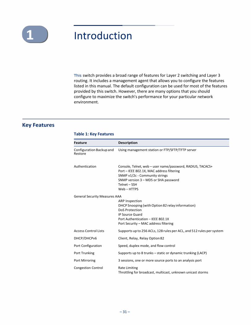
This switch provides a broad range of features for Layer 2 switching and Layer 3 routing. It includes a management agent that allows you to configure the features listed in this manual. The default configuration can be used for most of the features provided by this switch. However, there are many options that you should configure to maximize the switch’s performance for your particular network environment.
Key Features
Table 1: Key Features
Configuration Backup and Restore
Using management station or FTP/SFTP/TFTP server
Authentication Console, Telnet, web – user name/password, RADIUS, TACACS+ Port – IEEE 802.1X, MAC address filtering SNMP v1/2c - Community strings SNMP version 3 – MD5 or SHA password Telnet – SSH Web – HTTPS
General Security Measures AAA ARP Inspection DHCP Snooping (with Option 82 relay information) DoS Protection IP Source Guard Port Authentication – IEEE 802.1X Port Security – MAC address filtering
Access Control Lists Supports up to 256 ACLs, 128 rules per ACL, and 512 rules per system
DHCP/DHCPv6 Client, Relay, Relay Option 82
Port Configuration Speed, duplex mode, and flow control
Port Trunking Supports up to 8 trunks – static or dynamic trunking (LACP)
Port Mirroring 3 sessions, one or more source ports to an analysis port
Congestion Control Rate Limiting Throttling for broadcast, multicast, unknown unicast storms
Feature Description
– 32 –
Chapter 1 | Introduction Key Features
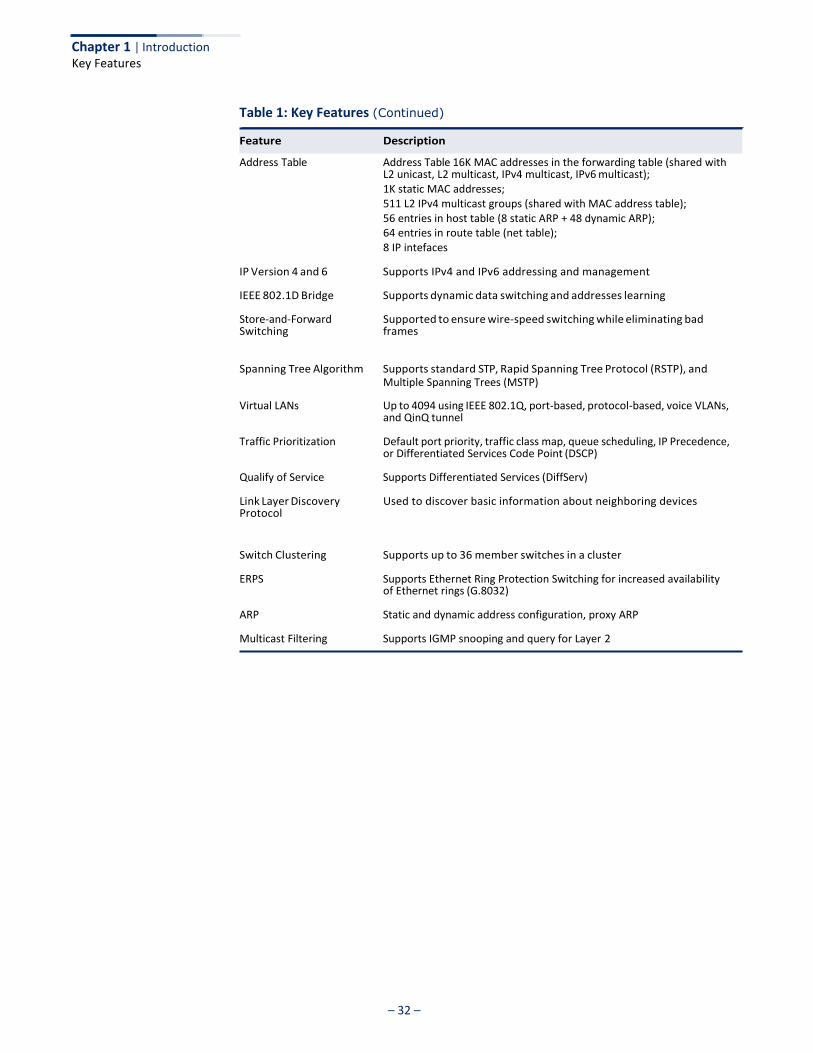
Table 1: Key Features (Continued)
Address Table Address Table 16K MAC addresses in the forwarding table (shared with L2 unicast, L2 multicast, IPv4 multicast, IPv6 multicast); 1K static MAC addresses; 511 L2 IPv4 multicast groups (shared with MAC address table); 56 entries in host table (8 static ARP + 48 dynamic ARP); 64 entries in route table (net table); 8 IP intefaces
IP Version 4 and 6 Supports IPv4 and IPv6 addressing and management
IEEE 802.1D Bridge Supports dynamic data switching and addresses learning
Store-and-Forward Switching
Supported to ensure wire-speed switching while eliminating bad frames
Spanning Tree Algorithm Supports standard STP, Rapid Spanning Tree Protocol (RSTP), and Multiple Spanning Trees (MSTP)
Virtual LANs Up to 4094 using IEEE 802.1Q, port-based, protocol-based, voice VLANs, and QinQ tunnel
Traffic Prioritization Default port priority, traffic class map, queue scheduling, IP Precedence, or Differentiated Services Code Point (DSCP)
Qualify of Service Supports Differentiated Services (DiffServ)
Link Layer Discovery Protocol
Used to discover basic information about neighboring devices
Switch Clustering Supports up to 36 member switches in a cluster
ERPS Supports Ethernet Ring Protection Switching for increased availability of Ethernet rings (G.8032)
ARP Static and dynamic address configuration, proxy ARP
Multicast Filtering Supports IGMP snooping and query for Layer 2
Feature Description

Chapter 1 | Introduction Description of Software Features
– 33 –
Description of Software Features
The switch provides a wide range of advanced performance enhancing features. Flow control eliminates the loss of packets due to bottlenecks caused by port saturation. Storm suppression prevents broadcast, multicast, and unknown unicast traffic storms from engulfing the network. Untagged (port-based), tagged, and protocol-based VLANs, plus support for automatic GVRP VLAN registration provide traffic security and efficient use of network bandwidth. CoS priority queueing ensures the minimum delay for moving real-time multimedia data across the network. While multicast filtering provides support for real-time network applications.
Some of the management features are briefly described below.
Configuration Backup and Restore
You can save the current configuration settings to a file on the management station (using the web interface) or an FTP/SFTP/TFTP server (using the web or console interface), and later download this file to restore the switch configuration settings.
Authentication This switch authenticates management access via the console port, Telnet, or a web browser. User names and passwords can be configured locally or can be verified via a remote authentication server (i.e., RADIUS or TACACS+). Port-based authentication is also supported via the IEEE 802.1X protocol. This protocol uses Extensible Authentication Protocol over LANs (EAPOL) to request user credentials from the 802.1X client, and then uses the EAP between the switch and the authentication server to verify the client’s right to access the network via an authentication server (i.e., RADIUS or TACACS+ server).
Other authentication options include HTTPS for secure management access via the web, SSH for secure management access over a Telnet-equivalent connection, SNMP Version 3, IP address filtering for SNMP/Telnet/web management access. MAC address filtering and IP source guard also provide authenticated port access. While DHCP snooping is provided to prevent malicious attacks from insecure ports.
Access Control Lists ACLs provide packet filtering for IP frames (based on address, protocol, TCP/UDP port number or TCP control code) or any frames (based on MAC address or Ethernet type). ACLs can be used to improve performance by blocking unnecessary network traffic or to implement security controls by restricting access to specific network resources or protocols.
Port Configuration You can manually configure the speed, duplex mode, and flow control used on specific ports, or use auto-negotiation to detect the connection settings used by the attached device. Use full-duplex mode on ports whenever possible to double the throughput of switch connections. Flow control should also be enabled to control network traffic during periods of congestion and prevent the loss of
– 34 –
Chapter 1 | Introduction Description of Software Features
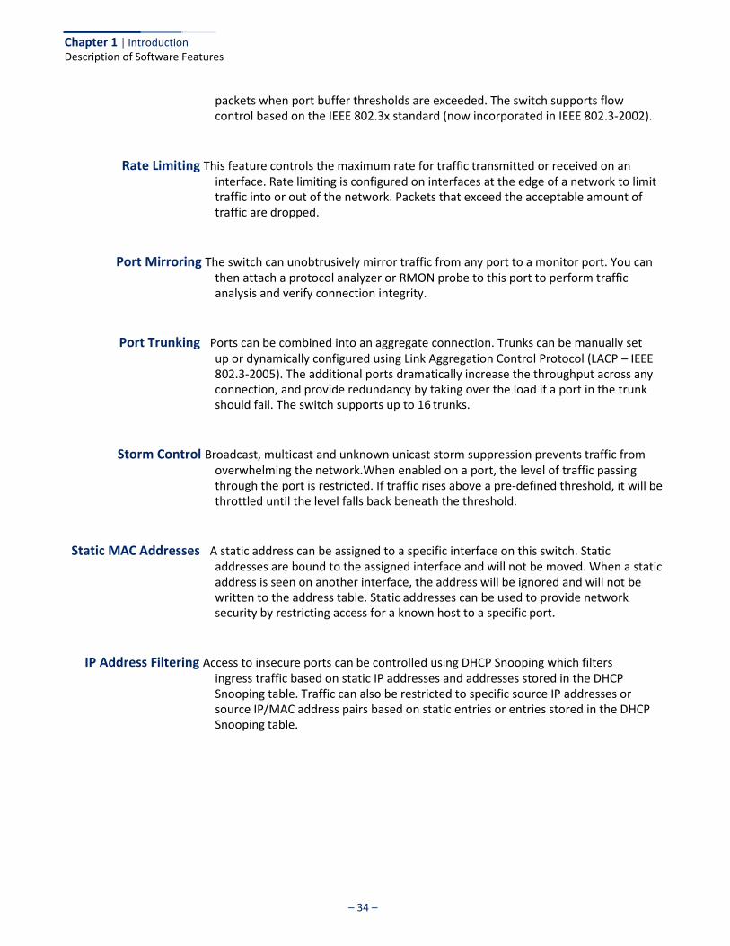
packets when port buffer thresholds are exceeded. The switch supports flow control based on the IEEE 802.3x standard (now incorporated in IEEE 802.3-2002).
Rate Limiting This feature controls the maximum rate for traffic transmitted or received on an interface. Rate limiting is configured on interfaces at the edge of a network to limit traffic into or out of the network. Packets that exceed the acceptable amount of traffic are dropped.
Port Mirroring The switch can unobtrusively mirror traffic from any port to a monitor port. You can then attach a protocol analyzer or RMON probe to this port to perform traffic analysis and verify connection integrity.
Port Trunking Ports can be combined into an aggregate connection. Trunks can be manually set up or dynamically configured using Link Aggregation Control Protocol (LACP – IEEE 802.3-2005). The additional ports dramatically increase the throughput across any connection, and provide redundancy by taking over the load if a port in the trunk should fail. The switch supports up to 16 trunks.
Storm Control Broadcast, multicast and unknown unicast storm suppression prevents traffic from overwhelming the network.When enabled on a port, the level of traffic passing through the port is restricted. If traffic rises above a pre-defined threshold, it will be throttled until the level falls back beneath the threshold.
Static MAC Addresses A static address can be assigned to a specific interface on this switch. Static addresses are bound to the assigned interface and will not be moved. When a static address is seen on another interface, the address will be ignored and will not be written to the address table. Static addresses can be used to provide network security by restricting access for a known host to a specific port.
IP Address Filtering Access to insecure ports can be controlled using DHCP Snooping which filters ingress traffic based on static IP addresses and addresses stored in the DHCP Snooping table. Traffic can also be restricted to specific source IP addresses or source IP/MAC address pairs based on static entries or entries stored in the DHCP Snooping table.
– 35 –
Chapter 1 | Introduction Description of Software Features
IEEE 802.1D Bridge The switch supports IEEE 802.1D transparent bridging. The address table facilitates data switching by learning addresses, and then filtering or forwarding traffic based on this information. The address table supports up to 16K addresses.
Store-and-Forward Switching
The switch copies each frame into its memory before forwarding them to another port. This ensures that all frames are a standard Ethernet size and have been verified for accuracy with the cyclic redundancy check (CRC). This prevents bad frames from entering the network and wasting bandwidth.
To avoid dropping frames on congested ports, the switch provides 12 Mbits for frame buffering. This buffer can queue packets awaiting transmission on congested networks.
Spanning Tree Algorithm
The switch supports these spanning tree protocols:
◆ Spanning Tree Protocol (STP, IEEE 802.1D) – This protocol provides loop detection. When there are multiple physical paths between segments, this protocol will choose a single path and disable all others to ensure that only one route exists between any two stations on the network. This prevents the creation of network loops. However, if the chosen path should fail for any reason, an alternate path will be activated to maintain the connection.
◆ Rapid Spanning Tree Protocol (RSTP, IEEE 802.1w) – This protocol reduces the
convergence time for network topology changes to about 3 to 5 seconds, compared to 30 seconds or more for the older IEEE 802.1D STP standard. It is intended as a complete replacement for STP, but can still interoperate with switches running the older standard by automatically reconfiguring ports to STP-compliant mode if they detect STP protocol messages from attached devices.
◆ Multiple Spanning Tree Protocol (MSTP, IEEE 802.1s) – This protocol is a direct extension of RSTP. It can provide an independent spanning tree for different VLANs. It simplifies network management, provides for even faster convergence than RSTP by limiting the size of each region, and prevents VLAN members from being segmented from the rest of the group (as sometimes occurs with IEEE 802.1D STP).
Virtual LANs The switch supports up to 4094 VLANs. A Virtual LAN is a collection of network nodes that share the same collision domain regardless of their physical location or connection point in the network. The switch supports tagged VLANs based on the IEEE 802.1Q standard. Members of VLAN groups can be dynamically learned via GVRP, or ports can be manually assigned to a specific set of VLANs. This allows the switch to restrict traffic to the VLAN groups to which a user has been assigned. By segmenting your network into VLANs, you can:
◆ Eliminate broadcast storms which severely degrade performance in a flat
network.
– 36 –
Chapter 1 | Introduction Description of Software Features
◆ Simplify network management for node changes/moves by remotely configuring VLAN membership for any port, rather than having to manually change the network connection.
◆ Provide data security by restricting all traffic to the originating VLAN, except
where a connection is explicitly defined via the switch's routing service.
◆ Use protocol VLANs to restrict traffic to specified interfaces based on protocol type.
IEEE 802.1Q Tunneling (QinQ)
This feature is designed for service providers carrying traffic for multiple customers across their networks. QinQ tunneling is used to maintain customer-specific VLAN and Layer 2 protocol configurations even when different customers use the same internal VLAN IDs. This is accomplished by inserting Service Provider VLAN (SPVLAN) tags into the customer’s frames when they enter the service provider’s network, and then stripping the tags when the frames leave the network.
Traffic Prioritization This switch prioritizes each packet based on the required level of service, using eight priority queues with strict priority, Weighted Round Robin (WRR) scheduling, or a combination of strict and weighted queuing. It uses IEEE 802.1p and 802.1Q tags to prioritize incoming traffic based on input from the end-station application. These functions can be used to provide independent priorities for delay-sensitive data and best-effort data.
This switch also supports several common methods of prioritizing layer 3/4 traffic to meet application requirements. Traffic can be prioritized based on the priority bits in the IP frame’s Type of Service (ToS) octet using DSCP, or IP Precedence. When these services are enabled, the priorities are mapped to a Class of Service value by the switch, and the traffic then sent to the corresponding output queue.
Quality of Service Differentiated Services (DiffServ) provides policy-based management mechanisms used for prioritizing network resources to meet the requirements of specific traffic types on a per-hop basis. Each packet is classified upon entry into the network based on access lists, IP Precedence or DSCP values, or VLAN lists. Using access lists allows you select traffic based on Layer 2, Layer 3, or Layer 4 information contained in each packet. Based on network policies, different kinds of traffic can be marked for different kinds of forwarding.
Ethernet Ring Protection Switching
ERPS can be used to increase the availability and robustness of Ethernet rings, such as those used in Metropolitan Area Networks (MAN). ERPS provides Layer 2 loop avoidance and fast reconvergence in Layer 2 ring topologies, supporting up to 255 nodes in the ring structure. It can also function with IEEE 802.1ag to support link monitoring when non-participating devices exist within the Ethernet ring.
– 37 –
Chapter 1 | Introduction Description of Software Features
Address Resolution Protocol
The switch uses ARP and Proxy ARP to convert between IP addresses and MAC (hardware) addresses. This switch supports conventional ARP, which locates the MAC address corresponding to a given IP address. This allows the switch to use IP addresses for routing decisions and the corresponding MAC addresses to forward packets from one hop to the next. Either static or dynamic entries can be configured in the ARP cache.
Proxy ARP allows hosts that do not support routing to determine the MAC address of a device on another network or subnet. When a host sends an ARP request for a remote network, the switch checks to see if it has the best route. If it does, it sends its own MAC address to the host. The host then sends traffic for the remote destination via the switch, which uses its own routing table to reach the destination on the other network.
Multicast Filtering Specific multicast traffic can be assigned to its own VLAN to ensure that it does not interfere with normal network traffic and to guarantee real-time delivery by setting the required priority level for the designated VLAN. The switch uses IGMP Snooping and Query for IPv4,and MLD Snooping and Query for IPv6 to manage multicast group registration.
Link Layer Discovery Protocol
LLDP is used to discover basic information about neighboring devices within the local broadcast domain. LLDP is a Layer 2 protocol that advertises information about the sending device and collects information gathered from neighboring network nodes it discovers.
Advertised information is represented in Type Length Value (TLV) format according to the IEEE 802.1ab standard, and can include details such as device identification, capabilities and configuration settings. Media Endpoint Discovery (LLDP-MED) is an extension of LLDP intended for managing endpoint devices such as Voice over IP phones and network switches. The LLDP-MED TLVs advertise information such as network policy, power, inventory, and device location details. The LLDP and LLDP- MED information can be used by SNMP applications to simplify troubleshooting, enhance network management, and maintain an accurate network topology.

– 38 –
Chapter 1 | Introduction System Defaults
System Defaults
The switch’s system defaults are provided in the configuration file “Factory_Default_Config.cfg.” To reset the switch defaults, this file should be set as the startup configuration file.
The following table lists some of the basic system defaults.
Table 2: System Defaults
Console Port Connection Baud Rate 115200 bps
Data bits 8
Stop bits 1
Parity none
Local Console Timeout 600 seconds
Authentication and Security Measures
Privileged Exec Level Username “admin” Password “admin”
Normal Exec Level Username “guest” Password “guest”
Enable Privileged Exec from Normal Exec Level
Password “super”
RADIUS Authentication Disabled
TACACS+ Authentication Disabled
802.1X Port Authentication Disabled
Web Authentication Disabled
MAC Authentication Disabled
HTTPS Enabled
SSH Disabled
Port Security Disabled
IP Filtering Disabled
DHCP Snooping Disabled
IP Source Guard Disabled (all ports)
Web Management HTTP Server Enabled
HTTP Port Number 80
HTTP Secure Server Enabled
HTTP Secure Server Port 443
Function Parameter Default
– 39 –
Chapter 1 | Introduction
System Defaults
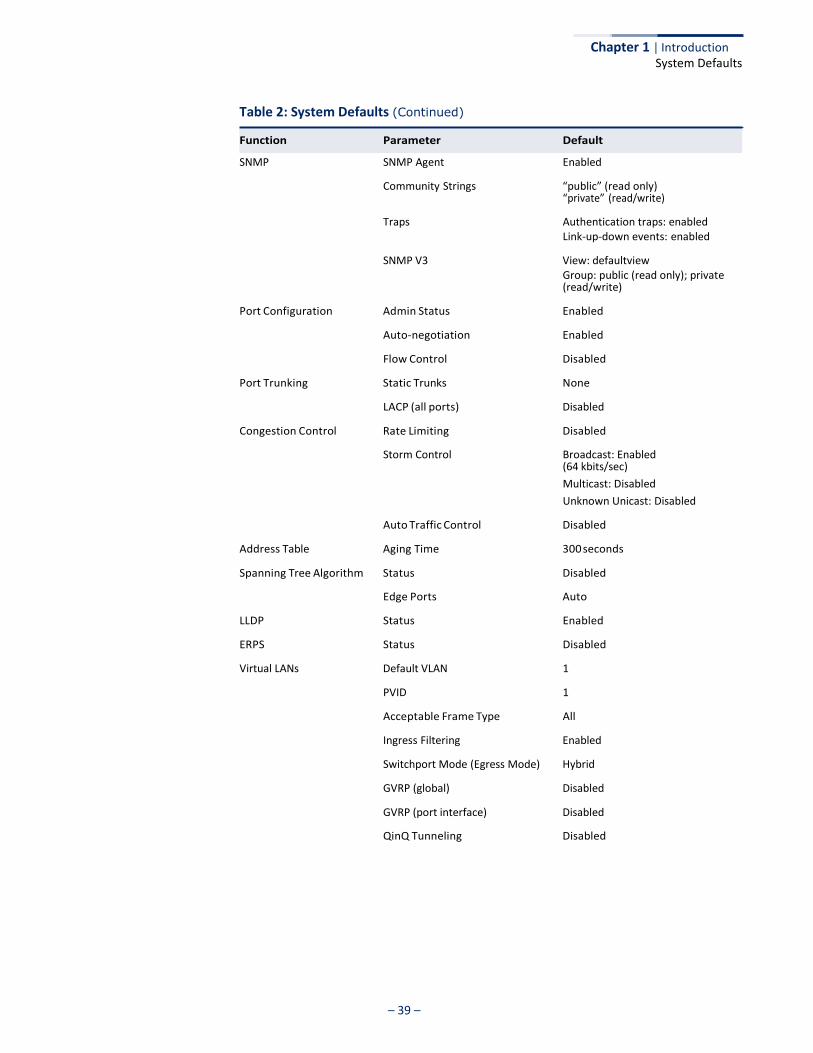
Table 2: System Defaults (Continued)
SNMP SNMP Agent Enabled
Community Strings “public” (read only) “private” (read/write)
Traps Authentication traps: enabled Link-up-down events: enabled
SNMP V3 View: defaultview Group: public (read only); private (read/write)
Port Configuration Admin Status Enabled
Auto-negotiation Enabled
Flow Control Disabled
Port Trunking Static Trunks None
LACP (all ports) Disabled
Congestion Control Rate Limiting Disabled
Storm Control Broadcast: Enabled (64 kbits/sec)
Multicast: Disabled
Unknown Unicast: Disabled
Auto Traffic Control Disabled
Address Table Aging Time 300 seconds
Spanning Tree Algorithm Status Disabled
Edge Ports Auto
LLDP Status Enabled
ERPS Status Disabled
Virtual LANs Default VLAN 1
PVID 1
Acceptable Frame Type All
Ingress Filtering Enabled
Switchport Mode (Egress Mode) Hybrid
GVRP (global) Disabled
GVRP (port interface) Disabled
QinQ Tunneling Disabled
Function Parameter Default

– 40 –
Chapter 1 | Introduction System Defaults
Table 2: System Defaults (Continued)
Function Parameter Default
Traffic Prioritization Ingress Port Priority 0
Queue Mode WRR
Queue Weight Queue: 0 1 2 3 4 5 6 7 Weight: 1 2 4 6 8 10 12 14
Class of Service Enabled
IP Precedence Priority Disabled
IP DSCP Priority Disabled
IPv6 DSCP Priority Disabled
IP Settings Management. VLAN VLAN 1
IP Address 192.168.1.1
Subnet Mask 255.255.255.0
Default Gateway Not configured
DHCP Client: Enabled
DNS Proxy service: Disabled
BOOTP Disabled
ARP Enabled Cache Timeout: 20 minutes
Multicast Filtering IGMP Snooping (Layer 2) Snooping: Enabled Querier: Disabled
MLD Snooping (Layer 2 IPv6) Snooping: Enabled Querier: Disabled
IGMP Proxy Reporting Disabled
System Log Status Enabled
Messages Logged to RAM Levels 0-7 (all)
Messages Logged to Flash Levels 0-3
SMTP Email Alerts Event Handler Enabled (but no server defined)
SNTP Clock Synchronization Disabled
Switch Clustering Status Disabled
Commander Disabled
– 41 –
Web Configuration
This section describes the basic switch features, along with a detailed description of how to configure each feature via a web browser.
This section includes these chapters:
◆ "Using the Web Interface" on page 43
◆ "Basic Management Tasks" on page 63
◆ "Interface Configuration" on page 97
◆ "VLAN Configuration" on page 147
◆ "Address Table Settings" on page 171
◆ "Spanning Tree Algorithm" on page 181
◆ "Congestion Control" on page 205
◆ "Class of Service" on page 209
◆ "Quality of Service" on page 219
◆ "VoIP Traffic Configuration" on page 229
◆ "Security Measures" on page 235
◆ "Basic Administration Protocols" on page 333
◆ "Multicast Filtering" on page 437
◆ "IP Tools" on page 489
◆ "IP Configuration" on page 499
◆ "General IP Routing" on page 521

– 42 –
Section II | Web Configuration
◆ "IP Services" on page 527
– 43 –
Using the Web Interface
This switch provides an embedded HTTP web agent. Using a web browser you can configure the switch and view statistics to monitor network activity. The web agent can be accessed by any computer on the network using a standard web browser (Internet Explorer 9, Mozilla Firefox 39, or Google Chrome 44, or more recent versions).
Note: You can also use the Command Line Interface (CLI) to manage the switch over a serial connection to the console port or via Telnet. For more information on using the CLI, refer to the CLI Reference Guide.
Connecting to the Web Interface
Prior to accessing the switch from a web browser, be sure you have first performed the following tasks:
1. The default IP address and subnet mask for the switch is 192.168.1.1 and 255.255.255.0, with no default gateway. If this is not compatible with the subnet connected to the switch, you can configure it with a valid IP address, subnet mask, and default gateway. To configure this device as the default gateway, use the IP > Routing > Static Routes (Add) page, set the destination address to the required interface, and the next hop to null address 0.0.0.0 .
2. Set user names and passwords using an out-of-band serial connection. Access to the web agent is controlled by the same user names and passwords as the onboard configuration program. (See “Configuring User Accounts” on page 253.)
3. After you enter a user name and password, you will have access to the system configuration program.
Note: You are allowed three attempts to enter the correct password; on the third failed attempt the current connection is terminated.
Note: If you log into the web interface as guest (Normal Exec level), you can view the configuration settings or change the guest password. If you log in as “admin” (Privileged Exec level), you can change the settings on any page.
Note: If the path between your management station and this switch does not pass through any device that uses the Spanning Tree Algorithm, then you can set the
Chapter 2 | Using the Web Interface Navigating the Web Browser Interface
– 44 –
switch port attached to your management station to fast forwarding (i.e., enable Admin Edge Port) to improve the switch’s response time to management commands issued through the web interface. See “Configuring Interface Settings for STA” on page 191.
Note: Users are automatically logged off of the HTTP server or HTTPS server if no input is detected for 600 seconds.
Note: Connection to the web interface is not supported for HTTPS using an IPv6 link local address.
Navigating the Web Browser Interface
To access the web-browser interface you must first enter a user name and password. The administrator has Read/Write access to all configuration parameters and statistics. The default user name and password for the administrator is “admin.” The administrator has full access privileges to configure any parameters in the web interface. The default user name and password for guest access is “guest.” The guest only has read access for most configuration parameters. Refer to “Configuring User Accounts” on page 253 for more details.
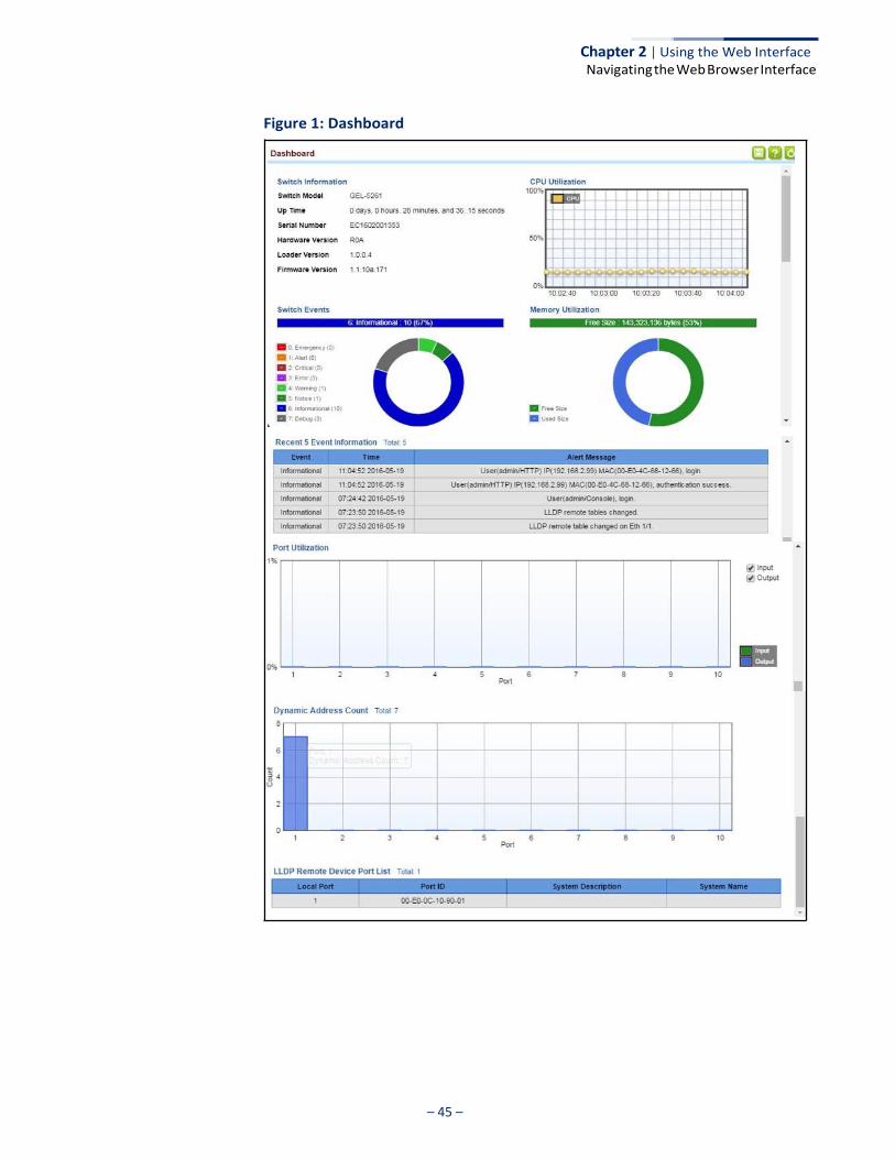
Dashboard When your web browser connects with the switch’s web agent, the Dashboard is displayed as shown below. The Dashboard displays the main menu on the left side of the screen and System Information, CPU Utilization, Temperature, and Top 5 Most Active Interfaces on the right side. The main menu links are used to navigate to other menus, and display configuration parameters and statistics.
Chapter 2 | Using the Web Interface Navigating the Web Browser Interface
– 45 –
Figure 1: Dashboard
Chapter 2 | Using the Web Interface Navigating the Web Browser Interface
– 46 –
Configuration Options Configurable parameters have a dialog box or a drop-down list. Once a configuration change has been made on a page, be sure to click on the Apply button to confirm the new setting. The following table summarizes the web page configuration buttons.
Table 3: Web Page Configuration Buttons
Apply Sets specified values to the system.
Revert Cancels specified values and restores current values prior to pressing “Apply.”
Saves current settings.
Displays help for the selected page.
Refreshes the current page.
Displays the site map.
Logs out of the management interface.
Sends mail to the vendor.
Links to the vendor’s web site.
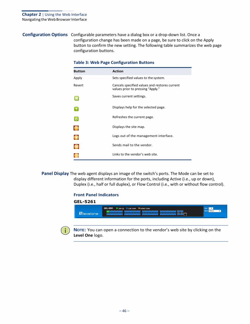
Panel Display The web agent displays an image of the switch’s ports. The Mode can be set to display different information for the ports, including Active (i.e., up or down), Duplex (i.e., half or full duplex), or Flow Control (i.e., with or without flow control).
Front Panel Indicators
GEL-5261
NOTE: You can open a connection to the vendor’s web site by clicking on the Level One logo.
Button Action
Chapter 2 | Using the Web Interface Navigating the Web Browser Interface
– 47 –
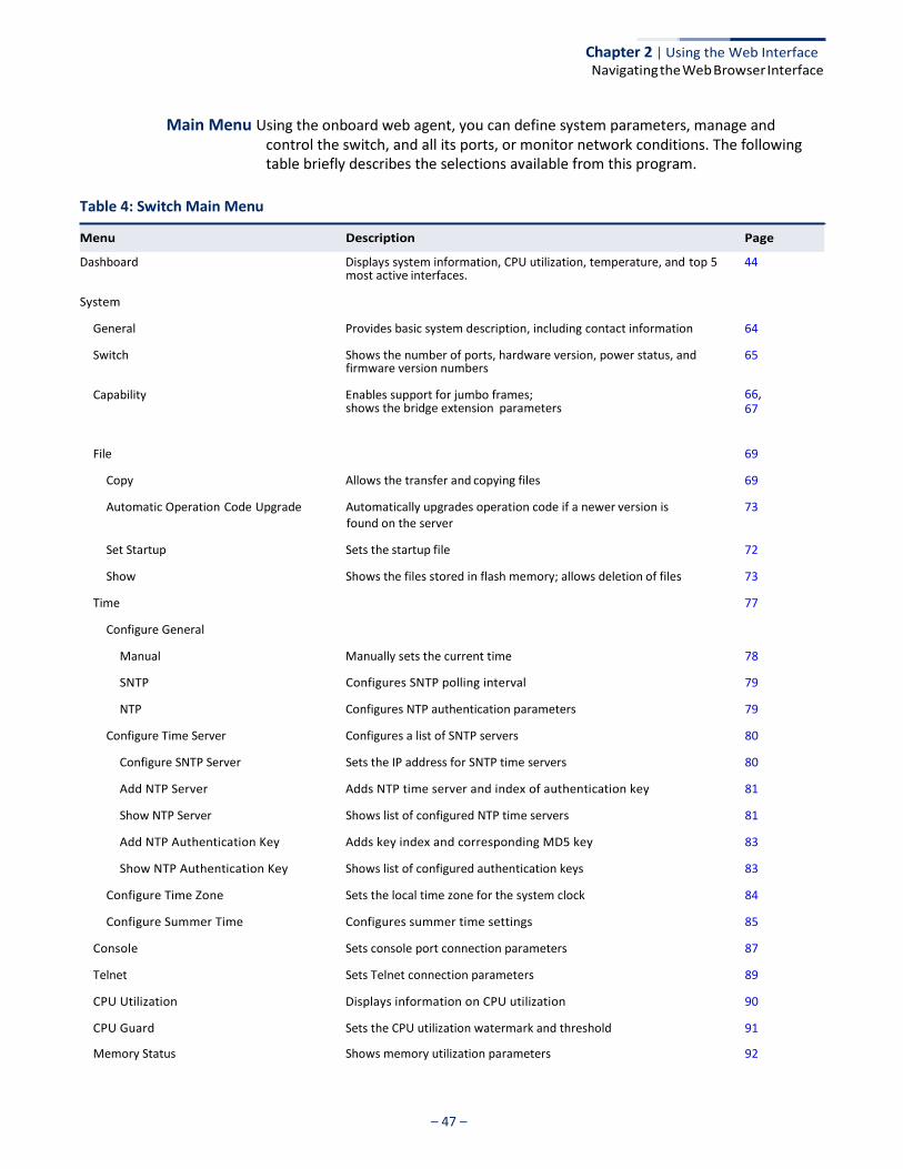
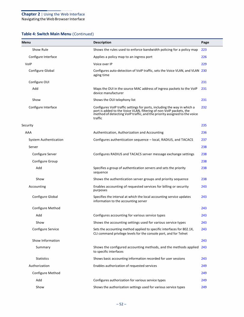
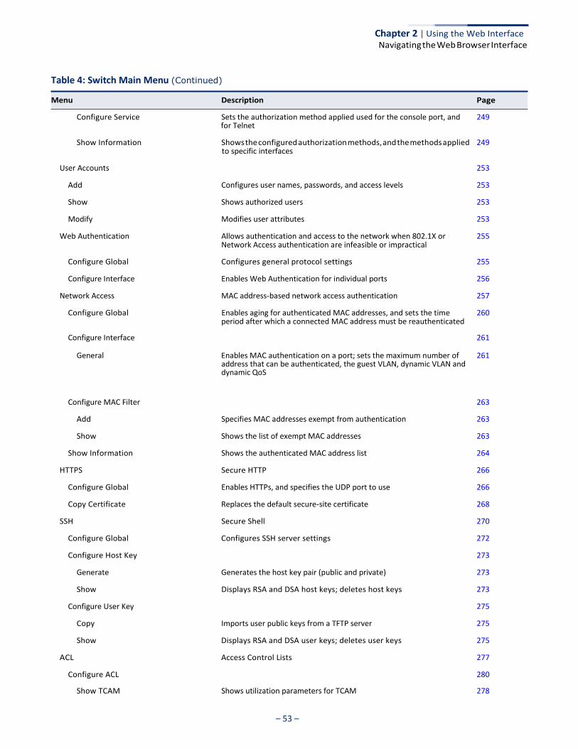
Main Menu Using the onboard web agent, you can define system parameters, manage and control the switch, and all its ports, or monitor network conditions. The following table briefly describes the selections available from this program.
Table 4: Switch Main Menu
Dashboard Displays system information, CPU utilization, temperature, and top 5 44 most active interfaces.
System
General Provides basic system description, including contact information 64
Switch Shows the number of ports, hardware version, power status, and firmware version numbers
Capability Enables support for jumbo frames; shows the bridge extension parameters
65
66, 67
File 69
Copy Allows the transfer and copying files 69
Automatic Operation Code Upgrade Automatically upgrades operation code if a newer version is 73 found on the server
Set Startup Sets the startup file 72
Show Shows the files stored in flash memory; allows deletion of files 73
Time 77
Configure General
Manual Manually sets the current time 78
SNTP Configures SNTP polling interval 79
NTP Configures NTP authentication parameters 79
Configure Time Server Configures a list of SNTP servers 80
Configure SNTP Server Sets the IP address for SNTP time servers 80
Add NTP Server Adds NTP time server and index of authentication key 81
Show NTP Server Shows list of configured NTP time servers 81
Add NTP Authentication Key Adds key index and corresponding MD5 key 83
Show NTP Authentication Key Shows list of configured authentication keys 83
Configure Time Zone Sets the local time zone for the system clock 84
Configure Summer Time Configures summer time settings 85
Console Sets console port connection parameters 87
Telnet Sets Telnet connection parameters 89
CPU Utilization Displays information on CPU utilization 90
CPU Guard Sets the CPU utilization watermark and threshold 91
Memory Status Shows memory utilization parameters 92
Menu Description Page

– 48 –
Chapter 2 | Using the Web Interface Navigating the Web Browser Interface
Table 4: Switch Main Menu (Continued)
Menu Description Page
Reset Restarts the switch immediately, at a specified time, after a specified 93 delay, or at a periodic interval
Interface 97
Port 98
General 98
Configure by Port List Configures connection settings per port 98
Configure by Port Range Configures connection settings for a range of ports 100
Show Information Displays port connection status 101
Statistics Shows Interface, Etherlike, and RMON port statistics 102
Chart Shows Interface, Etherlike, and RMON port statistics 102
History Shows statistical history for specified interfaces 106
Transceiver Shows identifying information and operational parameters for optical transceivers which support Digital Diagnostic Monitoring (DDM), and configures thresholds for alarm and warning messages for optical transceivers which support DDM
Cable Test Performs cable diagnostics for selected port to diagnose any cable faults (short, open etc.) and report the cable length
110 111
113
Trunk 115
Static 116
Configure Trunk 116
Add Creates a trunk, along with the first port member 116
Show Shows the configured trunk identifiers 116
Add Member Specifies ports to group into static trunks 116
Show Member Shows the port members for the selected trunk 116
Configure General 116
Configure Configures trunk connection settings 116
Show Information Displays trunk connection settings 116
Dynamic 119
Configure Aggregator Configures administration key and timeout for specific LACP groups
119
Configure Aggregation Port 116
Configure 116
local side
remote side
General Allows ports to dynamically join trunks 119
Actor Configures parameters for link aggregation group members on the 119
Partner Configures parameters for link aggregation group members on the 119
– 49 –
Chapter 2 | Using the Web Interface Navigating the Web Browser Interface
Table 4: Switch Main Menu (Continued)
Menu Description Page
of a link aggregation
side of a link aggregation
used to connect to other devices
the local switch
specified time interval, or an sFlow data source instance that takes
ports
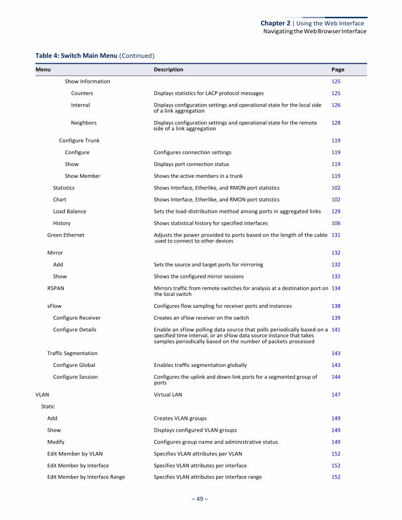
Show Information 125
Counters Displays statistics for LACP protocol messages 125
Internal Displays configuration settings and operational state for the local side 126
Neighbors Displays configuration settings and operational state for the remote 128
Configure Trunk 119
Configure Configures connection settings 119
Show Displays port connection status 119
Show Member Shows the active members in a trunk 119
Statistics Shows Interface, Etherlike, and RMON port statistics 102
Chart Shows Interface, Etherlike, and RMON port statistics 102
Load Balance Sets the load-distribution method among ports in aggregated links 129
History Shows statistical history for specified interfaces 106
Green Ethernet Adjusts the power provided to ports based on the length of the cable 131
Mirror 132
Add Sets the source and target ports for mirroring 132
Show Shows the configured mirror sessions 132
RSPAN Mirrors traffic from remote switches for analysis at a destination port on 134
sFlow Configures flow sampling for receiver ports and instances 138
Configure Receiver Creates an sFlow receiver on the switch 139
Configure Details Enable an sFlow polling data source that polls periodically based on a
samples periodically based on the number of packets processed
141
Traffic Segmentation 143
Configure Global Enables traffic segmentation globally 143
Configure Session Configures the uplink and down-link ports for a segmented group of 144
VLAN Virtual LAN 147
Static
Add Creates VLAN groups 149
Show Displays configured VLAN groups 149
Modify Configures group name and administrative status 149
Edit Member by VLAN Specifies VLAN attributes per VLAN 152
Edit Member by Interface Specifies VLAN attributes per interface 152
Edit Member by Interface Range Specifies VLAN attributes per interface range 152
– 50 –
Chapter 2 | Using the Web Interface Navigating the Web Browser Interface
Table 4: Switch Main Menu (Continued)
Menu Description Page
the transmit and receive counts for any static or system configured
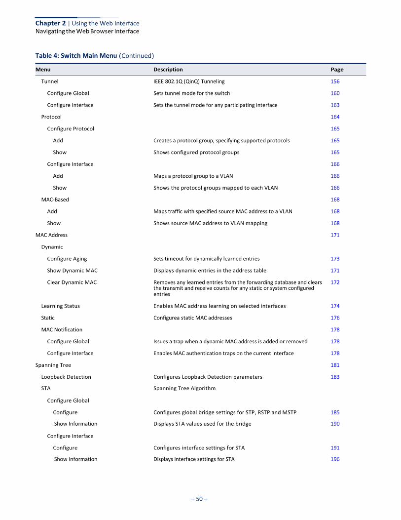
Tunnel IEEE 802.1Q (QinQ) Tunneling 156
Configure Global Sets tunnel mode for the switch 160
Configure Interface Sets the tunnel mode for any participating interface 163
Protocol 164
Configure Protocol 165
Add Creates a protocol group, specifying supported protocols 165
Show Shows configured protocol groups 165
Configure Interface 166
Add Maps a protocol group to a VLAN 166
Show Shows the protocol groups mapped to each VLAN 166
MAC-Based 168
Add Maps traffic with specified source MAC address to a VLAN 168
Show Shows source MAC address to VLAN mapping 168
MAC Address 171
Dynamic
Configure Aging Sets timeout for dynamically learned entries 173
Show Dynamic MAC Displays dynamic entries in the address table 171
Clear Dynamic MAC Removes any learned entries from the forwarding database and clears
entries
172
Learning Status Enables MAC address learning on selected interfaces 174
Static Configurea static MAC addresses 176
MAC Notification 178
Configure Global Issues a trap when a dynamic MAC address is added or removed 178
Configure Interface Enables MAC authentication traps on the current interface 178
Spanning Tree 181
Loopback Detection Configures Loopback Detection parameters 183
STA Spanning Tree Algorithm
Configure Global
Configure Configures global bridge settings for STP, RSTP and MSTP 185
Show Information Displays STA values used for the bridge 190
Configure Interface
Configure Configures interface settings for STA 191
Show Information Displays interface settings for STA 196

– 51 –
Chapter 2 | Using the Web Interface Navigating the Web Browser Interface
Table 4: Switch Main Menu (Continued)
Menu Description Page
Traffic
that will use a weighted or hybrid mode
priority processing
processing
the action to take for conforming and non-conforming traffic
MSTP Multiple Spanning Tree Algorithm 199
Configure Global 199
Add Configures initial VLAN and priority for an MST instance 199
Modify Configures the priority or an MST instance 199
Show Configures global settings for an MST instance 199
Add Member Adds VLAN members for an MST instance 199
Show Member Adds or deletes VLAN members for an MST instance 199
Show Information Displays MSTP values used for the bridge
Configure Interface 203
Configure Configures interface settings for an MST instance 203
Show Information Displays interface settings for an MST instance 203
Rate Limit
Sets the input and output rate limits for a port
205
Storm Control Sets the broadcast storm threshold for each interface 206
Priority
Default Priority Sets the default priority for each port or trunk 209
Queue Sets queue mode for the switch; sets the service weight for each queue 210
Trust Mode Selects DSCP or CoS priority processing 214
CoS to Queue Maps CoS/CFI values in incoming packets to per-hop behavior for 215
DSCP to Queue Maps DSCP values in incoming packets to per-hop behavior for priority 216
DiffServ 219
Configure Class 220
Add Creates a class map for a type of traffic 220
Show Shows configured class maps 220
Modify Modifies the name of a class map 220
Add Rule Configures the criteria used to classify ingress traffic 220
Show Rule Shows the traffic classification rules for a class map 220
Configure Policy
223
Add Creates a policy map to apply to multiple interfaces 223
Show Shows configured policy maps 223
Modify Modifies the name of a policy map 223
Add Rule Sets the boundary parameters used for monitoring inbound traffic, and 223
– 52 –
Chapter 2 | Using the Web Interface Navigating the Web Browser Interface
Table 4: Switch Main Menu (Continued)
Menu Description Page
port is added to the Voice VLAN, filtering of non-VoIP packets, the
purposes
Show Rule Shows the rules used to enforce bandwidth policing for a policy map 223
Configure Interface Applies a policy map to an ingress port 226
VoIP Voice over IP 229
Configure Global Configures auto-detection of VoIP traffic, sets the Voice VLAN, and VLAN 230
aging time
Configure OUI 231
Add Maps the OUI in the source MAC address of ingress packets to the VoIP 231
device manufacturer
Show Shows the OUI telephony list 231
Configure Interface Configures VoIP traffic settings for ports, including the way in which a 232
method of detecting VoIP traffic, and the priority assigned to the voice
traffic
Security 235
AAA Authentication, Authorization and Accounting 236
System Authentication Configures authentication sequence – local, RADIUS, and TACACS 237
Server 238
Configure Server Configures RADIUS and TACACS server message exchange settings 238
Configure Group 238
Add Specifies a group of authentication servers and sets the priority 238 sequence
Show Shows the authentication server groups and priority sequence 238
Accounting Enables accounting of requested services for billing or security 243
Configure Global Specifies the interval at which the local accounting service updates 243
information to the accounting server
Configure Method 243
Add Configures accounting for various service types 243
Show Shows the accounting settings used for various service types 243
Configure Service Sets the accounting method applied to specific interfaces for 802.1X, 243
CLI command privilege levels for the console port, and for Telnet
Show Information 243
Summary Shows the configured accounting methods, and the methods applied 243
to specific interfaces
Statistics Shows basic accounting information recorded for user sessions 243
Authorization Enables authorization of requested services 249
Configure Method 249
Add Configures authorization for various service types 249
Show Shows the authorization settings used for various service types 249
– 53 –
Chapter 2 | Using the Web Interface Navigating the Web Browser Interface
Table 4: Switch Main Menu (Continued)
Menu Description Page
for Telnet
to specific interfaces
Network Access authentication are infeasible or impractical
period after which a connected MAC address must be reauthenticated
General Enables MAC authentication on a port; sets the maximum number of
address that can be authenticated, the guest VLAN, dynamic VLAN and dynamic QoS
261
Configure MAC Filter 263
Add Specifies MAC addresses exempt from authentication 263
Show Shows the list of exempt MAC addresses 263
Show Information Shows the authenticated MAC address list 264
HTTPS Secure HTTP 266
Configure Global Enables HTTPs, and specifies the UDP port to use 266
Copy Certificate Replaces the default secure-site certificate 268
SSH Secure Shell 270
Configure Global Configures SSH server settings 272
Configure Host Key 273
Generate Generates the host key pair (public and private) 273
Show Displays RSA and DSA host keys; deletes host keys 273
Configure User Key 275
Copy Imports user public keys from a TFTP server 275
Show Displays RSA and DSA user keys; deletes user keys 275
ACL Access Control Lists 277
Configure ACL 280
Show TCAM Shows utilization parameters for TCAM 278
Configure Service Sets the authorization method applied used for the console port, and 249
Show Information Shows the configured authorization methods, and the methods applied 249
User Accounts 253
Add Configures user names, passwords, and access levels 253
Show Shows authorized users 253
Modify Modifies user attributes 253
Web Authentication Allows authentication and access to the network when 802.1X or 255
Configure Global Configures general protocol settings 255
Configure Interface Enables Web Authentication for individual ports 256
Network Access MAC address-based network access authentication 257
Configure Global Enables aging for authenticated MAC addresses, and sets the time 260
Configure Interface 261
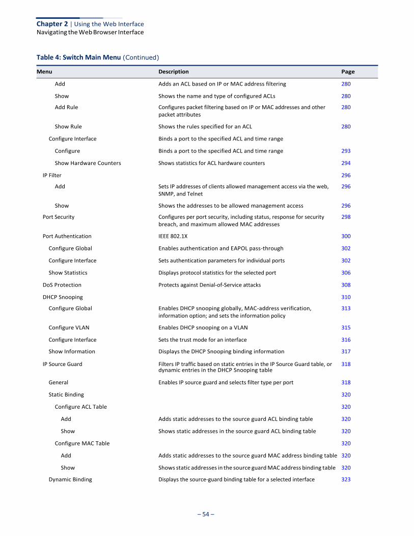
– 54 –
Chapter 2 | Using the Web Interface Navigating the Web Browser Interface
Table 4: Switch Main Menu (Continued)
Menu Description Page
dynamic entries in the DHCP Snooping table
Add Adds an ACL based on IP or MAC address filtering 280
Show Shows the name and type of configured ACLs 280
Add Rule Configures packet filtering based on IP or MAC addresses and other 280
packet attributes
Show Rule Shows the rules specified for an ACL 280
Configure Interface Binds a port to the specified ACL and time range
Configure Binds a port to the specified ACL and time range 293
Show Hardware Counters Shows statistics for ACL hardware counters 294
IP Filter 296
Add Sets IP addresses of clients allowed management access via the web, 296
SNMP, and Telnet
Show Shows the addresses to be allowed management access 296
Port Security Configures per port security, including status, response for security 298
breach, and maximum allowed MAC addresses
Port Authentication IEEE 802.1X 300
Configure Global Enables authentication and EAPOL pass-through 302
Configure Interface Sets authentication parameters for individual ports 302
Show Statistics Displays protocol statistics for the selected port 306
DoS Protection Protects against Denial-of-Service attacks 308
DHCP Snooping 310
Configure Global Enables DHCP snooping globally, MAC-address verification, 313
information option; and sets the information policy
Configure VLAN Enables DHCP snooping on a VLAN 315
Configure Interface Sets the trust mode for an interface 316
Show Information Displays the DHCP Snooping binding information 317
IP Source Guard Filters IP traffic based on static entries in the IP Source Guard table, or 318
General Enables IP source guard and selects filter type per port 318
Static Binding 320
Configure ACL Table 320
Add Adds static addresses to the source guard ACL binding table 320
Show Shows static addresses in the source guard ACL binding table 320
Configure MAC Table 320
Add Adds static addresses to the source guard MAC address binding table 320
Show Shows static addresses in the source guard MAC address binding table 320
Dynamic Binding Displays the source-guard binding table for a selected interface 323
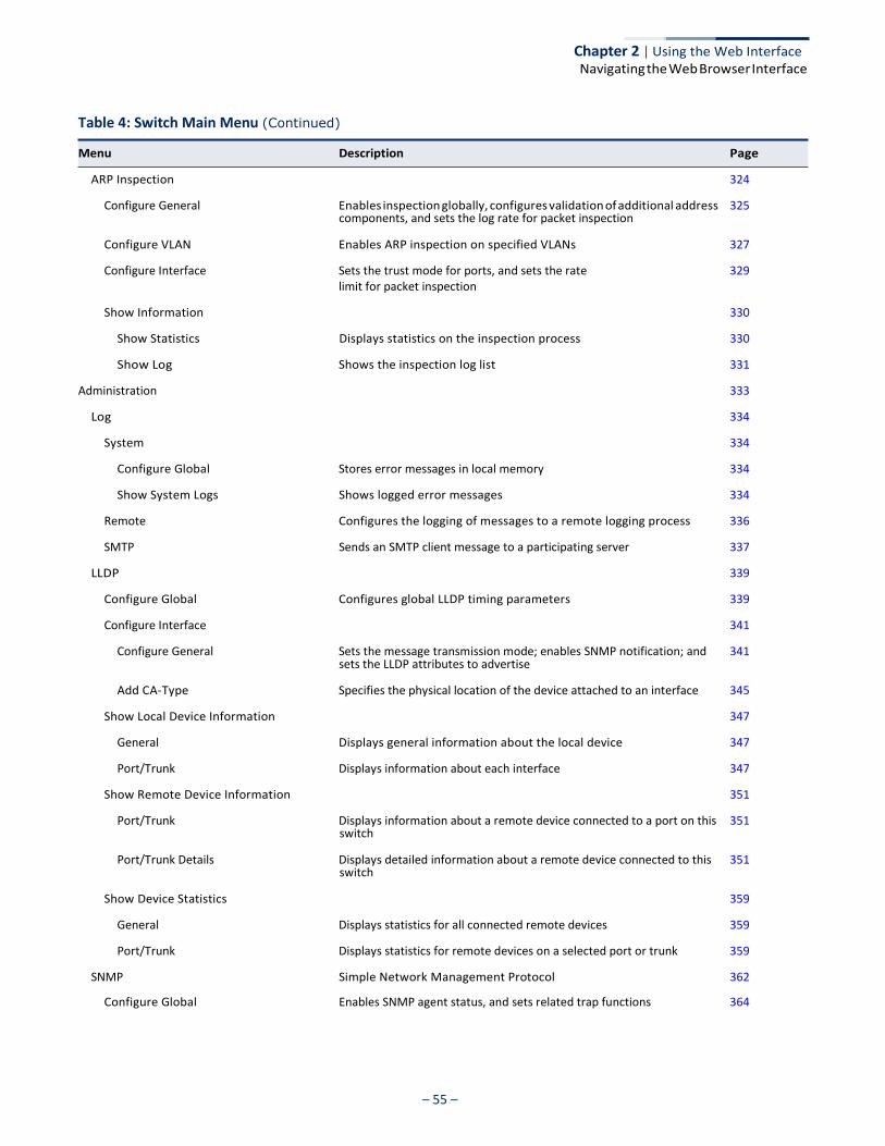
– 55 –
Chapter 2 | Using the Web Interface Navigating the Web Browser Interface
Table 4: Switch Main Menu (Continued)
Menu Description Page
components, and sets the log rate for packet inspection
sets the LLDP attributes to advertise
switch
switch
ARP Inspection 324
Configure General Enables inspection globally, configures validation of additional address 325
Configure VLAN Enables ARP inspection on specified VLANs 327
Configure Interface Sets the trust mode for ports, and sets the rate limit for packet inspection
329
Show Information 330
Show Statistics Displays statistics on the inspection process 330
Show Log Shows the inspection log list 331
Administration 333
Log 334
System 334
Configure Global Stores error messages in local memory 334
Show System Logs Shows logged error messages 334
Remote Configures the logging of messages to a remote logging process 336
SMTP Sends an SMTP client message to a participating server 337
LLDP 339
Configure Global Configures global LLDP timing parameters 339
Configure Interface 341
Configure General Sets the message transmission mode; enables SNMP notification; and 341
Add CA-Type Specifies the physical location of the device attached to an interface 345
Show Local Device Information 347
General Displays general information about the local device 347
Port/Trunk Displays information about each interface 347
Show Remote Device Information 351
Port/Trunk Displays information about a remote device connected to a port on this 351
Port/Trunk Details Displays detailed information about a remote device connected to this 351
Show Device Statistics 359
General Displays statistics for all connected remote devices 359
Port/Trunk Displays statistics for remote devices on a selected port or trunk 359
SNMP Simple Network Management Protocol 362
Configure Global Enables SNMP agent status, and sets related trap functions 364
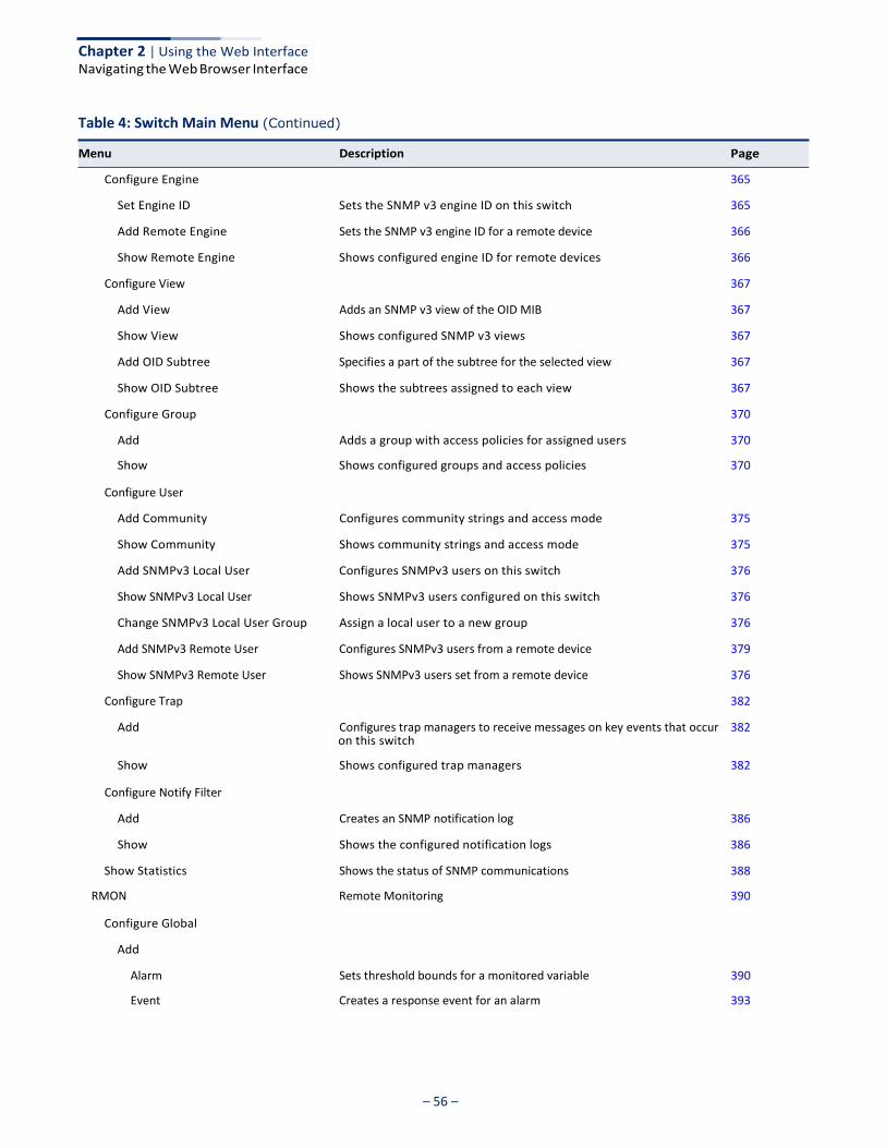
– 56 –
Chapter 2 | Using the Web Interface Navigating the Web Browser Interface
Table 4: Switch Main Menu (Continued)
Menu Description Page
on this switch
Configure Global
Add
Alarm Sets threshold bounds for a monitored variable 390
Event Creates a response event for an alarm 393
Configure Engine 365
Set Engine ID Sets the SNMP v3 engine ID on this switch 365
Add Remote Engine Sets the SNMP v3 engine ID for a remote device 366
Show Remote Engine Shows configured engine ID for remote devices 366
Configure View 367
Add View Adds an SNMP v3 view of the OID MIB 367
Show View Shows configured SNMP v3 views 367
Add OID Subtree Specifies a part of the subtree for the selected view 367
Show OID Subtree Shows the subtrees assigned to each view 367
Configure Group 370
Add Adds a group with access policies for assigned users 370
Show Shows configured groups and access policies 370
Configure User
Add Community Configures community strings and access mode 375
Show Community Shows community strings and access mode 375
Add SNMPv3 Local User Configures SNMPv3 users on this switch 376
Show SNMPv3 Local User Shows SNMPv3 users configured on this switch 376
Change SNMPv3 Local User Group Assign a local user to a new group 376
Add SNMPv3 Remote User Configures SNMPv3 users from a remote device 379
Show SNMPv3 Remote User Shows SNMPv3 users set from a remote device 376
Configure Trap 382
Add Configures trap managers to receive messages on key events that occur 382
Show Shows configured trap managers 382
Configure Notify Filter
Add Creates an SNMP notification log 386
Show Shows the configured notification logs 386
Show Statistics Shows the status of SNMP communications 388
RMON Remote Monitoring 390

– 57 –
Chapter 2 | Using the Web Interface Navigating the Web Browser Interface
Table 4: Switch Main Menu (Continued)
Menu Description Page
Show 390
Alarm Shows all configured alarms 390
Event Shows all configured events 393
Configure Interface
Add
transmit control frames, specifies the interval to wait before releasing
loopback, and traps to send
Tools
Ping Sends ICMP echo request packets to another node on the network 463
History Periodically samples statistics on a physical interface 395
Statistics Enables collection of statistics on a physical interface 398
Show
History Shows sampling parameters for each entry in the history group 395
Statistics Shows sampling parameters for each entry in the statistics group 398
Show Details
History Shows sampled data for each entry in the history group 395
Statistics Shows sampled data for each entry in the history group 398
Time Range Configures the time to apply an ACL 405
Add Specifies the name of a time range 405
Show Shows the name of configured time ranges 405
Add Rule 405
Absolute Sets exact time or time range 405
Periodic Sets a recurrent time 405
Show Rule Shows the time specified by a rule 405
ERPS Ethernet Ring Protection Switching 408
Configure Global Activates ERPS globally 412
Configure Domain 412
Add Creates an ERPS ring 412
Show Shows list of configured ERPS rings, status, and settings 412
Configure Details Configures ring parameters 412
Configure Operation Blocks a ring port using Forced Switch or Manual Switch commands
428
LDB Loopback Detection 432
Configure Global Enables loopback detection globally, specifies the interval at which to
an interface from shutdown state, specifies response to detect
433
Configure Interface Enables loopback detection per interface 435
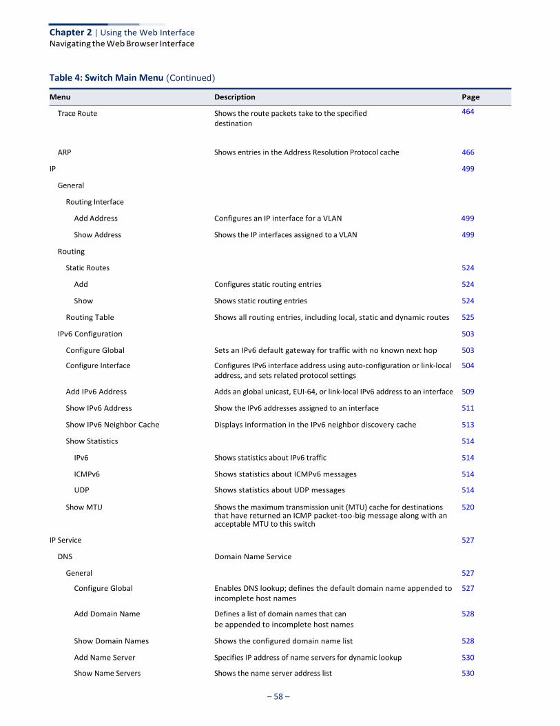
– 58 –
Chapter 2 | Using the Web Interface Navigating the Web Browser Interface
Table 4: Switch Main Menu (Continued)
Menu Description Page
Trace Route Shows the route packets take to the specified destination
464
ARP Shows entries in the Address Resolution Protocol cache 466
IP 499
General
Routing Interface
Add Address Configures an IP interface for a VLAN 499
Show Address Shows the IP interfaces assigned to a VLAN 499
Routing
that have returned an ICMP packet-too-big message along with an
Static Routes 524
Add Configures static routing entries 524
Show Shows static routing entries 524
Routing Table Shows all routing entries, including local, static and dynamic routes 525
IPv6 Configuration 503
Configure Global Sets an IPv6 default gateway for traffic with no known next hop 503
Configure Interface Configures IPv6 interface address using auto-configuration or link-local 504 address, and sets related protocol settings
Add IPv6 Address Adds an global unicast, EUI-64, or link-local IPv6 address to an interface 509
Show IPv6 Address Show the IPv6 addresses assigned to an interface 511
Show IPv6 Neighbor Cache Displays information in the IPv6 neighbor discovery cache 513
Show Statistics 514
IPv6 Shows statistics about IPv6 traffic 514
ICMPv6 Shows statistics about ICMPv6 messages 514
UDP Shows statistics about UDP messages 514
Show MTU Shows the maximum transmission unit (MTU) cache for destinations 520
acceptable MTU to this switch
IP Service 527
DNS Domain Name Service
General 527
Configure Global Enables DNS lookup; defines the default domain name appended to 527
incomplete host names
Add Domain Name Defines a list of domain names that can 528
be appended to incomplete host names
Show Domain Names Shows the configured domain name list 528
Add Name Server Specifies IP address of name servers for dynamic lookup 530
Show Name Servers Shows the name server address list 530
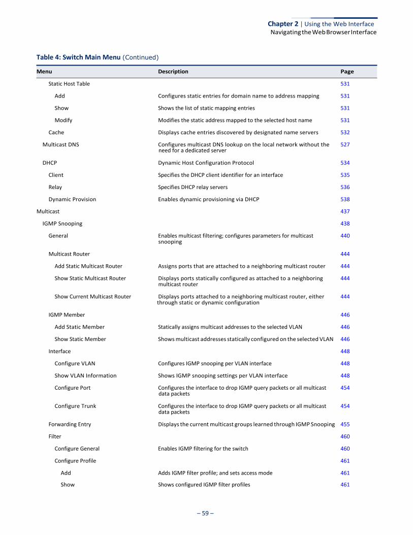
– 59 –
Chapter 2 | Using the Web Interface Navigating the Web Browser Interface
Table 4: Switch Main Menu (Continued)
Menu Description Page
need for a dedicated server
snooping
multicast router
through static or dynamic configuration
data packets
data packets
Static Host Table 531
Add Configures static entries for domain name to address mapping 531
Show Shows the list of static mapping entries 531
Modify Modifies the static address mapped to the selected host name 531
Cache Displays cache entries discovered by designated name servers 532
Multicast DNS Configures multicast DNS lookup on the local network without the 527
DHCP Dynamic Host Configuration Protocol 534
Client Specifies the DHCP client identifier for an interface 535
Relay Specifies DHCP relay servers 536
Dynamic Provision Enables dynamic provisioning via DHCP 538
Multicast 437
IGMP Snooping 438
General Enables multicast filtering; configures parameters for multicast 440
Multicast Router 444
Add Static Multicast Router Assigns ports that are attached to a neighboring multicast router 444
Show Static Multicast Router Displays ports statically configured as attached to a neighboring 444
Show Current Multicast Router Displays ports attached to a neighboring multicast router, either 444
IGMP Member 446
Add Static Member Statically assigns multicast addresses to the selected VLAN 446
Show Static Member Shows multicast addresses statically configured on the selected VLAN 446
Interface 448
Configure VLAN Configures IGMP snooping per VLAN interface 448
Show VLAN Information Shows IGMP snooping settings per VLAN interface 448
Configure Port Configures the interface to drop IGMP query packets or all multicast 454
Configure Trunk Configures the interface to drop IGMP query packets or all multicast 454
Forwarding Entry Displays the current multicast groups learned through IGMP Snooping 455
Filter 460
Configure General Enables IGMP filtering for the switch 460
Configure Profile 461
Add Adds IGMP filter profile; and sets access mode 461
Show Shows configured IGMP filter profiles 461
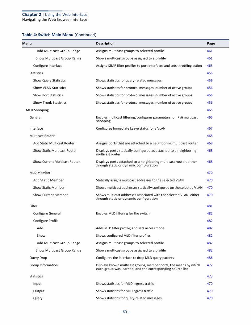
– 60 –
Chapter 2 | Using the Web Interface Navigating the Web Browser Interface
Table 4: Switch Main Menu (Continued)
Menu Description Page
snooping
multicast router
through static or dynamic configuration
through static or dynamic configuration
each group was learned, and the corresponding source list
Add Multicast Group Range Assigns multicast groups to selected profile 461
Show Multicast Group Range Shows multicast groups assigned to a profile 461
Configure Interface Assigns IGMP filter profiles to port interfaces and sets throttling action 463
Statistics 456
Show Query Statistics Shows statistics for query-related messages 456
Show VLAN Statistics Shows statistics for protocol messages, number of active groups 456
Show Port Statistics Shows statistics for protocol messages, number of active groups 456
Show Trunk Statistics Shows statistics for protocol messages, number of active groups 456
MLD Snooping 465
General Enables multicast filtering; configures parameters for IPv6 multicast 465
Interface Configures Immediate Leave status for a VLAN 467
Multicast Router 468
Add Static Multicast Router Assigns ports that are attached to a neighboring multicast router 468
Show Static Multicast Router Displays ports statically configured as attached to a neighboring 468
Show Current Multicast Router Displays ports attached to a neighboring multicast router, either 468
MLD Member 470
Add Static Member Statically assigns multicast addresses to the selected VLAN 470
Show Static Member Shows multicast addresses statically configured on the selected VLAN 470
Show Current Member Shows multicast addresses associated with the selected VLAN, either 470
Filter 481
Configure General Enables MLD filtering for the switch 482
Configure Profile 482
Add Adds MLD filter profile; and sets access mode 482
Show Shows configured MLD filter profiles 482
Add Multicast Group Range Assigns multicast groups to selected profile 482
Show Multicast Group Range Shows multicast groups assigned to a profile 482
Query Drop Configures the interface to drop MLD query packets 486
Group Information Displays known multicast groups, member ports, the means by which 472
Statistics 473
Input Shows statistics for MLD ingress traffic 470
Output Shows statistics for MLD egress traffic 470
Query Shows statistics for query-related messages 470

– 61 –
Chapter 2 | Using the Web Interface Navigating the Web Browser Interface
Table 4: Switch Main Menu (Continued)
Menu Description Page
Summary Shows summary statistics for querier and report/leave messages 470
Clear Clears all MLD statics or statistics for specified VLAN/port 470

– 62 –
Chapter 2 | Using the Web Interface Navigating the Web Browser Interface
– 63 –
Basic Management Tasks
This chapter describes the following topics:
◆ Displaying System Information – Provides basic system description, including contact information.
◆ Displaying Hardware/Software Versions – Shows the hardware version, power
status, and firmware versions
◆ Configuring Support for Jumbo Frames – Enables support for jumbo frames.
◆ Displaying Bridge Extension Capabilities – Shows the bridge extension parameters.
◆ Managing System Files – Describes how to upgrade operating software or
configuration files, and set the system start-up files.
◆ Setting the System Clock – Sets the current time manually or through specified NTP or SNTP servers.
◆ Configuring the Console Port – Sets console port connection parameters.
◆ Configuring Telnet Settings – Sets Telnet connection parameters.
◆ Displaying CPU Utilization – Displays information on CPU utilization.
◆ Configuring CPU Guard – Sets thresholds in terms of CPU usage time and number of packets processed per second.
◆ Displaying Memory Utilization – Shows memory utilization parameters.
◆ Resetting the System – Restarts the switch immediately, at a specified time, after a specified delay, or at a periodic interval.
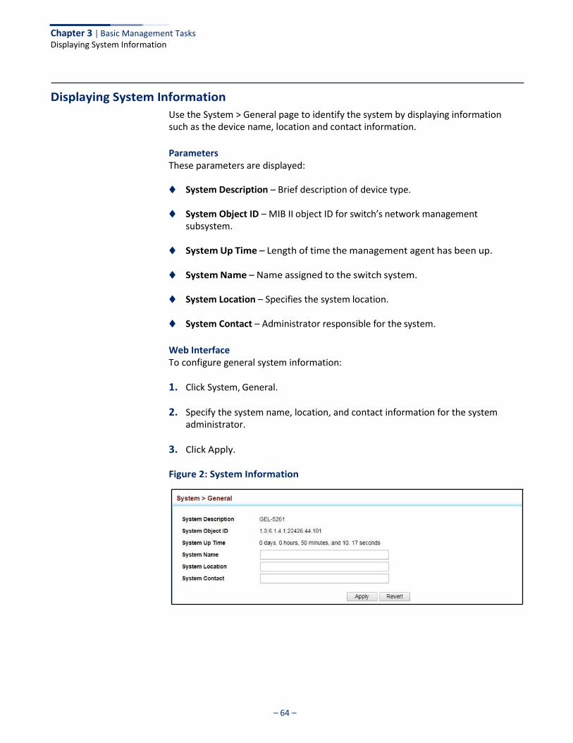
Chapter 3 | Basic Management Tasks Displaying System Information
– 64 –
Displaying System Information
Use the System > General page to identify the system by displaying information such as the device name, location and contact information.
Parameters These parameters are displayed:
◆ System Description – Brief description of device type.
◆ System Object ID – MIB II object ID for switch’s network management subsystem.
◆ System Up Time – Length of time the management agent has been up.
◆ System Name – Name assigned to the switch system.
◆ System Location – Specifies the system location.
◆ System Contact – Administrator responsible for the system.
Web Interface To configure general system information:
1. Click System, General.
2. Specify the system name, location, and contact information for the system administrator.
3. Click Apply.
Figure 2: System Information

Chapter 3 | Basic Management Tasks Displaying Hardware/Software Versions
– 65 –
Displaying Hardware/Software Versions
Use the System > Switch page to display hardware/firmware version numbers for the main board and management software, as well as the power status of the system.
Parameters The following parameters are displayed:
Main Board Information
◆ Serial Number – The serial number of the switch.
◆ Number of Ports – Number of built-in ports.
◆ Hardware Version – Hardware version of the main board.
◆ Main Power Status – Displays the status of the internal power supply.
Management Software Information
◆ Role – Shows that this switch is operating as Master or Slave.
◆ Loader Version – Version number of loader code.
◆ Linux Kernel Version – Version number of Linux kernel.
◆ Operation Code Version – Version number of runtime code.
◆ Thermal Detector – Thermal detector is near the back of the unit.
◆ Temperature – Temperature at specified thermal detection point.
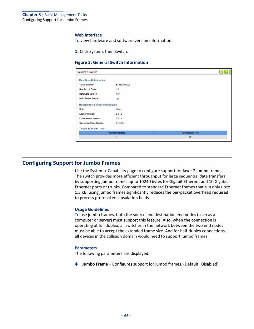
– 66 –
Chapter 3 | Basic Management Tasks Configuring Support for Jumbo Frames
Web Interface To view hardware and software version information.
1. Click System, then Switch.
Figure 3: General Switch Information
Configuring Support for Jumbo Frames
Use the System > Capability page to configure support for layer 2 jumbo frames. The switch provides more efficient throughput for large sequential data transfers by supporting jumbo frames up to 10240 bytes for Gigabit Ethernet and 10 Gigabit Ethernet ports or trunks. Compared to standard Ethernet frames that run only up to 1.5 KB, using jumbo frames significantly reduces the per-packet overhead required to process protocol encapsulation fields.
Usage Guidelines To use jumbo frames, both the source and destination end nodes (such as a computer or server) must support this feature. Also, when the connection is operating at full duplex, all switches in the network between the two end nodes must be able to accept the extended frame size. And for half-duplex connections, all devices in the collision domain would need to support jumbo frames.
Parameters The following parameters are displayed:
◆ Jumbo Frame – Configures support for jumbo frames. (Default: Disabled)
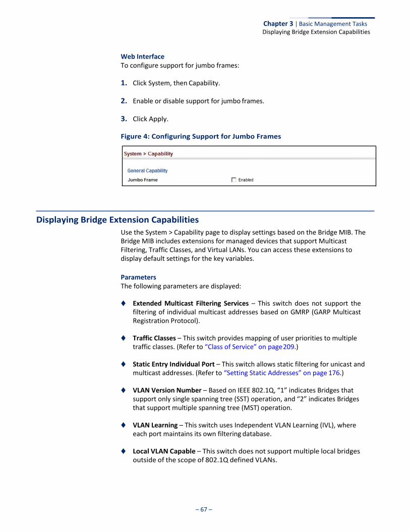
– 67 –
Chapter 3 | Basic Management Tasks Displaying Bridge Extension Capabilities
Web Interface To configure support for jumbo frames:
1. Click System, then Capability.
2. Enable or disable support for jumbo frames.
3. Click Apply.
Figure 4: Configuring Support for Jumbo Frames
Displaying Bridge Extension Capabilities
Use the System > Capability page to display settings based on the Bridge MIB. The Bridge MIB includes extensions for managed devices that support Multicast Filtering, Traffic Classes, and Virtual LANs. You can access these extensions to display default settings for the key variables.
Parameters The following parameters are displayed:
◆ Extended Multicast Filtering Services – This switch does not support the
filtering of individual multicast addresses based on GMRP (GARP Multicast Registration Protocol).
◆ Traffic Classes – This switch provides mapping of user priorities to multiple
traffic classes. (Refer to “Class of Service” on page 209.)
◆ Static Entry Individual Port – This switch allows static filtering for unicast and multicast addresses. (Refer to “Setting Static Addresses” on page 176.)
◆ VLAN Version Number – Based on IEEE 802.1Q, “1” indicates Bridges that
support only single spanning tree (SST) operation, and “2” indicates Bridges that support multiple spanning tree (MST) operation.
◆ VLAN Learning – This switch uses Independent VLAN Learning (IVL), where
each port maintains its own filtering database.
◆ Local VLAN Capable – This switch does not support multiple local bridges outside of the scope of 802.1Q defined VLANs.
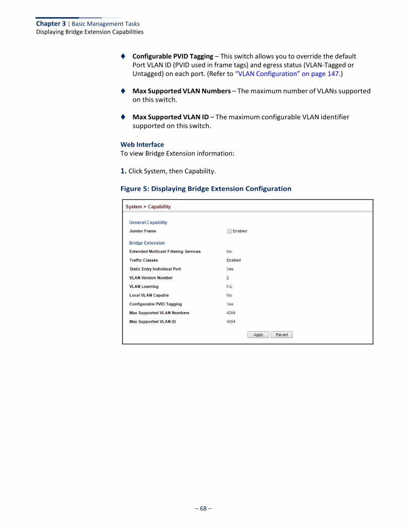
– 68 –
Chapter 3 | Basic Management Tasks Displaying Bridge Extension Capabilities
◆ Configurable PVID Tagging – This switch allows you to override the default Port VLAN ID (PVID used in frame tags) and egress status (VLAN-Tagged or Untagged) on each port. (Refer to “VLAN Configuration” on page 147.)
◆ Max Supported VLAN Numbers – The maximum number of VLANs supported
on this switch.
◆ Max Supported VLAN ID – The maximum configurable VLAN identifier supported on this switch.
Web Interface To view Bridge Extension information:
1. Click System, then Capability.
Figure 5: Displaying Bridge Extension Configuration
– 69 –
Chapter 3 | Basic Management Tasks Managing System Files
Managing System Files
This section describes how to upgrade the switch operating software or configuration files, and set the system start-up files.
Copying Files via FTP/ SFTP/TFTP or HTTP
Use the System > File (Copy) page to upload/download firmware or configuration settings using FTP, SFTP, TFTP or HTTP. By backing up a file to a FTP/SFTP/TFTP server or management station, that file can later be downloaded to the switch to restore operation. Specify the method of file transfer, along with the file type and file names as required.
You can also set the switch to use new firmware or configuration settings without overwriting the current version. Just download the file using a different name from the current version, and then set the new file as the startup file.
Command Usage ◆ When logging into an FTP/SFTP server, the interface prompts for a user name
and password configured on the remote server. Note that “Anonymous” is set as the default user name.
◆ Secure Shell FTP (SFTP) provides a method of transferring files between two
network devices over an SSH2-secured connection. SFTP functions similar to Secure Copy (SCP), using SSH for user authentication and data encryption.
Although the underlying premises of SFTP are similar to SCP, it requires some additional steps to verify the protocol versions and perform security checks. SFTP connection setup includes verification of the DSS signature, creation of session keys, creation of client-server and server-client ciphers, SSH key exchange, and user authentication. An SFTP channel is then opened, the SFTP protocol version compatibility verified, and SFTP finally initialized.
◆ The reset command will not be accepted during copy operations to flash memory.
Parameters The following parameters are displayed:
◆ Copy Type – The firmware copy operation includes these options:
■ FTP Upload – Copies a file from an FTP server to the switch.
■ FTP Download – Copies a file from the switch to an FTP server.
■ HTTP Upload – Copies a file from a management station to the switch.
■ HTTP Download – Copies a file from the switch to a management station
■ SFTP Upload – Copies a file from an SFTP server to the switch.
■ SFTP Download – Copies a file from the switch to an SFTP server.
■ TFTP Upload – Copies a file from a TFTP server to the switch.
– 70 –
Chapter 3 | Basic Management Tasks Managing System Files
■ TFTP Download – Copies a file from the switch to a TFTP server.
◆ FTP/SFTP/TFTP Server IP Address – The IP address of an FTP/SFTP/TFTP server.
◆ User Name – The user name for SFTP/FTP server access.
◆ Password – The password for SFTP/FTP server access.
◆ File Type – Specify Operation Code to copy firmware.
◆ File Name – The file name should not contain slashes (\ or /), the leading letter of the file name should not be a period (.), and the maximum length for file names is 32 characters for files on the switch or 127 characters for files on the server. (Valid characters: A-Z, a-z, 0-9, “.”, “-”, “_”)
Note: Up to two copies of the system software (i.e., the runtime firmware) can be stored in the file directory on the switch.
Note: The maximum number of user-defined configuration files is limited only by available flash memory space.
Note: The file “Factory_Default_Config.cfg” can be copied to a file server or management station, but cannot be used as the destination file name on the switch.
Web Interface To copy firmware files:
1. Click System, then File.
2. Select Copy from the Action list.
3. Select FTP Upload, HTTP Upload, SFTP or TFTP Upload as the file transfer method.
4. If FTP, SFTP or TFTP Upload is used, enter the IP address of the file server.
5. If FTP/SFTP Upload is used, enter the user name and password for your account on the FTP/SFTP server.
6. Set the file type to Operation Code.
7. Enter the name of the file to download.
8. Select a file on the switch to overwrite or specify a new file name.
9. Then click Apply.
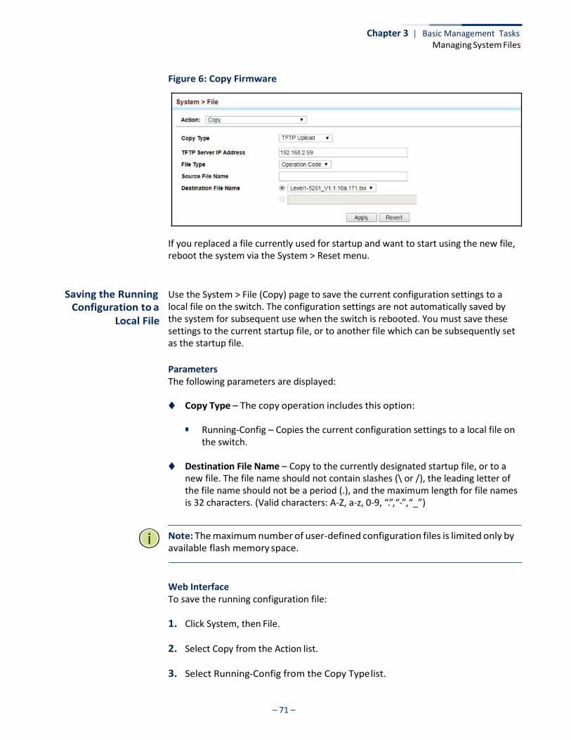
– 71 –
Chapter 3 | Basic Management Tasks Managing System Files
Figure 6: Copy Firmware
If you replaced a file currently used for startup and want to start using the new file, reboot the system via the System > Reset menu.
Saving the Running Configuration to a
Local File
Use the System > File (Copy) page to save the current configuration settings to a local file on the switch. The configuration settings are not automatically saved by the system for subsequent use when the switch is rebooted. You must save these settings to the current startup file, or to another file which can be subsequently set as the startup file.
Parameters The following parameters are displayed:
◆ Copy Type – The copy operation includes this option:
■ Running-Config – Copies the current configuration settings to a local file on the switch.
◆ Destination File Name – Copy to the currently designated startup file, or to a
new file. The file name should not contain slashes (\ or /), the leading letter of the file name should not be a period (.), and the maximum length for file names is 32 characters. (Valid characters: A-Z, a-z, 0-9, “.”, “-”, “_”)
Note: The maximum number of user-defined configuration files is limited only by available flash memory space.
Web Interface To save the running configuration file:
1. Click System, then File.
2. Select Copy from the Action list.
3. Select Running-Config from the Copy Type list.
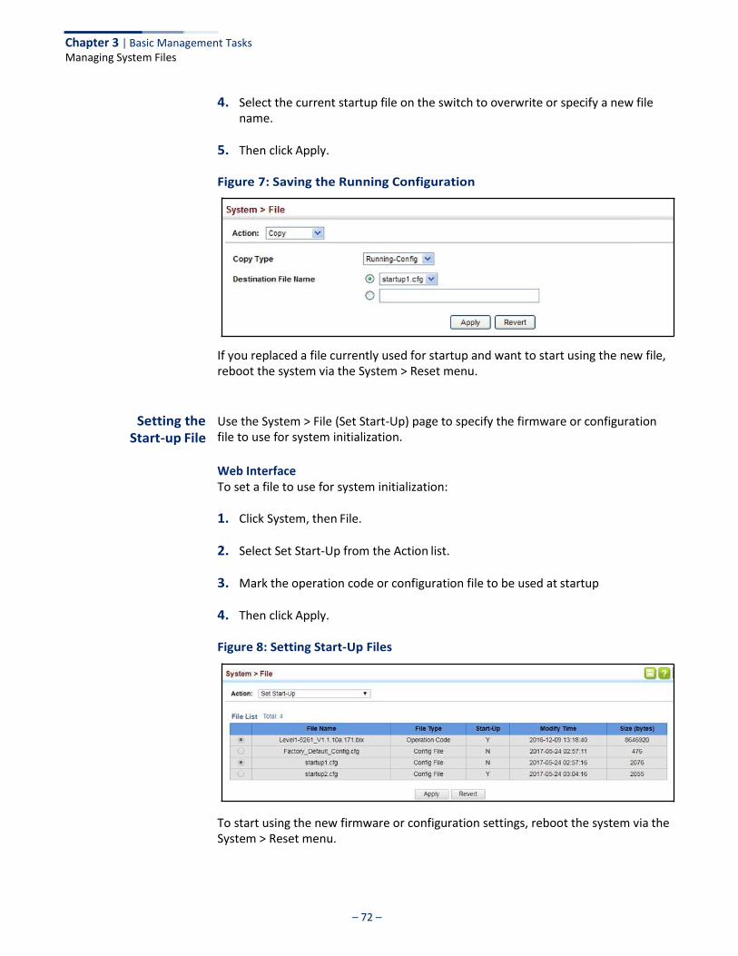
– 72 –
Chapter 3 | Basic Management Tasks Managing System Files
4. Select the current startup file on the switch to overwrite or specify a new file name.
5. Then click Apply.
Figure 7: Saving the Running Configuration
If you replaced a file currently used for startup and want to start using the new file, reboot the system via the System > Reset menu.
Setting the Start-up File
Use the System > File (Set Start-Up) page to specify the firmware or configuration file to use for system initialization.
Web Interface To set a file to use for system initialization:
1. Click System, then File.
2. Select Set Start-Up from the Action list.
3. Mark the operation code or configuration file to be used at startup
4. Then click Apply.
Figure 8: Setting Start-Up Files
To start using the new firmware or configuration settings, reboot the system via the System > Reset menu.
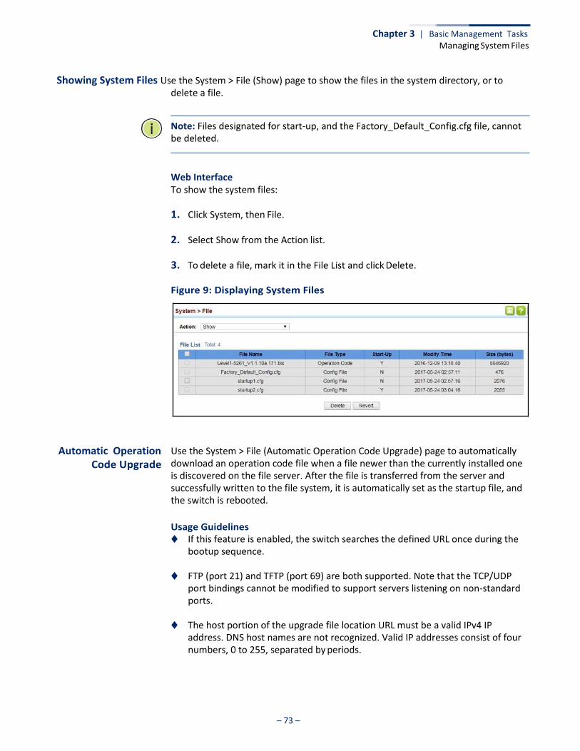
– 73 –
Chapter 3 | Basic Management Tasks Managing System Files
Showing System Files Use the System > File (Show) page to show the files in the system directory, or to delete a file.
Note: Files designated for start-up, and the Factory_Default_Config.cfg file, cannot be deleted.
Web Interface To show the system files:
1. Click System, then File.
2. Select Show from the Action list.
3. To delete a file, mark it in the File List and click Delete.
Figure 9: Displaying System Files
Automatic Operation Code Upgrade
Use the System > File (Automatic Operation Code Upgrade) page to automatically download an operation code file when a file newer than the currently installed one is discovered on the file server. After the file is transferred from the server and successfully written to the file system, it is automatically set as the startup file, and the switch is rebooted.
Usage Guidelines ◆ If this feature is enabled, the switch searches the defined URL once during the
bootup sequence.
◆ FTP (port 21) and TFTP (port 69) are both supported. Note that the TCP/UDP port bindings cannot be modified to support servers listening on non-standard ports.
◆ The host portion of the upgrade file location URL must be a valid IPv4 IP
address. DNS host names are not recognized. Valid IP addresses consist of four numbers, 0 to 255, separated by periods.

– 74 –
Chapter 3 | Basic Management Tasks Managing System Files
◆ The path to the directory must also be defined. If the file is stored in the root directory for the FTP/TFTP service, then use the “/” to indicate this (e.g., ftp:// 192.168.0.1/).
◆ The file name must not be included in the upgrade file location URL. The file
name of the code stored on the remote server must be level1-5261.bix (using upper case and lower case letters exactly as indicated here). Enter the file name for other switches described in this manual exactly as shown on the web interface.
◆ The FTP connection is made with PASV mode enabled. PASV mode is needed to
traverse some fire walls, even if FTP traffic is not blocked. PASV mode cannot be disabled.
◆ The switch-based search function is case-insensitive in that it will accept a file
name in upper or lower case (i.e., the switch will accept Level1-5261.BIX from the server even though Level1-5261.bix was requested). However, keep in mind that the file systems of many operating systems such as Unix and most Unix- like systems (FreeBSD, NetBSD, OpenBSD, and most Linux distributions, etc.) are case-sensitive, meaning that two files in the same directory, level1-2651.bix and Level1-2651.bix are considered to be unique files. Thus, if the upgrade file is stored as Level1-2651.bix on a case-sensitive server, then the switch (requesting level1-5261.bix) will not be upgraded because the server does not recognize the requested file name and the stored file name as being equal. A notable exception in the list of case-sensitive Unix-like operating systems is Mac OS X, which by default is case-insensitive. Please check the documentation for your server’s operating system if you are unsure of its file system’s behavior.
◆ Note that the switch itself does not distinguish between upper and lower-case file names, and only checks to see if the file stored on the server is more recent than the current runtime image.
◆ If two operation code image files are already stored on the switch’s file system,
then the non-startup image is deleted before the upgrade image is transferred.
◆ The automatic upgrade process will take place in the background without impeding normal operations (data switching, etc.) of the switch.
◆ During the automatic search and transfer process, the administrator cannot
transfer or update another operation code image, configuration file, public key, or HTTPS certificate (i.e., no other concurrent file management operations are possible).
◆ The upgrade operation code image is set as the startup image after it has been
successfully written to the file system.
◆ The switch will send an SNMP trap and make a log entry upon all upgrade successes and failures.

– 75 –
Chapter 3 | Basic Management Tasks Managing System Files
◆ The switch will immediately restart after the upgrade file is successfully written to the file system and set as the startup image.
Parameters The following parameters are displayed:
◆ Automatic Opcode Upgrade – Enables the switch to search for an upgraded
operation code file during the switch bootup process. (Default: Disabled)
◆ Automatic Upgrade Location URL – Defines where the switch should search for the operation code upgrade file. The last character of this URL must be a forward slash (“/”). The level1-5261.bix filename must not be included since it is automatically appended by the switch. (Options: ftp, sftp, tftp)
The following syntax must be observed:
tftp://host[/filedir]/
■ tftp:// – Defines TFTP protocol for the server connection.
■ host – Defines the IP address of the TFTP server. Valid IP addresses consist of four numbers, 0 to 255, separated by periods. DNS host names are not recognized.
■ filedir – Defines the directory, relative to the TFTP server root, where the upgrade file can be found. Nested directory structures are accepted. The directory name must be separated from the host, and in nested directory structures, from the parent directory, with a prepended forward slash “/”.
■ / – The forward slash must be the last character of the URL.
ftp://[username[:password@]]host[/filedir]/
■ ftp:// – Defines FTP protocol for the server connection.
■ username – Defines the user name for the FTP connection. If the user name is omitted, then “anonymous” is the assumed user name for the connection.
■ password – Defines the password for the FTP connection. To differentiate the password from the user name and host portions of the URL, a colon (:) must precede the password, and an “at” symbol (@), must follow the password. If the password is omitted, then “” (an empty string) is the assumed password for the connection.
■ host – Defines the IP address of the FTP server. Valid IP addresses consist of four numbers, 0 to 255, separated by periods. DNS host names are not recognized.
■ filedir – Defines the directory, relative to the FTP server root, where the upgrade file can be found. Nested directory structures are accepted. The directory name must be separated from the host, and in nested directory structures, from the parent directory, with a prepended forward slash “/”.
■ / – The forward slash must be the last character of the URL.

– 76 –
Chapter 3 | Basic Management Tasks Managing System Files
Examples
The following examples demonstrate the URL syntax for a TFTP server at IP address 192.168.0.1 with the operation code image stored in various locations:
■ tftp://192.168.0.1/
The image file is in the TFTP root directory.
■ tftp://192.168.0.1/switch-opcode/
The image file is in the “switch-opcode” directory, relative to the TFTP root.
■ tftp://192.168.0.1/switches/opcode/
The image file is in the “opcode” directory, which is within the “switches” parent directory, relative to the TFTP root.
The following examples demonstrate the URL syntax for an FTP server at IP address 192.168.0.1 with various user name, password and file location options presented:
■ ftp://192.168.0.1/
The user name and password are empty, so “anonymous” will be the user name and the password will be blank. The image file is in the FTP root directory.
■ ftp://switches:[email protected]/
The user name is “switches” and the password is “upgrade”. The image file is in the FTP root.
■ ftp://switches:[email protected]/switches/opcode/
The user name is “switches” and the password is “upgrade”. The image file is in the “opcode” directory, which is within the “switches” parent directory, relative to the FTP root.
Web Interface To configure automatic code upgrade:
1. Click System, then File.
2. Select Automatic Operation Code Upgrade from the Action list.
3. Mark the check box to enable Automatic Opcode Upgrade.
4. Enter the URL of the FTP or TFTP server, and the path and directory containing the operation code.
5. Click Apply.
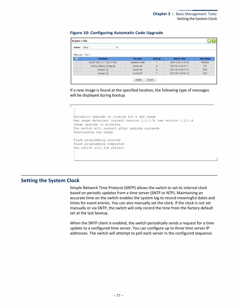
– 77 –
Chapter 3 | Basic Management Tasks Setting the System Clock
Figure 10: Configuring Automatic Code Upgrade
If a new image is found at the specified location, the following type of messages will be displayed during bootup.
.
.
.
Automatic Upgrade is looking for a new image
New image detected: current version 1.2.1.3; new version 1.2.1.6
Image upgrade in progress
The switch will restart after upgrade succeeds
Downloading new image
Flash programming started
Flash programming completed
The switch will now restart
.
.
.
Setting the System Clock
Simple Network Time Protocol (SNTP) allows the switch to set its internal clock based on periodic updates from a time server (SNTP or NTP). Maintaining an accurate time on the switch enables the system log to record meaningful dates and times for event entries. You can also manually set the clock. If the clock is not set manually or via SNTP, the switch will only record the time from the factory default set at the last bootup.
When the SNTP client is enabled, the switch periodically sends a request for a time update to a configured time server. You can configure up to three time server IP addresses. The switch will attempt to poll each server in the configured sequence.
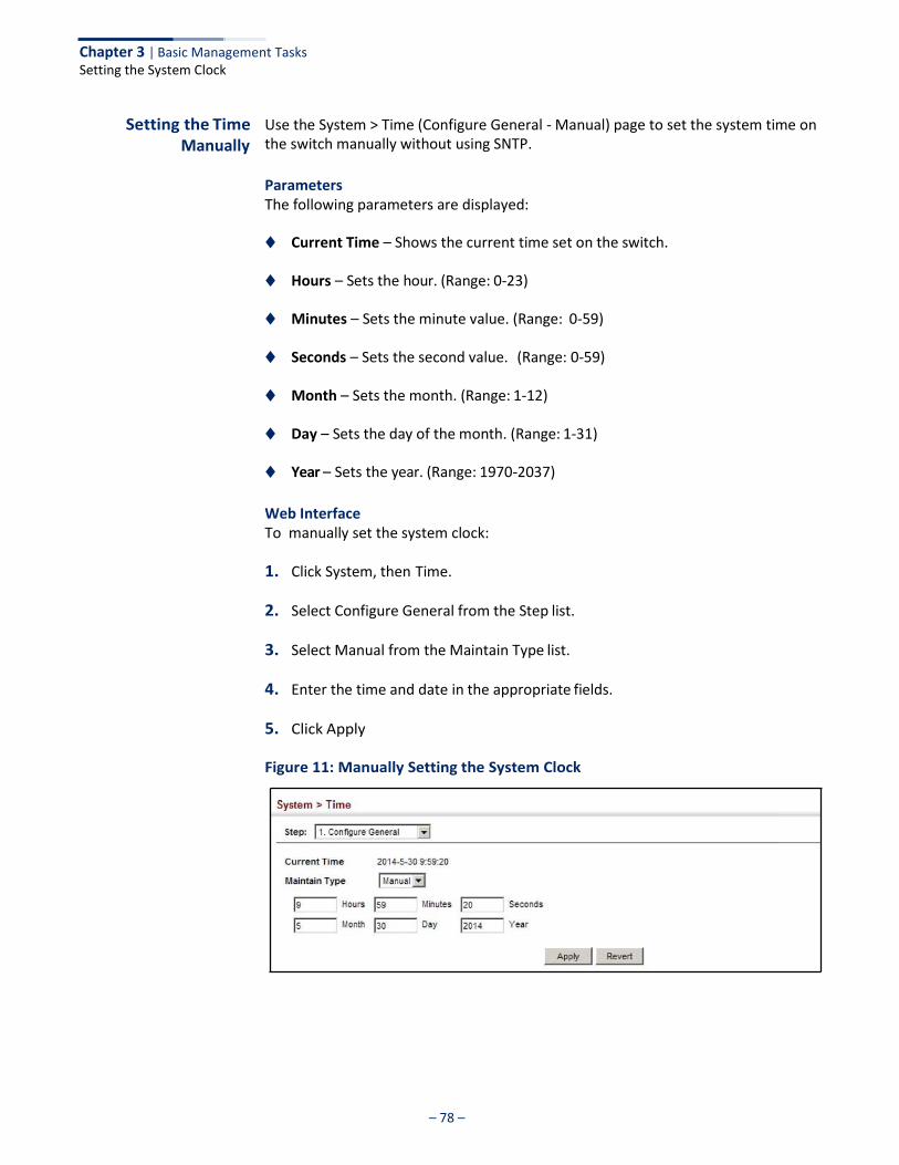
– 78 –
Chapter 3 | Basic Management Tasks Setting the System Clock
Setting the Time Manually
Use the System > Time (Configure General - Manual) page to set the system time on the switch manually without using SNTP.
Parameters The following parameters are displayed:
◆ Current Time – Shows the current time set on the switch.
◆ Hours – Sets the hour. (Range: 0-23)
◆ Minutes – Sets the minute value. (Range: 0-59)
◆ Seconds – Sets the second value. (Range: 0-59)
◆ Month – Sets the month. (Range: 1-12)
◆ Day – Sets the day of the month. (Range: 1-31)
◆ Year – Sets the year. (Range: 1970-2037)
Web Interface To manually set the system clock:
1. Click System, then Time.
2. Select Configure General from the Step list.
3. Select Manual from the Maintain Type list.
4. Enter the time and date in the appropriate fields.
5. Click Apply
Figure 11: Manually Setting the System Clock
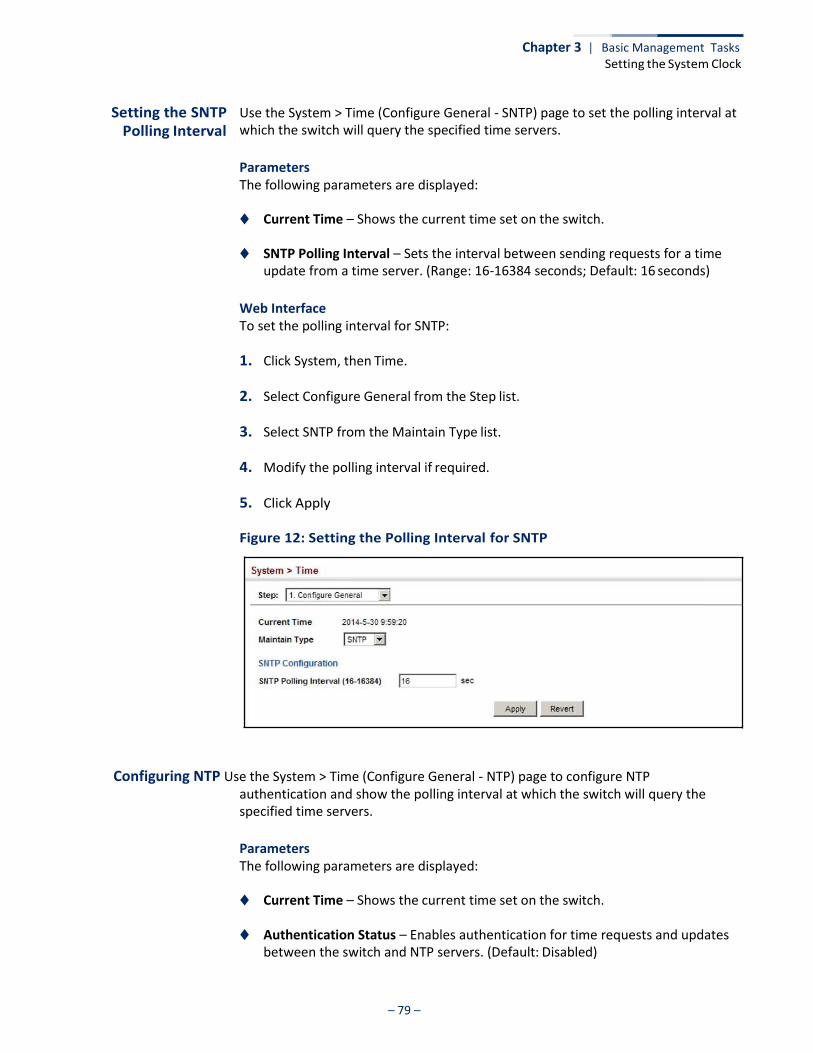
– 79 –
Chapter 3 | Basic Management Tasks Setting the System Clock
Setting the SNTP Polling Interval
Use the System > Time (Configure General - SNTP) page to set the polling interval at which the switch will query the specified time servers.
Parameters The following parameters are displayed:
◆ Current Time – Shows the current time set on the switch.
◆ SNTP Polling Interval – Sets the interval between sending requests for a time update from a time server. (Range: 16-16384 seconds; Default: 16 seconds)
Web Interface To set the polling interval for SNTP:
1. Click System, then Time.
2. Select Configure General from the Step list.
3. Select SNTP from the Maintain Type list.
4. Modify the polling interval if required.
5. Click Apply
Figure 12: Setting the Polling Interval for SNTP
Configuring NTP Use the System > Time (Configure General - NTP) page to configure NTP authentication and show the polling interval at which the switch will query the specified time servers.
Parameters The following parameters are displayed:
◆ Current Time – Shows the current time set on the switch.
◆ Authentication Status – Enables authentication for time requests and updates between the switch and NTP servers. (Default: Disabled)
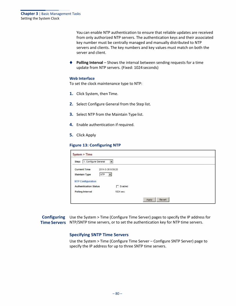
– 80 –
Chapter 3 | Basic Management Tasks Setting the System Clock
You can enable NTP authentication to ensure that reliable updates are received from only authorized NTP servers. The authentication keys and their associated key number must be centrally managed and manually distributed to NTP servers and clients. The key numbers and key values must match on both the server and client.
◆ Polling Interval – Shows the interval between sending requests for a time
update from NTP servers. (Fixed: 1024 seconds)
Web Interface To set the clock maintenance type to NTP:
1. Click System, then Time.
2. Select Configure General from the Step list.
3. Select NTP from the Maintain Type list.
4. Enable authentication if required.
5. Click Apply
Figure 13: Configuring NTP
Configuring
Time Servers
Use the System > Time (Configure Time Server) pages to specify the IP address for NTP/SNTP time servers, or to set the authentication key for NTP time servers.
Specifying SNTP Time Servers
Use the System > Time (Configure Time Server – Configure SNTP Server) page to specify the IP address for up to three SNTP time servers.

– 81 –
Chapter 3 | Basic Management Tasks Setting the System Clock
Parameters The following parameters are displayed:
◆ SNTP Server IP Address – Sets the IPv4 address for up to three time servers.
The switch attempts to update the time from the first server, if this fails it attempts an update from the next server in the sequence.
Web Interface To set the SNTP time servers:
1. Click System, then Time.
2. Select Configure Time Server from the Step list.
3. Select Configure SNTP Server from the Action list.
4. Enter the IP address of up to three time servers.
5. Click Apply.
Figure 14: Specifying SNTP Time Servers
Specifying NTP Time Servers
Use the System > Time (Configure Time Server – Add NTP Server) page to add the IP address for up to 50 NTP time servers.
Parameters The following parameters are displayed:
◆ NTP Server IP Address – Sets the IPv4 address for up to three time servers. The
switch will poll the specified time servers for updates when the clock maintenance type is set to NTP on the System > Time (Configure General) page. It issues time synchronization requests at a fixed interval of 1024 seconds. The switch will poll all the time servers configured, the responses received are filtered and compared to determine the most reliable and accurate time update for the switch.
◆ Version – Specifies the NTP version supported by the server. (Fixed: Version 3)
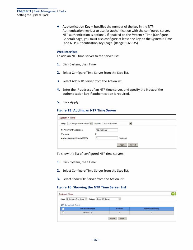
– 82 –
Chapter 3 | Basic Management Tasks Setting the System Clock
◆ Authentication Key – Specifies the number of the key in the NTP Authentication Key List to use for authentication with the configured server. NTP authentication is optional. If enabled on the System > Time (Configure General) page, you must also configure at least one key on the System > Time (Add NTP Authentication Key) page. (Range: 1-65535)
Web Interface To add an NTP time server to the server list:
1. Click System, then Time.
2. Select Configure Time Server from the Step list.
3. Select Add NTP Server from the Action list.
4. Enter the IP address of an NTP time server, and specify the index of the authentication key if authentication is required.
5. Click Apply.
Figure 15: Adding an NTP Time Server
To show the list of configured NTP time servers:
1. Click System, then Time.
2. Select Configure Time Server from the Step list.
3. Select Show NTP Server from the Action list.
Figure 16: Showing the NTP Time Server List
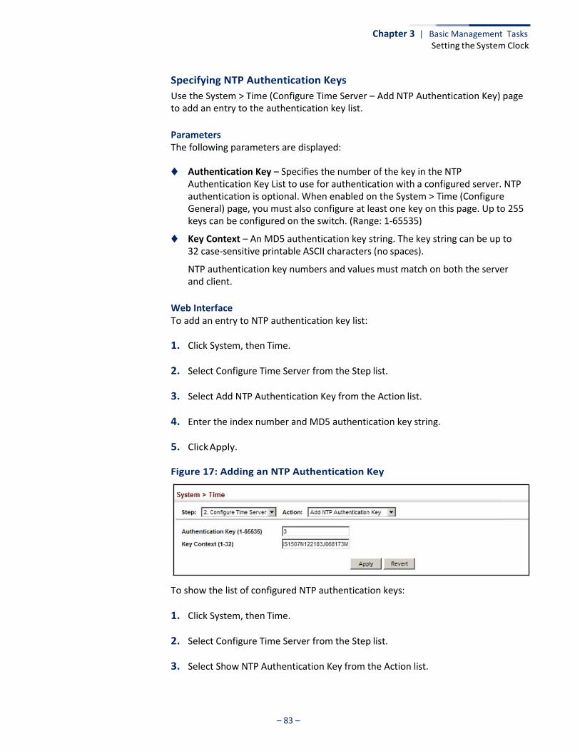
– 83 –
Chapter 3 | Basic Management Tasks Setting the System Clock
Specifying NTP Authentication Keys
Use the System > Time (Configure Time Server – Add NTP Authentication Key) page to add an entry to the authentication key list.
Parameters The following parameters are displayed:
◆ Authentication Key – Specifies the number of the key in the NTP
Authentication Key List to use for authentication with a configured server. NTP authentication is optional. When enabled on the System > Time (Configure General) page, you must also configure at least one key on this page. Up to 255 keys can be configured on the switch. (Range: 1-65535)
◆ Key Context – An MD5 authentication key string. The key string can be up to 32 case-sensitive printable ASCII characters (no spaces).
NTP authentication key numbers and values must match on both the server and client.
Web Interface To add an entry to NTP authentication key list:
1. Click System, then Time.
2. Select Configure Time Server from the Step list.
3. Select Add NTP Authentication Key from the Action list.
4. Enter the index number and MD5 authentication key string.
5. Click Apply.
Figure 17: Adding an NTP Authentication Key
To show the list of configured NTP authentication keys:
1. Click System, then Time.
2. Select Configure Time Server from the Step list.
3. Select Show NTP Authentication Key from the Action list.
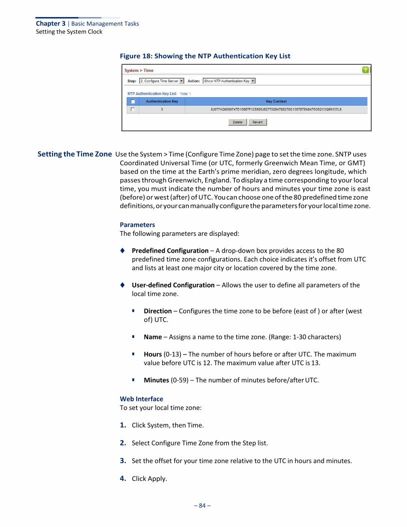
– 84 –
Chapter 3 | Basic Management Tasks Setting the System Clock
Figure 18: Showing the NTP Authentication Key List
Setting the Time Zone Use the System > Time (Configure Time Zone) page to set the time zone. SNTP uses Coordinated Universal Time (or UTC, formerly Greenwich Mean Time, or GMT) based on the time at the Earth’s prime meridian, zero degrees longitude, which passes through Greenwich, England. To display a time corresponding to your local time, you must indicate the number of hours and minutes your time zone is east (before) or west (after) of UTC. You can choose one of the 80 predefined time zone definitions, or your can manually configure the parameters for your local time zone.
Parameters The following parameters are displayed:
◆ Predefined Configuration – A drop-down box provides access to the 80
predefined time zone configurations. Each choice indicates it’s offset from UTC and lists at least one major city or location covered by the time zone.
◆ User-defined Configuration – Allows the user to define all parameters of the
local time zone.
■ Direction – Configures the time zone to be before (east of ) or after (west of) UTC.
■ Name – Assigns a name to the time zone. (Range: 1-30 characters)
■ Hours (0-13) – The number of hours before or after UTC. The maximum
value before UTC is 12. The maximum value after UTC is 13.
■ Minutes (0-59) – The number of minutes before/after UTC.
Web Interface To set your local time zone:
1. Click System, then Time.
2. Select Configure Time Zone from the Step list.
3. Set the offset for your time zone relative to the UTC in hours and minutes.
4. Click Apply.

– 85 –
Chapter 3 | Basic Management Tasks Setting the System Clock
Figure 19: Setting the Time Zone
Configuring Summer Time
Use the Summer Time page to set the system clock forward during the summer months (also known as daylight savings time).
In some countries or regions, clocks are adjusted through the summer months so that afternoons have more daylight and mornings have less. This is known as Summer Time, or Daylight Savings Time (DST). Typically, clocks are adjusted forward one hour at the start of spring and then adjusted backward in autumn.
Parameters The following parameters are displayed in the web interface:
General Configuration
◆ Summer Time in Effect – Shows if the system time has been adjusted.
◆ Status – Shows if summer time is set to take effect during the specified period.
◆ Name – Name of the time zone while summer time is in effect, usually an acronym. (Range: 1-30 characters)
◆ Mode – Selects one of the following configuration modes. (The Mode option
can only be managed when the Summer Time Status option has been set to enabled for the switch.)
Predefined Mode – Configures the summer time status and settings for the switch using predefined configurations for several major regions of the world. To specify the time corresponding to your local time when summer time is in effect, select the predefined summer-time zone appropriate for your location.
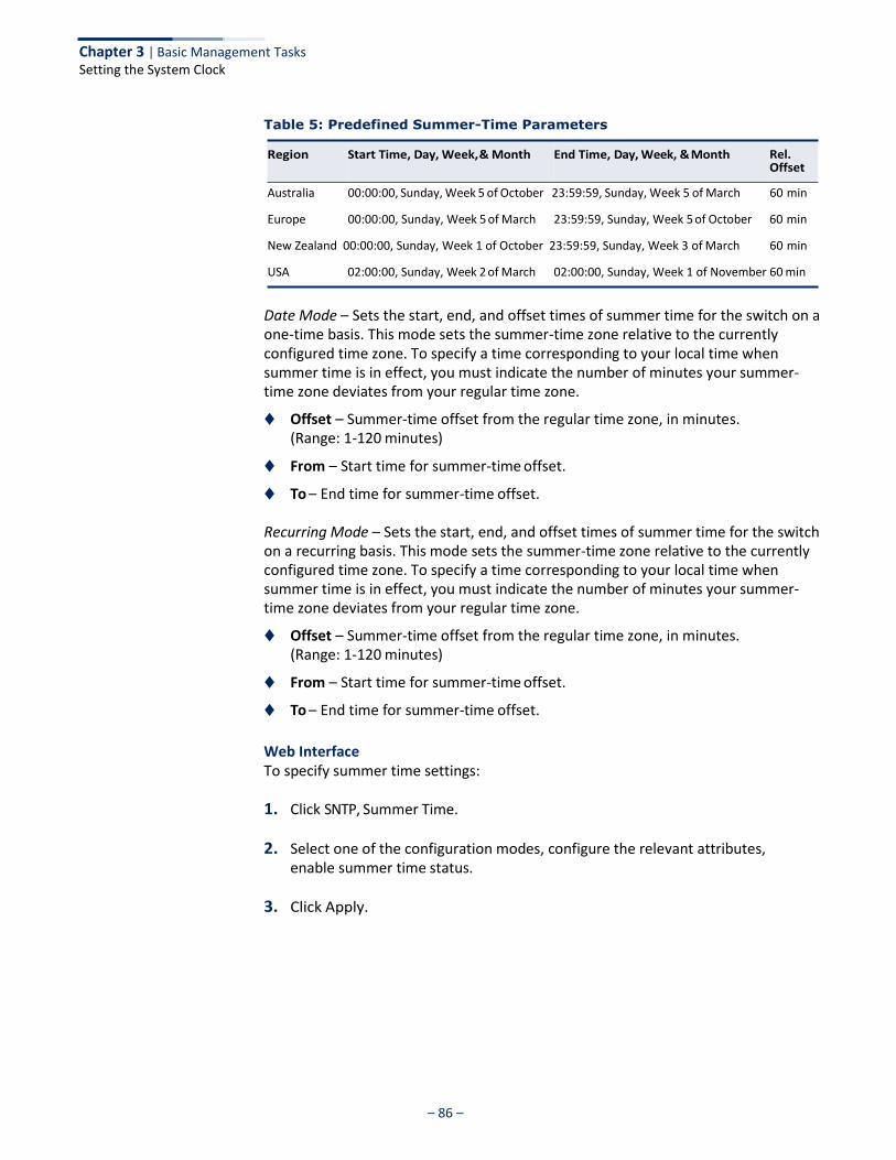
– 86 –
Chapter 3 | Basic Management Tasks Setting the System Clock
Table 5: Predefined Summer-Time Parameters
Australia 00:00:00, Sunday, Week 5 of October 23:59:59, Sunday, Week 5 of March 60 min
Europe 00:00:00, Sunday, Week 5 of March 23:59:59, Sunday, Week 5 of October 60 min
New Zealand 00:00:00, Sunday, Week 1 of October 23:59:59, Sunday, Week 3 of March 60 min
USA 02:00:00, Sunday, Week 2 of March 02:00:00, Sunday, Week 1 of November 60 min
Date Mode – Sets the start, end, and offset times of summer time for the switch on a one-time basis. This mode sets the summer-time zone relative to the currently configured time zone. To specify a time corresponding to your local time when summer time is in effect, you must indicate the number of minutes your summer- time zone deviates from your regular time zone.
◆ Offset – Summer-time offset from the regular time zone, in minutes. (Range: 1-120 minutes)
◆ From – Start time for summer-time offset.
◆ To – End time for summer-time offset.
Recurring Mode – Sets the start, end, and offset times of summer time for the switch on a recurring basis. This mode sets the summer-time zone relative to the currently configured time zone. To specify a time corresponding to your local time when summer time is in effect, you must indicate the number of minutes your summer- time zone deviates from your regular time zone.
◆ Offset – Summer-time offset from the regular time zone, in minutes. (Range: 1-120 minutes)
◆ From – Start time for summer-time offset.
◆ To – End time for summer-time offset.
Web Interface To specify summer time settings:
1. Click SNTP, Summer Time.
2. Select one of the configuration modes, configure the relevant attributes, enable summer time status.
3. Click Apply.

– 87 –
Chapter 3 | Basic Management Tasks Configuring the Console Port
Figure 20: Configuring Summer Time
Configuring the Console Port
Use the System > Console menu to configure connection parameters for the switch’s console port. You can access the onboard configuration program by attaching a VT100 compatible device to the switch’s serial console port. Management access through the console port is controlled by various parameters, including a password (only configurable through the CLI), time outs, and basic communication settings. Note that these parameters can be configured via the web or CLI interface.
Parameters The following parameters are displayed:
◆ Login Timeout – Sets the interval that the system waits for a user to log into
the CLI. If a login attempt is not detected within the timeout interval, the connection is terminated for the session. (Range: 10-300 seconds; Default: 300 seconds)
◆ Exec Timeout – Sets the interval that the system waits until user input is
detected. If user input is not detected within the timeout interval, the current session is terminated. (Range: 60-65535 seconds; Default: 600 seconds)
◆ Password Threshold – Sets the password intrusion threshold, which limits the
number of failed logon attempts. When the logon attempt threshold is reached, the system interface becomes silent for a specified amount of time (set by the Silent Time parameter) before allowing the next logon attempt. (Range: 1-120; Default: 3 attempts)
◆ Silent Time – Sets the amount of time the management console is inaccessible
after the number of unsuccessful logon attempts has been exceeded. (Range: 1-65535 seconds; Default: Disabled)
◆ Data Bits – Sets the number of data bits per character that are interpreted and generated by the console port. If parity is being generated, specify 7 data bits

– 88 –
Chapter 3 | Basic Management Tasks Configuring the Console Port
per character. If no parity is required, specify 8 data bits per character. (Default: 8 bits)
◆ Stop Bits – Sets the number of the stop bits transmitted per byte.
(Range: 1-2; Default: 1 stop bit)
◆ Parity – Defines the generation of a parity bit. Communication protocols provided by some terminals can require a specific parity bit setting. Specify Even, Odd, or None. (Default: None)
◆ Speed – Sets the terminal line’s baud rate for transmit (to terminal) and receive
(from terminal). Set the speed to match the baud rate of the device connected to the serial port. (Range: 9600, 19200, 38400, 57600, or 115200 baud; Default: 115200 baud)
Note: The password for the console connection can only be configured through the CLI (see the “password” command in the CLI Reference Guide).
Note: Password checking can be enabled or disabled for logging in to the console connection (see the “login” command in the CLI Reference Guide). You can select authentication by a single global password as configured for the password command, or by passwords set up for specific user-name accounts. The default is for local passwords configured on the switch.
Web Interface To configure parameters for the console port:
1. Click System, then Console.
2. Specify the connection parameters as required.
3. Click Apply
Figure 21: Console Port Settings
– 89 –
Chapter 3 | Basic Management Tasks Configuring Telnet Settings
Configuring Telnet Settings
Use the System > Telnet menu to configure parameters for accessing the CLI over a Telnet connection. You can access the onboard configuration program over the network using Telnet (i.e., a virtual terminal). Management access via Telnet can be enabled/disabled and other parameters set, including the TCP port number, time outs, and a password. Note that the password is only configurable through the CLI.) These parameters can be configured via the web or CLI interface.
Parameters The following parameters are displayed:
◆ Telnet Status – Enables or disables Telnet access to the switch.
(Default: Enabled)
◆ TCP Port – Sets the TCP port number for Telnet on the switch. (Range: 1-65535; Default: 23)
◆ Max Sessions – Sets the maximum number of Telnet sessions that can
simultaneously connect to this system. (Range: 0-8; Default: 8)
A maximum of eight sessions can be concurrently opened for Telnet and Secure Shell (i.e., both Telnet and SSH share a maximum number of eight sessions).
◆ Login Timeout – Sets the interval that the system waits for a user to log into
the CLI. If a login attempt is not detected within the timeout interval, the connection is terminated for the session. (Range: 10-300 seconds; Default: 300 seconds)
◆ Exec Timeout – Sets the interval that the system waits until user input is detected. If user input is not detected within the timeout interval, the current session is terminated. (Range: 60-65535 seconds; Default: 600 seconds)
◆ Password Threshold – Sets the password intrusion threshold, which limits the
number of failed logon attempts. When the logon attempt threshold is reached, the system interface becomes silent for a specified amount of time (set by the Silent Time parameter) before allowing the next logon attempt. (Range: 1-120; Default: 3 attempts)
◆ Silent Time – Sets the amount of time the management interface is
inaccessible after the number of unsuccessful logon attempts has been exceeded. (Range: 1-65535 seconds; Default: Disabled)
Note: The password for the Telnet connection can only be configured through the CLI (see the “password” command in the CLI Reference Guide).
Note: Password checking can be enabled or disabled for login to the console connection (see the “login” command in the CLI Reference Guide). You can select
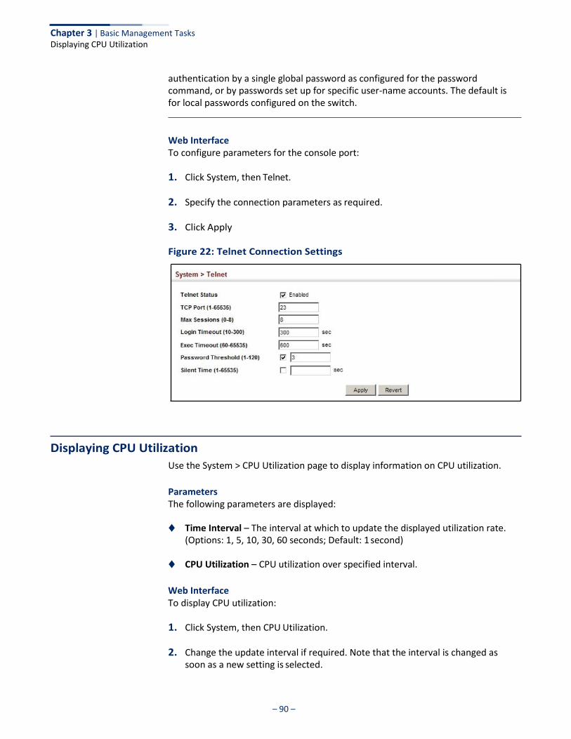
– 90 –
Chapter 3 | Basic Management Tasks Displaying CPU Utilization
authentication by a single global password as configured for the password command, or by passwords set up for specific user-name accounts. The default is for local passwords configured on the switch.
Web Interface To configure parameters for the console port:
1. Click System, then Telnet.
2. Specify the connection parameters as required.
3. Click Apply
Figure 22: Telnet Connection Settings
Displaying CPU Utilization
Use the System > CPU Utilization page to display information on CPU utilization.
Parameters The following parameters are displayed:
◆ Time Interval – The interval at which to update the displayed utilization rate.
(Options: 1, 5, 10, 30, 60 seconds; Default: 1 second)
◆ CPU Utilization – CPU utilization over specified interval.
Web Interface To display CPU utilization:
1. Click System, then CPU Utilization.
2. Change the update interval if required. Note that the interval is changed as soon as a new setting is selected.
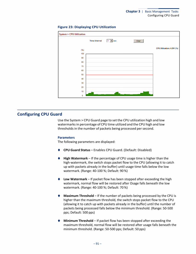
– 91 –
Chapter 3 | Basic Management Tasks Configuring CPU Guard
Figure 23: Displaying CPU Utilization
Configuring CPU Guard
Use the System > CPU Guard page to set the CPU utilization high and low watermarks in percentage of CPU time utilized and the CPU high and low thresholds in the number of packets being processed per second.
Parameters The following parameters are displayed:
◆ CPU Guard Status – Enables CPU Guard. (Default: Disabled)
◆ High Watermark – If the percentage of CPU usage time is higher than the high-watermark, the switch stops packet flow to the CPU (allowing it to catch up with packets already in the buffer) until usage time falls below the low watermark. (Range: 40-100 %; Default: 90 %)
◆ Low Watermark – If packet flow has been stopped after exceeding the high
watermark, normal flow will be restored after Osage falls beneath the low watermark. (Range: 40-100 %; Default: 70 %)
◆ Maximum Threshold – If the number of packets being processed by the CPU is
higher than the maximum threshold, the switch stops packet flow to the CPU (allowing it to catch up with packets already in the buffer) until the number of packets being processed falls below the minimum threshold. (Range: 50-500 pps; Default: 500 pps)
◆ Minimum Threshold – If packet flow has been stopped after exceeding the
maximum threshold, normal flow will be restored after usage falls beneath the minimum threshold. (Range: 50-500 pps; Default: 50 pps)
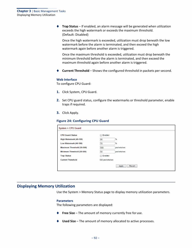
– 92 –
Chapter 3 | Basic Management Tasks Displaying Memory Utilization
◆ Trap Status – If enabled, an alarm message will be generated when utilization exceeds the high watermark or exceeds the maximum threshold. (Default: Disabled)
Once the high watermark is exceeded, utilization must drop beneath the low watermark before the alarm is terminated, and then exceed the high watermark again before another alarm is triggered.
Once the maximum threshold is exceeded, utilization must drop beneath the minimum threshold before the alarm is terminated, and then exceed the maximum threshold again before another alarm is triggered.
◆ Current Threshold – Shows the configured threshold in packets per second.
Web Interface To configure CPU Guard:
1. Click System, CPU Guard.
2. Set CPU guard status, configure the watermarks or threshold parameter, enable traps if required.
3. Click Apply.
Figure 24: Configuring CPU Guard
Displaying Memory Utilization
Use the System > Memory Status page to display memory utilization parameters.
Parameters The following parameters are displayed:
◆ Free Size – The amount of memory currently free for use.
◆ Used Size – The amount of memory allocated to active processes.
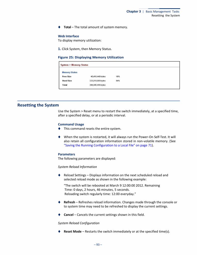
– 93 –
Chapter 3 | Basic Management Tasks Resetting the System
◆ Total – The total amount of system memory.
Web Interface To display memory utilization:
1. Click System, then Memory Status.
Figure 25: Displaying Memory Utilization
Resetting the System
Use the System > Reset menu to restart the switch immediately, at a specified time, after a specified delay, or at a periodic interval.
Command Usage ◆ This command resets the entire system.
◆ When the system is restarted, it will always run the Power-On Self-Test. It will
also retain all configuration information stored in non-volatile memory. (See “Saving the Running Configuration to a Local File” on page 71).
Parameters The following parameters are displayed:
System Reload Information
◆ Reload Settings – Displays information on the next scheduled reload and selected reload mode as shown in the following example:
“The switch will be rebooted at March 9 12:00:00 2012. Remaining Time: 0 days, 2 hours, 46 minutes, 5 seconds. Reloading switch regularly time: 12:00 everyday.”
◆ Refresh – Refreshes reload information. Changes made through the console or to system time may need to be refreshed to display the current settings.
◆ Cancel – Cancels the current settings shown in this field.
System Reload Configuration
◆ Reset Mode – Restarts the switch immediately or at the specified time(s).

– 94 –
Chapter 3 | Basic Management Tasks Resetting the System
■ Immediately – Restarts the system immediately.
■ In – Specifies an interval after which to reload the switch. (The specified time must be equal to or less than 24 days.)
■ hours – The number of hours, combined with the minutes, before the
switch resets. (Range: 0-576)
■ minutes – The number of minutes, combined with the hours, before the switch resets. (Range: 0-59)
■ At – Specifies a time at which to reload the switch.
■ DD - The day of the month at which to reload. (Range: 01-31)
■ MM - The month at which to reload. (Range: 01-12)
■ YYYY - The year at which to reload. (Range: 1970-2037)
■ HH - The hour at which to reload. (Range: 00-23)
■ MM - The minute at which to reload. (Range: 00-59)
■ Regularly – Specifies a periodic interval at which to reload the switch.
Time
■ HH - The hour at which to reload. (Range: 00-23)
■ MM - The minute at which to reload. (Range: 00-59)
Period
■ Daily - Every day.
■ Weekly - Day of the week at which to reload. (Range: Sunday ... Saturday)
■ Monthly - Day of the month at which to reload. (Range: 1-31)
Web Interface To restart the switch:
1. Click System, then Reset.
2. Select the required reset mode.
3. For any option other than to reset immediately, fill in the required parameters
4. Click Apply.
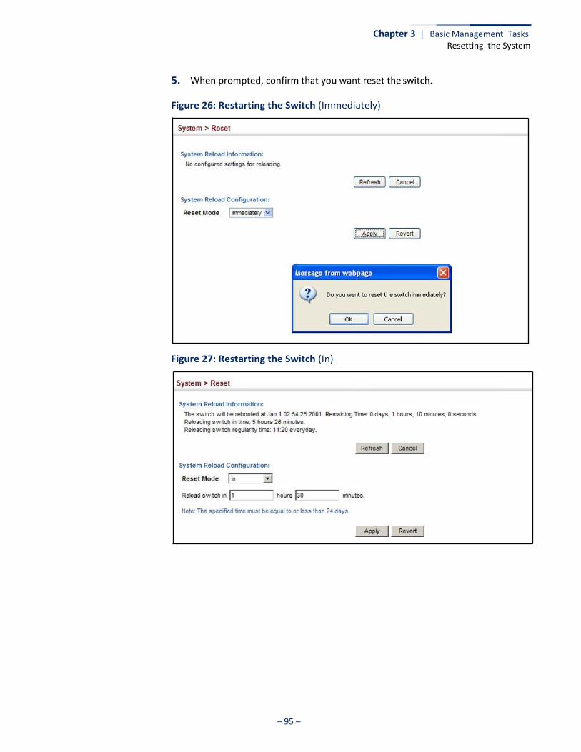
– 95 –
Chapter 3 | Basic Management Tasks Resetting the System
5. When prompted, confirm that you want reset the switch.
Figure 26: Restarting the Switch (Immediately)
Figure 27: Restarting the Switch (In)
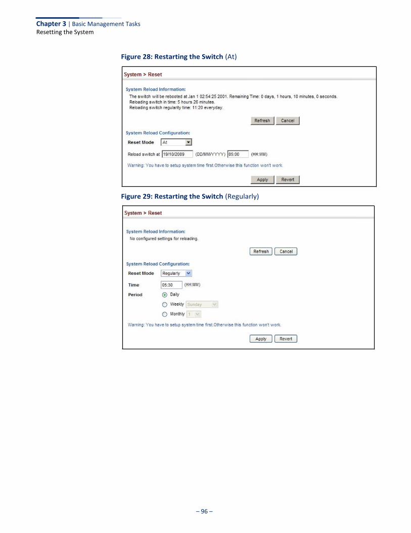
– 96 –
Chapter 3 | Basic Management Tasks Resetting the System
Figure 28: Restarting the Switch (At)
Figure 29: Restarting the Switch (Regularly)
– 97 –
Interface Configuration
This chapter describes the following topics:
◆ Port Configuration – Configures connection settings, including auto- negotiation, or manual setting of speed, duplex mode, and flow control.
◆ Displaying Statistics – Shows Interface, Etherlike, and RMON port statistics in
table or chart form.
◆ Displaying Statistical History – Displays statistical history for the specified interfaces.
◆ Displaying Transceiver Data – Displays identifying information, and operational
parameters for optical transceivers which support DDM.
◆ Configuring Transceiver Thresholds – Configures thresholds for alarm and warning messages for optical transceivers which support DDM.
◆ Cable Test – Performs cable diagnostics on the specified port.
◆ Trunk Configuration – Configures static or dynamic trunks.
◆ Saving Power – Adjusts the power provided to ports based on the length of the cable used to connect to other devices.
◆ Local Port Mirroring – Sets the source and target ports for mirroring on the local
switch.
◆ Remote Port Mirroring – Configures mirroring of traffic from remote switches for analysis at a destination port on the local switch.
◆ Flow Sampling – Configures periodic sampling of traffic flows.
◆ Traffic Segmentation – Configures the uplinks and down links to a segmented group of ports.
– 98 –
Chapter 4 | Interface Configuration Port Configuration
Port Configuration
This section describes how to configure port connections, mirror traffic from one port to another, and run cable diagnostics.
Configuring by Port List
Use the Interface > Port > General (Configure by Port List) page to enable/disable an interface, set auto-negotiation and the interface capabilities to advertise, or manually fix the speed, duplex mode, and flow control.
Command Usage ◆ Auto-negotiation must be disabled before you can configure or force a Gigabit
RJ-45 interface to use the Speed/Duplex mode or Flow Control options.
◆ When using auto-negotiation, the optimal settings will be negotiated between the link partners based on their advertised capabilities. To set the speed, duplex mode, or flow control under auto-negotiation, the required operation modes must be specified in the capabilities list for an interface.
◆ The Speed/Duplex mode is fixed at 100full for 100BASE-FX transceivers and
1000full for Gigabit transceivers. When auto-negotiation is enabled, the only attributes which can be advertised include flow control and symmetric pause frames.
◆ The 1000BASE-T standard does not support forced mode. Auto-negotiation
should always be used to establish a connection over any 1000BASE-T port or trunk. If not used, the success of the link process cannot be guaranteed when connecting to other types of switches.
Note: Auto-negotiation is not supported for 1000BASE SFP transceivers.
Parameters These parameters are displayed:
◆ Port – Port identifier. (Range: 1-52)
◆ Type – Indicates the port type. (1000BASE-T, 1000BASE SFP,)
◆ Name – Allows you to label an interface. (Range: 1-64 characters)
◆ Admin – Allows you to manually disable an interface. You can disable an interface due to abnormal behavior (e.g., excessive collisions), and then re- enable it after the problem has been resolved. You may also disable an interface for security reasons. (Default: Enabled)
◆ Autonegotiation (Port Capabilities) – Allows auto-negotiation to be enabled/
disabled. When auto-negotiation is enabled, you need to specify the
– 99 –
Chapter 4 | Interface Configuration Port Configuration
capabilities to be advertised. When auto-negotiation is disabled, you can force the settings for speed, mode, and flow control.The following capabilities are supported.
■ 10h - Supports 10 Mbps half-duplex operation.
■ 10f - Supports 10 Mbps full-duplex operation.
■ 100h - Supports 100 Mbps half-duplex operation.
■ 100f - Supports 100 Mbps full-duplex operation.
■ 1000f - Supports 1000 Mbps full-duplex operation.
■ Sym - Symmetric exchange of transmit and receive pause frames.
■ FC - Flow control can eliminate frame loss by “blocking” traffic from end
stations or segments connected directly to the switch when its buffers fill. When enabled, back pressure is used for half-duplex operation and IEEE 802.3-2005 (formally IEEE 802.3x) for full-duplex operation.
Default: Autonegotiation enabled; Advertised capabilities for 100BASE-FX (SFP) – 100full 1000BASE-T – 10half, 10full, 100half, 100full, 1000full 1000BASE-SX/LX/LHX/ZX (SFP) – 1000full
◆ Speed/Duplex – Allows you to manually set the port speed and duplex mode. (i.e., with auto-negotiation disabled)
◆ Flow Control – Allows automatic or manual selection of flow control.
(Default: Enabled)
◆ Link Up Down Trap – Issues a notification message whenever a port link is established or broken. (Default: Disabled)
Web Interface To configure port connection parameters:
1. Click Interface, Port, General.
2. Select Configure by Port List from the Action List.
3. Modify the required interface settings.
4. Click Apply.
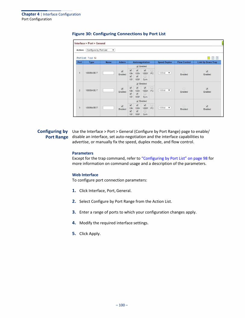
Chapter 4 | Interface Configuration Port Configuration
– 100 –
Figure 30: Configuring Connections by Port List
Configuring by Port Range
Use the Interface > Port > General (Configure by Port Range) page to enable/ disable an interface, set auto-negotiation and the interface capabilities to advertise, or manually fix the speed, duplex mode, and flow control.
Parameters Except for the trap command, refer to “Configuring by Port List” on page 98 for more information on command usage and a description of the parameters.
Web Interface To configure port connection parameters:
1. Click Interface, Port, General.
2. Select Configure by Port Range from the Action List.
3. Enter a range of ports to which your configuration changes apply.
4. Modify the required interface settings.
5. Click Apply.
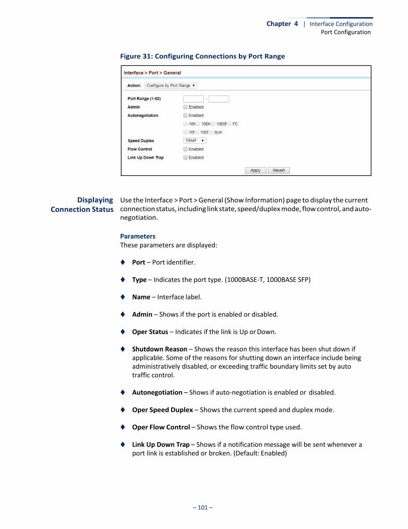
Chapter 4 | Interface Configuration Port Configuration
– 101 –
Figure 31: Configuring Connections by Port Range
Displaying Connection Status
Use the Interface > Port > General (Show Information) page to display the current connection status, including link state, speed/duplex mode, flow control, and auto- negotiation.
Parameters These parameters are displayed:
◆ Port – Port identifier.
◆ Type – Indicates the port type. (1000BASE-T, 1000BASE SFP)
◆ Name – Interface label.
◆ Admin – Shows if the port is enabled or disabled.
◆ Oper Status – Indicates if the link is Up or Down.
◆ Shutdown Reason – Shows the reason this interface has been shut down if applicable. Some of the reasons for shutting down an interface include being administratively disabled, or exceeding traffic boundary limits set by auto traffic control.
◆ Autonegotiation – Shows if auto-negotiation is enabled or disabled.
◆ Oper Speed Duplex – Shows the current speed and duplex mode.
◆ Oper Flow Control – Shows the flow control type used.
◆ Link Up Down Trap – Shows if a notification message will be sent whenever a port link is established or broken. (Default: Enabled)

Chapter 4 | Interface Configuration Port Configuration
– 102 –
Web Interface To display port connection parameters:
1. Click Interface, Port, General.
2. Select Show Information from the Action List.
Figure 32: Displaying Port Information
Showing Port or Trunk Statistics
Use the Interface > Port/Trunk > Statistics or Chart page to display standard statistics on network traffic from the Interfaces Group and Ethernet-like MIBs, as well as a detailed breakdown of traffic based on the RMON MIB. Interfaces and Ethernet-like statistics display errors on the traffic passing through each port. This information can be used to identify potential problems with the switch (such as a faulty port or unusually heavy loading). RMON statistics provide access to a broad range of statistics, including a total count of different frame types and sizes passing through each port. All values displayed have been accumulated since the last system reboot, and are shown as counts per second. Statistics are refreshed every 60 seconds by default.
Note: RMON groups 2, 3 and 9 can only be accessed using SNMP management software.
Parameters These parameters are displayed:
Table 6: Port Statistics
Interface Statistics
Received Octets The total number of octets received on the interface, including framing characters.
Transmitted Octets The total number of octets transmitted out of the interface, including framing characters.
Parameter Description

– 103 –
Chapter 4 | Interface Configuration Port Configuration
Table 6: Port Statistics (Continued)
Parameter Description
Received Errors The number of inbound packets that contained errors preventing them from being deliverable to a higher-layer protocol.
Transmitted Errors The number of outbound packets that could not be transmitted because of errors.
Received Unicast Packets The number of subnetwork-unicast packets delivered to a higher-layer protocol.
Transmitted Unicast Packets
The total number of packets that higher-level protocols requested be transmitted to a subnetwork-unicast address, including those that were discarded or not sent.
Received Discarded Packets The number of inbound packets which were chosen to be discarded even though no errors had been detected to prevent their being deliverable to a higher-layer protocol. One possible reason for discarding such a packet could be to free up buffer space.
Transmitted Discarded Packets
The number of outbound packets which were chosen to be discarded even though no errors had been detected to prevent their being transmitted. One possible reason for discarding such a packet could be to free up buffer space.
Received Multicast Packets The number of packets, delivered by this sub-layer to a higher (sub- )layer, which were addressed to a multicast address at this sub-layer.
Transmitted Multicast Packets
The total number of packets that higher-level protocols requested be transmitted, and which were addressed to a multicast address at this sub-layer, including those that were discarded or not sent.
Received Broadcast Packets The number of packets, delivered by this sub-layer to a higher (sub- )layer, which were addressed to a broadcast address at this sub-layer.
Transmitted Broadcast Packets
The total number of packets that higher-level protocols requested be transmitted, and which were addressed to a broadcast address at this sub-layer, including those that were discarded or not sent.
Received Unknown Packets The number of packets received via the interface which were discarded because of an unknown or unsupported protocol.
Etherlike Statistics
Single Collision Frames The number of successfully transmitted frames for which transmission is inhibited by exactly one collision.
Multiple Collision Frames A count of successfully transmitted frames for which transmission is inhibited by more than one collision.
Late Collisions The number of times that a collision is detected later than 512 bit-times into the transmission of a packet.
Excessive Collisions A count of frames for which transmission on a particular interface fails due to excessive collisions. This counter does not increment when the interface is operating in full-duplex mode.
Deferred Transmissions A count of frames for which the first transmission attempt on a particular interface is delayed because the medium was busy.
Frames Too Long A count of frames received on a particular interface that exceed the maximum permitted frame size.
Alignment Errors The number of alignment errors (missynchronized data packets).
FCS Errors A count of frames received on a particular interface that are an integral number of octets in length but do not pass the FCS check. This count does not include frames received with frame-too-long or frame-too- short error.
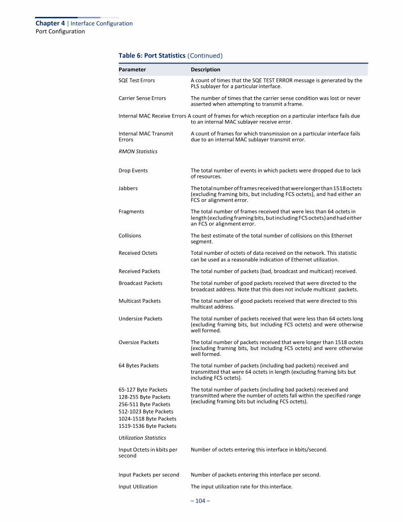
– 104 –
Chapter 4 | Interface Configuration Port Configuration
Table 6: Port Statistics (Continued)
SQE Test Errors A count of times that the SQE TEST ERROR message is generated by the PLS sublayer for a particular interface.
Carrier Sense Errors The number of times that the carrier sense condition was lost or never asserted when attempting to transmit a frame.
Internal MAC Receive Errors A count of frames for which reception on a particular interface fails due to an internal MAC sublayer receive error.
Internal MAC Transmit Errors
RMON Statistics
A count of frames for which transmission on a particular interface fails due to an internal MAC sublayer transmit error.
Drop Events The total number of events in which packets were dropped due to lack of resources.
Jabbers The total number of frames received that were longer than 1518 octets (excluding framing bits, but including FCS octets), and had either an FCS or alignment error.
Fragments The total number of frames received that were less than 64 octets in length (excluding framing bits, but including FCS octets) and had either an FCS or alignment error.
Collisions The best estimate of the total number of collisions on this Ethernet segment.
Received Octets Total number of octets of data received on the network. This statistic can be used as a reasonable indication of Ethernet utilization.
Received Packets The total number of packets (bad, broadcast and multicast) received.
Broadcast Packets The total number of good packets received that were directed to the broadcast address. Note that this does not include multicast packets.
Multicast Packets The total number of good packets received that were directed to this multicast address.
Undersize Packets The total number of packets received that were less than 64 octets long (excluding framing bits, but including FCS octets) and were otherwise well formed.
Oversize Packets The total number of packets received that were longer than 1518 octets (excluding framing bits, but including FCS octets) and were otherwise well formed.
64 Bytes Packets The total number of packets (including bad packets) received and transmitted that were 64 octets in length (excluding framing bits but including FCS octets).
65-127 Byte Packets 128-255 Byte Packets 256-511 Byte Packets 512-1023 Byte Packets 1024-1518 Byte Packets 1519-1536 Byte Packets
Utilization Statistics
Input Octets in kbits per second
The total number of packets (including bad packets) received and transmitted where the number of octets fall within the specified range (excluding framing bits but including FCS octets).
Number of octets entering this interface in kbits/second.
Input Packets per second Number of packets entering this interface per second.
Input Utilization The input utilization rate for this interface.
Parameter Description
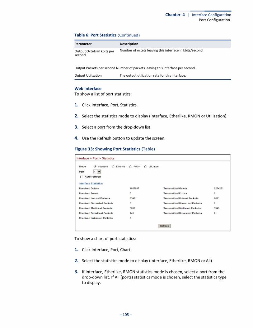
– 105 –
Chapter 4 | Interface Configuration Port Configuration
Table 6: Port Statistics (Continued)
Parameter Description
Output Octets in kbits per second
Number of octets leaving this interface in kbits/second.
Output Packets per second Number of packets leaving this interface per second.
Output Utilization The output utilization rate for this interface.
Web Interface To show a list of port statistics:
1. Click Interface, Port, Statistics.
2. Select the statistics mode to display (Interface, Etherlike, RMON or Utilization).
3. Select a port from the drop-down list.
4. Use the Refresh button to update the screen.
Figure 33: Showing Port Statistics (Table)
To show a chart of port statistics:
1. Click Interface, Port, Chart.
2. Select the statistics mode to display (Interface, Etherlike, RMON or All).
3. If Interface, Etherlike, RMON statistics mode is chosen, select a port from the drop-down list. If All (ports) statistics mode is chosen, select the statistics type to display.
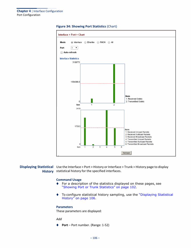
– 106 –
Chapter 4 | Interface Configuration Port Configuration
Figure 34: Showing Port Statistics (Chart)
Displaying Statistical History
Use the Interface > Port > History or Interface > Trunk > History page to display statistical history for the specified interfaces.
Command Usage ◆ For a description of the statistics displayed on these pages, see
“Showing Port or Trunk Statistics” on page 102.
◆ To configure statistical history sampling, use the “Displaying Statistical
History” on page 106.
Parameters These parameters are displayed:
Add
◆ Port – Port number. (Range: 1-52)
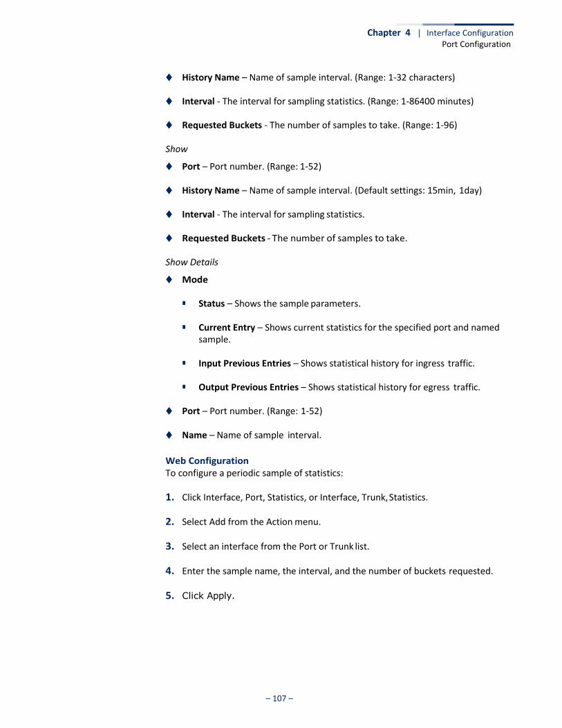
– 107 –
Chapter 4 | Interface Configuration Port Configuration
◆ History Name – Name of sample interval. (Range: 1-32 characters)
◆ Interval - The interval for sampling statistics. (Range: 1-86400 minutes)
◆ Requested Buckets - The number of samples to take. (Range: 1-96)
Show
◆ Port – Port number. (Range: 1-52)
◆ History Name – Name of sample interval. (Default settings: 15min, 1day)
◆ Interval - The interval for sampling statistics.
◆ Requested Buckets - The number of samples to take.
Show Details
◆ Mode
■ Status – Shows the sample parameters.
■ Current Entry – Shows current statistics for the specified port and named sample.
■ Input Previous Entries – Shows statistical history for ingress traffic.
■ Output Previous Entries – Shows statistical history for egress traffic.
◆ Port – Port number. (Range: 1-52)
◆ Name – Name of sample interval.
Web Configuration To configure a periodic sample of statistics:
1. Click Interface, Port, Statistics, or Interface, Trunk, Statistics.
2. Select Add from the Action menu.
3. Select an interface from the Port or Trunk list.
4. Enter the sample name, the interval, and the number of buckets requested.
5. Click Apply.
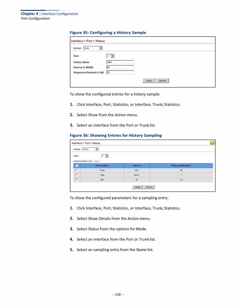
– 108 –
Chapter 4 | Interface Configuration Port Configuration
Figure 35: Configuring a History Sample
To show the configured entries for a history sample:
1. Click Interface, Port, Statistics, or Interface, Trunk, Statistics.
2. Select Show from the Action menu.
3. Select an interface from the Port or Trunk list.
Figure 36: Showing Entries for History Sampling
To show the configured parameters for a sampling entry:
1. Click Interface, Port, Statistics, or Interface, Trunk, Statistics.
2. Select Show Details from the Action menu.
3. Select Status from the options for Mode.
4. Select an interface from the Port or Trunk list.
5. Select an sampling entry from the Name list.
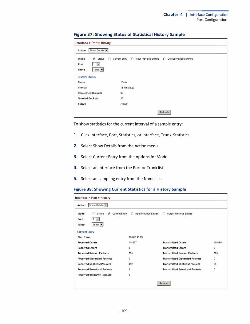
– 109 –
Chapter 4 | Interface Configuration Port Configuration
Figure 37: Showing Status of Statistical History Sample
To show statistics for the current interval of a sample entry:
1. Click Interface, Port, Statistics, or Interface, Trunk, Statistics.
2. Select Show Details from the Action menu.
3. Select Current Entry from the options for Mode.
4. Select an interface from the Port or Trunk list.
5. Select an sampling entry from the Name list.
Figure 38: Showing Current Statistics for a History Sample
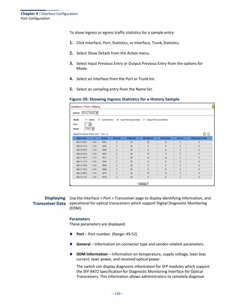
Chapter 4 | Interface Configuration Port Configuration
– 110 –
To show ingress or egress traffic statistics for a sample entry:
1. Click Interface, Port, Statistics, or Interface, Trunk, Statistics.
2. Select Show Details from the Action menu.
3. Select Input Previous Entry or Output Previous Entry from the options for Mode.
4. Select an interface from the Port or Trunk list.
5. Select an sampling entry from the Name list.
Figure 39: Showing Ingress Statistics for a History Sample
Displaying Transceiver Data
Use the Interface > Port > Transceiver page to display identifying information, and operational for optical transceivers which support Digital Diagnostic Monitoring (DDM).
Parameters These parameters are displayed:
◆ Port – Port number. (Range: 49-52)
◆ General – Information on connector type and vendor-related parameters.
◆ DDM Information – Information on temperature, supply voltage, laser bias current, laser power, and received optical power.
The switch can display diagnostic information for SFP modules which support the SFF-8472 Specification for Diagnostic Monitoring Interface for Optical Transceivers. This information allows administrators to remotely diagnose
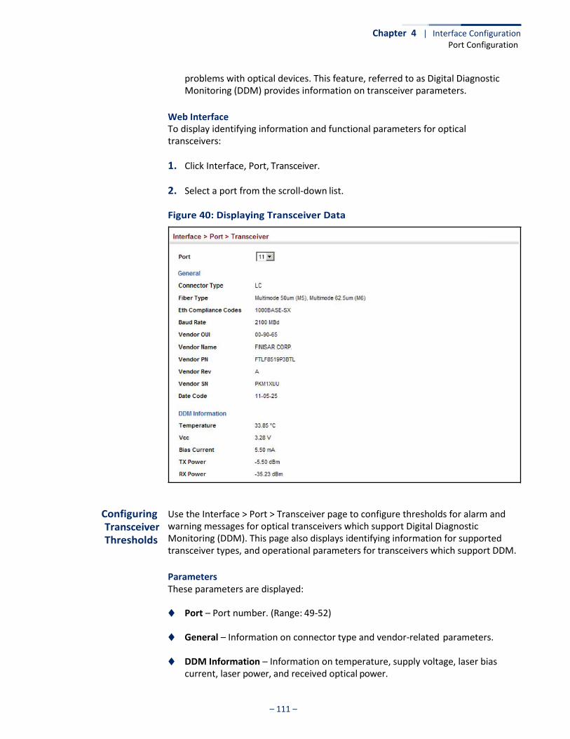
Chapter 4 | Interface Configuration Port Configuration
– 111 –
problems with optical devices. This feature, referred to as Digital Diagnostic Monitoring (DDM) provides information on transceiver parameters.
Web Interface To display identifying information and functional parameters for optical transceivers:
1. Click Interface, Port, Transceiver.
2. Select a port from the scroll-down list.
Figure 40: Displaying Transceiver Data
Configuring Transceiver Thresholds
Use the Interface > Port > Transceiver page to configure thresholds for alarm and warning messages for optical transceivers which support Digital Diagnostic Monitoring (DDM). This page also displays identifying information for supported transceiver types, and operational parameters for transceivers which support DDM.
Parameters These parameters are displayed:
◆ Port – Port number. (Range: 49-52)
◆ General – Information on connector type and vendor-related parameters.
◆ DDM Information – Information on temperature, supply voltage, laser bias current, laser power, and received optical power.
Chapter 4 | Interface Configuration Port Configuration
– 112 –
The switch can display diagnostic information for SFP modules which support the SFF-8472 Specification for Diagnostic Monitoring Interface for Optical Transceivers. This information allows administrators to remotely diagnose problems with optical devices. This feature, referred to as Digital Diagnostic Monitoring (DDM) provides information on transceiver parameters.
◆ Trap – Sends a trap when any of the transceiver’s operation values falls outside
of specified thresholds. (Default: Disabled)
◆ Auto Mode – Uses default threshold settings obtained from the transceiver to determine when an alarm or trap message should be sent. (Default: Enabled)
◆ DDM Thresholds – Information on alarm and warning thresholds. The switch
can be configured to send a trap when the measured parameter falls outside of the specified thresholds.
The following alarm and warning parameters are supported:
■ High Alarm – Sends an alarm message when the high threshold is crossed.
■ High Warning – Sends a warning message when the high threshold is crossed.
■ Low Alarm – Sends an alarm message when the low threshold is crossed.
■ Low Warning – Sends a warning message when the low threshold is crossed.
The configurable ranges are:
■ Temperature: -128.00 - 128.00 °C
■ Voltage: 0.00 - 6.55 Volts
■ Current: 0.00 - 131.00 mA
■ Power: -40.00 - 8.20 dBm
The threshold value for Rx and Tx power is calculated as the power ratio in decibels (dB) of the measured power referenced to one milliwatt (mW).
Threshold values for alarm and warning messages can be configured as described below.
■ A high-threshold alarm or warning message is sent if the current value is greater than or equal to the threshold, and the last sample value was less than the threshold. After a rising event has been generated, another such event will not be generated until the sampled value has fallen below the high threshold and reaches the low threshold.
■ A low-threshold alarm or warning message is sent if the current value is less than or equal to the threshold, and the last sample value was greater than the threshold. After a falling event has been generated, another such event will not be generated until the sampled value has risen above the low threshold and reaches the high threshold.
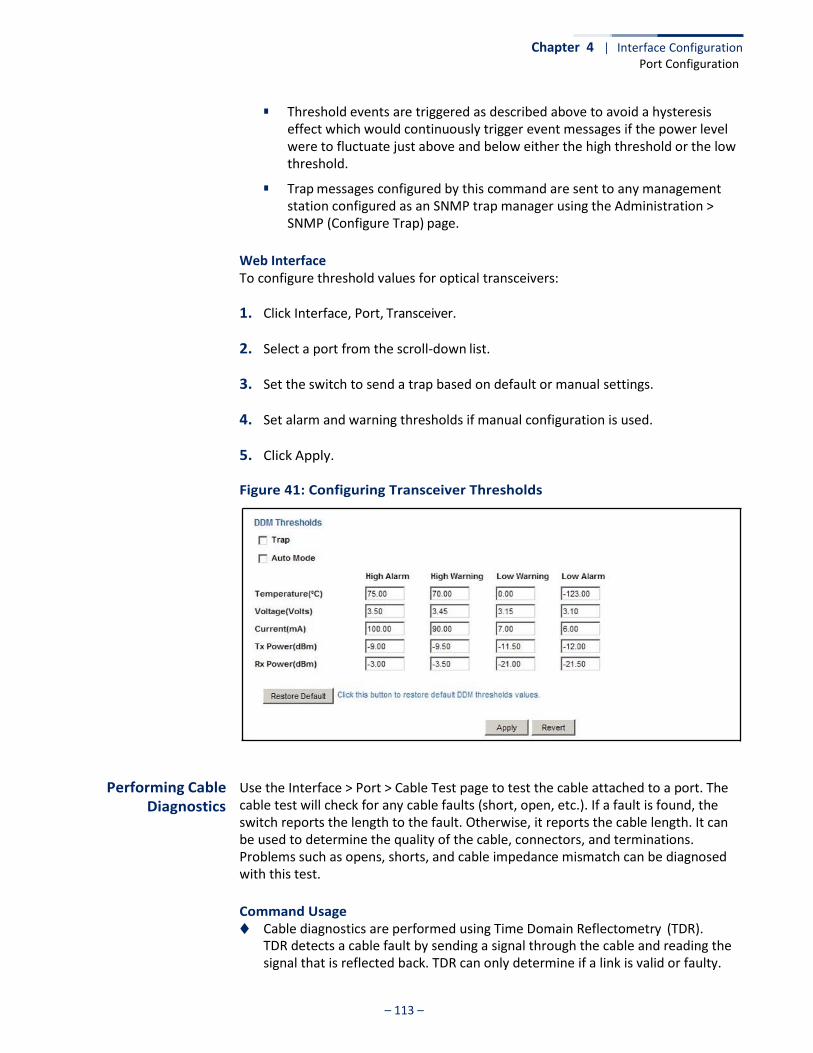
Chapter 4 | Interface Configuration Port Configuration
– 113 –
■ Threshold events are triggered as described above to avoid a hysteresis
effect which would continuously trigger event messages if the power level were to fluctuate just above and below either the high threshold or the low threshold.
■ Trap messages configured by this command are sent to any management station configured as an SNMP trap manager using the Administration > SNMP (Configure Trap) page.
Web Interface To configure threshold values for optical transceivers:
1. Click Interface, Port, Transceiver.
2. Select a port from the scroll-down list.
3. Set the switch to send a trap based on default or manual settings.
4. Set alarm and warning thresholds if manual configuration is used.
5. Click Apply.
Figure 41: Configuring Transceiver Thresholds
Performing Cable Diagnostics
Use the Interface > Port > Cable Test page to test the cable attached to a port. The cable test will check for any cable faults (short, open, etc.). If a fault is found, the switch reports the length to the fault. Otherwise, it reports the cable length. It can be used to determine the quality of the cable, connectors, and terminations. Problems such as opens, shorts, and cable impedance mismatch can be diagnosed with this test.
Command Usage ◆ Cable diagnostics are performed using Time Domain Reflectometry (TDR).
TDR detects a cable fault by sending a signal through the cable and reading the signal that is reflected back. TDR can only determine if a link is valid or faulty.
Chapter 4 | Interface Configuration Port Configuration
– 114 –
◆ Cable diagnostics can only be performed on twisted-pair media.
◆ This cable test is only accurate for Gigabit Ethernet cables 7 - 100 meters long.
◆ The test takes approximately 5 seconds. The switch displays the results of the test immediately upon completion, including common cable failures, as well as the status and approximate length to a fault.
◆ Potential conditions which may be listed by the diagnostics include those listed
below. Note that TDR testing can only show Test failed or OK.
■ Test failed
■ OK: Correctly terminated pair
■ Open: Open pair, no link partner
■ Short: Shorted pair
■ Impedance mismatch: Terminating impedance is not in the reference range.
■ No cable
■ Not tested ■ Not Supported: This message is displayed for any Gigabit Ethernet ports
linked up at a speed lower than 1000 Mbps
■ Unknown – Unknown error
◆ Ports are linked down while running cable diagnostics.
Parameters These parameters are displayed:
◆ Port – Switch port identifier.
◆ Type – Displays media type. (GE – Gigabit Ethernet, Other – SFP)
◆ Link Status – Shows if the port link is up or down.
◆ Test Result – The results include common cable failures, as well as the status and approximate distance to a fault, or the approximate cable length if no fault is found.
To ensure more accurate measurement of the length to a fault, first disable power-saving mode on the link partner before running cable diagnostics.
For link-down ports, the reported distance to a fault is accurate to within +/- 2 meters. For link-up ports, the accuracy is +/- 10 meters.
◆ Last Updated – Shows the last time this port was tested.
◆ Test – Initiates cable test.
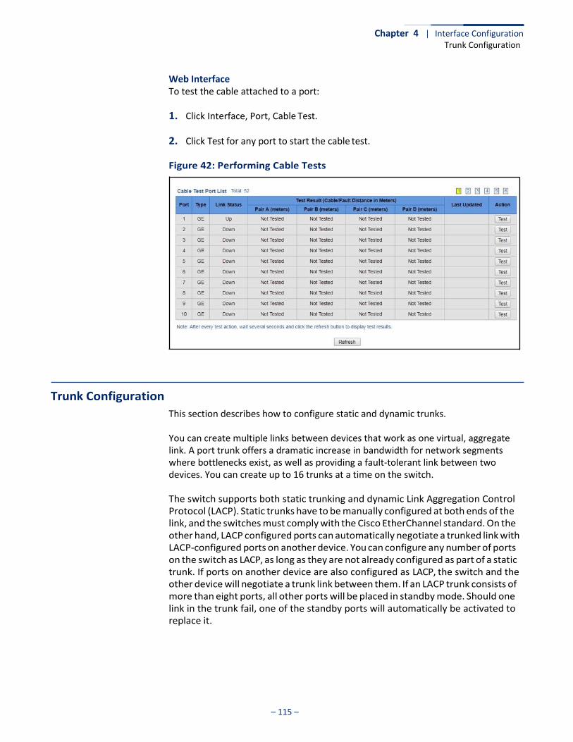
– 115 –
Chapter 4 | Interface Configuration Trunk Configuration
Web Interface To test the cable attached to a port:
1. Click Interface, Port, Cable Test.
2. Click Test for any port to start the cable test.
Figure 42: Performing Cable Tests
Trunk Configuration
This section describes how to configure static and dynamic trunks. You can create multiple links between devices that work as one virtual, aggregate link. A port trunk offers a dramatic increase in bandwidth for network segments where bottlenecks exist, as well as providing a fault-tolerant link between two devices. You can create up to 16 trunks at a time on the switch. The switch supports both static trunking and dynamic Link Aggregation Control Protocol (LACP). Static trunks have to be manually configured at both ends of the link, and the switches must comply with the Cisco EtherChannel standard. On the other hand, LACP configured ports can automatically negotiate a trunked link with LACP-configured ports on another device. You can configure any number of ports on the switch as LACP, as long as they are not already configured as part of a static trunk. If ports on another device are also configured as LACP, the switch and the other device will negotiate a trunk link between them. If an LACP trunk consists of more than eight ports, all other ports will be placed in standby mode. Should one link in the trunk fail, one of the standby ports will automatically be activated to replace it.
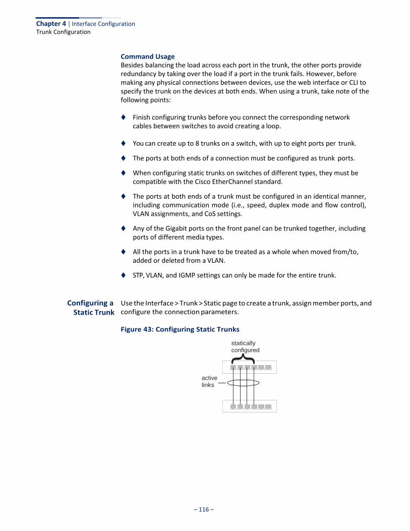
– 116 –
Chapter 4 | Interface Configuration Trunk Configuration
}
Command Usage Besides balancing the load across each port in the trunk, the other ports provide redundancy by taking over the load if a port in the trunk fails. However, before making any physical connections between devices, use the web interface or CLI to specify the trunk on the devices at both ends. When using a trunk, take note of the following points:
◆ Finish configuring trunks before you connect the corresponding network
cables between switches to avoid creating a loop.
◆ You can create up to 8 trunks on a switch, with up to eight ports per trunk.
◆ The ports at both ends of a connection must be configured as trunk ports.
◆ When configuring static trunks on switches of different types, they must be compatible with the Cisco EtherChannel standard.
◆ The ports at both ends of a trunk must be configured in an identical manner, including communication mode (i.e., speed, duplex mode and flow control), VLAN assignments, and CoS settings.
◆ Any of the Gigabit ports on the front panel can be trunked together, including ports of different media types.
◆ All the ports in a trunk have to be treated as a whole when moved from/to, added or deleted from a VLAN.
◆ STP, VLAN, and IGMP settings can only be made for the entire trunk.
Configuring a Static Trunk
Use the Interface > Trunk > Static page to create a trunk, assign member ports, and configure the connection parameters.
Figure 43: Configuring Static Trunks
statically configured
active links

– 117 –
Chapter 4 | Interface Configuration Trunk Configuration
Command Usage ◆ When configuring static trunks, you may not be able to link switches of
different types, depending on the vendor’s implementation. However, note that the static trunks on this switch are Cisco EtherChannel compatible.
◆ To avoid creating a loop in the network, be sure you add a static trunk via the
configuration interface before connecting the ports, and also disconnect the ports before removing a static trunk via the configuration interface.
Parameters These parameters are displayed:
◆ Trunk ID – Trunk identifier. (Range: 1-8)
◆ Member – The initial trunk member. Use the Add Member page to configure additional members.
■ Unit – Unit identifier. (Range: 1)
■ Port – Port identifier. (Range: 1-52)
Web Interface To create a static trunk:
1. Click Interface, Trunk, Static.
2. Select Configure Trunk from the Step list.
3. Select Add from the Action list.
4. Enter a trunk identifier.
5. Set the unit and port for the initial trunk member.
6. Click Apply.
Figure 44: Creating Static Trunks
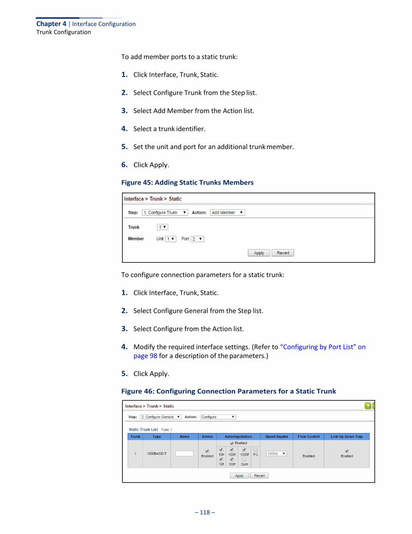
– 118 –
Chapter 4 | Interface Configuration Trunk Configuration
To add member ports to a static trunk:
1. Click Interface, Trunk, Static.
2. Select Configure Trunk from the Step list.
3. Select Add Member from the Action list.
4. Select a trunk identifier.
5. Set the unit and port for an additional trunk member.
6. Click Apply.
Figure 45: Adding Static Trunks Members
To configure connection parameters for a static trunk:
1. Click Interface, Trunk, Static.
2. Select Configure General from the Step list.
3. Select Configure from the Action list.
4. Modify the required interface settings. (Refer to “Configuring by Port List” on page 98 for a description of the parameters.)
5. Click Apply.
Figure 46: Configuring Connection Parameters for a Static Trunk
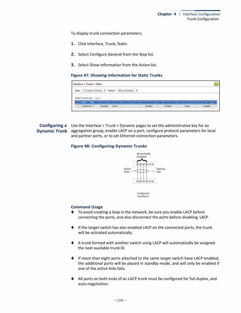
– 119 –
Chapter 4 | Interface Configuration Trunk Configuration
}
To display trunk connection parameters:
1. Click Interface, Trunk, Static.
2. Select Configure General from the Step list.
3. Select Show Information from the Action list.
Figure 47: Showing Information for Static Trunks
Configuring a Dynamic Trunk
Use the Interface > Trunk > Dynamic pages to set the administrative key for an aggregation group, enable LACP on a port, configure protocol parameters for local and partner ports, or to set Ethernet connection parameters.
Figure 48: Configuring Dynamic Trunks
dynamically enabled
active links
backup link
configured members
Command Usage ◆ To avoid creating a loop in the network, be sure you enable LACP before
connecting the ports, and also disconnect the ports before disabling LACP.
◆ If the target switch has also enabled LACP on the connected ports, the trunk will be activated automatically.
◆ A trunk formed with another switch using LACP will automatically be assigned
the next available trunk ID.
◆ If more than eight ports attached to the same target switch have LACP enabled, the additional ports will be placed in standby mode, and will only be enabled if one of the active links fails.
◆ All ports on both ends of an LACP trunk must be configured for full duplex, and
auto-negotiation.
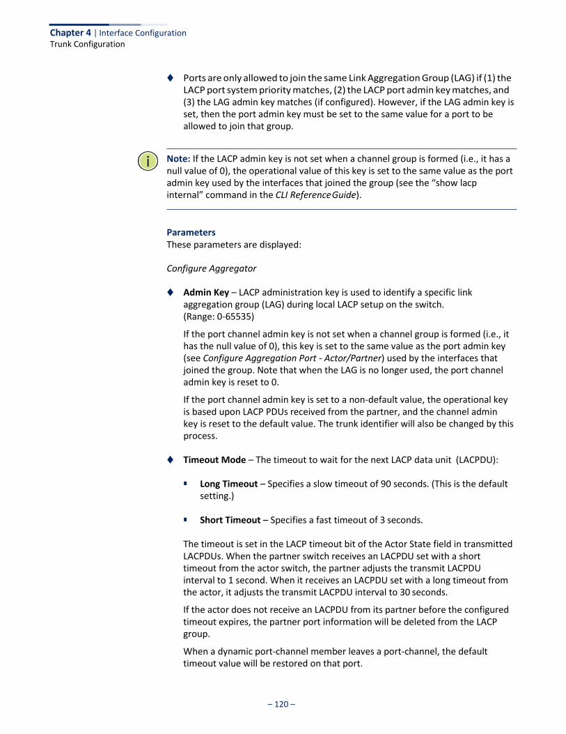
Chapter 4 | Interface Configuration Trunk Configuration
– 120 –
◆ Ports are only allowed to join the same Link Aggregation Group (LAG) if (1) the LACP port system priority matches, (2) the LACP port admin key matches, and (3) the LAG admin key matches (if configured). However, if the LAG admin key is set, then the port admin key must be set to the same value for a port to be allowed to join that group.
Note: If the LACP admin key is not set when a channel group is formed (i.e., it has a null value of 0), the operational value of this key is set to the same value as the port admin key used by the interfaces that joined the group (see the “show lacp internal” command in the CLI Reference Guide).
Parameters These parameters are displayed:
Configure Aggregator
◆ Admin Key – LACP administration key is used to identify a specific link aggregation group (LAG) during local LACP setup on the switch. (Range: 0-65535)
If the port channel admin key is not set when a channel group is formed (i.e., it has the null value of 0), this key is set to the same value as the port admin key (see Configure Aggregation Port - Actor/Partner) used by the interfaces that joined the group. Note that when the LAG is no longer used, the port channel admin key is reset to 0.
If the port channel admin key is set to a non-default value, the operational key is based upon LACP PDUs received from the partner, and the channel admin key is reset to the default value. The trunk identifier will also be changed by this process.
◆ Timeout Mode – The timeout to wait for the next LACP data unit (LACPDU):
■ Long Timeout – Specifies a slow timeout of 90 seconds. (This is the default setting.)
■ Short Timeout – Specifies a fast timeout of 3 seconds.
The timeout is set in the LACP timeout bit of the Actor State field in transmitted LACPDUs. When the partner switch receives an LACPDU set with a short timeout from the actor switch, the partner adjusts the transmit LACPDU interval to 1 second. When it receives an LACPDU set with a long timeout from the actor, it adjusts the transmit LACPDU interval to 30 seconds.
If the actor does not receive an LACPDU from its partner before the configured timeout expires, the partner port information will be deleted from the LACP group.
When a dynamic port-channel member leaves a port-channel, the default timeout value will be restored on that port.
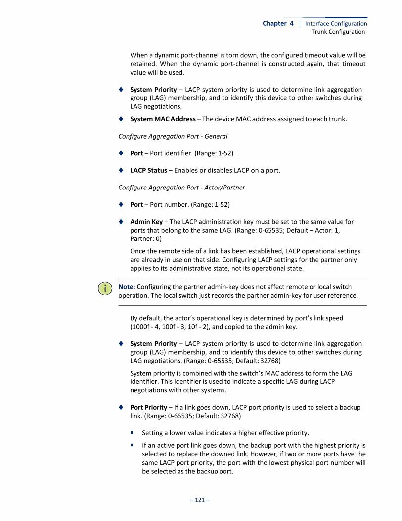
Chapter 4 | Interface Configuration Trunk Configuration
– 121 –
When a dynamic port-channel is torn down, the configured timeout value will be retained. When the dynamic port-channel is constructed again, that timeout value will be used.
◆ System Priority – LACP system priority is used to determine link aggregation
group (LAG) membership, and to identify this device to other switches during LAG negotiations.
◆ System MAC Address – The device MAC address assigned to each trunk.
Configure Aggregation Port - General
◆ Port – Port identifier. (Range: 1-52)
◆ LACP Status – Enables or disables LACP on a port.
Configure Aggregation Port - Actor/Partner
◆ Port – Port number. (Range: 1-52)
◆ Admin Key – The LACP administration key must be set to the same value for ports that belong to the same LAG. (Range: 0-65535; Default – Actor: 1, Partner: 0)
Once the remote side of a link has been established, LACP operational settings are already in use on that side. Configuring LACP settings for the partner only applies to its administrative state, not its operational state.
Note: Configuring the partner admin-key does not affect remote or local switch operation. The local switch just records the partner admin-key for user reference.
By default, the actor’s operational key is determined by port's link speed (1000f - 4, 100f - 3, 10f - 2), and copied to the admin key.
◆ System Priority – LACP system priority is used to determine link aggregation
group (LAG) membership, and to identify this device to other switches during LAG negotiations. (Range: 0-65535; Default: 32768)
System priority is combined with the switch’s MAC address to form the LAG identifier. This identifier is used to indicate a specific LAG during LACP negotiations with other systems.
◆ Port Priority – If a link goes down, LACP port priority is used to select a backup
link. (Range: 0-65535; Default: 32768)
■ Setting a lower value indicates a higher effective priority.
■ If an active port link goes down, the backup port with the highest priority is selected to replace the downed link. However, if two or more ports have the same LACP port priority, the port with the lowest physical port number will be selected as the backup port.

Chapter 4 | Interface Configuration Trunk Configuration
– 122 –
■ If an LAG already exists with the maximum number of allowed port
members, and LACP is subsequently enabled on another port using a higher priority than an existing member, the newly configured port will replace an existing port member that has a lower priority.
Note: Configuring LACP settings for a port only applies to its administrative state, not its operational state, and will only take effect the next time an aggregate link is established with that port.
Note: Configuring the port partner sets the remote side of an aggregate link; i.e., the ports on the attached device. The command attributes have the same meaning as those used for the port actor.
Web Interface To configure the admin key for a dynamic trunk:
1. Click Interface, Trunk, Dynamic.
2. Select Configure Aggregator from the Step list.
3. Set the Admin Key and timeout mode for the required LACP group.
4. Click Apply.
Figure 49: Configuring the LACP Aggregator Admin Key
To enable LACP for a port:
1. Click Interface, Trunk, Dynamic.
2. Select Configure Aggregation Port from the Step list.
3. Select Configure from the Action list.
4. Click General.
5. Enable LACP on the required ports.
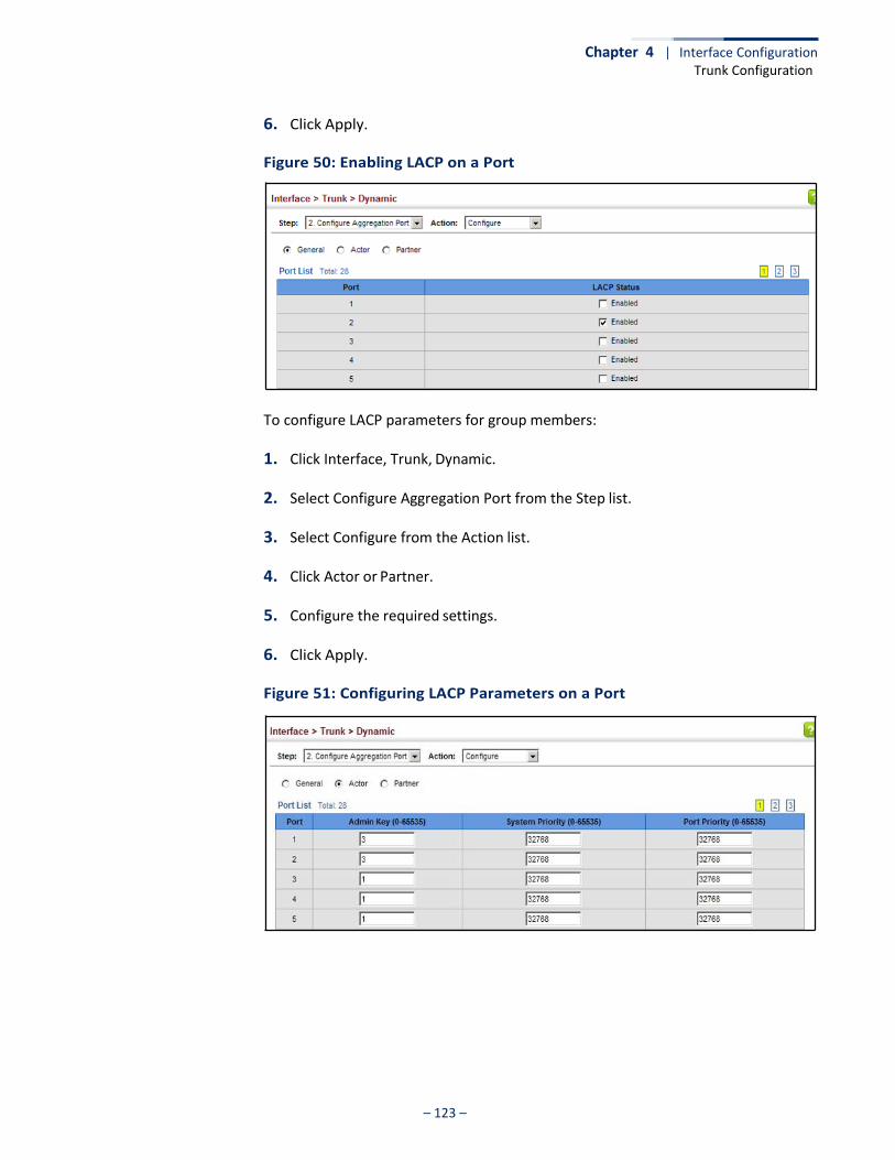
Chapter 4 | Interface Configuration Trunk Configuration
– 123 –
6. Click Apply.
Figure 50: Enabling LACP on a Port
To configure LACP parameters for group members:
1. Click Interface, Trunk, Dynamic.
2. Select Configure Aggregation Port from the Step list.
3. Select Configure from the Action list.
4. Click Actor or Partner.
5. Configure the required settings.
6. Click Apply.
Figure 51: Configuring LACP Parameters on a Port
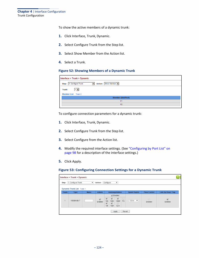
Chapter 4 | Interface Configuration Trunk Configuration
– 124 –
To show the active members of a dynamic trunk:
1. Click Interface, Trunk, Dynamic.
2. Select Configure Trunk from the Step list.
3. Select Show Member from the Action list.
4. Select a Trunk.
Figure 52: Showing Members of a Dynamic Trunk
To configure connection parameters for a dynamic trunk:
1. Click Interface, Trunk, Dynamic.
2. Select Configure Trunk from the Step list.
3. Select Configure from the Action list.
4. Modify the required interface settings. (See “Configuring by Port List” on page 98 for a description of the interface settings.)
5. Click Apply.
Figure 53: Configuring Connection Settings for a Dynamic Trunk

Chapter 4 | Interface Configuration Trunk Configuration
– 125 –
To show connection parameters for a dynamic trunk:
1. Click Interface, Trunk, Dynamic.
2. Select Configure Trunk from the Step list.
3. Select Show from the Action list.
Figure 54: Showing Connection Parameters for Dynamic Trunks
Displaying LACP
Port Counters
Use the Interface > Trunk > Dynamic (Configure Aggregation Port - Show Information - Counters) page to display statistics for LACP protocol messages.
Parameters These parameters are displayed:
Table 7: LACP Port Counters
LACPDUs Sent Number of valid LACPDUs transmitted from this channel group.
LACPDUs Received Number of valid LACPDUs received on this channel group.
Marker Sent Number of valid Marker PDUs transmitted from this channel group.
Marker Received Number of valid Marker PDUs received by this channel group.
Marker Unknown Pkts Number of frames received that either (1) Carry the Slow Protocols Ethernet Type value, but contain an unknown PDU, or (2) are addressed to the Slow Protocols group MAC Address, but do not carry the Slow Protocols Ethernet Type.
Marker Illegal Pkts Number of frames that carry the Slow Protocols Ethernet Type value, but contain a badly formed PDU or an illegal value of Protocol Subtype.
Web Interface To display LACP port counters:
1. Click Interface, Trunk, Dynamic.
2. Select Configure Aggregation Port from the Step list.
3. Select Show Information from the Action list.
4. Click Counters.
Parameter Description
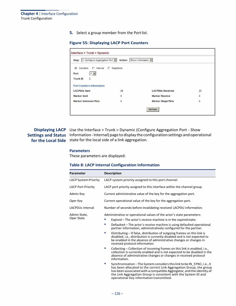
Chapter 4 | Interface Configuration Trunk Configuration
– 126 –
5. Select a group member from the Port list.
Figure 55: Displaying LACP Port Counters
Displaying LACP Settings and Status
for the Local Side
Use the Interface > Trunk > Dynamic (Configure Aggregation Port - Show Information - Internal) page to display the configuration settings and operational state for the local side of a link aggregation.
Parameters These parameters are displayed:
Table 8: LACP Internal Configuration Information
LACP System Priority LACP system priority assigned to this port channel.
LACP Port Priority LACP port priority assigned to this interface within the channel group.
Admin Key Current administrative value of the key for the aggregation port.
Oper Key Current operational value of the key for the aggregation port.
LACPDUs Interval Number of seconds before invalidating received LACPDU information.
Admin State, Oper State
Administrative or operational values of the actor’s state parameters: ◆ Expired – The actor’s receive machine is in the expired state; ◆ Defaulted – The actor’s receive machine is using defaulted operational
partner information, administratively configured for the partner. ◆ Distributing – If false, distribution of outgoing frames on this link is
disabled; i.e., distribution is currently disabled and is not expected to be enabled in the absence of administrative changes or changes in received protocol information.
◆ Collecting – Collection of incoming frames on this link is enabled; i.e., collection is currently enabled and is not expected to be disabled in the absence of administrative changes or changes in received protocol information.
◆ Synchronization – The System considers this link to be IN_SYNC; i.e., it has been allocated to the correct Link Aggregation Group, the group has been associated with a compatible Aggregator, and the identity of the Link Aggregation Group is consistent with the System ID and operational Key information transmitted.
Parameter Description
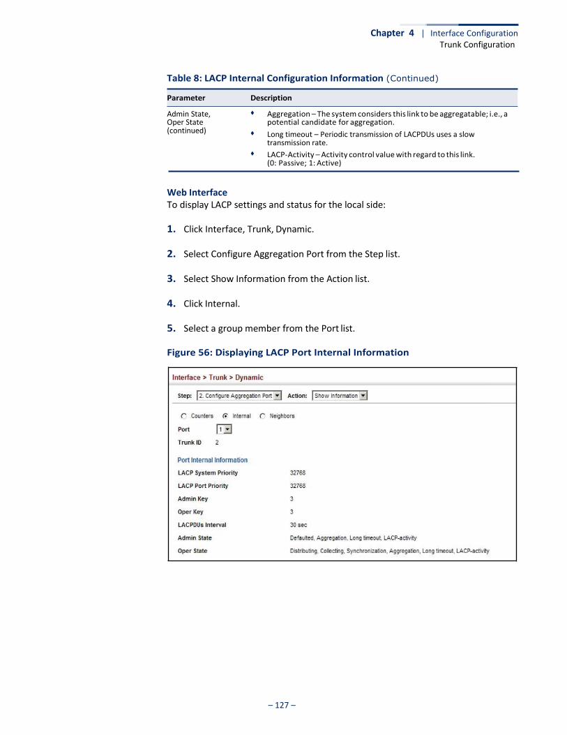
Chapter 4 | Interface Configuration Trunk Configuration
– 127 –
Table 8: LACP Internal Configuration Information (Continued)
Admin State, Oper State (continued)
◆ Aggregation – The system considers this link to be aggregatable; i.e., a potential candidate for aggregation.
◆ Long timeout – Periodic transmission of LACPDUs uses a slow transmission rate.
◆ LACP-Activity – Activity control value with regard to this link. (0: Passive; 1: Active)
Web Interface To display LACP settings and status for the local side:
1. Click Interface, Trunk, Dynamic.
2. Select Configure Aggregation Port from the Step list.
3. Select Show Information from the Action list.
4. Click Internal.
5. Select a group member from the Port list.
Figure 56: Displaying LACP Port Internal Information
Parameter Description
Chapter 4 | Interface Configuration Trunk Configuration
– 128 –
Displaying LACP Settings and Status for the Remote Side
Use the Interface > Trunk > Dynamic (Configure Aggregation Port - Show Information - Neighbors) page to display the configuration settings and operational state for the remote side of a link aggregation.
Parameters These parameters are displayed:
Table 9: LACP Remote Device Configuration Information
Partner Admin System ID
Partner Oper System ID
Partner Admin Port Number
Partner Oper Port Number
LAG partner’s system ID assigned by the user.
LAG partner’s system ID assigned by the LACP protocol.
Current administrative value of the port number for the protocol Partner.
Operational port number assigned to this aggregation port by the port’s protocol partner.
Port Admin Priority Current administrative value of the port priority for the protocol partner.
Port Oper Priority Priority value assigned to this aggregation port by the partner.
Admin Key Current administrative value of the Key for the protocol partner.
Oper Key Current operational value of the Key for the protocol partner.
Admin State Administrative values of the partner’s state parameters. (See preceding table.)
Oper State Operational values of the partner’s state parameters. (See preceding table.)
Web Interface To display LACP settings and status for the remote side:
1. Click Interface, Trunk, Dynamic.
2. Select Configure Aggregation Port from the Step list.
3. Select Show Information from the Action list.
4. Click Neighbors.
5. Select a group member from the Port list.
Parameter Description
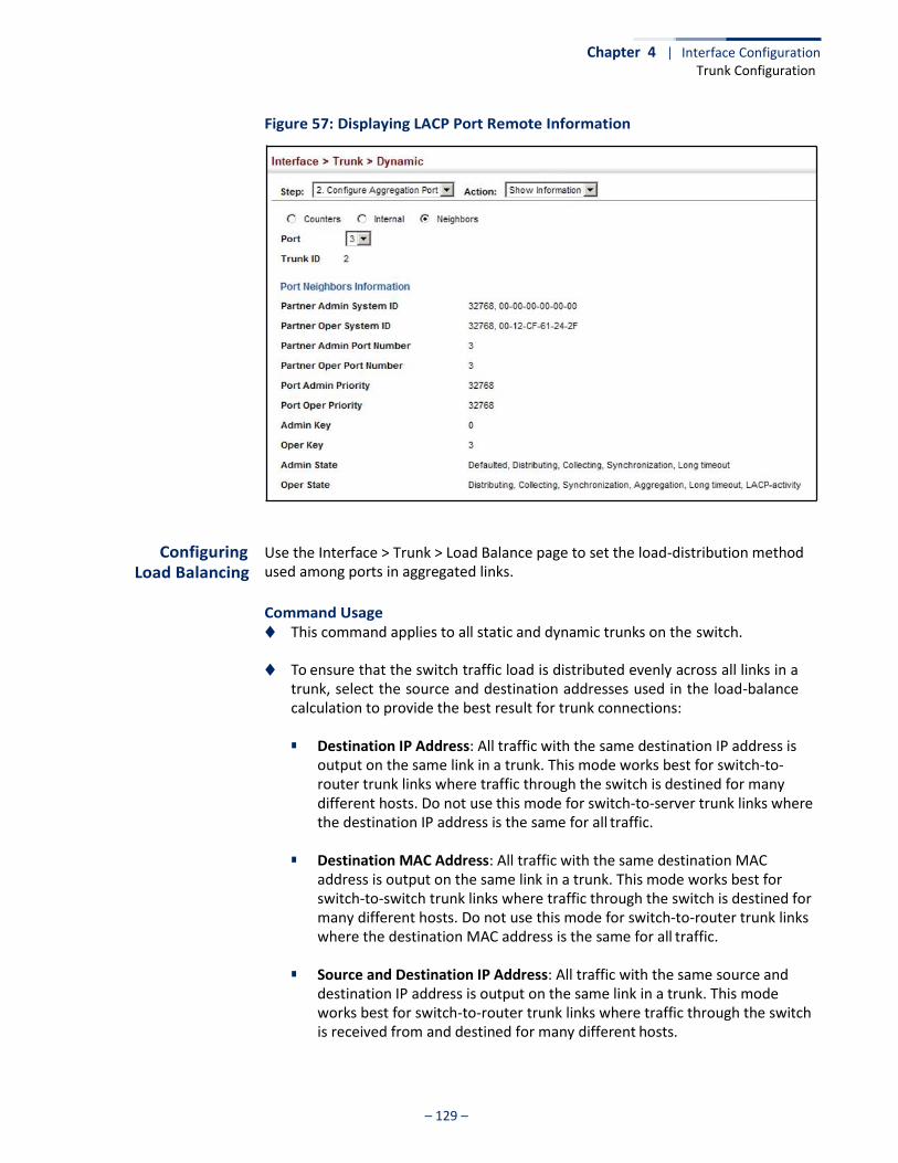
Chapter 4 | Interface Configuration Trunk Configuration
– 129 –
Figure 57: Displaying LACP Port Remote Information
Configuring
Load Balancing
Use the Interface > Trunk > Load Balance page to set the load-distribution method used among ports in aggregated links.
Command Usage ◆ This command applies to all static and dynamic trunks on the switch.
◆ To ensure that the switch traffic load is distributed evenly across all links in a
trunk, select the source and destination addresses used in the load-balance calculation to provide the best result for trunk connections:
■ Destination IP Address: All traffic with the same destination IP address is
output on the same link in a trunk. This mode works best for switch-to- router trunk links where traffic through the switch is destined for many different hosts. Do not use this mode for switch-to-server trunk links where the destination IP address is the same for all traffic.
■ Destination MAC Address: All traffic with the same destination MAC
address is output on the same link in a trunk. This mode works best for switch-to-switch trunk links where traffic through the switch is destined for many different hosts. Do not use this mode for switch-to-router trunk links where the destination MAC address is the same for all traffic.
■ Source and Destination IP Address: All traffic with the same source and
destination IP address is output on the same link in a trunk. This mode works best for switch-to-router trunk links where traffic through the switch is received from and destined for many different hosts.
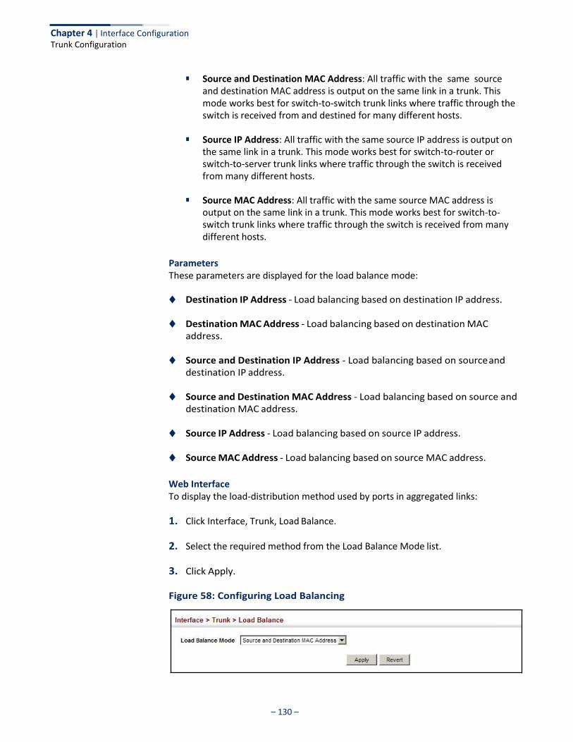
Chapter 4 | Interface Configuration Trunk Configuration
– 130 –
■ Source and Destination MAC Address: All traffic with the same source
and destination MAC address is output on the same link in a trunk. This mode works best for switch-to-switch trunk links where traffic through the switch is received from and destined for many different hosts.
■ Source IP Address: All traffic with the same source IP address is output on
the same link in a trunk. This mode works best for switch-to-router or switch-to-server trunk links where traffic through the switch is received from many different hosts.
■ Source MAC Address: All traffic with the same source MAC address is
output on the same link in a trunk. This mode works best for switch-to- switch trunk links where traffic through the switch is received from many different hosts.
Parameters These parameters are displayed for the load balance mode:
◆ Destination IP Address - Load balancing based on destination IP address.
◆ Destination MAC Address - Load balancing based on destination MAC address.
◆ Source and Destination IP Address - Load balancing based on source and
destination IP address.
◆ Source and Destination MAC Address - Load balancing based on source and destination MAC address.
◆ Source IP Address - Load balancing based on source IP address.
◆ Source MAC Address - Load balancing based on source MAC address.
Web Interface To display the load-distribution method used by ports in aggregated links:
1. Click Interface, Trunk, Load Balance.
2. Select the required method from the Load Balance Mode list.
3. Click Apply.
Figure 58: Configuring Load Balancing
– 131 –
Chapter 4 | Interface Configuration Saving Power
Saving Power
Use the Interface > Green Ethernet page to enable power savings mode on the selected port.
Command Usage ◆ IEEE 802.3 defines the Ethernet standard and subsequent power requirements
based on cable connections operating at 100 meters. Enabling power saving mode can reduce power used for cable lengths of 60 meters or less, with more significant reduction for cables of 20 meters or less, and continue to ensure signal integrity.
◆ The power-saving methods provided by this switch include:
■ Power saving when there is no link partner:
Under normal operation, the switch continuously auto-negotiates to find a link partner, keeping the MAC interface powered up even if no link connection exists. When using power-savings mode, the switch checks for energy on the circuit to determine if there is a link partner. If none is detected, the switch automatically turns off the transmitter, and most of the receive circuitry (entering Sleep Mode). In this mode, the low-power energy-detection circuit continuously checks for energy on the cable. If none is detected, the MAC interface is also powered down to save additional energy. If energy is detected, the switch immediately turns on both the transmitter and receiver functions, and powers up the MAC interface.
■ Power saving when there is a link partner:
Traditional Ethernet connections typically operate with enough power to support at least 100 meters of cable even though average network cable length is shorter. When cable length is shorter, power consumption can be reduced since signal attenuation is proportional to cable length. When power-savings mode is enabled, the switch analyzes cable length to determine whether or not it can reduce the signal amplitude used on a particular link.
Note: Power savings can only be implemented on Gigabit Ethernet ports when using twisted-pair cabling. Power-savings mode on a active link only works when connection speed is 1 Gbps, and line length is less than 60 meters.
Parameters These parameters are displayed:
◆ Port – Power saving mode only applies to the Gigabit Ethernet ports using
copper media.
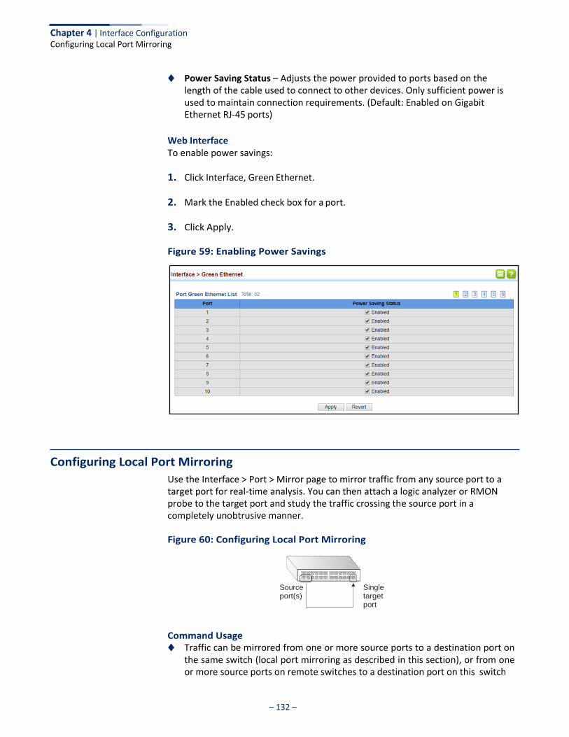
Chapter 4 | Interface Configuration Configuring Local Port Mirroring
– 132 –
◆ Power Saving Status – Adjusts the power provided to ports based on the length of the cable used to connect to other devices. Only sufficient power is used to maintain connection requirements. (Default: Enabled on Gigabit Ethernet RJ-45 ports)
Web Interface To enable power savings:
1. Click Interface, Green Ethernet.
2. Mark the Enabled check box for a port.
3. Click Apply.
Figure 59: Enabling Power Savings
Configuring Local Port Mirroring
Use the Interface > Port > Mirror page to mirror traffic from any source port to a target port for real-time analysis. You can then attach a logic analyzer or RMON probe to the target port and study the traffic crossing the source port in a completely unobtrusive manner.
Figure 60: Configuring Local Port Mirroring
Source port(s)
Single target port
Command Usage ◆ Traffic can be mirrored from one or more source ports to a destination port on
the same switch (local port mirroring as described in this section), or from one or more source ports on remote switches to a destination port on this switch

– 133 –
Chapter 4 | Interface Configuration Configuring Local Port Mirroring
(remote port mirroring as described in “Configuring Remote Port Mirroring” on page 134).
◆ Monitor port speed should match or exceed source port speed, otherwise
traffic may be dropped from the monitor port.
◆ The destination port cannot be a trunk or trunk member port.
◆ Note that Spanning Tree BPDU packets are not mirrored to the target port.
Parameters These parameters are displayed:
◆ Source Port – The port whose traffic will be monitored.
◆ Target Port – The port that will mirror the traffic on the source port.
◆ Type – Allows you to select which traffic to mirror to the target port, Rx (receive), Tx (transmit), or Both. (Default: Both)
Web Interface To configure a local mirror session:
1. Click Interface, Port, Mirror.
2. Select Add from the Action List.
3. Specify the source port.
4. Specify the monitor port.
5. Specify the traffic type to be mirrored.
6. Click Apply.
Figure 61: Configuring Local Port Mirroring
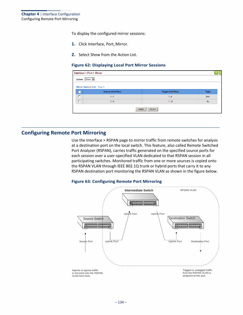
– 134 –
Chapter 4 | Interface Configuration Configuring Remote Port Mirroring
To display the configured mirror sessions:
1. Click Interface, Port, Mirror.
2. Select Show from the Action List.
Figure 62: Displaying Local Port Mirror Sessions
Configuring Remote Port Mirroring
Use the Interface > RSPAN page to mirror traffic from remote switches for analysis at a destination port on the local switch. This feature, also called Remote Switched Port Analyzer (RSPAN), carries traffic generated on the specified source ports for each session over a user-specified VLAN dedicated to that RSPAN session in all participating switches. Monitored traffic from one or more sources is copied onto the RSPAN VLAN through IEEE 802.1Q trunk or hybrid ports that carry it to any RSPAN destination port monitoring the RSPAN VLAN as shown in the figure below.
Figure 63: Configuring Remote Port Mirroring
Intermediate Switch RPSAN VLAN
Source Switch
Uplink Port Uplink Port Destination Switch
Source Port
Uplink Port Uplink Port
Destination Port
Ingress or egress traffic
is mirrored onto the RSPAN
VLAN from here.
Tagged or untagged traffic from the RSPAN VLAN is
analyzed at this port.
– 135 –
Chapter 4 | Interface Configuration Configuring Remote Port Mirroring
Command Usage ◆ Traffic can be mirrored from one or more source ports to a destination port on
the same switch (local port mirroring as described in “Configuring Local Port Mirroring” on page 132), or from one or more source ports on remote switches to a destination port on this switch (remote port mirroring as described in this section).
◆ Configuration Guidelines
Take the following step to configure an RSPAN session:
1. Use the VLAN Static List (see “Configuring VLAN Groups” on page 149) to reserve a VLAN for use by RSPAN (marking the “Remote VLAN” field on this page. (Default VLAN 1 is prohibited.)
2. Set up the source switch on the RSPAN configuration page by specifying the mirror session, the switch’s role (Source), the RSPAN VLAN, and the uplink port1. Then specify the source port(s), and the traffic type to monitor (Rx, Tx or Both).
3. Set up all intermediate switches on the RSPAN configuration page, entering the mirror session, the switch’s role (Intermediate), the RSPAN VLAN, and the uplink port(s).
4. Set up the destination switch on the RSPAN configuration page by specifying the mirror session, the switch’s role (Destination), the destination port1, whether or not the traffic exiting this port will be tagged or untagged, and the RSPAN VLAN. Then specify each uplink port where the mirrored traffic is being received.
◆ RSPAN Limitations
The following limitations apply to the use of RSPAN on this switch:
■ RSPAN Ports – Only ports can be configured as an RSPAN source, destination, or uplink; static and dynamic trunks are not allowed. A port can only be configured as one type of RSPAN interface – source, destination, or uplink. Also, note that the source port and destination port cannot be configured on the same switch.
■ Local/Remote Mirror – The destination of a local mirror session (created on
the Interface > Port > Mirror page) cannot be used as the destination for RSPAN traffic.
■ Spanning Tree – If the spanning tree is disabled, BPDUs will not be flooded
onto the RSPAN VLAN.
1. Only 802.1Q trunk or hybrid (i.e., general use) ports can be configured as an RSPAN uplink or destination ports – access ports are not allowed (see “Adding Static Members to VLANs” on page 152).
– 136 –
Chapter 4 | Interface Configuration Configuring Remote Port Mirroring
■ MAC address learning is not supported on RSPAN uplink ports when RSPAN
is enabled on the switch. Therefore, even if spanning tree is enabled after RSPAN has been configured, MAC address learning will still not be re- started on the RSPAN uplink ports.
■ IEEE 802.1X – RSPAN and 802.1X are mutually exclusive functions. When
802.1X is enabled globally, RSPAN uplink ports cannot be configured, even though RSPAN source and destination ports can still be configured. When RSPAN uplink ports are enabled on the switch, 802.1X cannot be enabled globally.
■ Port Security – If port security is enabled on any port, that port cannot be
set as an RSPAN uplink port, even though it can still be configured as an RSPAN source or destination port. Also, when a port is configured as an RSPAN uplink port, port security cannot be enabled on that port.
Parameters These parameters are displayed:
◆ Session – A number identifying this RSPAN session. (Range: 1-3)
Only one active session is allowed.
◆ Operation Status – Indicates whether or not RSPAN is currently functioning.
◆ Switch Role – Specifies the role this switch performs in mirroring traffic.
■ None – This switch will not participate in RSPAN.
■ Source - Specifies this device as the source of remotely mirrored traffic.
■ Intermediate - Specifies this device as an intermediate switch, transparently passing mirrored traffic from one or more sources to one or more destinations.
■ Destination - Specifies this device as a switch configured with a
destination port which is to receive mirrored traffic for this session.
◆ Remote VLAN – The VLAN to which traffic mirrored from the source port will be flooded. The VLAN specified in this field must first be reserved for the RSPAN application using the VLAN > Static page (see page 149).
◆ Uplink Port – A port on any switch participating in RSPAN through which
mirrored traffic is passed on to or received from the RSPAN VLAN.
Only one uplink port can be configured on a source switch, but there is no limitation on the number of uplink ports1 configured on an intermediate or destination switch.
Only destination and uplink ports will be assigned by the switch as members of the RSPAN VLAN. Ports cannot be manually assigned to an RSPAN VLAN through the VLAN > Static page. Nor can GVRP dynamically add port members
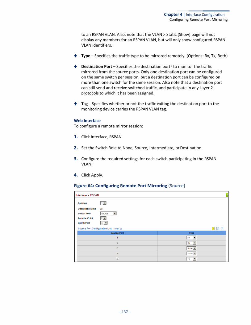
– 137 –
Chapter 4 | Interface Configuration Configuring Remote Port Mirroring
to an RSPAN VLAN. Also, note that the VLAN > Static (Show) page will not display any members for an RSPAN VLAN, but will only show configured RSPAN VLAN identifiers.
◆ Type – Specifies the traffic type to be mirrored remotely. (Options: Rx, Tx, Both)
◆ Destination Port – Specifies the destination port1 to monitor the traffic mirrored from the source ports. Only one destination port can be configured on the same switch per session, but a destination port can be configured on more than one switch for the same session. Also note that a destination port can still send and receive switched traffic, and participate in any Layer 2 protocols to which it has been assigned.
◆ Tag – Specifies whether or not the traffic exiting the destination port to the
monitoring device carries the RSPAN VLAN tag.
Web Interface To configure a remote mirror session:
1. Click Interface, RSPAN.
2. Set the Switch Role to None, Source, Intermediate, or Destination.
3. Configure the required settings for each switch participating in the RSPAN VLAN.
4. Click Apply.
Figure 64: Configuring Remote Port Mirroring (Source)
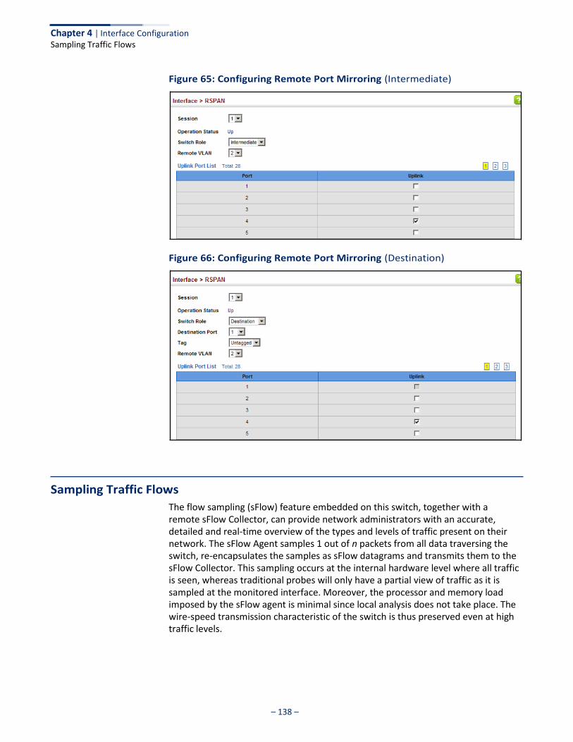
– 138 –
Chapter 4 | Interface Configuration Sampling Traffic Flows
Figure 65: Configuring Remote Port Mirroring (Intermediate)
Figure 66: Configuring Remote Port Mirroring (Destination)
Sampling Traffic Flows
The flow sampling (sFlow) feature embedded on this switch, together with a remote sFlow Collector, can provide network administrators with an accurate, detailed and real-time overview of the types and levels of traffic present on their network. The sFlow Agent samples 1 out of n packets from all data traversing the switch, re-encapsulates the samples as sFlow datagrams and transmits them to the sFlow Collector. This sampling occurs at the internal hardware level where all traffic is seen, whereas traditional probes will only have a partial view of traffic as it is sampled at the monitored interface. Moreover, the processor and memory load imposed by the sFlow agent is minimal since local analysis does not take place. The wire-speed transmission characteristic of the switch is thus preserved even at high traffic levels.
– 139 –
Chapter 4 | Interface Configuration Sampling Traffic Flows
Note: The terms “collector”, “receiver” and “owner”, in the context of this chapter, all refer to a remote server capable of receiving the sFlow datagrams generated by the sFlow agent of the switch.
As the Collector receives streams from the various sFlow agents (other switches or routers) throughout the network, a timely, network-wide picture of utilization and traffic flows is created. Analysis of the sFlow stream(s) can reveal trends and information that can be leveraged in the following ways:
◆ Detecting, diagnosing, and fixing network problems
◆ Real-time congestion management
◆ Understanding application mix (P2P, Web, DNS, etc.) and changes
◆ Identification and tracing of unauthorized network activity
◆ Usage accounting
◆ Trending and capacity planning
Configuring sFlow Receiver Settings
Use the Interface > sFlow (Configure Receiver – Add) page to create an sFlow receiver on the switch.
Parameters These parameters are displayed:
◆ Receiver Owner Name2 – The name of the receiver. (Range: 1-256 characters;
Default: None)
◆ Receiver Timeout – The time that the sFlow process will continuously send samples to the Collector before resetting all sFlow port parameters. (Range: 0-10000000 seconds, where 0 indicates no time out)
The sFlow parameters affected by this command include the sampling interval, the receiver’s name, address and UDP port, the time out, maximum header size, and maximum datagram size.
◆ Receiver Destination2 – IP address of the sFlow Collector.
■ ipv4-address - IPv4 address of the sFlow collector. Valid IPv4 addresses consist of four decimal numbers, 0 to 255, separated by periods.
■ ipv6-address - IPv6 address of the sFlow collector. A full IPv6 address including the network prefix and host address bits. An IPv6 address consists of 8 colon-separated 16-bit hexadecimal values. One double colon may be
2. Sampling must be disabled by setting the time out to 0 before these fields can be
configured.
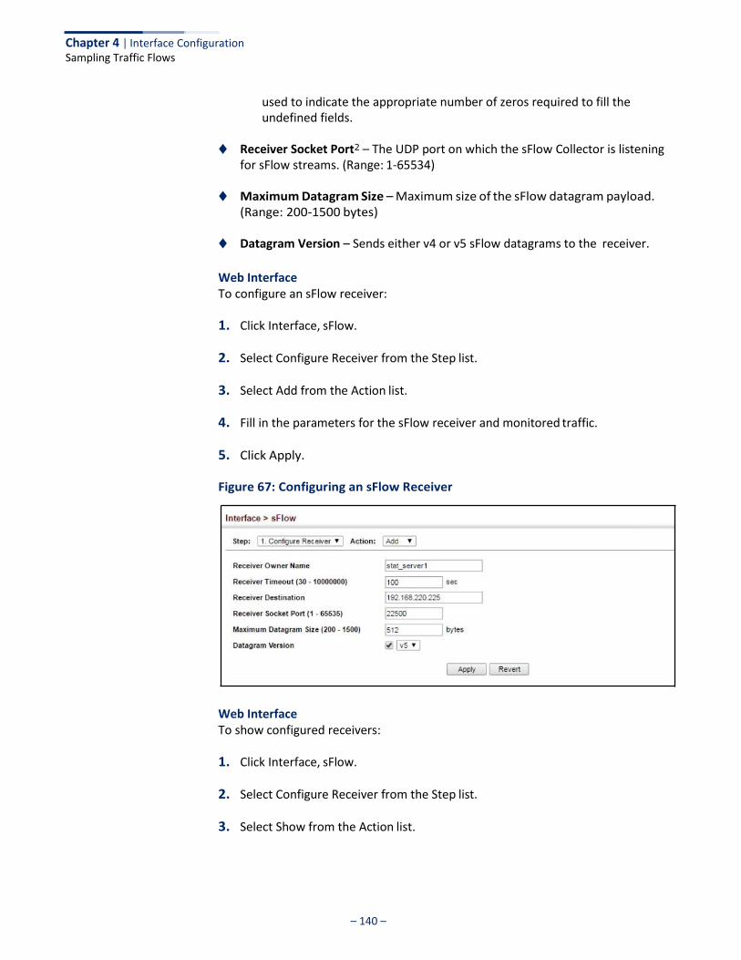
Chapter 4 | Interface Configuration Sampling Traffic Flows
– 140 –
used to indicate the appropriate number of zeros required to fill the undefined fields.
◆ Receiver Socket Port2 – The UDP port on which the sFlow Collector is listening
for sFlow streams. (Range: 1-65534)
◆ Maximum Datagram Size – Maximum size of the sFlow datagram payload. (Range: 200-1500 bytes)
◆ Datagram Version – Sends either v4 or v5 sFlow datagrams to the receiver.
Web Interface To configure an sFlow receiver:
1. Click Interface, sFlow.
2. Select Configure Receiver from the Step list.
3. Select Add from the Action list.
4. Fill in the parameters for the sFlow receiver and monitored traffic.
5. Click Apply.
Figure 67: Configuring an sFlow Receiver
Web Interface To show configured receivers:
1. Click Interface, sFlow.
2. Select Configure Receiver from the Step list.
3. Select Show from the Action list.
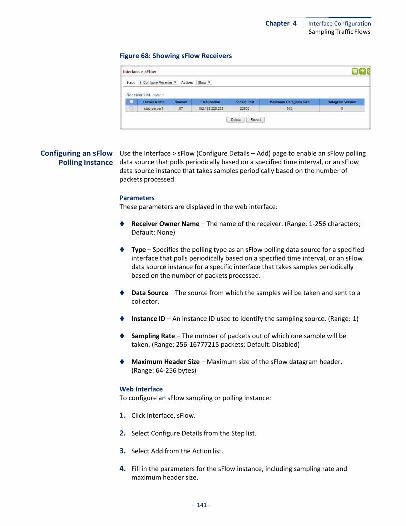
Chapter 4 | Interface Configuration Sampling Traffic Flows
– 141 –
Figure 68: Showing sFlow Receivers
Configuring an sFlow Polling Instance
Use the Interface > sFlow (Configure Details – Add) page to enable an sFlow polling data source that polls periodically based on a specified time interval, or an sFlow data source instance that takes samples periodically based on the number of packets processed.
Parameters These parameters are displayed in the web interface:
◆ Receiver Owner Name – The name of the receiver. (Range: 1-256 characters;
Default: None)
◆ Type – Specifies the polling type as an sFlow polling data source for a specified interface that polls periodically based on a specified time interval, or an sFlow data source instance for a specific interface that takes samples periodically based on the number of packets processed.
◆ Data Source – The source from which the samples will be taken and sent to a
collector.
◆ Instance ID – An instance ID used to identify the sampling source. (Range: 1)
◆ Sampling Rate – The number of packets out of which one sample will be taken. (Range: 256-16777215 packets; Default: Disabled)
◆ Maximum Header Size – Maximum size of the sFlow datagram header.
(Range: 64-256 bytes)
Web Interface To configure an sFlow sampling or polling instance:
1. Click Interface, sFlow.
2. Select Configure Details from the Step list.
3. Select Add from the Action list.
4. Fill in the parameters for the sFlow instance, including sampling rate and maximum header size.

Chapter 4 | Interface Configuration Sampling Traffic Flows
– 142 –
5. Click Apply.
Figure 69: Configuring an sFlow Instance
Web Interface To show configured instances:
1. Click Interface, sFlow.
2. Select Configure Details from the Step list.
3. Select Show from the Action list.
4. Select the owner name from the scroll-down list.
5. Select sFlow type as Sampling or Polling.
Figure 70: Showing sFlow Instances
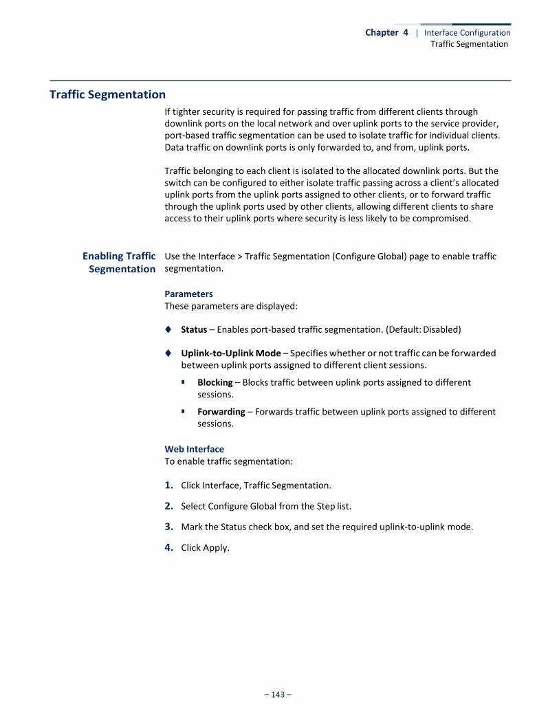
– 143 –
Chapter 4 | Interface Configuration Traffic Segmentation
Traffic Segmentation
If tighter security is required for passing traffic from different clients through downlink ports on the local network and over uplink ports to the service provider, port-based traffic segmentation can be used to isolate traffic for individual clients. Data traffic on downlink ports is only forwarded to, and from, uplink ports.
Traffic belonging to each client is isolated to the allocated downlink ports. But the switch can be configured to either isolate traffic passing across a client’s allocated uplink ports from the uplink ports assigned to other clients, or to forward traffic through the uplink ports used by other clients, allowing different clients to share access to their uplink ports where security is less likely to be compromised.
Enabling Traffic Segmentation
Use the Interface > Traffic Segmentation (Configure Global) page to enable traffic segmentation.
Parameters These parameters are displayed:
◆ Status – Enables port-based traffic segmentation. (Default: Disabled)
◆ Uplink-to-Uplink Mode – Specifies whether or not traffic can be forwarded between uplink ports assigned to different client sessions.
■ Blocking – Blocks traffic between uplink ports assigned to different sessions.
■ Forwarding – Forwards traffic between uplink ports assigned to different sessions.
Web Interface To enable traffic segmentation:
1. Click Interface, Traffic Segmentation.
2. Select Configure Global from the Step list.
3. Mark the Status check box, and set the required uplink-to-uplink mode.
4. Click Apply.
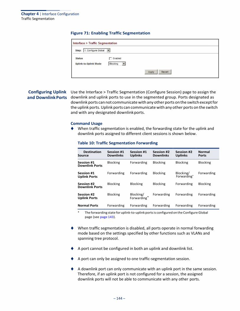
– 144 –
Chapter 4 | Interface Configuration Traffic Segmentation
Figure 71: Enabling Traffic Segmentation
Configuring Uplink and Downlink Ports
Use the Interface > Traffic Segmentation (Configure Session) page to assign the downlink and uplink ports to use in the segmented group. Ports designated as downlink ports can not communicate with any other ports on the switch except for the uplink ports. Uplink ports can communicate with any other ports on the switch and with any designated downlink ports.
Command Usage ◆ When traffic segmentation is enabled, the forwarding state for the uplink and
downlink ports assigned to different client sessions is shown below.
Table 10: Traffic Segmentation Forwarding
Downlink Ports
Forwarding*
Downlink Ports
Forwarding*
* The forwarding state for uplink-to-uplink ports is configured on the Configure Global page (see page 143).
◆ When traffic segmentation is disabled, all ports operate in normal forwarding mode based on the settings specified by other functions such as VLANs and spanning tree protocol.
◆ A port cannot be configured in both an uplink and downlink list.
◆ A port can only be assigned to one traffic-segmentation session.
◆ A downlink port can only communicate with an uplink port in the same session. Therefore, if an uplink port is not configured for a session, the assigned downlink ports will not be able to communicate with any other ports.
Destination Source
Session #1 Downlinks
Session #1 Uplinks
Session #2 Downlinks
Session #2 Uplinks
Normal Ports
Session #1 Blocking Forwarding Blocking Blocking Blocking
Session #1 Uplink Ports
Forwarding Forwarding Blocking Blocking/ Forwarding
Session #2 Blocking Blocking Blocking Forwarding Blocking
Session #2 Uplink Ports
Blocking Blocking/ Forwarding Forwarding Forwarding
Normal Ports Forwarding Forwarding Forwarding Forwarding Forwarding

– 145 –
Chapter 4 | Interface Configuration Traffic Segmentation
◆ If a downlink port is not configured for the session, the assigned uplink ports will operate as normal ports.
Parameters These parameters are displayed:
◆ Session ID – Traffic segmentation session. (Range: 1-4)
◆ Direction – Adds an interface to the segmented group by setting the direction to uplink or downlink. (Default: Uplink)
◆ Interface – Displays a list of ports or trunks.
◆ Port – Port Identifier. (Range: 1-52)
◆ Trunk – Trunk Identifier. (Range: 1-8)
Web Interface To configure the members of the traffic segmentation group:
1. Click Interface, Traffic Segmentation.
2. Select Configure Session from the Step list.
3. Select Add from the Action list.
4. Enter the session ID, set the direction to uplink or downlink, and select the interface to add.
5. Click Apply.
Figure 72: Configuring Members for Traffic Segmentation

– 146 –
Chapter 4 | Interface Configuration Traffic Segmentation
To show the members of the traffic segmentation group:
1. Click Interface, Traffic Segmentation.
2. Select Configure Session from the Step list.
3. Select Show from the Action list.
Figure 73: Showing Traffic Segmentation Members
– 147 –
VLAN Configuration
This chapter includes the following topics:
◆ IEEE 802.1Q VLANs – Configures static VLANs.
◆ IEEE 802.1Q Tunneling – Configures QinQ tunneling to maintain customer- specific VLAN and Layer 2 protocol configurations across a service provider network, even when different customers use the same internal VLAN IDs.
◆ Protocol VLANs – Configures VLAN groups based on specified protocols.
◆ MAC-based VLANs – Maps untagged ingress frames to a specified VLAN if the source MAC address is found in the IP MAC address-to-VLAN mapping table.
IEEE 802.1Q VLANs
In large networks, routers are used to isolate broadcast traffic for each subnet into separate domains. This switch provides a similar service at Layer 2 by using VLANs to organize any group of network nodes into separate broadcast domains. VLANs confine broadcast traffic to the originating group, and can eliminate broadcast storms in large networks. This also provides a more secure and cleaner network environment.
An IEEE 802.1Q VLAN is a group of ports that can be located anywhere in the network, but communicate as though they belong to the same physical segment.
VLANs help to simplify network management by allowing you to move devices to a new VLAN without having to change any physical connections. VLANs can be easily organized to reflect departmental groups (such as Marketing or R&D), usage groups (such as e-mail), or multicast groups (used for multimedia applications such as video conferencing).
VLANs provide greater network efficiency by reducing broadcast traffic, and allow you to make network changes without having to update IP addresses or IP subnets. VLANs inherently provide a high level of network security since traffic must pass through a configured Layer 3 link to reach a different VLAN.

– 148 –
Chapter 5 | VLAN Configuration IEEE 802.1Q VLANs
This switch supports the following VLAN features:
◆ Up to 4094 VLANs based on the IEEE 802.1Q standard
◆ Distributed VLAN learning across multiple switches using explicit tagging.
◆ Port overlapping, allowing a port to participate in multiple VLANs
◆ End stations can belong to multiple VLANs
◆ Passing traffic between VLAN-aware and VLAN-unaware devices
◆ Priority tagging
Assigning Ports to VLANs
Before enabling VLANs for the switch, you must first assign each port to the VLAN group(s) in which it will participate. By default all ports are assigned to VLAN 1 as untagged ports. Add a port as a tagged port if you want it to carry traffic for one or more VLANs, and any intermediate network devices or the host at the other end of the connection supports VLANs. Then assign ports on the other VLAN-aware network devices along the path that will carry this traffic to the same VLAN(s), either manually or dynamically using GVRP. However, if you want a port on this switch to participate in one or more VLANs, but none of the intermediate network devices nor the host at the other end of the connection supports VLANs, then you should add this port to the VLAN as an untagged port.
Note: VLAN-tagged frames can pass through VLAN-aware or VLAN-unaware network interconnection devices, but the VLAN tags should be stripped off before passing it on to any end-node host that does not support VLAN tagging.
Figure 74: VLAN Compliant and VLAN Non-compliant Devices
VA: VLAN Aware VU: VLAN Unaware
VA VA VU
VLAN Classification – When the switch receives a frame, it classifies the frame in one of two ways. If the frame is untagged, the switch assigns the frame to an associated VLAN (based on the default VLAN ID of the receiving port). But if the frame is tagged, the switch uses the tagged VLAN ID to identify the port broadcast domain of the frame.
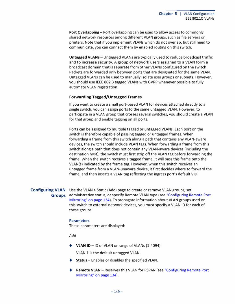
– 149 –
Chapter 5 | VLAN Configuration IEEE 802.1Q VLANs
Port Overlapping – Port overlapping can be used to allow access to commonly shared network resources among different VLAN groups, such as file servers or printers. Note that if you implement VLANs which do not overlap, but still need to communicate, you can connect them by enabled routing on this switch.
Untagged VLANs – Untagged VLANs are typically used to reduce broadcast traffic and to increase security. A group of network users assigned to a VLAN form a broadcast domain that is separate from other VLANs configured on the switch. Packets are forwarded only between ports that are designated for the same VLAN. Untagged VLANs can be used to manually isolate user groups or subnets. However, you should use IEEE 802.3 tagged VLANs with GVRP whenever possible to fully automate VLAN registration.
Forwarding Tagged/Untagged Frames
If you want to create a small port-based VLAN for devices attached directly to a single switch, you can assign ports to the same untagged VLAN. However, to participate in a VLAN group that crosses several switches, you should create a VLAN for that group and enable tagging on all ports.
Ports can be assigned to multiple tagged or untagged VLANs. Each port on the switch is therefore capable of passing tagged or untagged frames. When forwarding a frame from this switch along a path that contains any VLAN-aware devices, the switch should include VLAN tags. When forwarding a frame from this switch along a path that does not contain any VLAN-aware devices (including the destination host), the switch must first strip off the VLAN tag before forwarding the frame. When the switch receives a tagged frame, it will pass this frame onto the VLAN(s) indicated by the frame tag. However, when this switch receives an untagged frame from a VLAN-unaware device, it first decides where to forward the frame, and then inserts a VLAN tag reflecting the ingress port’s default VID.
Configuring VLAN Groups
Use the VLAN > Static (Add) page to create or remove VLAN groups, set administrative status, or specify Remote VLAN type (see “Configuring Remote Port Mirroring” on page 134). To propagate information about VLAN groups used on this switch to external network devices, you must specify a VLAN ID for each of these groups.
Parameters These parameters are displayed:
Add
◆ VLAN ID – ID of VLAN or range of VLANs (1-4094).
VLAN 1 is the default untagged VLAN.
◆ Status – Enables or disables the specified VLAN.
◆ Remote VLAN – Reserves this VLAN for RSPAN (see “Configuring Remote Port Mirroring” on page 134).

Chapter 5 | VLAN Configuration IEEE 802.1Q VLANs
– 150 –
Modify
◆ VLAN ID – ID of configured VLAN (1-4094).
◆ VLAN Name – Name of the VLAN (1 to 32 characters).
◆ Status – Enables or disables the specified VLAN.
◆ L3 Interface – Sets the interface to support Layer 3 configuration, and reserves memory space required to maintain additional information about this interface type. This parameter must be enabled before you can assign an IP address to a VLAN (see “Setting the Switch’s IP Address (IP Version 4)” on page 499).
Show
◆ VLAN ID – ID of configured VLAN.
◆ VLAN Name – Name of the VLAN.
◆ Status – Operational status of configured VLAN.
◆ Remote VLAN – Shows if RSPAN is enabled on this VLAN (see “Configuring Remote Port Mirroring” on page 134).
◆ L3 Interface – Shows if the interface supports Layer 3 configuration.
Web Interface To create VLAN groups:
1. Click VLAN, Static.
2. Select Add from the Action list.
3. Enter a VLAN ID or range of IDs.
4. Check Status to configure the VLAN as operational.
5. Specify whether the VLANs are to be used for remote port mirroring.
6. Click Apply.
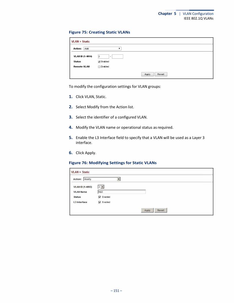
Chapter 5 | VLAN Configuration IEEE 802.1Q VLANs
– 151 –
Figure 75: Creating Static VLANs
To modify the configuration settings for VLAN groups:
1. Click VLAN, Static.
2. Select Modify from the Action list.
3. Select the identifier of a configured VLAN.
4. Modify the VLAN name or operational status as required.
5. Enable the L3 Interface field to specify that a VLAN will be used as a Layer 3 interface.
6. Click Apply.
Figure 76: Modifying Settings for Static VLANs
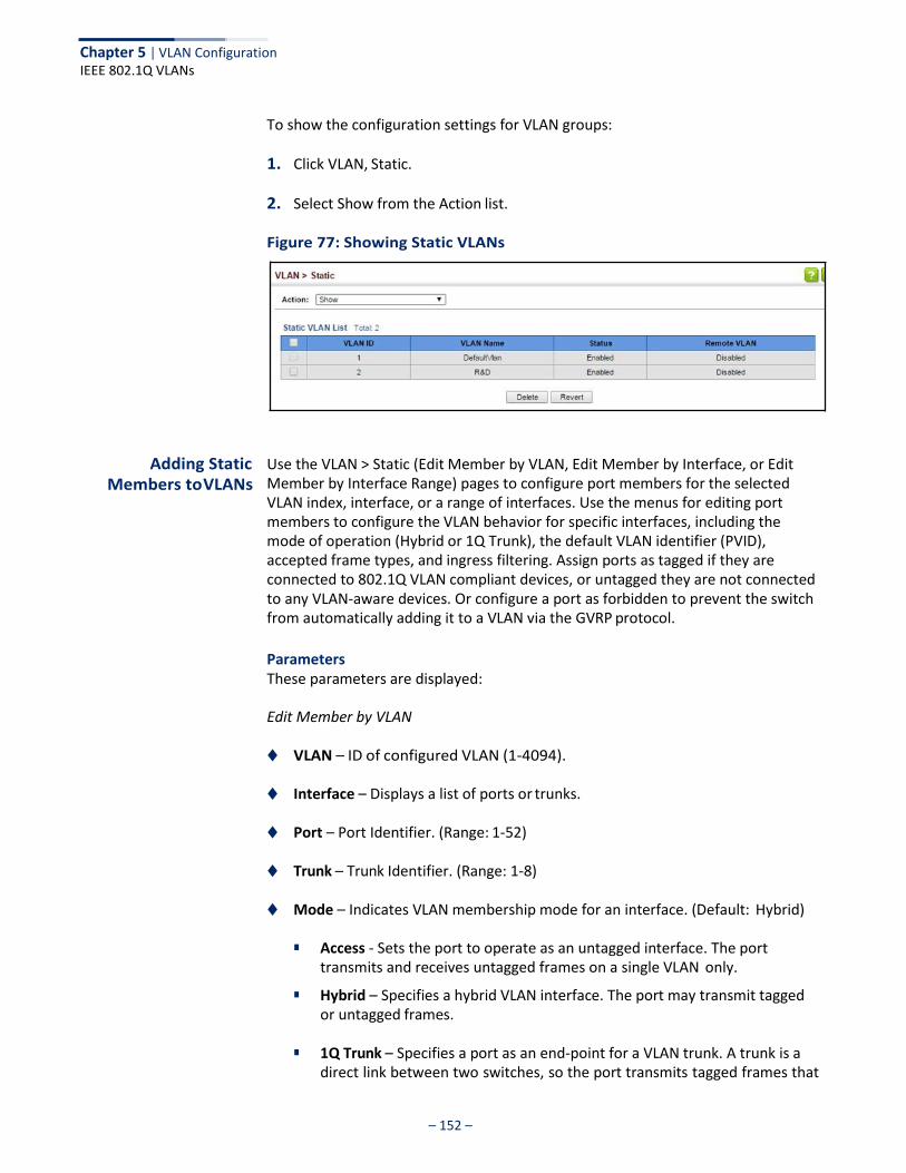
Chapter 5 | VLAN Configuration IEEE 802.1Q VLANs
– 152 –
To show the configuration settings for VLAN groups:
1. Click VLAN, Static.
2. Select Show from the Action list.
Figure 77: Showing Static VLANs
Adding Static
Members to VLANs
Use the VLAN > Static (Edit Member by VLAN, Edit Member by Interface, or Edit Member by Interface Range) pages to configure port members for the selected VLAN index, interface, or a range of interfaces. Use the menus for editing port members to configure the VLAN behavior for specific interfaces, including the mode of operation (Hybrid or 1Q Trunk), the default VLAN identifier (PVID), accepted frame types, and ingress filtering. Assign ports as tagged if they are connected to 802.1Q VLAN compliant devices, or untagged they are not connected to any VLAN-aware devices. Or configure a port as forbidden to prevent the switch from automatically adding it to a VLAN via the GVRP protocol.
Parameters These parameters are displayed:
Edit Member by VLAN
◆ VLAN – ID of configured VLAN (1-4094).
◆ Interface – Displays a list of ports or trunks.
◆ Port – Port Identifier. (Range: 1-52)
◆ Trunk – Trunk Identifier. (Range: 1-8)
◆ Mode – Indicates VLAN membership mode for an interface. (Default: Hybrid)
■ Access - Sets the port to operate as an untagged interface. The port transmits and receives untagged frames on a single VLAN only.
■ Hybrid – Specifies a hybrid VLAN interface. The port may transmit tagged or untagged frames.
■ 1Q Trunk – Specifies a port as an end-point for a VLAN trunk. A trunk is a
direct link between two switches, so the port transmits tagged frames that
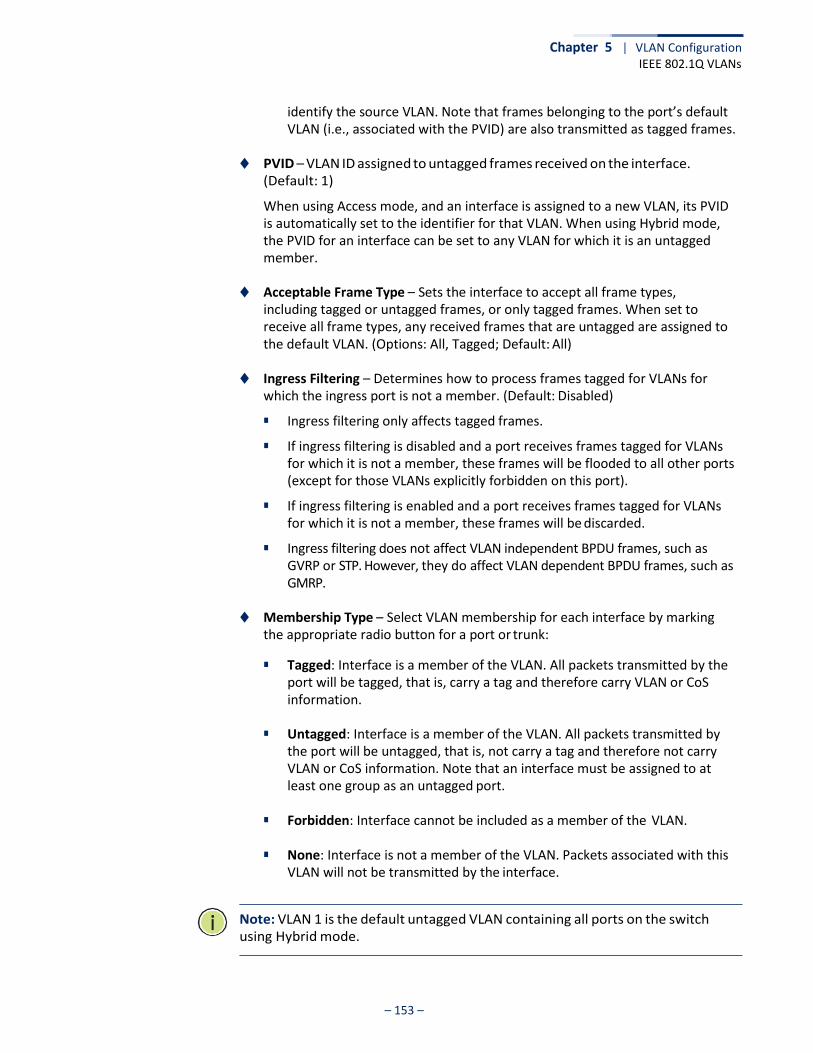
Chapter 5 | VLAN Configuration IEEE 802.1Q VLANs
– 153 –
identify the source VLAN. Note that frames belonging to the port’s default VLAN (i.e., associated with the PVID) are also transmitted as tagged frames.
◆ PVID – VLAN ID assigned to untagged frames received on the interface.
(Default: 1)
When using Access mode, and an interface is assigned to a new VLAN, its PVID is automatically set to the identifier for that VLAN. When using Hybrid mode, the PVID for an interface can be set to any VLAN for which it is an untagged member.
◆ Acceptable Frame Type – Sets the interface to accept all frame types,
including tagged or untagged frames, or only tagged frames. When set to receive all frame types, any received frames that are untagged are assigned to the default VLAN. (Options: All, Tagged; Default: All)
◆ Ingress Filtering – Determines how to process frames tagged for VLANs for
which the ingress port is not a member. (Default: Disabled)
■ Ingress filtering only affects tagged frames.
■ If ingress filtering is disabled and a port receives frames tagged for VLANs for which it is not a member, these frames will be flooded to all other ports (except for those VLANs explicitly forbidden on this port).
■ If ingress filtering is enabled and a port receives frames tagged for VLANs for which it is not a member, these frames will be discarded.
■ Ingress filtering does not affect VLAN independent BPDU frames, such as GVRP or STP. However, they do affect VLAN dependent BPDU frames, such as GMRP.
◆ Membership Type – Select VLAN membership for each interface by marking
the appropriate radio button for a port or trunk:
■ Tagged: Interface is a member of the VLAN. All packets transmitted by the port will be tagged, that is, carry a tag and therefore carry VLAN or CoS information.
■ Untagged: Interface is a member of the VLAN. All packets transmitted by
the port will be untagged, that is, not carry a tag and therefore not carry VLAN or CoS information. Note that an interface must be assigned to at least one group as an untagged port.
■ Forbidden: Interface cannot be included as a member of the VLAN.
■ None: Interface is not a member of the VLAN. Packets associated with this
VLAN will not be transmitted by the interface.
Note: VLAN 1 is the default untagged VLAN containing all ports on the switch using Hybrid mode.

Chapter 5 | VLAN Configuration IEEE 802.1Q VLANs
– 154 –
Edit Member by Interface
All parameters are the same as those described under the preceding section for Edit Member by VLAN.
Edit Member by Interface Range
All parameters are the same as those described under the earlier section for Edit Member by VLAN, except for the items shown below.
◆ Port Range – Displays a list of ports. (Range: 1-52)
◆ Trunk Range – Displays a list of ports. (Range: 1-8)
Note: The PVID, acceptable frame type, and ingress filtering parameters for each interface within the specified range must be configured on either the Edit Member by VLAN or Edit Member by Interface page.
Web Interface To configure static members by the VLAN index:
1. Click VLAN, Static.
2. Select Edit Member by VLAN from the Action list.
3. Select a VLAN from the scroll-down list.
4. Set the Interface type to display as Port or Trunk.
5. Modify the settings for any interface as required.
6. Click Apply.
Figure 78: Configuring Static Members by VLAN Index
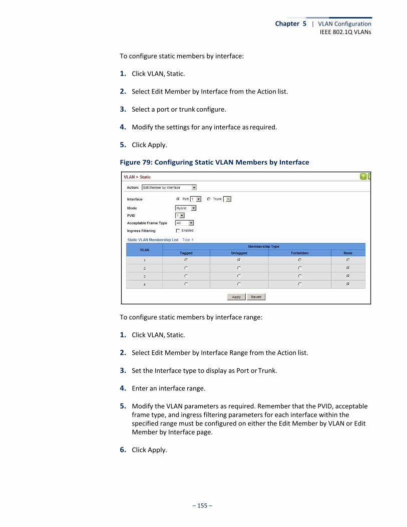
Chapter 5 | VLAN Configuration IEEE 802.1Q VLANs
– 155 –
To configure static members by interface:
1. Click VLAN, Static.
2. Select Edit Member by Interface from the Action list.
3. Select a port or trunk configure.
4. Modify the settings for any interface as required.
5. Click Apply.
Figure 79: Configuring Static VLAN Members by Interface
To configure static members by interface range:
1. Click VLAN, Static.
2. Select Edit Member by Interface Range from the Action list.
3. Set the Interface type to display as Port or Trunk.
4. Enter an interface range.
5. Modify the VLAN parameters as required. Remember that the PVID, acceptable frame type, and ingress filtering parameters for each interface within the specified range must be configured on either the Edit Member by VLAN or Edit Member by Interface page.
6. Click Apply.
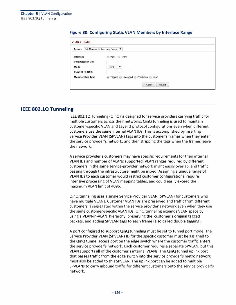
– 156 –
Chapter 5 | VLAN Configuration IEEE 802.1Q Tunneling
Figure 80: Configuring Static VLAN Members by Interface Range
IEEE 802.1Q Tunneling
IEEE 802.1Q Tunneling (QinQ) is designed for service providers carrying traffic for multiple customers across their networks. QinQ tunneling is used to maintain customer-specific VLAN and Layer 2 protocol configurations even when different customers use the same internal VLAN IDs. This is accomplished by inserting Service Provider VLAN (SPVLAN) tags into the customer’s frames when they enter the service provider’s network, and then stripping the tags when the frames leave the network.
A service provider’s customers may have specific requirements for their internal VLAN IDs and number of VLANs supported. VLAN ranges required by different customers in the same service-provider network might easily overlap, and traffic passing through the infrastructure might be mixed. Assigning a unique range of VLAN IDs to each customer would restrict customer configurations, require intensive processing of VLAN mapping tables, and could easily exceed the maximum VLAN limit of 4096.
QinQ tunneling uses a single Service Provider VLAN (SPVLAN) for customers who have multiple VLANs. Customer VLAN IDs are preserved and traffic from different customers is segregated within the service provider’s network even when they use the same customer-specific VLAN IDs. QinQ tunneling expands VLAN space by using a VLAN-in-VLAN hierarchy, preserving the customer’s original tagged packets, and adding SPVLAN tags to each frame (also called double tagging).
A port configured to support QinQ tunneling must be set to tunnel port mode. The Service Provider VLAN (SPVLAN) ID for the specific customer must be assigned to the QinQ tunnel access port on the edge switch where the customer traffic enters the service provider’s network. Each customer requires a separate SPVLAN, but this VLAN supports all of the customer's internal VLANs. The QinQ tunnel uplink port that passes traffic from the edge switch into the service provider’s metro network must also be added to this SPVLAN. The uplink port can be added to multiple SPVLANs to carry inbound traffic for different customers onto the service provider’s network.
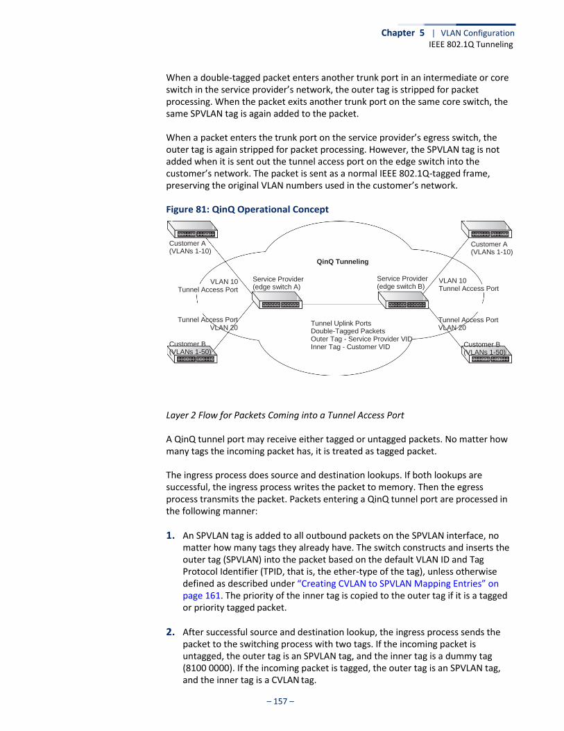
– 157 –
Chapter 5 | VLAN Configuration IEEE 802.1Q Tunneling
When a double-tagged packet enters another trunk port in an intermediate or core switch in the service provider’s network, the outer tag is stripped for packet processing. When the packet exits another trunk port on the same core switch, the same SPVLAN tag is again added to the packet.
When a packet enters the trunk port on the service provider’s egress switch, the outer tag is again stripped for packet processing. However, the SPVLAN tag is not added when it is sent out the tunnel access port on the edge switch into the customer’s network. The packet is sent as a normal IEEE 802.1Q-tagged frame, preserving the original VLAN numbers used in the customer’s network.
Figure 81: QinQ Operational Concept
Customer A (VLANs 1-10)
VLAN 10
Tunnel Access Port
Service Provider (edge switch A)
QinQ Tunneling
Service Provider (edge switch B)
Customer A (VLANs 1-10)
VLAN 10 Tunnel Access Port
Tunnel Access Port VLAN 20
Customer B (VLANs 1-50)
Tunnel Uplink Ports Double-Tagged Packets Outer Tag - Service Provider VID Inner Tag - Customer VID
Tunnel Access Port VLAN 20
Customer B (VLANs 1-50)
Layer 2 Flow for Packets Coming into a Tunnel Access Port
A QinQ tunnel port may receive either tagged or untagged packets. No matter how many tags the incoming packet has, it is treated as tagged packet.
The ingress process does source and destination lookups. If both lookups are successful, the ingress process writes the packet to memory. Then the egress process transmits the packet. Packets entering a QinQ tunnel port are processed in the following manner:
1. An SPVLAN tag is added to all outbound packets on the SPVLAN interface, no matter how many tags they already have. The switch constructs and inserts the outer tag (SPVLAN) into the packet based on the default VLAN ID and Tag Protocol Identifier (TPID, that is, the ether-type of the tag), unless otherwise defined as described under “Creating CVLAN to SPVLAN Mapping Entries” on page 161. The priority of the inner tag is copied to the outer tag if it is a tagged or priority tagged packet.
2. After successful source and destination lookup, the ingress process sends the packet to the switching process with two tags. If the incoming packet is untagged, the outer tag is an SPVLAN tag, and the inner tag is a dummy tag (8100 0000). If the incoming packet is tagged, the outer tag is an SPVLAN tag, and the inner tag is a CVLAN tag.
– 158 –
Chapter 5 | VLAN Configuration IEEE 802.1Q Tunneling
3. After packet classification through the switching process, the packet is written to memory with one tag (an outer tag) or with two tags (both an outer tag and inner tag).
4. The switch sends the packet to the proper egress port.
5. If the egress port is an untagged member of the SPVLAN, the outer tag will be stripped. If it is a tagged member, the outgoing packets will have two tags.
Layer 2 Flow for Packets Coming into a Tunnel Uplink Port
An uplink port receives one of the following packets:
◆ Untagged
◆ One tag (CVLAN or SPVLAN)
◆ Double tag (CVLAN + SPVLAN)
The ingress process does source and destination lookups. If both lookups are successful, the ingress process writes the packet to memory. Then the egress process transmits the packet. Packets entering a QinQ uplink port are processed in the following manner:
1. If incoming packets are untagged, the PVID VLAN native tag is added.
2. If the ether-type of an incoming packet (single or double tagged) is not equal to the TPID of the uplink port, the VLAN tag is determined to be a Customer VLAN (CVLAN) tag. The uplink port’s PVID VLAN native tag is added to the packet. This outer tag is used for learning and switching packets within the service provider’s network. The TPID must be configured on a per port basis, and the verification cannot be disabled.
3. If the ether-type of an incoming packet (single or double tagged) is equal to the TPID of the uplink port, no new VLAN tag is added. If the uplink port is not the member of the outer VLAN of the incoming packets, the packet will be dropped when ingress filtering is enabled. If ingress filtering is not enabled, the packet will still be forwarded. If the VLAN is not listed in the VLAN table, the packet will be dropped.
4. After successful source and destination lookups, the packet is double tagged. The switch uses the TPID of 0x8100 to indicate that an incoming packet is double-tagged. If the outer tag of an incoming double-tagged packet is equal to the port TPID and the inner tag is 0x8100, it is treated as a double-tagged packet. If a single-tagged packet has 0x8100 as its TPID, and port TPID is not 0x8100, a new VLAN tag is added and it is also treated as double-tagged packet.
5. If the destination address lookup fails, the packet is sent to all member ports of the outer tag's VLAN.
– 159 –
Chapter 5 | VLAN Configuration IEEE 802.1Q Tunneling
6. After packet classification, the packet is written to memory for processing as a single-tagged or double-tagged packet.
7. The switch sends the packet to the proper egress port.
8. If the egress port is an untagged member of the SPVLAN, the outer tag will be stripped. If it is a tagged member, the outgoing packet will have two tags.
Configuration Limitations for QinQ
◆ The native VLAN of uplink ports should not be used as the SPVLAN. If the SPVLAN is the uplink port's native VLAN, the uplink port must be an untagged member of the SPVLAN. Then the outer SPVLAN tag will be stripped when the packets are sent out. Another reason is that it causes non-customer packets to be forwarded to the SPVLAN.
◆ Static trunk port groups are compatible with QinQ tunnel ports as long as the
QinQ configuration is consistent within a trunk port group.
◆ The native VLAN (VLAN 1) is not normally added to transmitted frames. Avoid using VLAN 1 as an SPVLAN tag for customer traffic to reduce the risk of misconfiguration. Instead, use VLAN 1 as a management VLAN instead of a data VLAN in the service provider network.
◆ There are some inherent incompatibilities between Layer 2 and Layer 3
switching:
■ Tunnel ports do not support IP Access Control Lists.
■ Layer 3 Quality of Service (QoS) and other QoS features containing Layer 3 information are not supported on tunnel ports.
■ Spanning tree bridge protocol data unit (BPDU) filtering is automatically disabled on a tunnel port.
General Configuration Guidelines for QinQ
1. Enable Tunnel Status, and set the Tag Protocol Identifier (TPID) value of the tunnel access port (in the Ethernet Type field). This step is required if the attached client is using a nonstandard 2-byte ethertype to identify 802.1Q tagged frames. The default ethertype value is 0x8100. (See “Enabling QinQ Tunneling on the Switch” on page 160.)
2. Create a Service Provider VLAN, also referred to as an SPVLAN (see “Configuring VLAN Groups” on page 149).
3. Configure the QinQ tunnel access port to Access mode (see “Adding an Interface to a QinQ Tunnel” on page 163).
4. Configure the QinQ tunnel access port to join the SPVLAN as an untagged member (see “Adding Static Members to VLANs” on page 152).
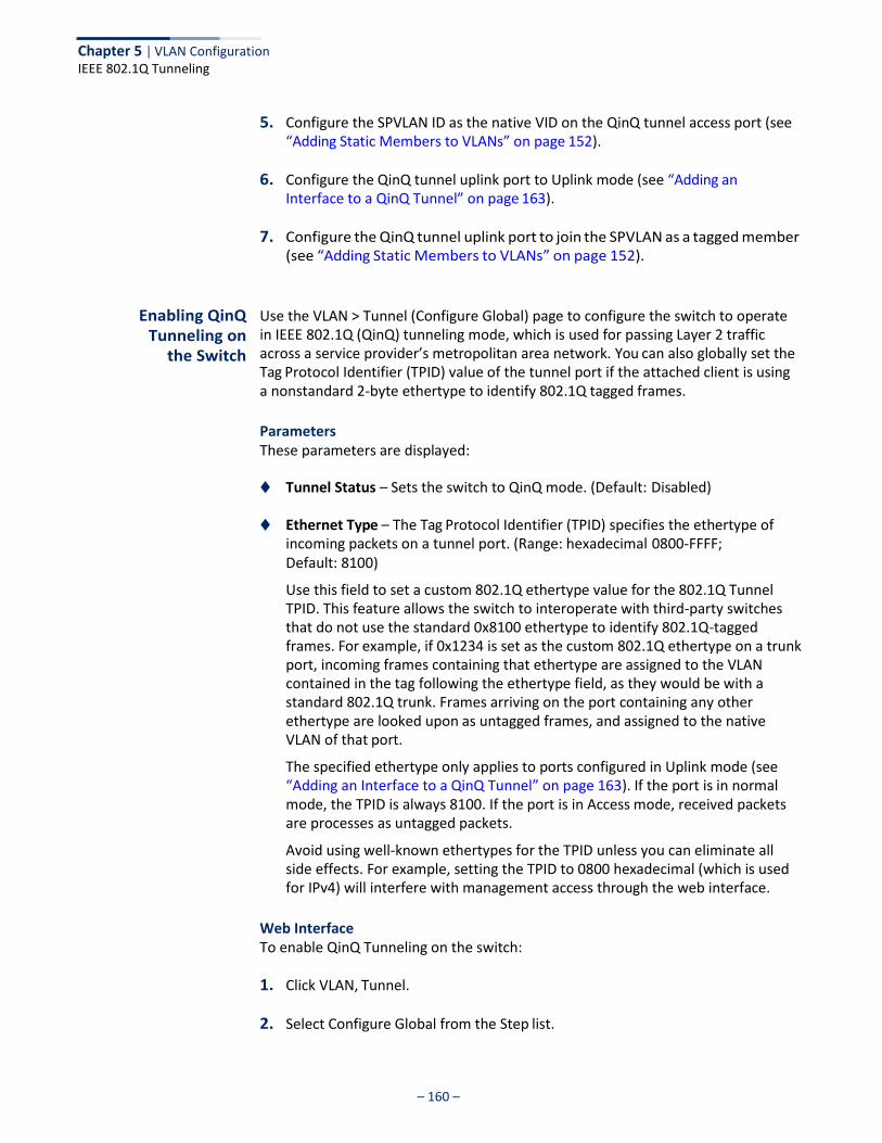
Chapter 5 | VLAN Configuration IEEE 802.1Q Tunneling
– 160 –
5. Configure the SPVLAN ID as the native VID on the QinQ tunnel access port (see “Adding Static Members to VLANs” on page 152).
6. Configure the QinQ tunnel uplink port to Uplink mode (see “Adding an Interface to a QinQ Tunnel” on page 163).
7. Configure the QinQ tunnel uplink port to join the SPVLAN as a tagged member (see “Adding Static Members to VLANs” on page 152).
Enabling QinQ Tunneling on
the Switch
Use the VLAN > Tunnel (Configure Global) page to configure the switch to operate in IEEE 802.1Q (QinQ) tunneling mode, which is used for passing Layer 2 traffic across a service provider’s metropolitan area network. You can also globally set the Tag Protocol Identifier (TPID) value of the tunnel port if the attached client is using a nonstandard 2-byte ethertype to identify 802.1Q tagged frames.
Parameters These parameters are displayed:
◆ Tunnel Status – Sets the switch to QinQ mode. (Default: Disabled)
◆ Ethernet Type – The Tag Protocol Identifier (TPID) specifies the ethertype of incoming packets on a tunnel port. (Range: hexadecimal 0800-FFFF; Default: 8100)
Use this field to set a custom 802.1Q ethertype value for the 802.1Q Tunnel TPID. This feature allows the switch to interoperate with third-party switches that do not use the standard 0x8100 ethertype to identify 802.1Q-tagged frames. For example, if 0x1234 is set as the custom 802.1Q ethertype on a trunk port, incoming frames containing that ethertype are assigned to the VLAN contained in the tag following the ethertype field, as they would be with a standard 802.1Q trunk. Frames arriving on the port containing any other ethertype are looked upon as untagged frames, and assigned to the native VLAN of that port.
The specified ethertype only applies to ports configured in Uplink mode (see “Adding an Interface to a QinQ Tunnel” on page 163). If the port is in normal mode, the TPID is always 8100. If the port is in Access mode, received packets are processes as untagged packets.
Avoid using well-known ethertypes for the TPID unless you can eliminate all side effects. For example, setting the TPID to 0800 hexadecimal (which is used for IPv4) will interfere with management access through the web interface.
Web Interface To enable QinQ Tunneling on the switch:
1. Click VLAN, Tunnel.
2. Select Configure Global from the Step list.
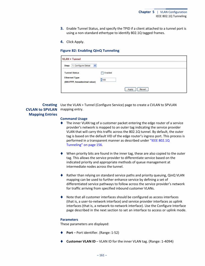
Chapter 5 | VLAN Configuration IEEE 802.1Q Tunneling
– 161 –
3. Enable Tunnel Status, and specify the TPID if a client attached to a tunnel port is using a non-standard ethertype to identify 802.1Q tagged frames.
4. Click Apply.
Figure 82: Enabling QinQ Tunneling
Creating CVLAN to SPVLAN
Mapping Entries
Use the VLAN > Tunnel (Configure Service) page to create a CVLAN to SPVLAN mapping entry.
Command Usage ◆ The inner VLAN tag of a customer packet entering the edge router of a service
provider’s network is mapped to an outer tag indicating the service provider VLAN that will carry this traffic across the 802.1Q tunnel. By default, the outer tag is based on the default VID of the edge router’s ingress port. This process is performed in a transparent manner as described under “IEEE 802.1Q Tunneling” on page 156.
◆ When priority bits are found in the inner tag, these are also copied to the outer tag. This allows the service provider to differentiate service based on the indicated priority and appropriate methods of queue management at intermediate nodes across the tunnel.
◆ Rather than relying on standard service paths and priority queuing, QinQ VLAN
mapping can be used to further enhance service by defining a set of differentiated service pathways to follow across the service provider’s network for traffic arriving from specified inbound customer VLANs.
◆ Note that all customer interfaces should be configured as access interfaces
(that is, a user-to-network interface) and service provider interfaces as uplink interfaces (that is, a network-to-network interface). Use the Configure Interface page described in the next section to set an interface to access or uplink mode.
Parameters These parameters are displayed:
◆ Port – Port identifier. (Range: 1-52)
◆ Customer VLAN ID – VLAN ID for the inner VLAN tag. (Range: 1-4094)
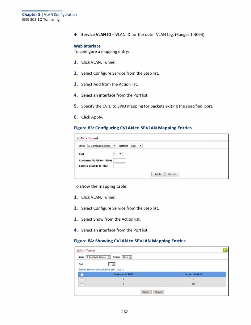
Chapter 5 | VLAN Configuration IEEE 802.1Q Tunneling
– 162 –
◆ Service VLAN ID – VLAN ID for the outer VLAN tag. (Range: 1-4094)
Web Interface To configure a mapping entry:
1. Click VLAN, Tunnel.
2. Select Configure Service from the Step list.
3. Select Add from the Action list.
4. Select an interface from the Port list.
5. Specify the CVID to SVID mapping for packets exiting the specified port.
6. Click Apply.
Figure 83: Configuring CVLAN to SPVLAN Mapping Entries
To show the mapping table:
1. Click VLAN, Tunnel.
2. Select Configure Service from the Step list.
3. Select Show from the Action list.
4. Select an interface from the Port list.
Figure 84: Showing CVLAN to SPVLAN Mapping Entries
Chapter 5 | VLAN Configuration IEEE 802.1Q Tunneling
– 163 –
The preceding example sets the SVID to 99 in the outer tag for egress packets exiting port 1 when the packet’s CVID is 2. For a more detailed example, see the “switchport dot1q-tunnel service match cvid” command in the CLI Reference Guide.
Adding an Interface to a QinQ Tunnel
Follow the guidelines under in the preceding section to set up a QinQ tunnel on the switch. Then use the VLAN > Tunnel (Configure Interface) page to set the tunnel mode for any participating interface.
Command Usage ◆ Use the Configure Global page to set the switch to QinQ mode before
configuring a tunnel access port or tunnel uplink port (see “Enabling QinQ Tunneling on the Switch” on page 160). Also set the Tag Protocol Identifier (TPID) value of the tunnel access port if the attached client is using a nonstandard 2-byte ethertype to identify 802.1Q tagged frames.
◆ Then use the Configure Interface page to set the access interface on the edge
switch to Access mode, and set the uplink interface on the switch attached to the service provider network to Uplink mode.
Parameters These parameters are displayed:
◆ Interface – Displays a list of ports or trunks.
◆ Port – Port Identifier. (Range: 1-52)
◆ Trunk – Trunk Identifier. (Range: 1-8)
◆ Mode – Sets the VLAN membership mode of the port.
■ None – The port operates in its normal VLAN mode. (This is the default.)
■ Access – Configures QinQ tunneling for a client access port to segregate and preserve customer VLAN IDs for traffic crossing the service provider network.
■ Uplink – Configures QinQ tunneling for an uplink port to another device within the service provider network.
Web Interface To add an interface to a QinQ tunnel:
1. Click VLAN, Tunnel.
2. Select Configure Interface from the Step list.
3. Set the mode for any tunnel access port to Access and the tunnel uplink port to Uplink.
4. Click Apply.
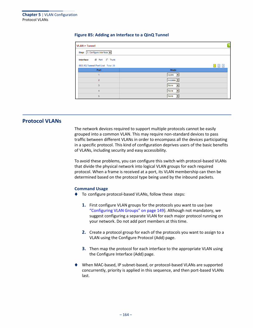
– 164 –
Chapter 5 | VLAN Configuration Protocol VLANs
Figure 85: Adding an Interface to a QinQ Tunnel
Protocol VLANs
The network devices required to support multiple protocols cannot be easily grouped into a common VLAN. This may require non-standard devices to pass traffic between different VLANs in order to encompass all the devices participating in a specific protocol. This kind of configuration deprives users of the basic benefits of VLANs, including security and easy accessibility.
To avoid these problems, you can configure this switch with protocol-based VLANs that divide the physical network into logical VLAN groups for each required protocol. When a frame is received at a port, its VLAN membership can then be determined based on the protocol type being used by the inbound packets.
Command Usage ◆ To configure protocol-based VLANs, follow these steps:
1. First configure VLAN groups for the protocols you want to use (see “Configuring VLAN Groups” on page 149). Although not mandatory, we suggest configuring a separate VLAN for each major protocol running on your network. Do not add port members at this time.
2. Create a protocol group for each of the protocols you want to assign to a VLAN using the Configure Protocol (Add) page.
3. Then map the protocol for each interface to the appropriate VLAN using the Configure Interface (Add) page.
◆ When MAC-based, IP subnet-based, or protocol-based VLANs are supported
concurrently, priority is applied in this sequence, and then port-based VLANs last.
– 165 –
Chapter 5 | VLAN Configuration Protocol VLANs
Configuring Protocol VLAN Groups
Use the VLAN > Protocol (Configure Protocol - Add) page to create protocol groups.
Parameters These parameters are displayed:
◆ Frame Type – Choose either Ethernet, RFC 1042, or LLC Other as the frame type
used by this protocol.
◆ Protocol Type – Specifies the protocol type to match. The available options are IP, ARP, RARP and IPv6. If LLC Other is chosen for the Frame Type, the only available Protocol Type is IPX Raw.
◆ Protocol Group ID – Protocol Group ID assigned to the Protocol VLAN Group.
(Range: 1-2147483647)
Note: Traffic which matches IP Protocol Ethernet Frames is mapped to the VLAN (VLAN 1) that has been configured with the switch's administrative IP. IP Protocol Ethernet traffic must not be mapped to another VLAN or you will lose administrative network connectivity to the switch. If lost in this manner, network access can be regained by removing the offending Protocol VLAN rule via the console. Alternately, the switch can be power-cycled, however all unsaved configuration changes will be lost.
Web Interface To configure a protocol group:
1. Click VLAN, Protocol.
2. Select Configure Protocol from the Step list.
3. Select Add from the Action list.
4. Select an entry from the Frame Type list.
5. Select an entry from the Protocol Type list.
6. Enter an identifier for the protocol group.
7. Click Apply.

– 166 –
Chapter 5 | VLAN Configuration Protocol VLANs
Figure 86: Configuring Protocol VLANs
To configure a protocol group:
1. Click VLAN, Protocol.
2. Select Configure Protocol from the Step list.
3. Select Show from the Action list.
Figure 87: Displaying Protocol VLANs
Mapping Protocol Groups to Interfaces
Use the VLAN > Protocol (Configure Interface - Add) page to map a protocol group to a VLAN for each interface that will participate in the group.
Command Usage ◆ When creating a protocol-based VLAN, only assign interfaces using this
configuration screen. If you assign interfaces using any of the other VLAN menus such as the VLAN Static table (page 152), these interfaces will admit traffic of any protocol type into the associated VLAN.
◆ When a frame enters a port that has been assigned to a protocol VLAN, it is
processed in the following manner:
■ If the frame is tagged, it will be processed according to the standard rules applied to tagged frames.
– 167 –
Chapter 5 | VLAN Configuration Protocol VLANs
■ If the frame is untagged and the protocol type matches, the frame is
forwarded to the appropriate VLAN.
■ If the frame is untagged but the protocol type does not match, the frame is forwarded to the default VLAN for this interface.
Parameters These parameters are displayed:
◆ Interface – Displays a list of ports or trunks.
◆ Port – Port Identifier. (Range: 1-52)
◆ Trunk – Trunk Identifier. (Range: 1-8)
◆ Protocol Group ID – Protocol Group ID assigned to the Protocol VLAN Group. (Range: 1-2147483647)
◆ VLAN ID – VLAN to which matching protocol traffic is forwarded.
(Range: 1-4094)
◆ Priority – The priority assigned to untagged ingress traffic. (Range: 0-7, where 7 is the highest priority)
Web Interface To map a protocol group to a VLAN for a port or trunk:
1. Click VLAN, Protocol.
2. Select Configure Interface from the Step list.
3. Select Add from the Action list.
4. Select a port or trunk.
5. Enter the identifier for a protocol group.
6. Enter the corresponding VLAN to which the protocol traffic will be forwarded.
7. Set the priority to assign to untagged ingress frames.
8. Click Apply.
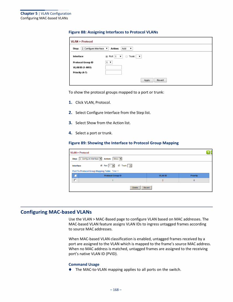
– 168 –
Chapter 5 | VLAN Configuration Configuring MAC-based VLANs
Figure 88: Assigning Interfaces to Protocol VLANs
To show the protocol groups mapped to a port or trunk:
1. Click VLAN, Protocol.
2. Select Configure Interface from the Step list.
3. Select Show from the Action list.
4. Select a port or trunk.
Figure 89: Showing the Interface to Protocol Group Mapping
Configuring MAC-based VLANs
Use the VLAN > MAC-Based page to configure VLAN based on MAC addresses. The MAC-based VLAN feature assigns VLAN IDs to ingress untagged frames according to source MAC addresses.
When MAC-based VLAN classification is enabled, untagged frames received by a port are assigned to the VLAN which is mapped to the frame’s source MAC address. When no MAC address is matched, untagged frames are assigned to the receiving port’s native VLAN ID (PVID).
Command Usage ◆ The MAC-to-VLAN mapping applies to all ports on the switch.
– 169 –
Chapter 5 | VLAN Configuration Configuring MAC-based VLANs
◆ Source MAC addresses can be mapped to only one VLAN ID.
◆ Configured MAC addresses cannot be broadcast or multicast addresses.
◆ When MAC-based, IP subnet-based, or protocol-based VLANs are supported concurrently, priority is applied in this sequence, and then port-based VLANs last.
Parameters These parameters are displayed:
◆ MAC Address – A source MAC address which is to be mapped to a specific
VLAN. The MAC address must be specified in the format xx-xx-xx-xx-xx-xx.
◆ Mask – Identifies a range of MAC addresses. (Range: 00-00-00-00-00-00 to ff-ff-ff-ff-ff-ff )
The binary equivalent mask matching the characters in the front of the first non-zero character must all be 1s (e.g., 111, i.e., it cannot be 101 or 001...). A mask for the MAC address: 00-50-6e-00-5f-b1 translated into binary:
MAC: 00000000-01010000-01101110-00000000-01011111-10110001
could be: 11111111-11xxxxxx-xxxxxxxx-xxxxxxxx-xxxxxxxx-xxxxxxxx
So the mask in hexadecimal for this example could be:
ff-fx-xx-xx-xx-xx/ff-c0-00-00-00-00/ff-e0-00-00-00-00
◆ VLAN – VLAN to which ingress traffic matching the specified source MAC address is forwarded. (Range: 1-4094)
◆ Priority – The priority assigned to untagged ingress traffic. (Range: 0-7, where
7 is the highest priority; Default: 0)
Web Interface To map a MAC address to a VLAN:
1. Click VLAN, MAC-Based.
2. Select Add from the Action list.
3. Enter an address in the MAC Address field, and a mask to indicate a range of addresses if required.
4. Enter an identifier in the VLAN field. Note that the specified VLAN need not already be configured.
5. Enter a value to assign to untagged frames in the Priority field.
6. Click Apply.
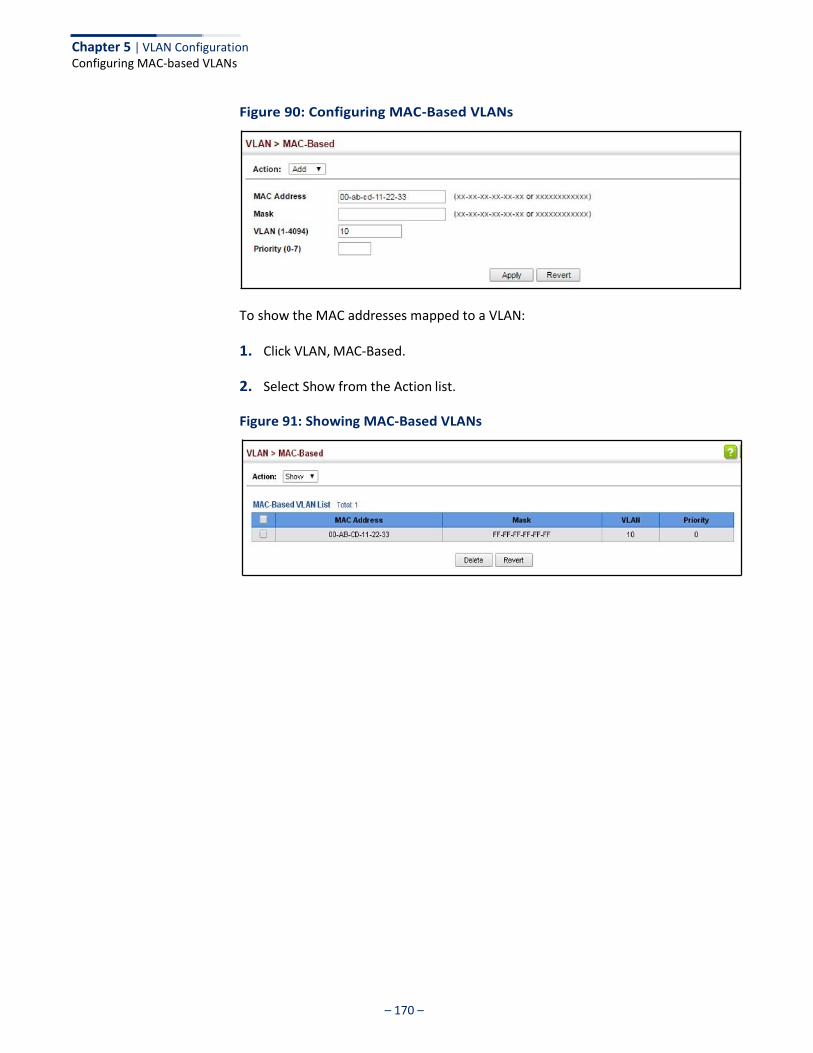
Chapter 5 | VLAN Configuration Configuring MAC-based VLANs
– 170 –
Figure 90: Configuring MAC-Based VLANs
To show the MAC addresses mapped to a VLAN:
1. Click VLAN, MAC-Based.
2. Select Show from the Action list.
Figure 91: Showing MAC-Based VLANs
– 171 –
Address Table Settings
Switches store the addresses for all known devices. This information is used to pass traffic directly between the inbound and outbound ports. All the addresses learned by monitoring traffic are stored in the dynamic address table. You can also manually configure static addresses that are bound to a specific port.
This chapter describes the following topics:
◆ Dynamic Address Cache – Shows dynamic entries in the address table.
◆ Address Aging Time – Sets timeout for dynamically learned entries.
◆ MAC Address Learning – Enables or disables address learning on an interface.
◆ Static MAC Addresses – Configures static entries in the address table.
◆ MAC Notification Traps – Issue trap when a dynamic MAC address is added or removed.
Displaying the Dynamic Address Table
Use the MAC Address > Dynamic (Show Dynamic MAC) page to display the MAC addresses learned by monitoring the source address for traffic entering the switch. When the destination address for inbound traffic is found in the database, the packets intended for that address are forwarded directly to the associated port. Otherwise, the traffic is flooded to all ports.
Parameters These parameters are displayed:
◆ Sort Key - You can sort the information displayed based on MAC address, VLAN
or interface (port or trunk).
◆ MAC Address – Physical address associated with this interface.
◆ VLAN – ID of configured VLAN (1-4094).
◆ Interface – Indicates a port or trunk.
◆ Type – Shows that the entries in this table are learned. (Values: Learned or Security, the last of which indicates Port Security)
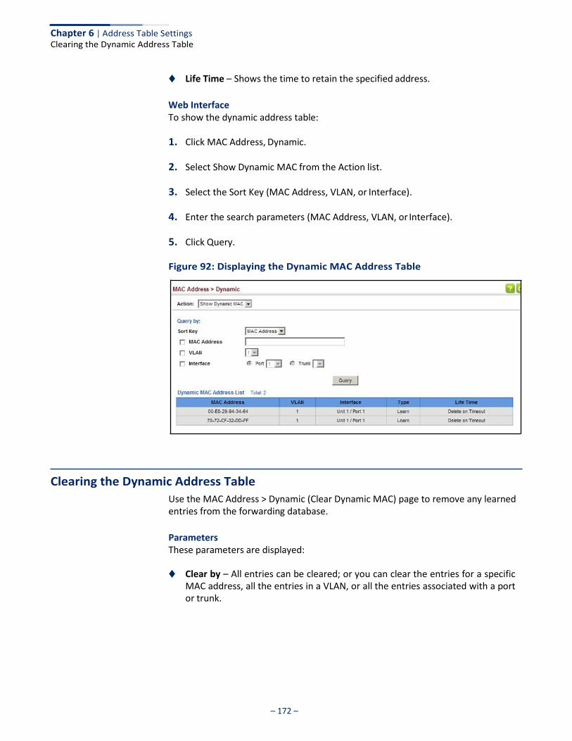
Chapter 6 | Address Table Settings
– 172 –
Clearing the Dynamic Address Table
◆ Life Time – Shows the time to retain the specified address.
Web Interface To show the dynamic address table:
1. Click MAC Address, Dynamic.
2. Select Show Dynamic MAC from the Action list.
3. Select the Sort Key (MAC Address, VLAN, or Interface).
4. Enter the search parameters (MAC Address, VLAN, or Interface).
5. Click Query.
Figure 92: Displaying the Dynamic MAC Address Table
Clearing the Dynamic Address Table
Use the MAC Address > Dynamic (Clear Dynamic MAC) page to remove any learned entries from the forwarding database.
Parameters These parameters are displayed:
◆ Clear by – All entries can be cleared; or you can clear the entries for a specific
MAC address, all the entries in a VLAN, or all the entries associated with a port or trunk.

Chapter 6 | Address Table Settings Changing the Aging Time
– 173 –
Web Interface To clear the entries in the dynamic address table:
1. Click MAC Address, Dynamic.
2. Select Clear Dynamic MAC from the Action list.
3. Select the method by which to clear the entries (i.e., All, MAC Address, VLAN, or Interface).
4. Enter information in the additional fields required for clearing entries by MAC Address, VLAN, or Interface.
5. Click Clear.
Figure 93: Clearing Entries in the Dynamic MAC Address Table
Changing the Aging Time
Use the MAC Address > Dynamic (Configure Aging) page to set the aging time for entries in the dynamic address table. The aging time is used to age out dynamically learned forwarding information.
Parameters These parameters are displayed:
◆ Aging Status – Enables/disables the function.
◆ Aging Time – The time after which a learned entry is discarded. (Range: 6-7200 seconds; Default: 300 seconds)
Web Interface To set the aging time for entries in the dynamic address table:
1. Click MAC Address, Dynamic.
2. Select Configure Aging from the Action list.
3. Modify the aging status if required.

Chapter 6 | Address Table Settings
– 174 –
Configuring MAC Address Learning
4. Specify a new aging time.
5. Click Apply.
Figure 94: Setting the Address Aging Time
Configuring MAC Address Learning
Use the MAC Address > Learning Status page to enable or disable MAC address learning on an interface.
Command Usage ◆ When MAC address learning is disabled, the switch immediately stops learning
new MAC addresses on the specified interface. Only incoming traffic with source addresses stored in the static address table (see “Setting Static Addresses” on page 176) will be accepted as authorized to access the network through that interface.
◆ Dynamic addresses stored in the address table when MAC address learning is
disabled are flushed from the system, and no dynamic addresses are subsequently learned until MAC address learning has been re-enabled. Any device not listed in the static address table that attempts to use the interface after MAC learning has been disabled will be prevented from accessing the switch.
◆ Also note that MAC address learning cannot be disabled if any of the following
conditions exist:
■ 802.1X Port Authentication has been globally enabled on the switch (see “Configuring 802.1X Global Settings” on page 302).
■ Security Status (see “Configuring Port Security” on page 298) is enabled on
the same interface.
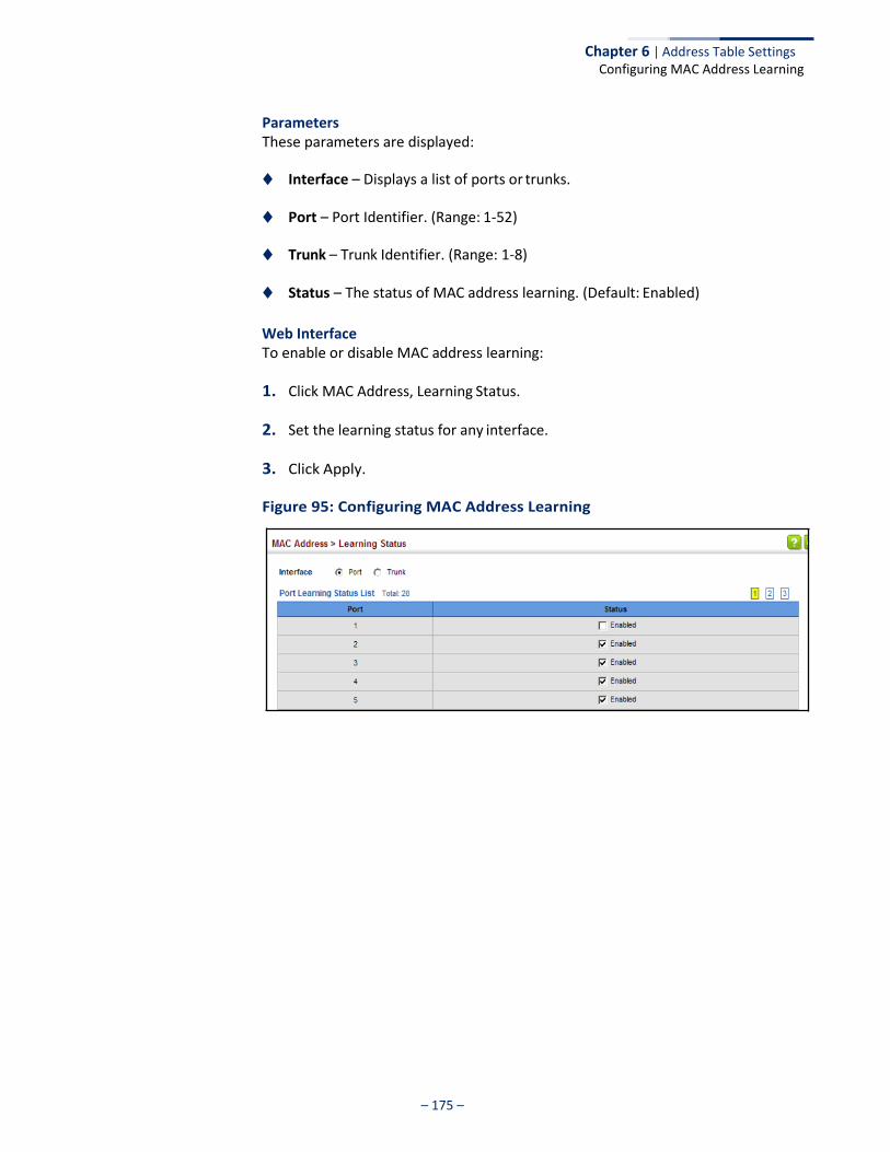
– 175 –
Chapter 6 | Address Table Settings Configuring MAC Address Learning
Parameters These parameters are displayed:
◆ Interface – Displays a list of ports or trunks.
◆ Port – Port Identifier. (Range: 1-52)
◆ Trunk – Trunk Identifier. (Range: 1-8)
◆ Status – The status of MAC address learning. (Default: Enabled)
Web Interface To enable or disable MAC address learning:
1. Click MAC Address, Learning Status.
2. Set the learning status for any interface.
3. Click Apply.
Figure 95: Configuring MAC Address Learning

– 176 –
Chapter 6 | Address Table Settings
Setting Static Addresses
Setting Static Addresses
Use the MAC Address > Static page to configure static MAC addresses. A static address can be assigned to a specific interface on this switch. Static addresses are bound to the assigned interface and will not be moved. When a static address is seen on another interface, the address will be ignored and will not be written to the address table.
Command Usage The static address for a host device can be assigned to a specific port within a specific VLAN. Use this command to add static addresses to the MAC Address Table. Static addresses have the following characteristics:
◆ Static addresses are bound to the assigned interface and will not be moved.
When a static address is seen on another interface, the address will be ignored and will not be written to the address table.
◆ Static addresses will not be removed from the address table when a given
interface link is down.
◆ A static address cannot be learned on another port until the address is removed from the table.
Parameters These parameters are displayed:
Add Static Address
◆ VLAN – ID of configured VLAN. (Range: 1-4094)
◆ Interface – Port or trunk associated with the device assigned a static address.
◆ MAC Address – Physical address of a device mapped to this interface. Enter an address in the form of xx-xx-xx-xx-xx-xx or xxxxxxxxxxxx.
◆ Static Status – Sets the time to retain the specified address.
■ Delete-on-reset - Assignment lasts until the switch is reset.
■ Permanent - Assignment is permanent. (This is the default.)
Show Static Address
The following additional fields are displayed on this web page:
Type – Displays the address configuration method. (Values: CPU, Config, or Security, the last of which indicates Port Security)
Life Time – The duration for which this entry applies. (Values: Delete On Reset, Delete On Timeout, Permanent)
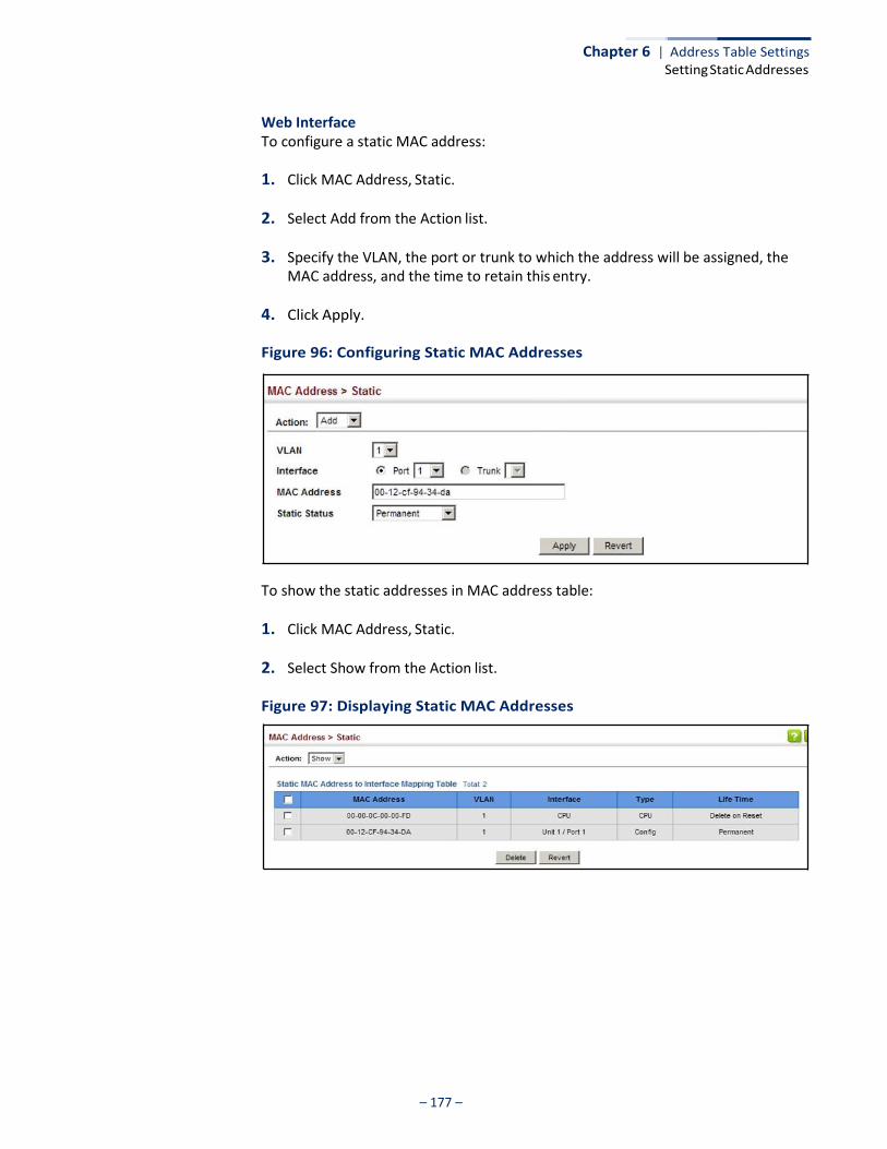
– 177 –
Chapter 6 | Address Table Settings Setting Static Addresses
Web Interface To configure a static MAC address:
1. Click MAC Address, Static.
2. Select Add from the Action list.
3. Specify the VLAN, the port or trunk to which the address will be assigned, the MAC address, and the time to retain this entry.
4. Click Apply.
Figure 96: Configuring Static MAC Addresses
To show the static addresses in MAC address table:
1. Click MAC Address, Static.
2. Select Show from the Action list.
Figure 97: Displaying Static MAC Addresses
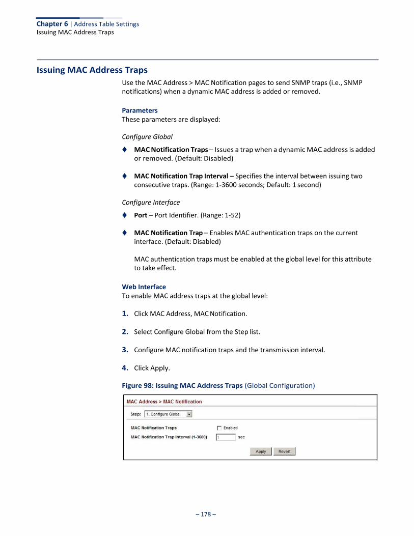
– 178 –
Chapter 6 | Address Table Settings Issuing MAC Address Traps
Issuing MAC Address Traps
Use the MAC Address > MAC Notification pages to send SNMP traps (i.e., SNMP notifications) when a dynamic MAC address is added or removed.
Parameters These parameters are displayed:
Configure Global
◆ MAC Notification Traps – Issues a trap when a dynamic MAC address is added or removed. (Default: Disabled)
◆ MAC Notification Trap Interval – Specifies the interval between issuing two
consecutive traps. (Range: 1-3600 seconds; Default: 1 second)
Configure Interface
◆ Port – Port Identifier. (Range: 1-52)
◆ MAC Notification Trap – Enables MAC authentication traps on the current interface. (Default: Disabled)
MAC authentication traps must be enabled at the global level for this attribute to take effect.
Web Interface To enable MAC address traps at the global level:
1. Click MAC Address, MAC Notification.
2. Select Configure Global from the Step list.
3. Configure MAC notification traps and the transmission interval.
4. Click Apply.
Figure 98: Issuing MAC Address Traps (Global Configuration)

– 179 –
Chapter 6 | Address Table Settings Issuing MAC Address Traps
To enable MAC address traps at the interface level:
1. Click MAC Address, MAC Notification.
2. Select Configure Interface from the Step list.
3. Enable MAC notification traps for the required ports.
4. Click Apply.
Figure 99: Issuing MAC Address Traps (Interface Configuration)

Chapter 6 | Address Table Settings Issuing MAC Address Traps
– 180 –

– 181 –
Spanning Tree Algorithm
This chapter describes the following basic topics:
◆ Loopback Detection – Configures detection and response to loopback BPDUs.
◆ Global Settings for STA – Configures global bridge settings for STP, RSTP and MSTP.
◆ Interface Settings for STA – Configures interface settings for STA, including
priority, path cost, link type, and designation as an edge port.
◆ Global Settings for MSTP – Sets the VLANs and associated priority assigned to an MST instance
◆ Interface Settings for MSTP – Configures interface settings for MSTP, including
priority and path cost.
Overview
The Spanning Tree Algorithm (STA) can be used to detect and disable network loops, and to provide backup links between switches, bridges or routers. This allows the switch to interact with other bridging devices (that is, an STA-compliant switch, bridge or router) in your network to ensure that only one route exists between any two stations on the network, and provide backup links which automatically take over when a primary link goes down.
The spanning tree algorithms supported by this switch include these versions:
◆ STP – Spanning Tree Protocol (IEEE 802.1D)
◆ RSTP – Rapid Spanning Tree Protocol (IEEE 802.1w)
◆ MSTP – Multiple Spanning Tree Protocol (IEEE 802.1s)
STP – STP uses a distributed algorithm to select a bridging device (STP-compliant switch, bridge or router) that serves as the root of the spanning tree network. It selects a root port on each bridging device (except for the root device) which incurs the lowest path cost when forwarding a packet from that device to the root device. Then it selects a designated bridging device from each LAN which incurs the lowest path cost when forwarding a packet from that LAN to the root device. All ports connected to designated bridging devices are assigned as designated ports. After determining the lowest cost spanning tree, it enables all root ports and designated ports, and disables all other ports. Network packets are therefore only forwarded between root ports and designated ports, eliminating any possible network loops.
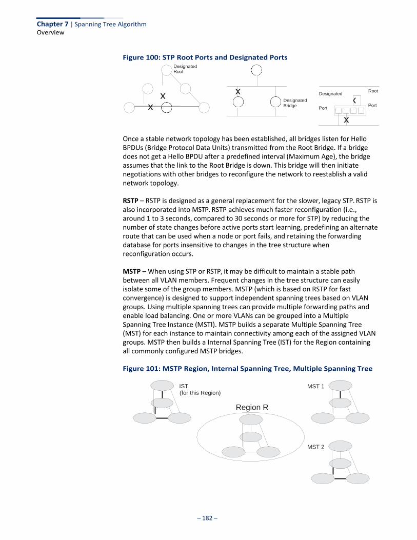
Chapter 7 | Spanning Tree Algorithm Overview
– 182 –
Figure 100: STP Root Ports and Designated Ports
x Designated
Bridge
Designated Root
Once a stable network topology has been established, all bridges listen for Hello BPDUs (Bridge Protocol Data Units) transmitted from the Root Bridge. If a bridge does not get a Hello BPDU after a predefined interval (Maximum Age), the bridge assumes that the link to the Root Bridge is down. This bridge will then initiate negotiations with other bridges to reconfigure the network to reestablish a valid network topology.
RSTP – RSTP is designed as a general replacement for the slower, legacy STP. RSTP is also incorporated into MSTP. RSTP achieves much faster reconfiguration (i.e., around 1 to 3 seconds, compared to 30 seconds or more for STP) by reducing the number of state changes before active ports start learning, predefining an alternate route that can be used when a node or port fails, and retaining the forwarding database for ports insensitive to changes in the tree structure when reconfiguration occurs.
MSTP – When using STP or RSTP, it may be difficult to maintain a stable path between all VLAN members. Frequent changes in the tree structure can easily isolate some of the group members. MSTP (which is based on RSTP for fast convergence) is designed to support independent spanning trees based on VLAN groups. Using multiple spanning trees can provide multiple forwarding paths and enable load balancing. One or more VLANs can be grouped into a Multiple Spanning Tree Instance (MSTI). MSTP builds a separate Multiple Spanning Tree (MST) for each instance to maintain connectivity among each of the assigned VLAN groups. MSTP then builds a Internal Spanning Tree (IST) for the Region containing all commonly configured MSTP bridges.
Figure 101: MSTP Region, Internal Spanning Tree, Multiple Spanning Tree
IST (for this Region)
Region R
MST 2
MST 1

Chapter 7 | Spanning Tree Algorithm Configuring Loopback Detection
– 183 –
An MST Region consists of a group of interconnected bridges that have the same MST Configuration Identifiers (including the Region Name, Revision Level and Configuration Digest – see “Configuring Multiple Spanning Trees” on page 199). An MST Region may contain multiple MSTP Instances. An Internal Spanning Tree (IST) is used to connect all the MSTP switches within an MST region. A Common Spanning Tree (CST) interconnects all adjacent MST Regions, and acts as a virtual bridge node for communications with STP or RSTP nodes in the global network.
Figure 102: Spanning Tree – Common Internal, Common, Internal
Region 1 Region 1
MSTP connects all bridges and LAN segments with a single Common and Internal Spanning Tree (CIST). The CIST is formed as a result of the running spanning tree algorithm between switches that support the STP, RSTP, MSTP protocols.
Once you specify the VLANs to include in a Multiple Spanning Tree Instance (MSTI), the protocol will automatically build an MSTI tree to maintain connectivity among each of the VLANs. MSTP maintains contact with the global network because each instance is treated as an RSTP node in the Common Spanning Tree (CST).
Configuring Loopback Detection
Use the Spanning Tree > Loopback Detection page to configure loopback detection on an interface. When loopback detection is enabled and a port or trunk receives it’s own BPDU, the detection agent drops the loopback BPDU, sends an SNMP trap, and places the interface in discarding mode. This loopback state can be released manually or automatically. If the interface is configured for automatic loopback release, then the port will only be returned to the forwarding state if one of the following conditions is satisfied:
◆ The interface receives any other BPDU except for it’s own, or;
◆ The interfaces’s link status changes to link down and then link up again, or;
◆ The interface ceases to receive it’s own BPDUs in a forward delay interval.
Note: If loopback detection is not enabled and an interface receives it's own BPDU, then the interface will drop the loopback BPDU according to IEEE Standard 802.1w- 2001 9.3.4 (Note 1).
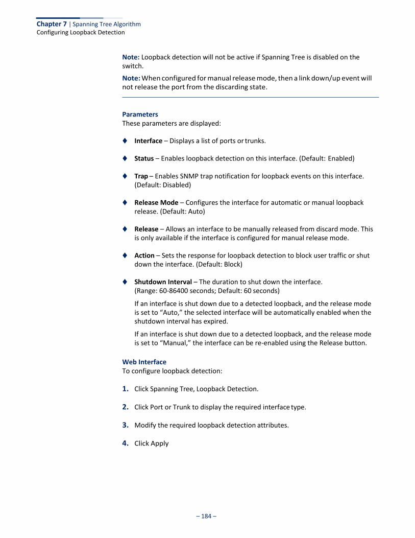
– 184 –
Chapter 7 | Spanning Tree Algorithm Configuring Loopback Detection
Note: Loopback detection will not be active if Spanning Tree is disabled on the switch.
Note: When configured for manual release mode, then a link down/up event will not release the port from the discarding state.
Parameters These parameters are displayed:
◆ Interface – Displays a list of ports or trunks.
◆ Status – Enables loopback detection on this interface. (Default: Enabled)
◆ Trap – Enables SNMP trap notification for loopback events on this interface. (Default: Disabled)
◆ Release Mode – Configures the interface for automatic or manual loopback
release. (Default: Auto)
◆ Release – Allows an interface to be manually released from discard mode. This is only available if the interface is configured for manual release mode.
◆ Action – Sets the response for loopback detection to block user traffic or shut
down the interface. (Default: Block)
◆ Shutdown Interval – The duration to shut down the interface. (Range: 60-86400 seconds; Default: 60 seconds)
If an interface is shut down due to a detected loopback, and the release mode is set to “Auto,” the selected interface will be automatically enabled when the shutdown interval has expired.
If an interface is shut down due to a detected loopback, and the release mode is set to “Manual,” the interface can be re-enabled using the Release button.
Web Interface To configure loopback detection:
1. Click Spanning Tree, Loopback Detection.
2. Click Port or Trunk to display the required interface type.
3. Modify the required loopback detection attributes.
4. Click Apply
– 185 –
Chapter 7 | Spanning Tree Algorithm Configuring Global Settings for STA
Figure 103: Configuring Port Loopback Detection
Configuring Global Settings for STA
Use the Spanning Tree > STA (Configure Global - Configure) page to configure global settings for the spanning tree that apply to the entire switch.
Command Usage ◆ Spanning Tree Protocol3
This option uses RSTP set to STP forced compatibility mode. It uses RSTP for the internal state machine, but sends only 802.1D BPDUs. This creates one spanning tree instance for the entire network. If multiple VLANs are implemented on a network, the path between specific VLAN members may be inadvertently disabled to prevent network loops, thus isolating group members. When operating multiple VLANs, we recommend selecting the MSTP option.
◆ Rapid Spanning Tree Protocol3
RSTP supports connections to either STP or RSTP nodes by monitoring the incoming protocol messages and dynamically adjusting the type of protocol messages the RSTP node transmits, as described below:
■ STP Mode – If the switch receives an 802.1D BPDU (i.e., STP BPDU) after a
port’s migration delay timer expires, the switch assumes it is connected to an 802.1D bridge and starts using only 802.1D BPDUs.
■ RSTP Mode – If RSTP is using 802.1D BPDUs on a port and receives an RSTP
BPDU after the migration delay expires, RSTP restarts the migration delay timer and begins using RSTP BPDUs on that port.
◆ Multiple Spanning Tree Protocol
MSTP generates a unique spanning tree for each instance. This provides multiple pathways across the network, thereby balancing the traffic load,
3. STP and RSTP BPDUs are transmitted as untagged frames, and will cross any VLAN
boundaries.
– 186 –
Chapter 7 | Spanning Tree Algorithm Configuring Global Settings for STA
preventing wide-scale disruption when a bridge node in a single instance fails, and allowing for faster convergence of a new topology for the failed instance.
■ To allow multiple spanning trees to operate over the network, you must
configure a related set of bridges with the same MSTP configuration, allowing them to participate in a specific set of spanning tree instances.
■ A spanning tree instance can exist only on bridges that have compatible
VLAN instance assignments.
■ Be careful when switching between spanning tree modes. Changing modes stops all spanning-tree instances for the previous mode and restarts the system in the new mode, temporarily disrupting user traffic.
Parameters These parameters are displayed:
Basic Configuration of Global Settings
◆ Spanning Tree Status – Enables/disables STA on this switch. (Default: Enabled)
◆ Spanning Tree Type – Specifies the type of spanning tree used on this switch:
■ STP: Spanning Tree Protocol (IEEE 802.1D); i.e., when this option is selected, the switch will use RSTP set to STP forced compatibility mode).
■ RSTP: Rapid Spanning Tree (IEEE 802.1w); RSTP is the default.
■ MSTP: Multiple Spanning Tree (IEEE 802.1s)
◆ Priority – Bridge priority is used in selecting the root device, root port, and designated port. The device with the highest priority becomes the STA root device. However, if all devices have the same priority, the device with the lowest MAC address will then become the root device. (Note that lower numeric values indicate higher priority.)
■ Default: 32768
■ Range: 0-61440, in steps of 4096
■ Options: 0, 4096, 8192, 12288, 16384, 20480, 24576, 28672, 32768, 36864, 40960, 45056, 49152, 53248, 57344, 61440
◆ BPDU Flooding – Configures the system to flood BPDUs to all other ports on
the switch or just to all other ports in the same VLAN when spanning tree is disabled globally on the switch or disabled on a specific port.
■ To VLAN: Floods BPDUs to all other ports within the receiving port’s native VLAN (i.e., as determined by port’s PVID). This is the default.
■ To All: Floods BPDUs to all other ports on the switch.
The setting has no effect if BPDU flooding is disabled on a port (see "Configuring Interface Settings for STA").
– 187 –
Chapter 7 | Spanning Tree Algorithm Configuring Global Settings for STA
◆ Cisco Prestandard Status – Configures spanning tree operation to be compatible with Cisco prestandard versions. (Default: Disabled)
Cisco prestandard versions prior to Cisco IOS Release 12.2(25)SEC do not fully follow the IEEE standard, causing some state machine procedures to function incorrectly. This command forces the spanning tree protocol to function in a manner compatible with Cisco prestandard versions.
Advanced Configuration Settings
The following attributes are based on RSTP, but also apply to STP since the switch uses a backwards-compatible subset of RSTP to implement STP, and also apply to MSTP which is based on RSTP according to the standard:
◆ Path Cost Method – The path cost is used to determine the best path between
devices. The path cost method is used to determine the range of values that can be assigned to each interface.
■ Long: Specifies 32-bit based values that range from 1-200,000,000. (This is the default.)
■ Short: Specifies 16-bit based values that range from 1-65535.
◆ Transmission Limit – The maximum transmission rate for BPDUs is specified by setting the minimum interval between the transmission of consecutive protocol messages. (Range: 1-10; Default: 3)
When the Switch Becomes Root
◆ Hello Time – Interval (in seconds) at which the root device transmits a configuration message.
■ Default: 2
■ Minimum: 1
■ Maximum: The lower of 10 or [(Max. Message Age / 2) -1]
◆ Maximum Age – The maximum time (in seconds) a device can wait without receiving a configuration message before attempting to reconverge. All device ports (except for designated ports) should receive configuration messages at regular intervals. Any port that ages out STA information (provided in the last configuration message) becomes the designated port for the attached LAN. If it is a root port, a new root port is selected from among the device ports attached to the network. (References to “ports” in this section mean “interfaces,” which includes both ports and trunks.)
■ Default: 20
■ Minimum: The higher of 6 or [2 x (Hello Time + 1)]
■ Maximum: The lower of 40 or [2 x (Forward Delay - 1)]
◆ Forward Delay – The maximum time (in seconds) this device will wait before changing states (i.e., discarding to learning to forwarding). This delay is required because every device must receive information about topology

– 188 –
Chapter 7 | Spanning Tree Algorithm Configuring Global Settings for STA
changes before it starts to forward frames. In addition, each port needs time to listen for conflicting information that would make it return to a discarding state; otherwise, temporary data loops might result.
■ Default: 15
■ Minimum: The higher of 4 or [(Max. Message Age / 2) + 1]
■ Maximum: 30
RSTP does not depend on the forward delay timer in most cases. It is able to confirm that a port can transition to the forwarding state without having to rely on any timer configuration. To achieve fast convergence, RSTP relies on the use of edge ports, and automatic detection of point-to-point link types, both of which allow a port to directly transition to the forwarding state.
Configuration Settings for MSTP
◆ Max Instance Numbers – The maximum number of MSTP instances to which this switch can be assigned.
◆ Configuration Digest – An MD5 signature key that contains the VLAN ID to
MST ID mapping table. In other words, this key is a mapping of all VLANs to the CIST.
◆ Region Revision4 – The revision for this MSTI. (Range: 0-65535; Default: 0)
◆ Region Name4 – The name for this MSTI. (Maximum length: 32 characters; Default: switch’s MAC address)
◆ Max Hop Count – The maximum number of hops allowed in the MST region
before a BPDU is discarded. (Range: 1-40; Default: 20)
NOTE: Region Revision and Region Name and are both required to uniquely identify an MST region.
Web Interface To configure global STA settings:
1. Click Spanning Tree, STA.
2. Select Configure Global from the Step list.
3. Select Configure from the Action list.
4. Modify any of the required attributes. Note that the parameters displayed for the spanning tree types (STP, RSTP, MSTP) varies as described in the preceding section.
4. The MST name and revision number are both required to uniquely identify an MST region.
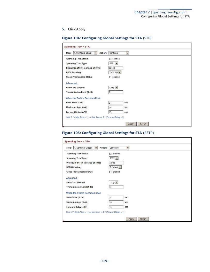
– 189 –
Chapter 7 | Spanning Tree Algorithm Configuring Global Settings for STA
5. Click Apply
Figure 104: Configuring Global Settings for STA (STP)
Figure 105: Configuring Global Settings for STA (RSTP)
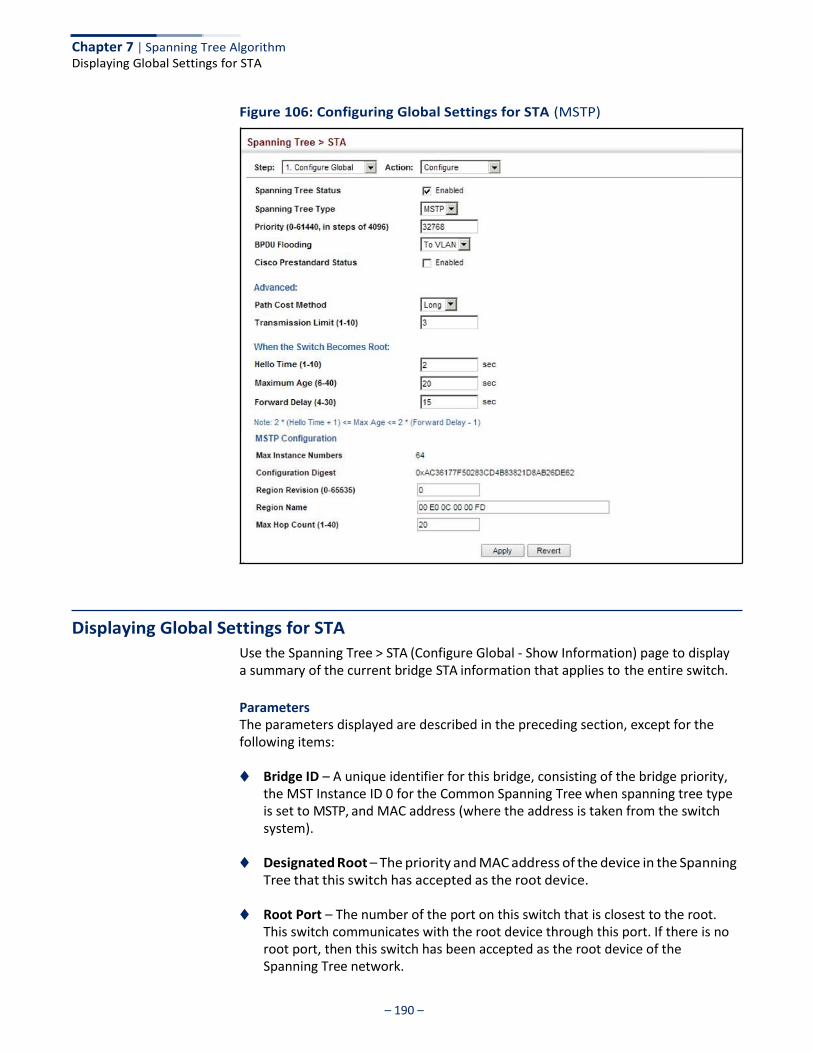
Chapter 7 | Spanning Tree Algorithm Displaying Global Settings for STA
– 190 –
Figure 106: Configuring Global Settings for STA (MSTP)
Displaying Global Settings for STA
Use the Spanning Tree > STA (Configure Global - Show Information) page to display a summary of the current bridge STA information that applies to the entire switch.
Parameters The parameters displayed are described in the preceding section, except for the following items:
◆ Bridge ID – A unique identifier for this bridge, consisting of the bridge priority,
the MST Instance ID 0 for the Common Spanning Tree when spanning tree type is set to MSTP, and MAC address (where the address is taken from the switch system).
◆ Designated Root – The priority and MAC address of the device in the Spanning
Tree that this switch has accepted as the root device.
◆ Root Port – The number of the port on this switch that is closest to the root. This switch communicates with the root device through this port. If there is no root port, then this switch has been accepted as the root device of the Spanning Tree network.
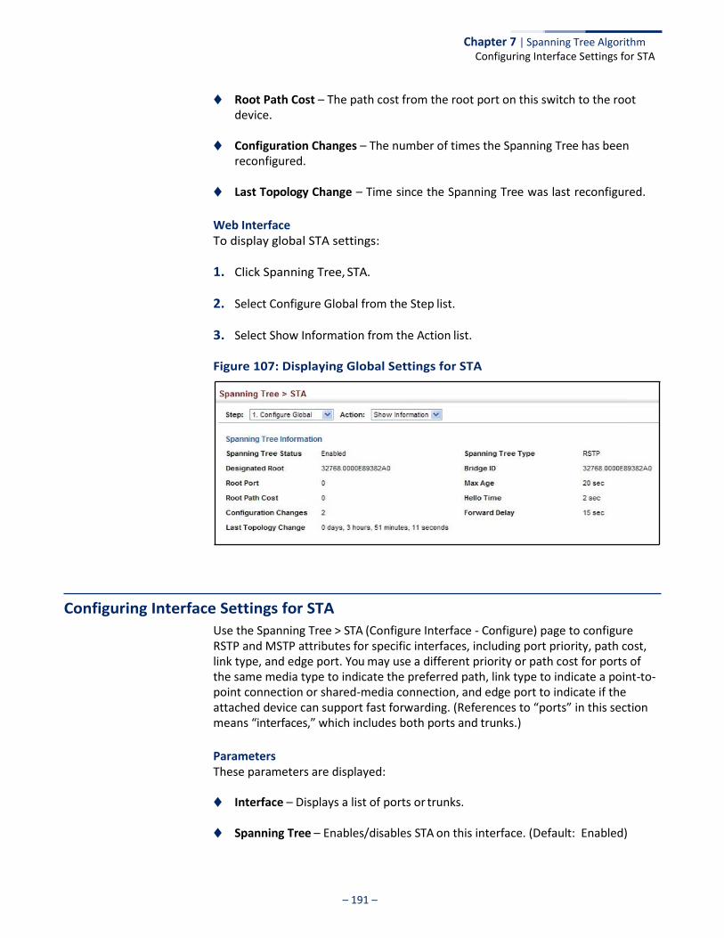
Chapter 7 | Spanning Tree Algorithm Configuring Interface Settings for STA
– 191 –
◆ Root Path Cost – The path cost from the root port on this switch to the root device.
◆ Configuration Changes – The number of times the Spanning Tree has been
reconfigured.
◆ Last Topology Change – Time since the Spanning Tree was last reconfigured.
Web Interface To display global STA settings:
1. Click Spanning Tree, STA.
2. Select Configure Global from the Step list.
3. Select Show Information from the Action list.
Figure 107: Displaying Global Settings for STA
Configuring Interface Settings for STA
Use the Spanning Tree > STA (Configure Interface - Configure) page to configure RSTP and MSTP attributes for specific interfaces, including port priority, path cost, link type, and edge port. You may use a different priority or path cost for ports of the same media type to indicate the preferred path, link type to indicate a point-to- point connection or shared-media connection, and edge port to indicate if the attached device can support fast forwarding. (References to “ports” in this section means “interfaces,” which includes both ports and trunks.)
Parameters These parameters are displayed:
◆ Interface – Displays a list of ports or trunks.
◆ Spanning Tree – Enables/disables STA on this interface. (Default: Enabled)
Chapter 7 | Spanning Tree Algorithm Configuring Interface Settings for STA
– 192 –
◆ BPDU Flooding - Enables/disables the flooding of BPDUs to other ports when global spanning tree is disabled (page 185) or when spanning tree is disabled on a specific port. When flooding is enabled, BPDUs are flooded to all other ports on the switch or to all other ports within the receiving port’s native VLAN as specified by the Spanning Tree BPDU Flooding attribute (page 185). (Default: Enabled)
◆ Priority – Defines the priority used for this port in the Spanning Tree Protocol. If the path cost for all ports on a switch are the same, the port with the highest priority (i.e., lowest value) will be configured as an active link in the Spanning Tree. This makes a port with higher priority less likely to be blocked if the Spanning Tree Protocol is detecting network loops. Where more than one port is assigned the highest priority, the port with lowest numeric identifier will be enabled.
■ Default: 128 ■ Range: 0-240, in steps of 16
◆ Admin Path Cost – This parameter is used by the STA to determine the best
path between devices. Therefore, lower values should be assigned to ports attached to faster media, and higher values assigned to ports with slower media. Note that path cost takes precedence over port priority. (Range: 0 for auto-configuration, 1-65535 for the short path cost method5, 1-200,000,000 for the long path cost method)
By default, the system automatically detects the speed and duplex mode used on each port, and configures the path cost according to the values shown below. Path cost “0” is used to indicate auto-configuration mode. When the short path cost method is selected and the default path cost recommended by the IEEE 8021w standard exceeds 65,535, the default is set to 65,535.
Table 11: Recommended STA Path Cost Range
Port Type IEEE 802.1D-1998 IEEE 802.1w-2001
Ethernet 50-600 200,000-20,000,000
Fast Ethernet 10-60 20,000-2,000,000
Gigabit Ethernet 3-10 2,000-200,000
10G Ethernet 1-5 200-20,000
Table 12: Default STA Path Costs
Port Type Short Path Cost (IEEE 802.1D-1998)
Long Path Cost (IEEE 802.1D-2004)
Ethernet 65,535 1,000,000
Fast Ethernet 65,535 100,000
5. Refer to “Configuring Global Settings for STA” on page 185 for information on setting the
path cost method.The range displayed on the STA interface configuration page shows the
maximum value for path cost. However, note that the switch still enforces the rules for path
cost based on the specified path cost method (long or short)
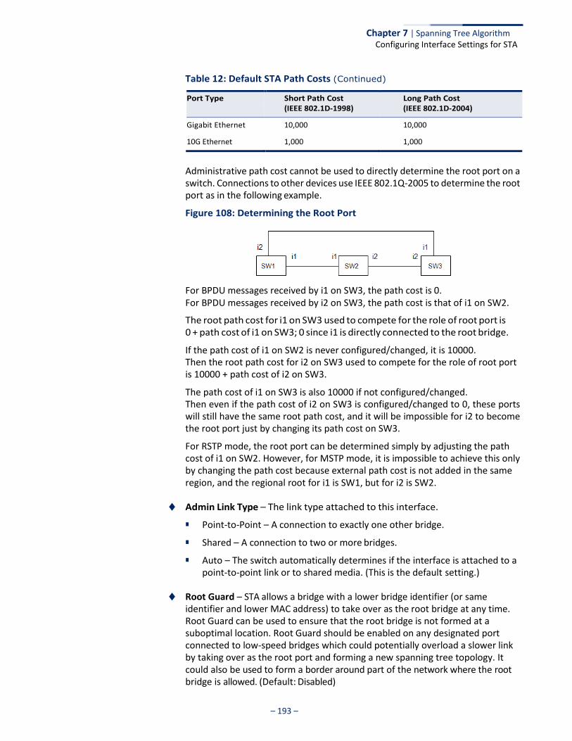
Chapter 7 | Spanning Tree Algorithm Configuring Interface Settings for STA
– 193 –
Table 12: Default STA Path Costs (Continued)
Port Type Short Path Cost Long Path Cost
(IEEE 802.1D-1998) (IEEE 802.1D-2004)
Gigabit Ethernet 10,000 10,000
10G Ethernet 1,000 1,000
Administrative path cost cannot be used to directly determine the root port on a switch. Connections to other devices use IEEE 802.1Q-2005 to determine the root port as in the following example.
Figure 108: Determining the Root Port
For BPDU messages received by i1 on SW3, the path cost is 0. For BPDU messages received by i2 on SW3, the path cost is that of i1 on SW2.
The root path cost for i1 on SW3 used to compete for the role of root port is 0 + path cost of i1 on SW3; 0 since i1 is directly connected to the root bridge.
If the path cost of i1 on SW2 is never configured/changed, it is 10000. Then the root path cost for i2 on SW3 used to compete for the role of root port is 10000 + path cost of i2 on SW3.
The path cost of i1 on SW3 is also 10000 if not configured/changed. Then even if the path cost of i2 on SW3 is configured/changed to 0, these ports will still have the same root path cost, and it will be impossible for i2 to become the root port just by changing its path cost on SW3.
For RSTP mode, the root port can be determined simply by adjusting the path cost of i1 on SW2. However, for MSTP mode, it is impossible to achieve this only by changing the path cost because external path cost is not added in the same region, and the regional root for i1 is SW1, but for i2 is SW2.
◆ Admin Link Type – The link type attached to this interface.
■ Point-to-Point – A connection to exactly one other bridge.
■ Shared – A connection to two or more bridges.
■ Auto – The switch automatically determines if the interface is attached to a point-to-point link or to shared media. (This is the default setting.)
◆ Root Guard – STA allows a bridge with a lower bridge identifier (or same
identifier and lower MAC address) to take over as the root bridge at any time. Root Guard can be used to ensure that the root bridge is not formed at a suboptimal location. Root Guard should be enabled on any designated port connected to low-speed bridges which could potentially overload a slower link by taking over as the root port and forming a new spanning tree topology. It could also be used to form a border around part of the network where the root bridge is allowed. (Default: Disabled)
Chapter 7 | Spanning Tree Algorithm Configuring Interface Settings for STA
– 194 –
◆ Admin Edge Port – Since end nodes cannot cause forwarding loops, they can pass directly through to the spanning tree forwarding state. Specifying Edge Ports provides quicker convergence for devices such as workstations or servers, retains the current forwarding database to reduce the amount of frame flooding required to rebuild address tables during reconfiguration events, does not cause the spanning tree to initiate reconfiguration when the interface changes state, and also overcomes other STA-related timeout problems. However, remember that Edge Port should only be enabled for ports connected to an end-node device. (Default: Auto)
■ Enabled – Manually configures a port as an Edge Port.
■ Disabled – Disables the Edge Port setting.
■ Auto – The port will be automatically configured as an edge port if the
edge delay time expires without receiving any RSTP or MSTP BPDUs. Note that edge delay time (802.1D-2004 17.20.4) equals the protocol migration time if a port's link type is point-to-point (which is 3 seconds as defined in IEEE 802.3D-2004 17.20.4); otherwise it equals the spanning tree’s maximum age for configuration messages (see maximum age under “Configuring Global Settings for STA” on page 185).
An interface cannot function as an edge port under the following conditions:
■ If spanning tree mode is set to STP (page 185), edge-port mode cannot automatically transition to operational edge-port state using the automatic setting.
■ If loopback detection is enabled (page 183) and a loopback BPDU is detected, the interface cannot function as an edge port until the loopback state is released.
■ If an interface is in forwarding state and its role changes, the interface cannot continue to function as an edge port even if the edge delay time has expired.
■ If the port does not receive any BPDUs after the edge delay timer expires, its role changes to designated port and it immediately enters forwarding state (see “Displaying Interface Settings for STA” on page 196).
When edge port is set as auto, the operational state is determined automatically by the Bridge Detection State Machine described in 802.1D-2004, where the edge port state may change dynamically based on environment changes (e.g., receiving a BPDU or not within the required interval).
◆ BPDU Guard – This feature protects edge ports from receiving BPDUs. It
prevents loops by shutting down an edge port when a BPDU is received instead of putting it into the spanning tree discarding state. In a valid configuration, configured edge ports should not receive BPDUs. If an edge port receives a BPDU an invalid configuration exists, such as a connection to an unauthorized device. The BPDU guard feature provides a secure response to invalid
Chapter 7 | Spanning Tree Algorithm Configuring Interface Settings for STA
– 195 –
configurations because an administrator must manually enable the port. (Default: Disabled)
BPDU guard can only be configured on an interface if the edge port attribute is not disabled (that is, if edge port is set to enabled or auto).
◆ BPDU Guard Auto Recovery – Automatically re-enables an interface after the
specified interval. (Range: 30-86400 seconds; Default: Disabled)
◆ BPDU Guard Auto Recovery Interval – The time to wait before re-enabling an interface. (Range: 30-86400 seconds; Default: 300 seconds)
◆ BPDU Filter – BPDU filtering allows you to avoid transmitting BPDUs on configured edge ports that are connected to end nodes. By default, STA sends BPDUs to all ports regardless of whether administrative edge is enabled on a port. BPDU filtering is configured on a per-port basis. (Default: Disabled)
BPDU filter can only be configured on an interface if the edge port attribute is not disabled (that is, if edge port is set to enabled or auto).
◆ Migration – If at any time the switch detects STP BPDUs, including
Configuration or Topology Change Notification BPDUs, it will automatically set the selected interface to forced STP-compatible mode. However, you can also use the Protocol Migration button to manually re-check the appropriate BPDU format (RSTP or STP-compatible) to send on the selected interfaces. (Default: Disabled)
◆ TC Propagate Stop – Stops the propagation of topology change notifications
(TCN). (Default: Disabled)
Web Interface To configure interface settings for STA:
1. Click Spanning Tree, STA.
2. Select Configure Interface from the Step list.
3. Select Configure from the Action list.
4. Modify any of the required attributes.
5. Click Apply.
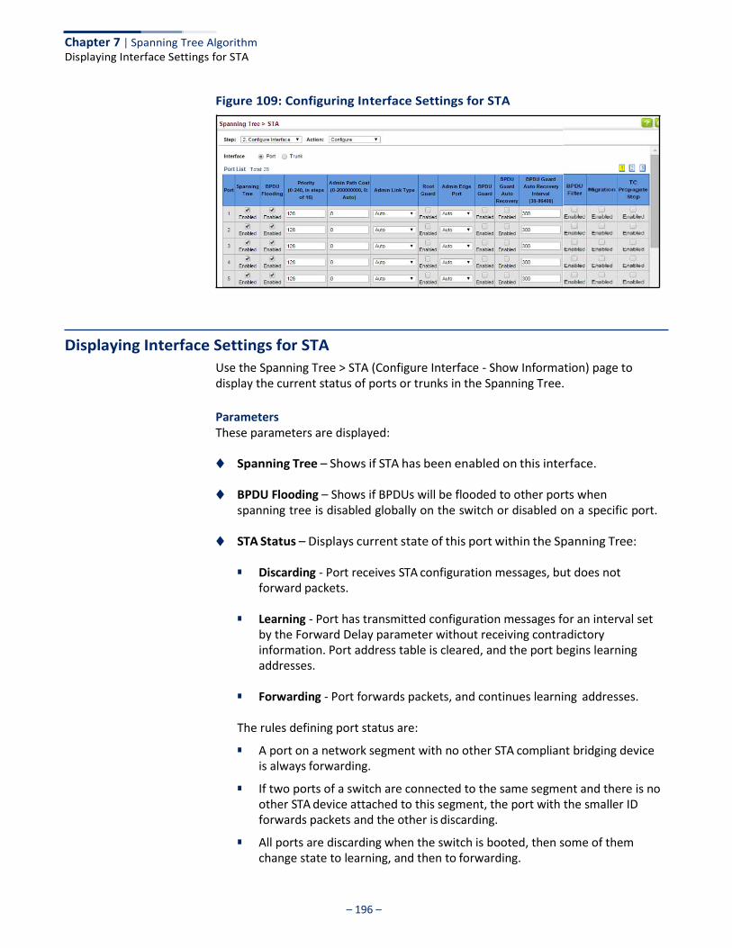
– 196 –
Chapter 7 | Spanning Tree Algorithm Displaying Interface Settings for STA
Figure 109: Configuring Interface Settings for STA
Displaying Interface Settings for STA
Use the Spanning Tree > STA (Configure Interface - Show Information) page to display the current status of ports or trunks in the Spanning Tree.
Parameters These parameters are displayed:
◆ Spanning Tree – Shows if STA has been enabled on this interface.
◆ BPDU Flooding – Shows if BPDUs will be flooded to other ports when spanning tree is disabled globally on the switch or disabled on a specific port.
◆ STA Status – Displays current state of this port within the Spanning Tree:
■ Discarding - Port receives STA configuration messages, but does not forward packets.
■ Learning - Port has transmitted configuration messages for an interval set
by the Forward Delay parameter without receiving contradictory information. Port address table is cleared, and the port begins learning addresses.
■ Forwarding - Port forwards packets, and continues learning addresses.
The rules defining port status are:
■ A port on a network segment with no other STA compliant bridging device is always forwarding.
■ If two ports of a switch are connected to the same segment and there is no other STA device attached to this segment, the port with the smaller ID forwards packets and the other is discarding.
■ All ports are discarding when the switch is booted, then some of them change state to learning, and then to forwarding.
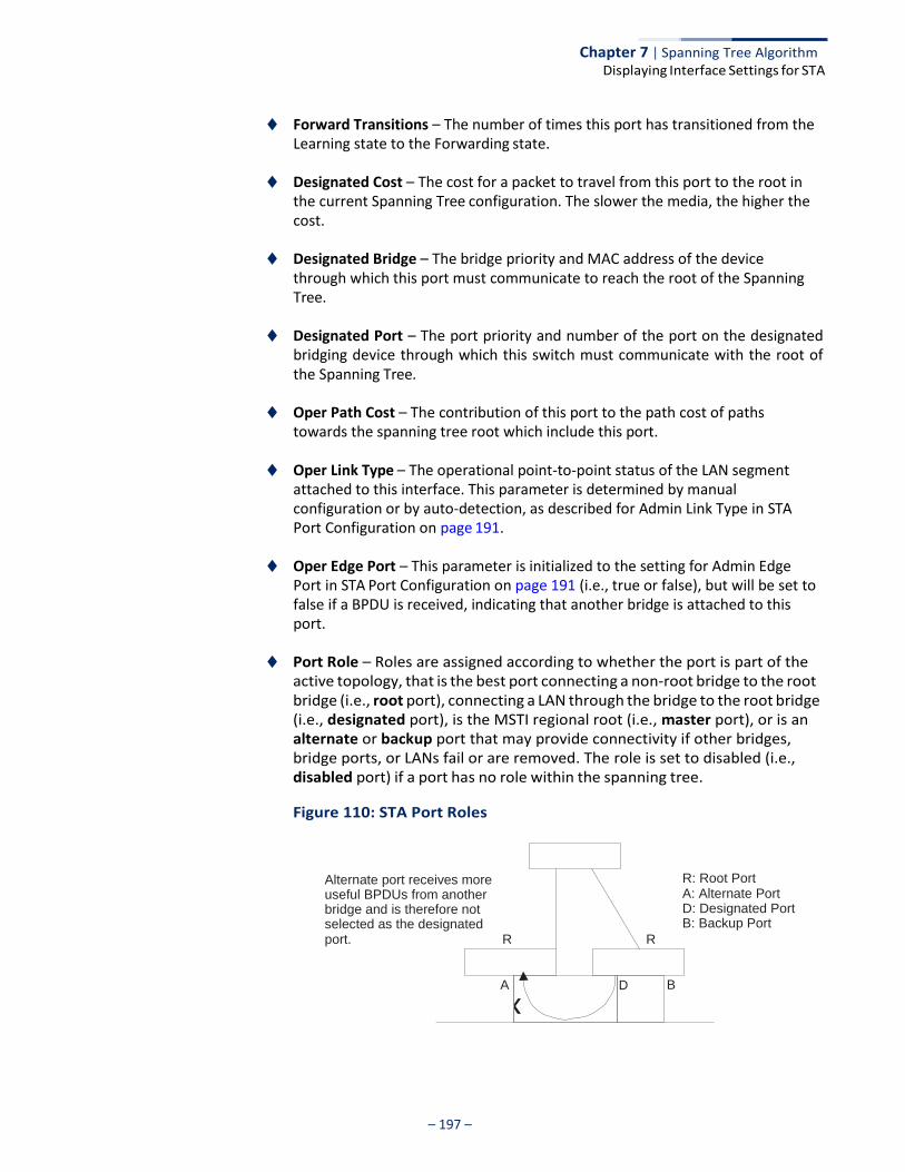
– 197 –
Chapter 7 | Spanning Tree Algorithm Displaying Interface Settings for STA
D
x
◆ Forward Transitions – The number of times this port has transitioned from the Learning state to the Forwarding state.
◆ Designated Cost – The cost for a packet to travel from this port to the root in
the current Spanning Tree configuration. The slower the media, the higher the cost.
◆ Designated Bridge – The bridge priority and MAC address of the device
through which this port must communicate to reach the root of the Spanning Tree.
◆ Designated Port – The port priority and number of the port on the designated
bridging device through which this switch must communicate with the root of the Spanning Tree.
◆ Oper Path Cost – The contribution of this port to the path cost of paths
towards the spanning tree root which include this port.
◆ Oper Link Type – The operational point-to-point status of the LAN segment attached to this interface. This parameter is determined by manual configuration or by auto-detection, as described for Admin Link Type in STA Port Configuration on page 191.
◆ Oper Edge Port – This parameter is initialized to the setting for Admin Edge
Port in STA Port Configuration on page 191 (i.e., true or false), but will be set to false if a BPDU is received, indicating that another bridge is attached to this port.
◆ Port Role – Roles are assigned according to whether the port is part of the
active topology, that is the best port connecting a non-root bridge to the root bridge (i.e., root port), connecting a LAN through the bridge to the root bridge (i.e., designated port), is the MSTI regional root (i.e., master port), or is an alternate or backup port that may provide connectivity if other bridges, bridge ports, or LANs fail or are removed. The role is set to disabled (i.e., disabled port) if a port has no role within the spanning tree.
Figure 110: STA Port Roles
Alternate port receives more useful BPDUs from another bridge and is therefore not selected as the designated port. R R
A
R: Root Port A: Alternate Port D: Designated Port B: Backup Port
B

– 198 –
Chapter 7 | Spanning Tree Algorithm Displaying Interface Settings for STA
D
Backup port receives more useful BPDUs from the same bridge and is therefore not selected as the designated port.
R R
A B
The criteria used for determining the port role is based on root bridge ID, root path cost, designated bridge, designated port, port priority, and port number, in that order and as applicable to the role under question.
Web Interface To display interface settings for STA:
1. Click Spanning Tree, STA.
2. Select Configure Interface from the Step list.
3. Select Show Information from the Action list.
Figure 111: Displaying Interface Settings for STA
x
– 199 –
Chapter 7 | Spanning Tree Algorithm Configuring Multiple Spanning Trees
Configuring Multiple Spanning Trees
Use the Spanning Tree > MSTP (Configure Global) page to create an MSTP instance, or to add VLAN groups to an MSTP instance.
Command Usage MSTP generates a unique spanning tree for each instance. This provides multiple pathways across the network, thereby balancing the traffic load, preventing wide- scale disruption when a bridge node in a single instance fails, and allowing for faster convergence of a new topology for the failed instance.
By default all VLANs are assigned to the Internal Spanning Tree (MST Instance 0) that connects all bridges and LANs within the MST region. This switch supports up to 33 instances. You should try to group VLANs which cover the same general area of your network. However, remember that you must configure all bridges within the same MSTI Region (page 185) with the same set of instances, and the same instance (on each bridge) with the same set of VLANs. Also, note that RSTP treats each MSTI region as a single node, connecting all regions to the Common Spanning Tree.
To use multiple spanning trees:
1. Set the spanning tree type to MSTP (page 185).
2. Enter the spanning tree priority for the selected MST instance on the Spanning Tree > MSTP (Configure Global - Add) page.
3. Add the VLANs that will share this MSTI on the Spanning Tree > MSTP (Configure Global - Add Member) page.
Note: All VLANs are automatically added to the IST (Instance 0).
To ensure that the MSTI maintains connectivity across the network, you must configure a related set of bridges with the same MSTI settings.
Parameters These parameters are displayed:
◆ MST ID – Instance identifier to configure. (Range: 0-4094)
◆ VLAN ID – VLAN to assign to this MST instance. (Range: 1-4094)
◆ Priority – The priority of a spanning tree instance. (Range: 0-61440 in steps of 4096; Options: 0, 4096, 8192, 12288, 16384, 20480, 24576, 28672, 32768, 36864, 40960, 45056, 49152, 53248, 57344, 61440; Default: 32768)
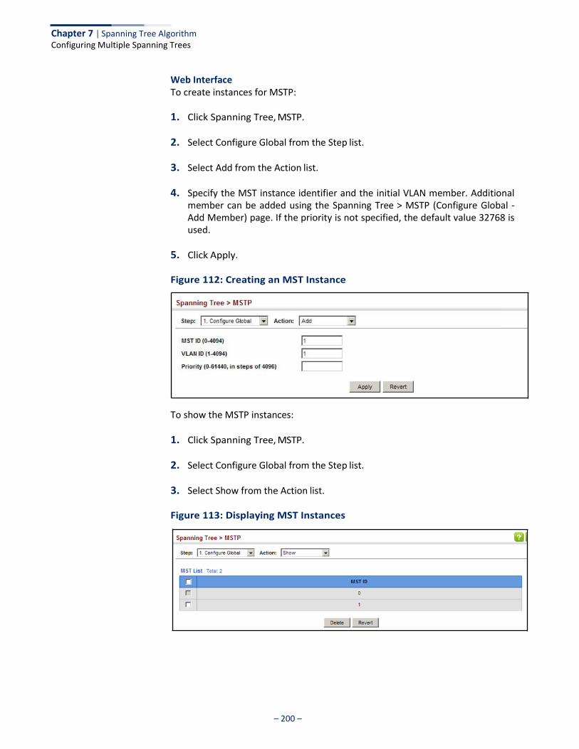
Chapter 7 | Spanning Tree Algorithm Configuring Multiple Spanning Trees
– 200 –
Web Interface To create instances for MSTP:
1. Click Spanning Tree, MSTP.
2. Select Configure Global from the Step list.
3. Select Add from the Action list.
4. Specify the MST instance identifier and the initial VLAN member. Additional member can be added using the Spanning Tree > MSTP (Configure Global - Add Member) page. If the priority is not specified, the default value 32768 is used.
5. Click Apply.
Figure 112: Creating an MST Instance
To show the MSTP instances:
1. Click Spanning Tree, MSTP.
2. Select Configure Global from the Step list.
3. Select Show from the Action list.
Figure 113: Displaying MST Instances

Chapter 7 | Spanning Tree Algorithm Configuring Multiple Spanning Trees
– 201 –
To modify the priority for an MST instance:
1. Click Spanning Tree, MSTP.
2. Select Configure Global from the Step list.
3. Select Modify from the Action list.
4. Modify the priority for an MSTP Instance.
5. Click Apply.
Figure 114: Modifying the Priority for an MST Instance
To display global settings for MSTP:
1. Click Spanning Tree, MSTP.
2. Select Configure Global from the Step list.
3. Select Show Information from the Action list.
4. Select an MST ID. The attributes displayed on this page are described under “Displaying Global Settings for STA” on page 190.
Figure 115: Displaying Global Settings for an MST Instance
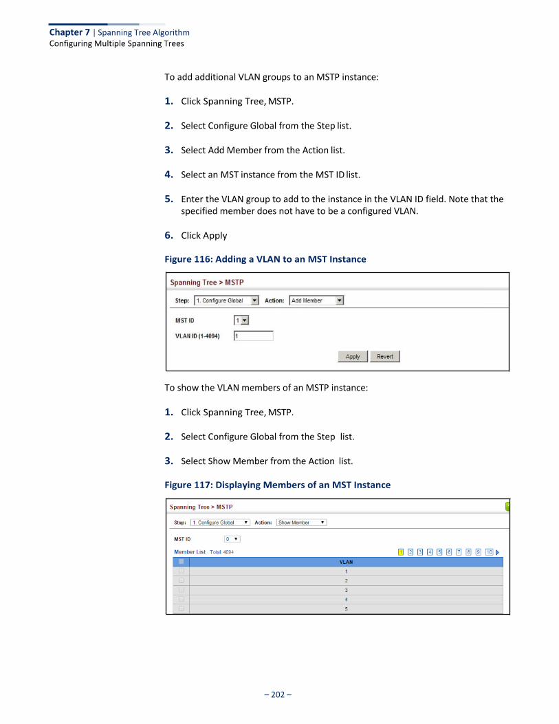
Chapter 7 | Spanning Tree Algorithm Configuring Multiple Spanning Trees
– 202 –
To add additional VLAN groups to an MSTP instance:
1. Click Spanning Tree, MSTP.
2. Select Configure Global from the Step list.
3. Select Add Member from the Action list.
4. Select an MST instance from the MST ID list.
5. Enter the VLAN group to add to the instance in the VLAN ID field. Note that the specified member does not have to be a configured VLAN.
6. Click Apply
Figure 116: Adding a VLAN to an MST Instance
To show the VLAN members of an MSTP instance:
1. Click Spanning Tree, MSTP.
2. Select Configure Global from the Step list.
3. Select Show Member from the Action list.
Figure 117: Displaying Members of an MST Instance

– 203 –
Chapter 7 | Spanning Tree Algorithm Configuring Interface Settings for MSTP
Configuring Interface Settings for MSTP
Use the Spanning Tree > MSTP (Configure Interface - Configure) page to configure the STA interface settings for an MST instance.
Parameters These parameters are displayed:
◆ MST ID – Instance identifier to configure. (Default: 0)
◆ Interface – Displays a list of ports or trunks.
◆ STA Status – Displays the current state of this interface within the Spanning Tree. (See “Displaying Interface Settings for STA” on page 196 for additional information.)
■ Discarding – Port receives STA configuration messages, but does not
forward packets.
■ Learning – Port has transmitted configuration messages for an interval set by the Forward Delay parameter without receiving contradictory information. Port address table is cleared, and the port begins learning addresses.
■ Forwarding – Port forwards packets, and continues learning addresses.
◆ Priority – Defines the priority used for this port in the Spanning Tree Protocol. If the path cost for all ports on a switch are the same, the port with the highest priority (i.e., lowest value) will be configured as an active link in the Spanning Tree. This makes a port with higher priority less likely to be blocked if the Spanning Tree Protocol is detecting network loops. Where more than one port is assigned the highest priority, the port with lowest numeric identifier will be enabled. (Default: 128; Range: 0-240, in steps of 16)
◆ Admin MST Path Cost – This parameter is used by the MSTP to determine the
best path between devices. Therefore, lower values should be assigned to ports attached to faster media, and higher values assigned to ports with slower media. (Path cost takes precedence over port priority.) Note that when the Path Cost Method is set to short (page 185), the maximum path cost is 65,535.
By default, the system automatically detects the speed and duplex mode used on each port, and configures the path cost according to the values shown below. Path cost “0” is used to indicate auto-configuration mode. When the short path cost method is selected and the default path cost recommended by the IEEE 8021w standard exceeds 65,535, the default is set to 65,535.
The recommended range is listed in Table 11 on page 192.
The default path costs are listed in Table 12 on page 192.
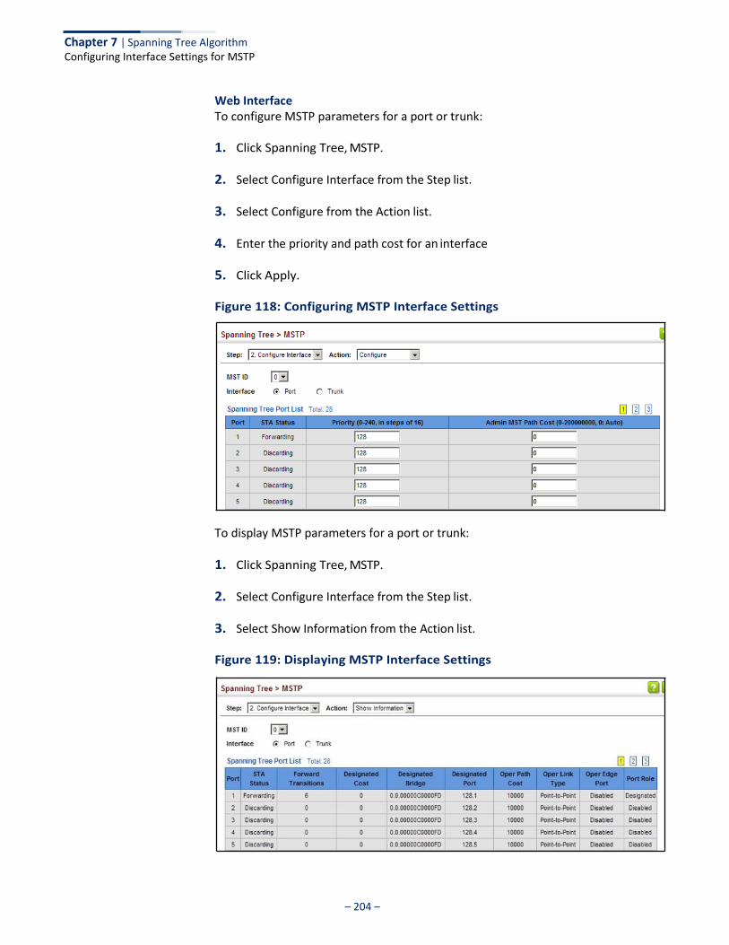
– 204 –
Chapter 7 | Spanning Tree Algorithm Configuring Interface Settings for MSTP
Web Interface To configure MSTP parameters for a port or trunk:
1. Click Spanning Tree, MSTP.
2. Select Configure Interface from the Step list.
3. Select Configure from the Action list.
4. Enter the priority and path cost for an interface
5. Click Apply.
Figure 118: Configuring MSTP Interface Settings
To display MSTP parameters for a port or trunk:
1. Click Spanning Tree, MSTP.
2. Select Configure Interface from the Step list.
3. Select Show Information from the Action list.
Figure 119: Displaying MSTP Interface Settings
– 205 –
Congestion Control
The switch can set the maximum upload or download data transfer rate for any port. It can also control traffic storms by setting a maximum threshold for broadcast traffic or multicast traffic. It can also set bounding thresholds for broadcast and multicast storms which can be used to automatically trigger rate limits or to shut down a port.
Congestion Control includes following options:
◆ Rate Limiting – Sets the input and output rate limits for a port.
◆ Storm Control – Sets the traffic storm threshold for each interface.
Rate Limiting
Use the Traffic > Rate Limit page to apply rate limiting to ingress or egress ports. This function allows the network manager to control the maximum rate for traffic received or transmitted on an interface. Rate limiting is configured on interfaces at the edge of a network to limit traffic into or out of the network. Packets that exceed the acceptable amount of traffic are dropped.
Rate limiting can be applied to individual ports or trunks. When an interface is configured with this feature, the traffic rate will be monitored by the hardware to verify conformity. Non-conforming traffic is dropped, conforming traffic is forwarded without any changes.
Parameters These parameters are displayed:
◆ Interface – Displays the switch’s ports or trunks.
◆ Type – Indicates the port type. (1000BASE-T, 1000BASE SFP)
◆ Status – Enables or disables the rate limit. (Default: Disabled)
◆ Rate – Sets the rate limit level. (Range: 64 - 1,000,000 kbits per second for Gigabit Ethernet ports
◆ Resolution – The resolution at which the rate can be configured is 16 kbits/sec
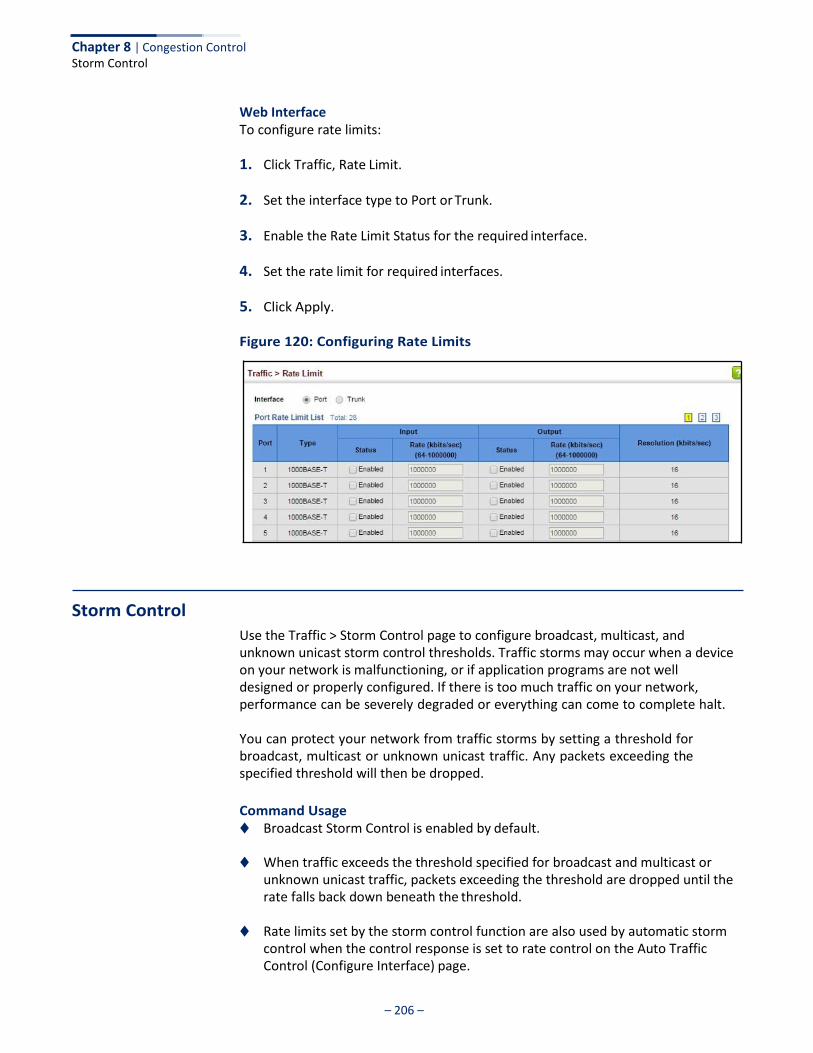
– 206 –
Chapter 8 | Congestion Control Storm Control
Web Interface To configure rate limits:
1. Click Traffic, Rate Limit.
2. Set the interface type to Port or Trunk.
3. Enable the Rate Limit Status for the required interface.
4. Set the rate limit for required interfaces.
5. Click Apply.
Figure 120: Configuring Rate Limits
Storm Control
Use the Traffic > Storm Control page to configure broadcast, multicast, and unknown unicast storm control thresholds. Traffic storms may occur when a device on your network is malfunctioning, or if application programs are not well designed or properly configured. If there is too much traffic on your network, performance can be severely degraded or everything can come to complete halt.
You can protect your network from traffic storms by setting a threshold for broadcast, multicast or unknown unicast traffic. Any packets exceeding the specified threshold will then be dropped.
Command Usage ◆ Broadcast Storm Control is enabled by default.
◆ When traffic exceeds the threshold specified for broadcast and multicast or
unknown unicast traffic, packets exceeding the threshold are dropped until the rate falls back down beneath the threshold.
◆ Rate limits set by the storm control function are also used by automatic storm
control when the control response is set to rate control on the Auto Traffic Control (Configure Interface) page.
– 207 –
Chapter 8 | Congestion Control Storm Control
◆ Using both rate limiting and storm control on the same interface may lead to unexpected results. It is therefore not advisable to use both of these features on the same interface.
Parameters These parameters are displayed:
◆ Interface – Displays a list of ports or trunks.
◆ Type – Indicates the port type. (1000BASE-T or 1000BASE SFP)
◆ Unknown Unicast – Specifies storm control for unknown unicast traffic.
◆ Multicast – Specifies storm control for multicast traffic.
◆ Broadcast – Specifies storm control for broadcast traffic.
◆ Status – Enables or disables storm control. (Default: Enabled for broadcast storm control, disabled for multicast and unknown unicast storm control)
◆ Rate – Threshold level in packets per second. (Range: 1-14881000 pps; Default: Disabled for unknown unicast and multicast traffic, 500 pps for broadcast traffic)
◆ Resolution – Indicates the resolution at which the rate can be configured.
Web Interface To configure broadcast storm control:
1. Click Traffic, Storm Control.
2. Set the interface type to Port or Trunk.
3. Set the Status field to enable or disable storm control.
4. Set the required threshold beyond which the switch will start dropping packets.
5. Click Apply.
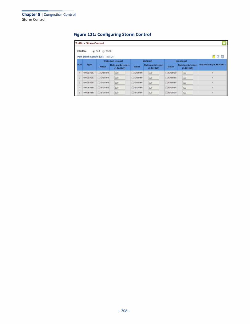
Chapter 8 | Congestion Control Storm Control
– 208 –
Figure 121: Configuring Storm Control
– 209 –
Class of Service
Class of Service (CoS) allows you to specify which data packets have greater precedence when traffic is buffered in the switch due to congestion. This switch supports CoS with eight priority queues for each port. Data packets in a port’s high- priority queue will be transmitted before those in the lower-priority queues. You can set the default priority for each interface, and configure the mapping of frame priority tags to the switch’s priority queues.
This chapter describes the following basic topics:
◆ Layer 2 Queue Settings – Configures each queue, including the default priority, queue mode, queue weight, and mapping of packets to queues based on CoS tags.
◆ Layer 3/4 Priority Settings – Selects the method by which inbound packets are
processed (DSCP or CoS), and sets the per-hop behavior and drop precedence for internal processing.
Layer 2 Queue Settings
This section describes how to configure the default priority for untagged frames, set the queue mode, set the weights assigned to each queue, and map class of service tags to queues.
Setting the Default Priority for Interfaces
Use the Traffic > Priority > Default Priority page to specify the default port priority for each interface on the switch. All untagged packets entering the switch are tagged with the specified default port priority, and then sorted into the appropriate priority queue at the output port.
Command Usage ◆ This switch provides eight priority queues for each port. It uses Weighted
Round Robin to prevent head-of-queue blockage, but can be configured to process each queue in strict order, or use a combination of strict and weighted queueing.
◆ The default priority applies for an untagged frame received on a port set to accept all frame types (i.e, receives both untagged and tagged frames). This priority does not apply to IEEE 802.1Q VLAN tagged frames. If the incoming frame is an IEEE 802.1Q VLAN tagged frame, the IEEE 802.1p User Priority bits will be used.
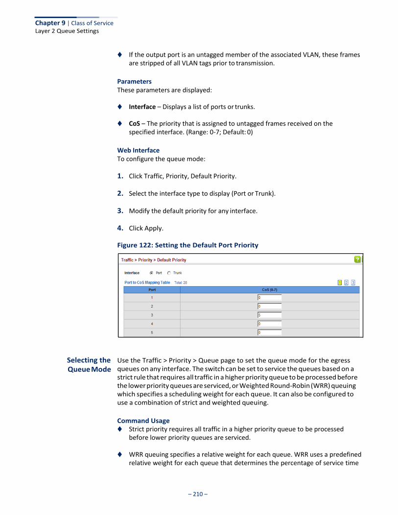
Chapter 9 | Class of Service Layer 2 Queue Settings
– 210 –
◆ If the output port is an untagged member of the associated VLAN, these frames are stripped of all VLAN tags prior to transmission.
Parameters These parameters are displayed:
◆ Interface – Displays a list of ports or trunks.
◆ CoS – The priority that is assigned to untagged frames received on the specified interface. (Range: 0-7; Default: 0)
Web Interface To configure the queue mode:
1. Click Traffic, Priority, Default Priority.
2. Select the interface type to display (Port or Trunk).
3. Modify the default priority for any interface.
4. Click Apply.
Figure 122: Setting the Default Port Priority
Selecting the Queue Mode
Use the Traffic > Priority > Queue page to set the queue mode for the egress queues on any interface. The switch can be set to service the queues based on a strict rule that requires all traffic in a higher priority queue to be processed before the lower priority queues are serviced, or Weighted Round-Robin (WRR) queuing which specifies a scheduling weight for each queue. It can also be configured to use a combination of strict and weighted queuing.
Command Usage ◆ Strict priority requires all traffic in a higher priority queue to be processed
before lower priority queues are serviced.
◆ WRR queuing specifies a relative weight for each queue. WRR uses a predefined relative weight for each queue that determines the percentage of service time
Chapter 9 | Class of Service Layer 2 Queue Settings
– 211 –
the switch services each queue before moving on to the next queue. This prevents the head-of-line blocking that can occur with strict priority queuing.
◆ If Strict and WRR mode is selected, a combination of strict service is used for the
high priority queues and weighted service for the remaining queues. The queues assigned to use strict priority should be specified using the Strict Mode field parameter.
◆ A weight can be assigned to each of the weighted queues (and thereby to the
corresponding traffic priorities). This weight sets the frequency at which each queue is polled for service, and subsequently affects the response time for software applications assigned a specific priority value.
Service time is shared at the egress ports by defining scheduling weights for WRR, or one of the queuing modes that use a combination of strict and weighted queuing.
◆ The specified queue mode applies to all interfaces.
Parameters These parameters are displayed:
◆ Queue Mode
■ Strict – Services the egress queues in sequential order, transmitting all traffic in the higher priority queues before servicing lower priority queues. This ensures that the highest priority packets are always serviced first, ahead of all other traffic.
■ WRR – Weighted Round-Robin shares bandwidth at the egress ports by
using scheduling weights, and servicing each queue in a round-robin fashion. (This is the default setting.)
■ Strict and WRR – Uses strict priority on the high-priority queues and WRR
on the remaining queues.
◆ Queue ID – The ID of the priority queue. (Range: 0-7)
◆ Strict Mode – If “Strict and WRR” mode is selected, then a combination of strict service is used for the high priority queues and weighted service for the remaining queues. Use this parameter to specify the queues assigned to use strict priority when using the strict-weighted queuing mode. (Default: Disabled)
◆ Weight – Sets a weight for each queue which is used by the WRR scheduler.
(Range: 1-127; Default: Weights 1, 2, 4, 6, 8, 10, 12 and 14 are assigned to queues 0 - 7 respectively)
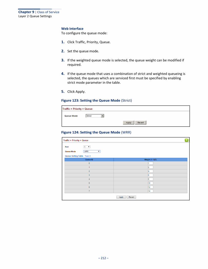
Chapter 9 | Class of Service Layer 2 Queue Settings
– 212 –
Web Interface To configure the queue mode:
1. Click Traffic, Priority, Queue.
2. Set the queue mode.
3. If the weighted queue mode is selected, the queue weight can be modified if required.
4. If the queue mode that uses a combination of strict and weighted queueing is selected, the queues which are serviced first must be specified by enabling strict mode parameter in the table.
5. Click Apply.
Figure 123: Setting the Queue Mode (Strict)
Figure 124: Setting the Queue Mode (WRR)
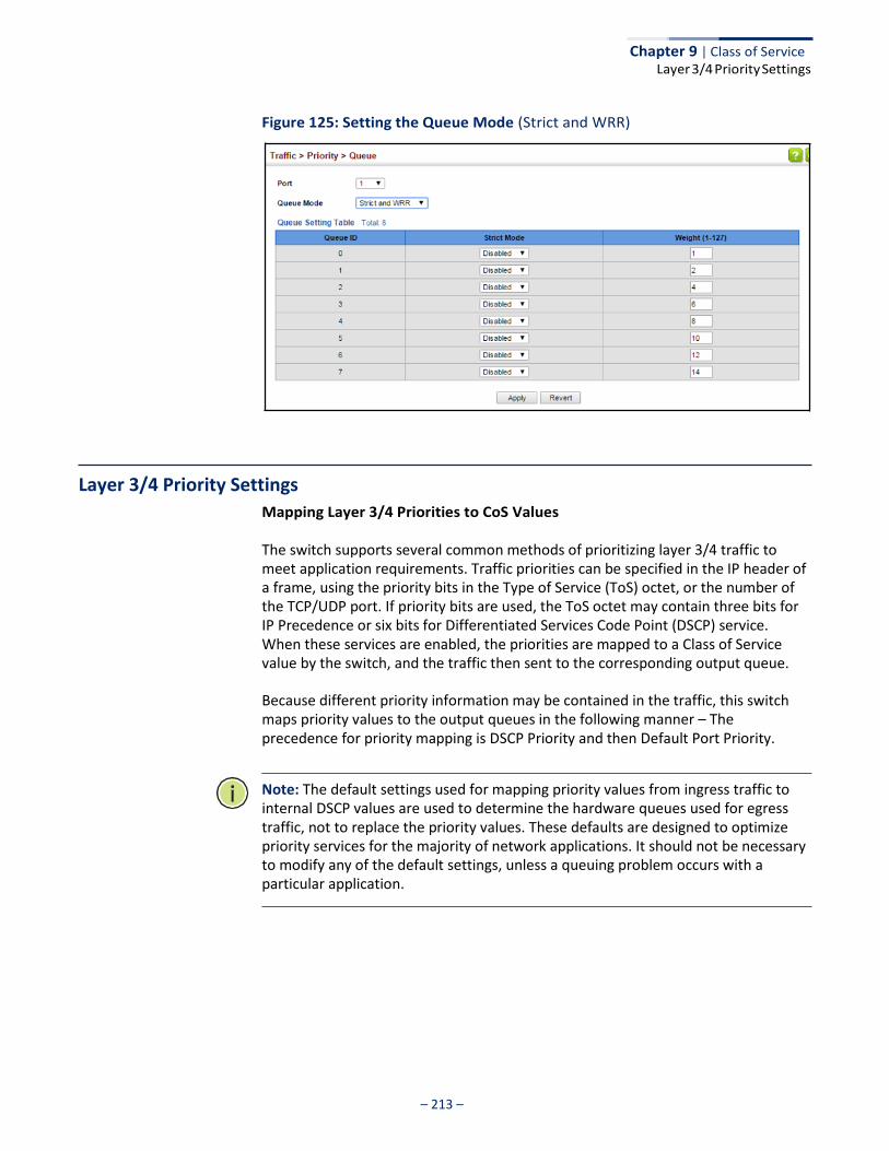
– 213 –
Chapter 9 | Class of Service Layer 3/4 Priority Settings
Figure 125: Setting the Queue Mode (Strict and WRR)
Layer 3/4 Priority Settings
Mapping Layer 3/4 Priorities to CoS Values
The switch supports several common methods of prioritizing layer 3/4 traffic to meet application requirements. Traffic priorities can be specified in the IP header of a frame, using the priority bits in the Type of Service (ToS) octet, or the number of the TCP/UDP port. If priority bits are used, the ToS octet may contain three bits for IP Precedence or six bits for Differentiated Services Code Point (DSCP) service. When these services are enabled, the priorities are mapped to a Class of Service value by the switch, and the traffic then sent to the corresponding output queue.
Because different priority information may be contained in the traffic, this switch maps priority values to the output queues in the following manner – The precedence for priority mapping is DSCP Priority and then Default Port Priority.
Note: The default settings used for mapping priority values from ingress traffic to internal DSCP values are used to determine the hardware queues used for egress traffic, not to replace the priority values. These defaults are designed to optimize priority services for the majority of network applications. It should not be necessary to modify any of the default settings, unless a queuing problem occurs with a particular application.
– 214 –
Chapter 9 | Class of Service Layer 3/4 Priority Settings
Setting Priority Processing to DSCP or CoS
The switch allows a choice between using DSCP or CoS priority processing methods. Use the Priority > Trust Mode page to select the required processing method.
Command Usage ◆ If the QoS mapping mode is set to DSCP, and the ingress packet type is IPv4,
then priority processing will be based on the DSCP value in the ingress packet.
◆ If the QoS mapping mode is set to DSCP, and a non-IP packet is received, the packet’s CoS and CFI (Canonical Format Indicator) values are used for priority processing if the packet is tagged. For an untagged packet, the default port priority (see page 209) is used for priority processing.
◆ If the QoS mapping mode is set to CoS, and the ingress packet type is IPv4, then
priority processing will be based on the CoS and CFI values in the ingress packet.
For an untagged packet, the default port priority (see page 209) is used for priority processing.
Parameters These parameters are displayed:
◆ Port – Port identifier. (Range: 1-52)
◆ Trust Mode
■ CoS – Maps layer 3/4 priorities using Class of Service values. (This is the default setting.)
■ DSCP – Maps layer 3/4 priorities using Differentiated Services Code Point
values.
Web Interface To configure the trust mode:
1. Click Traffic, Priority, Trust Mode.
2. Set the trust mode for any port.
3. Click Apply.
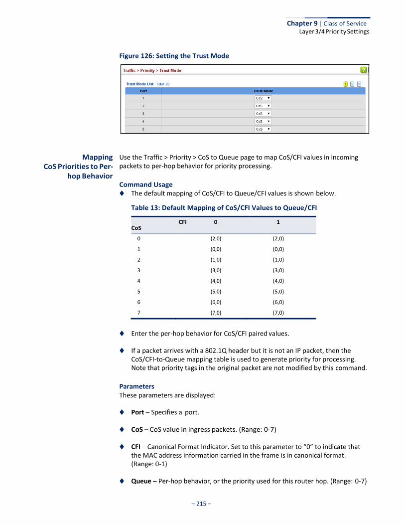
– 215 –
Chapter 9 | Class of Service Layer 3/4 Priority Settings
Figure 126: Setting the Trust Mode
Mapping
CoS Priorities to Per- hop Behavior
Use the Traffic > Priority > CoS to Queue page to map CoS/CFI values in incoming packets to per-hop behavior for priority processing.
Command Usage ◆ The default mapping of CoS/CFI to Queue/CFI values is shown below.
Table 13: Default Mapping of CoS/CFI Values to Queue/CFI
CoS CFI 0 1
0 (2,0) (2,0)
1 (0,0) (0,0)
2 (1,0) (1,0)
3 (3,0) (3,0)
4 (4,0) (4,0)
5 (5,0) (5,0)
6 (6,0) (6,0)
7 (7,0) (7,0)
◆ Enter the per-hop behavior for CoS/CFI paired values.
◆ If a packet arrives with a 802.1Q header but it is not an IP packet, then the
CoS/CFI-to-Queue mapping table is used to generate priority for processing. Note that priority tags in the original packet are not modified by this command.
Parameters These parameters are displayed:
◆ Port – Specifies a port.
◆ CoS – CoS value in ingress packets. (Range: 0-7)
◆ CFI – Canonical Format Indicator. Set to this parameter to “0” to indicate that the MAC address information carried in the frame is in canonical format. (Range: 0-1)
◆ Queue – Per-hop behavior, or the priority used for this router hop. (Range: 0-7)
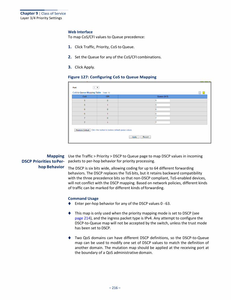
– 216 –
Chapter 9 | Class of Service Layer 3/4 Priority Settings
Web Interface To map CoS/CFI values to Queue precedence:
1. Click Traffic, Priority, CoS to Queue.
2. Set the Queue for any of the CoS/CFI combinations.
3. Click Apply.
Figure 127: Configuring CoS to Queue Mapping
Mapping DSCP Priorities to Per-
hop Behavior
Use the Traffic > Priority > DSCP to Queue page to map DSCP values in incoming packets to per-hop behavior for priority processing.
The DSCP is six bits wide, allowing coding for up to 64 different forwarding behaviors. The DSCP replaces the ToS bits, but it retains backward compatibility with the three precedence bits so that non-DSCP compliant, ToS-enabled devices, will not conflict with the DSCP mapping. Based on network policies, different kinds of traffic can be marked for different kinds of forwarding.
Command Usage ◆ Enter per-hop behavior for any of the DSCP values 0 - 63.
◆ This map is only used when the priority mapping mode is set to DSCP (see
page 214), and the ingress packet type is IPv4. Any attempt to configure the DSCP-to-Queue map will not be accepted by the switch, unless the trust mode has been set to DSCP.
◆ Two QoS domains can have different DSCP definitions, so the DSCP-to-Queue
map can be used to modify one set of DSCP values to match the definition of another domain. The mutation map should be applied at the receiving port at the boundary of a QoS administrative domain.
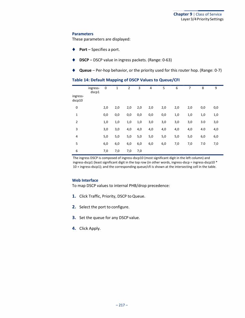
– 217 –
Chapter 9 | Class of Service Layer 3/4 Priority Settings
Parameters These parameters are displayed:
◆ Port – Specifies a port.
◆ DSCP – DSCP value in ingress packets. (Range: 0-63)
◆ Queue – Per-hop behavior, or the priority used for this router hop. (Range: 0-7)
Table 14: Default Mapping of DSCP Values to Queue/CFI
ingress- 0 1 2 3 4 5 6 7 8 9 dscp1
ingress-
dscp10
0 2,0 2,0 2,0 2,0 2,0 2,0 2,0 2,0 0,0 0,0
1 0,0 0,0 0,0 0,0 0,0 0,0 1,0 1,0 1,0 1,0
2 1,0 1,0 1,0 1,0 3,0 3,0 3,0 3,0 3.0 3,0
3 3,0 3,0 4,0 4,0 4,0 4,0 4,0 4,0 4.0 4,0
4 5,0 5,0 5,0 5,0 5,0 5,0 5,0 5,0 6,0 6,0
5 6,0 6,0 6,0 6,0 6,0 6,0 7,0 7,0 7.0 7,0
6 7,0 7,0 7,0 7,0
The ingress DSCP is composed of ingress-dscp10 (most significant digit in the left column) and ingress-dscp1 (least significant digit in the top row (in other words, ingress-dscp = ingress-dscp10 * 10 + ingress-dscp1); and the corresponding queue/cfi is shown at the intersecting cell in the table.
Web Interface To map DSCP values to internal PHB/drop precedence:
1. Click Traffic, Priority, DSCP to Queue.
2. Select the port to configure.
3. Set the queue for any DSCP value.
4. Click Apply.
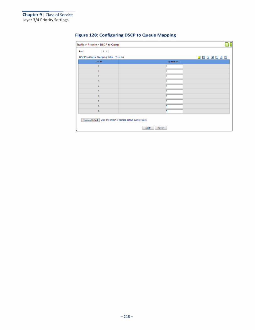
– 218 –
Chapter 9 | Class of Service Layer 3/4 Priority Settings
Figure 128: Configuring DSCP to Queue Mapping
– 219 –
Quality of Service
This chapter describes the following tasks required to apply QoS policies:
◆ Class Map – Creates a map which identifies a specific class of traffic.
◆ Policy Map – Sets the boundary parameters used for monitoring inbound traffic, and the action to take for conforming and non-conforming traffic.
◆ Binding to a Port – Applies a policy map to an ingress port.
Overview
The commands described in this section are used to configure Quality of Service (QoS) classification criteria and service policies. Differentiated Services (DiffServ) provides policy-based management mechanisms used for prioritizing network resources to meet the requirements of specific traffic types on a per hop basis. Each packet is classified upon entry into the network based on access lists, IP Precedence, DSCP values, VLAN lists, CoS values, or source ports. Using access lists allows you select traffic based on Layer 2, Layer 3, or Layer 4 information contained in each packet. Based on configured network policies, different kinds of traffic can be marked for different kinds of forwarding.
All switches or routers that access the Internet rely on class information to provide the same forwarding treatment to packets in the same class. Class information can be assigned by end hosts, or switches or routers along the path. Priority can then be assigned based on a general policy, or a detailed examination of the packet. However, note that detailed examination of packets should take place close to the network edge so that core switches and routers are not overloaded.
Switches and routers along the path can use class information to prioritize the resources allocated to different traffic classes. The manner in which an individual device handles traffic in the DiffServ architecture is called per-hop behavior. All devices along a path should be configured in a consistent manner to construct a consistent end-to-end QoS solution.
Note: You can configure up to 16 rules per class map. You can also include multiple classes in a policy map.
Note: You should create a class map before creating a policy map. Otherwise, you will not be able to select a class map from the policy rule settings screen (see page 223).
– 220 –
Chapter 10 | Quality of Service Configuring a Class Map
Command Usage To create a service policy for a specific category or ingress traffic, follow these steps:
1. Use the Configure Class (Add) page to designate a class name for a specific category of traffic.
2. Use the Configure Class (Add Rule) page to edit the rules for each class which specify a type of traffic based on an access list, a DSCP or IP Precedence value, a VLAN, a CoS value, or a source port.
3. Use the Configure Policy (Add) page to designate a policy name for a specific manner in which ingress traffic will be handled.
4. Use the Configure Policy (Add Rule) page to add one or more classes to the policy map. Assign policy rules to each class by “setting” the QoS value (CoS or PHB) to be assigned to the matching traffic class. The policy rule can also be configured to monitor the maximum throughput and burst rate. Then specify the action to take for conforming traffic, or the action to take for a policy violation.
5. Use the Configure Interface page to assign a policy map to a specific interface.
Note: Up to 16 classes can be included in a policy map.
Configuring a Class Map
A class map is used for matching packets to a specified class. Use the Traffic > DiffServ (Configure Class) page to configure a class map.
Command Usage ◆ The class map is used with a policy map (page 223) to create a service policy
(page 226) for a specific interface that defines packet classification, service tagging, and bandwidth policing. Note that one or more class maps can be assigned to a policy map.
◆ Up to 32 class maps can be configured.
Parameters These parameters are displayed:
Add
◆ Class Name – Name of the class map. (Range: 1-32 characters)
◆ Type – Only one match command is permitted per class map, so the match-any field refers to the criteria specified by the lone match command.
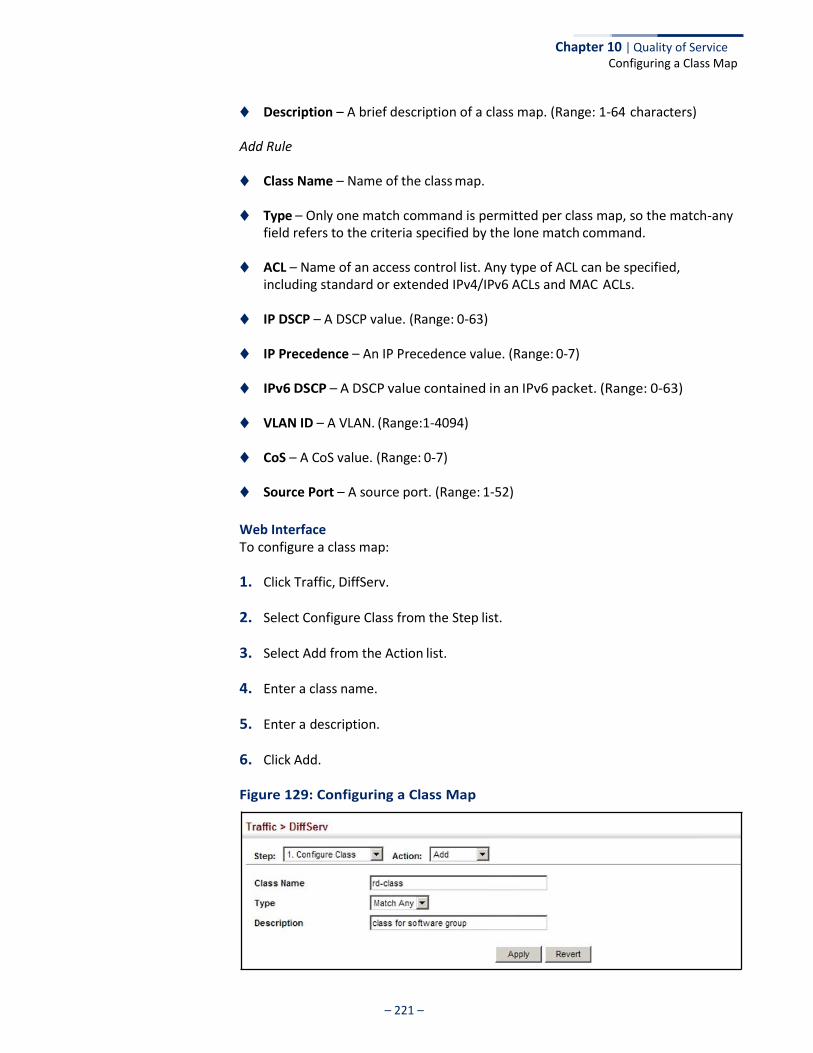
Chapter 10 | Quality of Service Configuring a Class Map
– 221 –
◆ Description – A brief description of a class map. (Range: 1-64 characters)
Add Rule
◆ Class Name – Name of the class map.
◆ Type – Only one match command is permitted per class map, so the match-any field refers to the criteria specified by the lone match command.
◆ ACL – Name of an access control list. Any type of ACL can be specified,
including standard or extended IPv4/IPv6 ACLs and MAC ACLs.
◆ IP DSCP – A DSCP value. (Range: 0-63)
◆ IP Precedence – An IP Precedence value. (Range: 0-7)
◆ IPv6 DSCP – A DSCP value contained in an IPv6 packet. (Range: 0-63)
◆ VLAN ID – A VLAN. (Range:1-4094)
◆ CoS – A CoS value. (Range: 0-7)
◆ Source Port – A source port. (Range: 1-52)
Web Interface To configure a class map:
1. Click Traffic, DiffServ.
2. Select Configure Class from the Step list.
3. Select Add from the Action list.
4. Enter a class name.
5. Enter a description.
6. Click Add.
Figure 129: Configuring a Class Map
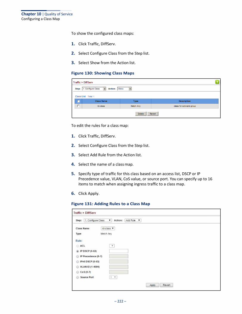
Chapter 10 | Quality of Service Configuring a Class Map
– 222 –
To show the configured class maps:
1. Click Traffic, DiffServ.
2. Select Configure Class from the Step list.
3. Select Show from the Action list.
Figure 130: Showing Class Maps
To edit the rules for a class map:
1. Click Traffic, DiffServ.
2. Select Configure Class from the Step list.
3. Select Add Rule from the Action list.
4. Select the name of a class map.
5. Specify type of traffic for this class based on an access list, DSCP or IP Precedence value, VLAN, CoS value, or source port. You can specify up to 16 items to match when assigning ingress traffic to a class map.
6. Click Apply.
Figure 131: Adding Rules to a Class Map
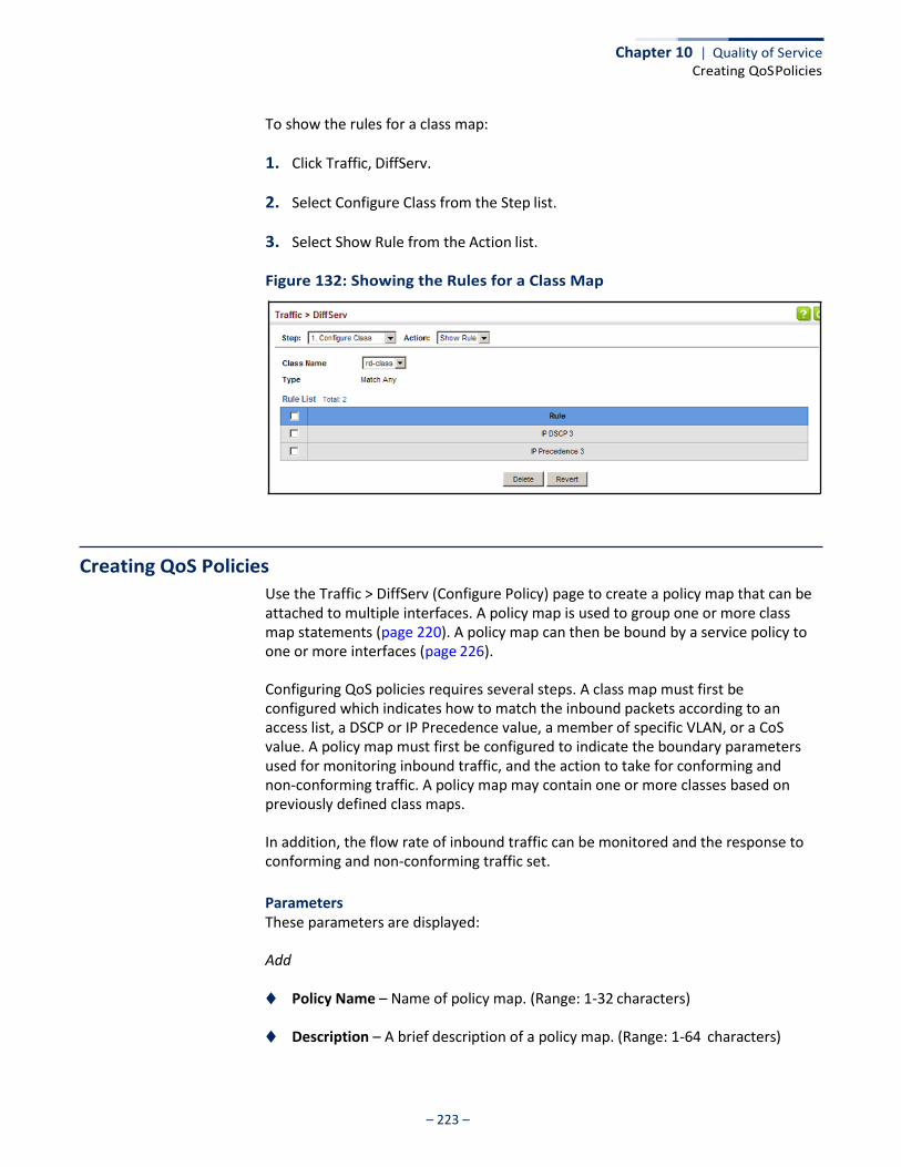
Chapter 10 | Quality of Service Creating QoS Policies
– 223 –
To show the rules for a class map:
1. Click Traffic, DiffServ.
2. Select Configure Class from the Step list.
3. Select Show Rule from the Action list.
Figure 132: Showing the Rules for a Class Map
Creating QoS Policies
Use the Traffic > DiffServ (Configure Policy) page to create a policy map that can be attached to multiple interfaces. A policy map is used to group one or more class map statements (page 220). A policy map can then be bound by a service policy to one or more interfaces (page 226).
Configuring QoS policies requires several steps. A class map must first be configured which indicates how to match the inbound packets according to an access list, a DSCP or IP Precedence value, a member of specific VLAN, or a CoS value. A policy map must first be configured to indicate the boundary parameters used for monitoring inbound traffic, and the action to take for conforming and non-conforming traffic. A policy map may contain one or more classes based on previously defined class maps.
In addition, the flow rate of inbound traffic can be monitored and the response to conforming and non-conforming traffic set.
Parameters These parameters are displayed:
Add
◆ Policy Name – Name of policy map. (Range: 1-32 characters)
◆ Description – A brief description of a policy map. (Range: 1-64 characters)

Chapter 10 | Quality of Service Creating QoS Policies
– 224 –
Add Rule
◆ Policy Name – Name of policy map.
◆ Class Name – Name of a class map that defines a traffic classification upon which a policy can act. A policy map can contain up to 32 class maps.
◆ Action – This attribute is used to set an internal QoS value in hardware for
matching packets.
■ Set CoS – Configures the service provided to ingress traffic by setting an internal CoS value for a matching packet (as specified in rule settings for a class map). (Range: 0-7)
See Table 13, “Default Mapping of CoS/CFI Values to Queue/CFI,” on page 215).
◆ Meter – Check this to define the maximum throughput.
◆ Meter Mode (Rate Limit) – Applies rate limiting to ingress or egress ports. This function allows the network manager to control the maximum rate for traffic received or transmitted on an interface. Rate limiting is configured on interfaces at the edge of a network to limit traffic into or out of the network. Packets that exceed the acceptable amount of traffic are dropped.
◆ Rate – Sets the rate limit level. (Range: 64 - 100000000 kbits per second)
Web Interface To configure a policy map:
1. Click Traffic, DiffServ.
2. Select Configure Policy from the Step list.
3. Select Add from the Action list.
4. Enter a policy name.
5. Enter a description.
6. Click Add.
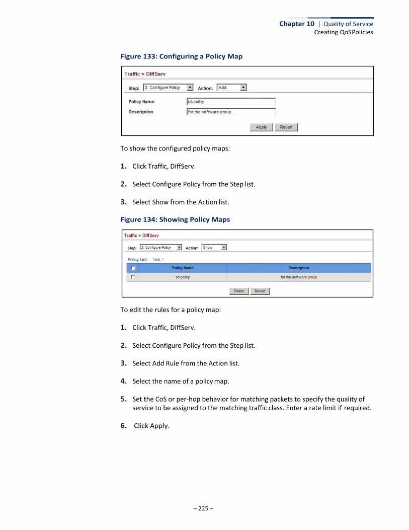
Chapter 10 | Quality of Service Creating QoS Policies
– 225 –
Figure 133: Configuring a Policy Map
To show the configured policy maps:
1. Click Traffic, DiffServ.
2. Select Configure Policy from the Step list.
3. Select Show from the Action list.
Figure 134: Showing Policy Maps
To edit the rules for a policy map:
1. Click Traffic, DiffServ.
2. Select Configure Policy from the Step list.
3. Select Add Rule from the Action list.
4. Select the name of a policy map.
5. Set the CoS or per-hop behavior for matching packets to specify the quality of service to be assigned to the matching traffic class. Enter a rate limit if required.
6. Click Apply.
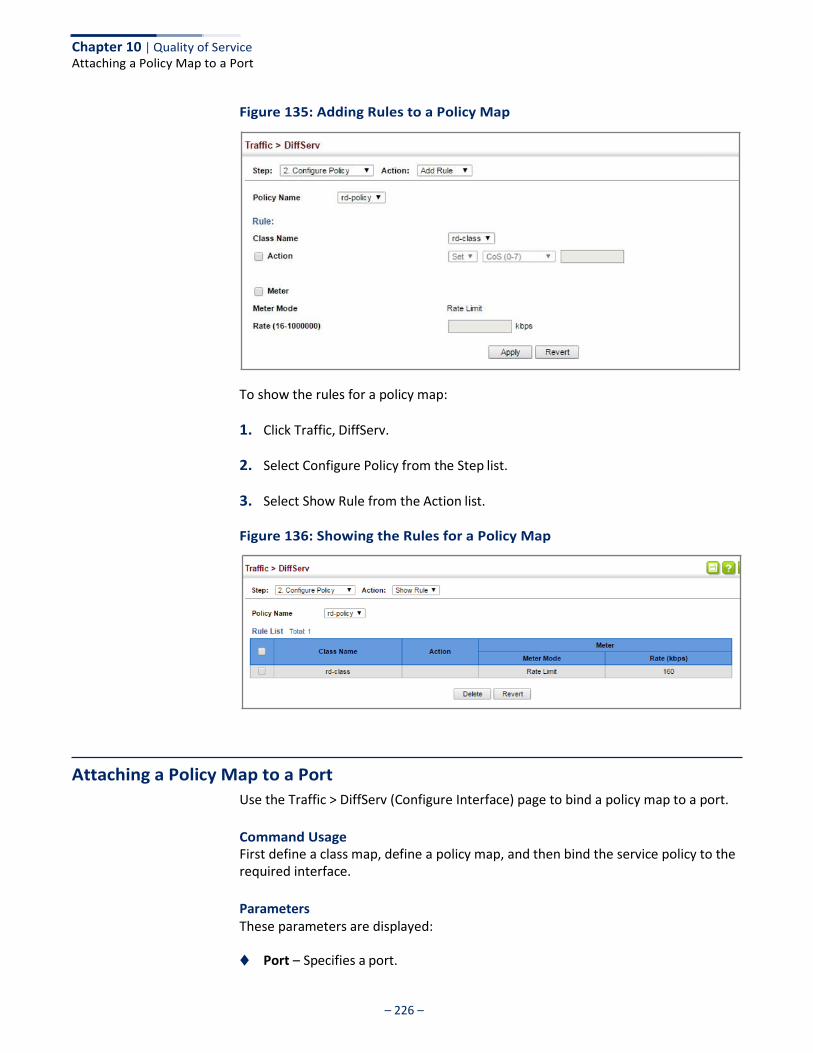
– 226 –
Chapter 10 | Quality of Service Attaching a Policy Map to a Port
Figure 135: Adding Rules to a Policy Map
To show the rules for a policy map:
1. Click Traffic, DiffServ.
2. Select Configure Policy from the Step list.
3. Select Show Rule from the Action list.
Figure 136: Showing the Rules for a Policy Map
Attaching a Policy Map to a Port
Use the Traffic > DiffServ (Configure Interface) page to bind a policy map to a port.
Command Usage First define a class map, define a policy map, and then bind the service policy to the required interface.
Parameters These parameters are displayed:
◆ Port – Specifies a port.
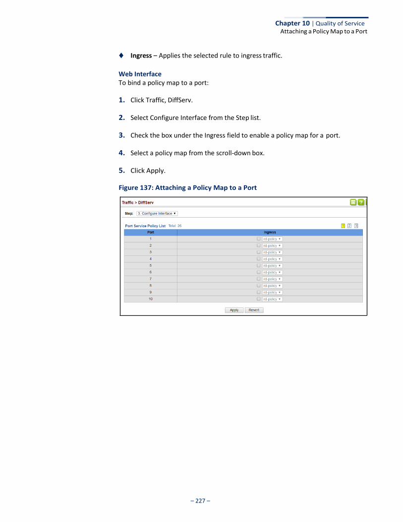
– 227 –
Chapter 10 | Quality of Service Attaching a Policy Map to a Port
◆ Ingress – Applies the selected rule to ingress traffic.
Web Interface To bind a policy map to a port:
1. Click Traffic, DiffServ.
2. Select Configure Interface from the Step list.
3. Check the box under the Ingress field to enable a policy map for a port.
4. Select a policy map from the scroll-down box.
5. Click Apply.
Figure 137: Attaching a Policy Map to a Port

– 228 –
Chapter 10 | Quality of Service Attaching a Policy Map to a Port

– 229 –
VoIP Traffic Configuration
This chapter covers the following topics:
◆ Global Settings – Enables VOIP globally, sets the Voice VLAN, and the aging time for attached ports.
◆ Telephony OUI List – Configures the list of phones to be treated as VOIP devices
based on the specified Organization Unit Identifier (OUI).
◆ Port Settings – Configures the way in which a port is added to the Voice VLAN, the filtering of non-VoIP packets, the method of detecting VoIP traffic, and the priority assigned to voice traffic.
Overview
When IP telephony is deployed in an enterprise network, it is recommended to isolate the Voice over IP (VoIP) network traffic from other data traffic. Traffic isolation can provide higher voice quality by preventing excessive packet delays, packet loss, and jitter. This is best achieved by assigning all VoIP traffic to a single Voice VLAN.
The use of a Voice VLAN has several advantages. It provides security by isolating the VoIP traffic from other data traffic. End-to-end QoS policies and high priority can be applied to VoIP VLAN traffic across the network, guaranteeing the bandwidth it needs. VLAN isolation also protects against disruptive broadcast and multicast traffic that can seriously affect voice quality.
The switch allows you to specify a Voice VLAN for the network and set a CoS priority for the VoIP traffic. The VoIP traffic can be detected on switch ports by using the source MAC address of packets, or by using LLDP (IEEE 802.1AB) to discover connected VoIP devices. When VoIP traffic is detected on a configured port, the switch automatically assigns the port as a tagged member the Voice VLAN. Alternatively, switch ports can be manually configured.
– 230 –
Chapter 11 | VoIP Traffic Configuration
Configuring VoIP Traffic
Configuring VoIP Traffic
Use the Traffic > VoIP (Configure Global) page to configure the switch for VoIP traffic. First enable automatic detection of VoIP devices attached to the switch ports, then set the Voice VLAN ID for the network. The Voice VLAN aging time can also be set to remove a port from the Voice VLAN when VoIP traffic is no longer received on the port.
Command Usage All ports are set to VLAN hybrid mode by default. Prior to enabling VoIP for a port (by setting the VoIP mode to Auto or Manual as described below), first ensure that VLAN membership is not set to access mode (see “Adding Static Members to VLANs” on page 152).
Parameters These parameters are displayed:
◆ Auto Detection Status – Enables the automatic detection of VoIP traffic on
switch ports. (Default: Disabled)
◆ Voice VLAN – Sets the Voice VLAN ID for the network. Only one Voice VLAN is supported and it must already be created on the switch. (Range: 1-4094)
◆ Voice VLAN Aging Time – The time after which a port is removed from the
Voice VLAN when VoIP traffic is no longer received on the port. (Range: 5-43200 minutes; Default: 1440 minutes)
Note: The Voice VLAN ID cannot be modified when the global Auto Detection Status is enabled.
Web Interface To configure global settings for a Voice VLAN:
1. Click Traffic, VoIP.
2. Select Configure Global from the Step list.
3. Enable Auto Detection.
4. Specify the Voice VLAN ID.
5. Adjust the Voice VLAN Aging Time if required.
6. Click Apply.
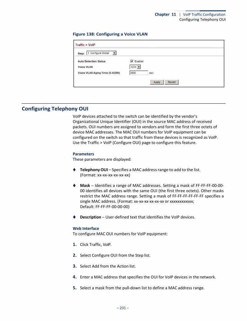
Chapter 11 | VoIP Traffic Configuration Configuring Telephony OUI
– 231 –
Figure 138: Configuring a Voice VLAN
Configuring Telephony OUI
VoIP devices attached to the switch can be identified by the vendor’s Organizational Unique Identifier (OUI) in the source MAC address of received packets. OUI numbers are assigned to vendors and form the first three octets of device MAC addresses. The MAC OUI numbers for VoIP equipment can be configured on the switch so that traffic from these devices is recognized as VoIP. Use the Traffic > VoIP (Configure OUI) page to configure this feature.
Parameters These parameters are displayed:
◆ Telephony OUI – Specifies a MAC address range to add to the list.
(Format: xx-xx-xx-xx-xx-xx)
◆ Mask – Identifies a range of MAC addresses. Setting a mask of FF-FF-FF-00-00- 00 identifies all devices with the same OUI (the first three octets). Other masks restrict the MAC address range. Setting a mask of FF-FF-FF-FF-FF-FF specifies a single MAC address. (Format: xx-xx-xx-xx-xx-xx or xxxxxxxxxxxx; Default: FF-FF-FF-00-00-00)
◆ Description – User-defined text that identifies the VoIP devices.
Web Interface To configure MAC OUI numbers for VoIP equipment:
1. Click Traffic, VoIP.
2. Select Configure OUI from the Step list.
3. Select Add from the Action list.
4. Enter a MAC address that specifies the OUI for VoIP devices in the network.
5. Select a mask from the pull-down list to define a MAC address range.
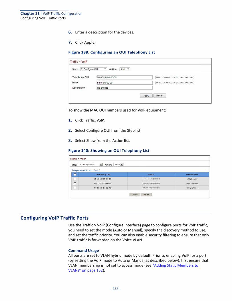
– 232 –
Chapter 11 | VoIP Traffic Configuration Configuring VoIP Traffic Ports
6. Enter a description for the devices.
7. Click Apply.
Figure 139: Configuring an OUI Telephony List
To show the MAC OUI numbers used for VoIP equipment:
1. Click Traffic, VoIP.
2. Select Configure OUI from the Step list.
3. Select Show from the Action list.
Figure 140: Showing an OUI Telephony List
Configuring VoIP Traffic Ports
Use the Traffic > VoIP (Configure Interface) page to configure ports for VoIP traffic, you need to set the mode (Auto or Manual), specify the discovery method to use, and set the traffic priority. You can also enable security filtering to ensure that only VoIP traffic is forwarded on the Voice VLAN.
Command Usage All ports are set to VLAN hybrid mode by default. Prior to enabling VoIP for a port (by setting the VoIP mode to Auto or Manual as described below), first ensure that VLAN membership is not set to access mode (see “Adding Static Members to VLANs” on page 152).
Chapter 11 | VoIP Traffic Configuration Configuring VoIP Traffic Ports
– 233 –
Parameters These parameters are displayed:
◆ Mode – Specifies if the port will be added to the Voice VLAN when VoIP traffic is
detected. (Default: None)
■ None – The Voice VLAN feature is disabled on the port. The port will not detect VoIP traffic or be added to the Voice VLAN.
■ Auto – The port will be added as a tagged member to the Voice VLAN
when VoIP traffic is detected on the port. You must select a method for detecting VoIP traffic, either OUI or 802.1AB (LLDP). When OUI is selected, be sure to configure the MAC address ranges in the Telephony OUI list.
■ Manual – The Voice VLAN feature is enabled on the port, but the port must
be manually added to the Voice VLAN.
◆ Security – Enables security filtering that discards any non-VoIP packets received on the port that are tagged with the voice VLAN ID. VoIP traffic is identified by source MAC addresses configured in the Telephony OUI list, or through LLDP that discovers VoIP devices attached to the switch. Packets received from non-VoIP sources are dropped. (Default: Disabled)
◆ Discovery Protocol – Selects a method to use for detecting VoIP traffic on the
port. (Default: OUI)
■ OUI – Traffic from VoIP devices is detected by the Organizationally Unique Identifier (OUI) of the source MAC address. OUI numbers are assigned to vendors and form the first three octets of a device MAC address. MAC address OUI numbers must be configured in the Telephony OUI list so that the switch recognizes the traffic as being from a VoIP device.
■ LLDP – Uses LLDP (IEEE 802.1AB) to discover VoIP devices attached to the
port. LLDP checks that the “telephone bit” in the system capability TLV is turned on. See “Link Layer Discovery Protocol” on page 339 for more information on LLDP.
◆ Priority – Defines a CoS priority for port traffic on the Voice VLAN. The priority of
any received VoIP packet is overwritten with the new priority when the Voice VLAN feature is active for the port. (Range: 0-6; Default: 6)
◆ Remaining Age – Number of minutes before this entry is aged out.
The Remaining Age starts to count down when the OUI’s MAC address expires from the MAC address table. Therefore, the MAC address aging time should be added to the overall aging time. For example, if you configure the MAC address table aging time to 30 seconds, and the voice VLAN aging time to 5 minutes, then after 5.5 minutes, a port will be removed from voice VLAN when VoIP traffic is no longer received on the port. Alternatively, if you clear the MAC address table manually, then the switch will also start counting down the Remaining Age.
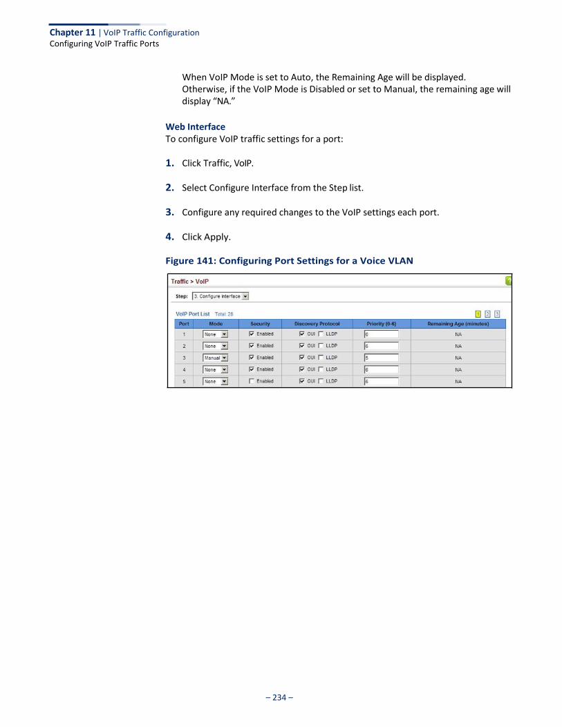
Chapter 11 | VoIP Traffic Configuration Configuring VoIP Traffic Ports
– 234 –
When VoIP Mode is set to Auto, the Remaining Age will be displayed. Otherwise, if the VoIP Mode is Disabled or set to Manual, the remaining age will display “NA.”
Web Interface To configure VoIP traffic settings for a port:
1. Click Traffic, VoIP.
2. Select Configure Interface from the Step list.
3. Configure any required changes to the VoIP settings each port.
4. Click Apply.
Figure 141: Configuring Port Settings for a Voice VLAN

– 235 –
Security Measures
You can configure this switch to authenticate users logging into the system for management access using local or remote authentication methods. Port-based authentication using IEEE 802.1X can also be configured to control either management access to the uplink ports or client access to the data ports. This switch provides secure network management access using the following options:
◆ AAA – Use local or remote authentication to configure access rights, specify
authentication servers, configure remote authentication and accounting.
◆ User Accounts – Manually configure access rights on the switch for specified users.
◆ Web Authentication – Allows stations to authenticate and access the network
in situations where 802.1X or Network Access authentication methods are infeasible or impractical.
◆ Network Access - Configure MAC authentication, intrusion response, dynamic VLAN assignment, and dynamic QoS assignment.
◆ HTTPS – Provide a secure web connection.
◆ SSH – Provide a secure shell (for secure Telnet access).
◆ ACL – Access Control Lists provide packet filtering for IP frames (based on address, protocol, Layer 4 protocol port number or TCP control code).
◆ IP Filter – Filters management access to the web, SNMP or Telnet interface.
◆ Port Security – Configure secure addresses for individual ports.
◆ Port Authentication – Use IEEE 802.1X port authentication to control access to specific ports.
◆ DoS Protection – Protects against Denial-of-Service attacks.
◆ DHCP Snooping – Filter IP traffic on insecure ports for which the source address cannot be identified via DHCP snooping.
◆ IPv4 Source Guard – Filters IPv4 traffic on insecure ports for which the source
address cannot be identified via DHCPv4 snooping nor static source bindings.
◆ ARP Inspection – Security feature that validates the MAC Address bindings for Address Resolution Protocol packets. Provides protection against ARP traffic
– 236 –
Chapter 12 | Security Measures AAA (Authentication, Authorization and Accounting)
with invalid MAC to IP Address bindings, which forms the basis for certain “man-in-the-middle” attacks.
Note: The priority of execution for the filtering commands is Port Security, Port Authentication, Network Access, Web Authentication, Access Control Lists, IP Source Guard, and then DHCP Snooping.
AAA (Authentication, Authorization and Accounting)
The authentication, authorization, and accounting (AAA) feature provides the main framework for configuring access control on the switch. The three security functions can be summarized as follows:
◆ Authentication — Identifies users that request access to the network.
◆ Authorization — Determines if users can access specific services.
◆ Accounting — Provides reports, auditing, and billing for services that users have accessed on the network.
The AAA functions require the use of configured RADIUS or TACACS+ servers in the network. The security servers can be defined as sequential groups that are applied as a method for controlling user access to specified services. For example, when the switch attempts to authenticate a user, a request is sent to the first server in the defined group, if there is no response the second server will be tried, and so on. If at any point a pass or fail is returned, the process stops.
The switch supports the following AAA features:
◆ Accounting for IEEE 802.1X authenticated users that access the network through the switch.
◆ Accounting for users that access management interfaces on the switch through
the console and Telnet.
◆ Accounting for commands that users enter at specific CLI privilege levels.
◆ Authorization of users that access management interfaces on the switch through the console and Telnet.
To configure AAA on the switch, you need to follow this general process:
1. Configure RADIUS and TACACS+ server access parameters. See “Configuring Local/Remote Logon Authentication” on page 237.
– 237 –
Chapter 12 | Security Measures AAA (Authentication, Authorization and Accounting)
2. Define RADIUS and TACACS+ server groups to support the accounting and authorization of services.
3. Define a method name for each service to which you want to apply accounting or authorization and specify the RADIUS or TACACS+ server groups to use.
4. Apply the method names to port or line interfaces.
Note: This guide assumes that RADIUS and TACACS+ servers have already been configured to support AAA. The configuration of RADIUS and TACACS+ server software is beyond the scope of this guide, refer to the documentation provided with the RADIUS or TACACS+ server software.
Configuring Local/ Remote Logon Authentication
Use the Security > AAA > System Authentication page to specify local or remote authentication. Local authentication restricts management access based on user names and passwords manually configured on the switch. Remote authentication uses a remote access authentication server based on RADIUS or TACACS+ protocols to verify management access.
Command Usage ◆ By default, management access is always checked against the authentication
database stored on the local switch. If a remote authentication server is used, you must specify the authentication sequence. Then specify the corresponding parameters for the remote authentication protocol using the Security > AAA > Server page. Local and remote logon authentication control management access via the console port, web browser, or Telnet.
◆ You can specify up to three authentication methods for any user to indicate the
authentication sequence. For example, if you select (1) RADIUS, (2) TACACS and (3) Local, the user name and password on the RADIUS server is verified first. If the RADIUS server is not available, then authentication is attempted using the TACACS+ server, and finally the local user name and password is checked.
Parameters These parameters are displayed:
◆ Authentication Sequence – Select the authentication, or authentication
sequence required:
■ Local – User authentication is performed only locally by the switch.
■ RADIUS – User authentication is performed using a RADIUS server only.
■ TACACS – User authentication is performed using a TACACS+ server only.
■ [authentication sequence] – User authentication is performed by up to three authentication methods in the indicated sequence.
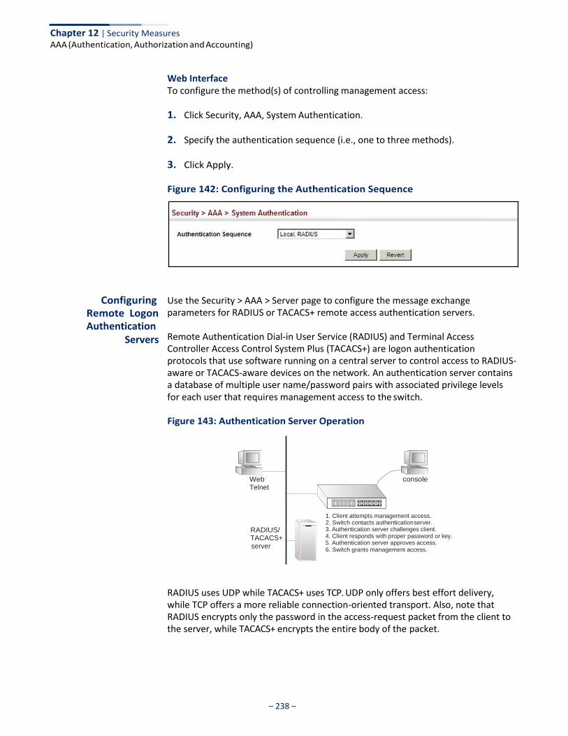
– 238 –
Chapter 12 | Security Measures AAA (Authentication, Authorization and Accounting)
Web Interface To configure the method(s) of controlling management access:
1. Click Security, AAA, System Authentication.
2. Specify the authentication sequence (i.e., one to three methods).
3. Click Apply.
Figure 142: Configuring the Authentication Sequence
Configuring Remote Logon Authentication
Servers
Use the Security > AAA > Server page to configure the message exchange parameters for RADIUS or TACACS+ remote access authentication servers.
Remote Authentication Dial-in User Service (RADIUS) and Terminal Access Controller Access Control System Plus (TACACS+) are logon authentication protocols that use software running on a central server to control access to RADIUS- aware or TACACS-aware devices on the network. An authentication server contains a database of multiple user name/password pairs with associated privilege levels for each user that requires management access to the switch.
Figure 143: Authentication Server Operation
Web Telnet
RADIUS/ TACACS+ server
console
1. Client attempts management access.
2. Switch contacts authentication server. 3. Authentication server challenges client. 4. Client responds with proper password or key. 5. Authentication server approves access. 6. Switch grants management access.
RADIUS uses UDP while TACACS+ uses TCP. UDP only offers best effort delivery, while TCP offers a more reliable connection-oriented transport. Also, note that RADIUS encrypts only the password in the access-request packet from the client to the server, while TACACS+ encrypts the entire body of the packet.
– 239 –
Chapter 12 | Security Measures AAA (Authentication, Authorization and Accounting)
Command Usage ◆ If a remote authentication server is used, you must specify the message
exchange parameters for the remote authentication protocol. Both local and remote logon authentication control management access via the console port, web browser, or Telnet.
◆ RADIUS and TACACS+ logon authentication assign a specific privilege level for
each user name/password pair. The user name, password, and privilege level must be configured on the authentication server. The encryption methods used for the authentication process must also be configured or negotiated between the authentication server and logon client. This switch can pass authentication messages between the server and client that have been encrypted using MD5 (Message-Digest 5), TLS (Transport Layer Security), or TTLS (Tunneled Transport Layer Security).
Parameters These parameters are displayed:
Configure Server
◆ RADIUS
■ Global – Provides globally applicable RADIUS settings.
■ Server Index – Specifies one of five RADIUS servers that may be configured. The switch attempts authentication using the listed sequence of servers. The process ends when a server either approves or denies access to a user.
■ Server IP Address – Address of authentication server.
(A Server Index entry must be selected to display this item.)
■ Accounting Server UDP Port – Network (UDP) port on authentication server used for accounting messages. (Range: 1-65535; Default: 1813)
■ Authentication Server UDP Port – Network (UDP) port on authentication
server used for authentication messages. (Range: 1-65535; Default: 1812)
■ Authentication Timeout – The number of seconds the switch waits for a reply from the RADIUS server before it resends the request. (Range: 1-65535; Default: 5)
■ Authentication Retries – Number of times the switch tries to authenticate
logon access via the authentication server. (Range: 1-30; Default: 2)
■ Set Key – Mark this box to set or modify the encryption key.
■ Authentication Key – Encryption key used to authenticate logon access for client. Enclose any string containing blank spaces in double quotes. (Maximum length: 48 characters)
Chapter 12 | Security Measures AAA (Authentication, Authorization and Accounting)
– 240 –
■ Confirm Authentication Key – Re-type the string entered in the previous
field to ensure no errors were made. The switch will not change the encryption key if these two fields do not match.
◆ TACACS+
■ Global – Provides globally applicable TACACS+ settings.
■ Server Index – Specifies the index number of the server to be configured. The switch currently supports only one TACACS+ server.
■ Server IP Address – Address of the TACACS+ server.
(A Server Index entry must be selected to display this item.)
■ Authentication Server TCP Port – Network (TCP) port of TACACS+ server used for authentication messages. (Range: 1-65535; Default: 49)
■ Authentication Timeout – The number of seconds the switch waits for a
reply from the TACACS+ server before it resends the request. (Range: 1-65535; Default: 5)
■ Authentication Retries – Number of times the switch tries to authenticate
logon access via the authentication server. (Range: 1-30; Default: 2)
■ Set Key – Mark this box to set or modify the encryption key.
■ Authentication Key – Encryption key used to authenticate logon access for client. Enclose any string containing blank spaces in double quotes. (Maximum length: 48 characters)
■ Confirm Authentication Key – Re-type the string entered in the previous
field to ensure no errors were made. The switch will not change the encryption key if these two fields do not match.
Configure Group
◆ Server Type – Select RADIUS or TACACS+ server.
◆ Group Name - Defines a name for the RADIUS or TACACS+ server group. (Range: 1-64 characters)
◆ Sequence at Priority - Specifies the server and sequence to use for the group.
(Range: 1-5 for RADIUS; 1 for TACACS)
When specifying the priority sequence for a sever, the server index must already be defined (see “Configuring Local/Remote Logon Authentication” on page 237).
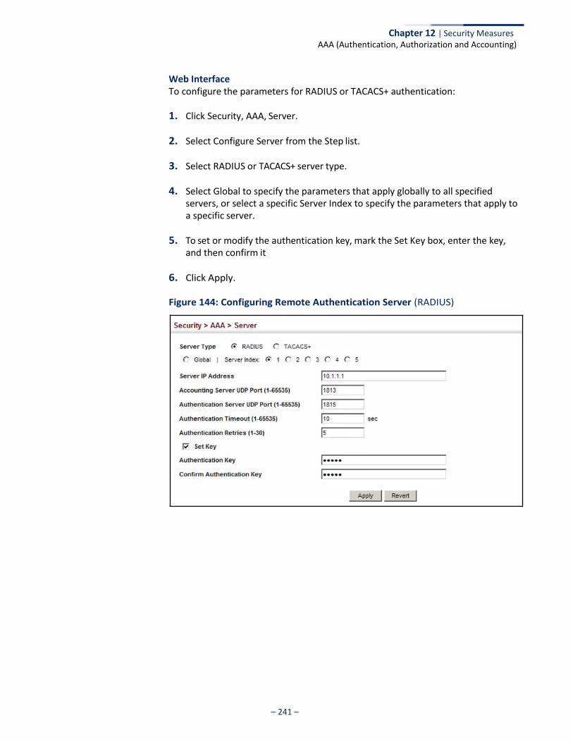
Chapter 12 | Security Measures AAA (Authentication, Authorization and Accounting)
– 241 –
Web Interface To configure the parameters for RADIUS or TACACS+ authentication:
1. Click Security, AAA, Server.
2. Select Configure Server from the Step list.
3. Select RADIUS or TACACS+ server type.
4. Select Global to specify the parameters that apply globally to all specified servers, or select a specific Server Index to specify the parameters that apply to a specific server.
5. To set or modify the authentication key, mark the Set Key box, enter the key, and then confirm it
6. Click Apply.
Figure 144: Configuring Remote Authentication Server (RADIUS)

Chapter 12 | Security Measures AAA (Authentication, Authorization and Accounting)
– 242 –
Figure 145: Configuring Remote Authentication Server (TACACS+)
To configure the RADIUS or TACACS+ server groups to use for accounting and authorization:
1. Click Security, AAA, Server.
2. Select Configure Group from the Step list.
3. Select Add from the Action list.
4. Select RADIUS or TACACS+ server type.
5. Enter the group name, followed by the index of the server to use for each priority level.
6. Click Apply.
Figure 146: Configuring AAA Server Groups
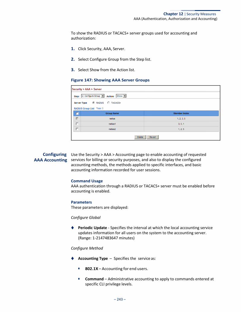
Chapter 12 | Security Measures AAA (Authentication, Authorization and Accounting)
– 243 –
To show the RADIUS or TACACS+ server groups used for accounting and authorization:
1. Click Security, AAA, Server.
2. Select Configure Group from the Step list.
3. Select Show from the Action list.
Figure 147: Showing AAA Server Groups
Configuring AAA Accounting
Use the Security > AAA > Accounting page to enable accounting of requested services for billing or security purposes, and also to display the configured accounting methods, the methods applied to specific interfaces, and basic accounting information recorded for user sessions.
Command Usage AAA authentication through a RADIUS or TACACS+ server must be enabled before accounting is enabled.
Parameters These parameters are displayed:
Configure Global
◆ Periodic Update - Specifies the interval at which the local accounting service updates information for all users on the system to the accounting server. (Range: 1-2147483647 minutes)
Configure Method
◆ Accounting Type – Specifies the service as:
■ 802.1X – Accounting for end users.
■ Command – Administrative accounting to apply to commands entered at specific CLI privilege levels.
Chapter 12 | Security Measures AAA (Authentication, Authorization and Accounting)
– 244 –
■ Exec – Administrative accounting for local console, Telnet, or SSH
connections.
◆ Privilege Level – The CLI privilege levels (0-15). This parameter only applies to Command accounting.
◆ Method Name – Specifies an accounting method for service requests. The
“default” methods are used for a requested service if no other methods have been defined. (Range: 1-64 characters)
Note that the method name is only used to describe the accounting method configured on the specified RADIUS or TACACS+ servers. No information is sent to the servers about the method to use.
◆ Accounting Notice – Records user activity from log-in to log-off point.
◆ Server Group Name - Specifies the accounting server group. (Range: 1-64 characters)
The group names “radius” and “tacacs+” specifies all configured RADIUS and TACACS+ hosts (see “Configuring Local/Remote Logon Authentication” on page 237). Any other group name refers to a server group configured on the Security > AAA > Server (Configure Group) page.
Configure Service
◆ Accounting Type – Specifies the service as 802.1X, Command or Exec as described in the preceding section.
◆ 802.1X
■ Method Name – Specifies a user defined accounting method to apply to an interface. This method must be defined in the Configure Method page. (Range: 1-64 characters)
◆ Command
■ Privilege Level – The CLI privilege levels (0-15).
■ Console Method Name – Specifies a user-defined method name to apply to commands entered at the specified CLI privilege level through the console interface.
■ VTY Method Name – Specifies a user-defined method name to apply to
commands entered at the specified CLI privilege level through Telnet or SSH.
◆ Exec
■ Console Method Name – Specifies a user defined method name to apply to console connections.
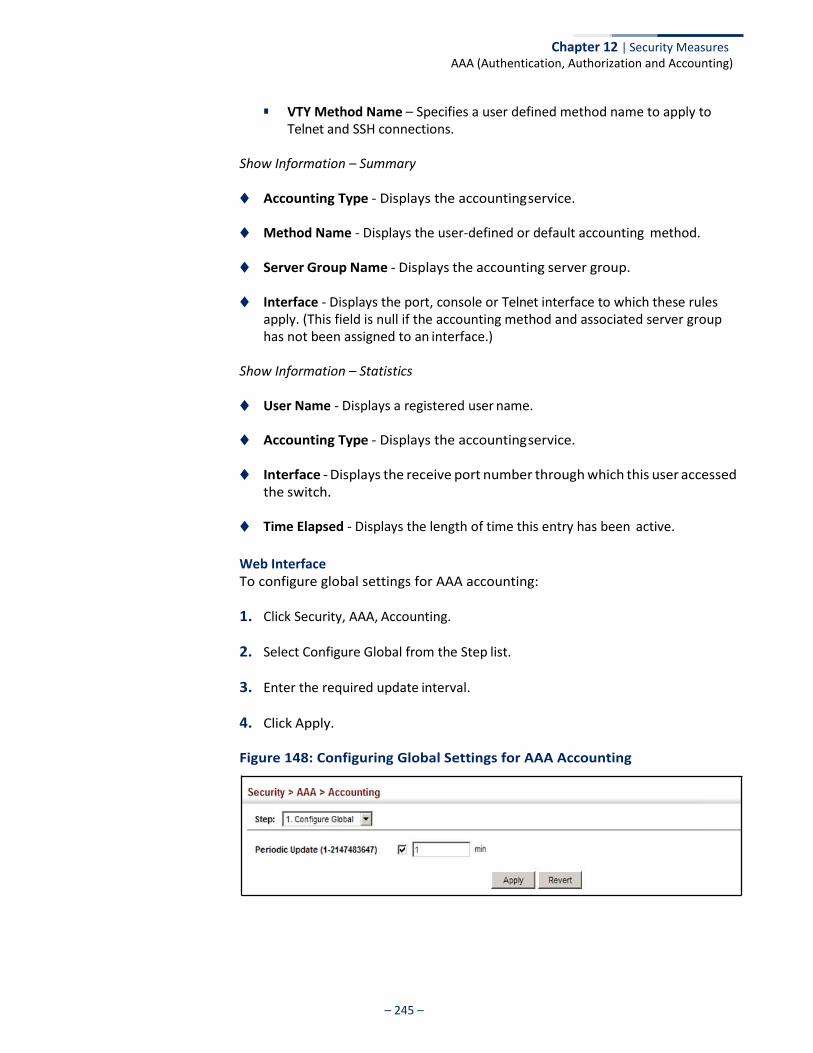
Chapter 12 | Security Measures AAA (Authentication, Authorization and Accounting)
– 245 –
■ VTY Method Name – Specifies a user defined method name to apply to
Telnet and SSH connections.
Show Information – Summary
◆ Accounting Type - Displays the accounting service.
◆ Method Name - Displays the user-defined or default accounting method.
◆ Server Group Name - Displays the accounting server group.
◆ Interface - Displays the port, console or Telnet interface to which these rules apply. (This field is null if the accounting method and associated server group has not been assigned to an interface.)
Show Information – Statistics
◆ User Name - Displays a registered user name.
◆ Accounting Type - Displays the accounting service.
◆ Interface - Displays the receive port number through which this user accessed the switch.
◆ Time Elapsed - Displays the length of time this entry has been active.
Web Interface To configure global settings for AAA accounting:
1. Click Security, AAA, Accounting.
2. Select Configure Global from the Step list.
3. Enter the required update interval.
4. Click Apply.
Figure 148: Configuring Global Settings for AAA Accounting

Chapter 12 | Security Measures AAA (Authentication, Authorization and Accounting)
– 246 –
To configure the accounting method applied to various service types and the assigned server group:
1. Click Security, AAA, Accounting.
2. Select Configure Method from the Step list.
3. Select Add from the Action list.
4. Select the accounting type (802.1X, Command, Exec).
5. Specify the name of the accounting method and server group name.
6. Click Apply.
Figure 149: Configuring AAA Accounting Methods
To show the accounting method applied to various service types and the assigned server group:
1. Click Security, AAA, Accounting.
2. Select Configure Method from the Step list.
3. Select Show from the Action list.
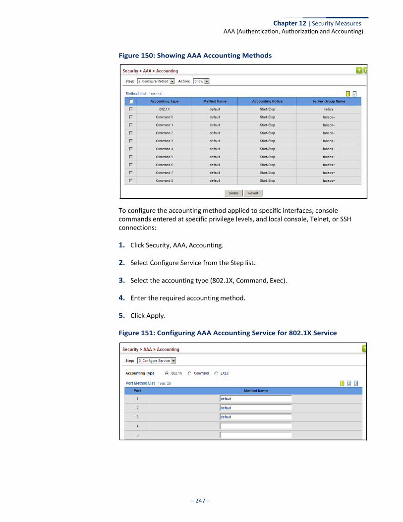
Chapter 12 | Security Measures AAA (Authentication, Authorization and Accounting)
– 247 –
Figure 150: Showing AAA Accounting Methods
To configure the accounting method applied to specific interfaces, console commands entered at specific privilege levels, and local console, Telnet, or SSH connections:
1. Click Security, AAA, Accounting.
2. Select Configure Service from the Step list.
3. Select the accounting type (802.1X, Command, Exec).
4. Enter the required accounting method.
5. Click Apply.
Figure 151: Configuring AAA Accounting Service for 802.1X Service
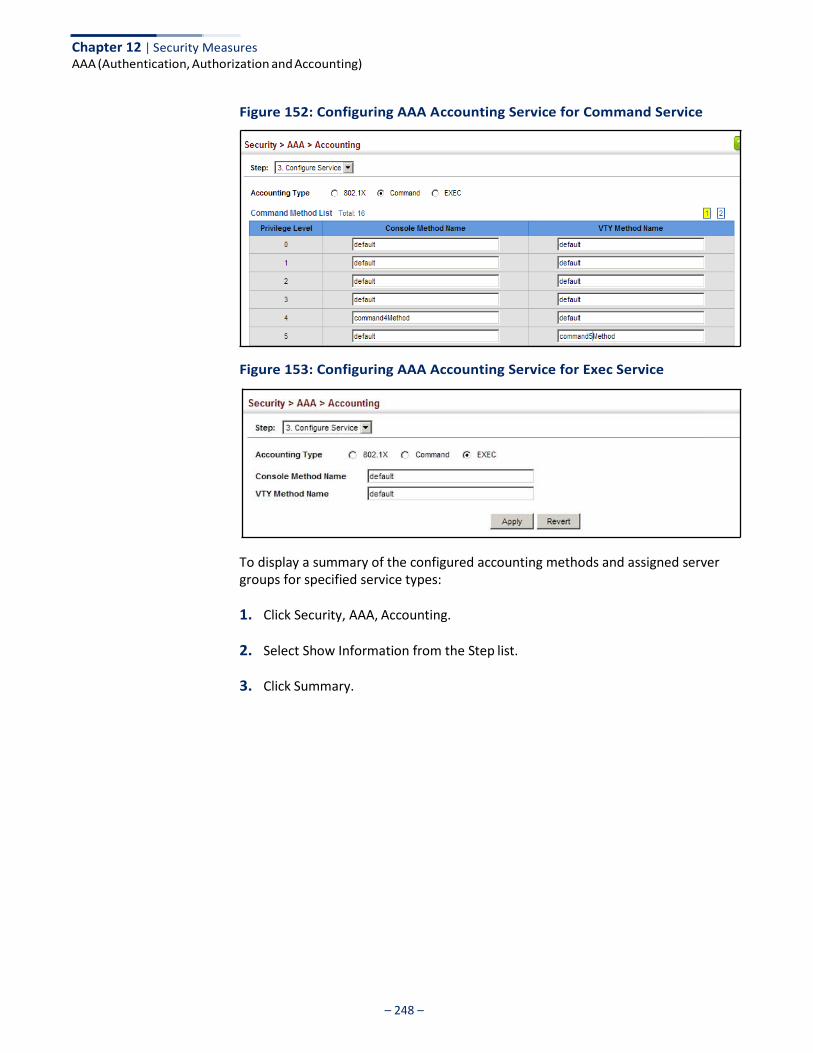
Chapter 12 | Security Measures AAA (Authentication, Authorization and Accounting)
– 248 –
Figure 152: Configuring AAA Accounting Service for Command Service
Figure 153: Configuring AAA Accounting Service for Exec Service
To display a summary of the configured accounting methods and assigned server groups for specified service types:
1. Click Security, AAA, Accounting.
2. Select Show Information from the Step list.
3. Click Summary.
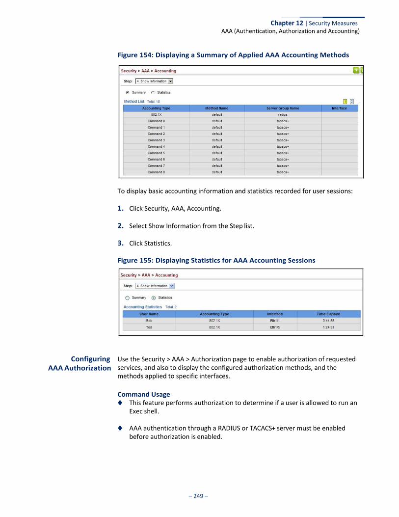
Chapter 12 | Security Measures AAA (Authentication, Authorization and Accounting)
– 249 –
Figure 154: Displaying a Summary of Applied AAA Accounting Methods
To display basic accounting information and statistics recorded for user sessions:
1. Click Security, AAA, Accounting.
2. Select Show Information from the Step list.
3. Click Statistics.
Figure 155: Displaying Statistics for AAA Accounting Sessions
Configuring AAA Authorization
Use the Security > AAA > Authorization page to enable authorization of requested services, and also to display the configured authorization methods, and the methods applied to specific interfaces.
Command Usage ◆ This feature performs authorization to determine if a user is allowed to run an
Exec shell.
◆ AAA authentication through a RADIUS or TACACS+ server must be enabled before authorization is enabled.
Chapter 12 | Security Measures AAA (Authentication, Authorization and Accounting)
– 250 –
Parameters These parameters are displayed:
Configure Method
◆ Authorization Type – Specifies the service as:
■ Command – Administrative authorization to apply to commands entered at specific CLI privilege levels.
■ Exec – Administrative authorization for local console, Telnet, or SSH
connections.
◆ Method Name – Specifies an authorization method for service requests. The “default” method is used for a requested service if no other methods have been defined. (Range: 1-64 characters)
◆ Server Group Name - Specifies the authorization server group.
(Range: 1-64 characters)
The group name “tacacs+” specifies all configured TACACS+ hosts (see “Configuring Local/Remote Logon Authentication” on page 237). Any other group name refers to a server group configured on the TACACS+ Group Settings page. Authorization is only supported for TACACS+ servers.
Configure Service
◆ Authorization Type – Specifies the service as Exec, indicating administrative authorization for local console, Telnet, or SSH connections.
◆ Console Method Name – Specifies a user defined method name to apply to
console connections.
◆ VTY Method Name – Specifies a user defined method name to apply to Telnet and SSH connections.
Show Information
◆ Authorization Type - Displays the authorization service.
◆ Method Name - Displays the user-defined or default accounting method.
◆ Server Group Name - Displays the authorization server group.
◆ Interface - Displays the console or Telnet interface to which these rules apply. (This field is null if the authorization method and associated server group has not been assigned to an interface.)
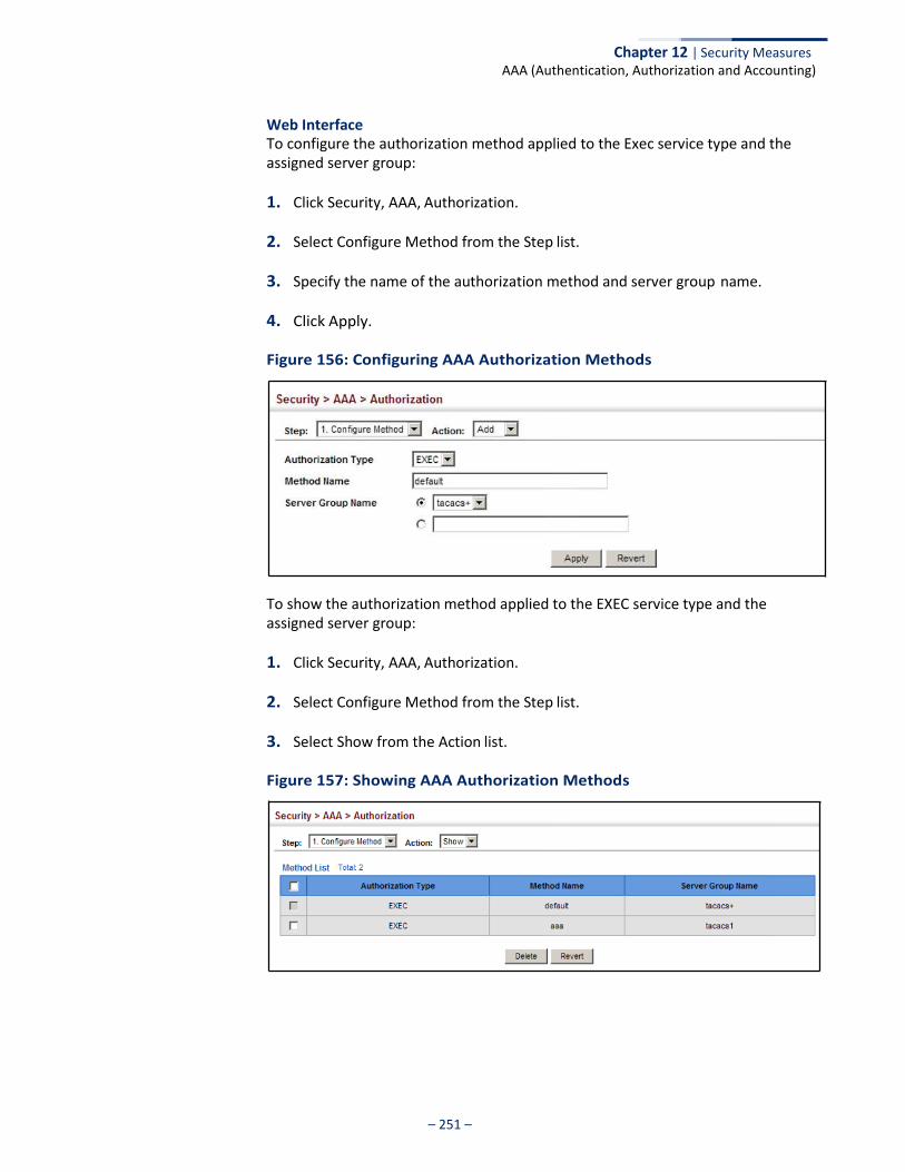
Chapter 12 | Security Measures AAA (Authentication, Authorization and Accounting)
– 251 –
Web Interface To configure the authorization method applied to the Exec service type and the assigned server group:
1. Click Security, AAA, Authorization.
2. Select Configure Method from the Step list.
3. Specify the name of the authorization method and server group name.
4. Click Apply.
Figure 156: Configuring AAA Authorization Methods
To show the authorization method applied to the EXEC service type and the assigned server group:
1. Click Security, AAA, Authorization.
2. Select Configure Method from the Step list.
3. Select Show from the Action list.
Figure 157: Showing AAA Authorization Methods
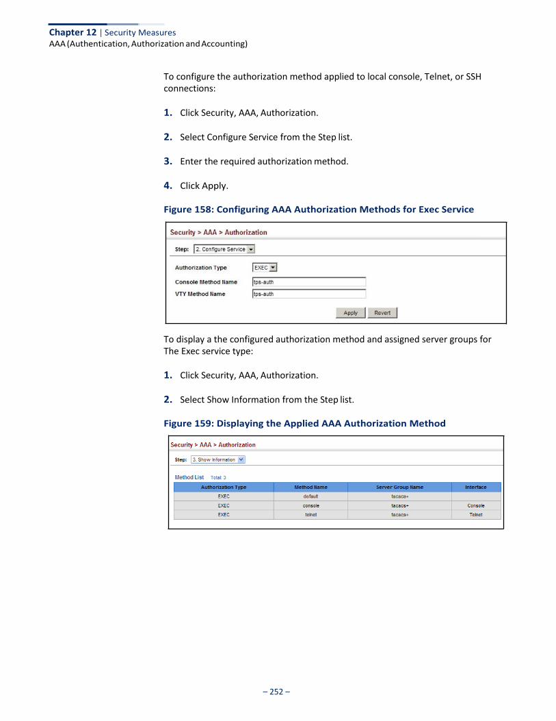
Chapter 12 | Security Measures AAA (Authentication, Authorization and Accounting)
– 252 –
To configure the authorization method applied to local console, Telnet, or SSH connections:
1. Click Security, AAA, Authorization.
2. Select Configure Service from the Step list.
3. Enter the required authorization method.
4. Click Apply.
Figure 158: Configuring AAA Authorization Methods for Exec Service
To display a the configured authorization method and assigned server groups for The Exec service type:
1. Click Security, AAA, Authorization.
2. Select Show Information from the Step list.
Figure 159: Displaying the Applied AAA Authorization Method
– 253 –
Chapter 12 | Security Measures
Configuring User Accounts
Configuring User Accounts
Use the Security > User Accounts page to control management access to the switch based on manually configured user names and passwords.
Command Usage ◆ The default guest name is “guest” with the password “guest.” The default
administrator name is “admin” with the password “admin.”
◆ The guest only has read access for most configuration parameters. However, the administrator has write access for all parameters governing the onboard agent. You should therefore assign a new administrator password as soon as possible, and store it in a safe place.
Parameters These parameters are displayed:
◆ User Name – The name of the user. (Maximum length: 32 characters; maximum number of users: 16)
◆ Access Level – Specifies command access privileges. (Range: 0-15)
Level 0, 8 and 15 are designed for users (guest), managers (network maintenance), and administrators (top-level access). The other levels can be used to configured specialized access profiles.
Level 0-7 provide the same default access to a limited number of commands which display the current status of the switch, as well as several database clear and reset functions. These commands are equivalent to those available under Normal Exec command mode in the CLI.
Level 8-14 provide the same default access privileges, including additional commands beyond those provided for Levels 0-7 (equivalent to CLI Normal Exec command mode), and a subset of the configuration commands provided for Level 15 (equivalent to CLI Privileged Exec command mode).
Level 15 provides full access to all commands.
The privilege level associated with any command can be changed using the “privilege” command described in the CLI Reference Guide.
Any privilege level can access all of the commands assigned to lower privilege levels. For example, privilege level 8 can access all commands assigned to privilege levels 7-0 according to default settings, and to any other commands assigned to levels 7-0 using the “privilege” command described in the CLI Reference Guide.
◆ Password Type – Specifies the following options:
■ No Password – No password is required for this user to log in.
■ Plain Password – Plain text unencrypted password.
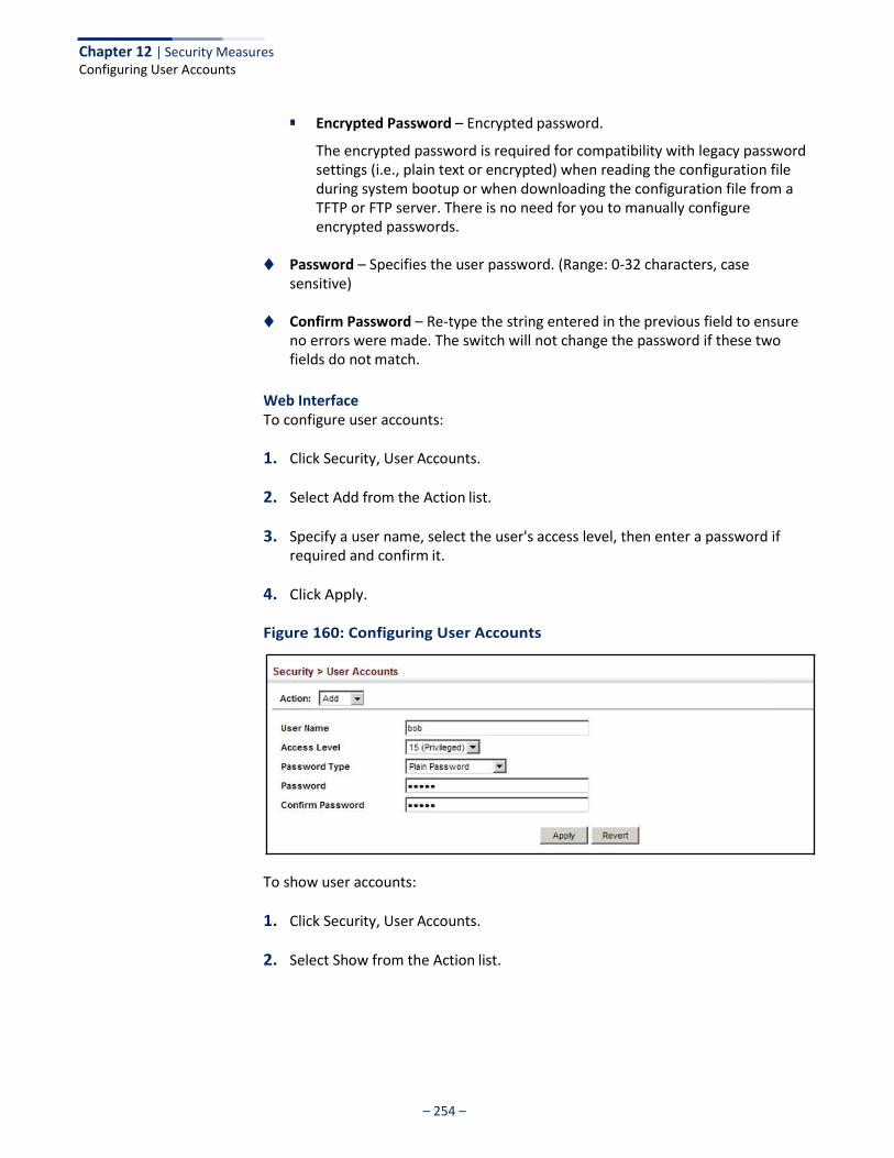
– 254 –
Chapter 12 | Security Measures Configuring User Accounts
■ Encrypted Password – Encrypted password.
The encrypted password is required for compatibility with legacy password settings (i.e., plain text or encrypted) when reading the configuration file during system bootup or when downloading the configuration file from a TFTP or FTP server. There is no need for you to manually configure encrypted passwords.
◆ Password – Specifies the user password. (Range: 0-32 characters, case
sensitive)
◆ Confirm Password – Re-type the string entered in the previous field to ensure no errors were made. The switch will not change the password if these two fields do not match.
Web Interface To configure user accounts:
1. Click Security, User Accounts.
2. Select Add from the Action list.
3. Specify a user name, select the user's access level, then enter a password if required and confirm it.
4. Click Apply.
Figure 160: Configuring User Accounts
To show user accounts:
1. Click Security, User Accounts.
2. Select Show from the Action list.
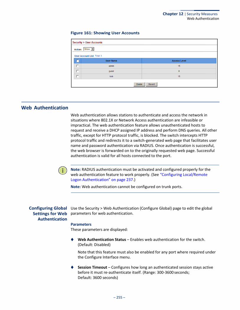
– 255 –
Chapter 12 | Security Measures
Web Authentication
Figure 161: Showing User Accounts
Web Authentication
Web authentication allows stations to authenticate and access the network in situations where 802.1X or Network Access authentication are infeasible or impractical. The web authentication feature allows unauthenticated hosts to request and receive a DHCP assigned IP address and perform DNS queries. All other traffic, except for HTTP protocol traffic, is blocked. The switch intercepts HTTP protocol traffic and redirects it to a switch-generated web page that facilitates user name and password authentication via RADIUS. Once authentication is successful, the web browser is forwarded on to the originally requested web page. Successful authentication is valid for all hosts connected to the port.
Note: RADIUS authentication must be activated and configured properly for the web authentication feature to work properly. (See “Configuring Local/Remote Logon Authentication” on page 237.)
Note: Web authentication cannot be configured on trunk ports.
Configuring Global Settings for Web
Authentication
Use the Security > Web Authentication (Configure Global) page to edit the global parameters for web authentication.
Parameters These parameters are displayed:
◆ Web Authentication Status – Enables web authentication for the switch. (Default: Disabled)
Note that this feature must also be enabled for any port where required under the Configure Interface menu.
◆ Session Timeout – Configures how long an authenticated session stays active
before it must re-authenticate itself. (Range: 300-3600 seconds; Default: 3600 seconds)
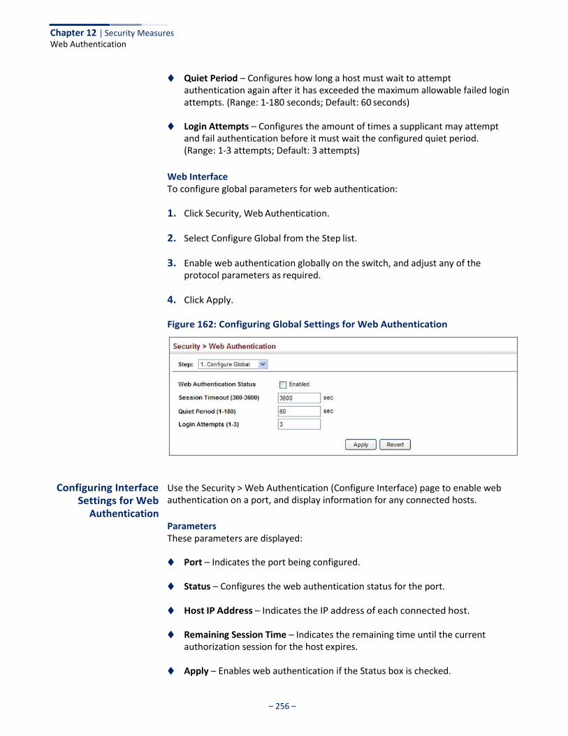
– 256 –
Chapter 12 | Security Measures Web Authentication
◆ Quiet Period – Configures how long a host must wait to attempt authentication again after it has exceeded the maximum allowable failed login attempts. (Range: 1-180 seconds; Default: 60 seconds)
◆ Login Attempts – Configures the amount of times a supplicant may attempt
and fail authentication before it must wait the configured quiet period. (Range: 1-3 attempts; Default: 3 attempts)
Web Interface To configure global parameters for web authentication:
1. Click Security, Web Authentication.
2. Select Configure Global from the Step list.
3. Enable web authentication globally on the switch, and adjust any of the protocol parameters as required.
4. Click Apply.
Figure 162: Configuring Global Settings for Web Authentication
Configuring Interface
Settings for Web Authentication
Use the Security > Web Authentication (Configure Interface) page to enable web authentication on a port, and display information for any connected hosts.
Parameters These parameters are displayed:
◆ Port – Indicates the port being configured.
◆ Status – Configures the web authentication status for the port.
◆ Host IP Address – Indicates the IP address of each connected host.
◆ Remaining Session Time – Indicates the remaining time until the current authorization session for the host expires.
◆ Apply – Enables web authentication if the Status box is checked.
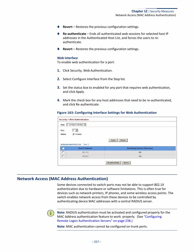
– 257 –
Chapter 12 | Security Measures Network Access (MAC Address Authentication)
◆ Revert – Restores the previous configuration settings.
◆ Re-authenticate – Ends all authenticated web sessions for selected host IP addresses in the Authenticated Host List, and forces the users to re- authenticate.
◆ Revert – Restores the previous configuration settings.
Web Interface To enable web authentication for a port:
1. Click Security, Web Authentication.
2. Select Configure Interface from the Step list.
3. Set the status box to enabled for any port that requires web authentication, and click Apply.
4. Mark the check box for any host addresses that need to be re-authenticated, and click Re-authenticate.
Figure 163: Configuring Interface Settings for Web Authentication
Network Access (MAC Address Authentication)
Some devices connected to switch ports may not be able to support 802.1X authentication due to hardware or software limitations. This is often true for devices such as network printers, IP phones, and some wireless access points. The switch enables network access from these devices to be controlled by authenticating device MAC addresses with a central RADIUS server.
Note: RADIUS authentication must be activated and configured properly for the MAC Address authentication feature to work properly. (See “Configuring Remote Logon Authentication Servers” on page 238.)
Note: MAC authentication cannot be configured on trunk ports.
– 258 –
Chapter 12 | Security Measures Network Access (MAC Address Authentication)
Command Usage ◆ MAC address authentication controls access to the network by authenticating
the MAC address of each host that attempts to connect to a switch port. Traffic received from a specific MAC address is forwarded by the switch only if the source MAC address is successfully authenticated by a central RADIUS server. While authentication for a MAC address is in progress, all traffic is blocked until authentication is completed. On successful authentication, the RADIUS server may optionally assign VLAN and quality of service settings for the switch port.
◆ When enabled on a port, the authentication process sends a Password
Authentication Protocol (PAP) request to a configured RADIUS server. The user name and password are both equal to the MAC address being authenticated. On the RADIUS server, PAP user name and passwords must be configured in the MAC address format XX-XX-XX-XX-XX-XX (all in upper case).
◆ Authenticated MAC addresses are stored as dynamic entries in the switch
secure MAC address table and are removed when the aging time expires. The maximum number of secure MAC addresses supported for the switch system is 1024.
◆ Configured static MAC addresses are added to the secure address table when
seen on a switch port. Static addresses are treated as authenticated without sending a request to a RADIUS server.
◆ When port status changes to down, all MAC addresses mapped to that port are
cleared from the secure MAC address table. Static VLAN assignments are not restored.
◆ The RADIUS server may optionally return a VLAN identifier list to be applied to
the switch port. The following attributes need to be configured on the RADIUS server.
■ Tunnel-Type = VLAN
■ Tunnel-Medium-Type = 802
■ Tunnel-Private-Group-ID = 1u,2t [VLAN ID list]
The VLAN identifier list is carried in the RADIUS “Tunnel-Private-Group-ID” attribute. The VLAN list can contain multiple VLAN identifiers in the format “1u,2t,3u” where “u” indicates an untagged VLAN and “t” a tagged VLAN.
◆ The RADIUS server may optionally return dynamic QoS assignments to be
applied to a switch port for an authenticated user. The “Filter-ID” attribute (attribute 11) can be configured on the RADIUS server to pass the following QoS information:
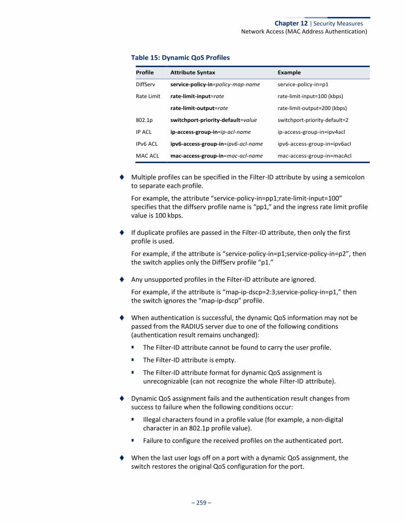
– 259 –
Chapter 12 | Security Measures Network Access (MAC Address Authentication)
Table 15: Dynamic QoS Profiles
Profile Attribute Syntax Example
DiffServ service-policy-in=policy-map-name service-policy-in=p1
Rate Limit rate-limit-input=rate rate-limit-input=100 (kbps)
rate-limit-output=rate rate-limit-output=200 (kbps)
802.1p switchport-priority-default=value switchport-priority-default=2
IP ACL ip-access-group-in=ip-acl-name ip-access-group-in=ipv4acl
IPv6 ACL ipv6-access-group-in=ipv6-acl-name ipv6-access-group-in=ipv6acl
MAC ACL mac-access-group-in=mac-acl-name mac-access-group-in=macAcl
◆ Multiple profiles can be specified in the Filter-ID attribute by using a semicolon
to separate each profile.
For example, the attribute “service-policy-in=pp1;rate-limit-input=100” specifies that the diffserv profile name is “pp1,” and the ingress rate limit profile value is 100 kbps.
◆ If duplicate profiles are passed in the Filter-ID attribute, then only the first
profile is used.
For example, if the attribute is “service-policy-in=p1;service-policy-in=p2”, then the switch applies only the DiffServ profile “p1.”
◆ Any unsupported profiles in the Filter-ID attribute are ignored.
For example, if the attribute is “map-ip-dscp=2:3;service-policy-in=p1,” then the switch ignores the “map-ip-dscp” profile.
◆ When authentication is successful, the dynamic QoS information may not be
passed from the RADIUS server due to one of the following conditions (authentication result remains unchanged):
■ The Filter-ID attribute cannot be found to carry the user profile.
■ The Filter-ID attribute is empty.
■ The Filter-ID attribute format for dynamic QoS assignment is unrecognizable (can not recognize the whole Filter-ID attribute).
◆ Dynamic QoS assignment fails and the authentication result changes from
success to failure when the following conditions occur:
■ Illegal characters found in a profile value (for example, a non-digital character in an 802.1p profile value).
■ Failure to configure the received profiles on the authenticated port.
◆ When the last user logs off on a port with a dynamic QoS assignment, the switch restores the original QoS configuration for the port.
Chapter 12 | Security Measures Network Access (MAC Address Authentication)
– 260 –
◆ When a user attempts to log into the network with a returned dynamic QoS profile that is different from users already logged on to the same port, the user is denied access.
◆ While a port has an assigned dynamic QoS profile, any manual QoS
configuration changes only take effect after all users have logged off the port.
Configuring Global Settings for
Network Access
MAC address authentication is configured on a per-port basis, however there are two configurable parameters that apply globally to all ports on the switch. Use the Security > Network Access (Configure Global) page to configure MAC address authentication aging and reauthentication time.
Parameters These parameters are displayed:
◆ Aging Status – Enables aging for authenticated MAC addresses stored in the
secure MAC address table. (Default: Disabled)
This parameter applies to authenticated MAC addresses configured by the MAC Address Authentication process described in this section, as well as to any secure MAC addresses authenticated by 802.1X, regardless of the 802.1X Operation Mode (Single-Host, Multi-Host, or MAC-Based authentication as described on page 302).
Authenticated MAC addresses are stored as dynamic entries in the switch’s secure MAC address table and are removed when the aging time expires.
The maximum number of secure MAC addresses supported for the switch system is 1024.
◆ Reauthentication Time – Sets the time period after which the switch removes
an authenticated MAC address from the secure table. When the reauthentication time expires for a secure MAC address, it is removed from the secure MAC address table, and the switch will only perform the authentication process the next time it receives the MAC address packet. (Range: 120-1000000 seconds; Default: 1800 seconds)
Web Interface To configure aging status and reauthentication time for MAC address authentication:
1. Click Security, Network Access.
2. Select Configure Global from the Step list.
3. Enable or disable aging for secure addresses, and modify the reauthentication time as required.
4. Click Apply.

Chapter 12 | Security Measures Network Access (MAC Address Authentication)
– 261 –
Figure 164: Configuring Global Settings for Network Access
Configuring Network Access
for Ports
Use the Security > Network Access (Configure Interface) page to configure MAC authentication on switch ports, including enabling address authentication, setting the maximum MAC count, and enabling dynamic VLAN or dynamic QoS assignments.
Parameters These parameters are displayed:
◆ MAC Authentication
■ Status – Enables MAC authentication on a port. (Default: Disabled)
■ Intrusion – Sets the port response to a host MAC authentication failure to either block access to the port or to pass traffic through. (Options: Block, Pass; Default: Block)
■ Max MAC Count6 – Sets the maximum number of MAC addresses that can be authenticated on a port via MAC authentication; that is, the Network Access process described in this section. (Range: 1-1024; Default: 1024)
◆ Network Access Max MAC Count6 – Sets the maximum number of MAC
addresses that can be authenticated on a port interface via all forms of authentication (including Network Access and IEEE 802.1X). (Range: 1-1024; Default: 1024)
◆ Guest VLAN – Specifies the VLAN to be assigned to the port when 802.1X Authentication or MAC authentication fails. (Range: 0-4094, where 0 means disabled; Default: Disabled)
The VLAN must already be created and active (see “Configuring VLAN Groups” on page 149). Also, when used with 802.1X authentication, intrusion action must be set for “Guest VLAN” (see “Configuring Port Authenticator Settings for 802.1X” on page 302).
A port can only be assigned to the guest VLAN in case of failed authentication, and switchport mode is set to Hybrid. (See “Adding Static Members to VLANs” on page 152.)
6. The maximum number of MAC addresses per port is 1024, and the maximum number of
secure MAC addresses supported for the switch system is 1024. When the limit is
reached, all new MAC addresses are treated as authentication failures.
Chapter 12 | Security Measures Network Access (MAC Address Authentication)
– 262 –
◆ Dynamic VLAN – Enables dynamic VLAN assignment for an authenticated
port. When enabled, any VLAN identifiers returned by the RADIUS server through the 802.1X authentication process are applied to the port, providing the VLANs have already been created on the switch. (GVRP is not used to create the VLANs.) (Default: Enabled)
The VLAN settings specified by the first authenticated MAC address are implemented for a port. Other authenticated MAC addresses on the port must have the same VLAN configuration, or they are treated as authentication failures.
If dynamic VLAN assignment is enabled on a port and the RADIUS server returns no VLAN configuration (to the 802.1X authentication process), the authentication is still treated as a success, and the host is assigned to the default untagged VLAN.
When the dynamic VLAN assignment status is changed on a port, all authenticated addresses mapped to that port are cleared from the secure MAC address table.
◆ Dynamic QoS – Enables dynamic QoS assignment for an authenticated port.
(Default: Disabled)
◆ MAC Filter ID – Allows a MAC Filter to be assigned to the port. MAC addresses or MAC address ranges present in a selected MAC Filter are exempt from authentication on the specified port (as described under "Configuring a MAC Address Filter"). (Range: 1-64; Default: None)
Web Interface To configure MAC authentication on switch ports:
1. Click Security, Network Access.
2. Select Configure Interface from the Step list.
3. Click the General button.
4. Make any configuration changes required to enable address authentication on a port, set the maximum number of secure addresses supported, the guest VLAN to use when MAC Authentication or 802.1X Authentication fails, and the dynamic VLAN and QoS assignments.
5. Click Apply.
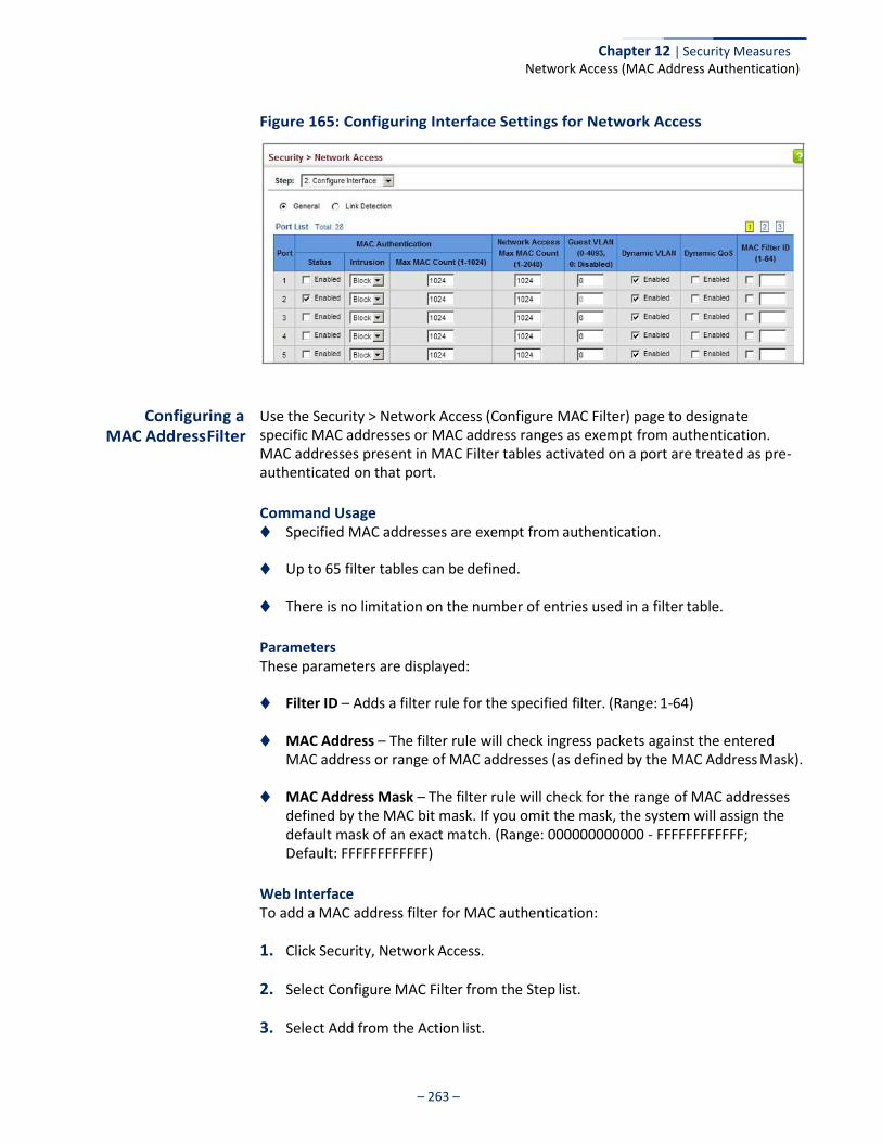
Chapter 12 | Security Measures Network Access (MAC Address Authentication)
– 263 –
Figure 165: Configuring Interface Settings for Network Access
Configuring a MAC Address Filter
Use the Security > Network Access (Configure MAC Filter) page to designate specific MAC addresses or MAC address ranges as exempt from authentication. MAC addresses present in MAC Filter tables activated on a port are treated as pre- authenticated on that port.
Command Usage ◆ Specified MAC addresses are exempt from authentication.
◆ Up to 65 filter tables can be defined.
◆ There is no limitation on the number of entries used in a filter table.
Parameters These parameters are displayed:
◆ Filter ID – Adds a filter rule for the specified filter. (Range: 1-64)
◆ MAC Address – The filter rule will check ingress packets against the entered MAC address or range of MAC addresses (as defined by the MAC Address Mask).
◆ MAC Address Mask – The filter rule will check for the range of MAC addresses
defined by the MAC bit mask. If you omit the mask, the system will assign the default mask of an exact match. (Range: 000000000000 - FFFFFFFFFFFF; Default: FFFFFFFFFFFF)
Web Interface To add a MAC address filter for MAC authentication:
1. Click Security, Network Access.
2. Select Configure MAC Filter from the Step list.
3. Select Add from the Action list.
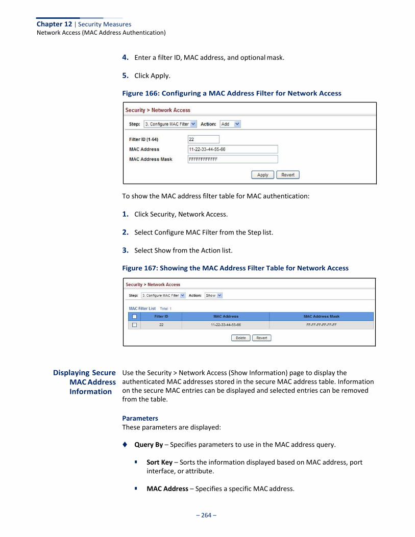
Chapter 12 | Security Measures Network Access (MAC Address Authentication)
– 264 –
4. Enter a filter ID, MAC address, and optional mask.
5. Click Apply.
Figure 166: Configuring a MAC Address Filter for Network Access
To show the MAC address filter table for MAC authentication:
1. Click Security, Network Access.
2. Select Configure MAC Filter from the Step list.
3. Select Show from the Action list.
Figure 167: Showing the MAC Address Filter Table for Network Access
Displaying Secure MAC Address Information
Use the Security > Network Access (Show Information) page to display the authenticated MAC addresses stored in the secure MAC address table. Information on the secure MAC entries can be displayed and selected entries can be removed from the table.
Parameters These parameters are displayed:
◆ Query By – Specifies parameters to use in the MAC address query.
■ Sort Key – Sorts the information displayed based on MAC address, port interface, or attribute.
■ MAC Address – Specifies a specific MAC address.
Chapter 12 | Security Measures Network Access (MAC Address Authentication)
– 265 –
■ Interface – Specifies a port interface.
■ Attribute – Displays static or dynamic addresses.
◆ Authenticated MAC Address List
■ MAC Address – The authenticated MAC address.
■ Interface – The port interface associated with a secure MAC address.
■ RADIUS Server – The IP address of the RADIUS server that authenticated the MAC address.
■ Time – The time when the MAC address was last authenticated.
■ Attribute – Indicates a static or dynamic address.
Web Interface To display the authenticated MAC addresses stored in the secure MAC address table:
1. Click Security, Network Access.
2. Select Show Information from the Step list.
3. Use the sort key to display addresses based MAC address, interface, or attribute.
4. Restrict the displayed addresses by entering a specific address in the MAC Address field, specifying a port in the Interface field, or setting the address type to static or dynamic in the Attribute field.
5. Click Query.
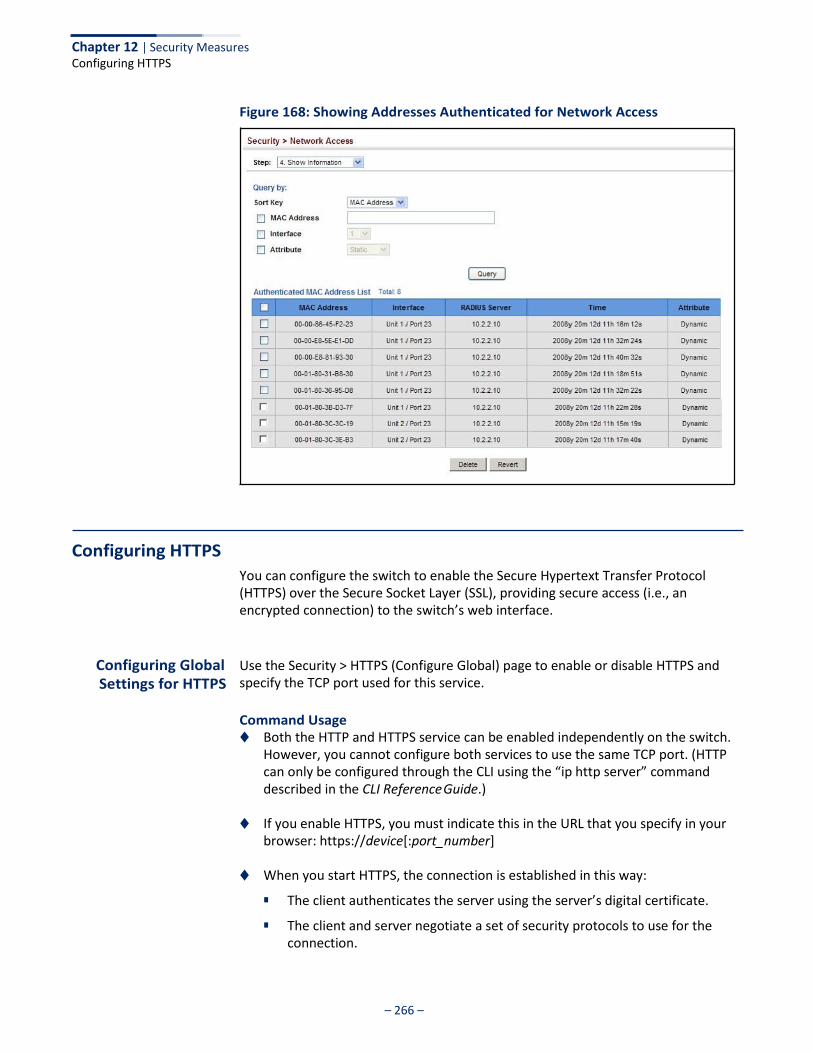
– 266 –
Chapter 12 | Security Measures Configuring HTTPS
Figure 168: Showing Addresses Authenticated for Network Access
Configuring HTTPS
You can configure the switch to enable the Secure Hypertext Transfer Protocol (HTTPS) over the Secure Socket Layer (SSL), providing secure access (i.e., an encrypted connection) to the switch’s web interface.
Configuring Global Settings for HTTPS
Use the Security > HTTPS (Configure Global) page to enable or disable HTTPS and specify the TCP port used for this service.
Command Usage ◆ Both the HTTP and HTTPS service can be enabled independently on the switch.
However, you cannot configure both services to use the same TCP port. (HTTP can only be configured through the CLI using the “ip http server” command described in the CLI Reference Guide.)
◆ If you enable HTTPS, you must indicate this in the URL that you specify in your
browser: https://device[:port_number]
◆ When you start HTTPS, the connection is established in this way:
■ The client authenticates the server using the server’s digital certificate.
■ The client and server negotiate a set of security protocols to use for the connection.
– 267 –
Chapter 12 | Security Measures Configuring HTTPS
■ The client and server generate session keys for encrypting and decrypting
data.
◆ The client and server establish a secure encrypted connection.
A padlock icon should appear in the status bar for Internet Explorer 11, Mozilla Firefox 53, or Google Chrome 59, or more recent versions.
◆ The following web browsers and operating systems currently support HTTPS:
Table 16: HTTPS System Support
Internet Explorer 11.x or later Windows 7, 8, 10
Mozilla Firefox 53 or later Windows 7, 8, 10, Linux
Google Chrome 59 or later Windows 7, 8, 10
◆ To specify a secure-site certificate, see “Replacing the Default Secure-site Certificate” on page 268.
Note: Connection to the web interface is not supported for HTTPS using an IPv6 link local address.
Parameters These parameters are displayed:
◆ HTTPS Status – Allows you to enable/disable the HTTPS server feature on the
switch. (Default: Enabled)
◆ HTTPS Port – Specifies the TCP port number used for HTTPS connection to the switch’s web interface. (Default: Port 443)
Web Interface To configure HTTPS:
1. Click Security, HTTPS.
2. Select Configure Global from the Step list.
3. Enable HTTPS and specify the port number if required.
4. Click Apply.
Web Browser Operating System

– 268 –
Chapter 12 | Security Measures Configuring HTTPS
Figure 169: Configuring HTTPS
Replacing the Default Secure-site Certificate
Use the Security > HTTPS (Copy Certificate) page to replace the default secure-site certificate.
When you log onto the web interface using HTTPS (for secure access), a Secure Sockets Layer (SSL) certificate appears for the switch. By default, the certificate that the web browser displays will be associated with a warning that the site is not recognized as a secure site. This is because the certificate has not been signed by an approved certification authority. If you want this warning to be replaced by a message confirming that the connection to the switch is secure, you must obtain a unique certificate and a private key and password from a recognized certification authority.
Caution: For maximum security, we recommend you obtain a unique Secure Sockets Layer certificate at the earliest opportunity. This is because the default certificate for the switch is not unique to the hardware you have purchased.
When you have obtained these, place them on your TFTP server and transfer them to the switch to replace the default (unrecognized) certificate with an authorized one.
Note: The switch must be reset for the new certificate to be activated. To reset the switch, see “Resetting the System” on page 93 or type “reload” at the command prompt: Console#reload
Parameters These parameters are displayed:
◆ TFTP Server IP Address – IP address of TFTP server which contains the certificate file.
◆ Certificate Source File Name – Name of certificate file stored on the TFTP server.
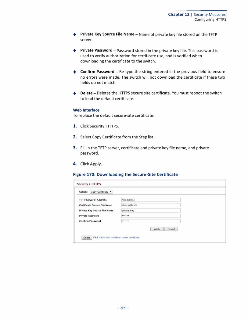
– 269 –
Chapter 12 | Security Measures Configuring HTTPS
◆ Private Key Source File Name – Name of private key file stored on the TFTP server.
◆ Private Password – Password stored in the private key file. This password is used to verify authorization for certificate use, and is verified when downloading the certificate to the switch.
◆ Confirm Password – Re-type the string entered in the previous field to ensure no errors were made. The switch will not download the certificate if these two fields do not match.
◆ Delete – Deletes the HTTPS secure site certificate. You must reboot the switch to load the default certificate.
Web Interface To replace the default secure-site certificate:
1. Click Security, HTTPS.
2. Select Copy Certificate from the Step list.
3. Fill in the TFTP server, certificate and private key file name, and private password.
4. Click Apply.
Figure 170: Downloading the Secure-Site Certificate
Chapter 12 | Security Measures Configuring the Secure Shell
– 270 –
Configuring the Secure Shell
The Berkeley-standard includes remote access tools originally designed for Unix systems. Some of these tools have also been implemented for Microsoft Windows and other environments. These tools, including commands such as rlogin (remote login), rsh (remote shell), and rcp (remote copy), are not secure from hostile attacks.
Secure Shell (SSH) includes server/client applications intended as a secure replacement for the older Berkeley remote access tools. SSH can also provide remote management access to this switch as a secure replacement for Telnet. When the client contacts the switch via the SSH protocol, the switch generates a public- key that the client uses along with a local user name and password for access authentication. SSH also encrypts all data transfers passing between the switch and SSH-enabled management station clients, and ensures that data traveling over the network arrives unaltered.
Note: You need to install an SSH client on the management station to access the switch for management via the SSH protocol.
Note: The switch supports both SSH Version 1.5 and 2.0 clients.
Command Usage The SSH server on this switch supports both password and public key authentication. If password authentication is specified by the SSH client, then the password can be authenticated either locally or via a RADIUS or TACACS+ remote authentication server, as specified on the System Authentication page (page 237). If public key authentication is specified by the client, then you must configure authentication keys on both the client and the switch as described in the following section. Note that regardless of whether you use public key or password authentication, you still have to generate authentication keys on the switch (SSH Host Key Settings) and enable the SSH server (Authentication Settings).
To use the SSH server, complete these steps:
1. Generate a Host Key Pair – On the SSH Host Key Settings page, create a host public/private key pair.
2. Provide Host Public Key to Clients – Many SSH client programs automatically import the host public key during the initial connection setup with the switch. Otherwise, you need to manually create a known hosts file on the management station and place the host public key in it. An entry for a public key in the known hosts file would appear similar to the following example:
10.1.0.54 1024 35 15684995401867669259333946775054617325313674890836547254
15020245593199868544358361651999923329781766065830956 10825913212890233 76546801726272571413428762941301196195566782 595664104869574278881462065194174677298486546861571773939016477935594230357741 309802273708779454524083971752646358058176716709574804776117
Chapter 12 | Security Measures Configuring the Secure Shell
– 271 –
3. Import Client’s Public Key to the Switch – See “Importing User Public Keys” on page 275 to copy a file containing the public key for all the SSH client’s granted management access to the switch. (Note that these clients must be configured locally on the switch via the User Accounts page as described on page 253.) The clients are subsequently authenticated using these keys. The current firmware only accepts public key files based on standard UNIX format as shown in the following example for an RSA Version 1 key:
1024 35 134108168560989392104094492015542534763164192187295892114317388005553616163105 177594083868631109291232226828519254374603100937187721199696317813662774141689
851320491172048303392543241016379975923714490119380060902539484084827178194372 288402533115952134861022902978982721353267131629432532818915045306393916643 [email protected]
4. Set the Optional Parameters – On the SSH Settings page, configure the optional parameters, including the authentication timeout, the number of retries, and the server key size.
5. Enable SSH Service – On the SSH Settings page, enable the SSH server on the switch.
6. Authentication – One of the following authentication methods is employed:
Password Authentication (for SSH v1.5 or V2 Clients)
a. The client sends its password to the server.
b. The switch compares the client's password to those stored in memory.
c. If a match is found, the connection is allowed.
Note: To use SSH with only password authentication, the host public key must still be given to the client, either during initial connection or manually entered into the known host file. However, you do not need to configure the client’s keys.
Public Key Authentication – When an SSH client attempts to contact the switch, the SSH server uses the host key pair to negotiate a session key and encryption method. Only clients that have a private key corresponding to the public keys stored on the switch can access it. The following exchanges take place during this process:
Authenticating SSH v1.5 Clients
a. The client sends its RSA public key to the switch.
b. The switch compares the client's public key to those stored in memory.
c. If a match is found, the switch uses its secret key to generate a random 256-bit string as a challenge, encrypts this string with the user’s public key, and sends it to the client.
d. The client uses its private key to decrypt the challenge string, computes the MD5 checksum, and sends the checksum back to the switch.
Chapter 12 | Security Measures Configuring the Secure Shell
– 272 –
e. The switch compares the checksum sent from the client against that computed for the original string it sent. If the two checksums match, this means that the client's private key corresponds to an authorized public key, and the client is authenticated.
Authenticating SSH v2 Clients
a. The client first queries the switch to determine if DSA public key authentication using a preferred algorithm is acceptable.
b. If the specified algorithm is supported by the switch, it notifies the client to proceed with the authentication process. Otherwise, it rejects the request.
c. The client sends a signature generated using the private key to the switch.
d. When the server receives this message, it checks whether the supplied key is acceptable for authentication, and if so, it then checks whether the signature is correct. If both checks succeed, the client is authenticated.
Note: The SSH server supports up to eight client sessions. The maximum number of client sessions includes both current Telnet sessions and SSH sessions.
Note: The SSH server can be accessed using any configured IPv4 or IPv6 interface address on the switch.
Configuring the SSH Server
Use the Security > SSH (Configure Global) page to enable the SSH server and configure basic settings for authentication.
Note: You must generate DSA and RSA host keys before enabling the SSH server. See “Generating the Host Key Pair” on page 273.
Parameters These parameters are displayed:
◆ SSH Server Status – Allows you to enable/disable the SSH server on the switch.
(Default: Disabled)
◆ Version – The Secure Shell version number. Version 2.0 is displayed, but the switch supports management access via either SSH Version 1.5 or 2.0 clients.
◆ Authentication Timeout – Specifies the time interval in seconds that the SSH
server waits for a response from a client during an authentication attempt. (Range: 1-120 seconds; Default: 120 seconds)
◆ Authentication Retries – Specifies the number of authentication attempts
that a client is allowed before authentication fails and the client has to restart the authentication process. (Range: 1-5 times; Default: 3)
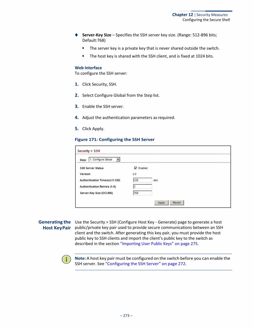
Chapter 12 | Security Measures Configuring the Secure Shell
– 273 –
◆ Server-Key Size – Specifies the SSH server key size. (Range: 512-896 bits; Default:768)
■ The server key is a private key that is never shared outside the switch.
■ The host key is shared with the SSH client, and is fixed at 1024 bits.
Web Interface To configure the SSH server:
1. Click Security, SSH.
2. Select Configure Global from the Step list.
3. Enable the SSH server.
4. Adjust the authentication parameters as required.
5. Click Apply.
Figure 171: Configuring the SSH Server
Generating the Host Key Pair
Use the Security > SSH (Configure Host Key - Generate) page to generate a host public/private key pair used to provide secure communications between an SSH client and the switch. After generating this key pair, you must provide the host public key to SSH clients and import the client’s public key to the switch as described in the section “Importing User Public Keys” on page 275.
Note: A host key pair must be configured on the switch before you can enable the SSH server. See “Configuring the SSH Server” on page 272.

Chapter 12 | Security Measures Configuring the Secure Shell
– 274 –
Parameters These parameters are displayed:
◆ Host-Key Type – The key type used to generate the host key pair (i.e., public
and private keys). (Range: RSA (Version 1), DSA (Version 2), Both; Default: Both)
The SSH server uses RSA or DSA for key exchange when the client first establishes a connection with the switch, and then negotiates with the client to select either DES (56-bit) or 3DES (168-bit) for data encryption.
Note: The switch uses only RSA Version 1 for SSHv1.5 clients and DSA Version 2 for SSHv2 clients.
◆ Save – Saves the host key from RAM (i.e., volatile memory) to flash memory. Otherwise, the host key pair is stored to RAM by default. Note that you must select this item from the Show page. (Default: Disabled)
Web Interface To generate the SSH host key pair:
1. Click Security, SSH.
2. Select Configure Host Key from the Step list.
3. Select Generate from the Action list.
4. Select the host-key type from the drop-down box.
5. Click Apply.
Figure 172: Generating the SSH Host Key Pair
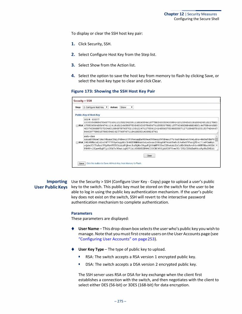
Chapter 12 | Security Measures Configuring the Secure Shell
– 275 –
To display or clear the SSH host key pair:
1. Click Security, SSH.
2. Select Configure Host Key from the Step list.
3. Select Show from the Action list.
4. Select the option to save the host key from memory to flash by clicking Save, or select the host-key type to clear and click Clear.
Figure 173: Showing the SSH Host Key Pair
Importing User Public Keys
Use the Security > SSH (Configure User Key - Copy) page to upload a user’s public key to the switch. This public key must be stored on the switch for the user to be able to log in using the public key authentication mechanism. If the user’s public key does not exist on the switch, SSH will revert to the interactive password authentication mechanism to complete authentication.
Parameters These parameters are displayed:
◆ User Name – This drop-down box selects the user who’s public key you wish to
manage. Note that you must first create users on the User Accounts page (see “Configuring User Accounts” on page 253).
◆ User Key Type – The type of public key to upload.
■ RSA: The switch accepts a RSA version 1 encrypted public key.
■ DSA: The switch accepts a DSA version 2 encrypted public key.
The SSH server uses RSA or DSA for key exchange when the client first establishes a connection with the switch, and then negotiates with the client to select either DES (56-bit) or 3DES (168-bit) for data encryption.
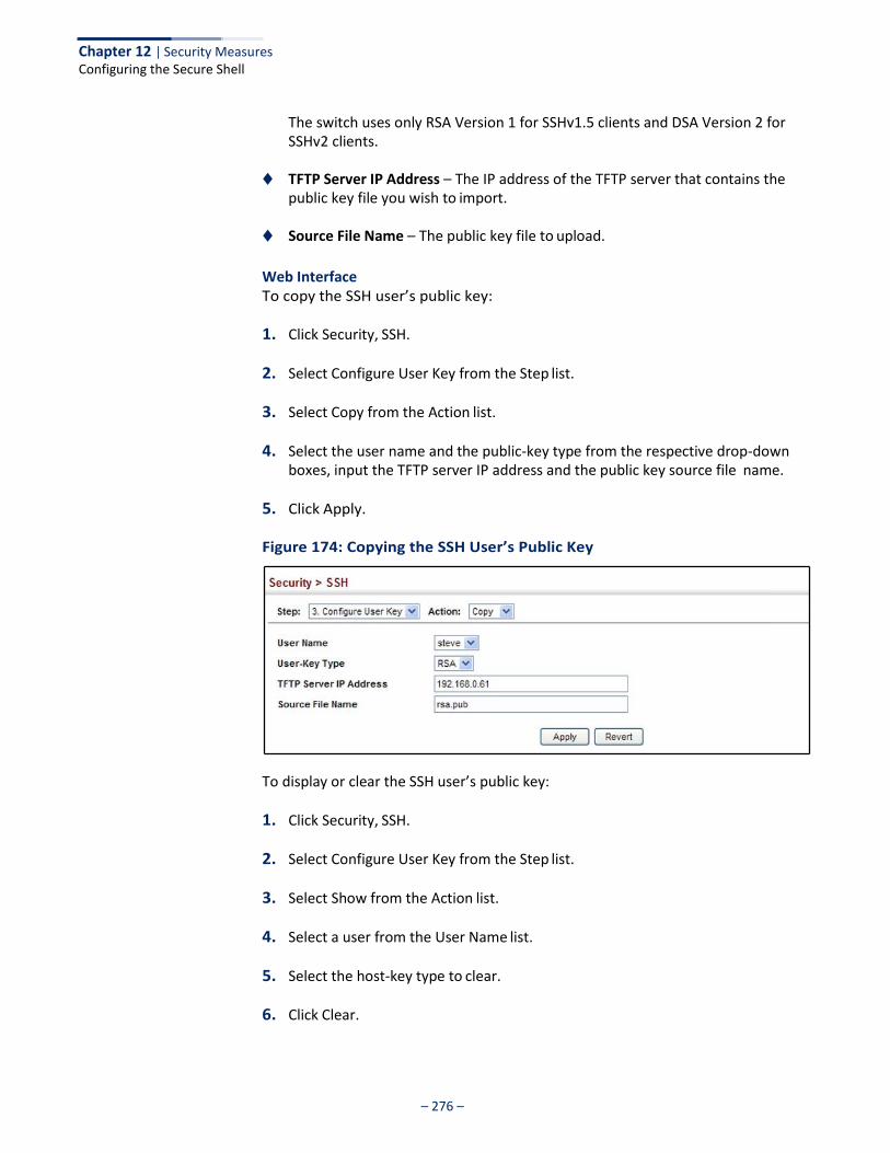
Chapter 12 | Security Measures Configuring the Secure Shell
– 276 –
The switch uses only RSA Version 1 for SSHv1.5 clients and DSA Version 2 for SSHv2 clients.
◆ TFTP Server IP Address – The IP address of the TFTP server that contains the
public key file you wish to import.
◆ Source File Name – The public key file to upload.
Web Interface To copy the SSH user’s public key:
1. Click Security, SSH.
2. Select Configure User Key from the Step list.
3. Select Copy from the Action list.
4. Select the user name and the public-key type from the respective drop-down boxes, input the TFTP server IP address and the public key source file name.
5. Click Apply.
Figure 174: Copying the SSH User’s Public Key
To display or clear the SSH user’s public key:
1. Click Security, SSH.
2. Select Configure User Key from the Step list.
3. Select Show from the Action list.
4. Select a user from the User Name list.
5. Select the host-key type to clear.
6. Click Clear.
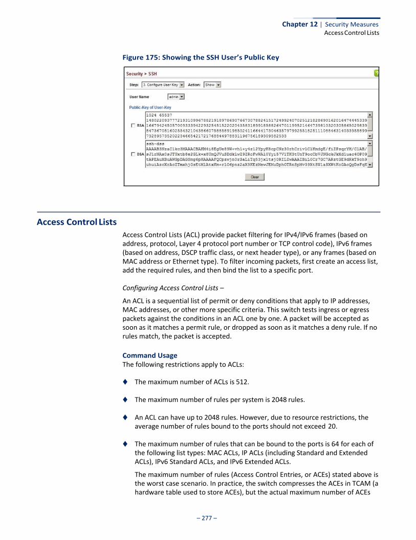
– 277 –
Chapter 12 | Security Measures Access Control Lists
Figure 175: Showing the SSH User’s Public Key
Access Control Lists
Access Control Lists (ACL) provide packet filtering for IPv4/IPv6 frames (based on address, protocol, Layer 4 protocol port number or TCP control code), IPv6 frames (based on address, DSCP traffic class, or next header type), or any frames (based on MAC address or Ethernet type). To filter incoming packets, first create an access list, add the required rules, and then bind the list to a specific port.
Configuring Access Control Lists –
An ACL is a sequential list of permit or deny conditions that apply to IP addresses, MAC addresses, or other more specific criteria. This switch tests ingress or egress packets against the conditions in an ACL one by one. A packet will be accepted as soon as it matches a permit rule, or dropped as soon as it matches a deny rule. If no rules match, the packet is accepted.
Command Usage The following restrictions apply to ACLs:
◆ The maximum number of ACLs is 512.
◆ The maximum number of rules per system is 2048 rules.
◆ An ACL can have up to 2048 rules. However, due to resource restrictions, the average number of rules bound to the ports should not exceed 20.
◆ The maximum number of rules that can be bound to the ports is 64 for each of
the following list types: MAC ACLs, IP ACLs (including Standard and Extended ACLs), IPv6 Standard ACLs, and IPv6 Extended ACLs.
The maximum number of rules (Access Control Entries, or ACEs) stated above is the worst case scenario. In practice, the switch compresses the ACEs in TCAM (a hardware table used to store ACEs), but the actual maximum number of ACEs
– 278 –
Chapter 12 | Security Measures Access Control Lists
possible depends on too many factors to be precisely determined. It depends on the amount of hardware resources reserved at runtime for this purpose.
Auto ACE Compression is a software feature used to compress all the ACEs of an ACL to utilize hardware resources more efficiency. Without compression, one ACE would occupy a fixed number of entries in TCAM. So if one ACL includes 25 ACEs, the ACL would need (25 * n) entries in TCAM, where “n” is the fixed number of TCAM entries needed for one ACE. When compression is employed, before writing the ACE into TCAM, the software compresses the ACEs to reduce the number of required TCAM entries. For example, one ACL may include 128 ACEs which classify a continuous IP address range like 192.168.1.0~255. If compression is disabled, the ACL would occupy (128*n) entries of TCAM, using up nearly all of the hardware resources. When using compression, the 128 ACEs are compressed into one ACE classifying the IP address as 192.168.1.0/24, which requires only “n” entries in TCAM. The above example is an ideal case for compression. The worst case would be if no any ACE can be compressed, in which case the used number of TCAM entries would be the same as without compression. It would also require more time to process the ACEs.
◆ If no matches are found down to the end of the list, the traffic is denied. For this reason, frequently hit entries should be placed at the top of the list. There is an implied deny for traffic that is not explicitly permitted. Also, note that a single- entry ACL with only one deny entry has the effect of denying all traffic. You should therefore use at least one permit statement in an ACL or all traffic will be blocked.
Because the switch stops testing after the first match, the order of the conditions is critical. If no conditions match, the packet will be denied.
The order in which active ACLs are checked is as follows:
1. User-defined rules in IP and MAC ACLs for ingress or egress ports are checked in parallel.
2. Rules within an ACL are checked in the configured order, from top to bottom.
3. If the result of checking an IP ACL is to permit a packet, but the result of a MAC ACL on the same packet is to deny it, the packet will be denied (because the decision to deny a packet has a higher priority for security reasons). A packet will also be denied if the IP ACL denies it and the MAC ACL accepts it.
Showing TCAM Utilization
Use the Security > ACL (Configure ACL - Show TCAM) page to show utilization parameters for TCAM (Ternary Content Addressable Memory), including the number policy control entries in use, the number of free entries, and the overall percentage of TCAM in use.
Command Usage Policy control entries (PCEs) are used by various system functions which rely on rule-based searches, including Access Control Lists (ACLs), IP Source Guard filter
– 279 –
Chapter 12 | Security Measures Access Control Lists
rules, Quality of Service (QoS) processes, QinQ, MAC-based VLANs, VLAN translation, or traps.
For example, when binding an ACL to a port, each rule in an ACL will use two PCEs; and when setting an IP Source Guard filter rule for a port, the system will also use two PCEs.
Parameters These parameters are displayed:
◆ Pool Capability Code – Abbreviation for processes shown in the TCAM List.
◆ Unit – Stack unit identifier.
◆ Device – Memory chip used for indicated pools.
◆ Pool – Rule slice (or call group). Each slice has a fixed number of rules that are used for the specified features.
◆ Total – The maximum number of policy control entries allocated to the each
pool.
◆ Used – The number of policy control entries used by the operating system.
◆ Free – The number of policy control entries available for use.
◆ Capability – The processes assigned to each pool.
Web Interface To show information on TCAM utilization:
1. Click Security, ACL.
2. Select Configure ACL from the Step list.
3. Select Show TCAM from the Action list.
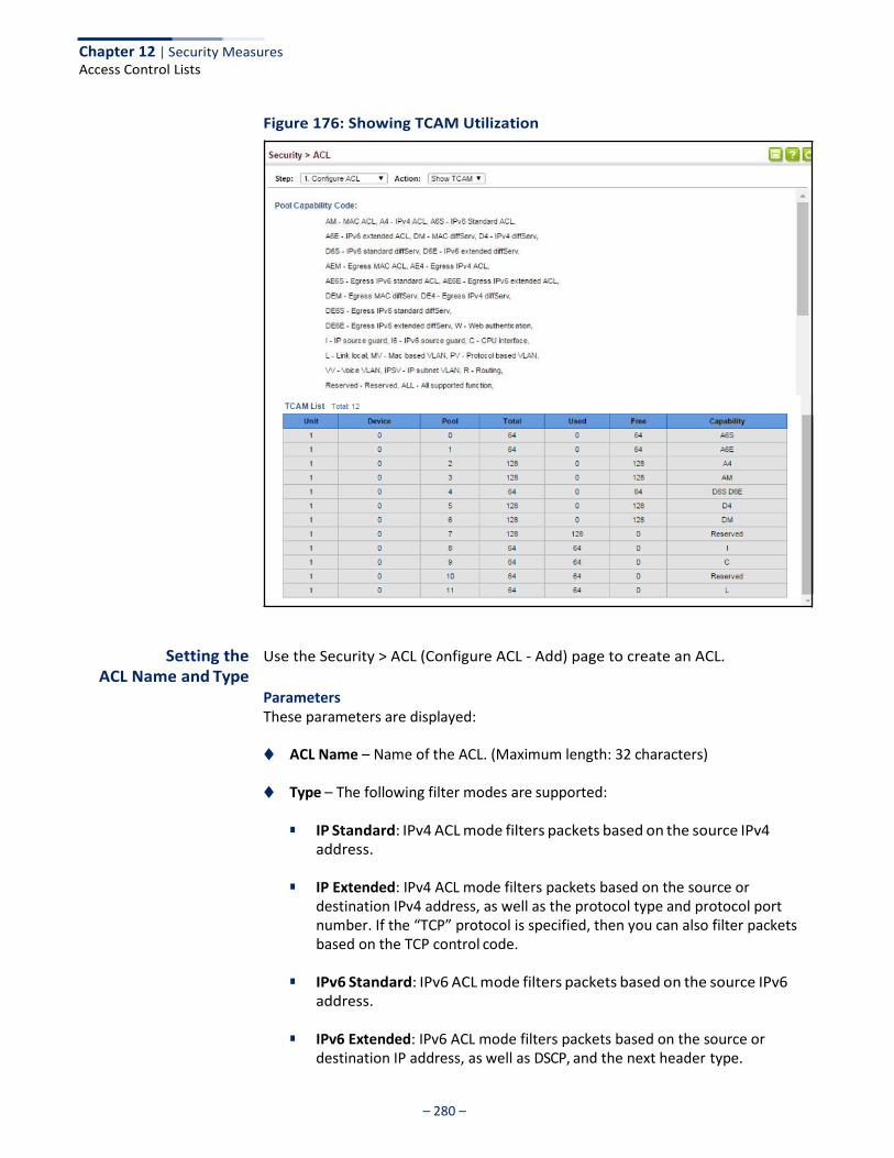
Chapter 12 | Security Measures Access Control Lists
– 280 –
Figure 176: Showing TCAM Utilization
Setting the ACL Name and Type
Use the Security > ACL (Configure ACL - Add) page to create an ACL.
Parameters These parameters are displayed:
◆ ACL Name – Name of the ACL. (Maximum length: 32 characters)
◆ Type – The following filter modes are supported:
■ IP Standard: IPv4 ACL mode filters packets based on the source IPv4 address.
■ IP Extended: IPv4 ACL mode filters packets based on the source or
destination IPv4 address, as well as the protocol type and protocol port number. If the “TCP” protocol is specified, then you can also filter packets based on the TCP control code.
■ IPv6 Standard: IPv6 ACL mode filters packets based on the source IPv6
address.
■ IPv6 Extended: IPv6 ACL mode filters packets based on the source or destination IP address, as well as DSCP, and the next header type.

Chapter 12 | Security Measures Access Control Lists
– 281 –
■ MAC – MAC ACL mode filters packets based on the source or destination
MAC address and the Ethernet frame type (RFC 1060).
■ ARP – ARP ACL specifies static IP-to-MAC address bindings used for ARP inspection (see “ARP Inspection” on page 324).
Web Interface To configure the name and type of an ACL:
1. Click Security, ACL.
2. Select Configure ACL from the Step list.
3. Select Add from the Action list.
4. Fill in the ACL Name field, and select the ACL type.
5. Click Apply.
Figure 177: Creating an ACL
To show a list of ACLs:
1. Click Security, ACL.
2. Select Configure ACL from the Step list.
3. Select Show from the Action list.
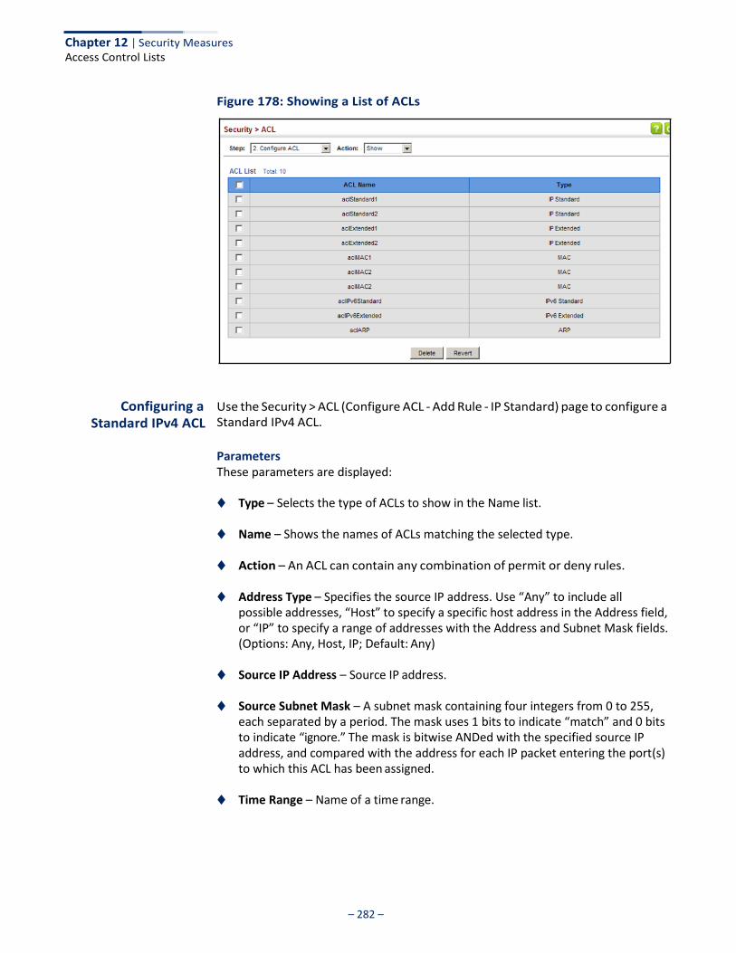
Chapter 12 | Security Measures Access Control Lists
– 282 –
Figure 178: Showing a List of ACLs
Configuring a Standard IPv4 ACL
Use the Security > ACL (Configure ACL - Add Rule - IP Standard) page to configure a Standard IPv4 ACL.
Parameters These parameters are displayed:
◆ Type – Selects the type of ACLs to show in the Name list.
◆ Name – Shows the names of ACLs matching the selected type.
◆ Action – An ACL can contain any combination of permit or deny rules.
◆ Address Type – Specifies the source IP address. Use “Any” to include all possible addresses, “Host” to specify a specific host address in the Address field, or “IP” to specify a range of addresses with the Address and Subnet Mask fields. (Options: Any, Host, IP; Default: Any)
◆ Source IP Address – Source IP address.
◆ Source Subnet Mask – A subnet mask containing four integers from 0 to 255, each separated by a period. The mask uses 1 bits to indicate “match” and 0 bits to indicate “ignore.” The mask is bitwise ANDed with the specified source IP address, and compared with the address for each IP packet entering the port(s) to which this ACL has been assigned.
◆ Time Range – Name of a time range.
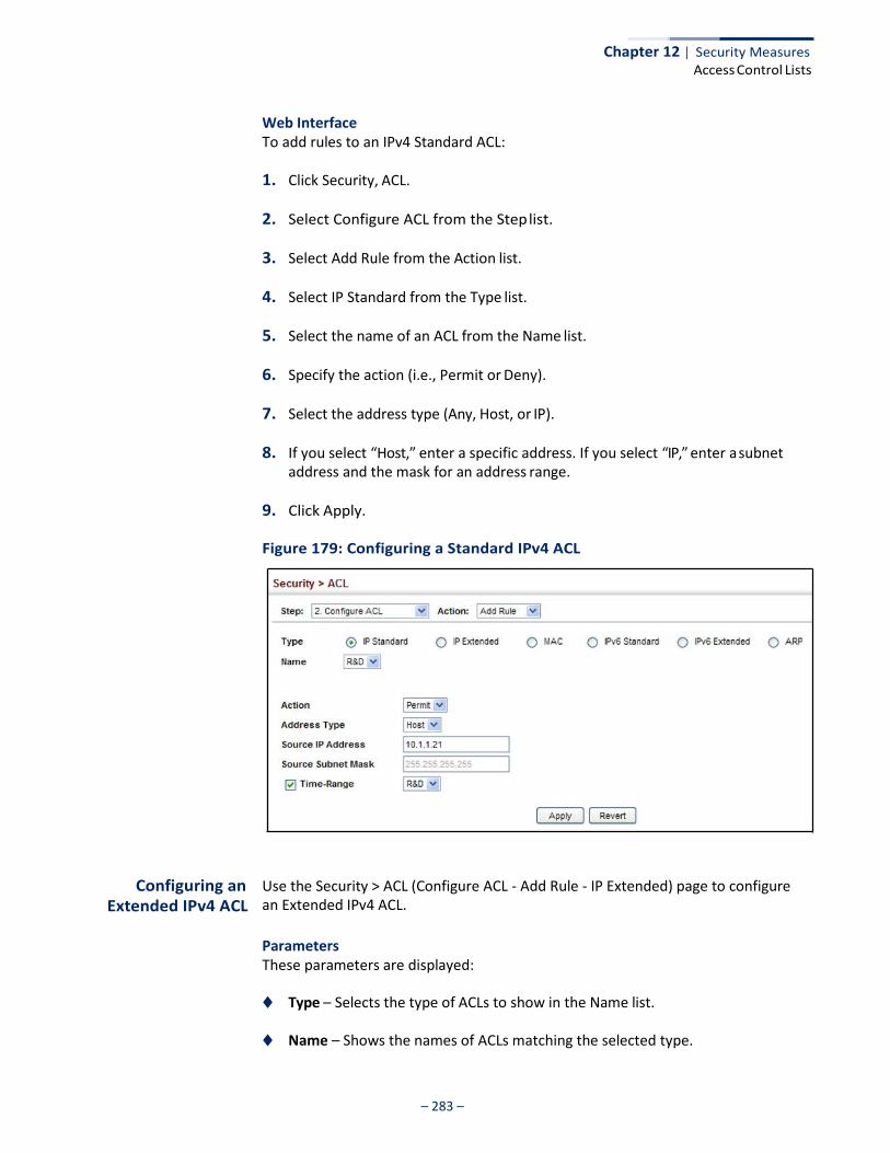
Chapter 12 | Security Measures Access Control Lists
– 283 –
Web Interface To add rules to an IPv4 Standard ACL:
1. Click Security, ACL.
2. Select Configure ACL from the Step list.
3. Select Add Rule from the Action list.
4. Select IP Standard from the Type list.
5. Select the name of an ACL from the Name list.
6. Specify the action (i.e., Permit or Deny).
7. Select the address type (Any, Host, or IP).
8. If you select “Host,” enter a specific address. If you select “IP,” enter a subnet address and the mask for an address range.
9. Click Apply.
Figure 179: Configuring a Standard IPv4 ACL
Configuring an Extended IPv4 ACL
Use the Security > ACL (Configure ACL - Add Rule - IP Extended) page to configure an Extended IPv4 ACL.
Parameters These parameters are displayed:
◆ Type – Selects the type of ACLs to show in the Name list.
◆ Name – Shows the names of ACLs matching the selected type.
Chapter 12 | Security Measures Access Control Lists
– 284 –
◆ Action – An ACL can contain any combination of permit or deny rules.
◆ Source/Destination Address Type – Specifies the source or destination IP address type. Use “Any” to include all possible addresses, “Host” to specify a specific host address in the Address field, or “IP” to specify a range of addresses with the Address and Subnet Mask fields. (Options: Any, Host, IP; Default: Any)
◆ Source/Destination IP Address – Source or destination IP address.
◆ Source/Destination Subnet Mask – Subnet mask for source or destination address. (See the description for Subnet Mask on page 282.)
◆ Source/Destination Port – Source/destination port number for the specified
protocol type. (Range: 0-65535)
◆ Source/Destination Port Bit Mask – Decimal number representing the port bits to match. (Range: 0-65535)
◆ Protocol – Specifies the protocol type to match as TCP, UDP or Others, where
others indicates a specific protocol number (0-255). (Options: TCP, UDP, Others; Default: Others)
The following items are under TCP
■ Control Code – Decimal number (representing a bit string) that specifies flag bits in byte 14 of the TCP header. (Range: 0-63)
■ Control Code Bit Mask – Decimal number representing the code bits to match. (Range: 0-63)
The control bit mask is a decimal number (for an equivalent binary bit mask) that is applied to the control code. Enter a decimal number, where the equivalent binary bit “1” means to match a bit and “0” means to ignore a bit. The following bits may be specified:
■ 1 (fin) – Finish
■ 2 (syn) – Synchronize
■ 4 (rst) – Reset
■ 8 (psh) – Push
■ 16 (ack) – Acknowledgement
■ 32 (urg) – Urgent pointer
For example, use the code value and mask below to catch packets with the following flags set:
■ SYN flag valid, use control-code 2, control bit mask 2
■ Both SYN and ACK valid, use control-code 18, control bit mask 18
■ SYN valid and ACK invalid, use control-code 2, control bit mask 18
Chapter 12 | Security Measures Access Control Lists
– 285 –
◆ Service Type – Packet priority settings based on the following criteria:
■ Precedence – IP precedence level. (Range: 0-7)
■ DSCP – DSCP priority level. (Range: 0-63)
◆ Time Range – Name of a time range.
Web Interface To add rules to an IPv4 Extended ACL:
1. Click Security, ACL.
2. Select Configure ACL from the Step list.
3. Select Add Rule from the Action list.
4. Select IP Extended from the Type list.
5. Select the name of an ACL from the Name list.
6. Specify the action (i.e., Permit or Deny).
7. Select the address type (Any, Host, or IP).
8. If you select “Host,” enter a specific address. If you select “IP,” enter a subnet address and the mask for an address range.
9. Set any other required criteria, such as service type, protocol type, or control code.
10. Click Apply.
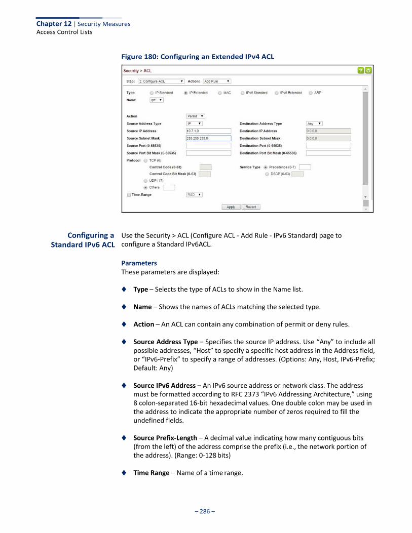
Chapter 12 | Security Measures Access Control Lists
– 286 –
Figure 180: Configuring an Extended IPv4 ACL
Configuring a Standard IPv6 ACL
Use the Security > ACL (Configure ACL - Add Rule - IPv6 Standard) page to configure a Standard IPv6ACL.
Parameters These parameters are displayed:
◆ Type – Selects the type of ACLs to show in the Name list.
◆ Name – Shows the names of ACLs matching the selected type.
◆ Action – An ACL can contain any combination of permit or deny rules.
◆ Source Address Type – Specifies the source IP address. Use “Any” to include all possible addresses, “Host” to specify a specific host address in the Address field, or “IPv6-Prefix” to specify a range of addresses. (Options: Any, Host, IPv6-Prefix; Default: Any)
◆ Source IPv6 Address – An IPv6 source address or network class. The address
must be formatted according to RFC 2373 “IPv6 Addressing Architecture,” using 8 colon-separated 16-bit hexadecimal values. One double colon may be used in the address to indicate the appropriate number of zeros required to fill the undefined fields.
◆ Source Prefix-Length – A decimal value indicating how many contiguous bits
(from the left) of the address comprise the prefix (i.e., the network portion of the address). (Range: 0-128 bits)
◆ Time Range – Name of a time range.
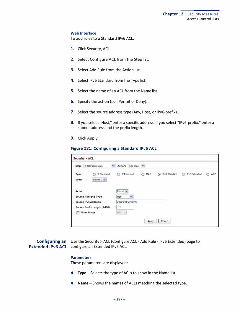
Chapter 12 | Security Measures Access Control Lists
– 287 –
Web Interface To add rules to a Standard IPv6 ACL:
1. Click Security, ACL.
2. Select Configure ACL from the Step list.
3. Select Add Rule from the Action list.
4. Select IPv6 Standard from the Type list.
5. Select the name of an ACL from the Name list.
6. Specify the action (i.e., Permit or Deny).
7. Select the source address type (Any, Host, or IPv6-prefix).
8. If you select “Host,” enter a specific address. If you select “IPv6-prefix,” enter a subnet address and the prefix length.
9. Click Apply.
Figure 181: Configuring a Standard IPv6 ACL
Configuring an Extended IPv6 ACL
Use the Security > ACL (Configure ACL - Add Rule - IPv6 Extended) page to configure an Extended IPv6 ACL.
Parameters These parameters are displayed:
◆ Type – Selects the type of ACLs to show in the Name list.
◆ Name – Shows the names of ACLs matching the selected type.

Chapter 12 | Security Measures Access Control Lists
– 288 –
◆ Action – An ACL can contain any combination of permit or deny rules.
◆ Source Address Type – Specifies the source IP address type. Use “Any” to include all possible addresses, “Host” to specify a specific host address in the Address field, or “IPv6-Prefix” to specify a range of addresses. (Options: Any, Host, IPv6-Prefix; Default: Any)
◆ Destination Address Type – Specifies the destination IP address type. Use
“Any” to include all possible addresses, or “IPv6-Prefix” to specify a range of addresses. (Options: Any, IPv6-Prefix; Default: Any)
◆ Source/Destination IPv6 Address – An IPv6 address or network class. The
address must be formatted according to RFC 2373 “IPv6 Addressing Architecture,” using 8 colon-separated 16-bit hexadecimal values. One double colon may be used in the address to indicate the appropriate number of zeros required to fill the undefined fields.
◆ Source/Destination Prefix-Length – A decimal value indicating how many
contiguous bits (from the left) of the address comprise the prefix; i.e., the network portion of the address. (Range: 0-128 bits for the source prefix; 0-8 bits for the destination prefix)
◆ DSCP – DSCP traffic class. (Range: 0-63)
◆ Source Port – Protocol7 source port number. (Range: 0-65535)
◆ Source Port Bit Mask – Decimal number representing the port bits to match. (Range: 0-65535)
◆ Destination Port – Protocol7 destination port number. (Range: 0-65535)
◆ Destination Port Bit Mask – Decimal number representing the port bits to match. (Range: 0-65535)
◆ Next Header – Identifies the type of header immediately following the IPv6
header. (Range: 0-255)
Optional internet-layer information is encoded in separate headers that may be placed between the IPv6 header and the upper-layer header in a packet. There are a small number of such extension headers, each identified by a distinct Next Header value. IPv6 supports the values defined for the IPv4 Protocol field in RFC 1700, and includes these commonly used headers:
0 : Hop-by-Hop Options (RFC 2460) 6 : TCP Upper-layer Header (RFC 1700) 17 : UDP Upper-layer Header (RFC 1700) 43 : Routing (RFC 2460) 44 : Fragment (RFC 2460) 50 : Encapsulating Security Payload (RFC 2406) 51 : Authentication (RFC 2402)
7. Includes TCP, UDP or other protocol types.
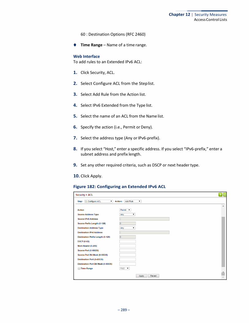
Chapter 12 | Security Measures Access Control Lists
– 289 –
60 : Destination Options (RFC 2460)
◆ Time Range – Name of a time range.
Web Interface To add rules to an Extended IPv6 ACL:
1. Click Security, ACL.
2. Select Configure ACL from the Step list.
3. Select Add Rule from the Action list.
4. Select IPv6 Extended from the Type list.
5. Select the name of an ACL from the Name list.
6. Specify the action (i.e., Permit or Deny).
7. Select the address type (Any or IPv6-prefix).
8. If you select “Host,” enter a specific address. If you select “IPv6-prefix,” enter a subnet address and prefix length.
9. Set any other required criteria, such as DSCP or next header type.
10. Click Apply.
Figure 182: Configuring an Extended IPv6 ACL
Chapter 12 | Security Measures Access Control Lists
– 290 –
Configuring a MAC ACL
Use the Security > ACL (Configure ACL - Add Rule - MAC) page to configure a MAC ACL based on hardware addresses, packet format, and Ethernet type.
Parameters These parameters are displayed:
◆ Type – Selects the type of ACLs to show in the Name list.
◆ Name – Shows the names of ACLs matching the selected type.
◆ Action – An ACL can contain any combination of permit or deny rules.
◆ Source/Destination Address Type – Use “Any” to include all possible addresses, “Host” to indicate a specific MAC address, or “MAC” to specify an address range with the Address and Bit Mask fields. (Options: Any, Host, MAC; Default: Any)
◆ Source/Destination MAC Address – Source or destination MAC address.
◆ Source/Destination Bit Mask – Hexadecimal mask for source or destination MAC address.
◆ Packet Format – This attribute includes the following packet types:
■ Any – Any Ethernet packet type.
■ Untagged-eth2 – Untagged Ethernet II packets.
■ Untagged-802.3 – Untagged Ethernet 802.3 packets.
■ Tagged-eth2 – Tagged Ethernet II packets.
■ Tagged-802.3 – Tagged Ethernet 802.3 packets.
◆ VID – VLAN ID. (Range: 1-4094)
◆ VID Bit Mask – VLAN bit mask. (Range: 0-4095)
◆ Ethernet Type – This option can only be used to filter Ethernet II formatted packets. (Range: 0-ffff hex.)
A detailed listing of Ethernet protocol types can be found in RFC 1060. A few of the more common types include 0800 (IP), 0806 (ARP), 8137 (IPX).
◆ Ethernet Type Bit Mask – Protocol bit mask. (Range: 0-ffff hex)
◆ CoS – CoS value. (Range: 0-7, where 7 is the highest priority)
◆ CoS Bit Mask – CoS bitmask. (Range: 0-7)
◆ Time Range – Name of a time range.
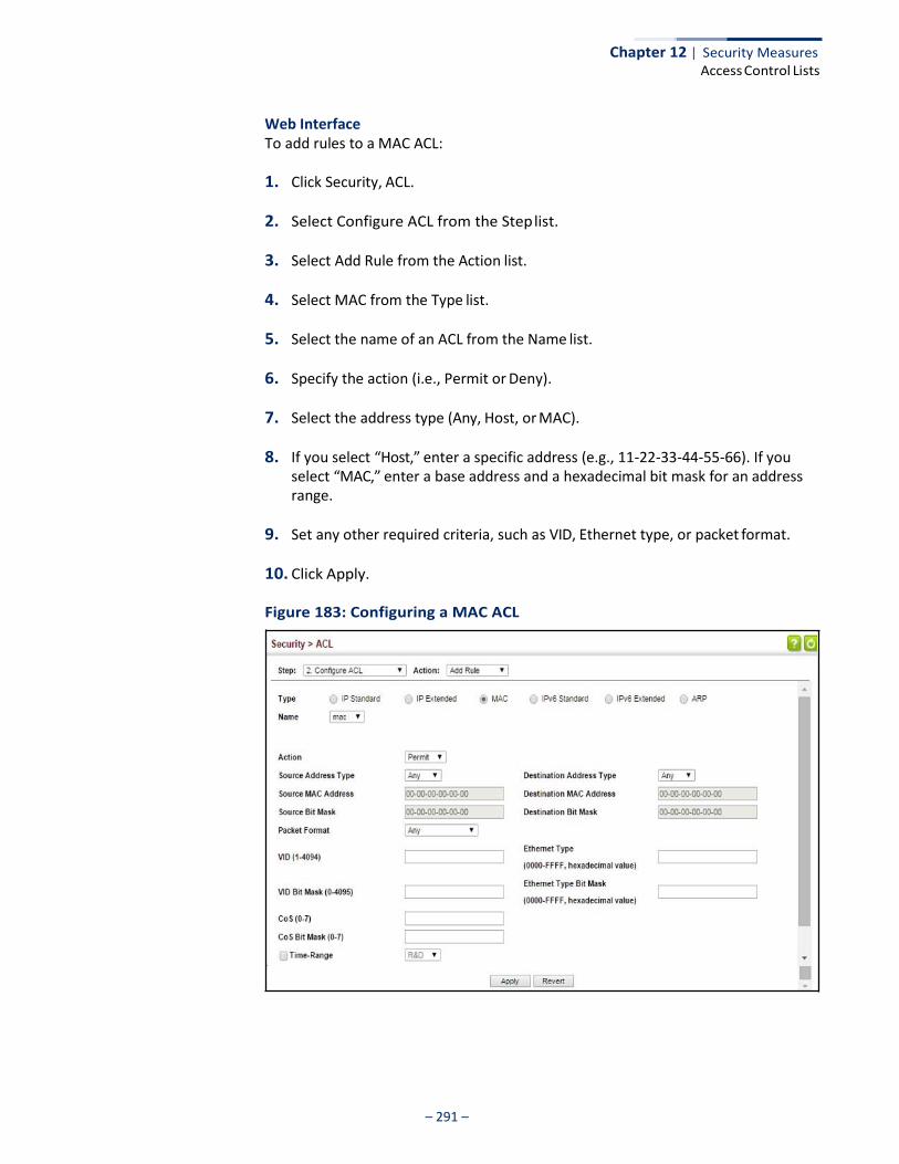
Chapter 12 | Security Measures Access Control Lists
– 291 –
Web Interface To add rules to a MAC ACL:
1. Click Security, ACL.
2. Select Configure ACL from the Step list.
3. Select Add Rule from the Action list.
4. Select MAC from the Type list.
5. Select the name of an ACL from the Name list.
6. Specify the action (i.e., Permit or Deny).
7. Select the address type (Any, Host, or MAC).
8. If you select “Host,” enter a specific address (e.g., 11-22-33-44-55-66). If you select “MAC,” enter a base address and a hexadecimal bit mask for an address range.
9. Set any other required criteria, such as VID, Ethernet type, or packet format.
10. Click Apply.
Figure 183: Configuring a MAC ACL
Chapter 12 | Security Measures Access Control Lists
– 292 –
Configuring an ARP ACL
Use the Security > ACL (Configure ACL - Add Rule - ARP) page to configure ACLs based on ARP message addresses. ARP Inspection can then use these ACLs to filter suspicious traffic (see “Configuring Global Settings for ARP Inspection” on page 325).
Parameters These parameters are displayed:
◆ Type – Selects the type of ACLs to show in the Name list.
◆ Name – Shows the names of ACLs matching the selected type.
◆ Action – An ACL can contain any combination of permit or deny rules.
◆ Packet Type – Indicates an ARP request, ARP response, or either type. (Range: IP, Request, Response; Default: IP)
◆ Source/Destination IP Address Type – Specifies the source or destination
IPv4 address. Use “Any” to include all possible addresses, “Host” to specify a specific host address in the Address field, or “IP” to specify a range of addresses with the Address and Mask fields. (Options: Any, Host, IP; Default: Any)
◆ Source/Destination IP Address – Source or destination IP address.
◆ Source/Destination IP Subnet Mask – Subnet mask for source or destination address. (See the description for Subnet Mask on page 282.)
◆ Source/Destination MAC Address Type – Use “Any” to include all possible
addresses, “Host” to indicate a specific MAC address, or “MAC” to specify an address range with the Address and Mask fields. (Options: Any, Host, MAC; Default: Any)
◆ Source/Destination MAC Address – Source or destination MAC address.
◆ Source/Destination MAC Bit Mask – Hexadecimal mask for source or destination MAC address.
◆ Log – Logs a packet when it matches the access control entry.
Web Interface To add rules to an ARP ACL:
1. Click Security, ACL.
2. Select Configure ACL from the Step list.
3. Select Add Rule from the Action list.
4. Select ARP from the Type list.
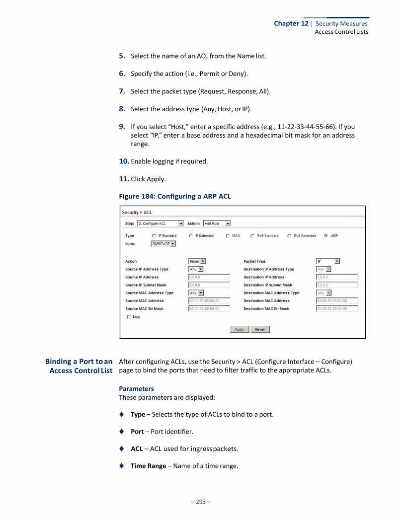
Chapter 12 | Security Measures Access Control Lists
– 293 –
5. Select the name of an ACL from the Name list.
6. Specify the action (i.e., Permit or Deny).
7. Select the packet type (Request, Response, All).
8. Select the address type (Any, Host, or IP).
9. If you select “Host,” enter a specific address (e.g., 11-22-33-44-55-66). If you select “IP,” enter a base address and a hexadecimal bit mask for an address range.
10. Enable logging if required.
11. Click Apply.
Figure 184: Configuring a ARP ACL
Binding a Port to an
Access Control List
After configuring ACLs, use the Security > ACL (Configure Interface – Configure) page to bind the ports that need to filter traffic to the appropriate ACLs.
Parameters These parameters are displayed:
◆ Type – Selects the type of ACLs to bind to a port.
◆ Port – Port identifier.
◆ ACL – ACL used for ingress packets.
◆ Time Range – Name of a time range.

Chapter 12 | Security Measures Access Control Lists
– 294 –
◆ Counter – Enables counter for ACL statistics.
Web Interface To bind an ACL to a port:
1. Click Security, ACL.
2. Select Configure Interface from the Step list.
3. Select Configure from the Action list.
4. Select IP, MAC or IPv6 from the Type options.
5. Select a port.
6. Select the name of an ACL from the ACL list.
7. Click Apply.
Figure 185: Binding a Port to an ACL
Showing ACL Hardware Counters
Use the Security > ACL > Configure Interface (Show Hardware Counters) page to show statistics for ACL hardware counters.
Parameters These parameters are displayed:
◆ Port – Port identifier. (Range: 1-52)
◆ Type – Selects the type of ACL.
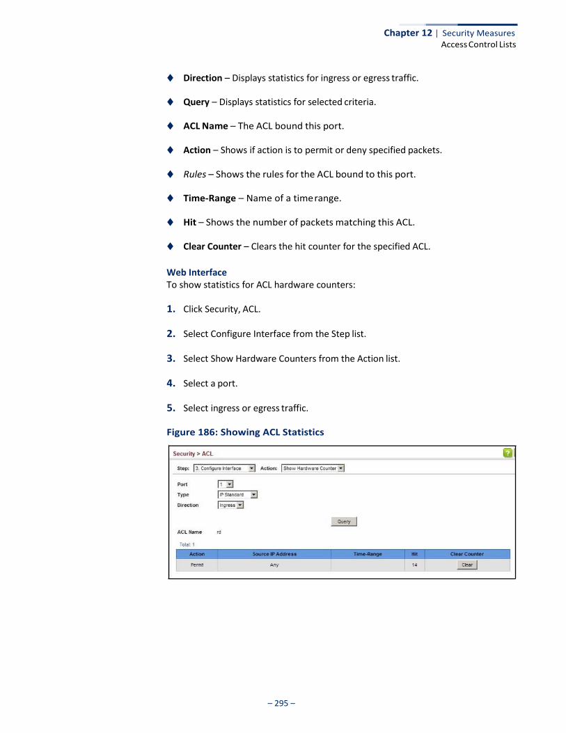
Chapter 12 | Security Measures Access Control Lists
– 295 –
◆ Direction – Displays statistics for ingress or egress traffic.
◆ Query – Displays statistics for selected criteria.
◆ ACL Name – The ACL bound this port.
◆ Action – Shows if action is to permit or deny specified packets.
◆ Rules – Shows the rules for the ACL bound to this port.
◆ Time-Range – Name of a time range.
◆ Hit – Shows the number of packets matching this ACL.
◆ Clear Counter – Clears the hit counter for the specified ACL.
Web Interface To show statistics for ACL hardware counters:
1. Click Security, ACL.
2. Select Configure Interface from the Step list.
3. Select Show Hardware Counters from the Action list.
4. Select a port.
5. Select ingress or egress traffic.
Figure 186: Showing ACL Statistics
– 296 –
Chapter 12 | Security Measures Filtering IP Addresses for Management Access
Filtering IP Addresses for Management Access
Use the Security > IP Filter page to create a list of up to 15 IP addresses or IP address groups that are allowed management access to the switch through the web interface, SNMP, or Telnet.
Command Usage ◆ The management interfaces are open to all IP addresses by default. Once you
add an entry to a filter list, access to that interface is restricted to the specified addresses.
◆ If anyone tries to access a management interface on the switch from an invalid
address, the switch will reject the connection, enter an event message in the system log, and send a trap message to the trap manager.
◆ IP address can be configured for SNMP, web and Telnet access respectively.
Each of these groups can include up to five different sets of addresses, either individual addresses or address ranges.
◆ When entering addresses for the same group (i.e., SNMP, web or Telnet), the
switch will not accept overlapping address ranges. When entering addresses for different groups, the switch will accept overlapping address ranges.
◆ You cannot delete an individual address from a specified range. You must
delete the entire range, and reenter the addresses.
◆ You can delete an address range just by specifying the start address, or by specifying both the start address and end address.
Parameters These parameters are displayed:
◆ Mode
■ Web – Configures IP address(es) for the web group.
■ SNMP – Configures IP address(es) for the SNMP group.
■ Telnet – Configures IP address(es) for the Telnet group.
■ All – Configures IP address(es) for all groups.
◆ Start IP Address – A single IP address, or the starting address of a range.
◆ End IP Address – The end address of a range.

– 297 –
Chapter 12 | Security Measures
Filtering IP Addresses for Management Access
Web Interface To create a list of IP addresses authorized for management access:
1. Click Security, IP Filter.
2. Select Add from the Action list.
3. Select the management interface to filter (Web, SNMP, Telnet, All).
4. Enter the IP addresses or range of addresses that are allowed management access to an interface.
5. Click Apply
Figure 187: Creating an IP Address Filter for Management Access
To show a list of IP addresses authorized for management access:
1. Click Security, IP Filter.
2. Select Show from the Action list.
Figure 188: Showing IP Addresses Authorized for Management Access
– 298 –
Chapter 12 | Security Measures Configuring Port Security
Configuring Port Security
Use the Security > Port Security page to configure the maximum number of device MAC addresses that can be learned by a switch port, stored in the address table, and authorized to access the network.
When port security is enabled on a port, the switch stops learning new MAC addresses on the specified port when it has reached a configured maximum number. Only incoming traffic with source addresses already stored in the address table will be authorized to access the network through that port. If a device with an unauthorized MAC address attempts to use the switch port, the intrusion will be detected and the switch can automatically take action by disabling the port and sending a trap message.
Command Usage ◆ The default maximum number of MAC addresses allowed on a secure port is
zero (that is, disabled). To use port security, you must configure the maximum number of addresses allowed on a port.
◆ To configure the maximum number of address entries which can be learned on
a port, and then specify the maximum number of dynamic addresses allowed. The switch will learn up to the maximum number of allowed address pairs <source MAC address, VLAN> for frames received on the port. When the port has reached the maximum number of MAC addresses, the port will stop learning new addresses. The MAC addresses already in the address table will be retained and will not be aged out.
Note that you can manually add additional secure addresses to a port using the Static Address Table (page 176).
◆ When the port security state is changed from enabled to disabled, all
dynamically learned entries are cleared from the address table.
◆ If port security is enabled, and the maximum number of allowed addresses are set to a non-zero value, any device not in the address table that attempts to use the port will be prevented from accessing the switch.
◆ If a port is disabled (shut down) due to a security violation, it must be manually
re-enabled from the Interface > Port > General page (page 98).
◆ A secure port has the following restrictions:
■ It cannot be used as a member of a static or dynamic trunk.
■ It should not be connected to a network interconnection device.
■ RSPAN and port security are mutually exclusive functions. If port security is enabled on a port, that port cannot be set as an RSPAN uplink port. Also, when a port is configured as an RSPAN uplink port, source port, or destination port, port security cannot be enabled on that port.
– 299 –
Chapter 12 | Security Measures
Configuring Port Security
Parameters These parameters are displayed:
◆ Port – Port identifier.
◆ Security Status – Enables or disables port security on a port. (Default: Disabled)
◆ Port Status – The operational status:
■ Secure/Down – Port security is disabled.
■ Secure/Up – Port security is enabled.
■ Shutdown – Port is shut down due to a response to a port security violation.
◆ Action – Indicates the action to be taken when a port security violation is detected:
■ None: No action should be taken. (This is the default.)
■ Trap: Send an SNMP trap message.
■ Shutdown: Disable the port.
■ Trap and Shutdown: Send an SNMP trap message and disable the port.
◆ Max MAC Count – The maximum number of MAC addresses that can be
learned on a port. (Range: 0 - 1024, where 0 means disabled)
The maximum address count is effective when port security is enabled or disabled.
◆ Current MAC Count – The number of MAC addresses currently associated with
this interface.
◆ MAC Filter – Shows if MAC address filtering has been set under Security > Network Access (Configure MAC Filter) as described on page 263.
◆ MAC Filter ID – The identifier for a MAC address filter.
◆ Last Intrusion MAC – The last unauthorized MAC address detected.
◆ Last Time Detected Intrusion MAC – The last time an unauthorized MAC address was detected.
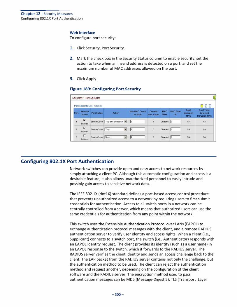
Chapter 12 | Security Measures Configuring 802.1X Port Authentication
– 300 –
Web Interface To configure port security:
1. Click Security, Port Security.
2. Mark the check box in the Security Status column to enable security, set the action to take when an invalid address is detected on a port, and set the maximum number of MAC addresses allowed on the port.
3. Click Apply
Figure 189: Configuring Port Security
Configuring 802.1X Port Authentication
Network switches can provide open and easy access to network resources by simply attaching a client PC. Although this automatic configuration and access is a desirable feature, it also allows unauthorized personnel to easily intrude and possibly gain access to sensitive network data.
The IEEE 802.1X (dot1X) standard defines a port-based access control procedure that prevents unauthorized access to a network by requiring users to first submit credentials for authentication. Access to all switch ports in a network can be centrally controlled from a server, which means that authorized users can use the same credentials for authentication from any point within the network.
This switch uses the Extensible Authentication Protocol over LANs (EAPOL) to exchange authentication protocol messages with the client, and a remote RADIUS authentication server to verify user identity and access rights. When a client (i.e., Supplicant) connects to a switch port, the switch (i.e., Authenticator) responds with an EAPOL identity request. The client provides its identity (such as a user name) in an EAPOL response to the switch, which it forwards to the RADIUS server. The RADIUS server verifies the client identity and sends an access challenge back to the client. The EAP packet from the RADIUS server contains not only the challenge, but the authentication method to be used. The client can reject the authentication method and request another, depending on the configuration of the client software and the RADIUS server. The encryption method used to pass authentication messages can be MD5 (Message-Digest 5), TLS (Transport Layer

Chapter 12 | Security Measures Configuring 802.1X Port Authentication
– 301 –
Security), PEAP (Protected Extensible Authentication Protocol), or TTLS (Tunneled Transport Layer Security). The client responds to the appropriate method with its credentials, such as a password or certificate. The RADIUS server verifies the client credentials and responds with an accept or reject packet. If authentication is successful, the switch allows the client to access the network. Otherwise, non-EAP traffic on the port is blocked or assigned to a guest VLAN based on the “intrusion- action” setting. In “multi-host” mode, only one host connected to a port needs to pass authentication for all other hosts to be granted network access. Similarly, a port can become unauthorized for all hosts if one attached host fails re- authentication or sends an EAPOL logoff message.
Figure 190: Configuring Port Authentication
802.1x client
RADIUS server
1. Client attempts to access a switch port. 2. Switch sends client an identity request. 3. Client sends back identity information. 4. Switch forwards this to authentication server. 5. Authentication server challenges client. 6. Client responds with proper credentials. 7. Authentication server approves access. 8. Switch grants client access to this port.
The operation of 802.1X on the switch requires the following:
◆ The switch must have an IP address assigned.
◆ RADIUS authentication must be enabled on the switch and the IP address of the RADIUS server specified.
◆ 802.1X must be enabled globally for the switch.
◆ Each switch port that will be used must be set to dot1X “Auto” mode.
◆ Each client that needs to be authenticated must have dot1X client software installed and properly configured.
◆ The RADIUS server and 802.1X client support EAP. (The switch only supports
EAPOL in order to pass the EAP packets from the server to the client.)
◆ The RADIUS server and client also have to support the same EAP authentication type – MD5, PEAP, TLS, or TTLS. (Native support for these encryption methods is provided in Windows 8, 7, Vista and XP, and in Windows 2000 with Service Pack 4. To support these encryption methods in Windows 95 and 98, you can use the AEGIS dot1x client or other comparable client software)
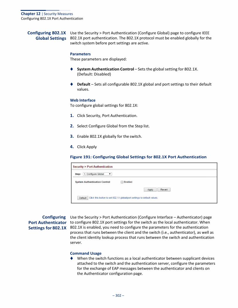
Chapter 12 | Security Measures Configuring 802.1X Port Authentication
– 302 –
Configuring 802.1X Global Settings
Use the Security > Port Authentication (Configure Global) page to configure IEEE 802.1X port authentication. The 802.1X protocol must be enabled globally for the switch system before port settings are active.
Parameters These parameters are displayed:
◆ System Authentication Control – Sets the global setting for 802.1X.
(Default: Disabled)
◆ Default – Sets all configurable 802.1X global and port settings to their default values.
Web Interface To configure global settings for 802.1X:
1. Click Security, Port Authentication.
2. Select Configure Global from the Step list.
3. Enable 802.1X globally for the switch.
4. Click Apply
Figure 191: Configuring Global Settings for 802.1X Port Authentication
Configuring
Port Authenticator Settings for 802.1X
Use the Security > Port Authentication (Configure Interface – Authenticator) page to configure 802.1X port settings for the switch as the local authenticator. When 802.1X is enabled, you need to configure the parameters for the authentication process that runs between the client and the switch (i.e., authenticator), as well as the client identity lookup process that runs between the switch and authentication server.
Command Usage ◆ When the switch functions as a local authenticator between supplicant devices
attached to the switch and the authentication server, configure the parameters for the exchange of EAP messages between the authenticator and clients on the Authenticator configuration page.
Chapter 12 | Security Measures Configuring 802.1X Port Authentication
– 303 –
◆ This switch can be configured to serve as the authenticator on selected ports by setting the Control Mode to Auto on this configuration page, and as a supplicant on other ports by the setting the control mode to Force-Authorized on this page and enabling the PAE supplicant on the Supplicant configuration page.
Parameters These parameters are displayed:
◆ Port – Port number.
◆ Status – Indicates if authentication is enabled or disabled on the port. The status is disabled if the control mode is set to Force-Authorized.
◆ Authorized – Displays the 802.1X authorization status of connected clients.
■ Yes – Connected client is authorized.
■ N/A – Connected client is not authorized, or port is not connected.
◆ Control Mode – Sets the authentication mode to one of the following options:
■ Auto – Requires a dot1x-aware client to be authorized by the authentication server. Clients that are not dot1x-aware will be denied access.
■ Force-Authorized – Forces the port to grant access to all clients, either
dot1x-aware or otherwise. (This is the default setting.)
■ Force-Unauthorized – Forces the port to deny access to all clients, either dot1x-aware or otherwise.
◆ Operation Mode – Allows single or multiple hosts (clients) to connect to an
802.1X-authorized port. (Default: Single-Host)
■ Single-Host – Allows only a single host to connect to this port.
■ Multi-Host – Allows multiple host to connect to this port.
In this mode, only one host connected to a port needs to pass authentication for all other hosts to be granted network access. Similarly, a port can become unauthorized for all hosts if one attached host fails re- authentication or sends an EAPOL logoff message.
■ MAC-Based – Allows multiple hosts to connect to this port, with each host
needing to be authenticated.
In this mode, each host connected to a port needs to pass authentication. The number of hosts allowed access to a port operating in this mode is limited only by the available space in the secure address table (i.e., up to 1024 addresses).
Chapter 12 | Security Measures Configuring 802.1X Port Authentication
– 304 –
◆ Max Count – The maximum number of hosts that can connect to a port when the Multi-Host operation mode is selected. (Range: 1-1024; Default: 5)
◆ Max Request – Sets the maximum number of times the switch port will
retransmit an EAP request packet to the client before it times out the authentication session. (Range: 1-10; Default 2)
◆ Quiet Period – Sets the time that a switch port waits after the Max Request
Count has been exceeded before attempting to acquire a new client. (Range: 1-65535 seconds; Default: 60 seconds)
◆ Tx Period – Sets the time period during an authentication session that the
switch waits before re-transmitting an EAP packet. (Range: 1-65535; Default: 30 seconds)
◆ Supplicant Timeout – Sets the time that a switch port waits for a response to
an EAP request from a client before re-transmitting an EAP packet. (Range: 1-65535; Default: 30 seconds)
This command attribute sets the timeout for EAP-request frames other than EAP-request/identity frames. If dot1x authentication is enabled on a port, the switch will initiate authentication when the port link state comes up. It will send an EAP-request/identity frame to the client to request its identity, followed by one or more requests for authentication information. It may also send other EAP-request frames to the client during an active connection as required for reauthentication.
◆ Server Timeout – Sets the time that a switch port waits for a response to an
EAP request from an authentication server before re-transmitting an EAP packet. (Default: 0 seconds)
A RADIUS server must be set before the correct operational value of 10 seconds will be displayed in this field. (See “Configuring Remote Logon Authentication Servers” on page 238.)
◆ Re-authentication Status – Sets the client to be re-authenticated after the
interval specified by the Re-authentication Period. Re-authentication can be used to detect if a new device is plugged into a switch port. (Default: Disabled)
◆ Re-authentication Period – Sets the time period after which a connected
client must be re-authenticated. (Range: 1-65535 seconds; Default: 3600 seconds)
◆ Re-authentication Max Retries – The maximum number of times the switch
port will retransmit an EAP request/identity packet to the client before it times out the authentication session. (Range: 1-10; Default: 2)
◆ Intrusion Action – Sets the port’s response to a failed authentication.
■ Block Traffic – Blocks all non-EAP traffic on the port. (This is the default setting.)

Chapter 12 | Security Measures Configuring 802.1X Port Authentication
– 305 –
■ Guest VLAN – All traffic for the port is assigned to a guest VLAN. The guest
VLAN must be separately configured (See “Configuring VLAN Groups” on page 149) and mapped on each port (See “Configuring Network Access for Ports” on page 261).
Supplicant List
◆ Supplicant – MAC address of authorized client.
Authenticator PAE State Machine
◆ State – Current state (including initialize, disconnected, connecting, authenticating, authenticated, aborting, held, force_authorized, force_unauthorized).
◆ Reauth Count – Number of times connecting state is re-entered.
◆ Current Identifier – Identifier sent in each EAP Success, Failure or Request packet by the Authentication Server.
Backend State Machine
◆ State – Current state (including request, response, success, fail, timeout, idle, initialize).
◆ Request Count – Number of EAP Request packets sent to the Supplicant
without receiving a response.
◆ Identifier (Server) – Identifier carried in the most recent EAP Success, Failure or Request packet received from the Authentication Server.
Reauthentication State Machine
◆ State – Current state (including initialize, reauthenticate).
Web Interface To configure port authenticator settings for 802.1X:
1. Click Security, Port Authentication.
2. Select Configure Interface from the Step list.
3. Modify the authentication settings for each port as required.
4. Click Apply

Chapter 12 | Security Measures Configuring 802.1X Port Authentication
– 306 –
Figure 192: Configuring Interface Settings for 802.1X Port Authenticator
Displaying 802.1X Statistics
Use the Security > Port Authentication (Show Statistics) page to display statistics for dot1x protocol exchanges for any port.
Parameters These parameters are displayed:
Table 17: 802.1X Statistics
Authenticator
Rx EAPOL Start The number of EAPOL Start frames that have been received by this Authenticator.
Rx EAPOL Logoff The number of EAPOL Logoff frames that have been received by this Authenticator.
Rx EAPOL Invalid The number of EAPOL frames that have been received by this Authenticator in which the frame type is not recognized.
Rx EAPOL Total The number of valid EAPOL frames of any type that have been received by this Authenticator.
Rx Last EAPOLVer The protocol version number carried in the most recent EAPOL frame received by this Authenticator.
Rx Last EAPOLSrc The source MAC address carried in the most recent EAPOL frame received by this Authenticator.
Parameter Description
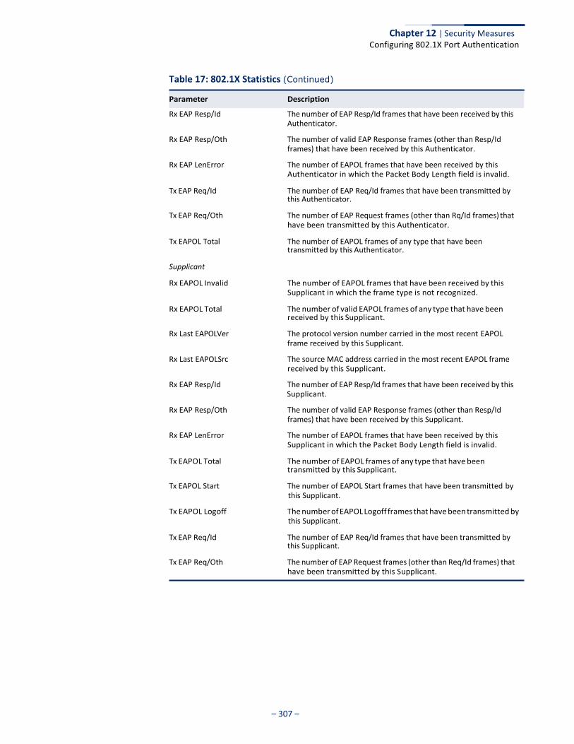
Chapter 12 | Security Measures Configuring 802.1X Port Authentication
– 307 –
Table 17: 802.1X Statistics (Continued)
Rx EAP Resp/Id The number of EAP Resp/Id frames that have been received by this Authenticator.
Rx EAP Resp/Oth The number of valid EAP Response frames (other than Resp/Id frames) that have been received by this Authenticator.
Rx EAP LenError The number of EAPOL frames that have been received by this Authenticator in which the Packet Body Length field is invalid.
Tx EAP Req/Id The number of EAP Req/Id frames that have been transmitted by this Authenticator.
Tx EAP Req/Oth The number of EAP Request frames (other than Rq/Id frames) that have been transmitted by this Authenticator.
Tx EAPOL Total The number of EAPOL frames of any type that have been transmitted by this Authenticator.
Supplicant
Rx EAPOL Invalid The number of EAPOL frames that have been received by this Supplicant in which the frame type is not recognized.
Rx EAPOL Total The number of valid EAPOL frames of any type that have been received by this Supplicant.
Rx Last EAPOLVer The protocol version number carried in the most recent EAPOL frame received by this Supplicant.
Rx Last EAPOLSrc The source MAC address carried in the most recent EAPOL frame received by this Supplicant.
Rx EAP Resp/Id The number of EAP Resp/Id frames that have been received by this Supplicant.
Rx EAP Resp/Oth The number of valid EAP Response frames (other than Resp/Id frames) that have been received by this Supplicant.
Rx EAP LenError The number of EAPOL frames that have been received by this Supplicant in which the Packet Body Length field is invalid.
Tx EAPOL Total The number of EAPOL frames of any type that have been transmitted by this Supplicant.
Tx EAPOL Start The number of EAPOL Start frames that have been transmitted by this Supplicant.
Tx EAPOL Logoff The number of EAPOL Logoff frames that have been transmitted by this Supplicant.
Tx EAP Req/Id The number of EAP Req/Id frames that have been transmitted by this Supplicant.
Tx EAP Req/Oth The number of EAP Request frames (other than Req/Id frames) that have been transmitted by this Supplicant.
Parameter Description
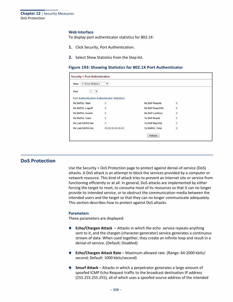
– 308 –
Chapter 12 | Security Measures DoS Protection
Web Interface To display port authenticator statistics for 802.1X:
1. Click Security, Port Authentication.
2. Select Show Statistics from the Step list.
Figure 193: Showing Statistics for 802.1X Port Authenticator
DoS Protection
Use the Security > DoS Protection page to protect against denial-of-service (DoS) attacks. A DoS attack is an attempt to block the services provided by a computer or network resource. This kind of attack tries to prevent an Internet site or service from functioning efficiently or at all. In general, DoS attacks are implemented by either forcing the target to reset, to consume most of its resources so that it can no longer provide its intended service, or to obstruct the communication media between the intended users and the target so that they can no longer communicate adequately. This section describes how to protect against DoS attacks.
Parameters These parameters are displayed:
◆ Echo/Chargen Attack – Attacks in which the echo service repeats anything
sent to it, and the chargen (character generator) service generates a continuous stream of data. When used together, they create an infinite loop and result in a denial-of-service. (Default: Disabled)
◆ Echo/Chargen Attack Rate – Maximum allowed rate. (Range: 64-2000 kbits/
second; Default: 1000 kbits/second)
◆ Smurf Attack – Attacks in which a perpetrator generates a large amount of spoofed ICMP Echo Request traffic to the broadcast destination IP address (255.255.255.255), all of which uses a spoofed source address of the intended
– 309 –
Chapter 12 | Security Measures
DoS Protection
victim. The victim should crash due to the many interrupts required to send ICMP Echo response packets. (Default: Enabled)
◆ TCP Flooding Attack – Attacks in which a perpetrator sends a succession of
TCP SYN requests (with or without a spoofed-Source IP) to a target and never returns ACK packets. These half-open connections will bind resources on the target, and no new connections can be made, resulting in a denial of service. (Default: Disabled)
◆ TCP Flooding Attack Rate – Maximum allowed rate. (Range: 64-2000 kbits/
second; Default: 1000 kbits/second)
◆ TCP Null Scan – A TCP NULL scan message is used to identify listening TCP ports. The scan uses a series of strangely configured TCP packets which contain a sequence number of 0 and no flags. If the target's TCP port is closed, the target replies with a TCP RST (reset) packet. If the target TCP port is open, it simply discards the TCP NULL scan. (Default: Enabled)
◆ TCP-SYN/FIN Scan – A TCP SYN/FIN scan message is used to identify listening
TCP ports. The scan uses a series of strangely configured TCP packets which contain SYN (synchronize) and FIN (finish) flags. If the target's TCP port is closed, the target replies with a TCP RST (reset) packet. If the target TCP port is open, it simply discards the TCP SYN FIN scan. (Default: Enabled)
◆ TCP Xmas Scan – A so-called TCP XMAS scan message is used to identify
listening TCP ports. This scan uses a series of strangely configured TCP packets which contain a sequence number of 0 and the URG, PSH and FIN flags. If the target's TCP port is closed, the target replies with a TCP RST packet. If the target TCP port is open, it simply discards the TCP XMAS scan. (Default: Enabled)
◆ UDP Flooding Attack – Attacks in which a perpetrator sends a large number of
UDP packets (with or without a spoofed-Source IP) to random ports on a remote host. The target will determine that application is listening at that port, and reply with an ICMP Destination Unreachable packet. It will be forced to send many ICMP packets, eventually leading it to be unreachable by other clients. (Default: Disabled)
◆ UDP Flooding Attack Rate – Maximum allowed rate. (Range: 64-2000 kbits/
second; Default: 1000 kbits/second)
◆ WinNuke Attack – Attacks in which affected the Microsoft Windows 3.1x/95/ NT operating systems. In this type of attack, the perpetrator sends the string of OOB out-of-band (OOB) packets contained a TCP URG flag to the target computer on TCP port 139 (NetBIOS), casing it to lock up and display a “Blue Screen of Death.” This did not cause any damage to, or change data on, the computer’s hard disk, but any unsaved data would be lost. Microsoft made patches to prevent the WinNuke attack, but the OOB packets. (Default: Disabled)
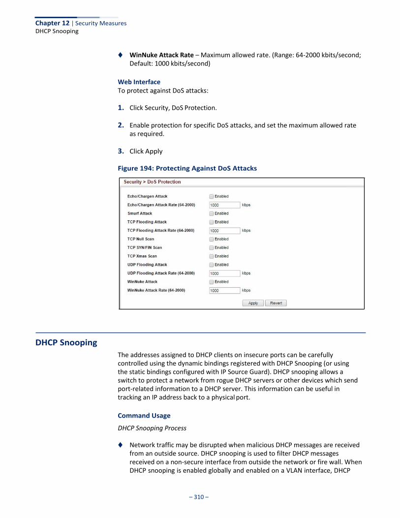
Chapter 12 | Security Measures DHCP Snooping
– 310 –
◆ WinNuke Attack Rate – Maximum allowed rate. (Range: 64-2000 kbits/second; Default: 1000 kbits/second)
Web Interface To protect against DoS attacks:
1. Click Security, DoS Protection.
2. Enable protection for specific DoS attacks, and set the maximum allowed rate as required.
3. Click Apply
Figure 194: Protecting Against DoS Attacks
DHCP Snooping
The addresses assigned to DHCP clients on insecure ports can be carefully controlled using the dynamic bindings registered with DHCP Snooping (or using the static bindings configured with IP Source Guard). DHCP snooping allows a switch to protect a network from rogue DHCP servers or other devices which send port-related information to a DHCP server. This information can be useful in tracking an IP address back to a physical port.
Command Usage
DHCP Snooping Process
◆ Network traffic may be disrupted when malicious DHCP messages are received from an outside source. DHCP snooping is used to filter DHCP messages received on a non-secure interface from outside the network or fire wall. When DHCP snooping is enabled globally and enabled on a VLAN interface, DHCP
Chapter 12 | Security Measures DHCP Snooping
– 311 –
messages received on an untrusted interface from a device not listed in the DHCP snooping table will be dropped.
◆ Table entries are only learned for trusted interfaces. An entry is added or
removed dynamically to the DHCP snooping table when a client receives or releases an IP address from a DHCP server. Each entry includes a MAC address, IP address, lease time, VLAN identifier, and port identifier.
◆ The rate limit for the number of DHCP messages that can be processed by the
switch is 100 packets per second. Any DHCP packets in excess of this limit are dropped.
◆ When DHCP snooping is enabled, DHCP messages entering an untrusted
interface are filtered based upon dynamic entries learned via DHCP snooping.
◆ Filtering rules are implemented as follows:
■ If the global DHCP snooping is disabled, all DHCP packets are forwarded.
■ If DHCP snooping is enabled globally, and also enabled on the VLAN where the DHCP packet is received, all DHCP packets are forwarded for a trusted port. If the received packet is a DHCP ACK message, a dynamic DHCP snooping entry is also added to the binding table.
■ If DHCP snooping is enabled globally, and also enabled on the VLAN where
the DHCP packet is received, but the port is not trusted, it is processed as follows:
■ If the DHCP packet is a reply packet from a DHCP server (including OFFER, ACK or NAK messages), the packet is dropped.
■ If the DHCP packet is from a client, such as a DECLINE or RELEASE message, the switch forwards the packet only if the corresponding entry is found in the binding table.
■ If the DHCP packet is from a client, such as a DISCOVER, REQUEST, INFORM, DECLINE or RELEASE message, the packet is forwarded if MAC address verification is disabled. However, if MAC address verification is enabled, then the packet will only be forwarded if the client’s hardware address stored in the DHCP packet is the same as the source MAC address in the Ethernet header.
■ If the DHCP packet is not a recognizable type, it is dropped.
■ If a DHCP packet from a client passes the filtering criteria above, it will only be forwarded to trusted ports in the same VLAN.
■ If a DHCP packet is from server is received on a trusted port, it will be
forwarded to both trusted and untrusted ports in the same VLAN.
■ If the DHCP snooping is globally disabled, all dynamic bindings are removed from the binding table.
Chapter 12 | Security Measures DHCP Snooping
– 312 –
■ Additional considerations when the switch itself is a DHCP client – The port(s)
through which the switch submits a client request to the DHCP server must be configured as trusted. Note that the switch will not add a dynamic entry for itself to the binding table when it receives an ACK message from a DHCP server. Also, when the switch sends out DHCP client packets for itself, no filtering takes place. However, when the switch receives any messages from a DHCP server, any packets received from untrusted ports are dropped.
DHCP Snooping Option 82
◆ DHCP provides a relay mechanism for sending information about its DHCP clients or the relay agent itself to the DHCP server. Also known as DHCP Option 82, it allows compatible DHCP servers to use the information when assigning IP addresses, or to set other services or policies for clients. It is also an effective tool in preventing malicious network attacks from attached clients on DHCP services, such as IP Spoofing, Client Identifier Spoofing, MAC Address Spoofing, and Address Exhaustion.
◆ DHCP Snooping must be enabled for Option 82 information to be inserted into
request packets.
◆ When the DHCP Snooping Information Option 82 is enabled, the requesting client (or an intermediate relay agent that has used the information fields to describe itself ) can be identified in the DHCP request packets forwarded by the switch and in reply packets sent back from the DHCP server. This information may specify the MAC address or IP address of the requesting device (that is, the switch in this context).
By default, the switch also fills in the Option 82 circuit-id field with information indicating the local interface over which the switch received the DHCP client request, including the port and VLAN ID. This allows DHCP client-server exchange messages to be forwarded between the server and client without having to flood them to the entire VLAN.
◆ If DHCP Snooping Information Option 82 is enabled on the switch, information
may be inserted into a DHCP request packet received over any VLAN (depending on DHCP snooping filtering rules). The information inserted into the relayed packets includes the circuit-id and remote-id, as well as the gateway Internet address.
◆ When the switch receives DHCP packets from clients that already include DHCP
Option 82 information, the switch can be configured to set the action policy for these packets. The switch can either drop the DHCP packets, keep the existing information, or replace it with the switch’s relay information.
Chapter 12 | Security Measures DHCP Snooping
– 313 –
DHCP Snooping Global Configuration
Use the Security > DHCP Snooping (Configure Global) page to enable DHCP Snooping globally on the switch, or to configure MAC Address Verification.
Parameters These parameters are displayed:
General
◆ DHCP Snooping Status – Enables DHCP snooping globally. (Default: Disabled)
◆ DHCP Snooping MAC-Address Verification – Enables or disables MAC address verification. If the source MAC address in the Ethernet header of the packet is not same as the client's hardware address in the DHCP packet, the packet is dropped. (Default: Enabled)
Information
◆ DHCP Snooping Information Option Status – Enables or disables DHCP Option 82 information relay. (Default: Disabled)
◆ DHCP Snooping Information Option Sub-option Format – Enables or
disables use of sub-type and sub-length fields in circuit-ID (CID) and remote-ID (RID) in Option 82 information. (Default: Enabled)
◆ DHCP Snooping Information Option Remote ID – Specifies the MAC address, IP
address, or arbitrary identifier of the requesting device (i.e., the switch in this context).
■ MAC Address – Inserts a MAC address in the remote ID sub-option for the DHCP snooping agent (i.e., the MAC address of the switch’s CPU). This attribute can be encoded in Hexadecimal or ASCII.
■ IP Address – Inserts an IP address in the remote ID sub-option for the DHCP snooping agent (i.e., the IP address of the management interface). This attribute can be encoded in Hexadecimal or ASCII.
■ string - An arbitrary string inserted into the remote identifier field. (Range: 1-32 characters)
◆ DHCP Snooping Information Option Remote ID TR101 VLAN Field – Adds
“:VLAN” in TR101 field for untagged packets.
The format for TR101 option 82 is: “<IP> eth <SID>/<PORT>[:<VLAN>]”. Note that the SID (Switch ID) is always 0. By default the PVID is added to the end of the TR101 field for untagged packets. For tagged packets, the VLAN ID is always added.
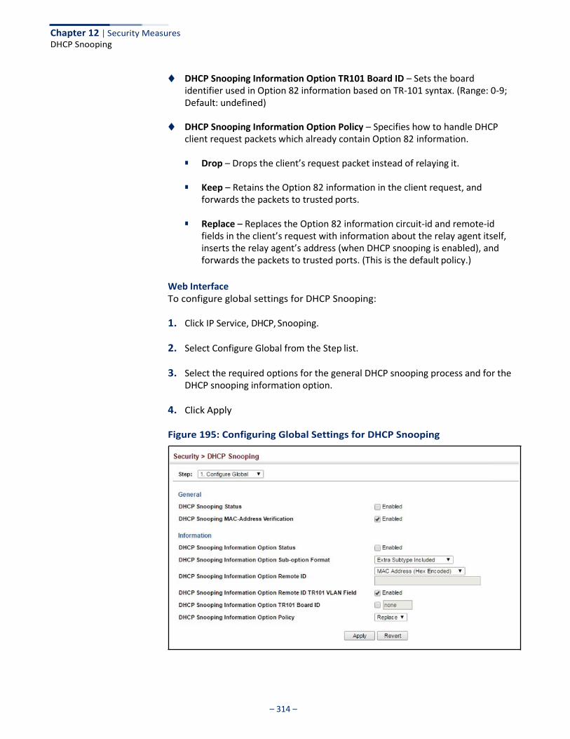
Chapter 12 | Security Measures DHCP Snooping
– 314 –
◆ DHCP Snooping Information Option TR101 Board ID – Sets the board identifier used in Option 82 information based on TR-101 syntax. (Range: 0-9; Default: undefined)
◆ DHCP Snooping Information Option Policy – Specifies how to handle DHCP
client request packets which already contain Option 82 information.
■ Drop – Drops the client’s request packet instead of relaying it.
■ Keep – Retains the Option 82 information in the client request, and forwards the packets to trusted ports.
■ Replace – Replaces the Option 82 information circuit-id and remote-id
fields in the client’s request with information about the relay agent itself, inserts the relay agent’s address (when DHCP snooping is enabled), and forwards the packets to trusted ports. (This is the default policy.)
Web Interface To configure global settings for DHCP Snooping:
1. Click IP Service, DHCP, Snooping.
2. Select Configure Global from the Step list.
3. Select the required options for the general DHCP snooping process and for the DHCP snooping information option.
4. Click Apply
Figure 195: Configuring Global Settings for DHCP Snooping
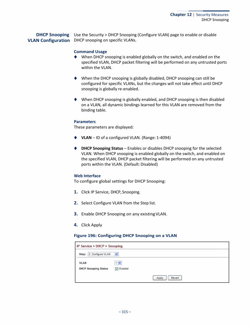
Chapter 12 | Security Measures DHCP Snooping
– 315 –
DHCP Snooping VLAN Configuration
Use the Security > DHCP Snooping (Configure VLAN) page to enable or disable DHCP snooping on specific VLANs.
Command Usage ◆ When DHCP snooping is enabled globally on the switch, and enabled on the
specified VLAN, DHCP packet filtering will be performed on any untrusted ports within the VLAN.
◆ When the DHCP snooping is globally disabled, DHCP snooping can still be
configured for specific VLANs, but the changes will not take effect until DHCP snooping is globally re-enabled.
◆ When DHCP snooping is globally enabled, and DHCP snooping is then disabled
on a VLAN, all dynamic bindings learned for this VLAN are removed from the binding table.
Parameters These parameters are displayed:
◆ VLAN – ID of a configured VLAN. (Range: 1-4094)
◆ DHCP Snooping Status – Enables or disables DHCP snooping for the selected VLAN. When DHCP snooping is enabled globally on the switch, and enabled on the specified VLAN, DHCP packet filtering will be performed on any untrusted ports within the VLAN. (Default: Disabled)
Web Interface To configure global settings for DHCP Snooping:
1. Click IP Service, DHCP, Snooping.
2. Select Configure VLAN from the Step list.
3. Enable DHCP Snooping on any existing VLAN.
4. Click Apply
Figure 196: Configuring DHCP Snooping on a VLAN
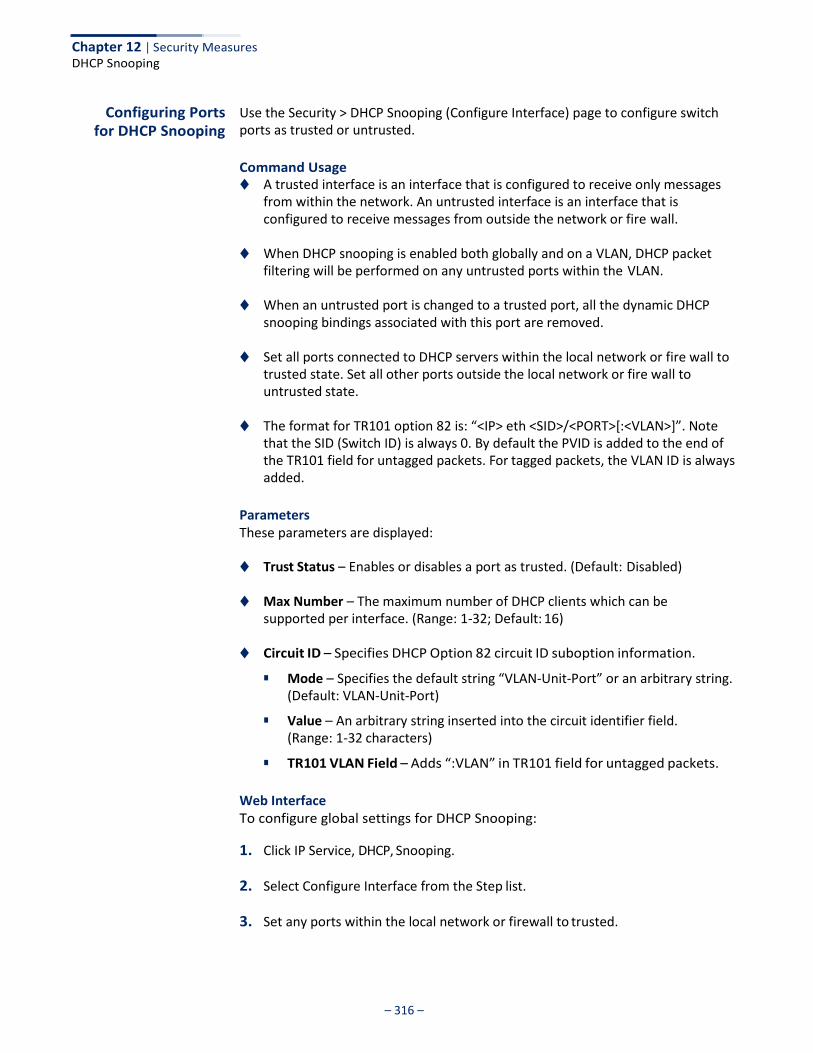
Chapter 12 | Security Measures DHCP Snooping
– 316 –
Configuring Ports for DHCP Snooping
Use the Security > DHCP Snooping (Configure Interface) page to configure switch ports as trusted or untrusted.
Command Usage ◆ A trusted interface is an interface that is configured to receive only messages
from within the network. An untrusted interface is an interface that is configured to receive messages from outside the network or fire wall.
◆ When DHCP snooping is enabled both globally and on a VLAN, DHCP packet
filtering will be performed on any untrusted ports within the VLAN.
◆ When an untrusted port is changed to a trusted port, all the dynamic DHCP snooping bindings associated with this port are removed.
◆ Set all ports connected to DHCP servers within the local network or fire wall to
trusted state. Set all other ports outside the local network or fire wall to untrusted state.
◆ The format for TR101 option 82 is: “<IP> eth <SID>/<PORT>[:<VLAN>]”. Note
that the SID (Switch ID) is always 0. By default the PVID is added to the end of the TR101 field for untagged packets. For tagged packets, the VLAN ID is always added.
Parameters These parameters are displayed:
◆ Trust Status – Enables or disables a port as trusted. (Default: Disabled)
◆ Max Number – The maximum number of DHCP clients which can be supported per interface. (Range: 1-32; Default: 16)
◆ Circuit ID – Specifies DHCP Option 82 circuit ID suboption information.
■ Mode – Specifies the default string “VLAN-Unit-Port” or an arbitrary string. (Default: VLAN-Unit-Port)
■ Value – An arbitrary string inserted into the circuit identifier field. (Range: 1-32 characters)
■ TR101 VLAN Field – Adds “:VLAN” in TR101 field for untagged packets.
Web Interface To configure global settings for DHCP Snooping:
1. Click IP Service, DHCP, Snooping.
2. Select Configure Interface from the Step list.
3. Set any ports within the local network or firewall to trusted.
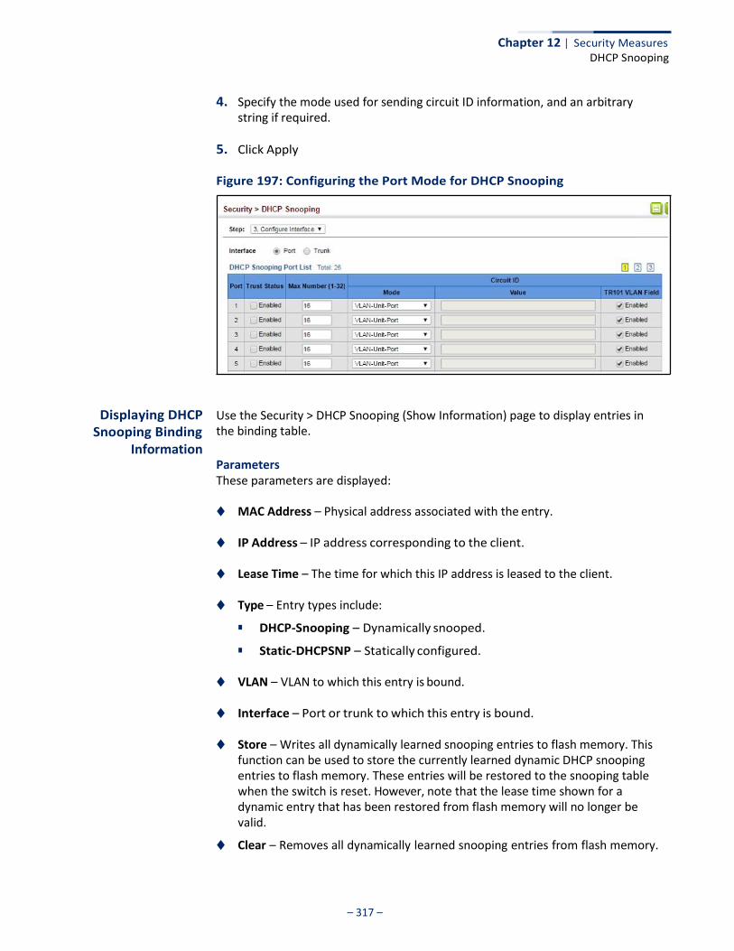
Chapter 12 | Security Measures DHCP Snooping
– 317 –
4. Specify the mode used for sending circuit ID information, and an arbitrary string if required.
5. Click Apply
Figure 197: Configuring the Port Mode for DHCP Snooping
Displaying DHCP Snooping Binding
Information
Use the Security > DHCP Snooping (Show Information) page to display entries in the binding table.
Parameters These parameters are displayed:
◆ MAC Address – Physical address associated with the entry.
◆ IP Address – IP address corresponding to the client.
◆ Lease Time – The time for which this IP address is leased to the client.
◆ Type – Entry types include:
■ DHCP-Snooping – Dynamically snooped.
■ Static-DHCPSNP – Statically configured.
◆ VLAN – VLAN to which this entry is bound.
◆ Interface – Port or trunk to which this entry is bound.
◆ Store – Writes all dynamically learned snooping entries to flash memory. This function can be used to store the currently learned dynamic DHCP snooping entries to flash memory. These entries will be restored to the snooping table when the switch is reset. However, note that the lease time shown for a dynamic entry that has been restored from flash memory will no longer be valid.
◆ Clear – Removes all dynamically learned snooping entries from flash memory.
– 318 –
Chapter 12 | Security Measures IPv4 Source Guard
Web Interface To display the binding table for DHCP Snooping:
1. Click IP Service, DHCP, Snooping.
2. Select Show Information from the Step list.
3. Use the Store or Clear function if required.
Figure 198: Displaying the Binding Table for DHCP Snooping
IPv4 Source Guard
IPv4 Source Guard is a security feature that filters IP traffic on network interfaces based on manually configured entries in the IP Source Guard table, or dynamic entries in the DHCP Snooping table when enabled (see “DHCP Snooping” on page 310). IP source guard can be used to prevent traffic attacks caused when a host tries to use the IPv4 address of a neighbor to access the network. This section describes how to configure IPv4 Source Guard.
Configuring Ports for IPv4 Source Guard
Use the Security > IP Source Guard > General page to set the filtering type based on source IP address, or source IP address and MAC address pairs. It also specifies lookup within the ACL binding table or the MAC address binding table, as well as the maximum number of allowed binding entries for the lookup tables.
IP Source Guard is used to filter traffic on an insecure port which receives messages from outside the network or fire wall, and therefore may be subject to traffic attacks caused by a host trying to use the IP address of a neighbor.
Command Usage
Filter Type
◆ Setting source guard mode to SIP (Source IP) or SIP-MAC (Source IP and MAC) enables this function on the selected port. Use the SIP option to check the
– 319 –
Chapter 12 | Security Measures IPv4 Source Guard
VLAN ID, source IP address, and port number against all entries in the binding table. Use the SIP-MAC option to check these same parameters, plus the source MAC address. If no matching entry is found, the packet is dropped.
Note: Multicast addresses cannot be used by IP Source Guard.
◆ When enabled, traffic is filtered based upon dynamic entries learned via DHCP snooping (see “DHCP Snooping” on page 310), or static addresses configured in the source guard binding table.
◆ If IP source guard is enabled, an inbound packet’s IP address (SIP option) or
both its IP address and corresponding MAC address (SIP-MAC option) will be checked against the binding table. If no matching entry is found, the packet will be dropped.
◆ An entry with same MAC address and a different VLAN ID cannot be added to
the binding table.
◆ Filtering rules are implemented as follows:
■ If DHCP snooping is disabled (see page 313), IP source guard will check the VLAN ID, source IP address, port number, and source MAC address (for the SIP-MAC option). If a matching entry is found in the binding table and the entry type is static IP source guard binding, the packet will be forwarded.
■ If DHCP snooping is enabled, IP source guard will check the VLAN ID, source
IP address, port number, and source MAC address (for the SIP-MAC option). If a matching entry is found in the binding table and the entry type is static IP source guard binding, or dynamic DHCP snooping binding, the packet will be forwarded.
■ If IP source guard is enabled on an interface for which IP source bindings
have not yet been configured (neither by static configuration in the IP source guard binding table nor dynamically learned from DHCP snooping), the switch will drop all IP traffic on that port, except for DHCP packets allowed by DHCP snooping.
Parameters These parameters are displayed:
◆ Filter Type – Configures the switch to filter inbound traffic based source IP
address, or source IP address and corresponding MAC address. (Default: None)
■ Disabled – Disables IP source guard filtering on the port.
■ SIP – Enables traffic filtering based on IP addresses stored in the binding table.
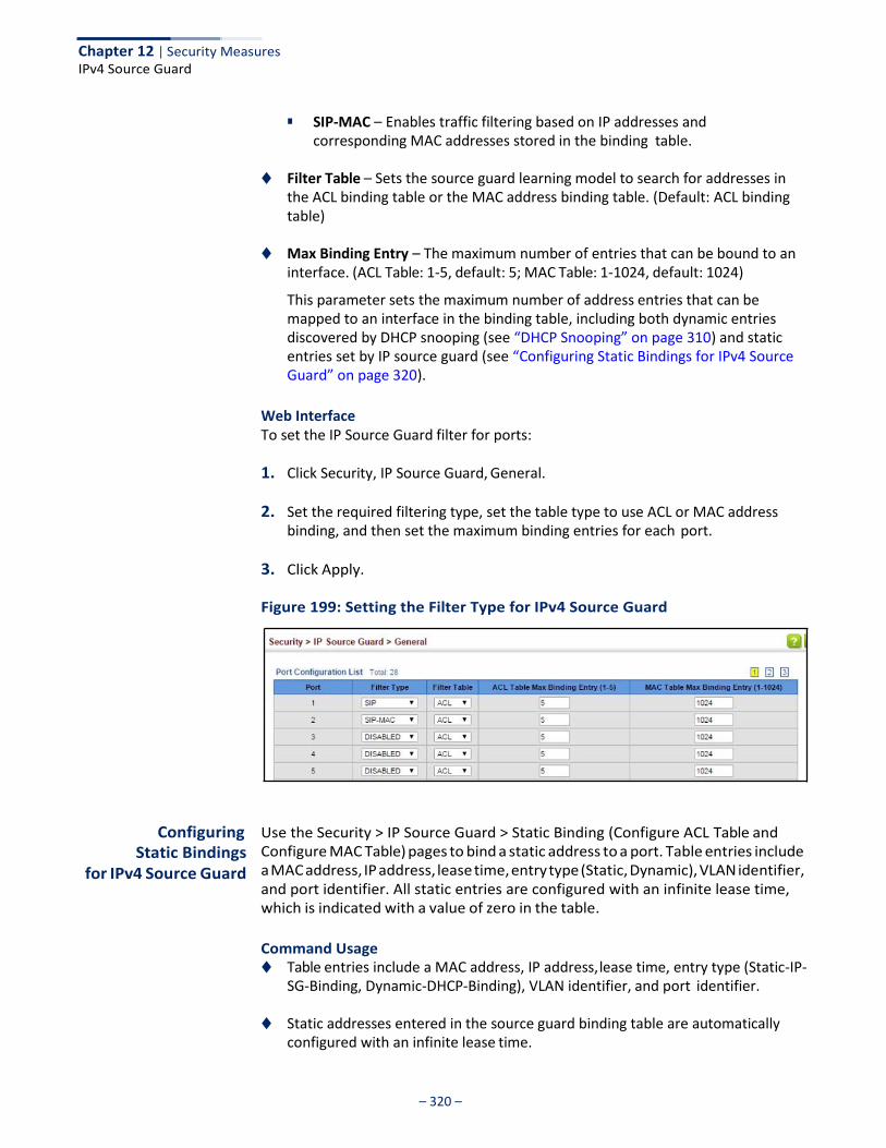
Chapter 12 | Security Measures IPv4 Source Guard
– 320 –
■ SIP-MAC – Enables traffic filtering based on IP addresses and
corresponding MAC addresses stored in the binding table.
◆ Filter Table – Sets the source guard learning model to search for addresses in the ACL binding table or the MAC address binding table. (Default: ACL binding table)
◆ Max Binding Entry – The maximum number of entries that can be bound to an
interface. (ACL Table: 1-5, default: 5; MAC Table: 1-1024, default: 1024)
This parameter sets the maximum number of address entries that can be mapped to an interface in the binding table, including both dynamic entries discovered by DHCP snooping (see “DHCP Snooping” on page 310) and static entries set by IP source guard (see “Configuring Static Bindings for IPv4 Source Guard” on page 320).
Web Interface To set the IP Source Guard filter for ports:
1. Click Security, IP Source Guard, General.
2. Set the required filtering type, set the table type to use ACL or MAC address binding, and then set the maximum binding entries for each port.
3. Click Apply.
Figure 199: Setting the Filter Type for IPv4 Source Guard
Configuring
Static Bindings for IPv4 Source Guard
Use the Security > IP Source Guard > Static Binding (Configure ACL Table and Configure MAC Table) pages to bind a static address to a port. Table entries include a MAC address, IP address, lease time, entry type (Static, Dynamic), VLAN identifier, and port identifier. All static entries are configured with an infinite lease time, which is indicated with a value of zero in the table.
Command Usage ◆ Table entries include a MAC address, IP address, lease time, entry type (Static-IP-
SG-Binding, Dynamic-DHCP-Binding), VLAN identifier, and port identifier.
◆ Static addresses entered in the source guard binding table are automatically configured with an infinite lease time.
Chapter 12 | Security Measures IPv4 Source Guard
– 321 –
◆ When source guard is enabled, traffic is filtered based upon dynamic entries learned via DHCP snooping, or static addresses configured in the source guard binding table.
◆ An entry with same MAC address and a different VLAN ID cannot be added to
the binding table.
◆ Static bindings are processed as follows:
■ A valid static IP source guard entry will be added to the binding table in ACL mode if one of the following conditions is true:
■ If there is no entry with the same VLAN ID and MAC address, a new entry is added to the binding table using the type “static IP source guard binding.”
■ If there is an entry with the same VLAN ID and MAC address, and the type of entry is static IP source guard binding, then the new entry will replace the old one.
■ If there is an entry with the same VLAN ID and MAC address, and the type of the entry is dynamic DHCP snooping binding, then the new entry will replace the old one and the entry type will be changed to static IP source guard binding.
■ A valid static IP source guard entry will be added to the binding table in
MAC mode if one of the following conditions are true:
■ If there is no binding entry with the same IP address and MAC address, a new entry will be added to the binding table using the type of static IP source guard binding entry.
■ If there is a binding entry with same IP address and MAC address, then the new entry shall replace the old one.
■ Only unicast addresses are accepted for static bindings.
Parameters These parameters are displayed:
Add – Configure ACL Table
◆ Port – The port to which a static entry is bound.
◆ VLAN – ID of a configured VLAN (Range: 1-4094)
◆ MAC Address – A valid unicast MAC address.
◆ IP Address – A valid unicast IP address, including classful types A, B or C.
Add – Configure MAC Table
◆ MAC Address – A valid unicast MAC address.
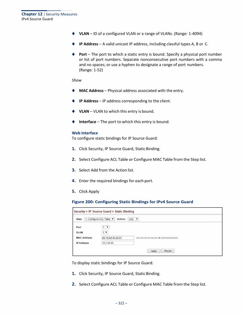
Chapter 12 | Security Measures IPv4 Source Guard
– 322 –
◆ VLAN – ID of a configured VLAN or a range of VLANs. (Range: 1-4094)
◆ IP Address – A valid unicast IP address, including classful types A, B or C.
◆ Port – The port to which a static entry is bound. Specify a physical port number or list of port numbers. Separate nonconsecutive port numbers with a comma and no spaces; or use a hyphen to designate a range of port numbers. (Range: 1-52)
Show
◆ MAC Address – Physical address associated with the entry.
◆ IP Address – IP address corresponding to the client.
◆ VLAN – VLAN to which this entry is bound.
◆ Interface – The port to which this entry is bound.
Web Interface To configure static bindings for IP Source Guard:
1. Click Security, IP Source Guard, Static Binding.
2. Select Configure ACL Table or Configure MAC Table from the Step list.
3. Select Add from the Action list.
4. Enter the required bindings for each port.
5. Click Apply
Figure 200: Configuring Static Bindings for IPv4 Source Guard
To display static bindings for IP Source Guard:
1. Click Security, IP Source Guard, Static Binding.
2. Select Configure ACL Table or Configure MAC Table from the Step list.
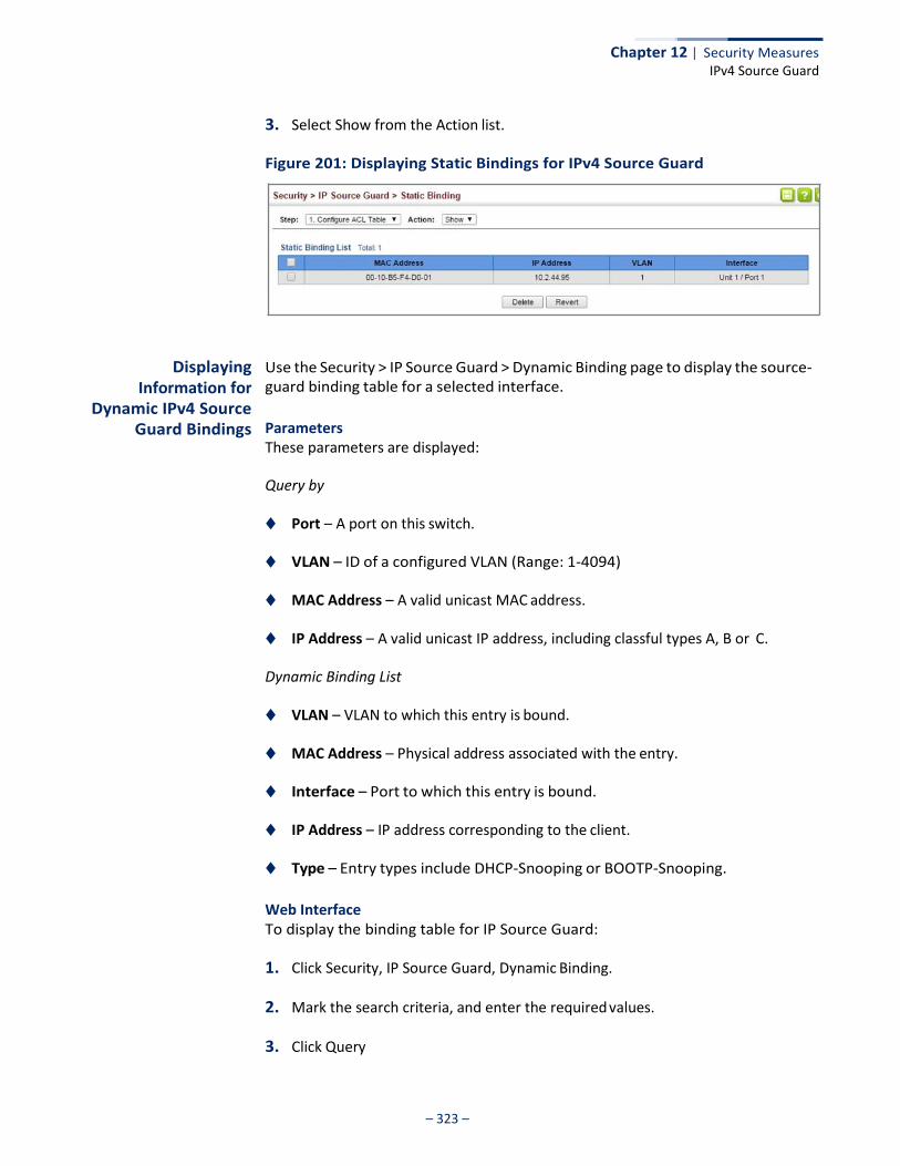
Chapter 12 | Security Measures IPv4 Source Guard
– 323 –
3. Select Show from the Action list.
Figure 201: Displaying Static Bindings for IPv4 Source Guard
Displaying Information for
Dynamic IPv4 Source Guard Bindings
Use the Security > IP Source Guard > Dynamic Binding page to display the source- guard binding table for a selected interface.
Parameters These parameters are displayed:
Query by
◆ Port – A port on this switch.
◆ VLAN – ID of a configured VLAN (Range: 1-4094)
◆ MAC Address – A valid unicast MAC address.
◆ IP Address – A valid unicast IP address, including classful types A, B or C.
Dynamic Binding List
◆ VLAN – VLAN to which this entry is bound.
◆ MAC Address – Physical address associated with the entry.
◆ Interface – Port to which this entry is bound.
◆ IP Address – IP address corresponding to the client.
◆ Type – Entry types include DHCP-Snooping or BOOTP-Snooping.
Web Interface To display the binding table for IP Source Guard:
1. Click Security, IP Source Guard, Dynamic Binding.
2. Mark the search criteria, and enter the required values.
3. Click Query
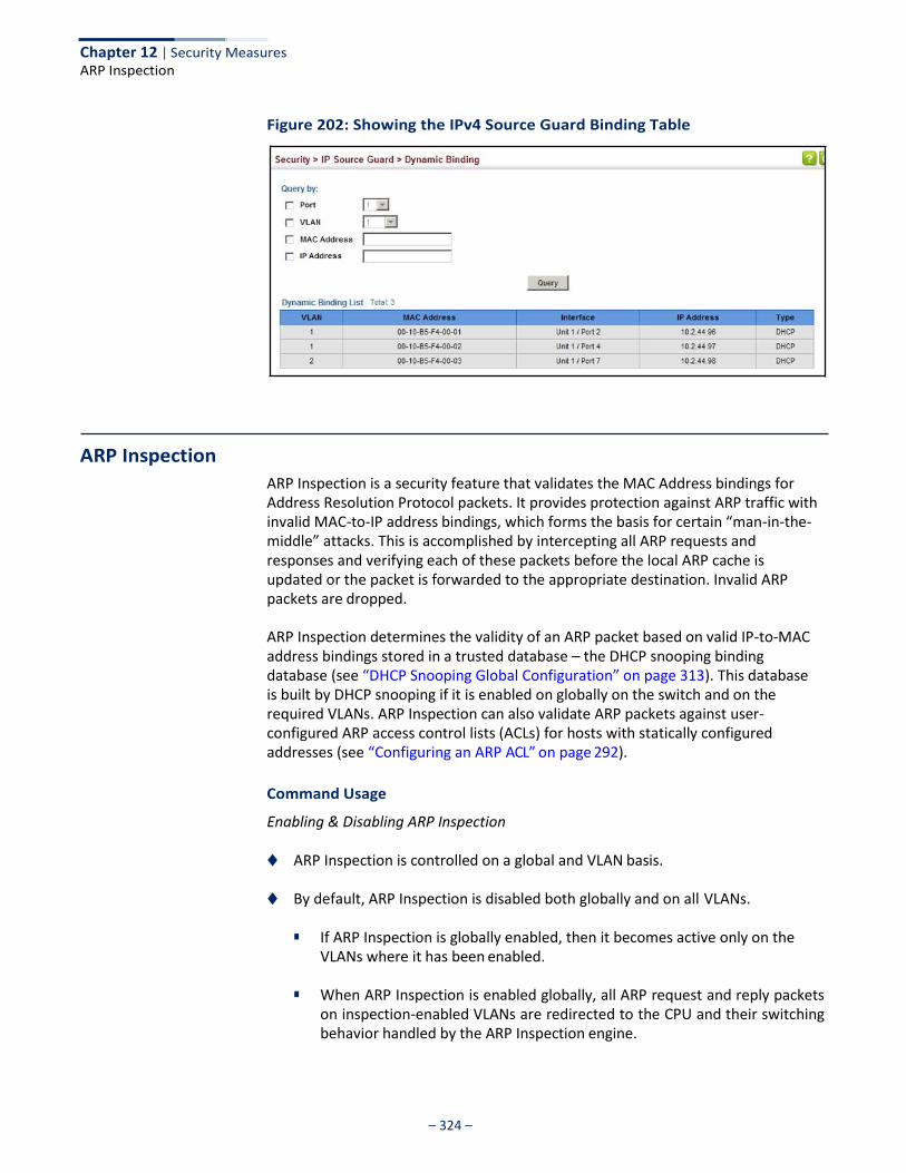
– 324 –
Chapter 12 | Security Measures ARP Inspection
Figure 202: Showing the IPv4 Source Guard Binding Table
ARP Inspection
ARP Inspection is a security feature that validates the MAC Address bindings for Address Resolution Protocol packets. It provides protection against ARP traffic with invalid MAC-to-IP address bindings, which forms the basis for certain “man-in-the- middle” attacks. This is accomplished by intercepting all ARP requests and responses and verifying each of these packets before the local ARP cache is updated or the packet is forwarded to the appropriate destination. Invalid ARP packets are dropped.
ARP Inspection determines the validity of an ARP packet based on valid IP-to-MAC address bindings stored in a trusted database – the DHCP snooping binding database (see “DHCP Snooping Global Configuration” on page 313). This database is built by DHCP snooping if it is enabled on globally on the switch and on the required VLANs. ARP Inspection can also validate ARP packets against user- configured ARP access control lists (ACLs) for hosts with statically configured addresses (see “Configuring an ARP ACL” on page 292).
Command Usage
Enabling & Disabling ARP Inspection
◆ ARP Inspection is controlled on a global and VLAN basis.
◆ By default, ARP Inspection is disabled both globally and on all VLANs.
■ If ARP Inspection is globally enabled, then it becomes active only on the VLANs where it has been enabled.
■ When ARP Inspection is enabled globally, all ARP request and reply packets
on inspection-enabled VLANs are redirected to the CPU and their switching behavior handled by the ARP Inspection engine.
– 325 –
Chapter 12 | Security Measures ARP Inspection
■ If ARP Inspection is disabled globally, then it becomes inactive for all
VLANs, including those where inspection is enabled.
■ When ARP Inspection is disabled, all ARP request and reply packets will bypass the ARP Inspection engine and their switching behavior will match that of all other packets.
■ Disabling and then re-enabling global ARP Inspection will not affect the
ARP Inspection configuration of any VLANs.
■ When ARP Inspection is disabled globally, it is still possible to configure ARP Inspection for individual VLANs. These configuration changes will only become active after ARP Inspection is enabled globally again.
◆ The ARP Inspection engine in the current firmware version does not support
ARP Inspection on trunk ports.
Configuring Global Settings for
ARP Inspection
Use the Security > ARP Inspection (Configure General) page to enable ARP inspection globally for the switch, to validate address information in each packet, and configure logging.
Command Usage
ARP Inspection Validation
◆ By default, ARP Inspection Validation is disabled.
◆ Specifying at least one of the following validations enables ARP Inspection Validation globally. Any combination of the following checks can be active concurrently.
■ Destination MAC – Checks the destination MAC address in the Ethernet
header against the target MAC address in the ARP body. This check is performed for ARP responses. When enabled, packets with different MAC addresses are classified as invalid and are dropped.
■ IP – Checks the ARP body for invalid and unexpected IP addresses. These
addresses include 0.0.0.0, 255.255.255.255, and all IP multicast addresses. Sender IP addresses are checked in all ARP requests and responses, while target IP addresses are checked only in ARP responses.
■ Source MAC – Checks the source MAC address in the Ethernet header
against the sender MAC address in the ARP body. This check is performed on both ARP requests and responses. When enabled, packets with different MAC addresses are classified as invalid and are dropped.
– 326 –
Chapter 12 | Security Measures ARP Inspection
ARP Inspection Logging
◆ By default, logging is active for ARP Inspection, and cannot be disabled.
◆ The administrator can configure the log facility rate.
◆ When the switch drops a packet, it places an entry in the log buffer, then generates a system message on a rate-controlled basis. After the system message is generated, the entry is cleared from the log buffer.
◆ Each log entry contains flow information, such as the receiving VLAN, the port
number, the source and destination IP addresses, and the source and destination MAC addresses.
◆ If multiple, identical invalid ARP packets are received consecutively on the
same VLAN, then the logging facility will only generate one entry in the log buffer and one corresponding system message.
◆ If the log buffer is full, the oldest entry will be replaced with the newest entry.
Parameters These parameters are displayed:
◆ ARP Inspection Status – Enables ARP Inspection globally. (Default: Disabled)
◆ ARP Inspection Validation – Enables extended ARP Inspection Validation if any of the following options are enabled. (Default: Disabled)
■ Dst-MAC – Validates the destination MAC address in the Ethernet header
against the target MAC address in the body of ARP responses.
■ IP – Checks the ARP body for invalid and unexpected IP addresses. Sender IP addresses are checked in all ARP requests and responses, while target IP addresses are checked only in ARP responses.
■ Allow Zeros – Allows sender IP address to be 0.0.0.0.
■ Src-MAC – Validates the source MAC address in the Ethernet header
against the sender MAC address in the ARP body. This check is performed on both ARP requests and responses.
◆ Log Message Number – The maximum number of entries saved in a log
message. (Range: 0-256; Default: 5)
◆ Log Interval – The interval at which log messages are sent. (Range: 0-86400 seconds; Default: 1 second)
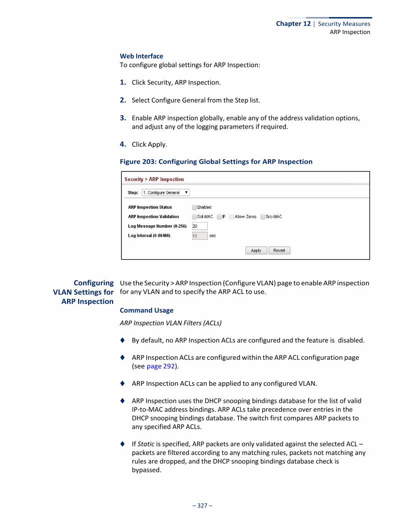
– 327 –
Chapter 12 | Security Measures ARP Inspection
Web Interface To configure global settings for ARP Inspection:
1. Click Security, ARP Inspection.
2. Select Configure General from the Step list.
3. Enable ARP inspection globally, enable any of the address validation options, and adjust any of the logging parameters if required.
4. Click Apply.
Figure 203: Configuring Global Settings for ARP Inspection
Configuring
VLAN Settings for ARP Inspection
Use the Security > ARP Inspection (Configure VLAN) page to enable ARP inspection for any VLAN and to specify the ARP ACL to use.
Command Usage
ARP Inspection VLAN Filters (ACLs)
◆ By default, no ARP Inspection ACLs are configured and the feature is disabled.
◆ ARP Inspection ACLs are configured within the ARP ACL configuration page (see page 292).
◆ ARP Inspection ACLs can be applied to any configured VLAN.
◆ ARP Inspection uses the DHCP snooping bindings database for the list of valid IP-to-MAC address bindings. ARP ACLs take precedence over entries in the DHCP snooping bindings database. The switch first compares ARP packets to any specified ARP ACLs.
◆ If Static is specified, ARP packets are only validated against the selected ACL –
packets are filtered according to any matching rules, packets not matching any rules are dropped, and the DHCP snooping bindings database check is bypassed.
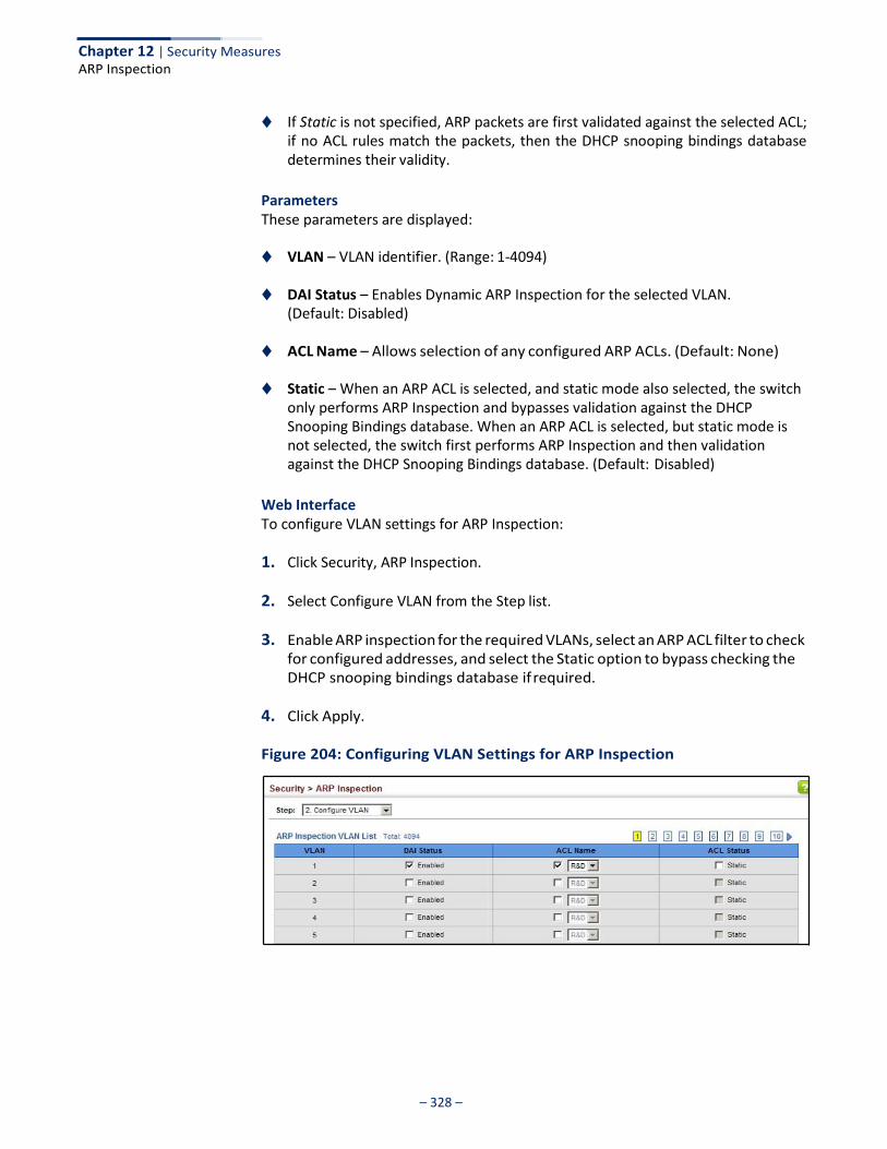
– 328 –
Chapter 12 | Security Measures ARP Inspection
◆ If Static is not specified, ARP packets are first validated against the selected ACL; if no ACL rules match the packets, then the DHCP snooping bindings database determines their validity.
Parameters These parameters are displayed:
◆ VLAN – VLAN identifier. (Range: 1-4094)
◆ DAI Status – Enables Dynamic ARP Inspection for the selected VLAN. (Default: Disabled)
◆ ACL Name – Allows selection of any configured ARP ACLs. (Default: None)
◆ Static – When an ARP ACL is selected, and static mode also selected, the switch only performs ARP Inspection and bypasses validation against the DHCP Snooping Bindings database. When an ARP ACL is selected, but static mode is not selected, the switch first performs ARP Inspection and then validation against the DHCP Snooping Bindings database. (Default: Disabled)
Web Interface To configure VLAN settings for ARP Inspection:
1. Click Security, ARP Inspection.
2. Select Configure VLAN from the Step list.
3. Enable ARP inspection for the required VLANs, select an ARP ACL filter to check for configured addresses, and select the Static option to bypass checking the DHCP snooping bindings database if required.
4. Click Apply.
Figure 204: Configuring VLAN Settings for ARP Inspection
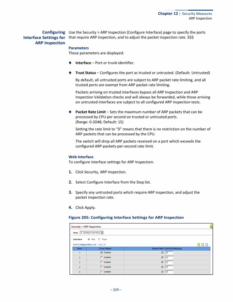
– 329 –
Chapter 12 | Security Measures ARP Inspection
Configuring Interface Settings for
ARP Inspection
Use the Security > ARP Inspection (Configure Interface) page to specify the ports that require ARP inspection, and to adjust the packet inspection rate. $$$
Parameters These parameters are displayed:
◆ Interface – Port or trunk identifier.
◆ Trust Status – Configures the port as trusted or untrusted. (Default: Untrusted)
By default, all untrusted ports are subject to ARP packet rate limiting, and all trusted ports are exempt from ARP packet rate limiting.
Packets arriving on trusted interfaces bypass all ARP Inspection and ARP Inspection Validation checks and will always be forwarded, while those arriving on untrusted interfaces are subject to all configured ARP inspection tests.
◆ Packet Rate Limit – Sets the maximum number of ARP packets that can be
processed by CPU per second on trusted or untrusted ports. (Range: 0-2048; Default: 15)
Setting the rate limit to “0” means that there is no restriction on the number of ARP packets that can be processed by the CPU.
The switch will drop all ARP packets received on a port which exceeds the configured ARP-packets-per-second rate limit.
Web Interface To configure interface settings for ARP Inspection:
1. Click Security, ARP Inspection.
2. Select Configure Interface from the Step list.
3. Specify any untrusted ports which require ARP inspection, and adjust the packet inspection rate.
4. Click Apply.
Figure 205: Configuring Interface Settings for ARP Inspection
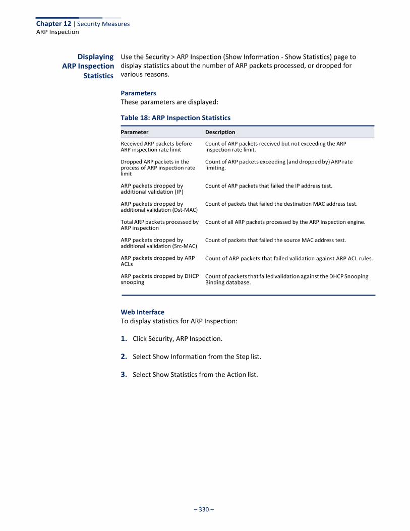
Chapter 12 | Security Measures ARP Inspection
– 330 –
Displaying ARP Inspection
Statistics
Use the Security > ARP Inspection (Show Information - Show Statistics) page to display statistics about the number of ARP packets processed, or dropped for various reasons.
Parameters These parameters are displayed:
Table 18: ARP Inspection Statistics
Received ARP packets before ARP inspection rate limit
Dropped ARP packets in the process of ARP inspection rate limit
ARP packets dropped by additional validation (IP)
ARP packets dropped by additional validation (Dst-MAC)
Total ARP packets processed by ARP inspection
ARP packets dropped by additional validation (Src-MAC)
ARP packets dropped by ARP ACLs
ARP packets dropped by DHCP snooping
Count of ARP packets received but not exceeding the ARP Inspection rate limit.
Count of ARP packets exceeding (and dropped by) ARP rate limiting.
Count of ARP packets that failed the IP address test.
Count of packets that failed the destination MAC address test.
Count of all ARP packets processed by the ARP Inspection engine.
Count of packets that failed the source MAC address test.
Count of ARP packets that failed validation against ARP ACL rules.
Count of packets that failed validation against the DHCP Snooping Binding database.
Web Interface To display statistics for ARP Inspection:
1. Click Security, ARP Inspection.
2. Select Show Information from the Step list.
3. Select Show Statistics from the Action list.
Parameter Description

Chapter 12 | Security Measures ARP Inspection
– 331 –
Figure 206: Displaying Statistics for ARP Inspection
Displaying the ARP Inspection Log
Use the Security > ARP Inspection (Show Information - Show Log) page to show information about entries stored in the log, including the associated VLAN, port, and address components.
Parameters These parameters are displayed:
Table 19: ARP Inspection Log
VLAN ID The VLAN where this packet was seen.
Port The port where this packet was seen.
Src. IP Address The source IP address in the packet.
Dst. IP Address The destination IP address in the packet.
Src. MAC Address The source MAC address in the packet.
Dst. MAC Address The destination MAC address in the packet.
Web Interface To display the ARP Inspection log:
1. Click Security, ARP Inspection.
2. Select Show Information from the Step list.
3. Select Show Log from the Action list.
Parameter Description
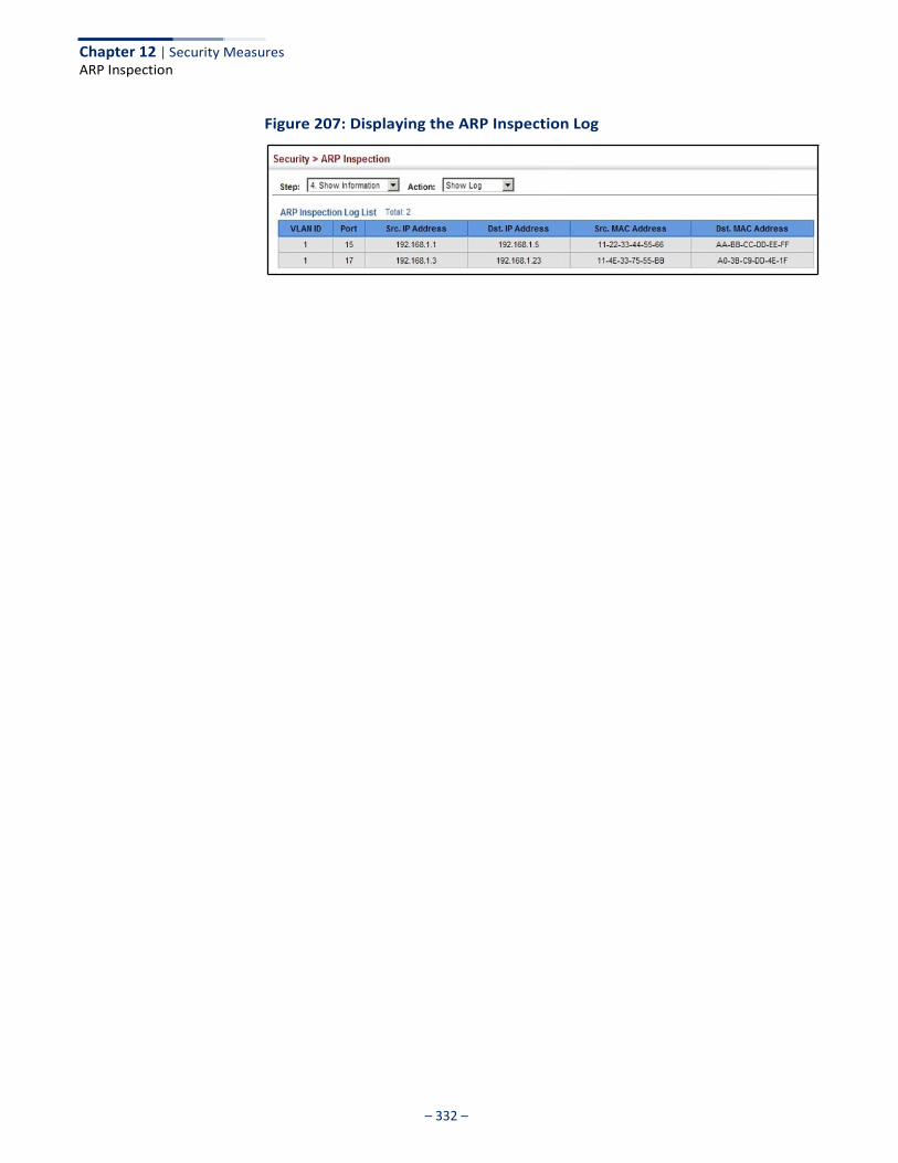
Chapter 12 | Security Measures ARP Inspection
– 332 –
Figure 207: Displaying the ARP Inspection Log
– 333 –
Basic Administration Protocols
This chapter describes basic administration tasks including:
◆ Event Logging – Sets conditions for logging event messages to system memory or flash memory, configures conditions for sending trap messages to remote log servers, and configures trap reporting to remote hosts using Simple Mail Transfer Protocol (SMTP).
◆ Link Layer Discovery Protocol (LLDP) – Configures advertisement of basic
information about the local switch, or discovery of information about neighboring devices on the local broadcast domain.
◆ Simple Network Management Protocol (SNMP) – Configures switch
management through SNMPv1, SNMPv2c or SNMPv3.
◆ Remote Monitoring (RMON) – Configures local collection of detailed statistics or events which can be subsequently retrieved through SNMP.
◆ Switch Clustering – Configures centralized management by a single unit over a
group of switches connected to the same local network.
◆ Time Range – Sets a time range during which various functions are applied, including applied ACLs or PoE.
◆ Ethernet Ring Protection Switching (ERPS) – Configures a protection switching
mechanism and protocol for Ethernet layer network rings.
◆ Loopback Detection (LBD) – Detects general loopback conditions caused by hardware problems or faulty protocol settings.
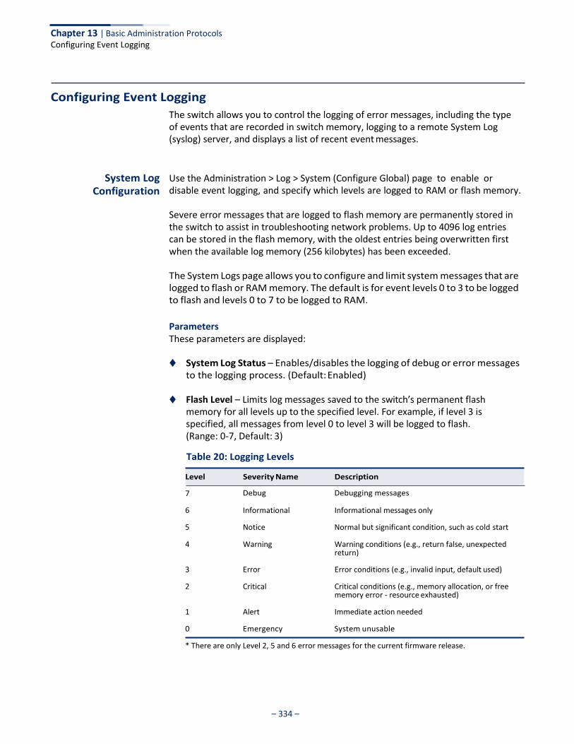
Chapter 13 | Basic Administration Protocols Configuring Event Logging
– 334 –
Configuring Event Logging
The switch allows you to control the logging of error messages, including the type of events that are recorded in switch memory, logging to a remote System Log (syslog) server, and displays a list of recent event messages.
System Log Configuration
Use the Administration > Log > System (Configure Global) page to enable or disable event logging, and specify which levels are logged to RAM or flash memory.
Severe error messages that are logged to flash memory are permanently stored in the switch to assist in troubleshooting network problems. Up to 4096 log entries can be stored in the flash memory, with the oldest entries being overwritten first when the available log memory (256 kilobytes) has been exceeded.
The System Logs page allows you to configure and limit system messages that are logged to flash or RAM memory. The default is for event levels 0 to 3 to be logged to flash and levels 0 to 7 to be logged to RAM.
Parameters These parameters are displayed:
◆ System Log Status – Enables/disables the logging of debug or error messages to the logging process. (Default: Enabled)
◆ Flash Level – Limits log messages saved to the switch’s permanent flash
memory for all levels up to the specified level. For example, if level 3 is specified, all messages from level 0 to level 3 will be logged to flash. (Range: 0-7, Default: 3)
Table 20: Logging Levels
7 Debug Debugging messages
6 Informational Informational messages only
5 Notice Normal but significant condition, such as cold start
4 Warning Warning conditions (e.g., return false, unexpected return)
3 Error Error conditions (e.g., invalid input, default used)
2 Critical Critical conditions (e.g., memory allocation, or free memory error - resource exhausted)
1 Alert Immediate action needed
0 Emergency System unusable
* There are only Level 2, 5 and 6 error messages for the current firmware release.
Level Severity Name Description
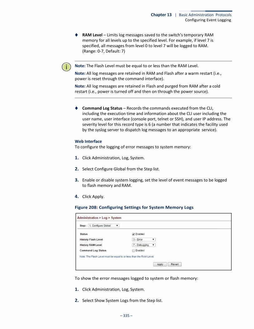
Chapter 13 | Basic Administration Protocols Configuring Event Logging
– 335 –
◆ RAM Level – Limits log messages saved to the switch’s temporary RAM memory for all levels up to the specified level. For example, if level 7 is specified, all messages from level 0 to level 7 will be logged to RAM. (Range: 0-7, Default: 7)
Note: The Flash Level must be equal to or less than the RAM Level.
Note: All log messages are retained in RAM and Flash after a warm restart (i.e., power is reset through the command interface).
Note: All log messages are retained in Flash and purged from RAM after a cold restart (i.e., power is turned off and then on through the power source).
◆ Command Log Status – Records the commands executed from the CLI, including the execution time and information about the CLI user including the user name, user interface (console port, telnet or SSH), and user IP address. The severity level for this record type is 6 (a number that indicates the facility used by the syslog server to dispatch log messages to an appropriate service).
Web Interface To configure the logging of error messages to system memory:
1. Click Administration, Log, System.
2. Select Configure Global from the Step list.
3. Enable or disable system logging, set the level of event messages to be logged to flash memory and RAM.
4. Click Apply.
Figure 208: Configuring Settings for System Memory Logs
To show the error messages logged to system or flash memory:
1. Click Administration, Log, System.
2. Select Show System Logs from the Step list.
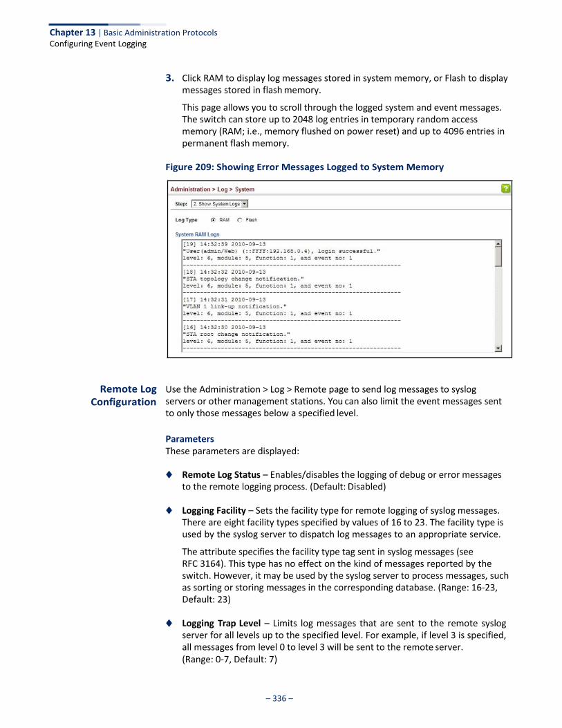
Chapter 13 | Basic Administration Protocols Configuring Event Logging
– 336 –
3. Click RAM to display log messages stored in system memory, or Flash to display messages stored in flash memory.
This page allows you to scroll through the logged system and event messages. The switch can store up to 2048 log entries in temporary random access memory (RAM; i.e., memory flushed on power reset) and up to 4096 entries in permanent flash memory.
Figure 209: Showing Error Messages Logged to System Memory
Remote Log Configuration
Use the Administration > Log > Remote page to send log messages to syslog servers or other management stations. You can also limit the event messages sent to only those messages below a specified level.
Parameters These parameters are displayed:
◆ Remote Log Status – Enables/disables the logging of debug or error messages to the remote logging process. (Default: Disabled)
◆ Logging Facility – Sets the facility type for remote logging of syslog messages.
There are eight facility types specified by values of 16 to 23. The facility type is used by the syslog server to dispatch log messages to an appropriate service.
The attribute specifies the facility type tag sent in syslog messages (see RFC 3164). This type has no effect on the kind of messages reported by the switch. However, it may be used by the syslog server to process messages, such as sorting or storing messages in the corresponding database. (Range: 16-23, Default: 23)
◆ Logging Trap Level – Limits log messages that are sent to the remote syslog
server for all levels up to the specified level. For example, if level 3 is specified, all messages from level 0 to level 3 will be sent to the remote server. (Range: 0-7, Default: 7)
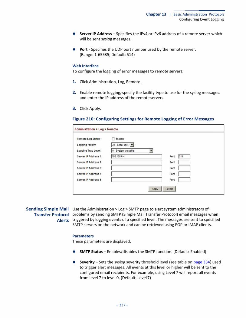
Chapter 13 | Basic Administration Protocols Configuring Event Logging
– 337 –
◆ Server IP Address – Specifies the IPv4 or IPv6 address of a remote server which will be sent syslog messages.
◆ Port - Specifies the UDP port number used by the remote server.
(Range: 1-65535; Default: 514)
Web Interface To configure the logging of error messages to remote servers:
1. Click Administration, Log, Remote.
2. Enable remote logging, specify the facility type to use for the syslog messages. and enter the IP address of the remote servers.
3. Click Apply.
Figure 210: Configuring Settings for Remote Logging of Error Messages
Sending Simple Mail Transfer Protocol
Alerts
Use the Administration > Log > SMTP page to alert system administrators of problems by sending SMTP (Simple Mail Transfer Protocol) email messages when triggered by logging events of a specified level. The messages are sent to specified SMTP servers on the network and can be retrieved using POP or IMAP clients.
Parameters These parameters are displayed:
◆ SMTP Status – Enables/disables the SMTP function. (Default: Enabled)
◆ Severity – Sets the syslog severity threshold level (see table on page 334) used to trigger alert messages. All events at this level or higher will be sent to the configured email recipients. For example, using Level 7 will report all events from level 7 to level 0. (Default: Level 7)

Chapter 13 | Basic Administration Protocols Configuring Event Logging
– 338 –
◆ Email Source Address – Sets the email address used for the “From” field in alert messages. You may use a symbolic email address that identifies the switch, or the address of an administrator responsible for the switch. (Range: 1-41 characters)
◆ Email Destination Address – Specifies the email recipients of alert messages.
You can specify up to five recipients.
◆ Server IP Address – Specifies a list of up to three recipient SMTP servers. IPv4 or IPv6 addresses may be specified. The switch attempts to connect to the listed servers in sequential order if the first server fails to respond.
Web Interface To configure SMTP alert messages:
1. Click Administration, Log, SMTP.
2. Enable SMTP, specify a source email address, and select the minimum severity level. Specify the source and destination email addresses, and one or more SMTP servers.
3. Click Apply.
Figure 211: Configuring SMTP Alert Messages
– 339 –
Chapter 13 | Basic Administration Protocols Link Layer Discovery Protocol
Link Layer Discovery Protocol
Link Layer Discovery Protocol (LLDP) is used to discover basic information about neighboring devices on the local broadcast domain. LLDP is a Layer 2 protocol that uses periodic broadcasts to advertise information about the sending device. Advertised information is represented in Type Length Value (TLV) format according to the IEEE 802.1AB standard, and can include details such as device identification, capabilities and configuration settings. LLDP also defines how to store and maintain information gathered about the neighboring network nodes it discovers.
Link Layer Discovery Protocol - Media Endpoint Discovery (LLDP-MED) is an extension of LLDP intended for managing endpoint devices such as Voice over IP phones and network switches. The LLDP-MED TLVs advertise information such as network policy, power, inventory, and device location details. LLDP and LLDP-MED information can be used by SNMP applications to simplify troubleshooting, enhance network management, and maintain an accurate network topology.
Setting LLDP Timing Attributes
Use the Administration > LLDP (Configure Global) page to set attributes for general functions such as globally enabling LLDP on the switch, setting the message ageout time, and setting the frequency for broadcasting general advertisements or reports about changes in the LLDP MIB.
Parameters These parameters are displayed:
◆ LLDP – Enables LLDP globally on the switch. (Default: Enabled)
◆ Transmission Interval – Configures the periodic transmit interval for LLDP advertisements. (Range: 5-32768 seconds; Default: 30 seconds)
◆ Hold Time Multiplier – Configures the time-to-live (TTL) value sent in LLDP
advertisements as shown in the formula below. (Range: 2-10; Default: 4)
The time-to-live tells the receiving LLDP agent how long to retain all information pertaining to the sending LLDP agent if it does not transmit updates in a timely manner.
TTL in seconds is based on the following rule: minimum value ((Transmission Interval * Holdtime Multiplier), or 65535)
Therefore, the default TTL is 4*30 = 120 seconds.
◆ Delay Interval – Configures a delay between the successive transmission of advertisements initiated by a change in local LLDP MIB variables. (Range: 1-8192 seconds; Default: 2 seconds)
The transmit delay is used to prevent a series of successive LLDP transmissions during a short period of rapid changes in local LLDP MIB objects, and to
Chapter 13 | Basic Administration Protocols Link Layer Discovery Protocol
– 340 –
increase the probability that multiple, rather than single changes, are reported in each transmission.
This attribute must comply with the rule: (4 * Delay Interval) Transmission Interval
◆ Reinitialization Delay – Configures the delay before attempting to re-initialize
after LLDP ports are disabled or the link goes down. (Range: 1-10 seconds; Default: 2 seconds)
When LLDP is re-initialized on a port, all information in the remote systems LLDP MIB associated with this port is deleted.
◆ Notification Interval – Configures the allowed interval for sending SNMP
notifications about LLDP MIB changes. (Range: 5-3600 seconds; Default: 5 seconds)
This parameter only applies to SNMP applications which use data stored in the LLDP MIB for network monitoring or management.
Information about changes in LLDP neighbors that occur between SNMP notifications is not transmitted. Only state changes that exist at the time of a notification are included in the transmission. An SNMP agent should therefore periodically check the value of lldpStatsRemTableLastChangeTime to detect any lldpRemTablesChange notification-events missed due to throttling or transmission loss.
◆ MED Fast Start Count – Configures the amount of LLDP MED Fast Start
LLDPDUs to transmit during the activation process of the LLDP-MED Fast Start mechanism. (Range: 1-10 packets; Default: 4 packets)
The MED Fast Start Count parameter is part of the timer which ensures that the LLDP-MED Fast Start mechanism is active for the port. LLDP-MED Fast Start is critical to the timely startup of LLDP, and therefore integral to the rapid availability of Emergency Call Service.
Web Interface To configure LLDP timing attributes:
1. Click Administration, LLDP.
2. Select Configure Global from the Step list.
3. Enable LLDP, and modify any of the timing parameters as required.
4. Click Apply.
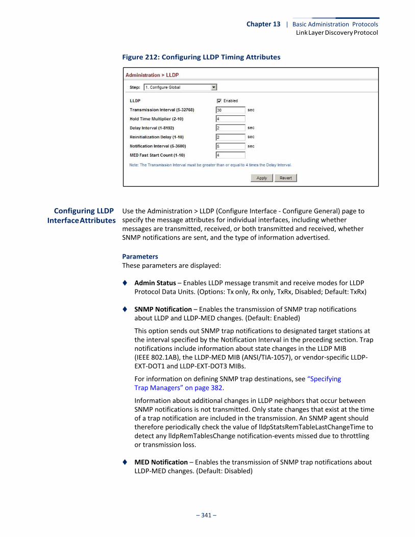
Chapter 13 | Basic Administration Protocols Link Layer Discovery Protocol
– 341 –
Figure 212: Configuring LLDP Timing Attributes
Configuring LLDP Interface Attributes
Use the Administration > LLDP (Configure Interface - Configure General) page to specify the message attributes for individual interfaces, including whether messages are transmitted, received, or both transmitted and received, whether SNMP notifications are sent, and the type of information advertised.
Parameters These parameters are displayed:
◆ Admin Status – Enables LLDP message transmit and receive modes for LLDP
Protocol Data Units. (Options: Tx only, Rx only, TxRx, Disabled; Default: TxRx)
◆ SNMP Notification – Enables the transmission of SNMP trap notifications about LLDP and LLDP-MED changes. (Default: Enabled)
This option sends out SNMP trap notifications to designated target stations at the interval specified by the Notification Interval in the preceding section. Trap notifications include information about state changes in the LLDP MIB (IEEE 802.1AB), the LLDP-MED MIB (ANSI/TIA-1057), or vendor-specific LLDP- EXT-DOT1 and LLDP-EXT-DOT3 MIBs.
For information on defining SNMP trap destinations, see “Specifying Trap Managers” on page 382.
Information about additional changes in LLDP neighbors that occur between SNMP notifications is not transmitted. Only state changes that exist at the time of a trap notification are included in the transmission. An SNMP agent should therefore periodically check the value of lldpStatsRemTableLastChangeTime to detect any lldpRemTablesChange notification-events missed due to throttling or transmission loss.
◆ MED Notification – Enables the transmission of SNMP trap notifications about LLDP-MED changes. (Default: Disabled)
Chapter 13 | Basic Administration Protocols Link Layer Discovery Protocol
– 342 –
◆ Basic Optional TLVs – Configures basic information included in the TLV field of advertised messages.
■ Management Address – The management address protocol packet
includes the IPv4 address of the switch. If no management address is available, the address should be the MAC address for the CPU or for the port sending this advertisement. (Default: Enabled)
The management address TLV may also include information about the specific interface associated with this address, and an object identifier indicating the type of hardware component or protocol entity associated with this address. The interface number and OID are included to assist SNMP applications in the performance of network discovery by indicating enterprise specific or other starting points for the search, such as the Interface or Entity MIB.
Since there are typically a number of different addresses associated with a Layer 3 device, an individual LLDP PDU may contain more than one management address TLV.
Every management address TLV that reports an address that is accessible on a port and protocol VLAN through the particular port should be accompanied by a port and protocol VLAN TLV that indicates the VLAN identifier (VID) associated with the management address reported by this TLV.
■ Port Description – The port description is taken from the ifDescr object in
RFC 2863, which includes information about the manufacturer, the product name, and the version of the interface hardware/software. (Default: Enabled)
■ System Capabilities – The system capabilities identifies the primary
function(s) of the system and whether or not these primary functions are enabled. The information advertised by this TLV is described in IEEE 802.1AB. (Default: Enabled)
■ System Description – The system description is taken from the sysDescr
object in RFC 3418, which includes the full name and version identification of the system's hardware type, software operating system, and networking software. (Default: Enabled)
■ System Name – The system name is taken from the sysName object in
RFC 3418, which contains the system’s administratively assigned name. To configure the system name, see “Displaying System Information” on page 64. (Default: Enabled)
◆ 802.1 Organizationally Specific TLVs – Configures IEEE 802.1 information
included in the TLV field of advertised messages.
■ Protocol Identity – The protocols that are accessible through this interface (see “Protocol VLANs” on page 164). (Default: Enabled)

Chapter 13 | Basic Administration Protocols Link Layer Discovery Protocol
– 343 –
■ VLAN ID – The port’s default VLAN identifier (PVID) indicates the VLAN with
which untagged or priority-tagged frames are associated (see “IEEE 802.1Q VLANs” on page 147). (Default: Enabled)
■ VLAN Name – The name of all VLANs to which this interface has been
assigned (see “IEEE 802.1Q VLANs” on page 147. (Default: Enabled)
■ Port and Protocol VLAN ID – The port-based protocol VLANs configured on this interface (see “Protocol VLANs” on page 164). (Default: Enabled)
◆ 802.3 Organizationally Specific TLVs – Configures IEEE 802.3 information
included in the TLV field of advertised messages.
■ Link Aggregation – The link aggregation capabilities, aggregation status of the link, and the IEEE 802.3 aggregated port identifier if this interface is currently a link aggregation member. (Default: Enabled)
■ Max Frame Size – The maximum frame size. (See “Configuring Support for
Jumbo Frames” on page 66 for information on configuring the maximum frame size for this switch. (Default: Enabled)
■ MAC/PHY Configuration/Status – The MAC/PHY configuration and status
which includes information about auto-negotiation support/capabilities, and operational Multistation Access Unit (MAU) type. (Default: Enabled)
◆ MED TLVs – Configures general information included in the MED TLV field of
advertised messages.
■ Capabilities – This option advertises LLDP-MED TLV capabilities, allowing Media Endpoint and Connectivity Devices to efficiently discover which LLDP-MED related TLVs are supported on the switch. (Default: Enabled)
■ Inventory – This option advertises device details useful for inventory
management, such as manufacturer, model, software version and other pertinent information. (Default: Enabled)
■ Location – This option advertises location identification details.
(Default: Enabled)
■ Network Policy – This option advertises network policy configuration information, aiding in the discovery and diagnosis of VLAN configuration mismatches on a port. Improper network policy configurations frequently result in voice quality degradation or complete service disruption. (Default: Enabled)
Chapter 13 | Basic Administration Protocols Link Layer Discovery Protocol
– 344 –
◆ MED-Location Civic Address – Configures information for the location of the attached device included in the MED TLV field of advertised messages, including the country and the device type.
■ Country – The two-letter ISO 3166 country code in capital ASCII letters.
(Example: DK, DE or US)
■ Device entry refers to – The type of device to which the location applies:
■ Location of DHCP server.
■ Location of network element closest to client.
■ Location of client. (This is the default.)
Web Interface To configure LLDP interface attributes:
1. Click Administration, LLDP.
2. Select Configure Interface from the Step list.
3. Select Configure General from the Action list.
4. Select an interface from the Port or Trunk list.
5. Set the LLDP transmit/receive mode, specify whether or not to send SNMP trap messages, and select the information to advertise in LLDP messages.
6. Click Apply.
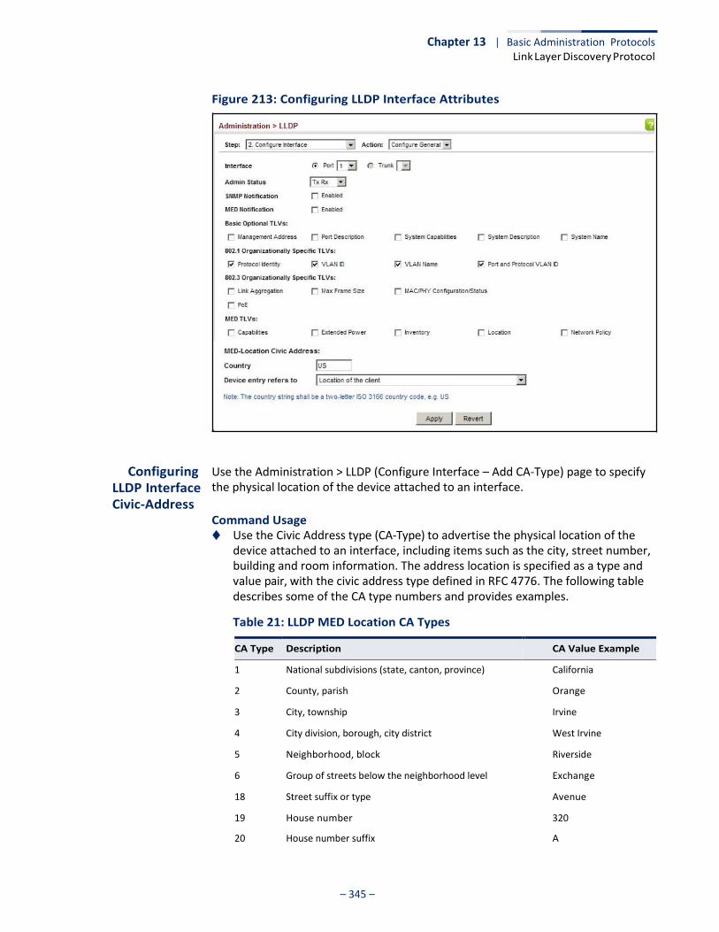
Chapter 13 | Basic Administration Protocols Link Layer Discovery Protocol
– 345 –
Figure 213: Configuring LLDP Interface Attributes
Configuring LLDP Interface Civic-Address
Use the Administration > LLDP (Configure Interface – Add CA-Type) page to specify the physical location of the device attached to an interface.
Command Usage ◆ Use the Civic Address type (CA-Type) to advertise the physical location of the
device attached to an interface, including items such as the city, street number, building and room information. The address location is specified as a type and value pair, with the civic address type defined in RFC 4776. The following table describes some of the CA type numbers and provides examples.
Table 21: LLDP MED Location CA Types
CA Type Description CA Value Example
1 National subdivisions (state, canton, province) California
2 County, parish Orange
3 City, township Irvine
4 City division, borough, city district West Irvine
5 Neighborhood, block Riverside
6 Group of streets below the neighborhood level Exchange
18 Street suffix or type Avenue
19 House number 320
20 House number suffix A
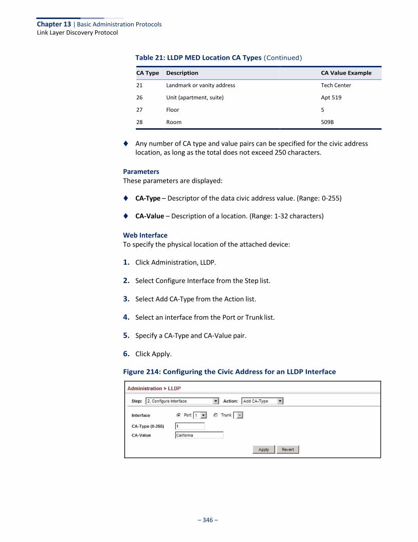
Chapter 13 | Basic Administration Protocols Link Layer Discovery Protocol
– 346 –
Table 21: LLDP MED Location CA Types (Continued)
CA Type Description CA Value Example
21 Landmark or vanity address Tech Center
26 Unit (apartment, suite) Apt 519
27 Floor 5
28 Room 509B
◆ Any number of CA type and value pairs can be specified for the civic address
location, as long as the total does not exceed 250 characters.
Parameters These parameters are displayed:
◆ CA-Type – Descriptor of the data civic address value. (Range: 0-255)
◆ CA-Value – Description of a location. (Range: 1-32 characters)
Web Interface To specify the physical location of the attached device:
1. Click Administration, LLDP.
2. Select Configure Interface from the Step list.
3. Select Add CA-Type from the Action list.
4. Select an interface from the Port or Trunk list.
5. Specify a CA-Type and CA-Value pair.
6. Click Apply.
Figure 214: Configuring the Civic Address for an LLDP Interface

Chapter 13 | Basic Administration Protocols Link Layer Discovery Protocol
– 347 –
To show the physical location of the attached device:
1. Click Administration, LLDP.
2. Select Configure Interface from the Step list.
3. Select Show CA-Type from the Action list.
4. Select an interface from the Port or Trunk list.
Figure 215: Showing the Civic Address for an LLDP Interface
Displaying LLDP Local Device Information
Use the Administration > LLDP (Show Local Device Information) page to display information about the switch, such as its MAC address, chassis ID, management IP address, and port information.
Parameters These parameters are displayed:
General Settings
◆ Chassis Type – Identifies the chassis containing the IEEE 802 LAN entity associated with the transmitting LLDP agent. There are several ways in which a chassis may be identified and a chassis ID subtype is used to indicate the type of component being referenced by the chassis ID field.
Table 22: Chassis ID Subtype
Chassis component EntPhysicalAlias when entPhysClass has a value of ‘chassis(3)’ (IETF RFC 2737)
Interface alias IfAlias (IETF RFC 2863)
Port component EntPhysicalAlias when entPhysicalClass has a value ‘port(10)’ or ‘backplane(4)’ (IETF RFC 2737)
MAC address MAC address (IEEE Std 802-2001)
Network address networkAddress
Interface name ifName (IETF RFC 2863)
Locally assigned locally assigned
ID Basis Reference
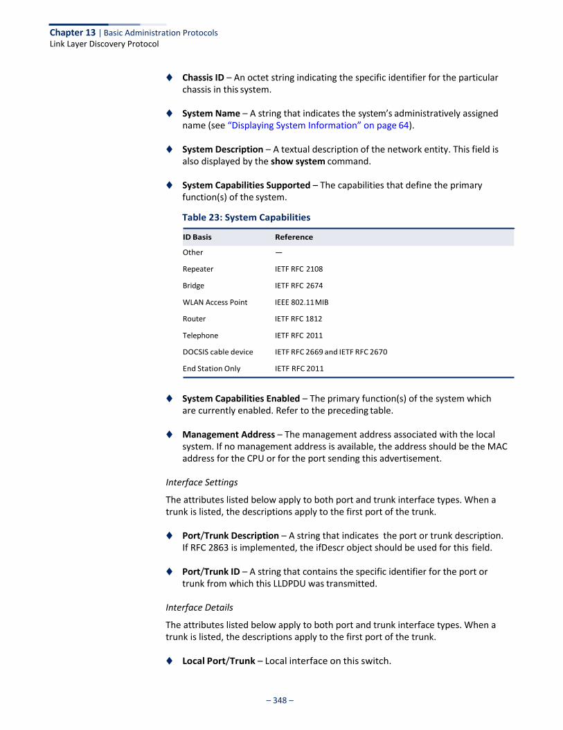
Chapter 13 | Basic Administration Protocols Link Layer Discovery Protocol
– 348 –
◆ Chassis ID – An octet string indicating the specific identifier for the particular chassis in this system.
◆ System Name – A string that indicates the system’s administratively assigned
name (see “Displaying System Information” on page 64).
◆ System Description – A textual description of the network entity. This field is also displayed by the show system command.
◆ System Capabilities Supported – The capabilities that define the primary
function(s) of the system.
Table 23: System Capabilities
Other —
Repeater IETF RFC 2108
Bridge IETF RFC 2674
WLAN Access Point IEEE 802.11 MIB
Router IETF RFC 1812
Telephone IETF RFC 2011
DOCSIS cable device IETF RFC 2669 and IETF RFC 2670
End Station Only IETF RFC 2011
◆ System Capabilities Enabled – The primary function(s) of the system which are currently enabled. Refer to the preceding table.
◆ Management Address – The management address associated with the local
system. If no management address is available, the address should be the MAC address for the CPU or for the port sending this advertisement.
Interface Settings
The attributes listed below apply to both port and trunk interface types. When a trunk is listed, the descriptions apply to the first port of the trunk.
◆ Port/Trunk Description – A string that indicates the port or trunk description.
If RFC 2863 is implemented, the ifDescr object should be used for this field.
◆ Port/Trunk ID – A string that contains the specific identifier for the port or trunk from which this LLDPDU was transmitted.
Interface Details
The attributes listed below apply to both port and trunk interface types. When a trunk is listed, the descriptions apply to the first port of the trunk.
◆ Local Port/Trunk – Local interface on this switch.
ID Basis Reference
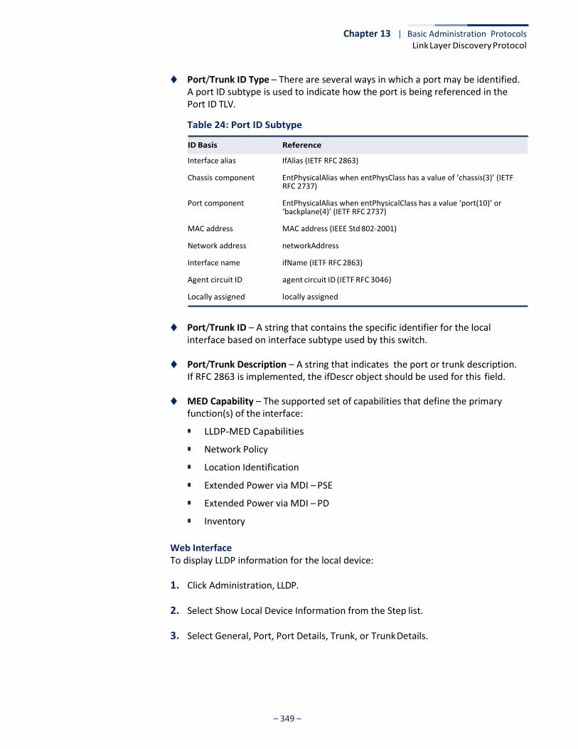
Chapter 13 | Basic Administration Protocols Link Layer Discovery Protocol
– 349 –
◆ Port/Trunk ID Type – There are several ways in which a port may be identified. A port ID subtype is used to indicate how the port is being referenced in the Port ID TLV.
Table 24: Port ID Subtype
Interface alias IfAlias (IETF RFC 2863)
Chassis component EntPhysicalAlias when entPhysClass has a value of ‘chassis(3)’ (IETF RFC 2737)
Port component EntPhysicalAlias when entPhysicalClass has a value ‘port(10)’ or ‘backplane(4)’ (IETF RFC 2737)
MAC address MAC address (IEEE Std 802-2001)
Network address networkAddress
Interface name ifName (IETF RFC 2863)
Agent circuit ID agent circuit ID (IETF RFC 3046)
Locally assigned locally assigned
◆ Port/Trunk ID – A string that contains the specific identifier for the local interface based on interface subtype used by this switch.
◆ Port/Trunk Description – A string that indicates the port or trunk description.
If RFC 2863 is implemented, the ifDescr object should be used for this field.
◆ MED Capability – The supported set of capabilities that define the primary function(s) of the interface:
■ LLDP-MED Capabilities
■ Network Policy
■ Location Identification
■ Extended Power via MDI – PSE
■ Extended Power via MDI – PD
■ Inventory
Web Interface To display LLDP information for the local device:
1. Click Administration, LLDP.
2. Select Show Local Device Information from the Step list.
3. Select General, Port, Port Details, Trunk, or Trunk Details.
ID Basis Reference
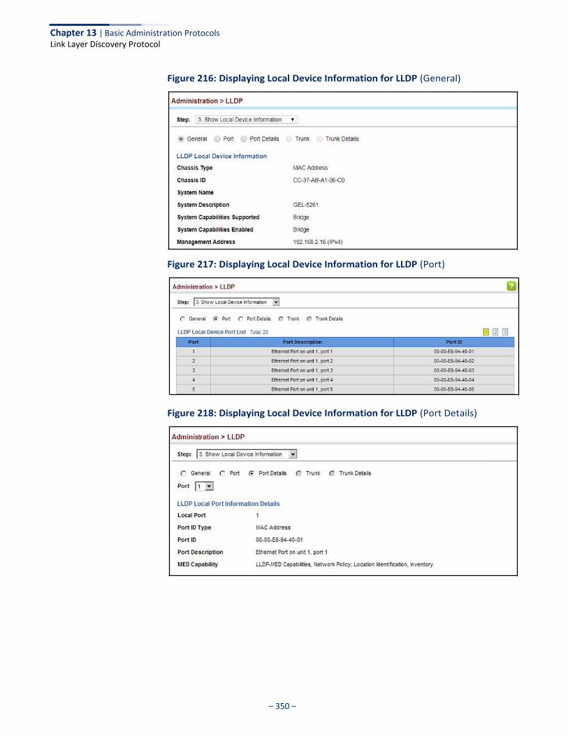
Chapter 13 | Basic Administration Protocols Link Layer Discovery Protocol
– 350 –
Figure 216: Displaying Local Device Information for LLDP (General)
Figure 217: Displaying Local Device Information for LLDP (Port)
Figure 218: Displaying Local Device Information for LLDP (Port Details)
Chapter 13 | Basic Administration Protocols Link Layer Discovery Protocol
– 351 –
Displaying LLDP Remote Device
Information
Use the Administration > LLDP (Show Remote Device Information) page to display information about devices connected directly to the switch’s ports which are advertising information through LLDP, or to display detailed information about an LLDP-enabled device connected to a specific port on the local switch.
Parameters These parameters are displayed:
Port
◆ Local Port – The local port to which a remote LLDP-capable device is attached.
◆ Chassis ID – An octet string indicating the specific identifier for the particular chassis in this system.
◆ Port ID – A string that contains the specific identifier for the port from which
this LLDPDU was transmitted.
◆ System Name – A string that indicates the system’s administratively assigned name.
Port Details
◆ Port – Port identifier on local switch.
◆ Remote Index – Index of remote device attached to this port.
◆ Local Port – The local port to which a remote LLDP-capable device is attached.
◆ Chassis Type – Identifies the chassis containing the IEEE 802 LAN entity associated with the transmitting LLDP agent. There are several ways in which a chassis may be identified and a chassis ID subtype is used to indicate the type of component being referenced by the chassis ID field. (See Table 22, "Chassis ID Subtype," on page 347.)
◆ Chassis ID – An octet string indicating the specific identifier for the particular
chassis in this system.
◆ System Name – A string that indicates the system’s assigned name.
◆ System Description – A textual description of the network entity.
◆ Port Type – Indicates the basis for the identifier that is listed in the Port ID field. See Table 24, “Port ID Subtype,” on page 349.
◆ Port Description – A string that indicates the port’s description. If RFC 2863 is
implemented, the ifDescr object should be used for this field.
◆ Port ID – A string that contains the specific identifier for the port from which this LLDPDU was transmitted.
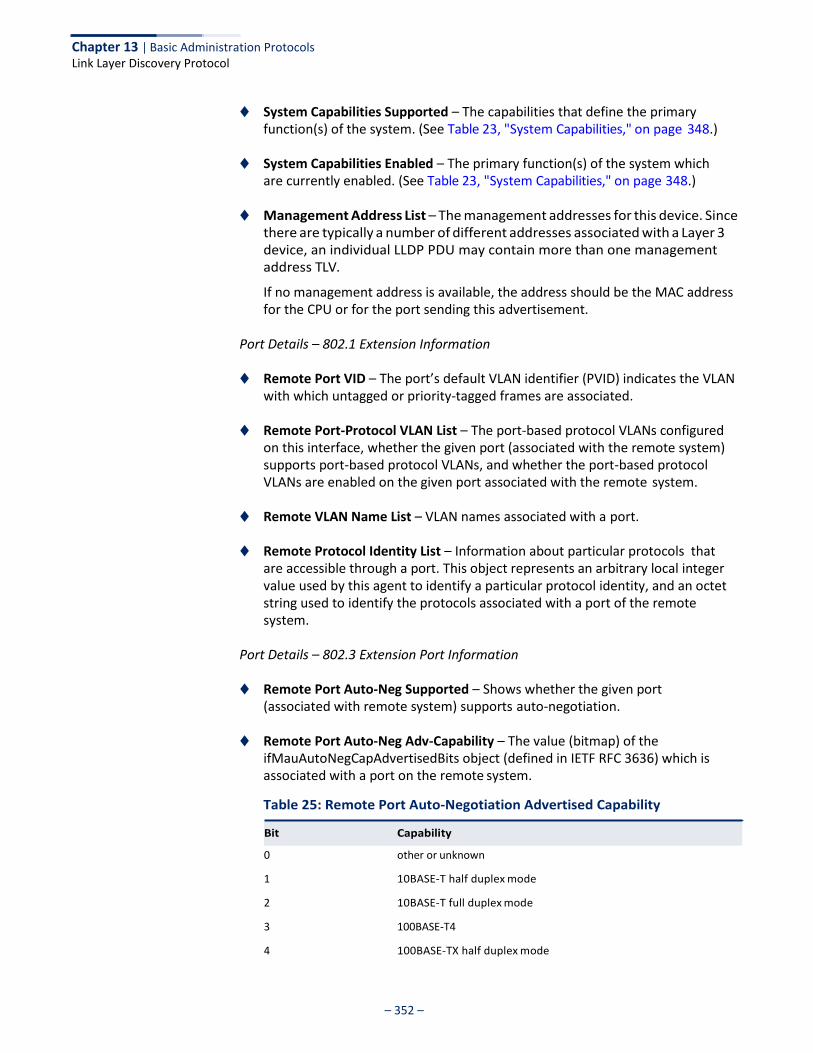
Chapter 13 | Basic Administration Protocols Link Layer Discovery Protocol
– 352 –
◆ System Capabilities Supported – The capabilities that define the primary function(s) of the system. (See Table 23, "System Capabilities," on page 348.)
◆ System Capabilities Enabled – The primary function(s) of the system which
are currently enabled. (See Table 23, "System Capabilities," on page 348.)
◆ Management Address List – The management addresses for this device. Since there are typically a number of different addresses associated with a Layer 3 device, an individual LLDP PDU may contain more than one management address TLV.
If no management address is available, the address should be the MAC address for the CPU or for the port sending this advertisement.
Port Details – 802.1 Extension Information
◆ Remote Port VID – The port’s default VLAN identifier (PVID) indicates the VLAN with which untagged or priority-tagged frames are associated.
◆ Remote Port-Protocol VLAN List – The port-based protocol VLANs configured
on this interface, whether the given port (associated with the remote system) supports port-based protocol VLANs, and whether the port-based protocol VLANs are enabled on the given port associated with the remote system.
◆ Remote VLAN Name List – VLAN names associated with a port.
◆ Remote Protocol Identity List – Information about particular protocols that are accessible through a port. This object represents an arbitrary local integer value used by this agent to identify a particular protocol identity, and an octet string used to identify the protocols associated with a port of the remote system.
Port Details – 802.3 Extension Port Information
◆ Remote Port Auto-Neg Supported – Shows whether the given port (associated with remote system) supports auto-negotiation.
◆ Remote Port Auto-Neg Adv-Capability – The value (bitmap) of the
ifMauAutoNegCapAdvertisedBits object (defined in IETF RFC 3636) which is associated with a port on the remote system.
Table 25: Remote Port Auto-Negotiation Advertised Capability
0 other or unknown
1 10BASE-T half duplex mode
2 10BASE-T full duplex mode
3 100BASE-T4
4 100BASE-TX half duplex mode
Bit Capability
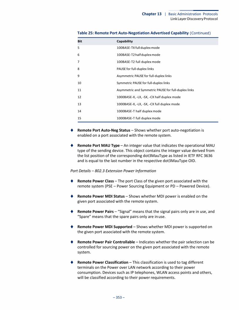
Chapter 13 | Basic Administration Protocols Link Layer Discovery Protocol
– 353 –
Table 25: Remote Port Auto-Negotiation Advertised Capability (Continued)
5 100BASE-TX full duplex mode
6 100BASE-T2 half duplex mode
7 100BASE-T2 full duplex mode
8 PAUSE for full-duplex links
9 Asymmetric PAUSE for full-duplex links
10 Symmetric PAUSE for full-duplex links
11 Asymmetric and Symmetric PAUSE for full-duplex links
12 1000BASE-X, -LX, -SX, -CX half duplex mode
13 1000BASE-X, -LX, -SX, -CX full duplex mode
14 1000BASE-T half duplex mode
15 1000BASE-T full duplex mode
◆ Remote Port Auto-Neg Status – Shows whether port auto-negotiation is enabled on a port associated with the remote system.
◆ Remote Port MAU Type – An integer value that indicates the operational MAU
type of the sending device. This object contains the integer value derived from the list position of the corresponding dot3MauType as listed in IETF RFC 3636 and is equal to the last number in the respective dot3MauType OID.
Port Details – 802.3 Extension Power Information
◆ Remote Power Class – The port Class of the given port associated with the remote system (PSE – Power Sourcing Equipment or PD – Powered Device).
◆ Remote Power MDI Status – Shows whether MDI power is enabled on the
given port associated with the remote system.
◆ Remote Power Pairs – “Signal” means that the signal pairs only are in use, and “Spare” means that the spare pairs only are in use.
◆ Remote Power MDI Supported – Shows whether MDI power is supported on
the given port associated with the remote system.
◆ Remote Power Pair Controllable – Indicates whether the pair selection can be controlled for sourcing power on the given port associated with the remote system.
◆ Remote Power Classification – This classification is used to tag different
terminals on the Power over LAN network according to their power consumption. Devices such as IP telephones, WLAN access points and others, will be classified according to their power requirements.
Bit Capability
Chapter 13 | Basic Administration Protocols Link Layer Discovery Protocol
– 354 –
Port Details – 802.3 Extension Trunk Information
◆ Remote Link Aggregation Capable – Shows if the remote port is not in link aggregation state and/or it does not support link aggregation.
◆ Remote Link Aggregation Status – The current aggregation status of the link.
◆ Remote Link Port ID – This object contains the IEEE 802.3 aggregated port identifier, aAggPortID (IEEE 802.3-2002, 30.7.2.1.1), derived from the ifNumber of the ifIndex for the port component associated with the remote system. If the remote port is not in link aggregation state and/or it does not support link aggregation, this value should be zero.
Port Details – 802.3 Extension Frame Information
◆ Remote Max Frame Size – An integer value indicating the maximum supported frame size in octets on the port component associated with the remote system.
Port Details – LLDP-MED Capability 8
◆ Device Class – Any of the following categories of endpoint devices:
■ Class 1 – The most basic class of endpoint devices.
■ Class 2 – Endpoint devices that supports media stream capabilities.
■ Class 3 – Endpoint devices that directly supports end users of the IP communication systems.
■ Network Connectivity Device – Devices that provide access to the IEEE 802 based LAN infrastructure for LLDP-MED endpoint devices. These may be any LAN access device including LAN switch/router, IEEE 802.1 bridge, IEEE 802.3 repeater, IEEE 802.11 wireless access point, or any device that supports the IEEE 802.1AB and MED extensions defined by this Standard and can relay IEEE 802 frames via any method.
◆ Supported Capabilities – The supported set of capabilities that define the
primary function(s) of the port:
■ LLDP-MED Capabilities
■ Network Policy
■ Location Identification
■ Extended Power via MDI – PSE
■ Extended Power via MDI – PD
■ Inventory
◆ Current Capabilities – The set of capabilities that define the primary function(s) of the port which are currently enabled.
8. These fields are only displayed for end-node devices advertising LLDP-MED TLVs.
Chapter 13 | Basic Administration Protocols Link Layer Discovery Protocol
– 355 –
Port Details – Network Policy8
◆ Application Type – The primary application(s) defined for this network policy:
■ Voice
■ Voice Signaling
■ Guest Signaling
■ Guest Voice Signaling
■ Softphone Voice
■ Video Conferencing
■ Streaming Video
■ Video Signaling
◆ Tagged Flag – Indicates whether the specified application type is using a tagged or untagged VLAN.
◆ Layer 2 Priority – The Layer 2 priority to be used for the specified application
type. This field may specify one of eight priority levels (0-7), where a value of 0 represents use of the default priority.
◆ Unknown Policy Flag – Indicates that an endpoint device wants to explicitly
advertise that this policy is required by the device, but is currently unknown.
◆ VLAN ID – The VLAN identifier (VID) for the port as defined in IEEE 802.1Q. A value of zero indicates that the port is using priority tagged frames, meaning that only the IEEE 802.1D priority level is significant and the default PVID of the ingress port is used instead.
◆ DSCP Value – The DSCP value to be used to provide Diffserv node behavior for
the specified application type. This field may contain one of 64 code point values (0-63). A value of 0 represents use of the default DSCP value as defined in RFC 2475.
Port Details – Location Identification8
◆ Location Data Format – Any of these location ID data formats:
■ Coordinate-based LCI9 – Defined in RFC 3825, includes latitude resolution, latitude, longitude resolution, longitude, altitude type, altitude resolution, altitude, and datum.
■ Civic Address LCI9 – Includes What, Country code, CA type, CA length and
CA value. “What” is described as the field entry “Device entry refers to” under “Configuring LLDP Interface Attributes.” The other items and described under “Configuring LLDP Interface Civic-Address.”
9. Location Configuration Information
Chapter 13 | Basic Administration Protocols Link Layer Discovery Protocol
– 356 –
■ ECS ELIN – Emergency Call Service Emergency Location Identification
Number supports traditional PSAP-based Emergency Call Service in North America.
◆ Country Code – The two-letter ISO 3166 country code in capital ASCII letters.
(Example: DK, DE or US)
◆ What – The type of device to which the location applies as described for the field entry “Device entry refers to” under “Configuring LLDP Interface Attributes.”
Port Details – Extended Power-via-MDI
◆ Power Type – Power Sourcing Entity (PSE) or Power Device (PD).
◆ Power Priority – Shows power priority for a port. (Unknown, Low, High, Critical)
◆ Power Source – Shows information based on the type of device:
■ PD – Unknown, PSE, Local, PSE and Local
■ PSE – Unknown, Primary Power Source, Backup Power Source - Power conservation mode
◆ Power Value – The total power in watts required by a PD device from a PSE
device, or the total power a PSE device is capable of sourcing over a maximum length cable based on its current configuration. This parameter supports a maximum power required or available value of 102.3 Watts to allow for future expansion. (Range: 0 - 102.3 Watts)
Port Details – Inventory8
◆ Hardware Revision – The hardware revision of the end-point device.
◆ Software Revision – The software revision of the end-point device.
◆ Manufacture Name – The manufacturer of the end-point device
◆ Asset ID – The asset identifier of the end-point device. End-point devices are typically assigned asset identifiers to facilitate inventory management and assets tracking.
◆ Firmware Revision – The firmware revision of the end-point device.
◆ Serial Number – The serial number of the end-point device.
◆ Model Name – The model name of the end-point device.

Chapter 13 | Basic Administration Protocols Link Layer Discovery Protocol
– 357 –
Web Interface To display LLDP information for a remote port:
1. Click Administration, LLDP.
2. Select Show Remote Device Information from the Step list.
3. Select Port, Port Details, Trunk, or Trunk Details.
4. When the next page opens, select a port on this switch and the index for a remote device attached to this port.
5. Click Query.
Figure 219: Displaying Remote Device Information for LLDP (Port)
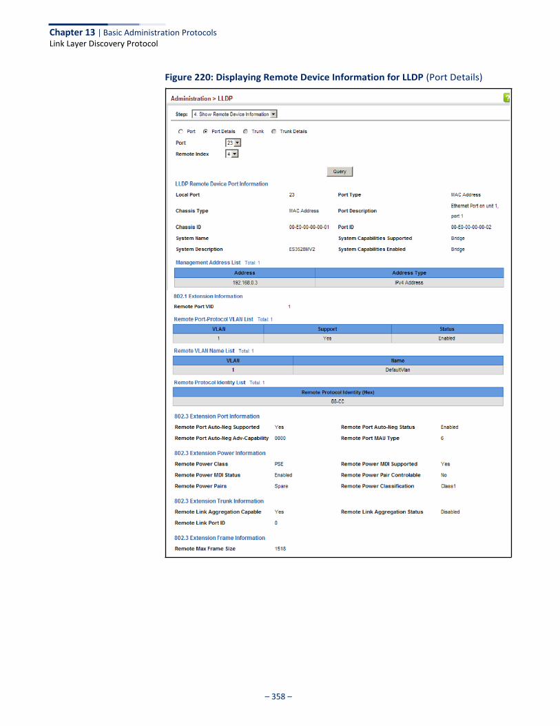
Chapter 13 | Basic Administration Protocols Link Layer Discovery Protocol
– 358 –
Figure 220: Displaying Remote Device Information for LLDP (Port Details)
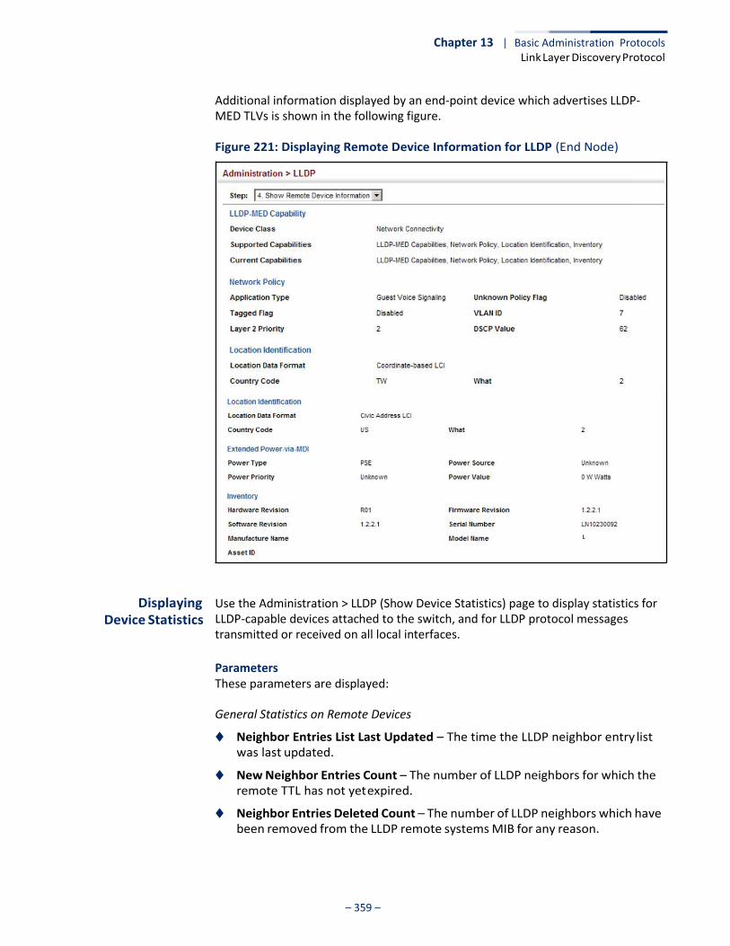
Chapter 13 | Basic Administration Protocols Link Layer Discovery Protocol
– 359 –
Additional information displayed by an end-point device which advertises LLDP- MED TLVs is shown in the following figure.
Figure 221: Displaying Remote Device Information for LLDP (End Node)
Displaying Device Statistics
Use the Administration > LLDP (Show Device Statistics) page to display statistics for LLDP-capable devices attached to the switch, and for LLDP protocol messages transmitted or received on all local interfaces.
Parameters These parameters are displayed:
General Statistics on Remote Devices
◆ Neighbor Entries List Last Updated – The time the LLDP neighbor entry list was last updated.
◆ New Neighbor Entries Count – The number of LLDP neighbors for which the remote TTL has not yet expired.
◆ Neighbor Entries Deleted Count – The number of LLDP neighbors which have been removed from the LLDP remote systems MIB for any reason.
Chapter 13 | Basic Administration Protocols Link Layer Discovery Protocol
– 360 –
◆ Neighbor Entries Dropped Count – The number of times which the remote database on this switch dropped an LLDPDU because of insufficient resources.
◆ Neighbor Entries Age-out Count – The number of times that a neighbor’s
information has been deleted from the LLDP remote systems MIB because the remote TTL timer has expired.
Port/Trunk
◆ Frames Discarded – Number of frames discarded because they did not conform to the general validation rules as well as any specific usage rules defined for the particular TLV.
◆ Frames Invalid – A count of all LLDPDUs received with one or more detectable
errors.
◆ Frames Received – Number of LLDP PDUs received.
◆ Frames Sent – Number of LLDP PDUs transmitted.
◆ TLVs Unrecognized – A count of all TLVs not recognized by the receiving LLDP local agent.
◆ TLVs Discarded – A count of all LLDPDUs received and then discarded due to
insufficient memory space, missing or out-of-sequence attributes, or any other reason.
◆ Neighbor Ageouts – A count of the times that a neighbor’s information has
been deleted from the LLDP remote systems MIB because the remote TTL timer has expired.
Web Interface To display statistics for LLDP-capable devices attached to the switch:
1. Click Administration, LLDP.
2. Select Show Device Statistics from the Step list.
3. Select General, Port, or Trunk.
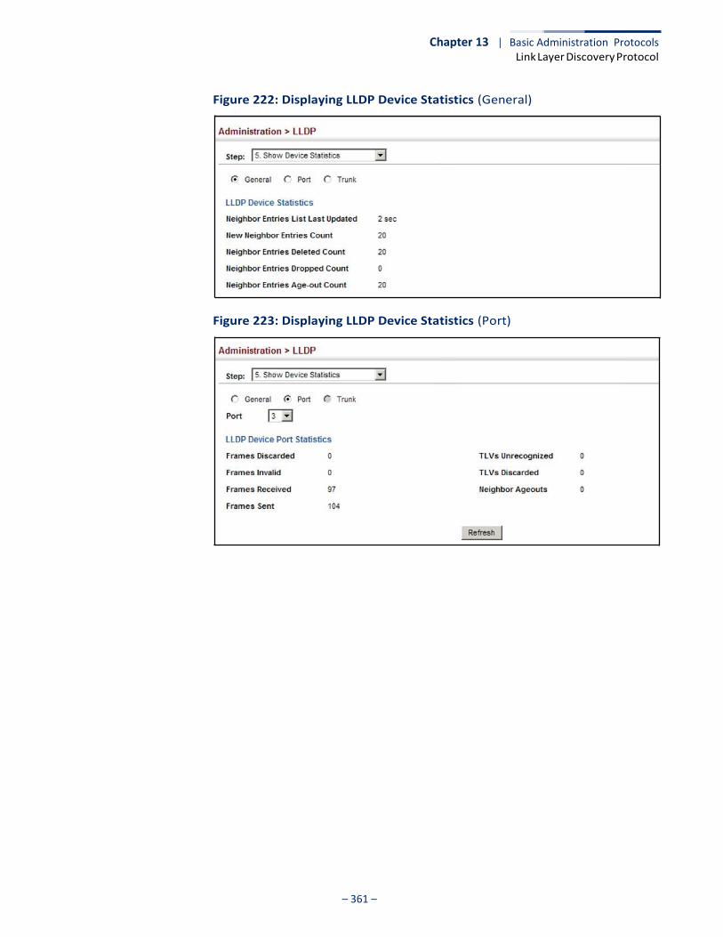
Chapter 13 | Basic Administration Protocols Link Layer Discovery Protocol
– 361 –
Figure 222: Displaying LLDP Device Statistics (General)
Figure 223: Displaying LLDP Device Statistics (Port)
Chapter 13 | Basic Administration Protocols Simple Network Management Protocol
– 362 –
Simple Network Management Protocol
Simple Network Management Protocol (SNMP) is a communication protocol designed specifically for managing devices on a network. Equipment commonly managed with SNMP includes switches, routers and host computers. SNMP is typically used to configure these devices for proper operation in a network environment, as well as to monitor them to evaluate performance or detect potential problems.
Managed devices supporting SNMP contain software, which runs locally on the device and is referred to as an agent. A defined set of variables, known as managed objects, is maintained by the SNMP agent and used to manage the device. These objects are defined in a Management Information Base (MIB) that provides a standard presentation of the information controlled by the agent. SNMP defines both the format of the MIB specifications and the protocol used to access this information over the network.
The switch includes an onboard agent that supports SNMP versions 1, 2c, and 3. This agent continuously monitors the status of the switch hardware, as well as the traffic passing through its ports. A network management station can access this information using network management software. Access to the onboard agent from clients using SNMP v1 and v2c is controlled by community strings. To communicate with the switch, the management station must first submit a valid community string for authentication.
Access to the switch from clients using SNMPv3 provides additional security features that cover message integrity, authentication, and encryption; as well as controlling user access to specific areas of the MIB tree.
The SNMPv3 security structure consists of security models, with each model having it’s own security levels. There are three security models defined, SNMPv1, SNMPv2c, and SNMPv3. Users are assigned to “groups” that are defined by a security model and specified security levels. Each group also has a defined security access to set of MIB objects for reading and writing, which are known as “views.” The switch has a default view (all MIB objects) and default groups defined for security models v1 and v2c. The following table shows the security models and levels available and the system default settings.
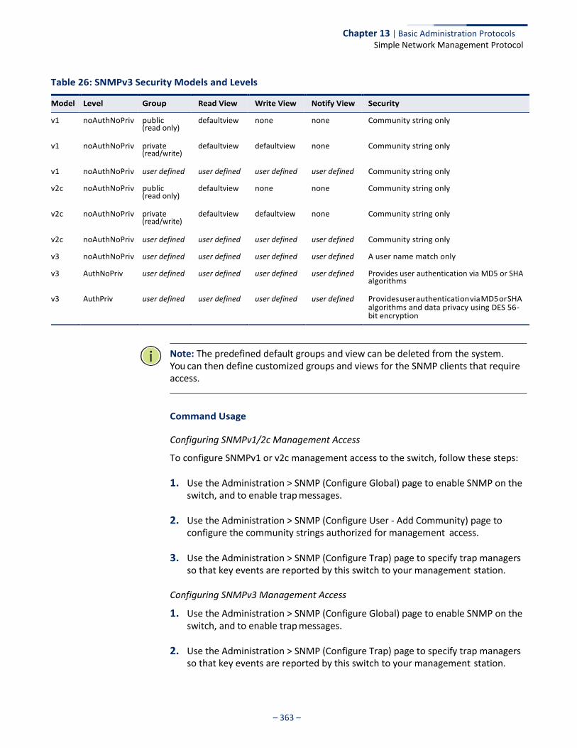
Chapter 13 | Basic Administration Protocols Simple Network Management Protocol
– 363 –
Table 26: SNMPv3 Security Models and Levels
(read only)
(read/write)
(read only)
(read/write)
algorithms
Note: The predefined default groups and view can be deleted from the system. You can then define customized groups and views for the SNMP clients that require access.
Command Usage
Configuring SNMPv1/2c Management Access
To configure SNMPv1 or v2c management access to the switch, follow these steps:
1. Use the Administration > SNMP (Configure Global) page to enable SNMP on the switch, and to enable trap messages.
2. Use the Administration > SNMP (Configure User - Add Community) page to configure the community strings authorized for management access.
3. Use the Administration > SNMP (Configure Trap) page to specify trap managers so that key events are reported by this switch to your management station.
Configuring SNMPv3 Management Access
1. Use the Administration > SNMP (Configure Global) page to enable SNMP on the switch, and to enable trap messages.
2. Use the Administration > SNMP (Configure Trap) page to specify trap managers so that key events are reported by this switch to your management station.
Model Level Group Read View Write View Notify View Security
v1 noAuthNoPriv public defaultview none none Community string only
v1 noAuthNoPriv private defaultview defaultview none Community string only
v1 noAuthNoPriv user defined user defined user defined user defined Community string only
v2c noAuthNoPriv public defaultview none none Community string only
v2c noAuthNoPriv private defaultview defaultview none Community string only
v2c noAuthNoPriv user defined user defined user defined user defined Community string only
v3 noAuthNoPriv user defined user defined user defined user defined A user name match only
v3 AuthNoPriv user defined user defined user defined user defined Provides user authentication via MD5 or SHA
v3 AuthPriv user defined user defined user defined user defined Provides user authentication via MD5 or SHA algorithms and data privacy using DES 56- bit encryption
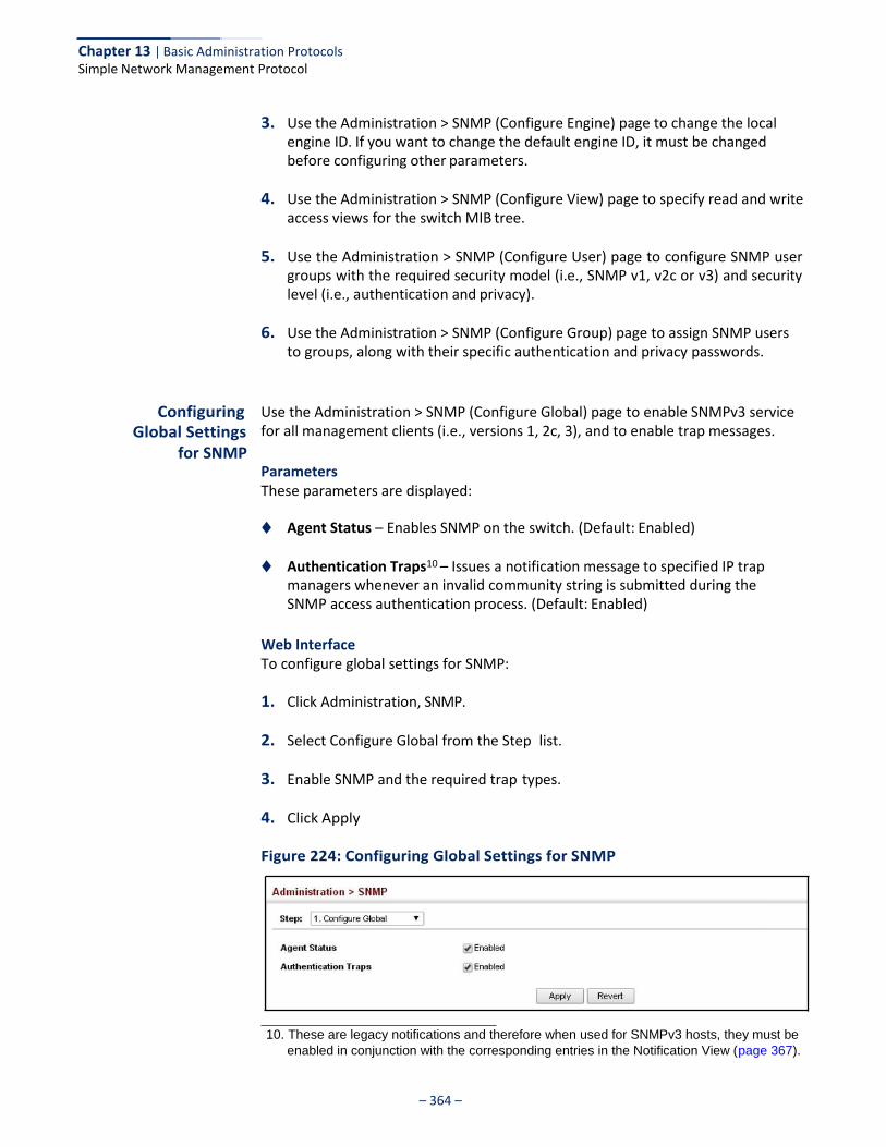
Chapter 13 | Basic Administration Protocols Simple Network Management Protocol
– 364 –
3. Use the Administration > SNMP (Configure Engine) page to change the local engine ID. If you want to change the default engine ID, it must be changed before configuring other parameters.
4. Use the Administration > SNMP (Configure View) page to specify read and write access views for the switch MIB tree.
5. Use the Administration > SNMP (Configure User) page to configure SNMP user groups with the required security model (i.e., SNMP v1, v2c or v3) and security level (i.e., authentication and privacy).
6. Use the Administration > SNMP (Configure Group) page to assign SNMP users to groups, along with their specific authentication and privacy passwords.
Configuring Global Settings
for SNMP
Use the Administration > SNMP (Configure Global) page to enable SNMPv3 service for all management clients (i.e., versions 1, 2c, 3), and to enable trap messages.
Parameters These parameters are displayed:
◆ Agent Status – Enables SNMP on the switch. (Default: Enabled)
◆ Authentication Traps10 – Issues a notification message to specified IP trap managers whenever an invalid community string is submitted during the SNMP access authentication process. (Default: Enabled)
Web Interface To configure global settings for SNMP:
1. Click Administration, SNMP.
2. Select Configure Global from the Step list.
3. Enable SNMP and the required trap types.
4. Click Apply
Figure 224: Configuring Global Settings for SNMP
10. These are legacy notifications and therefore when used for SNMPv3 hosts, they must be
enabled in conjunction with the corresponding entries in the Notification View (page 367).
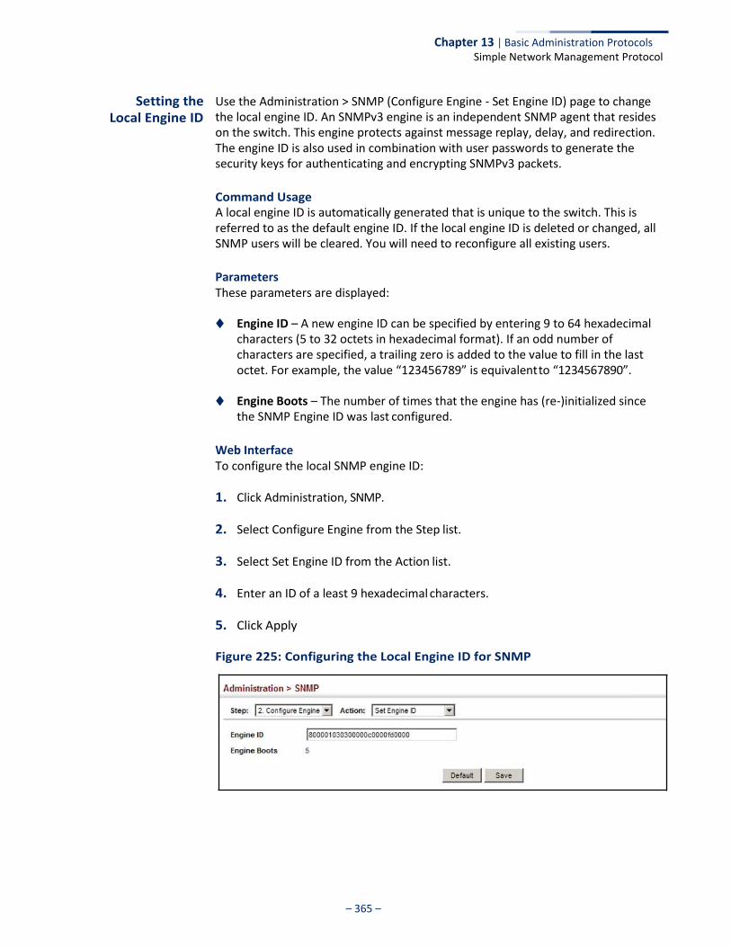
Chapter 13 | Basic Administration Protocols Simple Network Management Protocol
– 365 –
Setting the Local Engine ID
Use the Administration > SNMP (Configure Engine - Set Engine ID) page to change the local engine ID. An SNMPv3 engine is an independent SNMP agent that resides on the switch. This engine protects against message replay, delay, and redirection. The engine ID is also used in combination with user passwords to generate the security keys for authenticating and encrypting SNMPv3 packets.
Command Usage A local engine ID is automatically generated that is unique to the switch. This is referred to as the default engine ID. If the local engine ID is deleted or changed, all SNMP users will be cleared. You will need to reconfigure all existing users.
Parameters These parameters are displayed:
◆ Engine ID – A new engine ID can be specified by entering 9 to 64 hexadecimal
characters (5 to 32 octets in hexadecimal format). If an odd number of characters are specified, a trailing zero is added to the value to fill in the last octet. For example, the value “123456789” is equivalent to “1234567890”.
◆ Engine Boots – The number of times that the engine has (re-)initialized since
the SNMP Engine ID was last configured.
Web Interface To configure the local SNMP engine ID:
1. Click Administration, SNMP.
2. Select Configure Engine from the Step list.
3. Select Set Engine ID from the Action list.
4. Enter an ID of a least 9 hexadecimal characters.
5. Click Apply
Figure 225: Configuring the Local Engine ID for SNMP
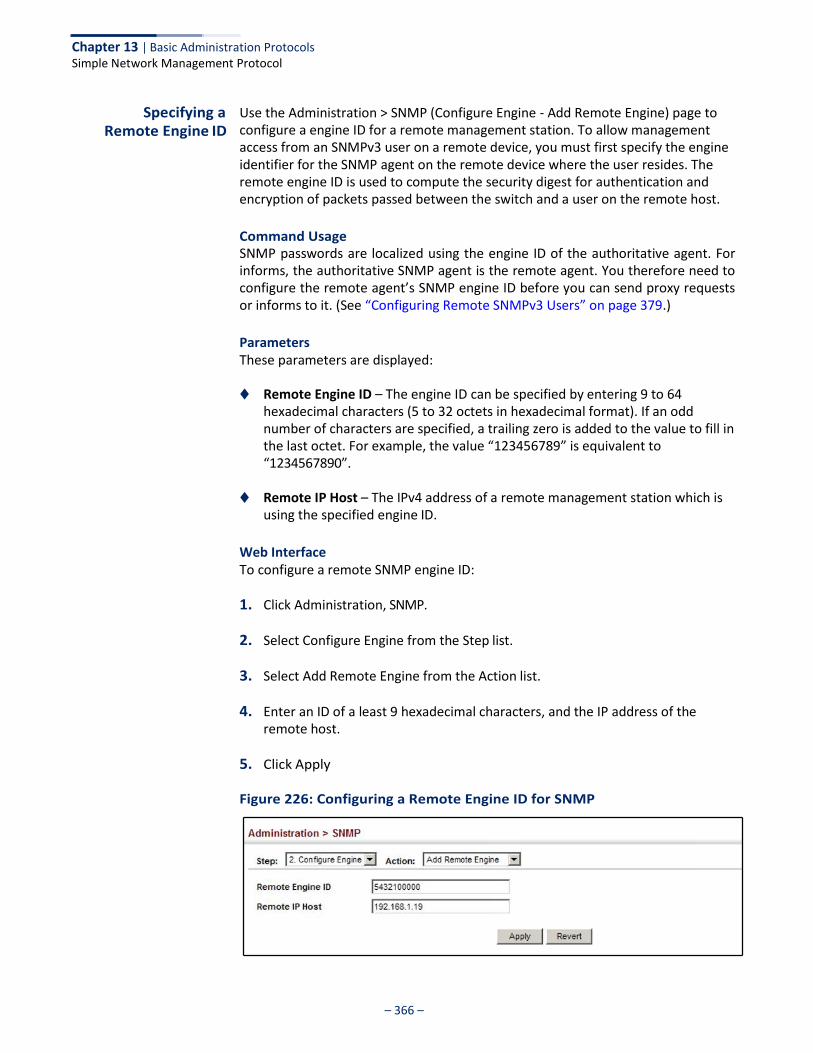
Chapter 13 | Basic Administration Protocols Simple Network Management Protocol
– 366 –
Specifying a Remote Engine ID
Use the Administration > SNMP (Configure Engine - Add Remote Engine) page to configure a engine ID for a remote management station. To allow management access from an SNMPv3 user on a remote device, you must first specify the engine identifier for the SNMP agent on the remote device where the user resides. The remote engine ID is used to compute the security digest for authentication and encryption of packets passed between the switch and a user on the remote host.
Command Usage SNMP passwords are localized using the engine ID of the authoritative agent. For informs, the authoritative SNMP agent is the remote agent. You therefore need to configure the remote agent’s SNMP engine ID before you can send proxy requests or informs to it. (See “Configuring Remote SNMPv3 Users” on page 379.)
Parameters These parameters are displayed:
◆ Remote Engine ID – The engine ID can be specified by entering 9 to 64 hexadecimal characters (5 to 32 octets in hexadecimal format). If an odd number of characters are specified, a trailing zero is added to the value to fill in the last octet. For example, the value “123456789” is equivalent to “1234567890”.
◆ Remote IP Host – The IPv4 address of a remote management station which is
using the specified engine ID.
Web Interface To configure a remote SNMP engine ID:
1. Click Administration, SNMP.
2. Select Configure Engine from the Step list.
3. Select Add Remote Engine from the Action list.
4. Enter an ID of a least 9 hexadecimal characters, and the IP address of the remote host.
5. Click Apply
Figure 226: Configuring a Remote Engine ID for SNMP
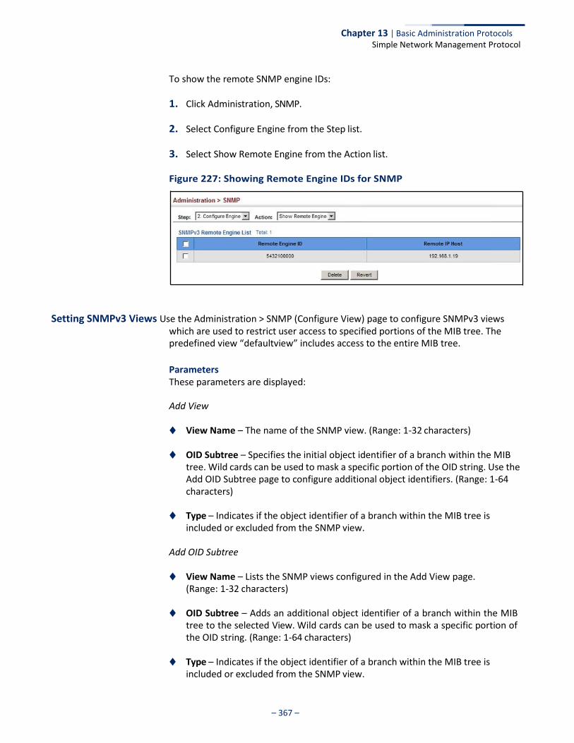
Chapter 13 | Basic Administration Protocols Simple Network Management Protocol
– 367 –
To show the remote SNMP engine IDs:
1. Click Administration, SNMP.
2. Select Configure Engine from the Step list.
3. Select Show Remote Engine from the Action list.
Figure 227: Showing Remote Engine IDs for SNMP
Setting SNMPv3 Views Use the Administration > SNMP (Configure View) page to configure SNMPv3 views which are used to restrict user access to specified portions of the MIB tree. The predefined view “defaultview” includes access to the entire MIB tree.
Parameters These parameters are displayed:
Add View
◆ View Name – The name of the SNMP view. (Range: 1-32 characters)
◆ OID Subtree – Specifies the initial object identifier of a branch within the MIB tree. Wild cards can be used to mask a specific portion of the OID string. Use the Add OID Subtree page to configure additional object identifiers. (Range: 1-64 characters)
◆ Type – Indicates if the object identifier of a branch within the MIB tree is
included or excluded from the SNMP view.
Add OID Subtree
◆ View Name – Lists the SNMP views configured in the Add View page. (Range: 1-32 characters)
◆ OID Subtree – Adds an additional object identifier of a branch within the MIB
tree to the selected View. Wild cards can be used to mask a specific portion of the OID string. (Range: 1-64 characters)
◆ Type – Indicates if the object identifier of a branch within the MIB tree is
included or excluded from the SNMP view.
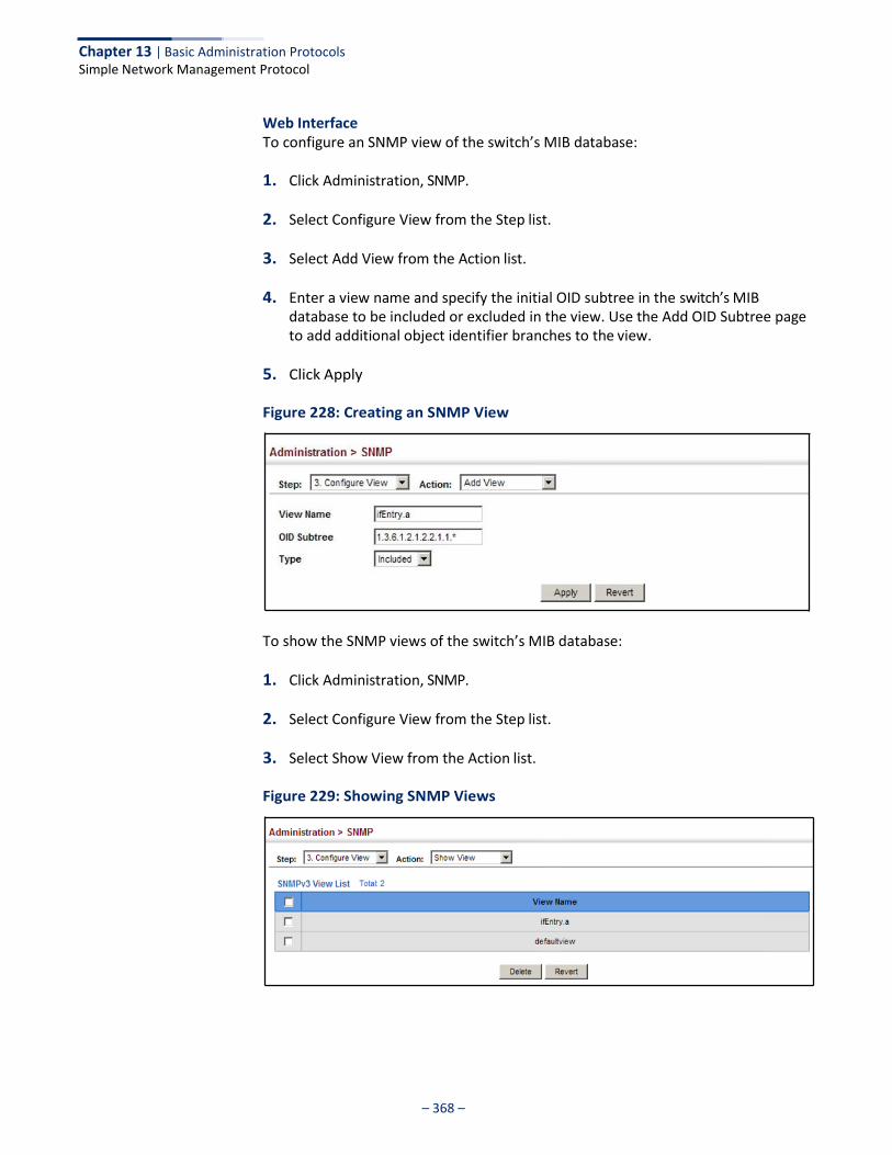
Chapter 13 | Basic Administration Protocols Simple Network Management Protocol
– 368 –
Web Interface To configure an SNMP view of the switch’s MIB database:
1. Click Administration, SNMP.
2. Select Configure View from the Step list.
3. Select Add View from the Action list.
4. Enter a view name and specify the initial OID subtree in the switch’s MIB database to be included or excluded in the view. Use the Add OID Subtree page to add additional object identifier branches to the view.
5. Click Apply
Figure 228: Creating an SNMP View
To show the SNMP views of the switch’s MIB database:
1. Click Administration, SNMP.
2. Select Configure View from the Step list.
3. Select Show View from the Action list.
Figure 229: Showing SNMP Views
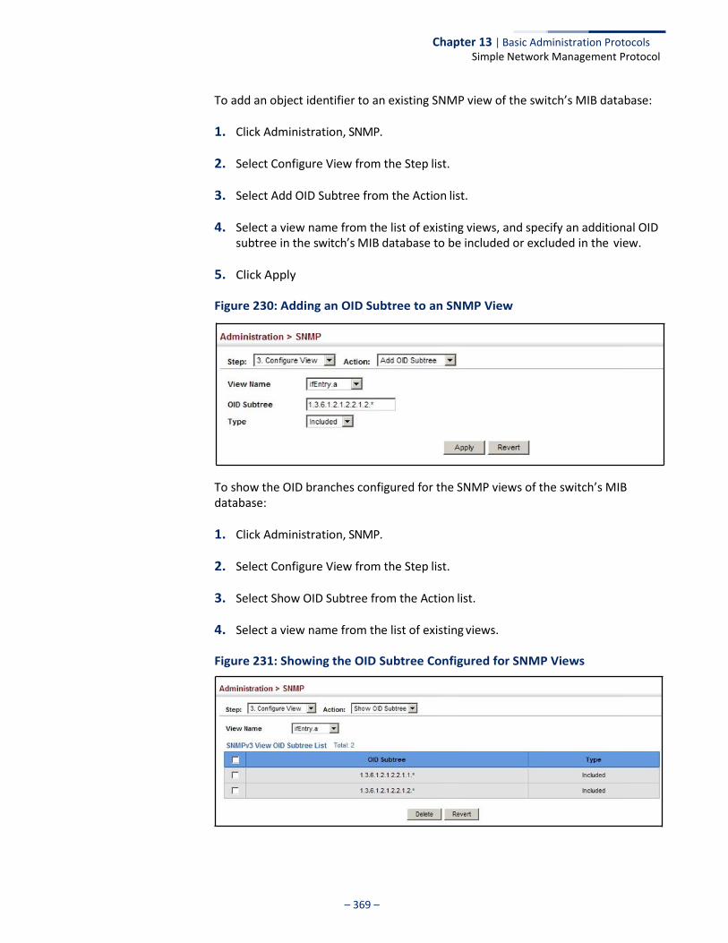
Chapter 13 | Basic Administration Protocols Simple Network Management Protocol
– 369 –
To add an object identifier to an existing SNMP view of the switch’s MIB database:
1. Click Administration, SNMP.
2. Select Configure View from the Step list.
3. Select Add OID Subtree from the Action list.
4. Select a view name from the list of existing views, and specify an additional OID subtree in the switch’s MIB database to be included or excluded in the view.
5. Click Apply
Figure 230: Adding an OID Subtree to an SNMP View
To show the OID branches configured for the SNMP views of the switch’s MIB database:
1. Click Administration, SNMP.
2. Select Configure View from the Step list.
3. Select Show OID Subtree from the Action list.
4. Select a view name from the list of existing views.
Figure 231: Showing the OID Subtree Configured for SNMP Views
Chapter 13 | Basic Administration Protocols Simple Network Management Protocol
– 370 –
Configuring SNMPv3 Groups
Use the Administration > SNMP (Configure Group) page to add an SNMPv3 group which can be used to set the access policy for its assigned users, restricting them to specific read, write, and notify views. You can use the pre-defined default groups or create new groups to map a set of SNMP users to SNMP views.
Parameters These parameters are displayed:
◆ Group Name – The name of the SNMP group to which the user is assigned.
(Range: 1-32 characters)
◆ Security Model – The user security model; SNMP v1, v2c or v3.
◆ Security Level – The following security levels are only used for the groups assigned to the SNMP security model:
■ noAuthNoPriv – There is no authentication or encryption used in SNMP
communications. (This is the default security level.)
■ AuthNoPriv – SNMP communications use authentication, but the data is not encrypted.
■ AuthPriv – SNMP communications use both authentication and
encryption.
◆ Read View – The configured view for read access. (Range: 1-32 characters)
◆ Write View – The configured view for write access. (Range: 1-32 characters)
◆ Notify View – The configured view for notifications. (Range: 1-32 characters)
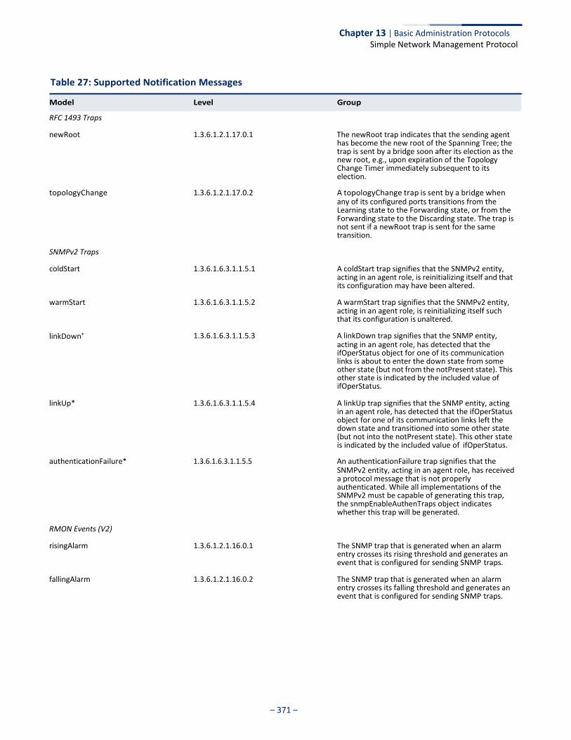
Chapter 13 | Basic Administration Protocols Simple Network Management Protocol
– 371 –
Table 27: Supported Notification Messages
RFC 1493 Traps
newRoot 1.3.6.1.2.1.17.0.1 The newRoot trap indicates that the sending agent has become the new root of the Spanning Tree; the trap is sent by a bridge soon after its election as the new root, e.g., upon expiration of the Topology Change Timer immediately subsequent to its election.
topologyChange 1.3.6.1.2.1.17.0.2 A topologyChange trap is sent by a bridge when any of its configured ports transitions from the Learning state to the Forwarding state, or from the Forwarding state to the Discarding state. The trap is not sent if a newRoot trap is sent for the same transition.
SNMPv2 Traps
coldStart 1.3.6.1.6.3.1.1.5.1 A coldStart trap signifies that the SNMPv2 entity, acting in an agent role, is reinitializing itself and that its configuration may have been altered.
warmStart 1.3.6.1.6.3.1.1.5.2 A warmStart trap signifies that the SNMPv2 entity, acting in an agent role, is reinitializing itself such that its configuration is unaltered.
linkDown* 1.3.6.1.6.3.1.1.5.3 A linkDown trap signifies that the SNMP entity, acting in an agent role, has detected that the ifOperStatus object for one of its communication links is about to enter the down state from some other state (but not from the notPresent state). This other state is indicated by the included value of ifOperStatus.
linkUp* 1.3.6.1.6.3.1.1.5.4 A linkUp trap signifies that the SNMP entity, acting in an agent role, has detected that the ifOperStatus object for one of its communication links left the down state and transitioned into some other state (but not into the notPresent state). This other state is indicated by the included value of ifOperStatus.
authenticationFailure* 1.3.6.1.6.3.1.1.5.5 An authenticationFailure trap signifies that the SNMPv2 entity, acting in an agent role, has received a protocol message that is not properly authenticated. While all implementations of the SNMPv2 must be capable of generating this trap, the snmpEnableAuthenTraps object indicates whether this trap will be generated.
RMON Events (V2)
risingAlarm 1.3.6.1.2.1.16.0.1 The SNMP trap that is generated when an alarm entry crosses its rising threshold and generates an event that is configured for sending SNMP traps.
fallingAlarm 1.3.6.1.2.1.16.0.2 The SNMP trap that is generated when an alarm entry crosses its falling threshold and generates an event that is configured for sending SNMP traps.
Model Level Group
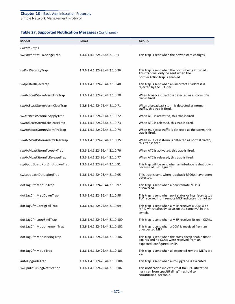
Chapter 13 | Basic Administration Protocols Simple Network Management Protocol
– 372 –
Table 27: Supported Notification Messages (Continued)
This trap will only be sent when the
rejected by the IP Filter.
trap is fired.
traffic, this trap is fired.
trap is fired.
this trap is fired.
because of BPDU guard.
detected.
discovered.
TLV received from remote MEP indicates it is not up.
MPID which already exists on the same MA in this
unexpected MEP.
expires and no CCMs were received from an
up.
Model Level Group
Private Traps
swPowerStatusChangeTrap 1.3.6.1.4.1.22426.44.2.1.0.1 This trap is sent when the power state changes.
swPortSecurityTrap
1.3.6.1.4.1.22426.44.2.1.0.36 This trap is sent when the port is being intruded.
portSecActionTrap is enabled.
swIpFilterRejectTrap 1.3.6.1.4.1.22426.44.2.1.0.40 This trap is sent when an incorrect IP address is
swAtcBcastStormAlarmFireTrap 1.3.6.1.4.1.22426.44.2.1.0.70 When broadcast traffic is detected as a storm, this
swAtcBcastStormAlarmClearTrap 1.3.6.1.4.1.22426.44.2.1.0.71 When a broadcast storm is detected as normal
swAtcBcastStormTcApplyTrap 1.3.6.1.4.1.22426.44.2.1.0.72 When ATC is activated, this trap is fired.
swAtcBcastStormTcReleaseTrap 1.3.6.1.4.1.22426.44.2.1.0.73 When ATC is released, this trap is fired.
swAtcMcastStormAlarmFireTrap 1.3.6.1.4.1.22426.44.2.1.0.74 When multicast traffic is detected as the storm, this
swAtcMcastStormAlarmClearTrap 1.3.6.1.4.1.22426.44.2.1.0.75 When multicast storm is detected as normal traffic,
swAtcMcastStormTcApplyTrap 1.3.6.1.4.1.22426.44.2.1.0.76 When ATC is activated, this trap is fired.
swAtcMcastStormTcReleaseTrap 1.3.6.1.4.1.22426.44.2.1.0.77 When ATC is released, this trap is fired.
stpBpduGuardPortShutdownTrap 1.3.6.1.4.1.22426.44.2.1.0.91 This trap will be sent when an interface is shut down
swLoopbackDetectionTrap 1.3.6.1.4.1.22426.44.2.1.0.95 This trap is sent when loopback BPDUs have been
dot1agCfmMepUpTrap 1.3.6.1.4.1.22426.44.2.1.0.97 This trap is sent when a new remote MEP is
dot1agCfmMepDownTrap 1.3.6.1.4.1.22426.44.2.1.0.98 This trap is sent when port status or interface status
dot1agCfmConfigFailTrap 1.3.6.1.4.1.22426.44.2.1.0.99 This trap is sent when a MEP receives a CCM with
switch.
dot1agCfmLoopFindTrap 1.3.6.1.4.1.22426.44.2.1.0.100 This trap is sent when a MEP receives its own CCMs.
dot1agCfmMepUnknownTrap 1.3.6.1.4.1.22426.44.2.1.0.101 This trap is sent when a CCM is received from an
dot1agCfmMepMissingTrap 1.3.6.1.4.1.22426.44.2.1.0.102 This trap is sent when the cross-check enable timer
expected (configured) MEP.
dot1agCfmMaUpTrap 1.3.6.1.4.1.22426.44.2.1.0.103 This trap is sent when all expected remote MEPs are
autoUpgradeTrap 1.3.6.1.4.1.22426.44.2.1.0.104 This trap is sent when auto upgrade is executed.
swCpuUtiRisingNotification 1.3.6.1.4.1.22426.44.2.1.0.107 This notification indicates that the CPU utilization has risen from cpuUtiFallingThreshold to cpuUtiRisingThreshold.

Chapter 13 | Basic Administration Protocols Simple Network Management Protocol
– 373 –
Table 27: Supported Notification Messages (Continued)
has fallen from cpuUtiRisingThreshold to
utilization has risen from
memoryUtiRisingThreshold.
utilization has fallen from
memoryUtiFallingThreshold.
a rouge server.
dynamic MAC addresses on the switch.
detected by LBD.
within alarm/warning thresholds.
successful.
login user information (trapVarLoginUserName/
trapVarLoginInetAddressTypes/
the high-watermark the first time or when CPU
above the high-watermark.
* These are legacy notifications and therefore must be enabled in conjunction with the corresponding traps on the SNMP Configuration menu.
Model Level Group
swCpuUtiFallingNotification 1.3.6.1.4.1.22426.44.2.1.0.108 This notification indicates that the CPU utilization
cpuUtiFallingThreshold.
swMemoryUtiRisingThreshold Notification
1.3.6.1.4.1.22426.44.2.1.0.109 This notification indicates that the memory
memoryUtiFallingThreshold to
swMemoryUtiFallingThreshold Notification
1.3.6.1.4.1.22426.44.2.1.0.110 This notification indicates that the memory
memoryUtiRisingThreshold to
dhcpRougeServerAttackTrap 1.3.6.1.4.1.22426.44.2.1.0.114 This trap is sent when receiving a DHCP packet from
macNotificationTrap 1.3.6.1.4.1.22426.44.2.1.0.138 This trap is sent when there are changes of the
lbdDetectionTrap 1.3.6.1.4.1.22426.44.2.1.0.141 This trap is sent when a loopback condition is
lbdRecoveryTrap 1.3.6.1.4.1.22426.44.2.1.0.142 This trap is sent when a recovery is done by LBD.
sfpThresholdAlarmWarnTrap 1.3.6.1.4.1.22426.44.2.1.0.189 This trap is sent when the sfp's A/D quantity is not
userAuthenticationFailureTrap 1.3.6.1.4.1.22426.44.2.1.0.199 This trap will be triggered if authentication fails.
userAuthenticationSuccessTrap 1.3.6.1.4.1.22426.44.2.1.0.200 This trap will be triggered if authentication is
loginTrap 1.3.6.1.4.1.22426.44.2.1.0.201 This trap is sent when user logs in.
logoutTrap 1.3.6.1.4.1.22426.44.2.1.0.202 This trap is sent when user logs out.
fileCopyTrap 1.3.6.1.4.1.22426.44.2.1.0.208 This trap is sent when file copy is executed. If the copy action is triggered by the system, the
trapVarSessionType/
trapVarLoginInetAddres) will be a null value.
userauthCreateUserTrap 1.3.6.1.4.1.22426.44.2.1.0.209 This trap is sent when a user account is created.
userauthDeleteUserTrap 1.3.6.1.4.1.22426.44.2.1.0.210 This trap is sent when a user account is deleted.
userauthModifyUserPrivilegeTrap 1.3.6.1.4.1.22426.44.2.1.0.211 This trap is sent when user privilege is modified.
cpuGuardControlTrap 1.3.6.1.4.1.22426.44.2.1.0.213 This trap is sent when CPU utilization rises above
utilization rises from below the low-watermark to
cpuGuardReleaseTrap 1.3.6.1.4.1.22426.44.2.1.0.214 This trap is sent when CPU utilization falls from above the high-watermark to below the low- watermark.
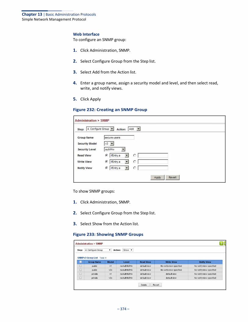
Chapter 13 | Basic Administration Protocols Simple Network Management Protocol
– 374 –
Web Interface To configure an SNMP group:
1. Click Administration, SNMP.
2. Select Configure Group from the Step list.
3. Select Add from the Action list.
4. Enter a group name, assign a security model and level, and then select read, write, and notify views.
5. Click Apply
Figure 232: Creating an SNMP Group
To show SNMP groups:
1. Click Administration, SNMP.
2. Select Configure Group from the Step list.
3. Select Show from the Action list.
Figure 233: Showing SNMP Groups
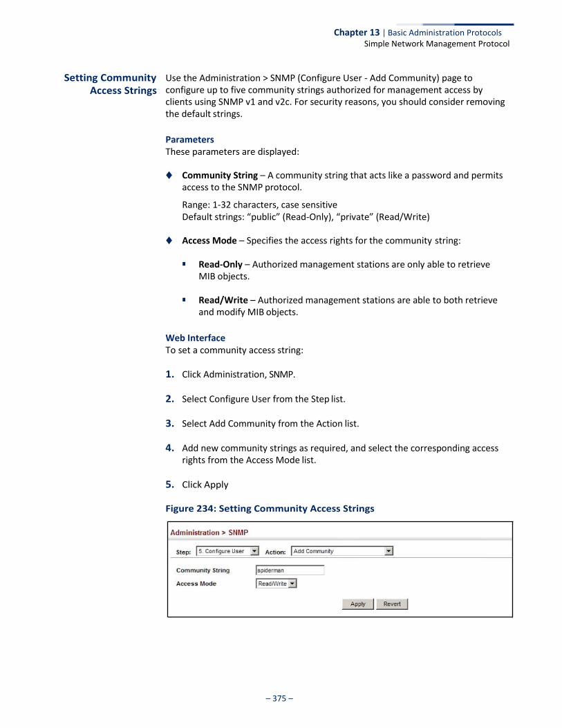
Chapter 13 | Basic Administration Protocols Simple Network Management Protocol
– 375 –
Setting Community Access Strings
Use the Administration > SNMP (Configure User - Add Community) page to configure up to five community strings authorized for management access by clients using SNMP v1 and v2c. For security reasons, you should consider removing the default strings.
Parameters These parameters are displayed:
◆ Community String – A community string that acts like a password and permits
access to the SNMP protocol.
Range: 1-32 characters, case sensitive Default strings: “public” (Read-Only), “private” (Read/Write)
◆ Access Mode – Specifies the access rights for the community string:
■ Read-Only – Authorized management stations are only able to retrieve MIB objects.
■ Read/Write – Authorized management stations are able to both retrieve
and modify MIB objects.
Web Interface To set a community access string:
1. Click Administration, SNMP.
2. Select Configure User from the Step list.
3. Select Add Community from the Action list.
4. Add new community strings as required, and select the corresponding access rights from the Access Mode list.
5. Click Apply
Figure 234: Setting Community Access Strings
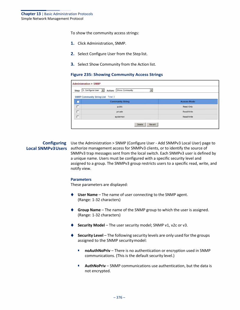
Chapter 13 | Basic Administration Protocols Simple Network Management Protocol
– 376 –
To show the community access strings:
1. Click Administration, SNMP.
2. Select Configure User from the Step list.
3. Select Show Community from the Action list.
Figure 235: Showing Community Access Strings
Configuring Local SNMPv3 Users
Use the Administration > SNMP (Configure User - Add SNMPv3 Local User) page to authorize management access for SNMPv3 clients, or to identify the source of SNMPv3 trap messages sent from the local switch. Each SNMPv3 user is defined by a unique name. Users must be configured with a specific security level and assigned to a group. The SNMPv3 group restricts users to a specific read, write, and notify view.
Parameters These parameters are displayed:
◆ User Name – The name of user connecting to the SNMP agent.
(Range: 1-32 characters)
◆ Group Name – The name of the SNMP group to which the user is assigned. (Range: 1-32 characters)
◆ Security Model – The user security model; SNMP v1, v2c or v3.
◆ Security Level – The following security levels are only used for the groups assigned to the SNMP security model:
■ noAuthNoPriv – There is no authentication or encryption used in SNMP
communications. (This is the default security level.)
■ AuthNoPriv – SNMP communications use authentication, but the data is not encrypted.
Chapter 13 | Basic Administration Protocols Simple Network Management Protocol
– 377 –
■ AuthPriv – SNMP communications use both authentication and
encryption.
◆ Authentication Protocol – The method used for user authentication. (Options: MD5, SHA; Default: MD5)
◆ Authentication Password – A minimum of eight plain text characters is
required. (Range: 8-32 characters)
◆ Privacy Protocol – The encryption algorithm use for data privacy; only 56-bit DES is currently available.
◆ Privacy Password – A minimum of eight plain text characters is required.
Web Interface To configure a local SNMPv3 user:
1. Click Administration, SNMP.
2. Select Configure User from the Step list.
3. Select Add SNMPv3 Local User from the Action list.
4. Enter a name and assign it to a group. If the security model is set to SNMPv3 and the security level is authNoPriv or authPriv, then an authentication protocol and password must be specified. If the security level is authPriv, a privacy password must also be specified.
5. Click Apply
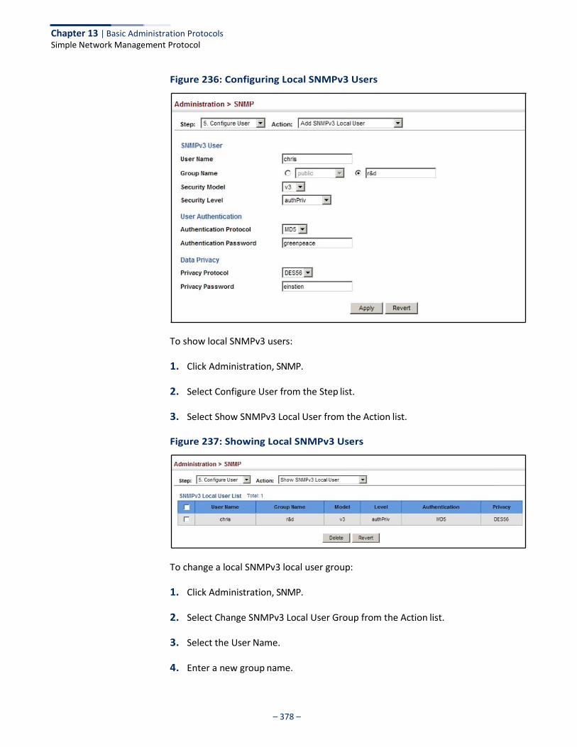
Chapter 13 | Basic Administration Protocols Simple Network Management Protocol
– 378 –
Figure 236: Configuring Local SNMPv3 Users
To show local SNMPv3 users:
1. Click Administration, SNMP.
2. Select Configure User from the Step list.
3. Select Show SNMPv3 Local User from the Action list.
Figure 237: Showing Local SNMPv3 Users
To change a local SNMPv3 local user group:
1. Click Administration, SNMP.
2. Select Change SNMPv3 Local User Group from the Action list.
3. Select the User Name.
4. Enter a new group name.
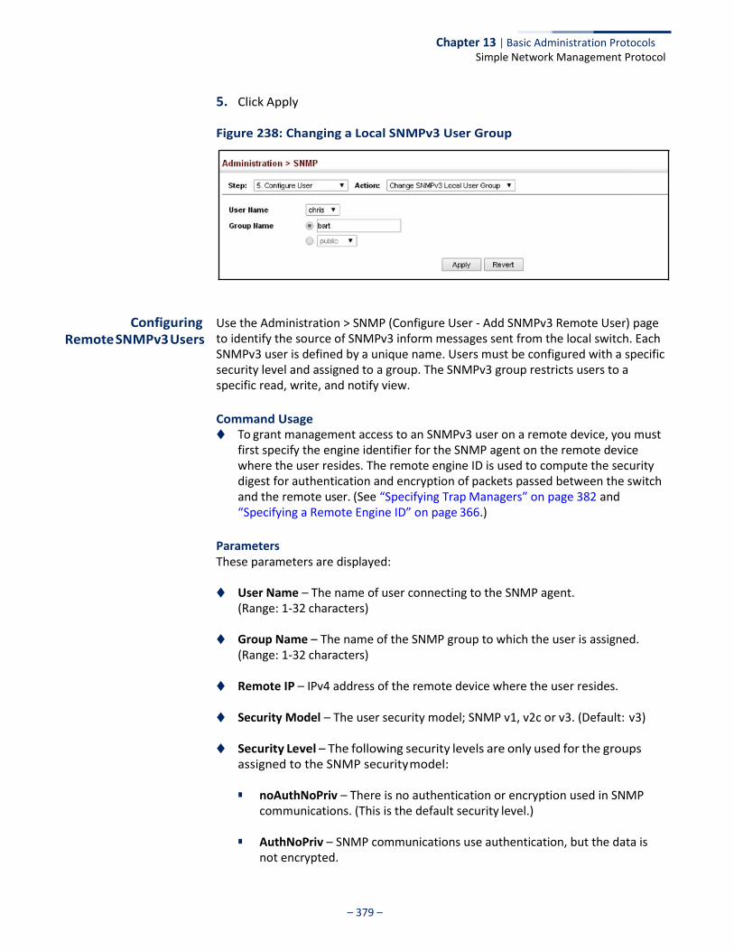
Chapter 13 | Basic Administration Protocols Simple Network Management Protocol
– 379 –
5. Click Apply
Figure 238: Changing a Local SNMPv3 User Group
Configuring Remote SNMPv3 Users
Use the Administration > SNMP (Configure User - Add SNMPv3 Remote User) page to identify the source of SNMPv3 inform messages sent from the local switch. Each SNMPv3 user is defined by a unique name. Users must be configured with a specific security level and assigned to a group. The SNMPv3 group restricts users to a specific read, write, and notify view.
Command Usage ◆ To grant management access to an SNMPv3 user on a remote device, you must
first specify the engine identifier for the SNMP agent on the remote device where the user resides. The remote engine ID is used to compute the security digest for authentication and encryption of packets passed between the switch and the remote user. (See “Specifying Trap Managers” on page 382 and “Specifying a Remote Engine ID” on page 366.)
Parameters These parameters are displayed:
◆ User Name – The name of user connecting to the SNMP agent.
(Range: 1-32 characters)
◆ Group Name – The name of the SNMP group to which the user is assigned. (Range: 1-32 characters)
◆ Remote IP – IPv4 address of the remote device where the user resides.
◆ Security Model – The user security model; SNMP v1, v2c or v3. (Default: v3)
◆ Security Level – The following security levels are only used for the groups assigned to the SNMP security model:
■ noAuthNoPriv – There is no authentication or encryption used in SNMP
communications. (This is the default security level.)
■ AuthNoPriv – SNMP communications use authentication, but the data is not encrypted.

Chapter 13 | Basic Administration Protocols Simple Network Management Protocol
– 380 –
■ AuthPriv – SNMP communications use both authentication and
encryption.
◆ Authentication Protocol – The method used for user authentication. (Options: MD5, SHA; Default: MD5)
◆ Authentication Password – A minimum of eight plain text characters is
required.
◆ Privacy Protocol – The encryption algorithm use for data privacy; only 56-bit DES is currently available.
◆ Privacy Password – A minimum of eight plain text characters is required.
Web Interface To configure a remote SNMPv3 user:
1. Click Administration, SNMP.
2. Select Configure User from the Step list.
3. Select Add SNMPv3 Remote User from the Action list.
4. Enter a name and assign it to a group. Enter the IP address to identify the source of SNMPv3 inform messages sent from the local switch. If the security model is set to SNMPv3 and the security level is authNoPriv or authPriv, then an authentication protocol and password must be specified. If the security level is authPriv, a privacy password must also be specified.
5. Click Apply

Chapter 13 | Basic Administration Protocols Simple Network Management Protocol
– 381 –
Figure 239: Configuring Remote SNMPv3 Users
To show remote SNMPv3 users:
1. Click Administration, SNMP.
2. Select Configure User from the Step list.
3. Select Show SNMPv3 Remote User from the Action list.
Figure 240: Showing Remote SNMPv3 Users
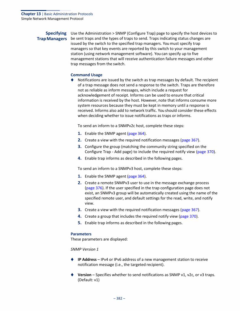
Chapter 13 | Basic Administration Protocols Simple Network Management Protocol
– 382 –
Specifying Trap Managers
Use the Administration > SNMP (Configure Trap) page to specify the host devices to be sent traps and the types of traps to send. Traps indicating status changes are issued by the switch to the specified trap managers. You must specify trap managers so that key events are reported by this switch to your management station (using network management software). You can specify up to five management stations that will receive authentication failure messages and other trap messages from the switch.
Command Usage ◆ Notifications are issued by the switch as trap messages by default. The recipient
of a trap message does not send a response to the switch. Traps are therefore not as reliable as inform messages, which include a request for acknowledgement of receipt. Informs can be used to ensure that critical information is received by the host. However, note that informs consume more system resources because they must be kept in memory until a response is received. Informs also add to network traffic. You should consider these effects when deciding whether to issue notifications as traps or informs.
To send an inform to a SNMPv2c host, complete these steps:
1. Enable the SNMP agent (page 364).
2. Create a view with the required notification messages (page 367).
3. Configure the group (matching the community string specified on the Configure Trap - Add page) to include the required notify view (page 370).
4. Enable trap informs as described in the following pages.
To send an inform to a SNMPv3 host, complete these steps:
1. Enable the SNMP agent (page 364).
2. Create a remote SNMPv3 user to use in the message exchange process (page 376). If the user specified in the trap configuration page does not exist, an SNMPv3 group will be automatically created using the name of the specified remote user, and default settings for the read, write, and notify view.
3. Create a view with the required notification messages (page 367).
4. Create a group that includes the required notify view (page 370).
5. Enable trap informs as described in the following pages.
Parameters These parameters are displayed:
SNMP Version 1
◆ IP Address – IPv4 or IPv6 address of a new management station to receive notification message (i.e., the targeted recipient).
◆ Version – Specifies whether to send notifications as SNMP v1, v2c, or v3 traps.
(Default: v1)
Chapter 13 | Basic Administration Protocols Simple Network Management Protocol
– 383 –
◆ Community String – Specifies a valid community string for the new trap manager entry. (Range: 1-32 characters, case sensitive)
Although you can set this string in the Configure Trap – Add page, we recommend defining it in the Configure User – Add Community page.
◆ UDP Port – Specifies the UDP port number used by the trap manager.
(Default: 162)
SNMP Version 2c
◆ IP Address – IPv4 or IPv6 address of a new management station to receive notification message (i.e., the targeted recipient).
◆ Version – Specifies whether to send notifications as SNMP v1, v2c, or v3 traps.
◆ Notification Type
■ Traps – Notifications are sent as trap messages.
■ Inform – Notifications are sent as inform messages. Note that this option is only available for version 2c and 3 hosts. (Default: traps are used)
■ Timeout – The number of seconds to wait for an acknowledgment
before resending an inform message. (Range: 0-2147483647 centiseconds; Default: 1500 centiseconds)
■ Retry times – The maximum number of times to resend an inform
message if the recipient does not acknowledge receipt. (Range: 0-255; Default: 3)
◆ Community String – Specifies a valid community string for the new trap
manager entry. (Range: 1-32 characters, case sensitive)
Although you can set this string in the Configure Trap – Add page, we recommend defining it in the Configure User – Add Community page.
◆ UDP Port – Specifies the UDP port number used by the trap manager.
(Default: 162)
SNMP Version 3
◆ IP Address – IPv4 or IPv6 address of a new management station to receive notification message (i.e., the targeted recipient).
◆ Version – Specifies whether to send notifications as SNMP v1, v2c, or v3 traps.
◆ Notification Type
■ Traps – Notifications are sent as trap messages.
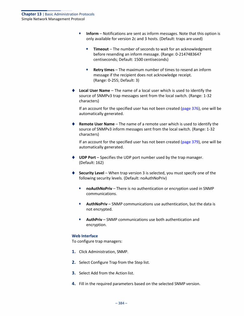
Chapter 13 | Basic Administration Protocols Simple Network Management Protocol
– 384 –
■ Inform – Notifications are sent as inform messages. Note that this option is
only available for version 2c and 3 hosts. (Default: traps are used)
■ Timeout – The number of seconds to wait for an acknowledgment before resending an inform message. (Range: 0-2147483647 centiseconds; Default: 1500 centiseconds)
■ Retry times – The maximum number of times to resend an inform
message if the recipient does not acknowledge receipt. (Range: 0-255; Default: 3)
◆ Local User Name – The name of a local user which is used to identify the
source of SNMPv3 trap messages sent from the local switch. (Range: 1-32 characters)
If an account for the specified user has not been created (page 376), one will be automatically generated.
◆ Remote User Name – The name of a remote user which is used to identify the
source of SNMPv3 inform messages sent from the local switch. (Range: 1-32 characters)
If an account for the specified user has not been created (page 379), one will be automatically generated.
◆ UDP Port – Specifies the UDP port number used by the trap manager.
(Default: 162)
◆ Security Level – When trap version 3 is selected, you must specify one of the following security levels. (Default: noAuthNoPriv)
■ noAuthNoPriv – There is no authentication or encryption used in SNMP
communications.
■ AuthNoPriv – SNMP communications use authentication, but the data is not encrypted.
■ AuthPriv – SNMP communications use both authentication and
encryption.
Web Interface To configure trap managers:
1. Click Administration, SNMP.
2. Select Configure Trap from the Step list.
3. Select Add from the Action list.
4. Fill in the required parameters based on the selected SNMP version.
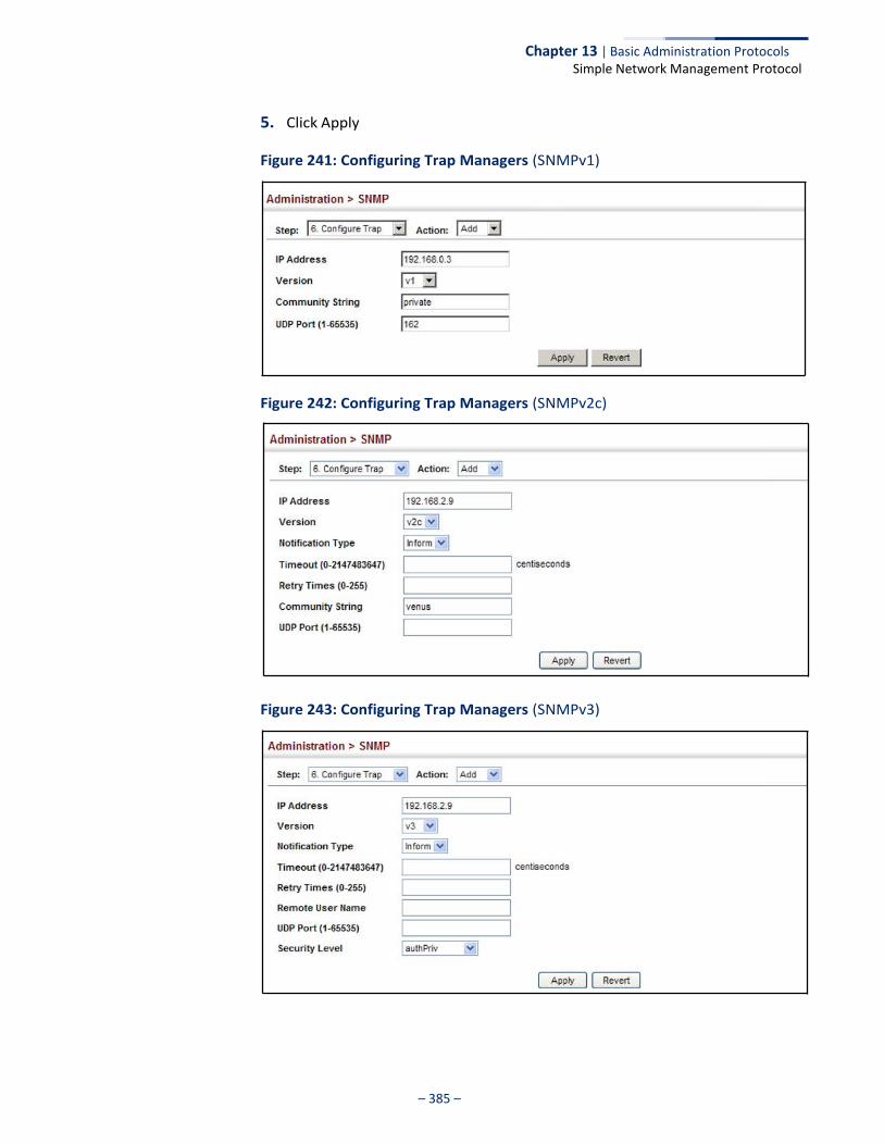
Chapter 13 | Basic Administration Protocols Simple Network Management Protocol
– 385 –
5. Click Apply
Figure 241: Configuring Trap Managers (SNMPv1)
Figure 242: Configuring Trap Managers (SNMPv2c)
Figure 243: Configuring Trap Managers (SNMPv3)
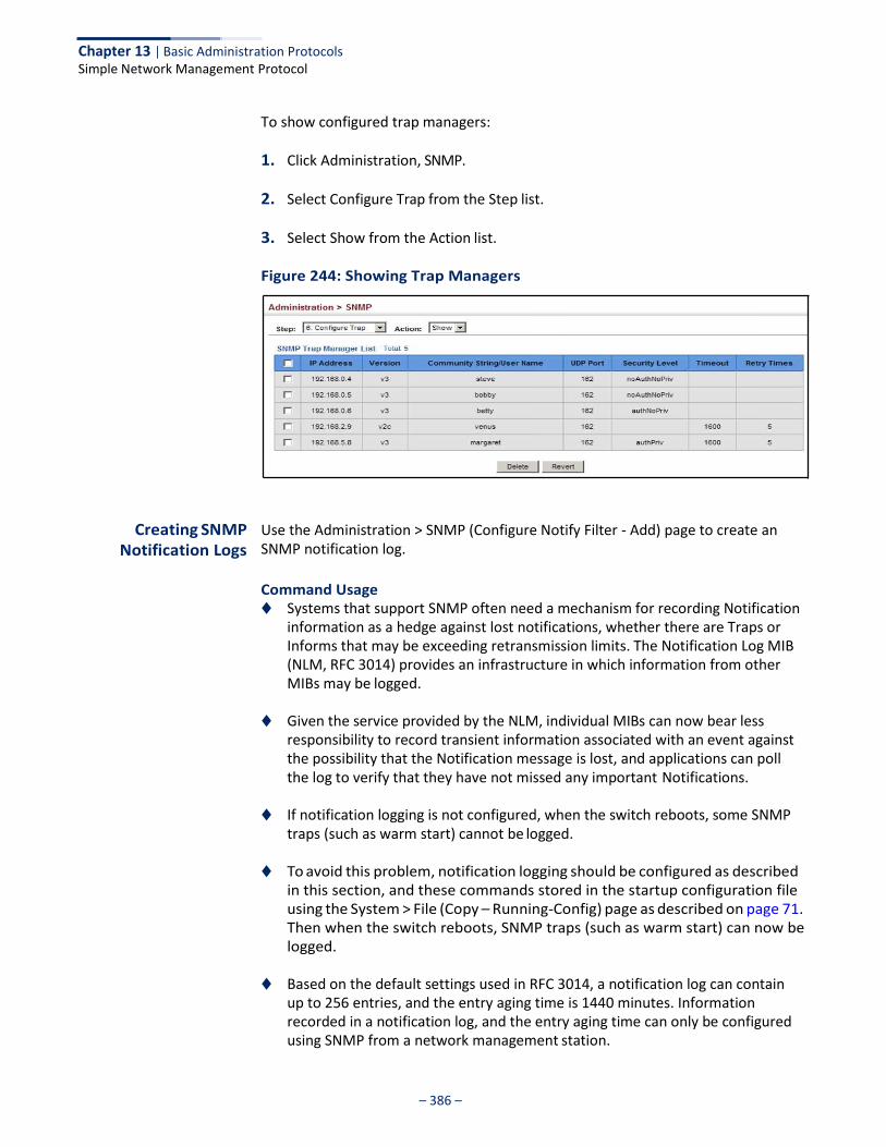
Chapter 13 | Basic Administration Protocols Simple Network Management Protocol
– 386 –
To show configured trap managers:
1. Click Administration, SNMP.
2. Select Configure Trap from the Step list.
3. Select Show from the Action list.
Figure 244: Showing Trap Managers
Creating SNMP Notification Logs
Use the Administration > SNMP (Configure Notify Filter - Add) page to create an SNMP notification log.
Command Usage ◆ Systems that support SNMP often need a mechanism for recording Notification
information as a hedge against lost notifications, whether there are Traps or Informs that may be exceeding retransmission limits. The Notification Log MIB (NLM, RFC 3014) provides an infrastructure in which information from other MIBs may be logged.
◆ Given the service provided by the NLM, individual MIBs can now bear less
responsibility to record transient information associated with an event against the possibility that the Notification message is lost, and applications can poll the log to verify that they have not missed any important Notifications.
◆ If notification logging is not configured, when the switch reboots, some SNMP
traps (such as warm start) cannot be logged.
◆ To avoid this problem, notification logging should be configured as described in this section, and these commands stored in the startup configuration file using the System > File (Copy – Running-Config) page as described on page 71. Then when the switch reboots, SNMP traps (such as warm start) can now be logged.
◆ Based on the default settings used in RFC 3014, a notification log can contain
up to 256 entries, and the entry aging time is 1440 minutes. Information recorded in a notification log, and the entry aging time can only be configured using SNMP from a network management station.

Chapter 13 | Basic Administration Protocols Simple Network Management Protocol
– 387 –
◆ When a trap host is created using the Administration > SNMP (Configure Trap – Add) page described on page 382, a default notify filter will be created.
Parameters These parameters are displayed:
◆ IP Address – The IPv4 or IPv6 address of a remote device. The specified target
host must already have been configured using the Administration > SNMP (Configure Trap – Add) page.
The notification log is stored locally. It is not sent to a remote device. This remote host parameter is only required to complete mandatory fields in the SNMP Notification MIB.
◆ Filter Profile Name – Notification log profile name. (Range: 1-32 characters)
Web Interface To create an SNMP notification log:
1. Click Administration, SNMP.
2. Select Configure Notify Filter from the Step list.
3. Select Add from the Action list.
4. Fill in the IP address of a configured trap manager and the filter profile name.
5. Click Apply
Figure 245: Creating SNMP Notification Logs
To show configured SNMP notification logs:
1. Click Administration, SNMP.
2. Select Configure Notify Filter from the Step list.
3. Select Show from the Action list.
Chapter 13 | Basic Administration Protocols Simple Network Management Protocol
– 388 –
Figure 246: Showing SNMP Notification Logs
Showing SNMP Statistics
Use the Administration > SNMP (Show Statistics) page to show counters for SNMP input and output protocol data units.
Parameters The following counters are displayed:
◆ SNMP packets input – The total number of messages delivered to the SNMP
entity from the transport service.
◆ Bad SNMP version errors – The total number of SNMP messages which were delivered to the SNMP entity and were for an unsupported SNMP version.
◆ Unknown community name – The total number of SNMP messages delivered
to the SNMP entity which used a SNMP community name not known to said entity.
◆ Illegal operation for community name supplied – The total number of SNMP
messages delivered to the SNMP entity which represented an SNMP operation which was not allowed by the SNMP community named in the message.
◆ Encoding errors – The total number of ASN.1 or BER errors encountered by the
SNMP entity when decoding received SNMP messages.
◆ Number of requested variables – The total number of MIB objects which have been retrieved successfully by the SNMP protocol entity as the result of receiving valid SNMP Get-Request and Get-Next PDUs.
◆ Number of altered variables – The total number of MIB objects which have
been altered successfully by the SNMP protocol entity as the result of receiving valid SNMP Set-Request PDUs.
◆ Get-request PDUs – The total number of SNMP Get-Request PDUs which have
been accepted and processed, or generated, by the SNMP protocol entity.
◆ Get-next PDUs – The total number of SNMP Get-Next PDUs which have been accepted and processed, or generated, by the SNMP protocol entity.
◆ Set-request PDUs – The total number of SNMP Set-Request PDUs which have
been accepted and processed, or generated, by the SNMP protocol entity.

Chapter 13 | Basic Administration Protocols Simple Network Management Protocol
– 389 –
◆ SNMP packets output – The total number of SNMP Messages which were passed from the SNMP protocol entity to the transport service.
◆ Too big errors – The total number of SNMP PDUs which were generated by the
SNMP protocol entity and for which the value of the error-status field is “tooBig.”
◆ No such name errors – The total number of SNMP PDUs which were delivered
to, or generated by, the SNMP protocol entity and for which the value of the error-status field is “noSuchName.”
◆ Bad values errors – The total number of SNMP PDUs which were delivered to, or
generated by, the SNMP protocol entity and for which the value of the error- status field is “badValue.”
◆ General errors – The total number of SNMP PDUs which were delivered to, or
generated by, the SNMP protocol entity and for which the value of the error- status field is “genErr.”
◆ Response PDUs – The total number of SNMP Get-Response PDUs which have
been accepted and processed by, or generated by, the SNMP protocol entity.
◆ Trap PDUs – The total number of SNMP Trap PDUs which have been accepted and processed by, or generated by, the SNMP protocol entity.
Web Interface To show SNMP statistics:
1. Click Administration, SNMP.
2. Select Show Statistics from the Step list.
Figure 247: Showing SNMP Statistics
Chapter 13 | Basic Administration Protocols Remote Monitoring
– 390 –
Remote Monitoring
Remote Monitoring allows a remote device to collect information or respond to specified events on an independent basis. This switch is an RMON-capable device which can independently perform a wide range of tasks, significantly reducing network management traffic. It can continuously run diagnostics and log information on network performance. If an event is triggered, it can automatically notify the network administrator of a failure and provide historical information about the event. If it cannot connect to the management agent, it will continue to perform any specified tasks and pass data back to the management station the next time it is contacted.
The switch supports mini-RMON, which consists of the Statistics, History, Event and Alarm groups. When RMON is enabled, the system gradually builds up information about its physical interfaces, storing this information in the relevant RMON database group. A management agent then periodically communicates with the switch using the SNMP protocol. However, if the switch encounters a critical event, it can automatically send a trap message to the management agent which can then respond to the event if so configured.
Configuring RMON Alarms
Use the Administration > RMON (Configure Global - Add - Alarm) page to define specific criteria that will generate response events. Alarms can be set to test data over any specified time interval, and can monitor absolute or changing values (such as a statistical counter reaching a specific value, or a statistic changing by a certain amount over the set interval). Alarms can be set to respond to rising or falling thresholds. (However, note that after an alarm is triggered it will not be triggered again until the statistical value crosses the opposite bounding threshold and then back across the trigger threshold.
Command Usage ◆ If an alarm is already defined for an index, the entry must be deleted before any
changes can be made.
Parameters These parameters are displayed:
◆ Index – Index to this entry. (Range: 1-65535)
◆ Variable – The object identifier of the MIB variable to be sampled. Only variables of the type etherStatsEntry.n.n may be sampled.
Note that etherStatsEntry.n uniquely defines the MIB variable, and etherStatsEntry.n.n defines the MIB variable, plus the etherStatsIndex. For example, 1.3.6.1.2.1.16.1.1.1.6.1 denotes etherStatsBroadcastPkts, plus the etherStatsIndex of 1.
◆ Interval – The polling interval. (Range: 1-31622400 seconds)
Chapter 13 | Basic Administration Protocols Remote Monitoring
– 391 –
◆ Sample Type – Tests for absolute or relative changes in the specified variable.
■ Absolute – The variable is compared directly to the thresholds at the end of the sampling period.
■ Delta – The last sample is subtracted from the current value and the
difference is then compared to the thresholds.
◆ Rising Threshold – If the current value is greater than or equal to the rising threshold, and the last sample value was less than this threshold, then an alarm will be generated. After a rising event has been generated, another such event will not be generated until the sampled value has fallen below the rising threshold, reaches the falling threshold, and again moves back up to the rising threshold. (Range: 0-2147483647)
◆ Rising Event Index – The index of the event to use if an alarm is triggered by
monitored variables reaching or crossing above the rising threshold. If there is no corresponding entry in the event control table, then no event will be generated. (Range: 0-65535)
◆ Falling Threshold – If the current value is less than or equal to the falling
threshold, and the last sample value was greater than this threshold, then an alarm will be generated. After a falling event has been generated, another such event will not be generated until the sampled value has risen above the falling threshold, reaches the rising threshold, and again moves back down to the failing threshold. (Range: 0-2147483647)
◆ Falling Event Index – The index of the event to use if an alarm is triggered by monitored variables reaching or crossing below the falling threshold. If there is no corresponding entry in the event control table, then no event will be generated. (Range: 0-65535)
◆ Owner – Name of the person who created this entry. (Range: 1-32 characters)
Web Interface To configure an RMON alarm:
1. Click Administration, RMON.
2. Select Configure Global from the Step list.
3. Select Add from the Action list.
4. Click Alarm.
5. Enter an index number, the MIB object to be polled (etherStatsEntry.n.n), the polling interval, the sample type, the thresholds, and the event to trigger.
6. Click Apply
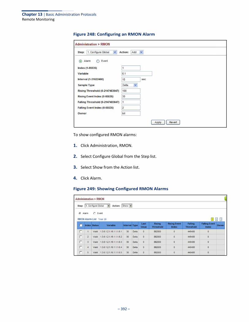
Chapter 13 | Basic Administration Protocols Remote Monitoring
– 392 –
Figure 248: Configuring an RMON Alarm
To show configured RMON alarms:
1. Click Administration, RMON.
2. Select Configure Global from the Step list.
3. Select Show from the Action list.
4. Click Alarm.
Figure 249: Showing Configured RMON Alarms
Chapter 13 | Basic Administration Protocols Remote Monitoring
– 393 –
Configuring RMON Events
Use the Administration > RMON (Configure Global - Add - Event) page to set the action to take when an alarm is triggered. The response can include logging the alarm or sending a message to a trap manager. Alarms and corresponding events provide a way of immediately responding to critical network problems.
Command Usage ◆ If an alarm is already defined for an index, the entry must be deleted before any
changes can be made.
◆ One default event is configured as follows:
event Index = 1 Description: RMON_TRAP_LOG Event type: log & trap Event community name is public Owner is RMON_SNMP
Parameters These parameters are displayed:
◆ Index – Index to this entry. (Range: 1-65535)
◆ Type – Specifies the type of event to initiate:
■ None – No event is generated.
■ Log – Generates an RMON log entry when the event is triggered. Log messages are processed based on the current configuration settings for event logging (see “System Log Configuration” on page 334).
■ Trap – Sends a trap message to all configured trap managers (see
“Specifying Trap Managers” on page 382).
■ Log and Trap – Logs the event and sends a trap message.
◆ Community – A password-like community string sent with the trap operation to SNMP v1 and v2c hosts.
Although the community string can be set on this configuration page, it is recommended that it be defined on the SNMP trap configuration page (see “Setting Community Access Strings” on page 375) prior to configuring it here. (Range: 1-32 characters)
◆ Description – A comment that describes this event. (Range: 1-127 characters)
◆ Owner – Name of the person who created this entry. (Range: 1-32 characters)
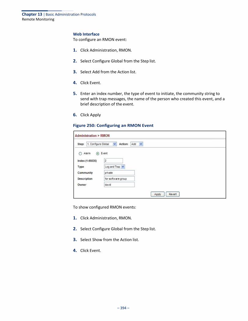
Chapter 13 | Basic Administration Protocols Remote Monitoring
– 394 –
Web Interface To configure an RMON event:
1. Click Administration, RMON.
2. Select Configure Global from the Step list.
3. Select Add from the Action list.
4. Click Event.
5. Enter an index number, the type of event to initiate, the community string to send with trap messages, the name of the person who created this event, and a brief description of the event.
6. Click Apply
Figure 250: Configuring an RMON Event
To show configured RMON events:
1. Click Administration, RMON.
2. Select Configure Global from the Step list.
3. Select Show from the Action list.
4. Click Event.

Chapter 13 | Basic Administration Protocols Remote Monitoring
– 395 –
Figure 251: Showing Configured RMON Events
Configuring RMON History Samples
Use the Administration > RMON (Configure Interface - Add - History) page to collect statistics on a physical interface to monitor network utilization, packet types, and errors. A historical record of activity can be used to track down intermittent problems. The record can be used to establish normal baseline activity, which may reveal problems associated with high traffic levels, broadcast storms, or other unusual events. It can also be used to predict network growth and plan for expansion before your network becomes too overloaded.
Command Usage ◆ Each index number equates to a port on the switch.
◆ If history collection is already enabled on an interface, the entry must be
deleted before any changes can be made.
◆ The information collected for each sample includes:
input octets, packets, broadcast packets, multicast packets, undersize packets, oversize packets, fragments, jabbers, CRC alignment errors, collisions, drop events, and network utilization.
For a description of the statistics displayed on the Show Details page, refer to “Showing Port or Trunk Statistics” on page 102.
◆ The switch reserves two index entries for each port. If a default index entry is re-
assigned to another port using the Add page, this index will not appear in the Show nor Show Details page for the port to which is normally assigned. For example, if control entry 15 is assigned to port 5, this index entry will be removed from the Show and Show Details page for port 8.
Parameters These parameters are displayed:
◆ Port – The port number on the switch.
◆ Index - Index to this entry. (Range: 1-65535)
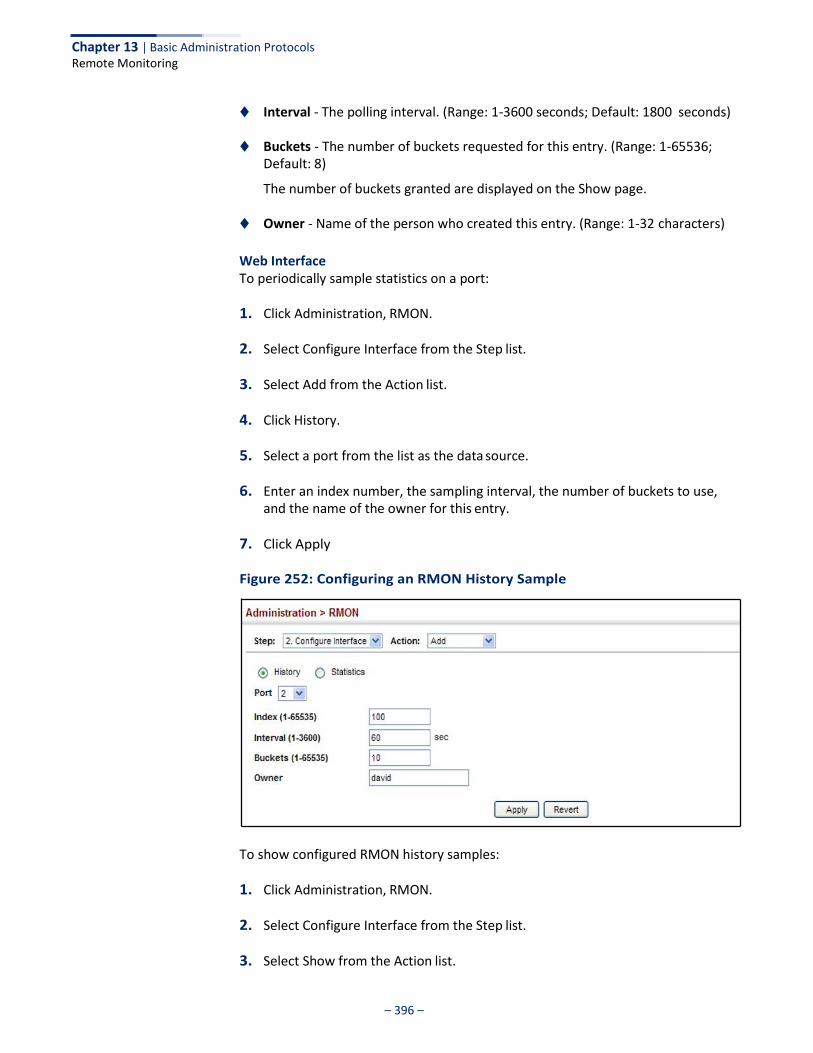
Chapter 13 | Basic Administration Protocols Remote Monitoring
– 396 –
◆ Interval - The polling interval. (Range: 1-3600 seconds; Default: 1800 seconds)
◆ Buckets - The number of buckets requested for this entry. (Range: 1-65536; Default: 8)
The number of buckets granted are displayed on the Show page.
◆ Owner - Name of the person who created this entry. (Range: 1-32 characters)
Web Interface To periodically sample statistics on a port:
1. Click Administration, RMON.
2. Select Configure Interface from the Step list.
3. Select Add from the Action list.
4. Click History.
5. Select a port from the list as the data source.
6. Enter an index number, the sampling interval, the number of buckets to use, and the name of the owner for this entry.
7. Click Apply
Figure 252: Configuring an RMON History Sample
To show configured RMON history samples:
1. Click Administration, RMON.
2. Select Configure Interface from the Step list.
3. Select Show from the Action list.
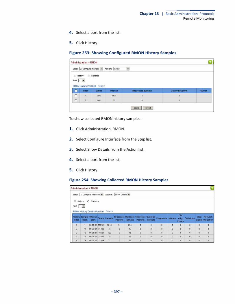
Chapter 13 | Basic Administration Protocols Remote Monitoring
– 397 –
4. Select a port from the list.
5. Click History.
Figure 253: Showing Configured RMON History Samples
To show collected RMON history samples:
1. Click Administration, RMON.
2. Select Configure Interface from the Step list.
3. Select Show Details from the Action list.
4. Select a port from the list.
5. Click History.
Figure 254: Showing Collected RMON History Samples
Chapter 13 | Basic Administration Protocols Remote Monitoring
– 398 –
Configuring RMON Statistical Samples
Use the Administration > RMON (Configure Interface - Add - Statistics) page to collect statistics on a port, which can subsequently be used to monitor the network for common errors and overall traffic rates.
Command Usage ◆ If statistics collection is already enabled on an interface, the entry must be
deleted before any changes can be made.
◆ The information collected for each entry includes:
input octets, packets, broadcast packets, multicast packets, undersize packets, oversize packets, CRC alignment errors, jabbers, fragments, collisions, drop events, and frames of various sizes.
Parameters These parameters are displayed:
◆ Port – The port number on the switch.
◆ Index - Index to this entry. (Range: 1-65535)
◆ Owner - Name of the person who created this entry. (Range: 1-32 characters)
Web Interface To enable regular sampling of statistics on a port:
1. Click Administration, RMON.
2. Select Configure Interface from the Step list.
3. Select Add from the Action list.
4. Click Statistics.
5. Select a port from the list as the data source.
6. Enter an index number, and the name of the owner for this entry
7. Click Apply
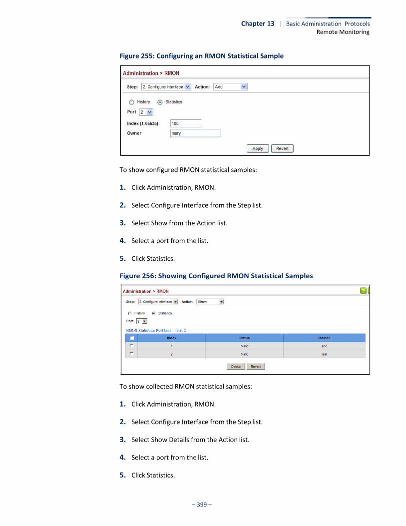
Chapter 13 | Basic Administration Protocols Remote Monitoring
– 399 –
Figure 255: Configuring an RMON Statistical Sample
To show configured RMON statistical samples:
1. Click Administration, RMON.
2. Select Configure Interface from the Step list.
3. Select Show from the Action list.
4. Select a port from the list.
5. Click Statistics.
Figure 256: Showing Configured RMON Statistical Samples
To show collected RMON statistical samples:
1. Click Administration, RMON.
2. Select Configure Interface from the Step list.
3. Select Show Details from the Action list.
4. Select a port from the list.
5. Click Statistics.

Chapter 13 | Basic Administration Protocols Switch Clustering
– 400 –
Figure 257: Showing Collected RMON Statistical Samples
Switch Clustering
Switch clustering is a method of grouping switches together to enable centralized management through a single unit. Switches that support clustering can be grouped together regardless of physical location or switch type, as long as they are connected to the same local network.
Command Usage ◆ A switch cluster has a primary unit called the “Commander” which is used to
manage all other “Member” switches in the cluster. The management station can use either Telnet or the web interface to communicate directly with the Commander through its IP address, and then use the Commander to manage Member switches through the cluster’s “internal” IP addresses.
◆ Clustered switches must be in the same Ethernet broadcast domain. In other
words, clustering only functions for switches which can pass information between the Commander and potential Candidates or active Members through VLAN 4093.
◆ Once a switch has been configured to be a cluster Commander, it automatically
discovers other cluster-enabled switches in the network. These “Candidate” switches only become cluster Members when manually selected by the administrator through the management station.
◆ There can be up to 100 candidates and 36 member switches in one cluster.
◆ A switch can only be a member of one cluster.
Chapter 13 | Basic Administration Protocols Switch Clustering
– 401 –
◆ The cluster VLAN 4093 is not configured by default. Before using clustering, take the following actions to set up this VLAN:
1. Create VLAN 4093 (see “Configuring VLAN Groups” on page 149).
2. Add the participating ports to this VLAN (see “Adding Static Members to VLANs” on page 152), and set them to hybrid mode, tagged members, PVID = 1, and acceptable frame type = all.
◆ After the Commander and Members have been configured, any switch in the
cluster can be managed from the web agent by choosing the desired Member ID from the Show Member page.
Configuring General Settings for Clusters
Use the Administration > Cluster (Configure Global) page to create a switch cluster.
Command Usage First be sure that clustering is enabled on the switch (the default is disabled), then set the switch as a Cluster Commander. Set a Cluster IP Pool that does not conflict with the network IP subnet. Cluster IP addresses are assigned to switches when they become Members and are used for communication between Member switches and the Commander.
Parameters These parameters are displayed:
◆ Cluster Status – Enables or disables clustering on the switch.
(Default: Disabled)
◆ Commander Status – Enables or disables the switch as a cluster Commander. (Default: Disabled)
◆ IP Pool – An “internal” IP address pool that is used to assign IP addresses to
Member switches in the cluster. Internal cluster IP addresses are in the form 10.x.x.member-ID. Only the base IP address of the pool needs to be set since Member IDs can only be between 1 and 36. Note that you cannot change the cluster IP pool when the switch is currently in Commander mode. Commander mode must first be disabled. (Default: 10.254.254.1)
◆ Role – Indicates the current role of the switch in the cluster; either Commander,
Member, or Candidate. (Default: Candidate)
◆ Number of Members – The current number of Member switches in the cluster.
◆ Number of Candidates – The current number of Candidate switches discovered in the network that are available to become Members.
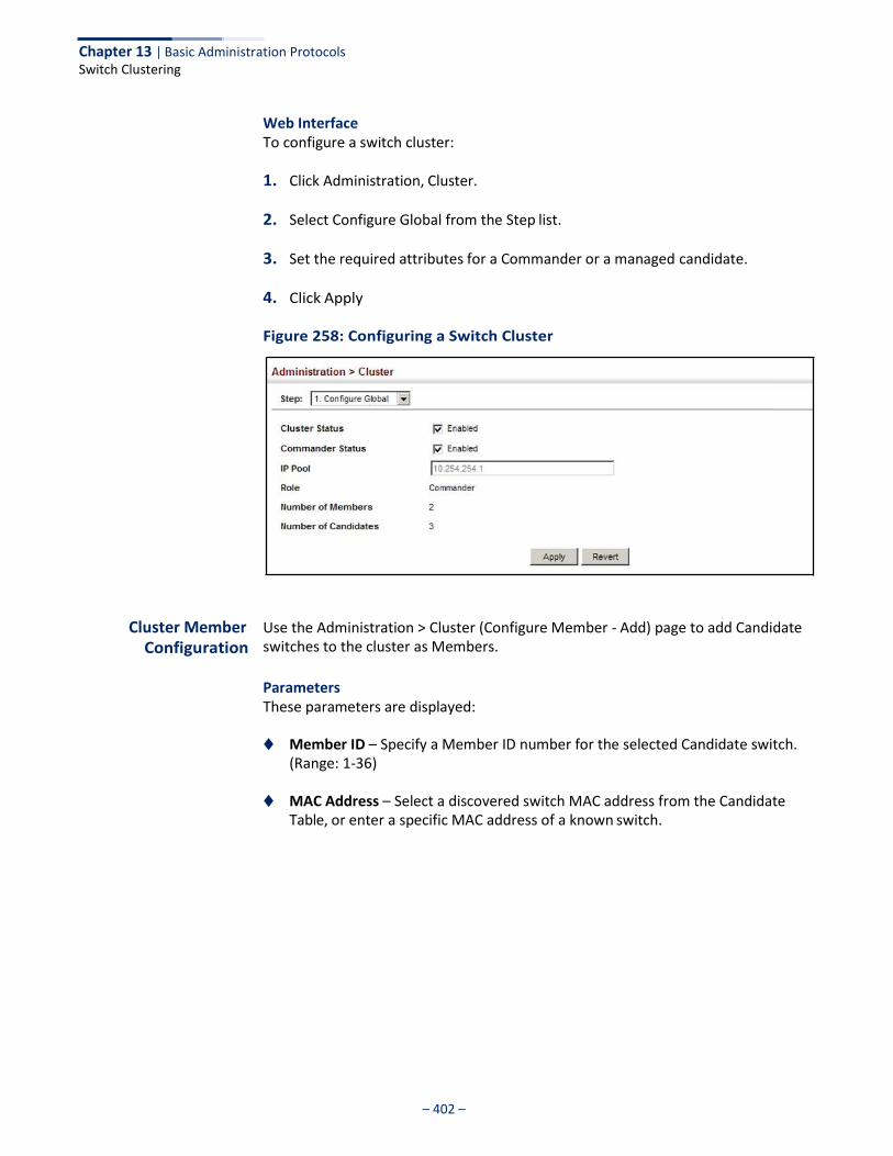
Chapter 13 | Basic Administration Protocols Switch Clustering
– 402 –
Web Interface To configure a switch cluster:
1. Click Administration, Cluster.
2. Select Configure Global from the Step list.
3. Set the required attributes for a Commander or a managed candidate.
4. Click Apply
Figure 258: Configuring a Switch Cluster
Cluster Member
Configuration
Use the Administration > Cluster (Configure Member - Add) page to add Candidate switches to the cluster as Members.
Parameters These parameters are displayed:
◆ Member ID – Specify a Member ID number for the selected Candidate switch.
(Range: 1-36)
◆ MAC Address – Select a discovered switch MAC address from the Candidate Table, or enter a specific MAC address of a known switch.
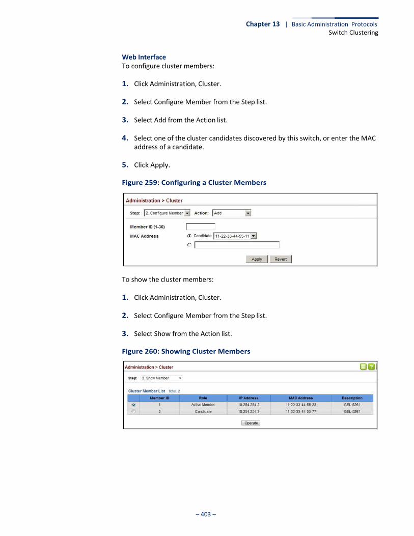
Chapter 13 | Basic Administration Protocols Switch Clustering
– 403 –
Web Interface To configure cluster members:
1. Click Administration, Cluster.
2. Select Configure Member from the Step list.
3. Select Add from the Action list.
4. Select one of the cluster candidates discovered by this switch, or enter the MAC address of a candidate.
5. Click Apply.
Figure 259: Configuring a Cluster Members
To show the cluster members:
1. Click Administration, Cluster.
2. Select Configure Member from the Step list.
3. Select Show from the Action list.
Figure 260: Showing Cluster Members

Chapter 13 | Basic Administration Protocols Switch Clustering
– 404 –
To show cluster candidates:
1. Click Administration, Cluster.
2. Select Configure Member from the Step list.
3. Select Show Candidate from the Action list.
Figure 261: Showing Cluster Candidates
Managing Cluster Members
Use the Administration > Cluster (Show Member) page to manage another switch in the cluster.
Parameters These parameters are displayed:
◆ Member ID – The ID number of the Member switch. (Range: 1-36)
◆ Role – Indicates the current status of the switch in the cluster.
◆ IP Address – The internal cluster IP address assigned to the Member switch.
◆ MAC Address – The MAC address of the Member switch.
◆ Description – The system description string of the Member switch.
◆ Operate – Remotely manage a cluster member.

– 405 –
Chapter 13 | Basic Administration Protocols Setting a Time Range
Web Interface To manage a cluster member:
1. Click Administration, Cluster.
2. Select Show Member from the Step list.
3. Select an entry from the Cluster Member List.
4. Click Operate.
Figure 262: Managing a Cluster Member
Setting a Time Range
Use the Administration > Time Range page to set a time range during which various functions are applied, including applied ACLs or PoE.
Command Usage ◆ If both an absolute rule and one or more periodic rules are configured for the
same time range (i.e., named entry), that entry will only take effect if the current time is within the absolute time range and one of the periodic time ranges.
◆ A maximum of eight rules can be configured for a time range.
Parameters These parameters are displayed:
Add
◆ Time-Range Name – Name of a time range. (Range: 1-32 characters)
Add Rule
◆ Time-Range – Name of a time range.
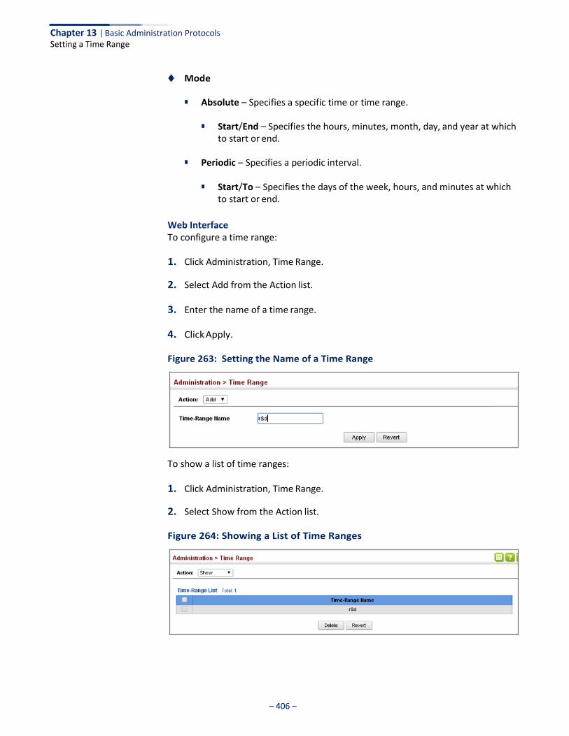
– 406 –
Chapter 13 | Basic Administration Protocols Setting a Time Range
◆ Mode
■ Absolute – Specifies a specific time or time range.
■ Start/End – Specifies the hours, minutes, month, day, and year at which to start or end.
■ Periodic – Specifies a periodic interval.
■ Start/To – Specifies the days of the week, hours, and minutes at which
to start or end.
Web Interface To configure a time range:
1. Click Administration, Time Range.
2. Select Add from the Action list.
3. Enter the name of a time range.
4. Click Apply.
Figure 263: Setting the Name of a Time Range
To show a list of time ranges:
1. Click Administration, Time Range.
2. Select Show from the Action list.
Figure 264: Showing a List of Time Ranges
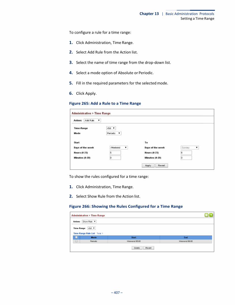
– 407 –
Chapter 13 | Basic Administration Protocols Setting a Time Range
To configure a rule for a time range:
1. Click Administration, Time Range.
2. Select Add Rule from the Action list.
3. Select the name of time range from the drop-down list.
4. Select a mode option of Absolute or Periodic.
5. Fill in the required parameters for the selected mode.
6. Click Apply.
Figure 265: Add a Rule to a Time Range
To show the rules configured for a time range:
1. Click Administration, Time Range.
2. Select Show Rule from the Action list.
Figure 266: Showing the Rules Configured for a Time Range
– 408 –
Chapter 13 | Basic Administration Protocols Ethernet Ring Protection Switching
Ethernet Ring Protection Switching
Note: Information in this section is based on ITU-T G.8032/Y.1344.
The ITU G.8032 recommendation specifies a protection switching mechanism and protocol for Ethernet layer network rings. Ethernet rings can provide wide-area multipoint connectivity more economically due to their reduced number of links. The mechanisms and protocol defined in G.8032 achieve highly reliable and stable protection; and never form loops, which would fatally affect network operation and service availability.
The G.8032 recommendation, also referred to as Ethernet Ring Protection Switching (ERPS), can be used to increase the availability and robustness of Ethernet rings. An Ethernet ring built using ERPS can provide resilience at a lower cost and than that provided by SONET or EAPS rings.
ERPS is more economical than EAPS in that only one physical link is required between each node in the ring. However, since it can tolerate only one break in the ring, it is not as robust as EAPS. ERPS supports up to 255 nodes in the ring structure. ERPS requires a higher convergence time when more that 16 nodes are used, but should always run under than 500 ms.
Operational Concept
Loop avoidance in the ring is achieved by guaranteeing that, at any time, traffic may flow on all but one of the ring links. This particular link is called the ring protection link (RPL), and under normal conditions this link is blocked to traffic. One designated node, the RPL owner, is responsible for blocking traffic over the RPL. When a ring failure occurs, the RPL owner is responsible for unblocking the RPL, allowing this link to be used for traffic.
Ring nodes may be in one of two states:
Idle – normal operation, no link/node faults detected in ring Protection – Protection switching in effect after identifying a signal fault
In Idle state, the physical topology has all nodes connected in a ring. The logical topology guarantees that all nodes are connected without a loop by blocking the RPL. Each link is monitored by its two adjacent nodes using Connectivity Fault Management (CFM) protocol messages.
Protection switching (opening the RPL to traffic) occurs when a signal failure message generated by the Connectivity Fault Management (CFM) protocol is declared on one of the ring links, and the detected failure has a higher priority than any other request; or a Ring – Automatic Protection Switching protocol request (R-APS, as defined in Y.1731) is received which has a higher priority than any other local request.
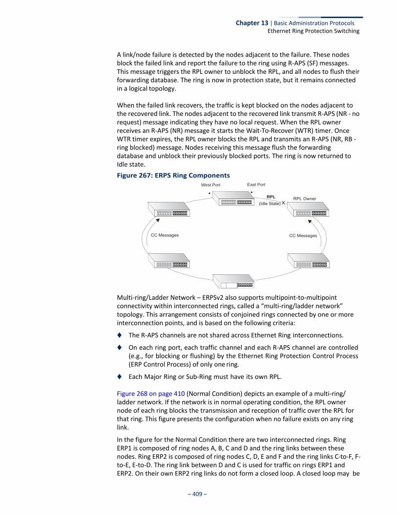
– 409 –
Chapter 13 | Basic Administration Protocols Ethernet Ring Protection Switching
A link/node failure is detected by the nodes adjacent to the failure. These nodes block the failed link and report the failure to the ring using R-APS (SF) messages. This message triggers the RPL owner to unblock the RPL, and all nodes to flush their forwarding database. The ring is now in protection state, but it remains connected in a logical topology.
When the failed link recovers, the traffic is kept blocked on the nodes adjacent to the recovered link. The nodes adjacent to the recovered link transmit R-APS (NR - no request) message indicating they have no local request. When the RPL owner receives an R-APS (NR) message it starts the Wait-To-Recover (WTR) timer. Once WTR timer expires, the RPL owner blocks the RPL and transmits an R-APS (NR, RB - ring blocked) message. Nodes receiving this message flush the forwarding database and unblock their previously blocked ports. The ring is now returned to Idle state.
Figure 267: ERPS Ring Components West Port East Port
Multi-ring/Ladder Network – ERPSv2 also supports multipoint-to-multipoint connectivity within interconnected rings, called a “multi-ring/ladder network” topology. This arrangement consists of conjoined rings connected by one or more interconnection points, and is based on the following criteria:
◆ The R-APS channels are not shared across Ethernet Ring interconnections.
◆ On each ring port, each traffic channel and each R-APS channel are controlled (e.g., for blocking or flushing) by the Ethernet Ring Protection Control Process (ERP Control Process) of only one ring.
◆ Each Major Ring or Sub-Ring must have its own RPL.
Figure 268 on page 410 (Normal Condition) depicts an example of a multi-ring/ ladder network. If the network is in normal operating condition, the RPL owner node of each ring blocks the transmission and reception of traffic over the RPL for that ring. This figure presents the configuration when no failure exists on any ring link.
In the figure for the Normal Condition there are two interconnected rings. Ring ERP1 is composed of ring nodes A, B, C and D and the ring links between these nodes. Ring ERP2 is composed of ring nodes C, D, E and F and the ring links C-to-F, F-to-E, E-to-D. The ring link between D and C is used for traffic on rings ERP1 and ERP2. On their own ERP2 ring links do not form a closed loop. A closed loop may be
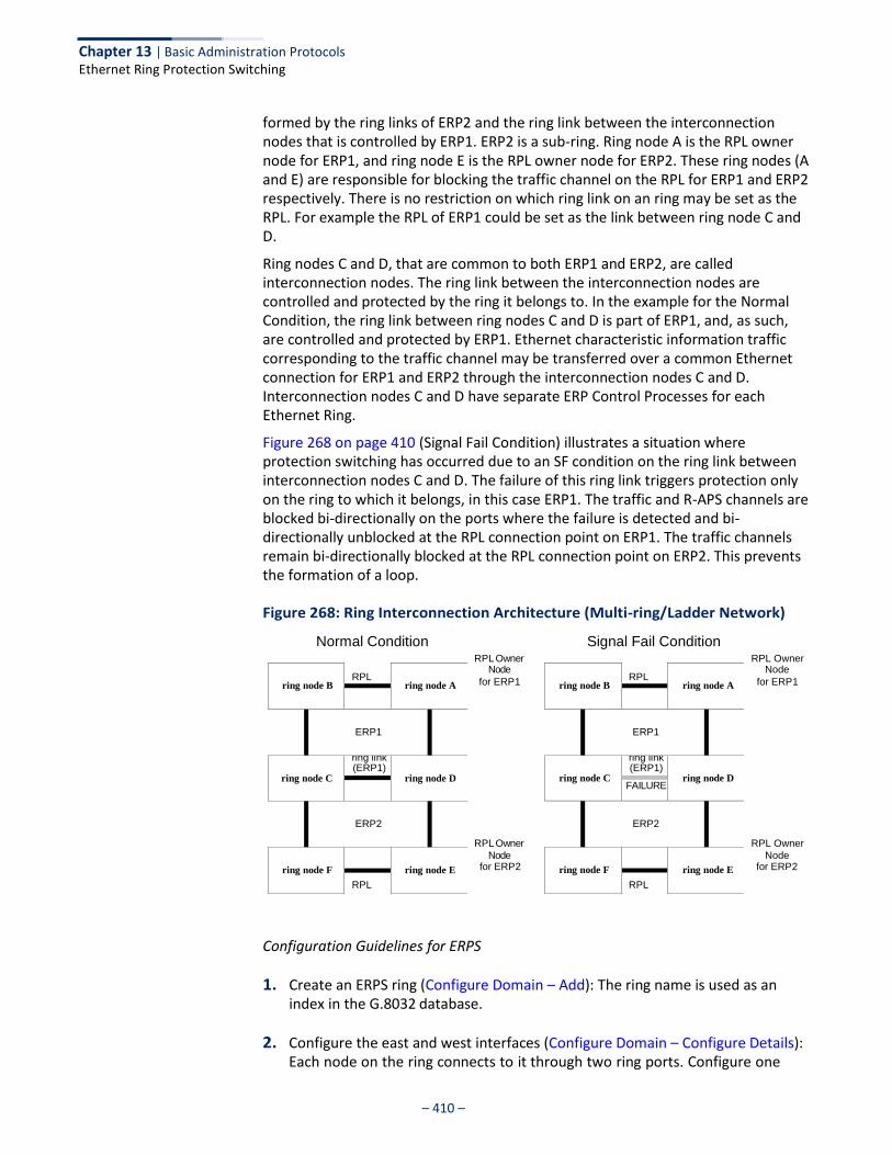
Chapter 13 | Basic Administration Protocols Ethernet Ring Protection Switching
– 410 –
formed by the ring links of ERP2 and the ring link between the interconnection nodes that is controlled by ERP1. ERP2 is a sub-ring. Ring node A is the RPL owner node for ERP1, and ring node E is the RPL owner node for ERP2. These ring nodes (A and E) are responsible for blocking the traffic channel on the RPL for ERP1 and ERP2 respectively. There is no restriction on which ring link on an ring may be set as the RPL. For example the RPL of ERP1 could be set as the link between ring node C and D.
Ring nodes C and D, that are common to both ERP1 and ERP2, are called interconnection nodes. The ring link between the interconnection nodes are controlled and protected by the ring it belongs to. In the example for the Normal Condition, the ring link between ring nodes C and D is part of ERP1, and, as such, are controlled and protected by ERP1. Ethernet characteristic information traffic corresponding to the traffic channel may be transferred over a common Ethernet connection for ERP1 and ERP2 through the interconnection nodes C and D. Interconnection nodes C and D have separate ERP Control Processes for each Ethernet Ring.
Figure 268 on page 410 (Signal Fail Condition) illustrates a situation where protection switching has occurred due to an SF condition on the ring link between interconnection nodes C and D. The failure of this ring link triggers protection only on the ring to which it belongs, in this case ERP1. The traffic and R-APS channels are blocked bi-directionally on the ports where the failure is detected and bi- directionally unblocked at the RPL connection point on ERP1. The traffic channels remain bi-directionally blocked at the RPL connection point on ERP2. This prevents the formation of a loop.
Figure 268: Ring Interconnection Architecture (Multi-ring/Ladder Network)
Normal Condition Signal Fail Condition RPL Owner
Node
for ERP1
RPL Owner
Node for ERP2
RPL Owner Node
for ERP1
RPL Owner
Node for ERP2
Configuration Guidelines for ERPS
1. Create an ERPS ring (Configure Domain – Add): The ring name is used as an index in the G.8032 database.
2. Configure the east and west interfaces (Configure Domain – Configure Details): Each node on the ring connects to it through two ring ports. Configure one
ring node B
RPL ring node A
ERP1
ring node C
ring link (ERP1)
ring node D
ERP2
ring node F
ring node E
RPL
ring node B
RPL ring node A
ERP1
ring node C
ring link (ERP1)
ring node D FAILURE
ERP2
ring node F
ring node E
RPL
Chapter 13 | Basic Administration Protocols Ethernet Ring Protection Switching
– 411 –
port connected to the next node in the ring to the east (or clockwise direction) and another port facing west in the ring.
3. Configure the RPL owner (Configure Domain – Configure Details): Configure one node in the ring as the Ring Protection Link (RPL) owner. When this switch is configured as the RPL owner, the west ring port is set as being connected to the RPL. Under normal operations (Idle state), the RPL is blocked to ensure that a loop cannot form in the ring. If a signal failure brings down any other link in the ring, the RPL will be unblocked (Protection state) to ensure proper connectivity among all ring nodes until the failure is recovered.
4. Configure ERPS timers (Configure Domain – Configure Details): Set the Guard timer to prevent ring nodes from receiving outdated R-APS messages, the Hold-off timer to filter out intermittent link faults, and the WTR timer to verify that the ring has stabilized before blocking the RPL after recovery from a signal failure.
5. Configure the ERPS control VLAN (Configure Domain – Configure Details): Specify the control VLAN (CVLAN) used to pass R-APS ring maintenance commands. The CVLAN must NOT be configured with an IP address. In addition, only ring ports may be added to the CVLAN (prior to configuring the VLAN as a CVLAN). No other ports can be members of this VLAN (once set as a CVLAN). Also, the ring ports of the CVLAN must be tagged. Failure to observe these restrictions can result in a loop in the network.
6. Enable ERPS (Configure Global): Before enabling a ring as described in the next step, first globally enable ERPS on the switch. If ERPS has not yet been enabled or has been disabled, no ERPS rings will work.
7. Enable an ERPS ring (Configure Domain – Configure Details): Before an ERPS ring can work, it must be enabled. When configuration is completed and the ring enabled, R-APS messages will start flowing in the control VLAN, and normal traffic will begin to flow in the data VLANs. A ring can be stopped by disabling the Admin Status on any node.
8. Display ERPS status information (Configure Domain – Show): Display ERPS status information for all configured rings.
Configuration Limitations for ERPS
The following configuration limitations apply to ERPS:
◆ The switch supports up to six ERPS rings – each ring must have one Control VLAN, and at most 255 Data VLANs.
◆ Ring ports can not be a member of a trunk, nor an LACP-enabled port.
◆ Dynamic VLANs are not supported as protected data ports.
◆ Exclusive use of STP or ERPS on any port.
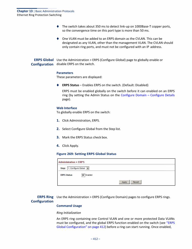
Chapter 13 | Basic Administration Protocols Ethernet Ring Protection Switching
– 412 –
◆ The switch takes about 350 ms to detect link-up on 1000Base-T copper ports, so the convergence time on this port type is more than 50 ms.
◆ One VLAN must be added to an ERPS domain as the CVLAN. This can be
designated as any VLAN, other than the management VLAN. The CVLAN should only contain ring ports, and must not be configured with an IP address.
ERPS Global Configuration
Use the Administration > ERPS (Configure Global) page to globally enable or disable ERPS on the switch.
Parameters These parameters are displayed:
◆ ERPS Status – Enables ERPS on the switch. (Default: Disabled)
ERPS must be enabled globally on the switch before it can enabled on an ERPS ring (by setting the Admin Status on the Configure Domain – Configure Details page).
Web Interface To globally enable ERPS on the switch:
1. Click Administration, ERPS.
2. Select Configure Global from the Step list.
3. Mark the ERPS Status check box.
4. Click Apply.
Figure 269: Setting ERPS Global Status
ERPS Ring Configuration
Use the Administration > ERPS (Configure Domain) pages to configure ERPS rings.
Command Usage
Ring Initialization
An ERPS ring containing one Control VLAN and one or more protected Data VLANs must be configured, and the global ERPS function enabled on the switch (see “ERPS Global Configuration” on page 412) before a ring can start running. Once enabled,
Chapter 13 | Basic Administration Protocols Ethernet Ring Protection Switching
– 413 –
the RPL owner node and non-owner node state machines will start, and the ring will enter the active state.
Limitations
When configuring a ring port, note that these ports cannot be part of a spanning tree, nor can they be members of a static or dynamic trunk.
Parameters These parameters are displayed:
Add
◆ Domain Name – Name of an ERPS ring. (Range: 1-12 characters)
◆ Domain ID – ERPS ring identifier used in R-APS messages. (Range: 1-255)
Show
◆ Domain Name – Name of a configured ERPS ring.
◆ ID – ERPS ring identifier used in R-APS messages.
◆ Admin Status – Shows whether ERPS is enabled on the switch.
◆ Ver – Shows the ERPS version.
◆ MEG Level – The maintenance entity group (MEG) level providing a communication channel for ring automatic protection switching (R-APS) information.
◆ Control VLAN – Shows the Control VLAN ID.
◆ Node State – Shows the following ERPS states:
■ Init – The ERPS ring has started but has not yet determined the status of the ring.
■ Idle – If all nodes in a ring are in this state, it means that all the links in the ring are up. This state will switch to protection state if a link failure occurs.
■ Protection – If a node in this state, it means that a link failure has occurred. This state will switch to idle state if all the failed links recover.
◆ Type – Shows node type as None, RPL Owner or RPL Neighbor.
◆ Revertive – Shows if revertive or non-revertive recovery is selected.
◆ W/E – Shows information on the west and east ring port for this node.
◆ West Port – Shows the west ring port for this node.
◆ East Port – Shows the east ring port for this node.
Chapter 13 | Basic Administration Protocols Ethernet Ring Protection Switching
– 414 –
◆ Interface – The port or trunk which is configured as a ring port.
◆ Port State – The operational state:
■ Blocking – The transmission and reception of traffic is blocked and the forwarding of R-APS messages is blocked, but the transmission of locally generated R-APS messages is allowed and the reception of all R-APS messages is allowed.
■ Forwarding – The transmission and reception of traffic is allowed; transmission, reception and forwarding of R-APS messages is allowed.
■ Unknown – The interface is not in a known state (includes the domain being disabled).
◆ Local SF – A signal fault generated on a link to the local node.
◆ Local FS – Shows if a forced switch command was issued on this interface.
◆ Local MS – Shows if a manual switch command was issued on this interface.
◆ MEP – The CFM MEP used to monitor the status on this link.
◆ RPL – Shows if this node is connected to the RPL.
Configure Details
◆ Domain Name – Name of a configured ERPS ring. (Range: 1-12 characters)
Service Instances within each ring are based on a unique maintenance association for the specific users, distinguished by the ring name, maintenance level, maintenance association’s name, and assigned VLAN. Up to 6 ERPS rings can be configured on the switch.
◆ Domain ID – ERPS ring identifier used in R-APS messages. (Range: 1-255;
Default: None)
R-A PS information is carried in an R-APS PDUs. The last octet of the MAC address is designated as the Ring ID (01-19-A7-00-00-[Ring ID]). If use of the default MAC address is disabled for the R-APS Def MAC parameter, then the Domain ID will be used in R-APS PDUs.
◆ Admin Status – Activates the current ERPS ring. (Default: Disabled)
Before enabling a ring, the global ERPS function should be enabled see (“ERPS Global Configuration” on page 412), the east and west ring ports configured on each node, the RPL owner specified, and the control VLAN configured.
Once enabled, the RPL owner node and non-owner node state machines will start, and the ring will enter idle state if no signal failures are detected.
Chapter 13 | Basic Administration Protocols Ethernet Ring Protection Switching
– 415 –
◆ Version – Specifies compatibility with the following ERPS versions:
■ 1 - ERPS version 1 based on ITU-T G.8032/Y.1344.
■ 2 - ERPS version 2 based on ITU-T G.8032/Y.1344 Version 2. (This is the default setting.)
In addition to the basic features provided by version 1, version 2 also supports:
■ Multi-ring/ladder network support
■ Revertive/Non-revertive recovery
■ Forced Switch (FS) and Manual Switch (MS) commands for manually blocking a particular ring port
■ Flush FDB (forwarding database) logic which reduces amount of flush FDB operations in the ring
■ Support of multiple ERP instances on a single ring
Version 2 is backward compatible with Version 1. If version 2 is specified, the inputs and commands are forwarded transparently. If set to version 1, MS and FS operator commands are filtered, and the switch set to revertive mode.
The version number is automatically set to “1” when a ring node, supporting only the functionalities of G.8032v1, exists on the same ring with other nodes that support G.8032v2.
When ring nodes running G.8032v1 and G.8032v2 co-exist on a ring, the ring ID of each node is configured as “1”.
In version 1, the MAC address 01-19-A7-00-00-01 is used for the node identifier. The R-APS Def MAC parameter has no effect.
◆ MEG Level – The maintenance entity group (MEG) level which provides a
communication channel for ring automatic protection switching (R-APS) information. (Range: 0-7)
This parameter is used to ensure that received R-APS PDUs are directed for this ring. A unique level should be configured for each local ring if there are many R- APS PDUs passing through this switch.
◆ Control VLAN – A dedicated VLAN used for sending and receiving E-APS
protocol messages. (Range: 1-4094)
Configure one control VLAN for each ERPS ring. First create the VLAN to be used as the control VLAN (see “Configuring VLAN Groups” on page 149), add the ring ports for the east and west interface as tagged members to this VLAN (see “Adding Static Members to VLANs” on page 152), and then use this parameter to add it to the ring.
The following restrictions are recommended to avoid creating a loop in the network or other problems which may occur under some situations:
■ The Control VLAN must not be configured as a Layer 3 interface (with an IP address), a dynamic VLAN (with GVRP enabled), nor as a private VLAN.

Chapter 13 | Basic Administration Protocols Ethernet Ring Protection Switching
– 416 –
■ In addition, only ring ports may be added to the Control VLAN. No other
ports can be members of this VLAN.
■ Also, the ring ports of the Control VLAN must be tagged.
Once the ring has been activated, the configuration of the control VLAN cannot be modified. Use the Admin Status parameter to stop the ERPS ring before making any configuration changes to the control VLAN.
◆ Node State – Refer to the parameters for the Show page.
◆ Node Type – Shows ERPS node type as one of the following:
■ None – Node is neither Ring Protection Link (RPL) owner nor neighbor. (This is the default setting.)
■ RPL Owner – Specifies a ring node to be the RPL owner.
■ Only one RPL owner can be configured on a ring. The owner blocks
traffic on the RPL during Idle state, and unblocks it during Protection state (that is, when a signal fault is detected on the ring or the protection state is enabled with the Forced Switch or Manual Switch commands on the Configure Operation page).
■ The east and west connections to the ring must be specified for all ring nodes. When this switch is configured as the RPL owner, the west ring port is automatically set as being connected to the RPL.
■ RPL Neighbor – Specifies a ring node to be the RPL neighbor.
■ The RPL neighbor node, when configured, is a ring node adjacent to
the RPL that is responsible for blocking its end of the RPL under normal conditions (i.e., the ring is established and no requests are present in the ring) in addition to the block at the other end by the RPL Owner Node. The RPL neighbor node may participate in blocking or unblocking its end of the RPL, but is not responsible for activating the reversion behavior.
■ Only one RPL owner can be configured on a ring. If the switch is set as the RPL owner for an ERPS domain, the west ring port is set as one end of the RPL. If the switch is set as the RPL neighbor for an ERPS domain, the east ring port is set as the other end of the RPL.
■ The east and west connections to the ring must be specified for all ring nodes. When this switch is configured as the RPL neighbor, the east ring port is set as being connected to the RPL.
■ Note that is not mandatory to declare a RPL neighbor.
Chapter 13 | Basic Administration Protocols Ethernet Ring Protection Switching
– 417 –
◆ Revertive – Sets the method of recovery to Idle State through revertive or non- revertive mode. (Default: Enabled)
■ Revertive behavior allows the switch to automatically return the RPL from
Protection state to Idle state through the exchange of protocol messages.
Non-revertive behavior for Protection, Forced Switch (FS), and Manual Switch (MS) states are basically the same. Non-revertive behavior requires the RPL to be restored from Protection state to Idle state using the Clear command (Configure Operation page).
■ Recovery for Protection Switching – A ring node that has one or more ring
ports in an SF (Signal Fail) condition, upon detecting the SF condition cleared, keeps at least one of its ring ports blocked for the traffic channel and for the R-APS channel, until the RPL is blocked as a result of ring protection reversion, or until there is another higher priority request (e.g., an SF condition) in the ring.
A ring node that has one ring port in an SF condition and detects the SF condition cleared, continuously transmits the R-APS (NR – no request) message with its own Node ID as the priority information over both ring ports, informing that no request is present at this ring node and initiates a guard timer. When another recovered ring node (or nodes) holding the link block receives this message, it compares the Node ID information with its own Node ID. If the received R-APS (NR) message has the higher priority, this ring node unblocks its ring ports. Otherwise, the block remains unchanged. As a result, there is only one link with one end blocked.
The ring nodes stop transmitting R-APS (NR) messages when they accept an R-APS (NR, RB – RPL Blocked), or when another higher priority request is received.
■ Recovery with Revertive Mode – When all ring links and ring nodes
have recovered and no external requests are active, reversion is handled in the following way:
a. The reception of an R-APS (NR) message causes the RPL Owner Node to start the WTR (Wait-to-Restore) timer.
b. The WTR timer is cancelled if during the WTR period a higher priority request than NR is accepted by the RPL Owner Node or is declared locally at the RPL Owner Node.
c. When the WTR timer expires, without the presence of any other higher priority request, the RPL Owner Node initiates reversion by blocking its traffic channel over the RPL, transmitting an R-APS (NR, RB) message over both ring ports, informing the ring that the RPL is blocked, and performing a flush FDB action.
d. The acceptance of the R-APS (NR, RB) message causes all ring nodes to unblock any blocked non-RPL link that does not have an SF condition. If it is an R-APS (NR, RB) message without a DNF (do not flush) indication, all ring nodes flush the FDB.
Chapter 13 | Basic Administration Protocols Ethernet Ring Protection Switching
– 418 –
■ Recovery with Non-revertive Mode – In non-revertive operation, the
ring does not automatically revert when all ring links and ring nodes have recovered and no external requests are active. Non-revertive operation is handled in the following way:
a. The RPL Owner Node does not generate a response on reception of an R-APS (NR) messages.
b. When other healthy ring nodes receive the NR (Node ID) message, no action is taken in response to the message.
c. When the operator issues the Clear command (Configure Operation page) for non-revertive mode at the RPL Owner Node, the non-revertive operation is cleared, the RPL Owner Node blocks its RPL port, and transmits an R-APS (NR, RB) message in both directions, repeatedly.
d. Upon receiving an R-APS (NR, RB) message, any blocking node should unblock its non-failed ring port. If it is an R-APS (NR, RB) message without a DNF indication, all ring nodes flush the FDB.
■ Recovery for Forced Switching – A Forced Switch command is removed
by issuing the Clear command (Configure Operation page) to the same ring node where Forced Switch mode is in effect. The clear command removes any existing local operator commands, and triggers reversion if the ring is in revertive behavior mode.
The ring node where the Forced Switch was cleared continuously transmits the R-APS (NR) message on both ring ports, informing other nodes that no request is present at this ring node. The ring nodes stop transmitting R-APS (NR) messages when they accept an RAPS (NR, RB) message, or when another higher priority request is received.
If the ring node where the Forced Switch was cleared receives an R-APS (NR) message with a Node ID higher than its own Node ID, it unblocks any ring port which does not have an SF condition and stops transmitting R-APS (NR) message over both ring ports.
■ Recovery with revertive mode is handled as follows:
a. The reception of an R-APS (NR) message causes the RPL Owner Node to start the WTB timer.
b. The WTB timer is cancelled if during the WTB period a higher priority request than NR is accepted by the RPL Owner Node or is declared locally at the RPL Owner Node.
c. When the WTB timer expires, in the absence of any other higher priority request, the RPL Owner Node initiates reversion by blocking the traffic channel over the RPL, transmitting an R-APS (NR, RB) message over both ring ports, informing the ring that the RPL is blocked, and flushes the FDB.
Chapter 13 | Basic Administration Protocols Ethernet Ring Protection Switching
– 419 –
d. The acceptance of the R-APS (NR, RB) message causes all ring nodes to unblock any blocked non-RPL that does not have an SF condition. If it is an R-APS (NR, RB) message without a DNF indication, all ring nodes flush their FDB. This action unblocks the ring port which was blocked as a result of an operator command.
■ Recovery with non-revertive mode is handled as follows:
a. The RPL Owner Node, upon reception of an R-APS(NR) message and in the absence of any other higher priority request does not perform any action.
b. Then, after the operator issues the Clear command (Configure Operation page) at the RPL Owner Node, this ring node blocks the ring port attached to the RPL, transmits an R-APS (NR, RB) message on both ring ports, informing the ring that the RPL is blocked, and flushes its FDB.
c. The acceptance of the R-APS (NR, RB) message triggers all ring nodes to unblock any blocked non-RPL which does not have an SF condition. If it is an R-APS (NR, RB) message without a DNF indication, all ring nodes flush their FDB. This action unblocks the ring port which was blocked as result of an operator command.
■ Recovery for Manual Switching – A Manual Switch command is
removed by issuing the Clear command (Configure Operation page) at the same ring node where the Manual Switch is in effect. The clear command removes any existing local operator commands, and triggers reversion if the ring is in revertive behavior mode.
The ring node where the Manual Switch was cleared keeps the ring port blocked for the traffic channel and for the R-APS channel, due to the previous Manual Switch command. This ring port is kept blocked until the RPL is blocked as a result of ring protection reversion, or until there is another higher priority request (e.g., an SF condition) in the ring.
The Ethernet Ring Node where the Manual Switch was cleared continuously transmits the R-APS (NR) message on both ring ports, informing that no request is present at this ring node. The ring nodes stop transmitting R-APS (NR) messages when they accept an RAPS (NR, RB) message, or when another higher priority request is received.
If the ring node where the Manual Switch was cleared receives an R-APS (NR) message with a Node ID higher than its own Node ID, it unblocks any ring port which does not have an SF condition and stops transmitting R-APS (NR) message on both ring ports.
■ Recovery with revertive mode is handled as follows:
Chapter 13 | Basic Administration Protocols Ethernet Ring Protection Switching
– 420 –
a. The RPL Owner Node, upon reception of an R-APS (NR) message and in the absence of any other higher priority request, starts the WTB timer and waits for it to expire. While the WTB timer is running, any latent R-APS (MS) message is ignored due to the higher priority of the WTB running signal.
b. When the WTB timer expires, it generates the WTB expire signal. The RPL Owner Node, upon reception of this signal, initiates reversion by blocking the traffic channel on the RPL, transmitting an R-APS (NR, RB) message over both ring ports, informing the ring that the RPL is blocked, and flushes its FDB.
c. The acceptance of the R-APS (NR, RB) message causes all ring nodes to unblock any blocked non-RPL that does not have an SF condition. If it is an R-APS (NR, RB) message without a DNF indication, all Ethernet Ring Nodes flush their FDB. This action unblocks the ring port which was blocked as a result of an operator command.
■ Recovery with non-revertive mode is handled as follows:
a. The RPL Owner Node, upon reception of an R-APS (NR) message and in the absence of any other higher priority request does not perform any action.
b. Then, after the operator issues the Clear command (Configure Operation page) at the RPL Owner Node, this ring node blocks the ring port attached to the RPL, transmits an R-APS (NR, RB) message over both ring ports, informing the ring that the RPL is blocked, and flushes its FDB.
c. The acceptance of the R-APS (NR, RB) message triggers all ring nodes to unblock any blocked non-RPL which does not have an SF condition. If it is an R-APS (NR, RB) message without a DNF indication, all ring nodes flush their FDB. This action unblocks the ring port which was blocked as result of an operator command.
◆ Major Domain – The ERPS ring used for sending control packets.
This switch can support up to six rings. However, ERPS control packets can only be sent on one ring. This parameter is used to indicate that the current ring is a secondary ring, and to specify the major ring which will be used to send ERPS control packets.
The Ring Protection Link (RPL) is always the west port. So the physical port on a secondary ring must be the west port. In other words, if a domain has two physical ring ports, this ring can only be a major ring, not a secondary ring (or sub-domain) which can have only one physical ring port. The major domain therefore cannot be set if the east port is already configured.
◆ Node ID – A MAC address unique to the ring node. The MAC address must be
specified in the format xx-xx-xx-xx-xx-xx or xxxxxxxxxxxx. (Default: CPU MAC address)
Chapter 13 | Basic Administration Protocols Ethernet Ring Protection Switching
– 421 –
The ring node identifier is used to identify a node in R-APS messages for both automatic and manual switching recovery operations.
For example, a node that has one ring port in SF condition and detects that the condition has been cleared, will continuously transmit R-APS (NR) messages with its own Node ID as priority information over both ring ports, informing its neighbors that no request is present at this node. When another recovered node holding the link blocked receives this message, it compares the Node ID information with its own. If the received R-APS (NR) message has a higher priority, this unblocks its ring ports. Otherwise, the block remains unchanged.
The node identifier may also be used for debugging, such as to distinguish messages when a node is connected to more than one ring.
◆ R-APS with VC – Configures an R-APS virtual channel to connect two
interconnection points on a sub-ring, allowing ERPS protocol traffic to be tunneled across an arbitrary Ethernet network. (Default: Enabled)
■ A sub-ring may be attached to a primary ring with or without a virtual
channel. A virtual channel is used to connect two interconnection points on the sub-ring, tunneling R-APS control messages across an arbitrary Ethernet network topology. If a virtual channel is not used to cross the intermediate Ethernet network, data in the traffic channel will still flow across the network, but the all R-APS messages will be terminated at the interconnection points.
■ Sub-ring with R-APS Virtual Channel – When using a virtual channel to
tunnel R-APS messages between interconnection points on a sub-ring, the R-APS virtual channel may or may not follow the same path as the traffic channel over the network. R-APS messages that are forwarded over the sub-ring’s virtual channel are broadcast or multicast over the interconnected network. For this reason the broadcast/multicast domain of the virtual channel should be limited to the necessary links and nodes. For example, the virtual channel could span only the interconnecting rings or sub-rings that are necessary for forwarding R-APS messages of this sub- ring. Care must also be taken to ensure that the local RAPS messages of the sub-ring being transported over the virtual channel into the interconnected network can be uniquely distinguished from those of other interconnected ring R-APS messages. This can be achieved by, for example, by using separate VIDs for the virtual channels of different sub-rings.
Note that the R-APS virtual channel requires a certain amount of bandwidth to forward R-APS messages on the interconnected Ethernet network where a sub-ring is attached. Also note that the protection switching time of the sub-ring may be affected if R-APS messages traverse a long distance over an R-APS virtual channel.
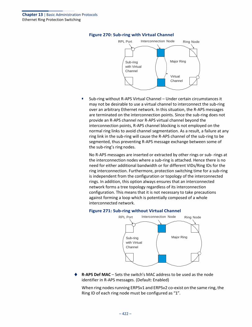
Chapter 13 | Basic Administration Protocols Ethernet Ring Protection Switching
– 422 –
Figure 270: Sub-ring with Virtual Channel
RPL Port Interconnection Node Ring Node
■ Sub-ring without R-APS Virtual Channel – Under certain circumstances it may not be desirable to use a virtual channel to interconnect the sub-ring over an arbitrary Ethernet network. In this situation, the R-APS messages are terminated on the interconnection points. Since the sub-ring does not provide an R-APS channel nor R-APS virtual channel beyond the interconnection points, R-APS channel blocking is not employed on the normal ring links to avoid channel segmentation. As a result, a failure at any ring link in the sub-ring will cause the R-APS channel of the sub-ring to be segmented, thus preventing R-APS message exchange between some of the sub-ring’s ring nodes.
No R-APS messages are inserted or extracted by other rings or sub- rings at the interconnection nodes where a sub-ring is attached. Hence there is no need for either additional bandwidth or for different VIDs/Ring IDs for the ring interconnection. Furthermore, protection switching time for a sub-ring is independent from the configuration or topology of the interconnected rings. In addition, this option always ensures that an interconnected network forms a tree topology regardless of its interconnection configuration. This means that it is not necessary to take precautions against forming a loop which is potentially composed of a whole interconnected network.
Figure 271: Sub-ring without Virtual Channel
RPL Port Interconnection Node Ring Node
◆ R-APS Def MAC – Sets the switch’s MAC address to be used as the node identifier in R-APS messages. (Default: Enabled)
When ring nodes running ERPSv1 and ERPSv2 co-exist on the same ring, the Ring ID of each ring node must be configured as “1”.
Sub-ring
with Virtual
Channel
Major Ring
Virtual
Channel
Sub-ring
with Virtual
Channel
Major Ring

Chapter 13 | Basic Administration Protocols Ethernet Ring Protection Switching
– 423 –
If this command is disabled, the following strings are used as the node identifier:
■ ERPSv1: 01-19-A7-00-00-01
■ ERPSv2: 01-19-A7-00-00-[Ring ID]
◆ Propagate TC – Enables propagation of topology change messages from a secondary ring to the primary ring. (Default: Disabled)
When a secondary ring detects a topology change, it can pass a message about this event to the major ring. When the major ring receives this kind of message from a secondary ring, it can clear the MAC addresses on its ring ports to help the second ay ring restore its connections more quickly through protection switching.
When the MAC addresses are cleared, data traffic may flood onto the major ring. The data traffic will become stable after the MAC addresses are learned again. The major ring will not be broken, but the bandwidth of data traffic on the major ring may suffer for a short period of time due to this flooding behavior.
◆ Non-ERPS Device Protection – Sends non-standard health-check packets
when an owner node enters protection state without any link down event having been detected through Signal Fault messages. (Default: Disabled)
■ The RPL owner node detects a failed link when it receives R-APS (SF - signal
fault) messages from nodes adjacent to the failed link. The owner then enters protection state by unblocking the RPL. However, using this standard recovery procedure may cause a non-EPRS device to become isolated when the ERPS device adjacent to it detects a continuity check message (CCM) loss event and blocks the link between the non-ERPS device and ERPS device.
CCMs are propagated by the Connectivity Fault Management (CFM) protocol. If the standard recovery procedure were used as shown in the following figure, and node E detected CCM loss, it would send an R-APS (SF) message to the RPL owner and block the link to node D, isolating that non- ERPS device.
Figure 272: Non-ERPS Device Protection
RPL
A B blocked
X
C D
fault
blocked
X
RPL E F Owner
non-ERPS non-ERPS
When non-ERPS device protection is enabled on the ring, the ring ports on the RPL owner node and non-owner nodes will not be blocked when signal loss is detected by CCM loss events.
Chapter 13 | Basic Administration Protocols Ethernet Ring Protection Switching
– 424 –
■ When non-ERPS device protection is enabled on an RPL owner node, it will
send non-standard health-check packets to poll the ring health when it enters the protection state. It does not use the normal procedure of waiting to receive an R-APS (NR - no request) message from nodes adjacent to the recovered link. Instead, it waits to see if the non-standard health-check packets loop back. If they do, indicating that the fault has been resolved, the RPL will be blocked.
After blocking the RPL, the owner node will still transmit an R-APS (NR, RB - ring blocked) message. ERPS-compliant nodes receiving this message flush their forwarding database and unblock previously blocked ports. The ring is now returned to Idle state.
◆ Holdoff Timer – The hold-off timer is used to filter out intermittent link faults.
Faults will only be reported to the ring protection mechanism if this timer expires. (Range: 0-10000 milliseconds, in steps of 100 milliseconds)
In order to coordinate timing of protection switches at multiple layers, a hold- off timer may be required. Its purpose is to allow, for example, a server layer protection switch to have a chance to fix the problem before switching at a client layer.
When a new defect or more severe defect occurs (new Signal Failure), this event will not be reported immediately to the protection switching mechanism if the provisioned hold-off timer value is non-zero. Instead, the hold-off timer will be started. When the timer expires, whether a defect still exists or not, the timer will be checked. If one does exist, that defect will be reported to the protection switching mechanism. The reported defect need not be the same one that started the timer.
◆ Guard Timer – The guard timer is used to prevent ring nodes from receiving
outdated R-APS messages. During the duration of the guard timer, all received R-APS messages are ignored by the ring protection control process, giving time for old messages still circulating on the ring to expire. (Range: 10-2000 milliseconds, in steps of 10 milliseconds)
The guard timer duration should be greater than the maximum expected forwarding delay for an R-APS message to pass around the ring. A side-effect of the guard timer is that during its duration, a node will be unaware of new or existing ring requests transmitted from other nodes.
◆ WTB Timer – The Wait to Block (WTB) timer is used when clearing Forced
Switch (FS) and Manual Switch (MS) commands. As multiple FS commands are allowed to co-exist in a ring, the WTB timer ensures that clearing of a single FS command does not trigger re-blocking of the RPL. When clearing an MS command, the WTB timer prevents the formation of a closed loop due to possible a timing anomaly where the RPL owner node receives an outdated remote MS request during the recovery process.
When recovering from an FS or MS command, the delay timer must be long enough to receive any latent remote FS or MS commands. This delay timer called the WTB timer is defined to be 5 seconds longer than the guard timer.
Chapter 13 | Basic Administration Protocols Ethernet Ring Protection Switching
– 425 –
This is enough time to allow a reporting ring node to transmit two R-APS messages and allow the ring to identify the latent condition.
This delay timer is activated on the RPL owner node. When the relevant delay timer expires, the RPL owner node initiates the reversion process by transmitting an R-APS (NR, RB) message. The delay timer, (i.e., WTR or WTB) is deactivated when any higher priority request preempts this delay timer.
The delay timers (i.e. WTR and WTB) may be started and stopped by the system. A request to start running the delay timer does not restart the delay timer. A request to stop the delay timer stops the delay timer and resets its value. The Clear command (Configure Operation page) can be used to stop the delay timer.
◆ WTR Timer – The wait-to-restore timer is used to verify that the ring has
stabilized before blocking the RPL after recovery from a signal failure. (Range: 5-12 minutes)
If the switch goes into ring protection state due to a signal failure, after the failure condition is cleared, the RPL owner will start the wait-to-restore timer and wait until it expires to verify that the ring has stabilized before blocking the RPL and returning to the Idle (normal operating) state.
◆ WTB Expire – The time before the wait-to-block timer expires.
◆ WTR Expire – The time before the wait-to-restore timer expires.
◆ West/East – Connects to next ring node to the west/east.
Each node must be connected to two neighbors on the ring. For convenience, the ports connected are referred to as east and west ports. Alternatively, the closest neighbor to the east should be the next node in the ring in a clockwise direction, and the closest neighbor to the west should be the next node in the ring in a counter-clockwise direction.
◆ Interface – The port or trunk attached to the west or east ring port.
Note that a ring port cannot be configured as a member of a spanning tree, a dynamic trunk, or a static trunk.
◆ Port State – Once configured, this field shows the operational state of the ring
ports for this node:
■ Blocking – The transmission and reception of traffic is blocked and the forwarding of R-APS messages is blocked, but the transmission of locally generated R-APS messages is allowed and the reception of all R-APS messages is allowed.
■ Forwarding – The transmission and reception of traffic is allowed; transmission, reception and forwarding of R-APS messages is allowed.
■ Unknown – The interface is not in a known state.
◆ Local SF – Shows if a signal fault exists on a link to the local node.

Chapter 13 | Basic Administration Protocols Ethernet Ring Protection Switching
– 426 –
◆ Local FS – Shows if a forced switch command was issued on this interface.
◆ Local MS – Shows if a manual switch command was issued on this interface.
◆ MEP – Specifies the CCM MEPs used to monitor the link on a ring node.
If a MEP is used to monitor the link status of an ERPS node with CFM continuity check messages, then the MEG Level parameter on this configuration page must match the authorized maintenance level of the CFM domain to which the specified MEP belongs.
To ensure complete monitoring of a ring node, specify the CFM MEPs used to monitor both the east and west ports of the ring node.
If CFM determines that a MEP node which has been configured to monitor a ring port with this command has gone down, this information is passed to ERPS, which in turn processes it as a ring node failure. For more information on how ERPS recovers from a node failure, refer to the description of the Revertive parameter on this configuration page.
◆ RPL – If node is connected to the RPL, this shows by which interface.
Web Interface To create an ERPS ring:
1. Click Administration, ERPS.
2. Select Configure Domain from the Step list.
3. Select Add from the Action list.
4. Enter a name and optional identifier for the ring.
5. Click Apply.
Figure 273: Creating an ERPS Ring

Chapter 13 | Basic Administration Protocols Ethernet Ring Protection Switching
– 427 –
To configure the ERPS parameters for a ring:
1. Click Administration, ERPS.
2. Select Configure Domain from the Step list.
3. Select Configure Details from the Action list.
4. Configure the ERPS parameters for this node. Note that spanning tree protocol cannot be configured on the ring ports, nor can these ports be members of a static or dynamic trunk. And the control VLAN must be unique for each ring. Adjust the protocol timers as required. The RPL owner must be set on one of the rings. And the administrative status enabled once all of the other settings have been entered.
5. Click Apply.
Figure 274: Creating an ERPS Ring
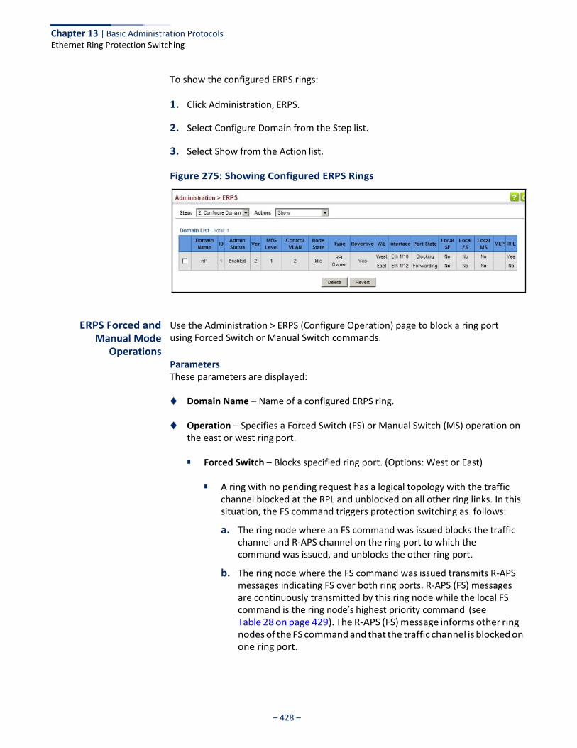
Chapter 13 | Basic Administration Protocols Ethernet Ring Protection Switching
– 428 –
To show the configured ERPS rings:
1. Click Administration, ERPS.
2. Select Configure Domain from the Step list.
3. Select Show from the Action list.
Figure 275: Showing Configured ERPS Rings
ERPS Forced and
Manual Mode Operations
Use the Administration > ERPS (Configure Operation) page to block a ring port using Forced Switch or Manual Switch commands.
Parameters These parameters are displayed:
◆ Domain Name – Name of a configured ERPS ring.
◆ Operation – Specifies a Forced Switch (FS) or Manual Switch (MS) operation on the east or west ring port.
■ Forced Switch – Blocks specified ring port. (Options: West or East)
■ A ring with no pending request has a logical topology with the traffic
channel blocked at the RPL and unblocked on all other ring links. In this situation, the FS command triggers protection switching as follows:
a. The ring node where an FS command was issued blocks the traffic channel and R-APS channel on the ring port to which the command was issued, and unblocks the other ring port.
b. The ring node where the FS command was issued transmits R-APS messages indicating FS over both ring ports. R-APS (FS) messages are continuously transmitted by this ring node while the local FS command is the ring node’s highest priority command (see Table 28 on page 429). The R-APS (FS) message informs other ring nodes of the FS command and that the traffic channel is blocked on one ring port.
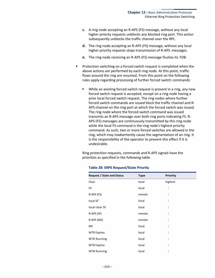
Chapter 13 | Basic Administration Protocols Ethernet Ring Protection Switching
– 429 –
c. A ring node accepting an R-APS (FS) message, without any local higher priority requests unblocks any blocked ring port. This action subsequently unblocks the traffic channel over the RPL.
d. The ring node accepting an R-APS (FS) message, without any local higher priority requests stops transmission of R-APS messages.
e. The ring node receiving an R-APS (FS) message flushes its FDB.
■ Protection switching on a forced switch request is completed when the above actions are performed by each ring node. At this point, traffic flows around the ring are resumed. From this point on the following rules apply regarding processing of further forced switch commands:
■ While an existing forced switch request is present in a ring, any new
forced switch request is accepted, except on a ring node having a prior local forced switch request. The ring nodes where further forced switch commands are issued block the traffic channel and R- APS channel on the ring port at which the forced switch was issued. The ring node where the forced switch command was issued transmits an R-APS message over both ring ports indicating FS. R- APS (FS) messages are continuously transmitted by this ring node while the local FS command is the ring node’s highest priority command. As such, two or more forced switches are allowed in the ring, which may inadvertently cause the segmentation of an ring. It is the responsibility of the operator to prevent this effect if it is undesirable.
Ring protection requests, commands and R-APS signals have the priorities as specified in the following table.
Table 28: ERPS Request/State Priority
Request / State and Status Type Priority
Clear local highest
FS local |
R-APS (FS) remote |
local SF* local |
local clear SF local |
R-APS (SF) remote |
R-APS (MS) remote |
MS local |
WTR Expires local |
WTR Running local |
WTB Expires local |
WTB Running local |
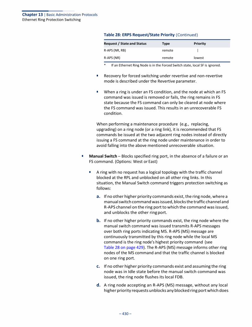
Chapter 13 | Basic Administration Protocols Ethernet Ring Protection Switching
– 430 –
Table 28: ERPS Request/State Priority (Continued)
R-APS (NR, RB) remote |
R-APS (NR) remote lowest
* If an Ethernet Ring Node is in the Forced Switch state, local SF is ignored.
■ Recovery for forced switching under revertive and non-revertive mode is described under the Revertive parameter.
■ When a ring is under an FS condition, and the node at which an FS
command was issued is removed or fails, the ring remains in FS state because the FS command can only be cleared at node where the FS command was issued. This results in an unrecoverable FS condition.
When performing a maintenance procedure (e.g., replacing, upgrading) on a ring node (or a ring link), it is recommended that FS commands be issued at the two adjacent ring nodes instead of directly issuing a FS command at the ring node under maintenance in order to avoid falling into the above mentioned unrecoverable situation.
■ Manual Switch – Blocks specified ring port, in the absence of a failure or an
FS command. (Options: West or East)
■ A ring with no request has a logical topology with the traffic channel blocked at the RPL and unblocked on all other ring links. In this situation, the Manual Switch command triggers protection switching as follows:
a. If no other higher priority commands exist, the ring node, where a manual switch command was issued, blocks the traffic channel and R-APS channel on the ring port to which the command was issued, and unblocks the other ring port.
b. If no other higher priority commands exist, the ring node where the manual switch command was issued transmits R-APS messages over both ring ports indicating MS. R-APS (MS) message are continuously transmitted by this ring node while the local MS command is the ring node’s highest priority command (see Table 28 on page 429). The R-APS (MS) message informs other ring nodes of the MS command and that the traffic channel is blocked on one ring port.
c. If no other higher priority commands exist and assuming the ring node was in Idle state before the manual switch command was issued, the ring node flushes its local FDB.
d. A ring node accepting an R-APS (MS) message, without any local higher priority requests unblocks any blocked ring port which does
Request / State and Status Type Priority
Chapter 13 | Basic Administration Protocols Ethernet Ring Protection Switching
– 431 –
not have an SF condition. This action subsequently unblocks the traffic channel over the RPL.
e. A ring node accepting an R-APS (MS) message, without any local higher priority requests stops transmitting R-APS messages.
f. A ring node receiving an R-APS (MS) message flushes its FDB.
■ Protection switching on a manual switch request is completed when the above actions are performed by each ring node. At this point, traffic flows around the ring are resumed. From this point on, the following rules apply regarding processing of further manual switch commands:
a. While an existing manual switch request is present in the ring, any new manual switch request is rejected. The request is rejected at the ring node where the new request is issued and a notification is generated to inform the operator that the new MS request was not accepted.
b. A ring node with a local manual switch command which receives an R-APS (MS) message with a different Node ID clears its manual switch request and starts transmitting R-APS (NR) messages. The ring node keeps the ring port blocked due to the previous manual switch command.
c. An ring node with a local manual switch command that receives an R-APS message or a local request of higher priority than R-APS (MS) clear its manual switch request. The ring node then processes the new higher priority request.
■ Recovery for manual switching under revertive and non-revertive
mode is described under the Revertive parameter.
■ Clear – Manually clears the protection state which has been invoked by a forced switch or manual switch command, and the node is operating under non-revertive mode; or before the WTR or WTB timer expires when the node is operating in revertive mode.
■ Two steps are required to make a ring operating in non-revertive mode
return to Idle state from forced switch or manual switch state:
1. Issue a Clear command to remove the forced switch command on the node where a local forced switch command is active.
2. Issue a Clear command on the RPL owner node to trigger the reversion.
■ The Clear command will also stop the WTR and WTB delay timers and
reset their values.
■ More detailed information about using this command for non-revertive mode is included under the Revertive parameter. (See the Command Usage section under “ERPS Ring Configuration” on page 412.)
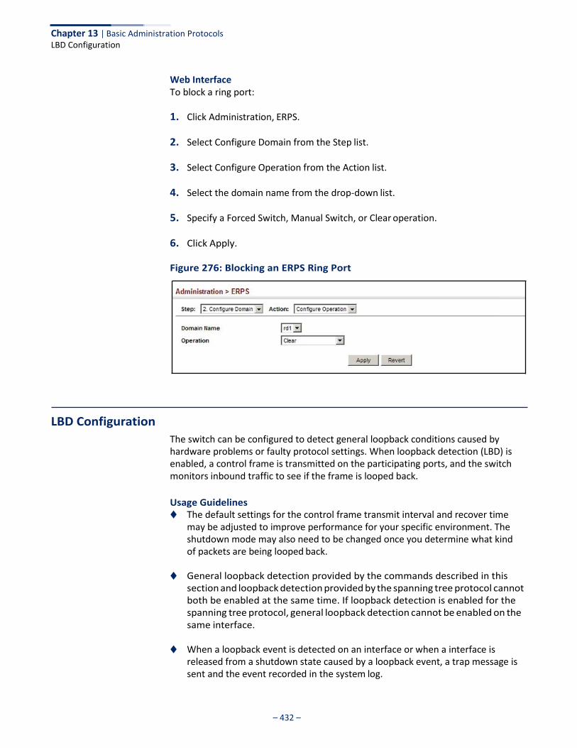
Chapter 13 | Basic Administration Protocols LBD Configuration
– 432 –
Web Interface To block a ring port:
1. Click Administration, ERPS.
2. Select Configure Domain from the Step list.
3. Select Configure Operation from the Action list.
4. Select the domain name from the drop-down list.
5. Specify a Forced Switch, Manual Switch, or Clear operation.
6. Click Apply.
Figure 276: Blocking an ERPS Ring Port
LBD Configuration
The switch can be configured to detect general loopback conditions caused by hardware problems or faulty protocol settings. When loopback detection (LBD) is enabled, a control frame is transmitted on the participating ports, and the switch monitors inbound traffic to see if the frame is looped back.
Usage Guidelines ◆ The default settings for the control frame transmit interval and recover time
may be adjusted to improve performance for your specific environment. The shutdown mode may also need to be changed once you determine what kind of packets are being looped back.
◆ General loopback detection provided by the commands described in this
section and loopback detection provided by the spanning tree protocol cannot both be enabled at the same time. If loopback detection is enabled for the spanning tree protocol, general loopback detection cannot be enabled on the same interface.
◆ When a loopback event is detected on an interface or when a interface is
released from a shutdown state caused by a loopback event, a trap message is sent and the event recorded in the system log.
Chapter 13 | Basic Administration Protocols LBD Configuration
– 433 –
◆ Loopback detection must be enabled both globally and on an interface for loopback detection to take effect.
Configuring Global Settings for LBD
Use the Administration > LBD (Configure Global) page to enable loopback detection globally, specify the interval at which to transmit control frames, the interval to wait before releasing an interface from shutdown state, the response to a detected loopback, and the traps to send.
Parameters These parameters are displayed:
◆ Global Status – Enables loopback detection globally on the switch.
(Default: Enabled)
◆ Transmit Interval – Specifies the interval at which to transmit loopback detection control frames. (Range: 1-32767 seconds; Default: 10 seconds)
◆ Recover Time – Specifies the interval to wait before the switch automatically
releases an interface from shutdown state. (Range: 60-1,000,000 seconds; Default: 60 seconds)
When the loopback detection mode is changed (enabled or disabled), any ports placed in shutdown state by the loopback detection process will be immediately restored to operation regardless of the remaining recover time.
If the recover time is not enabled (checkbox unmarked), all ports placed in shutdown state can be restored to operation using the Release button. To restore a specific port, re-enable Admin status on the Configure Interface page.
The recover-time is the maximum time when recovery is triggered after a loop is detected. The actual interval between recovery and detection will be less than or equal to the recover-time.
◆ Action – Specifies the protective action the switch takes when a loopback
condition is detected. (Options: Block, None, Shutdown; Default: Shutdown)
■ Block – When the response to a detected loopback condition is set to block user traffic, and a loopback is detected on a port which a member of a specific VLAN, packets belonging to that VLAN are dropped at the offending port. Under these conditions, loopback detection control frames may be untagged or tagged depending on the port’s VLAN membership type. Ingress filtering for the port is enabled automatically if not already enabled by other commands. The port’s original setting for ingress filtering will be restored when loopback detection is disabled.
■ None - No action is taken.
■ Shutdown – When the response to a detected loopback condition is set to shut down a port, and a port receives a control frame sent by itself, this means that the port is in looped state, and the VLAN in the frame payload is also in looped state with the wrong VLAN tag. The looped port is therefore shut down.
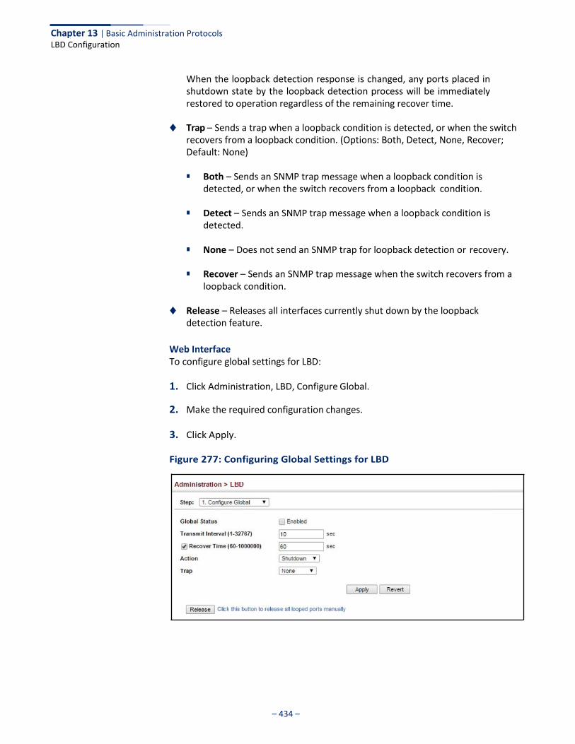
Chapter 13 | Basic Administration Protocols LBD Configuration
– 434 –
When the loopback detection response is changed, any ports placed in shutdown state by the loopback detection process will be immediately restored to operation regardless of the remaining recover time.
◆ Trap – Sends a trap when a loopback condition is detected, or when the switch
recovers from a loopback condition. (Options: Both, Detect, None, Recover; Default: None)
■ Both – Sends an SNMP trap message when a loopback condition is
detected, or when the switch recovers from a loopback condition.
■ Detect – Sends an SNMP trap message when a loopback condition is detected.
■ None – Does not send an SNMP trap for loopback detection or recovery.
■ Recover – Sends an SNMP trap message when the switch recovers from a
loopback condition.
◆ Release – Releases all interfaces currently shut down by the loopback detection feature.
Web Interface To configure global settings for LBD:
1. Click Administration, LBD, Configure Global.
2. Make the required configuration changes.
3. Click Apply.
Figure 277: Configuring Global Settings for LBD
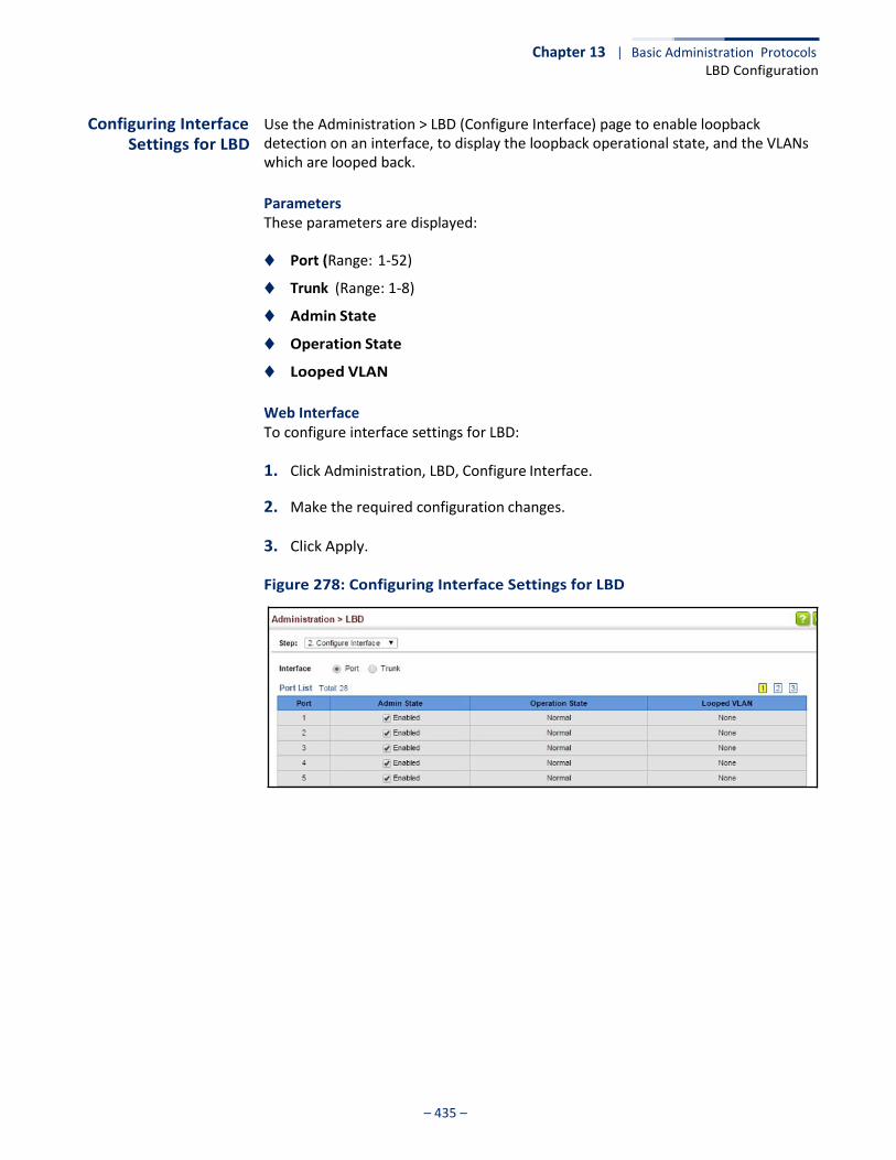
Chapter 13 | Basic Administration Protocols LBD Configuration
– 435 –
Configuring Interface Settings for LBD
Use the Administration > LBD (Configure Interface) page to enable loopback detection on an interface, to display the loopback operational state, and the VLANs which are looped back.
Parameters These parameters are displayed:
◆ Port (Range: 1-52)
◆ Trunk (Range: 1-8)
◆ Admin State
◆ Operation State
◆ Looped VLAN
Web Interface To configure interface settings for LBD:
1. Click Administration, LBD, Configure Interface.
2. Make the required configuration changes.
3. Click Apply.
Figure 278: Configuring Interface Settings for LBD

Chapter 13 | Basic Administration Protocols LBD Configuration
– 436 –
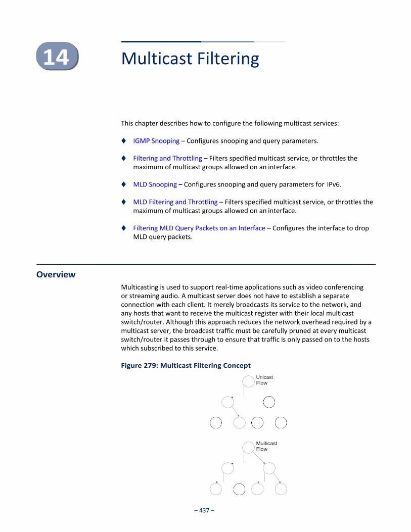
– 437 –
Multicast Filtering
This chapter describes how to configure the following multicast services:
◆ IGMP Snooping – Configures snooping and query parameters.
◆ Filtering and Throttling – Filters specified multicast service, or throttles the maximum of multicast groups allowed on an interface.
◆ MLD Snooping – Configures snooping and query parameters for IPv6.
◆ MLD Filtering and Throttling – Filters specified multicast service, or throttles the maximum of multicast groups allowed on an interface.
◆ Filtering MLD Query Packets on an Interface – Configures the interface to drop
MLD query packets.
Overview
Multicasting is used to support real-time applications such as video conferencing or streaming audio. A multicast server does not have to establish a separate connection with each client. It merely broadcasts its service to the network, and any hosts that want to receive the multicast register with their local multicast switch/router. Although this approach reduces the network overhead required by a multicast server, the broadcast traffic must be carefully pruned at every multicast switch/router it passes through to ensure that traffic is only passed on to the hosts which subscribed to this service.
Figure 279: Multicast Filtering Concept
Unicast Flow
– 438 –
Chapter 14 | Multicast Filtering Layer 2 IGMP (Snooping and Query for IPv4)
This switch can use Internet Group Management Protocol (IGMP) to filter multicast traffic. IGMP Snooping can be used to passively monitor or “snoop” on exchanges between attached hosts and an IGMP-enabled device, most commonly a multicast router. In this way, the switch can discover the ports that want to join a multicast group, and set its filters accordingly.
If there is no multicast router attached to the local subnet, multicast traffic and query messages may not be received by the switch. In this case (Layer 2) IGMP Query can be used to actively ask the attached hosts if they want to receive a specific multicast service. IGMP Query thereby identifies the ports containing hosts requesting to join the service and sends data out to those ports only. It then propagates the service request up to any neighboring multicast switch/router to ensure that it will continue to receive the multicast service.
The purpose of IP multicast filtering is to optimize a switched network’s performance, so multicast packets will only be forwarded to those ports containing multicast group hosts or multicast routers/switches, instead of flooding traffic to all ports in the subnet (VLAN).
Layer 2 IGMP (Snooping and Query for IPv4)
IGMP Snooping and Query – If multicast routing is not supported on other switches in your network, you can use IGMP Snooping and IGMP Query (page 440) to monitor IGMP service requests passing between multicast clients and servers, and dynamically configure the switch ports which need to forward multicast traffic. IGMP Snooping conserves bandwidth on network segments where no node has expressed interest in receiving a specific multicast service. For switches that do not support multicast routing, or where multicast routing is already enabled on other switches in the local network segment, IGMP Snooping is the only service required to support multicast filtering.
When using IGMPv3 snooping, service requests from IGMP Version 1, 2 or 3 hosts are all forwarded to the upstream router as IGMPv3 reports. The primary enhancement provided by IGMPv3 snooping is in keeping track of information about the specific multicast sources which downstream IGMPv3 hosts have requested or refused. The switch maintains information about both multicast groups and channels, where a group indicates a multicast flow for which the hosts have not requested a specific source (the only option for IGMPv1 and v2 hosts unless statically configured on the switch), and a channel indicates a flow for which the hosts have requested service from a specific source. For IGMPv1/v2 hosts, the source address of a channel is always null (indicating that any source is acceptable), but for IGMPv3 hosts, it may include a specific address when requested.
Only IGMPv3 hosts can request service from a specific multicast source. When downstream hosts request service from a specific source for a multicast service, these sources are all placed in the Include list, and traffic is forwarded to the hosts from each of these sources. IGMPv3 hosts may also request that service be
– 439 –
Chapter 14 | Multicast Filtering Layer 2 IGMP (Snooping and Query for IPv4)
forwarded from any source except for those specified. In this case, traffic is filtered from sources in the Exclude list, and forwarded from all other available sources.
Note: When the switch is configured to use IGMPv3 snooping, the snooping version may be downgraded to version 2 or version 1, depending on the version of the IGMP query packets detected on each VLAN.
Note: IGMP snooping will not function unless a multicast router port is enabled on the switch. This can accomplished in one of two ways. A static router port can be manually configured (see “Specifying Static Interfaces for a Multicast Router” on page 444). Using this method, the router port is never timed out, and will continue to function until explicitly removed. The other method relies on the switch to dynamically create multicast routing ports whenever multicast routing protocol packets or IGMP query packets are detected on a port.
Note: A maximum of up to 1023 multicast entries can be maintained for IGMP snooping. Once the table is full, no new entries are learned. Any subsequent multicast traffic not found in the table is dropped if unregistered-flooding is disabled (default behavior) and no router port is configured in the attached VLAN, or flooded throughout the VLAN if unregistered-flooding is enabled (see “Configuring IGMP Snooping and Query Parameters” on page 440).
Static IGMP Router Interface – If IGMP snooping cannot locate the IGMP querier, you can manually designate a known IGMP querier (i.e., a multicast router/switch) connected over the network to an interface on your switch (page 444). This interface will then join all the current multicast groups supported by the attached router/switch to ensure that multicast traffic is passed to all appropriate interfaces within the switch.
Static IGMP Host Interface – For multicast applications that you need to control more carefully, you can manually assign a multicast service to specific interfaces on the switch (page 446).
IGMP Snooping with Proxy Reporting – The switch supports last leave, and query suppression (as defined in DSL Forum TR-101, April 2006):
◆ When proxy reporting is disabled, all IGMP reports received by the switch are
forwarded natively to the upstream multicast routers.
◆ Last Leave: Intercepts, absorbs and summarizes IGMP leaves coming from IGMP hosts. IGMP leaves are relayed upstream only when necessary, that is, when the last user leaves a multicast group.
◆ Query Suppression: Intercepts and processes IGMP queries in such a way that
IGMP specific queries are never sent to client ports.
The only deviation from TR-101 is that the marking of IGMP traffic initiated by the switch with priority bits as defined in R-250 is not supported.
Chapter 14 | Multicast Filtering Layer 2 IGMP (Snooping and Query for IPv4)
– 440 –
Configuring IGMP Snooping and Query
Parameters
Use the Multicast > IGMP Snooping > General page to configure the switch to forward multicast traffic intelligently. Based on the IGMP query and report messages, the switch forwards multicast traffic only to the ports that request it. This prevents the switch from broadcasting the traffic to all ports and possibly disrupting network performance.
Command Usage ◆ IGMP Snooping – This switch can passively snoop on IGMP Query and Report
packets transferred between IP multicast routers/switches and IP multicast host groups to identify the IP multicast group members. It simply monitors the IGMP packets passing through it, picks out the group registration information, and configures the multicast filters accordingly.
Note: If unknown multicast traffic enters a VLAN which has been configured with a router port, the traffic is forwarded to that port. However, if no router port exists on the VLAN, the traffic is dropped if unregistered data flooding is disabled (default behavior), or flooded throughout the VLAN if unregistered data flooding is enabled (see “Unregistered Data Flooding” in the Command Attributes section).
◆ IGMP Querier – A router, or multicast-enabled switch, can periodically ask their hosts if they want to receive multicast traffic. If there is more than one router/ switch on the LAN performing IP multicasting, one of these devices is elected “querier” and assumes the role of querying the LAN for group members. It then propagates the service requests on to any upstream multicast switch/router to ensure that it will continue to receive the multicast service.
Note: Multicast routers use this information from IGMP snooping and query reports, along with a multicast routing protocol such as DVMRP or PIM, to support IP multicasting across the Internet.
Parameters These parameters are displayed:
◆ IGMP Snooping Status – When enabled, the switch will monitor network traffic to determine which hosts want to receive multicast traffic. This is referred to as IGMP Snooping. (Default: Enabled)
When IGMP snooping is enabled globally, the per VLAN interface settings for IGMP snooping take precedence (see “Setting IGMP Snooping Status per Interface” on page 448).
When IGMP snooping is disabled globally, snooping can still be configured per VLAN interface, but the interface settings will not take effect until snooping is re-enabled globally.
◆ Proxy Reporting Status – Enables IGMP Snooping with Proxy Reporting.
(Default: Disabled)
Chapter 14 | Multicast Filtering Layer 2 IGMP (Snooping and Query for IPv4)
– 441 –
When proxy reporting is enabled with this command, the switch performs “IGMP Snooping with Proxy Reporting” (as defined in DSL Forum TR-101, April 2006), including last leave, and query suppression.
Last leave sends out a proxy query when the last member leaves a multicast group, and query suppression means that specific queries are not forwarded from an upstream multicast router to hosts downstream from this device.
When proxy reporting is disabled, all IGMP reports received by the switch are forwarded natively to the upstream multicast routers.
◆ TCN Flood – Enables flooding of multicast traffic if a spanning tree topology
change notification (TCN) occurs. (Default: Disabled)
When a spanning tree topology change occurs, the multicast membership information learned by switch may be out of date. For example, a host linked to one port before the topology change (TC) may be moved to another port after the change. To ensure that multicast data is delivered to all receivers, by default, a switch in a VLAN (with IGMP snooping enabled) that receives a Bridge Protocol Data Unit (BPDU) with TC bit set (by the root bridge) will enter into “multicast flooding mode” for a period of time until the topology has stabilized and the new locations of all multicast receivers are learned.
If a topology change notification (TCN) is received, and all the uplink ports are subsequently deleted, a time out mechanism is used to delete all of the currently learned multicast channels.
When a new uplink port starts up, the switch sends unsolicited reports for all currently learned channels out the new uplink port.
By default, the switch immediately enters into “multicast flooding mode” when a spanning tree topology change occurs. In this mode, multicast traffic will be flooded to all VLAN ports. If many ports have subscribed to different multicast groups, flooding may cause excessive packet loss on the link between the switch and the end host. Flooding may be disabled to avoid this, causing multicast traffic to be delivered only to those ports on which multicast group members have been learned. Otherwise, the time spent in flooding mode can be manually configured to reduce excessive loading.
When the spanning tree topology changes, the root bridge sends a proxy query to quickly re-learn the host membership/port relations for multicast channels. The root bridge also sends an unsolicited Multicast Router Discover (MRD) request to quickly locate the multicast routers in this VLAN.
The proxy query and unsolicited MRD request are flooded to all VLAN ports except for the receiving port when the switch receives such packets.
◆ TCN Query Solicit – Sends out an IGMP general query solicitation when a
spanning tree topology change notification (TCN) occurs. (Default: Disabled)
When the root bridge in a spanning tree receives a TCN for a VLAN where IGMP snooping is enabled, it issues a global IGMP leave message (or query solicitation). When a switch receives this solicitation, it floods it to all ports in the VLAN where the spanning tree change occurred. When an upstream
Chapter 14 | Multicast Filtering Layer 2 IGMP (Snooping and Query for IPv4)
– 442 –
multicast router receives this solicitation, it immediately issues an IGMP general query.
A query solicitation can be sent whenever the switch notices a topology change, even if it is not the root bridge in spanning tree.
◆ Router Alert Option – Discards any IGMPv2/v3 packets that do not include the
Router Alert option. (Default: Disabled)
As described in Section 9.1 of RFC 3376 for IGMP Version 3, the Router Alert Option can be used to protect against DOS attacks. One common method of attack is launched by an intruder who takes over the role of querier, and starts overloading multicast hosts by sending a large number of group-and-source- specific queries, each with a large source list and the Maximum Response Time set to a large value.
To protect against this kind of attack, (1) routers should not forward queries. This is easier to accomplish if the query carries the Router Alert option. (2) Also, when the switch is acting in the role of a multicast host (such as when using proxy routing), it should ignore version 2 or 3 queries that do not contain the Router Alert option.
◆ Unregistered Data Flooding – Floods unregistered multicast traffic into the
attached VLAN. (Default: Disabled)
Once the table used to store multicast entries for IGMP snooping and multicast routing is filled, no new entries are learned. If no router port is configured in the attached VLAN, and unregistered-flooding is disabled, any subsequent multicast traffic not found in the table is dropped, otherwise it is flooded throughout the VLAN.
◆ Forwarding Priority – Assigns a CoS priority to all multicast traffic. (Range: 0-7,
where 7 is the highest priority; Default: Disabled)
This parameter can be used to set a high priority for low-latency multicast traffic such as a video-conference, or to set a low priority for normal multicast traffic not sensitive to latency.
◆ Version Exclusive – Discards any received IGMP messages which use a version
different to that currently configured by the IGMP Version attribute. (Default: Disabled)
◆ IGMP Unsolicited Report Interval – Specifies how often the upstream
interface should transmit unsolicited IGMP reports when proxy reporting is enabled. (Range: 1-65535 seconds, Default: 400 seconds)
When a new upstream interface (that is, uplink port) starts up, the switch sends unsolicited reports for all currently learned multicast channels via the new upstream interface.
This command only applies when proxy reporting is enabled.
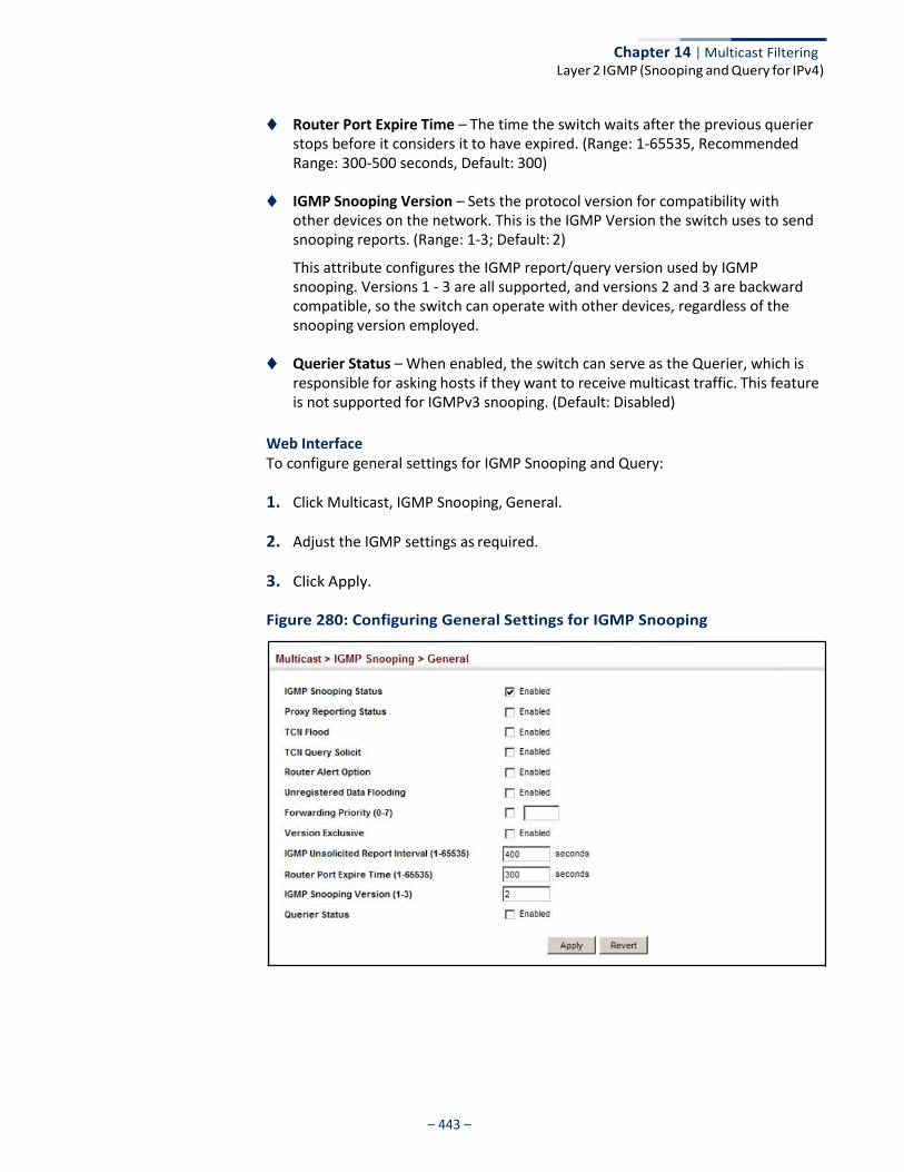
Chapter 14 | Multicast Filtering Layer 2 IGMP (Snooping and Query for IPv4)
– 443 –
◆ Router Port Expire Time – The time the switch waits after the previous querier stops before it considers it to have expired. (Range: 1-65535, Recommended Range: 300-500 seconds, Default: 300)
◆ IGMP Snooping Version – Sets the protocol version for compatibility with
other devices on the network. This is the IGMP Version the switch uses to send snooping reports. (Range: 1-3; Default: 2)
This attribute configures the IGMP report/query version used by IGMP snooping. Versions 1 - 3 are all supported, and versions 2 and 3 are backward compatible, so the switch can operate with other devices, regardless of the snooping version employed.
◆ Querier Status – When enabled, the switch can serve as the Querier, which is
responsible for asking hosts if they want to receive multicast traffic. This feature is not supported for IGMPv3 snooping. (Default: Disabled)
Web Interface To configure general settings for IGMP Snooping and Query:
1. Click Multicast, IGMP Snooping, General.
2. Adjust the IGMP settings as required.
3. Click Apply.
Figure 280: Configuring General Settings for IGMP Snooping
Chapter 14 | Multicast Filtering Layer 2 IGMP (Snooping and Query for IPv4)
– 444 –
Specifying Static Interfaces for a
Multicast Router
Use the Multicast > IGMP Snooping > Multicast Router (Add Static Multicast Router) page to statically attach an interface to a multicast router/switch.
Depending on network connections, IGMP snooping may not always be able to locate the IGMP querier. Therefore, if the IGMP querier is a known multicast router/ switch connected over the network to an interface (port or trunk) on the switch, the interface (and a specified VLAN) can be manually configured to join all the current multicast groups supported by the attached router. This can ensure that multicast traffic is passed to all the appropriate interfaces within the switch.
Command Usage IGMP Snooping must be enabled globally on the switch (see “Configuring IGMP Snooping and Query Parameters” on page 440) before a multicast router port can take effect.
Parameters These parameters are displayed:
Add Static Multicast Router
◆ VLAN – Selects the VLAN which is to propagate all multicast traffic coming from the attached multicast router. (Range: 1-4094)
◆ Interface – Activates the Port or Trunk scroll down list.
◆ Port or Trunk – Specifies the interface attached to a multicast router.
Show Static Multicast Router
◆ VLAN – Selects the VLAN for which to display any configured static multicast routers.
◆ Interface – Shows the interface to which the specified static multicast routers
are attached.
Show Current Multicast Router
◆ VLAN – Selects the VLAN for which to display any currently active multicast routers.
◆ Interface – Shows the interface to which an active multicast router is attached.
◆ Type – Shows if this entry is static or dynamic.
◆ Expire – Time until this dynamic entry expires.

Chapter 14 | Multicast Filtering Layer 2 IGMP (Snooping and Query for IPv4)
– 445 –
Web Interface To specify a static interface attached to a multicast router:
1. Click Multicast, IGMP Snooping, Multicast Router.
2. Select Add Static Multicast Router from the Action list.
3. Select the VLAN which will forward all the corresponding multicast traffic, and select the port or trunk attached to the multicast router.
4. Click Apply.
Figure 281: Configuring a Static Interface for a Multicast Router
To show the static interfaces attached to a multicast router:
1. Click Multicast, IGMP Snooping, Multicast Router.
2. Select Show Static Multicast Router from the Action list.
3. Select the VLAN for which to display this information.
Figure 282: Showing Static Interfaces Attached a Multicast Router
Multicast routers that are attached to ports on the switch use information obtained from IGMP, along with a multicast routing protocol (such as PIM) to support IP

Chapter 14 | Multicast Filtering Layer 2 IGMP (Snooping and Query for IPv4)
– 446 –
multicasting across the Internet. These routers may be dynamically discovered by the switch or statically assigned to an interface on the switch.
To show the all interfaces attached to a multicast router:
1. Click Multicast, IGMP Snooping, Multicast Router.
2. Select Current Multicast Router from the Action list.
3. Select the VLAN for which to display this information. Ports in the selected VLAN which are attached to a neighboring multicast router/switch are displayed.
Figure 283: Showing Current Interfaces Attached a Multicast Router
Assigning Interfaces to Multicast Services
Use the Multicast > IGMP Snooping > IGMP Member (Add Static Member) page to statically assign a multicast service to an interface.
Multicast filtering can be dynamically configured using IGMP Snooping and IGMP Query messages (see “Configuring IGMP Snooping and Query Parameters” on page 440). However, for certain applications that require tighter control, it may be necessary to statically configure a multicast service on the switch. First add all the ports attached to participating hosts to a common VLAN, and then assign the multicast service to that VLAN group.
Command Usage ◆ Static multicast addresses are never aged out.
◆ When a multicast address is assigned to an interface in a specific VLAN, the
corresponding traffic can only be forwarded to ports within that VLAN.
Parameters These parameters are displayed:
◆ VLAN – Specifies the VLAN which is to propagate the multicast service.
(Range: 1-4094)
◆ Interface – Activates the Port or Trunk scroll down list.
◆ Port or Trunk – Specifies the interface assigned to a multicast group.
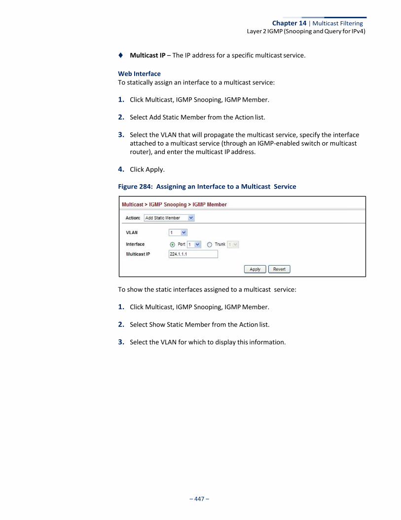
Chapter 14 | Multicast Filtering Layer 2 IGMP (Snooping and Query for IPv4)
– 447 –
◆ Multicast IP – The IP address for a specific multicast service.
Web Interface To statically assign an interface to a multicast service:
1. Click Multicast, IGMP Snooping, IGMP Member.
2. Select Add Static Member from the Action list.
3. Select the VLAN that will propagate the multicast service, specify the interface attached to a multicast service (through an IGMP-enabled switch or multicast router), and enter the multicast IP address.
4. Click Apply.
Figure 284: Assigning an Interface to a Multicast Service
To show the static interfaces assigned to a multicast service:
1. Click Multicast, IGMP Snooping, IGMP Member.
2. Select Show Static Member from the Action list.
3. Select the VLAN for which to display this information.

Chapter 14 | Multicast Filtering Layer 2 IGMP (Snooping and Query for IPv4)
– 448 –
Figure 285: Showing Static Interfaces Assigned to a Multicast Service
Setting IGMP Snooping Status
per Interface
Use the Multicast > IGMP Snooping > Interface (Configure VLAN) page to configure IGMP snooping attributes for a VLAN. To configure snooping globally, refer to “Configuring IGMP Snooping and Query Parameters” on page 440.
Command Usage
Multicast Router Discovery
There have been many mechanisms used in the past to identify multicast routers. This has lead to interoperability issues between multicast routers and snooping switches from different vendors. In response to this problem, the Multicast Router Discovery (MRD) protocol has been developed for use by IGMP snooping and multicast routing devices. MRD is used to discover which interfaces are attached to multicast routers, allowing IGMP-enabled devices to determine where to send multicast source and group membership messages. (MRD is specified in draft-ietf- magma-mrdisc-07.)
Multicast source data and group membership reports must be received by all multicast routers on a segment. Using the group membership protocol query messages to discover multicast routers is insufficient due to query suppression. MRD therefore provides a standardized way to identify multicast routers without relying on any particular multicast routing protocol.
Note: The default values recommended in the MRD draft are implemented in the switch.
Multicast Router Discovery uses the following three message types to discover multicast routers:
◆ Multicast Router Advertisement – Advertisements are sent by routers to
advertise that IP multicast forwarding is enabled. These messages are sent
Chapter 14 | Multicast Filtering Layer 2 IGMP (Snooping and Query for IPv4)
– 449 –
unsolicited periodically on all router interfaces on which multicast forwarding is enabled. They are sent upon the occurrence of these events:
■ Upon the expiration of a periodic (randomized) timer.
■ As a part of a router's start up procedure.
■ During the restart of a multicast forwarding interface.
■ On receipt of a Solicitation message.
◆ Multicast Router Solicitation – Devices send Solicitation messages in order to solicit Advertisement messages from multicast routers. These messages are used to discover multicast routers on a directly attached link. Solicitation messages are also sent whenever a multicast forwarding interface is initialized or re-initialized. Upon receiving a solicitation on an interface with IP multicast forwarding and MRD enabled, a router will respond with an Advertisement.
◆ Multicast Router Termination – These messages are sent when a router stops IP
multicast routing functions on an interface. Termination messages are sent by multicast routers when:
■ Multicast forwarding is disabled on an interface.
■ An interface is administratively disabled.
■ The router is gracefully shut down.
Advertisement and Termination messages are sent to the All-Snoopers multicast address. Solicitation messages are sent to the All-Routers multicast address.
Note: MRD messages are flooded to all ports in a VLAN where IGMP snooping or routing has been enabled. To ensure that older switches which do not support MRD can also learn the multicast router port, the switch floods IGMP general query packets, which do not have a null source address (0.0.0.0), to all ports in the attached VLAN. IGMP packets with a null source address are only flooded to all ports in the VLAN if the system is operating in multicast flooding mode, such as when a new VLAN or new router port is being established, or an spanning tree topology change has occurred. Otherwise, this kind of packet is only forwarded to known multicast routing ports.
Parameters These parameters are displayed:
◆ VLAN – ID of configured VLANs. (Range: 1-4094)
◆ IGMP Snooping Status – When enabled, the switch will monitor network traffic on the indicated VLAN interface to determine which hosts want to receive multicast traffic. This is referred to as IGMP Snooping. (Default: Enabled)
When IGMP snooping is enabled globally (see page 440), the per VLAN interface settings for IGMP snooping take precedence.
Chapter 14 | Multicast Filtering Layer 2 IGMP (Snooping and Query for IPv4)
– 450 –
When IGMP snooping is disabled globally, snooping can still be configured per VLAN interface, but the interface settings will not take effect until snooping is re-enabled globally.
◆ Version Exclusive – Discards any received IGMP messages (except for multicast
protocol packets) which use a version different to that currently configured by the IGMP Version attribute. (Options: Enabled, Using Global Status; Default: Using Global Status)
If version exclusive is disabled on a VLAN, then this setting is based on the global setting configured on the Multicast > IGMP Snooping > General page. If it is enabled on a VLAN, then this setting takes precedence over the global setting.
◆ Immediate Leave Status – Immediately deletes a member port of a multicast service if a leave packet is received at that port and immediate leave is enabled for the parent VLAN. (Default: Disabled)
If immediate leave is not used, a multicast router (or querier) will send a group- specific query message when an IGMPv2 group leave message is received. The router/querier stops forwarding traffic for that group only if no host replies to the query within the specified time out period. Note that this time out is set to Last Member Query Interval * Robustness Variable (fixed at 2) as defined in RFC 2236.
If immediate leave is enabled, the switch assumes that only one host is connected to the interface. Therefore, immediate leave should only be enabled on an interface if it is connected to only one IGMP-enabled device, either a service host or a neighbor running IGMP snooping.
This attribute is only effective if IGMP snooping is enabled, and IGMPv2 or IGMPv3 snooping is used.
If immediate leave is enabled, the following options are provided:
■ By Group – The switch assumes that only one host is connected to the interface. Therefore, immediate leave should only be enabled on an interface if it is connected to only one IGMP-enabled device, either a service host or a neighbor running IGMP snooping.
■ By Host IP – The switch will not send out a group-specific query when an IGMPv2/v3 leave message is received. But will check if there are other hosts joining the multicast group. Only when all hosts on that port leave the group will the member port be deleted.
◆ Multicast Router Discovery – MRD is used to discover which interfaces are
attached to multicast routers. (Default: Disabled)
◆ General Query Suppression – Suppresses general queries except for ports attached to downstream multicast hosts. (Default: Disabled)
By default, general query messages are flooded to all ports, except for the multicast router through which they are received.
Chapter 14 | Multicast Filtering Layer 2 IGMP (Snooping and Query for IPv4)
– 451 –
If general query suppression is enabled, then these messages are forwarded only to downstream ports which have joined a multicast service.
◆ Proxy Reporting – Enables IGMP Snooping with Proxy Reporting. (Options: Enabled, Disabled, Using Global Status; Default: Using Global Status)
When proxy reporting is enabled with this command, the switch performs “IGMP Snooping with Proxy Reporting” (as defined in DSL Forum TR-101, April 2006), including last leave, and query suppression.
Last leave sends out a proxy query when the last member leaves a multicast group, and query suppression means that specific queries are not forwarded from an upstream multicast router to hosts downstream from this device.
Rules Used for Proxy Reporting
When IGMP Proxy Reporting is disabled, the switch will use a null IP address for the source of IGMP query and report messages unless a proxy query address has been set.
When IGMP Proxy Reporting is enabled, the source address is based on the following criteria:
■ If a proxy query address is configured, the switch will use that address as the source IP address in general and group-specific query messages sent to downstream hosts, and in report and leave messages sent upstream from the multicast router port.
■ If a proxy query address is not configured, the switch will use the VLAN’s IP address as the IP source address in general and group-specific query messages sent downstream, and use the source address of the last IGMP message received from a downstream host in report and leave messages sent upstream from the multicast router port.
◆ Interface Version – Sets the protocol version for compatibility with other
devices on the network. This is the IGMP Version the switch uses to send snooping reports. (Options: 1-3, Using Global Version; Default: Using Global Version)
This attribute configures the IGMP report/query version used by IGMP snooping. Versions 1 - 3 are all supported, and versions 2 and 3 are backward compatible, so the switch can operate with other devices, regardless of the snooping version employed.
◆ Query Interval – The interval between sending IGMP general queries.
(Range: 2-31744 seconds; Default: 125 seconds)
An IGMP general query message is sent by the switch at the interval specified by this attribute. When this message is received by downstream hosts, all receivers build an IGMP report for the multicast groups they have joined.
This attribute applies when the switch is serving as the querier (page 440), or as a proxy host when IGMP snooping proxy reporting is enabled (page 440).
Chapter 14 | Multicast Filtering Layer 2 IGMP (Snooping and Query for IPv4)
– 452 –
◆ Query Response Interval – The maximum time the system waits for a response to general queries. (Range: 10-31740 tenths of a second in multiples of 10; Default: 10 seconds)
This attribute applies when the switch is serving as the querier (page 440), or as a proxy host when IGMP snooping proxy reporting is enabled (page 440).
◆ Last Member Query Interval – The interval to wait for a response to a group-
specific or group-and-source-specific query message. (Range: 1-31744 tenths of a second in multiples of 10; Default: 1 second)
When a multicast host leaves a group, it sends an IGMP leave message. When the leave message is received by the switch, it checks to see if this host is the last to leave the group by sending out an IGMP group-specific or group-and- source-specific query message, and starts a timer. If no reports are received before the timer expires, the group record is deleted, and a report is sent to the upstream multicast router.
A reduced value will result in reduced time to detect the loss of the last member of a group or source, but may generate more burst traffic.
This attribute will take effect only if IGMP snooping proxy reporting is enabled (page 440) or IGMP querier is enabled (page 440).
◆ Last Member Query Count – The number of IGMP proxy group-specific or
group-and-source-specific query messages that are sent out before the system assumes there are no more local members. (Range: 1-255; Default: 2)
This attribute will take effect only if IGMP snooping proxy reporting or IGMP querier is enabled.
◆ Proxy Query Address – A static source address for locally generated query and report messages used by IGMP Proxy Reporting. (Range: Any valid IP unicast address; Default: 0.0.0.0)
IGMP Snooping uses a null IP address of 0.0.0.0 for the source of IGMP query messages which are proxied to downstream hosts to indicate that it is not the elected querier, but is only proxying these messages as defined in RFC 4541. The switch also uses a null address in IGMP reports sent to upstream ports.
Many hosts do not implement RFC 4541, and therefore do not understand query messages with the source address of 0.0.0.0. These hosts will therefore not reply to the queries, causing the multicast router to stop sending traffic to them.
To resolve this problem, the source address in proxied IGMP query messages can be replaced with any valid unicast address (other than the router’s own address).
Web Interface To configure IGMP snooping on a VLAN:
1. Click Multicast, IGMP Snooping, Interface.
2. Select Configure VLAN from the Action list.
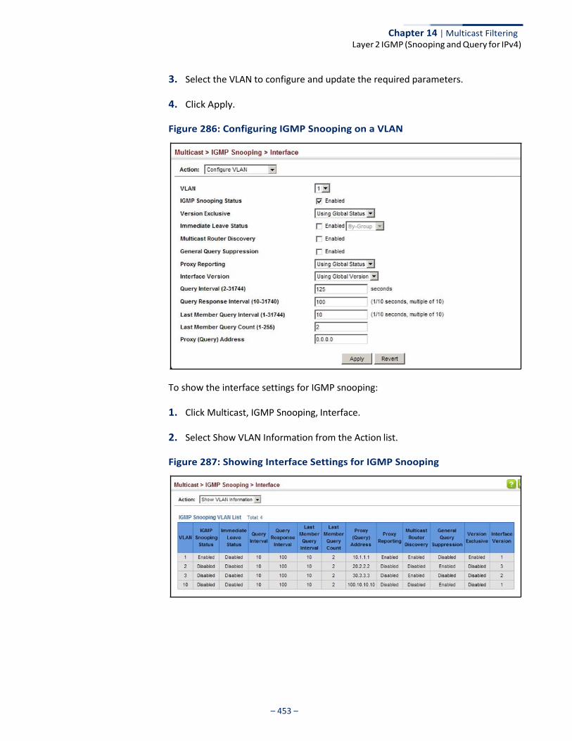
Chapter 14 | Multicast Filtering Layer 2 IGMP (Snooping and Query for IPv4)
– 453 –
3. Select the VLAN to configure and update the required parameters.
4. Click Apply.
Figure 286: Configuring IGMP Snooping on a VLAN
To show the interface settings for IGMP snooping:
1. Click Multicast, IGMP Snooping, Interface.
2. Select Show VLAN Information from the Action list.
Figure 287: Showing Interface Settings for IGMP Snooping
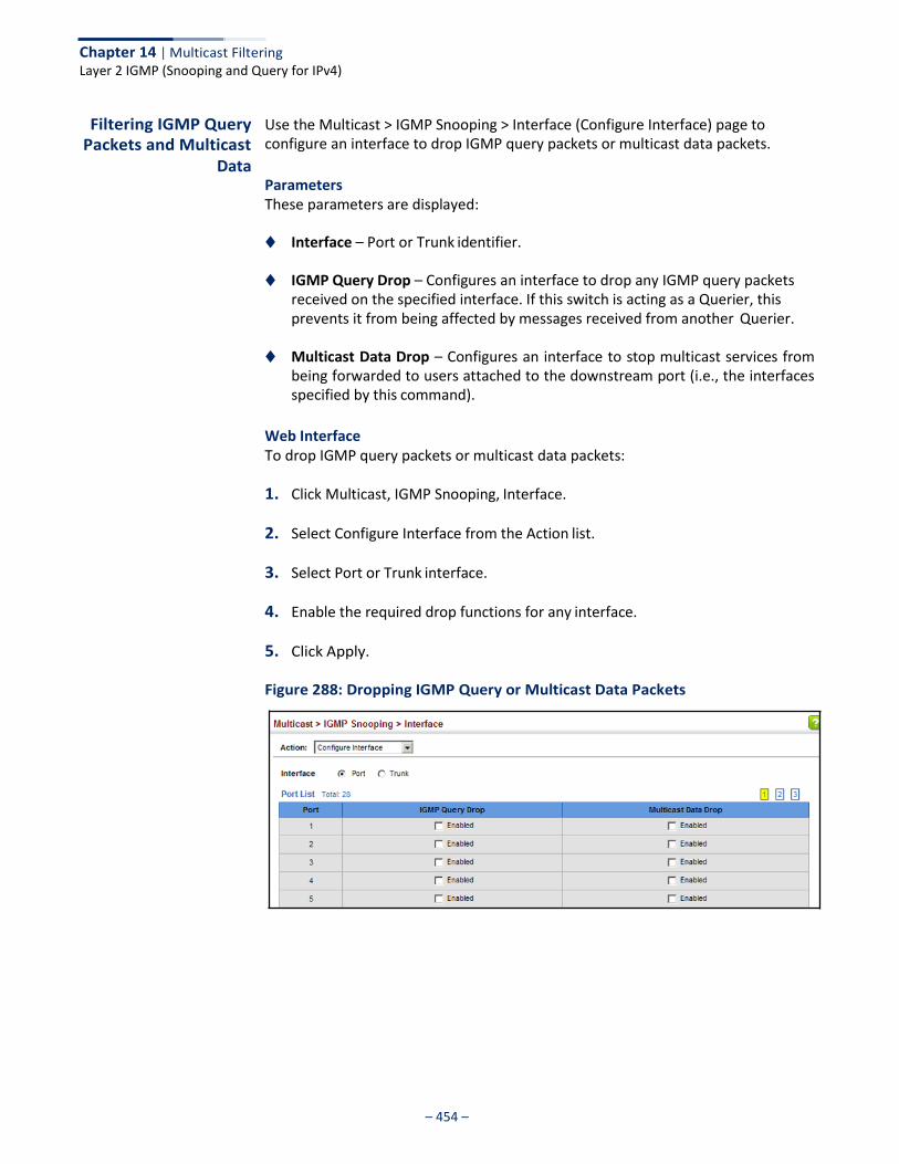
Chapter 14 | Multicast Filtering Layer 2 IGMP (Snooping and Query for IPv4)
– 454 –
Filtering IGMP Query Packets and Multicast
Data
Use the Multicast > IGMP Snooping > Interface (Configure Interface) page to configure an interface to drop IGMP query packets or multicast data packets.
Parameters These parameters are displayed:
◆ Interface – Port or Trunk identifier.
◆ IGMP Query Drop – Configures an interface to drop any IGMP query packets received on the specified interface. If this switch is acting as a Querier, this prevents it from being affected by messages received from another Querier.
◆ Multicast Data Drop – Configures an interface to stop multicast services from
being forwarded to users attached to the downstream port (i.e., the interfaces specified by this command).
Web Interface To drop IGMP query packets or multicast data packets:
1. Click Multicast, IGMP Snooping, Interface.
2. Select Configure Interface from the Action list.
3. Select Port or Trunk interface.
4. Enable the required drop functions for any interface.
5. Click Apply.
Figure 288: Dropping IGMP Query or Multicast Data Packets
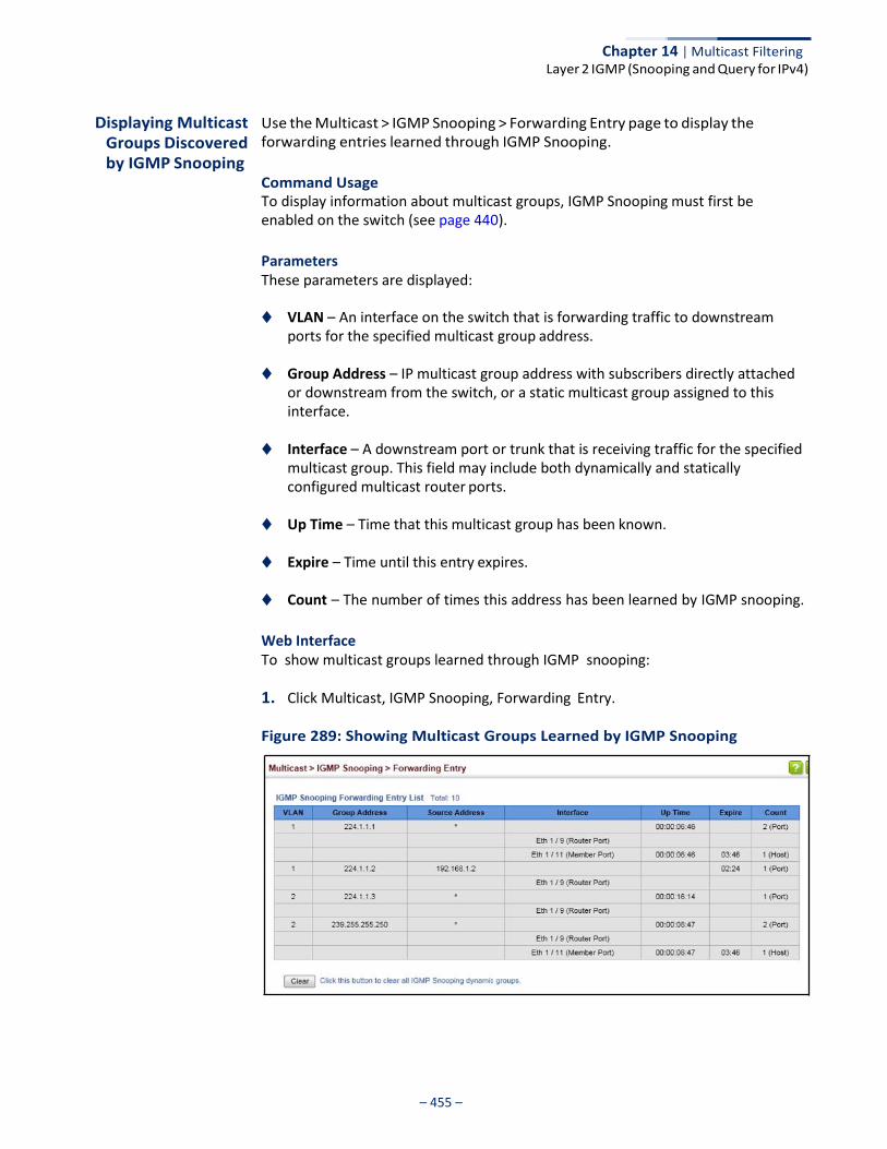
Chapter 14 | Multicast Filtering Layer 2 IGMP (Snooping and Query for IPv4)
– 455 –
Displaying Multicast Groups Discovered by IGMP Snooping
Use the Multicast > IGMP Snooping > Forwarding Entry page to display the forwarding entries learned through IGMP Snooping.
Command Usage To display information about multicast groups, IGMP Snooping must first be enabled on the switch (see page 440).
Parameters These parameters are displayed:
◆ VLAN – An interface on the switch that is forwarding traffic to downstream ports for the specified multicast group address.
◆ Group Address – IP multicast group address with subscribers directly attached
or downstream from the switch, or a static multicast group assigned to this interface.
◆ Interface – A downstream port or trunk that is receiving traffic for the specified
multicast group. This field may include both dynamically and statically configured multicast router ports.
◆ Up Time – Time that this multicast group has been known.
◆ Expire – Time until this entry expires.
◆ Count – The number of times this address has been learned by IGMP snooping.
Web Interface To show multicast groups learned through IGMP snooping:
1. Click Multicast, IGMP Snooping, Forwarding Entry.
Figure 289: Showing Multicast Groups Learned by IGMP Snooping
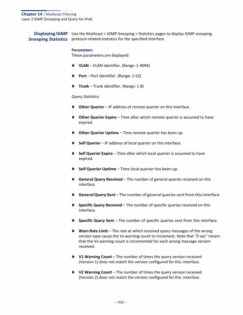
Chapter 14 | Multicast Filtering Layer 2 IGMP (Snooping and Query for IPv4)
– 456 –
Displaying IGMP Snooping Statistics
Use the Multicast > IGMP Snooping > Statistics pages to display IGMP snooping protocol-related statistics for the specified interface.
Parameters These parameters are displayed:
◆ VLAN – VLAN identifier. (Range: 1-4094)
◆ Port – Port identifier. (Range: 1-52)
◆ Trunk – Trunk identifier. (Range: 1-8)
Query Statistics
◆ Other Querier – IP address of remote querier on this interface.
◆ Other Querier Expire – Time after which remote querier is assumed to have expired.
◆ Other Querier Uptime – Time remote querier has been up.
◆ Self Querier – IP address of local querier on this interface.
◆ Self Querier Expire – Time after which local querier is assumed to have expired.
◆ Self Querier Uptime – Time local querier has been up.
◆ General Query Received – The number of general queries received on this interface.
◆ General Query Sent – The number of general queries sent from this interface.
◆ Specific Query Received – The number of specific queries received on this interface.
◆ Specific Query Sent – The number of specific queries sent from this interface.
◆ Warn Rate Limit – The rate at which received query messages of the wrong version type cause the Vx warning count to increment. Note that “0 sec” means that the Vx warning count is incremented for each wrong message version received.
◆ V1 Warning Count – The number of times the query version received
(Version 1) does not match the version configured for this interface.
◆ V2 Warning Count – The number of times the query version received (Version 2) does not match the version configured for this interface.

Chapter 14 | Multicast Filtering Layer 2 IGMP (Snooping and Query for IPv4)
– 457 –
◆ V3 Warning Count – The number of times the query version received (Version 3) does not match the version configured for this interface.
VLAN, Port, and Trunk Statistics
Input Statistics
◆ Report – The number of IGMP membership reports received on this interface.
◆ Leave – The number of leave messages received on this interface.
◆ G Query – The number of general query messages received on this interface.
◆ G(-S)-S Query – The number of group specific or group-and-source specific query messages received on this interface.
◆ Drop – The number of times a report, leave or query was dropped. Packets may
be dropped due to invalid format, rate limiting, packet content not allowed, or IGMP group report received.
◆ Join Success – The number of times a multicast group was successfully joined.
◆ Group – The number of IGMP groups active on this interface.
Output Statistics
◆ Report – The number of IGMP membership reports sent from this interface.
◆ Leave – The number of leave messages sent from this interface.
◆ G Query – The number of general query messages sent from this interface.
◆ G(-S)-S Query – The number of group specific or group-and-source specific query messages sent from this interface.
Web Interface To display statistics for IGMP snooping query-related messages:
1. Click Multicast, IGMP Snooping, Statistics.
2. Select Show Query Statistics from the Action list.
3. Select a VLAN.
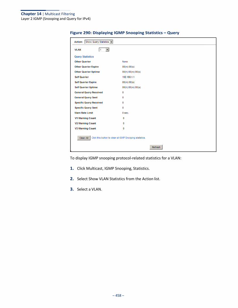
Chapter 14 | Multicast Filtering Layer 2 IGMP (Snooping and Query for IPv4)
– 458 –
Figure 290: Displaying IGMP Snooping Statistics – Query
To display IGMP snooping protocol-related statistics for a VLAN:
1. Click Multicast, IGMP Snooping, Statistics.
2. Select Show VLAN Statistics from the Action list.
3. Select a VLAN.
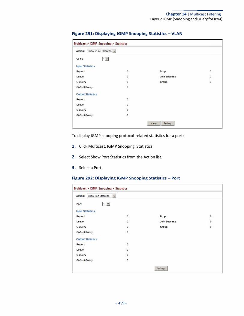
Chapter 14 | Multicast Filtering Layer 2 IGMP (Snooping and Query for IPv4)
– 459 –
Figure 291: Displaying IGMP Snooping Statistics – VLAN
To display IGMP snooping protocol-related statistics for a port:
1. Click Multicast, IGMP Snooping, Statistics.
2. Select Show Port Statistics from the Action list.
3. Select a Port.
Figure 292: Displaying IGMP Snooping Statistics – Port

Chapter 14 | Multicast Filtering Filtering and Throttling IGMP Groups
– 460 –
Filtering and Throttling IGMP Groups
In certain switch applications, the administrator may want to control the multicast services that are available to end users. For example, an IP/TV service based on a specific subscription plan. The IGMP filtering feature fulfills this requirement by restricting access to specified multicast services on a switch port, and IGMP throttling limits the number of simultaneous multicast groups a port can join.
IGMP filtering enables you to assign a profile to a switch port that specifies multicast groups that are permitted or denied on the port. An IGMP filter profile can contain one or more addresses, or a range of multicast addresses; but only one profile can be assigned to a port. When enabled, IGMP join reports received on the port are checked against the filter profile. If a requested multicast group is permitted, the IGMP join report is forwarded as normal. If a requested multicast group is denied, the IGMP join report is dropped.
IGMP throttling sets a maximum number of multicast groups that a port can join at the same time. When the maximum number of groups is reached on a port, the switch can take one of two actions; either “deny” or “replace.” If the action is set to deny, any new IGMP join reports will be dropped. If the action is set to replace, the switch randomly removes an existing group and replaces it with the new multicast group.
Enabling IGMP Filtering and
Throttling
Use the Multicast > IGMP Snooping > Filter (Configure General) page to enable IGMP filtering and throttling globally on the switch.
Parameters These parameters are displayed:
◆ IGMP Filter Status – Enables IGMP filtering and throttling globally for the
switch. (Default: Disabled)
Web Interface To enable IGMP filtering and throttling on the switch:
1. Click Multicast, IGMP Snooping, Filter.
2. Select Configure General from the Step list.
3. Enable IGMP Filter Status.
4. Click Apply.

Chapter 14 | Multicast Filtering Filtering and Throttling IGMP Groups
– 461 –
Figure 293: Enabling IGMP Filtering and Throttling
Configuring IGMP Filter Profiles
Use the Multicast > IGMP Snooping > Filter (Configure Profile – Add) page to create an IGMP profile and set its access mode. Then use the (Add Multicast Group Range) page to configure the multicast groups to filter.
Command Usage Specify a range of multicast groups by entering a start and end IP address; or specify a single multicast group by entering the same IP address for the start and end of the range.
Parameters These parameters are displayed:
Add
◆ Profile ID – Creates an IGMP profile. (Range: 1-4294967295)
◆ Access Mode – Sets the access mode of the profile; either permit or deny. (Default: Deny)
When the access mode is set to permit, IGMP join reports are processed when a multicast group falls within the controlled range. When the access mode is set to deny, IGMP join reports are only processed when the multicast group is not in the controlled range.
Add Multicast Group Range
◆ Profile ID – Selects an IGMP profile to configure.
◆ Start Multicast IP Address – Specifies the starting address of a range of multicast groups.
◆ End Multicast IP Address – Specifies the ending address of a range of
multicast groups.

Chapter 14 | Multicast Filtering Filtering and Throttling IGMP Groups
– 462 –
Web Interface To create an IGMP filter profile and set its access mode:
1. Click Multicast, IGMP Snooping, Filter.
2. Select Configure Profile from the Step list.
3. Select Add from the Action list.
4. Enter the number for a profile, and set its access mode.
5. Click Apply.
Figure 294: Creating an IGMP Filtering Profile
To show the IGMP filter profiles:
1. Click Multicast, IGMP Snooping, Filter.
2. Select Configure Profile from the Step list.
3. Select Show from the Action list.
Figure 295: Showing the IGMP Filtering Profiles Created
To add a range of multicast groups to an IGMP filter profile:
1. Click Multicast, IGMP Snooping, Filter.
2. Select Configure Profile from the Step list.
3. Select Add Multicast Group Range from the Action list.
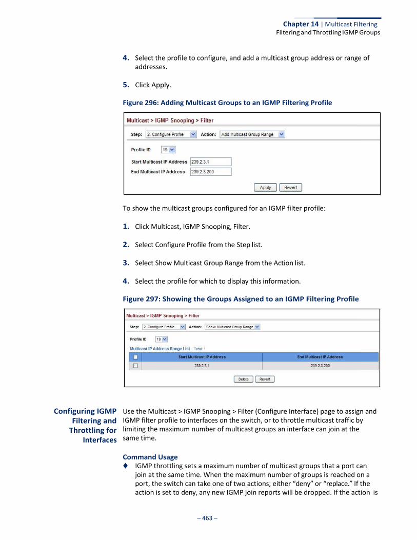
Chapter 14 | Multicast Filtering Filtering and Throttling IGMP Groups
– 463 –
4. Select the profile to configure, and add a multicast group address or range of addresses.
5. Click Apply.
Figure 296: Adding Multicast Groups to an IGMP Filtering Profile
To show the multicast groups configured for an IGMP filter profile:
1. Click Multicast, IGMP Snooping, Filter.
2. Select Configure Profile from the Step list.
3. Select Show Multicast Group Range from the Action list.
4. Select the profile for which to display this information.
Figure 297: Showing the Groups Assigned to an IGMP Filtering Profile
Configuring IGMP Filtering and
Throttling for Interfaces
Use the Multicast > IGMP Snooping > Filter (Configure Interface) page to assign and IGMP filter profile to interfaces on the switch, or to throttle multicast traffic by limiting the maximum number of multicast groups an interface can join at the same time.
Command Usage ◆ IGMP throttling sets a maximum number of multicast groups that a port can
join at the same time. When the maximum number of groups is reached on a port, the switch can take one of two actions; either “deny” or “replace.” If the action is set to deny, any new IGMP join reports will be dropped. If the action is
Chapter 14 | Multicast Filtering Filtering and Throttling IGMP Groups
– 464 –
set to replace, the switch randomly removes an existing group and replaces it with the new multicast group.
Parameters These parameters are displayed:
◆ Interface – Port or trunk identifier.
An IGMP profile or throttling setting can be applied to a port or trunk. When ports are configured as trunk members, the trunk uses the settings applied to the first port member in the trunk.
◆ Profile ID – Selects an existing profile to assign to an interface.
◆ Max Multicast Groups – Sets the maximum number of multicast groups an interface can join at the same time. (Range: 1-1024; Default: 1024)
◆ Current Multicast Groups – Displays the current multicast groups the
interface has joined.
◆ Throttling Action Mode – Sets the action to take when the maximum number of multicast groups for the interface has been exceeded. (Default: Deny)
■ Deny - The new multicast group join report is dropped.
■ Replace - The new multicast group replaces an existing group.
◆ Throttling Status – Indicates if the throttling action has been implemented on the interface. (Options: True or False)
Web Interface To configure IGMP filtering or throttling for a port or trunk:
1. Click Multicast, IGMP Snooping, Filter.
2. Select Configure Interface from the Step list.
3. Select a profile to assign to an interface, then set the maximum number of allowed multicast groups and the throttling response.
4. Click Apply.
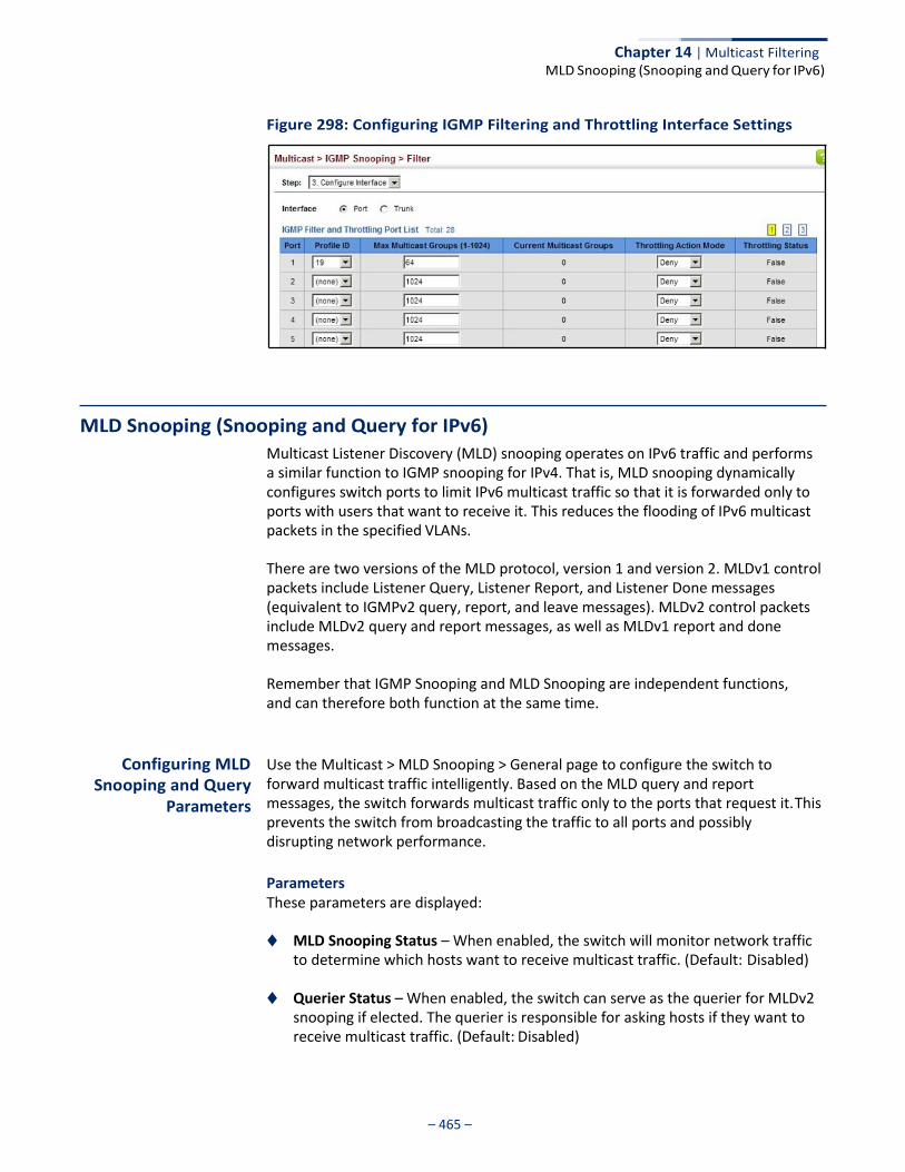
– 465 –
Chapter 14 | Multicast Filtering MLD Snooping (Snooping and Query for IPv6)
Figure 298: Configuring IGMP Filtering and Throttling Interface Settings
MLD Snooping (Snooping and Query for IPv6)
Multicast Listener Discovery (MLD) snooping operates on IPv6 traffic and performs a similar function to IGMP snooping for IPv4. That is, MLD snooping dynamically configures switch ports to limit IPv6 multicast traffic so that it is forwarded only to ports with users that want to receive it. This reduces the flooding of IPv6 multicast packets in the specified VLANs.
There are two versions of the MLD protocol, version 1 and version 2. MLDv1 control packets include Listener Query, Listener Report, and Listener Done messages (equivalent to IGMPv2 query, report, and leave messages). MLDv2 control packets include MLDv2 query and report messages, as well as MLDv1 report and done messages.
Remember that IGMP Snooping and MLD Snooping are independent functions, and can therefore both function at the same time.
Configuring MLD Snooping and Query
Parameters
Use the Multicast > MLD Snooping > General page to configure the switch to forward multicast traffic intelligently. Based on the MLD query and report messages, the switch forwards multicast traffic only to the ports that request it. This prevents the switch from broadcasting the traffic to all ports and possibly disrupting network performance.
Parameters These parameters are displayed:
◆ MLD Snooping Status – When enabled, the switch will monitor network traffic
to determine which hosts want to receive multicast traffic. (Default: Disabled)
◆ Querier Status – When enabled, the switch can serve as the querier for MLDv2 snooping if elected. The querier is responsible for asking hosts if they want to receive multicast traffic. (Default: Disabled)

– 466 –
Chapter 14 | Multicast Filtering MLD Snooping (Snooping and Query for IPv6)
An IPv6 address must be configured on the VLAN interface from which the querier will act if elected. When serving as the querier, the switch uses this IPv6 address as the query source address.
The querier will not start or will disable itself after having started if it detects an IPv6 multicast router on the network.
◆ Robustness – MLD Snooping robustness variable. A port will be removed from
the receiver list for a multicast service when no MLD reports are detected in response to a number of MLD queries. The robustness variable sets the number of queries on ports for which there is no report. (Range: 2-10 Default: 2)
◆ Query Interval – The interval between sending MLD general queries.
(Range: 60-125 seconds; Default: 125 seconds)
This attribute applies when the switch is serving as the querier.
An MLD general query message is sent by the switch at the interval specified by this attribute. When this message is received by downstream hosts, all receivers build an MLD report for the multicast groups they have joined.
◆ Query Max Response Time – The maximum response time advertised in MLD
general queries. (Range: 5-25 seconds; Default: 10 seconds)
This attribute controls how long the host has to respond to an MLD Query message before the switch deletes the group if it is the last member.
◆ Router Port Expiry Time – The time the switch waits after the previous querier
stops before it considers the router port (i.e., the interface that had been receiving query packets) to have expired. (Range: 300-500 seconds; Default: 300 seconds)
◆ MLD Snooping Version – The protocol version used for compatibility with other devices on the network. This is the MLD version the switch uses to send snooping reports. (Range: 1-2; Default: 2)
◆ Unknown Multicast Mode – The action for dealing with unknown multicast
packets. Options include:
■ Flood – Floods any received IPv6 multicast packets that have not been requested by a host to all ports in the VLAN.
■ To Router Port – Forwards any received IPv6 multicast packets that have not been requested by a host to ports that are connected to a detected multicast router. (This is the default action.)
Web Interface To configure general settings for MLD Snooping:
1. Click Multicast, MLD Snooping, General.
2. Adjust the settings as required.
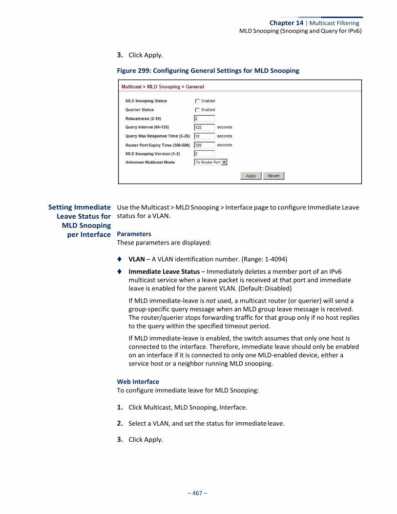
– 467 –
Chapter 14 | Multicast Filtering MLD Snooping (Snooping and Query for IPv6)
3. Click Apply.
Figure 299: Configuring General Settings for MLD Snooping
Setting Immediate Leave Status for
MLD Snooping per Interface
Use the Multicast > MLD Snooping > Interface page to configure Immediate Leave status for a VLAN.
Parameters These parameters are displayed:
◆ VLAN – A VLAN identification number. (Range: 1-4094)
◆ Immediate Leave Status – Immediately deletes a member port of an IPv6 multicast service when a leave packet is received at that port and immediate leave is enabled for the parent VLAN. (Default: Disabled)
If MLD immediate-leave is not used, a multicast router (or querier) will send a group-specific query message when an MLD group leave message is received. The router/querier stops forwarding traffic for that group only if no host replies to the query within the specified timeout period.
If MLD immediate-leave is enabled, the switch assumes that only one host is connected to the interface. Therefore, immediate leave should only be enabled on an interface if it is connected to only one MLD-enabled device, either a service host or a neighbor running MLD snooping.
Web Interface To configure immediate leave for MLD Snooping:
1. Click Multicast, MLD Snooping, Interface.
2. Select a VLAN, and set the status for immediate leave.
3. Click Apply.

– 468 –
Chapter 14 | Multicast Filtering MLD Snooping (Snooping and Query for IPv6)
Figure 300: Configuring Immediate Leave for MLD Snooping
Specifying Static Interfaces for an
IPv6 Multicast Router
Use the Multicast > MLD Snooping > Multicast Router (Add Static Multicast Router) page to statically attach an interface to an IPv6 multicast router/switch.
Depending on your network connections, MLD snooping may not always be able to locate the MLD querier. Therefore, if the MLD querier is a known multicast router/ switch connected over the network to an interface (port or trunk) on the switch, you can manually configure that interface to join all the current multicast groups.
Command Usage MLD Snooping must be enabled globally on the switch (see “Configuring MLD Snooping and Query Parameters” on page 465) before a multicast router port can take effect.
Parameters These parameters are displayed:
◆ VLAN – Selects the VLAN which is to propagate all IPv6 multicast traffic coming
from the attached multicast router. (Range: 1-4094)
◆ Interface – Activates the Port or Trunk scroll down list.
◆ Port or Trunk – Specifies the interface attached to a multicast router.
Web Interface To specify a static interface attached to a multicast router:
1. Click Multicast, MLD Snooping, Multicast Router.
2. Select Add Static Multicast Router from the Action list.
3. Select the VLAN which will forward all the corresponding IPv6 multicast traffic, and select the port or trunk attached to the multicast router.
4. Click Apply.
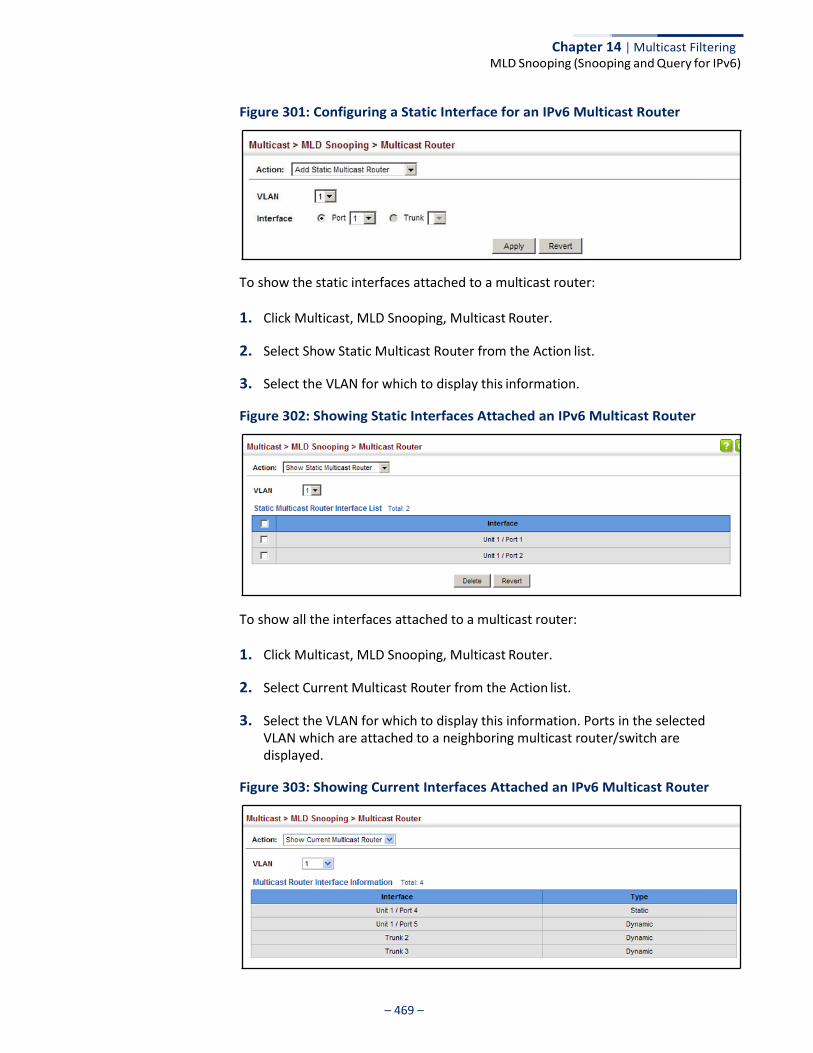
– 469 –
Chapter 14 | Multicast Filtering MLD Snooping (Snooping and Query for IPv6)
Figure 301: Configuring a Static Interface for an IPv6 Multicast Router
To show the static interfaces attached to a multicast router:
1. Click Multicast, MLD Snooping, Multicast Router.
2. Select Show Static Multicast Router from the Action list.
3. Select the VLAN for which to display this information.
Figure 302: Showing Static Interfaces Attached an IPv6 Multicast Router
To show all the interfaces attached to a multicast router:
1. Click Multicast, MLD Snooping, Multicast Router.
2. Select Current Multicast Router from the Action list.
3. Select the VLAN for which to display this information. Ports in the selected VLAN which are attached to a neighboring multicast router/switch are displayed.
Figure 303: Showing Current Interfaces Attached an IPv6 Multicast Router
Chapter 14 | Multicast Filtering MLD Snooping (Snooping and Query for IPv6)
– 470 –
Assigning Interfaces to IPv6 Multicast
Services
Use the Multicast > MLD Snooping > MLD Member (Add Static Member) page to statically assign an IPv6 multicast service to an interface.
Multicast filtering can be dynamically configured using MLD snooping and query messages (see “Configuring MLD Snooping and Query Parameters” on page 465). However, for certain applications that require tighter control, it may be necessary to statically configure a multicast service on the switch. First add all the ports attached to participating hosts to a common VLAN, and then assign the multicast service to that VLAN group.
Command Usage ◆ Static multicast addresses are never aged out.
◆ When a multicast address is assigned to an interface in a specific VLAN, the
corresponding traffic can only be forwarded to ports within that VLAN.
Parameters These parameters are displayed:
◆ VLAN – Specifies the VLAN which is to propagate the multicast service.
(Range: 1-4094)
◆ Multicast IPv6 Address – The IP address for a specific multicast service.
◆ Interface – Activates the Port or Trunk scroll down list.
◆ Port or Trunk – Specifies the interface assigned to a multicast group.
◆ Type (Show Current Member) – Shows if this multicast stream was statically configured by the user, discovered by MLD Snooping, or is a data stream to which no other ports are subscribing (i.e., the stream is flooded onto VLAN instead of being trapped to the CPU for processing, or is being processed by MVR6).
Web Interface To statically assign an interface to an IPv6 multicast service:
1. Click Multicast, MLD Snooping, MLD Member.
2. Select Add Static Member from the Action list.
3. Select the VLAN that will propagate the multicast service, specify the interface attached to a multicast service (through an MLD-enabled switch or multicast router), and enter the multicast IP address.
4. Click Apply.
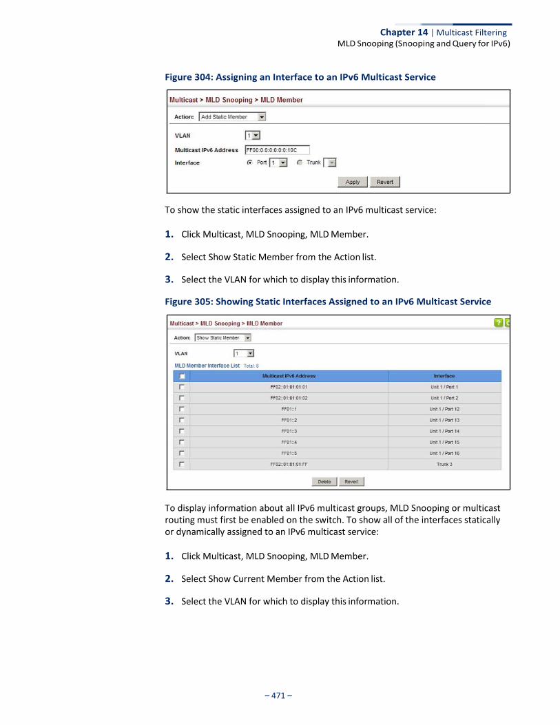
Chapter 14 | Multicast Filtering MLD Snooping (Snooping and Query for IPv6)
– 471 –
Figure 304: Assigning an Interface to an IPv6 Multicast Service
To show the static interfaces assigned to an IPv6 multicast service:
1. Click Multicast, MLD Snooping, MLD Member.
2. Select Show Static Member from the Action list.
3. Select the VLAN for which to display this information.
Figure 305: Showing Static Interfaces Assigned to an IPv6 Multicast Service
To display information about all IPv6 multicast groups, MLD Snooping or multicast routing must first be enabled on the switch. To show all of the interfaces statically or dynamically assigned to an IPv6 multicast service:
1. Click Multicast, MLD Snooping, MLD Member.
2. Select Show Current Member from the Action list.
3. Select the VLAN for which to display this information.
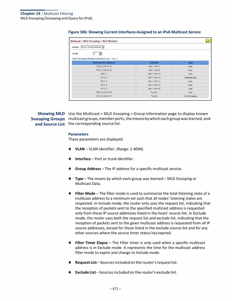
Chapter 14 | Multicast Filtering MLD Snooping (Snooping and Query for IPv6)
– 472 –
Figure 306: Showing Current Interfaces Assigned to an IPv6 Multicast Service
Showing MLD
Snooping Groups and Source List
Use the Multicast > MLD Snooping > Group Information page to display known multicast groups, member ports, the means by which each group was learned, and the corresponding source list.
Parameters These parameters are displayed:
◆ VLAN – VLAN identifier. (Range: 1-4094)
◆ Interface – Port or trunk identifier.
◆ Group Address – The IP address for a specific multicast service.
◆ Type – The means by which each group was learned – MLD Snooping or Multicast Data.
◆ Filter Mode – The filter mode is used to summarize the total listening state of a
multicast address to a minimum set such that all nodes' listening states are respected. In Include mode, the router only uses the request list, indicating that the reception of packets sent to the specified multicast address is requested only from those IP source addresses listed in the hosts’ source-list. In Exclude mode, the router uses both the request list and exclude list, indicating that the reception of packets sent to the given multicast address is requested from all IP source addresses, except for those listed in the exclude source-list and for any other sources where the source timer status has expired.
◆ Filter Timer Elapse – The Filter timer is only used when a specific multicast address is in Exclude mode. It represents the time for the multicast address filter mode to expire and change to Include mode.
◆ Request List – Sources included on the router’s request list.
◆ Exclude List – Sources included on the router’s exclude list.
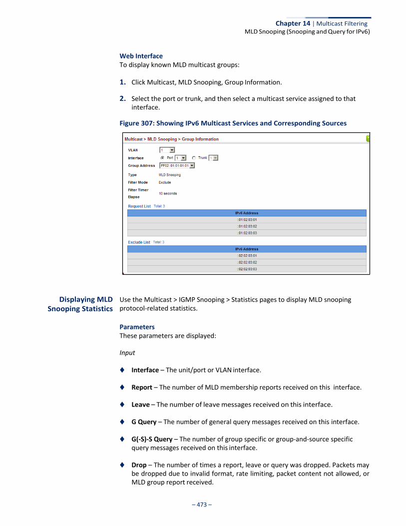
Chapter 14 | Multicast Filtering MLD Snooping (Snooping and Query for IPv6)
– 473 –
Web Interface To display known MLD multicast groups:
1. Click Multicast, MLD Snooping, Group Information.
2. Select the port or trunk, and then select a multicast service assigned to that interface.
Figure 307: Showing IPv6 Multicast Services and Corresponding Sources
Displaying MLD Snooping Statistics
Use the Multicast > IGMP Snooping > Statistics pages to display MLD snooping protocol-related statistics.
Parameters These parameters are displayed:
Input
◆ Interface – The unit/port or VLAN interface.
◆ Report – The number of MLD membership reports received on this interface.
◆ Leave – The number of leave messages received on this interface.
◆ G Query – The number of general query messages received on this interface.
◆ G(-S)-S Query – The number of group specific or group-and-source specific query messages received on this interface.
◆ Drop – The number of times a report, leave or query was dropped. Packets may
be dropped due to invalid format, rate limiting, packet content not allowed, or MLD group report received.

Chapter 14 | Multicast Filtering MLD Snooping (Snooping and Query for IPv6)
– 474 –
◆ Join Success – The number of times a multicast group was successfully joined.
◆ Group – The number of MLD groups active on this interface.
Output
Same as input parameters listed above, except that the direction of transmission is outbound.
Query
◆ Other Querier Address – IP address of remote querier on this interface.
◆ Other Querier Expire – Time after which remote querier is assumed to have expired.
◆ Other Querier Uptime – Time remote querier has been up.
◆ Self Querier – IP address of local querier on this interface.
◆ Self Querier Expire – Time after which local querier is assumed to have expired.
◆ Self Querier Uptime – Time local querier has been up.
◆ General Query Received – The number of general queries received on this interface.
◆ General Query Sent – The number of general queries sent from this interface.
◆ Specific Query Received – The number of group specific queries received on this interface.
◆ Specific Query Sent – The number of group specific queries sent from this
interface.
Summary
◆ Number of Groups – Number of active MLD groups active on the specified interface.
Chapter 14 | Multicast Filtering MLD Snooping (Snooping and Query for IPv6)
– 475 –
Physical Interface (Port/Trunk)
◆ Querier
■ Transmit
■ General – The number of general queries sent from this interface.
■ Group Specific – The number of group specific queries sent from this interface.
■ Received
■ General – The number of general queries received on this interface.
■ Group Specific – The number of group specific queries received on this
interface.
◆ Report & Leave
■ Transmit
■ Report – The number of MLD membership reports sent from this interface.
■ Leave – The number of leave messages sent from this interface.
■ Received
■ Report – The number of MLD membership reports received on this
interface.
■ Leave – The number of leave messages received on this interface.
■ Join Success – The number of times a multicast group was successfully joined.
■ Source Port Drop – The number of dropped messages that are
received on MVR source port or mrouter port.
■ Others Drop – The number of received invalid messages.
Logical Interface (VLAN) – The following parameters are included for a VLAN.
◆ Querier
■ Other Querier – IPv6 address of remote querier on this interface.
■ Other Uptime – Time remote querier has been up.
Chapter 14 | Multicast Filtering MLD Snooping (Snooping and Query for IPv6)
– 476 –
■ Other Expire – Time after which remote querier is assumed to have
expired.
■ Self Addr – IPv6 address of local querier on this interface.
■ Self Expire – Time after which local querier is assumed to have expired.
■ Self Uptime – Time local querier has been up.
■ Transmit
■ General – The number of general queries sent from this interface.
■ Group Specific – The number of group specific queries sent from this interface.
■ Receive
■ General – The number of general queries received on this interface.
■ Group Specific – The number of group specific queries received on this
interface.
◆ Report & Leave
■ Host Addr – The link-local or global IPv6 address that is assigned on that VLAN.
■ Unsolicit Expire – The number of group leaves resulting from timeouts
instead of explicit leave messages.
Clear
Parameters These parameters are displayed:
◆ All – Clears statistics for all MLD messages.
◆ VLAN – VLAN identifier. (Range: 1-4094)
◆ Unit – Stack unit. (Range: 1)
◆ Port – Port identifier. (Range: 1-52)
◆ Trunk – Trunk identifier. (Range: 1-8)
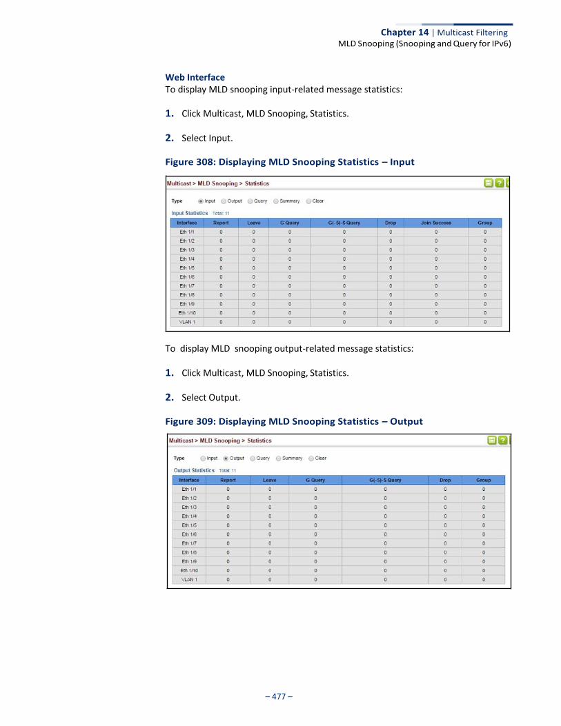
Chapter 14 | Multicast Filtering MLD Snooping (Snooping and Query for IPv6)
– 477 –
Web Interface To display MLD snooping input-related message statistics:
1. Click Multicast, MLD Snooping, Statistics.
2. Select Input.
Figure 308: Displaying MLD Snooping Statistics – Input
To display MLD snooping output-related message statistics:
1. Click Multicast, MLD Snooping, Statistics.
2. Select Output.
Figure 309: Displaying MLD Snooping Statistics – Output
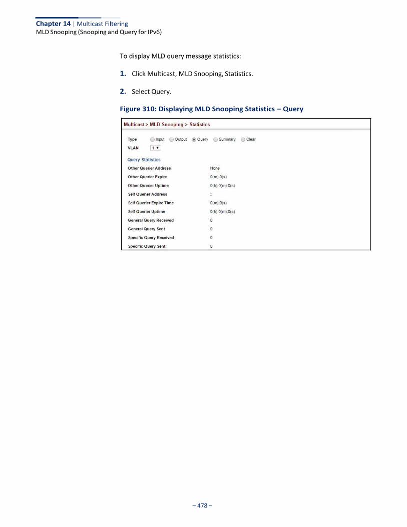
Chapter 14 | Multicast Filtering MLD Snooping (Snooping and Query for IPv6)
– 478 –
To display MLD query message statistics:
1. Click Multicast, MLD Snooping, Statistics.
2. Select Query.
Figure 310: Displaying MLD Snooping Statistics – Query
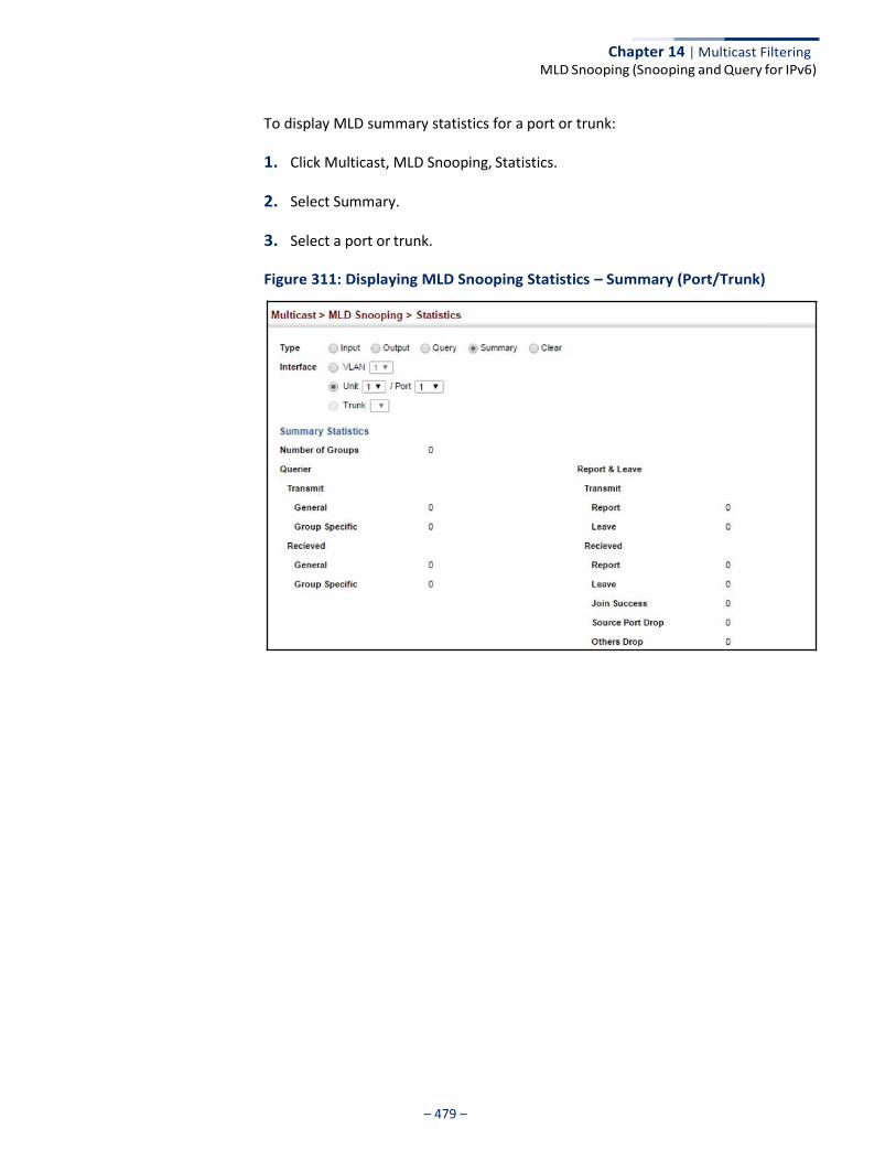
Chapter 14 | Multicast Filtering MLD Snooping (Snooping and Query for IPv6)
– 479 –
To display MLD summary statistics for a port or trunk:
1. Click Multicast, MLD Snooping, Statistics.
2. Select Summary.
3. Select a port or trunk.
Figure 311: Displaying MLD Snooping Statistics – Summary (Port/Trunk)
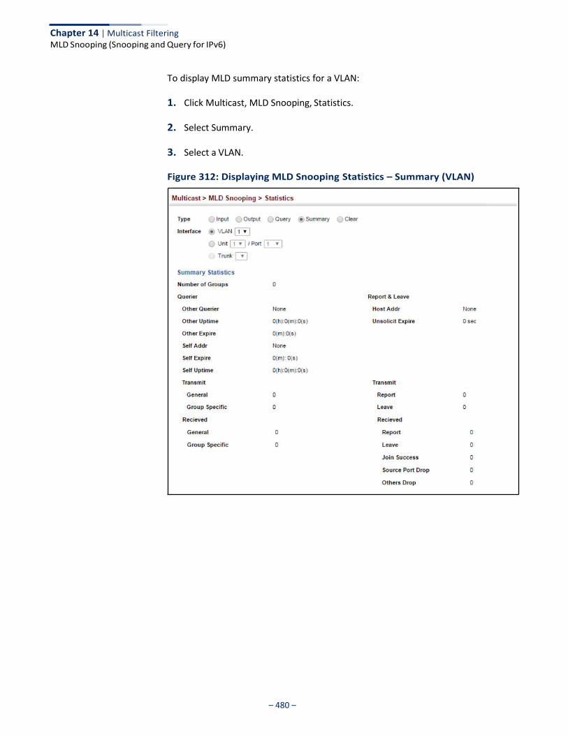
Chapter 14 | Multicast Filtering MLD Snooping (Snooping and Query for IPv6)
– 480 –
To display MLD summary statistics for a VLAN:
1. Click Multicast, MLD Snooping, Statistics.
2. Select Summary.
3. Select a VLAN.
Figure 312: Displaying MLD Snooping Statistics – Summary (VLAN)
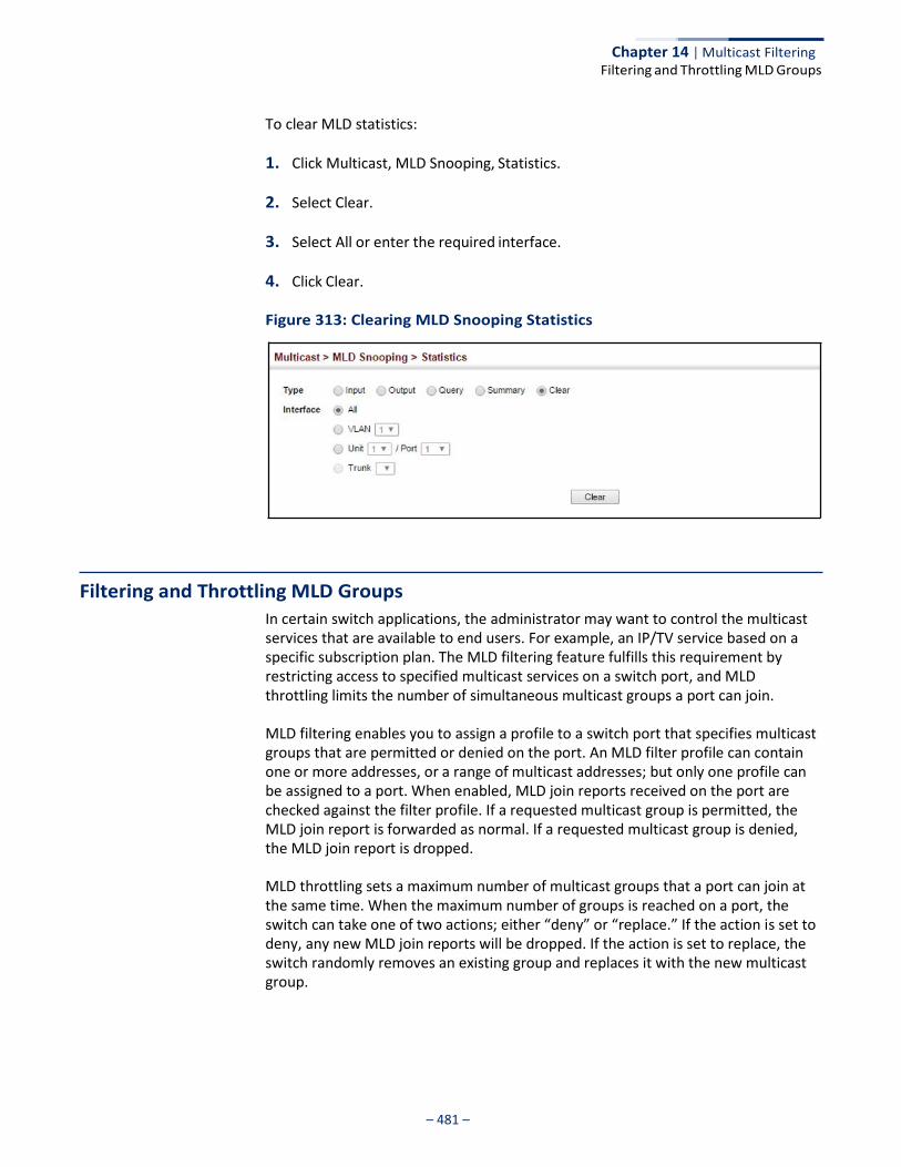
– 481 –
Chapter 14 | Multicast Filtering Filtering and Throttling MLD Groups
To clear MLD statistics:
1. Click Multicast, MLD Snooping, Statistics.
2. Select Clear.
3. Select All or enter the required interface.
4. Click Clear.
Figure 313: Clearing MLD Snooping Statistics
Filtering and Throttling MLD Groups
In certain switch applications, the administrator may want to control the multicast services that are available to end users. For example, an IP/TV service based on a specific subscription plan. The MLD filtering feature fulfills this requirement by restricting access to specified multicast services on a switch port, and MLD throttling limits the number of simultaneous multicast groups a port can join.
MLD filtering enables you to assign a profile to a switch port that specifies multicast groups that are permitted or denied on the port. An MLD filter profile can contain one or more addresses, or a range of multicast addresses; but only one profile can be assigned to a port. When enabled, MLD join reports received on the port are checked against the filter profile. If a requested multicast group is permitted, the MLD join report is forwarded as normal. If a requested multicast group is denied, the MLD join report is dropped.
MLD throttling sets a maximum number of multicast groups that a port can join at the same time. When the maximum number of groups is reached on a port, the switch can take one of two actions; either “deny” or “replace.” If the action is set to deny, any new MLD join reports will be dropped. If the action is set to replace, the switch randomly removes an existing group and replaces it with the new multicast group.
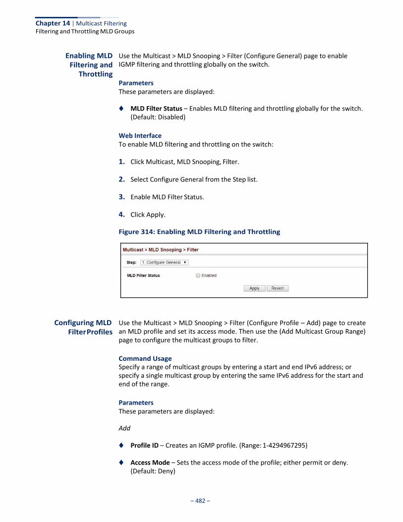
Chapter 14 | Multicast Filtering Filtering and Throttling MLD Groups
– 482 –
Enabling MLD Filtering and
Throttling
Use the Multicast > MLD Snooping > Filter (Configure General) page to enable IGMP filtering and throttling globally on the switch.
Parameters These parameters are displayed:
◆ MLD Filter Status – Enables MLD filtering and throttling globally for the switch.
(Default: Disabled)
Web Interface To enable MLD filtering and throttling on the switch:
1. Click Multicast, MLD Snooping, Filter.
2. Select Configure General from the Step list.
3. Enable MLD Filter Status.
4. Click Apply.
Figure 314: Enabling MLD Filtering and Throttling
Configuring MLD Filter Profiles
Use the Multicast > MLD Snooping > Filter (Configure Profile – Add) page to create an MLD profile and set its access mode. Then use the (Add Multicast Group Range) page to configure the multicast groups to filter.
Command Usage Specify a range of multicast groups by entering a start and end IPv6 address; or specify a single multicast group by entering the same IPv6 address for the start and end of the range.
Parameters These parameters are displayed:
Add
◆ Profile ID – Creates an IGMP profile. (Range: 1-4294967295)
◆ Access Mode – Sets the access mode of the profile; either permit or deny. (Default: Deny)
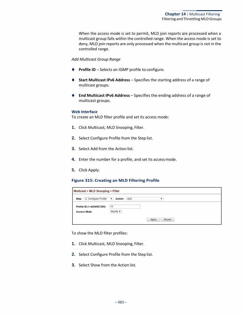
Chapter 14 | Multicast Filtering Filtering and Throttling MLD Groups
– 483 –
When the access mode is set to permit, MLD join reports are processed when a multicast group falls within the controlled range. When the access mode is set to deny, MLD join reports are only processed when the multicast group is not in the controlled range.
Add Multicast Group Range
◆ Profile ID – Selects an IGMP profile to configure.
◆ Start Multicast IPv6 Address – Specifies the starting address of a range of multicast groups.
◆ End Multicast IPv6 Address – Specifies the ending address of a range of
multicast groups.
Web Interface To create an MLD filter profile and set its access mode:
1. Click Multicast, MLD Snooping, Filter.
2. Select Configure Profile from the Step list.
3. Select Add from the Action list.
4. Enter the number for a profile, and set its access mode.
5. Click Apply.
Figure 315: Creating an MLD Filtering Profile
To show the MLD filter profiles:
1. Click Multicast, MLD Snooping, Filter.
2. Select Configure Profile from the Step list.
3. Select Show from the Action list.
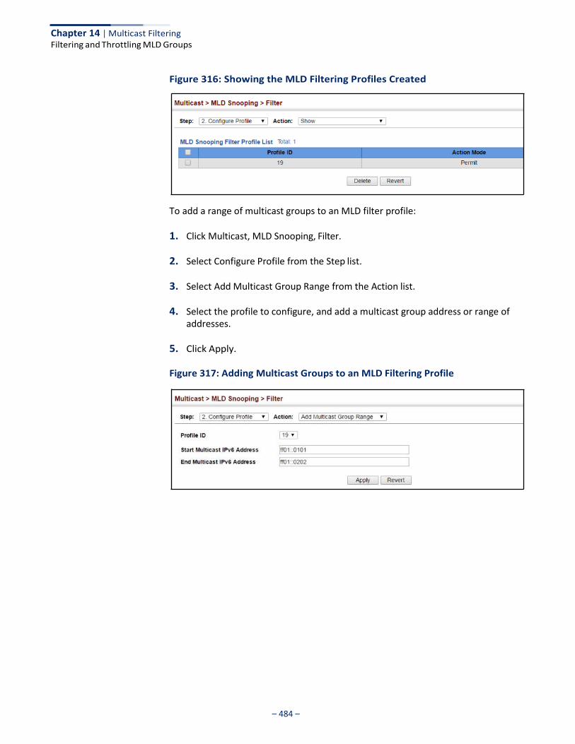
Chapter 14 | Multicast Filtering Filtering and Throttling MLD Groups
– 484 –
Figure 316: Showing the MLD Filtering Profiles Created
To add a range of multicast groups to an MLD filter profile:
1. Click Multicast, MLD Snooping, Filter.
2. Select Configure Profile from the Step list.
3. Select Add Multicast Group Range from the Action list.
4. Select the profile to configure, and add a multicast group address or range of addresses.
5. Click Apply.
Figure 317: Adding Multicast Groups to an MLD Filtering Profile
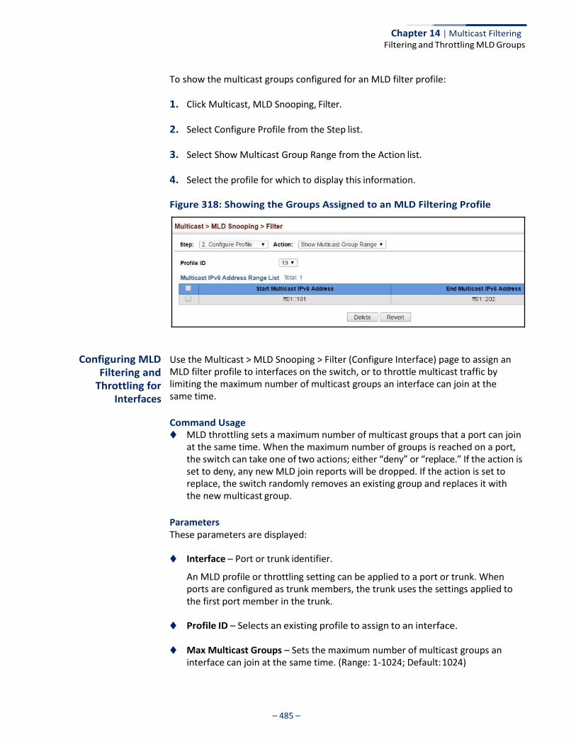
Chapter 14 | Multicast Filtering Filtering and Throttling MLD Groups
– 485 –
To show the multicast groups configured for an MLD filter profile:
1. Click Multicast, MLD Snooping, Filter.
2. Select Configure Profile from the Step list.
3. Select Show Multicast Group Range from the Action list.
4. Select the profile for which to display this information.
Figure 318: Showing the Groups Assigned to an MLD Filtering Profile
Configuring MLD Filtering and
Throttling for Interfaces
Use the Multicast > MLD Snooping > Filter (Configure Interface) page to assign an MLD filter profile to interfaces on the switch, or to throttle multicast traffic by limiting the maximum number of multicast groups an interface can join at the same time.
Command Usage ◆ MLD throttling sets a maximum number of multicast groups that a port can join
at the same time. When the maximum number of groups is reached on a port, the switch can take one of two actions; either “deny” or “replace.” If the action is set to deny, any new MLD join reports will be dropped. If the action is set to replace, the switch randomly removes an existing group and replaces it with the new multicast group.
Parameters These parameters are displayed:
◆ Interface – Port or trunk identifier.
An MLD profile or throttling setting can be applied to a port or trunk. When ports are configured as trunk members, the trunk uses the settings applied to the first port member in the trunk.
◆ Profile ID – Selects an existing profile to assign to an interface.
◆ Max Multicast Groups – Sets the maximum number of multicast groups an interface can join at the same time. (Range: 1-1024; Default: 1024)
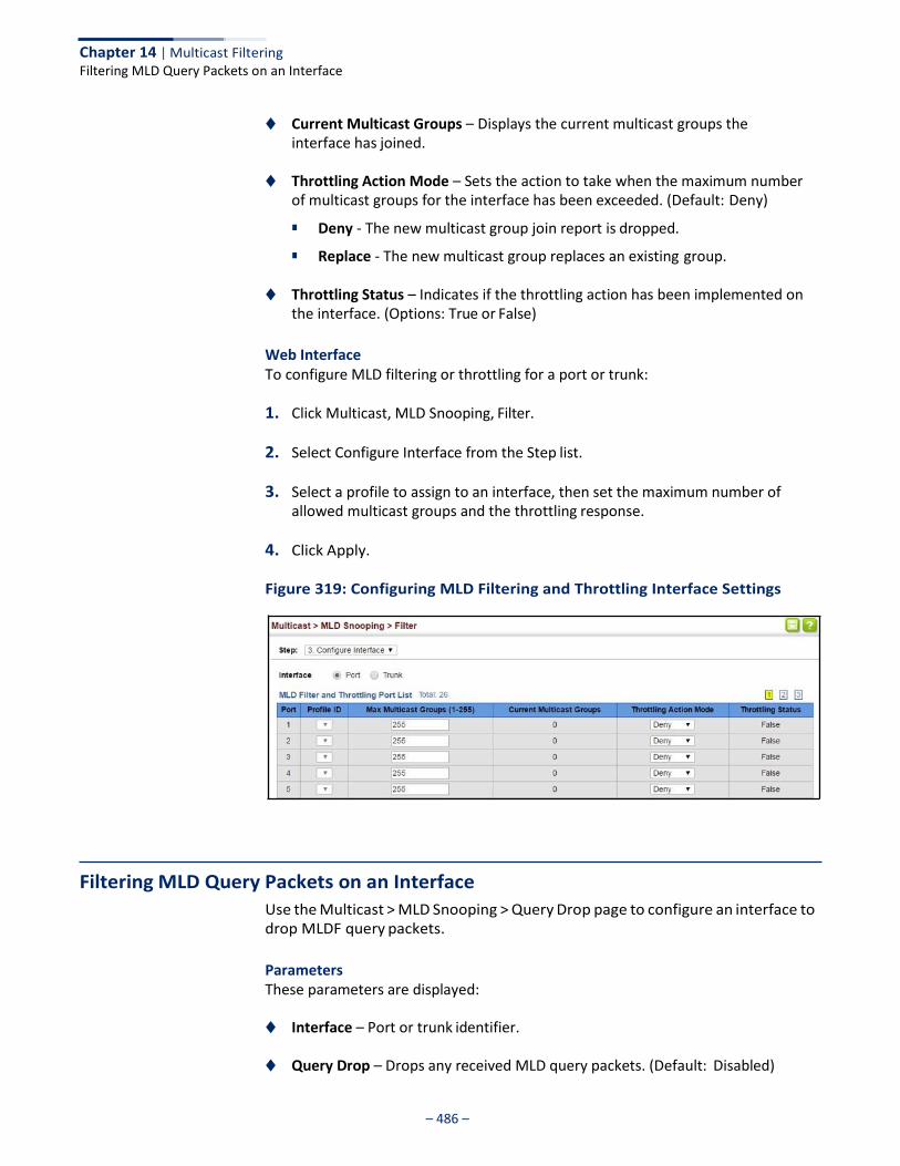
– 486 –
Chapter 14 | Multicast Filtering Filtering MLD Query Packets on an Interface
◆ Current Multicast Groups – Displays the current multicast groups the interface has joined.
◆ Throttling Action Mode – Sets the action to take when the maximum number
of multicast groups for the interface has been exceeded. (Default: Deny)
■ Deny - The new multicast group join report is dropped.
■ Replace - The new multicast group replaces an existing group.
◆ Throttling Status – Indicates if the throttling action has been implemented on the interface. (Options: True or False)
Web Interface To configure MLD filtering or throttling for a port or trunk:
1. Click Multicast, MLD Snooping, Filter.
2. Select Configure Interface from the Step list.
3. Select a profile to assign to an interface, then set the maximum number of allowed multicast groups and the throttling response.
4. Click Apply.
Figure 319: Configuring MLD Filtering and Throttling Interface Settings
Filtering MLD Query Packets on an Interface
Use the Multicast > MLD Snooping > Query Drop page to configure an interface to drop MLDF query packets.
Parameters These parameters are displayed:
◆ Interface – Port or trunk identifier.
◆ Query Drop – Drops any received MLD query packets. (Default: Disabled)

– 487 –
Chapter 14 | Multicast Filtering Filtering MLD Query Packets on an Interface
This feature can be used to drop any query packets received on the specified interface. If this switch is acting as a Querier, this prevents it from being affected by messages received from another Querier.
Web Interface To drop IGMP query packets:
1. Click Multicast, MLD Snooping, Query Drop.
2. Select Port or Trunk interface.
3. Enable query drop for any interface.
4. Click Apply.
Figure 320: Dropping MLD Query Packets

– 488 –
Chapter 14 | Multicast Filtering Filtering MLD Query Packets on an Interface
– 489 –
IP Tools
This chapter provides information on network functions including:
◆ Ping – Sends ping message to another node on the network.
◆ Trace Route – Sends ICMP echo request packets to another node on the network.
◆ Address Resolution Protocol – Describes how to configure proxy ARP or static
addresses, and how to display entries in the ARP cache.
Using the Ping Function
Use the Tools > Ping page to send ICMP echo request packets to another node on the network.
Parameters These parameters are displayed:
◆ Host Name/IP Address – Alias or IPv4/IPv6 address of the host.
◆ Probe Count – Number of packets to send. (Range: 1-16)
◆ Packet Size – Number of bytes in a packet. (Range: 32-512 bytes for IPv4, 0-1500 bytes for IPv6)
The actual packet size will be eight bytes larger than the size specified because the switch adds header information.
Command Usage ◆ Use the ping command to see if another site on the network can be reached.
◆ The following are some results of the ping command:
■ Normal response - The normal response occurs in one to ten seconds, depending on network traffic.
■ Destination does not respond - If the host does not respond, a “timeout”
appears in ten seconds.
■ Destination unreachable - The gateway for this destination indicates that the destination is unreachable.
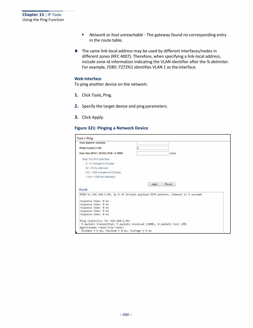
– 490 –
Chapter 15 | IP Tools Using the Ping Function
■ Network or host unreachable - The gateway found no corresponding entry
in the route table.
◆ The same link-local address may be used by different interfaces/nodes in different zones (RFC 4007). Therefore, when specifying a link-local address, include zone-id information indicating the VLAN identifier after the % delimiter. For example, FE80::7272%1 identifies VLAN 1 as the interface.
Web Interface To ping another device on the network:
1. Click Tools, Ping.
2. Specify the target device and ping parameters.
3. Click Apply.
Figure 321: Pinging a Network Device
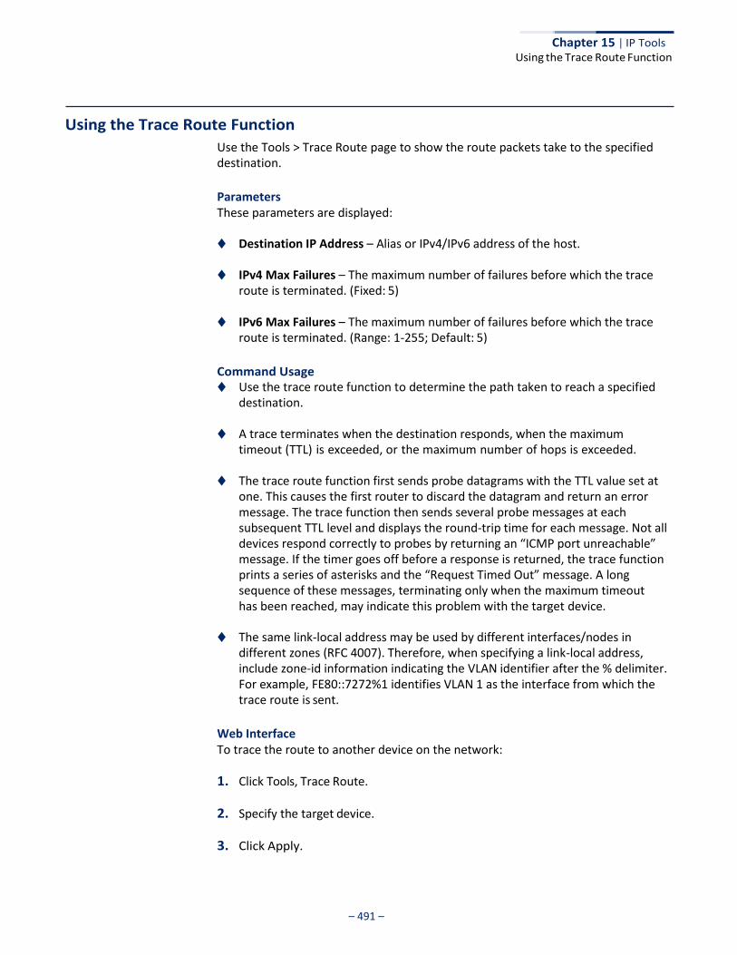
Chapter 15 | IP Tools Using the Trace Route Function
– 491 –
Using the Trace Route Function
Use the Tools > Trace Route page to show the route packets take to the specified destination.
Parameters These parameters are displayed:
◆ Destination IP Address – Alias or IPv4/IPv6 address of the host.
◆ IPv4 Max Failures – The maximum number of failures before which the trace route is terminated. (Fixed: 5)
◆ IPv6 Max Failures – The maximum number of failures before which the trace
route is terminated. (Range: 1-255; Default: 5)
Command Usage ◆ Use the trace route function to determine the path taken to reach a specified
destination.
◆ A trace terminates when the destination responds, when the maximum timeout (TTL) is exceeded, or the maximum number of hops is exceeded.
◆ The trace route function first sends probe datagrams with the TTL value set at
one. This causes the first router to discard the datagram and return an error message. The trace function then sends several probe messages at each subsequent TTL level and displays the round-trip time for each message. Not all devices respond correctly to probes by returning an “ICMP port unreachable” message. If the timer goes off before a response is returned, the trace function prints a series of asterisks and the “Request Timed Out” message. A long sequence of these messages, terminating only when the maximum timeout has been reached, may indicate this problem with the target device.
◆ The same link-local address may be used by different interfaces/nodes in different zones (RFC 4007). Therefore, when specifying a link-local address, include zone-id information indicating the VLAN identifier after the % delimiter. For example, FE80::7272%1 identifies VLAN 1 as the interface from which the trace route is sent.
Web Interface To trace the route to another device on the network:
1. Click Tools, Trace Route.
2. Specify the target device.
3. Click Apply.
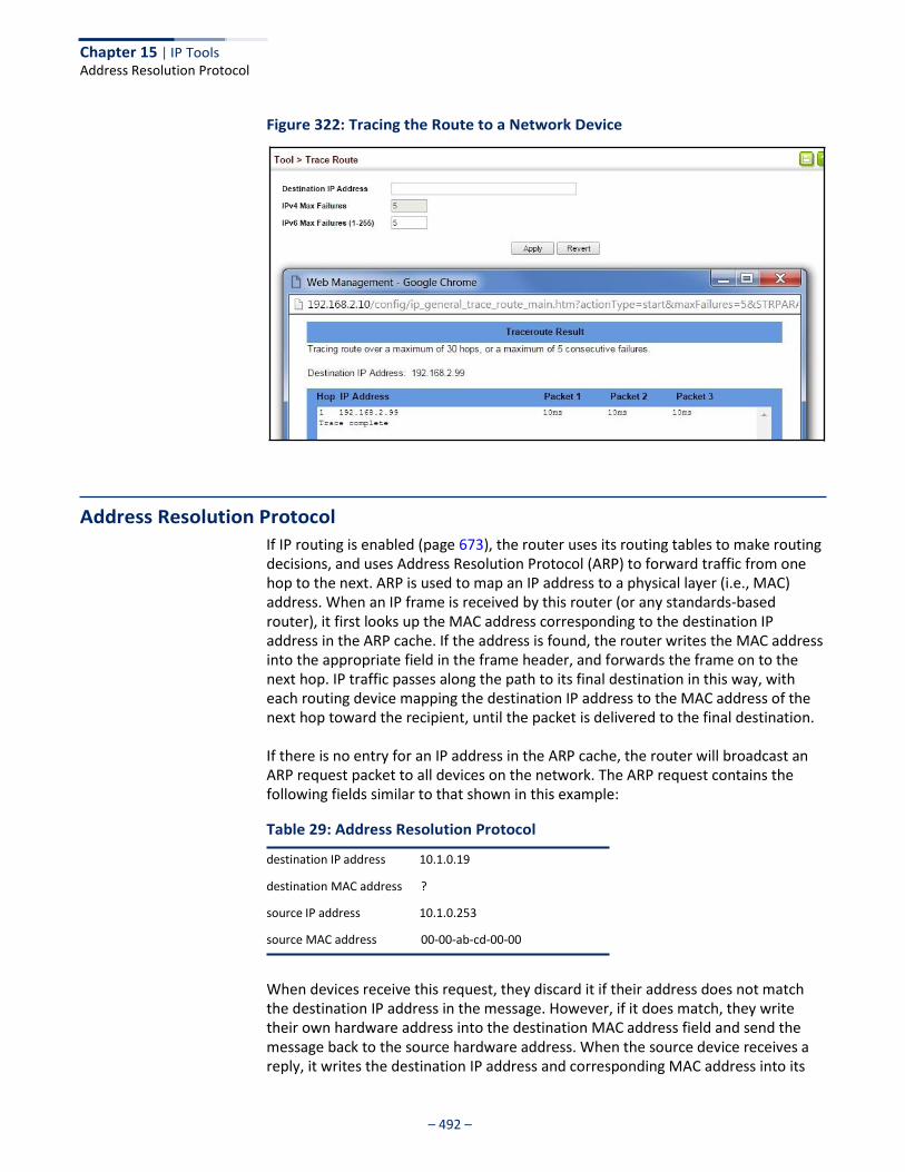
– 492 –
Chapter 15 | IP Tools Address Resolution Protocol
Figure 322: Tracing the Route to a Network Device
Address Resolution Protocol
If IP routing is enabled (page 673), the router uses its routing tables to make routing decisions, and uses Address Resolution Protocol (ARP) to forward traffic from one hop to the next. ARP is used to map an IP address to a physical layer (i.e., MAC) address. When an IP frame is received by this router (or any standards-based router), it first looks up the MAC address corresponding to the destination IP address in the ARP cache. If the address is found, the router writes the MAC address into the appropriate field in the frame header, and forwards the frame on to the next hop. IP traffic passes along the path to its final destination in this way, with each routing device mapping the destination IP address to the MAC address of the next hop toward the recipient, until the packet is delivered to the final destination.
If there is no entry for an IP address in the ARP cache, the router will broadcast an ARP request packet to all devices on the network. The ARP request contains the following fields similar to that shown in this example:
Table 29: Address Resolution Protocol
destination IP address 10.1.0.19
destination MAC address ?
source IP address 10.1.0.253
source MAC address 00-00-ab-cd-00-00
When devices receive this request, they discard it if their address does not match the destination IP address in the message. However, if it does match, they write their own hardware address into the destination MAC address field and send the message back to the source hardware address. When the source device receives a reply, it writes the destination IP address and corresponding MAC address into its
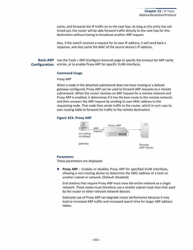
Chapter 15 | IP Tools Address Resolution Protocol
– 493 –
cache, and forwards the IP traffic on to the next hop. As long as this entry has not timed out, the router will be able forward traffic directly to the next hop for this destination without having to broadcast another ARP request.
Also, if the switch receives a request for its own IP address, it will send back a response, and also cache the MAC of the source device's IP address.
Basic ARP Configuration
Use the Tools > ARP (Configure General) page to specify the timeout for ARP cache entries, or to enable Proxy ARP for specific VLAN interfaces.
Command Usage
Proxy ARP
When a node in the attached subnetwork does not have routing or a default gateway configured, Proxy ARP can be used to forward ARP requests to a remote subnetwork. When the router receives an ARP request for a remote network and Proxy ARP is enabled, it determines if it has the best route to the remote network, and then answers the ARP request by sending its own MAC address to the requesting node. That node then sends traffic to the router, which in turn uses its own routing table to forward the traffic to the remote destination.
Figure 323: Proxy ARP
no routing, no default
ARP request
Proxy ARP
gateway Remote
ARP Server
Parameters These parameters are displayed:
◆ Proxy ARP – Enables or disables Proxy ARP for specified VLAN interfaces,
allowing a non-routing device to determine the MAC address of a host on another subnet or network. (Default: Disabled)
End stations that require Proxy ARP must view the entire network as a single network. These nodes must therefore use a smaller subnet mask than that used by the router or other relevant network devices.
Extensive use of Proxy ARP can degrade router performance because it may lead to increased ARP traffic and increased search time for larger ARP address tables.
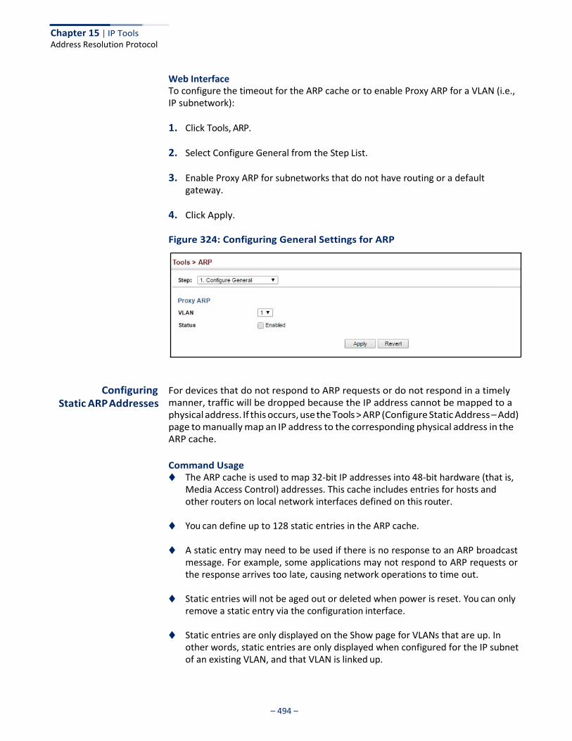
Chapter 15 | IP Tools Address Resolution Protocol
– 494 –
Web Interface To configure the timeout for the ARP cache or to enable Proxy ARP for a VLAN (i.e., IP subnetwork):
1. Click Tools, ARP.
2. Select Configure General from the Step List.
3. Enable Proxy ARP for subnetworks that do not have routing or a default gateway.
4. Click Apply.
Figure 324: Configuring General Settings for ARP
Configuring
Static ARP Addresses
For devices that do not respond to ARP requests or do not respond in a timely manner, traffic will be dropped because the IP address cannot be mapped to a physical address. If this occurs, use the Tools > ARP (Configure Static Address – Add) page to manually map an IP address to the corresponding physical address in the ARP cache.
Command Usage ◆ The ARP cache is used to map 32-bit IP addresses into 48-bit hardware (that is,
Media Access Control) addresses. This cache includes entries for hosts and other routers on local network interfaces defined on this router.
◆ You can define up to 128 static entries in the ARP cache.
◆ A static entry may need to be used if there is no response to an ARP broadcast message. For example, some applications may not respond to ARP requests or the response arrives too late, causing network operations to time out.
◆ Static entries will not be aged out or deleted when power is reset. You can only
remove a static entry via the configuration interface.
◆ Static entries are only displayed on the Show page for VLANs that are up. In other words, static entries are only displayed when configured for the IP subnet of an existing VLAN, and that VLAN is linked up.
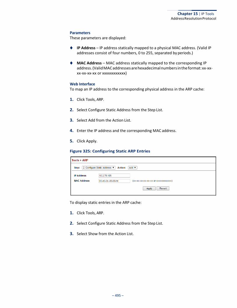
Chapter 15 | IP Tools Address Resolution Protocol
– 495 –
Parameters These parameters are displayed:
◆ IP Address – IP address statically mapped to a physical MAC address. (Valid IP
addresses consist of four numbers, 0 to 255, separated by periods.)
◆ MAC Address – MAC address statically mapped to the corresponding IP address. (Valid MAC addresses are hexadecimal numbers in the format: xx-xx- xx-xx-xx-xx or xxxxxxxxxxxx)
Web Interface To map an IP address to the corresponding physical address in the ARP cache:
1. Click Tools, ARP.
2. Select Configure Static Address from the Step List.
3. Select Add from the Action List.
4. Enter the IP address and the corresponding MAC address.
5. Click Apply.
Figure 325: Configuring Static ARP Entries
To display static entries in the ARP cache:
1. Click Tools, ARP.
2. Select Configure Static Address from the Step List.
3. Select Show from the Action List.
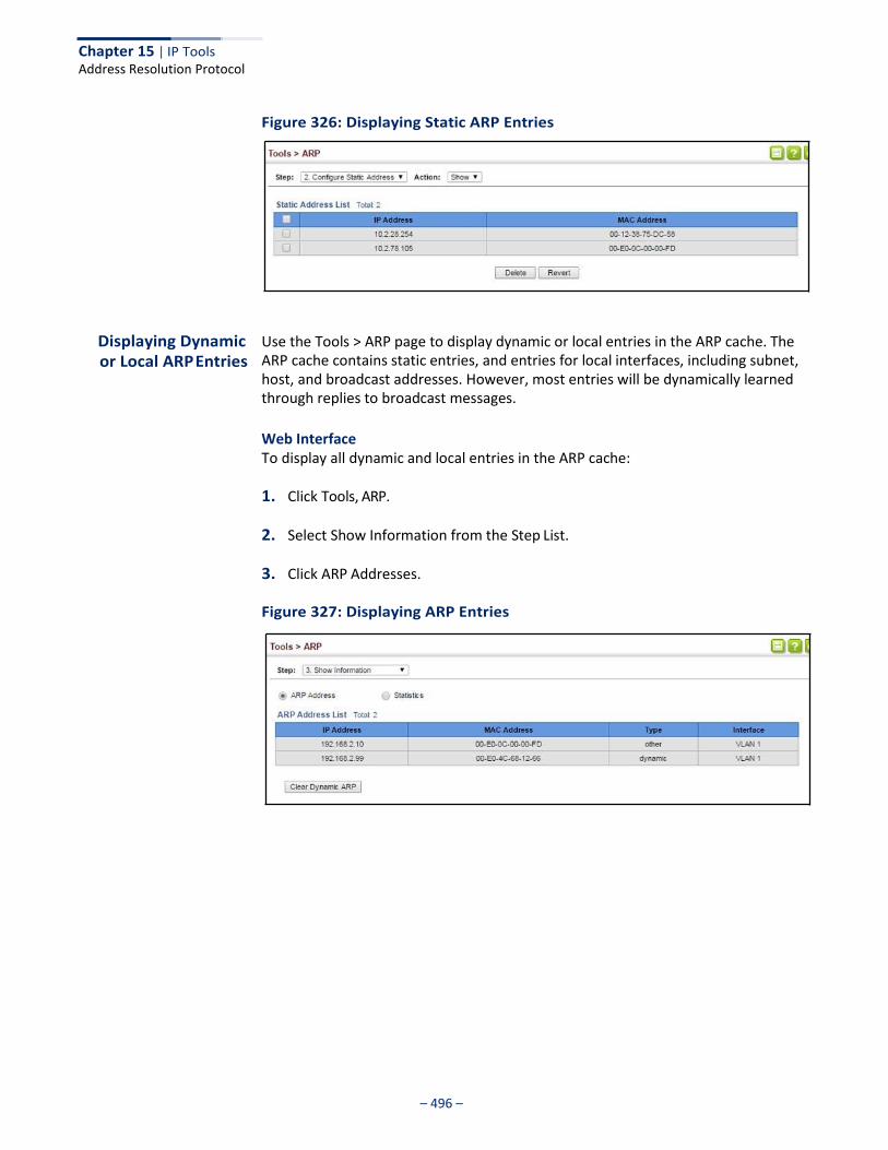
Chapter 15 | IP Tools Address Resolution Protocol
– 496 –
Figure 326: Displaying Static ARP Entries
Displaying Dynamic or Local ARP Entries
Use the Tools > ARP page to display dynamic or local entries in the ARP cache. The ARP cache contains static entries, and entries for local interfaces, including subnet, host, and broadcast addresses. However, most entries will be dynamically learned through replies to broadcast messages.
Web Interface To display all dynamic and local entries in the ARP cache:
1. Click Tools, ARP.
2. Select Show Information from the Step List.
3. Click ARP Addresses.
Figure 327: Displaying ARP Entries
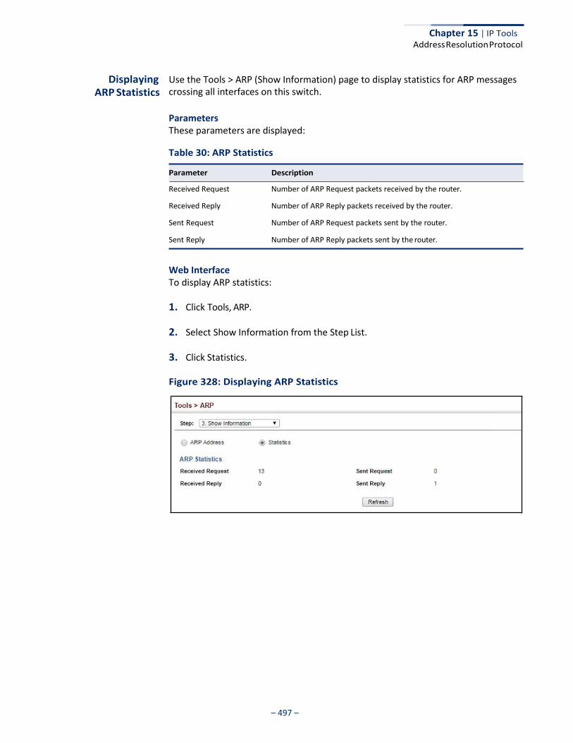
Chapter 15 | IP Tools Address Resolution Protocol
– 497 –
Displaying ARP Statistics
Use the Tools > ARP (Show Information) page to display statistics for ARP messages crossing all interfaces on this switch.
Parameters These parameters are displayed:
Table 30: ARP Statistics
Received Request Number of ARP Request packets received by the router.
Received Reply Number of ARP Reply packets received by the router.
Sent Request Number of ARP Request packets sent by the router.
Sent Reply Number of ARP Reply packets sent by the router.
Web Interface To display ARP statistics:
1. Click Tools, ARP.
2. Select Show Information from the Step List.
3. Click Statistics.
Figure 328: Displaying ARP Statistics
Parameter Description

Chapter 15 | IP Tools Address Resolution Protocol
– 498 –
– 499 –
IP Configuration
This chapter describes how to configure an IP interface for management access to the switch over the network. This switch supports both IP Version 4 and Version 6, and can be managed simultaneously through either of these address types. You can manually configure a specific IPv4 or IPv6 address, or direct the switch to obtain an IPv4 address from a BOOTP or DHCP server. An IPv6 address can either be manually configured or dynamically generated.
This chapter provides information on network functions including:
◆ IPv4 Configuration – Sets an IPv4 address for management access.
◆ IPv6 Configuration – Sets an IPv6 address for management access.
Setting the Switch’s IP Address (IP Version 4)
This section describes how to configure an initial IPv4 interface for management access over the network, or how to create an interface to multiple subnets. This switch supports both IPv4 and IPv6, and can be managed through either of these address types. You can manually configure a specific IPv4 or IPv6 address or direct the switch to obtain an IPv4 address from a BOOTP or DHCP server. An IPv6 global unicast or link-local address can be manually configured, or a link-local address can be dynamically generated. For information on configuring the switch with an IPv6 address, see “Setting the Switch’s IP Address (IP Version 6)” on page 503.
Configuring IPv4 Interface Settings
Use the IP > General > Routing Interface (Add Address) page to configure an IPv4 address for the switch. An IPv4 address is obtained via DHCP by default for VLAN 1. To configure a static address, you need to change the switch’s default settings to values that are compatible with your network. You may also need to a establish a default gateway between the switch and management stations that exist on another network segment. To configure this device as the default gateway, use the IP > Routing > Static Routes (Add) page, set the destination address to the required interface, and the next hop to null address 0.0.0.0.
You can direct the device to obtain an address from a BOOTP or DHCP server, or manually configure a static IP address. Valid IP addresses consist of four decimal numbers, 0 to 255, separated by periods. Anything other than this format will not be accepted.
– 500 –
Chapter 16 | IP Configuration Setting the Switch’s IP Address (IP Version 4)
Command Usage ◆ This section describes how to configure a single local interface for initial access
to the switch. To configure multiple IP interfaces, set up an IP interface for each VLAN.
◆ Once an IP address has been assigned to an interface, routing between
different interfaces on the switch is enabled.
◆ To enable routing between interfaces defined on this switch and external network interfaces, you can configure static routes (page 524) or a default gateway using the IP > Routing > Static Routes (Add) page (see “Configuring Static Routes” on page 524) or the IP > IPv6 Configuration (Configure Global) page (see “Configuring the IPv6 Default Gateway” on page 503”)
◆ The precedence for configuring IP interfaces is the IP > General > Routing
Interface (Add Address) menu, and then static routes (page 524).
Parameters These parameters are displayed:
◆ VLAN – ID of the configured VLAN (1-4094). By default, all ports on the switch
are members of VLAN 1. However, the management station can be attached to a port belonging to any VLAN, as long as that VLAN has been assigned an IP address. (Default: VLAN 1)
◆ IP Address Mode – Specifies whether IP functionality is enabled via manual
configuration (User Specified), Dynamic Host Configuration Protocol (DHCP), or Boot Protocol (BOOTP). If DHCP/BOOTP is enabled, IP will not function until a reply has been received from the server. Requests will be broadcast periodically by the switch for an IP address. DHCP/BOOTP responses can include the IP address, subnet mask, and default gateway. (Default: DHCP)
◆ IP Address Type – Specifies a primary or secondary IP address. An interface can have only one primary IP address, but can have many secondary IP addresses. In other words, secondary addresses need to be specified if more than one IP subnet can be accessed through this interface. For initial configuration, set this parameter to Primary. (Options: Primary, Secondary; Default: Primary)
Note that a secondary address cannot be configured prior to setting the primary IP address, and the primary address cannot be removed if a secondary address is still present. Also, if any router or switch in a network segment uses a secondary address, all other routers/switches in that segment must also use a secondary address from the same network or subnet address space.
◆ IP Address – IP Address of the VLAN. Valid IP addresses consist of four
numbers, 0 to 255, separated by periods. (Default: None)
Note: You can manage the switch through any configured IP interface.
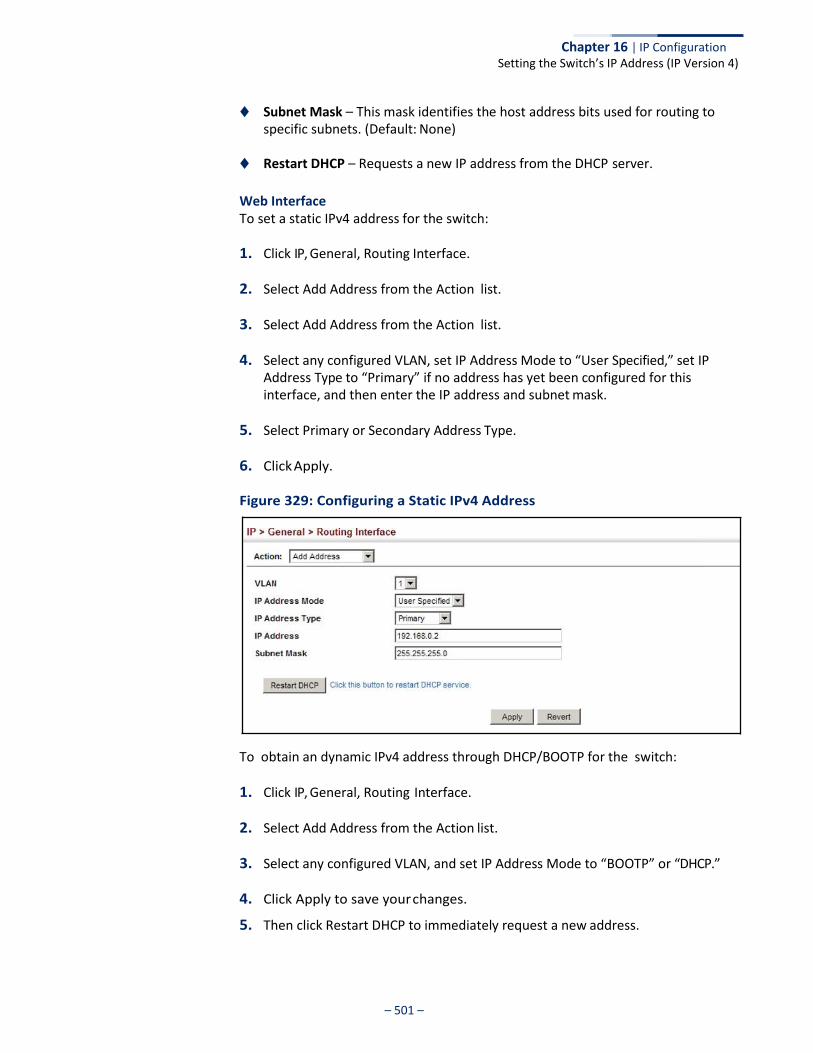
Chapter 16 | IP Configuration Setting the Switch’s IP Address (IP Version 4)
– 501 –
◆ Subnet Mask – This mask identifies the host address bits used for routing to specific subnets. (Default: None)
◆ Restart DHCP – Requests a new IP address from the DHCP server.
Web Interface To set a static IPv4 address for the switch:
1. Click IP, General, Routing Interface.
2. Select Add Address from the Action list.
3. Select Add Address from the Action list.
4. Select any configured VLAN, set IP Address Mode to “User Specified,” set IP Address Type to “Primary” if no address has yet been configured for this interface, and then enter the IP address and subnet mask.
5. Select Primary or Secondary Address Type.
6. Click Apply.
Figure 329: Configuring a Static IPv4 Address
To obtain an dynamic IPv4 address through DHCP/BOOTP for the switch:
1. Click IP, General, Routing Interface.
2. Select Add Address from the Action list.
3. Select any configured VLAN, and set IP Address Mode to “BOOTP” or “DHCP.”
4. Click Apply to save your changes.
5. Then click Restart DHCP to immediately request a new address.
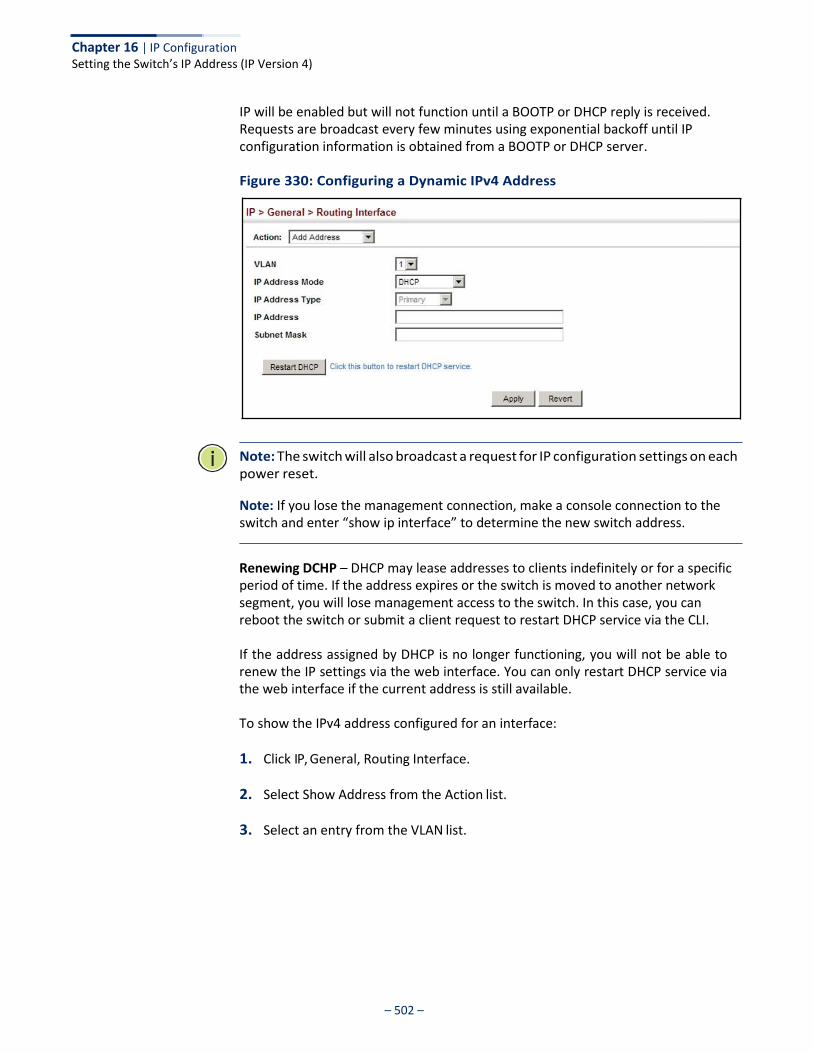
Chapter 16 | IP Configuration Setting the Switch’s IP Address (IP Version 4)
– 502 –
IP will be enabled but will not function until a BOOTP or DHCP reply is received. Requests are broadcast every few minutes using exponential backoff until IP configuration information is obtained from a BOOTP or DHCP server.
Figure 330: Configuring a Dynamic IPv4 Address
Note: The switch will also broadcast a request for IP configuration settings on each power reset.
Note: If you lose the management connection, make a console connection to the switch and enter “show ip interface” to determine the new switch address.
Renewing DCHP – DHCP may lease addresses to clients indefinitely or for a specific period of time. If the address expires or the switch is moved to another network segment, you will lose management access to the switch. In this case, you can reboot the switch or submit a client request to restart DHCP service via the CLI.
If the address assigned by DHCP is no longer functioning, you will not be able to renew the IP settings via the web interface. You can only restart DHCP service via the web interface if the current address is still available.
To show the IPv4 address configured for an interface:
1. Click IP, General, Routing Interface.
2. Select Show Address from the Action list.
3. Select an entry from the VLAN list.
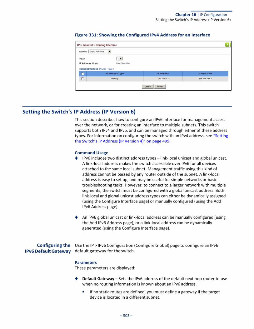
– 503 –
Chapter 16 | IP Configuration Setting the Switch’s IP Address (IP Version 6)
Figure 331: Showing the Configured IPv4 Address for an Interface
Setting the Switch’s IP Address (IP Version 6)
This section describes how to configure an IPv6 interface for management access over the network, or for creating an interface to multiple subnets. This switch supports both IPv4 and IPv6, and can be managed through either of these address types. For information on configuring the switch with an IPv4 address, see “Setting the Switch’s IP Address (IP Version 4)” on page 499.
Command Usage ◆ IPv6 includes two distinct address types – link-local unicast and global unicast.
A link-local address makes the switch accessible over IPv6 for all devices attached to the same local subnet. Management traffic using this kind of address cannot be passed by any router outside of the subnet. A link-local address is easy to set up, and may be useful for simple networks or basic troubleshooting tasks. However, to connect to a larger network with multiple segments, the switch must be configured with a global unicast address. Both link-local and global unicast address types can either be dynamically assigned (using the Configure Interface page) or manually configured (using the Add IPv6 Address page).
◆ An IPv6 global unicast or link-local address can be manually configured (using the Add IPv6 Address page), or a link-local address can be dynamically generated (using the Configure Interface page).
Configuring the IPv6 Default Gateway
Use the IP > IPv6 Configuration (Configure Global) page to configure an IPv6 default gateway for the switch.
Parameters These parameters are displayed:
◆ Default Gateway – Sets the IPv6 address of the default next hop router to use
when no routing information is known about an IPv6 address.
■ If no static routes are defined, you must define a gateway if the target device is located in a different subnet.
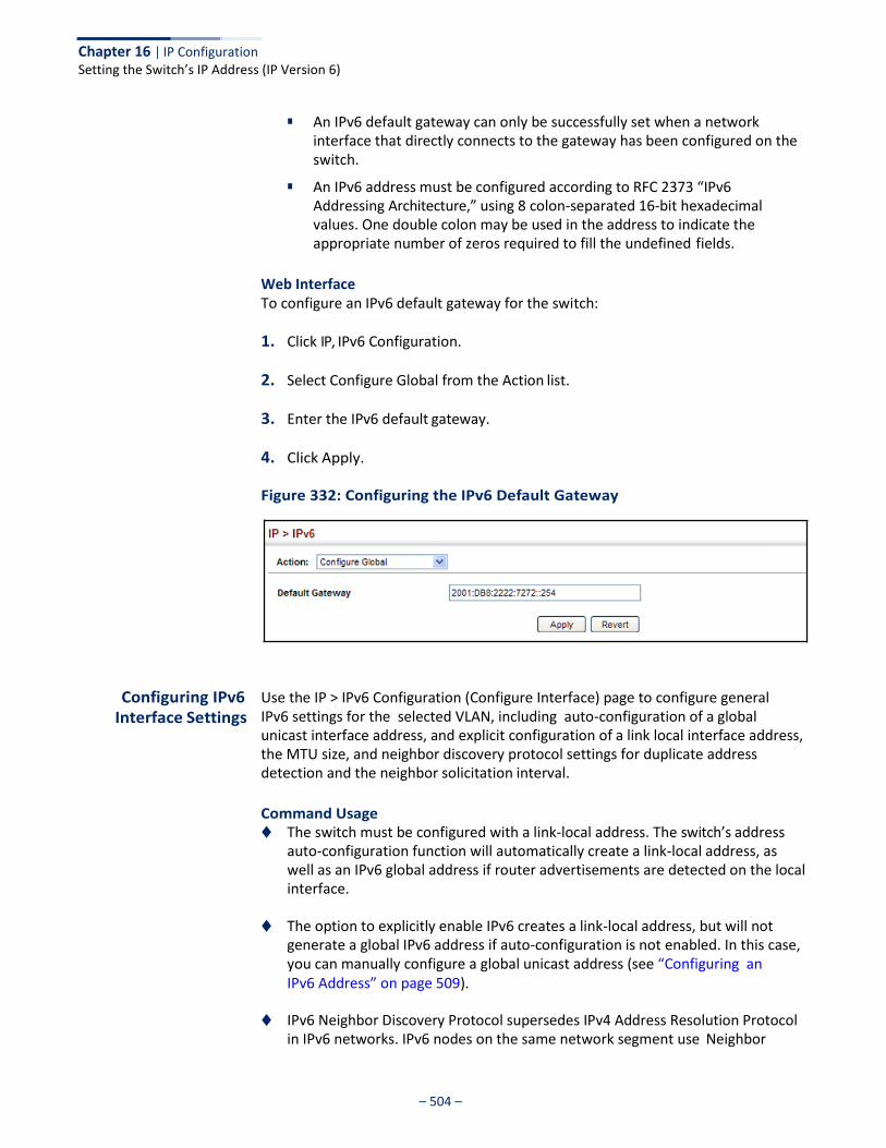
– 504 –
Chapter 16 | IP Configuration Setting the Switch’s IP Address (IP Version 6)
■ An IPv6 default gateway can only be successfully set when a network
interface that directly connects to the gateway has been configured on the switch.
■ An IPv6 address must be configured according to RFC 2373 “IPv6 Addressing Architecture,” using 8 colon-separated 16-bit hexadecimal values. One double colon may be used in the address to indicate the appropriate number of zeros required to fill the undefined fields.
Web Interface To configure an IPv6 default gateway for the switch:
1. Click IP, IPv6 Configuration.
2. Select Configure Global from the Action list.
3. Enter the IPv6 default gateway.
4. Click Apply.
Figure 332: Configuring the IPv6 Default Gateway
Configuring IPv6 Interface Settings
Use the IP > IPv6 Configuration (Configure Interface) page to configure general IPv6 settings for the selected VLAN, including auto-configuration of a global unicast interface address, and explicit configuration of a link local interface address, the MTU size, and neighbor discovery protocol settings for duplicate address detection and the neighbor solicitation interval.
Command Usage ◆ The switch must be configured with a link-local address. The switch’s address
auto-configuration function will automatically create a link-local address, as well as an IPv6 global address if router advertisements are detected on the local interface.
◆ The option to explicitly enable IPv6 creates a link-local address, but will not
generate a global IPv6 address if auto-configuration is not enabled. In this case, you can manually configure a global unicast address (see “Configuring an IPv6 Address” on page 509).
◆ IPv6 Neighbor Discovery Protocol supersedes IPv4 Address Resolution Protocol
in IPv6 networks. IPv6 nodes on the same network segment use Neighbor
– 505 –
Chapter 16 | IP Configuration Setting the Switch’s IP Address (IP Version 6)
Discovery to discover each other's presence, to determine each other's link- layer addresses, to find routers and to maintain reachability information about the paths to active neighbors. The key parameters used to facilitate this process are the number of attempts made to verify whether or not a duplicate address exists on the same network segment, and the interval between neighbor solicitations used to verify reachability information.
Parameters These parameters are displayed:
◆ VLAN – ID of a configured VLAN which is to be used for management access, or
as a standard interface for a subnet. By default, all ports on the switch are members of VLAN 1. However, the management station can be attached to a port belonging to any VLAN, as long as that VLAN has been assigned an IP address. (Range: 1-4094)
◆ Address Autoconfig – Enables stateless autoconfiguration of an IPv6 address
on an interface and enables IPv6 functionality on that interface. The network portion of the address is based on prefixes received in IPv6 router advertisement messages, and the host portion is automatically generated using the modified EUI-64 form of the interface identifier (i.e., the switch’s MAC address).
■ If a link local address has not yet been assigned to this interface, this command will dynamically generate one. The link-local address is made with an address prefix in the range of FE80~FEBF and a host portion based the switch’s MAC address in modified EUI-64 format. It will also generate a global unicast address if a global prefix is included in received router advertisements.
■ When DHCPv6 is started, the switch may attempt to acquire an IP address
prefix through stateful address autoconfiguration. If router advertisements have the “other stateful configuration” flag set, the switch will attempt to acquire other non-address configuration information (such as a default gateway).
■ If auto-configuration is not selected, then an address must be manually configured using the Add IPv6 Address page described below.
◆ Enable IPv6 Explicitly – Enables IPv6 on an interface and assigns it a link-local
address. Note that when an explicit address is assigned to an interface, IPv6 is automatically enabled, and cannot be disabled until all assigned addresses have been removed. (Default: Disabled)
Disabling this parameter does not disable IPv6 for an interface that has been explicitly configured with an IPv6 address.
◆ MTU – Sets the size of the maximum transmission unit (MTU) for IPv6 packets
sent on an interface. (Range: 1280-65535 bytes; Default: 1500 bytes)
■ The maximum value set in this field cannot exceed the MTU of the physical interface, which is currently fixed at 1500 bytes.
– 506 –
Chapter 16 | IP Configuration Setting the Switch’s IP Address (IP Version 6)
■ If a non-default value is configured, an MTU option is included in the router
advertisements sent from this device. This option is provided to ensure that all nodes on a link use the same MTU value in cases where the link MTU is not otherwise well known.
■ IPv6 routers do not fragment IPv6 packets forwarded from other routers. However, traffic originating from an end-station connected to an IPv6 router may be fragmented.
■ All devices on the same physical medium must use the same MTU in order to operate correctly.
■ IPv6 must be enabled on an interface before the MTU can be set. If an IPv6 address has not been assigned to the switch, “N/A” is displayed in the MTU field.
◆ ND DAD Attempts – The number of consecutive neighbor solicitation
messages sent on an interface during duplicate address detection. (Range: 0-600, Default: 3)
■ Configuring a value of 0 disables duplicate address detection.
■ Duplicate address detection determines if a new unicast IPv6 address already exists on the network before it is assigned to an interface.
■ Duplicate address detection is stopped on any interface that has been suspended (see “Configuring VLAN Groups” on page 149). While an interface is suspended, all unicast IPv6 addresses assigned to that interface are placed in a “pending” state. Duplicate address detection is automatically restarted when the interface is administratively re-activated.
■ An interface that is re-activated restarts duplicate address detection for all unicast IPv6 addresses on the interface. While duplicate address detection is performed on the interface’s link-local address, the other IPv6 addresses remain in a “tentative” state. If no duplicate link-local address is found, duplicate address detection is started for the remaining IPv6 addresses.
■ If a duplicate address is detected, it is set to “duplicate” state, and a warning message is sent to the console. If a duplicate link-local address is detected, IPv6 processes are disabled on the interface. If a duplicate global unicast address is detected, it is not used. All configuration commands associated with a duplicate address remain configured while the address is in “duplicate” state.
■ If the link-local address for an interface is changed, duplicate address detection is performed on the new link-local address, but not for any of the IPv6 global unicast addresses already associated with the interface.
◆ ND NS Interval – The interval between transmitting IPv6 neighbor solicitation
messages on an interface. (Range: 1000-3600000 milliseconds)
Default: 1000 milliseconds is used for neighbor discovery operations, 0 milliseconds is advertised in router advertisements.
This attribute specifies the interval between transmitting neighbor solicitation messages when resolving an address, or when probing the reachability of a
– 507 –
Chapter 16 | IP Configuration Setting the Switch’s IP Address (IP Version 6)
neighbor. Therefore, avoid using very short intervals for normal IPv6 operations.
When a non-default value is configured, the specified interval is used both for router advertisements and by the router itself.
◆ ND Reachable-Time – The amount of time that a remote IPv6 node is
considered reachable after some reachability confirmation event has occurred. (Range: 0-3600000 milliseconds)
Default: 30000 milliseconds is used for neighbor discovery operations, 0 milliseconds is advertised in router advertisements.
■ The time limit configured by this parameter allows the router to detect unavailable neighbors. During the neighbor discover process, an IPv6 node will multicast neighbor solicitation messages to search for neighbor nodes. For a neighbor node to be considered reachable, it must respond to the neighbor soliciting node with a neighbor advertisement message to become a confirmed neighbor, after which the reachable timer will be considered in effect for subsequent unicast IPv6 layer communications.
■ This time limit is included in all router advertisements sent out through an interface, ensuring that nodes on the same link use the same time value.
■ Setting the time limit to 0 means that the configured time is unspecified by this router.
◆ Restart DHCPv6 – When DHCPv6 is restarted, the switch may attempt to
acquire an IP address prefix through stateful address autoconfiguration. If the router advertisements have the “other stateful configuration” flag set, the switch may also attempt to acquire other non-address configuration information (such as a default gateway) when DHCPv6 is restarted.
Prior to submitting a client request to a DHCPv6 server, the switch should be configured with a link-local address using the Address Autoconfig option. The state of the Managed Address Configuration flag (M flag) and Other Stateful Configuration flag (O flag) received in Router Advertisement messages will determine the information this switch should attempt to acquire from the DHCPv6 server as described below.
■ Both M and O flags are set to 1:
DHCPv6 is used for both address and other configuration settings.
This combination is known as DHCPv6 stateful autoconfiguration, in which a DHCPv6 server assigns stateful addresses to IPv6 hosts.
■ The M flag is set to 0, and the O flag is set to 1:
DHCPv6 is used only for other configuration settings.
Neighboring routers are configured to advertise non-link-local address prefixes from which IPv6 hosts derive stateless addresses.
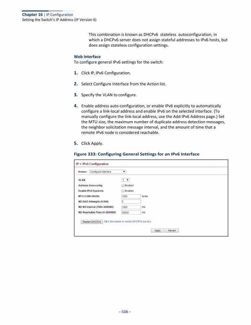
– 508 –
Chapter 16 | IP Configuration Setting the Switch’s IP Address (IP Version 6)
This combination is known as DHCPv6 stateless autoconfiguration, in which a DHCPv6 server does not assign stateful addresses to IPv6 hosts, but does assign stateless configuration settings.
Web Interface To configure general IPv6 settings for the switch:
1. Click IP, IPv6 Configuration.
2. Select Configure Interface from the Action list.
3. Specify the VLAN to configure.
4. Enable address auto-configuration, or enable IPv6 explicitly to automatically configure a link-local address and enable IPv6 on the selected interface. (To manually configure the link-local address, use the Add IPv6 Address page.) Set the MTU size, the maximum number of duplicate address detection messages, the neighbor solicitation message interval, and the amount of time that a remote IPv6 node is considered reachable.
5. Click Apply.
Figure 333: Configuring General Settings for an IPv6 Interface
– 509 –
Chapter 16 | IP Configuration Setting the Switch’s IP Address (IP Version 6)
Configuring an IPv6 Address
Use the IP > IPv6 Configuration (Add IPv6 Address) page to configure an IPv6 interface for management access over the network, or for creating an interface to multiple subnets.
Command Usage ◆ All IPv6 addresses must be formatted according to RFC 2373 “IPv6 Addressing
Architecture,” using 8 colon-separated 16-bit hexadecimal values. One double colon may be used in the address to indicate the appropriate number of zeros required to fill the undefined fields.
◆ The switch must always be configured with a link-local address. Therefore any
configuration process that enables IPv6 functionality, or assigns a global unicast address to the switch, including address auto-configuration or explicitly enabling IPv6 IPv6 (see “Configuring IPv6 Interface Settings” on page 504), will also automatically generate a link-local unicast address. The prefix length for a link-local address is fixed at 64 bits, and the host portion of the default address is based on the modified EUI-64 (Extended Universal Identifier) form of the interface identifier (i.e., the physical MAC address). Alternatively, you can manually configure the link-local address by entering the full address with a network prefix in the range of FE80~FEBF.
◆ To connect to a larger network with multiple subnets, you must configure a global unicast address. There are several alternatives to configuring this address type:
■ The global unicast address can be automatically configured by taking the network prefix from router advertisements observed on the local interface, and using the modified EUI-64 form of the interface identifier to automatically create the host portion of the address (see “Configuring IPv6 Interface Settings” on page 504).
■ It can be manually configured by specifying the entire network prefix and prefix length, and using the EUI-64 form of the interface identifier to automatically create the low-order 64 bits in the host portion of the address.
■ You can also manually configure the global unicast address by entering the full address and prefix length.
◆ You can configure multiple IPv6 global unicast addresses per interface, but only
one link-local address per interface.
◆ If a duplicate link-local address is detected on the local segment, this interface is disabled and a warning message displayed on the console. If a duplicate global unicast address is detected on the network, the address is disabled on this interface and a warning message displayed on the console.
◆ When an explicit address is assigned to an interface, IPv6 is automatically
enabled, and cannot be disabled until all assigned addresses have been removed.

Chapter 16 | IP Configuration Setting the Switch’s IP Address (IP Version 6)
– 510 –
Parameters These parameters are displayed:
◆ VLAN – ID of a configured VLAN which is to be used for management access, or
for creating an interface to multiple subnets. By default, all ports on the switch are members of VLAN 1. However, the management station can be attached to a port belonging to any VLAN, as long as that VLAN has been assigned an IP address. (Range: 1-4094)
◆ Address Type – Defines the address type configured for this interface.
■ Global – Configures an IPv6 global unicast address with a full IPv6 address including the network prefix and host address bits, followed by a forward slash, and a decimal value indicating how many contiguous bits (from the left) of the address comprise the prefix (i.e., the network portion of the address).
■ EUI-64 (Extended Universal Identifier) – Configures an IPv6 address for an
interface using an EUI-64 interface ID in the low order 64 bits.
■ When using EUI-64 format for the low-order 64 bits in the host portion of the address, the value entered in the IPv6 Address field includes the network portion of the address, and the prefix length indicates how many contiguous bits (starting at the left) of the address comprise the prefix (i.e., the network portion of the address). Note that the value specified in the IPv6 Address field may include some of the high-order host bits if the specified prefix length is less than 64 bits. If the specified prefix length exceeds 64 bits, then the bits used in the network portion of the address will take precedence over the interface identifier.
■ IPv6 addresses are 16 bytes long, of which the bottom 8 bytes typically
form a unique host identifier based on the device’s MAC address. The EUI-64 specification is designed for devices that use an extended 8- byte MAC address. For devices that still use a 6-byte MAC address (also known as EUI-48 format), it must be converted into EUI-64 format by inverting the universal/local bit in the address and inserting the hexadecimal number FFFE between the upper and lower three bytes of the MAC address.
For example, if a device had an EUI-48 address of 28-9F-18-1C-82-35, the global/local bit must first be inverted to meet EUI-64 requirements (i.e., 1 for globally defined addresses and 0 for locally defined addresses), changing 28 to 2A. Then the two bytes FFFE are inserted between the OUI (i.e., organizationally unique identifier, or company identifier) and the rest of the address, resulting in a modified EUI-64 interface identifier of 2A-9F-18-FF-FE-1C-82-35.
■ This host addressing method allows the same interface identifier to be
used on multiple IP interfaces of a single device, as long as those interfaces are attached to different subnets.
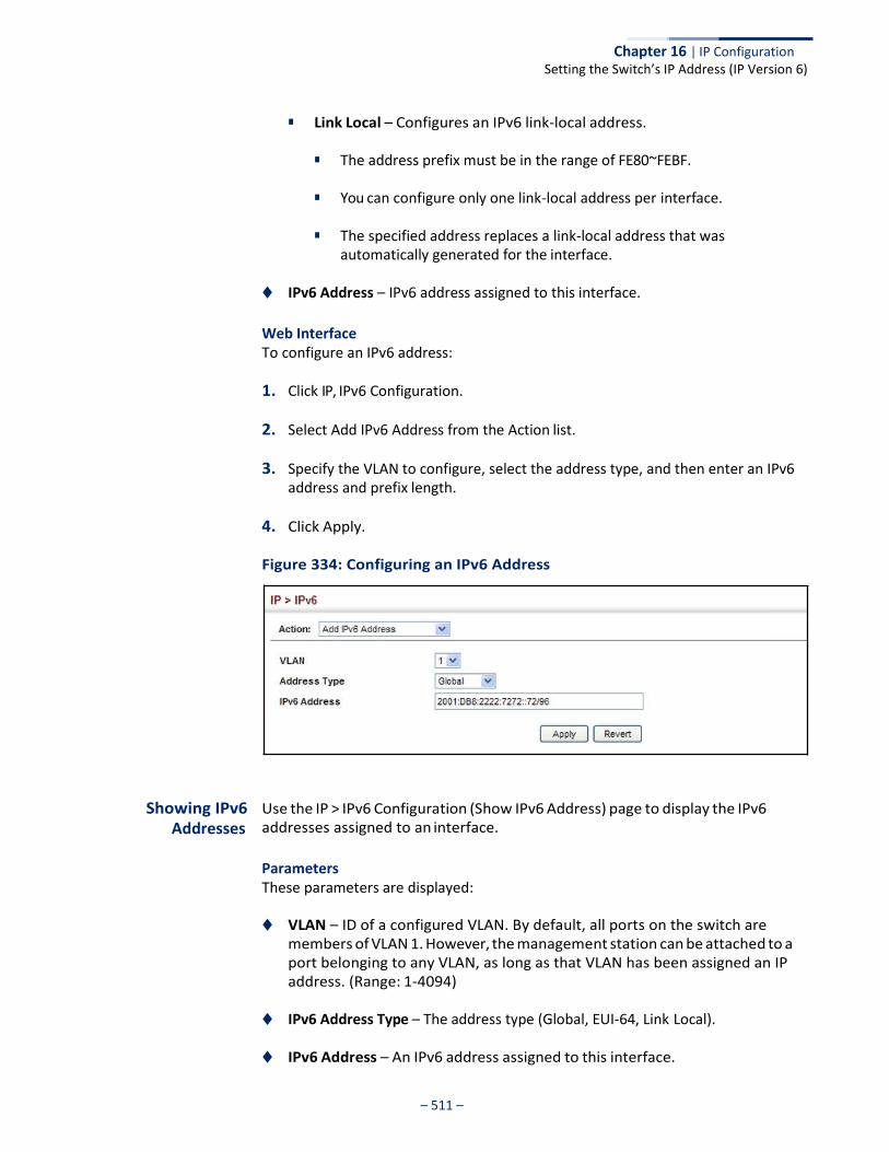
Chapter 16 | IP Configuration Setting the Switch’s IP Address (IP Version 6)
– 511 –
■ Link Local – Configures an IPv6 link-local address.
■ The address prefix must be in the range of FE80~FEBF.
■ You can configure only one link-local address per interface.
■ The specified address replaces a link-local address that was automatically generated for the interface.
◆ IPv6 Address – IPv6 address assigned to this interface.
Web Interface To configure an IPv6 address:
1. Click IP, IPv6 Configuration.
2. Select Add IPv6 Address from the Action list.
3. Specify the VLAN to configure, select the address type, and then enter an IPv6 address and prefix length.
4. Click Apply.
Figure 334: Configuring an IPv6 Address
Showing IPv6 Addresses
Use the IP > IPv6 Configuration (Show IPv6 Address) page to display the IPv6 addresses assigned to an interface.
Parameters These parameters are displayed:
◆ VLAN – ID of a configured VLAN. By default, all ports on the switch are members of VLAN 1. However, the management station can be attached to a port belonging to any VLAN, as long as that VLAN has been assigned an IP address. (Range: 1-4094)
◆ IPv6 Address Type – The address type (Global, EUI-64, Link Local).
◆ IPv6 Address – An IPv6 address assigned to this interface.
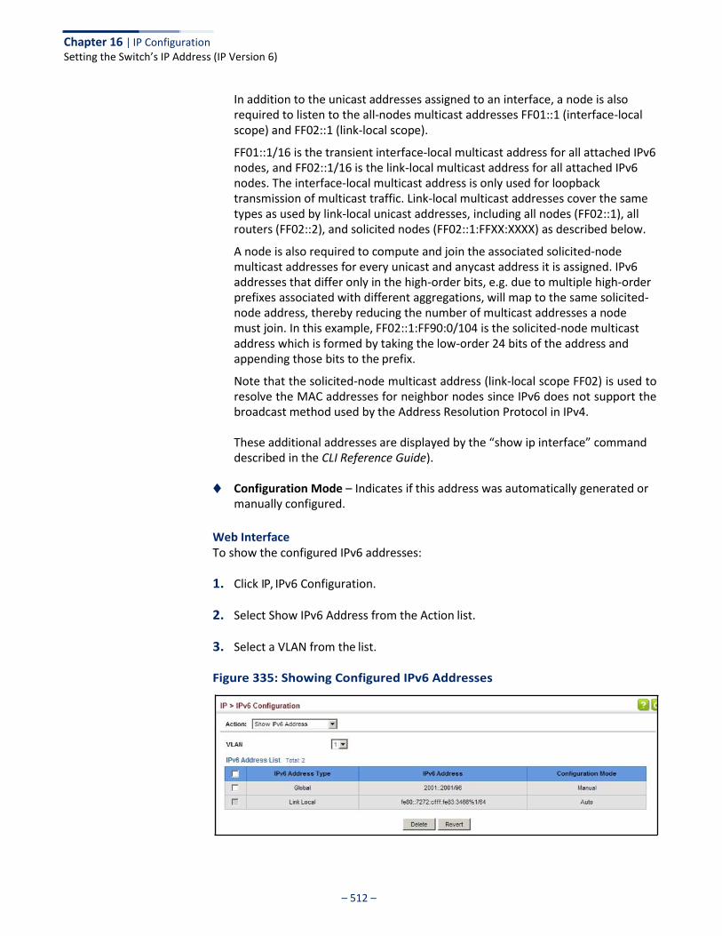
Chapter 16 | IP Configuration Setting the Switch’s IP Address (IP Version 6)
– 512 –
In addition to the unicast addresses assigned to an interface, a node is also required to listen to the all-nodes multicast addresses FF01::1 (interface-local scope) and FF02::1 (link-local scope).
FF01::1/16 is the transient interface-local multicast address for all attached IPv6 nodes, and FF02::1/16 is the link-local multicast address for all attached IPv6 nodes. The interface-local multicast address is only used for loopback transmission of multicast traffic. Link-local multicast addresses cover the same types as used by link-local unicast addresses, including all nodes (FF02::1), all routers (FF02::2), and solicited nodes (FF02::1:FFXX:XXXX) as described below.
A node is also required to compute and join the associated solicited-node multicast addresses for every unicast and anycast address it is assigned. IPv6 addresses that differ only in the high-order bits, e.g. due to multiple high-order prefixes associated with different aggregations, will map to the same solicited- node address, thereby reducing the number of multicast addresses a node must join. In this example, FF02::1:FF90:0/104 is the solicited-node multicast address which is formed by taking the low-order 24 bits of the address and appending those bits to the prefix.
Note that the solicited-node multicast address (link-local scope FF02) is used to resolve the MAC addresses for neighbor nodes since IPv6 does not support the broadcast method used by the Address Resolution Protocol in IPv4.
These additional addresses are displayed by the “show ip interface” command described in the CLI Reference Guide).
◆ Configuration Mode – Indicates if this address was automatically generated or
manually configured.
Web Interface To show the configured IPv6 addresses:
1. Click IP, IPv6 Configuration.
2. Select Show IPv6 Address from the Action list.
3. Select a VLAN from the list.
Figure 335: Showing Configured IPv6 Addresses
Chapter 16 | IP Configuration Setting the Switch’s IP Address (IP Version 6)
– 513 –
Showing the IPv6 Neighbor Cache
Use the IP > IPv6 Configuration (Show IPv6 Neighbor Cache) page to display the IPv6 addresses detected for neighbor devices.
Parameters These parameters are displayed:
Table 31: Show IPv6 Neighbors - display description
IPv6 Address IPv6 address of neighbor.
Age The time since the address was verified as reachable (in seconds). A static entry is indicated by the value “Permanent.”
Link-layer Address
Physical layer MAC address.
State The following states are used for dynamic entries: ◆ Incomplete - Address resolution is being carried out on the entry.
A neighbor solicitation message has been sent to the multicast address of the target, but it has not yet returned a neighbor advertisement message.
◆ Invalid - An invalidated mapping. Setting the state to invalid dis-associates the interface identified with this entry from the indicated mapping (RFC 4293).
◆ Reachable - Positive confirmation was received within the last ReachableTime interval that the forward path to the neighbor was functioning. While in Reachable state, the device takes no special action when sending packets.
◆ Stale - More than the ReachableTime interval has elapsed since the last positive confirmation was received that the forward path was functioning. While in Stale state, the device takes no action until a packet is sent.
◆ Delay - More than the ReachableTime interval has elapsed since the last positive confirmation was received that the forward path was functioning. A packet was sent within the last DELAY_FIRST_PROBE_TIME interval. If no reachability confirmation is received within this interval after entering the Delay state, the switch will send a neighbor solicitation message and change the state to Probe.
◆ Probe - A reachability confirmation is actively sought by re-sending neighbor solicitation messages every RetransTimer interval until confirmation of reachability is received.
◆ Unknown - Unknown state.
The following states are used for static entries: ◆ Incomplete - The interface for this entry is down. ◆ Permanent - Indicates a static entry. ◆ Reachable - The interface for this entry is up. Reachability detection is not
applied to static entries in the IPv6 neighbor discovery cache.
VLAN VLAN interface from which the address was reached.
Field Description
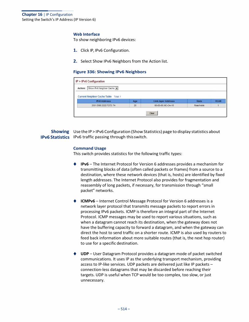
Chapter 16 | IP Configuration Setting the Switch’s IP Address (IP Version 6)
– 514 –
Web Interface To show neighboring IPv6 devices:
1. Click IP, IPv6 Configuration.
2. Select Show IPv6 Neighbors from the Action list.
Figure 336: Showing IPv6 Neighbors
Showing IPv6 Statistics
Use the IP > IPv6 Configuration (Show Statistics) page to display statistics about IPv6 traffic passing through this switch.
Command Usage This switch provides statistics for the following traffic types:
◆ IPv6 – The Internet Protocol for Version 6 addresses provides a mechanism for
transmitting blocks of data (often called packets or frames) from a source to a destination, where these network devices (that is, hosts) are identified by fixed length addresses. The Internet Protocol also provides for fragmentation and reassembly of long packets, if necessary, for transmission through “small packet” networks.
◆ ICMPv6 – Internet Control Message Protocol for Version 6 addresses is a
network layer protocol that transmits message packets to report errors in processing IPv6 packets. ICMP is therefore an integral part of the Internet Protocol. ICMP messages may be used to report various situations, such as when a datagram cannot reach its destination, when the gateway does not have the buffering capacity to forward a datagram, and when the gateway can direct the host to send traffic on a shorter route. ICMP is also used by routers to feed back information about more suitable routes (that is, the next hop router) to use for a specific destination.
◆ UDP – User Datagram Protocol provides a datagram mode of packet switched communications. It uses IP as the underlying transport mechanism, providing access to IP-like services. UDP packets are delivered just like IP packets – connection-less datagrams that may be discarded before reaching their targets. UDP is useful when TCP would be too complex, too slow, or just unnecessary.
Chapter 16 | IP Configuration Setting the Switch’s IP Address (IP Version 6)
– 515 –
Parameters These parameters are displayed:
Table 32: Show IPv6 Statistics - display description
IPv6 Statistics
IPv6 Received
Total The total number of input datagrams received by the interface, including those received in error.
Header Errors The number of input datagrams discarded due to errors in their IPv6 headers, including version number mismatch, other format errors, hop count exceeded, IPv6 options, etc.
Too Big Errors The number of input datagrams that could not be forwarded because their size exceeded the link MTU of outgoing interface.
No Routes The number of input datagrams discarded because no route could be found to transmit them to their destination.
Address Errors The number of input datagrams discarded because the IPv6 address in their IPv6 header's destination field was not a valid address to be received at this entity. This count includes invalid addresses (e.g., ::0) and unsupported addresses (e.g., addresses with unallocated prefixes). For entities which are not IPv6 routers and therefore do not forward datagrams, this counter includes datagrams discarded because the destination address was not a local address.
Unknown Protocols The number of locally-addressed datagrams received successfully but discarded because of an unknown or unsupported protocol. This counter is incremented at the interface to which these datagrams were addressed which might not be necessarily the input interface for some of the datagrams.
Truncated Packets The number of input datagrams discarded because datagram frame didn't carry enough data.
Discards The number of input IPv6 datagrams for which no problems were encountered to prevent their continued processing, but which were discarded (e.g., for lack of buffer space). Note that this counter does not include any datagrams discarded while awaiting re-assembly.
Delivers The total number of datagrams successfully delivered to IPv6 user- protocols (including ICMP). This counter is incremented at the interface to which these datagrams were addressed which might not be necessarily the input interface for some of the datagrams.
Reassembly Request Datagrams
The number of IPv6 fragments received which needed to be reassembled at this interface. Note that this counter is increment ed at the interface to which these fragments were addressed which might not be necessarily the input interface for some of the fragments.
Reassembled Succeeded The number of IPv6 datagrams successfully reassembled. Note that this counter is incremented at the interface to which these datagrams were addressed which might not be necessarily the input interface for some of the fragments.
Reassembled Failed The number of failures detected by the IPv6 re-assembly algorithm (for whatever reason: timed out, errors, etc.). Note that this is not necessarily a count of discarded IPv6 fragments since some algorithms (notably the algorithm in RFC 815) can lose track of the number of fragments by combining them as they are received. This counter is incremented at the interface to which these fragments were addressed which might not be necessarily the input interface for some of the fragments.
Field Description
– 516 –
Chapter 16 | IP Configuration Setting the Switch’s IP Address (IP Version 6)
Table 32: Show IPv6 Statistics - display description (Continued)
Field Description
IPv6 Transmitted
Forwards Datagrams The number of output datagrams which this entity received and forwarded to their final destinations. In entities which do not act as IPv6 routers, this counter will include only those packets which were Source- Routed via this entity, and the Source-Route processing was successful. Note that for a successfully forwarded datagram the counter of the outgoing interface is incremented.
Requests The total number of IPv6 datagrams which local IPv6 user-protocols (including ICMP) supplied to IPv6 in requests for transmission. Note that this counter does not include any datagrams counted in ipv6IfStatsOutForwDatagrams.
Discards The number of output IPv6 datagrams for which no problem was encountered to prevent their transmission to their destination, but which were discarded (e.g., for lack of buffer space). Note that this counter would include datagrams counted in ipv6IfStatsOutForwDatagrams if any such packets met this (discretionary) discard criterion.
No Routes The number of input datagrams discarded because no route could be found to transmit them to their destination.
Generated Fragments The number of output datagram fragments that have been generated as a result of fragmentation at this output interface.
Fragment Succeeded The number of IPv6 datagrams that have been successfully fragmented at this output interface.
Fragment Failed The number of IPv6 datagrams that have been discarded because they needed to be fragmented at this output interface but could not be.
ICMPv6 Statistics
ICMPv6 received
Input The total number of ICMP messages received by the interface which includes all those counted by ipv6IfIcmpInErrors. Note that this interface is the interface to which the ICMP messages were addressed which may not be necessarily the input interface for the messages.
Errors The number of ICMP messages which the interface received but determined as having ICMP-specific errors (bad ICMP checksums, bad length, etc.).
Destination Unreachable Messages
The number of ICMP Destination Unreachable messages received by the interface.
Packet Too Big Messages The number of ICMP Packet Too Big messages received by the interface.
Time Exceeded Messages The number of ICMP Time Exceeded messages received by the interface.
Parameter Problem Messages
The number of ICMP Parameter Problem messages received by the interface.
Echo Request Messages The number of ICMP Echo (request) messages received by the interface.
Echo Reply Messages The number of ICMP Echo Reply messages received by the interface.
Router Solicit Messages The number of ICMP Router Solicit messages received by the interface.
Router Advertisement Messages
The number of ICMP Router Advertisement messages received by the interface.
Neighbor Solicit Messages The number of ICMP Neighbor Solicit messages received by the

– 517 –
Chapter 16 | IP Configuration Setting the Switch’s IP Address (IP Version 6)
interface.
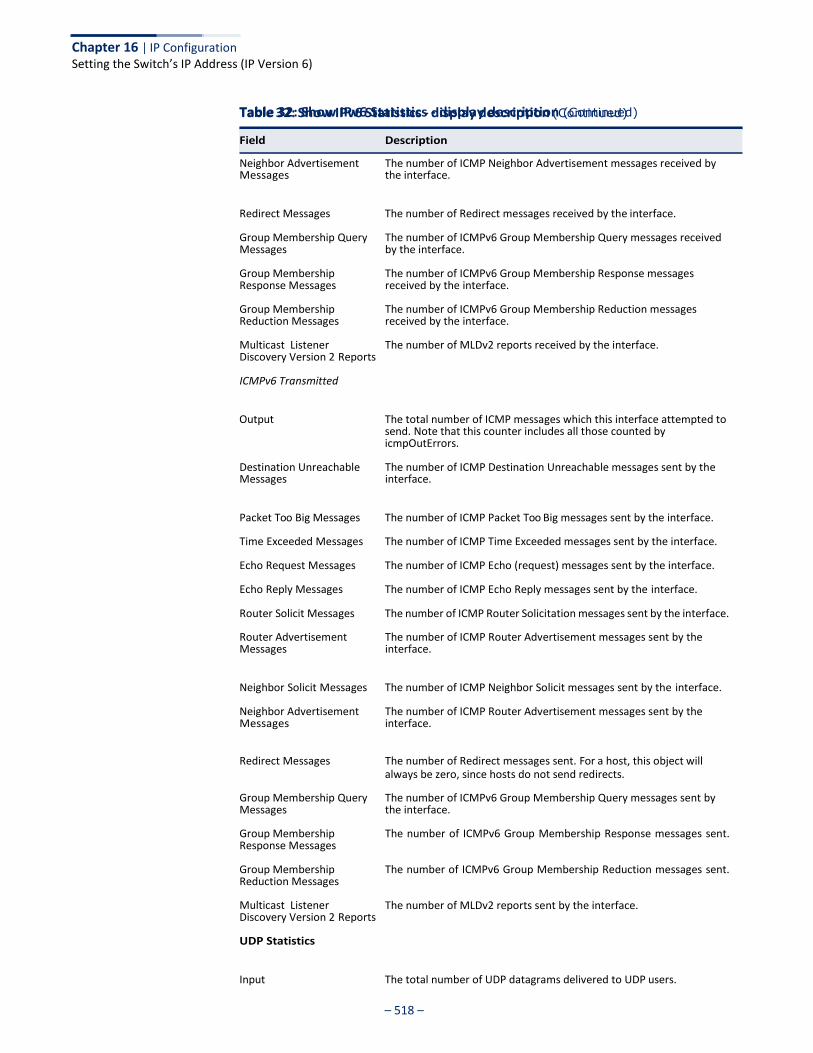
– 518 –
Chapter 16 | IP Configuration Setting the Switch’s IP Address (IP Version 6)
Table 32: Show IPv6 Statistics - display description (Continued)
Field Description
Table 32: Show IPv6 Statistics - display description (Continued)
Neighbor Advertisement Messages
The number of ICMP Neighbor Advertisement messages received by the interface.
Redirect Messages The number of Redirect messages received by the interface.
Group Membership Query Messages
Group Membership Response Messages
Group Membership Reduction Messages
Multicast Listener Discovery Version 2 Reports
ICMPv6 Transmitted
The number of ICMPv6 Group Membership Query messages received by the interface.
The number of ICMPv6 Group Membership Response messages received by the interface.
The number of ICMPv6 Group Membership Reduction messages received by the interface.
The number of MLDv2 reports received by the interface.
Output The total number of ICMP messages which this interface attempted to send. Note that this counter includes all those counted by icmpOutErrors.
Destination Unreachable Messages
The number of ICMP Destination Unreachable messages sent by the interface.
Packet Too Big Messages The number of ICMP Packet Too Big messages sent by the interface.
Time Exceeded Messages The number of ICMP Time Exceeded messages sent by the interface.
Echo Request Messages The number of ICMP Echo (request) messages sent by the interface.
Echo Reply Messages The number of ICMP Echo Reply messages sent by the interface.
Router Solicit Messages The number of ICMP Router Solicitation messages sent by the interface.
Router Advertisement Messages
The number of ICMP Router Advertisement messages sent by the interface.
Neighbor Solicit Messages The number of ICMP Neighbor Solicit messages sent by the interface.
Neighbor Advertisement Messages
The number of ICMP Router Advertisement messages sent by the interface.
Redirect Messages The number of Redirect messages sent. For a host, this object will always be zero, since hosts do not send redirects.
Group Membership Query Messages
Group Membership Response Messages
Group Membership Reduction Messages
Multicast Listener Discovery Version 2 Reports
UDP Statistics
The number of ICMPv6 Group Membership Query messages sent by the interface.
The number of ICMPv6 Group Membership Response messages sent.
The number of ICMPv6 Group Membership Reduction messages sent.
The number of MLDv2 reports sent by the interface.
Input The total number of UDP datagrams delivered to UDP users.
Field Description

– 519 –
Chapter 16 | IP Configuration Setting the Switch’s IP Address (IP Version 6)
No Port Errors The total number of received UDP datagrams for which there was no application at the destination port.
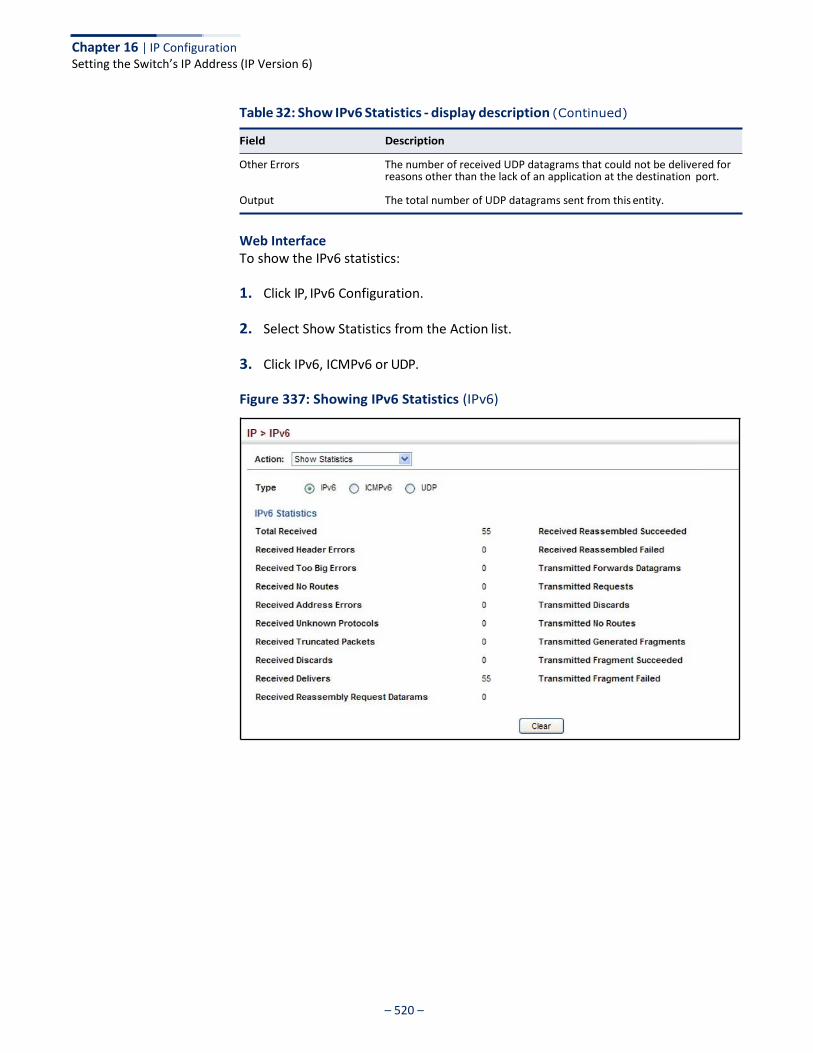
– 520 –
Chapter 16 | IP Configuration Setting the Switch’s IP Address (IP Version 6)
Table 32: Show IPv6 Statistics - display description (Continued)
Field Description
Other Errors The number of received UDP datagrams that could not be delivered for reasons other than the lack of an application at the destination port.
Output The total number of UDP datagrams sent from this entity.
Web Interface To show the IPv6 statistics:
1. Click IP, IPv6 Configuration.
2. Select Show Statistics from the Action list.
3. Click IPv6, ICMPv6 or UDP.
Figure 337: Showing IPv6 Statistics (IPv6)
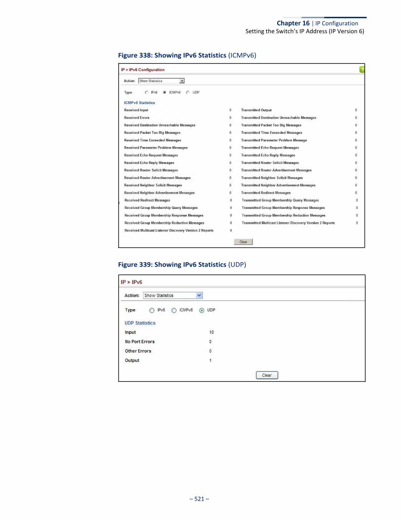
– 521 –
Chapter 16 | IP Configuration Setting the Switch’s IP Address (IP Version 6)
Figure 338: Showing IPv6 Statistics (ICMPv6)
Figure 339: Showing IPv6 Statistics (UDP)
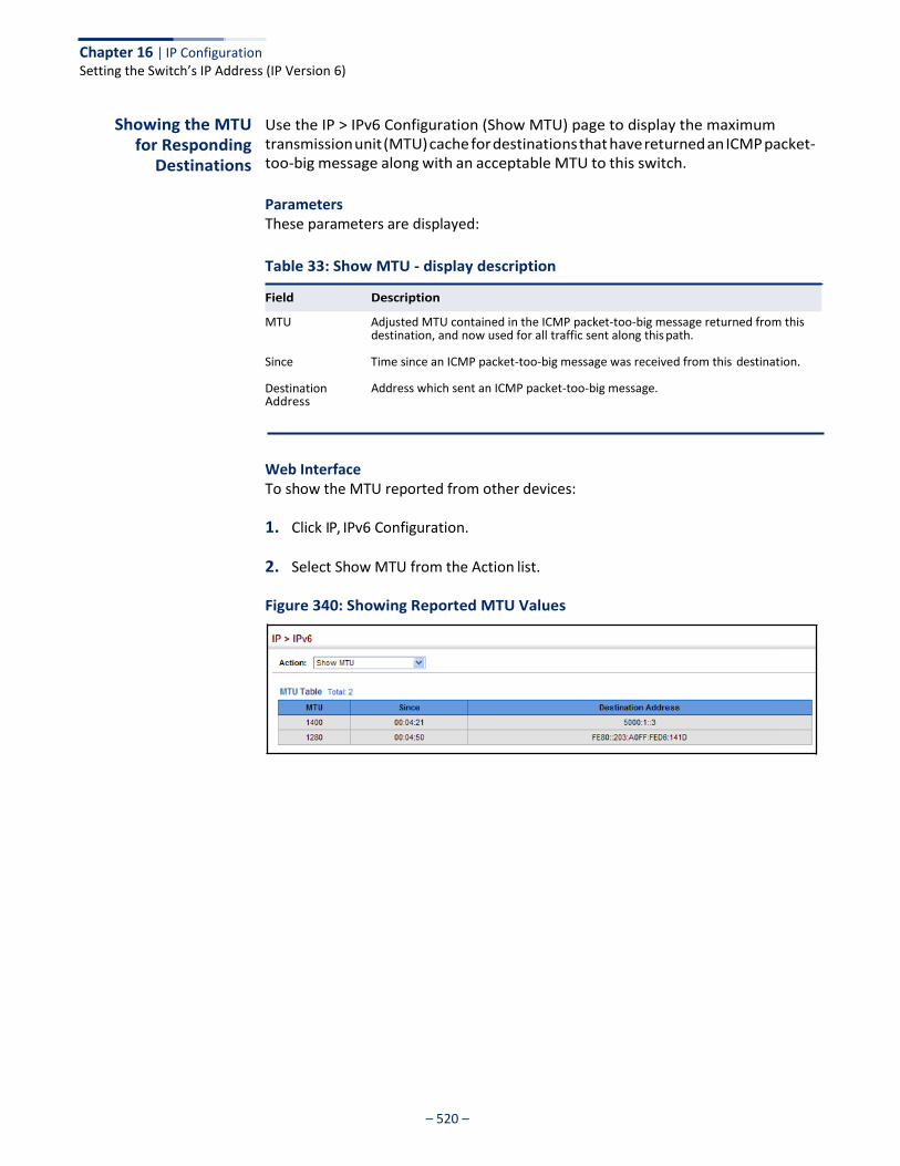
Chapter 16 | IP Configuration Setting the Switch’s IP Address (IP Version 6)
– 520 –
Showing the MTU for Responding
Destinations
Use the IP > IPv6 Configuration (Show MTU) page to display the maximum transmission unit (MTU) cache for destinations that have returned an ICMP packet- too-big message along with an acceptable MTU to this switch.
Parameters These parameters are displayed:
Table 33: Show MTU - display description
MTU Adjusted MTU contained in the ICMP packet-too-big message returned from this destination, and now used for all traffic sent along this path.
Since Time since an ICMP packet-too-big message was received from this destination.
Destination Address
Address which sent an ICMP packet-too-big message.
Web Interface To show the MTU reported from other devices:
1. Click IP, IPv6 Configuration.
2. Select Show MTU from the Action list.
Figure 340: Showing Reported MTU Values
Field Description
– 521 –
General IP Routing
This chapter provides information on network functions including:
◆ Static Routes – Configures static routes to other network segments.
◆ Routing Table – Displays routing entries learned through statically configured entries.
Overview
This switch supports IP routing and routing path management via static routing definitions. When IP routing is functioning, this switch acts as a wire-speed router, passing traffic between VLANs with different IP interfaces, and routing traffic to external IP networks. However, when the switch is first booted, default routing can only forward traffic between local IP interfaces. As with all traditional routers, static routing must first be configured to work.
Initial Configuration By default, all ports belong to the same VLAN and the switch provides only Layer 2 functionality. To segment the attached network, first create VLANs for each unique user group or application traffic (page 149), assign all ports that belong to the same group to these VLANs (page 152), and then assign an IP interface to each VLAN (page 499 or page 503). By separating the network into different VLANs, it can be partitioned into subnetworks that are disconnected at Layer 2. Network traffic within the same subnet is still switched using Layer 2 switching. And the VLANs can now be interconnected (as required) with Layer 3 switching.
Each VLAN represents a virtual interface to Layer 3. You just need to provide the network address for each virtual interface, and the traffic between different subnetworks will be routed by Layer 3 switching.
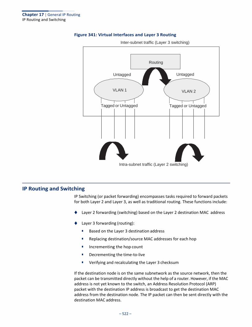
Chapter 17 | General IP Routing IP Routing and Switching
– 522 –
Unt Unt
Tagged or Untagged Tagged or Untagged
Figure 341: Virtual Interfaces and Layer 3 Routing
Inter-subnet traffic (Layer 3 switching)
Routing
Untagged Untagged
VLAN 1 VLAN 2
Tagged or Untagged Tagged or Untagged
Intra-subnet traffic (Layer 2 switching)
IP Routing and Switching
IP Switching (or packet forwarding) encompasses tasks required to forward packets for both Layer 2 and Layer 3, as well as traditional routing. These functions include:
◆ Layer 2 forwarding (switching) based on the Layer 2 destination MAC address
◆ Layer 3 forwarding (routing):
■ Based on the Layer 3 destination address
■ Replacing destination/source MAC addresses for each hop
■ Incrementing the hop count
■ Decrementing the time-to-live
■ Verifying and recalculating the Layer 3 checksum
If the destination node is on the same subnetwork as the source network, then the packet can be transmitted directly without the help of a router. However, if the MAC address is not yet known to the switch, an Address Resolution Protocol (ARP) packet with the destination IP address is broadcast to get the destination MAC address from the destination node. The IP packet can then be sent directly with the destination MAC address.
Chapter 17 | General IP Routing IP Routing and Switching
– 523 –
If the destination belongs to a different subnet on this switch, the packet can be routed directly to the destination node. However, if the packet belongs to a subnet not included on this switch, then the packet should be sent to the next hop router (with the MAC address of the router itself used as the destination MAC address, and the destination IP address of the destination node). The router will then forward the packet to the destination node through the correct path. The router can also use the ARP protocol to find out the MAC address of the destination node of the next hop router as necessary.
Note: In order to perform IP switching, the switch should be recognized by other network nodes as an IP router, either by setting it as the default gateway or by redirection from another router via the ICMP process.
When the switch receives an IP packet addressed to its own MAC address, the packet follows the Layer 3 routing process. The destination IP address is checked against the Layer 3 address table. If the address is not already there, the switch broadcasts an ARP packet to all the ports on the destination VLAN to find out the destination MAC address. After the MAC address is discovered, the packet is reformatted and sent out to the destination. The reformat process includes decreasing the Time-To-Live (TTL) field of the IP header, recalculating the IP header checksum, and replacing the destination MAC address with either the MAC address of the destination node or that of the next hop router.
When another packet destined to the same node arrives, the destination MAC can be retrieved directly from the Layer 3 address table; the packet is then reformatted and sent out the destination port. IP switching can be done at wire-speed when the destination address entry is already in the Layer 3 address table.
If the switch determines that a frame must be routed, the route is calculated only during setup. Once the route has been determined, all packets in the current flow are simply switched or forwarded across the chosen path. This takes advantage of the high throughput and low latency of switching by enabling the traffic to bypass the routing engine once the path calculation has been performed.
Routing Path Management
Routing Path Management involves the determination and updating of all the routing information required for packet forwarding, including:
◆ Updating the routing table
◆ Updating the Layer 3 switching database
Routing Protocols The switch supports static routing.
◆ Static routing requires routing information to be stored in the switch either manually or when a connection is set up by an application outside the switch.

– 524 –
Chapter 17 | General IP Routing Configuring Static Routes
Configuring Static Routes
You can enter static routes in the routing table using the IP > Routing > Static Routes (Add) page. Static routes may be required to force the use of a specific route to a subnet. Static routes do not automatically change in response to changes in network topology, so you should only configure a small number of stable routes to ensure network accessibility.
Command Usage ◆ Up to 512 static routes can be configured.
◆ If more than one static routes have the same lowest cost, the first route stored in the routing table will be used.
Parameters These parameters are displayed:
◆ Destination IP Address – IP address of the destination network, subnetwork,
or host.
◆ Net Mask – Network mask for the associated IP subnet. This mask identifies the host address bits used for routing to specific subnets.
◆ Next Hop – IP address of the next router hop used for this route.
◆ Distance – An administrative distance indicating that this route can be overridden by other routing information. (Range: 1-255, Default: 1)
Web Interface To configure static routes:
1. Click IP, Routing, Static Routes.
2. Select Add from the Action List.
3. Enter the destination address, subnet mask, and next hop router.
4. Click Apply.
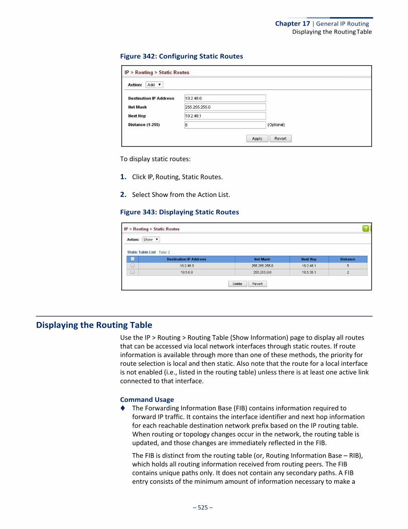
– 525 –
Chapter 17 | General IP Routing Displaying the Routing Table
Figure 342: Configuring Static Routes
To display static routes:
1. Click IP, Routing, Static Routes.
2. Select Show from the Action List.
Figure 343: Displaying Static Routes
Displaying the Routing Table
Use the IP > Routing > Routing Table (Show Information) page to display all routes that can be accessed via local network interfaces through static routes. If route information is available through more than one of these methods, the priority for route selection is local and then static. Also note that the route for a local interface is not enabled (i.e., listed in the routing table) unless there is at least one active link connected to that interface.
Command Usage ◆ The Forwarding Information Base (FIB) contains information required to
forward IP traffic. It contains the interface identifier and next hop information for each reachable destination network prefix based on the IP routing table. When routing or topology changes occur in the network, the routing table is updated, and those changes are immediately reflected in the FIB.
The FIB is distinct from the routing table (or, Routing Information Base – RIB), which holds all routing information received from routing peers. The FIB contains unique paths only. It does not contain any secondary paths. A FIB entry consists of the minimum amount of information necessary to make a
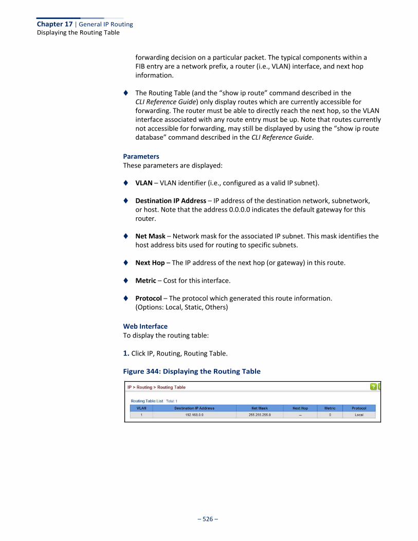
– 526 –
Chapter 17 | General IP Routing Displaying the Routing Table
forwarding decision on a particular packet. The typical components within a FIB entry are a network prefix, a router (i.e., VLAN) interface, and next hop information.
◆ The Routing Table (and the “show ip route” command described in the CLI Reference Guide) only display routes which are currently accessible for forwarding. The router must be able to directly reach the next hop, so the VLAN interface associated with any route entry must be up. Note that routes currently not accessible for forwarding, may still be displayed by using the “show ip route database” command described in the CLI Reference Guide.
Parameters These parameters are displayed:
◆ VLAN – VLAN identifier (i.e., configured as a valid IP subnet).
◆ Destination IP Address – IP address of the destination network, subnetwork, or host. Note that the address 0.0.0.0 indicates the default gateway for this router.
◆ Net Mask – Network mask for the associated IP subnet. This mask identifies the
host address bits used for routing to specific subnets.
◆ Next Hop – The IP address of the next hop (or gateway) in this route.
◆ Metric – Cost for this interface.
◆ Protocol – The protocol which generated this route information. (Options: Local, Static, Others)
Web Interface To display the routing table:
1. Click IP, Routing, Routing Table.
Figure 344: Displaying the Routing Table
– 527 –
IP Services
This chapter describes the following IP services:
◆ DNS – Configures default domain names, identifies servers to use for dynamic lookup, and shows how to configure static entries.
◆ Multicast DNS – Configures multicast DNS host name-to-address mapping on
the local network without the need for a dedicated DNS server.
◆ DHCP – Configures client, relay, and dynamic provisioning.
Domain Name Service
DNS service on this switch allows host names to be mapped to IP addresses using static table entries or by redirection to other name servers on the network. When a client device designates this switch as a DNS server, the client will attempt to resolve host names into IP addresses by forwarding DNS queries to the switch, and waiting for a response.
You can manually configure entries in the DNS table used for mapping domain names to IP addresses, configure default domain names, or specify one or more name servers to use for domain name to address translation.
Configuring General DNS Service Parameters
Use the IP Service > DNS - General (Configure Global) page to enable domain lookup and set the default domain name.
Command Usage ◆ To enable DNS service on this switch, enable domain lookup status, and
configure one or more name servers (see “Configuring a List of Name Servers” on page 530).
◆ If one or more name servers are configured, but DNS is not yet enabled and the
switch receives a DHCP packet containing a DNS field with a list of DNS servers, then the switch will automatically enable DNS host name-to-address translation.
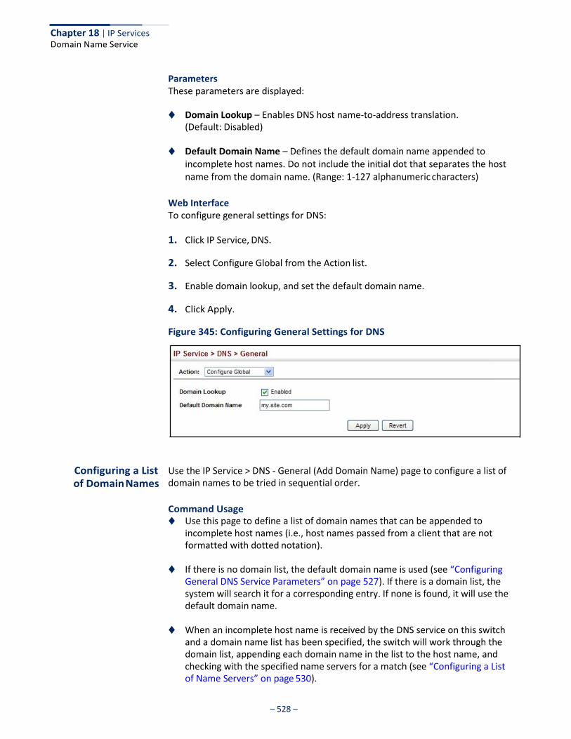
Chapter 18 | IP Services Domain Name Service
– 528 –
Parameters These parameters are displayed:
◆ Domain Lookup – Enables DNS host name-to-address translation.
(Default: Disabled)
◆ Default Domain Name – Defines the default domain name appended to incomplete host names. Do not include the initial dot that separates the host name from the domain name. (Range: 1-127 alphanumeric characters)
Web Interface To configure general settings for DNS:
1. Click IP Service, DNS.
2. Select Configure Global from the Action list.
3. Enable domain lookup, and set the default domain name.
4. Click Apply.
Figure 345: Configuring General Settings for DNS
Configuring a List of Domain Names
Use the IP Service > DNS - General (Add Domain Name) page to configure a list of domain names to be tried in sequential order.
Command Usage ◆ Use this page to define a list of domain names that can be appended to
incomplete host names (i.e., host names passed from a client that are not formatted with dotted notation).
◆ If there is no domain list, the default domain name is used (see “Configuring
General DNS Service Parameters” on page 527). If there is a domain list, the system will search it for a corresponding entry. If none is found, it will use the default domain name.
◆ When an incomplete host name is received by the DNS service on this switch
and a domain name list has been specified, the switch will work through the domain list, appending each domain name in the list to the host name, and checking with the specified name servers for a match (see “Configuring a List of Name Servers” on page 530).
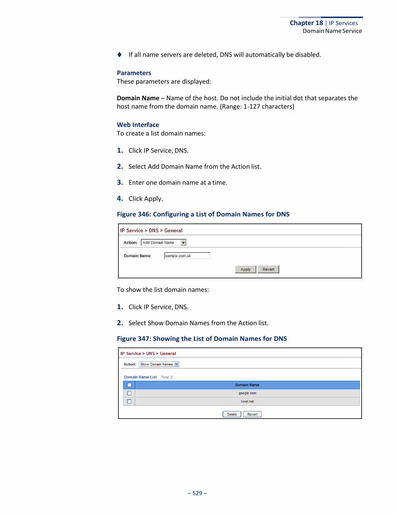
Chapter 18 | IP Services Domain Name Service
– 529 –
◆ If all name servers are deleted, DNS will automatically be disabled.
Parameters These parameters are displayed:
Domain Name – Name of the host. Do not include the initial dot that separates the host name from the domain name. (Range: 1-127 characters)
Web Interface To create a list domain names:
1. Click IP Service, DNS.
2. Select Add Domain Name from the Action list.
3. Enter one domain name at a time.
4. Click Apply.
Figure 346: Configuring a List of Domain Names for DNS
To show the list domain names:
1. Click IP Service, DNS.
2. Select Show Domain Names from the Action list.
Figure 347: Showing the List of Domain Names for DNS

Chapter 18 | IP Services Domain Name Service
– 530 –
Configuring a List of Name Servers
Use the IP Service > DNS - General (Add Name Server) page to configure a list of name servers to be tried in sequential order.
Command Usage ◆ To enable DNS service on this switch, configure one or more name servers, and
enable domain lookup status (see “Configuring General DNS Service Parameters” on page 527).
◆ When more than one name server is specified, the servers are queried in the
specified sequence until a response is received, or the end of the list is reached with no response.
◆ If all name servers are deleted, DNS will automatically be disabled. This is done
by disabling the domain lookup status.
Parameters These parameters are displayed:
Name Server IP Address – Specifies the IPv4 or IPv6 address of a domain name server to use for name-to-address resolution. Up to six IP addresses can be added to the name server list.
Web Interface To create a list name servers:
1. Click IP Service, DNS.
2. Select Add Name Server from the Action list.
3. Enter one name server at a time.
4. Click Apply.
Figure 348: Configuring a List of Name Servers for DNS
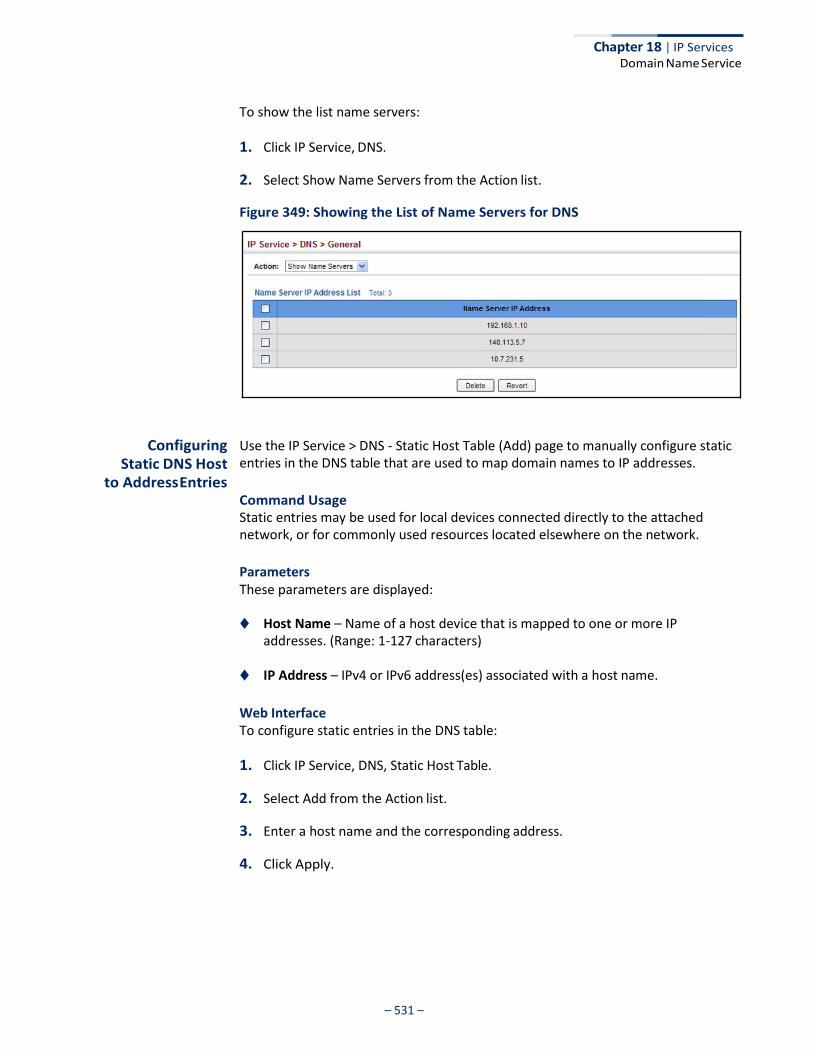
Chapter 18 | IP Services Domain Name Service
– 531 –
To show the list name servers:
1. Click IP Service, DNS.
2. Select Show Name Servers from the Action list.
Figure 349: Showing the List of Name Servers for DNS
Configuring Static DNS Host
to Address Entries
Use the IP Service > DNS - Static Host Table (Add) page to manually configure static entries in the DNS table that are used to map domain names to IP addresses.
Command Usage Static entries may be used for local devices connected directly to the attached network, or for commonly used resources located elsewhere on the network.
Parameters These parameters are displayed:
◆ Host Name – Name of a host device that is mapped to one or more IP
addresses. (Range: 1-127 characters)
◆ IP Address – IPv4 or IPv6 address(es) associated with a host name.
Web Interface To configure static entries in the DNS table:
1. Click IP Service, DNS, Static Host Table.
2. Select Add from the Action list.
3. Enter a host name and the corresponding address.
4. Click Apply.
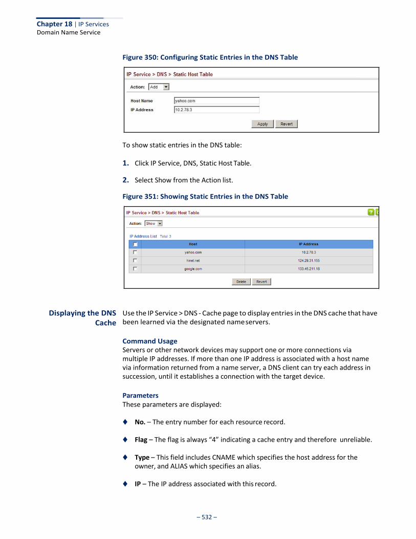
Chapter 18 | IP Services Domain Name Service
– 532 –
Figure 350: Configuring Static Entries in the DNS Table
To show static entries in the DNS table:
1. Click IP Service, DNS, Static Host Table.
2. Select Show from the Action list.
Figure 351: Showing Static Entries in the DNS Table
Displaying the DNS Cache
Use the IP Service > DNS - Cache page to display entries in the DNS cache that have been learned via the designated name servers.
Command Usage Servers or other network devices may support one or more connections via multiple IP addresses. If more than one IP address is associated with a host name via information returned from a name server, a DNS client can try each address in succession, until it establishes a connection with the target device.
Parameters These parameters are displayed:
◆ No. – The entry number for each resource record.
◆ Flag – The flag is always “4” indicating a cache entry and therefore unreliable.
◆ Type – This field includes CNAME which specifies the host address for the owner, and ALIAS which specifies an alias.
◆ IP – The IP address associated with this record.
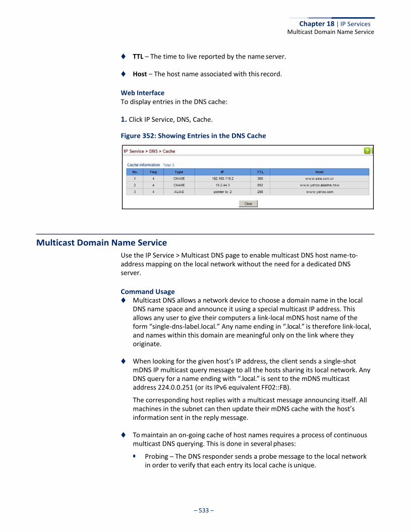
– 533 –
Chapter 18 | IP Services
Multicast Domain Name Service
◆ TTL – The time to live reported by the name server.
◆ Host – The host name associated with this record.
Web Interface To display entries in the DNS cache:
1. Click IP Service, DNS, Cache.
Figure 352: Showing Entries in the DNS Cache
Multicast Domain Name Service
Use the IP Service > Multicast DNS page to enable multicast DNS host name-to- address mapping on the local network without the need for a dedicated DNS server.
Command Usage ◆ Multicast DNS allows a network device to choose a domain name in the local
DNS name space and announce it using a special multicast IP address. This allows any user to give their computers a link-local mDNS host name of the form “single-dns-label.local.” Any name ending in “.local.” is therefore link-local, and names within this domain are meaningful only on the link where they originate.
◆ When looking for the given host’s IP address, the client sends a single-shot mDNS IP multicast query message to all the hosts sharing its local network. Any DNS query for a name ending with “.local.” is sent to the mDNS multicast address 224.0.0.251 (or its IPv6 equivalent FF02::FB).
The corresponding host replies with a multicast message announcing itself. All machines in the subnet can then update their mDNS cache with the host’s information sent in the reply message.
◆ To maintain an on-going cache of host names requires a process of continuous
multicast DNS querying. This is done in several phases:
■ Probing – The DNS responder sends a probe message to the local network in order to verify that each entry its local cache is unique.
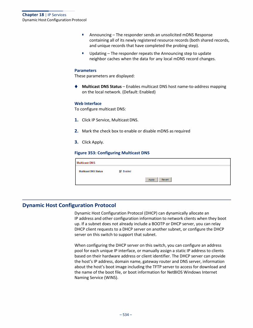
– 534 –
Chapter 18 | IP Services Dynamic Host Configuration Protocol
■ Announcing – The responder sends an unsolicited mDNS Response
containing all of its newly registered resource records (both shared records, and unique records that have completed the probing step).
■ Updating – The responder repeats the Announcing step to update neighbor caches when the data for any local mDNS record changes.
Parameters These parameters are displayed:
◆ Multicast DNS Status – Enables multicast DNS host name-to-address mapping
on the local network. (Default: Enabled)
Web Interface To configure multicast DNS:
1. Click IP Service, Multicast DNS.
2. Mark the check box to enable or disable mDNS as required
3. Click Apply.
Figure 353: Configuring Multicast DNS
Dynamic Host Configuration Protocol
Dynamic Host Configuration Protocol (DHCP) can dynamically allocate an IP address and other configuration information to network clients when they boot up. If a subnet does not already include a BOOTP or DHCP server, you can relay DHCP client requests to a DHCP server on another subnet, or configure the DHCP server on this switch to support that subnet.
When configuring the DHCP server on this switch, you can configure an address pool for each unique IP interface, or manually assign a static IP address to clients based on their hardware address or client identifier. The DHCP server can provide the host’s IP address, domain name, gateway router and DNS server, information about the host’s boot image including the TFTP server to access for download and the name of the boot file, or boot information for NetBIOS Windows Internet Naming Service (WINS).
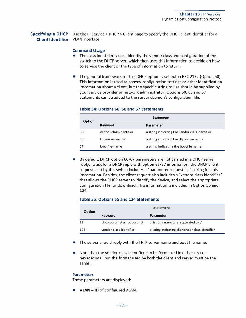
– 535 –
Chapter 18 | IP Services Dynamic Host Configuration Protocol
Specifying a DHCP Client Identifier
Use the IP Service > DHCP > Client page to specify the DHCP client identifier for a VLAN interface.
Command Usage ◆ The class identifier is used identify the vendor class and configuration of the
switch to the DHCP server, which then uses this information to decide on how to service the client or the type of information to return.
◆ The general framework for this DHCP option is set out in RFC 2132 (Option 60).
This information is used to convey configuration settings or other identification information about a client, but the specific string to use should be supplied by your service provider or network administrator. Options 60, 66 and 67 statements can be added to the server daemon’s configuration file.
Table 34: Options 60, 66 and 67 Statements
60 vendor-class-identifier a string indicating the vendor class identifier
66 tftp-server-name a string indicating the tftp server name
67 bootfile-name a string indicating the bootfile name
◆ By default, DHCP option 66/67 parameters are not carried in a DHCP server reply. To ask for a DHCP reply with option 66/67 information, the DHCP client request sent by this switch includes a “parameter request list” asking for this information. Besides, the client request also includes a “vendor class identifier” that allows the DHCP server to identify the device, and select the appropriate configuration file for download. This information is included in Option 55 and 124.
Table 35: Options 55 and 124 Statements
55 dhcp-parameter-request-list a list of parameters, separated by ','
124 vendor-class-identifier a string indicating the vendor class identifier
◆ The server should reply with the TFTP server name and boot file name.
◆ Note that the vendor class identifier can be formatted in either text or hexadecimal, but the format used by both the client and server must be the same.
Parameters These parameters are displayed:
◆ VLAN – ID of configured VLAN.
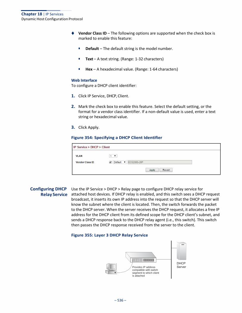
– 536 –
Chapter 18 | IP Services Dynamic Host Configuration Protocol
◆ Vendor Class ID – The following options are supported when the check box is marked to enable this feature:
■ Default – The default string is the model number.
■ Text – A text string. (Range: 1-32 characters)
■ Hex – A hexadecimal value. (Range: 1-64 characters)
Web Interface To configure a DHCP client identifier:
1. Click IP Service, DHCP, Client.
2. Mark the check box to enable this feature. Select the default setting, or the format for a vendor class identifier. If a non-default value is used, enter a text string or hexadecimal value.
3. Click Apply.
Figure 354: Specifying a DHCP Client Identifier
Configuring DHCP Relay Service
Use the IP Service > DHCP > Relay page to configure DHCP relay service for attached host devices. If DHCP relay is enabled, and this switch sees a DHCP request broadcast, it inserts its own IP address into the request so that the DHCP server will know the subnet where the client is located. Then, the switch forwards the packet to the DHCP server. When the server receives the DHCP request, it allocates a free IP address for the DHCP client from its defined scope for the DHCP client’s subnet, and sends a DHCP response back to the DHCP relay agent (i.e., this switch). This switch then passes the DHCP response received from the server to the client.
Figure 355: Layer 3 DHCP Relay Service
Provides IP address compatible with switch segment to which client is attached
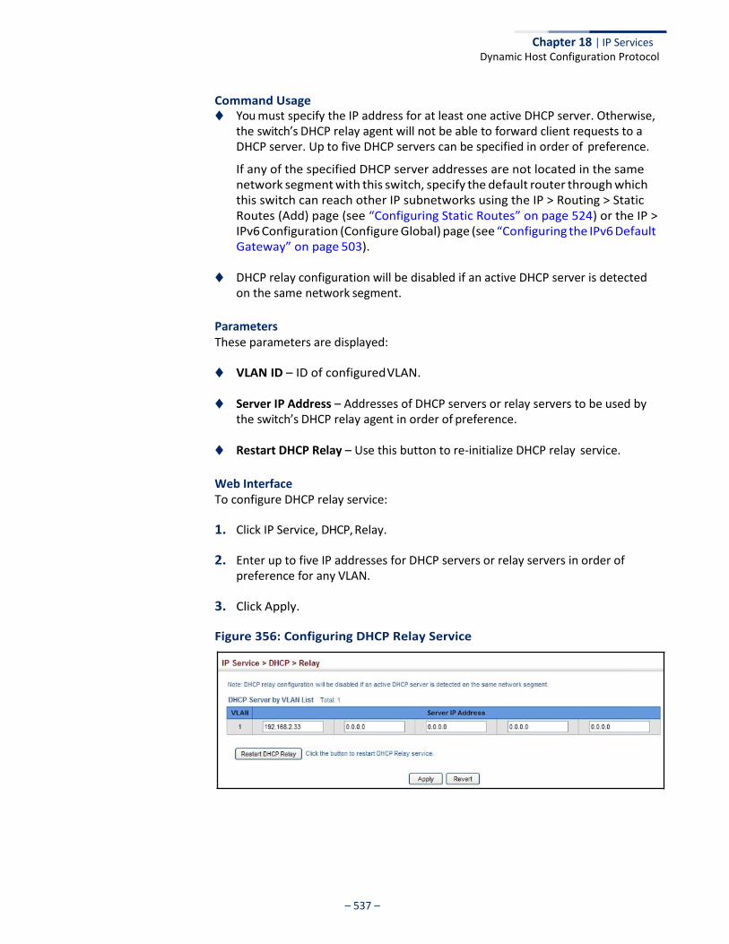
– 537 –
Chapter 18 | IP Services Dynamic Host Configuration Protocol
Command Usage ◆ You must specify the IP address for at least one active DHCP server. Otherwise,
the switch’s DHCP relay agent will not be able to forward client requests to a DHCP server. Up to five DHCP servers can be specified in order of preference.
If any of the specified DHCP server addresses are not located in the same network segment with this switch, specify the default router through which this switch can reach other IP subnetworks using the IP > Routing > Static Routes (Add) page (see “Configuring Static Routes” on page 524) or the IP > IPv6 Configuration (Configure Global) page (see “Configuring the IPv6 Default Gateway” on page 503).
◆ DHCP relay configuration will be disabled if an active DHCP server is detected
on the same network segment.
Parameters These parameters are displayed:
◆ VLAN ID – ID of configured VLAN.
◆ Server IP Address – Addresses of DHCP servers or relay servers to be used by the switch’s DHCP relay agent in order of preference.
◆ Restart DHCP Relay – Use this button to re-initialize DHCP relay service.
Web Interface To configure DHCP relay service:
1. Click IP Service, DHCP, Relay.
2. Enter up to five IP addresses for DHCP servers or relay servers in order of preference for any VLAN.
3. Click Apply.
Figure 356: Configuring DHCP Relay Service
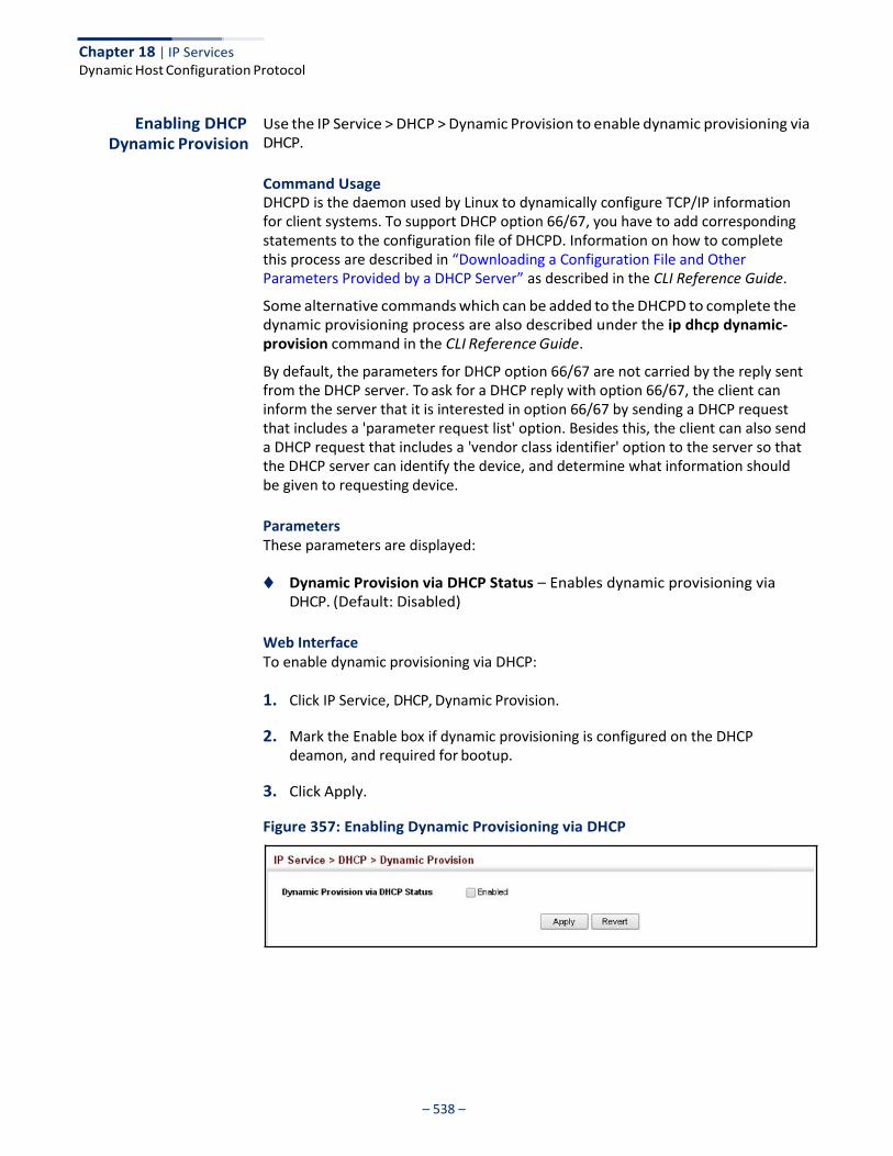
– 538 –
Chapter 18 | IP Services Dynamic Host Configuration Protocol
Enabling DHCP Dynamic Provision
Use the IP Service > DHCP > Dynamic Provision to enable dynamic provisioning via DHCP.
Command Usage DHCPD is the daemon used by Linux to dynamically configure TCP/IP information for client systems. To support DHCP option 66/67, you have to add corresponding statements to the configuration file of DHCPD. Information on how to complete this process are described in “Downloading a Configuration File and Other Parameters Provided by a DHCP Server” as described in the CLI Reference Guide.
Some alternative commands which can be added to the DHCPD to complete the dynamic provisioning process are also described under the ip dhcp dynamic- provision command in the CLI Reference Guide.
By default, the parameters for DHCP option 66/67 are not carried by the reply sent from the DHCP server. To ask for a DHCP reply with option 66/67, the client can inform the server that it is interested in option 66/67 by sending a DHCP request that includes a 'parameter request list' option. Besides this, the client can also send a DHCP request that includes a 'vendor class identifier' option to the server so that the DHCP server can identify the device, and determine what information should be given to requesting device.
Parameters These parameters are displayed:
◆ Dynamic Provision via DHCP Status – Enables dynamic provisioning via
DHCP. (Default: Disabled)
Web Interface To enable dynamic provisioning via DHCP:
1. Click IP Service, DHCP, Dynamic Provision.
2. Mark the Enable box if dynamic provisioning is configured on the DHCP deamon, and required for bootup.
3. Click Apply.
Figure 357: Enabling Dynamic Provisioning via DHCP

– 539 –
Appendices
This section provides additional information and includes these items:
◆ “Software Specifications” on page 541
◆ “Troubleshooting” on page 545
◆ “License Information” on page 547

– 540 –
Section III | Appendices

– 541 –
Software Specifications
Software Features
Management Authentication
Local, RADIUS, TACACS+, Port Authentication (802.1X), HTTPS, SSH, Port Security, IP Filter
General Security Measures
Access Control Lists (512 rules), Port Authentication (802.1X), MAC Authentication, Port Security, DHCP Snooping, IP Source Guard
Port Configuration 1000BASE-T: 10/100 Mbps at half/full duplex, 1000 Mbps at full duplex
1000BASE-SX/LX/LHX/ZX: 1000 Mbps at full duplex (SFP)
Flow Control Full Duplex: IEEE 802.3-2005
Half Duplex: Back pressure
Storm Control Broadcast, multicast, or unknown unicast traffic throttled above a critical threshold
Port Mirroring 3 sessions, one or more source ports to one destination port
Rate Limits Input/Output Limits
Range configured per port
Port Trunking Static trunks (Cisco EtherChannel compliant)
Dynamic trunks (Link Aggregation Control Protocol)
Spanning Tree Algorithm
Spanning Tree Protocol (STP, IEEE 802.1D-2004)
Rapid Spanning Tree Protocol (RSTP, IEEE 802.1D-2004)
Multiple Spanning Tree Protocol (MSTP, IEEE 802.1D-2004)
– 542 –
Appendix A | Software Specifications
Management Features
VLAN Support Up to 4094 groups; port-based, protocol-based, tagged (802.1Q),
voice VLANs, MAC-based, QinQ tunnel
Class of Service Supports four levels of priority
Strict, Weighted Round Robin (WRR), or a combination of strict and weighted queueing
Layer 3/4 priority mapping: IP DSCP
Quality of Service DiffServ11 supports class maps, policy maps, and service policies
Multicast Filtering IGMP Snooping (Layer 2 IPv4)
MLD Snooping (Layer 2 IPv6)
IP Routing ARP, CIDR (Classless Inter-Domain Routing)
Additional Features BOOTP Client
DHCP Client, Relay, Option 82
DNS Client
ERPS (Ethernet Ring Protection Switching)
LLDP (Link Layer Discover Protocol)
RMON (Remote Monitoring, groups 1,2,3,9)
SMTP Email Alerts
SNMP (Simple Network Management Protocol)
SNTP (Simple Network Time Protocol)
Management Features
In-Band Management Telnet, web-based HTTP or HTTPS, SNMP manager, or Secure Shell
Out-of-Band Management
RS-232 DB-9 console port
Software Loading HTTP, FTP, SFTP, TFTP in-band, or XModem out-of-band
SNMP Management access via MIB database
Trap management to specified hosts
RMON Groups 1, 2, 3, 9 (Statistics, History, Alarm, Event)
11. Only supported for IPv4.
– 543 –
Appendix A | Software Specifications Standards
Standards
IEEE 802.1AB Link Layer Discovery Protocol
IEEE 802.1D-2004 Spanning Tree Algorithm and traffic priorities
Spanning Tree Protocol
Rapid Spanning Tree Protocol
Multiple Spanning Tree Protocol
IEEE 802.1p Priority tags
IEEE 802.1Q VLAN
IEEE 802.1v Protocol-based VLANs
IEEE 802.1X Port Authentication
IEEE 802.3-2005 Ethernet, Fast Ethernet, Gigabit Ethernet Link Aggregation Control Protocol (LACP)
Full-duplex flow control (ISO/IEC 8802-3)
IEEE 802.3ac VLAN tagging
ARP (RFC 826)
DHCP Client (RFC 2131)
DHCP Relay (RFC 951, 2132, 3046)
HTTPS
ICMP (RFC 792)
IGMP (RFC 1112)
IGMPv2 (RFC 2236)
IGMP Proxy (RFC 4541)
IPv4 IGMP (RFC 3228)
MLD Snooping (RFC 4541)
NTP (RFC 1305)
RADIUS+ (RFC 2618)
RMON (RFC 2819 groups 1,2,3,9)
SNMP (RFC 1157)
SNMPv2c (RFC 1901, 2571)
SNMPv3 (RFC DRAFT 2273, 2576, 3410, 3411, 3413, 3414, 3415)
SNTP (RFC 2030)
SSH (Version 2.0)
TELNET (RFC 854, 855, 856)
TFTP (RFC 1350)
Management Information Bases Bridge MIB (RFC 1493)
Differentiated Services MIB (RFC 3289)
DNS Resolver MIB (RFC 1612)
ERPS MIB (ITU-T G.8032)
– 544 –
Appendix A | Software Specifications
Management Information Bases
Entity MIB (RFC 2737)
Ether-like MIB (RFC 2665)
Extended Bridge MIB (RFC 2674)
Extensible SNMP Agents MIB (RFC 2742)
Forwarding Table MIB (RFC 2096)
IGMP MIB (RFC 2933)
Interface Group MIB (RFC 2233)
Interfaces Evolution MIB (RFC 2863)
IP MIB (RFC 2011)
IP Forwarding Table MIB (RFC 2096)
IP Multicasting related MIBs
IPV6-MIB (RFC 2065)
IPV6-ICMP-MIB (RFC 2066)
IPV6-TCP-MIB (RFC 2052)
IPV6-UDP-MIB (RFC2054)
Link Aggregation MIB (IEEE 802.3ad)
MAU MIB (RFC 3636)
MIB II (RFC 1213)
NTP (RFC 1305)
P-Bridge MIB (RFC 2674P)
Port Access Entity MIB (IEEE 802.1X)
Port Access Entity Equipment MIB
Private MIB
Q-Bridge MIB (RFC 2674Q)
QinQ Tunneling (IEEE 802.1ad Provider Bridges)
Quality of Service MIB
RADIUS Accounting Server MIB (RFC 2621)
RADIUS Authentication Client MIB (RFC 2619)
RMON MIB (RFC 2819)
RMON II Probe Configuration Group (RFC 2021, partial implementation)
SNMP Community MIB (RFC 3584)
SNMP Framework MIB (RFC 3411)
SNMP-MPD MIB (RFC 3412)
SNMP Target MIB, SNMP Notification MIB (RFC 3413)
SNMP User-Based SM MIB (RFC 3414)
SNMP View Based ACM MIB (RFC 3415)
SNMPv2 IP MIB (RFC 2011)
TACACS+ Authentication Client MIB
TCP MIB (RFC 2012)
Trap (RFC 1215)
UDP MIB (RFC 2013)
– 545 –
Troubleshooting
Problems Accessing the Management Interface
Table 36: Troubleshooting Chart
Cannot connect using Telnet, web browser, or SNMP software
Cannot connect using Secure Shell
Cannot access the on- board configuration program via a serial port connection
◆ Be sure the switch is powered on.
◆ Check network cabling between the management station and the switch. Make sure the ends are properly connected and there is no damage to the cable. Test the cable if necessary.
◆ Check that you have a valid network connection to the switch and that the port you are using has not been disabled.
◆ Be sure you have configured the VLAN interface through which the management station is connected with a valid IP address, subnet mask and default gateway.
◆ Be sure the management station has an IP address in the same subnet as the switch’s IP interface to which it is connected.
◆ If you are trying to connect to the switch via the IP address for a tagged VLAN group, your management station, and the ports connecting intermediate switches in the network, must be configured with the appropriate tag.
◆ If you cannot connect using Telnet, you may have exceeded the maximum number of concurrent Telnet/SSH sessions permitted. Try connecting again at a later time.
◆ If you cannot connect using SSH, you may have exceeded the maximum number of concurrent Telnet/SSH sessions permitted. Try connecting again at a later time.
◆ Be sure the control parameters for the SSH server are properly configured on the switch, and that the SSH client software is properly configured on the management station.
◆ Be sure you have generated both an RSA and DSA public key on the switch, exported this key to the SSH client, and enabled SSH service. Try using another SSH client or check for updates to your SSH client application.
◆ Be sure you have set up an account on the switch for each SSH user, including user name, authentication level, and password.
◆ Be sure you have imported the client’s public key to the switch (if public key authentication is used).
◆ Check to see if you have set the terminal emulator program to VT100 compatible, 8 data bits, 1 stop bit, no parity, and the baud rate set to 115200 bps.
◆ Verify that you are using the DB-9 null-modem serial cable supplied with the switch. If you use any other cable, be sure that it conforms to the pin-out connections provided in the Installation Guide.
Forgot or lost the password ◆ Contact your local distributor.
Symptom Action
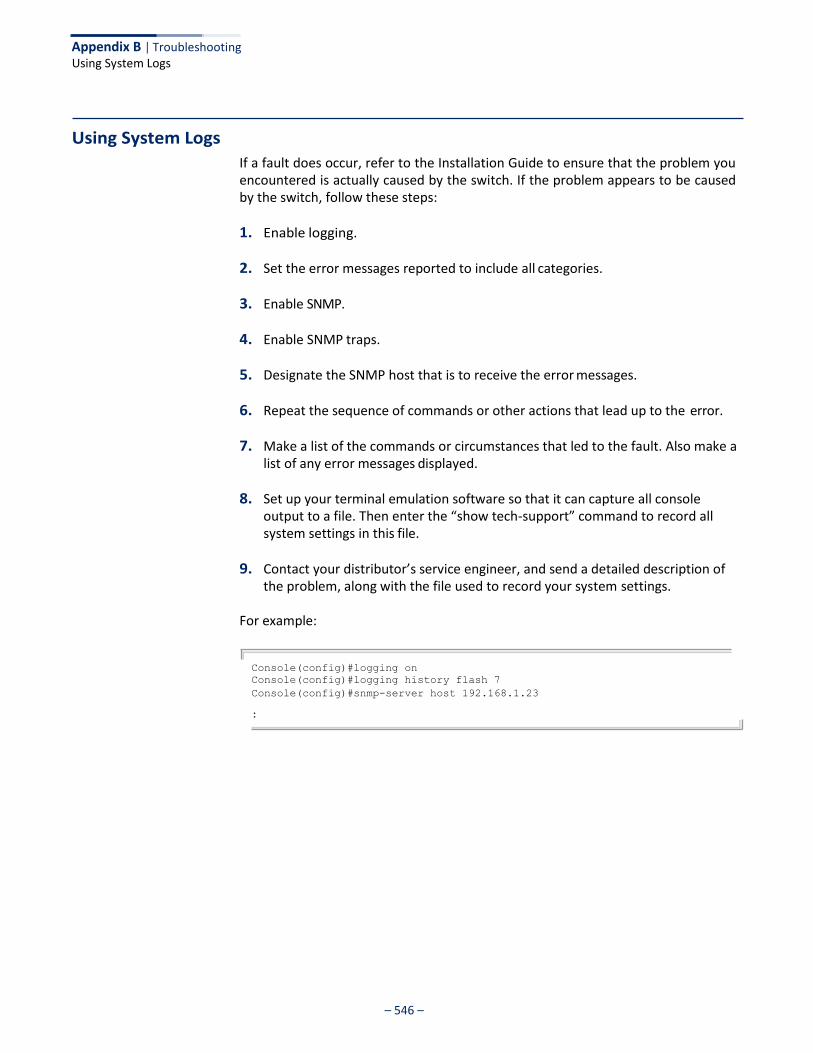
– 546 –
.
Appendix B | Troubleshooting Using System Logs
Using System Logs
If a fault does occur, refer to the Installation Guide to ensure that the problem you encountered is actually caused by the switch. If the problem appears to be caused by the switch, follow these steps:
1. Enable logging.
2. Set the error messages reported to include all categories.
3. Enable SNMP.
4. Enable SNMP traps.
5. Designate the SNMP host that is to receive the error messages.
6. Repeat the sequence of commands or other actions that lead up to the error.
7. Make a list of the commands or circumstances that led to the fault. Also make a list of any error messages displayed.
8. Set up your terminal emulation software so that it can capture all console output to a file. Then enter the “show tech-support” command to record all system settings in this file.
9. Contact your distributor’s service engineer, and send a detailed description of the problem, along with the file used to record your system settings.
For example:
Console(config)#logging on
Console(config)#logging history flash 7
Console(config)#snmp-server host 192.168.1.23
.

– 547 –
License Information
This product includes copyrighted third-party software subject to the terms of the GNU General Public
License (GPL), GNU Lesser General Public License (LGPL), or other related free software licenses.
The GPL code used in this product is distributed WITHOUT ANY WARRANTY and is subject to the
copyrights of one or more authors. For details, refer to the section "The GNU General Public License"
below, or refer to the applicable license as included in the source-code archive.
The GNU General Public License
GNU GENERAL PUBLIC LICENSE
Version 2, June 1991
Copyright (C) 1989, 1991 Free Software Foundation, Inc.
59 Temple Place, Suite 330, Boston, MA 02111-1307 USA
Everyone is permitted to copy and distribute verbatim copies of this license document, but changing it
is not allowed.
Preamble
The licenses for most software are designed to take away your freedom to share and change it. By
contrast, the GNU General Public License is intended to guarantee your freedom to share and
change free software--to make sure the software is free for all its users. This General Public License
applies to most of the Free Software Foundation's software and to any other program whose authors
commit to using it. (Some other Free Software Foundation software is covered by the GNU Library
General Public License instead.) You can apply it to your programs, too.
When we speak of free software, we are referring to freedom, not price. Our General Public Licenses
are designed to make sure that you have the freedom to distribute copies of free software (and
charge for this service if you wish), that you receive source code or can get it if you want it, that you
can change the software or use pieces of it in new free programs; and that you know you can do
these things.
To protect your rights, we need to make restrictions that forbid anyone to deny you these rights or to
ask you to surrender the rights. These restrictions translate to certain responsibilities for you if you
distribute copies of the software, or if you modify it.
For example, if you distribute copies of such a program, whether gratis or for a fee, you must give the
recipients all the rights that you have. You must make sure that they, too, receive or can get the
source code. And you must show them these terms so they know their rights.
We protect your rights with two steps: (1) copyright the software, and (2) offer you this license which
gives you legal permission to copy, distribute and/or modify the software.
Also, for each author's protection and ours, we want to make certain that everyone understands that
there is no warranty for this free software. If the software is modified by someone else and passed on,
we want its recipients to know that what they have is not the original, so that any problems introduced
by others will not reflect on the original authors' reputations.
Finally, any free program is threatened constantly by software patents. We wish to avoid the danger
that redistributors of a free program will individually obtain patent licenses, in effect making the
program proprietary. To prevent this, we have made it clear that any patent must be licensed for
everyone's free use or not licensed at all.
The precise terms and conditions for copying, distribution and modification follow.

Appendix C | License Information The GNU General Public License
– 548 –
GNU GENERAL PUBLIC LICENSE TERMS AND CONDITIONS FOR COPYING, DISTRIBUTION
AND MODIFICATION
1. This License applies to any program or other work which contains a notice placed by the
copyright holder saying it may be distributed under the terms of this General Public License. The
"Program", below, refers to any such program or work, and a "work based on the Program"
means either the Program or any derivative work under copyright law: that is to say, a work
containing the Program or a portion of it, either verbatim or with modifications and/or translated
into another language. (Hereinafter, translation is included without limitation in the term
"modification".) Each licensee is addressed as "you".
Activities other than copying, distribution and modification are not covered by this License; they
are outside its scope. The act of running the Program is not restricted, and the output from the
Program is covered only if its contents constitute a work based on the Program (independent of
having been made by running the Program). Whether that is true depends on what the Program
does.
2. You may copy and distribute verbatim copies of the Program's source code as you receive it, in
any medium, provided that you conspicuously and appropriately publish on each copy an
appropriate copyright notice and disclaimer of warranty; keep intact all the notices that refer to
this License and to the absence of any warranty; and give any other recipients of the Program a
copy of this License along with the Program.
You may charge a fee for the physical act of transferring a copy, and you may at your option offer
warranty protection in exchange for a fee.
3. You may modify your copy or copies of the Program or any portion of it, thus forming a work
based on the Program, and copy and distribute such modifications or work under the terms of
Section 1 above, provided that you also meet all of these conditions:
a) You must cause the modified files to carry prominent notices stating that you changed the
files and the date of any change.
b) You must cause any work that you distribute or publish, that in whole or in part contains or is
derived from the Program or any part thereof, to be licensed as a whole at no charge to all
third parties under the terms of this License.
c) If the modified program normally reads commands interactively when run, you must cause
it, when started running for such interactive use in the most ordinary way, to print or display
an announcement including an appropriate copyright notice and a notice that there is no
warranty (or else, saying that you provide a warranty) and that users may redistribute the
program under these conditions, and telling the user how to view a copy of this License.
(Exception: if the Program itself is interactive but does not normally print such an
announcement, your work based on the Program is not required to print an announcement.)
These requirements apply to the modified work as a whole. If identifiable sections of that work
are not derived from the Program, and can be reasonably considered independent and separate
works in themselves, then this License, and its terms, do not apply to those sections when you
distribute them as separate works. But when you distribute the same sections as part of a whole
which is a work based on the Program, the distribution of the whole must be on the terms of this
License, whose permissions for other licensees extend to the entire whole, and thus to each and
every part regardless of who wrote it.
Thus, it is not the intent of this section to claim rights or contest your rights to work written
entirely by you; rather, the intent is to exercise the right to control the distribution of derivative or
collective works based on the Program.
In addition, mere aggregation of another work not based on the Program with the Program (or
with a work based on the Program) on a volume of a storage or distribution medium does not
bring the other work under the scope of this License.
4. You may copy and distribute the Program (or a work based on it, under Section 2) in object code
or executable form under the terms of Sections 1 and 2 above provided that you also do one of
the following:
a). Accompany it with the complete corresponding machine-readable source code, which must
be distributed under the terms of Sections 1 and 2 above on a medium customarily used for
software interchange; or,

– 549 –
Appendix C | License Information The GNU General Public License
b) Accompany it with a written offer, valid for at least three years, to give any third party, for a
charge no more than your cost of physically performing source distribution, a complete
machine-readable copy of the corresponding source code, to be distributed under the terms
of Sections 1 and 2 above on a medium customarily used for software interchange; or,
c) Accompany it with the information you received as to the offer to distribute corresponding
source code. (This alternative is allowed only for noncommercial distribution and only if you
received the program in object code or executable form with such an offer, in accord with
Subsection b above.)
The source code for a work means the preferred form of the work for making modifications to it.
For an executable work, complete source code means all the source code for all modules it
contains, plus any associated interface definition files, plus the scripts used to control
compilation and installation of the executable. However, as a special exception, the source code
distributed need not include anything that is normally distributed (in either source or binary form)
with the major components (compiler, kernel, and so on) of the operating system on which the
executable runs, unless that component itself accompanies the executable.
If distribution of executable or object code is made by offering access to copy from a designated
place, then offering equivalent access to copy the source code from the same place counts as
distribution of the source code, even though third parties are not compelled to copy the source
along with the object code.
5. You may not copy, modify, sublicense, or distribute the Program except as expressly provided
under this License. Any attempt otherwise to copy, modify, sublicense or distribute the Program
is void, and will automatically terminate your rights under this License. However, parties who
have received copies, or rights, from you under this License will not have their licenses
terminated so long as such parties remain in full compliance.
6. You are not required to accept this License, since you have not signed it. However, nothing else
grants you permission to modify or distribute the Program or its derivative works. These actions
are prohibited by law if you do not accept this License. Therefore, by modifying or distributing the
Program (or any work based on the Program), you indicate your acceptance of this License to do
so, and all its terms and conditions for copying, distributing or modifying the Program or works
based on it.
7. Each time you redistribute the Program (or any work based on the Program), the recipient
automatically receives a license from the original licensor to copy, distribute or modify the
Program subject to these terms and conditions. You may not impose any further restrictions on
the recipients' exercise of the rights granted herein. You are not responsible for enforcing
compliance by third parties to this License.
8. If, as a consequence of a court judgment or allegation of patent infringement or for any other
reason (not limited to patent issues), conditions are imposed on you (whether by court order,
agreement or otherwise) that contradict the conditions of this License, they do not excuse you
from the conditions of this License. If you cannot distribute so as to satisfy simultaneously your
obligations under this License and any other pertinent obligations, then as a consequence you
may not distribute the Program at all. For example, if a patent license would not permit royalty-
free redistribution of the Program by all those who receive copies directly or indirectly through
you, then the only way you could satisfy both it and this License would be to refrain entirely from
distribution of the Program.
If any portion of this section is held invalid or unenforceable under any particular circumstance,
the balance of the section is intended to apply and the section as a whole is intended to apply in
other circumstances.
It is not the purpose of this section to induce you to infringe any patents or other property right
claims or to contest validity of any such claims; this section has the sole purpose of protecting
the integrity of the free software distribution system, which is implemented by public license
practices. Many people have made generous contributions to the wide range of software
distributed through that system in reliance on consistent application of that system; it is up to the
author/donor to decide if he or she is willing to distribute software through any other system and
a licensee cannot impose that choice.
This section is intended to make thoroughly clear what is believed to be a consequence of the
rest of this License.

Appendix C | License Information The GNU General Public License
– 550 –
9. If the distribution and/or use of the Program is restricted in certain countries either by patents or
by copyrighted interfaces, the original copyright holder who places the Program under this
License may add an explicit geographical distribution limitation excluding those countries, so
that distribution is permitted only in or among countries not thus excluded. In such case, this
License incorporates the limitation as if written in the body of this License.
10. The Free Software Foundation may publish revised and/or new versions of the General Public
License from time to time. Such new versions will be similar in spirit to the present version, but
may differ in detail to address new problems or concerns.
Each version is given a distinguishing version number. If the Program specifies a version
number of this License which applies to it and "any later version", you have the option of
following the terms and conditions either of that version or of any later version published by the
Free Software Foundation. If the Program does not specify a version number of this License,
you may choose any version ever published by the Free Software Foundation.
11. If you wish to incorporate parts of the Program into other free programs whose distribution
conditions are different, write to the author to ask for permission. For software which is
copyrighted by the Free Software Foundation, write to the Free Software Foundation; we
sometimes make exceptions for this. Our decision will be guided by the two goals of preserving
the free status of all derivatives of our free software and of promoting the sharing and reuse of
software generally.
NO WARRANTY
1. BECAUSE THE PROGRAM IS LICENSED FREE OF CHARGE, THERE IS NO WARRANTY
FOR THE PROGRAM, TO THE EXTENT PERMITTED BY APPLICABLE LAW. EXCEPT WHEN
OTHERWISE STATED IN WRITING THE COPYRIGHT HOLDERS AND/OR OTHER PARTIES
PROVIDE THE PROGRAM "AS IS" WITHOUT WARRANTY OF ANY KIND, EITHER
EXPRESSED OR IMPLIED, INCLUDING, BUT NOT LIMITED TO, THE IMPLIED
WARRANTIES OF MERCHANTABILITY AND FITNESS FOR A PARTICULAR PURPOSE. THE
ENTIRE RISK AS TO THE QUALITY AND PERFORMANCE OF THE PROGRAM IS WITH
YOU. SHOULD THE PROGRAM PROVE DEFECTIVE, YOU ASSUME THE COST OF ALL
NECESSARY SERVICING, REPAIR OR CORRECTION.
2. IN NO EVENT UNLESS REQUIRED BY APPLICABLE LAW OR AGREED TO IN WRITING
WILL ANY COPYRIGHT HOLDER, OR ANY OTHER PARTY WHO MAY MODIFY AND/OR
REDISTRIBUTE THE PROGRAM AS PERMITTED ABOVE, BE LIABLE TO YOU FOR
DAMAGES, INCLUDING ANY GENERAL, SPECIAL, INCIDENTAL OR CONSEQUENTIAL
DAMAGES ARISING OUT OF THE USE OR INABILITY TO USE THE PROGRAM (INCLUDING
BUT NOT LIMITED TO LOSS OF DATA OR DATA BEING RENDERED INACCURATE OR
LOSSES SUSTAINED BY YOU OR THIRD PARTIES OR A FAILURE OF THE PROGRAM TO
OPERATE WITH ANY OTHER PROGRAMS), EVEN IF SUCH HOLDER OR OTHER PARTY
HAS BEEN ADVISED OF THE POSSIBILITY OF SUCH DAMAGES.
END OF TERMS AND CONDITIONS
– 551 –
Glossary
ACL Access Control List. ACLs can limit network traffic and restrict access to certain users or devices by checking each packet for certain IP or MAC (i.e., Layer 2) information.
ARP Address Resolution Protocol converts between IP addresses and MAC (hardware) addresses. ARP is used to locate the MAC address corresponding to a given IP address. This allows the switch to use IP addresses for routing decisions and the corresponding MAC addresses to forward packets from one hop to the next.
BOOTP Boot Protocol. BOOTP is used to provide bootup information for network devices, including IP address information, the address of the TFTP server that contains the devices system files, and the name of the boot file.
CoS Class of Service is supported by prioritizing packets based on the required level of service, and then placing them in the appropriate output queue. Data is transmitted from the queues using weighted round-robin service to enforce priority service and prevent blockage of lower-level queues. Priority may be set according to the port default, the packet’s priority bit (in the VLAN tag), TCP/UDP port number, IP Precedence bit, or DSCP priority bit.
DHCP Dynamic Host Control Protocol. Provides a framework for passing configuration information to hosts on a TCP/IP network. DHCP is based on the Bootstrap Protocol (BOOTP), adding the capability of automatic allocation of reusable network addresses and additional configuration options.
DHCP Option 82 A relay option for sending information about the requesting client (or an intermediate relay
agent) in the DHCP request packets forwarded by the switch and in reply packets sent back from the DHCP server. This information can be used by DHCP servers to assign fixed IP addresses, or set other services or policies for clients.
DHCP Snooping A technique used to enhance network security by snooping on DHCP server messages to track the physical location of hosts, ensure that hosts only use the IP addresses assigned to them, and ensure that only authorized DHCP servers are accessible.
Glossary
– 552 –
DiffServ Differentiated Services provides quality of service on large networks by employing a well- defined set of building blocks from which a variety of aggregate forwarding behaviors may be built. Each packet carries information (DS byte) used by each hop to give it a particular forwarding treatment, or per-hop behavior, at each network node. DiffServ allocates different levels of service to users on the network with mechanisms such as traffic meters, shapers/droppers, packet markers at the boundaries of the network.
DNS Domain Name Service. A system used for translating host names for network nodes into IP addresses.
DSCP Differentiated Services Code Point Service. DSCP uses a six-bit tag to provide for up to 64 different forwarding behaviors. Based on network policies, different kinds of traffic can be marked for different kinds of forwarding. The DSCP bits are mapped to the Class of Service categories, and then into the output queues.
EAPOL Extensible Authentication Protocol over LAN. EAPOL is a client authentication protocol used by this switch to verify the network access rights for any device that is plugged into the switch. A user name and password is requested by the switch, and then passed to an authentication server (e.g., RADIUS) for verification. EAPOL is implemented as part of the IEEE 802.1X Port Authentication standard.
EUI Extended Universal Identifier is an address format used by IPv6 to identify the host portion
of the network address. The interface identifier in EUI compatible addresses is based on the link-layer (MAC) address of an interface. Interface identifiers used in global unicast and other IPv6 address types are 64 bits long and may be constructed in the EUI-64 format. The modified EUI-64 format interface ID is derived from a 48-bit link-layer address by inserting the hexadecimal number FFFE between the upper three bytes (OUI field) and the lower 3 bytes (serial number) of the link layer address. To ensure that the chosen address is from a unique Ethernet MAC address, the 7th bit in the high-order byte is set to 1 (equivalent to the IEEE Global/Local bit) to indicate the uniqueness of the 48-bit address.
GARP Generic Attribute Registration Protocol. GARP is a protocol that can be used by endstations and switches to register and propagate multicast group membership information in a switched environment so that multicast data frames are propagated only to those parts of a switched LAN containing registered endstations. Formerly called Group Address Registration Protocol.
GMRP Generic Multicast Registration Protocol. GMRP allows network devices to register end stations with multicast groups. GMRP requires that any participating network devices or end stations comply with the IEEE 802.1p standard.
GVRP GARP VLAN Registration Protocol. Defines a way for switches to exchange VLAN information in order to register necessary VLAN members on ports along the Spanning Tree so that VLANs defined in each switch can work automatically over a Spanning Tree network.
Glossary
– 553 –
ICMP Internet Control Message Protocol is a network layer protocol that reports errors in processing IP packets. ICMP is also used by routers to feed back information about better routing choices.
IEEE 802.1D Specifies a general method for the operation of MAC bridges, including the Spanning Tree Protocol.
IEEE 802.1Q VLAN Tagging—Defines Ethernet frame tags which carry VLAN information. It allows switches to assign endstations to different virtual LANs, and defines a standard way for VLANs to communicate across switched networks.
IEEE 802.1p An IEEE standard for providing quality of service (QoS) in Ethernet networks. The standard uses packet tags that define up to eight traffic classes and allows switches to transmit packets based on the tagged priority value.
IEEE 802.1s An IEEE standard for the Multiple Spanning Tree Protocol (MSTP) which provides independent spanning trees for VLAN groups.
IEEE 802.1w An IEEE standard for the Rapid Spanning Tree Protocol (RSTP) which reduces the convergence time for network topology changes to about 10% of that required by the older IEEE 802.1D STP standard. (Now incorporated in IEEE 802.1D-2004)
IEEE 802.1X Port Authentication controls access to the switch ports by requiring users to first enter a user ID and password for authentication.
IEEE 802.3ac Defines frame extensions for VLAN tagging.
IEEE 802.3x Defines Ethernet frame start/stop requests and timers used for flow control on full-duplex links. (Now incorporated in IEEE 802.3-2002)
IGMP Internet Group Management Protocol. A protocol through which hosts can register with their local router for multicast services. If there is more than one multicast switch/router on a given subnetwork, one of the devices is made the “querier” and assumes responsibility for keeping track of group membership.
IGMP Proxy Proxies multicast group membership information onto the upstream interface based on IGMP messages monitored on downstream interfaces, and forwards multicast traffic based on that information. There is no need for multicast routing protocols in an simple tree that uses IGMP Proxy.
Glossary
– 554 –
IGMP Query On each subnetwork, one IGMP-capable device will act as the querier — that is, the device that asks all hosts to report on the IP multicast groups they wish to join or to which they already belong. The elected querier will be the device with the lowest IP address in the subnetwork.
IGMP Snooping Listening to IGMP Query and IGMP Report packets transferred between IP Multicast Routers and IP Multicast host groups to identify IP Multicast group members.
In-Band Management Management of the network from a station attached directly to the network.
IP Multicast Filtering A process whereby this switch can pass multicast traffic along to participating hosts.
IP Precedence The Type of Service (ToS) octet in the IPv4 header includes three precedence bits defining eight different priority levels ranging from highest priority for network control packets to lowest priority for routine traffic. The eight values are mapped one-to-one to the Class of Service categories by default, but may be configured differently to suit the requirements for specific network applications.
LACP Link Aggregation Control Protocol. Allows ports to automatically negotiate a trunked link with LACP-configured ports on another device.
Layer 2 Data Link layer in the ISO 7-Layer Data Communications Protocol. This is related directly to the hardware interface for network devices and passes on traffic based on MAC addresses.
Layer 3 Network layer in the ISO 7-Layer Data Communications Protocol. This layer handles the routing functions for data moving from one open system to another.
Link Aggregation See Port Trunk.
LLDP Link Layer Discovery Protocol is used to discover basic information about neighboring devices in the local broadcast domain by using periodic broadcasts to advertise information such as device identification, capabilities and configuration settings.
MD5 MD5 Message-Digest is an algorithm that is used to create digital signatures. It is intended
for use with 32 bit machines and is safer than the MD4 algorithm, which has been broken. MD5 is a one-way hash function, meaning that it takes a message and converts it into a fixed string of digits, also called a message digest.
Glossary
– 555 –
MIB Management Information Base. An acronym for Management Information Base. It is a set of database objects that contains information about a specific device.
MRD Multicast Router Discovery is a A protocol used by IGMP snooping and multicast routing devices to discover which interfaces are attached to multicast routers. This process allows IGMP-enabled devices to determine where to send multicast source and group membership messages.
MSTP Multiple Spanning Tree Protocol can provide an independent spanning tree for different VLANs. It simplifies network management, provides for even faster convergence than RSTP by limiting the size of each region, and prevents VLAN members from being segmented from the rest of the group.
Multicast Switching A process whereby the switch filters incoming multicast frames for services for which no attached host has registered, or forwards them to all ports contained within the designated multicast VLAN group.
NTP Network Time Protocol provides the mechanisms to synchronize time across the network. The time servers operate in a hierarchical-master-slave configuration in order to synchronize local clocks within the subnet and to national time standards via wire or radio.
Out-of-Band Management
Management of the network from a station not attached to the network.
Port Authentication See IEEE 802.1X.
Port Mirroring A method whereby data on a target port is mirrored to a monitor port for troubleshooting with a logic analyzer or RMON probe. This allows data on the target port to be studied unobstructively.
Port Trunk Defines a network link aggregation and trunking method which specifies how to create a single high-speed logical link that combines several lower-speed physical links.
QoS Quality of Service. QoS refers to the capability of a network to provide better service to selected traffic flows using features such as data prioritization, queuing, congestion avoidance and traffic shaping. These features effectively provide preferential treatment to specific flows either by raising the priority of one flow or limiting the priority of another flow.
Glossary
– 556 –
RADIUS Remote Authentication Dial-in User Service. RADIUS is a logon authentication protocol that uses software running on a central server to control access to RADIUS-compliant devices on the network.
RMON Remote Monitoring. RMON provides comprehensive network monitoring capabilities. It eliminates the polling required in standard SNMP, and can set alarms on a variety of traffic conditions, including specific error types.
RSTP Rapid Spanning Tree Protocol. RSTP reduces the convergence time for network topology changes to about 10% of that required by the older IEEE 802.1D STP standard.
SMTP Simple Mail Transfer Protocol is a standard host-to-host mail transport protocol that operates over TCP, port 25.
SNMP Simple Network Management Protocol. The application protocol in the Internet suite of protocols which offers network management services.
SNTP Simple Network Time Protocol allows a device to set its internal clock based on periodic updates from a Network Time Protocol (NTP) server. Updates can be requested from a specific NTP server, or can be received via broadcasts sent by NTP servers.
SSH Secure Shell is a secure replacement for remote access functions, including Telnet. SSH can authenticate users with a cryptographic key, and encrypt data connections between management clients and the switch.
STA Spanning Tree Algorithm is a technology that checks your network for any loops. A loop can often occur in complicated or backup linked network systems. Spanning Tree detects and directs data along the shortest available path, maximizing the performance and efficiency of the network.
TACACS+ Terminal Access Controller Access Control System Plus. TACACS+ is a logon authentication protocol that uses software running on a central server to control access to TACACS- compliant devices on the network.
TCP/IP Transmission Control Protocol/Internet Protocol. Protocol suite that includes TCP as the primary transport protocol, and IP as the network layer protocol.
Telnet Defines a remote communication facility for interfacing to a terminal device over TCP/IP.

Glossary
– 557 –
TFTP Trivial File Transfer Protocol. A TCP/IP protocol commonly used for software downloads.
UDP User Datagram Protocol. UDP provides a datagram mode for packet-switched communications. It uses IP as the underlying transport mechanism to provide access to IP- like services. UDP packets are delivered just like IP packets – connection-less datagrams that may be discarded before reaching their targets. UDP is useful when TCP would be too complex, too slow, or just unnecessary.
UTC Universal Time Coordinate. UTC is a time scale that couples Greenwich Mean Time (based solely on the Earth’s rotation rate) with highly accurate atomic time. The UTC does not have daylight saving time.
VLAN Virtual LAN. A Virtual LAN is a collection of network nodes that share the same collision domain regardless of their physical location or connection point in the network. A VLAN serves as a logical workgroup with no physical barriers, and allows users to share information and resources as though located on the same LAN.
XModem A protocol used to transfer files between devices. Data is grouped in 128-byte blocks and error-corrected.

Glossary
– 558 –
– 559 –
Index
Numerics 802.1Q tunnel 156
access 163 configuration, guidelines 159 configuration, limitations 159 CVID to SVID map 161 description 156 ethernet type 160 interface configuration 163 mode selection 163 status, configuring 160 TPID 160 uplink 163
802.1X authenticator, configuring 302 global settings 302 port authentication 300
port authentication accounting 243, 244
A AAA
accounting 802.1X port settings 243, 244 accounting exec command privileges 243, 250
accounting exec settings 244, 250 accounting summary 245 accounting update 243 accounting, configuring 243 authorization & accounting 236 authorization exec settings 250 authorization method 250 authorization settings 249 RADIUS group settings 244 TACACS+ group settings 244
acceptable frame type 153 ACL 277
ARP 281, 292 binding to a port 293 IPv4 Extended 280, 283 IPv4 Standard 280, 282 IPv6 Extended 280, 287 IPv6 Standard 280, 286
MAC 281, 290 time range 405
Address Resolution Protocol See ARP
address table 171 aging time 173 aging time, displaying 173 aging time, setting 173
ARP configuration 493 description 492 proxy 493 statistics 497
ARP ACL 292 ARP inspection 324
ACL filter 327 additional validation criteria 326 ARP ACL 328 enabling globally 326 trusted ports 329
authentication MAC address authentication 257 MAC, configuring ports 261 network access 257 public key 271 web 255 web authentication port information, displaying 256 web authentication, configuring ports 256 web authentication, re-authenticating address 257 web authentication, re-authenticating ports 256 web, configuring 255
B BOOTP 500 BPDU 182
filter 195 flooding when STA disabled on VLAN 186 flooding when STA globally disabled 186 ignoring superior BPDUs 193 selecting protocol based on message format 195 shut down port on receipt 194, 195
bridge extension capabilities, displaying 67 broadcast storm, threshold 206, 207
C cable diagnostics 113 canonical format indicator 215 CFM
continuity check messages 423
– 560 –
Index
class map DiffServ 220
Class of Service See CoS clustering switches, management access 400 community string 375 configuration files, restoring defaults 69 configuration settings
restoring 71, 72 saving 71
continuity check messages, CFM 423 CoS 209
configuring 209 enabling 214 layer 3/4 priorities 213 queue mode 210 queue weights, assigning 211
CPU status 90 utilization, showing 90
CVLAN to SPVLAN map 161
D default IPv6 gateway, configuration 503 default priority, ingress port 209 default settings, system 38 DHCP 500, 534
class identifier 536 client 500
client identifier 535, 536 option 82 information 312 relay service 536 relay service, enabling 537
DHCP snooping information option, circuit ID 316 information option, remote ID 313
DHCPv4 snooping 310 enabling 313 global configuration 313 information option 313 information option policy 314 information option, enabling 313 policy selection 314 specifying trusted interfaces 316 verifying MAC addresses 313 VLAN configuration 315
DHCPv6 restart 507 Differentiated Code Point Service See DSCP Differentiated Services See DiffServ DiffServ 219
binding policy to interface 226 class map 220 classifying QoS traffic 220 configuring 219 policy map 223
policy map, description 221 QoS policy 223 service policy 226 setting CoS for matching packets 224
DNS default domain name 527 displaying the cache 532 domain name list 527 enabling lookup 527 name server list 527 static entries, IPv4 531 static entries, IPv6 531
Domain Name Service See DNS downloading software 69
automatically 73 using FTP or TFTP 73
DSA encryption 273, 275 DSCP 213
enabling 214 dynamic addresses
clearing 172 displaying 171
dynamic QoS assignment 258, 262
dynamic VLAN assignment 258, 262
E edge port, STA 194, 197 encryption
DSA 273, 275 RSA 273, 275
engine ID 365, 366 ERPS
configuration guidelines 410 control VLAN 415 domain configuration 412 domain, enabling 414 global configuration 412 guard timer 424 hold-off timer 424 major domain 420 MEG level 415 node identifier 420 propagate topology change 423 ring configuration 412 ring, enabling 414 status, displaying 428 wait-to-restore timer 425 WTR timer 425
event logging 334
exec command privileges, accounting 243, 250 exec settings
accounting 244 authorization 250

– 561 –
Index
F firmware
displaying version 65 upgrading 69 upgrading automatically 73 upgrading with FTP or TFP 73 version, displaying 65
G gateway, IPv6 default 503 general security measures 235
H hardware version, displaying 65 HTTPS 266, 268
configuring 266 replacing SSL certificate 268 secure-site certificate 268
HTTPS, secure server 266
I
query interval 451 query response interval 452 query suppression 439 router port expire time 443 static host interface 439 static multicast routing 444 static port assignment 446 static router interface 439 static router port, configuring 444 statistics, displaying 456, 473 TCN flood 441 unregistered data flooding 442 version exclusive 442 version for interface, setting 451 version, setting 443 with proxy reporting 439
immediate leave, IGMP snooping 450 immediate leave, MLD snooping 467 importing user public keys 275 ingress filtering 153 IP address
BOOTP/DHCP 500 setting 499
IP filter, for management access 296
filter profiles, configuration 461, 463, 482, 485 filter, parameters 461, 463, 482, 485 filtering & throttling 460, 481 filtering & throttling, creating profile 461, 482, 483 filtering & throttling, enabling 460, 482
filtering & throttling, interface configuration 463, 485 filtering & throttling, status 460, 482 groups, displaying 447 Layer 2 438 query 440 snooping 438 snooping & query, parameters 440 snooping, configuring 440 snooping, immediate leave 450
IGMP services, displaying 455 IGMP snooping
configuring 448
enabling per interface 448, 449 forwarding entries 455 immediate leave, status 450 interface attached to multicast router 446 last leave 439 last member query interval 452 proxy address 452 proxy reporting 451 querier timeout 443
learning mode, ACL table or MAC table 320 MAC table, learning mode 320 setting filter criteria 318 setting maximum bindings 320
IP statistics 514 IPv4 address
BOOTP/DHCP 500 setting 499
IPv6 displaying neighbors 513 duplicate address detection 513 enabling 505 MTU 505
IPv6 address dynamic configuration (global unicast) 510 dynamic configuration (link-local) 505 EUI format 510 EUI-64 setting 510 explicit configuration 505 global unicast 510 link-local 511 manual configuration (global unicast) 510 manual configuration (link-local) 511 setting 503
IEEE 802.1D 181 IP routing 521 IEEE 802.1s 181 unicast protocols 523 IEEE 802.1w 181 IP source guard IEEE 802.1X 300 ACL table, learning mode 320 IGMP configuring static entries 320

– 562 –
Index
J jumbo frame 66
K key
private 270 public 270 user public, importing 275
key pair host 270 host, generating 273
L LACP
TLV 343 TLV, inventory 343 TLV, location 343 TLV, MED capabilities 343 TLV, network policy 343
local engine ID 365 logging
messages, displaying 335 syslog traps 336 to syslog servers 337
log-in, web interface 44 logon authentication 253
encryption keys 240 RADIUS client 239 RADIUS server 239 sequence 237
protocol message statistics 125 protocol parameters 121 timeout, for LACPDU 120
last member query interval, IGMP snooping 452 LBD 432
recover action 433 recover time 433 transmit interval 433
license information 547 Link Layer Discovery Protocol - Media Endpoint Discovery See LLDP-MED Link Layer Discovery Protocol See LLDP link type, STA 193, 197 LLDP 339
device statistics details, displaying 361 device statistics, displaying 359 display device information 351 displaying remote information 351 interface attributes, configuring 341 message attributes 341 message statistics 359
remote information, displaying 358, 359 remote port information, displaying 351 timing attributes, configuring 339 TLV 339, 342 TLV, management address 342 TLV, port description 342 TLV, system capabilities 342 TLV, system description 342 TLV, system name 342
LLDP-MED 339 notification, status 341
M MAC address authentication 257
ports, configuring 261 reauthentication 260
main menu, web interface 47 management access, filtering per address 296 management access, IP filter 296 Management Information Bases (MIBs) 543 matching class settings, classifying QoS traffic 221 mDNS
domain name list 533 enabling lookup 533 multicast name service 533 name server list 533
memory status 92 utilization, showing 92
mirror port configuring 132 configuring local traffic 132 configuring remote traffic 134
MLD snooping 465 configuring 465 enabling 465
groups, displaying 471, 472 immediate leave 467 immediate leave, status 467 interface attached to multicast router 468, 469 multicast static router port 468 querier 465 querier, enabling 465 query interval 466
configuration 119 settings 238, 240 group attributes, configuring 123 TACACS+ client 238 group members, configuring 121 TACACS+ server 238 load balancing 129 loopback detection
local parameters 126 STA 183 partner parameters 128

– 563 –
Index
query, maximum response time 466 robustness value 466 static port assignment 470 static router port 468 unknown multicast, handling 466 version 466
MSTP 199
global settings, configuring 185, 199 global settings, displaying 190
interface settings, configuring 191, 203 interface settings, displaying 204 path cost 203
MTU for IPv6 505 Multicast Domain Name Service See mDNS multicast filtering 437
enabling IGMP snooping 449 enabling IGMP snooping per interface 448 enabling MLD snooping 465 router configuration 444
multicast groups 447, 455, 471 displaying 447, 455, 471
static 446, 447, 470, 471 multicast router discovery 448
multicast router port, displaying 445, 469 multicast services
configuring 446, 470
displaying 447, 471 multicast static router port 444
configuring 444 configuring for MLD snooping 468
multicast storm, threshold 207 multicast, filtering and throttling 460, 481
N network access
authentication 257 dynamic QoS assignment 262 dynamic VLAN assignment 262 MAC address filter 262 port configuration 261 reauthentication 260 secure MAC information 264
STA 197 PoE time range 405 policy map
DiffServ 223 port authentication 300 port priority
configuring 209 default ingress 209 STA 192
port security, configuring 298 port, statistics 102 ports
autonegotiation 98
broadcast storm threshold 206, 207 capabilities 98 configuring 98 duplex mode 99 flow control 99 mirroring 132 mirroring local traffic 132 mirroring remote traffic 134 multicast storm threshold 207 speed 99 statistics 102 transceiver threshold, auto-set 112 transceiver threshold, trap 112 unknown unicast storm threshold 207
power savings configuring 131 enabling per port 131
priority, default port ingress 209 private key 270 problems, troubleshooting 545 protocol migration 195 protocol VLANs 164
configuring 165 interface configuration 166 system configuration 165
proxy address, IGMP snooping 452 proxy ARP 493 proxy reporting, IGMP snooping 451 public key 270 PVID, port native VLAN 153
NTP
P
authentication keys, specifying 83 client, enabling 79 setting the system clock 81 specifying servers 81
Q QinQ Tunneling See 802.1Q tunnel QoS 219
configuring 219 dynamic assignment 262 matching class settings 221
passwords 253 administrator setting 253
path cost 197
method 187
– 564 –
Index
selecting DSCP, CoS 214 Quality of Service See QoS query interval, IGMP snooping 451 query response interval, IGMP snooping 452

– 565 –
Index
queue weight, assigning to CoS 211
R RADIUS
logon authentication 239 settings 239
rate limit port 205 setting 205
remote engine ID 365 remote logging 336 restarting the system 93
at scheduled times 93 showing restart time 96
RMON 390 alarm, displaying settings 392 alarm, setting thresholds 390
enabling traps, mac-address changes 178 filtering IP addresses 296 global settings, configuring 364 trap manager 382 users, configuring 376, 379
SNMPv3 365–383
engine ID 365, 366 engine identifier, local 365
engine identifier, remote 365, 366 groups 370 local users, configuring 376 remote users, configuring 379
user configuration 376, 379 views 367
SNTP setting the system clock 79 specifying servers 80
software
statistics history, collection 395 statistics history, displaying 396 statistics, collection 398 statistics, displaying 399
routing table, displaying 525
RSA encryption 273, 275 RSTP 181
global settings, configuring 185 global settings, displaying 190 interface settings, configuring 191 interface settings, displaying 196
S secure shell 270
configuration 270 security, general measures 235 serial port, configuring 87 sFlow 138
configuring receiver 139 datagram version 140 destination 139 maximum datagram 140 polling 141 receiver socket 140 receiver timeout 139 sampling 141
Simple Mail Transfer Protocol See SMTP Simple Network Management Protocol See SNMP SMTP
event handling 337 sending log events 337
SNMP 362 community string 375 enabling traps 382
version, displaying 65 Spanning Tree Protocol See STA specifications, software 541 SSH 270
authentication retries 272 configuring 270 downloading public keys for clients 275 generating host key pair 273 server, configuring 272 timeout 272
SSL, replacing certificate 268 STA 181
BPDU filter 195 BPDU flooding 186, 192
BPDU shutdown 194, 195 detecting loopbacks 183
edge port 194, 197 global settings, configuring 185 global settings, displaying 190 interface settings, configuring 191 interface settings, displaying 196
link type 193, 197 loopback detection 183 MSTP interface settings, configuring 203 MSTP path cost 203 path cost 197 path cost method 187 port priority 192 port/trunk loopback detection 183 protocol migration 195 transmission limit 187
standards, IEEE 543 startup files
creating 69
event settings, displaying 394 displaying version 65 response to alarm setting 393 downloading 69

– 566 –
Index
displaying 69 setting 69
static addresses, setting 176 static routes, configuring 524 statistics
ARP 497 history for port 106 history for trunk 106
statistics, port 102 STP 185 summary, accounting 245 summer time, setting 85 switch clustering, for management 400 switch settings
restoring 71 saving 71
system clock setting 77 setting manually 78 setting the time zone 84 setting with NTP 81 setting with SNTP 79 summer time 85
system software, downloading from server 69
T TACACS+
logon authentication 238 settings 240
TCN flood 441 general query solicitation 441
Telnet configuring 89 server, enabling 89
time range, ACL 405 time range, PoE 405 time zone, setting 84 time, setting 77 TPID 160 traffic segmentation 143
assigning ports 143 enabling 143 sessions, assigning ports 145 sessions, creating 144
transceiver data, displaying 110 transceiver thresholds
configuring 111 displaying 111
trap manager 382
troubleshooting 545, 547 trunk
configuration 115 LACP 119
static 116 Type Length Value
See LLDP TLV
U unknown unicast storm, threshold 207 unregistered data flooding, IGMP snooping 442 upgrading software 69 user account 253 user password 253
V VLANs 147–168
802.1Q tunnel mode 163 acceptable frame type 153 adding static members 152 creating 149 description 147, 168 displaying port members by interface 155 displaying port members by interface range 156 displaying port members by VLAN index 154 dynamic assignment 262 egress mode 152 ingress filtering 153 interface configuration 152 MAC-based 168 protocol 164 protocol, configuring 165 protocol, configuring groups 165 protocol, interface configuration 166 protocol, system configuration 165 PVID 153 voice 229
voice VLANs 229 detecting VoIP devices 230 enabling for ports 233 identifying client devices 231
VoIP traffic 229 ports, configuring 232 telephony OUI, configuring 231 voice VLAN, configuring 230
VoIP, detecting devices 233
W web authentication 255
address, re-authenticating 257 configuring 255 configuring ports 256
port information, displaying 256, 257 ports, configuring 256 ports, re-authenticating 256

– 567 –
Index
web interface access requirements 43 configuration buttons 46 menu list 47 panel display 46

– 568 –
Index
E062017/ST-R01