Fuzzy Hype-Plane Variable Sliding Mode Control to Reduce Joint Vibrations
12
International Journal of u-and e-Service, Science and Technology Vol.7, No.5 (2014), pp.105-116 http://dx.doi.org/10.14257/ijunnesst.2014.7.5.10 ISSN: 2005-4246 IJUNESST Copyright ⓒ 2014 SERSC Fuzzy Hype-Plane Variable Sliding Mode Control to Reduce Joint Vibrations Mahmoud Reza Safaei Nasrabad 1 , Ehsan Pouladi 1 , Ghasem Sahamijoo 1 , Alireza Salehi 1 , Farzin Piltan 1 and Nasri b. Sulaiman 1,2 1 Intelligent System and Robotic Lab, Iranian Institute of Advance Science and Technology (IRAN SSP), Shiraz/Iran 2 Faculty of Electrical and Electronic Engineering, Department of Engineering, University Putra Malaysia (UPM), Malaysia Email: [email protected], WWW.IRANSSP.COM/english Abstract The sliding mode controller is used to speed up the error convergence when the error is greater than one. To reduce the error terminal sliding mode controller is recommended in this research. Fuzzy hype-plane variable sliding mode controller is adopted to guarantee the error convergence to zero in a finite time when the error is around the zero. The chattering in the conventional sliding model control systems is avoided with the employed continuous controller. To increase the system robustness in presence of uncertainty fuzzy logic controller is recommended. This technique is used to adjust the band of terminals. The simulation results show that the proposed scheme has strong robust against the uncertainties and disturbances, as well as leads to the convergence of the output to the desired value quickly and precisely than employing either sliding mode controller or terminal sliding mode controller alone. Keywords: Fuzzy hype-plane variable sliding mode controller, fuzzy logic theory, flexible robot manipulator, robustness, stability, tuning the terminal 1. Introduction Controller (control system) is a device which can sense information from linear or nonlinear system (e.g., robot arm) to improve the systems performance and the immune system behavior [1-2]. In feedback control system considering that there are many disturbances and also variable dynamic parameters something that is really necessary is keeping plant variables close to the desired value. Feedback control system development is the most important thing in many different fields of safety engineering. The main targets in design control systems are safety stability, good disturbance rejection to reach the best safety, and small tracking error [3-4]. At present, in some applications robot arms are used in unknown and unstructured environment, therefore strong mathematical tools used in new control methodologies to design nonlinear robust controller with an acceptable safety performance (e.g., minimum error, good trajectory, disturbance rejection). According to the control theory, systems’ controls are divided into two main groups: conventional control theory and soft computing control theory. Conventional control theories are work based on manipulator dynamic model. This technique is highly sensitive to the knowledge of all parameters of nonlinear robot manipulator’s dynamic equation. Conventional control theory is divided into two main groups: linear control theory and nonlinear control theory. Soft computing (intelligent) control theory is free of some challenges associated to conventional
Transcript of Fuzzy Hype-Plane Variable Sliding Mode Control to Reduce Joint Vibrations

International Journal of u-and e-Service, Science and Technology
Vol.7, No.5 (2014), pp.105-116
http://dx.doi.org/10.14257/ijunnesst.2014.7.5.10
ISSN: 2005-4246 IJUNESST
Copyright ⓒ 2014 SERSC
Fuzzy Hype-Plane Variable Sliding Mode Control to Reduce Joint
Vibrations
Mahmoud Reza Safaei Nasrabad1, Ehsan Pouladi
1, Ghasem Sahamijoo
1, Alireza
Salehi1, Farzin Piltan
1 and Nasri b. Sulaiman
1,2
1Intelligent System and Robotic Lab, Iranian Institute of Advance Science and
Technology (IRAN SSP), Shiraz/Iran 2Faculty of Electrical and Electronic Engineering, Department of Engineering,
University Putra Malaysia (UPM), Malaysia
Email: [email protected], WWW.IRANSSP.COM/english
Abstract
The sliding mode controller is used to speed up the error convergence when the error is
greater than one. To reduce the error terminal sliding mode controller is recommended in
this research. Fuzzy hype-plane variable sliding mode controller is adopted to guarantee the
error convergence to zero in a finite time when the error is around the zero. The chattering in
the conventional sliding model control systems is avoided with the employed continuous
controller. To increase the system robustness in presence of uncertainty fuzzy logic controller
is recommended. This technique is used to adjust the band of terminals. The simulation
results show that the proposed scheme has strong robust against the uncertainties and
disturbances, as well as leads to the convergence of the output to the desired value quickly
and precisely than employing either sliding mode controller or terminal sliding mode
controller alone.
Keywords: Fuzzy hype-plane variable sliding mode controller, fuzzy logic theory, flexible
robot manipulator, robustness, stability, tuning the terminal
1. Introduction
Controller (control system) is a device which can sense information from linear or
nonlinear system (e.g., robot arm) to improve the systems performance and the immune
system behavior [1-2]. In feedback control system considering that there are many
disturbances and also variable dynamic parameters something that is really necessary is
keeping plant variables close to the desired value. Feedback control system development is
the most important thing in many different fields of safety engineering. The main targets in
design control systems are safety stability, good disturbance rejection to reach the best safety,
and small tracking error [3-4]. At present, in some applications robot arms are used in
unknown and unstructured environment, therefore strong mathematical tools used in new
control methodologies to design nonlinear robust controller with an acceptable safety
performance (e.g., minimum error, good trajectory, disturbance rejection). According to the
control theory, systems’ controls are divided into two main groups: conventional control
theory and soft computing control theory. Conventional control theories are work based on
manipulator dynamic model. This technique is highly sensitive to the knowledge of all
parameters of nonlinear robot manipulator’s dynamic equation. Conventional control theory
is divided into two main groups: linear control theory and nonlinear control theory. Soft
computing (intelligent) control theory is free of some challenges associated to conventional

International Journal of u-and e-Service, Science and Technology
Vol.7, No.5 (2014)
106 Copyright ⓒ 2014 SERSC
control theory. This technique is worked based on intelligent control theory. This theory is
divided into the following groups: fuzzy logic theory, neural network theory, genetic
algorithm and neuro-fuzzy theory.
To control of this system sliding mode controller is recommend in this research. Sliding
mode controller is an influential nonlinear controller to certain and uncertain systems which it
is based on system’s dynamic model. Sliding mode controller is a powerful nonlinear robust
controller under condition of partly uncertain dynamic parameters of system [5-6]. This
controller is used to control of highly nonlinear systems especially for continuum robot.
Chattering phenomenon and nonlinear equivalent dynamic formulation in uncertain dynamic
parameter are two main drawbacks in pure sliding mode controller [7-9]. The chattering
phenomenon problem in pure sliding mode controller is reduced by using linear saturation
boundary layer function but prove the stability is very difficult. Although the fuzzy-logic
control is not a new technique, its application in this current research is considered to be
novel since it aimed for an automated dynamic-less response rather than for the traditional
objective of uncertainties compensation [8]. The intelligent tracking control using the fuzzy-
logic technique provides a cost-and-time efficient control implementation due to the
automated dynamic-less input. This in turn would further inspire multi-uncertainties testing
for continuum robot [9].
Although the fuzzy-logic control is not a new technique, its application in this current
research is considered to be novel since it aimed for an automated dynamic-less response
rather than for the traditional objective of uncertainties compensation[10]. The intelligent
tracking control using the fuzzy-logic technique provides a cost-and-time efficient control
implementation due to the automated dynamic-less input. This in turn would further inspire
multi-uncertainties testing for continuum robot [11].
Sliding mode control methodology is used to control of continuum robot manipulator.
Continuum robots represent a class of robots that have a biologically inspired form
characterized by flexible backbones and high degrees-of-freedom structures [5].
Theoretically, the compliant nature of a continuum robot provides infinite degrees of freedom
to these devices. However, there is a limitation set by the practical inability to incorporate
infinite actuators in the device. Most of these robots are consequently under actuated (in
terms of numbers of independent actuators) with respect to their anticipated tasks. In other
words they must achieve a wide range of configurations with relatively few control inputs.
This is partly due to the desire to keep the body structures (which, unlike in conventional
rigid-link manipulators or fingers, are required to directly contact the environment) “clean
and soft”, but also to exploit the extra control authority available due to the continuum
contact conditions with a minimum number of actuators. For example, the Octarm VI
continuum manipulator, discussed frequently in this paper, has nine independent actuated
degrees-of-freedom with only three sections. Continuum manipulators differ fundamentally
from rigid-link and hyper-redundant robots by having an unconventional structure that lacks
links and joints. Hence, standard techniques like the Denavit-Hartenberg (D-H) algorithm
cannot be directly applied for developing continuum arm kinematics. Moreover, the design of
each continuum arm varies with respect to the flexible backbone present in the system, the
positioning, type and number of actuators. The constraints imposed by these factors make the
set of reachable configurations and nature of movements unique to every continuum robot.
This makes it difficult to formulate generalized kinematic or dynamic models for continuum
robot hardware. Thus, the kinematics (i.e., geometry based modeling) of a quite general set of
prototypes of continuum manipulators has been developed and basic control strategies now
exist based on these. The development of analytical models to analyze continuum arm
dynamics (i.e., physics based models involving forces in addition to geometry) is an active,

International Journal of u-and e-Service, Science and Technology
Vol.7, No.5 (2014)
Copyright ⓒ 2014 SERSC 107
ongoing research topic in this field. From a practical perspective, the modeling approaches
currently available in the literature prove to be very complicated and a dynamic model which
could be conveniently implemented in an actual device’s real-time controller has not been
developed yet. The absence of a computationally tractable dynamic model for these robots
also prevents the study of interaction of external forces and the impact of collisions on these
continuum structures. This impedes the study and ultimate usage of continuum robots in
various practical applications like grasping and manipulation, where impulsive dynamics are
important factors. Although continuum robotics is an interesting subclass of robotics with
promising applications for the future, from the current state of the literature, this field is still
in its stages of inception.
In this research the new technique of sliding mode controller is recommended, namely,
terminal sliding mode controller. To modify the response of terminal sliding mode controller,
on-line tuning terminal sliding mode controller is recommended in this research.
This paper is organized as follows; section 2, is served as an introduction to the dynamic of
continuum robot manipulator. Part 3, introduces and describes the sliding mode controller,
fuzzy logic controller and methodology algorithm. Section 4 presents the simulation results
and discussion of this algorithm applied to a continuum robot and the final section describe
the conclusion.
2. Theory
Dynamic Formulation of Continuum Robot: The Continuum section analytical model
developed here consists of three modules stacked together in series. In general, the model will
be a more precise replication of the behavior of a continuum arm with a greater of modules
included in series. However, we will show that three modules effectively represent the
dynamic behavior of the hardware, so more complex models are not motivated. Thus, the
constant curvature bend exhibited by the section is incorporated inherently within the model.
The model resulting from the application of Lagrange’s equations of motion obtained for this
system can be represented in the form
𝑭𝒄𝒐𝒆𝒇𝒇 𝝉 = 𝑫(𝒒) �̈� + 𝑪 (𝒒) �̇� + 𝑮(𝒒) (1)
where 𝜏 is a vector of input forces and q is a vector of generalized co-ordinates. The force
coefficient matrix 𝐹𝑐𝑜𝑒𝑓𝑓 transforms the input forces to the generalized forces and torques in
the system. The inertia matrix, 𝐷 is composed of four block matrices. The block matrices that
correspond to pure linear accelerations and pure angular accelerations in the system (on the
top left and on the bottom right) are symmetric. The matrix 𝐶 contains coefficients of the first
order derivatives of the generalized co-ordinates. Since the system is nonlinear, many
elements of 𝐶 contain first order derivatives of the generalized co-ordinates. The remaining
terms in the dynamic equations resulting from gravitational potential energies and spring
energies are collected in the matrix 𝐺. The coefficient matrices of the dynamic equations are
given below,
𝑭𝒄𝒐𝒆𝒇𝒇 =
[
𝟏 𝟏 𝒄𝒐𝒔(𝜽𝟏) 𝒄𝒐𝒔(𝜽𝟏) 𝒄𝒐𝒔(𝜽𝟏 + 𝜽𝟐) 𝒄𝒐𝒔(𝜽𝟏 + 𝜽𝟐)
𝟎 𝟎 𝟏 𝟏 𝒄𝒐𝒔(𝜽𝟐) 𝒄𝒐𝒔(𝜽𝟐)
𝟎 𝟎 𝟎 𝟎 𝟏 𝟏𝟏 𝟐⁄ −𝟏 𝟐⁄ 𝟏 𝟐⁄ −𝟏 𝟐⁄ 𝟏 𝟐⁄ + 𝒔𝟐𝒔𝒊𝒏(𝜽𝟐) −𝟏 𝟐⁄ + 𝒔𝟐𝒔𝒊𝒏(𝜽𝟐)
𝟎 𝟎 𝟏 𝟐⁄ −𝟏 𝟐⁄ 𝟏 𝟐⁄ −𝟏 𝟐⁄
𝟎 𝟎 𝟎 𝟎 𝟏 𝟐⁄ −𝟏 𝟐⁄ ]
(2)

International Journal of u-and e-Service, Science and Technology
Vol.7, No.5 (2014)
108 Copyright ⓒ 2014 SERSC
𝑫(𝒒) =
[ 𝒎𝟏 + 𝒎𝟐
+𝒎𝟑
𝒎𝟐𝒄𝒐𝒔(𝜽𝟏)
+𝒎𝟑𝒄𝒐𝒔(𝜽𝟏)𝒎𝟑𝒄𝒐𝒔(𝜽𝟏 + 𝜽𝟐)
−𝒎𝟐𝒔𝟐𝒔𝒊𝒏(𝜽𝟏)
−𝒎𝟑𝒔𝟐𝒔𝒊𝒏(𝜽𝟏)
−𝒎𝟑𝒔𝟑𝒔𝒊𝒏(𝜽𝟏 + 𝜽𝟐)−𝒎𝟑𝒔𝟑𝒔𝒊𝒏(𝜽𝟏 + 𝜽𝟐) 𝟎
𝒎𝟐𝒄𝒐𝒔(𝜽𝟏)
+𝒎𝟑𝒄𝒐𝒔(𝜽𝟏)𝒎𝟐 + 𝒎𝟑 𝒎𝟑𝒄𝒐𝒔(𝜽𝟐) −𝒎𝟑𝒔𝟑𝒔𝒊𝒏(𝜽𝟐) −𝒎𝟑𝒔𝟑𝒔𝒊𝒏(𝜽𝟐) 𝟎
𝒎𝟑𝒄𝒐𝒔(𝜽𝟏 + 𝜽𝟐) 𝒎𝟑𝒄𝒐𝒔(𝜽𝟐) 𝒎𝟑 𝒎𝟑𝒔𝟑𝒔𝒊𝒏(𝜽𝟐) 𝟎 𝟎
−𝒎𝟐𝒔𝟐𝒔𝒊𝒏(𝜽𝟏)
−𝒎𝟑𝒔𝟐𝒔𝒊𝒏(𝜽𝟏)
−𝒎𝟑𝒔𝟑𝒔𝒊𝒏(𝜽𝟏 + 𝜽𝟐)−𝒎𝟑𝒔𝟑𝒔𝒊𝒏(𝜽𝟐) 𝒎𝟑𝒔𝟐𝒔𝒊𝒏(𝜽𝟐)
𝒎𝟐𝒔𝟐𝟐 + 𝑰𝟏 + 𝑰𝟐
+𝑰𝟑 + 𝒎𝟑𝒔𝟐𝟐 + 𝒎𝟑𝒔𝟑
𝟐
+𝟐𝒎𝟑𝒔𝟑𝒄𝒐𝒔(𝜽𝟐)𝒔𝟐
𝑰𝟐 + 𝒎𝟑𝒔𝟑𝟐 + 𝑰𝟑
+𝒎𝟑𝒔𝟑𝒄𝒐𝒔(𝜽𝟐)𝒔𝟐
𝑰𝟑
−𝒎𝟑𝒔𝟑𝒔𝒊𝒏(𝜽𝟏 + 𝜽𝟐) −𝒎𝟑𝒔𝟑𝒔𝒊𝒏(𝜽𝟐) 𝟎𝑰𝟐 + 𝒎𝟑𝒔𝟑
𝟐 + 𝑰𝟑
+𝒎𝟑𝒔𝟑𝒄𝒐𝒔(𝜽𝟐)𝒔𝟐𝑰𝑰𝟐 + 𝒎𝟑𝒔𝟑
𝟐 + 𝑰𝟑 𝑰𝟑
𝟎 𝟎 𝟎 𝑰𝟑 𝑰𝟑 𝑰𝟑]
(3)
𝑪(𝒒) =
[
𝒄𝟏𝟏 + 𝒄𝟐𝟏
−𝟐𝒎𝟐𝒔𝒊𝒏(𝜽𝟏)�̇�𝟏
−𝟐𝒎𝟑𝒔𝒊𝒏(𝜽𝟏)�̇�𝟏
−𝟐𝒎𝟑𝒔𝒊𝒏(𝜽𝟏 + 𝜽𝟐)
(�̇�𝟏 + �̇�𝟐)
−𝒎𝟐𝒔𝟐
𝒄𝒐𝒔(𝜽𝟏)(�̇�𝟏)
+(𝟏 𝟐⁄ )(𝒄𝟏𝟏 + 𝒄𝟐𝟏)−𝒎𝟑𝒔𝟐
𝒄𝒐𝒔(𝜽𝟏)(�̇�𝟏)−𝒎𝟑𝒔𝟑
𝒄𝒐𝒔(𝜽𝟏 + 𝜽𝟐)(�̇�𝟏)
−𝒎𝟑𝒔𝟑𝒔𝒊𝒏(𝜽𝟏 + 𝜽𝟐) 𝟎
𝟎 𝒄𝟏𝟐 + 𝒄𝟐𝟐
−𝟐𝒎𝟑𝒔𝒊𝒏(𝜽𝟐)
(�̇�𝟏 + �̇�𝟐)
−𝒎𝟑𝒔𝟑(�̇�𝟏)
+(𝟏 𝟐⁄ )(𝒄𝟏𝟐 + 𝒄𝟐𝟐)
−𝒎𝟑𝒔𝟐(�̇�𝟏)−𝒎𝟑𝒔𝟑
𝒄𝒐𝒔(𝜽𝟐)(�̇�𝟏)
−𝟐𝒎𝟑𝒔𝟑
𝒄𝒐𝒔(𝜽𝟐)(�̇�𝟏)−𝒎𝟑𝒔𝟑
𝒄𝒐𝒔(𝜽𝟐)(�̇�𝟐)
𝟎
𝟎 𝟐𝒎𝟑𝒔𝒊𝒏(𝜽𝟐)(�̇�𝟏) 𝒄𝟏𝟑 + 𝒄𝟐𝟑
−𝒎𝟑𝒔𝟑𝒔𝟐
𝒄𝒐𝒔(𝜽𝟐)(�̇�𝟏)
−𝒎𝟑𝒔𝟑(�̇�𝟏)
−𝟐𝒎𝟑𝒔𝟑(�̇�𝟏)
−𝒎𝟑𝒔𝟑(�̇�𝟐)
(𝟏 𝟐⁄ )(𝒄𝟏𝟑 + 𝒄𝟐𝟑)
(𝟏 𝟐⁄ )(𝒄𝟏𝟏 + 𝒄𝟐𝟏)
𝟐𝒎𝟑𝒔𝟑𝒄𝒐𝒔(𝜽𝟐)(�̇�𝟏)
−𝟐𝒎𝟑𝒔𝟐(�̇�𝟏)
+𝟐𝒎𝟐𝒔𝟐(�̇�𝟏)
𝟐𝒎𝟑𝒔𝟑(𝜽�̇� + 𝜽�̇�)
−𝟐𝒎𝟑𝒔𝟐𝒄𝒐𝒔(𝜽𝟐)
(𝜽�̇� + 𝜽�̇�)
𝟐𝒎𝟑𝒔𝟑𝒔𝟐
𝒔𝒊𝒏(𝜽𝟐)(�̇�𝟐)
+(𝟏𝟐 𝟒⁄ )(𝒄𝟏𝟏 + 𝒄𝟐𝟏)
𝒎𝟑𝒔𝟑𝒔𝟐
𝒔𝒊𝒏(𝜽𝟐)(�̇�𝟐)𝟎
𝟎(𝟏 𝟐⁄ )(𝒄𝟏𝟐 + 𝒄𝟐𝟐) +
𝟐𝒎𝟑𝒔𝟑𝒄𝒐𝒔(𝜽𝟐)(�̇�𝟏)
𝟐𝒎𝟑𝒔𝟑
(𝜽�̇� + 𝜽�̇�)
𝒎𝟑𝒔𝟑𝒔𝟐
𝒔𝒊𝒏(𝜽𝟐)(�̇�𝟏)(𝟏𝟐 𝟒⁄ )
(𝒄𝟏𝟐 + 𝒄𝟐𝟐)𝟎
𝟎 𝟎 (𝟏 𝟐⁄ )(𝒄𝟏𝟑 − 𝒄𝟐𝟑) 𝟎 𝟎(𝟏𝟐 𝟒⁄ )
(𝒄𝟏𝟑 + 𝒄𝟐𝟑)]
(4)
𝑮(𝒒) = (5)
International Journal of u-and e-Service, Science and Technology
Vol.7, No.5 (2014)
Copyright ⓒ 2014 SERSC 109
3. Methodology
One of the significant challenges in control algorithms is a linear behavior controller
design for nonlinear systems. When system works with various parameters and hard
nonlinearities this technique is very useful in order to be implemented easily but it has some
limitations such as working near the system operating point [2]. Some of robot manipulators
which work in industrial processes are controlled by linear PID controllers, but the design of
linear controller for robot manipulators is extremely difficult because they are nonlinear,
uncertain and MIMO [11]. To reduce above challenges the nonlinear robust controllers is
used to systems control. One of the powerful nonlinear robust controllers is sliding mode
controller (SMC), although this controller has been analyzed by many researchers but the first
proposed was in the 1950 [3-7].This controller is used in wide range areas such as in robotics,
in control process, in aerospace applications and in power converters because it has an
acceptable control performance and solve some main challenging topics in control such as
resistivity to the external disturbance. The lyapunov formulation can be written as follows,
𝑽 =𝟏
𝟐𝑺𝑻. 𝑫. 𝑺
(6)
the derivation of 𝑉 can be determined as,
�̇� = 𝟏
𝟐𝑺𝑻. �̇�. 𝑺 + 𝑺𝑻 𝑫�̇� (7)
the dynamic equation of robot manipulator can be written based on the sliding surface as
𝑫�̇� = −𝑽𝑺 + 𝑫�̇� + 𝑽𝑺 + 𝑮 − 𝝉 (8)
it is assumed that
𝑺𝑻(�̇� − 𝟐𝑽)𝑺 = 𝟎 (9)
by substituting (8) in (7)
�̇� =𝟏
𝟐𝑺𝑻�̇�𝑺 − 𝑺𝑻𝑽𝑺 + 𝑺𝑻(𝑫�̇� + 𝑽𝑺 + 𝑮 − 𝝉) = 𝑺𝑻(𝑫�̇� + 𝑽𝑺 + 𝑮 − 𝝉) (10)
suppose the control input is written as follows
�̂� = 𝝉𝒆�̂� + 𝝉𝒅𝒊𝒔̂ = [𝑫−𝟏̂ (�̂� + �̂�) + �̇�]�̂� + 𝑲. 𝒔𝒈𝒏(𝑺) + 𝑲𝒗𝑺 (11)
by replacing the equation (11) in (10)
�̇� = 𝑺𝑻(𝑫�̇� + 𝑽𝑺 + 𝑮 − �̂��̇� − �̂�𝑺 − �̂� − 𝑲𝒗𝑺 − 𝑲𝒔𝒈𝒏(𝑺) = 𝑺𝑻 (𝑫�̇� + �̃�𝑺 + �̃� −
𝑲𝒗𝑺 − 𝑲𝒔𝒈𝒏(𝑺))
(12)
it is obvious that
|�̃��̇� + �̃�𝑺 + �̃� − 𝑲𝒗𝑺| ≤ |�̃��̇�| + |�̃�𝑺| + |�̃�| + |𝑲𝒗𝑺| (13)
the Lemma equation in robot manipulator system can be written as follows
[
−𝒎𝟏𝒈 − 𝒎𝟐𝒈 + 𝒌𝟏𝟏(𝒔𝟏 + (𝟏 𝟐⁄ )𝜽𝟏 − 𝒔𝟎𝟏) + 𝒌𝟐𝟏(𝒔𝟏 − (𝟏 𝟐⁄ )𝜽𝟏 − 𝒔𝟎𝟏) − 𝒎𝟑𝒈
−𝒎𝟐𝒈𝒄𝒐𝒔(𝜽𝟏) + 𝒌𝟏𝟐(𝒔𝟐 + (𝟏 𝟐⁄ )𝜽𝟐 − 𝒔𝟎𝟐) + 𝒌𝟐𝟐(𝒔𝟐 − (𝟏 𝟐⁄ )𝜽𝟐 − 𝒔𝟎𝟐) − 𝒎𝟑𝒈𝒄𝒐𝒔(𝜽𝟏)
−𝒎𝟑𝒈𝒄𝒐𝒔(𝜽𝟏 + 𝜽𝟐) + 𝒌𝟏𝟑(𝒔𝟑 + (𝟏 𝟐⁄ )𝜽𝟑 − 𝒔𝟎𝟑) + 𝒌𝟐𝟑(𝒔𝟑 − (𝟏 𝟐⁄ )𝜽𝟑 − 𝒔𝟎𝟑)
𝒎𝟐𝒔𝟐𝒈𝒔𝒊𝒏(𝜽𝟏) + 𝒎𝟑𝒔𝟑𝒈𝒔𝒊𝒏(𝜽𝟏 + 𝜽𝟐) + 𝒎𝟑𝒔𝟐𝒈𝒔𝒊𝒏(𝜽𝟏) + 𝒌𝟏𝟏(𝒔𝟏 + (𝟏 𝟐⁄ )𝜽𝟏 − 𝒔𝟎𝟏)(𝟏 𝟐⁄ )
+𝒌𝟐𝟏(𝒔𝟏 − (𝟏 𝟐⁄ )𝜽𝟏 − 𝒔𝟎𝟏)(−𝟏 𝟐⁄ )
𝒎𝟑𝒔𝟑𝒈𝒔𝒊𝒏(𝜽𝟏 + 𝜽𝟐) + 𝒌𝟏𝟐(𝒔𝟐 + (𝟏 𝟐⁄ )𝜽𝟐 − 𝒔𝟎𝟐)(𝟏 𝟐⁄ ) + 𝒌𝟐𝟐(𝒔𝟐 − (𝟏 𝟐⁄ )𝜽𝟐 − 𝒔𝟎𝟐)(−𝟏 𝟐⁄ )
𝒌𝟏𝟑(𝒔𝟑 + (𝟏 𝟐⁄ )𝜽𝟑 − 𝒔𝟎𝟑)(𝟏 𝟐⁄ ) + 𝒌𝟐𝟑(𝒔𝟑 − (𝟏 𝟐⁄ )𝜽𝟑 − 𝒔𝟎𝟑)(−𝟏 𝟐⁄ ) ]

International Journal of u-and e-Service, Science and Technology
Vol.7, No.5 (2014)
110 Copyright ⓒ 2014 SERSC
𝑲𝒖 = [|�̃��̇�| + |𝑽𝑺| + |𝑮| + |𝑲𝒗𝑺| + 𝜼]𝒊 , 𝒊 = 𝟏, 𝟐, 𝟑, 𝟒, … (14)
the equation (14) can be written as
𝑲𝒖 ≥ |[�̃��̇� + 𝑽𝑺 + 𝑮 − 𝑲𝒗𝑺]𝒊| + 𝜼𝒊
(15)
therefore, it can be shown that
�̇� ≤ −∑𝜼𝒊
𝒏
𝒊=𝟏
|𝑺𝒊| (16)
Based on above discussion, the control law for a multi degrees of freedom robot manipulator
is written as:
𝑼 = 𝑼𝒆𝒒 + 𝑼𝒓 (17)
Where, the model-based component 𝑼𝒆𝒒 is the nominal dynamics of systems and 𝑼𝒆𝒒 can be
calculate as follows:
𝑼𝒆𝒒 = [𝑫−𝟏(𝒇 + 𝑪 + 𝑮) + �̇�]𝑫 (18)
and 𝑼𝑺𝑾𝑰𝑻𝑪𝑯 is computed as;
𝑼𝒔𝒂𝒕 = 𝑲 ∙ 𝐒𝐆𝐍(𝑺) (19)
by replace the formulation (9) in (7) the control output can be written as;
𝑼 = 𝑼𝒆𝒒 + 𝑲. 𝐒𝐆𝐍(𝑺) (20)
By (10) and (8) the sliding mode control of robot manipulator is calculated as;
𝑼 = [𝑫−𝟏(𝒇 + 𝑪 + 𝑮) + �̇�]𝑫 + 𝑲 ∙ 𝐒𝐆𝐍(𝑺) (21)
For the terminal sliding mode control part, the hype-plane is defined as
𝑺 = 𝝀. 𝒆𝑷 + �̇� (22)
Where 0 < 𝑝 < 1
Based on foundation of fuzzy logic methodology; fuzzy logic controller has played
important rule to design nonlinear controller for nonlinear and uncertain systems [11].
However the application area for fuzzy control is really wide, the basic form for all command
types of controllers consists of;
Input fuzzification (binary-to-fuzzy [B/F] conversion)
Fuzzy rule base (knowledge base), Inference engine and Output defuzzification (fuzzy-to-
binary [F/B] conversion). Figure 1 shows a fuzzy controller part.
Figure 1. Fuzzy Controller Part

International Journal of u-and e-Service, Science and Technology
Vol.7, No.5 (2014)
Copyright ⓒ 2014 SERSC 111
The fuzzy inference engine offers a mechanism for transferring the rule base in fuzzy set
which it is divided into two most important methods, namely, Mamdani method and Sugeno
method. Mamdani method is one of the common fuzzy inference systems and he designed
one of the first fuzzy controllers to control of system engine. Mamdani’s fuzzy inference
system is divided into four major steps: fuzzification, rule evaluation, aggregation of the rule
outputs and defuzzification. Michio Sugeno uses a singleton as a membership function of the
rule consequent part. The following definition shows the Mamdani and Sugeno fuzzy rule
base
𝒊𝒇 𝒙 𝒊𝒔 𝑨 𝒂𝒏𝒅 𝒚 𝒊𝒔 𝑩 𝒕𝒉𝒆𝒏 𝒛 𝒊𝒔 𝑪 ′𝒎𝒂𝒎𝒅𝒂𝒏𝒊′ 𝒊𝒇 𝒙 𝒊𝒔 𝑨 𝒂𝒏𝒅 𝒚 𝒊𝒔 𝑩 𝒕𝒉𝒆𝒏 𝒛 𝒊𝒔 𝒇(𝒙, 𝒚)′𝒔𝒖𝒈𝒆𝒏𝒐′
(23)
When 𝑥 and 𝑦 have crisp values fuzzification calculates the membership degrees for
antecedent part. Rule evaluation focuses on fuzzy operation (𝐴𝑁𝐷/𝑂𝑅 ) in the antecedent of
the fuzzy rules. The aggregation is used to calculate the output fuzzy set and several
methodologies can be used in fuzzy logic controller aggregation, namely, Max-Min
aggregation, Sum-Min aggregation, Max-bounded product, Max-drastic product, Max-
bounded sum, Max-algebraic sum and Min-max. Two most common methods that used in
fuzzy logic controllers are Max-min aggregation and Sum-min aggregation. Max-min
aggregation defined as below;
𝝁𝑼(𝒙𝒌, 𝒚𝒌, 𝑼) = 𝝁⋃ 𝑭𝑹𝒊𝒓𝒊=𝟏
(𝒙𝒌, 𝒚𝒌, 𝑼) = 𝐦𝐚𝐱 {𝐦𝐢𝐧𝒊=𝟏𝒓 [𝝁𝑹𝒑𝒒
(𝒙𝒌, 𝒚𝒌), 𝝁𝒑𝒎(𝑼)]} (24)
The Sum-min aggregation defined as below
𝝁𝑼(𝒙𝒌, 𝒚𝒌, 𝑼) = 𝝁⋃ 𝑭𝑹𝒊𝒓𝒊=𝟏
(𝒙𝒌, 𝒚𝒌, 𝑼) = ∑𝐦𝐢𝐧𝒊=𝟏𝒓 [𝝁𝑹𝒑𝒒
(𝒙𝒌, 𝒚𝒌), 𝝁𝒑𝒎(𝑼)] (25)
where 𝑟 is the number of fuzzy rules activated by 𝑥𝑘 and 𝑦𝑘 and also 𝜇⋃ 𝐹𝑅𝑖𝑟𝑖=1
(𝑥𝑘, 𝑦𝑘 , 𝑈) is a
fuzzy interpretation of 𝑖 − 𝑡ℎ rule. Defuzzification is the last step in the fuzzy inference
system which it is used to transform fuzzy set to crisp set. Consequently defuzzification’s
input is the aggregate output and the defuzzification’s output is a crisp number. Centre of
gravity method (𝐶𝑂𝐺) and Centre of area method (𝐶𝑂𝐴) are two most common
defuzzification methods, which 𝐶𝑂𝐺 method used the following equation to calculate the
defuzzification
𝑪𝑶𝑮(𝒙𝒌, 𝒚𝒌) =∑ 𝑼𝒊 ∑ . 𝝁𝒖(𝒙𝒌, 𝒚𝒌, 𝑼𝒊)
𝒓𝒋=𝟏𝒊
∑ ∑ . 𝝁𝒖(𝒙𝒌, 𝒚𝒌, 𝑼𝒊)𝒓𝒋=𝟏𝒊
(26)
and 𝐶𝑂𝐴 method used the following equation to calculate the defuzzification
𝑪𝑶𝑨(𝒙𝒌, 𝒚𝒌) =∑ 𝑼𝒊. 𝝁𝒖(𝒙𝒌, 𝒚𝒌, 𝑼𝒊)𝒊
∑ 𝝁𝑼. (𝒙𝒌, 𝒚𝒌, 𝑼𝒊)𝒊
(27)
Where 𝐶𝑂𝐺(𝑥𝑘 , 𝑦𝑘) and 𝐶𝑂𝐴(𝑥𝑘 , 𝑦𝑘) illustrates the crisp value of defuzzification output,
𝑈𝑖 ∈ 𝑈 is discrete element of an output of the fuzzy set, 𝜇𝑈. (𝑥𝑘 , 𝑦𝑘 , 𝑈𝑖) is the fuzzy set
membership function, and 𝑟 is the number of fuzzy rules.
The new fuzzy hype-plane variable can be written as:
𝑺 = 𝜶. 𝑺𝑻 + (𝟏 − 𝜶). 𝑺 = 𝜶(𝝀. 𝒆𝑷 + �̇�) + (𝟏 − 𝜶). (𝝀𝒆 + �̇�) = �̇� + 𝝀𝜶𝒆𝑷 +
𝝀(𝟏 − 𝜶)𝒆
(28)
And 𝛼 is fuzzy output.
4. Results and Discussion
Fuzzy hype-plane variable sliding mode controller and conventional sliding mode
controller are tested to Step response trajectory. The simulation was implemented in

International Journal of u-and e-Service, Science and Technology
Vol.7, No.5 (2014)
112 Copyright ⓒ 2014 SERSC
MATLAB/SIMULINK environment. These systems are tested by band limited white noise
with a predefined 30% of relative to the input signal amplitude. This type of noise is used to
external disturbance in continuous and hybrid systems and applied to nonlinear dynamic of
these controllers.
Trajectory Follow: Figure 2 shows the trajectory performance in fuzzy hype plane sliding
mode controller and conventional sliding mode controller. Due to following graph SMC has
moderate chattering but proposed method can eliminate it.
Figure 2. Trajectory Follows: Fuzzy Hype-plane Variable SMC vs. SMC
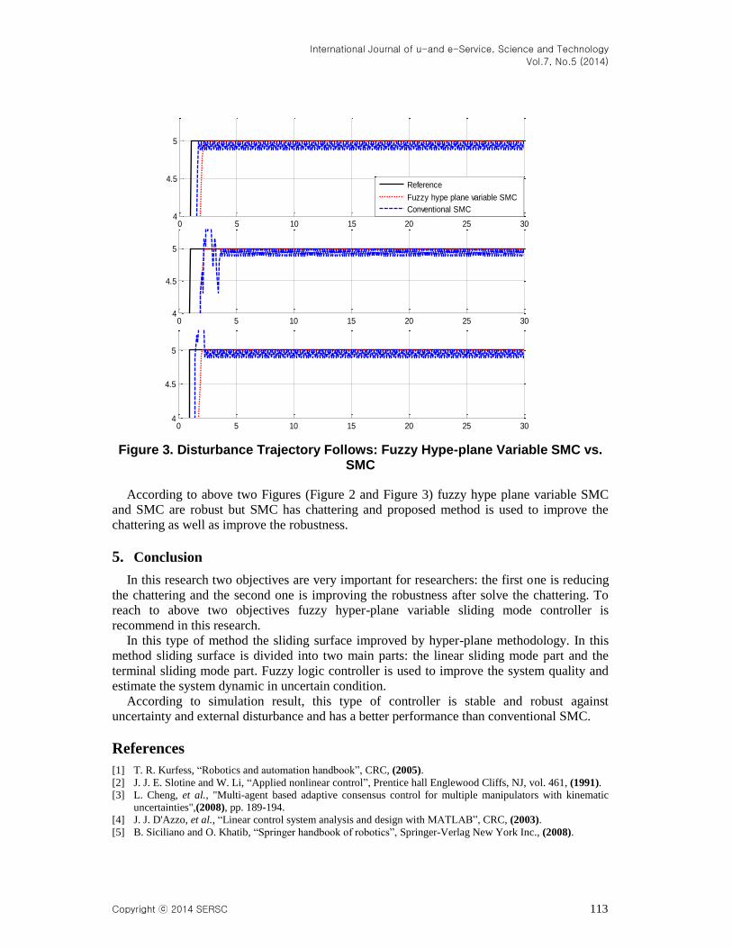
Disturbance trajectory follows: Figure 3 shows the power disturbance elimination in
proposed method and pure sliding mode controller. The disturbance rejection is used to test
and analyzed the robustness comparisons of these controllers for step trajectory. A band
limited white noise with predefined of 30% the power of input signal value is applied to the
step trajectory. It found fairly fluctuations in SMC trajectory responses. According to the
following graph, pure SMC has moderate chattering in presence of external disturbance and
uncertainty. However SMC has moderate chattering but this type of controller is robust.
Fuzzy hype-plane variable SMC can eliminate the chattering and fluctuation in presence of
uncertainty and external disturbance, therefore this type of controller is a robust.
0 5 10 15 20 25 30
4.6
4.8
5
5.2
join
t 1
0 5 10 15 20 25 30
4.6
4.8
5
5.2
join
t 2
0 5 10 15 20 25 30
4.6
4.8
5
5.2
join
t 3
Reference
Fuzzy hypeplane variable SMC
SMC
International Journal of u-and e-Service, Science and Technology
Vol.7, No.5 (2014)
Copyright ⓒ 2014 SERSC 113
Figure 3. Disturbance Trajectory Follows: Fuzzy Hype-plane Variable SMC vs. SMC
According to above two Figures (Figure 2 and Figure 3) fuzzy hype plane variable SMC
and SMC are robust but SMC has chattering and proposed method is used to improve the
chattering as well as improve the robustness.
5. Conclusion
In this research two objectives are very important for researchers: the first one is reducing
the chattering and the second one is improving the robustness after solve the chattering. To
reach to above two objectives fuzzy hyper-plane variable sliding mode controller is
recommend in this research.
In this type of method the sliding surface improved by hyper-plane methodology. In this
method sliding surface is divided into two main parts: the linear sliding mode part and the
terminal sliding mode part. Fuzzy logic controller is used to improve the system quality and
estimate the system dynamic in uncertain condition.
According to simulation result, this type of controller is stable and robust against
uncertainty and external disturbance and has a better performance than conventional SMC.
References
[1] T. R. Kurfess, “Robotics and automation handbook”, CRC, (2005).
[2] J. J. E. Slotine and W. Li, “Applied nonlinear control”, Prentice hall Englewood Cliffs, NJ, vol. 461, (1991).
[3] L. Cheng, et al., "Multi-agent based adaptive consensus control for multiple manipulators with kinematic
uncertainties",(2008), pp. 189-194.
[4] J. J. D'Azzo, et al., “Linear control system analysis and design with MATLAB”, CRC, (2003).
[5] B. Siciliano and O. Khatib, “Springer handbook of robotics”, Springer-Verlag New York Inc., (2008).
0 5 10 15 20 25 304
4.5
5
0 5 10 15 20 25 304
4.5
5
0 5 10 15 20 25 304
4.5
5
Reference
Fuzzy hype plane variable SMC
Conventional SMC

International Journal of u-and e-Service, Science and Technology
Vol.7, No.5 (2014)
114 Copyright ⓒ 2014 SERSC
[6] I. Boiko, et al., "Analysis of chattering in systems with second-order sliding modes," IEEE Transactions on
Automatic Control, vol. 52, (2007), pp. 2085-2102.
[7] J. Wang, et al., "Indirect adaptive fuzzy sliding mode control: Part I: fuzzy switching," Fuzzy Sets and
Systems, vol. 122, (2001), pp. 21-30.
[8] V. Utkin, "Variable structure systems with sliding modes," Automatic Control, IEEE Transactions on, vol.
22, (2002), pp. 212-222.
[9] R. A. DeCarlo, et al., "Variable structure control of nonlinear multivariable systems: a tutorial," Proceedings
of the IEEE, vol. 76, (2002), pp. 212-232.
[10] K. D. Young, et al., "A control engineer's guide to sliding mode control", (2002), pp. 1-14.
[11] M. M. Ebrahimi, F. Piltan, M. Bazregar and A. Nabaee, "Artificial Chattering Free on-line Modified Sliding
Mode Algorithm: Applied in Continuum Robot Manipulator", International Journal of Information
Engineering and Electronic Business, DOI: 10.5815/ijieeb.2013.05.08, vol.5, no.5, (2013), pp.57-69, 2013.
Author
Mahmoud Reza Safaei Nasrabad, he is currently working as a
primary researcher in the laboratory of Control and Robotic, Institute of
Advance Science and Technology, IRAN SSP research and development
Center. His current research interests are in the area of nonlinear control,
artificial control system and robotics.
Ehsan Pooladi, he is currently working as a co researcher in Control
and Robotic Lab at the institute of advance science and technology,
IRAN SSP research and development Center. He is a Master in field of
Mechanical Engineering from Islamic Azad University, IRAN. His
current research interests are in the area of nonlinear control, artificial
control system and robotics, and spherical motor.
Ghasem Sahamijoo, he is currently working as a primary researcher
in the laboratory of Control and Robotic, Institute of Advance Science
and Technology, IRAN SSP research and development Center. His
current research interests are in the area of nonlinear control, artificial
control system and robotics.
Alireza Salehi, he is currently working as a primary researcher in the
laboratory of Control and Robotic, Institute of Advance Science and
Technology, IRAN SSP research and development Center. His current
research interests are in the area of nonlinear control, artificial control
system and robotics.

International Journal of u-and e-Service, Science and Technology
Vol.7, No.5 (2014)
Copyright ⓒ 2014 SERSC 115
Farzin Piltan, he was born on 1975, Shiraz, Iran. In 2004 he is jointed
Institute of Advance Science and Technology, Research and
Development Center, IRAN SSP. Now he is a dean of Intelligent
Control and Robotics Lab. In addition to 7 textbooks, Farzin Piltan is the
main author of more than 100 scientific papers in refereed journals. He is
editorial review board member for ‘international journal of control and
automation (IJCA), Australia, ISSN: 2005-4297; ‘International Journal of
Intelligent System and Applications (IJISA)’, Hong Kong, ISSN: 2074-
9058; ‘IAES international journal of robotics and automation, Malaysia,
ISSN: 2089-4856; ‘International Journal of Reconfigurable and
Embedded Systems’, Malaysia, ISSN: 2089-4864. His current research
interests are nonlinear control, artificial control system and applied to
FPGA, robotics and artificial nonlinear control and IC engine modeling
and control.
Nasri Sulaiman, he Received The B. Eng From University Of Putra
Malaysia In 1994, M.Sc., From University Of Southampton, Uk In1999,
And Phd Degrees From University Of Edinburgh, Uk In 2007,
Respectively. He has more than 65 journal and conference papers. He Is
Currently A Senior Lecturer In The Department Of Electrical
Engineering At University Putra Malaysia Of The Program For Signal
Processing, And Evolvable Harware (EHW) And Also Is Head Of
Control And Automation Laboratory, Iranian Institute Of Advanced
Science And Technology, Shiraz, Iran. He Is An Advisor In Spherical
Motor Control.

International Journal of u-and e-Service, Science and Technology
Vol.7, No.5 (2014)
116 Copyright ⓒ 2014 SERSC