Future satellite technology the role of nanoelectronics - CORE
77
Calhoun: The NPS Institutional Archive Theses and Dissertations Thesis Collection 1998-09 Future satellite technology the role of nanoelectronics Rice, John S. Monterey, California. Naval Postgraduate School http://hdl.handle.net/10945/8440
-
Upload
khangminh22 -
Category
Documents
-
view
1 -
download
0
Transcript of Future satellite technology the role of nanoelectronics - CORE

Calhoun: The NPS Institutional Archive
Theses and Dissertations Thesis Collection
1998-09
Future satellite technology the role of nanoelectronics
Rice, John S.
Monterey, California. Naval Postgraduate School
http://hdl.handle.net/10945/8440


'»«*•
DUDLEY KNOX LIBRARYNAVAL POSTGRADUATE SCHOOLMONTEREY CA 93943.5101


NAVAL POSTGRADUATE SCHOOLMonterey, California
THESIS
FUTURE SATELLITE TECHNOLOGYTHE ROLE OF NANOELECTRONICS
by
John S. Rice
September 1998
Thesis Advisor:
Co-Advisor:
James H. Luscombe
Robert L. Armstead
Approved for public release; distribution is unlimited.


REPORT DOCUMENTATION PAGE Fonn Approved OMB No. 0704-0188
Public reporting burden for this collection of information is estimated to average 1 hour per response, including the time for reviewing instruction, searching existing data
sources, gathering and maintaining the data needed, and completing and reviewing the collection of information. Send comments regarding this burden estimate or any other
aspect of this collection of information, including suggestions for reducing this burden, to Washington Headquarters Services, Directorate for Information Operations and
Reports, 1215 Jefferson Davis Highway, Suite 1204, Arlington, VA 22202-4302, and to the Office of Management and Budget, Paperwork Reduction Project (0704-0188)
Washington DC 20503.
1 . AGENCY USE ONLY (Leave blank) 2. REPORT DATESeptember, 1998
3 . REPORT TYPE AND DATES COVEREDMaster's Thesis
4. TITLE AND SUBTITLE
FUTURE SATELLITE TECHNOLOGY THE ROLE OFNANOELECTRONICS
6. AUTHOR(S)
John S. Rice
FUNDING NUMBERS
7. PERFORMING ORGANIZATION NAME(S) AND ADDRESS(ES)
Naval Postgraduate School
Monterey CA 93943-5000
PERFORMINGORGANIZATIONREPORT NUMBER
9. SPONSORING/MONITORING AGENCY NAME(S) AND ADDRESS(ES) 10. SPONSORING/MONITORINGAGENCY REPORT NUMBER
1 1 . SUPPLEMENTARY NOTES The views expressed in this thesis are those of the author and do not reflect the
official policy or position of the Department of Defense or the U.S. Government.
12a. DISTRTBUTION/AVAILABILrrY STATEMENTApproved for public release; distribution is unlimited.
12b. DISTRIBUTION CODE
13. ABSTRACT (maximum 200 words)
Tiny earth-orbiting spacecraft known as nanosatellites are now possible due to breakthroughs in
microelectromechanics that permit engineers to build extremely small yet fully functional devices. With today's
satellite launch costs averaging around $20,000 per pound lifted into space, nanosatellites could revolutionize the
future of space access by significantly reducing the size, mass, power requirements, complexity and ultimately the
costs of space systems. The small satellite concept fosters a faster evolution in space science and introduces and
tests state-of-the-art space technology. Of the technologies required to design a miniaturized and yet autonomous
space vehicle, nanoelectronics is at the forefront.
The field of nanoelectronics is primarily concerned with integrated circuit (IC) technology at geometries
well below 100 nanometers. It is in this realm that the quantum mechanical nature of the electron becomes, of
paramount importance. With the tools of quantum physics, reduction in the size of individual transistors has
yielded the quantum dot; a three dimensional structure for the confinement of a single electron. The theoretical
study in this thesis will show that the width in p-n junctions is generally underestimated for curved interfaces by
textbook formulas. This result is significant for semi-cylindrical quantum dots which are logical result of
continued downscaling in semiconductor devices.
14. SUBJECT TERMSNanosatellites, Nanoelectronics, Solid State Physics
15. NUMBER OFPAGES 64
16. PRICE CODE
1 7. SECURITY CLASSIFICA-
TION OF REPORT
Unclassified
SECURITY CLASSIFI-
CATION OF THIS PAGE
Unclassified
19. SECURITY CLASSIFICA-
TION OF ABSTRACTUnclassified
20. LIMITATION OFABSTRACTUL
NSN 7540-01-280-5500 Standard Form 298 (Rev. 2-89)
Prescribed by ANSI Std. 239-18 298-102

11

Approved for public release; distribution is unlimited.
FUTURE SATELLITE TECHNOLOGYTHE ROLE OF NANOELECTRONICS
John S. Rice
Lieutenant, United States Navy
B.S., United States Naval Academy, 1992
Submitted in partial fulfillment
of the requirements for the degree of
MASTER OF SCIENCE IN APPLIED PHYSICS
from the
NAVAL POSTGRADUATE SCHOOLSeptember 1998


DUDLEY KNOX LIBRARY
aRCTU ArT NAVAL POSTGRADUATE SCHOOLABS 1KAC1 MONTEREY CA 93943-5101
Tiny earth-orbiting spacecraft known as nanosatellites are now possible due to
breakthroughs in microelectromechanics that permit engineers to build extremely small yet
fully functional devices. With today's satellite launch costs averaging around $20,000 per
pound lifted into space, nanosatellites could revolutionize the future of space access by
significantly reducing the size, mass, power requirements, complexity and ultimately the costs
of space systems. The small satellite concept fosters a faster evolution in space science and
introduces and tests state-of-the-art space technology. Ofthe technologies required to design
a miniaturized and yet autonomous vehicle, nanoelectronics is at the forefront.
The field of nanoelectronics is primarily concerned with integrated circuit (IC)
technology for scale sizes well below 100 nanometers. It is in this realm that the quantum
mechanical nature of the electron becomes of paramount importance. With the tools of
quantum physics, reduction in the size ofindividual transistors has yielded the quantum dot;
a three-dimensional structure for confinement of a single electron. The theoretical study in
this thesis will show that the width in p-n junctions is generally underestimated for curved
interfaces by textbook formulas. This result is significant for semi-cylindrical quantum dots
which are the logical result of continued down scaling in semiconductor devices.

VI

TABLE OF CONTENTS
I. INTRODUCTION 1
E. NANOSATELLITE APPLICATIONS 3
A. WHAT IS A NANOSATELLITE ? 3
B. ADVANTAGES OF NANOSATELLITES 4
1. Cost 4
2. Redundancy 5
3. Utility 6
m. NANOTECHNOLOGY IN SMALL SATELLITES .....9
A. ATTITUDE DETERMINATION 9
B. ATTITUDE CONTROL 10
C. THERMAL CONTROL 12
D. POWER SYSTEMS 13
E. SENSING DEVICES 15
F. COMPUTING AND ELECTRONICS 16
IV. THE QUANTUM REVOLUTION 19
V. QUANTUM DOT THEORY 21
A. ELECTRON CONFINEMENT 21
B. QUANTUM DEVICE FABRICATION 22
VI. THE DEPLETION REGION 25
A. DEPLETION REGION FUNDAMENTALS 25
B. DEPLETION WIDTH FOR PLANAR SURFACES 26
C. DEPLETION WIDTH FOR CYLINDRICAL SURFACES 28
VH. RESULTS 31
APPENDIX A. NANOSATELLITE LAUNCH VEHICLES 35
APPENDIX B. CURRENT NANOSATELLITE PROJECTS 43
LIST OF REFERENCES 49
INITIAL DISTRIBUTION LIST 53
vu

Vlll
ACKNOWLEDGEMENT
The author would like to acknowledge and thank Professor Luscombe for his guidance,
patience and support during the work in performing this analysis.
IX


I. INTRODUCTION
Most modern day satellites have masses on the order of several thousand kilograms.
With launch costs rising past ten thousand dollars per kilogram, there is little mystery behind
the movement to shrink the size of spacecraft. But loss of capability is a prime concern when
reducing a satellite's overall size. To offset this loss, many programs have been undertaken
worldwide to develop smaller satellites with advanced components allowing for a minimal loss
of functionality.
At first, there were miniature satellites with masses less than 500 kg which were often
simply stripped down versions oftheir larger cousins. Next to develop were microsatellites,
those having masses of around 100 kg, which employed advancing technologies but were
again limited in the scope of their missions. Currently under development, along with
continued development of both mini- and microsatellites, are nanosatellites; spacecraft with
masses of approximately 10 kg. Early nanosatellites have suffered in functional capacity as
did their predecessors; however, modern technology and advanced engineering techniques
have allowed for small satellites and satellite components which are capable of performing a
variety of missions.
Nearly every component subsystem of a spacecraft can be reduced in size through
advances in a variety oftechnologies. Ofthese subsystems, computers and electronics play
a vital role as the central nervous system ofmost satellites. Nanosatellite designs benefit from
smaller scale electronics, giving them more on orbit processing and more autonomy at a
fraction of the weight. Much of the progress in the microelectronics has come from the
reduction of size ofthe transistors that make up the integrated circuits, devices whose size
1

has dropped by a factor often in the last decade. [Ref 1]
As microelectronic components approach geometries on the order of nanometers, a
full understanding of the quantum properties of such a device becomes imperative. In such
semiconductor structures, knowledge of the extent of depleted regions is a significant
parameter in grasping device operation, the size of the depleted regions generally represents
a small fraction ofthe device geometry. In nanostructures, however, the spatial extent of the
depleted regions are often comparable to the physical dimensions of the device.
This thesis will show that the curved interface of certain nanoscale devices presents
new challenges in the accurate determination of the depletion region. Also, if the standard
formula for the depletion width of a planar interface is applied, it will generally underestimate
that width. Accurate modeling is essential as small errors in the estimation of the depletion
region can potentially represent a discernable fraction of the device geometry.

II. NANOSATELLITE APPLICATIONS
A. WHAT IS A NANOSATELLITE ?
After 40 years of evolution, conventional satellite technology is concentrating on
relatively few large satellites with high reliability and extensive capabilities. In certain
applications however, larger numbers of smaller satellites can provide a much lower cost
alternative without undue risk. Since the early days of Sputnik and Explorer in the late
1950's, developers have built small, simple systems alongside large, more conventional
satellites. Miniature satellites, those spacecraft less than 500 kg, were designed to fill certain
niches which required a short mission duration with relatively few subscribers. These small
satellites were assembled quickly by small teams, often with significant program risks.
However, in most small satellite programs, accepting a mission failure was the only alternative
to not attempting the mission at all. With less money at stake, users were more apt to take
risks with newer unproven components and more liberal designs in hopes of validating of
those technologies. [Ref 2]
In today's terms, the word nanosatellite generally refers to space vehicles with a mass
of less than 10 kg with most being only a few centimeters in diameter. [Ref 3] Although only
a few such craft are in developmental stages today, some ofwhich are listed in Appendix B,
many more will follow as their capabilities increase. The functionality of these satellites is
completely mission dependent with some being fully autonomous and others much more
simplified. In the earlier years, as was aforementioned, small satellites were possible only at

the expense of functionality. This is no longer the case, however, with the internal systems
of modern nanosatellites being identical to their larger counterparts although with micro-
miniaturized systems performing all of the necessary tasks.
B. ADVANTAGES OF NANOSATELLITES
1. Cost
A new trend is emerging in the satellite market with the theme of "smaller, cheaper,
faster, better". This trend is driven by many different factors: the need to lower up-front
costs of satellite procurement and a need to lower the launch and overall operations cost.
Current U.S. military satellites are too expensive to build and fly in an era of constricting
budgets. According to James Stuart, the cost required to engineer, launch and operate a
small, medium and large geosynchronous satellite are $100, $150 and $275 million,
respectively with launch costs generally dominating the budget. Payload and platform are the
other two major contributors to the cost. The platform mass and cost are related to the
payload mass, power requirements and volume. Thus any reduction in mass, volume or
power consumption is highly desirable and will have a significant impact on cost.
Nanosystems are considered an excellent means of obtaining these reductions. These types
of systems could lead to decentralization , whereby a given number of dispersed components
could be used in place of a larger centralized unit, therein achieving higher efficiency, better
redundancy and eliminating single point modes of failure. This leads to cost reduction in
space based systems not only at the platform and payload levels but also in the ground
facilities and launch vehicles, a few ofwhich are described in Appendix A, down to the end-
user achieved through the economies of scale. [Ref 4]

2. Redundancy
But cost-savings through the reduction of mass is not the only desirable aspect of
nanosatellites, redundancy being another key feature. As they are small, these satellites can
be mass produced in an assembly line fashion, a technique which is impossible for larger
satellites. Spacecraft manufacturing is currently a labor intensive artisanal process with few
similar units ever being produced. Traditional cost-reduction methods such as new design
and production paradigms, modularity and pre-fabrication have reduced overall costs but not
to the desired levels. A sensible way to cut cost and enable commercialization could be
through a technology or engineering breakthrough oriented towards mass production of space
subsystems. [Ref 4] Bulk production of these smaller systems would also lead to the
possibility ofincorporating redundancy into the layout of individual components. In current
satellite designs, mission critical subsystems are replicated in their entirety to avoid single
points of failure, resulting in added weight and complexity. The small size of nanosatellite
components alone allows for the duplication of most subsystems many times over without a
noticeable increase in mass. Redundancy can also be achieved at the architecture level by
using a low-earth orbit (LEO) constellation. An example might be an array of nanosatellites
in random LEO orbits providing fully connected, continuous communications as shown in
Figure 1. With random individual orbits, the satellites require no orbit maintenance and can
be flown in tandem with any LEO launch. In a short time the network could become fully
populated. [Ref 2] A computer model of this type ofnetwork has demonstrated that a
network of400 satellites could provide 95% global coverage. [Ref 2]

Figure 1 - Constellation of nanosatellites. From Ref. [5]
The intrinsic redundancy of this type of system is its inherent beauty. Destruction of 15 or
20 satellites has no effect on the overall system integrity and presumably the cost to destroy
enough satellites to disrupt the network would cost more than the network itself. An added
benefit is their small size which makes them nearly impossible to track.
3. Utility
Due to their reduced weight and volume, a small constellation of communication
nanosatellites could be placed into orbit by a vast array of launch vehicles, quickly providing
communications capability anywhere on the globe. Assuming a constellation of nanosatellites
are preconfigured for contingency operations, these satellites could be stored in their launch
vehicle and be lifted into space to support communications in regions with military operations,
natural disasters or other emergency situations.
More often than not, military operations in remote areas ofthe world suffer in their
initial stages primarily from a lack of dependable communications. When the U.S. began its
build-up of forces in the Saudi Arabian desert prior to Desert Storm, demand for satellite
communications outstripped the capability ofmilitary satellites in the area. As Air Force Brig.

Gen. William Jones, deputy chief of staff for requirements at the Air Force Space Command,
said; "We found ourselves in a very tenuous position in the early days, until we could get
satellite constellations optimized". [Ref 4]

III. NANOTECHNOLOGY IN SMALL SATELLITES
A. ATTITUDE DETERMINATION
Attitude sensors can be divided into two distinct groups: inertial and optical. Inertial
sensors include such devices as accelerometers and gyros and have shown a theoretical
performance dependence on the size ofthe instrument. The dimensions of optical sensors are
determined by the diffraction-induced resolution limits of the optics. Efforts are currently
underway to design nanosensing devices for both optical and inertial systems with the later
being more feasible albeit at considerable cost. Although there is substantial research in
micro-earth sensors, sun-sensors and micromachined gyros, the most promising design is of
a different sort.
A group at the Jet Propulsion Laboratory (JPL) has demonstrated a new sensing
technique that involves combining micromachined silicon structures with a highly sensitive
electron tunneling device. This device has an advantage of a reduction in the mass and
volume of sensor/actuator systems by a factor of 100 to 10,000. These devices offer an
improved sensitivity by a factor of 20,000 over that of conventional capacitive transducers
and also require simpler electronics, less power and have dimensions of less than 10X10 um.
They experience no problems from differential thermal expansion, radiation effects or
mechanical properties and can be mass-produced with standard lithographic techniques. The
benefits of the electron-tunneling displacement sensors are extensive and include: greater
sensitivity, reduced mass, smaller size, and immunity to the space environment. [Ref 6]

Another attempt to provide low-cost accurate attitude determination is the GPS
Attitude Determination Flyer (GADFLY). Built by TRW and flown on the demonstration
microsatelliteccLewis", GADFLY attempted to verify the accuracy of GPS based attitude
determination. Similar experiments had flown previously but the Lewis experiment contains
better filtering and processing of the GPS data with a more robust receiver that is less
suceptable to solar radiation. [Ref 7]
B. ATTITUDE CONTROL
Although microsensors can be scaled irrespective of satellite size, the same cannot be
said for the microactuators which physically control the motion of the spacecraft. It is
feasible that, for applications that require low pointing accuracies, passive attitude control via
scaled down gravity gradient booms or magnetotorquers could be employed. For missions
with higher pointing accuracy requirements, i.e. +/- 2 degrees or those needing full 3-axis
control, more advanced systems would be necessary.
Attitude control of three-axis stabilized spacecraft is accomplished by a variety of
systems comprised ofmomentum wheels, reaction wheels or control moment gyros. There
are two different classes of three-axis stabilization: momentum bias, which places a
momentum wheel along the pitch axis and zero momentum systems which have a reaction
wheel along each of three axes. It is well known that both stabilization methods can be
accomplished by all thruster systems. On modern spacecraft, all thruster systems are usually
not attempted because the constant drain of propellant makes for a poor satellite life
expectancy. However, recent advances in Pulsed Plasma Thruster (PPT) systems promises
to provide a simple, low mass, high specific impulse (L^) propulsion system which can be
10

effective in both attitude control and orbit maintenance.
The PPT is an electric propulsion device which uses electric power to ionize and
electromagnetically accelerate a plasma to high exhaust velocities, attaining an Isp in the 1000-
2000 second range. [Ref 8] The PPT is ideal for small spacecraft since it has a low (0. 1-50W)
power draw, a small (50-800/^N-s) impulse bit (Ibit), and uses an inert and inherently stable
propellant, Teflon. The use of the Teflon as a propellant provides other advantages such as
eliminating the need for expensive propellant feed systems, fuel heaters, tanks and valves. A
comparison ofminimum impulse bit characteristics is shown in Table 1 for several thrusters.
Thruster . Thrust (N) Ibit (mN-s)
Monopropellant 0.448 5.34
Bipropellant 5.0 100
Cold Gas 0.05 0.5
PPT <0.1
Table 1 - Comparison of various impulse bits. From Ref [8^
Although other electric propulsion devices such as resistojets, arcjets and ion thrusters are
capable of an equally high 1^ they require much greater power than most small satellite buses
can provide. Operational PPTs have proven effective with only 6-30 W and can be used as
attitude controllers with an average power of less than 1 W. A flight test and evaluation of
a PPT on orbit will be conducted by the Air Force's Phillip's Lab in mid 1999 when the
second MightySat I satellite is scheduled for launch. [Ref 8] Table 2 gives a mass
comparison of the PPT vs. more conventional attitude control systems used in the
requirements analysis ofa 100 kg LEO satellite. The only foreseeable sticking point to using
the PPTs in nanoscale satellites is the capacitor technology. PPTs require a capacitor for
11

energy storage in order to deliver electrical power in short bursts. Expanding the energy
density and lifetime of these capacitors while at the same time keeping their mass to a
minimum is a concern. Currently, NASA's Lewis Research Center is working to reduce the
mass of today's best PPT by one half. The goal is to develop a PPT which can
Component Unit mass (kg) No. of Units Total Mass (kg)
Spinning mass 3.6 4 14.4
Drive electronics 0.91 4 3.64
Structure 2.0 1 2.0
System mass 20.04
Thruster dry mass 0.4 6
280s Isp propellant 3.73 N/A
Six thruster mass 6.13
Table 2 - Mass ofPPT vs. other thrust systems. From Ref [9],
deliver 20 million pulses at a total energy level of 40 J and have a total system mass less than
lkg. [Ref 10]
C. THERMAL CONTROL
Since nanosatellites are designed around a bus with relatively small dimensions, the
removal ofheat is greatly simplified. In fact, a nanosatellite can be thought of as isothermal,
which facilitates the thermodynamic analysis and design process. An isothermal satellite
which generates all of its power via body mounted solar panels, as most do, can be thermally
controlled to within reasonable limits by the use of simple surface coatings and phase change
materials. [Ref 11]
12

However, as the power requirements for more complex nanosatellites increase, it may
be necessary to add deployable solar arrays or other energy sources. Consequently, the heat
dissipation requirements will increase until there is not sufficient area on the nanosatellite's
tiny frame to radiate the heat generated. The satellite will then require the use of miniature
heat pipes, micromachined heat pumps, or deployable radiators to increase heat rejection and
maintain operating temperatures.
At the forefront of nanosatellite thermal control is the development of mechanical
cryorefrigerators and heat pumps based on a micromachining technology. These techniques
have not yet been proven in nanosatellites and would not be the best approach for long term
space missions as they require a steady flux of coolant gas. A closed loop version of the
system is a possibility and could be used to cool the focal plane of a nanosatellite's infra-red
(TR) system. Although miniaturized cryorefrigerators and heat pumps will take more than ten
years to develop, an IR imager using microbolometers and operating at room temperature
has already been demonstrated and may be the best hope. [Ref 1 1]
D. POWER SYSTEMS
To date, the power requirements in small satellites have been small enough for body
mounted solar panels to be sufficient. Theoretically, solar cells can be reduced to any
practical size with the only limitations being in the manufacturing processes of the cells
themselves. Likewise, there is no fundamental obstacle to the furthered scaling down of
batteries with modern technology employing a vast assortment of small batteries in
pacemakers, watches and calculators. Advances have been made however, in more efficient
solar cells for nanosatellites with smaller batteries as well.
13

The second MightySat I microsatellite will be the first to fly with dual junction solar
cell technology. [Ref 12] These cells offer a 15% improvement in performance over
conventional gallium-arsenide (GaAs) cells. The dual junction cells have a layer of gallium-
indium-phosphide (GalnP) placed over a layer of GaAs. The GalnP absorbs shorter
wavelength incident photons which would normally pass unhindered through a GaAs-only
cell. The longer wavelength solar energy passes harmlessly through the GalnP and is
absorbed by the GaAs. Combined, these layers provide electrical power at an efficiency, solar
energy in divided by electrical power out, of 21% compared with conventional GaAs cells
which realize an efficiency of around 18% and silicon cells which offer 14% efficiency. It
remains to be seen what the degradation effects are on dual-junction cells over prolonged
exposure to solar radiation but the design appears promising for now. [Ref 12]
Significant progress has also been made in the size reduction of spacecraft batteries
which have been notorious as the greatest distributions of mass in many spacecraft. Although
nickel-hydrogen (NiH2) battery technology is not new, Eagle-Picher Industries (EPI), has
developed a Dependent Pressure Vessel (DPV) design which combines the advantages of
NiH2 electrochemistry with the simplicity and extensive heritage the of nickel-cadmium
(NiCd) battery system. The 15 amp-hour cell design offers a 1.25 VDC output which will
usually require the cells be wired in series as most applications require somewhat higher
voltages. Each cell has a diameter of 5.5", a thickness of 1 .12" and mass of 4.85 grams, thus
offering a significant size and weight savings over more conventional designs. [Ref 13]
14

E. SENSING DEVICES
In the current generation of launch vehicles and spacecraft, temperature and pressure
sensors are utilized mostly in housekeeping roles. Pressure sensors are mainly used for
propellant tanks and lines while temperature sensors have a much wider range of applications.
Thermal monitoring of a spacecraft is often accomplished with up to one hundred temperature
sensors distributed throughout the body of the satellite. Examples of subsystems where one
is likely to find temperature sensors include: solar arrays, propellant tanks, thruster
components, heater controls on electronic components, payload components such as traveling
wave tube amplifiers and cryogenic cooling systems. The current models of temperature
sensors are thermistors and thermocouples both of which are solid state devices with masses
substantially less than one gram. However, most of the mass associated with thermal sensors
is packaging. Packaging is required for a variety of reasons, such as to protect against
corrosive environments or simply to securely mount the sensor. Hence, decreasing the mass
ofthe sensor itself is essentially useless while decreasing the mass of the packaging is virtually
impossible. [Ref 8]
Pressure sensors, on the other hand, consist largely of piezoelectric crystals which
usually have a mass of a few grams. Attempts are currently underway to fabricate pressure
sensors from vapor-depositing piezoresistive films, whose electrical resistance changes as a
function of pressure. These new sensors work well at room temperatures but present
problems at temperatures below around 77K. [Ref 8]
In addition to piezoresistive films, piezoresistive elements are being made directly into
silicon structures through ion implantation but also act in a non-linear fashion at cooler
15
temperatures. Another new technique is measurement via a fiber optic line. Essentially, a
fiber optic wire is placed between two plates in such a way that the line will be bent as the
plates are pushed together or pulled apart. As the fiber is bent, its optical properties will be
altered in such a manner that can be measured and directly related to the pressure between
the plates.
In most nanosatellites, experts agree that temperature and pressure sensors will be
implanted directly into specific structures eliminating the use of packaging. Due to their small
size, the number of sensors which a spacecraft can support will be largely determined by the
amount of data the satellites computer can handle. [Ref 8]
F. COMPUTING AND ELECTRONICS
Though not usually a mass or volume constraint, reduction in the size of onboard
computing electronics with a marked increase in computing power would have a significant
impact in spacecraft functionality especially in the area of deep space missions. The Center
for Integrated Space Microsystems (CISM), the advanced computing department at JPL, has
recently been directed by NASA to advance the state of the art in microelectronics for near-
and mid-term missions. The CISM is actually one element of a larger NASA program termed
X-2000 which aims to produce a standardized spacecraft bus which can be tailored to various
mission requirements. But CISM officials have been challenged to design long-term
revolutionary computing technologies smaller than the width of a human hair. Eventually,
these technologies, based on the use of the innovative quantum dot, will be used to improve
U.S. encryption of national security transmissions. According to its director, Leon Alkalai,
"We (CISM) are studying how to build devices at the atomic or molecular scale, also referred
16

to as molecular nanotechnology". [Ref 14] Miniaturizing "electronics down to where
everything is dealing with electrons and photons" will allow NASA and other national
agencies to construct intelligent and fully autonomous systems on a microchip for use in
rovers, orbiters and other space systems, Alkalai said. [Ref 14]
Most of today's satellites contain classical computer systems in which all computing
logic is determined by switches between one and zero. In future "quantum computers"
decisions are based on energy levels of electrons allowing for an incredibly reduced size of
scale.
While security agencies are fascinated by the capabilities of quantum computing and
it's ability to keep messages secure, NASA is interested in building a quantum computer
"because it would be a breakthrough technology equivalent to the development of the
transistor 50 years ago" Alkali said. Both British and Japanese agencies have approached
CISM in an effort to jointly explore quantum computing for use in deep space nanosatellites
and other applications. [Ref 14]
By the year 2010, it is hypothesized that many important NASA missions will require
computing power approaching one petaflops (1015
floating point operations per second).
Unfortunately, it is uncertain whether or not the U.S. computer industry alone can fill that
need at an acceptable cost. To achieve such a high level of performance, significant
breakthroughs in computing hardware technologies, i.e. the quantum computer, must be
realized. [Ref 14]
17

18

IV. QUANTUM REVOLUTION
Nanosatellites are but one of a myriad of beneficiaries of quantum computing
technologies. Integrated circuits have become the technology of choice for electronic
functions. Their use has become so widespread that they dominate the world electronic
markets and have opened new markets which were previously nonexistent. As the demand
for these semiconductor devices has increased, so has their size decreased. According to
Moore's Law, the number of transistors on a single integrated circuit chip should continue
to double each year. But doubling the number of devices on a chip requires reductions in
both the size of the devices themselves and their interconnections. As the size of current chip
designs dip below 0.25 micrometers, one must wonder as to. the eventual limit of the ever-
shrinking transistor. [Ref 1 5]
It was thought in the mid-1980's that further size reduction of electronic devices below
the micrometer range would yield diminishing returns. However, newly developed quantum
dots have been fabricated at a width of only 100 nm. [Ref 15]
In this regime, the fundamental quantum' properties of a single electron will dominate
charge transport and also, at these dimensions, it is no longer satisfactory to think of electrons
as particles. It has been determined from such phenomenon as diffraction that electrons have
properties consistent with a wave nature which are described by the electron's wave function.
By exploiting this wave function, we can harness the electron's ability to tunnel through a
potential energy barrier, rather than having to go over it as a classical particle would. This
situation is known as resonant electron tunneling and is used in the simplest practical
19

nanoelectronic device; the resonant tunneling diode (RTD). [Ref 16]
In an RTD an electron is quantum-mechanically confined in one direction and is
otherwise free to move in the remaining two directions. This confinement produces a
nonlinear device characteristic that has innovative circuit applications. [Ref 1 6]
But the quantum dot achieves three dimensional electron confinement which is the
inevitable result of continued downscaling of semiconductor structures. The quantum dot
probably represents the smallest possible noncryogenic switching device and perhaps reaches
the ultimate scaling limits of solid state electronics.
[Ref 16]
20

V. QUANTUM DOT THEORY
A. ELECTRON CONFINEMENT
Technological advances in semiconductor materials science and photolithography
continue to force the size of the transistors that make up integrated circuits to smaller and
smaller limits. Device geometries on the order of 350 nanometers are now being constructed
in mass quantities, launching us into the new realm of nanotechnologies at the forefront of
which is the quantum dot.
The ability to confine an electron to a given point has proven elusive. Scientists had,
for some time, been able to reduce the electron's dimensions to lines or planes but have
recently confined it in all three spatial dimensions; hence a dot. Physicists have developed
new methods for artificially "creating" atoms, no longer relying on the natural solid state
structure of atoms, molecules, and crystals. These so called "designer atoms" have recently
proliferated and their capacities are as yet untapped. [Ref 17]
Applications of quantum dots to the fields of optics and micro technologies are
virtually without bounds. Materials may be fabricated which are capable of resonating at any
frequency chosen by the designer, giving rise to very precisely tuned semiconductor lasers
and other applications such as arrays ofdensely packed quantum dots molded into a substrate
and used as transistors for more powerful computing.
Quantum wells were the first successes in two-dimensional fabrication. These
structures, made by thin film epitaxial techniques grew a semiconductor structure as a series
of individual layers, each comprised of semiconducting material (usually gallium arsenide,
21

GaAs, and related compounds). [Ref 1 7] Since electrons tend toward states with the lowest
energy possible, and the energy of electrons inside the well are relatively lower than those
outside, electrons are forced into the well. Quantum wells are ubiquitous. No longer
relegated to simple constructs in quantum physics textbooks, they appear in laser diodes
which drive our compact disc players and are found in communications electronics such as
microwave receivers. [Ref 1 8]
B. QUANTUM DEVICE FABRICATION
Fabrication of nanoscale structures has proven difficult. The first attempts made use
of nanocrystallites, crystals which, when formed with glass at high temperature precipitate in
the glass, forcing electrons into a state of quantum confinement. It is important to note that
when particles are confined to a certain space, the boundary conditions and wave properties
of the particle dictate that the particle may occupy only certain discrete values of energy.
While strict 3D confinement would yield truly discrete energy levels, the electrons would also
be inaccessible for transport. Thus, it is necessary in quantum dot structures for the dot states
to be slightly unbound in one or more dimensions. Nanocrystallites have chemical properties
which dampen the vibration of electrons at higher energies, and thus a quantum dot made of
nanocrystallites could only operate at unsuitably low energies. [Ref 1 7]
The manufacturing process usually begins with molecular beam epitaxy (MBE) onto
a stable substrate. An MBE system is simply a very high vacuum evaporator. By rigidly
controlling the temperature of the single crystal substrate and flow rate of the evaporated
molecules, it is possible to achieve high purity epitaxial growth. Figure 2 shows an example
of an MBE system. As the crystal is grown, the effusion cell shutters are opened and closed
22

as necessary, producing the desired layering. The result is either a heterqjunction or a multi-
Su&sirate
Howee
GaAj WWer
Molecular
Beams
Snuf.er
Gallium
p-ryoe
Dccan:
Figure 2 - Schematic of a molecular beam epitaxy system (MBE). From Ref. [18].
layered heterostructure. Once grown, the slabs of quantum well material are cut and etched
by photolithography into semi-cylindrical pillars 100 angstroms wide as shown in Figure 3.
Quantum dots of different sizes have different sets of harmonic energy levels, a clear signal
that the electron is indeed confined. Various research has shown it plausible to construct a
potential gate around the dot which squeezes it, thus increasing its spectrum of energy levels.
The squeezing is accomplished by making the conducting strips around the electron negatively
charged so that the electrons in the quantum well beneath the surface will be repelled.
However, since the electrons are confined to a thin layer parallel to the surface, the lateral
direction is the only allowed dimension for movement. As a result, the electrons are confined
to a tiny cluster directly underneath the central square outlined by the electrodes. As the
23

square is reduced in size, a quantum dot is formed. This electrostatic squeezing has proven
to be the most successful method of controlling the size of individual dots. The problem that
arises is the difficulty in manufacturing electrical contacts small enough to allow for resonant
tunneling in and out of the squeezed dot. Recently however, successes have been realized in
the assembly of miniature tunnel barriers who are themselves electrostatically controlled.
[Refl7]
ELECTRON BEAM ELECTRODES
Building in Zero Dimensions
Fabrication of quantum dots pro-
ceeds through a series of maskingand etching steps. First, an electron
beam scans the surface of a semicon-ductor containing a buried layer of
quantum-well material (/). Resist is re-
moved where the beam has drawn a
pattern (2). A metal layer is depositedon the resulting surface (3), and then a
solvent removes the remaining resist,
leaving metal only where the electron
beam exposed the resist (4). Reactive
ions etch away the chip except whereit is protected by metal (5). leaving a
quantum dot (6). An alternative fabri-
cation method lays down a pattern of
electrodes above a buried quantum-well layer. When a voltage is applied to
the electrodes, the resulting held expels
electrons from the layer except in cer-
tain small regions (top right). The de-
gree of quantum confinement in those
regions can be manipulated by chang-ing the electrode voltages.
Figure 3 - Etching of quantum dots. From Ref [17]
24

VI. THE DEPLETION REGION
A. DEPLETION REGION FUNDAMENTALS
At the creation of a typical p-n junction there will be a motion of majority charge
carriers across the junction. Electrons close to the junction plane will tend to diffuse across
into the p-doped material leaving behind the donor sites fixed in the lattice and thereby
creating a net positive charge on the n-type material. Upon reaching the other side of the
barrier, the electron quickly drops out of the conduction band into the valence band and in
a sense, combines with a hole. The holes experience a similar sequence when drifting across
the junction from the p-type material to the n-type material. This motion of charges is the
diffusion current. [Ref 19] In the steady state, a region of fixed positive charge builds up on
one side of the barrier and a region of fixed negative charge builds up on the other side as
shown in Figure 4.
<-cL^
Figure 4 - Creation of a depletion region.
These two regions form the depletion region ofwidth d . The charges in the depletion region
set up a potential barrier, as illustrated in Figure 5, against further diffusion by the majority
25
carriers but enhances movement of the minority carriers on both sides of the junction.
v.o
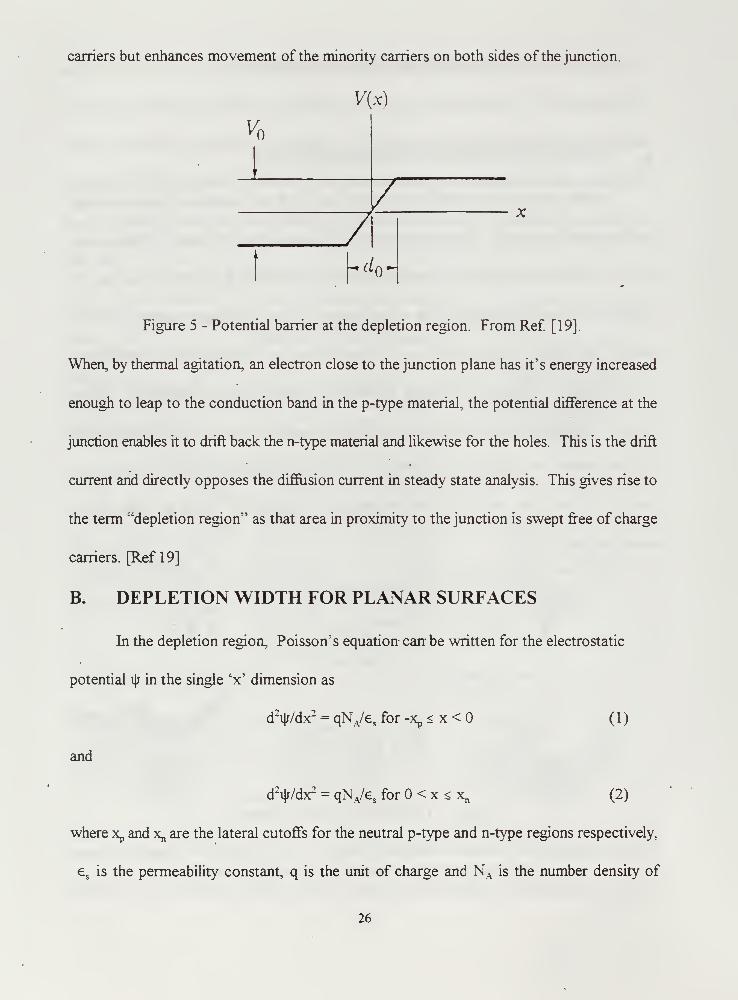
Figure 5 - Potential barrier at the depletion region. From Ref. [19].
When, by thermal agitation, an electron close to the junction plane has it's energy increased
enough to leap to the conduction band in the p-type material, the potential difference at the
junction enables it to drift back the n-type material and likewise for the holes. This is the drift
current and directly opposes the diffusion current in steady state analysis. This gives rise to
the term "depletion region" as that area in proximity to the junction is swept free of charge
carriers. [Ref 19]
B. DEPLETION WIDTH FOR PLANAR SURFACES
In the depletion region, Poisson's equation can be written for the electrostatic
potential ij; in the single 'x' dimension as
dfy/dx2 = qNA/e s
for -Xp < x < (1)
and
dVdx2 = qNA/e sfor < x < x„ (2)
where Xp and x„ are the lateral cutoffs for the neutral p-type and n-type regions respectively.
es
is the permeability constant, q is the unit of charge and N A is the number density of
26

acceptors and ND is the number density of donors as shown in Figure 6. Since the
semiconductor is overall electrically neutral, the charge density per unit area on the p-side
exactly equal the charge density on the n-side:
NAxp = NDxn . . (3)
NEUTRAL p
REGION
DEPLETION— REGION — - NEUTRAL n
REGION
Figure 6 - Space charge distribution in the depletion region. From Ref. [20]
The width of the depletion layer W, is given by
W=|xp|+xn . (4)
Since the component of the electric field x̂ is the negative rate of change of the potential in
the direction x, it can be found by integrating Equations 1 and 2 to yield
ar(x) = -ai|/A?x = -[qNA(x +xp)]/e sfor -x, < x < (5)
and
iT(x) = -9m + qNDx/e s= [qND/e s
](x - xj for < x < x,, (6)
where m̂ is the maximum electric field which exists at the junction (x = 0) and is given by
27

m̂ =qNDVe s= qNAxp/e s
- (7)
To determine the potential, i|rD, which occurs across the depletion region, we integrate
Equations 5 and 6 to find
i|rD = qNAXp2/2e
s+ qN^^e, = ^W/2 (8)
By combining equations 3 and 8 we obtain an expression for the width of the depletion region
as a function of i|/D
W = [(2es/q) {(NA + ND)/ NAND} i|/D]
1/2. (9)
C. DEPLETION WIDTH FOR CYLINDRICAL SURFACES
Although Equation 9 is a sufficient approximation of depletion width at a planar
interface, it is not satisfactory for a cylindrical geometry. For shorthand purposes, define a
characteristic length, £, given in terms of O, the energy at any given surface within the
semiconductor as
I = [e, <D/e2 ND]
1/2. (10)
Now, using cylindrical coordinates, Poisson's equation for an axisymmetrical potential,
i|j(r), can be written
V2ij;(r) = (l/r)(d/dr)[rd i|r/dr] = 0/
£
2(11)
where r denotes the radial position for cylindrical coordinates. The general solution to
Equation 1 1 is
i|/(r) - 0[Y + 61n(r/ 1) + l/4(r/02], (12)
where y and 6 are arbitrary constants. In order to solve this equation, we must first impose
some boundary conditions.
Between the neutral region and the depletion region on both sides of the junction is
28

a transition region as shown in Figure 7 for a planar geometry. Here the space charge of
impurity ions, fixed in their lattice sites, are partially compensated by the mobile carriers. The
transition region is very small on a scale with the depletion region and leads to the
approximation that it can be neglected and the depletion region can be represented as a
rectangular distribution shown in Figure 8.
[^DEPLETION REGION
N D -NANEUTRAL pREGION
NEUTRAL n
REGION
TRANSITION—<K£^2^T \ —|[^TRANSITION
W&- \ REGION
ARGE DENSITY DUEUNCOMPENSATED
MPURITY IONS
Figure 7 - Space charge distribution. From Ref. [20]
The assumption reveals that the potential, i|j, has zero slope at the interior edge of the
depletion region, or
ijj'(R-W) = (13)
In addition to the interfacial boundary condition given as the definition of O, we also require
that at an interior position x = R-W, ij; vanishes relative to Ep, the Fermi level energy, thus
v|j(R-W) = 0. (14)
Imposing these boundary conditions on Equation 12 we obtain the transcendental equation
A 2 = (R2- 4£
2)/( 1 + 21n(R/A)
,
(15)
where A = R-W. For any given cylindrical geometry of characteristic length £ and radius R,
29

NEUTRAL pREGION
NEUTRAL n
REGION
DEPLETIONREGION
Figure 8 - Rectangular approximation of charge distribution. From Ref [20]
Equation 15 can be solved numerically for A. The width of the depletion region W, as
illustrated in Figure 9, is now defined in terms ofR as
W = R-A.
\
—
F
wA
dC__.
—
^
(16)
Figure 9 - Geometric Depiction ofW.
30
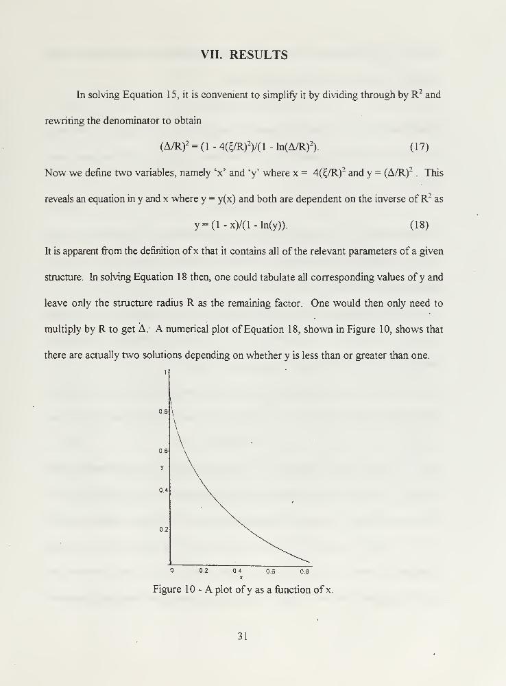
VII. RESULTS
In solving Equation 15, it is convenient to simplify it by dividing through by R2and
rewriting the denominator to obtain
(A/R)2 = ( 1 - 4(£/R)2)/( 1 - ln(A/R)
2). ( 1 7)
Now we define two variables, namely 'x' and 'y' where x = 4(£/R)2 and y = (A/R)2
. This
reveals an equation in y and x where y = y(x) and both are dependent on the inverse ofR2as
y = (l-x)/(l-ln(y)). (18)
It is apparent from the definition ofx that it contains all ofthe relevant parameters of a given
structure. In solving Equation 18 then, one could tabulate all corresponding values of y and
leave only the structure radius R as the remaining factor. One would then only need to
multiply by R to get A. A numerical plot of Equation 18, shown in Figure 10, shows that
there are actually two solutions depending on whether y is less than or greater than one.
Figure 10 - A plot of y as a function of x.
31

But for y > 1, the definition ofy demands A > R which is physically unrealizable. At the point
where y = 1 we have A = R and Equation 1 8 gives
l=(l-x)/(l-ln(l)). (19)
Simplification shows x = or in more specific terms 4(£/A)2 = 0. For this to be true either
A - °° or E, = 0. But A must equal R for y = 1 thus determining £ = 0. We will again define
£ here as
P = (Oe^e^o) (20)
to illustrate that for E, = 0, the dopant density ND must become large Indeed for highly doped
structures of semiconductor material it is possible to inject dopants to the point where the
entire structure is devoid of charge carriers, i.e. A = R.
Further analysis around the point y = 1 can be made by saying as R - °°, x - 0, thus
{A(R)/R} - 1 giving y - I. We now let y = 1 + X where A is a small term to be found.
Substituting into Equation 1 8 yields
1 + X = (1 - x)/(l - ln[l + A]) (21)
Using the approximation of ln( 1 + a) = a for any sufficiently small number a we arrive at
A = ±x1/2.
'
(22)
Indeed, an expansion about the point y = 1 , as shown in Figure 1 1 yields a parabolic curve
as expected. The values of x were chosen as actual results given a GaAs structure with <£ =
0.7 eV, ND = 1018 cm" 1
, € = 13.2e and a radius of 100 nm. These values yielded a value of
x ~ 10"s. A detailed analysis of x as x(R,ND) shows that as R is reduced by a factor often,
'
x increases by a factor of 100. Likewise as ND is reduced by a factor often, x increases only
by a factor often. Thus, our expected values of x in a given semiconductor structure are
32

approximately bounded roughly by 10"5 < x < 10
-2
1.02,
99
0.98
0.0O00S 0.0001 0.0001 S 0.0002x
Figure 1 1 - Plot ofy vs. x near y =1.
Another point to be examined in the limit ofW as R - « which should yield the same
result as that for a planar surface. By substituting A = R - W into Equation 15, then dividing
through by R it can be shown that
(1 - W/R)2(l - 21n(l-W/R)) = 1 - 4£
2/R2. (23)
Again using the approximation for ln(l + a) and keeping the first two terms of the
approximation we find
(1 - W/R)2(l + 2W/R +(W/R)2
) = 1 - 4£2/R2 . (24)
Expanding the left side of Equation 24 as a Taylor series gives
(W/R)2( 1 - W/3R) = 2£
2/R2. (25)
Clearing common terms from both sides of Equation 25 and defining a new variable Wj we
can say
W2(l - W/3R) = 2£
2 = V^ 2(26)
A clever guess at the value ofW can be made by saying W = Wj + p/R where P is some
33
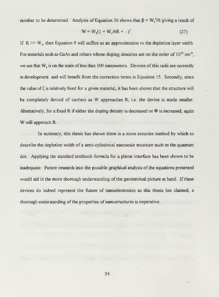
number to be determined. Analysis ofEquation 26 shows that P = W x
2/6 giving a result of
W =Wl(l + W,/6R + -)
2. (27)
If R» Wl9then Equation 9 will suffice as an approximation to the depletion layer width.
For materials such as GaAs and others whose doping densities are on the order of 1018cm'
3,
we see thatWxis on the scale of less than 100 nanometers. Devices of this radii are currently
in development and will benefit from the correction terms in Equation 15. Secondly, since
the value of \ is relatively fixed for a given material, it has been shown that the structure will
be completely devoid of carriers as W approaches R, i.e. the device is made smaller.
Alternatively, for a fixed R if either the doping density is decreased or is increased, again
W will approach R.
In summary, this thesis has shown there is a more accurate method by which to
describe the depletion width of a semi-cylindrical nanoscale structure such as the quantum
dot. Applying the standard textbook formula for a planar interface has been shown to be
inadequate. Future research into the possible graphical analysis ofthe equations presented
would aid in the more thorough understanding of the geometrical picture at hand. If these
devices do indeed represent the future of nanoelectronics as this thesis has claimed, a
thorough understanding of the properties of nanostructures is imperative.
34

APPENDIX A. NANOSATELLITE LAUNCH VEHICLES
A. PEGASUS
The Pegasus is an air launched booster which uses three solid-rocket motors for
propulsion and wings for lift. It is launched from the belly of a B-52 which enables it to
achieve an orbit of any desired inclination. An inertial system guides the booster while
aerodynamic fins control the first stage and vectorable nozzles assist the second and third
stages. Figure A- 1 shows Pegasus stages 1-3. [Ref21]
Figure A- 1 - Pegasus launch vehicle. From Ref. [22].
The Pegasus orbit and payload capabilities are as follows:
--maximum payload weight
—267 kg (250 nm polar orbit)
—400 kg (250 nm equatorial orbit)
35

B. TAURUS
The Taurus XL expendable launch vehicle, pictured in Figure A-2, is the latest
launch platform designed by the Orbital Sciences Corporation. It is essentially a Peacekeeper
missile body with enough flexibility and transportability to allow it's launch from any
unimproved concrete pad. Like the Pegasus, it is an excellent platform for launching small
payloads. [Ref 21]
Taurus payload and orbit statistics:
— 1390 kg (250 nm equatorial orbit)
--450 kg (geosynchronous transfer orbit)
--1 180 kg (250 nm polar orbit)
Figure A-2 -Launchof a Taurus rocket. From Ref [23].

C. SCOUT (ENHANCED)
The Scout launch vehicle, the first U.S. launch vehicle to use solid fuel exclusively,
was designed by LTV as a booster for DOD and NASA and foreign space probes. The
current Scout is a four stage solid propellant vehicle with maximum lift capabilities of up to
600 lbs depending on launch site and mission. [Ref 21] Figure A-3 shows a Scout launch
from Vandenberg AFB.
Orbit and payload data for the Scout:
--372 kg ( 100 nm polar orbit)
—525 kg ( 100 nm equatorial orbit)
-455 kg (100 nm @ 40° inclination)
S-: V',V
Figure A-3 - Scout launch from Vandeberg, CA. From Ref. [24].
37

D. TITAN II
The Titan II launch vehicles are decommissioned ICBMs that have been refurbished
and equipped with hardware required for space launch. The Titan II is the smallest of the
Titan series and has been modified by DOD for launches ot smaller payloads into polar
orbits. Figure A-4 shows a launch of the Titan II launch vehicle. The lift capacity for the
Titan II varies from 1905 kg to 3720 kg depending on the number of strap-on engines
required. [Ref 21]
Fisure A-4 - Launch of Titan II vehicle. From Ref. [25].
38

E. DELTA II
The Delta II is the newest, most powerful version of the Delta series originally
developed by NASA in 1960. Since that time, the Delta rocket, shown in Figure A-5
launching Iridium satellites, has an average utilization of one launch every 60 days, a launch
rate unmatched by any other platform. The Delta II is a three stage rocket with solid
propellant for the first stage and liquid propellant for the last two stages. It's design tailors
the rocket toward putting very heavy payloads into very high orbits but could also be used
to lift many nanosatellites at once. [Ref 21] Specifications on the Delta II are as follows:
— 1885 kg (geosynchronous transfer orbit)
--4000 kg ( 100 nm polar orbit)
Figure A-5 - Launch of a Delta II. From Ref. [26].
39

F. SPACE SHUTTLE
The infamous Space Shuttle, shown in Figure A-6, was originally conceived in 1969
and consists of a delta winged orbiter. two solid propellant rocket boosters, which are both
recoverable, and an expendable liquid fuel tank. The current method for launching
nanosatellite-size craft from the Space Shuttle is the Get-Away Special (GAS) canister.
These canisters are approximately the same size as a large trash can, are mounted in the
orbiter's cargo bay and release their payload via a spring mechanism.
.;.,- --- ~~-X
Figure A-6 - Launch of the Space Shuttle from Cape Canaveral. From Ref [27].
Standard and large are the two available sizes of GAS canisters. If the Space Shuttle were
configured to solely launch nanosatellites, a bridge of twelve canisters could be constructed
40

in the main cargo bay or the nanosatellites could be mounted to a steerable sled which could
be launched from the orbiter then maneuvered to launch each nanosatellite individually.
Space Shuttle payload characteristics are:
-maximum payload weight
-13608 kg (300 nm @ 28.1° inclination)
-8165 kg (300 nm @ 57° inclination)
-1361 kg (260 nm @ 98° inclination)
—payload bay dimensions
—diameter: 15 feet
—length: 60 feet
G. COMPARISON OF VEHICLES
Table A-l below illustrates the differences among the various aforementioned launch
vehicles in terms of their size and cost.
Launch Vehicle Height/Length Mass (lb) Success Rate Cost per Launch (98$)
Pegasus 51 ft. 42,000 100% 17-M
Taurus 90 ft 180,000 100% 17M
Scout 75 ft 109,000 87.6 % 15M
Titan II 140 ft 340,000 93% 60M
Delta H 125 ft 506,000 94% 60M
Space Shuttle 184 ft 4,500,000 97.4 % 150M
Table A-l - Comparison of nanosatellite launch vehicles. From Ref. [21].
41

42

APPENDIX B. CURRENT NANOSATELLITE PROJECTS
A. GENERAL
There are currently a multitude of nanosatellite designs from around the world
which are in various stages of design and deployment. Below is a partial list of these
satellites which will be briefly described in this appendix:
—Munin-Bitsy
--ASUSat I
—TUBSAT series
--SNAP-1
B. MUNIN
The Munin project is run by the Kiruna Division of the Swedish Institute of Space
Physics and was originally conceived in September of 1996. The scientific objective of
Munin is to collect data on the auroral activity on both the northern and southern
hemispheres with a miniature CCD camera such that a current picture of the global state of
activity can be made available via the Internet. The Munin nanosatellite will have a mass of
approximately 5 kg and will have a cubic shape as depicted in Figure B- 1 . [Ref 3] Onboard
it will house a combined ion and electron spectrometer and will also analyze high energy
particles with a solid state detector. The spacecraft has a passive attitude control system
using a magnet and oscillation dampers while it's power is derived from silicon solar cells
and stored in a lithium ion battery. Instrumentation control, telemetry and data formatting
are all accomplished with digital signal processors. The satellite should be ready for launch
toward the end of 1998. [Ref 3]
43

Figure B-l - The Munin nanosatellite. From Ref. [27].
C. BITSY
Bitsy is a fully-functioned, autonomous, three-axis stabilized spacecraft in a 1 kg
package. It features a single circuit board design which is easily tailored to specific mission
requirements. Electrical power of 2-10 watts is supplied to the 8 volt bus by silicon solar
cells and is stored in a rechargeable Lithium ion battery. Data handling is provided by a 32-
bit microprocessor with off-the-shelf real-time operating system, common communication
protocols and ANSI C language support. Bitsy is integrable with nearly every conceivable
payload and can be operated by a single PC at a ground terminal. [Ref 29] Developed by the
U.S. Air Force, Bitsy is now available for commercial applications in remote sensing, data
message store and forward, space science and astrophysics and environmental monitoring.
Bitsy is designed for flight only a few months after order and, like all nanosatllites, has
significantly reduced launch and maintenance costs with only one million dollars required
for a fully functioning turnkey system. [Ref 29] Bitsy is depicted in Figure B-2.
44

Figure B-2 - The Bitsy nanosatellite bus. From Ref [29].
D: ASUSat I
ASUSat I, shown in Figure B-3, has been developed by the Arizona State University
(ASU) beginning in 1993 and is scheduled for launch in the second half of 1998 on either
a Pegasus or Taurus launch vehicle. It is a 4.5 kg spacecraft which has been student-
designed as a technology demonstrator for a low cost satellite. The satellite will be placed
into a low earth polar orbit to provide earth imagery, an audio transponder for amateur radio
operators and a proof of concept on a fluid damping method and attitude determination
sensors. The lifetime of the satellite is approximately two years with all imagery and
telemetry data being transmitted to the ground station at ASU.
E. TUBSAT SERIES
The TUBSAT nanosatellites, a project directed by the Technical University of
Berlin, began in 1991 with TUBSAT- 1 whose primary mission was academic research,
particularly in the field of attitude determination. It was a cube weighing approximately 35
kg and was launched into a sun-synchronous orbit with an altitude of 780 km in 1991. It
contained a three-axis star sensor, a fixed momentum wheel and magnetotorquer coil, a two-
axis sun-sensor and three-axis magnetometer. [Ref 30]
45

TUBSAT-2, as shown in figure B-4. was launched in January of 1994 into an elliptical
orbit of axis 1221x1 198 km at an inclination of 83°. It included a second star sensor with
a one meter focal length which also acted as a camera. The satellite was similar in design
toTUBSAT- 1 but included a 3 kg three axis reaction wheel and meteorological and radiation
budget instruments.
The final satellite in the series is TUBSAT-C which will be launched next year and
is reported to be used for testing laser ring gyros as a means of attitude determination and
control. [Ref30]
Figure B-3 - The TUBSAT-C nanosatellite. From Ref. [31].
F. SNAP-1
The SNAP nanosatellite is also a proof of concept satellite built by the engineers at
University of Surrey Centre for Satellite Engineering research in England. It is a 2.5 kg and
is shaped as a hexagonal prism. [Ref 3] It is powered by 48 GaAs solar cells which deliver
an average power of one watt. It's payloads include two CMOS APD video cameras with
46
digital frame storage, an Orion GPS receiver and a diplexed quarter wave UHF monopole
antenna to enable it to operate in the amateur radio band at an uplink/downlink of 9600 bps
with frequency shift keying. [Ref 3]
47

48

LIST OF REFERENCES
1. Luscombe J.H., 1993, "Current Issues in Nanoelectronic Modeling" Nanotechnology
4, 1-20.
2. Larson W.J. and Wertz JR., 1996, Space Mission Analysis and Design (Torrance:
Microcosm Inc), pp. 340-357, 777-789.
3 . Small Satellite HomePage, Internet
http://www.ee.surrey.ac.uk/EE/CSER/UOSAT/SSHP.
4. Payne, Robert A., Applications of the Petite Amateur Naval Satellite, M.S. Thesis,
Naval Postgraduate School, Monterey, CA, 1992.
5. Lloyd's satellite constellations, "Iridium", Internet
http://www.ee.surrey.ac.ukyPersonal/L.Wood/constellations/iridium.html
6. Kenny, T.W. et al., 1992, "Electron Tunneling Sensors" J.Vac. Sci. Technol. A(Jul./Aug. 1992).
7. Smit/G.N., 1993, "Nanotechnology for Guidance, Navigation and Control" Aerospace
Report No. ATR-93(8349)-l pp. 13-19.
8. Radhakrishnan, G., 1993, "Microsensors and Microinstruments for Guidance,
Navigation and Control" Aerospace Report No. ATR-93(8349)-l pp 23-27.
9. Cassady, R.J., Meckel, N.J., and Hoskins, W.A, 1996, "Pulsed Plasma Thruster
Systems for Spacecraft Attitude Control" A paper delivered at the AIAA Conference
on Small Satellites.
10. Tilley, D.L., Pobst, J.A, and Bromaghim, D.R, 1996, "Advanced Pulsed Plasma
Thruster Demonstration on MightySat Flight HI" A paper delivered at the AIAAConference on Small Satellites.
11. Gilmore, D.G., 1993, "Nanotechnology for Spacecraft Thermal Control" Aerospace
Report No. ATR-93(8349)-l pp. 49-58.
12. Berry, E.R., 1993, "Miniaturizing Spacecraft Power and Electrical Systems"
Aerospace Report No. ATR-93(8349)-l pp. 57-59.
13. Caldwell, D.B., Fox, C.L., and Miller, L.E. "Powering Small Satellites with Advanced
NiH2 Dependent Pressure Vessel (DPV) Batteries" A paper delivered at AIAA.
49

14. Eisele, Anne, "JPL Explores New World of Tiny, Smarter Electronics," Space News,
30March-5 April, 1998.
15. Turton, Richard, 1995, The Quantum Dot, (New York: Oxford University Press).
16. Seabaugh, AC, Luscombe, J.H., Randall, J.N., 1993, "Quantum Functional Devices:
Present Status and Future Prospects" FED Journal 3, pp. 9-17.
17. Reed, Mark A., Quantum Dots, Scientific American, January 1993, pp. 98-104.
18. Kruppa, Suzanne, Modeling the Quantum Dot, M.S. Thesis, Naval Postgraduate
School, Monterey, CA, 1997.
19. Resnick R. and Halliday D., 1993, Fundamentals ofPhysics, (New York: John Wiley
and Sons), pp. 1219-1221.
20. Sze S.M., 1985, Semiconductor Devices, Physics and Technology, (New York: John
Wiley and Sons), pp. 71-80.
21. Isakowitz, Steven J., 1995, Space Launch Systems, (Washington DC: AJAA),
pp. 201-175.
22. Orbital Sciences Corporation, "Photo Gallery", Internet http://www.orbital.com/
Prods_n_Servs/Products/LaunchSystems/Pegasus/expanded.html
23. Orbital Sciences Corporation, Internet http://www.orbital.com/
Prods_n_Servs/Products/LaunchSystems/Taurus/index.html
24. Vandenberg Air Force Base marketing, Internet:
http://www.vaib.af.mil/orgs/xp/xpr/MARKET/Scout.htm
25. Patterson Air Force Base marketing, Internet:
http://www.pafb.af.mil/450G/45wa/titanlgf.htm
26. Delta II Launch Photos "A Delta II 7920-10 Iridium launch" Internet:
http://violet.pha.jhu.edu/photos/delta.html
27. My Shuttle Launch Pictures, Internet http://www.hal-pc.org/~kg5u/0413g.html
28. The Munin satellite homepage, Internet: http://munin.irf.se/
29. The AeroAstro Corporation Homepage, Internet: http://www.aerospace.com
50

30. Small Satellite Homepage, Internet:
http://www.ee.sun-ey.ac.uk/EE/CSER/UOSAT/SSHP/fliture_nanos.html
3 1 . Small Satellite HomePage Internet
http://www.ee.surrey.ac.uk/EE/CSER/UOSAT/SSHP/pix/tubsatla.gif
51

52

INITIAL DISTRIBUTION LIST
1
.
Defense Technical Information Center.
8725 John J. Kingman Rd., STE 0944
Fort Belvoir, VA 22060-6218
2. Dudley Knox Library
Naval Postgraduate School
411 DyerRd.
Monterey, CA 93943-5101
3. Professor J.H. Luscombe, Code Ph/Lj.
Department of Physics
Naval Postgraduate School
Monterey, CA 93943-5002
4. Lt. JackRice
2052 Quaker Way #5
Annapolis, MD 21401
53


C 483NPGu TH
10/99 22527-2002778
j