
The future of global satellite communications - World Radio ...
138
-
Upload
khangminh22 -
Category
Documents
-
view
0 -
download
0
Transcript of The future of global satellite communications - World Radio ...
Inside: 3-year editorial index
—page 61
90185 UK
TÏ:(9 IiI-
THE MAGAZINE OF BROADBAND TECHNOLOGY / DECEMBER 1990
05Vd LLC6 XU
Dbadd3N15Nb- OVISVH 2iON1 NOW
XDVWbODDh CiDdd t- .1.9£ZOCOD
*,:****************
Cable-TV: has it reached a fiber-optic watershed?
page 34
Fiber to the LE: A case study
page 46
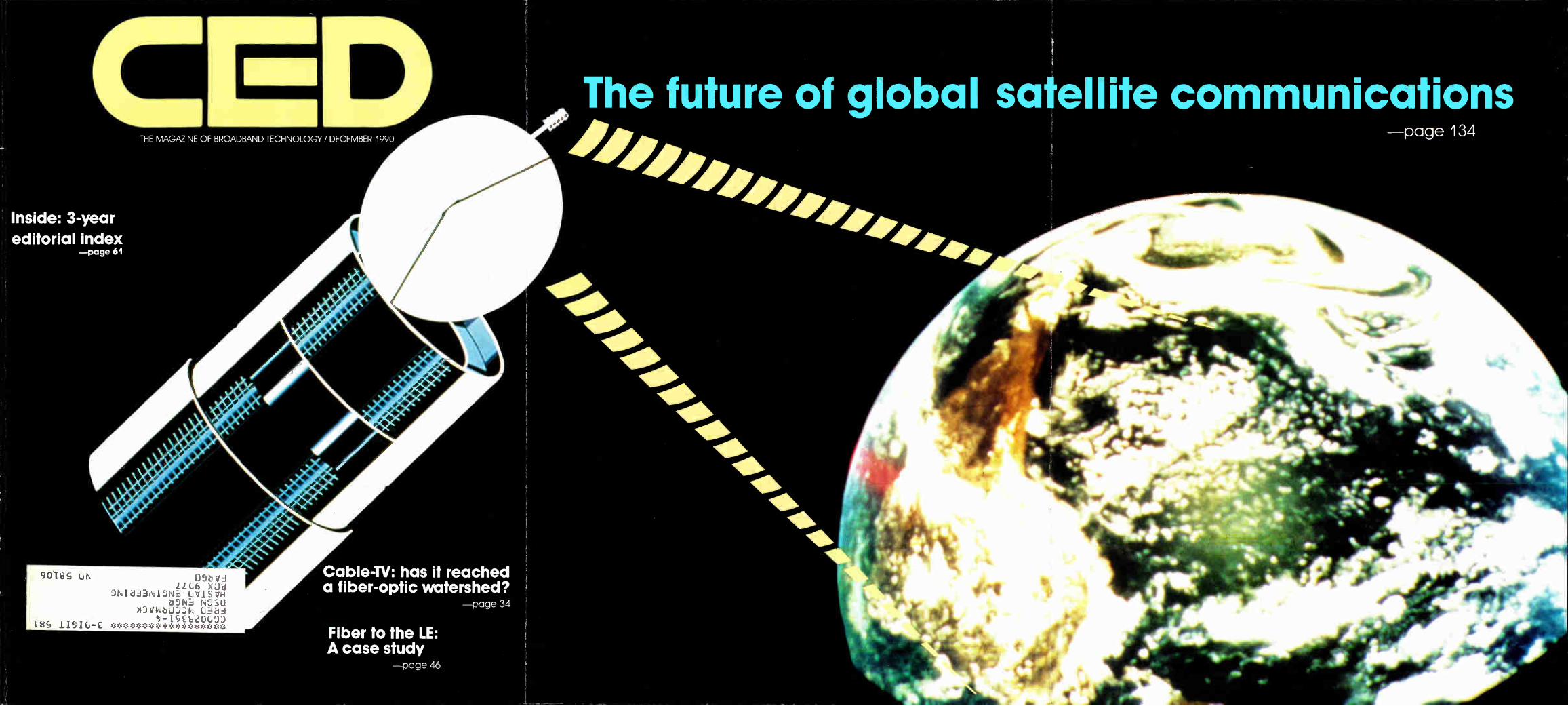
The future of global satellite communications page 134
Comm/Scope,Inc. THE Cable in Cable1V.
Comm/Scope, Inc., PO. Box 1729, Hickory NC 28602. Phone: (800) 982-1708 or (704) 324-2200.
Fax: (704) 328-2400. Reader Service Number 1
There is a cable product today that you can count on for the growth in your future. Quantum Reach.
QR, from Comm/Scope, is unmatched for its superior handling. It is, by far, the easiest coax to bend or to pull through conduit. It is also lightweight which makes it a favorite of construction crews. But now we have taken this field-proven QR line and made it even better. We've added 1GHz bandwidth capacity which will make Quantum Reach even more attractive for your future building plans.
For more information about QR or any of our Extended Reach family of 1GHz cable products, contact your nearest Comm/Scope representative or call Comm/ Scope, Inc. (800) 982-1708 or (704) 324-2200.
Comm/Scope, Inc. THE Cable in Cable TV
Comm/Scope, Inc., PO Box 1729, Hickory NC 28602. Phone: (800) 982-1708 or (704) 324-2200. Fax: (704) 328-2400. Telex: 802-166.
Reader Service Number 1
WE'VE MADE THE FIRST BUSE FOR RECYCLING.
Comm/Scope, the cable leader, now leads the way in helping solve some of the environmental issues and concerns you may have by introducing the first recy-clable drop cable box.
We know the problems and costs you face when prop-erly disposing of other empty cable boxes. Recycling centers won't take them. Landfills are either refusing to take them or are charging you more and more to accept them.
Our recyclable box means you don't have to pay for disposal. And recyclable doesn't mean second-rate. This box is just as strong and durable as any non-
recyclable box. It resists moisture. Its bursting strength is, the same as our old box. It is stackable. It is laboratory and field proven to hold up under even the most ex-treme condi:ions. It is even made from recycled paper. But it won't harm the environment.
For more information about our recyclable boxes as well as other measures Comm/Scope has taken to help improve our environment, contact your nearest Comm/Scope representative or call us at (800) 982--1708 or (704) 324-2200.
Comm/Scope, Inc. THE Cable in CableTV.
Comm/Scope, Inc., PO. Box 1729, Hickory, INC 28602. Phone: i,800) 982-1708 or (704) 324-2200.
Fax: (704) 328-2400. Reader Service Number 1
•
Panasonic Built.
From The Inside Out.
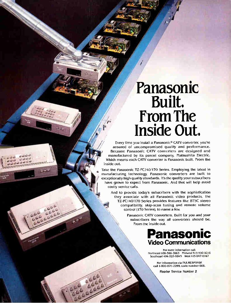
Every time you install a Panasonic® CATV converter, you're assured of uncompromised quality and performance.
Because Panasonic CATV converters are designed and
manufactured by its parent company, Matsushita Electric. Which means each CATV converter is Panasonic built. From the
inside out.
Take the Panasonic TZ-PC140/170 Series. Employing the latest in
manufacturing technology, Panasonic converters are built to exceptionally high quality standards. It's the quality your subscribers have grown to expect from Panasonic. And that will help avoid
costly service calls.
And to provide today's subscribers with the sophistication they associate with all Panasonic video products, the TZ-PC140/170 Series provides features like BTSC stereo
compatibility, skip-scan tuning and remote volume
control (170 Series), to name a few.
Panasonic CATV converters. Built for you and your subscribers the way all converters should be.
From the inside out.
del
Panasonic Video Communications
for more information call: Northeast 609-589-3063 Midwest 513-530-9216 Southeast 404-925-6845 West 415-947-0147
for Information via FAX RESPONSE call 1-800-876-2299, code number 008.
Reader Service Number 2
Facts For The Perfect Offense. With MC2, the facts speak for
themselves: Fact: Hermetically-sealed,
compartmentalized structure makes moist re ingress unlikely—highly localized, if at all.
Fact: The 93% velocity of propagation allows one size smaller diameters than foam cables—more MC2 per duct.
TE011104p tek\
4/0
Fact: Superior attenuation allows about 20% fewer amplifiers in new-builds—stronger signals in rebuilds and upgrades.
Fact: Total bonding assures maximum loop-strength and minimum suck-out. Excep-tional bending ability.
Case closed. The Choice Stops Here
Reader Service Number 3 COMMUNICATIONS INC.
Call or write for our free sample and brochure TRILOGY COMMUNICATIONS INC., 2910 Highway 8C East, Pearl, Mississippi 39208 800-874-5649 • 601-932-4461 • 201-462-8700
CED Fiber and CATV: Reaching a watershed Specifications are firm and costs have come down significantly, making fiber optic technologies a sound decision for most cable operators. David Robinson of Jerrold Communications' CableOptics division discusses AM fiber systems and its future developments.
34
Fiber to the line extender A new fiber architecture, fiber to the line extender, is highlighted in this case study approach to Cablevision Industry's Hillsborough, N.C. system. Written by Carl Newberry of Cablevision Industries, the article steps through the engineering processes taken to make it work.
46
In the field with outdoor addressability CED's George Sell takes a look at the popular off-premise addressibility architecture offered by Canada's Electroline Equipment, reviewing the technology, field applications, cost and reliability of the equipment.
53
Low-cost programmable attenuators Methods to slash the costs affiliated with programmable attenuators are examined by 'frilithic's Bruce Malcolm, with variables including enclosures, RF shielding, attenuator design and performance.
104
CED
Coble-1V: has it reached a fiber-optic watershed?
Fiber to the LE: A case study •
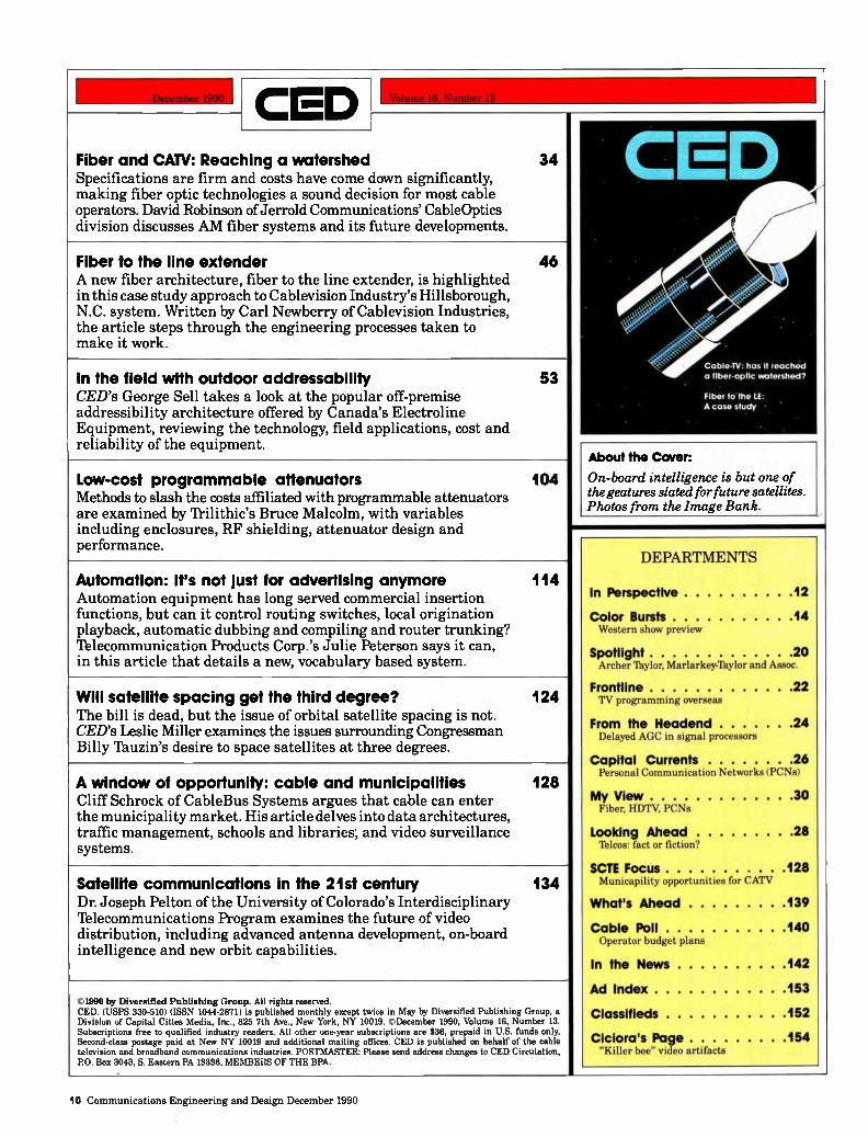
About the Cover:
On-board intelligence is but one of the geatures slated for future satellites. Photos from the Image Bank.
Automation: it's not just for advertising anymore Automation equipment has long served commercial insertion functions, but can it control routing switches, local origination playback, automatic dubbing and compiling and router trunking? Telecommunication Products Corp.'s Julie Peterson says it can, in this article that details a new, vocabulary based system.
114
Will satellite spacing get the third degree? The bill is dead, but the issue of orbital satellite spacing is not. CED's Leslie Miller examines the issues surrounding Congressman Billy Tauzin's desire to space satellites at three degrees.
124
A window of opportunity: cable and municipalities Cliff Schrock of CableBus Systems argues that cable can enter the municipality market. His article delves into data architectures, traffic management, schools and libraries; and video surveillance systems.
128
Satellite communications in the 21st century Dr. Joseph Pelton of the University of Colorado's Interdisciplinary Telecommunications Program examines the future of video distribution, including advanced antenna development, on-board intelligence and new orbit capabilities.
134
1980 by Diversified Publishing Group. All rights reserved. CED. (USPS 330-510) (ISSN 1044-2871) is published monthly except twice in May by Diversified Publishing Group, a Division of Capital Cities Media, Inc., 825 7th Ave., New York, NY 10019. ©December 1990, Volume 16, Number 13. Subscriptions free to qualified industry readers. All other one-year subscriptions are $36, prepaid in U.S. funds only. Second-class postage paid at New NY 10019 and additional mailing offices. CED is published on behalf of the cable television and broadband communications industries. POSTMASTER: Please send address changes to CED Circulation, PO. Box 3043, S. Eastern PA 19398. MEMBERS OF THE BPA.
DEPARTMENTS
In Perspective 12
Color Bursts 14 Western show preview
Spotlight 20 Archer Taylor, Marlarkey-lhylor and Assoc.
Frontline 22 TV programming overseas
From the Headend 24 Delayed AGC in signal processors
Capital Currents 26 Personal Communication Networks (PCNs)
My View 30 Fiber, HDTV, PCNs
Looking Ahead 28 Telcos: fact or fiction?
SCIE Focus 128 Municapility opportunities for CATV
What's Ahead 139
Cable Poll 140 Operator budget plans
In the News 142
Ad Index 153
Classifieds 152
Ciciora's Page 154 "Killer bee" video artifacts
10 Communications Engineering and Design December 1990
.... .. .. . • • •
.. ..
•
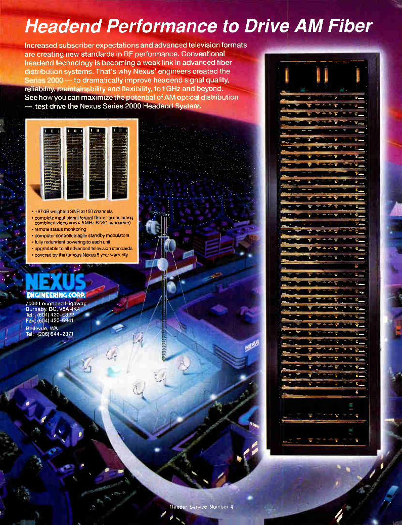
Headend Performance to Drive AM Fiber Increased subscriber expectations and advanced television formats are creating new standards in RF performance. Conventional headend technology is becoming a weak link in advanced fiber distribution systems. That's why Nexus' engineers created the Series 2000 — to dramatically improve headend signal quality, reliability, maintainability and flexibility, toi GHz and beyond. See how you can maximize the potential of AM optical distribution — test drive the Nexus Series 2000 Headend System.
• +67 dB weighted SNR at 150 channels
• complete input signal format flexibility (including combined video and 4.5 MHz BTSC subcarner)
• remote status monitoring
• computer controlled agile standby modulators
• fully redundant powering to each unit
• upgradable to all advanced television standards
• covered by the famous Nexus 5 year warranty
NFXUS 100) ENGINEERING CORR
7000 Lougheed [Highway Burmaby, BC, V5A 4K4 Tel: (604) 420-322 Fax: (694) 420 -e941
Bellevde, WA Tel: (206) 644-2371
eteee P
IN PERSPECTIVE
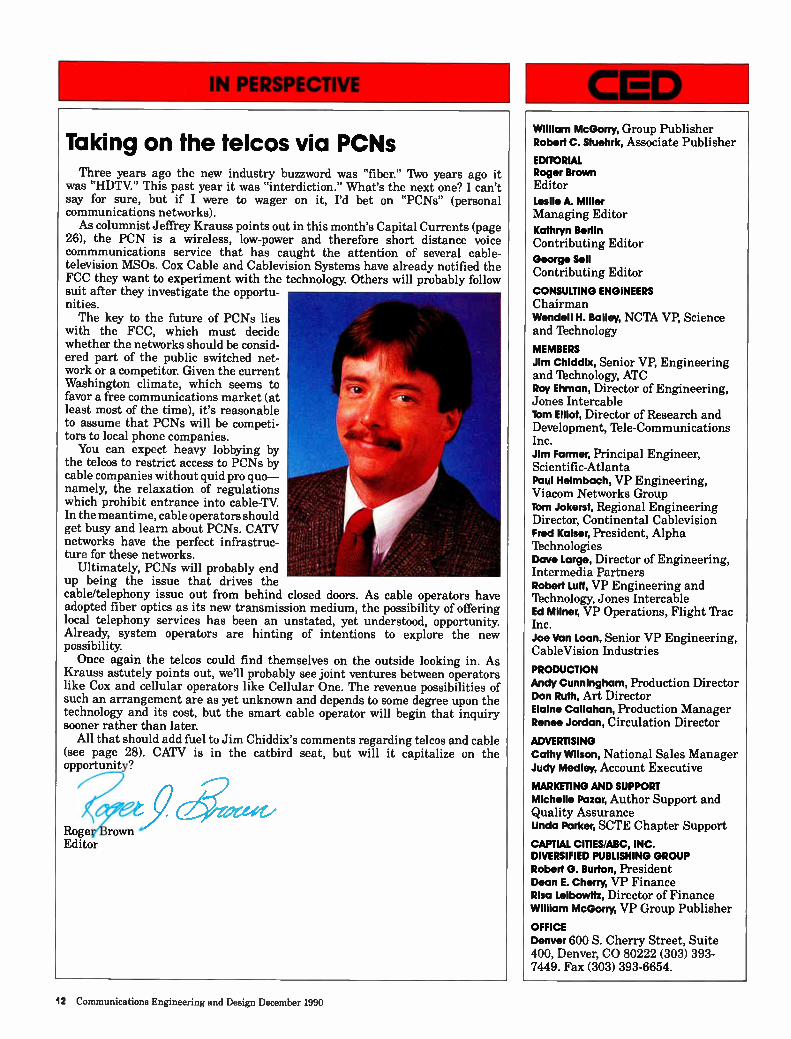
Taking on the telcos via PCNs Three years ago the new industry buzzword was "fiber." Two years ago it
was "HDTV." This past year it was "interdiction." What's the next one? I can't say for sure, but if I were to wager on it, I'd bet on "PCNs" (personal communications networks). As columnist Jeffrey Krauss points out in this month's Capital Currents (page
26), the PCN is a wireless, low-power and therefore short distance voice commmunications service that has caught the attention of several cable-television MS0s. Cox Cable and Cablevision Systems have already notified the FCC they want to experiment with the technology. Others will probably follow suit after they investigate the opportu-nities. The key to the future of PCNs lies
with the FCC, which must decide whether the networks should be consid-ered part of the public switched net-work or a competitor. Given the current Washington climate, which seems to favor a free communications market (at least most of the time), it's reasonable to assume that PCNs will be competi-tors to local phone companies. You can expect heavy lobbying by
the telcos to restrict access to PCNs by cable companies without quid pro quo— namely, the relaxation of regulations which prohibit entrance into cable-TV In the meantime, cable operators should get busy and learn about PCNs. CATV networks have the perfect infrastruc-ture for these networks.
Ultimately, PCNs will probably end up being the issue that drives the cable/telephony issue out from behind closed doors. As cable operators have adopted fiber optics as its new transmission medium, the possibility of offering local telephony services has been an unstated, yet understood, opportunity. Already, system operators are hinting of intentions to explore the new possibility. Once again the telcos could find themselves on the outside looking in. As
Krauss astutely points out, we'll probably see joint ventures between operators like Cox and cellular operators like Cellular One. The revenue possibilities of such an arrangement are as yet unknown and depends to some degree upon the technology and its cost, but the smart cable operator will begin that inquiry sooner rather than later.
All that should add fuel to Jim Chiddix's comments regarding telcos and cable (see page 28). CATV is in the catbird seat, but will it capitalize on the opportunity?
ftoge rown Editor
William McGorry, Group Publisher Robert C. Stuehrk, Associate Publisher
EDITORIAL Roger Brown
Editor Leslie A. Miller
Managing Editor Kathryn Berlin
Contributing Editor George Sell
Contributing Editor
CONSULTING ENGINEERS Chairman Wendell H. Bailey, NCTA VP, Science and Technology
MEMBERS
Jim Chiddlx, Senior VP, Engineering and Technology, ATC Roy Ehman, Director of Engineering, Jones Intercable Tom Elliot, Director of Research and Development, Ible-Communications Inc. Jim Farmer, Principal Engineer, Scientific-Atlanta Paul Helmbach, VP Engineering, Viacom Networks Group Torn Jokerst, Regional Engineering Director, Continental Cablevision Fred Kaiser, President, Alpha Technologies Dave Large, Director of Engineering, Intermedia Partners Robert Lull, VP Engineering and Technology, Jones Intercable Ed Milner, VP Operations, Flight 'frac Inc. Joe Van Loan, Senior VP Engineering, CableVision Industries
PRODUCTION
Andy Cunningham, Production Director Don Ruth, Art Director Elaine Callahan, Production Manager Renee Jordan, Circulation Director
ADVERTISING
Cathy Wilson, National Sales Manager Judy Medley, Account Executive
MARKETING AND SUPPORT Michelle Pinar, Author Support and Quality Assurance Linda Parker, SCTE Chapter Support
CAPTIAL CITIES/ABC, INC. DIVERSIFIED PUBLISHING GROUP Robert G. Burton, President Dean E. Cherry, VP Finance Risa Leibowitz, Director of Finance William McGorry, VP Group Publisher
OFFICE
Denver 600 S. Cherry Street, Suite 400, Denver, CO 80222 (303) 393-7449. Fax (303) 393-6654.
12 Communications Engineering and Design December 1990
Reader Service Number 5
ETTING YOU THE RIGHT ORDER .. "J US T-I N-T I M E."
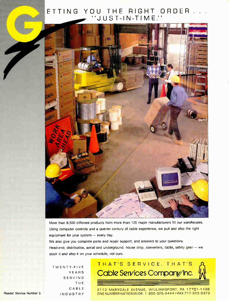
More than 8,500 different products from more tnan 125 major manufacturers fill our warehouses.
Using computer controls and a quarter century of cable experience, we pull and ship the right
equipment for your system — every day.
We also give you complete parts and repair support, and answers to your questions.
Head-end, distribution, aerial and underground, house drop, converters, cable, safety gear — we
stock it and ship it on your schedule, not ours.
TWENT Y- FIVE
YEARS
SERVING
THE
CABLE
INDUSTRY
THAT'S SERVICE. THAT'S
Cable Services Company/Inc.
211 3 MARYDALE AVENUE, WILLIAMSPORT, PA 177C1-1498 ONE NUMBER NATIONWIDE 1-800-326-9444 r FAX 717-322-5373
COLOR BURSTS
Brad/PTS becomes ConTec; plans product expansion
Flush with more than $10 million in new capital and a new management team, Schenectady, N.Y.-based BradPTS has changed its name to Conlbc Inter-national. According to new Chairman Danny Cachuela, Conlbc plans to ex-pand the company's existing converter and remote control product lines, per-haps add new product lines and revital-ize its ailing converter repair business. The new funding comes from Westing-
house Credit Corp., which upped its investment in the company from $10 million to more than $20 million, said Cachuela. Conlbc is expected to an-nounce key members of its new man-agement team, including a chief finan-cial officer and a vice president of sales and marketing at this year's Western Show in Anaheim, California.
"This company has numerous un-tapped resources and talents that were previously underutilized. Through. . . Westinghouse, we have received healthy refinancing that allows us to realize the full potential of our products and services," said Cachuela. A new corpo-rate culture focusing on quality and customer service will also be created, according to Cachuela.
This will result in new OEM agree-ments with converter manufacturers and exclusive contracts with MS0s, some of which will be announced in the near future, he stated.
In the interim, management turn-around experts Morris Anderson and Associates as well as the CEO Group, a marketing, sales and operations com-pany, will assist in Conlbc's rebirth, under the supervision of Cachuela.
Conlbc will keep its eight regional field offices, located in: Bloomington, Ind.; Fenton, Mich.; Seattle, Wash.; Longview, lexas; Tampa, Fla.; West Columbus, S.C.; Ventura, Calif.; and Schenectady. The company will be fully staffed to an excess of 300 persons who perform 14,000 converter repairs and upgrades per week and maintain an inventory of more than 200,000 con-verters, said Cachuela.
Although the company plans to re-main focused on its present business for the next year, it desires a better mix of products and services. It will prob-ably expand its headend and line gear business and perhaps pursue the satel-
lite receiver repair vocation.
Western Show preview features fiber, interdiction
Early glimpses into new product introductions planned for the 1990 Western Cable Show sound some famil-iar themes: outdoor addressability and fiber optics.
Several companies are expected to follow Scientific-Atlanta's lead and dem-onstrate or introduce interdicting, "off-premise" devices which scramble video signals outside the subscriber's prem-ises and provide a broadband feed to the home. S-A, which debuted its product last year, has experienced some success with its device.
Rival Jerrold Communications will show it's home-powered "Agile Jam-mer," which performs essentially the same function but is designed to be installed in existing cable systems without major re-design of powering needs or tap replacement. The system is slated for field trials early in calen-dar 1991.
Jerrold officials stress that the Agile Jammer is not part of a cable's system's distribution plant. The device can be mounted aerially, within pedestals or vaults or on the side of a residential dwelling. It can be used in two-, four-and eight-way tap locations, ac-cording to Jack Bryant, director of product management for Jerrold.
Because it is considered an "ad-junct" to the tap, the device's cost can be accurately assessed, without consid-eration for system penetration or tap port utilization. Jerrold has assigned a price of about $135 per unit. "There are no overhead costs to be amortized for the non-subscribers in the (cable) system," Bryant added. The Agile Jammer features eight
oscillators covering 54 MHz to 450 MHz. With each oscillator capable of jamming up to eight channels each, a cable operator could secure any and all channels up to 450 MHz with "com-plete video security and audio degrada-tion," said Bryant.
Conversely, Jerrold also plans to show off product enhancements de-signed to make set-top converters "wel-comed members of the home entertain-
ment system," according to Dan Moloney, director of product manage-ment in Jerrold's subscriber systems division. On hand in Anaheim will be converters with on-screen menus, new remote controls and a telephone/remote control combination.
Finally, Jerrold will once again dis-play its Remote `N' Phone, a product demonstration that received such in-terest that it's now headed for field trials. The unit allows subscribers to make and receive phone calls using the converter's remote control. "If reaction in the field is anything like what we've had when we've shown off this product, we expect it to be a booming success," said Moloney.
Here comes fiber
On the fiber front, vendors will be touting improved performance optical links, the availability of fiber-to-the-feeder architectures and equipment costs rivaling traditional coaxial-based technology.
For example, Magnavox CATV Sys-tems will exhibit its new 550 MHz MagnaHub Optical Mainstation, which features a single mainstation design, acceptance of up to three optical receiv-ers external ports for forward sweep and local return signal injection and a 200 MHz external return input port for upstream signaling.
Options for MagnaHub include a fiber-only design or redundancy design featuring independent A/B switching for forward and return signals with complete RF back-up.
Jerrold continues to ramp-up produc-tion of its second-generation laser, the first specifically designed for CATV use by Ortel. According to David Robinson, director of Cableoptics, Jerrold is "ap-proaching" its goal of producing 100 lasers per month in its Tucson, Ariz. manufacturing facility. Starting Octo-ber 25, devices were being shipped "in bulk" throughout North America and overseas, said Robinson. New fiber architectures—or vari-
ations of old designs—are constantly being modeled to determine maximum reach for the least cost. "The emphasis is shifting to how fiber fits into CATV, not if it will work," added Robinson. Along those lines, Optical Networks
International announced the activa-tion of the first fiber to the bridger network in a Ible-Communications Inc. cable system in Valdosta, Ga., signaling the arrival of cable systems
14 Communications Engineering and Design December 1990
THE ONLY GIG IN TOWN!
.,!::. .. •:.::. .g.4.7...............: •••• •. .............. ....,. • ::.. _4* •S. I
.... „fl.„ ...elan
....RM....
,...,.. ..... , .... ... * . *-; o...."' .: ' ' . " .2 . ' ' . ....." ii ›... . . ' « : . . . . . . .. n, . .: ". . . ,. ,... ...":::::'..• ..... ........................ ...... .. ..a ..,...••••.: :.. .: .. ......... ... .... .i.!:::::.:•:..7"': •......'.. ........ ... : . ..,, :Iir.• ........... . • ,
" 1 . ,,./1/./....81tm.. r=te: "'. 21.....j.."...• •
,, .e. , ,..„,„0,.. i....i71;4... ""-"2- • .::1 e :e.."-e- , • . ..... :ii.....;' .................. ••" ' - .. ."*". -, ..... . ...... .. :::..:. :. .f.- —. -- 7 "g. 7:: ::: .—..........___ r....,••1.,.
‘,.„..,. ........ : .. " ...... . • I 8 .......
:: .•.:.11" 4 IL MX Seel ••• ..,1 •••••••16. e •1111110.•.,. 4.••• ••••••••--• , .
. 0 • , . •••• • 1:11.r.'.::".'''''::«•'• I:: 7"''''. '• . : .."
m . M.
Ilre'' ..1•4 mall/... .... ' ' ../.
....... . • •—
••.' ' 1 11!.... :,,,, ::.: i
;11 illi.1411111 • a ••'.0.0.1ein .5-
.... •.• eft* ...... ., .,* ......‘,.,.. . .. CO.." ..... •••••••";...•••••:.: •••••• • ••• : ......... 7-7 "«•.::"...
41. 4111.1.04/k . • • mo . ..11.....--
MIL. .••••••• 403 ........ • •• ..m. ....1 . O •• ,. OM. o• . 4/1 0.•700 .........••••• ,,, ..... , ..... .". ... • • •. o. :::: r, r ........ " .... ...... ••••‘. .... ..— ..........«
• ...• MOM .,... 1,.........u.....
• ••• • ..111./. 0/1... `“_. .0 - O. 1.11.«, Mg • • IMO!. • .....1.1. tale.. e•-•• .... ...i.l.::: m ,... •••• ' •••• - • ••• ..... .,
4.* O r •• • lass ..•-e" - o e «re. • .amb ,.. . •.4aur,. ,,...• - , ., .., , s. 43 • •!:••:* ''''. - -
...,••• ••• .... • ' B ' " ' " ' 4. .'" e • 11 /De... ••••
• . • ' ' , .......... : • • é • 6. : ..... .., ...:........:...• : •i.;• .................:...•.:„...... ,z.:1..:.. .j.... ' ....." ...i.../..:i." . .r. mose.s. 5_ .
.... s •••••••• • . • •.-..*•••••••
• • • • •••••
I I .
...be I Nee. ••••. .• ••••-.''''` ..''' •"• • •• 7 .. ....
• . .... ...I. ago, ... .. r, ... 1, . . ....,.. ..• ...Z. ,. • a. j" ii".: b•Ne., ••••••S ..... ..
• .• • •»11
. • III • e a• • • • ..
.... • 11111 bl I. le . ••• I. . 1••
. et% --.• as •... m •••.
• MM. • mu ••=1....." .....S."' ..... "'"'
il. 0.1, III '..1. JI
... 2 .
• • IMomea1/1. III m....,. „,... .
I ..,. I-...,.., I. .18.1
« ' . .th Se • lt:: . ..... ..‘. .....i.i%ieje, E _. . 7 • .... ••• ..... ..•••••••• ......„ ::'
Pm
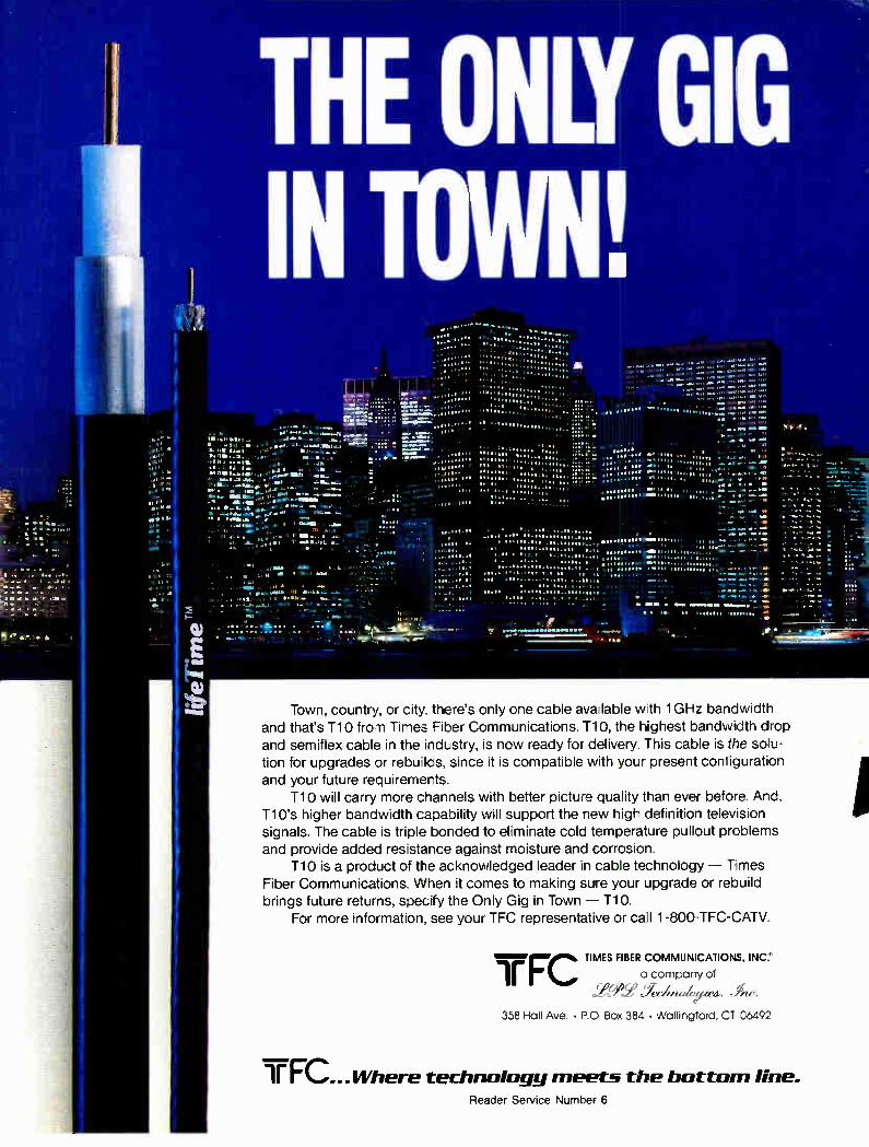
It•-b Town, country, or city, there's only one cable ava lable we 1GHz bandwidth and that's T10 from Times Fiber Communications. T10, the hi ghest bandwidth drop
and semiflex cable in the industry, is new ready for delivery. This cable is the soiu-tion for upgrades or rebuilds, since it is compatible with your present configuration and your future requirements.
T10 will carry more channels with better picture quality than ever before. And, Ti 0's higher bandwidth capability will support the new high definition television signals. The cable is triple bonded to eliminate cold temperature pullout problems and provide added resstance against moisture and corrosion.
T10 is a product of the acknowledged leader in cable technology — Times Fiber Communications. When it comes to making sure your upgrade or rebuild brings future returns, specify the Only Gig in Town — T10.
For more information, see your TFC representative or call 1-800.-TFC-CATV.
irFC a company of
TIMES FIBER COMMUNICATIONS, INC:
.
358 Hall Ave. • P.O Box 384 • Wallingford, CT 06492
TFC...14/here technology meets the bottom line. Reader Service Number 6
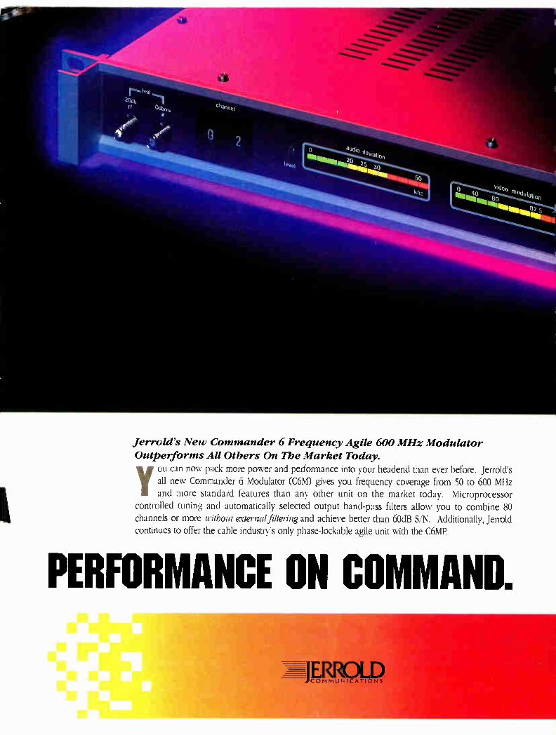
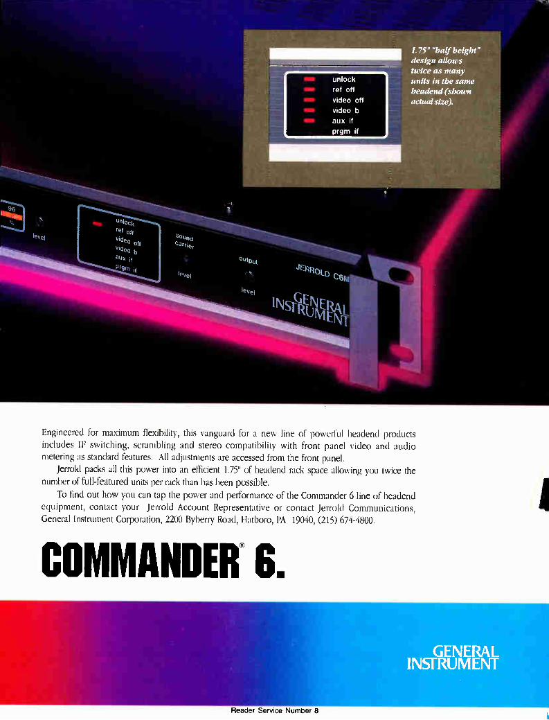
Jerrold's New Commander 6 Frequency Agile 600 MHz Modulator
Outperforms All Others On The Market Today. you can now pack more power and performance into your headend than ever before. Jerrold's all new Commander 6 Modulator (C6M) gives you frequency coverage from 50 to 600 MHz and more standard features than any other unit on the market today. Microprocessor
controlled tuning and automatically selected output band-pass filters allow you to combine 80 channels or more without external filtering and achieve better than 60dB S/N. Additionally, Jerrold continues to offer the cable industry's only phase-lockable agile unit with the C6MP.
PERFORMANCE ON COMMAND.
ERROLD JCOMMUNICATIONS
unlock
ref off
video off
video b
aux if
prgm if
Unlock
ref off
Video off
Video b
aux orsni
1.75" "half height" design allows twice as many
units in the same
headend (shown actual size).
Engineered for maximum flexibility, this vanguard for a new line of powerful headend products includes IF switching, scrambling and stereo compatibility with front panel video and audio metering as standard features. All adjustments are accessed from the front panel.
Jerrold packs all this power into an efficient 1.75" of headend rack space allowing you twice the number of full-featured units per rack than has been possible.
To find out how you can tap the power and performance of the Commander 6 line of headend equipment, contact your Jerrold Account Representative or contact Jerrold Communications, General Instrument Corporation, 2200 Byberry Road, Hatboro, PA 19040, (215) 674-4800.
COMMANDER® G.
GENERAL INSTRUMENT
Reader Service Number 8
SPOTLIGHT
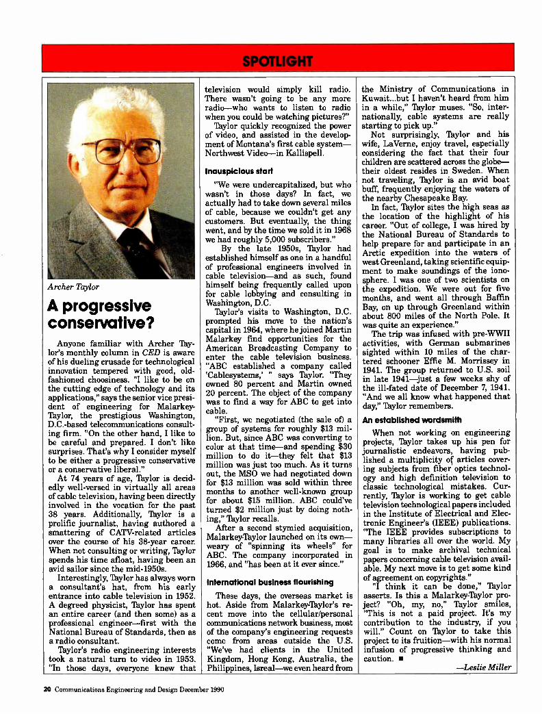
Archer Taylor
A progressive conservative? Anyone familiar with Archer Tay-
lor's monthly column in CED is aware of his dueling crusade for technological innovation tempered with good, old-fashioned choosiness. "I like to be on the cutting edge of technology and its applications," says the senior vice presi-dent of engineering for Malarkey-Taylor, the prestigious Washington, D.C.-based telecommunications consult-ing firm. "On the other hand, I like to be careful and prepared. I don't like surprises. That's why I consider myself to be either a progressive conservative or a conservative liberal." At 74 years of age, Taylor is decid-
edly well-versed in virtually all areas of cable television, having been directly involved in the vocation for the past 38 years. Additionally, Taylor is a prolific journalist, having authored a smattering of CATV-related articles over the course of his 38-year career. When not consulting or writing, Taylor spends his time afloat, having been an avid sailor since the mid-1950s.
Interestingly, Taylor has always worn a consultant's hat, from his early entrance into cable television in 1952. A degreed physicist, Taylor has spent an entire career (and then some) as a professional engineer—first with the National Bureau of Standards, then as a radio consultant.
Taylor's radio engineering interests took a natural turn to video in 1953. "In those days, everyone knew that
television would simply kill radio. There wasn't going to be any more radio—who wants to listen to radio when you could be watching pictures?"
Taylor quickly recognized the power of video, and assisted in the develop-ment of Montana's first cable system— Northwest Video—in Kallispell.
Inauspicious start
"We were undercapitalized, but who wasn't in those days? In fact, we actually had to take down several miles of cable, because we couldn't get any customers. But eventually, the thing went, and by the time we sold it in 1968 we had roughly 5,000 subscribers."
By the late 1950s, Taylor had established himself as one in a handful of professional engineers involved in cable television—and as such, found himself being frequently called upon for cable lobbying and consulting in Washington, D.C.
Taylor's visits to Washington, D.C. prompted his move to the nation's capital in 1964, where he joined Martin Malarkey find opportunities for the American Broadcasting Company to enter the cable television business. "ABC established a company called `Cablesystems,' " says Taylor. "They owned 80 percent and Martin owned 20 percent. The object of the company was to find a way for ABC to get into cable.
"First, we negotiated (the sale of) a group of systems for roughly $13 mil-lion. But, since ABC was converting to color at that time—and spending $30 million to do it—they felt that $13 million was just too much. As it turns out, the MSO we had negotiated down for $13 million was sold within three months to another well-known group for about $15 million. ABC could've turned $2 million just by doing noth-ing," Taylor recalls.
After a second stymied acquisition, Malarkey-Taylor launched on its own— weary of "spinning its wheels" for ABC. The company incorporated in 1966, and "has been at it ever since."
International business flourishing
These days, the overseas market is hot. Aside from Malarkey-Taylor's re-cent move into the cellular/personal communications network business, most of the company's engineering requests come from areas outside the U.S. "We've had clients in the United Kingdom, Hong Kong, Australia, the Philippines, Isreal—we even heard from
the Ministry of Communications in Kuwait...but I haven't heard from him in a while," Taylor muses. "So, inter-nationally, cable systems are really starting to pick up." Not surprisingly, Taylor and his
wife, LaVerne, enjoy travel, especially considering the fact that their four children are scattered across the globe— their oldest resides in Sweden. When not traveling, Taylor is an avid boat buff, frequently enjoying the waters of the nearby Chesapeake Bay.
In fact, Taylor sites the high seas as the location of the highlight of his career. "Out of college, I was hired by the National Bureau of Standards to help prepare for and participate in an Arctic expedition into the waters of west Greenland, taking scientific equip-ment to make soundings of the iono-sphere. I was one of two scientists on the expedition. We were out for five months, and went all through Baffin Bay, on up through Greenland within about 800 miles of the North Pole. It was quite an experience." The trip was infused with pre-WWII
activities, with German submarines sighted within 10 miles of the char-tered schooner Effie M. Morrissey in 1941. The group returned to U.S. soil in late 1941—just a few weeks shy of the ill-fated date of December 7, 1941. "And we all know what happened that day," Taylor remembers.
An established wordsmith
When not working on engineering projects, 'Baylor takes up his pen for journalistic endeavors, having pub-lished a multiplicity of> articles cover-ing subjects from fiber optics technol-ogy and high definition television to classic technological mistakes. Cur-rently, Taylor is working to get cable television technological papers included in the Institute of Electrical and Elec-tronic Engineer's (IEEE) publications. "The IEEE provides subscriptions to many libraries all over the world. My goal is to make archival technical papers concerning cable television avail-able. My next move is to get some kind of agreement on copyrights."
"I think it can be done," 'Baylor asserts. Is this a Malarkeylylor pro-ject? "Oh, my, no," 'Baylor smiles, "This is not a paid project. It's my contribution to the industry, if you will." Count on Taylor to take this project to its fruition—with his normal infusion of progressive thinking and caution.
—Leslie Miller
20 Communications Engineering and Design December 1990
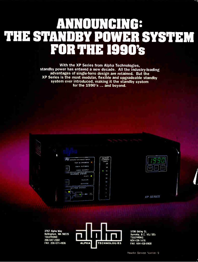
ANNOUNCING: THE STANDBY POWER SYSTEM
FOR THE 1990's With the XP Series from Alpha Technologies,
standby power has entered a new decade. All the industry-leading advantages of single-ferro design are retained. But the
XP Series is the most modular, flexible and upgradeable standby system ever introduced, making it the standby system
for the 1990's ... and beyond.
PM AUTOMATIC PERFORMANCE MONITOR
TEST IN PROGRESS
CHECK BATTERIES TEM USII
CHECK INVERTER
,ARIS
3767 Alpha Way Bellingham, WA 98226 TELEPHONE: 206-647-2360 FAX: 206-671-4936
CHARGER STATUS
FLOAT
EOUAL1ZE
RECHARGE
SYSTEM STATUS
•
OUTPUT CURRENT
20
10
IT
14
12
10
6
4
1 r ALPHA TECHNOLOGIES
1990i fl] El PM" DI, I
XP SERIES
5700 Sidley St. Burnaby, B.C. V5J 5E5 TELEPHONE: 604-430-1476 FAX: 604-430-8908
Reader Service Number 9
1111=11MsmeeLIMIIMM
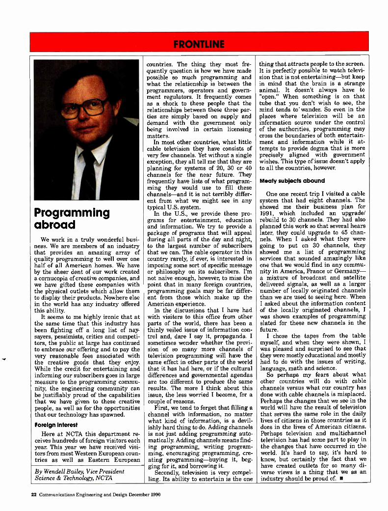
Programming abroad We work in a truly wonderful busi-
ness. We are members of an industry that provides an amazing array of quality programming to well over one half of all American homes. We have by the sheer dent of our work created a cornucopia of creative companies, and we have gifted these companies with the physical outlets which allow them to display their products. Nowhere else in the world has any industry offered this ability.
It seems to me highly ironic that at the same time that this industry has been fighting off a long list of nay-sayers, pessimists, critics and competi-tors, the public at large has continued to embrace our offering and to pay the very reasonable fees associated with the creative goods that they enjoy. While the credit for entertaining and informing our subscribers goes in large measure to the programming commu-nity, the engineering community can be justifiably proud of the capabilities that we have given to these creative people, as well as for the opportunities that our technology has spawned.
Foreign Interest
Here at NCTA this department re-ceives hundreds of foreign visitors each year. This year we have received visi-tors from most Western European coun-tries as well as Eastern European
By Wendell Bailey, Vice President Science & Technology, NCTA
countries. The thing they most fre-quently question is how we have made possible so much programming and what the relationship is between the programmers, operators and govern-ment regulators. It frequently comes as a shock to these people that the relationships between these three par-ties are simply based on supply and demand with the government only being involved in certain licensing matters.
In most other countries, what little cable television they have consists of very few channels. Yet without a single exception, they all tell me that they are planning for systems of 20, 30 or 40 channels for the near future. They frequently have lists of what program-ming they would use to fill these channels—and it is not terribly differ-ent from what we might see in any typical U.S. system.
In the U.S., we provide these pro-grams for entertainment, education and information. We try to provide a package of programs that will appeal during all parts of the day and night, to the largest number of subscribers that we can. The cable operator in this country rarely, if ever, is interested in imposing some sort of specific message or philosophy on its subscribers. I'm not naive enough, however, to miss the point that in many foreign countries, programming goals may be far differ-ent from those which make up the American experience.
In the discussions that I have had with visitors to this office from other parts of the world, there has been a thinly veiled issue of information con-trol and, dare I say it, propaganda. I sometimes wonder whether the provi-sion of so many more channels of television programming will have the same effect in other parts of the world that it has had here, or if the cultural differences and governmental agendas are too different to produce the same results. The more I think about this issue, the less worried I become, for a couple of reasons.
First, we tend to forget that filling a channel with information, no matter what kind of information, is a devil-ishly hard thing to do. Adding channels is not just adding programming auto-matically. Adding channels means find-ing programming, writing program-ming, encouraging programming, cre-ating programming—buying it, beg-ging for it, and borrowing it.
Secondly, television is very compel-ling. Its ability to entertain is the one
thing that attracts people to the screen. It is perfectly possible to watch televi-sion that is not entertaining—but keep in mind that the brain is a strange animal. It doesn't always have to "open." When something is on that tube that you don't wish to see, the mind tends to wander. So even in the places where television will be an information source under the control of the authorities, programming may cross the boundaries of both entertain-ment and information while it at-tempts to provide dogma that is more precisely aligned with government wishes. This type of issue doesn't apply to all the countries, however.
Meaty subjects abound
One one recent trip I visited a cable system that had eight channels. The showed me their business plan for 1991, which included an upgrade/ rebuild to 30 channels. They had also planned this work so that several hears later, they could upgrade to 45 chan-nels. When I asked what they were going to put on 30 channels, they showed me a list of programming services that sounded amazingly like one that we would find in any commu-nity in America, France or Germany— a mixture of broadcast and satellite delivered signals, as well as a larger number of locally originated channels than we are used to seeing here. When I asked about the information content of the locally originated channels, I was shown examples of programming slated for these new channels in the future. I chose the tapes from the table
myself, and when they were shown, I was pleased and surprised to see that they were mostly educational and mostly had to do with the issues of writing, language, math and science.
So perhaps my fears about what other countries will do with cable channels versus what our country has done with cable channels is misplaced. Perhaps the changes that we see in the world will have the result of television that serves the same role in the daily lives of citizens in those countries as it does in the lives of American citizens. Perhaps television and multichannel television has had some part to play in the changes that have occurred in the world. It's hard to say, it's hard to know, but certainly the fact that we have created outlets for so many di-verse views is a thing that we as an industry should be proud of. •
22 Communications Engineering and Design December 1990
POWER CL SURGE SUPPRES RS
POWER GUARD
• POWER INSERTERS • DIRE ONAL COUPLERS
• POWER SPLITTERS • P R SUPPLIES
Protects active and passive e.uipment from voltage surges and transie for increased system reliability
Easily installed in all major brands of existing power inserters, power splitters, directional couplers and Power Guard Power Supplies. Requires no solder connections, only a nut driver and a screwdriver
IN STOCK • CALL TODAY • 1 800 288-1507
POWER GUARD
Reader Service Number 10
• . . END
Delayed AGC in signal processors
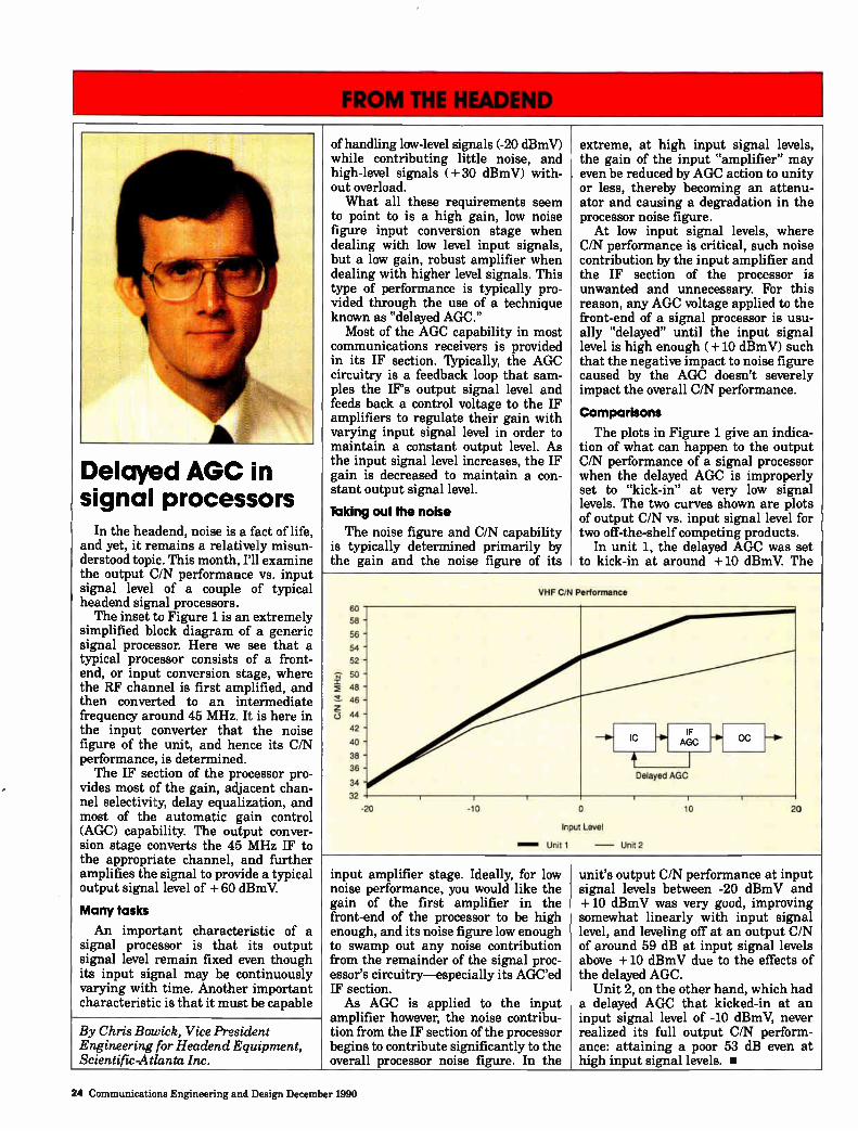
In the headend, noise is a fact of life, and yet, it remains a relatively misun-derstood topic. This month, I'll examine the output C/N performance vs. input signal level of a couple of typical headend signal processors. The inset to Figure 1 is an extremely
simplified block diagram of a generic signal processor. Here we see that a typical processor consists of a front-end, or input conversion stage, where the RF channel is first amplified, and then converted to an intermediate frequency around 45 MHz. It is here in the input converter that the noise figure of the unit, and hence its C/N performance, is determined. The IF section of the processor pro-
vides most of the gain, adjacent chan-nel selectivity, delay equalization, and most of the automatic gain control (AGC) capability. The output conver-sion stage converts the 45 MHz IF to the appropriate channel, and further amplifies the signal to provide a typical output signal level of + 60 dBmV.
Many tasks
An important characteristic of a signal processor is that its output signal level remain fixed even though its input signal may be continuously varying with time. Another important characteristic is that it must be capable
of handling low-level signals (-20 dBmV) while contributing little noise, and high-level signals (+ 30 dBmV) with-out overload. What all these requirements seem
to point to is a high gain, low noise figure input conversion stage when dealing with low level input signals, but a low gain, robust amplifier when dealing with higher level signals. This type of performance is typically pro-vided through the use of a technique known as "delayed AGC." Most of the AGC capability in most
communications receivers is provided in its IF section. Typically, the AGC circuitry is a feedback loop that sam-ples the IF's output signal level and feeds back a control voltage to the IF amplifiers to regulate their gain with varying input signal level in order to maintain a constant output level. As the input signal level increases, the IF gain is decreased to maintain a con-stant output signal level.
Taking out the noise
The noise figure and C/N capability is typically determined primarily by the gain and the noise figure of its
extreme, at high input signal levels, the gain of the input "amplifier" may even be reduced by AGC action to unity or less, thereby becoming an attenu-ator and causing a degradation in the processor noise figure.
At low input signal levels, where C/N performance is critical, such noise contribution by the input amplifier and the IF section of the processor is unwanted and unnecessary. For this reason, any AGC voltage applied to the front-end of a signal processor is usu-ally "delayed" until the input signal level is high enough ( + 10 dBmV) such that the negative impact to noise figure caused by the AGC doesn't severely impact the overall C/N performance.
Comparisons
The plots in Figure 1 give an indica-tion of what can happen to the output C/N performance of a signal processor when the delayed AGC is improperly set to "kick-in" at very low signal levels. The two curves shown are plots of output C/N vs. input signal level for two off-the-shelf competing products.
In unit 1, the delayed AGC was set to kick-in at around + 10 dBmV. The
2
o
60
58 -
56 - 54 -
52 -
50 -
48 -
46 -
VHF C/N Performance
44-
42 -
40 -
38 -
36 -
34
32
-20
IC IF
AGC
Delayed AGC
-fr OC
-1r0 o
Input Level
Unit 1 — unit 2
110 20
By Chris Bowick, Vice President Engineering for Headend Equipment, Scientific-Atlanta Inc.
input amplifier stage. Ideally, for low noise performance, you would like the gain of the first amplifier in the front-end of the processor to be high enough, and its noise figure low enough to swamp out any noise contribution from the remainder of the signal proc-essor's circuitry—especially its AGC'ed IF section. As AGC is applied to the input
amplifier however, the noise contribu-tion from the IF section of the processor begins to contribute significantly to the overall processor noise figure. In the
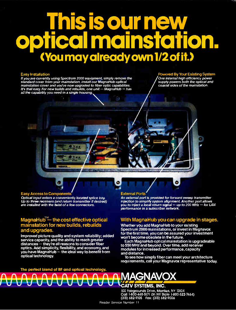
This is our new optical mainstation.
(You may already own 1/2 of it.) Easy Installation If you are currently using Spectrum 2000 equipment, simply remove the standard cover from your mainstation, install our MagnaHub optical mainstation cover and you've now upgraded to fiber optic capabilities. It's that easy For new builds and rebuilds, one unit — MagnaHub — has all the capability you need in a single housing.
4 Easy Access to Components Optical input enters a conveniently located splice tray. Up to three receivers (and return transmitter if desired) are installed with the twist of a few connectors.
MagnaHub- the cost effective optical mainstation for new builds, rebuilds and upgrades. Improved picture quality and system reliability; added service capacity, and the ability to reach greater distances — they're all reasons to consider fiber optics. Add simplicity, flexibility, and economy, ana you have MagnaHub — the ideal way to benefit from optical technology.
The perfect blend of RF and optical technology.
External Ports An external port is provided for forward sweep transmitter injection to simplify system alignment. Another port allows you to inject a local return signal — up to 200 MHz — for LAN performance in a subscriber network.
Powered By Your Existing System One internal high efficiency power supply powers both the optical and coaxial sides of the mainstation.
With MagnaHub you can upgrade in stages. Whether you add MagnaHub to your existing Spectrum 2000 mainstations, or invest in Magnavox for the first time, you can be assured your investment won't become obsolete in the future. Each MagnaHub optical mainstation is upgradeable
to 550 MHz and oeyond. Over time, add receiver modules for increased performance, capacity and &stance.
To see how simply fiber can meet your architecture requirements, call your Magnavox representative today.
ri ri ri ri ri ri MAGNAVOX vmairamarAmmur CATV SYSTEMS, INC. 100 Fairgrounds Drive, Manlius, NY 13104 Call 1-800-448-5171 (In NY State 1-800-522-7464) (315) 682-9105 Fax: (315) 682-9006
Reader Service Number 11
Wireless personal communications services One of the hottest areas of telecom-
munications development today is "per-sonal communications services" or PCS. In Europe it is called "personal com-munications networks" or PCN. The FCC has begun a broad inquiry into the technical and policy issues. Cable com-panies have a unique opportunity to participate in this new telecommunica-tions service.
PCS—The markets
PCS is a short-distance, low-power wireless voice communications system. It can serve several different market sectors: vehicular, pedestrian, business and residential. The FCC is looking at whether it will be an extension of the public switched wireline telephone net-work, or a new competitor. The vehicular market is served to-
day by cellular telephone. PCS is viewed by cellular operators as an evolution of their existing service. Some cellular operators have told the FCC that there is no need to permit new vendors to offer PCS, since they or will soon provide all of the new services. The pedestrian market for PCS is
By Jeffrey Krauss, Independent Telecommunications Policy Consultant and President of Telecommunications and Technology Policy of Rockville, Md.
served today by pay telephones in public areas such as airline terminals, shopping malls and downtown street corners. These pay telephones would become "telepoints," or low power fixed base stations that communicate with a pocket-sized telephone trans-ceiver. As you walk down the street, you can make a telephone call through one of these telepoints. The business market focus is the
wireless PBX. The rewiring of offices, in order to accommodate moves and rearrangements, is expensive. With a wireless PBX, there is no rewiring necessary. In addition, with a small wireless handset, you can carry your telephone with you as you visit other offices. The residential market is an evolution of the cordless telephone market. One base station might serve a cluster of 4 to 20 homes. Each market is already served by
some form of telephone technology. The key to success for PCS is to provide it with a lower-cost, smaller, lighter and more convenient system.
PCS—The technologies
Several different technologies have been proposed for PCS, and several different frequency ranges might be used. The FCC has granted several dozen experimental licenses to small start-up companies, wireline telephone companies and others to examine the feasibility of these different approaches.
There appear to be three main con-tenders in the technology area. One is analog FM voice modulation using frequency division multiple access to the radio spectrum. This is used in the first generation PCS systems being implemented in Great Britain under the name "CT-2," similar to the cur-rent U.S. cellular technology. The second technology contender is
compressed digital voice coding with time division multiple access to the radio spectrum. This is similar to the second generation cellular standard that will soon be implemented in the U.S. The third contender is compressed
digital voice coding with spread spec-trum modulation. Supporters claim that spread spectrum modulation, which produces a noise-like signal that is spread across a wide channel, can be used to share frequencies that are already in use for point-to-point micro-wave systems around 2 GHz. The existing point-to-point microwave us-ers dispute this claim.
PCS—The frequencies
The big fight in the U.S. will come over a specific allocation of frequencies for PCS. There are a few narrow slivers of spectrum around 900 MHz that are not being used, but this will not be adequate. The focus of attention now is on three bands around 1500 MHz, 1800 MHz and 2400 MHz. The 1500 MHz band is now being
used by aircraft manufacturers and the U.S. Air Force for telemetry in connec-tion with the flight testing of new aircraft. The 1800 MHz band is now used for
point-to-point microwave by oil compa-nies, railroads, electric utilities and local governments. The 2400 MHz band is now used for
military radars, and for consumer and industrial products such as microwave ovens and medical diathermy equipment. The FCC has a major inquiry under-
way, in Docket No. 90-314, looking at possible frequency bands, regulatory structures and other issues. Some deci-sions are due in 1991 or 1992.
Cable TV opportunities
Two cable operators, Cablevision Systems Corp. and Cox Enterprises have told the FCC that they would like to experiment with PCS networks. They plan to operate the low power radio systems, and to interconnect them with cable, fiber and CARS microwave links. PCS is a kind of mobile communica-
tions service, and some cable operators may be wary of entering a totally different line of business. But there is another option. Cable companies should think about entering into joint ven-tures with operators that already know the mobile communications market-place. In particular, think about mak-ing a deal with your non-wireline cellular operator.
In every city, there are two cellular operators. One of them is the local wireline telephone company. The other operator, known as the non-wireline cellular system, competes with the local telco. The non-wireline operator knows the mobile radio marketplace, but unlike the wireline telco, does not have an existing citywide wired net-work in place. The cable operator has that network. A joint venture between a the non-wireline cellular operator and the cable company would bring together the strengths of both, and provide cable systems with an impor-tant early-entry opportunity into PCS. •
26 Communications Engineering and Design December 1990
rEIE WORLD OF PIONEER
Our global commitment to CATV From North America to Europe to Asia and back, Pioneer cable television converter tech-nology is there. Pioneer's full line of address-able converter products has the capability of delivering CATV programming to over 450 mil-lion TV sets worldwide. Pioneer also offers a global network of sales, service and support. So wherever you are, you can count on the world-wide strength of the Pioneer name.
W) PIONEER PIONEER COMMUNICATIONS OF AMERICA, INC.
CATV Division 600 East Crescent Avenue Upper Saddle River, NJ 07458 (201) 327-6400 Outside New Jersey (800) 421-6450
990, Pioneer Communications of America, Inc.
'DI
LOOKING AH
Telco cable There continues to be widespread
talk about telco entry into the cable business. Indeed, the telephone compa-nies and their research organizations are devoting a level of resources to this issue which is almost unimaginable in our industry. There are literally thou-sands of people, many of them research engineers and strategic planners, who are focused on ways in which this may be accomplished.
This is a battle being fought at many levels. In Washington, telco and cable lobbyists clash over cross-subsidies and the public policy implications of letting telephone companies into the cable business—in particular, into the busi-ness of "controlling content."
Depreciation
At the state level, the cable and telephone industries are battling over accelerated depreciation schedules. If telephone companies can accelerate the rate at which they depreciate their existing assets, they essentially get reimbursed more quickly for those assets by telephone rate payers. This provides funds which are earmarked for use in replacing of the assets; in this case, replacing them with fiber plant capable of providing video capa-bilities in addition to the voice capabili-ties of the original plant. The fear of the cable industry is that
we will see overbuilds of our systems
By Jim Chiddix, Sr. Vice President, Technology and Engineering, ATC
financed by an increase in the rates that everyone pays for Plain Old Ible-phone Service (POTS). That is a serious prospect indeed—competition is a fact of life in any successful business, but no incumbent wants to see a competitor enter the field with an unfair advan-tage, particularly when that advantage amounts to public spending. While most people are fundamen-
tally satisfied with the cable service they get, they have observed that their rates have climbed over the last few years. We have not been successful in making them sufficiently aware of all the new services and plant improve-ments which have come along with those rate increases. In addition, too many people have experienced some form of poor service from their local cable operator.
Making headway with service
Some of the criticism which we receive is justified. We need to, and are, making progress in our front office customer service and the training level of our field personnel. But we are in a fundamentally
intrusive business. People want to watch television, not deal with our customer service reps on the telephone or our installers at the doorstep. Our real goal may be to merely lessen the irritation which having cable installs entails. Interdiction technology and a more coherent inside wiring strategy may go a long way toward helping this, but they cannot omit it entirely. The only good news is that any competitor providing video services into the home will run afoul of the same problems, and we will be further along the learning curve toward solving them.
Telcos face eroding market
There has been much talk about new information services which telco fiber-to-the-home market could provide. While there have not been any successful demonstrations of these services, most information services could be provided on twisted pair. Unless new services emerge for which there is a mass market, that rationale for replacing the residential telecommunications network may have a hollow ring, if it is to be paid for by the average consumer, which, of course, it must be. That leaves the revenues to be
generated by the video business as the only likely engine behind the construc-tion of a replacement telco plant. But
there, too, changes underway are likely to be discouraging. The cable industry is entering a mature phase, and efforts are already underway to improve serv-ice and to make our product more usable by the customer. In addition, the industry is in a gradual process of upgrading its plant. Through the use of fiber, these upgrades will be highly cost-effective and will lead to economi-cal, high performance 80-channel sys-tems in the near term, and 100-plus channel systems before long. This trend alone will be discouraging to overbuil-ders, but the picture will be compli-cated significantly by the entrance of a variety of DBS video delivery systems as the decade progresses.
Iblephone companies will thus face the prospect of making an enormous investment as they replace their plant on a house-by-house basis only to find that the only incremental revenue available to pay for that investment will have to be extracted from a fiercely competitive video delivery marketplace. At the same time, they will see their voice revenues threatened, particu-larly at the high-revenue end of the market. Hand-in-hand with that goes a threat to their lucrative long-distance access fees. The years ahead will be tough ones
for the telephone industry. We should not underestimate them as potential competitors because they are large, wealthy and adept at manipulating the regulatory and legislative processes. Nevertheless, we may find that time is on our side, and that overbuilding cable systems will prove to be economically uninteresting to telephone companies in the long run. We should not rejoice prematurely
at this, however, for we will have competition of our own. It will take the form of DBS and MMDS video delivery, along with the proliferation of inexpen-sive laser disc media and the continued refinement of videotape delivery We are, however, well positioned to capi-talize on the broadband plant which we have spent the last four decades building. As we add fiber trunking, and refine the remaining coaxial "last mile," we will find that we have a highly efficient, and competitively for-midable, delivery system for video and virtually any other imaginable service. The ultimate winner will, of course,
be the consumer, but there is no reason to believe the cable industry will not be a pivotal player in providing the cost-effective services which make the consumer happy. •
21 Communications Engineering and Design December 1990
CALAN 1776/1777
Integrated Sweep Receiver/Spectrum Analyzer
Improving picture quality is the fastest, most obvious way to improve subscriber satisfaction.
CALAN's integrated 1776/1777 helps you do just that. This portable, rugged system enables you to perform sweep and distortion measurements easily, quickly. With CALAN's flexible set-up capability, guard bands and phantom carriers, you can test and maintain your cable plant with no discernible interference to the home
viewer.. .even when scrambled channels are in use.
As the only company specializing in CATV sweep systems, CALAN offers a lot more than quality and proven reliability. We provide unmatched customer
service and support. . .along with system package pricing that makes CALAN your cost-effective tool for the '90s!
CABLE AND LOCAL AREA NETWORKS CALAN, INC.
Dingman's Ferry, PA 18328 1-800-544-3392 • In PA: 717-828-2356
The right tool for subscriber satisfaction!
Reader Service Number 13
MY VI EW
Network architecture
Cable TV network architecture has come a long way in 40 years: from single channel strip amplifiers carry-ing up to three non-adjacent, low-band VHF TV stations to modern broadband designs carrying 80 adjacent TV sig-nals; from braided shield coaxial cable to solid sheath aluminum; from coaxial cable to optical fiber hybrids; from tapped trunks to multi-hub distribu-tion; from traps to scrambling and addressability; from vacuum tubes in sheet metal pole cabinets to solid state hybrids in die-cast, weatherproof hous-ings; from the 704-B FSM to sophisti-cated, automated sweep testing and signal analyzers. Where do we go next? Some hand-
writing is already on the wall, but there is also a glow in the sky foretell-ing even greater transformations still to come.
Fiber optics
The fiber backbone architecture ap-pears to have become an acceptable option for rebuilding and upgrading, using either the ATC architecture developed by Jim Chiddix, or the CAN (cable area network) architecture de-veloped by Bob Luff. The concept of extending fiber to the bridger, or feeder, is quickly overtaking the fiber
By Archer S. Taylor, Senior Vice President, Engineering. Malarkey-Taylor Associates, Inc.
backbone. Not far behind is an archi-tecture based on optical fiber to the tap, or as the telephone industry puts it, to the curb. Photonic amplification seems destined to play a significant part in optical fiber network architec-ture.
Deflecting VSB/AMs progress
The related, but somewhat periph-eral developments in HDTV and digi-tal transmission may well deflect the apparent forward progress of VSB/AM optical fiber architecture as we pres-ently understand it. The remarkable progress of the Digi-
cipher HDTV proposal, and a host of aggressive digital compression schemes could have significant impact on cable TV network architecture. The advan-tages of digital over analog transmis-sion have long been recognized and widely appreciated. Digital signals can be transmitted over almost unlimited distances without significant degrada-tion. Digital transmission avoids the severe analog linearity requirement needed to prevent intermodulation. Output level control, peak-to-valley response, and signal-to-noise ratios are less critical for digital than for analog systems. Security for conditional access can be greatly enhanced with digital encryption.
Compression
Without aggressive bandwidth com-pression ratios, however, digital trans-mission must be paid for with intoler-ably large blocks of spectrum. It is the practicability of compressing 100 to 150 megabits per second of video, audio and control information into 6 MHz of spectral bandwidth that has raised engineering eyebrows.
Actually, the Digicipher system achieves about half of its compression by means of 16-QAM (16 level quadra-ture amplitude modulation). Therefore, it cannot be as free from the effects of amplitude errors in transmission as FSK, PSK or QPSK. The QAM signal cannot, for example, be hard limited, or clipped. Moreover, the bits at lower absolute amplitude levels must be more sensitive to noise. Success in the laboratory must be followed by success-ful experience in the real but imperfect world before we can join Archimedes in the bathtub, crying: "Eureka! I have found it!"
Nevertheless, while proof of perform-ance still lies ahead, there is scant
reason to doubt that Digicipher or some similar digital compression system will become an important part of the televi-sion landscape before the end of this decade. Conventional wisdom, but-tressed by market surveys, indicates that HDTV has little to offer the public unless displayed on screens large enough for the eye to see the fine detail.
New TV receivers required
Some believe rear-screen projection will do the job; others insist flat panel displays will be required. In either case, FCC has decided that a wholly new generation of TV receivers will be required, probably at significantly higher price, to display television pic-tures with the quality defined by HDTV. There now seems a strong likelihood that the new HDTV sets will be totally digital. Even videocassette players will either become digital, or give way to some form of digital laser disc or video CD.
However, even while accommodat-ing digital transmission, cable TV networks will probably be expected to continue distribution of analog NTSC television for several more decades. What network architecture can be devised effectively and economically to distribute both analog and digital transmissions? That is our homework assignment for the next few years. Once we are in the digital business,
switching is a natural corollary. Video on demand, or demand access video in telephone lingo, is probably the most viable video switching application. Video on demand means that any subscriber literally could specify the time and date for viewing any program title in the catalog.
For such a service, a separate chan-nel would have to be dedicated, from the program switch to each and every subscriber. Near video on demand might more realistically restrict the freedom of choice to a limited number of titles, available only at pre-designated times, with a cap on the number of concurrent users that could be accommodated.
To switch or not to switch?
Another plan, described in the Ma-larkey-Taylor report to the White House Office of Telecommunications Policy in 1971, would not require switching. Each title would be repeated continu-ously on separate channels, at stag-gered starting times. It is too early to
Continued on page 150
30 Communications Engineering and Design December 1990
AN ERA OF LIMITS BELDEN EXPANDS YOUR OPTIONS.
Neel Fiber Optic Supertrunk Cables
Messengered Cables
Burial Cables
'
Drop Cables
Dual Cable.s
. • , CorrCion--Resistant Duobond' Mus Cables
CiiStorn Cdmposite Cables ,
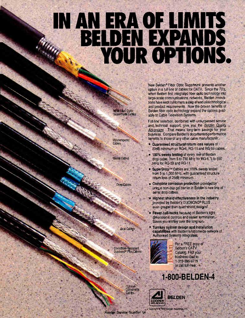
New Belden '' Fiber Optic Supertrunk presents another option in a full line of cables for CATV. Since the 70s, when Belden first ntegrated fiber optic technology into large-scale communications networks, Belden innova-tions have kept customers a step ahead of technological and product requirements. Now the proven benefits of Belden fiber optic technology expand the options avail-able to Cable Television Systems.
Full line selection combined with unsurpassed service and technical support, give you the Belden Quality Advantage. That means long-term savings for your business. Compare Belden's documented performance benefits to those of any other cable manufacturer:
•
•
Guaranteed structural return loss values of 23dB minimum on RG-6, RG-11 and RG-59 cables.
100% sweep testing of every reel of Belden drop cable, from 5 to 750 MHz for PG-6, 5 to 550 MHz for RG-59 and RG-11.
SuperDrop-Tm Cables are 100% sweep tested from 5 to 1,000 MHz, with guaranteed structure return loss of 26dB minimum.
• Complete corrosion protection provided by unique non-drio gel barrier in Belden's new line of aerial drop cables.
-• Highest shield effectiveness in the industry provided by Belden's DUOBOND PLUS . . . even greater than quad shield designs!
• Fewer call-bazks because of Belden's tight dimensional controls and easier termination. Saves you mohey over the long run.
• Turnkey system design and installation capabilities with Belden's nationwide network of Authorized Systems Integrators.
For a FREE copy of Belden's CATV Catalog, FAX your business card to 1-319-395-9719 or call toll-free: •
•
1-800-BELDEN-4
.411 'COOPER INDU 9'T RIES
BELDEN
Coyngtit 5'199O Cospe Industnes, ne:
Rea r Service Number 14 •

The fiber for people who don't know
their own strength. We've improved our single-mode fibers to help make up for the
fact that people aren't perfect. Most cable TV technicians, for example, are used to handling
coaxial cable. So when they mechanically strip fiber they might end up scratching it or nicking it. Both of which can weaken the fiber.
Corning Titan- fiber is forgiving of unintentional, but inevitable,
rough handling. A unique titania addition to the outer cladding glass makes Corning Titan fiber about 60 percent more abrasion resistant than any other standard fiber. The titania also makes the fiber more reliable by increasing its fatigue resistance—or life under load—dramatically. And the fiber's coating is tougher, too.
The result of all these improvements: Corning Titan fiber is
harder to damage and easier to work with. You can take advantage of Titan fiber now. It's compatible
with other standard single-mode fibers. And it can be spliced or otherwise joined using the same equipment with normal set-up and
operating procedures. What's more, like all standard Corning fibers, Titan fiber provides
excellent reel-to-reel consistency, which makes splicing easy. Your people want to do a good job, but they're only human. So
don't take just any optical fiber. Make sure you specify the tough, yet
forgiving, fiber: Titan. Corning. Fiber you can count on.
CORNING
To get your free Titan fiber baseball cap, or for more information on Corning Titan fiber and its availability, see us at the Western Cable Show, booth 154-156, or call Loretta Maloney at (607)974-7181.
Reader Service Number 15
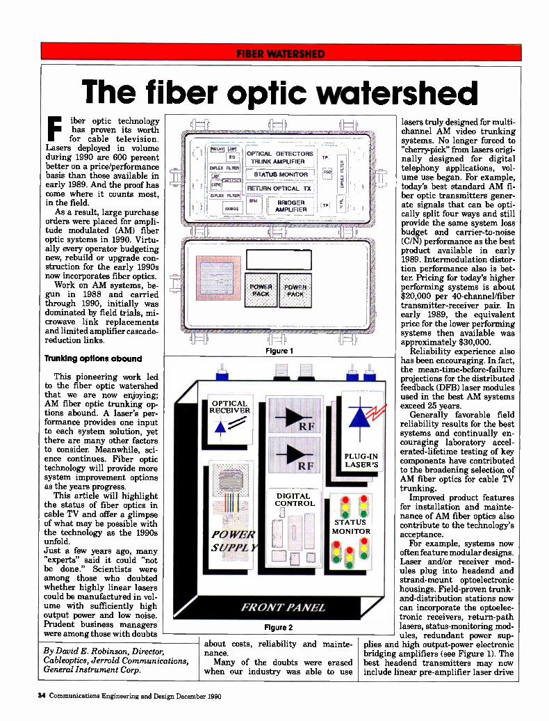
The fiber optic watershed Fiber optic technology
has proven its worth for cable television.
Lasers deployed in volume during 1990 are 600 percent better on a price/performance basis than those available in early 1989. And the proof has come where it counts most, in the field. As a result, large purchase
orders were placed for ampli-tude modulated (AM) fiber optic systems in 1990. Virtu-ally every operator budgeting new, rebuild or upgrade con-struction for the early 1990s now incorporates fiber optics. Work on AM systems, be-
gun in 1988 and carried through 1990, initially was dominated by field trials, mi-crowave link replacements and limited amplifier cascade-reduction links.
Ttunldng options abound
This pioneering work led to the fiber optic watershed that we are now enjoying; AM fiber optic trunking op-tions abound. A laser's per-formance provides one input to each system solution, yet there are many other factors to consider. Meanwhile, sci-ence continues. Fiber optic technology will provide more system improvement options as the years progress.
This article will highlight the status of fiber optics in cable TV and offer a glimpse of what may be possible with the technology as the 1990s unfold. Just a few years ago, many "experts" said it could "not be done." Scientists were among those who doubted whether highly linear lasers could be manufactured in vol-ume with sufficiently high output power and low noise. Prudent business managers were among those with doubts
er //17,W/)7177/112»,77,717.,
ri°
DIPLEX FILTEAI
SXRE
OPTICAL DETECTORS
TRUNK AMPLIFIER
ISTATUS MONITOR j
•RETUF1N OPTICAL TX [DIP- LE% FILTER' •
-- M ,L BRIDGER 1„ 1
[MC..5 j AMPLIFIER I • -
P
F.50
L-10
.07/Ze07
N
•
... ... .............. ......... ..... ...... ...... e
Figure 1
Figure 2
OPTICAL RECEIVER
POWER
SUP/'L
By David E. Robinson, Director, Cableoptics, Jerrold Communications, General Instrument Corp.
about costs, reliability and mainte-nance. Many of the doubts were erased
when our industry was able to use
lasers truly designed for multi-channel AM video trunking systems. No longer forced to "cherry-pick" from lasers origi-nally designed for digital telephony applications, vol-ume use began. For example, today's best standard AM fi-ber optic transmitters gener-ate signals that can be opti-cally split four ways and still provide the same system loss budget and carrier-to-noise (C/N) performance as the best product available in early 1989. Intermodulation distor-tion performance also is bet-ter. Pricing for today's higher performing systems is about $20,000 per 40-channel/fiber transmitter-receiver pair. In early 1989, the equivalent price for the lower performing systems then available was approximately $30,000.
Reliability experience also has been encouraging. In fact, the mean-time-before-failure projections for the distributed feedback (DFB) laser modules used in the best AM systems exceed 25 years.
Generally favorable field reliability results for the best systems and continually en-couraging laboratory accel-erated-lifetime testing of key components have contributed to the broadening selection of AM fiber optics for cable TV trunking.
Improved product features for installation and mainte-nance of AM fiber optics also contribute to the technology's acceptance.
For example, systems now often feature modular designs. Laser and/or receiver mod-ules plug into headend and strand-mount optoelectronic housings. Field-proven trunk-and-distribution stations now can incorporate the optoelec-tronic receivers, return-path lasers, status-monitoring mod-ules, redundant power sup-
plies and high output-power electronic bridging amplifiers (see Figure 1). The best headend transmitters may now include linear pre-amplifier laser drive
34 Communications Engineering and Design December 1990
Freedom package.
Solve your antenna site location problems.
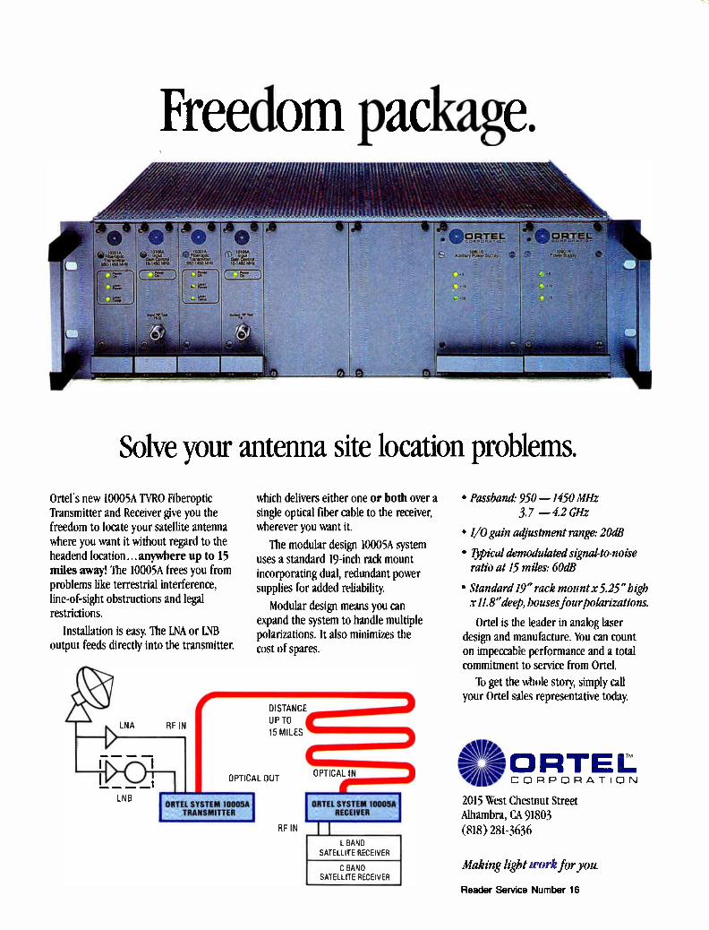
Ortel's new 10005A TYRO Fiberoptic Transmitter and Receiver give you the freedom to locate your satellite antenna where you want it without regard to the headend location... anywhere up to 15 miles away! The 10005A trees you from problems like terrestrial interference, line-of-sight obstructions and legal restrictions.
Installation is easy. The LNA or LNB output feeds directly into the transmitter,
LNB
RF IN
which delivers either one or both over a single optical fiber cable to the receiver, wherever you want it.
The modular design 10005A system uses a standard 19-inch rack mount incorporating dual, redundant power supplies for added reliability
Modular design means you can expand the system to handle multiple polarizations. It also minimizes the cost of spares.
DISTANCE
UP TO
15 MILES
OPTICAL OUT OPTICAL IN
ORTEL SYSTEM 10005A RECEIVER
L BAND SATELLITE RECEIVER
C BAND SATELLITE RECEIVER
• Passband: 950 — 1450 MHz 3.7 —4.2 GHz
• 1/0 gain adjustment range: 20dB
• ljpical demodulated sigrudto-noise ratio at 15 miles: 60dB
• Standard 19" rack mount x 5.25" high x IL8" deep, houses four polarizations.
Ortel is the leader in analog laser design and manufacture. You can count on impeccable performance and a total commitment to service from Ortel.
To get the whole story, simply call your Ortel sales representative today.
-1--0RTEL CORPORATION
2015 West Chestnut Street Alhambra, CA 91803 (818) 281-3636
Making light work for you.
Reader Service Number 16
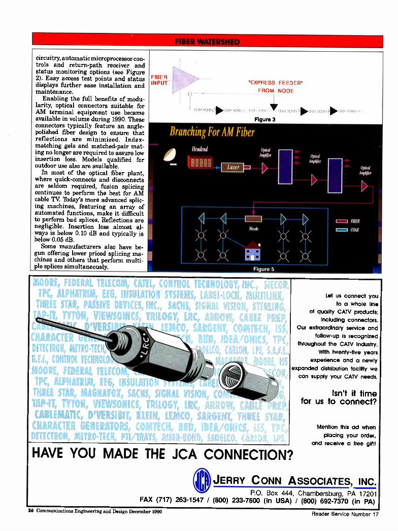
circuitry, automatic microprocessor con-trols and return-path receiver and status monitoring options (see Figure 2). Easy access test points and status displays further ease installation and maintenance.
Enabling the full benefits of modu-larity, optical connectors suitable for AM terminal equipment use became available in volume during 1990. These connectors typically feature an angle-polished fiber design to ensure that reflections are minimized. Index-matching gels and matched-pair mat-ing no longer are required to assure low insertion loss. Models qualified for outdoor use also are available.
In most of the optical fiber plant, where quick-connects and disconnects are seldom required, fusion splicing continues to perform the best for AM cable TV Today's more advanced splic-ing machines, featuring an array of automated functions, make it difficult to perform bad splices. Reflections are negligible. Insertion loss almost al-ways is below 0.10 dB and typically is below 0.05 dB. Some manufacturers also have be-
gun offering lower priced splicing ma-chines and others that perform multi-ple splices simultaneously.
FIBER INPUT 'EXPRESS FEEDER'
FROM NODE
lr !rfe ,
Figure 3
Branching For MI Fiber 111 'leaded
—
\ /
/ \
/ \
oriscgi AniPhlier
Laser 1=1
Node
ElEi Fi. ure 5
\I/
/ \
Opt ¡Lid Amplifier
/ \
\ /
LL-JII HIER
I=1 COAX
DETECTRON, hitik0.TEC CONTROL TENN(
MOORE, FEDERAL TELE, TPC, ALPHATRIM, EEG, INSULAi, THREE STAR, MAGNAVOX, SACHS, SIGNAL VISION, CO TAP•IT, TYTON, VIEWSONICS, TRILOGY, LRC, ARRO -â, CABLEMATIC, D'VERSIBIT, KLEIN, LEMCO, SARGENT, CHARACTER GENERATORS, COMTECH, BUD IDEA/ONICS,
(Anil CONTROL Ii(NtiOLuot li TPC, ALPHATRIM, EEG, INSULATION SYSTEMS, LABEL.1.0(1( THREE STAR, PASSIVE DEVICES, INC, SACHS, SIGNAL V-
TYT0N. wçwçONKS, TRILOGY, LRC, ARROW, CAP IrWin. SARGENT, COIV,
P!!D, IDEA/ONICS, LCO, CARLON, LPS, 5,4..
Let us connect you
to a whole line
of quality CAN products;
including connectors.
Our extraordinary service and
follow-up is recognized
throughout the CAN Industry.
With twenty-five years
experience and a newly
expanded distribution facility we
can supply your CAN needs.
HAVE YOU MADE THE JCA CONNECTION?
Isn't it time for us to connect?
Mention this ad when
placing your order,
and receive a free gift!
JERRY CONN ASSOCIATES, INC. P.O. Box 444, Chambersburg, PA 17201
FAX (717) 263-1547 / (800) 233-7600 (in USA) / (800) 692-7370 (in PA)
36 Communications Engineering and Design December 1990 Reader Service Number 17
MORE BENEFITS MEAN MORE
VENUE...
The most sophisticated har no better that driv syste ed ou StO
e control system Because it's control
ven, not hardware limit-gma 2000 takes software
is ve ost • owerful and sophisticate
control system in the business. And Sigma builds-in more rev nue generating benefits
Ise. Igma 000 enables the cable
provider to interrupt program-ming to prompt the customer who hasn't paid his bill by switching the viewer to a "barker" channel and displaying his account status. The customer can restore service by calling the cable company
y-
office an arranging payment. Benefit: a greatly increased reve-nue stream with greatly decreased manpower.
Sigma's control system features open-ended architecture so powerful that it can deliver service to 600,000+ subscribers, control 56 PPV channels simulta-neously and hold an active inven-tory of 3,000 PPV events vs. the current 102 of other technology. These benefits translate to in-creased revenues plus the potent-ial of changing Americans' viewing habits with an expanded menu of pay programming
choices. The enhanced sec-
urity of audio and video encryption
eliminates piracy, thus increasing the number
of revenue producing sub-scribers. With Sigma 2000,
everyone playing is paying. The combination of its power-
ful control system and the proven dependability of its hardware makes Sigma 2000 the most completely advanced, address-able system available anywhere.
MAM Oak Communications Inc. 16516 Via Esprillo, Rancho Bernardo, CA 92127 (619) 451-1500
Reader Service Number 18
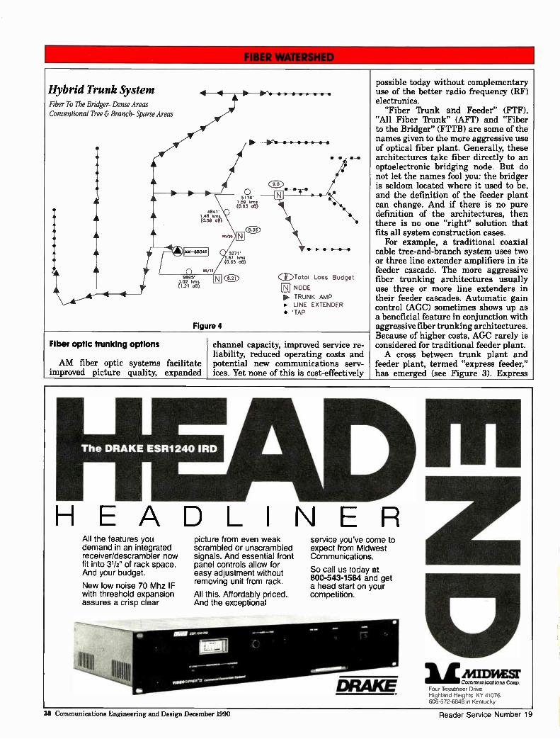
Hybrid Trunk System Fiber To The Bridger- Dense Areas Conventional Tree & Branch- Sparse Areas
A
4 1
o 5176'
1.59 krns (0.63 dB)
4841' 1.48 krns (0.59 d8)
Ah1-550A1
a5/15
9895' 3.02 krns (1.21 08)
Figure 4
(916)
so/2o
5271' 1.61 krns (0.65 el)
CEDTotol Loss Budget
NODE
I> TRUNK AMP • LINE EXTENDER • -TAP
Fiber optic trunking options
AM fiber optic systems facilitate improved picture quality, expanded
channel capacity, improved service re-liability, reduced operating costs and potential new communications serv-ices. Yet none of this is cost-effectively
possible today without complementary use of the better radio frequency (RF) electronics.
"Fiber Trunk and Feeder" (FTF), "All Fiber Trunk" (AFT) and "Fiber to the Bridger" (FTTB) are some of the names given to the more aggressive use of optical fiber plant. Generally, these architectures take fiber directly to an optoelectronic bridging node. But do not let the names fool you: the bridger is seldom located where it used to be, and the definition of the feeder plant can change. And if there is no pure definition of the architectures, then there is no one "right" solution that fits all system construction cases.
For example, a traditional coaxial cable tree-and-branch system uses two or three line extender amplifiers in its feeder cascade. The more aggressive fiber trunking architectures usually use three or more line extenders in their feeder cascades. Automatic gain control (AGC) sometimes shows up as a beneficial feature in conjunction with aggressive fiber trunking architectures. Because of higher costs, AGC rarely is considered for traditional feeder plant. A cross between trunk plant and
feeder plant, termed "express feeder," has emerged (see Figure 3). Express
HEADLINER All the features you demand in an integrated receiver/descrambler now fit into 31/2" of rack space. And your budget.
New low noise 70 Mhz IF with threshold expansion assures a crisp clear
picture from even weak scrambled or unscrambled signals. And essential front panel controls allow for easy adjustment without removing unit from rack.
All this. Affordably priced. And the exceptional
service you've come to expect from Midwest Communications.
So call us today at 800-543-1584 and get a head start on your competition.
111E Communications Corp
Four Tesseneer Drive Highland Heights, KY 41076 606-572-6848 in Kentucky
1141D}EST
38 Communications Engineering and Design December 1990 Reader Service Number 19
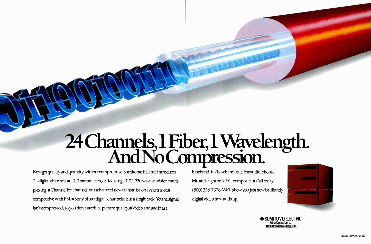
Channels 1 Fiber, 1 Wavelength. And Nb Compression.
Now get quality and quantity without compromise. Sumitomo Electric introduces
24 digital channels at 1310 nanometers, or 48 using 1310/1550 wave-division multi-
plexing. • Channel for channel, our advanced new transmission system is cost
competitive with FM. Sixty of our digital channels fit in a single rack. Yet the signal
isn't compressed, so you don't sacrifice picture quality. • Video and audio are
baseband-in/baseband-out. For audio, choose
left-and-right or BTSC-composite. • Call today,
(800) 358-7378. We'll show you just how brilliantly
digital video now adds up.
*SUMITOMO ELECTRIC Fiber Optics Corp.
YOUR LIGHT SUPPORT SYSTEM
Reader Service No. 110
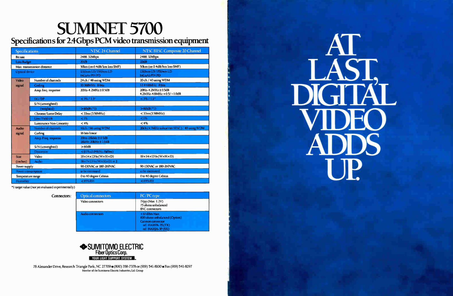
SUM1NE 1 5700 Specifications for 24 Gbps PCM video transmission equipment
Specifications
Bit rate
Max. transmission distance
Number of channels 24 ch / 48 using WDM Video
signal
111
Audio
signal
Size
(inches)
Amp. freq. response
S/N (unweighted)
Ch rome/Lume Delay
Luminance Non-Linearity
Coding
S/N (unweighted)
• Video
Audio
\ t'l
Power consumption
lemperature range
NTSC 24 Channel mg NTSC BTSC-Composite 20 Channel 2488. 32Mbps
50km (on 0.4dB/km loss SMF)
20Hz-4.2MHz ± 0.5dB
2488. 32Mbps
MOM 50km (on 0.4dB/km loss SMF)
20 ch / 40 using WDM
20Hz-4.2MHz ± 0.5dB 4.2MHz-4.8MHz +0.5/ —1.0dB
"11111r— r 11
.1111 111 < 33m (3.58MHz) <33m (3.58MHz)
BRIM < 4%
96 usi
16 bits linear
> 60dB
19x14 x 13 3/8 (WxHxD)
90-130VAC or 180-260VAC
0 to 40 degree CP1sius
< 4%
19 x 14 x1.33/8 (WxH xD)
90-130VAC or 180-260VAC
-11 1111111111. 0 to 40 degree Celsius
*1 target value (not yet evaluated experimentally)
Connectors: Optical connectors Video connectors
FC/PC type
1Vpp (Max. 1.2V) 75 ohms unbalanced 8NC connectors
MS un alanced (Option) Cannon connector
ref: HAl6PA-35 (TX) ref: HA16JA-3P (RX)
*SUMITOMO ELECTRIC Fiber Optics Corp.
YOUR LIGHT SUPPORT SYSTEM
78 Alexander Drive, Research Triangle Park, NC 27709 (800) 358-7378 or (919) 541-8100 Fax (919) 541-8297 Member of the Sumitomo Electric Industries, Ltd. Group
AT LAST,
DIGITAL MDR) ADDS UP
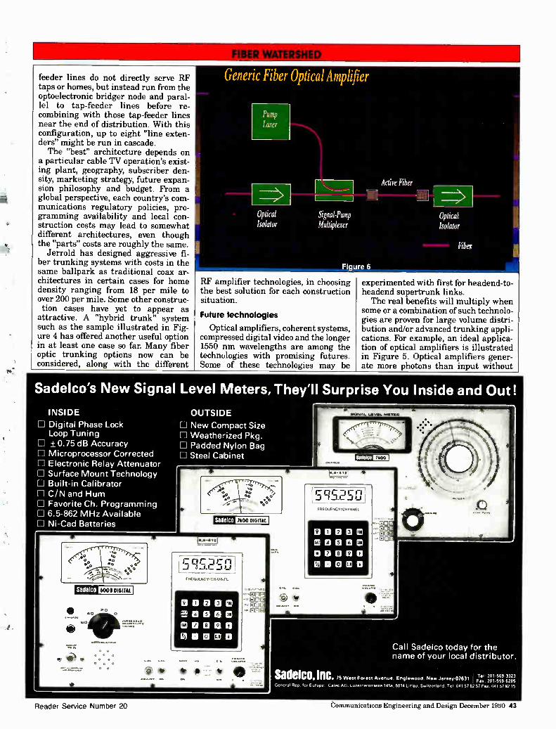
feeder lines do not directly serve RF taps or homes, but instead run from the optoelectronic bridger node and paral-lel to tap-feeder lines before re-combining with those tap-feeder lines near the end of distribution. With this configuration, up to eight "line exten-ders" might be run in cascade. The "best" architecture depends on
a particular cable TV operation's exist-ing plant, geography, subscriber den-sity, marketing strategy, future expan-sion philosophy and budget. From a global perspective, each country's com-munications regulatory policies, pro-gramming availability and local con-struction costs may lead to somewhat different architectures, even though the "parts" costs are roughly the same.
Jerrold has designed aggressive fi-ber trunking systems with costs in the same ballpark as traditional coax ar-chitectures in certain cases for home density ranging from 18 per mile to over 200 per mile. Some other construc-tion cases have yet to appear as
attractive. A "hybrid trunk" system such as the sample illustrated in Fig-ure 4 has offered another useful option in at least one case so far. Many fiber optic trunking options now can be considered, along with the different
Generic Fiber Optical Amplifier
Pump Laser
Optical Isolator
Signal-Pump Multiplexer
Active Fiber
1111 , Optical Isolator
Fiber
• • •
RF amplifier technologies, in choosing the best solution for each construction situation.
Future technologies
Optical amplifiers, coherent systems, compressed digital video and the longer 1550 nm wavelengths are among the technologies with promising futures. Some of these technologies may be
experimented with first for headend-to-headend supertrunk links. The real benefits will multiply when
some or a combination of such technolo-gies are proven for large volume distri-bution and/or advanced trunking appli-cations. For example, an ideal applica-tion of optical amplifiers is illustrated in Figure 5. Optical amplifiers gener-ate more photons than input without
Sadelco's New Signal Level Meters, They'll Surprise You Inside and Out!
INSIDE
LI Digital Phase Lock Loop Tuning + 0.75 dB Accuracy
H Microprocessor Corrected LI Electronic Relay Attenuator Ill Surface Mount Technology El Built-in Calibrator LI C/N and Hum H Favorite Ch. Programming 111 6.5-862 MHz Available 0 Ni-Cad Batteries
ri LI
OUTSIDE
New Compact Size Weathe-ized Pkg. Padded Nylon Bag Steel Cabinet
7600 DIGITAL I
_fic15.250 FREQIENCYlCHANNEL
°noon aeon 0 C10000 ZIOOCCO
FREQUENCY/CHANNEL
—00 un
--ED -EDO
Call Sadelco today for the name of your local distributor.
sadeico.inc. 75 West Forest Avenue. Englewood. ?gal./ Jersey, 07631 Fr...1 21 11.555599 63,382,3 (ir. 0 for Europe Gatec AG LezernersHasse 1454. 6014 beau SeHt4erland Tel 041 57 82 57 Fa. 041 57 82 15
Reader Service Number 20 communications Engineering and Design December 1990 43
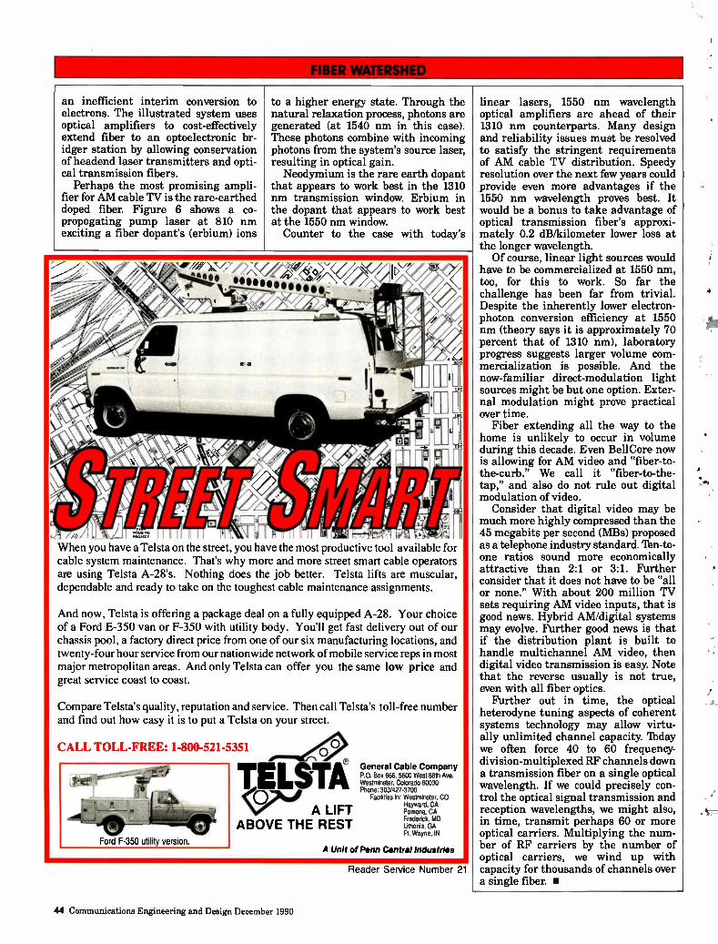
an inefficient interim conversion to electrons. The illustrated system uses optical amplifiers to cost-effectively extend fiber to an optoelectronic br-idger station by allowing conservation of headend laser transmitters and opti-cal transmission fibers.
Perhaps the most promising ampli-fier for AM cable TV is the rare-earthed doped fiber. Figure 6 shows a co-propogating pump laser at 810 nm exciting a fiber dopant's (erbium) ions
to a higher energy state. Through the natural relaxation process, photons are generated (at 1540 nm in this case). These photons combine with incoming photons from the system's source laser, resulting in optical gain. Neodymium is the rare earth dopant
that appears to work best in the 1310 nm transmission window. Erbium in the dopant that appears to work best at the 1550 nm window.
Counter to the case with today's
When you have a Telsta on the street, you have the most productive tool available for cable system maintenance. That's why more and more street smart cable operators are using Telsta A-28's. Nothing does the job better. Telsta lifts are muscular, dependable and ready to take on the toughest cable maintenance assignments.
And now, Telsta is offering a package deal on a fully equipped A-28. Your choice of a Ford E-350 van or F-350 with utility body. You'll get fast delivery out of our chassis pool, a factory direct price from one of our six manufacturing locations, and twenty-four hour service from our nationwide network of mobile service reps in most major metropolitan areas. And only Telsta can offer you the same low price and great service coast to coast.
Compare Telsta's quality, reputation and service. Then call Telsta's toll-free number and find out how easy it is to put a Telsta on your street.
CALL TOLL-FREE: 1-800-521-5351
TELSTA ç(D7 e A LIFT
ABOVE THE REST
General Cable Company P.O. Box 666, 5600 West 88th Ave. Westminster, Colorado 80430 Phone: 303/427-3700
Facilities in: Westminster, CO Hayward, CA Pomona, CA Frederick, MD Lithonia, GA Ft. Wayne, IN
A Unit of Penn Central Industries
Reader Service Number 21
linear lasers, 1550 nm wavelength optical amplifiers are ahead of their 1310 nm counterparts. Many design and reliability issues must be resolved to satisfy the stringent requirements of AM cable TV distribution. Speedy resolution over the next few years could provide even more advantages if the 1550 nm wavelength proves best. It would be a bonus to take advantage of optical transmission fiber's approxi-mately 0.2 dB/kilometer lower loss at the longer wavelength. Of course, linear light sources would
have to be commercialized at 1550 nm, too, for this to work. So far the challenge has been far from trivial. Despite the inherently lower electron-photon conversion efficiency at 1550 nm (theory says it is approximately 70 percent that of 1310 nm), laboratory progress suggests larger volume com-mercialization is possible. And the now-familiar direct-modulation light sources might be but one option. Exter-nal modulation might prove practical over time.
Fiber extending all the way to the home is unlikely to occur in volume during this decade. Even BellCore now is allowing for AM video and "fiber-to-the-curb." We call it "fiber-to-the-tap," and also do not rule out digital modulation of video.
Consider that digital video may be much more highly compressed than the 45 megabits per second (MBs) proposed as a telephone industry standard. 'Ibn-to-one ratios sound more economically attractive than 2:1 or 3:1. Further consider that it does not have to be "all or none." With about 200 million TV sets requiring AM video inputs, that is good news. Hybrid AM/digital systems may evolve. Further good news is that if the distribution plant is built to handle multichannel AM video, then digital video transmission is easy. Note that the reverse usually is not true, even with all fiber optics.
Further out in time, the optical heterodyne tuning aspects of coherent systems technology may allow virtu-ally unlimited channel capacity. lbday we often force 40 to 60 frequency-division-multiplexed RF channels down a transmission fiber on a single optical wavelength. If we could precisely con-trol the optical signal transmission and reception wavelengths, we might also, in time, transmit perhaps 60 or more optical carriers. Multiplying the num-ber of RF carriers by the number of optical carriers, we wind up with capacity for thousands of channels over a single fiber. •
44 Communications Engineering and Design December 1990
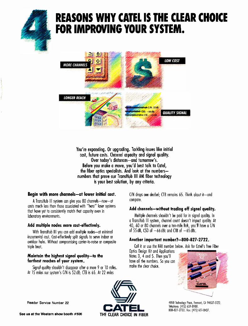
REASONS WHY CATEL IS THE CLEAR CHOICE FOR IMPROVING YOUR SYSTEM.
MORE CHANNELS
LONGER REACH
LOW COST
QUALITY SIGNAL
C/N: 558
(SO: -66€1115 (TB:
You're expanding. Or upgrading. Tackling issues like initial cost, future costs. Channel capacity and signal quality.
Over today's distances—and tomorrow's. Before you make a move, you'd best talk to Catel,
the fiber optics specialists. And look at the numbers— numbers that prove our TransHub Ill AM fiber technology
is your best solution, by any criteria.
Begin with more channels—at lower initial cost.
A TransHub Ill system can give you 80 channels—now—at costs much less than those associated with "hero" laser systems that have yet to consistently match that capacity even in laboratory environments.
Add multiple nodes more cost-effectively.
With TransHub Ill you can add multiple nodes—at minimal incremental cost. Cost-effectively split signals to serve indoor or outdoor hubs. Without compromising carrier-to-noise or composite triple beat.
Maintain the highest signal quality—to the farthest reaches of your system.
Signal quality shouldn't disappear after a mere 9 or 10 miles. At 15 miles our system's UN is 52dB; GB is 65. At 22 miles
Reader Service Number 22
C/N drops one decibel; GB remains 65. Think about it—and compare.
Add channels—without trading off signal quality.
Multiple channels shouldn't be paid for in signal quality. In a TransHub Ill system, channel count doesn't impact quality. At 40, 60 or 80 channels over a ten-mile link, you'll have a C/N of 55dB, CSO of —66dBc and GB of —65dBc.
Another important number?-800-827-2722. Call it or use the FAX number below. Ask for Catel's free Fiber
Optics Design Kit and Applications Notes 3, 4 and 5. Then you'll have all the numbers. So you can make the clear choice.
CATEL 4050 Technology Ploce, Fremont, CA 94537-5122. Telephone: (415) 659-8988. 800-827-2722. Fox: (415) 651-8437.
See us at the Western show booth #506 THE CLEAR CHOICE IN FIBER
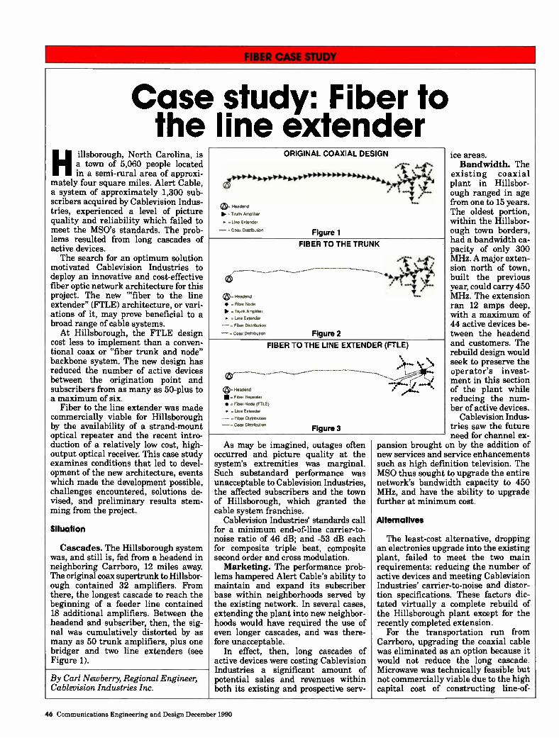
Case the
Hillsborough, North Carolina, is a town of 5,060 people located in a semi-rural area of approxi-
mately four square miles. Alert Cable, a system of approximately 1,300 sub-scribers acquired by Cablevision Indus-tries, experienced a level of picture quality and reliability which failed to meet the MSO's standards. The prob-lems resulted from long cascades of active devices. The search for an optimum solution
motivated Cablevision Industries to deploy an innovative and cost-effective fiber optic network architecture for this project. The new "fiber to the line extender" (FTLE) architecture, or vari-ations of it, may prove beneficial to a broad range of cable systems. At Hillsborough, the FTLE design
cost less to implement than a conven-tional coax or "fiber trunk and node" backbone system. The new design has reduced the number of active devices between the origination point and subscribers from as many as 50-plus to a maximum of six.
Fiber to the line extender was made commercially viable for Hillsborough by the availability of a strand-mount optical repeater and the recent intro-duction of a relatively low cost, high-output optical receiver. This case study examines conditions that led to devel-opment of the new architecture, events which made the development possible, challenges encountered, solutions de-vised, and preliminary results stem-ming from the project.
Situation
Cascades. The Hillsborough system was, and still is, fed from a headend in neighboring Carrboro, 12 miles away. The original coax supertrunk to Hillsbor-ough contained 32 amplifiers. From there, the longest cascade to reach the beginning of a feeder line contained 18 additional amplifiers. Between the headend and subscriber, then, the sig-nal was cumulatively distorted by as many as 50 trunk amplifiers, plus one bridger and two line extenders (see Figure 1).
study: Fiber to line extender
Headend
- Trunk Amplifier
•. Line Extender
— = Coe. Distributor
ORIGINAL COAXIAL DESIGN
Figure 1
Headend
• =FiberNode
PP. . Trunk Amplifier •. Line Extender
. Fiber Distribution
— Coax Distribuion
ice areas. Bandwidth. The
existing coaxial plant in Hillsbor-ough ranged in age from one to 15 years. The oldest portion, within the Hillsbor-ough town borders,
had a bandwidth ca-pacity of only 300 MHz. A major exten-sion north of town, built the previous year, could carry 450 MHz. The extension ran 12 amps deep, with a maximum of 44 active devices be-
tween the headend and customers. The rebuild design would seek to preserve the operator's invest-ment in this section of the plant while reducing the num-ber of active devices.
Cablevision Indus-tries saw the future
need for channel ex-pansion brought on by the addition of new services and service enhancements such as high definition television. The MSO thus sought to upgrade the entire network's bandwidth capacity to 450 MHz, and have the ability to upgrade further at minimum cost.
FIBER TO THE TRUNK
Figure 2
FIBER TO THE LINE EXTENDER (FTLE)
Headend
• . Fiber Repeater
• = Fiber Node (FTLE) • . Line Extender
. Fiber Distribution
— . Coax Distribution Figure 3
By Carl Newberry, Regional Engineer, Cablevision Industries Inc.
As may be imagined, outages often occurred and picture quality at the system's extremities was marginal. Such substandard performance was unacceptable to Cablevision Industries, the affected subscribers and the town of Hillsborough, which granted the cable system franchise.
Cablevision Industries' standards call for a minimum end-of-line carrier-to-noise ratio of 46 dB; and -53 dB each for composite triple beat, composite second order and cross modulation. Marketing. The performance prob-
lems hampered Alert Cable's ability to maintain and expand its subscriber base within neighborhoods served by the existing network. In several cases, extending the plant into new neighbor-hoods would have required the use of even longer cascades, and was there-fore unacceptable.
In effect, then, long cascades of active devices were costing Cablevision Industries a significant amount of potential sales and revenues within both its existing and prospective serv-
Alternatives
The least-cost alternative, dropping an electronics upgrade into the existing plant, failed to meet the two main requirements: reducing the number of active devices and meeting Cablevision Industries' carrier-to-noise and distor-tion specifications. These factors dic-tated virtually a complete rebuild of the Hillsborough plant except for the recently completed extension.
For the transportation run from Carrboro, upgrading the coaxial cable was eliminated as an option because it would not reduce the long cascade. Microwave was technically feasible but not commercially viable due to the high capital cost of constructing line-of-
46 Communications Engineering and Design December 1990
OFF-AIR, ON-LINE,
WORLD-WIDE
The Leader in Off-Air Antennas is Taking a Hard Line in Distribution Electronics.
Lindsay's off-air antennas are the standard of performance in CATV systems. Now, Lindsay is setting the standard again with its Hard Line distribution electronics.
Lindsay continues to be a major supplier of both active and passive electronics for CATV systems in Europe and North America. And, as the miles of installed Lindsay distribution plant grows in the U.S., the reasons for the Hard Line's success are clear.
• 100% tested to assure reliability
• Local stocking for rapid delivery. • Technical innovation that solves problems for system
operators before they become subscriber problems.
• A full line of amplifiers, line extenders and passives for all bandwidths.
The Lindsay Hard Line distribution products provide the same high quality and technical performance found in our off-air, communication and CLI antennas.
To find out more, write David Atman at 50 Mary St., Lindsay, Ontario, Canada K9V4S7 or call 705-324-2196 and receive the 1990 Lindsay Products Catalog.
É;a4 Reader Service Number 23
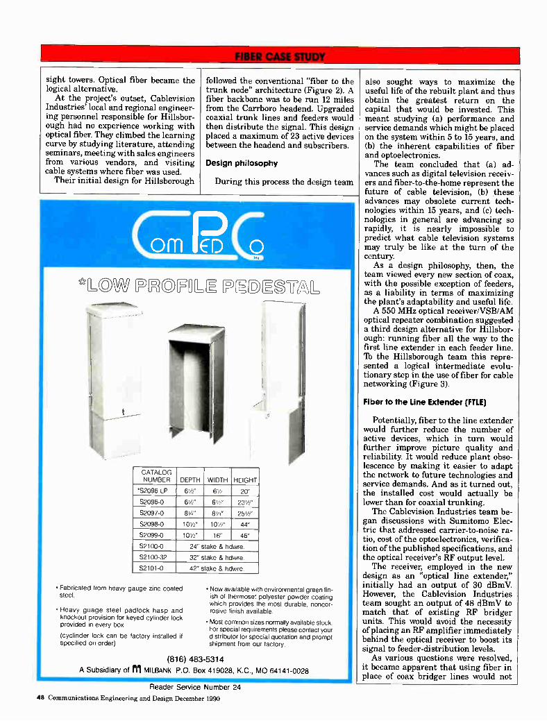
sight towers. Optical fiber became the logical alternative. At the project's outset, Cablevision
Industries' local and regional engineer-ing personnel responsible for Hillsbor-ough had no experience working with optical fiber. They climbed the learning curve by studying literature, attending seminars, meeting with sales engineers from various vendors, and visiting cable systems where fiber was used.
Their initial design for Hillsborough
followed the conventional "fiber to the trunk node" architecture (Figure 2). A fiber backbone was to be run 12 miles from the Can-boro headend. Upgraded coaxial trunk lines and feeders would then distribute the signal. This design placed a maximum of 23 active devices between the headend and subscribers.
Design philosophy
During this process the design team
CCECO
e,CDM II CDFLE EDIE2L
CATALOG NUMBER DEPTH WIDTH HEIGHT
'S2096-LP 61/2 61/2 20"
S2096-0 61/2" 6 le 23 1/2"
S2097-0 81/4 " 81/4 " 25 1/2"
S2098-0 10 1/2 " 101/2 " 44"
S2099-0 101/2" 16" 46"
S2100-0 24" stake & hdwre
S2100-32 32" stake & hdwre
S2101-0 42" stake & hdwre
• Fabricated from heavy gauge zinc coated steel.
• Heavy guage steel padlock hasp and knockout provision for keyed cylinder lock provided in every box.
(cyclinder lock can be factory installed if specified on order)
• Now available with environmental green fin-ish of thermoset polyester powder coating which provides the most durable, noncor-rosive finish available.
• Most common sizes normally available stock. For special requirements please contact your distributor for special quotation and prompt shipment from our factory.
(816) 483-5314
A Subsidiary of Ill MILBANK P.O. Box 419028, KG., MO 64141-0028 44
also sought ways to maximize the useful life of the rebuilt plant and thus obtain the greatest return on the capital that would be invested. This meant studying (a) performance and service demands which might be placed on the system within 5 to 15 years, and (b) the inherent capabilities of fiber and optoelectronics. The team concluded that (a) ad-
vances such as digital television receiv-ers and fiber-to-the-home represent the future of cable television, (b) •these advances may obsolete current tech-nologies within 15 years, and (c) tech-nologies in general are advancing so rapidly, it is nearly impossible to predict what cable television systems may truly be like at the turn of the century As a design philosophy, then, the
team viewed every new section of coax, with the possible exception of feeders, as a liability in terms of maximizing the plant's adaptability and useful life. A 550 MHz optical receiver/VSB/AM
optical repeater combination suggested a third design alternative for Hillsbor-ough: running fiber all the way to the first line extender in each feeder line. lb the Hillsborough team this repre-sented a logical intermediate evolu-tionary step in the use of fiber for cable networking (Figure 3).
Fiber to the Line Extender (FTLE)
Potentially, fiber to the line extender would further reduce the number of active devices, which in turn would further improve picture quality and reliability. It would reduce plant obso-lescence by making it easier to adapt the network to future technologies and service demands. And as it turned out, the installed cost would actually be lower than for coaxial trunking. The Cablevision Industries team be-
gan discussions with Sumitomo Elec-tric that addressed carrier-to-noise ra-tio, cost of the optoelectronics, verifica-tion of the published specifications, and the optical receiver's RF output level. The receiver, employed in the new
design as an "optical line extender," initially had an output of 30 dBmV. However, the Cablevision Industries team sought an output of 48 dBmV to match that of existing RF bridger units. This would avoid the necessity of placing an RF amplifier immediately behind the optical receiver to boost its signal to feeder-distribution levels. As various questions were resolved,
it became apparent that using fiber in place of coax bridger lines would not
Reader Service Number 24
48 Communications Engineering and Design December 1990
WESTEC
Design Manufacturing
Repair Modification
WESTEC CARS BAND Transmitters (TWT or Klystron)
Self-contained Power Supply
(reduced rack space)
Receivers Bandwidth 450 MHz
Phase Lock
Indoor/Outdoor
New Replacement Modules Repair and Modification
11\
Solid State Sources Upconverters Transmitters Receivers - Phase Lock & BW Mods Rebuilt Klystrons
Booth #1516 Western Show
Long Life Rebuilt
KLYSTRONS
• Standard and Long Term Warranty
• Off the shelf exchanges
• Price savings = 35%
• State-of-the-art cathode material
• Over temp indicators
• Test data with each Klystron
Westec products and services over the past 12 years are the results of our customers' input. Please let us know your requirements.
404' Bob O'Hara
WeTEC COMMUNIMIONS, INC. 14405 N. Scottsdale Road, Scottsdale, Arizona 85254
(602) 948-4484 FAX: (602) 998-8701 Microwave Service (800) 666-4441
Reader Service Number 25
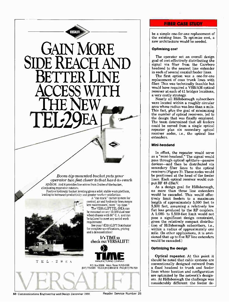
gm> GAIN MORE
SIDE REACH AND BETTER LINE ACCESS WITH THE NEW 11129
<O>.
dal"
Boom-tip-mounted bucket puts your operator two feet closer to that hard-to-reach
splice. And it provides line access from 3 sides of the bucket, eliminating expensive rotators.
Positive hydraulic bucket leveling gives a solid, stable work platform, leading to increased productivity and greater worker satisfaction.
A "cat-track" carrier system for control, air and hydraulic lines means less maintenance, more "up-time."
The VERSALIFT TEL-29EA can be mounted on any 10,500 dual rear wheel chassis with 60" C.A. and can be tailored to meet any aerial work requirement.
See your VERSALIFT Distributor for complete specifications, pricing• and a demonstration!
TEL-29EA
It's TIME to check out VERSALIFT!
TIME MANUFACTURING COMPANY
P.O. Box 20368 Waco, Texas 76702-0368 (817) 776-0900 TELEX (910) 894-5218 FAX (817)776-7531
be a simple one-for-one replacement of the existing lines. 'lb optimize cost, a new architecture would be needed.
Optimizing cost
The operator set an overall design goal of cost-effectively distributing the signal via fiber from the Carrboro headend to the nearest line extender in each of several coaxial feeder lines. The first option was a one-for-one
replacement of coax trunk lines with fiber. This was technically feasible but would have required a VSB/AM optical receiver at each of 41 bridger locations, a very costly strategy.
Nearly all Hillsborough subscribers were located within a roughly circular area whose radius was less than a mile. This fact, plus the goal of minimizing the number of optical receivers, led to the design that was finally employed. The team determined that all feeders could be served from a single optical repeater plus six secondary optical receiver nodes, i.e., the optical line extenders.
Mini-headend
In effect, the repeater would serve as a "mini-headend." The signal would pass through optical splitters—passive devices—and then be distributed via secondary fiber lines to the optical receivers (Figure 3). These nodes would be positioned at the head of the feeder lines. Each optical receiver would out-put RF 48 dBmV. As a design goal for Hillsborough,
no more than three line extenders would be cascaded. This would effec-tively limit feeders to a maximum length of approximately 5,000 feet to 5,500 feet, assuming a relatively low flat loss produced by the RF couplers. A 5,000- to 5,500-foot limit would not pose a significant design constraint, given the relatively compact distribu-tion of Hillsborough subscribers, i.e., within a radius of approximately one mile. (In other applications, it is envi-sioned that up to five RF line extenders would be cascaded.)
Optimizing the design
Optical repeater. At this point it should be noted that cable systems are conventionally designed outward from a fixed headend to trunk and feeder lines whose location and configuration are optimized by the network's design-ers. At Hillsborough the challenge was considerably different: the feeder de-
50 Communications Engineering and Design December 1990 Reader Service Number 26
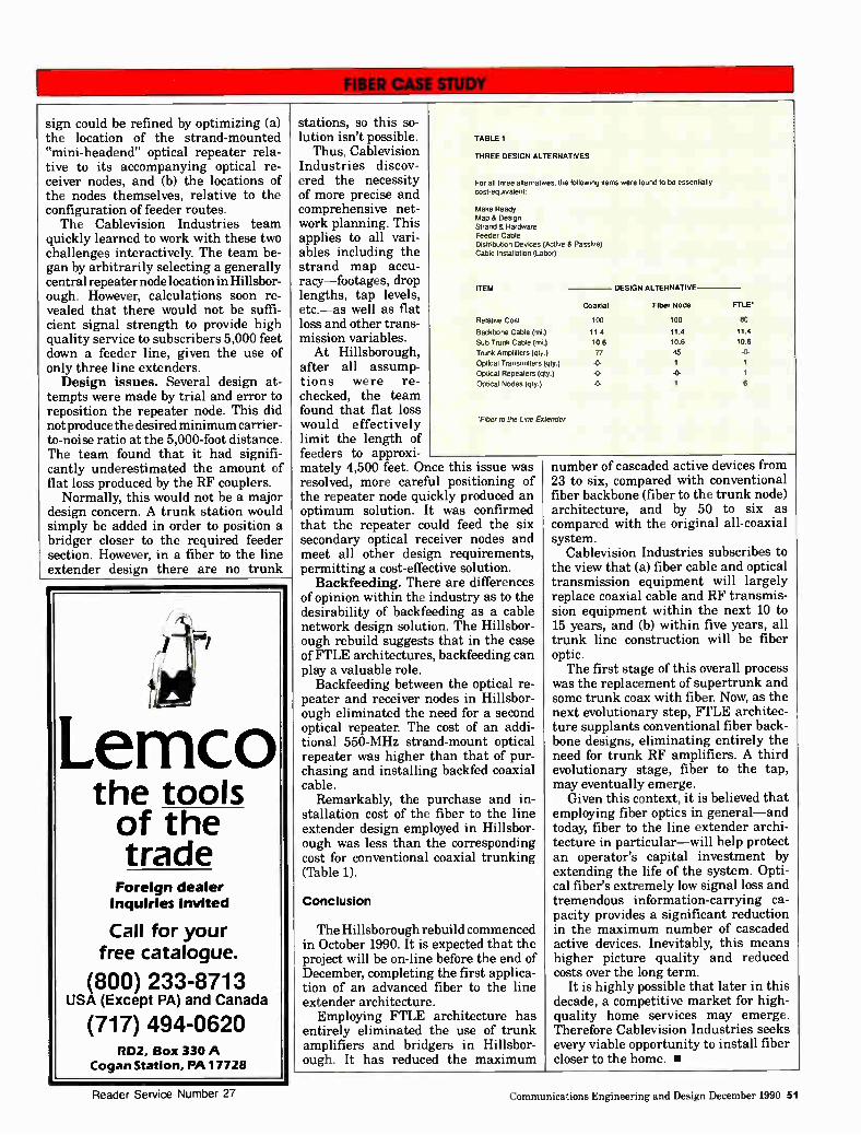
sign could be refined by optimizing (a) the location of the strand-mounted "mini-headend" optical repeater rela-tive to its accompanying optical re-ceiver nodes, and (b) the locations of the nodes themselves, relative to the configuration of feeder routes. The Cablevision Industries team
quickly learned to work with these two challenges interactively. The team be-gan by arbitrarily selecting a generally central repeater node location in Hillsbor-ough. However, calculations soon re-vealed that there would not be suffi-cient signal strength to provide high quality service to subscribers 5,000 feet down a feeder line, given the use of only three line extenders. Design issues. Several design at-
tempts were made by trial and error to reposition the repeater node. This did not produce the desired minimum carrier-to-noise ratio at the 5,000-foot distance. The team found that it had signifi-cantly underestimated the amount of flat loss produced by the RF couplers.
Normally, this would not be a major design concern. A trunk station would simply be added in order to position a bridger closer to the required feeder section. However, in a fiber to the line extender design there are no trunk
Lemco the tools of the trade
Foreign dealer inquiries invited
Call for your free catalogue.
(800) 233-8713 USA (Except PA) and Canada
(717) 494-0620 RD2, Box 330 A
Cogan Station, PA 17728
stations, so this so-lution isn't possible.
Thus, Cablevision Industries discov-ered the necessity of more precise and comprehensive net-work planning. This applies to all vari-ables including the strand map accu-racy—footages, drop lengths, tap levels, etc.—as well as flat loss and other trans-mission variables. At Hillsborough,
after all assump-tions were re-checked, the team found that flat loss would effectively limit the length of feeders to approxi-mately 4,500 feet. Once this issue was resolved, more careful positioning of the repeater node quickly produced an optimum solution. It was confirmed that the repeater could feed the six secondary optical receiver nodes and meet all other design requirements, permitting a cost-effective solution.
Backfeeding. There are differences of opinion within the industry as to the desirability of backfeeding as a cable network design solution. The Hillsbor-ough rebuild suggests that in the case of FTLE architectures, backfeeding can play a valuable role.
Backfeeding between the optical re-peater and receiver nodes in Hillsbor-ough eliminated the need for a second optical repeater. The cost of an addi-tional 550-MHz strand-mount optical repeater was higher than that of pur-chasing and installing !melded coaxial cable.
Remarkably, the purchase and in-stallation cost of the fiber to the line extender design employed in Hillsbor-ough was less than the corresponding cost for conventional coaxial trunking (Table 1).
TABLE 1
THREE DESIGN ALTERNATIVES
For all three alternatives, the following items were found to be essentially cost-equivalent:
Make Ready Map & Design Strand & Hardware Feeder Cable Distribution Devices (Active & Passive) Cable Installation (Labor)
ITEM
Relative Cost
Backbone Cable (mi.)
Sub Trunk Cade (rni.)
Trunk Amplifiers (qty.)
Optical Transmitters (qty.)
Optical Repeaters (qty.)
Optical Nodes (qty.)
Tiber to the Line Extender
Coaxial
100
11.4
10.6
77
-0-
-0-
-0-
DESIGN ALTERNATIVE
Fiber Node
100
11.4
10.6
45
1
1
FILE*
80
11.4
106
-0-
1
1
6
Conclusion
The Hillsborough rebuild commenced in October 1990. It is expected that the project will be on-line before the end of December, completing the first applica-tion of an advanced fiber to the line extender architecture.
Employing FTLE architecture has entirely eliminated the use of trunk amplifiers and bridgers in Hillsbor-ough. It has reduced the maximum
number of cascaded active devices from 23 to six, compared with conventional fiber backbone (fiber to the trunk node) architecture, and by 50 to six as compared with the original all-coaxial system.
Cablevision Industries subscribes to the view that (a) fiber cable and optical transmission equipment will largely replace coaxial cable and RF transmis-sion equipment within the next 10 to 15 years, and (b) within five years, all trunk line construction will be fiber optic. The first stage of this overall process
was the replacement of supertrunk and some trunk coax with fiber. Now, as the next evolutionary step, FTLE architec-ture supplants conventional fiber back-bone designs, eliminating entirely the need for trunk RF amplifiers. A third evolutionary stage, fiber to the tap, may eventually emerge.
Given this context, it is believed that employing fiber optics in general—and today, fiber to the line extender archi-tecture in particular—will help protect an operator's capital investment by extending the life of the system. Opti-cal fiber's extremely low signal loss and tremendous information-carrying ca-pacity provides a significant reduction in the maximum number of cascaded active devices. Inevitably, this means higher picture quality and reduced costs over the long term.
It is highly possible that later in this decade, a competitive market for high-quality home services may emerge. Therefore Cablevision Industries seeks every viable opportunity to install fiber closer to the home. •
Reader Service Number 27 Communications Engineering and Design December 1990 51
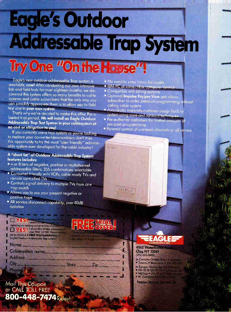
a e's Outdoor
Eagle's new outdoor addressable Trap system is available, now! After conducting our own intensive lab and field tests for over eighteen months, we dis-covered this system offers so many benefits to cable systems and cable subscribers that the only way you cc n possibly appreciate them is to allow you to field test one in your own system.
That's why we've dec ded to make this offer. For a limited trial period, We will install an Eagle Outdoor Addressable Trap Test System in your cablesystem at no cost or obligation to you!
If you currently use d trap system or you're looking to replace your converter/descramblers don't miss this opportunity to try the most "user friendly" address-able system ever developed for the cable industry!
A "short list" of Outdoor Addressable Trap System features includes: • L. or 8 tiers of negative, positive or multichannel addressable filters; 256 combinations selectable • Consumer f-iendly wit,-IVCRs, cable ready TVs and remote cont-olled TVs • Controls s,g la' delivery to multiple TVs from one tap switch
• Allows you to use your present negative or positive traps
• All service disconnect capability; over 80dB isolation
replaci 'èbrèrfdeecram .
I CI YES 8 '-would like to take advantage o your FREE OFFER. Please contaFtr:
I me to schedule a FREE trial installation of Eagle's Outdoor Addressable Trap system.'
Mail This Coupon or CALL TOLL FREE
800.-448••7474Today!
• No need to enter home for audits • IBM PC or compatible computer rontro • Compatible with billing systems • Optional Impulse Pay per View unit allows
subscriber to order premium programming without calling cable system
• Auto-dialer transmits customer usage back to system using store and forward techniques
• Pre-authorize customers for limited amounts of pre-paid programming
• Parental control of premium channels or all service
:discretion d Eagreto'm At)
it
4562 Water Clay, NY 13041 (3151 622-3402
In Canada: Deskin Sales • Manfred • Toronto • Vancouver • 416-475-1412'
in Europe: Electro • 011,32-15-20-95-_, • t\torinny • 011, _ • W. Germa
- Read .
,à11 sit
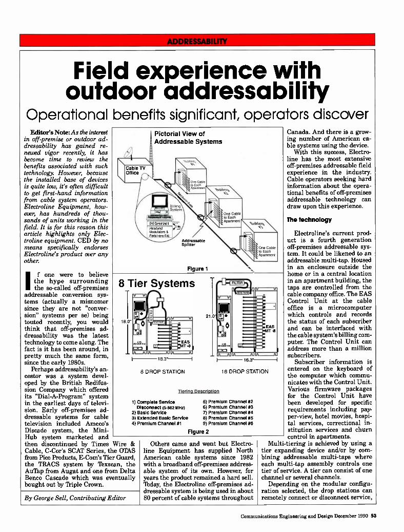
Field experience with outdoor addressability
Operational benefits significant, operators discover Editor's Note: As the interest
in off-premise or outdoor ad-dressability has gained re-newed vigor recently, it has become time to review the benefits associated with such technology. However, because the installed base of devices is quite low, it's often difficult to get first-hand information from cable system operators. Electroline Equipment, how-ever, has hundreds of thou-sands of units working in the field. It is for this reason this article highlights only Elec-troline equipment. CED by no means specifically endorses Electroline's product over any other.
If one were to believe the hype surrounding the so-called off-premises
addressable conversion sys-tems (actually a misnomer since they are not "conver-sion" systems per se) being touted recently, you would think that off-premises ad-dressability was the latest technology to come along. The fact is it has been around, in pretty much the same form, since the early 1980s.
Perhaps addressability's an-cestor was a system devel-oped by the British Redifus-sion Company which offered its "Dial-A-Program" system in the earliest days of televi-sion. Early off-premises ad-dressable systems for cable television included Ameco's Discade system, the Mini-Hub system marketed and then discontinued by Times Wire & Cable, C-Cor's SCAT Series, the OTAS from Pico Products, E-Com's Tier Guard, the TRACS system by Texscan, the Au'Pap from Augat and one from Delta Benco Cascade which was eventually bought out by Triple Crown.
tt.
Cable TV Office
Pictorial View of Addressable Systems
\n.
One Cable to Each Apartment
BtlItng System
- Ett≤Cera ten ---:-
Headend Modulators et Receurers Etc
Addressable Splitter
Figure 1
One Cable to Each Aparlment
One Cable \ \ •rr, lo Each
Apartment
8 Tier Systems -
16.3"
8 DROP STATION
Tiering Description
1) Complete Service Disconnect (5-862 MHz)
2) Basic Service 3) Extended Basic Service 4) Premium Channel #1
16.3"
16 DROP STATION
5) Premium Channel #2 6) Premium Channel #3 7) Premium Channel #4 8) Premium Channel #5 9) Premium Channel #6
Figure 2
By George Sell, Contributing Editor
Others came and went but Electro-line Equipment has supplied North American cable systems since 1982 with a broadband off-premises address-able system of its own. However, for years the product remained a hard sell. 'Ibday, the Electroline off-premises ad-dressable system is being used in about 80 percent of cable systems throughout
Canada. And there is a grow-ing number of American ca-ble systems using the device. With this success, Electro-
line has the most extensive off-premises addressable field experience in the industry. Cable operators seeking hard information about the opera-tional benefits of off-premises addressable technology can draw upon this experience.
The technology
Electroline's current prod-uct is a fourth generation off-premises addressable sys-tem. It could be likened to an addressable multi-tap. Housed in an enclosure outside the home or in a central location in an apartment building, the taps are controlled from the cable company office. The EAS Control Unit at the cable office is a microcomputer which controls and records the status of each subscriber and can be interfaced with the cable system's billing com-puter. The Control Unit can address more than a million subscribers.
Subscriber information is entered on the keyboard of the computer which commu-nicates with the Control Unit. Various firmware packages for the Control Unit have been developed for specific requirements including pay-per-view, hotel movies, hospi-tal services, correctional in-stitution services and churn control in apartments.
Multi-tiering is achieved by using a tier expanding device and/or by com-bining addressable multi-taps where each multi-tap assembly controls one tier of service. A tier can consist of one channel or several channels.
Depending on the modular configu-ration selected, the drop stations can remotely connect or disconnect service,
Communications Engineering and Design December 1990 53
or control anywhere from two tiers (total service or basic and/or extended basic) up to eight tiers (total service, basic, extended basic and six premium channels). The number of drops per station
range from four to 64 for either the single tier or the two tier units, and from four to 16 drops for the eight tier units. The most popular drop stations are the single tier and two tier units.
Operational benefits
There are some obvious and not so obvious operational benefits of such a system. Perhaps the most obvious is that it provides remote automated connect/disconnect and authorization. This often radically reduces the num- ber of truck rolls and technician service calls. Automating the connect/discon- nect process means skilled technical staff can concentrate on other pressing tasks,
This gives the operator the capabil- ity of conducting an exact audit from the office using the control computer. An off-premises addressable system
increases drop cable and connector reliability (an important consideration to operators concerned about signal
leakage) because drops are handled less frequently. With automated con- nection and disconnection, installers and technicians can usually install the drop once and may never touch it again,
subscriber dissatisfaction with set-top addressability can be eliminated if the configuration installed allows for the removal of the set-top addressable converter. Off-premises technology, when used to its fullest potential, can eliminate all use of headend scram-bling of services. The signal degrada-tion caused by scrambling and the equipment costs associated with it, including both the electronics at the headend and the expensive set-top converter/descrambler, could be a thing of the past. The remote multi-tiering capability
gives the cable operator enhanced flexi-bility for marketing of services target-ing subscribers that are signed up only for basic service. The potential sub-scriber can sample the service during a marketing trial offer. The cable operator has the same
automated flexibility in controlling pay-per-view. This can give the cable industry a long-term advantage in addressable pay-per-view relative to competition from Direct Broadcast Sat-ellite and the telephone industry.
Field applications
While it's easy to list the theoretical advantages of off-premises addressabil-
An off-premises
addressable system increases drop cable
and connector
reliability
When cable-ready consumer elec- tronics are in the home, broadband off-premises technology permits such equipment to work to their best advan- tage. Of course, because the customer
receives the signals without a set-top addressable converter, the temptation to steal the signal by tampering with an expensive in-home addressable con- verter is removed. Also, the widespread
Why do technicians prefer RISER-BOND INTRUMENTS
TDR'S?
The answer is SIMPLE!
Model 1210 $4395 Model 2901B+ $845
TIME DOMAIN RELECTOMETER
Cable Fault Locator
-RISER-BOND INSTRUMENTS
"High Tech Simplicity"
5101 North 57th St. Lincoln, NE 68507
800/ 688-8377
INTRODUCING...
THREE-STAR
I Quality Passives I Competitive
Prices II Available NOW!
Call your nearest distributor: Jerry Conn Associates, Inc. (East) (800) 233-7600 outside PA (800) 692-7370 inside PA
Signal Vision (West) (714) 586-3196
John Weeks Enterprises, Inc. (South) (404) 962-1020 (800) 241-1232
Reader Service Number 30 Reader Service Number 29
54 Communications Engineering and Design December 1990
THE FUTURE TREND IN THE CABLE INDUSTRY IS TOWARDS COMPLETE AUTOMATION
ARE YOU READY?... TPC recognizes that a product's value is more than just innovative design and stringent quality assurance. It's the service you get too! TPC gives the best customer service in the cable business.
We offer a full line of automation and commercial insertion equipment. We are committed to quality and customer satisfaction. All of our products are designed for high reliability and ease of operation. And our status as a Novell Authorized Reseller and authorized dealer for Sony and Everex equipment gives us the edge in providing quality systems.
TPC manufactures many products for the cable industry. Call us today and we will help you design the right system for your automation needs.
Commercial Insertion
• Nexus True Spot Random Access
• Medius Random Pod
• ON-Q Dynamic Pod Sequential
Automation • Queue Master Headend Automation & Control
• Barker System Automated Pay-Per-View Promotion
• CASEY Automated Syndex & Non-Dupe Switching
Software • ADministrator Spot Random Trafficking & Billing
• ADpod Random Pod Trafficking & Billing
• CLIDE Cumulative Leakage Index Management
Test Equipment • PVM-1000 Peak Audio Meter
• CGV Video Comb Generator
• NVU Video Noise Generator
Cable's Automation Experts
Telecommunication Products Corporation 1331 South 7th St.
P.O. Box 476 Chambersburg, PA 17201
(717) 267-3939 Reader Service Number 31
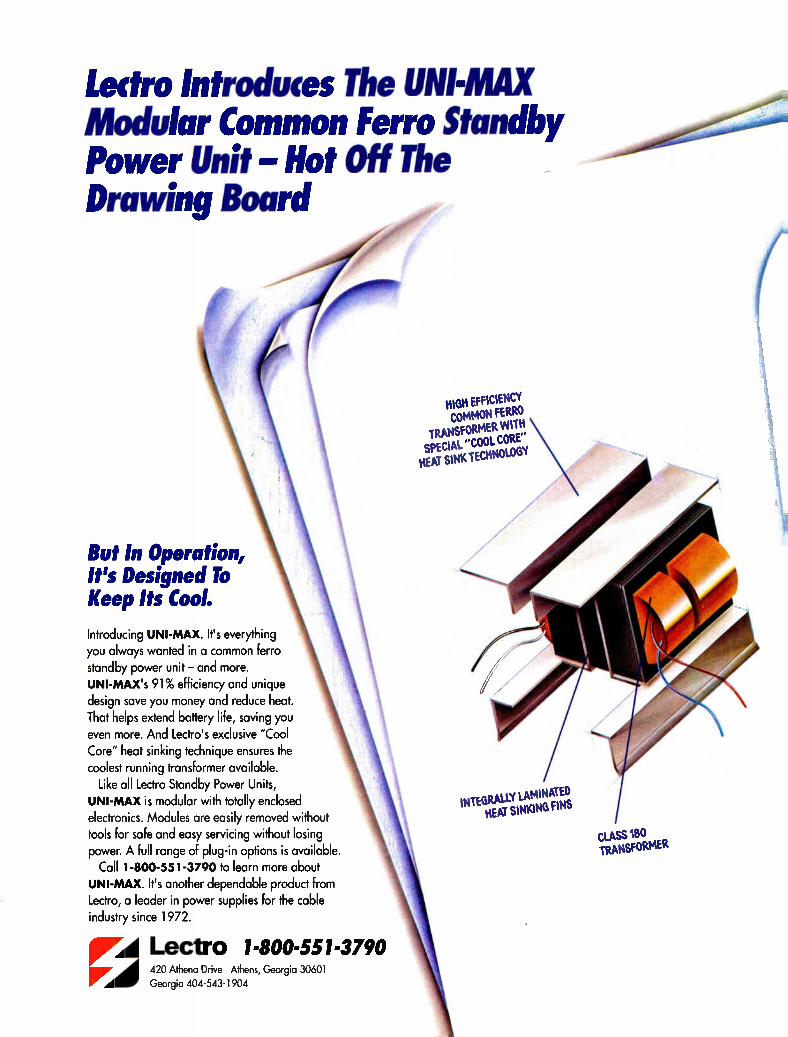
Leek° Introduces The UNI-MAX Modular Common Ferro Standby Power Unit Hot Off The Drawing Board
to»
But In Operation, It's Designed To Keep Its Cool.
Introducing UNI-MAX. It's everything you always wanted in a common ferro standby power unit — and more. UNI-MAX's 91% efficiency and unique design save you money and reduce heat. That helps extend battery life, saving you even more. And Lectro's exclusive "Cool Core" heat sinking technique ensures the coolest running transformer available.
Like all Lectro Standby Power Units, UNI-MAX is modular with totally enclosed electronics. Modules are easily removed without tools for safe and easy servicing without losing power. A full range of plug-in options is available.
Call 1-800-551-3790 to learn more about UNI-MAX. It's another dependable product from Lectro, a leader in power supplies for the cable industry since 1972.
rA Lectro 1-800-551-3790 420 Athena Drive Athens, Georgia 30601
Georgia 404-543-1904
HIGH EFFICIENCY COMMON FERRO
TRANSFORMER WITH SPECIAL "COOL CORE" HEAT SINK 'TECHNOLOGY
NIEGRALLY LAMINATED I HEAT SINKING FINS
cues 180 TRANSFORMER
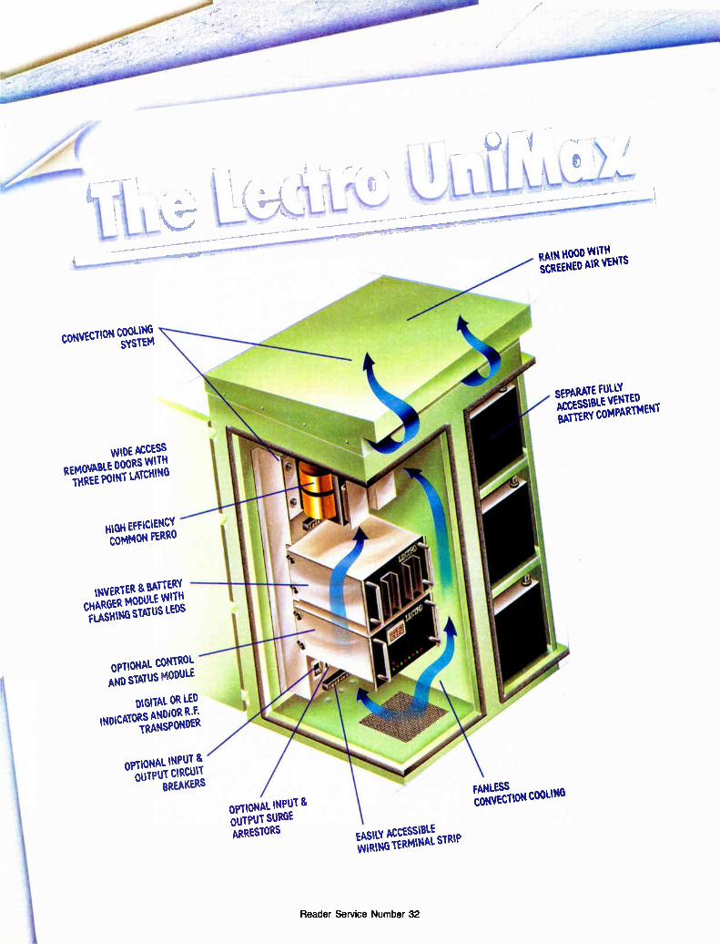
CONVECTION COOLING SYSTEM
WIDE ACCESS
REMOVABLE DOORS WITH THREE POINT LATCHING
HIGH EFFICIENCY COMMON FERRO
INVERTER & BATTERY CHARGER MODULE WITH FLASHING STATUS LEDS
OPTIONAL CONTROL AND STATUS MODULE
DIGITAL OR LED
INDICATORS ANDIOR R F TRANSPONDER
OPTIONAL INPUT & OUTPUT CIRCUIT
BREAKERS
OPTIONAL INPUT 8. OUTPUT SURGE ARRESTORS EASILY ACCESSIBLE
WIRING TERMINAL STRIP
Reader Service Number 32
RAIN HOOD WITH SCREENED AIR VENTS
SEPARATE FULLY ACCESSIBLE VENTED BATTERY COMPARTMENT
FANLESS CONVECTION COOLING
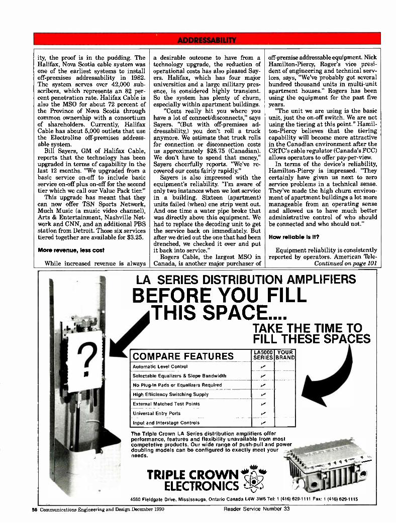
ity, the proof is in the pudding. The a desirable outcome to have from a off-premise addressable equipment. Nick Halifax, Nova Scotia cable system was technology upgrade, the reduction of Hamilton-Piercy, Roger's vice presi-one of the earliest systems to install operational costs has also pleased Say- dent of engineering and technical serv-off-premises addressability in 1982. ers. Halifax, which has four major ices, says, "We've probably got several The system serves over 42,000 sub- universities and a large military pres- hundred thousand units in multi-unit scribers, which represents an 82 per- ence, is considered highly transient. apartment houses." Rogers has been cent penetration rate. Halifax Cable is also the MSO for about 72 percent of
So the system has plenty of churn, especially within apartment buildings.
using the equipment for the past five years.
the Province of Nova Scotia through "Costs really hit you where you "The unit we are using is the basic common ownership with a consortium have a lot of connect/disconnects," says unit, just the on-off switch. We are not of shareholders. Currently, Halifax Sayers. "(But with off-premises ad- using the tiering at this point." Hamil-Cable has about 5,000 outlets that use dressability,) you don't roll a truck ton-Piercy believes that the tiering the Electroline off-premises address- anymore. We estimate that truck rolls capability will become more attractive able system. for connection or disconnection costs in the Canadian environment after the
Bill Sayers, GM of Halifax Cable, reports that the technology has been
us approximately $28.75 (Canadian). We don't have to spend that money,"
CRTC's cable regulator (Canada's FCC) allows operators to offer pay-per-view.
upgraded in terms of capability in the last 12 months. "We upgraded from a
Sayers cheerfully reports. "We've re- covered our costs fairly rapidly."
In terms of the device's reliability, Hamilton-Piercy is impressed. "They
basic service on-off to include basic Sayers is also impressed with the certainly have given us next to zero service on-off plus on-off for the second equipment's reliability. "I'm aware of service problems in a technical sense. tier which we call our Value Pack tier." only two instances when we lost service They've made the high churn environ-
This upgrade has meant that they in a building. Sixteen (apartment) ment of apartment buildings a lot more can now offer TSN Sports Network, units failed (when) one strip went out. manageable from an operating sense Much Music (a music video channel), And one time a water pipe broke that and allowed us to have much better Arts & Entertainment, Nashville Net- was directly above this equipment. We administrative control of who should work and CNN, and an additional PBS had to replace the decoding unit to get be connected and who should not." station from Detroit. Those six services the service back on immediately. But tiered together are available for $3.25. after we dried out the one that had been
drenched, we checked it over and put How reliable is it?
More revenue, less cost it back into service." Equipment reliability is consistently Rogers Cable, the largest MSO in reported by operators. American 'Ale-
While increased revenue is always Canada, is another major purchaser of Continued on page 101
LA SERIES DISTRIBUTION AMPLIFIERS
BEFORE YOU FILL THIS SPACE....
TAKE THE TIME TO FILL THESE SPACES
COMPARE FEATURES Automatic Level Control
Selectable Equalizers & Slope Bandwidth
No Plug-In Pads or Equalizers Required
LA5000 SERIES
YOUR BRAND
High Efficiency Switching Supply
External Matched Test Points
Universal Entry Ports
Input and Interstage Controls
The Triple Crown LA Series distribution amplifiers offer performance, features and flexibility unavailable from most competetive products. Our wide range of push•pull and power doubling models can be configured to exactly meet your ,. needs. —defog
TRIPLE CROWN ELECTRONICS ••"2!
4560 Fieldgate Drive, Mississauga. Ontario Canada L4W 3W6 Tel: 1 (416) 629.1111 Fax. 1 (416) 629-1115
58 Communications Engineering and Design December 1990 Reader Service Number 33
1988-1990
ditorial
Index Cable television's only complete guide to technical articles
Delivery off the Shelf
As Good As New And SAVE $1 000.° WESTEC — Your AML Support System
"CPR for AML"
(602) 948-4484
I
WESTEC COMMUNICATIONS
....
14405 N. Scottsdale Road, Scottsdale, Arizona 85254
Microwave Service (800) 666-4441 FAX (602) 998-8701 Reader Service Number 34
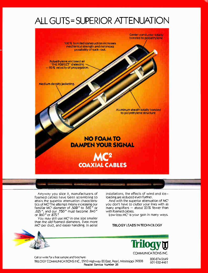
ALL GUTS= SUPERIOR ATTENUATION Center conductor totally bonded to polyethylene
100% bonded construction increases mechanical strength and minimizes
possibility of suck—out.
Polyethylene enclosed air THE PERFECT" dielectric
—93% velocity of propagation.
Medium density jacketing.
Aluminum sheath totally bonded to polyethylene structure.
NO FOAM TO DAMPEN YOUR SIGNAL
imembilimimmaim
Anyway you slice it, manufacturers of foamed cables have been scrambling to attain the superior attenuation characteris-tics of Me The attempt means increasing our familiar MC' diameter of .500" to .565" or .625 "; and our .750" must become .840" or .860" or .875 You may still use MC2 in one size smaller
than the old foamed diameters. Even more MC2 per duct, and easier handling. In aerial
,tê‘ „Iéritj.
installations, the effects of wind and ice-loading are reduced even further. And with the superior attenuation of MC2
you don't have to clutter your lines with as many amplifiers - about 20% fewer than with foamed cables.
Low-loss MC2 is your gain in many ways.
TRILOGY LEADS IN TECHNOLOGY
AIM
COMMUNICATIONS INC. Call or write for a free sample and brochure:
800-874-5649 TRILOGY COMMUNICATIONS INC., 2910 Highway 80 East, Pearl, Mississippi 39208 601-932-4461
Reader Service Number 35
Editoria
Table of Addressability 68
Advanced television 68
Amateur radio 70
Amplifiers 70
Antennas and earth stations 70
Audio 71
Back to Basics 71
Billing systems 71
Blonder's View 71
Capital Currents 72
Ciciora's Forum 72
Ciciora's Page 72
Commercial insertion 72
Competing technologies 74
Connectors 74
Construction techniques 74
Consumer interface 76
Converters 78
Correspondent's Report 78
Customer service 78
Data communication and LANs 78
Digital technology 78
Distortions and interference 78
Encryption 82
Engineering management 82
FCC and regulations 82
Fiber optics 82
From the headend 88
I Index
ontents Frontline 88
Grounding, bonding and lightning 89
Headends 89
International considerations 90
ISDN 90
Looking Ahead 90
Maintenance 90
Microwave 90
My Turn 90
My View 90
NCTA Notes 92
Pay-per-view 92
Powering 92
Satellites 92
SCTE 93
Signal leakage 93
Small system considerations 94
Spotlight 94
Standards 96
Status monitoring 96
Syndicated exclusivity 96
System design 96
Taylor's vantage 96
Tech book 97
Tech tips 97
Tests and measurements 97
Training and education 98
Two-way communication 98
Video compression 98
©1990 by Diversified Publishing Group. All rights reserved. CED. (USPS 330-510) (ISSN 1044-2871) is published monthly except twice in May by Diversified Publishing Group, a Division of Capital Cities Media, Inc., 825 7th Ave., New York, NY 10019. .'December 1990, Volume 16, Number 13. Subscriptions free to qualified industry readers. All other one-year subscriptions are $36, prepaid in U.S. funds only. Second-class postage paid at New NY 10019 and additional mailing offices. CED is published on behalf of the cable television and broadband communications industries. POSTMASTER: Please send address changes to CED Circulation, PO. Box 3043, S. Eastern PA 19398. MEMBERS OF THE BPA.
64 Communications Engineering and Design December 1990

WE'VE MADE THE FIRST CASE FOR RECYCLING.
Comm/Scope, the cable leader, now leads the way in helping solve some of the environmental issues and concerns you may have by introducing the first recy-clable drop cable box.
We know the problems and costs you face when prop-erly disposing of other empty cable boxes. Recycling centers won't take them. Landfills are either refusing to take them or are charging you more and more to accept them.
Our recyclable box means you don't have to pay for disposal. And recyclable doesn't mean second-rate. This box is just as strong and durable as any non-
recyclable box. It resists moisture. Es bursting strength is the same as our old box. It is stackable. It is laboratory and field proven to hold up under even the most ex-treme conditions. It is even made from recycled paper. But it won't harm the environment.
For more information about our recyclable boxes as well as other measures Comm/Scope has taken to help improve our environment, contact your nearest Comm/Scope representative or call us at (800) 982-1708 or (7C4) 324-2200.
Comm/Scope, Inc. THE Cable in CableiV
Con-urn/Scope, Inc., PO. Box 1729, Hickory NC 28602. Phone: (800) 982-1708 or (704) 324-2200.
Fax: (704) 328-2400. Reader Service Number 36

How to use this editorial index Keeping up with the accelerating pace of technological innovation is tough;
keeping track of informative technical articles that are published in the cable television trade journals is nearly impossible. But now, with the introduction of this editorial index to the industry's technical articles, the task just became much easier. Welcome to the industry's first all-inclusive index to technical articles. Over
the years, we've had repeated demands by our readers for an editorial index to CED magazine. But we decided to take it one step further and the result is a more useful product for you, the reader—this all-inclusive roster of technical articles that have appeared over the past three years in CED, CableVision, Communications Technology and Cable Television Business magazines. The index is divided into broad topics of interest, with articles that pertain
to that subject listed alphabetically underneath. As shown below, the article title is shown in bold type, followed by the publication in which it appeared, the author and page number. In many cases, a short description of the article is also included.
Converters
Category (listed alphabetically)
Article title (listed alphabetically)
Battling the cable converter pirates, (CED), GeorgeSell,CED,Novernber1989,P.44.Safeguards Publication
Author—, that manufactu and converter *r houses have in place to prey t converter
Issue
Description
Articles that encompass multiple subjects are often listed under more than one subject area. However, space limitations prohibited this practice in all cases. Therefore, stories are listed in the category which dominates the story's theme. For example, a story about using filters in the headend to reduce distortions could be listed under "Distortions" and "Headends." However, it may only appear under "Distortions" because that is the primary theme of the article.
This index covers articles that were published between January 1988 and October 1990. For information about any of the articles listed, please call or write the editor of the publication in which the story was published: • CED: 600 S. Cherry St., Ste. 400, Denver, Colo. 80222 (303) 393-7449. • CableVision: 825 7th Ave., 6th floor, New York, N.Y. 10019 (212) 887-8400. • Communications Technology: 50 S. Steele St., Ste. 500, Denver, Colo. 80209
(303) 355-2101. • Cable Television Business: 6300 S. Syracuse Way, Ste. 650, Englewood,
Colo. 80111 (303) 220-0600.
CED William McGorry, Group Publisher Robert C. Stuehrk, Associate Publisher
EDITORIAL Roger Brown Editor Leslie A. Miller Managing Editor Kathryn Berlin Contributing Editor George Sell Contributing Editor
CONSULTING ENGINEERS Chairman Wendell H. Bailey, NCTA VP, Science and Technology
MEMBERS Jim Chiddlx, Senior VP, Engineering and Technology, ATC Roy Ehman, Director of Engineering, Jones Intercable Tom Elliot, Director of Research and Development, Tele-Communications Inc. Jim Farmer, Principal Engineer, Scientific-Atlanta Paul Heimbach, VP Engineering, Viacom Networks Group Tom Jokerst, Regional Engineering Director, Continental Cablevision Fred Kaiser, President, Alpha Technologies Dave Large, Director of Engineering, Intermedia Partners Robert Luff, VP Engineering and Technology, Jones Intercable Ed Milner, VP Operations, Flight 'fl-ac Inc. Joe Van Loan, Senior VP Engineering, CableVision Industries
PRODUCTION Andy Cunningham, Production Director Don Ruth, Art Director Elaine Callahan, Production Manager Renee Jordan, Circulation Director
ADVERTISING Cathy Wilson, National Sales Manager Judy Medley, Account Executive
MARKETING AND SUPPORT Michelle Pazar, Author Support and Quality Assurance Linda Parker, SCTE Chapter Support
CAPTIAL CITIES/ABC, INC. DIVERSIFIED PUBLISHING GROUP Robert G. Burton, President Dean E. Cherry, VP Finance Risa Leibowitz, Director of Finance William McGarry, VP Group Publisher
OFFICE Denver 600 S. Cherry Street, Suite 400, Denver, CO 80222 (303) 393-7449. Fax (303) 393-6654.
66 Communications Engineering and Design December 1990
BUILT TO STAND THE TEST OF T
Few of the world's monuments with-stand the test of time and the ravages of the elements like the pyramids. And no standby power system lasts longer than Alpha Technologies' equipped with Dynasty gel batteries. The pyramids were built with one thing in mind: endurance. Just like Alpha power supplies and Dynasty batteries. Dynasty gel batteries outlive the com-
petition in the harsh en-vironments of cable tele-
a wide temperature range. Although they can be stored longer prior to use, you can avoid costly battery warehousing by us-ing Alpha's shipping service to put fresh batteries on your doorstep right when you are ready for them. Let's face it: a quality battery that lasts year after year costs less over time than a bargain bat-tery that needs replacement every 18 months
vision because they are co iJ designed to last. Unlike comegesoN
liquid-acid or absorbent glass mat technology. Dynasty batteries have real staying power over
TI I 11
ALPHA TECHNOLOGIES
No battery lasts for-ever. but Dynasty gel batteries pass the test of time like no others. And that can make a monu-mental difference in the reliability of your cable system.
3767 Alpha Way. Bellingham, WA 98226-8302 5700 Sidley St.. Burnaby, B.C. Vai 5E5 TELEPHONE: (206) 647-2360 FAX-. (206) 671-4936 TELEPHONE: (604) 430-1476 FAX: (604) 420-8908
Reader Service Numbe, 37
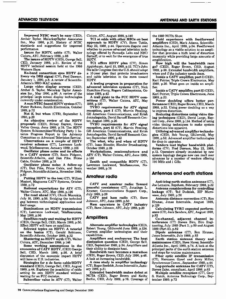
ADVANCED TELEVISION ANTENNAS AND EARTH STATIONS
Improved NTSC won't be easy (CED), Archer Taylor, Malarkey-Taylor Associates Inc., May 1988, p.10. History of NTSC standards and suggestions for improved performance.
Issues for HDTV, cable (CT), Walter Ciciora, ATC, February 1988, p.86 The issues of HDTV (CED), George Sell,
CED, January 1989, p.21. Review of the HDTV technical session held at the 1988 Western Show. Ku-band consortium eyes HDTV de-
livery via DBS signal (CV), Fred Dawson, January 1, 1990, p.8. A review of Scientific-Atlanta's HBD-MAC system. Large video display screens (CED),
Archer S. Taylor, Malarkey Taylor Associ-ates Inc., May 1990, p.96. A review of the principal large screen display technologies currently under consideration. A non-NTSC-based HDTV system (CT),
Pieter Fockens, Zenith Electronics, October 1989, p.72 Not if, but when (CTB), September 1,
1990, p.29 An objective review of the HDTV
proposals (CED), Birney Dayton, Grass Valley Group, June 1989, p.78. The HDTV System Subcommittee/Working Party 1 In-terim Progress Report to the Advisory Committee on Advanced Television Service.
Observations on a couple of HDTV receiver schemes (CT), Lawrence Lock-wood, IbleResources, January 1989, p.105
Oscillator phase noise and its effects in a CATV system (CT), Rezin Pidgeon, Scientific-Atlanta, and Dan Pike, Prime Cable, October 1988, p.78
Oscillator phase noise: A follow-up (CT), Dan Pike, Prime Cable, and Rezin Pidgeon, Scientific-Atlanta, November 1988, p.80
Putting HDTV to the test (CT), Willem Mostert, Magnavox CATV Systems, October 1988, p.72 Rational expectations for ATV (CT),
Walter Ciciora, ATC, May 1989, p.126 The road ahead (CV), Chuck Moozakis,
July 16, 1990, p.56. Bridging the technical gap between technological application and field usage. Ruminations on HDTV transmission
(CT), Lawrence Lockwood, IbleResources, May 1988, p.96
Satellites ready and waiting for HDTV (CED), George Sell, CED, March 1989, p.50. Effect HDTV will have on satellites.
Selected topics on HDTV: A tutorial on the basics (CT), Gerald Robinson, Scientific-Atlanta, October 1989, p.32
Shattering an HDTV myth (CT), Walter Ciciora, ATC, December 1988, p.146 Some working assumptions in the
economics of CATV HDTV, (CED) George Sell, CED, March 1989, p.56. A brief discussion of the economic impact HDTV will have on U.S. industries.
Strategies for a de facto cable/HDTV standard (CED), George Sell, CED, August 1989, p.44. Explores the possibility of cable setting its own HDTV standard without waiting for an FCC decision.
Subscriber value in ATV (CT), Walter
Ciciora, ATC, August 1989, p.140 TCI at odds with other MSOs on best
approach to HDTV (CV), Steve Tattle, May 22, 1989, p.44. Operators dispute over whether to pursue advanced television tech-nology offered by Faroudja Labs and NBC/ Sarnoff, or to wait for the emergence of true HDTV. TCI offers HDTV plan (CV), Simon
Applebaum, April 10, 1989, p.12. TCI's John Sie tells Congress that the U.S. should adopt a 10-year plan that protects broadcasters and cable television in the move toward HDTV. A testing program in preparation for
advanced television systems (CT), Nick Hamilton-Piercy, Rogers Cablesystems, Oc-tober 1989, p.42 A trail guide to the FCC HDTV com-
mittees (CT), Walter Ciciora, ATC, May 1988, p.120 TVRO requirements for ATV signal
reception, part I (CT), Marvin Freeling, GE American Communications, and Krish Jonnalagadda, David Sarnoff Research Cen-ter, August 1990, p.26 TVRO requirements for ATV signal
reception, part II (CT), Marvin Freeling, GE American Communications, and Krish Jonnalagadda, David Sarnoff Research Cen-ter, September 1990, p.42 The what, why and when of HDTV
(CT), Isaac Blonder, Blonder Broadcasting, October 1989, p.28
Workstations, semiconductors and ATV (CT), Walter Ciciora, ATC, June 1989, p.180
Zenith and compatible HDTV (CT), Lawrence Lockwood, TeleResources, No-vember 1988, p.76
Amateur radio
CATV and amateur radio: Toward peaceful coexistence (CT), Jonathan L. Kramer, Communications Support Corp., July 1989, p.28 CATV and ham radio (CT), Steve
Johnson, ATC, June 1990, p.50 Ham operators in CATV industry
(CT), Steve Johnson, ATC, July 1989, p.29
Amplifiers
Alternate amplifier technologies (CED), Robert Young, GI/Jerrold June 1989, p.124. Current amplifier technologies and their capabilities.
Amplifiers and enclosures: The heat dissipation question (CED), George Sell, CED, September 1989, p.34. Amplifiers and their ability to dissipate heat. Bandwidth race becomes a marathon
(CED), Roger Brown, CED, July 1990, p.48. A look at increasing bandwidth. A case study in amplifier technology
(CT), Roger Seefeldt, Jones Intercable, Janu-ary 1988, p.51 Extended bandwidth makes debut at
NCTA (CED), Roger Brown and Kathy Berlin, CED, July 1989, p.76. Coverage of
the 1989 NCTA Show. Field experience with feedforward
amplifiers (CED), Mark Adams, Scientific-Atlanta Inc., April 1988, p.54. Feedforward technology as a viable solution to an ampli-fier that provides a hidh level of distortion immunity while providing large amounts of amplification. How high will the bandwidth race
go? (CED), Roger Brown, CED, August 1989, p.68. Extended bandwidth amplifiers, when and if the industry needs them.
Inside a CATV amplifier, part I (CED), Karl Poirier, 'friple Crown Electronics, May 1989, p.20. What goes on inside an ampli-fier.
Inside a CATV amplifier, part II (CED), Karl Poirier, 'friple Crown Electronics, June 1989, p.20. Power doubling offers better per-
formance (CED), Roger Brown, CED, March 1988, p.52. Using power doubling as a way to improve distortion. Reducing distortions using video tim-
ing techniques (CED), David Large, Ray-net Corp., June 1989, p.114. Method of using video timing techniques to make system distortions less apparent.
Utilizing advanced amplifier technolo-gies (CED), Bob Young, GI/Jerrold, May 1988, p.52. Advanced amplifier technologies for drop-in upgrades. Vendors tout higher bandwidth plat-
forms (CV), Fred Dawson, May 22, 1989, p.12. Operators already inundated by new system topology designs now can mull over advances by a number of vendors offering 750 MHz and 1 GHz.
Antennas and earth stations
Anti-icing earth station antennas (CT), Joe Lemaire, Raychem, February 1988, p.32 Antenna considerations for controlling
leakage (CT), Ted Dudziak, EIP Micro-wave, July 1989, p.20 Antenna distance correction (CT), Ron
Hranac, Jones Intercable, August 1989, p.129
Calculating TVRO expected perform-ance (CT), Jack Sanders, ATC, August 1988, p.82
Co-channel, adjacent channel in-terference (CT) Steven Biro, Biro Engi-neering, July 1989 (Part I), p.89 and August 1989 (Part II), p.82 Dipole antennas (CT), Ron Hranac,
Jones Intercable, July 1988, p.83 Earth station antenna theory and
maintenance (CED), Steve Havey, Scientific-Atlanta Inc., April 1989, p.74. A look at the principal parts of the earth station antenna and steps for routine maintenance.
Fiber optic satellite IF transmission (CT), Hermann Gysel and Jerry Miller, Synchronous Comm., September 1989, p.44
Log-periodic antennas for CATV (CT), Steven Zahn, consultant, April 1988, p.63
Multiple satellite reception (CT), Gary S. Hatch, Antenna Technology Corp., Sep-tember 1989, p.72
70 Communications Engineering and Design December 1990
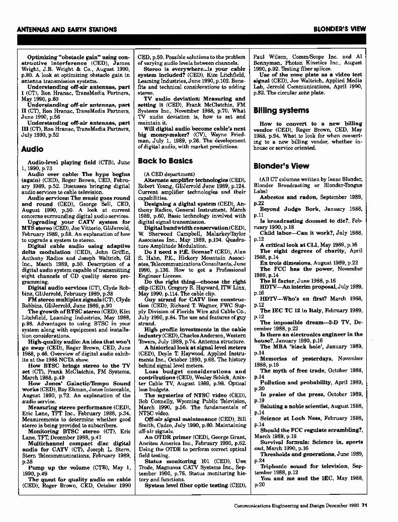
ANTENNAS AND EARTH STATIONS BLONDER'S VIEW
Optimizing "obstacle gain" using con-structive interference (CED), James Wright, J.B. Wright & Co., August 1990, p.80. A look at optimizing obstacle gain in antenna transmission systems. Understanding off-air antennas, part
I (CT), Ron Hranac, ll-ansMedia Partners, May 1990, p.60 Understanding off-air antennas, part
II (CT), Ron Hranac, 'fransMedia Partners, June 1990, p.56 Understanding off-air antennas, part
III (CT), Ron Hranac, ll-ansMedia Partners, July 1990, p.52
Audio
Audio-level playing field (CTB), June 1, 1990, p.73 Audio over cable: The hype begins
(again) (CED), Roger Brown, CED, Febru-ary 1989, p.52. Discusses bringing digital audio services to cable television. Audio services: The music goes round
and round (CED), George Sell, CED, August 1990, p.50. A look at current concerns surrounding digital audio services. Upgrading your CATV system for
MTS stereo (CED), Joe Vittorio, GI/Jerrold, February 1989, p.58. An explanation of how to upgrade a system to stereo.
Digital cable audio using adaptive delta modulation (CED), John Griffin, Anthony Radice and Joseph Waltrich, GI Inc., March 1989, p.30. Description of a digital audio system capable of transmitting eight channels of CD quality stereo pro-gramming.
Digital audio services (CT), Clyde Rob-bins, GI/Jerrold, February 1989, p.38 FM stereo multiplex signals (CT), Clyde
Robbins, GI/Jerrold, June 1989, p.90 The growth of BTSC stereo (CED), Kim
Litchfield, Leaming Industries, May 1988, p.98. Advantages to using BTSC in your system along with equipment and installa-tion considerations.
High-quality audio: An idea that won't go away (CED), Roger Brown, CED, June 1988, p.46. Overview of digital audio exhib-its at the 1988 NCTA show. How BTSC brings stereo to the TV
set (CT), Frank McClatchie, FM Systems, March 1988, p.49 How Jones' Galactic/Tempo Sound
works (CED), Roy Ehman, Jones Intercable, August 1990, p.72. An explanation of the audio service. Measuring stereo performance (CED),
Eric Lane, TFT Inc., February 1988, p.34. Measurements to determine whether good stereo is being provided to subscribers. Monitoring BTSC stereo (CT), Eric
Lane, TFT, December 1988, p.47 Multichannel compact disc digital
audio for CATV (CT), Joseph L. Stern, Stern Telecommunications, February 1989, p.38 Pump up the volume (CTB), May 1,
1990, p.49 The quest for quality audio on cable
(CED), Roger Brown, CED, October 1990
CED, p.50. Possible solutions to the problem of varying audio levels between channels.
Stereo is everywhere...is your cable system included? (CED), Kim Litchfield, Leaming Industries, June 1990, p.102. Bene-fits and technical considerations to adding stereo. TV audio deviation: Measuring and
setting it (CED), Frank McClatchie, FM Systems Inc., November 1988, p.70. What TV audio deviation is, how to set and maintain it.
Will digital audio become cable's next big money-maker? (CV), Wayne Fried-man, July 1, 1989, p.26. The development of digital audio, with market predictions.
Back to Basics
(A CED department) Alternate amplifier technologies (CED),
Robert Young, GI/Jerrold June 1989, p.124. Current amplifier technologies and their capabilities. Designing a digital system (CED), An-
thony Radice, General Instrument, March 1989, p.60, Basic technology involved with digital signal transmission.
Digital bandwidth conservation (CED), W Sherwood Campbell, Malarkey-Taylor Associates Inc., May 1989, p.104. Quadra-ture Amplitude Modulation. Do I need a P.E. license? (CED), Alan
S. Hahn, P.E., Hickory Mountain Associ-ates, Telecommunications Consultants, June 1990, p.136. How to get a Professional Engineer License. Do the right thing—choose the right
clip (CED), Gregory R. Hayward, ITW Linx, May 1990, p.114. The cable clip. Guy strand for CATV line construc-
tion (CED), Richard T. Wagner, FWC Sup-ply Division of Florida Wire and Cable Co., July 1990, p.84. The use and features of guy strand. High profile investments in the cable
industry (CED), Charles Anderson, Western lbwers, July 1989, p.74. Antenna structure. A historical look at signal level meters
(CED), Doyle T Haywood, Applied Instru-ments Inc., October 1990, p.68. The history behind signal level meters. Loss budget considerations and
contributions (CED), Wesley Schick, Anix-ter Cable TV, August 1989, p.98. Optical loss budgets. The mysteries of NTSC video (CED),
Bob Connelly, Wyoming Public 'Iblevision, March 1990, p.56. The fundamentals of NTSC video.
Off-air signal maintenance (CED), Bill Smith, Cadco, July 1990, p.80. Maintaining off-air signals. An OTDR primer (CED), George Grant,
Anritsu America Inc., February 1990, p.62. Using the OTDR to perform correct optical field testing.
Status monitoring 101 (CED), Uwe 'frode, Magnavox CATV Systems Inc., Sep-tember 1990, p.76. Status monitoring his-tory and functions. System level fiber optic testing (CEO),
Paul Wilson, Comm/Scope Inc. and Al Bonnyman, Photon Kinetics Inc., August 1990, p.92. "'bating fiber splices. Use of the zone plate as a video test
signal (CED), Joe Waltrich, Applied Media Lab, Jerrold Communications, April 1990, p.82. The circular zone plate.
Billing systems
How to convert to a new billing vendor (CED), Roger Brown, CED, May 1988, p.94. What to look for when convert-ing to a new billing vendor, whether in-house or service oriented.
Blonder's View
(All CT columns written by Isaac Blonder, Blonder Broadcasting or Blonder-lbngue Labs) Asbestos and radon, September 1989,
p.22 Beyond Judge Bork, January 1988,
p.11 Is broadcasting doomed to die?, Feb-
ruary 1990, p.18 Child labor—Can it work?, July 1988,
p.12 A critical look at CLI, May 1989, p.16 The eight degrees of charity, April
1988, p.14 En trois dimesions, August 1989, p.22 The FCC has the power, November
1989, p.14 The H factor, June 1988, p.16 HDTV—An interim proposal, July 1989,
p.16 HDTV—Who's on first? March 1988,
p.12 The IEC TC 12 in Italy, February 1989,
p.12 The impossible dream-3-D TV, De-
cember 1988, p.22 Is there an electronics engineer in the
house?, January 1990, p.16 The MBA 'black hole', January 1989,
p.14 Memories of yesterdays, November
1988, p.16 The myth of free trade, October 1988,
p.14 Pollution and probability, April 1989,
p.20 In praise of the press, October 1989,
p.19 Saluting a noble scientist, August 1988,
p.14 Science at Loch Ness, February 1988,
p.14 Should the FCC regulate scrambling?,
March 1989, p.16 Survival formula: Science in, sports
out, March 1990, p.16 Thresholds and generations, June 1989,
p.24 Triphonic sound for television, Sep-
tember 1988, p.12 You and me and the IEC, May 1988,
p.20
Communications Engineering and Design December 1990 71
CAPITAL CURRENTS COMMERCIAL INSERTION
Capital Currents (A CED department written by Michael
Schooler and Jeffrey Krauss.) Access to name-brand programming,
June 1990, p.32. Competition arguing ac-cess to name-brand programming is being denied. Cable and copyright, February 1990,
p.22. A look at the copyright act. Cable, sports and politics, August 1989,
p.26. Pay sports via cable television. C-band satellite orbital spacing, Septem-
ber 1990, p.20. The FCC and the 2-degree orbital spacing for satellites. Copyright fees at issue, March 1990,
p.22. Three current pending cases that affect fees operators must pay pursuant to the compulsory license.
Digital sound broadcasting, July 1990, p.20. Digital audio via cable television.
Digital video compression and HDTV, October 1990, p.22. Digital compression for NTSC and HDTV. FCC grants Cerritos waiver, June
1989, p.22. Review of decision to waiver the cross-ownership prohibition. FCC looking at telco/cable rule, Febru-
ary 1989, p.18. FCC's tentative decision to let telcos operate as programmers. FIN/SYN battle heating up again,
January 1990, p.18. A look at the financial interest and syndication rules. LO. in the spotlight, November 1989,
p.22. Cable's local origination channels a topic of debate in Washington. Must-carry politics, March 1989, p.16.
The issue of must-carry requirements for cable operators.
Must-carry (cont'd), October 1989, p.24. A further look at must- carry legislation.
'Mustn't carry' rules, July 1989, p.22. Three separate decisions which affect cable systems carriage requirements. Networks as MS0s?, October 1988 CED,
p.20. Issues regarding ownership of cable systems. New faces at FCC, September 1989,
p.24. Appointment of new commissioners at the FCC and their possible impact on cable television.
Part 15 of the FCC rules, August 1990, p.26. A look at Part 15, rules and effects. Scrambling in Congress, January 1989,
p.16. Legislative issues concerning scram-bling.
State regulators study telco TV, April 1989, p.18. The state PUCs new interest in cable television. Syndex redux, September 1988, p.26.
Syndicated exclusivity rules are back, how and why.
Vertical integration, December 1989, p.30. A discussion of vertical integration.
'Video dial tone', April 1990, p.20. What is meant by Video Dial Ibne and its implications. What do cities want?, November 1988,
p.23. Associations not satisfied with Cable Act. What is a cable system?, May 1989,
p.18. Defines a cable system, according to the Cable Communications Policy Act of
1984.
Ciciora's Forum (All CT columns written by Dr. Walter
Ciciora of ATC.) ATV and the consumer electronics
interface, September 1989, p.112. Cable technology S-curves, October
1988, p.114 Competitive cable ATV and motion
artifacts, July 1989, p.101 An HDTV conunittee road map, March
1988, p.74 HDTV report from Japan, April 1988,
p.110 High-definition television, January
1988, p.98 In-home wiring-Problems, potentials,
October 1989, p.120 Innovation in a competitive environ-
ment, September 1988, p.106 Issues for HDTV, February 1988, p.86 The paperback movie, July 1988, p.86 Rational expectations for ATV, May
1989, p.126 Shattering an HDTV myth, December
1988, p.146 Subscriber value in ATV, August 1989,
p.140 Three years in passing, December 1989,
p.134 A trail guide to the FCC HDTV com-
mittees, May 1988, p.120 Video digital downloading, June 1988,
p.118 Windows on the future, August 1988,
p.118 Winter Consumer Electronics Show,
part II, March 1989, p.104 Winter Consumer Electronics Show,
part I, February 1989, p.106 Workstations, semiconductors and
ATV, June 1989, p.180 Zenith as an HDTV S-curve example,
November 1988, p.110 1988 Retrospective, 1989 perspective,
January 1989, p.120
Ciciora's Page
(A CED column written by Dr. Walter Ciciora of ATC.) The visibility of consequences, Janu-
ary 1990, p.98. Behavior modification in the cable industry.
Threats from NTSC's deficiencies, Febru-ary 1990, p.90. The role played by the NTSC technical standard as a fundamental con-straint on video quality.
Transmissionless competition, March 1990, p.90. The consideration of transmis-sion path problems and competition from transmissionless video. The electronic program guide, April
1990, p.106. The need and use of an electronic program guide. A gradual move to mood guides, May
1990, p.138. Potential to make TV more enjoyable via cable television.
"Real world" electronics, June 1990, p.148. Visits to subscriber's homes and "real" problems.
"Pro-sumer" and "HDTV ready"?, July 1990, p.104. New consumer products present new challenges to the cable indus-try.
Digital mania, August 1990, p.116. Digi-tal belief in an analog world.
Hybridization in cable TV, September 1990, p.108. Benefits to the hybrid approach in cable TV. Video compression in cable-TV, Octo-
ber 1990, p.84. Video compression must be taken seriously by the cable television industry.
Commercial insertion
Ad insertion heats up (CTB), August 15, 1988, p.35 Ad insertion systems (CED), Bill Kil-
lion, Channelmatic Inc., March 1988, p.46. Design and equipment for an ad insertion system. What the engineer should know. Ad insertion and the 4.5 MHz audio
subcarrier (CT), Billy Williams, Cooke Ca-blevision, August 1989, p.52 Ad interconnects: Breaking into dol-
lars (CED), Leslie Miller, CED, September 1990, p.60. New developments, interconnect architectures and software growth for ad interconnects. Are ad sales levels taxing insertion
equipment? (CED), Fred Dawson, Ca-bleVision, April 1989, p.46. 'Bakes a look at ad insertion gear and whether it can keep up with the growing demand by cable operators. Automated multichannel ad insertion
for NuStar (CT), Steve Fox, Wegener Communications, October 1989, p.86 Automated tape editing, tape compil-
ing, random access (CED), Ibm Walsh, Channelmatic Inc., April 1990 CED, p.42. Possible equipment configurations for ad production and insertion. Bay interconnects join forces, reach-
ing one million households (CV), Wayne Friedman, July 18, 1988, p.13. Zonal selling offered with the merger of the Bay Area Interconnect and Cable AdNet; sales projec-tions come in at $3 million for 1989. Commercial insertion: more than a
trivial pursuit (CV), David Hawthorne, September 12, 1988, p.44. Cable systems look seriously at advertising revenues, espe-cially as automation suppliers strive to sophisticate products. Commercial insertion interface in the
headend (CT), Steve Fox, MegaHertz, August 1990, p.28 Connecting with interconnects: A
primer (CED), Michael Watson, Channel-matic Inc., December 1989, p.88. Types of advertising interconnects and benefits of various approaches.
Delivering ad insertion cues over sat-ellite (CT), Steve Fox, Wegener Communi-cations, September 1989, p.68 The evolution of commercial insertion
(CED), William Robertson, MSI Corp., May 1988, p.62. Traces the history of commercial insertion from one extra piece of equipment to a complex array of necessary components.
72 Communications Engineering and Design December 1990
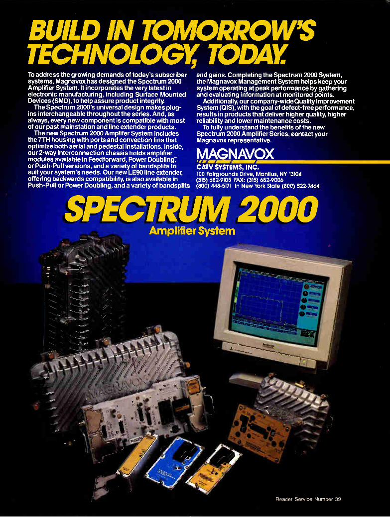
BUILD IN TOMORROW'S TECHNOLOGY' TODAY To address the growing demands of today's subscriber systems, Magnavox has designed the Spectrum 2000 Amplifier System. It incorporates the very latest in electronic manufacturing, including Surface Mounted Devices (SMD), to help assure product integrity. The Spectrum 2000's universal design makes plug-
ins interchangeable throughout the series. And, as always, every new component is compatible with most of our past mainstation and line extender products. The new Spectrum 2000 Amplifer System includes
the 7TH housing with ports and convection fins that optimize both aerial and pedestal installations. Inside, our 2-way interconnection chassis holds amplifier modules available in Feedforward, Power Doubling: or Push-Pull versions, and a variety of bandsplits to suit your system's needs. Our new LE90 line extender, offering backwards compatibility, is also available in Push-Pull or Power Doubling, and a variety of bandsplits
and gains. Completing the Spectrum 2000 System, the Magnavox Management System helps keep your system operating at peak performance by gathering and evaluating information at monitored points.
Additionally, our company-wide Quality Improvement System (OIS), with the goal of defect-free performance, results in products that deliver higher quality, higher reliability and lower maintenance costs. To fully understand the benefits of the new
Spectrum 2000 Amplifier Series, contact your Magnavox representative.
rFM
CATV SYSTEMS, INC. 100 Fairgrounds Drive, Manlius, NY 3104 (315) 682-9105 FAX: (315) 682-9006 (800) 448-5171 In New York State (KO) 522-7464
GNAVOX
SPECTRUM 2000 Amplifier System
'
Reader Service Number 39

COMMERCIAL INSERTION CONSTRUCTION TECHNIQUES
Innovative design of a commercial insertion system (CED), Ernest lkinmann and Eugene Bartlett, 11le-Engineering Corp., September 1988, p.58. How to enter the advertising business with commercial inser-tion. Network communications and control
(CT), Steve Fox, Wegener Communications, August 1989, p.46 New demands on ad insertion gear
(CV), Fred Dawson, April 10, 1989, p.32. As systems increase the number of channels on which they sell local ads, ever greater demands are placed on insertion gear-and vendors feel the heat. Not necessarily for ads (CV), Simon
Applebaum, March 26, 1990, p.44. Multi-uses for advertising insertion gear an issue in light of syndex legislation.
Optical discs: The new wave in conuner-cial insertion (CED), George Sell, CED, June 1990, p.48. Advantages and disadva-natages to using optical insertion technol-ogy.
Preventive maintenance of commer-cial insertion (CT), Doug Green, Jones Intercable, August 1989, p.50 Random access or suped-up sequen-
tial gear? Ad directors still disagree as products improve (CV), Fred Dawson, November 20, 1989, p.47. The debate of commercial insertion architectures. StarNet in the headend (CT), Wegener
Communications engineering staff, Febru-ary 1988, p.24 A Texas-size interconnect is launched
in 45 towns (CV), staff writer, June 19, 1989, p. 60. A group of five MSOs in the Dallas-Fort Worth area combine forces to develop an advertising interconnect that reaches more than 400,000 subscribers in 45 communities. A unique cable advertising intercon-
nect (CED), Norman Weinhouse, Norman Weinhouse Associates, May 1989, p.98. A different approach, using satellite implementa-tion.
Competing technologies
Competing technologies for conven-tional CATV (CT), Dave Wachob, GI/ Jerrold, January 1989, p.74
Creating a new vision to capture its destiny (CV), Fred Dawson, December 5, 1988, p.90. Premium broadcast television, HDTV and DBS are examples of new thinking to match the new age.
Fiber optics vs. satellite distribution (CT), Ray Sensey, Vyvx Video Network, October 1990, p.26
Filling the void with wireless (CT), Marty Jeffery, Microwave Distribution Sys-tems, October 1990, p.30 From design to dish (CT), Paul Beeman,
TVN Entertainment, October 1990, p.22 If MMDS comes to your town (CTB),
November 1, 1988, p.32 Landscape changing (CV), Gary Kim,
May 21, 1990, p.94. Multichannel competi-tion in the form of direct broadcast satellite may challenge cable operators in the '90s.
MMDS: Looking for a level playing field (CED), Kathy Berlin, CED, May 1989, p.46. MMDS technology and the politics. MMDS: A technical primer (CTB),
October 15, 1988, p.38 MS0 consortium close to announcing
creation of Ku-band DBS service (CV), Larry Jaffee, September 11, 1989, p.11. Cable satellite programming group to offer direct service to subscribers. Tempo pushes $500 million DBS bid
(CV), John Wolfe, May 9, 1988, p.36. Tempo and TCI pursue a 32-channel DBS bid, wait for FCC approval.
Wireless or wired cable: Comparable technologies? (CT), George Harter, GE/ Comband, January 1989, p.68
Connectors
The engineers' challenge: Improve signal quality now amid advancing tech-nology (CV), Fred Dawson, March 14, 1988, p.37. MSOs seek to streamline equipment in the face of upcoming technological ad-vancements.
F-fitting cross reference chart (CT), Barry Smith, SCTE Interface Practices Cmte., June 1989, p.155 "Gimme an F!" (CV), Chuck Moozakis,
July 30, 1990, p.27. Developments and enhancements to the F-connector, with ac-companying price increases. How to improve equipment reliability
with contact enhancement (CT), Mike Dayton Wright, D.W. Electrochemicals, June 1990, p.38 Improving reliability of drop wire
connections (CED), John Hood, Comlink Systems Inc., July 1988 CED, p.50. How to improve the F-connector and lower the incidence of service calls.
It's the person that matters in the F connection (CT), Ron Hranac, ftansMedia Partners, July 1990, p.40 Making the F connection (CT), Ron
Hranac, 'ftansMedia Partners, May 1990, p.74 Mechanical performance of the F-
fitting interface (CT), Barry Smith, TCI and David Franklin, ATC, June 1989, p.155
Construction techniques Alternative approaches to bandwidth
extension (CED), Karl Poirier, 'ftiple Crown Electronics, December 1989, p.68. Getting 550 MHz by reusing existing plant and progressive construction. The alternatives of turnkey construc-
tion (CT), Thomas Polis and William Earle, Communications Construction Group, April 1988, p.34 Anchoring utility poles, part I (CT),
David Chandler, Foresight Products, De-cember 1987, p.82 Anchoring utility poles, part II (CT),
David Chandler, Foresight Products, Janu-ary 1988, p.58
Basic aerial construction (CT), Bruce Liles, Casco Communications, March 1990,
p.88 Cable system upgrades and rebuilds
(CED), Fred Rogers, Quality RF Services Inc., September 1990, SCTE Focus, p.82. Taking advantage of tomorrow's technology in today's rebuild or upgrade.
Call before you dig, part I (CT), One-Call Systems International, April 1989, p.115
Call before you dig, part II (CT), One-Call Systems International, May 1989, p.111 CATV vendors poised for healthy
1989 (CED), Roger Brown and Gary Kim, CED, July 1988, p.40. Construction activity expected in 1989.
Cheaper, traditional upgrades may be best (CT), Monte Errington, Rob Lego, Fred Rogers and John Tinberg, Quality RF Services, June 1990, p.44 Common courtesy, common sense (CT),
Mike Mayberry, Continental Cablevision, April 1989, p.80
Construction and the soil: What it's like down there (CT), Wayne Sheldon, Sheldon Electronics, April 1989, p.34
Construction surge fueled by rebuilds (CED), Roger Brown, CED, April 1988, p.36. Discusses what MSOs can do with scrap cable after a major rebuild.
Construction surge seen booming into '89 (CV), Craig Kuhl, September 26, 1988, p.38. Rebuilds, extensions, retrofits, and addressability all predicted to flourish at a rate of ten percent into 1989. Operators discuss their future plans.
Contractor billing for system dam-ages (CT), Joey Caballero, Comcast Ca-blevision, December 1988, p.96 Designing the fiber backbone (CT),
Monica Younger, ATC, December 1988, p.122
Fiber optic architectures (CT), Tom Schatz, Anixter Cable TV, April 1989, p.22
Forecast is bright for long-term construction (CED), Roger Brown, CED, November 1989, p.24. The construction boom. Handling and installing aluminum-
sheathed cables (CT), Rex Porter, April 1988, p.28 High-tech tapped trunk (CED), Fred
Rogers, Quality RF Services Inc., July 1989, p.85. A method to deliver 40 channels with cost savings using tapped trunk. Hooking up multiple dwelling units
(CT), Glyn Bostick, Microwave Filter Co., March 1988, p.62 Hot dip galvanizing (CED), Ibm Ni-
emiera, Joslyn Mfg. Co., and Lawrence White, Anixter Cable TV, February 1990, p.74. How hot dip galvanizing can add life to outdoor equipment. How to manage rebuilds and up-
grades (CT), Larry Brown and Jerald Evans, NaCom Corp., April 1990, p.28 Importance of effective program
management (CED), Marcus W. Zion, An-drew Corp., April 1990, p.68. What opera-tors need to keep in mind when rebuilding.
Installation of fiber cable (CT), Sanford Lyons, Siecor Corp., April 1989, p.40
Is rebuilding on hold? (CV), Chuck
74 Communications Engineering and Design December 1990
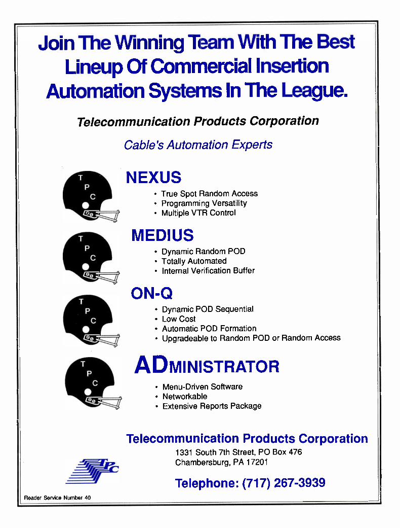
Join The Winning Team With The Best Lineup Of Commercial Insertion
Automation Systems In The League.
Telecommunication Products Corporation
Cable's Automation Experts
r r i=c:,
NEXUS • True Spot Random Access • Programming Versatility • Multiple VTR Control
MEDIUS • Dynamic Random POD • Totally Automated • Internal Verification Buffer
ON-Q • Dynamic POD Sequential • Low Cost • Automatic POD Formation • Upgradeable to Random POD or Random Access
ADMINISTRATOR • Menu-Driven Software • Networkable • Extensive Reports Package
Telecommunication Products Corporation 1331 South 7th Street, PO Box 476 Chambersburg, PA 17201
Telephone: (717) 267-3939 Reader Service Number 40
CONSTRUCTION TECHNIQUES CONSUMER INTERFACE
Moozakis, September 10, 1990, p.36. A look toward 1991 rebuild plans as seen by CATV operators and suppliers. Mapping a rebuild with computer.
aided drafting (CT), David Cervone, Viacom Cable of Long Island, April 1988, p.16 MDU post-wiring: A success story
(CT), Kenny Faust, Heritage Cablevision, October 1990, p.94 The MDU in the rebuild process (CT),
Rick Cooper, Geographic Mapping Systems, April 1990, p.26 NEC Article 820: Cable installation
(CT), May 1990, p.76 The new upgrade agenda: Caught
between the past and future, cable pursues an interim topology (CV), Fred Dawson, September 11, 1989, p.36. An array of unknowns such as lightwave technology, extended bandwidth and signal quality standards make construction decision-making a difficult challenge. OSHA's gonna get you if you don't
watch out (CT), Ralph Haimowitz, SCTE, March 1990, p.94 Personnel shortage hitting contrac-
tors hard (CED), Roger Brown, CED, November 1988, p.24. Contractors having a tough time finding qualified people.
Plant damage claims (CT), Mike May-berry, Continental Cablevision, May 1989, p.96
Profits and pitfalls in handling waste (CV), Ibm Wood, Resource Recovery Sys-tems, September 26, 1988, p.54. With the continuing surge in system construction, left-over materials grow as well, and shouldn't be wasted.
Project management for CATV engi-neers (CT), Steve Hubbard, Jones Interca-ble, April 1988, p.38 A rebuild strategy for the 1990s (CT),
Bernie Czarnecki, Cablemasters Corp., April 1990, p.24 Rebuild/upgrade trends (CTB), Febru-
ary 15, 1988, p.26 Replacing the cable in rebuilds and
upgrades (CT), Tim Dugan, Times Fiber Communications, April 1989, p.52 Rewiring America: Operators enhanc-
ing plants in preparation of a new cable era (CV), Richard Tedesco, March 12, 1990, p.30. Rebuilding aging plant a priority for systems desiring more channels and reli-ability.
Selecting a boring device (CT), Mike Cole, Carlton International, April 1989, p.30 So your system needs rebuilding (CT),
Jim Merriam, Palmer Cablevision, January 1988, p.66 Storer bounces back from Hugo's
destruction (CED), Roger Brown, CED, December 1989, p.110. Cleaning up after Hurricane Hugo. System design and management using
CAD (CED), ibny Steinmetz, Star Ca-blevision and Michael E Bauer, ADC, March 1990, p.42. Using CAD to aid in the development of and maintenance of system maps. Using CADD to rebuild (CED), Auto-
mated Drawing Systems Inc., December
1989, p.82. Your rebuild options (CT), Bob Young,
GI/Jerrold. June 1990, p.40
Consumer interface
A/B switch ruling better, but... (CED), Roger Brown, CED, January 1988, p.72. AJB switch controversy. FCC's latest ruling, as of January 1988. A broadband solution for VCR/
converter compatibility (CED), Richard E Annibaldi, Pioneer Communications, May 1988, p.104. Pioneer's approach to cleaning up the consumer VCR/converter incompati-bility problem. A case for ghostbusters (CED), Del
Heller, Viacom Cable, Consumer Interface Handbook, A Special Supplement of CED Magazine, April 1990, p.8. Direct pickup interference and steps the industry can take to get the consumer electronics manufactur-ers' attention. A case study of consumer friendliness
(CT), John Dawson Jr., Mile Hi Cablevision, May 1988, p.70 Connecting cable systems to subscrib-
ers' TVs and VCRs-Guidelines For the Cable Ulevision Industry, Supplemen-tal Reports (CED), by the NCTA Engineer-ing Committee's Subcommittee on Con-sumer Interconnection, Chairman David Large, October 1988, p.47. The Consumer Electronics Bus and
CATV (CT), James Farmer, Scientific-Atlanta, August 1989, p.44 The consumer electronics interface
with cable (CED), Walter Ciciora, ATC, Consumer Interface Handbook, A Special Supplement of CED Magazine, April 1990, p.12. The history and problems associated with interfacing cable television with con-sumer gear. Consumer interfaces (CT), Earl Langen-
berg, ATC, May 1988, p.22 Consumer interface issues and solu-
tions (CED), Dan Moloney, Jerrold Sub-scriber Systems Div., General Instrument Corp., Consumer Interface Handbook, A Special Supplement of CED Magazine, April 1990, p.40. Projects and products aimed at taking the hassle out of watching cable TV.
Converters aren't going away just yet (CV), Chuck Moozakis, p.43. The future of set-top devices. EIA MultiPort: An idea whose time
has come (CED), Joseph Van Loan, RE., Industry Consultant, June 1989, p.120. Frequently questions asked are answered. The elements of consumer friendliness
(CT), Pam King, Jones Intercable, May 1988, p.40 The evolution of the CATV converter
(CED), George Sell, CED, Consumer Inter-face Handbook, A Special Supplement of CED Magazine, April 1990, p.20. How converter manufacturers have had to re-main friendly with consumer gear.
First field tests of MultiPort show boxes working flawlessly (CV), Roger
Brown, July 17, 1989, p.48. Zenith and Jerrold release prototype MultiPort de-scramblers for test in several MS0 systems. The intelligent remote (CT), Michael
Hayashi and Dan Wiltshire, Pioneer Com-munications of America, May 1988, p.50 The interdiction alternative (CED),
James O. Farmer, Scientific-Atlanta Inc., Consumer Interface Handbook, A Special Supplement of CED Magazine, April 1990, p.33. An explanation of S-A's new interdic-tion system.
Interdiction colonizes Williamsburg (CT), Harry Johnson, Warner Cable, and John Cochran, Scientific-Atlanta, December 1989, p.33 Interfacing in the year 2000 (CT), H.
MArk Bowers, Centel Cable, May 1988, p.26 Interfacing pay-per-view in the cable-
compatible home environment (CT), David Wachob and Joseph Vittorio, GI/Jerrold, May 1988, p.32
Less is more (CV), Chuck Moozakis, July 2, 1990, p.37. Consumer electronics and converters.
MultiPort and the converter upgrade (CT), Anthony Wechselberger, Oak Commu-nications, August 1989, p.32
MultiPort's economic and business impact (CED), Claude Baggett, CableLabs, Consumer Interface Handbook, A Special Supplement of CED Magazine, April 1990, p. 25: Financial reasons why MultiPort has seen limited acceptance.
MultiPort gets another chance (CED), Leslie Miller, CED, August 1990, p.74. The current state of development as seen by operators and manufacturers of TVs, VCRs and decoders. The MultiPort and how it works (CT),
Dan Moloney and John Venner, GI/Jerrold, August 1989, p.30 A MultiPort solution (CT), Thomas
Jokerst, Continental Cablevision, August 1989, p.26 MultiPort strategic issues (CT), Walter
Ciciora, ATC, August 1989, p.36 MultiPort testing begins (CED), Roger
Brown, CED, August 1989, p.74. Market studies finally being done. The off-premises solution (CT), Joseph
Rocci, AM Communications, August 1989, 13.44 Prototype remote unit/phone may
point to Smart House role for operators (CV), Fred Dawson, December 4, 1989, p.20. Development overview of Jerrold's Remote Phone. Time for the MultiPort (CT), David
Franklin, ATC, August 1989, p.24 The VCR/CATV interface question
(CT), Michael Spratlin, Qintar, May 1988, p.30 Untangling the rat's nest (CV), Richard
lbdesco, October 24, 1988, p.60. The IS-15 MultiPort is making some headway and vendors are beginning to offer "learning" remotes, but untangling the TV's rat's nest remains a problem.
Warner, other MSOs test off-premises gear (CV), staff writer, June 5, 1989, p.20. Scientific-Atlanta's off-premise addressable gear goes onto homes in Williamsburg, Va.
76 Communications Engineering and Design December 1990
Digital Fiber optic
transmission systems. Superior system
performance at an economical price.
, e''' .. - 60 dB sial -to noMe ratio. • 4,.- f - b a Less budgets 4 29 9.
• Ne sigtnál dégradation. 49, .
0 : 0 Consolidation of hub sites and . .
., ,,„> * .,Iteadends. The.C-C19R/COMLUX .... .‘„_„ 'digital solutibn. Availal# only
' I from the el-CAR/COMLUX team.
Call today for more informa.tion about C-COR's comprehensive fiber
a optic product line. e
°IC ELECTRONICS INC \EOM LU ),(
A World of Advanced System Technology
C-COR Electronics. Inc. 60 Decibel Road State College, PA 16801-7580 USA 814-238-2461 / 800-233-2267 / FAX 814-238-4065
COM1.UX Suite F 453 Ravendale Drive Mountain View, CA 94043-520() / 415-964-9628 / FAX 415-964-0968
Reader Service Number 41
CONSUMER INTERFACE DISTORTIONS AND INTERFERENCE
What is home automation? (CED), Tho-mas Mock, Consumer Electronics Group, EIA, Consumer Interface Handbook, A Spe-cial Supplement of CED Magazine, April 1990, p.30. Where CATV fits in with the home of tomorrow.
Will set-top converters be relics? (CV), Gary Kim, April 9, 1990, p.47. A look into addressability control functions on the side of the home.
Converters
Battling the cable converter pirates (CED), George Sell, CED, November 1989, p.44. Safeguards that manufacturers and converter repair houses have in place to prevent converter theft. A converter for premium channels
only (CT), Archer Taylor, Malarkey-Taylor Assoc., September 1988, p.63
Converter maintenance vs. replace-ment (CED), Fredrick Rosales, United Art-ists Cable Systems, October 1988, p.44. Whether converters should be fixed or replaced. Converters aren't going away just
yet (CV), Chuck Moozakis, p.43. The future of set-top devices.
Converters: Gateways or blockades? (CTB), September 15, 1988, p.40 Heading for converter overpopula-
tion (CED), Shellie Rosser, Anixter Cable TV, September 1989, p.70. What can be done to remove excess converters from inventory. Improving picture quality (CED), Daniel
M. Maloney, Jerrold Communications, July 1990, p.60. Converter low noise pre-amplifiers.
Less is more (CV), Chuck Moozakis, July 2, 1990, p.37. Consumer electronics and converters. Modeling the converter in the residen-
tial lightning environment (CT), David Wachob, GI/Jerrold, August 1988, p.28 The mystery surrounding converter
preamplification (CT), Dan Moloney, GI/ Jerrold, November 1989, p.44 The new Part 15 set-top requirements
(CED), James O. Farmer, Alex M. Cook, Scientific-Atlanta Inc., June 1990 p.56. The FCC's Part 15 Rules concerning set-top converters. lbmorrow's converters: Tuning in the
future (CED), George Sell, CED, June 1989, p.86. A look at converters and their expected future performance.
Will set-top converters be relics? (CV), Gary Kim, MultiChannel News, April 9, 1990, p.47. A look into addressability con-trol functions on the side of the home.
Correspondent's Report
(All CT columns written by Lawrence W. Lockwood) About HDTV scanning line rates, May
1990, p.96 Faroudja and IDTV, September 1989,
p.84
General Instrument's HDTV proposal, August 1990, p.112
Levels in fiber optic networks, June 1988,. p.94 Light measurement, part I, October
1988, p.92 Light measurement, part II, December
1988, p.128 Light measurement, Part III, February
1989, p.71 Observations on a couple of HDTV
receiver schemes, January 1989, p.105 Optical amplifiers, January 1990, p.88 Optical bandwidth, June 1990, p.154 The relation of C/N and baseband
S/N, May 1989, p.98 Ruminations on HDTV transmission,
May 1988, p.96 Talcos and FITH activities, December
1989, p.114 Telcos, television and fiber optics,
September 1988, p.93 Why 75 ohms?, April 1989, p.82 Zenith and compatible HEVITNovember
1988, p.76
Customer service
How to prevent service calls (CED), Greg Packer, CED, June 1988, p.54. Differ-ent methods/solutions to stopping or pre-venting service calls.
Fiber optics: The key to improved customer service (CT), Dean DeBiase Sr., Anixter Cable TV, December 1989, p.34 Technology as consumer tool (CV),
Chuck Moozakis, June 4, 1990, p.36. Mak-ing technological changes invisible in the consumer's mind.
Total quality management (CED), Steve Hubbard, Jones Intercable, January 1990, p.78. Using total quality management for improving service problems. Using technology to meet customer
service needs (CED), George Sell, CED, September 1990, p.32. Management serv-ices, telephone response systems, ARUs and billing systems as ways to improve customer service.
Data communication and LANs
Design, installation and certification of a broadband LAN cabling system (CT), Larry Brown, NaCom, September 1988, p.14 Developing a community network (CT),
Karen Kalergis, Austin CableVision, Sep-tember 1988,p.36
Fiber optic LAN applications (CT), Jim Hartman, FiberLite International, July 1990, p.44
Fiber optics in LANs, part I (CT), Robert Southard, AMP Inc., September 1988, p.27 Hospital LAN communications (CED),
John Gutierrez, ComNet Co., and David Phillips, Netsery Inc., October 1989, p.64. The cabling mediums used in hospitals to connect voice, data and video communica-
tions. Implementing a broadband LAN (CT).
Geoff Roman, GI/Jerrold, September 1988, p.19 LANs and electronic mail (CT), Del
Guynes, Jones Intercable, September 1988, p.32 Modem emissions specs in broadband
LANs (CED), Joe Greaney, Lanex Corp., October 1988, p.78. What specs are impor-tant and how to calculate them. Powering broadband networks (CED),
Gary Kim, CED, August 1988, p.60. Power-ing a network depending on system needs. Spectrum allocation in broadband
systems (CT), Tom Saylor, Columbia Tele-communications, September 1988, p.24
Design
See "System design"
Digital technology
Digital audio services (CT), Clyde Rob-bins, GI/Jerrold, February 1989, p.32
Digital bandwidth conservation (CED), W. Sherwood Campbell, Malarkey-Taylor Associates Inc., May 1989, p.104. Quadra-ture Amplitude Modulation.
Digital coding: An HDTV solution (CT), Ed Burzycki and Ron Holeman, Rela Inc., March 1989, p.41
Digital fiber optic transmission of video (CT), John Holobinko, American Light-wave Systems, February 1989, p.20
Digital HDTV (CT), John Sie, TCI (speech), October 1989, p.14
Digital techniques in scrambling (CT), Joseph Keyes, Scientific-Atlanta, February 1989, p.26 The evolution of digital (CT), Hermann
Gysel, Synchronous Communications, Feb-ruary 1990, p.20 ISDN, B-ISDN, Sonet—A triple threat?
(CT), H. Mark Bowers, Centel Cable, Febru-ary 1989, p.28 Multichannel compact disc digital
audio for CATV (CT), Joseph Stern, Stern Telecommunications, February 1989, p.38 A new sync encoding method for
scrambling (CT), 'Ibd Johnson, The Serenics Co., November 1988, p.32
Distortions and interference
Characteristics of cross modulation (CED), R,ezin Pidgeon Jr., Scientific-Atlanta Inc., January 1988, p.16. Results of experi-ments made to measure the amount of cross modulation perceptible in a TV picture. Combining MMDS/ITFS adjacent chan-
nels (CT), Glyn Bostick and Andrew Olney, Microwave Filter Co., April 1990, p.34 Composite second order: Fact or fan-
tasy? (CED), Mark Adams, Scientific-Atlanta Inc., November 1988, p.64. What the distortion is and how to find it.
Crosstalk elimination with ground control (CED), Ronn Gunn, Lawrence Liver-
78 Communications Engineering and Design December 1990
AM Fiber optic
transmission systems. Designed for
the future. Available today.
,11,
• !1,11(
Flexible enttugh for all * AM, stchitectdrio. Siine enough for installation'
C- by RF technicians - no sncial AM training required. Reliable enougleto care the C-CpR name&:-
ahl today for more infórmation about C-COR's cemprehensive fiber optic produit line.
clanELECTRONICS INC
A World qf Advanced System Technology
-COR 'Electronics, Inc. 60 Decibel Road State College, PA 16801-7580 ESA 814-238-2461 / 800-233-2267 / FAX 814-238-4065
Reader Service Number 42
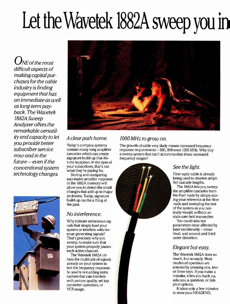
Let the Wavetek 1882A sweep you in
ONE of the most difficult aspects of making capital pur-chases for the cable industry is finding equipment that has an immediate as well as long-term pay-back. The Wavetek 1882A Sweep Analyzer offers the remarkable versatil-ity and capacity to let you provide better subscriber service now and in the future — even if the conventional system technology changes.
1000 MHz to grow on. A clear path home. Today's complex systems contain many long amplifier cascades which can create signature build-up that dis-torts reception. In the eyes of your subscribers, that's not what they're paying for.
Storing and comparing successive amplifer response in the 1882A memory will allow you to detect the small changes that add up to major problems. Today, signature build-up can be a thing of the past.
No interference. Why tolerate extraneous sig-nals that simply load your system or interfere with rev-enue generating signals? That's precisely why you sweep, to make sure that your system properly passes each active channel. The Wavetek 1882A uti-
lizes the multitude of signals already on your system to test the frequency response. So you're not adding extra carriers that can interfere with picture quality, set top converter operation, or VCR usage.
The growth of cable very likely means increased frequency response requirements —600, 800 even 1000 MHz. Why buy a sweep system that can't accommodate these increased frequency ranges?
See the light. Fiber optic cable is already being used to shorten ampli-fier cascade lengths. The 1882A lets you sweep
the amplifier cascades from the fiber node by simply stor-ing your reference at the fiber node and sweeping the rest of the system as you nor-mally would, without an elaborate field transmitter.
You could also test parameters most affected by laser nonlinearity — cross-mod, and second and third order distortion.
Elegant but easy. The Wavetek 1882A does so much, but so easily. Most modes of operation are entered by pressing one, two or three keys. If you make a mistake, it lets you back up, asks you a question, or lists your options.
It takes only a few minutes to store your HEADEND,
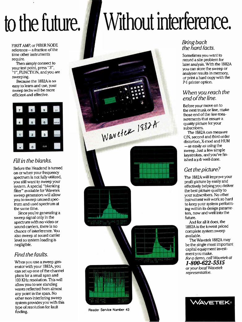
to the future. Without interference. FIRST AMP, or FIBER NODE reference — a fraction of the time other instruments require. Then simply connect to
your test point, press "3", "I", FUNCTION, and you are sweeping.
Because the 1882A is so easy to learn and use, your sweep techs will be more efficient and effective.
Fill in the blanks. Before the Headend is turned on or when your frequency spectrum is not fully utilized, you still want to sweep your system. A special "blanking filter" available for Wavetek sweep generators will allow you to sweep unused spec-trum and used spectrum at the same time.
Since you're generating a sweep signal only in the spectrum with no video or sound carriers, there is no chance of interference. You also sweep at sound carrier level so system loading is negligible.
Find the faults. When you use a sweep gen-erator with your 1882A, you can set up one of the channel plans for a small span and 100 KHz resolution. This will allow you to see standing waves reflected from almost any point in the span. No other non-interfering sweep system provides you with this type of resolution for fault finding.
_
1111111111111111111111011.1114
Reader Service Number 43
Bring back the hard facts. Sometimes you want to record a site problem for later analysis. With the 1882A you can store the sweep or analyzer results in memory, or print a hard copy with the P-1 printer option.
When you reach the end of the line. Before your move on to the next trunk or line, make those end of the line mea-surements that ensure a quality picture for your subscribers. The 1882A can measure
C/N, second and third order distortion, X-mod and HUM — as easily as using the sweep. Just a few simple keystrokes, and you've fin-ished a job well done.
Get the picture? The 1882A will improve your profit picture by easily and effectively helping you deliver the best picture quality to your subscribers. No other instrument will work so hard to keep your system perform-ing within its design parame-ters, now and well into the future. And for all it does, the
1882A is the lowest priced complete system sweep available. The Wavetek 1882A may
be the single most important capital equipment invest-ment you make. For a demo, call Wavetek at
1-800-622-5515 or your local Wavetek representative.
\A/AVETK
DISTORTIONS AND INTERFERENCE FIBER OPTICS
more National Laboratory, November 1989, p.68. How to eliminate crosstalk. Cures for off-air TV interference (CED),
Glyn Bostick, Microwave Filter Co. Inc., August 1988, p.78. Diagnosing and solving problems related to interference. Curing off-air interference (CT), Jean
Dickinson and Glyn Bostic, Microwave Fil-ter Co., May 1990, p.56 Curing off-air interference from adja-
cent channels (CED), Glyn Bostick, Micro-wave Filter Co. Inc., July 1988, p.72. Tips on fighting adjacent-channel interference from TV and FM stations. Curing terrestrial interference (CED),
Glyn Bostick, Microwave Filter Company Inc., January 1989, p.76. An examination of terrestrial interference and methods to eliminate it.
Eliminating paging transmitter inter-ference (CT), Glyn Bostick, Microwave Fil-ter Co., June 1988, p.88
Filtering MDUs (CED), Glyn Bostick, Microwave Filter Co. Inc., October 1988, p.90. Three types of networks for interfacing MDU complexes.
Getting better S/N and better pictures (CED), Gary Kim, CED, March 1988, p.20. Can you improve the dBmV S/N at the TV receiver in the headend or are operators at the mercy of the distribution system? How to phase out co-channel and
other co-frequency interferences (CT), Glyn Bostick, Microwave Filter, February 1990, p.26 Hum modulation in drop passives
(CT), Ron Hepler, Prime Cable, May 1990, p.28 Imbirdance measurement for CATV
antennas (CED), Thomas R. Haskett, for-merly with Radio Electronics, April 1988, p.16. Describes the effect of birds on TV antennas.
Internal interference suppression (CED), Glyn Bostick, Microwave Filter Co. Inc., September 1988, p.70. Interference within the system and how to reduce it. Negative trapping for pay-TV secu-
rity (CED), Glyn Bostick, Microwave Filter Co. Inc., November 1988, p.74. A look at negative trapping. Reducing distortions using video tim-
ing techniques (CED), David Large, Ray-net Corp., June 1989, p.114. Method of using video timing techniques to make system distortions less apparent. The sun and communications (CT),
Ron Hranac, TransMedia Partners, March 1990, p.40
Encryption
Advantages and savings by pre-wiring MDUs (CED), Frank Priebe, Reli-able Electric, April 1990, p.62. Security advantages to proper wiring and installa-tion of MDU enclosures.
Battling the cable converter pirates (CED), George Sell, CED, November 1989, p.44. Safeguards that manufacturers and converter repair houses have in place to prevent converter theft.
Cable piracy's effect on the industry (CED), Jim Allen, Office of Cable Signal Theft, NCTA, April 1990, SCTE Focus, p.72. Theft of cable services and how it affects the cable television industry. Can VideoCipher regain cable's trust?
(CED), Roger Brown, CED, February 1990, p.26. How VideoCipher alienated the cable industry and the company's efforts to regain trust. Deterring theft of service (CED), Peter
F. Hurst, Metrovision Inc. (Chicago), June 1990, p.117. One system's method for deter-ring theft.
Digital techniques in scrambling (CT), Joseph Keyes, Scientific-Atlanta, February 1989, p.26 How secure is fiber? (CT), Scott Esty,
Corning Glass Works, March 1989, p.22 A new approach to video inversion
(CT), Blair Schodowski, Scientific-Atlanta, March 1989, p.24 A new sync encoding method for
scrambling (CT), Ted Johnson, The Serenics Co., November 1988, p.32
Pay-per-view copy protection (CT), Graham Stubbs, Eidak Corp., March 1989, p.30 Phase Modulation system—past, pre-
sent and future (CT), Vito Brugliera, Zenith Cable Products, March 1989, p.36
Securing MDU equipment (CT), Mal-colm White, Priority Television Consult-ants, June 1988, p.90
Security and outdoor addressability (CED), Mike Phebus, Midwest CATV, August 1989, p.30. Using outdoor addressability to reduce security problems. Should the FCC regulate scrambling?
(CT), Isaac Blonder, Blonder-Tongue Labs, March 1989, p.16 Unauthorized reception of CATV serv-
ices (CT), Andrea Sheys, NCTA, March 1989, p.18 The value of a quality MDU enclosure
(CED), Russ Udelhofen, Electronic Metal Products, April 1990, p.62. A secure MDU enclosure.
Engineering management
Avoiding the rebuild blues (CTB), March 1, 1990, p.55 The biggest apple of all (CTB), April 1,
1989, p.35 CableLabs kicks off (CTB), July 1,
1989, p.20 Fleet safety is profitable (CT), Steve
Schultz, Nat'l Assoc. of Fleet Administra-tors, October 1990, p.43 How consolidation affects R&D (CTB),
July 1, 1988, p.24 How's your field crew doing today?
part I (CT), Barbara Wyatt, TCI Ca-blevision of Washington, April 1990, p.20 How's your field crew doing today?
part II (CT), Barbara Wyatt, TCI Ca-blevision of Washington, May 1990, p.62 The industry must take affirmative
action on EEO (CT), Howard Pardue, Broadcast Consulting Group, January 1990,
p.20 A look into the future (CTB), January
15, 1988, p.39 Management from the inside out (CT),
Eric Himes, Magnavox CATV Systems, January 1990, p.18 Managing construction projects (CT),
Ron Cotten, Engineering Technologies Group, October 1990, p.34 Network of the future: Which vision?
(CTB), November 1, 1989, p.64 A new push for R&D (CTB), February
15, 1988, p.40 New technologies and planning (CTB),
April 1, 1989, p.30 Paragon's 15-year solution (CTB),
March 1, 1990, p.50. Fiber optics plan. Planning cable installations for MDUs
(CT), Jerry Il^autwein, consultant, April 1988, p.81
Project management for CATV engi-neers (CT), Steve Hubbard, Jones Interca-ble, April 1988, p.38
113day's engineering executive (CTB), June 15, 1988, p.30
Today's engineering executive (CTB), June 15, 1989, p.26
Traffic jam (CTB), April 1, 1990, p.38. Ad traffic logistics. Up against the clock (CTB), May 15,
1988, p.42 Where have all the engineers gone?
(CTB), June 15, 1988, p.34 Zeroing in on budgets (CT), Steve
Hubbard, Jones Intercable, January 1990, p.22
FCC and regulations
Are you ready for 820-15? (CT), Ron Hranac, Jones Intercable, June 1988, p.79
Article 820: Community Antenna TV and Radio Distribution Systems, Na-tional Fire Protection Assn., June 1988, p.81 FCC leakage limits (CT), Ron Hranac,
Jones Intercable, October 1989, p.117 New FCC equipment authorization
rules (CT), Christopher Smallwood, attor-ney, March 1989, p.74 Should the FCC regulate scrambling?
(CT), Isaac Blonder, Blonder-Tongue Labs, March 1989, p.16
Testing the new NEC guidelines (CT), Christopher Huffman, GI/Comm/Scope, June 1988, p.81
Fiber optics
AM fiber optic trunks (CT), David Grubb III, GI/Jerrold, October 1988, p.24 AM fiber: The new tool (CED), John
Simons, Times Fiber Communications Inc., (Fiber Optics Application Guide, A special supplement of CED Magazine), September 1989, p.46. Why AM technology is taking the lead. The AM fiber optic trunk system and
its key components (CV), Heather Rand and Warren Weeks, Electrical Engineers,
82 Communications Engineering and Design December 1990
FIBER OPTICS FIBER OPTICS
Scientific-Atlanta, Fiber Optics Handbook (Part II), July 31, 1989, p.40. A review of the elements that go into laser-based transmit-ters and receiver modules for AM fiber trunking systems. AM fiber trunking field performance
guide (CED), Chuck Moore, Jerrold Communications, Fiber Optics Handbook, A Special Supplement of CED Magazine, September 1990, p.59. A primer for those systems that want to keep newly installed fiber networks running in top shape. AM lightwave transmission (CED),
Dean Bogert, Orchard Communications, (Fiber Optics Application Guide, A special supplement of CED Magazine), September 1989, p.38. A review of analog AM technol-ogy. AM transmission on fiber (CED), Dr.
Larry Stark, Ortel Corp., April 1988, p.20. Describes components and characteristics of an AM fiber system for CATV usage. Analog CATV optical system weak-
nesses (CED), Gary Moore, consultant, May 1989, p.74. A discussion of the weaknesses of analog fiber transmission.
Anixter unveils AM fiber system grown with AT&T (CV), Gary Kim, September 26, 1988, p.16. Anixter joins the growing list of CATV suplliers of AM fiber optic trunking systems with its new Laser Link. Another telco planning fiber system
(CV), Fred Dawson, January 4, 1988, p.12. Bell Atlantic and Alcatel Network Systems get closer to signing a deal involving construction of an all-fiber broadband net-work.
Application of analog fiber optic sys-tems (CED), John Holobinko, American Lightwave Systems, February 1988, p.38. The use of an analog fiber optic link for B-LAN extenders instead of a coaxial sys-tem.
Basic fiber-optic concepts (CT), Mike Solitro, Axsys Communications, September 1990, p.32
Bellcore seems to agree (CT), Gary Kim, April 1989, p.16
Better link performance cited by AT&T, Anixter in DFB lasers (CV), Fred Dawson, December 18, 1989, p.26. New ways to ensure gains in link performance promised by AT&T. Broadband AM lightwave transmis-
sion systems (CT), Carl McGrath, AT&T Bell Laboratories, September 1990, p.26 The Broward Cable Area Network
fiber model (CED), Robert Luff, Jones Intercable, February 1989, p.27. Jones In-tercable' new fiber architecture.
Building a fiber system, from design to operation (CED), Greg Packer, CED, p. 64. Review of the fiber optic technical sessions held during the 1987 Western Show. ' Cable sees a shortcut the telcos can't
follow (CV), Fred Dawson, August 15, 1988, p.39. Cable seizes a technological advance-ment over telcos in new broadband distribu-tion systems.
Cable/telco war erupts in D.C. over ownership of fiber I-Net (CV), Lisa Stein, August 28, 1989, p.8. A look into the grizzly
battle over CATV availability in the na-tion's capital.
Cable/telco venture running (CV), Si-mon Applebaum, February 27, 1989, p.16. Perryopolis, Pa. is home to the first inci-dence of telephone and cable service deliv-ery over a single fiber wire. CATV's evolution to a switched net-
work (CED), Roger Brown, CED, Fiber Optics Handbook, A Special Supplement of CED Magazine, September 1990, p.27. An interview with ATC's Jim Chiddix on his views on the evolution of a CATV fiber network. CATV fiber training, Dana Egert, Per-
formance Plus, (Fiber Optics Application Guide, A special supplement of CED Maga-zine), September 1989, p.64. The role of training with fiber optics. CATV for the '90s: Fiber and a vision
for the future (CT), Jim Chiddix, ATC, September 1990, p.24 The changing face of fiber optics
(CED), George Sell, CED, March 1990, p.28. Digital fiber optics and its possible use in CATV.
Clearing the fog around fiber (CV), Fred Dawson, February 29, 1988, p.14. An examination of fiber optic technology re-veals that CATV isn't eating the telco's dust. The coming of fiber optics (CTB),
January 1, 1989, p.30 Considerations for an AM-on-fiber
upgrade (CT), Richard Haube, Magnavox CATV Systems, September 1989, p.40 Conventional wisdom (CT), Archer 'Thy-
lor, Malarkey-Taylor Assoc., May 1989, p.122
Creating a new vision to capture its destiny (CV), Fred Dawson, December 5, 1988, p.90. Premium broadcast television, HDTV and DBS are examples of new thinking to match the new age.
Digital on the horizon: will it overtake AM and FM? (CV), Fred Dawson, Fiber Optics Handbook (Part III), January 29, 1990, p.32. Supplier announcements regard-ing digital transmission products.
Distributed headends (CT), James Hood, Catel Telecommunications, February 1988, p.16
Distribution system evolution (CT), Geoffrey Roman, GI/Jerrold, September 1990, p.22 An economic assessment of AM fiber
optic applications (CV), Lemuel Tarshis, VP, Applied Media Lab, Jerrold Communi-cations and Robert Young, Fiber Optics Handbook (Part II), July 31, 1989, p.50. Fiber optic product parameters and costs presented in a case study format. Employing an external modulator
(CED), Richard B. Childs, Vincent A. O'Byrne, GTE Laboratories Inc., May 1990, p.93. Use of an external modulator. The engineers' challenge: Improve
signal quality now amid advancing tech-nology (CV), Fred Dawson, March 14, 1988, p.37. MSOs seek to streamline equipment in the face of upcoming technological ad-vancements. The evolution of cable television de-
livery systems (CED), Kevin M. Casey,
Continental Cablevision of New England, Fiber Optics Handbook, A Special Supple-ment of CED Magazine, September 1990, p.8. How Continental Cablevision sees the future of a CATV network shaping up.
External modulators for AM video transmission (CED), Richard B. Childs, Vincent A. O'Byrne, GTE Laboratories Inc., May 1990, p.91. Transmission systems us-ing externally modulated, high-powered lasers. Fabry-Perot vs. distributed feedback
(CT), Larry Stark, Ortel Corp., September 1989, p.34 The facts about fiber (CED), Scott Esty,
Corning Glass Works, March 1989, p.44. Manufacturing methods and types of fiber available.
Fiber backbone: Multichannel AM video trunking (CT), James Chiddix, David Pangrac and Herzel Laor, ATC, December 1989, p.38 Fiber backbone: A proposal for an
evolutionary CATV architecture (CT), James Chiddix and David Pangrac, ATC, October 1988, p.36
Fiber's bandwidth question (CV), Fred Dawson, December 19, 1988, p.17. The proliferation of products at the 1988 West-ern Show demonstrates the acceptance of fiber, but many say more bandwidth (up to 1 GHz) is needed. Fiber comes to the fore (CED), Roger
Brown, CED, March 1988, p.62. Discusses products available for fiber technology as of February 1988.
Fiber evolution in CATV advances at Western Show (CED), George Sell, CED, January 1989, p.40. Review of all fiber technical sessions held at the 1988 Western Show. , Fiber, HDTV top '88 (CTB), December
15, 1988, p.37 Fiber in L.A. (CTB), April 1, 1990, p.37.
Century Cable activates link. Fiber in Rockland (CTB), December 15,
1989, p.66 Fiber lines take a licking, but keep
on ticking (CV), Richard Tedesco, February 26, 1990, p.32. A look at the environmental survivability of fiber communications.
Fiber momentum builds with several new projects (CV), Fred Dawson, June 5, 1989, p.8. Fiber optics takes on a new urgency as several new projects indicate that 1989 sales may reach $20 million or more.
Fiber's new reality (CV), Gary Kim, April 23, 1990, p.28. ATC fiber develop-ments.
Fiber optics action really heats up (CED), Roger Brown, CED, June 1988, p.36. Fiber optic coverage of the 1988 NCTA show.
Fiber optic architectures (CT), Tom Schatz, Anixter Cable TV, April 1989, p.22
Fiber optic cable design: What to consider (CED), Gary Lyons and Jay Scott, Siecor Corp., June 1989, p.98. Fiber con-struction, sizes and types.
Fiber optic cable standards and test-ing (CED), Sanford D. Lyons, Siecor Corp., Fiber Optics Handbook, A Special Supple-
Communications Engineering and Design December 1990 83
FIBER OPTICS FIBER OPTICS
ment of CED Magazine, September 1990, p.40. Standards for fiber optic usage.
Fiber optic CATV distribution in Ger-many (CED), David Large, Raynet Corp., January 1990, p.60. An integrated system which provides CATV and telephone to the home.
Fiber optics glossary, Part I (CT), Hal Williams, Jones Intercable, October 1988, p.111
Fiber optics glossary, Part II (CT), Hal Williams, Jones Intercable, November 1988, p.89
Fiber optics glossary, Part HI (CT), Hal Williams, Jones Intercable, December 1988, p.143 Fiber optic implementation: A case
study (CED), Jim Chiddix and Ronald Wolfe, ATC, (Fiber Optics Application Guide, A special supplement of CED Magazine), September 1989, p.8. A complete technical and economic analysis of a real fiber system.
Fiber optic installation (CED), Larry W. Nelson, GI/Comm/Scope Division, Novem-ber 1988, p.38. How to install and maintain fiber optic cable.
Fiber optic interest swells (CTB), Sep-tember 15, 1990, p.31. New products.
Fiber optics in local area networks (CT), Robert Southard, Amp Inc., September 1988, p.27 Fiber optics in local area networks,
part H (CT), Robert Southard, Amp Inc., December 1988, p.110
Fiber-optic loss budget (CT), Hal Wil-liams, Jones Intercable, June 1988, p.109
Fiber optics: planning for the future (CED), Kathy Berlin, CED, January 1990, p.46. Review of a fiber optic technical session held at the 1989 Western Show.
Fiber optic produ t evolution (CT), Wendell Woody, Anixterj Cable TV, Septem-ber 1989, p.24
Fiber optic satellite IF transmission (CT), Hermann Gysel and Jerry Miller, Synchronous Communications, September 1989, p.44 Fiber-optic splicing simplified (CT),
Colin Holway and Russell 'Darner, Sumi-tomo Electric, May 1990, p.66
Fiber optic supertrunking (CT), Britt McQuaide, consultant, October 1988, p.32
Fiber optic system design (CT), Robert Southard, AMP Inc., April 1988, p.24
Fiber optic system design, part H (CT), Robert Southard, AMP Inc., May 1988, p.74
Fiber optic system design, part III (CT), Robert Southard, AMP Inc., June 1988, p.84 Fiber optics: The CATV evolution of
the '90s (CT), David Robinson, GI/Jerrold, December 1989, p.36
Fiber optics: The key to improved customer service (CT), Dean BeBiase Sr., Anixter Cable TV, December 1989, p.34
Fiber optics: today and tomorrow (CED), David E. Robinson, Jerrold Cableop-tics, General Instrument Corp., February 1990, p.68. Learning to use, and live with, fiber optics.
Fiber to the home? (CT), Gary Kim, February 1989, p.16
Fiber spawns strategic options for
MSOs and telcos alike (CV), Fred Dawson, Fiber Optics Handbook (Part III), January 29, 1990, p.50. Using fiber as a means of servicing cellular phone service.
Fiber systems proliferate as interest grows (CV), Fred Dawson, April 11, 1988, p.36. New all-FM, all-AM, FM/AM hybrid and digital fiber optic transmission systems slated to be shown at the 1988 NCTA show.
Fiber trunk and feeder: ATC's new architecture (CED), David M. Pangrac, ATC, May 1990, p.28. A new architecture designed for total rebuilds. FM fiber optic systems (CED), Roger
Brown, CED, February 1988, p.68. Brief discussion of fiber optics in cable plus a breakdown of fiber manufacturers and their related products.
Fusion splicing technologies (CED), Scott Henry, Midwest CATV, Fiber Optics Handbook, A Special Supplement of CED Magazine, September 1990, p.65. New develop-ments in fusion splicing making them more user friendly in the field. Get serious: AM fiber optics (CT),
David Robinson, GI/Jerrold, March 1990, p.24
Getting it together: Fiber splicing options (CED), Scott Esty, Corning Inc., November 1989, p.78. Choosing the best splicing method. GI makes major moves into fiber (CV),
Fred Dawson, September 12, 1988, p.12. General Instrument establishes itself in putting lightwave technology at the service of cable operators. The growing strength of fiber (CTB),
April 1, 1989, p.22 GTE gets OK for Cerritos test (CV),
Fred Dawson, April 25, 1988, p.16. The FCC opens the way for GTE of California to proceed with its cable television project in Cerritos. HDTV, fiber making strides (CTB),
June 15, 1989, p.33 High performance couplers extend
cable reach (CED), Curt Weinstein, Telecommunications Products Division, Corn-ing Inc., Fiber Optics Handbook, A Special Supplement of CED Magazine, September 1990, p.32. A look at the different types of couplers and how high performance models can be used in today's fiber archictectures. How is fiber optics being used in
today's systems? (CED), George Sell, CED, (Fiber Optics Application Guide, A special supplement of CED Magazine), September 1989, p.24. Looks at how fiber is being used in CATV applications. How secure is fiber (CT), Scott Esty,
Corning Glass Works, March 1989, p.22 How to spec an optical receiver (CED),
Dr. Israel Ury and Dr. Henry Blauvelt, Ortel Corp., June 1989, p.108. Methods of specifying and measuring performance in optical receivers. Impulse electrifies age of interactivity
(CV), Fred Dawson, August 29, 1988, p.40. "Time impulse" pay-per-view technology rolls out to signal a new age in video communications. Discussions on optical fi-ber and HDTV.
Installation of fiber cable (CT), Sanford
Lyons, Siecor Corp., April 1989, p.40 Integrated AML/fiber backbone sys-
tem (CED), Dr. Thomas Straus, Hughes Aircraft Co., Microwave Communications Products, (Fiber Optics Application Guide, A special supplement of CED Magazine), September 1989, Integrated CATV and phone services on fiber optics (CED), James Hood, Catel Telecommunications Inc., (Fiber Optics Application Guide, A special supplement of CED Magazine), September 1989, p.42. Integrating AM video and digi-tal telephony signals on fiber.
p.50. Explores the need for microwave and fiber to coexist.
Introducing fiber in a coaxial world (CT), John Linebarger, Jones Intercable, June 1989, p.120
Is there fiber in your future? (CTB), June 15, 1988, p.40 ISDN to the home, Part I (CED), Steffen
Rasmussen, ABL Engineering, November 1989, p.54. A technical explanation of digital fiber to the home. ISDN to the home, part II (CED),
Steffen Rasmussen, ABL Engineering, De-cember 1989 p.96.
Jerrold and Ortel forsee spring test-ing of high performance AM laser link system (CV), Fred Dawson, December 4, 1989, p.18. Status of improved fiber trans-mission specs desired by ATC, including C/N of 55 dB or better for 60 or 80 channels over a 20 Km link.
Jerrold creates Cableoptics to pursue fiber potential (CV), Fred Dawson, May 8, 1989, p.8. Jerrold Communications forms a new unit to focus on research and applica-tions of fiber optics. Jones extends fiber plans (CV), Craig
Kuhl, February 13, 1989, p.20. Anixter and Jones Intercable agree to rebuild Jones' 60,000 sub Augusta, Ga. system, striking a $3 million deal. Keeping up with fiber technology
(CED), Roger Brown, CED, January 1988, p.70. Review of fiber optic technical session. Laser designers aim at CATV market-
place (CED), Fred Dawson, CableVision Magazine, May 1989, p.64. The players and market for cable-designed lasers.
Left in the dust (CTB), January 1, 1988, p.51
Levels in fiber-optic networks (CT), Lawrence Lockwood, ibleResources, June 1988, p.94 Lightguide cable placing in under-
ground plant (CED), Daniel L. Pope, AT&T Bell Laboratories, May 1990, p.78. Tips and myths on installing fiber under-ground.
Light measurement: Part I (CT), Law-rence Lockwood, IbleResources, October 1988, p.92 Light measurement: Part II (CT), Law-
rence Lockwood, Contel Corp., December 1988, p.128 Light measurement: Part III (CT),
Lawrence Lockwood, Contel Corp., Febru-ary 1989, p.71
Lightning damage susceptibility of fiber (CT), Richard Clinage and James Scott, Siecor Corp., May 1989, p.72
84 Communications Engineering and Design December 1990
What's ConTec Got That BradIPTS Didn't?
• Healthy Financing
• Commitment to Customer Service
II New Executive Management
MI Progressive Research and Development
• Product Warranties
• Pledge to Excellence in all Areas
of Sales, Service and Repair
INTERNATIONAL
We're Building the Best.
Reader Service Number 44
FIBER OPTICS FIBER OPTICS
Living with lightwaves (CT), Bill Grant, GWG Assoc., December 1988, p.118 Loss budget considerations and
contributions (CED), Wesley Schick, Anix-ter Cable TV, August 1989, p.98. Optical loss budgets. Major breaks with usual topology
loom as engineers confront future (CV), Fred Dawson, June 19, 1989, p.46. Adding more bandwidth to old systems to accommo-date more programming may not be the answer to the challenges posed by up-and-coming providers of video to the home, including telcos and DBS proponents. Market driven network planning
(CED), Thomas Gillett, CableLabs, Decem-ber 1989, p.36. Comparison of cable's AM hub-oriented fiber architectures to telco all-digital star network. Measuring fiber transmission systems
(CED), James E. Matthews, Telecommuni-cations Products Division, Corning Inc., April 1990, p.52. Necessary tests and meas-urments for fiber optic installation and use. Measuring return loss of mechanical
splices (CT), K.M. Yashinsky, AT&T Bell Labs, and Mike Kelly, Anixter Cable TV, March 1990, p.26 A mechanical splice yielding fusion
performance (CED), J.A. Aberson, AT&T Bell Laboratories and J.R. Anderson, Anix-ter Cable TV, January 1990, p.70. Four AM analog installations using angled rotary splices are compared to fusion splice results. Media Lab puts Jerrold at forefront
of R&D (CED), Gary Kim, CED, September 1988, p.32. Jerrold's new Applied Media Lab. Multichannel AM fiber optic trunks:
From lab to reality (CED), Carl McGrath, AT&T Bell Laboratories, September 1989, p.48. Design, characterization and perform-ance capabilities of AM optical technology. Multichannel AM on fiber: A status
report (CT), Vince Borelli and Hermann Gysel, Synchronous Communications, Octo-ber 1988, p.28 Multichannel video transmission in
fiber optics (CED), Dennis Donnelly, Catel Iblecommunications Inc., October 1989, p.48. How to meet RS-250-B short-haul transmis-sion requirements. Multihub distribution system... (CED),
Charles L. Cerino, Comcast Cable, March 1988, p.38. Cost analysis of a fiber optic multihub system. Networking strategy and design for
UK cable systems (CED), J.S. Crusan, United Artists International, February 1990, p.32. Designing for U.K. systems using fiber optics. New architecture makes fiber to the
feeder a reality (CED), Scott A. Esty, Douglas E. Wolfe, Telecommunications Prod-ucts Division, Corning Inc., June 1990, p.107. Another look at ATC's FTF concept. New architectures for fiber may boost
telcos' cable inroads (CV), Fred Dawson, July 18, 1988, p.40. Telephone interests unveil three new fiber-to-the-home designs which they hop will hasten telco efforts to draw CATV revenues from their customers. New research brings promise to fiber
to the home efforts (CED), Gary Moore, consultant, April 1989, p.32. A review of the Optical Fiber Conference 1989. The new upgrade agenda: Caught
between the past and future, cable pursues an interim topology (CV), Fred Dawson, September 11, 1989, p.36. An array of unknowns such as lightwave technology, extended bandwidth and signal quality standards make construction decision-making a difficult challenge. Number of fiber-to-the-home projects
by telcos double (CV), Fred Dawson, February 15, 1988, p.12. At least 10 last-mile fiber projects slated by telcos. One MSO's fiber option (CTB), October
15, 1989, p.34 Optical cable installation (CED), Larry
Nelson, Comm/Scope Inc., and Ken Carter, Cablevision of Central Florida, (Fiber Op-tics Application Guide, A special supple-ment of CED Magazine), September 1989, p.30. How to install fiber optic cable.
Optical-fiber system gives Rogers The Big Picture,' (CED) Scott Esty, Corning Inc., December 1989, p.106. Rogers Cablesys-tems' rebuild in Ibronto.
Optical return loss (CT), lbdd Jennings, Siecor Corp., March 1989, p.70
Optical vs. electrical power (CED), Chris Bowick, Scientific-Atlanta, May 1989, p.16. A comparison of electronics and optics.
Optical technology in a different light (CED), Kathy Berlin, CED, March 1990, p.60. Using an atmospheric infrared optical transmission link to cross short spans. The OTDR-A universal tool (CT),
Patrick Adiba, Schlumberger Instruments, December 1988, p.41 Outdoor fiber installation, part I (CT),
Jim Hartman, FiberLite International, Oc-tober 1990, p.88 Performance advantages of depressed-
cladding fiber (CED), David Kalish, AT&T Bell Laboratories, June 1989, p.44. Advan-tages to depressed-clad fiber. Performance of AM multichannel fi-
ber optic links (CT), Rezin Pidgeon, Frank Little and Lee Thompson, Scientific-Atlanta, March 1990, p.20
Picture quality and fiber (CT), John Simons, Times Fiber Communications, Sep-tember 1989, p.82 A practical approach to fiber optic
installations (CED), Rick Grenier, United International Holdings Inc., September 1990, p.72. Tips on preparing for fiber installation and how to perform the function efficiently. Prepping for the big catch (CV), Vir-
ginia Munger Kahn, July 4, 1988, p.37. Regional Bell Operating Companies (RBOCs) get a pre-cable education from other media flings. Rapid technology gains bring TV
future within cable's grasp (CV), Fred Dawson, June 20, 1988, p.34. Will the cable industry exploit fiber optics on its own terms? Rapid technological gains allow engineers to determine the right application for the right price.
Rethinking traditional CATV architec-tures (CED), Roger Brown, CED, September 1990, p.50. Cablevision Systems' fiber de-
ployment plan, includes how the system plans to install a Passive Optical 'fransmis-sion System. The road ahead (CV), Chuck Mooz,akis,
July 16, 1990, p.56. Bridging the technical gap between technological application and field usage. Rogers fiber architecture (CED), George
Hart and Nick Hamilton-Piercy, Rogers Engineering, July 1989, p.44. A new archi-tecture for signal distribution. Singlemode fiber-optic technology (CT),
Douglas Eccleston, Corning Glass Works, October 1988, p.16
Soaring demand, sinking costs indi-cate its time to rethink the bypass business (CV), Fred Dawson, October 23, 1989, p.62. A look into the pros and cons of a cable television delivered telecommunica-tions package.
SoBell outlines fiber strategy (CED), Gary Moore, consultant, April 1989, p.38. Southern Bell's description of its plans for the subscriber loop from '89 to '92. With Sonet, telcos move much closer
to achieving BISDN and video dial tone (CV), Fred Dawson, November 20, 1989, p.38. The introduction of AT&T and North-ern Telecom's broadband synchronous opti-cal network standards (Sonet).
Sorting reality from myth: New grounds for decision making (CV), Fred Dawson, Fiber Optics Handbook (Part ID, July 31, 1989, p.35. Technical specifications on lightwave equipment solidify, giving operators a better decision-making tool-box. Span rules for lashed aerial fiber
optic cables (CED), Dan L. Pope, AT&T Bell Laboratories, June 1990, p.92 The principles of aerial plant design.
Specifying AM fiber system perform-ance (CED), John A. Mattson, Scientific-Atlanta Inc., Fiber Optics Handbook, A Special Supplement of CED Magazine, Sep-tember 1990, p.54. The methodology for specifying noise and distortion of AM fiber links. Squeezing more margin from an opti-
cal link (CED), Mike Galli, Consultant for Palm Ibknologies, October 1990, p.46. The importance of optical margin in cable televi-sion applications. The star-bus network: Fiber optics to
the home (CED), David Large, Raynet Corp., January 1989, p.64. A new architec-ture for installing fiber to the home.
Status monitoring in fiber optic sys-tems (CT), John Holobinko, American Light-wave Systems, October 1989, p.90
Straight talk about fiber bending (CED), Scott Esty, Corning Inc., June 1989, p.56. A commentary on fiber bending and its effect on performance.
Suddenly, an R&D juggernaut: New solutions loom as fiber world turns to video (CV), Fred Dawson, Fiber Optics Handbook (Part III), January 29, 1990, p.40. Fiber is no longer just POTS; AM develop-ments provide video as well.
Surviving with fiber optics (CT), James Hayes, Fotec, and Al Bierman, Optical Networks International, September 1990,
86 Communications Engineering and Design December 1990
Our New Name Has a High Standard To Live Up To, And a Few Problems To Live Down.
For 13 years, Brad /PTS grew up with the cable induery, to become the only
national provider of sales, service, and repair of the equipment that makes
cable TV come to life in the subscriber's home. But it lacked the
financial and managerial resources to continue to grow the business.
Now an infusion of capital from Westinghouse Credit Corp.
and a new, restructured management team will enable ConTec
to realize Brad's potential.
ConTec offers a quality control program of uniform
management at all eight facilities. We guarantee a
quick turnaround on repa rs w.th
a product warranty to back up our work.
Call 1-(800) 382-2723 foi more information.
In New York State cal' 1-518-382-8000.
Come meet the ConTec management team
at Booth #701 at the Western Show.
We think you'l! agree that ConTec
has the goods ‘o make good.
INTERNATIONAL
We're Building the Best.
Reader Service Number 45

FIBER OPTICS FRONTLINE
p.28 Switched-star fiber optic architectures
for cable TV (CED), David Robinson, GI/Jerrold, March 1989, p.22. A comparison of three switched-star architectures. System design in fiber optic video
(CT), Robert Walker, PCO, November 1988, p.38 A technical analysis of a hybrid fiber/
coax system (CED), Perry Rogan, Raleigh SteIle and Louis Williamson, ATC, July 1988, p.20. A fiber backbone system.
iblcos, television and fiber optics (CT), Lawrence Lockwood, IbleResources, September 1988, p.93
Telecom's switched star cable system (CED), Jerry Adams, British Telecom, Feb-ruary 1988, p.20. Describes an optical fiber-based switched star cable system in London, England.
Testing fiber systems with simulated video modulation (CED), Herzel Laor, Fiber Optics Consultant, July 1990, p.66. Proposal for a new simulated video testing method. Too much hype over optics? (CT), Gary
Kim, May 1989, p.18 Teaming in the use of fiber optics (CT),
Rebecca Frye, Siecor Corp., June 1988, p.40 Training programs in fiber optics
(CT), Wes Schick, Anixter Cable TV, and Virgil Hollingsworth, AT&T National Prod-uct 'framing Center, June 1989, p.42 The 'franshub-Multichannel video
hub (CED), Mircho A. Davidov, Catel Telecom-munications Inc., October 1988, p.22. The designing and building of the 11-anshub fiber-to-coax system. The TV future is on display as tech
takes center stage (CV), Roger Brown, May 8, 1988, p.106. HDTV and fiber optic technology dominate the 1988 NCTA show. Using fiber in rebuilds and upgrades
(CT), Geoff Roman, GI/Jerrold, May 1989, p.80 Using T-1 in CATV applications (CED),
Ken Pyle, Comlux, May 1990, p.50. The history of T-1, its usage, reliability and costs.
Utility charges $50 per pole for fiber, sparking dispute (CV), Larry Jaffee, August 14, 1989, p.8. A Dallas utility jacks up pole rates to attach fiber; Heritage Cablevision rebels. VSB/AM on fiber-The quiet revolu-
tion (CT), James Hood, Catel Telecommuni-cations, September 1989, p.28 Ways to improve system reliability
(CED), Gary Kim, CED, June 1988, p.48. Fiber and power supplies as ways to increase reliability. What to look for in a fiber optic
connector (CED), J.E. Denny, AT&T 'Ibch-nologies, February 1988, p.60. Discussion of what a fiber optic connector should do and points to consider when selecting a connec-tor. Where do we go from here? (CED),
Kathy Berlin, CED, January 1990, p.48. Review of a fiber optic technical session held at the 1989 Western Show. The year of action: projects abound
as MSOs exploit fiber product gains,
(CV) Fred Dawson, Fiber Optics Handbook (Part III), January 29, 1990, p.32. Operators announce 1990 fiber inclusion plans.
From the Headend
(All CED columns written by Chris Bowick, Scientific-Atlanta) AMNSB and the nyquist slope, Febru-
ary 1990, p.20. The makeup of the AM-VSB signal. Antenna directivity, March 1990, p.20.
Earth station antenna directivity perform-ance. Bandwidth, resolution and aspect ra-
tio, May 1988, p.20. Baseband video band-width requirements needed to process a certain amount of horizontal resolution at a particular aspect ratio. Cable TV never sounded so good, July
1990, p.18. Technology in the international market. C/No vs SIN, September 1989, p.20.
Carrier-to-noise and its relation to baseband video signal-to-noise. Chrominance-huninance delay inequal-
ity, March 1988, p.14. Measurement of the relative delay through a transmission sys-tem between the chrominance and lumi-nance information. Combined headend output C/N, June
1989, p.20. The effect of modulators on the combined output C/N at the headend. Companding, deviation and stereo
separation, November 1988, p.16. A look at the system standard for noise reduction in stereo systems. Compression, limiting and clipping,
December 1989, p.28. Maintaining the in-tegrity of the audio source material.
Degradation accumulation methods, February 1989, p.20. Eliminating degrada-tion associated with accumulating many pieces of equipment in the headend.
Delay predistortion, January 1990, p.16. Including delay predistortion as part of the modulation process. Docket 21006: A pilot's view, August
1988, p.16. A brief review of Docket 21006. Envelope vs. synchronous detection,
November 1989, p.20. Operating a test demodulator in the synchronous or envelope detection modes. Faraday and rain depolarization, Oc-
tober 1990 CED, p.20. Discriminating be-tween polarizations. G/T calculation, August 1989 p.24. A set
of equations to calculate the G/T of a typical system.
Incidental Carrier Phase Modulation, September 1988, p.24. Theoretical aspects to dealing with ICPM. ICPM detection and measurement,
October 1988, p.18. The practical aspects of ICPM detection and measurements. Measurement errors, May 1990, p.26.
The use of an envelope detector for video measurements. NTSC artifacts: A thing of the past?,
April 1988, p.12. Explanation of what causes artifacts and the future possibility
of eliminating them through HDTV. Noise weighting: CCIR vs. RS-250B,
April 1989, p.16. Difference between CCIR and RS-250B weighting networks. Occupied FM bandwidth, June 1990,
p.24. The relationship between a satellite receiver's IF bandwidth vs. the occupied FM bandwidth of the video and audio subcarrier information transmitted.
Optical vs. electrical power, May 1989, p.16. A comparison of electronics and optics.
Predicting sun transit outage, Septem-ber 1990, p.18. The how and why of sun transit outages. Pre-emphasis and de-emphasis, April
1990, p.18. Overview of CCIR Recommenda-tion 405-1, the satellite video-emphasis standard for CATV. Preemphasis and deemphasis, March
1989, p.14. The subject of emphasis in FM systems.
Putting it all together, October 1989, p.22. The satellite downlink. Recommended practices on video per-
formance, January 1989, p.14. A review of the industry's standards on video perform-ance. A review of frequency modulation,
July 1988, p.18. FM deviation, modulation index, deviation ratio and the Bessel Null. System G/T, July 1989, p.20. Various
components of the satellite downlink and other noises that may contribute to a system's G/T
Unraveling threshold specifications, January 1988, p.14. Threshold performance of earth-station receivers. Video S/N...confusing? Historically,
maybe, February 1988, p.12. Considers the historical complication of the term "video S/N ratio." A view of audio loudness, August 1990,
p.24. Level consistency and S/N relative to audio.
Frontline (All CED columns written by Wendell
Bailey, NCTA) Articles turn fiber into science fiction,
November 1988, p.18. Fiber optics in the trunking environment. Cable can't afford to lose anymore top
statesmen, April 1988, p.8. Up level engi-neers/managers leaving the CATV industry. CATV best choice for fiber growth,
July 1990, p.16. The growth of fiber in cable television. The changing role of European cable,
March 1989, p.12. The growing awareness by American cable operators of the opportu-nities available in European cable televi-sion.
Constructive criticism, January 1990, p.14. The consumer and customer service. Cooperation crucial to R&D break-
through, August 1988, p.14. Cable Televi-sion Laboratories now in business.
Cooperative spirit must prevail, No-vember 1989, p.18. Cooperative relation needed between vendors and operators. Customers could be ally against
competition, March 1988, p.12. Service as a
88 Communications Engineering and Design December 1990
FRONTLINE HEADENDS
necessary part of keeping customers. Debunking some MultiPort myths,
April 1989, p.14. Issues and information surrounding MultiPort. Do cable systems ignore needs?, Octo-
ber 1988, p.16. Service problems in CATV. Feeding the passion, June 1990, p.22.
Engineers need to be more than just engi-neers.
Fourth of July in December, December 1989, p.26. Fiber optics and digital televi-sion announcements. Great nights, every night, May 1989,
p.14. Emphasis on industry programmers. Growth through education, October
1989, p.20. Why Americans do less invent-ing and patenting. HDTV review, October 1990, p.18. HDTV
and the proposed technologies. How to beat the telco threat, Septem-
ber 1988, p.22. Telephone companies want in CATV, how to ward them off. IDTV is just a short-term fix, July 1988,
p.16. IDTV as a short-term solution until HDTV is up and running.
Information Age already here, August 1989, p.20. Consumers not aware informa-tion age already available. The Japanese and HDTV, May 1988,
p.19. HDTV and the Japanese approach. Making sense of alphabet soup, Janu-
ary 1988, p.12. Committees developed to work on HDTV. Managers tend to forget training on
way, February 1988, p.18. Importance of training installers, technicians in the CATV industry. Meeting the new service stan-
dardsApril 1990 CED, p.16. Customer serv-ice standards for the cable television indus-try. A missed opportunity, September 1990,
p.16. Congress and the cable industry. More than entertainment, May 1990,
p.24. The use of fiber optics as a tool to expand our creative thinking. None of their business, September 1989,
p.18. Government agencies and their effect on setting standards. R&D consortium: It's time has come,
June 1988, p.12. The need for a research and development entity in the cable industry. SCTE: Foundation for cable's future,
June 1989, p.18. What the SCTE has done for the growth of the technical community. So many questions, so few answers,
July 1989, p.18. Service in the cable indus-try. So where are the cable guys?, Febru-
ary 1989, p.17. Issues concerning cable industry are not well represented by cable personnel.
Success includes engineering man-agement, February 1990, p.18. The need for multiple talents and skills in the cable industry.
Television as a worldwide media, March 1990 CED, p.18. Cable television throughout the world. Thinking your way to success in life,
January 1989, p.12. Using brain power to become successful. Time to show your hand, August 1990,
p.22. Digitizing the TV picture.
Grounding, bonding & lightning The art of reducing grounding resis-
tance (CT), Roy Carpenter Jr., Lightning Eliminators, August 1988, p.16
Basic lightning safety (CT), Laura Ha-milton, May 1990, p.24
Bringing CATV back to earth (CT), John Thorn III, Biddle Instruments, May 1990, p.26 Earth grounding design for cable TV
systems (CED), Larry White, Anixt,er Cable TV and Roger Montambo, American Elec-tric Co., October 1990, p.56 How to Cadweld ground connections
(CT), Ron Hranac, 'fransMedia Partners, May 1990, p.36 How to install ground straps (CT), Ron
Hranac, IhinsMedia Partners, August 1990, p.102
In the good ol' summertime, part I (CT), Roy Ehman, Jones Intercable, when In the good ol' summertime, part II (CT), Roy Ehman, Jones Intercable, June 1989, p.64
Lightning protection and the ground-ing interface (CT), Roy Carpenter Jr., May 1989, p.36 Lightning protection: The truth and
the fiction (CED), Roy Carpenter Jr., Lightning Eliminators and Consultants Inc., August 1988, p.63. Preventing lightning strikes. Modeling the converter in the residen-
tial lightning environment (CT), Dave Wachob, GI/Jerrold, August 1988, p.28 Reducing longitudinal sheath currents
in transport trunks (CT), Ron Hepler, Prime Cable, September 1989, p.76 Reducing outages in the plant (CT),
Austin Coryell, Mile Hi Cablevision, May 1989, p.30
Straight talk on static dissipation (CED), Bruce A. Kaiser, Lightning Master Corp., September 1988, p.80. The use of point discharge technology to dissipate static ground charges.
Headends
Agile modulator reliability (CED), Dr. Basil Peters and John Hacker, Nexus Engi-neering Corp., July 1988, p.58. A look at a headend with agile modulators. An agile modulator review (CED), Ken
Pyle, ISS Engineering Inc., May 1989, p.56. A review of agile modulators versus the fixed modulator. C/No vs S/N (CED), Chris Bowick, Scien-
tific-Atlanta, September 1989 p.20. Carrier-to-noise and its relation to baseband video signal-to-noise ratio. Combined headend output C/N (CED),
Chris Bowick, Scientific-Atlanta, June 1989, p.20. The effect of modulators on the com-bined output C/N at the headend.
Compression, limiting and clipping (CED), Chris Bowick, Scientific-Atlanta, December 1989, p.28. Maintaining the in-
tegrity of the audio source material. Design considerations for headend
switching (CED), Ibrry Bush, Trilithic Inc., April 1990, p.24. An examination of opera-tor switching needs.
Distributed headends (CT), James Hood, Catel Iblecommunications, February 1988, p.16 Envelope vs. synchronous detection
(CED), Chris Bowick, Scientific-Atlanta, November 1989, p.20. Operating a test demodulator in the synchronous or envelope detection modes.
Functional and durable gear is best in rough and tumble world of LO and access (CV), Craig Kuhl, July 3, 1989, p.33. CCD chip cameras and mobile vans top the list as the most rugged local origination production gear. G/T calculation (CED), Chris Bowick,
Scientific-Atlanta, August 1989 p.24. A set of equations to calculate the G/T of a typical system. HDTV in the headend (CED), Gerald
H. Robinson, Scientific-Atlanta Inc., April 1989, p.56. HDTV and how it affects headend requirements. Headend automation and its benefits
(CED), Roger Brown, CED, April 1990, p.30. Automating headends to improve reliabil-ity, reduce costs and perform maintenance. Headend processing: Why frequency
agility? (CED), Bill Beck, GI/Jerrold, Sep-tember 1988, p.48. The issue of agile processing. Headend rewire/redesign considera-
tions (CT), James Kuhns, Continental Ca-blevision, February 1989, p.66
Local production: making it pay (CED), George Sell, CED, April 1990 p.35. Cable systems that are competing head to head with local affiliates and independent broad-casters. Maintenance for the changing headend
(CT), Scott Cooper, Concord TV Cable, February 1988, p.70 Monitoring headend performance (CT),
William Homiller, GI/Jerrold, February 1988, p.20 No room at the 'inn' (CED), Kathy
Berlin, CED, September 1989, p.28. The lack of space in current-day headends, problems and possible solutions.
Optical vs electrical power (CED), Chris Bowick, Scientific-Atlanta, May 1989, p.16. A comparison of electronics and optics.
Pros and cons of frequency agility (CT), George Scherer, Blonder-Tongue Labs, April 1989, p.56
Putting it all together (CED), Chris Bowick, Scientific-Atlanta, October 1989, p.22. The satellite downlink.
Rebuilding a headend (CT), Peter Fried-man, Analytical Cable Consultants, Febru-ary 1988, p.28 Remote headend monitoring (CT),
Eugene Fuller, Monroe Electronics, March 1988, p.22 StarNet in the headend (CT), Wegener
Communications engineering staff, Febru-ary 1988, p.24
State-of-the-art news gear now within local cable's grasp (CV), Simon Apple-
Communications Engineering and Design December 1990 89
HEADENDS MY VIEW
baum, February 12, 1990, p.12. New equip-ment and pricing affect the advances of local origination programming. Syndex 'bomb' turns into a dud (CED),
Kathy Berlin, CED, June 1990, p.112. Why syndex never really took off. System G/T (CED), Chris Bowick, Scien-
tific-Atlanta, July 1989, p.20. Various com-ponents of the satellite downlink and other noises that may contribute to a system's G/T. Using CADD to reorganize your
headend (CED), Pete Smith, ATC Cablevision of Central Florida, November 1989, p.34. The advantages of designing a headend with CADD. X*Press in the headend (CT), Elizabeth
Blick, X*Press Information Services, May 1988, p.92
International considerations
Building bridges, part I (CT), Ron Hranac, SCTE, when Building bridges, part II (CT), Ron Hranac, SCTE, December 1988, p.134 hands across the pond (interview)
(CT), February 1989, p.68 The IEC TC 12 in Italy (CT), Isaac
Blonder, Blonder-lbngue Labs, February 1989, p.12
International dimensions of CATV (CT), Patrick McDonough, United Cable Television, May 1989, p.86
Is Europe taking another look? (CT), Archer Taylor, Malarkey-Taylor Assoc., Oc-tober 1989, p.122
ISDN
ISDN to the home, part I, (CED) Steffen Rasmussen, ABL Engineering, November 1989, p.54. A technical explanation of digital fiber to the home. ISDN to the home, part II (CED),
Steffen Rasmussen, ABL Engineering, De-cember 1989, p.96.
Looking Ahead
(All CED columns written by Jim Chid-dix, ATC) Cable in the year 2000-A technolo-
gist's view, March 1990, p.24. Where the cable industry might be a decade from now. Coax is dead-long live coax!, Septem-
ber 1990, p.27. The hybrid fiber/coax distribu-tion plant, the possible use of amplified taps. Engineering of the other network,
June 1989, p.24. A cable system within the context of a much larger network: the electrical world of the utility network and electrostatic system of the earth. HDTV-When?, June 1988, p.16. A look
at where we stand with HDTV technology and where we need to be. How to lie with specifications, Septem
sssber 1989, p.22. Using pieces of factual information in ways which mislead readers.
Let's rethink residential wiring!, Septem-ber 1988, p.28. Subscriber wiring as the largest cause of service calls.
R&D at the crossroads, March 1988, p.16. Reasons as to why the CATV industry should not fund a major R&D effort. The role of the cable system engineer,
December 1989, p.32. Cable engineers as part of the management team. Video compression: gift or menace,
June 1990, p.34. Sky Cable DBS service, new technology and increasing competition. Who trains who in what?, March 1989,
p.18. An examination of current training efforts and what needs to be done.
Maintenance
Four elements of success (CT), Dan Neiman, Times Mirror Cable, September 1988, p.78 Headend maintenance: Fixing inter-
mittent level problems (CT), Ron Hranac, "fransMedia Partners, May 1990, p.48 Maintenance for the changing headend
(CT), Scott Cooper, Concord TV Cable, February 1988, p.70
Vehicle and equipment maintenance (CT), Arnold Cisneros, Heritage Cablevision, April 1988, p.78
Microwave
Advanced TV and AML microwave (CT), TM. Straus, Hughes Aircraft Co., September 1988, p.38 Broadband microwave for CATV (CT),
Randy Karr, Channelmaster, January 1988, p.19
Building with blocks: A guide to basic AML (CED), Dane Walker, Hughes Aircraft Co., Microwave Products Div., September 1989, p.66. CARS band microwave frequency
chart (CT), January 1989, p.75 and January 1988, p.77 FCC licensing procedures (CT), Paul
Barth, United Cable Television, January 1988, p.12 Federal regulations and microwave
(CT), John Rowe, Telecommunications De-velopment Corp., January 1988, p.16 Feedforward applied to microwave
(CT), TM. Straus and R.T. Hsu, Hughes Aircraft Co., January 1988, p.24
Filling the void with wireless (CT), Marty Jeffery, Microwave Distribution Sys-tems, October 1990, p.30 The future of microwave: Good, bad
and uncertain (CED), Kathy Berlin, CED, June 1989, p.58. Microwave's future. High power microwave broadband
transmitter design and application (CT), Ibm Strauss and Rui Hsu, Hughes Aircraft, March 1990, p.30 How to successfully modify your tower
(CT), Donald Rose, Rose Engineering, Janu-ary 1989, p.32 Hughes AML reference data (CT), Ron
Hranac, Jones Intercable, January 1988, p.93
If MMDS comes to your town (CTB), November 1, 1988, p.32 Maintaining FML microwave equip-
ment (CT), Ron Hranac, Jones Intercable, January 1989, p.20 Microwave and satellite subcarriers
(CT), Frank McClatchie, FM Systems, Janu-ary 1989, p.27 Microwave design for intercept paths
(CT), Jack Sanders, ATC, January 1989, p.36 MMDS: A technical primer (CTB),
October 15, 1988, p.38 The move to higher frequency bands
(CT), Ernest Hickin, M/A-Com MAC, Janu-ary 1989, p.44 On the brink (CTB), September 1, 1990,
p.32. Wireless cable ready to compete. Reliability aspect of AML microwave
systems (CT), Jim Randolph, AML Special-ties, January 1990, p.28 A simple look at AML preventive
maintenance (CT), Dane Walker, Micro-wave Products Division, January 1989, p.16
State and local regulations for micro-wave communications (CT), John Rowe, Telecommunications Development Corp., April 1988, p.70
There's new competition and it's wire-less (CED), Roger Brown, CED, May 1990, p.58. MMDS progress over the past six months.
My Turn
(A CED column written by Archer Taylor of Malarkey-Taylor Associates.) Advanced TV compatibility, March
1988, p.8. Discusses compatibility and its importance in the NTSC/HDTV transition period.
'Blue Sky.'Is it coming?, July 1988, p.12. Cable and telco role in providing technology in the future.
Close ghosts redux, August 1988, p.12. The ghost phenomenon.
Competition, October 1988, p.14. Compe-tition in the cable industry. Improved NTSC won't be easy, May
1988, p.10. History of NTSC standards and suggestions for improved performance. NTSC standards were prologue to
HDTV's future, January 1988, p.6. Stan-dards for television technology for some form of advanced television.
Politics and HDTV, February 1988, p.12. Which HDTV plan will favor, or hurt, which industry? Program provider or cable provider?,
June 1988, p.8. Cable television's role in telecommunications. Smart House: Is it so smart?, Septem-
ber 1988, p.20. The Smart House concept. Zenith's blockbuster, November 1988,
p.14. Zenith's Spectrum Compatible HDTV System.
My View
(A CED column written by Archer Taylor, Malarkey-Taylor Associates.)
Classic technological mistakes, Octo-ber 1990, p.24. Don't bet the ranch on unproven technology.
90 Communications Engineering and Design December 1990
Jerrold Provides The Performance
The Future Of CATV Laser Technology Is At Jerrold Today
JERROLD PROVIDES
• 56dB C/N • -65dB CTB • -65dB CSO
• 80 Channels • Full 550 MHz Bandwidth • 10 Mile Reach
Jerrold Provides The Product Your Jerrold representative is now taking orders
for the STARLITEni AM-550AT Transmitter. Designed and manufactured specifically for the cable industry, this advanced AM laser transmitter is capable of sending clear 550MHz signals out 10 miles, or further with reduced C/N specifications. Microprocessor controlled, our STARLITETM Transmitter is fully compatible with the SX Amplifier when used with our STARLITE AM-550R Optical Receiver.
redundancy and two-way communication for impulse addressability. Modular construction offers the capability to upgrade for future technological advances. Front panel controls allow for field optimization and then protect your settings with a security code.
Jerrold Provides The Promise Our extensive R 8.z D efforts are responsible for
the development of this high performance DFB laser transmitter. built specifically for AM CATV transmission. To discuss your system's specifications and how to best benefit from this CableopticsTm technology, please get in touch with your Jerrold Communications account representative or contact us at
2200 Byberry Road, Optional modules support status monitoring, path C/15LEOrlIC.5 Hatboro, PA 19040 (215) 674-4800.
1111111111111111111111111111111111111111111111111111011i JERROLD INSTRUMENT
Reader Service Number 46

MY VIEW SATELLITES
Leasebacks revisited, June 1990, p.28. A look at the era of leasebacks. An extended fiber plan, July 1990,
p.22. An extended optical fiber network. Access to the European market, August
1990, p.28. Technical standards, U.S. and European.
Simulcast compatibility, September 1990, p.22. Compatibility in HDTV.
Classic technological mistakes, Octo-ber 1990, p.24. Learning from our mistakes.
NCTA Notes
(A CED department) Consolidation fuels productivity drop,
Brian James, NCTA, December 1989, p.34. Minutes from October 1989 meeting of the NCTA Engineering Committee. Examining the telco/cable bind, April
1989, p.20. Notes from February 1989 NCTA Engineering Committee meeting. Prepare now for syndex rules, Brian
James, NCTA, October 1989, p.26. Minutes from August 1989 meeting of the NCTA Engineering Committee. Re-reg and audio dominate engineer-
ing talk (CED), Katherine Rutkowski, NCTA, October 1990, p.28. Minutes from the August 1990 meeting of the NCTA Engineering Committee.
Re-regulation bills dominate news (CED), Brian James, NCTA, February 1990, p.24. Minutes from the December 1989 meeting of the NCTA Engineering Commit-tee. Re-reg bills: will they pass? (CED),
Brian James, CableLabs, June 1990, p.39. Minutes from the April 1990 meeting of the NCTA Engineering Committee.
Reregulation in 1991? (CED), Brian James, CableLabs, August 1990, p.32. Min-utes from the June 1990 meeting of the NCTA Engineering Committee.
Reregulation pressure rises (CED), Brian James, CableLabs, April 1990, p.22. Minutes from the February 1990 meeting of the NCTA Engineering Committee. Syndex deadline getting closer, August
1989, p.28. Notes from the June 1989 meeting of the NCTA engineering commit-tee. Taking a look at the SmartHouse,
June 1989, p.26. Notes from the April 1989 meeting of the NCTA engineering commit-tee.
Pay-per-view Automatic order system provides
economical PPV TV (CED), T.J. Watson, Science Dynamics Corp., May 1989, p.94. An explanation of the MACBS technology and how it uses ANI. Copy protection: What's in store for
PPV (CED), Graham Stubbs, Eidak Corp., February 1989, p.44. Using copy protection for PPV events, programs. The future of IPPV (CT), Glenn Sigler,
Pioneer Communications, January 1990, p.26
"Integration" is byword for PPV hardware vendors (CED), Roger Brown,
CED, p.64. Integration of IPPV in convert-ers through store and forward technology. Making it through the PPV maze
(CED), Kathy Berlin, CED, October 1989, p.31. Options for implementing PPV tech-nology. Making pay-per-view friendly for the
1990s (CT), Vito Brugliera, Zenith Electron-ics, December 1989, p.28
Pay-per-view technologies: Making the right choice, Frederick Alex Rosales, United Artists Cablesystems, February 1990, p.32
Pay-Per-View television and anticopy technology (CED), John Ryan, Macrovison Corp., May 1989, p.84. Macrovision's anti-copy technology and its implications for PPV. To solve the PPV puzzle, cable must
play technical and financial hardball (CV), Fred Dawson and Craig Kuhl, August 28, 1989, p.36. The issues that surround the ailing pay-per-view market.
There's more than one way to IPPV success (CED), Greg Packer, CED, June 1988, p.60. Technical session at NCTA 1988 on IPPV.
Powering
AC powering techniques, (CED) Robert Loveless, Scientific-Atlanta Inc., September 1988, p.44. AC powering and its effect on reliability. Anatomy of a tech-friendly standby
inverter (CT), Jud Williams, Performance Technologies, May 1990, p.40
Batteries in CATV standby power supplies (CT), Neil Tinggaard, Daniels and Assoc., August 1988, p.32
Battery revolution: Energy manage-ment charging (CT), 'fristan Juergens, Advanced Communications International, June 1990, p.48
Battery standards for CATV standby powering, Larry Lindner and Bob Bridge, Alpha Technologies, and Charles Marks, Johnson Controls, July 1989, p.60. The CATV standby power battery and the re-quirements for available classes of battery service.
Benefits of a strand-mounted power supply (CT), Jerry Schultz, Power Guard, May 1990, p.44 CATV power supply characteristics
(CT), John Schulta, Power Guard, May 1989, p.42 Don't assault your battery (CT), Chuck
Beckham, Voltex Batteries, February 1990, p.88 Energy consumption of power sup-
plies (CT), Paul Barth, United Cable Televi-sion, August 1988, p.104
Field powering of test equipment (CT), Bret Peters, 1111sa Cable Television, May 1989, p.46 Giving your system the power to
perform (CT), Jud Williams, Performance Technologies, February 1990, p.82 How to improve power supply effi-
ciency (CT), 113/TI Osterman, Alpha Tech-nologies, May 1990, p.32 Non-standby power supplies: Install
it and forget it? (CED), George Sell, CED,
May 1990, p.32. Features of power supplies. Outage checklist (CT), Lew Chandler,
King Videocable, July 1990, p.88 Outage management, part I (CT), Roy
Ehman, Jones Intercable, September 1988, p.80 Outage management, part II (CT), Roy
Ehman, Jones Intercable, October 1988, p.100 Outside-premise conversion, who
should power (CED), George Sell, CED, May 1990, p.35. On- and off-premise tech-nology and its effect on powering. Power supply efficiency (CT), Howard
Bobry, Albar Inc., August 1988, p.24 Power supply preventive maintenance,
Dave Cushman, Power Guard Inc., October 1990, p.64. Preventive maintenance pro-grams for power supplies. Powering broadband networks (CED),
Gary Kim, CED, August 1988, p.60. Power-ing a network depending on system needs.
Reliability of high efficiency switched mode power supplies (CT), Peter Deier-lein, Magnavox CATV Systems, May 1989, p.52 Standby power supplies (CT), Gene
Faulkner, Control Technology, March 1988, p.56 Surge suppressors: The story behind
clamping voltage (CED), Ron Chapman, Advanced Protection Technologies, October 1989, p.78. The role of surge suppressors and their importance. What do you know about standby
power? (CT), Mark Harrigan, United Cable, February 1990, p.86
Rebuilds and upgrades See "Construction"
Satellites
Calculating TVRO expected perform-ance (CT), Jack Sanders, ATC, August 1988, p.42 CATV consortium could give Ku-
band new life (CED), Kathy Berlin, CED, February 1990, p.58. A look at Ku-band technology and possible future users. Downlink frequencies for domestic
satellites (chart) (CT), August 1988, p.67 Fiber optics vs. satellite distribution
(CT), Ray Sensey, Vyvx National Video Network, OCtober 1990, p.26 How to find a satellite on the orbital
arc (CED), Steven Biro, Biro Engineering, October 1988, p.86. Using simple equipment to locate a satellite. Measuring Ku-band earth station para-
meters (CED), Craig Cuttner and Virgil Conanan, Home Box Office Inc., September 1988, p.72. Measuring the operating pa-rameters of Ku-band antennas with Ku-band margin pads. Programmers plot transponder strat-
egy as new generation of satellites loom (CV), Larry Jaffee, May 8, 1989, p.54. As current C-band satellites near the end of their life, programmers scramble to lock up the best slots on the new birds scheduled to launch in the '90s.
92 Communications Engineering and Design December 1990
SATELLITES SIGNAL LEAKAGE
Risky business? (CED), David H. Slim, Wegener Communications Inc., June 1988, p.18. Disagreement with J. Richard Kim's assertion that Ku-band is a risky business.
Satellites and cable TV: Going in circles (CED), George Sell, CED, May 1989, p.36. Discusses commitments to C-band satellite replacement and the future of Ku-band satellites.
Testing Ku-band's reliability (CED), J. Richard Kira, Florida Chapter of the SCTE, April 1988, p.40. Testing Ku-band receive sites in Florida.
SCTE
After 20 years, goal is still the same (CED), Roger Brown, CED, June 1989, p.28. History of the SCTE, its past and current presidents, as well as Society goals.
Cable-Tec Expo '88: San Francisco treat (CT), August 1988, p.62 Cable-Uc Expo '89: An SCTE theme
park (CT), August 1989, p.92 Cable-Tec Expo '90: Music to the ears
(CT), August 1990, p.30 A concise history of the SCTE (CT),
Bill Riker and Howard Whitman, SCTE, June 1989, p.94
Engineering Conference: Future tech-nologies today (CT) August 1989, p.96 Happy anniversary, SCTE! (CT), Ron
Hranac, SCTE, June 1989, p.142 HDTV and fiber optics at Cable-Tee
Expo '88 (CT), Lawrence Lockwood, IbleR-esources, August 1988, p.83 On the road again (CT), Ron Hranac,
SCTE, April 1989, p.86 SCTE: Foundation for cable's future
(CED), Wendell Bailey, NCTA, June 1989, p.18. What the SCTE has done for the growth of the technical community. SCTE: Making a splash in Orlando
(CED), Roger Brown and Kathy Berlin, CED, July 1989 p.30. Coverage of the 1989 Cable-Tec Expo.
programmers. The Society of Cable Television Engi-
neers: 21 years of service (CT), Howard Whitman, SCTE, June 1990, p.54
Scrambling
See "Encryption"
Security
See "Encryption"
Signal leakage
About 60 percent of cable systems expected to fail FCC CLI test (CV), Craig Kuhl, March 12, 1990, p.36. The FCC's John Wong shares his concerns for CLI compli-ance. Advances in CLI flyover measure-
ments: the helicopter (CED), Steven Biro, Biro Engineering, February 1989, p.82. Using a helicopter versus an airplane to
perform CLI flyover tests. Aeronautical band access: The new
regulations (CED), Brian James, NCTA, Signal Leakage Handbook, A supplement of CED magazine, June 1989, p.20. An explanation of the sections within Part 76. Antenna considerations for control-
ling leakage (CT), Ted Dudziak, EIP Micro-wave, July 1989, p.20 Antenna distance correction (CT), Ron
Hranac, Jones Intercable, August 1989, p.129
Basics of Cumulative Leakage Index (CED), Robert V.C. Dickinson, Dovetail Systems Corp., Signal Leakage Handbook, A supplement of CED magazine, June 1989, p.32. In-depth discussion of CLI.
Calculating CLI (CED), J. Richard Kim, Wire Tele-View Corp., August 1988, p.82. Formulas to help calculate CLI. CATV and amateur radio: Toward
peaceful coexistence (CT), Jonathan Kra-mer, Communications Support Corp., July 1989, p.28 CLI and its effect on aeronautical
navigation (CED), Larry Warren, Anixter Cable TV, Signal Leakage Handbook, A supplement of CED magazine, June 1989, p.64. Current aeronautical technologies and how CLI affects associated equipment. CLI and you (CTB), December 1, 1988,
p.68 CLI: The final preparation (CT), Andy
Skop, Anixter Cable TV, January 1990, p.40 CLI: A total proven approach (CED),
Victor Gates and Clayton Collins, Metro-Vision Inc., Signal Leakage Handbook, A supplement of CED magazine, June 1989, p.56. An explanation of a computer-aided program to manage leaks.
CLI: A total proven approach, part I (CT) Victor Gates and Clayton Collins, Metrovision, March 1989, p.77
CLI: A total proven approach, part II (CT) Victor Gates and Clayton Collins, Metrovision, April 1989, p.48 CLI measurements for large systems
(CED), Bob Saunders, Sammons Communi-cations, Signal Leakage Handbook, A sup-plement of CED magazine, June 1989, p.61. CLI and its effects on large systems.
CLI: It's not just for engineers any-more (CT), Ted Hartson, Post-Newsweek Cable, July 1989, p.19 CLI revisited (CT), Pam King and John
Green, Jones Intercable, July 1988, p.34 CLI revisited, part II (CT), Roy Ehman
and Pam King, Jones Intercable, January 1989, p.96 Code of Federal Regulations, Part 76
(reprint) (CT), June 1990, p.84 A critical look at CLI (CT), Isaac
Blonder, Blonder-Tongue Labs, May 1989, p.16
Deadline ahead (CTB), May 1, 1990, p.51. Operators scurry to meet deadline.
Detection equipment buyer's guide (CED), Roger Brown, CED, Signal Leakage Handbook, A supplement of CED magazine, June 1989, p.50. Hardware available for leakage detection.
Dipole antennas (CT), Ron Hranac, Jones Intercable, July 1988, p.83
Drop shielding integrity (CED), Wil-liam Smith, Times Fiber Communications, November 1989, p.74. Causes and solutions of corrosion in older drop systems.
Effects of AML microwave on CLI (CT), Dane Walker, Hughes Aircraft, June 1990, p.30 Engineers chilled by FCC forbidding
use of three channels for signal leakage (CV), Craig Kuhl and Larry Jaffee, Decem-ber 4, 1989, p.43. Paragon Cable of Graham, Texas gets nailed for signal leakage.
Engineers overcoming slow start (CV), Craig Kuhl, June 20, 1988, p.42. Industry engineers discuss their signal leakage com-pliance programs (or lack thereof..) Equipment and procedures for air-
borne leakage testing (CT), Chris Duros, Cable Time Inc., July 1989, p.42 FCC gets antsy as deadline looms
(CV), John Wolfe, June 20, 1988, p.42. FCC and cable operators perspective on the July 1, 1990 compliance deadline. FCC leakage limits (CT), Martin Walker,
Simmons Communications, July 1988, p.38 FCC leakage limits (CT), Ron Hranac,
Jones Intercable, October 1989, p.117 Four down and one to go (CT), J.
Donald Runzo, ComSonics Inc., July 1989, p.40 Going into training for a bout with
leakage (CT), Dave Barrett, Jones Interca-ble, January 1990, p.34
History of Docket 21006 (CT), Cliff Paul, RTK Corp., July 1988, p.28 The history of signal leakage: An
unauthorized autobiography (CED), Ted Hartson, Post-Newsweek Cable, Signal Leak-age Handbook, A supplement of CED maga-zine, June 1989, p.24. When leakage was first noticed, how it grew. How to build a calibrated leak (CT),
Ron Hranac, 'fransMedia Partners, June 1990, p.35 How to build a signal leakage dipole
(CT), Ron Hranac, TransMedia Partners, April 1990, p.94 How to cost-justify your signal leak-
age software (CT), Harry Long, Long Systems, July 1989, p.36 How to prepare Form 320 (CT), John
Wong, FCC, April 1990, p.32 How to win the CLI game by finding
and fixing leaks (CED), Roger Brown, CED, Signal Leakage Handbook, A supple-ment of CED magazine, June 1989, p.72. CLI tips from recent seminars are high-lighted. Ignore CLI-It'll only cost you 34
channels (CED), Gary Kim, CED, October 1988, p.68. CLI equipment/products. I'm from the FCC and this is an
inspection (CT), Clark Poole, FCC, Novem-ber 1989, p.59
Industry waking up to CLI, (CED) June 1988, p.40. Coverage of the NCTA technical session on cumulative leakage index rules.
Interpretation of airborne leakage data (CED), Chris Duros, Cable'frac Inc., and Edwin Dickinson, Dovetail, August 1989, p.88. Airborne leakage data and sources.
Communications Engineering and Design December 1990 93
SIGNAL LEAKAGE SPOTLIGHT
Leakage detection program (CT), Jim Bishop, United Cable of Colorado, July 1988, p.18 Locating signal leakage (CED), Steven
Johnson, ATC, October 1989, p.82. The causes of signal leakage and what to do once they're found. Managing leakage data and CLI re-
porting via software (CED), George Sell, CED, Signal Leakage Handbook, A supple-ment of CED magazine, June 1989, p.44. Programs and contractors available for the measurement and collection of CLI data. Mathematics for calculating CLI (CT),
James Kuhns, Continental Cablevision, Sep-tember 1989, p.48 Monitoring and locating signal leak-
age (CT), Steven Johnson, ATC, August 1988, p.42 Need to 'sniff out leaks or 'trace'
their source? The Gear's All Here (CED), June 1988, p.96. Products to detect and find RF leakage in a cable system. Non-compliance and consequences
(CT), (interview with John Wong of FCC), June 1990, p.32 Or you might consider a flyover (CED),
Robert V.C. Dickinson, Dovetail Systems Corp., Signal Leakage Handbook, A supple-ment of CED magazine, June 1989, p.40. The flyover as an alternative for qualifying a cable system.
Part 76: FCC rules and regulations (CED), reprinted from the Code of Federal Regulation, Title 47, Signal Leakage Hand-book, A supplement of CED magazine, June 1989, p.12. Picture this-the effects of a failed
CLI (CT), Steve Johnson, ATC, January 1990, p.42 Procedures for conducting a flyover
(CT), Robert V.C. Dickinson and Edwin Dickinson, Dovetail Systems Corp., July 1988, p.24 Quarterly monitoring key to compli-
ance (CTB), August 1, 1990, p.39. Operators emphasize annual test too much.
Receiver requirements for cable leak-age measurements (CED), Ted Dudziak, Wavetek, July 1989, p.70. Necessary re-ceiver requirements for making cable leak-age measurements. RF leakage testing using a simple test
chamber (CED), John Gutierrez, ComNet Engineering Co., February 1989, p.87. How to build your own leakage detection cham-ber.
Scrutinizing CATV operators: The FCC gets tough (CED), Roger Brown, CED, Signal Leakage Handbook, A supplement of CED magazine, June 1989, p.28. Often asked questions are posed to John Wong of the FCC.
Signal leakage compliance (CT), Robert Saunders, Sammons Communications, July 1988, p.14 Signal leakage control via computer
software (CED), George Sell, CED, Febru-ary 1989, p.76. Software available to assist cable operators in managing signal leakage compliance.
Signal leakage: Is it too late? (CTB), October 15, 1989, p.43
Signal leakage software Q&A (CT), Richard Amell, MetroVision, April 1990, p.100
Signal leakage: Take note, the dead-line approaches (CED), George Sell, CED, January 1989, p.37. Review of the CLI technical session at the 1988 Western Show. System tap audits (CED), Dave Barrett,
Jones Intercable, December 1989, p.125. Performing system tap audits correctly. A totally proven approach: 3 year
comparison (CED), Vic Gates and Clay Collins, MetroVision, September 1989, p.76. A comparison of system performance before and after CLI compliance.
'framing for leakage detection (CT), Douglas Ceballos, Paragon (Minnesota), July 1989, p.38 Twenty questions: CLI quiz, part I
(CT), Mark Harrigan, United Cable of Alameda, October 1989, p.92 Twenty questions: CLI quiz, part II
(CT), Mark Harrigan, United Cable of Alameda, November 1989, p.60 A 1990 U.K. view of radiation and
ingress, part I (CT), Bob Beaumont and Ian Chamberlain, British Telecommunications, June 1990, p.36 A 1990 U.K. view of radiation and
ingress, part II (CT), Bob Beaumont and Ian Chamberlain, British Telecommunica-tions, July 1990, p.54
Small system considerations
Equipment for small system opera-tors (CED), Gary Kim, CED, January 1988, p.30. Different headend equipment avail-able for systems. Vendor suggestions and tips are given. A new technique for small system
trunking (CED), John Hastings, C-Cor Electronics, April 1989, p.62. Providing high performance, low cost cable service to sparsely populated areas. Rural cable system design and construc-
tion (CED), Alan Hahn, Hickory Mountain Associates, June 1988, p.76. Design and construction of rural systems, ways to improve system reliability. Rural cable system headends (CED),
Alan Hahn, Hickory Mountain Associates, May 1988, p.78. Analyzes operations, equip-ment and problems associated with small, rural systems. Rural cable system technical opera-
tions (CED), Alan Hahn, Hickory Mountain Associates, July 1988, p.67. The final install-ment of designing and constructing rural systems. Small systems-the last frontier, part
I (CT), Bill Grant, GWG Assoc., and Lee Haefele, Haefele TV, January 1989, p.92 Small systems-the last frontier, part
II (CT), Bill Grant, GWG Assoc., and Lee Haefele, Haefele TV, February 1989, p.44 Small systems-the last frontier, part
III (CT), Bill Grant, GWG Assoc., and Lee Haefele, Haefele TV, April 1989, p.74
Small systems-the last frontier, part IV (CT), Bill Grant, GWG Assoc., and Lee Haefele, Haefele TV, May 1989, p.93
Small systems-the last frontier, part V (CT), Bill Grant, GWG Assoc., and Lee Haefele, Haefele TV, June 1989, p.128 Small systems-the last frontier, part
VI (CT), Bill Grant, GWG Assoc., and Lee Haefele, Haefele TV, September 1989, p.46
Small systems-the last frontier, part VII (CT), Bill Grant, GWG Assoc., and Lee Haefele, Haefele TV, October 1989, p.84
Small systems-the last frontier, part VIII (CT), Bill Grant, GWG Assoc., and Lee Haefele, Haefele TV, November 1989, p.46 Small systems-the last frontier, part
IX (CT), Bill Grant, GWG Assoc., and Lee Haefele, Haefele TV, December 1989, p.42
Spotlight
(A CED department) Addicted to success (CED), Kathy Ber-
lin, CED, May 1990, p.22. lbm Gillett, Vice President of Business Development and Technology, Cable Television Laboratories.
Attacking life with confidence, Kathy Berlin, CED, September 1989, p.16. David Pangrac, Director of engineering, ATC.
Cable's strength lies in its people, Kathy Berlin, CED, June 1989, p.14. Bill Kohrt, Kohrt Communications Inc. Callahan charts cable's future, Kathy
Berlin, CED, April 1989, p.10. Ed Callahan, Vice President of research and development for United Cable Television Corp. CATV must now shun complacency,
Roger Brown, CED, November 1988, p.12. Dan Pike, Vice President of Engineering for Prime Cable. Jim Chiddix: Forging new CATV tech-
nologies (Man of the Year), Roger Brown, CED, January 1989, p. 53. Jim Chiddix, Senior Vice President of engineering at ATC. A decade for reality, Kathy Berlin,
CED, December 1989, p.24. Andy Paff, VP of National Accounts, Anixter Cable TV. Early days gave Perez experience he
needs today, Roger Brown, CED, April 1988 CED, p.6. Paul Perez of Recoton. An eye for technology (CED), Leslie
Miller, CED, October 1990, p.16. Dom Stasi, president, Flight 'frac Inc.
Facing up to the challenges (CED), Kathy Berlin, CED, April 1990, p.14. James W. Stilwell, Retired Corporate Vice Presi-dent for Engineering Research and Develop-ment, IbleSystems Corp.
Fellows anchors S-A's fiber team, Roger Brown, CED, October 1988, p.12. David Fellows, Director of Marketing for distribution and headend earth station prod-ucts at Scientific-Atlanta.
Fighting to keep cable's advantage (CED), Kathy Berlin, CED, February 1990 CED, p.14. Richard Leghorn, President and CEO of Eidak Corp. The fine art of juggling, Roger Brown,
CED, July 1988, p.8. Matt Miller, Vice President of Science and Technology, Viacom. Giving more than you take (CED),
Kathy Berlin, CED, July 1990, p.14. Larry Lehman, Vice President of Technology and Planning, Cencom Cable Associates Inc.
94 Communications Engineering and Design December 1990
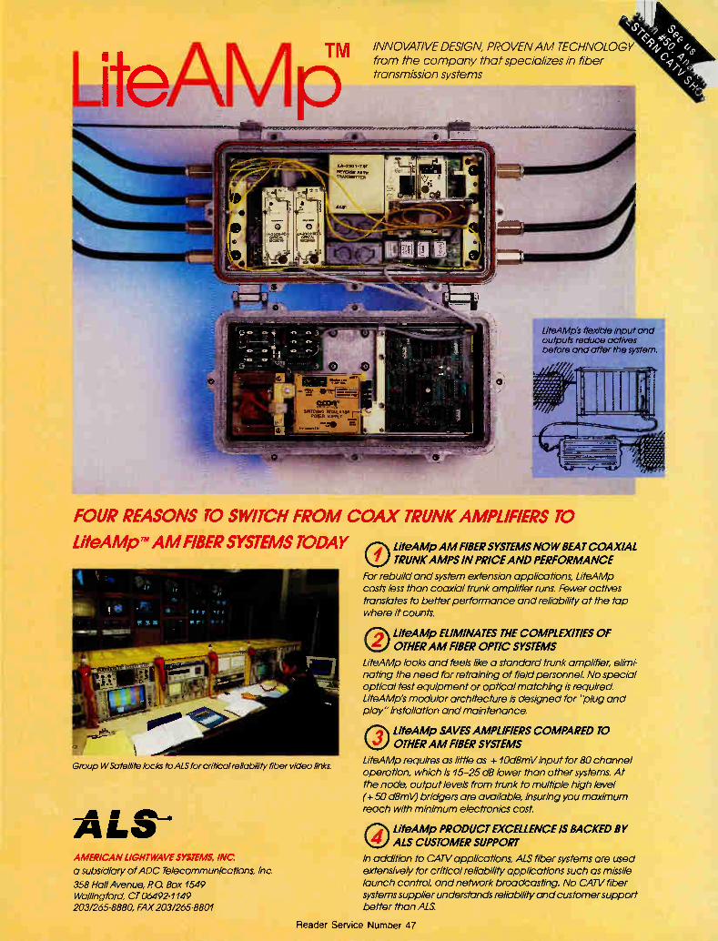
LiteAM LA -330,TXT
REVFPISF PATH TRAHPANT
INNOVATIVE DESIGN, PROVEN AM TECHNOLOGY from the company that specializes in fiber transmission systems
LiteAMp's flexible input and outputs reduce actives before and after the system.
FOUR REASONS TO SWITCH FROM COAX TRUNK AMPLIFIERS TO
LiteAMpw AM FIBER SYSTEMS TODAY
Group WSatellite locks to ALS for critical reliability fiber video links.
ALS-* AMERICAN LIGHTWAVE SYSTEMS, INC.
a subsidiary of ADC Telecommunications, Inc.
358 Hall Avenue, PO. Box 1549 Wallingford, CT 06492-1149 203/265-8880 FAX 203/265-8801
®LiteAMp AM FIBER SYSTEMS NOW BEAT COAXIAL
TRUNK AMPS IN PRICE AND PERFORMANCE
For rebuild and system extension applications, LiteAMp costs less than coaxial trunk amplifier runs. Fewer actives translates to better performance and reliability at the tap where it counts.
OLiteAMp ELIMINATES THE COMPLEXITIES OF OTHER AM FIBER OPTIC SYSTEMS
LiteAMp looks and feels like a standard trunk amplifier, elimi-nating the need for retraining of field personnel. No special optical test equipment or optical matching is required. LiteAMp's modular architecture is designed for 'plug and play" installation and maintenance.
®LiteAMp SAVES AMPLIFIERS COMPARED TO OTHER AM FIBER SYSTEMS
LiteAMp requites as little as + 10dBmV input for 80 channel operation, which is 15-25 dB lower than other systems. At the node, output levels from trunk to multiple high level (+50 dBml0 bridgers are available, insuring you maximum reach with minimum electronics cost.
OLiteAMp PRODUCT EXCELLENCE IS BACKED BY ALS CUSTOMER SUPPORT
In addition to CATV applications, ALS fiber systems are used extensively for critical reliability applications such as missile launch control, and network broadcasting. No CATV fiber systems supplier understands reliability and customer support better than ALS
Reader Service Number 47
SPOTLIGHT TAYLOR'S VANTAGE
Green, Labs poised for future, Kathy Berlin, CED, March 1989, p.8. Richard Green, President and CEO of Cable 'Iblevi-sion Laboratories Inc. Growth is goal of new SCTE president
(CED), Roger Brown, CED, August 1990, p.16. Wendell Woody, Director of Fiber Optics for Anixter Cable TV and 1990/91 SCTE President. Hranac carries SCTE message, Roger
Brown, CED, September 1988, p.14. Ron Hranac, Jones Intercable, newly elected President of the SCTE. Making change happen, Kathy Berlin,
CED, July 1989, p.16. Lemuel 'Parshis, VP and GM, Jerrold Distribution Systems. Man of the Year: Nick Hamilton-
Piercy (CED), Roger Brown, CED, January 1990, p.22. A profile of Nick Hamilton-Piercy, Vice President of Engineering and Technical Services at Rogers Cable TV. More than a technology, Kathy Berlin,
CED, November 1989, p.16. Al Johnson, director of technical operations, Cablevision Systems Corp. The more things change..., Linda J.
Johnson, CED, March 1988, p.6. Frank Ragone, Vice President of Engineering, Comcast. New spirit for head of R&D at Texscan,
Roger Brown, CED, p.8. Bert Henscheid, Vice President of Research and Develop-ment, lbxscan.
Nurturing customer satisfaction, Kathy Berlin, CED, August 1989, p.16. Jack 'frower, SCTE President and corporate engineer for WEHCO Video Inc. On technology's cutting edge (CED),
Kathy Berlin, CED, March 1990, p.16. Paul Heimbach, Senior Vice President of Engi-neering for Viacom Networks Group. People come first (CED), Leslie Miller,
CED, September 1990, p.14. Dick Hickman, Vice President of Engineering, Metrovision.
Quality, continuity still the keys, Kathy Berlin, CED, May 1989, p.12. David Willis, Director of Engineering, TCI.
Singing a different tune (CED), Kathy Berlin, CED, June 1990, p.20. Ned Moun-tain, Vice President of Marketing for We-gener Communications Inc.
Staying afloat with cable TV, Kathy Berlin, CED, October 1989, p.16. 'Ibrn Jokerst, asst. VP and director of engineering for Continental Cablevision. Stubbs part of cable's beginning, Kathy
Berlin, CED, February 1989, p.12. Graham Stubbs, Executive Vice President, Eidak Corp.
Vito and Zenith: Poised for the future, Roger Brown, CED, August 1988, p.8. Vito Brugliera, Vice President of Marketing, Zenith's Cable Products Division. Weathering the storm, Roger Brown,
CED, May 1988, p.8. Austin Coryell of ATC. Wendell Bailey, the engineer's man
in Washington (Man of the Year), Roger Brown, CED, January 1988, p.30. Back-ground and philosophy of Wendell Bailey.
Standards The right tool for the job (CED), Kathy
Berlin, CED, November 1989, p.40. The organizations working to develop standards for the cable industry.
Status monitoring
Advances in status monitoring (CT), Lee Thompson, Scientific-Atlanta, July 1989, p.76
Monitoring headend performance (CT), William Homiller, GI/Jerrold, February 1988, p.20 Remote headend monitoring (CT),
Eugene Fuller, Monroe Electronics, March 1988, p.22
Status monitoring: Hows and whys (CT), Colleen McGuire, GI/Jerrold, March 1988, p.14
Status monitoring in fiber optic sys-tems (CT), John Holobinko, American Light-wave Systems, October 1989, p.90
Status monitoring-It can be done (CT), Jerry Laufer, Bert Henscheid and Mark Harris, Uxscan, March 1988, p.19
Stereo
see "Audio"
Syndicated exclusivity
The good and bad of syndex (CED), Kathy Berlin, CED, December 1989, p.74. A re-examination of syndex. Syndex Who? What? When? Why?
(CED), Kathy Berlin, CED, August 1989, p.78. Syndicated exclusivity, what it is and what needs to be done.
System design
Basic AC system design (CT), Mark Bowers, CableSoft Engineering Services, October 1990, p.38
Basic RF system design (CT), Mark Bowers, CableSoft Engineering Services, September 1990, p.40
Calculating performance in the trunk (CT), Scott Loder, lbxscan Corp., June 1989, p.134 Care of the design department (CT),
William Bragg, CATV Designs Alive, July 1989, p.60 CATV system mapping using CADD
(CT), Michael Bauer, American Digital Cartography, and Ibny Steinmetz, Star Cablevision, July 1989, p.68
Complexities in cable system design (CED), David Fellows, Scientific-Atlanta Inc., February 1989, p.66. A brief overview of the technologies and tools in a system designer's toolkit. Designing a digital system (CED), An-
thony Radice, General Instrument, March 1989, p.60, Basic technology involved with digital signal transmission.
Designing the fiber backbone (CT), Monica Younger, ATC, December 1988, p.122 Earth grounding design for cable TV
systems (CED), Larry White, Anixter Cable TV and Roger J. Montambo, RE., American Electric Co., October 1990, p.56. Proper electrical grounding procedures.
Fiber optic system design, part I (CT), Robert Southard, Amp Inc., April 1988, p.24
Fiber optic system design, part II (CT), Robert Southard, Amp Inc., May 1988, p.74
Fiber optic system design, part I (CT), Robert Southard, Amp Inc., June 1988, p.84 Headend rewire/redesign considera-
tions (CT), James Kuhns, Continental Ca-blevision, February 1989, p.66 Keeping current with system design
(CED), Steven Biro, Biro Engineering, June 1988, p.91. How to deliver high C/N pictures to the TV set. Mapping a rebuild with computer.
aided drafting (CT), David Cervone, Viacom Cable of Long Island, April 1988, p.16 Microwave design for intercept paths
(CT), Jack Sanders, ATC, January 1989, p.36 PC software for accurate design (CT),
Barbara Lukens, ATC, February 1988, p.72 Sorting out CATV CAD, part I (CT),
John Gutierrez, ComNet, October 1990, p.32 System design in fiber optic video
(CT), Robert Walker, PCO, November 1988, p.38 A tracking procedure for drafting and
design (CT), Pam King, Jones Intercable, February 1988, p.62 UHF wideband networks alternative
design architecture (CED), Bob Beaury, C-COR Electronics and Rien Banna, C-COR Electronics, Europe, September 1990, p.66. The UHF approach to signal delivery and advantages to its use overseas. Using CADD to rebuild (CED), Auto-
mated Drawing Systems Inc., December 1989, p.82. Using CADD to reorganize your
headend (CED), Pete Smith, ATC Cablevision of Central Florida, November 1989, p.34. The advantages of designing a headend with CADD.
Taylor's Vantage
(All CT columns written by Archer Tay-lor, Malarkey-Taylor Associates.)
Allocation of tolerance, July 1989, p.102
Carrier-to-interference ratios, March 1989, p.106 Conventional wisdom, May 1989, p.122 Exponentialism, June 1989, p.186 Gee whiz!, May 1990, p.164 High definition television-When?, Janu-
ary 1989, p.122 How did it all start?, December 1989,
p.132 Is Europe taking another look?, Octo-
ber 1989, p.122 MMDS and 011ie North, March 1990,
p.111 Nothing ventured, nothing gained,
August 1989, p.146 On being young and growing old,
February 1989, p.89
96 Communications Engineering and Design December 1990
TAYLOR'S VANTAGE TESTS AND MEASUREMENTS
One or two lines?, February 1990, p.146 Statistical booby traps, November 1989,
p.96 What's the CATV business?, Septem-
ber 1989, p.114 What's going on out there?, April 1990,
P.138 Whither cable TV, April 1989, p.122
Tech Book
(A CT department) Amplitude modulation on an oscillo-
scope, Ron Hranac, Jones Intercable, May 1988, p.115 Amplitude modulation on a spectrum
analyzer, Ron Hranac, Jones Intercable, Apirl 1988, p.105 Antenna distance correction, Ron
Hranac, Jones Intercable, August 1989, p.129 Azimuth calculations, Ron Hranac, Jones
Intercable, September 1988, p.103 Call before you dig, part I, One-Call
Systems Intl, April 1989, p.159 Call before you dig, part II, One-Call
Systems Intl, May 1989, p.111 Dipole antennas, Ron Hranac, Jones
Intercable, July 1988, p.83 Distance calculations, Ron Hranac, Jones
Intercable, August 1988, p.117 EIA RS-250B video performance stan-
dards, Ron Hranac, Jones Intercable, June 1989, p.171 FCC leakage limits, Ron Hranac, Jones
Intercable, October 1989, p.117 Fiber optics glossary, part I, Hal
Williams, Jones Intercable, October 1988, p.111
Fiber optics glossary, part H, Hal Williams, Jones Intercable, November 1988, p.89
Fiber optics glossary, part III, Hal Williams, Jones Intercable, December 1988, p.143
G-line troubleshooting procedure, part I, Ron Hranac, Jones Intercable, February 1989, p.89
G-line troubleshooting procedure, part II, Ron Hranac, Jones Intercable, March 1989, p.99 Hughes AML reference data, Ron
Hranac, Jones Intercable, January 1988, p.93 MA-12X troubleshooting procedure,
Ron Hranac, Jones Intercable, January 1989, p.117
Noise, Ron Hranac and Frank Eichen-laub, Jones Intercable, March 1988, p.69 NTSC broadcast TV reference data,
Ron Hranac, Jones Intercable, July 1989, p.95
Voltage addition, Ron Hranac and Pam King, Jones Intercable, February 1988, p.83 µVim to dBp.V/m conversions, Ron Hranac,
Jones Intercable, September 1989, p.101
Tech Tips
(A CT department) Absolute vs. relative, Joe Sadel, Sadelco,
February 1990, p.142
Accuracy in visual carrier level meas-urements, Ron Hranac, Jones Intercable, November 1989, p.74 AML transmitter maintenance, Ron
Hranac, Jones Intercable, January 1990, p.82
Calculating performance in the trunk, Scott Loder, Texscan, June 1989, p.134
Co-channel, adjacent channel inter-ference, part I, Steve Biro, Biro Engineer-ing, July 1989, p.89
Co-channel, adjacent channel inter-ference, part II, Steve Biro, Biro Engineer-ing, August 1989, p.82 Headend rewire/redesign considera-
tions, Jim Kuhns, Continental Cablevision, February 1989, p.66 Hooking up multiple dwelling units,
Glyn Bostick, Microwave Filter, March 1988, p.62 Planning cable installations for MDUs,
Jerry linutwein, April 1988, p.81 Reducing longitudinal sheath currents
in transport trunks, Ron Hepler, Prime Cable, September 1989, p.76 RF splitter test and measurement,
part I, Michael Holland, Pico Macom, December 1988, p.124 RF splitter test and measurement,
part H, Michael Holland, Pico Macom, January 1989, p.100 A switch for syndex, Doug Greene,
Jones Intercable, December 1989, p.110 Upgrading for increased capacity, part
I, Richard Covell, GI/Jerrold, July 1988, p.66 Upgrading for increased capacity, part
H, Richard Covell, GI/Jerrold, August 1988, p.106 X*Press in the headend, Elizabeth
Buick, X*Press Information Services, May 1988, p.92
Tests and measurements
Amplitude modulation on an oscillo-scope (CT), Ron Hranac, Jones Intercable, MAy 1988, p.115 Amplitude modulation on a spectrum
analyzer (CT), Ron Hranac, Jones Interca-ble, April 1988, p.105
Easier testing with a CATV analyzer, part I (CED), Mary Jane Pahls, Hewlett-Packard Co., Signal Analysis Division, Oc-tober 1989, p.90. General spectrum analyzer applications and advantages.
Easier testing with a CATV analyzer, part II (CED), John Cecil, Mary Jane Pahls, Hewlett-Packard Co., Signal Analysis Divi-sion, October 1989, p.62.
Easier testing with a CATV analyzer, part HI, (CED), John Cecil, Mary Jane Pahls, Hewlett-Packard Co., Signal Analy-sis Division, December 1989, p.112.
Easier testing with a CATV analyzer, part IV (CED), John Cecil, Mary Jane Pahls, Hewlett-Packard Co., Signal Analy-sis Division, January 1990, SCTE Focus, p.82. Capabilities and convenience features of the analyzer. Fundamentals of spectrum analysis,
part I (CT), Bill Benedict, Tektronix, April 1988, p.46 Fundamentals of spectrum analysis,
part H (CT), Bill Benedict, Tektronix, May 1988, p.82 Fundamentals of spectrum analysis,
part III (CT), Bill Benedict, Tektronix, July 1988, p.53 Fundamentals of spectrum analysis,
part IV (CT), Bill Benedict, Tektronix, September 1988, p.70
Getting the most out of your SLM (CT), Steve Windle, Wavetek, April 1990, p.93 A historical look at signal level meters
(CED), Doyle Haywood, Applied Instru-ments, October 1990, p.68 How to adjust audio carrier deviation
(CT), Ron Hranac, Jones Intercable and Steve Johnson, ATC, November 1989, p.22 How to see video levels on an oscillo-
scope (CT), Ron Hranac, Jones Intercable, January 1988, p.52 How to set video depth of modulation
(CT), Ron Hranac, Jones Intercable, Decem-ber 1988, p.72 Measuring in-depth, part I (CT), A.
William LeDowc and William Benedict, Tektronix, November 1989, p.30 Measuring in-depth, part II (CT), Wil-
liam Benedict, Tektronix, December 1989, p.45 Measuring in-depth, part III (CT),
William Benedict, Tektronix, February 1990, p.28 Measuring video performance in
CATV (CT), Blair Fire, Precision Signal, December 1988, p.26 Merging broadband test and monitor
systems (CED), Jeffrey Cox and Aravanan Gurusami, Magnavox CATV, June 1988, p.84. The Magnavox Line Monitor, which combines the features of field test gear and status monitoring. Monitoring BTSC stereo (CT), Eric
Lane, TFT, December 1988, p.47 A new look at coaxial cable: Time
selective swept return loss (CT), John Huff, Times Mirror Cable, December 1988, p.60 The OTDIt—a universal tool (CT),
Patrick Abida, Schlumberger Instruments, December 1988, p.41 The progressing art of system sweep-
ing, part I (CED), Steve Windle, Wavetek RF Products, May 1988, p.58. Advantages and disadvantages of low, high and swee-pless sweep methods.
Putting HDTV to the test (CT), Willem Mostert, Magnavox CATV Systems, October 1988, p.72 Signal level meter basics (CED), Doyle
Haywood, Applied Instruments, October 1990, p.68 SLMs for all technical levels, (CT),
Steve Windle, Wavetek, December 1988, p.86 Standards and procedures for video
level measurement, Frank McClatchie, FM Systems Inc., March 1989, p.62. How to measure the voltage of a video waveform. Sweep technology comparisons (CT),
Mark Daugherty, Jones Intercable, Novem-ber 1989, p.40
Communications Engineering and Design December 1990 97
TESTS AND MEASUREMENTS VIDEO COMPRESSION
Sweeping modulators and processors (CT), Ron Hranac, fl-ansMedia Partners, May 1990, p.52 System sweeping (CED), Steve Windle,
Wavetek RF Products Inc., June 1989, p.128. How and why to sweep a system. System sweep techniques on an FM
transportation trunk (CT), William Le-Doux, CaLan, March 1988, p.26 Taking guesswork out of fiber testing
(CT), lbdd Jennings, Siecor, November 1989, p.34 Testing for "hot chassis" conditions
(CT), Alan Babcock, Warner Cable Commu-nications, September 1990, p.95 Using cable's "radar" (CED), J.R.
Johnston, TCI Cablevision of Wyoming, May 1990, SCTE Focus, p.122. Use of the time domain reflectometer. Using spectrum analyzers in micro-
wave digital radio measurements (CT), Jim Boyer, Hewlett-Packard, February 1990, p.24 Video hum distortions and measure-
ments (CT), Glen Wittrock, Sencore Elec-tronics, December 1988, p.56
Also see "From the Headend"
Training and education
Alternatives in training (CT), Al Dawk-ins, Al Dawkins Enterprises, June 1988, p.24
Basic electronics (CED), Steven D. Fry, Gateway Electronics Institute, June 1990, p.130. Basic electronics starting with the atom. CATV fiber training (CED), Dana
Eggert, Performance Plus, (Fiber Optics Application Guide, A special supplement of CED Magazine), September 1989, p.64. The role of training with fiber optics. CATV rules the Rockies (CED), Rikki
T. Lee, Rikki T. Lee Written Communica-tions Services, March 1990, p.64. The SCTE and its role in cable television training.
Certifiable technical training (CT), Alan Babcock, Warner Cable, June 1989, p.54
Continental's training school improves morale and efficiency (CV), P. Michael Saint, May 9, 1988, p.148. Continental's opening of a New Hampshire training facility renews commitment to CSR and technician training. A diverse endeavor (CT), Pam King,
Jones Intercable, October 1988, p.88 Engineers in training (CT), Pam King,
Jones Intercable, November 1988, p.36 An evolving training facility for our
changing industry (CT), Ronald Wolfe, ATC, July 1990, p.24
Federal job training program (CT), Frederick Sutliff, Henkels & McCoy, June 1989, p.48 Hands-on through interactive video
(CT), Pam Nobles, Jones Intercable, May 1990, p.72 How to implement a safety program
(CED), Roger Brown, CED, October 1988, p.84. How to set up a good safety program. How to improve your score on the
SCT/E category VII exam (CT), Ralph
Haimowitz, SCTE, January 1990, p.24 History of the NCTI (CT), Tom Brook-
sher, NCTI, July 1990, p.38 Improving efficiency of technical per-
sonnel (CT), Jon Ridley, GI/Jerrold, June 1988, p.70 Improving quality through perform-
ance management (CT), Dana Eggert, Performance Plus, July 1990, p.36
Installer certification program (CT), Ralph Haimowitz, SCTE, June 1989, p.52 The installer certification program:
Satisfying a need (CT), Howard Whitman, SCTE, May 1990, p.70
Interactive video: Touch your selec-tion (CT), Joel Milinsky and Rick Schick, A.R. Brasch Marketing, and Robt. McCleary, ATC, July 1989, p.64 Jones counts down to quality (CT),
Pam Nobles, Jones Intercable, March 1990, p.42 Keeping training records: It's smart,
it's the law (CT), Alan Babcock, Warner Cable Communications, July 1990, p.28 Management training for engineers
(CT), Chris Papas, The Mitre Corp., June 1988, p.50 Managing service call reduction (CT),
Robert Luff, Don Sutton and Pam King, Jones Intercable, with Dana Eggert, Per-formance Plus, June 1988, p.26 New approaches to training (CV),
Chuck Moozakis, August 13, 1990, p.31. Computer-based and interactive video train-ing to educate technicians. Oh no, another survey! (CT), Kenneth
Deschler, Cable Correspondence Courses, July 1990, p.42 One year later: Qualified installer
program (CT), Pam King, Jones Intercable, June 1989, p.26
Pole climbing classes: Who needs 'em? (CT), Kenny Faust, Heritage Ca-blevision, March 1990, p.92
Prerequisite to a training program (CT), Pam King, Jones Intercable, and Dana Eggert, Performance Plus, June 1988, p.32
Providing needs-based training (CT), Alan Babcock, ATC National 'fraining Cen-ter, June 1988, p.36 The renewed interest in tech training
(CED), Roger Brown, CED, October 1989, p.40. 'framing programs: options and avail-ability. The SCTE's role in training the indus-
try (CT), Howard Whitman, SCTE, July 1990, p.22 The SCTE's role as a training re-
source (CT), William Riker and Howard Whitman, SCTE, June 1988, p.47
Solution for CATV training: Interac-tive videodiscs (CT), Pam Nobles, Jones Intercable, July 1990, p.32 The supervisor's role in the training
process (CT), Dan Rumrill, Viacom Ca-blevision, June 1989, p.58
Technical training and the SCTE (CT), Howard Whitman, SCTE, June 1989, p.34 Techs and service: Back to school
(CTB), July 15, 1988, p.37 Think safety! Who me? (CT), Bruce
Habeck, Anixter, September 1990, p.94 Thwarting a crisis (CTB), August 1,
1990, p.42. Technical training programs. Training by the board (CT), Kenny
Faust, Heritage Cablevision, July 1990, p.92
'fraining for leakage detection (CT), Douglas Ceballos, Paragon (Minnesota), July 1989, p.38 'framing for the technical future, (CT),
Kenneth Deschler, Cable Correspondence Courses, June 1988, p.18 Iraining today prepares for impend-
ing fiber future (CT), Jim Hartman, Fiber-Lite International, September 1990, p.34
Training for tomorrow (CT), Ronald Wolfe, ATC, June 1989, p.50
Training installers (CTB), May 1, 1989, p.26
Training in the use of fiber optics (CT), Rebecca Frye, Siecor, June 1988, p.40
Training options and advantages (CT), Brooksher, NCTI, June 1989, p.36
'framing programs in fiber optics (CT), Wes Schick, Anixter Cable TV, and Virgil Hollingsworth, AT&T, June 1989, p.42 Training with interactive video (CT),
Judy Geisman, InterComm International, and Dana Eggert, dB Associates, June 1988, p.74
Training your maintenance and resto-ration team (CT), Rebecca Frye, Siecor, July 1990, p.30
Using videotapes in training (CT), Russell Smith, Cardinal Communications, June 1988, p.72 Vendor participation in technical train-
ing (CT), Dana Eggert, Performance Plus, June 1989, p.62
11fro-way communication BUSS remote switching system (CED),
Victor Nicholson, Buss Inc., May 1990, p.66. A detailed analysis of a new architecture.
Interactive TV: Who's playing now? (CED), Kathy Berlin, CED, September 1990, p.42. A history of interactive television and the current players. Which way for two-way? (CV), Chuck
Moozakis, August 27, 1990, p.17. Current developments in interactive television. Whither Two-Way? (CED), Kathy Ber-
lin, CED, May 1990, p.42. Whether two-way is making a comeback and the reasons behind the move.
Video compression Cable and compression (CV), Chuck
Moozakis, September 24, 1990, p.36. What video compression is, and why everyone is talking about it.
Putting the squeeze on (CV), Chuck Moozakis and Gary Kim, June 18, 1990, p.42. Video compression in light of consumer interface issues. Panel discussion with Bob Luff and John Linebarger of Jones Interca-ble and Jim Vaughn, Ili« Communica-tions. The road ahead (CV), Chuck Moozakis,
July 16, 1990, p.56. Bridging the gap between technological advancements and practical application.
98 Communications Engineering and Design December 1990
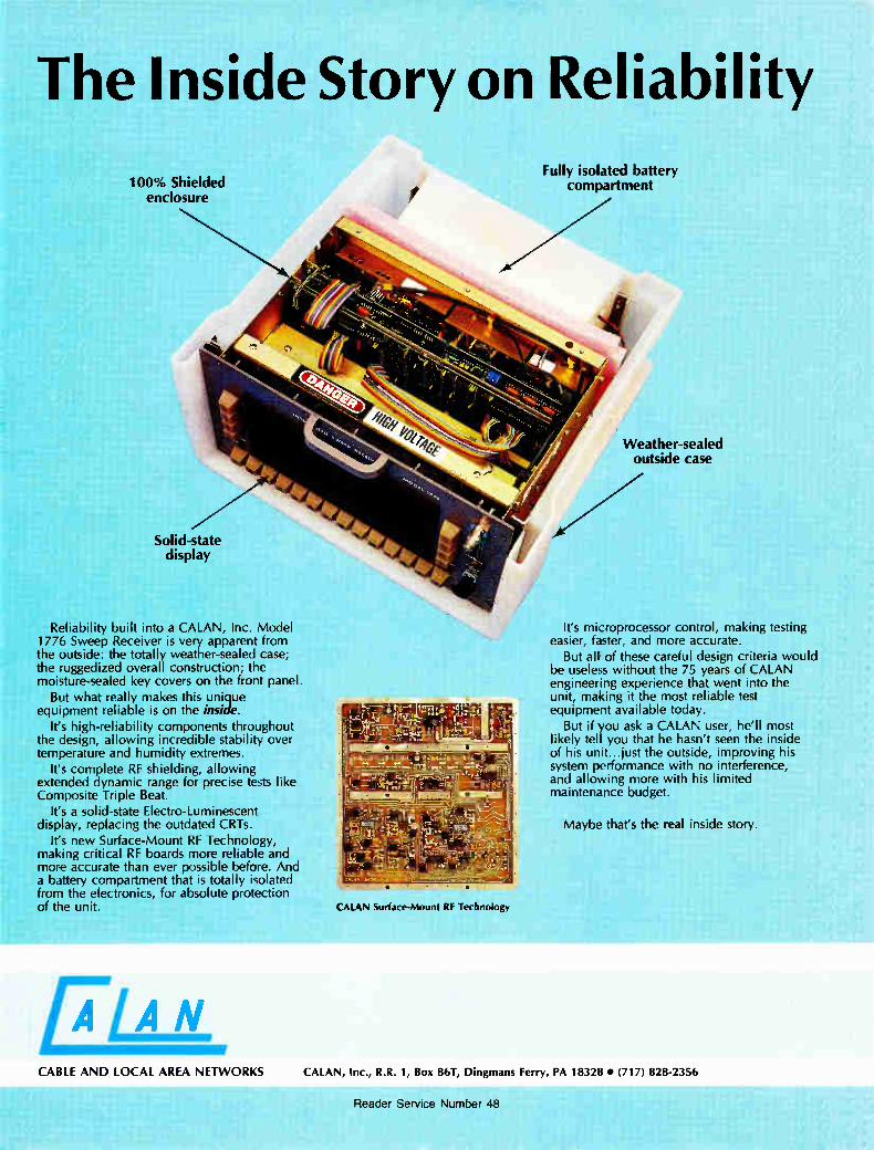
The Inside Story on Reliability
100% Shielded enclosure
Solid-state display
Reliability built into a CALAN, Inc. Model 1776 Sweep Receiver is very apparent from the outside: the totally weather-sealed case; the ruggedized overall construction; the moisture-sealed key covers on the front panel.
But what really makes this unique equipment reliable is on the inside.
It's high-reliability components throughout the design, allowing incredible stability over temperature and humidity extremes.
It's complete RF shielding, allowing extended dynamic range for precise tests like Composite Triple Beat.
It's a solid-state Electro-Luminescent display, replacing the outdated CRTs.
It's new Surface-Mount RF Technology, making critical RF boards more reliable and more accurate than ever possible before. And a battery compartment that is totally isolated from the electronics, for absolute protection of the unit. CALAN Surface-Mount RF Technology
Fully isolated battery compartment
Weather-sealed outside case
It's microprocessor control, making testing easier, faster, and more accurate.
But all of these careful design criteria would be useless without the 75 years of CALAN engineering experience that went into the unit, making it the most reliable test equipment available today.
But if you ask a CALAN user, he'll most likely tell you that he hasn't seen the inside of his unit...just the outside, improving his system performance with no interference, and allowing more with his limited maintenance budget.
Maybe that's the real inside story.
CABLE AND LOCAL AREA NETWORKS CALAN, Inc., R.R. 1, Box 86T, Dingmans Ferry, PA 18328 • (717) 828-2356
Reader Service Number 48
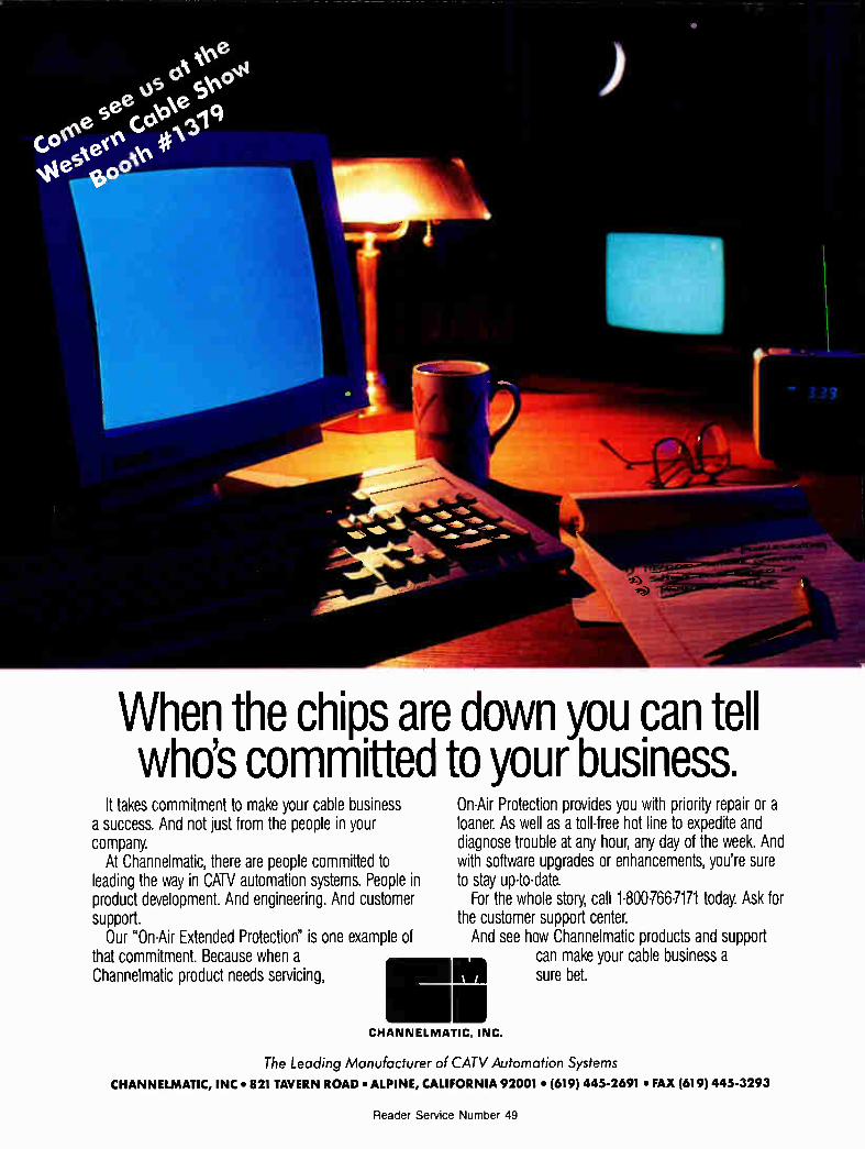
When the chips are down you can tell who's committed to your business.
It takes commitment to make your cable business a success. And not just from the people in your company.
At Channelmatic, there are people committed to leading the way in CATV automation systems. People in product development. And engineering. And customer support.
Our "On-Air Extended Protection" is one example of that commitment. Because when a Channelmatic product needs servicing,
On-Air Protection provides you with priority repair or a loaner. As well as a toll-free hot line to expedite and diagnose trouble at any hour, any day of the week. And with software upgrades or enhancements, you're sure to stay up-to-date.
For the whole story, call 1-800766-7171 today. Ask for the customer support center. And see how Channelmatic products and support
can make your cable business a sure bet.
CHANNELMATIC. INC.
The Leading Manufacturer of CATV Automation Systems CHANNELMATIC, INC • 821 TAVERN ROAD • ALPINE, CALIFORNIA 92001 • (619) 445-2691 • FAX (619) 445-3293
Reader Service Number 49
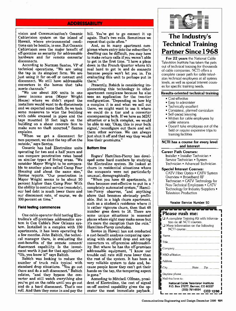
vision and Communication's Oceanic Cablevision system on the island of Hawaii, where environmental condi-tions can be hostile, is one. But Oceanic Cablevision sees the major benefit of off-premise as security for addressable hardware and for remote connects/ disconnects.
According to Norman Santos, VP of technical operations, "We are using the tap in its simplest form. We are just using it for on-off or connect and disconnect. We still have addressable converters in the homes that take movie channels." "We use about 300 units in one
lower income area (Mayor Wright House) where we didn't expect the installers would want to do disconnects and we expected some theft. So we took some measures to wire the building with cable encased in pipes and the taps mounted 18 feet high on the building on a shear concrete face to make sure no theft occurred," Santos explains. "When we get a disconnect for
non-payment, we shut the tap off on the outside," says Santos.
Oceanic has had Electroline units operating for two and a half years and can compare penetration rates based on similar types of living areas. "We consider Mayor Wright to be compara-ble to another place called Camp Four Housing and about the same size," Santos reports. "Our penetration in Mayor Wright seems to be about 20 percent higher than Camp Four. With the ability to control service (remotely), our bad debt is much lower there and our disconnect rate, of course, we do 100 percent on time."
Field testing commences
One cable operator field testing Elec-troline's off-premises addressable sys-tem is Cox Cable's New Orleans sys-tem. Installed in a complex with 150 apartments, it has been operating for a few months. John Babich, the techni-cal manager there, is evaluating the cost-benefits of the remote connect/ disconnect capability. Is the invest-ment worth it just for that application? "Oh, you know it!" says Babich.
Babich was looking to reduce the number of truck rolls typical with standard drop situations. "You go out there and do a soft disconnect," Babich relates, "and they bypass the con-verter and still watch everything else you've got on the cable until you go out and do a hard disconnect. That's one roll. And then they come in and pay the
bill. You've got to go connect it up again. That's two rolls. Sometimes we repeat that quite often."
And, as in many apartment com-plexes where entry into the subscriber's dwelling can be difficult, you may have to make return calls if you weren't able to get in the first time. "I have a place down in the French Quarter where it's real hard to get in and do connects because people won't let you in. I'm evaluating this unit to perhaps put in there."
Presently, Babich is considering im-plementing this technology in other apartment complexes because he also sees an application for the two-tier configuration. "Depending on how big a complex it is and what we sell out there, we might want to use it where we could do a tier and a converter encompassing both. If we have an MDU situation or a bulk complex, we would be able to say, 'Okay, this is your bulk signal,' reconfigure out there and sell them other services. We can always just shut it off and that way they would lose their premiums."
Bottom line
Rogers' Hamilton-Piercy has devel-oped some hard numbers by studying the Electroline system. He looked at churn in residential situations where the occupants were not particularly unusual, demographically. "When you have 48 apartments, it
then becomes cost-effective to put in a completely automated system," Hamil-ton-Piercy observes, "and anything above that becomes obviously profit-able. But in a high churn apartment, such as a student's residence where it is rather vigorous churn, then that 48 number goes down to 16. There are some unique situations in seasonal places where eight may make sense but it's more the exception than the rule," Hamilton-Piercy concludes.
Santos in Hawaii has not conducted a cost-benefit analysis comparing oper-ating with standard drop and set-top converters vs. off-premise addressabil-ity. But where he has the off-premises addressable equipment, "I know our trouble call rate still runs lower than the rest of the system. It has been a very reliable system to date and, be-cause people know they can't get their hands on the tap, the tampering aspect is gone."
According to Mitchell Olfman, presi-dent of Electroline, the cost of signal on-off control capability gives the op-erator the most immediate payback.
The Industry's Technical Training Partner Since 1968
For 22 years the National Cable Television Institute has taken the pain out of technical training for thousands of cable companies. NCTI offers a complete career path for cable televi-sion technical employees at all system levels, as well as special interest cours-es for specific training needs.
Results-oriented technical training
• Cost-effective • Easy to administer • Technically excellent • Consistent, planned curriculum • Self-paced learning • Written for cable employees by cable veterans • Doesn't take employees out of the
field or require expensive trips to training facilities
NCTI has a course for every level and interest
Career Path Courses: Installer • Installer Technician • Service Technician • System Technician • Advanced Technician
Special Interest Courses: CATV Fiber Optics • CATV System Overview • Broadband RF Technician • CATV Technology for Non-Technical Employees • CATV Technology for Industry Suppliers • Television Production
Reader Service Number 50
Please rush me: 13 A complete Training Kit with informa-
tion on all NCTI courses. 01 More information on the following
NCTI course:
Name
Title
Company
MSO affiliation
Address
City State Zip
Daytime phone
Mail this form to:
National Cable Television Institute P.O. Box 27277, Denver, CO 80227
(303) 761-8554 CED 12/90
Communications Engineering and Design December 1990 101
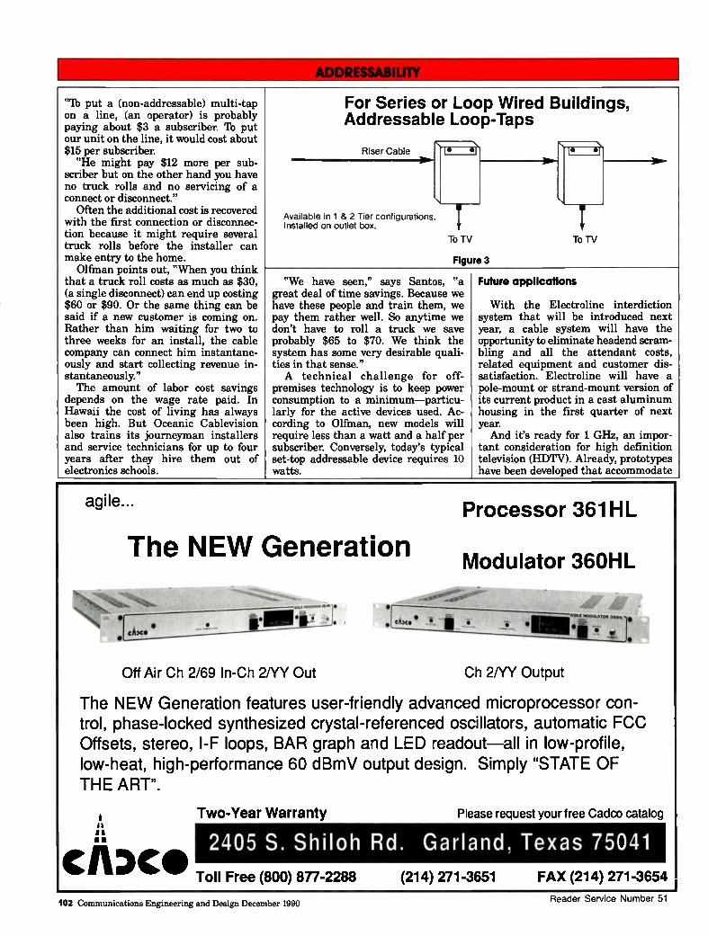
"lb put a (non-addressable) multi-tap on a line, (an operator) is probably paying about $3 a subscriber. lb put our unit on the line, it would cost about $15 per subscriber. "He might pay $12 more per sub-
scriber but on the other hand you have no truck rolls and no servicing of a connect or disconnect."
Often the additional cost is recovered with the first connection or disconnec- tion because it might require several truck rolls before the installer can make entry to the home.
Olfman points out, "When you think that a truck roll costs as much as $30, (a single disconnect) can end up costing $60 or $90. Or the same thing can be said if a new customer is coming on. Rather than him waiting for two to three weeks for an install, the cable company can connect him instantane- ously and start collecting revenue in- stantaneously." The amount of labor cost savings
depends on the wage rate paid. In Hawaii the cost of living has always been high. But Oceanic Cablevision also trains its journeyman installers and service technicians for up to four years after they hire them out of electronics schools.
For Series or Loop Wired Buildings, Addressable Loop-Taps
Riser Cable • ei vb .1
Available in 1 & 2 Tier configurations. Installed on outlet box.
To
Figure
i TV TO
3
TV
"We have seen," says Santos, "a great deal of time savings. Because we have these people and train them, we pay them rather well. So anytime we don't have to roll a truck we save probably $65 to $70. We think the system has some very desirable quali- ties in that sense." A technical challenge for off-
premises technology is to keep power consumption to a minimum—particu- larly for the active devices used. Ac- cording to Olfman, new models will require less than a watt and a half per subscriber. Conversely, today's typical set-top addressable device requires 10 watts.
Future applications
With the Electroline interdiction system that will be introduced next year, a cable system will have the opportunity to eliminate headend scram-bling and all the attendant costs, related equipment and customer dis-satisfaction. Electroline will have a pole-mount or strand-mount version of its current product in a cast aluminum housing in the first quarter of next year. And it's ready for 1 GHz, an impor-
tant consideration for high definition television (HDTV). Already, prototypes have been developed that accommodate
agile...
The NEW Generation
Processor 361HL
Modulator 36OHL
AGILE bl„OPAATOR
• • .4"
Off Air Ch 2/69 ln-Ch 2NY Out Ch 2NY Output
The NEW Generation features user-friendly advanced microprocessor con-trol, phase-locked synthesized crystal-referenced oscillators, automatic FCC Offsets, stereo, l-F loops, BAR graph and LED readout—all in low-profile, low-heat, high-performance 60 dBmV output design. Simply "STATE OF THE ART".
e▪ a
CADCO
Two-Year Warranty Please request your free Cadco catalog
2405 S. Shiloh Rd. Garland, Texas 75041
Toll Free (800) 877-2288 (214) 271-3651 FAX (214) 271-3654
102 Communications Engineering and Design December 1990 Reader Service Number 51
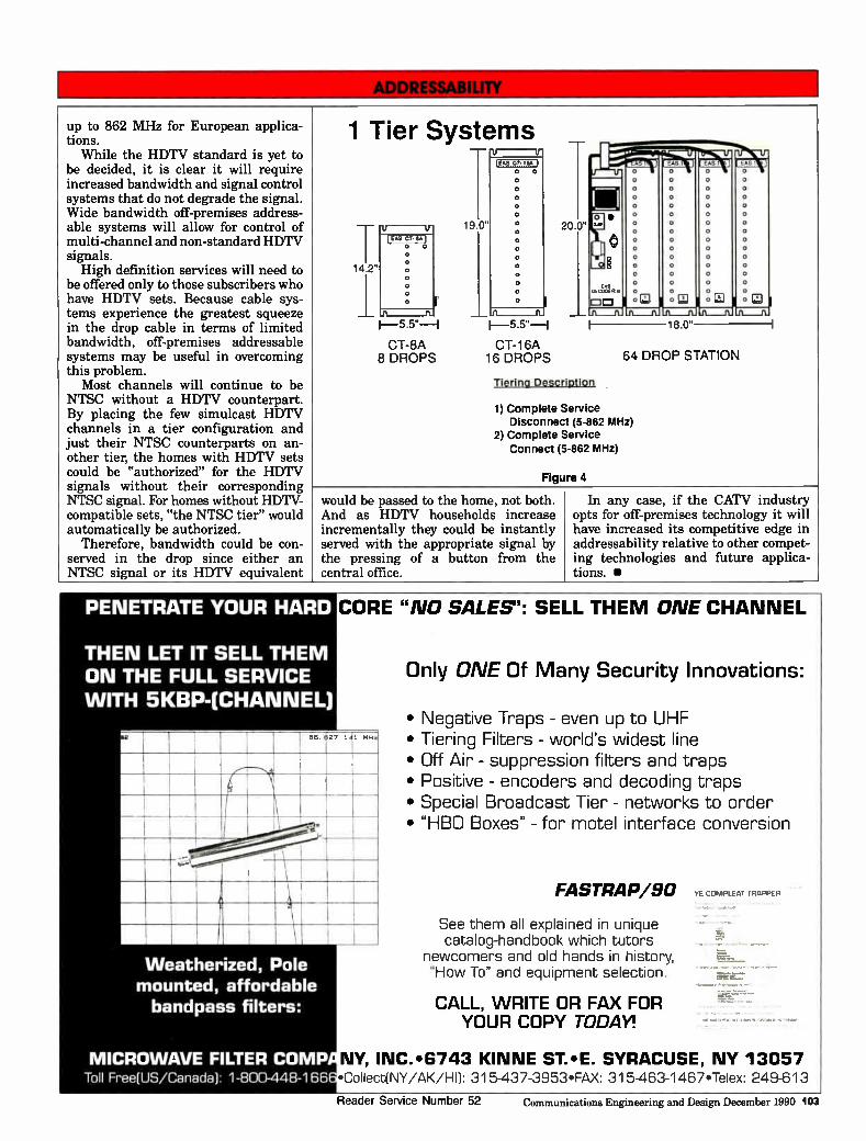
up to 862 MHz for European applica-tions.
While the HDTV standard is yet to be decided, it is clear it will require increased bandwidth and signal control systems that do not degrade the signal. Wide bandwidth off-premises address-able systems will allow for control of multi-channel and non-standard HDTV signals. High definition services will need to
be offered only to those subscribers who have HDTV sets. Because cable sys-tems experience the greatest squeeze in the drop cable in terms of limited bandwidth, off-premises addressable systems may be useful in overcoming this problem.
Most channels will continue to be NTSC without a HDTV counterpart. By placing the few simulcast HDTV channels in a tier configuration and just their NTSC counterparts on an-other tier, the homes with HDTV sets could be "authorized" for the HDTV signals without their corresponding NTSC signal. For homes without HDTV-compatible sets, "the NTSC tier" would automatically be authorized.
Therefore, bandwidth could be con-served in the drop since either an NTSC signal or its HDTV equivalent
1 Tier Systems
14 2"
CT-8A 8 DROPS
19.0"
(Ms At- IA*
0
CT-16A 16 DROPS
20.0"
DD
Tiering Description
18.0"
CAS ,
Ul I
64 DROP STATION
1) Complete Service Disconnect (5-862 MHz)
2) Complete Service
Connect (5-862 MHz)
Figure 4
would be passed to the home, not both. And as HDTV households increase incrementally they could be instantly served with the appropriate signal by the pressing of a button from the central office.
In any case, if the CATV industry opts for off-premises technology it will have increased its competitive edge in addressability relative to other compet-ing technologies and future applica-tions. •
PENETRATE YOUR HARD
THEN LET IT SELL THEM ON THE FULL SERVICE WITH 5KBP-(CHANNEL)
CORE "NO SALES": SELL THEM ONE CHANNEL
OIL 27 14
Weatherized, Pole mounted, affordable bandpass filters:
MICROWAVE FILTER COMP Toll Free(US/Canada) 1-800-448-166
Only ONE Of Many Security Innovations:
• Negative Traps - even up to UHF • Tiering Filters - world's widest line • Off Air - suppression filters and traps • Positive - encoders and decoding traps • Special Broadcast Tier - networks to order • "HBO Boxes" - for motel interface conversion
FASTRAP/90
See them all explained in unique catalog-handbook which tutors
newcomers and old hands in history, "How To" and equipment selection.
CALL, WRITE OR FAX FOR YOUR COPY TODAY!
YE COMPILAI IPAPPFP
NY, INC.•6743 KINNE ST.•E. SYRACUSE, NY 13057 •Collect[NY/AK/H1]: 315-437-3953•FAX: 315-463-1467•Telex: 249-613
Reader Service Number 52 Communications Engineering and Design December 1990 103
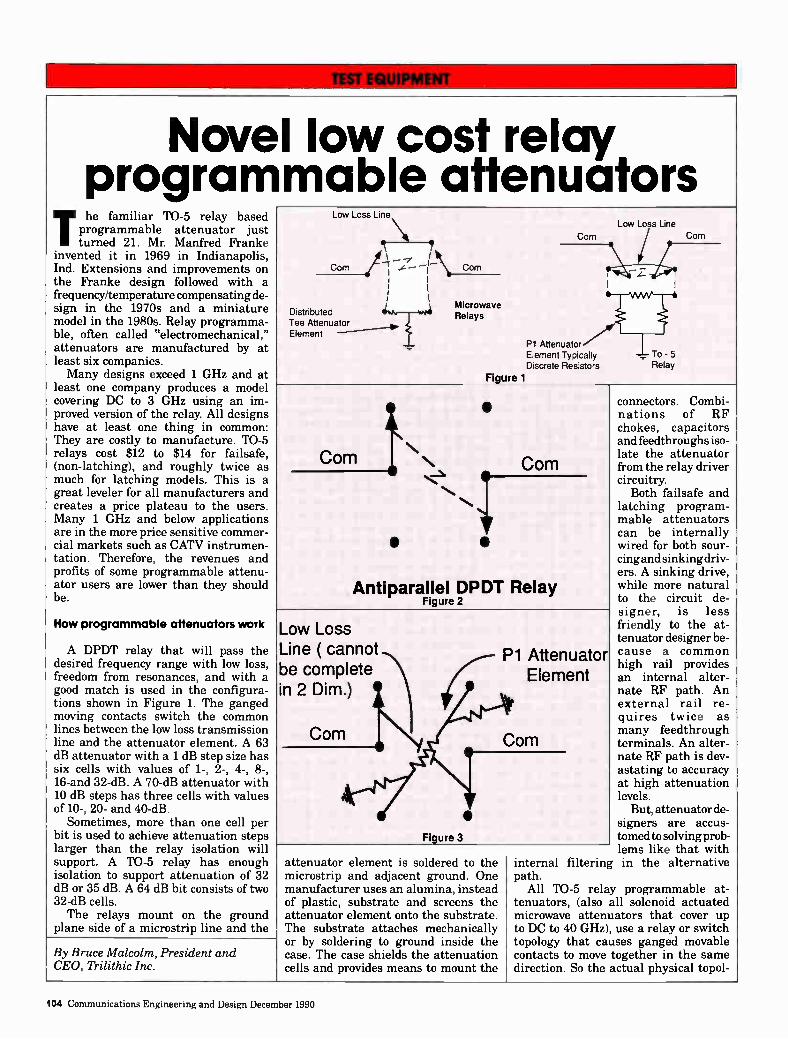
Nove program
.i. he familiar TO-5 relay based programmable attenuator just turned 21. Mr. Manfred Franke
invented it in 1969 in Indianapolis, Ind. Extensions and improvements on the Franke design followed with a frequency/temperature compensating de-sign in the 1970s and a miniature model in the 1980s. Relay programma-ble, often called "electromechanical," attenuators are manufactured by at least six companies. Many designs exceed 1 GHz and at
least one company produces a model covering DC to 3 GHz using an im-proved version of the relay. All designs have at least one thing in common: They are costly to manufacture. TO-5 relays cost $12 to $14 for failsafe, (non-latching), and roughly twice as much for latching models. This is a great leveler for all manufacturers and creates a price plateau to the users. Many 1 GHz and below applications are in the more price sensitive commer-cial markets such as CATV instrumen-tation. Therefore, the revenues and profits of some programmable attenu-ator users are lower than they should be.
How programmable attenuators work
A DPDT relay that will pass the desired frequency range with low loss, freedom from resonances, and with a good match is used in the configura-tions shown in Figure 1. The ganged moving contacts switch the common lines between the low loss transmission line and the attenuator element. A 63 dB attenuator with a 1 dB step size has six cells with values of 1-, 2-, 4-, 8-, 16-and 32-dB. A 70-dB attenuator with 10 dB steps has three cells with values of 10-, 20- and 40-dB.
Sometimes, more than one cell per bit is used to achieve attenuation steps larger than the relay isolation will support. A TO-5 relay has enough isolation to support attenuation of 32 dB or 35 dB. A 64 dB bit consists of two 32-dB cells. The relays mount on the ground
plane side of a microstrip line and the
I low cost relay mable attenuators
Low Loss Line
Corn
Distributed Tee Attenuator Element
1
_I\- -
Microwave Relays
Corn
PI Attenuator 7 Element Typically To - 5 Discrete Resistors Relay
Figure 1
Corn
Low Loss Line
Corn
Corn • Corn
• • •
S
Antiparallel DPDT Relay Figure 2
Low Loss Line ( cannot be complete in 2 Dim.) /
IN Corn
rPI Attenuator
Element
Figure 3
Corn
By Bruce Malcolm, President and CEO, Trilithic Inc.
attenuator element is soldered to the microstrip and adjacent ground. One manufacturer uses an alumina, instead of plastic, substrate and screens the attenuator element onto the substrate. The substrate attaches mechanically or by soldering to ground inside the case. The case shields the attenuation cells and provides means to mount the
internal filtering path.
All TO-5 rela tenuators, (also microwave attenu to DC to 40 GHz) topology that ca contacts to move direction. So the
connectors. Combi-nations of RF chokes, capacitors and feedthroughs iso-late the attenuator from the relay driver circuitry.
Both failsafe and latching program-mable attenuators can be internally wired for both sour-cing and sinking driv-ers. A sinking drive, while more natural to the circuit de-signer, is less friendly to the at-tenuator designer be-cause a common high rail provides an internal alter-nate RF path. An external rail re-quires twice as many feedthrough terminals. An alter-nate RF path is dev-astating to accuracy at high attenuation levels.
But, attenuator de-signers are accus-tomed to solving prob-lems like that with in the alternative
y programmable at-all solenoid actuated ators that cover up , use a relay or switch uses ganged movable together in the same actual physical topol-
104 Communications Engineering and Design December 1990
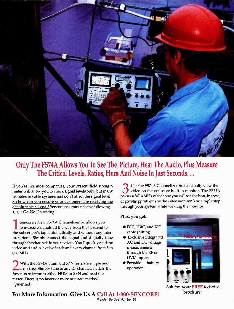
Only The FS74A Allows You To See The Picture, Hear The Audio, Plus Measure The Critical Levels, Ratios, Hum And Noise In Just Seconds. .
If you're like most companies, your present field strength meter will allow you to check signal levels only, but many
troubles in cable systems just don't affect the signal level!
So how can you ensure your customers are receiving the absolute best signal? Sencore recommends the following 1, 2, 3 Go-No-Go testing!
1 Sencore's New FS74A Channelizer Sr. allows you to measure signals all the way from the headend to
the subscriber's tap, automatically and without any inter-pretations. Simply connect the signal and digitally tune through the channels in your system. You'll quickly read the video and audio levels of each and every channel from 5 to
890 MHz.
2 With the FS74A, hum and S/N tests are simple and error free. Simply tune to any RF channel, switch the
function selector to either HUM or S/N and read the
meter. There is no faster or more accurate method. (patented)
3 Use the FS74A Channelizer Sr. to actually view the video on the exclusive built-in monitor. The FS74A
passes a full 4 MHz of video so you will see the beat, ingress, or ghosting problems on the video monitor. You simply step through your system while viewing the monitor.
Plus, you get:
• FCC, HRC, and ICC cable shifting.
• Exclusive integrated
AC and DC voltage measurements through the RF or DVM inputs.
• Portable — battery
operation.
For More Information Give Us A Call At 1-800-SENCORE! Reader Service Number 53
Ask for your FREE technical
brochure!
ogy matches the circuit of Figure 1.
A new design
The obvious way to make a cost breakthrough is to find lower cost parts. Inexpensive RF relays for cable ready TV sets had been available for some time, but the switching topology was antiparallel, as shown in Figure 2. An attenuator cell cannot be con-structed in a two dimensional plane
because the low loss RF line would run into the line containing the attenu-ation element, as can be seen by examining Figure 3. However, if an inexpensive way to route the RF signal in three dimensions could be con-structed, a low cost programmable attenuator would be possible. The answer was to use a combination
of stripline and microstrip lines. Stri-pline is a TEM line between ground planes and microstrip is a quasi-TEM
Check Your Automation! How many of the following will your present equipment handle?
El Commercial Insertion
lEl Pay-Per-View/Barker Channels
El Local Origination Channels
1111 Tape Management/Compile
El Satellite Record
El Channel Switching
TAP The Total Automation Platform
Wi9 All of the Above
For complete information on the Total Automation Platform call Jeff O'Brien at:
5‘SEe (617) 244-0354 iffAok Ammimpw 287 Grove Street
Newton, MA 02166
Reader Service Number 54
line above a ground plane 1,2. Both types of transmission line are easily constructed using plastic substrate ma-terials. The heart of the design is a three-
layer stack of substrates with crossing and fully isolated lines. Ground planes and plated-through holes help main-tain the impedance as the signal moves up and down the stack. There are also guard grounds beside the transmission lines, plated through holes to "carry" the RF ground everywhere in the multilayer stack it needs to be, and a place on the exposed microstrip level for the attenuation elements.
Slashing the costs
With the initial tests of the prototype models showing potential DC to 1 GHz performance, it was appropriate to look at each functional part and decide how the cost might be reduced and whether the part was really necessary.
If an inexpensive way to route the RF signal in three dimensions could be constructed,
a low cost programmable
attenuator would be possible.
Enclosure. An enclosure was neces-sary for many applications and it was likely that the user's mechanical mount-ing requirements would vary greatly. That suggested sheet metal because it is flexible and less costly than milling. Castings and extrusions require costly tooling and tend to freeze the mechani-cal design. Over a period of months, an extremely simple mechanical pack-age evolved with the help of local machine shop operators. These practi-cal sheet metal experts managed to eliminate a lot more cost. Finally, when the improvements stopped, new fabrication bids indicated that the plating cost was now 30 percent of the cost of the enclosure. A material that was workable, strong,
solderable, stainless and inexpensive
106 Communications Engineering and Design December 1990

Wavetek offers the clearest choices in signal level meters.
From the smallest to the largest CAD/ system, Wavetek has a complete family of field strength meters.
Beginning with MICRO SAM, Wavetek provides an easy to use installer meter with the versatility of auto-ranging and programmable channel plans. SAM JR is a proven field strength meter combining full amplitude and frequency range.
For more advanced trouble shooting, SAM 1000 ventures one step further with quick keyboard tuning and improved measurement accuracy. Complete system maintenance becomes a snap with the SAM 2000,
Wavetek's trunk and headend meter. The SAM 2000 incorporates automated test functions that simpW system measurements. The premier FIBER SAM rounds out
the complete SAM line with all the sim-plicity of the SAM 2000 and incorpo-rates an optical power meter.
For all their sophistication and effec-tiveness, Wavetek's SAM signal level meters are remarkably easy to use, so your technicians can spend more time testing.
Digital technology provides precise tuning at the push of a button, accu-rate amplitude measurement through-out the frequency range, and long
service life through the use of electronic attenuators rather than conventional mechanical types.
Also, Wavetek signal analysis meters (SAM'S) are built tough—to take bouncing around in a truck or swinging from a pole—in any weather!
Give your subscribers the best cable performance by using the best signal analysis meters. To see how Wavetek offers more in "SAM" technol-ogy, join us at the Western Show on November 28th-30th. Or contact your nearest representative or distributor for a demonstration.
Reader Service Number 55 \"/AN/1" K .

JERRY BINS ELECTROCUTED HIMSELF TODAY.
AND HIS BOSS IS GLAD NE DID.
Jerry just made a "fatal" error, but in the safety of a simulated work environment. What better way to learn about the myth of insulated gloves? It's just one of the many, many interactive exercises in the new technical training series from Mind Extension Instituter
This is interactive-video training at its best. The student is truly involved every step of the way; responding to questfons, making decisions and correcting mistakes. And, because the instruction is self-pacing and one-on-one, anyone at any time can get just the help they need.
The new courses include General Safety, featuring the top ten safety issues
in cable, and Installentaining, a nuts and bolts course that will challenge even the seasoned installer.
You take care of the hands-on training, we'll take care of the rest. Call now and take advantage of our free demonstration and special intro-ductory pricing 1-800-833-3472.
Experience the program yourself at the Western Show, Booth 1441. MIND EXTENSION INSTITUTE,,
Produced in cooperation with: Alpha lèchnologi, Animer Cable TV, AT&T CALAN, Inc., Channel! Commercial Corporation, Comm/Scope, Inc., Eagle Corntronics, Inc., Gilbert Engineering Co., Inc., Integal, Magnavox CATV ,sterns, Inc., Scientific-Atlanta, Inc., Trilithic, Inc.
Reader Service Number 56
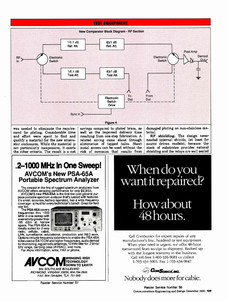
TEST EaUIPIIMMIIIMMIIIMM
New Comparator Block Diagram - RF Section
RE In
1 0 1 dB Ref. Att.
Electronic Switch
1/0.1 dB Test Att.
Sync in>
63/1 dB Ref. Att.
63/1 dB Test Att.
Electronic Switch Drive
Figure 4
A To Dut
Electronic Switch
From Dut
Post Amp
Ni Demod Out<
was needed to eliminate the require-ment for plating. Considerable time and effort were spent to find and qualify a material for the new attenu-ator enclosures. While the material is not particularly inexpensive, it meets the other criteria. The result is a net
savings compared to plated brass, as well as the improved delivery time resulting from one-step fabrication. A related saving came about through elimination of tapped holes. Sheet metal screws can be used without the risk of corrosion that results from
.2-1000 MHz In One Sweep! AVCOM's New PSA-65A
Portable Spectrum Analyzer The newest in the line of rugged spectrum analyzers from
AVCOM offers amazing performance for only $2,855. AVCOM'S new PSA-65A is the first low cost general pur-
pose portable spectrum analyzer that's loaded with features. It's small, accurate, battery operated, has a wide frequency coverage - a must for every technician's bench. Great for field use too. The PSA-65A covers
frequencies thru 1000 MHz in one sweep with asensitivity greater than -95 dBm at narrow spans. The PSA-65A is ideally suited for 2-way radio, cellular, cable, LAN, surveillance, educational, production and R&D work. Options include frequency extenders to enable the PSA-65A to be used at SATCOM and higher frequencies, audio demod for monitoring, log periodic antennas, 10 KHz filter for .2 MHz/ DIV range, carrying case (AVSAC), and more.
For more information, write, FAX or phone.
AVCOM BRINGING HIGH TECHNOLOGY DOWN TO EARTH
500 SOUTHLAKE BOULEVARD RICHMOND, VIRGINIA 23236; 804-794-2500
FAX: 804-794-8284, TLX: 701-545
Reader Service Number 57
damaged plating on non-stainless ma-terial. RF shielding. The design never
needed internal shields, (at least for source driven models), because the stack of substrates provides natural shielding and the relays are well sealed
When do you want it repaired?
How about 48 hours.
Call ComSonics for expert repairs of any manufacturer's line, headend or test equipment. When your need is urgent, we offer 48-hour
turnaround from receipt to shipment. Backed up with the longest warranty in the business.
Call toll-free 1-800-336-9681 or collect 1-703-434-5965. Fax 1-703-434-9847.
etalSONICS, MC.
Nobody does more for cable. Reader Service Number 58
Communications Engineering and Design December 1990 109
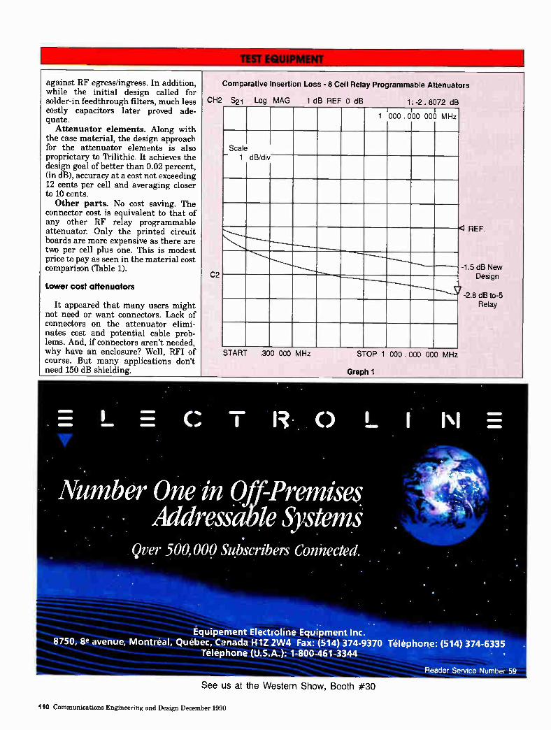
against RF egress/ingress. In addition, while the initial design called for solder-in feedthrough filters, much less costly capacitors later proved ade-quate.
Attenuator elements. Along with the case material, the design approach for the attenuator elements is also proprietary to 'Prilithic. It achieves the design goal of better than 0.02 percent, (in dB), accuracy at a cost not exceeding 12 cents per cell and averaging closer to 10 cents. Other parts. No cost saving. The
connector cost is equivalent to that of any other RF relay programmable attenuator. Only the printed circuit boards are more expensive as there are two per cell plus one. This is modest price to pay as seen in the material cost comparison (Table 1).
Lower cost altenuators
It appeared that many users might not need or want connectors. Lack of connectors on the attenuator elimi-nates cost and potential cable prob-lems. And, if connectors aren't needed, why have an enclosure? Well, RFI of course. But many applications don't need 150 dB shielding.
Comparative Insertion Loss - 8 Cell Relay Programmable Attenuators
CH2 S21 Log MAG 1 dB REF 0 dB
C2
1: -2 . 8072 dB
1 000 . 000 000 MHz
Scale — 1 dB/div
START .300 000 MHz STOP 1 000 . 000 000 MHz
Graph 1
REF.
-1.5 dB New Design
7 -2.8 dB to-5 Relay
UM»
MIMI» C T I. 0 L.
Number One in Off-Premises. Addressable Systems
Qver 500,000 Subscribers Connected
N E
Équipement Electroline Equipment Inc. 8750, 8e avenue, Montréal, Québec, Canada H1Z 2W4 Fax: (514) 374-9370 Téléphone: (514) 374-6335
Telephone (U.S.A.): 1-800-461-3344 • •
Reader Service Number 59
See us at the Western Show, Booth #30
110 Communications Engineering and Design December 1990
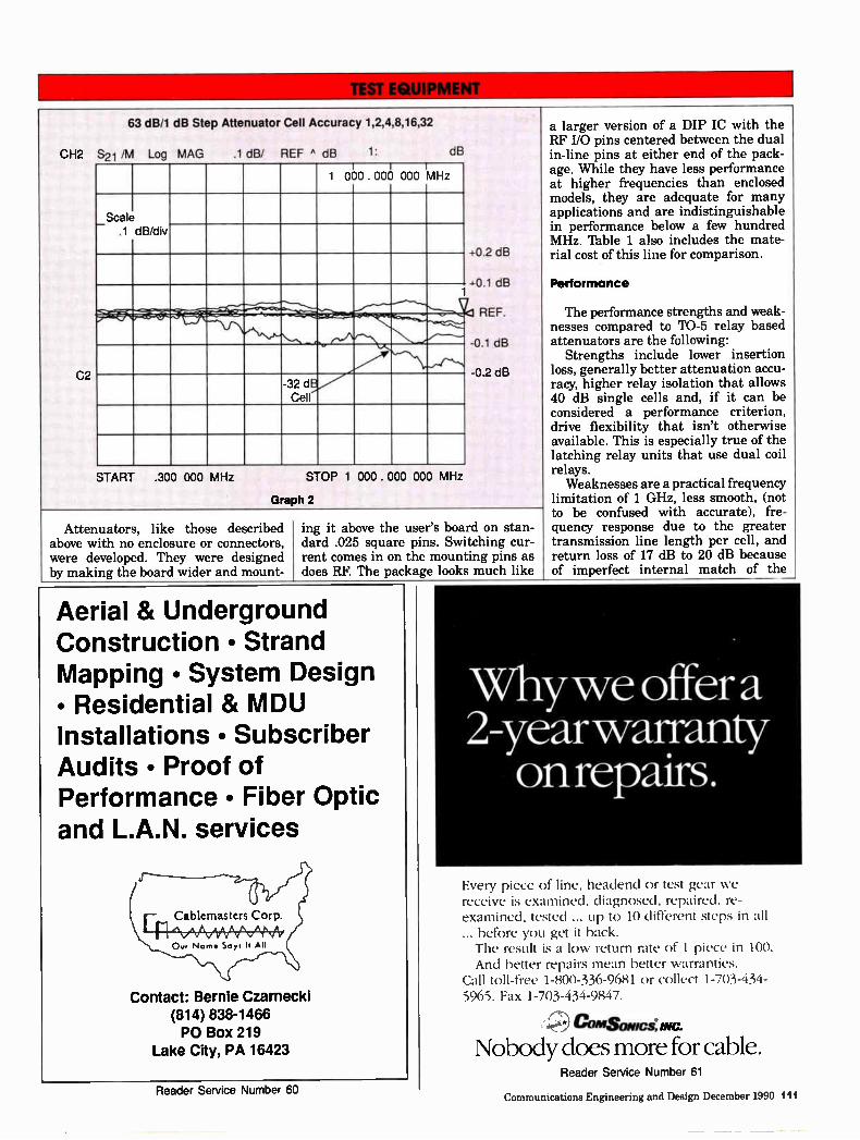
63 dB/1 dB Step Attenuator Cell Accuracy 1,2,4,8,16,32
CH2 S21 /M Log MAG
C2
.1 dB/ REF A dB 1: dB
1 000 . 000 000 MHz
_ Scale .1 dB/div
1
-32 dB Cell
START .300 000 MHz STOP 1 000 . 000 000 MHz
Graph 2
+0.2 dB
40.1 dB
REF.
0.1 dB
0.2 dB
Attenuators, like those described above with no enclosure or connectors, were developed. They were designed by making the board wider and mount-
ing it above the user's board on stan-dard .025 square pins. Switching cur-rent comes in on the mounting pins as does RF. The package looks much like
Aerial & Underground Construction • Strand Mapping • System Design • Residential & MDU Installations • Subscriber Audits • Proof of Performance • Fiber Optic and L.A.N. services
Contact: Bernie Czarnecki
(814) 838-1466
PO Box 219 Lake City, PA 16423
a larger version of a DIP IC with the RF I/O pins centered between the dual in-line pins at either end of the pack-age. While they have less performance at higher frequencies than enclosed models, they are adequate for many applications and are indistinguishable in performance below a few hundred MHz. Table 1 also includes the mate-rial cost of this line for comparison.
Performance
The performance strengths and weak-nesses compared to TO-5 relay based attenuators are the following:
Strengths include lower insertion loss, generally better attenuation accu-racy, higher relay isolation that allows 40 dB single cells and, if it can be considered a performance criterion, drive flexibility that isn't otherwise available. This is especially true of the latching relay units that use dual coil relays.
Weaknesses are a practical frequency limitation of 1 GHz, less smooth, (not to be confused with accurate), fre-quency response due to the greater transmission line length per cell, and return loss of 17 dB to 20 dB because of imperfect internal match of the
Why we offer a 2-year warranty on repairs.
Every piece of line, heaclend or test gear we receive is examined, diagnosed, repaired, re-examined, tested ... up to 10 different steps in all ... before you get it back. The result is a low return rate of 1 piece in 100. And better repairs mean better warranties.
Call toll-free 1-800-336-9681 or collect 1-703-434-5965. Fax 1-703-43.08-17.
CMSOICCS, INC.
Nobody does more for cable.
Reader Service Number 60
Reader Service Number 61
Communications Engineering and Design December 1990 111
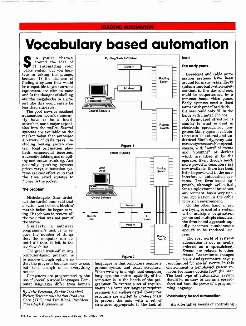
HEADEND AUTOMATION
Vocabulary based automation
So you've thrown around the idea of of automating your
cable system, but you hesi-tate in taking the plunge, because 1) the chances of finding a system that would be compatible to your current equipment are slim to none and 2) the thought of shelling out the megabucks to a pro-ject like this would surely be less than enjoyable. The good news is headend
automation doesn't necessar-ily have to be a head-scratcher, nor a major expedi-tion into the wallet. Several systems are available on the market today that automate a variety of daily tasks, in-cluding routing switch con-trol, local origination play back, commercial insertion, automatic dubbing and compil-ing and router trunking. And generally speaking (system prices vary), automation sys-tems are cost effective in that the time saved equates to money in the pocket.
The problem
Michelangelo (the artist, not the turtle) once said that a statue was inside a block of marble before he began carv-ing. His job was to remove all the rock that was not part of the statue.
Similarly, a software programmer's task is to re-duce the number of things that the computer can do, until all that is left is the user's wish list. The great trade-off in any
computer-based program is to remove enough options so that the program becomes easy to use, but keep enough to do everything needed. Computers are programmed by the
use of special purpose languages. Com-puter languages differ from human
Routing Switch Control
o
[ •am 111111111111111111111111111111
Modem
— t Modem
(deAegeek Control Software
Figure 1
Routing
Switch
Routing —
Switch —
Router Trunking
Local Office
rl E171111111111111111111111111111 1
Control Software
Remote Site
Modem
Modem
Figure 2
4 Trunks
Routing Switch
Routing Switch
By Julie Peterson, Senior Technical Writer, Telecommunication Products Corp. (TPC) and Tim Black, President, Tim Black Engineering
languages in that computers require a precise syntax and exact structure. When writing in a high level computer language, the entire capability of the computer is in the hands of the pro-grammer. 'lb express a set of require-ments in a computer language requires precision and endless detail. Computer programs are written by professionals to present the user with a set of structures appropriate to the task at
hand.
The early years
Broadcast and cable auto-mation systems have been around for many years. Early systems were built with comput-ers- that, in this day and age, could be outperformed by a common home video game. Early systems used a fixed format with predefined fields— the user could only fill in the fields with limited choices. A form-based structure is
similar to what is used in electronic spreadsheet pro-grams. Many types of calcula-tions can be entered and un-derstood. Similarly, many auto-mation systems are like spread-( sheets, with "rows" of events and "columns" of devices which are filled in by the operator. Even though much more powerful computers are now available, there has been little improvement in the user-interface of automation sys-tems. The form-based ap-proach, although well-suited for a single channel broadcast environment, has a very nar-row application in the cable television environment. On the other hand, if you
are trying to control a system with multiple origination points and multiple channels, the form-based approach rap-idly becomes cumbersome enough to be rendered use-less. The real world of systems
automation is not as neatly ordered as a spreadsheet. Events are related to other events. Last-minute changes occur. And systems are largely
reconfigured for special events. In this environment, a form-based system re-moves too many options from the user. The best type of automation system should be as easy to use as a spread-sheet but have the power of a program-ming language.
Vocabulary based automation
An alternative means of controlling
114 Communications Engineering and Design December 1990
If your head is no you're prob
Local advertising interconnects too often spin their wheels to get new spots out to their headends. They're doing it the old way, and that's wasteful and inefficient. The delays can translate into missed opportunities. Now Texscan MSI offers a better way to
get your reels — and profits — into focus. Tap into the future by upgrading your commercial insertion system with Texscan's Video Download Controller, the new CSR-294D.
Use it to automatically record satellite-delivered video for commercial spot reels right at the headend. Use it to record local news
updates microwaved across town. Point your heads in the right direction.
You may just see your profits soar to the heavens.
Texscanmsy-Salt Lake City, Utah
(800) 367-6011 • (801) 359-0077
Reader Service Number 63
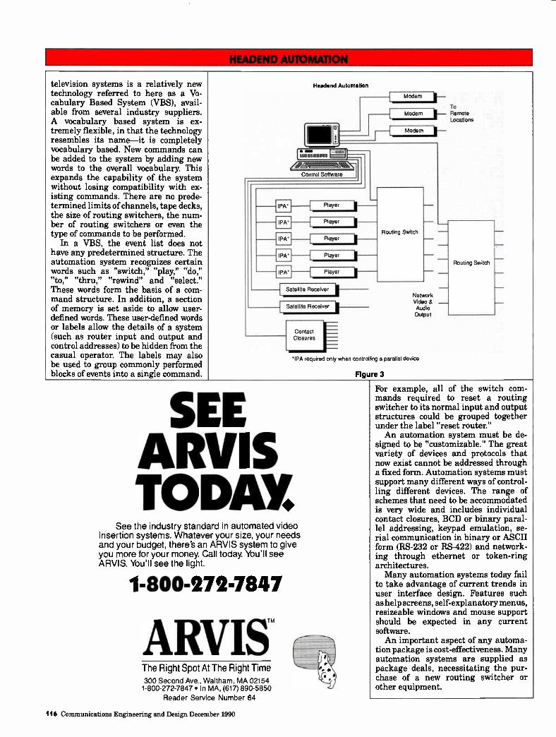
television systems is a relatively new technology referred to here as a Vo-cabulary Based System (VBS), avail-able from several industry suppliers. A vocabulary based system is ex-tremely flexible, in that the technology resembles its name—it is completely vocabulary based. New commands can be added to the system by adding new words to the overall vocabulary. This expands the capability of the system without losing compatibility with ex-isting commands. There are no prede-termined limits of channels, tape decks, the size of routing switchers, the num-ber of routing switchers or even the type of commands to be performed.
In a VBS, the event list does not have any predetermined structure. The automation system recognizes certain words such as "switch," "play," "do," "to," "thru," "rewind" and "select." These words form the basis of a com-mand structure. In addition, a section of memory is set aside to allow user-defined words. These user-defined words or labels allow the details of a system (such as router input and output and control addresses) to be hidden from the casual operator. The labels may also be used to group commonly performed blocks of events into a single command.
Headend Automation
o
•
Modem
To Modem s— Remote
Locations
Modem
KéP"MNa Control Software I
- IPA•
IPA•
—I IPA'
- IPA•
— I IPA
Player
Player
-t Player
Player
Player
Satellite Receiver
Satellite Receiver
Contact Closures
Routing Switch
Network Video & — Audio Output
IPA required only when controlling a parallel device
Figure 3
Routing Switch —
SEE AWE TODRL
See the industry standard in automated video insertion systems. Whatever your size, your needs and your budget, there's an ARVIS system to give you more for your money. Call today. You'll see ARVIS. You'll see the light.
1-800-272-7847
AIMS The Right Spot At The Right Time 300 Second Ave., Waltham, MA 02154 1-800-272-7847 • In MA, (617) 890-5850
Reader Service Number 64
For example, all of the switch com-mands required to reset a routing switcher to its normal input and output structures could be grouped together under the label "reset router." An automation system must be de-
signed to be "customizable." The great variety of devices and protocols that now exist cannot be addressed through a fixed form. Automation systems must support many different ways of control-ling different devices. The range of schemes that need to be accommodated is very wide and includes individual contact closures, BCD or binary paral-lel addressing, keypad emulation, se-rial communication in binary or ASCII form (RS-232 or RS-422) and network-ing through ethernet or token-ring architectures. Many automation systems today fail
to take advantage of current trends in user interface design. Features such as help screens, self-explanatory menus, resizeable windows and mouse support should be expected in any current software. An important aspect of any automa-
tion package is cost-effectiveness. Many automation systems are supplied as package deals, necessitating the pur-chase of a new routing switcher or other equipment.
116 Communications Engineering and Design December 1990
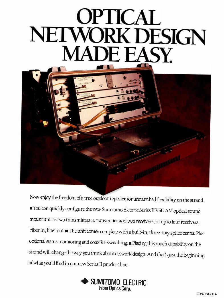
OPTICAL NETWORK DESIGN
MADE EASY
Now enjoy the freedom of a true outdoor repeater, for unmatched flexibility on the strand.
• You can quickly configure the new Sumitomo Electric Series II VSB-AM optical strand
mount unit as two transmitters; a transmitter and two receivers; or up to four receivers.
Fiber in, fiber out. • The unit comes complete with a built-in, three-tray splice center. Plus
optional status monitoring and coax RF switching u Placing this much capability on the
strand will change the way you think about network design. And that's just the beginning
of what you'll find in our new Series II product line.
• SUMITOMO ELECTRIC Fiber Optics Corp.
CONTINUED>
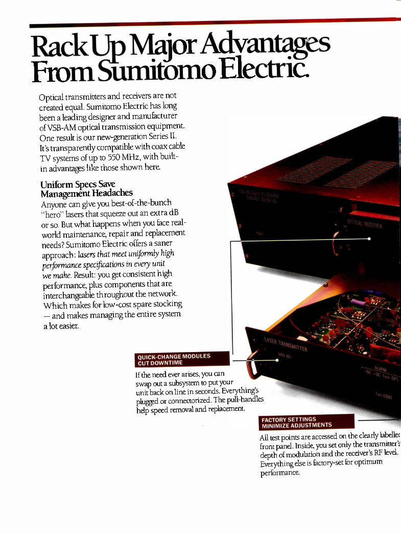
Rack Un Major Advantages From Sumitomo Electric
Optical transmitters and receivers are not created equal. Sumitomo Electric has long been a leading designer and manufacturer of VSB-AM optical transmission equipment. One result is our new-generation Series II. It's transparently compatible with coax cable TV systems of up to 550 MHz, with built-in advantages like those shown here.
Uniform Specs Save Management Headaches Anyone can give you best-of-the-bunch "hero" lasers that squeeze out an extra dB or so. But what happens when you face real-world maintenance, repair and replacement needs? Sumitomo Electric offers a saner approach: lasers that meet uniformly high performance specifications in every unit we maize. Result: you get consistent high performance, plus components that are interchangeable throughout the network. Which makes for low-cost spare stocking — and makes managing the entire system a lot easier.
QUICK-CHANGE MODULES CUT DOWNTIME
If the need ever arises, you can swap out a subsystem to put your unit back on line in seconds. Everything's plugged or connectorized. The pull-handles help speed removal and replacement.
FACTORY SETTINGS MINIMIZE ADJUSTMENTS
All test points are accessed on the clearly labelle( front panel. Inside, you set only the transmitter's depth of modulation and the receiver's RF level. Everything else is factory-set for optimum performance
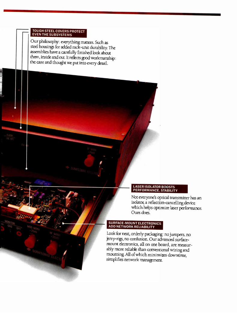
TOUGH STEEL COVERS PROTECT EVEN THE SUBSYSTEMS
Our philosophy: everything matters. Such as steel housings for added rack-unit durability The assemblies have a carefully finished look about them, inside and out. It reflects pod workmanship: the care and thought we put into every detail.
LASER ISOLATOR BOOSTS PERFORMANCE, STABILITY
Not everyone's optical transmitter has an isolator, a reflection-cancelling device which helps optimize laser performance Ours does.
SURFACE-MOUNT ELECTRONICS ADD NETWORK RELIABILITY
Look for neat, orderly packaging: no jumpers, no jerry-rigs, no confusion. Our advanced surface-mount electronics, all on one board, are measur-ably more reliable than conventional wiring and mounting All of which minimizes downtime, simplifies network manapment.
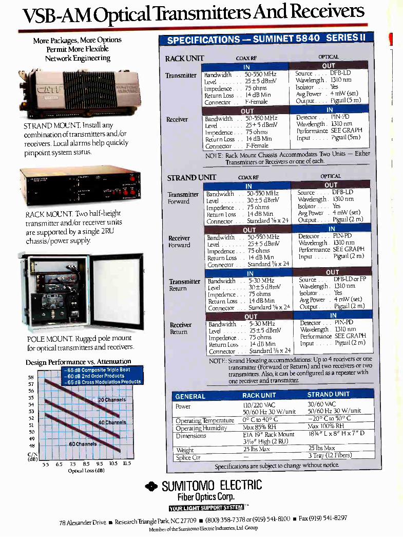
VSB-AM Optical Transmitters And Receivers More Packages, More Options
Permit More Flexible Network Engineering
F
'.'.;111.a132L.0.1 ar-C1.1.Z.V.t
STRAND MOUNT. Install any combination of transmitters and/or receivers. Local alarms help quickly pinpoint system status.
RACK MOUNT. Two half-height transmitter and/or receiver units are supported by a single 2RU chassis/power supply.
POLE MOUNT. Rugged pole mount for optical transmitters and receivers.
Design Performance vs. Attenuation
58
57
56
55
54
53 52
51
50 49
48
C/N (dB)
— —65 dB Composite —60 dB 2nd Order Products —65 dB Cross Modulation
MIIIMIIIIIIIIIIIIIIIII
"qgglaSZEM
Triple Beat
Produ
1 \...n illii -,--
_ ,
O tinnel.s_ 1
usa _66
III i I-' %nil.
' II
L
lb ' 55 65 75 85 95
Optical Loss (dB)
10.5 11.5
SPECIFICATIONS SUMINET 5840 SERIES II
RACK UNIT
Transmitter
Receiver
COAX RF OPTIC-AL
IN Bandwidth .. 50-550 MHz Level 25±5 dBmV Impedence . . 75 ohms Return Loss 14 dB Min Connector . F-Female
OUT Bandwidth .. 50-550 MHz Level 2_5 + 5 dBmV Impedence . . 75 ohms Return Loss 14 dB Min Connector F-Female NOTE: Rack Mount Chassis Accommodates Two Units — Either
Transmitters or Receivers or one of each.
OUT Source. DFB-LD Wavelength. L310 nm Isolator . . . . Yes Avg Power . 4 mW (set) Output . . . Pigtail (5 m)
IN Detector . . . PIN-PD Wavelength 1310 nm Performance SEE GRAPH Input Pigtail (5m)
STRAND UNIT
Transmitter Forward
Receiver Forward
Transmitter Return
Receiver Return
COAX RF OPTICAL
IN Bandwidth Level I mpedence Return Loss Connector .
• 50-550 MHz 30±5 dBmV
. . 75 ohms
. . 14 dB Min
. . Standard 5/8 x 24
OUT Bandwidth .. 50-550 MHz Level 25+ 5 dBmV Impedence . 75 ohms Return Loss 14 dB Min Connector Standard 5/8 x 24
IN Bandwidth .. 5-30 MHz Level 30± 5 dBmV Impedence . 75 ohms Return Loss 14 dB Min Connector Standard 5/8 x 24
OUT Source. DFB-LD Wavelength. 1310 nm Isolator. .. . Yes Avg Power . 4 mW (set) Output. . . Pigtail (2 m)
IN
OUT Bandwidth .. 5-30 MHz Level 25± 5 dBmV Impedence . . 75 ohms Return Loss . 14 dB Min Connector . . Standard 5/8 X 24
NOTE: Strand Housing accommodations: Up to 4 receivers or one transmitter (Forward or Return) and two receivers or two transmitters. Also, it can be configured as a repeater with one receiver and transmitter.
Detector . . . FIN-PD Wavelength 1310 nm Performance SEE GRAPH Input Pigtail (2 m)
OUT Source . . . DFB-LD or FP Wavelength. 1310 nm Isolator .. . . Yes Avg Power . 4 mW (set) Output . . Pigtail (2 m)
IN Detector . PIN-PD Wavelength L310 nm Performance SEE GRAPH Input Pigtail (2 m)
GENERAL RACK UNIT STRAND UNIT
Power 110/220 VAC 50/60 Hz 30 W/unit
30/60 VAC 50/60 Hz 30 W/unit
Operating Temperature 0° C to 40° C —20° C to 50° C
Operating Humidity Max 85% RH Max 100% RH
Dimensions EIA 19" Rack Mount 39/10" High (2 RU)
183/4 " Lx 8" H x 7" D
Weight 25 lbs Max 25 lbs Max
Splice Ctr — 3 Tray (12 Fibers)
Specifications are subject to change without nonce.
40, SUMITOMO ELECTRIC Fiber Optics Corp.
(1111;411dakiliiielitekilli
78 Alexander Drive u ResearchTriangle Park, NC 27709 u (800) 358-7378 or (919) 541-8100 • Fax (919) 541-8297 Member of the Sumitomo Electric Industries, Ltd. Group
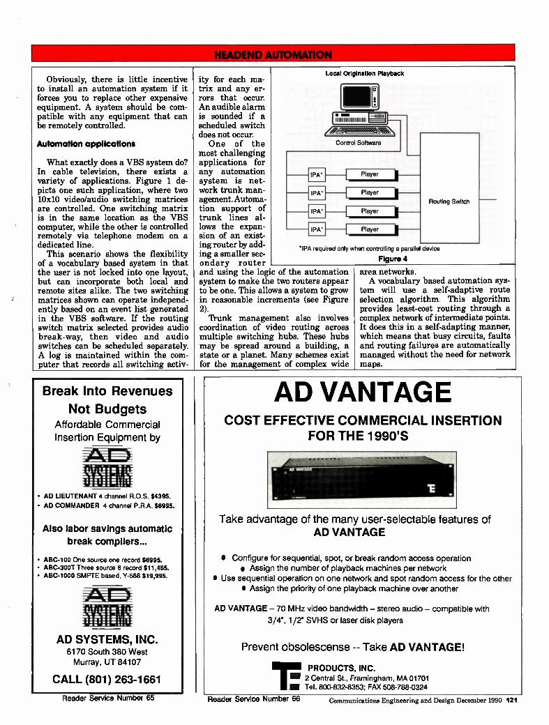
Obviously, there is little incentive to install an automation system if it forces you to replace other expensive equipment. A system should be com-patible with any equipment that can be remotely controlled.
Automation applications
What exactly does a VBS system do? In cable television, there exists a variety of applications. Figure 1 de-picts one such application, where two 10x10 video/audio switching matrices are controlled. One switching matrix is in the same location as the VBS computer, while the other is controlled remotely via telephone modem on a dedicated line.
This scenario shows the flexibility of a vocabulary based system in that the user is not locked into one layout, but can incorporate both local and remote sites alike. The two switching matrices shown can operate independ-ently based on an event list generated in the VBS software. If the routing switch matrix selected provides audio break-way, then video and audio switches can be scheduled separately. A log is maintained within the com-puter that records all switching activ-
ity for each ma-trix and any er-rors that occur. An audible alarm is sounded if a scheduled switch does not occur. One of the
most challenging applications for any automation system is net-work trunk man-agement. Automa-tion support of trunk lines al-lows the expan-sion of an exist-ing router by add-ing a smaller sec-ondary router and using the logic of the automation system to make the two routers appear to be one. This allows a system to grow in reasonable increments (see Figure 2). Trunk management also involves
coordination of video routing across multiple switching hubs. These hubs may be spread around a building, a state or a planet. Many schemes exist for the management of complex wide
Control Software
Local Origination Playback
o
IPA*
IPA*
IPA'
IPA
Player
Player
Player
Player
Routing Switch
PA required only when controlling a parallel device
Figure 4
area networks. A vocabulary based automation sys-
tem will use a self-adaptive route selection algorithm. This algorithm provides least-cost routing through a complex network of intermediate points. It does this in a self-adapting manner, which means that busy circuits, faults and routing failures are automatically managed without the need for network maps.
Break Into Revenues
Not Budgets Affordable Commercial Insertion Equipment by
• AD LIEUTENANT 4 channel R.O.S. $4395.
• AD COMMANDER 4 channel P.R.A. $6995.
Also labor savings automatic
break compilers...
• ABC-100 One source one record $6995. • ABC-300T Three source 8 record $11,485. • ABC-1000 SMPTE based, Y-688 $19,995.
XUZI
AD SYSTEMS, INC. 6170 South 380 West Murray, UT 84107
CALL (801) 263-1661
AD VANTAGE COST EFFECTIVE COMMERCIAL INSERTION
FOR THE 1990'S
Take advantage of the many user-selectable features of AD VANTAGE
• Configure for sequential, spot, or break random access operation e Assign the number of playback machines per network
• Use sequential operation on one network and spot random access for the other • Assign the priority of one playback machine over another
AD VANTAGE -- 70 MHz video bandwidth -- stereo audio -- compatible with
3/4", 1/2" SVHS or laser disk players
Prevent obsolescense -- Take AD VANTAGE!
1.111 PRODUCTS, INC. .11 2 Central St., Framingham, MA 01701 M Tel. 800-832-8353; FAX 508-788-0324
Reader Service Number 65 Reader Service Number 66 Communications Engineering and Design December 1990 121
Commercial insertion
Many types of commercial insertion can be managed by a vocabulary based system. One of the simplest means of inserting commercials is to control the playback of pods (groups of commercial spots) from a single tape deck onto a single channel. This is easily accom-plished by creating a definition file to cue and roll a tape deck. Conditional macros (special command words) allow playback functions to be synchronized with external events.
Conditional macros are special words which relate a group of functions to a specific synchronizing event. For in-stance, if you wanted a group of seven router switch outputs to be changed with the press of a single key, you could feasibly group the seven switch com-mands under the conditional macro ALT-F 1. Then, by pressing ALT-F 1 on the computer keyboard, the seven switches would simultaneously occur.
In the same way, a conditional macro can monitor the status of a contact from a satellite receiver. This contact clo-sure can cause an entire sequence of events—such as pre-rolling a tape, switching it on air, waiting for the commercial to run and switching back to the network. Note that there is nothing specific in the automation system to support a particular type or brand of commercial playback. All of the specifics of the system operation are user defined. It is possible, in fact, to create many variations on the simple commercial insertion scheme. Multiple tape decks may be cued and pre-rolled in sequence to insert spots from multi-ple tapes into a single commercial pod or a single tape may be inserted onto multiple channels on an as-needed basis. A VBS has even been used to control distributed commercial inser-tion across multiple hubs. A vocabulary based system will also
have the ability to provide automated control of an assortment of headend operations. Figure 3 depicts a typical example where three ports are con-nected to remote locations via tele-phone modem. Two ports are used to control routing switch matrices for local origination and channel recon-figuration. One port is designated as a tape machine interface loop (referred to in Figures 3, 4 and 5 for tape deck control. Two ports provide control of satellite receivers. Additionally, eight contact closures are provided to control IF switching or other closure initiated devices. For additional functionality, a
feedback path could be incorporated for monitoring test equipment.
Figure 4 illustrates how a VBS can be used for local origination playback. Here, the controlling software operates a playback center consisting of four videotape players and a routing switch matrix. This configuration is also typi-cally used for pay-per-view playback. One port controls the switch matrix, while the second port controls four tape machines via a tape machine interface loop. A tape machine interface is, as it sounds, an addressable tape machine controller. In some controllers, up to 100 tape machines can be controlled in one tape machine interface loop. Cueing and playback of the tape
machines and routing of the appropri-ate switch matrix inputs is executed according to an event list generated in the software. A log maintained by the software records all tape machine and switch matrix activity, as well as any errors that occur. 'Pape machines can be cued by control track or by FSK toning. Verification of playback can also be generated by means of FSK toning. In any application shown, VTRs can be replaced with laser disks. Many possibilities exist in using
laser disk video playback of commer-cials. The VBS approach to automation will allow mixing laser disk and video tape devices on the same system.
Time-shifting
A bothersome task at many sites is time-shifting of network and satellite programs. Often this will require full time attention of an operator to put a tape deck into the record mode once or twice an hour. It is easy to put extra record and playback commands into a log. Simple record and playback com-mands are adequate for shifting whole programs to another playback time.
However, suppose you want to take a live show and shift it just five minutes later than it would normally air, a phenomenon which is done at many broadcast stations to provide an extra commercial break in the evening news. This is a complicated task, as it requires recording the show in seg-ments of a few minutes each and then splicing them back together. This can be accomplished on a general purpose automation system by use of a schedule compiler. A schedule compiler is a small computer program that accepts three parameters: The time the show starts, the time the show ends and how long to delay the show. From these three parameters, the
schedule compiler will create a com-
plete list of events to cut the live show into pieces and edit it back together after the appropriate time delay. With three tape decks dedicated to this net delay function, time shifts of three to 90 minutes can be achieved. The de-layed show can be many hours long because tapes are continuously reused.
Yet another application for headend automation is that of automatic dub-bing and compiling. With a vocabulary based system, a switch matrix and six tape machines can be controlled. Four videotape players used as library sources
are routed through the switch matrix to the the record decks. Two record decks
are used to simultaneously produce two .1 dubs of the final tape. There is practi-cally no limit to the number of library source decks and record decks that may be utilized in one operation.
Note that all of the functions de- I scribed—router management, trunk man-agement, headend automation, com-mercial insertion, local origination, net delays, automatic dubbing and compil-ing and event logging—can feasibly be achieved by the same vocabulary based automation program. The details of one individual system are defined by the user creating his own system vocabu-lary, which can be changed or edited at any time.
'Ibm Sheridan, chief engineer at ATC's American Cablevision, has util-ized a vocabulary based system in the company's Indianapolis, Indiana facil-ity with notable results. In the configu-ration, the VBS system controls VCR playback, satellite downlink recording, stereo encoder switching, scrambling units, switching of character genera-tors and management of alternate feeds. "When our original automation system failed us, we switched to a vocabulary based approach," Sheridan comments. "Not having budgeted for a new automation system, the VBS method proved to be the most cost-effective, in that it used an IBM compatible computer and a specifal interface that allowed us to use our older tape machine interface (IPA) cards."
Cost effectivness is certainly good news in light of current CATV market conditions—obviously, to be profitable, more money needs to come in than goes out. When selecting an automation system, keep an eye out for equipment that offers "budget friendliness", com-patibility with existing technology and design specifications that provide for future growth—as offered in a vocabu-lary based approach. The result will be an automation expedition that is
122 Communications Engineering and Design December 1990
Complete automa "When you've sold out all your
avails, there's no room for error, and no room for make-goods," says Norm Scott, video engineering supervisor for Cox Cable, San Diego. Scott faced that kind of situation last December, when the aggressive efforts of Cox's local sales staff resulted in the scheduling of 24,950 paid commercial spots to be inserted into 10 separate cable chan-nels.
That kind of spot load would have many engineering managers shaking their heads. But for Scott, armed with his commercial insertion "money ma-chine," it was business as usual. And with 99.8 percent of the scheduled spots "run as ordered," for Cox Cable, it was money in the bank.
What works
The key to a successful local adver-tising operation is the ability to insert local commercials into the satellite network feeds with a high degree of accuracy and reliability, while utiliz-ing a minimum amount of manpower. System operators have—and continue to—look to modern technology for the means to maximize productivity and profits. While there are many possible approaches to commercial insertion, system operators are beginning to rec-ognize that the total integration of all control functions and tape playback operations represents the best possible application of technology. "Our policy is to take every avail
and fill it," says Clint Rathmell, direc-tor of developmental engineering for Paragon Cable. "If it's not a paid spot, we fill with cross channel promotions or corporate image advertising," he adds.
Both Paragon and Cox Cable have selected a total automation package for commercial insertion. A total automa-tion system approach allows the opera-tor to select only those functions which meet current, specific requirements, while providing for future expansion. As the cable industry grows and ma-tures, this capability is essential, as it permits operators to respond to changes in the marketplace.
For example, the Paragon systems handle commercial insertion on 16 cable channels by building channel-specific spot reels. According to Clint
By Jeff O'Brian, Vice President, Basys LaKart Inc.
tion equals profit Rathmell this approach provides the "capability to support the projected level of business, while falling within the capital amount we had to spend." Down the road, Rathmell is looking to add the capability to control almost all of his technical operations through a complete headend automation system.
Meanwhile, at Cox Cable's San Di-ego facility, commercial insertion, pub-lic access, local origination and pay-per-view playback are all under automated control. Using a bank of Super VHS players, all machines operate in a random access mode, with any player able to feed any channel through the computer controlled routing switcher. In addition, syndication blackouts are handled automatically, with "inform-ercial" programming rolling from sev-eral 3/4-inch players used to fill in as required. Even the pay-per-view barker channel is under computer control. Additionally, Cox Cable's Eureka, Cali-fornia cable origination station (dubbed "KCBL-TV") has started 18-hour per day operation using a similar automa-tion system. As the number of viewing options
increases, advertisers will require ca-ble operators to deliver even more specific audiences. By using fiber optic distribution, combined with the capa-bilities of a random access playback system, operators will be able to zone thier spot announcements, just as a newspaper produces zoned editions with specific ads for specific geographic areas. While this type of zoned delivery is impossible for "over the air" broad-casters, it will provide considerable revenue opportunities for cable opera-tors, who deliver via hardwire— allowing the sale of the same commercial "spot" to different advertisers.
While this approach may sound like something out of "Star Wars," the groundwork is already underway, with New York City's Manhattan Cable Television feeding zoned commercials to its different franchise areas from a central automation system. This allows advertisers to cablecast their messages only in those areas where their poten-tial customers live. The future will present both chal-
lenges and opportunities for cable sys-tem operators. Technology will provide the capability to meet these challenges. Te best take advantage of the opportu-nities, cable operators must build a platform today—to reap the profits of tommorrow. •
There's More Than One Way to Send a Quality Signal to Your Subscribers...
Your subsribers' most impor-tant concern is receiving a quality reception, on screen and off. And by providing your front line personnel (technicians, installers, sales and customer service) with the education and training CIE's Cable Tech program provides you'll be sending a strong, clear signal about your commitment to customer satisfaction and service. We encourage you to look, but
you won't find a more compre-hensive training program in the business.
Cable
II III IV
V
VI
VII
VIII
IX
Tech Basic Electricity (40 lessons) Basic Electronics ( 26 lessons) Digital/Video Theory (34 lessons) Technical Report Writing (16 lessons, 3 papers) Trouble Shooting using Symptom Diagnosis (18 lesssons) Electronics Technology with Digital (18 lessons) Electronic Technology with Advanced Digital & Microprocessor Laboratories (21 lessons) Electronics Engineering Technolo-gies: Engineering, Math & Circuit Analysis (42 lessons) Electronics Engineering Technol-ogy: Advanced Engineering Math, Circuit Analysis, and Physics (36 lessons 1 paper)
CIE's Cable Tech is an Effective, Easily Adminis-tered, Independent Study, Patented Learning Method for the Development of CA TV Professionals.
YES! Send Me More Information
Name
Title
Company
Address
City State Zip
Phone ( )
Number of Employees
f.i ,-, I. . ,..... i CI.E%ElAND I I NSTITI TF: OF
1 j__ ._ ir i I, F:La THoND:s
-, ACD - 02
Communications Engineering and Design December 1990 123
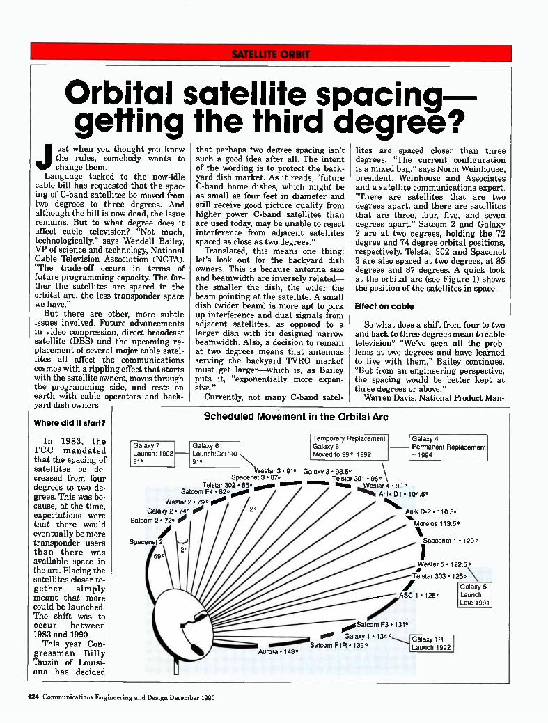
Orbital satellite spacing getting the third degree?
ust when you thought you knew the rules, somebody wants to change them.
Language tacked to the now-idle cable bill has requested that the spac-ing of C-band satellites be moved from two degrees to three degrees. And although the bill is now dead, the issue remains. But to what degree does it affect cable television? "Not much, technologically," says Wendell Bailey, VP of science and technology, National Cable Iblevision Association (NCTA). "The trade-off occurs in terms of future programming capacity. The far-ther the satellites are spaced in the orbital arc, the less transponder space we have." But there are other, more subtle
issues involved. Future advancements in video compression, direct broadcast satellite (DBS) and the upcoming re-placement of several major cable satel-lites all affect the communications cosmos with a rippling effect that starts with the satellite owners, moves through the programming side, and rests on earth with cable operators and back-yard dish owners
Where did it start?
In 1983, the FCC mandated that the spacing of satellites be de-creased from four degrees to two de-grees. This was be-cause, at the time, expectations were that there would eventually be more transponder users than there was available space in the arc. Placing the satellites closer to-gether simply meant that more could be launched. The shift was to occur between 1983 and 1990.
This year Con-gressman Billy Tauzin of Louisi-ana has decided
Galaxy 2 • 74.
Satcom 2 • 72. 0
Spacenet 2
69° 2°
Galaxy 7 Launch: 1992 91°
Telstar 302 • 85...00 1011111111. Satcom F4 • 82. 0 000
Westar 2 .790 00. 2°
Aurora • 143°
that perhaps two degree spacing isn't such a good idea after all. The intent of the wording is to protect the back-yard dish market. As it reads, "future C-band home dishes, which might be as small as four feet in diameter and still receive good picture quality from higher power C-band satellites than are used today, may be unable to reject interference from adjacent satellites spaced as close as two degrees."
Translated, this means one thing: let's look out for the backyard dish owners. This is because antenna size and beamwidth are inversely related— the smaller the dish, the wider the beam pointing at the satellite. A small dish (wider beam) is more apt to pick up interference and dual signals from adjacent satellites, as opposed to a larger dish with its designed narrow beamwidth. Also, a decision to remain at two degrees means that antennas serving the backyard TVRO market must get larger—which is, as Bailey puts it, "exponentially more expen-sive."
Currently, not many C-band satel-
lites are spaced closer than three degrees. "The current configuration is a mixed bag," says Norm Weinhouse, president, Weinhouse and Associates and a satellite communications expert. "There are satellites that are two degrees apart, and there are satellites that are three, four, five, and seven degrees apart." Satcom 2 and Galaxy 2 are at two degrees, holding the 72 degree and 74 degree orbital positions, respectively. lelstar 302 and Spacenet 3 are also spaced at two degrees, at 85 degrees and 87 degrees. A quick look at the orbital arc (see Figure 1) shows the position of the satellites in space.
Effect on cable
So what does a shift from four to two and back to three degrees mean to cable television? "We've seen all the prob-lems at two degrees and have learned to live with them," Bailey continues. "But from an engineering perspective, the spacing would be better kept at three degrees or above."
Warren Davis, National Product Man-
Scheduled Movement in the Orbital Arc
Galaxy 6 Launch Oct '90 91°
Temporary Replacement Galaxy 6 Moved to 99° 1992
Westar 3 • 91° Galaxy 3 • 93.5° Spacenet 3 • 870 Telstar 301 • 960
ma% ...W._estar 4 • 99 ° Anik D1 • 104.5°
Galaxy 4 Permanent Replacement 1994
Anik D-2 • 110.5.
Morelos 113.5°
Spacenet 1 • 120 °
Westar 5 • 122.5°
Telstar 303 • 125° \
ASC 1 • 128°
Satcom F3 • 131°
100. Galaxy 1 • 134 1R
Satcom F1R • 139° Launch 1992
Galaxy 5 Launch Late 1991
124 Communications Engineering and Design December 1990
DATA LINKS FROM IPITEK
GO FARTHER AND FASTER
The FiberTrunk 600TM AM Fiberoptic Transmission System Developed for the Most Rigorous Environment.
Available Today
The system to get when you need top grade DFB Performance:
• Without "Field Optimization"
• Without codes
• Without adjustments, under varying channel loading
• Without excuses
Our staff of engineers and technicians accepted the challenge of designing and manufacturing a high performance, tweakless AM Fiberoptic system. The result is the Fibertrunk 600:
• "Plug and Play" design eliminates complicated installation procedures
• Independent of laser manufacturer: for the flexibility to choose
• Fully connectorized: No splices required
• Pre-Calibrated, continuously optimized OMI
• Optional dual power supplies
• Optional upstream path
At IPITEK we build this and other high performance fiberoptic products to serve our customers. When you need a fiberoptic link for video, data, or telecommunications, we have the technology and the flexibility to design for your market. Our researchers and engineers anticipate advancements in technology and specialize in analog and digital links that meet your requirements.
Call our Applications Center today to see how IPITEK can improve your competitive position.
TOPS IN DATA LINKS IPITEK, Inc.
2330 Faraday Avenue, Carlsbad, CA 92008 Phone: (619) 438-8362 Fax: (619) 438-2412
iPii "I =it A TACAN COMPANY
Reader Service Number 68
Th conn
ar he coaxial cable used by CATV is a high capacity multiplex me-dium, capable of passing dozens of
quality video signals as well as hun-dreds of other data, voice and telemetry channels of information. Imagine for a moment, the off-air spectrum from 5 MHz to 450 MHz, and the thousands of signals that occupy these bands. Besides 12 VHF and the bottom edge of the UHF TV bands, there are thousands of police, fire, amateur, air-craft, business band, shortwave and military channels. This tremendous capacity is available in the modern broadband coax cable, independent of the off-air spectrum. A CATV operator normally fills the
cable spectrum with TV channels. However, there are still hundreds of potential narrowband data, telemetry and voice slots typically laying idle. In addition, the return, which is often in place but "decommissioned," could be used for two-way video and interactive services.
Municipality opportunities
Municipalities use hundreds of "data" circuits for such applications as traffic light control, security sys-tems, computer data circuits, police and fire circuits, city telephone systems and switchboards, and others. City managers are often unaware of the total number of circuits and the costs can run to the tens of thousands per month. Many of these applications could be displaced to cable at large cost savings per month, providing the CATV operators with a good profit and addi-tional revenue streams.
In addition to the circuits that could be displaced onto cable, a whole new field of services are possible that would be virtually cost prohibitive by any other means. These include such capa-bilities as citywide surveillance for traffic, utility and security applica-tions; two-way video training for fire, police and municipal employees; video "classrooms" for shut-in students; re-mote bulletin and schedule boards for traffic and bus schedule information. The CATV system remains one of the
largest "untapped" resources for cities
By Clifford Schrock, President, CableBus Systems Corp.
e municip ection to
The franchise wars of the early '70s are over, and so are discussions of the multiple service capabilities of the CATV plant. Yet, the benefits of using excess capacity on the broad-band cable for a host of special services can be signficant. Broad-band cable can be applied to the operations of a modern city, offering cost savings over other alternatives such as leased lines and microwave.
In some cases new services can be considered that woukl be cost prohibi-tive by other means. This article does not go into the political reaons why the cable operator and the munici-pality may tend to have a more adversarial relationship, rather than one of cooperation and sharing of this powerful resource. With coopera-tion, the cable capacity could im-prove the quality of life and reduce expenses to the community.
to utilize to improve city services. Some cities even have vast I-nets, built to comply with franchise requirements, many of which are idle or turned off. Now that franchises are built, cable operators as well as municipalities are taking a long, hard look at the many applications of cable.
A false start
The two factors that were large contributors to the demise of two-way services in the early 1980s were the poor performance of the return plant cable and the lack of high quality terminal units. The first and foremost problem was
the performance of the cable itself. System operators spent enormous amounts of money trying to keep two-way plants operating. Today, with the advent of CLI compliance and testing, much of the time and money spent troubleshooting the two-way plant because of ingress has been eliminated. The plant is tighter, connectors and drops are better, and the reactivation of two-way in systems today has been characterized as "uneventful." The other major factor was the poor
quality of the terminal units. Many
al CATV
major MSOs tried to commit substan-tial resources to security, data and telemetry systems that were unfortu-nately "crude" by today's standards. Older units had to be manually set up at the home or remote location, often by a technician talking to the headend where another technician had to watch a spectrum analyzer. The setup was short lived because the cable plant could change by 12 dB or 15 dB from night to day, and more seasonally.
Modems more sophisticated
Modern modems are more sophisti-cated and many are capable of remote setup. One master modem and PC-type computer with special software serves as a network manager and adjusts the terminals automatically as often as necessary to keep all units on line and at optimum performance levels. In essence, each remote device on the cable becomes a "status monitor" test point, not only for the particular serv-ice provided by that terminal, but also because it gives a relative indication of all data and TV services at that particular location.
Another factor contributing to the failure of many of the early two-way services was the pressure that CATV operators were under to complete the construction of the CATV plant in the franchise area. The operators had their hands full building the system, with no manpower left over to implement additional services.
Today, with better cable plant and terminals, and a commitment by opera-tors to find other revenue sources for the cable, the time has come to take another serious look at other services on cable.
Traffic management
'fraffic has become a major factor in any medium or large sized city. Central traffic light control is rapidly becoming the accepted standard for cities. Each intersection has a local controller to actually operate the signals. The local controllers are connected to a central computer that can synchronize the individual locations, upload new pro-grams, select special time-of-day se-quences and perform diagnostics of the
128 Communications Engineering and Design December 1990
How to get hometown response from a national telco distributor You no longer have to choose be-tween the fast, personalized re-sponse of a hometown distributor and the broad stocks and purchas-ing power of a national firm, Power & Telephone Supply offers you both.
„ ,emir.saiaret
‘„'s•
DO YOU KNOW YOUR LOCAL POWER & TEL REP?
CALL 1-800-238-7514 AND WE'LL GET YOU INTRODUCED!
Power & Tel representatives are people you know — or should know. They live in your part of the country. They know what's going on and what's needed among telcos, power utilities, interconnects, communi-cations users and cable TV providers in your specific area. You get home-town service and a hometown attitude, without the inherent dis-advantage of dealing with a small distributor.
Power & Tel is a truly national source of hardware, cable, test instru-mentation and a myriad of other prod-ucts. A multi-million-dollar inventory is dispersed into 13 regional warehouses; restocking and customer deliveries are handled via a company-owned trucking fleet.
Power & Tel's national presence generates buying
leverage with the industry's leading suppliers. The result: significant price advantages that are passed along to customers.
Don't sacrifice the advantages of a big-distributor connection or the comfort of local distributor attention and response. You can have both, simply by selecting Power & Tele-phone Supply as your hardware dis-tributor of choice. For the name of your local representative, contact Power & Tel today!
Power &Telephone Supply Company 2701 Union Extended, Suite 300 Memphis, TN 38112-4417 901/324-6116 FAX 901/320-3082 Reader Service Number 71
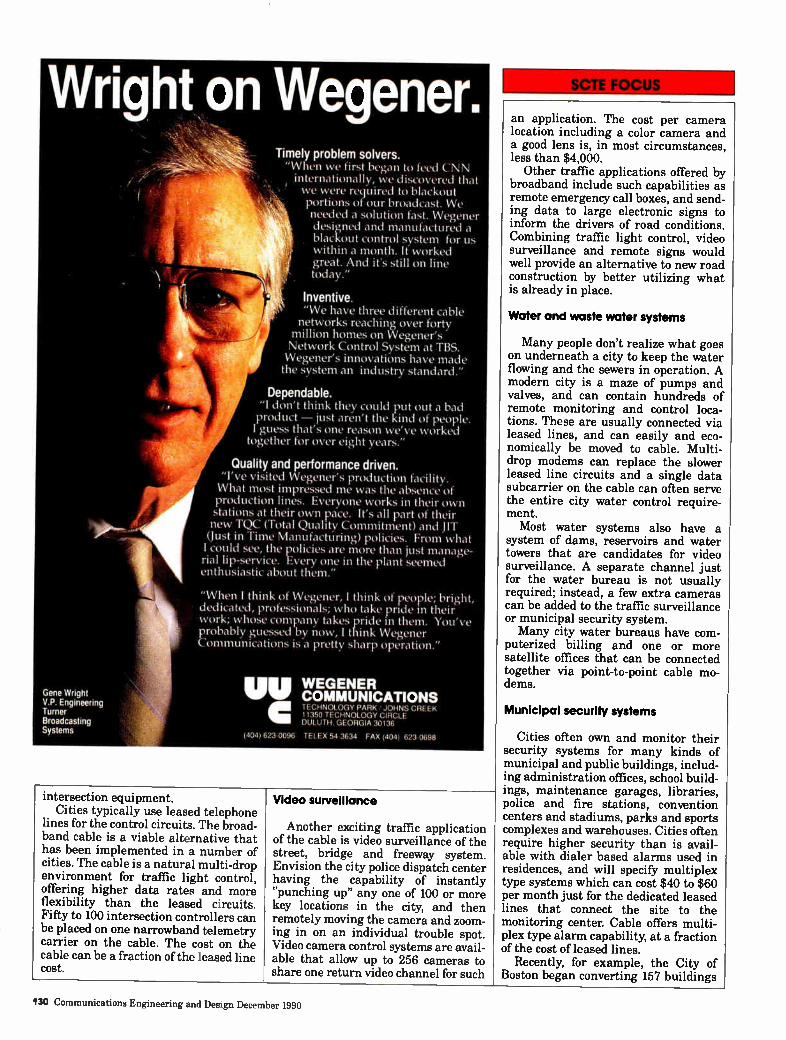
Wright on Wegener.
Gene Wright V.P. Engineering Turner Broadcasting Systems
Timely problem solvers. "When we first began to feed CNN internationally, we discovered thd t we were required to blackout portions of our broadcast. We needed a solution fast. Wegener designed and manufactured a blackout control system for us within a month. It worked great. And it's still on line today."
Inventive. "We have three different cable networks reaching over forty
million homes on Wegener's Network Control System at TBS. Wegener's innovations have made the system an industry standard."
Dependable. "1 don't think they could put out a bad product — just aren't the kind of people. I guess that's one reason we've worked
together for over eight years."
Quality and performance driven. "I've visited Wegener's production facility. What most impressed me was the absence of production lines. Everyone works in their own stations at their own pace. It's all part of their new TQC (Total Quality Commitment) and JIT (Just in Time Manufacturing) policies. From what I could see, the policies are more than just manage-rial lip-service. Every one in the plant seemed enthusiastic about them."
"When I think of Wegener, I think of people; bright, dedicated, professionals; who take pride in their work; whose company takes pride in them. You've probably guessed by now, I think Wegener Communications is a pretty sharp operation."
UV WEGENER COMMUNICATIONS TECHNOLOGY PARK JOHNS CREEK 11350 TECHNOLOGY CIRCLE DULUTH. GEORGIA 30136
( 4 0 4) 623 0096 TELEX 54-3634 FAX (404) 623.0698
intersection equipment. Cities typically use leased telephone
lines for the control circuits. The broad-band cable is a viable alternative that has been implemented in a number of cities. The cable is a natural multi-drop environment for traffic light control, offering higher data rates and more flexibility than the leased circuits. Fifty to 100 intersection controllers can be placed on one narrowband telemetry carrier on the cable. The cost on the cable can be a fraction of the leased line cost.
Video surveillance
Another exciting traffic application of the cable is video surveillance of the street, bridge and freeway system. Envision the city police dispatch center having the capability of instantly "punching up" any one of 100 or more key locations in the city, and then remotely moving the camera and zoom-ing in on an individual trouble spot. Video camera control systems are avail-able that allow up to 256 cameras to share one return video channel for such
an application. The cost per camera location including a color camera and a good lens is, in most circumstances, less than $4,000.
Other traffic applications offered by broadband include such capabilities as remote emergency call boxes, and send-ing data to large electronic signs to inform the drivers of road conditions. Combining traffic light control, video surveillance and remote signs would well provide an alternative to new road construction by better utilizing what is already in place.
Water and waste water systems
Many people don't realize what goes on underneath a city to keep the water flowing and the sewers in operation. A modern city is a maze of pumps and valves, and can contain hundreds of remote monitoring and control loca-tions. These are usually connected via leased lines, and can easily and eco-nomically be moved to cable. Multi-drop modems can replace the slower leased line circuits and a single data subcarrier on the cable can often serve the entire city water control require-ment. Most water systems also have a
system of dams, reservoirs and water towers that are candidates for video surveillance. A separate channel just for the water bureau is not usually required; instead, a few extra cameras can be added to the traffic surveillance or municipal security system. Many city water bureaus have com-
puterized billing and one or more satellite offices that can be connected together via point-to-point cable mo-dems.
Municipal security systems
Cities often own and monitor their security systems for many kinds of municipal and public buildings, includ-ing administration offices, school build-ings, maintenance garages, libraries, police and fire stations, convention centers and stadiums, parks and sports complexes and warehouses. Cities often require higher security than is avail-able with dialer based alarms used in residences, and will specify multiplex type systems which can cost $40 to $60 per month just for the dedicated leased lines that connect the site to the monitoring center. Cable offers multi-plex type alarm capability, at a fraction of the cost of leased lines.
Recently, for example, the City of Boston began converting 157 buildings
130 Communications Engineering and Design December 1990
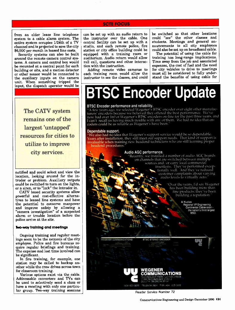
from an older lease line telephone system to a cable alarm system. The entire system occupies 1/24th of a TV channel and is projected to save the city $6,000 per month in leased line costs.
Security systems can also be built around the remote camera control sys-tems. A camera and control box would be mounted at a central point for each building or site, and a motion detector or other sensor would be connected to the auxiliary inputs on the camera unit. When something tripped the input, the dispatch operator would be
The CATV system
remains one of the
largest untapped'
resources for cities to
utilize to improve
city services.
notified and could select and view the location, looking around for the in-truder or problem. Auxiliary outputs could be switched to turn on the lights, or a siren, or to "lock" the intruder in. CATV based security systems allow
powerful and cost-effective alterna-tives to leased line systems and have the potential to conserve manpower and improve safety by allowing a "camera investigation" of a suspected alarm or trouble location before the police arrive at the site.
Two-way training and meetings
Ongoing training and regular meet-ings seem to be the nemesis of the city employee. Police and fire bureaus re-quire regular briefings and training. The expense and lost time involved can be significant.
In fire training, for example, one station may be called to backup an-other while the crew drives across town for classroom training.
Various options exist via the cable. Addressable converters and TVs can be used to selectively send a class or have a meeting with only one particu-lar group. Two-way training sessions
can be set up with an audio return to the instructor over the cable. One central facility can be set up with a studio, and each remote police, fire station or city office building could be equipped with a training room or auditorium. Audio return would allow roll call, questions and other interac-tion with the instruction.
Adding remote video cameras to each training room would allow the instructor to see the classes, and could
be switched so that other locations could "see" the other classes and students. Meetings and general an-nouncements to all city employees could also be set up on broadband cable. The potential of using the cable for
training has long-range implications. Time away from the job and associated expenses, the cost of fuel and the need for city vehicles to drive to meetings must all be considered to fully under-stand the benefits of using cable for
•
mtv, %, • t•,,
1.11.
.; WEGENER COMMUNICATIONS
BTSC Encoder Update BTSC Encoder performance and reliability. "A few veal - ago, we selected Wegener's BTSC encoder over eight other manufac-turers' éncoL1L'is because we believed they offered the best performance. We've now had over 160 of Weî,,ener's BTSC encoders on-line for the past three years, and I can't recall us having much trouble with an of them. We had no idea that en-coders could be as reliable as 1Veî,,ener's have been."
Dependable support. "We also had no idea that Weg,ener's support service would be so dependable. Years after installation, they still meet our support needs. That kind of support is invaluable when training new headend technicians who are still learning proper
headend procedures.'
Audio AGC performance. "Recently, we installed a number of audio AGC boards
1 on channels that are switched between multiple ii sources and/or carry local commercial
insertions. They've performed excep-tionallv well. And they've reduced customer complaints "about varying audio levels to virtually zero."
"e. %elm 1111k , •
"Over the years, I'd sa v Wegener has been building more than
fine products; they've been building a reputation."
Al Kuolas Regional VP Engineering
N.„. Continental Cablevision • the nation's third largest
.411be.;44. MSO. '"••••••., 4114,
BTSC STEREO ENCODER
WEGENER COMMUNICATIONS TECHNOLOGY PMI‘ , .1350 TECHNOLOGY C DUL, - • MORGIA
C98
Reader Service Number 72
Communications Engineering and Design December 1990 131
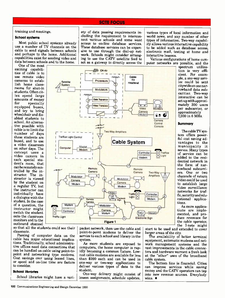
training and meetings.
School systems
Most public school systems already use a number of TV channels on the cable to send signals between schools and perhaps to the home. Additional capabilities exist for sending video and data between schools and to the home. One of the most
exciting capabili-ties of cable is to use remote video cameras to estab-lish home class-rooms for shut-in students. Often cit-ies spend large amounts of money for specially equipped buses, and try to bring wheelchair and dis-abled students to school. An alterna-tive possible with cable is to limit the number of days these students are bused, and to use a video classroom on other days. The concept uses a video camera in each special stu-dent's room, that can be remotely con-trolled by the in-structor. The in-structor is viewed by the student on a regular TV, but the instructor can individually have a dialogue with the student. In the case of a question, the instructor might switch the student onto the classroom monitors and to the outbound channel so that all the students could see their classmate.
Passing of computer data on the cable has major educational implica-tions. Traditionally, school administra-tive offices need data connections that can be handled on cable using point-to-point and networking type modems. Cost savings over using leased lines, or speed and on-line time are factors to consider.
School libraries
School libraries might have a vari-
ety of data passing requirements in-cluding the requirement to intercon-nect various schools and some want access to on-line database services. These database services can be expen-sive to use through the dial-up net-work. Schools might consider arrang-ing to use the CATV satellite feed to act as a gateway to directly access the
packet network, then use the cable and point-to-point modems to deliver the service to each school and library in the system. As more students are exposed to
computers, the home computer is rap-idly becoming a common fixture. Low-cost cable modems are available for less than $200 each and can be used in one-way or two-way applications to deliver various types of data to the student. One-way delivery might consist of
lesson assignments, schedule updates,
various types of local information and world news, and any number of other types of information. Two-way capabil-ity allows various interactive capability to be added such as database access, electronic mail, testing at home and interactive lessons.
Various configurations of home com-puter networks are possible, and the
spectrum utiliza-tion is very effi-cient. For exam-ple, a one-way serv-ice could be sent citywide on one nar-rowband data sub-carri er. Two-way interactive can be set-up with approxi-mately 300 users per subcarrier, or approximately 7,200 in 6 MHz.
Summary
The cable TV sys-tem offers power-ful cost saving ad-vantages to the municipality it serves. Many types of service can be added to the resi-dential network in the form of nar-rowband subcarri-ers. One or two channels of return video could be used to establish large video surveillance networks for traf-fic, security and edu-cational applica-tions. As more applica-
tions are imple-mented, and pro-duce revenues for the cable operator, the I-nets might
start to be used and extended to cover larger areas of the city. The availability of better terminal
equipment, automatic modems and net-work management systems and the vast improvements in the cable connec-tors and hardware warrant a fresh look at the "other" uses of the broadband cable system. The bottom line is financial. Cities
can improve services while saving money and the CATV operators can tap into new revenue sources. Everybody wins. •
132 Communications Engineering and Design December 1990
MICRO-BEAM:.. A Commitment to Service. Channel Master® believes that customer service shouldn't be a "High-Cost" option. That's why MICRO-BEAM system specialists offer more custo-mer services at no extra charge than anyone in the business.
Total Customer Service • 2 Year Warranty - Includes Parts
and Labor.
• 24 Hour On-Site Service - 7 Days a Week. (Continental U.S. Only)
• System Design/Path Feasibility.
• On-Site Training.
• FCC Application Assistance.
• Equipment Installation and Path Alignment.
• Fastest Lead Time in the Industry. Equipment and Spare Parts are In-Stock Ready to Install.
MICRO-BEAM allows you to cost effectively consoli-date system equipment into a single headend. 1, 2, 5
& 10 watt high performance CARS-BAND microwave systems can be designed in a variety of hub configurations delivering up to 80 channels.
For more information about the MICRO-BEAM service advantage, contact:
Jim Crownover MICRO-BEAM Sales Manager.
See us at the WESTERN SHOW, Booth #I16
©1990 Channel Master. All Rights Reserved
•
ChaillidleSterDeivision of Avnet, Inc. P.O. Box 1416. Industrial Park Drive, Smithfield. NC 27577
Phone (919) 934-9711 • Fax (919) 989-2200 Reader Service Number 73
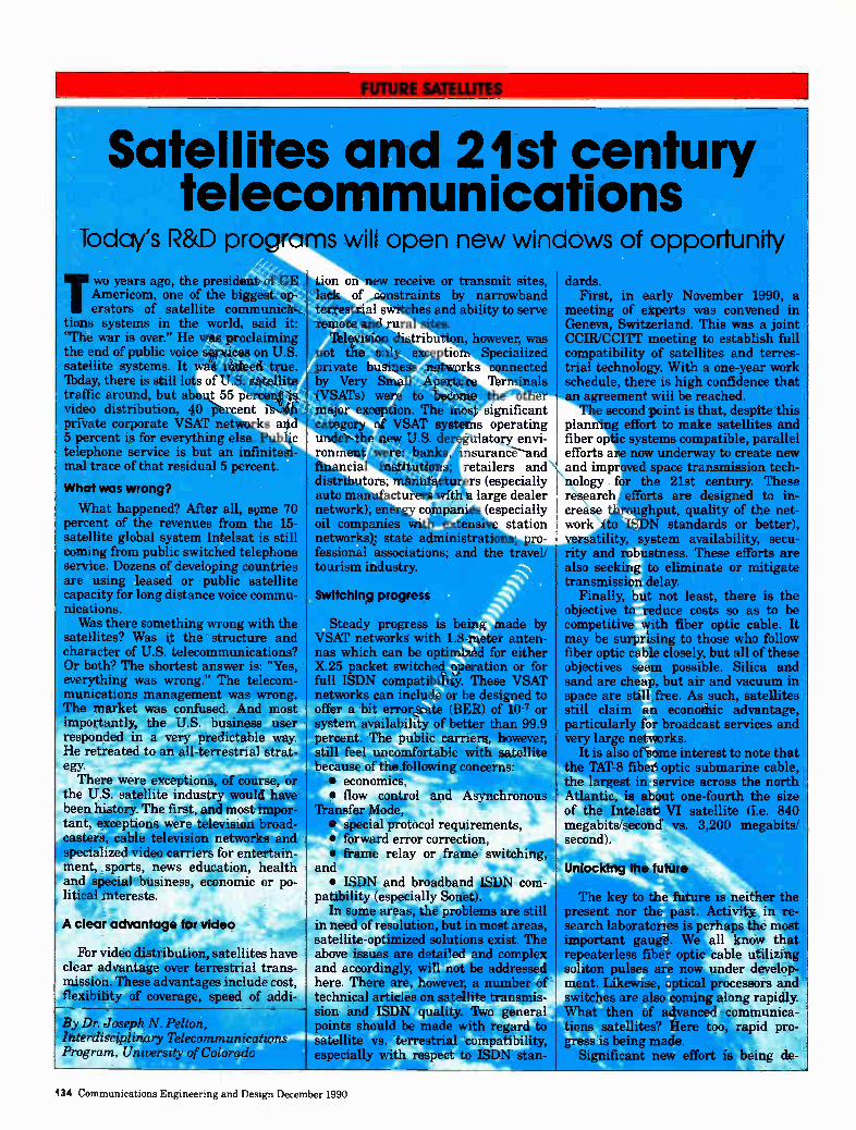
FUTURE SATELLITES
Satellites and 21st century telecommunications
Today's R&D programs will open new windows of opportun uy
Two years ago, the president of GE Americom, one of the biggest op-erators of satellite communica-
tions systems in the world, said it: "The war is over." He was proclaiming the end of public voice services on U.S. satellite systems. It was indeed true. lbday, there is still lots of U.S. satellite traffic around, but about 55 percent is video distribution, 40 percent is on private corporate VSAT networks and 5 percent is for everything else. Public telephone service is but an infinitesi-mal trace of that residual 5 percent.
What was wrong?
What happened? After all, some 70 percent of the revenues from the 15-satellite global system Intelsat is still coming from public switched telephone service. Dozens of developing countries are using leased or public satellite capacity for long distance voice commu-nications. Was there something wrong with the
satellites? Was it the structure and character of U.S. telecommunications? Or both? The shortest answer is: "Yes, everything was wrong." The telecom-munications management was wrong. The market was confused. And most importantly, the U.S. business user responded in a very predictable way. He retreated to an all-terrestrial strat-egy.
There were exceptions, of course, or the U.S. satellite industry would have been history. The first, and most impor-tant, exceptions were television broad-casters, cable television networks and specialized video carriers for entertain-ment, sports, news education, health and special business, economic or po-litical interests.
A clear advantage for video
For video distribution, satellites have clear advantage over terrestrial trans-mission. These advantages include cost, flexibility of coverage, speed of addi-
By Dr. Joseph N. Pelton, Interdisciplinary Telecommunications Program. University of Colorado
tion on new receive or transmit sites, of constraints by narTowband
estrial switches and ability to serve iwte and rural sites. Television distribution, however, was
not the only exception. S alized private business networks ected by Very Small Apert inals (VSATs) were to beco major exception. The In category of VSAT s under the new U.S. ronment weeelijan nsurance financial ffiketion retailers and distributors; !Idea- rs (especially auto manufacturers wit large dealer network); energy compan (especially oil companies with e station networks); state administrations; pro-fessional associations; and the travel/ tourism industry.
Switching progress
r.other significant operating
itory envi-
Steady progress is being made by VSAT networks with 1.8-meter anten-nas which can be optimized for either X.25 packet switched operation or for full ISDN compatibility. These VSAT networks can include or be designed to offer a bit error rate (BER) of 10-7 or system availability of better than 99.9 percent. The public carriers, however, still feel uncomfortable with satellite because of the following concerns: • economics, • flow control and Asynchronous
rfransfer Mode, • special protocol requirements, • forward error correction, • frame relay or frame switching,
and • ISDN and broadband IS
patibility (especially Sonet). In some areas, the problems
in need of resolution, but in most areas, satellite-optimized solutions exist. The above issues are detailed and complex and accordingly, will not be addressed here. There are, however, a number of technical articles on satellite transmis-sion and ISDN quality. Two general points should be made with regard to satellite vs. terrestrial compatibility, especially with respect to ISDN stan-
dards. First, in early November 1990, a
meeting of experts was convened in Geneva, Switzerland. This was a joint CCIR/CCITT meeting to establish full compatibility of satellites and terres-trial technology. With a one-year work schedule, there is high confidence that an agreement will be reached. The second point is that, despite this
plan& effort to make satellites and fiber op systems compatible, parallel efforts a now underway to create new and impr ed space transmission tech-
re earch efforts are designed to in-creâse throughput, quality of the net-work Ito ISDN standards or better),
lity, system availability, secu-d robustness. These efforts are
also seeking to eliminate or mitigate transmission delay.
Finally, but not least, there is the objective to reduce costs so as to be competitive with fiber optic cable. It may be surprising to those who follow fiber optic cable closely, but all of these objectives seem possible. Silica and sand are cheap, but air and vacuum in space are still free. As such, satellites still claim an economic advantage, particularly for broadcast services and very large networks.
It is also of some interest to note that the TAT-8 fiber optic submarine cable, the largest in service across the north Atlantic, is about one-fourth the size of the Intelsat VI satellite (i.e. 840 megabits/second vs. 3,200 megabits/ second).
Unlocking the future Ili
The key to the future is neither the present nor the past. Activity in re-search laboratories is perhaps the most important gauge. We all know that repeaterless fiber optic cable utilizing soliton pulses are now under develop-ment. Likewise, optical processors and switches are also coming along rapidly. What then of advanced communica-tions satellites? Here too, rapid pro-gress is being made.
Significant new effort is being de-
134 Communications Engineering and Design December 1990
BUILDING COMMUNICATION SYSTEMS THROUGHOUT AMERICA
A Full Service Communications Contractor
Specialists in: Design/Drafting, Construction, Installation, LAN
• Full Installation Services
• Aerial Underground Construction (Including Fiber Optics)
• Strand Mapping (AutoCAD & LYNX)
• Field Engineering, Make-Ready, As-Builts
• RF Design (CADSUM II & LYNX)
• CLI Detection/Correction
• Converter Exchanges, Audits, Special Projects
• MOU, SMATV, LAN, Pre,Postwiring
NaCom 1900 E. Dublin-Granville Rd.
Columbus, Ohio 43229
614 895-1313 • 800,669-8765 • FAX 614,895-8942
Reader Service Number 74
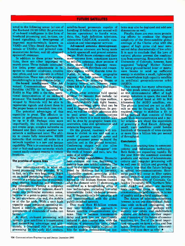
voted to the following areas: (a) use of the Ku-band (30/20 GHz); (b) provision of on-board intelligence in the form of baseband processing and, in-time, on-board signalling; (c) development of improved microterminals (known as VSATs and Ultra Small Aperture Ter-minals or USATs), and personal com-munications devices; and (d) advanced spacecraft antennas.
In addition to these prime innova-tions, there are other important re-search areas. These include: intersatel-lite links, power adjustments in re-sponse to weather conditions, creative new orbits and new concepts in orbital stabilization. These new orbits promise breakthroughs in transmission delay. On-board intelligence. The Ad-
vanced Communications Technology Satellite (ACTS) to be launched by NASA in May 1992 is the first opera-tional demonstration of an on-board processor. The baseband processor de-veloped by Motorola will be able to regenerate signals and direct them to the proper beam or downlink time slot. The potential advantages of this
capability is great. The effective in-crease in performance is expected to be up to 9 dB. Perhaps even more importantly, the on-board processing can create large, complex networks on demand and then create another new network a millisecond later. The abil-ity to create fully interactive MESH networks that connect all nodes in a network together is a new and unique capability. This is in contrast to limited star or hub-and-spoke networks which cannot easily connect remote to remote locations.
The promise of space links
True interconnectivity is what on-board processing truly provides. It is, in fact, only the very beginning. What an on-board processing capability rep-resents in a whole new way of transmit-ting, storing, handling and distribut-ing information. Putting a computer in a fiber-optic link for instance, doesn't make any particular economic sense,
r because in a point-to-point link, it can be put anywhere—the end, the middle or at the far node. With a very high capacity super computer operating on-board a satellite, the processing re-quirements of thousands of nodes can be met.
In short, on-board processing will initially give satellites a transmission and networking advantage and ulti-mately, a leveraged role in network processing. In the early 21st century,
satellite-based processors capable of handling 10 billion bits per second will become operational to handle voice, data, fax, high definition television, interactive CAD/CAM, scientific visu-alization and telecomputer services. Advanced antenna development.
Tremendous advances are being made .4, in both spacecraft and ground antenna 'design. Multi-beam antennas and their more extreme form, sometimes known as cellular antennas, show promise of more than 20-fold frequency reuse. Antennas which distribute and concen-trate signals within discrete time do-mains, to serve various geographic regions, also hold interest. These de-vices, known as scanning beams or hopping beams, are, however, some-times felt to be too complex and expen-sive.
Phase array antennas hold special promise for reasons th t include: (a) ability to conform to type surface, (b) config-urability in tight beams, and (c) processing p r that can be used to improve performance. In gen-eral, we will see satellite antennas able to send power and communications traffic to where it is most needed. This will be done by geographic beam con-centration, time slot optimization and extensive frequency reuse. On the ground, receivers will con-
tinue to shrink in size and cost as a result of greater satellite power and greater processor power on-board the satellite and in the ground terminal. Conforming shapes will also allow ground terminals to "disappear" into the roofs of houses and cars, into the sides of jet airplanes. New orbit capabilities. Dramatic
new changes are now beginning to develop from new orbital concepts. The most in-the-news concept is that pro-posed by Motorola for a low-orbit, 77-satellite system providing global cellular telephone service. This system, known as the Iridium System (named after the element with 77 electrons), is conceived as a breathtaking array of new technologies, including low-orbit intersatellite links, on-board process-ing, 37 frequency cells for spectrum use and interconnection with the global public switched network.
This more than $2-billion system may well redefine the approach to future satellite communications sys-tems. This is because transmission delay and path loss are significantly reduced in this concept even with the addition of intersatellite links. Other systems proposing highly elliptical or-bits for mobile communications sys-
tems may also be deployed and add new dimensions as well.
Finally, there are even more promis-ing efforts to combine the elegant simplicity of the three-satellite global coverage of the Clarke orbit with the appeal of high gains and near zero-second delay characteristic of low orbit. It is easy to conclude that the laws of natural physics prevent the combina-tion from occurring. Researchers at the University of Colorado, however, have suggested "helping" Mother Nature by using ground-based laser or micro-wave beams to send up sufficient energy to stabilize a small, lightweight but nevertheless high capacity satellite in artificial geosynchronous orbit (AGEO).
This concept has many advantages, but also poses several questions, such as the environmental effect of high energy radiation in space, the need for a special orbital band at 800 to 900 kilometers for AGEO satellites, etc. The physics involved are not as diffi-cult as may be thought. In fact, the required energy to stabilize a 10- to 20-kg payload that consists of little more than microelectronics and a my-lar antenna are about the equivalent of powering a Ford Escort. Although small, such satellites could handle hundreds of thousands of voice circuits or more than a billion bits per second of throughput.
Conclusion
This is an exciting time in communi-cations and information technology. Both fields are expanding rapidly. By the year 2000 the combined economic products and services of telecommuni-cations and computer processing will be well over $1 trillion and growing. It is clearly true that the future belongs to optical telecommunications. Enor-mous gains will occur in fiber optics, optical switching and optical process-ing. The University of Colorado, Co-lumbia University, MIT, Northern 'Tele-com, AT&T and others are making truly important gains in optical tele-communications performance, in terms of quality and practical applications. The future of telecommunications,
however, is not one-dimensional. Satel-lites with on-board intelligence, new types of antennas and perhaps with entirely new orbits and stabilization systems are defining another impor-tant dimension of the future of commu-nications, too. Two of the most impor-tant resources we have a silica and free space. Twenty-first century communi-cations will soon show us why. •
136 Communications Engineering and Design December 1990
1 I 9 Ida,
(SCR Following is a list of SCTE technical seminars with contact name. If known, location and seminar topic are listed. January 9-10 National
SCTE Conference "Fiber 4, Optics 1990." Hyatt Regency Grand Cypress, Orlando, Fl. Panel discussions and hands-on demonstrations to be held, focusing on "Planning and using fiber optics in your cable system today." Contact SCTE National Headquarters at (215) 363-6888. December 5 Delaware
Valley Chapter "Newbuild and rebuild construction." Williamsons Restaurant, Horsham, Pa. Contact Dan McMonigle, (215) 265-4233. December 5 Florida
Chapter BCT/E examinations to be administered. Jacksonville, Fl. Contact Keith Kreager, (407) 844-7227 or Pat
Skerry, (904) 735-1571. December 6 Upper
Valley Meeting Group "System Powering and Design." Holiday Inn, White River Junction, Vt. Contact Matthew Alldredge, (203) 328-0640. December 8 Rocky
Mountain Chapter "CSR Troubleshooting," with Ron Hranac of Coaxial International and Jeff Jones of Jones Intercable. Te be held at Jones Intercable, Englewood, CO. Contact Rikki Lee, (303) 321-7551. December 11 Desert
Meeting Group "Installation practices." Contact Chris Middleton, (619) 340-4300, extension 258 for location information. December 12 Big Sky
Chapter "Microwave systems," Colonial Inn, Helena, Mont. Contact Marla DeShaw (406) 632-4300. December 12 Penn/Ohio
Meeting Group "Construction and installation standards and practices" and "Safety." Contact Bernie Czarnecki, (814) 838-1466 for location. December 13
Chesapeake Chapter "BCT/ E Certification." Holiday Inn, Columbia, Md. Contact Keith Hennek, (301) 731-5560. December 13-14 Sierra
Chapter Northern California vendor meeting to be held, featuring tabletop demonstations and breakout discussions. Party Palace, Fairfield, California. Contact Eric Brownwell, (916) 372-2221. December 14 Miss-Lou
Chapter "BCT/E Category II training" with Paul Beeman, curriculm chairman, SCTE. Holiday Inn, Baton Rouge, La. Contact Charles Thibodeaux, (504) 641-9251.
.daa
rt. Fiber Communications
Corp., a certified training facility for GTE, Anritsu and Ametek Controls, is offering 5-day fiber optic splicing and termination workshops at its Sturbridge, Mass. facility. The course is college accredited, and available these dates: December 10-14 January 14-18 February 11-15 March 11-15 For further details, call
(800) 776-0518.
SIECOR Siecor Corp. will sponsor
a four-day, hands-on fiber optic training program designed for craftsmen and contractors who install, splice and test fiber optic cable in a cable television environment. Following is the date for the program "Fiber Optic Installation, Splicing, Maintenance and Restoration for Cable TV Applications." For info call (800) 634-9064. December 17-20
Trade Shows
Western Show November 28-30 Anaheim, Calif. Contact Trade Associates Inc., (301) 468-3210 SCTE Fiber Optics 1991
January 8-10 Hyatt Regency Grand Cypress, Orlando, Fla. For further information, contact the SCTE National Headquarters at (215) 363-6888.
Texas Show February 27-March 1 San Antonio Convention Center, San Antonio, Texas. Contact: (512) 474-2082. North Central Show
(NCCTA) March 11-13 Hyatt Regency Hotel, Minneapolis, Minn. For more information, contact Mike Martin at the North Central Cable Television Association, (612) 641-0268.
National Show March 24-27 New Orleans Convention Center, New Orleans. Contact: (202) 775-3669.
Communications Engineering and Design December 1990 139
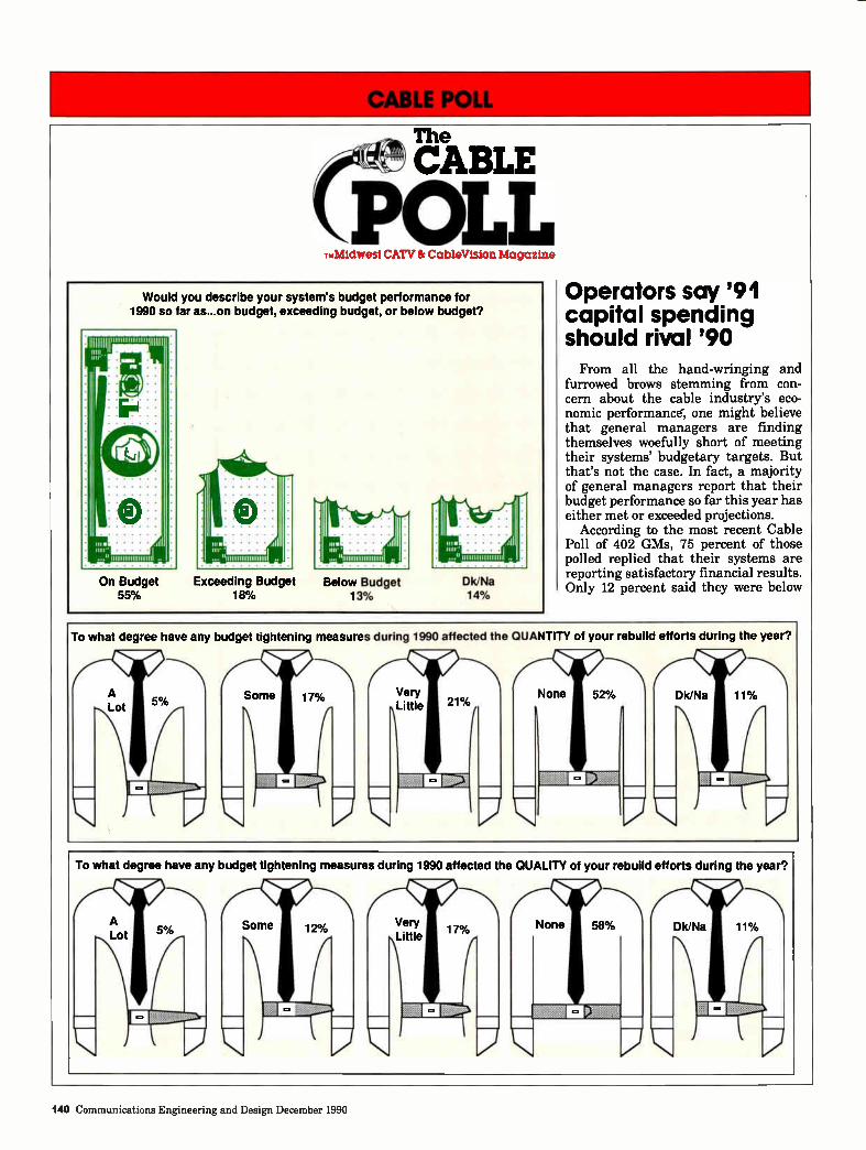
111M CABLE POLL
The
CABLE
POLL TmMidwest CATV 8r CableVision Magazine
Would you describe your system's budget performance for 1990 so far as...on budget, exceeding budget, or below budget?
Operators say '91 capital spending should rival '90 From all the hand-wringing and
furrowed brows stemming from con-cern about the cable industry's eco-nomic performancer, one might believe that general managers are finding themselves woefully short of meeting their systems' budgetary targets. But that's not the case. In fact, a majority of general managers report that their budget performance so far this year has either met or exceeded projections.
According to the most recent Cable Poll of 402 GMs, 75 percent of those polled replied that their systems are reporting satisfactory financial results. Only 12 percent said they were below
To what degree have any budget tightening measures during 1990 affected the QUANTITY of your rebuild efforts during the year?
To what degree have any budget tightening measures during 1990 affected the QUALITY of your rebuild efforts during the year?
140 Communications Engineering and Design December 1990
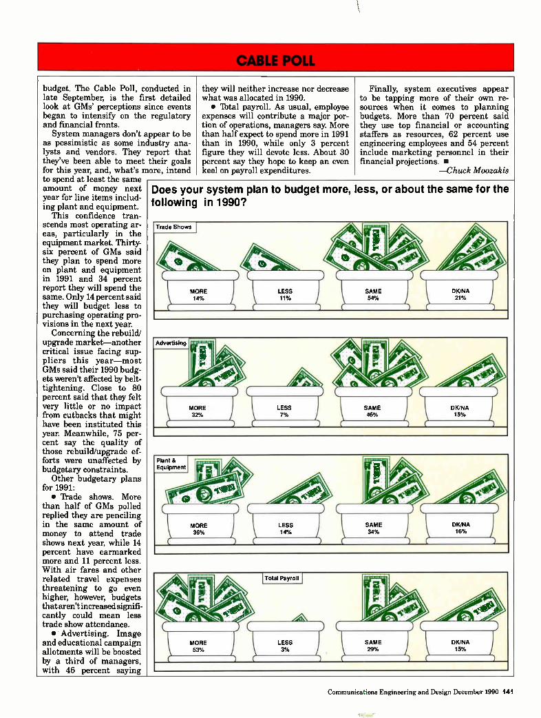
budget. The Cable Poll, conducted in late September, is the first detailed look at GMs' perceptions since events began to intensify on the regulatory and financial fronts. System managers don't appear to be
as pessimistic as some industry ana-lysts and vendors. They report that they've been able to meet their goals for this year, and, what's more, intend to spend at least the same amount of money next year for line items includ-ing plant and equipment.
This confidence tran-scends most operating ar-eas, particularly in the equipment market. Thirty-six percent of GMs said they plan to spend more on plant and equipment in 1991 and 34 percent report they will spend the same. Only 14 percent said they will budget less to purchasing operating pro-visions in the next year.
Concerning the rebuild/ upgrade market—another critical issue facing sup-pliers this year—most GMs said their 1990 budg-ets weren't affected by belt-tightening. Close to 80 percent said that they felt very little or no impact from cutbacks that might have been instituted this year. Meanwhile, 75 per-cent say the quality of those rebuild/upgrade ef-forts were unaffected by budgetary constraints.
Other budgetary plans for 1991: • 'frade shows. More
than half of GMs polled replied they are penciling in the same amount of money to attend trade shows next year, while 14 percent have earmarked more and 11 percent less. With air fares and other related travel expenses threatening to go even higher, however, budgets that aren't increased signifi-cantly could mean less trade show attendance. • Advertising. Image
and educational campaign allotments will be boosted by a third of managers, with 46 percent saying
they will neither increase nor decrease what was allocated in 1990. • Ibtal payroll. As usual, employee
expenses will contribute a major por-tion of operations, managers say. More than half expect to spend more in 1991 than in 1990, while only 3 percent figure they will devote less. About 30 percent say they hope to keep an even keel on payroll expenditures.
Finally, system executives appear to be tapping more of their own re-sources when it comes to planning budgets. More than 70 percent said they use top financial or accounting staffers as resources, 62 percent use engineering employees and 54 percent include marketing personnel in their financial projections. •
—Chuck Moozakis
Does your system plan to budget more, less, or about the same for the following in 1990?
Trade Shows
Advertising
Plant 8, Equipment
Communications Engineering and Design December 1990 141
IN THE NEWS
OSHA Ar e you read
Is your OSHA Form 200 properly completed and current? Your OSHA Job Safety and Health Protection
poster properly displayed? How about your written HAZCOM (Hazardous Substance/Chemical Listing) program— everything in order? Most of the re-spondents to an exit poll at the Na-tional Cable Iblevision Institute's (NCTI) recent OSHA seminar responded positively to these questions. But that doesn't mean that OSHA rules are any less rigorous—which is why the NCTI sponsored the well-attended two-day seminar in Denver last month. "We essentially have an awakened giant on our hand," says Roger Keith, newly appointed director of the NCTI's semi-nar department. "The news is, OSHA has finally awakened after a 20-year inactive period."
Apparently, the federal government is seeking additional revenue sources, and OSHA has been targeted to serve that purpose. In fact, Keith suspects that the Department of Labor will soon triple all fines and change the current worst-case criminal charge from a misdemeanor to a felony. "This will probably happen, as there is a great push in Washington to give the OSHA organization more teeth."
Several cable operators have already been investigated by licensed OSHA inspectors. Interestingly, an informal poll of the more than 80 seminar attendees revealed that nearly half had already been inspected—some more than once.
Why me?
An OSHA investigation can be trig-gered by literally anyone: a disgrun-tled employee, a relative, or even the elderly person who looks out the living room window and notices someone working on a pole without a hardhat. "They can come at any time, and most importantly, speak with any employee privately—off the job—about company safety policies. This is why the dissipa-tion of safety knowledge is so impor-tant," Keith explains.
What happens when an OSHA in-spector arrives on your doorstep? In most circumstances, the routine is fairly predictable: • Credential presentation. Make sure
that the inspection officer can prove his or her affiliation with the U.S. Depart-ment of Labor. "Anyone who tries to collect a penalty at the time of inspec-tion or promotes the sale of a product or service at any time is not an OSHA compliance officer," warns Keith. • Opening conference. At this time,
the OSHA officer explains the purpose of the visit and asks for an employer representative to conduct a facility tour. "Keep in mind that, if the visit is complaint specific, the OSHA officer should be taken directly to the site of the complaint," says Keith. "Anything seen during the trek to the complaint site is deemed 'finable.'" • Closing conference. Following the
inspection, the OSHA officer will con-duct a closing interview to alert the employer as to the severity of the conditions found. No fines are levied at this point. "This is a time for free discussion; a time for frank questions and answers," says Keith. "It's a good time to discuss your company's safety habits, manuals or procedures."
Who gets nailed?
"The OSHA administration is ada-mant that responsibility go as far up the line as it may go," says Keith. "There have been cases where the top brass of an organization have served a prison term for negligent action on the behalf of their employees." The good news is, though, cable
television is an unlikely target for general and routine OSHA inspections. As yet, no cable television execs have ended up in the slammer. "We use accident statistics to find out which industries to inspect on a routine basis. Cable television has pretty low num-bers," says OSHA representative Harry Borchelt, guest speaker at the seminar. "The likelihood of targeting you in-dustry for generally scheduled inspec-
y? tions is nil, unless you have a fatality or catastrophe. My advice is, keep your skirts clean, and you won't see us." One seminar attendee posed the
question of who would be subject for criminal investigation in a bucket truck fatality. In the scenario, a super-visor asks his GM for funds to repair a malfunctioning bucket truck and is told that money hasn't been allocated for the repair. One week later, a technician dies when the bucket truck malfunctions. Who is responsible? "That GM better be sweating bullets," Borchelt promptly replies. "That's why it's easier to go criminal with smaller businesses. Then we have the smoking gun, as opposed to a corporate infra-structure."
According to Borchelt, an upcoming standard will require that all employ-ers have a written safety and health program that includes general guide-lines on safety measures to be used. "How soon that is going to happen is anyone's guess. I'd like to say it will be out in a year, but probably not," says Borchelt.
Not an ogre
Borchelt was quick to point out that OSHA isn't just a penalty-house, but provides a variety of genuine services, including consultations, voluntary pro-tection programs, training programs and library resources. "OSHA has one purpose: to protect employees from unsafe conditions," Borchelt says. These services can be tapped by calling any one of the 85 regional OSHA offices nationwide. "Many people have the misconception that a phone call to a regional OSHA office will prompt an investigation. That's definitely not the case. We're here to provide safety information—for prevention, not inves-tigation."
MSO programs
A panel discussion moderated by Midwest CATV's Tom Pritchard fol-lowed Borchelt's presentation, with
142 Communications Engineering and Design December 1990
SACHS your construction and subscriber ligelware specialist.
mg»
Read&Service Number 75
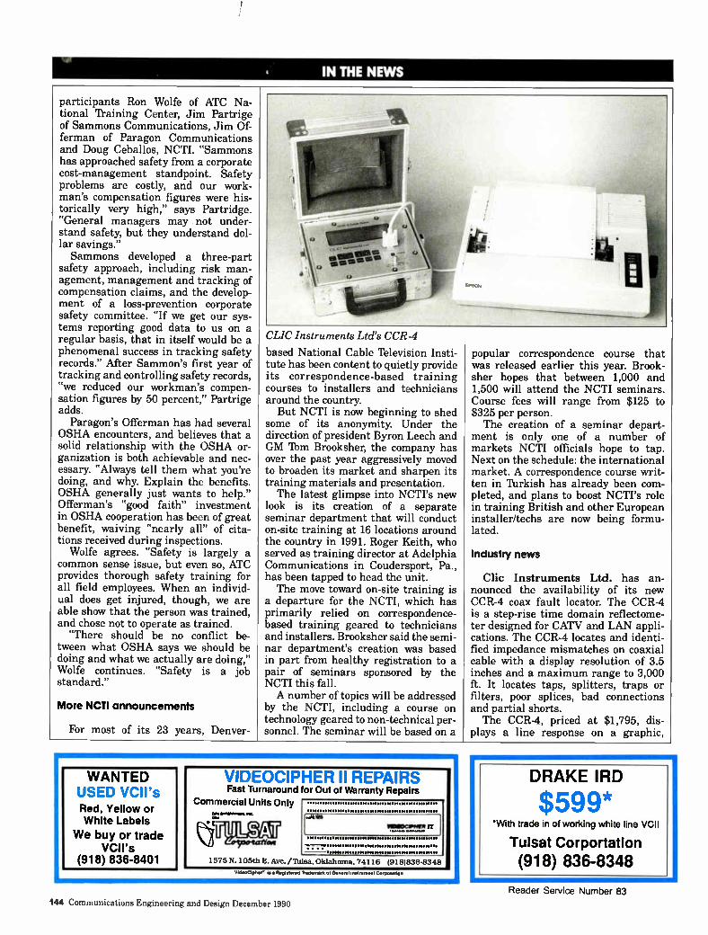
IN THE NEWS
participants Ron Wolfe of ATC Na-tional Training Center, Jim Partrige of Sammons Communications, Jim Of-ferman of Paragon Communications and Doug Ceballos, NCTI. "Sammons has approached safety from a corporate cost-management standpoint. Safety problems are costly, and our work-man's compensation figures were his-torically very high," says Partridge. "General managers may not under-stand safety, but they understand dol-lar savings." Sammons developed a three-part
safety approach, including risk man-agement, management and tracking of compensation claims, and the develop-ment of a loss-prevention corporate safety committee. "If we get our sys-tems reporting good data to us on a regular basis, that in itself would be a phenomenal success in tracking safety records." After Sammon's first year of tracking and controlling safety records, "we reduced our workman's compen-sation figures by 50 percent," Partrige adds.
Paragon's Offerman has had several OSHA encounters, and believes that a solid relationship with the OSHA or-ganization is both achievable and nec-essary. "Always tell them what you're doing, and why. Explain the benefits. OSHA generally just wants to help." Offerman's "good faith" investment in OSHA cooperation has been of great benefit, waiving "nearly all" of cita-tions received during inspections.
Wolfe agrees. "Safety is largely a common sense issue, but even so, ATC provides thorough safety training for all field employees. When an individ-ual does get injured, though, we are able show that the person was trained, and chose not to operate as trained.
"There should be no conflict be-tween what OSHA says we should be doing and what we actually are doing," Wolfe continues. "Safety is a job standard."
More NCTI announcements
For most of its 23 years, Denver-
CLIC Instruments Ltd's CCR -4
based National Cable Iblevision Insti-tute has been content to quietly provide its correspondence-based training courses to installers and technicians around the country. But NCTI is now beginning to shed
some of its anonymity. Under the direction of president Byron Leech and GM 'Dam Brooksher, the company has over the past year aggressively moved to broaden its market and sharpen its training materials and presentation. The latest glimpse into NCTI's new
look is its creation of a separate seminar department that will conduct on-site training at 16 locations around the country in 1991. Roger Keith, who served as training director at Adelphia Communications in Coudersport, Pa., has been tapped to head the unit. The move toward on-site training is
a departure for the NCTI, which has primarily relied on correspondence-based training geared to technicians and installers. Brooksher said the semi-nar department's creation was based in part from healthy registration to a pair of seminars sponsored by the NCTI this fall. A number of topics will be addressed
by the NCTI, including a course on technology geared to non-technical per-sonnel. The seminar will be based on a
popular correspondence course that was released earlier this year. Brook-sher hopes that between 1,000 and 1,500 will attend the NCTI seminars. Course fees will range from $125 to $325 per person. The creation of a seminar depart-
ment is only one of a number of markets NCTI officials hope to tap. Next on the schedule: the international market. A correspondence course writ-ten in Turkish has already been com-pleted, and plans to boost NCTI's role in training British and other European installer/techs are now being formu-lated.
Industry news
Clic Instruments Ltd. has an-nounced the availability of its new CCR-4 coax fault locator. The CCR-4 is a step-rise time domain reflectome-ter designed for CATV and LAN appli-cations. The CCR-4 locates and identi-fied impedance mismatches on coaxial cable with a display resolution of 3.5 inches and a maximum range to 3,000 ft. It locates taps, splitters, traps or filters, poor splices, bad connections and partial shorts. The CCR-4, priced at $1,795, dis-
plays a line response on a graphic,
WANTED USED VCII's Red, Yellow or White Labels
We buy or trade VCII's
(918) 836-8401
VIDEOCIPHER II REPAIRS Fast Turnaround for Out of Warranty Repairs
Commercial Units Only •ereenberi.
reilSett
MICOCIPMMII
1575 N. 105th E. Ave./Tulsa, Oklahoma, 74116 (918)836-8348
Videtelpher. le it Registered %demist of Gene/el Instrument Corgi:melon
DRAKE IRD
$599* With trade in of working white line VCII
Tulsat Corportation
(918) 836-8348
144 Communications Engineering and Design December 1990
Reader Service Number 83
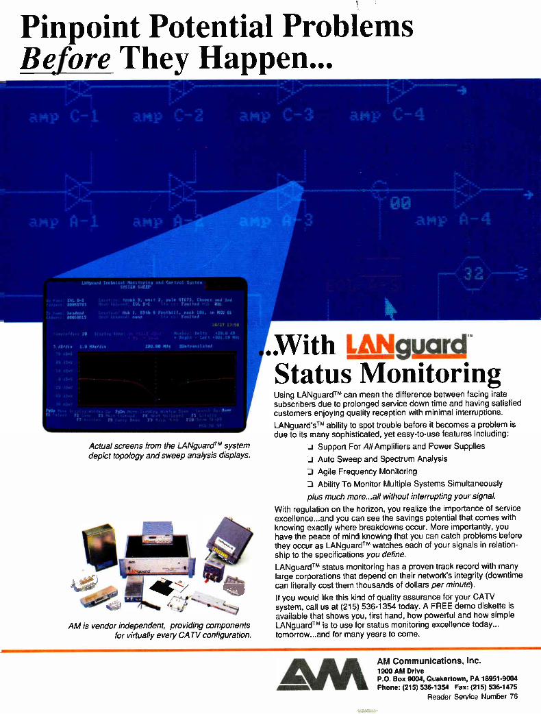
Pinpoint Potential Problems Before They Happen...
BOL 8-2 09968783
Wade.' 90068015
1.1.nit.41 Mu,. tc.".4 i.n.I Cur 1,.‘,1 SIllOn SYSTEM SNEEP
9.9 M F 9t9 6 r??,.).11,,re.191, en MCU 01 .
10/22 '
RIght - Luf -
.40/ellv 1.0 MHx/dir 120.90 MHz Mr fr. 5 1.0
Actual screens from the LANguardTM system depict topology and sweep analysis displays.
AM is vendor independent, providing components for virtually every CATV configuration.
.With LANgygre Status Monitoring Using LANguardTM can mean the difference between facing irate subscribers due to proloiged service down time and having satisfied customers enjoying quality reception with minimal interruptions.
LANguard'sTM ability to spot trouble before it becomes a problem is due to its many sophisticated, yet easy-to-use features including:
J Support For All Amplifiers and Power Supplies
-.1 Auto Sweep and Spectrum Analysis
J Agile Frequency Monitoring
Ability To Monitor Multiple Systems Simultaneously
plus much more.. all without interrupting your signal.
With regulation on the horizon, you realize the importance of service excellence.. and you can see the savings potential that comes with knowing exactly where breakdowns occur. More importantly, you have the peace of mind knowing that you can catch problems before they occur as LANguardTM watches each of your signals in relation-ship to the specifications you define.
LANguardTM status monitoring has a proven track record with many large corporations that depend on their network's integrity (downtime can literally cost them thousands of dollars per minute).
If you would like this kind of quality assurance for your CATV system, call us at (215) 536-1354 today. A FREE demo diskette is available that shows you, first hand, how powerful and how simple LANguardTM is to use for status monitoring excellence today... tomorrow.. and for many years to come.
AM AM Communications, Inc. 1900 AM Drive P.O. Box 9004, Quakertown, PA 18951-9004 Phone: (215) 536-1354 Fax: (215) 536-1475
Reader Service Number 76
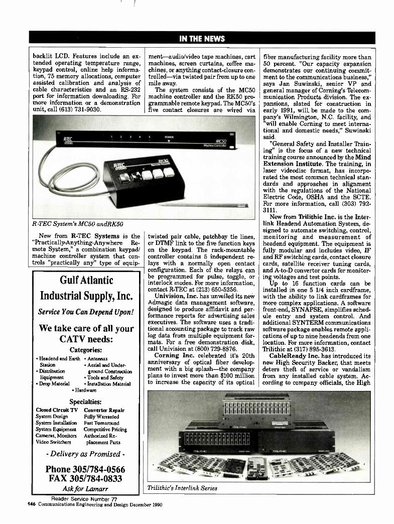
IN THE NEWS
backlit LCD. Features include an ex-tended operating temperature range, keypad control, online help informa-tion, 75 memory allocations, computer assisted calibration and analysis of cable characteristics and an RS-232 port for information downloading. For more information or a demonstration unit, call (613) 731-9030.
R-TEC System's MC50 andRK50
New from R-TEC Systems is the "Practically-Anything-Anywhere Re-mote System," a combination keypad/ machine controller system that con-trols "practically any" type of equip-
Gulf Atlantic
Industrial Supply, Inc.
Service You Can Depend Upon!
We take care of all your CATV needs:
Categories: • Headend and Earth Station • Distribution Equipment • Drop Material
• Antennas • Aerial and Under-ground Construction • Tools and Safety • Installation Material
• Hardware
Specialties: Closed Circuit TV System Design System Installation System Equipment Cameras, Monitors Video Switchers
Converter Repair Fully Warranted Fast Turnaround Competitive Pricing Authorized Re-placement Pans
- Delivery as Promised -
Phone 305/784-0566 FAX 305/784-0833
Ask for Lamarr Trilithic's Interlink Series
ment—audio/video tape machines, cart machines, screen curtains, coffee ma-chines, or anything contact-closure con-trolled—via twisted pair from up to one mile away. The system consists of the MC50
machine controller and the RK50 pro-grammable remote keypad. The MC50's five contact closures are wired via
twisted pair cable, patchbay tie lines, or DTMF link to the five function keys on the keypad. The rack-mountable controller contains 5 independent re-lays with a normally open contact configuration. Each of the relays can be programmed for pulse, toggle, or interlock modes. For more information, contact R-TEC at (213) 650-5256.
Univision, Inc. has unveiled its new Admagic data management software, designed to produce affidavit and per-formance reports for advertising sales executives. The software uses a tradi-tional accounting package to track raw log data from multiple equipment for-mats. For a free demonstration disk, call Univision at (800) 729-8876. Corning Inc. celebrated it's 20th
anniversary of optical fiber develop-ment with a big splash—the company plans to invest more than $100 million to increase the capacity of its optical
- 7771 7.1F.T717:7-71.-1,17,71,7-7„7
..1
fiber manufacturing facility more than 50 percent. "Our capacity expansion demonstrates our continuing commit-ment to the communications business," says Jan Suwinski, senior VP and general manager of Corning's Iblecom-munication Products division. The ex-pansions, slated for construction in early 1991, will, be made to the com-pany's Wilmington, N.C. facility, and "will enable Corning to meet interna-tional and domestic needs," Suwinski said.
"General Safety and Installer Train-ing" is the focus of a new technical training course announced by the Mind Extension Institute. The training, in laser videodisc format, has incorpo-rated the most common technical stan-dards and approaches in alignment with the regulations of the National Electric Code, OSHA and the SCTE. For more information, call (303) 792-3111. New from Trilithic Inc. is the Inter-
link Headend Automation System, de-signed to automate switching, control, monitoring and measurement of headend equipment. The equipment is fully modular and includes video, IF and RF switching cards, contact closure cards, satellite receiver tuning cards, and A-to-D convertor cards for monitor-ing voltages and test points. Up to 16 function cards can be
installed in one 5 1/4 inch cardframe, with the ability to link cardframes for more complex applications. A software front-end, SYNAPSE, simplifies sched-ule entry and system control. And additional SYNTERM communications software package enables remote appli-cations of up to nine headends from one location. For more information, contact Trilithic at (317) 895-3613. CableReady Inc. has introduced its
new High Security Backer, that meets deters theft of service or vandalism from any installed cable system. Ac-cording to company officials, the High
Reader Service Number 77 146 Communications Engineering and Design December 1990
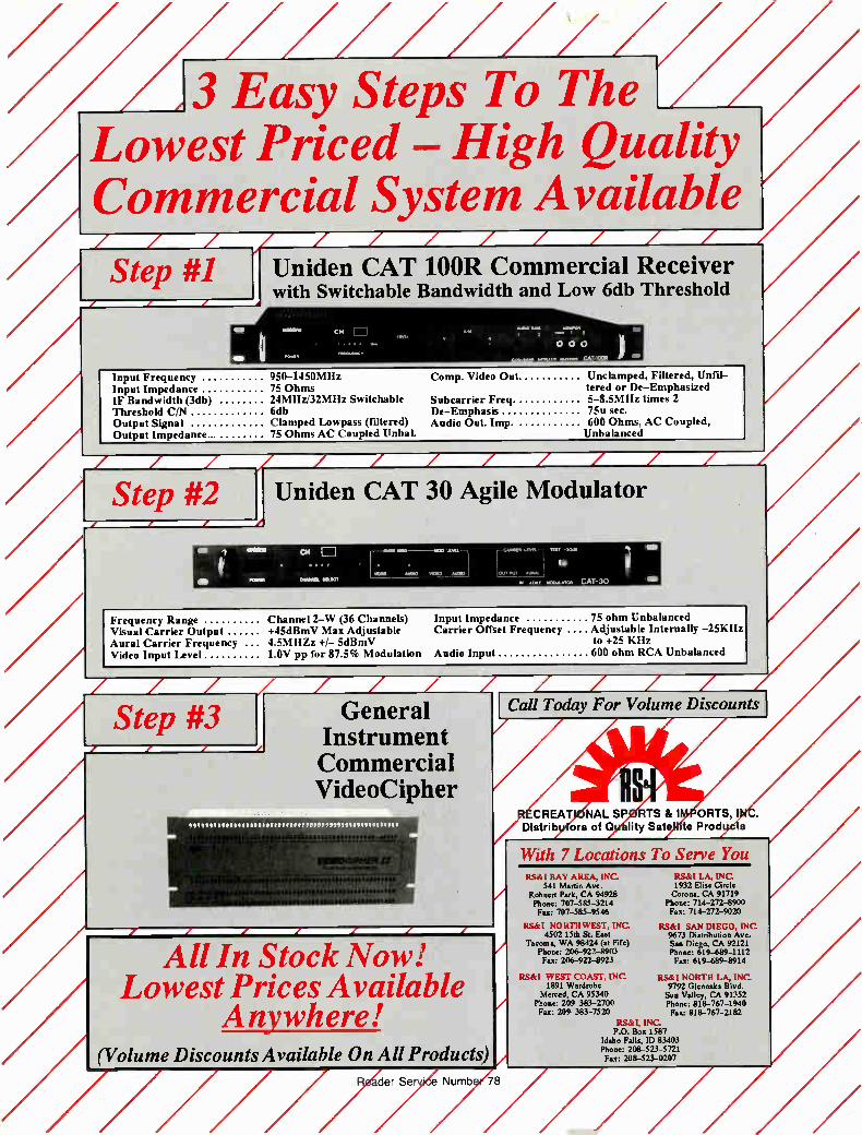
Input Impedance 75 ohm Unbalanced Carrier Offset Frequency Adjustable Internally —25KHz
to +25 KHz 600 ohm RCA Unbalanced
/ / Call Today For Volume Discounts
CREAT NAL SP TS & I ORTS, I Distrib ors of Q lity Sate te Prod s
With 7 Locations To Serve You RSA' BAY AREA, INC.
541 Martin Ave. Rohnert Park, CA 94928 Phone: 707-585-3214 Fax: 707-585-9546
RS&I NORTHWEST, INC. 4502 15th St. East
Tacoma, WA 98424 (at Fife) Phone: 206-922-8903 Fax: 206-9224923
RS&I WEST COAST, INC. 1891 Wardrobe
Merced, CA 95340 Phone: 209-383-2700 Fax: 209-383-7520
RS&I LA, INC 1932 Elise Circle Corona, CA 91719
Phone: 714-272-8900 Fax: 714-272-9020
RS&I SAN DIEGO, INC 9673 Distribution Ave. San Diego, CA 92121 Phone: 619-689-1112 Fax: 619-689-8914
RS&I NORTH LA, INC 9792 Glenoaks Blvd. Sun Valley, CA 91352 Phone: 818-767-1940 Fax: 818-767-2182
RS&I, INC. P.O. Box 1587
Idaho Falls, ID 83403 Phone: 208-523-5721 Fax: 208-523-0207
/////,/// /3 Easy Steps To The
Lowest Priced — High Quality , /
Commercial System Available / / / / / / / / /
Step #1 Uniden CAT 100R Commercial Receiver with Switchable Bandwidth and Low 6db Threshold
Input Frequency Input Impedance IF Bandwidth (3db) Threshold C/N Output Signal Output Impedance.
950-1450MHz 75 Ohms 24MHz132MHz Switchable 6db Clamped Lowpass (filtered) 75 Ohms AC Coupled Unbal.
Comp. Video Out Unclamped, Filtered, Unfil— tered or De—Emphasized
Subcarrier Freq 5-8.5MHz times 2 De—Emphasis 75u sec. Audio Out. Imp. 600 Ohms, AC Coupled,
Unbalanced
/ / /
Step #2
1811 MUM
POEM
Uniden CAT 30 Agile Modulator
E]
0101011111. OIL=
LiNORn - 30.I
Amu. .ss.> MOO [OLT! PO
PI, au. 1000.M. CAT-30
Frequency Range Channel 2—W (36 Channels) Visual Carrier Output +45dBmV Max Adjustable Aural Carrier Frequency 4.5MIIZz +1— 5dBmV Video Input Level 1 OV pp for 87.5% Modulation Audio Input
z Step #3 General
Instrument Commercial VideoCipher
All In Stock Now! Lowest Prices Available
Anywhere! olume Discounts Available On All Products
der SerrÔe Numb
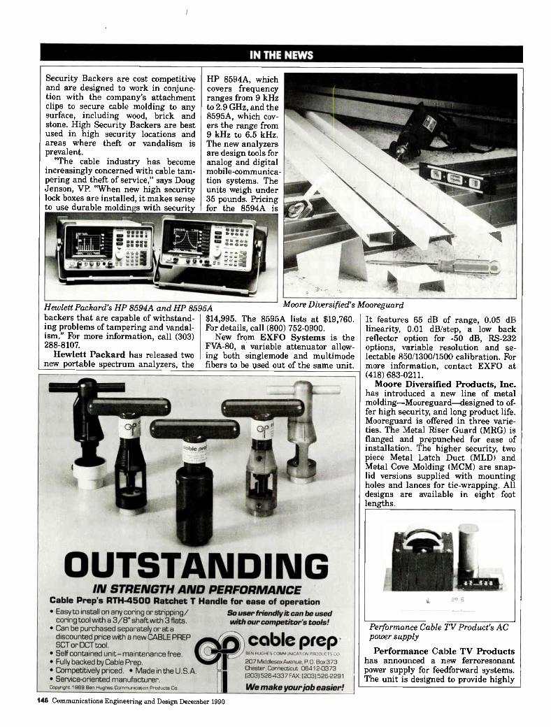
IN THE NEWS
Security Backers are cost competitive and are designed to work in conjunc-tion with the company's attachment clips to secure cable molding to any surface, including wood, brick and stone. High Security Backers are best used in high security locations and areas where theft or vandalism is prevalent.
"The cable industry has become increasingly concerned with cable tam-pering and theft of service," says Doug Jenson, VP. "When new high security lock boxes are installed, it makes sense to use durable moldin s with security
HP 8594A, which covers frequency ranges from 9 kHz to 2.9 GHz, and the 8595A, which cov-ers the range from 9 kHz to 6.5 kHz. The new analyzers are design tools for analog and digital mobile-communica-tion systems. The units weigh under 35 pounds. Pricing for the 8594A is
Hewlett Packard's HP 8594A and HP 8595A backers that are capable of withstand-ing problems of tampering and vandal-ism." For more information, call (303) 288-8107.
Hewlett Packard has released two new portable spectrum analyzers, the
Moore Diversified's Mooreguard
$14,995. The 8595A lists at $19,760. For details, call (800) 752-0900. New from EXFO Systems is the
FVA-80, a variable attenuator allow-ing both singlemode and multimode fibers to be used out of the same unit.
OUTSTANDING IN STRENGTH AND PERFORMANCE
Cable Prep's RTH-4500 Ratchet T Handle for ease of operation • Easy to install on any coring or stripping/ So user friendly it can be used coring tool with a 3/8" shaft with 3 flats. with our competitor's tools! • Can be purchased separately or at a discounted price with a new CABLE PREP SCT or OCT tool. • Self contained unit- maintenance free. • Fully backed by Cable Prep. • Competitively priced. • Made in the U.S.A. • Service-oriented manufacturer. Copyreght 1989 Ben Hughes CommurscatIon Products Co.
cable prep BEN HUGHUS ('OMMury,Cqt1rg
207 Middlesex Avenue , P.O. Box 373 Chester, Connecticut 06412-0373 (203)526.4337 FAX: (203)526-2291
We make your ice easier!
It features 65 dB of range, 0.05 dB linearity, 0.01 dB/step, a low back reflector option for -50 dB, RS-232 options, variable resolution and se-lectable 850/1300/1500 calibration. For more information, contact EXFO at (418) 683-0211. Moore Diversified Products, Inc.
has introduced a new line of metal molding—Mooreguard—designed to of-fer high security, and long product life. Mooreguard is offered in three varie-ties. The Metal Riser Guard (MRG) is flanged and prepunched for ease of installation. The higher security, two piece Metal Latch Duct (MLD) and Metal Cove Molding (MCM) are snap-lid versions supplied with mounting holes and lances for tie-wrapping. All designs are available in eight foot lengths.
Performance Cable TV Product's AC power supply
Performance Cable TV Products has announced a new ferroresonant power supply for feedforward systems. The unit is designed to provide highly
148 Communications Engineering and Design December 1990
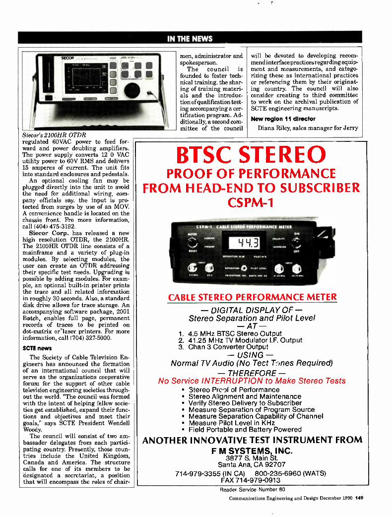
IN THE NEWS
Siecor's 2100HR OTDR regulated 60VAC power to feed for ward and power doubling amplifiers. The power supply converts 12 0 VAC utility power to 60V RMS arid delivers 15 amperes of current. The unit fits into standard enclosures and pedestals. An optional cooling fan may be
plugged directly into the unit to avoid the need for additional wiring, com-pany officials say. the input is pro-tected from surges by use of an MOV. A convenience handle is located on the chassis front. Fro more information, call (404) 475-3192
Siecor Corp. has released a new high resolution OTDR, the 2100HR. The 2100HR OTDR line consists of a mainframe and a variety of plug-in modules. By selecting modules, the user can create an OTDR addressing their specific test needs. Upgrading is possible by adding modules. For exam-ple, an optional built-in printer prints the trace and all related information in roughly 30 seconds. Also, a standard disk drive allows for trace storage. An accompanying software package, 2001 Batch, enables full page, permanent records of traces to be printed on dot-matrix or'laser printers. For more information, call (704) 327-5000.
SCTE news
The Society of Cable Television En-gineers has announced the formation of an international council that will serve as the organizations cooperative forum for the support of other cable television engineering societies through-out the world. "The council was formed with the intent of helping fellow socie-ties get established, expand their func-tions and objectives and meet their goals," says SCTE President Wendell Woody. The council will consist of two am-
bassador delegates from each partici-pating country. Presently, those coun-tries include the United Kingdom, Canada and America. The structure calls for one of its members to be designated a secretariat, a position that will encompass the roles of chair-
men, administrator and spokesperson. The council is
founded to foster tech-nical training, the shar-ing of training materi-als and the introduc-tion of qualification test-ing accompanying a cer-tification program. Ad-ditionally, a second com-mittee of the council
will be devoted to developing recom-mend interface practices regarding equip-ment and measurements, and catego-rizing these as international practices or referencing them by their originat-ing country. The council will also consider creating to third committee to work on the archival publication of SCTE engineering manuscripts.
New region 11 director
Diana Riley, sales manager for Jerry
BTSC STEREO PROOF OF PERFORMANCE
FROM HEAD-END TO SUBSCRIBER CSPM-1
C S PM-1 CABLE STEREO PIRROMMANCE MITER
Unit
tint
C•0111111•
drIMUTAnne
ilF
1-14 3 011 411410 ritoroms
on .01,1111,
OFF
1011
1.10
o 11.0 .11..111.
1•0. 1.1.•
CABLE STEREO PERFORMANCE METER
— DIGITAL DISPLAY OF— Stereo Separation and Pilot Level
— AT — 1. 4.5 MHz BTSC Stereo Output 2. 41.25 MHz TV Modulator I.F. Output 3. Chan 3 Converter Output
— USING — Normal TV Audio (No Tect T.-dies Required)
— THEREFORE — No Service INTERRUPTION to Make Stereo Tests
• Stereo Proof of Performance • Stereo Alignment and Maintenance • Verify Stereo Delivery to Subscriber • Measure Separation of Program Source • Measure Separation Capability of Channel • Measure Pilot Level in KHz • Field Portable and Battery Powered
ANOTHER INNOVATIVE TEST INSTRUMENT FROM F M SYSTEMS, INC.
3877 S. Main St. Santa Ana, CA 92707
714-979-3355 (IN CA) 800-235-6960 (WATS) FAX 714-979-0913
Reader Service Number 80
Communications Engineering and Design December 1990 149
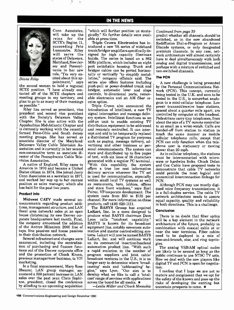
IN THE NEWS
Diana Riley
Conn Associates, will take up the reins for the SCTE's Region 11, succeeding Pete Luscombe. Riley will serve the states of Delaware, Maryland, NewJer-sey and Pennsyl-vania in her new role. "I'm very ex-cited about this ap-pointment," says
the second woman to hold a regional SCTE position. "I have already con-tacted all of the SCTE chapters and meeting groups in my territory, and plan to go to as many of their meetings as possible."
Riley has served as president, vice president and second vice president with the Society's Delaware Valley Chapter. She is also active with the Appalachian Mid-Atlantic Chapter and is currently working with the recently formed Penn-Ohio and South Jersey meeting groups. She has served as associate director of the Maryland/ Delaware Valley Cable Television As-sociation and is currently in her second non-consecutive term as associate di-rector of the Pennsylvania Cable Tele-vision Association. A native of England, Riley came to
America in 1970 and became a United States citizen in 1974. She joined Jerry Conn Associates as a secretary in 1977, and worked her way up to her current position as sales manager, which she has held for the past two years.
Product Into
Midwest CATV made several an-nouncements regarding product addi-tions, management structure, and LAN (local area network) sales at an open house christening its new Denver cor-porate headquarters last month. First, the company announced the addition of the Antron Milenium 2000 line of taps, line passives and house passives to their distribution network.
Several infrastructural changes were announced, including the centraliza-tion of purchasing and finance func-tions out of the Denver corporate office and the promotion of Chuck Krone, previous manager/new business, to VP/ marketing.
In a final announcement, Mary Rose Shearer, LAN group manager, an-nounced a 200 percent increase in LAN sales over the past year. Chris Sophi-nos, president, closed the conference by alluding to an upcoming acquisition
"which will further position us strate-gically." No further details were avail-able at press time.
Triple Crown Electronics has in-troduced a new VA series of wideband trunk/bridger amplifiers specifically de-signed for high capacity fiber/coax builds. The series is based on a 862 MHz platform, which includes an eight port switchable housing. 'frunk and bridger cables can be ported horizon-tally or vertically "to simplify instal-lation," company officials said. The series also offers features including push-pull or power-doubled trunk and bridger, automatic lever and slope controls, bi-directional ports, remov-able electronics and an AM fiber re-ceive option.
'fliple Crown also announced the introduction of Intellitext, a new TV signal interception and message deliv-ery system. Intellitext functions as an add-on unit to enable existing TV distribution equipment to be addressed and remotely controlled. It can inter-cept and add to (or temporarily replace) a distributed TV program for purposes such as paging, message delivery, ad-vertising and other business or per-sonal announcements. The system can store and distributed up to five pages of text, with six lines of 16 characters generated with a regular PC terminal. "With this capability, the system offers a true low cost information delivery service wherever the TV set is used for communication, especially within small local TV systems as well as restaurants, bars, lobbies, offices and store front windows," says Karl Poirer, VP/corporate development. The system costs from $50 to $125 per channel. For more information on these products, call (416) 629-1111. The BASYS Group has acquired
Leine, Inc. in a move designed to produce what BASYS chairman Dave Lyon calls "totalcast capability." BASYS is known for its broadcast equipment line, notably newsroom auto-mation and master control/editing sys-tems. Lakart will now be named BASYS LaKart, Inc. and will continue work on its commercial insertion/headend automation product line. "With such a rapid evolution in the number of program suppliers and joint cable/ broadcast ventures in the U.S., it is no longer easy to determine where 'broad-casting' ends and tcablecasting' be-gins," says Lyon. "Our aim is to develop what we like to call a 'total-cast' range of services with applications across the board for all media. •
—Leslie Miller and Chuck Moozakis
Continued from page 30 predict whether all channels should be switched, as in the now abandoned Rediffusion Dial-a-Program or Ameco Discade systems, or only designated premium channels. In any case, net-work architecture will almost certainly have to deal simultaneously with both analog and digital transmissions, and perhaps with a mixture of switched and non-switched channels.
The PCN
A new challenge is being presented by the Personal Communications Net-work (PCN). This concept, currently being tested in the U.K. and soon to be tested in the U.S., is somewhat analo-gous to a mini-cellular telephone. Low power transmit/receive base stations, spaced about a quarter mile apart, are controlled by computer at the headend. Pedestrians carry tiny telephones, from about the size of a TV remote controller to as small as a wrist-watch. Calls are handed-off from station to station in much the same manner as mobile cellular telephone calls, except that PCN can only function when the tele-phone user is stationary or moving slower than 20 mph. As in cellular telephony, the stations
must be interconnected with micro-wave or hardwire links. Chuck Dolan and Cox Cable have proposed tests to demonstrate that cable TV networks could provide the most logical and economical interconnection linkage for PCN.
Although PCN may use mostly digi-tized voice frequency transmissions, it is a full-duplex service. The cable TV network architecture needs to assure equal capacity, quality and reliability in both directions. This is a challenge.
Conclusion
There is no doubt that fiber optics will be a key element in the network architecture of the future, probably in combination with coaxial cable at or near the user terminus. Fiber cables need to be deployed in a mix of tree-and-branch, star, and ring topolo-gies. The analog VSB/AM optical nodes
are likely to be around as long as the public continues to use NTSC TV sets. How we deal with the new players like digital TV and PCN is open for negotia-tion. I confess that I hope we are not so
mature and complacent that we opt for the safety of the known and pass up the risks of developing the exciting but uncertain prospects to come. •
150 Communications Engineering and Design December 1990
CLASSIFIEDS
PROFESSIONAL DIRECTORY
White _randi Jumper Cables
Custom connectors and cables for all aspects of CATV Gilbert AHS All types of cable from Magnavox Belden Pyramid F59-81 Times LRC and others Comm Scope Quick delivery on all colors with lengths from 6" to 15'
Write or call: (602) 581-0331
335 West Melinda Drive, Phoenix, AZ 85027
EQUIPMENT FOR SALE/RENT
AERIAL BUCKET TRUCKS Large selection geared for CAN ...fLf
STANDARD TRUCK 8 e4s, EQUIPMENT CO. 1155 Hill St. S.E.
Atlanta, GA 30315 *
1 .4
Phone: 1-800-241-9357 eucKET meats
Bucket Trucks—Used Telsta, Versa-Lift, Digger Derricks-10 in Stock. 30 other Utility Construction Trucks.
"We Buy and Sell" Opdyke, Inc. (Philadelphia Area) 3123 Bethlehem Pike (215) 721-4444 Hatfield, Pa. 19440
WANTED: SURPLUS CABLE EQUIPMENT
Jerrold, Oak, Hamlin & Scientific Atlanta equipment. Highest Prices Paid
Cable Equipment Brokerage Co.
(818) 709-3724
CAREER MARKETPLACE
Baker3cott a co. EXECUTIVE SEARCH 1359 Roule 46 Parteppany, NJ 07054 201 263-33SS
Specialists ha the COMMUNICATIONS INDUSTRY
CABLE TWEIROADCAST TELECOMMUNICATIONS
DIVISION Divesee POSMONS AVAILABLE AT ALL LEVELS OF
MANAGEMENT. COAST TO COAST CaM or tortee COPFDDICE
FEE PAD
WE DONT TALK CABLE, WE KNOW CABLE' PRINCIPALS DAVID ALLEN & JUDY BOUER
VIDEO PAGE GENERATOR
TOUCHTONE C64 EPROM CART AUDIO IS NTSC MODEL VIDG
VIDEO OUT $189.95
DISK DRIVE OPTIONAL
COMMODORE 64
TSDO TOUCKTONE DECODER S QUAD RELAY CONTROL
er .911-C=I • E=3 TSDOS 89.95
31, 3 31, 31
=Da1lenn:_kni= 1 E1 QUAD S 99.95
D I G ITAL RECORDER me VOICE
4 R.F. RELAYS $179.95 $179.95
' LOW COST SYNDEX SOLUTIONS ' C64 MULTI-PAGE VIDEO & R.F.GENERATOR AUTOBOOT EPROM CARTRIDGE outputs NTSC COLOR VIDEOS ch. 3/4 R.F. "EPROM PROGRAM CART gives high resolution multi -page display • scroll, flash, crawl, 10 pages ; timer & clock controls
relays, computer sends touchtone commands • MODEL VIDG $189.95 *SWITCH VIDEO / R.F. *65 DB ISOLATION D.C. TO 600 MHZ • (4) DPDT-750 RELAYS MODEL
RL4 $179.95 *- COMPUTER CONTROLS any number of relays via touchtone 2-5 DIGIT commands via audio link to decoders • TYPICAL C64 RETAIL IS $99 TO $129.00 'DIGITAL VOICE RECORDER 32-64 SEC. ROTATING MSG., MODEL DVR $179.95 . • ENGINEERING CONSULTING e PRODUCT
583 CANDLEWOOD ST. BREA, CA. 92621 CATALOG • TEL:714-671-2009 FAX: 714-255-9984 ‘. AVAILABLE,
VIDEO SUPPLIES
HARKERTEK VIDEO SUPPLY Uleor Ave Sau9vVes. NV 12.77 U S A
zt 1-800-522-2025 In NY: 914-248-3036
ANTHONY'S MANUFACTURING SERVICE
PLOW BLADES Irrigation/Wire/Combination
For Any Machine—For Any Application
1-800-383-PLOW
(719) 475-PLOW P.O. Box 17701
Colorado Springs, CO 80935
WANTED USED VCII's Red, Yellow or
White Labels
We buy or trade
VCII's (918) 836-8401
VIDEOCIPHER Il REPAIRS Fast Turnaround for Out of Warranty Repairs
Commercial Units Only enti eineliOniene
ealiamereent n
1575 N. 105th E. Ave. /1111sa, Oklahoma. 74116 (918)836-8348
VionoCipnert ie • Requiter. Tredernarlt of General Inetrument Corporation
CAREER MARKETPLACE Leader in the placement of Cable Television Professionals
Call toll free 1-800/433-2160; In Texas call collect 817 599-7623. FAX 817.599-4483.
SALES ENG—Sell product line for top cable mfgr in the SE. $60k. CORP ENG—Growing mid-sized MSO, Rocky Mt. location, report to the President, high visibility. $70k. SALES ENG—Top cable mfgr. NE region. Sell top product line. $60k. DISTRICT SALES ENG—Sell both product and repair service, Midwest market. $60K. PLANT MGR—Take charge of this 100k system in upper Midwest. PLANT MGR—Top 10 MSO West Coast location. Attractive S. CA location. CORP ENG—Strong property evaluation background. $45k + profit sharing.
PROJECT ENG—Urban newbuild experience a must, multiple projects in England. $80k TECH OPS MGR—New England, strong constructioin background a plus. $50k. DESIGN COORDINATOR—CADD a plus, IBM a must. $35k. CHIEF TECH—Top 10 MSO, state of the art technology, NE. $32k. MANAGER/CHIEF TECH—Multiple opportunities. Top MSO's. $25k-35k. HEADEND/MICROWAVE TECH—Numer-ous opportunities nationwide. $25k-35k. LINE & SERVICE TECH—Jobs nationwide. Companies will relocate. Call for geographic preference. $8-15/hr
JIM YOUNG I& ASSOCIATES One Young Plaza 1235 Ranger Highway Weatherford, TX 76086
Call for information about these and many other opportunities nationwide.
Communications Engineering and Design December 1990 151
CLASSIFIEDS
CAREER MARKETPLACE
TECHNICAL TRAINER
Adelphia Cable seeks a well-organized Technical Trainer to provide on-going training for a staff of 40 technicians in its regional Plymouth Meeting office.
Candidate should have 3-5 years of technical experience; be fully qualified in installation, service and maintenance of cable plant; and have excellent interpersonal, oral and written communications skills.
Position offers competitive salary and benefits. For consideration, send resume to:
Plant Operations Manager
Adelphia Cable Communications 1 Apollo Road RO. Box 198
Plymouth Meeting, PA 19462
EEO/M/FN/H
SYSTEM TECHNICIAN
WORK IN SUNNY SOUTH CENTRAL WASHINGTON STATE. DISCOVER THE SENSE OF OWNERSHIP THAT ONLY A SMALL MS0 CAN PROVIDE. THE SUCCESSFUL CANDIDATE MUST BE ABLE TO MAKE DECISIONS WITHOUT LOCAL SUPERVISION AND BE AN EFFECTIVE PROBLEM SOLVER.
DUTIES INCLUDE HEADEND OPERATION, SYSTEM MAINTENANCE, INSTALLA-TION, CLI AND LOCAL CONSTRUCTION PROJECTS. GOOD COMPANY WITH COMPETITIVE SALARY.
IF YOU THINK YOU ARE THE PERSON WE'RE LOOKING FOR, SEND RESUME OR CALL: SUN COUNTRY CABLE, PO BOX 61, UMATILLA, OR. 97882—(503) 922-5759—ATTN: KIP OR TIM.
EOE
EQUIPMENT FOR SALE/RENT
ELECTRONICS DIRECT
YOUR NEW AND USED HEADEND/ DISTRIBUTION ELECTRONIC SPECIALISTS
• Products by Magnavox, Scientific Atlanta, and Jerrold
• Large inventory
• Competitive prices
• We broker your used amplifiers
CALL:
800-448-7863
RECRUITING AND SEARCH
Operations Engineering Corporate-Regions
Systems
JIM CAHOON Cable Operations and Engineering
Since 1966
7100 E. Belleview, #102 Englewood, CO 80111
Ph: (303)779-8890 Fax: (303)779-8139
EMERGENCY ALERT SYSTEMS
by Idea/onics
69 channels 14 day delivery compatible with all headends
—AFFORDABLE— (701) 786-3904
24 and 88 channel units also available
dB-tron• icssm CONVERTER —GET CONVERTED' , — REPAIRS
Scientific Atlanta 8550's $23.95 Flat!! All P.J. Digitals - $13.95 Flat!! We buy and Sell converters!
For more information call Chris or Keith @ 1-800-356-2730
TSB, Inc. • Design, Strand Map, As-Builts • CAD Drafting Service • Headend Racking and Renovations • CLI • Audits • Onsight Technical Training • Structural Analysis of Towers PO Box 244 (605) 665-1393
Yankton, SD 57078
152 Communications Engineering and Design December 1990
CLASSIFIEDS
PROFESSIONAL DIRECTORY
ZEN 116U rEalitwa COMMUNICATIONS CORP.
" One Source Accountability
From Towers to Taps"
Automated Mapping Cable Construction Broadband Design Facilities Management
Two Route 9 Wappingers Falls, N.Y. 12590
Phone (914) 298-7515 Fax (914) 298-7998
/NaCom BUILDING COMMUNICATION SYSTEMS THROUGHOUT AMERICA
• Full Installation Services • Converter Exchanges, Audits, Special Projects • MDU, SMATV, LAN, Pre/Postwiring • Aerial/Underground Construction (including Fiber Optics) • Strand Mapping (AutoCAD & LYNX) • Field Engineering, Make-Ready, As-Builts • RF Design (CADSUM II & LYNX) • CLI Detection/Correction
1900 E. Dublin-Granville Road, Suite 100A, Columbus, OH 43229 • (614) 895-1313 • (800) 669-8765 • FAX (614) 895-8942
74dvbeereu
WATS
FAX
Cable Services
A Dnnalon ol Coble Senile«. Inc.
Established in 1979
REPAIR / BUY / SELL
Converters & Distribution Equipment
P/U / Delivery, Central-Eastern United States
(National) (800) 654-7956
(904) 728-6738
CALESOLUT1ONS
= PACE RIEAVVE Preérelerd *Moaner Cemmel•••• evelmalm
• STATE OF THE ART EQUIPMENT & PROCEDURES
• TRAINED, PROFESSIONAL PERSONNEL
• MAPPED, DETAILED TEST RESULTS
• COMPETITIVE PRICING
2700 Flora St. • Dallas, Texas 75201-9835 • (214) 475-3436
Reader Sonia # P090 #
AM Communications 76 145 AT&T 62 113 Ad Systems 65 121 Alpha lbchnologies 9, 37 21, 67 American Lightwave 47 95 Anixter Cable TV 82 156 Aryls 64 116 Authorized Parta 59-60 Automation lbchniquestIldsat 83 144 Avcom of Virginia 57 109 Basys Lakart 54 106 Belden Corp 14 31 Business Learning Group 56 108 C-COR Electronics 41, 42 77, 79 Cable Prep/Ben Hughes Comm 79 148 Cable Services 5 13 CADCO Inc 51 102 Calan, Inc 13, 48 29, 99 Cablemasters 60 111 Catel 22 45 Channel Master 73 133 Channelmatic 49 100 Comm/Scope Inc 1, 36 4-7, 65 ComPedco 24 48 ComSonics 58, 61 109, 111 Contec International 44, 45 85, 87 Corning 15 32-33 Eagle Comtronics 28 52 Electroline 59 110 FM Systems 80 149 Flight-111m 38 69 General Cable Iblsta 21 44 General Inst./Jerrold (Dist.) 8, 46 18-19, 91 Gulf Atlantic 77 146 IPITEK 68 125 ITW Linx 59-60 Jerry Conn Assoc 17 36
Reader Service Pee* # Lectro Products 32 56-57 Lemco lbol 27 51 Lindsay Specialty 23 47 Magnavox CATV 11, 39 25, 73 Microwave Filter 52 103 Midwest Communications 19 38 National Cable Iblevision Institute 50 101 Nacom 74 135 Nexus Engineering 4 11 Oak Industries 18 37 Ortel 16 35 Panasonic 2 8 Pioneer Communications of America 12 27 Power Guard 10 23, 59-60 Power & Iblephone Supply 71 129 Rainbow Satellite Comm 69 126 Recreational Sports 78 147 Reliable Electric 81 155 Riser-Bond 29 54 Sachs Comm. 75 143 Sadelco, Inc 20 43 Sencore 53 105 Signal Vision 70 127 Standard Communications 7 17 Sumitomo 110 39-42, 117-120 TE Products Inc 66 121 Iblecommunication Products Corp.31, 40 55, 75 'Ibiu3can MSI 63 115 Three Star 30 54 Time Manufacturing 26 50 Times Fiber 6 15 Ililogy Communications 3, 35 9, 63 Triple Crown Electronics 33 58 Wavetek 43, 55 80-81, 107 Wegener Comm 72 130-131 Westec 25, 34 49, 62
Communications Engineering and Design December 1990 153
PAGdMIIMME
Attack of the killer bees I wish I could take credit for the
phrase used in the title—but I can't. It was used by one HDTV proponent to describe video artifacts in another proponent's HDTV pictures. The arti-facts were due to video compression of the HDTV signal so that it could fit into 6 MHz. The first proponent based his criticism on a computer simulation of the proposal. The second proponent is no longer in the race to become the national standard for HDTV. I'd like to keep such a clever phrase from being lost, so I'll apply it to artifacts I've seen in compressed NTSC.
Let's investigate the nature of video compression. We'll take it step-by-step. It may take us a while before we get to the "killer bees," but we will get there.
Seeing is (almost) believing
I have now seen compressed video in a variety of flavors and qualities. Some of what I have seen has been NTSC; some has been HDTV. Some of what I've seen has been simulation and some has involved actual circuits. Some has been almost too good to believe. Some has been so bad it was more fun to watch the impairments than the video itself. There is enough promise in what I have seen for me to be confident that commercially important
By Walter Ciciora, Vice President of Technology, American Television and Communications
video compression is possible. The really difficult part will be to
determine when the technology has progressed far enough to where there will be no further significant improve-ments. We need to balance the problem of being left behind because we too timidly approached the very real prob-lem of jumping so soon that the next guy got much improved performance at a reduced price. There is no way of knowing which way to go.
Video compession
Color video starts out as equal bandwidth red, green and blue signals at the camera. For NTSC these are band limited to 4.2 MHz. HDTV signals extend to beyond 30 MHz. These sig-nals are combined into a luminance signal conveying the brightness infor-mation and two color difference sig-nals. These later signals are adjusted to match the eye's sensitivity to colors. Humans have an acute sensitivity to flesh tones. At this point, the first compression
of the signal takes place. The color difference signals are reduced in band-width because the eye's ability to resolve color is less than its ability to discriminate brightness. The NTSC standard suggests that signals carry-ing flesh tones be sent in a wider bandwidth than those describing colors which are most different from flesh tones. So rather than having three equal bandwidth signals, we have a wide band brightness signal, a flesh tone signal of about one-third the bandwidth, and a non-flesh tone signal of nearly 12 percent the bandwidth. Instead of a 200 percent premium to carry color, the extra amount has been reduced to only about 45 percent.
This relatively easy bandwidth re-duction has been accomplished without the use of memory or storage and, for the most part, without introducing significant artifacts. This is all the video compression needed by NTSC to squeeze color into holes in the black and white signal's spectrum. This com-pression can be handled with circuits having relatively few active devices.
Color resolution has been reduced horizontally to match the eye's proper-ties. The vertical color resolution has not been reduced. It too is beyond the eye's ability to utilize. If we allow for storage, we can send only one of the color difference signals per line. Verti-cal color resolution now more nearly matches horizontal color resolution.
The eye still doesn't see any degrada-tion. The amount of color information has been cut in half. Thus the color premium is now less than 25 percent. It would be about 12 percent if narrow bandwidth color difference signals were used. Nothing inherently "digital" has been done. It is convenient to accom-plish the storage of this last step in a digital manner, but digital is not the only way to this end.
Scanning Inefficiencies
It was anticipated that early televi-sion receivers would have difficulty maintaining synchronization with the transmitted picture. Thus, the creators of the NTSC black and white standard allocated relatively large amounts of transmit time to synchronization pulses. About 10.5 precious microseconds out of the horizontal lines' 63.5 are allo-cated to the horizontal sync pulse. The picture tube's deflection yoke
and the high voltage transformer are tuned circuits. The movement of en-ergy between the inductance and ca-pacitance of this circuit requires time. This time is also used to bring the electron beam back to the beginning of the line. These time requirements im-pose a 16.5 percent loss of information-carrying capacity. About 41 of the 525 scan lines are lost to vertical synchro-nization and beam retrace. Another 7.8 percent of information capacity is lost. Because of these two synchronization needs, video is carried only about three quarters of the time.
Another practical waste is the over-scan of the picture tube. At least five percent of the picture is placed on parts of the picture tube which are not visible to the viewer. This is reduced from a significantly larger number in years past. Over-scan allows for aging of components while still avoiding black bands on the picture edges. The NTSC signal has been specified
in a manner that simplifies the design of television receivers. While this was critical in the early days, it is no longer necessary. A significant amount of compression is possible if these hard-ware facilitating approaches are elimi-nated. The strategy so far has been to avoid
sending what the eye can't see. This has been done in a fixed, non-adaptive manner. Next month we'll consider some of the recent techniques which have been applied to make dramatic further reductions in the information transmitted. We'll get closer to the killer bees. •
154 Communications Engineering and Design December 1990
UTILITY PRODUCTS
Anixter Cable TV stocks the complete line of Utility Products pedestals because they're made to last. Made to last, because it's just good business to protect valuable equipment inside quality enclosures.
Utility Products are made to outlast the equip-ment inside. They average 25 years in use. Buy today and don't think about replacement until 2015.
Utility Products' nine-step finishing process gen-erates a high gloss weather-fighting finish that resists corrosion and the onslaughts of acid rain, pol-lutants and other atmo-spheric contaminants.
For more information about the full line of Utility Products pedestals, call the Anixter Cable TV distribu-tion center in your area.
RELIANCENBAterrn COIVIIVI/TEC
CABLE TV
WEST-ANAHEIM: (714) 779-0500, (800) 854-0443; DENVER: (303) 740-8949, (BOO) 841-1531-, SEATTLE: (206) 251-6760, (800) 426-7665: MIDWEST-CHICAGO: (708) 350-7788, (800) 544-5368; CLEVELAND: (216)526-0919, (800) 321-8068: DALLAS: (214) 446-CATV, (800) 231-5006; IRON MOUNTAIN, MI: (906) 774-4111, (800) 624-8358; SKOKIE, IL HDOTRS: (708) 677-2600: EAST-ATLANTA: (404) 840-7901, (800) 242-1181; LONG ISLAND, NY: (516) 293;7788, (800) 645-9540; NEW JERSEY: (201) 328-0980, (800) 631-9603; ORLANDO: (407) 240-1888, (800) 477-8396: CANADA-CALGARY: (403) 250-9646; MONTREAL: (514) 636-3636; TORONTO: (416) 625-5110; VANCOUVER: (604) 321-5885.
In an emergency, weeKends and holidays or after 5 P.M. call toll free 1 (800) 323-8166. CORPORATE OFFICES, ANIXTER CABLE TV, 4711 Golf Road, Skokie, IL 60076, (708) 677-2600 Reader Service Number 81
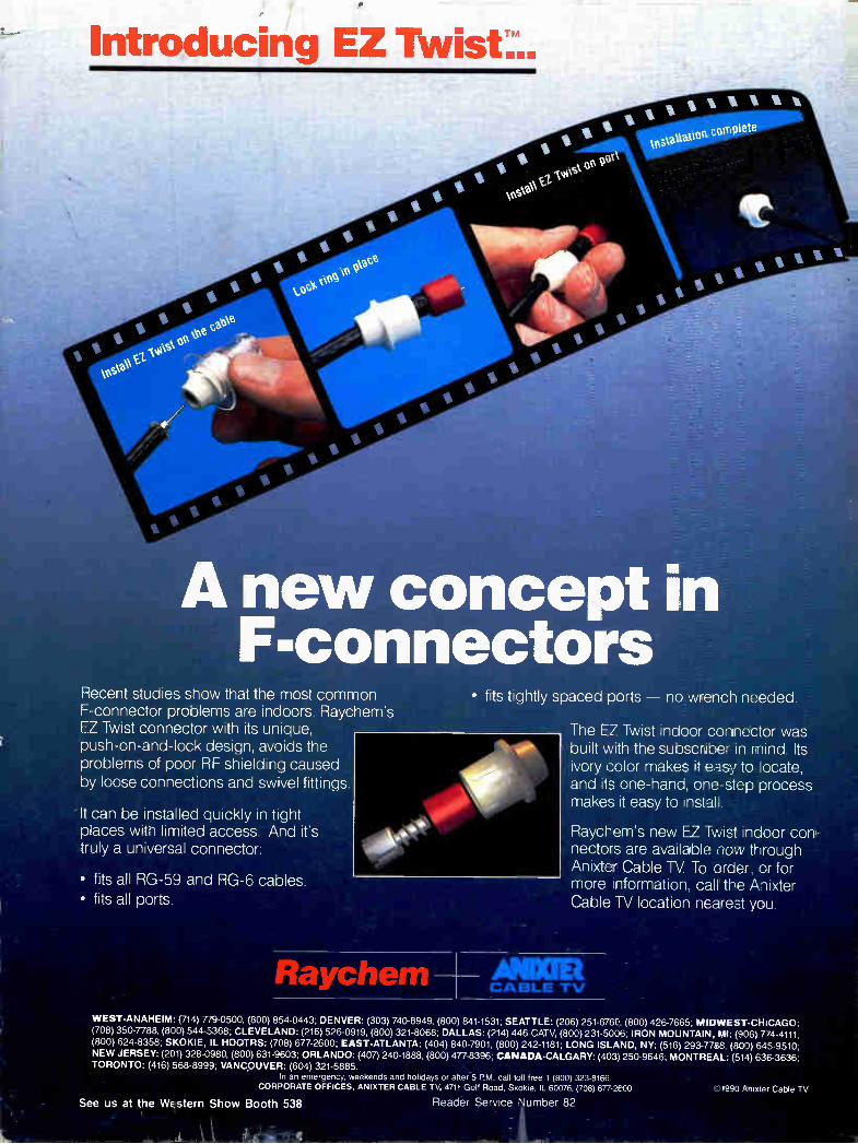
A new concept in IF-connectors
Recent studies show that the most common F-connector problems are indoors. Raychem's EZ Twist connector with its unique, push-on-and-lock design, avoids the problems of poor RF shielding caused by loose connections and swivel fittings.
It can be installed quickly in tight places with limited access. And it's truly a universal connector:
• fits all RG-59 and RG-6 cables. • fits all ports.
Raychem
• fits tightly spaced ports no wrench needed.
The EZ Twist indoor connector was built with the subscriber in mind. Its ivory color makes it easy to locate, and its one-hand, one-step process makes it easy to install.
Raycl-em's new F7 Twist indoor con-nectors are available now through Anixter Cable TV To order, or for more !nformation, calf the Anixter Cable TV location nearest you.
AMR CABLE :TV
WEST-ANAHEIM: (714) 779-0500. (800) 854-0443; DENVER: (303) 740-8949, (800) 841-1531, SEATTLE: (206) 251-676C,. (800) 426-7665. MIDWEST-CHICAGO: (708) 350-7788. (800) 544-5368; CLEVELAND: (216) 526-0919, (800) 321-8068; DALLAS: (214) 446-CATV. (800) 231-5006, IRON MOUNTAIN, MI: (906) 774-4111, (800) 624-8358; SKOKIE, IL HDQTRS: (708) 677-2600; EAST-ATLANTA: (404) 840-7901. (800) 242-1181; LONG ISLAND, NY: (516) 293-7788, (800) 645-9510; NEW JERSEY: (201) 328-0980, (800) 631-9603; ORLANDO: (407) 240-1888, (800) 477-8396. CANADA-CALGARY: (403) 250-9646; MONTREAL: (514) 636-3636; TORONTO: (416) 568-8999: VANCOUVER: (604) 321-5885.
In an emergency, weekends and holidays or after 5 PM call toll free 1 (800) 323-8166. CORPORATE OFFICES, ANIXTER CABLE TV, 4711 Golf Road, Skokie, IL 60076. (708) 677-2600
See us at the WE stern Show Booth 538 Reader Service Number 82 1990 Anixter Cable TV