Functional evaluation of an integrated IP over WDM management solution
14
FUNCTIONAL EVALUATION OF AN INTEGRATED IP OVER WDM MANAGEMENT SOLUTION SerratJ.’, E.Grampin’, L.RaptisZ, F.Karayannis’, K.Vaxevanahs4, D.Chronis5, H.Katopodis5, G.Hoekstra6, W.Romijn6, A.Galis7 and E.Kozlovski7 (I) Universitat Polireknica de Catalunya; (2) National Technical Universiry of Athens; (3) OTE-Consulting; (4) Ellemedia Technologies; (5) OTE; (6) Lucenr Technologies; (7) University College London Abstract: The management of heterogeneous and hybrid networks has been always a challenge for network operators. Different frameworks and architectural approaches have been proposed and investigated in the literature. The purpose of this paper is to present the evaluation results of an integrated network management solution for the provisioning and maintenance of IP over WDM end-to-end services with network parameters derived from Service Level Agreements (SLAs). A detailed description of the test-bed environment as well as an integrated scenario for architectural evaluation is also included. Key words: Management of IP over Optical Networks
-
Upload
independent -
Category
Documents
-
view
0 -
download
0
Transcript of Functional evaluation of an integrated IP over WDM management solution

FUNCTIONAL EVALUATION OF AN INTEGRATED IP OVER WDM MANAGEMENT SOLUTION
SerratJ.’, E.Grampin’, L.RaptisZ, F.Karayannis’, K.Vaxevanahs4, D.Chronis5, H.Katopodis5, G.Hoekstra6, W.Romijn6, A.Galis7 and E.Kozlovski7 (I) Universitat Polireknica de Catalunya; (2) National Technical Universiry of Athens; (3) OTE-Consulting; (4) Ellemedia Technologies; (5) OTE; (6) Lucenr Technologies; (7) University College London
Abstract: The management of heterogeneous and hybrid networks has been always a challenge for network operators. Different frameworks and architectural approaches have been proposed and investigated in the literature. The purpose of this paper is to present the evaluation results of an integrated network management solution for the provisioning and maintenance of IP over WDM end-to-end services with network parameters derived from Service Level Agreements (SLAs). A detailed description of the test-bed environment as well as an integrated scenario for architectural evaluation is also included.
Key words: Management of IP over Optical Networks

680 Serrat, J. et al.
1. INTRODUCTION
Procedures in the field of network provisioning have become increasingly complex. The manual configuration of connectivity pipes on the network is costly, time consuming, and error prone. As the demand for timely delivery of more innovative services increases, the requirement to automate the provisioning process is stronger than ever. Automating the provisioning process allows service providers to scale their operations and improve quality of end-to-end deployment for new customers.
In the area of network technology, current trends are pointing IP over an Optical Transport Network based on WDM as the approach that will prevail in the future. These two layers need to be integrated with the goal of providing enough bandwidth for quality-differentiated services. Here again an automated provisioning process hound with a personalised service management mechanism is required.
Different approaches have been proposed for the smooth, fast and reliable provisioning and management of Internet services over the optical layer. Most of the research in the area has been focused in the control plane hy extending the distributed Intemet network control approach to the optical layer using signalling mechanisms either in an overlay model or a peer model. Such efforts, driven by different standardisation bodies, are among others the ASON/ASTN [ I ] and the Generalised MPLS frameworks [2].
Complementing the above mentioned trends, in July 2000 the IST project WINMAN [3] was launched to look for an integrated network management solution capable of providing end-to-end Integrated Connectivity Services (ICSs) with parameters derived from SLAs. The WINMAN solution consists of the extension of the telecom-style network management approach to the IP layer through the use of MPLS, which could be treated as a connection-oriented technology. The Internet services would be offered mostly by the management plane, but some features of the control plane, such as restoration and protection mechanisms or routed connection set-up could be exploited.
The WINMAN network management solution and system architecture for managing hybrid IP over WDM networks have being developed and presented so far [4],[5] . In addition the initial results of the evaluation of the WINMAN solution have been available quite recently.
This paper is precisely the presentation and evaluation of these results along with the test-bed that was necessary to show up the system behaviour. Hence, aRer the summary presentation of the WINMAN management approach of Section 2, we devote Section 3 to describe the test-bed that was installed with the purpose of validating the functional characteristics of the WINMAN system. This section covers details of the IP and WDM infrastructure as well as the adaptations that were required to use proprietary management systems, at NE level, with the WINMAN

Functional Evaluation of an IPN'DM Management Solution 681
network management system prototypes. Section 4 presents the integrated testing scenario that was conducted with emphasis on the applications that were executed and the detailed steps that were conceived. Section 5 presents the results obtained along with comments on the fulfilment of the specified functional behaviour. Finally we end with remarks on what we have leamt from these results.
2. THE WINMAN MANAGEMENT APPROACH
The WINMAN scope is defined through a model following the TMN layers. As shown in Figure 1, WINMAN focuses in the Network Management Layer (NML) of the TMN pyramid. The NML is further subdivided in two sub-layers, one being the integrated or inter-technology network management layer, and the other one being the technology dependent layer. This approach is currently being adopted by the ITU SG4 and in particular Q7/4.
servlce Management
Semce Management
Layer
WINMAN Operator
MANAGEMENT FUNCTION
WDM
Element-Management
Actor
1 Element Management LaVW
IP - MPLS
Element-Management
Actor
Figure 1. WINMAN High Level Functional Architecture
The reference points for interactions with the outer world are the northbound reference point towards other Service Management Systems, such as VPN or VoIP and the southbound reference points to the Element Management Layer (EML). Also a Workstation function in TMN terms enables the WINMAN operator

682 Serrat, J. et al.
controlling and monitoring the WINMAN functionality through the corresponding workstarion reference point. The WINMAN solution provides inter-technology (inter-domain) functionality as well as network layer functionality for WDM and IP functional systems. For testing or demonstration purposes a lightweight Service Management Layer (SML) has been also developed.
As it is well known the TMF has launched a significant activity to capture the needs of network operators and service providers and thus to enable the “end-to-end process automation of telecommunications and data services operations processes”. The Telecom Operations Map (TOM) is the framework for accomplishing the above mission [6]. The TOM defines the business processes and their interactions used by Service Providers in the Customer, Service and Network Management areas. This methodology of business processes decomposition has been also adopted by WINMAN making the appropriate adaptation and customisation.
Specifically, WINMAN covers the following processes of the Network and Systems Management layers:
Network Provisioning Network Inventory Management Network Maintenance and Restoration
0 Network Data Management
The requirements capture of the WINMAN system was also based in the TOM Business Process decomposition. Specifically, the functional requirements considered in the area of network provisioning are:
The Provisioning of end-to-end IP paths over light-paths using MPLS technology (the Integrated Connectivity Service or ICs). In this context the WINMAN system is capable of calculating, designing and creating MPLS Label Switched Paths (LSPs) over the corresponding light-paths in the optical domain. Support traffic and QoS parameters (network level parameters) for MPLS LSPs derived from SLAs. Policies are also applied in the path-provisioning process.
0
Secondary functions supporting the above ones are: the discovery of network resources; the maintenance of an inventory of all the network resources with their status and their hierarchical relationship; the notification to the SML about service status and network parameters identified in the SLAs and the updating of the Fault and Performance Management units with the network configuration changes. Network Data Management and Network Maintenance and Restoration although being part of the WINMAN solution are not considered in this paper, because at the time of the writing no results from a test-bed environment were yet available. More detailed information is provided in [7].

Functional Evaluation of an IP/WDM Management Solution 683
From the physical point of view, the WINMAN solution was implemented as three interconnected network management systems (NMSs), namely one is for managing the P, another for the WDM and the third one is meant for the integrated view of the end-to-end connectivity. These NMSs were specialised from a generic NMS solution, thus giving the design the flexibility to incorporate other technologies. A more detailed description of the physical architecture is contained in ~ 5 1 .
3. TEST-BED SET-UP FOR THE EVALUATION OF THE WINMAN SOLUTION
The test-bed includes the WDM infrastructure, the IP infrastructure as well as the corresponding element management systems (EMSs). The EMSs are out of the WINMAN solution and therefore they must be considered in the test-bed as complementary modules along with the data transport equipment. In this section we present the main aspects of this test-bed.
3.1 Description of the WDM test-bed infrastructure
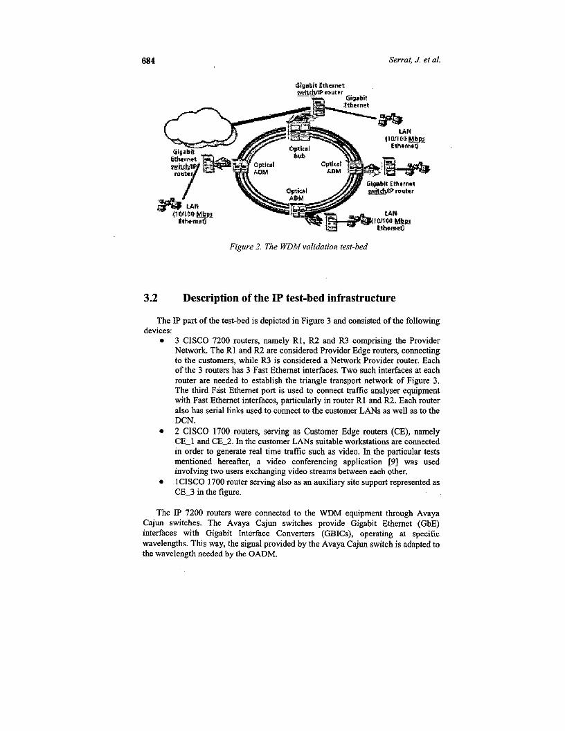
As shown in Figure 2 the WDM infrastructure consists of a hub and 3 remote nodes, connected via a 2-fibre counter-rotating ring. In fact the hub can be considered as a remote node as well. On the outer fibre ring dedicated (fixed) wavelengths are used for communication between the hub and the remote nodes. On the inner fibre ring, each node is provided with a programmable optical add and drop multiplexer (OADM) to set up wavelength paths with other remote nodes or with the hub. At every node aggregated IP traffic from the LAN is routed to the appropriate wavelength. The remote nodes are located at business sites where IP over 101100 Base-T is the major service.
The distance between two remote nodes is 8 km on average, with a total ring circumference of 32 km. An optical supervisory channel at 1310 nm is used to transport the management information.
The WDM test-bed contains the following management systems (not represented
A NE manager per optical' node. This software presents a management view of the OADMs to the agents that control the optical components by means of an RS-232 link. An EMS, which will control the four agents. The information model and the northbound interface of this system are aligned with the TMF-MTNM standards [8].
in Figure 2):
684 Serrat, J . et al.
Figure 2. The WDM vnlidntion test-bed
3.2 Description of the IP test-bed infrastructure
The IP pan of the test-bed is depicted in Figure 3 and consisted of the following
3 CISCO 7200 routers, namely RI, R2 and R3 comprising the Provider Network. The R1 and R2 are considered Provider Edge routers, connecting to the customers, while R3 is considered a Network Provider router. Each of the 3 routers has 3 Fast Ethemet interfaces. Two such interfaces at each router are needed to establish the triangle transport network of Figure 3. The third Fast Ethemet port is used to connect traffic analyser equipment with Fast Ethemet interfaces, particularly in router R1 and R2. Each router also has serial links used to connect to the customer LANs as well as to the DCN. 2 CISCO 1700 routers, serving as Customer Edge routers (CE), namely CE-1 and CE-2. In the customer LANs suitable workstations are connected in order to generate real time traffic such as video. In the particular tests mentioned hereafter, a video conferencing application [9] was used involving two users exchanging video streams between each other. ICISCO 1700 router serving also as an auxiliary site support represented as CE-3 in the figure.
devices:
The IP 7200 routers were connected to the WDM equipment through Avaya Cajun switches. The Avaya Cajun switches provide Gigabit Ethemet (GbE) interfaces with Gigabit Interface Converters (GBICs), operating at specific wavelengths. This way, the signal provided by the Avaya Cajun switch is adapted to the wavelength needed by the OADM.

Functional Evaluation of an IPiWDM Management Solution 685
In the opposite direction, the wavelength that is dropped at the switch is directly passed to the client receiving interface. Therefore, the transport stack IP/GbEANDM at 1.25 Gbit/s is used. The GhE-switches in the test-bed are equipped with WDM lasers, which allow them to interface directly with the WDM layer.
SITE # 3
L4nk.m-d Fa31 Elnernet over WDM
I 7?09.l I 7200.2 I I 4- DCN
SITE # 1 IP-EMS 101 WINMAN-NMS SITE # 2
Figure 3. The IP validation test-bed
3.3 Adaptation of the technology dependent EMSs to the WINMAN southbound interface
Once the requirements are met and the test-bed has been set-up, the network management systems under test have to he connected to it through a DCN. This set- up is based on existing NEs, which may have proprietary management interfaces towards the DCN. Consequently, EMSs responsible for those elements are equipped with their native Application Programming Interfaces (APIs) implemented in a proprietary way. Those APIs are incompatible with each other and with the southbound interface of the W I " IP and WDM NMSs. Therefore, an adaptation layer between native test-bed APIs and the WINMAN southbound interface is needed. Although the context of this section is tailored to the WINMAN solution, the methodology can be easily applied to any other NMS solution. This methodology consists of the specification and design of an adaptation component on top of each EMS (IP and WDM). These adaptation components appear as a top layer of the test-bed infrastructure and they are the only test-bed entities visible from the WINMAN perspective.
686 Serrat, J. et al.
Further down there are different possibilities for the adaptation of the EMS for the IP or WDM technologies. The objective is to adapt through the corresponding EMS either for the WDM network or for the IP network or directly to the management interface of the NEs (e.g. by means of SNMP).
3.3.1 Adaptation of the WDM EMS
Adaptation of the WDM-EMS is based on the TMF-MTNM [SI interface for the WDM-EMS to NMS interconnection.
The corresponding Information Model (IM) describes the configuration of the subnetwork managed by the EMS. This model gives the objects that can he present in the subnetwork, and their relationships. Instances of these objects are contained in the database of the EMS. This database has a.static and a dynamic part. In the static part, the physical configuration like the NEs, their physical ports and the links between those ports is represented. The dynamic configuration contains the connections that are sustained by the NEs, together with their connection termination points. If a new optical NE is added, the static configuration changes; if a new sub network connection is created, the dynamic configuration is altered.
3.3.2 Adaptation of the IP EMS
The adaptation between the WINMAN Management System and the EMSS is also based on the MTNM specification. The IP-EMS is conceived more as a mediation device than a stand-alone EMS. The IP NMS to EMS adaptation ensures the establishment of IP Connectivity Services through configuration of LSPs with bandwidth constraints. Hence, the IP-EMS performs this basic functionality, provided that the basic IP and MPLS configuration is already set-up. The interface between the IP-EMS and the routers is through CLI commands with additional SNMP support for monitoring purposes. In fact, The IP-MPLS configuration of routing devices can be accomplished by different means; basic SNMP “Set” commands and CLI commands. As the IP equipment in the test-bed is composed by Cisco routers that currently do not support SNMP “Set” commands for MPLS, the configuration was done by CLI commands.
The initial idea was to have the IP devices pre-configured with basic connectivity (Layer-3) and the MPLS enabled. WINMAN performs the configuration of LSPs with bandwidth assurance, in response to ICs establishment requests. The routing computation for such LSPs will be done by the IP-NMS, while the set-up will he done using the control plane through the RSVP-TE signalling protocol; the Control Plane can also provide dynamic backup for these LSPs in case of failure.

Functional Evaluation of an IP/WDMManagement Solution
4.
687
INTEGRATED SCENARIO FOR VALIDATION OF THE WINMAN FUNCTIONALITY
The WINMAN functionality has been validated using an integrated network provisioning scenario. The main purpose of this scenario is to establish an ICs between routers 7200-2 and 7200-1 using the 7200-3 intermediate node appearing in Figure 3 and shown again here in Figure 4, which is a complete picture representing all the layers involved in the testing scenario.
The IP link between R2 and R3 is configured but not operational because there is no physical (WDM) connectivity. in order to provide an ICs between the RI and the R2 through R3, the management system has to establish first the physical link between R2 and R3 and then create a bi-directional LSP (7200-2-7200-3-7200-1 and 7200-1-7200-3-7200-2). The business case behind this scenario is that the WINMAN system is capable to find the resources and provide an ICs with QoS constraints, in a case where the default shortest path cannot accommodate the request due to shortage of resources (e.g. lack of bandwidth).
This scenario involves multiple provisioning requests and all the scenario steps along with the start-up conditions are listed below.
4.1 Initial set-up
There are two customers, namely IXIA and DEMO as shown in Figure 4: e IXIA: Consists of two traffic generators connected to RI and R2.
DEMO: Two multimedia clients connected also to RI and R2.
There is pure Layer-3 (IP) connectivity between routers Rl-R3 and between routers Rl-R2. The IP link between R2-R3 is configured but not operational because there is not physical (WDM) connectivity, so communication between R2 and R3 is only feasible through RI ,
The 10/100 Ethemet ports between the core routers are configured at 10 Mbps, so the link RI-R2 can be easily saturated. This kind of configuration also limits the bandwidth available in each WDM h to 10Mhps. But this does not reduce the hnctionality of the network; it will only decrease its bandwidth to values that are more suitable for testing purposes.
The WiNMAN system has the following policies activated
A positive authorisation policy at IP-MPLS level allows the establishment of links with guaranteed bandwidth between R1 and R2. A negative authorisation policy at IP-MPLS level is not enabling the routing of traffic between routers R3 and RI.

688 Serrat, J. et aI.
I I
L I I
L IP Layer
Figure 4. Integratedfunctional validation scenario
4.2 Scenario Steps
4.2.1 Creation of an I C s for the MIA customer
The IXIA generators belong to a WINMAN customer that needs to exchange information between its two sites. Therefore, one of the clients requests a WINMAN service between RI and R2 asking for 9.5 Mhps always available. The WINMAN system creates the ICs making the necessary bandwidth reservation and establishing two Unidirectional LSPs between the involved routers. The two generaton start working and they really use all the bandwidth requested to the WINMAN system.
Under these network conditions, the DEMO customer requests a connection between the same locations specifying 1.5 Mbps bandwidth. Clearly, the request can’t be satisfied through the same path.
Functional Evaluation of an IP/WDM Management Solution
4.2.2
689
Creation of an optical path
The WINMAN system will be aware of the lack of bandwidth in the shortest path between R1 and R2 and therefore will look at the WDM network and conclude that there is a possibility to create an additional optical trail connecting R2 to R3. The request for the creation of the optical trail is forwarded by the WINMAN system to the WDM-EMS.
4.2.3 Synchronisation of the network inventory
The new optical trail is created and a new IP link is discovered by the IP-EMS between R2 and R3. The WINMAN nehGork inventory is upxated with the new WDM,and IP links, and the GUI is displaying the actual network configuration.
The bi-directional SNC creation RZR3-Rl and Rl-R3-R2 is not yet possible because the routing policy Disable IP link between R3 and RIfor routing is applied. Then the WO manually changes the disable policy for a positive authorisation one.
4.2.4 Creation of the I C s for the DEMO customer
Once the new optical path has been created, the new IP link is detected and the applicable policies allow it, WINMAN will create a new ICs through R1 <-> R3 <- > R2. The shortest path was excluded because it didn’t have enough bandwidth. The traffic generated by the DEMO multimedia clients is now forwarded through the new ICs and the video service reaches its SLA.
5. RESULTS EVALUATION
The integrated scenario defined in the previous section was completed successfully.
The GUI.always presents the most up-to-date status of the managed network to the WINMAN operator. The policy user interface is launched directly from the main GUI window for additional convenience. There was no situation of having misalignments between network status and network map. This proves the good functioning of the southbound interface and the network inventory manager functionality. End-to-end routing triggered by the provisioning functionality exhibits sophisticated router-based methods speeding discovery of available or potential routes.
Serrat, J. et al.
Nevertheless, some of the nodes and termination points are not easily distinguishable, and in case of many depicted elements the screen should be adjusted to higher resolutions to have a better view of the underlying network. All nodes (termination points, devices) in the views can be dragged on the screen so that they can he allocated in a manner that is “readable” to the operator.
690
The views are not automatically refreshed when a change takes place in the system. It is only updated with the changes when it interrogates the system using a refreshfirnetion. That is why there is a refresh button by means of which the GUI retrieves all the newly available information.
The experiments referenced were performed using the WINMAN GUI and not sending requests by an SMS system. To test that WINMAN is open to other high level management systems we sent some SMS commands using Tcl/tk scripts emulating the whole process. The outcome was as expected.
The waiting time to see a connection displayed in the GUI since the moment of issuing the connectivity request is quite long. However this is not considered a drawback because the project was more oriented to a proof of concept than to a precompetitive product. In fact, this was assumed since the early beginning when, for instance, the use of two platforms with a mediation gateway in between was adopted; no special adoption of protocols or operative systems was considered in regards to efficiency, etc. For this reason we haven’t provided numerical data of performance measures in the different steps involved in the management processes because they wouldn’t be representative of an operative system. Nevertheless to give an example we have estimated that with a single platform type, making use of high performance hardware and with an optimised software implementation, the total process described in the scenario would take around 1 minute.
The experiments validated that WINMAN exhibits and leverages network relationships. The WINMAN system succeeded in carrying out the provisioning of IP connectivity services with guaranteed QoS (in terms of guaranteed end-to-end bandwidth provisioning) in an automatic way by making the appropriate changes to the IP and WDM networks. Having knowledge of both network layers, network resources are exploited in an easy and consistent way under the supervision of policies. System installation is rather complex but as we said before WINMAN is a just an experimentation prototype.
Traditionally, each layer of hybrid transport networks is independently managed having its own requirements, problems and unique operational characteristics. WINMAN is the first system that can deal with the integrated management of IP and WDM technologies providing increased flexibility, services and utilisation of resources.
The results on the adaptation of the network infrastructure to the WINMAN southbound interface, executed for the IP network and the WDM network, were also

Functional Evaluation of an IP/WDMManagement Solution 691
successful both in terms of functionality and also satisfactory in respect to the system overhead. The diversity of interfaces between EMSs and their managed NEs and also the interfaces offered to the NMSs is really high. Nevertheless from the WINMAN perspective all that is required is an adaptation to a TMF interface. This adaptation will adopt the shape of a Q-adaptor, IDL mediation or any other. Of course this is valid under the assumption that the northbound interfaces presented by the NE managers are open.
6. CONCLUSIONS
Experimental test scenarios were designed and executed for the functional evaluation and demonstration of the WINMAN integrated management solution. These experiments were done in an integrated scenario in the context of the first release of the WINMAN solution (that covers Configuration Management only). Clearly, providing an integrated 1P and WDM Configuration Management is only half way towards an integrated solution for managing IP and WDM networks. Fault and Performance management and especially alarm monitoring, network restoration, in conjunction with SLA and QoS monitoring are challenging and are currently being addressed. But the execution of experiments in the currently available version has proven that WINMAN provides a feasible solution with increased flexibility and utilisation of resources. As the same design concepts and tools are used for the extended functionality system we believe that the results will be also satisfactory. Therefore we conclude that WINMAN is an integrated and automated provisioning solution of IP-based network services over an Optical Transport Network that empowers service providers to quickly bring new differentiated services to market. In addition, WINMAN is paving the way for flow-through automation in conjunction with other operations support system (OSS) applications, by means of standardised interfaces.
The main outcome of the WINMAN evaluation is that not only it provides the design guidelines for an integrated management system based in a 3-tier concept that makes it extensible to manage any connection-oriented technology, but also and the most important perhaps is that it provides the means for a smooth evolution path towards the full integration of IPMPLS and WDM. This is important because the peer integration based on the control plane will be for sure delayed especially due to the telecom crisis-slowdown; so intermediate solutions having the management plane as a basis and possibly supported by the control plane features (especially of the mature IP layer) should be promoted. This paper shows that these solutions are viable.
The WINMAN solution proves that the design, implementation and integration of such a complex system is feasible and can actually work if: a) state of the art software technology like component-based frameworks and distributed architectures like CORBA are used; b) standardised interfaces between the main sub-systems (IP- NMS, WDM-NMS, INMS) are adopted and the appropriate extensions are proposed

692 Serrat, J. et al.
in order to cover the managed networks (i.e. MTNM extensions to cover IPMF'LS); c) a systematic and well-defined methodology (RUP-like) is applied for the whole life-cycle of the system (design, implementation, integration).
7. ACKNOWLEDGMENTS
This paper describes part of the work undertaken and in progress in the context of the WINMAN-IST 13305, a two and a half years research and development project during 2000-2003. The IST program is partially funded by the Commission of the European Union.
8. REFERENCES
[I] Aboul-Magd, 0. et. al., "Automatic Switched Optical Network (ASON) Architecture and Its Related Protocols", draft-ietf-ipo-ason-OO.txt, work in progress, July 2001.
[2] Ashwood-Smith, P. et. al., "Generalized MPLS- Signalling Functional Describtion", draft- ieff-mpls-generalized-signaling-O5.txt, work in progress, December 2002.
[3] Project IST-1999-13305 WINMAN http://www.telecom.ntua.gr/winman/.
[4] Serrat, J. et al., "Integrated Management for IP end-to-end Transport Services over WDM Networks" IFIP/IEEE International Symposium on Integrated Management IM 2001, 14-18 May 2001, Seattle, USA.
Network
[SI Karayannis, F. et al. "Management vs. Control Plane approaches for integration of IP and WDM layer- A synergy paradigm", 8th IFIPfiEEE Network Operations and Management SymposiumNOMS 2002, 15-19 April 2002, Florence, Italy.
[6] Enhanced Telecom Operations Map (eTOM): The Business Process Framework for the Information and Communication Services Industry - GB921 v3.0.
[7] Raptis, L. et al, "Integrated Management of IP over Optical Transport Networks", IEEE Intemational Conference on Telecommunications ICT 2001,4-7 June 2001, Bucharest, Romania.
[XI TMF 608 Multi-Technology Network Management Infomation Agreement NML-EML Interface. Version 2.0. October 2001.
[9] Meeuwissen, H.B., H. J. Batteram, and J.L. Bakker, "The FRIENDS Platform- A Software Platform for Advanced Services and Applications", Bell Labs Tech. J., Vo1.5, No.3, Jul.-Sep. 2000, pp. 59 -75.