Full report group 6
35
ADVANCED POWER LABORATORY EXPERIMENT: VOLTAGE VARIATION AND CONTROL IN TRANSMISSION SYSTEM LECTURER: DR. SAIFULNIZAM ABD. KHALID PREPARED BY: AZRUL MUHAIRI BIN HJ MOHD BADRI (SX080709EEJ04) MACMILLAN BIN BONEY (SX080600EEJ04) HISHAMUDDIN BIN CHURIKI (SX080591EEJ04) HAMRIN BIN ABU HASAN (SX080712EEJ04) MOHD RASHID BIN RADUAN (SX080644EEJ04) GROUP 6, SECTION 5 SUBMISSION DATE: 1 AUGUST 2012
-
Upload
independent -
Category
Documents
-
view
2 -
download
0
Transcript of Full report group 6

ADVANCED POWER LABORATORY
EXPERIMENT:
VOLTAGE VARIATION AND CONTROL IN TRANSMISSION SYSTEM
LECTURER: DR. SAIFULNIZAM ABD. KHALID
PREPARED BY:
AZRUL MUHAIRI BIN HJ MOHD BADRI (SX080709EEJ04) MACMILLAN BIN BONEY (SX080600EEJ04)
HISHAMUDDIN BIN CHURIKI (SX080591EEJ04) HAMRIN BIN ABU HASAN (SX080712EEJ04)
MOHD RASHID BIN RADUAN (SX080644EEJ04)
GROUP 6, SECTION 5
SUBMISSION DATE: 1 AUGUST 2012

ADVANCED POWER/ SECTION 5/GROUP 6 2
TABLE OF CONTENTS PAGES
1) ABSTRACT 3
2) INTRODUCTION 3
3) PROBLEM STATEMENT 3
4) OBJECTIVE 4
5) SCOPE OF EXPIREMENT 4
6) EQUIPMENT 5 - 7
5) METHODOLOGY & PROCEDURE 8 - 12
6) RESULT 13 - 27
7) DISCUSSION 28 - 29
8) CONCLUSION 30
9) QUESTION 31 - 33
10) REFERENCES 34
11) APPENDIX 35

ADVANCED POWER/ SECTION 5/GROUP 6 3
Abstract
When analyzing the effects of supply voltage variation on power consumption and ultimately cost to the consumer it is found that domestic appliances can be divided into 3 general types i.e. Resistive, Inductive and Electronic. Resistive devices have a prime function to produce light and heat and make up 60% to 80% of most household energy usage.[4] The inductive devices are often those with some form of electric motor whose output is that of mechanical work albeit that work may be used to provide heating or cooling as in the case of refrigerators and air conditioners. These devices contribute between 10% to 40% of household energy use. The electronic devices form part of entertainment systems in the home but are becoming more common in all appliances where some form of control is required. These are normally low power devices and rarely contribute more than 20% to the energy cost.
This experiment is use a star connection on the transmission side by use load without compensation and a circuit with compensation. From this experiment, we also study the characteristic of transmission voltage with compensation and without compensation.
Introduction
In the modern society electric power is a very important part of the infrastructure. Power systems are found or normally used in industry, hospitals, commercial buildings and homes. An electric power system used to supply, transmit and distribute electric power to the consumer. Modern power system may be subdivided into the following major subsystems such as generation subsystem, transmission and sub-transmission subsystem, distribution subsystem and utilization subsystem.
Problem Statement
A power utility received complaints from a steel mill about voltage variation problem which caused equipments failure. The mill is connected directly to power system transmission line. You as a utility engineer have been assigned by your superior to investigate the problem and propose solutions. Justify your findings and solutions by experiment.

ADVANCED POWER/ SECTION 5/GROUP 6 4
Objectives
To understand voltage variation and control.
To justify the solutions to control the voltage.
To design a circuit connection.
Scope
This experiment will cover the investigation of voltage variation problem which cause equipments failure. Then will find the solution to control the voltage.

ADVANCED POWER/ SECTION 5/GROUP 6 5
Equipment
NE9202 Distribution Trainer
Capacitive Loading Bank Inductive Loading Bank
Resistive Loading Bank

ADVANCED POWER/ SECTION 5/GROUP 6 6
-Transmission Line (supply-output) - -Input Meter-
-Transmission Line - - Output Meter -
- Neutral switch -

ADVANCED POWER/ SECTION 5/GROUP 6 7
-circuit connection for the experiment-

ADVANCED POWER/ SECTION 5/GROUP 6 8
Methodology
1. Design the circuit
2. Load RL star delta connection without compensation

ADVANCED POWER/ SECTION 5/GROUP 6 9
3. Load RL star delta with 25% compensation
4. Load RL star delta with 50% compensation
ADVANCED POWER/ SECTION 5/GROUP 6 10
5. Load RL star delta with 75% compensation
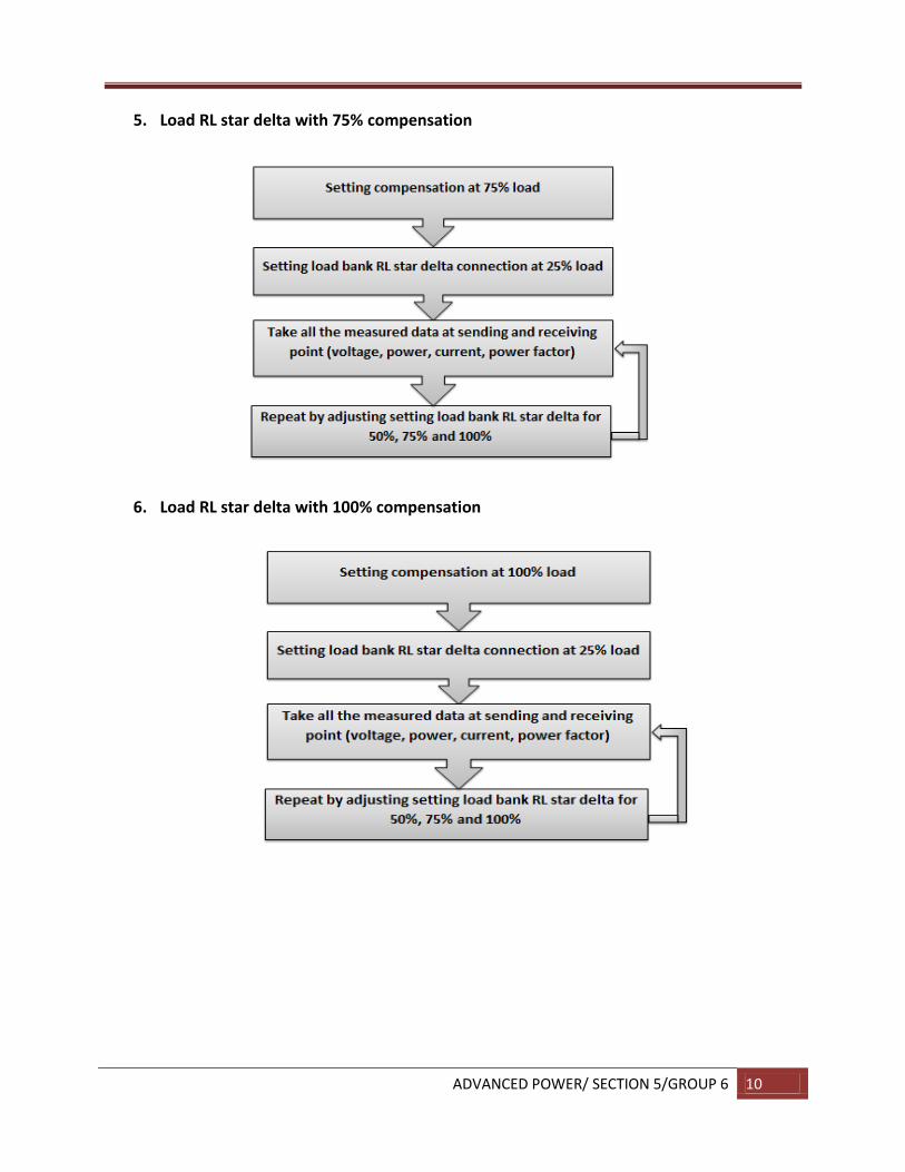
6. Load RL star delta with 100% compensation

ADVANCED POWER/ SECTION 5/GROUP 6 11
Procedure Title: Voltage Variation and Control in Transmission System. Part A: Design the Circuit.
1. Identify the problem of experiment. 2. Design the circuit to be used in the experiment. 3. For this experiment we used RL star delta connection with compensation at load side. 4. Confirm with the supervisor experiment that the design circuit is suitable for experiment
or not. 5. Do connection between The Distribution Trainer (NE9202) and load bank, consisting of
resistor, inductor and capacitor and refer to the circuit has been design. Important: Make sure all cable is connect correctly like circuit design and get confirmation from supervisor
Part B: Used load RL star delta connection without compensation
1. On main power supply for The Distribution Trainer (NE9202). 2. Switch on the MCB at The Distribution Trainer (NE9202). 3. Select the switch CB1 at close position. 4. Setting load bank RL star delta connection at 25% load. 5. Take all the measured data at sending and receiving point like a voltage, power, current
and the power factor. 6. Repeat step 5 by adjusting setting load bank RL star delta for 50%, 75% and 100% load.
Part C: Used load RL star delta with 25% compensation
1. Setting compensation at 25% load. 2. Setting load bank RL star delta connection at 25% load 3. Take all the measured data at sending and receiving point like a voltage, power, current
and the power factor. 4. Repeat step 3 by adjusting setting load bank RL star delta for 50%, 75% and 100% load.

ADVANCED POWER/ SECTION 5/GROUP 6 12
Part D: Used load RL star delta with 50% compensation
1. Setting compensation at 50% load. 2. Setting load bank RL star delta connection at 25% load 3. Take all the measured data at sending and receiving point like a voltage, power, current
and the power factor. 4. Repeat step 3 by adjusting setting load bank RL star delta for 50%, 75% and 100% load.
Part E: Used load RL star delta with 75% compensation
1. Setting compensation at 75% load. 2. Setting load bank RL star delta connection at 25% load 3. Take all the measured data at sending and receiving point like a voltage, power, current
and the power factor. 4. Repeat step 3 by adjusting setting load bank RL star delta for 50%, 75% and 100% load.
Part F: Used load RL star delta with 100% compensation
1. Setting compensation at 100% load. 2. Setting load bank RL star delta connection at 25% load 3. Take all the measured data at sending and receiving point like a voltage, power, current
and the power factor. 4. Repeat step 3 by adjusting setting load bank RL star delta for 50%, 75% and 100% load.

ADVANCED POWER/ SECTION 5/GROUP 6 13
Result and Finding
Table 1: RL load without compensation

ADVANCED POWER/ SECTION 5/GROUP 6 14
Table 2: RL load with 25% compensation

ADVANCED POWER/ SECTION 5/GROUP 6 15
Table 3: RL load with 50% compensation

ADVANCED POWER/ SECTION 5/GROUP 6 16
Table 4: RL load with 75% compensation

ADVANCED POWER/ SECTION 5/GROUP 6 17
Table 5: RL load with 100% compensation

ADVANCED POWER/ SECTION 5/GROUP 6 18
Table 6: Comparison for 25% load

ADVANCED POWER/ SECTION 5/GROUP 6 19
Table 7: Comparison for 50% load

ADVANCED POWER/ SECTION 5/GROUP 6 20
Table 8: Comparison for 75% load

ADVANCED POWER/ SECTION 5/GROUP 6 21
Table 9: Comparison for 100% load

ADVANCED POWER/ SECTION 5/GROUP 6 22
Graph 1: Output Current for 25% Load

ADVANCED POWER/ SECTION 5/GROUP 6 23
Graph 2: Output Phase Voltage for 25% Load
Graph 3: Output Current for 50% Load
Graph 4: Output Phase Voltage for 50% Load

ADVANCED POWER/ SECTION 5/GROUP 6 24
Graph 5: Output Current for 75% Load
Graph 6: Output Phase Voltage for 75% Load

ADVANCED POWER/ SECTION 5/GROUP 6 25
Graph 7: Output Current for 100% Load
Graph 8: Output Phase Voltage for 100% Load

ADVANCED POWER/ SECTION 5/GROUP 6 26
Graph 9: Reactive Power Output for 25% Load
Graph 10: Reactive Power Output for 50% Load

ADVANCED POWER/ SECTION 5/GROUP 6 27
Graph 11: Reactive Power Output for 75% Load
Graph 12: Reactive Power Output for 100% Load

ADVANCED POWER/ SECTION 5/GROUP 6 28
Discussion
The flow of reactive power Q determines the voltage drop and the flow of active power P determines the transmission angle and these two statements are substantially independent of each other. A transmission line absorbs an increasing amount of reactive power as the load current increases. Reactive power affects power system operation in numerous ways: 1. The delivery system (transmission lines and transformers) consumes reactive power, so this must be provided by some source (even if the loads do not consume reactive power). Note however that all transmission lines do provide some reactive power from their shunt line charging which offsets their consumption of reactive power in their series line losses. 2. The flow of reactive power from the supplies to the sinks causes additional heating of the lines and voltage drops in the network. 3. The generation of reactive power can limit the generation of real power.
From the table result:
1. Comparison for load 25%
From comparison load 25%, we can see when the compensation 75% is more reliable compare to other reading, because the output voltage and input voltage don’t have change too much. And the Power reactive for compensation 0% and 75% almost have the same reading.
2. Comparison for load 50%
From comparison load 50%, we can see the compensation 25% is more reliable compare to other reading, because the output voltage and input voltage have the nearly reading to each other. And the Power reactive for compensation 0% and 25% also has the close reading.
3. Comparison for load 75%
From comparison load 75%, we can see when the compensation 25% is more reliable compare to other reading, because the output voltage and input voltage have close reading. And the Power reactive for compensation 0% and 25% also has the close reading.
4. Comparison for load 100%

ADVANCED POWER/ SECTION 5/GROUP 6 29
From comparison load 100%, we can see when the compensation 25% is more reliable compare to other reading, because the output voltage and input voltage have the close reading. And the Power reactive for compensation 0% and 25% also has the close reading
From this result we know that compensation voltage have the different reading for each load. To find the better compensation, the reading for input voltage and output voltage must not change too much. The reactive power also play the main role in transmission line, the close reading for reactive power in 0% compensation is the better to use.

ADVANCED POWER/ SECTION 5/GROUP 6 30
Conclusion
1. Concept voltage variation is a voltage drop that causes equipment failure. It’s become
a big problem to the customer especially at industrial field.
2. From the experiment , we can conclude that : 25% of compensation is a most suitable value than other. This is because of the different between the output voltage and reference voltage and the relation with reactive power shows that 25% compensation is minimum.
3. There are few recommendation to overcome this problem :
Use an automatic voltage regulator to minimize the unstable voltage problem for power transformer with on-load tap-changer (OLTC)
Four major method are used to control the voltage in power system
I. Changing the set point of generator at excites II. Changing the tap of transformer
III. Using the shunt compensator IV. Use series capacitor to transmission system

ADVANCED POWER/ SECTION 5/GROUP 6 31
Question
Triggers:
1. Review the relationship between load power angle and voltage.
In the electrical world - power transfer is P = [(E1 x E2) sin (a)]/X where E1 and E2 are the sending and receiving end voltages a is the angle between E1 and E2 X is the reactance of the circuit
This expression says that will voltages constant, the power transfer through a circuit is a function of a. If a is zero, there is no power transfer. Maximum power transfer occurs when the a is 90 degrees. Because power transfer is a function of a. a is also known as the 'load angle'. If you have an array of generators on a system, the fact that the system operates at a single frequency means that the generators must all be rotating at the same speed. (Well - almost. All two-pole generators will be at one speed, while all four-pole generators will be at exactly have that rotational speed, etc.). But there will be a small difference in the physical position of the rotors of those generators - the rotors of generators that are more heavily loaded (in per unit of their individual rating) will lag the rotors of the more lightly loaded machines. These angular differences are the load angles of the individual machines and can be calculated from the power transfer expression above.
2. Find out available methods for voltage control in transmission network.
Available method for voltage control in transmission network is used series capacitor to effectively shorten long lines, thus, decreasing the net reactive loss. In addition, the line can deliver more reactive power from a strong system at one end to one experiencing a reactive shortage at the other one. We also can used shunt capacitors. Through the heavy use of shunt capacitors can be part of the voltage stability problem, sometimes additional capacitors can also solve the problem by freeing “spinning reactive reserve” in generators. In
general, most of the required reactive power should be supplied locally, with generators supplying primary active power.

ADVANCED POWER/ SECTION 5/GROUP 6 32
Question:
1. What is the referred standard for voltage supply in Malaysia?
Transmission: 60 kV (66 kV), 132 kV, 275 kV and 400 kV line-to-line.
Distribution: 4 kV to 33 kV (primary)
230 V; single-phase (secondary) with variation -6% and +10%
400 V; three-phase (secondary) with variation -6% and +10%
2. Can you list down the nominal rating of transmission and distribution voltage supply?
Transmission: 132kV, 274kV, 500kV
Distribution: 230/400V, 11kV, 33kV
3. Why voltage at load cannot be constant all the time?
Ideally, the output of most power supplies should be a constant voltage. Unfortunately, this is difficult to achieve. There are two factors that can cause the output voltage to change. First, the ac line voltage is not constant. The ac line voltage alone can be responsible for nearly a 20 percent change in the dc output voltage. The second factor that can change the dc output voltage is a change in the load resistance. In complex electronic equipment, the load can change as circuits are switched in and out. In a television receiver, the load on a particular power supply may depend on the brightness of the screen, the control settings, or even the channel selected.
These variations in load resistance tend to change the applied dc voltage because the power supply has a fixed internal resistance. If the load resistance decreases, the internal resistance of the power supply drops more voltage. This causes a decrease in the voltage across the load.
Many circuits are designed to operate with a particular supply voltage. When the supply voltage changes, the operation of the circuit may be adversely affected. Consequently, some types of equipment must have power supplies that produce the same output voltage regardless of changes in the load resistance or changes in the ac line voltage. This constant output voltage may be achieved by adding a circuit called the VOLTAGE REGULATOR at the output of the filter.

ADVANCED POWER/ SECTION 5/GROUP 6 33
4. How can we raise or lower the distribution voltages to an acceptable (rated) level?
Under voltage is most commonly attributable to reduced voltage levels on the utility’s transmission and distribution system. In areas with low electrical load density, such as suburban and rural locations, voltage drop on electrical conductors is a significant issue. Conductor impedance driven by load demand serves to decrease the voltage along the length of a conductor. The electric utility uses on-load tap changing voltage regulators (OLTCs) at substations and line drop compensating voltage regulators (LDCs) along the length of a conductor to boost (raise) or buck (lower) voltage levels within a proper range for delivery to customers. Customers nearest to an OLTC or LDC will see the highest voltage levels while those farthest away will see the lowest voltage levels.
5. To what extent the utility engineer can control the voltage variation in the system?
In a stable power system, the total loads and the power losses should be equal with the generated power. The variation of the reactive power will change the bus voltages. Thus keeping the voltage at a constant value is an important factor for the stability of the power system. It is important to notice that load type and its variations are more major factors in the voltage and reactive power control. Three major methods are used to control the voltage in the power system: 1- Changing the set point of generator exciters. 2- Changing the tap of the transformers 3- Using the shunt compensators

ADVANCED POWER/ SECTION 5/GROUP 6 34
References
[1] M. Lin, R. K. Rayudu and S. Samarasinghe. A Review of Voltage / VAR Control. Centre for Advanced Computational Solutions Lincoln University. [2] Pablo Fr´ıas, Tom´as G´omez, David Soler. (2006). Voltage Control and Reactive Power Support in the Spanish Transmission Network. IEEE MELECON 2006, May 16-19, Benalmadena (Malaga), Spain.
[3] M. Calligaris, M. A. Johnson, L. J. Layo Rivacoba and J. L. Femandez. (2000). On the Performance Benchmarking of Hierarchical Voltage Control in a Power Transmission Network. Industrial Control Centre, University of Strathclyde Glasgow, GI IQE, Scotland, UK.
[4] J.Duncan Glover, Mulukutla S. Sarma and Thomas J. Overbye (2008), Cengage Learning, USA.
[5] Mohd Wazir Mustafa, Power System Analysis Teaching Module, Faculty of Electrical Engineering, Universiti Teknologi Malaysia

ADVANCED POWER/ SECTION 5/GROUP 6 35
Appendix A
Group member from left: Azrul, Rashid, Macmillan, Hamrin, Hishammudin