FUEL INJECTION SYSTEMS, uploaded on 2016-09-19
29
-
Upload
khangminh22 -
Category
Documents
-
view
0 -
download
0
Transcript of FUEL INJECTION SYSTEMS, uploaded on 2016-09-19

Topic Under This Units
Introduction.
Requirements of a diesel injection system.
Classification of injection system.
Diesel injection systems(jerk pump injectors).
Nozzles of different types.
Electronic fuel infection system.

INTRODUCTION:
The fuel-injection system is the most vital component in the
working of CI engine.
The engine performance, power o/p , economy etc is greatly
dependent on the effectiveness of the fuel-injection system.
Basically the purpose of carburetion & fuel-injection is the
same i.e. preparation of the combustible charge. But in case
of carburetion fuel is atomized by processes relying on the air
speed greater than fuel speed at the fuel nozzle , whereas in
fuel-injection the fuel speed at the point of delivery is greater
than the air speed to atomize the fuel.

Requirements of a diesel injection
systemThe functional requirements of an injection system are listed
below;
1. Introduction of the fuel into the combustion chambershould take place within a precisely defined period of thecycle.
2. The metering of amount of fuel injected per cycle shoulddone very accurately.
3. The quantities of fuel metered should vary to meet thechanging load & speed requirements.
4. The injection rate should be such that it results in thedesired heat-release pattern.
5. The injected fuel must be broken into very fine droplets.

6. Proper spray pattern to ensure rapid mixing
of fuel & air.
7. Beginning & end of injection should be
sharp.
8. Timing the injection of the fuel correctly in
cycle so that maximum power is obtained,
ensuring economy & clean burning.
9. Uniform distribution of fuel droplets
throughout the combustion chamber.

For accomplishing these requirements the following
functional elements are required in a fuel injection
system;
1. PUMPING ELEMENT:
To move the fuel from the fuel tank to cylinder & piping etc.
2. METERING ELEMENTS:To measure & supply the fuel at the rate demanded by load & speed.
3. METERING CONTROL:To adjust the rate of metering elements for changes in load & speed of
the engine.
4. DISTRIBUTING ELEMENTS:To divide the metered fuel equally among the cylinder.
5. TIMING CONTROLS:To adjust the start & the stop of injection.
6. MIXING ELEMENT:To atomizes & distribute the fuel within the combustion chamber.
CLASSIFICATION OF INJECTION
SYSTEMS
Diesel injection systems can be divided into two basic types.
They are :
Air injection system
Solid injection system
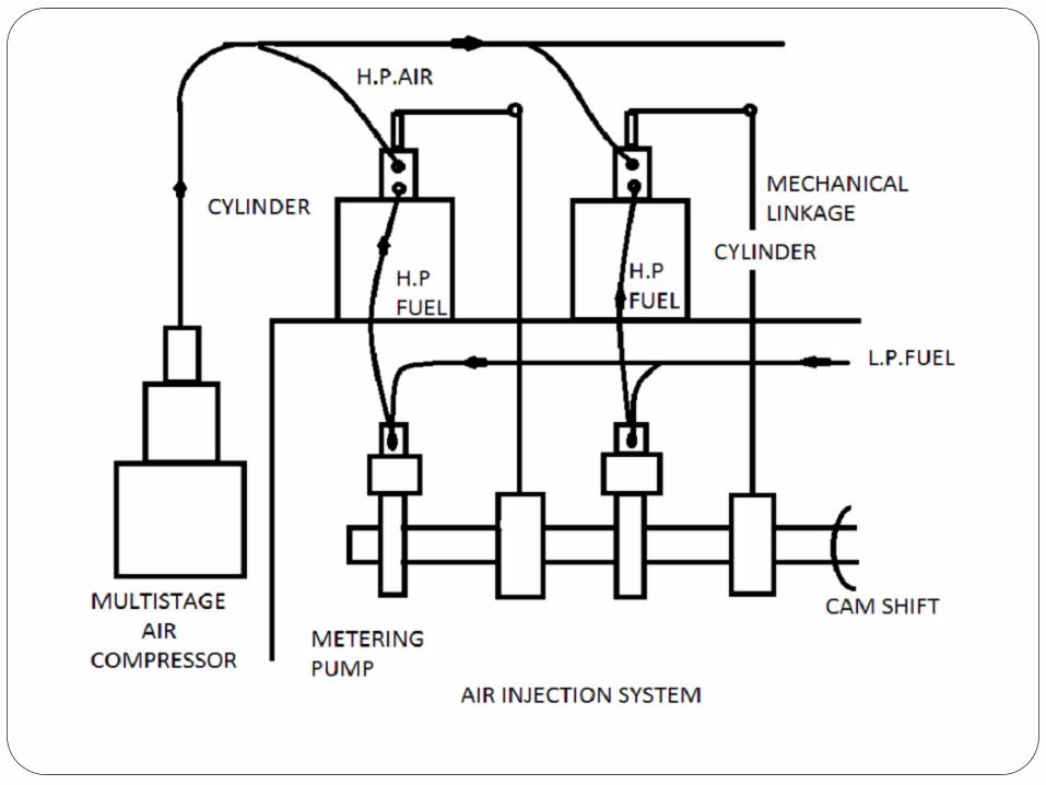
1. Air injection system
In this method fuel is forced into the cylinder bymeans of compressed air to a very high pressure. Therate of fuel admission can be controlled by varyingthe pressure of air .
The fuel is metered & pumped to the fuel valve by acamshaft driven fuel pump. The fuel valve is openedby means of a mechanical linkage operated by thecamshaft which controls the timing of injection . Thefuel valve is also connected to a high pressure air linefed by a multi stage compressor which supplies air ata pressure of about 60 to 70 bar.

ADVANTAGES;
It provides better atomization & distribution of fuel.
Heavy & viscous fuels, which are cheaper can also be injected.
DISADVANTAGES;
This method is not used now a day due to following reasons:
It requires a high pressure multi stage compression.
A separate mechanical linkage is required to time the operation of fuel valve.
Due to the compression & the linkage the bulk of the engine increases . This also results in reduced B.P due to power loss in operating the compression & linkage.
In case of sticking of the fuel valve , the system becomesquite dangerous due to the presence of high pressure air.

2. Solid injection system
In this method fuel is injected directly into the combustion
chamber without primary atomization is termed as solid
injection. it is also termed as mechanical injection.
Solid injection system can be classified into four types:
1. Individual pump & injector.
2. Unit injector system.
3. Common rail system.
4. Distributor system.
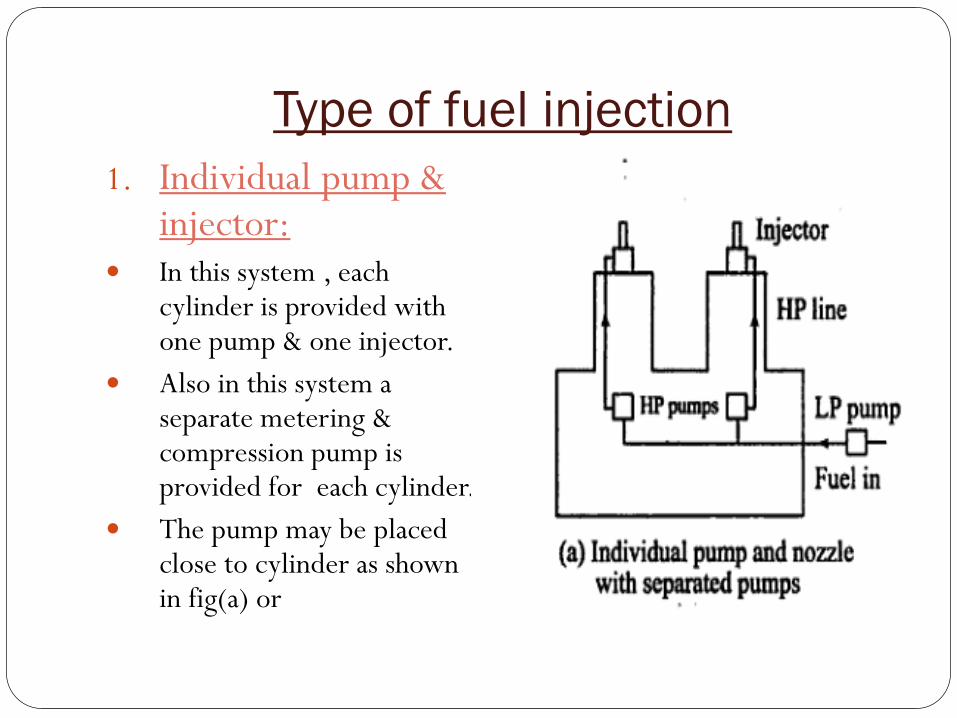
Type of fuel injection
1. Individual pump & injector:
In this system , each cylinder is provided with one pump & one injector.
Also in this system a separate metering & compression pump is provided for each cylinder.
The pump may be placed close to cylinder as shown in fig(a) or
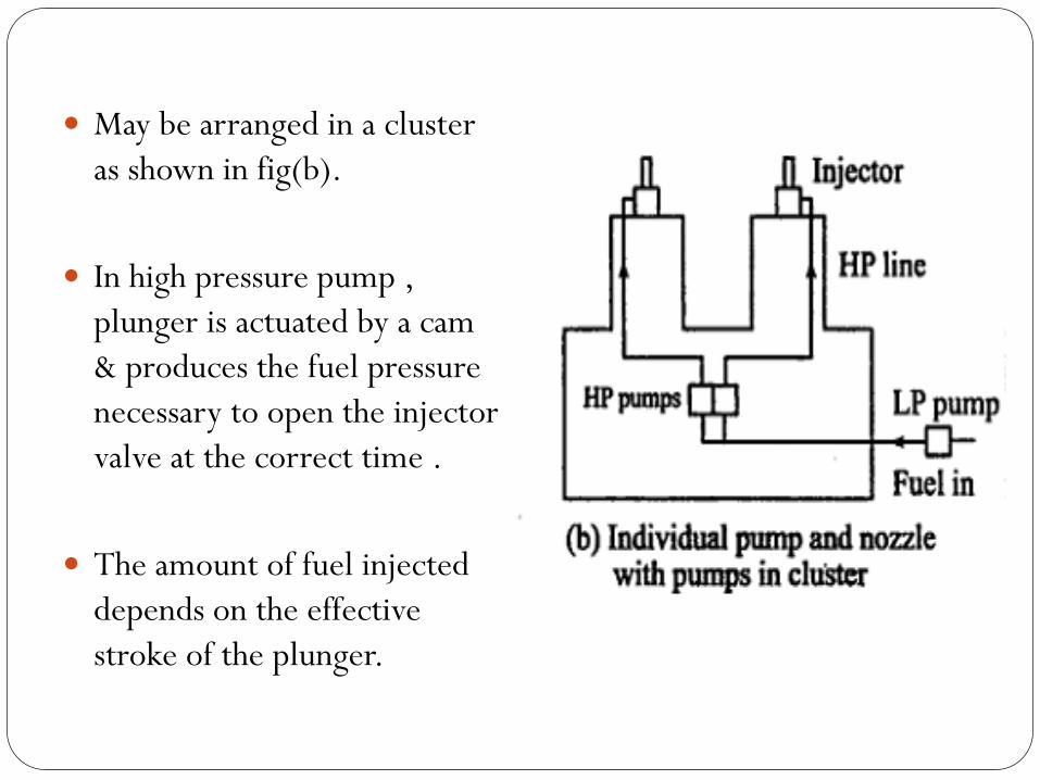
May be arranged in a cluster
as shown in fig(b).
In high pressure pump ,
plunger is actuated by a cam
& produces the fuel pressure
necessary to open the injector
valve at the correct time .
The amount of fuel injected
depends on the effective
stroke of the plunger.

2. Unit injector system:•The unit injectorsystem is one inwhich the pump &injector arecombined in onehousing.
•Each cylinder isprovided with one ofthese unit injectors.
•Fuel is brought upto the injector by alow pressure pumpat proper time, arocker arm actuatesthe plunger & thusinjects the fuel intothe cylinder.

3. Commmon rail system:
In common rail system a high
pressure fuel pump delivers
fuel to an accumulator, whose
pressure is kept constant with
the help of a pressure
regulating valve.
A common rail or a pipe
starts from the accumulator &
leads to the different
distributing elements for each
cylinder.

For each cylinder there is a separate metering & timing element
which is connected to an automatic injector injecting fuel into
the cylinder.
In the common rail system the supply pressure of the fuel is
independent of speed & hence is not affected by the fuel pump.
The amount of fuel entering the cylinder is regulated by varying
the length of the push rod stroke.

4. Distributor system:
In this system the pump
which pressurizes the fuel
also meters & times it .
The fuel pump after metering
the required amount of fuel
supplies it to rotating
distributor at the correct time
for supply to each cylinder.

The number of injection strokes per cycle for the pump is equal
to the number of cylinders.
Since there is only one metering element , a uniform distribution
is automatically ensured .
Not only that , the cost of the fuel injection system also reduces
to a valve less than two – third of that for individual pump
system.
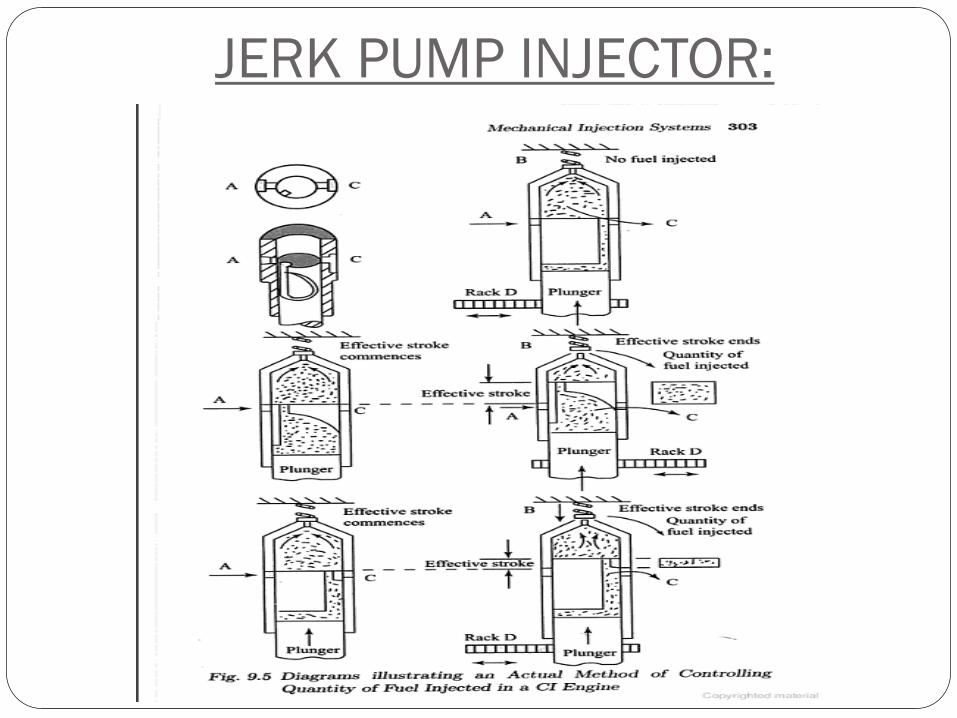
JERK PUMP INJECTOR:

WORKING OF JERK PUMP INJECTOR:
It consists of a reciprocating plunger inside a barrel. The
plunger is driven by a camshaft. The working principle of jerk
pump is as follow: Near the port A, fuel is always available under relatively low pressure.
while the axial movement of the plunger is through camchaft,its
rotational movement is by mean of rack D. port B is the orifice
through which fuel is delivered to the injector. At this stage it is closed
by means of a spring loaded check valve.
When the plunger is below port A, the fuel gets filled in the barrel
above it. As the plunger rises & closes the port A the fuel will flow out
through port C. this is because it has to overcome the spring force of
the check valve in order to flow through port B. hence it takes the
easier way out via port C.

At this stage rack rotates the plunger & as a result port C also closes. The
only escape route for the fuel is pass the check valve through orifice B to
the injector. This is the beginning of injection & also the effective stroke
of the plunger.
The injection continues till the helix on the plunger uncovers port C. now
the fuel will take the easy way out through C & the check valve will close
the orifice B. the fuel injection stops & the effective stroke ends.

NOZZLE :Nozzle is a part of an injector through which the fuel is
sprayed into the combustion chamber.
Various types of nozzles used in C I engine
are:
A. Single hole nozzle.
B. multi-hole nozzle.
C. Pintaux nozzle.
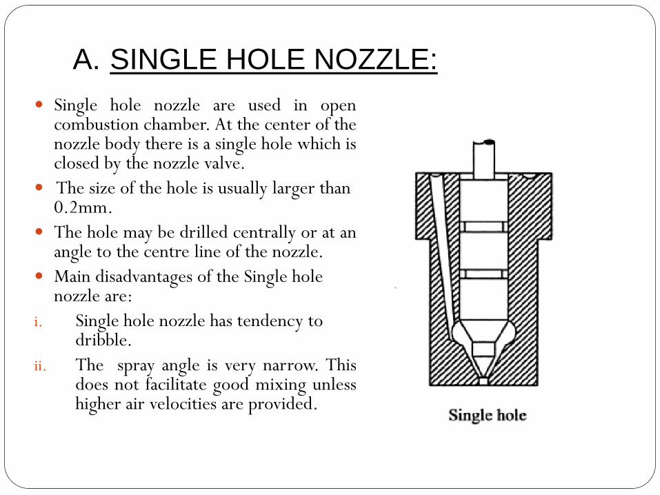
A. SINGLE HOLE NOZZLE:
Single hole nozzle are used in opencombustion chamber. At the center of thenozzle body there is a single hole which isclosed by the nozzle valve.
The size of the hole is usually larger than 0.2mm.
The hole may be drilled centrally or at anangle to the centre line of the nozzle.
Main disadvantages of the Single hole nozzle are:
i. Single hole nozzle has tendency to dribble.
ii. The spray angle is very narrow. Thisdoes not facilitate good mixing unlesshigher air velocities are provided.
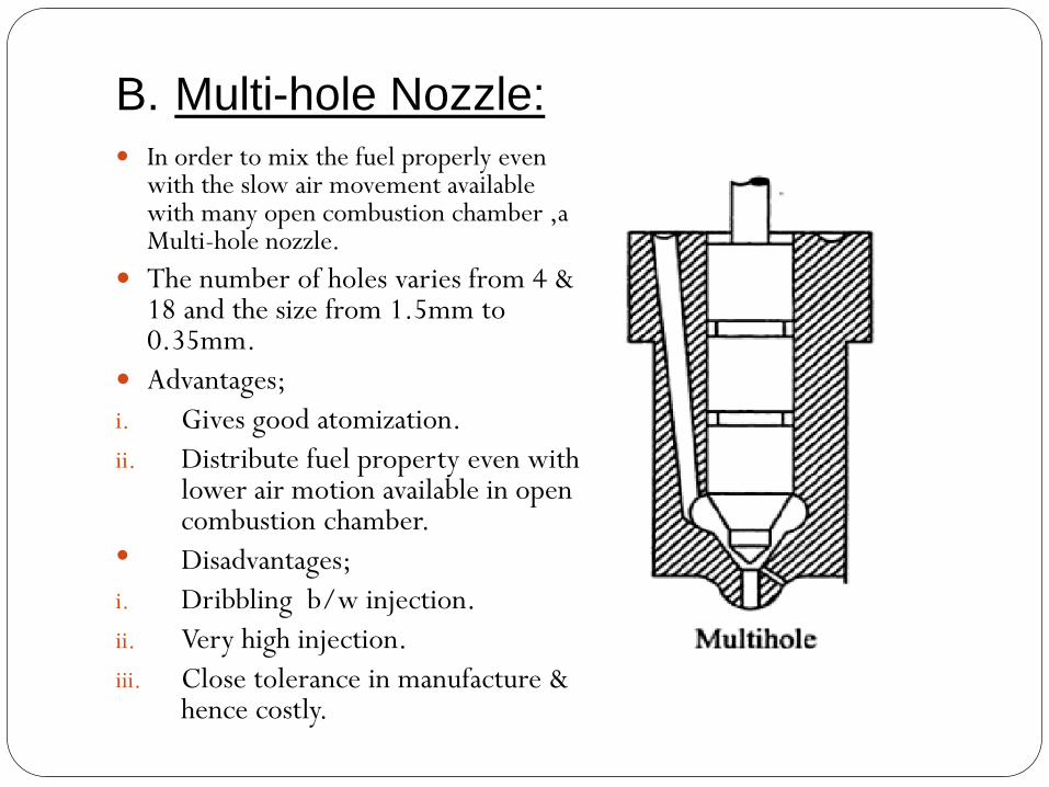
B. Multi-hole Nozzle:
In order to mix the fuel properly even with the slow air movement available with many open combustion chamber ,a Multi-hole nozzle.
The number of holes varies from 4 & 18 and the size from 1.5mm to 0.35mm.
Advantages;
i. Gives good atomization.
ii. Distribute fuel property even with lower air motion available in open combustion chamber.
• Disadvantages;
i. Dribbling b/w injection.
ii. Very high injection.
iii. Close tolerance in manufacture & hence costly.
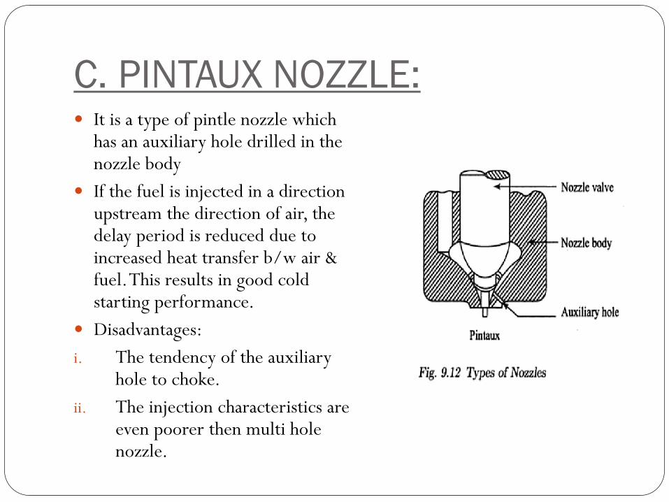
C. PINTAUX NOZZLE: It is a type of pintle nozzle which
has an auxiliary hole drilled in the nozzle body
If the fuel is injected in a direction upstream the direction of air, the delay period is reduced due to increased heat transfer b/w air & fuel. This results in good cold starting performance.
Disadvantages:
i. The tendency of the auxiliary hole to choke.
ii. The injection characteristics are even poorer then multi hole nozzle.
ELECTRONIC FUEL INJECTION
SYSTEM(EFL):
Modern gasoline injection system use engine sensors, a computer and solenoid operated fuel injectors to meter & inject the right amount of fuel into the engine cylinder. These system is called as electronic fuel injection system(EFL) use electrical & electronic devices to monitor & control engine operation.
An electronic control unit (ECU) or computer receives electrical signals in the form of current or voltage from various sensors. It then uses the stored data to operate the injectors , ignition system & other engine related devices. As a result, less unburned fuel leaves the engine as emissions & the vehicle gives better milage.
Under full load, the ECU will sense a wide open throttle, high
intake manifold pressure,& high inlet air flow. The ECU will then
increase the injector pulse width to enrich the mixture which will
enable the engine to produce higher power.
Under low load & idling conditions, the ECU will shorten the
pulse width by which the injectors are kept in the closed position
over a longer period of time. Because of this, air-fuel mixture will
become leaner & will result in better fuel economy.
EFI system has a cold start injector too. This is an extra injector
that sprays fuel into the center of the engine intake manifold when
the engine is cold. It server the same purpose as the carburetor
choke. The cold start injector ensures easy engine start up in very
cold weather.
Typical sensors used in EFI system are
as follows:I. Exhaust gas (or) oxygen sensor.
II. Engine temperature sensor.
III. Air flow sensor.
IV. Air inlet temperature sensor.
V. Throttle position sensor.
VI. Manifold pressure sensor.
VII.Camshaft position sensor.
VIII.Knock sensor.

Merits of EFI system:1) Formation of ice on the throttle plate is eliminated.
2) Better atomization & vapourization will make the engine less knock.
3) Manifold wetting is eliminated due to the fuel being injected into or close to cylinder & need not flow through the manifold.
4) Atomization of fuel is independent of cracking speed & therefore starting will be easier.
5) Distribution of fuel being independent of vapourization less volatile fuel can be used.
6) Position of the injection unit is not so critical & thereby the height of the engine can be less.
Demerit of EFI system:1) High maintenance cost.
2) Difficulty in servicing.
3) Possibility of malfunction of some sensors.