Front Street Reconstruction, Begbie Street to Sixth Street
192
CORPORATION OF THE CITY OF NEW WESTMINSTER CONTRACT No. NWIT-16-03 Front Street Reconstruction, Begbie Street to Sixth Street MMCD 2009 Edition February 2016 Reference No. NWIT-16-03 Document #863145
-
Upload
khangminh22 -
Category
Documents
-
view
1 -
download
0
Transcript of Front Street Reconstruction, Begbie Street to Sixth Street
CORPORATION OF THE CITY OF NEW WESTMINSTER
CONTRACT No. NWIT-16-03
Front Street Reconstruction, Begbie Street to Sixth Street
MMCD 2009 Edition February 2016 Reference No. NWIT-16-03 Document #863145

Title Dwg. No. Pages
Table of Contents 1 Page Invitation to Tenderers 1 Page INSTRUCTIONS TO TENDERERS: PART I 1.0 Introduction IT -1 2.0 Tender Documents IT -1 3.0 Submission of Tenders IT - 2 4.0 Additional Instructions to Tenderers IT - 2 Instructions to Tenderers: Part II (MMCD, Platinum Edition) Not Reproduced
FORM OF TENDER Appendix 1 – Schedule of Quantities and Prices FT Page 4 Appendix 2 – Preliminary Construction Schedule FT Page 16 Appendix 3 – Experience of Superintendent FT Page 17 Appendix 4 – Comparable Work Experience FT Page 18 Appendix 5 – Subcontractors FT Page 19 Appendix 6 – Force Account Labour Rates FT Page 20 Appendix 7 – Declaration – Living Wage Employer FT Page 21 AGREEMENT Agreement between Contractor and Owner AGT Page 1 Schedule 1 – Schedule of Contract Documents AGT Page 5 Schedule 2 – List of Contract Drawings AGT Page 6
CONDITIONS, SPECIFICATIONS AND DRAWINGS General Conditions (MMCD, Platinum Edition) Not Reproduced Supplementary General Conditions SGC 1 – 7 Standard Specifications (MMCD, Platinum Edition) Not Reproduced Supplementary Specifications SSPEC 2 Landscape Specifications 67 Pages Specifications for Underground Electrical Distribution Structures 18 Pages Front Street Mews – Specifications 57 Pages Standard Detail Drawings (MMCD, Platinum Edition) Not Reproduced
ATTACHMENTS Attachment 1 – Contract Drawings 45 Pages
ADDITIONAL ATTACHMENTS REFERENCE DOCUMENTS Geotechnical Report (for information purposes only) 22 Pages
MMCD 2009 Edition February 2016 Reference No. NWIT-16-03
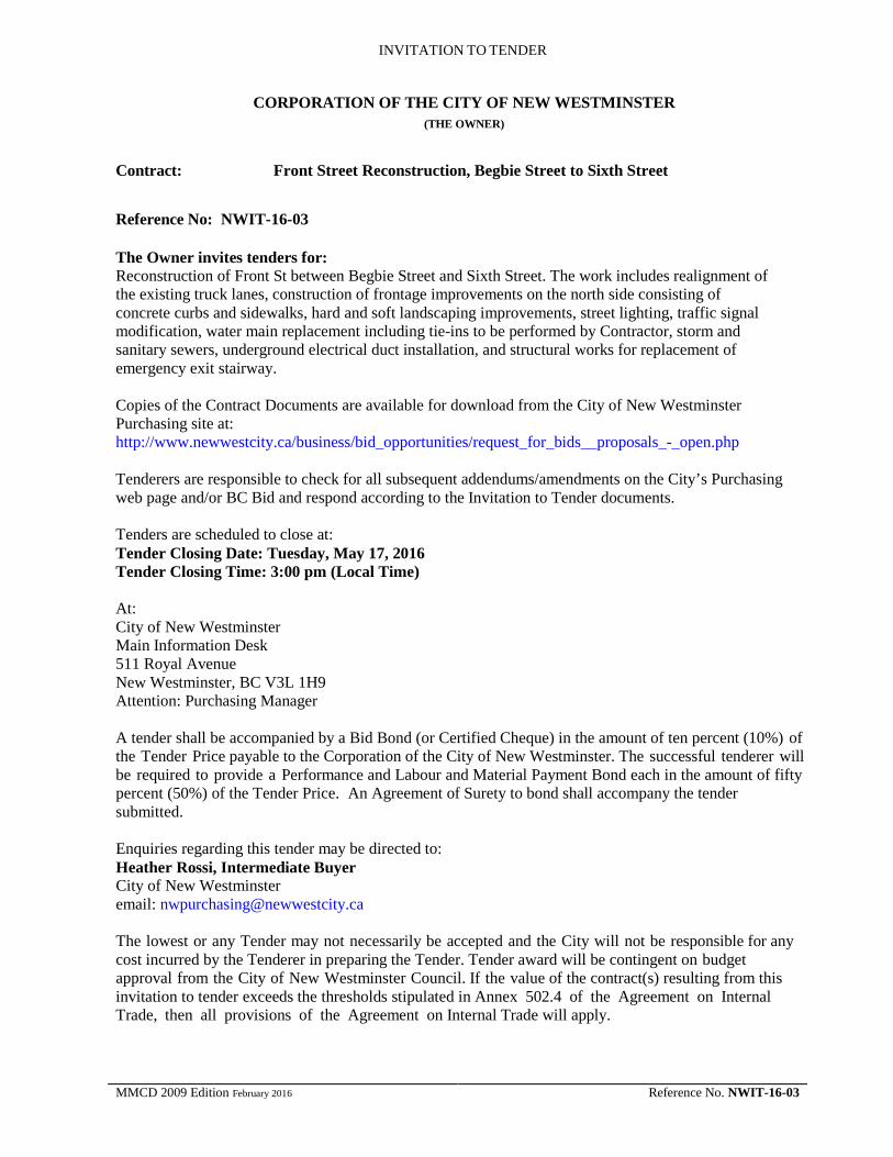
INVITATION TO TENDER
CORPORATION OF THE CITY OF NEW WESTMINSTER
(THE OWNER)
Contract: Front Street Reconstruction, Begbie Street to Sixth Street Reference No: NWIT-16-03 The Owner invites tenders for: Reconstruction of Front St between Begbie Street and Sixth Street. The work includes realignment of the existing truck lanes, construction of frontage improvements on the north side consisting of concrete curbs and sidewalks, hard and soft landscaping improvements, street lighting, traffic signal modification, water main replacement including tie-ins to be performed by Contractor, storm and sanitary sewers, underground electrical duct installation, and structural works for replacement of emergency exit stairway. Copies of the Contract Documents are available for download from the City of New Westminster Purchasing site at: http://www.newwestcity.ca/business/bid_opportunities/request_for_bids__proposals_-_open.php Tenderers are responsible to check for all subsequent addendums/amendments on the City’s Purchasing web page and/or BC Bid and respond according to the Invitation to Tender documents.
Tenders are scheduled to close at: Tender Closing Date: Tuesday, May 17, 2016 Tender Closing Time: 3:00 pm (Local Time) At: City of New Westminster Main Information Desk 511 Royal Avenue New Westminster, BC V3L 1H9 Attention: Purchasing Manager A tender shall be accompanied by a Bid Bond (or Certified Cheque) in the amount of ten percent (10%) of the Tender Price payable to the Corporation of the City of New Westminster. The successful tenderer will be required to provide a Performance and Labour and Material Payment Bond each in the amount of fifty percent (50%) of the Tender Price. An Agreement of Surety to bond shall accompany the tender submitted. Enquiries regarding this tender may be directed to: Heather Rossi, Intermediate Buyer City of New Westminster email: [email protected] The lowest or any Tender may not necessarily be accepted and the City will not be responsible for any cost incurred by the Tenderer in preparing the Tender. Tender award will be contingent on budget approval from the City of New Westminster Council. If the value of the contract(s) resulting from this invitation to tender exceeds the thresholds stipulated in Annex 502.4 of the Agreement on Internal Trade, then all provisions of the Agreement on Internal Trade will apply.
MMCD 2009 Edition February 2016 Reference No. NWIT-16-03

INSTRUCTIONS TO TENDERERS Instructions to Tender, Part I
MMCD 2009 Edition February 2016 Reference No. NWIT-16-03

IT PART 1 PAGE 1
INSTRUCTIONS TO TENDERERS – PART 1
(TO BE READ WITH “INSTRUCTIONS TO TENDERERS - PART II” CONTAINED IN THE EDITION OF THE PUBLICATION “MASTER MUNICIPAL CONSTRUCTION DOCUMENTS” SPECIFIED IN
ARTICLE 2.2 BELOW)
CORPORATION OF THE CITY OF NEW WESTMINSTER (THE OWNER)
Contract: Front Street Reconstruction, Begbie Street to Sixth Street Reference No: NWIT-16-03
1.0 Introduction 1.1 These Instructions apply to and govern the preparation of tenders for this Contract. The Contract is generally for the following work:
Reconstruction of Front Street between Begbie Street and Sixth Street. The work includes realignment of the existing truck lanes, construction of frontage improvements on the north side consisting of concrete curbs and sidewalks, hard and soft landscaping improvements, street lighting, traffic signal modification, water main replacement including tie-ins to be performed by Contractor, storm and sanitary sewers, underground electrical duct installation, and structural works for replacement of emergency exit stairway
1.2 Direct all inquiries regarding the Contract, to:
Heather Rossi, Intermediate Buyer City of New Westminster 511 Royal Ave, New Westminster, BC, V3L 1H9 email: [email protected]
2.0 Tender Documents
2.1 The tender documents, which a tenderer should review to prepare a tender, consist of all of the Contract Documents listed in Schedule 1 entitled “Schedule of Contract Documents”. Schedule 1 is attached to the Agreement which is included as part of the tender package. The Contract Documents include the drawings listed in Schedule 2 to the Agreement, entitled “List of Contract Drawings”.
2.2 A portion of the Contract Documents are included by reference. Copies of these documents have not been included with the tender package. These documents are the Instructions to Tenderers - Part II, General Conditions, Specifications, and Standard Detail Drawings. They are those contained in the publication entitled “Master Municipal Construction Documents - General Conditions, Specifications, and Standard Detail Drawings”. Refer to Schedule 1 to the Agreement or, if not specified in Schedule 1, then the applicable edition shall be the most recent edition as of the date of the Tender Closing Date. All sections of this publication are by reference included in the Contract Documents.
Copies of the Master Municipal Construction Document (Platinum Edition) can be obtained at:
Support Services Unlimited #102 – 211 Columbia Street Vancouver, BC, V6A 2R5 604 681-0295
MMCD 2009 Edition Reference No. NWIT-16-03

IT PART 1 PAGE 2 2.3 Any additional information made available to tenderers prior to the
Tender Closing Time by the Owner or representative of the Owner, such as geotechnical reports or as-built plans, which is not expressly included in Schedule 1 or Schedule 2 to the Agreement, is not included in the Contract Documents. Such additional information is made available only for the assistance of tenderers who must make their own judgment about its reliability, accuracy, completeness and relevance to the Contract, and neither the Owner nor any representative of the Owner gives any guarantee or representation that the additional information is reliable, accurate, complete or relevant.
Addenda 2.4 Should addenda to the tender documents be required for any reason, it is the City’s intention not to issue addenda during a period three (3) days prior to the Tender Closing date and time.
2.5 All Addenda become part of the Contract Documents.
2.6 Failure to acknowledge any Addendum may result in the disqualification of the Tenderer.
3.0 Submission of Tenders
3.1 Tenders must be submitted in a sealed envelope, marked on the outside with the above Contract Title and Reference No., and must be received by the office of:
City of New Westminster Purchasing Department
on or before:
Tender Closing Time: 3:00 pm (Local Time)
Tender Closing Date: Tuesday, May 17, 2016
Address: City of New Westminster Main Information Desk 511 Royal Avenue New Westminster, BC V3L 1H9
Attention: Purchasing Manager
3.2 Late tenders will not be accepted or considered, and will be returned unopened.
3.3 Facsimile electronic mail or other unsealed bids will not be accepted.
3.4 The City will not open this Tender in public. The City will make the Tender results available to Tenderers within a reasonable period following the Tender Closing Date and Time.
4.0 Additional Instructions to Tenderers
4.1 IT 5 (amend clause 5 as follows) Add Appendix 6 – Force Account Labour Rates. Add Appendix 7 – Declaration – Living Wage Employer
Award 4.2
IT 15.5 (add clause 15.5 as follows) In exercising its discretion, the Owner will have regard to the information provided by the Tenderer in the Appendices to the Form of Tender as described under IT 5, and may also have regard to any information obtained by the Owner in evaluating such tender information, as well as the Owner’s previous experience, if any, with the Tenderer. In exercising its discretion the Owner may consider, but is not limited to, the following criteria in addition to the Tender Price:
MMCD 2009 Edition Reference No. NWIT-16-03

IT PART 1 PAGE 3 a) the proven experience of the Tenderer, and any listed
subcontractors to do the Work; b) the Tenderer’s ability to complete the Work within the
Preliminary Construction Schedule; c) the Tenderer’s ability to work effectively with the Owner, its
consultants and representatives; d) the Tenderer’s ability to manage and do the work effectively
using the named superintendent and submitted contractors and subcontractors;
e) the Tenderer’s history on other projects including with respect to quality of work, changes in the work, force account work, and the contract administration costs of the Owner;
f) the nature of any legal proceedings undertaken the by Tenderer, or any officer or director of the Tenderer or affiliate of the Tenderer, directly (or indirectly through another corporation) against the Owner within the previous five years of the Invitation to Tenders;
g) litigation and on-going unresolved claims; a. in addition to any other provision of this tender
document, and without limiting the City’s discretion under any other provision of this tender document, the City may, in its absolute discretion, reject a tender if:
i. the Tenderer, or any officer or director of the Tenderer, is or has been engaged directly or indirectly in a legal action against the City in relation to any matter; or,
ii. the Tenderer has current unresolved extra work claims totalling in excess of $100,000.00 beyond 90 days of contract substantial completion for any construction project with the City.
b. in determining whether or not to reject a tender under this section, the City will consider whether the litigation or unresolved extra work claim is likely affect the Tenderer’s ability to work with the City, its employees, consultants and representatives and whether the City’s experience with the Tenderer indicates an unusual risk the City will incur increased staff and legal costs in the administration of the contract if awarded to the Tenderer.
The Owner will, following receipt of an acceptable tender, issue in writing a Notice of Acceptance to the successful tenderer. This Notice will be given as soon as possible following the closing of tenders and, unless otherwise agreed to by the tenderer, not later than sixty (60) days following the Tender Closing Date. The Owner may, prior to and after Contract Award, negotiate changes to the scope of the Work, the type of materials, the specifications or any conditions with the lowest qualified tenderer without having any duty or obligation to advise any other tenderer or to allow them to vary their Tender Prices as a result of such changes and the Owner shall have no liability to any other tenderer as a result of such negotiations or modifications. The award of this Contract is subject to approval of the Owner and to the availability of sufficient funds to complete the Work. The City may delete
MMCD 2009 Edition Reference No. NWIT-16-03

IT PART 1 PAGE 4 certain portions of the Work if Tender Prices exceed the available budget.
Freedom of Information
4.3 IT 18 (add clause 18 as follows) The City of New Westminster is subject to the Province of British Columbia Freedom of Information and Protection of Privacy Act. All documents will be received and held in confidence by the City of New Westminster and the information will not be disclosed, except to the extent necessary for carrying out the City's purposes or as required by law.
Living Wage Information
4.4 IT 19 (add clause 19 as follows) Effective January 1, 2011, the City of New Westminster became a “Living Wage Employer” (see Form of Tender - Appendix 7). As such, the City has established a Living Wage Policy that requires all firms that are contracted by the City to provide services on City premises, to pay their employees, who perform said service on City property, a Living Wage as calculated by the Living Wage for Families Campaign. The figure for 2016 for the Lower Mainland is $20.68, assuming no benefits are provided by the employer. In order to determine an employee’s hourly rate with benefits the Living Wage for Families has created a Living Wage Calculator to assist with this determination. Please access the following website to determine your compatibility. http://www.livingwageforfamilies.ca/employers/living-wage-calculator/ The City includes in all its competitive bid documents a Declaration referencing the City’s expectations with regards to compliance of the Policy. Completion and submission of the Declaration is required prior to Contract award (see Form of Tender - Appendix 7). In evaluating submissions, the City intends to rely on the Declaration provided by a Respondent and shall have no obligation or duty to investigate the truthfulness of the Declaration. Please review the City’s Living Wage Policy for further information. http://www.newwestcity.ca/business/living_wage_employer/living-wage-policy-and-declaration
Good Neighbour Protocol
4.5 IT 20 (add clause 20 as follows) This policy is for City-led construction projects and works. The Good Neighbour Protocol (GNP) provides guidelines to minimize construction related impacts to residents and businesses. The successful contractor will be required to adhere to the Good Neighbour Protocol. Please review the City’s Good Neighbour Protocol for further information http://www.newwestcity.ca/database/files/library/Good_Neighbour_Protocol__External_Dec_2015.pdf
Geotechnical Report 4.6 Tenderers are advised that a geotechnical report is appended to the tender package. This report is available for information purposes only and does not form part of the Contract Documents.
MMCD 2009 Edition Reference No. NWIT-16-03

IT PART 1 PAGE 5
Communication Equipment
4.7 Contrary to MMCD Section 01 51 01, clause 1.4.1, telephone and telecommunications equipment for the use of the Contract Administrator will not be required.
Schedule 4.8 Tenderers are advised that the Owner requires all works to be substantially performed within one hundred (100) working days of Notice to Proceed. Tenderers are further advised that the Owner requires completion of all works included in the realignment of the Front Street Truck Lane as the first priority, and the realigned Truck Lane be opened for use within thirty (30) working days of Notice to Proceed.
Specification for Landscape Work
4.9 For the purpose of this project, specifications for landscape work are as outlined in Landscape Specifications for Front Street Mews authored by PWL Partnership Landscape Architects Inc. and attached to these documents.
Specification for Electrical Distribution Ducts
4.10 For the purpose of this project, specifications for underground electrical distribution conduit work are as outlined in City Of New Westminster Specifications For Underground Electrical Distribution Structures authored by The City of New Westminster, and attached to these documents. Tenderers are advised that they must be holders of BC Hydro Civil Standards ES54 series, be qualified to carry out this type of work, be able to provide examples of similar work completed successfully for the City or BC Hydro, and be able to supply appropriate references. Tenderers are further advised that payment for this work will be made on a lump sum basis, and that references to unit price payments in the electrical specifications do not form part of this Contract. The City of New Westminster will supply the following materials to be picked up by the Contractor either from the City Works Yard at 901 – First Street, or from the City Storage Yard, 800-block Boyd Street, Queensborough.
- 2 x “832” junction vaults and grounding materials (BCHPA Civil Standards ES54 D4-01-03)
- 2 x “332” service boxes and grounding materials (BCHPA Civil Standards ES54 B2-05.01-04)
- 1 x 3 phase PMT (transformer X418) pad and counterpoise materials (BCHPA Civil Standards ES54 F3-04.01-03)
- 1 x 1 phase LPT (transformer X419) pyramid pad and counterpoise materials (BCHPA Civil Standards ES54 F1-03.01-04)
Specification for Structural Work
4.11 For the purpose of this project, specifications for structural work are as outlined in Front Street - Specifications authored by Dialog Design, and attached to these documents.
MMCD 2009 Edition Reference No. NWIT-16-03

FORM OF TENDER WITH APPENDICES
• Form of Tender • Appendix 1: Schedule of Quantities and Prices • Appendix 2: Preliminary Construction Schedule • Appendix 3: Experience of Superintendent • Appendix 4: Comparable Work Experience • Appendix 5: List of Sub-Contractors • Appendix 6: Force Account Labour Rates • Appendix 7: Declaration – Living Wage Employer
MMCD 2009 Edition February 2016 Reference No. NWIT-16-03

FT PAGE 1
FORM OF TENDER
CORPORATION OF THE CITY OF NEW WESTMINSTER (THE OWNER)
Contract: Front Street Reconstruction, Begbie Street to Sixth Street Reference No: NWIT-16-03
4 WE CONFIRM: 4.1 that the following appendices are attached to and form a part of this tender: 4.1.1 the appendices as required by paragraph 5.3 of the Instructions to Tenderers – Part
II; and 4.1.2 the Bid Security as required by paragraph 5.2 of the Instructions to Tenderers – Part
II.
To Owner: 1 WE, THE UNDERSIGNED: 1.1 have received and carefully reviewed all of the Contract Documents, including the
Instructions to Tenderers, the specified edition of the “Master Municipal Construction Documents - General Conditions, Specifications and Standard Detail Drawings” and the following Addenda:
(Addenda, if any) 1.2 have full knowledge of the Place of the Work, and the Work required; and 1.3 have complied with the Instructions to Tenderers; and
2 ACCORDINGLY WE HEREBY OFFER 2.1 to perform and complete all of the Work and to provide all the labour, equipment and
material all as set out in the Contract Documents, in strict compliance with the Contract Documents; and
2.2 to achieve Substantial Performance of the Work on or before one hundred (100) days from the Notice to Proceed; and
2.3 to do the Work for the price, which is the sum of the products of the actual quantities incorporated into the Work and the appropriate unit prices set out in Appendix 1, the “Schedule of Quantities and Prices”, plus any lump sums or specific prices and adjustment amounts as provided by the Contract Documents. For the purposes of tender comparison, our offer is to complete the Work for the “Tender Price” as set out on Appendix 1 of this Form of Tender. Our Tender Price is based on the estimated quantities listed in the Schedule of Quantities and Prices, and excludes GST.
3 WE CONFIRM: 3.1 that we understand and agree that the quantities as listed in the Schedule of Quantities and
Prices are estimated, and that the actual quantities will vary.
Tenderer’s Initials MMCD 2009 Edition Reference No. NWIT-16-03

FT PAGE 2
5 WE AGREE: 5.1 that this tender will be irrevocable and open for acceptance by the Owner for a period of
sixty (60) calendar days from the day following the Tender Closing Date and Time, even if the tender of another tenderer is accepted by the Owner. If within this period the Owner delivers a written notice (“Notice of Award”) by which the Owner accepts our tender we will:
5.1.1 within 7 Business Days of receipt of the written Notice of Award deliver to the Owner:
a) a Performance Bond in the amount of 50% of the Contract Price, issued by a surety licensed to carry on the business of surety ship in the Province of British Columbia, and in a form acceptable to the Owner;
b) a Labour and Material Payment Bond in the amount of 50% of the Contract price, the Labour and Material Payment Bond must be a Broad Form bond, protecting all companies with a direct contract with the Principal or any sub-contractor of the Principal;
c) a Construction Schedule, as provided by GC 4.6.1; d) a “clearance letter” indicating that the tenderer is in WorkSafe BC
compliance;
e) a copy of the insurance policies as specified in GC 24 indicating that all such insurance coverage is in place; and,
f) proof of a valid City of New Westminster or Inter-Municipal Business License
5.1.2 within 2 Days of receipt of written “Notice to Proceed”, or such longer time as may be otherwise specified in the Notice to Proceed, commence the Work; and
5.1.3 sign the Contract Documents as required by GC 2.1.2.
6 WE AGREE: 6.1 that, if we receive written Notice of Award of this Contract and, contrary to paragraph 5 of
this Form of Tender, we: a) fail or refuse to deliver the documents as specified by paragraph 5.1.1 of this Form of
Tender; or b) fail or refuse to commence the Work as required by the Notice to Proceed, then such failure or refusal will be deemed to be a refusal by us to enter into the Contract
and the Owner may, on written notice to us, award the Contract to another party. We further agree that, as full compensation on account of damages suffered by the Owner because of such failure or refusal, the Bid Security shall be forfeited to the Owner, in an amount equal to the lesser of:
a) the face value of the Bid Security; and
b) the amount by which our Tender Price is less than the amount for which the Owner contracts with another party to perform the Work.
Tenderer’s Initials MMCD 2009 Edition Reference No. NWIT-16-03

FT PAGE 3
7 OUR ADDRESS is as follows:
Phone:
Fax:
E-mail::
Attention:
This Tender is executed this _______ day of ______________________, 2016
Contractor: (full legal name of corporation, partnership or individual)
(Authorized Signatory)
(Authorized Signatory)
8 WE CONFIRM: 8.1 our Goods and Services Tax registration status is as follows: 8.1.1 for information purposes, our Goods and Services Tax registration number is:
(GST REGISTRATION NUMBER)
Tenderer’s Initials MMCD 2009 Edition Reference No. NWIT-16-03

FT PAGE 4
FORM OF TENDER – Appendix 1
SCHEDULE OF QUANTITIES AND PRICES (See paragraph 5.3.1 of the Instructions to Tenderers - Part II)
(All prices and Quotations including the Contract Price shall include all Taxes,
but shall not include GST. GST shall be shown separately.)
Item Description Reference Unit Quantity Unit Price Amount
PART A: CIVIL WORKS
PART A1 – TRUCK LANE REALIGNMENT
SECTION 1 - ROADWORKS
1.1 Concrete
.1) Barrier Curb (MMCD C5) 03 30 20 1.4.3 lin m 475
$ $
.2) Modified Barrier Curb 03 30 20 1.4.3 lin m 25
$ $
.3) Wheel Chair Ramp 03 30 20 1.4.5 sq m 5
$ $
.4) Median Infill 03 03 20 1.4.5 sq m 18
$ $
.5) Precast Median Pier Barrier 03 40 01 1.4.4 lin m 222.5
$ $
1.2 Removals
.1) Rock Removal 31 23 17 1.6.4
cu m 5 $ $
.2) Existing Asphalt 31 24 13 1.8.5. sq m 1500 $ $
1.3 Road Structure
.1) Common Excavation 31 24 13 1.8.5.4 cu m 1650
$ $
.2) Subgrade Preparation 31 24 13 1.8.9 sq m 2100
$ $
.3) Granular Subgrade Fill 31 24 13 1.8.10 tonne 500
$ $
.4) Cold Milling, 50 mm Depth 32 01 16.7 1.5.1 sq m 350
$ $
.5) Granular Subbase 32 11 16.1 1.4.2 tonne 1100
$ $
.6) Granular Base 32 11 23 1.4.2 tonne 720
$ $ Tenderer’s Initials MMCD 2009 Edition Reference No. NWIT-16-03

FT PAGE 5
Item Description Reference Unit Quantity Unit Price Amount
1.4 Asphalt Tack Coat
.1) Tack Coat 32 12 13.1 1.5 sq m 2100 $ $
1.5 Hot-Mix Asphalt
.1) Lower Course (MMCD LC#1)
32 12 16 1.5.1 tonne 650
$ $
.2) Surface Course (MMCD UC#1)
32 12 16 1.5.1 tonne 325
$ $
.3) Asphalt Overlay, 50 mm thick(MMCD UC#1)
32 12 16 1.5.1
tonne 44
$ $
.4) Asphalt Median Infill 32 12 16 1.5.3 sq m 135 $ $
.5) Asphalt Wheelchair Pad 32 12 16 1.5.3 sq m 7 $ $
1.6 Pavement Markings
.1) Painted Markings 32 17 23 1.5.2 LS 1 $ $
.2) Thermoplastic Markings 32 17 23 1.5.3 LS 1 $ $
.3) Signage LS 1 $ $
.4) Removable Bollard (MMCD C9)
32 17 23 1.5.4 ea. 13
$ $
SECTION 2 - DRAINAGE 2.1 Drainage
.1) Terminal cleanout (MMCD S6)
33 40 01 1.6.4 ea. 1
$ $
.2) 150 mm CB Lead 33 40 01 1.6.5 lin m 25 $ $
.3) 200 mm CB Lead 33 40 01 1.6.5 lin m 35 $ $
.4) Side Inlet CB 33 44 01 1.5.2 ea. 6 $ $
SUBTOTAL PART A1 – $ OPTIONAL WORK
1.1 Barrier Sound Wall – Armtec or Approved Equivalent
03 40 01 1.4.6S lin m 222.5
$ $
SUBTOTAL OPTIONAL WORK– (CARRY FORWARD TO TENDER SUMMARY)
$
Tenderer’s Initials MMCD 2009 Edition Reference No. NWIT-16-03

FT PAGE 6
Item Description Reference Unit Quantity Unit Price Amount
PART A2 – MEWS
SECTION 1 – ROADWORKS
1.1 Concrete
.1) Barrier Curb (MMCD C5) 03 30 20 1.4.3 lin m 390
$ $
.2) Modified Barrier Curb 03 30 20 1.4.3 lin m 210
$ $
.3) Concrete Driveway Crossing (MMCD C7)
03 30 20 1.4.6
sq m 55
$ $ 1.2 Removals
.1) Rock removal 31 23 17 1.6.4 cu m 5
$ $
.2) Existing Concrete Curb and Gutter
31 24 13 1.8.5 lin m 70
$ $
.3) Existing Asphalt Curb 31 24 13 1.8.5 lin m 245
$ $
.4) Existing Asphalt Pavement 31 24 13 1.8.5 sq m 250
$ $
.5) Existing Asphalt Sidewalk 31 24 13 1.8.5 sq m 270
$ $
.6) Existing Concrete Sidewalk 31 24 13 1.8.5 sq m 350
$ $ 1.3 Road Structure
.1) Reshaping Granular Roadbeds
31 22 16 1.4.1 sq m 1000
$ $
.2) Common Road Excavation 31 24 13 1.8.5.4 cu m 350
$ $
.3) Cold Milling 32 01 16.7 1.5.1 hour 16
$ $
.4) Granular Subbase 32 11 16.1 1.4.2 tonne 475
$ $
.5) Granular Base 32 11 23 1.4.2 tonne 375
$ $ 1.4 Asphalt Tack Coat
.1) Tack Coat 32 12 13.1 1.5 sq m 1400
$ $
Tenderer’s Initials MMCD 2009 Edition Reference No. NWIT-16-03

FT PAGE 7
Item Description Reference Unit Quantity Unit Price Amount
1.5 Hot-Mix Asphalt
.1) Lower Course MMCD LC#2)
32 12 16 1.5.1 tonne 75
$ $
.2) Asphalt Overlay 32 12 16 1.5.1 tonne 140
$ $
.3) Sidewalk Asphalt 32 12 16 1.5.3 sq m 270
$ $ 1.6 Pavement Markings
.1) Thermoplastic Markings 32 17 23 1.5.2 LS 1
$ $
.2) Amber Lane Reflectors 32 17 23 1.5.4 LS 1
$ $
.3) White Parking Markers 32 17 23 1.5.4 LS 1
$ $
SECTION 2 - DRAINAGE 2.1 Drainage
.1) 150 CB Lead 33 40 01
1.6.5 lin m 40 $ $
.2) 200 CB Lead 33 40 01
1.6.5 lin m 4 $ $
.3) Top Inlet CB (MMCD S11)
33 44 01 1.5.2 ea. 10
$ $
.4) Remove Existing CB 33 44 01 1.5.4 ea. 5
$ $
SUBTOTAL PART A2 – $
Item Description Reference Unit Quantity Unit Price Amount
PART A3 – MCKENZIE STREET SECTION 1 - ROADWORKS 1.1 Concrete
.1) Barrier Curb (MMCD C5) 03 30 20 1.4.3 lin m 95
$ $
.2) Concrete Sidewalk (100 mm thick)
03 30 20 1.4.5 sq m 175
$ $
1.2 Removals
Tenderer’s Initials MMCD 2009 Edition Reference No. NWIT-16-03
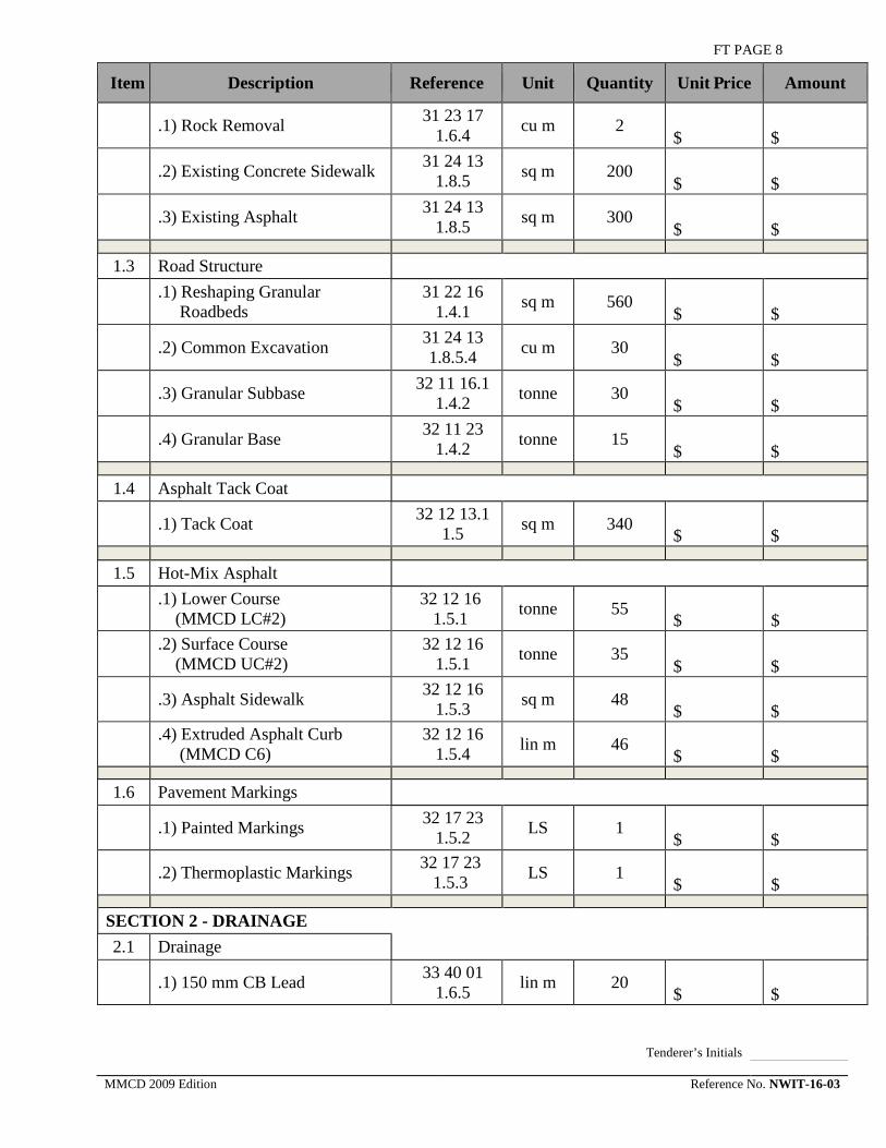
FT PAGE 8
Item Description Reference Unit Quantity Unit Price Amount
.1) Rock Removal 31 23 17 1.6.4 cu m 2
$ $
.2) Existing Concrete Sidewalk 31 24 13 1.8.5 sq m 200
$ $
.3) Existing Asphalt 31 24 13 1.8.5 sq m 300
$ $
1.3 Road Structure
.1) Reshaping Granular Roadbeds
31 22 16 1.4.1 sq m 560
$ $
.2) Common Excavation 31 24 13 1.8.5.4 cu m 30
$ $
.3) Granular Subbase 32 11 16.1 1.4.2 tonne 30
$ $
.4) Granular Base 32 11 23 1.4.2 tonne 15
$ $ 1.4 Asphalt Tack Coat
.1) Tack Coat 32 12 13.1 1.5 sq m 340
$ $
1.5 Hot-Mix Asphalt
.1) Lower Course (MMCD LC#2)
32 12 16 1.5.1 tonne 55
$ $
.2) Surface Course (MMCD UC#2)
32 12 16 1.5.1 tonne 35
$ $
.3) Asphalt Sidewalk 32 12 16 1.5.3 sq m 48
$ $
.4) Extruded Asphalt Curb (MMCD C6)
32 12 16 1.5.4 lin m 46
$ $
1.6 Pavement Markings
.1) Painted Markings 32 17 23 1.5.2 LS 1
$ $
.2) Thermoplastic Markings 32 17 23 1.5.3 LS 1
$ $
SECTION 2 - DRAINAGE 2.1 Drainage
.1) 150 mm CB Lead 33 40 01 1.6.5 lin m 20
$ $
Tenderer’s Initials MMCD 2009 Edition Reference No. NWIT-16-03

FT PAGE 9
Item Description Reference Unit Quantity Unit Price Amount
.2) Remove Existing CB 33 44 01 1.5.4 ea. 2
$ $
.3) Top Inlet CB 33 44 01 1.5.2 ea. 2
$ $
SUBTOTAL PART A3 – $
Item Description Reference Unit Quantity Unit Price Amount
PART A4 – WATERWORKS, SANITARY SEWER, DRAINAGE
SECTION 1 – WATERWORKS 1.1 Fire Hydrant
.1) Fire Hydrant (MMCD W4) 33 11 01 1.8.14S ea. 2
$ $
1.2 Watermain
.1) Trench Over-excavation and Backfill
31 23 01 1.10.3 cu m 15
$ $
2) Rock Removal 31 23 17 1.6.4 cu m 5
$ $
.3) 100 mm DI Cl 52 Main 33 11 01
1.8.2
lin m 4 $ $
.4) 150 mm DI Cl 52 Main 33 11 01
1.8.2
lin m 35 $ $
.5) 200 mm DI Cl 52 Main 33 11 01
1.8.2
lin m 405 $ $
.6) 300 mm DI Cl 52 Main 33 11 01
1.8.2
lin m 13 $ $
1.3 Gate Valves
.1) 100 mm dia 33 11 01 1.8.3 ea. 1
$ $
.2) 150 mm dia 33 11 01 1.8.3 ea. 4
$ $
.3) 200 mm dia 33 11 01 1.8.3 ea. 8
$ $
.4) 300 mm dia 33 11 01 1.8.3 ea. 2
$ $
1.4 Tees
.1) 100x200x200 33 11 01 1.8.3 ea. 1
$ $
Tenderer’s Initials MMCD 2009 Edition Reference No. NWIT-16-03

FT PAGE 10
Item Description Reference Unit Quantity Unit Price Amount
.2) 150x200x200 33 11 01 1.8.3 ea. 4
$ $
.3) 150x300x300 33 11 01 1.8.3 ea. 1
$ $
.4) 200x200x200 33 11 01 1.8.3 ea. 2
$ $
1.5 Cross
.1) 200x300x200x300 33 11 01 1.8.3 ea. 1
$ $
1.6 Bends
.1) 45 degree, 150 mm dia 33 11 01 1.8.3 ea. 1
$ $
.2) 45 degree, 200 mm dia 33 11 01 1.8.3 ea. 1
$ $
.3) 45 degree, 300 mm dia 33 11 01 1.8.3 ea. 1
$ $ 1.7 Reducer
.1) 200 x 150 33 11 01 1.8.3 ea. 1
$ $
1.8 Blow-off Assembly
.1) 200 mm dia (MMCD W8) 33 11 01 1.8.3 ea. 1
$ $
.2) 300 mm dia (MMCD W8) 33 11 01 1.8.3 ea. 1
$ $
1.9 Temporary End of Watermain
.1) 100 mm dia 33 11 01 1.8.5 ea. 3
$ $
.2) 150 mm dia 33 11 01 1.8.5 ea. 3
$ $
.3) 200 mm dia. 33 11 01 1.8.5 ea. 1
$ $
.4) 300 mm dia. 33 11 01 1.8.5 ea. 1
$ $
1.10 Tie-In By Contractor
.1) Tie-in at Begbie 33 11 01 1.8.13 LS 1
$ $
Tenderer’s Initials MMCD 2009 Edition Reference No. NWIT-16-03

FT PAGE 11
Item Description Reference Unit Quantity Unit Price Amount
.2) Tie-in at Front (W) 33 11 01 1.8.13 LS 1
$ $
.3) Tie-in at McKenzie (N) 33 11 01 1.8.13 LS 1
$ $
.4) Tie-in at McKenzie (S) 33 11 01 1.8.13 LS 1
$ $
.5) Tie-in at Sixth 33 11 01 1.8.13 LS 1
$ $
.6) Tie-in at Front (E) 33 11 01 1.8.13 LS 1
$ $
.7) Tie-in at Army & Navy 33 11 01 1.8.13 LS 1
$ $
1.11 Water Service Connection
.1) 20 mm dia 33 11 01 1.8.4 ea. 3
$ $
.2) 25 mm dia 33 11 01 1.8.4 ea. 1
$ $
.3) 38 mm dia 33 11 01 1.8.4 ea. 2
$ $
.4) 50 mm dia 33 11 01 1.8.4 ea. 1
$ $
.5) Meter Box 33 11 01 1.8.4 ea. 7
$ $
SUBTOTAL WATER WORKS $
SECTION 2 – SANITARY WORKS 2.1 Sanitary Sewer
2.1.1 200 PVC Main 33 30 01 1.6.2 lin m 30
$ $
2.1.2 Sanitary Service Tie-in 33 30 01 1.6.7 ea. 1
$ $
SUBTOTAL SANITARY WORKS $
SECTION 3 - DRAINAGE
3.1.1 300 mm PVC main 33 40 01 1.6.2 lin m 39.5
$ $
3.1.2 150 mm CB lead 33 40 01 1.6.5 lin m 25
$ $
3.1.3 200 mm CB lead 33 40 01 1.6.5 lin m 15
$ $
Tenderer’s Initials MMCD 2009 Edition Reference No. NWIT-16-03

FT PAGE 12
Item Description Reference Unit Quantity Unit Price Amount
3.1.4 Service Connection 33 40 01 1.6.3 ea. 2
$ $
3.1.5 1050 Manhole Base, Lid, Frame, Cover
33 44 01 1.5.1.1 ea. 1
$ $
3.1.6 1200 Overbuild Manhole Base, Lid, Frame, Cover
33 44 01 1.5.1.1 ea. 1
$ $
3.1.7 1050 Manhole Riser Sections 33 44 01 1.5.1.1 vert m 1.75
$ $
3.1.8 1200 Manhole Riser Sections 33 44 01 1.5.1.1 vert m 2
$ $
SUBTOTAL DRAINAGE WORKS $
3.2.1 100 mm Separator lead 33 40 01 1.6.5 lin m 62
$ $
3.2.2 150 mm Separator lead 33 40 01 1.6.5 lin m 110
$ $
3.2.3 200 mm Separator lead 33 40 01 1.6.5 lin m 15
$ $
3.2.4 Oil & Grit Separator (CDS 2015-4) ea. 3
$ $
SUBTOTAL PARKADE DRAINAGE $
SUBTOTAL PART A4-
(CARRY FORWARD TO TENDER SUMMARY) $
Item Description Reference Unit Quantity Unit Price Amount
PART B: LANDSCAPING SECTION 1 - HARDSCAPE
1.1 Concrete Sidewalk
sq m 651 $ $
1.2 Landscape Planter Curb
cu m 4 $ $
1.3 Concrete Footings for Furnishings
cu m 48
$ $
1.4 Granite Sett Paving
sq m 244 $ $
1.5 Granite Sett’s on Paver-Grates
sq m 27 $ $
Tenderer’s Initials MMCD 2009 Edition Reference No. NWIT-16-03

FT PAGE 13
Item Description Reference Unit Quantity Unit Price Amount
1.6 Gravel Strip
sq m 108 $ $
1.7 Road Banding
sq m 270 $ $
1.8 Road Banding Colour Set Up
ea. 1 $ $
1.9 Pedestrian Banding sq m 455 $ $
1.10 Wall Banding sq m 58 $ $
SECTION 2 – PLANTING
2.1 Trees ea. 33 $ $
2.2 Shrubs sq m 800 $ $
2.3 Growing Medium – 450 mm sq m 93 $ $
2.4 Growing Medium – 900 mm sq m 147 $ $
2.5 Growing Medium – Structural Soil sq m 219
$ $
SECTION 3 – SITE FURNISHINGS & MISCELLANEOUS
3.1 Bench (No Back) ea. 3 $ $
3.2 Bench (With Back) ea. 2 $ $
3.3 Bollards ea. 27 $ $
3.4 Combined Trash/Recycling Receptacle ea. 6
$ $
3.5 Bike Racks ea. 14 $ $
3.6 Paver-grate ea. 12 $ $
3.7 PLAZA Planter ea. 6 $ $
3.8 Chain-link Fence * lin m 222 $ $
SUBTOTAL PART B- (CARRY FORWARD TO TENDER SUMMARY) $
Tenderer’s Initials MMCD 2009 Edition Reference No. NWIT-16-03

FT PAGE 14
Item Description Reference Unit Quantity Unit Price Amount
PART C: STREET LIGHTING & TRAFFIC SIGNALS
1.1 Street Lighting 26 56 01 1.9.1 LS 1
$ $
1.2 Traffic Signal Modification 34 41 13 1.9.1 LS 1
$ $ SUBTOTAL PART C-
(CARRY FORWARD TO TENDER SUMMARY) $
Item Description Reference Unit Quantity Unit Price Amount
PART D: ELECTRICAL
1.1 Supply and Install Underground Electrical Distribution Conduits
d A LS
$ $ SUBTOTAL PART D-
(CARRY FORWARD TO TENDER SUMMARY) $ Item Description Reference Unit Quantity Unit
Amount
PART E: STRUCTURAL 1.1 Staircase Structure and
Foundation LS 1 $ $
SUBTOTAL PART E- (CARRY FORWARD TO TENDER SUMMARY)
$
Tenderer’s Initials MMCD 2009 Edition Reference No. NWIT-16-03

FT PAGE 15
FORM OF TENDER – Appendix 1
SCHEDULE OF QUANTITIES AND PRICES (See paragraph 5.3.1 of the Instructions to Tenderers - Part II)
(All prices and Quotations including the Contract Price shall include all Taxes,
but shall not include GST. GST shall be shown separately.)
TENDER SUMMARY
ITEM TOTAL AMOUNT
PART A CIVIL WORKS $
PART B LANDSCAPING $
PART C STREET LIGHTING & TRAFFIC SIGNALS $
PART D ELECTRICAL $
PART E STRUCTURAL $
TENDERED PRICE (A-E) $
OPTIONAL WORK $
TENDERED PRICE INCLUDING OPTIONAL WORK $
5% GST $
TOTAL TENDERED PRICE $
Tenderer’s Initials MMCD 2009 Edition Reference No. NWIT-16-03

FT PAGE 16
FORM OF TENDER – Appendix 2
PRELIMINARY CONSTRUCTION SCHEDULE (See paragraph 5.3.2 of the Instructions to Tenderers - Part II)
Indicate schedule with bar chart with major item descriptions and time
ACTIVITY CONSTRUCTION SCHEDULE (WEEKS)
1 2 3 4 5 6 7 8 9 10 11 12
Tenderer’s Initials MMCD 2009 Edition Reference No. NWIT-16-03

FT PAGE 17
FORM OF TENDER – Appendix 3
EXPERIENCE OF SUPERINTENDENT (See paragraph 5.3.3 of the Instructions to Tenderers - Part II)
Name: Years’ Experience: Experience:
Date:
Project Name:
Responsibilities:
References:
Date:
Project Name:
Responsibilities:
References:
Date:
Project Name:
Responsibilities:
References:
Tenderer’s Initials MMCD 2009 Edition Reference No. NWIT-16-03

FT PAGE 18
FORM OF TENDER – Appendix 4
COMPARABLE WORK EXPERIENCE (See paragraph 5.3.4 of the Instructions to Tenderers - Part II)
PROJECT OWNER / CONTACT NAME PHONE and FAX
WORK DESCRIPTION VALUE
($)
Owner / Contract
Phone ( ) Fax ( )
Owner / Contract
Phone ( ) Fax ( )
Owner / Contract
Phone ( ) Fax ( )
Owner / Contract
Phone ( ) Fax ( )
Owner / Contract
Phone ( ) Fax ( )
Owner / Contract
Phone ( ) Fax ( )
Tenderer’s Initials MMCD 2009 Edition Reference No. NWIT-16-03

FT PAGE 19
FORM OF TENDER – Appendix 5
SUBCONTRACTORS
(See paragraph 5.3.5 of the Instructions to Tenderers - Part II)
TENDER ITEM TRADE SUBCONTRACTOR NAME
PHONE NUMBER
Tenderer’s Initials MMCD 2009 Edition Reference No. NWIT-16-03

FT PAGE 20
FORM OF TENDER – Appendix 6
FORCE ACCOUNT LABOUR RATES (See paragraph 5.3.6 of the Instructions to Tenderers - Part II)
Labour Classification Hourly Rate Overtime Rate
Foreman $ /hour $ /hour
Equipment Operator $ /hour $ /hour
Labourer $ /hour $ /hour
Flag person $ /hour $ /hour
Grade person $ /hour $ /hour
$ /hour $ /hour
$ /hour $ /hour
$ /hour $ /hour
$ /hour $ /hour
Tenderer’s Initials MMCD 2009 Edition Reference No. NWIT-16-03

FT PAGE 21
FORM OF TENDER – Appendix 7
DECLARATION – LIVING WAGE EMPLOYER (See paragraph 5.8 of the Instructions to Tenderers)
I, as a duly authorized signing officer of
Company:
Address
, confirm that all employees and sub‐contractors under our contract with the City as outlined below, are paid not less than the “Living Wage” as calculated by the Living Wage for Families Campaign. I understand that this requirement extends only to those employees and sub‐contractors’ employees that perform work while on City premises and property for durations in excess of one continuous hour per occasion.
I understand that the City will conduct audits if and when notification of breach of this compliance is received by the City. I understand that in the event any breach of this declaration is found to be true, the City reserves the right to cancel its contract without penalty at any time once said authentication of the breach is made.
Contract Name:
Authorized Signatory: Dated:
Tenderer’s Initials MMCD 2009 Edition Reference No. NWIT-16-03

AGREEMENT
• Agreement o Schedule 1 -- Schedule of Contract Documents o Schedule 2 -- List of Drawings
MMCD 2009 Edition February 2016 Reference No. NWIT-16-03

AGT PAGE 1 AGREEMENT
BETWEEN OWNER AND CONTRACTOR ( FOR USE WHEN UNIT PRICES FORM THE BASIS OF PAYMENT - TO BE USED ONLY WITH THE GENERAL CONDITIONS AND OTHER STANDARD DOCUMENTS OF THE UNIT PRICE MASTER MUNICIPAL CONSTRUCTION DOCUMENTS. )
BETWEEN OWNER AND CONTRACTOR
This agreement made in duplicate this
______ day of ___________, 2016
Contract: Front Street Reconstruction, Begbie Street to Sixth Street Reference No. NWIT-16-03
BETWEEN:
The Corporation of the City of New Westminster 511 Royal Avenue New Westminster, BC, V3L 1H9
(the “Owner”)
AND:
( NAME AND OFFICE ADDRESS OF CONTRACTOR )
(the “Contractor”)
The Owner and the Contractor agree as follows:
Article 1 The Work Start / Completion Dates
1.1 The Contractor will perform all Work, provide all labour, equipment, and material, and do all things strictly as required by the Contract Documents.
1.2 The Contractor will commence the Work in accordance with the Notice to Proceed. The Contractor will proceed with the Work diligently, will perform the Work generally in accordance with the construction schedules as required by the Contract Documents and will achieve Substantial Performance of the Work on or before 100 working days from the Notice to Proceed, subject to the provisions of the Contract Documents for adjustments to the Contract Time.
1.3 Time shall be of the essence of the Contract.
MMCD 2009 Edition Reference No. NWIT-16-03

AGT PAGE 2 Article 2 Contract Documents
2.1 The “Contract Documents” consist of the documents listed or referred to in Schedule 1, entitled “Schedule of Contract Documents”, which is attached and forms a part of this Agreement, and includes any and all additional and amending documents issued in accordance with the provisions of the Contract Documents. All of the Contract Documents shall constitute the entire Contract between the Owner and the Contractor.
2.2 The Contract supersedes all prior negotiations, representations, or agreements, whether written or oral, and the Contract may be amended only in strict accordance with the provisions of the Contract Documents.
Article 3 Contract Price
3.1 The price for the Work (“Contract Price”) shall be the sum in Canadian dollars of the following
3.1.1 the product of the actual quantities of the items of Work listed in the Schedule of Quantities and Prices which are incorporated into or made necessary by the Work and the unit prices listed in the Schedule of Quantities and Prices; plus
3.1.2 all lump sums, if any, as listed in the Schedule of Quantities and Prices, for items relating to or incorporated into the Work; plus
3.1.3 any adjustments, including any payments owing on account of Changes and agreed to Extra Work, approved in accordance with the provisions of the Contract Documents
3.2 The Contract Price shall be the entire compensation owing to the Contractor for the Work and this compensation shall cover and include all profit and all costs of supervision, labour, material, equipment, overhead, financing, and all other costs and expenses whatsoever incurred in performing the Work.
Article 4 Payment
4.1 Subject to applicable legislation and the provisions of the Contract Documents, the Owner shall make payments to the Contractor.
4.2 If the Owner fails to make payments to the Contractor as they become due in accordance with the terms of the Contract Documents then interest calculated at 0% per annum over the prime commercial lending rate of the Royal Bank of Canada on such unpaid amounts shall also become due and payable until payment. Such interest shall be calculated and added to any unpaid amounts monthly.
MMCD 2009 Edition Reference No. NWIT-16-03

AGT PAGE 3
Article 5 Rights and Remedies
5.1 The duties and obligations imposed by the Contract Documents and the rights and remedies available thereunder shall be in addition to and not a limitation of any duties, obligations, rights and remedies otherwise imposed or available by law.
5.2 Except as specifically set out in the Contract Documents, no action or failure to act by the Owner, Contract Administrator or Contractor shall constitute a waiver of any of the parties’ rights or duties afforded under the Contract, nor shall any such action or failure to act constitute an approval of or acquiescence in any breach under the Contract.
Article 6 Notices
6.1 Communications among the Owner, the Contract Administrator and the Contractor, including all written notices required by the Contract Documents, may be delivered by hand, or by fax, or by pre-paid registered mail to the addresses as set out below:
The Owner:
Corporation of the City of New Westminster 511 Royal Avenue New Westminster, BC V3L 1H9
Fax:
Attention:
Email:
The Contractor:
Fax:
Attention:
The Contract Administrator:
McElhanney Consulting Services Ltd Suite 2300 Central City Tower 13450 – 102 Avenue Surrey BC V3T 5X3
Fax: 604-584-5050
Attention: Mr. Brian Wright
Email: [email protected]
6.2 A communication or notice that is addressed as above shall be considered to have been received
6.2.1 immediately upon delivery, if delivered by hand; or
6.2.2 immediately upon transmission if sent by fax and received in
MMCD 2009 Edition Reference No. NWIT-16-03
AGT PAGE 4 hard copy; or
6.2.3 after 5 Days from date of posting if sent by registered mail.
6.3 The Owner or the Contractor, at any time, may change its address for notice by giving written notice to the other at the address then applicable. Similarly, if the Contract Administrator changes its address for notice then the Owner will give or cause to be given written notice to the Contractor.
6.4 The sender of a notice by fax assumes all risk that the fax is received in hard copy.
Article 7 General
7.1 This Contract shall be construed according to the laws of British Columbia.
7.2 The Contractor shall not, without the express written consent of the Owner, assign this Contract, or any portion of this Contract.
7.3 The headings included in the Contract Documents are for convenience only and do not form part of this Contract and will not be used to interpret, define, or limit the scope or intent of this Contract or any of the provisions of the Contract Documents.
7.4 A word in the Contract Documents in the singular includes the plural and, in each case, vice versa.
7.5 This agreement shall enure to the benefit of and be binding upon the parties and their successors, executors, administrators and assigns.
IN WITNESS WHEREOF, the parties hereto have executed this Agreement the day and year first written above.
Contractor:
(FULL LEGAL NAME OF CORPORATION, PARTNERSHIP OR INDIVIDUAL) (AUTHORIZED SIGNATORY) (AUTHORIZED SIGNATORY)
Owner:
Corporation of the City of New Westminster (FULL LEGAL NAME OF CORPORATION, PARTNERSHIP OR INDIVIDUAL) (AUTHORIZED SIGNATORY)
Roy Moulder, SCMP, Purchasing Manager (AUTHORIZED SIGNATORY)
Schedule 1 Schedule of Contract
The following is an exact and complete list of the Contract Documents, as referred to in Article 2.1 of the Agreement.
MMCD 2009 Edition Reference No. NWIT-16-03

AGT PAGE 5 Documents NOTE: The documents noted with “*” are contained in the “Master Municipal
Construction Documents - General Conditions, Specifications and Standard Detail Drawings”, edition dated 2009 Platinum. All sections of this publication are included in the Contract Documents.
Agreement, including all Schedules;
Supplementary General Conditions (if any);
General Conditions*;
Supplementary Specifications (if any);
Specifications*;
Supplementary Standard Detail Drawings (if any);
Standard Detail Drawings*;
Executed Form of Tender, including all Appendices;
Contract Drawings listed in Schedule 2 to the Agreement –”List of Contract Documents”;
Instructions To Tenderers - Part I;
Instructions to Tenderers - Part II*;
The following Addenda:
( ADDENDA, IF ANY )
MMCD 2009 Edition Reference No. NWIT-16-03

AGT PAGE 6 Schedule 2 List of Contract Drawings
TITLE DRAWING NO.
REVISION NO.
REVISION DATE
McElhanney Consulting Services Ltd.
COVER SHEET C000 PC APRIL 13/16
SITE PLAN C001 PC APRIL 13/16
TRUCK LANE REALIGNMENT C101, C102 PC APRIL 13/16
TRUCK LANE REALIGNMENT – CROSS SECTIONS
C103, C104 PC APRIL 13/16
FRONT STREET MEWS C201, C202 PC APRIL 13/16
FRONT STREET MEWS – CROSS SECTIONS
C203, C204 PC APRIL 13/16
MCKENZIE STREET RECONSTRUCTION C301 PC APRIL 13/16
MCKENZIE STREET CROSS SECTIONS C302 PC APRIL 13/16
SIGNAGE AND PAVEMENT MARKINGS C401, C402 PC APRIL 13/16
WATER WORKS C501, C502 PC APRIL 13/16
WATERMAIN TIE-IN DETAILS C503 PC APRIL 13/16
STORM AND SANITARY SEWER C601 PC APRIL 13/16
PARKADE DRAINAGE C602 PC APRIL 13/16
PWL Landscape Architects Ltd.
KEY PLAN L0.00 1 APRIL 1/16
TREE MANAGEMENT PLAN L0.01 1 APRIL 1/16
MATERIALS PLAN L1.01, L1.02 1 APRIL 1/16
LAYOUT PLAN L2.01, L2.02 1 APRIL 1/16
MMCD 2009 Edition Reference No. NWIT-16-03
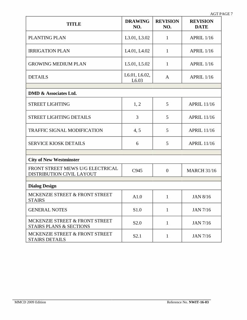
AGT PAGE 7
TITLE DRAWING NO.
REVISION NO.
REVISION DATE
PLANTING PLAN L3.01, L3.02 1 APRIL 1/16
IRRIGATION PLAN L4.01, L4.02 1 APRIL 1/16
GROWING MEDIUM PLAN L5.01, L5.02 1 APRIL 1/16
DETAILS L6.01, L6.02, L6.03
A APRIL 1/16
DMD & Associates Ltd.
STREET LIGHTING 1, 2 5 APRIL 11/16
STREET LIGHTING DETAILS 3 5 APRIL 11/16
TRAFFIC SIGNAL MODIFICATION 4, 5 5 APRIL 11/16
SERVICE KIOSK DETAILS 6 5 APRIL 11/16
City of New Westminster
FRONT STREET MEWS U/G ELECTRICAL DISTRIBUTION CIVIL LAYOUT
C945 0 MARCH 31/16
Dialog Design
MCKENZIE STREET & FRONT STREET STAIRS
A1.0 1 JAN 8/16
GENERAL NOTES S1.0 1 JAN 7/16
MCKENZIE STREET & FRONT STREET STAIRS PLANS & SECTIONS
S2.0 1 JAN 7/16
MCKENZIE STREET & FRONT STREET STAIRS DETAILS
S2.1 1 JAN 7/16
MMCD 2009 Edition Reference No. NWIT-16-03

SUPPLEMENTARY GENERAL CONDITIONS
• Supplementary General Conditions
MMCD 2009 Edition February 2016 Reference No. NWIT-16-03

SGC PAGE 1
SUPPLEMENTARY GENERAL CONDITIONS
TABLE OF CONTENTS Page 1 DEFINITIONS 2 4 CONTRACTOR 2 4.1 Control of Work 2 4.3 Protection of Work, Property and the Public 2 4.6 Construction Schedule 4 4.17 Survey Layout and As-Constructed Information 4 4.18 City Industrial Health and Safety Program 5 9 VALUATION OF CHANGES AND EXTRA WORK 5 9.4 Quantity Variations 5 11 CONCEALED OR UNKNOWN CONDITIONS 5 11.11 Definition 5 13 DELAYS 13.8 Liquidated Damages for Late Completion 18 PAYMENT 5 18.2 Supporting Documentation 5 18.5 Payment 6 18.6 Substantial Performance 6 24 INSURANCE 6 24.1 Required Insurance 6 25 MAINTENANCE PERIOD 7 25.1 Correction of Defects 7 25.2 Commencement of Maintenance Period 7
MMCD 2009 Edition Reference No. NWIT-16-03

SGC PAGE 2
SUPPLEMENTARY GENERAL CONDITIONS
(TO BE READ WITH “GENERAL CONDITIONS” CONTAINED IN THE PLATINUM EDITION OF THE PUBLICATION “MASTER MUNICIPAL CONSTRUCTION DOCUMENTS” SPECIFIED IN “INSTRUCTIONS TO TENDERERS" IT - 2.2)
DEFINITIONS 1 1.79 “(amend clause X.XX as follows)” preceding a
supplementary clause means this clause modifies or provides additional information or restrictions to the referenced clause in the Master Municipal Construction Documents Platinum Edition, Volume II.
1.80 “(add new clause X.XX as follows)” preceding a supplementary clause means this clause provides additional requirements or information not found in the Master Municipal Construction Documents Platinum Edition, Volume II.
1.81 “(delete clause X.XX and replace as follows)” preceding a supplementary clause means this clause replaces the referenced clause in the Master Municipal Construction Documents Platinum Edition, Volume II in its entirety.
CONTRACTOR 4 Control of Work 4.1 4.1.3 (add clause 4.1.3 as follows) The Contractor shall take precautions to reduce nuisance
caused from mud or dust by clean-up, sweeping, sprinkling with water or other means as necessary to accomplish results satisfactory to the Contract Administrator. If the Contractor fails to maintain the site tidy or refuses to remove waste and debris as directed by the Contract Administrator, the Owner, at its own discretion, may proceed to clean the site, remove waste and debris from site, and deduct from any payment due the Contractor the cost of such cleaning or removing materials.
Protection of Work, Property and the Public
4.3 4.3.1 (Delete the following from the last sentence of G.C.4.3.1 as follows) … except for damage, which, in the Performance of the Work, the Contractor could not reasonably avoid.
4.3.4 (amend clause 4.3.4 as follows) (1) expose and determine conclusively the location in the field all underground utilities and structures whether or not indicated on the Contract Documents as being at the Place of the Work. The Contractor shall also be responsible to consult with all utility corporations that provide electricity, communication, gas or other utility services in the area of the Place of the Work, to locate in three dimensions all underground utilities for which they have records. The Contractor shall also locate in three dimensions any other utilities or underground structures that are reasonably apparent in an inspection of the Place of the Work. The
MMCD 2009 Edition Reference No. NWIT-16-03

SGC PAGE 3 Contractor shall provide Fortis BC with three weeks’ notice for relocation of any gas mains or services if it is required when crossing the gas lines.
4.3.6 (Delete 4.3.6 entirely)
4.3.7 (add new clause 4.3.7 as follows) The Contractor shall locate, mark, and protect from damage or disturbance, any and all stakes, survey pins, monuments and markers at the Place of the Work. All survey stakes, survey pins, monuments, or markers that are damaged or disturbed shall be made good following construction by a registered B.C. Land Surveyor. Such repairs shall become part of the Work and shall be at the Contractor's expense.
4.3.8 (add new clause 4.3.8 as follows) Contractor to submit, fourteen (14) calendar days prior to the start of construction, a Traffic Management Plan (TMP) provided by a qualified traffic management company, and prepared in accordance with the “Traffic Control Manual for Work in Roadways”. Road closures will not be allowed without prior approval from the City of New Westminster. The cost of the TMP will be incidental to payment of work described in other sections. The Contractor shall ensure that single lane traffic movement is available in each direction at all times and shall minimize impact to on-street parking and pedestrian access to commercial and residential properties during working hours.
The Contractor shall carry out the work such that access to commercial and residential properties is maintained at all times. The Contractor shall provide a minimum one week advance written notice to all property owners prior to construction, and shall also provide a minimum two (2) working days’ notice to individual property owners prior to commencing work affecting individual property access. The Contractor shall give due notice to local police and fire department prior to beginning construction and shall comply in all respects with their requirements. The Contractor shall comply with the requirements of the appropriate authority concerned with closure of streets or highways and shall post proper notices and/or signals, and provide necessary barriers, guards, lights, flagmen or watchmen as may be necessary for proper maintenance of traffic and protection of persons and property from injury or damage. All costs involved in respect of the above requirements will be deemed to be included in the Contract Price.
MMCD 2009 Edition Reference No. NWIT-16-03

SGC PAGE 4
Where existing streets or roads are not available as detours, all traffic shall be permitted to pass through the Work with as little inconvenience and delay as possible unless otherwise provided or authorized. If half the street only is under improvement, the other half shall be conditioned and maintained as detour. Where construction is to be carried out on highways or properties other than those of the Owner it shall be the responsibility of the Contractor to familiarize himself with the requirements of the owners or controllers of these properties which pertain to traffic safety or control of the construction operation and to carry out his work in accordance with these requirements.
Construction Schedule
4.6 4.6.8 (add new clause 4.6.8 as follows) The Contractor may carry out the Work between 0700 h and 1900 h inclusive, Monday to Friday. The Contractor shall schedule their Work within these hours and will not be permitted to commence Work earlier than 0700 h and/or work later than 1900 h, except as authorized by the Contract Administrator.
4.6.9 (add new clause 4.6.9 as follows) The Contractor shall not schedule work that will require inspection beyond an eight-hour day without the Contract Administrator’s prior approval. Any extra cost incurred by the Owner for work done outside of normal office hours may be deducted from the Contractor’s monthly payments.
4.6.10 (add new clause 4.6.10 as follows) On the infrequent occasion that the Contractor finds it necessary to work on Saturday, Sunday or Statutory Holiday, the Contractor shall obtain the Contract Administrator’s approval forty-eight (48) hours in advance. Work on Sundays or Statutory Holidays will also require the City’s approval, with a minimum two weeks’ notice. The Contractor shall also be charged a working day and may be charged the overtime inspection costs incurred by the Owner. Such costs shall be deducted from monthly progress payments.
Survey Layout and As-Constructed Information
4.17 4.17.1 (add new clause 4.17.1 as follows) The Contractor is responsible for all survey required for construction layout and for record drawings associated with this contract. The Contractor shall be responsible for recording of all field survey information pertaining to the as-constructed drawings. The Contractor shall provide, at no charge, a completed set of legible, marked-up as-constructed prints to the Contract Administrator on completion of the
MMCD 2009 Edition Reference No. NWIT-16-03

SGC PAGE 5 Work. The Contractor shall provide any additional information as requested to enable the Contract Administrator to prepare and submit as-constructed record drawings to the Municipality or the Owner for their records.
City Industrial Health and Safety Program
4.18 4.18.1 (add new clause 4.18.1 as follows) 4.18.1 All Contractors working for the City of New Westminster are required to be aware of the City’s Industrial Health and Safety Program. It is the Contractor’s responsibility to perform the job in compliance with the City’s safety standards. The Contractor is responsible for the compliance of all employees for whom he is primarily responsible, with all WorkSafe BC Industrial Health and Safety Regulations, as well as all other applicable Regulations.
VALUATION OF CHANGES AND EXTRA WORK
9
Quantity Variations 9.4 9.4.1 (delete clause 9.4.1 and replace as follows) The Contractor shall hold firm all unit prices submitted in the Schedule of Quantities and Prices regardless of the increase or decrease in quantities.
CONCEALED OR UNKNOWN CONDITIONS
11
Definition 11.1 11.1.1 (delete 11.1.1 and substitute with the following) A “Concealed or Unknown Conditions” is Hazardous Materials not disclosed in the Contract Documents.
11.1.2 (add the clause 11.1.2 as follows) The Contractor bears the risk and liability for utilities and subsurface soil conditions. The Contractor acknowledges that it has not relied on accuracy of any information provided by the Owner in evaluating these risks. The Contractor acknowledges that it has full responsibility for locating utilities and has conducted its own investigation and has made allowance in the Contract Price for these risks.
DELAYS 13 Liquidated Damages for Late Completion
13.8 13.8.1 a) (delete clause 13.8.1 a) and replace as follows) As a genuine pre-estimate of the Owner’s increased costs for the Contract Administrator and the Owner’s own staff caused by such delay an amount of $2,350.00 per day or pro rata portion for each Day that actual Substantial Performance is achieved after the Substantial Performance Milestone Date; plus
MMCD 2009 Edition Reference No. NWIT-16-03

SGC PAGE 6
PAYMENT 18 Supporting Documentation 18.2.2 18.2.2 (amend clause 18.2.2 as follows)
If requested in writing by the Contract Administrator, the Contractor shall, as a precondition to the issuance of the Payment Certificate, provide a sworn declaration in the form of a CCDC 9A-2001 Statutory Declaration to the Contract Administrator that all amounts relating to the Work, due and owing as of the end of the month covered by the Payment Certificate to third parties including all subcontractors and suppliers, have been paid.
18.2.3 18.2.3 (add clause 18.2.3 as follows) The Owner retains the right to obtain proof of payment, in the form of a CCDC 9A-2001 Statutory Declaration, of all sub-trades and material suppliers from the Contractor prior to making final payment.
Payment 18.5.1 18.5.1 (amend clause 18.2.2 as follows) The net amount shown for payment on a Payment Certificate shall be due and payable to the Contractor on or before the 30th Day after the date of the Contractor’s invoice.
Substantial Performance 18.6.3 (3) (add clause 18.6.3(3) as follows) Record drawings in format specified in MMCD Section 01 33 01 clause 1.7
INSURANCE 24 Required Insurance 24.1 24.1 (amend 24.1 as follows)
In addition to the MMCD insurance requirements, the Contractor shall also comply with the following requirements, which will take precedence. 24.1.1 The Contractor shall insure and keep insured while this Contract is in force, with such companies and on such forms as are acceptable to the Owner, at the Contractor’s expense. Commercial General Liability Insurance covering premises and operations liability; Contractor’s Contingency Liability with respect to the operations of Subcontractor’s Completed Operations Liability, Contractual Liability and Non-Owned Automobile Liability Insurance.
24.1.1(1) (replace 24.1.1(1) with the following) The limits of liability for Personal Injury and Property Damage combined shall be for not less than $5,000,000 each occurrence.
24.1.1(2) (add to 24.1.1(2) as follows) The following shall be named as additional insured on the Contract:
MMCD 2009 Edition Reference No. NWIT-16-03

SGC PAGE 7 • Corporation of the City of New Westminster
• McElhanney Consulting Services Ltd
(Full name of Contract Administrator)
• PWL Partnership Landscape Architects Inc. (Full name of Contract Administrator sub consultant)
• DMD & Associates Ltd
(Full name of Contract Administrator sub consultant)
• Dialog Design (Full name of Contract Administrator sub consultant)
• All subcontractors A Cross Liability Clause shall be made part of the Commercial General Liability Insurance.
24.1.7 (add new 24.1.7 as follows) Should the Contractor neglect to obtain and/or maintain insurance as aforesaid, or deliver such policy or policies to the Owner, then the Owner shall obtain and/or maintain such insurance and the Contractor hereby appoints the Owner its true and lawful attorney to do all things necessary for this purpose. All monies expended by the Owner for Insurance premiums under the provisions of this clause shall be charged to the Contractor.
MAINTENANCE PERIOD 25 Correction of Defects 25.1 25.1.4 (add clause 25.1.4 as follows)
The Owner is authorized to make repairs to defects or deficiencies if, ten days after giving written notice, the Contractor has failed to make or undertake with due diligence the required repairs. However, in the case of emergency where, in the opinion of the Owner, delay is not reasonable, repairs may be made without notice being sent to the Contractor. All expenses incurred by the Owner in connection with repairs made pursuant to GC 25 shall be paid by the Contractor and may be deducted from the Maintenance Security, or other holdbacks. The Contractor shall promptly pay any shortfall.
Commencement of Maintenance Period
25.2 25.2.2 (amend clause 25.2.2 as follows) All warranties under this Contract commence from the date of Substantial Performance of the Contract, regardless of whether any Subcontractor achieves Substantial Performance of its Subcontract prior to Substantial Performance of the Contract.
MMCD 2009 Edition Reference No. NWIT-16-03

SUPPLEMENTARY SPECIFICATIONS
• Supplementary Specifications
MMCD 2009 Edition February 2016 Reference No. NWIT-16-03

SSPEC PAGE 1
SUPPLEMENTARY SPECIFICATIONS
TABLE OF CONTENTS PAGE 03 40 01 PRECAST CONCRETE 1.4 Measurement and Payment 2 33 11 01 WATERWORKS 1.8 Measurement and Payment 2
MMCD 2009 Edition Reference No. NWIT-16-03

SSPEC PAGE 2
SUPPLEMENTARY SPECIFICATIONS
Section Sub-Section Title Supplementary Specification
03 40 01 PRECAST CONCRETE
1.4. Measurement and Payment
1.4.6 (add clause 1.4.6 as follows) Payment for precast concrete sound wall includes detailed design of precast sections and pile supports by a Professional Engineer registered in British Columbia, submission of shop drawings for review, supply of all components and installation at the locations shown on the Contract Drawings.
33 11 01 WATERWORKS
1.8 Measurement and Payment
1.8.13 (change clause 1.8.13 as follows) Delete 1.8.13 in second line; insert 1.8.12
MMCD 2009 Edition Reference No. NWIT-16-03

LANDSCAPE SPECIFICATIONS Based on National Master Specification (NMS)
FOR
FRONT STREET MEWS NEW WESTMINSTER, BC
(Tender Set)
PWL Partnership
Landscape Architects Inc.
500 – 1201 West Pender Street VANCOUVER, BC
V6E 2V2
PHONE: 604. 688.6111 FAX: 604. 688.6112
April 1, 2016

01 33 00 SHOP DRAWING PRODUCT DATA TESTING AND SAMPLES FRONT STREET MEWS, Based on National Master Specification (NMS) New Westminster, BC Project No: 15025
01 33 00 PWL Partnership
Landscape Architects Inc. Page 1 of 5
1.00 GENERAL 1.01 GENERAL REQUIREMENTS .1 Refer to Division 1, General requirements. .2 All contract documents form an integral part of this section.
1.01 DESCRIPTION OF WORK
.1 This section specifies general requirements and procedures for contractors
submissions of the to Consultant for review. Additional specific requirements for submissions are specified in individual sections. .1 Shop Drawings. .2 Product Data. .3 Samples and Mock-Ups. .4 Material Testing
1.02 SUBMISSION REQUIREMENTS
.1 Coordinate each submission with requirements of work and Contract Documents. Individual submission will not be reviewed until all related information is available.
.2 Allow ten working days for Consultant’s review of each submission. .3 All submissions are to include a transmittal letter outlining the following information:
.1 Date of Submission
.2 Project name
.3 Contractor’s name, address, telephone, email address
.4 Contact person’s name and position
.5 Identification including colour, finish, material type, trade name, texture, etc. clearly marked on each sample or product.
.4 All submissions of project components, products, samples, etc. shall be clearly marked
with the following information: .1 Date of Submission .2 Project title and number .3 Name, address telephone, email address, contact person of the;
.1 Subcontractor
.2 Supplier
.3 Manufacturer In addition to the above information the Contractor shall indicate via stamp on transmittal (if submittal is a product), shop drawing or product information sheet, their corporate name, address and telephone number signed by Contractors authorized

01 33 00 SHOP DRAWING PRODUCT DATA TESTING AND SAMPLES FRONT STREET MEWS, Based on National Master Specification (NMS) New Westminster, BC Project No: 15025
01 33 00 PWL Partnership
Landscape Architects Inc. Page 2 of 5
representative certifying approval of submissions, verification of field measurements and compliance with Contract Documents. Submittals, which do not contain this information, will be returned without being examined and shall be considered rejected.
.5 Shop Drawings and submittal information shall include but are not limited to the
following information; .1 Fabrication details .2 Layout, showing dimensions, including identified field dimensions, and
Clearances .3 Setting or erection details .4 Capacities .5 Performance characteristics .6 Standards .7 Operating weight .8 Wiring diagrams .9 Single line and schematic diagrams .10 Relationship to adjacent work .11 Materials .12 Finishes
.6 Contractor is responsible for the distribution of submittals reviewed by the Consultant
to all trades necessary to complete the work. Contractor shall maintain an up to date file of all submissions and revisions on site at all times.
1.03 GENERAL REQUIREMENTS
.1 Work adjacent to or impacted by the submittal shall not proceed until the Consultant review of the submittal is complete and has been submitted to the Contractor.
.3 Shop drawings, product data, samples and mock-ups shall be submitted in SI Metric
Units. .4 Where items or information are not in SI Metric units provide converted values in
brackets adjacent to imperial units. .5 Should the Contractor feel it is necessary to deviate from the details to fully meet the
intended requirements of the project they are to provide written documentation and rationale for the deviation to the Consultant at the time of submission.
.6 Contractor to revise submissions as indicated by the Consultants written mark ups or
comments and resubmit as required. Fabrication, selection, purchase of components noted in the submission prior to the review by the Consultant is at Contractors own risk.

01 33 00 SHOP DRAWING PRODUCT DATA TESTING AND SAMPLES FRONT STREET MEWS, Based on National Master Specification (NMS) New Westminster, BC Project No: 15025
01 33 00 PWL Partnership
Landscape Architects Inc. Page 3 of 5
1.03 SHOP DRAWINGS
.1 Shop drawings: are defined as original drawings, or modified standard drawings, catalogue information, illustrations, schedules, performance charts, brochures and other product data provided by Contractor, to illustrate details of portions of work, which are specific to project requirements.
.2 Adjustments made on shop drawings by the Consultant are not intended to change the
Contract Price. If adjustments affect the value of work, state such in writing to the Consultant. Do not proceed with work until such time a change order has been issued.
.3 Unless otherwise noted in the Contract Documents the Contractor is to submit six (6)
full scale copies of each shop drawing requested. Reduced, electronically transmitted drawings either via email or fax are not acceptable.
.4 Cross-reference shop drawing information to applicable portions of Contract
Documents.
1.04 SAMPLES
.1 Samples: Samples include but are not limited to examples of materials, products, equipment, hardware, etc. that clearly illustrate the quality, finishes, workmanship indicated in the Contract Documents.
.2 Unless otherwise noted on the Contract Documents the Contractor shall submit two (2)
samples of each element. .2 Unless otherwise indicated in the Contract documents samples are to be delivered
prepaid to the consultant’s business address. .3 Where colour, pattern or texture is criterion, submit full range of samples. .4 Comments made by the Consultant regarding the sample review are not intended to
change the Contract Price. If adjustments affect the value of work, state such in writing to the Consultant. Do not proceed with work until such time a change order has been issued.
.5 Reviewed samples will become standard of workmanship and material against which
installed work will be compared. 1.06 MOCK-UPS
.1 Mock-ups: A Mock Up is a field-erected example of work complete with specified

01 33 00 SHOP DRAWING PRODUCT DATA TESTING AND SAMPLES FRONT STREET MEWS, Based on National Master Specification (NMS) New Westminster, BC Project No: 15025
01 33 00 PWL Partnership
Landscape Architects Inc. Page 4 of 5
materials and workmanship. .2 Mock Ups are to be erected on site in a location where they can remain for the duration
of the Contract. Coordinate location of the mock-up(s) with the Consultant. .3 Adjustments made to mock-ups by the Consultant are not intended to change the
Contract Price. If adjustments affect the value of work, state such in writing to the Consultant. Do not proceed with work until such time a change order has been issued.
.4 Reviewed mock-ups will become standards of workmanship and material against
which installed work will be compared. 1.07 SHOP DRAWING, MOCK-UP AND SAMPLE REVIEW
.1 The review of shop drawings, mock-ups and samples by the Consultant is for the sole purpose of ascertaining conformance with the general concept. This review shall not mean that the Consultant approves the detail design inherent in the shop drawings, responsibility for which shall remain with the Contractor submitting same, and such review shall not relieve the Contractor of responsibility for requirements of the construction and contract documents. Without restricting the generality of the foregoing, the Contractor is responsible for dimensions to be confirmed and correlated at the job site, for information that pertains solely to fabrication processes or to techniques of construction and installation and for co-ordination of the work of all sub trades.
1.08 MATERIAL TESTING AND INSPECTIONS
.1 The Contractor at no cost to the Owner and as part of their work shall coordinate the performance of all inspections and material testing and approvals required by this Contract. Should the test require a representative sample or repair of as constructed area as a result of testing the Contractor at no cost to the Owner will undertake the selection and delivery of samples to the testing agency and carry our repairs to constructed work as required by the Consultant. Unless otherwise noted all tests prepared by an independent testing agency will be paid for by the Owner.
.2 Prior to the start of work the Contractor shall provide the Consultant with a schedule
outlining the required tests and inspections and indicate the dates or frequency of testing or inspections to ensure that they are fully coordinated with the requirements of the Contract Documents.
.3 The Contractor shall provide certificate of inspections and test results to the
Consultant via email noting within the body of the email whether the tests or inspections conform to the requirements of the Contract Documents.

01 33 00 SHOP DRAWING PRODUCT DATA TESTING AND SAMPLES FRONT STREET MEWS, Based on National Master Specification (NMS) New Westminster, BC Project No: 15025
01 33 00 PWL Partnership
Landscape Architects Inc. Page 5 of 5
.4 Should the Contractor cover work to be tested or inspected prior to carrying out
required testing or inspections then the Consultant has the right request at no cost to the Owner to have the work in question be uncovered, tested. Following positive test results or inspection the work in question is to at no cost the Owner be reinstated as per the Contract documents.
.5 Should the inspection or test results indicate that the work by the Contractor not meet
the requirements of the Contract documents the Consultant has the right request at no cost to the Owner that the work be demolished or removed from the site, replaced or re-executed in accordance with the Contract documents and re-tested or inspected to ensure conformance with the Contract documents.
PART 2 PRODUCTS (Not Applicable) PART 3 EXECUTION (Not Applicable) END OF SECTION 01330

01 56 00 TREE AND PLANT PROTECTION FRONT STREET MEWS, Based on National Master Specification (NMS) New Westminster, BC Project No: 15025
01 56 00
PWL Partnership
Landscape Architects Inc. Page 1 of 5
1.00 GENERAL 1.01 GENERAL REQUIREMENTS
.1 Refer to Division 1, General Requirements. .2 All contract documents to form an integral part of this section.
1.02 DESCRIPTION
.1 Furnish all labour, materials, equipment, and services necessary to erect/ maintain tree protection fencing delineating the tree protection zone noted on the contract drawings. Coordinate work within the tree protection zone with the Consultant and/or the project Arbourist.
.2 The work shall include but is not limited to the following areas:
.1 Hand excavation around roots
.2 Hand root pruning, general pruning of crown as directed by Arbourist or Consultant.
.3 Grading operations including cutting and filling within the tree protection area.
.4 Removal and disposal of excess material off site
1.03 PROTECTION OF EXISTING TREES
.1 A tree Protection fence shall be installed delineating the tree protection zone by the Contractor prior to start of all clearing and/or construction around existing trees, understory plants and shrubs in accordance the layout indicated on the contract documents. Damage to trees and shrubs during construction shall be reported immediately to the Consultant for assessment and direction with regard to repair, remediation or replacement by the Contractor at no cost to the owner.
.4 The Contractor shall ensure that during the course of construction the tree protection
zone is maintained and monitored to ensure that the existing trees, under storey plants and shrubs to remain and their root systems are protected from damaging activities that include but are not limited to:
.1 Dumping of refuse.
.2 Materials, whether solid or liquid that may cause damage to the plant material, surrounding soil and root system.
.3 Materials, whether solid or liquid sourced from runoff and spillage during mixing and placement of construction materials, outside the tree protection zone that may cause damage to the plant material, surrounding soil and root system.
.4 Water ponding adjacent to or within the tree protection zone that may cause damage to the plant material.
.5 Flooding, erosion, excessive wetting and drying resulting from de-watering and other operations.
.6 Vehicular and foot traffic within the tree protection zone including casual seating or equipment and material storage.
.7 Fires adjacent to or within the tree protection zone.
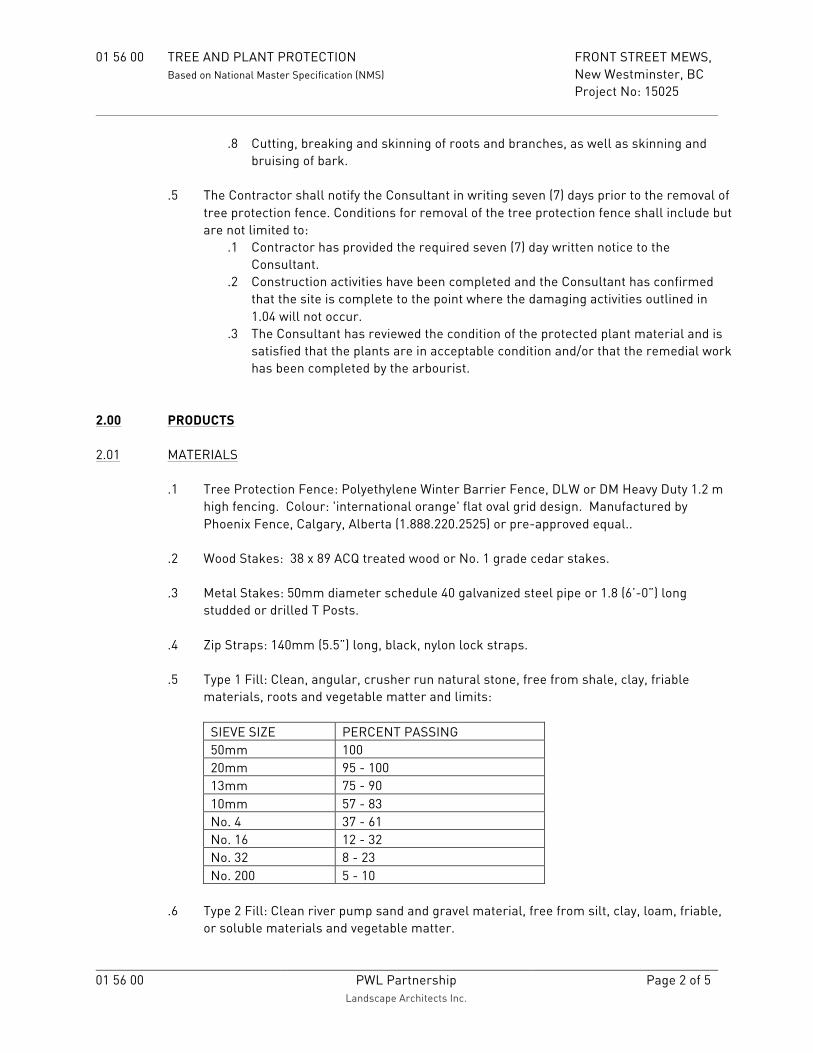
01 56 00 TREE AND PLANT PROTECTION FRONT STREET MEWS, Based on National Master Specification (NMS) New Westminster, BC Project No: 15025
01 56 00
PWL Partnership
Landscape Architects Inc. Page 2 of 5
.8 Cutting, breaking and skinning of roots and branches, as well as skinning and bruising of bark.
.5 The Contractor shall notify the Consultant in writing seven (7) days prior to the removal of
tree protection fence. Conditions for removal of the tree protection fence shall include but are not limited to:
.1 Contractor has provided the required seven (7) day written notice to the Consultant.
.2 Construction activities have been completed and the Consultant has confirmed that the site is complete to the point where the damaging activities outlined in 1.04 will not occur.
.3 The Consultant has reviewed the condition of the protected plant material and is satisfied that the plants are in acceptable condition and/or that the remedial work has been completed by the arbourist.
2.00 PRODUCTS 2.01 MATERIALS
.1 Tree Protection Fence: Polyethylene Winter Barrier Fence, DLW or DM Heavy Duty 1.2 m
high fencing. Colour: 'international orange' flat oval grid design. Manufactured by Phoenix Fence, Calgary, Alberta (1.888.220.2525) or pre-approved equal..
.2 Wood Stakes: 38 x 89 ACQ treated wood or No. 1 grade cedar stakes. .3 Metal Stakes: 50mm diameter schedule 40 galvanized steel pipe or 1.8 (6’-0”) long
studded or drilled T Posts. .4 Zip Straps: 140mm (5.5”) long, black, nylon lock straps.
.5 Type 1 Fill: Clean, angular, crusher run natural stone, free from shale, clay, friable
materials, roots and vegetable matter and limits:
SIEVE SIZE PERCENT PASSING 50mm 100 20mm 95 - 100 13mm 75 - 90 10mm 57 - 83 No. 4 37 - 61 No. 16 12 - 32 No. 32 8 - 23 No. 200 5 - 10
.6 Type 2 Fill: Clean river pump sand and gravel material, free from silt, clay, loam, friable,
or soluble materials and vegetable matter.

01 56 00 TREE AND PLANT PROTECTION FRONT STREET MEWS, Based on National Master Specification (NMS) New Westminster, BC Project No: 15025
01 56 00
PWL Partnership
Landscape Architects Inc. Page 3 of 5
.7 Type 3 Fill: Approved premixed growing medium. .8 Clear Stone: Shall consist of clean, round, washed stone. Acceptable material includes 10
mm (3/8”) rock conforming to the following gradations.
SIEVE SIZE PERCENT PASSING (10MM)
14mm 100 10mm 85 - 100 5mm 10 - 30 2.5mm 0 - 10 1.25mm 0 - 5
.9 Drain Tile: 150mm (6”) diameter Schedule 40 PVC (polyvinyl chloride) perforated pipe
conforming to ASTM D 1784. .10 Burlap: 10 ounce, untreated, woven, natural jute based burlap.
3.00 EXECUTION 3.01 INSTALLATION OF SNOW FENCING
.1 Prior to the start of any construction or demolition activity erect the Tree Protection Fence as detailed on Drawings.
.2 Consultant to review Tree Protection Fence installation to confirm that it conforms with
the layout indicated on the contract documents. 3.02 PRUNING OF ROOTS
.1 All pruning operations shall carried out or under the direction of an I.S.A. Certified Arborist using clean sharp pruning tools.
.2 Do not break, chop and mutilate roots or branches during pruning operations.
3.03 EXCAVATION AROUND TREES AND SHRUBS
.1 Excavation within drip line of trees shall be in strict accordance with those areas indicated on the contract documents or as directed by the Consultant.
.2 Excavation for New Construction within Drip Line of Tree(s):
.1 Hand excavate to minimize damage to root systems.
.2 Use narrow tine spading forks to probe and comb soil to expose roots.
.3 Relocate roots into backfill areas whenever possible. If large, main lateral roots are encountered, expose beyond excavation limits as required to bend and relocate without breaking.

01 56 00 TREE AND PLANT PROTECTION FRONT STREET MEWS, Based on National Master Specification (NMS) New Westminster, BC Project No: 15025
01 56 00
PWL Partnership
Landscape Architects Inc. Page 4 of 5
.4 Utility trenching Within the Drip Line of a Tree(s): .1 Tunnel under and around roots by hand digging. .2 Do not cut main lateral roots. .3 Cutting of smaller roots that interfere with installation of new work shall be done
with clean, sharp pruning tools. .5 Roots encountered immediately adjacent to the location of new construction that are not
readily maneuvered to beyond the excavation area shall be cut 150mm (6”) back from new construction.
.6 Protection of Exposed Roots: Do not allow exposed roots to dry out prior to placement of
permanent cover. Provide one of the following temporary remedial measures: .1 Provide temporary earth cover using Type 3 fill. .2 Pack with four (4) layers of wet, untreated burlap.
.7 Temporarily support and protect exposed roots from damage until permanently relocated
and covered with backfill. Water puddle backfill around roots to eliminate voids and air pockets.
.8 When directed by the Consultant to pruning operations may be include the removal of
limbs to restore natural shape or reduce the area of the crown of the tree(s) or shrub(s). No crown pruning shall be undertaken without the consent of the Consultant.
.10 Trees and shrubs to remain are to be thoroughly watered as required to maintain a
healthy condition throughout the construction period. Contractor to document all watering operations and submit to the Consultant one (1) copy of documentation at substantial performance.
3.04 RAISING GRADE AROUND EXISTING TREES
.1 DO NOT RAISE GRADES within or adjacent to the tree protection zone unless authorized by Consultant.
.2 Drain Tile Installation: Install drain tile on existing grade as follows:
.1 Layout drain tile in a spoke like arrangement consisting of eight (8) horizontal lines radiating out from the trunk of the tree to the limit of branch spread. Horizontal line to be approximately 150 mm (6”) from base of trunk.
.2 Slope drain tile at a minimum of 1% away from trunk of the tree to the limit of branch spread. Connect ends of each of the spokes laterally around the perimeter of the tree to form a continuous, uninterrupted circle.
.3 Install vertical drain tile at each end of each spoke. Vertical drain tile to extend to proposed finished grade (vertical drain tile provides a means of aeration and watering).
.4 Consultant to review drain tile installation prior to backfill operation. .3 Drain Tile Backfill:

01 56 00 TREE AND PLANT PROTECTION FRONT STREET MEWS, Based on National Master Specification (NMS) New Westminster, BC Project No: 15025
01 56 00
PWL Partnership
Landscape Architects Inc. Page 5 of 5
.1 Type 1 Fill: place a minimum of 150mm (6”) cover around perimeter of drain tile.
.2 Type 2 Fill: place a Type 2 Fill to minimum depth of 150mm (6”) over the Type 1 Fill.
.3 Type 3 Fill: place Type 3 Fill in 150 mm (6”) lifts to raise grade specified elevations. Ensure allowance is made for depth of growing medium.
.4 Fill vertical drain tiles with Clear Stone. Ensure Clear Stone are flush with top of drain tile.
3.05 LOWERING GRADE AROUND EXISTING TREES
.1 DO NOT LOWER GRADES within or adjacent to the tree protection zone unless authorized
by Consultant. .2 Lowering Grade:
.1 Carefully excavate by hand from limit of drip line of branch spread to proposed grade until the specified gradient has been achieved.
.2 Re bury or prune and remove roots as per the instructed by the project Arbourist.
.2 Construct a growing medium dike at periphery of branch spread to retain water. Dike to be constructed at each individual tree location unless instructed otherwise by Consultant.
.3 Excavation Through Root Area: If excavation through root area is required, excavate
around roots by hand. Carefully expose root and remove by using a tree lopper or sharp pruning saw.
3.05 SURPLUS MATERIAL
.1 Remove surplus material from site and dispose of at approved disposal area. END OF SECTION 01 56 00

03 35 00 CONCRETE FINISHING FRONT STREET MEWS, Based on National Master Specification (NMS) New Westminster, BC Project No: 15025
03 35 00 PWL Partnership
Landscape Architects Inc. Page 1 of 4
1.00 GENERAL 1.01 GENERAL REQUIREMENTS
.1 Refer to Division 1, General Requirements. .2 All contract documents form an integral part of this section.
1.02 DESCRIPTION .1 This section describes the tolerance and finish requirements for architectural concrete
surfaces and rough formed finish concrete and includes the application of anti graffiti coatings. It is intended to supplement and to be read in conjunction with other sections of the Contract Documents governing concrete work. In the case of conflicts between this section and other sections, the most stringent requirement will govern.
1.03 RELATED WORK
.1 Shop Drawings, Product Data, Material Testing and Samples Section 01 33 20
.2 Abrasive Blast Finish Section 03 35 10
1.04 REFERENCE STANDARDS .1 Concrete finishes shall conform to the requirements of the following standards unless
otherwise required by this specification: .1 CSA/CAN3-A23.1, Concrete Materials and Methods of Concrete Construction
1.05 SUBMITTALS
.1 Manufacturers product information sheets for all component parts of the concrete
installation including but not limited to, coloured, or stained concrete. .2 Quality control procedures for coloured or stained concrete.
2.00 PRODUCTS 2.01 MATERIALS
.1 Concrete Materials: In accordance with CSA/CAN3-A23.1. .2 Bonding Agent: Formulated for bonding new concrete to cured concrete. Acceptable
materials include but are not limited to: .1 Daraweld C, Grace Construction Materials .2 Polymer Bonding Agent, Target

03 35 00 CONCRETE FINISHING FRONT STREET MEWS, Based on National Master Specification (NMS) New Westminster, BC Project No: 15025
03 35 00 PWL Partnership
Landscape Architects Inc. Page 2 of 4
.3 Concresive Liquid LPL, Master Builders .3 Non-shrink Grout for Patching: Acceptable materials include but are not limited to:
.1 Embeco Mortar, Master Builder’s,
.2 Fast- Set Patching Concrete, Target .4 Integral Liquid Colour Additive: Iron oxide pigment suitable for sandblasted concrete
that will produce a uniform, consistent colour. Colour pigment shall be permanent, inert, stable in atmospheric conditions, sun fast, weather resistant, alkali resistant, lime proof and non bleeding. Particle size shall be 95to 99% minus 325 mesh. .1 Acceptable products include; SGS Color-Flo Liquid Colors, by Solomon Colors,
Springfield, Illinois, [email protected] or pre approved equal. .2 Colour as indicated on Contract drawings.
.5 Anti Graffiti Coating: Water based, low VOC, biodegradable, non-hazardous, odorless,
allowing high vapor transmission and the surface to retain natural appearance. Acceptable products include but are not limited to: .1 Dayton Superior: Graffiti Protector (J-44)
3.00 EXECUTION 3.01 SITE MOCK UP - ARCHITECTURAL CONCRETE
.1 A minimum of ten (10) working days prior to the start of work of this section a mock up of the components listed shall be constructed on site. Do not proceed with work of this section until the mock up(s) have been reviewed and approved by the Consultant. If the mock up(s) are not approved, construct additional mock up(s) until approval is obtained.
.2 The mock up shall be stored on site as a standard of quality, colour, finish and anti
graffiti coating for each component. At the discretion of the Consultant the mock up may be constructed as part of the finished component.
.3 The mock up shall clearly illustrate all finishes, reveals, patterns, shapes and colours
indicated on construction drawings and details. .4 Construct a 2.5M (8’-0”) length mock up of each of the following:
.1 Concrete cheek wall
.2 Concrete stairs (anti graffiti coating to risers and treads)
.3 Concrete seat step
.4 Concrete wall
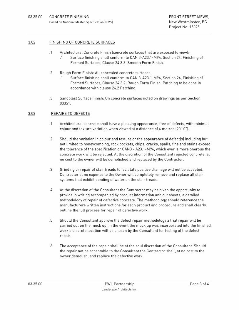
03 35 00 CONCRETE FINISHING FRONT STREET MEWS, Based on National Master Specification (NMS) New Westminster, BC Project No: 15025
03 35 00 PWL Partnership
Landscape Architects Inc. Page 3 of 4
3.02 FINISHING OF CONCRETE SURFACES .1 Architectural Concrete Finish (concrete surfaces that are exposed to view):
.1 Surface finishing shall conform to CAN 3-A23.1-M94, Section 24, Finishing of Formed Surfaces, Clause 24.3.3, Smooth Form Finish.
.2 Rough Form Finish: All concealed concrete surfaces.
.1 Surface finishing shall conform to CAN 3-A23.1-M94, Section 24, Finishing of Formed Surfaces, Clause 24.3.2, Rough Form Finish. Patching to be done in accordance with clause 24.2 Patching.
.3 Sandblast Surface Finish: On concrete surfaces noted on drawings as per Section
03351.
3.03 REPAIRS TO DEFECTS .1 Architectural concrete shall have a pleasing appearance, free of defects, with minimal
colour and texture variation when viewed at a distance of 6 metres (20’-0”).
.2 Should the variation in colour and texture or the appearance of defect(s) including but not limited to honeycombing, rock pockets, chips, cracks, spalls, fins and stains exceed the tolerance of the specification or CAN3 - A23.1-M94, which ever is more onerous the concrete work will be rejected. At the discretion of the Consultant rejected concrete, at no cost to the owner will be demolished and replaced by the Contractor.
.3 Grinding or repair of stair treads to facilitate positive drainage will not be accepted.
Contractor at no expense to the Owner will completely remove and replace all stair systems that exhibit ponding of water on the stair treads.
.4 At the discretion of the Consultant the Contractor may be given the opportunity to
provide in writing accompanied by product information and cut sheets, a detailed methodology of repair of defective concrete. The methodology should reference the manufacturers written instructions for each product and procedure and shall clearly outline the full process for repair of defective work.
.5 Should the Consultant approve the defect repair methodology a trial repair will be
carried out on the mock up. In the event the mock up was incorporated into the finished work a discrete location will be chosen by the Consultant for testing of the defect repair.
.6 The acceptance of the repair shall be at the soul discretion of the Consultant. Should
the repair not be acceptable to the Consultant the Contractor shall, at no cost to the owner demolish, and replace the defective work.

03 35 00 CONCRETE FINISHING FRONT STREET MEWS, Based on National Master Specification (NMS) New Westminster, BC Project No: 15025
03 35 00 PWL Partnership
Landscape Architects Inc. Page 4 of 4
3.04 APPLICATION OF ANTI GRAFFITI COATING
.1 Unless otherwise indicated in the specifications or on the contract drawings anti graffiti coating to be applied to all exposed vertical concrete surfaces.
.2 Surface preparation and application in strict accordance with the manufacturers
technical data and application instruction sheet.
3.05 PROECTION
.1 Protect architectural concrete from any damage by the elements and defacement of any nature during construction operation.
.2 All corners and surfaces subject to possible damage shall be suitably protected with
boards or hoardings. .3 The Contractor shall make adequate provision to keep all exposed concrete free from
laitance caused by spillage, leaking forms or other contaminants. In no event shall laitance be allowed to penetrate, stain or harden on surfaces that have been sandblasted.
.4 Adequate protection shall be given to all exposed reinforcing steel in architectural
concrete to prevent staining of surfaces of concrete due to rust and corrosion. If any rust or corrosion does occur it shall be removed immediately to avoid permanent staining.
3.06 CLEAN UP
.1 Rubbish, debris and demolition material resulting from work of this section shall be
collected regularly, removed from the project site and properly disposed. .2 Repair, remove and clean all drips or smears resulting from the work of this section on
exposed, finished surfaces or surfaces to be subsequently finished. END OF SECTION 03 35 00

03 35 10 ABRASIVE BLAST FINISH FRONT STREET MEWS, Based on National Master Specification (NMS) New Westminster, BC Project No: 15025
03 35 10 PWL Partnership Landscape Architects Inc.
Page 1 of 3
1.00 GENERAL 1.01 GENERAL REQUIREMENTS
.1 Refer to Division 1, General Requirements. .2 All Contract Documents form an integral part of this section.
1.02 DESCRIPTION
.1 Furnish labour, material, equipment and services necessary for abrasive blasting of
surfaces indicated on the construction drawings .2 The work shall include but is not limited to the following components:
.1 Concrete Walls and Cheek Walls
.2 Concrete Seat Walls and Steps
.3 Concrete Planters
.4 Concrete Banding
.5 Cast in Place Concrete Walks, and Miscellaneous Flat Work 1.03 RELATED WORK
.1 Shop Drawings, Product Data, Material Testing and Samples Section 01 33 00 .2 Cast In Place Concrete Pavement Section 32 13 13 .3 Concrete Finishing Section 03 35 00
1.04 QUALITY ASSURANCE
.1 All work and material shall conform to Chapter 9 of CPCA/MPDA Specification Manual (latest edition) and as herein specified.
.2 This Contractor shall have a record of satisfactory performance in the trade and shall
maintain a qualified crew of abrasive blasters throughout the duration of the work. 1.05 REQUIREMENTS OF REGULATORY AGENCIES
.1 Applicable Provincial, municipal regulations and environmental requirements shall be fully maintained during abrasive blasting operations.
.2 Worksafe BC safety regulations shall be strictly adhered to in all respects. Specific
emphasis shall be placed on monitoring and adhering to permissible noise levels and air borne particulate levels.
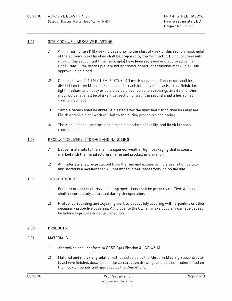
03 35 10 ABRASIVE BLAST FINISH FRONT STREET MEWS, Based on National Master Specification (NMS) New Westminster, BC Project No: 15025
03 35 10 PWL Partnership Landscape Architects Inc.
Page 2 of 3
1.06 SITE MOCK UP – ABRASIVE BLASTING .1 A minimum of ten (10) working days prior to the start of work of this section mock up(s)
of the abrasive blast finishes shall be prepared by the Contractor. Do not proceed with work of this section until the mock up(s) have been reviewed and approved by the Consultant. If the mock up(s) are not approved, construct additional mock up(s) until approval is obtained.
.2 Construct two (2) 1.8M x 1.8M (6’-0”x 6’-0”) mock up panels. Each panel shall be
divided into three (3) equal zones, one for each intensity of abrasive blast finish, i.e. light, medium and heavy or as indicated on construction drawings and details. One mock up panel shall be of a vertical section of wall, the second shall a horizontal concrete surface.
.3 Sample panels shall be abrasive blasted after the specified curing time has elapsed.
Finish abrasive blast work will follow the curing procedure and timing. .4 The mock up shall be stored on site as a standard of quality, and finish for each
component.
1.07 PRODUCT DELIVERY, STORAGE AND HANDLING
.1 Deliver materials to the site in unopened, weather tight packaging that is clearly marked with the manufacturers name and product information.
.2 All materials shall be protected from the rain and excessive moisture, sit on pallets
and stored in a location that will not impact other trades working on the site. 1.08 JOB CONDITIONS
.1 Equipment used in abrasive blasting operations shall be properly muffled. All dust shall be completely controlled during the operation.
.2 Protect surrounding and adjoining work by adequately covering with tarpaulins or other
necessary protective covering. At no cost to the Owner, make good any damage caused by failure to provide suitable protection.
2.00 PRODUCTS 2.01 MATERIALS
.1 Abbrasives shall conform to CGSB Specification 31-GP-421M. .2 Material and material gradation will be selected by the Abrasive blasting Subcontractor
to achieve finishes described in the construction drawings and details, implemented on the mock up panels and approved by the Consultant.

03 35 10 ABRASIVE BLAST FINISH FRONT STREET MEWS, Based on National Master Specification (NMS) New Westminster, BC Project No: 15025
03 35 10 PWL Partnership Landscape Architects Inc.
Page 3 of 3
3.00 EXECUTION 3.01 INSPECTION
.1 The Contractor shall inspect all surfaces to be abrasive blasted and report to the Consultant in writing any defects or elements that will hinder the completion of abrasive blast operations. Commencement of work indicates acceptance for the above condition.
.2 Prior to start of work of this section the Contract shall ensure that the Consultant has
reviewed and accepted all surfaces to be abrasive blasted. 3.02 FINISH
.1 Abrasive blasting finishes shall be light, medium and heavy abrasive blast finishes as called up on details and drawings. The exact finish of abrasive blast will be governed by matching samples reviewed by the Consultant.
.2 Refer to drawing for location, type and extent of abrasive blast finishes.
3.03 ABRASIVE BLAST OPERATION
.1 All abrasive blasting required on this project shall be carried out by the air-blasting method.
.2 Concrete shall have cured for a minimum of twenty one (21) days prior to abrasive
blasting. .3 Schedule abrasive blasting operations to ensure cure times match those of the
approved mock up panels. .4 Abrasive blasting operation shall yield uniform texture and colour to all surfaces. The
texture and colour shall match the approved mock up panels. 3.04 CLEAN UP
.1 During the progress of the work keep the premises free from any unnecessary accumulation of tools, equipment, surplus materials and debris.
.2 Upon completion of the work remove all excess materials and clean all surfaces.
END OF SECTION 03 35 10

32 13 13 CAST IN PLACE CONCRETE PAVEMENT FRONT STREET MEWS, Based on National Master Specification (NMS) New Westminster, BC Project No: 15025
32 13 13 PWL Partnership Landscape Architects Inc.
Page 1 of 6
1.00 GENERAL 1.01 GENERAL REQUIREMENTS
.1 Refer to Division 1, General Requirements. .2 All contract documents form an integral part of this section.
1.02 DESCRIPTION
.1 Work of this section refers to scope that is unique to the construction of Portland cement concrete walks. This section must be referenced to and interpreted simultaneously with all other sections pertinent to the works described herein.
1.03 RELATED WORK
.1 Concrete Finishing Section 03 35 00 2.00 PRODUCTS 2.01 MATERIALS
.1 Concrete mixes and materials: As per Section 03300 Cast in Place Concrete with the following criteria specific to this Section: Concrete
Slump 80mm, (3”), +/- 20mm, (3/4”) Air entrainment 5% to 8% (14-20mm aggregate) Maximum aggregate size 14mm (9/16”) Water to Cement ration (W/C) 0.45 max Minimum 28 day compressive strength 32Mpa Exposure Class C2
.2 Non-staining type form release agent: chemically active release agents containing
compounds that react with free lime to provide water-soluble soap. .3 Expansion Joint Material: 13mm (1/2”) Resilient, flexible, non-extruding, expansion-
contraction joint filler. Cellular fibers securely bonded together, uniformly saturated with asphalt. When compressed to half of original thickness, recover to a minimum of 70 percent of original thickness. Joint filler shall conform to ASTM D1751. Acceptable suppliers include by W R Meadows; or other pre approved equal.
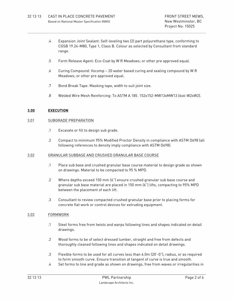
32 13 13 CAST IN PLACE CONCRETE PAVEMENT FRONT STREET MEWS, Based on National Master Specification (NMS) New Westminster, BC Project No: 15025
32 13 13 PWL Partnership Landscape Architects Inc.
Page 2 of 6
.4 Expansion Joint Sealant: Self-leveling two (2) part polyurethane type, conforming to CGSB 19.24-M80, Type 1, Class B. Colour as selected by Consultant from standard range.
.5 Form Release Agent: Eco-Coat by W R Meadows; or other pre approved equal. .6 Curing Compound: Vocomp – 20 water based curing and sealing compound by W R
Meadows; or other pre approved equal. .7 Bond Break Tape: Masking tape, width to suit joint size. .8 Welded Wire Mesh Reinforcing: To ASTM A 185. 152x152-MW13xMW13 (6x6-W2xW2).
3.00 EXECUTION 3.01 SUBGRADE PREPARATION
.1 Excavate or fill to design sub grade. .2 Compact to minimum 95% Modified Proctor Density in compliance with ASTM D698 (all
following references to density imply compliance with ASTM D698). 3.02 GRANULAR SUBBASE AND CRUSHED GRANULAR BASE COURSE
.1 Place sub base and crushed granular base course material to design grade as shown on drawings. Material to be compacted to 95 % MPD.
.2 Where depths exceed 150 mm (6”) ensure crushed granular sub base course and
granular sub base material are placed in 150 mm (6”) lifts, compacting to 95% MPD between the placement of each lift.
.3 Consultant to review compacted crushed granular base prior to placing forms for
concrete flat work or control devices for extruding equipment.
3.03 FORMWORK
.1 Steel forms free from twists and warps following lines and shapes indicated on detail drawings.
.2 Wood forms to be of select dressed lumber, straight and free from defects and
thoroughly cleaned following lines and shapes indicated on detail drawings. .3 Flexible forms to be used for all curves less than 6.0m (20’-0”), radius, or as required
to form smooth curve. Ensure transition at tangent of curve is true and smooth. .4 Set forms to line and grade as shown on drawings, free from waves or irregularities in

32 13 13 CAST IN PLACE CONCRETE PAVEMENT FRONT STREET MEWS, Based on National Master Specification (NMS) New Westminster, BC Project No: 15025
32 13 13 PWL Partnership Landscape Architects Inc.
Page 3 of 6
line or grade. .5 Set special forms as required around catch basins, manholes, poles or other objects as
shown on drawings. .6 Tolerances: Maximum horizontal deviation: 6mm (1/4”)
Maximum vertical deviation: 6mm (1/4”) Maximum deflection from horizontal or vertical alignment to be 6mm in 3m (1/4” in 10’-0”)
.7 Adequately brace forms to maintain specified tolerances after concrete is placed. .8 Apply form release agent in strict accordance with manufacturer’s written instructions.
3.04 WELDED WIRE MESH
.1 Place mesh over compacted granular material to form a continuous mat.
.1 Hold mesh back 50mm (2”) from the exposed edge of the concrete slab.
.2 Tie mesh sheets together with reinforcing wire at each cell.
.3 Provide non porous spacer support under mesh at sufficient spacing to ensure that the mesh placement in the concrete provides; 50mm (2”) of cover over the top of the mesh and 75mm (3”) of cover under the mesh. Pulling mesh up during the concrete pour is not acceptable.
3.05 INSPECTION
.1 Notify Consultant a minimum of twenty four hours in advance of concrete placement
for review of formwork. Consultant review to include but is not limited to: .1 Forms are properly set at required horizontal and vertical alignment, .2 Forms are sufficiently rigid, .3 Forms are clean and ready for placement of concrete.
3.06 CONCRETE PLACEMENT
.1 Place concrete to Section 03300 Cast in Place Concrete and the following criteria specific to this Section.
.2 Do not place concrete during rain or on wet or frozen base. .3 Do not place concrete when air temperature appears likely to fall below 5 degrees
Celsius (41 degrees F) within 24 hours, unless specified precautions are taken. Provide consultant with written construction process of concrete placement for work undertaken in these conditions.
.4 Schedule concrete placement to ensure sufficient daylight hours available to permit
edging and finishing.

32 13 13 CAST IN PLACE CONCRETE PAVEMENT FRONT STREET MEWS, Based on National Master Specification (NMS) New Westminster, BC Project No: 15025
32 13 13 PWL Partnership Landscape Architects Inc.
Page 4 of 6
.5 Moisten crushed granular base immediately prior to placing concrete. .6 Place concrete within 1.5 hours of batching time. .7 Place concrete in forms, ensuring no segregation of aggregate and consolidate with
approved mechanical vibrator or power screed. .8 Concrete to be placed in continuous operation until entire panel or section competed.
Do note place fresh concrete that has achieved partial set. .9 Incorporate all castings into concrete at time of placement. .10 Discontinue placement at expansion, construction or isolation joints only.
3.07 EXPANSION JOINTS
.1 Form transverse expansion joints at both end of curb returns and at a maximum spacing of 10m for sidewalks, at each end of driveway crossings and at tangent points on circular walk.
.2 Extend through full depth of concrete and terminate 12 mm (1/2”) below finished
surface to allow for approved sealant. Apply bond break tape before applying sealant.
3.08 CONTROL JOINTS
.1 In sidewalks: construct control joints at maximum 1.5m (5’-0”) intervals or to lines and patterns indicated on drawings.
.2 Construct to minimum 1/4 depth of concrete section at point of cut or as otherwise
shown on project details.
3.09 ISOLATION JOINTS
.1 Form isolation joints around all poles, hydrants, manholes and all structures or fixed objects located within the concrete section by using approved expansion joint material.
.2 Form longitudinal isolation joints between sidewalk and abutting curb and gutter,
abutting utility strips, abutting structures using expansion joint material. .3 Use expansion joint material to form isolation joints between sidewalks and abutting
walls and structures.
3.10 FINISHING
.1 Pre finish surface of concrete sidewalks and utility strips to smooth surface with

32 13 13 CAST IN PLACE CONCRETE PAVEMENT FRONT STREET MEWS, Based on National Master Specification (NMS) New Westminster, BC Project No: 15025
32 13 13 PWL Partnership Landscape Architects Inc.
Page 5 of 6
magnesium or wood float trowel. .2 Unless otherwise noted on the drawings or details the concrete finish shall be light
broom finish, perpendicular to the path of travel or as directed by the Consultant to match adjacent finish.
.3 Grooves, scoring or saw cutting used for aesthetic purposes as shown on the drawings
or as directed by Consultant, to be marked with proper tools or saw cut to depths shown on drawings.
.4 Finish driveway crossing, curb let downs and wheel chair ramps as shown on detail
drawings. .5 Round edges with steel edging tool to a width of 50mm (2”) around perimeter of each
panel or as shown and described on drawings. .6 Under no circumstances is concrete to be overworked by troweling, dusted with dry
cement or finished with a mortar coat. .7 Finished surface to be as specified and to satisfaction of Consultant.
3.11 PROTECTION
.1 Protect freshly finished concrete from dust, rain or frost by using tarpaulins or other suitable protective coverings. Keep clear of finished surface.
.2 Place and maintain suitable barriers to protect finished concrete from equipment,
vehicles or pedestrian traffic. .3 Provide personnel, as required, to prevent vandalism until concrete has set. .4 Do not run vehicles or construction equipment on concrete for at least 7 days or as
directed by Consultant. 3.12 CURING
.1 Apply approved curing compound to all exposed concrete surfaces at rate
recommended by manufacturer or alternatively, use moist curing procedures for a minimum of 7 days.
.2 When temperature is below 5 degrees Celsius (41 degrees F) maintain all concrete at
temperatures not less than 10 degrees Celsius (50 degrees F) for at least 72 hours. .3 Protect from freezing for at least another 72 hours or such time, as required, to ensure
proper curing of concrete. Admixtures are not be used for prevention of freezing.

32 13 13 CAST IN PLACE CONCRETE PAVEMENT FRONT STREET MEWS, Based on National Master Specification (NMS) New Westminster, BC Project No: 15025
32 13 13 PWL Partnership Landscape Architects Inc.
Page 6 of 6
3.13 ACCEPTANCE
.1 Prior to acceptance of finished concrete the following conditions will be met; .1 Consultant shall have reviewed concrete batch design and test results provided
by the contractor. .2 Concrete shall have full 28-day cure. .3 All irregular, cracked or otherwise defective sections to be removed and
replaced to satisfaction of Consultant. The extent of removal will be at a minimum to the nearest joint.
.4 All stains, marks and discolouration as a result of spills or drips shall have been removed.
3.14 CLEAN UP
.1 Promptly, as the work proceeds and on completion, clean up and remove from the site
any debris, waste material and rubbish resulting from work of this section.
END OF SECTION 32 13 13

32 14 40 STONE SETT PAVING FRONT STREET MEWS, Based on National Master Specification (NMS) New Westminster, BC Project No: 15025
32 14 40 PWL Partnership Landscape Architects Inc.
Page 1 of 5
1.00 GENERAL 1.01 GENERAL REQUIREMENTS
.1 Refer to Division 1, General Requirements .2 All contract documents form an integral part of this section.
1.02 DESCRIPTION
.1 Furnish all labour, materials, equipment and services necessary for the delivery to site, cleaning, preparation and installation of exterior stone sett paving as indicated as specified.
.2 The work of this section shall include, but shall not necessarily be limited to the
cleaning preparation and installation of the following: .1 Exterior stone pavers. .2 All setting beds, and accessories required to complete paver installations.
1.03 QUALIFICATIONS
.1 The Subcontractor executing the work of this section shall have at least five (5) years’ experience in work of similar scope and nature to that indicated and specified.
.2 All stone paving work shall be done by an experienced Stone Subcontractor, employing
skilled stone masons.
1.04 SUBMITTALS
.1 Submit to the Consultant two (2) samples of each type of stone with specific stone finish required in the work of this contract. Sample sizes shall match unit size of specified material. All samples shall be identified as to type, unit size, and date.
.2 Submit to the Consultant documentation of delivery dates so as to indicate the correct
material will be delivered to the site as per required schedule. .3 Failure of on-site work to match approved samples will be cause for rejection of work.
The Subcontractor will be required to expedite replacement of all rejected work and make good at no additional cost to the Owner.
1.05 ON SITE MOCK-UP
.1 Construct a 1 square Metre (10 square feet) sample mock-up of stone paving on site for review by the Consultant and the appointed inspection agency. Sample mock–up shall include all joint types, finishes and surface coatings as per drawings and specifications. The Consultant will approve the mock-up before the balance of the work of this section

32 14 40 STONE SETT PAVING FRONT STREET MEWS, Based on National Master Specification (NMS) New Westminster, BC Project No: 15025
32 14 40 PWL Partnership Landscape Architects Inc.
Page 2 of 5
proceeds. The approved mock-up shall form the basis of acceptable quality required for the remainder of the stone paving.
.2 The approved mock-up shall form part of finished work.
1.06 PRODUCT DELIVERY, STORAGE AND HANDLING
.1 Deliver all specified stone to the job site. .2 Remove from the job site immediately all damaged or broken stone pavers caused by
improper handling or storage. 1.07 JOB CONDITIONS
.1 Inspect all substrate surfaces to receive stone paving. Report any unsatisfactory conditions to the Consultant. Start of work shall imply acceptance.
.2 Check all surfaces ready to receive pavers; all level, plumb, smooth, firm, free from
loose particles, droppings, projections and other foreign matter and from other unsuitable conditions.
.3 Protect adjacent surfaces until work under this section has been completed. .4 Protect work of other trades as necessary from damage resulting from work of this
trade. .5 Make good such damage, if any, at no additional cost to the contract.
2.00 PRODUCTS 2.01 ASSOCIATED MATERIALS
.41 Granular Base: The 19 mm (3/4”) crushed granular base course shall consist of sound, durable particles, free from clay, organic material or other deleterious matter, evenly graded, to meet the following gradation requirements.
Sieve Size (mm) Percent
Passing 19 100
12.5 75-100 9.5 60-90
4.75 40-70 2.36 27-55 1.18 16-42 0.60 8-30

32 14 40 STONE SETT PAVING FRONT STREET MEWS, Based on National Master Specification (NMS) New Westminster, BC Project No: 15025
32 14 40 PWL Partnership Landscape Architects Inc.
Page 3 of 5
0.30 5-20 0.075 2-8
.2 Sand Setting Bed: shall be sand free of deleterious soluble salts and other
contaminants, which may cause efflorescence and comply with ASTM, C33, CAN/CSA A231.1-M9-0. Use as noted on Contract Documents:
Sieve Size (mm) Percent Passing
10mm 100 5mm 95-100
2.5mm 80–100 1.25mm 50-90 .630mm 25-65 .315mm 10-35 .160mm 2-10
.3 Clear Crushed Open-graded Bedding Course: shall be sand free of deleterious soluble
salts and other contaminants, which may cause efflorescence and comply with ASTM, C33, ASTM D 448 No. 8 CAN/CSA A231.1-M9-0. Use as noted on Contract Documents:
Sieve Size (mm) Percent Passing 12.5mm 100 9.5mm 85-100
4.75mm 10–30 2.36mm 0-10 1.16mm 0-5
.4 Polymeric Jointing Sand: Consisting of Graded Sand meeting ASTM-144 Standard and
Polymeric Binder. Approved Type: Techniseal HP2 Polymeric Sand. Provide Cutsheet submittal. Install
under dry conditions s per manufacturer’s instructions. 5. Joint Stabilizer: Pre-bagged AquaPave® Engineered Joint Stabilizer as supplied by: Abbotsford Concrete Products Phone: 1-800-663-4091
2.02 STONE PAVING
.1 Stone: All stone shall be of sound stock and uniform texture, and shall be free from holes, seams, shake, clay pockets, spills, stains, starts and other defects which will impair the strength durability and appearance of the work to the following standards;
• Absorption by Weight ASTM C97 0.15% • Density ASTM C97 2,660 Kg/cubic Metre (165.8 lbs/cu foot) • Compressive Strength ASTM C170 186 Mpa (354,943 psi) • Modulus of Rupture ASTM C99 14.1 Mpa (26,907 psi)

32 14 40 STONE SETT PAVING FRONT STREET MEWS, Based on National Master Specification (NMS) New Westminster, BC Project No: 15025
32 14 40 PWL Partnership Landscape Architects Inc.
Page 4 of 5
Approved Types: Refer to Paving Legend on Landscape drawings for the approved stone paver types, sizes, patterns, finish and supplier.
.2 Finish Types: Flamed and Thermal finish refers to application of high temperature
flame to surface area. For the purpose of this specification Thermal finish shall have a higher degree of surface variation and rustication as a result of the application of high temperature flame.
3.00 EXECUTION 3.01 INSPECTION .1 Contractor shall examine all areas of work to receive precast concrete pavers and
report any unsatisfactory conditions to Consultant. Commencement of work shall imply acceptance of conditions.
3.02 SUBGRADE PREPARATION AND CRUSHED GRANULAR BASE COURSE – ON GRADE
.1 Sub grade Preparation; excavate or fill to design sub grade elevations. Compact to 95% MPD. Consultant to review sub grade preparation prior to Contractor proceeding with placement of crushed granular base course.
.2 Place granular base over compacted sub grade to depths indicated on Contract
Documents. .3 Placement of granular base shall be in 150mm (6”) lifts. Each lift shall be compacted to
95% MPD. .4 Final grades of compacted granular base shall be to elevations indicated on Contract
drawings. Ensure finished grade of crushed granular base course does not exceed 10mm (3/8”) of finished grade less combined thickness of setting bed and thickness of precast concrete paver.
.5 Consultant to review completed installation of granular base course prior to placement
of setting bed.
3.03 SETTING BED
.1 Place setting bed material evenly over an area that does not exceed the amount of precast concrete paver work that can be completed in one day.
.2 Do not use setting bed material to correct variations in the granular base. .3 Screed setting bed to lines and level noted on Contract Documents. Ensure depths of
setting bed fall within the minimum and maximum depths indicated on details.

32 14 40 STONE SETT PAVING FRONT STREET MEWS, Based on National Master Specification (NMS) New Westminster, BC Project No: 15025
32 14 40 PWL Partnership Landscape Architects Inc.
Page 5 of 5
.4 Do not be disturb screed and leveled setting bed. Protect against accidental pre-compaction and rain. Areas that have been disturbed, rained on or accidentally compacted shall be re screed and leveled.
3.04 STONE PAVING INSTALLATION
.1 Saw cut and drill stone pavers for proper fitting without marring pavers. .2 Stone pavers shall be evenly pitched to form run-offs to drains at slopes indicated on
Contract drawings. Areas that exhibit pooling, ponding or water retention will be rejected and remedied at the Contractor’s expense.
.3 Install stone pavers to pattern indicated on the Contract drawings. .4 Stone paving shall have joints as indicated on contract documents. .5 Install Setts true and flush within lippage tolerances as per the Interlocking Concrete
Pavement Institute (ICPI). 6. Joints and pavers to be installed straight and true.
3.05 ADJUST AND CLEAN
.1 On completion, check work and replace defective, upset or misaligned pavers. .3 Remove all haze, stains, dirt, excess mortar, and defacements as found on all stone.
3.06 CLEAN UP
.1 At completion, remove all debris, tools and equipment as directed from the premises.
END OF SECTION 32 14 40

32 31 13 CHAIN LINK FENCE FRONT STREET MEWS, Based on National Master Specification (NMS) New Westminster, BC Project No: 15025
32 31 13
PWL Partnership Landscape Architects Inc.
Page 1 of 5
1.00 GENERAL 1.01 GENERAL REQUIREMENTS
.1 Refer to Division 1, General Requirements. .2 All contract documents form an integral part of this section.
1.02 DESCRIPTION
.1 Furnish all labour, materials, equipment and services necessary for the complete installation of the all weld construction galvanized chain link fence system to City of New Westminster Parks Standards as indicated in the Contract documents. The work includes but is not limited to supply and installation of;
.1 Fusion bonded vinyl woven metal mesh fabric.
.2 Field welding of post, rail connection.
.3 Priming and painting of all exposed, uncoated galvanized metal components.
.4 Excavation and placement of concrete footings for all posts
1.03 RELATED WORK
.1 Shop Drawings, Product Data, Material Testing and Samples Section 01 33 00 1.04 SUBMITTALS
.1 Provide shop drawings of all fence and gate components illustrating post spacing, footing design, gate locations, assembly details and general arrangement of all components for complete installation. Provide product data that includes gauge of metal wire and mesh, post wall thickness, conformation of fusion bonded vinyl mesh,
.2 Samples:
.1 300mm x 300mm (12”x12”) sample of the fusion bonded vinyl chain link fabric.
.2 Paint colour chip and manufacturers colour code number matching mesh colour.
.3 Product data sheets confirming galvanized metal specifications. 1.05 REFERENCE STANDARDS
.1 CAN-138.1-M80 Fence, chain link, fabric, ASTM – F668 Class 2B thermally fused vinly coated steel fabric
.2 CAN/CGSB-138.2-M80 Fence, chain link, fabric, framework, zinc-coated, steel
.3 CAN/ CGSB -138.3-M80 Fence, chain link, fabric - installation
.4 CAN/ CGSB -138.4-M80 Fence, chain link, gates
.5 CAN/ CGSB –1.181-92 Ready-mixed organic zinc-rich coating
.6 CAN/CSA-G164-M92 Hot dipped galvanizing of irregularly shaped articles
.7 CAN3-A23.1-M90 Cast-in-place concrete work shall be in accordance with.
.8 CAN3-A23.2-M90 Materials and concrete testing in accordance with

32 31 13 CHAIN LINK FENCE FRONT STREET MEWS, Based on National Master Specification (NMS) New Westminster, BC Project No: 15025
32 31 13
PWL Partnership Landscape Architects Inc.
Page 2 of 5
1.05 PRODUCT DELIVERY, STORAGE AND HANDLING
.1 Store packaged material in original containers with all manufacturer’s seals and labeling intact.
.2 Prevent damage to materials during handling and storage. Keep materials under cover and
free from moisture. 1.06 APPROVED EQUALS
.1 All items as specified or pre-approved equals. 2.00 PRODUCTS 2.01 MATERIALS
.1 All pipe, woven mesh, tie wires, tension wires and bands, connectors, fittings and hardware to be hot-dipped galvanized.
.2 Pipe: to CAN2-138.2 M80, Table 1 Medium Duty, Schedule 40 (wall thicknesses as shown
below), standard continuous weld, modulus of elasticity 30,000.
Outside Pipe Diameter Schedule 40 Wall Thickness 1-5/8" 0.140" (9/64") 1-7/8" 0.145" (19/128") 2-3/8" 0.154" (5/32") 2-7/8" 0.203" (13/64") 3-1/2" 0.216" (7/32") 4-1/2" 0.237" (15/64")
.3 Fusion Bonded Vinyl Woven Metal Mesh Fabric;
.1 To CAN2-138.1.M80, 6 guage, 4.88mm (0.1920") with 45mm (1-3/4") openings. Top and bottom selvedges to have knuckled finish.
.2 Fusion bonded vinyl coating to ASTM – F668 Class 2B, 7-10mil coating thickness. Vinyl coating shall have specific gravity of minimum 1.30, ASTM D792. Hardness of vinyl coating A-93-3, ASTM D2240
.3 Colour: Black
.4 Fence Component Sizes Note: pipe sizes shown are outside diameter.
Fence Component Size (1.2M (4’-0”) Ht) Size (1.5M (5’-0”) and
Taller Ht.) Bottom Rail 50mm (1-7/8") 63mm (2-1/2") Mid Rails 63mm (2-1/2") 63mm (2-1/2") Top Rail 50mm (1-7/8") 75mm (2-7/8")

32 31 13 CHAIN LINK FENCE FRONT STREET MEWS, Based on National Master Specification (NMS) New Westminster, BC Project No: 15025
32 31 13
PWL Partnership Landscape Architects Inc.
Page 3 of 5
Line Posts 75mm (2-7/8") 75mm (2-7/8") End/Man Gate Posts 75mm (2-7/8") 75mm (2-7/8") Vehicular Gate Posts 89mm (3-1/2") 89mm (3-1/2") Mid Brace 50mm (1-7/8") 63mm (2-1/2") Tie Wire Spacing 150mm (6") o.c 150mm (6") o.c Hog Ring Spacing 100mm (4”) o.c. 100mm (4”) o.c. Tack Welds Where Specified All tension bands and
frame members All tension bands and frame members
.5 Tension Bar: 16 x 5mm (3/4" x 3/16"), length to match entire height of fabric section. .6 Tie Wire: 3.55mm (9 gauge) galvanized. .7 Bottom Tension Wire: tension wire is not acceptable, provide pipe rail as per ‘Fence
Component Size’ chart. .8 Concrete: to CSA CAN3-A 23. 1-M90 and A23.3.
.1 Type 10 Cement.
.2 Compressive strength 32 Mpa minimum at 28 days.
.3 Coarse aggregate nominal size 19 mm (3/4”).
.4 Admixture for Air entrainment: 5% +/- 1%.
.5 Slump at time and point of discharge (19 mm to 75 mm) (3/4” to 3”). .9 Galvanizing Touch Up: zinc rich (minimum 96% zinc) paint or powder aerosl spray. Acceptable
products include Zinga and Zingaspray as supplied by Zinga – USA (www.zinga-usa.com) or pre approved equal.
.10 Post Caps: Cone type galvanized steel or cast aluminum alloy designed to fit snugly over
posts and exclude moisture. 3.00 EXECUTION 3.01 POST SPACING
.1 Maximum post spacing 3Metres (10’-0”) on centre. Unless otherwise indicated in Contract documents set end posts in straight and true alignments. Line posts spacing shall be field adjusted to ensure equal spacing between end posts. Set all end, line and gate posts vertical and plumb in concrete footings.
3.02 CONCRETE FOOTINGS
.1 Unless otherwise detailed the minimum footing dimensions shall be 1200mm (4’-0”) deep, footing diameter, 150mm (6”) larger than outside post diameter, post depth embedment in footing, 75mm (3”) from bottom of footing.
.2 Posts shall be installed in concrete footings prior to installation and welding of top and
bottom rail.
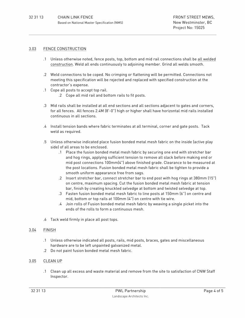
32 31 13 CHAIN LINK FENCE FRONT STREET MEWS, Based on National Master Specification (NMS) New Westminster, BC Project No: 15025
32 31 13
PWL Partnership Landscape Architects Inc.
Page 4 of 5
3.03 FENCE CONSTRUCTION
.1 Unless otherwise noted, fence posts, top, bottom and mid rail connections shall be all welded construction. Weld all ends continuously to adjoining member. Grind all welds smooth.
.2 Weld connections to be coped. No crimping or flattening will be permitted. Connections not
meeting this specification will be rejected and replaced with specified construction at the contractor’s expense.
.1 Cope all posts to accept top rail. .2 Cope all mid rail and bottom rails to fit posts.
.3 Mid rails shall be installed at all end sections and all sections adjacent to gates and corners,
for all fences. All fences 2.4M (8'-0”) high or higher shall have horizontal mid rails installed continuous in all sections.
.4 Install tension bands where fabric terminates at all terminal, corner and gate posts. Tack
weld as required.
.5 Unless otherwise indicated place fusion bonded metal mesh fabric on the inside (active play side) of all areas to be enclosed.
.1 Place the fusion bonded metal mesh fabric by securing one end with stretcher bar and hog rings, applying sufficient tension to remove all slack before making end or mid post connections 100mm(4") above finished grade. Clearance to be measured at the post locations. Fusion bonded metal mesh fabric shall be tighten to provide a smooth uniform appearance free from sags.
.2 Insert stretcher bar, connect stretcher bar to end post with hog rings at 380mm (15") on centre, maximum spacing. Cut the fusion bonded metal mesh fabric at tension bar, finish by creating knuckled selvedge at bottom and twisted selvedge at top.
.3 Fasten fusion bonded metal mesh fabric to line posts at 150mm (6”) on centre and mid, bottom or top rails at 100mm (4") on centre with tie wire.
.4 Join rolls of Fusion bonded metal mesh fabric by weaving a single picket into the ends of the rolls to form a continuous mesh.
.6 Tack weld firmly in place all post tops.
3.04 FINISH
.1 Unless otherwise indicated all posts, rails, mid posts, braces, gates and miscellaneous hardware are to be left unpainted galvanized metal.
.2 Do not paint fusion bonded metal mesh fabric.
3.05 CLEAN UP
.1 Clean up all excess and waste material and remove from the site to satisfaction of CNW Staff Inspector.

32 31 13 CHAIN LINK FENCE FRONT STREET MEWS, Based on National Master Specification (NMS) New Westminster, BC Project No: 15025
32 31 13
PWL Partnership Landscape Architects Inc.
Page 5 of 5
END OF SECTION 32 31 13

32 91 13 GROWING MEDIUM PREPARATION & PLACEMENT FRONT STREET MEWS, Based on National Master Specification (NMS) New Westminster, BC Project No: 15025
32 91 13 PWL Partnership Landscape Architects Inc.
Page 1 of 10
1.00 GENERAL 1.01 GENERAL REQUIREMENTS
.1 Refer to Division 1, General Requirements .2 All contract documents form an integral part of this section.
1.02 DESCRIPTION
.1 Furnish all labour, materials, equipment, and services necessary to mix, supply and install Growing Medium for landscape areas and planters shown on the drawings and as specified herein. This section does not include urban agriculture beds or sustainable roof landscape.
.2 The work shall include but is not limited to:
.1 Planting areas and planter pots. 1.03 RELATED WORK
.1 Planting Section 32 93 00
1.04 REFERENCE STANDARDS
.1 BC Landscape Standard, Current Edition. .2 BC Organic Matter Recycling Regulation’s (OMRR) “Biosolids Growing Medium”
standards. http://www.bclaws.ca/EPLibraries/bclaws_new/document/ID/freeside/18_2002
1.05 TESTING
.1 Submit to the Consultant one (1) copy of the growing medium analysis for each growing medium type from a laboratory approved by the consultant. Acceptable laboratories include; Benchmark Laboratories Nanaimo, Ltd. Nanaimo, BC (250-585-2555), Pacific Soil Analysis Inc., Richmond, BC (604.273.8226) or preapproved equal.
.2 The analysis shall be of tests done on the proposed growing medium from samples
taken at the supply source within three weeks immediately prior to growing medium placement.
.3 Cost of initial analysis and subsequent tests to ensure compliance with specification
shall be borne by the contractor. Test results shall be provided to the Consultant for review PRIOR TO any growing medium delivery to site.
.4 The analysis will include measurement of;
.1 Percent sand, fines, (silt and clay),

32 91 13 GROWING MEDIUM PREPARATION & PLACEMENT FRONT STREET MEWS, Based on National Master Specification (NMS) New Westminster, BC Project No: 15025
32 91 13 PWL Partnership Landscape Architects Inc.
Page 2 of 10
.2 Organic matter to total 100%,
.3 pH as per ASTM D4972 Standard Test Method for pH Soils,
.4 Water soluble salts,
.5 Total carbon to total nitrogen ratio,
.6 Total nitrogen and available levels of phosphorus, potassium, calcium and magnesium.
.5 At the discretion of the consultant submit up to two (2) additional samples at intervals
outlined by consultant of growing medium taken from material delivered to site. Samples shall be taken from a minimum of three (3) random locations and mixed to create a single uniform sample for testing. Results of these tests shall be presented to the Consultant for review.
.6 Biosolids Data Submission: .1 Test Reports:
.1 Submit to the Consultant confirmation that monthly testing at a Qualified Laboratory indicates conformance with BC Organic Matter Recycling Regulation’s (OMRR) “Biosolids Growing Medium” standards for biosolid material at the source.
.2 Submit to the Consultant confirmation that a Qualified Professional (as defined by OMRR) has carried out annual reviews of the process and testing of to ensure compliance with BC Organic Matter Recycling Regulation’s (OMRR) “Biosolids Growing Medium” standards;
.7 Rejection of Growing Medium: Failure to satisfy these contractual requirements will
result in the Contractor being required to remove and dispose of unacceptable growing medium from the construction site and at no expense to the Owner. The Contractor will be fully responsible for the supply and testing of the replacement-growing medium at no expense to the Owner.
1.06 SAMPLES
.1 Samples of each growing medium type (e.g. lawn versus tree/ shrub planting area)
shall be submitted to the testing lab and the Consultant in zip lock plastic bags clearly marked with the date, project name, sample name and supplier name and telephone number.
.2 Growing Medium Sample: One composite sample. Sample shall be a composite of at
least three equal sized samplings from the proposed source, and shall be at least one (1) litre in volume.
.3 Organic Material: One composite sample or each organic material type. Sample shall
be a composite of at least three equal sized samplings from the proposed source, and shall be at least one (1) litre in volume. Submit to Consultant only. Upon review by the Consultant the Contractor may be requested to provide an organic material sample to the testing laboratory.

32 91 13 GROWING MEDIUM PREPARATION & PLACEMENT FRONT STREET MEWS, Based on National Master Specification (NMS) New Westminster, BC Project No: 15025
32 91 13 PWL Partnership Landscape Architects Inc.
Page 3 of 10
1.07 QUALITY CONTROL
.1 Carry out growing medium preparation and placement such that the final product matches the standard established by the approved sample test results. At the discretion and written instructions of the Consultant apply amendments as recommended by the testing laboratory.
1.08 PRODUCT HANDLING
.1 Do not move or work growing medium or additives when they are excessively wet, extremely dry, frozen or in any manner which will adversely affect growing medium structure. Growing medium whose structure has been destroyed by handling under these conditions will be rejected and shall be replaced by the contractor at no cost to the owner.
.2 Protect growing medium and additives against extreme wetting by rain or other agents,
and against contamination by weeds and insects. .3 Deliver fertilizer and other chemicals in manufacturer’s original containers. Protect
against damage and moisture until incorporated into the work. .4 All growing medium will be delivered to site premixed from a recognized growing
medium source ensuring consistency throughout the mix. 2.00 PRODUCTS 2.01 MATERIALS
.1 Fertilizer: Complete commercial synthetic slow release fertilizer meeting the
requirements of the Canada Fertilizer Act, packed in water proof containers, clearly marked with the name of the manufacture, weight and analysis. Formulation ratio: As per the recommendation provided in the growing medium analysis.
.2 Lime: Unless otherwise noted in the growing medium analysis or directed by
Consultant lime shall be coarse, ground dolomite limestone containing minimum 85% of total carbonates.
.3 Organic Material:
.1 Shall be derived from an organic source free of contaminants, animal or plant chemical additives or supplements.
.2 The material shall be fully composted material that does not contain cedar or redwood bark or wood, black/brown in colour.
.3 Landscape growing medium containing biosolids shall meet the BC Organic Matter Recycling Regulation’s (OMRR) “Biosolids Growing Medium” standards.
.4 Acceptable suppliers include but are not limited to; Veratec, Chilliwack, BC (Formerly Yardworks Supply Ltd), Harvest Power Canada Ltd. – British Columbia (Formerly Fraser Richmond Soil and Fibre Ltd.), Richmond, B.C.
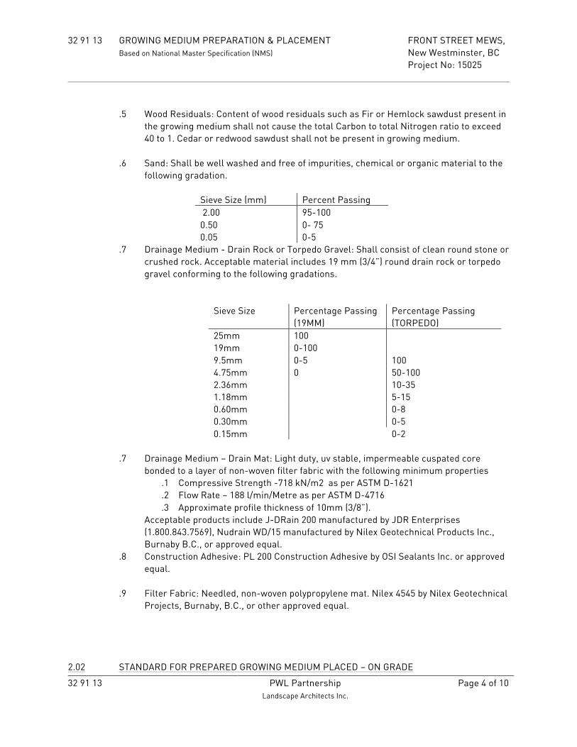
32 91 13 GROWING MEDIUM PREPARATION & PLACEMENT FRONT STREET MEWS, Based on National Master Specification (NMS) New Westminster, BC Project No: 15025
32 91 13 PWL Partnership Landscape Architects Inc.
Page 4 of 10
.5 Wood Residuals: Content of wood residuals such as Fir or Hemlock sawdust present in
the growing medium shall not cause the total Carbon to total Nitrogen ratio to exceed 40 to 1. Cedar or redwood sawdust shall not be present in growing medium.
.6 Sand: Shall be well washed and free of impurities, chemical or organic material to the
following gradation.
Sieve Size (mm) Percent Passing 2.00 95-100 0.50 0- 75 0.05 0-5
.7 Drainage Medium - Drain Rock or Torpedo Gravel: Shall consist of clean round stone or crushed rock. Acceptable material includes 19 mm (3/4”) round drain rock or torpedo gravel conforming to the following gradations.
Sieve Size Percentage Passing (19MM)
Percentage Passing (TORPEDO)
25mm 100 19mm 0-100 9.5mm 0-5 100 4.75mm 0 50-100 2.36mm 10-35 1.18mm 5-15 0.60mm 0-8 0.30mm 0-5 0.15mm 0-2
.7 Drainage Medium – Drain Mat: Light duty, uv stable, impermeable cuspated core
bonded to a layer of non-woven filter fabric with the following minimum properties .1 Compressive Strength -718 kN/m2 as per ASTM D-1621 .2 Flow Rate – 188 l/min/Metre as per ASTM D-4716 .3 Approximate profile thickness of 10mm (3/8”).
Acceptable products include J-DRain 200 manufactured by JDR Enterprises (1.800.843.7569), Nudrain WD/15 manufactured by Nilex Geotechnical Products Inc., Burnaby B.C., or approved equal.
.8 Construction Adhesive: PL 200 Construction Adhesive by OSI Sealants Inc. or approved equal.
.9 Filter Fabric: Needled, non-woven polypropylene mat. Nilex 4545 by Nilex Geotechnical
Projects, Burnaby, B.C., or other approved equal.
2.02 STANDARD FOR PREPARED GROWING MEDIUM PLACED – ON GRADE

32 91 13 GROWING MEDIUM PREPARATION & PLACEMENT FRONT STREET MEWS, Based on National Master Specification (NMS) New Westminster, BC Project No: 15025
32 91 13 PWL Partnership Landscape Architects Inc.
Page 5 of 10
.1 Growing Medium Composition – ON GRADE
% Dry Weight of Total Growing Medium Particle Size Class and Properties
Imported Growing Medium Grass Areas
Imported Growing Medium Planting Areas
Acidity (pH) 6.0 – 7.0 4.5 – 6.5 Salinity (E.C) Maximum saturation extract conductivity
3.0 millimhos/cm at 25 degrees C
3.0 millimhos/cm at 25 degrees C
All Gravel (2mm to 40mm)
0-5% 0-5%
Coarse Gravel (19mm to 40mm)
0-1% 0-1%
Sand (larger than 0.05mm and smaller than 2 mm
70-90% 50-80%
Silt (larger than 0.002mm and smaller than 0.05 mm)
0-15% 10-20%
Clay (smaller than .002 mm)
0-15% 0-15%
% Dry Weight of Growing Medium Excluding Gravel
Fines Maximum Clay and Silt Combined
15% 25%
Organic Content (OM) 3-5% 10-20% Carbon Nitrogen Ratio (C/N)
Maximum 40:1 Maximum 40:1
.2 Micronutrients – All growing medium types Total Nitrogen (N) 0.2% - 0.6% Available Phosphorus (P) 20 – 500ppm Available Potassium (K) 50 -1000 ppm Available Sodium (Na) (SAR) (SAR) not to exceed
8.0
.3 Drainage: Percolation shall be such that no standing water is visible 60 minutes after at least 10 minutes of moderate to heavy rain or irrigation.
2.02 STANDARD FOR PREPARED GROWING MEDIUM PLACED - ON SLAB
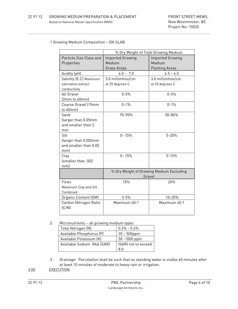
32 91 13 GROWING MEDIUM PREPARATION & PLACEMENT FRONT STREET MEWS, Based on National Master Specification (NMS) New Westminster, BC Project No: 15025
32 91 13 PWL Partnership Landscape Architects Inc.
Page 6 of 10
.1 Growing Medium Composition – ON SLAB
% Dry Weight of Total Growing Medium Particle Size Class and Properties
Imported Growing Medium Grass Areas
Imported Growing Medium Planting Areas
Acidity (pH) 6.0 – 7.0 4.5 – 6.5 Salinity (E.C) Maximum saturation extract conductivity
3.0 millimhos/cm at 25 degrees C
3.0 millimhos/cm at 25 degrees C
All Gravel (2mm to 40mm)
0-5% 0-5%
Coarse Gravel (19mm to 40mm)
0-1% 0-1%
Sand (larger than 0.05mm and smaller than 2 mm
70-90% 50-80%
Silt (larger than 0.002mm and smaller than 0.05 mm)
0- 15% 5-20%
Clay (smaller than .002 mm)
0- 15% 0-15%
% Dry Weight of Growing Medium Excluding Gravel
Fines Maximum Clay and Silt Combined
15% 20%
Organic Content (OM) 3-5% 10-20% Carbon Nitrogen Ratio (C/N)
Maximum 40:1 Maximum 40:1
.2 Micronutrients – all growing medium types
Total Nitrogen (N) 0.2% - 0.6% Available Phosphorus (P) 20 – 500ppm Available Potassium (K) 50 -1000 ppm Available Sodium (Na) (SAR) (SAR) not to exceed
8.0
.3 Drainage: Percolation shall be such that no standing water is visible 60 minutes after at least 10 minutes of moderate to heavy rain or irrigation.
3.00 EXECUTION

32 91 13 GROWING MEDIUM PREPARATION & PLACEMENT FRONT STREET MEWS, Based on National Master Specification (NMS) New Westminster, BC Project No: 15025
32 91 13 PWL Partnership Landscape Architects Inc.
Page 7 of 10
3.01 PREPARATION OF GROWING MEDIUM
.1 Thoroughly mix using mechanical mixing/screening equipment the constituent growing medium components. Resulting mixture will have a particle size class and properties that match the requirements of this specification.
.2 No hand mixing will be accepted unless specifically approved by the Consultant. .3 Mixing/screening of growing medium on site is not allowed. All growing medium is to
arrive pre-mixed with the exception of addition of the following components that are to be applied at rates indicated in the growing medium analysis recommendations:
.1 Addition of organic matter recommended by the soil analysis. This material shall be top-dressed and cultivated into the top 150 -200mm (6”-8”) of the growing medium prior to fine grading.
.2 Addition of lime: Lime shall be cultivated into the top 150 -200mm (6”-8”) of the
growing medium prior to fine grading. .1 Ensure lime does not come in contact with the nitrogen - phosphate -
potash fertilizers during amending process. .3 Addition of other amendment components shall be at the rates indicated in
the growing medium analysis recommendations via the following methods: .1 Fertilizer: Applied with mechanical spreaders over entire planting
areas and contained planters. .2 Mix thoroughly into the top 50-100mm (2”-4”) of growing medium.
3.02 IMPORTING PROCEEDURES FOR PREPARED GROWING MEDIUM
.1 Imported Growing Medium: Growing medium shall be imported and stockpiled on site
in a location approved by the Consultant. .1 Carry out stock piling operation such that the growing medium structure is not
compromised through compaction, vibration or other actions. .2 Stock piled growing medium shall be protected from rain, drying and
contaminants. .3 Growing medium shall be free of subsoil, pests, roots, wood, construction
debris, undesirable grasses including crabgrass or couch grass, noxious or weeds and weed seeds or parts thereof foreign objects and toxic materials. Presence of these contaminates shall be grounds for rejection of growing medium and replacement at no cost to the Owner.
3.03 ON GRADE SUB GRADE OR ON SLAB PLANTING AREA PREPARATION .1 On Grade Sub Grade Preparation:
.1 Scarify, break up and loosen existing sub grade and compacted gravel areas to a minimum depth of 200 mm (8”) to allow for proper drainage in all planting areas and tree pits.

32 91 13 GROWING MEDIUM PREPARATION & PLACEMENT FRONT STREET MEWS, Based on National Master Specification (NMS) New Westminster, BC Project No: 15025
32 91 13 PWL Partnership Landscape Architects Inc.
Page 8 of 10
.2 Review sub grade conditions to ensure that there is proper drainage in all planting areas and tree pits. Perform a percolation test as needed to confirm proper drainage.
.2 On Slab Planting Area:
.1 Verify planter drains and or slab drains have been installed.
3.04 PLACEMENT OF DRAINAGE MEDIUM– DRAIN ROCK
.1 Verify that architectural slab membrane, protection board, insulation, etc. has been approved by the Architect or Envelop Consultant prior to the placement of drainage medium.
.2 Place drainage medium over entire planter bottom ensuring consistent depth as per
construction details. .3 Place filter fabric over the entire finished surface of drainage medium. Ensure seams
are overlapped as per manufacturers recommendations and is carried up vertical faces a minimum of 150mm (6”).
.4 Ensure filter fabric fits tight to face of planter wall. Take care during loading of growing
medium to ensure filter fabric is not dislodged. Adhere filter fabric to vertical surfaces.
3.04 PLACEMENT OF DRAINAGE MEDIUM– DRAIN MAT
.1 Verify that architectural slab membrane, protection board, insulation, etc. has been approved by the Architect or Envelop Consultant prior to the placement of drainage medium.
.2 Place drainage medium – drain mat over entire planter bottom cut outs for slab drains.
Ensure that overlap of filter cloth portion of drain mat is provided as per manufacturers recommendations. Ensure there are no gaps between drainage medium panels.
3.05 PLACEMENT OF GROWING MEDIUM – ON SLAB
.1 Do not place growing medium until Consultant has reviewed drainage medium installation.
.2 Ensure that irrigation lines to be installed have been reviewed by the consultant prior
to the placing of growing medium. .3 Place growing medium to the required finished grades with adequate moisture, in
uniform lifts of 100 mm to 150 mm (4” to 6”) compacted to 80 MPD during dry weather, over drainage medium where planting is indicated to the following minimum depths: Trees pits: 900 mm (3’-0”) Shrub beds: 450 mm (1’-6”)
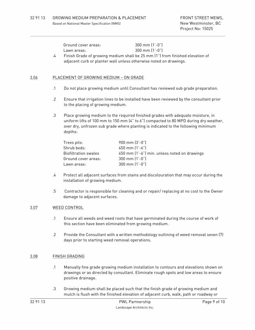
32 91 13 GROWING MEDIUM PREPARATION & PLACEMENT FRONT STREET MEWS, Based on National Master Specification (NMS) New Westminster, BC Project No: 15025
32 91 13 PWL Partnership Landscape Architects Inc.
Page 9 of 10
Ground cover areas: 300 mm (1’-0”) Lawn areas: 300 mm (1’-0”)
.4 Finish Grade of growing medium shall be 25 mm (1”) from finished elevation of adjacent curb or planter wall unless otherwise noted on drawings.
3.06 PLACEMENT OF GROWING MEDIUM – ON GRADE
.1 Do not place growing medium until Consultant has reviewed sub grade preparation. .2 Ensure that irrigation lines to be installed have been reviewed by the consultant prior
to the placing of growing medium. .3 Place growing medium to the required finished grades with adequate moisture, in
uniform lifts of 100 mm to 150 mm (4” to 6”) compacted to 80 MPD during dry weather, over dry, unfrozen sub grade where planting is indicated to the following minimum depths: Trees pits: 900 mm (3’-0”) Shrub beds: 450 mm (1’-6”) Biofiltration swales 450 mm (1’-6”) min. unless noted on drawings Ground cover areas: 300 mm (1’-0”) Lawn areas: 300 mm (1’-0”)
.4 Protect all adjacent surfaces from stains and discolouration that may occur during the
installation of growing medium. .5 Contractor is responsible for cleaning and or repair/ replacing at no cost to the Owner
damage to adjacent surfaces.
3.07 WEED CONTROL
.1 Ensure all weeds and weed roots that have germinated during the course of work of this section have been eliminated from growing medium.
.2 Provide the Consultant with a written methodology outlining of weed removal seven (7)
days prior to starting weed removal operations. 3.08 FINISH GRADING
.1 Manually fine grade growing medium installation to contours and elevations shown on drawings or as directed by consultant. Eliminate rough spots and low areas to ensure positive drainage.
.3 Growing medium shall be placed such that the finish grade of growing medium and
mulch is flush with the finished elevation of adjacent curb, walk, path or roadway or

32 91 13 GROWING MEDIUM PREPARATION & PLACEMENT FRONT STREET MEWS, Based on National Master Specification (NMS) New Westminster, BC Project No: 15025
32 91 13 PWL Partnership Landscape Architects Inc.
Page 10 of 10
25mm (1”) below the finished grade of adjacent planter wall, unless otherwise noted on drawings
.2 Leave surface smooth, uniform, firm against deep foot printing, with a fine loose
texture. 3.10 CLEANING AND REMOVAL OF SURPLUS MATERIAL
.1 Ensure all paved areas, tops of planters, adjacent surfaces have been thoroughly cleaned. Ensure all discoloration of adjacent surfaces as a result of growing medium installation have been removed.
.2 Dispose of surplus materials off site.
END OF SECTION 32 91 21

32 93 10 PLANTING FRONT STREET MEWS, Based on National Master Specification (NMS) New Westminster, BC Project No: 15025
32 93 10 PWL Partnership
Landscape Architects Inc. Page 1 of 12
1.00 GENERAL
1.01 GENERAL REQUIREMENTS
.1 Refer to Division 1, General Requirements.
.2 All contract documents form an integral part of this section. 1.02 DESCRIPTION
.1 Furnish all labour, materials, equipment, and services necessary source, supply, install and maintain the plant material indicated on the contract drawings and plant list(s).
.2 The work shall include but is not limited to the following areas:
.1 All planting areas, raised planters, planter pots, street tree pits. 1.03 RELATED WORK .1 Growing Medium Preparation and Placement Section 32 91 13 1.04 SOURCE QUALITY CONTROL
.1 Seven (7) days prior to the Consultant review of plant material at source the Contractor shall confirm in writing availability of plant material noted on Plant List.
.2 Plant material will be supplied from nurseries who are certified by the Clean Plants
program, Canadian Nursery Certification Institute (CNCI), current certification standard http://cleanplants.ca/. The certification shall include but is not limited to the requirements of the current active module(s), e.g. P. Ramorum module. The certification must extend to all fields and allied nursery operations where plant material is sourced. Only nurseries, fields and allied nursery operations that are certified will be permitted to supply plant material for this project. .1 Prior to the review of plant material by the Consultant the Contractor shall
submit written documentation with CNCI certification stamp stating that the nursery has undergone all components of a certification program and has been audited to verify that all components are properly implemented.
.2 The documentation submitted shall include but is not limited to the nurseries CNCI Clean Plants certification number.
.3 Plant Material Review at the source nursery
.1 Contractor request for review of the plant material at source nursery to be a minimum of seven (7) days prior to scheduled review.
.2 Shipping of plant material to project site shall not proceed until Consultant has reviewed the plant material at the source nursery.
.3 Consultant shall make one (1) visit to source nursery for review of plant material for entire project.

32 93 10 PLANTING FRONT STREET MEWS, Based on National Master Specification (NMS) New Westminster, BC Project No: 15025
32 93 10 PWL Partnership
Landscape Architects Inc. Page 2 of 12
.4 All plant material, including substitutions shall be gathered at one location for review.
.5 Contractor shall accompany Consultants during plant material review at the source nursery.
.4 Plant Material Review at Project Site
.1 All plant material shall be reviewed at the project site by the Consultant prior to planting.
.2 Plant material that is rejected by the consultant shall be immediately removed from the site and replaced at the Contractors expense.
.5 Imported Plant Material
.1 Plant material imported from out of province and out of country shall be accompanied with necessary federal and provincial permits and import licenses.
.2 The contractor shall conform to all federal and provincial laws and regulations with regard to horticultural inspection of domestic and imported plant material.
.6 Condition of Plant Materal
.1 Plant rootballs and containers shall be completely free of noxious weeds and volunteer plants including Horsetail and Morning Glory.
.7 Plant material grown or supplied in Fabric Containers are not acceptable.
1.05 SUBMITTALS .1 Confirmation Plant List
.1 Contractor shall provide in writing to the Consultant a minimum of seven (7) days prior to review of plant material at the source nursery a plant list confirming the quantity, botanical name, common name and size of plants specified.
.2 Substitutions
.1 Contractor shall provide in writing to the Consultant a minimum of seven (7) days prior to review of plant material at the source nursery a list of proposed substitutions for review.
.2 Plant substitutions shall be of similar genus and species and of equal or greater
size as those originally specified. The list shall contain the following information:
.1 Botanical name, common name of the specified plant
.2 Botanical name, common name of the proposed substitute plant
.3 Pot size and plant size in the nursery
.3 Planting Schedule .1 Contractor shall provide in writing to the Consultant upon award of the Contract

32 93 10 PLANTING FRONT STREET MEWS, Based on National Master Specification (NMS) New Westminster, BC Project No: 15025
32 93 10 PWL Partnership
Landscape Architects Inc. Page 3 of 12
a detailed planting schedule outlining dates and duration of planting operations. .2 Revisions to the Planting Schedule as a result of delays of any kind shall be
submitted to the Consultant in a timely manner prior to the start of planting operations.
.4 Composted Mulch
.1 Contractor to submit a one (1) litre sample of Composted Mulch to the Consultant for review prior to shipment to the site.
.5 Prepared Growing Medium
.1 Contractor to submit a one (1) litre sample of the Prepared Growing Medium to the Consultant for review prior to shipment to the site.
.6 Antidesicant
.1 Contractor to submit three (3) copies of manufacturer product data and specification for Consultant review.
1.06 STANDARDS
.1 Except as modified in this specification, all plant material specified shall conform to the
latest additions of the: .1 Canadian Nursery & Landscape Association (CNLA) Standard for Nursery Stock
– Current Edtion. .2 The British Columbia Landscape & Nursery Association (BCLNA). .3 The BC Landscape Standard – Current Edition. .4 ANSI A-300 Tree Pruning Guidelines
1.07 SHIPMENT AND PRE-PLANTING CARE
.1 Coordinate shipping of plant material and excavation of planting pits to ensure minimum time lapse between nursery digging and on site planting.
.2 Ensure branches of trees and shrubs are bound securely into a confined mass during
handling and transport. .3 Do not bind planting stock with rope or wire that would damage bark, break or damage
branches or damage the natural shape of the plant
.4 Protect plant material against abrasion, and exposure to extreme temperature change during transit.
.5 Cover plant foliage and branches with tarpaulin to prevent loss of moisture during
transit. .6 Fully support root ball of large trees during all lifting operations.

32 93 10 PLANTING FRONT STREET MEWS, Based on National Master Specification (NMS) New Westminster, BC Project No: 15025
32 93 10 PWL Partnership
Landscape Architects Inc. Page 4 of 12
.7 Do not lift trees or shrub by the trunk or branches. Plant material to be moved by lifting the root ball or container.
.8 Remove broken and damaged roots with clean cuts using sharp pruning shears.
.9 Consultant Tree Review Seals: .1 Trees that have been reviewed at the nursery and tagged with PWL Partnership
Landscape Architects Inc. numbered tree review seals shall be shipped to the site with the tree review seals in place.
.2 Under no circumstances are the tree review seals to be removed without written instruction by the Consultant to do so.
.3 Trees that were tagged with tree review seals at the nursery by the Consultant that have had their tree review seals removed without written consent by the Consultant will at the Consultants discretion be rejected and replaced at no cost to the Owner.
.10 Temporary Storage/ Heel-In of Plant Material on Site:
.1 Temporarily store trees, shrubs and miscellaneous plant material that can not be planted immediately by heeling-in. Acceptable heel-in material includes approved growing medium or sawdust.
.2 Ensure temporary storage/heel -in area is shaded and protected from the wind.
.3 Provide sufficient water at regular intervals to ensure health of plant material in the temporary storage/heel-in area.
.4 Plant material that has not been properly maintained in the storage/heel-in area and illustrates signs of degradation or stress will be rejected by the Consultant. Rejected plant material shall be replaced at by the Contractor at no cost to the Owner.
1.08 PLANT MATERIAL SEARCH AREA .1 Search area for availability of plant material shall include all of Western North
America. 1.09 GUARANTEE
.1 The Contractor hereby guarantees that the plant material will remain free of defects in
accordance the General Conditions for a period of one (1) year from the date of Substantial Performance. The contractor shall make all corrections, adjustments and replacements required as a result of failure of all plant material in this section.
.2 The Owner reserves the right to extend Contractor's guarantee period and
responsibilities for one (1) additional year if, at end of the initial guarantee period the leaf development and growth of the plant material is not sufficient to ensure future survival.
1.10 PLANT MATERIAL REPLACEMENTS

32 93 10 PLANTING FRONT STREET MEWS, Based on National Master Specification (NMS) New Westminster, BC Project No: 15025
32 93 10 PWL Partnership
Landscape Architects Inc. Page 5 of 12
.1 The contractor shall remove from the site and immediately replace any plant material that has been determined by the Consultant to have died or failed to grow in a satisfactory manner during the guarantee or maintenance period.
.3 The Contractor shall extend the guarantee on this replacement plant material for one
(1) year from the date of removal.
.4 The Contractor shall continue such replacement and guarantee of plant material until the Consultant has determined that the ‘Conditions for Final Acceptance’ have been met.
2.00 PRODUCTS 2.01 MATERIALS
.1 Water: potable and free of minerals that are detrimental to plant growth.
.2 Composted Mulch: 9mm (3/8”) Composted Mulch, black/brown in colour with no cedar
or redwood bark or wood material manufactured by Yard Works, Richmond, BC, Eco-Soil ,Langley BC Fraser Richmond Bio-Cycle, Richmond, B.C. or pre-approved equal.
.3 Anti-desiccant: wax-like emulsion that will provide a transpiration reducing film over
the plant surface. Moisturin by GSI Horticultural, Bend, Oregon, (541) 383-0222 or approved equal.
.4 Tree Trunk Protection: extrusion mold process, polyethylene with UV protectors:
“Arborgard” manufactured by DeepRoot products Canada, Inc., Vancouver, B.C., or pre-approved equal.
.5 Burlap: shall be untreated, free from toxic contaminants and of sufficient strength to
hold the rootball in a compact, stable mass that does not move relative to the main stem(s) of the tree or shrub.
.6 Wire Baskets: non-galvanized metal basket designed and manufactured for the
purpose of tree moving. Basket shall be shaped to ensure that the root ball will allow a stable planting condition in accordance with standards noted.
.7 Tree Ties: Flat woven polypropylene material. 20 mm (3/4”) wide, 544 Kg. (1200 lb),
break strength. Arbor Tie by Deep Root or approved equal.. .8 Tree Guy Anchors/ Tree Guy System: Direct burial or screw type disc guy anchor and
guy system. The Arrow Anchor by Tree-Guy/ Tree Guy System, Santa Anna, California (800) 624-1116, or approved equal.

32 93 10 PLANTING FRONT STREET MEWS, Based on National Master Specification (NMS) New Westminster, BC Project No: 15025
32 93 10 PWL Partnership
Landscape Architects Inc. Page 6 of 12
.9 Stakes and Stake Fasteners: ACQ pressure treated Hem/Fir, 75 mm dia. (3") round, 2500 mm (8’-0”) long. Stake fasteners shall be hot dipped galvanized or stainless steel.
.10 Flagging Tape; 30mm (13/16”) wide ‘Red’ PVC flagging tape by Identi-Tape, Boulder, CO
or approved equal. 2.02 PLANT MATERIAL .1 Plant Material Size:
.1 Overall plant spread to be measured when branches are in their natural position.
.2 Height and spread dimensions refer to main body of plant and not from branch tip to branch tip.
.2 Grade: Plant material to be No. 1 grade or better.
.3 Plant material obtained from areas with milder climatic conditions from those of site is acceptable provided:
.1 Plant material is moved to the site prior to the breaking of buds at their original climatic zone.
.2 Plant material is heeled-in at a protected area until the climatic conditions are suitable for planting.
.4 Plant material shall have structurally sound, strong fibrous root system free of disease,
insects, defects or injuries. .5 Root Pruning at Source Nursery:
.1 Plant material shall have been root pruned on a regular basis at the source nursery.
.2 Plant material shall be root pruned at least one growing season prior to digging and shipment to the project site.
.3 Large trees shall be half root pruned during each of two successive growing seasons. The second root pruning shall have carried out a minimum of one growing season prior to shipment to the site.
.6 Shade, Ornamental and Evergreen Trees:
.1 Trees shall have straight trunks and a well-formed branch system which is characteristic of the species
.2 Trees shall exhibit clear signs of vigorous growth.
.3 Trees shall have good twig extension growth, branch spacing and trunk taper.
.4 Tree foliage shall be evenly distributed on upper 2/3 of the tree.
.5 Trees shall not have upright branches other than leaders.
.6 Trees will have spreading branches with a single trunk and a single leader and, unless otherwise noted on plans or plant list.
.7 Tree trunks and branches shall not have any mechanical damage.

32 93 10 PLANTING FRONT STREET MEWS, Based on National Master Specification (NMS) New Westminster, BC Project No: 15025
32 93 10 PWL Partnership
Landscape Architects Inc. Page 7 of 12
.8 Trees shall be in good health with no presence of insects or disease.
.9 Trees shall not have been ‘headed back’.
.10 Tree root balls shall be solid, kept moist at all times and/or protected from drying.
.11 Trees shall not exhibit symptoms of root circling or girdling. .8 Container Grown Plant Material:
.1 Root ball to container relationship shall be of sufficient ratio to ensure room for healthy, vigorous root development.
.2 Plant material shall have been container grown for a minimum of one (1) growing season but not longer than two (2) growing seasons.
.3 The plant root systems that do not have the ability to "hold" growing medium when removed from the container will be rejected.
.4 Root bound plant material will be rejected.
.9 Balled and Burlapped Plant Material: .1 Coniferous and broadleafed evergreens over 2.4 metre (7’-8”) tall shall be dug
with firm soil root ball. .2 Deciduous trees in excess of 3.0 metre (10’-0”) height shall be dug with firm soil
root ball. .3 Root ball diameter shall be a minimum of 230 mm (9”) for each 25 mm (1”)
caliper size. .4 Secure root-balls with burlap, heavy twine and rope. .5 Large tree root balls shall be double layer burlap wrapped. Burlap to be
secured with drum laces made up of 10 mm (3/8”) (minimum) diameter rope
.10 Tree Spade Dug Plant Material: .1 Plant material shall be dug with mechanized hydraulic spade or clamshell type
digging equipment. .2 Root ball diameter shall be a minimum of 230 mm (9”) for each 25 mm (1”)
caliper size. .3 Wire basket shall be lined with burlap. Root ball shall be laced and tied to wire
basket with heavy rope. .4 Ensure trunk of tree is not damaged by wire basket, ties or rope.
3.00 EXECUTION
3.01 PRE PLANTING OPERATIONS
.1 Place stakes on site to identify location trees and plant beds in accordance with the landscape plans.
.2 Consultant to review all tree locations and plant bed layout prior to start of plant bed
preparation and planting operation.
.2 Anti-desiccant shall be applied only as directed by the Consultant. Application of anti-

32 93 10 PLANTING FRONT STREET MEWS, Based on National Master Specification (NMS) New Westminster, BC Project No: 15025
32 93 10 PWL Partnership
Landscape Architects Inc. Page 8 of 12
desiccant shall be in accordance with manufacturer's instructions.
.3 Coordinate planting operations with other trades and project schedule.
3.02 PLANTING SCHEDULE .1 All planting operations shall be done in a timely manner in accordance to the ‘Planting
Schedule’.
.2 ‘Planting Schedule’ shall be updated as required by the Contractor to coincide with status of site and coordination with other trades. Provide the Consultant with up dates to the schedule as required throughout the planting process.
3.03 EXCAVATION
.1 Existing Utilities; The contractor is responsible for confirming the location and extent of existing utilities prior to the start of all planting operations. All attempts should be made to ensure that utility services are maintained to all on and off site parties through out the entire planting operation.
.2 Tree Pits;
.1 Tree Pit Depth 900mm (3’-0”) minimum.
.2 Width of tree pit shall be a minimum of 450 mm to 600 mm (1’-6” to 2’-0”) greater than diameter of the root ball.
.3 Prior to the placement of growing medium scarify the sides and bottom of tree pits created with a tree spade to eliminate glazed surface.
.3 Ensure tree pits dug in heavy or compacted soils exhibit the ability to drain freely by
filling each tree pit with a minimum of 20 litres (5 gallon) of water. Water should freely drain through subsoil within ten (10) minutes.
.1 Notify Consultant if tree pits in any soil condition do not drain freely or if tree pit fills with ground water.
.2 There shall be no standing water in the bottom of tree pit at time of planting.
.4 Protect bottom of tree pit(s) against freezing.
.5 Ensure tree pits and plant beds are kept well drained and free of contaminants and construction debris.
.6 Planting Areas; Excavate planting areas to accommodate the following depths;
.1 Shrub Beds, Perennials, Ornamental Grasses
450 mm (1’- 6”)
.2 Ground Cover, Annual Flowers
300 mm (1’- 0”)
.3 Trees 900 mm (3’- 0”)

32 93 10 PLANTING FRONT STREET MEWS, Based on National Master Specification (NMS) New Westminster, BC Project No: 15025
32 93 10 PWL Partnership
Landscape Architects Inc. Page 9 of 12
3.04 PLANTING .1 Planting operations shall be carried out under conditions that are conducive to healthy,
vigorous growth of plant material.
.2 Planting operations shall not be carried out when the growing medium is frozen, saturated or compacted to levels that exceed this specification.
.3 Plant material shall be planted vertical, straight and plumb at locations staked in field
and or noted on landscape plans. .4 Ensure orientation of plant material will give best appearance in relation to views from
adjacent buildings, roads, walks or use areas. .5 Planting Depth of Root Ball: Unless directed otherwise in writing by the Consultant
plant material shall be installed to lines and levels that ensure the nursery grade of the root ball (depth of root ball originally established in the nursery) is level with adjacent growing medium.
.1 Plants that have the nursery grade of the root ball higher or lower than established finish grade will be rejected.
.2 The Contractor will reset rejected plant material to conform to the specifications at no cost to the Owner.
.6 Ball and Burlap Plant Material: After plant has been lowered into plant bed or tree pit
cut away all root ball ties from around trunk. Loosen burlap from around trunk and cut away minimum top 1/3 without disturbing root ball.
.7 Container Grown Plant Material: Remove entire container (including biodegradable
containers) without disturbing root ball. Score root ball vertically at six (6) locations evenly spaced around entire root ball to minimize girdling of roots.
.8 Tree Spade Dug Root Balls: Cut wire basket around entire perimeter of root ball. Bend
down top 2/3 of wire basket without disturbing root ball. Cut away all root ball ties from around trunk. Loosen burlap from around trunk and cut away minimum top 1/3 without disturbing root ball.
.9 Growing Medium Placemtent:
.1 Planting areas in 150 mm (6”) lifts to 2/3 of the depth tamping each lift of growing medium around root system to eliminate air voids. Do not use frozen or saturated growing medium for backfill operation.
.2 Prior to placing remaining growing medium, thoroughly water planting areas, fill tree pits with water. Complete backfill operation only after water has completely penetrated into growing medium.
.10 Build 100 mm high by 150 mm wide (4” high by 6” wide) saucer around outer edge of
tree pit to assist with maintenance watering.

32 93 10 PLANTING FRONT STREET MEWS, Based on National Master Specification (NMS) New Westminster, BC Project No: 15025
32 93 10 PWL Partnership
Landscape Architects Inc. Page 10 of 12
.12 Tree Stabilization;
.1 Guying or staking of trees shall be done by the Contractor at the discretion of the Consultant.
.2 Ensure guy pins and stakes are placed out beyond the root ball.
.3 Trees that have had root balls penetrated by guy pins and stakes will be rejected.
.4 Tie one (1) to two (2) flagging tape flags to all guy wires at a height that is clearly visible.
.13 Tree Trunk Protection and: Place tree trunk protection around base of tree trunk as
per manufacturer instructions. .1 Trees 100 mm (4”) caliper or less shall have one protector. Do not interlock
ends of tree protector. .2 Trees greater than 100 mm (4”) caliper shall have a minimum of two interlocked
protectors. Do not interlock outside ends.
.14 Tree Rings .1 Trees in sod lawn shall have 750mm (30”) tree rings cut around the base of each
tree. The tree rings shall; .1 Be true circles centered on the trunk of the tree. .2 Have sod removed and area mulched as per specifications.
.2 Trees in seeded areas shall have 750mm (30”) tree rings cut around the base of each tree once seeded areas have been accepted by the Consultant. The tree rings shall;
.1 Be true circles centered on the trunk of the tree.
.2 Have grass removed and area mulched as per specifications.
3.05 PRUNING
.1 All pruning cuts shall be made with pruning saws or hook and blade pruning tools designed and manufactured for pruning operations. Anvil-type pruning tools shall not be used in any pruning operations.
.2 Prune trees and shrubs after planting operation as directed by Consultant. .3 Employ clean sharp tools and make cuts without damaging the branch collar. .4 Do not damage the leader or lead branches. Plants which have had the main leader or
lead branches damaged or removed will be rejected and replaced by the Contractor at no cost to the Owner.
.5 Do not remove minor twig branches along the main structural branches.
3.06 APPLICATION OF COMPOSTED MULCH
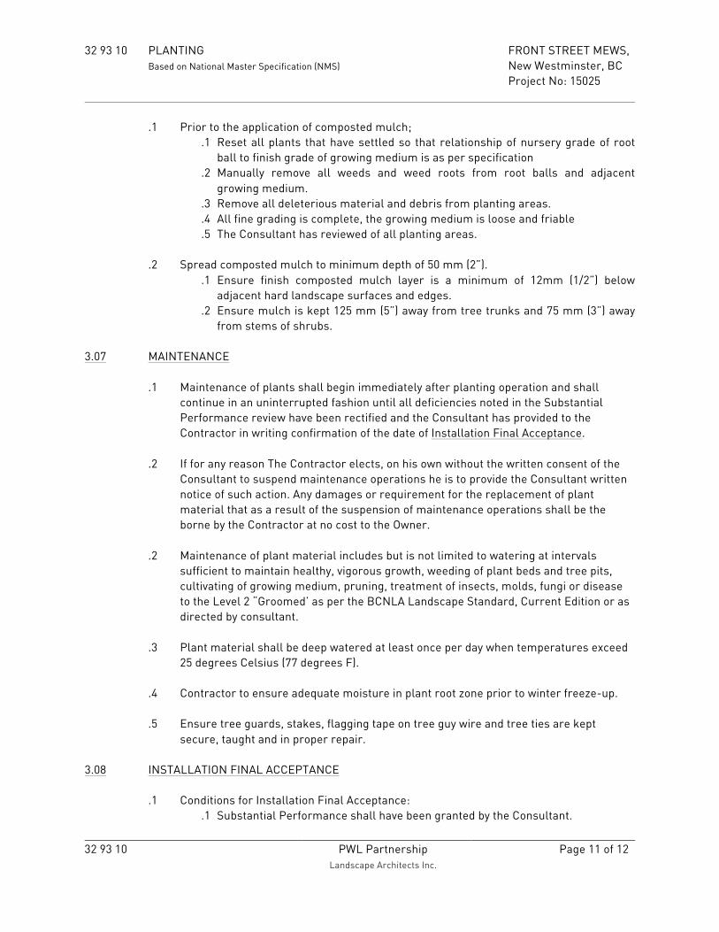
32 93 10 PLANTING FRONT STREET MEWS, Based on National Master Specification (NMS) New Westminster, BC Project No: 15025
32 93 10 PWL Partnership
Landscape Architects Inc. Page 11 of 12
.1 Prior to the application of composted mulch; .1 Reset all plants that have settled so that relationship of nursery grade of root
ball to finish grade of growing medium is as per specification .2 Manually remove all weeds and weed roots from root balls and adjacent
growing medium. .3 Remove all deleterious material and debris from planting areas. .4 All fine grading is complete, the growing medium is loose and friable .5 The Consultant has reviewed of all planting areas.
.2 Spread composted mulch to minimum depth of 50 mm (2”).
.1 Ensure finish composted mulch layer is a minimum of 12mm (1/2”) below adjacent hard landscape surfaces and edges.
.2 Ensure mulch is kept 125 mm (5”) away from tree trunks and 75 mm (3”) away from stems of shrubs.
3.07 MAINTENANCE
.1 Maintenance of plants shall begin immediately after planting operation and shall continue in an uninterrupted fashion until all deficiencies noted in the Substantial Performance review have been rectified and the Consultant has provided to the Contractor in writing confirmation of the date of Installation Final Acceptance.
.2 If for any reason The Contractor elects, on his own without the written consent of the
Consultant to suspend maintenance operations he is to provide the Consultant written notice of such action. Any damages or requirement for the replacement of plant material that as a result of the suspension of maintenance operations shall be the borne by the Contractor at no cost to the Owner.
.2 Maintenance of plant material includes but is not limited to watering at intervals
sufficient to maintain healthy, vigorous growth, weeding of plant beds and tree pits, cultivating of growing medium, pruning, treatment of insects, molds, fungi or disease to the Level 2 “Groomed’ as per the BCNLA Landscape Standard, Current Edition or as directed by consultant.
.3 Plant material shall be deep watered at least once per day when temperatures exceed
25 degrees Celsius (77 degrees F). .4 Contractor to ensure adequate moisture in plant root zone prior to winter freeze-up. .5 Ensure tree guards, stakes, flagging tape on tree guy wire and tree ties are kept
secure, taught and in proper repair. 3.08 INSTALLATION FINAL ACCEPTANCE
.1 Conditions for Installation Final Acceptance: .1 Substantial Performance shall have been granted by the Consultant.

32 93 10 PLANTING FRONT STREET MEWS, Based on National Master Specification (NMS) New Westminster, BC Project No: 15025
32 93 10 PWL Partnership
Landscape Architects Inc. Page 12 of 12
.2 All plant material is healthy, exhibiting signs of vigorous growth and meets the requirements of this specification.
.3 Unless otherwise indicated in the contract drawings the original shape and form of the plant as reviewed by the Consultant has been maintained, leaders are in tact, there are no wounds or abrasions on trunks or branches.
.4 Mulch has been maintained to specified depths and has been pulled away from the trunk or stems of plant material as per specifications.
.5 Relationship of nursery grade of root ball to finish grade of growing medium is as per specification.
.6 All planting areas continue to be free draining with no signs of standing water.
.7 All plant beds are completely free of weeds and noxious grasses.
.8 All tree tags, nursery tape and tags have been removed.
.9 Twine and burlap have been removed from around base of tree/ top of rootball as per specifications.
.10 Tree rings have been cut into sod and seeded areas as per specifications.
.2 The Contractor shall continue to maintain the work of this section until the Consultant provides written confirmation that Installation Final Acceptance Conditions have been met.
3.09 CLEAN-UP
.1 Ensure growing medium spilled onto pavement and growing medium stains on pavement or adjacent hard surfaces is cleaned up immediately.
.2 Remove all materials and other debris resulting from work of this section and dispose
of off site. END OF SECTION 32 93 10

Page1of11
Irrigation Standards and Specifications
2014

Page2of11
TABLE OF CONTENTS
SECTION 1 GENERAL
1.1 General Requirements 1.2 Description 1.3 Related Work in Other Sections 1.4 Codes and Regulations 1.5 Permits and Fees 1.6 Quality Assurance 1.7 Submittals and Instructions 1.8 Delivery and Storage 1.9 Site Conditions 1.10 Protection 1.11 Guarantee 1.12 Equals 1.13 Sequence 1.14 Inspection
SECTION 2 PRODUCTS 2.1 Pipe and Fittings 2.2 Valves and Valve Boxes 2.3 Sprinkler Heads 2.4 Control and Common Wire 2.5 Automatic Controller and Equipment 2.6 Back Flow Preventer 2.7 Pressure Reducing Valve 2.8 Yellow Warning Tape 2.9 Pipe Bedding Sand 2.10 Valve Box Drain Rock 2.11 Filter Medium 2.12 Miscellaneous Materials SECTION 3 EXECUTION 3.1 Irrigation System Layout 3.2 Installation of Piping 3.3 Pipe Pulling 3.4 Installation of Equipment 3.5 Testing 3.6 Winterizing 3.7 Spring Start-Up 3.8 Site Maintenance and Clean-up

Page3of11
1 GENERAL 1.1 General Requirements .1 All Contract Documents form an integral part of this section. 1.2 Description .1 Furnish all equipment, materials, labour, and services necessary for the complete supply and installation of fully operational, automatic irrigation system including but not limited to trenching, excavation, backfill, sleeving, connection to municipal water supply and supply of water to irrigation heads. Coordination of reviews, testing, and approvals with the City Representative. 1.3 Related Work in Other Sections .1 Not applicable 1.4 Codes and Regulation .1 Work of this section shall be installed in accordance with the requirements of local and applicable provincial and federal regulations. Any Work shown on the Drawings or described in the Specifications that varies from the regulations shall be changed to comply with the requisite authority at no cost to the Owner. .2 WorkSafe BC regulations shall be followed. 1.5 Permits and Fees .1 Obtain and pay for all permits covering the Work connected with the installation of the systems specified and as shown on the Drawings.
1.6 Quality Assurance .1 Irrigation Work shall be done by an experienced and competent irrigation Contractor having adequate equipment and fully trained personnel for all phases of the Work specified. .2 The irrigation Contractor shall be a member in good standing of the Irrigation Industry Association of British Columbia (IIABC) and have met the qualification standards currently applied to Contractors by that organization. The Contractor must provide proof of membership to the City Representative prior to the start of Work of this section. .3 Contractor shall verify Site measurements as they relate to irrigation coverage. If any conditions are observed on Site that will impair proper and intended uniform irrigation coverage, notify the City Representative before proceeding with Work that would yield unsatisfactory coverage. 1.7 Submittals and Instructions .1 Maintenance Data and Operation Instructions/Manual: prior to and as a condition of substantial performance, submit to the City Representative two copies of all operating and maintenance manual for all components including cleaning and lubrication schedules, overhaul/adjustment schedules, and similar maintenance operations. Each manual shall be bound in a three ring binder. Clearly indicate the Project name, name, address, and telephone number of the irrigation Contractor, and date of substantial completion on the spine of each of the binders. .2 As-Built Drawings: submit an accurate, detailed as-built drawing, drawn on a clean copy of the original design drawings. CAD drawing file of the irrigation system as-built drawings to be submitted to the City. All components of the irrigation system shall be shown as installed including the location of the controller, water source, backflow preventer, and pressure reducing valves. .3 As-Built Record Sketches: the Contractor is to maintain a set of as-built record sketches on Site at all times. The as-built record sketches are to be updated daily noting changes made to the irrigation design Drawings. The City Representative will without notice, periodically review the as-built record sketches during the irrigation installation process. .4 Maintenance Materials: submit to the City Representative two sets of all special tools, keys, and

Page4of11
equipment provided by the manufacturer for proper operation and maintenance of the installed system. .5 System Demonstration: as part of the requirements for the completion and acceptance of the Work of this section, demonstrate the complete operating and maintenance procedures for this system to a designated representative of the City of New Westminster. This instruction shall include but not be limited to demonstration of the relative timing differences between zones, of different precipitation rates and a schedule of run times suggested for various weather conditions.
1.8 Delivery and Storage .1 Deliver and store materials in new condition, in unopened containers and protect until installed. Ensure that the pipe is not gouged, bent, or cracked during delivery, handling, and storage. 1.9 Site Conditions .1 Existing Conditions/Underground Services: prior to the start of Work, verify and mark the location of all below ground Site utilities/underground services by hand digging or employing personnel trained in the use of an electronic toning device or M-scope. Verify the location of any above ground elements that may impede the Work of this section. Notify the City Representative immediately for directions as to the procedure should any piping, conduit, structures, or utilities be encountered during excavation or trenching. .2 Repair to Underground Services: the Contractor shall employ the appropriate skilled trades to repair all damage to underground services caused by the Work of this Contract. Damage to services that are shown on the Drawings or have been brought to the Contractor’s attention in the field prior to commencement or during construction of the Work shall be repaired at the Contractor’s expense. .3 Repair of damages to underground services where the location of services were clearly unknown after all reasonable measures were taken by the Contractor to ascertain the existence of these services will be paid for by the Owner. .4 The Contractor shall cooperate with the Owner and utility companies to keep their respective utilities in operation. .5 Site Preparation: prior to the Work of this section, carefully inspect any installed Work of other trades or Contractors and verify with the City Representative that all such Work is complete to the extent that the Work of this section may commence. .6 Discrepancies: the Contractor is to immediately notify the City Representative in the event of discrepancy, errors, or conflicts between the Drawings and the actual Site conditions
1.10 Protection .1 Protect existing buildings, equipment, sidewalks, landscape reference points, monuments, markers, and other completed Work. At no expense to the Owner, make good any damage resulting from Work of this Contract. .2 The Contractor shall bring only vehicles or equipment onto the Site that are essential for construction of the system. .3 Trenching and other excavations for vaults, valve boxes, etc. are not to be left open during non-Work hours unless they are protected to current WorkSafe BC standards. Cover, clearly mark, and protect all open excavations to ensure public safety. 1.11 Guarantee .1 The Contractor shall provide a written warranty for all workmanship for a period of one year from date of substantial performance. .2 Manufactured Products, including but not limited to irrigation heads, piping, quick couplers, controllers, valve boxes, and valves shall be warranted from the date of substantial performance as per the manufacturer's standard warranty period or a minimum of two years, whichever is greater.

Page5of11
1.12 Equals .1 Equals will not be considered for Work of this section. All items are as specified in the Specifications or on the Contract Drawings. 1.13 Sequence .1 As required, coordinate the layout and location of the water supply/municipal connection point(s) for the automatic irrigation system with the city representative. .2 As required, coordinate with the city representative for the layout and location of the electrical conduit for the low voltage control wire from the controller location in the service building to a location accessible outside the building face. 1.14 Inspection .1 Prior to commencement of Work of this section, the Contractor is to arrange an on Site meeting with the City Representative to review procedures and protocols .2 Work is to remain uncovered for inspection of workmanship and materials. Notify the City Representative a minimum of 48 hours prior to required inspections. Failure to provide such notice or closing in Work that has not been inspected is sufficient grounds for withholding any payments due to the Contractor. The City Representative will request all buried Work not approved to be unearthed for proper inspection. 2 PRODUCTS 2.1 Pipe and Fittings .1 Wherever “as per manufacturer's Specifications” is used, it shall mean in strict accordance with the manufacturer's printed directions. Review any conflicts between manufacturers instructions and this Specification with the City Representative prior to proceeding with Work. .2 All materials throughout the system shall be new and in perfect condition. .3 Plastic Pipe: plastic pipe shall be rigid un-plasticized polyvinyl-chloride (PVC): .3.1 Lateral Lines: unless otherwise noted, non CSA Schedule 40 PVC. .3.2 Main Lines: non CSA Schedule 40 PVC conforming to ASTM D-2466-97. .3.3 All pipe to be continuously and permanently marked showing manufacturer’s name or trademark, type of material, pipe size, and pressure rating. .3.4 The pipe shall be homogeneous throughout and free from visible cracks, holes, foreign material, blisters, deleterious substances, wrinkles, and dents. .3.5 There shall be no ¼ pipe sizes used (3/4”, 1 ¼”). Systems must be designed to minimize the variety of pipe sizes used, and to allow for future expansion. .4 Plastic Pipe Fittings: .4.1 Schedule 40 PVC conforming to ASTM D-2466-97 (and F438-97 for CPVC) standards designed for solvent welding to PVC pipe except where valves, risers, etc. require threaded joints. .4.2 Fittings for PVC pipe shall be to ²⁄3 interface fit to ensure a fully sealed joint. Provide minimum 25 mm (1 in.) clearance between fittings to allow for repair. City Representative will require fittings that do not provide this clearance to be removed and reinstalled in accordance with the Specification. .4.3 All threaded connections shall be joined with a minimum of three wraps Teflon tape or an Teflon based pipe thread compound approved for use with plastic pipe. .4.4 Threaded nipples shall be Schedule 80 PVC and be manufactured from the same material specified for the pipe. .4.5 Threaded connections of PVC to metal shall have male threads on the PVC and female threads on the metal .5 Primers and Pipe Solvents: CSA approved type as recommended by pipe manufacturer for the temperature and conditions under which the Work is being performed. Solvent cement to be heavy bodied gray 711, Primer to be P70 purple, all to be delivered in sealed labeled containers clearly marked with name of manufacturer and lot number. Use of non CSA specialty primers or solvents such as “Wet R Dry” are not acceptable. .6 Sleeves: shall be Schedule 40 PVC to the extent and locations noted on the Contract

Page6of11
Drawings. Coordinate the location of sleeves with Work of other trades: .6.1 Sized a minimum of two pipe sizes larger than the irrigation lateral line to be carried. .6.2 Sized a minimum of three pipe sizes larger if carrying a mainline: 2.2 Valves and Valve Boxes .1 Solenoid Valves: Rainbird, size and type as shown on drawing. .2 Quick Coupler Valves and Blow-Out Tees: Rainbird 33DRC, brass body, 19 mm (³⁄4 in.). .3 Isolation Valves: cast bronze gate valves with non-rising stems; R&W Model 280 for valves up to 63.5 mm (2½ in.) diameter, or pre-approved equal. .4 Bronze Ball Valves: Jones J1949SG-19 mm to 50 mm (³⁄4 in. to 2 in.), size as required, 90 degree shut off curb stop type, or pre-approved equal. .5 Valve Boxes: shall be heavy duty,green plastic irrigation boxes complete with captive lock bolt covers; sized to suit valves and other components with adequate room for operating and maintenance access. 2.3 Sprinkler Heads 2.3.1 Sprinkler Heads .1 Sprinkler heads shall be Rainbird, types and sizes as indicated on Drawings with the diameter or radius of throw, pressure, and discharge required for head-to-head coverage. .2 All sprinkler Rainbird heads shall be marked with the manufacturer's name and identification such that they can be identified without being removed from the system
2.3.2 Sprinklers Risers Not applicable 2.3.3 Rainbird Stationary Pop-Up Sprinklers .1 The risers shall be of sufficient height so as not to cause any interruption of the stream from the sprinkler nozzle when the plant material has reached its optimum growth. 2.4 Control and Common Ground Wire .1 Insulated PE14 or TWU14 Direct burial irrigation wire. White wire shall be common wire. .2 One spare control wire to be installed from controller to each solenoid valve location (valve box containing one or more solenoid valves). .3 Locate Wire: YELLOW, 14-gauge insulated solid copper, TWU, RW90 or approved equal. .4 Direct Bury Splice Kit: 2.5.1 DBY or DBR by 3M or approved equal. .5 Confirm control wire size with the manufacturer of zone control valves to ensure wire is sized to the length of its run and in compliance with the BC Electrical Code, latest edition. .6 Wire, breakers, conduits, and related materials that comprise the electrical supply to the controller shall be CSA approved. 2.5 Automatic Controller and Control Equipment .1 Rainbird Model ESP-LXMEF automatic irrigation controller. .2 When specified ESP-LX Modular Pedestal and Controller Cabinet to be used. Top of concrete mounting pedestal to be minimum 500mm above finished grade. .3 Rain Sensor: Rainbird WR2 wireless rain sensor. .4 Flow Sensor to be sized to mainline piping and installed as per manufacturer’s recommendations. Flow sensor must be compatible with the specified controller. .5 DC controllers (when specified) to be Rainbird TBOS DC controllers with DC solenoids. Tree drip zones must have their own independent controller unless otherwise specified. 2.6 Back Flow Preventer Watts 007 DCVA sized to system as per design. 2.7 Pressure Reducing Valve

Page7of11
If required by design - Watts Series 223 sized to suit system. 2.8 Yellow Warning Tape .1 S-14687, 75 mm (3 in.), 5 mLl, yellow ‘caution’ tape as supplied by ULINE, www.uline.ca or pre-approved equal. 2.9 Pipe Bedding Sand .1 Clean sharp, washed sand with particle size passing a 5 mm sieve. 2.10 Valve Box Drain Rock .1 19 mm (³⁄4 in.) clean round stone or crushed rock. 2.11 Filter Medium .1 Needled, non-woven polypropylene mat. Acceptable Products include Nilex 4545 by Nilex Geotechnical Projects, Burnaby, BC, or Mirafi 150N by Tencate Systems, Oakville, Ontario, or approved equal. 2.12 Miscellaneous Materials .1 Electrical Tape: all weather, black plastic 19 mm (³⁄4 in.) wide, minimum 0.1778 mm thick. .2 Thread Lubricant: type manufactured for plastic to metal connections such as Teflon tape or Liquid Teflon. 3 EXECUTION 3.1 Irrigation System Layout .1 Coordinate exact locations of lines, valves and heads, within lawn areas and planting beds, with the Work of other trades to avoid conflicts during installation. .2 Layout of sprinkler heads shall be in accordance with the construction Drawings. Irrigation construction Drawings are diagrammatic in nature, Contractor to ensure that full head to head coverage on a triangular layout is achieved throughout the entire Project. Alternative layouts shall be reviewed with the City Representative and the adjustments made recorded on the ‘as-built’ Drawings. .3 Prior to the start of installation of Work for this section, the Contractor shall, using ‘on-Site flagging’, layout all irrigation system components. The City Representative may require minor changes to system layout that will not affect quantities of components to ensure that on-Site elements and situations have been accommodated. 3.2 Installation of Piping .1 Layout the piping system in accordance with Drawings. Route piping to take into account Site elevation changes and to minimize possible low head drainage issues. .2 No irrigation line shall be directly over and parallel to another irrigation line or service line of any other trade. Ensure minimum horizontal and vertical clearance requirements as dictated by Canadian Electrical Code for all piping installations near any electrical conduit/service. .3 Where possible, main supply lines may occupy the same trench as sprinkler lines, provided a minimum horizontal clearance of 150 mm (6 in.) is maintained. Multiple lateral lines may occupy the same trench provided that a minimum of 50 mm (2 in.) horizontal clearance can be maintained and the pipes are all in the same plane. .4 Install pipes in long ‘S’ curves to allow for expansion and contraction. Ensure longest mainline straight run is installed and sized to compensate for potential surges in system. .5 Comply with all the manufacturer’s printed data and recommendations regarding pipe cutting, cleaning, bevelling, deburring, fitting preparation, primer and cement application, and correct joining techniques. Ensure that all joints are properly fused and bonded and that all curing times given Site climatic conditions are fully observed prior to testing or charging of piping system. .6 Prior to the start of construction, verify that all pipe, fittings, primers, and cements are compatible for uniform installation. .7 Obtain field assistance from pipe manufacturer/Supplier as necessary to ensure correct

Page8of11
installation and joining techniques are used. .8 Do not cement pipe and fittings under wet or muddy conditions. .9 Pipes that are not run with a parallel traceable control wire shall have a yellow,14-gauge, insulated solid copper; TWU, RW90 or equivalent locate wire installed adjacent to the pipe run over its entire distance. Terminate all trace wires in the nearest valve box to allow for connections to locater. .10 Install yellow warning tape 250 mm (10 in.) above all mainline runs with low voltage wiring located beside and below piping. Yellow warning tape on lateral lines is not required
.11 Trenching and Backfilling:
.11.1 Open excavation operations shall be carried out in a safe and orderly manner and in accordance with the requirements of WorkSafe BC. Approved shoring shall be used where required for safe working conditions. .11.2 Irrigation main and zone lines shall be buried to a depth of at least 400 mm (16 in.) below finished grade measured to top of pipe. Trenches are to be straight with uniform slopes to the bottom of the trench. .11.3 Prior to backfilling, all lines, valves, and fittings shall be inspected by the City of New Westminster inspector. Any Work closed in before inspection will be required to be exposed for inspection at no extra cost to the Owner. Provide 48 hours minimum notice to City Representative to arrange inspections. .11.4 All material refuse such as pipe pieces, excess wire, rags, fittings, or PVC cement canisters left shall be removed from trenches prior to backfill operation. .11.5 Backfilling shall take place in an orderly fashion. Where the line is within an enclosed planting bed or sodded lawn area and does not penetrate below the growing medium, the growing medium shall be carefully placed over the pipe and be carefully tamped by hand, or using a jumping jack type compactor to achieve compaction equivalent to the surrounding area. .11.6 Contractor is responsible to repair all trenches which have settled below the adjacent grade for a period of one year from date of substantial performance.
3.3 Pipe Pulling
.1 Pipe pulling will be allowed where appropriate.
.2 Plow bullet to be a minimum of one pipe size larger than the pipe being pulled. This is to minimize the
friction on the pipe being installed.
.3 Trenches and plow lines to be compacted with a vibratory compactor within 48 hours of pipe
installation. The contractor will be responsible for continuing compacting and/ or removal of excess fill
until final level grade is achieved.
3.4 Installation of Equipment
.1 General: install all equipment as shown on plans and details to City of New Westminster Parks and Recreation standards. .2 Valve Boxes: install valves in valve boxes, allowing adequate space within boxes for proper operation/servicing of each component. Valve box installation to meet the following requirements: .2.1 Install whole valve boxes whenever possible. Minimize cutting of valve boxes. .2.2 Valve boxes to be blocked (with brick or concrete pavers) so that neither blocking or valve box rest on lateral or mainlines when supporting the weight of expected traffic. .2.3 All valve boxes to be wrapped from underneath using a full piece filter medium cut to

Page9of11
accommodate pipes and/or wiring contained in the box. Filter medium shall be large enough to fully cover any opening into the valve box to minimize the migration of soil into the bottom of the box. .2.4 Place 150 mm (6 in.) of drain rock on filter medium. Ensure drain rock completely covers the bottom of the valve box. .2.5 The top of the valve box is to be level and flush with grade, and located in shrub areas where possible. .2.6 Valves to be installed vertical and centered in the valve box. .2.7 Quick coupler valves to be installed within valve boxes upstream of any solenoid valves. .3 Automatic Controllers: locate controller at location indicated on Drawings. Coordinate location with City Representative. Ensure all line voltage connections are made by the electrician to Canadian Electrical Code requirements. Provide the appropriate number of conduits into the base of the controller to accommodate all control wires. .4 Rain Sensor: .4.1Location of rain sensor to be determined on site by the City Representative. .4.2 Wiring of rain sensor receiver to controller in accordance with manufacturers written instructions. .4.3 Calibrate and test rain sensor to ensure it is operational and performing as specified.
.5 Control Wiring:
.5.1 Irrigation control wire to be TWU14 direct burial irrigation wire. Ensure white wire only as the common wire. .5.2 Wiring to be taped together into a tight bundle, a minimum of every 1 metre. Protect wire bundles by taping to main line as necessary to ensure its proper placement in the trench. Ensure an additional 600 mm (24 in.) of extra wire is looped in valve box for each valve. Provide an additional 300 mm (12 in.) of wire at all direction changes. Do not run wire above main line. .5.3 Wire splices are to be made in accessible locations such as valve boxes or 250 mm (10 in.) round valve box. All splices to made using 3M DBY of DBR as per manufacturers recommendations. .5.4 Provide for a minimum of 300 mm (12 in.) wire slack above finish grade of top of valve box at all splice locations, valve wiring, and miscellaneous locations to allow for future expansion. .5.5 Wire splices shall be made using 3M DBY of DBR direct bury splice kit. Minimize the number of splices wherever possible ensuring continuous uninterrupted wire runs. .5.6 The Contractor shall obtain approval from City Representative for all wiring to be installed in separate trench. .5.7 Wire size shall allow for no more that 5 V drop at the end of the run when fully loaded. .5.8 One spare control wire to be installed from controller to each solenoid valve location (valve box containing one or more solenoid valves).
.6 Quick Coupler Valves (QCV): install in valve box to allow for free insertion and rotation of quick coupler keys 50 mm (2 in.) below box lid on swing jointed piping to provide sufficient “give” should a hose or line be pulled. Ensure QCV installation is stabilized. Piping from the mainline to the QCV to be brass up to and including the first direction change. Brass male fittings into plastic female fittings are not acceptable and will be rejected. .7 Irrigation Heads: install all heads on unitized swing joint assemblies or swing pipe as specified below. Adjust all heads to 12 mm (¹⁄2 in.) below finished grade for sodded lawn areas and flush with finish grade in planter areas: .7.1 All sprinkler heads to be installed a minimum 50 mm away from any hard surface. .7.2 All pop-up sprinklers (spray heads and rotors) with 13 mm (½ in.) and 19 mm (¾ in.) inlets to be installed on 13 mm (½ in.) swing pipe with manufacturer recommended fittings. Swing pipe length to ensure proper vertical alignment of head, and future height adjustment. .7.3 Maximum flow through swing pipe to be 23 ℓ per minute (5 gpm). If a sprinkler head requires more than 23 ℓ per minute (5 gpm), a properly sized unitized swing joint is to

Page10of11
be used. .7.4 All pop-up sprinklers with 25 mm (1 in.) or larger inlets to be installed on unitized swing joints. .7.5 Swing pipe to be used to feed sprinkler heads on lateral lines only. No other uses will be accepted. 3.5 Testing .1 Flushing: mainline: allow for a thorough flushing of mainline piping before allowing any water to pass through the newly installed solenoid valves. Lateral lines: prior to attaching the last sprinkler on a pipe run, flush out each section to remove any accumulated dirt. .2 Adjustment: adjust the irrigation heads for optimum coverage and rate of flow, including minor adjustment in actual head locations. Controller operation settings shall be coordinated with the City Representative and the City of New Westminster inspector. The Contractor is required to balance and adjust the various components of the system to ensure the efficient operation of the system. This includes the adjustment of any pressure regulators, full and part circle radius heads, valves controller settings. .3 Coverage Test: when the irrigation system has been completed, a coverage test will be carried out in the presence of the City Representative and the City of New Westminster inspector to demonstrate head-to-head coverage in planting and lawn areas. The Contractor shall carry all necessary adjustments to ensure head-to-head coverage. .5 Controller Test: when the irrigation system has been completed, a demonstration of the irrigation controller will be carried out in the presence of City Representative and the City of New Westminster inspector. The demonstration shall include but not be limited to the sequencing through each irrigation zone. The Contractor shall carry all necessary adjustments to ensure full automated operation to the satisfaction of the City Representative and the City of New Westminster inspector. .6 Irrigation systems that are substantially complete after September 15, 2011 shall be fully winterized by the Contractor including but not limited to blowing out all main and lateral lines from the water source to each irrigation head, zone by zone. The Contractor is responsible to return in the following Spring agreed to with the City Representative and the City of New Westminster inspector and start-up the system performing all maintenance functions necessary to provide a fully operating system. 3.6 Winterizing .1 Winterize the system for the first time with the City of New Westminster’s designated representative(s) observing. Winterizing shall include all operations necessary to protect the system from freezing temperatures, including manual and solenoid valve operations to isolate vulnerable parts of the system and draining components and pipes and/or blowing water out of all pipes with compressed air.
3.7 Spring Start-Up .1 Provide Spring “start-up” with the City Representative and the City of New Westminster inspector. Spring start-up shall include charging the system with water, reviewing zone scheduling and duration, head operation and replacement as required, leak repairs and general maintenance to ensure system is operating to the satisfaction of the City Representative and the City of New Westminster Inspector. 3.8 Site Maintenance/Clean-Up .1 The job Site shall be kept in a neat, clean, and orderly condition at all times during the installation process. .2 Trenching, laying pipe, and backfilling shall be continuous so that the amount of open trenching at the end of each workday is minimized. Any open trench or other excavations shall be barricaded and marked with high visibility marking tape to current WorkSafe BC requirements. .3 Any damage to paving, planting, or any other structures/elements due to settlement of improperly compacted trenches shall be immediately repaired at the Contractor’s expense to

Page11of11
satisfaction of City Representative and the City of New Westminster inspector. .4 Remove and dispose of off Site all surplus material, excess excavated materials, trash, debris, and waste material from the Work of this section. *** END OF SECTION ***

CITY OF NEW WESTMINSTER
Page 1 of 18
CITY OF NEW WESTMINSTER SPECIFICATIONS FOR
UNDERGROUND ELECTRIC DISTRIBUTION STRUCTURES
Issue Date: 2011 11 26

CITY OF NEW WESTMINSTER
Page 2 of 18
1. SCOPE
This Specification describes the standard work requirements for the construction and installation
of underground electrical ducts and structures in accordance with Contract Documents and any
details, instructions, and drawings provided by the City.
All work is to be done in a substantial, complete, and workmanlike manner and no details
necessary to the proper performance and completion of the work may be omitted even if specific
mention of such details is not made in the project documents.
The clauses contained in this Specification shall form a part of any Specification of work or
drawings to which they are attached.
2. WORK INCLUDED/NOT INCLUDED
The Contractor is required to furnish all supervision, labour, materials, bricks, tools, trucks and
special equipment as may be required to install underground electric distribution plant in
accordance with issued plans and specifications.
The contractor shall provide all expendable material items required, not listed in the Project
Specifications as being supplied by the City. The Contractor shall be responsible for ensuring
that adequate materials are on hand to complete the work.
Included are installation of pilasters, vaults, manholes, spliceboxes, service boxes and duct
banks, including the full excavation, form and concrete work, bricking and setting vault,
manhole and splicebox frames and covers, laying duct, backfilling, removing and disposal of
excavated material, maintenance of backfill, temporary repairing and all other work shown on
the drawings or as hereinafter specified.
The Contractor shall supply all duct and accessories, solvent, duct string and warning tape,
gravel, sand, reinforcing steel, forming lumber, screws, nails, tape, and other miscellaneous
expendable construction items, together with materials required to replace breakages.
The Contractor shall remove from the site, from time to time, all rubbish, debris, and scrap
materials accumulating from the work. Upon completion of the work, the Contractor shall leave
the site in a clean and presentable condition.
Temporary and permanent pavement and concrete sidewalk repair shall be completed, by the
Contractor, in occordance with the master municipal construction documents.

CITY OF NEW WESTMINSTER
Page 3 of 18
3. MATERIALS SUPPLIED BY THE CITY
Unless otherwise indicated in the project specifications or drawings, the City will, without
charge, supply the Contractor with cast iron frames and covers, pre-cast concrete manholes,
counterpoise kits, ground rods and connectors, service boxes, and pilasters.
The Contractor shall be responsible for the sorting, bundling, handling and transporting of all
material supplied by the City from the City store or other supply points to the job site. The
Contractor shall be responsible for the care and safekeeping of all the City material from the
time it is issued to the Contractor until all work is completed and any excess material is returned.
The Contractor shall be responsible for returning all excess new material supplied by the City to
the City stores in good order within 72 hours of completion of the work. All new material
returned will be documented and acknowledged by the City’s Storekeeper.
The Contractor shall be responsible for returning all material salvaged from the project to the
City stores. All salvaged material returned shall be sorted by the Contractor, and will be
documented and acknowledged by the City’s Storekeeper.
At all reasonable times the Contractor shall permit representatives of the City to inspect, audit and
inventory all the City material in the Contractor’s possession.
4. FIELD SURVEY AND INSPECTION
The Contractor will, unless otherwise indicated in the Project Specifications, set all stakes for
running lines and grades for the underground structures. Typically, structures are placed at
existing boulevard, sidewalk or pavement elevations. Changing grades for new sidewalks or
pavement are available from the engineering plans. Setting of additional reference hubs or stakes
that may be required by the Contractor shall be included in the contract price.
All work performed under the terms of the Project Specifications will be subject to continuous
and rigid inspection by the City's representative, and the work will not be accepted as complete
until final acceptance has been clearly given.
5. MUNICIPAL REGULATIONS
5.1 Utilization of Streets
The scope and extent to which public streets may be utilized or occupied by the Contractor
for the purpose of carrying out the work under this contract will be determined by the
City, who will also control the manner in which such streets may be used for such
purposes in order to cause the least possible inconvenience to vehicular and pedestrian
traffic on the streets, lanes and sidewalks affected.
A Street Occupancy Permit must be obtained from the City Engineering Department prior
to the commencement of work. A traffic plan may be required at this time.

CITY OF NEW WESTMINSTER
Page 4 of 18
6. SAFETY AND THE ENVIRONMENT
6.1 General
The Contractor, as an independent Contractor, has the duty at all times to exercise due
care, skill and diligence in connection with the work to protect against harm to human life
or property of any person, or the natural environment.
6.2 Pre-Job Conference
Prior to commencing the work the Contractor shall attend a Pre-Job Conference with the
City’s representative to discuss scheduling, material supply, safety rules, environmental
requirements and Powerline Technician stand-by arrangements when working on
structures containing energized cables. The Contractor employee who attends the Pre-Job
Conference will be deemed by the City to be the Contractor Representative for the
contract/project. A standardized Pre-Job Conference document will be used.
The discussion on material supply shall include the City project material list and the
supply source. It shall be the Contractor’s responsibility to review the list and advise
within 24 hours of the Pre-Job Conference if modifications to the material list are
required.
7. EXCAVATION
7.1 General
The Contractor shall make all machine and hand excavations necessary to install the
underground structures and equipment to the alignment and depths indicated by the
Project Specifications and the City's representative.
Before excavation through heavy asphaltic or concrete surfaces, the surface shall be cut in
a straight line with abrasive wheel or pneumatic spade equipment to a nominal 150 mm
outside of the limits of the excavation.
7.2 Proving Route
Grades of the trench, ducts, and structures shall be proven far enough along the route in
advance of duct laying or forming and concreting that any relocation or redesign
necessitated by unforeseen obstacles may be carried out.
It is essential that the Contractor prove the location of any existing utility by digging test
holes or other equivalent method satisfactory to the City's representative. The Contractor
shall not install a chamber until the next chamber has been fully excavated, and the
intervening duct line proven feasible. Any ducts or chambers constructed by the
Contractor in contravention of these requirements, and which have to be relocated or
redesigned because of an unforeseen obstacle along the route, shall be demolished,
removed from the site, and replaced at the Contractor’s expense.

CITY OF NEW WESTMINSTER
Page 5 of 18
7.3 Basis of Tender
Unless otherwise specified in the Project Specification, the Contractor shall prepare
Tenders on the basis that the entire excavation will be common excavation and will be
immediately removed from the site.
The Contractor must also quote unit prices for rock excavation and extra common
excavation as defined herein. These unit prices shall include removal of excavated
material.
7.4 Material Definitions
All excavated material shall be classed as either "common excavation" or "rock
excavation" as defined in the following paragraphs:
(a) Common Excavation
Common excavation will include such materials as are commonly called earth,
loam, clay, muck, sand, gravel, gumbo, boulders each less than 1 m³ in void, angular
rock fragments, hardpan, pavement, and all other materials of every description not
defined as "rock excavation".
(b) Rock Excavation
The term "rock" is hereby defined as:
(i) Solid formations of dense homogeneous sedimentary or igneous material
which require, in the judgement of the City's representative, the continuous
blasting, drilling or wedging for their removal. In order to qualify for
payment under the unit price for rock excavation, material so removed shall
measure at least 1 m³ in void within the limits of excavation as defined
herein.
(ii) Individual boulders of any type measuring at least 1 m³. Payment for
excavation of this type of material shall be based upon the amount in cubic
metres of boulders removed within the limits of excavation as defined herein.
The breaking and removing of road or sidewalk pavements or frozen material,
regardless of thickness, will in no case be taken as rock excavation.
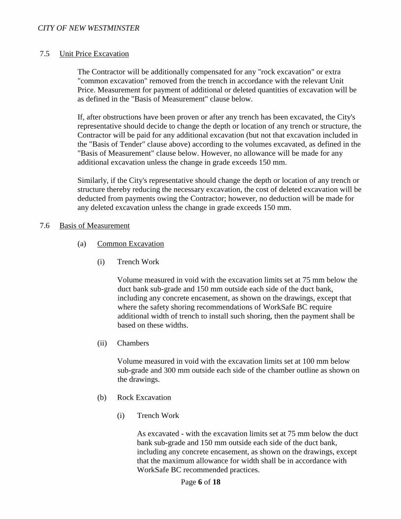
CITY OF NEW WESTMINSTER
Page 6 of 18
7.5 Unit Price Excavation
The Contractor will be additionally compensated for any "rock excavation" or extra
"common excavation" removed from the trench in accordance with the relevant Unit
Price. Measurement for payment of additional or deleted quantities of excavation will be
as defined in the "Basis of Measurement" clause below.
If, after obstructions have been proven or after any trench has been excavated, the City's
representative should decide to change the depth or location of any trench or structure, the
Contractor will be paid for any additional excavation (but not that excavation included in
the "Basis of Tender" clause above) according to the volumes excavated, as defined in the
"Basis of Measurement" clause below. However, no allowance will be made for any
additional excavation unless the change in grade exceeds 150 mm.
Similarly, if the City's representative should change the depth or location of any trench or
structure thereby reducing the necessary excavation, the cost of deleted excavation will be
deducted from payments owing the Contractor; however, no deduction will be made for
any deleted excavation unless the change in grade exceeds 150 mm.
7.6 Basis of Measurement
(a) Common Excavation
(i) Trench Work
Volume measured in void with the excavation limits set at 75 mm below the
duct bank sub-grade and 150 mm outside each side of the duct bank,
including any concrete encasement, as shown on the drawings, except that
where the safety shoring recommendations of WorkSafe BC require
additional width of trench to install such shoring, then the payment shall be
based on these widths.
(ii) Chambers
Volume measured in void with the excavation limits set at 100 mm below
sub-grade and 300 mm outside each side of the chamber outline as shown on
the drawings.
(b) Rock Excavation
(i) Trench Work
As excavated - with the excavation limits set at 75 mm below the duct
bank sub-grade and 150 mm outside each side of the duct bank,
including any concrete encasement, as shown on the drawings, except
that the maximum allowance for width shall be in accordance with
WorkSafe BC recommended practices.

CITY OF NEW WESTMINSTER
Page 7 of 18
(ii) Chambers
As excavated - with the excavation limits set at 100 mm below sub-
grade and 300 mm outside each side of the chamber outline as shown
on the drawings.
Where rock excavation is required above the sub-grade of the duct banks or
chambers, as shown on the drawings, the Contractor will be paid only at the unit
rock excavation price quoted in the Tender. Where rock excavation is required
below the aforementioned sub-grades, the Contractor will also receive the unit
common machine excavation price quoted.
7.7 Subsurface Structures
The drawings show the available information on the type and location of existing surface
and subsurface structures and utilities. Neither the accuracy nor the completeness of this
information is guaranteed.
If the location of such a utility is not as shown on the drawings, but requires that the
underground structures be installed either above or below the utility, then the only unit
price adjustments allowable will be those for additional excavation and backfill.
The Contractor shall be responsible for locating and exposing all buried utility services;
building around, under, or over these services, and taking proper precautions against
accidental damage; temporary supporting where required and removing such supports
upon completion; and maintaining specified clearance between services and the
underground structures.
7.8 Removal of Obstructions
After the excavation is opened and all pipes and other obstructions are exposed, the City's
representative shall be notified that the excavation is ready for examination. Should the
City's representative decide any pipes or other structures excluding pavement at the same
elevation as the trench require moving, the expense of such moving will be borne by the
City, but the Contractor will have no charge against the City by reason of delay so
occasioned, nor shall the Contractor be held responsible for any delay in completion of the
work due solely to the above cause.
If the Contractor wishes to temporarily remove, disconnect, or relocate service pipes
crossing the excavation to facilitate installation of the underground structures, they shall
make their own arrangements with the owners of the service pipes and shall bear all costs
of such temporary work. The City will neither guarantee that such temporary work may be
done nor bear any cost of such temporary work. Payments for all such temporary work
shall be made directly by the Contractor.
Disconnected or abandoned utilities shall not be removed or salvaged without the
permission of the City's representative.

CITY OF NEW WESTMINSTER
Page 8 of 18
7.9 Irregularities in Excavation
All irregularities and cavities in the bottom of the trench or excavation shall be filled up to
the required sub-grade with approved backfill material properly tamped in place.
7.10 Adjacent Structures and Properties
Prior to excavation, the Contractor shall consult and cooperate with owners of adjacent
structures which may be endangered, or whose gardens, trees, tree roots, and shrubs
require protection or alteration during construction, to eliminate future dispute and
litigation over that which may already be in a damaged condition. Under no circumstances
shall the Contractors permit their forces, materials, and/or equipment to encroach on
private properties adjacent to the work, without the express consent of the City's
representative. Any survey pins displaced during the construction work shall be reinstalled
by a legal surveyor at the Contractor's expense.
7.11 Drainage and Shoring
The Contractor shall, without additional charge, construct such temporary drains or do
such dewatering of the trench and chamber excavations as may be necessary to keep water
away from concrete work until the concrete has thoroughly set.
Without additional charge, the Contractor shall provide and place adequate shoring as
required by WorkSafe BC and as required to protect adjacent paving and structures, and to
prevent any sloughing in of material that is under adjacent sections of sidewalk, road
pavement, pipes, or ducts.
8. UNDERGROUND DUCTS, CHAMBERS, AND TRANSFORMER PADS
The location, number, and arrangement of ducts, chambers, transformer pads, and service boxes
shall be as shown on the drawings. Ducts may be directly buried, concrete encased, or a
combination of both as specified on the drawings. The size, shape, routing, and concrete
encasement of ducts between terminations may be varied by the City's representative according
to space available in the street or the obstructions encountered as may be determined after the
trench is excavated.

CITY OF NEW WESTMINSTER
Page 9 of 18
9. PROTECTION OF FOREIGN UTILITIES
In the performance of the work, care shall be taken not to move, without consent of the proper
parties, any structure, and in crossing or running parallel with any structures they shall be
secured in place until the work is completed. Any damage to structures of any kind, caused by
neglect to attend to such structures, shall be paid by the Contractor.
The Contractor shall build around, under, over, or through pipes, sewers, culverts, catch basins,
or any other structure encountered in the line of the work, or shall divide the ducts so as to lay
part on each side either horizontally or vertically or both, of any such structure, as required by
the City's representative, and shall supply such materials and make such alterations, substitutions
and repairs as may be required for such work. Whenever concrete duct bank is so divided, each
part must have a full concrete envelope 75 mm in thickness.
10. DUCT INSTALLATION
10.1 URD/UD Class Ducts
It is recommended that excavation for transformer pads be completed and trenching
extended from the respective pads. This permits duct bends to be secured and tamped in
the pad subsurface and duct laying can proceed therefrom in the excavated trench.
In locations other than where native soil is a fine sandy material completely devoid of
rocks or small stones, a 75 mm layer of sand shall be placed in the bottom of the trench.
The plastic duct shall be either direct buried or encased in concrete as shown on the
drawings. All joints shall be cemented and joined in an approved manner. Duct runs
except stubbed off sections shall be terminated with preformed bell ends and plugs. The
caps installed on stubbed off service ducts shall not be cemented, however, caps shall be
cemented on main runs intended for future extension.
10.2 Feeder Ductbanks
The Contractor shall build complete forms to the full height of, and on each side of every
duct bank, before pouring concrete or laying duct. Forms shall be made rigid and shall be
adequately braced to prevent bulging or movement. All duct banks shall be poured on a
minimum 50 mm thick bed of 40 mm minus drain rock, supplied and placed by the
Contractor without additional compensation.
Duct banks shall be installed in accordance with the following procedure:
(a) After the grade of the trench has been checked by the City's representative, a 75 mm
base of stiff concrete shall be poured in sufficient quantity that the bottom row of
ducts may be laid before the concrete has attained its initial set.
(b) The duct shall be checked for defects in material and structure before being placed
in the trench. Any field-cut ducts or bends shall have their inside edges bevelled
smooth by sanding. The bottom row of ducts shall then be laid, with open ends

CITY OF NEW WESTMINSTER
Page 10 of 18
closed with plugs secured to prevent removal by hand. Any work done to repair or
connect to existing transite ducts must comply with approved methods and
regulations for working with asbestos cement duct.
(c) For 4-inch and 5-inch ducts, a separation of 45 mm, both vertically and horizontally,
shall be maintained between ducts by the use of approved separators of the correct
dimensions. However, vertical separation shall be increased to 115 mm before
entering a manhole, unless otherwise noted on the drawings. Increase in vertical
separation shall begin a minimum of 6 m back from the outside face of the manhole.
(d) The duct joints shall be staggered at least 150 mm from neighbouring duct joints in
both the vertical and horizontal rows.
(e) After the alignment has been checked by the City's representative, the concrete
sheathing and fill shall be poured around the ducts to the level set by the City's
representative. The Contractor shall ensure that the correct duct separations and
thicknesses of concrete are maintained at all times.
(f) The separators shall then be removed and the holes filled with concrete.
(g) The next horizontal row of ducts shall then be laid and the same procedure repeated
until the required section is obtained and the top 75 mm concrete sheathing is
complete.
(h) The ends of ducts in a run, which will be extended later, shall be staggered and shall
extend at least 300 mm beyond the end of the concrete envelope. The open ends of
these ducts shall be closed with caps cemented in place.
10.3 Mandrelling and Duct String
(a) URD/UD Class Ducts:
The ducts shall be proven clean and free of obstructions or faulty joints by use of a
Greenlee Piston or an acceptable combination of mandrell, swab, and wire brush to
the satisfaction of the City's representative.
(b) Feeder Class Ducts:
When the duct work is completed and the concrete and mortar thoroughly set, a test
mandrel shall be drawn through each duct in the presence of the City's
representative. The test mandrel will be comprised of a wire brush, cutter and disc
type mandrel (General Machine Products attachment Part No. 25, Cat. No. G-1011,
followed by Part No. 27 or equivalent, sized according to the duct). The minimum
diameter of such mandrels shall be 0.5 inch below the nominal duct size.
After test-mandrelling, an approved light waterproof cord shall be left through all ducts or
as designated by the City’s representative.

CITY OF NEW WESTMINSTER
Page 11 of 18
10.4 Feeder Duct Measurements
Duct measurement shall be from centre to centre of chamber covers, or centre of chamber
cover to centre of terminal poles, measured horizontally, less the distance from centre of
chamber cover to face of duct where it enters each chamber.
11. CHAMBERS
11.1 General
Chambers are vaults, manholes, spliceboxes, and similar structures. Some chambers are
prefabricated and will be designated as such on the drawings and supplied from the City
stores or manufacturer's plant depending upon size.
11.2 Chambers Built on Site
Chambers built on site shall be in accordance with the contract drawings except where
changes to location and shape are authorized by the City's representative.
Floor slabs shall be poured on a minimum 50 mm thick bed of 40 mm minus drain rock
supplied, placed, and compacted by the Contractor.
After formwork is completed care, shall be taken in placing concrete for wall cavities.
Concrete lifts for such cavities shall not exceed 300 mm and concrete for such lifts shall
be first placed on the manhole roof form or a pouring deck before placing into wall
cavities. Concrete shall not be poured directly into wall cavities. Wall pours must be
continuous until completed.
The top of the chamber roof and the chamber casting shall be set to conform to the line of
the street or as otherwise determined by the City's representative. Manhole openings shall
have a 75 mm chamfer at the bottom. Manholes are normally built with a brick chimney,
cement rendered inside and out, extending from the chamber roof slab to the underside of
the cover castings to allow for any subsequent lowering of street grade. Cement bricks or
equivalent materials are to be supplied and installed by the Contractor for this purpose as
required by the City's representative. The Contractor shall also install a 250mm
ventitaliton hose casting in a manner similar to the manhole lid.
11.3 Precast Chambers
(a) Base Preparation
(i) The excavation shall be completed and roughly leveled to the proper
elevation.
(ii) Timber screeds shall then be set to the elevation of the base of the precast
chamber. The screeds shall be leveled to a tolerance of ±6 mm.

CITY OF NEW WESTMINSTER
Page 12 of 18
(iii) 150 mm of 40 mm minus drain rock or sand shall be placed, leveled,
compacted to 90% Modified Proctor, and struck-off level with the top of the
timber screeds.
(iv) During this base preparation the precast sump and drainage duct shall be
installed. If not connected immediately, drainage duct shall stubbed off at
least 600 mm beyond the manhole wall in the direction indicated by the City's
representative.
(v) Under wet conditions, at the discretion of the City's representative, the above
150 mm layer of drain rock shall be increased to 200 mm.
(b) Placing
(i) Manhole sections shall be placed with great care. The responsibility of off-
loading and placing manholes (or sections) into excavations shall be the
Contractor's. Care shall be taken to maintain adequate clearances from hoist
booms to overhead conductors.
(ii) Gaskets - Care shall be taken to place precast sections so that gaskets between
sections are totally contained and compressed.
(iii) Sumps - A suitable sealing grout shall be placed, at the the City
representative's direction, between sump and base of manhole.
11.4 Duct Terminations
The Contractor shall terminate all ducts with bell ends installed 75 mm back from the
inside face of chamber walls when poured in place (25 mm back when precast), and shall
finish the recesses with chamfered edges in a clean and workmanlike manner. For precast
manholes any wall openings shall be filled with concrete to the satisfaction of the City's
representative.
Where the drawings indicate a future duct bank on any face of a chamber, a brick window
100 mm thick, cement rendered both sides, shall be provided.
11.5 Chamber Designations
Each manhole lid shall be permanently identified by the Contractor with the letters CNWE
and the manhole number (MHXXX).
Secondary service boxes shall be identified with the letters CNWE only.
CITY OF NEW WESTMINSTER
Page 13 of 18
11.6 Irons, Hooks, Rods, and Inserts
The Contractor shall set pull-in irons, hooks, and inserts as shown on the contract
drawings or as specified by the City's representative.
The Contractor shall install in each manhole and vault, at points designated by the City's
representative, suitable grounding rods about 9 feet long, driven at a 45 angle downward
into the ground so that the upper ends shall project into the manhole about 100 mm.
11.7 Drainage
(a) All manholes and vaults shall be provided with a sump. Manholes and vaults shall
be drained as shown on the drawings or as required by the City's representative.
Drain pipes shall be of approved grade of vitrified clay, or PVC. Backwater valves
and P-traps with cleanout and strainers shall be installed as shown on the drawings
or as required by the City's representative.
(b) All drainage pipe, valves and P-traps shall be provided by the Contractor.
(c) Connection of drains to City sewers or catch basins will normally be done by the
Contractor. Drainage excavations shall then be back-filled to the same standards as
set for duct excavation. All costs of installing and backfilling drains shall be
included in the lump sum bid price. Under no circumstances will laying of drains as
shown on construction drawings be considered as unit price or extra work.
11.8 Removal of Forms and Traffic Loading
Inside roof forms of poured-in-place chambers will not be removed for a minimum of 14
days if the chamber is in the sidewalk and 21 days if in the travelled road.
Poured-in-place chambers shall not be subjected to traffic loading for 21 days unless
otherwise directed by the City's representative.
12. BACKFILL
12.1 General
The Tenderer shall allow for the supply and placement of backfill materials in accordance
with these Tender Documents, and the clean-up after backfill.
Backfill will normally be imported granular or sand material (see below). However, native
materials may be used, at the City representative's discretion, if location and soil
conditions are considered satisfactory, and/or if specified in the Project Specifications.

CITY OF NEW WESTMINSTER
Page 14 of 18
12.2 Backfill Materials
Unless otherwise specified in the Project Specifications or by the City's representative, the
excavation shall be backfilled as follows:
(a) To 150 mm above direct buried ducts or 200 mm above concrete encased ducts with
approved sand, hand tamped. A portable plate vibrator may be used at the discretion
of the City's representative.
(b) From the point specified in (a) above to the point specified in (c) below with any of
the following materials, providing all materials are compacted in accordance with
the compaction clause below. Backfill shall be done in maximum lifts of 300 mm
(loose) for imported material or 150 mm to 200 mm (loose) for native material
unless otherwise specified by the City's representative. Warning tape reading, as a
minimum, "Caution Buried Electric Line Below" shall be supplied and installed by
the Contractor at a depth of 300mm below finished grade.
(i) Sand
Sand shall be free of organic materials, clay or silt. 100% shall pass a 5 mm
sieve, 90 – 100% shall pass a 2 mm sieve and not more than 5% shall pass a
75 m mesh sieve by mass. Fraser River pump sand is acceptable.
(ii) Combined Crushed Aggregate Fill
This fill shall be free from organic materials, clay or silt. The fraction retained
on a 10 mm sieve shall be at least 50% crushed. The fraction passing a 75 m
mesh sieve shall be not more than 5% by mass.
(iii) Select Backfill
This material shall be essentially granular and shall not contain stones larger
than 75 mm, organic material, silt or clay. The fraction passing a 75 m mesh
sieve shall not be more than 5% by mass.
(iv) Native or Random Backfill
This material may be used, if the required compaction can be obtained.
Compaction ability is very dependent upon water content and to obtain
approval for use of this material the Contractors may be called upon to
demonstrate their methods and machinery to prove to the City's representative
that the compaction requirements can be met. In any event, all stones larger
than 150 mm must be removed.

CITY OF NEW WESTMINSTER
Page 15 of 18
(c) The top zone of the excavation shall be backfilled with 300 mm of 20 mm minus
combined crushed aggregate fill where the excavation is situated in a paved or
travelled road; 150 mm of 20 mm minus combined crushed aggregate where the
excavation is situated in a sidewalk; 150 mm of black loam where the excavation is
situated in a developed grass boulevard. All these materials shall be thoroughly
compacted after placement.
(d) In all locations where road paving or sidewalk has been removed for trench
excavation the Contractor shall, unless otherwise directed, supply and place a
temporary tamped asphalt patch within 24 hours of backfilling to facilitate the
movement of traffic and pedestrians until permanent repairs are made. Compacted
thicknesses shall be 50 mm for roads and 25 mm for sidewalks.
(e) In all locations where the excavation is located in developed grass boulevards, the
Contractor shall neatly cut the grass sod and store it in a suitable location. After
backfill is completed the black loam shall be leveled off, raked clear of stones and
debris and the grass sod replaced. If the Contractors damage the adjacent grass, or
are unable to preserve the grass sod, they shall resod the boulevard. The Contractor
shall be responsible for maintaining sod until it has grown to a condition similar to
that existing before excavations were begun. If, in the opinion of the City's
representative, the time of year is not suitable for resodding, the Contractor will be
required to carry out this work at a more seasonable time.
(f) Backfilling of all voids around chambers shall be done with river sand or other
approved material.
The supply and placement of all the above backfill materials including the supply and
placement of sand for the minimum cover over all ducts, and the disposal of any native
excavated backfill materials, shall be the responsibility of the Contractor, and shall be
included in the Contractor's lump sum tender.

CITY OF NEW WESTMINSTER
Page 16 of 18
12.3 Compaction of Backfill
All excavations shall be backfilled with specified materials, placed in layers, and
compacted to the following requirements unless otherwise indicated in the project
specifications:
Minimum Corrected
Dry Density**
(a) Trench in boulevards (assuming
that excavated trench is greater
than excavated depth distance
from roadway, sidewalk, curbs,
walls, or structures) 85%
(b) Trench in all other areas:
Within 1.2 m of the surface 95%
Depths below 1.2 m from surface 85%
** In accordance with ASTM D1557-66T (Modified Proctor) and shall be corrected for
material retained on No. 4 Sieve according to the following formula:
D = Pf x Df + Pt x 0.90 x 62.4G
100 100
Where: D = corrective maximum dry density in pounds per cubic foot for
total sample,
Pf = percent of total sample passing the No. 4 sieve,
Df = maximum dry density in pounds per cubic foot (ASTM D1557-
66T) for material passing the No. 4 sieve,
Pt = percent of total sample retained on the No.4 sieve,
G = bulk specific gravity (dry basis) of material retained on the No. 4
sieve (ASTM C127-59).
Upon request of the City's representative, the Contractors shall, at their own expense,
provide certified test results demonstrating that the above compaction requirements have
been met.
12.4 Unit Price Work - Backfill
Additional unit price excavation shall be backfilled with material specified by the City's
representative. Unit prices for such materials shall be provided by the Contractor;
measurement shall be in accordance with the Basis of Measurement clause above.

CITY OF NEW WESTMINSTER
Page 17 of 18
12.5 Acceptability of Backfill Material
Notwithstanding the backfill materials herein specified, all materials must be satisfactory
to the City.
12.6 Maintenance of Backfill
As part of the work the Contractors shall maintain the backfilled excavation at their own
expense until all settlement has ceased, except that on paved streets they shall maintain the
backfilled trenches and temporary surfaces for 45 days after completion of backfill. This
"completion" will be done on a section-by-section basis and the 45-day period will not
commence until the the City representative's written approval has been obtained that the
backfill of a particular section is completed.
12.7 Liability
In accepting the responsibility for maintenance of backfill, the Contractor shall be fully
responsible for any damage or accident to persons and/or property resulting from the
condition of the backfilled trench.
13. PLAIN AND REINFORCED CONCRETE AND MORTAR
13.1 Applicable Standard Specifications
Except as otherwise specified or shown on drawings, concrete shall comply with the
current A-23 Canadian Standard for Concrete and Reinforced Concrete;
A-23.1 Concrete Materials and Methods of Concrete Construction and A-23.2 Methods of
Test for Concrete.
13.2 Gravel
Stone or gravel used in normal concrete for underground construction shall include all the
aggregate too large to pass through a 5 mm mesh and that which will pass through a 20
mm mesh. Stone or gravel shall be clean, hard, durable, and well graded.
13.3 Concrete
All concrete shall be proportioned to have a compressive strength of not less than 20 MPa
at 28 days. Slump shall be maximum 80 mm and minimum 20 mm. Concrete for manholes
to be compacted by mechanical vibration shall have the following maximum and
minimum slump:
Floors and roofs -- 50 mm maximum, 20 mm minimum.
Walls -- 80 mm maximum, 20 mm minimum.

CITY OF NEW WESTMINSTER
Page 18 of 18
13.4 Mortar
Mortar shall be composed of one part cement and three parts sand by volume, and water,
all as previously specified. Mortar that has been mixed over ½ hour or that has
commenced to set shall not be used. The mortar shall be as dry as practicable to obtain
adhesion. Not more than 5% of Mason's Hydrated Lime shall be added to the mortar.
13.5 Admixtures
The use and choice of concrete admixtures will be subject to the approval of the City's
representative, but the expense of using admixtures shall be borne by the Contractor.
Air-entraining admixtures if used, shall conform to the requirements of ASTM designation
C-260-Current. A cement dispersant may be used at the option of the supplier, with the
approval of the City's representative.
13.6 Air Entrainment
The total air content of the concrete at the time of placing shall be 6% ± 1%.
13.7 Concrete Inspection
To ensure that these requirement are met, test results on concrete shall be supplied to the
City's representative upon request.
14. COMPLETION TIME
Within 5 days of receipt of purchase order, the Contractor shall submit to the City's
representative for approval, a progress schedule showing the proposed dates of the
commencement and completion of the project in the time specified.
15. PERMANENT REPAVING
Unless otherwise specified in the Project Specifications the Contractor will be required to
complete the permanent repaving of excavated areas. The work will normally be done as
follows, unless otherwise specified in the Project Specifications:
Cut (saw cut if necessary) pavement to nominal 150 mm outside of trench width including
adjacent extremities of surface damage, settlement or cracking.
Remove temporary patch and sufficient backfill to replace with a minimum of 75 mm compacted
hot asphaltic material to the elevation of the existing road grade.
No permanent repaving shall be done at air temperatures below -1 C or when the subgrade is
frozen.
In addition to the above, other work including permanent sidewalk and curb and gutter
restoration will, if required by the Project Specification, be completed to the satisfaction of the
City.

CITY OF NEW WESTMINSTER 01 33 50
Front Street MEWS DELEGATED DESIGN SUBMITTALS
Page 1 of 5
1.0 General
1.1 Intent
a) The intent of Delegated Design Submittals required by this section is to
account for professional engineering responsibility for design, review
and acceptance of components of Work forming a part of permanent
Work in accordance with Building Code, and that has been assigned to
a design entity other than Consultant including, but not limited to, the
following:
Design requiring structural analysis of load bearing components
and connections.
Design requiring compliance with fire safety regulations.
Design requiring compliance with life or health safety regulations.
b) This section provides standard forms for submittal of Letters of
Assurance and Due Diligence required complying with requirements of
Building Code and design delegated to a professional Engineer within
technical specification sections.
c) Delegated Design Submittals are not required for components of Work
requiring engineering for temporary Work (for example: crane
hoisting, engineered lifts, false Work, shoring, concrete formwork) that
would normally form a part of Constructor or responsible
Subcontractor’s scope of Work.
d) The requirements of this section are in general conformance with
recommended Responsibilities for Engineering Services for Building
Projects published by Association of Professional Engineers and
Geoscientists of British Columbia (APEGBC), with regards to duties of
specialty professionals appointed during construction period.
e) The requirements of this section do not diminish responsibilities of
Consultant’s role as Registered Professional of Record; submittals will
be used by Consultant to establish that Work is substantially performed
in accordance with Building Code.
1.2 Related Requirements
Structural Drawings
1.3 Definitions
a) Delegated Design Professional Engineer: The professional engineer
hired or contracted to the fabricator or manufacturer to design specialty
elements, produce delegated design submittals and shop drawings to
meet the requirements of the Project; who is registered in the province
of the Work; and who is not the Consultant.

CITY OF NEW WESTMINSTER 01 33 50
Front Street MEWS DELEGATED DESIGN SUBMITTALS
Page 2 of 5
b) Letters of Assurance and Due Diligence: Documents prepared by the
delegated design professional engineer as recommended by
APEGBC’s Bulletin K: Letters of Assurance and Due Diligence.
c) Engineered Judgement for Fire Rated Assembly Components: A
written proposal submitted by manufacturer to the Authority Having
Jurisdiction arising from a variation that modifies the manufacturer’s
standard listed assemblies and details to account for actual site
conditions and as follows:
Engineered Judgements are prepared by a certified specialist that
has completed a sanctioned examination and has professional
accreditation in the assemblies affected by site conditions different
than those forming standard listed assemblies and details.
Person issuing Engineered Judgement must be directly employed
by the manufacturer and have direct experience in the preparation
of Engineered Judgements required for the Project.
Engineered Judgements do not require signature and seal of a
professional engineer unless required by the Authority Having
Jurisdiction.
1.4 Reference Standards
a) Association of Professional Engineers and Geoscientists of British
Columbia (APEGBC):
APEGBC Bulletin K: Letters of Assurance and Due Diligence
1.5 Submittals
a) Provide required information in accordance with Section 01 00 06 –
General Requirements: Submittals.
b) Informational Submittals: Provide the following submittals during the
course of the Work:
Letter of Assurance: Submit a signed and sealed Letter of
Assurance on company letterhead addressed to Consultant in
accordance with format in Appendix A attached to the end of this
Section prior to starting Work requiring design and seal of a
professional engineer.
1.6 Project Closeout Submissions
a) Record Documentation: Submit the following required information in
accordance with Section 01 00 06 – General Requirements: Project
Record Documents before application for Substantial Performance:
Letter of Due Diligence: Submit a signed and sealed Letter of Due
Diligence on company letterhead addressed to Consultant in
accordance with format in Appendix B attached to the end of this
Section on completion of Work requiring design and seal of a
professional engineer.

CITY OF NEW WESTMINSTER 01 33 50
Front Street MEWS DELEGATED DESIGN SUBMITTALS
Page 3 of 5
2.0 Products
2.1 Delegated Design
a) Performance and Design Criteria: Provide products and systems
complying with specific performance and design criteria indicated
where professional design services or certifications by a design
professional are specifically required of Contractor by Contract
Documents.
b) Submit a written request for additional information to Consultant
and Contractor if criteria indicated within documents are not
sufficient to perform services or certification required.
c) Delegated design will be required for elements designed by a
specialty professional, which may include:
Elements normally fabricated off-site
Elements that require specialized fabrication equipment or a
proprietary fabrication process not usually available at job site (for
example: open web steel joists, wood trusses, combination wood
and metal or plywood joists, prefabricated wood or metal buildings,
noise and vibration isolation devices, elevators).
Elements requiring civil engineering, not normally a part of scope
of services performed by architectural; structural; mechanical;
electrical; or geotechnical disciplines of Consultant (for example:
structural steel connection design, steel deck design).
3.0 Execution
3.1 Implementation
a) Include Summary of Work described in technical specification
section as a part of the required Letter of Assurance.
b) Prepare required submittals and present to Consultant within
sufficient time to allow for Consultant’s detailed review and
acceptance.
REMAINDER OF PAGE LEFT INTENTIONALLY BLANK

CITY OF NEW WESTMINSTER 01 33 50
Front Street Parkade Demolition and Rehabilitation DELEGATED DESIGN SUBMITTALS:
APPENDICES
Page 4 of 5
APPENDIX A
LETTER OF ASSURANCE
Submit a signed and sealed Letter of Assurance on company letterhead in the form as follows:
[Date]
DIALOG®
[Consultant’s Address]
Attention: [Consultant’s Registered Professional of Record]
Re: Letter of Assurance for Delegated Design of [System of Component of Work]
Front Street Parkade Demolition and Rehabilitation
04326E0100
New Westminster
As the retained registered professional engineer for design and field review of the above named
component of Work and project, I hereby give assurance I am qualified to perform the following
Work as required by Contract Documents:
1. [List appropriate design services for System or Component of Work];
2. Preparation of shop and erection documents;
3. Review fabrication of [structural] [fire rated] [life and health safety] components;
4. Review erection of [structural] [fire rated] [life and health safety] components.
5. [Modify list to suit System of Component of Work.]
I hereby give assurance that I will be responsible for above noted Work as described in Section
[?????] – [Name of Section] of Project Manual, including requirements of addenda, change
orders and change directives.
I also undertake to be responsible for field review of fabrication and erection of [structural] [fire
rated] [life and health safety] components as required to ascertain substantial compliance with
the Building Code and Contract Documents.
I will notify you in writing if my responsibility is terminated at any time during the course of
Work covered by this Letter of Assurance.
Retained Professional Engineer
Signature
Date
(Apply seal)
SAMPLE LETTER
ONLY

CITY OF NEW WESTMINSTER 01 33 50
Front Street Parkade Demolition and Rehabilitation DELEGATED DESIGN SUBMITTALS:
APPENDICES
Page 5 of 5
APPENDIX B
[LETTER OF DUE DILIGENCE] [LETTER OF COMPLIANCE]
[Date]
DIALOG®
[Consultant’s Address]
Attention: [Consultant’s Registered Professional of Record]
Re: Letter of Due Diligence for Delegated Design of [System of Component
of Work]
Front Street Parkade Demolition and Rehabilitation
04326E0100
New Westminster
I hereby give assurance that I have fulfilled my obligations for field review as outlined by
previously submitted Letter of Assurance.
I hereby give assurance that aspects of [structural] [life and health safety] Work as defined by
previously submitted Letter of Assurance substantially comply with Contract Documents and
Building Code.
Retained Professional Engineer
Signature
Date
(Apply seal)
END OF SECTION
SAMPLE LETTER
ONLY

CITY OF NEW WESTMINSTER 03 08 10
Front Street MEWS TESTING CONCRETE
Page 1 of 3
1.0 GENERAL
1.1 Documents
a) This section, along with the drawings, forms part of the contract documents and is to
be read, interpreted and co-ordinated with all other parts.
1.2 Related Requirements
a) Section 03 11 00 – Concrete Forming
b) Section 03 20 00 – Concrete Reinforcing
1.3 Reference Standards
a) Testing of concrete shall conform to the requirements of the following standards
unless otherwise required by this specification:
Canadian Standards Association (CSA):
CAN/CSA-A23.1-09, Concrete Materials and Methods of Concrete
Construction
CAN/CSA-A23.2-09, Methods of Test for Concrete
British Columbia Building Code 2012
b) Where the standard is referred to in this specification it shall mean the documents
specified in this clause.
1.4 Appointment of Testing Agency
a) The Owner will appoint and pay for the services of a CSA approved testing agency
selected from the following list who shall test all concrete, grout and reinforcing steel
as per this specification.
WSP
Metro Testing Laboratories Ltd.
EXP
b) All technicians employed in the testing shall have taken and successfully completed
the ACI Certification Level I - Concrete Field Testing Technicians course.
c) Submit a list of technicians to be employed on the project for review prior to the start
of concrete work. The list should detail the relevant experience of each individual and
include a copy of their course certification. Only technicians approved by Jones
Kwong Kishi shall be used on the project. The same technicians shall, as much as
possible, be used throughout the project.
1.5 General Testing
a) Submit completed British Columbia Building Code - 2012, Schedule B-1, Assurance
of Professional Design and Commitment for field Review and Schedule B-2,
Summary of Design and Field Review Requirements, together with mix design
review.
b) Review all mix designs and provide detailed comments to the consultant.
c) Review test reports submitted by concrete supplier of the mixing materials for
conformance with project specifications.
d) Review aggregate for conformance to type N concrete.
e) Test chloride-ion content in accordance with ASTM D512.

CITY OF NEW WESTMINSTER 03 08 10
Front Street MEWS TESTING CONCRETE
Page 2 of 3
f) At the completion of the concrete construction, submit a Schedule C-B confirming
review of the concrete and conformance with the project specifications.
1.6 Responsibility of the Contractor
a) The Contractor shall co-operate fully with the testing agency.
b) The Contractor shall give the testing agency at least 4 hours prior notice of a concrete
placement.
c) The Contractor shall provide a finished product that meets the specification. If initial
tests indicate that the concrete failed to meet the specification, then the Consultant
shall decide if any additional testing is necessary in accordance with Section 03 30
00.
1.7 Responsibility of the Testing Agency
a) The Testing Agency shall reject any concrete not meeting the specifications.
b) If the Testing Agency becomes aware that concrete is being placed without their
being notified, or if insufficient notice is received, then the Testing Agency shall
notify the Consultant immediately.
c) Maintain statistical records of all classes of concrete used on the project. Provide an
estimate of the expected strength at acceptance day (28, 56, or 90 days) for each 7-
day test based on the statistical data for the concrete class.
d) Low 7 day and acceptance day strength tests shall be brought immediately to the
attention of the Consultant and the Contractor.
e) Provide a graph of the 3 test running average for each class of concrete on a monthly
basis.
f) Submit report to the Concrete Supplier, Contractor, Owner, Architect and Engineer.
1.8 Testing Frequency
a) Shall conform to the standard except for the following:
The Testing Engineer or his representative shall be on the job site at all times
when column and shear wall concrete above 35 MPa are being placed. He will
test the slump of the concrete from every truck and has the power to and will
reject any concrete that does not comply with the design mix.
The Testing engineer or his representative shall be on the job site at all times
when parking garage concrete is being poured. Test slump in accordance with
CAN/CSA A23.1 clause 4.4.3 and air content in accordance with clause 4.4.4. Air
content shall be taken in accordance with clause 4.4.2 Note (b) or the air content
loss from the point of discharge to the point of deposition shall be established and
air test results corrected accordingly.
Take not less than one set of three cylinders for every 100 cubic metres of
concrete placed and no less than one set of three cylinders for each class of
concrete placed on any one day. One of the cylinders shall be tested for 7-day
strength and the remaining two for acceptance day strength.
CITY OF NEW WESTMINSTER 03 08 10
Front Street MEWS TESTING CONCRETE
Page 3 of 3
1.9 Field Cured Cylinders
a) Shall conform to the standard, except the cylinder shall be stored on the floor right
below the slab it represents and be protected against the wind unless the floor below
is heated in which case the cylinder shall be stored on top of the slab but covered with
a plywood box. The cylinder is to be left undisturbed at this location until picked up
by the testing agency.
END OF SECTION

CITY OF NEW WESTMINSTER 03 11 00
Front Street MEWS CONCRETE FORMING
Page 1 of 3
1.0 GENERAL
1.1 Documents
a) This section, along with the drawings, forms part of the contract documents and is to
be read, interpreted and co-ordinated with all other parts.
1.2 Description of Work Included
a) Provide all labour, materials, equipment and services necessary to supply, erect, and
strip all formwork and falsework for cast-in-place concrete shown or indicated on the
contract drawings and specifications.
1.3 Related Requirements
a) Section 03 20 00 – Concrete Reinforcing
b) Section 03 31 00 – Cast-in-Place Concrete
1.4 Reference Standards
a) Concrete formwork shall conform to the requirements of the following standards
unless otherwise required by this specification:
American Concrete Institute (ACI):
ACI 347-04, Guide to Formwork for Concrete
British Columbia Building Code - 2012
Canadian Standards Association (CSA):
CAN/CSA-A23.1-14, Concrete Materials and Methods of Concrete
Construction
CSA-A23.3-04 (R2010), Design of Concrete Structures
CAN/CSA-S269.1-1975 (R2003), Falsework for Construction Purposes
CAN/CSA-S269.3-M92 (R2003), Concrete Formwork
WCB of British Columbia - Section 34.28
b) Where the standard is referred to in this section it shall mean the documents specified
in this clause.
2.0 Products
2.1 General
a) Products shall satisfy the requirements of the standard unless otherwise specified
herein or on the drawings.
2.2 Materials
a) Forms for concrete, except as specified under item .2, shall be G.I.S. sanded exterior
grade Douglas Fir plywood in as large a sheet as practical, or steel or other pre-
approved form grade material. Forms for exposed concrete surfaces or surfaces to
receive waterproof membrane shall not have patches, broken edges, or joint spacing
greater than 1/16".
b) Forms for special architectural finishes shall be overlay or coated plywood.
c) The form release agent shall be a pre-approved chemical agent, not an oil, and shall
be compatible with the waterproofing treatment or membrane materials and any other
special finishes that are to bond directly on to concrete surfaces.

CITY OF NEW WESTMINSTER 03 11 00
Front Street MEWS CONCRETE FORMING
Page 2 of 3
d) Form ties shall be of a type which leaves no metal within 1" of the concrete surface
and shall be to the approval of the Consultant.
2.3 Design of Formwork, Falsework and Reshoring
a) Conform to the standard.
b) The Contractor shall assume full responsibility for the structural adequacy of the
forms to withstand all concrete and construction loads.
c) Where concrete is exposed to view, forms are to be laid out so that joints are kept to a
minimum and located in an orderly and symmetrical arrangement where possible. The
location of form ties shall be evenly spaced and in straight horizontal and vertical
lines. Refer to architectural drawings for special layouts. Spacing and location of
form tie holes shall be detailed by the Contractor and approved by the Consultant.
d) The strength and rigidity of forms shall be such that they will not leak mortar or result
in visible irregularities in the finished concrete, but in any case the deflection of
facing materials between studs as well as deflection of studs and whalers shall not
exceed 0.0025 times the span.
e) Forms shall be so constructed that the finished concrete will conform to the shape,
dimensions and tolerances as specified in the standard or on the structural drawing,
whichever is most rigorous. They shall also incorporate the cambers specified on the
structural drawings.
f) The Contractor shall submit details of sequence and extent of formwork removal and
re-shoring to the consultant for review. Such details shall include magnitude of loads
and location of all reshores at each level. Calculate floor reshore capacity based on
percent of design concrete strength and include a reduction of .80 to account for
unknowns in load sharing. Forms shall not be removed or adjusted until the review is
complete. Such review does not relieve the Contractor of responsibility for formwork
reshoring and safety during construction.
3.0 Execution
3.1 General
a) All phases of concrete formwork construction shall be in accordance with the
standard unless otherwise specified herein or on the drawings. The work shall be done
by workers who are skilled and experienced in their trade.
3.2 Erection
a) Install all inserts including anchors, reglets, ties, bolts, nailers, and forms for openings
as required by all trades.
b) Provide all mechanical and electrical blockouts and sleeves as shown on the drawings
or required in the specifications. Sleeves, openings, etc. not on the structural drawings
must be approved by the Consultant. Sleeves, openings, etc. shown on the structural
drawings must be co-ordinated with the drawing of other disciplines.
c) Keep all untreated forms moist to prevent shrinkage prior to placing of concrete and
wet the surface at time of placing.
d) Treated formwork surfaces shall have the approved form coating applied in
accordance with the manufacturer's recommendations, prior to placing reinforcing
steel. Remove any excess form coating.

CITY OF NEW WESTMINSTER 03 11 00
Front Street MEWS CONCRETE FORMING
Page 3 of 3
3.3 Removal of Formwork
a) Forms shall not be removed until concrete has attained sufficient strength that no
damage to strength or continuity of concrete will occur when forms are removed.
Time for formwork removal of suspended concrete shall be approved by the
Consultant. See also the requirements of section 2.
b) Prying against face of concrete to remove forms is not allowed, only wooden wedges
shall be used.
c) Where forms are being re-used, thoroughly clean and retreat them.
d) Removal of form ties shall be done carefully to avoid marking concrete and to allow
for patching. Grout bottom of form tie hole to prevent rust staining.
END OF SECTION

CITY OF NEW WESTMINSTER 03 20 00
Front Street MEWS CONCRETE REINFORCING
Page 1 of 3
1.0 General
1.1 Documents
a) This section, along with the drawings, forms part of the contract documents and is to
be read, interpreted and co-ordinated with all other parts.
1.2 Description Of Work Included
a) Provide all labour, materials, equipment and services necessary to supply and install
reinforcing steel work shown or indicated in all the contract drawings and
specifications including accessories such as hanger bars, spirals, wire ties, support
bars, chairs, spacer supports or other devices required to position reinforcing
properly.
1.3 Related Requirements
a) Section 03 11 00 – Concrete Forming
b) Section 03 30 00 – Cast-in-Place Concrete
c) Section 05 50 13 – Metal Fabrications
1.4 Reference Standards
a) Concrete reinforcing shall conform to the requirements of the following standards
unless otherwise required by this specification:
ACI Manual of Standard Practice for Detailing
American Society for Testing and Materials (ASTM):
ASTM A185-07, Welded Steel Wire Reinforcing for Concrete
ASTM A497/A497M-06e1, Standard Specification for Steel Welded Wire
Reinforcement, Deformed, for Concrete
British Columbia Building Code - 2012
Canadian Standards Association (CSA):
CAN/CSA-A23.1-09, Concrete Materials and Methods of Concrete
Construction
CSA-A23.3-04 (R2010), Code for the Design of Concrete Structures for
Buildings
CAN/CSA-G30.18-09, Carbon Steel Bars for Concrete Reinforcement
CSA W186-M1990 (R2002), Welding of Reinforcing Bars in Reinforced
Concrete Construction
b) Where the standard is referred to in this section it shall mean the documents specified
in this clause.
1.5 Testing
a) The Owner will engage and pay for a CSA certified testing laboratory to test all
reinforcing as detailed in the following sections:
The testing laboratory shall perform at least one tensile and bend test for each bar
size used on this project. Such testing shall comply with CSA G30.18.

CITY OF NEW WESTMINSTER 03 20 00
Front Street MEWS CONCRETE REINFORCING
Page 2 of 3
The Consultant will select the bars to be tested from the reinforcing supplied to
the construction site, not from the suppliers' yard. The Contractor shall cut the
bars to the required length and replace the shortened bars without cost to the
Owner.
Reinforcing shipped to site shall be tagged to identify mill, grade of steel, lot or
heat number from the manufacturers bill, a copy which shall be sent to the
consultant at the same time.
b) The Contractor shall supply mill certificates of chemical analysis in accordance with
CSA G30.18.
2.0 Products
2.1 General
a) Products shall satisfy the requirements of the standard unless otherwise specified
herein or on the drawings.
2.2 Materials
a) Reinforcing bars shall conform to CSA G30.18-Grade 400R except those bars to be
welded, pile reinforcement and those required for ductile seismic elements. See shear
wall and frame detail drawings for reinforcement required to conform to CSA
G30.18-Grade 400W.
b) Reinforcing not marked in accordance with the above standards shall be considered as
300 MPa reinforcing until the following information has been received in writing
from an independent CSA certified testing firm.
Name of mill where reinforcing was produced.
Explanation of all marks rolled into surface of bars, especially the difference
between 300 MPa and 400 MPa grade reinforcing.
Complete set of tests for each size of reinforcing used.
c) Reinforcing bars to be welded shall conform to CSA G30.18-Grade 400W.
d) Welded wire fabric shall conform to ASTM A185 or ASTM A497, size and gauges as
shown on the drawings.
e) Welded wire fabric for slabs shall be delivered in sheets.
2.3 Fabrication
a) Reinforcing bars shall be cold bent. Special attention shall be paid to mandrel size to
assure that all bends are to the correct radius. Bars shall not be straightened or rebent.
No bars partially embedded in concrete shall be field bent except as shown on
drawings or as specifically permitted by the Consultant.
b) Splices in reinforcing bars at locations not shown on the drawings may be
pre-approved by the Consultant. Such splices shall conform to the splice length for
that class of splice according to CSA-A23.3.
3.0 Execution
3.1 General
a) All phases of concrete reinforcement work shall be in accordance with the standard
unless otherwise specified herein or on the drawings. The work shall be done by
workers who are skilled and experienced in their trade.

CITY OF NEW WESTMINSTER 03 20 00
Front Street MEWS CONCRETE REINFORCING
Page 3 of 3
3.2 PLACING
a) Reinforcing of size and shapes shown on the structural drawings shall be accurately
placed in accordance with the drawings and the requirements of the standard.
b) Reinforcement shall be adequately supported by chairs, spacers, support bars, hangers
or other accessories, and secured against displacement within the tolerances permitted
in the standard. Support devices contacting surfaces exposed to the exterior shall be
non-corroding. Bars that are not part of the structural design or drawings, and whose
only function is supporting other reinforcing in lieu of other support accessories, shall
also be considered as accessories.
c) At the time concrete is placed, reinforcement shall be free from rust, scale or other
coatings that will destroy or reduce the bond.
3.3 Welding
a) Any welding of reinforcing steel shall be in accordance with CSA W186.
b) Copies of the Canadian Welding Bureau approved welding procedure and certificate
of current operator qualification shall be submitted to the Consultants prior to
commencement of welding.
END OF SECTION

CITY OF NEW WESTMINSTER 03 31 00
Front Street MEWS CAST-IN-PLACE CONCRETE
Page 1 of 8
1.0 General
1.1 Documents
a) This section, along with the drawings, forms part of the contract documents and is to
be read, interpreted and co-ordinated with all other parts.
1.2 Description Of Work Included
a) This section of the contract shall include the furnishing of all labour, material,
equipment and services necessary and incidental to the completion of reinforced
concrete work indicated on the drawings and specified herein.
b) This shall include but not be limited to the following:
Concrete work for footings, pilecaps, walls, pedestals, beams, columns, slabs,
slabbands and bases.
Slabs on grade, walks, etc., including construction joints and saw cut joints.
Concrete retaining walls, concrete trenches and concrete enclosed pipes.
Nailing strips, anchor bolts, inserts, ties, etc., except where otherwise indicated.
Setting of inserts, bolts and other embeded elements to attach precast, structural
steel, miscellaneous metal, masonry, heavy timber and other
architectural/mechanical/electrical components to the structural concrete as
applicable.
Expansion joints and control joints.
Sumps, tanks and pits.
Concrete bases for equipment.
Grouting of base plates.
1.3 Related Requirements
a) Section 03 08 10 – Testing of Concrete
b) Section 03 11 00 – Concrete Forming
c) Section 03 20 00 – Concrete Reinforcing
d) Section 07 05 53 – Fire and Smoke Assembly Design Requirements and
Identification
1.4 Reference Standards
a) Concrete work shall conform to the requirements of the following standards unless
otherwise required by this specification:
American Society for Testing and Materials (ASTM):
ASTM D512
British Columbia Building Code - 2012
Canadian Standards Association (CSA):
CAN/CSA-A23.1-14, Concrete Materials and Methods of Concrete
Construction
CAN/CSA-A23.2-14, Methods of Test and Standard Practices for Concrete
CSA-A23.3-04, Design of Concrete Structures
CAN/CSA-S413-14, Parking Structures
b) Where the standard is referred to in this specification it shall mean the documents
specified in this clause.

CITY OF NEW WESTMINSTER 03 31 00
Front Street MEWS CAST-IN-PLACE CONCRETE
Page 2 of 8
c) A copy of the standard shall be kept by the Contractor on site for the duration of the
work and be made available for reference.
1.5 Testing
a) As per Section 03 08 10.
2.0 Products
2.1 Materials
a) All materials and methods used in concrete work shall be in accordance with CSA
A23.1 and A23.2, for concrete and reinforced concrete.
2.2 Concrete Mixing Material
a) Cement shall be Type GU and conform to the standard.
b) Cement for parking slabs shall conform to the standard.
c) Aggregates shall be natural stone and shall be type N as defined in Appendix D of the
British Columbia Building Code – 2012.
d) Mixing water shall conform to the standard.
e) Air entraining admixtures shall be used in all concrete and shall conform to the
standard.
f) Pozzolanic admixtures may be used and shall conform to the standard.
g) Chemical admixtures may be used for specific purposes providing they conform to
the standard and have been approved by the Consultant.
h) Calcium chloride, either as a raw material or as a constituent in another admixture,
shall not be used unless it is deemed acceptable by the Consultant.
i) Concrete for parking levels and post-tension floors shall contain not more than 0.06%
water-soluble chloride-ion by weight of cementing materials, including chlorides
contained in admixtures, as determined in accordance with ASTM D512.
j) Curing compounds shall conform to the specification and shall also be compatible
with specified floor hardeners, covering adhesives and waterproofing compounds.
k) Grout shall be pre-approved pre-mixed non-shrink conforming to the standard.
Exposed grout shall be non-staining cement with color to match adjacent concrete.
l) Submit test reports to the Testing Engineer certifying compliance of all materials and
admixtures to the requirements of CSA A23.1 and this specification.
m) Submit samples of all cement used to the testing engineer.
2.3 Mix Designs
a) The Contractor shall be responsible for mix designs as detailed in CSA A23.1 Clause
4.1.2.1 Alternate 1. The property requirements are shown on the structural drawings.
b) Submit data for mix design based on Alternate A or B below:
Alternate A:
Submit data suitable for review to the Structural Engineer and Materials Testing
Agency certifying that the mix satisfies the requirements for concrete properties
of cement type, strengths, slump, aggregate size and exposure class shown in the
General Notes on Structural Drawings.

CITY OF NEW WESTMINSTER 03 31 00
Front Street MEWS CAST-IN-PLACE CONCRETE
Page 3 of 8
Under a confidentiality agreement, submit to the Materials Testing Agency data
suitable for review confirming types of supplementary cementing materials and
percentage of total cementing material, mix of sand and aggregate, water cement
ration, air content, types and amounts of admixtures, plastic properties, and
quantities and types of any other constituents in the mix.
Alternate B:
Submit data suitable for review to the Structural Engineer and the Materials
Testing Agency certifying that the mix satisfies the requirements for concrete
properties of cement type, strength, slump, aggregate size and exposure class
shown in the General Notes on Structural Drawings.
Submit to the Structural Engineer and Materials Testing Agency a letter sealed by
a Professional Engineer registered in the jurisdiction where the project is being
built stating the mix design and production satisfy the requirements of the plans
and specifications and CSA A23.1 and referenced documents. Such a letter is
available from the Structural Engineer for signing.
Submit to the Materials Testing Agency test results suitable for review sealed by
the same Professional Engineer for the proposed mixes confirming strength at
specified age, air content, slump and volume stability requirements.
2.4 Addition of Water
a) To conform to CSA-A23.1, Clause 5.2.4.3.
b) In brief, no water from the truck system or elsewhere shall be added after the initial
introduction of the mixing water for the batch except when, at the start of discharge,
the measured slump of the concrete is less than that specified and no more than 60
minutes have elapsed from the time of batching to the start of discharge. In this case
water may be added by the producer up to an amount not exceeding 16 litres per
cubic metre, or 10% of the mixing water. The resulting concrete must satisfy the
specified requirements. However, the concrete may be used as long as it is of such
slump that, in the opinion of the representative of the Engineer, it can be placed and
properly consolidated without the addition of any other water to the batch but in no
case shall the time between batching and complete discharge exceed 120 minutes.
2.5 Strength Requirements
a) In accordance with CSA A23.1, Clause 4.4.6.7.1 to be considered a member of a class
all components of the mix shall be identical and the proportions identical with all the
other members of the class.
b) Failure to meet test requirements:
The consultant, upon request, will select measures from CSA A23.1, Clause 4.4.6.8.1
which he feels are appropriate. Cores shall generally be tested wet in accordance with
the standard for all exposures. The acceptance criteria of Clause 4.4.6.7.2 shall be
modified if cores are tested air dry for columns and shear walls as follows:
Clause (a) Substitute 100% for 85%
Clause (b) Substitute 90% for 75%
If any of the criteria are not met, the Consultant shall have the right to have the
suspect concrete removed and replaced at no cost to the Owner.

CITY OF NEW WESTMINSTER 03 31 00
Front Street MEWS CAST-IN-PLACE CONCRETE
Page 4 of 8
Load tests shall be made not less than sixty days after concrete is placed. The expense
of such load tests shall be paid for by the Contractor.
In the event that a load test causes in the opinion of the Consultant injury or
permanent deformation, the Consultant will have the right to require strengthening or
replacement of those portions of structure which fail to develop required strength. All
expense shall be paid by the Contractor.
3.0 Execution
3.1 Shop Drawings
a) Submit shop drawings, if requested by the Consultant, of reinforcement placement
details in areas of congestion such as beam-columns, beam-wall junctions, etc.
b) Adjust reinforcement for any changes to the concrete outline made on the job. He
shall inform the Consultant of such adjustments and changes.
3.2 Inspection By Engineer
a) Submit to the Consultant for approval the proposed schedule of concrete placing
sequences.
b) Give the Consultant at least one working day notice of when inspection is required, so
that the Consultant or his representative may review:
Bending and placing of reinforcement.
Cleanliness of forms, freedom and debris.
Mixing and conveying equipment.
c) Access shall be provided by the Contractor for inspection purposes. Allow 4 - 8 hours
to inspect any section of completed placement of reinforcing steel dependent of the
size of pour. Reinforcing steel shall be in place a minimum of 6 working hours prior
to placing concrete.
d) The Contractor must check his own work and the subtrades work before the
inspection by the Consultant. Construction that is not in accordance to plan and/or
specifications must be remedied by the Contractor at his cost whether the error is
discovered before or after concrete is poured.
3.3 Faulty Work
a) All work which has been condemned by the Consultant because of poor
workmanship, faulty materials, or for not being built in accordance with the plans,
omissions, or other causes shall be cut out and replaced as and when the Consultant
directs, and to his approval, all at the expense of the Contractor.
b) Submit design notes, and drawings, if requested by the Consultant, for approval
before any remedial work is carried out. Should the remedial work be of structural
significance the design must be performed by a Professional Engineer and bearing his
seal, hired and paid for by the Contractor
3.4 Preparation Of Equipment And Place Of Deposit
a) Before placement, all equipment for mixing and transporting the concrete shall be
cleaned, and all debris and ice shall be removed from the places to be occupied by the
concrete. Forms shall be thoroughly wetted (except in freezing weather) or oiled. The
reinforcement shall be thoroughly cleaned of ice, dirt, scale, or other coating.

CITY OF NEW WESTMINSTER 03 31 00
Front Street MEWS CAST-IN-PLACE CONCRETE
Page 5 of 8
b) Water shall be removed from place of deposit before concrete is placed unless
otherwise permitted by the Consultant. All laitance and other unsound material shall
be removed from hardened concrete before additional concrete is added.
3.5 Placing
a) Concrete shall be discharged at the job and placed in its final position in the forms
within 120 minutes after the introduction of the mixing water to the cement and
aggregate. No concrete shall be allowed to fall freely for more than 1500 mm (5 ft)
without the use of chutes to prevent segregation. The placing of concrete shall be
carried on at such a rate that concrete is at all times plastic and flows readily into the
spaces between the bars. No concrete that has been contaminated by foreign material
shall be used, nor shall retempered concrete be used unless approved by the
Consultant.
b) When placing is once started, it shall be carried on as a continuous operation until
placement of the panel or section is completed. When construction joints are
necessary, they shall be made in accordance with section "Construction Joints".
c) All concrete shall be thoroughly consolidated by suitable means during placement. It
shall be thoroughly worked around reinforcement and embedded fixtures and into the
corners of the forms.
3.6 Curing
a) Concrete surfaces shall be cured for either 3 days at a minimum temperature of 10C.,
or for the time necessary to attain 35% of the specified 28 day compressive strength
of the concrete.
b) All parking decks and ramps shall be protected from premature drying and extremes
of temperature, and shall be wet-cured at a temperature of at least 10C for a
minimum period of 3 days. Total curing time to be 7 days minimum at a temperature
of at least 10C and for the time necessary to attain 70% of the specified strength.
3.7 Cold Weather Requirements
a) Adequate equipment shall be provided for heating concrete materials and protecting
concrete during freezing weather. No frozen materials or materials containing snow
or ice shall be used.
b) All reinforcement, forms, fillers, and ground with which the concrete is to come in
contact shall be free from snow and where ambient temperature is below 4C. all
concrete placed in the forms shall have a temperature of 7C. or higher after
placement. Adequate means shall be provided for maintaining this temperature for 4
days. When high-early-strength concrete is used, a temperature of at least 7C. shall
be maintained for 3 days. In either case, any additional time necessary to ensure
proper curing of the concrete shall be provided as directed by the Consultant. The
housing, covering or other protection used in connection with curing shall remain in
place and intact at least 24 hours after the artificial heating is discontinued. No
dependence shall be placed on salt or other chemicals for the prevention of freezing.
3.8 Hot Weather Requirements
a) In hot weather, suitable precautions shall be taken to avoid drying of the concrete
prior to finishing operations. Use of windbreaks, sun-shades, fog sprays, or other
devices shall be pre-approved by the testing Consultant.
CITY OF NEW WESTMINSTER 03 31 00
Front Street MEWS CAST-IN-PLACE CONCRETE
Page 6 of 8
b) Concrete deposited in hot weather shall not have a placing temperature which will
cause difficulty from loss of slump, flash set, or cold joints. Concrete temperature
shall be less than 32C., unless high temperatures are permitted by the Consultant.
3.9 Rain
a) No concrete shall be placed during rainfall intense enough to separate the cement
from the surface of the concrete mixture.
b) Concrete poured prior to rainfall shall be protected by mats or other appropriate
means.
3.10 Pipes, Conduits, Etc. Embeded In Concrete
a) Pipes or conduits if permitted to be embedded in structural concrete shall follow the
guidelines listed on the drawings.
b) In columns where electrical conduits or pipes are allowed to be embedded, no pipe
surface shall extend into the concrete cover specified for reinforcing steel.
c) Sleeves or other pipes passing through floors, walls, or beams shall not be of such
size or in such locations as to impair the strength of the structure. Such sleeves or
pipes may be considered to replace the displaced concrete provided they are not
exposed to rusting or other deterioration, are of uncoated iron or steel not thinner than
standard wrought iron pipe, have a nominal inside diameter not over two inches, and
are spaced not less than three diameters on centre.
d) No pipes not shown specifically on the structural plans shall pass through beams,
girders or columns without specific approval in each and every instance of the
Consultant.
e) Drilling or coring through after concrete is poured is not permitted without the
Engineer’s approval. This drilling or coring will only be permitted if the strength of
the structure is not significantly affected and only in approval locations. Cost of
investigation will be charged by the engineer.
f) Aluminum conduit, pipe or fittings shall not be embedded in concrete under any
circumstances.
3.11 Construction Joints
a) Joints not indicated on the plans shall be so made and located as to least impair the
strength of the structure. Where a joint is to be made, the surface of the concrete shall
be thoroughly cleaned and all laitance removed. In addition, vertical joints shall be
thoroughly wetted and slushed with a coat of neat cement grout immediately before
placement of new concrete. A delay until the concrete is no longer plastic in columns
or walls (generally at least 2 hours) must occur before concrete is placed in the
beams, girders, or slabs to be supported. Beams, girders, brackets, column capitals,
and haunches shall be considered as part of the floor system and shall be placed
integrally with it. Construction joints in floors shall be located near the middle of the
spans of slabs, beams or girders. If a beam intersects a girder at this point, the joint in
the girder shall be offset a distance equal to twice the beam width and adequate shear
reinforcement provided.
3.12 Finished Surfaces
a) The finishes in this clause shall be used for elements not covered by Section 03 35 00.
b) Concrete slabs except parking decks shall be screeded, floated and machine trowelled
to produce a high-quality finish to the tolerance listed on the drawings.

CITY OF NEW WESTMINSTER 03 31 00
Front Street MEWS CAST-IN-PLACE CONCRETE
Page 7 of 8
c) Concrete slabs of parking decks which will not have an applied waterproof membrane
shall have a swirl trowel finish. Parking decks which will have a membrane shall
have a smooth trowel finish as outlined in the previous paragraph.
d) Formed surfaces shall have a smooth-rubbed finish where exposed to public view.
3.13 Repair of Defects on Exposed Surfaces
a) Immediately after the removal of forms, any fins or projections on the exposed
interior or exterior surfaces of concrete shall be carefully removed and offsets
levelled.
b) All form ties, rods and spreaders shall be removed after the concrete has reached 80%
of its design strength. The holes resulting there from shall be flushed with water,
dried and filled to within 3/8" of the surfacing with caulking compound of a color to
match the surrounding concrete. The appearance of the filled holes shall be to the
Consultants approval. All exposed form ties shall be of a pre-approved cone type.
c) All voids or damaged places shall be cleaned of dust, laitance and foreign particles,
saturated with water and repaired by filling with concrete or mortar of the same
composition as that used in surface. The surface shall be finished with a wooden float
so as to be free from streaks or other imperfections.
d) All nails, wires and bolts shall be removed, or cut back to a depth of at least one inch
from the surface of the concrete. Bolt holes shall be filled with corks or wooden plugs
driven into the holes until the head is at least one inch back from the surface. The spot
shall be patched as described in the previous paragraph.
e) Patching in hot sunshine or in quick-drying wind shall be avoided unless it is possible
to protect mortar with wet burlap.
f) Proprietary compounds for adhesion or as patching ingredients may be used in lieu of
or in addition to the foregoing patching procedures. Such compounds shall be used in
accordance with manufacturer's recommendations.
3.14 Slab on Grade
a) All concrete for slabs on grade shall have properties as listed on drawings.
b) Welded wire fabric if specified shall be placed as shown on the drawings and shall be
supported at maximum 1000 mm (3 ft) centres by suitable means. Mesh shall be
lapped 150 mm (6") and wired at all splices.
Control joints shall be located in the slab not greater than 9 m (30 ft.) apart or as
shown on the drawings. Control joints shall be formed by providing a 12 mm
(1/2") wide by 25 mm (1") high crack inducer at the bottom of the slab and a saw
cut at the top of the slab. The saw cut shall be 3 mm (1/8") wide by 30 mm (1
1/4") deep and shall be made as soon as the saw can be operated without
damaging the slab surface but not more than 16 hours after the initial set.
Diamond intersecting the control joints shall be formed around the columns and
poured after the initial shrinkage of the surrounding slab has occurred. Additional
control joints shall be provided at all re-entrant corners whether due to slab layout
or pouring sequence.
Where the crack inducers at the bottom of the slab are not used, control joints
shall be located in the slab not greater than 4.5 m (15 ft) apart. Saw cuts shall be
made as per 3.14.2.1 above.

CITY OF NEW WESTMINSTER 03 31 00
Front Street MEWS CAST-IN-PLACE CONCRETE
Page 8 of 8
c) Where construction joints are required in the slab, they shall be located at control
joint locations. Joints shall be keyed.
d) The concrete shall be permitted to cure adequately and shall be protected from
damaging effects of the elements and construction operations.
3.15 Stair Treads
a) All stair tread forms should not be removed until the job is close to completion. This
requirement is to prevent concrete nosing damage during the progress of construction.
b) If form has been removed, the Contractor shall provide lumber to protect these edges.
3.16 Surfaces to Receive Waterproofing Treatments
a) As membrane and other waterproofing treatments will be bonded or applied directly
to concrete surfaces, all fins, rough areas, etc. shall be removed, cleaned, patched and
made suitable for such applications immediately after the forms are removed. Special
attention shall be given to areas along the bottom of walls and upstands and along all
construction joints to ensure smooth and properly aligned surfaces. The contractor is
to provide treated wood cants or other materials acceptable to the Consultant to carry
the membrane or other waterproofing systems across unacceptable rough or uneven
concrete surfaces.
4.0 Special Requirements
4.1 Progress Payment
a) Provide breakdown of quantities of formwork, concrete and reinforcing steel by area
and by level for the entire project at the commencement of the project.
b) Provide schedule of quantities completed with each application for payment
following the format of the project breakdown.
4.2 Product Certification
a) At project completion provide a letter, sealed by a Professional Engineer registered in
the jurisdiction where the project is being built, stating that the concrete supplied met
the project specifications.
END OF SECTION

CITY OF NEW WESTMINSTER 05 05 19
Front Street MEWS COMMON WORK RESULTS FOR
METALWORK FINISHING
Page 1 of 5
1.0 General
1.1 Summary
a) This Section includes requirements regarding the appearance and surface preparation
for non-exposed, exposed priming, and finishing of the following metal items and
assemblies:
Related Requirements Structural steel framing
Metal fabrications
Ornamental metal fabrications
1.2 Related Requirements
a) Section 05 10 00 – Structural Steel Framing: Priming and finishing steel framing.
b) Section 05 50 00 – Miscellaneous Metalwork: Loose steel bearing plates and
miscellaneous steel framing and assemblies.
c) Section 05 50 13 – Metal Fabrications
d) Section 07 81 23 – Intumescent Fireproofing
e) Section 09 96 00 – High Performance Coatings
1.3 Definitions
a) Non-Exposed Standard Structural Steel: Structural steel that is concealed in final
construction; that is not subject to weathering or aggressive conditions; and that does
not require special coatings to prevent corrosion.
b) Exposed Standard Structural Steel: Structural steel that is exposed to view or
concealed in final construction and is subject to weathering or aggressive conditions
that require additional protection to prevent corrosion and loss of sectional area.
1.4 Reference Standards
a) American Society for Testing and Materials (ASTM):
ASTM D4417-03, Standard Test Methods for Field Measurement of Surface
Profile of Blast Cleaned Steel
b) Canadian General Standards Board (CGSB):
CAN/CGSB 1.40-97, Anticorrosive Structural Steel Alkyd Primer
CAN/CGSB-1.181, Single Component Organic Zinc Rich Primer
CAN/CGSB 85.10-99, Protective Coatings for Metals
c) Canadian Standards Association (CSA):
CSA W47.1-09, Certification of Companies for Fusion Welding of Steel CSA W48-01, Filler Metals and Allied Materials for Metal Arc Welding
CSA W55.3-1965 (R1998), Resistance Welding Qualification Code for
Fabricators of Structural Members Used in Buildings
CSA W59-M1989 (R1998), Welded Steel Construction (Metal Arc Welding)
CSA W178.2-1996, Certification of Welding Inspectors
d) Canadian Welding Bureau (CWB Group Industry Services):
CWB 113E, 94-1, Weld Quality and Examination Methods Study Guide

CITY OF NEW WESTMINSTER 05 05 19
Front Street MEWS COMMON WORK RESULTS FOR
METALWORK FINISHING
Page 2 of 5
e) Canadian Institute of Steel Construction (CISC):
CISC Code of Standard Practice 7th Edition, 2009
f) The Society for Protective Coatings (SSPC)/National Association of Corrosion
Engineers (NACE International):
Coating Materials Guidelines
Surface Preparation Guidelines:
SSPC-SP3, Power Tool Cleaning
SSPC-SP6/NACE No. 3, Commercial Blast Cleaning
Application, Inspection and Quality Control Guidelines
SSPC-QP 1, Standard Procedure for Evaluating Painting Contractors (Field
Application to Complex Industrial Structures)
SSPC-QP 3, Standard Procedure for Evaluating Qualifications of Shop
Painting Applicators
SSPC-QP 4, Standard Procedure for Evaluating the Qualifications of
Contractors Disturbing Hazardous Coatings during Demolition and Repair
Work
SSPC-QP 5, Standard Procedure for Evaluating the Qualifications of Coating
and Lining Inspection Companies
Metallizing Guidelines:
SSPC-AB 2, Specification for Cleanliness of Recycled Ferrous Metallic
Abrasives
SSPC-AB 3, Ferous Metallic Abrasive
SSPC-CS 23.00, Specification for the Application of Thermal Spray Coatings
(Metallizing) of Aluminum, Zinc, and Their Alloys and Composites for the
Corrosion Protection of Steel
g) Master Painter’s Institute (MPI):
Architectural Painting Specification Manual
h) The National Association of Architectural Metal Manufacturers (NAAMM):
AMP 505-88, Applied Coatings
AMP 550-89, Metal Product Outline
AMP 555-92, Code of Standard Practice for Architectural Metal Industry,
including Miscellaneous Iron
1.5 Submittals
a) Provide requested information in accordance with Section 01 00 06 – General
Requirements.
b) Action Submittals: Provide the following submittals before starting any work of this
Section:
Product Data: Submit product data for each type of coating products and primers
indicating:

CITY OF NEW WESTMINSTER 05 05 19
Front Street MEWS COMMON WORK RESULTS FOR
METALWORK FINISHING
Page 3 of 5
Submit components and application procedures of the paint system as a single
coordinated submittal and indicate compatibility and maximum recoat times
for each product.
Identify required surface preparation, primer, intermediate coat (if
applicable) and finish coat.
c) Informational Submittals: Provide the following submittals when requested by the
Consultant:
Certification: Submit SSPC certification listing qualifications of finish coating
[and metallizing] application for finish systems and type of work specified in this
Section.
1.6 Delivery, Storage, and Handling
a) Storage and Handling Requirements: Store materials to permit easy access for review
and identification; store steel members off ground by using pallets, platforms, or other
supports; protect steel members and packaged materials from erosion and
deterioration.
2.0 Products
2.1 Metal Materials
a) Coordinate requirements of this Section with related requirements of referenced
Division 5 – Metals technical specification sections.
2.2 Non-Exposed Standard Structural Steel
a) Clean and prepare structural steel surfaces in accordance environmental exposure
class as follows:
Zone 0: Leave uncoated
2.3 Shop Finishing; Exposed Standard Structural Steel
a) Clean and prepare exposed structural steel surfaces in accordance with coating
manufacturer’s recommended profile and surface specification requirements; where
they are more stringent than the minimums listed in this Section, and for the
following environmental exposure classes:
Zone 0: Leave uncoated
Zone 1A: Leave uncoated.
Zone 1B: Not Used
Zone 2A: Not Used
Zone 2B: Hot dip galvanize with 600 g/m2 coverage ready for acrylic modified
polysiloxane based coating system and as follows:
Non-MPI Coating System, specified in Section 09 91 13
Zone 3: Not Used
Zone 4: Not Used
b) Do not prime exposed structural steel surfaces in the following conditions:
Surfaces that are embedded in concrete or mortar; prime partially embedded
members to a depth of 50 mm only
CITY OF NEW WESTMINSTER 05 05 19
Front Street MEWS COMMON WORK RESULTS FOR
METALWORK FINISHING
Page 4 of 5
Surfaces that will be site welded
Surfaces that will be high strength bolted with slip critical connections
Surfaces that will receive sprayed applied fire resistant material
Galvanized surfaces
c) Apply primer under cover, on dry surfaces only and when surface and air
temperatures are at and rising, or above manufacturer’s recommended minimum
application temperature; and maintain temperature until primer is thoroughly cured.
d) Apply primer immediately after surface cleaning and priming in accordance with
manufacturer's instructions and dry film thickness recommendations using methods as
required to achieve full coverage of the following:
Joints, corners, edges, and exposed surfaces
Corners, crevices, bolts, welds, and sharp edges
Apply second coat of shop primer to surfaces that will be inaccessible after
assembly or erection; change colour of second coat.
e) Refer to Section 09 91 00 for coating and application requirements for application of
site applied finishing systems.
2.4 Galvanizing
a) Hot Dip Galvanized Finish: Hot dip galvanize in accordance with
ASTM A123/A123M to locations indicated; 600 g/m2 minimum zinc coating;
galvanize components after assembly where size permits.
2.5 Shop Coatings
a) Isolation Coating: Acid and alkali resistant asphaltic paint to CAN/CGSB-1.108.
Apply an isolation coating to contact surfaces of following components in contact
with cementitious materials and dissimilar metals except stainless steel:
Exterior components
Interior components exposed to high humidity conditions
b) Use primer as prepared by manufacturer without thinning or adding admixtures.
Paint on dry surfaces, free from rust, scale, grease, do not paint when temperature is
below 7°C.
c) Do not paint surfaces to be site welded. Prime and apply first finish coat after site
welding has been completed, immediately prior to applying final finish coat to
completed assembly.
2.6 SHOP CONNECTIONS
a) Bolted Connections: Make in accordance with Section 05 05 00 and 05 12 00
Provide bolt type and finish as specified in this section; align bolt heads as
indicated on shop and erection drawings.
b) Welded Connections:
Comply with requirements specified in Section 05 05 00 and 05 12 00.
Make appearance and quality of welds consistent with mock-up.
Assemble and weld built-up sections by methods that maintain alignment of
members without warp exceeding tolerances of this section.
CITY OF NEW WESTMINSTER 05 05 19
Front Street MEWS COMMON WORK RESULTS FOR
METALWORK FINISHING
Page 5 of 5
3.0 Execution
3.1 Examination
a) Verify exposure of steel components, architectural or non-exposed, and finish
assemblies as specified.
b) Report any discrepancy and potential problem areas to Consultant for direction
commencing finishing operations.
3.2 Application of Primers and Coatings
a) Primer: Spray applied at fabrication shop by this Section, touch-up and recoating by
Section 09 91 00, and as follows:
Work primer into all corners
Touch-up bare or worn areas on site after installation
Leave surfaces unpainted as follows:
Surfaces that are embedded in concrete or mortar; prime partially embedded
members to a depth of 50 mm only.
Surfaces that will be site welded.
Surfaces that will be high strength bolted with slip critical connections.
Surfaces that will receive sprayed applied fire resistant material.
3.3 ADJUSTING AND CLEANING
a) Site Touch-Up and Repair Shop Primer and Galvanized Finishes:
Touch-Up Painting: Cleaning and touch-up painting of site welds, bolted
connections, and abraded areas of shop paint shall completed to blend with the
adjacent surfaces in accordance with manufacturer’s instructions as specified in
Section 09 91 00.
Galvanized Surfaces: Clean site welds, bolted connections, and abraded areas and
repair galvanizing in accordance with ASTM A780.
END OF SECTION

CITY OF NEW WESTMINSTER 05 08 10
Front Street MEWS QUALITY CONTROL OF METAL
FABRICATION
Page 1 of 2
1.0 General
1.1 Documents
a) This section, along with the drawings, forms part of the contract documents and is to
be read, interpreted and co-ordinated with all other parts.
1.2 Related Requirements
a) Section 05 10 00 – Structural Metal Framing
b) Section 05 50 13 – Metal Fabrications
1.3 Reference Standards
a) Quality control of metal fabrication shall conform to the requirements of the
following standards unless otherwise required by this specification:
American Society for Testing and Materials (ASTM):
ASTM A307-12, Standard Specification for Carbon Steel Bolts, Studs, and
Threaded Rod 60 000 PSI Tensile Strength
ASTM A325-10e1, Standard Specification for Structural Bolts, Steel, Heat
Treated, 120-105 ksi Minimum Tensile Strength
Canadian Standards Association (CSA):
CAN/CSA-G40.20-13, General Requirements for Rolled or Welded Structural
Quality Steel
CAN/CSA-G40.21-13, Structural Quality Steels
CAN/CSA-S16-09, Design of Steel Structures
CSA-S136-12, North American Specification for the Design of Cold-Formed
Steel Structural Members and Commentary
CSA W47.1-09, Certification of Companies for Fusion Welding of Steel
CSA W48-06, Filler Metals and Allied Materials for Metal Arc Welding
CSA W59-03, Welded Steel Construction (Metal-Arc Welding)
CSA W178.1-02
CSA W186-M1990 (R2002), Welding for Reinforcing Bars in Reinforced
Concrete Construction
British Columbia Building Code - 2012
1.4 Qualifications
a) The Owner will appoint an inspection agency certified by the Canadian Welding
Bureau to the requirements of CSA Standard W178.1-02 for buildings. Approved
companies include:
Industrial Non-Destructive Testing Ltd.
Cantech Inspections Ltd.
Acuren
b) Other certified companies will be considered upon submission to the engineer.
1.5 General Testing
a) Review the materials supplied for conformance to the project specifications:
Structural Steel to CAN/CSA-G40.21

CITY OF NEW WESTMINSTER 05 08 10
Front Street MEWS QUALITY CONTROL OF METAL
FABRICATION
Page 2 of 2
Bolts to ASTM A307 and ASTM A325
Welding materials to CSA W48
b) Review Contractor personnel to confirm that all welders are certified for the class of
work they are performing.
c) Review welding procedures used to assure that only qualified procedures are being
used.
d) Review workmanship in the fabrication shop. Determine it conforms to the project
specification.
e) Review the field erection for general conformance with the specification.
1.6 Specific Testing
a) Visually examine all welds.
b) Examine all member splices and moment connections by a NDT method.
c) Examine all bolted connection in accordance with CAN/CSA-S16 clause 23.7.
d) Any connection which fails the initial examination shall be repaired and reinspected.
The cost of reinspection more than 5% shall be borne by the Contractor.
1.7 Reporting
a) Provide inspection reports to the Architect with copies to the Contractor and
Structural Engineer.
b) Report any non-conformance with the project specifications.
c) Provide final letter under Professional Engineer's seal at end of project confirming
that all elements of the project have been inspected and all remedial measures
reinspected and accepted.
END OF SECTION
CITY OF NEW WESTMINSTER 05 10 00
Front Street MEWS STRUCTURAL METAL FRAMING
Page 1 of 6
1.0 General
1.1 Documents
a) This section, along with the drawings, forms part of the contract documents and is to
be read, interpreted and co-ordinated with all other parts.
1.2 Description Of Work Included
a) Provide all labour, materials, equipment and services to supply and erect structural
steel and open web steel joists required and/or indicated on the drawings or specified
herein, including the supply of embedded steel parts which will form the connection
between the structural steel and poured-in-place concrete and reinforcement of steel
deck openings larger than 18 inches. Report any discrepancies between structural,
mechanical, electrical and architectural drawings to the Consultant immediately.
1.3 Related Requirements
a) Section 03 31 00 – Cast-in-Place Concrete
b) Section 05 50 13 – Metal Fabrications
c) Section 07 81 23 – Intumescent Fireproofing
d) Section 09 96 00 – High Performance Coatings
1.4 Reference Standards
a) American Society for Testing and Materials (ASTM):
ASTM A307-12, Standard Specification for Carbon Steel Bolts, Studs, and
Threaded Rod 60 000 PSI Tensile Strength
ASTM A325-10e1, Standard Specification for Structural Bolts, Steel, Heat
Treated, 120-105 ksi Minimum Tensile Strength
b) British Columbia Building Code - 2012
c) Canadian General Standards Board (CGSB):
CAN/CGSB 1-GP-40M
d) Canadian Institute of Steel Construction (CISC):
CISC-CPMA 1-73, Quick Drying Primer for use on Structural Steel
e) Canadian Standards Association (CSA):
CAN/CSA-G40.20-13, General Requirements for Rolled or Welded Structural
Quality Steel
CAN/CSA-G40.21-13, Structural Quality Steel
CSA G164-M92 (R2003), Hot Dip Galvanizing of Irregularly Shaped Articles -
no longer valid - use ASTM
CAN/CSA-S16-09, Design of Steel Structures
CSA S136-12, North American Specification for the Design of Cold-Formed
Steel Structural Members and Commentary
CSA W47.1-09, Certification of Companies for Fusion Welding of Steel
CSA W59-03, Welded Steel Construction (Metal-Arc Welding)
CSA W186-M1990 (R2002), Welding Reinforcing Bars in Reinforced Concrete
Construction
f) Society for Protective Coatings (SSPC):

CITY OF NEW WESTMINSTER 05 10 00
Front Street MEWS STRUCTURAL METAL FRAMING
Page 2 of 6
SSPC-SP6
1.5 Qualifications
a) All work of this section shall be under the direction and control of a fabricator
member of the Canadian Institute of Steel Construction or one of the following firms:
Westbridge Steelworks Ltd.
XL Ironworks Co.
A1 Industries
b) All steel fabricators and erectors must be certified under Division 1 or 2.1 of
CSA W47.1 for fusion welding of steel structures by the Canadian Welding Bureau.
c) Welding of reinforcing bar shall be performed in a shop certified to CSA W186 by
the Canadian Welding Bureau.
1.6 Design
a) Design details and connection in accordance with the requirements of CAN/CSA S16
to resist forces, moments and shears indicated.
b) Standard connections may be selected from CISC Handbook of Steel Construction.
Supply a table listing only the connections used on the project and their capacity for
review along with or as part of the shop drawings.
c) Connections for shear due to gravity loadings shall be designed for the end shear of a
laterally supported uniformly loaded beam of same span and section loaded to its
maximum bending capacity unless otherwise shown on the drawings. Provide a
minimum of two 3/4" (20 mm) A325 bolts or an equivalent weld for all beam and
girder connections.
d) Design stiffeners as required at all joints and points of reaction.
e) Joists and non-standard connections including moment connections, bracing
connection and welded or bolted connection not shown in the CISC Handbook shall
be designed by a qualified structural engineer registered as a Professional Engineer in
the province of British Columbia. Submit sketches and design calculations of these
joists, connection and details stamped and signed by the Professional Engineer. At the
completion of the shop drawing review process, provide a complete set of final shop
drawings of these components signed and sealed by the Professional Engineer.
f) Where bolts are utilized in connection for bracings, trusses and roof struts, friction
connections shall be used. Use friction-values for wind loads, and bearing-values for
seismic loads.
g) Design joists, trusses and their bridging to carry the loads shown on the drawings.
h) Limit deflection due to specified live load to L/360 for roof joists and L/480 for floor
joists.
i) Limit deflections due to specified total loading to L/240 for roof joists and L/360 for
floor joists.
j) Design joist bottom chord for hanging load of 1 kN (specified) located anywhere
between panel points.
1.7 Shop Drawings
a) Submit completed British Columbia Building Code 2012, Schedule B-1, Assurance of
Professional Design and Commitment for field Review and Schedule B-2, Summary
of Design and Field Review Requirements, together with initial shop drawing
submissions.

CITY OF NEW WESTMINSTER 05 10 00
Front Street MEWS STRUCTURAL METAL FRAMING
Page 3 of 6
b) Submit shop drawings prepared under the supervision of a British Columbia
Registered Professional Engineer. Provide the name of the supervising Professional
Engineer with the first shop drawing submission.
c) Submit in accordance with Section 01 33 00 - Submittal Procedures.
d) Structural drawings are not prepared to be used as the base for erection drawings.
Design drawings include architectural, mechanical, and electrical drawings. Examine
the tender structural drawings carefully. Any information required for the preparation
of shop drawings not shown on the structural drawings must be obtained from the rest
of the design drawings. Information required but not contained on the design drawing
will be supplied by the engineer/architect upon written request. Allow for this process
in the tender price.
e) Shop drawings shall show complete details necessary for fabrication and erection of
the component parts of the structure, including location, type, size and extent of all
welds. Splices not shown on the shop drawings will not be accepted.
f) Joist drawings shall show joist eccentricity limits at maximum fabrication tolerances
as described in the Open-Web Steel Joist Clause of CAN/CSA-S16.
g) Letter of Assurance: Registered Professional Engineer who signed and sealed shop
drawings shall perform sufficient field reviews in order to allow him to provide a
letter of professional assurance after completion of the Work, giving assurance that
the Work has been installed in general conformance with the sealed shop drawings.
Approved form is British Columbia Building Code Schedule C, Assurance of
Professional Field Review and Compliance. Written inspection reports of field
reviews shall be submitted to Consultant promptly as the field reviews are made.
1.8 Examination
a) All dimensions shall be taken from the drawings and checked against the building. Be
responsible for the correctness of such measurements and report to the Consultant in
writing all discrepancies between measurements at building and those shown on
drawings prior to commencing work. Verify location of anchor bolts and embedded
steel and ensure that work prepared by other trades is at a proper elevation, on line,
level and true.
1.9 Inspection and Testing
a) Inspection and testing of materials and workmanship will be carried out by a testing
agency selected by the engineer and paid for by the Owner.
b) Allow free access to all parts of the works for the purposes of inspection at all times.
c) Prior to commencement of work provide a schedule of shop fabrication.
d) Submit certified results of testing in accordance with CAN/CSA G40.20 properly
correlated to the elements being fabricated.
e) High tensile bolts will be tested in accordance to Clause 22.7 of CAN/CSA-S16.
f) For the purposes of bidding, assume all welds will be examined by a non-destructive
testing method.
g) Testing of all connections and splices not indicated on the design drawings shall be
undertaken by the owner's testing agency and will be charged to the contractor's
account.
h) If more than 5% reinspection is required due to faulty workmanship, the Structural
Steel Sub-Contractor shall be required to pay for this reinspection.

CITY OF NEW WESTMINSTER 05 10 00
Front Street MEWS STRUCTURAL METAL FRAMING
Page 4 of 6
i) The Consultant may reject at any time during the progress of the work a piece of
material for any member which he may find defective or not in accordance with the
detailed drawings. This material may be rejected notwithstanding any previous
implied acceptance and components so rejected shall be replaced at no expense to the
owner. In case of dispute, the decision of the Consultant shall be final.
1.10 Storage and Handling
a) Be responsible for the protection of all steel work during fabrication, shipping,
storage and construction. All small bends and damage shall be reported to the
engineer for instructions. Steel work, which is bent, broken or otherwise damaged,
shall be repaired or replaced by the Contractor prior to erection to the satisfaction of
the Consultant and at no cost to the Owner.
b) Be responsible for proper scheduling of delivery and erection for the structural steel,
all in accordance with the construction schedule.
1.11 Co-Ordination with Other Trades
a) Supply all necessary instructions and drawings to other trades for setting bearing
plates, anchor bolts, and other members that are built in with the work of other trades.
Supply the necessary material in accordance to the construction schedule.
2.0 Products
2.1 Materials
a) All steel shall be new unless otherwise indicated and be of sizes and shapes listed in
the current C.I.S.C. handbook and as indicated of the drawings.
b) Welded wide flange sections shall be to CAN/CSA-G40.21-350W.
c) Channels, angles, and rolled plate sections shall be to CAN/CSA-G40.21-300W.
d) Hollow structural sections shall be to CAN/CSA-G40.21-350W Class C.
e) High strength bolts shall be to ASTM A325.
f) Bolts and nuts to ASTM A307.
g) Welding materials to CSA W59 and certified by Canadian Welding Bureau.
h) Primers for exterior exposure shall be oil alkyd type conforming to
CAN/CGSB 1-GP-40M.
i) Primers for interior exposure shall be CISC/CPMA Standard 1-73 Primer or other
pre-approved.
j) Hot dip galvanizing where indicated to CAN/CSA-G164-M92, minimum zinc coating
600 g/m2.
3.0 Execution
3.1 Fabrication
a) All fabrication shall be to CAN/CSA-S16.
b) All welding shall be to CSA W59.
c) All fabricated units shall be straight and true and without sharp kinks or bends.
d) All hollow structural sections shall be closed airtight with end plates sealed with
welds. Grind welds smooth.
e) All plates and shapes shall be inspected visually for laminations. Repair plates or
shapes that contain laminations in a manner approved by the Consultant.

CITY OF NEW WESTMINSTER 05 10 00
Front Street MEWS STRUCTURAL METAL FRAMING
Page 5 of 6
3.2 Cleaning and Priming
a) All steel shall be thoroughly cleaned of all loose mill scale, loose rust, oil or dirt.
b) All steel shall be primed except for steel to be encased in concrete, steel to be
fireproofed, steel which will receive shear studs, and faying surfaces of friction
connections.
c) Structural steel to be primed for interior exposure shall be cleaned in accordance with
CISC/CPMA Standard 1-73 (minimum).
d) Structural steel to be primed for exterior exposure or to receive a shop or field paint
finish shall be cleaned in accordance with SSPC-SP6 "Commercial Blast Cleaning".
e) All primers shall be applied strictly in accordance with the manufacturers
instructions. Apply one (1) coat of primer thoroughly and evenly and work well into
the joints and other open spaces.
f) After erection and after connections are completed, provide a field touch up coat of
primer to all surfaces that had no shop coat, or have been chipped or scraped.
3.3 Erection
a) Supervise the setting of bases, anchor bolts, and other steel to concrete connections.
Cutting of base plates to accommodate anchor bolts shall be cause for rejection of
base plates.
b) Install all temporary bracing that is required to stabilize the work against wind,
earthquake and construction loads. Keep structure true and plumb until completion of
the building.
c) As erection progresses, the work shall be securely bolted up to take care of all dead
loads, wind, and erection stresses. Any failure to make proper and adequate
provisions for stresses during erection shall be the sole responsibility of the Structural
Steel Erector.
d) The structural steel erector shall be responsible for the design of all hooks, erection
connections and handling gear.
e) Whenever piles of materials, erection equipment, or other loads are carried during
erection, proper provision shall be made to take care of stresses resulting from same.
f) All structural steel shall be assembled and erected in accordance with the approved
erection drawings and specified reference standards.
g) Structural steel work shall be carefully located at the proper grade and rigidly secured
in place, using steel shims. All spaces under the steel shall then be filled with
non-shrink pre-mix grout.
h) Plumb, level and align individual members of steel work as specified in the latest
CAN/CSA-S16.
i) Ensure that no portion of any structure is overloaded by structural steel storage or
erection activities.
3.4 Welding
a) All welding shall be done by the shielded metal-arc method in accordance with the
requirements of CSA W59. The welding operators shall have passed within the
preceding six (6) months, the qualification test as set forth in CSA W47.1.
b) Submit welding procedures prepared and sealed by a Professional Engineer registered
in B.C. familiar with this discipline to the Consultant for his examination and
comments.

CITY OF NEW WESTMINSTER 05 10 00
Front Street MEWS STRUCTURAL METAL FRAMING
Page 6 of 6
c) Surfaces to be welded shall be free from loose scale, rust, paint, or other foreign
matter. Where weld material is deposited in two or more layers, each layer shall be
cleaned before the next layer is deposited. Care shall be taken to minimize stresses
due to heat expansion, contraction and distortion by using proper sequence in welding
and by approved methods.
d) Welding consumables for all processes shall be fully approved by the Canadian
Welding Bureau and certified by the manufacturers as complying with the
requirements of this specification. Such certificates shall be not more than two years
old.
e) Electrode strengths to be equal to E70XX or better.
f) Ensure that the work of other trades is protected from damage due to any structural
steel activities (welding, grinding, etc.).
3.5 Architectural Steel
a) All steel which will be exposed to view in the completed building shall comply with
the additional requirements of this Clause.
b) The compliance to the requirements of this Clause shall be judged from the closest in
service reviewing distance.
c) All sections shall be true, straight, and not contain dents, bends or other noticeable
damage.
d) Connection details designed by the contractor shall meet, in addition to the structural
requirements, the aesthetic requirements of the architect.
e) The workmanship for all connections shall respect the exposed nature of the element.
All weld passes shall be continuous with uniform bead size. Protect surrounding steel
from damage due to weld spatter. Grind all welds to a smooth uniform surface to the
approval of the architect.
3.6 The Fabrication and Erection Inspection
a) The Engineer who certified the connections and fabricator designed components shall
visit the construction site and review their construction.
b) Provide a sealed letter from this Engineer certifying that the installation conforms
with his design.
4.0 Special Requirements
4.1 Making Good and Clean-Up
a) Make good to the satisfaction of the architect any damage or injury to the work of
other trades. Remove all debris and scrap resulting from the execution of this trade.
4.2 Progress Payment
a) Provide a breakdown of quantities by area and by level for the entire project at the
commencement of the project.
b) Provide schedule of quantities completed with each application for payment
following the format of the project breakdown.
END OF SECTION

CITY OF NEW WESTMINSTER 05 50 13
Front Street MEWS METAL FABRICATIONS
Page 1 of 6
1.0 General
1.1 Summary
a) This Section includes requirements for supply and installation of non-ornamental
metal fabrications and miscellaneous metals required for installation of structural
steel, decking and joist framing, and other structural components.
1.2 Related Requirements
a) Section 05 58 00 – Custom Metal Fabrications
b) Section 07 46 00 – Chain Link Mesh Wall Cladding
1.3 Administrative Requirements
a) Pre-Construction Meetings: Schedule and conduct a pre-installation conference at the
project site in accordance with Section 01 00 06 – General Requirements: Project
Meetings with Contractor, Subcontractor responsible for fabrication and erection,
Subcontractor responsible for finish painting, and the Consultant to verify project
requirements, fabricator’s installation instructions and manufacturer's warranty
requirements.
b) Coordination: Coordinate with for requirements affecting this Section and as follows:
Anchorages: Provide setting drawings, templates and directions for installing
anchorages including sleeves, concrete inserts, anchor bolts, and items with
integral anchors that are embedded in concrete or masonry, and deliver to site in
time for installation.
1.4 Submittals
a) In addition to submittal items listed in other sections, provide required information in
accordance with Section 01 00 06 – General Requirements: Submittals.
b) Action Submittals: Provide the following submittals before starting any work of this
Section:
Product Data: Submit product data for the following:
Non-slip aggregates and non-slip aggregate surface finishes
Grout
Fasteners
Prefabricated components
Paint and coating products
Shop Drawings: Submit shop drawings indicating detailed fabrication and
erection of each metal fabrication indicated in accordance with NAAMM
AMP 555 including; but not limited to plans, elevations, sections, and details of
metal fabrications and connections; show anchorage and accessory items.
c) Informational Submittals: Provide the following submittals when requested by the
Consultant:
Certificates: Submit certificates for the following:
Mill certificates signed by manufacturers of stainless steel sheet certifying that
products provided are in accordance with requirements of this Section.
Copies of welding certificates for welding procedures and personnel.

CITY OF NEW WESTMINSTER 05 50 13
Front Street MEWS METAL FABRICATIONS
Page 2 of 6
1.5 Quality assurance
a) Regulatory Requirements: Perform structural welding, use personnel and qualify
procedures in accordance with requirements listed in Section 05 05 00.
b) Qualifications: Provide proof of qualifications when requested by Consultant:
Fabricators: Use fabricator experienced in producing metal fabrications similar to
those required for this project and with a record of successful in-service
performance with sufficient production capacity to produce required units.
Personnel: Use welders qualified by Canadian Welding Bureau for classification
of work being performed that are experienced in type and extent of work required
for the project.
1.6 Project conditions
a) Site Measurements: Verify dimensions by site measurements before fabrication and
indicate measurements on shop drawings where metal fabrications are indicated to fit
walls and other construction; coordinate fabrication schedule with construction
progress to avoid delaying the Work.
b) Established Dimensions: Establish dimensions and proceed with fabricating metal
fabrications without site measurements where site measurements cannot be made
without delaying the Work; coordinate construction to ensure that actual dimensions
correspond to established dimensions; allow for trimming and fitting.
2.0 Products
2.1 Materials
a) Metal Surfaces: Provide materials with smooth, flat surfaces without blemishes for
metal fabrications exposed to view in the completed Work; do not use materials with
exposed pitting, seam marks, roller marks, rolled trade names, or roughness.
b) Ferrous Metals:
Steel Plates, Shapes, and Bars: In accordance with CSA G40.20/G40.21,
Grade 300W or ASTM A36/A36M.
Hollow Structural Sections: In accordance with CSA G40.20/G40.21,
Grade 350W, Class C.
Rolled Steel Floor Plate: In accordance with ASTM A786/A786M, rolled from
plate meeting requirements for ASTM A36/A36M or ASTM A283/A283M,
Grade C or D.
Steel Tubing: Cold formed steel tubing in accordance with ASTM A500.
Welding Rods and Bare Electrodes: Select according to CWB specifications for
metal alloy welded.
c) Cementitious Materials:
Grout:
Non-Shrink, Metallic Grout: Factory packaged ferrous aggregate grout in
accordance with ASTM C1107/C1107M, specifically recommended by
manufacturer for heavy duty loading applications.
Non-Shrink, Non-Metallic Grout: Factory packaged, non-staining,
non-corrosive, non-gaseous grout in accordance with ASTM C1107/C1107M,
specifically recommended by manufacturer for interior and exterior
applications.

CITY OF NEW WESTMINSTER 05 50 13
Front Street MEWS METAL FABRICATIONS
Page 3 of 6
d) General Fasteners: Provide Type 304 or 316 stainless steel fasteners for exterior use
and zinc plated fasteners with coating in accordance with ASTM B633,
Class Fe/Zn 5, where built into exterior walls; select fasteners for type, grade and
class required and selected from the following:
Bolts and Nuts:
Bolts: Regular hexagon head bolts, ASTM A307, Grade A or
ASTM F568/F568M, Property Class 4
Nuts and Washers ASTM A563/A563M hex nuts and flat washers
Anchor Bolts: ASTM F1554, Grade 36.
Machine Screws: ASME B18.6.3/B18.6.7M.
Plain Washers: Round, carbon steel, ASME B18.22.1/B18.22M.
Lock Washers: Helical, spring type, carbon steel, ASME B18.21.1/B18.21.2M.
e) Premanufactured Fasteners:
Site Installed Headed Stud Shear Connectors: Steel in accordance with
ASTM A108, Grades 1010 through 1020 or CSA W59, Appendix H, headed stud
type, cold finished carbon steel, with arc shields, size as indicated on drawings:
Minimum Tensile Stress: 414 MPa
Minimum Yield Stress: 345 MPa
Minimum Elongation: 50 mm 20%
Acceptable Materials:
Nelson Stud Welding
Erico International Corporation
Other acceptable manufacturer
Expansion Anchors: Anchor bolt and sleeve assembly of material indicated below
with capability to sustain, without failure, a load equal to six times the load
imposed when installed in unit masonry and equal to four times the load imposed
when installed in concrete, as determined by testing in accordance with
ASTM E488, conducted by a qualified independent testing agency and as follows:
Carbon steel components zinc plated in accordance with ASTM B633,
Class Fe/Zn 5
Alloy Group 1 or 2 stainless steel bolts in accordance with
ASTM F593/ASTM F738M and nuts in accordance with
ASTM F594/ASTM F836M
f) Finishes: Finish metal fabrications in accordance with NAAMM Metal Finishes
Manual for Architectural and Metal Products following recommendations for
applying and designating finish after assembly and as follows:
Steel and Iron Finishes:
Galvanizing: Hot dip galvanize items as indicated in accordance with
applicable standard following:
Products: ASTM A123/A123M
Hardware ASTM A153/A153M

CITY OF NEW WESTMINSTER 05 50 13
Front Street MEWS METAL FABRICATIONS
Page 4 of 6
Preparation for Shop Priming: Prepare uncoated ferrous metal surfaces in
accordance with minimum requirements indicated below for SSPC surface
preparation specifications and environmental exposure conditions of installed
metal fabrications:
Exteriors SSPC Zone 1B: SSPC-SP6, Commercial Blast Cleaning
Interiors SSPC Zone 1A: SSPC-SP3, Power Tool Cleaning
Applied Finishes: Apply finishes to uncoated surfaces of metal fabrications,
except items with galvanized finishes and those to be embedded in concrete,
sprayed-on fireproofing, or masonry in accordance with SSPC-PA1, Paint
Application Specification No. 1 and as follows:
Bituminous Paint: Cold applied asphalt mastic in accordance with SSPC-
Paint 12; except containing no asbestos fibres, or cold applied asphalt
emulsion in accordance with ASTM D1187.
2.2 Fabrication
a) Shop Fabrication: Shear and punch metals cleanly and accurately, remove burrs; ease
exposed edges to a radius of approximately 1 mm; form bent metal corners to
smallest radius possible without causing grain separation or otherwise impairing work
and as follows:
Fabricate joints exposed to weather in a manner to exclude water, or provide weep
holes where water may accumulate.
Fabricate assemblies exposed to exterior conditions that allow for thermal
movement resulting from ambient and surface temperatures by preventing
buckling, opening up of joints, overstressing of components, failure of
connections, and other detrimental effects.
Form exposed work true to line and level with accurate angles and surfaces and
straight sharp edges.
Remove sharp or rough areas on exposed traffic surfaces.
b) Shop Welding: Weld corners and seams continuously and as follows:
Use materials and methods that minimize distortion and develop strength and
corrosion resistance of base metals.
Obtain fusion without undercut or overlap.
Remove welding flux immediately.
At exposed connections, finish exposed welds and surfaces smooth and blended
so no roughness shows after finishing and contour of welded surface matches that
of adjacent surface.
c) Shop Assembly: Pre-assemble items in shop to greatest extent possible to minimize
site splicing and assembly and as follows:
Form exposed connections with hairline joints, flush and smooth, using concealed
fasteners where possible.
Use exposed fasteners of type indicated; or if not indicated, Phillips
flat-head countersunk screws or bolts.
Locate joints where least conspicuous.
Disassemble units only as necessary for shipping and handling limitations.
Use connections that maintain structural value of joined pieces.

CITY OF NEW WESTMINSTER 05 50 13
Front Street MEWS METAL FABRICATIONS
Page 5 of 6
Clearly mark units for reassembly and coordinated installation.
d) Anchorage Fabrication: Fabricate and space anchoring devices to secure metal
fabrications rigidly in place and to support required loads; provide for anchorage of
type indicated and suitable for supporting structure, and as follows:
Cut, reinforce, drill, and tap metal fabrications as indicated to receive finish
hardware, screws, and similar items.
3.0 Execution
3.1 Installation
a) Fastening to In-Place Construction: Provide anchorage devices and fasteners where
necessary for securing metal fabrications to in-place construction. Include threaded
fasteners for concrete and masonry inserts, toggle bolts, through bolts, lag bolts, wood
screws, and other connectors.
b) Cutting, Fitting, and Placement: Perform cutting, drilling, and fitting required for
installing metal fabrications. Set metal fabrications accurately in location, alignment,
and elevation; with edges and surfaces level, plumb, true, and free of rack; and
measured from established lines and levels and as follows:
Provide temporary bracing or anchors in formwork for items that are to be built
into concrete, masonry, or similar construction.
Fit exposed connections accurately together to form hairline joints. Weld
connections that are not to be left as exposed joints but cannot be shop welded
because of shipping size limitations.
c) Site Welding: Perform welding work in accordance with CSA W59; do not weld, cut
or abrade surfaces of exterior units that have been hot dip galvanized after fabrication
and are for bolted or screwed site connections and as follows:
Use materials and methods that minimize distortion and develop strength and
corrosion resistance of base metals.
Obtain fusion without undercut or overlap.
Remove welding flux immediately.
At exposed connections, finish exposed welds and surfaces smooth and blended
so no roughness shows after finishing and contour of welded surface matches that
of adjacent surface.
CITY OF NEW WESTMINSTER 05 50 13
Front Street MEWS METAL FABRICATIONS
Page 6 of 6
3.2 Adjusting and cleaning
a) Touch-Up of Shop Applied Primer: Immediately after erection, clean site welds,
bolted connections, and abraded areas of shop coatings, and recoat exposed areas
using same material as used for shop priming in accordance with SSPC-PA1 for
touching up shop coated surfaces; apply by brush or spray to a minimum 0.05 mm dry
film thickness.
b) Galvanized Surfaces: Clean site welds, bolted connections, and abraded areas and
repair galvanizing in accordance with ASTM A780.
3.3 Schedule of Components
a) The following listing of metal fabrications is provided by the Consultant for the
convenience of the Contractor every attempt has been made to provide a complete list
metal fabrications; however, it and is not intended to be comprehensive listing, which
is the Contractor’s responsibility; list of metal fabrications includes; but is not limited
to, the following:
Loose Bearing and Levelling Plates: Provide plates for steel items bearing on
masonry or concrete construction; drill plates to receive anchor bolts and for
grouting; galvanize plates after fabrication.
Miscellaneous Framing and Supports: Structural steel shapes, plates, and bars of
welded construction; galvanize where located in exterior construction; fabricated
to sizes, shapes, and profiles necessary to receive adjacent construction retained
by framing and supports; cut, drill, and tap units to receive hardware, hangers, and
similar items including but not limited to the following:
END OF SECTION

CITY OF NEW WESTMINSTER 05 58 00
Front Street MEWS CUSTOM METAL FABRICATION
Page 1 of 4
1.0 General
1.1 Summary
a) This section includes, but is not limited to, the following:
Parkade Railings
1.2 Related Requirements
a) Section 05 05 19 – Common Work Result for finishing Metalwork
b) Section 05 50 13 – Metal Fabrications
1.3 Submittals
a) Provide submittals in accordance with Section 01 00 06 – General Requirements:
Submittals.
b) Shop Drawings:
Show fabrication and installation of custom metal. Include plans, elevations,
component details, and attachments to other Work.
Indicate materials and profiles of each custom metal member, fittings, joinery,
finishes, fasteners, anchorages, and accessory items.
Include setting drawings, templates, and directions for installing anchor bolts and
other anchorages.
1.4 Delivery, storage, and handling
a) Store custom metal inside a well ventilated area, away from uncured concrete and
masonry, and protected from weather, moisture, soiling, abrasion, extreme
temperatures, and humidity.
1.5 Coordination
a) Coordinate installation of anchorages for custom metal items. Furnish Setting
Drawings, templates, and directions for installing anchorages, including sleeves,
concrete inserts, anchor bolts, and items with integral anchors, that are to be
embedded in concrete or masonry. Deliver such items to Project site in time for
installation.
2.0 Products
2.1 Materials
a) General: Provide metals free from surface blemishes where exposed to view in
finished unit. Exposed to view surfaces exhibiting pitting, seam marks, roller marks,
stains, discolorations, or other imperfections on finished units are not acceptable.
b) Metal Surfaces: Provide materials with smooth, flat surfaces without blemishes for
metal fabrications exposed to view in the completed Work; do not use materials with
exposed pitting, seam marks, roller marks, rolled trade names, or roughness.

CITY OF NEW WESTMINSTER 05 58 00
Front Street MEWS CUSTOM METAL FABRICATION
Page 2 of 4
c) Ferrous Metals:
Steel Plates, Shapes, and Bars: In accordance with CSA G40.20/G40.21,
Grade 300W or ASTM A36/A36M.
Hollow Structural Sections: In accordance with CSA G40.20/G40.21,
Grade 350W, Class C.
Rolled Steel Floor Plate: In accordance with ASTM A786/A786M, rolled from
plate meeting requirements for ASTM A36/A36M or ASTM A283/A283M,
Grade C or D.
Steel Tubing: Cold formed steel tubing in accordance with ASTM A500.
Welding Rods and Bare Electrodes: Select according to CWB specifications for
metal alloy welded.
d) General Fasteners: Provide Type 304 or 316 stainless steel fasteners for exterior use
and zinc plated fasteners with coating in accordance with ASTM B633,
Class Fe/Zn 5, where built into exterior walls; select fasteners for type, grade and
class required and selected from the following:
Bolts and Nuts:
Bolts: Regular hexagon head bolts, ASTM A307, Grade A or
ASTM F568/F568M, Property Class 4
Nuts and Washers ASTM A563/A563M hex nuts and flat washers
Anchor Bolts: ASTM F1554, Grade 36.
Machine Screws: ASME B18.6.3/B18.6.7M.
Plain Washers: Round, carbon steel, ASME B18.22.1/B18.22M.
Lock Washers: Helical, spring type, carbon steel, ASME B18.21.1/B18.21.2M.
2.2 Miscellaneous materials
a) Welding Electrodes and Filler Metal: Type and alloy of filler metal and electrodes as
recommended by producer of metal to be welded, complying with applicable CSA
requirements, and as required for colour match, strength, and compatibility in
fabricated items.
b) Fasteners: Use fasteners of same basic metal as fastened metal, unless otherwise
indicated. Do not use metals that are corrosive or incompatible with materials joined:
Provide concealed fasteners for interconnecting custom metal components and for
attaching them to other work, unless exposed fasteners are unavoidable or are the
standard fastening method.
2.3 Fabrication, general
a) Form custom metal to required shapes and sizes, with true curves, lines, and angles.
Provide components in sizes and profiles indicated, but not less than that needed to
comply with requirements indicated for structural performance.

CITY OF NEW WESTMINSTER 05 58 00
Front Street MEWS CUSTOM METAL FABRICATION
Page 3 of 4
b) Provide necessary rebates, lugs, and brackets to assemble units and to attach to other
work. Drill and tap for required fasteners, unless otherwise indicated. Use concealed
fasteners where possible.
c) Mill joints to a tight, hairline fit. Cope or mitre corner joints. Form joints exposed to
weather to exclude water penetration. Weld and grind joints in countertops, smooth
and flush.
d) Finish exposed surfaces to smooth, sharp, well defined lines and arris.
2.4 Fabricating Metal Guard Rails
a) Fabricate guard rails of bare steel sections as indicated on Drawing S-3.0; and as
follows
Vertical and horizontal railing panel support
Rail panels
Finish: Finish to Level SSS, Hot Dip Galvanize as conformance with
Section 05 50 19.
3.0 Execution
3.1 Installation, general
a) Provide anchorage devices and fasteners where necessary for securing custom metal
to in place construction.
b) Fit exposed connections accurately together to form tight, hairline joints or, where
indicated, with uniform reveals and spaces for sealants and joint fillers. Where
cutting, welding, and grinding are required for proper shop fitting and jointing of
custom metal, restore finishes to eliminate any evidence of such corrective work.
c) Do not cut or abrade finishes that cannot be completely restored in the field. Return
items with such finishes to the shop for required alterations, followed by complete
refinishing, or provide new units as required.
d) Restore protective coverings that have been damaged during shipment or installation.
Remove protective coverings only when there is no possibility of damage from other
work yet to be performed at same location.
Retain protective coverings intact; remove coverings simultaneously from
similarly finished items.
3.2 Cleaning
a) Clean stainless steel by washing thoroughly with clean water and soap and rinsing
with clean water. Polish.
3.3 Protection
a) Protect finishes of custom metal from damage during construction period with
temporary protective coverings approved by custom metal fabricator. Remove
protective covering at the time of Substantial Completion.

CITY OF NEW WESTMINSTER 05 58 00
Front Street MEWS CUSTOM METAL FABRICATION
Page 4 of 4
b) Restore finishes damaged during installation and construction period so no evidence
remains of correction work. Return items that cannot be refinished in the field to the
shop; make required alterations and refinish entire unit, or provide new units.
END OF SECTION
CITY OF NEW WESTMINSTER 07 46 00
Front Street MEWS CHAIN LINK MESH CLADDING
Page 1 of 2
1.0 General
1.1 Summary
a) This Section specifies requirements for supply and installation of industrial chain link
mesh used as a façade cladding material with exposed mounting hardware connected
to a structural steel frame.
1.2 Related Requirements
a) Section 05 05 19 – Common Work Results for Metalwork Finishing
b) Section 05 10 00 – Structural Steel Framing
c) Section 05 50 13 – Metal Fabrications
1.3 Submittals
a) Provide required information in accordance with Section 01 00 06 – General
Requirements: Submittals.
b) Action Submittals: Provide the following submittals before starting any work of this
Section:
Product Data: Submit product data including, but not limited to construction
details, material descriptions, dimensions of individual components and profiles,
and finishes for chain link mesh cladding as follows:
Chain link fabric, reinforcements, and attachments.
Shop Drawings: Submit shop drawings detailing mounting and bracing methods
required for chain link mesh attachment to the building face
Samples: Submit samples for each type of chain link mesh indicating finish
materials as follows:
Steel Wire chain link mesh: 150 mm lengths.
1.4 Stie Conditions
a) Site Measurements: Verify chain link fences and gates dimensions by site
measurements before fabrication and indicate measurements on shop drawings in
relation to property lines, easements and existing structures.
2.0 Products
2.1 Performance Requirements
a) Design cladding mounting system capable of withstanding the effects of gravity loads
to meet specified loads and stresses within limits and under conditions indicated.
b) Design minimum mounting system size and maximum spacing for wind velocity
pressure based on mesh size and pattern specified in this Section, as follows:
Wind Velocity: 94km/h Maximum Hourly Speed
Wind Gust: 152 km/h Maximum 3 Second Speed
Fence Height: 9150 mm (verify)
Wind Exposure Category: C
2.2 Chain Link Fence Mesh
a) Provide fabric in one piece heights measured between top and bottom of outer edge of
selvage knuckle or twist in accordance with CAN/CGSB 138.1 and as follows:

CITY OF NEW WESTMINSTER 07 46 00
Front Street MEWS CHAIN LINK MESH CLADDING
Page 2 of 2
Steel Wire Fabric: Metallic coated wire, 4.88 mm core metal diameter.
Mesh Size: 50 mm.
Polymer Coating: ASTM D668, Class 1 over metallic coated steel wire; colour
selected by Consultant.
Selvage: Twisted top and knuckled bottom.
2.3 Mounting Accessories
a) Provide fittings and fixtures required for complete installation including, but not
limited to, the following:
Tension and Brace Bands: Pressed steel
Tension Bars: Steel, not less than 50 mm shorter than full height of chain link
mesh; one bar for each gate and end post, and two for each corner and pull post,
unless fabric is integrally woven into post.
Truss Rod Assemblies: Steel, hot dip galvanized after threading rod and
turnbuckle or other means of adjustment.
b) Tie Wires, Clips, and Fasteners: Standard round wire ties for attaching chain link
fabric to frames; hot dip galvanized steel 3.76 mm Ø wire; galvanized coating
thickness matching coating thickness of chain link fence fabric.
c) Finish: Zinc coating for pressed steel or cast iron fittings, not less than 366 g/m2 zinc.
Colour match to chain link mesh material.
3.0 Execution
3.1 Installation
a) Erect fence along lines as indicated on Drawing S-2.4, and in accordance with
CAN/CGSB 138.3.
b) Lay out chain link mesh. Stretch tightly to tension recommended by manufacturer and
fasten to end, corner, gate and straining posts with tension bar secured to post with
tension bar bands spaced at 300 mm intervals with knuckled selvedge at bottom and
twisted selvedge at top.
c) Secure chain link mesh to structural support frame with mounting hardware.
3.2 Touch Up
a) Clean damaged surfaces with wire brush removing loose and cracked coatings; apply
two coats of organic zinc rich paint to damaged areas to a protection level similar to
original zinc coating.
b) Pre-treat damaged surfaces according to manufacturers' instructions for zinc rich
coatings.
END OF SECTION

Front Street MEWSNew Westminster, British Columbia 07 81 23Project No.: 1285 Intumescent Fireproofing2016-03-21 CR Page 1
1 General
1.1 SUMMARY
1.1.1 This Section includes requirements of design, supply and installation of thin film intumescent fire resistant protective coating systems consisting of surface preparation, basecoat and protective decorative finish coat, having a fire resistance rating indicated on Drawings.
1.2 RELATED REQUIREMENTS
1.2.1 Section 05 05 19 – Common Work Results for Metalwork Finishing: Coordination of surface preparation and priming requirements for structural steel surfaces and surface exposure classifications for exterior steel.
1.2.2 Section 05 10 00 – Structural Metal Framing: Coordination with application schedule of intumescent fireproofing and structural steel installation.
1.3 REFERENCE STANDARDS
1.3.1 Society for Protective Coatings (SSPC)/National Association of Corrosion Engineers (NACE International):
1.3.1.1 Coating Materials Guidelines1.3.1.2 Surface Preparation Guidelines1.3.1.3 SSPC-PA2, Paint Application Specification No.2 - Measurement of Dry
Paint Thickness with Magnetic Gages
1.3.2 National Fire Protection Association (NFPA):
1.3.2.1 NFPA 703-2012, Standard for Fire Retardant-Treated Wood and Fire-Retardant Coatings for Building Materials
1.3.3 Underwriters Laboratories of Canada (ULC):
1.3.3.1 CAN/ULC S101-07, Standard Methods of Fire Endurance Tests of Building Construction and Materials
1.3.3.2 CAN/ULC S102-10, Method of Test for Surface Burning Characteristics of Building Materials and Assemblies
1.3.3.3 CAN/ULC S102.2-10 Method of Test for Surface Burning Characteristics of Flooring, Floor Coverings and Miscellaneous Materials and Assemblies
1.3.3.4 ULC List of Equipment and Materials, latest edition
1.4 ADMINISTRATIVE REQUIREMENTS
1.4.1 Coordination: Coordinate with Section 05 05 19 so that steel surfaces meet manufacturer’s minimum surface preparation requirements for bond surface, free from wax, grease or other deleterious material and that weld flashes are ground smooth ready for work of this Section.
1.4.2 Sequencing: Sequence work in conjunction with installation of structural steel and finishing materials, sprinkler pipes, HVAC systems and other mechanical systems; steel surfaces having less than 900 mm clear working access may necessitate applying materials to inaccessible surfaces prior to erection of the finished steel members, either at the point of fabrication or on-site prior to erection.

Front Street MEWSNew Westminster, British Columbia 07 81 23Project No.: 1285 Intumescent Fireproofing2016-03-21 CR Page 2
1.5 SUBMITTALS
1.5.1 Provide required information in accordance with Section 01 33 00 – Submittal Procedures.
1.5.2 Action Submittals: Provide the following submittals before starting any work of this Section:
1.5.2.1 Product Data: Submit product data indicating product characteristics, performance and limitation criteria.
1.5.3 Informational Submittals: Provide the following submittals as work of this Section progresses:
1.5.3.1 Design Submittals: Design intumescent coating thickness required by the Contract Documents to withstand fire ratings indicated and in accordance with requirements of the Building Code, and as follows:
1.5.3.1.1 Provide manufacturers standard listing where site conditions match standard assembly listings.
1.5.3.1.2 Provide manufacturers engineered judgment, indicating acceptance by the Authority Having Jurisdiction, signed and sealed by manufacturer’s design engineer, where assembly does not match standard assembly listing.
1.5.3.1.3 Design thickness of intumescent fire resistant system to provide a fire resistance rating for time period indicated on drawings for columns and beams in accordance with Metric Steel Mass/Heated Perimeter (M/D) calculations.
1.5.3.2 Certification: Submit written certification indicating performance requirements required by Authorities Having Jurisdiction for listed fire resistance rating.
1.6 QUALITY ASSURANCE
1.6.1 Regulatory Requirements: Products supplied and installed by this section shall be manufactured under testing requirements acceptable to the Authority Having Jurisdiction, and packaged in containers indicating ULC compliance label.
1.6.2 Qualifications: Provide proof of qualifications when requested by Consultant:
1.6.2.1 Manufacturer: Company specializing in manufacturing products specified in this section for a minimum of five (5) years.
1.6.2.2 Applicator: Use applicator that is approved, licensed and supervised by the manufacturer of fire resistant materials; applicator shall have a minimum three (3) years documented experience in work of similar extent and complexity.
1.6.3 Certifications: Provide the following during the course of the Work:
1.6.3.1 Compliance Certification: Provide certificates from manufacturer indicating tested performance requirements required by Authorities Having Jurisdiction for required fire resistance rating.
1.7 DELIVERY, STORAGE AND HANDLING
1.7.1 Delivery and Acceptance Requirements: Deliver materials in original, undamaged, sealed containers with manufacturer's labels and seals intact.
1.7.2 Storage and Handling Requirements: Store materials at manufacturer’s recommended temperature in a dry, protected area, elevated off ground, and as follows:
1.7.2.1 Protect from freezing.1.7.2.2 Do not store in direct sunlight.1.7.2.3 Check Freeze Watch indicators before accepting delivery of materials.

Front Street MEWSNew Westminster, British Columbia 07 81 23Project No.: 1285 Intumescent Fireproofing2016-03-21 CR Page 3
1.7.2.4 Discard any materials that have come into contact with contaminants prior to actual use.
1.8 SITE CONDITIONS
1.8.1 Ambient Conditions: Apply intumescent fire resistant materials when temperature of substrate and surrounding air is above manufacturer’s minimum temperature requirement accounting for effects of humidity and wind.
2 Products
2.1 MANUFACTURERS
2.1.1 Basis-of-Design Materials: Products named in this Section were used as the basis-of-design for the project; manufacturers listed as additional acceptable materials and that offer similar products may be incorporated into the work of this Section provided they meet the performance requirements established by the named products.
2.1.2 Additional Acceptable Materials Manufacturers: Subject to [matching of colour and] compliance with performance requirements specified in this Section; as established by the Basis-of-Design Materials, use any of the listed manufacturers’ products in accordance with Section 01 62 00 – Product; following manufacturer’s do not require submission of a request for substitutions provided required shop drawing and product data submissions are submitted before starting any work of Section:
2.1.2.1 A/D Fire Protection Systems Inc.- Carboline Company2.1.2.2 Cafco/Isolatek International Inc.2.1.2.3 Akzol Nobel, International
2.1.1 Substitutions: Consultant may consider additional manufacturers having similar products to Acceptable Materials Manufacturers listed above during the construction period, provided they meet the performance requirements established by the named products and provided they submit requests for substitution in accordance with 01 25 00 – Substitution Procedures before starting any work of this Section:
2.1.1.1 Do not use substitute materials to establish Bid Price.2.1.1.2 Substitutions that appear as a part of the project without review and
acceptance by the Consultant will be rejected, and replaced with one of the specified materials.
2.1.2 Exterior, Epoxy Intumescent Fireproofing Materials: Site applied intumescent fire resistant coating meeting design requirements and tested in accordance with CAN/ULC S101 and accepted by authorities having jurisdiction.
2.1.2.1 Fire Rating: As indicated2.1.2.2 Primer coating shall be approved by the intumescent fireproofing
manufacturer and applied in accordance with the primer manufacturers documented instructions.
2.1.2.3 Base Coat: multi component, 100% solids coating applied in thickness required to meet design fire rating based on steel section properties
2.1.2.4 Decorative top coat: Manufacturer’s approved topcoat to meet the design requirements, colour as selected by consultant from manufacturer’s standard colours.
2.1.2.5 Basis of Design: Akzol Nobel, International, interchar212

Front Street MEWSNew Westminster, British Columbia 07 81 23Project No.: 1285 Intumescent Fireproofing2016-03-21 CR Page 4
3 Execution
3.1 EXAMINATION
3.1.1 Verification of Conditions: Verify that materials having a high moisture load that could cause excessive humidity and affect application and drying of intumescent coatings are installed and cured before applying materials of this Section.
3.1.2 Preinstallation Testing: Test surfaces to receive work of this Section and report any defects that may affect the Work of this Section and to confirm compatibility of surfaces to receive fire resistant materials.
3.2 PREPARATION
3.2.1 Protect adjacent surfaces and equipment from over-spray of sprayed materials.
3.2.2 Clean substrate free of dust, dirt, grease or other deleterious materials that could affect bond of fire resistance material to substrates.
3.2.3 Comply with surface preparation of galvanized surfaces in accordance with SSPC SP-16 for minimum surface preparation or as instructed by coating manufacturer.
3.2.4 Grind smooth all weld spatter and defects prior to commencement of fireproofing application.
3.2.1 Coordinate application of compatible primer to steel prior to shipping to site.
3.3 APPLICATION
3.3.1 Apply intumescent fire resistant coating in accordance with manufacturer's instructions in sufficient thickness to achieve fire rating indicated; beginning of application means acceptance of substrate.
3.3.2 Apply intumescent fire resistant and decorative finish using airless spray equipment to achieve smooth, high gloss finish; orange peel texture and other surface runs or marks arising from painting operations will require remedial action or replacement.
3.3.3 Apply decorative finish and protective seal coat in accordance with manufacturer's recommendations for smooth glossy finish.
3.4 SITE QUALITY CONTROL
3.4.1 Owner will appoint and pay for third party inspection agency in accordance with Section 01 45 00 – Quality Control, to inspect site applied intumescent coatings to:
3.4.1.1 Verify thickness of intumescent fire resistant material, in accordance with SSPC-PA2 and requirements to achieve fire ratings indicated.
3.4.1.2 Inspection will be carried out before application of decorative top coat.3.4.1.3 Notify Consultant when system is ready for testing a minimum of
48 hours prior to tests being required.
3.5 CLOSEOUT ACTIVITIES
3.5.1 Patching: Patch and repair any fire resistant material that has been damaged by this or any other section; coordinate cost of repairs with Contractor; costs for repairs will be assessed to Sections of work responsible for damage.
3.5.2 Cleaning: Remove fire resistant from materials and surfaces not specifically required to be fire rated; remove excess material, over spray, droppings and debris.
END OF SECTION

Front Street MEWSNew Westminster, British Columbia 09 96 00Project No.: 1285 High Performance Coatings2016-03-11 CR Page 1
1 General
1.1 SUMMARY
1.1.1 This Section includes requirements for surface preparation, and supply and site application of high performance coating systems.
1.2 RELATED REQUIREMENTS
1.2.1 Section 05 05 19 – Common Work Results for Metalwork Finishing: Shop preparation for structural steel, and metal fabrications.
1.2.2 Section 05 10 00 – Structural Metal Framing
1.3 DEFINITIONS
1.3.1 Terminology: Standard coating terms defined in ASTM D16 apply to this Section.
1.3.2 Gloss Range: Standard gloss range shall be as follows:
1.3.2.1 Semi-Gloss: Medium sheen finish with a gloss range between 30 and 65 when measured at a 60 degree meter.
1.3.2.2 High Gloss: High sheen finish with a gloss range more than 65 when measured at a 60 degree meter.
1.3.3 Exposure Conditions: Defines the environments that coatings may be applied in to distinguish between different corrosive exposures, and as follows:
1.3.3.1 Severe Environments:
1.3.3.1.1 Highly corrosive industrial atmospheres with sustained exposure to high humidity and condensation and with frequent cleaning using strong chemicals.
1.3.3.1.2 Environments with heavy concentrations of strong chemical fumes and frequent splashing and spilling of harsh chemical products are severe environments.
1.3.3.2 Moderate Environments:
1.3.3.2.1 Corrosive industrial atmospheres with intermittent exposure to high humidity and condensation, occasional mould and mildew development, and regular cleaning with strong chemicals.
1.3.3.2.2 Environments with exposure to heavy concentrations of chemical fumes and occasional splashing and spilling of chemical products are moderate environments.
1.3.3.3 Mild Environments:
1.3.3.3.1 Industrial atmospheres with normal exposure to moderate humidity and condensation, occasional mould and mildew development, and infrequent cleaning with strong chemicals.
1.3.3.3.2 Environments with low levels of mild chemical fumes and occasional splashing and spilling of chemical products are mild environments.
1.3.3.3.3 Normal outdoor weathering is also considered a mild environment.
Front Street MEWSNew Westminster, British Columbia 09 96 00Project No.: 1285 High Performance Coatings2016-03-11 CR Page 2
1.4 SUBMITTALS
1.4.1 Provide required information in accordance with – General Requirements: Submittals.
1.4.2 Action Submittals: Provide the following submittals before starting any work of this Section:
1.4.2.1 Product Data: Submit product data for each coating system indicated including block fillers and primers required for the system including; not limited to, the following:
1.4.2.1.1 An inclusive list of required coating materials indicating each material cross referenced to specific coating, finish system, and application; with manufacturer's catalogue number and general classification.
1.4.2.1.2 Manufacturer's technical information, including label analysis and instructions for handling, storing, and applying each material specified.
1.4.2.2 Samples: Submit manufacturer's colour charts showing the full range of colours available for each type of finish coat material indicated for Consultant’s initial selection.
1.4.2.2.1 Submit samples on the following substrates for Consultant's review of colour and texture:
Ferrous Metal: Provide two (2) - 100 mm square samples of flat metal
1.4.3 Informational Submittals: Provide the following submittals when requested by the Consultant:
1.4.3.1 Certificates: Submit written certification prepared by manufacturer that products supplied are in accordance with requirements indicated for amounts of VOC’s in coating products.
1.5 PROJECT CLOSEOUT SUBMISSIONS
1.5.1 Operation and Maintenance Data: Submit copies of paint manufacturer’s written maintenance information for inclusion in the operations manual in accordance with Section 01 00 06 – General Requirements including specific warning of any maintenance practice or materials that may damage or disfigure the finished Work.
1.5.2 Maintenance Materials: Deliver maintenance materials to Owner in quantities indicated and in accordance with Section 01 00 06 – General Requirements that match products installed; packaged with protective covering for storage, and identified with labels describing contents and building location.
1.6 QUALITY ASSURANCE
1.6.1 Qualifications: Provide proof of qualifications when requested by Consultant:
1.6.1.1 Manufacturers: Obtain primers and undercoat materials for each coating system from the same manufacturer as the finish coats.
1.6.1.2 Applicators: Use experienced applicators having a record of successful in-service high performance coating system applications similar in material and extent to those indicated and as follows:
1.6.1.2.1 Applicators must have completed coating manufacturer’s training program for materials specified.
1.6.1.2.2 Applicators must be licensed or certified by the coating manufacturer for the materials specified.

Front Street MEWSNew Westminster, British Columbia 09 96 00Project No.: 1285 High Performance Coatings2016-03-11 CR Page 3
1.7 SITE CONDITIONS
1.7.1 Ambient Conditions: Apply coatings only when temperature of surfaces being coated and surrounding air temperatures are within temperature range recommended in writing by coating manufacturer and as follows:
1.7.1.1 Do not apply coatings in snow, rain, fog, or mist; when relative humidity
exceeds 85%; at temperatures less than 3C above dew point; or to damp or wet surfaces:
1.7.1.1.1 Allow wet surfaces to dry thoroughly and attain temperature and conditions specified before proceeding with or continuing coating operation.
1.7.1.1.2 Work may continue during inclement weather only if areas and surfaces being coated are enclosed and temperature within the area can be maintained within limits specified by manufacturer during application and drying periods.
2 Products
2.1 MANUFACTURERS
2.1.1 Basis-of-Design Materials: Products named in this Section were used as the basis-of-design for the project; manufacturers listed as additional acceptable materials and that offer similar products may be incorporated into the work of this Section provided they meet the performance requirements established by the named products.
2.1.2 Acceptable Materials Manufacturers: Subject to compliance with requirements specified in this Section; where multiple listings of manufacturers occur, use any of the following listed manufacturers’ products in accordance with Section 01 00 06 – Product Options.
2.1.2.1 Carboline Company2.1.2.2 AkzoNobel - Devoe High Performance Coatings2.1.2.3 International Protective Coatings2.1.2.4 Sherwin Williams; Protective and Marine Coatings2.1.2.5 Stoncor Canada
2.1.3 Notwithstanding the requirements of Section 01 00 06 – General Requirements: Substitutions, the Consultant will review all proposed alternates prior to close of bids when submitted no later than seven (7) days prior to bid closing date as follows:
2.1.3.1 Proposed alternates shall match colour range, texture and performance characteristics of named products, and shall not require a change to the colour board for the Project.
2.1.3.2 Proposed alternates found acceptable by the Consultant will be listed in the form of an Addendum.
2.1.3.3 The Consultant is not obliged to accept any materials presented for their review and does not need to provide reasons for rejection of proposed alternates.
2.2 COATINGS MATERIALS
2.2.1 Provide primers, undercoats, and finish coat materials that are compatible with one another and substrates indicated under conditions of service and application, as demonstrated by manufacturer based on testing and site experience.
2.2.2 Provide manufacturer's highest grade of the various high performance coatings specified; materials not displaying manufacturer's product identification are not acceptable.

Front Street MEWSNew Westminster, British Columbia 09 96 00Project No.: 1285 High Performance Coatings2016-03-11 CR Page 4
2.3 EXTERIOR HIGH PERFORMANCE COATING SYSTEMS
2.3.1 Pedestrian Non-Slip Traffic Surface: Heavy duty, impact and abrasion resistant, 2 component, 2 coat, polyamide modified, high performance Coating; and as follows:
2.3.1.1 Surface Preparation: SSPC-SP16 Brush (Sweep) Blast Cleaning, for galvanized surfaces
2.3.1.2 Colour: Selected by Consultant from Manufacturer’s full colour range2.3.1.3 Gloss Level: Satin2.3.1.4 Basis of Design: Carboline, Carboguard 869 Non-Skid with LT Cure
2.3.2 Stair Nosings and Tactile Warning Strips: Heavy duty, impact and abrasion resistant, Liquid applied, aliphatic Acrylic-polyurethane high performance coating, applied directly on pedestrian non-slip traffic surface coating; and as follows:
2.3.2.1 Colour: Safety Yellow2.3.2.2 Gloss Level: Semi-gloss2.3.2.3 Basis of Design: Carboline, Carbothane 133 LH
3 Execution
3.1 EXAMINATION
3.1.1 Examine substrates and conditions under which high performance coatings will be applied for acceptability in accordance with coating manufacturer’s application requirements, and as follows:
3.1.1.1 Apply coatings only after unsatisfactory conditions have been corrected and surfaces to receive coatings are thoroughly dry.
3.1.1.2 Start of application is construed as Applicator's acceptance of surfaces within that particular area.
3.1.2 Coordinate requirements of substrates to which primers or other coatings are being applied to ensure compatibility of total systems; provide information on characteristics of specified finish materials to indicate compatibility when requested.
3.2 PREPARATION
3.2.1 Remove plates, machined surfaces, and similar items already in place that are not being coated. If removal is impractical or impossible because of size or weight of item, provide surface applied protection before surface preparation and coating.
3.2.2 After completing coating operations, reinstall items that were removed; use workers skilled in the trades involved.
3.2.3 Clean substrates of substances that could impair bond of coatings before applying high performance coatings; remove oil and grease before cleaning.
3.2.4 Schedule cleaning and coating application so dust and other contaminates from cleaning process will not fall on wet, newly coated surfaces.
3.2.5 Clean and prepare surfaces being coated in accordance with manufacturer's written instructions for each substrate condition and as specified and as follows:
3.2.5.1 Prepare galvanized metal substrates by cleaning surfaces in accordance with manufacturer's written instructions for the type of service, metal substrate, and application required.
Front Street MEWSNew Westminster, British Columbia 09 96 00Project No.: 1285 High Performance Coatings2016-03-11 CR Page 5
3.2.6 Carefully mix and prepare coating materials in accordance with manufacturer's written instructions.
3.2.7 Tint each undercoat a lighter shade to facilitate identification of each coat if multiple coats of the same material are being applied; tint undercoats to match colour of finish coat, but provide sufficient difference in shade of undercoats to distinguish each separate coat.
3.3 APPLICATION
3.3.1 Apply high performance coatings in accordance with manufacturer's written instructions, and as follows:
3.3.1.1 Use applicators and techniques best suited for the material being applied.
3.3.1.2 Do not apply high performance coatings over dirt, rust, scale, grease, moisture, scuffed surfaces, or conditions detrimental to forming a durable coating film.
3.3.1.3 Coating colours, surface treatments, and finishes are indicated in the coating system descriptions.
3.3.1.4 Provide finish coats compatible with primers used.3.3.1.5 The term "exposed surfaces" includes areas visible when permanent
or built in fixtures, grilles, covers and similar components are in place; extend coatings in these areas to maintain system integrity and provide desired protection, and as follows:
3.3.2 Apply first coat to surfaces that have been cleaned, pre-treated, or otherwise prepared for coating as soon as practicable after preparation and before subsequent surface deterioration, and as follows:
3.3.2.1 The number of coats and film thickness required is the same regardless of application method:
3.3.2.1.1 Do not apply succeeding coats until previous coat has cured as recommended by manufacturer.
3.3.2.1.2 Sand between applications to produce a smooth, even surface where manufacturer's written instructions require sanding.
3.3.2.1.3 Allow sufficient time between successive coats to permit proper drying.
3.3.2.1.4 Do not recoat surfaces until coating has dried to where it feels firm, does not deform or feel sticky under moderate thumb pressure, and application of another coat does not cause undercoat to lift or lose adhesion.
3.3.2.2 Apply additional coats until cured film has a uniform coating finish, colour, and appearance if undercoats or other conditions show through final coat; give special attention to edges, corners, crevices, welds, exposed fasteners, and similar surfaces to ensure that they receive a dry film thickness equivalent to that of flat surfaces.
3.3.3 Apply coatings by brush, roller, spray, or other applicators in accordance with manufacturer's written instructions, and as follows:
3.3.3.1 Brush Application: Use brushes best suited for material applied and of appropriate size for the surface or item being coated:
3.3.3.1.1 Apply primers and first coats by brush unless manufacturer's written instructions permit using roller or mechanical applicators.
3.3.3.1.2 Brush out and work brush coats into surfaces in an even film.

Front Street MEWSNew Westminster, British Columbia 09 96 00Project No.: 1285 High Performance Coatings2016-03-11 CR Page 6
3.3.3.1.3 Eliminate cloudiness, spotting, holidays, laps, brush marks, runs, sags, ropiness, or other surface imperfections.
3.3.3.1.4 Neatly draw glass lines and colour breaks.
3.3.3.2 Rollers: Use rollers of carpet, velvet back, or high pile sheep's wool as recommended by manufacturer for the material and texture required.
3.3.3.3 Spray Equipment: Use mechanical methods to apply coating if permitted by manufacturer's written instructions and governing regulations:
3.3.3.3.1 Use spray equipment with orifice size recommended by manufacturer for material and texture required.
3.3.3.3.2 Apply each coat to provide the equivalent hiding of brush applied coats.
3.3.3.3.3 Do not double back with spray equipment building up film thickness of two coats in one pass, unless recommended by manufacturer.
3.3.4 Apply each material no thinner than manufacturer recommended spreading rate; provide total dry film thickness of the entire system as recommended by manufacturer.
3.3.5 Apply prime coat as recommended by manufacturer to material being coated or finished that has not been prime coated by others before applying finish coats.
3.3.6 Remove, refinish, or recoat work that does not are in accordance with specified requirements.
3.4 CLEANING
3.4.1 At end of each workday, remove rubbish, empty cans, rags, and other discarded materials from Project site.
3.4.2 Clean spattered surfaces after completing coating application.
3.4.3 Remove spattered coatings by washing, scraping, or other methods.
3.4.4 Do not scratch or damage adjacent finished surfaces.
3.5 PROTECTION
3.5.1 Protect work of other trades, whether being coated or not, against damage from coating operation. Correct damage by cleaning, repairing, replacing, and recoating, as approved by Consultant, and leave in an undamaged condition.
3.5.2 Provide "Wet Paint" signs to protect newly coated finishes. After completing coating operations, remove temporary protective wrappings provided by others to protect their work.
3.5.3 At completion of construction activities of other trades, touch up and restore damaged or defaced coated surfaces.
END OF SECTION