FR-A7AY, FR-A7AY E kit INSTRUCTION MANUAL - Mitsubishi ...
46
INSTRUCTION MANUAL 2 3 4 5 6 INVERTER Plug-in option 1 FR-A7AY FR-A7AY E kit Analog output function Digital output function INSTALLATION AND WIRING (FR-E700 SERIES (E kit)) PARAMETER LIST EXTENSION ANALOG OUTPUT INSTALLATION AND WIRING (FR-A700/F700 SERIES) DIGITAL OUTPUT PRE-OPERATION INSTRUCTIONS
-
Upload
khangminh22 -
Category
Documents
-
view
3 -
download
0
Transcript of FR-A7AY, FR-A7AY E kit INSTRUCTION MANUAL - Mitsubishi ...

INSTRUCTION MANUAL
23456
INVERTERPlug-in option
1
FR-A7AYFR-A7AY E kit
Analog output function
Digital output functionINSTALLATION AND WIRING
(FR-E700 SERIES (E kit))
PARAMETER LIST
EXTENSION ANALOG OUTPUT
INSTALLATION AND WIRING(FR-A700/F700 SERIES)
DIGITAL OUTPUT
PRE-OPERATION INSTRUCTIONS

A-1
ntion
TRUCTIONS
WARNINGwhen the inverter is running, do not
ou may get an electric shock.r with the front cover or wiring coveryou may access the exposed high-harging part and get an electric shock.move the front cover except for wiring
You may access the charged invertertric shock.r inspection, check to make sure that
verter operation panel is off, wait for ate power supply has been switched off,e no residual voltage using a tester oris charged with high voltage for some it is dangerous.lved in the wiring or inspection of thislly competent to do the work.
g-in option before wiring. Otherwise, shock or be injured.-in option with wet hands. Otherwise shock.bles to scratches, excessive stress,g. Otherwise you may get an electric
Thank you for choosing this Mitsubishi Inverter plug-in option.This instruction manual gives handling information andprecautions for use of this equipment. Incorrect handling mightcause an unexpected fault. Before using the equipment, pleaseread this manual carefully to use the equipment to its optimum.Please forward this manual to the end user.
1. Electric Shock Preve
This section is specifically about safety matters
Do not attempt to install, operate, maintain or inspect thisproduct until you have read through this instruction manual andappended documents carefully and can use the equipmentcorrectly. Do not use this product until you have a fullknowledge of the equipment, safety information andinstructions.In this instruction manual, the safety instruction levels areclassified into "WARNING" and "CAUTION".
Assumes that incorrect handling maycause hazardous conditions, resultingin death or severe injury.Assumes that incorrect handling maycause hazardous conditions, resultingin medium or slight injury, or maycause physical damage only.
Note that even the level may lead to a seriousconsequence according to conditions. Please follow theinstructions of both levels because they are important topersonnel safety.
WARNING
CAUTION
CAUTION
SAFETY INS
• While power is on or open the front cover. Y
• Do not run the inverteremoved. Otherwise, voltage terminals and c
• If power is off, do not reor periodic inspection.circuits and get an elec
• Before starting wiring othe indication of the inleast 10 minutes after thand check that there arthe like. The capacitor time after power off and
• Any person who is invoequipment should be fu
• Always install the pluyou may get an electric
• Do not touch the plugyou may get an electric
• Do not subject the caheavy loads or pinchinshock.
ion and parts replacement
WARNINGpment.emoval which is not instructed in thislead to fault or damage of the inverter.
CAUTION or all parameter clear is performed,rameters before starting operations. to the initial value.age due to static electricity, touch
uching this product to eliminate staticdy.
CAUTIONent with a megger (measure insulation
CAUTIONte.
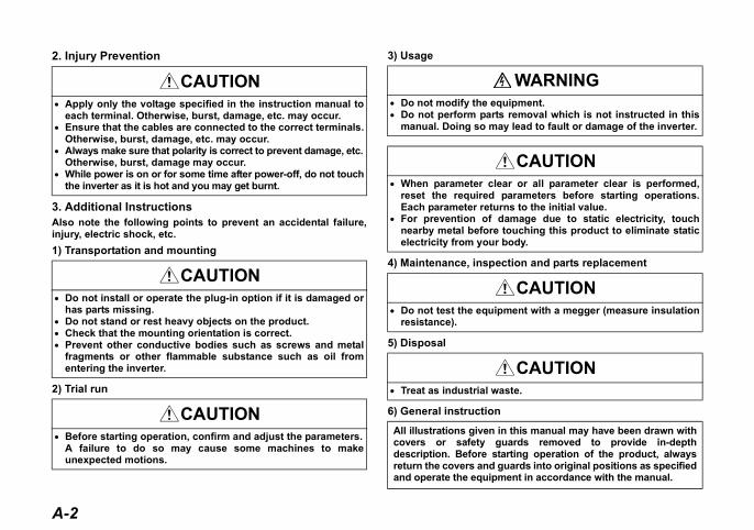
his manual may have been drawn withrds removed to provide in-depthing operation of the product, alwaysrds into original positions as specified
nt in accordance with the manual.
A-2
2. Injury Prevention
3. Additional InstructionsAlso note the following points to prevent an accidental failure,injury, electric shock, etc.1) Transportation and mounting
2) Trial run
3) Usage
4) Maintenance, inspect
5) Disposal
6) General instruction
CAUTION• Apply only the voltage specified in the instruction manual to
each terminal. Otherwise, burst, damage, etc. may occur.• Ensure that the cables are connected to the correct terminals.
Otherwise, burst, damage, etc. may occur.• Always make sure that polarity is correct to prevent damage, etc.
Otherwise, burst, damage may occur.• While power is on or for some time after power-off, do not touch
the inverter as it is hot and you may get burnt.
CAUTION• Do not install or operate the plug-in option if it is damaged or
has parts missing.• Do not stand or rest heavy objects on the product.• Check that the mounting orientation is correct.• Prevent other conductive bodies such as screws and metal
fragments or other flammable substance such as oil fromentering the inverter.
CAUTION• Before starting operation, confirm and adjust the parameters.
A failure to do so may cause some machines to makeunexpected motions.
• Do not modify the equi• Do not perform parts r
manual. Doing so may
• When parameter clearreset the required paEach parameter returns
• For prevention of damnearby metal before toelectricity from your bo
• Do not test the equipmresistance).
• Treat as industrial was
All illustrations given in tcovers or safety guadescription. Before startreturn the covers and guaand operate the equipme

I
— CONTENTS —1
...............................................1
...............................................2.....................................................2.....................................................3...............................................4...............................................5
6
...............................................6
...............................................7
...............................................9
13
.............................................13
.............................................13
.............................................18
21
23
.............................................23
.............................................24
.............................................25
1 PRE-OPERATION INSTRUCTIONS
1.1 Inverter Type .......................................................................................1.2 Unpacking and Product Confirmation ..............................................
1.2.1 Packing confirmation (FR-A700/F700 series)............................................1.2.2 Packing confirmation (FR-E700 series (E kit)) ..........................................
1.3 Parts .....................................................................................................1.4 Specifications......................................................................................
2 INSTALLATION AND WIRING (FR-A700/F700 SERIES)
2.1 Pre-Installation Instructions ..............................................................2.2 Installation Procedure ........................................................................2.3 Wiring...................................................................................................
3 INSTALLATION AND WIRING (FR-E700 SERIES (E kit))
3.1 Pre-Installation Instructions ..............................................................3.2 Installation Procedure ........................................................................3.3 Wiring...................................................................................................
4 PARAMETER LIST
5 EXTENSION ANALOG OUTPUT
5.1 Wiring Example ...................................................................................5.2 Internal Block Diagram.......................................................................5.3 Terminals .............................................................................................

5.4 Extension Analog Output Function Parameter List......................................................................26.............................................27...................................................27...................................................28...................................................30...................................................32...................................................33.............................................34
35
.............................................35
.............................................36
.............................................37
.............................................38
.............................................40
II
5.5 Adjustment Procedure .......................................................................5.5.1 Setting of analog output signal voltage/current switchover (Pr. 309) ........5.5.2 Calibration of meter ...................................................................................5.5.3 Output signal setting (FR-A700/F700 series) ............................................5.5.4 Output signal setting (FR-E700 series) .....................................................5.5.5 Analog signal adjustment [Pr. 307, Pr. 308, Pr. 311, Pr. 312] ...................
5.6 Instructions .........................................................................................
6 DIGITAL OUTPUT
6.1 Internal Block Diagram.......................................................................6.2 Terminals .............................................................................................6.3 Digital Output Function Parameter List ............................................6.4 Output Signal List (FR-A700/F700 series) ........................................6.5 Output Signal List (FR-E700 series)..................................................

1
1
1 PRE-OPERATION INSTRUCTIONS
rding to each -NA, -EC, -CH(T). (Refer to the instruction manual
r more" in the case of FR-A740
CH⎯⎯
FR-F740-55K-CH(T)FR-F740-S75K-CH(T)
⎯⎯
FR-A740-55K-CHT
FR-A740-75K-CHT
1.1 Inverter TypeThe inverter type, 55K and 75K stated in this Instruction Manual differs accoversions. Refer to the following correspondence table for each inverter typeof each inverter for the inverter type.)For example, "for the 75K or more" indicates "for the FR-A740-01440-NA oof NA version.
NA EC
F700
FR-F720-55K FR-F720-02330-NA ⎯FR-F720-75K FR-F720-03160-NA ⎯FR-F740-55K FR-F740-01160-NA FR-F740-01160-ECFR-F740-75K FR-F740-01800-NA FR-F740-01800-EC
A700
FR-A720-55K FR-A720-02150-NA ⎯FR-A720-75K FR-A720-02880-NA ⎯
FR-A740-55K FR-A740-01100-NA(FR-A760-00840-NA) FR-A740-01800-EC
FR-A740-75K FR-A740-01440-NA(FR-A760-01040-NA) FR-A740-02160-EC

PRE-OPERATION INSTRUCTIONS
nfirm that the product is as you
on
e 7.)
2
1.2 Unpacking and Product ConfirmationTake the plug-in option out of the package, check the product name, and coordered and intact.This product is a plug-in option dedicated for the FR-A700/F700/E700 series.
1.2.1 Packing confirmation (FR-A700/F700 series)Check the enclosed items.
Plug-in option......................................... 1
Mounting screw (M3 × 6mm).............. 2 (Refer to page 7.)
Hex-head screw for optimounting (5.5mm)............... 1 (Refer to pag
5.5mm

3
PRE-OPERATION INSTRUCTIONS
1
40-170) or less.740-230) or more.
*2r to page 17)
tion.
1.2.2 Packing confirmation (FR-E700 series (E kit))Check the enclosed items.
*1 Used with the FR-E720-3.7K (FR-E720-175) or less and FR-E740-7.5K (FR-E7*2 Used with the FR-E720-5.5K (FR-E720-240) or more and FR-E740-11K (FR-E
Plug-in option ..............................................1
Mounting screw (M3 × 6mm) ............ 2 (Refer to page 15, 17)
Front cover for plug-in option............. 1 (Refer to page 15, 17)
Option protective cover *1..................1 (Refer to page 15)
Option small cover.................. 1 (Refe
CAUTIONIn place of the inverter front cover, install a provided front cover for plug-in op

PRE-OPERATION INSTRUCTIONS
Rear view
Mounting holector
ct to the inverter
slot
to page 7, 15, 17.)
4
1.3 Parts
AMC
NC
SE
Y3
Y4
Y5
Y6
AM0
AM1
NC
SE
Y0
Y1
Y2
Front view
Terminal layout
Mounting
hole
Mounting
hole
Terminal
block
Conne
Conne
option
(Refer

5
PRE-OPERATION INSTRUCTIONS
1
1.4 Specifications
(1) Output signalsVoltage output (across terminals AM0-AMC) 0 to 10VDCMAXCurrent output (across terminals AM1-AMC) 0 to 20mADC
(2) Output resolutionVoltage output 3mVCurrent output 10μA
(3) Output accuracy (reference value)±10% of the full-scale output valueDepends on the output signal type.
(4) Meters used• Voltmeter
DC voltmeter Full-scale 10V (internal impedance 10kΩ or more)• Ammeter
DC ammeter Full-scale 20mA (internal impedance 300Ω or less)• Wiring length
Maximum 10m

2 INSTALLATION AND WIRING (FR-A700/F700 SERIES)
Otherwise, the inverter and
metal before touching this
6
2.1 Pre-Installation InstructionsMake sure that the input power of the inverter is off.
CAUTIONWith input power on, do not install or remove the plug-in option.plug-in option may be damaged.For prevention of damage due to static electricity, touch nearbyproduct to eliminate static electricity from your body.

7
INSTALLATION AND WIRING (FR-A700/F700 SERIES)
2
the inverter front cover.
e hex-head screw for option g into the inverter screw hole plate). (size 5.5mm, g torque 0.56N⋅m to 0.75N⋅m)
fit the connector of the plug-in the inverter connector along es.
fix the both right and left sides ug-in option to the inverter with ssory mounting screws. ing torque 0.45N⋅m to ) If the screw holes do not line-onnector may not have been
snugly. Check for loose .
700 series), it is easier to remove
2.2 Installation Procedure1)Remove
2)Mount thmountin(on earthtightenin
3)Securelyoption tothe guid
4)Securelyof the plthe acce(Tighten0.55N⋅mup, the cpluggedplugging
REMARKS• Remove a plug-in option after removing two screws on both left and right sides.
(When the plug-in option is mounted in the connector 3 (connector 1 for the FR-Fthe plug-in option after removing a control circuit terminal block.)
4) Mounting screws
Inverter side
option
connector
Screw hole for
option mounting
Screw hole for
option mounting
(on earth plate)
Hex-head screw
for option mounting
1)
2)3)

INSTALLATION AND WIRING (FR-A700/F700 SERIES)
s are mounted, priority is in rity are inoperative.per FR-
hen the inverter can not
" " (option alarm) is
w during mounting and removal.aged.
Mounting Position
Error Display
Connector 1
Connector 2
Connector 3
8
CAUTION• Only one type of option per inverter may be used. When two or more option
order of inverter option connectors 1, 2 and 3, the options having lower prio• When the inverter cannot recognize that the option is mounted due to impro
installation, etc., " to " (option alarm) are displayed for the A700 series. The errors shown differ according to the mounting positions (connectors 1, 2, 3).
• The FR-F700 series has one connection connector for the plug-in option. W
recognize that the option unit is mounted due to improper installation, etc., displayed.
• Take care not to drop a hex-head screw for option mounting or mounting scre• Pull out the option straight to remove. Otherwise, the connector may be dam

9
INSTALLATION AND WIRING (FR-A700/F700 SERIES)
2
t
heng
e.
Sheath
Shield
(perform protective treatment)
Twisted pair
shielded cable
Cable stripping size
5mm
MakerleevePhoenix Contact
Co.,Ltd.
2.3 Wiring(1) Untwist the twisted pair shielded cables after stripping its sheath.
Also, perform protective treatment of the shield to ensure that it will nomake contact with the conductive area.
Strip off the sheath about the size as in the right figure. If the length of tsheath pealed is too long, a short circuit may occur among neighboriwires. If the length is too short, wires might come off.Wire the stripped cable after twisting it to prevent it from becoming loos(Do not solder it.)Use a bar type terminal as required.
REMARKS• Information on bar terminals
Commercially available product examples (as of September, 2006)
Bar terminal crimping tool: CRIMPFOX ZA3 (Phoenix Contact Co., Ltd.)
Terminal Screw Size
Wire Size (mm2)
Bar Terminal ModelWith insulation sleeve Without insulation s
M2 0.3 to 0.5 Al 0,5-6WH A 0,5-6
When using the bar terminal (without insulation sleeve), use care so that the twisted wires do not come out.

INSTALLATION AND WIRING (FR-A700/F700 SERIES)
Screwdriverall flat-blade screwdriver kness: 0.4mm/tip width: 2.5mm )
ing can cause a short circuit or
10
(2) Loosen the terminal screw and insert the cable into the terminal. Screw Size Tightening Torque Cable Size
M2 0.22N⋅m to 0.25N⋅m 0.3mm2 to 0.75mm2 Sm (Tip thic
CAUTION• Undertightening can cause cable disconnection or malfunction. Overtighten
malfunction due to damage to the screw or unit.

11
INSTALLATION AND WIRING (FR-A700/F700 SERIES)
2
K* or less, route wires between ted between the control circuit move a hook of the front cover
37K* or more, use the space
each -NA, -EC versions are as follows.EC⎯
FR-A740-00620-EC⎯
FR-A740-00770-EC⎯
FR-F740-00620-EC⎯
FR-F740-00770-EC
Control circuit
terminal block
700 series 30K* or moreR-F700 series 37K* or more
(3) For wiring of the FR-A700 series 22K* or less and the FR-F700 series 30the control circuit terminal block and front cover. If cables can not be routerminal block and front cover due to the increased number of cables, reand use a space become available.For wiring of the FR-A700 series 30K* or more and the FR-F700 serieson the left side of the control circuit terminal block.
*The inverter type of 22K and 30K of FR-A700 series, 30K and 37K of FR-F700 series in NA
A700
FR-A720-22K FR-A720-00900-NAFR-A740-22K FR-A740-00440-NA (FR-A760-00330-NA)FR-A720-30K FR-A720-01150-NAFR-A740-30K FR-A740-00570-NA (FR-A760-00550-NA)
F700
FR-F720-30K FR-F720-01250-NAFR-F740-30K FR-F740-00620-NAFR-F720-37K FR-F720-01540-NAFR-F740-37K FR-F740-00770-NA
Cut off a hook on the inverter
front cover side surface.
(Cut off so that no portion is left.)
Cut off
with a
nipper,
etc.
FR-A700 series 22K* or lessand FR-F700 series 30K* or less
FR-Aand F

INSTALLATION AND WIRING (FR-A700/F700 SERIES)
ture (JEM1030) changes to open
re used in the option unit. Ifaged.nt cover and control circuit
ay cause a fault, failure or
12
REMARKS• When the hook of the inverter front cover is cut off for wiring, the protective struc
type (IP00).
Do not use empty terminals as junction terminals because they athey are used as the junction terminals, the option unit may be damWhen performing wiring using the space between the inverter froterminal block, take care not to subject the cable to stress.After wiring, wire offcuts must not be left in the inverter. They mmalfunction.
CAUTION

13
3
3 INSTALLATION AND WIRING (FR-E700 SERIES (E kit))
Otherwise, the inverter and
metal before touching this
inals before installing the
per installation, etc., " "
aged.
3.1 Pre-Installation InstructionsMake sure that the input power of the inverter is off.
3.2 Installation ProcedureThe FR-E700 series has one connection connector for the plug-in option.
CAUTIONWith input power on, do not install or remove the plug-in option.plug-in option may be damaged.For prevention of damage due to static electricity, touch nearbyproduct to eliminate static electricity from your body.
CAUTION• Always perform wiring to the main circuit terminals and control circuit term
option. Wiring cannot be performed after installing the option.• When the inverter cannot recognize that the option is mounted due to impro
(option alarm) is displayed.• Take care not to drop a mounting screws during mounting and removal.• Pull out the option straight to remove. Otherwise, the connector may be dam

INSTALLATION AND WIRING (FR-E700 SERIES (E kit))
For FR-E720-3.7K (FR-E720-175) or less, FR-E740-7.5K (FR-E740-170) or less(1) Remove the front cover from the inverter. (For removing the front cover, refer to the FR-E700 series
instruction manual.)(2) Remove the PU cover from the front cover. Open the PU cover with a driver, etc. and remove it in the
direction of arrow as shown below.
rial (only voltage class is labeled for the FR-E740-5.5K (FR-E740-ce a PU cover of a plug-in option front cover with the removed PU
(1) Front cover
(2) PU cover*
rd the arrow
14
REMARKS• Because the voltage class, model name and se
120) or more) are stated on the PU cover, replacover from the inverter.
* Open the PU cover, then open it towadirection to remove.

15
INSTALLATION AND WIRING (FR-E700 SERIES (E kit))
3
r along the guides.r with the accessory mounting line-up, the connector may not
d install the other PU cover,
r plug-in option to the inverter.
cover
ption connector
f inverter
(3) Install the option protective cover.(4) Securely fit the connector of the plug-in option to the inverter connecto(5) Securely fix the both top and bottom of the plug-in option to the inverte
screws.(tightening torque 0.45N⋅m to 0.55N⋅m) If the screw holes do nothave been plugged snugly. Check for loose plugging.
(6) Remove the PU cover provided on the front cover for plug-in option anwhich was removed in (2).
(7) When wiring to the plug-in option is completed, install the front cover fo
(5)
Mounting screws
Front cover
for plug-in option
plug-in option(7)
(6) Replace
(3) Option protective
O
o
(4)
INSTALLATION AND WIRING (FR-E700 SERIES (E kit))
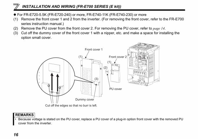
For FR-E720-5.5K (FR-E720-240) or more, FR-E740-11K (FR-E740-230) or more(1) Remove the front cover 1 and 2 from the inverter. (For removing the front cover, refer to the FR-E700
series instruction manual.)(2) Remove the PU cover from the front cover 2. For removing the PU cover, refer to page 14.(3) Cut off the dummy cover of the front cover 1 with a nipper, etc. and make a space for installing the
option small cover.
ace a PU cover of a plug-in option front cover with the removed PU
Front cover 1
cover
r is left.
Front cover 2(1)
(2)
(3)
PU cover
(1)
16
REMARKS• Because voltage is stated on the PU cover, repl
cover from the inverter.
Dummy
Cut off the edges so that no bur

17
INSTALLATION AND WIRING (FR-E700 SERIES (E kit))
3
r along the guides.r with the accessory mounting ot line-up, the connector may
d install the other PU cover,
r plug-in option to the inverter.
n connector of inverter
(4) Securely fit the connector of the plug-in option to the inverter connecto(5) Securely fix the both top and bottom of the plug-in option to the inverte
screws. (tightening torque 0.45N⋅m to 0.55N⋅m) If the screw holes do nnot have been plugged snugly. Check for loose plugging.
(6) Remove the PU cover provided on the front cover for plug-in option anwhich was removed in (2).
(7) When wiring to the plug-in option is completed, install the front cover fo(8) Install the option small cover to the front cover 1.(9) Install the front cover 1 to the inverter.
(4) Optio
(5) Mounting screws
Front cover for
plug-in option
plug-in option
(7)
Option small cover
(8)
(9) Front cover 1(6) Replace

INSTALLATION AND WIRING (FR-E700 SERIES (E kit))
t
heng
e.
Sheath
Shield
(perform protective treatment)
Twisted pair
shielded cable
Cable stripping size
5mm
MakerleevePhoenix Contact
Co.,Ltd.
18
3.3 Wiring(1) Untwist the twisted pair shielded cables after stripping its sheath.
Also, perform protective treatment of the shield to ensure that it will nomake contact with the conductive area.
Strip off the sheath about the size as in the right figure. If the length of tsheath pealed is too long, a short circuit may occur among neighboriwires. If the length is too short, wires might come off.Wire the stripped cable after twisting it to prevent it from becoming loos(Do not solder it.)Use a bar type terminal as required.
REMARKS• Information on bar terminals
Commercially available product examples (as of September, 2006)
Bar terminal crimping tool: CRIMPFOX ZA3 (Phoenix Contact Co., Ltd.)
Terminal Screw Size
Wire Size (mm2)
Bar Terminal ModelWith insulation sleeve Without insulation s
M2 0.3 to 0.5 Al 0,5-6WH A 0,5-6
When using the bar terminal (without insulation sleeve), use care so that the twisted wires do not come out.

19
INSTALLATION AND WIRING (FR-E700 SERIES (E kit))
3
Screwdriver
all flat-blade screwdriver kness: 0.4mm/tip width: 2.5mm )
ing can cause a short circuit or
(2) Loosen the terminal screw and insert the cable into the terminal. Screw Size Tightening Torque Cable Size
M2 0.22N⋅m to 0.25N⋅m 0.3mm2 to 0.75mm2 Sm (Tip thic
CAUTION• Undertightening can cause cable disconnection or malfunction. Overtighten
malfunction due to damage to the screw or unit.

INSTALLATION AND WIRING (FR-E700 SERIES (E kit))
g-in option impedes wiring, cut
is not passed through even if tive structure (JEM1030)
re used in the option unit. Ifaged.
ay cause a fault, failure or
k at the bottom cover.at no portion is left.)
20
(3) When wiring the FR-E700 series, if a hook of the front cover for the pluoff the hook and perform wiring.
REMARKS• When the option protective cover or option small cover is not fitted or wire
the hook of the front cover of the plug-in option has been cut off, the protecchanges to open type (IP00).
CAUTIONDo not use empty terminals as junction terminals because they athey are used as the junction terminals, the option unit may be damWhen wiring, take care not to subject the cable to stress.
After wiring, wire offcuts must not be left in the inverter. They mmalfunction.
Cut off with a nipper, etc.
Cut off a hooof the option(Cut off so th
21
4
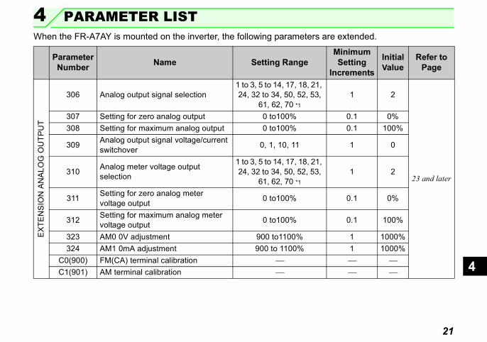
4 PARAMETER LISTe extended.
MinimumSetting
ncrements
Initial Value
Refer to Page
1 2
23 and later
0.1 0%0.1 100%
1 0
1 2
0.1 0%
0.1 100%
1 1000%1 1000%⎯ ⎯⎯ ⎯
When the FR-A7AY is mounted on the inverter, the following parameters ar
Parameter Number Name Setting Range
I
EX
TEN
SIO
N A
NA
LOG
OU
TPU
T
306 Analog output signal selection1 to 3, 5 to 14, 17, 18, 21, 24, 32 to 34, 50, 52, 53,
61, 62, 70 *1307 Setting for zero analog output 0 to100%308 Setting for maximum analog output 0 to100%
309 Analog output signal voltage/current switchover 0, 1, 10, 11
310 Analog meter voltage output selection
1 to 3, 5 to 14, 17, 18, 21, 24, 32 to 34, 50, 52, 53,
61, 62, 70 *1
311 Setting for zero analog meter voltage output 0 to100%
312 Setting for maximum analog meter voltage output 0 to100%
323 AM0 0V adjustment 900 to1100%324 AM1 0mA adjustment 900 to 1100%
C0(900) FM(CA) terminal calibration ⎯C1(901) AM terminal calibration ⎯

PARAMETER LIST
32.40.
1 9999 35 and later
MinimumSetting
ncrements
Initial Value
Refer to Page
22
*1 The setting range differs according to the inverter. For details refer to page 30, *2 The setting range differs according to the inverter. For details refer to page 38,
DIG
ITA
L O
UTP
UT 313 DO0 output selection 0 to 8, 10 to 20, 25 to 28,
30 to 36, 39, 41 to 47, 64, 70 to 78, 84 to 99,100 to 108, 110 to 116,
120, 125 to 128, 130 to 136, 139,
141 to 147, 164, 170,184 to 199, 9999 *2
314 DO1 output selection315 DO2 output selection316 DO3 output selection317 DO4 output selection318 DO5 output selection319 DO6 output selection
Parameter Number Name Setting Range
I

23
5
5 EXTENSION ANALOG OUTPUT
quency and output current canl (AM1).
be 10m maximum.
IM
Motor
5.1 Wiring ExampleBy setting the Pr. 306 to Pr. 312 values, analog signals such as the output frebe output from the voltage output terminal (AM0) and current output termina
Connect the voltmeter or ammeter as shown below:
CAUTION• The wiring length between the FR-A7AY and the voltmeter/ammeter should
Power
supply
+
-
+
-
(Voltmeter)
(Ammeter)
FR-A7AY0 to 10VDC
0 to 20 mADC
AM0
AM1
AMC
InverterMCCB

EXTENSION ANALOG OUTPUT
t function.
M0
M1
MC
24
5.2 Internal Block DiagramThe following is the internal block diagram about the FR-A7AY analog outpu
ControllerConnector
A
A
A
Current amplifier
Voltage amplifier
Common to
AM0/AM1
25
EXTENSION ANALOG OUTPUT
5
Description
ct a DC voltmeter (10VDC).
ct a DC ammeter (20mADC).
on to AM0 and AM1
ction. (Refer to page 35 )
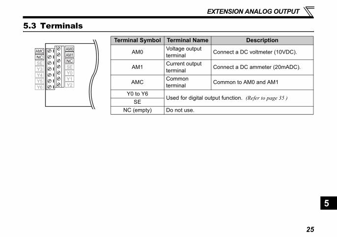
5.3 Terminals
Terminal Symbol Terminal Name
AM0 Voltage output terminal Conne
AM1 Current output terminal Conne
AMC Common terminal Comm
Y0 to Y6Used for digital output fun
SENC (empty) Do not use.
NCNC
AMC
SE
Y3
Y4
Y5
Y6
AM0
AM1
SE
Y0
Y1
Y2

EXTENSION ANALOG OUTPUT
r List
nge Minimum Increments
Initial Value
14, , 32
, 53, *
1 2
0.1 0%0.1 100%
1 1 014, , 32
, 53, *
1 2
0.1 0%0.1 100%
0% 1 1000%0% 1 1000%
⎯ ⎯⎯ ⎯
26
5.4 Extension Analog Output Function Paramete
* The setting range differs according to the inverter. For details refer to page 30, 32.
Parameter Number Name Setting Ra
306 Analog output signal selection
1 to 3, 5 to 17, 18, 21, 24to 34, 50, 52
61, 62, 70307 Setting for zero analog output 0 to 100%308 Setting for maximum analog output 0 to 100%309 Analog output signal voltage/current switchover 0, 1, 10, 1
310 Analog meter voltage output selection
1 to 3, 5 to 17, 18, 21, 24to 34, 50, 52
61, 62, 70311 Setting for zero analog meter voltage output 0 to 100%312 Setting for maximum analog meter voltage output 0 to 100%323 AM0 0V adjustment 900 to 110324 AM1 0mA adjustment 900 to 110
C0(900) FM terminal calibration ⎯C1(901) AM terminal calibration ⎯
REMARKS• For Pr. 306 and Pr. 310, write is enabled even when the inverter is operating.

27
EXTENSION ANALOG OUTPUT
5
witchover (Pr. 309)r to output the same signal ornt output).
ettingParameters
for Adjustment
ero analog output aximum analog output Pr. 323
Pr. 324C1 (Pr. 901)
zero output signalaximum output signal
ero analog outputaximum analog output
Pr. 323C0 (Pr. 900)
ero analog outputaximum analog output
Pr. 324C1 (Pr. 901)
zero output signalaximum output signal
Pr. 323C0 (Pr. 900)
zero output signalaximum output signal
Pr. 324C1 (Pr. 901)
minal AM0 and AM1, and output
5.5 Adjustment Procedure5.5.1 Setting of analog output signal voltage/current sUse Pr. 309 Analog output signal voltage/current switchover to select whethedifferent signals from terminal AM0 (voltage output) and terminal AM1(curre
Pr. 309 Setting Parameters for SDescription Terminal
0(initial value)
Same select signals are output from the voltage output terminal (AM0) and current output terminal (AM1). The signal set in Pr. 306 Analog output signal selection is made valid. (The setting of Pr. 310 is made invalid.)
AM0 Pr. 306 : Select the output signal.Pr. 307 : Output signal value for zPr. 308 : Output signal value for mAM1
10AM0 Pr. 306 : Select the output signal.
Pr. 307 : Analog output value for Pr. 308 : Analog output value for mAM1
1Different select signals are output from voltage output terminal (AM0) and current output terminal (AM1).
AM0Pr. 310 : Select the output signal.Pr. 311 : Output signal value for zPr. 312 : Output signal value for m
AM1Pr. 306 : Select the output signal.Pr. 307 : Output signal value for zPr. 308 : Output signal value for m
11
AM0Pr. 310 : Select the output signal.Pr. 311 : Analog output value for Pr. 312 : Analog output value for m
AM1Pr. 306 : Select the output signal.Pr. 307 : Analog output value for Pr. 308 : Analog output value for m
REMARKS• Analog output means voltage (0 to 10 V) and current (0 to 20mA) output from ter
signal means the monitor signal (refer to page 30, 32) set in Pr. 306 and Pr. 310.

EXTENSION ANALOG OUTPUT
09 = "0 or 10")
orrect
ctually output and deflects the meter.
sly (factory setting: 10VDC)
ly (factory setting: 20mADC)
when voltage or current input is 0,
24 AM1 0mA adjustment to
U or external operation mode.
.)
terminals FM/AM/CA* of the "21" in Pr. 306.
nd Pr. 324 to calibrate again.
28
5.5.2 Calibration of meter(1) Outputting the same select signals from terminals AM0 and AM1 (Pr. 3
At this time, check that the polarity is c
press to set.
At this time, the following analog signal is a
<across terminals AM0-AMC>Maximum output voltage set previou
<across terminals AM1-AMC>Maximum output current set previous
If the meter needle does not point to 0
use Pr. 323 AM0 0V adjustment or Pr. 3
calibrate the meter
START
Run the inverter
Use Pr. 901 to perform adjustment, then set.
END
Connect a DC voltmeter (or DC ammeter) across
terminals AM0 (or terminal AM1) and AMC.
Use Pr. 323 (Pr. 324) to calibrate the meter
when the voltage (current) input is 0.
Set "21" (reference voltage output) in Pr. 306.
In Pr. 306, set the types of the signals to be output.
The inverter may be run in either the P
(Refer to page 30, 32
CAUTION• If calibration is made without "21" (reference voltage output) set in Pr. 306,
inverter are calibrated. To calibrate the extension analog output, always set(* Terminals provided differ according to the inverter.)
• When the plug-in option used was remounted on other inverter, use Pr. 323 a

29
EXTENSION ANALOG OUTPUT
5
9 = "1 or 11")
rrect
ctually output and deflects the meter.
ly (factory setting: 10VDC)
ly (factory setting: 20mADC)
or external operation mode.
hen voltage or current input is 0,
4 AM1 0mA adjustment to
r to page 30, 32.)
r Pr. 310, terminals FM/AM/CA* ys set "21" in Pr. 306.
nd Pr. 324 to calibrate again.
(2) Outputting different select signals from terminals AM0 and AM1 (Pr. 30
START
At this time, check that the polarity is co
At this time, the following analog signal is a
<across terminals AM0-AMC>Maximum output voltage set previous
<across terminals AM1-AMC>Maximum output current set previous
Run the inverter The inverter may be run in either the PU
END
Terminal AM0 Terminal AM1
Connect a DC voltmeter (or DC ammeter)
across terminals AM0 (or terminal AM1)
and AMC.
Set "21" (reference voltage output) in Pr.
306 and Pr. 310.
press to set.
If the meter needle does not point to 0 w
use Pr. 323 AM0 0V adjustment or Pr. 32
calibrate the meter
Use Pr. 323 (or Pr. 324) to calibrate the
meter when the voltage (current) input is 0.
Use Pr. 900 to set Use Pr. 901 to set
In Pr. 306 and Pr. 310, set the types of the signals to be output. (Refe
CAUTION• If calibration is made without "21" (reference voltage output) set in Pr. 306 o
of the inverter are calibrated. To calibrate the extension analog output, alwa(* Terminals provided differ according to the inverter.)
• When the plug-in option used was remounted on other inverter, use Pr. 323 a

EXTENSION ANALOG OUTPUT
l from terminals AM0 and AM1itions, refer to Pr. 54 and Pr. 158
0.1V 200V class : 400V400V class : 800V
0.01kW/0.1kW *2 Rated inverter power × 2
0.01kW/0.1kW *2 Rated inverter power × 2
0.1% Pr. 866/Pr. 56 *4
0.01A/0.1A *2 Pr. 56
⎯ ⎯
0.1% 200%
0.1% Pr. 866
0.1% Pr. 866
0.01kW/0.1kW *2 Rated motor capacityVariable
according to parameters
Inverter capacity
Increments Full-Scale Value
30
5.5.3 Output signal setting (FR-A700/F700 series)Set the output signals to be monitored. Set Pr. 306 to output the same signaand Pr. 306 and Pr. 310 to output different signals. For details of signal definof the inverter (FR-A700/F700 series) manual.Pr. 306/Pr. 310Setting
Types of Monitor Increments Full-Scale Value
1 Output frequency 0.01Hz Pr. 55
2 Output current 0.01A/0.1A *2 Pr. 56
3 Output voltage 0.1V 200V class : 400V400V class : 800V
5 Frequency setting 0.01Hz Pr. 55
6 Running speed 1(r/min)The value converted with the Pr. 37 value from Pr. 55.
7 *3 Motor torque 0.1% Pr. 866
8 Converter output voltage 0.1V 200V class : 400V
400V class : 800V
9 *1 Regenerative brake duty 0.1% Pr. 70
10Electronic thermal relay function load factor
0.1% 100%
11 Output current peak value 0.01A/0.1A *2 Pr. 56
12Converter output voltage peak value
13 Input power
14 Output power
17 Load meter
18 *3Motor excitation current
21 Reference voltage output
24 Motor load factor
32 *3 Torque command
33 *3 Torque current command
34 *3 Motor output
50 Power saving effect
Pr. 306/Pr. 310Setting
Types of Monitor

31
EXTENSION ANALOG OUTPUT
5
page 1.)
s)
*1 This parameter value is not available with the FR-F700 series 55K or less.*2 The setting depends on capacities. (55K or less/75K or more.)
The inverter type, 55K and 75K differ according to -NA and -EC version. (Refer to*3 They can be set for the FR-A700 series only.*4 Full-scale value differs according to the inverter. (FR-A700 series/FR-F700 serie
52 PID set point 0.1% 100%
53 PID process value 0.1% 100%
70 *3
Programmable controller function output (-NA, -EC version only)
0.1% 100%
Pr. 306/Pr. 310Setting
Types of Monitor Increments Full-Scale Value

EXTENSION ANALOG OUTPUT
l from terminals AM0 and AM1itions, refer to Pr. 54 and Pr. 158
Full-Scale Value
s : 400Vs : 800V
ue of the applied motor × 2s : 400Vs : 800V
s : 400Vs : 800Verter power × 2
elay operation level (100%)elay operation level (100%)
32
5.5.4 Output signal setting (FR-E700 series)Set the output signals to be monitored. Set Pr. 306 to output the same signaand Pr. 306 and Pr. 310 to output different signals. For details of signal definof the inverter (FR-E700 series) manual.Pr. 306/Pr. 310
Setting Types of Monitor Increments
1 Output frequency 0.01Hz Pr. 552 Output current 0.01A Pr. 56
3 Output voltage 0.1V 200V clas400V clas
5 Frequency setting 0.01Hz Pr. 557 Motor torque 0.1% Rated torq
8 Converter output voltage 0.1V 200V clas400V clas
9 Regenerative brake duty 0.1% Pr. 7010 Electronic thermal relay function load factor 0.1% 100%11 Output current peak value 0.01 Pr. 56
12 Converter output voltage peak value 0.1V 200V clas400V clas
14 Output power 0.01kW Rated inv21 Reference voltage output ⎯ ⎯24 Motor load factor 0.1% 200%52 PID set point 0.1% 100%53 PID process value 0.1% 100%61 Motor thermal load factor 0.1% Thermal r62 Inverter thermal load factor 0.1% Thermal r

33
EXTENSION ANALOG OUTPUT
5
1, Pr. 312]ts 0) and Pr. 308 or Pr. 312 for
to set the value for zero analog
(for terminal AM1) and Pr. 311 terminal AM1) and Pr. 312 (for
Pr. 309 = 10, 11
Output signal value
Analog output value (Pr. 308 or Pr. 312) for maximum output signal
tput signal value (Pr. 307 or . 311) for zero output signal
8, Pr. 311 = Pr. 312, the output M0 and AM1 are values set in
5.5.5 Analog signal adjustment [Pr. 307, Pr. 308, Pr. 31Use Pr. 307 or Pr. 311 to set the value for zero analog output (meter poinmaximum analog output (full scale).When outputting the same signal from terminals AM0 and AM1, use Pr. 307 output and Pr. 308 for maximum analog output. When outputting different signal from terminals AM0 and AM1, use Pr. 307(for terminal AM0) to set the value for zero analog output and Pr. 308 (forterminal AM0) for maximum analog output. (Refer to page 27.)
When Pr. 309 = 0, 1 When
Voltage
Analog output
(AM0)Current(AM1)
10V20mA
0Output signal value
Output signal value (Pr. 308 or Pr. 312) for maximum analog output
Output signal value (Pr. 307 or Pr. 311) for zero analog output
REMARKS• When Pr. 307 ≥ Pr. 308, Pr. 311 ≥ Pr. 312, the output
values at terminals AM0 and AM1 are always zero.
10V20mA
0
OuPr
Voltage
Analog output
(AM0)
Current
(AM1)
REMARKS• When Pr. 307 = Pr. 30
values at terminals Aparameters always.

EXTENSION ANALOG OUTPUT
arger internal impedance) than cale and may not be calibrated.
inal AM0 and AM1 to minimum,
alibration value deviation when hen Pr. 309 = "10 or 11".
VDC and 20mADC. Hence, amall full-scale value may bed.
34
5.6 Instructions(1) A voltmeter having smaller internal impedance (or an ammeter having l
the value indicated in the Specifications (page 4) may not deflect to full-s
(2) When calibrating a meter with a small full-scale value, set output of termthen connect a meter.
(3) Set "0%" in Pr. 307 or Pr. 311 and "100%" in Pr. 308 or Pr. 312 to prevent ccalibrating the meter using Pr. 323, Pr. 324, C0 (Pr. 900), or C1 (Pr. 901) w
(4) When an option error ( to ) occurs, all outputs are off.
This option unit is factory-set to provide the full-scale output of 10voltmeter (7VDC or less) or an ammeter (14mADC or less) with a sdamaged accidentally during calibration. This should be fully note
CAUTION

356
6 DIGITAL OUTPUT
t function
0
6
E
6.1 Internal Block DiagramThe following is the internal block diagram about the FR-A7AY digital outpu
ControllerConnector
Y
Y
SCommon to Y0-T6
DIGITAL OUTPUT
ble with an inverter as standard
ic).
Description. 313 to assign functions.. 314 to assign functions.. 315 to assign functions.. 316 to assign functions.. 317 to assign functions.. 318 to assign functions.. 319 to assign functions. a common terminal (for sink and ).
nction. (Refer to page 23)
36
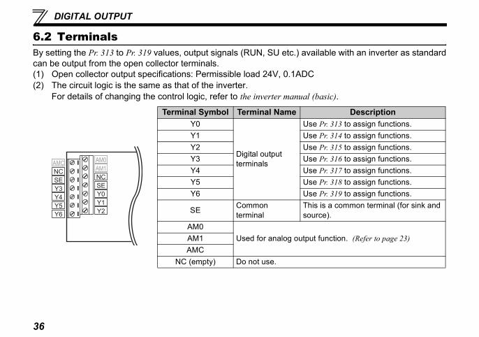
6.2 TerminalsBy setting the Pr. 313 to Pr. 319 values, output signals (RUN, SU etc.) availacan be output from the open collector terminals.(1) Open collector output specifications: Permissible load 24V, 0.1ADC(2) The circuit logic is the same as that of the inverter.
For details of changing the control logic, refer to the inverter manual (bas
Terminal Symbol Terminal NameY0
Digital output terminals
Use PrY1 Use PrY2 Use PrY3 Use PrY4 Use PrY5 Use PrY6 Use Pr
SE Common terminal
This issource
AM0Used for analog output fuAM1
AMCNC (empty) Do not use.
NCNC
AMC
SE
Y3
Y4
Y5
Y6
AM0
AM1
SE
Y0
Y1
Y2

37
DIGITAL OUTPUT
6
Setting Range
0 to 8, 10 to 20, 25 to 28,to 36, 39, 41 to 47, 64, 70 to 84 to 99,100 to 108, 110 to 6, 120, 125 to 128, 130 to , 139, 141 to 147, 164, 170,
184 to 199, 9999 *
6.3 Digital Output Function Parameter List
* The setting range differs according to the inverter. For details refer to page 38, 40.
Parameter Number Name Initial Value313 DO0 output selection 9999
30 78,
11136
314 DO1 output selection 9999315 DO2 output selection 9999316 DO3 output selection 9999317 DO4 output selection 9999318 DO5 output selection 9999319 DO6 output selection 9999
REMARKS• With this function, output signals can be set redundantly.

DIGITAL OUTPUT
tion selection) of the inverter (FR-
ommercial power-supply witchover MC3rake opening request *1an fault outputeatsink overheat pre-alarmrientation in-position *1rientation error *1orward rotation output *1everse rotation output *1egenerative status output *1peration ready 2 *1ow speed output *1orque detection *1n-position *1tart time tuning completion *1peed detection *1econd speed detection *1hird speed detection *1
nverter running 2 *1uring inverter running and start ommand is on
Function
38
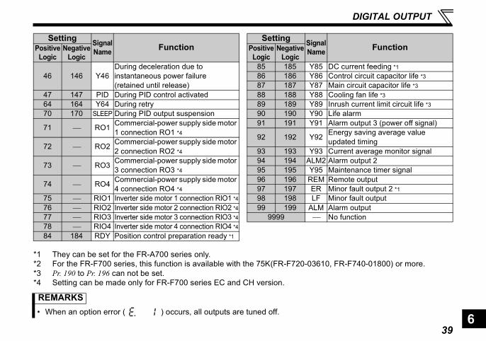
6.4 Output Signal List (FR-A700/F700 series)For details of signal definitions, refer to Pr. 190 to Pr. 196 (Output terminal funcA700/F700 series) manual.
Setting Signal Name FunctionPositive
LogicNegative
Logic0 100 RUN Inverter running1 101 SU Up to frequency
2 102 IPF Instantaneous power failure/undervoltage
3 103 OL Overload alarm4 104 FU Output frequency detection5 105 FU2 Second output frequency detection6 106 FU3 Third output frequency detection *17 107 RBP Regenerative brake prealarm *2
8 108 THP Electronic thermal relay function prealarm
10 110 PU PU operation mode11 111 RY Inverter operation ready12 112 Y12 Output current detection13 113 Y13 Zero current detection14 114 FDN PID lower limit15 115 FUP PID upper limit16 116 RL PID forward/reverse rotation output
17 ⎯ MC1 Commercial power-supply switchover MC1
18 ⎯ MC2 Commercial power-supply switchover MC2
19 ⎯ MC3 Cs
20 120 BOF B25 125 FAN F26 126 FIN H27 127 ORA O28 128 ORM O30 130 Y30 F31 131 Y31 R32 132 Y32 R33 133 RY2 O34 134 LS L35 135 TU T36 136 Y36 I39 139 Y39 S41 141 FB S42 142 FB2 S43 143 FB3 T44 144 RUN2 I
45 145 RUN3 Dc
Setting Signal NamePositive
LogicNegative
Logic
39
DIGITAL OUTPUT
6
, FR-F740-01800) or more.
C current feeding *1ontrol circuit capacitor life *3ain circuit capacitor life *3ooling fan life *3
nrush current limit circuit life *3ife alarmlarm output 3 (power off signal)nergy saving average value pdated timingurrent average monitor signallarm output 2aintenance timer signalemote outputinor fault output 2 *1inor fault outputlarm outputo function
Function
*1 They can be set for the FR-A700 series only.*2 For the FR-F700 series, this function is available with the 75K(FR-F720-03610*3 Pr. 190 to Pr. 196 can not be set.*4 Setting can be made only for FR-F700 series EC and CH version.
46 146 Y46During deceleration due to instantaneous power failure (retained until release)
47 147 PID During PID control activated64 164 Y64 During retry70 170 SLEEP During PID output suspension
71 ⎯ RO1 Commercial-power supply side motor 1 connection RO1 *4
72 ⎯ RO2 Commercial-power supply side motor 2 connection RO2 *4
73 ⎯ RO3 Commercial-power supply side motor 3 connection RO3 *4
74 ⎯ RO4 Commercial-power supply side motor 4 connection RO4 *4
75 ⎯ RIO1 Inverter side motor 1 connection RIO1 *476 ⎯ RIO2 Inverter side motor 2 connection RIO2 *477 ⎯ RIO3 Inverter side motor 3 connection RIO3 *478 ⎯ RIO4 Inverter side motor 4 connection RIO4 *484 184 RDY Position control preparation ready *1
Setting Signal Name FunctionPositive
LogicNegative
Logic85 185 Y85 D86 186 Y86 C87 187 Y87 M88 188 Y88 C89 189 Y89 I90 190 Y90 L91 191 Y91 A
92 192 Y92 Eu
93 193 Y93 C94 194 ALM2 A95 195 Y95 M96 196 REM R97 197 ER M98 198 LF M99 199 ALM A
9999 ⎯ N
Setting Signal NamePositive
LogicNegative
Logic
REMARKS• When an option error ( ) occurs, all outputs are tuned off.

DIGITAL OUTPUT
tion selection) of the inverter (FR-
eatsink overheat pre-alarmuring deceleration due to
nstantaneous power failure retained until release)uring PID control activateduring retryife alarmlarm output 3 (Power-off signal)urrent average monitor signalaintenance timer signalemote outputinor fault outputlarm outputo function
Function
40
6.5 Output Signal List (FR-E700 series)For details of signal definitions, refer to Pr. 190 to Pr. 192 (Output terminal funcE700 series) manual.
SettingSignal Name FunctionPositive
LogicNegative
Logic0 100 RUN Inverter running1 101 SU Up to frequency3 103 OL Overload alarm4 104 FU Output frequency detection7 107 RBP Regenerative brake prealarm
8 108 THP Electronic thermal relay function prealarm
11 111 RY Inverter operation ready12 112 Y12 Output current detection13 113 Y13 Zero current detection14 114 FDN PID lower limit15 115 FUP PID upper limit16 116 RL PID forward/reverse rotation output20 120 BOF Brake opening request 25 125 FAN Fan fault output
26 126 FIN H
46 146 Y46Di(
47 147 PID D64 164 Y64 D90 190 Y90 L91 191 Y91 A93 193 Y93 C95 195 Y95 M96 196 REM R98 198 LF M99 199 ALM A
9999 ⎯ N
SettingSignal NamePositive
LogicNegative
Logic
REMARKS• When an option error ( ) occurs, all outputs are tuned off.
41
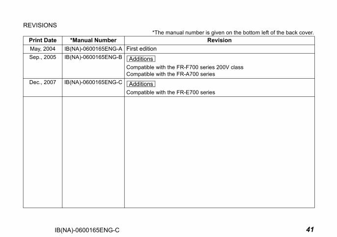
REVISIONS*The manual number is given on the bottom left of the back cover.
Print Date *Manual Number RevisionMay, 2004 IB(NA)-0600165ENG-A First editionSep., 2005 IB(NA)-0600165ENG-B
Compatible with the FR-F700 series 200V classCompatible with the FR-A700 series
Dec., 2007 IB(NA)-0600165ENG-C
Compatible with the FR-E700 series
Additions
Additions
IB(NA)-0600165ENG-C