FPE 385 M POWER PARAMETERS
11
POWERED BY: PERKINS - MARELLI #version 2.0 FPE 385 M STALWART SERIES Address: Stamsneset 100, 5252 Søreide - Bergen / Norway Tel: +47 56 12 30 90 email: offi[email protected] web: www.mpnp.no 1 These details shown on this data sheet are intended for guidance only. FMT Group reserves the right to change the details without prior notice. The present documents will not be part of any sales contract. Standby Rating (ESP) 1500 50 Three phase Water cooled Soundproof Diesel 3 G2 class load acceptance in accordance with ISO 8528-5:2005 L H w DIMENSION / WEIGHT / FUEL TANK Weight (kg) Tank Capacity (lt) NOTE: For reference only, do not use for installation design. Please contact your local dealer for exact weight and dimensions. Dimension W x L x H (mm) Canopy Open Type NOISE LEVEL db(A) 7mt@70-75db(A) POWER PARAMETERS Standard Voltage 400/230 VAC Rated at power factor Cos Ø 0,8 STANDBY POWER A PRIME POWER L H w Prime Rating (PRP) According to ISO 8528-1:2005, Emergency standby power is the maximum power available during a variable electrical power sequence, under the stated operating conditions, for which a generating set is capable of delivering in the event of a utility power outageor under test conditions for up to 200h of operation per year with the maintenance intervals and procedures being carried out as prescribed by the manufacturers. The permissible average power output over 24h of operation shall not exceed 70% of the ESP. According to ISO 8528-1:2005, Prime power is the maximum power which a generating set is capable of delivering continuously whilst supplying a variable electrical load when operated for an unlimited number of hours per year under the agreed operating conditions with the maintenance intervals and procedures being carried out as prescribed by the manufacturer. The permissible average power output (Ppp) over 24h of operation shall not exceed 70% of the PRP. TBA: To Be Asked, N/A: Not Applicable kW A kW Generating Rates kva kva 385 308 350 280 556 505 1700 x 4200 x 2300 3,752 3,189 900 900 1700 x 4200 x 2200 Exclusive Norway Distributor
-
Upload
khangminh22 -
Category
Documents
-
view
2 -
download
0
Transcript of FPE 385 M POWER PARAMETERS

POWERED BY: PERKINS - MARELLI
#version 2.0
FPE 385 M
STALWART SERIES
Address: Stamsneset 100, 5252 Søreide - Bergen / Norway
Tel: +47 56 12 30 90 email: [email protected] web: www.mpnp.no
1These details shown on this data sheet are intended for guidance only. FMT Group reserves the right to change the details without prior notice. The present documents will not be part of any sales contract.
Standby Rating (ESP)
1500 50 Three phase Water cooled Soundproof Diesel3
G2 class load acceptance in accordance with ISO 8528-5:2005
L
H
w
DIMENSION / WEIGHT / FUEL TANK
Weight (kg) Tank Capacity (lt)
NOTE: For reference only, do not use for installation design. Please contact your local dealer for exact weight and dimensions.
Dimension W x L x H (mm)
Canopy
Open Type
NOISE LEVEL db(A) 7mt@70-75db(A)
POWER PARAMETERS
Standard Voltage 400/230 VAC
Rated at power factor Cos Ø 0,8
STANDBY POWER
A
PRIME POWER
L
H
w
Prime Rating (PRP)
According to ISO 8528-1:2005, Emergency standby power is the maximum power available during a variable electrical power sequence, under the stated operating conditions, for which a generating set is capable of delivering in the event of a utility power outageor under test conditions for up to 200h of operation per year with the maintenance intervals and procedures being carried out as prescribed by the manufacturers. The permissible average power output over 24h of operation shall not exceed 70% of the ESP.
According to ISO 8528-1:2005, Prime power is the maximum power which a generating set is capable of delivering continuously whilst supplying a variable electrical load when operated for an unlimited number of hours per year under the agreed operating conditions with the maintenance intervals and procedures being carried out as prescribed by the manufacturer. The permissible average power output (Ppp) over 24h of operation shall not exceed 70% of the PRP.
TBA: To Be Asked, N/A: Not Applicable
kW
A
kW
Generating Rates
kva kva385 308 350 280
556 505
1700 x 4200 x 2300 3,752
3,189
900
9001700 x 4200 x 2200
Exclusive Norway Distributor

POWERED BY: PERKINS - MARELLI
#version 2.0
FPE 385 M
STALWART SERIES
Address: Stamsneset 100, 5252 Søreide - Bergen / Norway
Tel: +47 56 12 30 90 email: [email protected] web: www.mpnp.no
2These details shown on this data sheet are intended for guidance only. FMT Group reserves the right to change the details without prior notice. The present documents will not be part of any sales contract.
TY..! 2 YEARS WARRANTY..! 2 YEARS WARRANTY..! 2 YE2 YEARS WARRANTY..!
17
7
5
6
4
13
8
12
10
9
115 161418
3
17
12
1
2
3
4
5
6
7
8
9
2
11
GENSET STANDARD SPECIFICATION
• Diesel engine• Water cooled• Radiator with mechanical fan• ATS automatic transfer switch 4P• Protective grille for rotating and hot parts• Electric starter and charge alternator• Engine coolant heater• Base frame with integrated fuel tank
• Galvanized steel that provides extra strength, durability and protection
• Tightly structure, excellent design
• Easy access to serviceable parts
• Double swinging doors for ease of service
• Doors have high quality gaskets to avoid leakage of sound
• LCD display shows system status and setup information
• Adequate ventilation to meet air requirement for combustion and heat removal
• Antivibration shock absorbers • Flexible fuel connection hoses • Single bearing, class H alternator • Industrial exhaust silencer and steel bellows supplied separately• Static battery charger• Starting battery (with lead acid) including rack and cables• Battery isolator• Manual for application and installation
FEATURES
low lube oil pressure
high water temperature protective earth point
emergency stop push-button
SAFETY FEATURES
Low fuel consumption
High efciency
Easy lift Low noise
Base Frame
Canopy
Engine
Alternator
Control Panel
Connection Box
Cooling fun
Emergency stop button
Exhaust Outlet
Air Filter
Fuel filter
Oil Filter
10
11
12
13
14
15
Fuel Tank
Battery
Radiator
16
17
18
Vibration Isolators
Lifting Lug
Earthing Point
*Image for guidance purposes
POWERED BY: PERKINS - MARELLI
#version 2.0
FPE 385 M
STALWART SERIES
Address: Stamsneset 100, 5252 Søreide - Bergen / Norway
Tel: +47 56 12 30 90 email: [email protected] web: www.mpnp.no
3These details shown on this data sheet are intended for guidance only. FMT Group reserves the right to change the details without prior notice. The present documents will not be part of any sales contract.
HORSE POWERDurable Energy
Unique design
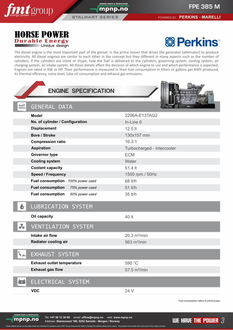
The diesel engine is the most important part of the genset. Is the prime mover that drives the generator (alternator) to produce electricity. All diesel engines are similar to each other in the concept but they different in many aspects such as the number of cylinders, if the cylinders are inline or Vtype, how the fuel is delivered to the cylinders, governing system, cooling system, air charging system, air intake system. All these details affect the decision of which engine to use and which performance is expected. Engines are rated in KW or HP. Their performance is measured in their fuel consumption in filters or gallons per KWh produced, its thermal effciency, noise level, lube oil consumption and exhaust gas emissions.
GENERAL DATA
Model
Displacement
No. of cylinder / Configuration
Aspiration
Compression ratio
Governor type
Cooling system
Coolant capacity
Fuel consumption 100% power used
Speed / Frequency
Fuel consumption 75% power used
Oil capacity
Intake air flow
Radiator cooling air
Exhaust gas flow
Exhaust outlet temperature
VDC
LUBRICATION SYSTEM
VENTILATION SYSTEM
EXHAUST SYSTEM
ELECTRICAL SYSTEM
Bore / Stroke
Fuel consumption 50% power used
+ -
ENGINE SPECIFICATION
Fuel consumption refers to prime power
2206A-E13TAG2
In-Line 6
12.5 lt
130x157 mm
16.3:1
Turbocharged - Intercooler
ECM
Water
51.4 lt
1500 rpm / 50Hz
68 lt/h
51 lt/h
35 lt/h
40 lt
20.3 m³/min
563 m³/min
590 °C
57.5 m³/min
24 V
R

POWERED BY: PERKINS - MARELLI
#version 2.0
FPE 385 M
STALWART SERIES
Address: Stamsneset 100, 5252 Søreide - Bergen / Norway
Tel: +47 56 12 30 90 email: [email protected] web: www.mpnp.no
4These details shown on this data sheet are intended for guidance only. FMT Group reserves the right to change the details without prior notice. The present documents will not be part of any sales contract.
Marelli alternator has been designed for three phase and mono phase. They are brushless type and are controlled by AVR card. The windings have been industrially produced to give maximum efficiency in the production of energy. Throughout the AVR card system the output voltage is always stable. The smart AVR is a professional controller than enables the whole operation of excitement. Marelli alternator is protected by a special cabin that enables the electrical connections.
GENERAL DATA
Model
Power Factor
No. of Phase
No of Leads
No of Poles
Insulations Class
Voltage Regulation (Steady State)
Degree of Protection
Connection System
Excitation System
Frequency
No of Bearing
Voltage Output
Rated Power (standby)
Efficiency
ALTERNATOR SPECIFICATION
SELF EXCITEDSTRONG ROTOR
Isolated Stator
AVR
Fan
Coupling Disc
Terminal outgoing
Exciter
Ectier
Rotor
Stator
Alternator Structure
Power Solutions since 1891
0.8
3
12
4
H
± 1%
IP 23
STAR
Self excited, AVR, Brushless
50 Hz
400/230 VAC
SINGLE
MJB 315 SB4
385 kVA
93.4 %

POWERED BY: PERKINS - MARELLI
#version 2.0
FPE 385 M
STALWART SERIES
Address: Stamsneset 100, 5252 Søreide - Bergen / Norway
Tel: +47 56 12 30 90 email: [email protected] web: www.mpnp.no
5These details shown on this data sheet are intended for guidance only. FMT Group reserves the right to change the details without prior notice. The present documents will not be part of any sales contract.
GENA is a next genera�on genset controller combining mul�-func�onality and wide communica�on capabili�es together with a reliable and low-cost design. The same controller provides synchroniza�on, load share, AMF, ATS, Remote Start, Engine Control and Remote Display Panel func�onali�es. The module comes ready for remote monitoring over GSM or Ethernet with plug-in communica�on modules. Various plug-in modules provide unlimited expansion capabili�es allowing to meet any special requirement. The unit complies and mostly exceeds world’s �ghtest safety, vibra�on and environmental standards for the industrial category. So�ware features are complete with easy firmware upgrade process through USB port. The Windows based PC so�ware allows monitoring and programming through USB, RS-485, Ethernet and GPRS.
GENA
The InteliLiteNT AMF 9 is integrated controller for gen-sets opera�ng in single standby mode. The controller meets all requirements for Auto Mains Failure (AMF) applica�ons including remote communica�on and internet control,user confi gura�on and complete gen-set monitoring and protec�on. InteliLiteNT AMF 9 is easy to use with a simpleintui�ve user interface and graphic display. Unit is designed for quick and cost saving commissioning and bring seamless integra�on with the latest breed of EFI diesel engines from all major manufacturers. This offers a higherlevel of func�onality with users able to display a comprehensive range of values from the EFI engine on standard analog gauges and true RMS measurement of electric values.
3P5-V400-CA9InteliLiteNT AMF9
InteliLite AMF25
DSE7320
InteliLite® AMF 25 is new integrated controller for gen-sets opera�ng in single standby mode. It meet all possible requirements for AMF applica�ons, including modem control, user configura�on and full gen-set monitoring and protec�on.InteliLite® controllers are equipped with a powerful graphic display. Icons, symbols and bar graphs for intui�ve opera�on together with high func�onality set new standards in gen-set control. Special low temperature (IL-AMF 20-LT or IL-AMF 25-LT) version is also available, allowing the display to work up to -30 ⁰C.
The DSE6120 is an Auto Mains (U�lity) Failure Control Module suitable for a wide variety of single gen-set applica�ons. Monitoring speed, frequency, voltage, current, oil pressure, coolant temperature and fuel level, the modules will display warnings, shutdown and engine status informa�on on the back-lit LCD screen and illuminated LED. Both modules offer electronic (CAN) and non-electronic (magne�c pick-up/alternator sensing) engine versions and offer a number of flexible inputs, outputs and engine protec�ons so the system can be easily adapted to suit a wide range of applica�on demands. The modules can be easily configured using the DSE Configura�on Suite PC so�ware. Selected front panel edi�ng is also available.
DSE6120
The DSE7320 is an Auto Mains (U�lity) Failure Control Module suitable for a wide variety of single, diesel or gas,gen-set applica�ons. Monitoring an extensive number of engine parameters, the modules will display warnings, shutdown and engine status informa�on on the back-lit LCD screen, illuminated LEDs, remote PC and via SMS textalerts (with external modem). The DSE7320 will also monitor the mains (u�lity) supply. The modules include USB, RS232 and Rs485 ports as well as dedicated DSENet® terminals for system expansion. Is compa�ble with electronic (CAN) and non-electronic (magne�c pick-up/alternator sensing) engines and offer an extensive number of flexible inputs, outputs and extensive engine protec�ons so the system can be easily adapted to meet the most demanding industry requirements.
OPTIONAL
OPTIONAL
STANDARD
3P5-V400-CA25
3P5-V400-DSE6120
3P5-V400-GENA
3P5-V400-DSE7320
datasheetDOWNLOAD
The Rainbow Scada web monitoring service allows monitoring and control of an unlimited number of gensets through any web browser. datasheet
DOWNLOAD
datasheetDOWNLOAD
datasheetDOWNLOAD
datasheetDOWNLOAD
AMF AUTOMATIC MAINS FAILURESINGLE GEN-SET
control panel
MAINS
GENSET
PGM
LOAD
A M F C O N T R O L U N I TGENSET
WARNING
SERVICEREQUEST
ALARM
AUTOREADY
STATUS
A
AUTO STOP RUNMANTEST
GEN-A
GEN PHASE VOLTAGES
000
-2-3-1
000
L1L2L3
A
control panel

POWERED BY: PERKINS - MARELLI
#version 2.0
FPE 385 M
STALWART SERIES
Address: Stamsneset 100, 5252 Søreide - Bergen / Norway
Tel: +47 56 12 30 90 email: [email protected] web: www.mpnp.no
6These details shown on this data sheet are intended for guidance only. FMT Group reserves the right to change the details without prior notice. The present documents will not be part of any sales contract.
The FSYNCH-7 is a next genera�on synchronizing genset controller combining mul�-func�onality and wide communica�on capabili�es together with a reliable and low cost design. The unit offers auto-genset learning capability, a first in the industry. The mul�-func�onality of the unit allows it to be a genset or mains synchronizer, even a parallel to mains controller with so� transfer in both direc�ons. The unit is available with 4.3”TFT color display or 128x64 pixels B/W display. The unit complies and mostly exceeds world’s �ghtest safety, EMC, vibra�on and environmental standards for the industrial category. So�ware features are complete with easy firmware upgrade process through USB port. The Windows based PC so�ware allows monitoring and programming through USB, RS-485, Ethernet and GPRS. Scada web monitoring service allows monitoring and control of an unlimited number of gensets through any web browser.
FSYNCH-7
OPTIONAL
3P5-V400-FSYNCH-7
datasheetDOWNLOAD
The new ComAp InteliGen 200 introduces a new era in parallel genset control. The power and reliability of InteliGen, combined with the design and flexibility of the InteliLite gives you the best paralleling controller ComAp have ever made. The InteliGen 200 allows you to choose the configura�on that best suits your applica�on. Add more inputs and outputs, add GPS or 4G/LTE communica�ons – it’s up to you. Configura�on and monitoring is supported by InteliConfig – a new version of ComAp’s PC so�ware offering the possibility to control and monitor either one, or mul�ple gen-sets. Thanks to manuals incorporated directly into InteliConfig and a context sensi�ve hint feature, customers have always help at hand.
3P5-V400-CI200InteliGen 200
The DSE8610 MKII is a marketleading Synchronising Auto Start Control Module suitable for use in a mul�-generator loadshare system, designed to synchronise up to 32 generators including electronic and non-electronic engines.The DSE8610 MKII monitors the generator and indicates opera�onal status and fault condi�ons, automa�cally star�ng or stopping the engine on load demand or fault condi�ons. System alarms are annunciated on the LCD screen (mul�ple language op�ons available), illuminated LED and audible sounder. The event log records 250 events to facilitate easy maintenance, and an extensive number of fixed and flexible monitoring, metering and protec�on features are included.
DSE8610
OPTIONAL
OPTIONAL
3P5-V400-DSE8610
datasheetDOWNLOAD
AMF AUTOMATIC MAINS FAILURE control panel
datasheetDOWNLOAD
SYNCHRONIZE SYSTEM
GENA is a next genera�on genset controller combining mul�-func�onality and wide communica�on capabili�es together with a reliable and low-cost design. The same controller provides synchroniza�on, load share, AMF, ATS, Remote Start, Engine Control and Remote Display Panel func�onali�es. The module comes ready for remote monitoring over GSM or Ethernet with plug-in communica�on modules. Various plug-in modules provide unlimited expansion capabili�es allowing to meet any special requirement. The unit complies and mostly exceeds world’s �ghtest safety, vibra�on and environmental standards for the industrial category. So�ware features are complete with easy firmware upgrade process through USB port. The Windows based PC so�ware allows monitoring and programming through USB, RS-485, Ethernet and GPRS.
GENA-SYC
MAINS
GENSET
PGM
LOAD
A M F C O N T R O L U N I TGENSET
WARNING
SERVICEREQUEST
ALARM
AUTOREADY
STATUS
A
AUTO STOP RUNMANTEST
GEN-A
GEN PHASE VOLTAGES
000
-2-3-1
000
L1L2L3
A
STANDARD
3P5-V400-GENA
The Rainbow Scada web monitoring service allows monitoring and control of an unlimited number of gensets through any web browser. datasheet
DOWNLOAD
SMART LOGIC SUPER CONTROL FULL PROTECTION
control panel
control panel

POWERED BY: PERKINS - MARELLI
#version 2.0
FPE 385 M
STALWART SERIES
Address: Stamsneset 100, 5252 Søreide - Bergen / Norway
Tel: +47 56 12 30 90 email: [email protected] web: www.mpnp.no
7These details shown on this data sheet are intended for guidance only. FMT Group reserves the right to change the details without prior notice. The present documents will not be part of any sales contract.
FEATURES• Diesel and gas genset support
• 400Hz operation support
• 400 event logs, full snapshot
• All parameters front panel editable
• 3 level configuration password
• 128x64 graphical LCD display
• Downloadable languages
• Waveform display of V & I
• Harmonic analysis of V & I
• Synchroscope & check synch
• Allows closed transfers
• 16Amp MCB & GCB outputs
• 8 configurable digital inputs
• Inputs expandable to 40
• 8 configurable digital outputs
• Outputs expandable to 40
• 7 configurable analog inputs
• Both CANBUS-J1939 & MPU
• 3 configurable service alarms
• Multiple topologies
• 6xCT, true mains metering
• Supports up to 48 gensets
• Automatic learning/self adjust
• Direct governor & AVR control
• Voltage and phase matching
• kW & kVAr load sharing
• True soft transfer in both ways
• PLC functions
• Peak Lopping / peak shaving
• Mains de-coupling protection
• R.O.C.O.F protection
• Vector shift protection
• Reverse power protection
• Over/under freq. Protection
• Over/under voltage protection
• Smart load management
• Smart genset sequencing
• Run/stop priority support
• Equal aging of gensets
• Base load (power export)
• Unmanaged distributed power
export support
• AVR & GOV droop support
• Dead bus sensing
• Multiple automatic exerciser
• Weekly operation schedule
• Dual mutual standby with equal
aging of gensets
• Manual “speed fine adjust” on
selected ECUs
• Automatic fuel pump control
• Disable protections feature
• Excess power protection
• Reverse power protection
• Overload IDMT protection
• Load shedding, dummy load
• Multiple load management
• Current unbalance protection
• Voltage unbalance protection
• Fuel filling & fuel theft alarms
• Contactor & MCB drive
• Battery back-up real time clock
• Idle speed control
• Battery charge run enabled
• Combat mode support
• Multiple nominal conditions
• 4 quadrant genset power counters
• Mains power counters
• Fuel filling counter
• Fuel consumption counter
• Modem & ethernet diagnostics
• Configurable through USB, RS-485,
Ethernet and GPRS
• Free configuration program
• Allows SMS controls
• Ready for central monitoring
ethernet & GPRS
• Mobile genset support
• Automatic GSM geo-location
• GPS connectivity (USB&RS232)
• Dynamic DNS support
• Easy USB firmware upgrade
• IP65 rating with standard gasket
Selects TEST modeThe genset runs and takes the load
Selects RUN modeRuns the genset off load. Applicable only in MANUAL mode
Selects AUTO modeThe genset runs when necessary and takes the load
Selects OFF modeThe genset stops after cooldown. If depressed again, the genset will immediately stop
Selects next display screen in the same display groupLAMP TEST when held pressed
Selects previous display group
Selects next display group
Selects previous display screen in the same display groupResets the ALARM RELAY
Manual MAINS CONTACTOR (or Busbar contactor) control in RUN mode
Manual GENSET CONTACTOR (or Busbar contactor) control in RUN mode
When held pressed for 5 seconds, enters PROGRAMMING mode
FUNCTION DESCRIPTIONBUTTON
Selects MANUAL modeThe RUN push button is enabled. The genset will run when RUN mode is selected. It can be stopped anytime by depressing the OFF button
Makes factory reset. Please review chapter RESETTING TO FACTORY DEFAULTS for more details.
When held pressed for 5 seconds, resets service request counters. Please review chapter SERVICE REQUEST ALARM for more details
GEN-A
HIGH TECHNOLOGY FOR EVERYONE
• BOTH AMF AND SYNCHRONIZING
• SAME UNIT FOR ALL FUNCTIONS
• INTERNET BASED
• MULTI-PROTOCOL
• FLEXIBLE WITH PLUG-IN MODULES
• AUTO LEARNING
MAINS
GENSET
PGM
LOAD
AMF CONTROL UNITGENSET
AUTO STOP RUNMANTEST
GEN-A
GEN PHASE VOLTAGES
000
-2-3-1
000
L1L2L3
A
WARNING
SERVICEREQUEST
ALARM
AUTOREADY
STATUS
A

POWERED BY: PERKINS - MARELLI
#version 2.0
FPE 385 M
STALWART SERIES
Address: Stamsneset 100, 5252 Søreide - Bergen / Norway
Tel: +47 56 12 30 90 email: [email protected] web: www.mpnp.no
8These details shown on this data sheet are intended for guidance only. FMT Group reserves the right to change the details without prior notice. The present documents will not be part of any sales contract.
• 2G GSM Modem • 3G GSM Modem • 4G GSM Mode • Wi-Fi (802.11 b/g/n) • Ethernet 10/100 Mbits • USB Host • RS-232 (isolated) • RS-485 (isolated) • Synchro/LoadShare Module • 3x AC Current Inputs • 3x Analog Inputs
PLUG-IN MODULES FUNCTIONALITIES COMMUNICATIONS
• Multi genset synch & load share
• Single genset parallel with mains
• AMF unit (uninterrupted transfer)
• ATS unit (uninterrupted transfer)
• Remote start controller
• Manual start controller
• Engine controller
• Remote display panel
• Central Monitoring • Embedded Web Server • USB • GPS (geo-location) • SMS • E-mail • Modbus • Modbus TCP/IP • SNMP 1.0 with trap • HTML • UDP • SNTP
MULTI GENSET SYNCHRONIZATION
Up to 48 gensets may be paralleled on the samebusbar. Smart load management is a standardfeature.
MAINS SYNCHRONIZATION
Up to 16 mains controller per system are supported . Mains controllers provide the REMOTE START signal and handle synchronization of the complete genset system with mains.
Backpanel view
Plug-in modules
Datalink
Bus
To mains
controllers
TO LOAD
GENSET
BUSBAR
LOAD
TO GENSET
CONTROLLERS
DATALINK BUS
MAINS
GENSET
PGM
LOAD
AMF CONTROL UNITGENSET
WARNING
SERVICEREQUEST
ALARM
AUTOREADY
STATUS
A
AUTO STOP RUNMAN
A
TEST
GEN-A
GEN PHASE VOLTAGES
000
-2-3-1
000
L1L2L3
MAINS
GENSET
PGM
LOAD
AMF CONTROL UNITGENSET
WARNING
SERVICEREQUEST
ALARM
AUTOREADY
STATUS
A
AUTO STOP RUNMAN
A
TEST
GEN-A
GEN PHASE VOLTAGES
000
-2-3-1
000
L1L2L3
MAINS
GENSET
PGM
LOAD
AMF CONTROL UNITGENSET
WARNING
SERVICEREQUEST
ALARM
AUTOREADY
STATUS
A
AUTO STOP RUNMAN
A
TEST
GEN-A
GEN PHASE VOLTAGES
000
-2-3-1
000
L1L2L3
MAINS
GENSET
PGM
LOAD
AMF CONTROL UNITGENSET
WARNING
SERVICEREQUEST
ALARM
AUTOREADY
STATUS
A
AUTO STOP RUNMAN
A
TEST
GEN-A
GEN PHASE VOLTAGES
000
-2-3-1
000
L1L2L3
MAINS
GENSET
PGM
LOAD
AMF CONTROL UNITGENSET
WARNING
SERVICEREQUEST
ALARM
AUTOREADY
STATUS
A
AUTO STOP RUNMAN
A
TEST
GEN-A
GEN PHASE VOLTAGES
000
-2-3-1
000
L1L2L3
MAINS
GENSET
PGM
LOAD
AMF CONTROL UNITGENSET
WARNING
SERVICEREQUEST
ALARM
AUTOREADY
STATUS
A
AUTO STOP RUNMAN
A
TEST
GEN-A
GEN PHASE VOLTAGES
000
-2-3-1
000
L1L2L3
MAINS
GENSET
PGM
LOAD
AMF CONTROL UNITGENSET
WARNING
SERVICEREQUEST
ALARM
AUTOREADY
STATUS
A
AUTO STOP RUNMAN
A
TEST
GEN-A
GEN PHASE VOLTAGES
000
-2-3-1
000
L1L2L3
MAINS
GENSET
PGM
LOAD
AMF CONTROL UNITGENSET
WARNING
SERVICEREQUEST
ALARM
AUTOREADY
STATUS
A
AUTO STOP RUNMAN
A
TEST
GEN-A
GEN PHASE VOLTAGES
000
-2-3-1
000
L1L2L3
MAINS
GENSET
PGM
LOAD
AMF CONTROL UNITGENSET
WARNING
SERVICEREQUEST
ALARM
AUTOREADY
STATUS
A
AUTO STOP RUNMAN
A
TEST
GEN-A
GEN PHASE VOLTAGES
000
-2-3-1
000
L1L2L3
MAINS
GENSET
PGM
LOAD
AMF CONTROL UNITGENSET
WARNING
SERVICEREQUEST
ALARM
AUTOREADY
STATUS
A
AUTO STOP RUNMAN
A
TEST
GEN-A
GEN PHASE VOLTAGES
000
-2-3-1
000
L1L2L3
MAINS
GENSET
PGM
LOAD
AMF CONTROL UNITGENSET
WARNING
SERVICEREQUEST
ALARM
AUTOREADY
STATUS
A
AUTO STOP RUNMAN
A
TEST
GEN-A
GEN PHASE VOLTAGES
000
-2-3-1
000
L1L2L3
MAINS
GENSET
PGM
LOAD
AMF CONTROL UNITGENSET
WARNING
SERVICEREQUEST
ALARM
AUTOREADY
STATUS
A
AUTO STOP RUNMAN
A
TEST
GEN-A
GEN PHASE VOLTAGES
000
-2-3-1
000
L1L2L3

POWERED BY: PERKINS - MARELLI
#version 2.0
FPE 385 M
STALWART SERIES
Address: Stamsneset 100, 5252 Søreide - Bergen / Norway
Tel: +47 56 12 30 90 email: [email protected] web: www.mpnp.no
9These details shown on this data sheet are intended for guidance only. FMT Group reserves the right to change the details without prior notice. The present documents will not be part of any sales contract.
Alternator voltage: 0 to 300 V-AC (Ph-N) Alternator frequency: 0-600 Hz. Mains voltage: 0 to 300 V-AC (Ph-N) Mains frequency: 0-600 Hz. Topology: 1-2-3 phases, with or without neutral DC Supply Range: 8.0 to 36.0 V-DC. V-A-cos Accuracy: 0.5% + 1 digit kW-kVA-kVAr Accuracy: 1.0% + 1 digit Current consump�on: 500 mA-DC max. Current Inputs: from current transformers. ../5A or ../1A. Digital inputs: input voltage 0 to 36 V-DC. Analog input range: 0-5000 ohms. Mains and genset contactor outputs: 16Amps@250V DC Outputs: Protected mosfet semiconductor outputs, rated 1Amp@28V-DC Cranking dropouts: survives 0V for 100ms. Magne�c pickup voltage: 0.5 to 50Vpk. Magne�c pickup frequency: 0 to 20000 Hz. Charge Alternator Excita�on: 2W. Display Screen: 2.9”, 128x64 pixels Ethernet Port: 10/100 Mbits USB Device: USB 2.0 Full speed USB Host: USB 2.0 Full speed RS-485 Port: selectable baud rate (2400-115200baud) RS-232 Port: selectable baud rate (2400-115200baud) Opera�ng temperature: -20°C to 70°C (-4 to +158 °F) Storage temperature: -40°C to 80°C (-40 to +176°F) Maximum humidity: 95% non-condensing. IP Protec�on: IP65 from front panel, IP30 from the rear (with gasket) Dimensions: 211 x 162 x 42mm (WxHxD) Panel Cut-out Dimensions: 176 x 121 mm minimum. Weight: 500 g (approx.) Case Material: High Temperature, non-flammable ABS/PC Installa�on: Flat surface moun�ng on a Type 1 enclosure. Rear retaining plas�c brackets.
TECHNICAL SPECIFICATIONS
CONFORMITY
EU Direc�ves Conformity-2014/35/EC (low voltage) -2014/30/EC (electro-magne�c compa�bility)
Norms of reference:EN 61010 (safety requirements) EN 61326 (EMC requirements)
UL & CSA Compa�bility:
RAINBOW SCADA CENTRAL MONITORING
WEB SERVERSCOPEMETER & HARMONICS
• UL 6200, Controls for Sta�onary Engine Driven Assemblies (File# - 20140725-E314374) • CAN/CSA C22.2 No. 14-13 – Industrial Control Equipment
MAINSL1
L2
L3
N
LOADL3 N
FU
SEMC
FU
SE
FU
SE
FU
SE
FU
SE
FU
SE
L1
L2
L3
N
ALTERNATORL1 L2
GC
BA
TTE
RY
12
/24
V
Starter Motor
Fuse
Cra
nk
Ala
rm
Fuel
SSS
Battery Negative must be grounded
Ch
arge
Alt
ern
ato
rD
+ /
WL
Sto
p
Idle
Sp
eed
Low
Oil
Pre
ssu
re
Hig
h T
emp
Emer
gen
cy S
top
Low
Co
ola
nt
Leve
l
Spar
e In
pu
t 1
Forc
e O
FF M
od
e
Pre
hea
t
Connect to the engine body, close to the senders.
*2 Ground from one end only.
J19
39
-H
J19
39
-L
*2
To ECU
Spar
e In
pu
t 2
Spar
e In
pu
t 3
Sen
der
Gn
d
*1
Tem
p. S
end
er
Oil
Pre
ss. S
end
er
Fuel
Lev
. Sen
der
Oil
Tem
p. S
end
er
MPU
*1
* 2
to AVR
*2
to other *3
to GOVCONTROL
TYPICAL CONNECTIONS

POWERED BY: PERKINS - MARELLI
#version 2.0
FPE 385 M
STALWART SERIES
Address: Stamsneset 100, 5252 Søreide - Bergen / Norway
Tel: +47 56 12 30 90 email: [email protected] web: www.mpnp.no
10These details shown on this data sheet are intended for guidance only. FMT Group reserves the right to change the details without prior notice. The present documents will not be part of any sales contract.
630A 4P
A
ATS professional XP series
LED INDICATOR
1 2 3
4 5 6
STANDBYPOWER
MAINPOWER
OPENElectric
Manual
Warning, Live Terminals
ON
OFF
Automatic Transfer Switches
eletric ats system
400/230 VAC
MODEL
CONFIGURATION
3P5-V400-GENA
VOLTAGEATS
PANEL MODELDimension (mm)
W x L x H CAPACITY AMPS
OPTIN
AL
FMT PRO-ACB Series intelligent type universal circuit breaker is
suitable for AC50HZ, rated voltage up to 660V(690) and below,
rated current 400A-6300A of the distribution network used to
distribute power and protect circuits and power supply equipment
against overload, under-voltage, short circuit, single-phase ground
fault. Circuit breaker protection with intelligent, selective protection
of precision, improve the reliability of power supply, avoid
unnecessary power outages. At the same time with an open
communication interface for four remote, meet the requirements of
the system centers and automation systems. The circuit breaker
at an altitude of 2000 meters pulse pressure 8000V (different
altitude correction according to the standard, no more than 12000V).
The circuit breaker without in Intelligent Release and sensor can be
used for isolation, mask as Circuit Breaker meets the requirement
specified in GB14048.2 ”low-voltage switchgear and control
equipment low-voltage circuit breakers” and IEC947-2 “low-voltage
switchgear and control equipment circuit breaker”.
A IR C IRCU I T BREAKER
PRO-ACB Series
*Image for guidance purposes
An ATS is a device that interfaces with a generator and the yours electrical system. It monitors the utility power and signals the generator to start if the utility power goes out of spec or drops out entirely (blackout). Backup power is now fed to the main utility panel or an emergency panel via the ATS. All FMT group generators has the ATS system.
L w
H
note:■ All information given in this data sheet is intended for guidance only
■ Producing with ISO9001, ISO14001, OHSAS18001, CE standards
■ FMT GROUP reserves the right to change the details without prior notice
■ TBA: To Be Asked, N/A: Not ApplicableISO 9001:2008registered company
ATSXP 630A 4P 500 x 600 x 1500

POWERED BY: PERKINS - MARELLI
#version 2.0
FPE 385 M
STALWART SERIES
Address: Stamsneset 100, 5252 Søreide - Bergen / Norway
Tel: +47 56 12 30 90 email: [email protected] web: www.mpnp.no
11These details shown on this data sheet are intended for guidance only. FMT Group reserves the right to change the details without prior notice. The present documents will not be part of any sales contract.
www.fmtgroup.al www.fmtengine.com www.fmtgenerator.com www.fmtalternator.com
Exclusive Norway Distributor
Tel:
email:
web:
Address:
+47 56 12 30 90
www.mpnp.no
Stamsneset 100, 5252 Søreide - Bergen / Norway


![MAA 385 - [ww2] - Herman Goring Division.pdf](https://static.fdokumen.com/doc/165x107/632522f3e491bcb36c0a272a/maa-385-ww2-herman-goring-divisionpdf.jpg)