Arachidonic acid modulates the crosstalk between prostate carcinoma and bone stromal cells
Research ArticleFour-Wave Mixing Crosstalk Suppression Based on the PairingCombinations of Differently Linear-Polarized Optical Signals
Haider Abd1 Norashidah Md Din1 M H Al-Mansoori2 F Abdullah1 and H A Fadhil3
1 Centre for Communication Services Convergence Technologies College of Engineering Universiti Tenaga NasionalJalan Ikram-Uniten 43000 Kajang Malaysia
2 Faculty of Engineering Sohar University PO Box 44 PCI 311 Sohar Oman3 School of Computer Engineering University Malaysia Perlis Malaysia 02600 Arau Perlis Malaysia
Correspondence should be addressed to Haider Abd haiderlaseryahoocomand Norashidah Md Din norashidahunitenedumy
Received 11 November 2013 Accepted 24 December 2013 Published 4 May 2014
Academic Editors N Zhao and W Zou
Copyright copy 2014 Haider Abd et al This is an open access article distributed under the Creative Commons Attribution Licensewhich permits unrestricted use distribution and reproduction in any medium provided the original work is properly cited
A new approach to suppressing the four-wave mixing (FWM) crosstalk by using the pairing combinations of differently linear-polarized optical signals was investigated The simulation was conducted using a four-channel system and the total data rate was40Gbs A comparative study on the suppression of FWM for existing and suggested techniques was conducted by varying theinput power from 2 dBm to 14 dBmThe robustness of the proposed technique was examined with two types of optical fiber namelysingle-mode fiber (SMF) and dispersion-shifted fiber (DSF) The FWM power drastically reduced to less than minus68 and minus25 dBm atan input power of 14 dBm when the polarization technique was conducted for SMF and DSF respectively With the conventionalmethod the FWM powers were respectively minus56 and minus20 dBm The system performance greatly improved with the proposedpolarization approach where the bit error rates (BERs) at the first channel were 257 times 10
minus40 and 347 times 10
minus29 at received powers ofminus490 and minus1384 dBm for SMF and DSF respectively
1 Introduction
Four-wave mixing (FWM) is one of the phenomena that maylower the effectiveness of the transmitted signal inwavelengthdivision multiplexing (WDM) systems under dense channelspacing and low chromatic dispersion In a WDM systemwith equally spaced channels the new frequencies generatedby FWM will drop at the channel frequencies and willintroduce crosstalk [1ndash3] The FWM effect is a result of thechange in the intensity dependence of the refractive index ofoptical fiber
Few reports and methods have been proposed for solvingthe problems associated with FWM The examples of suchmethods are the use of nonzero dispersion fibers relativelylow channel counts and unequal channel spacing techniques[4ndash6] However dispersion causes the distortion of thetransmitted signals and needs to be compensated to achievea long-haul system As the channel count increases morechannels have to be confined to the erbium-doped fiber
amplifier gain band by reducing the channel spacing Thiscondition increases the FWM effects and has a negativeeffect on the FWM suppression methods Increased channelseparation would prevent the implementation of a denseWDM Similarly reducing the levels of FWM crosstalk bychoosing unequal channel frequency spacing may not be apractical option because this technique also needs additionaloptical bandwidth
By contrast orthogonal polarization has recently beenfound to reduce the FWM crosstalk The FWM time averagepower strongly depends on the relative polarization statesof the mixing channels The researcher has reduced theFWM by randomly adjusting the polarization state of theadjacent channels to be orthogonal to one another [7ndash10]Nevertheless adjusting the polarization state randomly willnot surely reduce the FWM crosstalk in all optical channelsFurthermore the bit error rate (BER)may be not improved inall users because the orthogonal polarization does not includeall channel interactions
Hindawi Publishing Corporatione Scientific World JournalVolume 2014 Article ID 243795 10 pageshttpdxdoiorg1011552014243795
2 The Scientific World Journal
In this work we combined pairs of channels with differentpolarizations The first channel was polarized by a linearpolarization of 45∘ while the second channel was polarizedat 90∘ away by a linear polarization of (45
∘
+ 90
∘
) Bothof the polarized channels were combined using a polarizercombiner The proposed technique was investigated in bothsingle-mode fiber (SMF) and dispersion-shifted fiber (DSF)with a 70 km fiber length and four channels Through thisapproach the FWM crosstalk significantly reduced and agood improvement was observed in system performanceTheresults confirm the robustness of the polarization techniqueagainst the FWM crosstalk and show that the FWM crosstalkhas no dangerous influence on the system performance evenat a high value of input power
2 System Description andTheoretical Background
Figures 1(a)-1(b) describe the proposed and conventionalsystem configuration of the transmitter and receiver At thetransmitter part the array of continuous wave lasers (L
1
ndashL4
)is used to generate the carrier signal The frequency of thefirst user is set to 193 THz and the spacing between each useris 100GHz Each user is modulated with a 10Gbs data rateTherefore the total data rate of the system was 40Gbs Thearray laser sources are connected to an external modulatorThe external modulator comprised a Pseudo-Random BitSequence (PRBS) which is connected to a pulse generatorto modulate the optical signals using an NRZ modulationformat It is then connected to the Mach-Zehnder modulator(MZM) which acts as an intensity modulator
In the proposed system simulation each two channelsare linearly polarized 90∘ apart and then combined togetherAs shown in Figure 1(a) the first channel is polarized usinga linear polarization of (120579) while the second channel ispolarized using a linear polarization of (120579 + 90
∘
) Each ofthe two channels is combined using a polarizer combinerthat combines the two input signals to one output port Thepolarization angle has been selected at 120579 = 45
∘ Then thefour signals are collected using a polarizer combiner witha 0∘ polarization angle The combined signals pass throughoptical fiber with a 70 km length In the conventional systemFigure 1(b) the state of polarization of each transmittedchannel is 0∘ Two types of optical fiber were used such asSMF and DSF and the standard parameters of each one werein Table 1 At the receiver the signal is demultiplexed Thesignal is detected by a PIN photodiode for direct detection Itis then passed through the low-pass Bessel filter Finally thesignal is then connected directly to the system performanceanalyzer which is used to generate the graph
The nonlinear light amplitude ENL describes the FWMlight FFWM = 119865
119894
+ 119865
119895
minus 119865
119896
The total nonlinear amplitude is[10]
119864
NL= 120578
1003816
1003816
1003816
1003816
119864
1
(0)
1003816
1003816
1003816
1003816
1003816
1003816
1003816
1003816
119864
2
(0)
1003816
1003816
1003816
1003816
1003816
1003816
1003816
1003816
119864
3
(0)
1003816
1003816
1003816
1003816
sdot (⟨119878
119896
| 119878
119895
⟩
1003816
1003816
1003816
1003816
119878
119894
⟩ + ⟨119878
119896
| 119878
119894
⟩
1003816
1003816
1003816
1003816
1003816
119878
119895
⟩)
(1)
where |119864
119895
(0)| (119895 = 119860 119861 119862) are the amplitudes at 119911 = 0
Table 1 System simulation parameters
Parameter Unit ValuesFiber length 119871 km 70 for SMF
Input power 119875119894
dBmVaried from 2 to14 dBm with step
2 dBmInput frequencies 119891
119894
119891119895
and 119891
119896
THz 193 to 1933Channel spacing Δ119891 GHz 100Standard SMF G652
Dispersion 119863119888
psnmsdotkm 17Cross effective area 119860 eff 120583m2 80Dispersion slope psnm2
sdotkm 007Standard DSF G653
Dispersion 119863119888
psnmsdotkm 03Cross effective area 119860 eff 120583m2 50Dispersion slope psnm2
sdotkm 0075Degeneracy factor 119863
119892
mdash 6Third order susceptibility 119883
111
m3wsdots 6 times 10
minus15
Refractive index 119899 mdash 148Speed of light 119888 (ms) 3 times 10
8
Attenuation factor (dBkm) 02Number of channel mdash 4119870 detector responsively AW 08Total data rate Gbs 40Optical bandwidth 119861 MHz 622
Relative polarization states can be represented by normal-ized Jones vectors |119878⟩119895 which are assumed to be maintainedthroughout the fiber The orthogonal polarization effect onFWM efficiency can be classified into the following cases
(1) For all waves identically polarized ⟨119878
119894
| 119878
119895
⟩ 119894 = 119895 =
1 the value of 119883
2
111119903
= 1 and (1) for 119894 and 119895 canrewritten as
119864
NL= 2120578
1003816
1003816
1003816
1003816
119864
1
(0)
1003816
1003816
1003816
1003816
1003816
1003816
1003816
1003816
119864
2
(0)
1003816
1003816
1003816
1003816
1003816
1003816
1003816
1003816
119864
3
(0)
1003816
1003816
1003816
1003816
1003816
1003816
1003816
1003816
1003816
119864
NL10038161003816
1003816
1003816
1003816
2
= 4120578
1003816
1003816
1003816
1003816
119864
1
(0)
1003816
1003816
1003816
1003816
2
1003816
1003816
1003816
1003816
119864
2
(0)
1003816
1003816
1003816
1003816
2
1003816
1003816
1003816
1003816
119864
3
(0)
1003816
1003816
1003816
1003816
2
(2)
(2) For the case of two waves being copolarized and thethird being orthogonally polarized (|119878
119894
⟩ = |119878
119895
⟩ perp
|119878
119896
⟩) this means ⟨119878
119896
| 119878
119895
⟩ = 0 ⟨119878
119896
| 119878
119894
⟩ = 0 withthe value of 119883
2
111119903
= 0
(3) In the case of |119878
119894
⟩ = |119878
119896
⟩ perp |119878
119895
⟩ both ⟨119878
119894
| 119878
119895
⟩ =
0 ⟨119878
119894
| 119878
119896
⟩ = 1 in this case the value of 119883
2
111119903
=
14 so the square of the nonlinear amplitude nowbecomes
1003816
1003816
1003816
1003816
1003816
119864
NL10038161003816
1003816
1003816
1003816
2
= 120578
1003816
1003816
1003816
1003816
119864
1
(0)
1003816
1003816
1003816
1003816
2
1003816
1003816
1003816
1003816
119864
2
(0)
1003816
1003816
1003816
1003816
2
1003816
1003816
1003816
1003816
119864
3
(0)
1003816
1003816
1003816
1003816
2
(3)
The Scientific World Journal 3
Optical fiber
Ext mod 1
Ext mod 2
Ext mod 3
Ext mod 4
CW laser
120579
120579 + 90
Polirizationcombiner
array
Polirizationcombiner
Polirizationcombiner
120579
120579 + 90
Linearpolarizer
Linearpolarizer
Linearpolarizer
Linearpolarizer
WDM demux
PhotodiodeLow pass filter
Low pass filter
Low pass filter
BER 1
Photodiode
Photodiode
BER 2
BER 4
(a)
Optical fiberExt mod 1
Ext mod 2
Ext mod 4
CW laserarray
WDM demuxWDM mux
Photodiode
Photodiode
Low pass filter
Low pass filter
BER 1
BER 2
BER 4
(b)
Figure 1 Optical system simulation configuration (a) proposed system and (b) conventional system
In a WDM system the power transferred to new frequenciesdue to FWMafter light propagation within a distance 119871 in thefiber can be estimated using equation [11]
119875FWM = 120578
119899
times
1024120587
6
119899
4
119903
120582
2
119862
2
(
119863119883
111
119871eff119860eff
)
2
(119875
119894
119875
119895
119875
119896
) 119890
minus120572119871
(4)
where 119875
119894
119875
119895
and 119875
119896
are the input power values at centralfrequencies 119891
119894
119891
119895
and 119891
119896
respectively 119863 is the degeneracyfactor that is equal to 3 for two-tone and 6 for three-tonesystems 119883
111
is third-order susceptibility that is equal to6 times 10
minus15 (m3ws) 119860eff is the effective area 119862 is the speed oflight 120582 is the laser wavelength 120572 is the fiber loss coefficient 119871is the total fiber length 119899
119903
is the refractive index of the fiber
and 119871eff is the nonlinear effective length that can be calculatedusing the following equation
119871eff =
(1 minus 119890
minus120572119871
)
120572
(5)
The efficiency (120578) of four-wave mixing is given by [3]
120578 =
120572
2
120572
2
+ Δ120573
2
(1 +
4119890
minus120572119871sin2 (Δ1205731198712)
[1 minus 119890
minus120572119871
]
2
) (6)
4 The Scientific World Journal
FWM frequencies FWM frequenciesFWM frequencies FWM frequencies
1928 T 1931 T 1934 T 1937 TFrequency (Hz)
Pow
er (d
Bm)
minus20
minus40
minus60
minus80
minus100
(a)
Frequency (Hz)
Pow
er (d
Bm)
minus20
minus40
minus60
minus80
minus100
1925 T 1928 T 1931 T 1934 T 1937 T
(b)
minus30
minus40
minus50
minus60
minus70
minus80
minus90
1928 T 1931 T 1934 T 1937 TFrequency (Hz)
Pow
er (d
Bm)
(c)
Frequency (Hz)
minus10
minus20
minus30
minus40
minus50
minus60
minus70
Pow
er (d
Bm)
1926 T 1928 T 193 T 1932 T 1934 T 1936 T
(d)
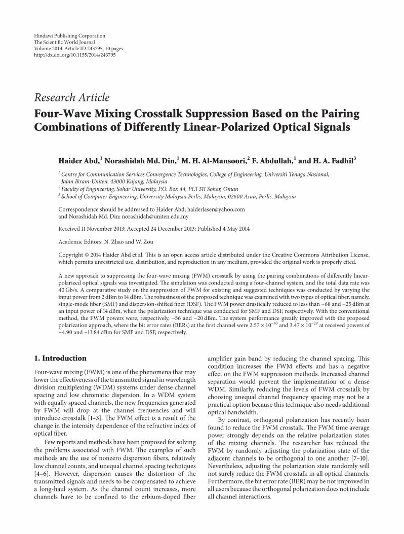
Figure 2 Optical spectrum comparison after 70 kmSMF (a) without polarization technique at input power of 2 dBm (b) without polarizationtechnique at input power of 14 dBm (c) with polarization technique at input power of 2 dBm and (d) with polarization technique at inputpower 14 dBm
where Δ120573 represents the phase mismatch and may beexpressed in terms of signal frequency differences
Δ120573 =
2120587120582
2
119888
1003816
1003816
1003816
1003816
119891
119894
minus 119891
119896
1003816
1003816
1003816
1003816
1003816
1003816
1003816
1003816
1003816
119891
119895
minus 119891
119896
1003816
1003816
1003816
1003816
1003816
times (119863
119862
+
119889119863
119889120582
(
120582
2
2119888
) (
1003816
1003816
1003816
1003816
119891
119894
minus 119891
119896
1003816
1003816
1003816
1003816
+
1003816
1003816
1003816
1003816
1003816
119891
119895
minus 119891
119896
1003816
1003816
1003816
1003816
1003816
))
(7)
where 119863
119862
is the fiber chromatic dispersion and 119889119863119889120582 isa derivative dispersion coefficient of the optical fiber Theright term of (6) and (7) has small and negligible values
The general equation of FWM power can be summarized asfollows
119875FWM =
1024120587
6
119899
4
120582
2
119862
2
(
119863
119892
119883
111
119871eff
119860eff)
2
(119875
119894
119875
119895
119875
119896
)
times 119890
minus120572119871
120572
2
119888120572
2
+ 2120587119863
119888
(Δ119891
119894119896
) (Δ119891
119895119896
)
(8)
where (Δ119891
119894119896
Δ119891
119895119896
) is the channel spacingUnder the effect of polarization FWMefficiency becomes
120578FWM(polirization) =1
119873
times 120578
119899
times 119883
2
111119903
(9)
The Scientific World Journal 5
Received power (dBm)
BER
10minus5
10minus10
10minus15
10minus20
10minus25
10minus30
10minus35
10minus40
minus18 minus16 minus14 minus12 minus10 minus8 minus6 minus4
Without polarization ch1
With polarization ch1
(a)
10minus3
10minus4
10minus5
10minus6
10minus7
10minus8
10minus9
10minus10
Received power (dBm)minus18 minus16 minus14 minus12 minus10 minus8 minus6 minus4
Without polarization ch2
With polarization ch2
BER
(b)
BER
10minus5
10minus10
10minus15
10minus20
10minus25
10minus30
Received power (dBm)minus18 minus16 minus14 minus12 minus10 minus8 minus6 minus4
Without polarization ch3
With polarization ch3
(c)
BER
10minus4
10minus5
10minus6
10minus7
10minus8
10minus9
10minus10
10minus11
Received power (dBm)
minus18 minus16 minus14 minus12 minus10 minus8 minus6 minus4
Without polarization ch4
With polarization ch4
(d)
Figure 3 Received power versus BER in the presence and absence of the polarization techniques at (a) ch1
(b) ch2
(c) ch3
and (d) ch4
where 120578FWM(polarized) is FWM efficiency attained by polariza-tion technique 119883
1111119903
is a factor that represents polarizationdependency of the FWM process and changes from 0 to 1according to SOP between channels as shown in (1) to (3)
119873 is the total number of channel and 120578
119899
is the FWMefficiency in the conventional system
Using (8) FWM efficiency (120578
119899
) can be rewritten asfollows
120578
119899
=
120572
2
119888120572
2
+ 2120587119863
119862
(Δ119891
119894119896
) (Δ119891
119895119896
)
(10)
6 The Scientific World Journal
(a) (b)
Figure 4 Optimum eye diagram performance of SMF using ch1
(a) without polarization technique and (b) with polarization Both at 119875in =
14 dBm
By substituting (10) into (9) we can derive (11) as thefollowing
120578FWM(polirized) =1
119873
times
119883
2
111119903
times 120572
2
119888120572
2
+ 2120587119863
119862
(Δ119891
119894119896
) (Δ119891
119895119896
)
(11)
With the polarization effect FWM power in (8) can bemodified as follows
119875FWM(poarized) =1024120587
6
119899
4
120582
2
119862
2
(
119863119883
111
119871eff119860eff
)
2
(119875
119894
119875
119895
119875
119896
) 119890
minus120572119871
times 120578FWM(polarized)
(12)
By substituting (11) into (12) the general FWM power is asfollows
119875FWM(polirized) =1024120587
6
119899
4
120582
2
119862
2
(
119863119883
111
119871eff119860eff
)
2
(119875
119894
119875
119895
119875
119896
) 119890
minus120572119871
times
119883
2
111119903
times 120572
2
119873 times (119888120572
2
+ 2120587119863
119862
(Δ119891
119894119896
) (Δ119891
119895119896
))
(13)
In the Gaussian approximation [8 9] error probability iswritten as
119875
119890
=
1
radic
2120587
int
infin
119876
exp[minus
119905
2
2
] 119889119905 (14)
To calculate system performance under the effect of FWMshot and thermal noises we used the following equations
119876 =
119870119875
119878
radic119873th + 119873sh + 2119870
2
119875119904
2
119862
(119898)
IM + radic119873th
(15)
119862
(119898)
IM =
1
8
sum
I
119875
119894119895119896
119875
119904
+
1
4
sum
III
119875
119894119894119896
119875
119904
(16)
where119876 is the119876 factor119862(119898)IM is the effective FWMcrosstalk inintensity modulation-direct modulation transmission 119875
119894119895119896
isthe FWM power generated at frequency fs from a frequency
combination satisfying 119891
119894
+ 119891
119895
minus 119891
119896
= 119891
119904
where 119891
119896
= 119891
119904
119875
119894119894119896
is the FWM power at identical 119894 and 119895 where 119894 = 119895 = 119896 119875
119904
is the received power at the receiver 119890 is the electron charge(16times10
minus19
119862)119873th is thermal noise and119873sh is the shot noiseTo calculate the received power and to achieve a given
BER = 10
minus9 119876 = 6 without FWM and 119862
(119898)
IM = 0 (15) ismodified as follows
2119870
2
119875
2
119904
119862
(119898)
IM + 119873th + 119873sh =
119870
2
119875
2
119904
119876
2
minus 2radic
119873th119870119875
119904
119876
+ 119873th
119875
1198780
=
119876
2
119870
[2119861119890 + 2
radic119873th
119876
]
(17)
The effect of shot and thermal noises can be neglected becausethese noises have smaller values than those of FWM noise 119876can be obtained using (15) as follows
119876 =
119870119875
119878
radic
2119870
2
119875119904
2
119862
(119898)
IM
119876
2
=
119870
2
119875
2
119904
2119870
2
119875
2
119878
119862
(119898)
(IM)
=
1
2119862
(119898)
(IM)
119876 =
radic
1
2119862
(119898)
(IM)
(18)
BER is calculated using the following equation
BER = 05 times erfc [
119876
radic
2
] (19)
3 Analysis Results and Discussions
The proposed polarization technique was compared with theconventional method (without using the polarization) andexaminedwith SMF andDSFThe comparisonwas conductedat an input power range of 2 dBm to 14 dBm as follows
31 Effect of Proposed Technique on FWM Behavior andBER Using SMF The simulation for a standard single-mode
The Scientific World Journal 7
minus20
minus40
minus60
minus80
minus100
193 T 194 TFrequency (Hz)
Pow
er (d
Bm)
(a)
minus20
minus40
minus60
minus80
minus100
Pow
er (d
Bm)
191 T 192 T 193 T 194 T 195 TFrequency (Hz)
(b)
minus40
minus60
minus80
minus100
193 T 1935T 194 T
Frequency (Hz)
Pow
er (d
Bm)
(c)
minus20
minus40
minus60
minus80
Pow
er (d
Bm)
192 T 193 T 194 T 195 T
Frequency (Hz)
(d)
Figure 5 Optical spectrum comparison after 70 kmDSF (a) without polarization technique at input power of 2 dBm (b) without polarizationtechnique at input power of 14 dBm (c) with polarization technique at input power of 2 dBm and (d) with polarization technique at inputpower 14 dBm
optical fiber ITU-T G652 was conducted according to theindustrial environment protocol in Table 1 Figures 2(a)ndash2(d) illustrate the optical spectrum over a 70 km opticalfiber Decreasing the input power can decrease the FWMeffects In the absence of the polarization technique the FWMpower was minus56 dBm at an input power of 14 dBm while itwas minus64 dBm at a 2 dBm input power With our proposedtechnique the FWM numbers and power are dramaticallyreducedTheFWMpower decreased to less thanminus82 dBmat a2 dBm input power and to minus68 dBm at a 14 dBm input power
Figures 3(a)ndash3(d) reveal that the BER in all channelsimproved with the polarization technique compared with
the nonuse of the polarization technique The BER valuesat ch1
ch2
ch3
and ch4
without the polarization techniquewere 309 times 10minus18 935 times 10minus6 111 times 10minus13 and 469 times 10minus7at a received power of minus49 dBm respectively When thepolarization technique was used the system performancerespectively yielded theminimumBER values of 257times 10minus40935 times 10minus10 439 times 10minus27 and 3 times 10minus11 Figures 4(a)-4(b)compare the optimum eye diagram with the polarizationtechnique and that without the polarization technique Theformer was higher and more optimized than the latter Forch1
the former was more open (BER of 257 times 10minus40) than thelatter (BER of 309 times 10minus18) at 119875in = 14 dBm
8 The Scientific World Journal
Received power (dBm)
BER
100
10minus5
10minus10
10minus15
10minus20
10minus25
10minus30
minus18 minus16 minus14 minus12 minus10 minus8 minus6 minus4
Without polarization ch1
With polarization ch1
(a)
Received power (dBm)BE
R
100
10minus5
10minus10
10minus15
10minus20
10minus25
Without polarization ch2
With polarization ch2
minus18 minus16 minus14 minus12 minus10 minus8 minus6 minus4
(b)
Received power (dBm)
BER
100
10minus12
10minus10
10minus14
10minus16
10minus4
10minus6
10minus8
10minus2
10minus18
10minus20
Without polarization ch3
With polarization ch3
minus18 minus16 minus14 minus12 minus10 minus8 minus6 minus4
(c)
Received power (dBm)
BER
Without polarization ch4
With polarization ch4
100
10minus5
10minus10
10minus15
10minus20
10minus25
minus18 minus16 minus14 minus12 minus10 minus8 minus6 minus4
(d)
Figure 6 Received power versus BER in the presence and absence of the polarization techniques using DSF at (a) ch1
(b) ch2
(c) ch3
and(d) ch
4
32 Effect of Proposed Technique on FWM Behavior andBER Using DSF For further investigation the proposedpolarization technique was tested with DSF using the stan-dard parameters in Table 1 In the DSF FWM can stronglyinfluence the transmission performance because most of theFWM interaction occurs near zero dispersion wavelengths
At a high input power the FWM crosstalk increased dra-matically and superimposed with the transmitted channelsFigure 5 shows that for the conventional system at a 2 dBminput power the FWM power was minus52 dBm At a high inputpower of 14 dBm the FWM power significantly increasedwith the number of FWM interfacing with channels and
The Scientific World Journal 9
(a) (b)
Figure 7 Optimum eye diagram performance of DSF using ch1
(a) without polarization technique and (b) with polarization Both at 119875in =
14 dBm
the FWM power was about minus20 dBm With the proposedpolarization technique most of the FWM frequencies werecanceled because the interaction between multiple opticalchannels that pass through the same fiber reduced whichsuppressed the FWM At 2 and 14 dBm input powers theFWM powers were minus69 and minus25 dBm respectively
The overlapping between the transmitted channel andthe FWM crosstalk was translated into a distorted signaland detected by the receiver which led to the significantdegradation of the system performance Figure 6 show theBER pattern using DSF with and without the polarizationtechnique With lower input power BERs decreased withincreasing received signal power At a received power ofminus1703 dBm the BERs at ch
1
ch2
ch3
and ch4
are 34 times 10
minus154 times 10
minus8 3 times 10
minus8 and 16 times 10
minus9 respectively With thepolarization technique the BERs are respectively 73 times 10
minus2439 times 10
minus15 3 times 10
minus16 and 28 times 10
minus17With the increase of the input power the FWM power
also increased and more FWM crosstalk superimposedwith channels which affected the transmitted channel BERincreased as the received signal power decreased and thenoise power increased For example at a high input power of14 dBm (minus1384 dBm received power) the BERs were 1 0050033 and 1 at ch
1
ch2
ch3
and ch4
with the conventionaltechnique respectively The system performance drasticallyimproved in the presence of the polarization techniquewhere the BER values were respectively 34 times 10
minus29 8 times 10
minus2216 times 10
minus20 and 18 times 10
minus21 Based on these findings thepolarization approach introduces a dramatic durability forreducing the FWM crosstalk even at high input power andlow dispersion In terms of the eye diagram the first channelrevealed a high and optimum eye diagram in the proposedtechnique than in the conventional one
Figures 7(a)-7(b) illustrate the eye diagram using DSF forboth techniques at a 14 dBm input power The polarizationtechnique was superior to the conventional technique at highinput power values
4 Conclusion
In this paper we propose an efficient approach for reducingthe transmission limitation caused by the FWM in a WDM
system by using the pairing combinations of differentlylinear-polarized optical signals The FWM behavior andsystem performance were evaluated with the proposed tech-nique under the input power parameter and using two kindsof optical fiber namely SMF andDSFThe FWMpowers weresuppressed to less than minus68 and minus25 dBm at a 14 dBm inputpower in the presence of this approach using the SMF andDSF respectively The polarization technique also enhancedthe BERs in the range of 257 times 10
minus40 and 347 times 10
minus29
at received powers of minus490 and minus1384 dBm for SMF andDSF respectively The findings prove that the polarizationapproach significantly reduced the FWM crosstalk throughfiber transmission The obtained results also show that in theexistence of the polarization approach the FWM crosstalkhas no dangerous effect even with a high input optical powerof 14 dBm
Conflict of Interests
The authors declare that there is no conflict of interestsregarding the publication of this paper
Acknowledgment
The authors would like to thank the Ministry of HigherEducation Malaysia for funding this project under theExploratory Research Grant no ERGS12013STG02UNITEN0201
References
[1] A R Chraplyvy ldquoLimitations on lightwave communicationsimposed by optical-fiber nonlinearitiesrdquo Journal of LightwaveTechnology vol 8 no 10 pp 1548ndash1557 1990
[2] H J Abed N M Din M H Al-Mansoori H A Fadhil andF Abdullah ldquoRecent four-wave mixing suppression methodsrdquoOptik vol 124 no 15 pp 2214ndash2218 2013
[3] C Wehmann L Fernandes C Sobrinho et al ldquoAnalysis of thefour wave mixing effect (FWM) in a dispersion decreasing fiber(DDF) for aWDM systemrdquoOptical Fiber Technology vol 11 no3 pp 306ndash618 2005
[4] M Jamshidifar A Vedadi and M E Marhic ldquoReduction offour-wave-mixing crosstalk in a short fiber-optical parametric
10 The Scientific World Journal
amplifierrdquo IEEE Photonics Technology Letters vol 21 no 17 pp1244ndash1246 2009
[5] H J Abd M H Al-Mansoori N M Din F Abdullah andH A Fadhil ldquoPriority-based parameter optimization strategyfor reducing the effects of four-wave mixing on WDM systemrdquoOptik vol 125 no 1 pp 25ndash30 2014
[6] R Kaler and R S Kaler ldquoInvestigation of four wave mixingeffect at different channel spacingrdquo Optik vol 123 no 4 pp352ndash356 2012
[7] K Inoue ldquoArrangement of orthogonal polarized signals for sup-pressing fiber four-wave mixing in optical multichannel trans-mission systemsrdquo IEEE Photonics Technology Letters vol 3 no6 pp 560ndash563 1991
[8] J Onishi S Kojima and T Numai ldquoEffects of frequencypola-rization allocations and the zero-dispersion frequency on FDMlightwave transmission systemsrdquo Optics Communications vol281 no 14 pp 3882ndash3891 2008
[9] J Onishi S Kojima and T Numai ldquoEffects of frequency andpolarization allocations on FDM lightwave transmission sys-temsrdquo Optics Communications vol 281 no 9 pp 2627ndash26322008
[10] K Inoue ldquoPolarization effect on four-wave mixing efficiency ina single-mode fiberrdquo IEEE Journal of Quantum Electronics vol28 no 4 pp 883ndash894 1992
[11] H J Abed N M DIN M H Al-Mansoori F Abdullah and HA Fadhil ldquoA new FWM reduction technique based on dampingselective wavelengthsrdquo Ukrainian Journal of Physics vol 58 no10 pp 956ndash961 2013

2 The Scientific World Journal
In this work we combined pairs of channels with differentpolarizations The first channel was polarized by a linearpolarization of 45∘ while the second channel was polarizedat 90∘ away by a linear polarization of (45
∘
+ 90
∘
) Bothof the polarized channels were combined using a polarizercombiner The proposed technique was investigated in bothsingle-mode fiber (SMF) and dispersion-shifted fiber (DSF)with a 70 km fiber length and four channels Through thisapproach the FWM crosstalk significantly reduced and agood improvement was observed in system performanceTheresults confirm the robustness of the polarization techniqueagainst the FWM crosstalk and show that the FWM crosstalkhas no dangerous influence on the system performance evenat a high value of input power
2 System Description andTheoretical Background
Figures 1(a)-1(b) describe the proposed and conventionalsystem configuration of the transmitter and receiver At thetransmitter part the array of continuous wave lasers (L
1
ndashL4
)is used to generate the carrier signal The frequency of thefirst user is set to 193 THz and the spacing between each useris 100GHz Each user is modulated with a 10Gbs data rateTherefore the total data rate of the system was 40Gbs Thearray laser sources are connected to an external modulatorThe external modulator comprised a Pseudo-Random BitSequence (PRBS) which is connected to a pulse generatorto modulate the optical signals using an NRZ modulationformat It is then connected to the Mach-Zehnder modulator(MZM) which acts as an intensity modulator
In the proposed system simulation each two channelsare linearly polarized 90∘ apart and then combined togetherAs shown in Figure 1(a) the first channel is polarized usinga linear polarization of (120579) while the second channel ispolarized using a linear polarization of (120579 + 90
∘
) Each ofthe two channels is combined using a polarizer combinerthat combines the two input signals to one output port Thepolarization angle has been selected at 120579 = 45
∘ Then thefour signals are collected using a polarizer combiner witha 0∘ polarization angle The combined signals pass throughoptical fiber with a 70 km length In the conventional systemFigure 1(b) the state of polarization of each transmittedchannel is 0∘ Two types of optical fiber were used such asSMF and DSF and the standard parameters of each one werein Table 1 At the receiver the signal is demultiplexed Thesignal is detected by a PIN photodiode for direct detection Itis then passed through the low-pass Bessel filter Finally thesignal is then connected directly to the system performanceanalyzer which is used to generate the graph
The nonlinear light amplitude ENL describes the FWMlight FFWM = 119865
119894
+ 119865
119895
minus 119865
119896
The total nonlinear amplitude is[10]
119864
NL= 120578
1003816
1003816
1003816
1003816
119864
1
(0)
1003816
1003816
1003816
1003816
1003816
1003816
1003816
1003816
119864
2
(0)
1003816
1003816
1003816
1003816
1003816
1003816
1003816
1003816
119864
3
(0)
1003816
1003816
1003816
1003816
sdot (⟨119878
119896
| 119878
119895
⟩
1003816
1003816
1003816
1003816
119878
119894
⟩ + ⟨119878
119896
| 119878
119894
⟩
1003816
1003816
1003816
1003816
1003816
119878
119895
⟩)
(1)
where |119864
119895
(0)| (119895 = 119860 119861 119862) are the amplitudes at 119911 = 0
Table 1 System simulation parameters
Parameter Unit ValuesFiber length 119871 km 70 for SMF
Input power 119875119894
dBmVaried from 2 to14 dBm with step
2 dBmInput frequencies 119891
119894
119891119895
and 119891
119896
THz 193 to 1933Channel spacing Δ119891 GHz 100Standard SMF G652
Dispersion 119863119888
psnmsdotkm 17Cross effective area 119860 eff 120583m2 80Dispersion slope psnm2
sdotkm 007Standard DSF G653
Dispersion 119863119888
psnmsdotkm 03Cross effective area 119860 eff 120583m2 50Dispersion slope psnm2
sdotkm 0075Degeneracy factor 119863
119892
mdash 6Third order susceptibility 119883
111
m3wsdots 6 times 10
minus15
Refractive index 119899 mdash 148Speed of light 119888 (ms) 3 times 10
8
Attenuation factor (dBkm) 02Number of channel mdash 4119870 detector responsively AW 08Total data rate Gbs 40Optical bandwidth 119861 MHz 622
Relative polarization states can be represented by normal-ized Jones vectors |119878⟩119895 which are assumed to be maintainedthroughout the fiber The orthogonal polarization effect onFWM efficiency can be classified into the following cases
(1) For all waves identically polarized ⟨119878
119894
| 119878
119895
⟩ 119894 = 119895 =
1 the value of 119883
2
111119903
= 1 and (1) for 119894 and 119895 canrewritten as
119864
NL= 2120578
1003816
1003816
1003816
1003816
119864
1
(0)
1003816
1003816
1003816
1003816
1003816
1003816
1003816
1003816
119864
2
(0)
1003816
1003816
1003816
1003816
1003816
1003816
1003816
1003816
119864
3
(0)
1003816
1003816
1003816
1003816
1003816
1003816
1003816
1003816
1003816
119864
NL10038161003816
1003816
1003816
1003816
2
= 4120578
1003816
1003816
1003816
1003816
119864
1
(0)
1003816
1003816
1003816
1003816
2
1003816
1003816
1003816
1003816
119864
2
(0)
1003816
1003816
1003816
1003816
2
1003816
1003816
1003816
1003816
119864
3
(0)
1003816
1003816
1003816
1003816
2
(2)
(2) For the case of two waves being copolarized and thethird being orthogonally polarized (|119878
119894
⟩ = |119878
119895
⟩ perp
|119878
119896
⟩) this means ⟨119878
119896
| 119878
119895
⟩ = 0 ⟨119878
119896
| 119878
119894
⟩ = 0 withthe value of 119883
2
111119903
= 0
(3) In the case of |119878
119894
⟩ = |119878
119896
⟩ perp |119878
119895
⟩ both ⟨119878
119894
| 119878
119895
⟩ =
0 ⟨119878
119894
| 119878
119896
⟩ = 1 in this case the value of 119883
2
111119903
=
14 so the square of the nonlinear amplitude nowbecomes
1003816
1003816
1003816
1003816
1003816
119864
NL10038161003816
1003816
1003816
1003816
2
= 120578
1003816
1003816
1003816
1003816
119864
1
(0)
1003816
1003816
1003816
1003816
2
1003816
1003816
1003816
1003816
119864
2
(0)
1003816
1003816
1003816
1003816
2
1003816
1003816
1003816
1003816
119864
3
(0)
1003816
1003816
1003816
1003816
2
(3)
The Scientific World Journal 3
Optical fiber
Ext mod 1
Ext mod 2
Ext mod 3
Ext mod 4
CW laser
120579
120579 + 90
Polirizationcombiner
array
Polirizationcombiner
Polirizationcombiner
120579
120579 + 90
Linearpolarizer
Linearpolarizer
Linearpolarizer
Linearpolarizer
WDM demux
PhotodiodeLow pass filter
Low pass filter
Low pass filter
BER 1
Photodiode
Photodiode
BER 2
BER 4
(a)
Optical fiberExt mod 1
Ext mod 2
Ext mod 4
CW laserarray
WDM demuxWDM mux
Photodiode
Photodiode
Low pass filter
Low pass filter
BER 1
BER 2
BER 4
(b)
Figure 1 Optical system simulation configuration (a) proposed system and (b) conventional system
In a WDM system the power transferred to new frequenciesdue to FWMafter light propagation within a distance 119871 in thefiber can be estimated using equation [11]
119875FWM = 120578
119899
times
1024120587
6
119899
4
119903
120582
2
119862
2
(
119863119883
111
119871eff119860eff
)
2
(119875
119894
119875
119895
119875
119896
) 119890
minus120572119871
(4)
where 119875
119894
119875
119895
and 119875
119896
are the input power values at centralfrequencies 119891
119894
119891
119895
and 119891
119896
respectively 119863 is the degeneracyfactor that is equal to 3 for two-tone and 6 for three-tonesystems 119883
111
is third-order susceptibility that is equal to6 times 10
minus15 (m3ws) 119860eff is the effective area 119862 is the speed oflight 120582 is the laser wavelength 120572 is the fiber loss coefficient 119871is the total fiber length 119899
119903
is the refractive index of the fiber
and 119871eff is the nonlinear effective length that can be calculatedusing the following equation
119871eff =
(1 minus 119890
minus120572119871
)
120572
(5)
The efficiency (120578) of four-wave mixing is given by [3]
120578 =
120572
2
120572
2
+ Δ120573
2
(1 +
4119890
minus120572119871sin2 (Δ1205731198712)
[1 minus 119890
minus120572119871
]
2
) (6)
4 The Scientific World Journal
FWM frequencies FWM frequenciesFWM frequencies FWM frequencies
1928 T 1931 T 1934 T 1937 TFrequency (Hz)
Pow
er (d
Bm)
minus20
minus40
minus60
minus80
minus100
(a)
Frequency (Hz)
Pow
er (d
Bm)
minus20
minus40
minus60
minus80
minus100
1925 T 1928 T 1931 T 1934 T 1937 T
(b)
minus30
minus40
minus50
minus60
minus70
minus80
minus90
1928 T 1931 T 1934 T 1937 TFrequency (Hz)
Pow
er (d
Bm)
(c)
Frequency (Hz)
minus10
minus20
minus30
minus40
minus50
minus60
minus70
Pow
er (d
Bm)
1926 T 1928 T 193 T 1932 T 1934 T 1936 T
(d)
Figure 2 Optical spectrum comparison after 70 kmSMF (a) without polarization technique at input power of 2 dBm (b) without polarizationtechnique at input power of 14 dBm (c) with polarization technique at input power of 2 dBm and (d) with polarization technique at inputpower 14 dBm
where Δ120573 represents the phase mismatch and may beexpressed in terms of signal frequency differences
Δ120573 =
2120587120582
2
119888
1003816
1003816
1003816
1003816
119891
119894
minus 119891
119896
1003816
1003816
1003816
1003816
1003816
1003816
1003816
1003816
1003816
119891
119895
minus 119891
119896
1003816
1003816
1003816
1003816
1003816
times (119863
119862
+
119889119863
119889120582
(
120582
2
2119888
) (
1003816
1003816
1003816
1003816
119891
119894
minus 119891
119896
1003816
1003816
1003816
1003816
+
1003816
1003816
1003816
1003816
1003816
119891
119895
minus 119891
119896
1003816
1003816
1003816
1003816
1003816
))
(7)
where 119863
119862
is the fiber chromatic dispersion and 119889119863119889120582 isa derivative dispersion coefficient of the optical fiber Theright term of (6) and (7) has small and negligible values
The general equation of FWM power can be summarized asfollows
119875FWM =
1024120587
6
119899
4
120582
2
119862
2
(
119863
119892
119883
111
119871eff
119860eff)
2
(119875
119894
119875
119895
119875
119896
)
times 119890
minus120572119871
120572
2
119888120572
2
+ 2120587119863
119888
(Δ119891
119894119896
) (Δ119891
119895119896
)
(8)
where (Δ119891
119894119896
Δ119891
119895119896
) is the channel spacingUnder the effect of polarization FWMefficiency becomes
120578FWM(polirization) =1
119873
times 120578
119899
times 119883
2
111119903
(9)
The Scientific World Journal 5
Received power (dBm)
BER
10minus5
10minus10
10minus15
10minus20
10minus25
10minus30
10minus35
10minus40
minus18 minus16 minus14 minus12 minus10 minus8 minus6 minus4
Without polarization ch1
With polarization ch1
(a)
10minus3
10minus4
10minus5
10minus6
10minus7
10minus8
10minus9
10minus10
Received power (dBm)minus18 minus16 minus14 minus12 minus10 minus8 minus6 minus4
Without polarization ch2
With polarization ch2
BER
(b)
BER
10minus5
10minus10
10minus15
10minus20
10minus25
10minus30
Received power (dBm)minus18 minus16 minus14 minus12 minus10 minus8 minus6 minus4
Without polarization ch3
With polarization ch3
(c)
BER
10minus4
10minus5
10minus6
10minus7
10minus8
10minus9
10minus10
10minus11
Received power (dBm)
minus18 minus16 minus14 minus12 minus10 minus8 minus6 minus4
Without polarization ch4
With polarization ch4
(d)
Figure 3 Received power versus BER in the presence and absence of the polarization techniques at (a) ch1
(b) ch2
(c) ch3
and (d) ch4
where 120578FWM(polarized) is FWM efficiency attained by polariza-tion technique 119883
1111119903
is a factor that represents polarizationdependency of the FWM process and changes from 0 to 1according to SOP between channels as shown in (1) to (3)
119873 is the total number of channel and 120578
119899
is the FWMefficiency in the conventional system
Using (8) FWM efficiency (120578
119899
) can be rewritten asfollows
120578
119899
=
120572
2
119888120572
2
+ 2120587119863
119862
(Δ119891
119894119896
) (Δ119891
119895119896
)
(10)
6 The Scientific World Journal
(a) (b)
Figure 4 Optimum eye diagram performance of SMF using ch1
(a) without polarization technique and (b) with polarization Both at 119875in =
14 dBm
By substituting (10) into (9) we can derive (11) as thefollowing
120578FWM(polirized) =1
119873
times
119883
2
111119903
times 120572
2
119888120572
2
+ 2120587119863
119862
(Δ119891
119894119896
) (Δ119891
119895119896
)
(11)
With the polarization effect FWM power in (8) can bemodified as follows
119875FWM(poarized) =1024120587
6
119899
4
120582
2
119862
2
(
119863119883
111
119871eff119860eff
)
2
(119875
119894
119875
119895
119875
119896
) 119890
minus120572119871
times 120578FWM(polarized)
(12)
By substituting (11) into (12) the general FWM power is asfollows
119875FWM(polirized) =1024120587
6
119899
4
120582
2
119862
2
(
119863119883
111
119871eff119860eff
)
2
(119875
119894
119875
119895
119875
119896
) 119890
minus120572119871
times
119883
2
111119903
times 120572
2
119873 times (119888120572
2
+ 2120587119863
119862
(Δ119891
119894119896
) (Δ119891
119895119896
))
(13)
In the Gaussian approximation [8 9] error probability iswritten as
119875
119890
=
1
radic
2120587
int
infin
119876
exp[minus
119905
2
2
] 119889119905 (14)
To calculate system performance under the effect of FWMshot and thermal noises we used the following equations
119876 =
119870119875
119878
radic119873th + 119873sh + 2119870
2
119875119904
2
119862
(119898)
IM + radic119873th
(15)
119862
(119898)
IM =
1
8
sum
I
119875
119894119895119896
119875
119904
+
1
4
sum
III
119875
119894119894119896
119875
119904
(16)
where119876 is the119876 factor119862(119898)IM is the effective FWMcrosstalk inintensity modulation-direct modulation transmission 119875
119894119895119896
isthe FWM power generated at frequency fs from a frequency
combination satisfying 119891
119894
+ 119891
119895
minus 119891
119896
= 119891
119904
where 119891
119896
= 119891
119904
119875
119894119894119896
is the FWM power at identical 119894 and 119895 where 119894 = 119895 = 119896 119875
119904
is the received power at the receiver 119890 is the electron charge(16times10
minus19
119862)119873th is thermal noise and119873sh is the shot noiseTo calculate the received power and to achieve a given
BER = 10
minus9 119876 = 6 without FWM and 119862
(119898)
IM = 0 (15) ismodified as follows
2119870
2
119875
2
119904
119862
(119898)
IM + 119873th + 119873sh =
119870
2
119875
2
119904
119876
2
minus 2radic
119873th119870119875
119904
119876
+ 119873th
119875
1198780
=
119876
2
119870
[2119861119890 + 2
radic119873th
119876
]
(17)
The effect of shot and thermal noises can be neglected becausethese noises have smaller values than those of FWM noise 119876can be obtained using (15) as follows
119876 =
119870119875
119878
radic
2119870
2
119875119904
2
119862
(119898)
IM
119876
2
=
119870
2
119875
2
119904
2119870
2
119875
2
119878
119862
(119898)
(IM)
=
1
2119862
(119898)
(IM)
119876 =
radic
1
2119862
(119898)
(IM)
(18)
BER is calculated using the following equation
BER = 05 times erfc [
119876
radic
2
] (19)
3 Analysis Results and Discussions
The proposed polarization technique was compared with theconventional method (without using the polarization) andexaminedwith SMF andDSFThe comparisonwas conductedat an input power range of 2 dBm to 14 dBm as follows
31 Effect of Proposed Technique on FWM Behavior andBER Using SMF The simulation for a standard single-mode
The Scientific World Journal 7
minus20
minus40
minus60
minus80
minus100
193 T 194 TFrequency (Hz)
Pow
er (d
Bm)
(a)
minus20
minus40
minus60
minus80
minus100
Pow
er (d
Bm)
191 T 192 T 193 T 194 T 195 TFrequency (Hz)
(b)
minus40
minus60
minus80
minus100
193 T 1935T 194 T
Frequency (Hz)
Pow
er (d
Bm)
(c)
minus20
minus40
minus60
minus80
Pow
er (d
Bm)
192 T 193 T 194 T 195 T
Frequency (Hz)
(d)
Figure 5 Optical spectrum comparison after 70 kmDSF (a) without polarization technique at input power of 2 dBm (b) without polarizationtechnique at input power of 14 dBm (c) with polarization technique at input power of 2 dBm and (d) with polarization technique at inputpower 14 dBm
optical fiber ITU-T G652 was conducted according to theindustrial environment protocol in Table 1 Figures 2(a)ndash2(d) illustrate the optical spectrum over a 70 km opticalfiber Decreasing the input power can decrease the FWMeffects In the absence of the polarization technique the FWMpower was minus56 dBm at an input power of 14 dBm while itwas minus64 dBm at a 2 dBm input power With our proposedtechnique the FWM numbers and power are dramaticallyreducedTheFWMpower decreased to less thanminus82 dBmat a2 dBm input power and to minus68 dBm at a 14 dBm input power
Figures 3(a)ndash3(d) reveal that the BER in all channelsimproved with the polarization technique compared with
the nonuse of the polarization technique The BER valuesat ch1
ch2
ch3
and ch4
without the polarization techniquewere 309 times 10minus18 935 times 10minus6 111 times 10minus13 and 469 times 10minus7at a received power of minus49 dBm respectively When thepolarization technique was used the system performancerespectively yielded theminimumBER values of 257times 10minus40935 times 10minus10 439 times 10minus27 and 3 times 10minus11 Figures 4(a)-4(b)compare the optimum eye diagram with the polarizationtechnique and that without the polarization technique Theformer was higher and more optimized than the latter Forch1
the former was more open (BER of 257 times 10minus40) than thelatter (BER of 309 times 10minus18) at 119875in = 14 dBm
8 The Scientific World Journal
Received power (dBm)
BER
100
10minus5
10minus10
10minus15
10minus20
10minus25
10minus30
minus18 minus16 minus14 minus12 minus10 minus8 minus6 minus4
Without polarization ch1
With polarization ch1
(a)
Received power (dBm)BE
R
100
10minus5
10minus10
10minus15
10minus20
10minus25
Without polarization ch2
With polarization ch2
minus18 minus16 minus14 minus12 minus10 minus8 minus6 minus4
(b)
Received power (dBm)
BER
100
10minus12
10minus10
10minus14
10minus16
10minus4
10minus6
10minus8
10minus2
10minus18
10minus20
Without polarization ch3
With polarization ch3
minus18 minus16 minus14 minus12 minus10 minus8 minus6 minus4
(c)
Received power (dBm)
BER
Without polarization ch4
With polarization ch4
100
10minus5
10minus10
10minus15
10minus20
10minus25
minus18 minus16 minus14 minus12 minus10 minus8 minus6 minus4
(d)
Figure 6 Received power versus BER in the presence and absence of the polarization techniques using DSF at (a) ch1
(b) ch2
(c) ch3
and(d) ch
4
32 Effect of Proposed Technique on FWM Behavior andBER Using DSF For further investigation the proposedpolarization technique was tested with DSF using the stan-dard parameters in Table 1 In the DSF FWM can stronglyinfluence the transmission performance because most of theFWM interaction occurs near zero dispersion wavelengths
At a high input power the FWM crosstalk increased dra-matically and superimposed with the transmitted channelsFigure 5 shows that for the conventional system at a 2 dBminput power the FWM power was minus52 dBm At a high inputpower of 14 dBm the FWM power significantly increasedwith the number of FWM interfacing with channels and
The Scientific World Journal 9
(a) (b)
Figure 7 Optimum eye diagram performance of DSF using ch1
(a) without polarization technique and (b) with polarization Both at 119875in =
14 dBm
the FWM power was about minus20 dBm With the proposedpolarization technique most of the FWM frequencies werecanceled because the interaction between multiple opticalchannels that pass through the same fiber reduced whichsuppressed the FWM At 2 and 14 dBm input powers theFWM powers were minus69 and minus25 dBm respectively
The overlapping between the transmitted channel andthe FWM crosstalk was translated into a distorted signaland detected by the receiver which led to the significantdegradation of the system performance Figure 6 show theBER pattern using DSF with and without the polarizationtechnique With lower input power BERs decreased withincreasing received signal power At a received power ofminus1703 dBm the BERs at ch
1
ch2
ch3
and ch4
are 34 times 10
minus154 times 10
minus8 3 times 10
minus8 and 16 times 10
minus9 respectively With thepolarization technique the BERs are respectively 73 times 10
minus2439 times 10
minus15 3 times 10
minus16 and 28 times 10
minus17With the increase of the input power the FWM power
also increased and more FWM crosstalk superimposedwith channels which affected the transmitted channel BERincreased as the received signal power decreased and thenoise power increased For example at a high input power of14 dBm (minus1384 dBm received power) the BERs were 1 0050033 and 1 at ch
1
ch2
ch3
and ch4
with the conventionaltechnique respectively The system performance drasticallyimproved in the presence of the polarization techniquewhere the BER values were respectively 34 times 10
minus29 8 times 10
minus2216 times 10
minus20 and 18 times 10
minus21 Based on these findings thepolarization approach introduces a dramatic durability forreducing the FWM crosstalk even at high input power andlow dispersion In terms of the eye diagram the first channelrevealed a high and optimum eye diagram in the proposedtechnique than in the conventional one
Figures 7(a)-7(b) illustrate the eye diagram using DSF forboth techniques at a 14 dBm input power The polarizationtechnique was superior to the conventional technique at highinput power values
4 Conclusion
In this paper we propose an efficient approach for reducingthe transmission limitation caused by the FWM in a WDM
system by using the pairing combinations of differentlylinear-polarized optical signals The FWM behavior andsystem performance were evaluated with the proposed tech-nique under the input power parameter and using two kindsof optical fiber namely SMF andDSFThe FWMpowers weresuppressed to less than minus68 and minus25 dBm at a 14 dBm inputpower in the presence of this approach using the SMF andDSF respectively The polarization technique also enhancedthe BERs in the range of 257 times 10
minus40 and 347 times 10
minus29
at received powers of minus490 and minus1384 dBm for SMF andDSF respectively The findings prove that the polarizationapproach significantly reduced the FWM crosstalk throughfiber transmission The obtained results also show that in theexistence of the polarization approach the FWM crosstalkhas no dangerous effect even with a high input optical powerof 14 dBm
Conflict of Interests
The authors declare that there is no conflict of interestsregarding the publication of this paper
Acknowledgment
The authors would like to thank the Ministry of HigherEducation Malaysia for funding this project under theExploratory Research Grant no ERGS12013STG02UNITEN0201
References
[1] A R Chraplyvy ldquoLimitations on lightwave communicationsimposed by optical-fiber nonlinearitiesrdquo Journal of LightwaveTechnology vol 8 no 10 pp 1548ndash1557 1990
[2] H J Abed N M Din M H Al-Mansoori H A Fadhil andF Abdullah ldquoRecent four-wave mixing suppression methodsrdquoOptik vol 124 no 15 pp 2214ndash2218 2013
[3] C Wehmann L Fernandes C Sobrinho et al ldquoAnalysis of thefour wave mixing effect (FWM) in a dispersion decreasing fiber(DDF) for aWDM systemrdquoOptical Fiber Technology vol 11 no3 pp 306ndash618 2005
[4] M Jamshidifar A Vedadi and M E Marhic ldquoReduction offour-wave-mixing crosstalk in a short fiber-optical parametric
10 The Scientific World Journal
amplifierrdquo IEEE Photonics Technology Letters vol 21 no 17 pp1244ndash1246 2009
[5] H J Abd M H Al-Mansoori N M Din F Abdullah andH A Fadhil ldquoPriority-based parameter optimization strategyfor reducing the effects of four-wave mixing on WDM systemrdquoOptik vol 125 no 1 pp 25ndash30 2014
[6] R Kaler and R S Kaler ldquoInvestigation of four wave mixingeffect at different channel spacingrdquo Optik vol 123 no 4 pp352ndash356 2012
[7] K Inoue ldquoArrangement of orthogonal polarized signals for sup-pressing fiber four-wave mixing in optical multichannel trans-mission systemsrdquo IEEE Photonics Technology Letters vol 3 no6 pp 560ndash563 1991
[8] J Onishi S Kojima and T Numai ldquoEffects of frequencypola-rization allocations and the zero-dispersion frequency on FDMlightwave transmission systemsrdquo Optics Communications vol281 no 14 pp 3882ndash3891 2008
[9] J Onishi S Kojima and T Numai ldquoEffects of frequency andpolarization allocations on FDM lightwave transmission sys-temsrdquo Optics Communications vol 281 no 9 pp 2627ndash26322008
[10] K Inoue ldquoPolarization effect on four-wave mixing efficiency ina single-mode fiberrdquo IEEE Journal of Quantum Electronics vol28 no 4 pp 883ndash894 1992
[11] H J Abed N M DIN M H Al-Mansoori F Abdullah and HA Fadhil ldquoA new FWM reduction technique based on dampingselective wavelengthsrdquo Ukrainian Journal of Physics vol 58 no10 pp 956ndash961 2013
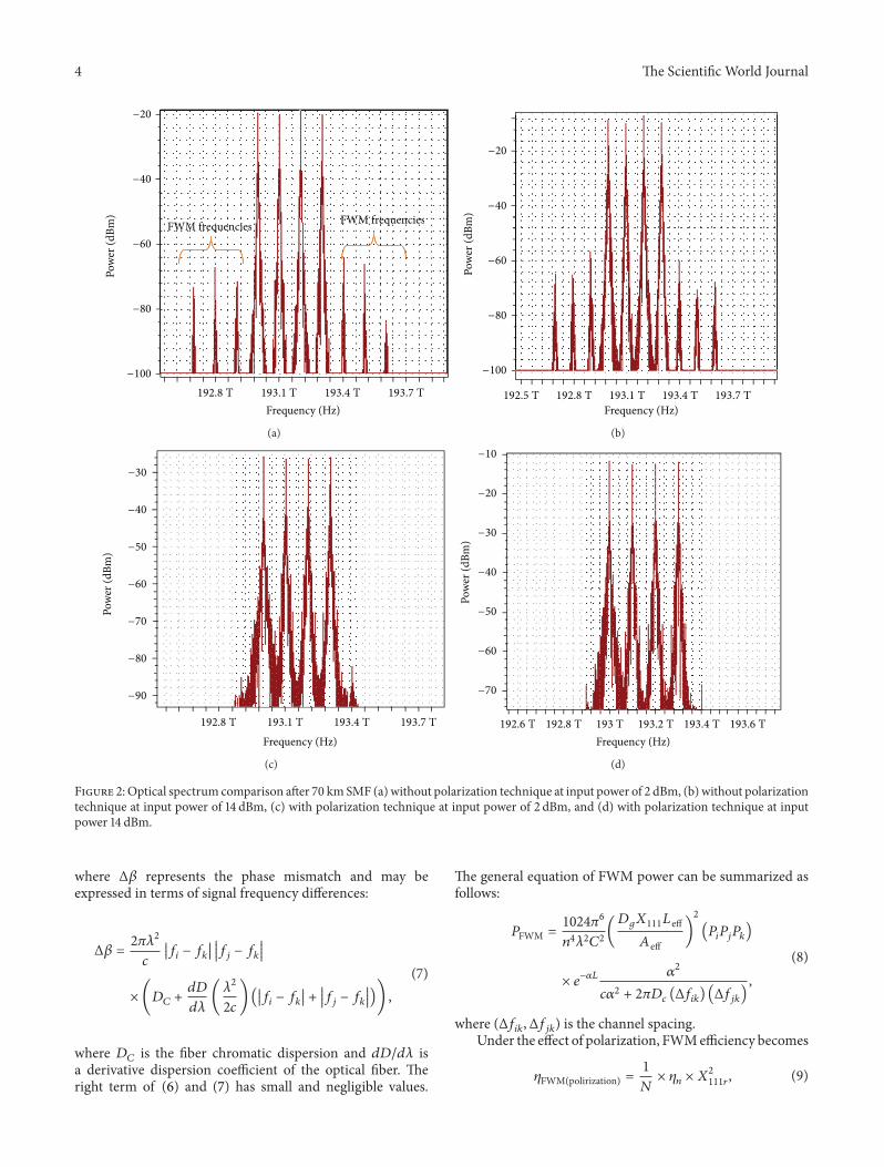
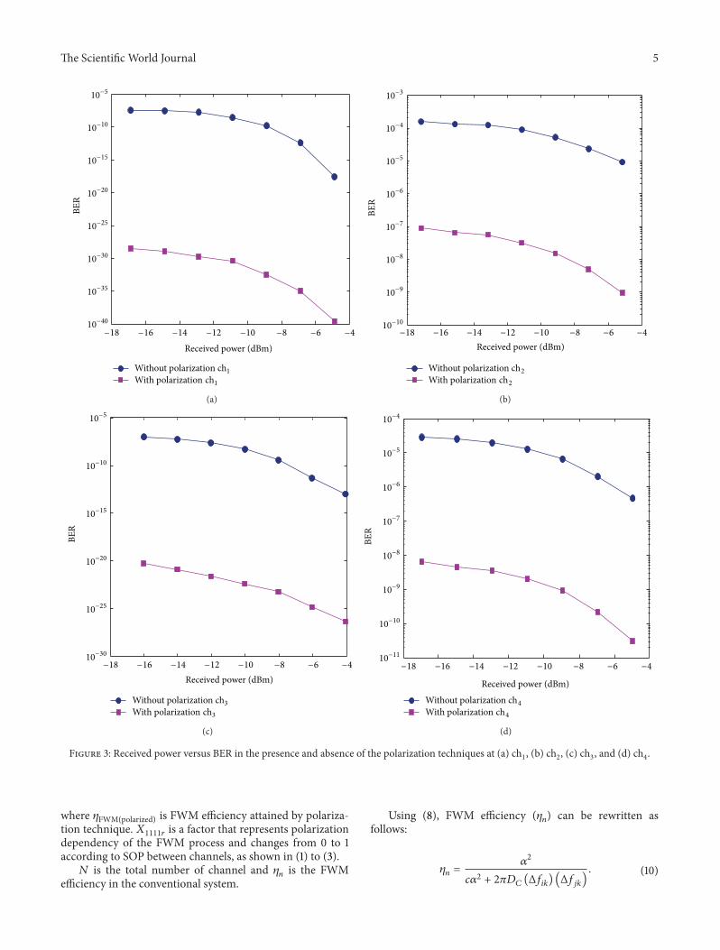
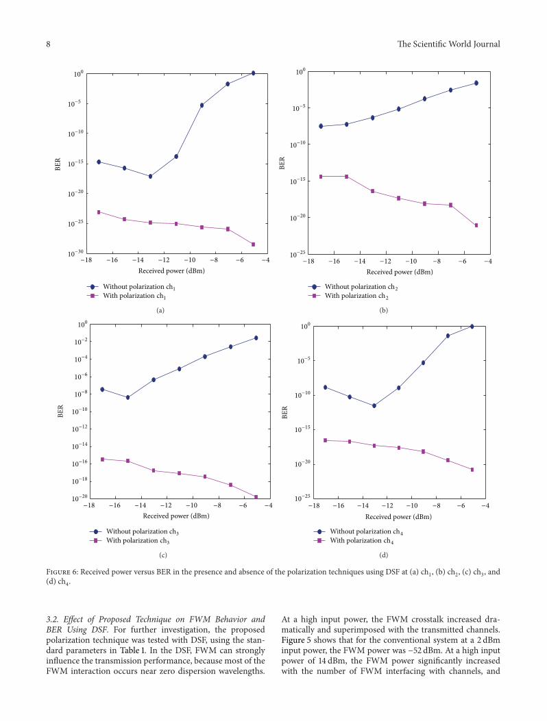
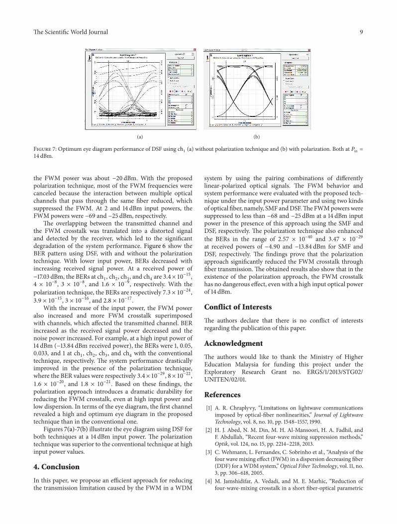
Copyright © 2022 FDOKUMEN