Four-bar motion generation with elasticity constraints and optimization
10
http://pik.sagepub.com/ Dynamics Engineers, Part K: Journal of Multi-body Proceedings of the Institution of Mechanical http://pik.sagepub.com/content/223/3/245 The online version of this article can be found at: DOI: 10.1243/14644193JMBD173 2009 223: 245 Proceedings of the Institution of Mechanical Engineers, Part K: Journal of Multi-body Dynamics Y M Al-Smadi, K Russell and R S Sodhi Four-bar motion generation with elasticity constraints and optimization Published by: http://www.sagepublications.com On behalf of: Institution of Mechanical Engineers can be found at: Proceedings of the Institution of Mechanical Engineers, Part K: Journal of Multi-body Dynamics Additional services and information for http://pik.sagepub.com/cgi/alerts Email Alerts: http://pik.sagepub.com/subscriptions Subscriptions: http://www.sagepub.com/journalsReprints.nav Reprints: http://www.sagepub.com/journalsPermissions.nav Permissions: http://pik.sagepub.com/content/223/3/245.refs.html Citations: What is This? - Sep 1, 2009 Version of Record >> at Saint Paul's University on October 11, 2013 pik.sagepub.com Downloaded from at Saint Paul's University on October 11, 2013 pik.sagepub.com Downloaded from at Saint Paul's University on October 11, 2013 pik.sagepub.com Downloaded from at Saint Paul's University on October 11, 2013 pik.sagepub.com Downloaded from at Saint Paul's University on October 11, 2013 pik.sagepub.com Downloaded from at Saint Paul's University on October 11, 2013 pik.sagepub.com Downloaded from at Saint Paul's University on October 11, 2013 pik.sagepub.com Downloaded from at Saint Paul's University on October 11, 2013 pik.sagepub.com Downloaded from at Saint Paul's University on October 11, 2013 pik.sagepub.com Downloaded from at Saint Paul's University on October 11, 2013 pik.sagepub.com Downloaded from
Transcript of Four-bar motion generation with elasticity constraints and optimization

http://pik.sagepub.com/Dynamics
Engineers, Part K: Journal of Multi-body Proceedings of the Institution of Mechanical
http://pik.sagepub.com/content/223/3/245The online version of this article can be found at:
DOI: 10.1243/14644193JMBD173
2009 223: 245Proceedings of the Institution of Mechanical Engineers, Part K: Journal of Multi-body DynamicsY M Al-Smadi, K Russell and R S Sodhi
Four-bar motion generation with elasticity constraints and optimization
Published by:
http://www.sagepublications.com
On behalf of:
Institution of Mechanical Engineers
can be found at:Proceedings of the Institution of Mechanical Engineers, Part K: Journal of Multi-body DynamicsAdditional services and information for
http://pik.sagepub.com/cgi/alertsEmail Alerts:
http://pik.sagepub.com/subscriptionsSubscriptions:
http://www.sagepub.com/journalsReprints.navReprints:
http://www.sagepub.com/journalsPermissions.navPermissions:
http://pik.sagepub.com/content/223/3/245.refs.htmlCitations:
What is This?
- Sep 1, 2009Version of Record >>
at Saint Paul's University on October 11, 2013pik.sagepub.comDownloaded from at Saint Paul's University on October 11, 2013pik.sagepub.comDownloaded from at Saint Paul's University on October 11, 2013pik.sagepub.comDownloaded from at Saint Paul's University on October 11, 2013pik.sagepub.comDownloaded from at Saint Paul's University on October 11, 2013pik.sagepub.comDownloaded from at Saint Paul's University on October 11, 2013pik.sagepub.comDownloaded from at Saint Paul's University on October 11, 2013pik.sagepub.comDownloaded from at Saint Paul's University on October 11, 2013pik.sagepub.comDownloaded from at Saint Paul's University on October 11, 2013pik.sagepub.comDownloaded from at Saint Paul's University on October 11, 2013pik.sagepub.comDownloaded from

245
Four-bar motion generation with elasticityconstraints and optimizationY M Al-Smadi1∗, K Russell2, and R S Sodhi3
1AECOM, Special Structures Group, New York, USA2Armaments Engineering and Technology Center, US Army Research, Development and Engineering Center, Picatinny,New Jersey, USA
3Department of Mechanical Engineering, New Jersey Institute of Technology, Newark, New Jersey, USA
The manuscript was received on 1 July 2008 and was accepted after revision for publication on 17 April 2009.
DOI: 10.1243/14644193JMBD173
Abstract: In conventional planar four-bar motion generation, all mechanism links are assumedrigid or non-deforming. Although the assumption of link rigidity in kinematic synthesis maybe generally appropriate and often practiced, a statically loaded planar four-bar mechanism willundergo a degree of elastic deflection, particularly the crank and follower links. In this work, a non-linear optimization problem is formulated for planar four-bar motion generation that considersan applied coupler force and corresponding crank static torque, crank transverse deflection, andfollower buckling. The output from the non-linear optimization problem – mechanism fixed andmoving pivot loci – are input for a search algorithm that down selects a mechanism solutionthat satisfies transmission angle conditions, Grashof conditions, and a mechanism compactnesscondition. The final output of the presented method is planar four-bar motion generator thatapproximates prescribed coupler poses with satisfactory crank deflection and without followerbuckling and also satisfies conditions for link rotatability, transmission angle and compactness.
Keywords: motion generation, coupler force, elastic deflection, buckling, selection algorithm
1 INTRODUCTION
In conventional planar four-bar motion generation,the objective is to calculate the mechanism param-eters required to achieve or approximate a set ofprescribed coupler poses. This mechanism designobjective is particularly useful when the coupler mustachieve a specific position sequence for effective oper-ation (e.g. specific tool paths and orientations foraccurate fabrication operations). In Fig. 1, five pre-scribed coupler poses are defined by the coordinates ofvariables p, q, and r (motion generation model input)and the model output are the calculated coordinatesof the fixed pivot variables a0 and b0, and moving pivotvariables a1 and b1 (Fig. 1). Suh and Radcliffe [1] pro-vide a numerical planar four-bar motion generationmodel that is presented in the next section.
∗Corresponding author: AECOM, Special Structures Group, New
York, NY 10005, USA.
email: [email protected]
The number of recent published works in the area ofplanar four-bar motion generation is much too vast tocite in its entirety. Noted recent contributions includethe work of Yao and Angeles [2] who applied the con-tour method in the approximate synthesis of planarlinkages for rigid-body guidance. Hong and Erdman[3] introduced a new application Burmester curves foradjustable planar four-bar linkages. Zhou and Che-ung [4] introduced an optimal synthesis method ofadjustable four-bar linkages for multi-phase motiongeneration. Al-Widyan et al. [5] considered the robustsynthesis of planar four-bar linkages for motion gener-ation. Zhixing et al. [6] presented a guidance-line rota-tion method of rigid-body guidance for the synthesisof planar four-bar mechanisms.
Although planar four-bar motion generation is awell-established field, the concept of including staticstructural conditions in motion generation is notnearly as established. With the exception of Huangand Roth [7] whose work includes analytical motiongeneration models for planar four-bar mechanismswith a prescribed rigid-body force, most other worksthat investigate the structural behaviour of a classical
JMBD173 © IMechE 2009 Proc. IMechE Vol. 223 Part K: J. Multi-body Dynamics

246 Y M Al-Smadi, K Russell, and R S Sodhi
Fig. 1 Prescribed coupler poses (left) and calculatedplanar four-bar mechanism (right)
planar four-bar mechanism under a load do not con-sider the structural behaviour in the context of motiongeneration. Shen et al. [8] presented a non-linear opti-mization problem for the synthesis of planar motiongenerators, but the context was planar five-bar motiongeneration with rigid links. The works of Dado [9],Venanzi et al. [10], Sönmez [11], Plaut et al. [12],and Sriam and Mruthyunjaya [13] do consider flexiblelinks and/or buckling in mechanism design, they con-sider the design of compliant mechanisms as opposedto classical planar four-bar mechanisms. The worksof Hac [14], Yang and Park [15], and Caracciolo andTrevisani [16] also consider flexible mechanism linklengths, but in the context of dynamic systems.
The specific contribution this work makes regard-ing motion generation with structural conditions forthe classical planar four-bar mechanism is the for-mulation of a non-linear optimization problem thatincludes elastic deflection and static torque con-straints for the crank and a buckling constraint forthe follower and a modified version of the selectionalgorithm presented by Martin et al. [17] to searchthe non-linear optimization problem solutions for theoptimum solution with respect to specified rotatabil-ity, transmission angle, and compactness constraints.An indefinite number of prescribed coupler posescan be incorporated in the non-linear optimizationproblem. As demonstrated in the included example, aplanar four-bar mechanism is synthesized to approxi-mate a set of prescribed coupler poses and also satisfyspecified elastic deflection and static torque for thecrank and follower link buckling conditions for a givencoupler force. In addition, the synthesized mechanismsatisfies specified transmission angle conditions, is aGrashof crank-rocker and has the smallest perimeterof the calculated solutions.
2 CONVENTIONAL PLANAR FOUR-BAR MOTIONGENERATION
Equations (1) and (2) encompass the numerical planarfour-bar motion generation model presented by Suh
and Radcliffe [1]. Equations (1) and (2) ensure the con-stant lengths of the crank and follower links. Equation(3) is a planar coupler displacement matrix.
When using this conventional mechanism synthe-sis model to calculate the components of the fixedpivots a0 and b0 (where a0 = [a0x , a0y , 1]T and b0 =[b0x , b0y , 1]T) and moving pivots a1 and b1 (where a1 =[a1x , a1y , 1]T and b1 = [b1x , b1y , 1]T) of a planar four-bar motion generator (Fig. 1), the user can specify amaximum of five coupler poses [1]
[(D1i)a1 − a0]T[(D1i)a1 − a0]− (a1 − a0)
T(a1 − a0) = 0 (1)
[(D1i)b1 − b0]T[(D1i)b1 − b0]− (b1 − b0)
T(b1 − b0) = 0 (2)
where
[D1i] =⎡⎢⎣
pix qix rix
piy qiy riy
1 1 1
⎤⎥⎦
⎡⎢⎣
pix qix rix
piy qiy riy
1 1 1
⎤⎥⎦
−1
(i = 2, 3, 4, 5) (3)
3 PLANAR FOUR-BAR MECHANISM WITHCOUPLER FORCE
Figure 2 illustrates a statically loaded planar four-barmechanism deflection model diagram. A force {F } isapplied to the mechanism (in this work, at couplerpoint q). An analytical model to calculate the deflec-tions {U } at nodes a1 and b1 on this mechanismis formulated using equation (4) where the 15 × 15global stiffness matrix [Kglobal] for the planar four-barmechanism is comprised of equation (5) – the elementstiffness matrix for each mechanism link. The elementstiffness matrix for link −−→a0a1 and the coupler (links −−→a1q
Fig. 2 Statically loaded four-bar mechanism diagram(for deflection model)
Proc. IMechE Vol. 223 Part K: J. Multi-body Dynamics JMBD173 © IMechE 2009

Four-bar motion generation with elasticity constraints and optimization 247
and−→qb1) is equation (6) [18]. Because link
−−→b0b1 is a
two-force member (and therefore under columnarloading only) its element stiffness matrix [kaxial] isequation (7) [18]. Equation (8) transforms each localelement coordinate frame to the global coordinateframe by rotating each element node by the associatedelement angle θj [18].
In Fig. 2 variables Ej , Aj , Ij , and Lj (where j = 1, 2, 3,4) are the modulus of elasticity, cross-sectional area,moment of inertia, and length of each link, respec-tively. Because links −−→a1q and
−→qb1 comprise a uniform
rigid-body in this study, E2 = E3, A2 = A3, I2 = I3 andits modulus of elasticity is 1 million times higher thanthose of link −−→a0a1 and link
−−→b0b1 (specifying such a large
modulus makes the coupler link virtually rigid). Theangular orientation of each link (using the positive x-axis as reference) is denoted by angle θj (where j = 1,2, 3, 4). These angles are used in the transformationmatrix [Mtransj ] (equation (8))
{F } = [K global]{U } (4)
[Kj] = [Mtransj ][kj][Mtransj ]−1 (5)
[kj] =
⎡⎢⎢⎢⎢⎢⎢⎢⎢⎢⎢⎢⎢⎢⎢⎢⎢⎢⎢⎢⎢⎢⎢⎢⎢⎢⎣
AjEj
Lj0 0
012EjIj
L3j
6EjIj
L2j
06EjIj
L2j
4EjIj
Lj
−AjEj
Lj0 0
0 −12EjIj
L3j
−6EjIj
L2j
06EjIj
L2j
2EjIj
Lj
−AjEj
Lj0 0
0 −12EjIj
L3j
6EjIj
L2j
0 −6EjIj
L2j
2EjIj
Lj
AjEj
Lj0 0
012EjIj
L3j
−6EjIj
L2j
0 −6EjIj
L2j
4EjIj
Lj
⎤⎥⎥⎥⎥⎥⎥⎥⎥⎥⎥⎥⎥⎥⎥⎥⎥⎥⎥⎥⎥⎥⎥⎥⎥⎥⎦
(6)
[kaxial] =
⎡⎢⎢⎢⎢⎢⎢⎢⎢⎢⎢⎢⎢⎢⎢⎣
A4E4
L40 0 −A4E4
L40 0
0 0 0 0 0 0
0 0 0 0 0 0
−A4E4
L40 0
A4E4
L40 0
0 0 0 0 0 0
0 0 0 0 0 0
⎤⎥⎥⎥⎥⎥⎥⎥⎥⎥⎥⎥⎥⎥⎥⎦
(7)
[Mtransj ] =
⎡⎢⎢⎢⎢⎢⎢⎢⎢⎢⎢⎢⎣
cos θj sin θj 0 0 0 0
−sin θj cos θj 0 0 0 0
0 0 1 0 0 0
0 0 0 cos θj sin θj 0
0 0 0 −sin θj cos θj 0
0 0 0 0 0 1
⎤⎥⎥⎥⎥⎥⎥⎥⎥⎥⎥⎥⎦
(8)
4 CRANK LINK STATIC TORQUE CONSTRAINT
With an external force F acting on the coupler ofthe planar four-bar mechanism, a crank link torqueT achieves static equilibrium. In Fig. 3(a), the force Fis applied at the arbitrary coupler point q. To formu-late the crank static torque constraint, the momentcondition �M = 0 is considered about the crank linkfixed pivot a0. As illustrated in Fig. 3(c), the fixedpivot reaction forces Ra0 and Rb0 are also consideredin the moment condition. The resulting equilibriumequation of the moments about the fixed pivot a0 is
−−→a0b0 × Rb0 + −−→a0q × F + T = 0 (9)
where
Rb0 = Rb
−−→b0b1∣∣∣−−→b0b1
∣∣∣ (10)
(a) (b) (c)
Fig. 3 Planar four-bar mechanism (a) in static equilib-rium, (b) with reaction forces Ra0 and Rb0 , and (c)with reaction forces Rb0 and Ra1
JMBD173 © IMechE 2009 Proc. IMechE Vol. 223 Part K: J. Multi-body Dynamics

248 Y M Al-Smadi, K Russell, and R S Sodhi
and the reaction force Rb is a real number that varieswith the mechanism crank link position.
By expanding the vectors−−→a0b0 and −−→a0q, equation (9)
becomes(−−→a0a1 + −−→a1b1 + −−→
b1b0
)× Rb0 + (−−→a0a1 + −→a1q
)× F + T = 0 (11)
Because link b0b1 is a two-force member, vectors Rb0
and−−→b0b1 are collinear and subsequently result in a zero
cross product. As a result equation (11) is simplified as
(−−→a0a1 + −−→a1b1
)× Rb0 + (−−→a0a1 + −−→a1q
) × F + T = 0
(12)
Next, the moment condition �M = 0 is consideredabout the moving pivot a1 considering all of thelinks and joints to the right of a1. As illustrated inFig. 3(b), the fixed pivot reaction forces Ra1 and Rb0 arealso considered in the moment condition. The result-ing equilibrium equation of the moments about themoving pivot a1 is
−−→a1b1 × Rb0 + −−→a1q × F = 0 (13)
Substituting equation (13) into equation (12) produces
−−→a0a1 × Rb0 + −−→a0a1 × F + T = 0 (14)
Substituting equation (10) into equations (13) and (14)produces
Rb∣∣∣−−→b0b1
∣∣∣−−→a1b1 × −−→
b0b1 = F × −−→a1q (15)
Rb∣∣∣−−→b0b1
∣∣∣−−→a0a1 × −−→
b0b1 = F × −−→a0a1 − T (16)
Combining equations (15) and (16) produces
T =⎛⎝
∣∣F × −−→a1q∣∣∣∣∣−−→a1b1 × −−→
b0b1
∣∣∣−−→b0b1 + F
⎞⎠ × −−→a0a1 (17)
where
F =⎛⎝fx
fy
0
⎞⎠ , T =
⎛⎝0
0τi
⎞⎠ , −−→a1q = qi − [D1i] a1,
−−→a0a1 = [D1i] a1 − a0,−−→b0b1 = [D1i] b1 − b0, and
−−→a1b1 = [D1i]
(b1 − a1
)
In equation (17) the terms (F × −−→a1q)3 and(−−→a1b1 × −−→
b0b1)3 are the third elements of the corre-sponding vectors. Equation (17) calculates the four-bar mechanism crank static torque for a given
rigid-body force. Expressing equation (17) as aninequality constraint to limit the maximum crankstatic torque (τmax) for N prescribed coupler posesyields
(T j)T(T j) < τ 2
max i = 1, 2, 3, . . . , N (18)
5 FOLLOWER BUCKLING AND CRANK ELASTICDEFLECTION CONSTRAINTS
As previously discussed, the follower link is undercolumnar loading only because it is a two-force mem-ber. The Euler formula for critical buckling load for acolumn with pinned ends [18] is
Pcr = π2EIL2
(19)
where variables E , I , and L are the modulus of elastic-ity, moment of inertia, and effective column length,respectively. Solving for the columnar load in thefollower link (Rb) from equation (15) yields
Rb =∣∣F × −−→a1q
∣∣∣∣∣−−→a1b1 × −−→b0b1
/∣∣b0b1
∣∣∣∣∣ (20)
Expressing equation (2) as an inequality constraint toprevent follower buckling for N prescribed couplerposes yields
([D1i] b1 − b0
)T ([D1i] b1 − b0
)<
π2EIRb
1
i = 1, 2, 3, . . . , N (21)
where the right-side term is L2 in equation (19).Being a constant length constraint, equation (21) doesnot calculate the follower buckling load. Instead, thisequation prevents follower from reaching a bucklinglength when under the follower columnar load Rb.
Unlike the follower, the crank link is not a two-forcemember and subsequently not under columnar load-ing only. Because this link is held in static equilibriumby a torque about a0 (Fig. 2) there is also a trans-verse load component acting on link a0a1. The statictorque applied to the crank at a0 (Figs 3(a) and (b)) andthe crank reaction load at a1 because of F (Fig. 3(c))result in the transversely loaded, cantilevered beamstate of the crank. In this work, the buckling of linka0a1 is not explicitly considered because the link stiff-ness required to limit transverse deflection is generallysufficient in avoiding link buckling (especially as themaximum permissible transverse deflection becomessmaller).
Proc. IMechE Vol. 223 Part K: J. Multi-body Dynamics JMBD173 © IMechE 2009

Four-bar motion generation with elasticity constraints and optimization 249
The Euler formula for the deflection of a fixed-endcantilevered beam [18] is
δ = PL3
3EI(22)
where variables P, L, E , and I are the free-end trans-verse load, beam length, modulus of elasticity, andmoment of inertia, respectively. From equation (17),the total load on the moving pivot of the crank (a1) is
−→Ra =
⎛⎝
∣∣F × −−→a1q∣∣∣∣∣−−→a1b1 × −−→
b0b1
∣∣∣−−→b0b1 + F
⎞⎠ (23)
The transverse component of the crank load is
−−−→Ratrans =
⎛⎝
∣∣F × −−→a1q∣∣∣∣∣−−→a1b1 × −−→
b0b1
∣∣∣−−→b0b1 + F
⎞⎠ ×
−−→a0a1∣∣−−→a0a1
∣∣ (24)
Expressing equation (1) as an inequality constraint tolimit crank deflection for N prescribed coupler posesyields
([D1i] a1 − a0)T([D1i] a1 − a0) <
⎛⎝ 3δEI∣∣∣−−−→
Ratrans
∣∣∣
⎞⎠
2/3
i = 1, 2, 3, . . . , N (25)
where the right-side term is L2 in equation (22).
6 MOTION GENERATION NON-LINEAROPTIMIZATION PROBLEM
Formulating equations (1) and (2) into a single objec-tive function (that accommodates an indefinite num-ber of N prescribed coupler poses) to be minimizedyields
f (X ) =N∑
i=2
{ [([D1i] a1 − a0)
T([D1i] a1 − a0)
− (a1 − a0)T (a1 − a0)
]2 +[(
[D1i] b1 − b0
)T
× ([D1i] b1 − b0
) − (b1 − b0
)T (b1 − b0
)]2}
(26)
where X = (a0x , a0y , a1x , a1y , b0x , b0y , b1x , b1y)T. Equa-
tion (26) and inequality constraints (18), (21), and (25)constitute a non-linear optimization problem fromwhich mechanism solutions that approximate the pre-scribed coupler poses and satisfy maximum crankstatic torque, maximum crank elastic deflection, andfollower buckling conditions are calculated.
The algorithm employed for solving this optimiza-tion problem (a non-linear constraints problem) is
sequential quadratic programming (SQP), which usesQuasi–Newton approach to solve its quadratic pro-gramming subproblem and line search approach todetermine iteration step. The merit function used byHan [19] and Powell [20] is used in the following form
�(X ) = f (X ) +m∑
k=me+1
rk max[0, gk(X )] (27)
where gk(X ) represents each inequality constraint andm is the total number of inequality constraints and thepenalty parameter is
rk = (rl+1)k = maxk
{λk ,
12
[(rl)k + λk]
}(28)
The value of r for successive minimizations can befound as
rl = (FAC)1−IR (29)
where IR at the start and is incremented by one aftereach successive suboptimum is found. The factor FACcan be set arbitrarily although ten is suggested fornormal use [1]. In equation (29) l is the iterationindex for calculating the penalty parameter rk for eachinequality constraint (l = 0, 1, 2, 3, . . .). The Lagrangemultiplier, which is the rate of the change of theobjective function being optimized with respect to theconstraint variables, is
λk = ∇f (X )
∇gk(X )(30)
After specifying initial guesses for the unknown vari-ables in the optimization problem (X ), the followingSQP steps were employed to calculate the unknownvariables.
1. Calculate λk and (rl+1)k (where l = 0 and k =1 . . . m).
2. Solve equation (27) using Quasi–Newton method.3. Calculate (rl+1)k using equation (28) (where l =
l + 1 and k = 1 . . . m).4. Repeat step 2 with newly calculated rk .
Steps 2 through 4 constitute a loop that isrepeated until the penalty term in equation (27),∑m
k=1 rk max[0, gk(X )], is less than a specified penaltyterm residual ε (which is 0.001 for the example in thiswork).
The SQP algorithm does not guarantee global opti-mization. The quality of the initial guesses could deter-mine whether or not the algorithm converges (or if itdoes converge, to what values). The author employedcomputer-aided drafting software to assist in speci-fying the initial guesses. Drafting and superimposingthe prescribed precision positions in two-dimensional
JMBD173 © IMechE 2009 Proc. IMechE Vol. 223 Part K: J. Multi-body Dynamics
250 Y M Al-Smadi, K Russell, and R S Sodhi
space enabled the authors to determine likely loca-tions (and subsequently likely initial guesses) for thefixed and moving pivots.
Rather than codifying the SQP algorithm as a stand-alone program, the authors used Mathcad – a com-mercial mathematical analysis software with SQP builtin. Other commercial mathematical analysis soft-wares such as Mathematica and Matlab also includenon-linear optimization problem solvers like SQP.
7 MOTION GENERATOR SELECTION ALGORITHM
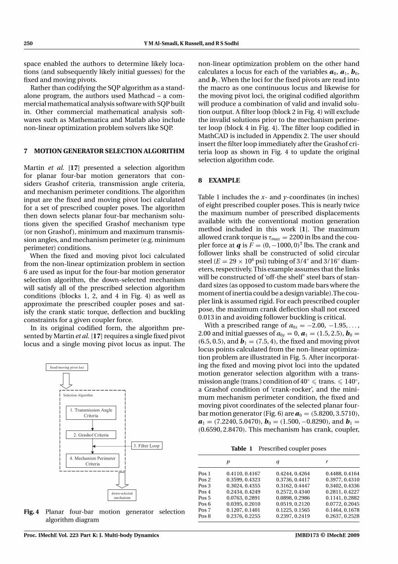
Martin et al. [17] presented a selection algorithmfor planar four-bar motion generators that con-siders Grashof criteria, transmission angle criteria,and mechanism perimeter conditions. The algorithminput are the fixed and moving pivot loci calculatedfor a set of prescribed coupler poses. The algorithmthen down selects planar four-bar mechanism solu-tions given the specified Grashof mechanism type(or non Grashof), minimum and maximum transmis-sion angles, and mechanism perimeter (e.g. minimumperimeter) conditions.
When the fixed and moving pivot loci calculatedfrom the non-linear optimization problem in section6 are used as input for the four-bar motion generatorselection algorithm, the down-selected mechanismwill satisfy all of the prescribed selection algorithmconditions (blocks 1, 2, and 4 in Fig. 4) as well asapproximate the prescribed coupler poses and sat-isfy the crank static torque, deflection and bucklingconstraints for a given coupler force.
In its original codified form, the algorithm pre-sented by Martin et al. [17] requires a single fixed pivotlocus and a single moving pivot locus as input. The
Fig. 4 Planar four-bar motion generator selectionalgorithm diagram
non-linear optimization problem on the other handcalculates a locus for each of the variables a0, a1, b0,and b1. When the loci for the fixed pivots are read intothe macro as one continuous locus and likewise forthe moving pivot loci, the original codified algorithmwill produce a combination of valid and invalid solu-tion output. A filter loop (block 2 in Fig. 4) will excludethe invalid solutions prior to the mechanism perime-ter loop (block 4 in Fig. 4). The filter loop codified inMathCAD is included in Appendix 2. The user shouldinsert the filter loop immediately after the Grashof cri-teria loop as shown in Fig. 4 to update the originalselection algorithm code.
8 EXAMPLE
Table 1 includes the x- and y-coordinates (in inches)of eight prescribed coupler poses. This is nearly twicethe maximum number of prescribed displacementsavailable with the conventional motion generationmethod included in this work [1]. The maximumallowed crank torque is τmax = 2200 in lbs and the cou-pler force at q is F = (0, −1000, 0)T lbs. The crank andfollower links shall be constructed of solid circularsteel (E = 29 × 106 psi) tubing of 3/4′′ and 3/16′′ diam-eters, respectively. This example assumes that the linkswill be constructed of ‘off-the shelf’ steel bars of stan-dard sizes (as opposed to custom made bars where themoment of inertia could be a design variable).The cou-pler link is assumed rigid. For each prescribed couplerpose, the maximum crank deflection shall not exceed0.013 in and avoiding follower buckling is critical.
With a prescribed range of a0x = −2.00, −1.95, . . . ,2.00 and initial guesses of a0y = 0, a1 = (1.5, 2.5), b0 =(6.5, 0.5), and b1 = (7.5, 4), the fixed and moving pivotlocus points calculated from the non-linear optimiza-tion problem are illustrated in Fig. 5. After incorporat-ing the fixed and moving pivot loci into the updatedmotion generator selection algorithm with a trans-mission angle (trans.) condition of 40◦ � trans. � 140◦,a Grashof condition of ‘crank-rocker’, and the mini-mum mechanism perimeter condition, the fixed andmoving pivot coordinates of the selected planar four-bar motion generator (Fig. 6) are a0 = (5.8200, 3.5710),a1 = (7.2240, 5.0470), b0 = (1.500, −0.8290), and b1 =(0.6590, 2.8470). This mechanism has crank, coupler,
Table 1 Prescribed coupler poses
p q r
Pos 1 0.4110, 0.4167 0.4244, 0.4264 0.4488, 0.4164Pos 2 0.3599, 0.4323 0.3736, 0.4417 0.3977, 0.4310Pos 3 0.3024, 0.4355 0.3162, 0.4447 0.3402, 0.4336Pos 4 0.2434, 0.4249 0.2572, 0.4340 0.2811, 0.4227Pos 5 0.0763, 0.2891 0.0898, 0.2986 0.1141, 0.2882Pos 6 0.0395, 0.2010 0.0519, 0.2120 0.0772, 0.2045Pos 7 0.1207, 0.1401 0.1225, 0.1565 0.1464, 0.1678Pos 8 0.2376, 0.2255 0.2397, 0.2419 0.2637, 0.2528
Proc. IMechE Vol. 223 Part K: J. Multi-body Dynamics JMBD173 © IMechE 2009

Four-bar motion generation with elasticity constraints and optimization 251
Fig. 5 Calculated motion generator fixed and movingpivot locus points
Fig. 6 Synthesized planar four-bar motion generator
Fig. 7 Motion generator transmission angles
follower, and ground link lengths of 2.0357, 6.8927,3.8685, and 6.1676, respectively, (satisfying Grashofcrank-rocker conditions) and produces the transmis-sion profile illustrated in Fig. 7. This mechanism is alsothe most compact of the available solutions (satisfyingminimum perimeter condition).
Table 2 includes the resulting static torque anddeflection of the crank as well as the resulting followercolumnar loads. Using equation (19), the calculatedcritical buckling load for link b0b1 for the synthesizedmechanism is 1464 pounds.
Because the crank and follower links are flexible,the deflections of these links simultaneously compro-mise the accuracy of the coupler poses achieved by the
Table 2 Crank static torques, deflections, and followercolumnar loads
Crank static Crank Followertorque (in lb) deflection (in) load (lbf)
Pos 1 878 0.0027 310Pos 2 374 0.0011 310Pos 3 241 0.0007 308Pos 4 843 0.0026 310Pos 5 1863 0.0057 405Pos 6 1569 0.0039 534Pos 7 978 0.0033 556Pos 8 238 0.0007 528
Table 3 Coupler poses achieved by synthesized mecha-nism with elastic crank and follower links
p q r
Pos 1 0.4112, 0.4166 0.4246, 0.4263 0.4490, 0.4163Pos 2 0.3615, 0.4346 0.3740, 0.4454 0.3992, 0.4373Pos 3 0.3025, 0.4360 0.3144, 0.4476 0.3400, 0.4411Pos 4 0.2456, 0.4196 0.2569, 0.4317 0.2828, 0.4264Pos 5 0.1313, 0.2764 0.1423, 0.2888 0.1683, 0.2842Pos 6 0.1323, 0.2237 0.1439, 0.2355 0.1696, 0.2296Pos 7 0.1498, 0.1908 0.1624, 0.2015 0.1875, 0.1935Pos 8 0.2287, 0.1798 0.2439, 0.1864 0.2656, 0.1714
synthesized mechanism. Table 3 includes the couplerposes calculated after incorporating the parametersof the synthesized mechanism in the four-bar mech-anism deflection model in section 3. Coupler posesone through eight correspond to crank angles ofθ1 = 133.5271◦, 112.8409◦, 92.5959◦, 72.2693◦, 8.6884◦,336.4193◦, 331.0413◦, and 294.6046◦, respectively.
9 DISCUSSION
The non-linear optimization problem presented inthis work does not consider the load contributionmade by the link masses because the four-bar mech-anism is assumed static and the coupler force con-sidered is assumed to far exceed the link body forces.Planar four-bar applications as such are best suitedfor this methodology. Equation (17) becomes invalidwhen the pivots a1, b1, and b0 are collinear. Such astate is possible when the four-bar mechanism reachesa ‘lock-up’ or binding position. When pivots a1, b1,and b0 are collinear, the denominator in equation(17) becomes zero (making the equation and subse-quent constraint invalid). The mathematical analysissoftware MathCAD was used to codify and solve theformulated non-linear optimization problem. By sub-stituting Euler’s buckling formula (equation (19)) withJohnson’s critical buckling load formula [18], equation(21) could be reformulated to consider the latterbuckling condition.
JMBD173 © IMechE 2009 Proc. IMechE Vol. 223 Part K: J. Multi-body Dynamics

252 Y M Al-Smadi, K Russell, and R S Sodhi
10 CONCLUSIONS
Using the non-linear optimization problem formu-lated in this work, a planar four-bar mechanism wassynthesized to approximate nearly twice the maxi-mum number of prescribed coupler poses availablewith the conventional motion generation model ofSuh and Radcliffe [1]. The optimization problem alsoincluded constraints to limit the transverse deflectionof the crank, avoid follower buckling, (using Euler’sbuckling formula) and limit the maximum crank statictorque for a given coupler force. The non-linear opti-mization problem ran efficiently in Mathcad-havingrun times measuring in seconds. The mechanismfixed and moving pivot loci output from the optimiza-tion problem were then used as input for a modifiedsearch algorithm by Martin et al. [17] to down selectthe optimum four-bar motion generator that satisfiedthe Grashof crank-rocker condition, maintained pre-scribed minimum and maximum transmission anglelimits, and was the most compact solution of theavailable mechanism solutions.
REFERENCES
1 Suh, C. H. and Radcliffe, C. W. Kinematics and mech-anism design, 1978 (John Wiley and Sons Inc., NewYork).
2 Yao, J. and Angeles, J. Computation of all optimum dyadsin the approximate synthesis of planar linkages for rigid-body guidance. Mech. Mach. Theory, 2000, 35(8), 1065–1078.
3 Hong, B. and Erdman, A. G. A method for adjustableplanar and spherical four-bar linkage synthesis. ASME J.Mech. Des., 2005, 127(3), 456–463.
4 Zhou, H. and Cheung, E. H. M. Adjustable four-bar link-ages for multi-phase motion generation. Mech. Mach.Theory, 2004, 39(3), 261–279.
5 Al-Widyan, K., Angeles, J., and Jesús Cervantes-Sánchez, J. The robust synthesis of planar four-barlinkages for motion generation. In Proceedings of theASME Design Engineering Technical Conference 5 A,2002, pp. 627–633.
6 Zhixing, W., Hongying, Y., Dewei, T., and Jiansheng, L.Study on rigid-body guidance synthesis of planar linkage.Mech. Mach. Theory, 2002, 37(7), 673–684.
7 Huang, C. and Roth, R. Dimensional synthesis of closed-loop linkages to match force and position specifications.J. Mech. Des., 1993, 115, 194–198.
8 Shen, Q., Al-Smadi,Y. M., Russell, K., and Sodhi, R. S. Onplanar five-bar motion generation with a driver torqueconstraint. J. Adv. Mech. Des. Syst. Manuf., 2008, 2(3),408–416.
9 Dado, M. H. F. Limit position synthesis and analysis ofcompliant 4-bar mechanism with specified energy lev-els using parametric pseudo-rigid-body model. Mech.Mach. Theory, 2005, 40(1), 977–992.
10 Venanzi, S., Giesen, P., and Parenti-Castelli, V. A noveltechnique for position analysis of planar complaint
mechanisms. Mech. Mach. Theory, 2005, 40(11), 1224–1239.
11 Sönmez, Ü. Introduction to compliant long dwell mech-anism designs using buckling beams and arcs. J. Mech.Des., 2007, 129(8), 831–843.
12 Plaut, R. H., Alloway, L. A., and Virgin, L. N. A nonlinearoscillations of a buckled mechanism used as a vibrationisolator. In Proceedings of the IUTAM Symposium, 2003,vol. 122, pp. 241–250.
13 Sriram, B. R. and Mruthyunjaya, T. S. Synthesis of pathgenerating flexible-link mechanisms. Comput. Struct.,1995, 56(4), 657–666.
14 Hac, M. Dynamics of flexible mechanisms with mutualdependence between rigid body motion and longitu-dinal deformation of links. Mech. Mach. Theory, 1995,30(6), 837–847.
15 Yang, K. and Park, Y. Dynamic stability of a flexiblefour-bar mechanism and its experimental investigation.Mech. Mach. Theory, 1998, 33(3), 307–320.
16 Caracciolo, R. and Trevisani, A. Simultaneous rigid-body motion and vibration control of a flexible four-barlinkage. Mech. Mach. Theory, 2001, 36(2), 221–243.
17 Martin, P. J., Russell, K., and Sodhi, R. S. On mechanismdesign optimization for motion generation. Mech. Mach.Theory, 2007, 42(10), 1251–1263.
18 Pilkey, W. D. Formulas for stress, strain and structuralmatrices, 1994 (John Wiley and Sons Inc., New York).
19 Han, S. P. A globally convergent method for nonlinearprogramming. J. Optim. Theory Appl., 1977, 22, 297.
20 Powell, M. J. D. A fast algorithm for nonlinearly con-strained optimization calculations. In Numerical ana-lysis, lecture notes in mathematics (Ed. G. A. Watson),vol. 630, 1978 (Springer-Verlag, Berlin, Germany).
APPENDIX 1
Notation−−→a0a1 crank link vectora0, b0 mechanism fixed pivotsa1, b1 mechanism moving pivotsA cross-sectional area−−→b0b1 follower link vector[D1j] coupler displacement matrixE modulus of elasticity{F } coupler link forceI moment of inertia[kaxial
]local stiffness matrix (follower link)
[kj] local stiffness matrix (crank/couplerlinks)
[Kj] global link stiffness matrix[Kglobal] global mechanism stiffness matrixL link length[Mtransj
]coordinate frame transformation matrix
p, q, r coupler pointsRb scalar mechanism reaction force at b0−→Ra mechanism force vector at a1−−−→Ratrans mechanism transverse force vector at a1
Proc. IMechE Vol. 223 Part K: J. Multi-body Dynamics JMBD173 © IMechE 2009

Four-bar motion generation with elasticity constraints and optimization 253
Rb0 mechanism reaction force vector at b0
T crank link static torque{U } mechanism node deflections
δ beam transverse deflection
APPENDIX 2
Filter loop (codified in MathCAD) for planar four-barmotion generator selection algorithm
Cell :=∣∣∣∣∣∣∣∣∣∣∣∣∣∣∣∣∣∣∣∣∣∣∣∣∣∣∣∣
M ← stack(∞∞∞∞)
for i ∈ 1 . . . rows(cell) − 1∣∣∣∣∣∣∣∣∣∣∣∣∣∣∣∣∣
M1 ← (celli,0 celli,1 celli,2 celli,3)
for j ∈ 0 . . . (end/2) − 1
∣∣∣∣∣∣∣∣∣
continue if (celli,0 = CRANKj)
M1 ← (∞∞∞∞)if celli,2 = CRANKj+(end/2)
M ← stack(M, M1)
M
JMBD173 © IMechE 2009 Proc. IMechE Vol. 223 Part K: J. Multi-body Dynamics