Forwards rev,"Shutdown from Outside Control Room,"procedures ...
Upload
khangminh22Category
view
0download
0
ACOKLILRATED DISTRIBUTION DEMONSTRATlON SYSTEM
REGULATORY INFORMATION DISTRIBUTION SYSTEM (RIDS)
ACCESSION NBR:8811100265 DOC.DATE: 88/11/02 NOTARIZED: NOFACIL:50-250 Turkey Point Plant, Unit 3, Florida Power and Light C
50-251 Turkey Point Plant, Unit 4, Florida Power and Light CAUTH.NAME AUTHOR AFFILIATION
CONWAY,W.F. Florida Power & Light Co. ~6~RECIP.NAME RECIPIENT AFFILIATION ~e"o1V
Document Control Branch (Document Control Desk)
SUBJECT: Forwards comments on proof & review version of Tech Specsissued to util on 880609,in form of marked-up pages.
DISTRIBUTION CODE: AOOID COPIES RECEIVED:LTR J ENCL J SIZE:TITLE: OR Submittal: General DistributionNOTES
DOCKET g'I05000250I05000251
RECIPIENT'D
CODE/NAMEPD2-2 LAEDISON,G
INTERNAL: ARM/DAF/LFMBNRR/DEST/CEB 8HNRR/DEST/MTB 9HNRR/DOEA/TSB 11NUDOCS-ABSTRACT
01
,COPIES "
LTTR ENCL1 01 1y'
RECIPIENT )a'OPIESID CODE/NAME LTTR ENCL
PD2-2 PD I g-
NRR/DEST/ADS 7ENRR/DEST/ESB 8DNRR/DEST/RSB 8ENRR/PMAS/ILRB12OGC/HDS2RES/DSIR/EIB
A,
h.
EXTERNAL: LPDRNSIC
NRC PDR 1 1 P
NOPE M ALL "RIDS" RECIPIENIS:
PIZASE HELP US TO REDIICE HASTE.'XRKAGT 'LHE DOCUMEFZ CDWZROL DESK,ROOM Pl-37 (EXT. 20079) KO XXBMZQTE YOUR 5MB FMM DISTRIBUTIONLISTS FOR DOCIIMENXS K)U DON'T NEED)
jlA
TOTAL NUMBER OF COPIES REQUIRED: LTTR 19 ENCL '

fp I
j»
,(h
'I l
P. O. 4000, JUNO BEACH, FL 33408-0420
4i X+
NOVEMBER 2 1988
L-88-478
U. S. Nuclear Regulatory CommissionAttn: Document Control DeskWashington, D. C. 20555
Gentlemen:
Re: Turkey Point Units 3 and 4Docket Nos. 50-250 and 50-251Revised Technical SpecificationsProof and Review Comments
The purpose of this letter is to transmit Florida Power 6 Light Company (FPL)comments on the Proof and Review version of the revised Technical Specificationsfor Turkey Point Units 3 and 4. This Proof and Review version was issued to FPLwith an NRC letter dated June 9, 1988.
The FPL comments are provided in a marked up form in the attachment to thisletter. Justification sheets for non-editorial comments are provided, which areindexed to the numbers adjacent to the individual comments.
Further comments, as a result of issues that were identified late in the reviewprocess, are expected to be provided during the comment resolution period.These comments are expected to involve control room emergency ventilation andintake cooling water strainers.
The numerical values for items such as pump flows, tank levels, and setpointsare being reviewed through a parallel effort as we have previously discussed.Should any of these values change as a result of our review, we will advise theTechnical Specification Branch and the Project Manager.
As previously discussed with the staff, we have not provided comments on Section3/4.8 - Electrical Power Systems and this section has been deleted from oursuomittal. A separate license amendment on this subject is being prepared whichwe will be providing later this month. Upon approval of this amendment, it willreplace our previous submittal of Section 3/4.8.
ADOCg »0~<'OSOOOZgo
po~»Ilo<
(((an FPL Group company

0
U. S. Nuclear Regulatory CommissionL-88-478Page two
IAt our last meeting with the staff a milestone schedule for the remainder of thisproject was discussed. The period between November 4, 1988 and January 6, 1989was provided for resolution of comments. Due to the extent and complexity ofour comments, we would like to work with the staff to develop a working scheduleto detail the process that will be necessary to reach this next milestone. Weare prepared to provide the support necessary to meet this milestone. Thedetails of the schedule to meet the January 6, 1989 date can be discussed withthe FPL manager for this project, Mr. J. Arias, at (305) 246-6007.
Very truly yours,
W. . CoSenior Vice resident - Nuclear
WFC/PLP/gp
Attachment
cc: Malcolm L. Ernst, Acting Regional Administrator, Region II, USNPCSenior Resident Inspector, USNRC, Turkey Point Plant

SECTION 1.0
DEFINITIONS
TURKEY POINT - UNITS 3 8 4 1-0

-PQ
~Ij s. I .
pc~ ., ~ > ge 77ov al/( //~
0
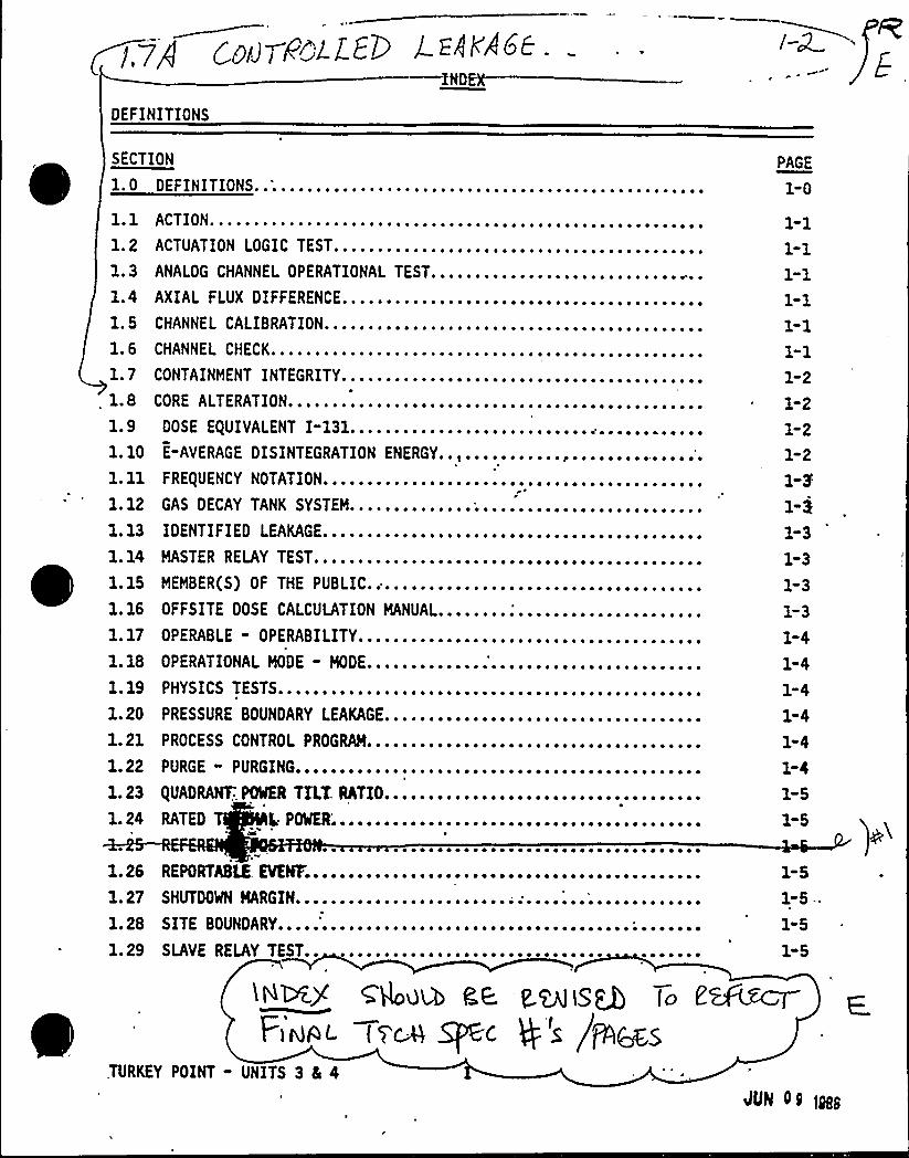
DEFINITIONS
SECTION
1 . 0 DEFINITIONS..;................................................~ 1 ACTIONe ~ ~ ~ ~ ~ ~ ~ ~ ~ ~ ~ ~ ~ ~ ~ ~ ~ o ~ ~ ~ ~ ~ ~ ~ ~ ~ ~ ~ ~ ~ ~ ~ ~ ~ ~ ~ ~ ~ ~ ~ ~ ~ ~ ~ ~ ~ ~ ~ ~ ~ ~ ~ ~ ~1
1.2 ACTUATION LOGIC TEST.............................,............1.3 ANALOG CHANNEL OPERATIONAL TEST...............................1.4 AXIAL FLUX DIFFERENCE.........................................1. 5 CHANNEL CALIBRATION...........................................1.6 CHANNEL CHECK......................... ~ .......................1.71.8
CONTAINMENT INTEGRITY...............CORE ALTERATION.....................
~ ~ ~ ~ ~ ~ ~ ~ ~ ~ ~ ~ ~ ~ ~ ~ ~ ~ ~ ~ ~ ~ ~ ~ ~ ~
1.9l. 10
l. 11
l. 12
DOSE EQUIVALENT I-131..............E-AVERAGE DISINTEGRATION ENERGY
FREQUENCY NOTATION.................GAS DECAY TANK SYSTEM..............
~ ~ ~ ~ ~ ~ ~ ~ ~ ~ ~ ~ ~ ~ ~ ~ ~ ~ ~ ~ o ~ ~ ~ ~ ~
~ ~ ~ ~ ~ ~ ~ ~ ~ ~ pt ~ ~ ~ ~ ~ ~ ~ ~ ~ ' ~ ~ ~ ~ ~
~ ~ ~ ~ ~ ~ ~ ~ ~ ~ ~ o ~ ~ ~ ~ ~ ~ ~ ~ ~ ~ ~ ~ ~ ~
1. 13
1. 14
IDENTIFIED LEAKAGE...........................................MASTER RELAY TEST............................................
1. 15
1. 16
MEMBER(S) OF THE PUBLIC.;..........OFFSITE DOSE CALCULATION MANUAL....~ ~ ~ ~ ~ ~ ~ ~ ~ ~ ~ ~ ~ ~ ~ ~ ~ ~ o ~ ~ ~ ~ ~ ~ ~
1. 17
1. 18
OPERABLE - OPERABILITY.............OPERATIONAL MODE - MODE............ ~ ~ ~ ~ ~ ~ ~ ~ ~ ~ ~ ~ ~ ~ ~ ~ ~ o ~ ~ ~ ~ ~ ~ ~ ~
l. 19
1. 20
1. 21
1. 22
1. 23
1. 24
PHYSICS TESTS................................................
PROCESS CONTROL PROGRAM......................................P URGE PURGINGo ~ ~ ~ o ~ ~ ~ ~ ~ ~ ~ ~ ~ ~ ~ ~ ~ ~ ~ ~ ~ ~ ~ ~ ~ ~ ~ ~ ~ ~ ~ ~ ~ ~ ~ ~ ~ ~ ~ ~ o ~ ~ ~ ~
QUADRANT:,ONER TILT, RATIO..........RATED T L. P56................
~ ~ ~ ~ ~ ~ ~ ~ ~ ~ ~ ~ ~ ~ ~ ~ ~ ~ ~ ~ ~ ~ ~ ~ ~ ~
PRESSURE BOUNDARY LEAKAGE....................................
1.261. 27
EPO RTNK EVElfFo ~ ~ ~ ~ ~ ~ ~ ~ ~ ~ ~ ~ ~ ~ ~ ~ ~ ~ ~ ~ ~ ~ ~ o ~ o ~ ~ ~ ~ ~ ~ ~ ~ ~ ~ ~ ~ ~ o ~ ~ ~ ~R
HUTDOO MARGINo ~ ~ ~ ~ ~ ~ ~ ~ ~ ~ ~ ~ ~ ~ ~ ~ ~ ~ ~ ~ ~ ~ ~ o o' ~ ~ ~ ~ ~ ~'o
~ ~ ~ ~ ~ ~ ~ ~ ~ ~ ~ ~S
1. 28 SITE BOUNDARY.....'...................................;.......1.29 SLAVE RELAY TEST..
c4uu e.a t mis To E
Fird|OL t VC-A ~< @ S /56CS,TURKEY POINT - UNITS 3 4 4
INOEX
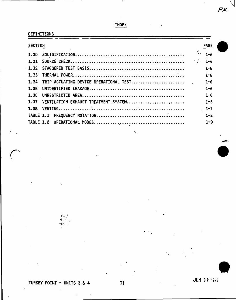
OEF INITIONS
SECTION
1. 30
l. 31
1. 32
1. 33
1. 34
1. 35
1. 36
1. 37
1. 38
TABLE
TABLE
SOLIDIFICATION.........................SOURCE CHECK...........................STAGGERED TEST BASIS.........................................
HERMAL POWER.................T
TRIP ACTUATING DEVICE OPERATIONAL TEST.......................
UNRESTRICTED AREA..............VENTILATION EXHAUST TREATMENT SYSTEM.........................VENTING ~ ~ ~ ~ ~ ~ ~ ~ ~ ~ ~ ~ ~ ~ ~ ~ ~ ~ ~ ~ ~ ~ ~ ~ ~ ~ ~ ~ ~ ~ ~ ~ ~ ~ ~ ~ ~ ~ ~ ~ ~ ~ ~ ~ ~ ~ ~ ~ ~ ~ ~ ~ ~ ~
1.1 FRE(UENCY NOTATION................1. 2 OPERATIONAL MODES..........,......
~ ~ ~ ~ ~ ~ ~ ~ ~ ~ 0 ~ ~ ~ ~ ~ ~ ~ ~ ~ ~ ~
UNIDENTIFIED LEAKAGE.........................................
1"6
1-6
1-6
1-61-61-61-6
1-7
1-81-9
C'URKEY
POINT - UNITS 3 Ea 4JUK 09 19<a
INDEX
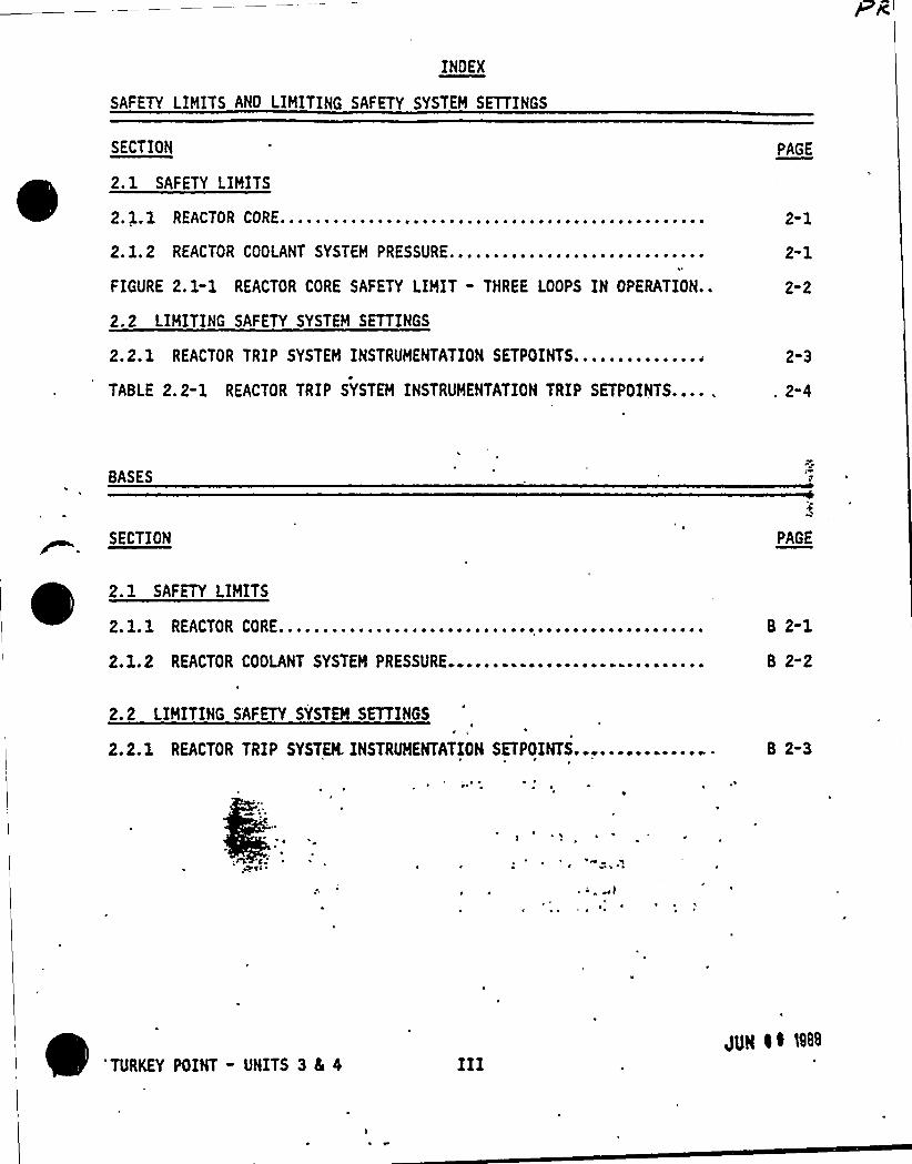
SAFETY LIMITS ANO LIMITING SAFETY SYSTEH SETTINGS
SECTION
2.1 SAFETY LIMITS
2. 1. 1 REACTOR CORE..............,.....,.........,,.....,,.........2. 1.2 REACTOR COOLANT SYSTEM PRESSURE.............................FIGURE 2.1"1 REACTOR CORE SAFETY LIMIT - THREE LOOPS IN OPERATION..
2.2 LIHITING SAFETY SYSTEM SETTINGS
2.2.1 REACTOR TRIP SYSTEM INSTRUHENTATION SETPOINTS...............
TABLE 2.2-1 REACTOR TRIP SYSTEM INSTRUHENTATION TRIP SETPOINTS....
PAGE
2-1
2-1
2-2
2-3
2-4
BASES
SECTION PAGE
2. 1 SAFETY LIMITS
2. 1.1 REACTOR CORE................................................2.1.2 REACTOR COOLANT SYSTEH PRESSURE.............................
B 2-1
B 2-2
2.2 LIMITING SAFETY SYSTEM SETTINGS
2.2.1 REACTOR TRIP SYSTEM. INSTRUMENTATION SETPOINTS.............. B 2-3
~ ~
~ I
~ ~
'TURKEY POINT - UNITS 3 4 4gUg i0 N8
INDEX
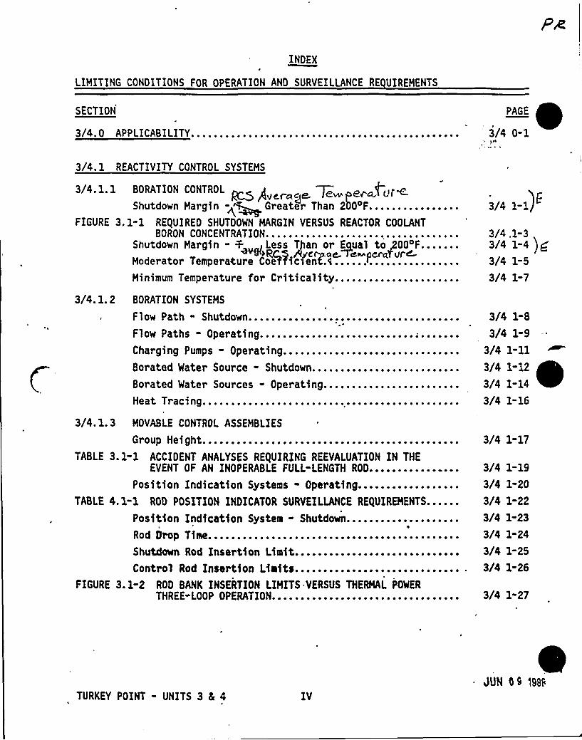
LIMITING CONDITIONS FOR OPERATION AND SURVEILLANCE RE UIREMENTS
SECTION
3/4. 0 APPLICABILITY...............................................PAGE
3/4 0-1
Flow Path - Shutdown................................Fl ow Paths - Operating.......... ~ . ~... - .. ~ " - " . ~ = ~ ~
Charging Pumps - Operating..........................Borated Water Source - Shutdown......,..............
~ ~ ~ ~ 4
~ ~ ~ ~ ~
Borated Water Sources - Operating........................Heat Tracsng..........................-.-....-.
3/4. 1.3 MOVABLE CONTROL ASSEMBLIES
roup Hei ghta ~ ~ ~ ~ ~ ~ ~ ~ ~ ~ ~ ~ ~ ~ ~ a ~ e ~ ~ ~ ~ ~ ~ ~ ~ ~ ~ ~ ~ ~ ~ ~ ~ ~ ~ ~ ~ ~ ~ ~ ~ ~ ~G
TABLE 3.1-1 ACCIDENT ANALYSES RE(UIRING REEVALUATION IN THEEVENT OF AN INOPERABLE FULL-LENGTH ROD..............--
Position Indication Systems - Operating.............TABLE 4. 1-1 ROD POSITION INDICATOR SURVEILLANCE RE/UIREMENTS.
Position Indication System - Shutdown...............i
Rod Orop Time.......................................Shutdown Rod Insertion Limit............. " . """"Control Rod Insertion Liaits.....-...---......-... "
FIGURE 3.1-2 ROD BANK INSERTION LIMITS VERSUS THERMAL POWER
THREE-LOOP OPERATION........-...............-...
3/4. 1 REACTIVITY CONTROL SYSTEMS
3/4. 1. 1 BORATION CONTROL ~ /I ~d dr~p<)r~Shutdown Nargin -g Greater Than 2 OoF................
FIGURE 3.1"1 REQUIRED SHUTDOWN MARGIN VERSUS REACTOR COOLANTBORON CONCENTRATION.....................,.............
Shutdown Margin - + , Less Than or Equal to g004F.......Moderator Temperature Coet'tie)ent.4 ......................Minimum Temperature for Criticality......................
3/4. 1. 2 BORATION SYSTEMS
3/4 1-1
3/4 .1" 33/4 1-4 )f3/4 1-5
3/4 1-7
3/4 1-8
3/4 1-9
3/4 1-11
3/4 1-12
3/4 1"14
3/4 1-16
3/4 1-17
3/4 1-19
3/4 1-20
3/4 1-22
3/4 1-23
3/4 1-24
3/4 1-25
3/4 1-26
3/4 1-27
TURKEY POINT - UNITS 3 Ec 4 IVJUN OS l98S
INDEX
LIMITING CONDITIONS FOR OPERATION ANO SURVEILLANCE RE UIREMENTS
SECTION'I
'/4. 2 POWER DISTRIBUTION LIMITS
3/4.2.1 AXIAL FLUX DIFFERENCE..........................FIGURE 3.2-1 AXIAL FLUX DIFFERENCE LIMITS AS A FUNCTION
RATED THERMAL POWER......................:.3/4.2.2 HEAT FLUX HOT CHANNEL FACTOR...................
OF
~ ~ ~ ~ ~ ~ ~ ~ ~ ~
FIGURE 3.2-2 K(Z) - NORMALIZED FQ(Z) AS A FUNCTION OF CORE HEIGHT.
3/4.2.3 NUCLEAR ENTHALPY RISE HOT CHANNEL FACTOR.................3/4.2.4 QUADRANT POWER TILT RATIO................................3/4.2.5 ONB PARAMETERS...;.......................................TABLE 3. 2-1 DNB PARAMETERS........................................
PAGE
3/4 2-1
3/4 2-3
3/4 2"4
3/4 2-5
3/4 2-8
3/4 2-11
3/4 2-13
3/4 2-14
3/4. 3 INSTRUMENTATION
3/4.3. 1 REACTOR TRIP SYSTEM INSTRUMENTATION'.;....................TABLE 3. 3-1 REACTOR TRIP SYSTEH INSTRUMENTATION...................TABLE 4. 3-1 REACTOR TRIP SYSTEH INSTRUMENTATION SURVEILLANCE
REQUIREMENTS...................'.......................~ ~
~
3/4.3.2 ENGINEERED SAFETY FEATURES ACTUATION SYSTEHINSTRUMENTATION..........................................
TABLE 3. 3-2 ENGINEEREO SAFETY FEATURES, ACTUATION SYSTEMINSTRUMENTATION..........................................
TABLE 3.3-3 ENGINEERED SAFETY FEATURES ACTUATION SYSTEHINSTRUMENTATION TRIP SETPOINTS...........................
TABLE 4.3-2 ENGINEERED SAFETY FEATURES ACTUATION SYSTEMINSTRUMENTATION SURVEILLANCE REQUIREMENTS................
3/4. 3, 3 MONITORING INSTRUMENTATION
Radfatfon, Honftorfng For Plant Operatfons......:.........
3/4 3-g3/4 3-2
3/4,3-8
3/4 3-13
3/4 3-14
3/4 3-22
3/4 3-28
3/4 3-34
TURKEY POINT - UNITS 3 S 4 V .-4UN i~ ee
INDEX
LIMITING CONDITIONS FOR OPERATION AND SURVEIL'LANCE REUIREMENTS'ECTION
TABLE 3-3-4 RADIATION MONITORING INSTRUMENTATIONFOR PLANT OPERATIONS........................,.....
TABLE 4. 3-3 RADIATION MONITORING INSTRUMENTATION FOR PLANTOPERATIONS SURVEILLANCE RE(UIREMENTS.....................Movable Incore Detectors.................................Accident Honitoring Instrumentation......................
TABLE 3. 3-5 ACCIDENT MONITORING INSTRUMENTATION...................TABLE 4.3-4 ACCIDENT MONITORING INSTRUMENTATION SURVEILLANCE
REQUIREMENTS.............................................Fire Detection Instrumentation.............;.............
TABLE 3. 3-6 FIRE DETECTION INSTRUMENTS............................Radioactive Liquid Effluent Honitoring Instrumentation...
TABLE 3.3-7 RADIOACTIVE LI(UID EFFLUENT MONITORING INSTRUHENTATION
TABLE 4.3-5 RADIOACTIVE LIQUID EFFLUENT MONITORINGINSTRUMENTATION SURVEILLANCE REQUIREMENTS................Radioactive Gaseous Effluent Monitoring Instrumentation..
TABLE 3.3-8 RADIOACTIVE GASEOUS EFFLUENT MONITORINGINSTRUMENTATION......................................-...
TABLE 4.3-6 RADIOACTIVE GASEOUS EFFLUENT HONITORINGINSTRUMENTATION SURVEILLANCE RE(UIREHENTS................
E
3/4 3-35
3/4 3-38
3/4 3-39
3/4 3-40
3/4 3-41
3/4 3-45
, 3/4 3-48
3/4 3-49
3/4 3-51
3/4 3-52
3/4 3-54
3/4 3-55
3/4 3-56
3/4 3-59
TURKEY POINT - UNITS 3 8s 4 VISUN ie tyg
INOEX
LIHITING CONDITIONS FOR OPERATION AND SURVEILLANCE RE UIREHENTS
SECTION
3/4.4 REACTOR COOLANT SYSTEH
3/4.4. 1 REACTOR COOLANT LOOPS AND COOLANT CIRCULATION
PAGE
3/4.4. 2
Startup and Power Operation..............................ot Standby........................................H
ot Shutdown ~ o o ~ ~ ~ ~ ~ ~ ~ ~ ~ ~ ~ ~ ~ ~ ~ ~ ~ ~ ~ ~ ~ ~ ~ ~ ~ ~ ~ ~ ~ ~ ~ ~ ~ ~ ~ ~ ~ ~ ~ ~ ~ ~H
Cold Shutdown - Loops Filled.............................Cold Shutdown - Loops Not Filled.........................SAFETY VALVES
3/4 4-1
3/4 4-2
3/4 4-3
3/4 4-5
3/4 4-6
hutdown ~ ~ ~ ~ ~ o ~ ~ ~ ~ ~ ~ ~ ~ ~ ~ ~ ~ ~ ~ o ~ ~ ~ ~ ~ ~ ~ ~ ~ ~ ~ ~ ~ ~ ~ ~ ~ ~ ~ ~ ~ ~ ~ o ~ ~S
perating.............................................0
344.3/4 4.34 ~ 4o 3 P ESS RIZERo ~ ~ ~ ~ ~ ~ ~ ~ ~ ~ ~ ~ ~ ~ ~ ~ ~ o ~ ~ ~ ~ ~ ~ ~ ~ ~ ~ o o o o ~ ~ ~ ~ ~ ~ ~ ~ ~ ~ ~ o ~
LOC K3 /4. 4. 4 VALVES~ ~ ~ ~ ~ ~ ~ ~ ~ ~ ~ ~ ~ ~ ~ ~ ~ ~ ~ ~ ~ o ~ ~ ~ ~ ~ ~ ~ ~ ~ ~ ~ ~ ~ ~ ~ ~ ~ ~ ~ ~ ~ ~
3/4.4. 5 STEAM GENERATORS...................;........;............TABLE 4.4-1 MINIHUH NUMBER OF STEAM GENERATORS TO BE INSPECTED
DURING INSERVICE INSPECTION.............................TABLE 4.4-2 STEAM GENERATOR TUBE INSPECTION.......................3/4. 4. 6 REACTOR COOLANT SYSTEM LEAKAGE
Leakage Detection Systems.............'...................Operational Leakage......................................
TABLE 3.4-1 REACTOR COOLANT SYSTEH PRESSURE ISOLATION VALVES......3/4o 4o 7 CHEMISTRYo ~ ~ o ~ o ~ ~ ~ ~ ~ ~ ~ ~ ~ ~ ~ ~ ~ ~ o ~ ~ ~ o ~ ~ ~ ~ ~ ~ ~ ~ ~ ~ ~ ~ ~ ~ ~ ~ ~ ~ ~ ~ ~ ~ ~
TABLE 3.4-2 REACTOR COOLANT SYSTEH CHEMISTRY LIMITS...............TABLE 4.4-3 REACTOR COOLANT SYSTEM CHEMISTRY LIMITS SURVEILLANCE
RE(UIREHENTSo ~ ~ ~ ~ ~ ~ ~ ~ ~ ~ ~ ~ ~ ~ ~ ~ ~ ~ ~ ~ ~ ~ ~ ~ ~ ~ ~ ~ ~ ~ ~ ~ ~ ~ ~ ~ ~ ~ ~ ~ ~ ~ ~ ~
3/4.4. 8 SPEC@/'CTIVHY'........................................FIGURE 3.4-1 . E(VIVALENT I-131 REACTOR COOLANT SPECIFIC
A LIHI'F VERSUS PERCENT OF RATED THERHAL POWER
WI . REACTOR COOLANT SPECIFIC ACTiVITY> AC)/grasDOSE EQUIVALENT I-3.31..............,.......,...............
TABLE 4.4-4 REACTOR COOLANT SPECIFIC ACTIVITY SAHPLE AND ANALYSISP ROG RAMo ~ ~ ~ ~ ~ ~ ~
'~ ~ ~ ~ ~ ~ ~ ~ ~ ~ ~ ~ ~ ~ ~ ~ ~ ~ ~ ~ ~ ~ ~ ~ ~ ~ ~ ~ ~ ~ ~ ~ ~ ~ ~ ~ ~ ~ ~ ~ o
3/4 4-7
3/4 4-8
3/4 4-9
3/4 4-1O j ~3/4 4-1X
3/4 4-16
3/4 4-17
3/4 4-18
3/4 4-19
3/4 4-21
3/4 4-22
3/4 4-23
3/4 4-24
3/4 4-25,
3/1 4-26
3/4 4-27
TURKEY POINT - UNITS 3 4 4 VII JUN 00 )gas
INOEX
LIMITING CONDITIONS FOR OPERATION AND SURVEILLANCE RE UIREMENTS
Pressurizer.Overpressure>
3/4.4. 10 STRUCTURAL
~ J' ~ ~ ~ ~ ~ ~ ~ ~ ~ ~ ~ ~ ~ ~ ~ ~ ~ ~ ~ ~ ~ ~ ~ ~ ~ ~ ~ ~
I &in Systems................. ~ ~ ~ ~ ~ ~ ~ ~ ~
3/4.4. 11 REACTOR COOLANT SYSTEM VENTS.......................-.....
SECTION
3/4.4. 9 PRESSURE/TEHPERATURE LIMITS
Reactor Coolant System...............................FIGURE 3.4-2 UNIT 3 REACTOR COOLANT SYSTEM HEATUP LIHITATIONS-
APPLICABLE UP TO 10 EFPY.................................FIGURE 3.4-3 UNIT 3 REACTOR COOLANT SYSTEM COOLDOWN LIHITATIONS-
APPLICABLE UP TO 10 EFPY.................................FIGURE 3.4-4 UNIT 4 REACTOR COOLANT SYSTEH HEATUP LIHITATIONS-
APPLICABLE UP TO 10 EFPY.................................FIGURE 3.4-5 UNIT 4 REACTOR COOLANT SYSTEM COOLDOWN LIHITATIONS-
APPLICABLE UP TO 10 EFPY.................................TABLE 4.4-5 REACTOR VESSEL MATERIAL SURVEILLANCE PROGRAM
WITHDRAWAL SCHEDULE.............................
3/4 4"29
3/4 4-30
3/4 4-31
3/4 4-32
3/4 4-33
3/4 4-34
3/4 4-35
V4 4-33) 8.3/4 4-38
3/4 4"40
3/4. 5 EMERGENCY CORE COOLING SYSTEHS
3/4.5.1 ACCUMULATORS 3/4 5-1
3/4.5. 2
3/4.5. 3
Rcs ANWA6E cc E34 A~ ~KP~~e-FECCS SUBSYSTEHS - ~ GREATER THAN OR EQUAL TO 3SO~F....
e,cs Awe~~ Mo~ur W&v p~~~a-E,ECCS SUBSYSTEHS - ~ LESS'HAN 35O~F...................
3/4 5-3
3/4 5-7
3/4.5.4 REFUELING WATER STORAGE TANK..........."""" 3/4 5-8
TURKEY POINT - UNITS 3 4 4 VIIIJUN 00 1988
PR
INOEX
LIMITING CONDITIONS FOR OPERATION AND SURVEILLANCE RE UIREMENTS
SECTION
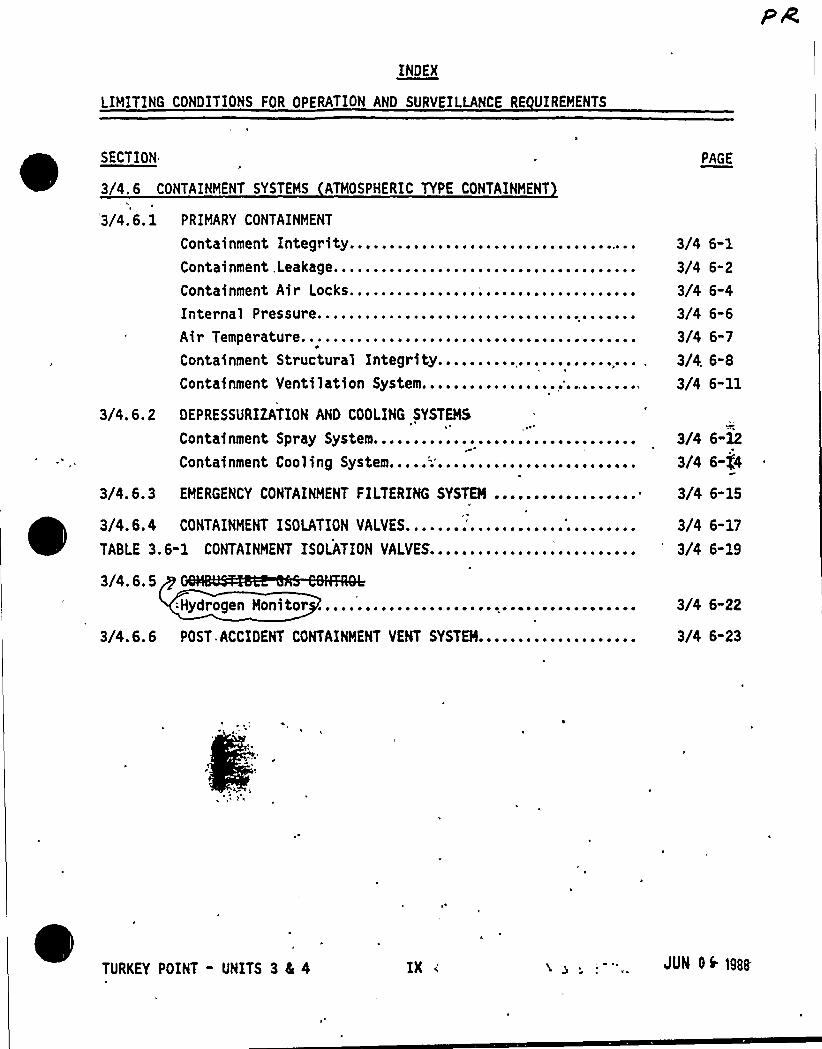
3/4.6 CONTAINMENT SYSTEMS ATMOSPHERIC TYPE CONTAINMENT
PAGE
Air Temperature..........................Containment Structural Integrity.........Containment Ventilation System...........
~ ~ ~ ~ ~ ~
~ ~ ~ ~ ~ ~
~ ~ ~ ~ ~ ~ ~ )0 ~ ~
3/4. 6. 2 DEPRESSURIZATION AND COOLING SYSTEMS
Containment Spray System.................Containment Cooling System.....'..........
~ ~ ~ ~ ~ ~ ~ ~ ~ ~ ~ ~ ~ ~ ~ ~
~ ~ ~ ~ ~ ~ ~ ~ ~ ~ ~ ~ ~ ~ ~ ~
3/4. 6. 3 EMERGENCY CONTAINMENT FILTERING SYSTEM ..................
'3/4. 6. 1 PRIMARY CONTAINMENT
Containment Integrity.....................,...............Containment,Leakage......................................Containment Air Locks.....................,..............Internal Pressure........................................
3/4 6-1
3/4 6-2
3/4 6-4
3/4 6"6
3/4 6-7
3/4 6-8
3/4 6-11
3/4 6-12
3/4 6-fO
3/4 6-15
~ ~
~
3/4.6.4 CONTAINMENT ISOLATION VALVES.......'.....TABLE 3.6-1 CONTAINMENT ISOLATION VALVES.......... ~ ~ ~ ~ ~ ~ ~ ~ ~ ~ ~ ~ t ~ 1 ~
3/4 6-17
3/4 6-19
3/4.6.5r
=Hydrogen Monitor ........................................ 3/4 6-22
3/4.6.6 POST ACCIDENT CONTAINMENT VENT SYSTEM.................... 3/4 6-23
TURKEY POINT - UNITS 3 4 4 JUN Ok 1988
PR
INDEX
LIMITING CONDITIONS FOR OPERATION AND SURVEILLANCE RE UIREMENTS
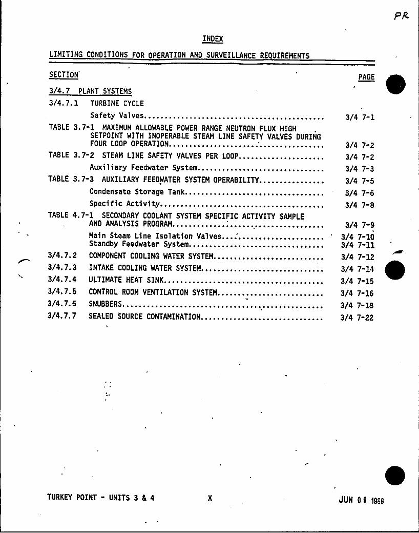
3/4.7.23/4.7.33/4.7.43/4. 7. 5
3/4.7. 6
3/4.7. 7
COMPONENT COOLING WATER SYSTEM..........................-INTAKE COOLING WATER SYSTEM.........................-....ULTIMATE HEAT SINK......................-....-...........CONTROL ROOM VENTILATION SYSTEM................ -...- - -...NUBBERS.................................................S
SEALED SOURCE CONTAMINATION..............................
SECTION'/4.
7 PLANT SYSTEMS
3/4.7. 1 TURBINE CYCLE
afety Valves............................................S
TABLE 3.7"1 MAXIMUM ALLOWABLE POWER RANGE NEUTRON FLUX HIGHSETPOINT WITH INOPERABLE STEAM LINE SAFETY VALVES DURINGFOUR LOOP OPERATION......................'................
TABLE 3.7-2 STEAM LINE SAFETY VALVES PER LOOP.....................Auxiliary Feedwater System...........................
TABLE 3.7"3 AUXILIARYFEEDWATER SYSTEM OPERABILITY............Condensate Storage Tank..............................SPecific Activity................................... ~
TABLE 4.7-1 SECONDARY COOLANT SYSTEM SPECIFIC ACTIVITY SAMPLEAND ANALYSIS PROGRAM.............;...................Main Steam Line Isolation Valves.....................Standby Feedwater System.............................
3/4 7-1
3/4 7-2
3/4 7"2
3/4 7-3
3/4 7-5
3/4 7-6
3/4 7-8
3/4 7-9
3/4 7-103/4 7-11
3/4 7-12
3/4 7-14
3/4 7-15
3/4 7-16
3/4 7-18
3/4 7-22
~
'URKEY
POINT - UNITS 3 4 4 SUN OQ 1gse
INDEX
LIMITING CONDITIONS FOR OPERATION ANO SURVEILLANCE RE UIREMENTS
SECTION
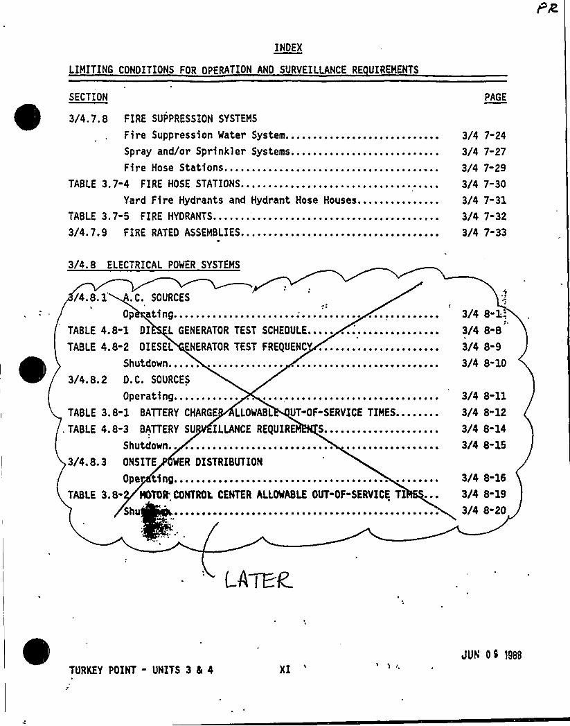
3/4.7.8~ ~ FIRE SUPPRESSION SYSTEMS
PAGE
Yard Fire Hydrants and Hydrant Hose Houses....TABLE 3.7-5 FIRE HYDRANTS.......'.......................
~ ~ ~ ~ ~ ~ ~ ~ ~ ~ ~
3/4. 7.9 FIRE RATED ASSEMBLIES....................................
Fire Suppression Water System.................Spray and/or Sprinkler Systems................Fire Hose Stations.............,..............
TABLE 3.7-4 FIRE HOSE STATIONS....................................
3/4 7-24
3/4 7-27
3/4 7-29
3/4 7-30
3/4 7-31
3/4 7-32
3/4 7-33
3/4.8 ELECTRICAL POWER SYSTEMS
/4.8.1 .C. SOURCES
0 p ating......................;........... .............TABLE 4.8-1 DI L GENERATOR TEST SCHEDULE.....
TABLE 4.8-2 DIESEL ENERATOR TEST FREgUENC
~ ~
~
~ ~
Shutdowno ~ t ~ ~ ~ ~ ~ ~ ~ t ~ ~ ~ ~ ~ ~ ~ ~ ~ ~ ~ ~ ~ ~ ~ ~ ~ ~ ~ ~ ~ ~ ~ ao ~ ~ ~ ~ ~ 0 ~
3/4.8.2 D.C. SOURCES
perating............0
TABLE 3. 8-1 BATTERY CHARGE LLOWABL UT-OF-SERVICE TIMES........, TABLE 4.8-3 BATTERY SU ILLANCE REQUIR S.....................
hutdown1 ~ ~ ~ ~ ~ I ~ ~ ~ ~ ~ ~ ~ ~ 0 ~ ~ ~ ~ ~ ~ ~ ~ ~ ~ ~ ~ ~ ~ ~ ~ ~ ~ ~ ~ ~ ~ 0 ~ ~ ~ 0 ~ ~ ~S
3/4.8. 3 ONSITE WER DISTRIBUTION
per tinge ~ ~ ~ ~ ~ ~ ~ ~ ~ ~ ~ ~ ~ ~ ~ ~ ~ ~ ~ s ~ ~ ~ ~ ~ ~ ~ ~ ~ ~ ~ ~ ~ ~ ~ ~ ~ ~ ~ ~ ~ ~ ~ ~ ~ ~0
TABLE 3.8- NTOR'CONTROL. CENTER ALLOWABLE OUT-OF-SERVICE TIS h ~ ~ ~ ~ ~ e ~ o ~ ~ ~ ~ ~ ~ ~ ~ ~ ~ ~ ~ ~ ~ ~ ~ ~ ~ ~ ~ ~ ~ ~ ~ ~ ~ ~ ~ ~ ~ ~ ~ ~ ~ ~ ~ ~ ~ ~ ~
3/4 B-X.',
3/4 8-8
3/4 8-9
3/4 8-10
3/4 8-11
3/4 8-12
3/4 8-14
3/4 8-15
3/4 8-16
3/4 8-19
3/4 8-20
(A~t
TURKEY POINT - UNITS 3 4 4 XIJUN 0 S 1988
INDEX
LIMITING CONDITIONS FOR OPERATION AND SURVEILLANCE RE UIREMENTS
SECTION
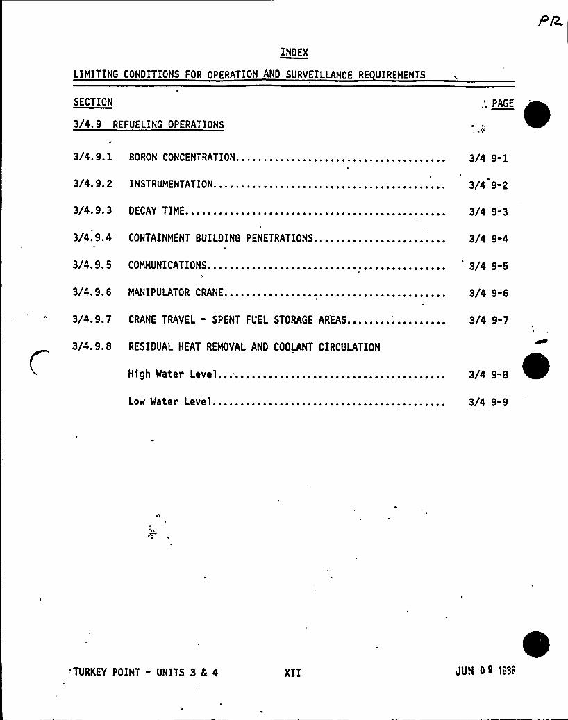
3/4. 9 REFUELING OPERATIONS
3/4. 9. 1
3/4. 9. 2
BORON CONCENTRATION......................................
INSTRUMENTATION..........................................
3/4 9-1
3/4 9-2
3/4.9.3 DECAY TIME............................................... 3/4 9-3
3/4. 9.4 CONTAINMENT BUILDING PENETRATIONS........................ 3/4 9-4
3/4. 9. 5 COMMUNICATIONS...........................................
3/4. 9. 6 MANIPULATOR CRANE...............;........................
3/4 9-5
3/4 9-6
3/4.9.7 CRANE TRAVEL - SPENT FUEL STORAGE AREAS........'.......... 3/4 9-7
~ ~3/4.9.8 RESIDUAL HEAT REMOVAL AND COOLANT CIRCULATION
H'gh Water Level......................................... 3/4 9"8
Low Water Level...................-...-....-..---- .. " . 3/4 9-9
'TURKEY POINT - UNITS 3 4 4 XII JUN 09 1988

INOEX
LIMITING CONDITIONS FOR OPERATION AND SURVEILLANCE RE UIREHENTS
~ ~
SECTION
3/4. 11.2 GASEOUS EFFLUENTS
PAGE
0 ose Rate.............................................-.. 3/4 11 '7
Dose - Iodine-131, Iodine-133, TritiMaterial in Particulate Form........Gaseous Radwaste Treatment System...Explosive Gas Mixture...............
um, and Radioactive
as Decay Tanks..........................................G
TABLE 4.11-2 RADIOACTIVE GASEOUS WASTE SAMPLING AND ANALYSISROGRAMo ~ ~ ~ ~ ~ ~ ~ ~ ~ ~ ~ ~ ~ ~ ~ ~ ~ ~ ~ ~ ~ ~ i ~ ~ ~ ~ ~ ~ ~ ~ ~ ~ ~ ~ ~ ~ ~ ~ ~ ~ ~ ~ ~ ~ ~ ~ ~ ~P
Dose - Noble Gases.......................................3/4 11-8
3/4 11-12
3/4 11-13
3/4 11"14
3/4 11"15
3/4 11-16
3/4.11. 3 SOLID RADIOACTIVE WASTES...........;.................... 3/4 11-17I
3/4. 11. 4 TOTAL DOSE............................................... 3/4 11-18
3/4. 12 RADIOLOGICAL ENVIRONMENTAL MONITORING
3/4. 12. 1 HONITORING PROGRAM............................... -.......TABLE 3.12-1 RADIOLOGICAL ENVIRONMENTAL HONITORING PROGRAM........TABLE 3.12-2 REPORTING LEVELS FOR RADIOACTIVITYCONCENTRATIONS
IN ENVIRONMENTAL SAHPLES.....'............... -............TABLE 4.12-1 DETECTION CAPABILITIES FOR ENVIRONMENTAL SAMPLE
ANALYSISo ~ ~ ~ ~ ~ ~ ~ ~ ~ ~ ~ ~ ~ ~ ~ ~ ~ ~ ~ ~ ~ ~ ~ ~ ~ ~ ~ ~ ~ ~ ~ ~ ~ ~ ~ ~ ~ ~ ~ ~ ~ ~ ~ ~ ~ ~ ~ ~
3/4.12.2 LAND USE CENSUS...............'............ "...........3/4.12.3 INTERLABORATORY COMPARISON PROGRAM........ " . "..... "-..
3/4 12-1
3/4 12-3
3/4 12-7
3/4 12-8
3/4 12-11
3/4 12-13
TURKEY POINT - UNITS 3 da 4 XIV gag a0 1888

INOEX
LIMITING CONDITIONS FOR OPERATION AND SURVEILLANCE RE UIREMENTS
SECTION
3/4. 9. 9 CONTAINMENT VENTILATION ISOLATION SYSTEM.................
PAGE
1
3/4 9-10
3/4.9.10 WATER LEVEL - REACTOR VESSEL............................. 3/4'9-11
3/4.9. 11 WATER LEVEL - STORAGE POOL .............................. - 3/4 9-12
3/4.9. 12 HANDLING OF SPENT FUEL CASK..............................
3/4. 9. 13 RADIATION MONITORING.....................................
3/4.9. 14 SPENT FUEL STORAGE......................................,
3/4 9-13
3/4 9-14
3/4 9-15
TABLE F 9. 1 SPENT FUEL BURNUP REQUIREMENTS. FOR STORAGE IN
REGION II OF THE SPENT FUEL PIT..........................., 3/4 9-15
3/4. 10 SPECIAL TEST EXCEPTIONS
3/4.10.1 SHUTDOWN MARGIN..........................;............... 3/4 10-1
3/4.10.2 GROUP HEIGHT, INSERTION, AND POWER DISTRIBUTION LIMITS... 3/4 10-2
3/4. 10. 3 PHYSICS TESTS............................................ 3/4 10-3
3/4 10-4
3/4. 10. OSITION INDICATION SYSTEM - SHUTDOWN.................... 3/4 10-5
3/4. 11 RADIO
3/4.11.1 LIQ
Co
Vf EFFLUENTS
LUENTS
400llor ~ ~ ~ ~ ~ ~ ~ ~ ~ ~ ~ ~ ~ ~ ~ ~ ~ ~ ~ ~ ~ ~ ~ ~ ~ ~ ~ ~ ~ ~ ~ ~ ~ ~ ~ ~ ~ ~ ~ ~ ~ ~ 3/4 11-1
TABLE 4.11-1 RADIOACTIVE LIQUID WASTE SAMPLING AND'ANALYSISROGRAMo ~ ~ ~ ~ ~ ~ ' ~ ~ ~ ~ ~ ~ ~ ~ ~ ~ ~ ~ ~ ~ ~ ~ ~ ~ ~ ~ ~ ~ ~ ~ ~ ~ ~ ~ ~ ~ ~ ~ ~ ~ ~ ~ ~ ~ ~ ~ ~ ~P
Oseo ~ ~ ~ ~ ~ ~ ~ ~ ~ ~ ~ ~ ~ ~ ~ ~ ~ ~ ~ ~ ~ ~ ~ ~ ~ ~ ~ ~ ~ ~ ~ ~ ~ ~ ~ ~ ~ ~ ~ ~ ~ ~ ~ ~ ~ ~ ~ ~ ~ ~ ~ ~D
Liquid Radwaste Treatment Systea..................;......
3/4 11-2~ 3/4 11-5
3/4 11-6
'TURKEY POINT - UNITS 3 Sc 4 XIII. JUN Sr >as'
BASES
INDEX
PAGE
3/4. 0 APPLICABILITY............................................... B 3/4 0-1
3/4.1 REACTIVITY CONTROL SYSTEMS
3/4. 1. 1 BORATION CONTROL..........................................3/4. 1.2 BORATION SYSTEMS..........................................3/4. 1.3 MOVABLE CONTROL ASSEMBLIES................................
B 3/4 1-1
B 3/4 1-2
B 3/4 1-4
3/4.2 POWER DISTRIBUTION LIMITS..............................,....3/4.2.1 AXIAL FLUX DIFFERENCE.............
FIGURE B 3/4.2-1 TYPICAL INDICATED AXIAL'LUXDIFFERENCE VERSUSTHERMAL POWERo ~ ~ ~ ~ ~ ~ ~ ~ ~ ~ ~ ~ ~ ~ ~ ~ ~ ~ ~ ~ ~ ~ ~ ~ ~ ~ ~ ~ ~ ~ ~ ~ ~ ~ ~ ~ ~ ~ ~ ~ ~ ~ ~ ~
3/4.2.2 and 3/4.2.3 HEAT FLUX HOT CHANNEL FACTOR and RCS FLOWRATE AND NUCLEAR ENTHALPY RISE HOT CHANNEL FACTOR.........
3/4.2.4 QUADRANT POWER TILT RATIO.................................3/4.2.5 ONB PARAMETERS............................................
B 3/4 2-1
B 3/4 2-X
B 3/4 2-0
B 3/4 2-4
B 3/4 2-5
B 3/4 2-6
3/4. 3 INSTRUMENTATION
3/4.3.1 and 3/4.3.2 REACTOR TRIP SYSTEM and ENGINEERED SAFETYFEATURES ACTUATION SYSTEM INSTRUMENTATIOM.......,... B 3/4 3-1
3/4.3.3 MONITORING INSTRUMENTATION.............................. B 3/4 3-3
TURKEY POINT - UNITS 3 8L 4 XV JUN C$ t9<:.
BASES
INDEX
SECTION
3/4.4 REACTOR COOLANT SYSTEM
3/4.4.1 REACTOR COOLANT LOOPS ANO COOLANT CIRCULATION............. B 3/4 4-1
3/4.4.8 'PECIFIC ACTIVITY.........................3/4.4. 9 PRESSURE/TEMPERATURE LIMITS...............TABLE B 3/4.4-1 REACTOR VESSEL TOUGHNESS - UNIT 3.
TABLE B 3/4.4-2 REACTOR VESSEL TOUGHNESS - UNIT 4.
3/4.4. 10 STRUCTURAL INTEGRITY.....................3/4.4. 11 REACTOR COOLANT SYSTEM VENTS.............3/4. 5 EMERGENCY CORE COOLING SYSTEMS
~ ~ ~ ~ ~ l ~ ~ ~ ~ ~ ~ ~ ~ ~ ~
3/4.5. 1 ACCUMULATORS...................-.....-...........3/4.5.2 and 3/4.5.3 ECCS SUBSYSTEMS...................- ".----....3/4.5.4 REFUELING MATER STORAGE TANK..................
3/4.4.2 SAFETY VALVES................
3/4. 4. 3 PRESSURIZER...................................... -........3/4.4. 4 RELIEF VALVES.............................................3/4.4.5 STEAM GENERATORS..........................................3/4.4.6 REACTOR COOLANT SYSTEM LEAKAGE............................3/4.4.7 CHEMISTRY.................................................
B 3/4 4-2
B 3/4 4-2
B 3/4 4"3
B 3/4 4-3
B 3/4 4-4
B 3/4 4-5
B 3/4 4-5
8 3/4 4-7
B 3/4 4-9
B 3/4 4-10
B 3/4 4-16
B 3/4 4-16
B.3/4 5-1
B 3/4 5-1
B 3/4 5-2
TURKEY POINT - UNITS 3 Ei 4 XVIJUN 09 1SSS
BASES
INOEX
SECTION
3/4.6 CONTAINMENT SYSTEHS
3/4. 6. 1 PRIMARY CONTAINMENT.......................................3/4.6.2 DEPRESSURIZATION AND COOLING SYSTEHS...................
PAGE
8 3/4 6-1
B 3/4 6-3
3/4. 6. 3 EMERGENCY CONTAINMENT FILTERING SYSTEM.................... B 3/4 6-3
3/4.6.4 CONTAINMENT ISOLATION VALVES.............................. B 3/4 6-3
3/4.6. 5 COMBUSTIBLE GAS CONTROL................................... B 3/4 6-4
3/4.6.6 POST ACCIDENT CONTAINMENT VENT SYSTEM..................... B 3/4 6-4
TURKEY POINT - UNITS 3 4 4 XVII'UNot Ms'

BASES
INDEX
SECTION,
3/4. 7 PLANT SYSTEHS
3/4. 7. 1 TURBINE CYCLE............... "............'............... B 3/4 7-1
3/4.7.2 COMPONENT COOLING WATER SYSTEM............................ B 3/4 7-5
3/4.7.3 INTAKE COOLING WATER SYSTEM............................... B 3/4 7-5
3/4.7.4 ULTIMATE HEAT SINK........................................3/4.7.5 CONTROL ROOM VENTILATION SYSTEM...........................3/4. 7. 6 NUBBERS......; ...........................................S
3/4.8 ELECTRICAL POWER SYSTEMS
3/4.7.7 SEALED SOURCE CONTAMINATION.........................-'.....3/4.7. 8 FIRE SUPPRESSION SYSTEMS..................................3/4.7.9 FIRE RATED ASSEHBLIES................................ - -...
B 3/4 7-5
,B 3/4 7-6
B 3/4 7-6
B 3/4 7-7
B 3/4 7-8
03/4.8.1, 3/4.8.2, and 3/4.8.3 A.C. SOURCES, D.C. SOURCES, and
ONSITE POWER DISTRIBUTION................................. B 3/4 8-1
TURKEY POINT - UNITS 3 8L 4 XVIII JUN 0 ~ 1988
BASES
INDEK
PAGE
3/4. 9 REFUELING OPERATIONS
3/4. 9. 1 BORON CONCENTRATION..........................,............
3/4. 9. 2 INSTRUMENTATION....................,......................
3/4o9o3 DECAY TIMEo ~ ~ ~ ~ ~ ~ ~ ~ ~ ~ ~ ~ ~ ~ ~ ~ ~ ~ ~ ~ ~ ~ ~ ~ ~ ~ ~ ~ ~ ~ ~ ~ ~ ~ ~ ~ ~ ~ ~ ~ ~ ~ o ~ ~ ~
8 3/4 9-1
8 3/4 9-1
8 3/4 9-1
3/4.9.4 CONTAINMENT BUILDING PENETRATIONS........................: 8 3/4 9-1
3/4. 9. 5 COMMUNICATIONS..................................;.........
3/4. 9o 6 MANIPULATOR CRANE.........................................3/4.9.7 CRANE TRAVEL - SPENT FUEL STORAGE AREAS...................3/4.9.8 RESIDUAL HEAT REMOVAL AND COOLANT CIRCULATION.............
3/4.9.9 CONTAINMENT VENTILATION ISOLATION-SYSTEM..................
8 3/4 9-1
8 3/4 9-2
8 3/4 9-2
8 3/4 9-4
8 3/4 9-2
3/4.9.10 and 3/4.9.11 WATER LEVEL - REACTOR VESSELSTORAGE POOL..............................
AND
8 3/4 9-3
3/4.9. 12 HANDLING OF SPENT FUEL CASK............................... 8 3/4 9-3
3/4. 9.13 RADIATION MONITORING......................................3/4 9 14 SPENT + FUEL STORAGE ~ ~ ~ ~ ~ ~ ~ ~ ~ ~ ~ ~ ~ ~ ~ ~ ~ ~ ~ ~ ~ ~ ~ ~ ~ ~
8 3/4 9-3
8 3/4 9-3
3/4. 10 SPECIAL TEST EXCEPTIONS
3/4. 10. 1 SHUT% MARGINS...........................................3/4.10.2 GRO $GST, INSERTION, AND POWER DISTRIBUTION LIMITS....
3 /4o 10o 3 PHY TESTS'e ~ ~ e ~ ~ ~ ~ ~ ~ ~ 'e ~ ~ ~ ~ ~ e ~ ~ ~ ~ ~ ~ ~ ~ ~ ~ ~ ~ ~ ~ ~ ~ ~ ~ ~ ~ ~ ~ ~ ~ ~ ~ ~
3/4.10.4 (Thfs spec$ ffcat$ on nueber $ s not used)...................
8 3/4 10-1
8 3/4 10-1
8 3/4 10-1
8 3/4 10-1
3/4.10.5 POSITION INDICATION SYSTEM - SHUTDNM..................... 8 3'/4 10-1
TURKEY POINT - UNITS 3 4 4 XIX',
BASES
INDEX
SECTION
3/4. 11 RADIOACTIVE EFFLUENTS
3/4. 11. 1 LI(UID EFFLUENTS....................3/4.11.2 GASEOUS EFFLUENTS................... ~ ~ ~ ~ ~ ~ ~ ~ ~ ~ ~ ~ ~ ~ ~ ~ ~ ~ ~ ~
3/4.11. 3 SOLID RADIOACTIVE WASTES................................3/4. 11.4 TOTAL DOSE..............................................3/4. 12 RADIOLOGICAL ENVIRONMENTAL MONITORING
B 3/4 11-1
B 3/4 11-3
B 3/4 11-6
B 3/4 11-6
3/4. 12. 1 MONITORING PROGRAM..................3/4.12. 2 LAND USE CENSUS.....................3/4. 12.3 INTERLABORATORY COMPARISON PROGRAM.. ~ ~ ~ ~ ~ ~ ~ ~ ~ ~ ~ ~ ~ ~ ~ ~ ~ ~ ~ ~
B 3/4 12-1
B 3/4 12-1
B 3/4 12-2
TURKEY POINT - UNITS 3 4 4 XX JL/N 0 ~ 1S88
INDEX
DESIGN FEATURES
SECTION0 '.1. 1 EXCLUSION AREA,..................................,.....,...,
PAGE
5-15. 1. 2 LOW POPULATION ZONE......................................... 5-15.1.3 MAP DEFINING UNRESTRICTED AREAS AND SITE BOUNDARY
RADIOACTIVE GASEOUS AND LIQUID EFFLUENTS..........FOR~ ~ ~ ~ ~ ~ ~ ~ ~ ~ 5-1
5. 2 CONTAINMENT
5.2.1 CONFIGURATION...............................................5.2.2 DESIGN PRESSURE AND TEMPERATURE.............................FIGURE 5.1-1 SITE AREA MAP........................................
5-15-1
5-2
5. 3 REACTOR CORE
5.3. 1 FUEL ASSEMBLIES.. ~ ~ ~ . ~ ~ ~ ~ ~ ~ ~ ~ ~ ~ ~ ~ ~ ~ ~ - ~
5.3.2 CONTROL ROD ASSEHBLIES......................................5-$5-3
5.4 REACTOR COOLANT SYSTEM
5.4.1 DESIGN PRESSURE AND TEMPERATURE............................. 5-3.4.2 VOLUME......................................................5 5-3
5.5 HETEOROLOGICAL TOWER LOCATION................................. 5-3
5.6 FUEL STORAGE
5. 6. 1 CRITICALITY.;............................................... 5-45 ~ 6e 2 DRAINAGEe ~ ~ ~ ~ ~ ~ ~ ~ ~ ~ ~ ~ ~ ~ ~ ~ ~ ~ ~ ~ ~ ~ ~ ~ ~ ~ ~ ~ ~ ~ ~ ~ ~ ~ ~ ~ ~ ~ ~ ~ ~ ~ ~ ~ ~ ~ ~ ~ ~ ~ ~ 5-5
5 .6.3 CAPACI ~ I ~ ~ I ~ ~ ~ ~ ~ ~ ~ ~ ~ ~ ~ ~ ~ ~ ~ ~ ~ ~ ~ ~ ~ ~ ~ ~ ~ ~ ~ ~ ~ ~ ~ ~ ~ ~ ~ ~ ~ ~ ~ ~ ~ ~ ~ ~ ~ ~ 5-5
5. 7 COMPONE CVCt.IC OR TRANSIENT LIMIT........................... 5-5
TABLE 5.7-1 CONTINENT CYCLIC OR TRANSIENT LINITS...,............... 5-6
TURKEY POINT - UNITS 3 Sc 4 XXI " JUN 0 0 ]egg
INOEX
ADMINISTRATIVE CONTROLS
SECTION
6. 1 RESPONSIBILITY.......,,........,.......,...,...,,...,.......PAGE
6-1"
6. 2 ORGANIZATION,...~........,..............,...,,...........,... 6-1
6. 2. 1 ONSITE AND OFFSITE ORGANIZATION........................... 6-16.2.2 UNIT STAFF.............. 6-2TABLE 6.2-1 MINIMUM SHIFT CREW COMPOSITION...................... 6-46.2.3 SHIFT TECHNICAL ADVISOR................................... 6"5
6. 3 FACILITY STAFF UALIFICATIONS............................... 6-5
6 . 4 TRAINING.................................................... 6-5
6o5 REVIEW AND AUDITo ~ ~ ~ ~ ~ ~ ~ o ~ ~ ~ ~ ~ ~ ~ ~ ~ ~ ~ ~ ~ ~ ~ ~ ~ ~ ~ ~ ~ ~ ~ ~ ~ ~ ~ ~ ~ ~ ~ ~ ~ ~ ~ 6-5
6.5. 1 'LANT NUCLEAR SAFETY COMMITTEE
unct) Ono ~ ~ ~ ~ ~ ~ ~ ~ ~ ~ ~ ~ ~ ~ ~ ~ ~ ~ ~ ~ ~ ~ ~ ~ ~ ~ ~ ~ ~ ~ ~ ~ ~ ~ ~ ~ ~ ~ ~ ~ ~ ~ ~ ~ ~ ~ ~ ~ ~F 6-5C
~ ~Ompas 1 t) On ~ ~ ~ ~ ~ ~ ~ ~ ~ ~ ~ ~ ~ ~ ~ ~ ~ ~ ~ ~ ~ ~ ~ ~ ~ ~ ~ ~ ~ ~ ~ ~ ~ ~ ~ ~ ~ ~ ~ ~ ~ ~ ~ ~ ~ ~ ~
lternates.........................--......-".-...""".A
6-6
6-6M teetsng Frequency......................................... 6-6uorum.................................................... 6-6
Respanslb I llties................. ". - ~ " ~ ~ " - ~ -""~ - ~ - ~ ~ ~
6-6'cardSo
~ ~ ~ ~ ~ ~ ~ ~ ~ ~ ~ ~ ~ ~ ~ ~ ~ ~ ~ ~ ~ ~ ~ ~ ~ ~ ~ ~ ~ ~ ~ ~ ~ ~ ~ ~ ~ ~ ~ ~ ~ ~ ~ ~ ~ ~ ~ o ~ ~R 6-8
~of
''TURKEY POINT - UNITS 3 5 4 XXII JUt4 CS 19gg

INDEX
ADMINISTRATIVE CONTROLS
~ ~
SECTION
6.5..2 COMPANY NUCLEAR REVIEW BOARD
unctiono ~ ~ ~ ~ ~ ~ ~ ~ ~ ~ ~ ~ ~ ~ ~ ~ ~ ~ ~ ~ ~ ~ ~ ~ ~ ~ ~ ~ ~ ~ ~ ~ ~ ~ ~ ~ ~ ~ ~F 6-8
Composition... ~ ~ ~ ~ ~ ~ ~ ~ ~ ~ ~ ~ ~ ~ ~ ~ ~ ~ ~ ~ ~ ~ ~ ~ ~ ~ ~ ~ ~ ~ ~ ~ 6-8
lternates..................................,.....A ~ ~ ~ ~ ~ ~ ~ ~ ~ < ~ 6-8
onsultants........C 6-9
M t.eetlng Frequency......................................... 6-9
uorum. ~ ~ ~ ~ ~ ~ ~ ~ ~ ~ ~ ~ ~ ~ ~ ~ ~ ~ ~ ~ ~ ~ ~ ~ ~ ~ ~ ~ ~ ~ ~ ~ ~ ~ ~ ~ ~ ~ ~ ~ ~ 6-9
Revsew...............A d tUdlts ~ ~ ~ ~ ~ o ~ ~ ~ ~ ~ ~ ~ ~ ~
~ ~ ~ ~ ~ ~ ~ ~ ~ ~ ~ ~ ~ ~ ~ ~ ~ ~ ~ ~ ~ ~ ~ ~ ~ ~ ~ \ ~ ~ ~ ~ ~ ~ ~ ~ ~
~ ~ ~ ~ ~ t ~ ~ ~ ~ ~ ~ ~ ~ ~ ~ ~ ~ ~ ~ ~ ~ ~ ~ ~ ~ ~ ~ ~ ~ ~ ~ ~ ~ ~ ~ ~
6-9
6-10
ecords ~ ~ ~ ~ ~ ~ ~ ~ ~ ~ ~ ~ ~ ~ ~ ~ ~ ~ ~ ~ ~ ~ ~ ~ ~ ~ ~ ~ ~ ~ ~ ~ ~ ~ ~ ~ ~ o ~ ~ ~ ~ ~ ~ ~ ~ ~ ~ ~ ~ ~R 6-11
6.6 REPORTABLE EVENT ACTION...........!....'..................... 6-11
6. 7 SAFETY LIMIT VIOLATION...................................... 6-11
6.8 PROCEDURES AND PROGRAMS..................................... 6-12
6. 9 REPORTING RE UIREMENTS...................................... 6-14
6.9. 1 ROUTINE REPORTS......................................;.... 6-14I ESStartup Report............................................ 6-14
Annual Reports...........................Semiannual Radioactive Effluent Release
Monthly Operating Report................Radial Peek)ng Factor Limit Report......
6.9.2 SPECIAREPORTS.........................
Reporto ~ ~ ~ ~ ~ ~ ~ ~ ~ ~ ~
6-15
6-17
6-18
6-18
6-19
6. IO RECORD RETENTION............................................ 6-19
TURKEY POINT - UNITS 3 L 4 XXIII
ADMINISTRATIVE CONTROLS
INOEX
SECTION
6. 11 RADIATION PROTECTION PROGRAM............................... 6-21'
6.12 HIGH RADIATION AREA........................................ 6-21
6.13 PROCESS CONTROL PROGRAM PCP .............................. 6-22
6. 14 OFFSITE DOSE CALCULATION MANUAL ODCM ...................... 6-22
6. 15 MAJOR CHANGES TO LI UID GASEOUS AND SOLID
RADWASTE TREATMENT SYSTEMS................................. 6-23
TURKEY POINT - UNITS 3 4 4 XXIV JUN 09 198~
p~ g~~ ~c ~OLD g 6 /<<USE~l. 0 DEFINITIONS g~q~ gj)Q;Qs.M &~6S~-
The defined terms of this section appear in capitalized type and are applicablethroughout these Technical Specifications.
ACTION
l. 1 ACTION shall be that part of a Technical Specification which prescribesremedial measures required under designated conditions.
ACTUATION LOGIC TEST
1.2 An ACTUATION LOGIC TEST shall be the application of various simulatedinput combinations in conjunction with each possible interlock logic state andveri ficati on of the required 1 ogi c output. The ACTUATION LOGIC TEST shal 1
include a continuity check, as a minimum, of output devices.
ANALOG CHANNEL OPERATIONAL TEST
1.3 An ANALOG CHANNEL OPERATIONAL TEST. shall be the injection of a simulatedsignal into the channel as close to the sensor as practicable to verifyOPERABILITY of alarm, inter lock and/or trip functions. The ANALOG CHANNELOPERATIONAL TEST shall include adjustments, as necessary, of the alarm, inter-
'ockand/or Trip Setpoints such that the setpoints are within the requiredrange and accuracy,
AXIAL FLUX OIFFERENCE ( t- )1.4 AXIAL FLUX DIFFERENCE shall be the difference in normalized flux signalsbetween the top and bottom halves of a two section excore neutron detector.
CHANNEL CALIBRATION
1.5 A CHANNEL.CALIBRATION shall be the adjustment, as necessary, of thechannel such that it responds within the required range and accuracy to knownvalues of input. The CHANNEL CALIBRATION shall encompass the entire channelincluding the sensors and alarm, interlock and/or trip functions and may beperformed by any series of sequential, overlapping, or total channel stepssuch that the entire channel is calibrated.
CHANNEL CHECK'~';"
1.6 A CHANNEKCHECK shall be the qualitative assessment of channel behaviorduring operation by observation. This determination shall include, wherepossible, comparison of the channel indication and/or status with otherindications and/or statuq derived from independent instrument channelsmeasuring the same paramiter.
JUN 09 >'.;i
TURKEY POINT - UNITS 3 4 4
CsuTRC ILES /gk'~GQi '74 ~I'7P~u.& 0'LCSeC~ s/ J/ /~ 4~v ~~./ ~Per r'~~~ ~
/'l e.re ~Per zeal», ('~ ge../s.DEFINITI NS
CONTAINMENT INTEGRITY
1.7 CONTAINMENT INTEGRITY shall exist when:
a. All penetrations required to be closed during accident conditionsare either: t
1) Capable of being closed by an OPERABLE containment automaticisolation valve system, or
2) Closed by manual valves, blind flanges, or deactivated automaticvalves secured in their closed positions, except as provided inTable 3.6-1 of Specification 3.6.4.
b. The equipment hatch is closed and sealed,
C.
d.
e.
Each air lock is in compliance with the requirements of Specification3.6.1.3,
The containment leakage rates are within the limits of Specification-3.6.1.2, and
The sealing mechanism associated with each penetration (e. g., welds,bellows, or 0-rings) is OPERABLE.
CORE ALTERATIONS
1.8 CORE ALTERATIONS shall be the movement or manipulation of any componentwithin the reactor pressure vessel with the vessel head removed and fuel inthe vessel. Suspension of CORE ALTERATIONS shall not preclude completion ofmovement of a component to a safe conservative position.
DOSE E UIVALENT I-131
1.9 DOSE EQUIVALENT I-131 shall be that concentration of I-131 (microCurie/gram)which alone would produce the same thyroid dose as the quantity and isotopicmixture of I-131, I-132, I-133, I-134, and I-135 actually present. The thyroiddose conversion factors used for this calculation shall be those listed inTable III of TI0-14844, "Calculation of Distance Factors for Power and TestReactor Sites".-'.or Table E-7 of NRC Regulatory Guide 1.109, Revision 1,October 1977; "
f - AVERAGE DISINTEGRATION ENERGY
1.10 Z shall be the average (weighted in proportion to the concentration of each .
radionuclide in the reactor coolant at the time of sampling) of the s~ of theaverage beta and gamma energies per disintegration (HeV/d) for the radionuclidesin the sample isotopes, other than iodines, with half lines- greater than 15 minutes,making up at least 95 percent of the total non-iodine activity in the coolant.
TURKEY POINT - UNITS 3 8a 4 1-2 JUN OQ 188t:

DEF INITIONS
FREIR E CY TATION.
l. 11 The FRE(UENCY NOTATION specified for the performance of SurveillanceRequirements shall'orrespond to the intervals defined in Table 1.1.
GAS DECAY TANK SYSTEM
l. 12 A GAS DECAY TANK SYSTEM shall be any system designed and installed toreduce radioactive gaseous effluents by collecting Reactor Coolant System offgases from the Reactor Coolant System and providing for delay or holdup forthe purpose of reducing the total radioactivity prior to release to theenvironment.
IDENTIFIED LEAKAGE
1.13 IDENTIFIED LEAKAGE shall- be:( (~ccp1 COV1ROLi'Eb LEAK866~~
a. Leakag to closed systems, such as pump seal or valve packing leaks Jthat are captured and conducted to a sump or collecting tank, or
b. Leakage into the containment atmosphere from sources that are bothspecifically located and known either. not to interfere with theoperation of Leakage Detection Systems or not to be PRESSURE
BOUNDARY'EAKAGE,or
c. Reactor Coolant System leakage through a steam generator to theSecondary Coolant System.
'of OPE
e
MEMBER S OF THE PUBLIC
1.15 MEMBER(S) OF THE PUBLIC shall include all persons who are not occupa-tionally associated with the plant.. This category does not include employeesof the licensee, its contractors, vendors or members of the Armed Forces usingproperty locat~within the SITE, BOUNDARY. Also excluded from this categoryare persons wh4Ventar the site to service equipment or to make deliveries.This category ~ include persons who use portions of the site for- recre-ational, occupaffonal, or other purposes not associated with the plant..
OFFSITE DOSE CALCULATION MANUAL
1.1S The OFFSITE 00SE CALCULATION MANUAL (ODCM) shall contain the methodologyand parameters used in the calculation of offsite doses due to radioactivegaseous and liquid effluents, in the calculation of gaseous and liquideffluent monitoring Alarm/Trip Setpoints, and in the conduct of the Environ-mental Radiological Monitoring Program.
TURKEY POINT - UNITS 3 8E 4 1-3
DEFINITIONS
OPERABLE - OPERABILITY
1.17 A system, subsystem, train, component or device shall be OPERABLE orhave OPERABILITY when it is capable of performing its specified function(s),and when all necessary attendant instrumentation, controls, electrical power,cooling or seal water, lubrication or other auxiliary equipment that arerequired for the system, subsystem, train, component, or device to perform itsfunction(s) are also capable of performing their related support'unction(s).
OPERATIONAL MODE - MODE
1.18 An OPERATIONAL MODE (i.e., MODE) shall correspond to any one inclusivecombination of core reactivity condition, power level, and average reactorcoolant te"verature specified in Table 1.2.
PHYSICS TESTS
1. 19 PHYSICS TESTS shall be those tests performed to measure the fundamentalnuclear characteristics of the reactor core. and related instrumentation:(1) described in Chapter 13.5 of the FSAR, (2) authorized under theprovisions of 10 CFR 50.59, or (3) otherwise approved by the Comnission.
PRESSURE BOUNDARY LEAKAGE
1.20 PRESSURE BOUNDARY LEAKAGE shall be leakage (except steam generator tubeleakage) through a nonisolable fault in a Reactor Coolant System componentbody, pipe wall, or vessel wall.
PROCESS CONTROL PROGRAM
1.21 The PROCESS CONTROL PROGRAM (PCP) shall contain the current formulas,sampling, analyses, 'tests, and determinations to be made to ensure thatprocessing and packaging of solid radioactive wastes based on demonstrated
'rocessing of actual or simulated wet solid wastes will be accomplished insuch a way as to assure compliance with 10 CFR Parts 20, 61, and 71 andFederal and State regulations, burial ground requirements, and other require-ments governing the disposal of radioactive waste.
PURGE - PURGI II
1.22 PURGE ~PURGING shall be any controlled process of discharging air or gasfrom a confinement to maintain temperature, pressure, humidity, concentrationor other operating condition, in such a manner that'eplacement air or gas isrequired to purify the confinement.
TURKEY POINT - UNITS 3 4 4 1-4 JUh' 5 195j
DE F INITION 5
UADRANT POWER TILT RATIO
1.23 QUADRANT POWER TILTdetector calibrated out u
RATIO shall be the ratio of the maximum upper excorep t to the average of the upper excore detector cali-
brated outputs, or the ratio of the maximum lower excore detector calibratedoutput to the average of the lower excore detector calibrated outputs, whicheveris greater. With one excore detector inoperable, the remaining three detectorsshall be used for computing the average.
RATED THERMAL POWER
1.24 RATED THERMAL POWER shall be a total reactor core heat transfer rate tothe reactor coolant of 2200 MWt.
ENCE POSITION
REPORTABLE EVENT
1.26 A REPORTABLE EVENT shall be any of those conditions specified inSection- 50.73 of 10 CFR Part 50.
SHUTDOWN MARGIN
1.27 SHUTDOWN MARGIN shall be the instantaneous amount of'reactivity by whichthe reactor is subcritical or would be subcritical from its present conditionassuming all fo)l-length rod cluster assemblies (shutdown and control) arefully insertiexcept for the single rod cluster assembly of highest reactivity.worth which $~smed to be fully withdrawn.
SITE BOUNDARY'
''.28
The SITE BOUNDARY:shall be that line beyond'which the land is neitherowned, nor leased, nor otherwise controlled by the licensee.
SLAVE RELAY TEST
1.29 A SLAVE RELAY TEST shall be the energization of each slave relay andverification of OPERABILITY of each relay. The SLAVE RELAY TEST shall includea continuity check, as a minimum,: of associated tes~le actuation devices.
1. 25 Analo d Position Indication System REFERENCE POSITIO defined as:
a. For all Shu Banks and Control Banks A B; the group demandcounter indicate ition between 0 0 steps withdrawn inclusiviand between 200 and 2 s wi wn inclusive.
b. For Control Banks C a ; the gr emand counter indicated positionbetween 0 and 30 ps withdrawn inclus d between 150 and 228
~ steps withdr inclusive. For the withdrawa e of 31 to 149steps i sive the REFERENCE POSITION shall be the idual rodcal ation curve noting indicated analog rod position vers ndicated
oup demand counter position.
TURKEY POINT - UNITS 3 4 4 1-5 JUN 0 9 19»:
DEFINITIONS
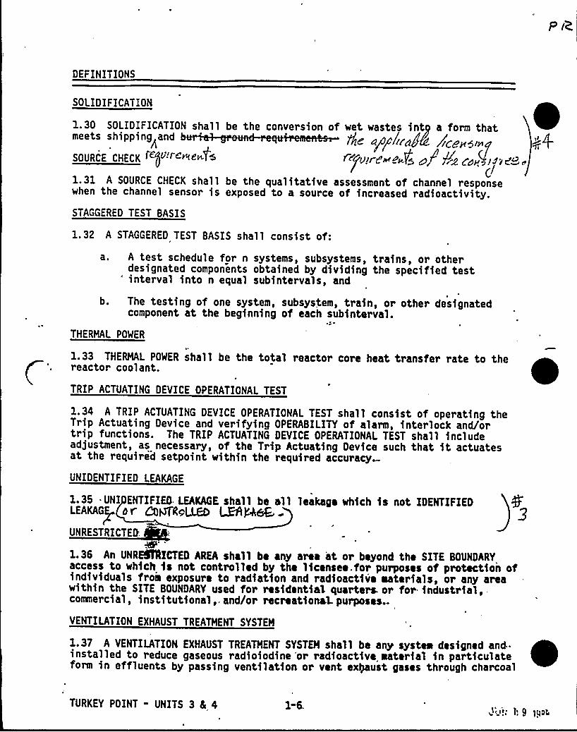
SOLIDIFICATION
1. 30 SOLIDIFICATION shallmeets shipping and
SOURCE CHECK4$ c "c-<c'<
1.31 A SOURCE CHECK shallwhen the channel sensor is
be the conversion of wet wasteth inty a form thatlk aPPbr~48 /zgeHSingr~ ~sr'>+~a O r~Co~ »ice.
dbe the qualitative assessment of channel responseexposed to a source of increased radioactivity.
STAGGERED TEST BASIS
1.32 A STAGGERED TEST BASIS shall consist of:
a. A test schedule for n systems, subsystems, trains, or otherdesignated components obtained by dividing the specified test" interval into n equal subintervals, and
b. The testing of one system, subsystem, train, or other designatedcomponent at the beginning of each subinterval.
THERMAL POWER
1.33 THERMAL POWER shall be the total reactor core heat transfer rate to thereactor coolant.
TRIP ACTUATING DEVICE OPERATIONAL TEST
1.34 A TRIP ACTUATING DEVICE OPERATIONAL TEST shall consist of operating theTrip Actuating Device and verifying OPERABILITY of alarm, interlock and/ortrip functions. The TRIP ACTUATING DEVICE OPERATIONAL TEST shall includeadjustment, as necessary, of the Trip Actuating Device such that it actuatesat the required setpoint within the required accuracy
UNIDENTIFIED LEAKAGE
1.35 UNI ENTIFIED LEAKAGE shall be all leakage which is not IDENTIFIEDLEAKAGE Or COPQOLCEO ~P,~UNRESTRICTED.
1.36 An UNREINECTN AREA shall be any area at or beyond the SITE BOUNDARYaccess to which is not controlled by the licensee. for purposes of protection ofindividuals frois exposure to radiation and radioactive aaterials, or any areawithin the SITE BOUNDARY used for residential quarters. or for industrial,-commercial, institutional,, and/or recreational purposes.-
VENTILATION EXHAUST TREATMENT SYSTEM
1.37 A VENTILATION EXHAUST TREATMENT SYSTEM shall be any systea designed and"installed to reduce gaseous radioiodine 'or radioactive material in particulateform in effluents by passing ventilation or vent exteust gases through charcoal
TURKEY POINT - UNITS 3 4 4 1-6.pcc<; t', 9 )QQrc

DEFINITIONS
VENTILATION EXHAUST TREATMENT SYSTEM (Continued)
adsorbers and/or HEPA filters for the purpose of removing iodines or particulatesfrom h ex u stream~rice to the release to the environment. Such
, ysteq is not onsldered to have any ef ct on noble gas effluents. Engineeredafetysneaturas tmospheric peanupgystemd are not considered to be VENTILATION )Q
EXHAUST TREATME SYSTEM compon nts.
VENTING
1.38 VENTING shall be the controlled process of discharging air or gas from aconfinement to maintain temperature, pressure, humidity, concentration, or otheroperating condition, in such a manner that replacement air or gas is not pro-vided or required during VFNTING. Vent, used in system names, does not implya VENTING process.
sa~ a+
TW
TURKEY POINT - UNITS 3 Ec 4 1-7 JUN 00 1988
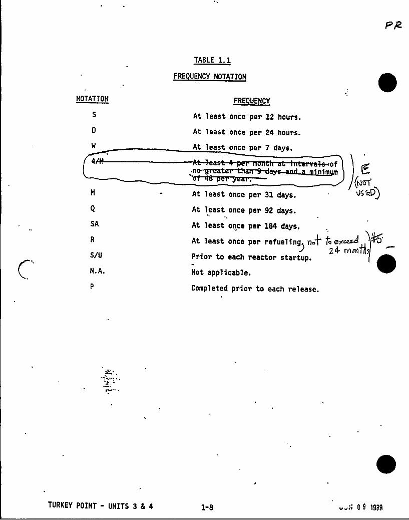
TABLE 1.1
FRE UENCY NOTATION
NOTATION FRE UENCY
At least once per 12 hours.
At least once per 24 hours.
At least once per 7 days.
,no-grea
SA
S/U
N.A.
At least once per 31 days.
At least once per 92 days.
At least once per 184 days.
At least once per refuelingnA'rior
to each reactor startup.
Not applicable.
Completed prior to each release.
TURKEY POINT - UNITS 3 4 4 1-8
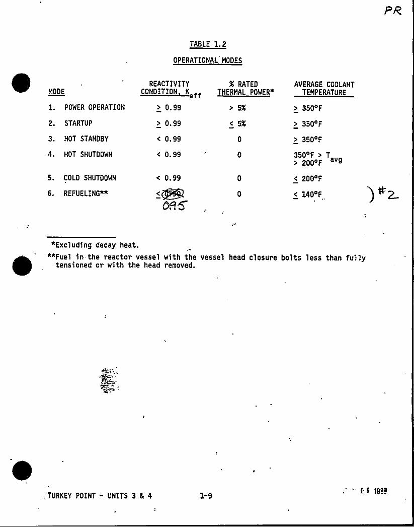
TABLE 1.2
OPERATIONAL MODES
MODE
1. POWER OPERATION
2. STARTUP
3. HOT STANDBY
4. HOT SHUTDOWN
5. COLD SHUTDOWN
6. REFUELING"*
REACTIVITYtt Kt
> 0.99
> 0.99
< 0.99
< 0.99
< 0.99
QR5
X RATEDTHERMAL POWER"
> 5X
< 5X
AVERAGE COOLANTTEMPERATURE
> 350'F
> 350'F
> 350 F
350 F > T> 200 F
< 200 F
<140F
"Excluding decay heat.""Fuel in the reactor vessel with the vessel head closure bolts less than fully
tensioned or with the head removed.
. TURKEY POINT - UNITS 3 8I 4 1-9.' 0S 1S88

/Vl 5 n /V~p
/~ 5!<.k,
a1
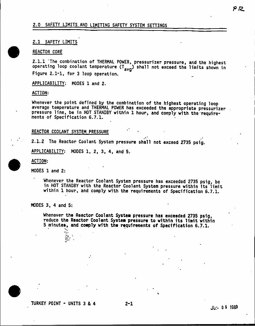
2.0 SAFETY LIMITS AND LIMITING SAFETY SYSTEM SETTINGS
2.1 SAFETY LIMITS
~
~
REACTOR CORE
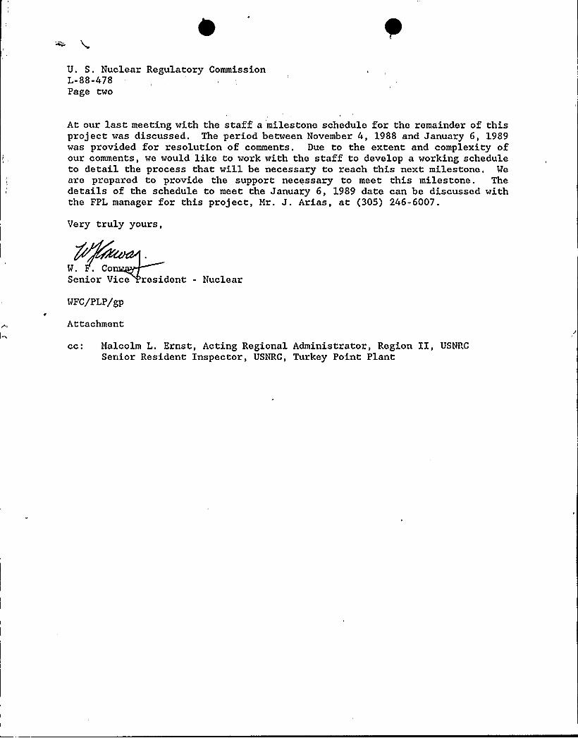
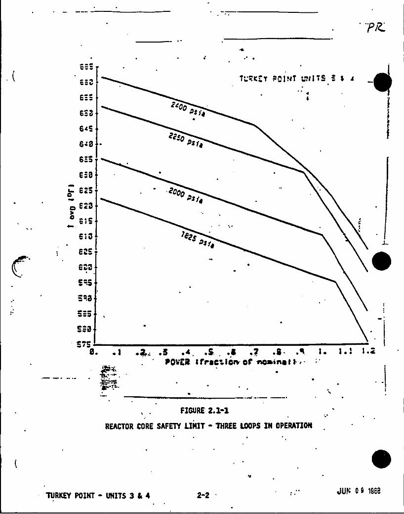
2. l. 1 'The combination of THERMAL POWER, pressurizer pressure, and the highestoperating loop coolant temperature (T ) shall not exceed the limits shown inavgFigure 2. 1-1, for 3 loop operation.
APPLICABILITY: MODES 1 and 2.
ACTION:
Whenever the point defined by the combination of the highest operating loopaverage temperature and THERMAL POWER has exceeded the appropriate pressurizerpressure line, be in HOT STANDBY within 1 hour, and comply with the require-ments of Specification 6.7.1.
REACTOR COOLANT SYSTEM PRESSURE
2.1.2 The Reactor Coolant System pressure shall not exceed 2735 psig.
APPLICABILITY: MODES 1, 2, 3, 4, and 5.
ACTION:
MODES 1 and 2:
'Whenever the Reactor Coolant System pressure has exceeded 2735 psig, bein HOT STANDBY with the Reactor Coolant System pressure within its limitwithin 1 hour, and comply with the requirements of Specification 6.7.1.
MODES 3, 4 and 5:
Whenever the Reactor Coolant System pressure has exceeded 2735 psig,reduce the Reactor Coolant System pressure to within its limit within5 minutes, and coeply with the requirements of Specification 6.7.1.
TURKEY POINT - UNITS 3 8c 4 2-1JL.. 0 S 1988
tte
ZcgpP$ ]'y
e;SO>$
< ScS
ScS
o tl~~sa .
coopP$ f~
g AHVCO
8. .s .~ .s. .a .v .I.POvEI f free i'teoaini t l- ~-
FIGURE'.1-1
REACTOR CORE SAFETY LINIT- THREE LOOPS IN OPERATION
TURKEY POINT - NITS 3 4 4 2-2 JUY 0> 1868
SAFETY LIMITS ANO LIMITING SAFETY SYSTEM SETTINGS
2. 2 LIMITING SAFETY SYSTEM SETTINGS
REACTOR TRIP SYSTEM INSTRUMENTATION SETPOINTS
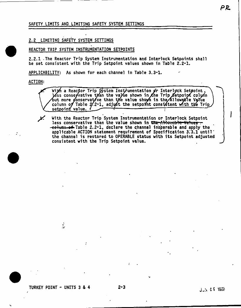
2.2.1 .The Reacto~ Trip System Instrumentation and Interlock Setpoints shallbe set consistent with the Trip Setpoint values shown in Table 2.2-1.
APPLICABILITY: As shown for each channel in Table 3.3-1.
ACTION:
Wi a Reac or Trip stem Ins umentation r Interl ck Set ointss conse vative t an the va e shown in he Trip etpoi col n
ut more onserva ve than e value sho in th liow e V uecolumn o Table .2-1, adj t the setpo nt cons tent th t e Tripset oin value.
p. Nlth the Reactor Trip System Inetrumentetlon or Interlock Setpointless conservative than the value shown in~i P y.h-l, P *1 h h 1 i p hh P pphy happlicable ACTION statement requirement of Specification 3;3.1 untilthe channel is restored to OPERABLE status with its Setpoint adjustedconsistent with the Trip Setpoint value.
TURKEY POINT - UNITS 3 4 4 2-3J„;i C < 19~i
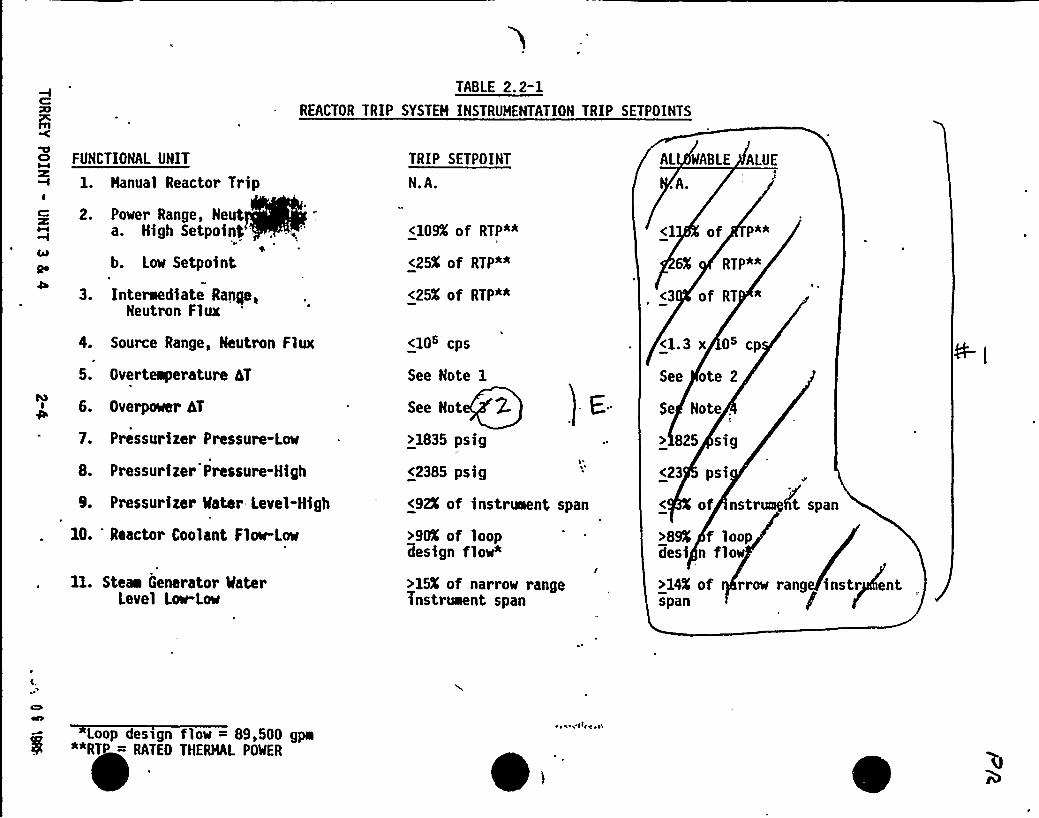
TABLE 2.2-1REACTOR TRIP SYSTEH INSTRUMENTATION TRIP SETPOINTS
FUNCTIONAL UNIT
1. Hanual Reactor TripI
C 2. Power Range, Neuta. High Setpoinl .
b. Low Setpoint\
3. Interaediate Range,Neutron Flux
4. Source Range, Neutron Flux
5. Overteaperature hT
6. Overpower hT
7. Pressurizer Pressure-Low
8. Pressurizer Prcssure-High
9. Pressurizer Mater Level-High
10. Reactor Coolant Flow-Low
TRIP SETPOINT
N.A.
<1QQ of RTP*~
<25K of RTP*"
<25K of RTP"*
<10s cps
See Note 1
See Not 2-
>1835 psig
<2385 psig
<92K of instreaent span
>90X of looplesign flow"
AL WABLE ALUE
.A.
of Pa*
eX RTP*<
<3 of RT *
<1.3 x Os cp
See ote 2
Se Note .
> 825 sig
<23 psi
of nstr
>8% f loopdesi n flow
t span
11. Stem Generator MaterLevel Low-Low
>15K of narrow rangeinstrument span
>14% of rrow rang instr entspan /
Loop design flow = 89,500 gpa"*RTP = RATEO THERHAL POWER
ib
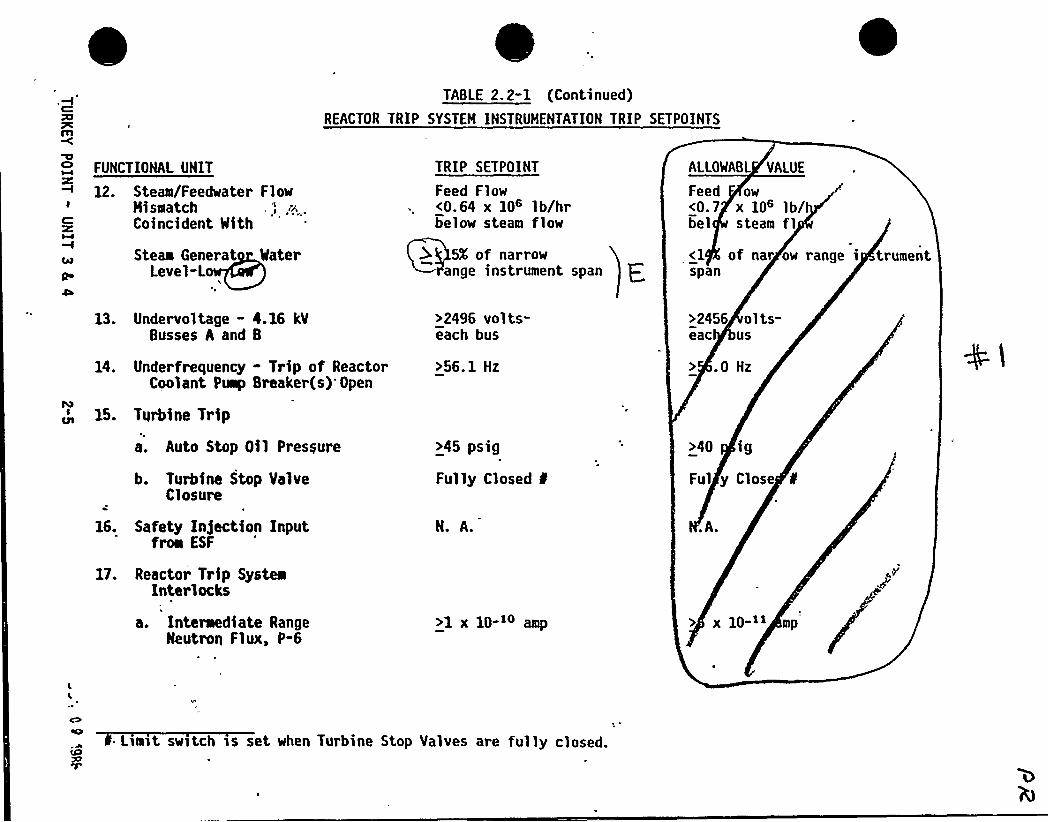
TABLE 2. 2-1 (Continued)
REACTOR TRIP SYSTEM INSTRUMENTATION TRIP SETPOINTS
g FUNCTIONAL UNIT
12. Steam/Feedwater FlowHiseatch
Q Coincident Mith
Steam Generat MaterQe Level-L
TRIP SETPOINT
Feed Flow<0.64 x 10 lb/hrbelow steam flow
5X of narrowange instrument span F
ALLOWABL VANE
Feed ow<0.7 x 10⁶ lb/bel steam fl<1 of nar ow range i trumentspan
13. Undervoltage - 4.16 kVBusses A and B
14. Underfrequency - Trip of ReactorCoolant Pump Breaker(s)'pen
15. Turbine Trip
a. Auto Stop Oil Pressure
b. Turbine Stop ValveClosure
16. Safety In)ection Inputfroa ESF
17. Reactor Trip SysteaInterlocks
a. Interaediate RangeNeutron Flux, P-6
>2496 volts-each bus
>56.1 Hz
>45 psig
Fully Closed ¹
N. A.
>1x10 ao am
>2456 ol ts-eac us
.0 Hz
>40 ig
Ful y Close
.A.
x 10-'i mp"
Liant switch is set when Turbine Stop Valves are fully closed.
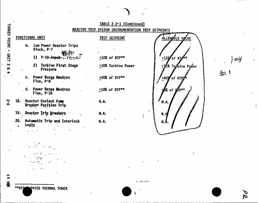
TABLE 2. 2-1 Continued
REACTOR TRIP SYSTEM INSTRUMENTATION TRIP SETPOINTS
FUNCTIONAL UNIT
b. Low Power Reactor TripsBlock, P-7
1) P-104npu0-,. ~~et2) Tugine Firyt Stage
Pressure
c. Power Rangy HeyttonFlux'-8
d. P.ower Range NeutronFlux, P-10
I
18. Reactor Coolant PuepBrqaker Popjfion Trip
19. Reactor $I'ip greaQrs
20. Autowatic Trip and InterlockLogfq
TRIP SETPOINT
<gg of RTP**
<lOX Turbine Power
<45K of RTP*"
>10X of RTP*+
N.A.
N.A.
N.A.
ALLO LE V UE
<1 of R *
T ine P Ger
<46 of RTP
of P*"
N.A.
N.
**RTATED THERMAL POWER
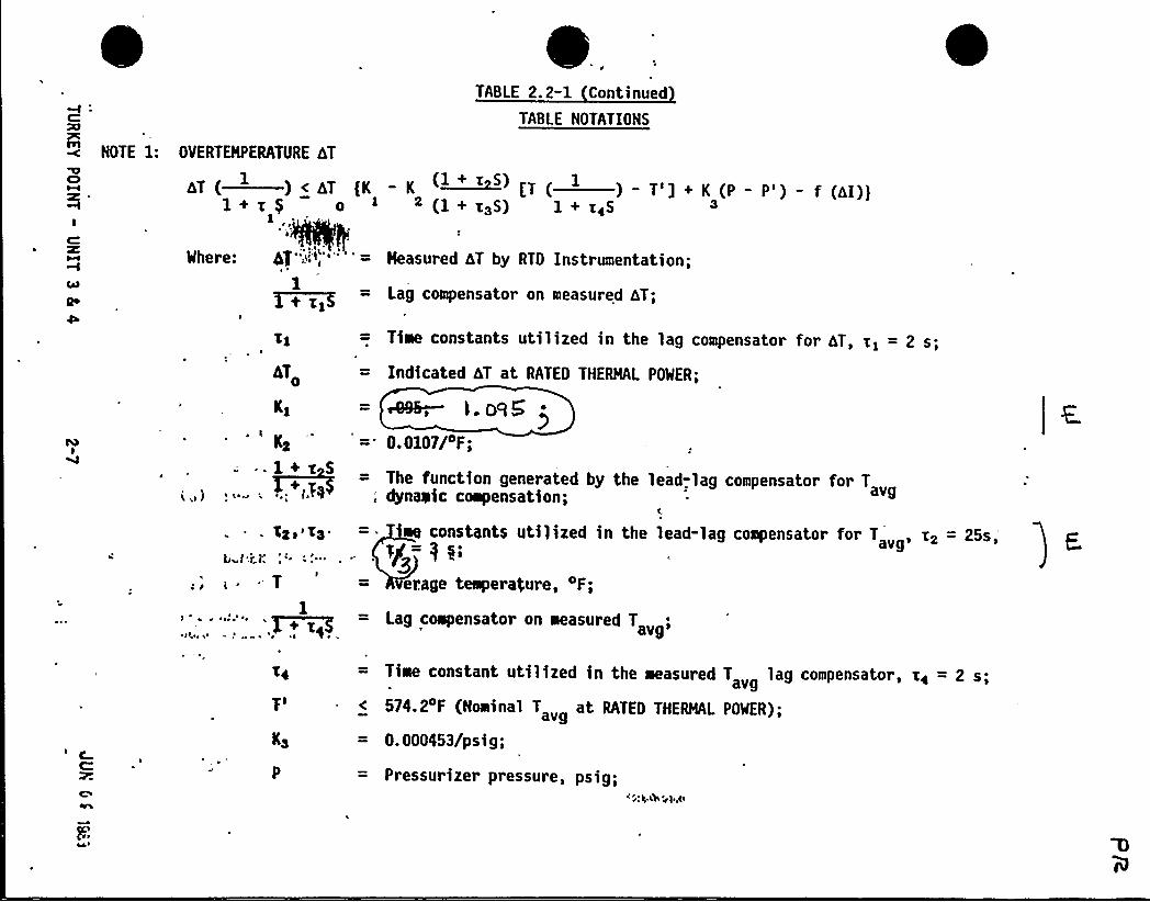
NOTE 1: OVERTNPERATURE hTP
AT(—) <AT (K-I 1+x) oI 1
C
1Qo ~+Xf
I
Kg
1+v S+ Y
~ Le K
bvf ''T.'f".:f~
T
.TABLE 2. 2-1 Continued
TABLE NOTATIONS
- K ~ (T ( ) — T'] + K (P - P') — f (A())2 (1 + t3S) 1 + xgS 3
Heasured hT by RTD Instrumentation;
Lag compensator on measured hT;
Time constants utilized in the lag compensator for AT, xg = 2 s;
Indicated 4T at RATED THERMAL POWER;
ms, ). ops0.0107/OF;
The function generated by the lead-lag compensator for Tdynaeic compensation; avg
f„
eo constants utilized in the lead-lag compensato~ for T „, x2 =25s,'/=
35'rage
temperature, OF;
Lag ciipensator on measured T
avg'ime
constant utilized in the measured T lag compensator, t< = 2 s.avg
574.2'F (Nominal T at RATED THERMAL POWER);
0.000453/psig;
Pressurizer pressure, psig;K y, +lb ~)e,gl

TABLE 2. 2-1 Continued
TABLE NOTATIONS Continued
NOTE 1: (Continued)CIM
IC
Qo
D
pl 2235 psig (Nominal RCS operating pressure);
S : ,, —. Laplace transform operator, s-~;
/,aand f '(4I) is a function of the indicated difference between top and bottom detectors of thepower-range neutron ion chambers; with gains to be selected based on measured instrumentresponse during plant startup tests such that:
(1) For qt -qb bebeen -. 14K and + 10', f (AI) = 0, where qt and qb are percent RATED THERMAL
POWER in the top and bottom halves of the core respectively, and qt + qb is total THERMAL
POWER in percent of RATED THERMAL POWER;
ICO
(2) For each percent that the magnitude of qt -qb exceeds - 14K, the hT Trip Setpoint shall
be automatically reduced by 2.0X of its value at RATED THERMAL POWER; and
(3) For each percent that the magnitude of qt -qb exceeds + 10K, the AT Trip Setpoint shall
be autoaatically reduced by 3.5X of its value at RATED THERMAL POWER.
NOTE 2: The nq 'axiam Tr t oint shall t ts co ted Setpoi by mo h
0TABLE 2. 2-1 Continued
TABLE NOTATIONS Continued
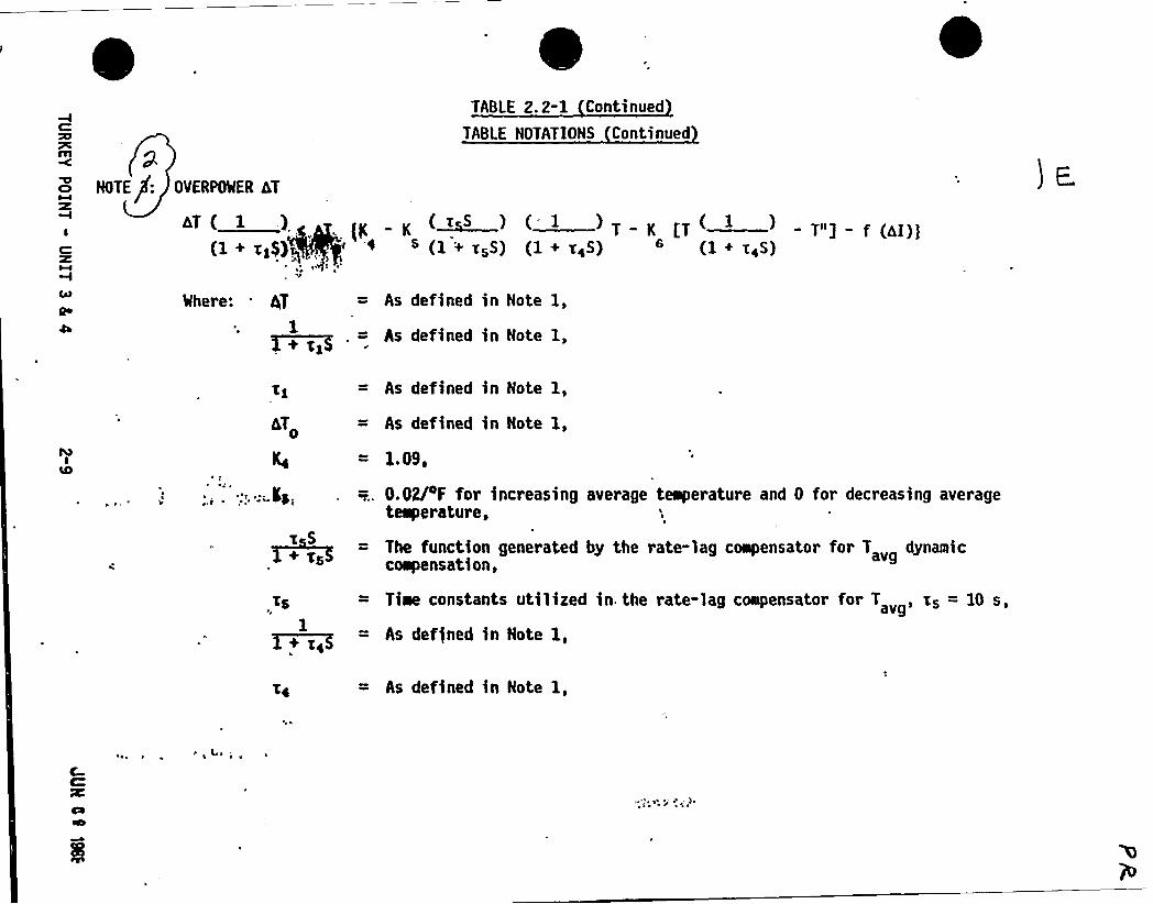
NOTE : OVERPOWER dT
AT ( 1 .)(N N
(~tS ) ( 1 ) T ( 1 )(1+ ts$ )o e s (1+ sss) (1+ ses) e (1+ ass)
s ~~ ~ s
~e
%here: . hT = As defined in Note 1,
As defined in Note 1,1
4T
+ ss~sS
As defined in Note 1,
As defined in Note 1,
1.09,
0.02/4F for increasing average teaperature and 0 for decreasing averagetemperature, s
The function generated by the rate-lag coapensator for T dynamiccoipensation, avg
Tiae constants utilized in. the rate-lag compensator for T x = 10avg's
def)ned in Note 1,
As defined in Note 1,
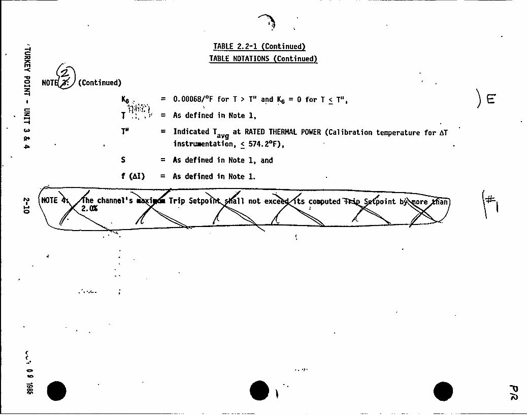
TABLE 2. 2-1 Continued
TABLE NOTATIONS Continued
NOT : (Continued)
Kg .
', js)~.1
T .',, ~"
OO gNQo
f (aI)
0.00068/ F for T > T" and Kz = 0 for T < T",
As defined in Note 1,
Indicated T „ at RATED THERHAL POWER (Calibration temperature for bT
instruaentation, < 574.2 F),
As defined in Note 1, and
As defined in Note 1.
NOTEW
he channel's i Trip Setpoi all not exce ts computed' point b're an
2. CL
BASES
FOR
SECTION 2.0
SAFETY LIMITS
AND
LIMITING SAFETY SYSTEM SETTINGS
NOTE
The BASES contained in succeeding pages summarizethe reasons For the Specifications in Section 2.0,but in accordance with 10 CFR 50.36 are not partof these Technical Specifications.
TURKEY POINT - UNITS 3 81 4 B 2-0

0
I5 'pA.ri8 In.78nlidvlz(l~/ g
4p~

2. 1 SAFETY LIMITS
BASES
2.1. 1 REACTOR CORE
The restrictions of this Safety Limit prevent overheating of the fueland possible cladding perforation which would result in the release of fissionproducts to the reactor coolant. Overheating of the fuel cladding is preventedby restricting fuel operation to within the nucleate boiling regime where theheat transfer coefficient is'arge and the cladding surface temperature isslightly above the coolant saturation temperature.
Operation above the upper boundary of the nucleate boiling regime couldresult in excessive cladding temperatures because of the onset of departurefrom nucleate boiling (DNB). and the resultant sharp reduction in heat transfercoefficient. DNB is not a directly measurable parameter during operation andtherefore THERMAL POWER and reactor coolant temperature and pressure have beenrelated to DNB. This relationship has been developed to predict the ONB fluxand the location of DNB for axially uniform and nonuniform heat flux distribu-tions. The local ONB heat flux ratio (ONBR)'is defined as the ratio of theheat flux that would cause DNB at a particular cort location to the local heat:t.flux and is indicative of the margin to ONB.
'
The ONB design basis fs as follows: there must,bc at least a 95 percentprobability with 95 percent confidence that the minimus ONBR of the limitingrod during Condition I and II events is greater than or equal to the ONBRlimit of the DNB correlation being used. The correlation ONBR limit isestablished based on the entire applicable experimental data set such thatthere is a 95 percent probability with 95 percent confidence that ONB willnot occur when the minimum DNBR is at the ONBR limit.
The curves of Figure 2.1-1 show the loci of points of THERMAL POWER,Reactor Coolant System pressure and average temperature for which the minimumONBR is no less than the design ONBR value, or the average enthalpy at thevessel exit is equal to the enthalpy of saturated liquid.
These curves are based on an enthalpy hot channel factor, F~, of 1.62 andN
and a reference cosine with a pegk of 1.55 for axial power shape. An allowanceis included for ah increase in F~ at reduced power based on the expression:
F~ < 1. Q+ 0.3 (I-P)3
1&ere P iFthe-fraction of RATED THERMAL PNER.
These limiting heat flux conditions are higher than those calculated forthe range of all control:rods fully withdrawn to th» maxim'llowable controlrod insertion limit assuming the axial power imbalance is within the l.imits ofthe f (dI) function of the Overtemperature trip. %hen the axial power imbalanceis not within the tolerance, the axial power imbalance effect on the Overtemperature hT trips will reduce the setpo$ nts. to provide protection consistentwith core Safety Limits.
TURKEY POINT - UNITS 3 4 4 B 2-1 JUN 35 )9>:
SAFETY LIMITS
BASES
2. 1. 1 REACTOR CORE (Continued)
Fuel rod bowing reduces the values of DNB ratio (DNBR). .The amount ofthe DNBR reduction is 4.7X for LOPAR fuel with the j.-grid ONB correlation and5.5X for the OFA,fuel with the WRB-1 DNB correlation. The penalties arecalculated pursuant to "Fuel Rod Bow Evaluation," WCAP-8691-P-A Revision 1(Proprietary) and WCAP-8692 Revision 1 (Non-Proprietary). The restrictionsof the Core Thermal Hydraulic Safety Limits assure that an amount of DNBRmargin greater than or equal to the above penalties is retained to offset therod bow DNBR penalty.
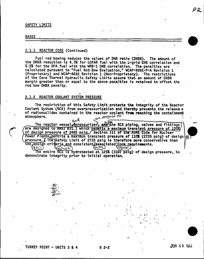
2. 1.2 REACTOR COOLANT SYSTEM PRESSURE
The restriction of this Safety Limit protects the integrity of the ReactorCoolant System (RCS) from overpressuriiation and thereby prevents the release iof radionuclides contained in the reactor coolant froa reaching the containmentatmosphere. J!rggf< 4t;Cl f~
0, est~
The reactor vessel ressurizeelv mstd7he RCS p!p!ng, valves and flttlngsare es gne to w c e s a maximum transient ressure 20Kof desi n pressure of 2485 ps! Sect!on III of odc for Nuclear
ower Plan s permfte a max>mum trans!ent pressure of 110K (2735 pslg) of design gressure. The afety Limit of 2735 psig is therefore more conservative thane esxgn cri eri nd consisten iated"Co
~
~
rements.'84< < 4<gL ~ i%5» ASIDE
e entire ydrotested at 125K (3107 psig) of design pressure, todemonstrate integrity prior to initial operation.
TURKEY POINT - UNITS 3 Cc 4 B 2-2 JUtf'7 fi l9»~
2. 2 LIMITING SAFETY SYSTEM SETTINGS
BASES
PR~gg~)o4a gns$ru~C cl riA
opcraYiun+ ge.sly~ +E ~~ t~,„$ ,g nw-n ~lay
4- pr1C!M COYlSI2YV~ 1VC, IM'4JAAA
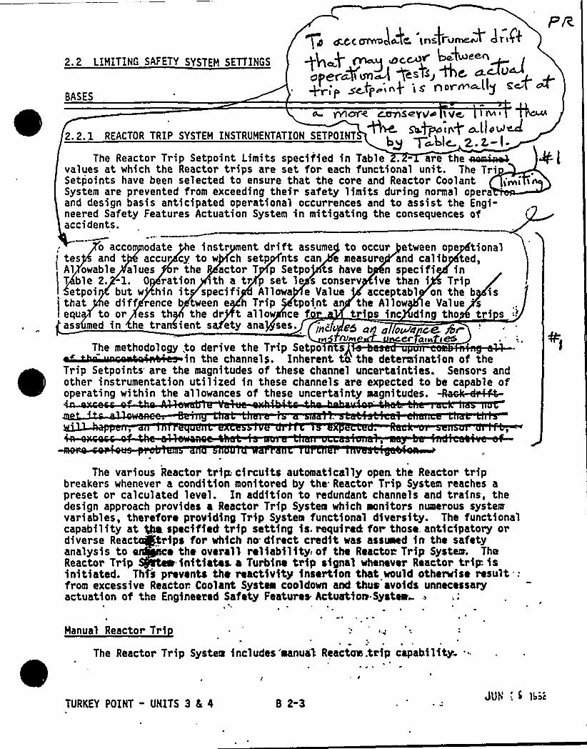
2.2.1 REACTOR TRIP SYSTEM INSTRUMENTATION SETPOINT mqpoiry a.ll~~
The Reactor Trip Setpoint Limits specified in Table . - are the ~~values at which the Reactor trips are set for each functional unit. The TriSetpoints have been selected to ensure that the core and Reactor Coolant i~i iSystem are prevented from exceeding their safety limits during normal operaand design basis anticipated operational occurrences and to assist the Engi«neered Safety Features Actuation System in mitigating the consequences ofaccidents.
o acco odate e instr ent drift assume to occur etween ope tional< tes and t accur cy to w ch setp nts can e measure and calib ted,~ Al owable alues r the actor T p Setpo ts have b n specifi in
T ble 2. -1. 0 ration th a tr p set le s conserv ive than i Tripetpoi but w'in it specifi Allowa e Value acceptabl on the b is
that e diff rence b tween e h Trip tpoint an the Allow e Value 'sequ to or ess th the dr t allow ce f tri s inc ding tho tri sas med in he tra ient s ety ana ses.
Cf'llN 4M ~
The methodology .to derive the Trip Setpo n s lin the channels. Inherent the determination of the
Trip Setpoints are the magnitudes of these channel uncertainties. Sensors andother instrumentation utilized in these channels are expected to be capable of
ig ill t 11 f 1 t y gt d
The various Reactor trip circuits automatically open. the Reactor tripbreakers whenever a condition monitored by the Reactor Trip System reaches apreset or calculated level. In addition to redundant channels and trains, thedesign approach provides a Reactor Trip System which monitors numerous systemvariables, therefore providing Trip System functional diversity. The functionalcapability at Qa specified trip setting is. required for those. anticipatory ordiverse Reac trips for which no direct credit was assed in the safetyanalysis to o the overall reliability of the Reactor Trip System. TheReactor Trip fnitiataL a Turbine trip signal whenever Reactor trip isinitiated. Thfi prevents the reactivity instrtion that would otheneise result .:from excessive Reactor. Coolant System cooldown and thus avoids unnecessaryactuation of the Engiaeered Safety Features hctuatfoo Syatea
Manual Reactor Tri
The Reactor Trip Systea includes 'manual Reactaw.tHp capability
TURKEY POINT - UNITS 3 4 4 1 2-3 Jub '. i 1b~t
LIMITING SAFETY SYSTEM SETTINGS
BASES
Power Ran e Neutron Flux
. eIn each of the Power Range Neutron Flux channels there are two independent
bistables, each with its own trip setting used for a High and Low Range tripsetting. The Low Setpoint trip provides protection during subcritical and lowpower operations to mitigate the consequences of a power excursion beginningfrom low power, and the High Setpoint trip provides protection during poweroperations for all power levels to mitigate the consequences of a reactivityexcursion which may be too rapid for the temperature and pressure protectivetrips.
The Low Setpoint trip may be manually blocked above P-10 (a power levelof approximately 10K of RATED THERMAL POWER) and fs automatically reinstatedbelow the P-10 Setpoint.
Intermediate and Source Ran e NeutronFlux'he
Intermediate and Source Range, Neutron Flux trips provide coreprotection during reactor startup to mitigate the consequences of an uncon-trolled rod cluster control assembly bank withdrawal froa a subcrfticalcondition. These trips provide redundant. protection to the Low Setpoint tripof the Power Range, Neutron Flux channels. The Source Range channels wi11initiate a Reactor trip at about 10s counts per second unless manually blockedwhen P-6 becomes active. The Intermediate Range. channels will initiate aReactor trip at a current level equivalent to approximately 25K of RATED
H L POWER unless manually blocked when P-10 becomes active, No credit~~~ taken for operation of the trips associated with either the Intermediateource Range Channels fn the accident analyses; however, their functi'onal
capability at the specified trip settings is required by this specificationto enhance the overall reliability of the Reactor Protectfon System.
Qvertem erature hT
JUH 00 )g..B 2-4TURKEY POINT - UNITS 3 4 4
I
The Overteayerature ALT. trip provides core protection to prevent GNS forall combfnatfoo0t,of pressure, power, coolant temperature,'nd axial powerdistribution; jftovfdsd that the transient fs slow wfth respect to pfpfnytransit delays'.fisc the core to the taaperature detectors (about 4 seconds),and pressure fs within the rangI between the Pressurfzer. High and Low Pressuretrips. The setpofnt is automatically varfed with.". (1) coolant temperature tocorrect for temperature induced changes. fn density and heat capacity of waterand includes dynamic compensation for piping delays from the core to the looptemperature detectors, (2) pressurizer pressure, and (3) axial power distribu-tion. With normal axial power dfstrfbutfon, this Reactor trip lfaft fs a1waysbelow the core Safety Limit as shown. in Figure 2.1-1. If axial peaks aregreater than design, as, indicated by the dtrferenoe between top and bottompower range nuclear detectors, the Reactor trip is automatically reducedaccording to the notations in Table 2.2-1.
se pin
LIMITING SAFETY SYSTEM SETTINGS
BASES
The Overpower 4T trip prevents power density anywhere in the core fromexceeding 118K of the design power density. This provides assurance of fuelintegrity (e. g., no fuel pellet melting and less than IX cladding strain)under all possible overpower conditions, limits the required range for Over-temperature hT trip, and provides a backup to the High Neutron Flux trip. Thesetpoint is automatically varied with: (1) coolant temperature to correct fortemperature induced changes in density and heat capacity of water, (2) rate ofchange of temperature for dynamic compensation for piping delays from the coreto the loop temperature detectors, and (3) axial power distribution, to ensurethat the allowable heat generation rate (kW/ft) is not exceeded.
Pressurizer Pressure
In each of the pressurizer pressur'e channels, there are two independentbistables, each with its own trip setting to provide for a High and Low Pressuretrip thus limiting the pressure range in which reactor operation is permitted.'.The Low Setpoint trip protects against low pressure which could lead to DNB bye .
tripping the reactor in the event of a loss of reactor coolant pressure.
On decreasing power the Low Setpoint trip is automatically blocked by P-7(a power level of approximately 10K of RATED THERMAL POWER with turbine firststage .pressure at approximately lOX of full power equivalent); and on increasingpower, automatically reinstated by P-7.
The High Setpoint trip functions in conjunction with the pressurizersafety valves to protect the Reactor Coolant System against system 4- Q
rpressure.
Pressurizer Water Level
The Pressurizer Mater Level-High trip is provided to prevent water reliefthrough the pressurizer safety valves. On decreasing power the PressurizerHigh Mater LI 'trip is automatically blocked by P-7 (a peer lovel ofapproximatel .of RATED THERMAL POMER with a turbine first stage pressureat approxima 1l% of full power equivalent); and on increasing power, auto-matically re d by P-7.
Reactor Coolant Flow
The Reactor Coolant Flow-Low trip provi e core protection to prevent DNb
by mitigating the consequences of a loss of ,resulting fmo-the loss of-one or more reactor coolant pumps..
On increasing power above P-7 (a powIr level of approxiaately 10K'ofRATED THERMAL POMER or a turbine first stage pressure at approximately 10K
TURKEY POINT - UNITS 3 dc 4 B 2-5
LIMITING SAFETY SYSTE> SETTINGS
BASES
Reactor Coolant Flow (Continued)'% ~ 1
of full power equivalent), an automatic Reactor trip will occur if the flow inmore than one loop drops below 90K of nominal full loop flow. Above P-8 (apower level of approximately 45X of RATED THERMAL POWER) an automatic Reactortrip will occur if the flow in any single loop drops below 90K of nominalfull loop flow. Conversely, on decreasing power between P-8 and the P-7 anautomatic Reactor trip will occur on low reactor coolant flow in more thanone loop and below P-7 the trip function is automatically blocked.
Steam Generator Water Level-
The Steam Generator Mater Level Low-Low trip protects the reactor fromloss of heat sink in the event of a sustained steam/feedwater flow mismatchresulting from loss of normal feedwater.'he specified setpoint providesallowances for star ting delays of the Auxiliary Feedwater System.
Steam/Feedwater Flow Mismatch and Low Steam Generator Mater Level
The Steam/Feedwater Flow Mismatch in coincidence with a Steam GeneratorWater Level-Lo trip is not used in the transient and accident analyses )~but is included n Table 2.2-1 to ensure the functional capability of thespecified trip settings and thereby enhance the overall reliability of theReactor Trip System. This trip is redundant to the Steam Generator MaterLevel Low-Low trip. The Steam/Feedwater Flow Mismatch portion of this trip isactivated when the steam flow exceeds the feedwater flow by greater an orequal to 0.64 x 10e lbs/hours The Steam Generator Mater Level-Loportion of the trip is activated when the water level drops belo , asindicated by the narrow range instrument. These trip values inclu e su c enallowance in excess of normal operating values to preclude spurious trips butwill initiate a Reactor trip before the steam generators are dry. Therefore,the required capacity and starting tiaa requirements of the auxiliary feedwaterpumps are reduced and the resulting thiraal transient on e Reactor CoolantSystem and s~ generators is minimized.
I,Ac. '$'e p(n
Undervolta e - 4.16 kV Bug A and S Tri s
The 4.16 kV Bus A and B Undervoltage trips provide core protection againstDNB as a result of complete loss of forced coolant flow. The specifiedsetpoint assures a Reactor trip signal is generated before the Low Flow TripSetpoint is reached. Time delays are incorporated.. in the Undervoltage tripsto prevent spurious Reactor trips from momentary electrical power transients.The delay is set so that the time required. for a signa) to reach the Reactortrip breakers following the trip of at least one undervoltage relay in both ofthe associated Units 4.16 kV busses shall not exceed 1.3 seconds. On decreasing
'URKEY POINT - UNITS 3 4 4 B 2-6 'UN ti9 )~
LIMITING SAFETY SYSTEM SETTINGS
BASES
Undervolta e and - 4. 16 kV Bus A and B Tri s (Continued)
power the Undervoltage Bus trips are automatically blocked by P-7 (a powe~level of approximately 10K 'of RATED THERMAL POWER with a turbine first stagepressure at approximately 10K of full power equivalent}; and on iacreasingpower, reinstated automatically by P-7.
~pgaWnr 4v'ipA Turbine trip initiates a Reactor trip. On decreasing powe Turbine
trip is automatically blocked by P-7 (a power level of approximately 10K ofRATED THERMAL POWER with a 4urbine first stage pressure at approximatelylOX of full power equivalent); and on increasing power, reinstated automatic-ally by P-7.
Sa fet In 'ecti on In ut from ESF
If a Reactor trip has not already been generated by the Reactor TripSystem instrumentation, the ESF automatic actuation logic channels willinitiate a Reactor trip upon any signal which initiates a Safety In)ection.The ESF instrumentation channels which initiate a Safety Injection signal areshown in Table 3.3-3.
Reactor Coolant Pum Breaker Position Tri
The Reactor Coolant Pump Breaker Position Trips are anticipatory tripswhich provide reactor core protection against, DNB'. The open/close positiontrips assure a reactor trip signal is generated before the low flow tripsetpoint is reached. No credit was taken in the accident analyses for operationof these trips Their functional capability at the open/close position settingsis required to enhance the overall reliability of the Reactor Protection System.Above P-7 (a power level of approximately 10K of RATED THERMAL POWER or aturbine first stage pressure at approximately 10% of full power equivalent) anautomatic reactor trip will occur if more than one reactor coolant pump breakeris opened. Above P-8 (a power level of approxiaately 45% of RAT THERMAL Q EPOWER) an automatic reactor trip will occur if one reactor coolant p rea eris opened. On."jftcreasing power between P-8 and P-7, an automatic reactor tripwill occur if mme than one reactor coolant pump breaker is opened and belowP-7 the trip f&ation is automatically blocked.
Underfrequency sensors are also installed on the 4.16 kV busses to detectunderfrequency and initiate breaker trip on underfrequency. The underfrequencytrip setpoints preserve the coast down energy of the reactor coolant pumps, incase of a grid frequency decrease so DNB does not occur.
TURKEY POINT - UNITS 3 SL 4 B 2-7 JuN <> |S>
LIMITING SAFETY SYSTEM SETTINGS
BASES
Reactor Tri S stem Interlocks
The Reactor Trip System interlocks perform the following functions:'-6
On increasing power, P-6 allows the manual block of the Source Rangetrip (i.e., prevents premature block of Source Range trip) anddeenergizes the high voltage to the detectors. On decreasing power,Source Range Level trips are automatically reactivated and highvoltage restored.
P-7 On increasing power, P-7 automatically enables Reactor trips on lowflow in more than-one reactor coolant loop, more than one reactorcoolant pump breaker open, reactor coolant pump bus undervoltage andunderfrequency, Turbine trip, pressurizer low pressure and pressurizerhigh level. On decreasing power, the above listed trips are auto-matically blocked.
P-8 On increasing power, P-8 automaticafly enables Reactor trips on low-:.flow in one or more reactor coolant loops, and one or more reactor
„'oolantpump breakers open. On decreasing power, the P-8 interlockautomatically blocks the trip on low flow in one coolant loop orone coolant pump breaker open.
P-10 On increasing power, P-10 allows the manual block of the IntermediateRange trip and the Low Setpoint Power Range trip; and automaticallyblocks the Source Range trip and deenergizes the Source Range highvoltage power. On decreasing power, the Intermediate Range trip andthe Low Setpoint Power Range trip are automatically reactivated.P-10 also provides input to P-7..
~ a
TURKEY POINT - UNITS 3 81 4 B 2-8
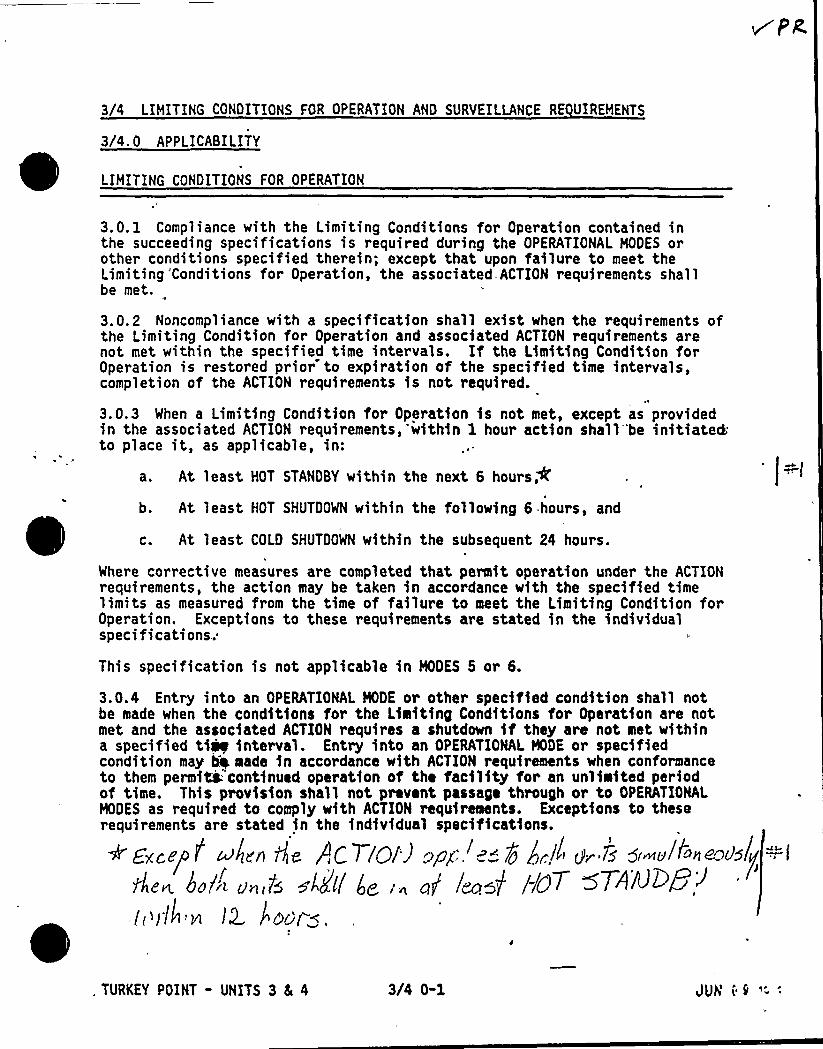
3/4 LIMITING CONDITIONS FOR OPERATION AND SURVEILLANCE RE UIREMENTS
3/4. 0 APPLICABILITY
LIMITING CONDITIONS FOR OPERATION
3.0. 1 Compliance with the Limiting Conditions for Operation contained inthe succeeding specifications is required during the OPERATIONAL NOES orother conditions specified therein; except that upon failure to meet theLimiting 'Conditions for Operation, the associated ACTION requirements shallbe met.
3.0.2 Noncompliance with a specification shall exist when the requirements ofthe Limiting Condition for Operation and associated ACTION requirements arenot met within the specified time intervals. If the Limiting Condition forOperation is restored prior to expiration of the specified time intervals,completion of the ACTION requirements is not required.
3.0.3 When a Limiting Condition for Operation is not met, except as providedin the associated ACTION requirements,'within 1 hour action shall'be initiated.to place it, as applicab1e, in:
a. At least HOT STANDBY within the next 6hours'.
At least HOT SHUTDOWN within the following 6 hours, and
c. At least COLD SHUTDOWN within the subsequent 24 hours.
Where corrective measures are completed that permit operation under the ACTIONrequirements, the action may be taken in accordance with the specified timelimits as measured from the time of failure to meet the Limiting Condition forOperation. Exceptions to these requirements are stated in the individualspecifications.:
This specification is not applicable in MODES 5 or 6.
3.0.4 Entry into an OPERATIONAL NODE or other specified condition shall notbe made when the conditions for the Limiting Conditions for Operation are notmet and the associated ACTION requires a shutdown if they are not met withina specified ti~ interval. Entry into an OPERATIONAL NDE or specifiedcondition may Q made in accordance with ACTION requirements when conformanceto them permiti: continued operation of the facility for an unlimited periodof time. This provision shall not prevent passage through or to OPERATIONALMODES as required to comply with ACTION requirements. Exceptions to theserequirements are stated in the individual specifications.
+'Excel'! ~/en 6e r,cTloi) apg-,. "7g gr!! gr 75~ 5<~v!~~nc'>~15((""l
d,e~ koln'„6 ~!di( 4,,„g< lpga~] //07 ~7~ND8~:I( /Ill'8 /2 I"Qci f (.
. TURKEY POINT - UNITS 3 5 4 3/4 0-1 JUNik '-'
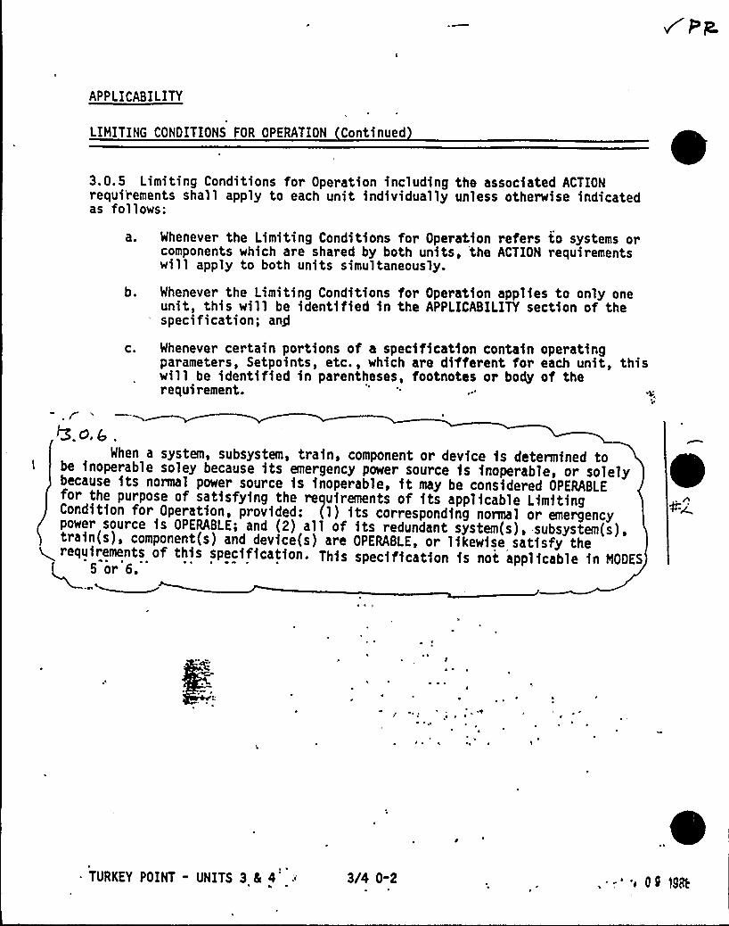
APPLICABILITY
LIMITING CONDITIONS FOR OPERATION Continued
3.0.5 Limiting Conditions for Operation including the associated ACTIONrequirements shall apply to each unit individually unless otherwise indicatedas follows:
a. Whenever the Limiting Conditions for Operation refers to systems orcomponents which are shared by both units, the ACTION requirementswill apply to both units simultaneously.
b. Whenever the Limiting Conditions for Operation applies to only oneunit, this will be identified in the APPLICABILITY section of thespecification; an/
c. Whenever certain portions of a specification contain operatingparameters, Setpoints, etc., which are different for each unit, thiswill be identified in parentheses, footnotes or body of therequirement.
5.o,g .
When a system, subsystem, train, component or device is determined tobe inoperable soley because its emergency power source is inoperable, or solelybecause its normal power source is inoperable, it may be considered OPERABLEfor the purpose of satisfying the requirements of its applicable LimitingCondition for Operation, provided: (1) its corresponding normal or emergencypower source is OPERABLE; and (2) all of its redundant system(s), subsystem(s),train(s), component(s) and device(s) are OPERABLE, or likewise satisfy the+ requirements of this specification. This specification is not applicable in NODES
~
~ ~
~ ~ ~
TURKEY POINT - UNITS 3 4 4 3/4 0-2 - 'i 0 0 1Sct

APPLICABILITY
SURVEILLANCE RE UIREMENTS
4.0. 1 Surveillance Requirements shall be met during the OPERATIONAL MODESor other conditions specified for individual Limiting Conditions forOperation unless otherwise stated in an individual Surveillance Requirement.
4.0.2 Each Surveillance Requirement shall be performed within the specifiedtime interval with:
a. A maximum allowable extension not to exceed 25X of the surveillanceinterval, but
b. The combined time interval for any three consecutive surveillanceintervals shall not exceed 3.25 times the specified surveillanceinterval.
4.0.3 Failure to perform a Surveillance Requirement within the allowedsurveillance interval, defined by Specification 4.0.2, shall constitutenoncompliance with the OPERABILITY requirements for a Limiting Conditionfor Operation. The time limits of the ACTION requirements are applicable atthe time it is identified that a Surveillance Requirement has not beenperformed. The ACTION requirements may be delayed for up to 24 hours topermit the completion of the surveillance when the allowable outage timelimits of the ACTION requirements are less than 24 hours. SurveillanceRequirements do not have to be performed on inoperable equipment.
4.0.4 Entry into an OPERATIONAI MODE or other specified condition shall notbe made unless the Surveillance Requirement(s) associated with a LimitingCondition for Operation has been performed within the stated surveillanceinterval or as'otherwise specified. This provision shall not prevent, passagethrough or to OPERATIONAL MODES as required to comply with ACTION requirements.
4.0.5 Surveillance Requirements for inservice inspection and testing of ASMECode Class 1, 2, and 3 components shall be applicable as follows:
Inservice inspection of ASME Code Class 1, 2, and 3 components andinsoiHce testing of ASME Code Class 1, 2, and 3 pumps and valvesshaQ be performed in accordance with Section XI of the ASME Boilerand P&ssur» Vessel Code and applicable Addenda as required by10 CFR 50, Section 50.55a(g), except where specific written reliefhas been granted by the Commission pursuant to 10 CFR 50, Section50.55a(g)(6)(i,).
'URKEY POINT - UNITS 3 Sc 4 3/4 0-3 r4 CS ';nP
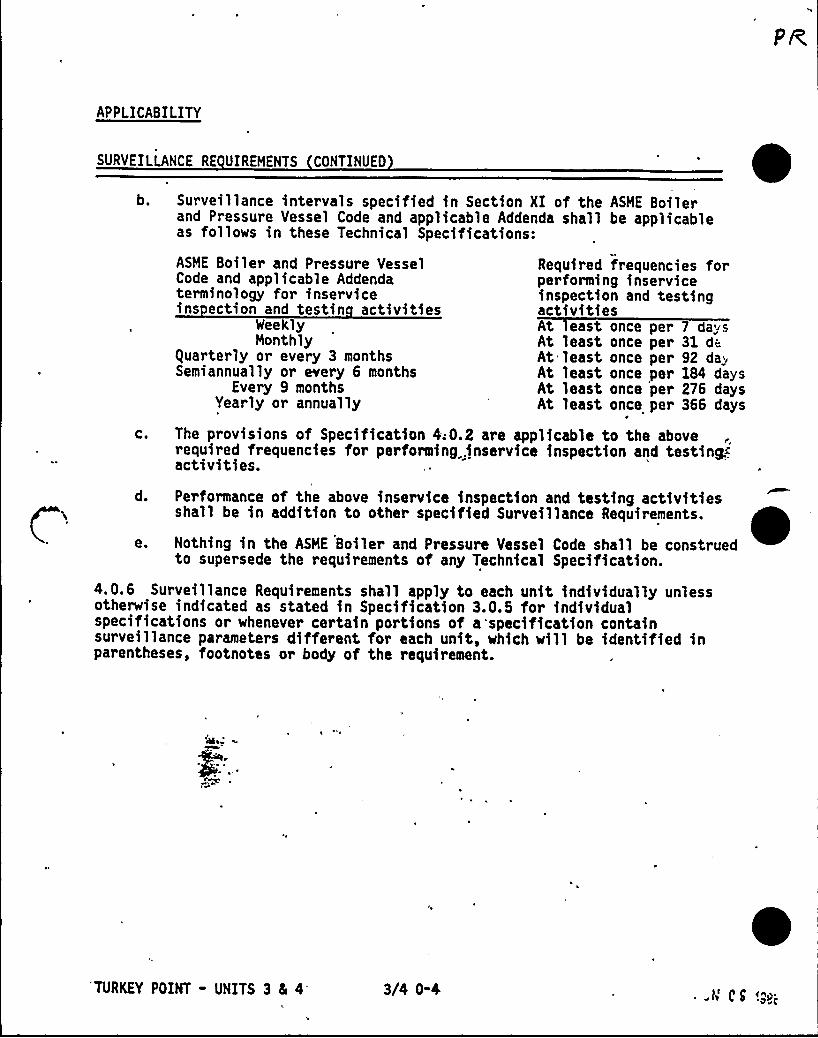
APPLICABILITY
SURVEILLANCE RE UIREHENTS CONTINUEO
b. Surveillance intervals specified in Section XI of the ASIDE Boilerand Pressure Vessel Code and applicable Addenda shall be applicableas follows in these Technical Specifications:
ASME Boiler and Pressure Vessel Required frequencies forCode and applicable Addenda performing inserviceterminology for inservice inspection and testingins ection and testin activities activities
sleekly At east once per 7 daysMonthly At least once per 31 d~
quarterly or every 3 months At least once per 92 da.Semiannually or every 6 months At least once per 184 days
Every 9 months At least once per 276 daysYearly or annually At least once per 366 days
c. The provisions of Specification 4;0.2 are applicable to the aboverequired frequencies for performing .inservice inspection and testing..activities.
d. Performance of the above inservice inspection and testing activitiesshall be in addition to other specified Surveillance Requirements.
e. Nothing in the ASME Boiler and Pressure Vessel Code shall be construedto supersede the requirements of any Technical Specification.
4.0.6 Surveillance Requirements shall apply to each unit individually unlessotherwise indicated as stated in Specification 3.0.5 for individualspecifications or whenever certain portions of a specification containsurveillance parameters different for each unit, which will be identified inparentheses, footnotes or body of the requirement.
'TURKEY POINT - UNITS 3 4 4'4
3/4 0-4 -t4 C S '.go;

3/4. 1 REACTIVITY CONTROL SYSTEMS
3/4. 1. 1 BORATION CONTROLRt" 5 /~err'<~<>'p "=~"
SHUTDOWN MARGIN ~M GREATER THAN 200 F
LIMITING CONDITION FOR OPERATION
3.1.1.1 The SHUTDOWN MARGIN shall be greater than or equal to the applicablevalue shown in Figure 3.1-1.
APPLICABILITY: MODES 1, 2*, 3, and 4.
ACTION:
With the SHUTDOWN MARGIN less than the applicable value shown in Figure 3.1-1,immediately initiate and continue boration at greater than or equal to 10gpm of a solution containing greater than or equal to 20,000 ppm boron orequivalent until the required SHUTDOWN MARGIN is restored.
SURVEILLANCE RE UIREMENTS
4.1.1.1.1 The SHUTDOWN MARGIN shall be determfned to be greater than or equah-to the applicable value shown in Figure 3;1-1:
a. Within 1 hour after detection of an inoperable control rod(s) andat least once per 12 hours thereafter while the rod(s) is inoperable.If the inoperable control rod is immovable or untrippable, the aboverequired SHUTDOWN MARGIN shall be verified acceptable with an increasedallowance for the withdrawn worth of the immovable or untrippablecontrol rod(s);
b. When in MODE 1 or MODE 2 with K ff greater than or equal to 1 atleast once per 12 hour's by verifying that control bank withdrawal iswithin the limits of Specification 3.1.3.6;
c. When in MODE 2 with K ff less than 1, within 4 hours prior to achievingreactor criticality bg verifying that the predicted critical controlrod position is within the limits of Specification 3.1.3.6;
d. Prfto initial operation above 5X RATED THERMAL POWER after eachfu~loading, by consideration of the factors of Specification4.3@5 I.le. below, with the control banks at the maximum insertionlimit of Specificatfon 3.1.3.6; and
"See Special Test Exceptions Specification 3.10.1.
TURKEY POINT - UNITS 3 4 4 3/4 1-1 JUti 09 1='-'

REACTIVITY CONTROL SYSTEMS
SURVEILLANCE RE UIREMENTS Continued
e. When in MODE 3 or 4, at least once per 24 hours by consideration ofthe following factors:
1) Reactor Coolant System boron concentration,
2) Control rod position,
3) Reactor Coolant System average temperature,
4) Fuel burnup based on gross thermal energy generation,
5) Xenon concentration, and
6) Samarium concentration.
0
4.1.1.1.2 When in MODE 1 or 2, the overall core reactivity balance shall becompared to predicted values to demonstrate agreement within 4 3X hk/k at leastonce per 31 Effective Full Power Days (EFPD). This comparison shall consider..-at least those factors stated in Specification 4.1.1. l.le, above. Thepredicted reactivity values ~~ be ad)usted. (normalized) to correspond to 43the actual core conditions prio to exceeding a fuel burnup of 60 EFPD aftereach fuel loading.
TURKEY POINT - UNITS 3 4 4 3/4 1-2JUN 09 1888

),77% h k/ k
CI
X
750 ~~<
lS .
fThoeeea4e3ECS. RÃ%N «MSNIRaTICR (HN)
Figure 3.1-1Requ)red Shutdown Hargfn vs Reactor Coolant
Boron Concentration
TURKEY POINT - UNITS 3 4 4 3/4 1-3
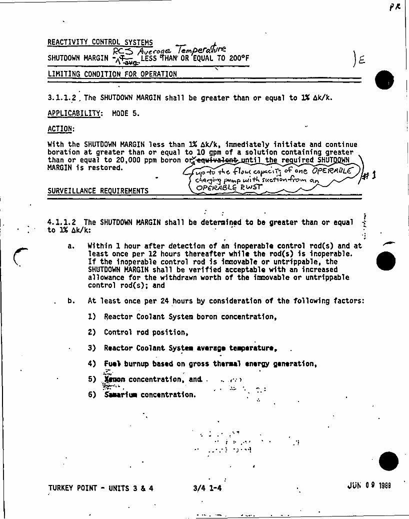
REACTIVITY CONTROL SYSTEMS
pc> uututptA 7tumpeiakpoSHUTDOWN MARGIN -p~ LESS fHAN'R EQUAL TO 200 F
LIMITING CONDITION FOR OPERATION
3. 1.1.2 . The SHUTDOWN MARGIN shall be greater than or equal to IX hk/k.
APPLICABILITY: MODE 5.
ACTION:
With the SHUTDOWN MARGIN less than 1X hk/k, immediately initiate and continueboration at greater than or equal to 1Q gpm of a solution containing greater
20, t p t'~ u t t ttMARGIN is restored. ~,~ ~~ go~ c p,c,V„- None, OpeeeeLC
t:IttttOiuIpump tttiN r«uaan4o u utttoF e~SLG @~M
SURVEILLANCE RE UIREMENTS
r4.1.1.2 The SHUTDOWN MARGIN shall be determined to be greater than or equalto 1X hk/k:
t
a. Within 1 hour after detection of an inoperable control rod(s) and atleast once per 12 hours thereafter while the rod(s) is inoperable.If the inoperable control rod is iaeovable or untrippable, theSHUTDOWN MARGIN shall be verified acceptable with an increasedallowance for the withdrawn worth of the iaaevable or untrippablecontrol rod(s); and
b. At least once per 24 hours by consideration of the following factors:
1) Reactor Coolant System boron concentration,
2) Control rod position,
3) Reactor Coolant Systea average temperature,
4) Fuei burnup based on gross thermal energy generation,
5) .Icon concentration, and..I
6) Saaarim concentration.
at
~ ~ u tj
TURKEY POINT" UNITS 3 4 4 3/4 1-4 JUN I 9 198|I
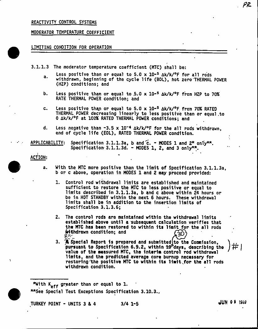
REACTIVITY CONTROL SYSTEMS
MODERATOR TEMPERATURE COEFFICIENT
LIMITING CONDITION FOR OPERATION
0
3.1.1.3 The moderator temperature coefficient (MTC) shall be:
Less positive than or equal to 5.0 x 10-s hk/k/ F for all rodswithdrawn, beginning of the cycle life (BOL), hot zero'THERMAL POWER(HZP) conditions; and
b. Less positive than or equal to .5.0 x 10- hk/k/ F from HZP to 70KRATE THERMAL POWER condition; and
c. Less positive thW or equal to 5.0 x 10- hk/k/ F from 70X RATEDTHERMAL POWER decreasing linearly to less positive than or equal.to0 hk/k/ F at 100K RATED THERMAL POWER conditions; and
d. Less negative than -3.5 x 10 ~ hk/k/oF for the all rods withdrawn,end of cycle life (EOL), RATED THERMAL POWER condition.
APPLICABILITY: Specification 3.1.1.3a, b and c. - MODES 1 and 2~ only*".Specification 3.1.1.3d. - MODES 1, 2, and 3 only**.
ACTION:
With the MTC more positive than the limit of Specification 3.1.1.3a,b or c above, operation in MODES 1 and 2 may proceed provided:
1. Control rod withdrawal limits are established and maintainedsufficient to restore the MTC to less positive or equal tolimits described in 3.1.1.3a, b and c above within 24 hours orbe in HOT STANDBY within the next 6 hours. These withdrawallimits shall be in addition to the insertion limits ofSpecification 3.1.3.6;
2. The control rods are maintained within the withdrawal limitsestablished above until a subsequent calculation verifies thatthe NTC has been restored to within fts limit for the all rods%6Chdrawn condition; and 30
3. 4 Special Report fs prepared and submitted to the Coaefssfon,pursuant to Specification 6.9.2, within %0 days, describing thevalue of the measured MTC, the fnterfm control rod withdrawallimits, and the predicted average core burnup necessary forrestoring the positive MTC to within fts lfaft,for the all rodswithdrawn condition.
TURKEY POINT - UNITS 3 4 4 3/4 1-5
'With K ff greater than or equal to 1.effe *"See Special Test Exceptions Specification 3.10.3.,
QQN 0 9 1968
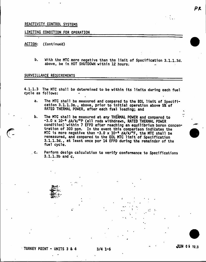
REACTIVITY CONTROL SYSTEMS
LIMITING CONDITION .FOR OPERATION
ACTION: (Continue'd)
b. With the MTC more negative than the limit of Specification 3.1.1.3d.above, be in HOT SHUTDOWN within 12 hours.
SURVEILLANCE RE UIREMENTS
4.1.1.3cycle as
aO
b.
, C.
The MTC shall be determined to be within its limits during each fuelfol 1 ows:
The MTC shall be measured and compared to the BOL limit of Specifi-cation 3.1.1.3a., above, prior to initial operation above SX ofRATED THERMAL POWER, after each fuel loading; and
The MTC shall be measured at any THERMAL POWER and compared to-3.0 x 10⁻⁴ hk/k/DF (all rods withdrawn, RATED THERMAL POWERcondition) within 7 EFPD after reaching an equilibrium boron concen-tration of 300 ppm. In the event this comparison indicates theMTC is more negative than -3.0 x 10-i hk/k/oF, the MTC shall beremeasured, and compared to the EOL MTC limit of Specification3.1.1.3d., at least once per 14 EFPD during the remainder of thefuel cycle.
Perform design calculation to verify conformance to Specifications3.1.1.3b and c.
'URKEY POINT - UNITS 3 8L 4 3/4 1-6 dUN Os ~s'.8
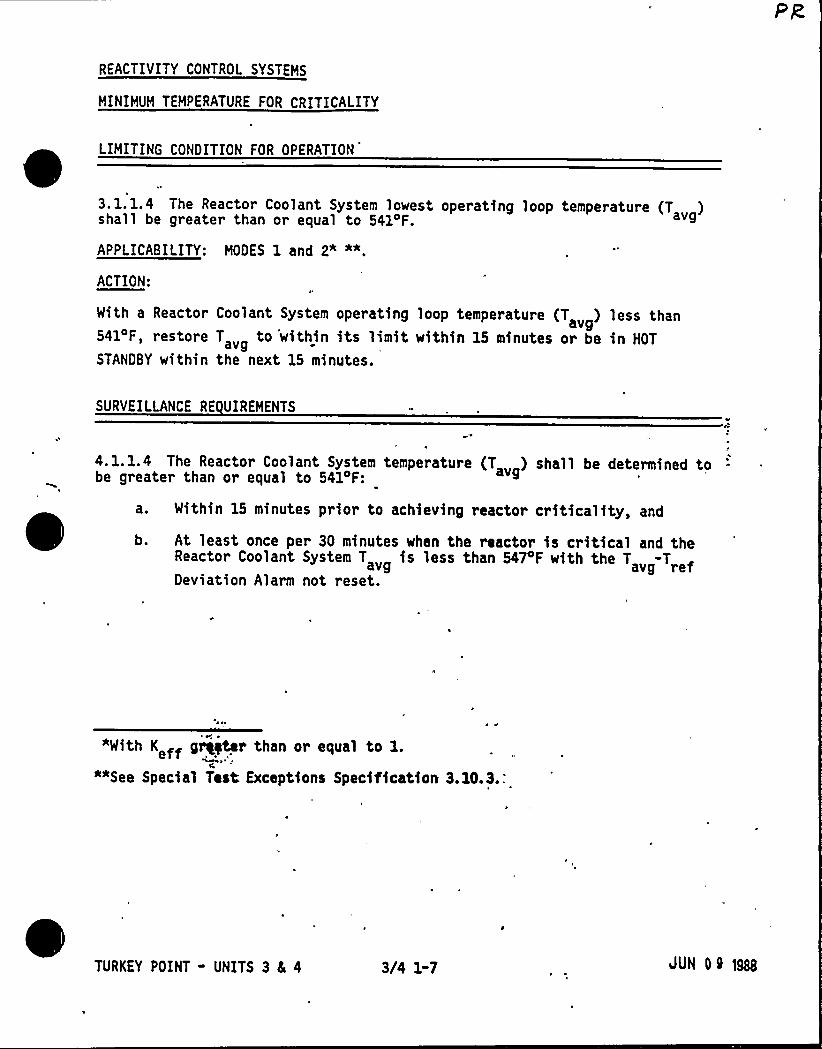
REACTIVITY CONTROL SYSTEMS
MINIMUM TEMPERATURE FOR CRITICALITY
LIMITING CONDITION FOR OPERATION
3. 1. 1.4 The Reactor Coolant System lowest operating loop temperature (T )shall be greater than or equal to 541 F. avg
APPLICABILITY: MODES 1 and 2" "".
ACTION:
With a Reactor Coolant System operating loop temperature (T ) less thanavg541'F, restore T „ to 'within its limit within 15 minutes or be in HOT
STANDBY within the next 15 minutes.
SURVEILLANCE RE UIREMENTS
04. 1.1.4 The Reactor Coolant System temperature (Tav ) shall be determined tobe greater than or equal to 541 F:
a. Within 15 minutes prior to achieving reactor criticality, and
b. At least once per 30 minutes when the reactor is critical and theReactor Coolant System T is less than 5474F with the T -T
avg refDeviation Alarm not reset.
"With K <f g~yter than or equal to 1.
""See Special Test Exceptions Specification 3.10.3.:
TURKEY POINT - UNITS 3 81 4 3/4 1-7 JUN 09 l988

REACTIVITY CONTROL SYSTEMS
3/4. 1. 2 BORATION SYSTEMS
FLOW PATH - SHUTDOWN
LIMITING CONDITION FOR OPERATION
3.1.2.1 As a minimum, one of the following boron injection flow paths shallbe OPERABLE and capab1e of being powered from an OPERABLE emergency powersource:
a. A flow path from the boric acid storage tanks via a boric acidtransfer pump and a charging pump to the Reactor Coolant System ifthe boric acid storage tank in Specification 3.1.2.5a. isOPERABLE, or
b. The f1ow path from the refueling water storage tank via a chargingpump to the Reactor Coolant System if the refueling water storagetank in Specification 3.1.2.5b. fs OPERABLE;
APPLICABILITY: MODES 5 and 6.
ACTION:
With none of the above flow paths OPERABLE or capable of being powered from an ~OPERABLE emergency power source, suspend all operations involving COREALTERATIONS or positive reactivity changes.
SURVEILLANCE RE UIREMENTS
4.1.2.1 At least one of the above 'required flow paths shall be demonstratedOPERABLE:
",7da 5 >
a. At least once per'. by verifying that the temperature of the /heat. traced portion of the flow path is greater than or equal to14 ' a flow path froa the boric acid inks is up/ and
~ g~c ~Echeb. A - 'nce. per 31 days by verifying that eactr>vive- nual,
p pirated, or autoeatic) in the flow. path tQt is not locked,sealed; or otherwise secured in position; is in its correctposition.
TURKEY POINT - UNITS 3 4 4 3/4 1-8 JUN 09 1II
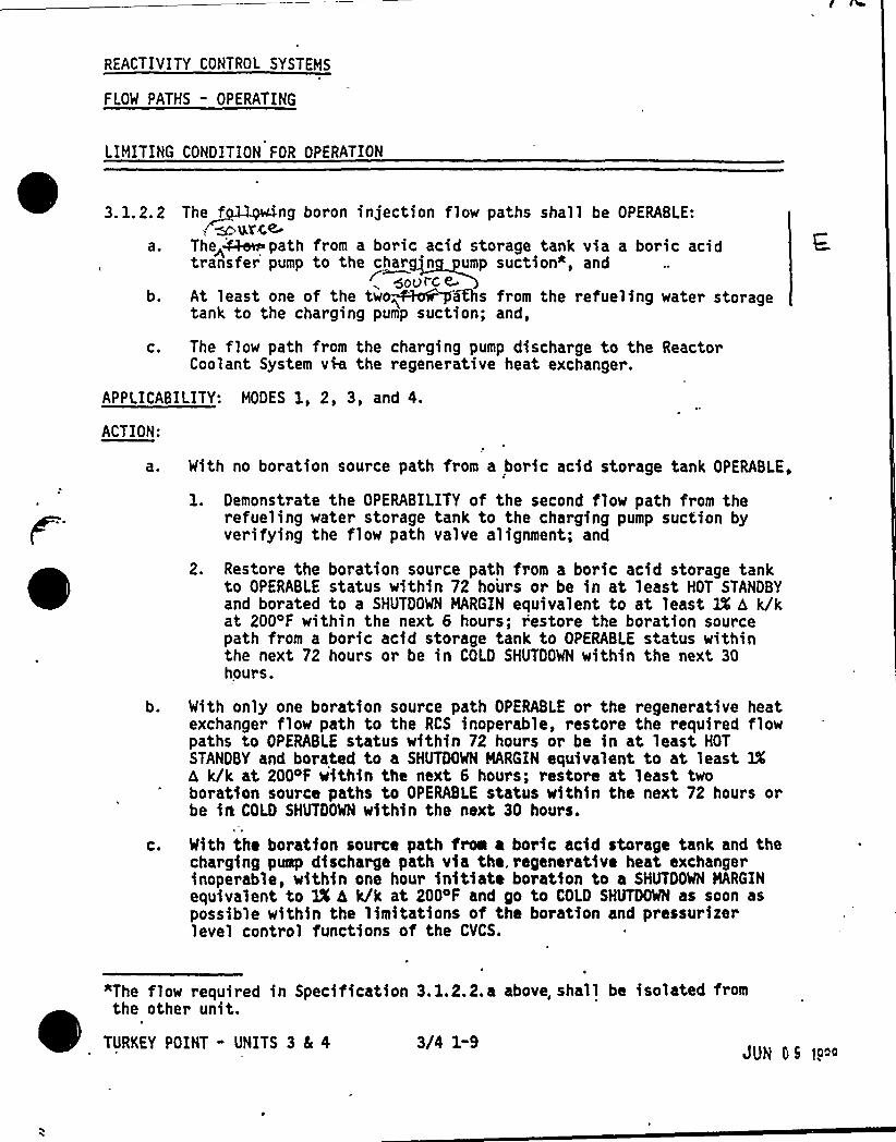
REACTIVITY CONTROL SYSTEMS
FLOW PATHS - OPERATING
LIMITING CONDITION FOR OPERATION
3. 1.2.2 The~f ing boron injection f1ow paths sha11 be OPERABLE:, ~urce-
a. The+~path from a boric acid storage tank via a boric acidtransfer pump to the charg n ump suction*, and
~ source.b. At least one of the two~+~a&s from the refueling water storage
tank to the charging pump suction; and,
c. , The flow path from the charging pump discharge to the ReactorCoolant System vie the regenerative heat exchanger.
APPLICABILITY: MODES 1, 2, 3, and 4.
ACTION:
a. With no boration source path from a boric acid storage tank OPERABLE,
1. Demonstrate the OPERABILITY of the second flow path from therefueling water storage tank to the charging pump suction byverifying the flow path valve alignment; and
2. Restore the boration source path from a boric acid storage tankto OPERABLE status within 72 hours or be in at least HOT STANDBYand borated to a SHUTDOWN MARGIN equivalent to at least lX h k/kat 200'F within the next 6 hours; r'estore the boration sourcepath from a boric acid storage tank to OPERABLE status withinthe next 72 hours or be in COLD SHUTDOWN within the next 30hours.
b. With only one boration source path OPERABLE or the regenerative heatexchanger flow path to the RCS inoperable, restore the required flowpaths to OPERABLE status within 72 hours or be in at least HOTSTANDBY and borated to a SHUTDOWN MARGIN equivalent to at least 3X6 k/k at 2004F within the next 6 hours; restore at least twoboration source paths to OPERABLE status within the next 72 hours orbe irt COlD SHUTDOWN within the next 30 hours.
c. With the boratfon source path froa a boric acid storage tank and thecharging pump discharge path via the, regenerative heat exchangerinoperable, within one hour initiate boration to a SHUTDOWN MARGINequivalent to 1% h k/k at 2004F and go to COLD SHUTDOWN as soon aspossible within the limitations of the boration and pressurizerlevel control functions of the CVCS.
"The flow required in Specification 3.1.2.2.a above, shall be isolated fromthe other unit.
TURKEY POINT - UNITS 3 5 4 3/4 1-9JUN 05 t9oo
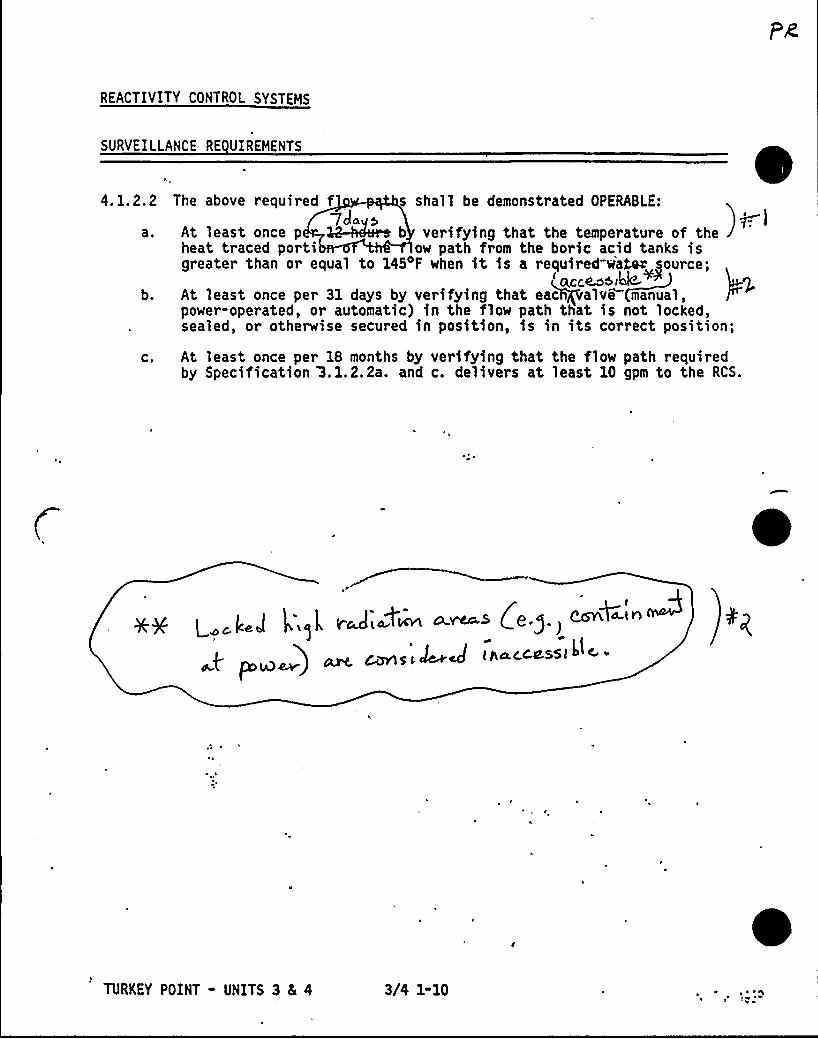
REACTIVITY CONTROL SYSTEMS
SURVEILLANCE RE UIREHENTS
4.1.2.2
a ~
b.
C.
The above required f s shall be demonstrated OPERABLE:
7Jag>At least once p ~~ b verifying that the temperature of theheat traced porti ow path from the boric acid tanks isgreater than or equal to 1454F when it is a re~uired wa~ source;
< acce.es i'd@+~At least once per 31 days by verifying that eacRPalve manual,power-operated, or automatic) in the flow path that is not locked,sealed, or otherwise secured in position, is in its correct position;
At least once per 18 months by verifying that the flow path requiredby Specification '3. 1.2.2a. and c. delivers at least 10 gpm to the RCS.
TURKEY POINT - UNITS 3 4 4 3/4 1-10
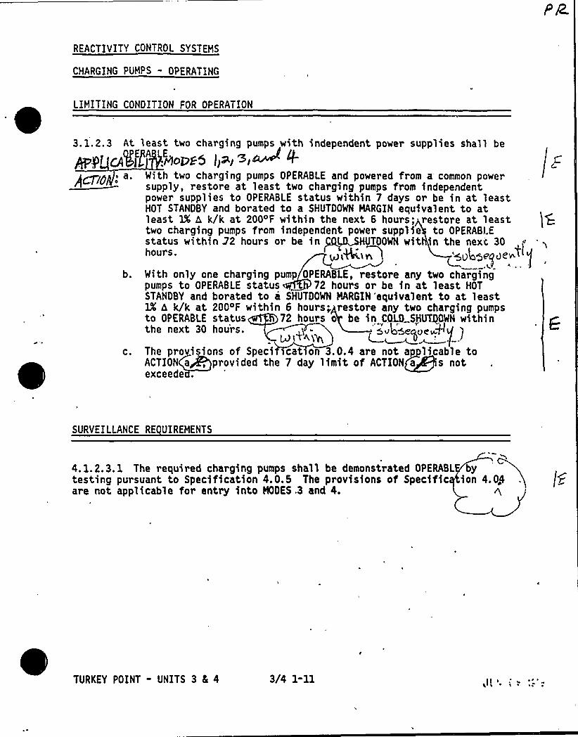
REACTIVITY CONTROL SYSTEMS
CHARGING PUMPS - OPERATING
LIMITING CONDITION FOR OPERATION
3.1.2.3 At least two charging pumps with independent power supplies shall be
~y age'" 'ni.mEPgs )i~i»~ +a. With two charging pumps OPERABI.E and powered from a common power
supply, restore at least two charging pumps from independentpower supplies to OPERABLE status within 7 days or be in at leastHOT STANDBY and borated to a SHUTDOWN MARGIN equivalent to atleast 1% 6 k/k at 200'f within the next 6 hours; restore at leasttwo charging pumps from independent power supplie to OPERABLEstatus within 22 hours or be in TDOWN wit in the next 30hours. ~ L'ttln 'sv4e~~e ~~<
b. With only one charging pump OPERABLE, restore any two chargingpumps to OPERABLE status 72 hours or be in at least HOTSTANDBY and borated to a SHUTDOWN MARGIN 'equivalent to at least1X h k/k at 200'F within 6 hours.„ restore any two charging pumpsto OPERABLE status 72 hours o be in COLD SH~GWN withinthe next 30 hours. Ou in6euuewd
c. The provisions of Speci cation 3.0.4 are not ap licable toACTION a, provided the 7 day limit of ACTION a s notexceede .
SURVEILLANCE RE UIREMENTS
4. 1.2.3.1 The required charging pumps shall be demonstrated OPERABL bytesting pursuant to Specification 4.0e5 The provisions of Specific ion 4.04are not applicable for entry into MODES .3 and 4. h,
TURKEY POINT - UNITS 3 Ec 4 3/4 1-11~ s
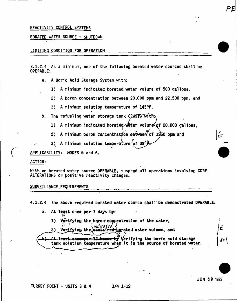
REACTIVITY CONTROL SYSTEMS
BORATEO WATER SOURCE - SHUTDOWN
LIMITING CONOITION FOR OPERATION
3. 1.2.4 As a minimum, one of the following borated water sources shall beOPERABLE:
a. A Boric Acid Storage System with:
1) A minimum indicated borated water volume of 500 gallons,
2) A boron concentration between 20,000 ppm and 22,500 ppm, and
3) A minimum solution temperature of 145 F.
b. The refueling water storage tank ( ST wAtt.
1) A minimum indicated borate'd. er volum f 20,000 gallons,
2) A minimum boron concentrat on ~of 1 0 ppm and
3) A minimum solution tempera re '-of 39o .
APPLICABILITY: MODES 5 and 6.
ACTION:
With no borated water source OPERABLE, suspend all operations involving COREALTERATIONS or positive reactivity changes.
I&
SURVEILLANCE RE UIREMENTS
4.1.2.4 The above required borated water source shall be demonstrated OPERABLE:
a. At least once per ? days by:
1) 4irifyinO the boron'concentration of the mater,Io)iwfcA
2 Ver inO the< rated water vol~, anda)
'tterifying the boric acid storagetank solution temperature whe it is the source of borated water.
TURKEY POINT - UNITS 3 8s 4 3/4 1-12JUN 09 1988
REACTIVITY CONTROL SYSTEHS-
SURVEILLANCE RE UIREMENTS Continued
By verifying the RWST temperature is above its iimit whenever theoutside air temperature is less than 394F at the followingfrequencies:
1) Within one hour when the outside temperature is below. 394F for23 consecutive hours, and
2) At least once per 24 hours when the outside temperature is below39 F.
TURKEY POINT - UNITS 3 5 4 , 3/4 1-13
JUN 09 )98&

REACTIVITY CONTROL SYSTEMS
BORATED WATER SOURCES - OPERATING
LIMITING CONDITION FOR OPERATION
3.1.2.5 The following borated water sources shall be OPERABLE:
a. A Boric Acid Storage System with:
1) A minimum indicated borated water volume of 3080 gallons,
2) A boron concentration between 20,000 ppm and 22,500 ppm, and
3) A minimum solution temperature of 145 F.
b. The refueling water storage tank (RWST) with:
1) A minimum indicated borated water volume of 320,000 gallons,
2) A minimum boron concentration of 1950 ppm,
3) A minimum solution temperature of 394F, and
4) A maximum solution temperature of 1004F.
APPLICABILITY: MODES 1, 2, 3, and 4.
ACTION:
a. With the required Boric Acid Storage System inoperable verify thatthe RWST is OPERABLE; restore the system to OPERABLE status within72 hours or be in at least HOT STANDBY within the next 6 hours andborated to a SHUTDOWN MARGIN equivalent to at least lX dk/k at 200'F;restore the Boric Acid Storage System to OPERABLE status within thenext 72 hours or be in COLD SHUTDOWN within the next 30 hours.
b. With the RWST inoperable, restore the tank to OPERABLE statuswithin 1 hour or be in at least HOT STANDBY within the next6 hours and in COLD SHUTDOWN within the following 30 hours.
TURKEY POINT - UNITS 3 4 4 3/4 1-14
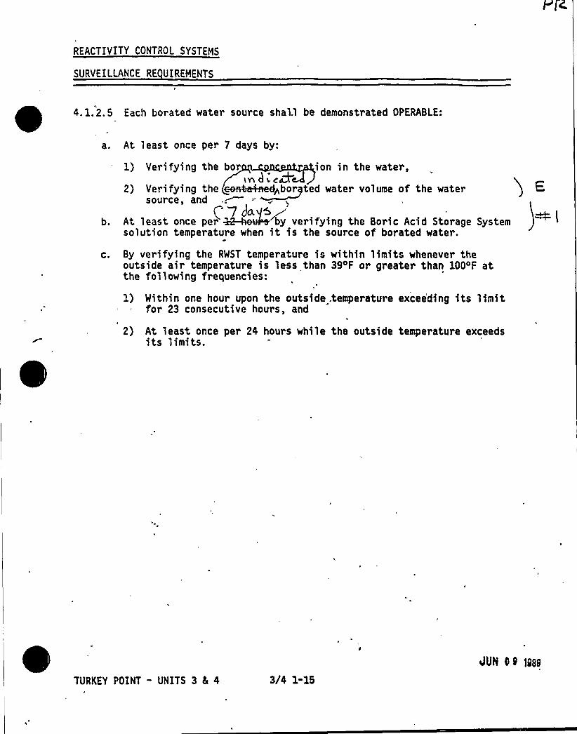
REACTIVITY CONTROL SYSTEHS
SURVEILLANCE RE UIREHENTS
4. 1.2.5 Each borated water source shal.l be demonstrated OPERABLE:
a. At least once per 7 days by:
b.
1) Verifying the bor ion in the water,LYl CI 1 CN
2) Verifying the ~Haed~bor ted water volume of the watersource, and
At least once per by verifying the Boric Acid Storage Systemsolution temperature when it is the source of borated water.
c. By verifying the RWST temperature is within limits whenever theoutside air temperature is less than 39~F or greater than 100'F atthe following frequencies:
1) Within one hour upon the outside .temperature excee'ding its limitfor 23 consecutive hours, and
2) At least once per 24 hours while the outside temperature exceedsits limits.
TURKEY POINT - UNITS 3 4 4 3/4 1-15
JUN OQ ]pap
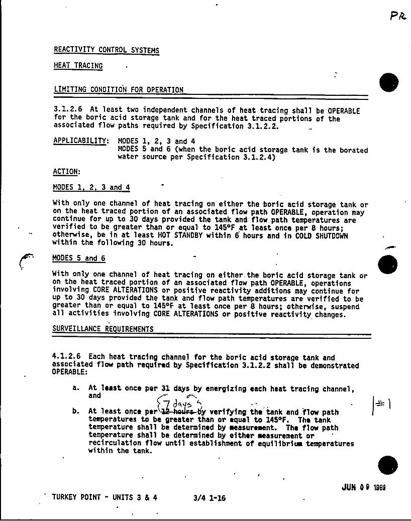
REACTIVITY CONTROL SYSTEMS
HEAT TRACING
LIMITING CONDITION FOR OPERATION
3.1.2.6 At least two independent channels of heat tracing shall be OPERABLEfor the boric acid storage tank and for the heat traced portions of theassociated flow paths required by Specification 3.1.2.2.
APPLICABILITY: MODES 1, 2, 3 and 4MODES 5 and 6 (when the boric acid storage tank is the boratedwater source per Specification 3.1.2.4)
ACTION:
MODES 1 2 3 and 4
With only one channel of heat tracing on either the boric acid storage tank oron the heat traced portion of an associated flow path OPERABLE, operation maycontinue for up to 30 days provided the tank and flow path temperatures areverified to be greater than or equal to 145 F at least once per 8 hours;otherwise, be in at least HOT STANDBY within 6 hours and in COLD SHUTDOWNwithin the following 30 hours.
MODES 5 and 6
With only one channel of heat tracing on either the boric acid storage tank oron the heat traced portion of an associated flow path OPERABLE, operationsinvolving CORE ALTERATIONS or positive reactivity additions may continue forup to 30 days provided the tank and flow path temperatures are verified to begreater than or equal to 1454F at least once per 8 hours; otherwise, suspendall activities involving CORE ALTERATIONS or positive reactivity changes.
SURVEILLANCE RE UIREMENTS
4.1.2.6 Each heat tracing channel for the boric acid storage tank andassociated flow path required by Specification 3.1.2.2 shall be demonstratedOPERABLE:
a. At least once per 31 days by energizing each heat tracing channel,and
b. At least once per y verifying the tank and flow pathtemperatures to be greater than or equal to 1454F. The tanktemperature shall be determined by measurement. The flow pathtemperature shall be determined by either measurement orrecirculation flow until establishment of equilibrim temperatureswithin the tank.
4TURKEY POINT - UNITS 3 4 4
k
3/4 1-16JUN 09 @8<
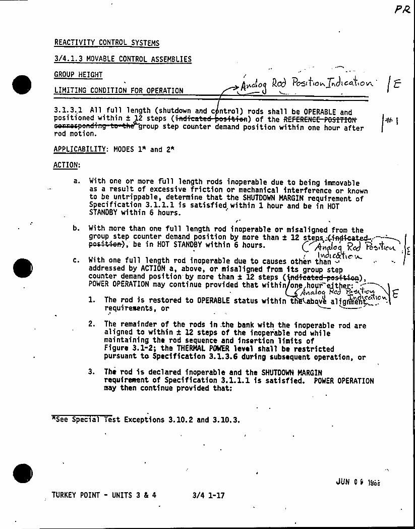
REACTIVITY CONTROL SYSTEMS
3/4.1.3 MOVABLE CONTROL ASSEMBLIES
GROUP HEIGHT
LIMITING CONDITION FOR OPERATION
/Pod(f'to33733clicttttotr,
'
3. 1.3. 1 All full length (shutdown and c ntrol) rods shall be OPERABLE andpositioned within + 12 steps (' of the
group step counter demand position within one hour afterrod motion.
APPLICABILITY: MODES 1" and 2*
ACTION:
With one or more full length rods inoperable due to being immovableas a result of excessive friction or mechanical interference or knownto be untrippable, determine that the SHUTDOWN MARGIN requirement ofSpecification 3. 1. 1.1 is satisfied within 1 hour and be in HOTSTANDBY within 6 hours.
b.
C.
With more than one full length rod inoperable or misaligned from thegroup step counter demand position by more than t 1lp steps,gieA'mated-;.~po~~),'e in HOT STANDBY within 6 hours. /~An loj Pg 'Pootto~, r
133 3 clgf'pe: 33.With one full length rod inoperable dua to causes other- than-addressed by ACTION a, above, or misaligned from its group stepcounter demand position by more than k 12 steps ( „),POWER OPERATION may continue provided that within on hogr ejthez:
1. The rod is restored to OPERABLE status within th bqv% aligkiWYi<.,„.requirements, or
2. The remainder of the rods in.the bank with the inoperable rod arealigned to within f 12 steps of the inoperable rod whilemaintaining the rod sequence and insertion limits ofFigure 3.1-2; the THERMAL POWER level shall be restrictedpursuant to Specification 3.1.3.6 during subsequent operation, or
3. The rod is declared inoperable and the SHUTDOWN MARGINrequirewtent of Specification 3.1.1.1 is satisfied. POWER OPERATIONmay then continue provided that:
~dp * 3 * 3 1 113.1 3 3.13.3.
TURKEY POINT - UNITS 3 8L 4 3/4 1-17
JUN 0 9 lanai
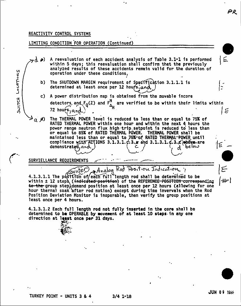
REACTIVITY CONTROL SYSTEMS
LIMITING CONDITION FOR OPERATION Continued
g m) A reevaluatfon of each accident analysfs of Tab'le 3.1-1 ls performedwithin 5 days; this reevaluation shall confirm that the previouslyanalyzed results of these accidents remain valid for the duration ofoperation under these conditions,
b) The SHUTDOWN MARGIN requirement of S citric tion 3.1.1.1 isdetermined at least once per 12 hou s ar4
c) A power distribution map is obtained from the movable incoredetectors and,F~(Z) and F are verified to be within their limits within( p i g72 hours>stroll /~
q*P) The THERMAL POWER level is reduced to less than or equal to 75% ofRATED THERMAL POWER within one hour and within the next 4 hours thepower range neutron flux high trip.setpoint is reduced to less thanor equal to 85'f RATED THERMAL POWER. THERMAL POWER shall bemaintained less than or equal to ~f RATED THENQ~tIWER untilcompliance w TONS 3.1.3.1.ci3.m' d 3.1.3.1.4.3.d'I aredemonstrat a~&. ( c. l g beo~u
SURVIELLANCE RE UIREMENTS
p „afo~ g +eLt om X ice'f crt ')
4.1.3.1.1 The p n of eac full length rod shall be determined to bewithin + 12 step ( ) of the ml4e &e-group step demand position at least once per 12 hours (allowing for onehour thermal soak fter rod motion) except during time invervals when the RodPosition Deviation Monitor is inoperable, then verify the group positions atleast once per 4 hours.
4.1.3.1.2 Each full length rod not fully inserted in the core shall bedetermined to be OPERABLE by movement of at least 10 steps.in any onedirection at least once ptr 31 days.
+%2.> ~
0TURKEY POINT - UNITS 3 Cs 4 3/4 1-18
JUN 01 ice~
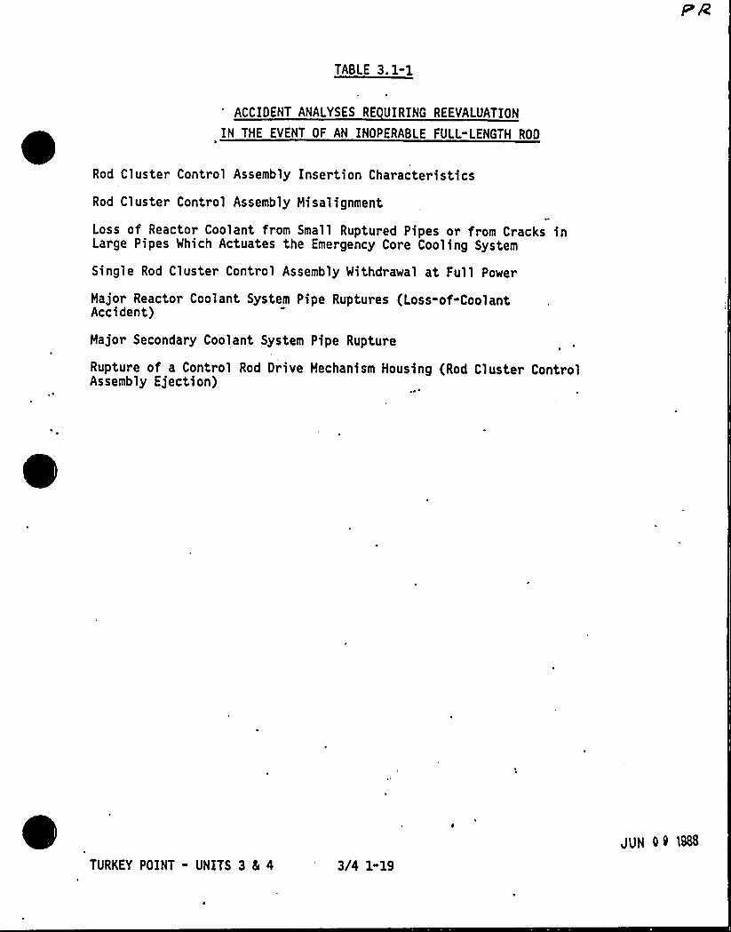
TABLE 3.1-1
ACCIDENT ANALYSES RE UIRING REEVALUATION
IN THE EVENT OF AN INOPERABLE FULL-LENGTH ROD
Rod Cluster Control Assembly Insertion Characteristics
Rod Cluster Control Assembly Misalignment
Loss of Reactor Coolant from Small Ruptured Pipes or from Cracks inLarge Pipes Which Actuates the Emergency Core Cooling System
Single Rod Cluster Control Assembly Withdrawal at Full Power
Major Reactor Coolant System Pipe Ruptures (Loss-of-CoolantAccident)
Major Secondary Coolant System Pipe Rupture
Rupture of a Control Rod Drive Mechanism Housing (Rod Cluster ControlAssembly Ejection)
TURKEY POINT - UNITS 3 81 4 3/4 1-19
JUN Q Q 1888
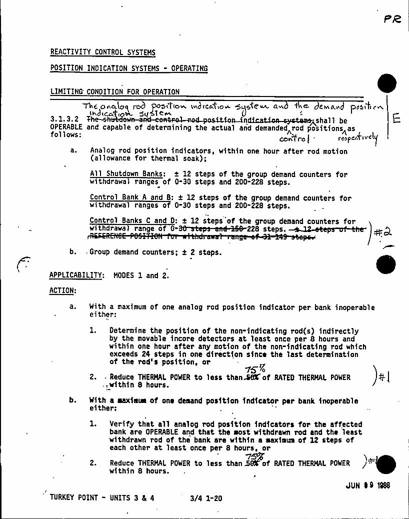
REACTIVITY CONTROL SYSTEMS
POSITION INDICATION SYSTEMS - OPERATING
LIMITING'ONDITIONFOR OPERATION
mg o<aJcg rob Po>Lt(a~ Lwhtc44Lo~ +g4c'~ ~ f ~ dl~A,~ pcsLfLc~L~ I ~ 5VCle U3.1.3.2 n shall be
OPERABLE and capable of determining the actual and demanded rod positions<asfollows:
a. Analog rod position indicators, within one hour after rod motion(allowance for thermal soak);
All Shutdown Banks: + 12 steps of the group demand counters forwithdrawal ranges of 0-30 steps and 200-228 steps.
Control Bank A and B: k 12 steps of the group demand counters forwithdrawal ranges of 0-30 steps and 200-228 steps.
Control Banks C and 0: + 12 steps of the group demand counters for.~228 p .
b. . Group demand counters; k 2 steps.
APPLICABILITY: MODES 1 and 2.
ACTION:
With a maximum of one analog rod position indicator per bank inoperableeither:
1. Determine the position of the non-indicating rod(s) indirectlyby the movable incore detectors at least once per 8 hours andwithin one hour after any motion of the non-indicating rod whichexceeds 24 steps in one diriction since the last determinationof the rod's position, or
UFO2. . Reduce THERMAL POWER to less than~ of RATED THERMAL POWER
. within 8 hours.
b. With a maximum of one demand position indicator per bank inoperableeither:
l. Verify that all analog rod position indicators for the affectedbank are OPERABLE and that the most withdrawn rod and the leastwithdrawn rod of thi bank are within a maximum of 12 steps ofeach other at least once per 8 hours, or
vsr2. Reduce THERMAL POWER to less than 59K'f RATED THERMAL POWER
within 8 hours.
JUN I9 1988
TURKEY POINT - UNITS 3 8L 4 3/4 1-20
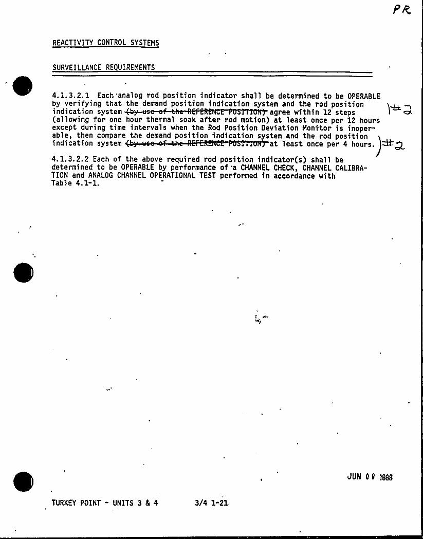
REACTIVITY CONTROL SYSTEMS
SURVEILLANCE RE UIREMENTS
4, 1.3.2. 1 Each'analog rod position indicator shall be determined to be OPERABLEby verifying that the demand position indication system and the rod positionindication system agree within 12 steps(allowing for one hour thermal soak after rod motion) at least once per 12 hoursexcept during time intervals when the Rod Position Deviation Monitor is inoper-able, then compare the demand position indication system and the rod positionindication system at least once per 4 hours.
4. 1. 3. 2, 2 Each of the above required rod position indicator(s) shall bedetermined to be OPERABLE by performance of a CHANNEL CHECK, CHANNEL CALIBRA-TION and ANALOG CHANNEL OPERATIONAL TEST performed in accordance withTable 4.1-1.
vtmsp
JUN 09 gals
TURKEY POINT - UNITS 3 8c 41
3/4 1-21
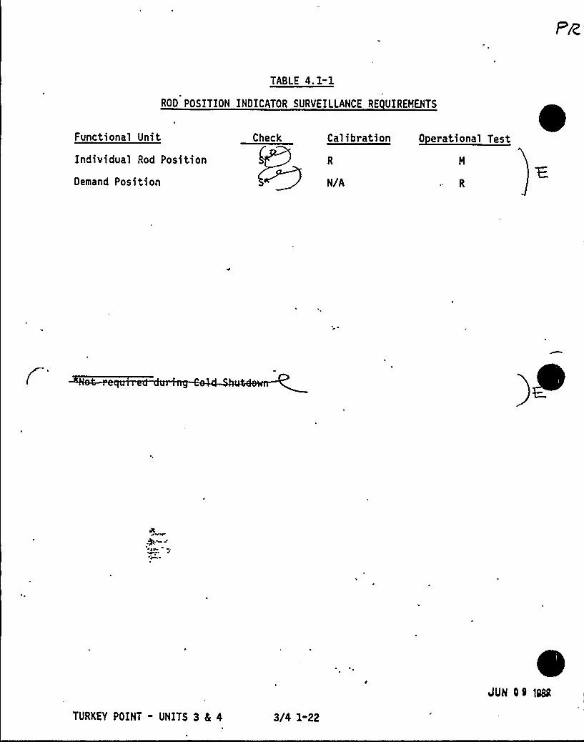
TABLE 4.1-1
ROD POSITION INDICATOR SURVEILLANCE RE UIREHENTS
Functional Unit
Individual Rod Position
Demand Position
Check C lib l ~CT T
N/A
TURKEY POINT - UNITS 3 4 4 3/4 1-22
VuN O9 >sea
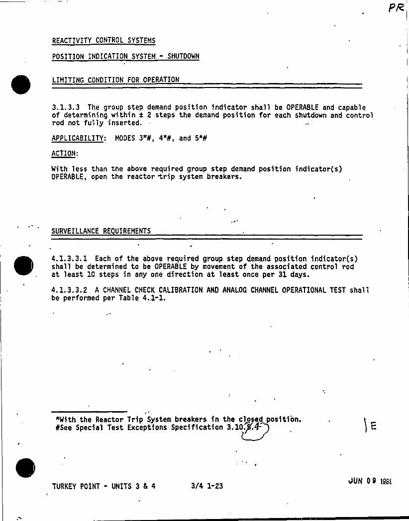
PR
REACTIVITY CONTROL SYSTEMS
POSITION INDICATION SYSTEM - SHUTDOWN
LIMITING CONDITION FOR OPERATION
3. 1.3.3 The group step demand position indicator shall be OPERABLE and capableof determining within i 2 steps the demand position for each shutdown and controlrod not fully inserted.
APPLICABILITY: MODES 3"8, 4*8, and '5*8
ACTION:
With less than the above required group step demand position indicator(s)OPERABLE, open the reactor <rip system breakers.
SURVEILLANCE RE UIREMENTS
4, 1.3.3. 1 Each of the above required group step demand position indicator(s)~ ~ ~ ~
~
~shall be determined to be OPERABLE by movement of the associated control rodat least 10 steps in any one direction at least once per 31 days.
4. 1.3,3.2 A CHANNEL CHECK CALIBRATION AND ANALOG CHANNEL OPERATIONAL TEST shallbe performed per Table 4. 1-1.
"With the Reactor Trip System breakers in the closed position.SSee Special Test Exceptions Specification 3.10. .+
TURKEY POINT - UNITS 3 4 4 3/4 1-23 JUN 09 lg><
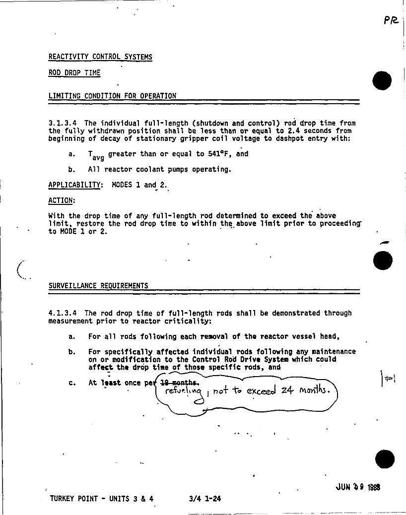
REACTIVITY CONTROL SYSTEMS
ROD DROP TIME
LIMITING CONDITION FOR OPERATIONe
3. 1.3.4 The individual full"length (shutdown and control) rod drop time fromthe fully withdrawn position shall be less than or equal to 2.4 seconds frombeginning of decay of stationary gripper coil voltage to dashpot entry with:
a. T greater than or equal to 541DF, andavg
b. All reactor coolant pumps operating.
APPLICABILITY: MODES 1 and 2.
ACTION:
With the drop time of any full-length rod determined to exceed the abovelimit, restore the rod drop time to within the above limit prior to proceedingto MODE 1 or 2.
SURVEILLANCE RE UIREMENTS
4. 1.3.4 The rod drop time of full-length rods shall be demonstrated throughmeasurement prior to reactor criticality:
b.
C.
For all rods following each removal of the reactor vessel head,
For specifically affected individual rods following any maintenanceon or modification to the Control Rod Drive System which couldaffect the drop time of those specific rods, and
At least once pe ~oaths.refocliop
L
rook to e~ Z4 OLOnl4 ~
TURKEY POINT - UNITS 3 SL 4 3/4 1-24
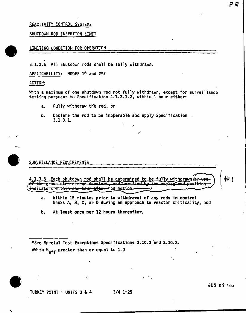
REACTIVITY CONTROL SYSTEMS
SHUTDOWN ROD INSERTION LIMIT
LIMITING CONDITION FOR OPERATION
3. 1.3.5 All shutdown rods shall be fully withdrawn.
APPLICABILITY: MODES 1" and 2"8
ACTION:
With a maximum of one shutdown rod not fully withdrawn, except for surveillancetesting pursuant to Specification 4.1.3.1.2, within 1 hour either:
a. Fully withdraw the rod, or
b. Declare the rod to be inoperable and apply Specification3. 1.3. l.
SURVEILLANCE RE UIREHENTS
4. 1 3 5 Ea h shutdo rod sh ll be determi'ne to b 11 withdrawn;~~
a. Within 15 minutes prior to withdrawal of any rods in controlbanks A, 8, C, or D during an approach to reactor criticality, and
b. At least once per 12 hours thereafter.
*See Special Test Exceptions Specifications 3.10.2 and 3.10.3.IIWith K ff greater than or equal to 1 . 0
TURKEY POINT - UNITS 3 8 4 3l'4 1-254UN 0 9 1888
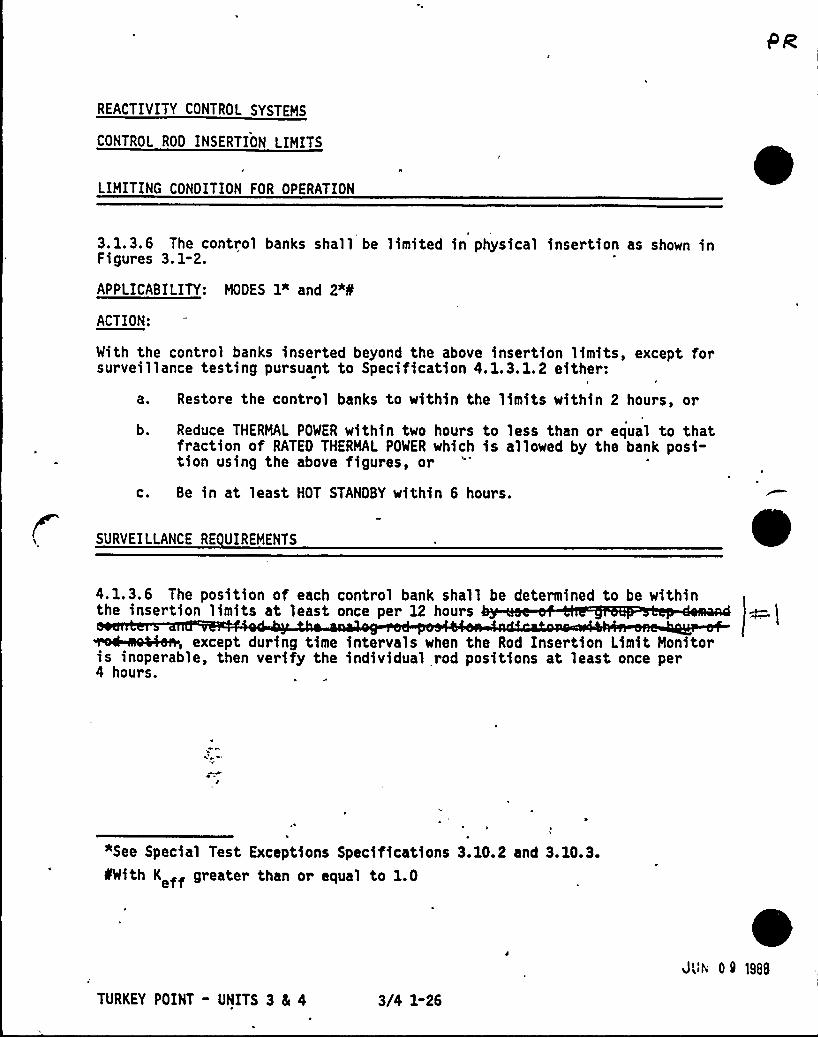
REACTIVITY CONTROL SYSTEMS
CONTROL ROD INSERTION LIMITS
LIMITING CONDITION FOR OPERATION0
3. l. 3. 6 The control banks shall be limited in physical insertion as shown inFigures 3. 1-2.
APPLICABILITY: MODES 1* and 2"8
ACTION:
With the control banks inserted beyond the above insertion limits, except forsurveillance testing pursuant to Specification 4.1.3.1.2 either:
l d
a. Restore the control banks to within the limits within 2 hours, or
b. Reduce THERMAL POWER within two hours to less than or equal to thatfraction of RATED THERMAL POWER which is allowed by the bank posi-tion using the above figures, or
c. Be in at least HOT STANDBY within 6 hours.
SURVEILLANCE RE UIREMENTS
4.1.3.6 The position of each control bank shall be determined to be withinthe insertion limits at least once per 12 hours
d ig l i 1 dg ddt l ill gis inoperable, then verify the individual rod positions at least once per4 hours.
"See Special Test Exceptions Specifications 3.10.2 and 3.10.3.4Wth K ff greater than or equal to 1.0eff
0J:,'t 09 1988
TURKEY POINT - UNITS 3 8c 4 3/4 1-26
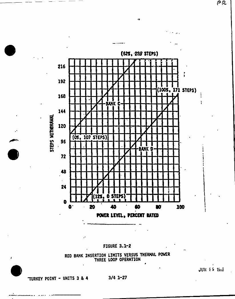
215
192
(lS, Sn SnPS)
ace c
120
(OS, 1O7 S>ESS)
72
24
0'ltS. 0 SmrS)
40 '0~OWN LKNLo tQCNT NT
FIGURE 3.1-2
ROD BANK INSERTION LIMITS VERSUS THERMAL POWER
THREE LOOP OPERATION
TURKEY POINT - UNITS 3 5 4 3/4 NVJVN ( S 5--

/ ~tS VGA +- i w,~ v V <Qwo.~ai w
'I .t
3/4. 2 POWER DISTRIBUTION LIMITS
3/4.2.1 AXIAL FLUX DIFFERENCE
LIMITING CONDITION FOR OPERATION
3.2. 1 The indicated AXIAL FLUX DIFFERENCE (AFD) shall be maintained withina t 5X target band (flux difference units) about the target flux difference.
The indicated AFD may deviate outside the above required target band at greaterthan or equal to 50K but less than 90K of RATED THERMAL POWER provided the indi-cated AFD is within the Acceptable Operation Limits of Figure 3.2-1 and the cumu-lative penalty deviation time does not exceed 1 hour during the previous 24 hours.
The indicated AFD may deviate outside the above required target band at greaterthan 15K but less than 50K of RATED THERMAL POWER provided the cumulativepenalty deviation time does not exceed 1 hour during the previous 24 hours.
APPLICABILITY: MODE 1, above lSX of RATED THERMAL POWER."
ACTION:
'a ~
b.
With the indicated AFD outside of the above required target band andwith THERMAL POWER greater than or equal to 90'f RATED THERMALPOWER, within 15 minutes either:
1. Restore the indicated AFD to within the target band limits, or
2. Reduce THERMAL'OWER to less than 90K of RATED THERMAL POWER.
With the indicated AFD outside of the above required target band formore than 1 hour of cumulative penalty deviation time during theprevious 24 hours or outside the Acceptable Operation Limits ofFigure 3.2-1 and with THERMAL POWER less than 90X but equal to orgreater than 50K of RATED THERMAL POWER:
1. Reduce THERMAL POWER to less than 50K of RATED THERMAL POWER
within 30,minutes, and
2. Reduce the Power Range Neutron Flux~ "" - High Trip Setpoints toless than or equal to 55K of RATED THERMAL POWER within the next4 hours.
"See Special Test Exceptions Specification 3.10.2.Surveillance testing of the Power Range Neutron Flux Channels may be performedpursuant to Specification 4.3.1.1 provided the indicated AFD is maintained withinthe Acceptable Operation Limits of Figure 3.2-1. A total of 16 hours operationmay be accumulated with the AFD outside of the above required target band duringtesting without penalty deviation.
, TURKEY POINT - UNITS'3 4 4 3/4 2-1J:.', ~:988
AJd Coue gg W <Z.l.(.a. Z)
*Qv )Qr ~a~(.Q,PqI'~i«TVos@ qI ri.,
c ~e4 to ~0 Ac We <VA m g I e.Sa &SviTu+e2 Qn +Lie Wgc i~mgv t.
POWER DISTR!BUTION LIMITS
LIMITING CONDITION FOR OPERATION Continued
ACTION Continued
c. With the indicated AFD outside of the above required target band formore than 1 hour of cumulative penalty deviation time during theprevious 24 hours and with THERMAL POWER less than 50X but greaterthan 15'f RATED THERMAL POWER, the THERMAL POWER shall not be
'ncreasedequal to or greater than 50K of RATED THERMAL POWER untilthe indicated AFD is within the above required target band.
SURVEILLANCE RE UIREMENTS
4.2. l. 1 The indicated AFO shall be determined to be within its limits duringPOWER OPERATION above 15X of RATED THERMAL POWER by:
a. Monitoring the indicated AFO for each OPERABLE excore channel:
1) At least once per 7 days when the alarm used to monitor the AFQ:is OPERABLE, and
r
2) At least once per hour for the first ~ hours~after ~toringthe alarm used to monitor the AFD to OPERABLE statu
b. Monitoring and logging the indicated AFD for each OPERABLE excorechannel at least once per hour for the first 24 hours and at leastonce per 30 minutes thereafter, when the alarm used to monitor theAFO is inoperable. The logged values of the indicated AFO shall beassumed to exist during the interval preceding each logging.
4.2. 1.2 The indicated AFD shall be considered outside of its target band whentwo or more OPERABLE excore channels are indicating the AFD to be outside thetarget band. Penalty deviation outside of the above required target band shallbe accumulated on a time basis of:
a. One minute penalty deviation for each 1 minute of POWER OPERATIONoutside of the target band at THERMAL POWER levels equal to or above5~of RATED THERMAL POWER, and
b. One~if minute penalty deviation for each 1 minute of POWER OPERATIONoutside of the target band at THERMAL POWER levels between -15K and50K of RATED THERMAL POWER.
4.2.1.3 The target flux difference of each OPERABLE excore channel shall be..determined by measurement at least once per 92 Effective Full Power Days.The provisions of Specification 4.0.4 are not applicable.
4.2.,1.4 The target flux difference shall be updated at least once per31 Effective Full Power Days by either determining the target flux differencepursuant to Specification 4.2. 1.3 above or by linear interpolation between themost recently measured value and the predicted value at the end of the cyclelife. The provisions of Specification 4.0.4 are not applicable.
TURKEY POINT - UNITS 3 8L 4 3/4 2-2
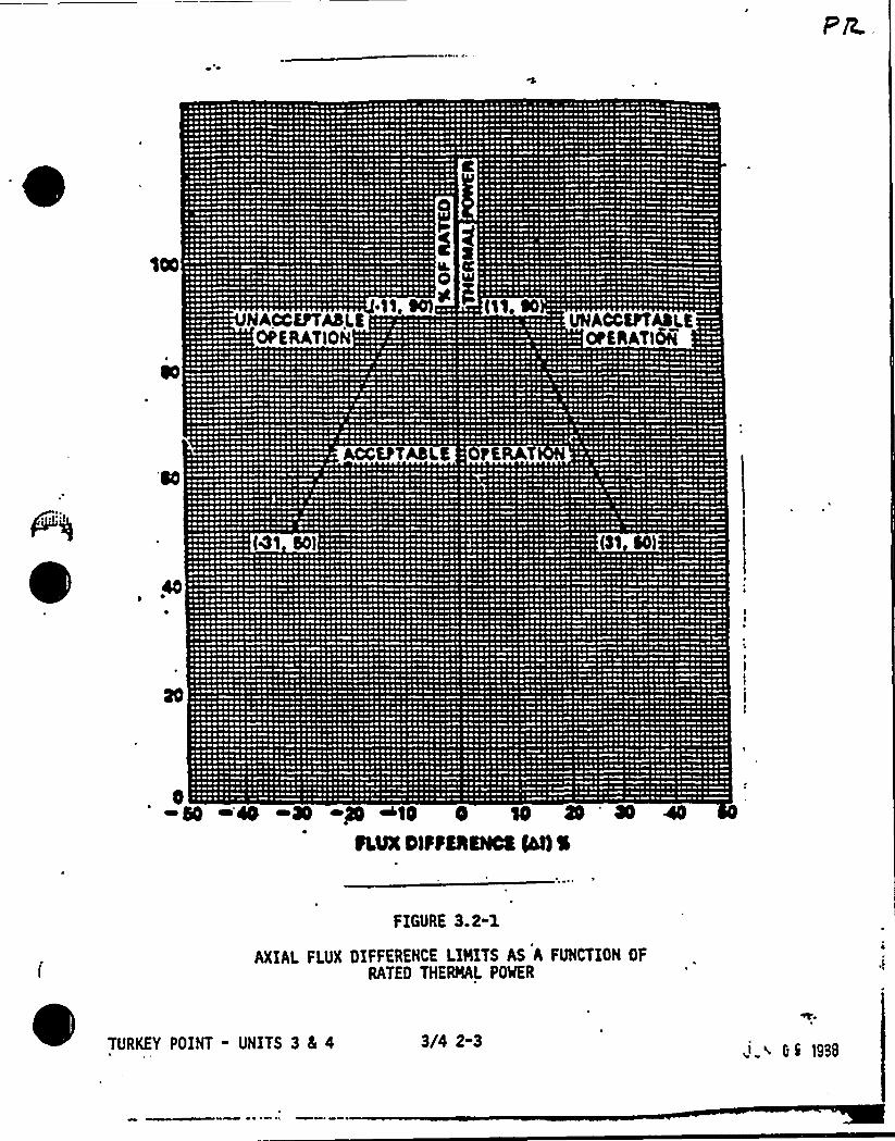
~ 0010000 011 10100100 I ~ ~ I ~ 04 ~ I~ R ~
~ ~ 0000010000 0«00000 00 10 00 010 I ~ H ~ 4~ 0 ~ ~ 10~ 00 00 I~ ~ 0 ~ 0~ ~ I~ 0011 I 0«~ «0000 ~ 00 ~ I I 0010 0001 1 00 ~ ~ 0 ~ ~ ~ 1 ~ 00I 00 ~ ~ I~ ~ 010 I ~~ 0000000 00$ 000100 0 000 I I~ ~ 0 ~ I 0« ~
~ 010 I 00I00 ~ II N ~ 10 I~ II~ 00 H 00 00 1st ~ I I « ~ ~ ~ I I ~ I ~
~ ~ 00 1st 0000 ~ ~ 0000 Iftsoat 00 101000000000 001001000 I I I ~ I~ I ~ ~ ~ ~ 000 Isttra« II I 10 IIPI~ I 000000 00 I ~ sstttt Its sttrsstP ~ I~ 00 I 000«0 ~ ~ 1 ~ 10Rt ~ I~ 00 000 $ ~~ 0 0000 1st 0000 0000001 00 ~ 000000 00000 Iss ~ sstssetssstttstt ~ 1«000 t $ 01« 1st ~ I ~00 IIII« ~ IQ ~ Q ~ ~ ~ ~ I»I I Ps 1st I« 000 1st Ists« tslt Ss N 0~ I II I ~ ~ I ~ ~ ~ II I 10 ~ 00 I I ~ I » ~
~ 00 ~ ~ I~ OttO ~ 11 Rst«00 ~ I~ Of0»0 ~ 11 ~ 1st ~ Is ~ ~ I ~ I~ I~ I~ ~ I ~ »~ ~ ~ 00 ~ It 0000 ~ \ ~ ~ 0«00 I I 11 00 ~ I ~ 00 ~ I ~ 00 «0
0 I 0 00 ~ 0 0 ~ ~ ~ I 10 ~ 001 1101100 00010 00«0 I~ I I~ 10 ~ I 0Q 0 I
10 I I ~ It I I ~ I~ 0 ~ 0 0I 000 0 0000000 00 ~ I 0 ~ 00 00 0000M 0 0 0~ 00 100000« ~ 0 00 ~ 0 ~ 01 ~ ~ \ 00 ~ 0001» 0 ~ 0 \ 00 ~ ~ 00 ~ 00I 00001 St I 110 N ~ N 1 I 00 ~ I~I»00 000 I 1st I~ I I I~ H I0000»10 ~ 0000 ~ 00 I I I ~ 10 I N 110~ 00000000«0 ~ 00$ 11 ol 11 asst~ ~ I~ 004000000000 000000 ~ 10 ~ I I 00 I
0 100000 ~ 1st 0»000 00 ~ 1st 00 1st~ 0 \ 0000»I \ ~ I 1st \00 001\00000$ ON ~ I I ~ I ~ 00 «I 0«1000000000 ~ IOINI~ 00«0001 I 00» I 1st ~ 01000 ~ 0004110 1st ~ 1st 1st 0 ~ 00 010 00 ~«0000000»0» N ~ I « ' 0000 \I 4 IPH
~ ~ ~ 00 I» 0 ~ I~ 1st ~ I I I~ 00 ~ ~ I ~ 00000 1st ~ 10 ~ I 0100 ~ ~ I~ 00 1st I~ 10 I~ 0 ~ ~ 0000000100$ I~ ~ 1st 0000 ~ 0«0400 1st~ 00 ~ 00 ~ 0000000000110 ~ Orts ~ I 00 ~ 1st 00000«0 011PIII er ~ 0100 0000 ~ 0000 H ~
~ I 11 10 00 ~ 1 NI N
I I~ ~ ~ I~ 10 ~ I» ~ I ~ 01 I~ I I 00 I~ ~ ~~ I 01 rr ~1st 00 ~ ~ 0 4 10 ~ 00 000 1st~ ~ ~ e I~ 00 ~ QI ~ 10 ~ Q ~~ I 1 I Q ~ ~ 0« ' ~ 1«0 I I It~ 00 0 Q I ' ~ ~ I~HHr I ~ I
~ I I I tOOt 1st ~I 0 I ~ I~ 1 ~ 0000~ ~ 00»rt ~ ~ ~ ~ Ittrt I I~ 00 ~ 010 ~ H I~ N
0 I ~ I ~ I 10 INtt I IPI Nt I ~ 00 000~ 00 0 0 ~ \ ~I Oa ~ 00 ~ t«
0 \ ~ 00 ~ ~ 11 ~ IHR ~ \ I Q «I~ \ \ I 10 0 IH 00~«000 I ~ ~
0 0 ~ ~ ~ ~ \ ~INI N 00100 ~ ~ I00 0 ~ ~ 10 ~I~ \ ~ 0«0 0 ~ IH ~0 $ 1»01 ~ ~ I 000 IR 00 10«00 ~ \
~ 0 11104 ~ 004 Pt 0 ~ ~ I I«~ ~ Nos P ~ ~
~ ~ 000»000 000000 ~ 000100001 00 \ ~ KH~. 0000 ~ ~ a001000\aa«~ ~ I~ ~ ~ 1st ~ I ~
000~ 0 10010001 0 ~ P ~ OOO~ I~I 0 ~
~I 1stI 100 I0
~ 04000~ 000HO
~ I t»«1 ~ ~~ «ISIS IP
~'
~~~ P ~ ~ ~ ~ I ~ ~~ \ ~ ~ 1«r tt ~ ~ 00 ~ 0 ~
Ir 410 I Isel 000«0 « ortsI I 01 I 0040 ~0000 $$ 10 0 I 10 04~ 00 Sttsts H «1~ I~ I 4000000 0001I 00 ~ 0«0001 Ios 0 01$ \'Ps 400 IN
~ \ ~ ~0 \ I 00 ~ I ~ $ 0 ~ 100I I I 00 ~ ~ I I ~ IRI
sf ~ ~ 01 04 I~ Issssssrss Irs rs ~ 400 I~ ~ 00 ~ f100 ~ Isssots ~10000 00\01010 ~ ~ 10010 ~ 0 ~ I 4000000 00010~ 00 0O0010001$ ~ 00011 ~ 0 ~ 0@O100 ~ 0 OP I 00 ~ SOS@«ts»10 «IPI 00 ttat ~ 00$004«H «I II I I ~
I 00$ ~ 00 'I ~ ~ ~ 1 ~ ~ I» OINI~ 4 \00000 I 00 ~ I ~ I ~ ~ 0 4 I ~ I I' H ~ 00001 ts 0$ ss IIN I I I~ »I~ I R s~ ~ «0 ~ ~
10111IIOIIP I $0«II~ 0400 ~ Is 41 10 ~ ~ I ~ IQ OOOO I I~ Qt ~ ~ I ~ ~ ~ ~ ~ ~ ~ ~0\SISIII Psssss 0$ 00000N 0400 ~ I 00 ~ 0 00 0 00 0000 Qt 'I ~ ~ ~ ~ 10 ~ ~ ~ 010» ~~ 01 0« \ 01 1st ~ I~SR I NIP \ 00 I ~ ~ ~ IN ~ ~ R 0« ~sssessse«PI I ISP0000001\00 400 ~ t«sste 00 101$ 1100000 01 ~ I~ ~ 000 ~ ~ ~ t 01 ~ ~ ~ I~ 00 $ 1 S«IIP OOOO 001 Hsts«40 ~ IN I\~ ~ ~ \ 00 I ~ Q ~ 004 ~ 11 ~ I I ~ ~ ~ ~~ 00 001110101IIIIIH\Pt 0 I »000 ~ ~ I'4 N»040 Ises ~ 10 001%0 00 \ ~ ~ W 1 ~«QIOOSIOIPO0000000 0 ~ 00$ $00 H I ~ ~ ~ 0 ~ 0 ~ ~ ~ ~ 1 1 ~Q Q Q ~I I I 01 I I I PIP I ~ ~ ~ ~ ~ 10 ~ 4 ~I I esss P0000$ 00 INIH40000 ~ I ~ ~ Ns ~ I I I~ ~ ~ ~ 000 04 01 R ~ I~ IRetl0»00101 01000NOP «000 ~ I~ ~ ~ 0 ~ ~ ~ ~ ~ I ~ 011 ~ ~ ~ ~ ~ ~ ~ ~ ~
~ ra ~ ~ ~ Ci 001 Ir ~ 01 ~ 1 ~100101001000000000 0110 ~ ~ I I I~ ~ ~ ~ I\~ ~ 0Isssssessotess 000000«00$ Is «00 OOOO «I
00$»4$ 100$ 0$ 1000000001 4001$ 000$ 00ets ~ I~ I sets«4IIIIIP00$100000 ~ 11 ~ 00~ 010000 11 I ~ I~ I~ 0 I~ I
~I400 4 ~ I ~ IR ~ I4 I 0 I I
0 sl Q ~ ~ I ~ IR ~ ~~ ~~ I R I ~ ~ I ~ Ip ~ ~
~ ~ tel N ~ ~ ~ ~ 101 ~ I 1 ~ ~ 01 ~ 11 4 ~P«0 I I~ ~ 00 t ~ ONO P M «0I~ I 0 I X ~ I I~ I ~ ~~ 0 ~ ~ 0 0 ~ 00 Pr ~ I ~ ttsttP14$ INQ ~ ~ ~ R ~ ~Qta ~ ~ PPP I ~ It ~ 1 P Pss s 10 ~Ht~ IIIP 1 10 100 ~ 01 ~ ~ 14 04 1 ~ I ~ 1100
~0$ 0$$00«000««000$ 14 PIIPsltQOO ~»tse 01»«0 4 4«11 I 010 ~ IP ~0000000$ 011100 1st 0«4000010$ 01000 ~ 00~ 0 010100 III 100000 Ht ~ ~ 00101000 ~ 00
00 0100000P ~ 00000 400 ~ 0001 ~ 000000 ~~ 0001010 0000»$ 0000 ~ $00 ~ IIQOIIOIIIPI~~ OOOO I 00 I I 40 I 100 0»I»OP0 I~I«01000 Q 00000» PPI ~ 0100000000000 ~ I~ IIIIP000000000 00004 0 ~ 000000000000 ~ \I I 00 OOOO I 00$ »10000 000 001 I ~ I
1st ~ ~ 00 00 1111IPIIII 040 0 I ~ I QI Nts Ot « I H 4 4 0~ I~ 000100 ~ 0 IH ~ 0 00 00 ~ ~ I I 00 ~ OQ P1st ~ ~ 0 ~ 10 ~ \ ~ ~ ~ 0 00001 ~ 04 4 0004 0 01»I~ I ~ I~ 0 ~ 00 ~ I 00111« ~ ~ I~ ~ 00 ~ ~ 1st ~ « ~ ~ IP
saestts\$ 001»01 1st 100 ~ 0000 '«4000$ 10 ~ 0\01001 0 It~ 0 ~ ~ I~ ~ 0% ~ ~ ~ ~ 00«10 ~ 0 ~ '4 4 ~001010101 ~ 00000 ~ \ ~ ~ 1010$ ~ 0$ H 0«00001 I I ~ ~ ~ ~ ~ ~ 040 ~ ~ 0 ~ ~ ~ IQ 0 ~ ~
~ I 00 001seeeee
~IIIIII'0I~1st esr~II0001st I~ OOOO I011 II 1st ~10 PtrssetIII00 0$ ea 4~ 000000000~ 0ss I040 I
~ 0»00
I~ I $0 sastt'H »$000«00«0 00 ~ IQ I IO 10 I 0PII ~I OP ~ ~ 00 Q P04~~0 1 H 1st 0«0 1 \ Ps ~ 0 0 00 ~ 0 ~ $40%4««4Ptstt 040010000 ~ Itatsssssoe 00 ~ I 00 400 I or ~ 004 4 ~ I~ ~ toras ~ 000010000 ~ ~ I I ~ ~ ~ 4 I~ I ~ Ir ~ I ~ ~ ~
~ IIH000100000 ~ ~ I 0 ~ I~ I ~ IA 1$ I 001000 ~ ~ I ~ I ~ ~ $ 0Ha 0 ~ ~ 11110 ~ 1000000$ HNI~ 0 ~ 0 ~ $ 0 ~ I 0»0 ~ 011» I ~ 01 ~ 0 ~ ~ 14 ~ ~ ~ 0 ~ ~ \ ~ \I I ~ I IOINI 0000111 ININ I~ I I P 0 I~~0000010 I~ 000101000 00$ 000000Ã0 000000 ~ I 00 01 Otrstt 0 0 0000 ~ 00 0000«IIIPOIPIIOR«000 ~ 0\Of 0101100 ~ 00000$ 00000 ~ 0 I Ot ~ 0 01000101 ~ 01000«II« H \ P I ~ ~ ~~ 00 ~ 1st \ ~ 01000 0 ~ 00 ~ 000001000010000000 ~ 00 001000100 ~ 1st ~ ~ I ~ I~ 04 \ ~ I~ I~ ~ ~ 0000 ~I ~ 00«0 ~ I~ NQ«000»$ 0 0«HIN I 00 ~ P Q ~ H Ottts ~ 'PH 40 ~ 0'4$000 I~ I~ I Irs I~ rs ss I Rt 1 I I» H 00 ae
~ 0 ~ 11 HIIQ 1st ~ 00 ~ ~ 0 000 ~ 01 ~ asttos I sess Irt 00 ~ 00 \ 04 ~ ~ 0 ~ 00 ~ I~I QQ ~ 00 ~ I 0 I~0000«00$ 000 ~ OOOO ~ I~ 110011 ~ 1011 \I 00100 ~ 00 ~ 11101 1st 00 ~ 00 ~ 1000 11 ~ ~ 1000 ~ Rsta ~ 00000«000000 ~ I ~ I~ 01000000000000000001 00 ~ 0010 ~ 100000 00 ~ ~ I~ I 00 ~ 101 ~ 00000 Ht 0 4 1« I~ I 10 ~ 00010»SNI ~IIII0100 ~ I~ ~ 0000 10100 tsts 00 11 01 ~ ~ ~ 00 ~ ttsts~st IQI ~ OOQ~ I «0 0 I 00000 00 ~ ~ IQ I 1011 \ I 0 0 I 0 IHI QP ~ Qt Q ~Issssssss rss ~ 1st 040 ~ Ir 1st ~ 100000 0»0 00 00$ 0 I I 00 00«0 001000 ~ I~ I ~ ~~ 0000040«$ 0000000000000000 ~ 0@10 ~ 01100 10 I e00$ $%00 ~ 0100 000HSQ 10 ~ 1st QRI 01«»00~ 00 000000«0000 ~ 1st 0101 ~IIHII ~ 00 I~ I 00 ~ 000 ~ IP ~ 0411 ~ 010044 ~I ~ 00000 RRI I~ ~ I I~ 100001 101 00000«0 00 ~ \ ~ 00«0000000 1st II I ~ 0 1000 ~ 00P tt ~ 10 ~ ~ ~ 0~0 0410« 0014«» 0~00 ~ 0«Q NI «00 Q 0 I Qa \ 4 H I HQ~OISIN»a 00000000a« 00 0000000000000«H I 1 esls «I ~ I~ Ptt I~ I~ 00 NQO eall ~ ete«saa
0 1st ~ 000000 01 ~ 0 ~ I~ 010 ~ I ~ 0000000 ~ ~ 0 0 I 0 0 001 I~ 1st ~ 10 ~ 111040 ~ \ ~ ss«r H Hs~ 0100000000000 ~ IP00 ~ 100 ~ I~ 0 0 ~ 1010 ~ I~ IN 00 0 ~ 1st ~ f 0 ~ I Q ~ ~ 0440 ~ 0QI ~ \ ~ a«0 IIIP0000000«0 ~ IQOQI ~ ~IN«III~ IQIII 00010000 ~ I ~ ~ ~ ~ 0 ~ ~ ~ ~ I IIIP I~ H I~~ 0000 $$ 00 I f~~ 00 I 00 I 01 \» ~ '4 ~ ~
00\100 01 010100 00 ~ 01 as 00010000100100 at I \ 00 0000 001 I ~ essa ~ ~ ~ 01 I ON ~I OOOO ~ 1st I I ~ ~ ~ I 1000 0000 I 001 10 QQI ~ ~ H ~ IQ 0 ~ ~ ~ I~ I ~ I «00 H ~ I ~ s 4 P I r» ~ ~ oa ~ ~
~ 000$ 0000000001000 ~ 0 ~ ~ ~ ~ 00 0 ~ 1st ~ ~ ~ 0 0 I ~ 1 I ~ \ ~ 00 IP ~ \ ~ ~ IIR OQ 0 ~ ~~ ~ 0 ~ 1st ~ tstt ~ 0 $ 0 ~ ~ ~ 10 ~ ~ ~ 00 ~ 0 ~ ~ \ ~ I 1st ~ 00 ~ I0« ~ ~ 04 ~ 40 ~ I' ~ ~ 0~ I 00000«0 ~ I~ I~ ~ ~ ~ I~I ~ ~ ~ I ~ I 000 ~ I ~ ~ I I 0100 00 ~ I ~ ~ ~ ~ at ~ I ~ ~ ~ ~ 1 ~I~ ~ I ~ ~I 0 10 00 H 4 ~ ~ ~ \ tt I~ ~ ~ ~00 «I t ~ ~ 000 I ~ ~ I~ INI~ 0«1 ~ II I 000» I I~ ~ ~ 0 ~ ~ I 01100 0~ 0000 000001 ~ 0 00 ~ ~ \ ~ ~ ~ 0 ~ 0 ~ ~ ~ 0 ~ 0 ~ \ ~ ~ 0 \ Pter 0 ~ 0 I» ~ IP ~ Qt ~ I~ ~ 4« ~ ~ 00 01«\ ~ ~ ~ 0 ~
01 ~ 00000 ~ 0 ~ 0 ~ ~ ~ 0 ~ ~ ~ 0 0 ~ 0 0 01 ~ 0 0 ~ ~ ~ ~ 0 ~ ~ ~ ~ I ~ 0 ~ ~ ~0 000000 ~ 1st 1st ~ 0 ~ ~ ~ ~ I~ ~ 0 ~ 0 ~ ~ I~ 00 ~ 00 ~ 0 ~ 0010 ~ ~ ~ ~ ~ ~ 0 ~ ~ I ~ ~ ~ ~ 10
~ 0000 0$IPI 0000 I 0« ~ I ~ ~ » ~ I I ~0 »00 11$ ~ 0 ~ ~ ~ ~ 1« ~ 0 \ ~ ~
\ ~ ~ \ Qt Q ~ ~ IN ~\ ~ I ~ II~ ~ 0 ~ 0 ~ 0 ~ 001011 ~ 1QI ~ 001 ~ ~ ~ ~ ~ \ 0 I 1 ~ 11~ Itstsst«00 1st ~ ~ ~ \ $ 0 0$ 1«0 ~ 1 ~~ \ 010 OOOO ~ 00«1 ~ ~ ~ ~ I~ ~ ~ ~ I ~ I \ ~ 1 ~ 000
\ ~ II ~ ~ ~ \ ~ ~ 0 I ~ ~ ~ ~ ~ ~00 I ~ ~ ~ ~ ~ ~ ~ ~ ~ ~
IP I ~ ~ ~ ~ ~ ~ ~ ~4 ~ ~ ~ ~ I~ I ~ I » 0 ~ ~ ~ ~ «4 ~ 4 ~ ~~ 000 I Rt ~ ~ ~ ~ ~ Q P Q ~ ~ W ~
~ 01st ~ ~ I\ ~ ~ 1st ~ ~ ~ ~ IQI 0 0 ~ 10 r ~ ~ ~ ~I ~ ~ ~ \ ~ ~ ~ ~ IQ ~ ~ » tl ~ 4 ~ ~~ ~ ~ H 00 ~ ~ ~ ~ ~ ~ ~~ I ~ ~ 00 I~~ 00 ~ a ~ ~ I ~ I ~ 110 ~ a ~ ~ I~ ~ ~ 1 1st ~ I I ~ ~ r '
~ ~ QQ ~ ~ 0 ~ ~ ~ ea ~~ ~ ~
~ 00000010001101 ~ 0»I ~ 1st ~ I~ 0 ~IIIIIIH ~ ~ 0 ~ I~ I ~ 01 ~ 0 ~ 00 ~ 0»00 ~ 10 Qet ~ 00 0«$ 0~ \ IPI«00« 00 ~ 0 ~ ~ 0 ~ ~ 0 ~ I IIN 000000P ~ 0 0 0 I~ 0 N 0 ~ ~ I~ 0 4 ~ Qt ~ 00 ~ ~ 0 I I~
pa
~ )
~ ~ ~
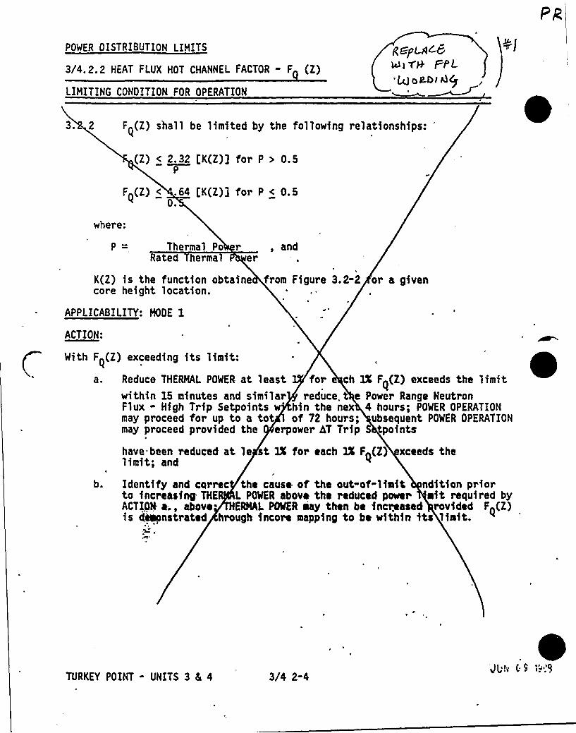
PR
POWER OISTRIBUTION LIMITS
3/4. 2. 2 HEAT FLUX HOT CHANNEL FACTOR - F (Z)
LIMITING CONDITION FOR OPERATION
g ALA~~>v+ FrL~>A.t» Alp
3. 2 F (Z) shall be limited by the following relationships: 0(Z) < 2.32 t;K(Z}] for P > 0.5
P
F~(Z) < .64 [K(Z)3 for P < 0.50.
where:
Thermal Po r , andRated hermal er
K(2) is the function obtaine from Figure 3.2-2 or a givencore height location.
APPLICABILITY: MOOE 1
ACTION:
With F~(Z} exceeding its limit:a. Reduce THERMAL POWER at least for ch IX F~(Z) exceeds the limit
within 15 minutes and similar reduce. t e Power Range NeutronFlux - High Trip Setpoints w hin the nex 4 hours; POWER OPERATIONmay proceed for up to a tot of 72 hours; ubsequent POWER OPERATIONmay proceed provided the erpower 4T Trip S oints
have. been reduced at le st 1X for each 3X F~(Z) xceeds thelimit; and
b. Identify and colrec the cause of the out-of-limit ndition priorto increasing. THE L POWER above the reduced power sit required byACTION a., above ERMAL PlNER may then be increased rovided F~(Z)is dhonstrated hrough incore mapping to be within its limit.
TURKEY POINT - UNITS 3 8 4 3/4 2"4Jl" < 9 l'.".'9
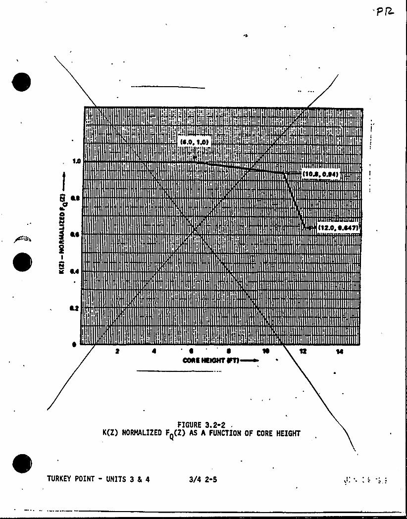
,Iel
~ )[
II~
~ ~J
':li~eee
(I.O,
~ I
;. r j[!.
SAI)
)le
!1
II~it!~ 1
~ / f ~
eef'SOA
~ 0.0
g I.i
I
ac Li
ItxNIIRNHTFtl~
FIGURE 3.2-2K(Z) NORMALIZED Fq(Z) AS A FUNCTION OF CORE HEIGHT
TURKEY POINT - UNITS 3 8 4 3/4 2-5 I ~ e
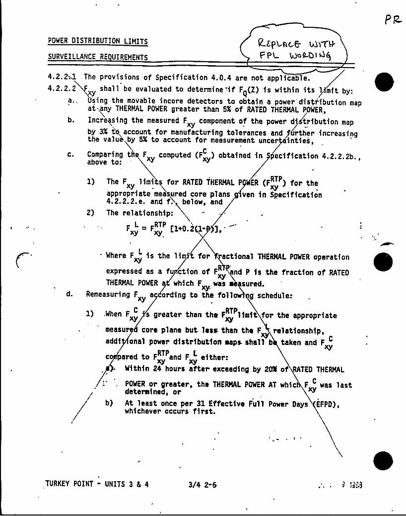
POWER DISTRIBUTION LIMITS
SURVEILLANCE RE UIREMENTS
R E.pv~c.C un H.
P PU mLQ14$
4.2.~ The provisions of Specification 4.0.4 are not applicable.4.2.2.2 shall be evaluated to determinetif F~(Z) is within its ~lrmit by:
a.. Using the movable incore detectors to obtain a power*distr'ibution mapat any THERMAL POWER greater than 5X of RATED THERMAL POWER,
b. Increasing the measured Fx component of the power di tribution map
by 3X to account for manufacturing tolerances and rther increasingthe value by 5X to account for measurement uncer inties,
c. Comparing t Fx computed (F ) obtained in ecification 4.2.2.2b.,above to:
d.
1) The F limit for RATED THERMAL P ER (F ) for thexy xyappropriate mea ured core plans ven in Specification4.2.2.2.e. and fi below, and
2) The relationship:
F = F [1+0.2 1-],'yxy
. Where Fx is the li t for actional THERMAL POWER operation
expressed as a fu ction of F nd P is the fraction of RATED
THERMAL POWER which F was sured.xy.Remeasuring Fx a ording to the follow g schedule:
C) .When Fx s greater than the F limit for the appropriateRTP
measur core plane but less than the F relationship,addi onal power distribution maps shall b taken and Fxyc ared to Fx and „ either:RTP E.
Within 24 hours after exceeding by 20% of TED THERMAL
POWER or greater, the THERMAL POWER AT whic Fx was lastC
determined, or xy
b) At least once per 31 Effective Full Powe~ Days EFPD),whichever occurs first.
TURKEY POINT - UNITS 3 4 4 3/4 2-6 o~ ii I 0 a)
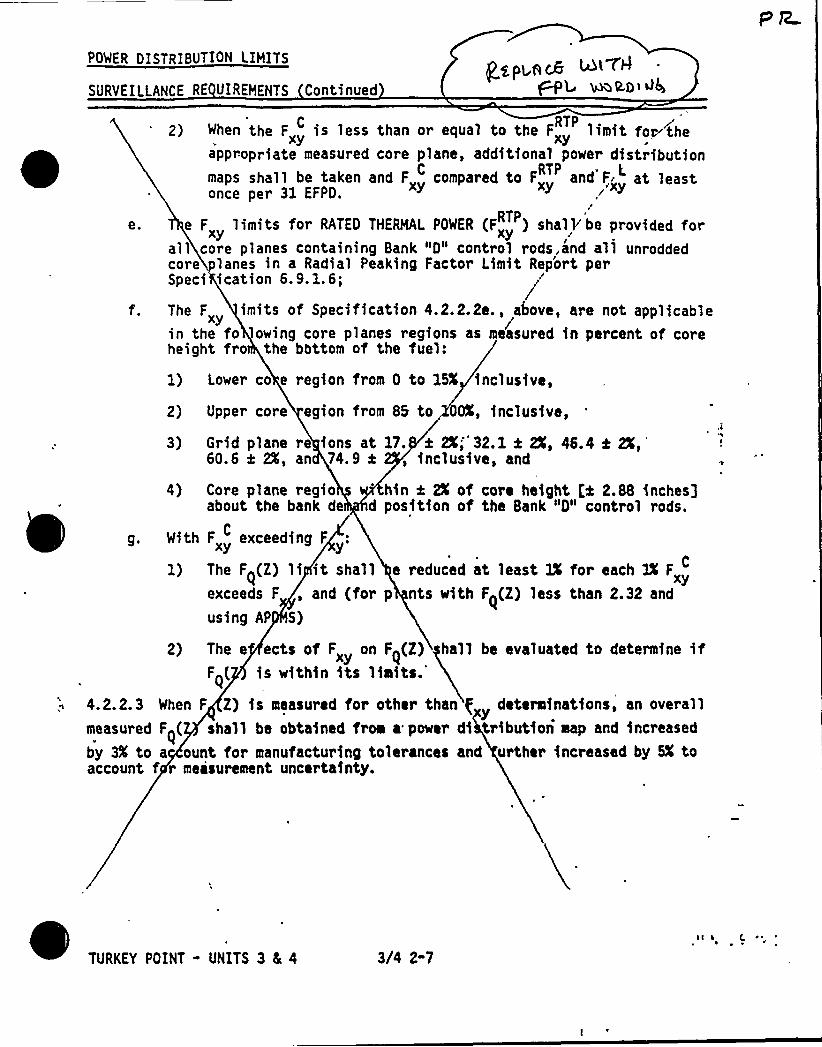
POWER DISTRIBUTION LIMITS
SURVEILLANCE RE UIREMENTS Continued
gypped~ LDl CA
~L ~QDi ~4
e.
2 ) When the F is less than or equal to the F limit foe ther
appropriate measured core plane, additional power distributionmaps shall be taken and Fx compared to Fx and F„ at leastC RTP ~ L
once per 31 EFPO.
e F limits for RATEO THERMAL POWER (Fx ) shalVbe provided forRTP
xy xyall core planes containing Bank "0" control rods,and all unroddedcore lanes in a Radial Peaking Factor Limit Rep'ort perSpeci ication 6.9.1.6;
The F imits of Specification 4.2.2.2e., above, are not applicablexy /in the fo owing core planes regions as measured in percent of coreheight fro the bottom of the fuel:
1) Lower co e region from 0 to 15X inclusive,
2) Upper core egion from 85 to OOX, inclusive,
3) Grid plane re ions at l7. i 2X;"32.1 4 2X, 46.4 k2X,'0.6x 2X, an 74.9 t, inclusive, and
4) Core plane regioabout the bank de d
With Fx exceeding FC
1) The F~(Z) li it shallexceeds F , and (forusing AP S)
hin t 2X of core height t:4 2.88 inches3position of the Bank "0" control rods.
e reduced at least 2X for each 3X FxC
p nts with F~(Z) less than 2.32 and
2) The e ects of Fx on F~(Z) hall be evaluated to determine ifF~( is within its limits.
4.2.2.3 When F Z) is, measured for other than f determinations, an overallmeasured F~( shall be obtained from a power di tribution map and increased
by 3X to a ount for manufacturing tolerances and urther increased by SX toaccount f r meisurement uncertainty.
TURKEY POINT - UNITS 3 4 4 3(4 2-7~ ~
~ ~
) rl gm /80<-
feR- h/„k

POWER DISTRIBUTION LIMITS
3/4 2.2 HEAT FLUX HOT CHANNEL FACTOR - F Z
LIMITING CONDITION FOR OPERATION
UsE,
PLM08-b lh3$
3.2.2 Fq(Z) shall be limited by the following relationships:L
F~(Z) < LF~] X [K(Z)j for P > 0.5
P
Fq(2) < [Fqj X [K(Z)l for P < O.S
~5where: [Fq] = 2. 32 1 imitL
P = Thermal PowerRated Thermal Power
M
[Fqj = The Measured Value,
and K(Z) is the function obtained from Figure 3.2-2 for a givencore height location.
APPLICABILITY: MODE 1
ACTION:
thWith the measured value of Fq(Z) exceeding its limit:
a. Reduce THERMAL POWER at least 1% for each 1% F~(Z) exceedsM
F (2) within 15 minutes and similarly reduce the Power Range NeutrontF ux - High Trip Setpoints within the next 4 hours; POWER OPERATION
may proceed for up to a total of 72 hours; subsequent POWER OPERATION
may proceed provided the Overpower Delta-T Trip Setpoints (value of
K4) have been reduced at least 1% for each 1% F~(Z) exceeds theM
F~(Z); and
b. Identify and correct the cause of the out-of-limit condition priorto increasing THERMAL POWER above the reduced power limit required by
ACTION a., above; THERMAL POWER may then be increased provided F~(Z)M
is demonstrated through incore mapping to be within its limit.
3/4 2-4

/ vtAvifidunlit
).e 8/. 6
0
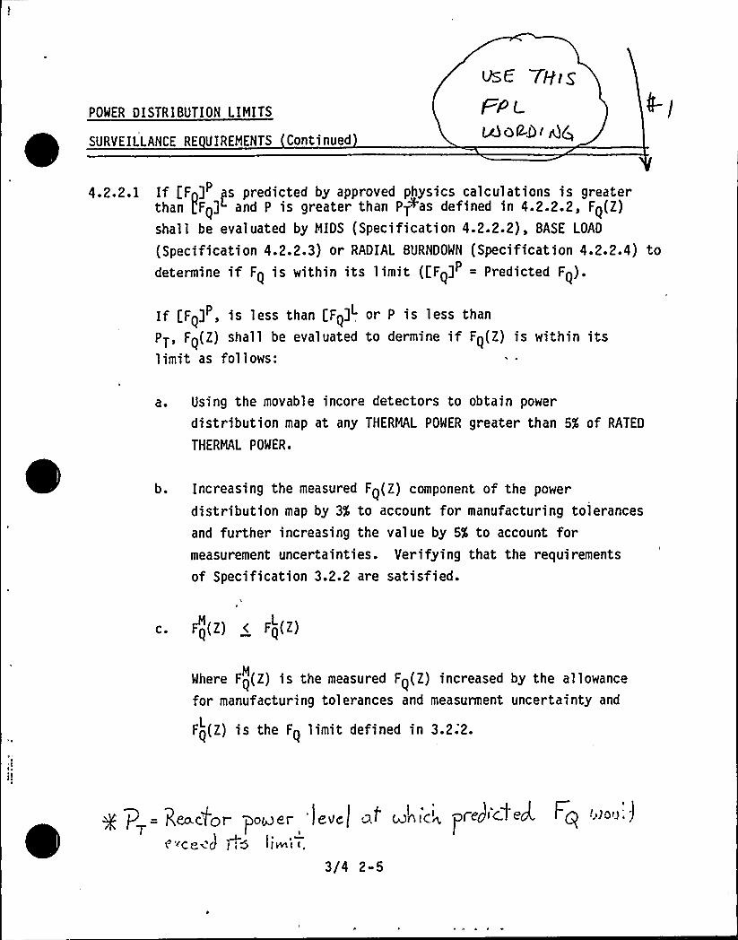
POWER DISTRIBUTION LIMITS
SURVEILLANCE RE UIREMENTS Continued
vsE 7H]sFPLMQP-Di dQ
4.2.2.1 If [Fn] ~s predicted by approved physics calculations is greaterthan pFqj and P is greater than PT+as defined in 4.2.2.2, F~(Z)
shall be evaluated by MIDS (Specification 4.2.2.2), BASE LOAD
(Specification 4.2.2.3) or RADIAL BURNDOWN (Specification 4.2.2.4) todetermine if F~ is within its limit ([Fqj = Predicted Fq).
If [F~] , is less than [Fq]" or P is less than
PT, F~(Z) shall be evaluated to dermine if F~(Z) is within itslimit as follows:
a. Using the movable incore detectors to obtain power
distribution map at any THERMAL POWER greater than 5X of RATED
THERMAL POWER.
b. Increasing the measured Fq(Z) component of the power
distribution map by 3$ to account for manufacturing tolerances
and further increasing the value by 5X to account formeasurement uncertainties. Verifying that the requirements
of Specification 3.2.2 are'satisfied.
c. F<(Z) < F<(Z)
Where Fq(Z) is the measured Fq(Z) increased by the allowanceM
for manufacturing tolerances and measurment uncertainty and
Fq(Z) is the F~ limit defined in 3.2;2.L
g p = Reactor sower 'leva) z> mkic~ peed~'~~ed. Fq '»o'~;!T I
8'~CC~ J j <5 l)m< t.
3/4 2-5

0
/A /yl, gw l 4-6
),p- g/~.
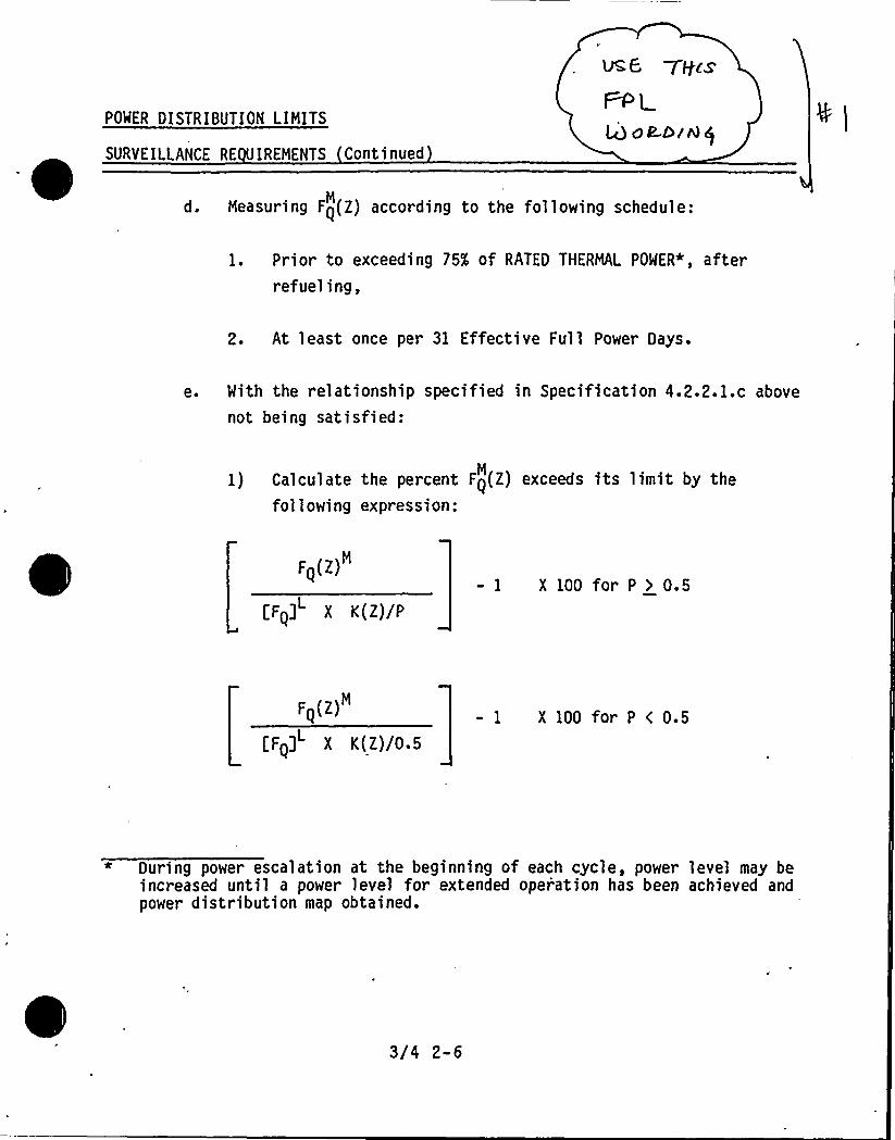
POWER DISTRIBUTION LIMITS
SURVEILLANCE RE IREMENTS Continued
ÃE 7ffcsPP1
43oR.D(8$
d. Measuring Fq(Z) according to the following schedule:M
1. Prior to exceeding 75% of RATED THERMAL POWER*, afterrefueling,
2. At least once per 31 Effective Full Power Days.
e. With the relationship specified in Specification 4.2.2.1.c above
not being satisfied:
1) Calculate the percent Fq(Z) exceeds its limit by theM
fol 1 owing expression:
F (Z)
[F<j" X V(Z)/P
- 1 X 100 for P > 0.5
F (Z)
[Fqj X K(Z)/0.5
- 1 X 100 for P ( 0.5
* During power escalation at the beginning of each cycle, power level may beincreased until a power level for extended oper'ation has been achieved andpower distribution map obtained.
3/4 2-6

~ y~ fp pi t(Q H6~f~~ )

POWER DISTRIBUTION LIMITS
SURVEILLANCE RE UIREMENTS Continued
UsC 7H u'
~os>]Wp
2) The following action shall be taken:
a) Comply with the requirements of Specification 3.2.2 for
FQ(2) exceeding its limit by the percent calculatedM
above.
4.2.2.2 MIDS
Operation is permitted at power above PT where PT equals the ratio ofLF ]L divided by [FQ] if the following Augmented Surveillance
Q
(Movable Incore Detection System, MIDS) requirements are satisfied:
a. The axial power distribution shall be measured by MIDS when
required such that the limit of LFQ] /P times Figure 3.2.2 isnot exceeded. F>(Z) is the normalized axial power distributionfrom thimble j at core elevation (Z).
I. If F>(Z) exceeds [F>(Z)judas defined in the bases by
< 4%, iomediately reduce thermal power one percent forevery percent by which [F>(Z)]s is exceeded.
2. If F>(Z) exceeds LF>(Z)]s by > 4X imnediately reduce
thermal power below PT. Corrective action to reduce F>(Z)
below the limit will permit return to thermal power not toexceed cvrrent Ifj4 defined in the bases.
+ j'F:(z)J (g ),< o,or,,i i=:'~io Nil)5J
~ 'P„ is raixc4r )Peri cl i.o~-idr exjare~e3. od ci frocf'r~l (
of '( fine'f 's !!5ro( (o coic:,.oii [('(~)j
3/4 2-7

I/ V~ pl~qE'w I r. ~.) /Pic~ l(
kA l/..e
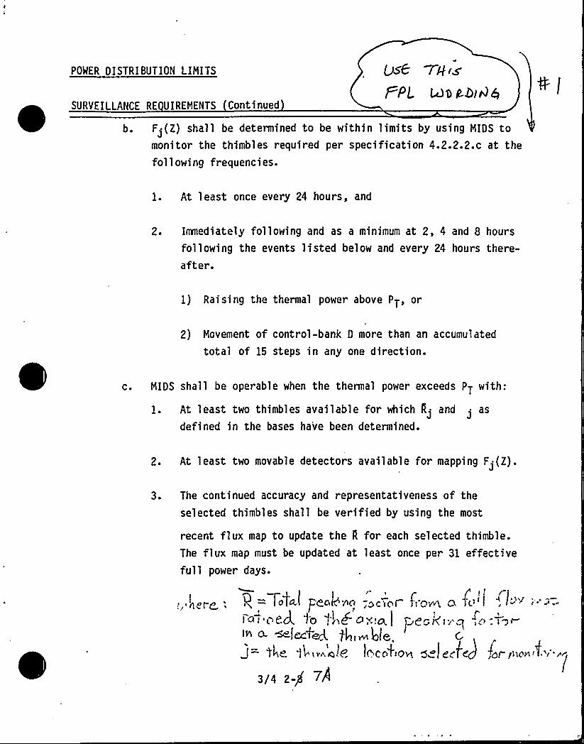
POWER DISTRI BUTION LIMITS ~6PPL
SURVEILLANCE RE UIREMENTS Continued
b. F ~ (Z) shall be determined to be within limits by using MIDS tomonitor the thimbles required per specification 4.2.2.2.c at thefollowing frequencies.
1. At least once every 24 hours, and
2. Immediately following and as a minimum at 2, 4 and 8 hours
following the events listed below and every 24 hours there-after.
1) Raising the thermal power above PT, or
2) Movement of control-bank 0 more than an accumulated
total of 15 steps in any one direction.
c. MIDS shall be operable when the thermal power exceeds PT with:
1. At least two thimbles available for which 0> and>
as
defined in the bases have been determined.
2. At least two movable detectors available for mapping F>(Z).
3. The continued accuracy and representativeness of the
selected thimbles shall be verified by using the most
recent flux map to update the 0 for each selected thimble.The flux map must be updated at least once per 31 effectivefull power days.
I
:, her< ~
)/ 'I f—+0[P.l p+op'/lg,gr'<pf f( g~ Q "j(> l ", la '~ i': >.
1
eed. to t„bo. ial peak:~" ~ ~~ <w H~, 4t~, c
44. 'l4v~e!~ !o'coki08 0 (Ec4) fgpp<>@nit
3/4 2-p 7A

C
le& -~'-k ,
POWER DISTRIBUTION LIMITS
SURVEILLANCE RE U IREMENTS Continued
0567+a'p
L~ o P-> /'AQ
4.2.2.3 Base Load
Base Load operation is permitted at powers above PT if the followingrequirements are satisfied:
a. Either of the following preconditions for Base Load operationmust be satisfied.
1. For entering Base Load operation with power less than PT,
a) Maintain THERMAL POWER between PT/1.05 and PT for atleast 24 hours,
b) Maintain the AFD (Delta-I) to within a + 2X or + 3X
target band for at least 23 hours per 24 hour period.
c) After 24 hours have elapsed, take a full core flux map
to determine F~(Z) unless a valid full core flux mapM
was taken within the time period specified in 4.2.2.1d.
d) Calculate PBL per 4.2.2.3b.
2. For entering Base Load operation with power greater than
a) Maintain THERMAL POWER between PT and the power
limit determined in 4.2.2.2 for at least 24 hours, and
maintain Augmented Surveillance requirements of 4.2.2.2during this period.
b) Maintain the AFD {Delta-I) to within a + 2X or + 3X
target band for at least 23 hours per 24 hour period,
7..;~c,c,e;,,'':-, /-,: //g/w ~".~.4
POWER DISTRIBUTION LIMITS
SURVEILLANCE RE UIREMENTS Continued
Vs& VH«
La~A>'~Cj
c) After 24 hours have elapsed, take a full core flux map
to determine FQ(Z) unless a valid full core flux map
was taken within the time period specified in 4.2.2.1d.
d) Calculate PBL per 4.2.2.3b.
b. Base Load operation is permitted provided:
1. THERMAL POWER is maintained between PT and PBL or between
PT and 100% (whichever is most limiting).
2. AFD (Delta-I) is maintained within a + 2% or + 3X targetband.
3. Full core flux maps are taken at least once per 31
effective Full Power Days.
PBL and PT are defined as:
PBL [FQ] X K(Z)
Fg~z~ X M~Z~ BLX 1'09
PT = [FQ] /[FQ]
where: FQ(Z) is the measured FQ(Z) with no allowance forM
manufacturing tolerances or measurement uncertainty. For the
purpose of this Specification [FQ(Z)] shall be obtained betweenM
elev~tions bounded by 10% and 90% of the active core height.[Fn] is the FQ limit. K(Z) is given infigure 3.2-2. W(Z)qL is the cycle dependent function thataccounts for limited'ower distribution transients encounteredduring base load operation.
3/4 2-Sl
0
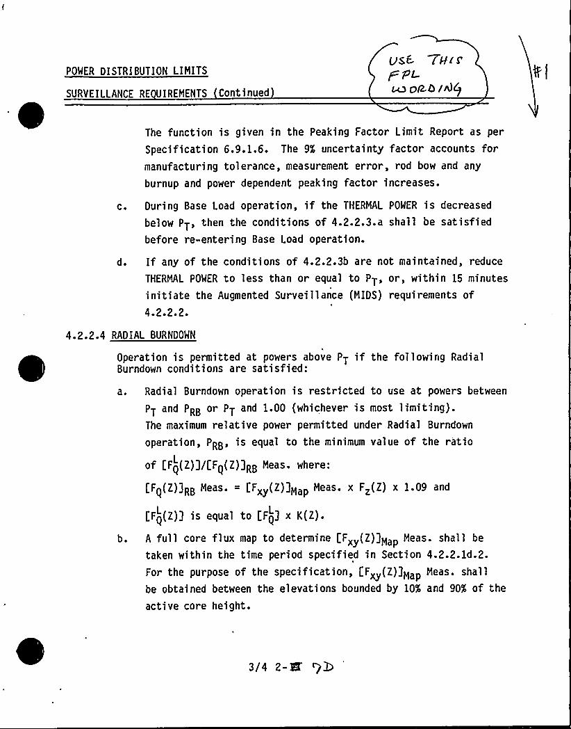
POWER DISTRIBUTION LIMITS
SURVEILLANCE RE UIREMENTS Continued
The function is given in the Peaking Factor Limit Report as per
Specification 6.9.1.6. The 9% uncertainty factor accounts formanufacturing tolerance, measurement error, rod bow and any
burnup and power dependent peaking factor increases.
c. During Base Load operation, if the THERMAL POWER is decreased
below PT, then the conditions of 4.2.2.3.a shall be satisfiedbefore re-entering Base Load operation.
d. If any of the conditions of 4.2.2.3b are not maintained, reduce
THERMAL POWER to less than or equal to PT, or, within 15 minutes
initiate the Augmented Surveillance (MIDS) requirements of4.2.2.2.
4.2.2.4 RADIAL BURNDOWN
I
Operation is permitted at powers above PT if the following RadialBurndown conditions are satisfied:
a. Radial Burndown operation is restricted to use at powers between
PT and PRB or PT and 1.00 (whichever is most limiting).The maximum relative power permitted under Radial Burndown
operation, PRB, is equal to the minimum value of the ratio
of [F~(Z)j/[F~(Z)]RB Meas. where:L
[Fq(Z)]RB Meas. = [Fxy(Z)lMap Meas. x Fz(Z) x 1.09 and
[F~(Z)j is equal to [F~j x K(Z).L L
b. A full core flux map to determine [Fxy(Z)]Map Meas. shall be
taken within the time period specified in Section 4.2.2.ld.2.for the PurPose of the sPecification, [Fxy(Z)]Map Meas. shall
be obtained between the elevations bounded by 10% and 90$ of the
active core height.
3/4 2-EC

~/~ C 8 'i < (. «'V ~6v"i/~ I //
k+ 2/<,.p
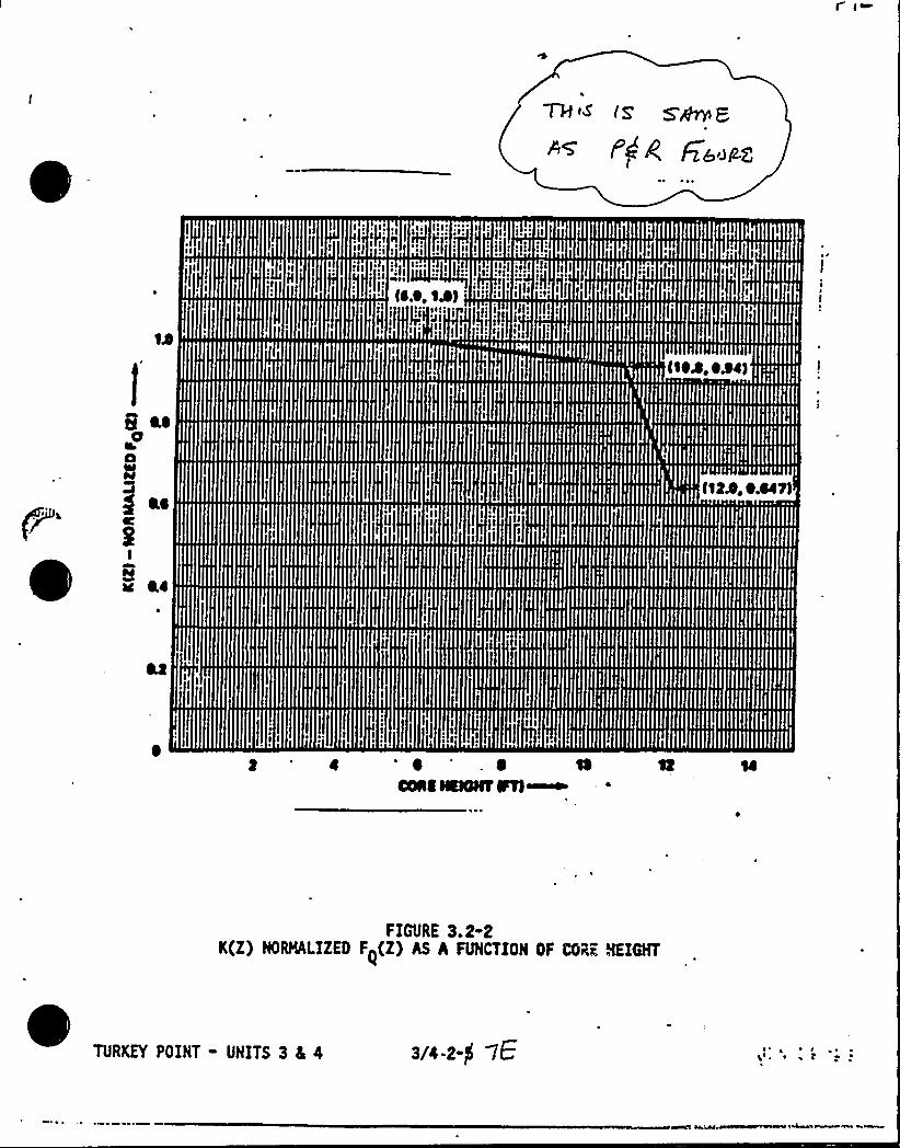
tl lttlttilNhtNttttttII tt tl!NNIIIIHIIS
iltl lt I ltNtllNlttfff IIIIIIIft
fl I ttl
II I III
mIImllilllllft
Ift II
Ni If, I
tllIfl f
IHIP'I
III
IIIIIItftffIIIIIINII
IllffIIIII
llllll
lt II
ff II
ff!!It!III tttfff
I!II!IIII
It!litt!III I I II It
I rt
fill I littlitt I lttt
I IIIII
IfIll
lllllllll1(tlt )Pl Ilt)lNt lf Illff IIIIIIIII I IIIII
I tt
I tf
ltlll I INIIIIII IN
flilt1BB
Pill
l!I
fili
H!INtf
IIDIHh
INI!f
NMIteQI I NiffNNAIININIII I!IltlttftttflfltlIIIJtf tfffl
8HHtf!Itt!
5 HI!
llftBIIftfU tllll lttltfll!IN IIH!IIIttt I ltllllllfllllllI'~Mllll'~!!!if!i!!!Illll!Hl!Illllff 'llllllllllIIII!llll!INIIII!I!I, I I ......, . Ill!I!Ill!I
III Iffill lllllifllf!fill.'i fi!IHIIIIIHIIIIllllllHlllllhlllIII IIIIIIIIHI!HlllllllII iflllllllllllllllllllllllll)IIIIHIIIlillilffiilli'llltllllilli f(llllilllllHllllilllllllllillll
[III lllllllllllllllllllhlII ).Hllllllllllllllill.!IIIIHlllh
ITillill
ItttttjtIlgwu'I II I lf fl
ftfl flitltf tt t!I!II lllfllllrIIR lflHH ll fttift ftttttttt
ltlfltINIlflflfffl
Iff
Iftflflfltlflfltlit fflf lltllllflIflllflfliltftfllIll IIII llftftftf
ffflIlflltftfff
Itf l ft I
ftfNI!ttff!Nftlll!IflflfltflfklllftfltlffIII!IIIIIIIII
If If!]hh!I
Ill!fit!flit
I lt III
I tl liltI
IIIIIIIIIlllltt
I!fili
IIIIIII
II Ilt
ttttflllllItllllllll,l{lllllllllltltlltItllftftllffttf!III
tt llllflllllfltIIIIIIIIIII d IIII
I!It tl fit lllllll tftlltl ttltltlllllllllllttlilt ll )IllfftlttIIIIIIItlllllllllltlllllttillllIIIIIIIlllflillllllIII IIIIII!I/I!III
1 ttlB
fill I.'tiff fit lilt iltflfftlflflfl ltlflftfi llllflitlltllllftlllll !!Iftt tfftfltltI IIIlfftIIIII<
tttltttlltt tlttfH ttlftlllftfttltttlttltltttttlIIIIL'll
g5 j~Q, /+
POWER DISTRIBUTION LIMITS
SURVEILLANCE RE UIREMENTS Continued
7H cJ
~PLWOt i»AG,
c ~ The function Fz(Z), provided in the Peaking Factor Limit Report
(6.9.1.6), is determined analytically and accounts for the most
perturbed axial power shapes which can occur under axial power
distribution control. The uncertainty factor of 9% accounts formanufacturing tolerances, measurement error, rod bow, and any
burnup dependent peaking factor increases.
d. Radial Burndown operation may be utilized at powers between
PT and PRB, or, PT and 1.00 (whichever is most limiting)provided that the AFD (Delta-I) is within + 5% of the targetaxial offset.
e. If the requirements of Section 4.2.2.4d are not maintained, then
the power shall be reduced to less than or equal to PT, or
within 15 minutes Augmented Surveillance of hot channel factors
shall be initiated if the power is above PT.
4.2.2.5 When F~(Z) is measured for reasons other than meeting the
requirements of specification 4.2.2.1, 4.2.2.2, 4.2.2.3 or
4.2.2.4 an overall measured F~(Z) shall be obtained from
a power distribution map and increased by 3% to account formanufacturing tolerances and further increased by 5% to account
for measurement uncertainty.
3/4 2-$R "7P
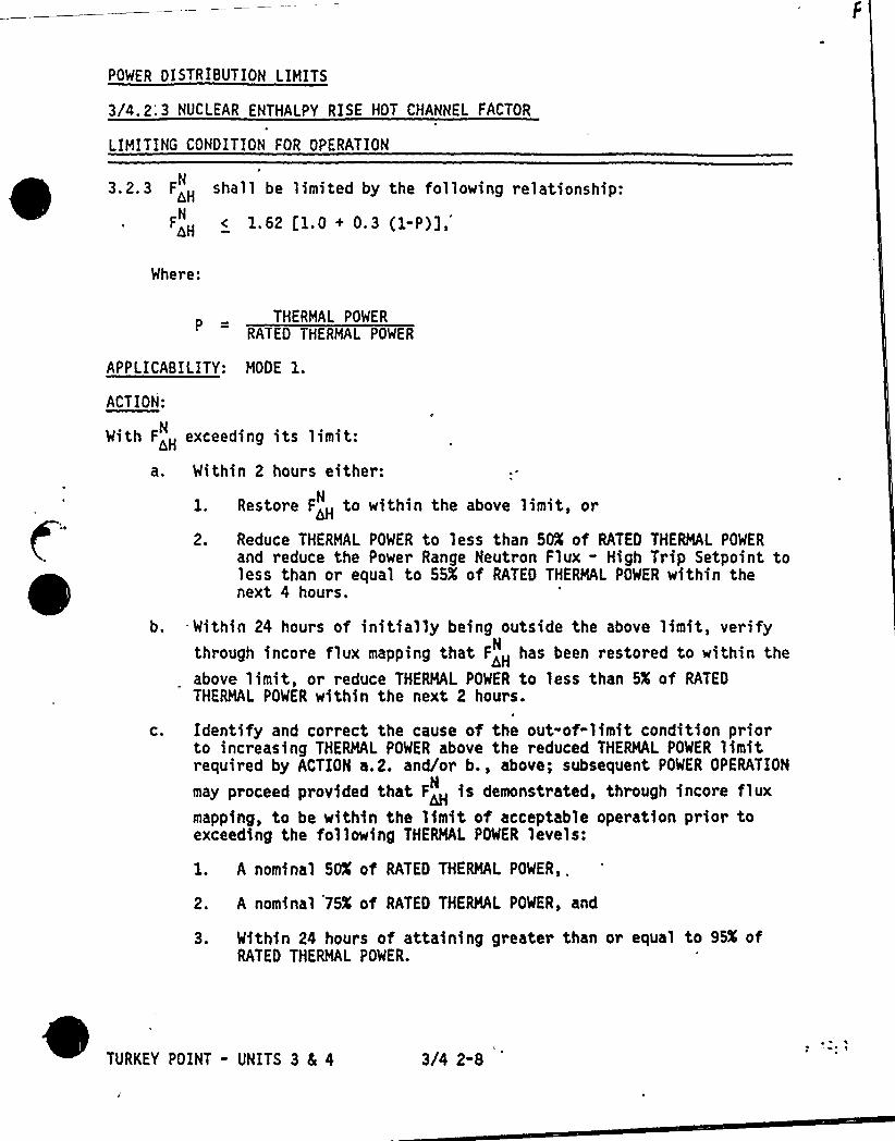
POWER DISTRIBUTION LIMITS
3/4.2;3 NUCLEAR ENTHALPY RISE HOT CHANNEL FACTOR
LIMITING CONDITION FOR OPERATION
3.2,3 FH
shall be limited by the following relationship:
AH< 1.62 l1.0 + 0.3 (1-P)],N
Whe~e:
THERMAL POWER
RATED THERMAL POWER
APPLICABILITY: MODE l.ACTION:
With F<H exceeding its limit:
a. Within 2 hours either:
2.
Restore F~ to within the above limit, or
Reduce THERMAL POWER to less than 50K of RATEO THERMAL POWER
and reduce the Power Range Neutron Flux - High Trip Setpoint toless than or equal to 55X of RATED THERMAL POWER within thenext 4 hours.
b. Within 24 hours of initially being outside the above limit, verifythrough incore flux mapping that F~ has been restored to within the
above limit, or reduce THERMAL POWER to less than 5X of RATEDTHERMAL POWER within the next 2 hours.
C. Identify and correct the cause of the out-of-limit condition priorto increasing THERMAL POWER above the reduced THERMAL POWER limitrequired by ACTION a.2. and/or b., above; subsequent POWER OPERATION
may proceed provided that F is demonstrated, through fncore fluxN
mapping, to be within the limit of acceptable operation prior toexceeding the following THERMAL POWER levels:
l. A nominal 50K of RATEO THERMAL POWER,.
2. A nominal 75K of RATEO THERMAL POWER, and
3. Within 24 hours of attaining greater than or equal to 95K ofRATED THERMAL POWER.
TURKEY POINT - UNITS 3 4 4 3/4 2-8

ICf'l~ p '~7~ 'i ~' '+1<' ll~
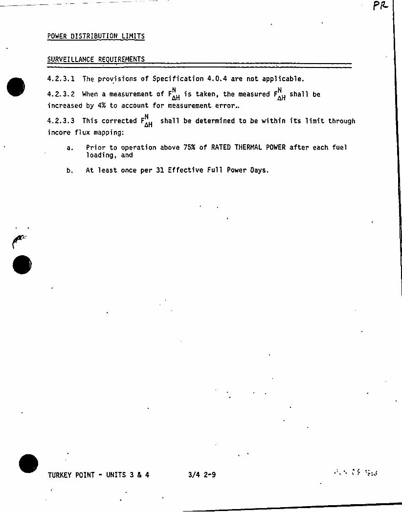
POWER DISTRIBUTION LIMITS
SVRYEILLANCE RE UIREMENTS
4. 2. 3. 1 The provisions of Specification 4. Q.4 are not applicable.
4. 2. 3. 2 When a measurement of F<H is taken, the measured FH
shall beN N
nHincreased by 4X to account for measurement error..
4.2.3.3 This corrected F<H shall be determined to be within its limit throughincore flux mapping:
a. Prior to operation above 75K of RATED THERMAL POWER after each fuelloading, and
b. At least once per 31 Effective Full Power Days.
TURKEY POINT - UNITS 3 & 4 3/4 2-9
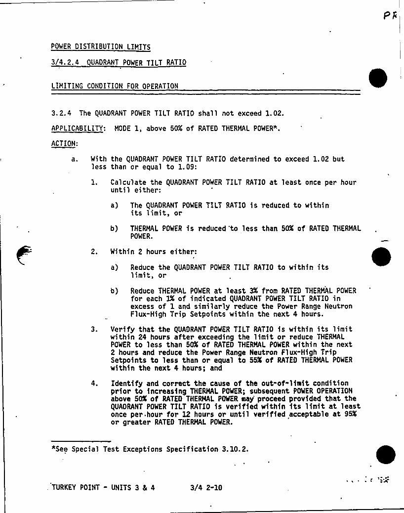
POWER DISTRIBUTION LIMITS
3/4. 2.4 UAORANT POWER TILT RATIO
LIMITING CONDITION FOR OPERATION
3.2.4 The QUADRANT POWER TILT RATIO shall not exceed 1.02.
APPLICABILITY: MODE 1, above 50K of RATED THERMAL POWER".
ACTION:
a. With the QUADRANT POWER TILT RATIO determined to exceed 1.02 butless than or equal to 1.09:
Calculate the QUADRANT POWER TILT RATIO at least once per houruntil either:
a) The QUADRANT POWER TILT RATIO is reduced to withinits limit, or
b) THERMAL POWER is reduced 'to less than 50K of RATED THERMALPOWER.
2. Within 2 hours either:
a) Reduce the QUADRANT POWER TILT RATIO to within itslimit, or
b) Reduce THERMAL POWER at least 3X from RATED THERMAL POWER
for each 3X of indicated QUADRANT POWER TILT RATIO inexcess of 1 and similar ly reduce the Power Range NeutronFlux-High Trip Setpoints within the next 4 hours.
3. Verify that the QUADRANT POWER TILT RATIO is within its limitwithin 24 hours after exceeding the limit or reduce THERMALPOWER to less than 50K of RATED THERMAL POWER within the next2 hours and reduce the Power Range Neutron Flux-High TripSetpoints to less than or equal to 55K of RATED THERMAL POWER
within the next 4 hours; and
Identify and correct the cause of the out-of-limit conditionprior to increasing THERMAL POWER; subsequent POWER OPERATIONabove 50% of RATED THERMAL POWER say'roceed provided that theQUADRANT POWER TILT RATIO is verified within its limit at leastonce per.hour for 12 hours or until verified acceptable at 95Kor greater RATED THERMAL POWER.
*See Special Test Exceptions Specification 3. 10.2.
. TURKEY POINT - UNITS 3 4 4 3/4 2-10
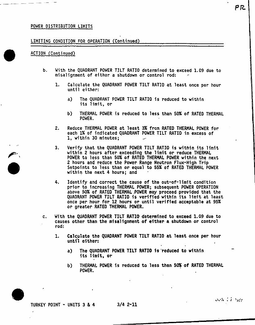
POWER DISTRIBUTION LIMITS
LIMITING CONDITION FOR OPERATION Continued
ACTION Continued
b. With the QUADRANT POWER TILT RATIO determined to exceed 1.09 due tomisalignment of either a shutdown or control rod:
1. Calculate the QUADRANT POWER TILT RATIO at least once per hourunti 1 ei ther:
a) The QUADRANT POWER TILT RATIO is reduced to withinits limit, or
b) THERMAL POWER is reduced to less than SO% of RATED THERMALPOWER.
2. Reduce THERMAL POWER at least 3X from RATED THERMAL POWER foreach lX of indicated QUADRANT POWER TILT RATIO in excess of1, within 30 minutes;
3. Verify that the QUADRANT POWER TILT RATIO is within its limitwithin 2 hours after exceeding the limit or reduce THERMALPOWER to less than 50K of RATED THERMAL POWER within the next2 hours and reduce the Power Range Neutron Flux-High TripSetpoints to less than or equal to 55'f RATED THERMAL POWER
within the next 4 hours; and
4. Identify and correct the cause of the out-of-limit conditionprio~ to increasing THERMAL POWER; subsequent POWER OPERATIONabove 50K of RATED THERMAL,POWER may proceed provided that theQUADRANT POWER TILT RATIO is verified within its limit at leastonce per hour for 12 hours or until verified acceptable at 95Kor greater RATED THERMAL POWER.
With the QUADRANT POWER TILT RATIO determined to exceed 1.09 due tocauses other than the misalignment of either a shutdown or controlrod:
1. Calculate the QUADRANT POWER TILT RATIO at least, once per houruntil either:
a) The QUADRANT POWER TILT RATIO is reduced to withinits limit, or
b) THERMAL POWER is ~educed to less than 50K of RATED THERMALPOWER.
TURKEY POINT - UNITS 3 5 4 3/4 2-11~ l ~
l~L~A ~ ~
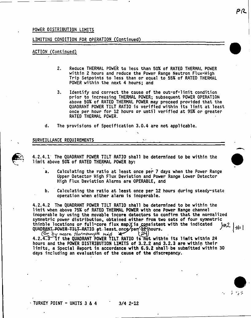
POWER DISTRIBUTION LIMITS
LIMITING CONDITION FOR OPERATION Continued
ACTION Continued
2. Reduce THERMAL POWER to less than 50K of RATED THERMAL POWERwithin 2 hours and reduce the Power Range Neutron Flux-HighTrip Setpoints to less than or equal to 55K of RATED THERMALPOWER within the next 4 hours; and
3. Identify and correct the cause of the out-of-limit conditionprior to increasing THERMAL POWER; subsequent POWER OPERATIONabove 50K of RATED THERMAL POWER may proceed provided that theQUADRANT POWER TILT RATIO is verified within its limit at leastonce per hour for 12 hours or until verified at 95K or greaterRATED THERMAL POWER.
d. The provisions of Specification 3.0.4 are not applicable.
SURVEILLANCE RE UIREMENTS
4.2.4.1 The QUADRANT POWER TILT RATIO shall be determined to be within thelimit above SOX of RATED THERMAL POWER by:
4
a. Calculating the ratio at least once per 7 days when the Power RangeUpper Detector High Flux Deviation and Power Range Lower DetectorHigh Flux Deviation Alarms are OPERABLE, and
b. Calculating the ratio at least once per 12 hours during steady-stateoperation when either alarm is inoperable.
4.2.4.2 The QUADRANT POWER TILT RATIO shall be determined to be within thelimit when above 75K of RATED THERMAL POWER with one Power Range channelinoperable by using the movable incore detectors to confirm that the normalizedsymmetric power distribution, obtained either from two sets of four symmetricthimble locations or fu11-core flux map> is nsistent with the indicatedgUAD WER-TAT-RATIO yt'least.onc pe hours.
or by Ixcor-c. jkcf'mockup(< ~<p4.2.W 4f the QUADRANT POWER 'fILT RATIO is not within its limit within 24hours and the POWER DISTRIBUTION LIMITS of 3.2.2 and 3.2.3 are within theirlimits, a Special Report in accordance with 6.9.2 shall be submitted within 30days including an evaluation of the cause of the discrepancy.
TURKEY POINT - UNITS 3 8L 4 3/4 2-12
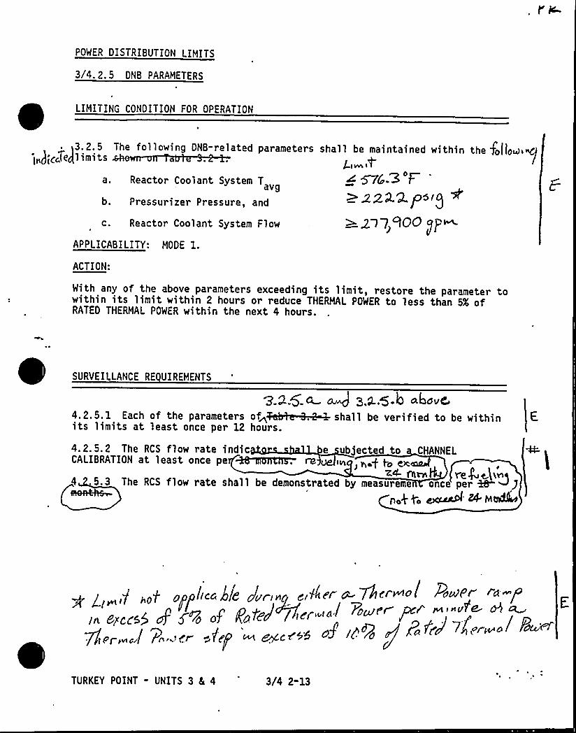
POWER DISTRIBUTION LIMITS
3/4.2.5 DNB PARAMETERS
LIMITING CONDITION FOR OPERATION
>3.2.5 The following DNB-related parametersI„);C lesIlimits ah
a. Reactor Coolant System T
b. Pressurizer Pressure, and
c. Reactor Coolant System Flow
APPLICABILITY: MODE 1.
ACTION:
shall be maintained within the fo'lto+IECiL>m tt4 ZT(.3'Fo gag.g.pdicb 'st
) Zaq,BOO qP~
With any of the above parameters exceeding its limit, restore the parameter towithin its limit within 2 hours or reduce THERMAL POWER to less than 5X ofRATED THERMAL POWER within the next 4 hours.
SURVEILLANCE RE UIREMENTS
.p gg 6 3 g.,5.13 o,kdvC.211 I «2 «E~ 1112 11; I 2
its limits at least once per 12 hours.
4.2.5.2 The RCS flow rate indic e ubjected to CHANNELAAIBAAI I 2
«Tasm sake'tE'4 5.3 The RCS flow rate shall be demonstrated by measureme once per ~ ~ J
n~$ go ~cgAJI Z4'lbdJ4
~ nbdd 5/d,'er Enc dEA er Ep Tkeimnpo~
TURKEY POINT - UNITS 3 4 4 3/4 2-13

TABLE 3.2-1
DNB PARAMETERS
LIMITS
PARAMETER
Indicated Reactor Coolant System Tavg
Indicated Pressurizer Pressure
Indicated Reactor Coolant Flaw
< 576. F
) 2 7 psia"
?7,900 gpaP
I3
iL)Jl ~
I
3/4 2-14TURKEY POINT - UNITS 3 5 4
"Li it not applicable during either a THERMAL POWER ramp in excess of SX ofR TEO THERMAL POWER per minute or a THERMAL POWER step in excess of 10K of
TEO THERMAL POWER.
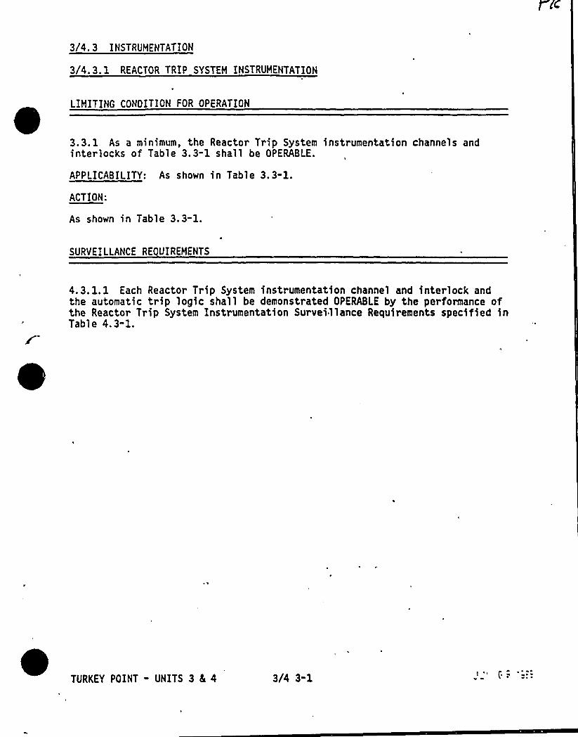
3/4.3 INSTRUMENTATION
3/4.3. 1 REACTOR TRIP SYSTEM INSTRUMENTATION
LIMITING CONOITION FOR OPERATION
3.3. 1 As a minimum, the Reactor Trip System instrumentation channels andinterlocks of Table 3.3-1 shall be OPERABLE.
APPLICABILITY: As shown in Table 3.3-1.
ACTION:
As shown in Table 3.3-1.
SURVEILLANCE RE UIREMENTS
4.3. 1.1 Each Reactor Trip System instrumentation channel and interlock andthe automatic trip logic shall be demonstrated OPERABLE by the performance ofthe Reactor Trip System Instrumentation Surveillance Requirements specified inTable 4.3"1.
TURKEY POINT - UNITS 3 8L 4 3/4 3-1
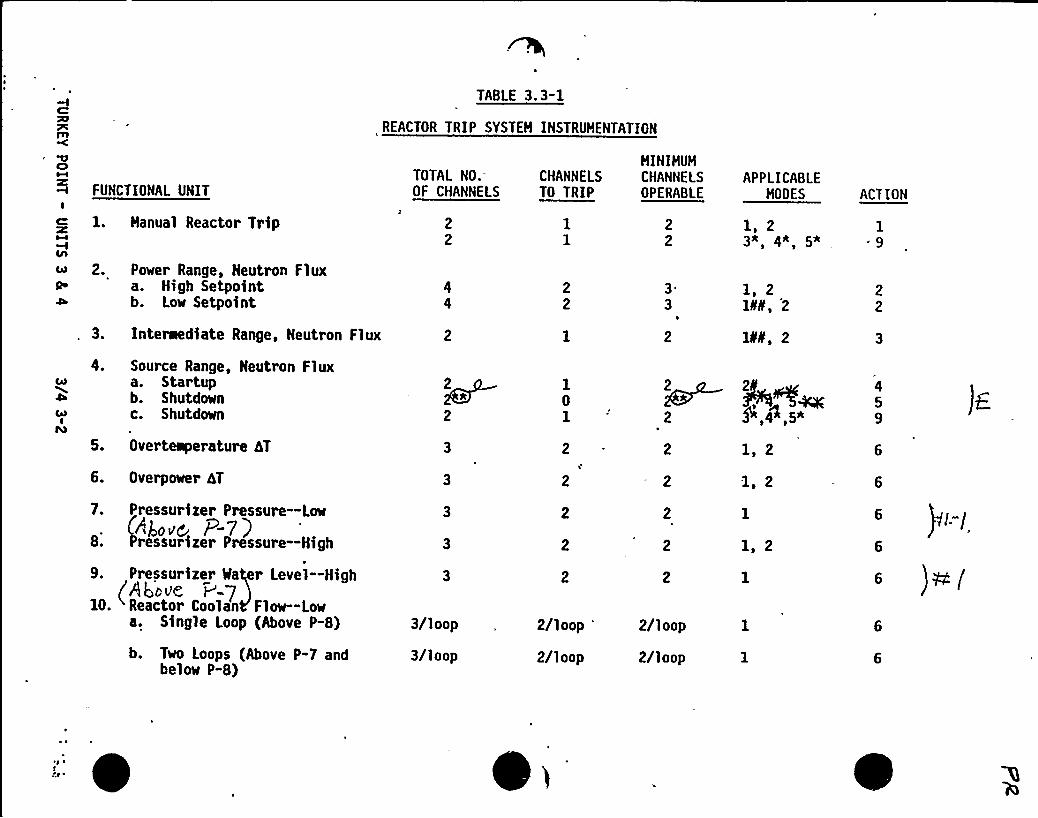
TABLE 3 ~ 3-1
REACTOR TRIP SYSTEH INSTRUHENTATION
FUNCTIONAL UNITI
1. Hanual Reactor Trip
2. Power Range, Neutron Fluxa a. High Setpoint4h b. Low Setpoint
3. Interaediate Range, Neutron Flux
TOTAL NO.OF CHANNELS
CHANNELSTg TRIP
HINIHUHCHANNELSOPERABLE
33
APPLICABLEMODES
1, 23* 4* 5A
1, 2ltII, 2
leak', 2
ACTION
19
Rag
IFO
4. Source Range, Neutron Fluxa. Startupb. Shutdownc. Shutdown
5. Overteaperature hT
6. Overpower 4T
7. Pressurizer Pressure —Low
Above P-7)8. ressurizer Pressure —High
9. Pressurizer Ha er Level —HighAt)ovc v-7
10. Reactor Coolao Flow-Lowa. Single Loop (Above P-8)
b. Two Loops (Above P-7 andbelow P-8)
3/loop
3/loop
2v
2
2/loop
2/loop
2
2/loop
2/loop
1, 2
1. 2
1, 2
0 )Th. (
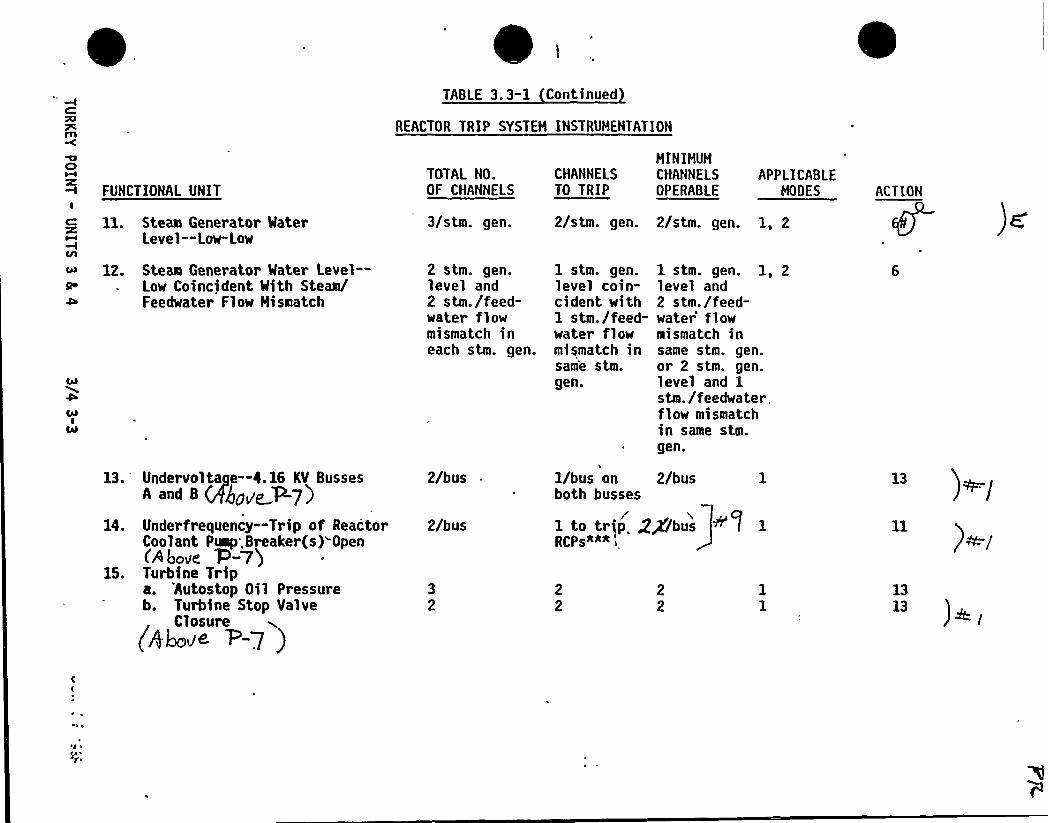
,TABLE 3. 3-1 Continued
REACTOR TRIP SYSTEM INSTRUMENTATION
C)
FUNCTIONAL UNITI
ll. Steam Generator MaterLevel-"Low-Low
12. Steam Generator Mater Level-Low Coincident With Steam/Feedwater Flow Hismatch
13. Undervoltage —4.16 KV BussesA and 8 +$~pt ~7)
14. Underfrequency —Trip of ReactorCoolant Pump'.Breaker(s) Open<Above 'P=/)
15. Turbine Tripa. 'Autostop Oil Pressureb. Turbine Stop Valve
(Abaa< 1 -7)
TOTAL NO.OF CHANNELS
3/stm. gen.
2 stm. g en.level and2 stm./feed-water flowmismatch ineach stm. gen.
2/bus
2/bus
1 stm. gen.level coin-cident with1 stm./feed-water flowmismatch insam'e stm.gen.
1 stm. gen. 1, 2level and2 stm./feed-water'lowmismatch insame stm. gen.or 2 stm. gen.level and 1stm./feedwaterflow mismatchin same stm.gen.
1/bus on 2/busboth busses
1 to trfp gg/bus '//1 1
RCPs*~* .
MINIMUMCHANNELS CHANNELS APPLICABLETO TRIP OPERABLE MOOES
2/stm. gen. 2/stm. gen. 1, 2
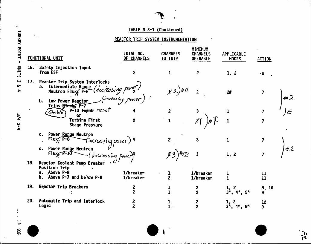
7Cm
FUNCTIONAL UNITI
Q 16. Safety Injection Inputfrom ESF
TOTAL NO.OF CHANNELS
HINIHUHCKANNELS CMANNELSTO TRIP OPERABLE
TABLE 3. 3-1 Continued
REACTOR TRIP SYSTEH INSTRUHENTATION
APPLICABLEHODES
1, 2
ACTION
47. Reactor Trip Systea Interlocksa. Interaediate R n e / I - ~~e/
Neutron Fl P-6 (6'CC EP&lgf 2
Tr sP- 0 &<pat'><t 4
orTurbine First 2Stage Pressure
p ~)+II
3 1
1/breaker1/breaker
19. Reactor Trip Breakers
20. Automatic Trip and InterlockLogic
c. Power Ran Neutron(increagi~ pyre) ~
d. Paar Ran Neutronl ( J8 C<076 <+
f'OrJC/'8.
Reactor Coolant Puep BreakerPosition Tripa..Above P-8b. Above P-7 and below P-8
yg 4/~
12
1/breaker1/breaker
1s 2
1, 2 8, 103A 4* 5* 9
1, 2. 123A'* 5* g
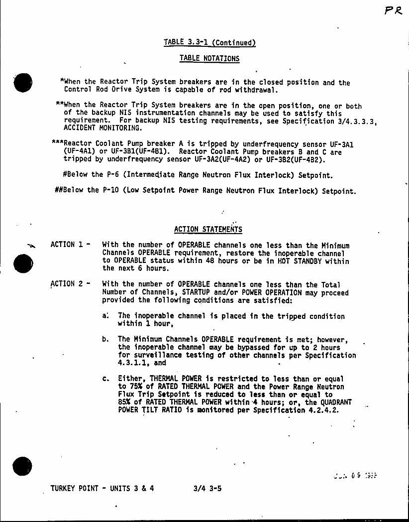
TABLE 3.3-1 Continued
TABLE NOTATIONS
"When the Reactor Trip System breakers are in the closed position and theControl Rod Drive System is capable of rod withdrawal.
*"When the Reactor Trip System breakers are in the open position, one or bothof the backup NIS instrumentation channels may be used to satisfy thisrequirement. For backup NIS testing requirements, see Specification 3/4.3.3.3,ACCIDENT MONITORING.
"*"Reactor Coolant Pump breaker A is tripped by underfrequency sensor UF-3A1(UF-4A1) or UF-3Bl(UF-4Bl). Reactor Coolant Pump breakers B and C aretripped by underfrequency sensor UF-3A2(UF-4A2) or UF-3B2(UF-4B2).
SBelow the P-6 (Interme4iate Range Neutron Flux Interlock) Setpoint.
PPBelow the P-10 (Low Setpoint Power Range Neutron Flux Interlock) Setpoint.
eACTION 1-
ACTION 2-
ACTION STATEMENTS
With the number of OPERABLE channels one less than the MinimumChannels OPERABLE requirement, restore the inoperable channelto OPERABLE status within 48 hours or be in HOT STANDBY withinthe next 6 hours.
With the number of OPERABLE channels one less than the TotalNumber of Channels, STARTUP and/or POWER OPERATION may proceedprovided the following conditions are satisfied:a'. The inoperable channel is placed in the tripped condition
within 1 hour,
b. The Minimum Channels OPERABLE requirement is met; however,the inoperable channel may be bypassed for up to 2 hoursfor surveillance testing of other channels per Specification4.3.1.1, and
c. Either, THERMAL POWER is restricted to less than or equalto 75K of RATED THERMAL POWER and the Power Range NeutronFlux Trip Setpoint is reduced to less than or equal to85K of RATED THERMAL POWER within 4 hours; or, the QUADRANTPOWER TILT RATIO is monitored per Specification 4.2.4.2.
TURKEY POINT - UNITS 3 8 4 3/4 3-5
~ ~

TABLE 3.3-1 Continued
ACTION STATEMENTS Continued
ACTION 3 - With the number of channels OPERABLE one less than the MinimumChannels OPERABLE requirement and with the THERMAL POWER level:
a. Below the P-6 (Intermediate Range Neutron Flux Interlock)Setpoint, restore the inoperable channel to OPERABLEstatus prior to increasing THERMAL POWER above. the P-6Setpoint, and
ACTION 4-
ACTION 5-
ACTION 6-
ACTION 7-
ACTION 8-
b. Above the P-6 (Intermediate Range Neutron Flux Interlock)Setpoint but below lOX of RATED THERMAL POWER, restore theinoperable channel to OPERABLE status prior to increasingTHERMAL POWER above 10X of RATED THERMAL POWER.
With the number of OPERABLE channels one less than the MinimumChannels OPERABLE requirement, suspend all operations involvingpositive reactivity changes.
With the number of OPERABLE channels one less than the MinimumChannels OPERABLE requirement, suspend all operations involvingpositive reactivity changes and verify compliance with the SHUTDOWNMARGIN requirements of Specification 3.1. 1.1 or 3. 1.1.2, as appli-cable, within 1 hour and at least once per 12 hours thereafter.
With the number of OPERABLE channels one less than the TotalNumber of Channels, STARTUP and/or POWER OPERATION may proceeduntil performance of the next required ANALOG CHANNEL OPERATIONALTEST provided the inoperable channel is placed in the trippedcondition within 1 hour.
With less than the Minimum Number of Channels OPERABLE, within1. hour determine by observation of the associated permissiveannunciator window(s) that the interlock is in its required statefor the existing plant condition, or apply Specification 3.0.3.
With the number of OPERABLE channels one less than the MinimumChannels OPERABLE requirement, be in at least HOT STANDBYwithin 6 hours; however, one channel say, be bypassed for up to2 hours for surveillance testing per Specification 4.3.1. 1,provided the other channel is OPERABLE.
ACTION 9 - Nth the number of OPERABLE channels one less than the MinimumChannels OPERABLE requirement, restore the inoperable channelto OPERABLE status within 48 hours or open the Reactor TripSystem breakers within the next hour.
ACTION 1Q - With one of the diverse trip features (undervoltage or shunttrip attachment) inoperable, restore it to OPERABLE statuswithin 48 hours or declare the breaker inoperable and applyACTION 8. The breaker shall not be bypassed while one of the
TURKEY POINT - UNITS 3 4 4 3/4 3-6 ~ ~ ~
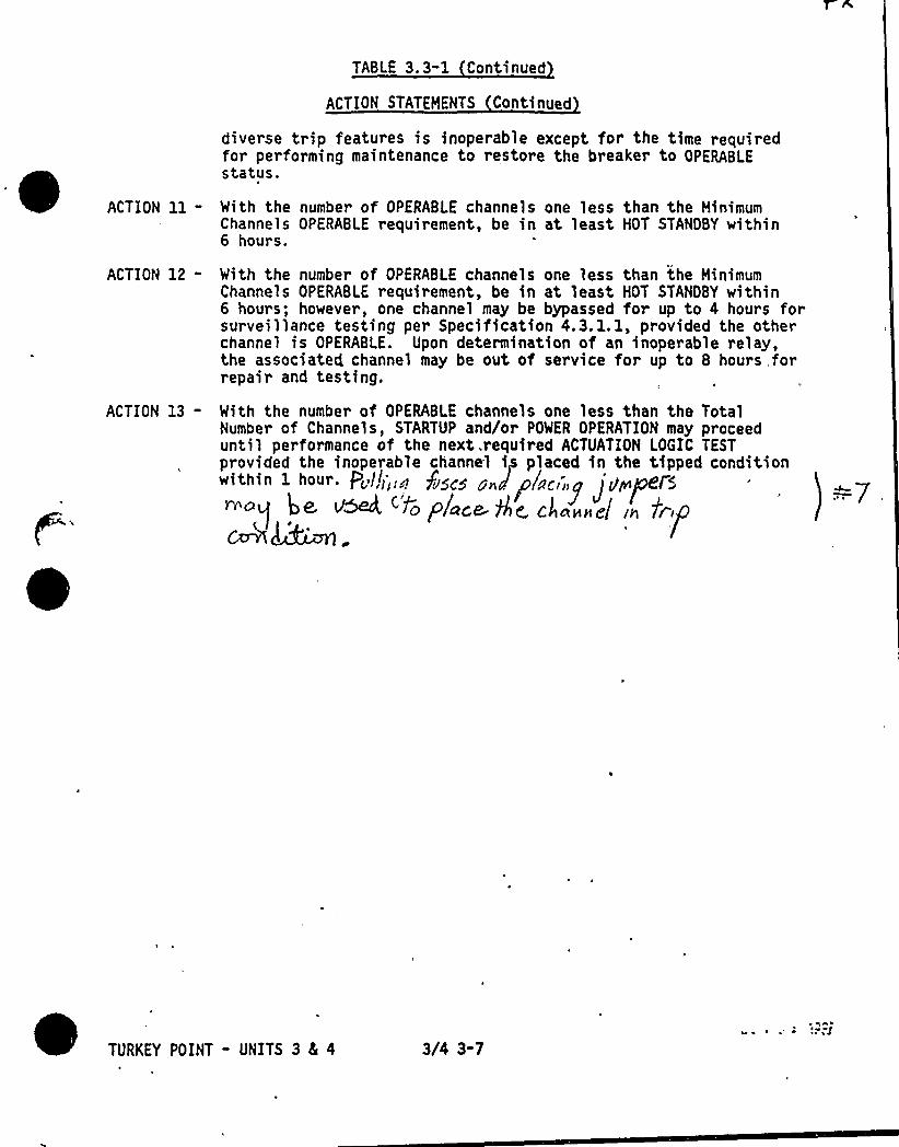
TABLE 3. 3-1 Continued
ACTION STATEMENTS Continued
diverse trip features is inoperable except for the time requiredfor performing maintenance to restore the breaker to OPERABLEstatus.
ACTION ll - With the number of OPERABLE channels one less than the MinimumChannels OPERABLE requirement, be in at least HOT STANOBY within6 hours.
ACTION 12 - With the number of OPERABLE channels one less than the Minimumhannels OPERABLE requirement, be in at least HOT STANDBY within
6 hours; ho~eve~, one channel may be bypassed for up to 4 hours forsurveillance testing per Specification 4.3. 1. 1, provided the otherchannel is OPERABLE. Upon determination of an inoperable relay,the associated channel may be out of service for up to 8 hours, forrepair and testing.
I
ACTION 13 - With the number of OPERABLE channels one less than the TotalNumber of Channels, STARTUP and/or POWER OPERATION may proceeduntil per formance of the next„required ACTUATION LOGIC TESTprovided the inoperable channel ip placed in the tipped conditionwithin 1 hour. P„//>».rr $~<~ ~~„j~/<«-,
~ro rrorrrr r f~r'.err r.'j n
?f'URKEY
POINT " UNITS 3 4 4 3/4 3-7
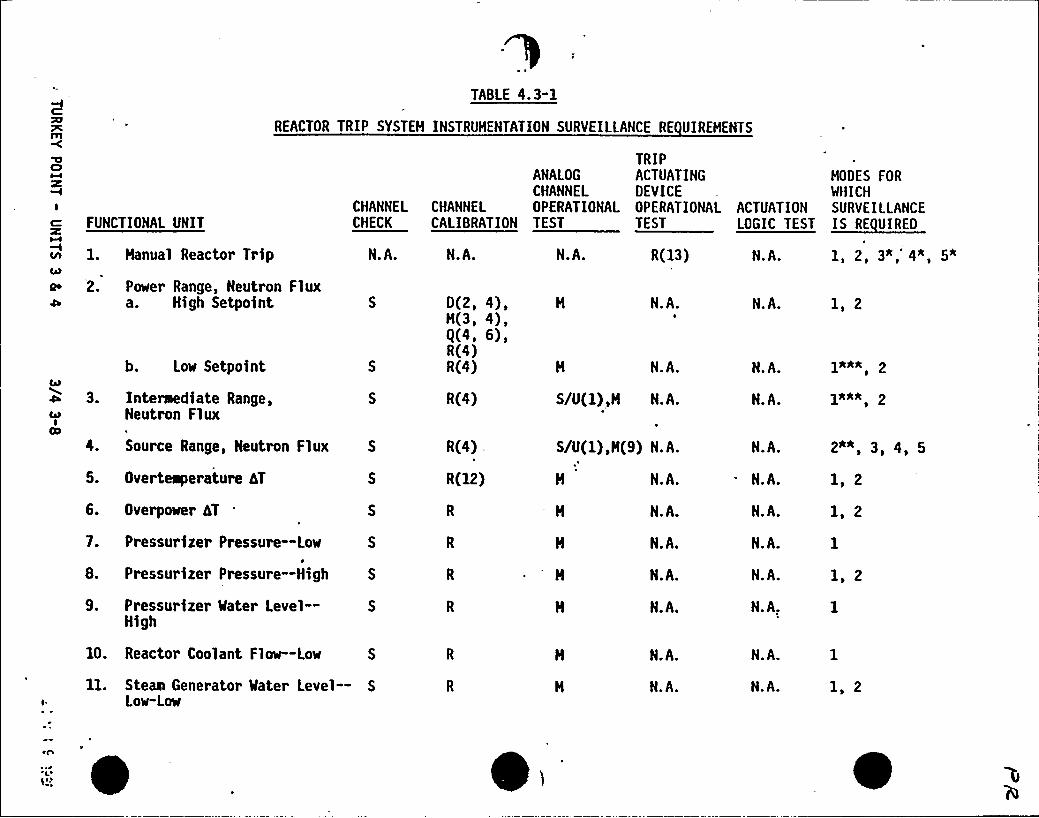
TABLE 4.3-1
REACTOR TRIP SYSTEM INSTRUMENTATION SURVEILLANCE RE UIREMENTS
Cl
I
FUNCTIONAL UNITCHANNELCHECK
TRIPANALOG ACTUATING MODES FORCHANNEL DEVICE WHICH
CHANNEL OPERATIONAL OPERATIONAL ACTUATION SURVEILLANCECALIBRATION TEST TEST ~E"
MC/l 1. Hanual Reactor Trip N.A. N.A. N.A. R(13) N.A. 3A 4* 5*
'2. Power Range, Neutron Fluxa. High Setpoint
b. Low Setpoint S
3. Interwediate Range, Scu Neutron Flux
Source Range, Neutron Flux S
5. Overteaperature AT
6. Overpower AT
7. Pressurizer Pressure —Low S
8. Pressurizer Pressure —High S
9. Pressurizer Water Level — S
High
10. Reactor Coolant Flow—Low S
ll. Steam Generator Water Level — SLow-Low
D(2, 4),H(3, 4),Q(4, 6),R(4)R(4)
R(4)
R(4)
R(12)
S/U(1),H
S/U(1),N(9)
N.A.
N.A.
N.A.
N.A.
N.A.
N.A.
N.A.
N.A.
N.A.
N.A.
N.A.
N.A.
N.A.
N.A.
N.A.
N.A.
N.A.
N.A.
N.A.
N.A,
N.A.
N.A.
1, 2
]*Ah'***
2"", 3, 4, 5
1, 2
1, 2
1, 2
1, 2
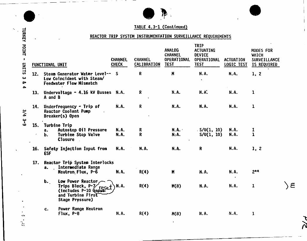
TABLE 4. 3-1 Continued
REACTOR TRIP SYSTEM INSTRUMENTATION SURVEILLANCE RE UIREMEHTS
I
FUNCTIONAL UNITCHANNELCHECK
ANALOGCHANNEL
CHANNEL OPERATIONALCALIBRATION TEST
TRIPACTUATING MOOES FOROEVICE WHICHOPERATIONAL ACTUATION SURVEILLANCETEST L l«E
12. Steam Generator Mater Level— S
Low Coincident with SteamlFeedwater Flow Hissatch
13. Undervoltage - 4.16 kV Busses N.A.A and B
N.A.
H.A.
N. A'.
N.A. 1, 2
N.A.
14. Underfrequency - Trip ofReactor Coolant PulpBreaker(s) Open
15. Turbine Tripa. Autostop Oil Pressureb. Turbine Stop Valve
Closure
N.A.
N.A.N.A.
N.A.
N.A.N;A.
N.A. H.A.
. S/U(1, 10) H.A.S/U(1, 10) N.A.
16. Safety Injection Input from N.A.ESF
1T. Reactor Trip Systemr Interlocksa. . Interaediate Range
Neutron. Flux, P"6 N.A.
N.A.
R(4)
N.A.
N.A.
H.A.
N.A.
1 2
b.
C.
Low Power ReactorTrips Block, P-(includes P-10and Turbine FirsStage Pressure)
Power Range NeutronFlux, P-8
H.A.
N.A.
R(4)
R(4)
M(8)
M(8)
N.A.
N.A.
N.A.
N.A.
~ ~~ ~
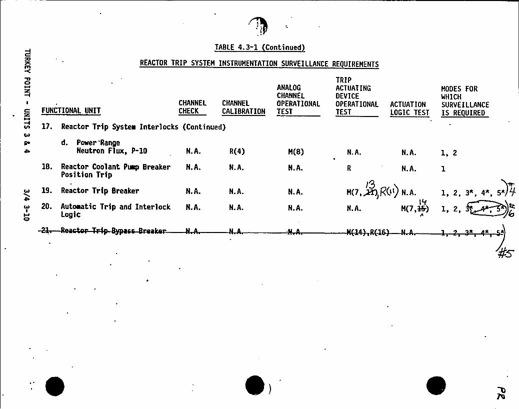
TABLE 4.3-1 Continued
REACTOR TRIP SYSTEH INSTRUHENTATION SURVEILLANCE
ANALOGCHANNEL
CHANNEL CHANNEL OPERATIONALCHECK CALIBRATION TEST
R(4) H(8)
18. Reactor Coolant Puep Breaker N.A.Position Trip
N.A. N.A.
CA3
ICl
19. Reactor Trip Breaker
20. Autoaatic Trip and InterlockLogic
N.A.
N.A.
N.A.
N.A.
N.A.
N.A.
I
FUNCTIONAL UNIT
v 17. Reactor Tr ip System Interlocks (Continued)
Qe d. Pmer 'RangeD Neutron Flux, P-10 N.A.
RE UIREHENTS
TRIPACTUATINGDEVICEOPERATIONALTEST
N.A. N.A.
N.A.
1, 2
l9H(7,~ g0') N.A.
1'fN.A. H(7,i+)
1, 2, 3*, 4*, 5)91, 2, , (
* *
HODES FORWHICH
ACTUATION SURVE ILLANCEl E«Ettl
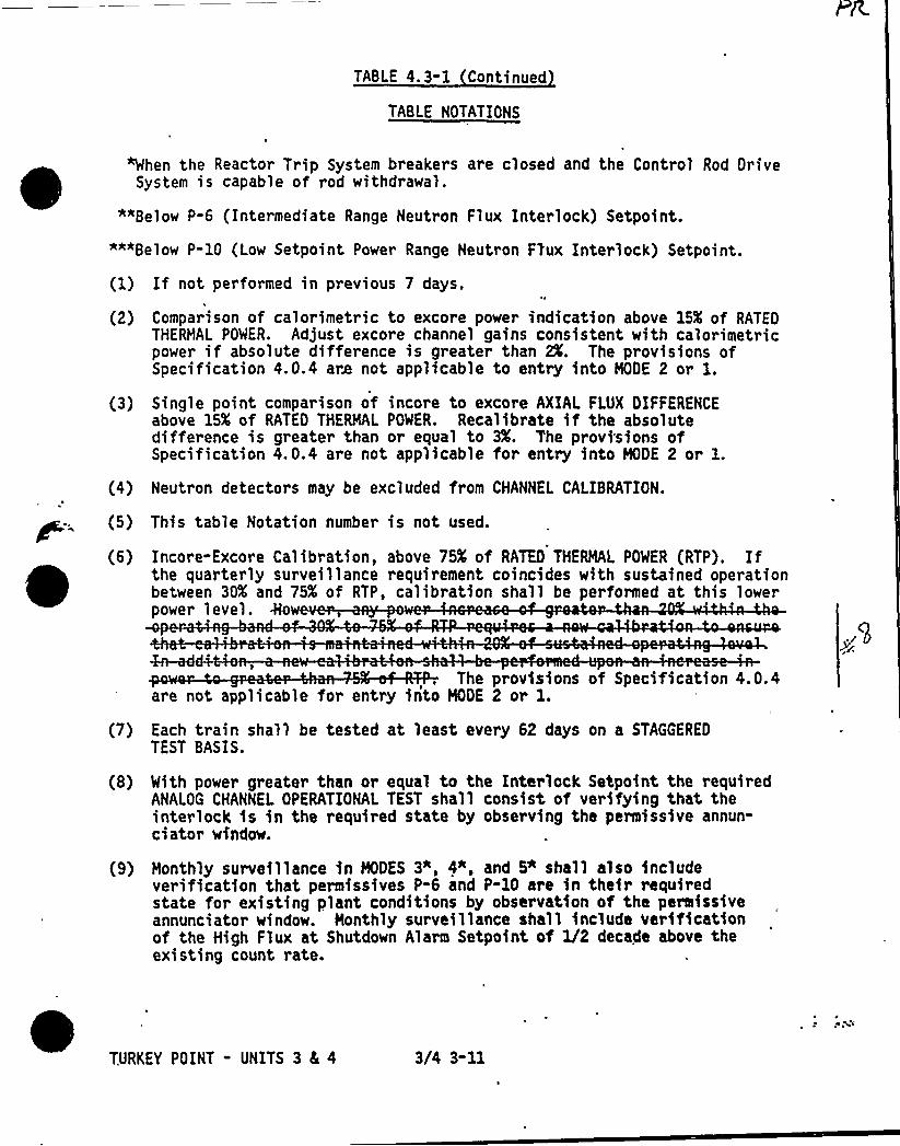
TABLE 4. 3-1 Continued
TABLE NOTATIONS
"When the Reactor Trip System breakers are closed and the Control Rod DriveSystem is capable of rod withdrawal.
""Below P-6 (Intermediate Range Neutron Flux Interlock) Setpoint.
""*Below P-10 (Low Setpoint Power Range Neutron Flux Interlock) Setpoint.
If not performed in previous 7 days.
(2)
(3)
(4)
(5)
(6)
Comparison of calorimetric to excore power indication above 15K of RATEDTHERMAL POWER. Adjust excore channel gains consistent with calorimetricpower if absolute difference is greater than 2X. The provisions ofSpecification 4. 0.4 are not applicable to entry into MODE 2 or l.Single point comparison of incore to excore AXIAL FLUX DIFFERENCEabove 15K of RATED THERMAL POWER. Recalibrate if the absolutedifference is greater than or equal to 3X. The provisions ofSpecification 4.0.4 are not applicable for entry into MODE 2 or l.Neutron detectors may be excluded from CHANNEL CALIBRATION.
This table Notation number is not used.
Incore-Excore Calibration, above 75K of RATH) THERMAL POWER (RTP). Ifthe quarterly surveillance requirement coincides with sustained operationbetween 30K and 75K of RTP, calibration shall be performed at this lowerpower level.
(7)
4e-add+The provisions of Specification 4.0.4
are not applicable for entry into MODE 2 or l.Each train shall be tested at least every 62 days on a STAGGEREO
TEST BASIS.
With power greater than or equal to the Interlock Setpoint the requiredANALOG CHANNEL OPERATIONAL TEST shall consist of verifying that, theinterlock is in the required state by observing the permissive annun-ciator window.
Monthly surveillance in MODES 3", 4", and 5" shall also includeverification that permissives P-6 and P-10 are in their requiredstate for existing plant conditions by observation of the permissiveannunciator window. Monthly surveillance shall include verificationof the High Flux at Shutdown Alarm Setpoint of 1/2 decade above theexisting count rate.
TURKEY POINT - UNITS 3 4, 4 3/4 3-11

TABLE 4. 3-1 Continued
TABLE NOTATIONS Continued
(1Q) Setpoint verifica is t applicable.r
<uel'11)At least once p r a following maintenance or adjustment of theReactor trip bre P ACTUATING DEVICE OPERATIONAL TEST shallinclude independent verification of the Undervoltage and Shunt trips.
(12) CHANNEL CALIBRATION shall include the RTD bypass loops flow rate.
(13) The TRIP ACTUATING DEVICE OPERATIONAL TEST shall independently verifythe OPERABILITY of the undervoltage and shunt trip circuits for the ManualReactor Trip Function. The test shall also verify the OPERABILITY. of theBypass Breaker trip circuit(s).
lg~) Interlock Logic Test shall consist of verifying that the interlock is inits required state by observing the permissive annunciator window.
0
, TURKEY POINT - UNITS 3 4 4 3/4 3-12~ ~
~ ~ I ~
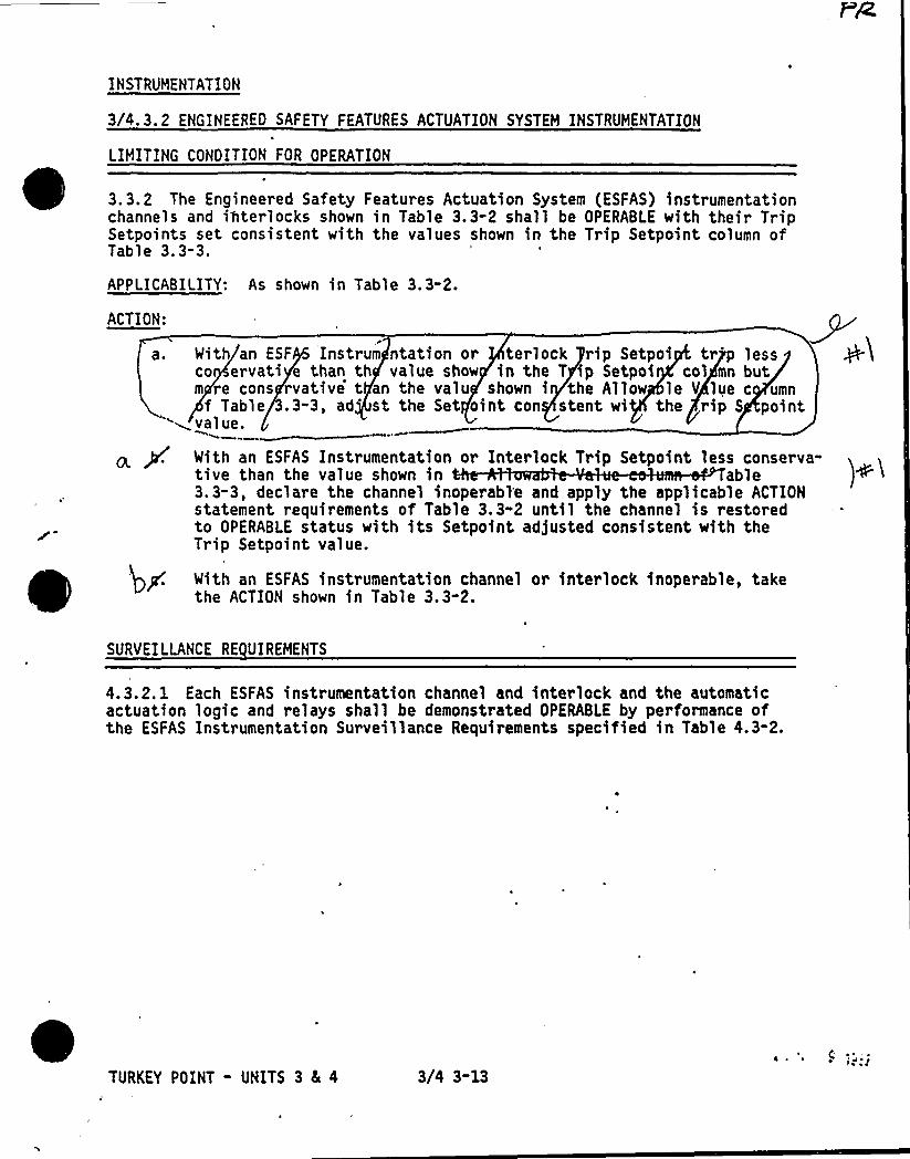
INSTRUMENTATION
3/4.3.2 ENGINEEREO SAFETY FEATURES ACTUATION SYSTEH INSTRUMENTATION
LIMITING CONOITION FOR OPERATION
3.3.2 The Engineered Safety Features Actuation System (ESFAS) instrumentation~ ~
~
~
~
channels and interlocks shown in Table 3.3-2 shall be OPERABLE with their TripSetpoints set consistent with the values shown in the Trip Setpoint column ofTable 3.3-3.
APPLICABILITY: As shown in Table 3.3-2.
ACTION:
a. With an ESF Instrum ntation or terlock rip Setpoi tr'p lessco ervati e than th value show in the T ip Setpoi col mn butm re cons rvative t an the valu shown i the Allow le V lue c umnf Table 3.3-3, ad 't the Set oint con stent wi the rip S point
~value.
P. With an SSFAS Instrumentation or Interlock Trip Setpoint less conserva-tive than the value shown in able3.3-3, declare the channel inoperabl'e and apply the applicable ACTIONstatement requirements of Table 3.3-2 until the channel is restoredto OPERABLE status with its Setpoint adjusted consistent with theTrip Setpoint value.
With an ESFAS instrumentation channel or interlock inoperable, takethe ACTION shown in Table 3.3-2.
SURVEILLANCE RE UIREHENTS
4.3.2. 1 Each ESFAS instrumentation channel and interlock and the automaticactuation logic and relays shall be demonstrated OPERABLE by performance ofthe ESFAS Instrumentation Surveillance Requirements specified in Table 4.3-2.
TURKEY POINT - UNITS 3 ic 4 3/4 3-13
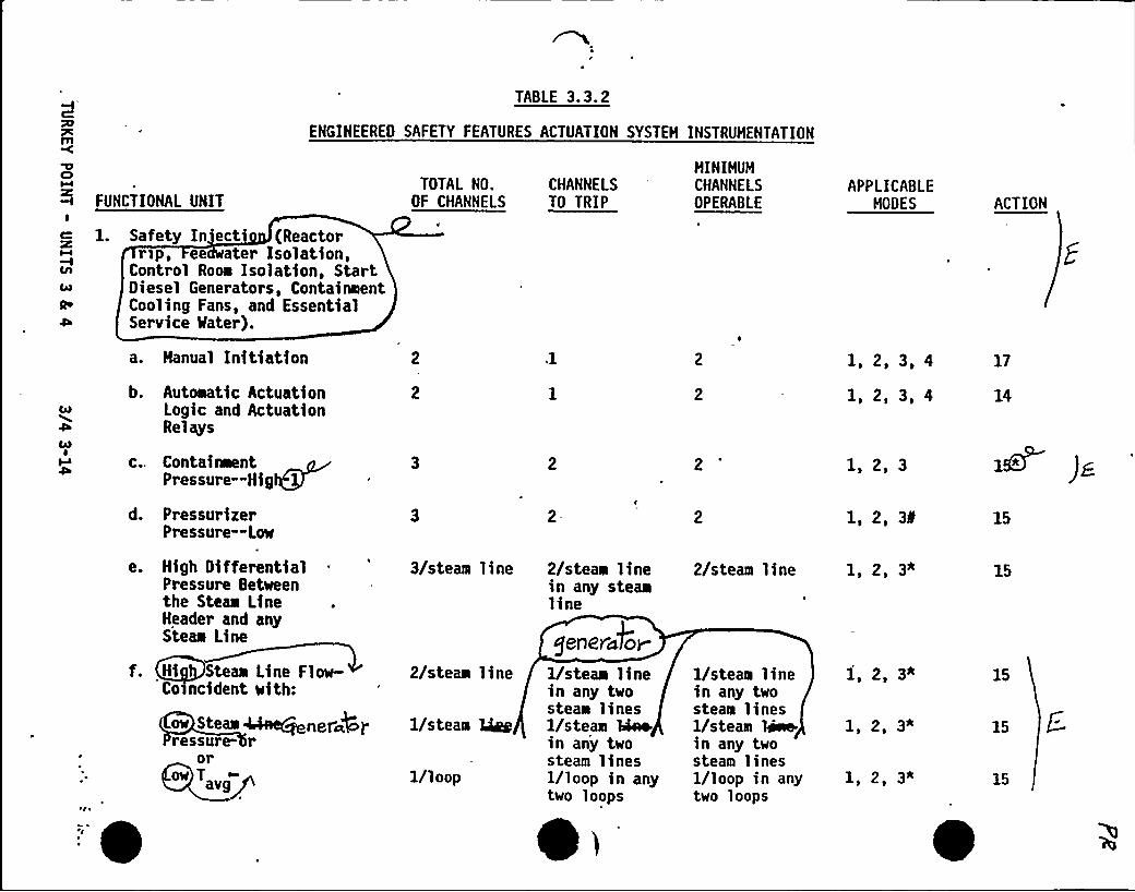
TABLE 3.3.2
ENGINEERED SAFETY FEATURES ACTUATION SYSTEH INSTRUMENTATION
CI'I
FUNCTIONAL UNIT
1. Safety In'ect (Reactorrsp, ee ater Isolation,
Control Room Isolation, StartDiesel Generators, ContainmentCooling Fans, and EssentialService Mater).
TOTAL NO.OF CHANNELS
CHANNELSTO TRIP
HINIHUHCHANNELSOPERABLE
APPLICABLEHODES ACTION
OiD00I
a. Hanual Initiation
b. Automatic ActuationLogic and ActuationRelays
c.. ContainwentPressure-Hig
d. PressurizerPressure —Low
e. High DifferentialPressure Betweenthe Steam LineHeader and anySteam Line
f. Hi Steam Line Flow-Co ncident with:
ee Steee ~ACjenera@Iressure- r
orhssowT„
'0
3/steam line
2/steam line
1/steam Qgg
1/loop
2/steam linein any steamline
geIIerci&or
1/steam linein any twosteam lines1/steam Qaoin any twosteam lines1/loop in anytwo loops
2
2/steam line
1/steam linein any twosteam lines1/steam Beein any twosteam lines1/loop in anytwo loops
1, 2, 3, 4
1, 2, 3, 4
1, 2, 3
1, 2, 3f
1, 2, 3"
1, 2, 3*
1, 2, 3*
1, 2, 3*
17
14
1SB )g
15
15
15
15
15
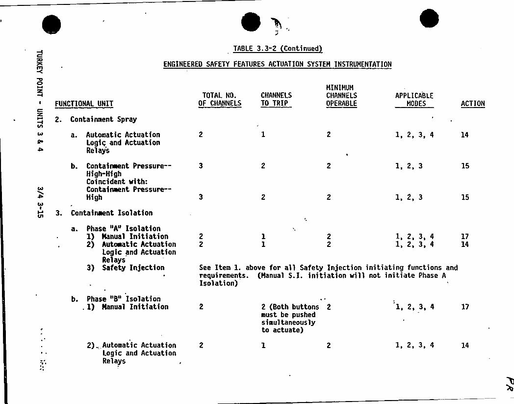
yTABLE 3.3-2 Continued
ENGINEERED SAFETY FEATURES ACTUATION SYSTEM INSTRUMENTATION
Cl
FUNCTIONAL UNIT
2. Containment Spray
a. Automatic ActuationLogig and ActuationRelays
TOTAL NO. CHANNELSOF CHANNELS TO TRIP
MINIMUMCHANNELSOPERABLE
APPLICABLEMODES
1, 2, 3, 4
ACTION
14
00
ColI
Ql
b. Containment Pressure—High-HighCoincident with:Containment Pressure—High
3. Containient Isolation
a. Phase "A" Isolation1) Nanual Initiation2) Autoeatic Actuation
Logic and ActuationRelays
3) Safety Injection
1, 2, 3
1,2,3
1, 2, 3, 41, 2, 3, 4
See Item 1. above for all Safety Injection initiating functions andrequirements. (Manual S.I. initiation sill not initiate Phase AIsolation)
15
15
1714
b. Phase "8" Isolation. I) Hanual Initiation
2) Automatic ActuationLogic and ActuationRelays
2 (Both buttons 2must be pushedsimultaneouslyto actuate)
1, 2, 3, 4
1, 2, 3, 4
17

TABLE 3. 3-2 Continued
ENGINEERED SAFETY FEATURES ACTUATION SYSTEH INSTRUNENTATION
FUNCTIONAL UNIT
3. Containment Isolation (Continued)
TOTAL NO.OF CHANNELS
CHANNELSTO TRIP
HINIHUHCHANNELSOPERABLE
APPLICABLENODES ACTION
3) Containment 3Pressure —High-HighCoincident with:Containment Pressure—High 3 2
1, 2, 3
1,2,3
15
15
c. Containment Vent)lationIsolation1) Containment Isolation
Manual Phase A orPhase B
2) Automatic ActuationLogic and ActuationRelays
3) Safety Injection
4) High Containmentoactivity-
4. Steam Line Isolation
See Items 3.a.l and 3.b.l above for all Hanual ContainmentVentilation functions and requirements.
1, 2, 3, 4
See Item 1. above for all Safety Injection initiating functions andrequirements.
1, 2, 3, 4
16
X6 )g
a. Nanual Initiation(individual)
b. Automatic ActuationLogic and ActuationRelays
1/steam line
1/steam line
1/steam line
1, 2, 3
1, 2, 3
21
20
0
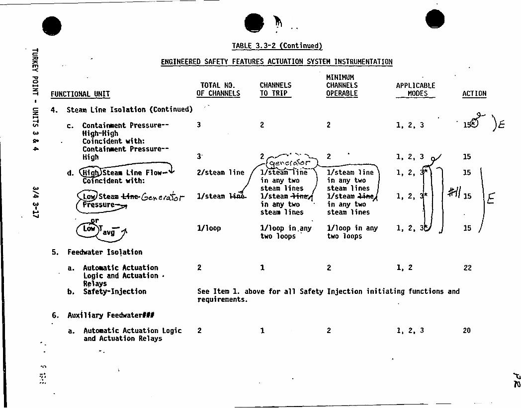
TABLE 3.3-2 Continued
ENGINEEREO SAFETY FEATURES ACTUATION SYSTEH INSTRUMENTATION
FUNCTIONAL UNIT
4. Steam Line Isolation (Continued)
TOTAL NO.OF CHANNELS
CHANNELSTO TRIP
HINIHUNCHANNElSOPERABLE
APPLICABLENODES ACTION
c. Containment Pressure—High-HighCoincident with:Containment Pressure—High
d. Hi Steam Line Flow-Co>ncident with:
2/steam line
Lo Steam 44ee-Qc> ei~gzt- 1/steamPressure
2ev ei'e$ nf"
1/steam inein any twosteam lines1/steam +ice/in any twosteam lines
2
1/steam linein any twosteam lines1/steam kinein any twosteam lines
1 2 3
1,2,31, 2,
15
15
@I x5
Low T„
5. Feedwater isolation
1/loop 1/loop in. anytwo loops
'/loop in anytwo loops
1, 2, 3
a. Automatic ActuationLogic and Actuation .
Relaysb. Safety-injection
6. Auxiliary FeedwaterÃf
1, 2
See Item 1. above for all Safety Injection initiating functions andrequirements.
22
a. Automatic Actuation Logic 2and Actuation Relays
1, 2, 3 20
rg
~ e
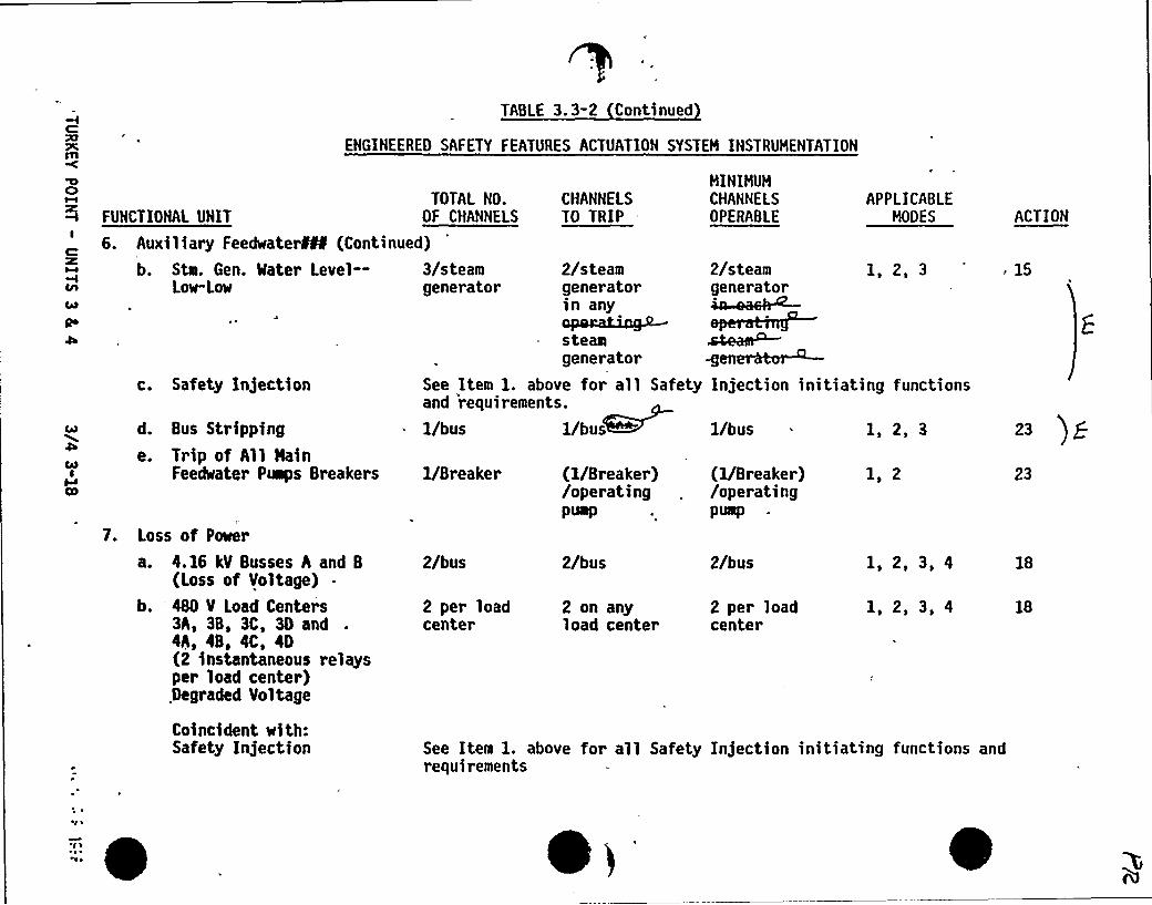
C:
m
TABLE 3.3-2 Continued
ENGINEERED SAFETY FEATURES ACTUATION SYSTEM INSTRUMENTATION
C)
I
C
Qo
TOTAL NO.FUNCTIONAL UNIT OF CHANNELS
6. Auxiliary FeedwaterfN (Continued)
b. Ste. Gen. Water Level — 3/steamLos-Low generator
CHANNELSTO TRIP
2/steamgeneratorin any
MINIMUMCHANNELSOPERABLE
2/steamgenerator
APPLICABLEMODES
1,2,3
ACTION
~ 15
Ca>I
CD
c. Safety Injection
d. Bus Stripping 1/bus
e. Trip of All NainFeedwater Pueps Breakers 1/Breaker
1, 2, 3
(1/Breaker)/operatingpuep
(1/Breaker)/operatingpulap
1, 2
steam ~eg
See Item 1. above for all Safety Injection initiating functionsand 'requirements.
I/bus 1/bus 23 )P23
7. Loss of Paara. 4.16 kV Busses A and B
(Loss of Voltage)-b. '480 V Load Centers
3A, 3B, 3C, 3D and4A, 4B, 4C, 4D(2 instantaneous relaysper load center)Degraded Voltage
2/bus
2 per loadcenter
2/bus
2 on anyload center
2/bus
2 per loadcenter
1, 2, 3, 4
1, 2, 3, 4
18
18
Coincident with:Safety Injection See Item 1. above for all Safety Injection initiating functions and
requirements
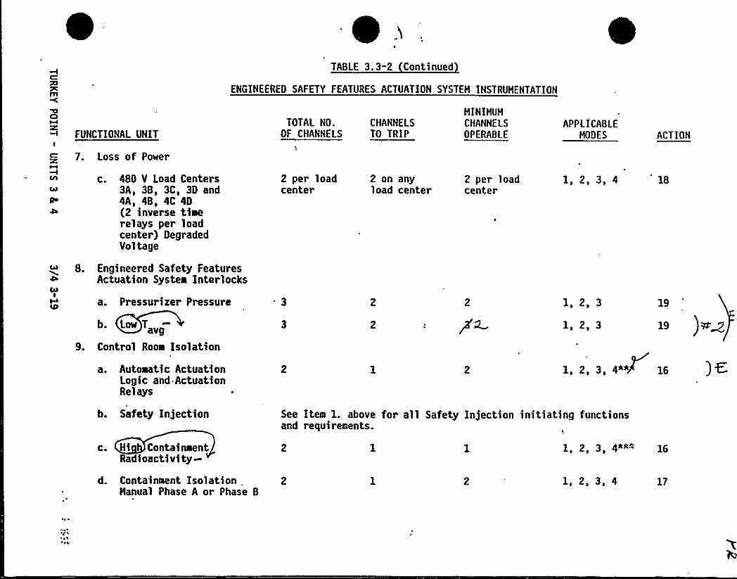
TABLE 3.3-2 Continued
ENGINEERED SAFETY FEATURES ACTUATION SYSTEM INSTRUMENTATION
C)
FUNCTIONAL UNITI
7. Loss of Power
Qo
c. 480 V Load Centers3A, 3B, 3C, 3D and4A, 48, 4C 4D(2 inverse timerelays per loadcenter) DegradedVoltage
b. Lee T
9. Control Room Isolation
a. Automatic ActuationLogic and.ActuationRelays
8. Engineered Safety FeaturesActuation System Interlocks
IW a. Pressurizer Pressure
2 per loadcenter
2 on anyload center
TOTAL NO. CHANNELSOF CHANNELS TO TRIP
HINIHUMCHANNELSOPERABLE
2 per loadcenter
APPLICABLEMODES
1, 2, 3, 4
1 2 3
1, 2, 3
2 3 4~*
ACTION
18
19
19 ) 9S'~
b. Safety Injection
c. Hi ContainwentRadioactivity-
See Item 1. above for all Safety Injection initiating functionsand requireaients.
1 2 3 4""" 16
d. Containment Isolation „2Hanual Phase A or Phase 8
1, 2, 3, 4 17
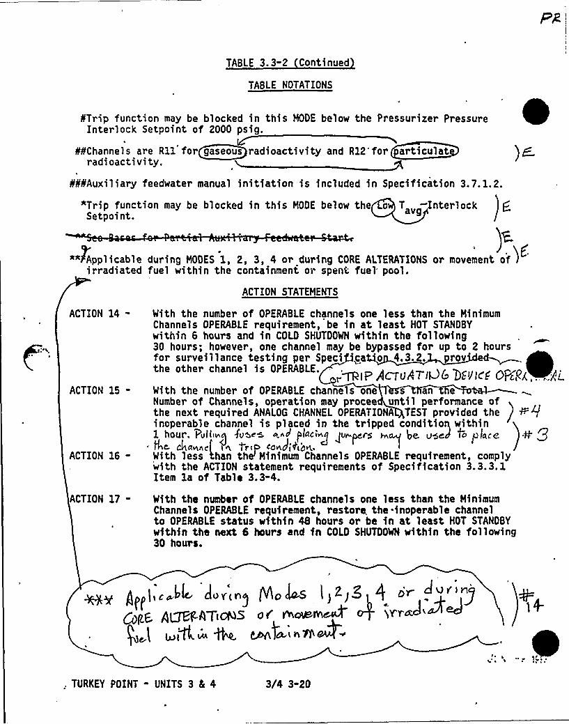
TABLE 3. 3-2 Continued
TABLE NOTATIONS
STrip function may be blocked in this MODE below the Pressurizer PressureInterlock Setpoint of 2000 psig.
¹¹Channels are R11 for gaseous radioactivity and R12'for articulatradioactivity.
a
¹¹¹Auxiliary feedwater manual initiation is included in Specification 3.7. 1.2.
*Trip function may be blocked in this MODE below the o T „ -InterlockSetpoint. avg
"" Applicableirradiated
ACTION 14-
ACTION 15-
ACTION 16-
ACTION 17-
)~during MODES 1, 2, 3, 4 or during CORE ALTERATIONS or movement offuel within the containment o> spent fuel pool.
ACTION STATEMENTS
With the number of OPERABLE channels one less than the MinimumChannels OPERABLE requirement, be in at least HOT STANDBYwithin 6 hours and in COLD SHUTDOWN within the following30 hours; however, one channel may be bypassed for up to 2 hoursfor surveillance testing per Speci ca o 4.3.2. rovthe other channel is OPERABLE.
With the number of OPERABLE channels one s an eNumber of Channels, operation may procee until performance ofthe next required ANALOG CHANNEL OPENATIONA TEST provided the ) Vrginoperable channel is placed in the tripped conditioq withinI hour. iavlliacI Tvoau a d pfaci~g pc pere cap iae oooo ih place
. AC C4aeneI i n TriP LOWO jADN.,With less than the'inimum Channels OPERABLE requirement, complywith the ACTION statement requirements of Specification 3.3.3. 1Item 1a of Table 3.3-4.
With the number of OPERABLE channels one less than the MinimumChannels OPERABLE requirement, restore. the inoperable channelto OPERABLE status within 48 hours or be in at least HOT STANDBYwithin the next 6 hours and in COLD SHUTDOWN within the following30 hours.
),c LIe cIovcrag gocjcts I>E.JS l f ov
Qfgg QQpfATcggs dd vvadaeephM p 'iv'rcto'~~lac lflcaa ~ CdutIduc n Tp ~~ .0
, TURKEY POINT - UNITS 3 8L 4 3/4 3-20

TABLE 3 '-2 Continued
ACTION STATEMENTS Continued
ACTION 18 - With the number of OPERABLE channels one less than the TotalNumber of Channels, STARTUP and/or POWER OPERATION may proceedprovided the inoperable channel is placed in the trippedcondition within 1 hour.
ACTION 19-
ACTION 20-
ACTION 21-
ACTION 22-
ACTION 23-
With less than the Minimum Number of Channels OPERABLE, within1 hour determine by observation of the associated permissiveannunciator window(s) that the interlock is in its requiredstate for the existing plant condition, or apply Specification3. 0. 3.
With the number of OPERABLE channels one less than the HinimumChannels OPERABLE requirement, be in at least HOT STANDBYwithin 6 hours and in at least HOT SHUTDOWN within the following6 hours; however, one channel may be bypassed for up to 2 hoursfor surveillance testing per Specification 4.3.2.1 provided theother channel is OPERABLE.
With the number of OPERABLE channels one less than the TotalNumber of Channels, restore the inoperable channel to OPERABLEstatus within 48 hours or declare the associated valve inoperableand take the ACTION required by Specification 3.7.1.5.
With the number of OPERABLE channels one less than the MinimumChannels OPERABLE requirement, be in at least HOT STANDBY within6 hours; however, one channel may be bypassed for up to 2 hoursfor surveillance testing per Specification 4.3.2.1 provided theother channel is OPERABLE.
With the number of OPERABLE channels one less than the MinimumChannels OPERABLE requirement, comply with Specification 3. 0. 3.
I
TURKEY POINT - UNITS 3 8c 4 3/4 3-21
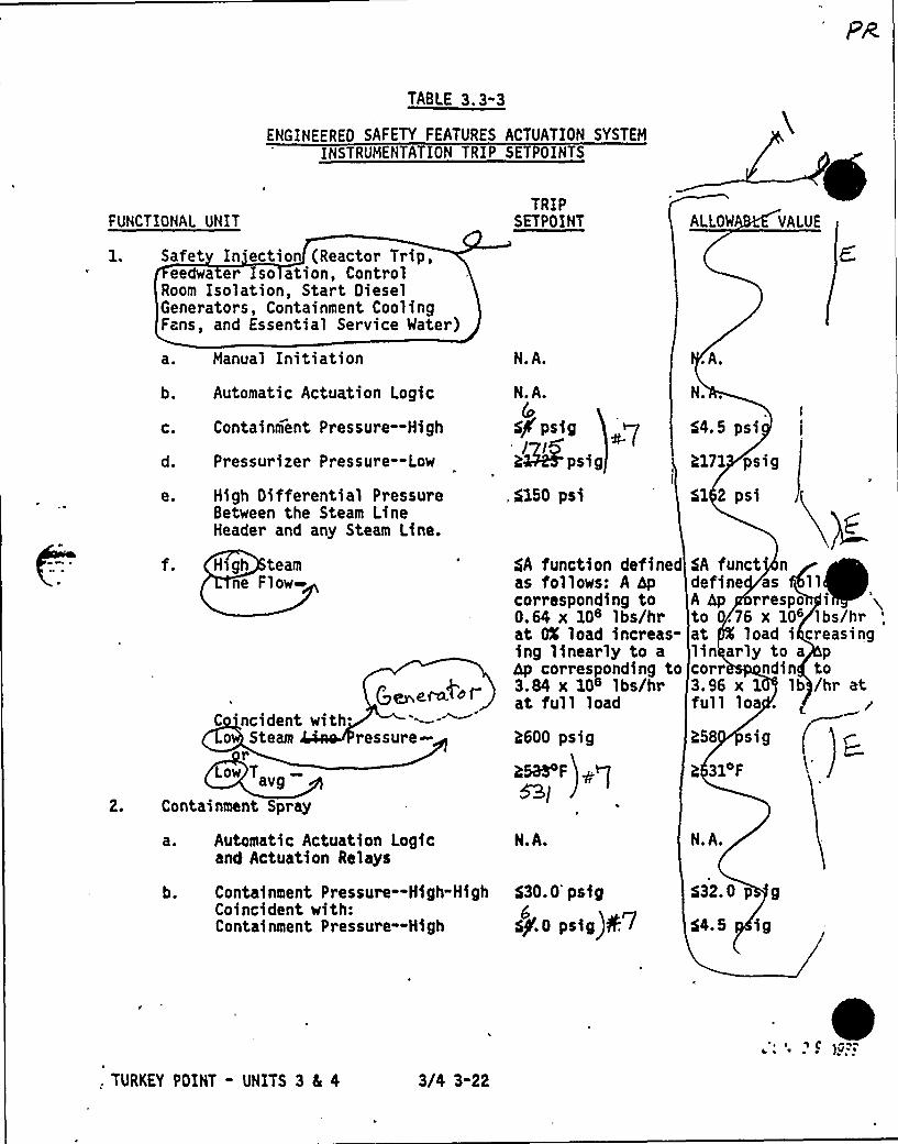
TABLE 3.3-3
ENGINEERED SAFETY FEATURES ACTUATION SYSTEMINSTRUMENTATION TRIP SETPOINTS
FUNCTIONAL UNIT
Safet In'ectian (Reactor Trip,eedwa er so ation, Control
Room Isolation, Start DieselGenerators, Containment CoolingFans, and Essential Service Water)
TRIPSETPOINT ALLOW VALUE
a ~
b.
C.
d.
e.
Manual Initiati on
Automatic Actuation Logic
Containment Pressure —High
Pressurizer Pressure--Low
High Differential PressureBetween the Steam LineHeader and any Steam Line.
N.A.
N.A.
.$l50 psi
.A.
N.
$4.5 psi
?171 ps ig1
51 2 psi
2.
H>gh teamne Flow
c,~ ~0of-C 'ncident with.
o Steam 'essure-Low T „
Containment Spray
Automatic Actuation Logicand Actuation Relays
$A function definedas follows: A hpcorresponding to0.64 x 10e lbs/hrat OX load increas-ing linearly to ahp corresponding to3 84 x 10e lbs/hrat full load
?600 psig
2525 F
S3g
N.A.
$A funct ndefine as 11
A hp rrespo ito .76 x 10 lbs/hrat load i creasinglin arly to a pcorr ndin to3.96 x 1 lb /hr atfull loa .
?58 sig
? 3IF ~
N.A.
b. Containment Pressure-High-HighCoincident with:Containment Pressure-High
530. 0's ig
sP'.0 psig)+ 76
$32.0 p g
54. 5 ig
, TURKEY POINT - UNITS 3 4 4 3/4 3-22
~ ~ ~ p )V ~
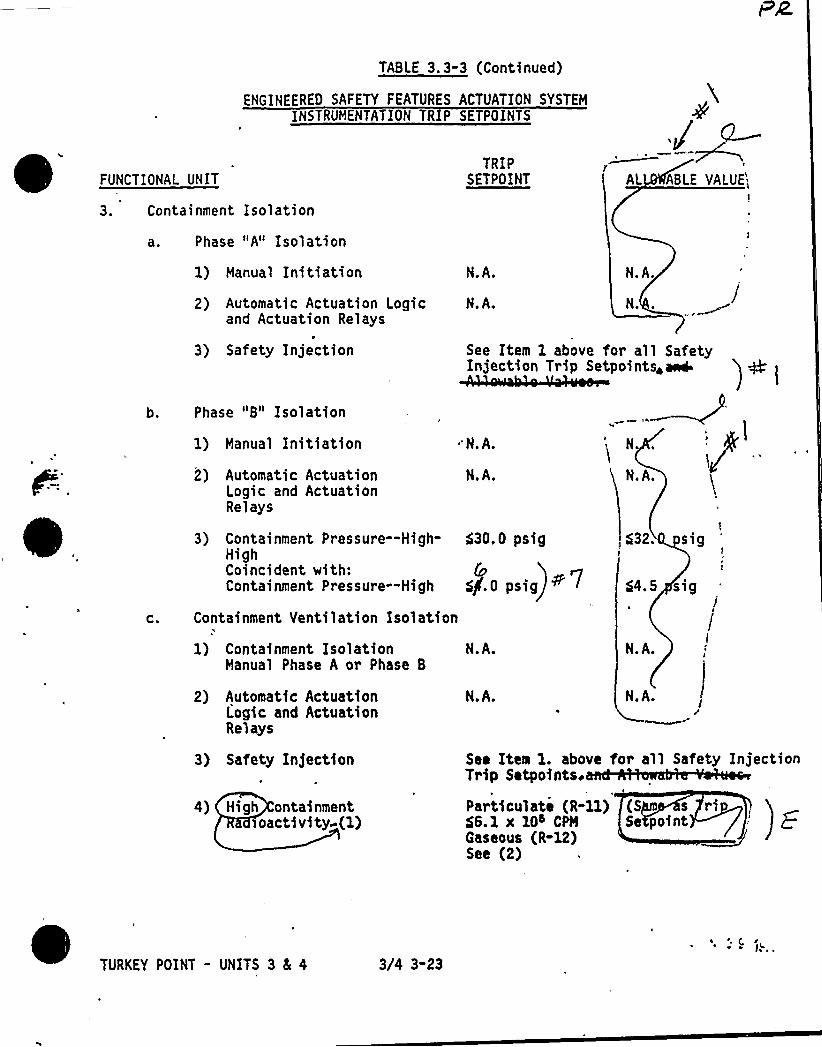
TABLE 3. 3-3 (Continued)
ENGINEERED SAFETY FEATURES ACTUATION SYSTEMINSTRUMENTATION TR P SETPOINTS
FUNCTIONAL UNITTRIP
SETPOINT AL ABLE VALUE
3. Containment Isolation
a. Phase "A" Isolation
1} Manual Initiation N.A. N.A.
b.
2) Automatic Actuation Logicand Actuation Relays
3) Safety Injection
Phase "B" Isolation
1) Manual Initiation
2) Automatic ActuationLogic and ActuationRelays
N.A. N.
'N.A.
N.A.
See Item 1 above for all SafetyInjection Trip Setpointsiaa4
N
N.A.
3) Containment Pressure-High-HighCoincident with:Containment Pressure —High
530.0 psig
5)0 psig
$32. s ig
$4.5 sig
C. Containment Ventilation Isolation
1) Containment Isolation N.A.Manual Phase A or Phase B
N.A.
2) Automatic ActuationLogic and ActuationRelays
N.A. N.A.J
3) Safety Injection
4) High ontainmentioactivity-(1)
See Item 1. above for all Safety InjectionTrip Setpointsi
Particulate (R-ll) (S s ri56.1 x 10s CPH Se pointGaseous (R-12)See (2)
t
TURKEY POINT - UNITS 3 Ec 4 3/4 3-23
~ Q r~ ~ JI
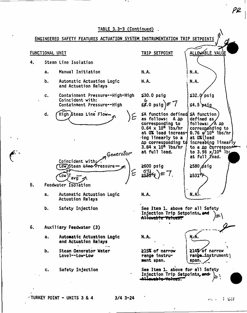
TABLE 3. 3-3 Continued
ENGINEEREO SAFETY FEATURES ACTUATION SYSTEM INSTRUMENTATION TRIP SETPOINTS
FUNCTIONAL UNIT TRIP SETPOINT ALLO BLE VAL
4.
5.
Steam Line Isolation
a. Hanual Initiation
b. Automatic Actuation Logicand Actuation Re1ays
C.
d.
Containment Pressure--High-HighCoincident with:Containment Pressure--High
High team Line Flow-
@~errorCoincident with
ow Steam kkee- ressure-0
avg~Feedwater Iso ation
a. Automatic Actuation LogicActuation Relays
N.A.
N.A.
530.0 psig&
$$.0 psig 8
$A function defineas follows: A hpcorresponding to0.64 x 10e lbs/hrat GX load increas
~ ing linearly to ahp corresponding t3.&4 x 1Qe lbs/hrat full load.
2600 psig
N.A.
I N.A.
„'.A.
$32. psig
54.5
$A functiondefined asfollows: A hpcorres nding to0.76 10'bs/hat OX loadincrea ng linea r'ly
?580 sig
2531
N.A.
to a hp rrespon~to 3a96 x 10s lbat full oad.
6.
b. Safety Injection
Auxiliary Feedwater (3)
See Item 1. above for all SafetyInjection Trip Setpointa, ene
)
b.
Automatic Actuation Logicand Actuation Relays
Steam Generator MaterLevel —Low-Low
N.A.
215K of narrowrange instru-ment span.
214 of narrowran strument jspan.
c. Safety Injection See Item 1. above for all SafetyInjection Trip Setpoints, and
'URKEY POINT - UNITS 3 4 4 3/4 3-24

TABLE 3.3"3 (Continued)
ENGINEERED SAFETY FEATURES ACTUATION SYSTEM INSTRUMENTATION TRIP SETPOINTS
~
~FUNCTIONAL UNIT
6. Auxiliary Feedwater (Continued)
d. Bus Stripping
e. Trip of All Hain FeedwaterPump Breakers.
TRIP SETPOINT
N.A.
See Item 7. below for all BusStripping Setpoints,
4eiees-.
N.A.
+)!
7. Loss of Power
4.16 kV Busses A and B
(Loss of Voltage)N.A. N.A.
b. 480V Load Centers(Instantaneous Relays)Degraded Voltage
Load enter
3A
3B
3C
30
4B
4C
40
Coincident With:Safety In5ection
~g,y'(8 la436VPBI-sec delay)
~6-Iy(4@'16VQesec delay);
=rll~,'2417VQQ sec delay);
6
Within + 5volts'of
S point
--/&io42f~sec delay)al big
415fR8 sec delay)mv'(hl0
414 ~ sec delay)~svk/0
401V sec delay)h+mfbe
403V secdelay)'ee
Item 1. above for all SafetyInjection Tain Setnoints aad 'j~ )
7
TURKEY POINT - UNITS 3 81 4 3/4 3-25
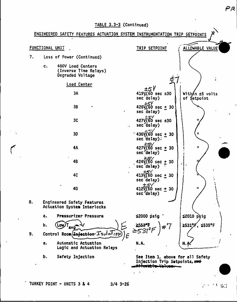
TABLE 3.3-3 (Continued)
ENGINEERED SAFETY FEATURES ACTUATION SYSTEM INSTRUMENTATION TRIP SETPOINTS
FUNCTIONAL UNIT TRIP SETPOINT ALLOWAB VALUE
7. Loss of Power (Continued)
C. 480V Load Centers(Inverse Time Relays)Degraded Voltage
Load Center
3A
3B
3C
30
4B
4C
40
419$ (60 sec 130sec delay)
~eY426V<(60 sec + 30sec delay)
~c/427V(KO sec 430sec Belay)
~ e ~
"436V'(65 sec + 30sec Belay)-
427llg(( eec + 30sec delay)
424V„ sec + 30sec delay)
+m/413V(60 sec + 30sec delay)
+~/412Vf60 sec + 30sec delay)
Wit n t5 voltsof etpoi nt
8. Engineered Safety FeaturesActuation System Interlocks
a. Pressurizer Pressure $2000 psig
b. Low T „~ RID 0set'F
Control Room 4ajoc44en-C sar~ r W
a. Automatic Actuation N.A.Logic and Actuation Relays
$2010 p ig
R531 $535 F
N.
b. Safety Injection See Item 1. above for all SafetyIn)ection Trip Setpoints, eel
TURKEY POINT - UNITS 3 4 4 3/4 3-26

TABLE 3.3-3 Continued
ENGINEERED SAFETY FEATURES ACTUATION SYSTEM INSTRUMENTATION TRIP SETPOINTS
FUNCTIONAL UNIT. +~/~pl FVl
c ')F-ioacti vi ty-(1)
d. Containment IsolationManual Phase A or Phase B
TRIP SETPOINT
Particulate (R-Il)S6.1 x 10s CPMGaseous (R-12)See (2)
N.A.
ALLOWABLE VALUE
(Sa as TripSetpoi t)
N.A.
TABLE NOTATIONS
(1) Either the particulate or gaseous channel in the OPERABLE status willsatisfy this LCO.
r3,2 x 10~>(2) Containment Gaseous Monitor Setpoint= .'
CPM,
Where FActual Purge Fl ow
esign Purge Flow 35,000 CFM
Setpoint may vary according to current plant conditions provided thatthe release rate. does not exceed allowable limits provided inSpecification 3.11.2.1.
(3) Auxiliary feedwater manual initiation is included in Specification3. 7. 1. 2.:
TURKEY POINT - UNITS 3 4 4 3/4 3-27
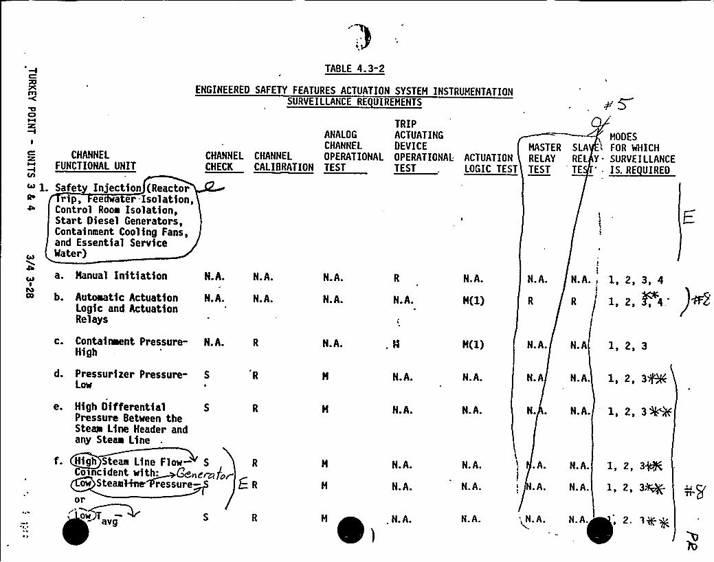
CHANNELFUNCTIONAL UNIT
Safet Injection (Reactorrip, ee a er-Isolation,
Control Rooa Isolation,Start Diesel Generators,Containment Cooling Fans,and Essential ServiceMater)
3TABLE 4.3"2
ENGINEERED SAFETY FEATURES ACTUATION SYSTEM INSTRUMENTATIONSURVEILLANCE RE UIREMENTS
TRIPANALOG ACTUATINGCHANNEL DEVICE
CHANNEL CHANNEL OPERATIONAL OPERATIONAL ACTUATIONCHECK CALIBRATION TEST TEST . LOGIC TEST
HOOES
MASTER SLA i FOR WHICHRELAY REL Y. SURVEILLANCE~E
a. Manual Initiation N.A.
b. Autoaatic Actuation N.A.Logic and ActuationRelays
N.A.
N.A.
N.A.
N.A. N.A.
N.A.
M(1)
N.A. N.A.I 1,2,3,4
c. Contaiment Pressure- N.A.High
d. Pressurizer Pressure- SLow
e. High OifferentialPressure Between theStew Line Header andany Steaa Line
f. High Steaw Line Flow- S Ro ncident with:ow SteaNHee ressure- E. R
or
N.A.
N.A.
N.A.
N.A.
N.A.
M(1)
N.A.
N.A.
N.A.
N.A.
N.A. N.A
N.A N.A.
N.. N.A.
.A. N.A.
.A. N.A.
1, 2, 3
ow Tavg M
iN.A. N.A. - N.A. N.A.
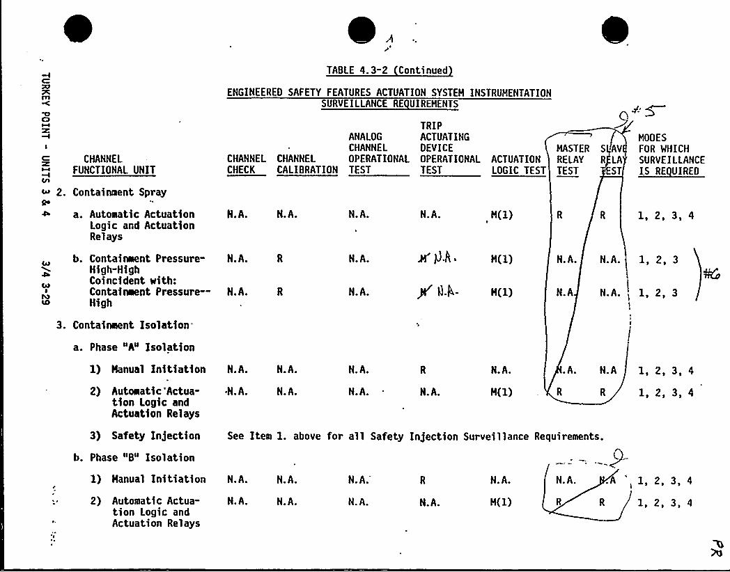
m
CI
I
CHANNELFUNCTIONAL UNIT
c 2. Containment Spray
a. Automatic ActuationLogic and ActuationRelays
N.A. N.A. N.A. N.A. H(1)
TABLE 4. 3-2 Continued
ENGINEERED SAFETY FEATURES ACTUATION SYSTEH INSTRUMENTATIONSURVEILLANCE RE UIREHENTS
TRIPANALOG ACTUATINGCHANNEL DEVICE
CHANNEL CHANNEL OPERATIONAL OPERATIONAL ACTUATIONCHECK CALIBRATION TEST TEST LOGIC TEST
MASTER S AVRELAY R LATEST ST
MODES
FOR WHICHSURVEILLANCEIS RE UIREO
1, 2, 3, 4
Ca7
LD
b. Containment Pressure-High-HighCoincident with:Containment Pressure—High
3. Containeent Isolation-
a. Phase "A" Isolation
N.A.
N.A.
N.A.
N.A.
H(l)
H(1)
N.A.
N.A
N.A.( 1, 2, 3
N.A.)
1, 2, 3
1) Hanual Initiation N.A. N.A. N.A. N.A. .A. N.A 1, 2, 3, 4
2) Automatic'Actua-tion Logic andActuation Relays
~N.A. N.A. N.A. N.A. H(1) R 1, 2, 3, 4
3) Safety Injection
b. Phase "8" Isolation
1) Hanual Initiation
2) Automatic Actua-tion Logic andActuation Relays
N.A.
N.A.
N.A.
N.A.
N.A.
N. A. N.A.
N.A.
H(l)
N. A.
See Item l. above for all Safety Injection Surveillance Requirements.
.A,
1, 2, 3, 4
1, 2, 3, 4
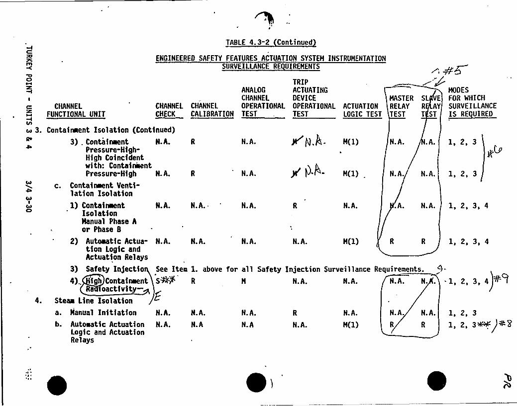
R7PCfll
KBCI
TABLE 4.3-2 Continued
ENGINEERED SAFETY FEATURES ACTUATION SYSTEH INSTRUMENTATIONSURVEILLANCE RE UIREMENTS
TRIPANALOG ACTUATINGCHANNEL OEVICE
CHANNEL CHANNEL OPERATIONAL OPERATIONAL ACTUATIONCHECK CALIBRATION TEST . TEST LOGIC TEST
MODES
FOR WHICHSURVEILLANCEIS RE VIREO
MASTER SL E
RELAY R AYTEST T ST
E= CHANNELFUNCTIONAL UNIT
o'. Containment Iso
3) . Conta
1 ation (Continued)
inaent N.h.Pressure-High-High Coincidentwith: ContainwentPressure-High N.A.
c. Containeent Venti-lation Isolation1) Containeent N.A.
IsolationManual Phase Aor Phase B
2) Autoaatic Actua- N.A.tion Logic andActuation Relays
3) Safety Injectio See Item
4). igh Containaent SM
jl g.g. N(1)N.A. N.A. 1,2,3.A.
N.A. N.A. 1,2,3N.A.CAB
00I
ClN.A. N.A. ~ A. N.A.N.A. 1, 2, 3, 4
N.A. N.A. N.A. 1, 2, 3, 4
1. above for all Safety Injection Surveillance Requirements.
R N N.A. N.A. N.A. N... 1, 2, 3, 4
4,
Ra oactivity-Steaa LIne IeolatIona. Hanual Initiationb. Autoaatic Actuation N.A.
Logic and ActuationRelays
N.A.
N.A
N.A.
N.A N.A.
N.A.
R R s ~) a."pN.A. N.A. 1, 2, 3
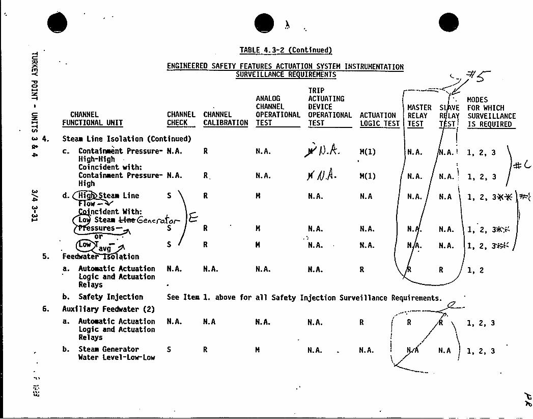
CHANNELFUNCTIONAL UNIT
g
TABLE 4.3-2 Continued
ENGINEEREO SAFETY FEATURES ACTUATION SYSTEH INSTRUHENTATIONSURVEILLANCE RE UIREHENTS
TRIPANALOG ACTUATING HOOESCHANNEL DEVICE HASTER S VE fOR WHICH
CHANNEL CHANNEL OPERATIONAL OPERATIONAL ACTUATION RELAY R LAt SURVEILLANCECHECK CALIBRATION TEST TEST
Steaa Line Isolation (Continued)
c. Containeent Pressure- N.A.High-HighCoincident with:Containment Pressure- N.A.High
d. H teaa Line Sow ~ncident With:
Le Steee &tee(oenord orssures Sor
avgFeedwater o ationa. Autoaatic Actuation N.A.
Logic and ActuationRelays
b. Safety InjectionAuxiliary Feedwater (2)a. Automatic Actuation
Logic and ActuationRelays
b. Steas Generator S
Water Level-Low-Low
P g.A. R(1)
J( /J $ ~ R(1)
N.A. .A.'- 1, 2, 3N.A.
N.A. 'N.A. N.A. 1,2,3
1. 2. 34%N.A. N.A N.A.
N.A. N.A. N. N.A. 1, 2, 33K.V-
1,2,~&N.A. N.A. N A. N.A.
N.A. N.A. N.A. 1, 2
N.A N.A. R gR q 1,2,3
A NA 1,2,3
N.A.
N.A.. N.A.
See Itea 1. above for all Safety Injection Surveillance Requirements.
N A
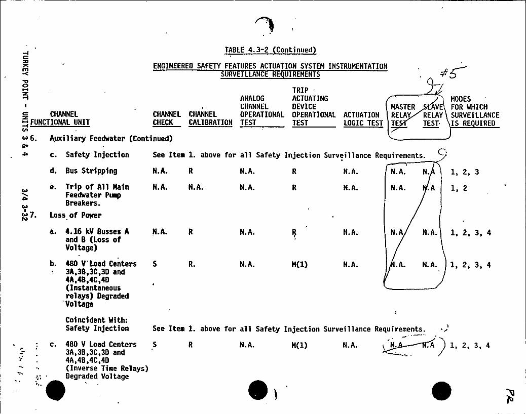
ClM
TABLE 4.3-2 Continued
ENGINEEREO SAFETY FEATURES ACTUATION SYSTEH INSTRUHENTATIONSURVEILLANCE RE UIREHENTS
TRIP .
ANALOG ACTUATING
~6. AuQo
c. Safety Injection See Itea l. above for all Safety Injection Surveillance Requirements.
N.A. R N.A. R N.A. N
.A
N.A.Bus Strippingd.
N.A.N.A.N.A.N.A.N.A.e. Trip of All HainFeedwater PumpBreakers.
Loss of Power
D04
tQ
I CHANNEL DEVICE HASTER AVECHANNEL CHANNEL CHANNEL OPERATIONAL OPERATIONAL ACTUATION RELAY RELAY
M~ FUNCTIONAL UNIT CHECK CALIBRATION TEST TEST LOGIC TEST TE TEST.
xiliary Feedwatel (Continued)
HOOES
FOR WHICHSURVEILLANCEIS RE UIREO
1, 2, 3
1, 2
a. 4.16 kV Busses Aand B (Loss ofVoltage)
N.A. R N.A. N.A. N.A N.A. 1, 2, 3, 4
b. 4BD V Load Centers3A,38,3C,3D and4A,48,4C,4D(Instantaneousrelays) Degraded
'Voltage
R. N.A. N.A. .A. N.A. 1, 2, 3, 4
C.
Coincident With:Safety Injection
480 V Load Centers3A,38,3C,30 and4A,4B,4C,4D(Inverse Time Relays)Degraded Voltage
See Item l. above for all Safety Injection Surveillance Requirements.
S R N.A. H(1) N.A.<N..A 1, 2, 3, 4
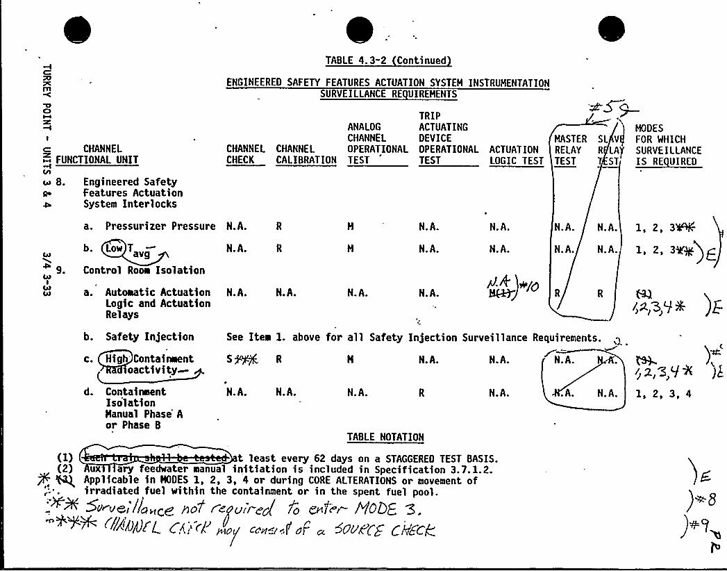
TABLE 4.3-2 Continued
ENGINEERED SAFETY FEATURES ACTUATION SYSTEH INSTRUHENTATIONPCmSURVEILLANCE RE UIREHENTS
CD
I
TRIPANALOG ACTUATINGCHANNEL DEVICE
CHANNEL CHANNEL OPERATIONAL OPERATIONAL ACTUATIONCHECK CALIBRATION TEST TEST LOGIC TEST
HODESHASTER SL V FOR WHICHRELAY R LA}'URVEILLANCEc= CHANNEL
~ FUNCTIONAL UNIT
cu 8.Qo
Engineered SafetyFeatures ActuationSystem Interlocks
1, 2, 3~a. Pressurizer Pressure N.A. N.A.
N.A.
N.A. N.A. N.A.
I, 2, 3IE+)gN.A. N.A. N.A.b. Low T
Control Room Isolation
N.A.CAR
4 gI + +roa. Automatic Actuation
Logic and ActuationRelays
N.A. N.A. N.A. N.A.
See Item 1. above for all Safety Injection Surveillance Requirements. ~S+~ R H N.A. N.A. N.A.
b. Safety Injection
c. High'ontainmentoactivity
N.A. N.A.d. ContainmentIsolationHanual Phase'or Phase B
.A. N.A.N.A. N.A. 1, 2, 3, 4
TABLE NOTATION
)~)~g
) v
(1) t least every 62 days on a STAGGERED TEST BASIS.(2) ux ary feedwater manual initiation is included in Specification 3.7.1.2.
Applicable in HODES 1, 2, 3, 4 or during CORE ALTERATIONS or movement ofirradiated fuel within the containment or in the spent fuel pool.'++ SN veil/o„,Cg P>o7 r
enquire/fo 5nfi r HQDE. '3.
'"+++ ~~I«~4CL C.'„"~P'.~ ".=:f.F . Sc ueCZ Ceres
INSTRUMENTATION
3/4. 3. 3 MONITORING INSTRUMENTATION
RADIATION MONITORING FOR PLANT OPERATIONS
LIMITING CONDITION FOR OPERATION
3.3.3. 1 The radiation monitoring instrumentation channels for plant operationsshown in Table 3.3-4 shall be OPERABLE with their Alarm/Trip Setpoints withinthe specified limits.
APPLICABILITY: As shown in Table 3.3-4.
ACTION:
a.
b.
C.
With a radiation monitoring channel Alarm/Trip Setpoint for plantoperations exceeding the value shown in Table 3.3-4, adjust the
'etpointto within the limit within 4 hours or declare the channelinoperable.
With one or more radiation monitoring channels for plant operationsinoperable, take the ACTION shown in Table 3.3-4.
The provisions of Specifications 3.0.3 are not applicable.
SURVEILLANCE RE UIREMENTS
4.3.3. 1 Each radiation monitoring instrumentation channel for plant operationsshall be demonstrated OPERABLE by the performance of the CHANNEL CHECK, CHANNELCALIBRATION and ANALOG CHANNEL OPERATIONAL TEST for the MODES and at thefrequencies shown in Table 4.3-3.
TURKEY POINT - UNITS 3 8s 4 3/4 3-34
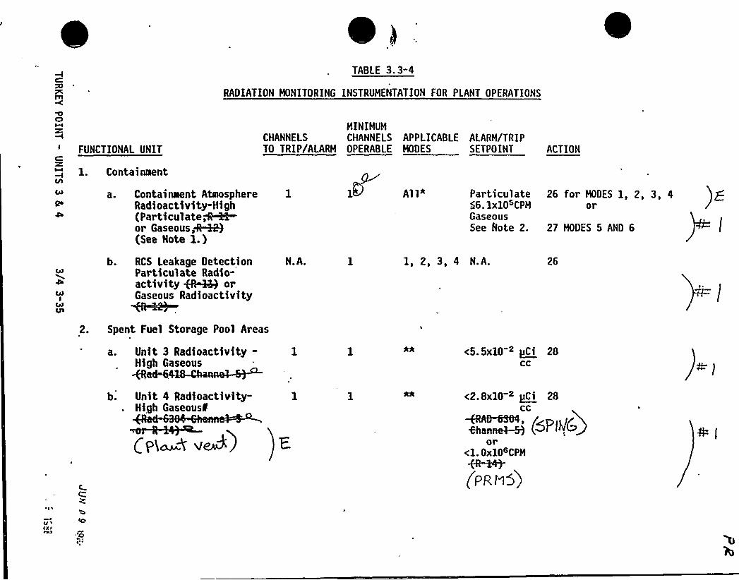
TABLE 3.3-4
RADIATION HONITORING INSTRUHENTATION FOR PLANT OPERATIONS
FUNCTIONAL UNIT
1. Containtaent
a. Containaent AbnosphereRadioactivity-High(Par ticulated~h-or Gaseous 4.~(See Note 1.)
ACTION
All" Particulate 26 for HOOES 1, 2, 3, 4$ 6.lxlOsCPH orGaseousSee Rote 2. 27 HODES 5 AND 6
HINIHUHCHANNELS CHANNELS APPLICABLE ALARH/TRIPTO TRIP/ALARH OPERABLE HOOES SETPOINT
b. RCS Leakage DetectionParticulate Radio-activity ~ orGaseous Radioactivity
N.A. 1, 2, 3, 4 N.A. 26
2. Spent Fuel Storage Pool Areas
a. Unit 3 Radioactivity-High Gaseous
<5.5xl0 2 pCi 28CC
b. Unit 4 Radioactivity-High
Gaseous'i
0 va8)
<2.8x10 2 ~Ci 28CC
~~".~ (~PI~C)or
<1. Oxl06CPH
(PR I15)'
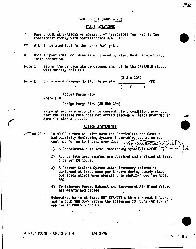
TABLE 3.3-4 Continued
TABLE NOTATIONS
During CORE ALTERATIONS or movement of irradiated fuel'within thecontainment comply with Specification 3/4.9. 13.
With irradiated fuel in the spent fuel pits.
Unit 4 Spent Fuel Pool Area is monitored by Plant Vent radioactivityinstrumentation.
Note 1 Either the particulate or gaseous channel in the OPERABLE statuswill satisfy this LCO.
(3.2 x 10')Note 2 Containment Gaseous Monitor Setpoint=
( F
Actual Pur ge F 1 owWhe~e F =
Design Purge Flow (35,000 CFH)
CPM,
Setpoint may vary according to current plant conditions providedthat the release rate does not exceed allowable limits provided inSpecification 3.11.2.1.
ACTION STATEMENTS
ACTION 26- In MODES 1 thru 4: With both the Particulate and GaseousRadioactivity Honitoring Systems inoperable, operation maycontinue for up to 7 days p~ovided:
per 5 ec,<TicaT(ow 5A,b.i 01) A Containment sump level'monitoring system<is OP L ,
2) Appropriate grab samples are obtained and analyzed at leastonce per 24 hours,
3) A Reactor Coolant System water inventory balance isperformed at least once per & hours during steady stateoperation except when operating in shutdown cooling mode,and
4) Containment Purge, Exhaust and Instrument Air Bleed Valvesare maintained closed.
Otherwise, be in at least NOT STANDBY within the next 6 hoursand in COLD SHUTDOWN ~ithin the following 30 hours (ACTION 27
'ppliesin HODES 5 and 6).
TURKEY POINT - UNITS 3 CL 4 3/4 3-36
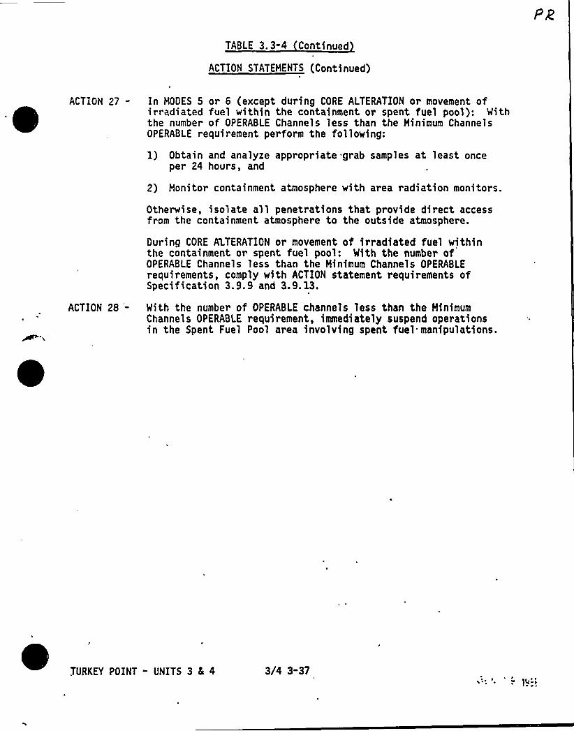
TABLE 3. 3-4 Continued
ACTION STATEMENTS (Continued)
ACTION 27- In MODES 5 or 6 (except during CORE ALTERATION or movement ofirradiated fuel within the containment or spent fuel pool): Withthe number of OPERABLE Channels less than the Minimum ChannelsOPERABLE requirement perform the following:
1) Obtain and analyze appropriate grab samples at least onceper 24 hours, and
2) Monitor containment atmosphere with area radiation monitors.
Otherwise, isolate all penetrations that provide direct accessfrom the containment atmosphere to the outside atmosphere.
During CORE ALTERATION or movement of irradiated fuel withinthe containment or spent fuel pool: With the number ofOPERABLE Channels less than the Minimum Channels OPERABLErequirements, comply with ACTION statement requirements ofSpecification 3.9.9 and 3.9. l3.
ACTION 28 '- With the number of OPERABLE channels less than the MinimumChannels OPERABLE requirement, immediately suspend operationsin the Spent Fuel Pool area involving spent fuel manipulations.
TURKEY POINT - UNITS 3 8 4 3/4 3-37
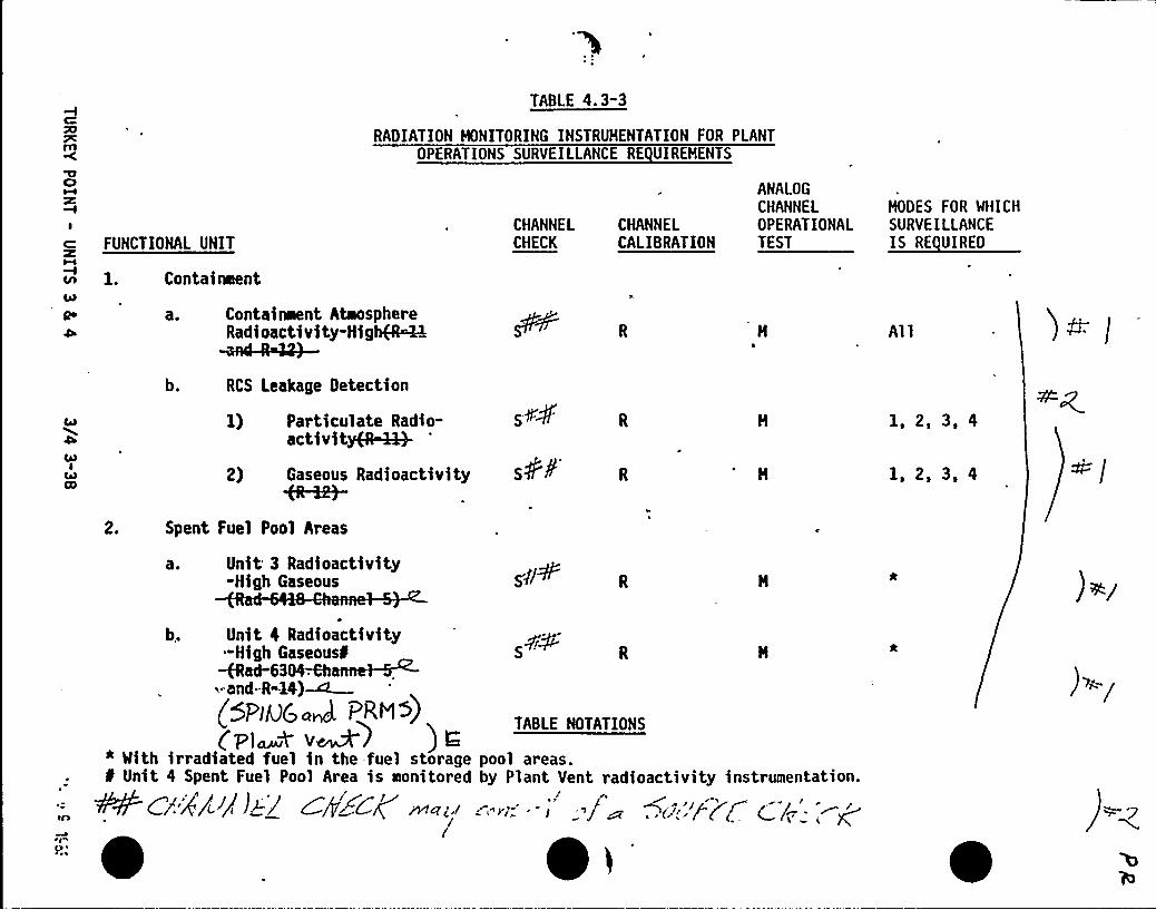
TABLE 4.3"3
RADIATION MONITORING INSTRUMENTATION FOR PLANTOPERATIONS SURVEILLANCE RE UIREMENTS
I
FUNCTIONAL UNIT
cn 1. Containment
o a. Contaiment AtoosphereRadioactivity-Highg~k
ANALOGCHANNEL MODES FOR WHICH
CHANNEL CHANNEL OPERATIONAL SURVEILLANCECHECK CALIBRATION TEST Ettt
Al 1 )~cb. RCS Leakage Detection
CAB
CABI
CO2)
Particulate Radio-activityfRWQ-
Gaseous Radioactivity
1, 2, 3, 4
1, 2, 3, 4
2. Spent Fuel Pool Areas
a. Unit 3 Radioactivity-High Gaseous )</
b, Unit 4 Radioactivity-High Gaseous' H
~ad-63&MhanneIM~-And-B-IB)~
TABLE NOTATIONS(Plawk V~) ) g
* With irradiated fuel in the-fuel storage pool areas.f Unit 4 Spent Fuel Pool Area is Itonitored by Plant Vent radioactivity instrumentation.
~C/.'8/4 /i 4tH/'P+Cl( JPct<i' 'I:. -' 'if~ ~('./// Q/p-
~ ~
)>-/
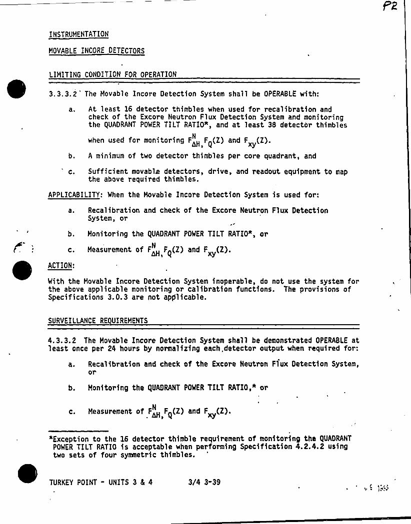
INSTRUMENTATION
MOVABLE INCORE DETECTORS
LIMITING CONDITION FOR OPERATION
3.3.3,2 'he Movable Incore Detection System shall be OPERABLE with:
'a ~ At least 16 detector thimbles when used for recalibration andcheck of the Excore Neutron Flux Detection System and monitoringthe QUADRANT POWER TILT RATIO", and at least 38 detector thimbles
when used for monitoring F~ F~(Z) and F (Z).xyA minimum of two detector thimbles per core quadrant, and'. Sufficient movable detectors, drive, and readout equipment to mapthe above required thimbles.
APPLICABILITY: When the Movable Incore Detection System is used for:
a ~
b.
C.
ACTION:
Recalibration and check of the Excore Neutron Flux DetectionSystem, or
Monitoring the QUADRANT POWER TILT RATIO*, or
Measurement of F>H F~(Z) and Fx (Z).N
With the Movable Incore Detection System inoperable, do not use the system forthe above applicable monitoring or calibration functions. The provisions ofSpecifications 3.0.3 are not apglicable.
SURVEILLANCE RE UIREMENTS
4. 3. 3.2 The Movable Incore Detection System shall be demonstrated OPERABLE atleast once per 24 hours by normalizing each. detector output when required for:
a. Recalibration and check of the Excore Neutron Flux Detection System,or
b. Monitoring the QUADRANT POWER TILT RATIO,* or
c. Measurement of F~ F~(Z) and F„ (Z).N
«Exception to the 16 detector thimble requirement of monitoring the QUADRANT
POWER TILT RATIO is acceptable when performing Specification 4.2.4.2 usingtwo sets of four symmetric thimbles.
TURKEY POINT - UNITS 3 & 4 3/4 3-39~ ( I'.'
~
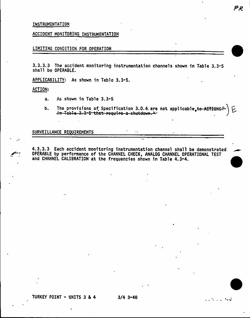
INSTRUMENTATION
ACCIDENT MONITORING INSTRUMENTATION
LIMITING CONDITION FOR OPERATION
3.3.3.3 The accident monitoring instrumentation channels shown in Table 3.3-5shall be OPERABLE.
APPLICABILITY: As shown in Table 3.3-5.
ACTION:
a. As shown in Table 3.3-5
b. The provisions of. Specification 3.0.4. are not applicable,
SURVEILLANCE RE UIREMENTS
~c c
4.3.3.3 Each accident monitoring instrumentation channel shall be demonstratedOPERABLE by performance of the CHANNEL CHECK, ANALOG CHANNEL OPERATIONAL TEST tand CHANNEL CALIBRATION at the frequencies shown in Table 4.3-4.
TURKEY POINT - UNITS 3 8L 4 3/4 3-40

TABLE 3.3"5
ACCIDENT MONITORING INSTRUHENTATION
INSTRUMENTI
Q 1. Containment Pressure (Wide Range)
2. Containment Pressure (Narrow Range)
'Qo Reactor Coolant Outlet TemperatureTT (Wide Range)
Reactor Coolant Inlet Temperature-TCOLD (Mid R g )
TOTALNO. OF
CHANNELS
2
HINIMUHCHANNELSOPERABLE
1
Ch
/ &anne/-2-Oetec-hn~er
APPLI-CABLEMODES ACTIONS
1, 2, 3
1, 2, 3
1, 2, 3
36
31, 32
31, 32
1, 2, 3 31, 32
5
6.
7.
Reactor Coolant Pressure - Mide Range
Pressurizer Mater Level
Auxiliary Feedwater Flow Rate 2/steamgenerator
1/steamgenerator
1 2 3
1, 2, 3
1, 2, 3
31, 32
31, 32
31, 32
8.
9.
10.
12.
13.
Reactor Coolant System Subcooling HarginHonitor
. PDRV Position Indicator (Primary Detector)
PORV Block Valve Position Indicator
-Safety Valve Position Indicator (PrimaryDetector)
Containment Mater Level (Narrow Range)
Containment Mater Level (Wide Range)
2(2)
1/valve
1/valve
1/valve
1(2) 1, 2, 3 31, 32
1/valve
1/valve
1, 2, 3 33
I, 2, 3 32
1, 2, 3 36
1, 2, 3 31, 32
1/valve 1, 2, 3 33
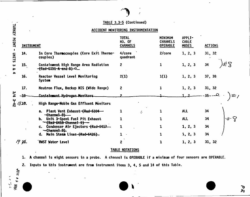
2(1)
TABLE 3.3-5 (Continued)
ACCIDENT HONITORING INSTRUHENTATION
TOTALNO. OF
INSTRUMENT CHANNELSI
14. In Core Theraocouples (Core Exit Thermo- 4/corecouples) quadrant
c 15. Containment High Range Area Radiation 2Qo
16. Reactor Vessel Level HonitoringSystem
ACTIONS
31, 32
1, 2, 3 34
1, 2, 3 37, 38
HINIHUM APPLI-CHANNELS CABLEOPERABLE MORES
2/core 1, 2, 3
17.
o /g&.
Neutron Flux, Backup NIS (Mide Range)
High Range-Noble Gas Effluent Honitors
1, 2, 3 31, 32
~~--35-~' RO g
lfPf.
Pt tt ttt t~cannel-9)—
b. Unit 3-Spent Fuel Pit Exhaustltttttllttt~
c. Condenser Air Ejectors ad-64~d. Nain Steaa Lines
RMST Mater Level
ALL
ALL
1, 2, 3
1, 2, 3
1, 2, 3
34
34
34
34
31, 32
TABLE NOTATIONS
1. A channel is eight sensors in a probe. A channel is OPERABLE if a minimum of four sensors are OPERABLE.
2. Inputs to this instr~nt are from instrument items 3, 4, 5 and 14 of this Table.
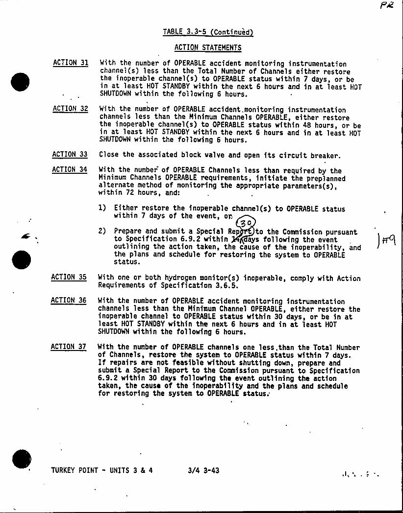
ACTION 31
ACTION 32
TABLE 3.3-5 Continued
ACTION STATEMENTS
With the number of OPERABLE accident monitoring instrumentationchannel(s) less than the Total Number of Channels either restorethe inoperable channel(s) to OPERABLE status within 7 days, or bein at least HOT STANDBY within the next 6 hours and in at least HOTSHUTDOWN within the following 6 hours.
With the number of OPERABLE accident. monitoring instrumentationchannels less than the Minimum Channels OPERABLE, either restorethe inoperable channel(s) to OPERABLE status within 48 hours, or bein at least HOT STANDBY within the next 6 hours and in at least HOTSHUTDOWN within the following 6 hours.
ACTION 33 Close the associated block valve and open its circuit breaker.
ACTION 34
ACTION 35
ACTION 36
ACTION 37
With the number of OPERABLE Channels less than required by theMinimum Channels OPERABLE requirements, initiate the preplannedalternate method of monitoring the appropriate parameters(s),within 72 hours, and:
1) Either restore the inoperable channel(s) to OPERABLE statuswithin 7 days of the event, op.
$ 02) Prepare and submit a Special Rep to the Commission pursuant
to Specification 6.9.2 within ays following the eventoutlining the action taken, the cause of the inoperability, andthe plans and schedule for restoring the system to OPERABLEstatus.
With one or both hydrogen monitor(s) inoperable, comply with ActionRequirements of Specification 3.6.5.
With the number of OPERABLE accident monitoring instrumentationchannels less than the Minimum Channel OPERABLE, either restore theinoperable channel to OPERABLE status within 30 days, or be in atleast HOT STANDBY within the next 6 hours and in at least HOTSHUTDOWN within the following 6 hours.
With the number of OPERABLE channels one less. than the Total Numberof Channels, restore the system to OPERABLE status within 7 days.If repairs are not feasible without shutting down, prepare andsubmit a Special Report to the Commission pursuant to Specification6.9.2 within 30 days following the event outlining the actiontaken, the cause of the inoperability and the plans and schedulefor restoring the system to OPERABLE status;
TURKEY POINT - UNITS 3 8L 4 3/4 3-43

TABLE 3. 3-5 Continued
ACCIPENT MONITORING INSTRUMENTATION
ACTION BB Nith the number of OPERABLE channels less than the Minimum Channels ~OPERABLE requirements, restore the inoperable channel(s) toOPERABLE status within 48 hours. If repairs are not feasiblewithout shutting down:
1. Initiate an alternate method of monitoring the reactor vesselinventory; and
2. Prepare and submit a Special Report to the Commission pursuantto Specification 6.9.2 within 30 days following the event outlinin~the action taken, the cause of the inoperability and the plans andschedule for restoring the system to OPERABLE status; and
3. Restore at least one channel to OPERABLE status at the nextscheduled refueling.
O.
TURKEY POINT - UNITS 3 4 4 3/4 3-44
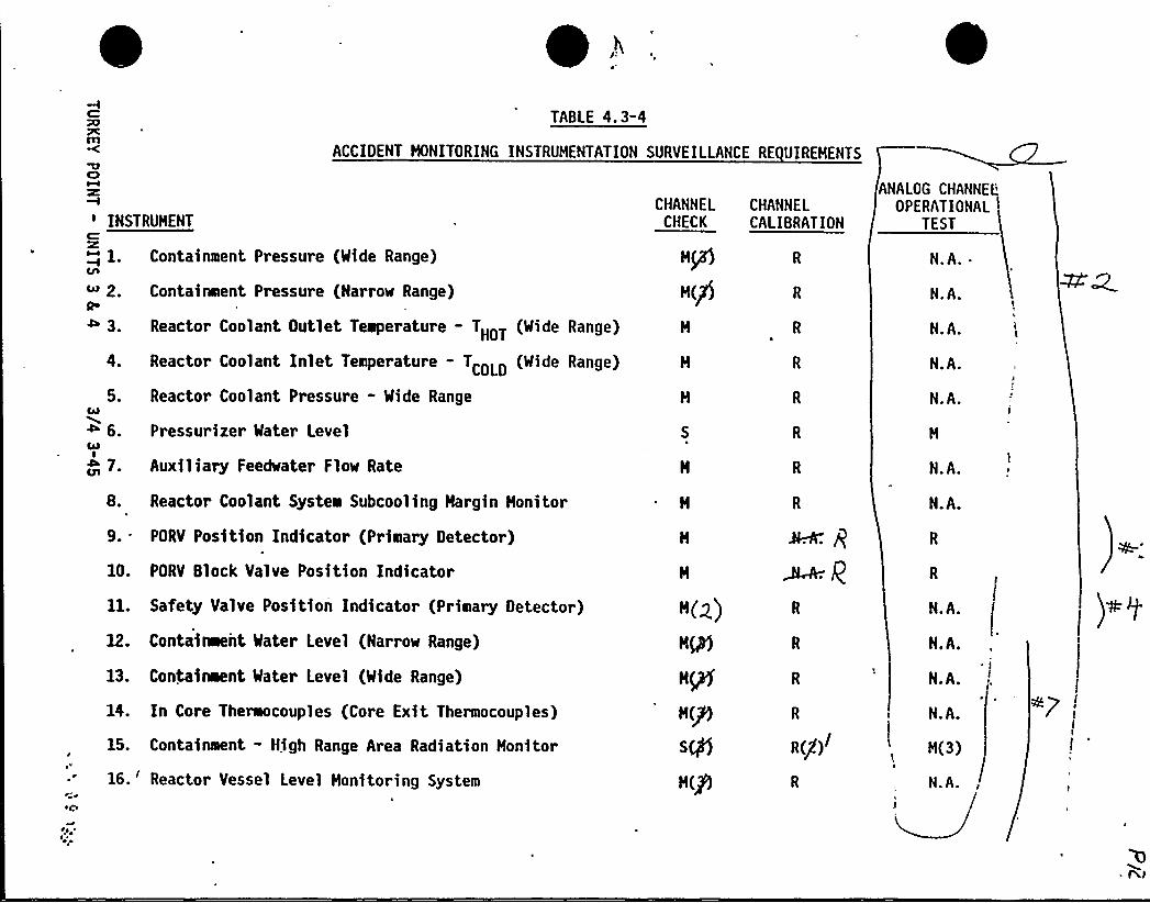
ycm
TABLE 4.3-4
ACCIDENT HONITORING INSTRUMENTATION SURVEILLANCE RE UIREMENTS
INSTRUMENTC
~ 1. Containment Pressure (Mide Range)
R" 2. Containeent Pressure (Narrow Range)
4 3 Reactor Coolant Outlet Teeperature -THOT (Wide Range)
CHANNELCHECK
HP)
H(fJ
CHANNELCALIBRATION
ANALOGCHANNEL'PERATIONAL
TEST
N.A.
N.A.
N.A.
5.
4 6.QlI
7 0
Reactor Coolant Inlet Temperature -TCOLD (Wide Range)
Reactor Coolant Pressure - Wide Range
Pressurizer Mater Level
Auxiliary Feedwater Flow Rate
N.A.
N.A.
N.A.
8. Reactor Coolant Systea Subcooling Hargin Honitor
9. PORV Position Indicator (Priltary Detector)
10. PORV Block Valve Position Indicator
11. Safety Valve Position Indicator (Prieary Detector)
12. Contaitaent Mater Level (Narrow Range)
13. Containoent Mater Level (Mide Range)
14. In Core Theraocouples (Core Exit Thermocouples)
15. Contaieient - High Range Area Radiation Honitor
16.'eactor Vessel Level Honitoring System
H(g)
HP)
HQ
H(P)
Sgl5
H(P
R
R(g)
R
N.A.
N.A.
N.A.
N.A.
N.A.
H(3)
N.A.
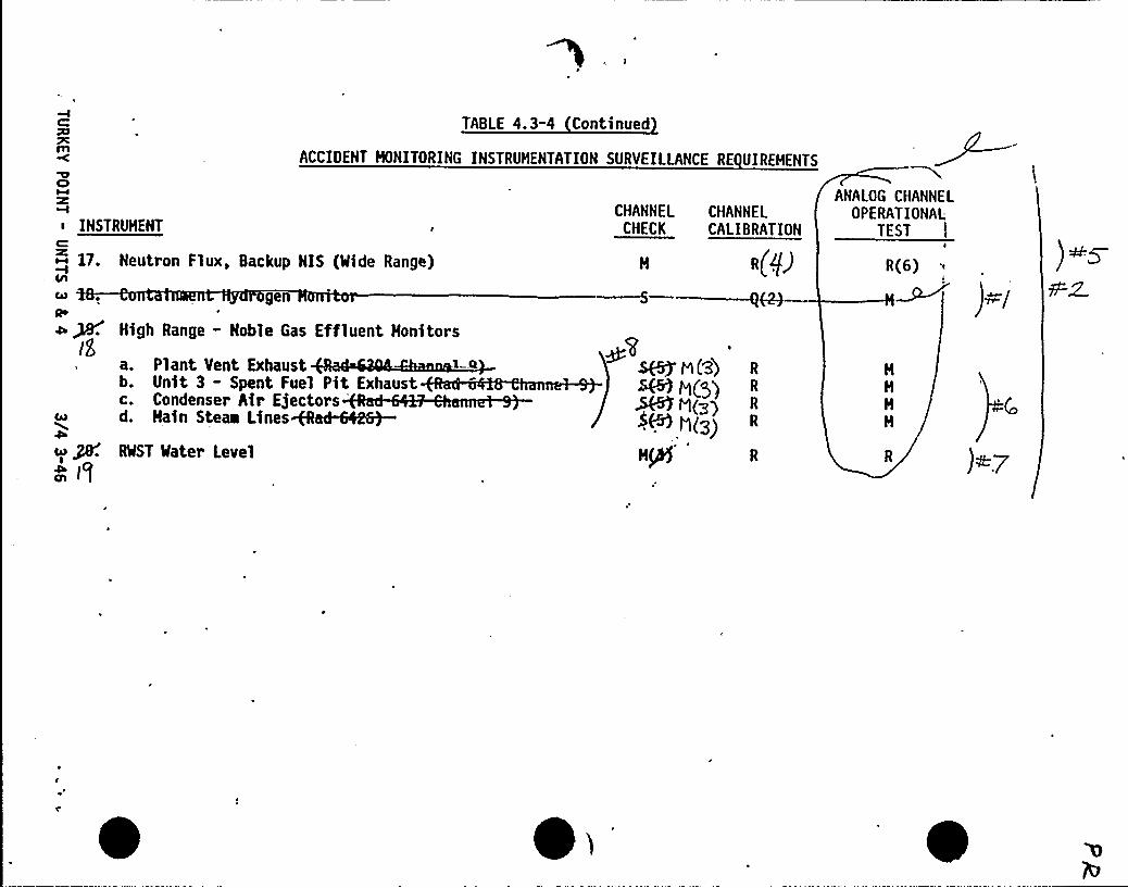
TABLE 4.3-4 Continued
ACCIOENT HONITORING INSTRUMENTATION SURVEILLANCE RE UIREHENTS
4l ~
4 ~IE
High Range - Noble Gas Effluent Honitors
a. Plant Vent Exhaustb. Unit 3 - Spent Fuel Pit Exhaustc. Condenser Air E)ectorsd. Ni St Lf
cu PK'I RMST Mater Level
Cl
INSTRUHENT
~ 17. Neutron Flux, Backup NIS (Mide Range)
gen
CHANNEL CHANNELCHECK CALIBRATION
H R(g)
~ 8['3) R
R~ g(~) R
5~ q(~) R
HP$ R
ANALOG CHANNELOPERATIONAL
TESTI
R(6)
)wy
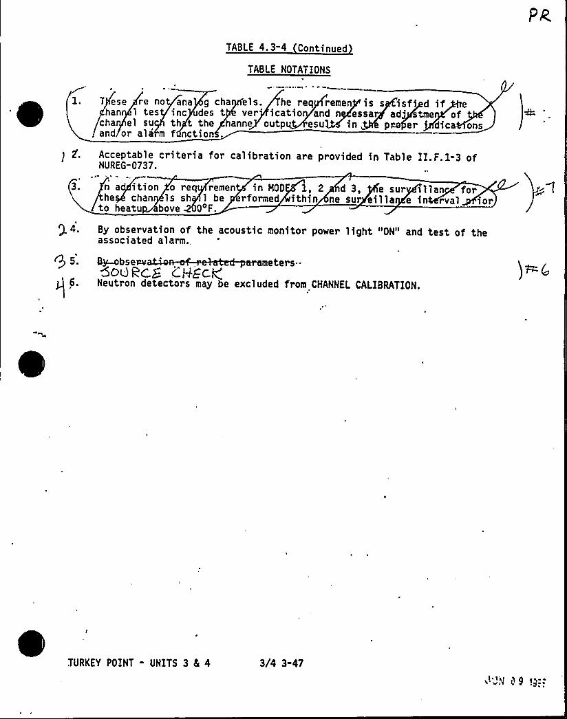
TABLE 4.3-4 Continued
TABLE NOTATIONS
5
T ese re no ana g cha els. he req remen is s isfi if ehan 1 tes inc des t ver'catio and n essar adj tme of
cha el su th t the hanne outp esu. in pm er dic onsand or al m f nction .
Acceptable criteria for calibration are provided in Table II.F.1-3 ofNUREG-0737.
3. n a ition o req remen in NOD 1, 2 d 3, e sur > lian forhe chan ls sh 1 be rformed ithin ne sur eilla e i rval iorto heatu bove 04F.
Q 4. By observation of the acoustic monitor power light "ON" and test of theassociated alarm.,
5. ~secv meters---5oukc.S c'.P&cy
6. Neutron detectors may be excluded from CHANNEL CALIBRATION.
TURKEY POINT - UNITS 3 8L 4 3/4 3-47
's i~9 ~y.-
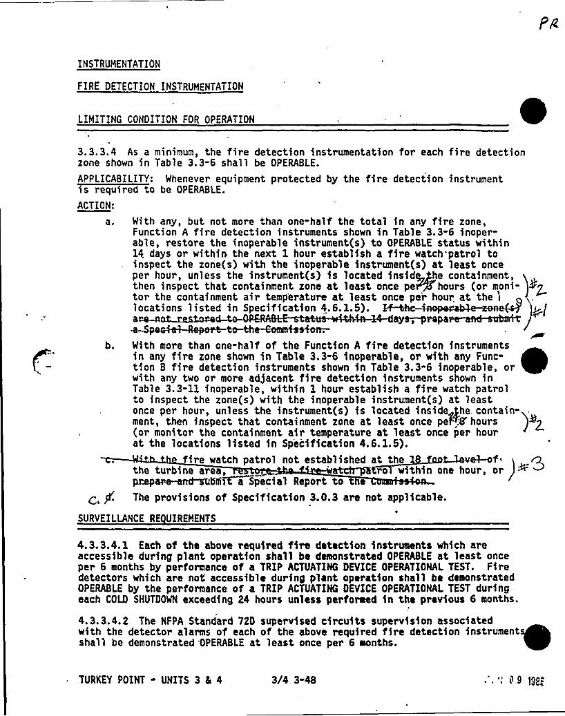
INSTRUMENTATION
FIRE DETECTION INSTRUMENTATION
LIMITING CONDITION FOR OPERATION
3.3.3.4 As a minimum, the fire detection instrumentation for each fire detectionzone shown in Table 3.3-6 shall be OPERABLE.
APPLICABILITY: Whenever equipment protected by the fire detection instrumentis required to be OPERABLE.
ACTION:
a. With any, but not more than one-half the total in any fire zone,Function A fire detection instruments shown in Table 3.3-6 inoper-able, restore the inoperable instrument(s) to OPERABLE status within14 days or within the next 1 hour establish a fire watch patrol toinspect the zone(s) with the inoperable instrument(s) at least onceper hour, unless the instrument(s) is located inside /he containment,then inspect that containment zone at least once pe hours (or moni- ~Ztor the containment air temperature at least once per hour at the 'i
locations listed in Specification 4.6.1.5). ~bc >Ia p
b. With more than one-half of the Function A fire detection instrumentsin any fire zone shown in Table 3.3-6 inoperable, or with any Func-tion B fire detection instruments shown in Table 3.3-6 inoperable, orwith any two or more adjacent fire detection instruments shown inTable 3.3-11 inoperable, within 1 hour establish a fire watch patrolto inspect the zone(s) with the inoperable instrument(s) at leastonce per hour, unless the instrument(s) is located inside~/he. contain-ment, then inspect that containment zone at least once peP'8'hours j>p(or monito~ the containment air temperature at least once per hourat the locations listed in Specification 4.6.1.5).
fire match patrol not established at the 1 ~et-otthe turbine area, ro within one hour, orpr~m n~55it a Special Report to e
The provisions of Specification 3.0.3 are not applicable.
SURVEILLANCE RE UIREHENTS
4.3.3.4.1 Each of the above required fire detection instruments which areaccessible during plant operation shall be demonstrated OPERABLE at least onceper 6 months by performance of a TRIP ACTUATING DEVICE OPERATIONAL TEST. Firedetectors which are not accessible during plant operation shall be demonstratedOPERABLE by the performance of a TRIP ACTUATING DEVICE OPERATIONAL TEST duringeach COLD SHUTOOWN exceeding 24 hours unless performed in the previous 6 months.
4.3.3.4.2 The NFPA Standard 72D supervised circuits supervision associatedwith the detector alarms of each of the above required fire detection instrumentsshall be demonstrated OPERABLE at least once per 6 months.
TURKEY POINT - UNITS 3 5 4 3/4 3-48 .', ", i~ 9 >gyp
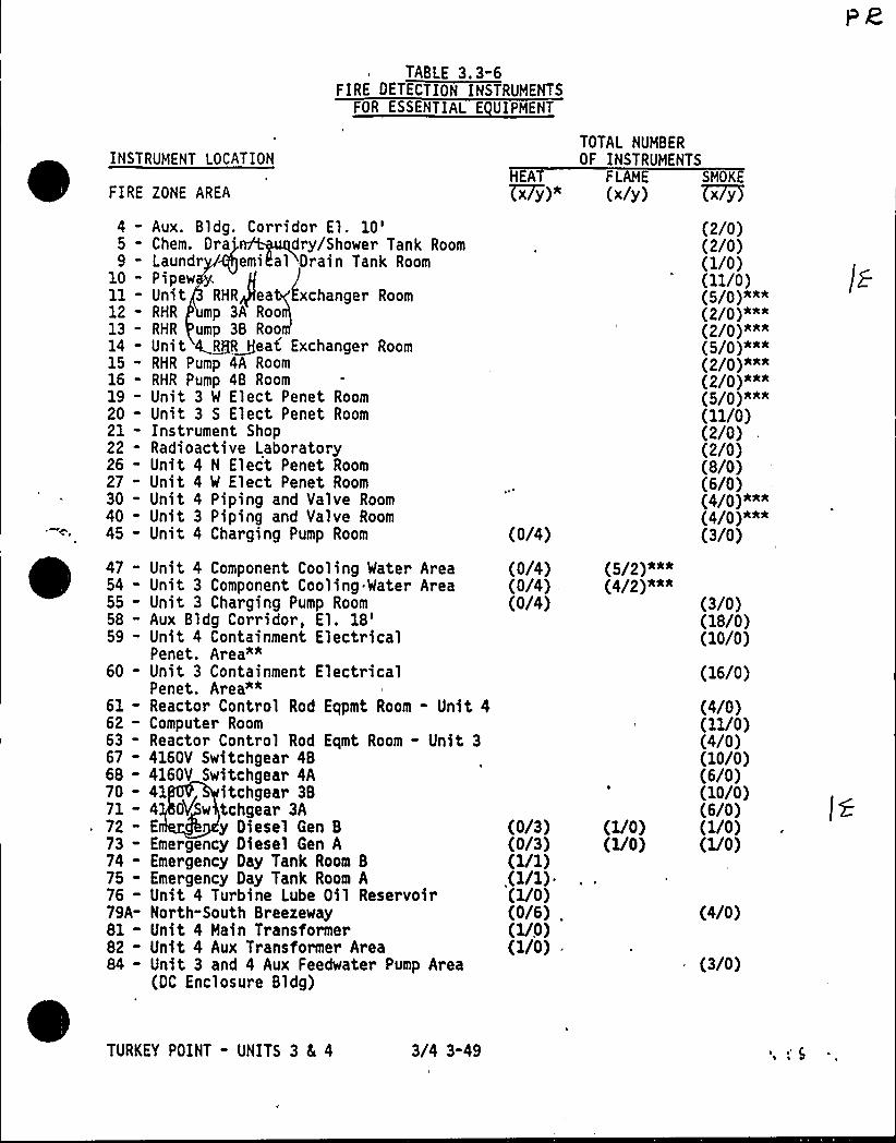
INSTRUMENT LOCATION
FIRE ZONE AREA
TABLE 3.3-6FIRE DETECTION INSTRUMENTS
FOR ESSENTIAL E UIPMENT
HEA~xy)"
FLAME
(x/y)SMOKE
~xy
TOTAL NUMBEROF INSTRUMENTS
4 - Aux. Bldg. Corridor El. 10'- Chem. Ora'ry/Shower Tank Room
9 - Laundr emi al Drain Tank Room10 - Pipewll - Unit RHR ea xchanger Room12 - RHR mp 3A Roo13 - RHR ump 3B Room14 - Unit ~R, I]eat Exchanger Room15 - RHR Pump 4A Room16 " RHR Pump 4B Room19 - Unit 3 W Elect Penet Room20 - Unit 3 S Elect Penet Room21 - Instrument Shop22 - Radioactive Laboratory26 - Unit 4 N Elect Penet Room27 - Unit 4 W Elect Penet Room30 - Unit 4 Piping and Valve Room40 - Unit 3 Piping and Valve Room45 - Unit 4 Charging Pump Room
47 - Unit 4 Component Cooling Water Area54 - Unit 3 Component Cooling. Water Area55 - Unit 3 Charging Pump Room58 - Aux Bldg Corridor, El.
18'9- Unit 4 Containment ElectricalPenet. Area"*
60 - Unit 3 Containment ElectricalPenet. Area""
61 - Reactor Control Rod Eqpmt Room - Unit 462 - Computer Room63 - Reactor Control Rod Eqmt Room - Unit 367 - 4160V Switchgear 4B68 - 4160V Switchgear 4A70 - 41 itchgear 3B71 - 4 OY w tchgear 3A72 - E y Diesel Gen B73 - Emergency Diesel Gen A74 - Emergency Oay Tank Room B75 - Emergency Day Tank Room A76 - Unit 4 Turbine Lube Oil Reservoir79A- North-South Breezeway81 - Unit 4 Main Transformer82 - Unit 4 Aux Transformer Area84 - Unit 3 and 4 Aux Feedwater Pump Area
(DC Enclosure Bldg)
(0/4)
(0/4)(0/4)(0/4)
(0/3)(0/3)(1/1){1/1)-(1/0)(0/6) .
(1/0)(1/0)
(5/2)AAA(4/2) M*
(1/0)(1/0)
(2/0)(2/0)(1/0)(11/0)
(2/P)kak(2/0))4k'5/P)AAA
(2/P)aaa(2/0)*AN(5/P)A*A'll/0)
(2/0)(2/0)(8/0)(6/0)(4/0)~~(4/P)AA*(3/0)
(3/0)(18/0)(10/0)
(16/0)
(4/0)(11/0)(4/0)(10/0)(6/0)(10/0)(6/0)(1/0)(1/0)
(4/0)
(3/0)
TURKEY POINT - UNITS 3 8E 4 3/4 3-49
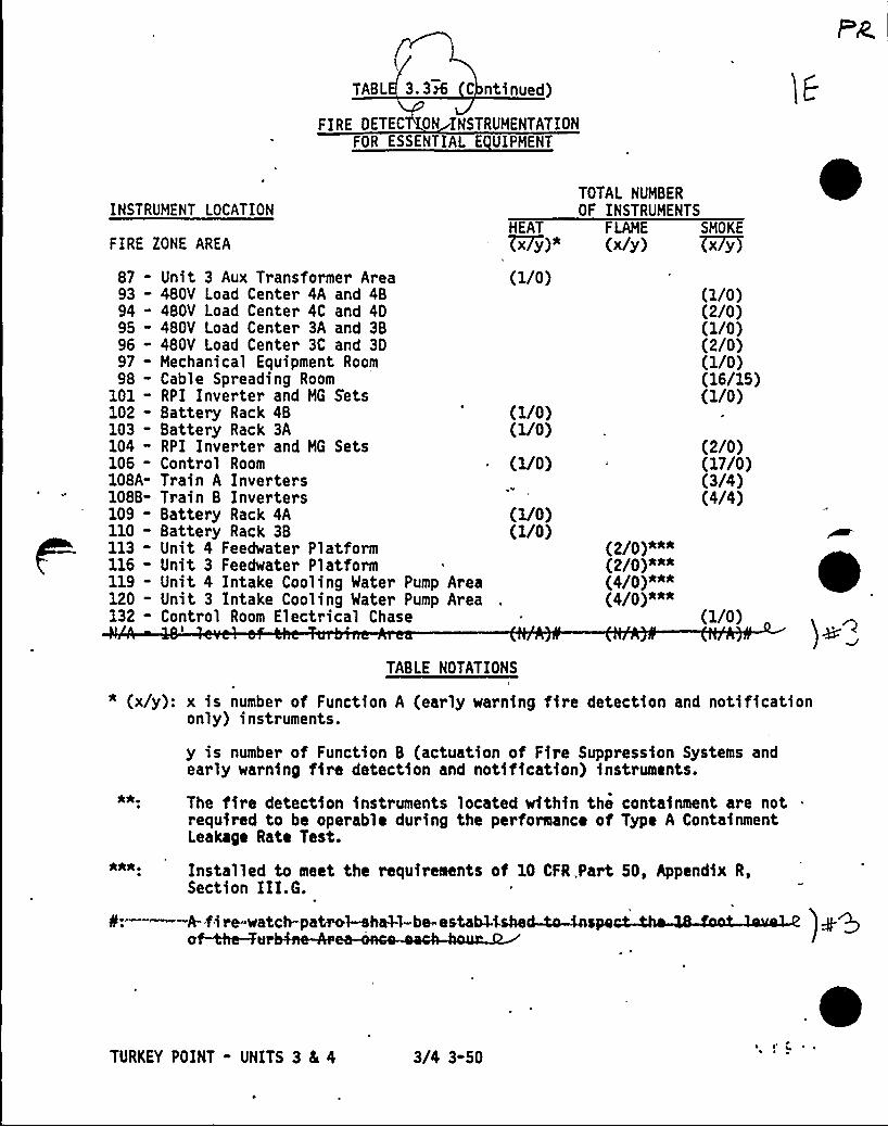
TABL 3.3' ntinued)
FIRE OETEC ON INSTRUHENTATIONFOR ESSENTIAL E UIPHENT
INSTRUMENT LOCATION
FIRE ZONE AREA
TOTAL NUMBEROF INSTRUHENTS
HEAT FLAME SMOKE
~x y)" (x/y) ~x7yy
87-93 "94-95-96-97-98-
101-102-103-104-106-108A-108B-109-110-113-116-119-120-132-
Unit 3 Aux Transformer Area480V Load Center 4A and 4B480V Load Center 4C and 40480V Load Center 3A and 3B480V Load Center 3C and 30Mechanical Equipment RoomCable Spreading RoomRPI Inverter and MG SetsBattery Rack 4BBattery Rack 3ARPI Inverter and MG SetsControl RoomTrain A InvertersTrain B InvertersBattery Rack 4ABattery Rack 3BUnit 4 Feedwater PlatformUnit 3 Feedwater PlatformUnit 4 Intake Cooling Water Pump AreaUnit 3 Intake Cooling Water Pump AreaControl Room Electrical Chase
I
(1/0)
(1/0)(1/0)
(1/0)
(1/0)(1/0)
(2/0)***(2/0)*A*(4/0)AAA(4/0)"aa
(1/0)(2/0)(1/0)(2/0)(1/0)(16/15)(1/0)
(2/0)(17/0)(3/4)(4/4)
(1/0)
TABLE NOTATIONS
* (x/y): x is number of Function A (early warning fire detection and notificationonly) instruments.
y is number of Function B (actuation of Fire Suppression Systems andearly warning fire detection and notification) instruments.
The fire detection instruments located within the containment are notrequired to be operable during the performance of Type A ContainmentLeakage Rate Test.
Installed to meet the requirements of 10 CFR,Part 50, Appendix R,Section III.G.
0r——-A-.fire-watch-patrol-eh&i-be-estabNshe~4espeh4 ~~I
TURKEY POINT - UNITS 3 L 4 3/4 3-50~ I
~ ~ ~

INSTRUMENTATION
RAQIOACTIVE LI UID EFFLUENT MONITORING INSTRUMENTATION
LIMITING CONQITION FOR OPERATION
3.3.3.5 The radioactive liquid effluent monitoring instrumentation channelsshown in Table 3. 3-7 shall be OPERABLE with their Alarm/Trip Setpoints set toensure that the limits of Specification 3.11. 1. 1 are not exceeded. The Alarm/Trip Setpoints of these channe1s shall be determined and adjusted in accordancewith the methodology and parameters in the OFFSITE QOSE CALCULATION MANUAL(OQCM).
APPLIOA8ILITY: At all times mYcctst as A~cdJ sa Tccgim 8.3-7. g 3ACTION:
a. With a radioactive liquid effluent monitoring instrumentation channelAlarm/Trip Setpoint less conservative than required by the abovespecification, immediately suspend the release of radioactive liquideffluents monitored by the affected channel, declare the channelinoperable, or change the setpoint so it is acceptably conservative.
b. With less than the minimum number of:radioactive liquid effluentmonitoring instrumentation channels OPERABLE, take the ACTION shownin Table 3.3-7. Restore the inoperable instrumentation to OPERABLEstatus within 30 days and, if unsuccessful, explain in the nextSemiannual Radioactive Effluent Release Report pursuant to Specifi-cation 6. 9. 1.4 why this inoperability was not corrected in a timelymanner.
c. The provisions of Specification 3. 0.3 are not applicable.
SURVEILLANCE RE UIREMENTS
4.3.3.5 Each radioactive liquid effluent monitoring instrumentation channelshall be demonstrated OPERABLE by performance of the CHANNEL CHECK, SOURCE
CHECK, CHANNEL CALIBRATION, and ANALOG CHANNEL OPERATIONAL TEST at thefrequencies shown in Table 4.3-5.
TURKEY POINT - UNITS 3 5 4 3/4 3-51
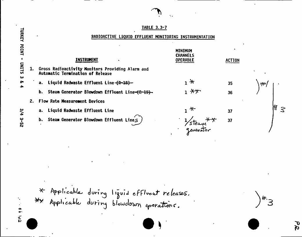
C
m
TABLE 3.3-7
RADIOACTIVE LI UID EFFLUENT HONITORING INSTRUHENTATION
C)
I
C
lA
Qo
INSTRIRIENT
1. Gross Radioactivity Honitors Providing Alarm andAutoaatic Termination of Release
a. Liquid Radwaste Effluent Line+0-:~b. Steae Generator Blowdown Effluent Lin~~
2. Flow Rate Heasureaent Devices
HINIHUMCHANNELSOPERABLE ACTION
35
36
CARI
a. Liquid Radwaste Effluent Line
b. Steaa Generator Slowdown Effluent Lineg
37
lpgaW+ 37
CIAO!f'A0 V
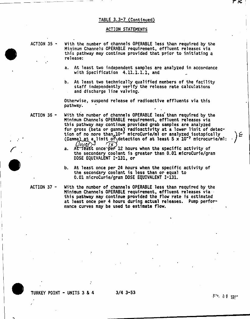
TABLE 3 3-7 Continued
ACTION STATEMENTS
ACTION 35- With the number of channels OPERABLE less than required by theMinimum Channels OPERABLE requirement, effluent releases viathis pathway may continue provided that prior to initiatin arelease:
sng a
ACTION 36-
ACTION 37-
a. At least two independent samples are analyzed in accordancewith Specification 4. 11. 1.1. 1, and
b. At least two technically qualified members of the facilitystaff independently verify the release rate calculationsand discharge line valving.
Otherwise, suspend release of radioactive effluents via thispathway.
With the number of channels OPERABLE less than required by theMinimum Channels OPERABLE requirement, effluent releases viathis pathway may continue provided grab samples are analyzedfor gross (beta or gamma) radioactivity at a lower limit of detec-tion of no more than 10-~ microCurie/ml or analyzed isotopically(Gamma t a limit o detection of at least 5 x 10 ~ microcurie/ml:
over /p',a. A a t once 12 hours when the specific activity of
the secondary coolant is greater than 0.01 microCurie/gramDOSE E(UIVALENT I-131, or
b. At least once per 24 hours when the specific activity ofthe secondary coolant is less than or equal to0.01 microCur ie/gram DOSE E)UIVALENT I-131.
With the number of channels OPERABLE less than required by theNinimum Channels OPERABLE requirement, effluent releases via--this pathway may continue provided the flow rate is estimatedat least once per 4 hours during actual releases. Pump perfor-mance curves may be used to estimate flow.
TURKEY POINT - UNITS 3 4 4 3/4 3-53
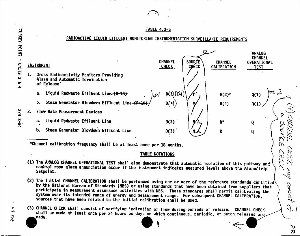
TABLE 4.3"5
RADIOACTIVE LI UID EFFLUENT MONITORING INSTRUMENTATION SURVEILLANCE RE UIREMENTS
CHANNELCHECK
D(3)
Q INSTRUMENT
1. Gross Radioactivity Honitors ProvidingAlarm and Automatic Terminationof
Release'.
Liquid RaGuaate Effluent Lie~~ ~1 BGi) pal)b. Stean Generator Blouuown Effluent Line+lMQ 0(g)
2. Flow Rate Measurement Devices
a. Liquid Radwaste Effluent Line D(3)
b. Steam Generator Blowdown Effluent Line.
C CK CALIBRATION
R(2)*
R(2)
R*
SOU E CHANNEL
ANALOGCHANNEL
OPERATIONALTEST
(1) The ANALOG CHANNEL OPERATIONAL TEST shall also demonstrate that automatic isolation of this pathway andcontrol room alarm annunciation occur if the instrument indicates measured levels above the Alarm/TripSetpoint.
~Channel calibration frequency shall be at least once per 18 months.
TABLE NOTATIONS
( t
(2) The initial CHANNEL CALIBRATION shall be performed using one or more of the reference standards certifiedby the National Bureau of Standards (NBS) or using standards that have been obtained from suppliers thatparticipate in measurement assurance activities with NBS. These standards shall permit calibrating thesystem over its intended range of energy and measurement range. For subsequent CHANNEL CALIBRATION,sources that have been related to the initial calibration shall be used.
(3) CHANNEL CHECK shall consist of verifying indication of flow during periods of release. CHANNEL CHECKshall be made at least once per 24 hours on days on which continuous, periodic, or batch releases are
~ ~ -~-
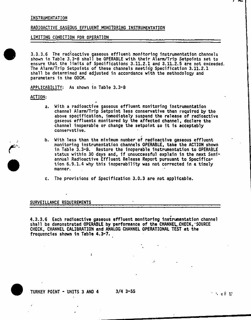
INSTRUHENTATION
RADIOACTIVE GASEOUS EFFLUENT HONITORING INSTRUHENTATION
LIHITING CONDITION FOR OPERATION
3.3.3,6 The radioactive gaseous effluent monitoring instrumentation channelsshown in Table 3.3-8 shall be OPERABLE with their Alarm/Trip Setpoints set toensure that the limits of Specifications 3. 11.2. 1 and 3. 11.2.5 are not exceeded.The Alarm/Trip Setpoints of these channels meetin'g Specification 3. 11.2. 1shall be determined and adjusted in accordance with the methodology andparameters in the ODCH.
APPLICABILITY: As shown in Table 3.3-8
ACTION:
a.
b.
With a radioactive gaseous effluent monitoring instrumentationchannel Alarm/Trip Setpoint less conservative than required by theabove specification, immediately suspend the release of radioactivegaseous effluents monitored by the affected channel, declare thechannel inoperable or change the setpoint so it is acceptablyconservative.
With less than the minimum number of radioactive gaseous effluentmonitoring instrumentation channels OPERABLE, take the ACTION shownin Table 3,3-8. Restore the inoperable instrumentation to OPERABLEstatus within 30 days and, if unsuccessful explain in the next Semi-ann'ual Radioactive Effluent Release Report pursuant to Specifica-tion 6.9.1.4 why this inoperability was not corrected in a timelymanner.
c. The provisions of Specification 3. 0.3 are not applicable.
SURVEILLANCE RE UIREHENTS
4.3.3.6 Each radioactive gaseous effluent monitoring instrumentation channelshall be demonstrated OPERABLE by performance of the CHANNEL„.CHECK, SOURCE
CHECK, CHANNEL CALIBRATION and ANALOG CHANNEL OPERATIONAL TEST at thefrequencies shown in Table 4.3-7.
TURKEY POINT - UNITS 3 AND 4 3/4 3-55 '. v~ l."
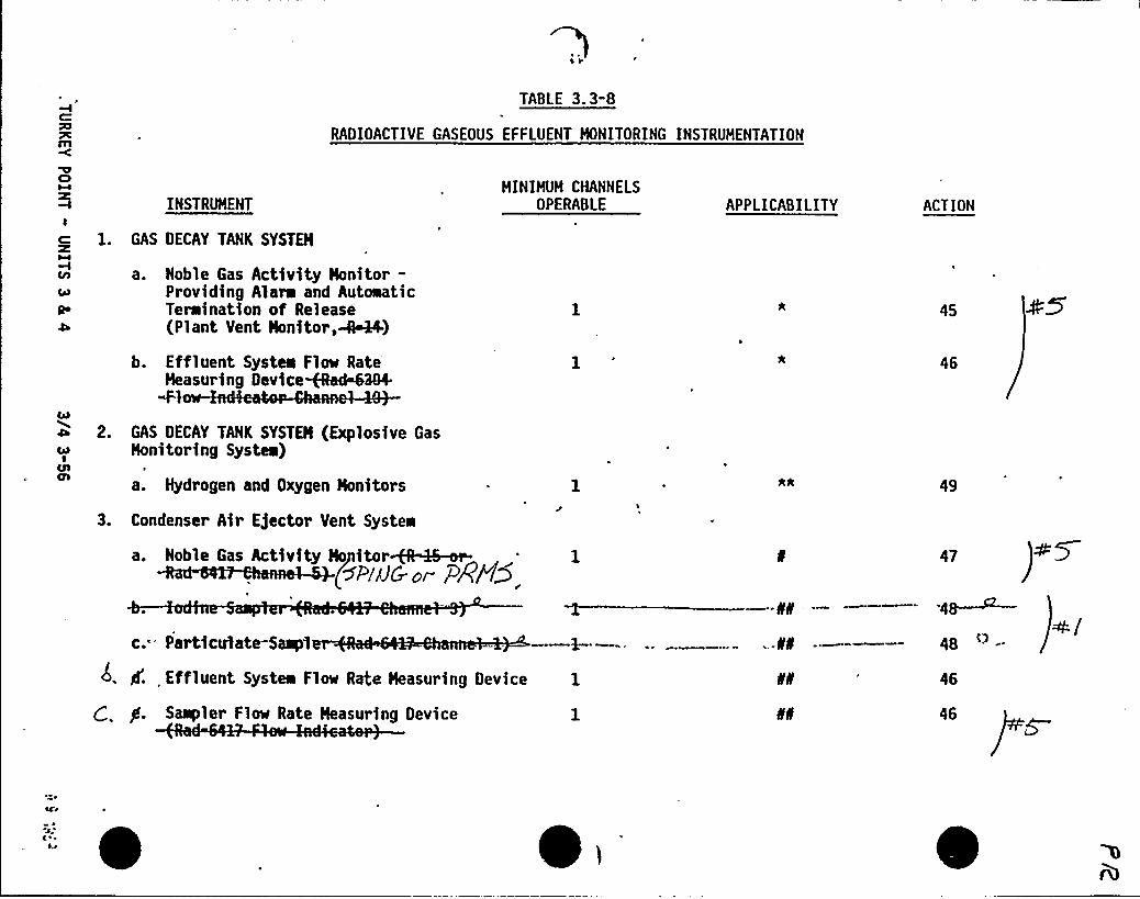
Ã77Cm
TABLE 3.3-8
RADIOACTIVE GASEOUS EFFLUENT HONITORING INSTRUMENTATION
IC
Qe
INSTRUHENT
1. GAS DECAY TANK SYSTEH
a. Noble Gas Activity Honitor-Providing Alarm and AuteaaticTeraination of Release(Plant Vent Honitor,-i&44)
HINIHUM CHANNELSOPERABLE APPLICABILITY ACTION
45
b. Effluent Systea Flow RateHeasuring Device~arMSN
Wl
a 2. GAS DECAY TANK SYSTEH (Explosive Gasc, Honitoring Systee)
a. Hydrogen and Oxygen Honitors
3. Condenser Air Ejector Vent System
a. Noble Gas Activity Ho itor~S-or-(5PAJ& or PÃg5
c.'articulate-Saap1 -NN
gf. Effluent Systea Flow Rate Heasuring Device 1 N
Sampler Flow Rate Heasuring Device
46
49
47
.48—~4a
46
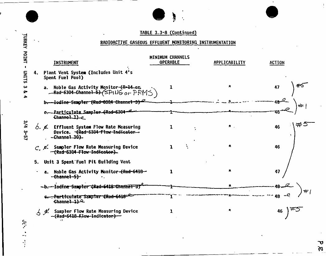
C:
7c
TABLE 3. 3-8 Continued
RADIOACTIVE GASEOUS EFFLUENT HONITORING INSTRUMENTATION
CIHINIHUH CHANNELS
OPFRABLEINSTRUHENTI
Q 4. Plant Vent Systea (Includes Unit 4'sSpent Fuel Pool)
a. Noble Gas Activity Honitor~4-er - 1RacH5 S Pi'lJ6 os- PP+jg
APPLICABILITY ACT ION
48
Effluent System Flm Rate HeasuringDevice.
-Channe~+-
Saapler Flm Rate Heasuring Device~d-65. Unit 3 Spent'Fuel Pit Building Vent
a. Noble Gas Activity Nonitor-6hanne~
-h—.-XocÃ
46
47
-* ———.- -- 48 ss
Soapier Flow Rate Neasurieg Oevice~Md
46
)
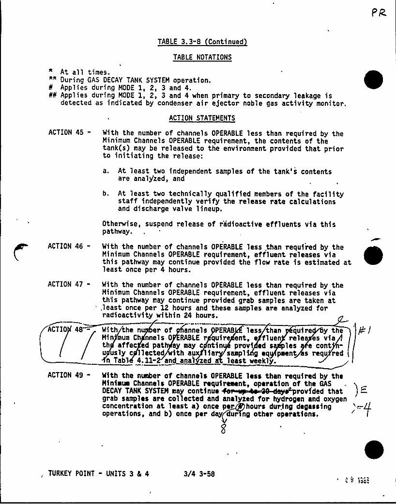
TABLE 3.3-8 Continued
TABLE NOTATIONS
At all times."" During GAS DECAY TANK SYSTEM operation.Applies during MODE 1, 2, 3 and 4.
H Applies during MODE 1, 2, 3 and 4 when primary to secondary leakage isdetected as indicated by condenser air ejector noble gas activity monitor.
ACTION STATEMENTS
ACTION 45 - With the number of channels OPERABLE less than required by theMinimum Channels OPERABLE requirement, the contents of thetank(s) may be released to the environment provided that priorto initiating the release:
a. At least two independent samples of the tank's contentsare analy'zed, and
b. At least two technically qualified members of the facilitystaff independently verify the release rate calculationsand discharge valve lineup.
Otherwise, suspend release of radioactive effluents via thispathway.
ACTION 46 - With the number of channels OPERABLE less than required by theMinimum Channels OPERABLE requirement, effluent releases viathis pathway may continue provided the flow rate is estimated atleast once per 4 hours.
ACTION 47-
ACTIO 48 "
With the number of channels OPERABLE less than required by theMinimum Channels OPERABLE requirement, effluent releases viath'is pathway may continue provided grab samples are taken at,least once per 12 hours and these samples are analyzed forradioactivity within 24 hours.
With the n er of annels PERAB less than quire y theMin'mum Ch nnels 0 RABLE r quir ent, e fluen relea es viath affec ed pat ay may c ntin provi ed s les e contu usly c lected ith aux lia saapl g eq pment s requ red
n Tab 4.11- and anal zed least weekly.
'gl
ACTION 49 - With the number of channels OPERABLE less than required by theMinimum Channels OPERABLE requirement, operation of the GASDECAY TANK SYSTEM may continue rovided thatgrab samples are collected and analyzed for hydrogen and oxygenconcentration at least a) once per hour s during degassingoperations, and b) once per day dur ng other operations.
, TURKEY POINT - UNITS 3 4 4 3/4 3-58 ~,g P~ ~ ~, ~~ IOCi

TABLE 4.3-6
RADIOACTIVE GASEOUS EFFLUENT MONITORING INSTRUMENTATION SURVEILLANCE RE UIREMENTS
RR
CO
C
Cia
INSTRUMENT
1. GAS DECAY TANK SYSTEM
CHANNELCHECK
URCE
CHECCHANNEL
CALIBRATION
ANALOG
CHANNELOPERATIONAL
TEST
MODES FOR WHICHSURVEILLANCE
IS RE UIRED
a. Noble Gas Activity Monitor-Providing Alara and AutoeaticTernination of Release p(g) P(y)- (Plant Vent Monitor,~+)
b. Effluent Systea Flow Rate<ss
g 2. GAS DECAY TANK SYSTEM (ExplosiveGas Monitoring Systea)
a. Hydrogen and Oxygen Monitors
N.A.
N.
R(3) '(1)
N.A.
q(4,5) i*3. Condenser Air Ejector Vent System
a. Noble Gas Activity Nonitor~~ D(p)~~~Co'(3) 9(2)
Effluent System Flow RateMeasuring Device
N.A. N.A.
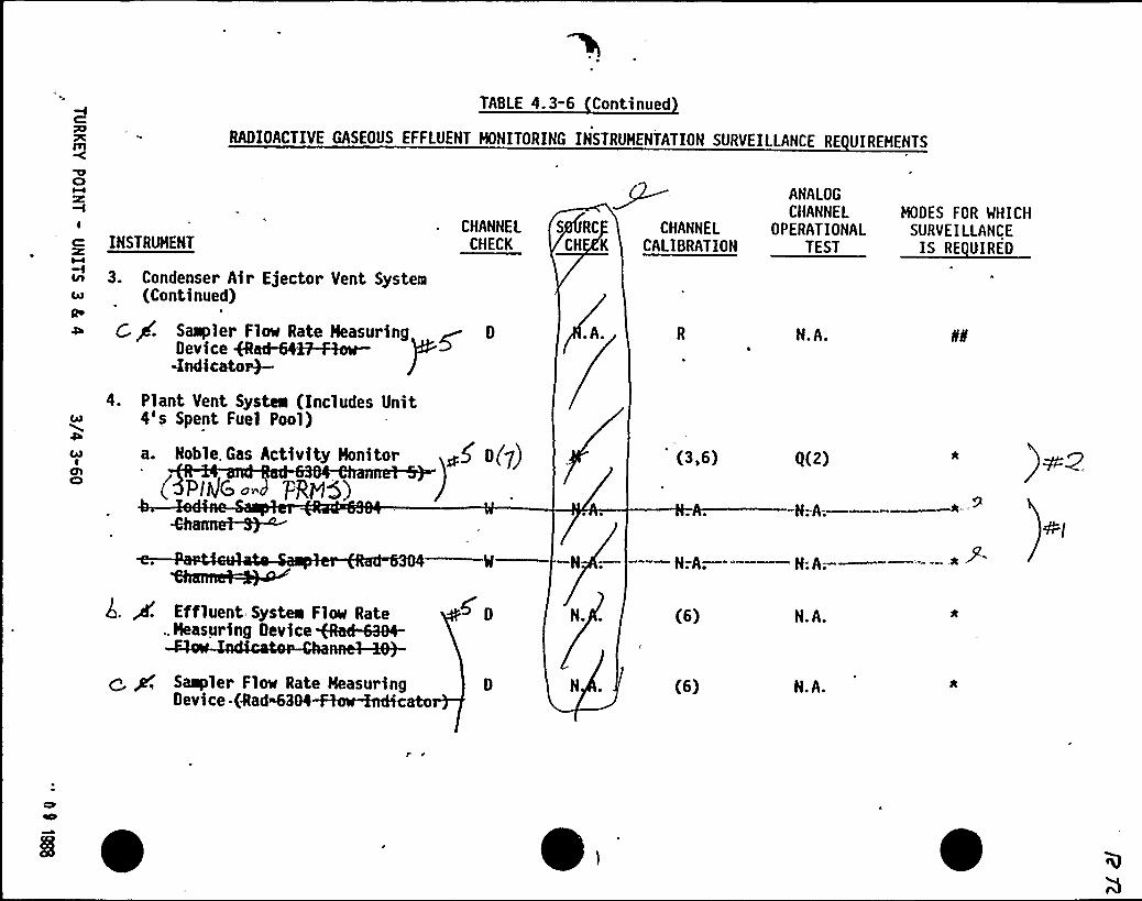
C:R77C
TABLE 4.3-6 Continued
RADIOACTIVE GASEOUS EFFLUENT HONITORING INSTRUHENTATION SURVEILLANCE RE UIREHENTS
RgCI
CHANNELCHECK
'I
INSTRUHENT
R 3. Condenser Air E)ector Vent SystemR (Continued)Qe
d G p'. Saepler Fine Rate Heaauring ~ D
Device eHi4~WrQndicato~
S RC
CH K
.A.
CHANNELCALIBRATION
ANALOGCHANNEL
OPERATIONALTEST
N.A.
HODES FOR WHICHSURVEILLANCEEll
RAA
CARI
OlC)
4. Plant Vent Systea (Includes Unit4's Spent Fuel Pool)
a. Noble. Gas Activity Honitor < g(7) (3,6) 0(2)
4;A—.— *
'.A
—." —H:A:—
P'-
Effluent Systea Fle» Rate., Heasur ing Oevice+hd~4-
nnel-~-
~ p, Sampler Flow Rate HeasuringII I -Ed daddd~
N.
N
(6)
(6)
N.A.
N.A.
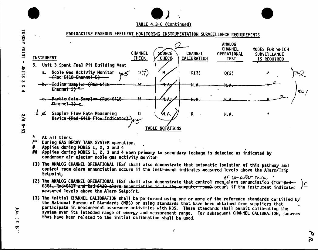
TABLE 4.3-6 Continued
RADIOACTIVE GASEOUS EFFLUENT MONITORING INSTRUMENTATION SURVEILLANCE RE UIREMENTS
Cl
Cib
INSTRUMENT
5. Unit 3 Spent Fuel Pit Building Vent
a. Noble Gaa Activity Hooitor
CHANNELCHECK
G(7)
RCE CHANNELCHEC CALIBRATION
- R(3)
OPERATIONALTEST
SURVEILLANCEIS RE UIRED
0(2)
ANALOG
CHANNEL MODES FOR WHICH
CayI
CJl
Sampler Flow Rate Measuring 0D
N.A.
TABLE NOTATIONS
N.A.
* At all times.-"* During GAS DECAY TANK SYSTEH operation.
Applies during NDES 1, 2, 3 and 4Applies during NDES 1, 2, 3 and 4 when primary to secondary leakage is detected as indicated bycondenser air ejector noble gas activity monitor
(1) The ANALOG CHANNEL OPERATIONAL TEST shall also demonstrate that automatic isolation of this pathway andcontrol room alarm annunciation occurs if the instrument indicates measured levels above the Alarm/TripSetpoint.
o~ Co~pAe,t- >co~(2) The ANALOG CHANNEL OPERATIONAL TEST shall also demonstrate that control room~alarm annunciation ~&nf-
ter-roea+ occurs if the instrument indicatesmeasured levels above the Alarm Setpoint.
(3) The initial CHANNEL CALIBRATION shall be performed using one or more of the reference standards certified bythe National Bureau of Standards (NBS) or using standards that have been obtained from suppliers thatparticipate in measurement assurance activities with NBS. These standards shall permit ca1ibrating thesystem over its intended range of energy and measurement range. For subsequent CHANNEL CALIBRATION, sourcesthat have been related to the initial calibration shall be used.
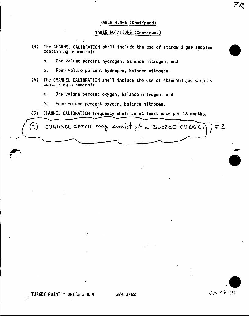
TABLE 4, 3" 6 Continued
TABLE NOTATIONS Continued
(4) The CHANNEL CALIBRATION shall include the use of standard gas samplescontaining a-nominal:
a. One volume percent hydrogen, balance nitrogen, and
b. Four volume percent hydrogen, balance nitrogen.
(5) The CHANNEL CALIBRATION shall include the use of standard gas samplescontaining a nominal:
a. One volume percent oxygen, balance nitrogen, and
b. Four volume percent oxygen, balance nitrogen.
(6) CHANNEL CALIBRATION frequency shall be at least once per 18 months.
Pf) c8AANSL ~au™.p crnsisk a4 o. 5'oUR.cG c H-fc,K ~ ) 0 z
TURKEY POINT - UNITS 3 8L 4 3/4 3-62
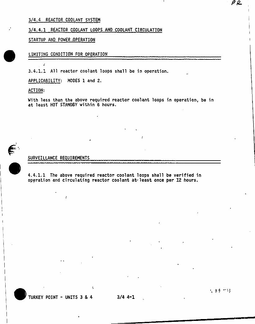
3/4. 4 REACTOR COOLANT SYSTEM
3/4.4. 1 REACTOR COOLANT LOOPS AND COOLANT CIRCULATION
STARTUP AND POWER .OPERATION
LIMITING CONDITION FOR OPERATION
3.4.1.1 All reacto~ coolant loops shall be in operation.
APPLICABILITY: MODES 1 and 2.
ACTION:
With less than the above required reactor coolant loops in operation, be inat least HOT STANDBY within 6 hours.
SURVEILLANCE RE UIREMENTS
4.4. 1. 1 The above required reactor coolant loops shall be verified inoperation and circulating reactor coolant at-least once per X2 hours.
TURKEY POINT - UNITS 3 4 4 3i4 4-1~ ij C
A
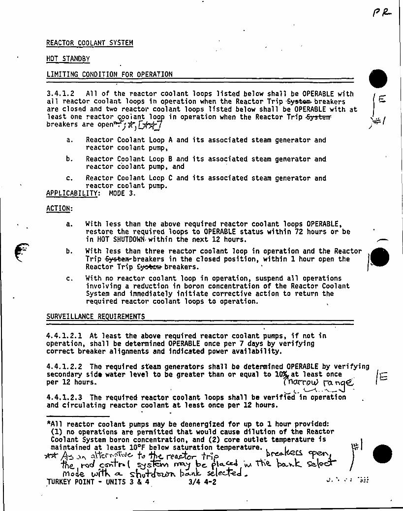
REACTOR COOLANT SYSTEM
HOT STANDBY
LIMITING CONDITION FOR OPERATION
3.4. 1.2 All of the reactor coolant loops listed below shall be OPERABLE withall reactor coolant loops in operation when the Reactor Trip Sys4am- breakersare closed and two reactor coolant loops listed below shall be OPERABLE with atleast one reactor~ooiant loop in operation when the Reactor Trip k~r.breakers are open .
> Q ~f 7a. Reactor Coolant
reacto~ coolantb, Reactor Coolant
reactor coolantc. Reactor Coolant
reactor coolantAPPLICABILITY: MODE 3.
Loop A and its associated steam generator andpump,
Loop B and its associated steam generator andpump, and
Loop C and its associated steam generator andpump.
ACTION:
b.
C.
With less than the above required reactor coolant loops OPERABLE,restore the required loops to OPERABLE status within 72 hours or bein HOT SHUTDOWN within the next 12 hours.
With less than three reactor coolant loop in operation and the ReactorTrip i~wbreakers in the closed position, within 1 hour open theReactor Tr Ip C~e breakers.With no reactor coolant loop in operation, suspend all operationsinvolving a reduction in boron concentration of the Reactor CoolantSystem and immediately initiate corrective action to return therequired reactor coolant loops to operation.
SURVEILLANCE RE UIREMENTS
4.4. 1.2. 1 At least the above required reactor coolant pumps, if not inoperation, shall be determined OPERABLE once per 7 days by verifyingcorrect breaker alignments and indicated power availability.
4.4. 1.2.2 The required st'earn generators shall be determined OPERABLE by verifyingsecondary side water level to be greater than or equal to 1 at least onceper 12 hours. C~rroQ i-a nq44.4.1.2.3 The required reactor coolant loops shall be verified in operationand circulating reactor coolant at least once per 12 hours.
"All reactor coolant pumps may be deenergized for up to 1 hour provided:(1) no operations are permitted that would cause dilution of the ReactorCoolant System boron concentration, and (2) core outlet temperature ismaintained at least 104F below saturation temperature.~ As ~~ a~~«~"-"<~ '4 '5c renvoi trip
5C. md c~+~.t sos m y bc PI ~ ~ ~A. b aK S i~No@, ~)4, ca. gg„+g~ p~k, Qe+wJ
TURKEY POINT - UNITS 3 4 4 3/4 4-2
0
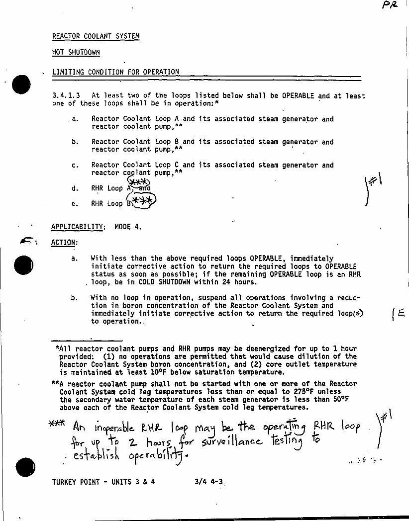
REACTOR COOLANT SYSTEM
HOT SHUTDOWN
LIMITING CONDITION FOR OPERATION
3.4.1.3 At least two of the loops listed below shall beone of these loops shall be in operation:"
OPERABLE and at least
a. Reactor Coolant Loop A and its associated steam generator andreactor coolant pump,""
b.
C.
d.
e.
Reactor Coolant Loop B and its associated steamreactor coolant pump,"*
Reactor Coolant Loop C and its associated steamreactor coolant pump,""
RHR Loop A, d
RNR Loop ~4~
generator and
generator and
APPLICABILITY: MODE 4.
ACTION:
a. With less than the above required loops OPERABLE, immediatelyinitiate corrective action to return the required loops to OPERABLEstatus as soon as possible; if the remaining OPERABLE loop is an RHR
, loop, be in COLD SHUTDOWN within 24 hours.
b. With no loop in operation, suspend all operations involving a reduc-tion in boron concentration of the Reactor Coolant System andimmediately initiate corrective action to return the required loop(5)to operation..
"All reactor coolant pumps and RHR pumps may be deenergized for up to 1 hourprovided: (1} no operations are permitted that would cause dilution of theReactor Coolant System boron concentration, and (2) core outlet temperatureis maintained at least 10 F below saturation temperature.
*~A reactor coolant pump shall not be started with one or more of the Reacto~Coolant System cold leg temperatures less than or equal to 275oF unlessthe secondary water temperature of each steam generator is less than 504Fabove each of the Reactor Coolant System cold leg temperatures.
A> IAcyli )(o. ggP t Oo[ fA~g Q AO. OP&griWl+n P'HR lPO)
y» o Wo z L,~Tg Q» yurt.;i)~.c~ feofi~g. e~)~t(is( o)«~4lQ).
TURKEY POINT - UNITS 3 5 4 3/4 4-3
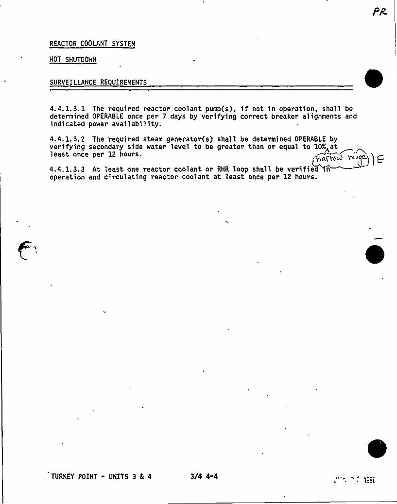
REACTOR COOLANT SYSTEM
HOT SHUTOOWN
SURVEILLANCE RE UIREHENTS 04.4.1.3.1 The required reactor coolant pump(s), if not in operation, shall bedetermined OPERABLE once per 7 days by verifying correct breaker alignments andindicated power availability.
4. 4. 1. 3. 2 The required steam generator(s) shall be determined OPERABLE byverifying secondary side water level to be greater than or equal to lOX atleast once per 12 hours. anooo «~g) ~g4.4.1.3.3 At least one reactor coolant or RHR loop shall be verifie noperation and circulating reactor coolant at least once per 12 hours.
TURKEY POINT - UNITS 3 8E 4 3l4 4-4 l1'o~ ~ Iv) l
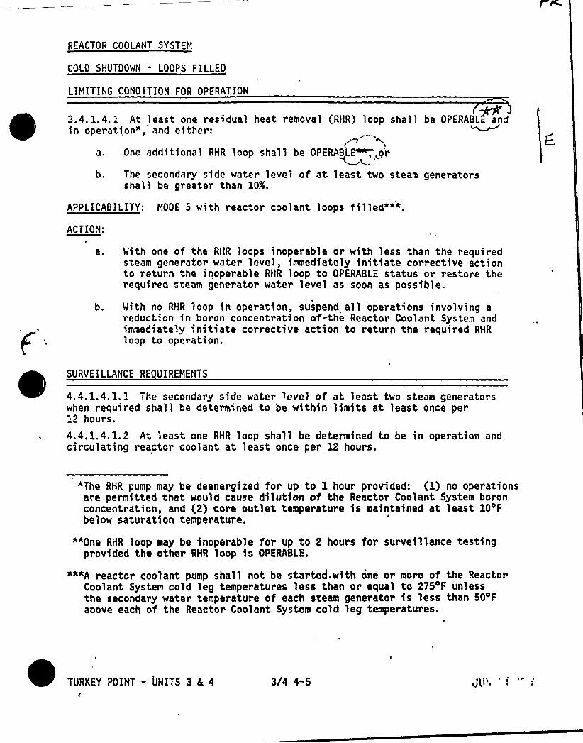
REACTOR COOLANT SYSTEM
COLO SHUTOOWN - LOOPS FILLED
LIMITING CONOITION FOR OPERATION
3.4. 1.4.1 At least one residual heat removal (RHR) loop shall be OPERABL&andin operation", and either:
a. One additional RHR loop shall be OPERAB P , or
b. The secondary side water level of at least two steam generatorsshall be greater than 10K.
APPLICABILITY: MOOE 5 with reactor coolant loops filled""".ACTION:
a.
b.
With one of the RHR loops inoperable or with less than the requiredsteam generator water level, immediately initiate corrective actionto return the inoperable RHR loop to OPERABLE status or restore therequired steam generator water level as soon as possible.
With no RHR loop in operation, suspend all operations involving areduction in boron concentration of-.the Reactor Coolant System andimmediately initiate corrective action to return the required RHR
loop to operation.
SURVEILLANCE RE UIREMENTS
4.4. 1.4. 1. 1 The secondary side water level of at least two steam generatorswhen required shall be determined to be within limits at least once per12 hours,
4.4. 1.4. 1. 2 At least one RHR loop shall be determined to be in operation andcirculating reactor coolant at least once per 12 hours.
"The RHR pump may be deenergized for up to 1 hour provided: (1) no operationsare permitted that would cause dilution of the Reactor Coolant System boronconcentration, and (2) core outlet temperature is maintained at least 104Fbelow saturation temperature.
""One RHR loop may be inoperable for up to 2 hours for surveillance testingprovided the other RHR loop is OPERABLE.
"""A reactor coolant pump shall not be started. with one or more of the ReactorCoolant System cold leg temperatures less than or equal to 275oF unlessthe secondary water temperature of each steam generator is less than 504Fabove each of the Reactor Coolant System cold leg temperatures.
TURKEY POINT - UNITS 3 4 4 3/4 4-5

REACTOR COOLANT SYSTEM
COLD SHUTDOWN " LOOPS NOT FILLED
LIMITING CONDITION FOR OPERATION
3.4. 1.4.2 Two residual heat removal (RHR) loops shall be OPERABLE" and atleast one RHR loop shall be in operation.""
APPLICABILITY: MODE 5 with reactor coolant loops not filled.ACTION:
b.
With less than the above required RHR loops OPERABLE, immediatelyinitiate corrective action to return the required RHR loops toOPERABLE status as soon as possible.
With no RHR loop in operation, suspend all operations involving areduction in boron concentration of the Reactor Coolant System andimmediately initiate corrective action to return the required RHR
loop to operation.
SURVEILLANCE RE UIREMENTS
4.4. 1.4.2 At least one RHR l.oop shall be determined to be in operation andcirculating reactor coolant at least once per, 12 hour s.
"One RHR loop may be inoperable for up to 2 hours for surveillance testingprovided the other RHR loop is OPERABLE.
""The RHR pump may be deenergized for up to 1 hour provided: (1) no opera-tions are permitted that would cause dilution of the Reactor Coolant Systemboron concentration, and (2) core outlet temperature is maintained at least10'F below saturation temperature.
TURKEY POINT - UNITS 3 4 4 3/4 4-6
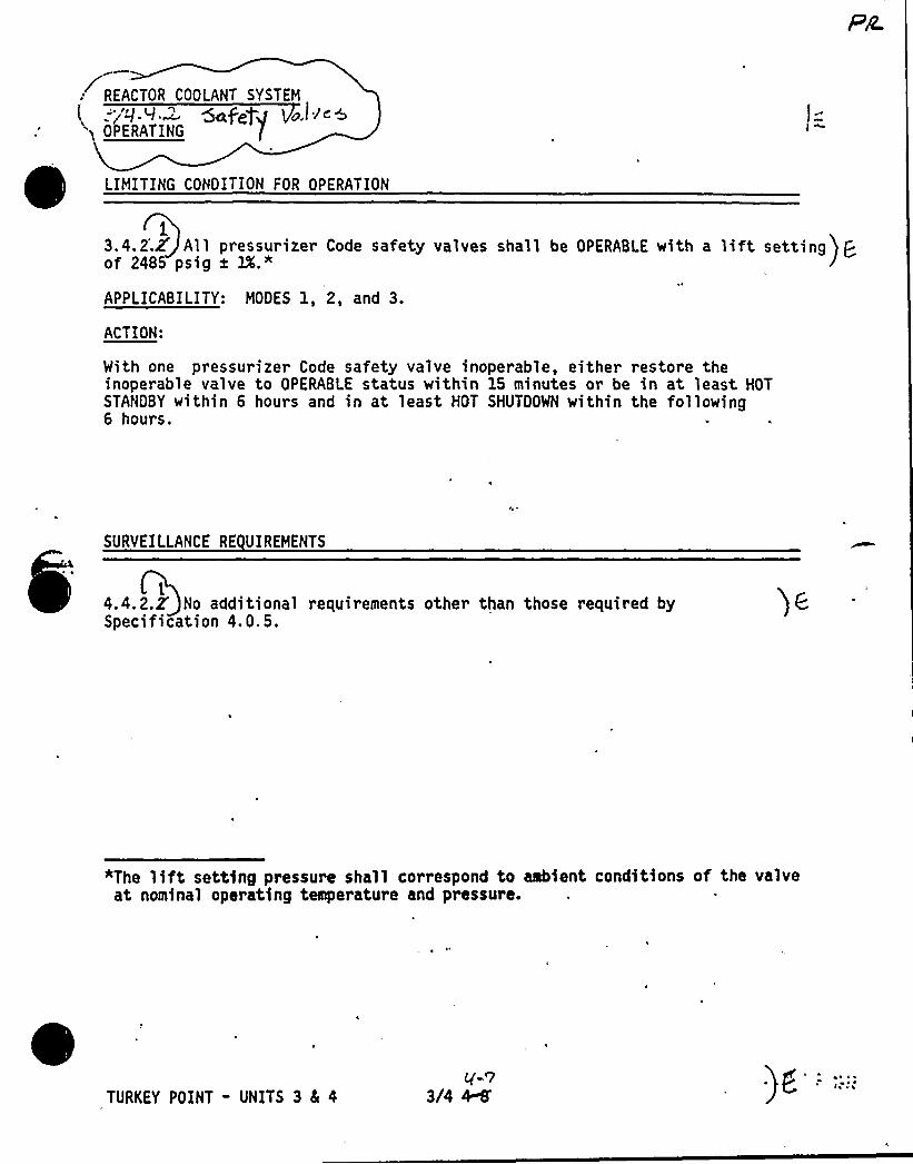
REACTOR COOLANT SYSTEM
."j'd. I" 5e peg] a.l le&
'y OPERATING
LIMITING CONOITION FOR OPERATION
.13.4.2.Z A'll pressurizer Code safety valves shall be OPERABLE with a lift setting) Qof 2485 psig a lX."
APPLICABILITY: MOOES 1, 2, and 3.
ACTION:
With one pressurizer Code safety valve inoperable, either restore theinoperable valve to OPERABI E status within 15 minutes or be in at least HOTSTANDBY within 6 hours and in at least HOT SHUTOOWN within the following6 hours.
SURVEILLANCE RE UIREMENTS
14.4.2.Z No additional requirements other than those required bySpecification 4.0.5.
"The lift setting pressure shall correspond to ambient conditions of the valveat nominal operating temperature and pressure.
TURKEY POINT - UNITS 3 4 4

REACTOR COOLANT SYSTEM
~evts- SAFETY VALVES
SHUTDOWN
LIMITING CONDITION FOR OPERATION
3.4.2M A minimum of one pressurizer Code safetya lift etting of 2485 psig a lX."
QQD~ H . ("QAPPLICABILITY: MOD@ 4 and~5~
~Ac'~I"~~I ed,MACTION:
valve shall be OPERARLE with ) C
1r ~ure l'.-: J
With no pressurizer Code safety valve OPERABLE, immediately suspend alloperations involving positive reactivity changes-loop into-operation i'~ ~n-cool-i-ng-mode:.exbep. ~eT as OPERA Lie /gal Iaop >4ss~~ ssv. plat Ysg lave
p+ „,4u. sI flan ooI~ Mp
SURVEILLANCE RE UIREMENTS
4.4.2.Z No additional requirements other than those required bySpeci 'tion 4.0.5.
"The lift setting pressure shall correspond to ambient condit4ons of the valveat nominal operating temperature and pressure.~ RCS PPOS~ure BOus 9 F"y ~ ~~4~~Y~A LFFile~e W PC~ig
+e' ~Ysvs~n+nTh~vssv~ a Vvs~sn V slperu pTURKEY POINT - UNITS 3 4 4 3/4 ~
C~ g'
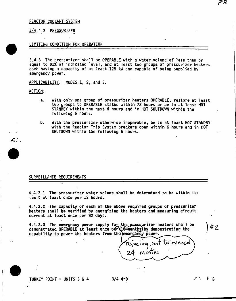
REACTOR COOLANT SYSTEM
3/4.4.3 PRESSURIZER
LIMITING CONDITION FOR OPERATION
3.4.3 The pressurizer shall be OPERABLE with a water volume of less than orequal to 92K of indicated level, and at least two groups. of pressurizer heaterseach having a capacity of at least 125 kW and capable of being supplied byemergency power.
APPLICABILITY: MODES 1, 2, and 3.
ACTION:
a. With only one group of pressurizer heaters OPERABLE, restore at leasttwo groups to OPERABLE status within 72 hours or be in at least HOTSTANDBY within the next 6 hours and in HOT SHUTDOWN within thefollowing 6 hours.
With the pressurizer otherwise inoperable, be in at least HOT STANDBYwith the Reactor Trip System breakers open within 6 hours and in HOTSHUTDOWN within the following 6 hours.
SURVEILLANCE RE UIREMENTS
4.4.3. 1 The pressurizer water volume shall be determined to be within itslimit at least once per 12 hours.
4.4. 3. 2 The capacity of each of the above required groups of pressurizerheaters shall be verified by energizing the heaters and measuring circuitcurrent at least once per 92 days.
4.4.3.3 The emergency power supply fog the urizel heaters shall bedemonstrated OPERABLE at least once p6r by demonstrating thecapability to power the heaters from the'mergency power.
IN,I.vC,tin) ho4 ~+ <<<~2 Cj msn44
TURKEY POINT - UNITS 3 & 4 3/4 4-9
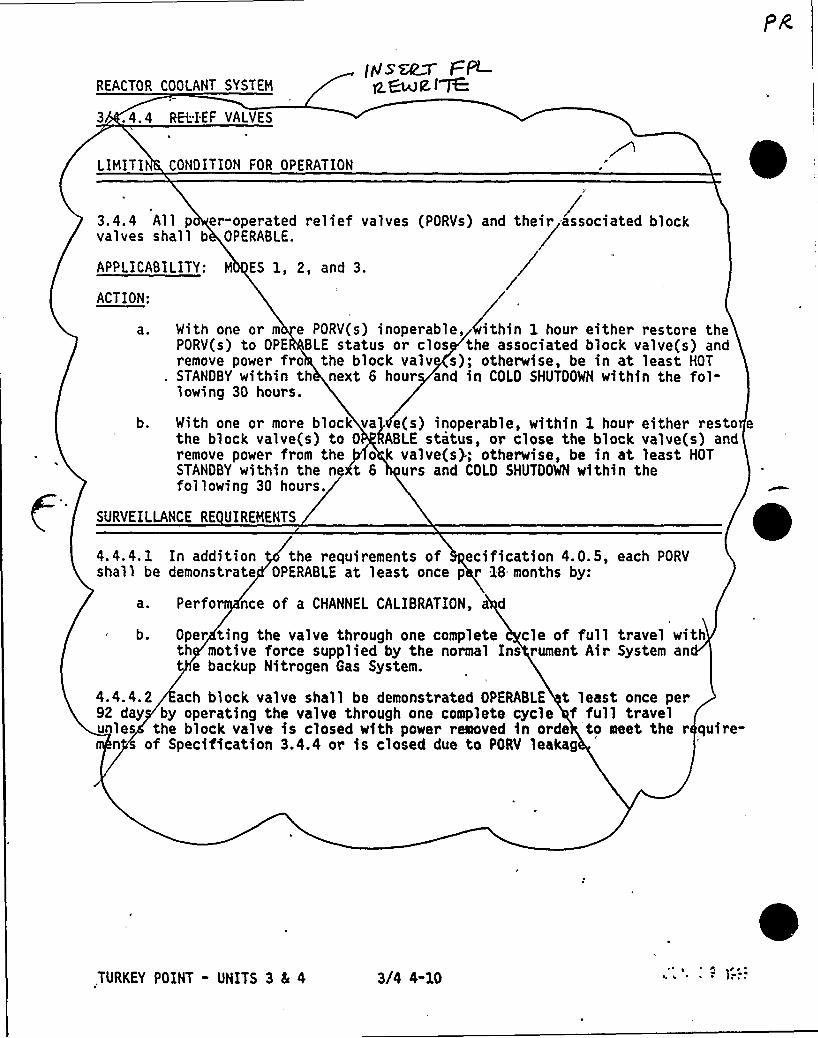
REACTOR COOLANT SYSTEM
3 .4.4 REi;.IEF VALVES
LIHITI CONDITION FOR OPERATION
INsazT F8-g ~g.l~
3.4.4 All p er"operated relief valvesvalves shall b OPERABLE.
APPLICABILITY: H ES 1, 2, and 3.
ACTION:
iPORVs) end their dssocieted block
a r
b,
With one or m e PORV(s) inoperable, ithin 1 hour either restore thePORV(s) to OPE BLE status or clos the associated block valve(s) andremove power fro the block valv s); otherwise, be in at least HOTSTANDBY within th next 6 hour and in COLD SHUTDOWN within the fol-lowing 30 hours.
With one or more block va) e(s) inoperable, within 1 hour either restothe block valve(s) to 0 'RABLE status, or close the block valve(s) andremove power from the o k valve(s); otherwise, be in at least HOTSTANDBY within the n t 6 urs and COLD SHUTDOWN within thefollowing 30 hours.
SURVEILLANCE RE UIREHENTS
4.4.4. 1 In addition the requirements of ecification 4.0.5, each PORVshall be demonstrate OPERABLE at least once p r 18 months by:
a. Perfor nce of a CHANNEL CALIBRATION, a d
b. Oper ting the valve through one complete cle of full travel withth motive force supplied by the normal Ins rument Air System ant e backup Nitrogen Gas System.
4.4.4.2 ach block valve shall be demonstrated OPERABLE t least once per92 day by operating the valve through one complete cycle f full travelunles the block valve is closed with power removed in orde to meet the r quire-
n of Specification 3.4.4 or is closed due to PORV leakag
.TURKEY POINT - UNITS 3 5 4 3/4 4-10
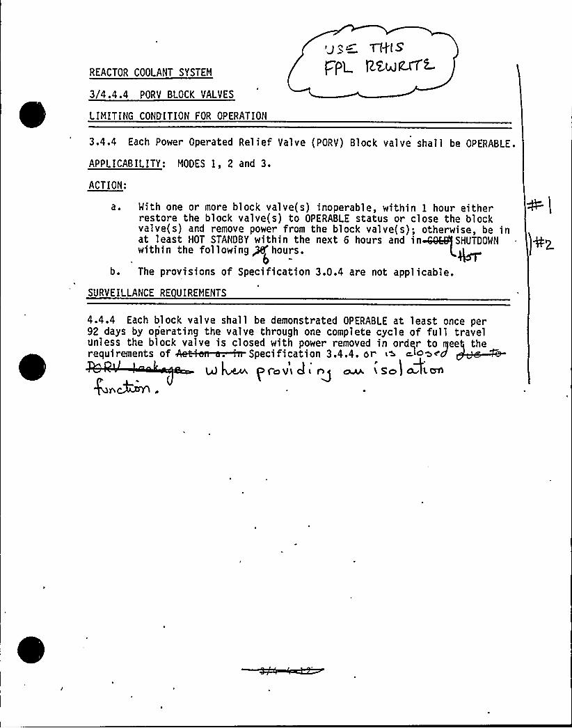
REACTOR COOLANT SYSTEM
3/4.4.4 PORV BLOCK VALVES
LIMITING COND'ITION FOR OPERATION
Cfg( S
/pe. RR+Rx74
3.4.4 Each Power Operated Relief Valve (PORV) Block valve shall be OPERABLE.
APPLICABILITY: MODES I, 2 and 3.
ACTION:
a.
b.
With one or more block valve(s) inoperable, within 1 hour eitherrestore the block valve(s) to OPERABLE status or close the blockvalve(s) and remove power from the block valve(s); otherwise, be inat least HOT STANDBY within the next 6 hours and in SHUTDOWNwithin the following Pf hours.
The provisions of Specification 3.0 .4 are not applicable.
SURVEILLANCE RE UIREMENTS
4.4.4 Each block valve shall be demonstrated OPERABLE at least once per92 days by operating the valve through one complete cycle of full travelunless the block valve is closed with power removed in order to gee theqi fAkl . 'p if' 3.4.4. '
f ~
pro v J ~ ( so)
f' l'
Ie
f \
l1

REACTOR COOLANT SYSTEM
3/4.4.5 STEAM GENERATORS
LIMITING CONDITION FOR OPERATION
3.4.5 'ach steam generator shall be OPERABLE.
APPLICABILITY: MODES 1, 2, 3, and 4.
ACTION: h~~~With one or more steam generators inoperable, restore the inoperable generator(s)to OPERABLE statu 'v CIt 4L E< QfHOT AU'D ()(~4 ~ Co kc(or~ >Q (~ COLD <HU~L,(g (O(qg ~(~
SlfkE1LLANCE RE REBATE
4. 4. 5, 0 Each steam generator shall be demonstrated OPERABLE by performance ofthe following augmented inservice inspection-proSpecification 4.0.5. -~ g ~, „ $ p ~~ z4. rn~Qs
4.4.5. 1 Steam Generator Sam le S 1 tion and In ection - Each steam generatorshall be determined OPERABLE duri g by select ng and inspecting atleast the minimum number of steam gen rator< specified in Table 4.4-1.
4.4.5.2 Steam Generator Tube Sam le Selection and Ins ection - The steamgenerator tube minimum sample size, inspect>on result classification, and thecorresponding action required shall be as specified in Table 4.4-2. Theinservice inspection of steam generator tubes shall be performed at the fre-quencies specified in Specification 4.4.5.3 and the inspected tubes shall beverified acceptable per the acceptance criteria of Specification 4.4.5.4. Thetubes selected'for each inservice inspection shall include at least 3X of thetotal number of tubes in all steam generators; the tubes selected for theseinspections shall be selected on a random basis except:
a. Where experience in similar plants with similar water chemistryindicates critical areas to be inspected, then at least 50K of thetubes inspected shall be from these critical areas;
b. The first sample of tubes selected for each inservice inspection(subsequent to the preservice inspection) of each steam generatorshall include:
TURKEY POINT " UNITS 3 4 4 3/4 4-11
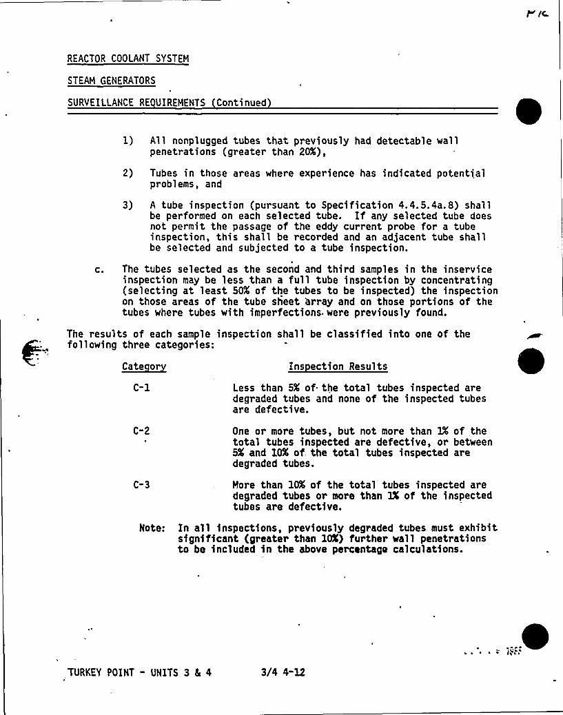
REACTOR COOLANT SYSTEM
STEAM GENERATORS
SURVEILLANCE RE UIREMENTS Continued
1) All nonplugged tubes that previously had detectable wallpenetrations (greater than 20X),
2) Tubes in those areas where experience has indicated potentialproblems, and
3) A tube inspection (pursuant to Specification 4.4.5.4ar8) shallbe performed on each selected tube. If any selected tube doesnot permit the passage of the eddy cur rent probe for a tubeinspection, this shall be recorded and an adjacent tube shallbe selected and subjected to a tube inspection.
c. The tubes selected as the second and third samples in the inserviceinspection may be less than a full tube inspection by concentrating(selecting at least 50X of the tubes to be inspected) the inspectionon those areas of the tube sheet 'array and on those portions of thetubes where tubes with imperfections. were previously found.
The results of each sample inspection shall be classified into one of thefollowing three categories:
~Cate or Ins ection Results
C-1 Less than 5X of the total tubes inspected aredegraded tubes and none of the inspected tubesare defective.
C"2
C-3
One or more tubes, but not more than IX of thetotal tubes inspected are defective, or between5X and 10X of. the total tubes inspected aredegraded tubes.
More than 10X of the total tubes inspected aredegraded tubes or more than 3X of the inspectedtubes are defective.
Note: In all inspections, previously degraded tubes must exhibitsignificant (greater than 10X) further wall penetrationsto be included in the above percentage calculations.
TURKEY POINT - UNITS 3 L 4 3/4 4-12
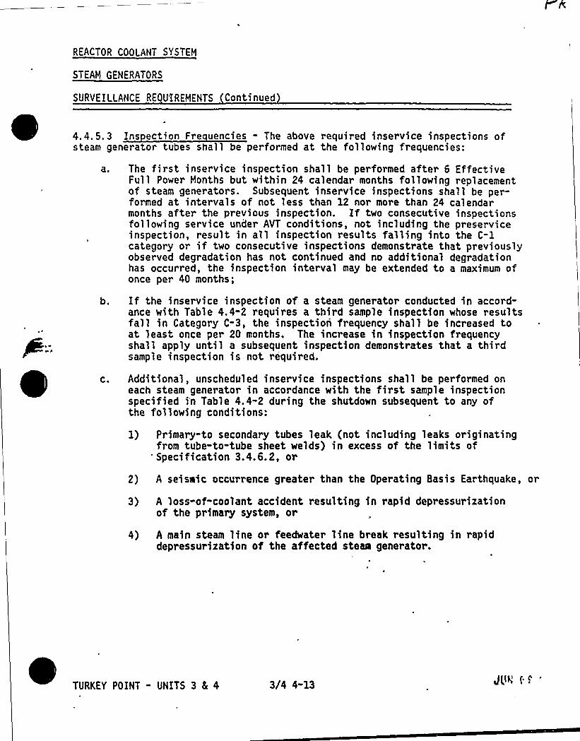
REACTOR COOLANT SYSTEM
STEAM GENERATORS
SURVEILLANCE RE UIREMENTS Continued
4. 4. 5. 3 Ins ection Fr e uencies - The above required inservice inspections ofsteam generator tubes shall be performed at the following frequencies:
a ~ The first inservice inspection shall be performed after 6 EffectiveFull Power Months but within 24 calendar months following replacementof steam generators. Subsequent inservice inspections shall be per-formed at intervals of not less than 12 nor more than 24 calendarmonths after the previous inspection. If two consecutive inspectionsfollowing service under AVT conditions, not including the preserviceinspection, result in all inspection results falling into the C-1category or if two consecutive inspections demonstrate that previouslyobserved degradation has not continued and no additional degradationhas occurred, the inspection interval may be extended to a maximum ofonce per 40 months;
b. If the inservice inspection of a steam generator conducted in accord-ance with Table 4.4-2 requires a third sample inspection whose resultsfall in Category C-3, the inspection frequency shall be increased toat least once per 20 months. The increase in inspection frequencyshall apply until a subsequent inspection demonstrates that a thirdsample inspection is not required.
C. Additional, unscheduled inservice inspections shall be performed oneach steam generator in accordance with the first sample inspectionspecified i'n Table 4.4-2 during the shutdown subsequent to any ofthe following conditions:
1) Primary-to secondary tubes leak (not including leaks originatingfrom tube-to-tube sheet welds) in excess of the limits of
'pecification 3.4.6.2, or
2) A seisaic occurrence greater than the Operating Basis Earthquake, or
3) A loss-of-coolant accident resulting in rapid depressurizationof the primary system, or
4) A main steam line or feedwater line break resulting in rapiddepressurization of the affected steam generator.
TURKEY POINT - UNITS 3 8 4 3/4 4-13 JUN ( ~
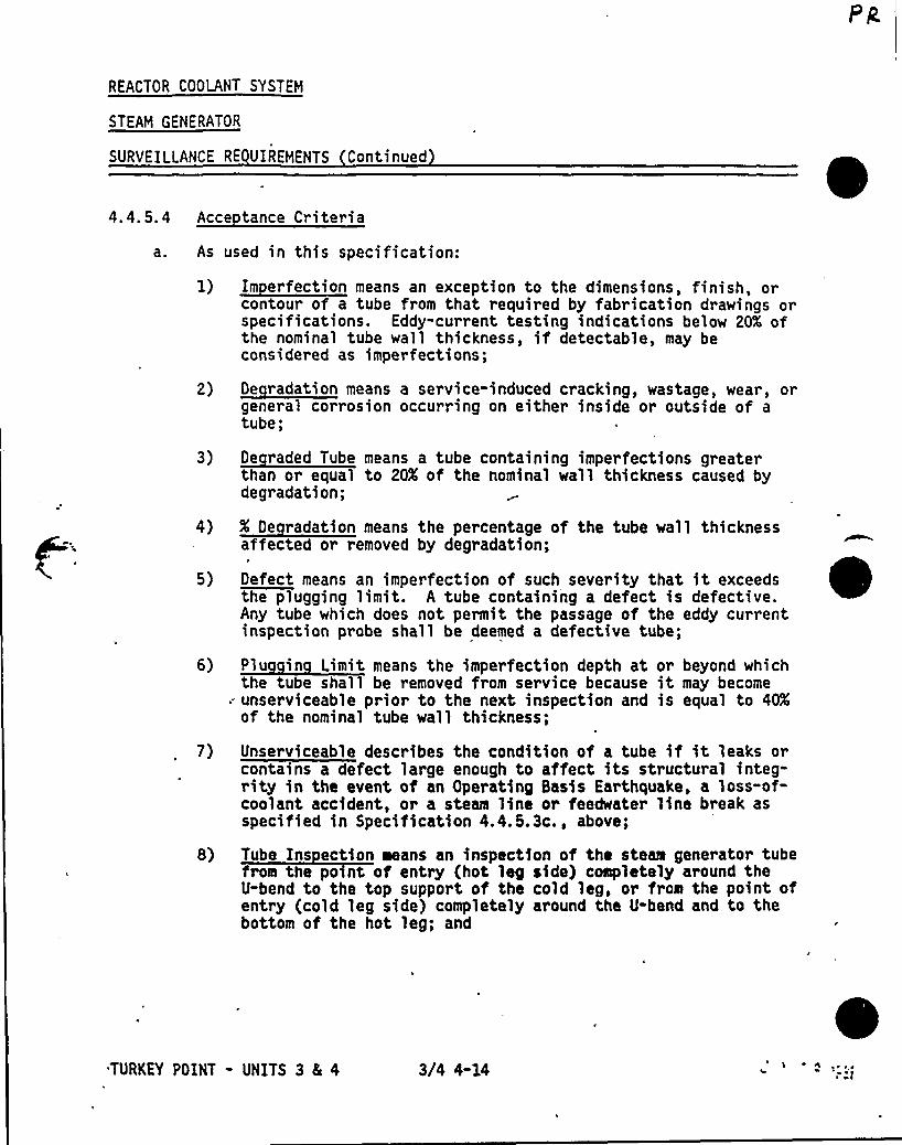
REACTOR COOLANT SYSTEM
STEAM GENERATOR
SURVEILLANCE RE UIREMENTS Continued
4.4. 5.4 Acce tance Criteria
As
2)
3)
4)
5)
6)
7)
8)
used in this specification:
~T" * p hcontour of a tube from that required by fabrication drawings orspecifications. Eddy-current testing indications below 20K ofthe nominal tube wall thickness, if detectable, may beconsidered as imperfections;
d d 1, g,general corrosion occurring on either inside or outside of atube;
~ddp h 1 1gl 1 1 gthan or equal to 20X of the nominal wall thickness caused bydegradation;
g~g" T h p g 1 h h 11 P 1affected or removed by degradation;
gefect means an imperfection of such severity that it exceedsthe plugging iimit. A tube containing a defect is defective.Any tube which does not permit the passage of the eddy currentinspection probe shall be deemed a defective tube;
~PT 1 11 lp 1 1 dphthe tube shall be removed from service because it may becomeunserviceable prior to the next inspection and is equal to 4(Cof the nominal tube wall thickness;
Unserviceable describes the condition of a tube if it leaks orcontains a defect large enough to affect its structural integ-rity in the event of an Operating Basis Earthquake, a loss-of-coolant accident, or a steam line or feedwater line break asspecified in Specification 4.4.5.3c., above;
Tube Ins ection means an inspection of the steaa generator tubefrom the po nt of entry (hot leg side) completely around theU-bend to the top support of the cold leg, or from the point ofentry (cold leg side) completely around the U-bend and to thebottom of the hot leg; and
0TURKEY POINT - UNITS 3 & 4 3/4 4-14 1 + de t ~ ~
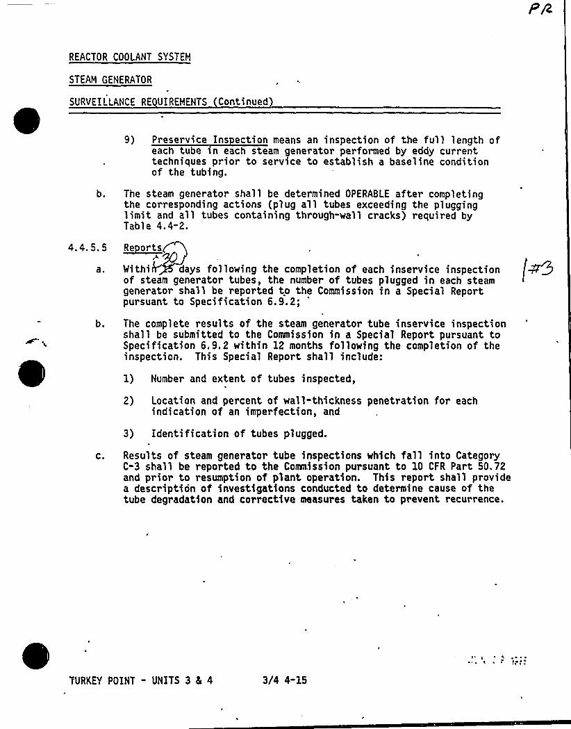
REACTOR COOLANT SYSTEM
STEAM GENERATOR
SURYEILLANCE RE UIREMENTS Continued
b.
9) Preservice Ins ection means an inspection of the full length ofeach tube sn each steam generator performed by eddy currenttechniques prior to service to establish a baseline conditionof the tubing.
The steam generator shall be determined OPERABLE after completingthe corresponding actions (plug all tubes exceeding the plugginglimit and all tubes containing through"wall cracks) required byTable 4.4-2.
4.4. 5. 5
a.
b.
C.
~Re orts
Withi days following the completion of each inservice inspectionof steam generator tubes, the number of tubes plugged in each steamgenerator shall be reported to the Commission in a Special Reportpursuant to Specification 6.9.2;
'he
complete results of the steam generator tube inservice inspectionshall be submitted to the Commission in a Special Report pursuant toSpecification 6.9. 2 within 12 months following the completion of theinspection. This Special Report shall include:
1) Number and extent of tubes inspected,
2) Location and percent of wall-thickness penetration for eachindication of an imperfection, and
3) Identification of tubes plugged.
Results of steam generator tube inspections which fall into CategoryC-3 shall be reported to the Commission pursuant to 10 CFR Part 50.72and prior to resumption of plant operation. This report shall providea description of investigations conducted to determine cause of thetube degradation and corrective measures taken to prevent recurrence.
T'URKEY POINT - UNITS 3 5 4 3/4 4-15
~ ~I ~
1
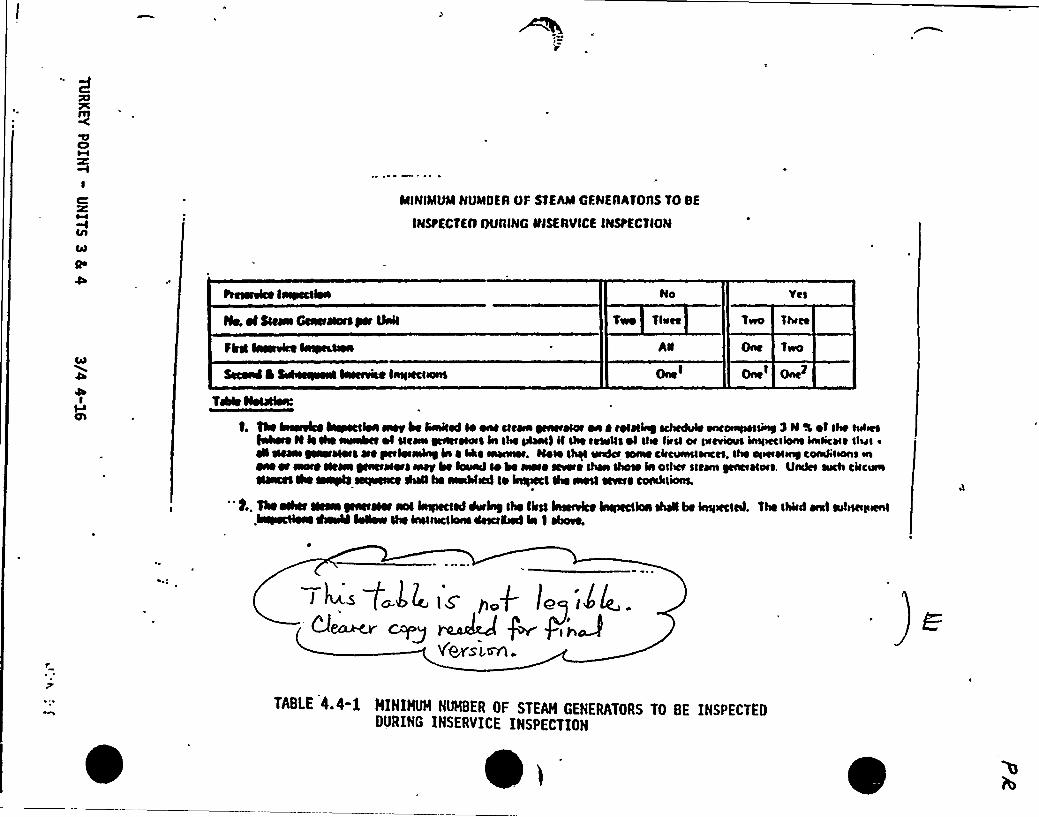
ClM
IC
Qo
ININIMUMNUNIIIER OF STEhAI GENEAATOAS TD SE
IMStECTEtl OURING IIJSERVICE INSPECTION
Ne. el Slewa GcacrHols per Ustil
Flrcl I~lee IalpcLCtea
Second 0 Sehceiwal laccttae lnritccltons
Yet
Two Theet
One Two
O IO~I
crtTchie NoIHlea:
0. The htretelee leryecllea awt be fitnired lo one cretin ycacteror oa o rolHby ccltcthere eneoettrttr&sy lM 4 ol lhe reelect~ N le Ihe tnrtnbec ol i!coen NetrctHotc hr lhe phnr) il lhe ltlellc ol lite Iiear ot litcieiatr intiiecriont intricate thar ~
H Heter QNNlHotc ere gletletlnleN in ~ lke tncne»t. l4OH I+ ltndet lotne cltetitnrrtticer, It» or<titlingconkllont in~ae oc ~ clem oeetHotc ~ be hrttnd lo he arete cctete rI»a lhote ia osl»r sicken yenceHtttc. Under tttclt circtttnNaeei lhe searle serlaeace ANhe aredtitcd Io hapccl lhe rail ccvcre condtlionL
" f.. The ochcc Ilcwa jsetHet aol hrrpccled keiey Ihe Ilail hratvice hrrpcctioa lheli be inritccietl. The lhltd entI atitMtittcnl.hrrlteclieae Aerthl hrwew I» inrintHlonc ritter%ted Ia I ebote.
TABLE 4.4-1 HININJH NlNBER OF STEAM GENERATORS TO BE INSPECTEODURING INSERVICE INSPECTION
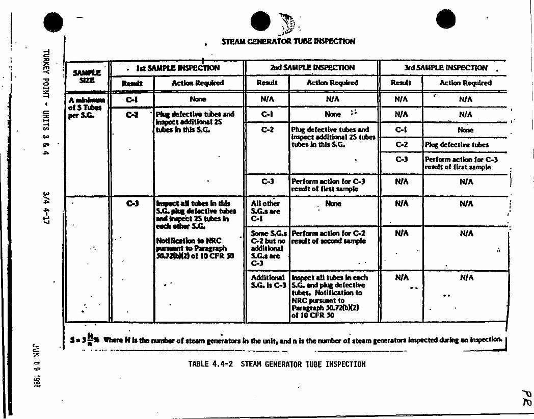
STEhil GEtKRATOR %VS'NSPECTIIOH
lst SAMPLE INSPECTION 2nd SAMPLE INSPECTION 3rd SAMPLE INSPECTION
ltasaft hction ~iced Result Action Required
Aminie~ofST~yerSQ
C-I
C4 'ug defects eblis «ndImpact additional 25tubes In this S.G.
hsyect aN ahes In this5A yhg*factlve tubesand Inspect 2$ hgea lneach other 54,
Notification so INCswat to Par«Ipaph3tM%4Mof IO CFR $0
N/A
C-I
C-2
C-3
NlotherS MareC-I
Saae S.~C-2 but noadditionalS.Ga areC-3
AdditionalSG IsC-3
N/A
Nane
Phg*fectbe tubes andlmpect additional 25 tubestubes in this S.C.
Perform action for C 3result of first sample
Perforce action for C-2result of second sample
Inspect all tubes in eachS.G. and plug defectbetubes. Notification toNRC pursuant toPar~ape 3O.nSX2)of IOCFR%
N/A
C-I
C-2
C-3
N/h
N/A
Plug defectl~ tubes
Perform action fw C-3result of first sample
N/A
N/A
++ IlIs the +anbar of steam cenerators In the unit> and n Is the numler of steam generators ieyacted Arlng an Inspection
TABLE 4.4"2 STEAH GENERATOR TUBE INSPECTIOH
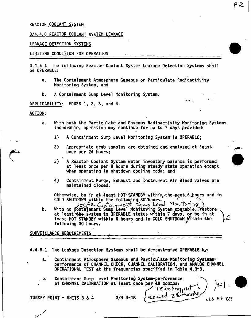
REACTOR COOLANT SYSTEM
3/4. 4. 6 REACTOR COOLANT SYSTEM LEAKAGE
LEAKAGE DETECTION SYSTEMS
LIMITING CONDITION FOR OPERATION
3.4.6. 1 'The following Reactor Coolant System Leakage Detection Systems shallbe OPERABLE:
a. The Containment Atmosphere Gaseous or Particulate RadioactivityMonitoring System, and
b. A Containment Sump Level Monitot ing System.
APPI ICABILITY: MODES 1, 2, 3, and 4.
ACTION:
a. With both the Particulate and Gaseous Radioactivity Monitoring Systemsinoperable, operation may continue for up to 7 days provided:
1) A Containment Sump Level Monitoring System is OPERABLE;
2) Appropriate grab samples are obtained and analyzed at leastonce per 24 hours;
3) A Reactor Coolant System water inventory balance is performedat least once per 8 hours during steady state operation exceptwhen operating in shutdown cooling mode; and
4) Containment Purge, Exhaust and Instrument Air Bleed valves aremaintained closed.
b.
Otherwise, be in at least HOT-STANDBY within the-next 6 >ours and inCOLD SHUTDOWN within the folloqing 30~hours.
o+Q Covetous'nme3 Cvw.n LevJ YvnPori eggWith no ontainment Sump Level Monitoring System op~erable,.restoreat least System to OPERABLE status within 7 days, or be in atleast HOT STANOBY within 6 hours and in COLO SHUTOONNP(ithin thefollowing 30 hours.
SURVEILLANCE RE UIREMENTS
, b. Containment Sump Level Monitoring System-performanceof CHANNEL CALIBRATION at least once per 48-moaths
f-eaucjinq n ~ tZ + mes3/4 4-18TURKEY POINT - UNITS 3 4 4
4.4.6. 1 The Leakage Detection Systems shall be deeonstrated OPERABLE by:
a. Containment Atmosphere Gaseous and Particulate Monitoring Systems-performance of CHANNEL CHECK, CHANNEL CALIBRATION, and ANALOG CHANNELOPERATIONAL TEST at the frequencies specified in Table 4.3-3,
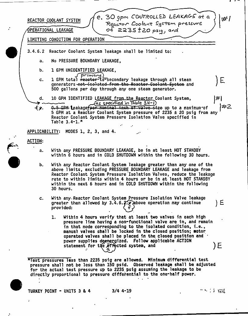
REACTOR COOLANT SYSTEM
PERATIONAL LEAKAGE
|.. 30~@ Co4rro<~H I EevnG-E. w%ea~~~r Coo lc,~c Cycle~ pv.ess~re.
<>35 +2.0 prig~ @no{
LIMITING CONDITION FOR OPERATION
0
3. 4. 6. 2 Reactor Coolant System leakage shall be limited to:
a. No PRESSURE BOUNDARY LEAKAGE,
b. 1 GPM UNIDENTIFIED LEAKAGE,prlWarq
c. 1 GPM total +ea~Zo-secondary leakage through all steamgenerators and500 gallons per day through any one steam generator.
d. 10 GPM IDENTIFIED LEAKAGE fr e R tor Coolant System,~s s,pecifted 'in Table 3A-I
+g. ~4'- 4akage„ up to a maximum. of5 GPM at a Reactor Coolant System pressure of 2235 k 20 psig from anyReactor Coolant System Pressure Isolation Valve specified inTab1e 3.4-1."
APPLICABILITY: MODES 1, 2, 3, and 4.
ACTION:
With any PRESSURE BOUNDARY LEAKAGE, be in at least HOT STANDBYwithin 6 hours and in COLD SHUTDOWN within the following 30 hours,
With any Reactor Coolant System leakage greater than any one of theabove limits, excluding PRESSURE BOUNDARY LEAKAGE and leakage fromReactor Coolant System Pressure Isolation Valves, reduce the leakagerate to within limits within 4 hours or be in at least HOT STANDBYwithin the next 6 hours and in COLD SHUTDOWN within the following30 hours.
C. With any Reactor Coolant System Pressure Isolation Valve leakagegreater than a'l1owed by 3.4.6..g bove operation may continue ) Fprovided:
Within 4 hours verify that at least two valves in each highpressure line having a non-functional valve are in, and remainin that mode corresponding to the isolated condition, i.e.,manual valves shall be locked in the closed position; aotoroperated valves shall be placed in the closed position and .
power supplies d gized. Follow applicable ACTIONstatement for t e >if cted system, and
Test pressures loss than 2235 psig are allowed. Minimuti differential testpressure shall not be less than 150 psid. Observed leakage shall be adjustedfor the actual test pressure up to 2235 psig assuming the leakage to bedirectly proportional to pressure differential to the one-half power.
TURKEY POINT - UNITS 3 5 4 3/4 4-19
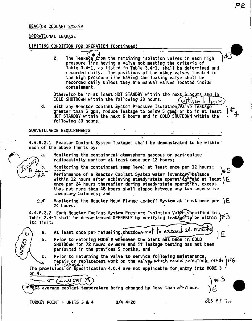
REACTOR COOLANT SYSTEM
OPERATIONAL LEAKAGE
LIMITING CONDITION FOR OPERATION Continued
d.
2. The 'leak om the remaining isolation valves in each highpressure line having a valve not meeting the criteria ofTable 3.4-1, as listed in Table 3.4-1, shall be determined andrecorded daily. The positions of the other valves located inthe high pressure line having the leaking valve shall berecorded daily unless they are manual valves located insidecontainment,
Otherwise be in at least HOT STANDBY within the next inCOLO SHUTOOWN within the following 30 hours.
With any Reactor Coolant System Pressure Isolation alve ea agegreater than 5 gpm, reduce leakage to below 5 gp or be in at leastHOT STANDBY within the next 6 hours and in COLD UTDOWN within thefollowing 30 hours.
SURVEILLANCE RE UIREMENTS
4.4.6.2.1 Reactor Coolant System leakages shall be demonstrated to be within'achof the above limits by:
a. Monitoring the containment atmosphere gaseous or particulateradioactivity monitor at least once per 12 hours;
~ ~g(Kb. Monitoring the containment sump level at least once per 12 hours;
)dy. Performance of a Reactor Coolant System water invent lancewithin 12 hours after achieving steady-state operati *ea d at least
) gonce per 24 hours thereafter during steady-state opera son, exceptthat not more than 48 hours shall elapse between any two successiveinventory balances; and
e+. Monitoring the Reactor Head Flange Leakoff System at least once per ) E .24 hours.
4.4.6.2.2 Each Reactor Coolant System Pressure Isolation Va e s cified inTable 3.4-1 shall be demonstrated OPERABLE by verifying leak gPt be within t3its limit:
a. At least once per refueling sbutdovsv no) fo CX.-- - I z.4. meiW
)E.b. Prior to entering MODE'2 whenever the plant has been in COLO
SHUTDOWN for 72 hours or sere and if leakage testing has not beenperformed in the previous 9 months, and
c. Prior to returning the valve to service following maintenancerepair or replacement work on the valve~ Nomic.h cold pote~tsaliZ ~~~oh W(oI rt lac kAiOL4- ~
The provisions of 'Specification 4.0.4 are not applicable for. entry into NODE 3or 4.
d W~/CVCT ECS average coolant temperature being changed by less than Sop/hour. ) j
TURKEY POINT - UNITS 3 dc 4 3/4 4-20
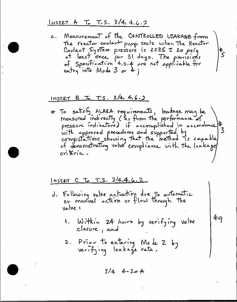
Meosurem~ a4 'ttie, D ~<oLi-~ LEAK<ce6 frccnaf gy.Qyy MO(4-~+ Pq~ ZeC ~S. Q he.~ 74 Re&ceV
~(a ~t 5~ s%~pressure is 22.'ZS ~ 2o psfq
a~ leasW Crnes par 3 l days Wa dna«is ieras
cipeaiPc'a~4<'~ 4.O.P o.re nat ~p( c&4.Jr'krq'(do Mole 3 ov 4
7:s. SA. +,C.a
5o S~b g AlALA- u i carciecds ) le~4 )e. yriagiviecueureat indi really ( as Pram Aa pe.r+ca~aau
f'~eu
tc. InJ I alLfo i s) tg 4 acsrrapliSLcl ln Ac c ar JocccC
wiK ~piaVa.cl ti&Waice ~ s pulo aCcvcl 3ld + in+~ i ~ Ll
.4 ~a,d~iig V lVe ~p'Li'~ ~'i4 g4 (. k pCYl ~Yi W
l ~seas ~ 'T t.5. ~~4..
F. lieu> i'c(ue o.c.p oki irci clue t. caAi ra~Pic
Qr fncknvcJ d.ctC ccn DY 'P( oui tKrdv)kvo-lvc:
h. ldiSin 24 ho«+ Ig Vevcfg in> yalVe
C t450W)
P ria v 4a e.wfe.riagVe.i i a) leaked r~t,
COlt 'A'$8 Mlitt WHO'D
4
I
r,
4k
'
I 'S
is
4 t s
4
iss
ii
s
'4
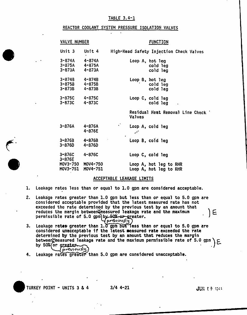
TABLE 3.4-1
REACTOR COOLANT SYSTEM PRESSURE ISOLATION VALVES
VALVE NUMBER
Unit 3 Unit 4
FUNCTION
High-Head Safety Injection Check Valves
3-874A3-875A3-873A
3-87483"8?5B3-873B
3-8?5C3"873C
4-874A4-875A4-873A
4-8?4B4-87584-8738
4-875C4-873C
Loop A, hot legcold legcold leg
Loop B, hot legcold legcold leg
Loop C, cold legcold leg
Residual Heat Removal Line CheckValves
3-876A 4"876A4-876E
Loop A, cold leg
3-876B3"8760
4-876B4-876O
Loop B, cold leg
3"876C 4-876C3-876EMOV3-750 MOV4-750MOV3-751 MOV4-751
Loop C, cold leg
Loop A, hot leg to RHR
Loop A, hot leg to RHR
2.
3.
ACCEPTABLE LEAKAGE LIMITS
Leakage rates less than or equal to 1.0 gpm are considered acceptable.
Leakage rates greater than 1.0 gpm but less than or equal to 5.0 gpm areconsidered acceptable provided that the latest measured rate has notexceeded the rate determined by the previous test by an amount thatreduces the margin betwee w asured leakage rate and the maximumpermissible rate of 5.0 gpm b reater.
pmi~uglgLeakage rates greater than 1. gpm u ess than or equal to 5.0 gpm areconsidered unacceptable if the latest measured rate exceeded the ratedetermined by the previous test by an amount that reduces the marginbetwee wmeasured leakage rate and the maximum permfsstble rate of 5.0 gpm
) Eby 50'r
p WplVMSIQ,Leakage rates grea e than 5.0 gpm are considered unacceptable.
TURKEY POINT " UNITS 3 Ec 4 3/4 4"21 tJl'V 0 ~ ""

REACTOR COOLANT SYSTEM
3/4.4.7 CHEMISTRY
LIMITING CONDITION FOR OPERATION
3.4.7 The Reactor Coolant System chemistry shall be maintained within thelimits specified in Table 3.4-2.
APPLICABILITY: At al 1 times.
ACTION:
MODES 1, 2, 3, and 4:
a.
b.
With any one or more chemistry parameter in excess of,its Steady"State Limit but within its Transient Limit, restore the parameter towithin its Steady-State Limit within 24 hours or be in at least HOTSTANDBY within the next 6 hours and in COLD SHUTDOWN within thefollowing 30 hours
With any one or more chemistry parameter in excess of its TransientLimit, be in at least HOT STANDBY within 6 hours and in COLD SHUTDOWNwithin the following 30 hour s.
At All Other Times:
With the concentration of either chloride ot fluoride in the ReactorCoolant System in excess of its Steady-State Limit for more than 24 hoursor in excess of its Transient Limit, reduce the pressurizer pressure toless than or equal to 500 psig, if applicable, and perform an engineeringevaluation to determine the effects of the out-of-limit condition on thestructural integrity of the Reactor Coolant System; determine that theReactor Coolant System remains acceptable for continued operation priorto increasing the pressurizer pressure above 500 psig or prior toproceeding to MODE 4.
SURVEILLANCE RE UIREMENTS
4.4.7 The Reactor Coolant System chemistry shall be determined to be withinthe limits by analysis of those parameters at the frequencies specified inTable 4.4-3.
TURKEY POINT - UNITS 3 8c 4 3/4 4-22~ ~'j
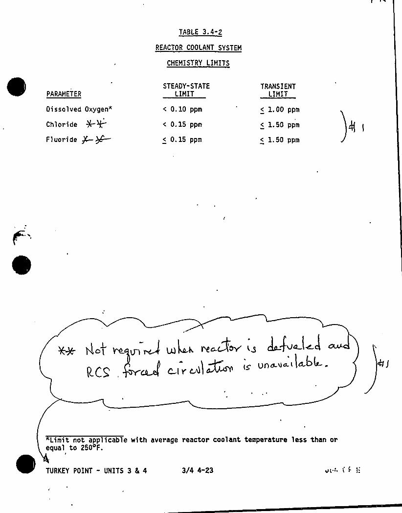
TABLE 3.4-2
REACTOR COOLANT SYSTEM
CHEMISTRY LIMITS
PARAMETER
Dissolved Oxygen"
Chl ori de
Fluoride ~~
STEADY-STATELIMIT
< 0.10 ppm
< 0.15 ppm
< 0.15 ppm
TRANSIENTLIMIT
< 1.00 ppm
< 1.50 ppm
< 1.50 ppm
V4
gpa.ua. < )ak4-.
Limit not applicable with average reactor coolant temperature less than orequal to 250 F.
TURKEY POINT - UNITS 3 4 4 3/4 4-23 v('. i~ 1:
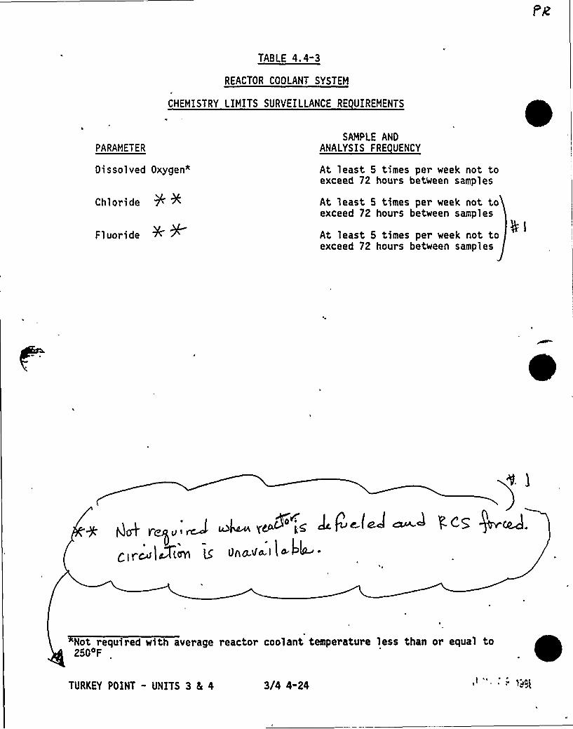
TABLE 4.4-3
REACTOR COOLANT SYSTEM
CHEMISTRY LIMITS SURVEILLANCE RE UIREMENTS
PARAMETER
Oissolved Oxygen*
Chloride
Fluoride
SAMPLE ANDANALYSIS FRE UENCY
At least 5 times per week not toexceed 72 hours between samples
At least 5 times per week not toexceed 72 hours between samples
At least 5 times per week not toexceed 72 hours between samples
gglc IU ~ 0 c5 QGKcL
clrc4l Plagal g Unada.l l 4 ~4
Not required with average reactor coolant temperature less than or equal to2500F
TURKEY POINT - UNITS 3 5 4 3/4 4-24
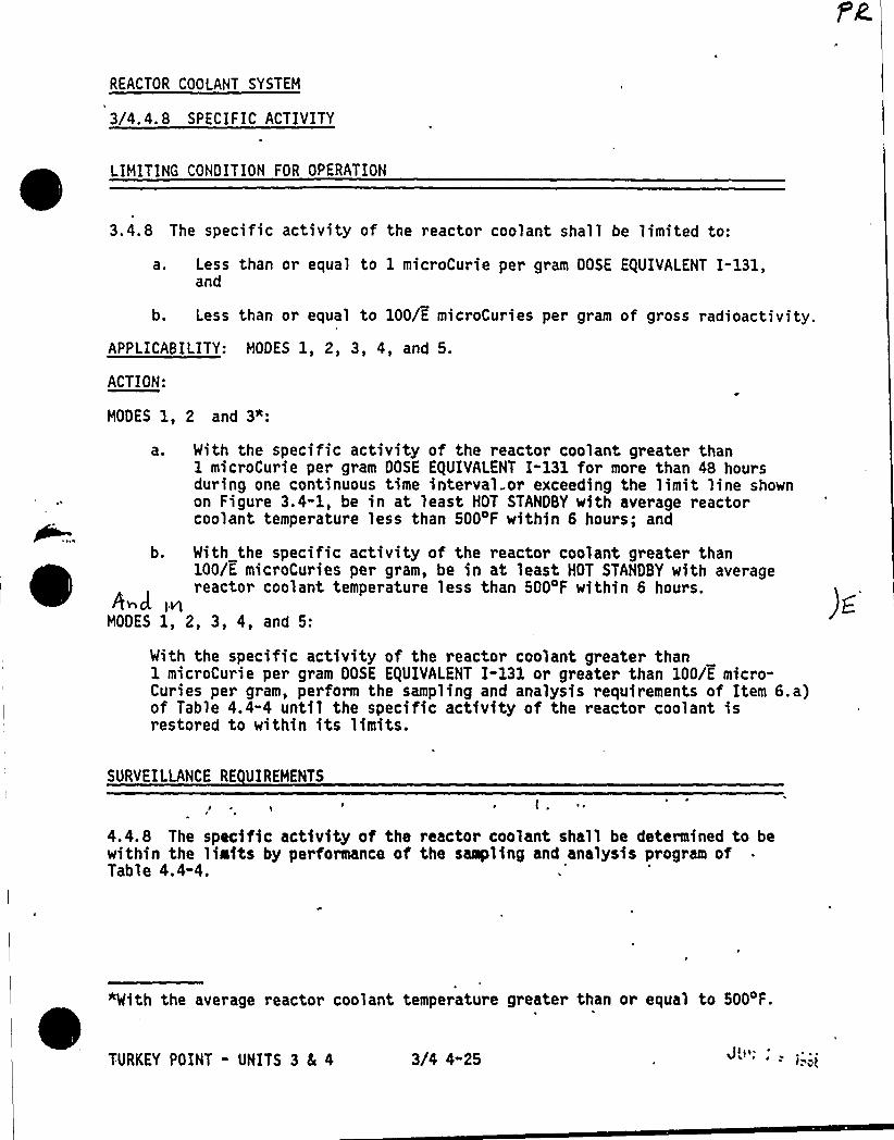
REACTOR COOLANT SYSTEM
3/4. 4. 8 SPECIFIC ACTIVITY
LIMITING CONDITION FOR OPERATION
3.4.8 The specific activity of the reactor coolant shall be limited to:
a. Less than or equal to 1 microCurie per gram DOSE EQUIVALENT I-131,and
b. Less than or equal to 100/E microCuries per gram of gross radioactivity.
APPLICABILITY: MODES 1, 2, 3, 4, and 5.
ACTION:
HODES 1, 2 and 3":
a. With the specific activity of the reactor coolant greater than1 microCurie per gram DOSE EQUIVALENT I-131 for more than 48 hoursduring one continuous time interval or exceeding the limit line shownon Figure 3.4-1, be in at least HOT STANDBY with average reactorcoolant temperature less than 500 F within 6 hours; and
b. With the specific activity of the reactor coolant greater than100/E microCuries per gram, be in at least HOT STANDBY with averagereactor coolant temperature less than 500 F within 6 hours.
h~J. inMODES 1, 2, 3, 4, and 5:
With the specific activity of the reactor coolant greater than1 microCurie per gram DOSE E(UIVALENT I-131 or greater than 100/E micro-Curies per gram, perform the sampling and analysis requirements of Item 6.a)of Table 4.4-4 until the specific activity of the reactor coolant isrestored to within its limits.
SURVEILLANCE RE UIREHENTS
~,
4.4.8 The specific activity of the reactor coolant shall be determined to bewithin the limits by performance of the sampling and analysis program ofTable 4.4-4.
Jlty.Jim)3/4 4-25
"With the average reactor coolant temperature greater than or equal to 5004F.
TURKEY POINT - UNITS 3 5 4
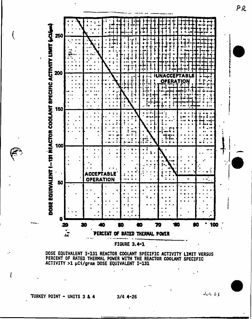
P ~
~ ~
~ ~ ~ ~
~ ~ 0 oo
~ ~ ~
~ ~
~ ) ~ o + +~ ~ o. ~
Oo
t'~t ~
mo
~o ~
~ ~
0 ~ ~
~ . I ~ ~
~ ~ o ~
o p ~ ~
~ ~ ~ '~ ~ ~
~ % ~
~ ~ ~
~ o I f.o o4 ~
~ f~ ~ o ~
4 ~ ~
o o
;jul~ oo
I
P}o foo< ~ Ip ~o.oo f ) ~
~ omfqr
f
'Q+1
r~~o
200~ ~
~ ~
~ P\ ~ ~
6 ~r ~
150
~ ~ ~
~ ~ ~
~ ~ ~ ~
~ ~ ~
o ~ ~ ~ ~
'
~ ~
~ ~
P ~ I
~ ~
~ ot ~
~ ~ ~ ~
~ ~ ~
f f ~ ~
'~~ ~ ~
~ 4 ~ P
~ ~
) f f lUNACCEPTABLEt I
f P TlOMI,.f.i .I.fo),o~ ) ~ o }t ~ Qo O
~ ~
f af~.$ »~~e ~ ~I ~ f
~ or f + ~ ~ ~ ~ oo ~~ ~ ~ ~
r «+»P fao f-«I
~oopsI ~~ 4~~ y j't'op
P f ~
$ foo
~ ~
~ ~ ~
~ ~
~ ~
~ ~r ~ p~ ~
~ ~ ~
~ ~ P'I ~
~ ~
~ ~ ~f oooo«.f o
~ f ~
~o oo ~ ~
~ ~ ~
~ f ~ ~ ~ ~
OQP~ o ~
~ o l.~ I
~ ~ ~
fef ~
~ ~ o ~ ~
P ~
~ ~ ~
~ ~ ~
o ~ ~II
P ~
I ~
)Wol P
~ i o ~
~ ~ ~
~ M ~~ ~ P ~~ ~ ~ ~
~ ~
~ ~ ~ ~
~ ~ P~ P ~ ~
~ ~ % ~
LPP
~ 4 ~ ePo ~ ~
~ ~
o p ~
~ ~ ~
~ o ~
~ ~
ACCEPTABLE�
'PERATlON
~ ~
~ P
~ ~ ~ ~ ~
~ ~ ~
~ ~
~ ~ ~ ~
P ~ ~
0 oopI.
of ~
f o ~
~ ~ ~
~ ~ ~
~ ~
~ ~ ~
~ ~ ~
~ ~
o ~
~ ~
~ ~
~ ~ ~
~ ~ ~
~ P ~ ~
~ ~ ~ ~
~ ~~ ~
o ~
~ ~ ~ ~
~ o~ P ~ ~
~ ~ ~
~ ~ ~
~ ~
oo a so a e a so coo'ECKMTIfGATED %ERAL tONER
FIGURE 3.4-1
00SE E/UIVALENT I-.131 REACTOR COOLANT SPECIFIC ACTIVITYLIMITVERSUSPERCENT OF RATED THERMAL RNER %TH THE REACTOR COOLANT SPECIFICACTIVITY>1 pC)/gras DOSE E/UIVALENT I-131
TURKEY POINT - UNITS 3 4 i 3/4 4-26J.', (g

.7Cm
TABLE 4.4-4REACTOR COOLANT SPECIFIC ACTIVITY SAMPLE
AND ANALYSIS 'PROGRAM
C/l
TYPE OF MEASUREMENT
AND ANALYSIS
1. Gross RadioactivityDetermination
2. Tritium Activity Determination
3. Isotopic Analysis for OOSE EQUIVA-LENT I-131 Concentration
4. Radiochemical IsotopicDetermination Including GaseousActivity
5. Radiochemical for E Determination
6. Isotopic Analysis for IodineIncluding I-131, I-133, and I-135
SAMPLE AND ANALYSISFRE UENCY
At least once per 72 hours.
1 per 7 days.
1 per 14 days.
Monthly
1 per 6 months"
a) Once per 4 hours,whenever the specificactivity exceeds 1pCi/gram 00SEEQUIVALENT I-131or 100/E pCi/gram ofgross radioactivity, and
b) One sample between 2and 6 hours followinga THERMAL POWER changeexceeding 15Kof the RATED THERMALPOWER within a 1-hourperiod.
MODES IN WHICH SAMPLEAND ANALYSIS RE UIRED
1, 2, 3, 4
1, 2, 3, 4
1, 2, 3, 4
1¹, 2¹, 3¹, 4¹, 5¹
1, 2, 3
~ Qt
~ ~
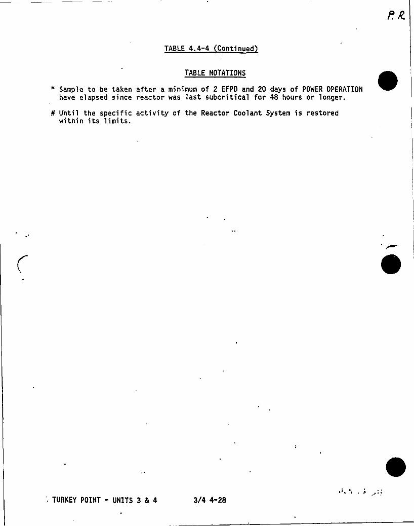
TABLE 4. 4-4 Continued
TABLE NOTATIONS
* Sample to be taken after a minimum of 2 EFPD and 20 days of POWER OPERATIONhave elapsed since reactor was last subcritical for 48 hours or longer.
8 U'ntil the specific activity of the Reactor Coolant System is restoredwithin its limits.
0
'. TURKEY POINT - UNITS 3 5 4 3/4 4-28l. ~ ~
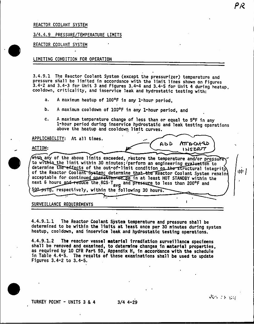
REACTOR COOLANT SYSTEM
3/4.4.9 PRESSURE/TEMPERATURE LIMITS
REACTOR COOLANT SYSTEM
LIMITING CONDITION FOR OPERATION
3.4.9. 1 The Reactor Coolant System (except the pressurizer) temperature andpressure shall be limited in accordance with the limit lines shown on Figures3.4-2 and 3.4-3 for Unit 3 and Figures 3.4-4 and 3.4-5 for Unit 4 during heatup,cooldown, criticality, and inservice leak and hydrostatic testing with:
a, A maximum heatup of 100 F in any 1-hour period,
b. A maximum cooldown of 1004F in any 1-hour period, and
c. A maximum temperature change of less than or equal to 54F in any1-hour period during inservice hydrostatic and leak testing operationsabove the heatup and cooldown limit curves.
'I
APPLICABILITY: At al l times.
ACTION:> Asz4~
any of the above limits exceeded,,restore the temperature and/or pressuto wi 'he limit within 30 minutes;Iperform an engineering e atfon todetermine t cts of the out-of-limit condition o ructural integritof the Reactor Coolan determine t eactor Coolant System remainacceptable for continued e in at least HOT STANDBY within thenext 6 hours ce the,RCS-T and
avg e to less than 2004F and5 , respectively, within the following 30 hours.
SURVEILLANCE RE UIREMENTS
4.4.9.1. 1 The Reactor Coolant System temperature and pressure shall bedetermined to be within the limits at least once per 30 minutes during systemheatup, cooldown, and inservice leak and hydrostatic testing operations.
4.4.9.1.2 The reactor vessel material irradiation surveillance specimensshall be removed and examined, to determine changes in material properties,as required by 10 CFR Part 50, Appendix H, in accordance with the schedulein Table 4.4-5. The results of these examinations shall be used to updateFigures 3.4-2 to 3.4-5.
TURKEY POINT - UNITS 3 81 4 3/4 4-29
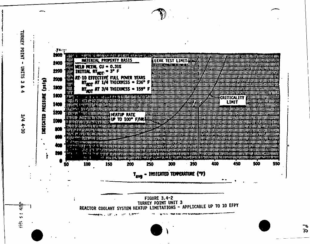
1
eaI ~
l g,%sr
f0N
g CO
I4N8
NTKRl fNPKNY SA$1$
%N %fM. Ol 0.31%lNNN. Nfl. 8 F
N l0 KFSCtltC M.L, Nea TENSNF N 1/l TNINNKSS a m F
abet At 8/4 TNCIKS$ a 1Q P
%hTlF lATE.0 TO 100'/Nt
LKAK TKST Llll1
RlTlCALlTYLllllT
1N 150 200 25Q XO
T~ flSMO150 5 550
FIGURE 3.4-2TURKEY POINT UNIT 3
REACTOR COOLANT SYSTEH HEATUP LIHITAT!ONS - APPLICABLE UP TO 10 EFPY

ld it L any of thc 4 Ve ( inni4 cyceec(ec(
.'estoret'e iona pcratu re W /ar pressure
te iuigin ttic (iini t Lui"Lin 3o iviinutes cvJ)
Ii-u" the ..a.. 'p(etc a.n erig iiiecring ella.(uatl sN go
de4e ',.~ the elf~ c$ .5e ~f-.f- li'~hLaVLe(kevin
m 5e St»ctur ( inVegv-ttg
g.C5 cu c( defe on Ine, tko.t t(ie
RCS y'erne in'' mes'~t'a.44,
IQgiri) I nl/c.d epev"a I I Irrl
)oy-
Lo ~ Ba in HoT'7R4bC'I W redueiL 4auera.cp, coo(cu+ CcMpei atul c.
(iressvrc 'ta (e.ss +a.n. ~~ F
f4 g(la~in~
au r5 iunc( urn
p�(etc th c. ~ i na~ < ng
I)eva.(ua.hm in Z.a- 'coasts pr'
ri~ «ge i- Zoo'F ai Qoo tos i y.

Tp I8 pp 4w I~~t nQALQ
8'LAA

C
CA
4l
ICab
~ ~ ~ '
ERI PROPERTY SASISSNNOR0Cfee
1'N
p ss
gI NTKS
e L
SN
I p ioo
RN %TR, CO i 0.31$NlfQLNag + 3 F
gf 10 KHKCflTKSllL NKR %NSat~ at lie mrCenS ~ SCi C
keg AT Sf'NNIESS 15 F
flCNQPt5 gverage l~e~vi~ l'0 .
FIGURE 3.4-3. TURKEY POINT UNIT 3
REACTOR COOLANT SYSTEH COOLDOMN LIHITATIONS - APPLICASLE UP TO 10 EFPY
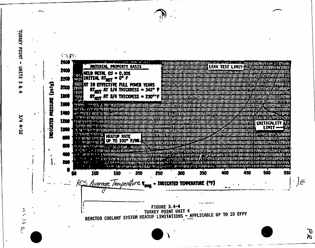
S8NI
isofiN
I metea
IIII. aa
I~
TEkl PROPGNY SA$1$
%$ %N. CO ~ 0.ÃSQlTN. NTgg ~ 0 F
fiEFFKCOS ML KRR %NSNgg AT fl4 ONCllESS ~ 3C fNFL AT 3I4 TNNIESS ~ 030 F
LEAK TEST LllllT
%AM RATElt TO fOO F/l
ISO m m ae 350 4
7~> puree IarCee meeeeE (%
FIGURE 3-4 4TURKEY POINT UHIT 4
REACTOR COOLAHT SYSTEH HEATUP LIHITATIOHS " APPLICABLE UP TO 10 EFPY
0

t0Ri%8NNOfae
IQTERIAL PROPERTY SASIS
%$ CITAL CQ ~ 0.38lalalL arar ~ O'
N 10 EFFKCTBK FOR KNN mN5e~ Ar 1/4maaaSS i Se'%Fag Af 0/i lHICNKSS ~ t$0
tea.l010N
OLNNN NATES
~y F/N "
eo LNO
l 150 2N tO 3N
es u..).i.-q, J . ~- mens eeeti50 500 $%
FIGURE 3.I-STURKEY POINT UNIT I
REACTOR COOLANT SYSTEN COOUNNN LIIIITATIONS- APPLICABLE UP TO 10 EFPY
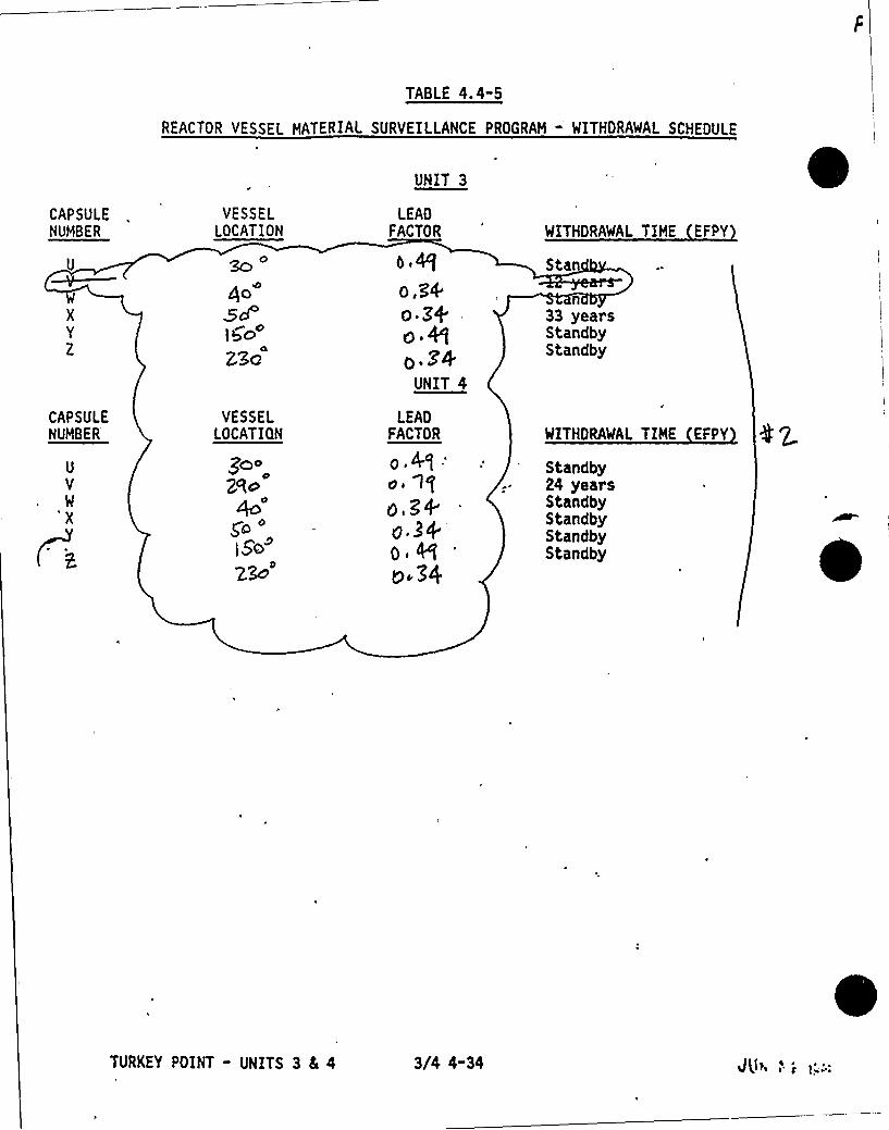
TA8LE 4.4-5
REACTOR VESSEL MATERIAL SURVEILLANCE PROGRAM - WITHDRAWAL SCHEDULE
CAPSULENUMBER
U
CAPSULENUMBER
VESSELLOCATION
so4o
ICcZ30
VESSELLOCATION
300Nc
gG
l5~'c'NIT
3
LEADFACTOR
o,3'4o Z4e Qo.M
UNIT 4
LEADFACTOR
p, A.q:oi 1 f
g+
o Po 34
WITHDRAWAL TIME EFPY
Stan
33 yeal'sStandbyStandby
WITHDRAWAL TIME EFPY
Standby24 yeatsStandbyStandbyStandbyStandby
TURKEY POINT - UNITS 3 4 4 3/4 4-34
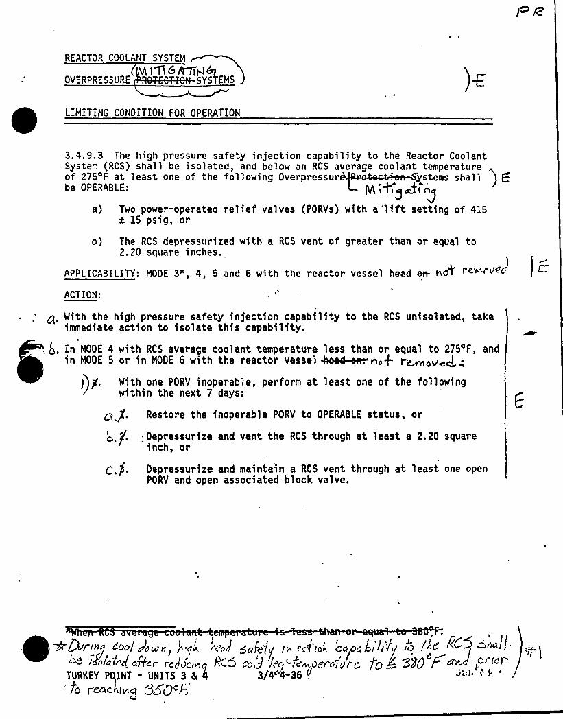
REACTOR COOLANT SYSTEM
1 D 6]&7idb)OVERPRESSURE SYSTEMS
3.4.9.3 The high pressure safety injection capability to the Reactor CoolantSystem (RCS) shall be isolated, and below an RCS average coolant temperatureof 275'F at least one of the fol'lowing Overpressur 'ystems shallbe OPERABLE:
a) Two power-operated relief valves (PORVs) with a'lift setting of 415a 15 psig, or
b) The RCS depressurized with a RCS vent of greater than or equal to2.20 square inches.
APPLICABILITY: NODE 3", 4, 5 and 6 with the reactor vessel heed err no~ re~russ j ~
ACTION:
g, With the high pressure safety injection capability to the RCS unisolated, takeimmediate action to isolate this capability.
, g, In HOOE 4 with RCS average coolant temperature less than or equal to 275'F, andin MOOE 5 or in MODE 6 with the reactor vessel 4oac&~no+ r~z~~J, ~
)))f. With one PORV inoperable, perform at least one of the followingwithin the next 7 days:
Restore the inoperable PORV to OPERABLE status, or
Depressurize and vent the RCS through at least a 2.20 squareinch, or
(:.jf. Depressurite and maintain a RCS vent through at least one openPORV and open associated block valve.
W ~
~
4
~~!9» p ~ol vroklnl 8'o( r!OJ Qofg)f I' c'Tlo(,
co(octal
~If/ lrf I '(d ~ '~':u.f~ ~>ol~Y~(oR~r rcgu'co)A"-5 c,o3 l..rl "i" ddt ,yr +C) ~ BED r.<4 IO i«
TURKEY POINT - UNITS 3 4 4 3/4~4-36 .J s)1s I
po f cmckiwm ~~Qof-s

REACTOR COOLANT SYSTEM
PRESSURIZER
LIMITING CONDITION FOR OPERATION
3.4.9.2 The pressurizer temperature shall be limited to:
a. A maximum heatup of 1004F in any 1-hour'eriod,
b. A maximum cooldown of 200'F in any 1-hour period, andgZo .P
c. A maximum spray water temperature differential of ~-'..APPLICABILITY: At all times.
ACTION:
res rszer temperature limits in excess of any of t arestore t e e to within the limits w nutes; perform anengineering evaluation to ects of the out-of-limit conditioon the structural in ' the pre~ri-zap~ determine that the pressurizeremains acce for continued operation or be fr("at-.least HOT STANDBY with nthe nex ours and reduce the pressurizer pressure to less Chan-50Q gsig
the following 30 hours.
SURVEILLANCE RE UIRB1ENTS
R~cA~ l %5 ~~~
4.4.9.2 The pressurizer temperatures shall be determined to be within thelimits at least once per 30 minutes during system heatup or cooldown. Thespray water temperature differential shal,l be determined to be within thelimit at least once per 12 hour s during auxiliary spray operation.
'TURKEY POINT - UNITS 3 8I 4 3/4 4-35
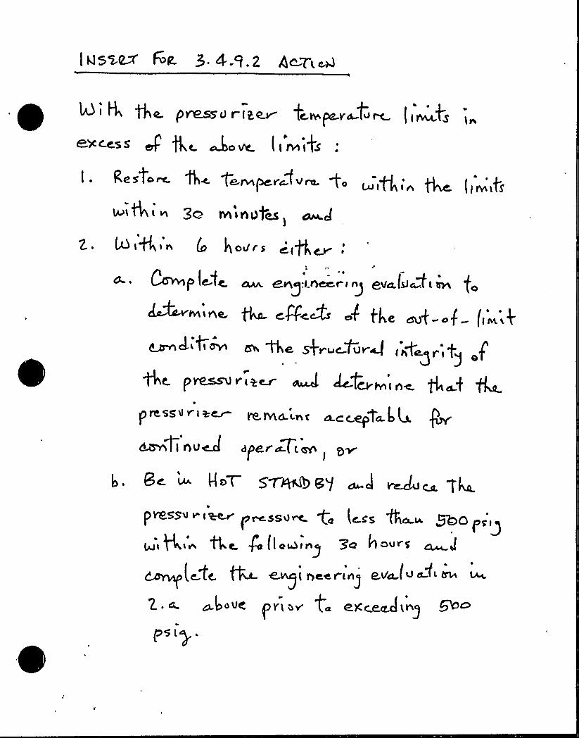
R i 4 ~a. pr&ssU r it~ fc.w pa.va-t<~ ( 1~TS
&XcesS' ore l nni S
I . RCSiO~ f4 pP~+Vrf+At fO ~(Q<< ~ (~~>ff
lu~4i ~ gc nninOges>
z. 4i6'n ho~.s ~(ft,~:tII*
a. ~ ~pl@:fw cw, aeg:t.~c i>g e~al<~>'~ fe
WL1AC C C o C ~ o (M i
~ J Ci~ n the sf~ ~Pung ('~+~ r, g
QC. p~~ Vly~ ~ ~QCVllhl hC. ga.f f4.pre.ssv v i y~
mrna.inc
ca.cc epona.k 4.I~( i su~ ape~~t <m
~
Bc u HnT SWAN 8'/ cu-~ ~<4 ca T4.pvessuv,aav p~ssv~ ge less (ha~ ~opsig
Q llO~ing j( gee r(~ ega u
~)~vs ~v< n~ t ex~eAi~)p5 lp ~

+gas pp gC t pfPi'.~i~&A~'f
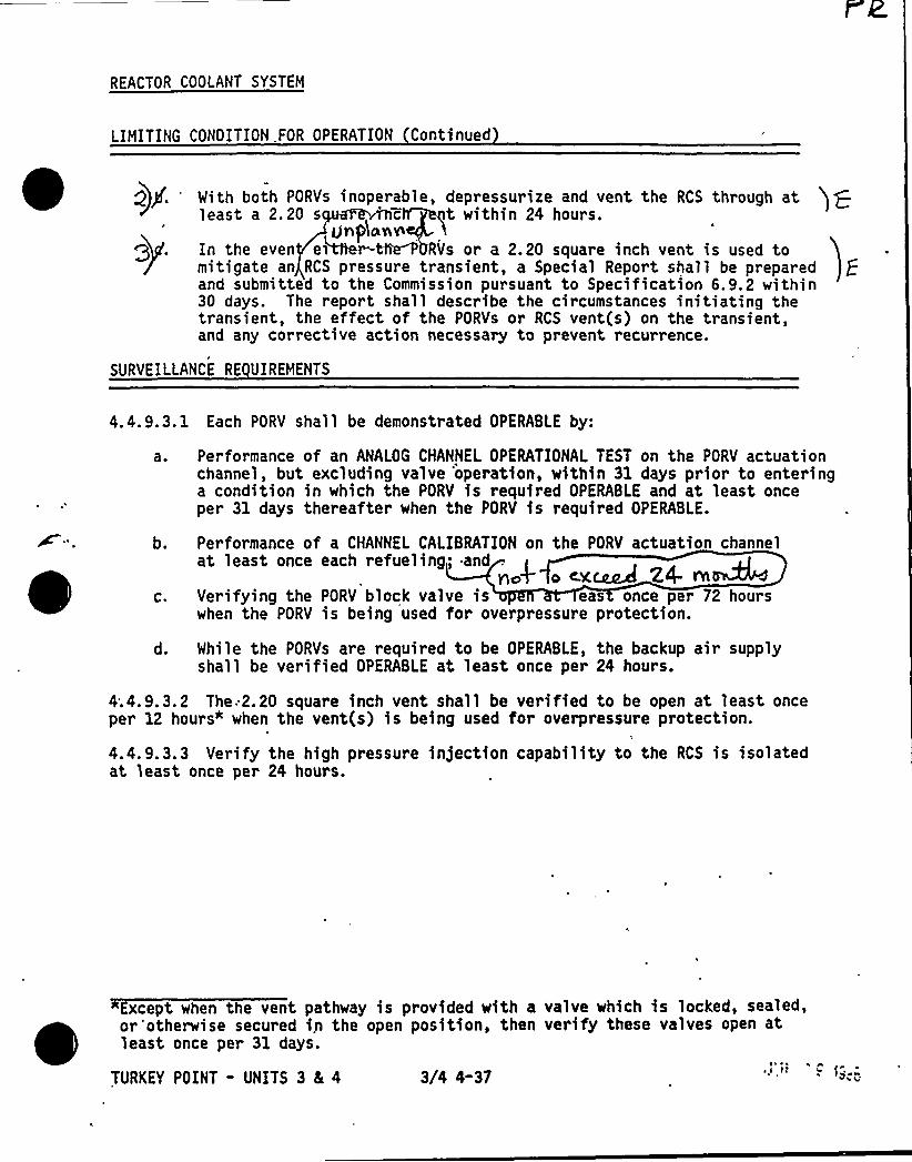
REACTOR COOLANT SYSTEM
LIMITING CONOITION.FOR OPERATION Continued
Q)p. 'ith both PORYs inoperable, depressor ize and vent the RCS through atleast a 2.20 s
' t within 24 hours.Ur p)onv
In the even eiNer ~ RVs or a 2.20 square inch vent is used tomitigate an RCS pressure transient, a Special Report shall be preparedand submitted to the Commission pursuant to Specification 6.9.2 within30 days. The report shall describe the circumstances initiating thetransient, the effect of the PORVs or RCS vent(s) on the transient,and any corrective action necessary to prevent recurrence.
SURVEILLANCE RE UIREMENTS
4.4.9.3. 1 Each PORV shall be demonstrated OPERABLE by:
a. Performance of an ANALOG CHANNEL OPERATIONAL TEST on the PORV actuationchannel, but excluding valve 'operation, within 31 days prior to enteringa condition in which the PORV is required OPERABLE and at least onceper 31 days thereafter when the PORV is required OPERABLE.
b. Performance of a CHANNEL CALIBRATION on the PORV actuation channelat least once each refueling; and .
ncg o «x~ 24- Alc. Verifying the PORV block valve is eas once per 72 hours
when the PORV is being used for overpressure protection.
d. While the PORVs are required to be OPERABLE, the backup air supplyshall be verified OPERABLE at least once per 24 hours.
4;4.9.3.2 The:2 '0 square inch vent shall be verified to be open at least onceper 12 hours" when the vent(s) is being used for overpressure protection.
4.4. 9. 3. 3 Verify the high pressure infection capability to the RCS is isolatedat least once per 24 hours.
Except when the vent pathway is provided with a valve which is locked, sealed,or "otherwise secured i.n the open position, then verify these valves open atleast once per 31 days.
TURKEY POINT - UNITS 3 8L 4 3/4 4-37
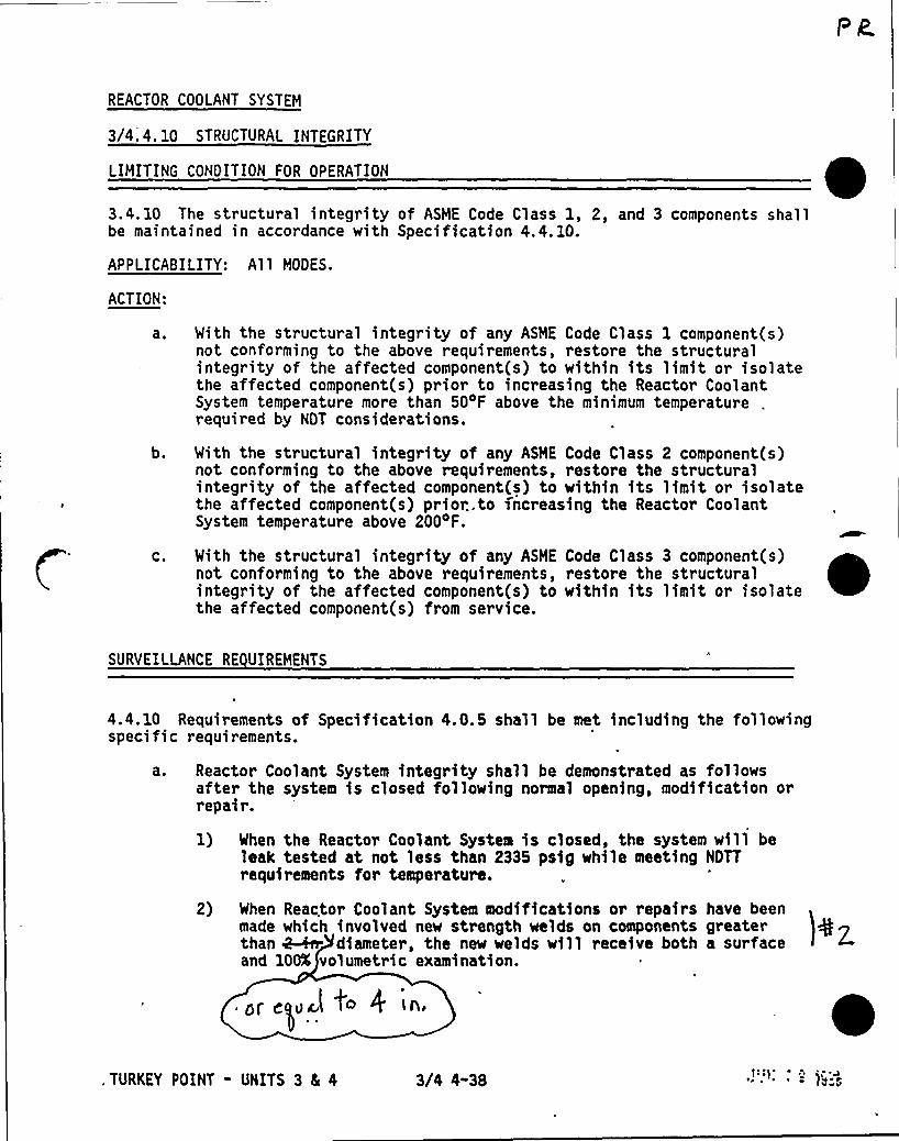
REACTOR COOLANT SYSTEM
3/4.4. 10 STRUCTURAL INTEGRITY
LIMITING CONDITION FOR OPERATION
3.4. 10 The structural integrity of ASHE Code Class 1, 2, and 3 components shallbe maintained in accordance with Specification 4.4. 10.
APPLICABILITY: Al 1 MODES.
ACTION:
a ~
b.
C.
With the structural integrity of any ASME Code Class 1 component(s)not conforming to the above requirements, restore the structuralintegrity of the affected component(s) to within its limit or isolatethe affected component(s) prior to increasing the Reactor CoolantSystem temperature more than 50 F above the minimum temperature .
required by NOT considerations.
With the structural integrity of any ASME Code Class 2 component(s)not conforming to the above requirements, restore the structuralintegrity of the affected component(s) to within its limit or isolatethe affected component(s) prior..to increasing the Reactor CoolantSystem temperature above 2004F.
With the structural integrity of any ASME Code Class 3 component(s)not conforming to the above requirements, restore the structuralintegrity of the affected component(s) to within its limit or isolatethe affected component(s) from service.
SURVEILLANCE RE UIREMENTS
4.4.10 Requirements of Specification 4.0.5 shall be met including the followingspecific requirements.
at Reactor Coolant System integrity shall be demonstrated as followsafter the system is closed following normal opening, modification orrepair.
1) When the Reactor Coolant System is closed, the system will beleak tested at not less than 2335 psig while meeting NDTTrequirements for temperature.
2) When Reactor Coolant System modifications or repairs have beenmade which involved new strength welds on components greater )Q Zthan 4-fn. diameter, the new welds will receive both a surfaceand 100K volumetric examination.
0 lh
. TURKEY POINT - UNITS 3 5 4 3/4 4-38
REACTOR COOLANT SYSTEH
SURVEILLANCE RE UIREMENTS Continued
3) Mhen Reactor Coolant System modificati'ons or repairs have beenmade which involve new strength welds on components ~ diameter ~g
)@gal gk~ 4
TURKEY POINT - UNITS 3 4 4 3(4 4-39
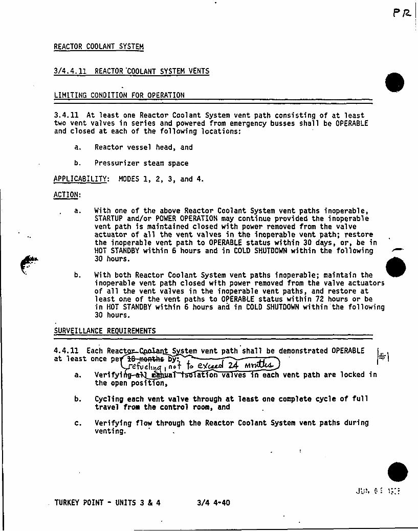
REACTOR COOLANT SYSTEM
3/4.4. 11 REACTOR 'COOLANT SYSTEM VENTS
LIMITING CONDITION FOR OPERATION
3.4. 11 At least one Reactor Coolant System vent path consisting of at leasttwo vent valves in series and powered from emergency busses shall be OPERABLEand closed at each of the following locations:
a, Reactor vessel head, and
b. Pressurizer steam space
APPLICABILITY: MODES 1, 2, 3, and 4.
ACTION:
a ~
b.
With one of the above Reactor Coolant System vent paths inoperable,STARTUP and/or POWER OPERATION may continue provided the inoperablevent path is maintained closed with power removed from the valveactuator of all the vent valves in the inoperable vent path; restorethe inoperable vent path to OPERABLE status within 30 days, or, be inHOT STANDBY within 6 hours and in COLD SHUTDOWN within the following30 hours.
With both Reactor Coolant System vent paths inoperable; maintain theinoperable vent path closed with power removed from the valve actuatorsof all the vent valves in the inoperable vent paths, and restore atleast one of the vent paths to OPERABLE status within 72 hours or bein HOT STANDBY within 6 hours and in COLD SHUTDOWN within the following30 hours.
SURVEILLANCE RE UIREMENTS
4.4.11 Each React t S stem vent path shall be demonstrated OPERABLEat least once pe %8-a~Ra b :
efveli~, no< fo t'-Aaccl 4 M 44.
a. Verifyi m ation va ves n each vent path are locked inthe open posit on,
b. Cycling each vent valve through at least, one complete cycle of fulltravel from the control room, and
c. Verifying flow through the Reactor Coolant System vent paths duringventing.
TURKEY POINT - UNITS 3 SI 4 3/4 4-40
JI ~0
A ~ ~ ~
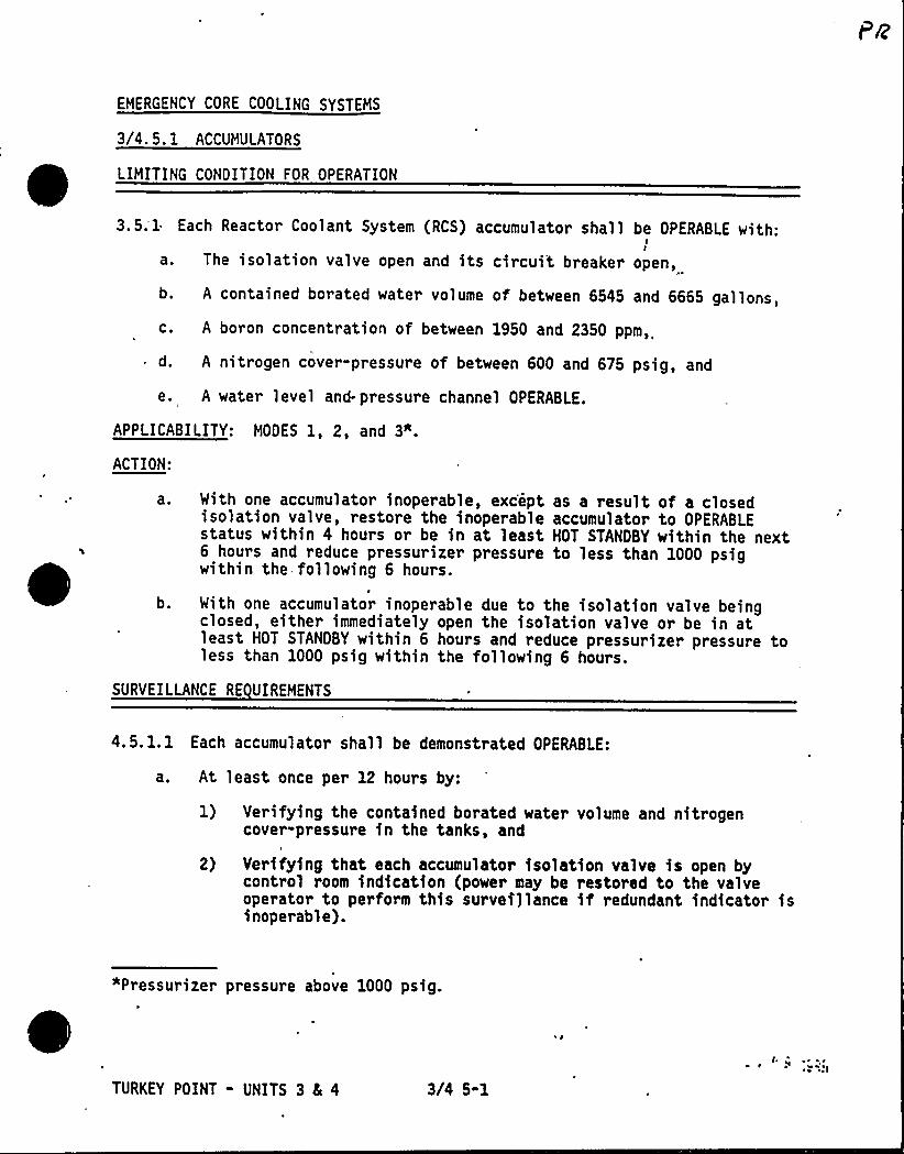
EMERGENCY CORE COOLING SYSTEMS
3/4. 5. 1 ACCUMULATORS
LIMITING CONDITION FOR OPERATION
3.5;1 Each Reactor Coolant System (RCS) accumulator shall be OPERABLE with:II
a. The isolation valve open and its circuit breaker open,
b, A contained borated water volume of between 6545 and 6665 gallons,
c. A boron concentration of between 1950 and 2350 ppm,
d. A nitrogen cover-pressure of between 600 and 675 psig, and
e, A water level and- pressure channel OPERABLE.
APPLICABILITY: MODES 1, 2, and 3".
ACTION:
a ~
b.
With one accumulator inoperable, except as a result of a closedisolation valve, restore the inoperable accumulator to OPERABLEstatus within 4 hours or be in at least HOT STANDBY within the next6 hours and reduce pressurizer pressure to less than 1000 psigwithin the following 6 hours.
With one accumulator inoperable due to the isolation valve beingclosed, either immediately open the isolation valve or be in atleast HOT STANDBY within 6 hours and reduce pressurizer pressure toless than 1000 psig within the following 6 hours.
SURVEILLANCE RE UIREMENTS
4.5. 1. 1 Each accumulator shall be demonstrated OPERABLE:
a ~ At least once per 12 hours by:
1) Verifying the contained borated water volume and nitrogencover-pressure in the tanks, and
2) Verifying that each accumulator isolation valve is open bycontrol room indication (power may be restored to the valveoperator to perform this survei)lance if redundant indicator isinoperable).
"Pressurizer pressure above 1000 psig.
TURKEY POINT - UNITS 3 4 4 3/4 5-1
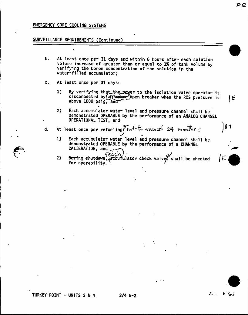
EMERGENCY CORE COOLING SYSTEMS
SURVEILLANCE RE UIREMENTS Continued
b. At least once per 31 days and within 6 hours after each solutionvolume increase of greater than or equal to IX of tank volume byverifying the boron concentration of the solution in thewater-filled accumulator;
c. At least once per 31 days:
d.
er to the isolation valve operato~ ispen breaker when the RCS pressure is
1) By verifying thadisconnected byabove 1000 psig, n
2) Each accumulator water level and pressure channel shall bedemonstrated OPERABLE by the performance of an ANALOG CHANNELOPERATIONAL TEST, and
At least ante per ref eul nlg~rtof"4 elk~ Z+ rnuk~k
1) Each accumulator water level and pressure channel shall bedemonstrated OPERABLE by the performance of a CHANNELCALIBRATION, and
,kka 1 *k k 1 kkkk k kfor operability..
TURKEY POINT - UNITS 3 4 4 3/4 5-2s ~ ~ i s ~ ~
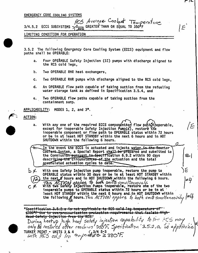
EMERGENCY CORE COOLING SYSTEMS
Q5 Puc'no~ c+~e4 Ten pere,'furl3/4.5.2 ECCS SUBSYSTEMS -~ GREATER THAN OR E(UAL TO 35O~F
LIMITING CONDITION FOR OPERATION
3.5.2 The following Emergency Core Cooling System (ECCS) equipment and flowpaths shall be OPERABLE:
a. Four OPELABLE Safety Injection (SI) pumps with discharge aligned tothe RCS cold legs,
b. Two OPERABLE RHR heat exchangers,
c. Two OPERABLE RHR pumps with discharge aligned to the RCS cold legs,
d. An OPERABLE flow path capable of taking suction from the refuelingwater storage tank as defined in Specification 3.5.4, and
e. Two OPERABLE flow paths capable of taking suction from thecontainment sump.
APPLICABILITY: MODES 1, 2, and 3".
ACTION:
a.
/gcf
With any one of the required ECCS compo ntso flow pat iyoperable,except for inoperable Safety Injection , restorb' einoperable component or flow path to OPERABLE status within 72 hoursor be in at least HOT STANDBY within the next 6 hours and in HOTSHUTDOWN within the following 6 hours.
In the event the ECCS is actuated and injects wa orCoo stem, a Special Report sh epared and submitted tothe Commiss cation 6.9.2 within 90 daysdescri c rcums e actuation and the totala ulated actuation cycles to date.
With one Safety Injection pump inoperable, restore the pump toOPERABLE status within 30 days or be in at least HOT STANDBY withinthe nex hours and in HOT pHUTOOHN within the folloying g hours.
/Cll4I upp/Ieh +p CIn> 5 innulianepu=~~/.i h two afety Xrl)ection Pumps inoperahle, restore ohe of tha two
inoperable pumps to OPERABLE status within.72 hours or be in at'eastHOT STANDBY within the next 6 hours and. in HOT SHUTDOWN within
the following'ours.gas rfC77pAn'rnplirs /c hc/< union'Irnultuncc~'<lu l+0/pL
IDurin hcofup hi g I"<«J Qnjalg in''ccfio~ ce mal /Py Q )"-'"'': 't-/
u
~ t
only 8 IcsforCgn r rene','c OS@'p 5$ 8ri rccP~cvt '9 5:P,Q. i4 CLED/'g~i; .e,TURKE( POINT - UNITS 3 8t 4 C 3/4 5-3
nit'n gC5 CO/„:I /"~.CCf/ "«~uf> + ~"S'O'F.
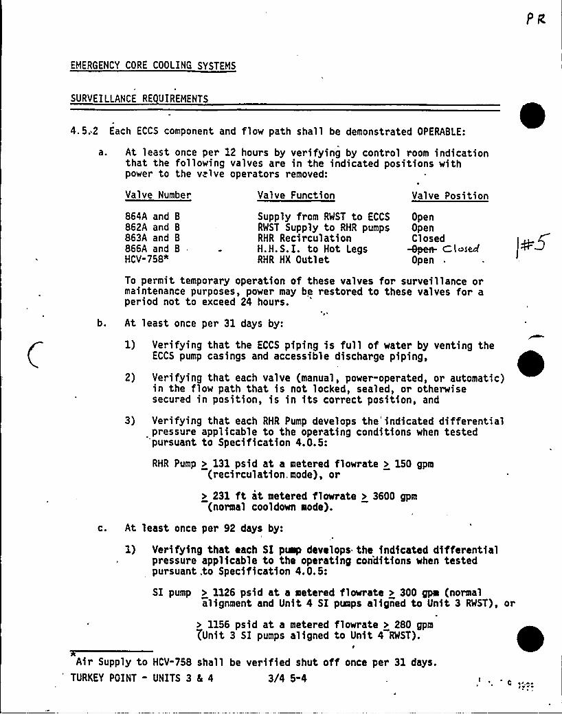
EMERGENCY CORE COOLING SYSTEMS
SURVEILLANCE RE UIREMENTS
4.5:2 Each ECCS component and flow path shall be demonstrated OPERABLE:0
a. At least once per 12 hours by verifying by control room indicationthat the following valves are in the indicated positions withpower to the v.lve operators removed:
Valve Number Valve Function Valve Position
864A and B
862A and B
863A and B
866A and BHCV-758"
Supply from RWST to ECCSRWST Supply to RHR pumpsRHR RecirculationH. H. S. I. to Hot LegsRHR HX Outlet
OpenOpenClosed
+pen- C, l ~sec(Open
To permit temporary operation of these valves for surveillance ormaintenance purposes, power may be restored to these valves for aperiod not to exceed 24 hours.
b. At least once per 31 days by:
1) Verifying that the ECCS piping is full of water by venting theECCS pump casings and accessible discharge piping,
2) Verifying that each valve (manual, power-operated, or automatic)in the flow path that is not locked, sealed, or otherwisesecured in position, is in its correct position, and
3) Verifying that each RHR Pump develops the'ndicated differentialpressure applicable to the operating conditions when testedpursuant to Specification 4.0.5:
RHR Pump > 131 psid at a metered flowrate > 150 gpm(recirculation. mode), or
> 231 ft at metered flowrate > 3600 gpm(normal cooldown mode).
c. At least once per 92 days by:
1) Verifying that each SI puap develops the indicated differentialpressure applicable to the operating con'ditions when testedpursuant .to Specification 4.0.5:
SI pump > 1126 psid at a metered flowrate > 300 gps (normalalignment and Unit 4 SI pumps aligned to Unit 3 RWST), or
> 1156 psid at a metered flowrate > 280 gpmYUnit 3 SI pumps aligned to Unit 4 RWST).
Air Supply to HCV-758 shall be verified shut off once per 31 days.TURKEY POINT - UNITS 3 5 4 3/4 5-4
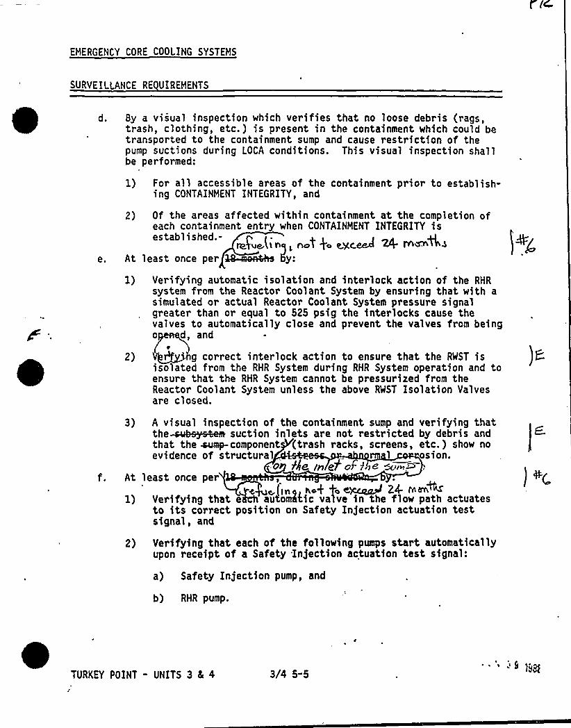
EMERGENCY CORE COOLING SYSTEMS
SURVEILLANCE RE UIREMENTS
d. By a visual inspection which verifies that no loose debris (rags,trash, clothing, etc.) is present in the containment which could betransported to the containment sump and cause restriction of thepump suctions during LOCA conditions. This visual inspection shallbe performed:
For all accessible areas of the containment prior to establish-ing CONTAINMENT INTEGRITY, and
e.
2)
At
2)
Of the areas affected within containment at the completion ofeach containment entry when CONTAINMENT INTEGRITY isestablished.-
ra4 (in(, n t4 eycW 24 ~~+~least once per ~walks 5y:
Verifying automatic isolation and interlock action of the RHRsystem from the Reactor Coolant System by ensuring that with asimulated or actual Reactor Coolant System pressure signalgreater than or equal to 525 psig the interlocks cause thevalves to automatically close and prevent the valves from beingo d, and
V~ g correct interlock action to ensure that the EST isisolated from the RHR System during RHR System operation and toensure that the RHR System cannot be pressurized from theReactor Coolant System unless the above EST Isolation Valvesare closed.
3) A visual inspection of the containment sump and verifying thatthe-sob.~e suction inlets are not restricted by debris andthat the ~component (trash racks, screens, etc.} show noevidence of structural osion.
a PAe In e7 o g~e ~,~~,At least once per
~(ig~ ~o+ fo e)zap~ 24 >m~1) Verifying that e automhic valve in the flow path actuates
to its correct position on Safety Injection actuation testsignal, and
2} Verifying that each of the follo~ing pumps start automaticallyupon receipt of a Safety Injection actuation test signal:
a) Safety Injection pump, and
b) RHR pump.
TURKEY POINT - UNITS 3 8( 4 3/4 5-59 )@
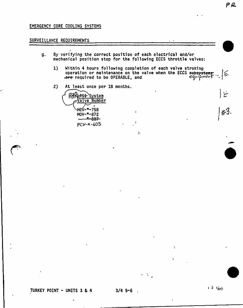
EMERGENCY CORE COOLING SYSTEMS
SURVEILLANCE RE UI'REMENTS
g. By verifying the correct position of each electrical and/ormechanical position stop for the following ECCS throttle valves:
1) Within 4 hours following completion of each valve strokingoperation or maintenance on the valve when the ECCS~ required to be OPERABLE, and g$ U f
PtNetm
2} At least once per 1& months.
S stemVal ve umber
-"-758MOV-*-872
Fcv-*-cp05
TURKEY POINT - UNITS 3 5 4 3/4 5-6rit )jttj.

EMERGENCY CORE COOLING SYSTEMS
Qc5 Avrcra5lc Cool a T ) dvugo< roti) fro3/4. 5. 3 ECCS SUBSYSTEMS -~ LESS TEAN 350 F
LIMITING CONDITION FOR OPERATION
3.5.3 .As a minimum, the following ECCS components and flow path shall beOPERABLE:
a. One OPERABLE RHR heat exchanger,
b. One OPERABLE RHR pump, and(i)
c. An OPERABLE flow path capable of<taking suction from therefueling water storage tank upon being manually realigned and(Q )transferring suction to the containment sump during therecirculation phase of operation.
APPLICABI LITY: MODE 4.
ACTION:
b.
With no OPERABLE ECCS flow path from'-the refueling water storagetank, restore at least one ECCS flow path to OPERABLE status within '
hour or be in COLD SHUTDOWN within the next 20 hours.
With either the residual heat removal heat exchanger or RHR pumpinoperable, restore the components to OPERABLE status or maintainthe Reactor Coolant System ~ less than 3504F by use of alternateheat removal methods.
the ECC'S ~s ac ~ated"'anal rn eactoCoolant System, p e prepared and submitted tothe Commission purs pecific s ithin 90 daysdescribin rcumstances of the actuation andac ed actuation cycles to date.
SURVEILLANCE RE UIREMENTS
4.5.3. The ECCS components shall be demonstrated OPERABLE per the applicablerequirements of Specification 4.5.2.
, TURKEY POINT - UNITS 3 8 4 3/4 5-7r
Lit ~ tr 5vs
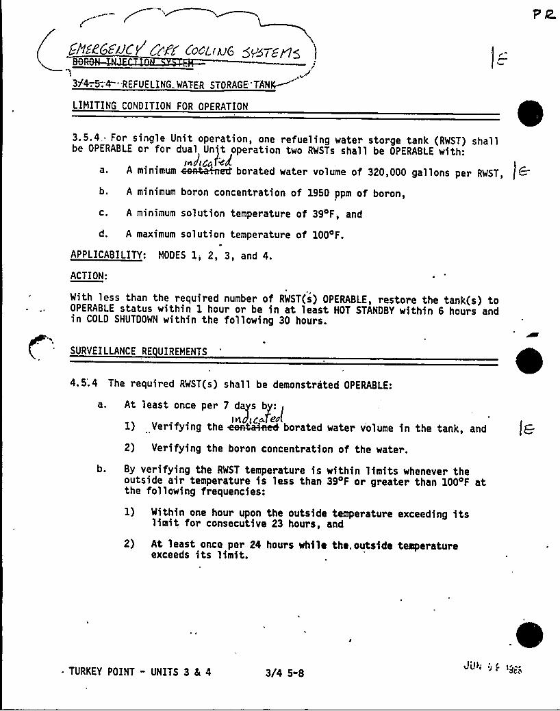
fP1EZCEJJCV CjdC'odLiAI6 gPg7g~g
3T4-.5.4 "REFUELING. WATER STORAGE TAN%~
LIMITING CONDITION FOR OPERATION
3.5.4„For single Unit operation, one refueling water storge tank (RWST) shallbe OPERABLE or for dual Unit operation two RWSTs shall be OPERABLE with:
I.Jic~i'~la. A minimum ~~ borated water volume of 320,000 gallons per RWST,
b. A minimum boron concentration of 1950 ppm of boron,
c. A minimum solution temperature of 394F, and
d. A maximum solution temperature of 1004F.
APPLICABILITY: MODES 1, 2, 3, and 4.
ACTION:
With less than the required number of RWST(s) OPERABLE, restore the tank(s) toOPERABLE status within 1 hour or be in at least HOT STANDBY within 6 hours andin COLD SHUTDOWN within the following 30 hours.
'
SURVEILLANCE RE UIREMENTS
4.5'.4 The required RWST(s) shall be demonstrated OPERABLE:
a. At least once per 7 days by: I
1) Verifying the ~%eeet borated water volume in the tank, and
2) Verifying the boron concentration of the water.
b. By verifying the RWST temperature is within limits whenever theoutside air temperature is less than 394F or greater than 1004F atthe following frequencies:
1) Within one hour upon the outside temperature exceeding itslimit for consecutive 23 hours, and
2) At least once per 24 hours while the.outside temperatureexceeds its limit.
* TURKEY POINT - UNITS 3 4 4 3/4 5-8 >U4 4; 1g"Cia
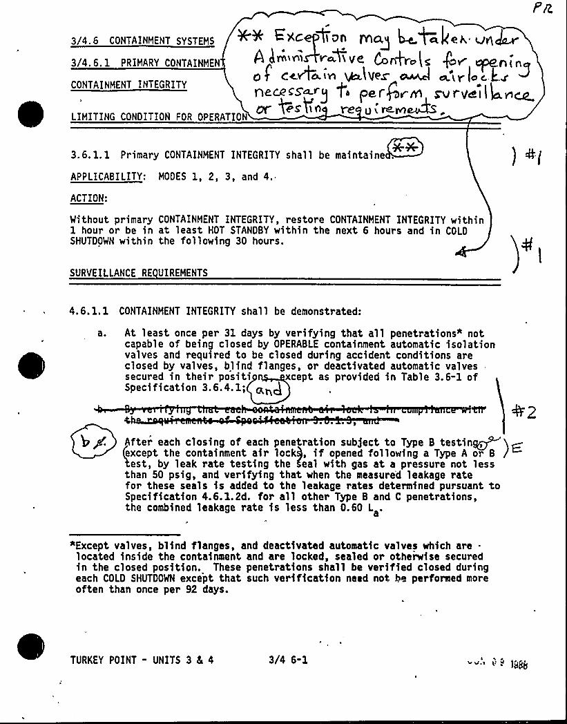
3/4 6 coNTAINMENT sYsTEMs ++ ~Yacc- CIoo TYICLQ 44.+a )eh, vs\~3/4.6.1 PRIMARY CONTAINMEN Pa er ~~ << QAkrolc fV Cpl?PLLOMof'eW~in IA tVe~ ~ ~'irloc j:.~ ~CONTAINMENT INTEGRITY
yf es'Cin re O i rarrI&S .LIMITING CONDITION FOR OPERATION
3.6.1.1 Primary CONTAINMENT INTEGRITY shall be maintaine .
APPLICABILITY: MODES 1, 2, 3, and 4.
ACTION:
Without primary CONTAINMENT INTEGRITY, restore CONTAINMENT INTEGRITY within1 hour or be in at least HOT STANDBY within the next 6 hours and in COLDSHUTDOWN within the following 30 hours.
) 4g
SURVEILLANCE RE UIREHENTS
4.6.1. 1 CONTAINMENT INTEGRITY shall be demonstrated:
At least once per 31 days by verifying that all penetrations" notcapable of being closed by OPERABLE containment automatic isolationvalves and required to be closed during accident conditions areclosed by valves, blind flanges, or deactivated automatic valvessecured in their positi xcept as provided in Table 3.6-1 ofSpecIfLcatIon 3.6.4.1;
After each c1osfng of each penetratfon sob)act to Type 6 testin~except the containment air lock), if opened following a Type A or B /est, by leak rate testing the Seal with gas at a pressure not less
than 50 psig, and verifying that when the measure'd leakage ratefor these seals is added to the leakage rates determined pursuant toSpecification 4.6.1.2d. for all other Type B and C penetrations,the combined leakage rate is less than 0.60 L .
*Except valves, blind flanges, and deactivated automatic valves which are .
located inside the containment and are locked, sealed or otherwise securedin the closed position. These penetrations shall be verified closed duringeach COLD SHUTDOWN except that such verification need not be performed moreoften than once per 92 days.
TURKEY POINT - UNITS 3 8L 4 3/4 6-1
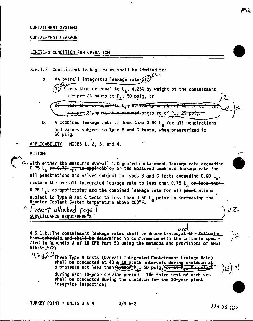
CONTAINMENT SYSTEMS
CONTAINMENT LEAKAGE
LIMITING CONDITION FOR OPERATION
3.6. 1. 2 Containment leakage rates shall be limited to:
a ~ An overall integrated leakage rate
i1) Less than or equal to L , 0.25K by weight of the containment
a'ir
per 24 hours at~ 50 psig, or~ de <~ww~
+e2 ~h
b. A combined leakage rate of less than 0.60 L for. all penetrationsaand valves subject to Type B and C tests, when pressurized to50 psig.
APPLICABILITY: MODES 1, 2, 3, and 4.
ACTION:
A,. With either the measured overall integrated containment leakage rate exceeding0.75 L or the measured combined leakage rate forall penetrations and valves subject to Types B and C tests exceeding 0.60 L ,a'
21 kd 1 2 2121a
, and the combined leakage rate for all penetrationssubject to Type B and C tests to less than 0.60 L prior to increasing theReactor Coolant System temperature above 200 F.
jihudert a4alej Fkoqd7SURVEILLANCE RE UIREMEAS
.2.1.2.11 1 1 k 11 2t determined in conformance with the criteria speci-fied in Appendix J of 10 CFR Part 50 using the methods and provisions of ANSIN45; 4-1972:
Three Type A tests (Overall Integrated Containaent Leakage Rate)shall be conducted at 40 k 10 month intervals durin shutdown aa pressure not less than~~ 50 psig,during each 10-year service period. The third test of each setshall be conducted during the shutdown for the 10-year plantinservice inspection;
- TURKEY POINT - UNITS 3 4 4 3/4 6-2JL'4 ng tg<~
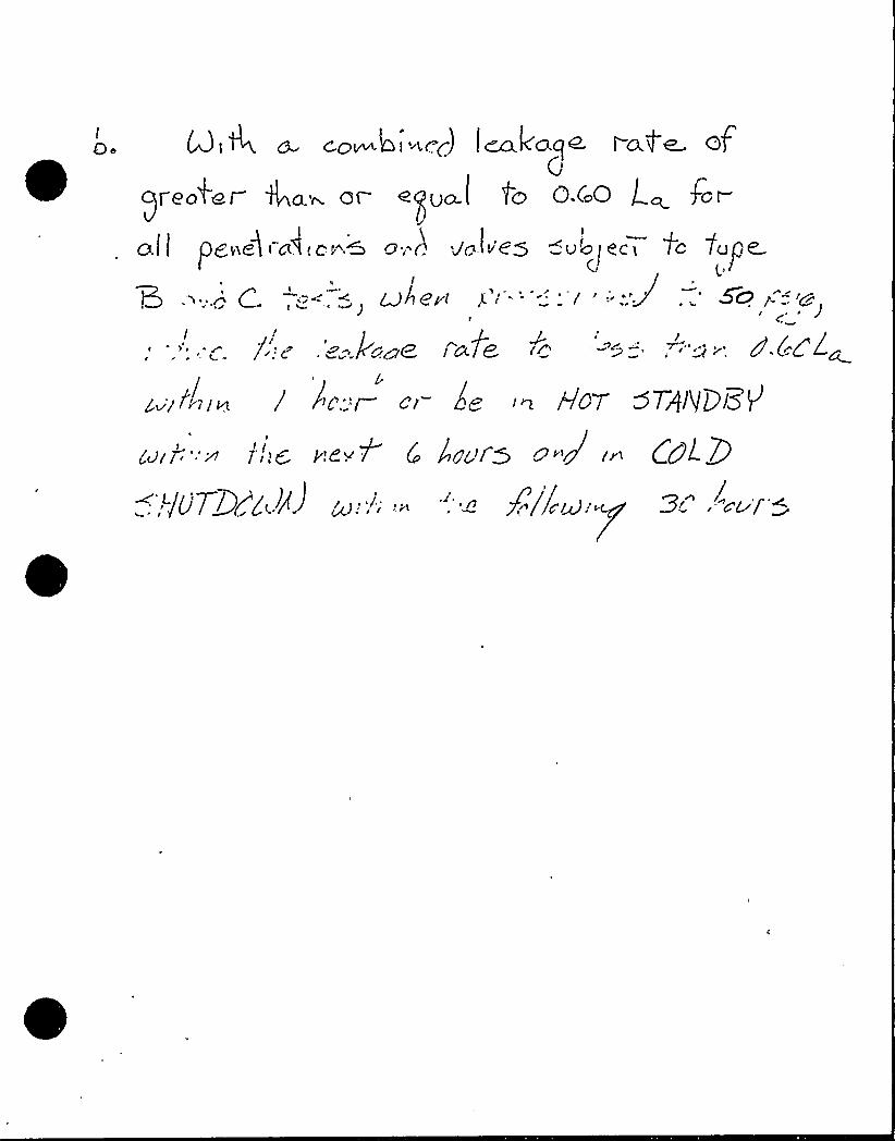
c.ow o i "ir..r-) I eccl'a.q ~ I"a.f' GfG
)I Ga4I 4a~ Qr" eQUO.C gC) Q Co.O Qcr )Or
a.j I pe~ic3 i cd.o>~~ a;.) uglier ~u'c>I ace tc fuge(r t,/
4 l
I3 .'>;c' ~, +~ LIAerr p'' I '".":g, '0 g-:.'g
I /1:.. -= lc c~e../ale ~c -'- ='.': ". d'.CC lc.
g~'ifnr~ ) />c'"~ or 6g in HOT 57/1)P/3$/

/nJ7 C~i~ a ~i+ 4Y,Fr 8 C ~le
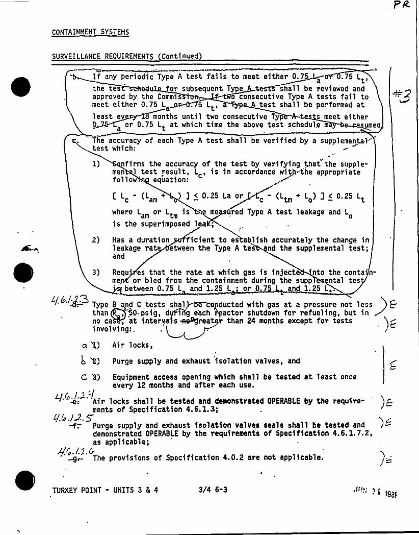
CONTAINMENT SYSTEMS
SURVEILLANCE RE UIREHENTS Continued
If any periodic Type A test fails to meet either 0.7 L .75 L,athe tes for subsequent Type crt% shall be reviewed andapproved by the Commss o consecutive Type A tests fail tomeet either 0.75 L . 5 Lt, a test shall be performed atleast ev months until two consecutive Typ s meet either0 or 0.75 Lt at which time the above test schedul.e m ~~umed
The accuracy of each Type A test shall be verified by a supplemental.test which:
1) nfirms the accuracy of the test by verifying that the supple-men 1 test result, L , is in accordance witP the appropriatefollow equation:
c am+ ) 3 < 0. 25 La or c Ltm +
o ~ — '
where L or Lt is th me red Type A test leakage and Ltm ois the superimposed lea;
2) Has a duration ficient to es ablish accurately the change inleakage rat etween the Type A tesetnd the supp lame'ntal test;and
3) Requ's that the rate at which gas is injecte nto the conta n-me or bled from the containment during the supp ntal tes
between 0.75 L and 1.25 L or'.7 and 1.25 L .
Type B nd C tests shalq/~./2.Qthan, 50 psig, d i g e'achno ca, at inter s hereatinvolving:.
ducted with gas at a pressure not lessactor shutdown for refueling, but inthan 24 months except for tests
)C
a g) Air locks,
L 'R) Purge supply and exhaust isolation valves, and
C 8) Equipment access opening which shall be tested at least onceevery 12 months and after each use.
Air locks shall be tested and demonstrated OPERABLE by the require- )gments of Specification 4.6;1.3;
4.(.12.5Purge supply and exhaust isolation valves seals shall be tested and. )>demonstrated OPERABLE by the requirements of Specification 4.6.1.7.2,as applicable;
qc.S.Z.SThe provisions of Specification 4.0.2 are not applicable.
TURKEY POINT - UNITS 3 8( 4 3/4 6-3 "": "-9i&aF
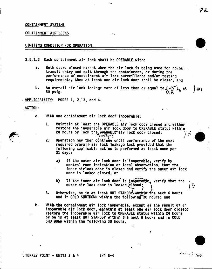
CONTAINMENT SYSTEMS
CONTAINMENT AIR LOCKS
LIMITING CONDITION. FOR OPERATION
3.6. 1.3 Each containment air lock shall be OPERABLE with:
a. Both doors closed except when the air lock is being used for normaltransit entry and exit through the containment, or during theperformance of containment air lock surveillance and/or testingrequirements, then at least one air lock door shall be closed, and
b. An overall air lock leakage rate of less than or equal to ~WL at50 psig. O.Q,
, APPLICABILITY: MODES 1, 2, 3, and 4.
ACTION:
With one containment air lock door'noperable:
1. Maintain at least the OPERABLE air lock door closed and eitherrestore the inoperable air lock door to OPERABLE status within24 hours or lock the BP8%H&air lock door closed;
~ov5~r i2. Operation may then continue until performance of the next
required overall= air lock leakage test provided that thefollowing applicable action is performed at least once per31 days:
a) If the outer air lock door is inoperable, verify bycontrol room indication or local observation, that theinner airlock door is closed and verify the outer air lockdoor is locked closed, or
3.
verify that theb) If the inner air lock door is peraouter air lock door is locked closed>
Otherwise, be in at least HOT STANDS thi he next 6 hoursand in COLD SHUTDOWN within the following 30 hours; and
b. With. the containment air lock inoperable, except as the result of aninoperable air lock door, maintain at leait one air lock door closed;restore the inoperable air lock to OPERABLE status within 24 hoursor be in at least HOT STANDBY within the next 6 hours and in COLDSHUTDOWN within the following 30 hours.
', TURKEY POINT - UNITS 3 8L 4 3/4 6-4
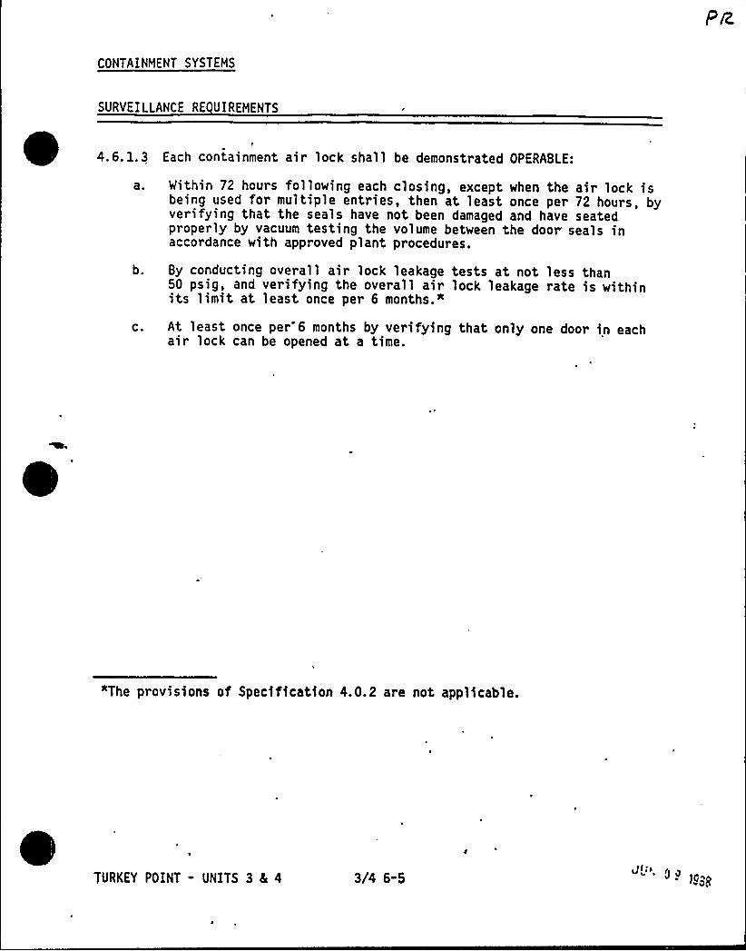
CONTAINMENT SYSTEMS
SURVEILLANCE RE UIREMENTS
4.6.1.3 Each containment air lock shall be demonstrated OPERABLE:
a.
b.
C.
Within 72 hours following each closing, except when the air lock isbeing used for multiple entries, then at least once per 72 hours, byverifying that the seals have not been damaged and have seatedproperly by vacuum testing the volume between the door seals inaccordance with approved plant procedures.
By conducting overall air lock leakage tests at not less than50 psig, and verifying the overall air lock leakage rate is withinits limit at least once per 6 months."
At least once per 6 months by verifying that only one door in eachair lock can be opened at a time.
"The provisions of Specification 4.0.2 are not applicable.
TURKEY POINT - UNITS 3 4 4 3/4 6-5Jll> 0~ lo~
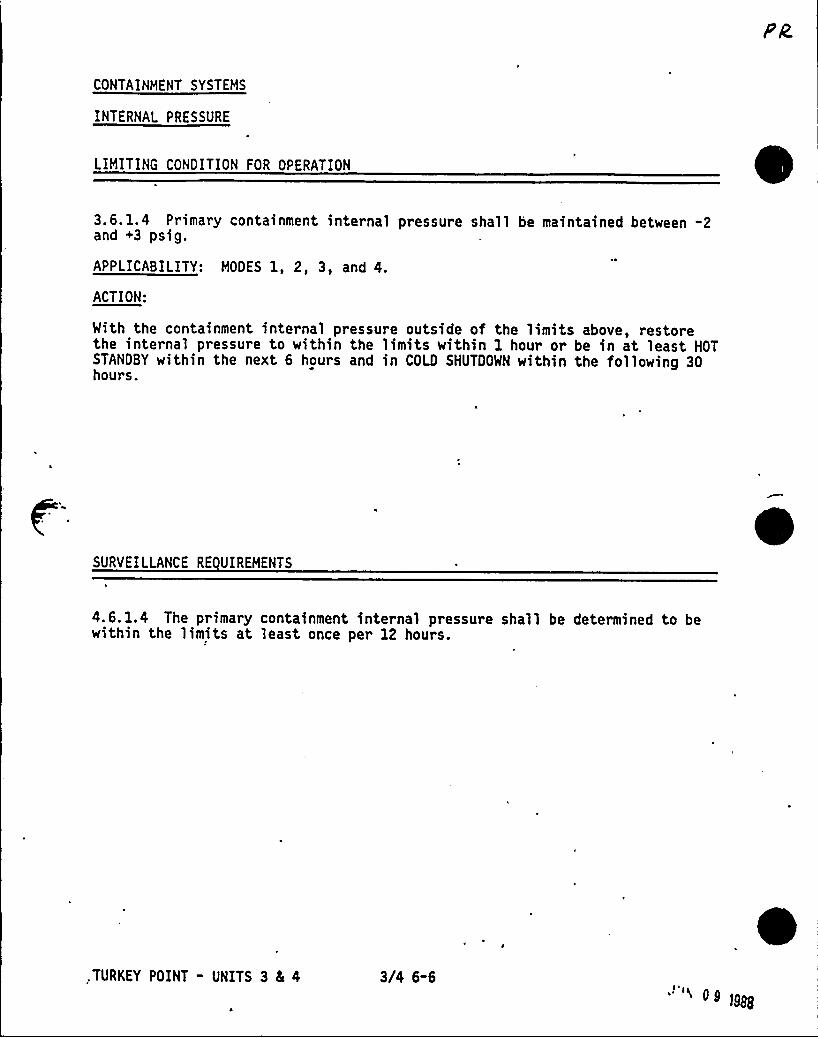
CONTAINMENT SYSTEMS
INTERNAL PRESSURE
LIMITING CONDITION FOR OPERATION
3.6. 1.4 Primary containment internal pressure shall be maintained between -2and +3 psig.
APPLICABILITY: MODES 1, 2, 3, and 4.
ACTION:
With the containment internal pressure outside of the limits above, restorethe internal pressure to within the limits within 1 hour or be in at least HOTSTANDBY within the next 6 hours and in COLO SHUTDOWN within the following 30hours.
SURVEILLANCE RE UIREMENTS
4.6. 1.4 The primary containment internal pressure shall be determined to bewithin the limits at least once per 12 hours.
.TURKEY POINT - UNITS 3 8L 4 3/4 6-600
1988
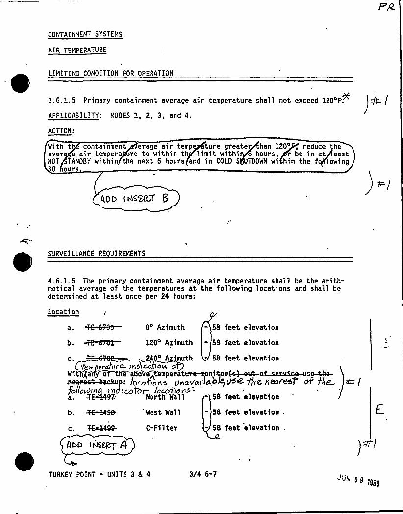
CONTAINMENT SYSTEMS
AIR TEMPERATURE
LIMITING CONDITION FOR OPERATION
3.6. 1.5 Primary containment average air temperature shall not exceed 120'F;
APPLICABILITY: MODES 1, 2, 3, and 4.
ACTION:
With t conta>nment erage air temp ture greater han 120' reduce heaver e air temper re to within th limit withi hours, be in at eastHOT TANDBY within the next 6 hours and in COLD S UTDOWN wi hin the f owing
0 ours
/DE toS~T 5
SURVEILLANCE RE UIREHENTS
4.6.1.5 The primary containment average air temperature shall be the arith-metical average of the temperatures at the following locations and shall bedetermined at least once per 24 hours:
Location
a. ~RN— 04 Azimuth - 58 feet elevation
b. ~TOT- 1204 Azimuth - 58 feet elevation
$4II'M IQtg~pera,'4rc- lncLcc&dN NLRB
Mithgaify of the abov~<empp:/ ~ i', II
go/tou)in > <>d i~tor ken'ho v>5-a. North Mall
b. ~49& 'est Mall
c. 7&4AQQ- C-Filter
AUD IHS~ 4
58 feet elevation
eh ~a Pe.ne r.esP af flan
- 58 feet elevation
58 feet elevation
58 feet elevation
)Wi/
TURKEY POINT " UNITS 3 4 4 3/4 6-7JN 0g
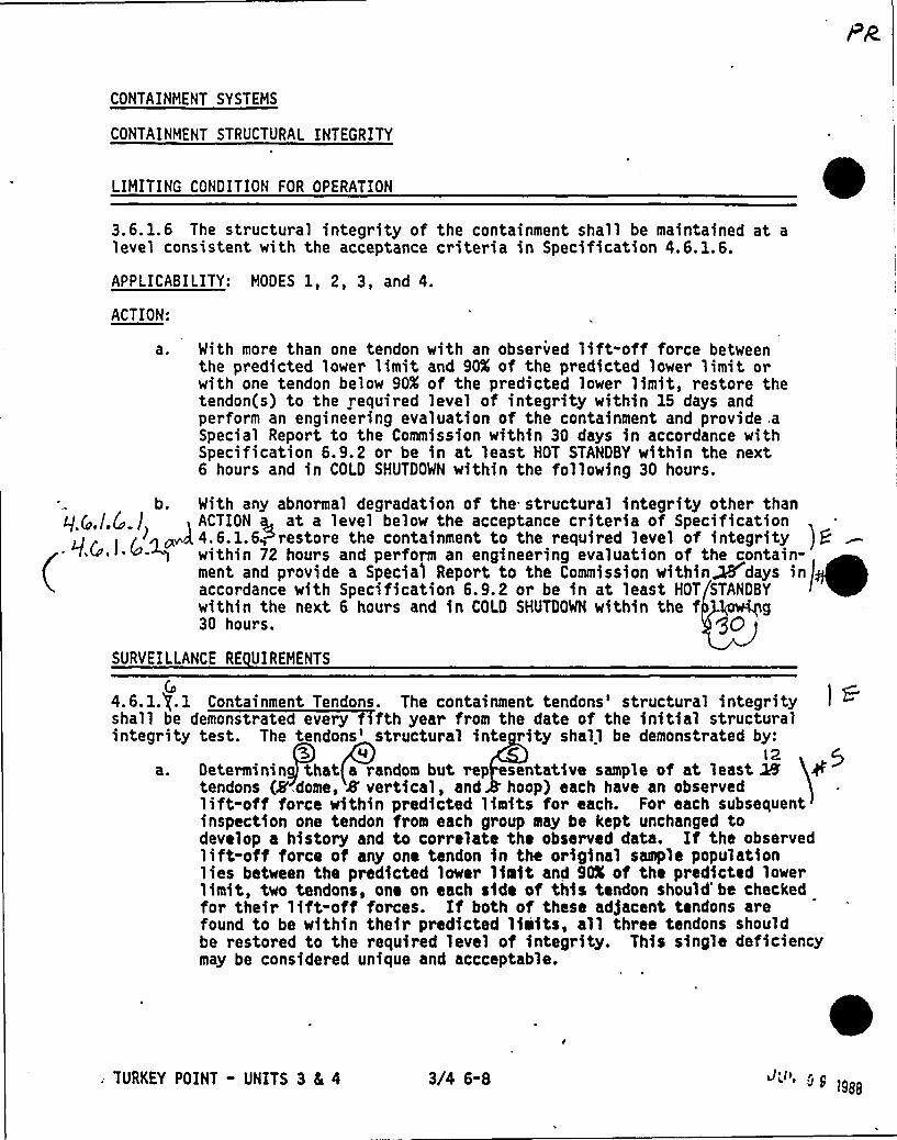
CONTAINMENT SYSTEMS
CONTAINMENT STRUCTURAL INTEGRITY
LIMITING CONDITION FOR OPERATION
3.6. 1.6 The structural integrity of the containment shall be maintained at alevel consistent with the acceptance criteria in Specification 4.6.1.6.
APPLICABILITY: MODES 1, 2, 3, and 4.
ACTION:
a ~ With more than one tendon with an observed lift-offforce betweenthe predicted lower limit and 90K of the predicted lower limit orwith one tendon below 90K of the predicted lower limit, restore thetendon(s) to the required level of integrity within 15 days andperform an engineering evaluation of the containment and provide .aSpecial Report to the Commission within 30 days in accordance withSpecification 6.9.2 or be in at least HOT STANDBY within the next6 hours and in COLD SHUTDOWN within the following 30 hours.
SURVEILLANCE RE UIREMENTS
(n4.6.1.).1shall beintegrity
Containment Tendons. The containment tendons'tructural integritydemonstrated every fth year from the date of the initial structuraltest. The tendons'tructural inte rity shall be demonstrated by:
l2Determinin that a random but rep esentative sample of at least Mtendons Q'.dome, 8'ertical, and hoop) each have an observedlift-offforce within predicted limits for each. For each subsequentinspection one tendon from each group may be kept unchanged todevelop a history and to correlate the observed data. If the observedlift-offforce of any one tendon in the original sample populationlies between the predicted lower limit and 90K of the predicted lowerlimit, two tendons, one on each side of thia tendon should'e checkedfor their lift-offforces. If both of these adjacent tendons arefound to be within their predicted limits, all three tendons shouldbe restored to the required level of integrity. This single deficiencymay be considered unique and accceptable.
av
b. With any abnormal degradation of the structural integrity other thanq („/.Q.j , ACTION 6, at a 'level below the acceptance criteria of Specification
mv,d 4.6. 1.6~mrestore the containment to the required level of integrity e~
~ ~
~
~ ~
~ ~
~within 72 hours and perform an engineering evaluation of the contain-ment and provide a Specia'l Report to the Commission within~days inaccordance with Specification 6.9.2 or be in at least HOT STANDBYwithin the next 6 hours and in COLD SHUTDOWN within the f '
30 hours. QOg
: TURKEY POINT - UNITS 3 4 4 3/4 6-8 ' "8 1988
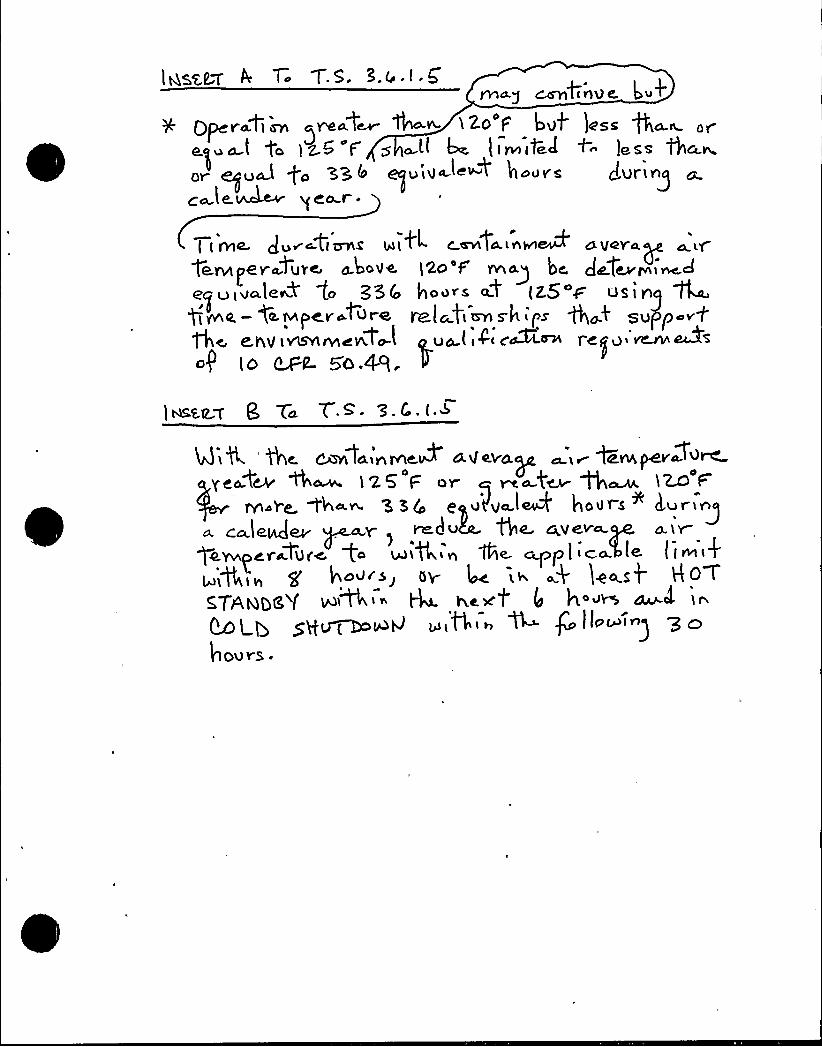
lesser 4 T l.5. >.4 c G'tinvc, Lu+
gperoCisn ~roof~ th o- i2o'F but )oss tho.~ orQ) ( t (z.5 F g (( (oe lire(t ~ +- less aha.o.
or guU go xs4 quiu~(o~t hoors turingc te.A~ ge~r.
~r A( Iivie. turotiznis IoilL c en(oinvieu+ aiIeroy
ieno~er~turc aboiIQ (2a'Irmop bo tafcv+i~4
eguiuale~+ to '356 hoors ot (2.5 r us inQ~Q —VILlvlpcroture yalogim s hips 'th+0 su p
eniI i vts'virncnV~I (Luo (i4~ cMooi r<IIu '~~sog (O u~ 5O.4q.
Tu Y.<- 3.~ l ~
Mik '(hc Canla nNiIQP ai(evay ~i~ ~evwpevo+u~geo:tch W~ 125 F or ~ ma f~ ~~ )~ t-
m ve. Ch«v 3 SIo cpu(lvo.l~ hours + iI.ur n~a. ca.leQev Y r(-d< 4~ Av<~~
$0 Ywpcrotufc fo 4)l th< n 1th.capp ( i <o- (Q I I oo '
gihig f hour>) bv (oc i< ak 1++s4gTAggg~( WN,i» ~ coat II hou~ SIu.el IiLOLb S8u(~OO4 IO,+ o t4 Qllo~i
gPO
ours.
TOIT 'A'38 MT IT h Thhh08
h,
I
I
Ih
II
V
h
VI
jV
l!,
h
h
h
lif
I
ll
I
I
I il
II
V
I
f
I>
4
I
I
Il
III
II
h
lll I
II
h
II
II
llII
h
ff
II
II
hr
I
,'1
h
I
V
I,f
j
jI f
II
V I
II I
t„
II
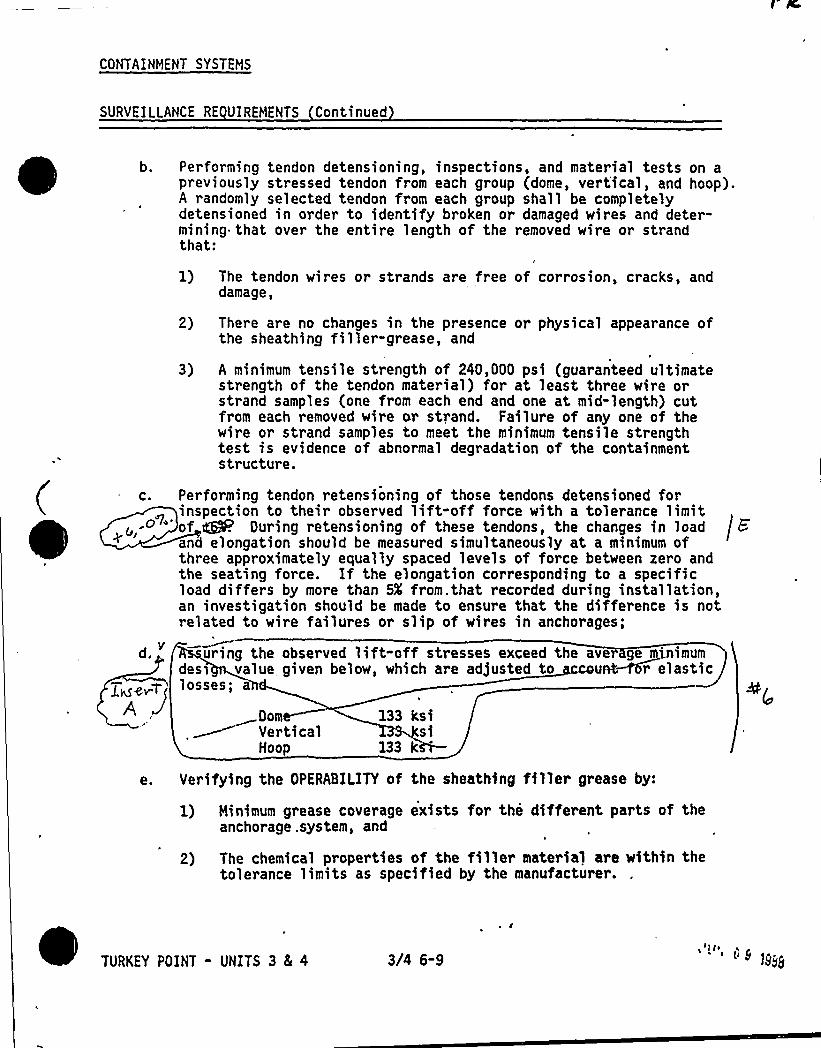
CONTAINMENT SYSTEMS
SURVEILLANCE RE UIREMENTS Continued
b. Performing tendon detensioning, inspections, and material tests on apreviously stressed tendon from each group (dome, vertical, and hoop).A randomly selected tendon from each group shall be completelydetensioned in order to identify broken or damaged wires and deter-mining that over the entire length of the removed wire or strandthat:
1) The tendon wires or strands are free of corrosion, cracks, anddamage,
2) There are no changes in the presence or physical appearance ofthe sheathing filler-grease, and
I')
A minimum tensile strength of 24D,OOO psi (guaranteed ultimat'estrength of the tendon material) for at least three wire orstrand samples (one from each end and one at mid-length) cutfrom each removed wire or strand. Failure of any one of thewire or strand samples to meet the minimum tensile strengthtest is evidence of abnormal degradation of the containmentstructure.
C.
.O~o~6~
LK54h"+(
Performing tendon retensioning of those tendons detensioned forinspection to their observed lift-offforce with a tolerance limitof CNo. goring retensioning of these tendons, the changes in load /&and elongation should be measured simultaneously at a minimum ofthree approximately equally spaced levels of force between zero andthe seating force. If the elongation corresponding to a specificload differs by more than 5X from. that recorded during installation,an investigation should be made to ensure that the difference is notrelated to wire failures or slip of wires in anchorages;
uring the observed lift-offstresses exceed the ave ge mznimumdes> value given below, which are adjusted to uat-tbr elasticlosses; a
Oom~VerticalMoop
133 ksiSi
133 k
e. Verifying the OPERABILITY of the sheathing filler grease by:
1) Minimum grease coverage exists for the different parts of theanchorage .system, and
2) The chemical properties of the filler material are within thetolerance limits as specified by the manufacturer.
TURKEY POINT - UNITS 3 & 4 3/4 6-9'ii''
8„-g
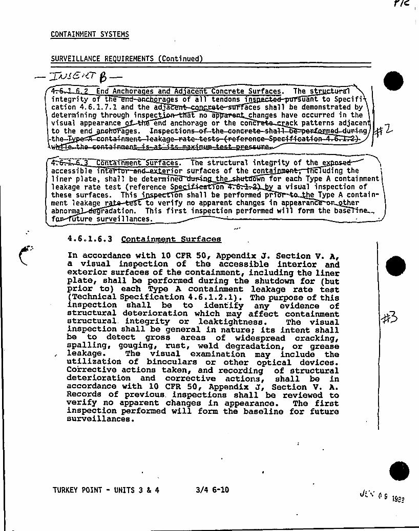
CONTAINMENT SYSTEHS
SURVEILLANCE RE UIREHENTS Continued
in<8'<7 gEnd Anchora es and Ad acen Concrete Surfaces. The str ural
integrity of t e orages of all tendons 1n uant to Specification 4. 6. 1. 7. 1 and the adga aces shall be demonstrated bydetermining through inspect a no ap changes have occurred in thevisual appearance end anchorage or the conc ack patterns adjacento the end ages. Inspections-of-the-cona etc-sh ed-dUF4AQ
-the-T-
Conta'>ament Sur aces. The structural integrity of theaccessible sn e error surfaces of the conta, c uding theliner plate, shall be determine th own for each Type A containmentleakage rate test (reference Spe >on . . . a visual snspectson ofthese surfaces. This i on shall be performed pr ~o. he Type A contain-ment leakage r to verify no apparent changes in appearanc therabnorm radation. This first, inspection performed will form the base '~e „f uture surveillances.
4.6.1.6.3 o tainment urfaces
In accordance with 10 CFR 50'ppendix J. Section V. Aia visual inspection of the accessible interior andexterior surfaces of the containment, including the linerplate, shall be performed during the shutdown for (butprior to) each Type A containment leakage rate test(Technical Specification 4.6.1e2 F 1) ~ The purpose of thisinspection shall be to identify any evidence ofstructural deterioration which may affect containmentstructural, integrity or leaktightness. The visualinspection shall be general in nature; its intent shallbe to detect gross areas of widespread cracking,spalling, gouging, rust, weld degradation, or greaseleakage. The visual examination may include theutilization of binoculars or other optical devices.Co'rrective actions taken, and recording of structuraldeterioration and corrective actions, shall be inaccordance with 10 CPR 50, Appendix J, Section V. A.Records of previous, inspections shall be reviewed toverify no apparent changes in appearance. The firstinspection performed will form the baseline for futuresurveillances.
TURKEY POINT - UNITS 3 4 4 3/4 6-10

Ct( AJA'egg
7 h 9 y le olsc~~<rJ /i+i "afZirrr.e. Ar e~ c.A
I
~.<~~u~i e~ceePJ 7"4Q ~~ nl>~rvfv~l v egu<r-~ /k>Mh'&e ~ Eegu re~
~i4- g4P grcez s 4al/Zq ~<Pc.~(<de/'>ripliatduulg~ Pg< e~~/
Sar VC//lgnCQ, W~4o~( priA- H +~6, kgtnitsn> OP8c'C 4 $ 4~Vgs /la~ceJ{ Ao(. leg C.a~> Agqr' 4rc,g Nc~Vg <FAN !
2j / scam ~> /gf/PJ~
3g ange - cCr~eiinle~+ /onset (~ .p~rC~ k<pe~ nI~<~<e~)z
c.a»sic6y «y 7 i~ 8/agate ~sew p~MCCii~

0
~l 5 Dog C g~ lg~6oecjfl/Wlg k

4.6.1.6.2 End Anchora es and Ad'acent Concrete Surfaces
The structural integrity of the end anchorages of all'endonsinspected pursuant to Specification 4.6.1.6.1 and
the adjacent concrete surfaces shall be demonstrated bydetermining through visual inspection that nounacceptable levels of corrosion exist on the endanchorages and no unacceptable cracking exists in theconcrete adjacent to the end anchorages. Determinationof acceptance levels shall be by engineering evaluationof the areas in question. If unacceptable conditions arefound, the tendons inspected during the previoussurveillance shall be examined to determine whether thecorrosion levels or concrete cracking have increasedsince the previous surveillance. Inspection of adjacentconcrete surfaces shall be performed concurrently withthe containment tendon surveillance (TechnicalSpecification 4.6.1.6.1).

~/ /~ p~p~ y~ 7~~i p/8 l~&lfpf
/~HI/ k
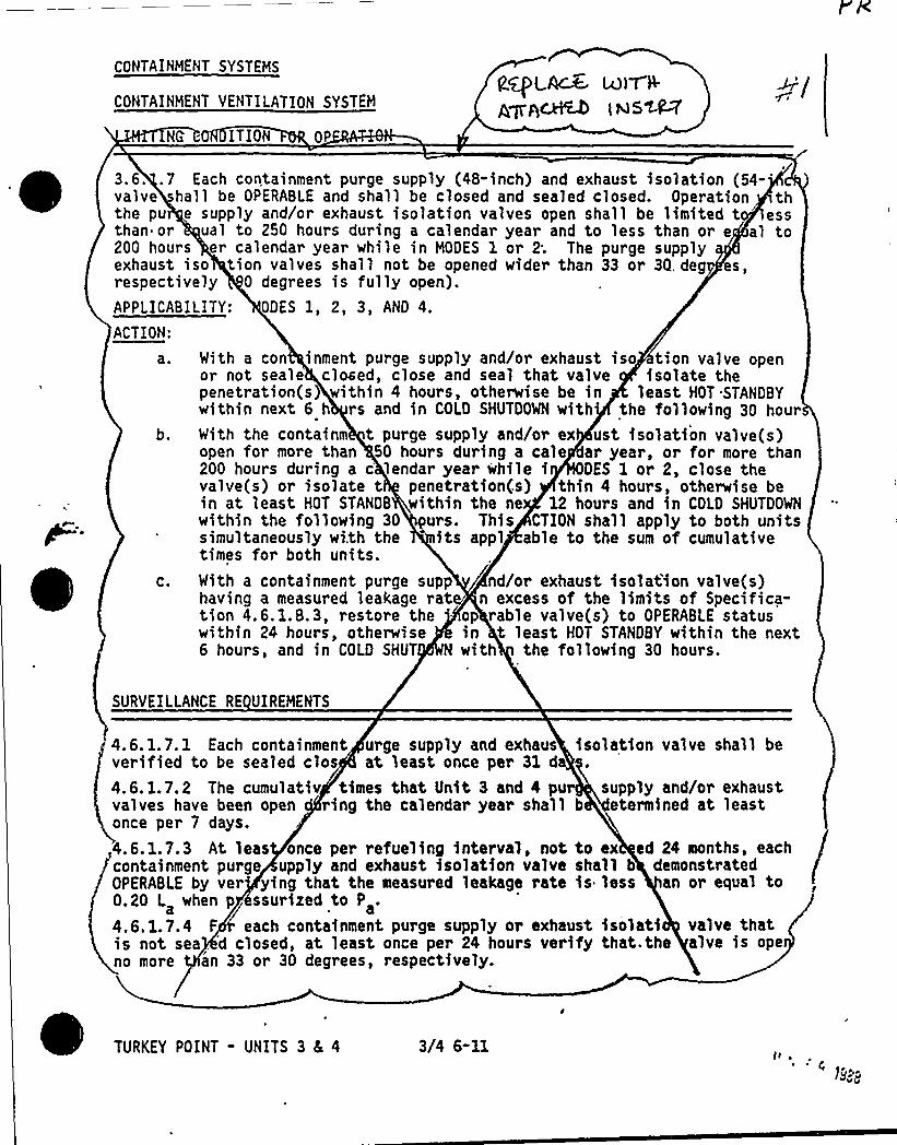
CONTAINMENT SYSTEMS
CONTAINMENT VENTILATION SYSTEM
NQ IT ION OP
gg>LACK IAII&IIles~
p g pp y / exhaust >so tion valve openor not scale clued, close and seal that valve isolate thepenetration(s) within 4 hours, otherwise be in least HOT STANDBYwithin next 6 h rs and in COLD SHUTDOWN with'he following 30 hourWith the containm t purge supply and/or ex ust isolation valve(s)open for more than 50 hours during a cale ar year, or for more than200 hours during a c'endar year while i DES 1 or 2, close thevalve(s) or isolate t penetration(s} thin 4 hours, otherwise bein at least HOT STANDS within the ne 12 hours and in COLO SHUTDOWNwithin the following 30 urs. This CTION shall apply to both unitssimultaneously wi.th the its appl able to the sum of cumulativetimes for both units.With a containment purge supp nd/or exhaust isolation valve(s)having a measured leakage rat n excess of the limits of Specifica-tion 4.6. 1.8.3, restore the op rable valve(s) to OPERABLE statuswithin 24 hours, otherwise in t least HOT STANDBY within the next6 hours, and in COLD SHUT N with the following 30 hours.
b.
C.
3.6. .7 Each containment purge supply (48-inch) and exhaust isolation(54-'alvehall be OPERABLE and shall be closed and sealed closed. Operation th
the pu e supp1y and/or exhaust iso1ation valves open shall be limited t 'ssthan or ual to 250 hours during a calendar year and to less than or e al to200 hours er calendar year while in MODES 1 or 2; The purge supplyexhaust iso tion valves shall not be opened wider than 33 or 3Q. deg es,respective1y 0 degrees is fully open).APPLICABILITY: ODES 1, 2, 3, AND 4.
ACTION:
a. With a con inment ur e su 1 and or
SURVEILLANCE RE UIREMENTS
4.6. 1.7. 1 Each containment urge supply and exhaus isolation valve shall beverified to be sealed clos at least once per 31 da
4. 6. l. 7. 2 The cumulativ times that Unit 3 and 4 pu supply and/or exhaustvalves have been open ring the calendar year shall b etermined at leastonce per 7 days.
4.6.1.7.3 At leas once per refueling interval, not to ex ed 24 months, eachcontainment purge upply and exhaust isolation valve shall b demonstratedOPERABLE by ver ying that the measured leakage rate is less an or equal to0.20 L when p ssurized to P .
4.6.1.?.4 F each containment purge supply or exhaust isolati valve thatis not sea .
'd closed, at least once per 24 hours verify that. the alve is openo more an 33 or 30 degrees, respectively.
TURKEY POINT - UNITS 3 4 4 3/4 6-11
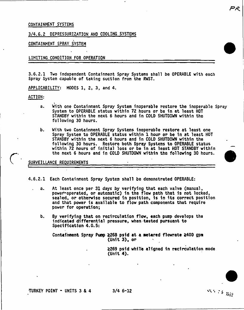
CONTAINHENT SYSTEHS
3/4.6.2 DEPRESSURIZATION AND COOLING SYSTEHS
CONTAINMENT SPRAY SYSTEM
LIMITING CONDITION FOR OPERATION
3.6.2. 1 Two independent Containment Spray Systems shall be OPERABLE with eachSpray System capable of taking suction from the RWST.
APPLICABILITY: MODES 1, 2, 3, and 4.
ACTION:
a ~ With one Containment Spray System inoperable restore the inoperable SpraySystem to OPERABLE status within 72 hours or be in at least HOTSTANDBY within the next 6 hours and in COLD SHUTDOWN within thefollowing 30 hours.
b. With two Containment Spray Systems inoperable restore at least oneSpray System to OPERABLE status within 1 hour or be in at least HOTSTANDBY within the next 6 hours and in COLO SHUTDOWN within thefollowing 30 hours. Restore both Spray Systems to OPERABLE statuswithin 72 hours of initial loss or be in at least HOT STANDBY withinthe next 6 hours and in COLD SHUTDOWN within the following 30 hours.
SURVEILLANCE RE UIREHENTS
4.6.2. 1 Each Containment Spray System shall be demonstrated OPERABLE:
a. At least once per 31 days by verifying that each valve (manual,power operated, or automatic) in the flow path that is not locked,sealed, or otherwise secured in position, is in its correct positionand that power is available to flow path components that requirepower for operation;
b. By verifying that on recirculation flow, each pump develops theindicated differential pressure, when tested pursuant toSpecification 4.0.5:
Containment Spray Pump R268 psid at a metered flowrate 2400 gpm(Unit 3), or
h269 psid whil'e aligned in recirculation mode(Unit 4).
TURKEY POINT - UNITS 3 4 4 3/4 6-12 Al( A ~
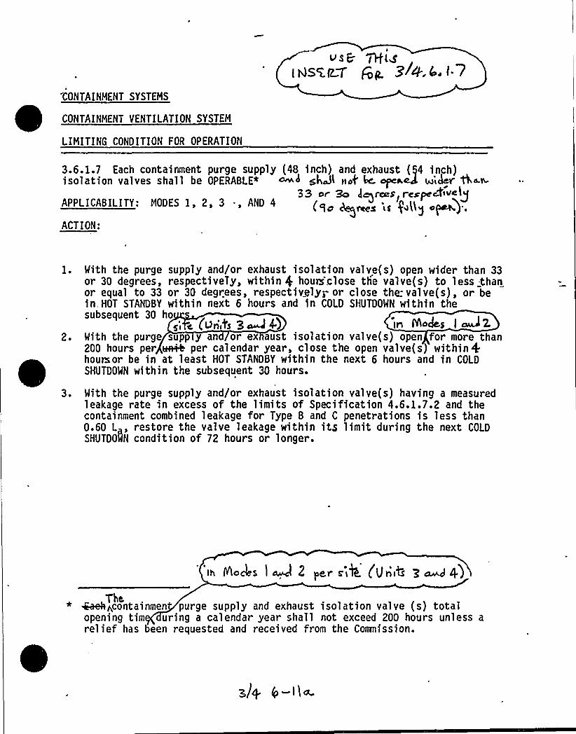
CONTAINMENT SYSTEMS
CONTAINMENT VENTILATION SYSTEM
LIMITING CONDITION FOR OPERATION
3.6.1.7 Each containment purge supply (48 inch) and exhaust (54 inch)isolation valves shall be OPERABLE» ~~ s4dl not' ape~ek e'Idev't ~~
33 or So )~re g, r~~p 4~valyAPPLICADILITT: MODES I, 2, 3 ., AND 4 (CI A;s q„gACTION:
2 ~
3 ~
With the purge supply and/or exhaust isolation valve(s) open wider than 33or 30 degrees, respectiveTy, within $ houe close the valve(s) to less thanor equal to 33 or 30 degrees, respectively; or close the: valve(s), or bein HOT STANDBY within next 6 hours and in COLD SHUTDOWN within thesubsequent 30 ho
sl c, (uri,i's 3~4) "ir fAoJ s I WZWith the purge supp y an or ex aust isolation valve(s) open for more than200 hours per erH+ per calendar year, close the open valve(s) within +hoursor be in at least HOT STANDBY within the next 6 hours and in COLDSHUTDOWN within the subsequent 30 hours.
With the purge supply and/or exhaust isolation valve(s) having a measuredleakage rate in excess of the limits of Specification 4.6.1.7.2 and thecontainment combined leakage for Type B and C penetrations is less than0.60 L , restore the valve leakage within its limit during the next COLD
SHUTDOWN condition of 72 hours or longer.
'Ih Necks I cwJ 2 Per zi4 (IJiih
The.* 4aeh~containmen purge supply and exhaust isolation valve (s) totalopening tim uring a calendar year shall not exceed 200 hours unless arelief has been requested and received from the Coranission.

TH «PA$ 6 tnTC&m ~au J
LwFV g ~gwk,
0
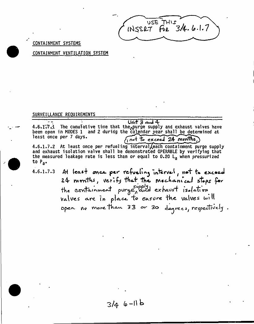
vS,E 7E-llew
(AsM7 gu. 3/4. 6 t.7
CONTAINMENT SYSTEMS
CONTAINMENT VENTILATION SYSTEM
SURVEILLANCE RE UIREMENTS
Un< 3caw'.6.1=.7,3The cumulative time that thegurge supply and exhaust valves have
been open in MODES 1 and 2 during the calendar year shall be determined atleast once per 7 days.
j nor™lc C)C @em 24 Ata7l
4,6.1.7.2 At least once per refueling interval each containment purge supplyand exhaust isolation valve shall be demonstrated OPERABLE by verifying thatthe measured leakage rate is less than or equal to 0.20 La when pressurizedto Pa.
4.6.1.7-3 [ea~k on~ pe~ re$ ve,li~~.id~rva(, net ta c»c.easel
Nml4, var fy Act 1hc. tNcc.~~vied sf.ps fepu~ „M e~4ausW is
5upplg
y~(lpcs a.rR / n pla.~ +o ~s'o~ %< va)ves w> Il
Q~ gq wlo~ fh~ 3 3 o~ 3o ~ ~ > r~<ae~givc.(yI
TH> 5 pAC l ~E~iau RLVf
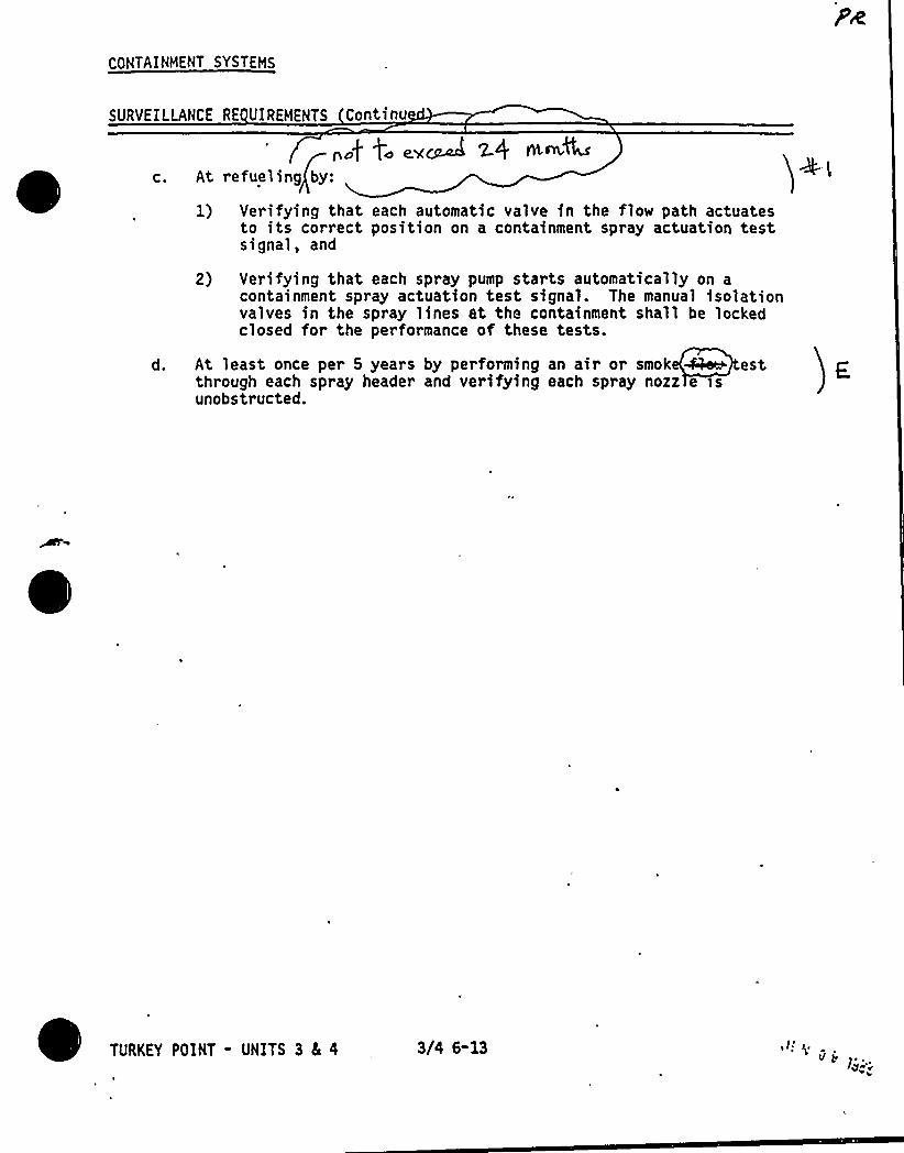
CONTAINMENT SYSTEMS
SURVEILLANCE RE UIREHENTS Continu
C.
d.
„.g f. ~~M x< m,~WAt refueling by:
1) Verifying that each automatic valve in the flow path actuatesto its correct position on a containment spray actuation testsignal, and
2) Verifying that each spray pump starts automatical'ly on acontainment spray actuation test signal. The manual isolationvalves in the spray lines at the containment shall be lockedclosed for the performance of these tests.
At least once per 5 years by performing an air or smok ~ estthrough each spray header and verifying each spray nozz e isunobstructed.
TURKEY POINT - UNITS 3 4 4 3/4 6-13
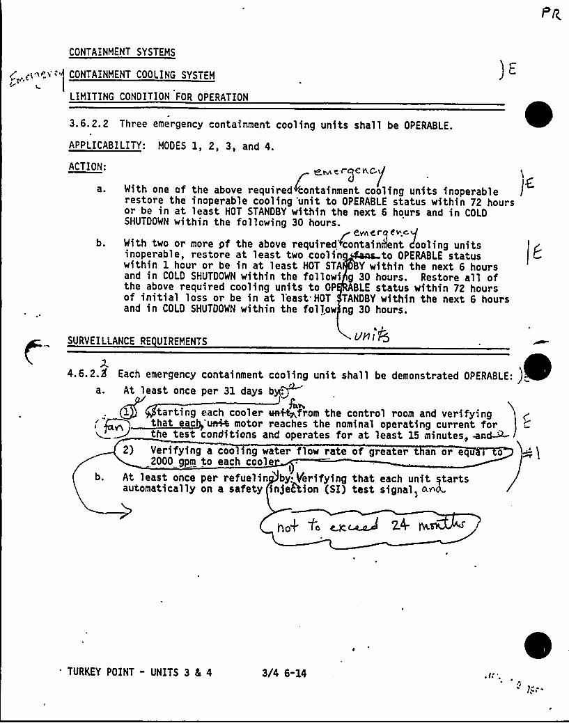
CONTAINMENT SYSTEMS
p(<d'>' CONTAINMENT COOLING SYSTEMl~
LIMITING CONDITION FOR OPERATION
3.6.2.2 Three emergency containment cooling units shall be OPERABLE.
APPLICABILITY: MODES 1, 2, 3, and 4.
ACTION:
a 0
b.
~t ~rqen.C gWith one of the above required ontainment cooling units inoperablerestore the inoperable cooling 'unit to OPERABLE status within 72 hoursor be in at least HOT STANDBY within the next 6 hours and in COLDSHUTDOWN within the following 30 hours.
~ e,vft C. rq e v c gWith two or more yf the above required>contain8ent Pooling unitsinoperable, restore at least two coolin to OPERABLE statuswithin 1 hour or be in at least HOT STA Y within the next 6 hoursand in COLD SHUTDOWN within the followi g 30 hours. Restore all ofthe above required cooling units to OP BLE status within 72 hoursof initial loss or be in at 1'east HOT TANDBY within the next 6 hoursand in COLD SHUTDOWN within the follow ng 30 hours.
SURVEILLANCE RE UIREMENTS uni@
2.4.6.2.8 Each emergency containment cooling unit shall be demonstrated OPERABLE: )
a. At least once per 31 days byo
Ql 1 tarting each cooler ueii4p,from the control room and verifyingthat eac 'un4e motor reaches the nominal operating current forthe test conditions and operates for at least 15 minutes, mnd-st-
2) Verifying a coo ing water flow rate of greater t an or enu o2000 gpm to each cool e
b. At least once per refuelin by: Verifying that each unit startsautomatically on a safety in)eftion (SI) test signal> oA<
2.0 IVL
'URKEY POINT - UNITS 3 4 4 3/4 6-14
47i ; .
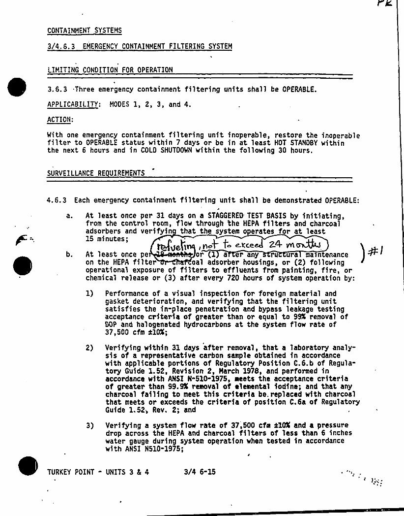
CONTAINMENT SYSTEMS
3/4.6.3 EMERGENCY CONTAINHENT FILTERING SYSTEM
LIHITING CONOITION FOR OPERATION
3.6.3 Three emergency containment filtering units shall be OPERABLE.
APPLICABILITY: MODES 1, 2, 3, and 4.
ACTION:
Mith one emergency containment filtering unit inoperable, restore the inoperablefilter to OPERABLE status within 7 days or be in at least HOT STANOBY withinthe next 6 hours and in COLO SHUTDOWN within the following 30 hours.
SURVEILLANCE RE UIREHENTS
4.6.3 Each emergency containment filtering unit shall be demonstrated OPERABLE:
a. At least once per 31 days on a STAGGERED- TEST BASIS by initiating,from the control room, flow through the HEPA filters and charcoaladsorbers and verifyin that the system operates for at least15 minutes;
C.'KCC.CA 2.4'l~b. At least once pe or (1 a er any ru ura ma ntenance
on the HEPA filter oal adsorber housings, or (2) followingoperational exposure of filters to effluents from painting, fire, orchemical release or (3) after every 720 hours of system operation by:
1) Performance of a visual inspection for foreign material andgasket deterioration, and verifying that the filtering unitsatisfies the in-place penetration and bypass leakage testingacceptance criteria of greater than or equal to 99K removal ofOOP and halogenated hydrocarbons at the system flow rate of37,500 cfm ilOX;
2) Verifying within 31 days after removal, that a laboratory analy-sis of a representative carbon sample obtained in accordancewith applicable portions of Regulatory Position C.S.b of Regula-tory Guide 1.52, Revision 2, March 1978, and performed inaccordance with ANSI N-510-1975, aeets the acceptance criteriaof greater than 99.SX remeval of elemental iodine; and that anycharcoal failing to meet this criteria be. replaced with charcoalthat meets or exceeds the criteria of position C.6a of RegulatoryGuide 1.52; Rev. 2; and
3) Verifying a system flow rate of 37,500 cfm ilOX and a pressuredrop across the HEPA and charcoal filters of less than 6 incheswater gauge during system operation when tested in accordancewith ANSI N510-1975;
TURKEY POINT - UNITS 3 4 4 3/4 6-15
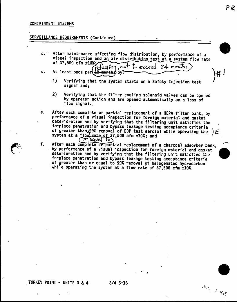
CONTAINMENT SYSTEMS
SURVEILLANCE RE UIREMENTS Continued
c.'fter maintenance affecting flow distribution, by performance of avisual inspection and an air distribut' t t at a system flow rateof 37,500 cfm ale.
~,f„g(~, n.t t. e) c,e4 Za ~M@d. At least once pe by:
1) Verifying that the system starts on a Safety In)ection testsignal and;
2) Verifying that the filter cooling solenoid valves can be openedby operator action and are opened automatically on a loss offlow signal.
e. After each complete or partial replacement of a HEPA filter bank, byperformance of a visual inspection for foreign material and gasketdeterioration and by verifying that the filtering unit satisfies thein-place penetration and bypass leakage testing acceptance criteriaof greater than 9% removal ot Dgp test aeroso'I while operating the j gsystem at a f„ 37,500 cfm ilOX; and"ore Va o
f. After each complete o partial replacement of a charcoal adsorbed bank,by performance'f a visual inspection for foreign material and gasketdeterioration and by verifying that the filtering unit satisfies thein-place penetration and bypass leakage testing acceptance criteriaof greater than or equal to 99K removal of halogenated hydrocarbon*
while operating the system at a flow rate of 37,500 cfm ilOX.
TURKEY POINT - UNITS 3 Ec 4 3/4 6-16I
s ~
~ ~
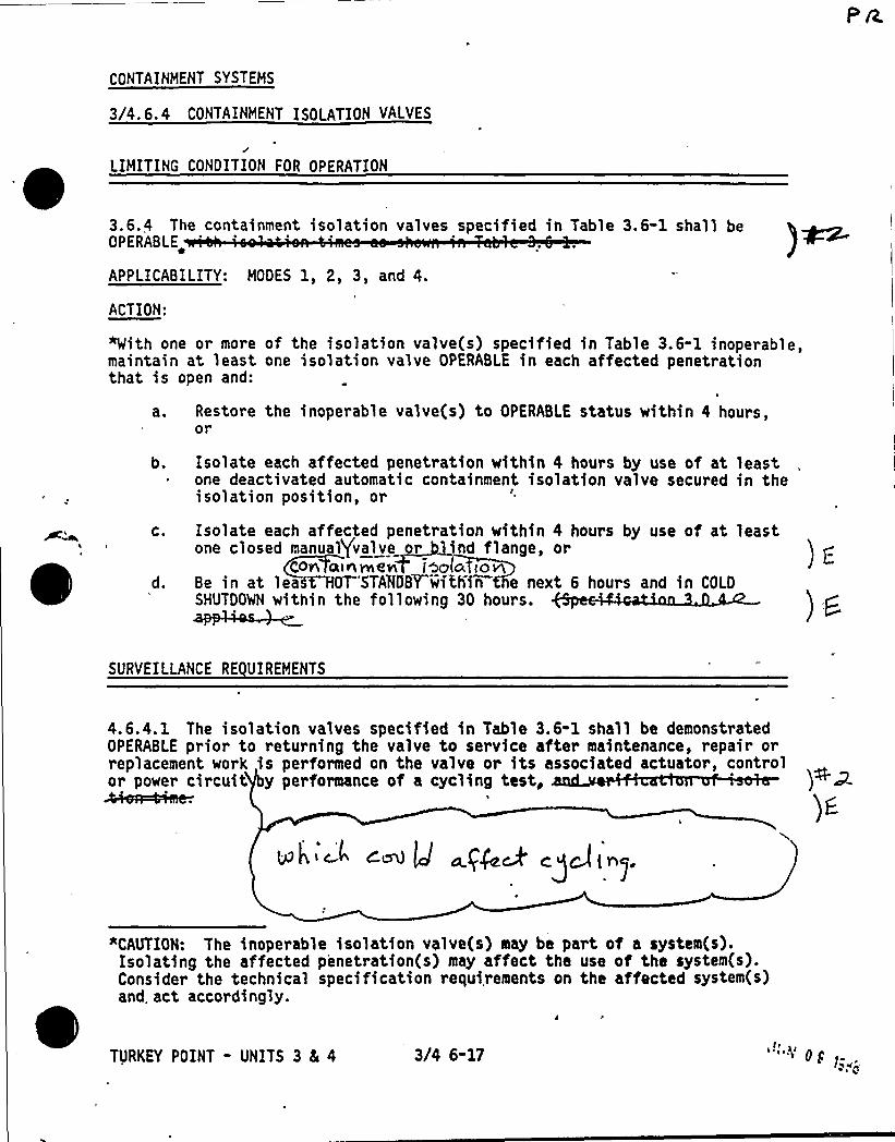
CONTAINMENT SYSTEMS
3/4. 6. 4 CONTAINMENT ISOLATION VALVES
LIMITING CONDITION FOR OPERATION
3.6.4 The containment isolation valves specified in Table 3.6-1 shall beOPERABLE
APPLICABILITY: MODES 1, 2, 3, and 4.
ACTION:
*With one or more of the isolation valve(s) specified in Table 3.6"1 inoperable,maintain at least one isolation valve OPERABLE in each affected penetrationthat is open and:
Restore the inoperable valve(s) to OPERABLE status within 4 hours,or
Isolate each affected penetration within 4 hours by use of at leastone deactivated automatic containment isolation valve secured in theisolation position, or
C.
d.
Isolate each affected penetration within 4 hours by use of at leastone closed manual/valve or ind flange, or
C0+ a~nvne~ l~c ionBe in at lea t HOT'STAMBYwithin e next 6 hours and in COLDSHUTDOWN within the following 30 hours.
SURVEILLANCE RE UIREMENTS
4.6.4.1 The isolation valves specified in Table 3.6-1 shall be demonstratedOPERABLE prior to returning the valve to service after maintenance, repair ofreplacement work is performed on the valve or its associated actuator, controlor power circuit y performance of a cycling test, )NI.~
CM g +gQ~ ~gC'j I~~
"CAUTION: The inoperable isolation valve(s) may be part of a system(s).Isolating the affected penetration(s) may affect the use of the system(s).Consider the technical specification requirements on the affected system(s)and. act accordingly.
TURKEY POINT - UNITS 3 Ec 4 3/4 6-17 "'~'g
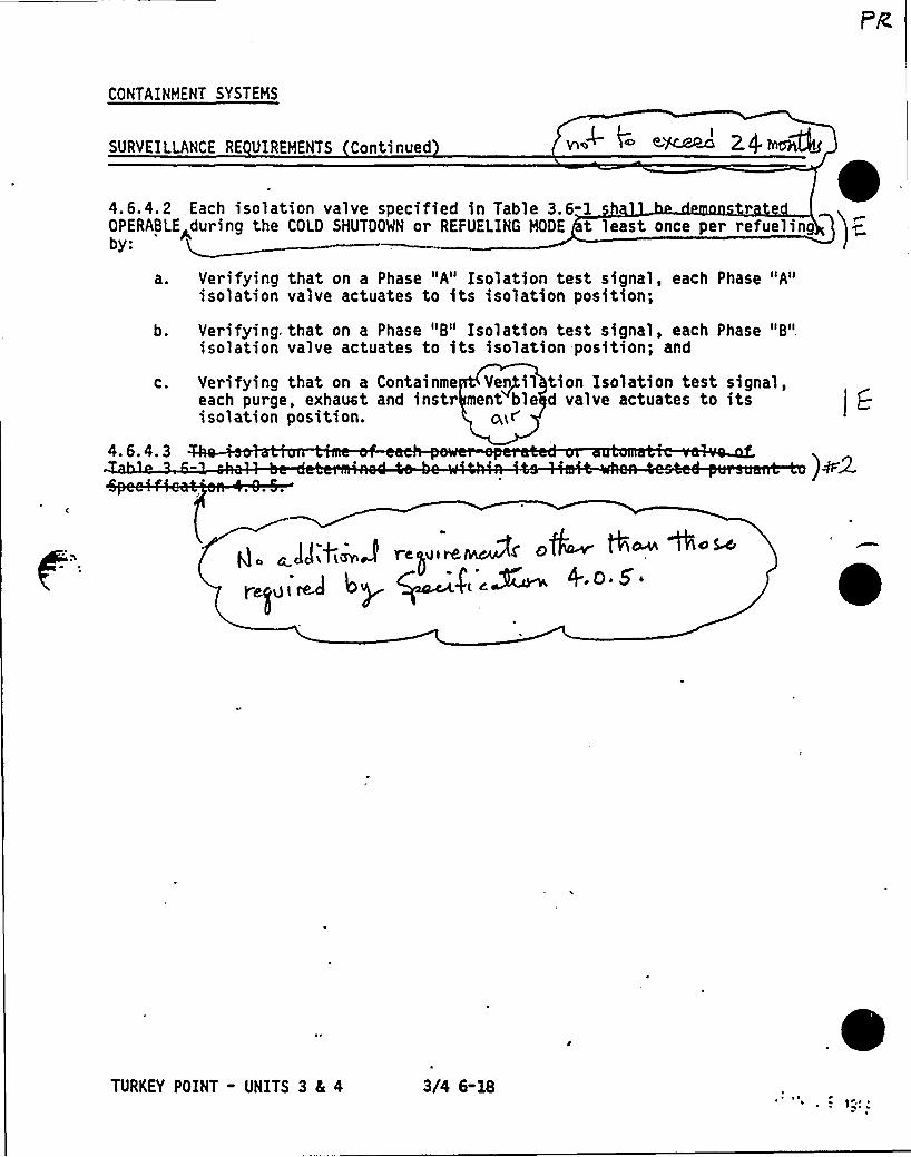
CONTAINMENT SYSTEMS
SURVEILLANCE RE UIREMENTS Continued e'jcAseoI
4 .6.4.2 Each isolation valve specified in Table 3.6-1 rOPERABLE during the COLD SHUTDOWN or REFUELING NODE t least once per refueling
'a ~
b.
C.
4. 6.4. 3
Verifying that on a Phase "A" Isolation test signal, each Phase "A"isolation valve actuates to its isolation position;
Verifying. that on a Phase "B" Isolation test signal, each Phase "B"isolation valve actuates to its isolation position; and
Verifying that on a Containee Vs+nil thon Isolation test signai,each purge, exhaust and instr ment ble d valve actuates to itsisolation position. a,i~
TURKEY POINT - UNITS 3 4 4 3/4 6-18~ ~
) P
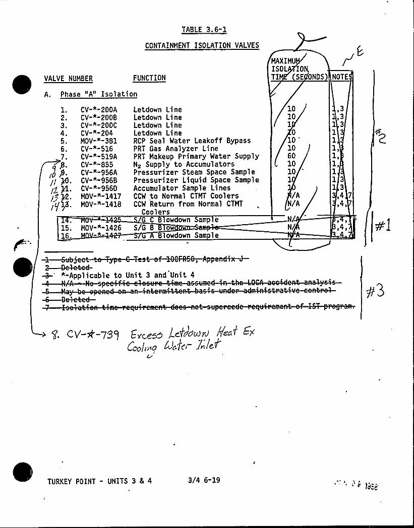
FUNCTIONVALVE NUMBER
A. Phase "A" Isolation
TABLE 3.6-1
CONTAINMENT ISOLATION VALVES
MAXIMUISO L IOTI SE ONDS NOTE
1.2,3.4,5.6 ~
7.
15.16.
CV-"-200ACV-*-200BCV-"-200CCV""-204MOV-"-381CV-"-516CV-"™519ACV-A-855CV-*-956ACV-"-956BCV-"-9560MOV-"-1417MOV-"-1418
MOV-"-1426*
Letdown LineLetdown LineLetdown LineLetdown LineRCP Seal Water Leakoff BypassPRT Gas Analyzer LinePRT Makeup Primary Water SupplyNz Supply to AccumulatorsPressurizer Steam Space SamplePressurizer Liquid Space SampleAccumulator Sample LinesCCW to Normal CTMT CoolersCCW Return from Normal CTMT
CoolersG C 8 owdown amp e
S/G B owlowdown Sam le
10101
010
'0
6010101
/AN/A
/N/
33
1 31111,1)11 31 3
,4 7
$ 40
"-Applicable to Unit 3 and Unit 4
TURKEY POINT - UNITS 3 4 4 3/4 6-19
/ i> ~'Q <!6 r~gg~lia~g II~f+j / ~ ~O'~k'
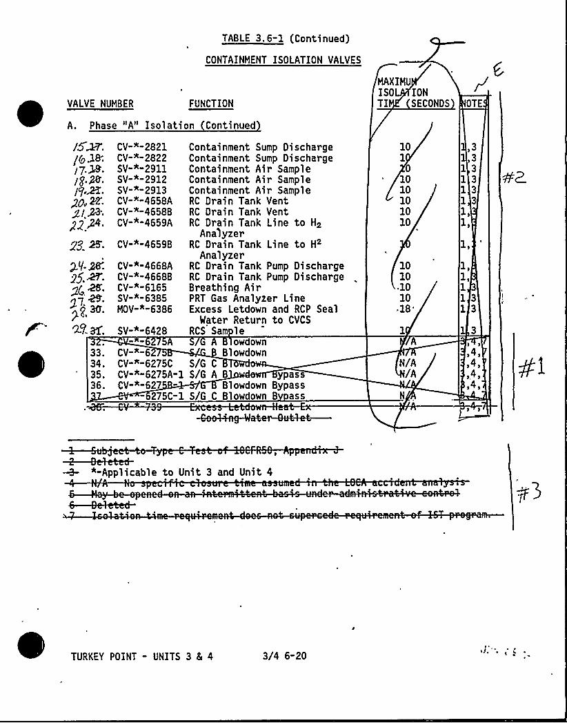
TABLE 3.6-1 (Continued)
CONTAINMENT ISOLATION VA1 VES
~
~ ~
VALVE NUMBER FUNCTION
A. Phase "A" Isolation Continued
MAXIMUISOL IONTI SECONDS OTE
33.34.35.36.
SV-""6428
CV-"-6CV-"-6275CCV-"-6275A-1CV""-627
- 275C-1
CV"""2821CV""-2822SV"""2911SV-"™2912SV-"-2913CV-"-4658ACV-"™4658BCV-*-4659A
gg K CV-"-4659B
CV-"™4668ACV-"-4668BCV-""6165SV-"-6385MOV-""6386
Containment Sump DischargeContainment Sump DischargeContainment Air SampleContainment Air SampleContainment Air SampleRC Drain Tank VentRC Drain Tank VentRC Drain Tank Line to H2
AnalyzerRC Drain Tank Line to H2
AnalyzerRC Drain Tank Pump DischargeRC Drain Tank Pump DischargeBreathing AirPRT Gas Analyzer LineExcess Letdown and RCP Seal
Mater Return to CVCSRCS Sam le
owdownBlowdown
S/G C
S/G A B ypassBlowdown Bypass
S/G C Blowdown B ass
101
01010101010
1010.1010
-18'/A
/A
33
1 31 31 31 3
1,1 j
1,1 $
11 313
l41~4)~4),4,
"-Applicable to Unit 3 and Unit 4
TURKEY POINT " UNITS 3 8( 4 3/4 6-20~ I, ''
~ i'',

, Pe.d;:(P~
/e+ ../
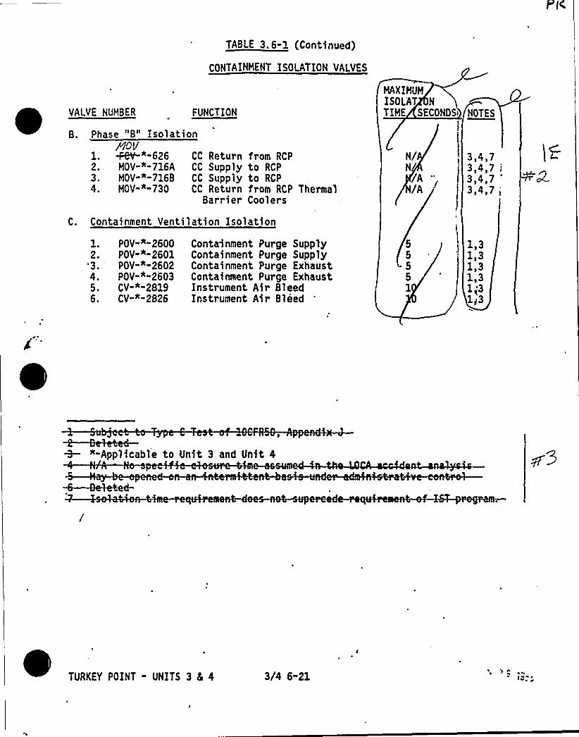
VALVE NUHBER
B. Phase "B" Isolation
FUNCTION
TABLE 3. 6-1 (Continued)
CONTAINHENT ISOLATION VALVES
HAXIHUMISO LAT N
TIHE SECONDS'OTES
1.2.3.4.
<OY~*-626HOV"'™716AHOV-"-716BHOV-*-730
CC Return from RCPCC Supply to RCPCC Supply to RCPCC Return from RCP Thermal
Bar rier Cool ers
3,4,73,4,7 i
3,4,7 "
3,4,7 t
C. Containment Ventilation Isolation
1.2.
"3.
5.6.
POV-"™2600POV-"-2601POV-*-2602POV-"-26Q3CV-""2819CV""-2826
Containment Purge SupplyContainment Purge SupplyContainment Purge ExhaustContainment Purge ExhaustInstrument Air BleedInstrument Air Bleed
1.313131,31 $ 31i3
"-Applicable to Unit 3 and Unit 4
TURKEY POINT - UNITS 3 5 4 3/4 6-21't ~v ~ ~
~ f4% ~V
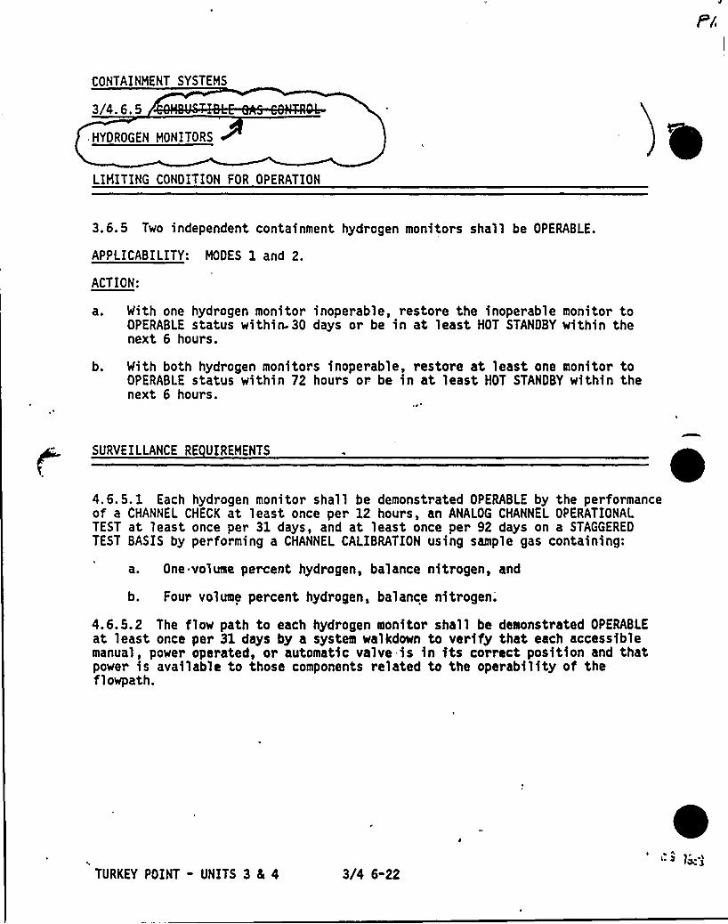
CONTAINMENT SYSTEMS
3/4.6.5
HYDROGEN MONITORS
LIMITING CONDITION FOR OPERATION
3.6.5 Two independent containment hydrogen monitors shall be OPERABLE.
APPLICABILITY: MODES 1 and 2.
ACTION:
a. With one hydrogen monitor inoperable, restore the inoperable monitor toOPERABLE status within- 30 days or be in at least HOT STANDBY within thenext 6 hours.
b. With both hydrogen monitors inoperable, restore at least one monitor toOPERABLE status within 72 hours or be in at least HOT STANDBY within thenext 6 hours.
SURVEILLANCE RE UIREMENTS
4.6.5. 1 Each hydrogen monitor shall be demonstrated OPERABLE by the performanceof a CHANNEL CHECK at least once per 12 hours, an ANALOG CHANNEL OPERATIONALTEST at least once per 31 days, and at least once per 92 days on a STAGGEREDTEST BASIS by performing a CHANNEL CALIBRATION using sample gas containing:
a. One volume percent hydrogen, balance nitrogen, and
b. Four volume percent hydrogen, balance nitrogen.
4.6.5.2 The flow path to each hydrogen monitor shall be demonstrated OPERABLEat least once per 31 days by a system walkdown to verify that each accessiblemanual, power operated, or automatic valve is in its correct position and thatpower is available to those components related to the operability of theflowpath.
TURKEY POINT - UNITS 3 4 4 3/4 6"22
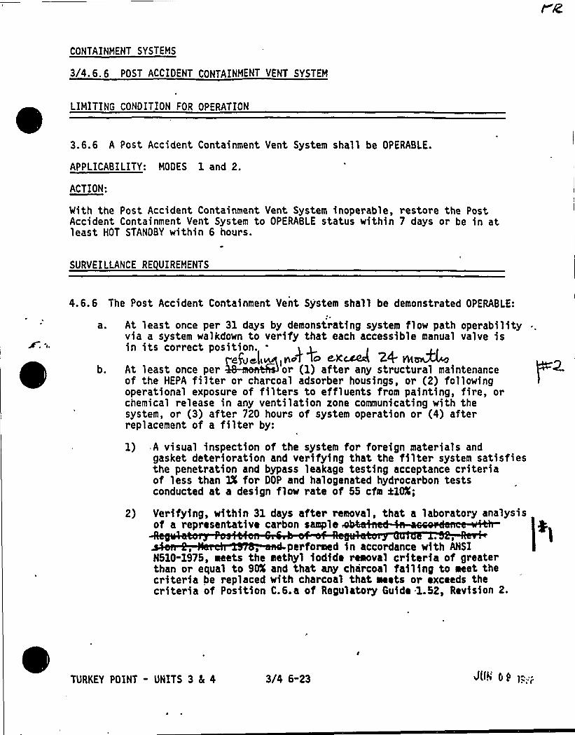
CONTAINMENT SYSTEMS
3/4.6.6 POST ACCIDENT CONTAINMENT VENT SYSTEM
LIMITING CONDITION FOR OPERATION
3.6.6 A Post Accident Containment Vent System shall be OPERABLE.
APPLICABILITY: MODES 1 and 2.
ACTION:
With the Post Accident Containment Vent System inoperable, restore the PostAccident Containment Vent System to OPERABLE status within 7 days or be in atleast HOT STANDBY within 6 hours.
SURVEILLANCE RE UIREMENTS
4.6.6 The Post Accident Containment Vent System shall be demonstrated OPERABLE:
0 b.
At least once per 31 days by demonstrating system flow path operabilityvia a system walkdown to verify that each accessible manual valve isin its correct position.-
,nA 4o ~xM 24. w~
At least once per or (1) after any structural maintenanceof the HEPA filter or charcoal adsorber housings, or (2) followingoperational exposure of filters to effluents from painting, fire, orchemical release in any ventilation zone communicating with thesystem, or (3) after 720 hours of system operation or (4) afterreplacement of a filter by:
1) A visual inspection of the system for foreign materials andgasket deterioration and verifying that the filter system satisfiesthe penetration and bypass leakage testing acceptance criteriaof less than 1X for DOP and halogenated hydrocarbon testsconducted at a design flow rate of 55 cfm ilOX;
2) Verifying, within 31 days after removal, that a laboratory analysisof a representative carbon sample
performed in accordance with ANSIN510-1975, meets the methyl iodide removal criteria of greaterthan or equal to St% and that any charcoal failing to Neet thecriteria be replaced with charcoal that meets or exceeds thecriteria of Position C.6.a of Regulatory Guide 1.52, Revision 2.
TURKEY POINT - UNITS 3 5 4 3/4 6-23 J(ft'& >:;;.
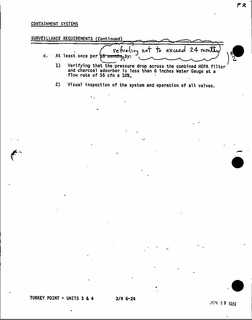
CONTAINMENT SYSTEMS
SURVEILLANCE RE UIREMENTS Continued
r~k,g;.~ ~.4 t; ~x~ z4 n~c. At least once per Rby
1) Verifying that the pressure drop across the combined HEPA filterand charcoal adsorber is less than 6 inches Water Gauge at aflow rate of 55 cfm k 10K,
2) Visual inspection of the system and operation of all valves.
0
TURKEY POINT - UNITS 3 4 4 3/4 6-24":<' 9 H>a
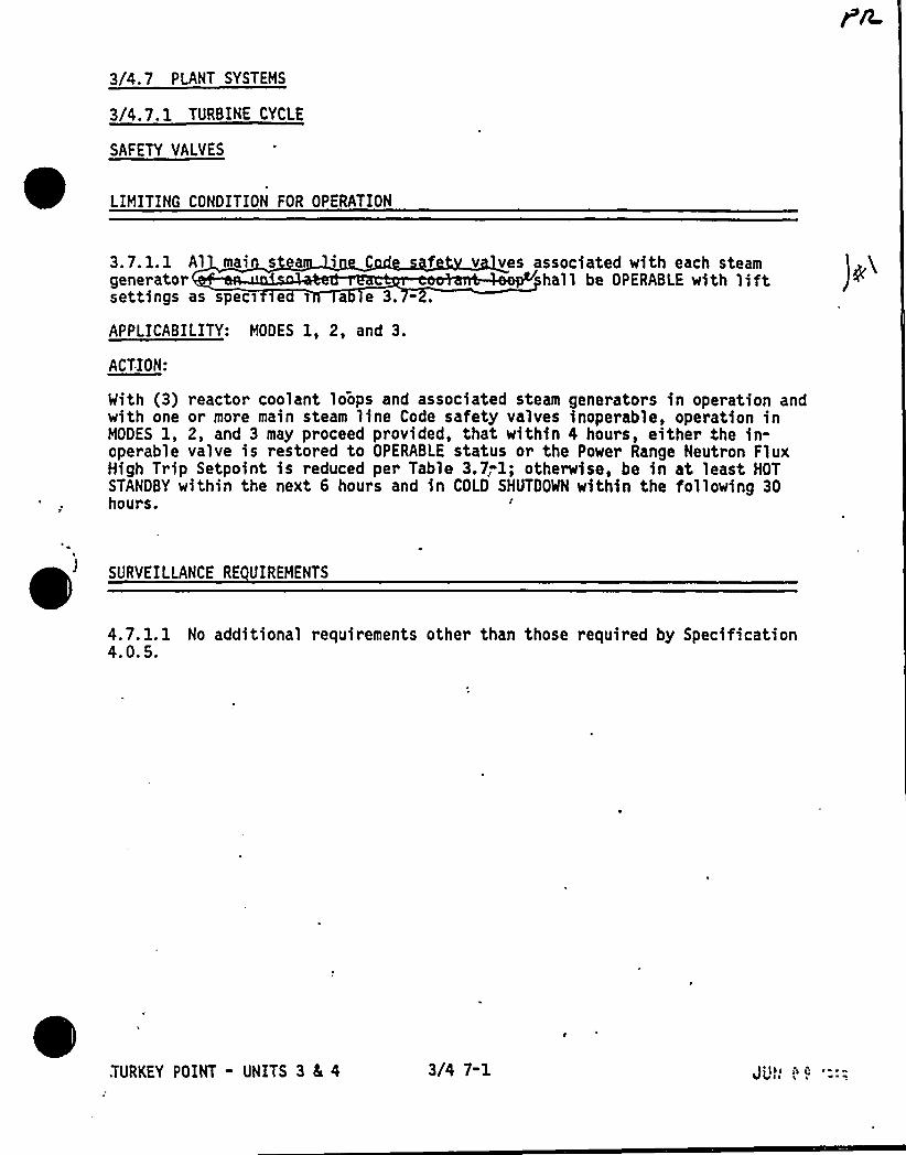
3/4.7 PLANT SYSTEMS
3/4.7.1 TURBINE CYCLE
SAFETY VALVES
f v ves associated with each steamhall be OPERABLE with lift3.7.1.1 Al mai s ea i C
generatorsettings as specs se s a e 3. - .
APPLICABILITY: MODES 1, 2, and 3.
ACTION:
With (3) reactor coolant loops and associated steam generators in operation andwith one or more main steam line Code safety valves inoperable, operation inMODES 1, 2, and 3 may proceed provided, that within 4 hours, either the in-operable valve is restored to OPERABLE status or the Power Range Neutron FluxHigh Trip Setpoint is reduced per Table 3.7;1; otherwise, be in at least HOTSTANDBY within the next 6 hours and in COLD SHUTDOWN within the following 30hours. A
4.7. 1. 1 No additional requirements other than those required by Specification4. 0. 5.
TURKEY POINT - UNITS 3 4 4 3/4 7-1 ) [lgJ'l ~ a ~
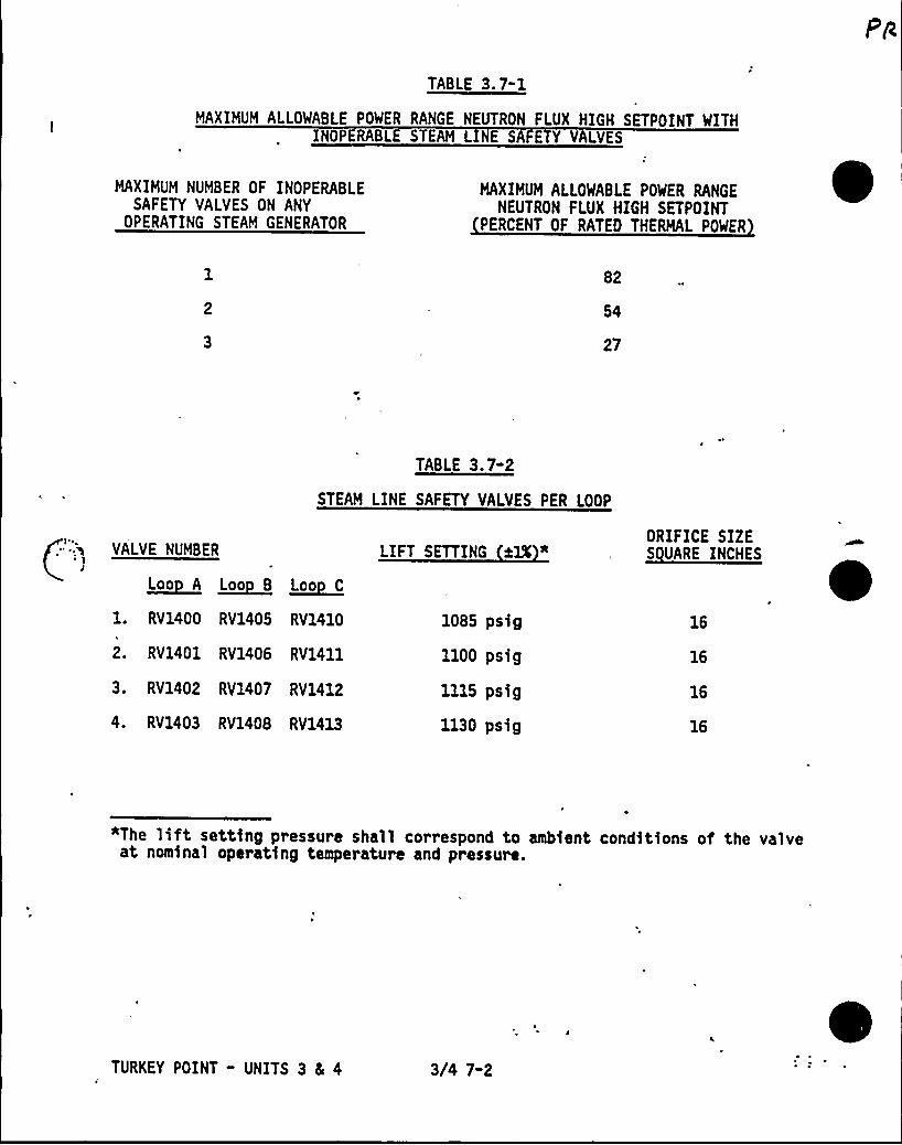
TABLE 3.7-1
MAXIMUM ALLOWABLE POWER RANGE NEUTRON FLUX HIGH SETPOINT WITHINOPERABL STEAM L E SA E Y VALVES
MAXIMUM NUMBER OF INOPERABLESAFETY VALVES ON ANY
OPERATING STEAM GENERATOR
MAXIMUM ALLOWABLE POWER RANGENEUTRON FLUX HIGH SETPOINT
PERCENT OF RATED THERMAL POWER
82
54
27
TABLE 3.7-2
STEAM LINE SAFETY VALVES PER LOOP
VALVE NUMBER
~Loo A ~Loo 8 ~Loo C
1. RV1400 RV1405 RV1410
2. RV1401 RV1406 RV1411
3. RV1402 RY1407 RV1412
4. RV1403 RV1408 RV1413
LIFT SETTING %IX "
1085 psig
1100 psig
1115 psig
1130 psig
ORIFICE SIZES UARE INCHES
16
16
16
16
*The lift setting pressure shall correspond to ambient conditions of the valveat nominal operating temperature and pressure.
TURKEY POINT - UNITS 3 Ec 4 3/4 7-2
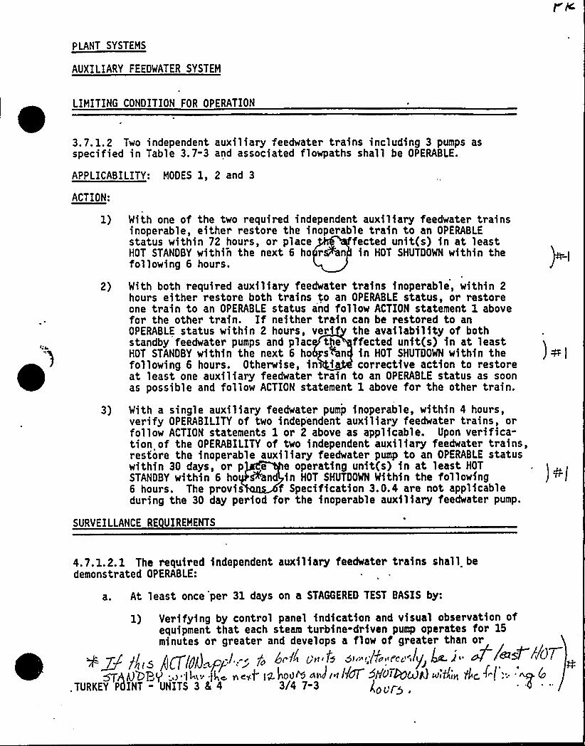
PLANT SYSTEMS
AUXILIARYFEEDWATER SYSTEM
LIMITING CONDITION FOR OPERATION
0
3.7.1.2 Two independent auxiliary feedwater trains including 3 pumps asspecified in Table 3.7-3 and associated flowpaths shall be OPERABLE.
APPLICABILITY: MODES 1, 2 and 3
ACTION:
1) With one of the two required independent auxiliary feedwater trainsinoperable, either restore the inoperable train to an OPERABLEstatus within 72 hours, or place fected unit(s) in at leastHOT STANDBY within the next 6 ho r n in HOT SHUTDOWN within thefollowing 6 hours.
2) With both required auxiliary feedwater trains inoperable, within 2hours either restore both trains to an OPERABLE status, or restoreone train to an OPERABLE status and follow ACTION statement 1 abovefor the other train. If neither train can be restored to anOPERABLE status within 2 hours, verif the availability of bothstandby feedwater pumps and plac tPe ffected unit(s) in at leastHOT STANDBY within the next 6 ho s%n in HOT SHUTDOWN within thefollowing 6 hours. Otherwise, in i corrective action to restoreat least one auxiliary feedwater train to an OPERABLE status as soonas possible and follow ACTION statement 1 above for the other train.
3) With a single auxiliary feedwater pump inoperable, within 4 hours,verify OPERABILITY of two independent auxiliary feedwater trains, orfollow ACTION statements 1 or 2 above as applicable. Upon verifica-tion of the OPERABILITY of two independent auxiliary feedwater trains,restore the inoperable auxiliary feedwater pump to an OPERABLE statuswithin 30 days, or p e e operating unit(s) in at least HOT
STANDBY within 6 ho Pan in HOT SHUTDOWN Within the following6 hours. The provis f Specification 3.0.4 are not applicableduring the 30 day period for the inoperable auxiliary feedwater pump.
SURVEILLANCE RE UIREMENTS
4.7.1.2.1 The required independent auxiliary feedwater trains shall bedemonstrated OPERABLE:
a. At least once 'per 31 days on a STAGGERED TEST BASIS by:
1) Verifying by control panel indication and visual observation ofequipment that each steam turbine-driven pump operates for 15minutes or greater and develops a flow of greater than or
/j > gg7/y(J p-.l.,- f~ kc X/i c nfl 5i'~ ;j7'a Pcs:.I/i> .g )'fl@W~~~I~AO'OBQ,> '14m <4c, new/ ]g Rod~~ an) (n IKON 5h'045CdR) u>'tlirt lk
f~l'TURKEY
POINT - UNITS 3 8 4 3 4 7 3 "OU/5
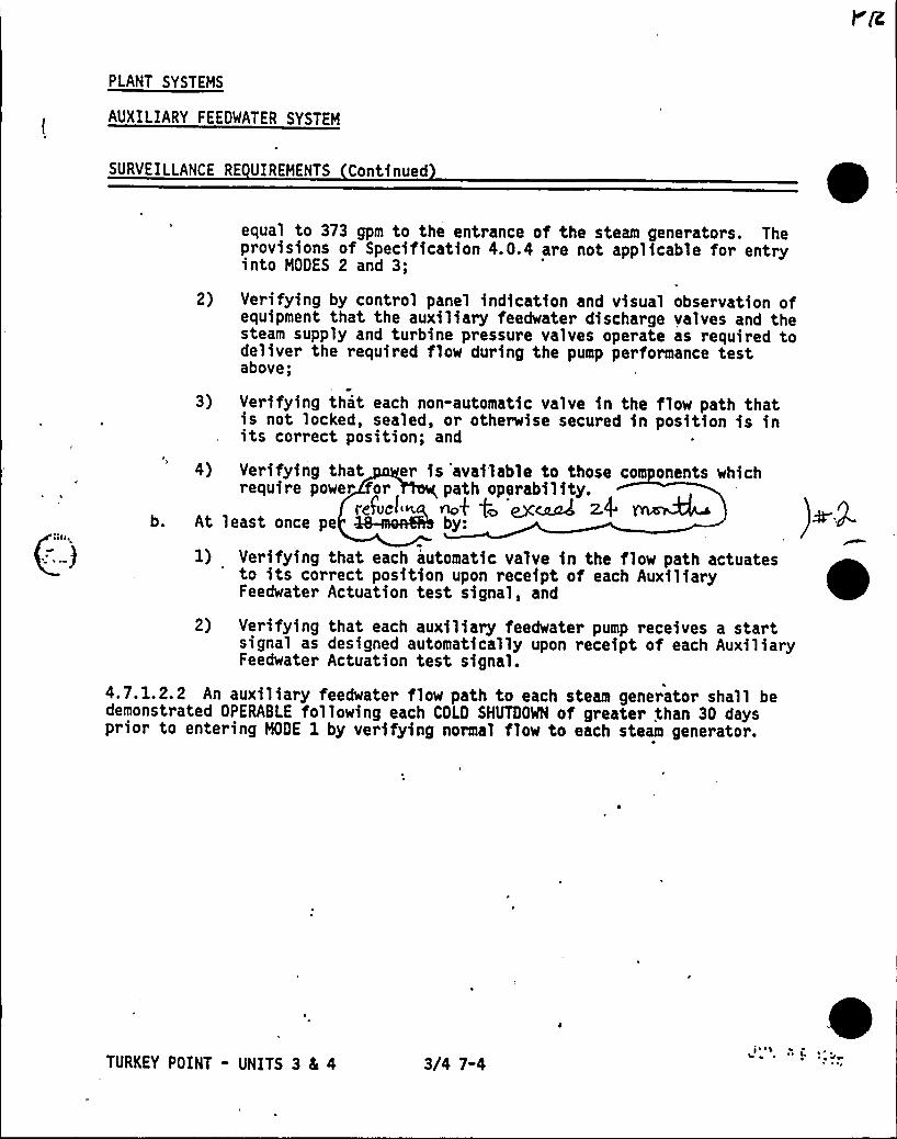
PLANT SYSTEMS
AUXILIARY FEEDMATER SYSTEM
SURVEILLANCE RE UIREHENTS Continued
b.
equal to 373 gpm to the entrance of the steam generators. Theprovisions of Specification 4.0.4 are not applicable for entryinto MODES 2 and 3;
2) Verifying by control panel indication and visual observation ofequipment that the auxiliary feedwater discharge valves and thesteam supply and turbine pressure valves operate as required todeliver the required flow during the pump performance testabove;
3) Verifying that each non-automatic valve in the flow path thatis not locked, sealed, or otherwise secured in position is inits correct position; and
4) Verifying that er is 'available to those corn onents whichrequire power or path operability.
ref'vcr ~k t ex~ z.4 ~At least once pe by:
1) Verifying that each automatic valve in the flow path actuatesto its correct position upon receipt of each AuxiliaryFeedwater Actuation test signal, and
2) Verifying that each auxiliary feedwater pump receives a startsignal as designed automatically upon receipt of each AuxiliaryFeedwater Actuation test signal.
4.7.1.2.2 An auxiliary feedwater flow path to each steam generator shall bedemonstrated OPERABLE following each COLD SHUTDOWN of greater than 30 daysprior to entering MODE 1 by verifying normal flow to each steam generator.
TURKEY POINT - UNITS 3 Ec 4 3/4 7-4~ ~
0
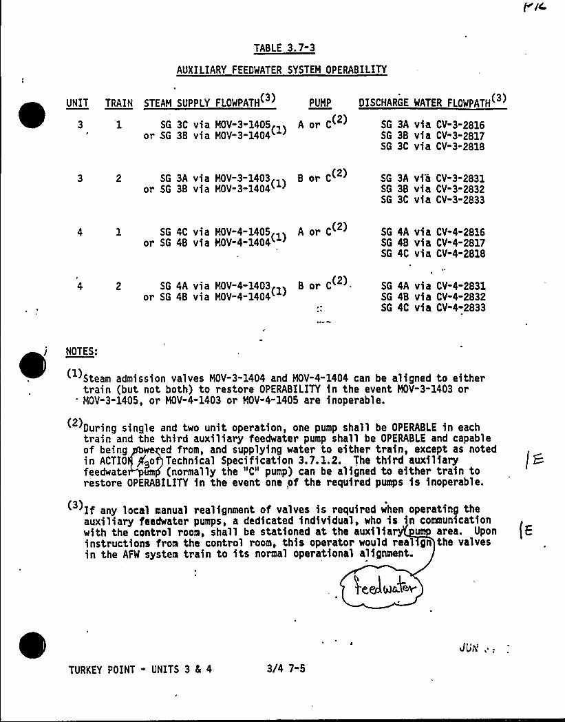
TABLE 3.7-3
AUXILIARYFEEDWATER SYSTEM OPERABILITY
UNIT TRAIN STEAM SUPPLY FLOWPATH PUMP OISCHARGE MATER FLOWPATH
3 '1 SG 3C via MOV-3-1405<)
A or C SG 3A via CV-3-2816(2)or SG 3B via MOV-3-1404 (1)
SG 3B via CV-3-2817SG 3C via CV-3-2818
SG 3A via MOV-3-14031
B or C
or SG 3B via MOV-3-1404( ) SG 3A via CV-3-2831SG 3B via CV-3-2832SG 3C via CV-3-2833
SG 4C via MOV-4-1405<>
A or C(2)
or SG 4B via HOV-4-1404 (1) SG 4A via CV-4-2816SG 4B via CV-4-2817SG 4C via CV-4-2818
SG 4A via MOV-4-1403>
B or C
or SG 4B via HOV-4-1404SG 4A via CV-4-2831SG 4B via CV-4-2832SG 4C via CV-4-2833
ei NOTES:
Steam admission valves MOV-3-1404 and MOV-4-1404 can be aligned to eithertrain (but not both) to restore OPERABILITY in the event MOV-3-1403 or
* MOV-3-1405, or MOV-4-1403 or MOV-4-1405 are inoperable.
During single and two unit operation, one pump shall be OPERABLE in eachtrain and the third auxiliary feedwater pump shall be OPERABLE and capableof being ed from, and supplying water to either train, except as notedin ACTIO P>o Technical Specification 3.7.1.2. The third auxiliaryfeedwate (normally the "C" pump) can be aligned to either train torestore OPERABILITY in the event one,of the required pumps is inoperable.
If any local manual realignment of valves is required when operating theauxiliary feedwater pumps, a dedicated individual, who is in communicationwith the control room, shall be stationed at the auxilia area. Uponinstructions from the control room, this operator would real gn the valvesin the AFW system train to its normal operational alignment.
TURKEY POINT - UNITS 3 8 4 3/4 7-5
Sii N',,
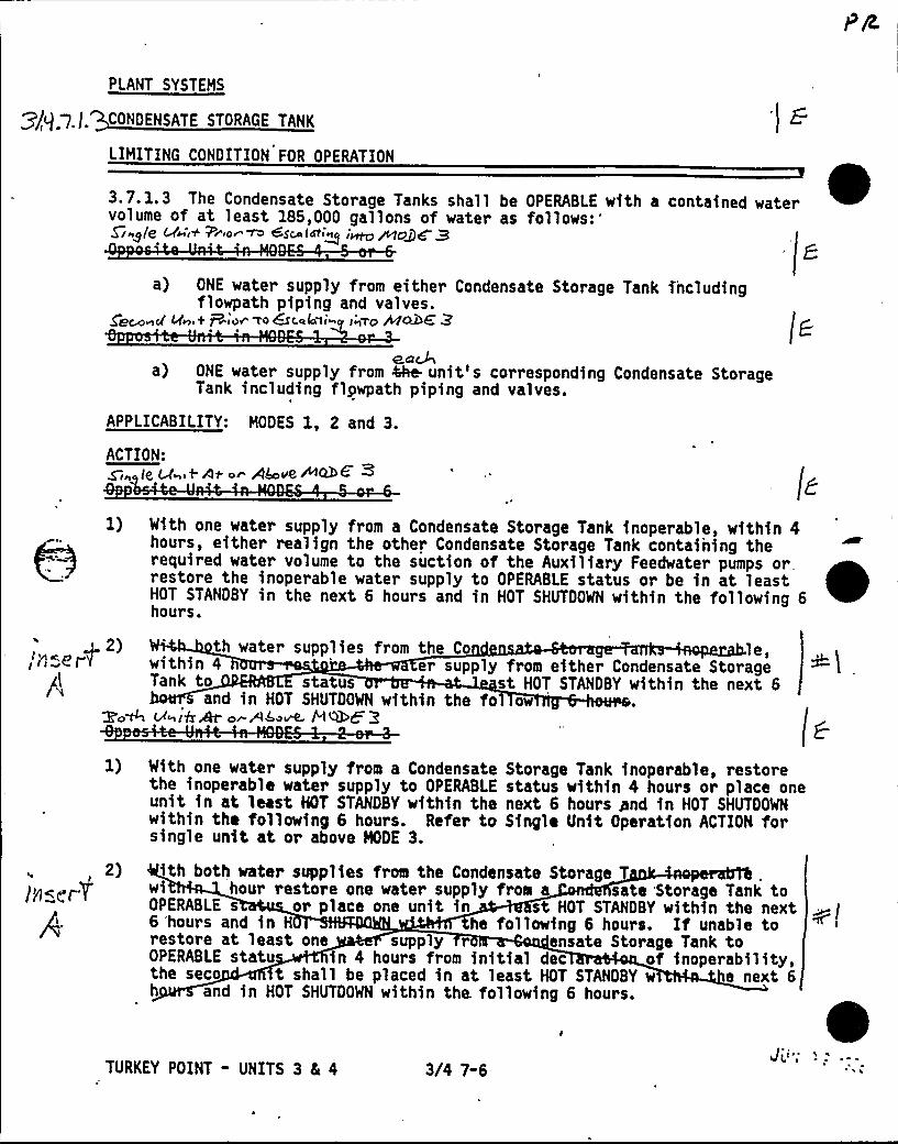
PLANT SYSTEHS
CONDENSATE STORAGE TANK
LIMITING CONDITION FOR OPERATION
3.7.1.3 The Condensate Storage Tanks shall be OPERABLE with a contained watervolume of at least 185,000 gallons of water as
follows:'/Ag/QMb"i+ 7~iot ~ 4$ca(~i~I i~~Ops Q~ ~ 8
a) ONE water supply from either Condensate Storage Tank ihcludingflowpath piping and valves.
Qe~~g Lfng+ +I@V TO &Cata l(w ItIl'g /kgOQQ P
~aWa) ONE water supply from 4he- unit's corresponding Condensate Storage
Tank including flpwpath piping and valves.
APPLICABILITY: HODES 1, 2 and 3.
ACTION:It ll t At o AkovCP&+ +
1) With one water supply from a Condensate Storage Tank inoperable, within 4hours, either realign the other Condensate Storage Tank containing therequired water volume to the suction of the Auxiliary Feedwater pumps orrestore the inoperable water supply to OPERABLE status or be in at least l
HOT STANDBY in the next 6 hours and in HOT SHUTDOWN within the following 6hours.
~ 2) th water supplies from the Co le,;rl~8f Y within 4 er supply from either Condensate StorageTank to status st HOT STANDBY within the next 6
and in HOT SHUTDOWN within the fo owWoW M~r*At e~A4~~ HC>E3
2))pcgp7
With one water supply from a Condensate Storage Tank inoperable, restorethe inoperable water supply to OPERABLE status within 4 hours or place oneunit in at least HOT STANDBY within the next 6 hours and in HOT SHUTDOWNwithin tht following 6 hours. Refer to Single Unit Operation ACTION forsingle unit at or above HODE 3.
ith both water supplies from the Condensate Storagewi hour restore one water supply from sate Storage Tank toOPERABLE s or place one unit in st HOT STANDBY within the next6 'hours and in H he following 6 hours. If unable torestore at least one supply ensate Storage Tank toOPERABLE statu in 4 hours from initial dec of inoperability,the seco t shall be placed in at least HOT STANDBY w e next 6h and in HOT SHUTDOWN within the. following 6 hours.
TURKEY POINT - UNITS 3 SL 4 3/4 7-6 t ~

-f,s >! lW
/
/ w ~ICQ5ieraue/ ~
7A vi&51
ld ~IG I'8 ,'." np
stoJ~Mewf
~g
fQC J0l ~Q~
CQf'l ~~6 ) JC
to t~ jOI .8
g//~ Ac7ioLi
ct" Q I ta vI[4 a
ted ~
ca<4 gee Co~de ...c i'e,"'ocaae(i
G~ 9 6 '4.8
Q.NDVP- TG f
0
I ~W~ion3 r ivg L~ 5M~K
PLANT SYSTEHS
SURVEILLANCE RE UIREHENTS Continued
4.7.1.3 The Condensate Storage Tanks shall be demonstrated OPERABLE at leastonce per 12 hours by verifying the contained water volume is within its limitwhen the tank is the supply source for the auxiliary feedwater pumps.
TURKEY POINT - UNITS 3 8E 4 3/4 7-7
PLANT SYSTEHS
SPECIFIC ACTIVITY
LIHITING CONDITION FOR OPERATION
3.7. 1.4 The specific activity of the Secondary Coolant System shall be lessthan or equal to 0. 10 microCurie/gram DOSE E(UIVALENT I-131.
APPLICABILITY: HODES 1, 2, 3, and 4.
ACTION:
With the specific activity of the Secondary Coolant System greater than 0.10microCurie/gram DOSE EQUIVALENT I-131, be in at least HOT STANDBY within 6hours and in COLO SHUTDOWN within the following 30 hours.
SURVEILLANCE RE UIREHENTS
4.7.1.4 The specific activity of the Secondary Coolant System shall bedetermined to be within the limit by performance of the sampling and analysisprogram of Table 4.7-1.
'TURKEY POINT - UNITS 3 4 4 3/4 7-8
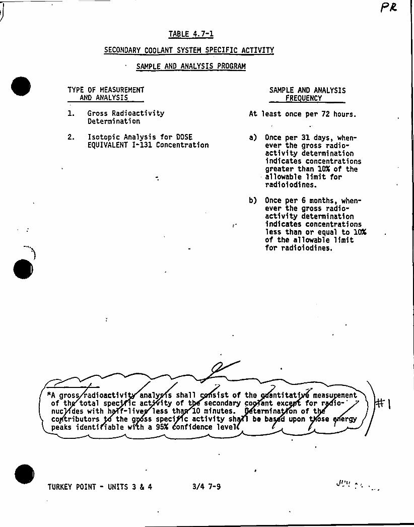
TABLE 4.7"1
SECONDARY COOLANT SYSTEM SPECIFIC ACTIVITY
SAMPLE AND ANALYSIS PROGRAM
TYPE OF MEASUREMENTAND ANALYSIS
1. Gross RadioactivityDetermination
2. Isotopic Analysis for DOSEE(UIVALENT I-131 Concentration
SAMPLE AND ANALYSISFRE UENCY
At least once per 72 hours.
a) Once per 31 days, when-ever the gross radio-activity determinationindicates concentrationsgreater than 10X of theallowable limit forradioiodines.
b) Once per 6 months, when-ever the gross radio-activity determinationindicates concentrationsless than or equal to lOXof the allowable limitfor radioiodines.
"A gross radioactivi analy s shall sist of the antitati measu ementof th total spec c act ity of t secondary co ant exc for r
io-'uc
des with h f-live less th IO minutes. termina on of tco tributors the g ss speci c activity sh be ba d upon ose ergypeaks identi iable w' a 95K onfidence level
TURKEY POINT - UNITS 3 Ec 4 3/4 7-9

PLANT SYSTEMS
HAIN STEAM LINE ISOLATION VALVES
LIMITING CONDITION FOR OPERATION
3.7.1.5 Each main steam line isolation valve (HSIV) shall be OPERABLE.
APPLICABILITY: MODES 1, 2, and 3.
ACTION:
MODE 1:
With one MSIV inoperable but open, POWER OPERATION may continue~
~rovided the inoperablg valve is restored to OPERABLE status within24'ours; otherwise be i OT STANDBY within the next 6 hours and
sn HOT SHUTDOWN within the following 6 hours.
MODES 2 and 3: a (e.4With one HSIV inoperable, subsequent operation in MODE 2 or 3 ma roceedprovided the isolation valve Is malntalned closed. Othervlse, be n OT 'gSTANDBY within the next 6 hours and in HOT SHUTDOWN within the follow ng6 hours.
SURVEILLANCE RE UIREHENTS
4.7.1.5 'ach MSIV shall be demonstrated OPERABLE by verifying full closurewithin 5 seconds when tested pursuant to Specification 4.0.5. The provisionsof Specification 4.0.4 are not applicable for entry into HODE 3. P2
TURKEY POINT - UNITS 3 8t 4 3/4 7-10

PLANT SYSTEMS
STANDBY FEEDWATER SYSTEM
LIMITING CONDITION FOR OPERATION
3.7. 1.6 Two standby feedwater pumps shall be OPERABLE" and at least 60,000gallons of water (available volume), shall be in the Demineralized WaterStorage Tank"".
APPLICABILITY: MODES 1, 2 and 3
ACTION:
b.
With one standby feedwater pump inoperable, restore the inoperable pumpsto available status within 30 days or submit a SPECIAL REPORT per 3.7. 1.6d.
With both standby feedwater pumps inoperable: g~~yQ'ICa(1. Within 24 hours, notify the NRC and provide cause for
and plans to restore pump(s).to status and,
2. Submit a SPECIAL REPORT per 3.7.1.6d." Q~g.//LANc. With less than 60,000 gallons of water in the Demineralized Water Storage
Tank restore the available volume to at least 60 00 lions within 24hours or submit a SPECIAL REPORT per 3.7.1.6d.
~n~eV4td. If a SPECIAL REPORT is required per the above sp cs ca ons submit a
report describing the cause of the , action taken and aschedule for restoration within 30 da s in accordance with 6.9.2.
E'. The Isrovisirns eF + >4,'< 1'iirn s.o.Z are hot apphavuk4 .SURVEIL U EMENTS
4.7. 1.6. 1 The Demineralized Water Storage tank water volume shall be deter-mined to be within limits at least once per 24 hours.
4.7.1.6.2 At least monthly verify the standby feedwater pumps are OPERABLE- bytesting in recirculation on a STAGGERED TEST BASIS.
no+to ~X~ 24- +~ ~4.7.1.6.3 During each refueling<eu4age; verify operability of the respectivestandby feedwater pump by powering from the non-safety grade diesel generatorsand providing feedwater to the steam generators.
These pumps are not safety related equipment and do not require plant safetyrelated emergency power sources for operability
"*The Demineralized Water 'Storage Tank is non-safet grade.
'.IIV'4flounged~Is lnotlYlvllg l Die~~
3/4 7-11
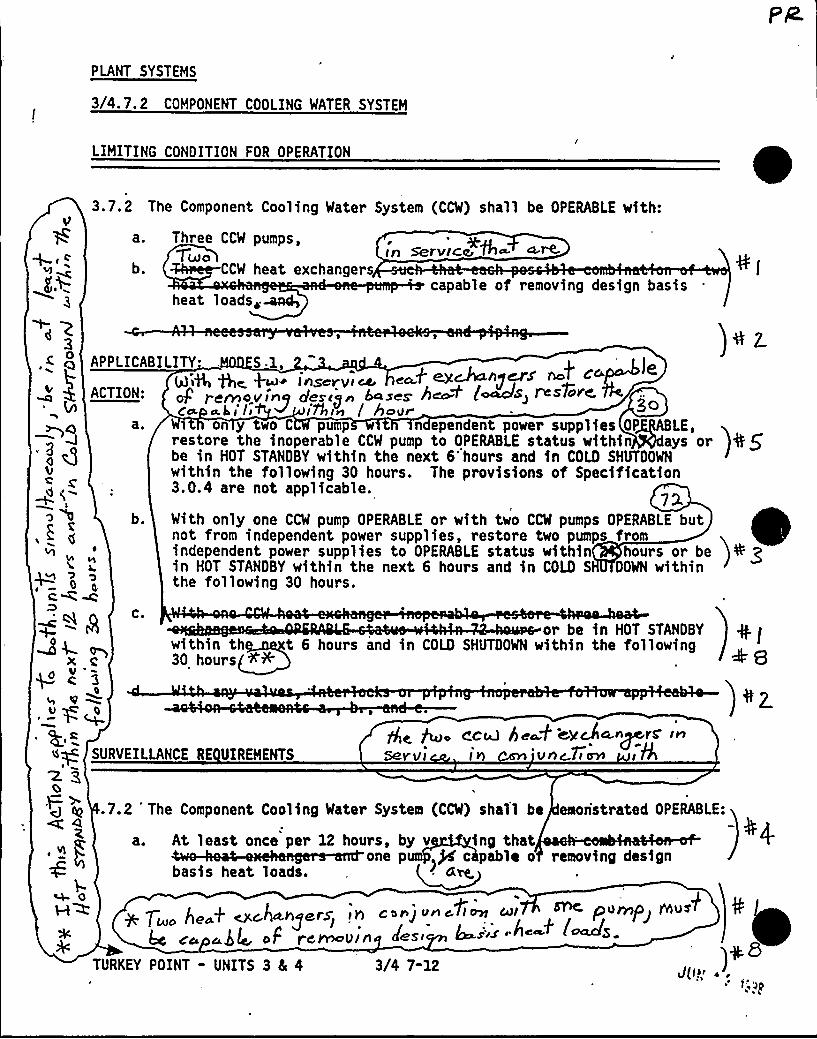
PLANT SYSTEMS
3/4.7.2 COMPONENT COOLING WATER SYSTEM
LIMITING CONDITION FOR OPERATION
3.7.2 The Component Cooling Water System (CCW) shall be OPERABLE with:
Three CCW pumps,%LAO tn ServlCc, 7'~ a.~
CCW heat exchangers+ s C
gQ
EI
O
b.capable of removing design basis
heat loads~~
restore the knoperahle CCW pump to OPERABLE status w$ th$ n ays or )4 gbe in HOT STANDBY within the next 6'hours and in COLD SHUTOOWNwithin the following 30 hours. The provisions of Specification3.0.4 are not applicable.
73.With only one CCW pump OPERABLE or with two CCW pumps OPERABLE butnot from independent power supplies, restore two pumps fromindependent power supplies to OPERABLE status within hours or bein HOT STANDBY within the next 6 hours and in COLD S DOWN withinthe following 30 hours.
z "o
+1a
C,W M
b.
C.ol be in HOT STANOBY + ~within th t 6 hours and in COLD SHUTOOWN within the following
30 hours <+ +8c
lB
APPLICABILITY S 1,insevvrpee
oP rernovine riescj n A»see heo:P (e»efs restore ~e»»tii ~ iyhin i beer Qo
ae on y two C pump n ependent power supplies OP LE,
URVEILLANCE RE UIREMENTS
<CaJ hespf egcJl4.n~rS'~5ayl/I I kj vAc 77~ p l%
~g8f','
.7.2 'he Component Cooling Water System (CCW) shall be eaonstrated OPERABLE:
a. At least once per 12 hours, by v ing thatone p ~j4 c pable o removing design
basis heat loads.0
7 / + ~~4,kly~lS Jg gong tlat s ~l~ Ml Pu~P'"~g,p
TURKEY POINT - UNITS 3 8c 4 3/4 7-12
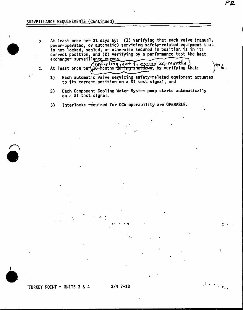
SURVEILLANCE RE UIREHENTS Continued
b.
C.
At least once per 31 days by: (1) verifying that each valve (manual,power-operated, or automatic) servicing safety-related equipment thatis not locked, sealed, or otherwise secured in position is in itscorrect position, and (2) verifying by a performance test the heatexchanger surveillan v
,ylok- ~ ~~ ~ IYIMRAt least once pe < , by verifying that:
1) Each automatic valve servicing safety-related equipment actuatesto its correct position on a SI test signal, and
2) Each Component Cooling Water System pump starts automaticallyon a SI test signal.
3) Interlocks required for CCW operability are OPERABLE.
'TURKEY POINT - UNITS 3 8L 4 3/4 7-13
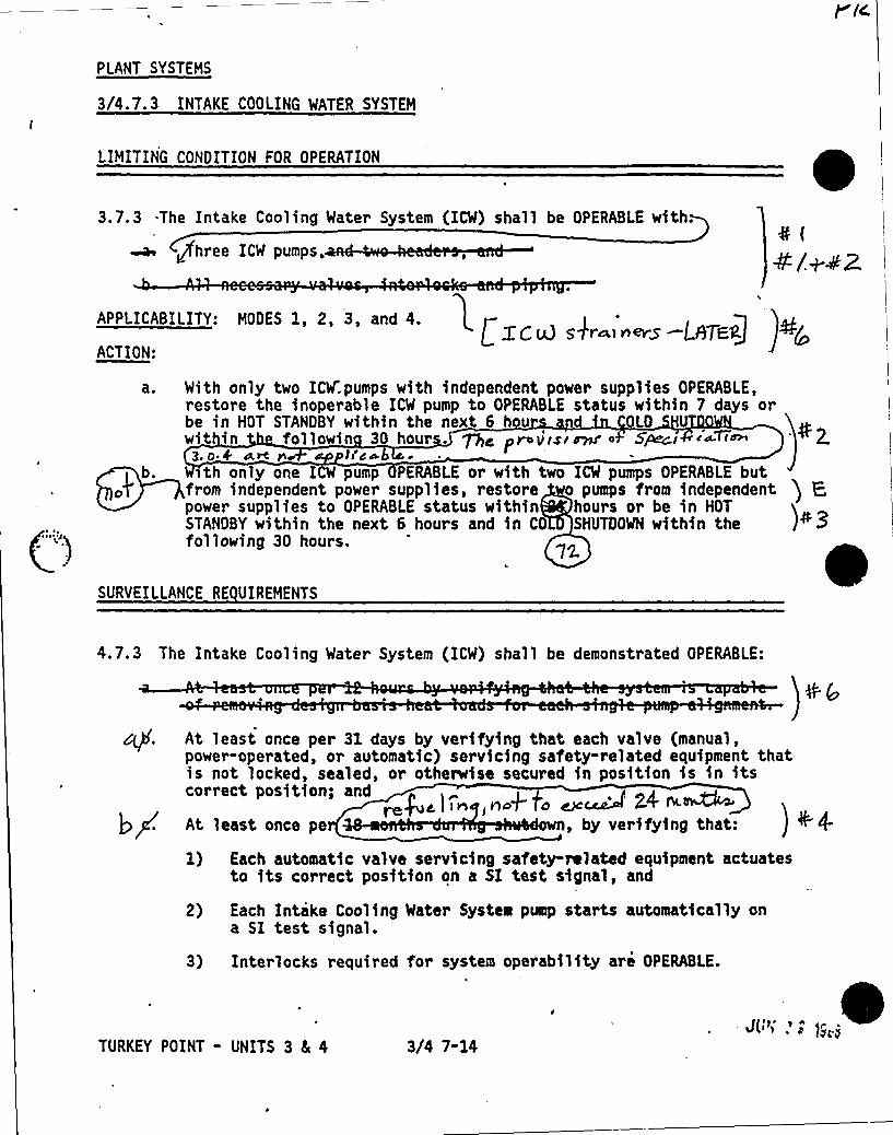
PLANT SYSTEMS
3/4.7.3 INTAKE COOLING WATER SYSTEM
LIMITING CONDITION FOR OPERATION
3.7.3 .The Intake Cooling Water System (ICW) shall be OPERABLE with.
ufhree ICW pumps.4(4/+ 4Z
APPLICABILITY: MODES 1, 2, 3, and 4. r
L gQ~) gfr~) nevy L$7Egf.ACTION:
(-")
) b.
With only two ICW.pumps with independent power supplies OPERABLE,restore the inoperable ICW pump to OPERABLE status within 7 days orbe in HOT STANDBY within the next 6 hou LQ
wit in fol lowin 30 hours. ~d pro v'lsi~ o Specs i~~f~ ' 2.Z. 0.4 tl 4dt r ~
~th only one I W pump PERABLE or with two ICW pumps OPERABLE butfrom independent power supplies, restore o pumps from independent ) P.power supplies to OPERABLE status within hours or be in HOTSTANOBY within the next S hours and in CO SNUTOOWN within the )+3following 30 hours.
SURVEILLANCE RE UIREMENTS
4.7.3 The Intake Cooling Water System (ICW) shall be demonstrated OPERABLE:
At least once per Sl days by verifying that each valve (manual,power-operated, or automatic) servicing safety-related equipment thatis not locked, sealed, or otherwise secured in position is in itscorrect position; and
re)gg ) I Vl>
V)dp~ dAt least once pe wn, by verifying that: )
'.1) Each automatic valve servicing safety-related equipment actuates
to its correct position on a SI test signal, and
2) Each Intake Cooling Water System pump starts automatically ona SI test signal.
3) Interlocks required for system operability are OPERABLE.
TURKEY POINT - UNITS 3 5 4 3)'4 7-14J( ~ )'

PLANT SYSTEMS
3/4. 7.4 ULTIMATE HEAT SIN
LIM ING ONDITION FOR OPERATION
vexw ~sSPS 4
~ ~
~3.7.4 The ul imate heat sink shall be OPERABLE with an average upply watertemperature to the Intake Cooling Water System less than or e l to 954F.
APPLICABILITY: ODES 1, 2, 3, and 4.
ith the requirement ',of the above specification not s isfied, be in at leastHOT STANDBY within 12 ours and in COLD SHUTDOWN wit the following 30 hours.This action shall be a licable to both units simul neously.
SURVEILLANCE RE UIREMENTS
4.7.4 The ultimate heat sink shall e determined OPERABLE at least once per24 hours by verifying the average u ly water temperature" to the IntakeCooling Water System to be withi its imit.
Porta e monitors may be used to measure the temperature.
TURKEY POINT - UNITS 3 8 4 3/4 7-15
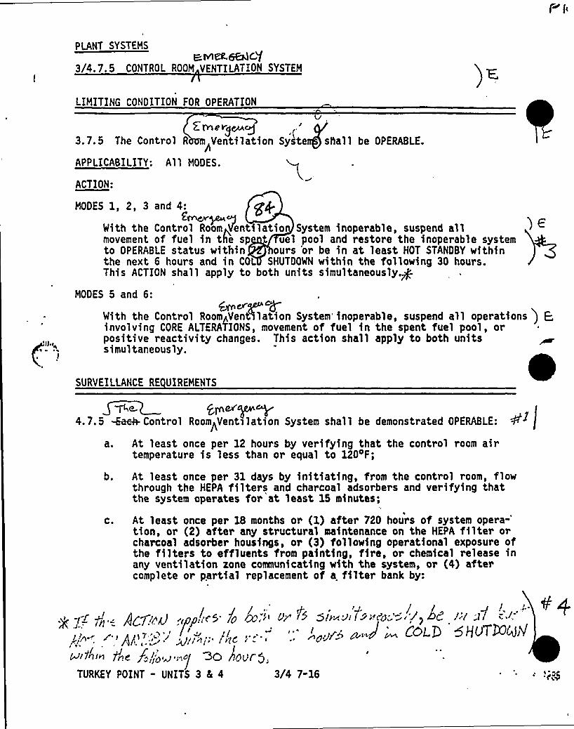
PLANT SYSTEMS
R lVICL6BQC'f3/4.7.5 CONTROL ROOM VENTILATION SYSTEM
LIMITING CONDITION FOR OPERATION
2 Wdo Yg~Q3.7. 5 The Control R Ventilation Syste sla11 be OPERABLE.
APPLICABILITY: All MODES.
ACTION:
MODES 1, 2, 3 and 4: graf.Grn~~gNth the Control Room~Ventilatio System inoperable, suspend allmovement of fuel in the sp uel pool and restore the inoperable systemto OPERABLE status within ours 'or be in at least HOT STANDBY withinthe next 6 hours and in COL SHUTDOWN within the following 30 hours.This ACTION shall apply to both units simultaneously.g
MODES 5 and 6:&~%
With the Control RoomAVentllatlon System'inoperable, suspend all operations ) E,involving CORE ALTERATIONS, movement of fuel in the spent fuel pool, orpositive reactivity changes. This action shall apply to both units tsimultaneously.
SURVEILLANCE RE UIREMENTS
4. 7. 5 -Ea~ ControlRoom~Ventilation System shall be demonstrated OPERABLE:
a. At least once per 12 hours by verifying that the control room airtemperature is less than or equal to 120 F;
b. At least once per 31 days by initiating, from the control room, flowthrough the HEPA filters and charcoal adsorbers and verifying thatthe system operates for at least 15 minutes;
c. At least once per 18 months or (1) after 720 hours of systemopera-'ion,
or (2) after any structural maintenance on the HEPA filter orcharcoal adsorber housings, or (3) following operational exposure ofthe filters to effluents from painting, fire, or chemical release inany ventilation zone comaunicating with the system, or (4) aftercomplete or partial replacement of a filter bank by:
~ -J r g =. AICT!od .pp: rS 7o
W"''g/'~'yt~/:/'''vc l - '
ISJi>~«de y'!ba i.~] GO rtOOroTURKEY POINT - UNITS 3 4 4 3/4 7-16

PLANT SYSTEMS
SURVEILLANCE RE UIREMENTS Continued
d.
e.
y(<Verifying that th eanup system satisfies the in-place pene-tration an'd bypass leakage testing acceptance criteria of greaterthan or equal to 99K 00P and halogenated hydrocarbon removal ata system flow rate of 1000 cfm %10K.
2) Verifying, within 31 days after removal, that a laboratory analysisof a representative carbon sample obtained in accordance withRegulatory Position C. 6. b of Regulatory Guide 1.52, Revision 2,March 1978, and analyzed per ANSI N510-1975, meets the criteriafor methyl iodine removal efficiency of greater than or equal to90 o the charcoal be replaced with charcoal that meets orexce s the criteria of position C.6.a. of Regulatory Guide 1.52(Revision 2) and
3) Verifying by a visual inspection the absence of foreignmaterials and gasket deterioratioy in We. HEPT Pte~~ ~~Mc~<~f %4tSO~~
At least once per 12 months by verifying that the pressure dropacross the combined HEPA filters and charcoal adsorber banks is lessthan 6 inches Water Gauge while operating the system at a flow rateof 1000 cfm tlOX;
At least once per 18 months by verifying that on a Containment Phase"A" Isolation test signal the, system automatically switches into therecirculation mode of operation.
TURKEY POINT - UNITS 3 5 4 3/4 7-17
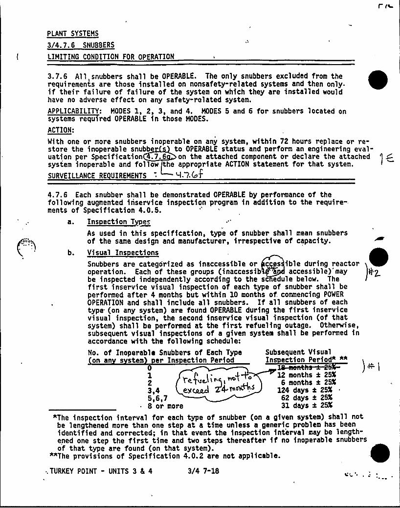
PLANT SYSTEMS
3/4.7.6 SNUBBERS
LIMITING CONDITION FOR OPERATION
03.7.6 All snubbers shall be OPERABLE. The only snubbers excluded from therequirements are those installed on nonsafety-related systems and then only-if their failure of failure of the system on which they are installed wouldhave no adverse effect on any safety-related system.
APPLICABILITY: MODES 1, 2, 3, and 4. MODES 5 and 6 for snubbers located onsystems required OPERABLE in those MODES.
ACTION:
With one or more snubbers inoperable on any system, within 72 hours replace or re-store the inoperable snubb to OPERABLE status and perform an engineering eval-uation per Specification .7.6 on the attached component or declare the attachedsystem inoperable and follow the appropriate ACTION statement for that system.
SURVEILLANCE RE UIREMENTS I. 7 (cpf
No. of Inoperable Snubbers of Each Type Subsequent Visualon an s stem er Ins ection Period In ection Period" ""
11 p i- „$+o 12 months 4 25%2 Negate. i>gi" 6 months g 25%
3,4 eMcaad Z4 ~~ ". 124 days k 25%
5,6,7 62 days 4 25~ 8 or more 31 days 4 25K
"The inspection interval for each type of snubber (on a given system) shall notbe lengthened more than one step at a time unless a generic problem has beenidentified and corrected; in that event the inspection interval may be length-ened one step the first time and two steps thereafter if no inoperable snubbersof that type are found (on that system).
*"The provisions of Specification 4.0.2 are not applicable.
~ . TURKEY POINT - UNITS 3 4 4 3/4 7-18
4.7.6 Each snubber shall be demonstrated OPERABLE by performance of thefollowing augmented inservice inspection program in addition to the require-ments of Specification 4.0.5.~ltt l,:
As used in this specification, type of snubber shall mean snubbersof the same design and manufacturer, irrespective of capacity.
b. Visual Ins ectionsSnubbers are categorized as inaccessible or c s ible during reactoroperation. Each of these groups (inaccessib accessible)'may gZbe inspected independently according to the sc edule below. Thefirst inservice visual inspection of each type of snubber shall beperformed after 4 months but within 10 months of. commencing POWER
OPERATION and shall include all snubbers. If all snubbers of eachtype (on any system) are found OPERABLE during the first inservicevisual inspection, the second inservice visual inspection (of thatsystem) shall be performed at the first refueling outage. Otherwise,subsequent visual inspections of a given system shall be performed inaccordance with the following schedule:
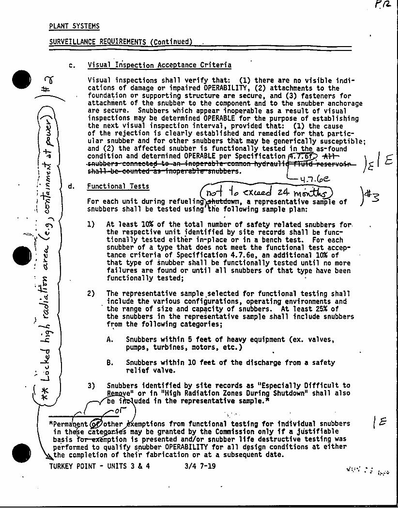
PLANT SYSTEMS
SURVEILLANCE RE UIREMENTS Continued
C. Visual Ins ection Acce tance Criteria
per Specification +1+-condition and determine
Visual inspections shall verify that: (1) there are no visible indi-cations of damage or impaired OPERABILITY, (2) attachments to thefoundation or supporting structure are secure, and (3) fasteners forattachment of the snubber to the component and to the snubber anchorageare secure. Snubbers which appear inoperable as a result of visualinspections may be determined OPERABLE for the purpose of establishingthe next visual inspection interval, provided that: (1) the causeof the rejection is clearly established and remedied for that partic-ular snubber and for other snubbers th'at may be generically susceptible;and (2) the affected snubber is functionally tested in the as-found
d OPERABLE
4
q.q. (gtd. Functional Tests
For each unit during refueling , a representative sample ofsnubbers shall be tested using he following sample plan:
1) At least 10K of the total number of safety related snubbers for.the respective unit identified by site records shall be func-tionally tested either in-place or in a bench test. For eachsnubber of a type that does not meet the functional test accep-tance criteria of Specification,4.7.6e, an additional 10K ofthat type of snubber shall be functionally tested until no morefailures are found or until all snubbers of that type have beenfunctionally tested;
2) The representative sample selected for functional testing shallinclude the various configurations, operating environments andthe range of size and capacity of snubbers. At least 25X ofthe snubbers in the representative sample shall include snubbersfrom the following categories;
A. Snubbers within 5 feet of heavy equipment (ex. valves,pumps, turbines, motors, etc.)
B. Snubbers within 10 feet of the discharge from a safetyrelief valve.'0
( ~ 3) Snubbers identified by site records as "Especially Oifficult tove" or in "High Radiation Zones DuHng Shutdown" shall also
be i uded in the representative sample."ol
"Perma nt other emptions from functional testing for individual snubbersin th se cate s may be granted by the Commission only if a justifiablebasis mption is presented and/or snubber life destructive testing wasperformed to qualify snubber OPERABILITY for all dysign conditions at eithe~the completion of their fabrication or at a subsequent date.
TURKEY POINT - UNITS 3 8L 4 3/4 7"19

PLANT SYSTEHS
SURVEILLANCE RE UIREMENTS Continued
In addition to the regular sample, snubbers which failed theprevious functional test shall be retested during the next testperiod. If a spare snubber has been installed in place of afailed snubber, then both the failed snubber (if it is repairedand installed in another position) and the spare snubber shallbe retested. Test r'esults of these snubbers may not be includedfor the re-sampling.
e. Mechanical Snubbers Functional Test Acce tance Criteria
('hesnubber functional test shall verify that:
1) Activation (restraining action) is achieved with the specifiedrange of velocity or acceleration in both tension andcompression;
2) Snubber release rate, where required, is within the specifiedrange in tension and compression,
3) The force required to initiate or maintain motion of thesnubber is within the specified range in both directions oftravel.
f. Functional Test Failure Anal sis
An engineering evaluation shall be made of each failure to meet thefunctional test acceptance criteria to determine the cause of thefailure. The results of this evaluation shall be used, if applicable,in selecting snubbers to be tested in an effort to determine theOPERABILITY of other snubbers irrespective of type which may besubject to the same failure mode.
If any snubber selected for functional testing either fails toactivate or fails to move, i.e., frozen-in-place, the cause will beevaluated under the provisions of 10 CFR Part 21.
Should the results of the evaluation indicate that the failure wascaused by either manufacturer or design deficiency, further actionshall be taken, if needed, based on manufacturer or engineeringrecoaeendations.
For the snubber(s) found inoperable, an evaluation shall be pe~formedon the components to which thi inoperable snubbers are attached.The purpose of this evaluation shall be to determine if the componentsto which the inoperable snubber(s) are attached were adversely affectedby the inoperability of the snubber(s) in order to ensure that thecomponent remains capable of meeting the designed service.
TURKEY POINT - UNITS 3 8E 4 3/4 7-20
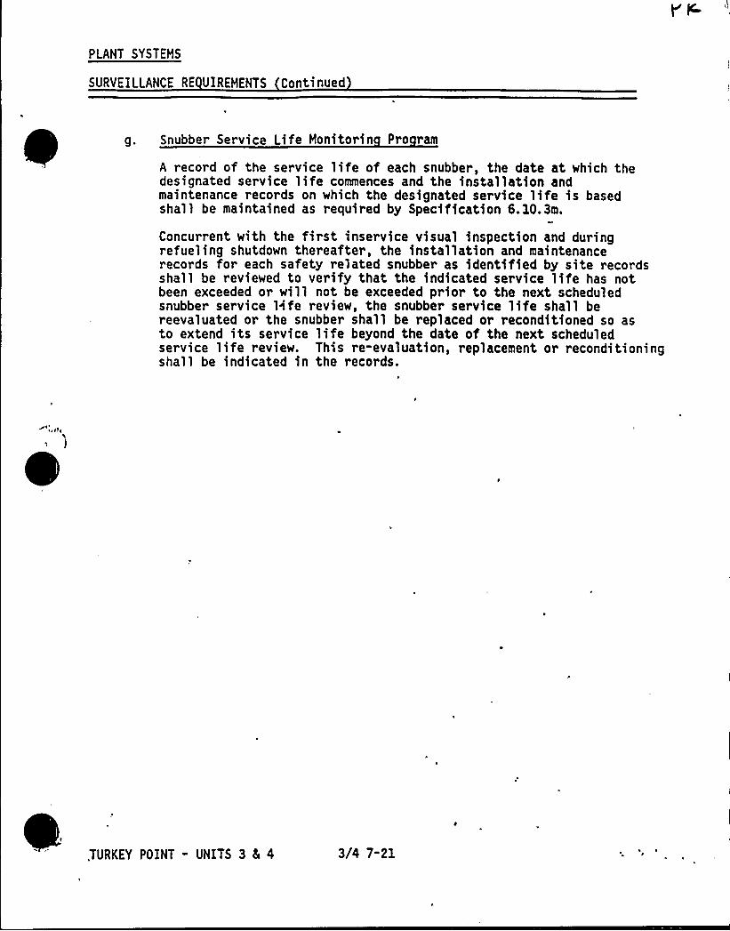
PLANT SYSTEMS
SURVEILLANCE RE UIREMENTS Continued
g. Snubber Service Life Monitorin Pro ram
A record of the service life of each snubber, the date at which thedesignated service life commences and the installation andmaintenance records on which the designated service life is basedshall be maintained as required by Specification 6.10.3m.
Concurrent with the first inservice visual inspection and duringrefueling shutdown thereafter, the installation and maintenancerecords for each safety related snubber as identified by site recordsshall be reviewed to verify that the indicated service life has notbeen exceeded or will not be exceeded prior to the next scheduledsnubber service life review, the snubber service life shall bereevaluated or the snubber shall be replaced or reconditioned so asto extend its service life beyond the date of the next scheduledservice life review. This re-evaluation, replacement or reconditioningshall be indicated in the records.
.TURKEY POINT - UNITS 3 8E 4 3/4 7-21
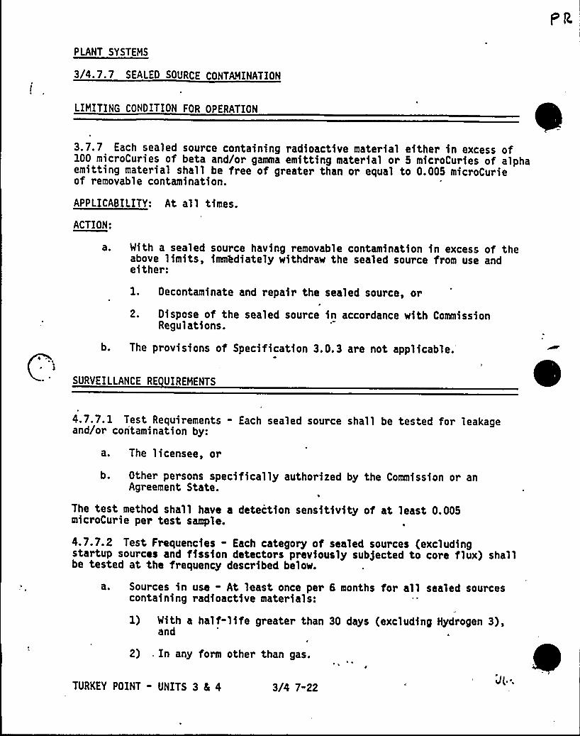
PLANT SYSTEMS
3/4.7.7 SEALED SOURCE CONTAMINATION
LIMITING CONDITION FOR OPERATION
3.7.7 Each sealed source containing radioactive material either in excess of100 microCuries of beta and/or gamma emitting material or 5 microCuries of alphaemitting material shall be free of greater than or equal to 0.005 microCurieof removable contamination.
APPLICABILITY: At all times.
ACTION:
aO With a sealed source having removable contamination in excess of theabove limits, immhdiately withdraw the sealed source from use andeither:
b.
l. Decontaminate and repair the sealed source, or
2. Dispose of the sealed source in accordance with CommissionRegulations.
The provisions of Specification 3. 0. 3 are not applicable.
SURVEILLANCE RE UIREMENTS
4.7.7.1 Test Requirements - Each sealed source shall be tested for leakageand/or contamination by:
a. The licensee, or
b. Other persons specifically authorized by the Commission or anAgreement State.
The test method shall have a detection sensitivity of at least 0.005microCurie per test sample.
4.7.7.2 Test Frequencies - Each category of sealed sources (excludingstartup sources and fission detectors previously sub)ected to core flux) shallbe tested at the frequency described below.
a. Sources in use - At least once per 6 months for all sealed sourcescontaining radioactive materials:
1) With a half-life greater than 30 days (excluding Hydrogen 3),and
2) , In any form other than gas.
TURKEY POINT - UNITS 3 8L 4 3/4 7-22
PLANT SYSTEMS
SURVEILLANCE RE UIREMENTS Continued
b. Stored sources not in use - Each sealed source and fission detectorshall be tested prior to use or transfer to another licensee unlesstested within the previous 6 months. Sealed sources and fissiondetectors transferred without a certificate indicating the last testdate shall be tested prior to being placed into use; and
C. Startup sources and fission detectors - Each sealed startup sourceand fission detector shall be tested within 31 days prior to beingsubjected to core flux or installed in the core and following repairor maintenance to the source.
4.7.7.3 Reports - A report. shall be prepared and submitted to the Commissionon an annual basis if sealed source or fission detector leakage tests revealthe presence of greater than or equal to 0.005 microCurie of removablecontamination.
4.7.7.4 A complete inventory of licensed radioactive materials in possessionshall be maintained current at all times.
TURKEY POINT - UNITS 3 5 4 3/4 7-23

PLANT SVSTEHS
3/4.7. 8 FIRE SUPPRESSION SYSTEHS
FIRE WATER SUPPLY AND DISTRIBUTION SYSTEH
LIHITING CONDITION FOR OPERATION
3.7.8.1 The Fire Mater Supply and Distribution System shall be OPERABLE with:
a. At least two fire suppression pumps, one electric dr iven ~~d u Idl
-ca , with their discharge aligned to the firesuppression header,
b. Separate water supplies, each with a minimum contained volume of300,000 gallons, and'
. An OPERABLE flow path capable of taking suction from the, Raw WaterTank I and Raw Mater Tank II and transferring the water through dis-tribution piping with OPERABLE sectionalizing control or isolationvalves to the yard hydrant curb valves, the last valve .ahead of thewater flow alarm device on each sprinkler or hose standpipe, and thelast valve ahead of the deluge valve on each Deluge or Spray Systemrequired to be OPERABLE per Specifications 3.7.8.2, 3.7.8.g, and3.7.8.$ . 3'-
APPLICABILITY: At al 1 times.
ACTION:
a. With one pump and/or one water supply inoperable, restore the inoper-able equipment to OPERABLE status within 7 days or provide an alter-nate backup pump or supply. The provisions of Specification 3.0.3are,not applicable. This action applies to both units simultaneously.
b. With the Fire Mater Supply and Distribution System otherwise inoper-able, establish a backup fire water capability within 24 hours. Thisaction applies to both units simultaneously.
TURKEY POINT - UNITS 3 5 4 3/4 7-240
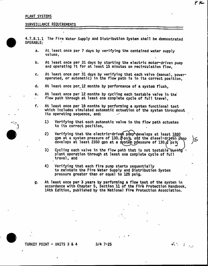
PLANT SYSTEMS
SURVEILLANCE RE UIREMENTS
4.7.8. 1. 1 The Fire Mater Supply and Distribution System shall be demonstratedOPERASLE:
a. At least once per 7 days by verifying the contained water supplyvolume,
b. At least once per 31 days by starting the electric motor-driven pumpand operating it for at least 15 minutes on recirculation flow,
c. At least once per 31 days by verifying that each valve (manual, power-operated, or automatic) in the flow path is in its correct position,
d. At least once per. 12 months by performance of a system flush,
e. At least once per 12 months by cycling each testable valve in the~ flow path through at least one complete cycle of full travel,
f. At least once per 18 months by performing a system functional testwhich includes simulated automatic actuation of the system throughoutits operating sequence, and:
1) Verifying that each automatic valve in the flow path actuatesto its correct position,
2)
3)
Verifying that the electric-driv p mp evelops at least 1880gpm at a system pressure of 130. sQ a d the diesel-dr en p pdevelops at least 2350 gpm at a ste p essure of 130.
ps'yclingeach valve in the flow path that is not testableplant operation through at, least one complete cycle of fulltravel, and
4) Verifying that each fire pump starts sequentiallyto maintain the Fire Mater Supply and Distribution Systempressure greater than or equal to 125 psig.
g. At least once per 3 years by performing a flow test of the system inaccordance with Chapter 5, Section 11 of the Fire Protection Handbook,14th Edition, published by the National fire Protection Association.
TURKEY POINT - UNITS 3 8E 4 3/4 7"25
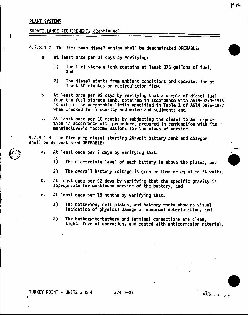
PLANT SYSTEHS
SURVEILLANCE RE UIREHENTS Continued
4 7.8.1.2 The fire pump diesel engine shall be demonstrated OPERABLE:
a. At least once per 31 days by verifying:
1) The fuel storage tank contains at least 375 gallons of fuel,and
2) The diesel starts from ambient conditions and operates for atleast 30 minutes on recirculation flow.
b. At least once per 92 days by verifying that a sample of diesel fuelfrom the fuel storage tank, obtained in accordance with ASTH-0270-1975is within the acceptable limits specified in Table 1 of ASTH 0975-1977when checked for viscosity and water and sediment; and
c. At least once per 18 months by subjecting the diesel to an inspec-tion in accordance with procedures prepared in con)unction with itsmanufacturer's recommendations for the class of service.
4.7.8.1.3 The fire pump diesel starting 24-volt battery bank and chargershall be demonstrated OPERABLE:
a. At least once per 7 days by verifying that:
1) The electrolyte level of each battery is above the plates, and
2) The overall battery voltage is greater than or equal to 24 volts.
b. At least once per 92 days by verifying that the specific gravity isappropriate for continued service of the battery, and
C. At least once per 18 months by verifying that:
2)
The batteries, cell plates, and battery racks show no visualindication of physical damage or abnormal deterioration, and
The battery-to-battery and terminal connections are clean,tight, free of corrosion, and coated with &ticorrosion material.
TURKEY POINT - UNITS 3 4 4 3/4 7-26 dU> .:
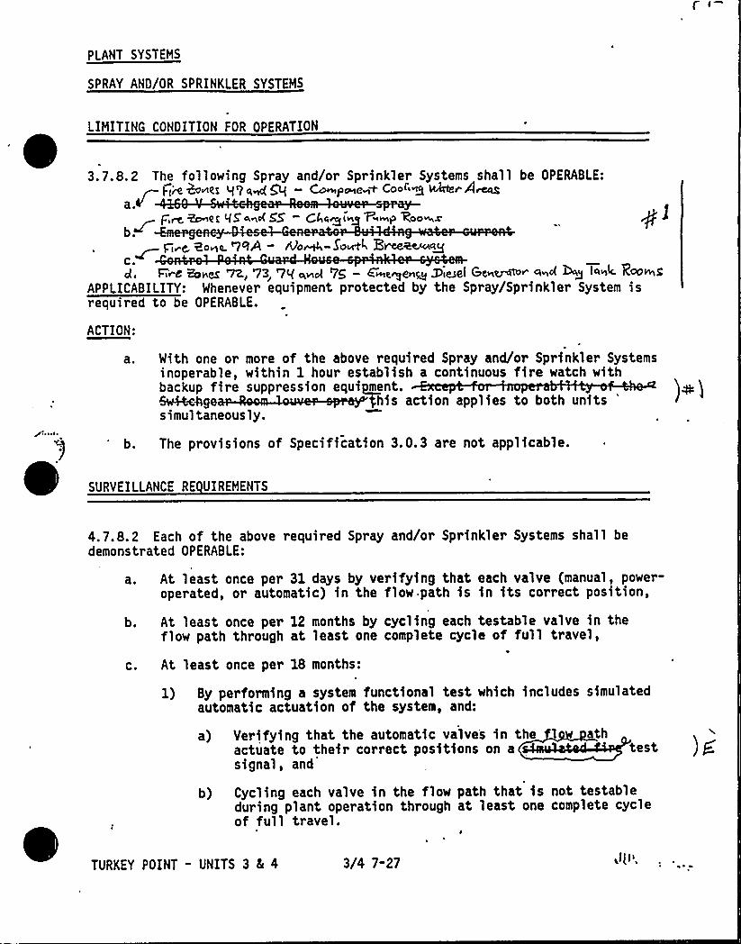
PLANT SYSTEMS
SPRAY AND/OR SPRINKLER SYSTEMS
LIMITING CONDITION FOR OPERATION
3.7.8.2 The following Spray and/or Sprinkler Systems shall be OPERABLE:&vtLsg L{ Li gag Q C~p0etisnt COO" Q ~e 4rCcg
a ~
F'm ~et 95<~4 5'5 —Gl a~i~g V~~bb WOO~Xb.~ Fi~C 20+LL. '7RA - DO~-SO~K E~aema~C.d. FLM Bsbt& V2., 73~ '7Q ciinol '7p — E~e~en~ DieSe( Genres" And WQ l4st4
RA)&S'PPLICABILITY:Whenever equipment protected by the Spray/Sprinkler System isrequired to be OPERABLE.
ACTION:
a ~ With one or more of the above required Spray and/or Sprinkler Systemsinoperable, within 1 hour establish a continuous fire watch withbackup fire suppression equipment.&A+c +his action applies to both units
'imultaneously.
b.C
SURVEILLANCE RE UIREMENTS
The provisions of Specification 3.0.3 are not applicable.
4.7.8.2 Each of the above required Spray and/or Sprinkler Systems shall bedemonstrated OPERABLE:
a. At least once per 31 days by verifying that each valve (manual, power-operated, or automatic) in the flow path is in its correct position,
b.
C.
At least once per 12 months by cycling each testable valve in theflow path through at least one complete cycle of full travel,
At least once per 18 months:
1) By performing a system functional test which includes simulatedautomatic actuation of the system, and:
a) Verifying that the automatic valves in theactuate to their correct positions on asignal, and
athtest ) g
of ful
TURKEY POINT - UNITS 3 8L 4 3/4 7-27
b) Cycling each valve in the flow path that is not testableduring plant operation through at least one complete cycle
1 travel.
PLANT SYSTEMS
SURVEILLANCE RE UIREMENTS Continued
2) By'a visual inspection of the dry pipe spray and sprinklerheaders to verify their integrity; and
3) By a visual inspection of each nozzle's spray area to verify thespray pattern is not obstructed.
d. At.1east once per 3 years by performing an a$ r or water eeasr test ) fthrough each open head spray/sprinkler header and verifying eachopen head spray/sprinkler nozzle is unobstructed.
..TURKEY POINT - UNITS 3 4 4 3/4 7-28~ ~s ~
s ~
FIRE HOSE STATIONS
LIMITING CONDITION FOR OPERATION
3.7.8.3 The fire. hose stations given in Table 3.7-4 shall be OPERABLE.
APPLICABILITY: Whenever equipment in the areas protected by the fire hose
ACTION:
a ~
b.
With one or more of the fire hose stations given in Table 3.7-4inoperable, provide an equivalent capacity fire hose from the nearestequivalent OPERABLE water source. The fire hose shall be of a lengthof hose sufficient to provide coverage for the area left unprotectedby the inoperable hose station, and shall be stored in a roll at theoutlet of the OPERABLE water supply. The above ACTION requirementshall be accomplished within 1 hour if the inoperable fire hose isthe primary means of fire suppression; otherwise route the additionalhose within 24 hours. This action applies to both units'imultaneously
~ ~ ~ lwThe provisions of Specification 3.0.3 are not applicable.
SURVEILLANCE RE UIREMENTS
4.7.8.3 Each of the fire hose stations given in Table 3.7-4 shall bedemonstrated OPERABLE:
a. At least once per 31 days, by a visual inspection of the fire hosestations accessible during plant operations to assure all requiredequipment is at the station.
b. At least once per 12 months, by:
1) Visual inspection of the stations not accessible during plantoperations to assure all required equipment is at the station,
2) Removing the hose for inspection and re-racking, and
3) Inspecting all gaskets and replacing any degraded gaskets inthe couplings.
C. At least once per 3 years, by:
1) Partially opening each hose(station valve to verify valveOPERABILITY and no flow blockage, and
2) Conducting a hose hydrostatic test at a pressure of 150 psig orat least 50 psig above maximum fire main operating, pressure,whichever is greater.
TURKEY POINT - UNITS 3 Ec 4 3/4 7-29
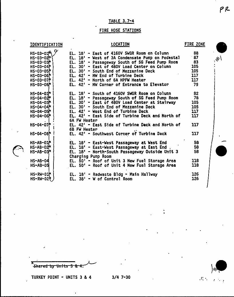
TABLE 3.7-4
FIRE HOSE STATIONS
IDENTIFICATION
HS-03-0HS-03-0HS-03-03HS-03-04HS-03-05HS-03-06HS-03-07HS-03-0
HS-04-0HS-04"0HS-04-03HS-04-04HS-04-0HS-04-06
HS-04-07
HS-04-08
HS-AB-0HS-AB-0HS-AB-0
HS-AB-0HS-AB"0
HS-RW-01HS-RW-02
LOCATION
EL. 18' East of 4160V SWGR Room on ColumnEL. 18' West of 3A Condensate Pump on PedestalEL. 18' Passageway South of SG Feed Pump RoomEL. 30' East of 480V Load Center on ColumnEL. 30' South End of Mezzanine DeckEL. 42' NW End of Turbine DeckEL. 42' North of 6A HPFW HeaterEL. 42' NW Corner of Entrance to Elevator
EL. 18' South of 4160V SWGR Room on ColumnEL. 18' Passageway South of SG Feed Pump RoomEL. 30' East of 480V Load Center at StairwayEL. 30' South End of Mezzanine DeckEL. 42' West End of Turbine DeckEL. 42' East Side of Turbine Deck and North of6A FW HeaterEL. 42' East Side of Turbine Deck and North of6B FW HeaterEL. 42' Southwest Corner of Turbine Deck
EL. 18' East-West Passageway at West EndEL. 18' East-West Passageway at East End ,
EL. 18' North-South Passageway Outside Unit 3Charging Pump RoomEL. 50' Roof of Unit 3 New Fuel Storage AreaEL. 50' Roof of Unit 4 New Fuel Storage Area
EL. 18' Radwaste Bldg - Main HallwayEL. 38' W of Control Room
8783
105105117117
79
8278
105105117117
117
117
585858
118118
126126
TURKEY POINT - UNITS 3 4 4 3/4 7-30
NT SYST HS
VAPO fIR HYDRANTS AND HYDRANT HOSE HOUSES
NG CONDITION FOR OPERATION
3 .7.8.4 The fire hydrants and associated hydrant hose houses givTable 3.7-5 shall be OPERABLE.
APPLICABILITY: Whenever equipment in the areas protected b the ~f$ rehydrants is required to be OPERABLE.
ACTION:
a ~ With one or more of the fire hydrants or associated hydrant hosehouses given in Table 3.7-5 inoperable, within 1 hour have sufficientadditional lengths of 2 1/2 inch diameter hose located in an adjacentOPERABLE hydrant hose house to provide service to the unprotectedarea(s) if the inoperable fire hydrant or associated hydrant hosehouse is the primary means of fire suppression; otherwise, providethe additional hose within 24 hours.
b. The provisions of Specification 3.0.3 and are not applicable.
SURVEILLANCE RE UIRE NT
4.7.8.4 Each of the yerbs% hydrants and associated hydrant hose housesgiven in Table 3. shall b demonstrated OPERABLE:
a ~
b.
C.
At least once per 31 days, by visual inspection of the hydrant hosehouse to assure all required equipment is at the hose house,
At least once per 6 months by visually inspecting each fire hydrantand verifying that the hydrant is not damaged, and
At least once per 12 months by:
2)
Conducting a hose hydrostatic test at a pressure of 150 psig orat least 50 psig above maximum fire main operating pressure,whichever is greater,
Inspecting all the gaskets and replacing any degraded gasketsin the couplings, and
3) Performing a flow check of each hydrant to verify itsOPERABILITY.
TURKEY POINT - UNITS 3 84 4 3/4 7-31 JU" " '+
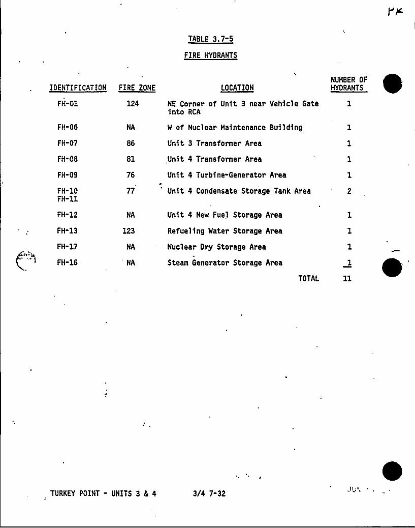
TABLE 3.7-5
FIRE HYDRANTS
FH-06
FH-07
FH-08
NA
81
IDENTIFICATION FIRE ZONE
FH-01 124
LOCATION
NE Corner of Unit 3 near Vehicle Gathinto RCA
W of Nuclear Maintenance Building
Unit 3 Transformer Area
Unit 4 Transformer Area
NUMBER OFHYDRANTS
1
FH-09
FH-10FH-11
FH"12
FH-13
FH-17
FH"16
76
77
NA
Unit 4 Turbine-Generator Area
Unit 4 Condensate Storage Tank Area
Unit 4 New Fuel Storage Area
Refueling Water Storage Area
Nuclear Ory Storage Area
Steam Generator Storage Area
TOTAL
2
TURKEY POINT - UNITS 3 4 4 3/4 7-32
A
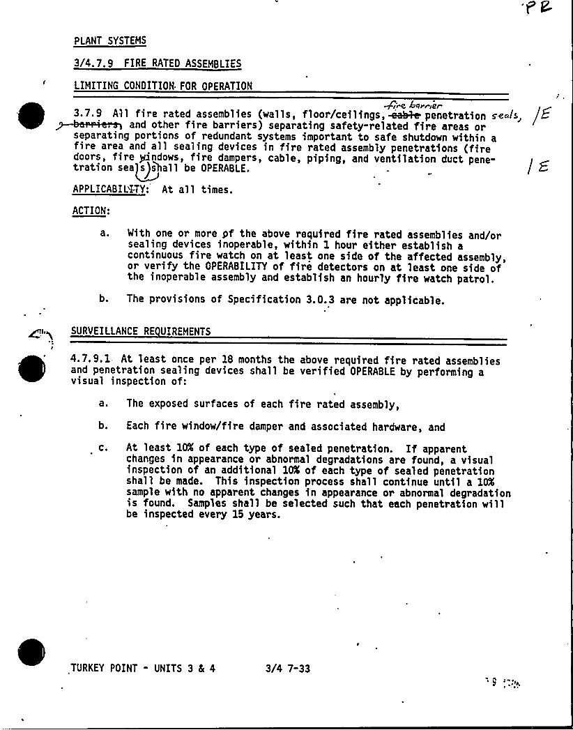
PLANT SYSTEMS
3/4.7.9 FIRE RATED ASSEMBLIES
LIMITING CONDITION FOR OPERATION
Qfn Affrayfer3.7.9 All fire rated assemblies (walls, floor/ceilings, wsal&e penetration se~ls, jE
d 8 I ) p tg f y- 1 dflseparating portions of redundant systems important to safe shutdown within afire area and all sealing devices in fire rated assembly penetrations (firedoors, fire Ptindows, fire dampers, cable, piping, and ventilation duct pene-tration sea~a)shall be OPERABLE.
APPLICABILITY: At al 1 times.
ACTION:
as With one or more yf the above required fire rated assemblies and/orsealing devices inoperable, within 1 hour either establish acontinuous fire watch on at least one side of the affected assembly,or verify the OPERABILITY of fire detectors on at least one side ofthe inoperable assembly and establish an hourly fire watch patrol.
b. The provisions of Specification 3.0.3 are not applicable.
SURVEILLANCE RE UIREMENTS
4.7.9.1 At least once per 18 months the above required fire rated assembliesand penetration sealing devices shall be verified OPERABLE by performing avisual inspection of:
a. The exposed surfaces of each fire rated assembly,
b. Each fire window/fire damper and associated hardware, and
Cs At least 10X of each type of sealed penetration. If apparentchanges in appearance or abnormal degradations are found, a visualinspection of an additional 10K of each type of sealed penetrationshall be made. This inspection process shall continue until a 10Ksample with no apparent changes in appearance or abnormal degradationis found. Samples shall be selected such that each penetration willbe inspected every 15 years.
TURKEY POINT - UNITS 3 4 4 3/4 7-33
PLANT SYSTEMS
SURVEILLANCE RE UIRENENTS Continued
4.7.9.2 Each of the above required fire doors shall be verified OPERABLE byinspecting the release and closing mechanism and latches at least once per6 months, and by verifying:
a; The OPERABILITY of the fire door supervision system for eachelectrically supervised fire door by performing a TRIP ACTUATINGDEVICE OPERATIONAL TEST at least once per 31 days,
b. That each locked closed fire door is closed at least once per7 days,
c. That door s with automatic hold-open and release mechanisms are freeof obstructions at least once per 24 hours, and a functional testis performed at least once per 18 months, and
d. That each unlocked fire door without electrical supervisionis closed at least once per 24 hours.
TURKEY POINT - UNITS 3 8 4 3/4 7-34
3/vg A~
oW v 4e Wi~ie> &~4
4~e ~stwa ~ +le F'.~p ~< ie ~~i o~
7~ <,i/~e rusw.dd/~4pc~A Pg) >~
~ W~~~~~8ce~re A~ >~~~~ ~ <4e
cccv<m4 ~~( ~ +pCC ~

e
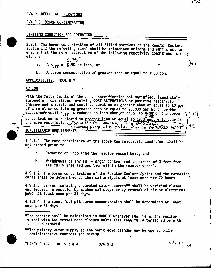
3/4. 9 REFUELING OPERATIONS
3/4.9. 1 BORON CONCENTRATION
0e'IMITING
CONDITION FOR OPERATION
3.9.1 The boron concentration of all filled portions of the Reactor CoolantSystem and the refueling canal shall be maintained uniform and sufficient toensure that the more restrictive of. the following reactivity conditions is met;
cs5a. A Keff of JA6 or less, or
b. A boron concentration of greater than or equal to 1950 ppm.
APPLICABILITY: MODE 6."
ACTION:
With the requirements of the above specification not satisfied, immediatelysuspend all operations involving CORE ALTERATIONS or positive reactivitychanges and initiate and continue boration at greater than or equal to 10 gpmof a solution containing greater than or equal to 20,000 ppm boron or ~
K111 d d 1 1 1 1t dt-dtt tt 109Kconcentration is restored to reate~ n or equal to 1950 m whichever is
the more restrictive. gp fo e cuP ~p«i y aFone Op~g 8~In PIP&P +lg gS~i 'ow b'd~ o rt Q+Pg gag @ps>T
SURVEILLANCE RE UIREMEN
4.9. l. 1 The more restrictive of the above two reactivity conditions shall bedetermined prior to:
a. Removing or unbolting the reactor vessel head, and
b. Withdrawal of any full-length control rod in excess of 3 feet fromits fully inserted position within the reactor vessel.
4.9. 1.2 The boron concentration of the Reactor Coolant System and the refuelingcanal shall be determined by chemical analysis at least once per 72 hours.
4.9. 1.3 Valves isolating unborated water sources*" shall be verified closedand secured in position by mechanical stops or by removal of air or electricalpower at least once per 31 days.
4.9.1.4 The spent fuel pit boron concentration shall be determined'at leastonce per 31 days.
adms n>strative controls
TURKEY POINT - UNITS 3 8 4!!;a~" r "i C3/4 9-1
"The reactor shall be maintained in MODE 6 whenever fuel is in the reactorvessel with the vessel head closure bolts less than fully tensioned or withthe head removed.
""The primary water supply to the boric acid blender may be opened underfor makeup.
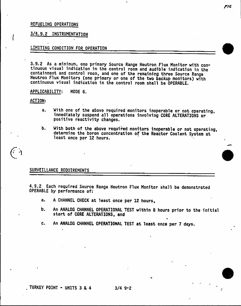
REFUELING OPERATIONS
3/4. 9. 2 INSTRUMENTATION
LIMITING CONDITION FOR OPERATION
3.9.2 As a minimum, one primary Source Range Neutron Flux Monitor with con-tinuous visual indication in the control room and audible indication in thecontainment and control room, and one of the remaining three Source RangeNeutron Flux Monitors (one primary or one of the two backup monitors) withcontinuous visual indication in the control room shall be OPERABLE.
APPLICABILITY: MODE 6.
ACTLON:
at
b.
With one of the above required monitors inoperable or not operating,immediately suspend all operations involving CORE ALTERATIONS orpositive reactivity changes.
With both of the above required monitors inoperable or not operating,determine the boron concentration of the Reactor Coolant System atleast once per 12 hours.
SURVEILLANCE RE UIREMENTS
4. 9.2 Each required Source Range Neutron Flux Monitor shall be demonstratedOPERABLE by performance of:
a. A CHANNEL CHECK at least once per 12 hours,
b. An ANALOG CHANNEL OPERATIONAL TEST within 8 hours prior to the initialstart of CORE ALTERATIONS, and
c. An ANALOG CHANNEL OPERATIONAL TEST at least once-per 7 days.
0TURKEY POINT - UNITS 3 8L 4 3/4 9-2

REFUELING OPERATIONS
3/4. 9. 3 DECAY TIME
LIMITING CONDITION FOR OPERATION
~ ~3.9.3 The reactor shall be subcritical for at least 100 hours.
APPLICABILITY: During movement of irradiated fuel in the reactor vessel.
ACTION:
With the reactor subcritical for less than 100 hours, suspend all operationsinvolving movement of irradiated fuel in the reactor vessel.
SURVEILLANCE RE UIREMENTS
4.9.3 The reactor shall be determined to have been subcritical for at least100 hours by verification of the date and time of subcriticality prior tomovement of irradiated fuel in the reactor vessel.
e J
TURKEY POINT - UNITS 3 8 4 3/4 9-3
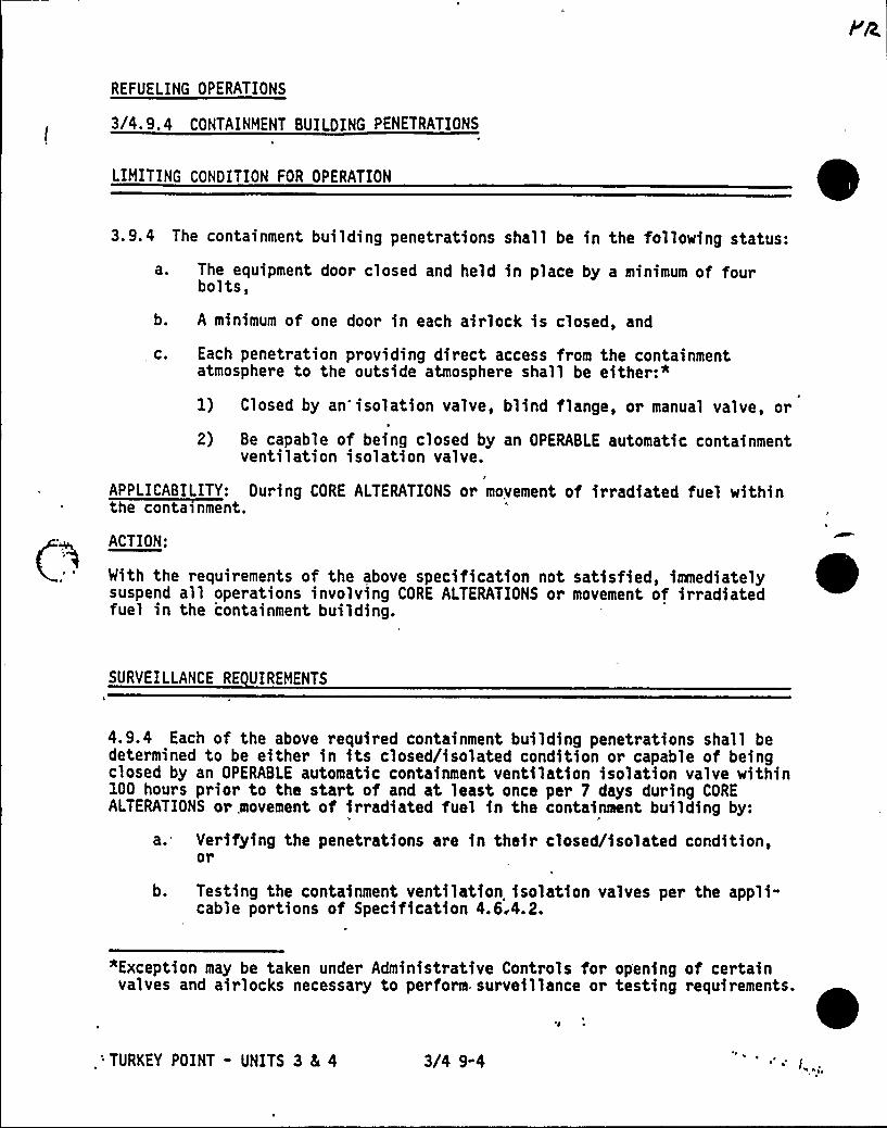
REFUELING OPERATIONS
3/4 '9. 4 CONTAINMENT BUILDING PENETRATIONS
LIMITING CONDITION FOR OPERATION 03.9.4 The containment building penetrations shall be in the following status:
a. The equipment door closed and held in place by a minimum of fourbolts,
b. A minimum of one door in each airlock is closed, and
c. Each penetration providing direct access from the containmentatmosphere to the outside atmosphere shall be either:"
1) Closed by an isolation valve, blind flange, or manual valve, or
2) Be capable of being closed by an OPERABLE automatic containmentventilation isolation valve.
APPLICABILITY: During CORE ALTERATIONS or movement of irradiated fuel within
~
~
~
~ ~
~
ACTION:
With the requirements of the above specification not satisfied, immediatelysuspend all operations involving CORE ALTERATIONS or movement of irradiatedfuel in the containment building.
SURVEILLANCE RE UIREMENTS
4.9.4 Each of the above required containment building penetrations shall bedetermined to be either in its closed/isolated condition or capable of beingclosed by an OPERABLE automatic containment ventilation isolation valve within100 hours prior to the start of and at least once per 7 days during COREALTERATIONS or .movement of irradiated fuel in the containment building by:
'a 4 Verifying the penetrations are in their closed/isolated condition,or
b. Testing the containment ventilation isolation valves per the appli-cable portions of Specification 4.6.4.2.
"Exception may be taken under Administrative Controls for opening of certainvalves and airlocks necessary to perform. surveillance or testing requirements.
'l
:TURKEY POINT - UNITS 3 8 4 3/4 9-4
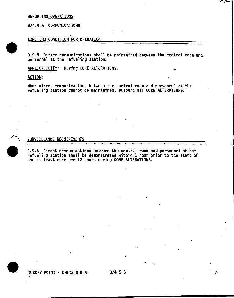
REFUELING OPERATIONS
3/4.9. 5 COMMUNICATIONS
LIMITING CONOITION FOR OPERATION
~ ~
~3.9.5 Direct communications shall be maintained between the control room andpersonnel at the refueling station.
APPLICABILITY: During CORE ALTERATIONS.
ACTION:
When direct communications between the control room and personnel at therefueling station cannot be maintained, suspend all CORE ALTERATIONS.
SURVEILLANCE RE UIREMENTS
4.9.5 Direct communications between the control room and personnel at therefueling station shall be demonstrated within 1 hour prior to the start ofand at least once per 12 hours during CORE ALTERATIONS.
TURKEY POINT - UNITS 3 8s 4 3/4 9-5
REFUELING OPERATIONS
3/4. 9. 6 MANIPULATOR CRANE
LIMITING CONDITION FOR OPERATION
3.9.6 The manipulato~ crane and auxiliary hoist shall be used for movement ofdrive rods or fuel assemblies and shall be OPERABLE with:
a. The manipulator crane used for movement of fuel assemblies having:
1) A minimum capacity of 2750 pounds, and
2) An overload cutoff limit less than or equal to 2700 pounds.
b. The auxiliary hoist used for latching and unlatching drive rodshaving:
1) A minimum capacity of 610 pounds, and
2) A load indicator which shall be used to prevent lifting loadsin excess of 600 pounds.
APPLICABILITY: During movement of drive rods or fuel assemblies withinthe reactor vessel.
With the requirements for crane and/or hoist OPERABILITY not satisfsed, suspenduse of any inoperable manipulator crane and/or auxiliary hoist from operationsinvolving the movement of drive rods and fuel assemblies within the reactorvessel.
SURVEILLANCE RE UIREMENTS
4.9.6.1 At least once each refueling, each manipulator crane used for movementof fuel assemblies within the reactor vessel shall be demonstrated OPERABLEwithin 100 hours prior to the start of such operations by performing a loadtest of at least 2750 pounds and demonstrating an automatic load cutoff whenthe crane load exceeds 2700 pounds.
4.9.6.2 At least once each refueling, each auxiliary hoist and associated'oadindicator used for movement of drive rods within the reactor vessel shall bedemonstrated OPERABLE within 100 hours prior to the start of such operations byperforming a load test of at least 610 pounds.
TURKEY POINT - UNITS 3 4 4 3/4 9-6
REFUELING OPERATIONS
3/4.9.7 CRANE TRAVEL - SPENT FUEL STORAGE AREAS
3.9.7 Loads in excess of 2000 pounds shall be prohibited from travel overfuel assemblies in the storage pool."
APPLICABILITY: With fuel assemblies in the storage pool.
ACTION:
a. With the requirements of the above specification not satisfied, placethe crane load in a safe condition.
b. The provisions of Specification 3.0.3 are not applicable.
SURVEILLANCE RE UIREMENTS
4.9.7 Prior to crane operation over fuel assemblies in the spent fuel storagepool, verify that each load is 2000 pounds or less.
*Exception may be taken for the temporary construction crane. to be used forthe re-rack operation which may be carried over irradiated fuel to facilitateinstallation of the crane. Lift rigs which meet the design and operationalrequirements of NUREG-0612 "Control of Heavy Loads at Nuclear Power Plants"will be used while performing this installation.
TURKEY POINT - UNITS 3 & 4 3/4 9-7
REFUELING OPERATIONS
3/4.9.8 RESIDUAL HEAT REMOVAL AND COOLANT CIRCULATION
HIGH WATER LEVEL
LIMITING CONDITION FOR OPERATION0
3.9.8. 1 At least one residual heat removal (RHR) loop shall be OPERABLE andin operation."
APPLICABILITY: MODE 6, when the water level above the top of the reactor2 1 2 2 1 2 1 t.
ACTION:
With no RHR loop OPERABLE and in operation, suspend all operations involving'n increase in the reactor decay heat load or a reduction in boron concentrationof the Reactor Coolant System and immediately initiate corrective action toreturn the required RHR loop to OPERABLE and operating status as soon aspossible. Pose all contalnment penetratlons provfdlng direct access fromthe con ainment atmos here to the outside atmosphere within 4 hours. 4l
SURVEILLANCE RE UIREMENTS
4.9.8. 1. 1 At least one RHR loop shall be verified in operation and circulatingreactor coolant at a flow rate of greater than or equal to 3000 gpm at leastonce per 12 hours.
4.9.8. 1.2 The RHR flow indicator shall be subjected to a CHANNEL CALIBRATIONat least once per refuelingi hog f~ <<+~+ Z4. ~Qs
"The RHR loop may be removed from operation for up to 1 hour per 8-hour periodduring the performance of CORE ALTERATIONS in the vicinity of the reactor vesselhot legs.
TURKEY POINT - UNITS 3 8 4 3/4 9-8
REFUELING OPERATIONS
LOW WATER LEVEL
LIMITING CONOITION FOR OPERATION
3.9.8.2 Two independent residual heat removal (RHR) loops shall be OPERABLE,and at least one RHR loop shall be in operation.
APPLICABILITY: MODE 6, when the water level above the top of the reactorvessel flange is less than 23 feet.
ACTION:
a ~ With less than the required RHR loops OPERABLE, immediately initiatecorrective action to return the required RHR loops to OPERABLEstatus, or to establish greater than or equal to 23 feet of waterabove the reactor vessel flange, as soon as possible.
b. With no RHR loop in operation, suspend all operations involving areduction in boron concentration of the Reactor Coolant System andimmediately initiat corrective action to return the required RHR
loop to operation. goose all containment penetrations providingdirect access from the containment atmosphere to the outsideatmosphere within 4 s.
+a
SURVEILLANCE RE UIREH
4.9.8.2 At least one RHR loop shall be verified in operation and circulatingreactor coolant at a flow rate of greater than or equal to 3000 gpm at leastonce per 12 hours.
TURKEY POINT - UNITS 3 8L 4 3/4 9"9
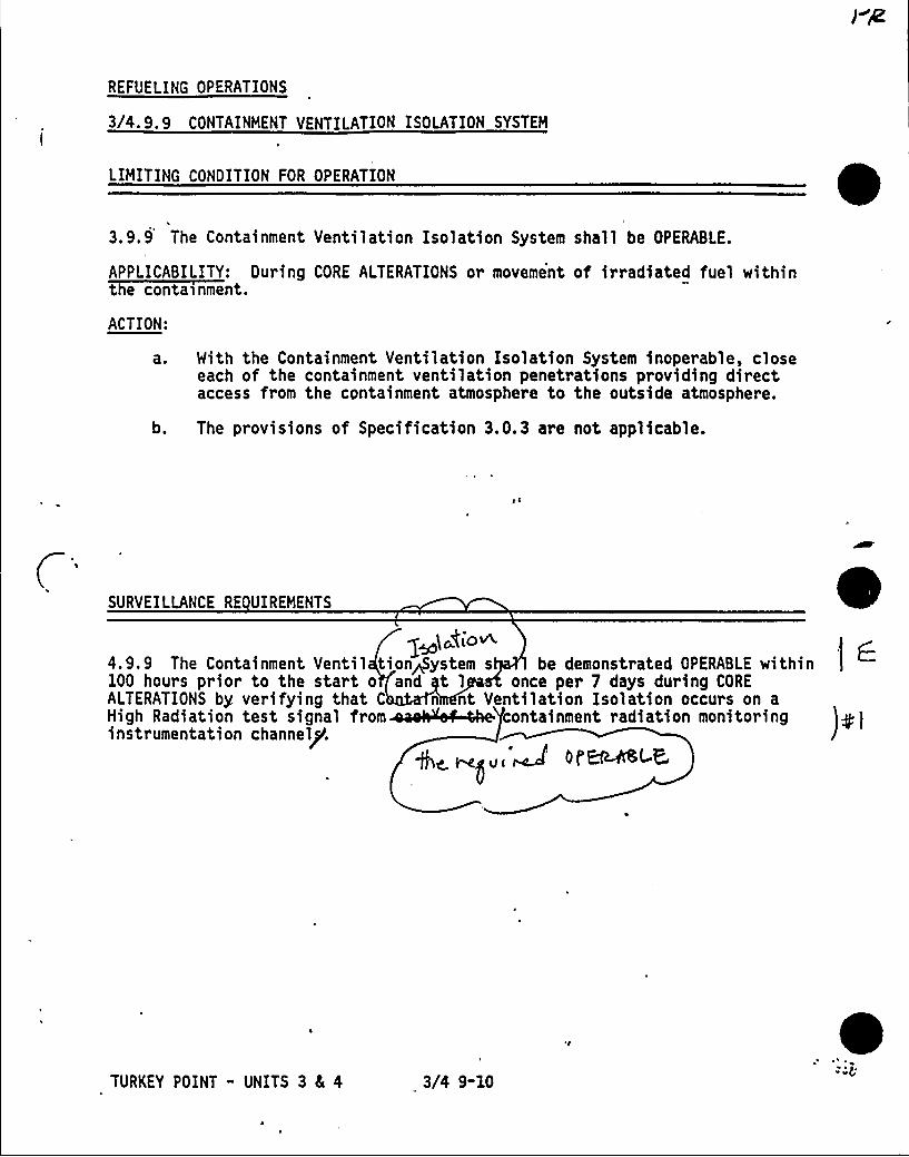
)eggs+
REFUELING OPERATIONS
3/4. 9. 9 CONTAINMENT VENTILATION ISOLATION SYSTEM
LIMITING CONDITION FOR OPERATION
3.9.9 The Containment Ventilation Isolation System shall be OPERABLE.
APPLICABILITY: During CORE ALTERATIONS or movement of irradiated fuel within
ACTION:
'a ~
b.
With the Containment Ventilation Isolation System inoperable, closeeach of the containment ventilation penetrations providing directaccess from the containment atmosphere to the outside atmosphere.
The provisions of Specification 3.0.3 are not applicable.
SURVEILLANCE RE UIREMENTS
(~bio~4.9.9 The Containment Ventil tiongystem s be demonstrated OPERABLE within100 hours prior to the start o and t 1 once per 7 days during COREALTERATIONS by. verifying that C n nt Ventilation Isolation occurs on aHigh g gi i « ig i i tghght t i gi i i i ginstrumentation channel/.
+c rs~ug ~ Oi EMfSL
TURKEY POINT - UNITS 3 8c 4 3/4 9-10
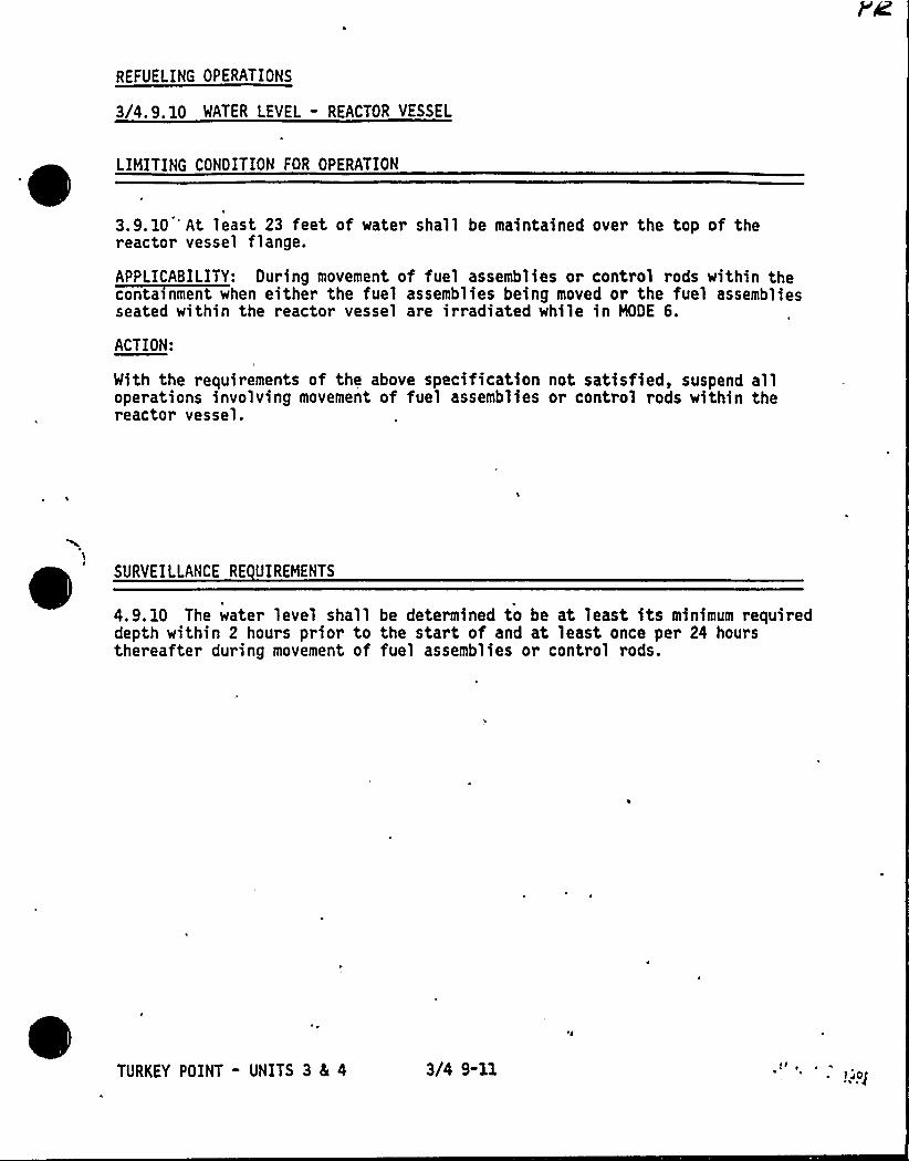
REFUELING OPERATIONS
3/4.9.10 WATER LEVEL - REACTOR VESSEL
LIMITING CONOITION FOR OPERATION
3.9.10 't least 23 feet of water shall be maintained over the top of thereactor vessel flange.
APPLICABILITY: Ouring movement of fuel assemblies or control rods within theconta>nment when either the fuel assemblies being moved or the fuel assembliesseated within the reactor vessel are irradiated while in MODE 6.
ACTION:
With the requirements of the above specification not satisfied, suspend alloperations involving movement of fuel assemblies or control rods within thereactor vessel.
e SURVEILLANCE RE UIREHENTS
4.9. 10 The water level shall be determined to be at least its minimum requireddepth within 2 hours prior to the start of and at least once per 24 hoursthereafter during movement of fuel assemblies or control rods.
TURKEY POINT - UNITS 3 4 4 3/4 9-11 II ~
~ I pe
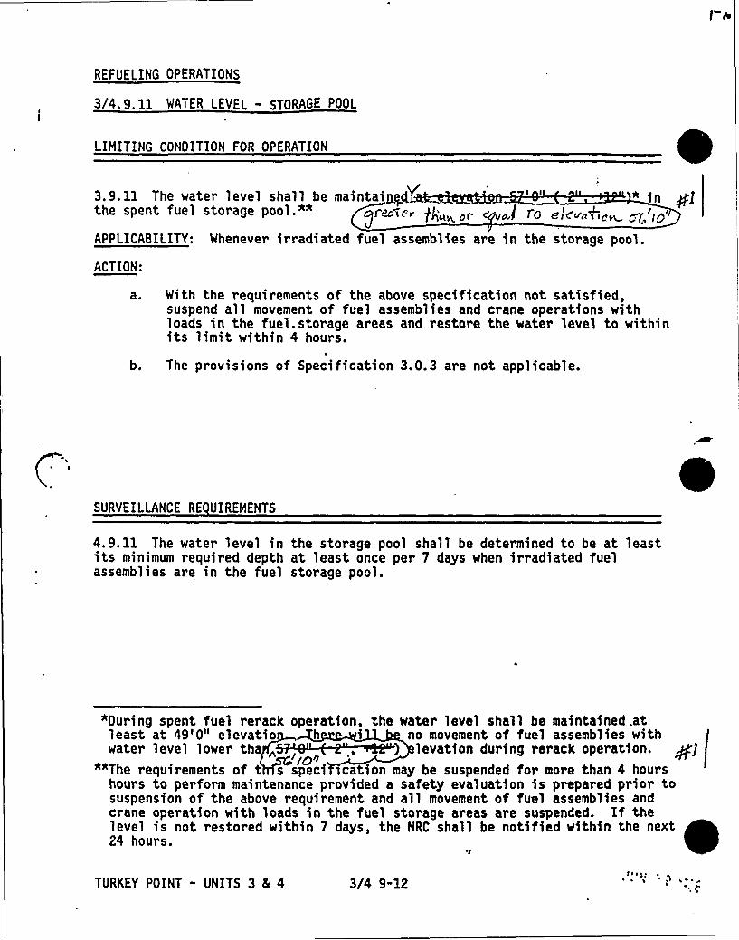
REFUELING OPERATIONS
3/4. 9. 11 WATER LEVEL - STORAGE POOL
LIMITING CONDITION FOR OPERATION
s
3.9.11 The water level shall be maintainp4 ' " in Plthe sPent fuel stonege Pool.*" gr~Tf, gJ;„o„~j ro e/s~„+o
APPLICABILITY: Whenever irradiated fuel assemblies are in the storage pool.
ACTION:
as With the requirements of the above specification not satisfied,suspend all movement of fuel assemblies and crane operations withloads in the fuel. storage areas and restore the water level to withinits limit within 4 hours.
b. The provisions of Specification 3.0.3 are not applicable.
SURVEILLANCE RE UIREHENTS
4.9. 11 The water level in the storage pool shall be determined to be at leastits minimum required depth at least once per 7 days when irradiated fuelassemblies are in the fuel storage pool.
"During spent fuel rerack operation, the water level shall be maintained .atleast at 49'0" elevatio h i no movement of fuel assemblies with
) 1 t 4 ill *k p i . +i'iO'f"*The requirements of t s speci ica ion may be suspended for more than 4 hours
hours to perform maintenance provided a safety evaluation is prepared prior tosuspension of the above requirement and all movement of fuel assemblies andcrane operation with loads in the fuel storage areas are suspended. If thelevel is not restored within 7 days, the NRC shall be notified within the next24 hours.
's
TURKEY POINT - UNITS 3 4 4 3/4 9-12tsstf
r p,
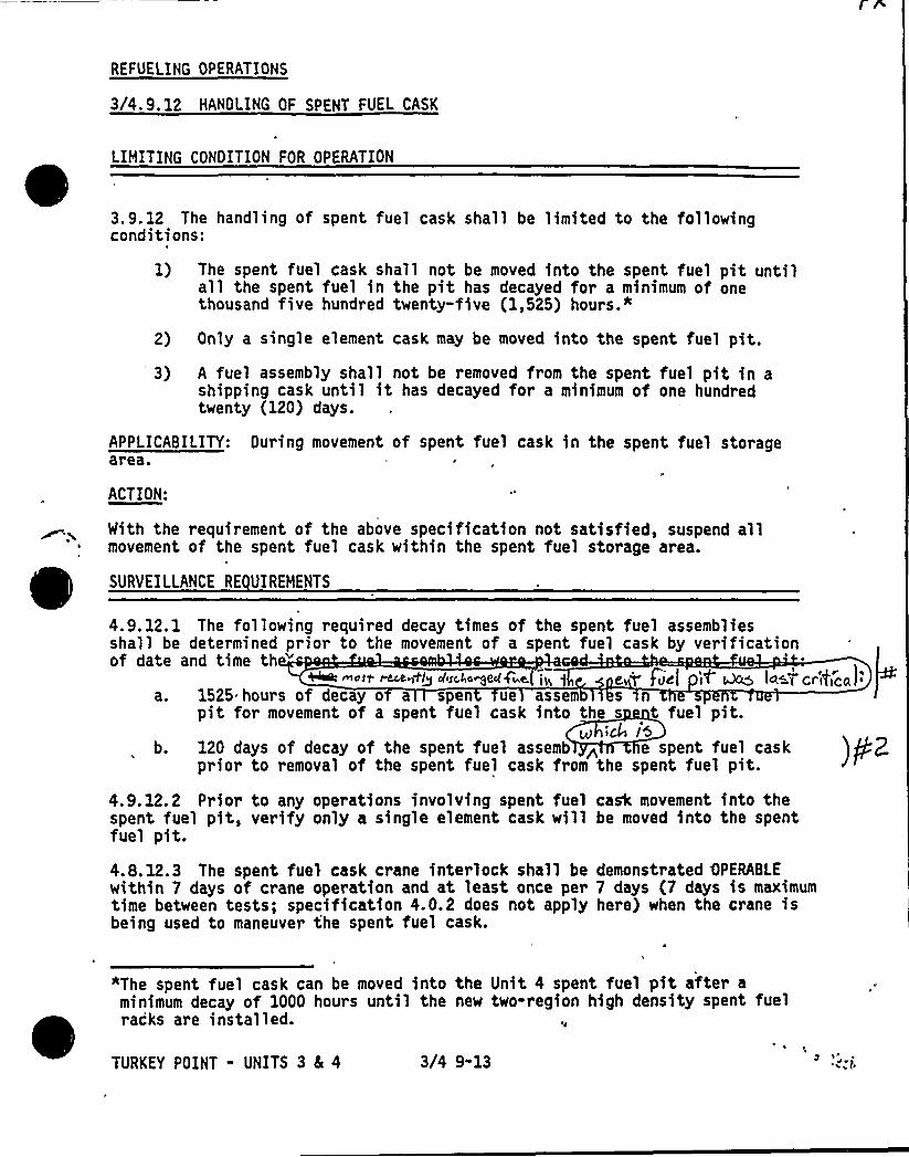
REFUELING OPERATIONS
3I4.9.12 HANOLING OF SPENT FUEL CASK
LIMITING CONOITION FOR OPERATION
~ ~~ ~
3.9.12 The handling of spent fuel cask shall be limited to the followingconditions:
1) The spent fuel cask shall not be moved into the spent fuel pit untilall the spent fuel in the pit has decayed for a minimum of onethousand five hundred twenty-five (1,525) hours.*
2) Only a single element cask may be moved into the spent fuel pit.') A fuel assembly shall not be removed from the spent fuel pit in a
shipping cask until it has decayed for a minimum of one hundredtwenty (120) days.
APPLICABILITY: Ouring movement of spent fuel cask in the spent fuel storagearea.
ACTION:
Mith the requirement of the above specification not satisfied, suspend allmovement of the spent fuel cask within the spent fuel storage area.
SURVEIlLANCE RE UIREMENTS
4.9. 12.1 The following required decay times of the spent fuel assembliesshall be determined prior to the movement of a spent fuel cask by verificationof date and time th ~ mott ~@+pl diSC,go~eclgi e.( ~g e T'iiel iT ~ la=T'ce',4cai'.
1525 hours of decay o a spen ue assem s snpit for movement of a spent fuel cask into the s t fuel pit.
I @LE lSb. 120 days of decay of the spent fuel assemb > e spent fuel cask
prior to removal of the spent fuel cask from the spent fuel pit.
4.9.12.2 Prior to any operations involving spent fuel cask movement into thespent fuel pit, verify only a single element cask will be moved into the spentfuel pit.4.8. 12.3 The spent fuel cask crane interlock shall bewithin 7 days of crane operation and at least once pertime between tests; specification 4.0.2 does not applybeing used to maneuver the spent fuel cask.
demonstrated OPERABLE7 days (7 days is maximumhere) when the crane is
"The spent fuel cask can be moved into the Unit 4 spent fuel pit after aminimum decay of 1000 hours until the new two-region high density spent fuelracks are installed.
e
TURKEY POINT - UNITS 3 4 4 3/4 9-13 ) 1
, 4 ~(
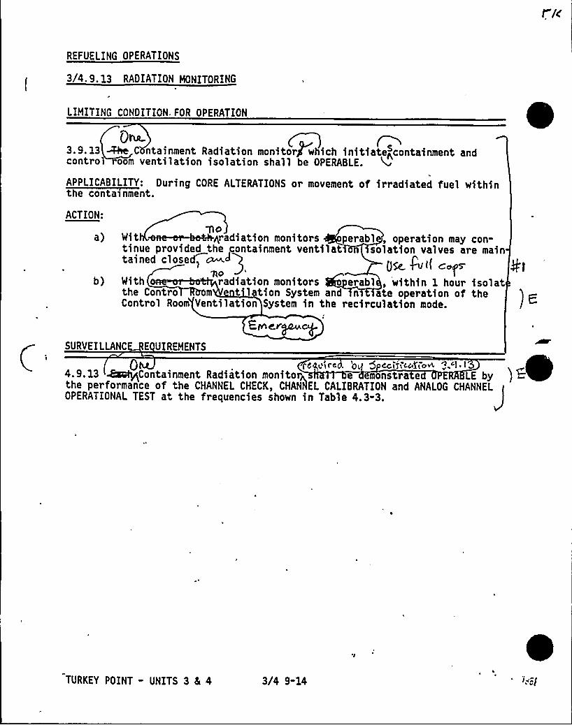
REFUELING OPERATIONS
3/4. 9 e 13 RADIATION MONITORING
LIMITING CONDITION„FOR OPERATION
Qha.3.9. 13 ~ C ntainment Radiation monitor which initiatencontainment andcontro oom ventilation isolation shall be OPERABLE.
APPLICABILITY: During CORE ALTERATIONS or movement of irradiated fuel within
ACTION:
a)
b)
AOIh ~r i i < p b1, i" Ytinue provided the containment ventilat solation valves are maintained closed> ~~
Dfc. Pvi( c:~QO
With radiation monitors erabl, within 1 hour isolatthe Contro m t 1 tion System and n ate operation of theControl Room Ventilation System in the recirculation mode.
Einmr
SURVEILLANC E UIREMENTS
Om ietre 'OL 5 CCI3LCC4'LOw< g 1 ~ ~
4.9. 13 EsafyLContainment Radiation monitor e monetra e LE by ) +the performance of the CHANNEL CHECK, CHAN~tlEL CALIBRATION and ANALOG CHANNEL~OPERATIONAL TEST at the frequencies shown in Table 4.3-3.
TURKEY POINT - UNITS 3 4 4 3/4 9-14
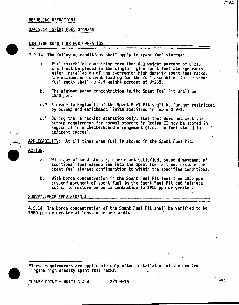
REFUELING OPERATIONS
3/4.9.14 SPENT FUEL STORAGE
~ ~
LIMITING CONOITION FOR OPERATION
3.9.14 The following conditions shall apply to spent fuel storage:
a. Fuel assemblies containing more than 4. 1 weight percent of U-235shall not be placed in the single region spent fuel storage racks.After installation of the two-region high density spent fuel racks,the maximum enrichment loading for the fuel assemblies in the spentfuel racks shall be 4.5 weight percent of U-235.
b. The minimum boron concentration inI the Spent Fuel Pit shall be1950 ppm.
c.* Storage in Region II of the Spent Fuel Pit shall be further restrictedby burnup and enrichment limits specified in Table 3.9-1.
d.* Ouring the re-racking operation only, fuel that does not meet theburnup requirement for normal. storage in Region II may be stored inRegion II in a checkerboard arrangement (i.e., no fuel stored inadjacent spaces).
APPLICABILITY: At all times when fuel is stored in the Spent Fuel Pit.1
ACTION:
a. With any of conditions a, c or d not satisfied, suspend movement ofadditional fuel assemblies into the Spent Fuel Pit and restore thespent fuel storage configuration to within the specified conditions.
b. With bo~on concentration in the Spent Fuel Pit less than 1950 ppm,suspend movement of spent fuel in the Spent Fuel Pit and initiateaction to restore boron concentration to 1950 ppm or greater.
SURVEILLANCE RE UIREMENTS
4.9.14 The boron concentration of the Spent Fuel Pit shall be verified to be1950 ppm or greater at least once per month.
"These requirements are applicable only after installation of the new two-' ~region high density spent fuel racks.
TURKEY POINT - UNITS 3 8E 4 3/4 9-15
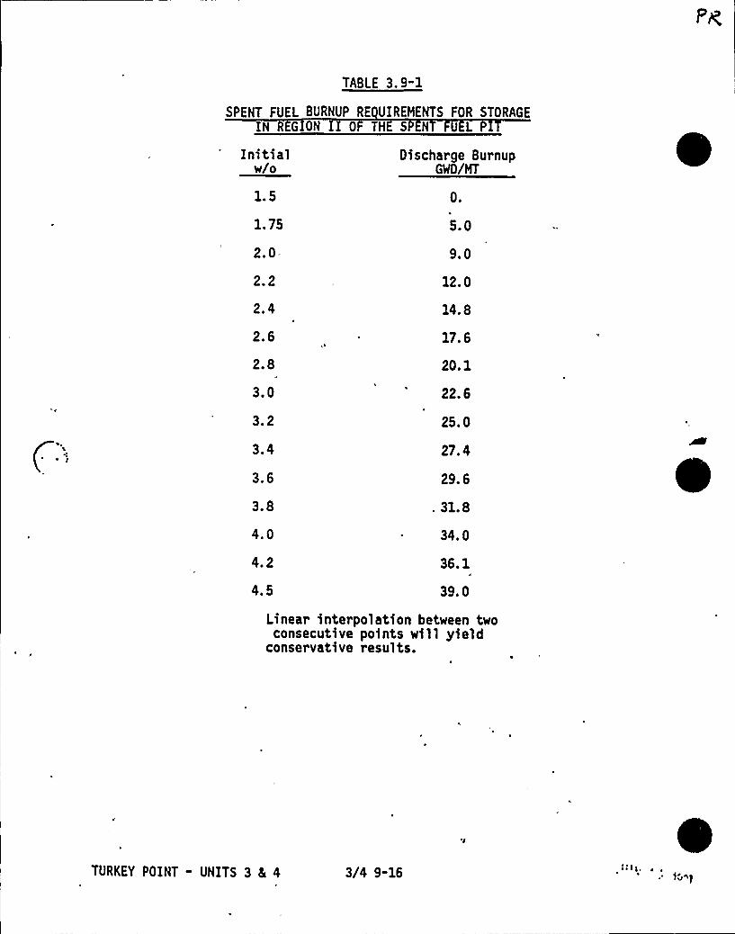
TABLE 3.9-1
SPENT FUEL BURNUP RE UIREHENTS FOR STORAGEIN GION II 0 THE S N UL
Initialw/o
1.5
1. 75
2.0-
2.2
2.4
2.6
2.8
3.0
3.2
3.4
3.6
3.8
4.0
4.2
4.5
Oischarge BurnupGWD/HT
0.
5.0
9.0
12. 0
14. 8
17. 6
20. 1
22. 6
25. 0
27. 4
29. 6
. 31.8
34. 0
36. 1
39. 0
Linear interpolation between twoconsecutive points will yield
conservative results.
TURKEY POINT - UNITS 3 5 4 3/4 9-16
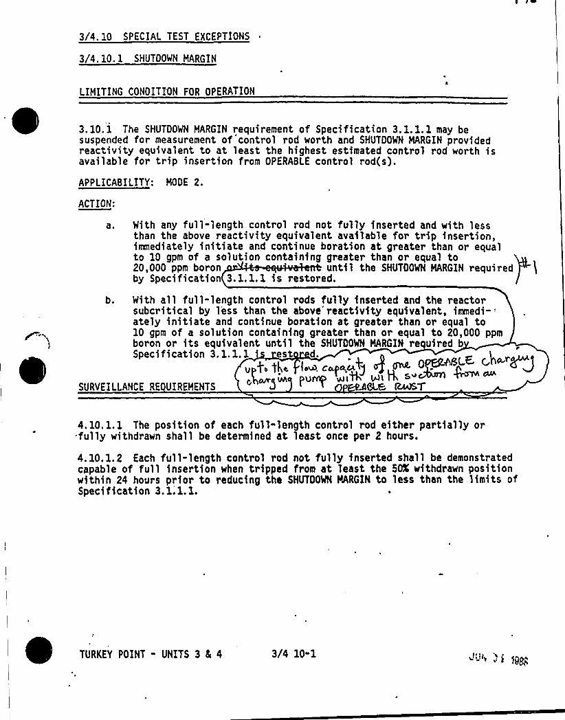
3/4. 10 SPECIAL TEST EXCEPTIONS
3/4. 10. 1 SHUTDOWN MARGIN
LIMITING CONDITI'ON FOR OPERATION
APPLICABILITY: MODE 2.
ACTION:
With any full-length control rod not fully inserted and with lessthan the above reactivity equivalent available for trip insertion,immediately initiate and continue boration at greater than or equalto 10 gpm of a solution containing greater than or equal to20,000 ppm boron until the GNUTOONN MARGIN requiredby Specification 3. 1. 1. 1 is restored.
With all full-length control rods fully inserted and the reactorsubcritical by less than the above'reactivity equivalent,
immedi-'telyinitiate and continue boration at greater than or equal to10 gpm of a solution containing greater than or equal to 20,000 ppmboron or its equivalent until the SHUTDOWN MARGIN re uired bSpecification 3.1.1.1 'st d.
As(.~ c,n ~"< «. ~ '~'> ~ K'g "pu+ uiW wl H
6L,& ~'T
b.
SURVEILLANCE RE UIREMENTS
3.10.1 The SHUTDOWN MARGIN requirement of Specification 3.1.1.1 may besuspended for measurement of control rod worth and SHUTDOWN MARGIN providedreactivity equivalent to at least the highest estimated control rod worth isavailable for trip insertion from OPERABLE control rod(s}.
4.10.1.1 The position of each full-length control rod either partially orfully withdrawn shall be determined at least once per 2 hours.
4. 10. 1.2 Each full-length control rod not fully inserted shall be demonstratedcapable of full insertion when tripped from at least the 50K withdrawn positionwithin 24 hours prior to reducing the SHUTDOWN MARGIN to less than the limits ofSpecification 3.1.1.1.
r
TURKEY POINT - UNITS 3 5 4 3/4 10-1
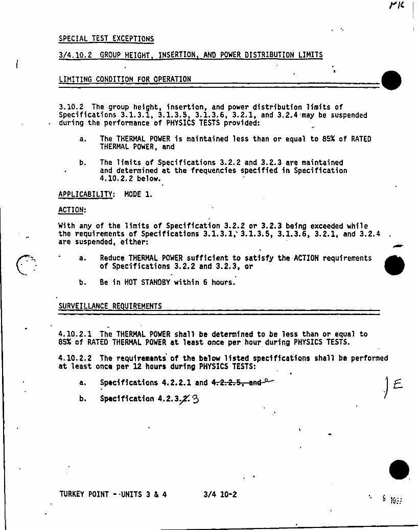
SPECIAL TEST EXCEPTIONS
3/4.10. 2 GROUP HEIGHT INSERTION AND POWER DISTRIBUTION LIMITS
LIMITING CONDITION FOR OPERATION
3. 10.2 The group height, insertion, and power distribution limits ofSpecifications 3. 1.3. 1, 3.1.3.5, 3. 1.3.6, 3.2. 1, and 3.2.4 may be suspendedduring the performance of PHYSICS TESTS provided:,
a. The THERMAL POWER is maintained less than or equal to BSX of RATEDTHERMAL POWER, and
b. The limits of Specifications 3.2.2 and 3.2.3 are maintainedand determined at the frequencies specified in Specification4.10.2.2 below.
APPLICABILITY: MODE l.ACTION:
With any of the limits of Specification 3.2.2 or 3.2.3 being exceeded whilethe requirements of Specifications 3. 1. 3. 1; 3. 1. 3.5, 3.1.3. 6, 3.2.1, and 3. 2.4are suspended, either:
a. Reduce THERMAL POWER sufficient to satisfy the ACTION requirementsof Specifications 3.2.2 and 3.2.3, or
b. Be in HOT STANDBY within 6 hours.
SURVEILLANCE RE UIREMENTS
4. 10.2. 1 The THERMAL POWER shall be determined to be less than or equal to85X of RATED THERMAL POWER at least once per hour during PHYSICS TESTS.
4.10.2.2 The requirements of the below listed specifications shall be performedat least once per 12 hours during PHYSICS TESTS:
a. Specifications 4.2.2.1 and
b. Spec<1<catkon 4.2.3P $
TURKEY POINT -.UNITS 3 4 4 3/4 10-2

SPECIAL TEST EXCEPTIONS
3/4. 10. 3 PHYSICS TESTS
LIMITING CONDITION FOR OPERATION
3. 10.3 The limitations of Specifications 3. l. 1.3, 3. l. 1.4, 3. 1.3. 1, 3. 1.3.5,and 3. 1.3.6 may be suspended during the performance of PHYSICS TESTS provided:
a. The THERMAL POWER does not exceed 5X of RATED THERMAL POWER,
b.
C.
The Reactor Trip Setpoints on the OPERABLE Intermediate and PowerRange channels are set at less than or equal to 25X of RATEDTHERMAL POWER, and g~The Reactor Coolant System lowe trloperating loop temperature (T )is greater than or equal to 531 F. avg
ACTION:
SURVEILLANCE RE UIREMENTS
APPLICABILITY: MODE 2.
r -1-'-'SR'/L +war R Lelosd S Po~>+ ~A4cca. With the T R L POWER greater than 5X of RATED THERMAL POWER,
immediately open the Reactor tri br kers.avero e.
b. With a Reactor Coolant System~ p r ng loop temperature ~-+less than 5314F, restore T—to within its limit within15 minutes or be in a least HOT STANDBY within the next15 minutes.
RGS aueca~e Pe pero~ure
)~
1
4. 10.3.1 The THERMAL POWER shall be determined to be. less than or equal to 5Xof RATED THERMAL POWER at least once per hour du~ing PHYSICS TESTS.
4.10.3.2 Each Intermediate and Power Range channel shall be subjected to anANALOG CHANNEL OPERATIONAL TEST within 12 hours prior to initiating PHYSICSTESTS.
aaen ae-4. 10.3.3 The Reactor Coolant System temp rature gT—+ shall be determined tobe greater than or equal to 5314F at least once per 30 minutes during PHYSICSTESTS.
TURKEY POINT - UNITS 3 4 4 3/4 10-3 l C,.5
SPECIAL TEST EXCEPTIONS
3/4. 10: is s e 'rati number 'ot us
TURKEY POINT - UNITS 3 5 4 3/4 10-4
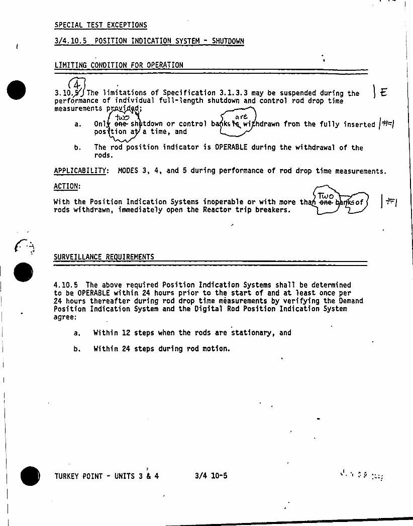
SPECIAL TEST EXCEPTIONS
3/4. 10. 5 POSITION INDICATION SYSTEM - SHUTDOWN
LIHITING CONDITION FOR OPERATION
3.10+ The limitations of Specification 3.1.3.3 may be suspended during the I Eperformance of individual full-length shutdown and control rod drop timemeasurements pr vi d;
tuZ) 4 3'8
a. Onl ene.sh tdown or control b kale,wi hdrawn fram the fu]]y inserted idf=ipos tion a a time, and
b. The rod position indicator is OPERABLE during the withdrawal of therods.
APPLICABILITY: HOOES 3, 4, and 5 during performance of rod drop time measurements.
ACT!OM:
TiesWith the Position Indication Systems inoperable or with more tha eve.rods withdrawn, immediately open the Reactor trip breakers.
SURVEILLANCE RE UIREHENTS
4. 10.5 The above required Position Indication Systems shall be determinedto be OPERABLE within 24 hours prior to the start of and at least once per24 hours thereafter during rod drop time measurements by verifying the DemandPosition Indication System and the Digital Rod Position Indication Systemagree;
a. Within 12 steps when the rods are stationary, and
b. Within 24 steps during rod motion.
3/4 10-5

/r1/4~/rc'n el~
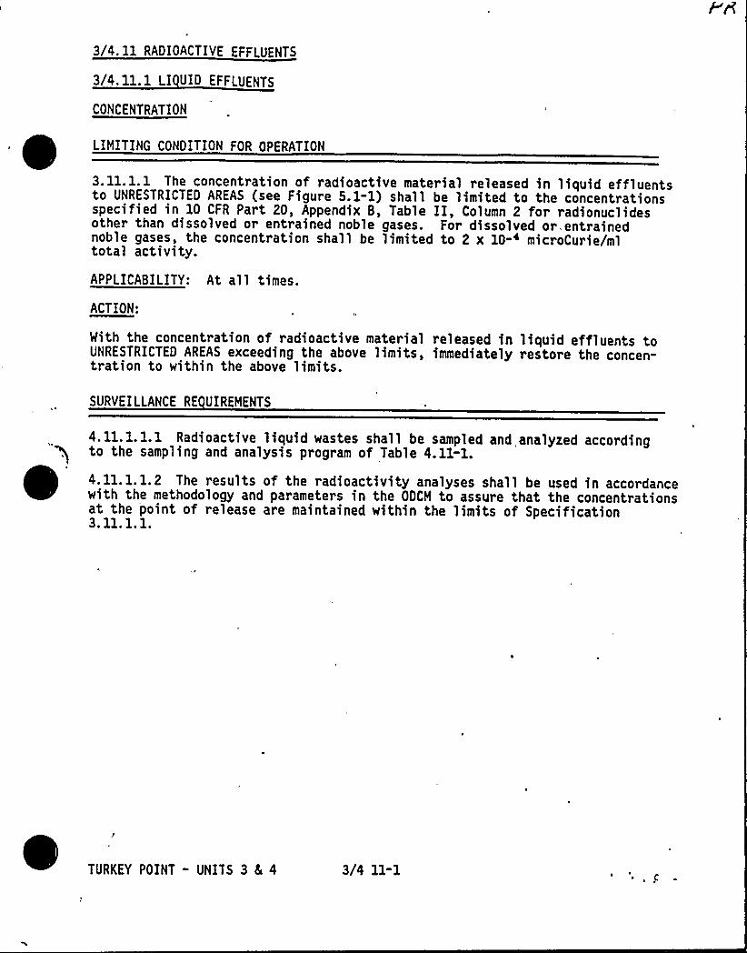
3/4. 11 RADIOACTIVE EFFLUENTS
3/4.11.1 LI UID EFFLUENTS
CONCENTRATION
LIMITING CONDITION FOR OPERATION
3.11.1.1 The concentration of radioactive material released in liquid effluentsto UNRESTRICTED AREAS (see Figure 5.1-1) shall be limited to the concentrationsspecified in 10 CFR Part 20, Appendix B, Table II, Column 2 for radionuclidesother than dissolved or entrained noble gases. For dissolved or. entrainednoble gases, the concentration shall be limited to 2 x 10-~ microCurie/mltotal activity.
APPLICABILITY: At all times.
ACTION:
With the concentration of radioactive material released in liquid effluents toUNRESTRICTED AREAS exceeding the above limits, immediately restore the concen-tration to within the above limits.
SURVEILLANCE RE UIREMENTS
4. 11.1.1.1 Radioactive liquid wastes shall be sampled and,analyzed accordingto the sampling and analysis program of Table 4.11-1.
4. 11.1.1.2 The results of the radioactivity analyses shall be used in accordancewith the methodology and parameters in the ODCH to assure that the concentrationsat the point of release are maintained within the limits of Specification3. 11. 1. 1.
I
TURKEY POINT - UNITS 3 8 4 3/4 11-1

TABLE 4.11-1
RADIOACTIVE LI UID WASTE SAMPLING AND ANALYSIS PROGRAM
LIQUID RELEASETYPE
1. Batch WasteRelease
Tanks
SAMPLING'REQUENCY
P
Each Batch
MINIMUM
ANALYSISFREQUENCY
P
Each Batch
TYPE OF ACTIVITYANALYSIS
Principal Gaiiima
EmittersI-131
LOWER LIMITOF DETECTIO
(LLD)(1)(pCi/ml)
Sxl0-7
lxl0-s
P
One Batch/M
P
Each BatchM
Composite
Dissolved andEntrained Gases(Gamma Emitters)
H-3
Gross Alpha
lxl0-s
lx10-s
lx10-7
2. Continuous
Releases
a. SteamGener atop)Blowdown
('.~'4 eDrain
P
Each Batch
M(8)
W(8)
W(8)
Q 4Composite(")
M(8)
(')Composite
Q(8)Composite
Sr-89, Sr-90
Fe-55
Principal Gamma
Emitters
I-131
Dissolved andEntrained Gases(Gamma Emitters)
Gross Alpha
.Sr-89, Sr-90
Fe-55
Principal Gaaea
Emitters
I-131
5x10-s
Ix10-s
5x10-7
lx10-s
lxl0-s
lx10-s
lx10-7
5x10 s
lx10-s
5xlO-~
1x10-s
jp
- TURKEY POINT - UNITS 3 Ec 4 3/4 11-2

TABLE 4.11" 1 continued
TABLE NOTATIONS
(1) The LLD is the smallest concentration of radioactive material in a sample0
that will be detected with 95K probability with only SX probability offalsely concluding that a blank observation represents a "real" signal.
for a particular measurement system, which may include radiochemicalseparation:
4.66LLD =
~ V ~ .2 x 1 ~ ~ exp -UtWhere:
LLD' the "a priori" lower limit of detection as defined above
for a blank sample (microCurie per unit mass or volume),
sb = the standard deviation of the background counting rateor of the counting rate of a blank sample as appropriate(counts per minute),
.E = the counting efficiency (counts per disintegration),
V = the sample size (units of mass or volume),
2.22 x 10' the number of disintegrations per minute per microCurie,
Y = the fractional radiochemical yield, when applicable,
the radioactive decay constant for the particularradionuclide, and
Lt = the elapsed time between the midpoint of sample collectionand the time of counting (for plant effluents, notenvironmental samples).
The value of sb used in the calculation of the LLD for a detection system
shall be based on the actual observed variance of the background countingrate or of the counting rate of the blank samples (as appropriate) ratherthan on an unverified theoretically predicted variance. Typical values ofE, V, Y, and ht should be used in the calculation.
A batch release is the discharge of liquid wastes of a discrete volume.(2)Prior to sampling for analyses, each batch shall be isolated, and thenthoroughly mixed by a method described in the ODCM to assure representa-tive sampling.
TURKEY POINT - UNITS 3 84 4 3/4 11-3
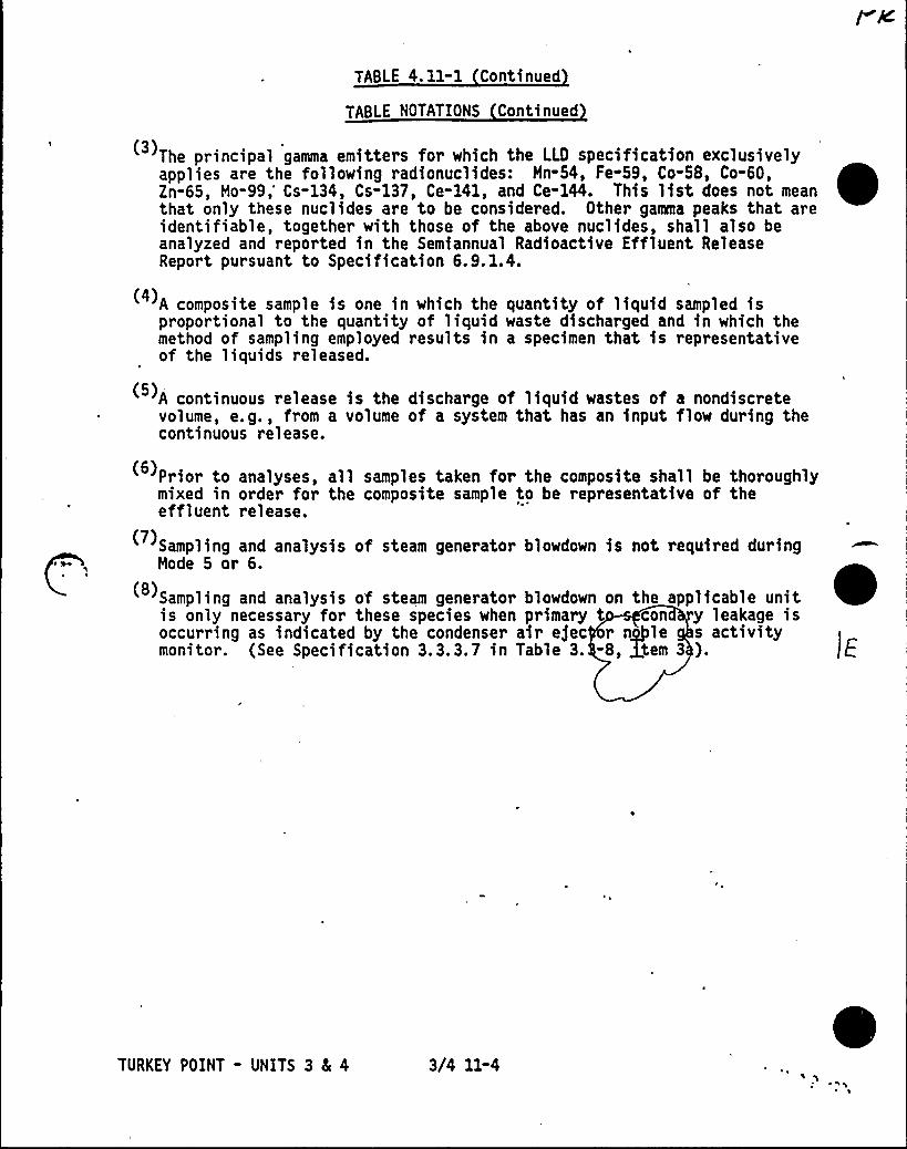
TABLE 4. 11-1 Continued
TABLE NOTATIONS Continued
The principal gamma emitters for which the LLO specification exclusivelyapplies are the following radionuclides: Hn-54, Fe-59, Co-58, Co-60,Zn-65, Ho-99,'s-134, Cs-137, Ce-141, and Ce-144. This list does not meanthat only these nuclides are to be considered. Other gamma peaks that areidentifiable, together with those of the above nuclides, shall also beanalyzed and reported in the Semiannual Radioactive Effluent ReleaseReport pursuant to Specification 6.9.1.4.
A composite sample is one in which the quantity of liquid sampled isproportional to the quantity of liquid waste discharged and in which themethod of sampling employed results in a specimen that is representativeof the liquids released.
A continuous release is the discharge of liquid wastes of a nondiscretevolume, e.g., from a volume of a system that has an input flow during thecontinuous release.
C'rior to analyses, all samples taken for the composite shall be thoroughly(6)mixed in order for the composite sample to be representative of theeffluent release.
Sampling and analysis of steam generator blowdown is not required duringMode 5 or 6.
Sampling and analysis of steam generator blowdown on the applicable unitis only necessary for these species when primary t con y leakage isoccurring as indicated by the condenser air e$ ec r nile s activitymonitor. (See Specification 3.3.3.7 in Table 3. -8, Stem 3 ).
TURKEY POINT - UNITS 3 8E 4 3/4 11-4
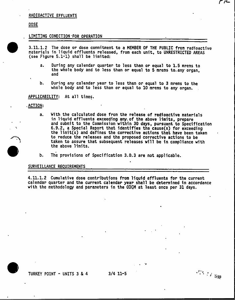
RADIOACTIVE EFFLUENTS
DOSE
LIMITING CONDITION 'FOR OPERATION
3. 11. 1.2 The dose or dose commitment to a HEHBER OF THE PUBLIC from radioactive~ ~~
~
~materials in liquid effluents released, from each unit, to UNRESTRICTED AREAS(see Figure 5. 1-1) shall be limited:
a. During any calendar quarter to less than or equal to 1.5 mrems tothe whole body and to less than or equal to 5 mrems to any organ,and
b. During any calendar year to less than or equal to 3 mrems to thewhole body and to less than or equal to 10 mrems to any organ.
APPLICABILITY: At all times.
. ACTION:
With the calculated dose from the release of radioactive materialsin liquid effluents exceeding any. of the above limits, prepareand submit to the Commission within 30 days, pursuant to Specification6.9.2, a Special Report that identifies the cause(s) for exceedingthe limit(s) and defines the corrective actions that have been takento reduce the releases and the proposed corrective actions to betaken to assure that subsequent releases will be in compliance withthe above limits.
b. The provisions of Specification 3.0.3 are not applicable.
SURVEILLANCE RE UIREHENTS
4.11.1.2 Cumulative dose contributions from liquid effluents for the currentcalendar quarter and the current calendar year shall be determined in accordancewith the methodology and parameters in the ODCM at least once per 31 days.
TURKEY POINT - UNITS 3 8( 4 3/4 11-5
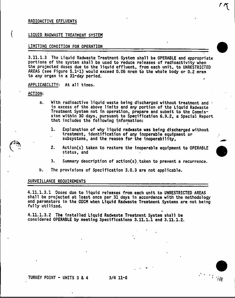
RADIOACTIVE EFFLUENTS
LI UID RAOWASTE TREATMENT SYSTEM
LIMITING CONDITION FOR OPERATION
3.11. 1.3 The Liquid Radwaste Treatment System shall be OPERABLE and appropriateportions of the system shall be used to reduce releases of radioactivity whenthe projected doses due to the liquid effluent, from each unit, to UNRESTRICTEDAREAS (see Figure 5. 1-1) would exceed 0.06 mrem to the whole body or 0.2 mremto any organ in a 31-day period.
I
APPLICABILITY: At al 1 times.
ACTION:
a. With radioactive liquid waste being discharged without treatment and .
in excess of the above limits and any portion of the Liquid RadwasteTreatment System not in operation, prepare and submit to the Commis-sion within 30 days, pursuant to Specification 6. 9.2, a Special Reportthat includes the following information:
l. Explanation of why liquid radwaste was being discharged withouttreatment, identification of any inoperable equipment orsubsystems, and the reason for the inoperability,
2. Action(s) taken to restore the inoperable equipment to OPERABLEstatus, and
3. Summary description of action(s) taken to prevent a recurrence.
b. The provisions of Specification 3.0.3 are not applicable.
SURVEILLANCE RE UIREMENTS
4. 11.1.3.1 Doses due to liquid releases from each unit to UNRESTRICTED AREASshall be projected at least once per 31 days in accordance with the methodologyand parameters in the ODCM when Liquid Radwaste Treatment Systems are not beingfully utilized.
4. 11.1.3.2 The installed Liquid Radwaste Treatment System shall beconsidered OPERABLE by meeting Specifications 3.11.1.1 and 3.11.1.2.
TURKEY POINT - UNITS 3 8( 4 3/4 11-6
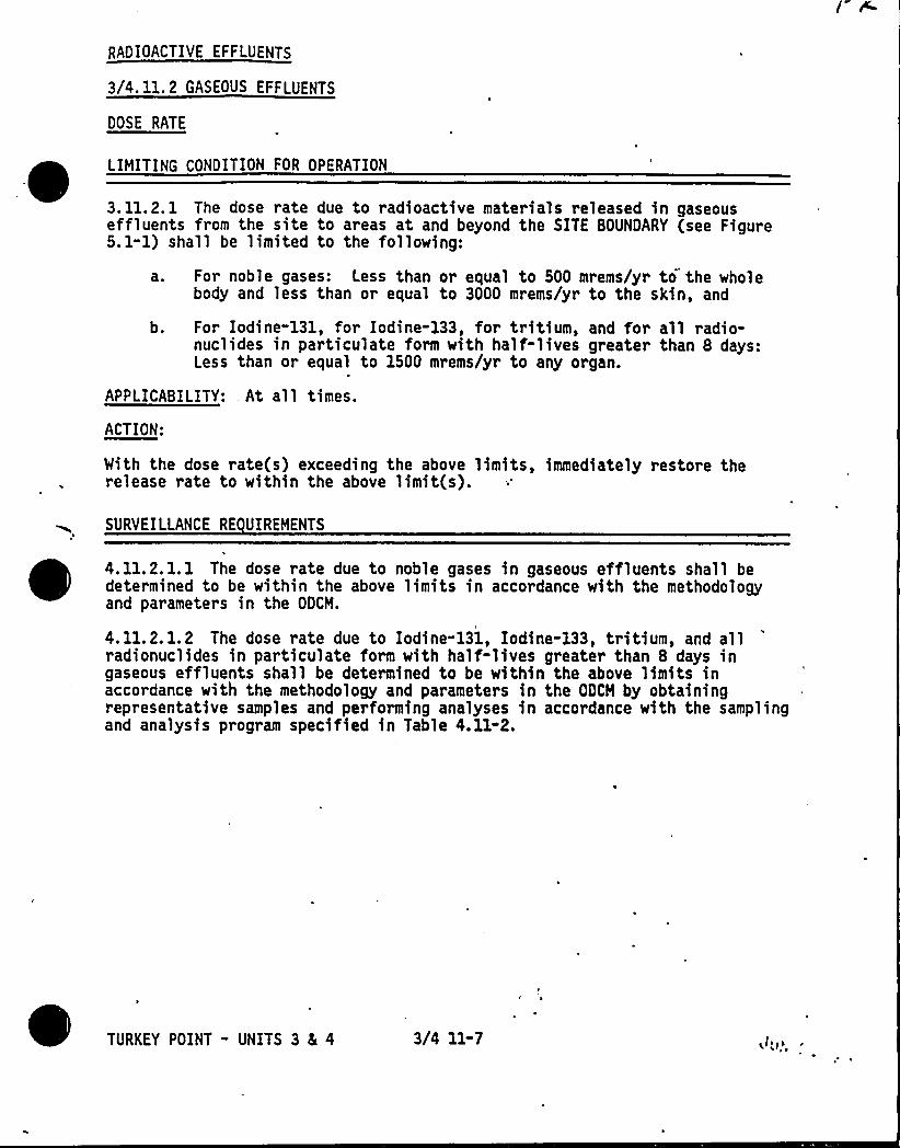
RADIOACTIVE EFFLUENTS
3/4. 11.2 GASEOUS EFFLUENTS
DOSE RATE
LIMITING CONDITION FOR OPERATION
~ ~ ~3. 11.2. 1 The dose rate due to radioactive materials released in gaseouseffluents from the site to areas at and beyond the SITE BOUNDARY (see Figure5. 1-1) shall be limited to the following:
a. For noble gases: Less than or equal to 500 mrems/yr to the wholebody and less than or equal to 3000 mrems/yr to the skin, and
b. For Iodine-131, for Iodine-133, for tritium, and for all radio-nuclides in particulate form with half-lives greater than 8 days:Less than or equal to 1500 mrems/yr to any organ.
APPLICABILITY:,At all times.
ACTION:
With the dose rate(s) exceeding the above limits, immediately restore therelease rate to within the above limit(s).
SURVEILLANCE RE UIREMENTS
~ ~ ~~ ~
~
4.11.2.1.1 The dose rate due to noble gases in gaseous effluents shall bedetermined to be within the above limits in accordance with the methodologyand parameters in the ODCM.
4.11.2.1.2 The dose rate due to Iodine-131, Iodine-133, tritium, and allradionuclides in particulate form with half-lives greater than 8 days ingaseous effluents shall be determined to be within the above limits inaccordance with the methodology and parameters in the ODCM by obtainingrepresentative samples and performing analyses in accordance with the samplingand analysis program specified in Table 4.11-2.
3/4 11-7
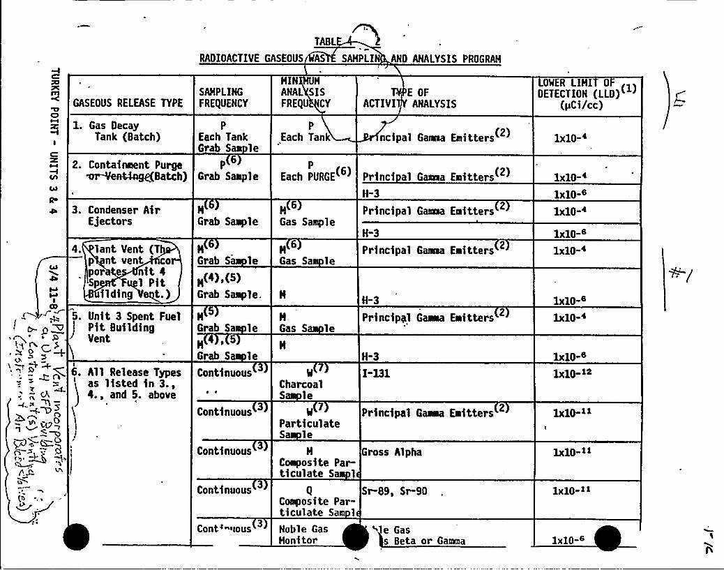
TABL
RADIOACTIVE GASEOUS AS SAMPLI AND ANALYSIS PROGRAM
WI
CO
~ ~g O
o~ CQA
8~ ~Cgg
J(b
~tP
GASEOUS RELEASE TYPE
1. Gas DecayTank (Batch)
2. Containment PurgeBatch)
3. Condenser AirEjectors
lant Vent (Tp nt vent opor e nit 4Sp 1 Pit
ilding qt.)5. Unit 3 Spent Fuel
Pit BuildingVent
6. All Release Typesas listed in 3.,4., and 5. above
SAMPLINGFREqUENCY
P
Each TankGrab SaN le
P6
Grab Salple
HGrab Saiiple
1Grab S leM(4),(5)Grab Saaple.
HGrab Sa le
Grab S leContinuous
Continuous
Continuous
Continuous
Cont'ious
MIN M
ANAL SISFREQU CY
P
Each Tank
P
Each PURGE
Gas Sample
M
Gas Sa le
HGas S le
CharcoalS le
ParticulateS le
M
Coiiiposite Par-ticulate S 1
Coliposite Par-ticulate Sam 1
Noble GasMonitor
E OFACTIVI ANALYSIS
ncipal Gawaa Emiitters
Princi al Gaeaa EoittersH-3
Principal Gaaea Eilitters
H-3
Principal Gaaaa Eiaitters
H-3
Principyl aiaaa Eeitters
H-3
I-131
Principal Gama EIiitters
Gross Alpha
Sr-89, Sr-90
le Gass Beta or Gamma
LOWER LIMI 0DETECTION (LLD)
(pCi/cc)
1x10-
1x10-~
1xlO-6
x10 B
1 iO-~
1x10⁻⁶
1x10-i
1x10-~~
1x]O-»
1x10-»
1x10⁻⁶n
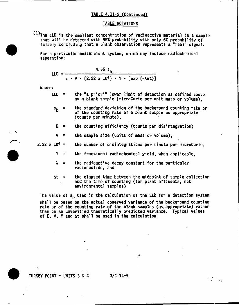
TABLE 4. 11-2 Continued
TABLE NOTATIONS
(1}The LLD is the smallest concentration of radioactive material in a samplethat will be detected with 95X probability with only 5X probability offalsely concluding that a blank observation represents a "real" signal.
For a particular measurement system, which may include radiochemicalseparation:
LLD4.66 sb
E ' (2.22 x 10 ) ~ Y . [exp (-Mt)]Where:
LLD = the "a priori" lower limit of detection as defined aboveas a blank sample (microCurie per unit mass or volume),
sb = the standard deviation of the background counting rate orof the counting rate of a blank sample as appropriate(counts per minute},
E = the counting efficiency (counts per disintegration)
V = the sample size (units of mass or volume),
2.22 x 10' the number of disintegrations per minute per microCurie,
Y = the fractional radiochemical yield, when applicable,
the radioactive decay constant for the particularradionuclide, and
ht = the elapsed time between the midpoint of sample collectionand the time of counting (for plant effluents, notenvironmental samples)
The value of sb used in the calculation of the LLD for a detection system
shall be based on the actual observed variance of the background countingrate or of the counting rate of the blank samples (as. appropriate) ratherthan on an unverified theoretically predicted variance. Typical valuesof E, V, Y and ht shall be used in the calculation.
TURKEY POINT - UNITS 3 8 4 3/4 11-9
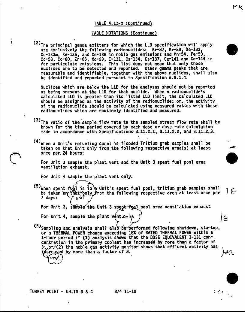
TABLE 4. 11-2 Continued
TABLE NOTATIONS Continued
The principal gamma emitters for which the LLD specification will apply(2)are exclusively the following radionuclides: Kr-87, Kr-88, Xe-133,Xe-133m, Xe-135, and Xe-138 in noble gas emissions and Mn-54, Fe-59,Co-58, Co-60, Zn-65, Mo-99, I-131, Cs-134, Cs-137, Ce-141 and Ce-144 infor particulate emissions. This list does not mean that only thesenuclides are to be detected and reported. Other ganna peaks that aremeasurable and identifiable, together with the above nuclides, shall alsobe identified and reported pursuant to Specification 6.9.1.4.
Nuclides which are below the LLD for the analyses should not be reportedas being present at the LLD for that nuclide. When a radionuclide'scalculated LLD is greater than its listed LLD limit, the calculated LLDshould be assigned as the activity of the radionuclide; or, the activityof the radionuclide should be calculated using measured ratios with thoseradionuclides which are routinely identified and measured.
The ratio of the sample flow rate to the sampled stream flow rate shall beknown for the time period covered by each dose or dose rate calculationmade in accordance with Specifications 3.11.2.1, 3.11.2.2, and 3.11.2.3.
When a Unit's refueling canal is flooded Tritium grab samples shall betaken on that Unit only from the following respective area(s) at leastonce per. 24 hours:
For Unit 3 sample the plant vent and the Unit 3 spent fuel pool areaventilation exhaust.
For Unit 4 sample the plant vent only.
When spent f 1 is in Unit's spent fuel pool, tritium grab samples shallbe taken o at~only rom the following respective area at least once per7 days: pviif
For Unit 3, s the Unit 3 spe 1 pool area ventilation exhaust
For Unit 4, sample the p lant v'nt.mnli/,C.
Sampling and analysis shall also performed following shutdown, startup,or a THERMAL POWER change exceeding 15K of RATED THERMAL POWER within a1-hour period if (1) analysis shows that the DOSE E)UIVALENT I-131 con-centration in the primary coolant has increased by moro than a factor of3; (2) the noble gas activity monitor shows that effluent activity hasi creased by more than a factor of 3. 4Q
Ay)g ~
TURKEY POINT - UNITS 3 4 4 3/4 11-10
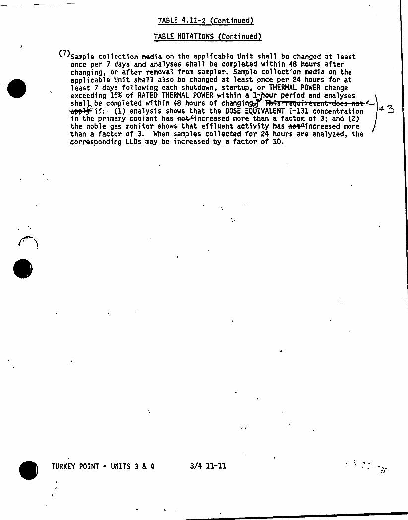
TABLE 4. 11-2 Continued
TABLE NOTATIONS Continued
(7) Sample collection media on the applicable Unit shall be changed at leastonce per 7 days and analyses shall be completed within 48 hours afterchanging, or after removal from sampler. Sample collection media on theapplicable Unit shall also be changed at least once per 24 hours for atleast 7 days following each shutdown, startup, or THERMAL POWER changeexceeding 15X of RATED THERMAL POWER within a I-hour period and analysesshal be completed within 48 hours of changinaP
if: (1) analysis shows that the DOSE EglJIVALENT I-131 concentrationin the primary coolant has ~increased more than a factor of 3; and (2)the noble gas monitor shows that effluent activity has ~increased morethan a factor of 3. When samples collected for 24 hours are analyzed, thecorresponding LLQs may be increased by a factor of 10.
TURKEY POINT - UNITS 3 4 4 3/4 11-11
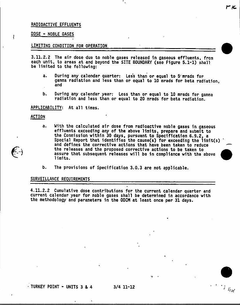
RADIOACTIVE EFFLUENTS
DOSE - NOBLE GASES
LIMITING CONDITION FOR OPERATION
3.11.2.2 The air dose due to noble gases released in gaseous effluents, fromeach unit, to areas at and beyond the SITE BOUNDARY (see Figure 5.1-1) shallbe limited to the following:
a. During any calendar quarter: Less than or equal to 5" mrads forgamma radiation and less than or equal to 10 mrads for beta radiation,and
b. During any calendar year: Less than or equal to 10 mrads for gammaradiation and less than or equal to 20 mrads for beta radiation.
APPLICABILITY: At all times.
ACTION
With the calculated air dose from radioactive noble gases in gaseouseffluents exceeding any of the above limits, prepare and submit tothe Commission within 30 days, pursuant to Specification 6.9.2, aSpecial Report that identifies the cause(s) for exceeding the limit(s)and defines the corrective actions that have been taken to reducethe releases and the proposed corrective actions to be taken toassure that subsequent releases will be in compliance with the abovelimits.
b. The pr ov i s ions of Speci ficati on 3.0. 3 are not app1 icab 1 e.
SURVEILLANCE RE UIREMENTS
4. 11.2.2 Cumulative dose contributions for the current calendar quarter andcurrent calendar year for noble gases shall be determined in accordance withthe methodology and parameters in the ODCM at least once per 31 days.
TURKEY POINT - UNITS 3 81 4 3/4 11-12
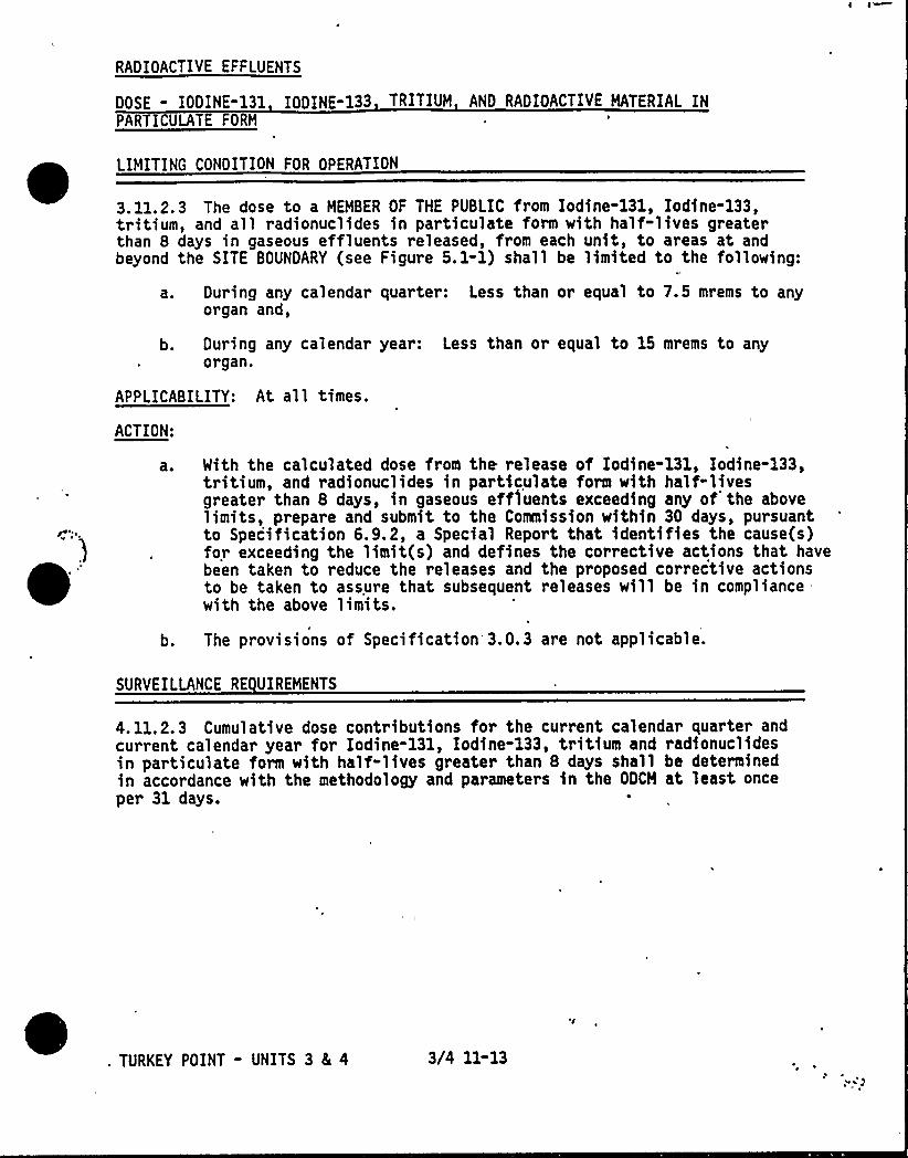
RADIOACTIVE EFFLUENTS
DOSE - IODINE-131 IODINE-133 TRITIUM AND RADIOACTIVE MATERIAL INPARTICULATE FORM
LIMITING CONDITION FOR OPERATION
3.11.2.3 The dose to a MEMBER OF THE PUBLIC from Iodine-131, Iodine-133,tritium, and all radionuclides in particulate form with half-lives greaterthan 8 days in gaseous effluents released, from each unit, to areas at andbeyond the SITE BOUNDARY (see Figure 5. 1-1) shall be limited to the following:
a. During any calendar quarter: Less than or equal to 7.5 mrems to anyorgan and,
b. During any calendar year: Less than or equal to 15 mrems to anyorgan.
APPLICABILITY: At all times.
ACTION:
aO With the calculated dose from the release of Iodine-131, Iodine-133,tritium, and radionuclides in particulate form with half-livesgreater than 8 days, in gaseous effluents exceeding any of'he abovelimits, prepare and submit to the Commission within 30 days, pursuantto Specification 6.9.2, a Special Report that identifies the cause(s)for exceeding the limit(s) and defines the corrective actions that havebeen taken to reduce the releases and the proposed corrective actionsto be taken to assure that subsequent releases will be in compliancewith the above limits.
b. The provisions of Specification 3.0.3 are not applicable.
SURVEILLANCE RE UIREMENTS
4.11.2.3 Cumulative dose contributions for the current calendar quarter andcurrent calendar year for Iodine-131, Iodine-133, tritium and radionuclidesin particulate form with half-lives greater than 8 days shall be determinedin accordance with the methodology and parameters in the ODCM at least onceper 31 days.
TURKEY POINT - UNITS 3 & 4 3/4 11-13
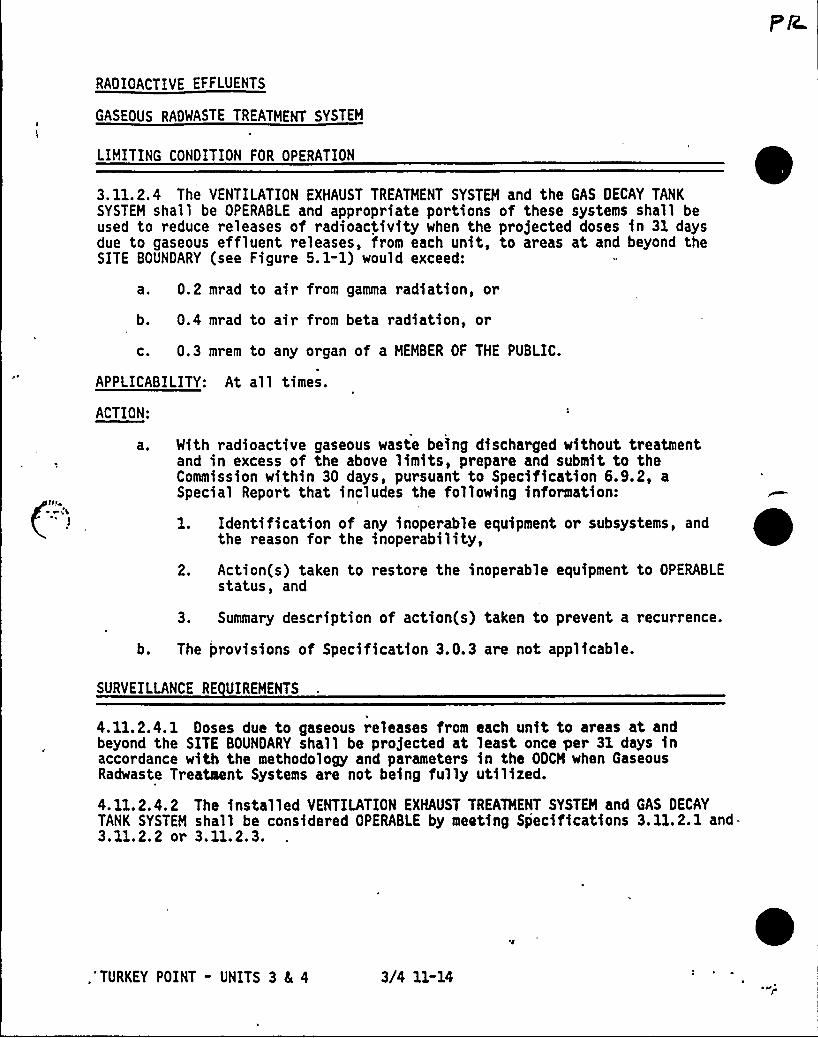
RADIOACTIVE EFFLUENTS
GASEOUS RADWASTE TREATMENT SYSTEM
LIMITING CONDITION FOR OPERATION
3. 11.2.4 The VENTILATION EXHAUST TREATMENT SYSTEM and the GAS DECAY TANKSYSTEM shall be OPERABLE and appropriate portions of these systems shall beused to reduce releases of radioactivity when the projected doses in 31 daysdue to gaseous effluent releases, from each unit, to areas at and beyond theSITE BOUNDARY (see Figure 5. 1-1) would exceed:
a. 0.2 mrad to air from gamma radiation, or
b. 0.4 mrad to air from beta radiation, or
c. 0.3 mrem to any organ of a MEMBER OF THE PUBLIC.
APPLICABILITY: At all times.
ACTION:
With radioactive gaseous waste being discharged without treatmentand in excess of the above limits, prepare and submit to theCommission within 30 days, pursuant to Specification 6.9.2, aSpecial Report that includes the following information:
l. Identification of any inoperable equipment or subsystems, andthe reason for the inoperability,
2. Action(s) taken to restore the inoperable equipment to OPERABLEstatus, and
3. Summary description of action(s) taken to prevent a recurrence.
b. The provisions of Specification 3.0.3 are not applicable.
SURVEILLANCE RE UIREMENTS
4.11.2.4.1 Doses due to gaseous releases from each unit to areas at andbeyond the SITE BOUNDARY shall be projected at least once per 31 days inaccordance with the methodology and parameters in the ODCM when GaseousRadwaste Treatment Systems are not being fully utilized.
4.11.2.4.2 The installed VENTILATION EXHAUST TREATMENT SYSTEM and GAS DECAYTANK SYSTEM shall be considered OPERABLE by meeting Specifications 3. 11.2.1 and.3.11.2.2 or 3.11.2.3.
,'TURKEY POINT - UNITS 3 4 4 3/4 11-14
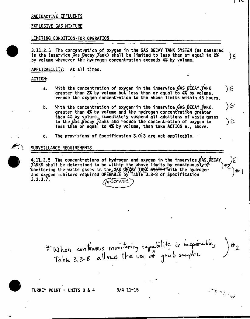
RADIOACTIVE EFFLUENTS
EXPLOSIVE GAS MIXTURE
LIMITING CONDITION FOR OPERATION
3. 11. 2. 5 The concpntration of oxygen in the GAS DECAY TANK SYSTEM (as measuredin the inservice /fang'ecay fank) shall be limited to less than or equal to 2%
) gby volume whenever the hydrogen concentration exceeds 4X by volume.
APPLICABILITY: At all times.
ACTION:
a ~
b.
C.
With the concentration of oxygen in the inservicepAS CAY JANKgreater than 2X by volume but less than or equal to 4 by volume,reduce the oxygen concentration to the above limits within 48 hours.
With the concentration of oxygen in the inservicepAS JECAYQANK.greater than 4X by volume and the hydrogen concentration greaterthan 4X by volume, immediately suspend all additions of waste gasesto the gas J[ecay inks and reduce the concentration of oxygen toless than or equal to 4S by volume, then take ACTION a., above.
The provisions of Specification 3.0:3 are not applicable.
SURVEILLANCE RE UIREHENTS
4.11.2.5 The concentrations of hydrogen and oxygen in the inservicegAS/ECAYfANKS shall be determined to be within the above limits by continuouslyW ')mZmonitoring the waste gases in the PP)P]kgb/ g+ SYSTEM with the hydrogen )db )and oxygen monitors required OPE HLE by'able 3.3-8 of Specification3.3.3.7. fg-5cI AGK
~lsd I,8 is sw orner ~~~gCaw[ llnudug Ivio>~'"J p
T $g ~ ~ g ~ll~s We Usc of
TURKEY POINT - UNITS 3 8[ 4 3/4 11-15
RADIOACTIVE EFFLUENTS
GAS DECAY TANKS
LIMITING CONDITION FOR OPERATION
3. 11.2.6 The quantity of radioactivity contained in each gas decay tankshall be limited to less than or equal to 70,000 Curies of noble gases (con-sidered as Xe-133 equivalent).
APPLICABILITY: At all times.
ACTION:
With the quantity of radioactive material in any gas decay tankexceeding the above limit, immediately suspend all additions ofradioactive material to the tank, within 48 hours reduce the tankconte'nts to within the limit, and describe the events leading to thiscondition in the next Semiannual Radioactive Effluent Release Report,pursuant to Specification 6.9.1.4.
b. The provisions of Specification 3.0.3 are not applicable.
SURVEILLANCE RE UIREMENTS
~ ~ ~4. 11.2.6 The quantity of radioactive material contained in each gas decaytank shall be determined to be within the above limit at least once per 24hours when radioactive materials are being added to the tank and the ReactorCoolant System total activity exceeds the limit of Specification 3.4.8.
TURKEY POINT - UNITS 3 Sc 4 3/4 11-16

RADIOACTIVE EFFLUENTS
3/4. 11. 3 SOLID RADIOACTIVE WASTES
LIMITING CONDITION FOR OPERATION
l ~g'I''+/~+7"r/ 1 / I
4. 11. 3. 1with the PCP.
4.11.3e2 SOLIDIFICATION (excluding dewatering) of at least one representativetest specimen from at least every tenth batch of each type of wet radioactivewastes (e.g., filter'ludges, spent resins, evaporator bottoms, boric acidsolutions, and sodium sulfate solutions) shall be verified in accordance withthe PROCESS CONTROL PROGRAM:
a. If any test specimen fails to verify SOLIDIFICATION, the SOLIDIFICATIONof the batch under test shall be suspended until such time as additionaltest specimens can be obtained, alternative SOLIDIFICATION parameterscan be determined in accordance with the PROCESS CONTROL PROGRAM,and a subsequent test verifies SOLIDIFICATION. SOLIDIFICATION ofthe batch may then be resumed using the alternative SOLIDIFICATIONparameters determined by the PROCESS CONTROL PROGRAM;
b. If the initial test specimen from a batch of waste fails to verifySOLIDIFICATION, the PROCESS CONTROL PROGRAM shall provide for thecollection and testing of representative test specimens from eachconsecutive batch of the same type of wet waste until at least threeconsecutive initial test specimens demonstrate SOLIDIFICATION.The PROCESS CONTROL PROGRAM shall be modified as required, as providedin Specification 6.13, to assure SOLIDIFICATION of. subsequent batchesof waste; and
c. With the installed equipment incapable of meeting Specificati'on3. 11.3 or declared inoperable, restore the equipment to OPERABLEstatus or provide for contract capability to process wastes asnecessary to.satisfy all applicable transportation and disposalrequirements.
TURKEY POINT - UNITS 3 8 4 3/4 11-17 /I ~~
1
I F.r3. 11.3 gadioactive wastes shall be in accordance withthe PROCESS CONTROL PROGRAM to meet shipping and transportation requirements
,..p ~ qi ~h I h1$ G op/cool llccr~5~i~ ~B %e conoicnec' ifyam )coflrA+<.
APPLICABILITY: At e11 'times'.
ACTION:o I,coo m Ilcmll5 nid reef <?)f ori..e, ~ GT
e. With SOLIDIFICATION or re iiot me et'i ngf' 'en~ roe..oirrG
shipping and transportation requirements, suspend shipment of theinadequately processed wastes and correct the PROCESS CONTROL PROGRAM,the procedures, and/or the Solid Waste System as necessary to preventrecurrence.
b. With SOLIDIFICATION or dewatering not performed in accordance withthe PROCESS CONTROL PROGRAM, test the improperly processed waste ineach container to ensure that it meets and shippingrequirements a aQ~pp dmi ietrmtisrs-ection-ta.~r euen~recurrence. re
aphonica linen i'e~uireeerF'm oF Fge coro)see >
c. The provisions of peC are not-ayplkcabl e-.
SURVEILLANCE RE UIREMENTS r
RADIOACTIVE EFFLUENTS
3/4.11.4 TOTAL DOSE
LIHITING CONDITION FOR OPERATION
3. 11.4 The annual (calendar year) dose or dose commitment to any HEHBER OF
THE PUBLIC due to releases of radioactivity and to radiation from uranium fuelcycle sources shall be limited to less than or equal to 25 mrems to the wholebody or any organ, except the thyroid, which shall be limited to less than orequal to 75 mrems.
APPLICABILITY: At all times.ACTION:
0
aO
b.
With the calculated doses from the release of radioactive materialsin liquid or gaseous effluents exceeding twice the limits of Specifi-cation 3.11.1.2a., 3.11.1.2b., 3.11.2.2a., 3.11.2.2b., 3.11.2.3a., or3. 11.2.3b., calculations shall be made including direct radiationcontributions from the units to determine whether the above limitsof Specification 3.11.4 have been exceeded. If such is the case,prepare and submit to the Commission within 30 days, pursuant toSpecification 6. 9. 2, a Special Report that defines the correctiveaction to be taken to reduce subsequent releases to prevent recur-rence of exceeding the above limits and includes the schedule forachieving conformance with the above limits. This Special Report,as defined in 10 CFR 20.405(c), shall include an analysis thatestimates the radiation exposure (dose) to a HEHBER OF THE PUBLICfrom uranium fuel cycle sources, including all effluent. pathwaysand direct radiation, for the calendar year that includes therelease(s) covered by this report. It shall also describe levelsof radiation and concentrations of radioactive material involved, andthe cause of the exposure levels or concentrations. If the estimateddose(s) exceeds the above limits, and if the release condition result-ing in violation of 40 CFR Part 190 has not already been corrected,the'Special Report shall include a request for a variance in accor-dance with the provisions of 40 CFR Part 190. Submittal of the reportis considered a timely request, and a variance is granted until staffaction on the request is complete.
The provisions of Specification 3.0.3 are not applicable.
SURVEILLANCE RE UIREHENTS
4.11.4.1 Cumulative dose contributions froa liquid and gaseous effluentsshall be determined in accordance with Specifications 4.11.1.2, 4.11.2.2, and4.11.2.3, and in accordance with the methodology and parajaeters in the ODCH.
4.11.4.2 Cumulative dose contributions from direct radiation from the unitsand the methodology used shall be indicated in the Semiannual RadioactiveEffluent Release Report. This requirement is applicable only under conditionsset forth in ACTION a. of Specification 3.11.4.
TURKEY POINT - UhITS 3 4 4 3/4 11-18 ~~
3/4. 12 RADIOLOGICAL ENVIRONMENTAL MONITORING
3/4. 12. 1 MONITORING PROGRAM
LIMITING CONDITION FOR OPERATION
3. 12. 1 The Radiological Environmental Monitoring Program shall be conducted~ ~~
~ ~
~as specified in Table 3.12-1.
APPLICABILITY: At al 1 times.
ACTION:
b.
With the Radiological Environmental Monitoring Program not beingconducted as specified in Table 3.12-1, prepare and submit tothe Commission, in the Annual Radiological Environmental OperatingReport required by Specification 6.9.1.3, a description of the reasonsfor not conducting the program as required and the plans for preventinga recurrence.
With the level of confirmed"" radioactivity as the result of planteffluents in. an environmental sampling medium at a specified locationexceeding the reporting levels of-,Table 3.12-2 when averaged over anycalendar quarter, prepare and submit to the Commission within 3O days,pursuant to Specification 6.9.2,, a Special Report that identifies thecause(s) for exceeding the limit(s) and defines the correctiveactions to be taken to reduce radioactive effluents so that thepotential annual dose" to a MEHBER OF THE PUBLIC is less than thecalendar year limits of Specifications 3.11.1.2, 3.11.2.2, or3. 11.2.3. When more than one of the radionuclides in Table 3. 12-2are detected in the sampling medium; this report shall be submittedif:
concentration 1 + concentration 2reporting leve 1 report ng eve 2
When radionuclides other than those in Table 3.12-2 are detected andare the result of plant effluents, this report shall be submitted ifthe potential annual dose" to a MEMBER OF THE PUBLIC from all radio-nuclides is equal to or greater than the calendar year limits ofSpecification 3.11.1.2, 3.11.2.2; or 3.11.2.3. This report is notrequired if the measured level of radioactivity 'Was not the resultof plant effluents; however, in such an event, the condition shallbe reported and described in the Annual Radiological EnvironmentalOperating Report required by Specification 6.9.1.3.
"The methodology and parameters used to estimate the potential annual dose to '
MEMBER OF THE PUBLIC shall be indicated in this report.""A confirmatory reanalysis of the original, a duplicate, or.a new sample may
be desirable, as appropriate. The results of the confirmatory analysis shallbe completed at the earliest time consistent with the analysis, but in anycase within 30 days.
TURKEY POINT - UNITS 3 8L 4 3/4 12-1JUN,' o
RADIOLOGICAL ENVIRONMENTAL MONITORING
LIMITING CONDITION FOR OPERATION
ACTION Continued
C. With milk or fresh leafy vegetation samples unavailable from one ormore of the sample locations required by Table 3.12-1, identifyspecific locations for obtaining replacement samples and add themwithin 30 days to the Radiological Environmental Monitoring Programgiven in the ODCM. The specific locations from which samples wereunavailable may then be deleted from the monitoring program. Pursuantto Specification 6.14, submit in the next Semiannual RadioactiveEffluent Release Report documentation for a change in the ODCMincluding a revised figure(s) and table for the ODCM reflecting thenew location(s) 'with supporting information identifying the cause ofthe unavailability of samples and justifying the selection of thenew location(s) for obtaining samples.
d. The provisions of Specification 3.0.3 are not applicable.
SURVEILLANCE RE UIREMENTS
4.12. 1 The radiological environmental monitor ing samples shall be collectedpursuant to Table 3.12-1 from the specific locations given in the table andfigure(s) in the ODCH, and shali be analyzed pursuant to the requirements ofTable 3.12"1 and the detection capabilities required by Table 4.12-1.
TURKEY POINT - UNITS 3 4 4 3/4 12-2
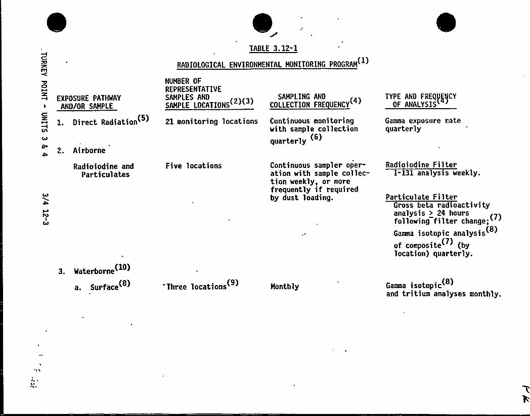
TABLE 3.12"1
RADIOLOGICAL ENVIRONMENTAL HONITORING PROGRAM
EXPOSURE PATHWAY
AND/OR SAMPLE
1. Direct Radiation
2. Airborne
Radioiodine andParticulates
3. Waterborne~
a. Surface~ ~
NUHBER OF
REPRESENTATIVESAMPLES AND
SAMPLE LOCATIONS
21 monitoring locations
Five locations
'Three locations
SAHPLING AND«EEE Ffl I
Continuous monitoringwith sample collectionquarterly
Continuous sampler oper-ation with sample collec-tion weekly, or morefrequently if requiredby dust loading.
Monthly
TYPE AND FRED((ICYOF ANALYSIS
Gamma exposure ratequarterly
Radioiodine FilterI-131 analyst s weekly.
Par ticulate FilterGross beta radioactivityanalysis > 24 hoursfollowing filter change;
Gamma isotopic analysisof composite (bylocation) quarterly.
Gama isotopicand tritium analyses monthly.
I~ *g ~
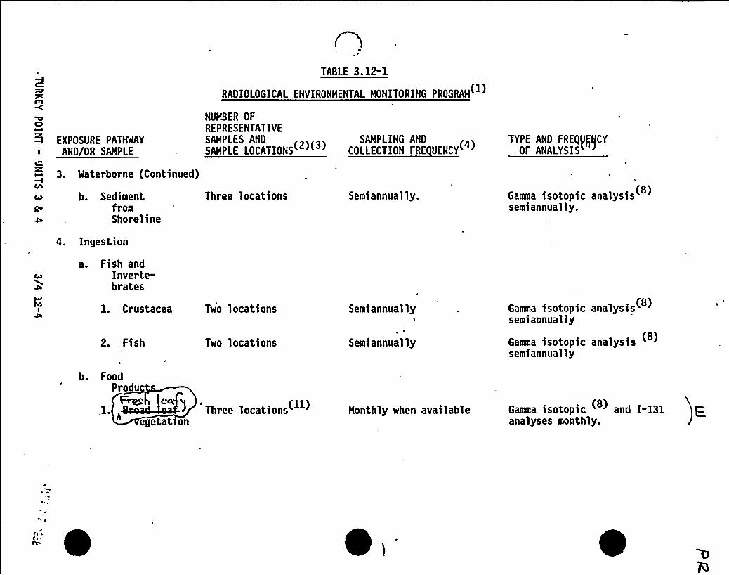
CI
EXPOSURE PATWAYAND/OR SAMPLE
C
3. waterborne (Continued)
c b. SedimentQo from
Shoreline
4. Ingestion
a. Fish and- Inverte-
brates
Three locations Semiannually.
TABLE 3.12-1
RADIOLOGICAL ENVIRONMENTAL HONITORING PROGRAM
NUMBER OF
REPRESENTATIVESAHPLES AND
2 3SAMPLING AND
NNIPLE LOINT (ONE( (( ) OLI Tl I FNEILUENOT( (TYPE ARD FREQ(g)CY
OF ANALYSIS
N
Gama isotopic analysissemiannually.
1. Crustacea
2. Fish
Two locations
Two locations
Semiannually
Semiannually
Gaaea isotopic analysissemiannually
Gaama isotopic analysissemiannually
'
b. FoodPro
leafy1.„~ TN Iegetatson
Honthly when available Gaaea isotopic and I-131 panalyses monthly.
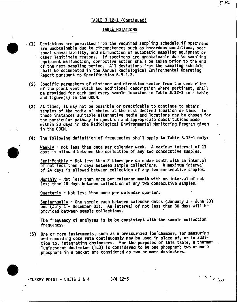
TABLE 3.12-1 Continued
TABLE NOTATIONS
(2)
(3)
Deviations are permitted from the required sampling schedule if specimensare unobtainable due to circumstances such as hazardous conditions, sea-sonal unavailability, and malfunction of automatic sampling equipment orother legitimate reasons. If specimens are unobtainable due to samplingequipment malfunction, corrective action shall be taken prior to the endof the next sampling period. All deviations from the sampling scheduleshall be documented in the Annual Radiological Environmental OperatingReport pursuant to Specification 6. 9. 1. 3.
Specific parameters of distance and direction sector from the centerlineof the plant vent stack and additional description where pertinent, shallbe provided for each and every sample location in Table 3.12-1 in a tableand figure(s) in the OOCM.
At times, it may not be possible or practicable to continue to obtainsamples of the media of choice at the most desired location or time. Inthese instances suitable alternative media and locations may be chosen forthe particular pathway in question and. appropriate substitutions madewithin 30 days in the Radiological Environmental Monitoring Program givenin the OOCM.
(4)
(5)
The following definition of frequencies shall apply to Table 3.12-1 only:
W~eekl - not less than once per calendar week. A maximum Interval of 11days ss allowed between the collection of any two consecutive samples.
Semi-Monthl - Not less than 2 times per calendar month with an intervalof not ess than 7 days between sample collections. A maximum intervalof 24 days is allowed between collection of any two consecutive samples.
Monthl - Not less than once per calendar month with an interval of notess than'0 days between collection of any two consecutive samples.
~uarterl - Not less than once per calendar quarter.
Semiannuall - One sample each between calendar dates (January 1 - June 30)and u y 1 - Oecember 31). An interval of not less than 30 days will beprovided between sample collections.
The frequency of analyses is to be consistent with the sample collectionfrequency.
One or more instruments, such as a pressurized ion chamber, for measuringand recording dose. rate continuously may be used in place of, or in addi-tion to, integrating dosimeters. For the purposes of this table, a thermo-luminescent dosimeter (TLD) is considered to be one phosphor; two or more
phosphors in a packet are considered as two or. more dosimeters.
TURKEY POINT - UNITS 3 8 4 3/4 12-5 ~'p
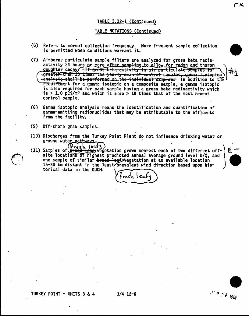
TABLE 3. 12-1 Continued
TABLE NOTATIONS Continued
(6) Refers to normal collection frequency. More frequent sample collectionis permitted when conditions warrant it.
(7) Airborne particulate sample filters are analyzed for gross beta radio-activity 24 hours ore l r n and thorondau hter deca
I ddi'ment for a gamma isotopic on a composite sample, a gamma isotopic
is also required for each sample having a gross beta radioactivity whichis > 1.0 pCi/m3 and which is also > 10 times that of the most recentcontrol sample.
(8) Gamma isotopic analysis means the identification and quantification ofgamma-emitting radionuclides that may be attributable to the effluentsfrom the facility.
(9) Off-shore grab samples.
(10) Discharges from the Turkey Point Plant do not influence drinking water orground water
re S le(ll) Samples of vegetation grown nearest each of two different off-site locations o h ghest predicted annual average ground level D/g, andone sample of similar egetation at an available location15-30 km distant in the leas prevalent wind direction based upon his-torical data in the ODCM.
(~el, l eZg
~ TURKEY POINT - UNITS 3 8L 4 3/4 12-6
04T
giO+f
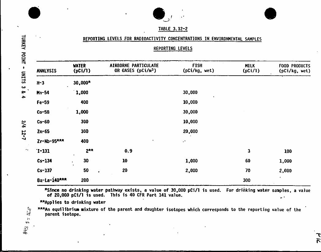
.TABLE 3. 12-2
REPORTING LEVELS FOR RADIOACTIVITYCONCENTRATIONS IN ENVIRONMENTAL SAMPLES
REPORTING LEVELS
ANALYSIS
H-3
Hn-54
Fe-59
MATER
(pCi/1)
30,000*
1,000
400
Co-58 1,000
Co-60 300
Zn-65 300I
Z~Nb-95*** 400
AIRBORNE PARTICULATEOR GASES (pCi/e~)
FISH(pCi/kg, wet)
30,000
10,000
30,000
10,000
20,000
MILK(pCi/1)
FOOD PRODUCTS
(pCi/kg, wet)
I-131
Cs-134
Cs-137
Ba La 140***
2*0
30
50
200
0.9
10
20
1,000
2,000
60
70
300
100
1,000
2,000
Qnce no drinking water pathway exists, a value of 30,000 pCi/1 is used. For drinking water samples, a valueof 20,MO pCi/l is used. This is 40 CFR Part 141 value.
**Applies to drinking water*""An equilibriua aixture of the parent and daughter isotopes which corresponds to the reporting value of the
parent isotope.
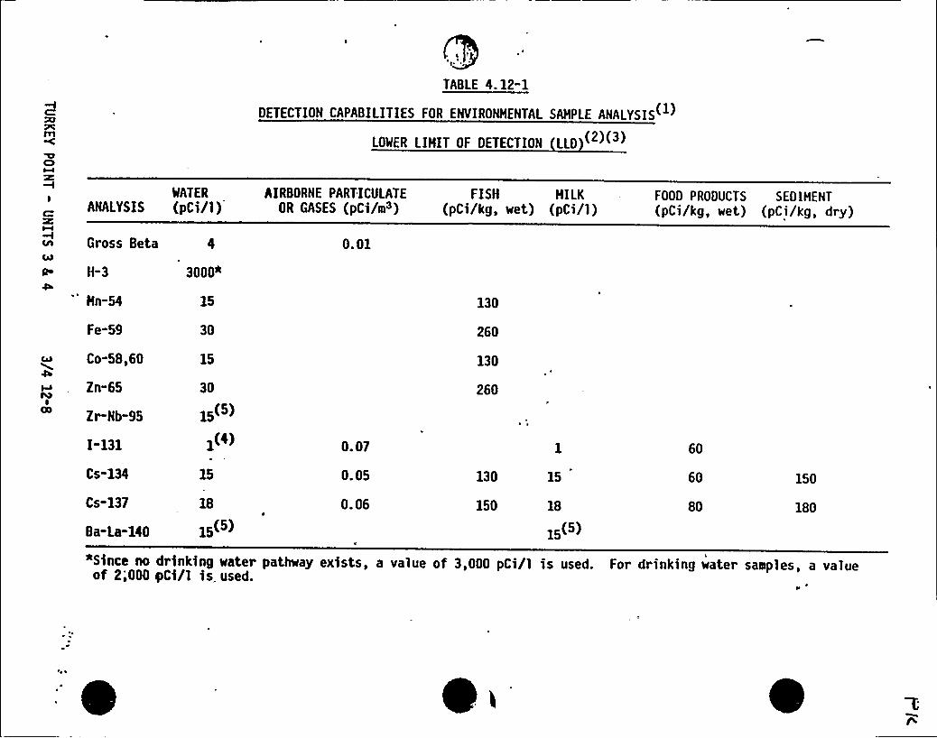
TABLE 4.12-1
DETECTION CAPABILITIES FOR ENVIRONMENTAL SAMPLE ANALYSIS
LOWER LIHIT OF DETECTION LLD
WATER
ANALYSIS (pCi/1 )AIRBORNE PARTICULATE
OR GASES (pCi/m3)FISH HILK
(pCi/kg, wet) (pCi/1)FOOD PRODUCTS SEDIMENT(pCi/kg, wet) (pCi/kg, dry)
c Gross Beta
a H-3D
Hn-54
Fe-59
Co-58,60
Zn-65
Zr-Nb-95
I"131
Cs-134
Cs-137
Ba-La-140
3000*
15
30
15
30
15(5)
1(4)
15
18
15(')
0. 01
0. 07
0. 05
0.06-
130
260
130
260
130
150
15
18
15(
60
60
80
150
180
*Since no drinking water pathway exists, a value of 3,000 pCi/1 is used. For drinking water samples, a valueof 2;000 yCi/1 is, used.
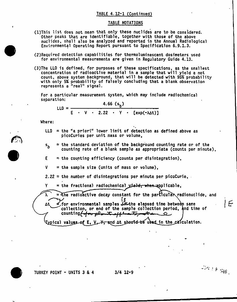
TABLE 4. 12-1 Continued
TABLE NOTATIONS
(l)This list does not mean that only these nuclides are to be considered.Other peaks that are identifiable, together with those of the abovenuclides, shall also be analyzed and reported in the Annual RadiologicalEnvironmental Operating Report pursuant to Specification 6. 9. l. 3.
(2)Required detection capabilities for thermoluminescent dosimeters usedfor environmental measurements are given in Regulatory Guide 4. 13.
(3)The LLQ is defined, for purposes of these specifications, as the smallestconcentration of radioactive material in a sample that will yield a netcount, above system background, that will be detected with 95K probabilitywith only 5X probability of falsely concluding that a blank observationrepresents a "real" signal.
For a particular measurement system, which may include radiochemicalseparation:
4.et (sb)LLD
E ~ Y ~ 2. 22 ~ Y iexp(-Alt)]
Where:
LLQ = the "a priori" lower limit of detection as defined above aspicoCuries per unit mass or volume,
sb = the standard deviation of the background counting rate or of thecounting rate of a blank sample as appropriate (counts per minute),
E = the counting efficiency (counts per disintegration),
Y = the sample size (units of mass or volume),
2.22 = the number of disintegrations per minute per picoCurie,
Y = the fractional radiochemical , plicable,
E, V, ndhts u in the culation.
he radioactive decay constant for the par >cula radionuclide, and/ i8dt~for environmental samples ~the elapsed time betwe samecollection, or end of the sample collection period, nd time ofcounting
ical valu
TURKEY POINT - UNITS 3 8( 4 3(4 12-9
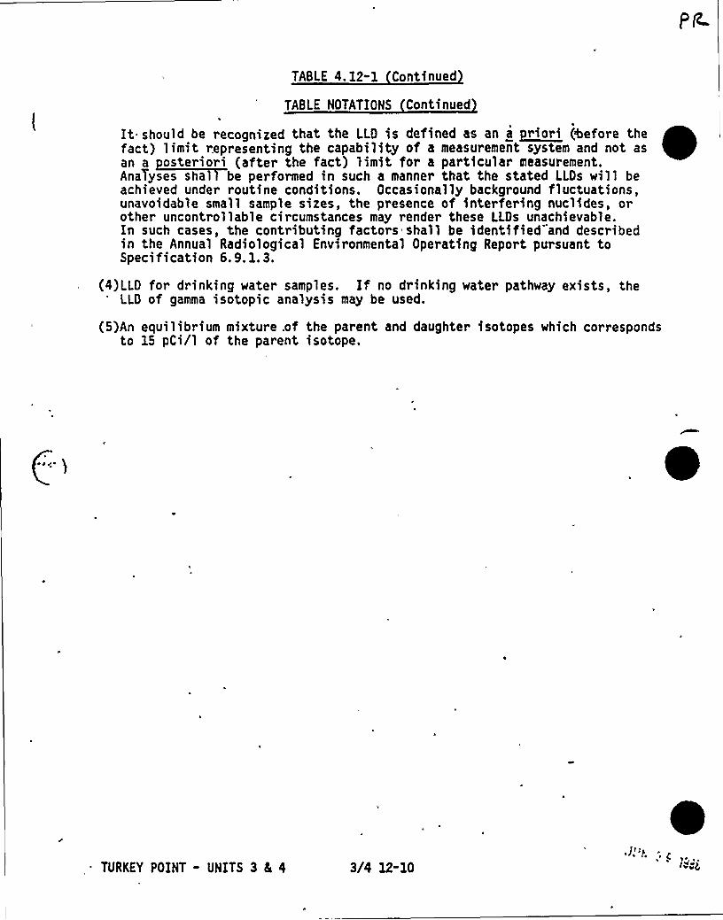
TABLE 4. 12-1 Continued
TABLE NOTATIONS Continued
It should be recognized that the LLD is defined as an a priori (%afore thefact) limit representing the capability of a measurement system and not asan a osteriori (after the fact) limit for a particular measurement.AnaTyses shal be performed in such a manner that the stated LLDs will beachieved under routine conditions. Occasionally background fluctuations,unavoidable small sample sires, the presence of interfering nuclides, orother uncontrollable circumstances may render these LLDs unachievable.In such cases, the contributing factors shall be identified and describedin the Annual Radiological Environmental Operating Report pursuant toSpecification 6. 9. 1. 3.
(4)LLD for drinking water samples. If no drinking water pathway exists, theLLD of gamma isotopic analysis may be used.
(5)An equilibrium mixture .of the parent and daughter isotopes which correspondsto 15 pCi/1 of the parent isotope.
. ~
TURKEY POINT - UNITS 3 81 4 3/4 12-10C
(Ill
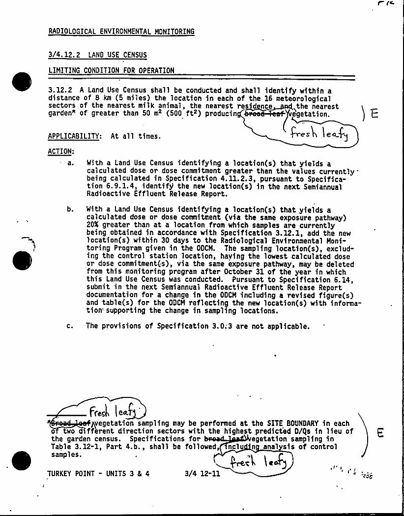
RADIOLOGICAL ENVIRONMENTAL MONITORING
3/4. 12. 2 LAND USE CENSUS
LIMITING CONDITION FOR OPERATION
3.12.2 A Land Use Census shall be conducted and shall identify within adistance of 8 km (5 miles) the location in each of the 16 meteorologicalsectors of the nearest milk animal, the nearest resid nce the nearestgarden" of greater than 50 m2 (500 ft ) producin egetation.
APPLICABILITY: At all times.
ACTION:
res en
a.
b.
C.
With a Land Use Census identifying a location(s) that yields acalculated dose or dose commitment greater than the values currentlybeing calculated in Specification 4. 11.2.3, pursuant to Specifica-tion 6.9. 1.4, identify'he new location(s) in the next SemiannualRadioactive Effluent Release Report.
With a Land Use Census identifying a location(s) that yields acalculated dose or dose commitment (via the same exposure pathway)20K greater than at a location from which samples are currentlybeing obtained in accordance with Specification 3.12.1, add the newlocation(s) within 30 days to the Radiological Environmental Moni-toring Program given in the ODCH. The sampling location(s), exclud-ing the control station location, haying the lowest calculated doseor dose commitment(s), via the same exposure pathway, may be deletedfrom this monitoring program after October 31 of the year in whichthis Land Use Census was conducted. Pursuant to Specification 6.14,submit in the next Semiannual Radioactive Effluent Release Reportdocumentation for a change in the ODCH including a revised figure(s)and table(s) for the ODCM reflecting the new location(s) with informa-tion: supporting the change in sampling locations.
The provisions of Specification 3.0;3 are not applicable.
pvegetation sampling may be performed at the SITE BOUNDARY in eacho two different direction sectors with the highest predicted D/gs in lieu ofthe garden census. Specifications for egetation sampling inTable 3. 12-1, Part 4.b., shall be followed, nclu n anal sis of controlsamples.
TURKEY POINT - UNITS 3 & 4 3/4 12-11
)~i'L (Nd)
RADIOLOGICAL ENVIRONMENTAL MONITORING
SURVEILLANCE RE UIREMENTS
4. 12.2 The Land Use Census shall be conducted during the growing season atleast once per 12 months using that information that will provide the bestresults, such as'by a door-to-door survey, aerial survey, or by consultinglocal agriculture authorities. The results of the Land Use Census shall beincluded in the Annual Radiological Environmental Operating Report pursuant toSpecification 6.9. 1.3.
TURKEY POINT - UNITS 3 8L 4 3/4 12-12
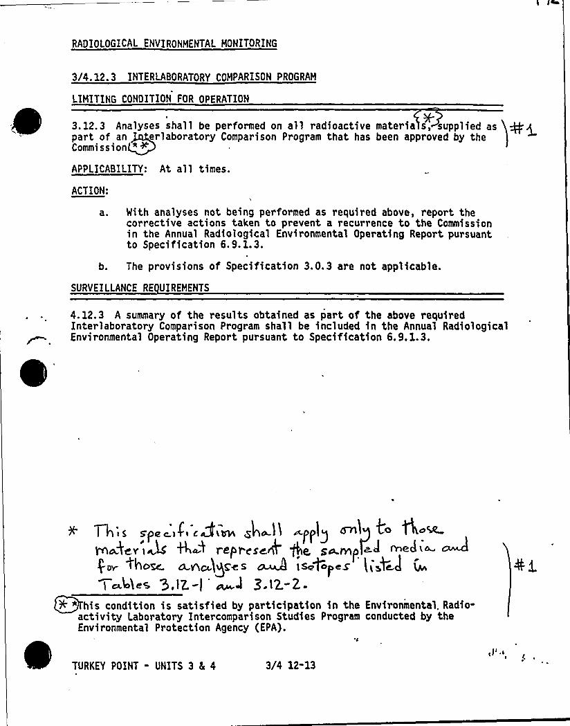
RADIOLOGICAL ENVIRONMENTAL MONITORING
3/4.12.3 INTERLABORATORY COMPARISON PROGRAM
LIMITING CONDITION FOR OPERATION
3.12.3 Analyses shall be performed on all radioactive materia s, supplied aspart of an erlaboratory Comparison Program that has been approved by theCommission " <
APPLICABILITY: At all times.
ACTION:
a ~ Mith analyses not being performed as required above, report thecorrective actions taken to prevent a recurrence to the Commissionin the Annual Radiological Environmental Operating Report pursuantto Specification 6.9. 1.3.
b. The provisions of Specification 3.0.3 are not applicable.
SURVEILLANCE RE UIREMENTS
4.12.3 A summary of the results obtained as part of the above requiredInterlaboratory Comparison Program shall be included in the Annual RadiologicalEnvironmental Operating Report pursuant to Specification 6.9.1.3.
0
Th'i S spe i<i crim Zh~1~ applyvnaAev'|A th~4 eIpr see* +e se.mp ed ~e4<~ ~pro| toom n.ne)QSes o 4 is+pcs iiJ~cl
l c 44es 3.lZ.-) ~J Q.E~-2.-
~ ~
F" his condition is satisfied by participation in the Environmental. Radio-activity Laboratory Intercomparison Studies Program conducted by theEnvironmental Protection Agency (EPA).
TURKEY POINT - UNITS 3 4 4 3/4 12-13

g g Q )+i jg<t» //~a,.k
BASES FOR
SECTIONS 3.0 AND 4.0
LIMITING CONDITIONS FOR OPERATION
AND
SURVEILLANCE REQUIREMENTS
NOTE
The BASES contained in succeeding pages summarizethe reasons for the Specifications in Sections 3. 0and 4.0, but in accordance with 10 CFR 50.36 arenot part of these Technical Specifications.
TURKEY POINT - UNITS 3 AND 4 B 3/4 0"0

'ipQ.Pp Q '. )VL"( P 'IK~CONCi j4
eA
3/4 LIMITING CONDITIONS FOR OPERATION AND SURVEILLANCE RE UIREMENTS
3/4. 0 APPLICABILITY
BASES
eTURKEY POINT - UNITS 3 and 4 B 3/4 0-1
S ecification 3.0. 1 throu h 3.0.4 establish the general requirementsapplicable to Limiting Condst ons for Operation. These requirements are basedon the requirements for Limiting Conditions for Operation stated in the Codeof Federal Regulations, 10 CFR 50.36(c)(2):
"Limiting conditions for operation are the lowest functional capability orperformance levels of equipment required for safe operation of the facility.When a limiting condition for operation of a nuclear reactor is not met, thelicensee shall shut down the reactor or follow any remedial action permitted bythe technical specificatioq, until the condition can be met."
.I Il Appll y tll y I ~ I hl h'ndividual specsfscation as the requirement for when (i.e., in whipchOPERATIONAL MODES or other specified conditions) conformance to the LimitingConditions for Operation is required for safe operation of the facility. TheACTION requirements establish those remedial measures that must be takenwithin specified time limits when the requirements of a Limiting Condition forOperation are not met.
There are two basic types of ACTION requirements. The first specifies theremedial measures that permit continued operation of the facility which is notfurther restricted by the time limits of the ACTION requirements. In thiscase, conformance to the ACTION requirements provides an acceptable level ofsafety for unlimited continued operation as long as the ACTION requirementscontinue to be met. The second type of ACTION requirement specifies a timelimit in which conformance to the conditions of the Limiting Condition forOperation must be met. This time limit is the allowable outage time torestore an inoperable system or component to OPERABLE status or for ~estoringparameters within specified limits. If these actions are not completed withinthe allowable outage time limits, a shutdown is required to place the facilityin a MODE or condition in which the specification no longer applies. It isnot intended that the shutdown ACTION requirements be used as an operationalconvenience which permits (routine) voluntary 'removal of a system(s) orcomponent(s) from service in lieu of other alternatives that would not resultin redundant systems or components being inoperable.
The specified time limits of the ACTION requirements are applicable from thepoint in time it is identified that a Limiting Condition for Operation is notmet. The tiae limits of the ACTION requirements are also applicable when asystem or component is removed from service for surveil,lance testing or in-vestigation of operational problems. Individual specifications aey include aspecified time limit for the completion of a Surveillance Requirement whenequipment is removed from service. In this case, the allowable outage timelimits of the ACTION requirements are applicable when this limit expires ifthe surveillance has not been completed. When a shutdown is required to complywith ACTION requirements, the plant may have entered a MODE in which a newspecification becomes applicable. In this case, the time limits of the ACTION
3/4. 0 APPLICABILITY
BASES
requirements would apply from the point in time that the new specificationbecomes applicable if the requirements of the Limiting Condition for Operationare not met.
~if' .0.2 bit h pit I h p I!!exists when the requirements of the Limiting Condition for Operation are notmet and the associated ACTION requirements have not been implemented withinthe specified time interval. The purpose of this specification is to clarifythat (1) implementation of the ACTION requirements within the specified timeinterval constitutes compliance with a specification and (2) completion ofthe remedial measures of the ACTION requirements is not required whencompliance with a LimitingLondition of Operation is restored within the timeinterval specified in the associated ACTION requirements.
S ecification 3.0.3 establishes the shutdown ACTION requirements that must bemplemented when a Limiting Condition for Operation is not met and the
condition is not specifically addressed by the associated ACTION requirements..The purpose of this specification is to delineate the time limits for placingthe unit in a safe shutdown MODE when plant operation cannot be maintainedwithin the limits for safe operation defined by the Limiting Conditions forOperation and its ACTION requirements. It is not intended to be used as anoperational convenience which permits (routine) voluntary removal of redundantsystems or components from service in lieu of other alternatives that wouldnot result in redundant systems or components being inoperable. One hour isallowed to prepare for an orderly shutdown before initiating a change inplant operation. This time permits the operator to coordinate the reductionin electrical generation with the load dispatcher to ensure the stability andavailability of the electrical grid. The time limits specified to reachlower MODES of operation permit the shutdown to proceed in a controlled andorderly manner that is well within the specified maximum cooldown rate andwithin the cooldown capabilities of the facility assuming only the minimumrequired equipment is OPERABLE. This reduces thermal stresses on componentsof the primary coolant system and the potential for a plant upset that couldchallenge safety systems under conditions for which this specificationapplies.
If remedial measures permitting liaited continued operatidn of the facilityunder the provisions of the ACTION requirements are completed, the shutdown maybe terminated: The time limits of the ACTION requirements are applicable fromthe point in time there was a failure to eeet a Lioiting Condition forOperation. Therefore, the shutdown may be terminated. if the ACTION require-ments have been met or the time limits of the ACTION requirements have notexpired, thus providing an allowance for the completion of the requiredactions.
~,
The time limits of Specification 3.0.3 allow 37 hours for the plant to be inthe COLD SHUTDOWN MODE when a shutdown is required during the POWER MODE ofoperation. If the plant is in a lower HODE of operation when a shutdown isrequired, the time limit for reaching the next lower HODE of operation 0TURKEY POINT - UNITS 3 and 4 8 3/4 0-2 ~ al
' ~ g
3/4. 0 APPLICABILITY
BASES
applies. However, if a lower MODE of operation is reached in less time thanallowed, the total allowable time to reach COLD SHUTDOWN, or other'applicable.MODE, is not reduced. For example, if HOT STANDBY is reached in 2 hours;~theWtime allowed to reach HOT SHUTDOWN is the next 11 hours because the total timeto reach HOT SHUTDOWN is not reduced from the allowable limit of 13 hours.Therefore, if remedial measures are completed that would permit a return toPOWER operation, a penalty is not incurred by having to reach a lower HODE ofoperation in less than the total time allowed.
The same principle applies with regard to the allowable outage time limitsof the ACTION requirements, if compliance with the ACTION requirements forone specification results ip entry into a MODE or condition of operation foranother specification in which the requirements of the Limiting Condition forOperation are not met. If the new specification becomes applicable in lesstime than specified, the difference may be added to the allowable outagetime limits of the second specification. However, the allowable outage timelimits of ACTION requirements for a higher HODE of operation may not be usedto extend the allowable outage time that is applicable when a LimitingCondition for Operation is not met in a lower HODE of operation.
The shutdown requirements of Specification 3.0.3 do not apply in HODES 5 and6, because the ACTION requirements of individual specifications define theremedial measures to be taken.
.tl.4 blah lit tl INDE h g 1 LMigCondstlon for Operation is not met. It precludes placing the facility in ahigher MODE of operation when the requirements for a Limiting ion forOperation are not met and continued noncompliance to these nditio wouldresult in e shutdown to comply with the ACTION requ$ remen if<chen $ n NOOESwere permitted. The purpose of this specification is to e ure th facilityoperation is not initiated or that higher HODES of operati not enteredwhen corrective action is being taken to obtain compliance with a specificationby restoring equipment to OPERABLE status or parameters to specified limits.Compliance with ACTION requirements that permit continued operation of thefacility for an unlimited period 0f time provides an acceptable level of safetyfor continued operation without regard to the status of the plant before orafter a HODE change. Therefore, in this case, entry into 'an OPERATIONAL MODEor other specified condition may be made in accordance with the provisions ofthe ACTION requirements. The provisions of this specification should not,however, be interpreted as endorsing the failure to exercise good practice inrestoring systems or components to OPERABLE status before plant startup.
When a shutdown is required to comply with ACTION requirements, theprovisions of..Specification 3.0.4 do not apply because they would delayplacing the facility in a. lower MODE of"operation.~AC7/W) fi~rs all~a) Sc'r a~ aVrr/g gd d~ fQ yfuPJ~~~
cof k66l ')rt 't&
Nkvd'rt
4[< )roPPr < I(f c j ~ dP~AS<,,-c ( II /
r
TURKE'g POINT - UNITS 3'and 4'
B 3/4 0-'3.
'"~'I"5
3/4. 0 APPLICABILITY
BASES
S ecification 3.0.5 delineates the applicability of each specification toUni nd Unit peration.
3 +S ec ication 4. . 1 throu h 4.0.5 establish the general requirements applicableto Survei lance equirements. hese requirements are based on the SurveillanceRequirements stated in the Code of Federal Regulations, 10 CFR 50.36(c)(3):
"Surveillance requirements are requirements relating to test, calibrationor inspection to ensure that the necessary quality of systems and components ismaintained, that facility operation will be within safety limits, and that thelimiting conditions of operation will be met."
S ecification 4.0.1 establishes the requirement that surveillances must be. performed dur ng the OPERATIONAL MODES or other conditions for which the
requirements of the Limiting Conditions for Operation apply unless otherwisestated in an individual Surveillance Requirement. The purpose of thisspecification is to ensure that surveillances are performed to verify theoperational status of systems and components and that parameters are withinspecified limits to ensure safe operation of the facility when the plant isin a MODE or other specified condition for which the associated LimitingConditions for Operation are applicable. Surveillance Requirements do nothave to be performed when the facility is in an OPERATIONAL MODE for whichthe requirements of the associated Limiting Condition for operation do notapply unless otherwise specified. The Surveillance Requirements associatedwith a Special Test Exception are only applicable when the Special TestException is used as an allowable exception to the requirements of aspecification.
S ecification 4. 0.2 establishes the conditions under which the specified timeinterval for Surve llance Requirements may be extended. Item a. permits anallowable extension of the normal surveillance interval to facilitatesurveillance scheduling and consideration of plant operating conditions thatmay not be suitable for conducting the surveillance; e.g., transientconditions or other ongoing surveillance or maintenance activities. Item b.limits the use of the provisions of item a. to ensure that it is not usedrepeatedly to extend the surveillance interval beyond that specified. Thelimits of Specification 4.0.2 are based on engineering 5udgment and therecognition that the most probable result of any particular surveillancebeing performed is the verification of conformance with the SurveillanceRequirements. These provisions are sufficient to ensure that the reliabilityensured through surveillance activities is not significantly degraded beyondthat obtained from the specified surveillance interval.
TURKEY POINT - UNITS 3 and 4 B 3/4 0-4I I ~
v

>3.0 This soecification delineates what additiona! conditions must be satisiied'o
permit operation to continue, consistent with the ACTION statementsfor power sources, when a normal or emergency power source is notOpERABLE. It specifically prohibits operation when one division isinoperable because its normal or emergency power source is inoperableand a system, subsystem, train, component or device in another division isinoperable for another reason. isis a su~ca gkar o e, ivl/diwsro Qe „)geC Zb tucr crCccC a~sprcy pPLv~ 'cs,asiptglg ~l/IW Optg+gg. pThe provisions of this specification permit the ACTION statementsassociated with individual systems, subsystems, trains, components ordevices to be consistent with the ACTION statements of the associatedelectrical power sources It allows operation to be governed by the timelimits of the ACTION statement associated with the Limiting Conditionfor Operation for the normal or emergency power source, not theindividual ACTION statements for each system, subsystem, train,component or device that is determined to be inoperable solely because ofthe inoperability of its normal or emergency power source.z8',rFor example, Specification ~l requires in part that two emergencydiesel generators be OPERABLE. The ACTION statement provides for anout-of-service time when one emergency diesel generator is notOPERABLE. If the definition of OPERABLE were applied withoutconsideration of Specification 3.0P',~ all systems, subsystems, trains,components and devices supplied by the inoperable emergency powersource would also be inoperable. This would dictate invoking theapplicable ACTION statements for each of the applicable LimitingConditions for Operation. However, the provisions of Specification 3.0.0permit the time limits for continued ooeration to be consistent with theACTION statement for the inoperable emergency diesel generatorinstead, provided the other specified conditions are satisfied. In this case,this would mean that the corresponding normal power source must beOPERABLE, and all redundant systems, subsystems, trains, componentsand devices must be OPERABLE, or otherwise satisfy Specification 3.0.lf(i.e., be capable of performing their design function and have at least oneaetna~ one emergency power source OPERABLB. If they are notsatisfied, shutdown is
required.'obes
$ ' 6, ~gee(kcMw z.p6 is ~up ~pAccb~~cl<>><<4 a I ~sr c(e C. igiq J > ~ Hg dc', fro~ of ol ~4< 4-
CLICE >Of'4$ Vir4 4aep +<)~ ap 8s MD <Qp+ Ii))) 6ayp~ P4vtVg~i<ed by Spmcigr<~ru~ 5. j"./ 2-, I h~ i~ des ada'< I A r.7(OV
'
5f <f4we~ gv 4M4 ~P I/g ~C l/eeet Wlzg Q~ dr@>qol'~~la i~ W~>~ ~ooM n t >v- ~ ad 4~~~ W ~
,B3.0-2/

l+ e~ io~eR 4(a~k.
3/4. 0 APPLICABILITY
BASES
S ecification 4.0.3 establishes the failure to perform a SurveillanceRequirement withsn the allowed surveillance interval, defined by theprovisions of Specification 4.0.2, as a condition that constitutes a failureto meet the OPERABILITY requirements for a Limiting Condition for Operation.Under the provisions of this specification, systems and components areassumed to be OPERABLE when Surveillance Requirements have been satisfactorilyperformed within the specified time interval. However, nothing in thisprovision is to be construed as implying that systems or components areOPERABLE when they are found or known to be inoperable although still meetingthe Surveillance Requirements. This specification also clarifies that theACTION requirements are applicable when Surveillance Requirements have not beencompleted within the allowed surveillance interval and that the time limits ofthe ACTION requirements apply from the point in time it is identified that asurveillance has not been performed and not at the time that the allowedsurveillance interval was exceeded. , Completion of the Surveillance Requirementwithin the allowable outage time limits of the ACTION requirements restorescompliance with the requirements of Specification 4.0.3. However, this doesnot negate the fact that the failure to have performed the surveillance withinthe allowed surveillance interval, defined by. the provisions of Specification4.0.2, was a violation of the OPERABILITY requirements of a Limiting Conditionfor Operation that is subject to enforcement action. Further, the failure toperform a surveillance within the provisions of Specification 4.0.2 is aviolation of a Technical Specification requirement and is, therefore, a re-portable event under the requirements of 10 CFR 50.73(a)(2)(i)(B) because itis a con pion yrohiPited by .the plant's Tec al Specifications.
Cn@en QC. C <OtJ Sg~'Ve~eIf thea wa e uae > >ms so ON requirements are less than24 hours or a shutdown is required to comply with ACTION requirements, e.g.,Specfficatfon 3.0.3, a 24-hour allowance ia provided to permit a delay 1n
This provides an adequate time limit tocomplete Surveillance Requirements that have not been performed. The purposeof this allowance is to permit the completion of a surveillance before ashutdown is required to comply with ACTION requirements or before otherremedial measures would be required that may preclude completion of asurveillance. The basis for this allowance includes consideration for plantconditions, adequate planning, availability of personnel, the time required toperform the surveillance, and the safety significance of the delay incompleting the required surveillance. The provision also provides a timelimit for the completion of Surveillance Requirements that become applicableas a consequence of HODE changes imposed by ACTION requirements and forcompleting Surveillance Requirements that are applicable when an exception tothe requirements of Specification 4.0.4 is allowed. If a surveillance is notcompleted within the 24-hour allowance, the time limits of the ACTIONrequirements are applicable at that time. %hen a surveillance is performedwithin the 24-hour allowance and the Surveillance Requirements are not met,the time limits of the ACTION requirements are applicable at'he time that thesurveillance is terminated.
TURKEY POINT - UNITS 3 and 4 B 3/4 0-5

3/4. 0 APPLICABILITY
BASES
Surveillance Requirements do not have to be performed on inoperable equipmentbecause the ACTION requirements define the remedial measures that apply.However, the Surveillance Requirements have to be met to demonstrate thatinoperable equipment has been restored to OPERABLE status.
S ecification 4.0.4 establishes the requirement that all applicablesurveys llances must be met before entry into an OPERATIONAL MODE or othercondition of operation specified in the Applicability statement. The purposeof this specification is to ensure that system and component OPERABILITYrequirements or parameter limits are met before entry into a MODE orcondition for which these systems and components ensure safe operation of thefacility. This provision applies to changes in OPERATIONAL MODES or otherspecified conditions associated with plant shutdown as well as startup.
Under the provisions of this specification, the applicable SurveillanceRequirements must be performed within the specified surveillance interval toensure that the Limiting Conditions for Operation are met during initial plantstartup or following a plant outage.
When a shutdown is required to comply with ACTION requirements, the provisionsof Specification 4.0.4 do not apply. because this would delay placing thefacility in a lower MODE of operation.
S ecification 4.0.5 establishes the requirement that inservice inspection ofASHE Code Class 1, 2, and 3 components and inservice testing of ASIDE Code Class1, 2, and 3 pumps and valves shall be performed in accordance with aperiodically updated version of Section XI'of the ASME Boiler and PressureVessel Code and Addenda as required by 10 CFR 50.55a. These requirementsapply, except when relief has been provided in writing by the Coaeission.
This specification includes a clarification of the frequencies for performingthe inservice inspection and testing activities required by Section XI'of theASME Boiler and Pressure Vessel Code and applicable Addenda. Thisclarification is provided to ensure consistency in surveillance intervalsthroughout the Technical Specifications and to remove any ambiguities relativeto the frequencies for performing the required inservice inspection andtesting activities.
Under the texas of this specification, the sere restrictive requirements ofthe Technical Specifications take precedence over the ASIDE Boiler and PressureVessel Code and applicable Addenda. The requirements of Specification 4.0.4to perform surveillance activities before entry into an OPERATIONAL MODE orother specified condition takes precedence over the ASHE Boiler and Pressure
TURKEY POINT - UNITS 3 and 4 B 3/4 0-6
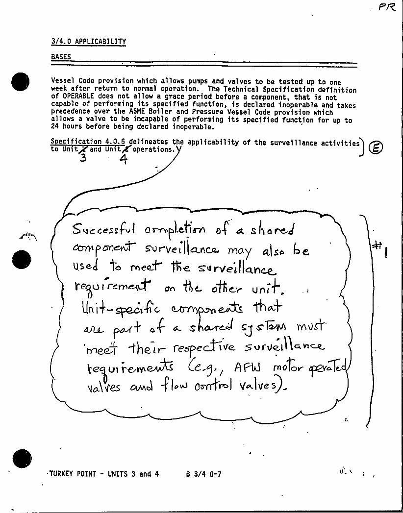
3/4. 0 APPLICABILITY
BASES
Vessel Code provision which allows pumps and valves to be tested up to oneweek after return to normal operation. The Technical Specification definitionof OPERABLE does not allow a grace period before a component, that is notcapable of performing its specified function, is declared inoperable and takesprecedence over the ASME Boiler and Pressure Vessel Code provision whichallows a valve to be incapable of performing its specified function for up to24 hours before being declared inoperable.
S ecification 4.0.6 delineates the applicability of the surveillance activitiesto Un>t and Un~tg operations.
3
5'yacc ssf l Qvw~l.elm Gf w s]are.J~ /
s'U r ye L ( PAcp tY10y'gigata pAeQ+ ge, Sll~+)Il~p~
Qec~ljt Ic&l&~ ~ ge ager u~~+' 0
L(ni$-~,4'~ ~my ~ 6 4a Z4 A Cg S't~ Md&
fespe3 ive, Svf'Velhc ~~(<.g,
<P ~ razor ~vc.g
„„i<e ~a fl.~ o&~l v Ives)
TURKEY POINT - UNITS 3 and 4 B 3/4 0-7

) Vl4 A&(C'/ICg
3/4. 1 REACTIVITY CONTROL SYSTEMS
BASES
3/4.1. 1 BORATION CONTROL
3/4.1.1.1 and 3/4.1.1.2 SHUTDOWN MARGIN
A sufficient SHUTDOWN MARGIN ensures that: (1) the reactor can be madesubcritical from all operating conditions, (2) the reactivity transients asso-ciated with postulated accident conditions are controllable within acceptablelimits, and (3) the reactor will be maintained sufficiently subcritical topreclude inadvertent criticality in the shutdown condition.
SHUTDOWN, MARGIN requirements vary throughout core life as a function offuel depletion, RCS boron concentration, and RCS Tavg The most restrictivecondition occurs at EOL. with Tav at no load operating tmperature. and isassociated with a postulated steam line break accident and resulting uncon-trolled RCS cooldown. Figure 3.1-1 shows the SHUTDOWN MARGIN equivalent to1.77'k/k at the end-of-core-life with respect to an uncontrolled cooldown.Accordingly, the SHUTDOWN MARGIN requirement is based upon this limitingcondition and is consistent with FSAR safety a'nalysis assump5ions. '6th T—-~ ~„jq« ~
less than 200oF, the reactivity transients resulting f~romha1d M I d e uk.NIIIDML ~ )rl
aeequa<e pro<ac<<on., r g+ gCg op y~ ino3eerfeef dilufio~ o$ PQQ nero'~5T
3/4.1.1. 3 MODERATOR TEMPERATURE COEFFICIENT
The limitations on moderator temperature coefficient (MTC) are providedto ensure that the value of this coefficient remains within the limiting.condition assumed in the FSAR accident and transient analyses.
The MTC values of this specification are applicable to a specific set ofplant conditions; accordingly, verification of MTC values at conditions otherthan those explicitly stated will require extrapolation to those conditions inorder to permit an accurate comparison.
The most negative MTC, value equivalent to the most Positive moderatordensity coefficient (MDC), was obtained by incrementally correcting the MDC
used in the FSAR analyses to nominal operating conditions. These corrections
TURKEY POINT - UNITS 3 AND 4 B 3/4 1-1
REACTIVITY CONTROL SYSTEMS
BASES
involved subtracting the incremental change in the MDC associated with a corecondit'ton of all rods inserted (most positive MDC) to an all rods withdrawncondition and, a conversion for the rate of change of moderator-density withtemperature at RATED THERMAL POWER conditions. This value of the HDC was thentransformed into the limiting MTC value -3.5 x 10-~ hk/k/4F. The HTC valueof -3. 0 x 10-~ hk/k/4F represents a conservative value (with corrections forburnup and soluble boron) at a core condition of 300 ppm equilibrium boronconcentration and is obtained by making these corrections to the limiting HTCvalue of -3.5 x 10-~ hk/k/4F.
The Surveillance Requirements for measurement of the MTC at the beginningand near the end of the fuel cycle are adequate to confirm that the MTC remainswithin its limits since this coefficient changes slowly due principally to thereduction in RCS boron concentration associated with fuel burnup.
3/4.1.1.4 MINIMUMTEMPERATURE FOR CRITICALITY
This specification ensures that the reactor will not be made criticalwith the Reactor Coolant System average temperature less than 5414F. Thislimitation is required to,ensure: (1) the moderator temperature coefficientis within it analyzed temperature range, (2) the trip instrumentation is withinits normal operating range, (3) the pressurizer is capable of being in anOPERABLE status with a steam bubble, and (4) the reactor vessel is above itsminimum RTNDT temperature.
3/4.1. 2 BORATIOX SYSTEMS
The Boron In)ection System ensures that negative reactivity control isavailabla 4uring each mode of facility operation.'he components required tope~form this function include: (1) borated water sources, (2) charging pumps,(3) separate flow paths, (4) boric acid transfer pumps, (5) associated HeatTracing Systems, and (6) an emergency power supply froe OPERABLE dieselgenerators.
With the RCS average temperature above 2004F, a minima of two boroninjection flow paths are required to ensure single'functional capability inthe event an assumed failure renders one of the flow paths inoperable. Oneflow path from the charging pump discharge is acceptable since the flow pathcomponents sub)ect to an active failure are upstream of the charging pumps.
TURKEY POINT - UNITS 3 AND 4 B 3/4 1-2
REACTIVITY CONTROL SYSTEMS
BASES
BORATION SYSTEMS (Continued)
The boration flow path spe icati allows the RWST and the boric acidstorage tank to be the boron so e5. Du to the lower boron concentration inthe RWST, borating the RCS from this s ce is less effective than Loratingfrom the boric acid tank and a time may be required to achieve thedesired SHUTDOWN MARGIN required by ACTION statement restrictions.
The ACTION statement restrictions for the boration flow paths allowcontinued operation in mode 1 for a limited time period with either borationsource flow path or the normal flow path to the RCS (via the regenerative heatexchanger) inoperable. In this case, the plant capability to borate andcharge into the RCS is limited and the potential operational impact of thislimitation on mode 1 operation must be addressed. Nth both the flow pathfrom the boric acid tanks and the regenerative heat exchanger flow path
~ inoperable, immediate initiation of action to go to COLD SHUTDOWN is requiredbut no time is specified for the mode reduction due to the reduced plantcapability with these flow paths inoperable.
Two charging pumps with independent power supplies are required to beOPERABLE to ensure single functional capability in the event an assumedfailure renders one of the pumps or power supplies inoperable. However, theACTION statement 'restrictions allow 7 days to restore an inoperable pumpprovided that two charging pumps are available. This restriction isacceptable based on the low probability of losing the power source common toboth charging pumps. The bus supplying the pumps can be fed from either theEmergency Diesel Generator or the offsite grid through the startuptransformer.
The boration capability of either flow path is sufficient to provide therequired SHUTDOWN MARGIN in accordance with Figure 3.1-1 from expectedoperating conditions after xenon decay and cooldown to 2004F. The maximumexpected boration capability requirement occurs at EOL froa full power.equilibrium xenon conditions and requires 3080 gallons of 20,000 PPM boratedwater from the boric acid storage tanks or 320,000 gallons of 1950 PPM boratedwater from the refueling water storage tank (EST).
Nth the RCS temperature below 2004F, one boron in$edtion source flowpath is acceptable without single failure consideration on the basis of thestable reactivity condition of the reactor and the additional restrictionsprohibiting CORE ALTERATIONS and positive reactivity changes in the event thesingle boron infection systea source flow path becowes inoperable.
r
The boron capability required below 2004F is sufficient to provide aSHUTDOWN MARGIN of 1X hk/k after xenon decay and cooldown.froa 2004F to1404F. This condition requires either 500 gallons of 20,000 ppa borated waterfrom the boric acid storage tanks or 20,000 gallons of 1950 .ppe borated waterfrom the RWST.
TURKEY POINT - UNITS 3 AND 4 B 3/4 1-3 i '\
REACTIVITY CONTROL SYSTEMS
BASES
BORATION SYSTEMS (Continued)
The charging pumps are demonstrated to be OPERABLE by testing as requiredby Section XI of the ASME code or by specific surveillance requirements in thespecification. These requirements are adequate to determine OPERABILITYbecause no safety analysis assumption relating to the charging pumpperformance is more restrictive than these acceptance criteria for the pumps.
The limits on contained water volume and boron concentration of the RWST
also ensure a pH valu'e of between 8.5 and 11.0 for the solution recirculatedwithin containment after a LOCA. This pH band minimizes the evolution ofiodine and minimizes the effect of chloride and caustic stress corrosion onmechanical systems and components. The.,cr ~era~ore. f'eq J <re y e~f5 -.<r ',.eRld'5W p rP knOP'p,'' ~ 'r, ' ~: «, "r ..; <eOI-r4 ling ~~~/'/~~~ 055+~Df«t ~
The OPERABILITY of one Boron In)ection System derring REFUELIHG ensures ~that this system is available for reactivity control while in %DE 6.
The OPERABILITY of the redundant heat tracing channels associated with theboric acid tank system ensures that the solubility of the boron solution willbe maintained above the solubility limit of 135 F at 22,500 ppa boron.
One channel of heat tracing is'ufficient to maintain the specifiedtemperature limit. Since one channel of heat tracing is sufficient to maintainthe specified temperature, operation with one channel out-of-service ispermitted for a period of 30 days provided additional temperature surveillanceis performed.
3/4.1. 3 MOVABLE CONTROL ASSEMBLIES
. —;
between 0 andY:f)':~'" withdrawn inclusive. 8l ~Hog-rM-position-vs- i
1
The specifications of this section ensure that: (1) acceptable power distri-bution limits are maintained, (2) the minimum SHUTDOWN MARGIN is maintained, and(3) the potential effects of rod misalignment. on associated accident analyses arelimited. OPERABILITY of the control rod position indicators is required todetermine control rod positions and thereby ensure compliance with the controlrod alignment and insertion limits continue. OPERABLE condition for theanalog rod position indicators is difined as heing cspahl ~ of indicatin odposition to within 412 steps of the . or e utdownBanks and Control Banks h and B, the R is defined as thegroup demand counter indicated position between 0 and ps rawninclusive, and between 200 and 228 steps withdrawn inclusive. This permits >'~,'the operator to verify that the control rods in these'binks are either fully~" '-
'ithdrawnor fully inserted, the normal operating modes for these banks.Knowledge of these bank positions in these two areas satisfies all accident
i analysis assonptions concerning thoir position. For Control Banks C and D, thes defined as the group demand counter indicated position
228 steps
TURKEY POINT - UNITS 3 AND 4 B'3/4 1-4
REACTIVITY CONTROL SYSTEMS
BASES
MOVABLE CONTROL ASSEMBLIES (Continued)~ ~
0
;- Comparison of the group demand counters to the bankinsertion limits with verification of rod position with the analog rodposition indicators (after thermal soak after rod motion) is sufficientverification that the control rods are above the insertion limits.
Rod position indication is provided by two methods: a digital count ofactuating pulses which shows demand position of the banks and a linearposition indicator Linear Variable Differential Transformer which indicatesthe actual rod position. The relative accuracy of the linear positionindicator Linear Variable Differential Transformer is such that, with the mostadverse error, an alarm will be actuated if any two rods within a bank deviateby more than 24 steps for rods in motion and 12 steps for rods at rest.Complete rod misalignment (12 feet out of alignment with its bank) does notresult in exceeding core limits in steady-state operation at RATED THERMALPOWER.
The ACTION statements which permit limited variations from the basicrequirements are accompanied by additional restrictions which ensure that theoriginal design criteria are met. Misalignment of a rod requires measurementof peaking factors and a restriction in THERMAL POWER. These restrictions pro-vide assurance of fuel rod integrity during continued operation. In addition,those safety analyses affected by a misaligned rod are reevaluated to confirmthat the results remain valid during future operation.
The maximum rod drop time restriction is consistent with the assumed roddrop time used in the safety analyses. Measurement with T greater than orequal to 5414F and with all reactor coolant pumps operating ensures that themeasured drop times will be representative of insertion times experiencedduring a Reactor trip at operating conditions.
. Control rod positions and OPERABILITY of the rod position indicators arerequired to be verified on a nominal basis of once per 12'hours with more fre-quent verifications required if an automatic monitoring channel is inoperable.These verification frequencies are adequate for assuring that the applicableLCOs are satisfied.
TURKEY POINT - UNITS 3 AND 4 B 3/4 1-5 'l ~ le g(

I P l ~i f'8'<'Ci /j<
3/4. 2 POWER DISTRIBUTION LIMITS
BASES
The specifications of this section provide assurance of fuel integrityduring Condition I (Normal Operation) and II (Incidents of Moderate Frequency)events by: {1) m'aintaining the minimum DNBR in the core greater than or equalto 1.30 during normal operation and in short-term transients, and (2) limitingthe fission gas release, fuel pellet temperature, and cladding mechanicalproperties to within assumed design criteria. In addition, limiting the peaklinear power density during Condition I events provides assurance that theinitial conditions assumed for the LOCA analyses are met and the- ECCS acceptancecriteria limit of 22004F is not exceeded.
The definitions of certain hot channel and peaking factors as used inthese specifications are as follows:
F (Z) Heat Flux Hot Channel Factor, is defined as the maximum local heatflux on the surface of a fuel rod at core elevation Z divided by theaverage fuel rod heat flux, allowing for manufacturing tolerances onfuel pellets and rods;
N Nuclear Enthalpy Rise Hot Channel- Factor, is defined as the ratio ofthe integral of linear power along the rod with the highest integratedpower to the average rod power; and
F (Z) Radial Peaking Factor, is defined as the ratio of peak power densityto average power density in the horizontal plane at core elevation Z.
4.2.1 AXIAL FLUX DIFFERENCE gc"Act '3/v'.0.l R LThe 'ts on AXIAL FLUX DIFFERENCE (AFD) assure that the F (Z) uppe
bound envelope o 32 times the normalized axial peaking factor is not exceededduring either normal ration or in the event of xenon redistribution followingpower changes.
Target flux difference is de ined at equilibrium xenon conditions.The full-length rods may be positione thin the core in accordance withtheir respective insertion limits and shou e inserted near their normalposition for steady-state operation at high po levels. The value of thetar get flux difference obtained under these condit diVided by the fractionof RATED THERMAL POWER is the target flux difference a TED THERMAL POWER
for the associated core burnup conditions. Target flux dif ces for otherTHERMAL POWER levels are obtained by multiplying the RATED THE POWER valueby the appropriate fractional THERMAL POWER level. The periodic up ing 'ofthe target flux difference value is necessary to reflect core burnupconsiderations.
TURKEY POINT - UNITS 3 AND 4 B 3/4 2-1
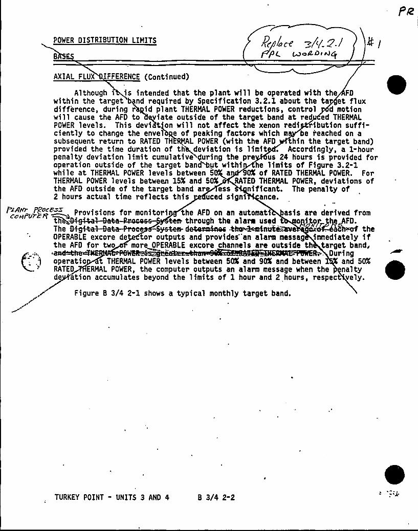
POWER DISTRIBUTION LIMITS
+j9+ ~mCOi Wg
AXIAL FLUX FFERENCE (Continued)
Although s is intended that the plant will be operated with the FDwithin the tar get bynd required by Specification 3.2.1 about the ta et fluxdifference, during r'hpid plant THERMAL POWER reductions, control d motionwill cause the AFD to 6eviate outside of the target band at red ed THERMALPOWER levels. This deviation will not affect the xenon redi ibution suffi-ciently to change the envel'bye of peaking factors which m be reached on asubsequent return to RATED THERMAL POWER (with the AFD hin the target band)provided the time duration of th+deviation is limit . Accordingly, a 1-hourpenalty deviation limit cumulative>guring the pre us 24 hours is provided foroperation outside of the target banMut withi he limits of Figure 3.2-1while at THERMAL POWER levels between 5 a 90K of RATED THERMAL POWER. ForTHERMAL POWER levels between 15K and 50K RATED THERMAL POWER, deviations ofthe AFD outside of the target band ar ess nificant. The penalty of2 hours actual time reflects this uced signi ance.
Provisions for monitori the AFD on an automati asis are derived fromthrough the alarm used pit p FD.
The de4eeokoac Phe~ni4i= -. . the
OPERABLE excore de or outputs and provides"an alarm messag immediately ifthe AFD for two more OPERABLE excore channels are outside th target band,
. Duringoperatio t THERMAL POWER levels between 50K and 9'nd between and 50KRATED ERMAL POWER, the computer outputs an alarm message when the naltyde ation accumulates beyond the limits of 1 hour and 2 hours, respect vely.
Figure B 3/4 2-1 shows a typical monthly target band.
TURKEY POINT - UNITS 3 AND 4 B 3/4 2-2
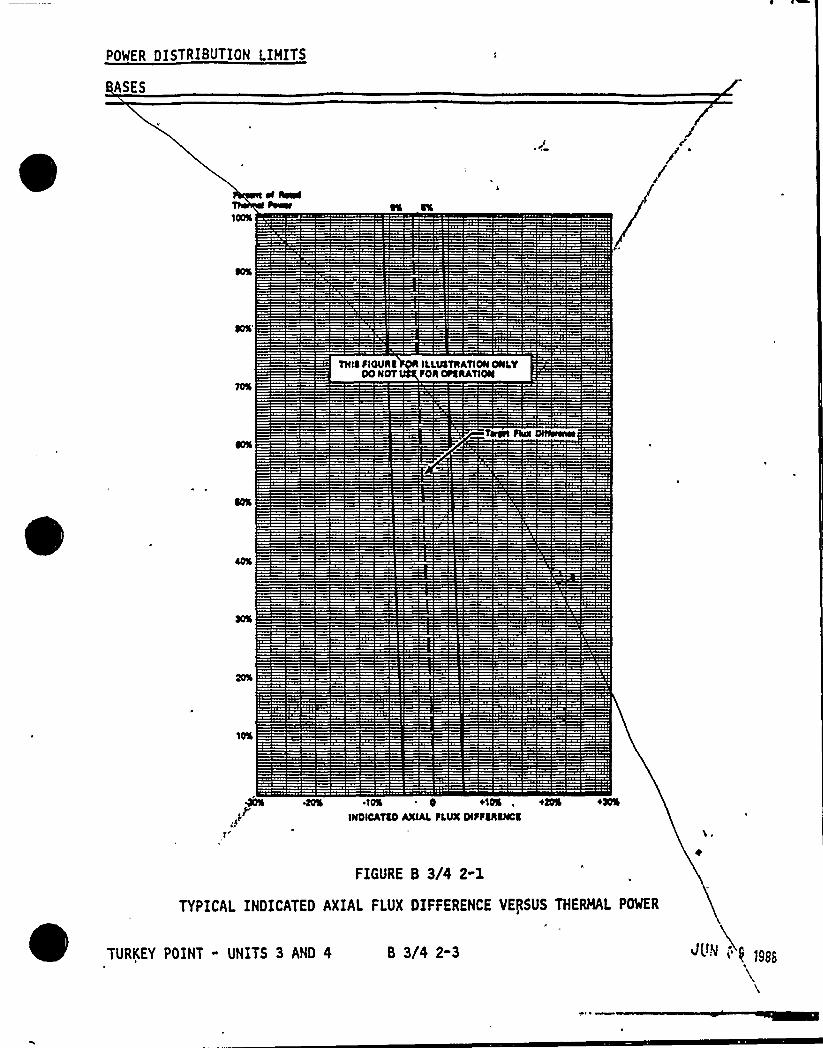
POWER DISTRIBUTION LIMITS
ASES
THIS SIOURCOO NOT
ILLIIaTRATION ONlYSOR OS% RATION
40% 'I0% 0 +10%, +00%
IHDICATlDAXIAlSlVX DISS(haSSC'm
FIGURE B 3/4 2-1
TYPICAL INDICATED AXIAL FLUX DIFFERENCE VERSUS THERMAL POWER
8 3/4 2-3
POWER DISTRIBUTION LIMITS
I ES
MoM/3/4.2. nd 3/4.2.3 HEAT FLUX HOT CHANNEL FACTOR AND NUCLEAR ENTHALPY~NISEHOT CHAN L FACTOR
The lim> s on heat flux hot channel factor and nuclear e alpy rise hotchannel factor nsure that: (1) the design limits on peak cal power densityand minimum DNBR re not exceeded and (2) in the event of LOCA the peak fuelclad temperature w 1 not exceed the 2200 F ECCS accep nce criteria limit.
Each of these is asurable but will normall only be determinedperiodically as specific in Specifications 4. and 4.2.3. This periodicsurveillance is sufficient o ensure that th imits are maintained provided:
a. Control rods in < si le grou ove together with no individual rodinsertion differing by ore an a 12 steps, indicated, from thegroup demand position;
b. Control rod groups ar sequenin Specification 3 .3.6;
1
with overlapping groups as described
c. The control ro insertion limits of"S ifications 3.1.3.5 and3. 1.3.6 are intained; and
d. The axi power distribution, expressed in te of AXIAL FLUXDIFFE CE, is maintained within the limits.
F<H wil be maintained within its limits provided Condition a. through d.N
above are aintained. The relaxation of F~ as a function of THE POWER
allows anges in the radial power shape for all permissible rod insert nlimit .
TURKEY POINT - UNITS 3 AND 4 B 3/4 2-4
POWER DISTRIBUTION LIHITS
BASES
HEA CHANNEL FACTOR AND NUCLEAR ENTHALPY RISE HOT CHANNEL FACTOR
Co ued
Fue rod bowing reduces the value of DNB ratio. Credit is av'ai-3able tooffset th reduction in the generic margin. The generic margins, totaljh'.
1X DNBR c pletely offset any rod bow penalties. This margin inclu thefollowing.
a. Desi limit DNBR of j1.30 vs 1.283,b. Grid Sp cing (K ) of [0.046 vs 0.0597,
c. Thermal D fusion Coefficient of f0.038 vs 0.05
d. ONBR Noltlp iee of [0.86 vs 0.88], eod
e. Pitch reductio
The applicable values of ro bow penalties are ferenced in the FSAR.
When an F~ measurement is ken, an al owance for both experimental errorand manufacturing tolerance must mad An allowance of 5X is appropriatefor a full-core map taken with the re Detector Flux Mapping System, and a3X allowance is appropriate for manu uring tolerance.
The Radial Peaking Factor, (Z), i easured periodically to provide
assurance that the Hot Charm Factor, F~(Z), emains within its limit. The
RTP
F limit for RATED TH L POWER (Fx ) as provi 'n the Radial Peakingxy
, Factor Limit Report er Specification 6.9.1.6 was dete ed from expectedpower control man ers over the full range of burnup con ions in the core.
When RCS ow rate and F~ are measured, no additional a wances areN
necessary p or to comparison with the limits of Figures 3. 2-3 an .2-4.
Heasurem t errors of 2.1X for RCS total flow rate and 4X for F~ have eenN
allowe for in tion of the design DNBR value.
3/4. 2. 4 UADRANT POWER TILT RATIO
The (VAGRANT POWER TILT RATIO limit assures that the radial power dis-tribution satisfies the design values used in the power capability analysis.Radial power distribution measurements are made during STARTUP testing andperiodically during power operation.
The limit of 1.02, at which corrective action is required, provides DNB
and linear heat generation rate protection with x-y plane power tilts. A
limit of 1.02 was selected to provide an allowance for the uncertainty asso-ciated with the indicated power tilt.
TURKEY POINT - UNITS 3 AND 4 B 3/4 2-5 ~ > j!<
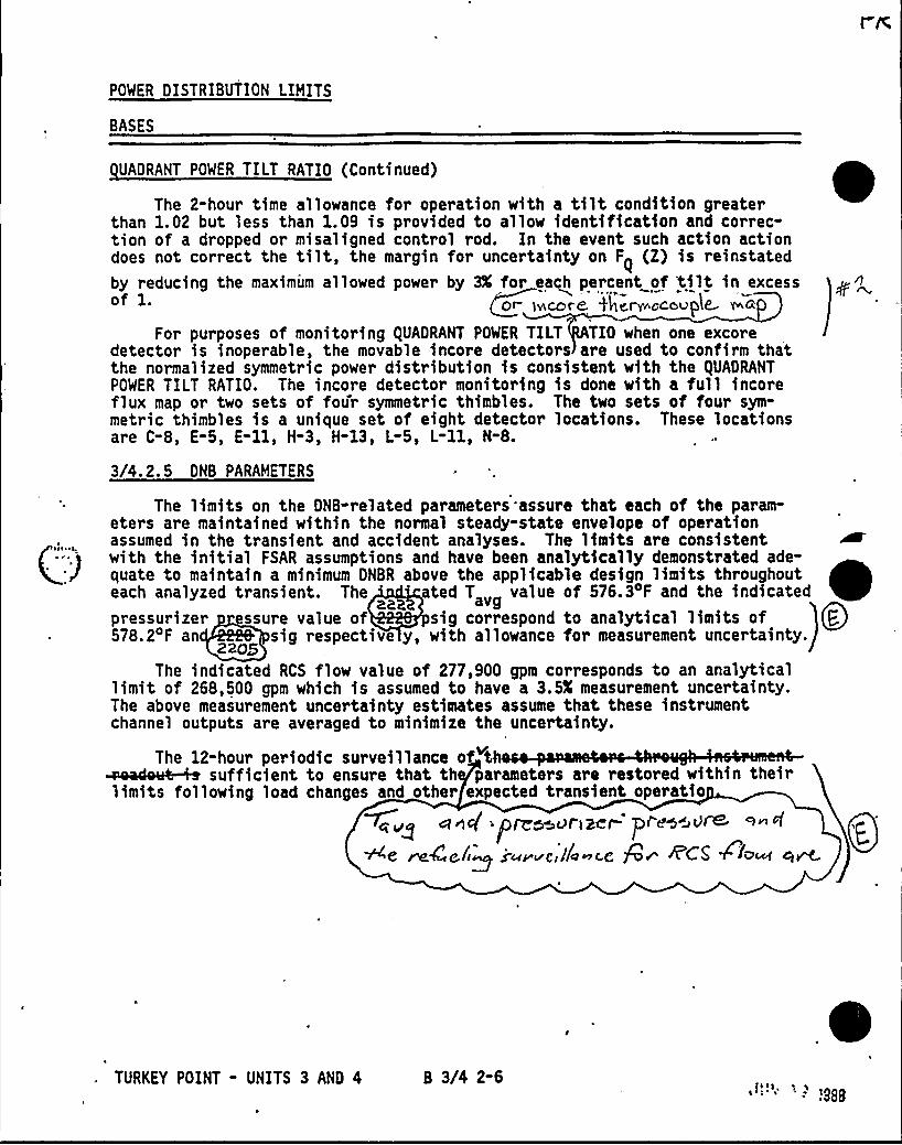
POWER DISTRIBUTION LIMITS
BASES
UADRANT POWER TILT RATIO (Continued)
The 2-hour time allowance for operation with a tilt condition greaterthan 1.02 but less than 1.09 is provided to allow identification and correc-tion of a dropped or misaligned control rod. In the event such action actiondoes not correct the tilt, the margin for uncertainty on F (Z) is reinstatedby reducing the maximum allowed power by 3X for each percent of tilt in excessof 1. ~or iecore iYierr ocovple r'ia
For purposes of monitoring QUADRANT POWER TILT TIO when one excoredetector is inoperable, the movable incore detectors are used to confirm thatthe normalized symmetric power distribution is consistent with the QUADRANTPOWER TILT RATIO. The incore detector monitoring is done with a full incoreflux map or two sets of four symmetric thimbles. The two sets of four sym-metric thimbles is a unique set of eight detector locations. These locationsare C-8, E-5, E-ll, H-3, H-13, L-5, L-ll, N-8.
3/4.2. 5 DNB PARAMETERS
The limits on the DNB-related parameters assure that each of the param-eters are maintained within the normal steady-state envelope of operationassumed in the transient and accident analyses. The limits are consistentwith the initial FSAR assumptions and have been analytically demonstrated ade-quate to maintain a minimum DNBR above the applicable design limits throughouteach analyzed transient. The 'ted T value of 576.3 F and the indicatedpressurizer ssure value of sig correspond to analytical limits of QP.578.2 F an sig respective y, with allowance for measurement uncertainty.
22'he
indicated RCS flow value of 277,900 gpm corresponds to an analyticallimit of 268,500 gpm which is assumed to have a 3.5X measurement uncertainty.The above measurement uncertainty estimates assume that these instrumentchannel outputs are averaged to minimize the uncertainty.
The 12-hour periodic surveillance offIi ht 1 p t t d tthI hglimits following load changes and other expected transient operatio
mug sine( ~pnmouriacr prso~iure™" fQ~~e ~4e,/i~i-~ave /l~ c.e R~ ~CG ~ib~ g~
TURKEY POINT - UNITS 3 AND 4 B 3/4 2-6t988
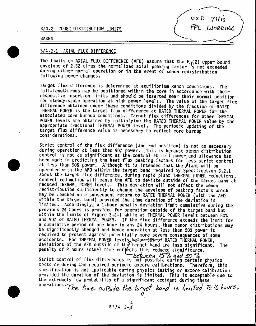
3/4.2 POWER DISTRIBUTION LIMITS
BASES
os 6 7HigFPL Ac COIAQ
3/4 .2 .I AXIAL FLUX DIFFERENCE
The limits on AXIAL FLUX DIFFERENCE (AFD) assure that the F (Z) upper boundenvelope of 2.32 times the nomaalized axial peaking factor )s not exceededduring either normal operation or in the event of xen'on redistributionfollowing power changes.
Target flux difference is determined at equilibrium xenon conditions. Thefull-length rods may be positioned within the core in accordance with theirrespective insertion limits and should be inserted near their normal positionfor steady-state operation at high power levels. The value of the target fluxdifference obtained under these conditions divided by the fraction of RATEDTHERMAL POWER is the target flux difference at RATED THERMAL POWER for theassociated core burnup conditions. Target flux differences for other THERMALPOWER levels are obtained by multiplying the RATED THERMAL POWER value by theappropriate fractional THERMAL POWER level. The periodic updating of thetarget flux difference value is necessary to reflect core burnupconsiderations.
Strict control of the flux difference (and rod position) is not as necessaryduring operation at less than 90% power. ,This is because xenon distributioncontrol is not as significant as the control at full power and allowance hasbeen made in predicting the heat flux peaking factors for less strict controlat less than 90% power. Although it is intended that the Plant will beoperated with the AFD within the target band required by Specification 3.2.1about the target flux difference, during rapid plant THERMAL POWER reductions,control rod motion will cause the AFD to deviate outside of the target band atreduced THERMAL POWER levels. This deviation will not affect the xenonredistribution sufficiently to change the envelope of peaking factors whichmay be reached on a subsequent return to RATED THERMAL POWER (with the AFDwithin the target band) provided the time duration of the deviation islimited . Accordingly, a I-hour penalty deviation limit cumulative during theprevious 24 hours is provided for operation outside of the target band butwithin the limits of Figure 3.2-1 while at THERMAL POWER levels between 50$and 905 of RATED THERMAL POWER. If the flux difference exceeds the limit fora cumulative period of one hour in any 24 hours, then xenon distributions maybe significantly changed and hence operation at less than 501 power isrequired to protect against potentially more severe consequences of some
0 T ERREL 0 ER l T ~f TER TRERRRL 0 ER,deviations of the AFD outside of th target band are less significant. Thepenalty of 2 hours actual time ref cts this reduced significance.
4e'toseen IZffo Eoe 50 fyoStrict control of flux differences is not possible during certain physicstests or during the required periodic excore calibrations. Therefore, thisspecification is not applicable during physics testing or excore calibrationprovided the duration of the deviation is limited. This is acceptable due tothe extremely low probability of a significant accident during these
'17lE fi»E& Ou fgirvf0 th'e, targe7 4»dz f5 li»EE tea
2B3/4 2-g
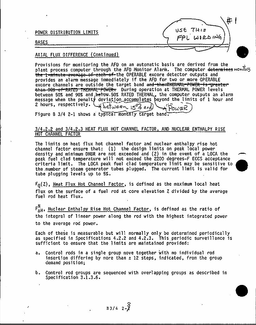
POWER DISTRIBUTION LIMITS
BASES
USE 7lh is@PL, Rl~i4A
AXIAL FLUX DIFFERENCE Continued
Provisions for monitoring the AFD on an automatic basis are derived from theplant process computer through the AFD Monitor Alarm. The computer 4eteriim~r oviform
the OPERABLE excore detector outputs andprovides an alarm message iomediately if the AFD for two or more OPERABLEexcore channels are outside the target band
g P i" EMAL 0
between 505 and 90% and hei~,505 RATED THERMAL, the computer outputs an alarmmessage when the penalt deviation accumulates eyond the limits of 1 hour and2 hours, respectively. <i~+<M l5 ro an
) D~~F<Figure B 3/4 2-1 shows a typsca month y target band.
3/4.2.2 and 3/4.2.3 HEAT FLUX HOT CHANNEL FACTOR AND NUCLEAR ENTHALPY RISEHOT CHANNEL FACTOR
The limits on heat flux hot channel factor and nuclear enthalpy rise hotchannel factor ensure that: (1) the design limits on peak local powerdensity and minimum DNBR are not exceeded and (2) in the event of a LOCA thepeak fuel clad temperature will not exceed the 2200 degrees-F ECCS acceptancecriteria limit. The LOCA peak fuel clad temperature limit may be sensitive tothe, number of steam generator tubes plugged. The current limit is valid fortube plugging levels up to 5X.
Fq(Z), Heat Flux Hot Channel Factor, is defined as the maximum local heat
flux on the surface of a fuel rod at core elevation Z divided by the averagefuel rod heat flux.
F<H, Nuclear Enthal Rise Hot Channel Factor, is defined as the ratio ofN
the integral of linear power along the rod with the highest integrated power
to the average rod power.
Each of these is measurable but will normally only be determined periodicallyas specified in Specifications 4.2.2 and 4.2.3. This periodic surveillance issufficient to ensure that the limits are maintained provided:
a. Control rods in a single group move together with no individual rodinsertion differing by more than + 12 steps, indicated, from the groupdemand position;
b. Control rod groups are sequenced with overlapping groups as described inSpecification 3.1.3.6.
0B 3/4 2-g
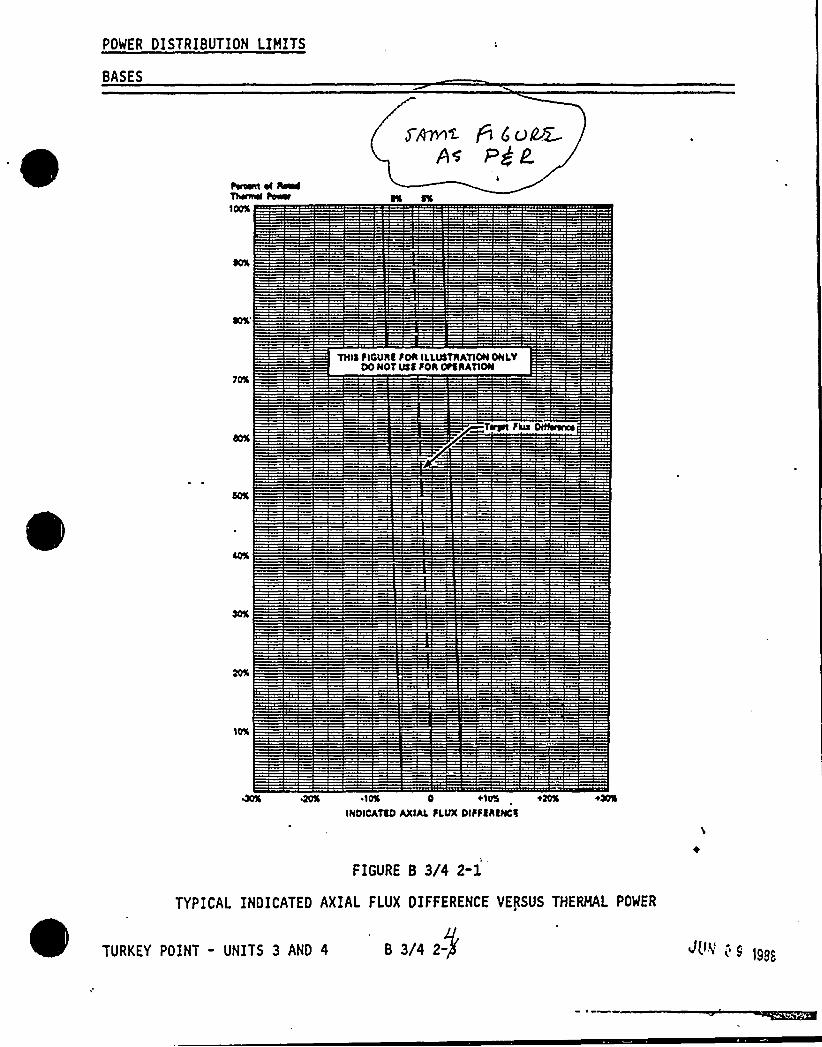
POWER DISTRIBUTION LIMITS
BASES
TNIE FIGUhE FDN ILLUEThATIONONLYDO NOT USE FOh OfthATION
40% K% I0% 0 +10% +00% +X%
INDICATED AXIALFLVX DIFFEhENCE
FIGURE B 3/4 2-1
TYPICAL INDICATED AXIAL FLUX DIFFERENCE VERSUS THERMAL POWER
B 3/4 2-

/ > g pg p (~ppzi>7>cy'C'.~
POWER Q I 5 TR I BU T I ON L IMITS
use 78.«A'<Wea 0 iP4
8ASES
HEAT FL'Jg 1OT CHANNEL FACTOR ANO NUCLEAR ENTHALPY R ISE HOT CHANNEL FACTORonto'ueo
c. Thc control rod fnsertfon limits of Spccfffcat1ons 3.1.3.S and 3.1.3.6 aremaf ntd intd ~ and
d. Thc axial power distribution, expressed fn terms of AXIAL FLUX DIFFERENCE,is maintained within the limits.
'%hen an F~ measurement 1s taken, both experimental error and manufacturingtolerance must be allowed for. F1ve percent fs the appropriate allowance fora full core map taken wfth the movable incore detector flux mapp1ng system anathree percent 1s thc appropr1ate allowance for manufactur 1ng tolerance. Theseuncertainties only apply ff the map fs taken for purposes other than thedetermination of P8L and PR8.
F<< will be mafnta1ned wfthfn fts limits provided Conditions a. throughN
d. above are maintained.
In the.spcc1ffed limit of FaN, there fs an 8 percent allowance forN
uncertainties which means Chat normal operation of the core fs expected to
rcsulc fn F<H < l,62/1.08. The logic behind the larger uncertainty in thisN
case is that (a} normal perturbatfons fn the radial po~er shape (e.g., rod
misa11gnment} affect F<H, fn most cases without necessarily affecting F<,N
(b) although the operator has a dfrect influence on Fn through movementof rods, and can lfmft ft to the desired value, he haE no d1rcct control over
F<H and (c) an error 1n the prediction for radial power shape, which may be
detected during startup physics tests can be ccmpensatcd for in F~ by tighteraxial control, but compensation i'r F<H 1s less readily available. Qhcn a
mcasur cmcnt of F>H fs taken, experimental error must be allowed for and 4% isN
the appropriate allowance for a full core map taken with the movable incoredetector flux mapping systea.
83/4 2-4A

I
If s//
U
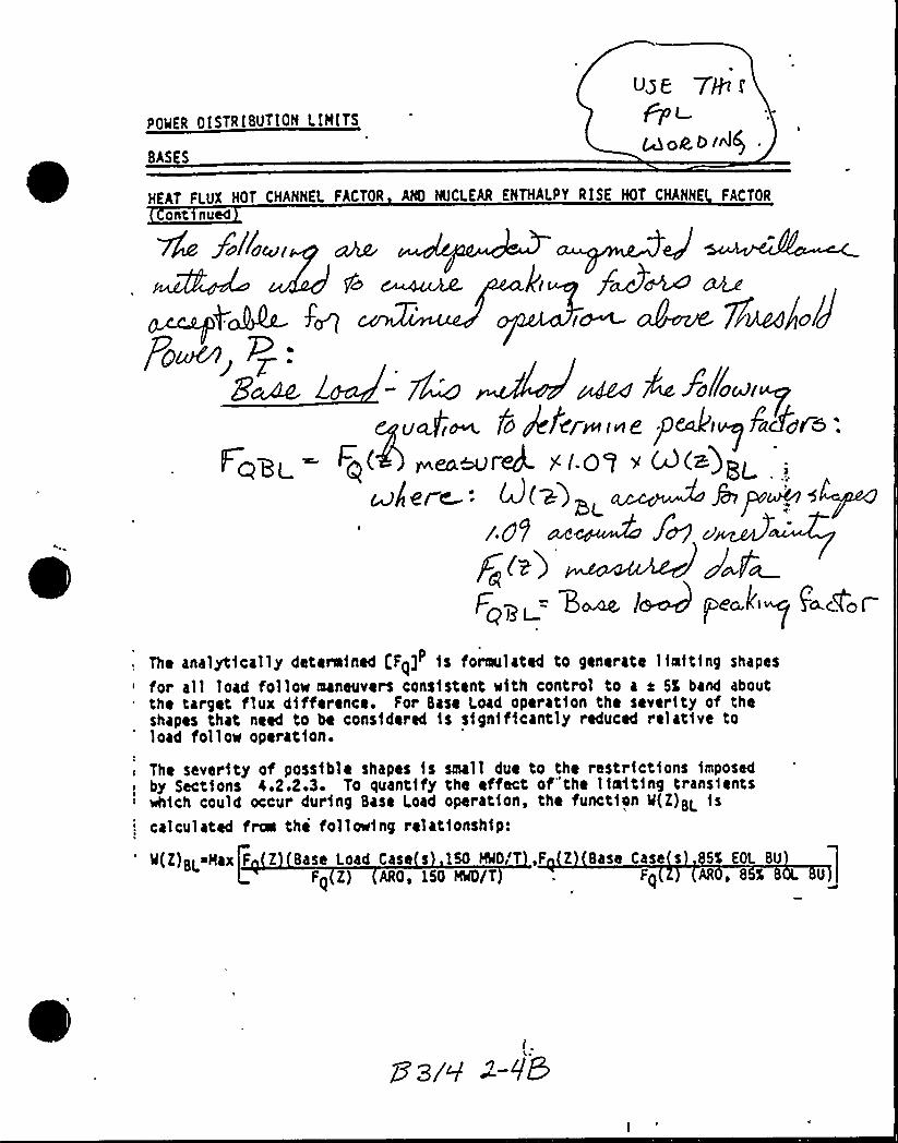
POWER OISTRIBUTION LIMITS
BAS S
Use 70 (
Mok5 i~(
HEAT Ft UX HOT CHANNEL FACTOR AND NUCLEAR ENTHALPY RISE HOT CHANNE FACTOR
ont nued
O dMl
j~crtW ~~~ ~ g~go/J
g.~Cd'glcPCÃi
The analyt1cally detera1ned [F~]P 1s formulated to gener ate 11aft1ng shapes
for all load follow maneuvers cons1stent w1th control to a a 5% band aboutthe target flux 41fference. For Base Load operat1on the sever1ty of theshapes that need to be cons1dered 1s s1gn1f1cantly reduced relat1ve toload follow operatfon.
WM 4 Xo(/ocJ<uy
u4~ fo gt~r~«e p&i~6a~es:I dpi- ~q( r eamrekw.I.OU ~ K(a)p~
cJ/8/ e: d(w)> Jalap~/. g P dt's
Fqg~= B~ lMpe~"iq Facfoi.
~ The sever1ty of poss1ble shapes 1s small due to the restrfct1ons 1mposed
by Sect1ons 4.2.2.3. To quant1fy the effect of"the 11mtt1ng trans1ents: wh1ch could occur dur1ng Base Load operat1on, the funct1on Q(Z)BL 1s
calculated f~ the follow1ng relat1onsh1p:
'(Z)BL Wax F Z Base Load Case s 150 HN,'T ,F Z Base Case s 5X EOL BU
Fq Z) AROo 150 $8/T Fq AR , 8 L .]
Ii,,
(~> 'P
~l
I
J
) gl' pp". l ' YCi
I I
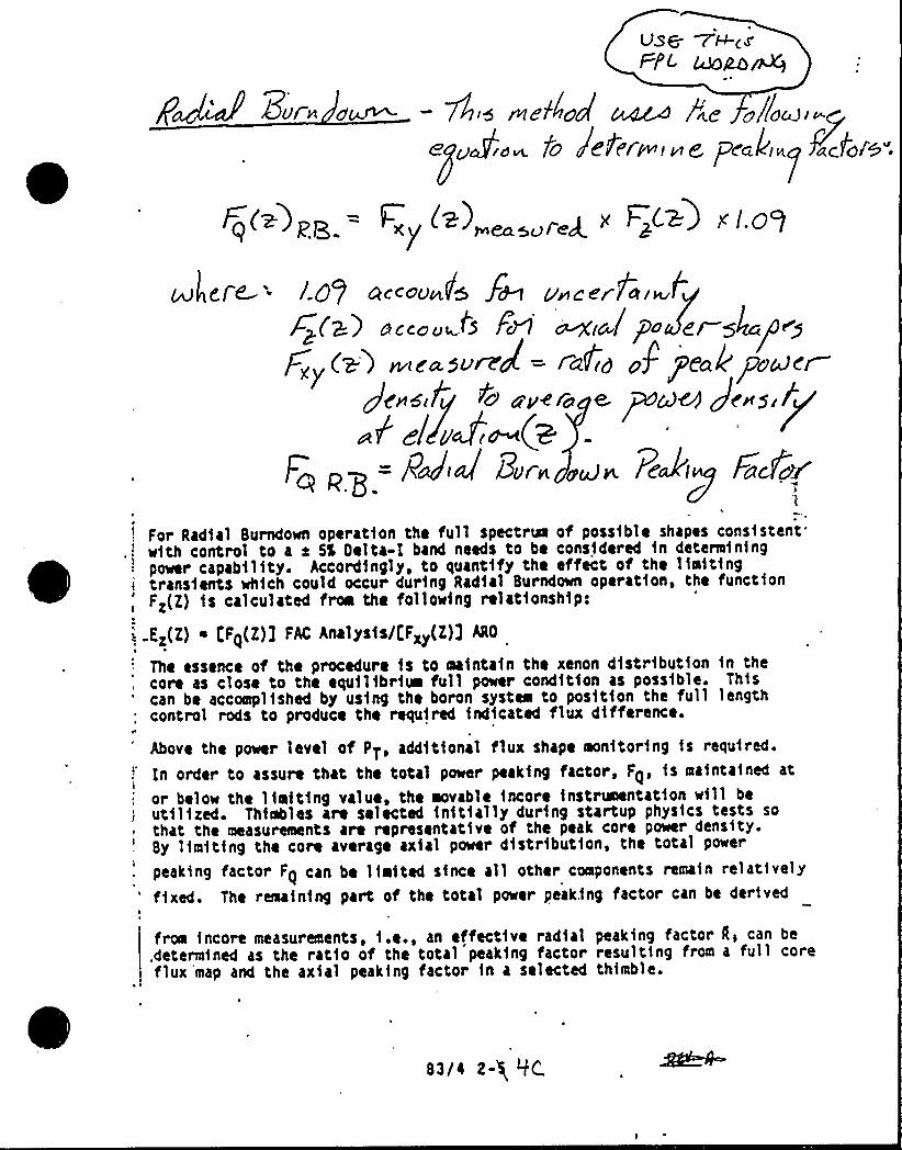
UD+ WH-(4FPL mao~
Bur. ere.~ — 4; wep~od'c4~ /re ollocuI-r.e > .a~ O e err-~tvtg ia I~ aCdl'0".
Fq(~)p~ = V (z)„„„g x F~C>) ) I.gq
u/ere '8) ac~ou~fs fw v~cerfai~l~~(k) uecoo~tS Fd1 ~i@/Po emglca/<y
C2') nneayuMd(= <aFid pf fE'ale j7ucdct4 uvero e ~a~ Je~slgf
P el ed~(aF~ ~
= PdJ Bur. «Pedip FaZ>~
For Radial Surndown operation the full spectral of possible shapes consistentw1th control to a e 5% Delta-l band needs to be considered fn determiningpower capability. Accordingly, to quantify the effect of the liait1ng
i transients which could occur during Rad1al Surndown operation, the functionFz(Z) 1s calculated from the following relationship:
:. Ez(Z) ~ tF<(Z)1 FAC Analysislt:Fxy(Z)] ARO
The essence of the procedure fs to maintain the xenon distribution in thecore as close to the equilibria full power condition as poss1ble. Thiscan be accompl1shed by usfng the boron system to position the full lengthcontrol rods to produce the requ1red 1ndicated flux difference.
Above the power level of PT, additional flux shape monitor1ng fs required.
?n order to assure that the total power peaking factor, F~, is maintained at
or belo~ the limit1ng value, the movable incore instr~ntation will beut11ized. Thimbles are selected init1ally during startup physics tests sothat the measurements are representat1ve of the peak core power density.Sy limiting the core average axial power distribut1on, the total power
peaking factor Fq can be limited since all other components remain relatively"'ixed. The reaaining part of the total power peak.ing factor can be derivedI
froi incore measurements, i.e., an effective radial peaking factor 0, can be
.determined as the ratio of the total peak1ng factor resulting from a full coreflux map and the axial peaking factor in a selected thimble.
B3/i 2-$ QC.
/ „. r, a
g la nr'C
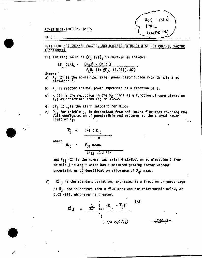
POQER OISTRIBUTION.LIMITS
BASES
vs,e
Fpi~CD I Rg
HEAT FLUX iOT .-HANNEL FACTOR ANO NUCLEAR ENTHALPY RISE HOT CHANNEL FACTORCont>nued
The limiting value of (Fj (E)]s is derived as fo'llows:
[Fj (E)]s I F " x K E
PPj (1+ 5'j) (1 03)(1 07)%here:
')
F, (E) is the normalized axial power distribution from thimble j atelevation E.
b) PL is reactor thermal power expressed as a fraction of 1.
c) K (E) is the reduction in the Fg limit as a function of core elevation(E) as determined from Figure 3.2-2.
d) {:Fj (l)3sis the alarm setpo1nt for NIGS.
e) Jt,, for thimble j, is determined from n~6 incore flux maps covering thefill configuration of permiss1ble rod patterns at the thermal powerlimit of PT.
s ia1 g Rij
Rij ~ Fqi meas ~
max
and Fij (E) 1s the normalized axial distribution at elevation E fromthimble j in map 1 which has a measured peaking factor withoutunce~tainties og densification allo~ance of F~i meas.
f) (5 j is the standard deviation, expressed as a fraction or percentage
of IIj, and is der1ved from n flux maps and the relationship belo~, or0.02 (2X), whichever 1s greeter .
n1 E (Rij - Rj)
n-t 1~1
kj
8 3/4 2/ qg
1/2

I/'~@DE~
)67C'~iK '0'~"'l
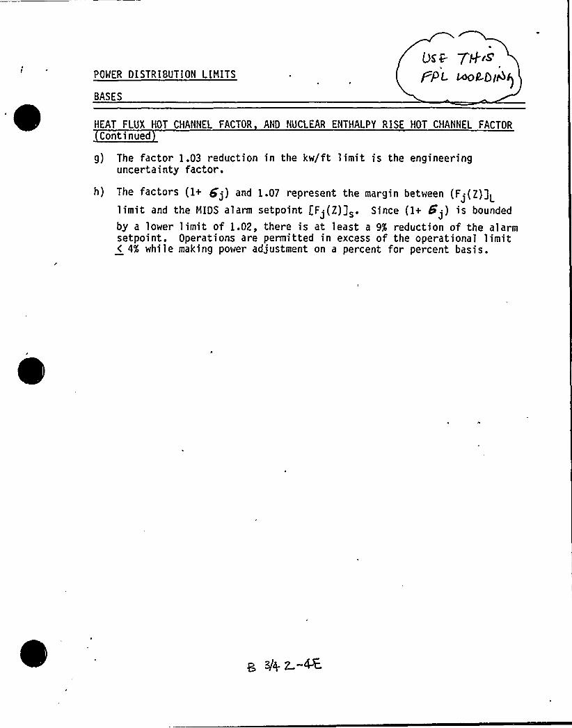
POWER DISTRIBUTION LIMITS
BASES
(35~ 7+rSPPL ~Los~)
HEAT FLUX HOT CHANNEL FACTOR AND NUCLEAR ENTHALPY RISE HOT CHANNEL FACTORContinued
g) The factor 1.03 reduction in the kw/ft limit is the engineeringuncertainty factor.
h) The factors (1+ $ j) and 1.07 represent the margin between (F'(Z)]Ljlimit and the MIDS alarm setpoint [F.(Z)3s. Since (1+ 8'.) is bounded
by a lower limit of 1.02, there is at least a 9$ reduction of the alarmsetpoint. Operations are permitted in excess of the operational limit< 4X, while making power adjustment on a percent for percent basis.

/i i -'P-I
/VIYCr 'i''."i
lf
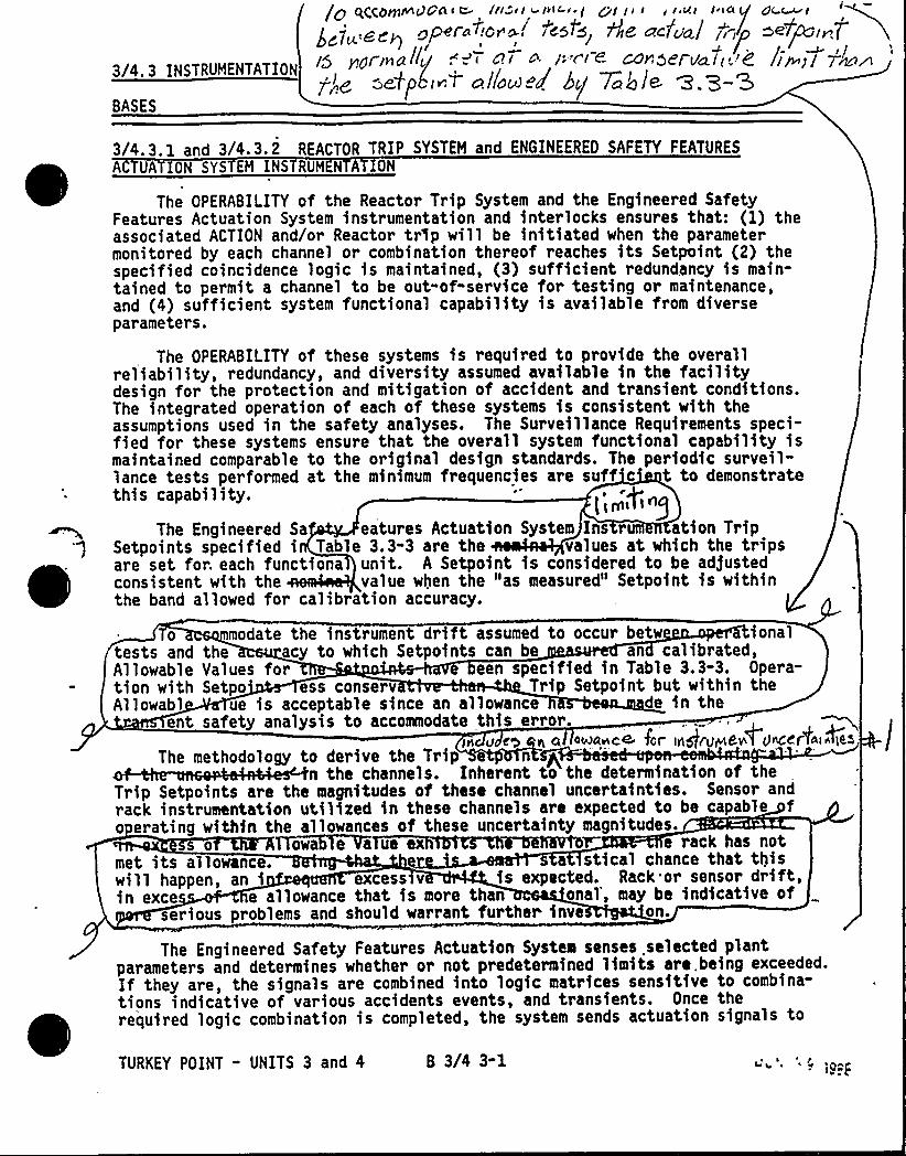
3/4.3 INSTRUMENTATION
BASES
g q~~O~~ggAS e. In el ~VIC-e ] ~g ja I y r ui I sa/ j,yl/5 peal Inall<g .. I 4? r a I.Y'( ~ COr!5E't uhl<.->~
~!e, -etpLi T.cillacooo'g 7ac') Je e.Z-S
dc ~tze7pg,~Pliw)/
3/4. 3. 1 and 3/4. 3. 2 REACTOR TRIP SYSTEM and ENGINEERED SAFETY FEATURES
A UATION SYS EM INS RUM N A ION
The OPERABILITY of the Reactor Trip System and the Engineered SafetyFeatures Actuation System instrumentation and interlocks ensures that: (1) theassociated ACTION and/or Reactor tr3p will be initiated when the parametermonitored by each channel or combination thereof reaches its Setpoint (2) thespecified coincidence logic is maintained, (3) sufficient redundancy is main-tained to permit a channel to be out-of-service for testing or maintenance,and (4) sufficient system functional capability is available from diverseparameters.
The OPERABILITY of these systems is required to provide the overallreliability, redundancy, and diversity assumed available in the facilitydesign for the protection and mitigation of accident and transient conditions.The integrated operation of each of these systems is consistent with theassumptions used in the safety analyses. The Surveillance Requirements speci-fied for these systems ensure that the overall system functional capability ismaintained comparable to the original design standards. The periodic surveil-lance tests performed at the minimum frequencies are suff c t to demonstratethis capability.
l<+'he
Engineered Sa eatures Actuation System Ins r ation TripSetpoints specified i Table 3.3-3 are the values at which the tripsare set for. each functiona unit. A Setpoint is considered to be ad]ustedconsistent with the value when the "as measured" Setpoint is withinthe band allowed for calibration accuracy.
modate the instrument drift assumed to occur betw ionalthe acy to which Setpoints can be an calibrated,Values for een specified in Table 3.3-3. Opera-Setpo ess conserv Trip Setpoint but within the
ue is acceptable since an allowance de in thesafety analysis to accommodate this error.
ia u e a oiuaace far in ev Once
0tests andAllowabletion withAllowabl
ent
The Engineered Safety Features Actuation System senses selected plantparameters and determines whether or not predetermined limits are. being exceeded.If they are, the signals are combined into logic matrices sensitive to combina-tions indicative of various accidents events, and transients. Once therequired logic combination is completed, the system sends actuation signals to
pggII md'.5
The methodology to derive the Trip e nn the channels. Inherent to the determination of the
Trip Setpoints are the magnitudes of these channel uncertainties. Sensor andrack instrumentation utilized in these channels are expected to be capable fo crating within the allowances of these uncertainty magnitudes.
e rack has notmet its allowa a stical chance that thiswill happen, an i s v is expected. Rack or sensor drift,in exce e allowance that is more h onal', may be indicative of
serious problems and should warrant further inve on.
TURKEY POINT - UNITS 3 and 4 B 3/4 3-1
INSTRUMENTATION
BASES
REACTOR TRIP SYSTEM and ENGINEEREO SAFETY FEATURES ACTUATION SYSTEMINSTRUM NTATION Continued
those Engineered Safety Features components whose aggregate function bestserves the requirements of the condition. As an example, the following actionsmay be initiated by the Engineered Safety Features Actuation System to mitigatethe consequences of a steam line break or loss-of-coolant accident: (1) SafetyInjection pumps start and automatic valves position, (2) Reactor trip, (3) feedwater isolation, (4) startup of the emergency diesel generators, (5) containmentspray pumps start and automatic valves position (6) containment isolation,(7) steam line iso1ation, (8) turbine trip, (9) auxiliary feedwater pumpsstart and automatic valves position, (10) containment cooling fans start andautomatic valves position, (11 water pumps start and auto-matic valves position, and (1 R ol ~t nd Ventilation Systemsstart. llipiQ ~~]q +pge,r ot ng gg+t ~g 8~7
The Engineered Safety Features Actuation ystem interlocks perform thefollowing functions:
HIGH STEAM FLOW SAFETY INJECTION BLOCK -. This permissive is used to blockthe safety injection (SI)- signal generated by High Steam Line Flow coincidentwith Low Steam Line Pressure or Low T . The permissive is generated when
avg'wo
out of three Low Tav channels drop below their setpoints and the manual
SI Block/Unblock switch is momentarily placed in the block position. Thisswitch is a spring return to the normal position type. The permissive willautomatically be defeated if two out of three Low T channels rise above
avgtheir setpoints. The permissive may be manually defeated when two out ofthree Low T channels are below their setpoints and the manual SI Block/
avgUnblock switch is momentarily placed in the unblock position.
LOW PRESSURIZER PRESSURE SAFETY -INJECTION BLOCK - This permissive is usedto block the safety injection signals generated by Low Pressurizer Pressureand High Oifferential Pressure between the Steam Line Header and any SteamLine. The permissive is generated when two out of three pressurizer pressurepermissive channels drop below their setpoints and the manual SI Block/Unblockswitch is momentarily placed in the block position. This is the same switchthat is used to manually block the High Steam Flow Safety Injection signalsmentioned above. This permissive will automatically be defeated if two out ofthree pressurizer pressure perwissive channels rise above their setpoints.The permissive channels rise above their setpoints.. The permissive may bemanually defeated when two out of three pressurizer pressure permissivechannels are below their setpoints and the manual SI Block/Unblock switchmomentarily placed in the Unblock position.
0
/4: 7-.-1-.
, TURKEY POINT - UNITS 3 and 4 B 3/4 3-2

INSTRUMENTATION
BASES
3/4. 3. 3 MONITORING INSTRUMENTATION
3/4. 3. 3. 1 RADIATION MONITORING FOR PLANT OPERATIONS
The OPERABILITY of the radiation monitoring instrumentation for plantoperations ensures that conditions indicative of potential uncontrolledradioactive releases are monitored and that appropriate actions will beautomatically or manually initiated when the radiation level monitored by eachchannel reaches its alarm or trip setpoint.
3/4.3.3.2 MOVABLE INCORE DETECTORS
The OPERABILITY of the movable incore detectors with the specified minimumcomplement of equipment ensures that the measurements obtained from use ofthis system accurately represent the spatial neutron flux distribution of thecore. The OPERABILITY of this system is demonstrated by irradiating eachdetector used and determining the acceptability of its voltage curve.
For the purpose of measuring F~(Z) or F~ a full incore flux map is used.N
A
quarter-core flux maps, as defined in WCAP-8648, June 1976, may be used inrecalibration of the Excore Neutron Flux Detection System, and full incoreflux maps or symmetric incore thimbles may be used for monitoring the QUADRANTPOWER TILT RATIO when one Power Range channel is inoperable.
3/4. 3. 3. 3 ACCIDENT MONITORING INSTRUMENTATION
The OPERABILITY.of the accident monitoring instrumentation ensures thatsufficient information is available on selected plant parameters to monitorand assess these variables following an accident. This capability is consis-tent with the recommendations of Regulatory Guide 1.97, Revision 3, "Instrumen-tation for Light-Water-Cooled Nuclear Power Plants to Assess Plant ConditionsDuring and Following an Accident," May 1983 and NUREG-0737, "Clarification ofTMI Action Plan Requirements," November 1980.
3/4. 3. 3. 4 FIRE DETECTION INSTRUMENTATION
The OPERABILITY of the fire detection instrumentation ensures that bothadequate warning capability is available for prompt detection of fires and thatFire Suppression Systems, that are actuated by fire detectors, will dischargeextinguishing.agents in a timely manner. Prompt detection and suppression offires will reduce the potential for damage to safety-related equipment and isan integral element in the overall facility Fire Protection Program.
Fire detectors that are used to actuate Fire Suppression Systems representa more critically important component of a plant Fire Protection Programthan detectors that are installed solely for early fire warning and notifica-tion. Consequently, the minimum number of OPERABLE fire detectors must be
'reater.
The loss of detection capability for Fire Suppression Systems, actuatedby fire detectors, represents a significant degradation of fire protection for
TURKEY POINT - UNITS 3 and 4 B 3/4 3-3
INSTRUMENTATION
BASES
FIRE DETECTION INSTRUMENTATION (Continued)
any'area. As a result, the establishment of a fire watch patrol must be ini-tiated at an earlier stage than would be warranted for the loss of detectorsthat provide only early fire warning. The establishment of frequent firepatrols in the affected areas is required to provide detection capabilityuntil the inoperable instrumentation is restored to OPERABILITY.
3/4. 3. 3. 5 RADIOACTIVE LI UID EFFLUENT MONITORING INSTRUMENTATION
The radioactive liquid effluent instrumentation is provided to monitorand control, as applicable, the, releases of radioactive materials in liquideffluents during actual or potential releases of liquid effluents. TheAlarm/Trip Setpoints for these instruments shall be ca3culated and ad)usted inaccordance with the methodology and parameters in the ODCH to ensure that thealarm/trip will occur prior to exceeding the limits of 10 CFR Part 20. TheOPERABILITY and use of this instrumentation is consistent with the requirementsof General Design Criteria 60, 63, and. 64 of Appendix A to 10 CFR Part 50.
3/4. 3. 3. 6 RADIOACTIVE GASEOUS EFFLUENT HONITORING INSTRUMENTATION
The radioactive gaseous effluent instrumentation is provided to monitor andcontrol, as applicable, the releases of radioactive materials in gaseous efflu-ents during actual or potential releases of gaseous effluents. The Alarm/TripSetpoints for these instruments shall be calculated and adjusted in accordancewith the methodology and parameters in the ODCM to 'ensure that the alarm/tripwill occur prior to exceeding the limits of 10 CFR Part 20. This instrumenta-tion also includes provisions for monitoring (and controlling) the concentrationsof potentially explosive gas mixtures in the GAS DECAY TANK SYSTEM. The OPERA-BILITY and use of this instrumentation is consistent with the requirements ofGeneral Design Criteria 60, 63, and 64 of Appendix A to 10 CFR Part 50. Thesensitivity of any noble gas activity monitors used to show compliance with thegaseous effluent release requirements of Specification 3.11.2.2 shall be suchthat concentrations as low as 1 x 10-'~ pCi/ml're measurable.
TURKEY POINT - UNITS 3 and 4 8 3/4 3-4l
4f~r
3/4.4 REACTOR COOLANT SYSTEH
BASES
3/4.4. 1 REACTOR CDOLANT LOOPS AND COOLANT CIRCULATION
The plant is designed to operate with all reactor coolant loops inoperation and maintain DNBR above the applicable design limit during all normaloperations and anticipated transients. In HODES 1 and 2 with one reactorcoolant loop not in operation this specification requires that the plant be inat least HOT STANDBY within S hours.
In HODE 3, three reactor coolant loops provide sufficient heat removalcapability for removing core decay heat in the event of a bank withdrawalaccident; however, a single reactor coolant loop provides sufficient heatremoval capacity if a bank withdrawal accident can be prevented, i.e., byopening the Reactor Trip Nyo4em breakers or-by placing the Rod Control Systemin the Bank Select Hode with a Shutdown Bank Selected.
In HODE 4, and in HODE 5 with reactor coolant loops filled, a singlereacto~ coolant loop or RHR loop provides sufficient heat removal capabilityfor removing decay heat~
In HODE 5 with reactor coolant loops not filled, a single RHR loop providessufficient heat removal capability for removing decay heat; but single failureconsiderations, and the unavailability of the steam generators as a heatremoving component, require that at least two RHR loops be OPERABLE.
The operation of one reactor coolant pump (RCP) or one RHR pump providesadequate flow to ensure mixing, prevent stratification and produce gradualreactivity changes during boron concentration reductions in the Reactor CoolantSystem. The reactivity change rate associated with boron reduction will,therefore, be within the capability of operator recognition and control.
The restrictions on starting an RCP with one or more RCS cold legs lessthan or equal to 2754F are provided to prevent RCS pressure transients, causedby energy additions from the Secondary Coolant Systeo, which could exceed thelimits of Appendix G to 10 CFR Part 50. The RCS will be, protected againstoverpressure transients and will not exceed the limits of Appendix G by either:(1) restricting the water volume in the pressurizer and thereby providing avolume for the reactor coolant to expand into, or (2) by restricting starting ofthe RCPs to when the secondary water temperature of ea nefa&r4s lt+~0 F ag of the RCS cold leg temperatures Q~ ~'F hpvif inc e5gjh Ctumewl el"IO/,
T~eehnical~Specifications for Hot Shutdown and Cold Shutdown allow aninoperable RHR pump to be the operating RHR pump for up to 2 hours for sur-veillance testing to establish operability. This is required because of thepiping arrangement when the RHR system is being used for Decay Heat Removal.
'URKEY
POINT - UNITS 3 AND 4 B 3/4 4-1J 111 ~
t'.e y 9~ Jv
REACTOR COOLANT SYSTEM
BASES
C:
3/4.4.2 SAFETY VALVES gpss, 3~g)
The pressurize Code safety valves operate to prevent the RCS from beingpressurized above its Safety Limit of 2735 psig. Each safety val e is designedto relieve 480-4'I89- lbs per hour of saturated steam at the valv etpoint. The J E:relief capacity of a single safety valve $ s adequate to relieve aug overpressurecondition which could occur'uring shutdown. In the event that no safetyva1ves are OPERABLE, an RCS vent opening of at least 2.20 square- inches willprovide overpressure relief capability and will prevent RCS overpressurization.r, 0 ~ y pprotection against RCS overpressurization at low temperatures.
During operation, all pressurizer Code safefy val s must be OPERABLE toprevent the RCS from being pressurized above its Safety Limit of 2735 psig.The combined relief capacity of all of these valves is greater than the maximumsurge rate resulting from a complete loss-of-load assuming no Reactor tripuntil the first Reactor Trip System Trip Setpoint is reached (i.e., nocredit is taken for a direct Reactor trip on the loss-of-load) and also assumingno operation of the power-operated relief valves or steam dump valves.
Demonstration of the safety valves'ift settings will occur only duringshutdown and will be performed in accordance with the provisions of Section XIof the ASIDE Boiler and Pressure Code.
3/4.4. 3 PRESSURIZER
~ g
The limit on the maximum water volume in the pressurize'r assures that theparameter is maintained within the normal steady-state envelope of operationassumed in the, FSAR. , The limit is consistent with the initial FSAR assumptions.The 12-hour periodic surveillance is sufficient to ensure that the parameteris restored to within its limit following expected transient operation. Themaximum water volume cubic feet) also ensures that a steam bubble isformed and thus the RC is not a hydraulically solid system. The requirementthat both backup pre urizer heater groups be OPERABLE enhances the capabilityof the plant to con ol Reactor Coolant System pressure and establish naturalcirculation.
( //93~ L
Jot-]
'URKEY POINT - UNITS 3 AND 4 B 3/4 4-2
REACTOR COOLANT SYSTEM
BASES
pokd BLe3/4. 4, 4 l~~ VALVES
T4o~w~es
gn rans en s up
The opening of the PORVs fulfills no safety-related function and no credit istaken for their operation in the safety analysis for MODE 1, 2 or 3. Each PORVhas a remotely operated block valve to provide a positive shutoff capabilityshould a relief valve become inoperable.
3/4.4.5 STEAM GENERATORS
The Surveillance Requirements for inspection of the steam generator tubesensure that the structural integrity of this portion of the RCS will be main-tained. The program for inservice inspection of steam generator tubes isbased on a modificati'on of Regulatory Guide 1.83, Revision 1. Inserviceinspection of steam generator tubing is essential in order to maintain surveil-lance of the conditions of the tubes in the event that there is evidence ofmechanical damage or progressive degradation due to design, manufacturingerrors, or inservice conditions that lead to corrosion. Inservice inspectionof steam generator tubing also provides a means of characterizing the natureand cause of any tube degradation so that corrective measures can be taken.
The plant is expected to be operated in a manner such that the secondarycoolant will be maintained within those chemistry limits found to result innegligible corrosion of the steam generator tubes. If the secondary coolantchemistry is not maintained within these limits, localized cor rosion maylikely result in stress corrosion cracking. The extent of cracking duringplant operation would be limited by the limitation of steam generator tubeleakage between the Reactor Coolant System and the Seconda Coolant Syste(reactor-to-secondary leakage = 500 gallons per day peP earn genera or . ~ ~
~) ECracks having a reactor to-secondary leakage less than this limit during ~"f o'
i
operation will have an adequate margin of safety to withstand the loads im s'il'uringnormal operation and by postulated accidents. Operating plants have
demonstrated that reactor-to-secondary leakage of 500 gallons per day persteam generator can readily be detected by radiation monitors of steam generatorblowdown. Leakage in excess of this limitvill require plant shutdown and anunscheduled inspection, during ~hich the leaking tubes will be located andplugged.
wastage-type defects are unlikely with the all volatile treatment (AVT)of the secondary coolant. However, even if a defect should develop in service,it will be found during s'cheduled inservice steam generator tube examinations.Plugging will be required. for all tubes with imperfections exceeding theplugging limit of 40K of the tube nominal wal1 thickness. Steam generatortube inspections of operating plants have demonstrated the capability toreliably detect degradation that has penetrated 20K of the original tube wallthickness.
TURKEY POINT - UNITS 3 AND 4 B 3/4 4-3
REACTOR COOLANT SYSTEM
BASES
STEAM GENERATORS (Continued)
Whenever the results of any steam generator tubing inservice inspectionfall into Category C-3, these results will be promptly reported to the Commissionin a Special Report pursuant to Specfffcation 6.9.2 within 30 days and prior toresumption of plant operation. Such cases will be considered by„the Commissionon a case-by-case basis and may result in a requirement for analysis, laboratoryexaminations, tests, additional eddy-current inspection, and revision of theTechnical Specifications, if necessary.
3/4.4. 6 REACTOR COOLANT SYSTEM LEAKAGE
3 4'4'6'I LEAKAGE UETEGTIo sYGTEMs A0 lect<+ end 'c~cL~~
The RCS Leakage Detection stems required by this specification areprovided to monitor and detec leakage from the reactor coolant pressureboundary to the containment. The containment sump level system is the normalsump level instrumentation. ~/he Post Accident Containment Wat er Level Monitor - 0Narrow range instrumentatfon also satisfies the requirement for a sump levelmonitoring system. In addition, gross leakage will be detected by changes inmakeup water require ents, visual inspection, and audible detection. Leakageto" other systems will detected by activity changes (e.g., within the tcomponent cooling system or water inventory changes (e.g ,, tank levels).3/4.4.6.2 OPERATIONAL LEAKA 'per loIple. ~ ~ -5"
)
PRESSURE BOUNDARY LEAKAGE of any magnitude fs unacceptable since it maybe indicative of an impending gross failure of the pressure boundary. Therefore,the presence of any PRESSURE BOUNDARY LEAKAGE requires the unit to be promptlyplaced in COLD SHUTDOWN.
Industry experience has shown that while a limited amount of leakage isexpected from the RCS, the unidentified portion of this leakage can be reducedto a threshold value of less than 1 gpm. This threshold value fs sufficientlylow to ensure early detection of'dditional leakage.
The total steam generator tube leakage limit of 1 gpm for all steamgenerators ensures that the dosage contribution from the tube leakage will belimited to a small fraction of 10 CFR Part 100 dose guideline values in theevent of either a steam generator tube rupture or steam line break. The 1 gpmlimit is consistent with the assumptions used fn the analysis of these acci-dents. The 500 gpd leakage limit per steam generator ensures that steamgenerator tube integrity is maintained fn the event of a main steam linerupture or under LOCA conditions.
The 10 gpm IDENTIFIED LEAKAGE limitation provides allowance for a limitedamount of leakage from known sources whose presence will not interfere withthe detection of UNIDENTIFIED LEAKAGE by the Leakage Detection Systems.
g<~Q /~WAG-E. f3 e 3+4 tc"IS P ~Jr I K+ ClpeMOn ~<4egp4sc, o,- c~ .Ic„;. p>+p se~ls pseefs 30SP~ 87
W Z nO,„»i„t gC.S PreSS~mTURKEY POINT - UNITS 3 ANO 4 6 3/4 4-4 +o4'235 .si~.
REACTOR COOLANT SYSTEM
BASES
OPERATIONAL LEAKAGE (Continued)
The leakage from any RCS pressure isolation valve is sufficiently low toensur early detection of possible in-series valve failure. It is apparentthat when pressure isolation is provided by two in"series valves and whenfai lure of one valve in the pair can go undetected for a substantial lengthof time, verification of valve integrity is required. Since these valves areimportant in preventing overpressurization and rupture of the ECCS low pressurepiping which could result in a LOCA, these valves should be tested periodicallyto ensure low probability of gross failure.
The Surveillance Requirements for RCS pressure isolation valves provideadded assurance of valve integrity thereby reducing the probability of grossvalve failure and consequent intersystem LOCA.
. Q~ )w+G ibe<4(led. Q~iM 4c5c. gus-dclll~qc.e.5 0Am// lioi6g n»~i ~l < <~ ZLW77 F'IC D 4.CA'KA&E polio~ +he iepuIP i~ ac+pc..l~a5~ jw~ fm~ the QC5 |n >t ic4. case +he 1'~ >h<~I
bi'/4.4.7 CHEMISTRY ~ggT|F tgpThe limitations on Reacto~ Coolant System chemistry ensure that corrosion
of the Reactor Coolant System is minimized and reduces the potential forReactor Coolant System leakage or failure due to stress corrosion. Maintainingthe chemistry within the Steady-State Limits provides adequate corrosionprotection to ensure the structural integrity of the Reactor Coolant Systemover the life of the plant. The associated effects of exceeding the oxygen,chloride, and fluoride limits are time and temperature dependent. Corrosionstudies show that operation may be continued with contaminant concentrationlevels in excess of the Steady-State Limits, up to the Transient Limits, forthe specified limited time intervals without having a significant effect onthe structural integrity of the Reactor Coolant System. The time intervalpermitting continued operation within the restrictions of the Transient Limitsprovides time for taking corrective actions to restore the contaminant concen-trations to within the Steady-State Limits.
The Surveillance Requirements provide adequate assurance that concentrationsin excess of 'the limits will be detected in sufficient time to take correctiveaction.
3/4.4. 8 SPECIFIC ACTIVITY
The limitations on the specific activity of the reactor coolant ensurethat the resulting 2-hour doses at the SITE BOUNDARY will not exceed an
TURKEY POINT - UNITS 3 AND 4 B 3/4 4-5
REACTOR COOLANT SYSTEM
BASES
SPECIFIC ACTIVITY (Continued)
appropriately small fraction of 10 CFR Part 100 dose guideline values followinga steam generator tube rupture accident in conjunction with an assumed steady-state reactor-to-secondary steam generator leakage rate of 1 gpm.. The valuesfor the limits on specific activity represent limits based upon a parametricevaluation by the NRC of typical site locations. These values are conservativein that specific site parameters of the Turkey Point site, Units 3 and 4 site,such as SITE BOUNDARY location and meteorological conditions, were not con-sidered in this evaluation.
The ACTION statement permitting POWER OPERATION to continue for limitedtime periods with the reactor coolant's specific activity greater than1 microCurie/gram DOSE EQUIVALENT I-131, but within the allowable limitshown on Figure 3.4-1, accommodates possible iodine spiking phenomenon whichmay occur following changes in THERMAL POWER.
The sample analysts for determining th o s specific activity and E canexclude the radioiodines because of the 1 reactor coolant limit of 1 microCurie/"gram DOSE EQUIVALENT I-131, and because, f the limit is exceeded, theradioiodine level is to be determined e ery 4 hours. If the gross specificactivity level and radioiodine level i the reactor coolant were at theirlimits, the radioiodine contribution uld be approximately 3X. In a releaseof reactor coolant with a typical mix ure of radioactivity, the actual radio-iodine contribution would probably be about 20K.. The exclusion of radio-nuclides with half-lfves less than minutes from these determinations has )
™~
been made for several reasons. The first consideration is the difficulty toidentify short-lived radionuclides in a sample that requires a significanttime to collect, transport, and analyze., The second consideration is thepredictable delay time between the postulated release of radioactivity fromthe reactor coolant to its release to the environment and transport to theSITE BOUNDARY, which is relatable to at least 30 minutes decay time. Thechoice o Pf minutes for the ha'It-life cutoff was made because of the nuclearcharacteristics of the typical reactor coolant radioactivity. s
n ewe
the.t-to'%e YLT~OU
TURKEY POINT " UNITS 3 AND. 4 B 3/4 4-6 J(q... g
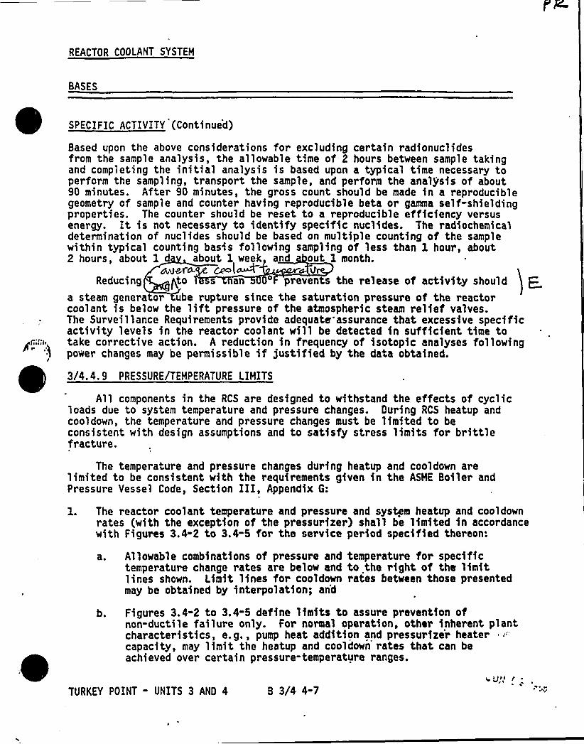
REACTOR COOLANT SYSTEM
BASES
Based upon the above considerations for excluding certain radionuclidesfrom the sample analysis, the allowable time of 2 hours between sample takingand completing the initial analysis is based upon a typical time necessary toperform the sampling, transport the sample, and perform the analysis of about90 minutes. After 90 minutes, the gross count should be made in a reproduciblegeometry of sample and counter having reproducible beta or gamma self-shieldingproperties. The counter should be reset to a reproducible efficiency versusenergy. It is not necessary to identify specific nuclides. The radiochemicaldetermination of nuclides should be based on multiple counting of the samplewithin typical counting basis following sampling of less than 1 hour, about2 hours, about 1 d about 1 week, a d out 1 month.
a,<~r~ ce l~Reducing gto s an 'revents the release of activity should p
a steam generator ube rupture since the saturation pressure of the reactorcoolant is below the liftpressure of the atmospheric steam relief valves.The Surveillance Requirements provide adequate assurance that excessive specificactivity levels in the reactor coolant will be detected in sufficient time totake corrective action. A reduction in frequency of isotopic analyses followingpower changes may be permissible if justified by the data obtained.
3/4.4. 9 PRESSURE/TEMPERATURE LIMITS~ ~
All components in the RCS are designed to withstand the effects of cyclicloads due to system temperature and pressure changes. Ouring RCS heatup andcooldown, the temperature and pressure changes must be limited to beconsistent with design assumptions and to satisfy stress limits for brittlefracture.
The temperature and pressure changes during heatup and cooldown arelimited to be consistent with the requirements given in the ASME Boiler andPressure Vessel Code, Section III, Appendix G:
1. The reactor coolant temperature and pressure and system heatup and cooldownrates (with the exception of the pressurizer) shall be limited in accordancewith Figures 3.4-2 to 3.4-5 for the service period specified thereon:
a. Allowable combinations of pressure and temperature for specifictemperature change rates are below and to the right of the limitlines shown. Limit lines for cooldown rates between those presentedmay be obtained by interpolation; and
b. Figures 3.4-2 to 3.4-5 define limits to assure prevention ofnon-ductile failure only. For normal operation, other inherent plantcharacteristics, e.g., pump heat addition and pressurizer heatercapacity, may limit the heatup and cooldown rates that can beachieved over certain pressure-temperature ranges.
TURKEY POINT - UNITS 3 AND 4 B 3/4 4-7
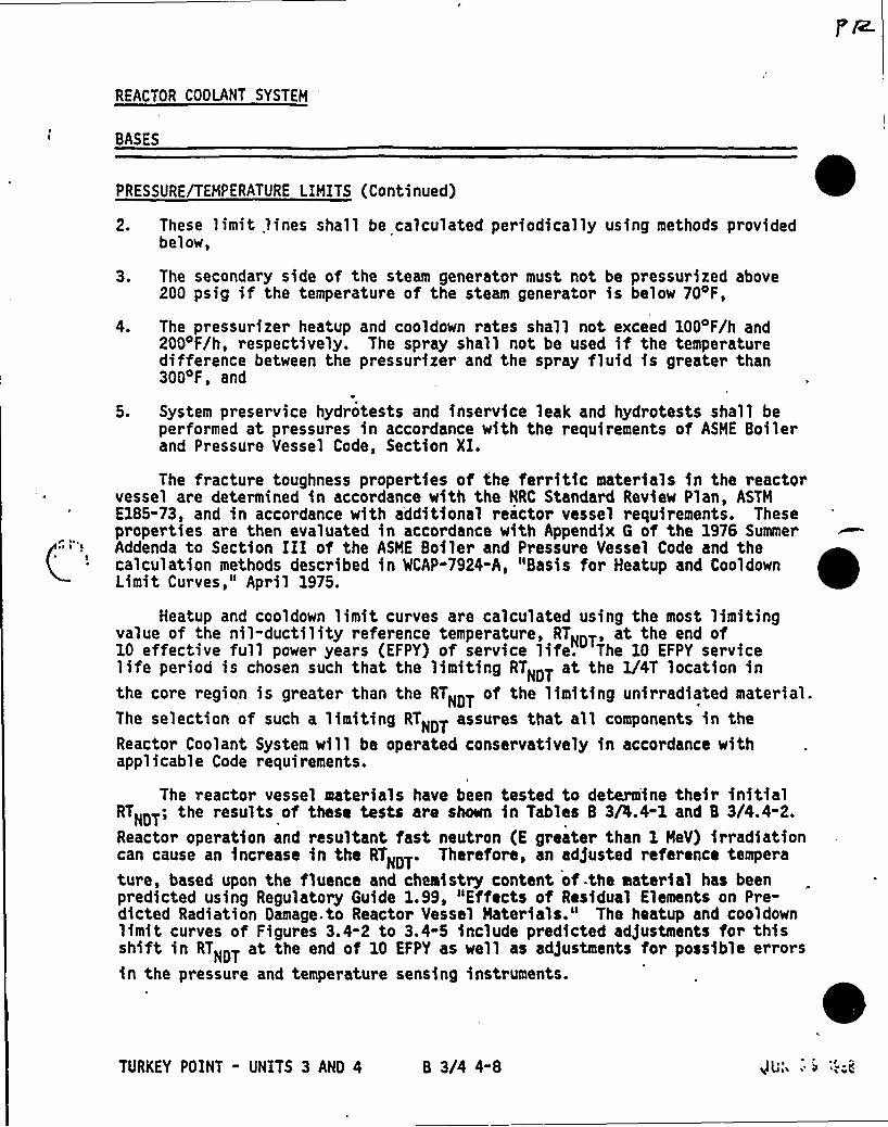
REACTOR COOLANT SYSTEM
BASES
C'RESSURE/TEMPERATURE
LIMITS (Continued)
2. These limit 1ines shall be calculated periodically using methods providedbelow,
3. The secondary side of the steam generator must not be pressurized above200 psig if the temperature of the steam generator is below 70oF,
The pressurizer heatup and cooldown rates shall not exceed 1004F/h and200 F/h, respectively. The spray shall not be used if the temperaturedifference between the pressurizer and the spray fluid is greater than3004F, and
System preservice hydrotests and inservice leak and hydrotests shall beperformed at pressures in accordance with the requirements of ASME Boilerand Pressure Vessel Code, Section XI.
The fracture toughness properties of the ferritic materials in the reactorvessel are determined in accordance with the NRC Standard Review Plan, ASTHE185-73, and in accordance with additional reactor vessel requirements. Theseproperties are then evaluated in accordance with Appendix G of the 1976 SummerAddenda to Section III of the ASHE Boiler and Pressure Vessel Code and thecalculation methods described in CAP-7924-A, "Basis for Heatup and CooldownLimit Curves," April 1975.
Heatup and cooldown limit curves are calculated using the most limitingvalue of the nil-ductility reference temperature, RTNOT, at the end of10 effective full power years (EFPY) of service life. The 10 EFPY servicelife period is chosen such that the limiting RTNOT at the 1/4T location inthe core region is greater than the RTN>T of the limiting unirradiated material.The selection of such a limiting RTN>T assures that all components in theReactor Coolant System will be operated conservatively in accordance withapplicable Code requirements.
The reactor vessel materials have been tested to determine their initialRTN>T., the results of these tests are shown in Tables B 3'.4-1 and B 3/4.4-2.Reactor operation and resultant fast neutron (E greater than 1 HeV) irradiationcan cause an increase in the RTN>T. Therefore, an adjusted reference tempera
ture, based upon the fluence and chemistry content of .the material has beenpredicted using Regulatory Guide 1.99, Effects of Residual Elements on Pre-dicted Radiation Damage.to Reactor Vessel Materials." The heatup and cooldownlimit curves of Figures 3.4-2 to 3.4-5 include predicted adjustments for thisshift in RTNOT at the end of 10 EFPY as well as adjustments for possible errorsin the pressure and temperature sensing instruments.
TURKEY POINT - UNITS 3 ANO 4 B 3/4 4-8
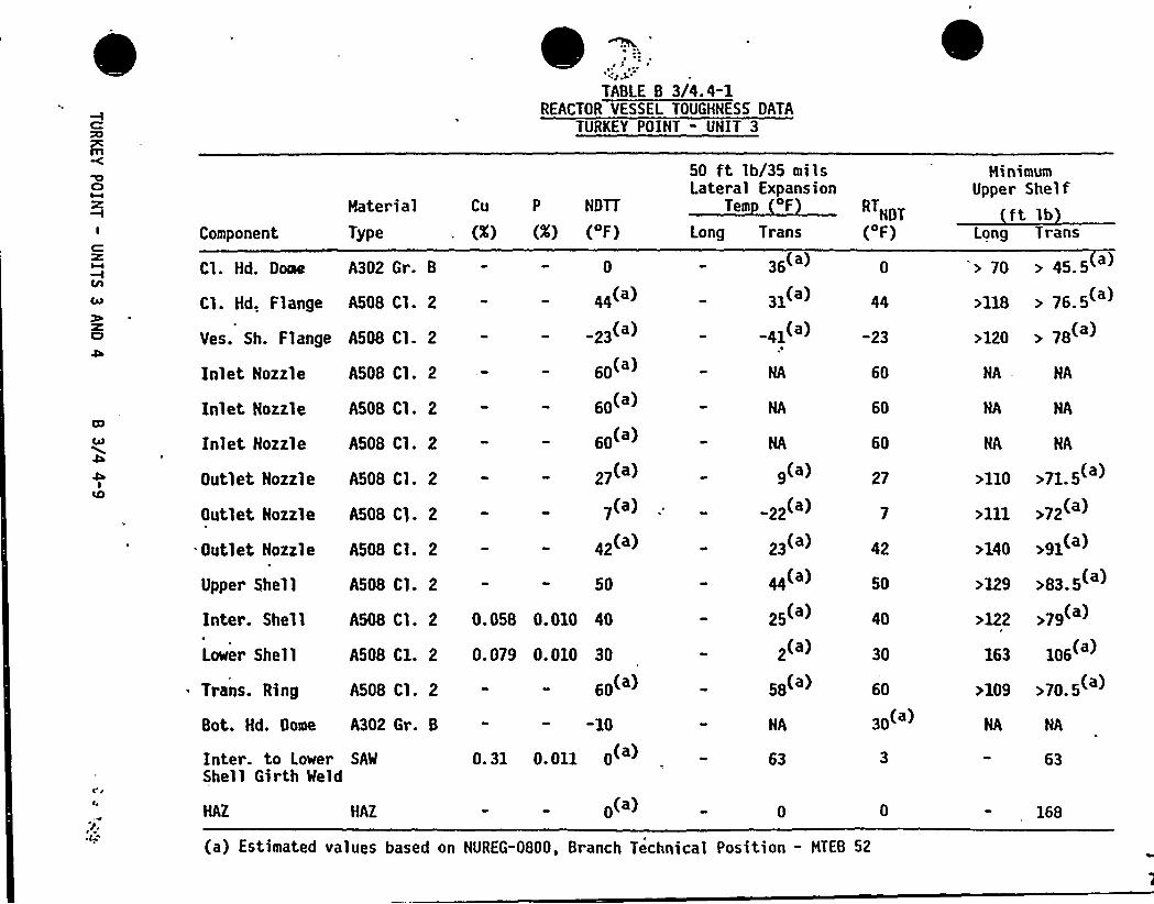
L
TABLE 8 3/4.4-1REACTOR VESSEL TOUGHNESS OATA
TURKEY POINT - UNIT 3
Component
Mater ialType
Cu P NDTT
(<) (>) ('F)
50 ft lb/35 milsLateral Expansion
Tem F
Long Tr ansNDT
('F)
MinimumUpper Shelf
ft lbLong Trans
Cl. Hd. Dome A302 Gr. B
Cl. Hd, Flange A508 Cl. 2
Yes. Sh. Flange A508 Cl. 2
Inlet Nozzle A508 Cl. 2
Inlet Nozzle A508 Cl. 2
Inlet Nozzle A508 Cl. 2
Outlet Nozzle A508 Cl. 2
Outlet Nozzle A508 Cl. 2
Outlet Nozzle
Upper Shell
A508 Cl. 2
A508 Cl. 2
0
44
23(a)
60(')
60(')
60(')
27(a)
7(a)
42(a)
50
Inter. Shell
Lower'hel 1
Trans. Ring
A508 C1. 2 0.079 0.010
A508 Cl. 2
30
60(a)
Bot. Hd. Dome A302 Gr. B
Inter. to Lower SAW
Shell Girth Weld0. 31 0. 011
-10
0('a)
A508 Cl. 2 0.058 0.010 40
„(a)
-41(')p
NA
9(a)
22(a)
23(')
44(a)
25(')
2(a)
58(')
NA
-23
60
60
60
27
50
40
30
60
30(')
> 70 > 45.5
«18 76.5(')
>120 > 78( )
NA — NA
NA NA
NA NA
>110 >71.5( )
111 72(')
140 91(')
>129 >83.5( )
122 >79(a)
163 106
>109 >70.5(')
HAZ HAZ 0(a) 168
(a) Estimated values based on NUREG-0800, Branch Technical Position - MTEB 52
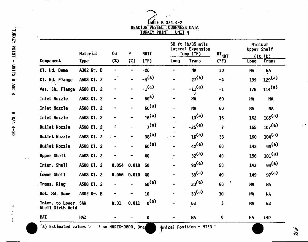
ASLE 8 3/4.4-2REACTOR VESSEL TOUGHNESS DATA
TURKEY POINT - UNIT 4
ClM
I Component
Haterial
Type
Cu P HDTT
(>) (X) ('F)
50 ft lb/35 milsLateral Expansion
Tem 4F
Long TransHDT
('F)
NinimumUpper Shelf
ft lbLong Trans
C
l/l00
C7
IC)
Cl. Hd. Dome A302 Gr. 8
Cl. Hd. Flange A508 Cl. 2
Ves. Sh. Flange A508 Cl. 2
Inlet Nozzle A508 Cl. 2
Inlet Hozzle A508 Cl. 2
Inlet Hozzle A508 Cl. 2
Outlet Nozzle A508 Cl..2
Outlet Nozzle A508 Cl. 2
Outlet Nozzle A508 Cl. 2
"20
4(a)
1(a)
eo')
eo(')
16(')
7(a)
38(')
eo(')
Upper Shell.
Inter. Shell
Lower Shell
. Trans. Ring
A508 Cl. 2 40
%08 Cl. 2 0.054 0.010 50
A508 Cl. 2 0.056 0.010
A508 Cl. 2
40
eo(')
Bot. Hd. Dome A302 Gr. 8
Inter. to Lower SAW
Shell Girth iield
HAZ
0. 31 0. 011
10
0('a)
a) Estimated values t 4 on NUREG-0800, Bra
HA
27(a)
-11(a)
NA
HA
13(a)
25(a)
16(a)
42(a)
32(')
90(a)
38(a)
30(a)
30(a)
63
nical Position - HTEB
'0
60
60
16
38
60
40
50
40
60
10
NA . NA
199 129
176 114
NA NA
HA NA
162 105
165 107(')
160 104( )
143 93
156 101( )
149 97(')
HA NA
NA NA
HA 63
NA 140
REACTOR COOLANT SYSTEM
BASES
0
PRESSURE/TEHPERATURE LIMITS (Continued)
Values of IRTNOT determined in this manner may be used until the resultsfrom the material surveillance program, evaluated according to ASTH E185, areavailable. Capsules will be removed in accordance with the requirements ofASTM E185-73 and 10 CFR Part 50, Appendix H. The surveillance specimen with-drawal schedule is shown in Table 4.4-5. The lead factor represents the rela-tionship between the fast neutron flux density at the location of the capsuleand the inner wall of the reactor vessel. Therefore, the results obtainedfrom the surveillance specimens can be used to predict future radiation damageto the reactor vessel material by using the lead factor and the withdrawaltime of the capsule. The heatup and cooldown curves must be recalculated whenthe hRTN>T determined from the surveillance capsule exceeds the calculated
BRTNOT for the equi val ent capsul e radiation exposure. The survei 1 1 ance capsul e"T" results from Unit 3 (WCAP 8631) and Unit 4 (SWRI 02-4221) were used togenerate the heatup and cooldown curves in Figure 3.4-2 through 3.4-5.
Allowable pressure-temperature relationships for various heatup andcooldown rates are calculated using methods derived from Appendix G in Sec-tion III of the ASHE Boiler and Pressure Vessel Code as required by Appendix G
to 10 CFR Part 50, and these methods are discussed in detail in WCAP-7924-A.
The general method for calculating heatup and cooldown limit curves isbased upon the principles of the linear elastic fracture mechanics (LEFH)technology. In the calculation procedures a semielliptical surface defectwith a depth of one-quarter of the wall thickness, T, and a length of 3/2Tis assumed to exist at the inside of the vessel wall as well as at theoutside of the vessel wall. The dimensions of this postulated crack,referred to in'Appendix G of ASME Section III as the reference flaw, amplyexceed the current capabilities of inservice inspection techniques.Therefore, the reactor operation limit curves developed for this referencecrack are conservative and provide sufficient safety margins for protectionagainst nonductile failure. To assure that the radiation embrittlementeffects are accounted for in the calculation of the limit .curves, the mostlimiting value of the nil-ductility reference temperature, RTNpT is used
and this includes the radiation-induced shift, hRTNDT, corresponding tothe end of the period for which heatup and cooldown curves are generated.
The ASHE approach for calculating the allowable limit curves for variousheatup and cooldown rates specifies that the total stress intensity factor,KI, for the combined thermal and pressure stresses at any time during heatup
or cooldown cannot be greater than the reference stress intensity factor, KIR,for the metal temperature at that time. KIR is obtained from the reference
fracture toughness curve, defined in Appendix G to the ASHE Code. The KIR'urveis given by the equation:
TURKEY POINT - UNITS 3 AND 4 B 3/4 4-11 LI~ ~ ~
REACTOR COOLANT SYSTEM
BASES
PRESSURE/TEMPERATURE LIMITS (Continued)
KIR 26.78 + 1.223 exp [0.0145(T-RTNDT 160)] o)Where: KIR is the reference stress intensity factor as a function of the metaltemperature T and the metal nil-ductility reference temperature RTNDT., Thus,the governing equation for the heatup-cooldown analysis is defined in Appendix Gof the ASME Code as follows:
C KIM + KIt c KIR (2)
Where: KIM= the stress intensity factor caused by membrane (pressure) stress,
KIt = the stress intensity factor caused by the thermal gradients,
KIR= constant provided by the Code as a function of temperature
relative to the RTNDT of the material,
C = 2.0 for level A and B service limits, and
C = 1.5 for inservice hydrostatic and leak test operations.
At any time during the heatup or cooldown transient, KIR is determined bythe metal temperature at the tip of the postulated flaw, the appropriate valuefor RTNDT, and the reference fracture toughness curve. The thermal stressesresulting from temperature gradients through the vessel wall are calculatedand then the corresponding thermal stress intensity factor, KIT, for thereference flaw is computed. From Equation (2) the pressure stress intensityfactors are obtained and, from these, the allowable pressures are calculated.
COOLDOWN
For the calculation of the allowable pressure versus coolant temperatureduring cooldown, the Code reference flaw is assumed to exist at the inside ofthe vessel wall. During cooldown, the controlling location of the flaw isalways at the inside of the wall because the thermal gradients produce tensilestresses at the inside, which increase with increasing cooldown rates. Allowablepressure-temperature relations are generated for both steady-state and finitecooldown rate situations. From these relations, composite limit curves areconstructed for each cooldown rate of interest.
The use of the composite curve in the cooldown analysis is necessarybecause control of the cooldown procedure is based on measurement of reactorcoolant temperature, whereas the limiting pressure is'actually dependent on thematerial temperature at the tip of the assumed flaw.'uring cooldown, the1/4T vessel location is at a higher temperature than the fluid ad)acent to thevessel ID. This condition, of course, is not true for the steady-state situa-tion. It follows that at any given reactor coolant temperature, the hTdeveloped during cooldown results in a higher value of K at the 1/4T locationIRTURKEY POINT - UNITS 3 AND 4 B 3/4 4-12'

REACTOR COOLANT SYSTEM
BASES
PRESSURE/TEMPERATURE LIMITS (Continued}
for finite coo1down rates than for steady-state operation. Furthermore, ifconditions exist such that the increase in KIR exceeds KIt, the calculatedallowable pressure during cooldown will be greater than the steady-statevalue.
The above procedures are needed because there. is no direct control ontemperature at the 1/4T location; therefore, allowable pressures may unknowinglybe vio1ated if the rate of cooling is decreased at various intervals along acooldown ramp. The use of She composite curve eliminates this problem andassures conservative operation of the system for the entire cooldown period.
HEATUP~illa'hreeseparate calculations are required to determine the limit curves
for finite heatup rates. As is done in the cooldown analysis, allowablepressure-temperature relationships are developed for steady-state conditionsas well as finite heatup rate conditions assuming the presence of a 1/4Tdefect at the inside of the vessel wall. The thermal gradients during heatupproduce compressive stresses at the inside of the wall that alleviate thetensile stresses produced by internal pressure. The metal temperature at thecrack tip lags the coolant temperature; therefore, the KIR for .the 1/4T crackduring heatup is lower than the KIR for the 1/4T crack during steady-stateconditions at the same coolant temperature. During heatup, especially at theend of the transient, conditions may exist such that the effects of compressivethermal stresses and different KIR's for steady-state and finite heatup ratesdo not offset each other and the pressure-temperature curve based on steady-stateconditions no longer represents a lower bound of all similar curves for finiteheatup rates when the 1/4T flaw is considered. Therefore, both cases have tobe analyzed in or der to assure that at any coolant temperature the lower valueof the allowable pressure calculated for steady-state and finite heatup ratesis obtained.
The second portion of the heatup analysis concerns the calculation ofpressure-temperature limitations for the case in which a 1/4T deep outsidesurface flaw is assumed. Unlike the situation at the vessel inside surface,the thermal gradients established at the outside surface during heatup producestresses which are tensile in nature and thus tend to reinforce any pressurestresses present. These thermal stresses, of 'course, are dependent on boththe rate of heatup and the time (or coolant temperature) along the heatupramp. Furthermore, since the thermal stresses at the outside are tensile andincrease with increasing heatup rate, a lower bound curve cannot be defined.Rather, each heatup rate of interest must be analyzed on an individual basis.
TURKEY POINT - UNITS 3 AND 4 B 3/4 4-13 j~g ' ~ ~
~~
REACTOR COOLANT SYSTEH
BASES
g-)
PRESSURE/TEMPERATURE LIMITS (Continued)Following the generation of pressure-temperature curves for both the
steady-state and finite heatup rate situations, the final limit curves areproduced as follows. A composite curve is constructed based on a point-by-point comparison of the steady-state and finite heatup rate data. At anygiven temperature, the allowable pressure is taken to be the lesser of thethree values taken from the curves under consideration.
The use of the composite curve is necessary to set conservative heatuplimitations because it is possible for conditions to exist such that over thecourse of the heatup ramp the controlling condition switches from the insideto the outside and the pressure limit must at all times be based on analysisof the most critical criterion.
Finally, the new 10 CFR 50 Appendix G rule which addresses the metaltemperature of the closure head flange and vessel flange regions isconsidered. The rule states that the minimum metal temperature for the flangeregions should be at least 120 F higher than the limiting RTNOT for theseregions when the pressure exceeds 20 percen't of the preservice hydrostatictest pressure (621 psig). Since the limiting RTNpT for the flange regions forTurkey Point Units 3 and 4 is 44 F, the minimum temperature required forpressure of 621 psig and greater based on the Appendix G rule is 164 F. Theheatup and cooldown curves as shown in Figures 3.4-2 to 3.4"5 clearly satisfythe above requirement by ample margins.
Finally, the composite curves for the heatup rate data and the cooldownrate data are adjusted for possible errors in'he pressure and temperaturesensing instruments by the values indicated on the respective curves.
Although the pressurizer operates in temperature ranges above those forwhich there is reason for concern of nonductile failure, operating limitsare provided to assure compatibility of operation with the fatigue analysisperformed in accordance with the ASHE Code requirements.
RVEIIPREEEURE RVRREERR PRIV AAVl IE, VVE''VV VlThe Technical Specifications provide requirements to isolate High
Pressure Safety Injection from the RCS
an4 to prevent thestart of an idle RCP if secondary temperature is more than 50 F above the RCScold leg temperatures. These requirements are designed to ensure that massand heat input transients more severe than those assumed in the lowtemperature overpressurization protection analysis cannot occur.
The OPERABILITY of two PORVs or an RCS vent opening of at least 2.20square inches ensures that the RCS will be protected from pressure transientswhich could exceed the limits of Appendix G to 10 CFR Part 50 when one or moreof the RCS cold legs are less than or equal to 275OF. Either PORV hasadequate relieving capability to protect the RCS from overpressurization whenthe transient is limited to either: (1) the start of an idle RCP with thesecondary water temperature of the steam generator less than or equal to 50'Fabove the RCS cold leg temperatures including margin for instrument error, or(2) the start of a HPSI pump and its injection''nto a water solid RCS.
TURKEY POINT - UNITS 3 ANP 4 B 3/4 4-14~ ~ 'V
E
~ 'aV
REACTOR COOLANT SYSTEM
BASES
PRESSURE/TEMPERATURE LIMITS (Continued)
REACTOR MATERIAL SURVEILLANCE PROGRAM
Each Type I capsule contains 28 V-notch specimens, ten Charpy specimensmachined from each of the two shell forgings. The remaining eight Charpyspecimens are machined from correlated monitor material. In addition, eachType I capsule contains four tensile specimens (two specimens from each of thetwo shell forgings). Dosimeters of copper, nickel, aluminum-cobalt, andcadmium"shielded aluminum-cobalt wire are secured in holes drilled in spacersat the top, middle and bottom of each Type I capsule.
Each Type II capsule contains 32 Charpy V-notch specimens: eightspecimens machined from one of the shell forgings, eight specimens of weld'etal and eight specimens of HAZ metal, the remaining eight specimens arecorrelation monitors. In addition, each Type II capsule contains four tensilespecimens and four WOL forgings and the weld metal. Each Type II capsulecontains a dosimeter block at the center of the capsule. Two cadmium-oxide-shielded capsules, containing the two isotopes uranium-238'and neptunium-237,are contained in the dosimeter block. The double containment afforded by thedosimeter assembly prevents loss and contamination by the neptunium-237 anduranium-238 and their activation products. Each dosimeter block containsapproximately 20 milligrams of neptunium-237 and 13 milligrams of uranium238contained in a 3/8-inch OD sealed brass tube. Each tube is placed in a 1/2-inchdiameter hole in the dosimeter block (one neptunium-237 and one uranium-238tube per block), and the space around the tube is filled with cadmium oxide.After placement of this material, each hole is blocked with two 1/16-inchaluminum spacer discs and an outer 1/8-inch steel cover disc, which is weldedin place. Dosimeters of copper, nickel, aluminum-cobalt and cadmium-shieldedaluminum-cobalt are also secured in holes drilled in spacers located at thetop, middle and bottom of each Type II capsule.
Ca sule T e Ca sule Identification
IIIIII
IIIII
S
VT0XW
Y— Z
TURKEY POINT - UNITS 3 AND 4 B 3/4 4-15
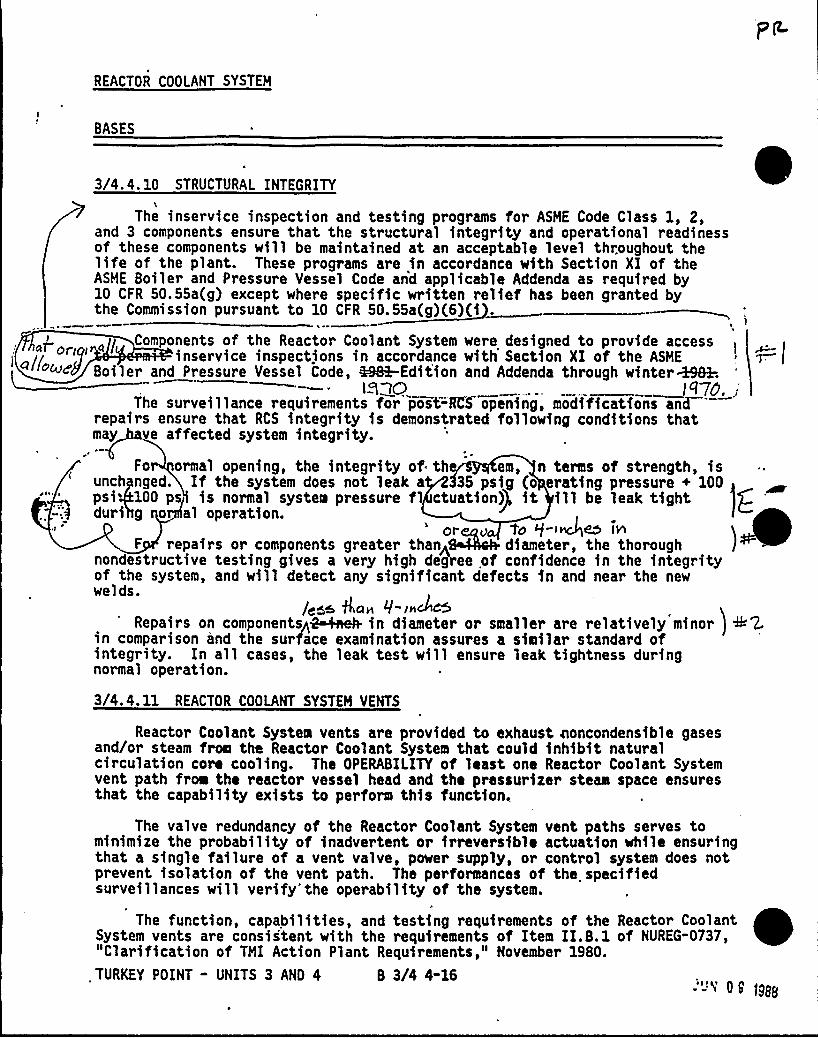
REACTOR COOLANT SYSTEM
BASES
3/4.4. 10 STRUCTURAL INTEGRITY
The inservice inspection and testing programs for ASME Code Class 1, 2,and 3 components ensure that the structural integrity and operational readinessof these components will be maintained at an acceptable level throughout thelife of the plant. These programs are in accordance with Section XI of theASME Boiler and Pressure Vessel Code and applicable Addenda as required by10 CFR 50.55a(g) except where specific written relief has been granted bythe Commission pursuant to 10 CFR 50.55a(g)(6)(i .
Components of the Reactor Coolant System were designed to provide accessinservice inspections in accordance with Section XI of the ASME
Boiler and Pressure Vessel Code, 4%&-Edition and Addenda through winterM&h- Ll1Q 1'le
The surveillance requirements for post=RCS opening, modifications andrepairs ensure that RCS integrity is demonstrated following conditions thatmay ve affected system integrity.
For ormal opening, the integrity of th em, n terms of strength, isunch nged. If the system does not leak a 35 psig (o crating pressure + 100psi 100 ps is normal system pressure f ctuatlon)P it ill be leak tightduri g o al operation.
s or u 'tosli moanF repairs or components greater than< diameter, the thorough
nondestructive testing gives a very high degree of confidence in the integrityof the system, and will detect any significant defects in and near the newwelds.
/gal& fLan 0-ln445Repairs on componentsp4~4 in diameter or smaller are relatively minor
in comparison and the surface examination assures a similar standard ofintegrity. In all cases, the leak test will ensure leak tightness duringnormal operation.
3/4.4.11 REACTOR COOLANT SYSTEM VENTS
Reactor Coolant System vents are provided to exhaust ooncondensible gasesand/or steam from the Reactor Coolant System that could inhibit naturalcirculation core cooling. The OPERABILITY of least one Reactor Coolant Systemvent path froe the reactor vessel head and the pressurizer steam space ensuresthat the capability exists to perform this function,
The valve redundancy of the Reactor Coolant System vent paths serves tominimize the probability of inadvertent or irreversible actuation while ensuringthat a single failure of a vent valve, power supply, or control system does notprevent isolation of the vent path. The performances of the specifiedsurveillances will verify'the operability of the system.
The function, capabilities, and testing requirements of the Reactor CoolantSystem vents are consistent with the requirements of Item II.B.1 of NUREG-0737,"Clarification of TMI Action Plant Requirements," November 1980.
TURKEY POINT - UNITS 3 AND 4 8 3/4 4-16 -"-'4'9)ggg
0TURKEY POINT - UNITS 3 AND 4


3/4 5 EHERGENCY CORE COOLING SYSTEHS
BASES
3/4. 5. 1 ACCUMULATORS
The OPERABILITY of each Reactor Coolant System (RCS) accumulator ensuresthat a sufficient volume of borated water will be immediately forced into thereactor core through each of the cold legs in the event the RCS pressure fallsbelow the pressure of the accumulators. This initial surge of water into thecore provides the initial cooling mechanism during large RCS pipe ruptures.
The limits on accumulator volume, boron concentration and pressure ensurethat the assumptions used for accumulator injection in the safety analysis aremet.
e
The accumulator isolation valves fail to meet single failure criteria,therefore, removal of power to the valves is required.
The limits for operation with an accumulator inoperable for any reasonexcept an isolation valve closed minimizes the time exposure of the plant to aLOCA event occurring concurrent with failure of an additional accumulator whichmay result in unacceptable peak cladding temperatures. If a closed isolationvalve cannot be immediately opened, the full capability of one accumulator isnot available and prompt action is required to place the reactor in a modewhere this capability is not required.
3/4. 5. 2 and 3/4. 5. 3 ECCS SUBSYSTEHS
The OPERABILITY of ECCS components and flowpaths required in Modes 1, 2and 3 ensures that sufficient emergency core cooling capability will be avail-able in the event of a LOCA assuming any single active failure consideration.Two SI pumps and one RHR pump operating in conjunction with two accumulatorsare capable of supplying sufficient core 'cooling to limit the peak claddingtemperatures within acceptable limits for all pipe break sizes up to andincluding the maximum hypothetical accident of a circumferential rupture of areactor coolant loop. In addition, the RHR subsystem provides long-term corecooling capability in the recirculation mode during the accident recoveryperiod
With the RCS temperature below 350 F, operation with less than fullredundant equipment is acceptable without single failure consideration on thebasis of the stable reactivity condition of the reactor and the limited corecooling requirements.
A/7 /gQ fjene5 olfocd /ol on overly'e don'ha/5llu'toom'P
boll Unii4 u)4o< Pne wpodrrn@liP'f a compo'~e~~(<)
o6ck= boisei u. 6 ~ ill eo„'/.e) r:f/,..
TURKEY POINT " UNITS 3 5 4 B 3/4 5-1
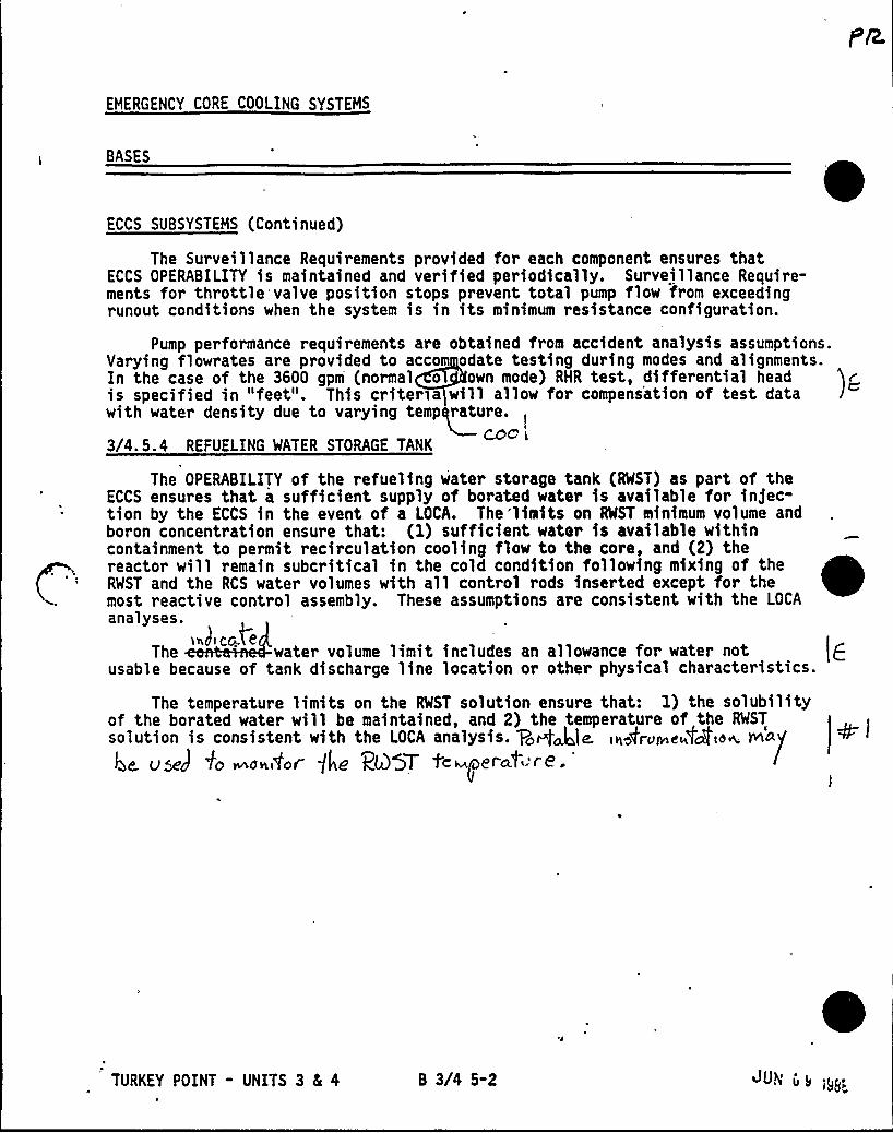
EMERGENCY CORE COOLING SYSTEMS
BASES
ECCS SUBSYSTEMS (Continued)
The Surveillance Requirements provided for each component ensures thatECCS OPERABILITY is maintained and verified periodically. Surveillance Require-ments for throttle valve position stops prevent total pump flow from exceedingrunout conditions when the system is in its minimum resistance configuration.
Pump performance requirements are obtained from accident analysis assumptions.Varying flowrates are provided to acco odate testing during modes and alignments.In the case of the 3600 gpm (normal o own mode) RHR test, differential headis specified in "feet". This criter a will allow for compensation of test datawith water density due to varying temp rature.
3/4.5.4 REFUELING WATER STORAGE TANKCOCi <
The OPERABILITY of the refueling water storage tank (RWST) as part of theECCS ensures that a sufficient supply of borated water is available for injec-tion by the ECCS in the event of a LOCA. The 'limits on RWST minimum volume andboron concentration ensure that: (1) sufficient water is available withincontainment to permit recirculation cooling flow to the core, and (2) thereactor will remain subcritical in the cold condition following mixing of theRWST and the RCS water volumes with all control rods inserted except for themost reactive control assembly. These assumptions are consistent with the LOCA
analyses.|.J c~ e
The 'ater volume limit includes an allowance f orwater notusable because of tank discharge line location or other physical characteristics.
The temperature limits on the RWST solution ensure that: 1) the solubilityof the borated water will be maintained, and 2) the temperature of the RWST
solution is consistent with the LOCA analysis. RQ@ie. in~tron e~tc4'ion. wo/Udc] 40 monitor't4'RQ57 icmmerclt" r8 ~
gl
TURKEY POINT - UNITS 3 4 4 8 3/4 5-2 ~UN us
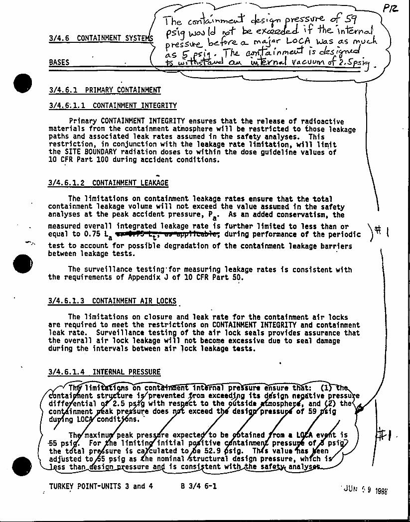
3/4.6 CONTAINMENT SYSTE
BASES
ge c~h~'i ~ kgi~ Mss~ uf 5gp~,)~,g ~e } e if Ae. >4~~2~<<~ ~P~~ ~ r ajar L.ocA was a.s n uD
PMS ~~ g p„,. y< g 1~i'nmM (s Jsoui'Aw~ <be. kvhel Y+cii>vl ofp.s sg
~ ~3/4. 6. 1 PRIMARY CONTAINMENT
3/4. 6; l. 1 CONTAINMENT INTEGRITY
Primary CONTAINMENT INTEGRITY ensures that the release of radioactivematerials from the containment atmosphere will be restricted to those leakagepaths and associated leak rates assumed in the safety analyses. Thisrestriction, in conjunction with the leakage rate limitation, will limitthe SITE BOUNDARY radiation doses to within the dose guideline values of10 CFR Part 100 during accident conditions.
3/4. 6.1. 2 CONTAINMENT LEAKAGE
The limitations on containment leakage rates ensure that the totalcontainment leakage volume will not exceed the value assumed in the safetyanalyses at the peak accident pressure, P . As an added conservatism, themeasured overall integrated leakage rate is further limited to less than orequal to 0.75 L , during performance of the periodictest to account for possible degradation of the containment leakage barriersbetween leakage tests.
The surveillance testing for measuring leakage rates is consistent withthe requirements of Appendix J of 10 CFR Part 50.
3/4. 6.1. 3 CONTAINMENT AIR LOCKS
The limitations on closure and leak rate for the containment air locksare required to meet the restrictions on CONTAINMENT INTEGRITY and containmentleak rate. Surveillance testing of the air lock seals provides assurance thatthe overall air lock leakage will not become excessive due to seal damageduring the intervals between air lock leakage tests.
3/4.6.1.4 INTERNAL PRESSURE
T limi i s on cont en int ma pre sure ensure th t: (1ntai ent str ure i prevented om exceedjpg its dsign neyftive pressu e
diffe ential 2.5 p g with res ct to the odtside osphe 4, and 2') thecon inment ak pre ure does exceed t desi pressu of 59 sigdu ng LOC condit ns.
'h
maximu peak pres re expecte to be tained rom a L A ev t isk5 psi . For e limitin initial po itive ntainme pressu of psithe t tal pr sure is ca culated to e 52.9 sig. T s value as eenadjusted to 5 psig as he nominal tructural design pressure, wh ch i
ss than esi n essure an is consi tent with the safe analys
TURKEY POINT-UNITS 3 and 4 8 3/4 6-1 """ "" 1988
CONTAINMENT SYSTEMS
BASES
3/4.6.1.5 AIR TEMPERATURE
The limitations on containment average air temperature ensure that the aver-all containment average air temperature does not exceed the initial temperature
dl I dl 5 f y ly I f Lggh~g, )shall be made at all listed locations, whether by fixed or portable instruments,prfor to determining the average afr temperature.
3/4.6.1.6 CONTAINMENT STRUCTURAL INTEGRITY
This limitation ensures that, the structural integrity of the containmentwill be maintained comparable to the orfgfnal design standards for the life ofthe facility. Structural integrity is required to ensure that the containment
h d h t ll "" fgtgdiiif th I LAAA~JEThe measurement of containment tendon lift-offforce, the tensile tests of thetendon wires or strands, the visual examination of tendons, anchorages andexposed interior and exterior surfaces of the containment, and the Type Aleakage test are sufficient to demonstrate this capability.
The required Special Reports from any engineering evaluation of contain-ment abnormalities shall include a description of the tendon condition, thecondition of the concrete (especfally at tendon anchorages), the inspection5 d,th I Aid. 5 lt MW%leMldgevaluation, and the corrective actions take
( SJI J,„se~ 0~> mau
3~4 6 I 7 coNTAINMENT YENTILATIQN sYsTEM '
g,~ ~ALQ iusi)cc fo> ~ali crefgfe
person el p.qrThe containment purge supply and exhau t-fsbht8o ce-requtrud to
h I dd lg Lgdh~gf f1 5 h I Id I dd lgplant operation ensures that excessive quantltles of radloactlve aaterlals willnot be released via the Containment Purge System.
The total time the containment purge (vent) system isolation valves maybe open during HOOES 1, 2, 3, and 4 fn a calendar year fs a function ofanticipated need and operating experience.
Leakage integrity tests with a maximum allowable leakage rate for contain-ment purge supply and exhaust supply valves will provide early indication ofresilient material seal degradation and will allow opportunity for repair beforegross leakage failures could develop. The Oe60 L .leakage limit of Specifica-tion 3.6.1.2b. shall not be exceeded when the leakage rates determined by theleakage integrity tests of these valves are added to the previously determinedtotal for all valves and penetrations subject to Type B and C tests.
TURKEY POINT-UNITS 3 and 4 B 3/4 6-21 s ~
CONTAINMENT SYSTEMS
BASES
3/4.6.2 OEPRESSURIZATION AND COOLING SYSTEMS
3/4.6.2. 1 CONTAINMENT SPRAY SYSTEM
The OPERABILITY of the Containment Spray System ensures that containmentdepressurization capability will be available in the event of a LOCA. Thepressure reduction and resultant lower containment leakage rate are consistentwith the assumptions used in the safety analyses.
The allowable out-of-service time requirements for the Containment SpraySystem have been maintained consistent with that assigned other inoperable ESFequipment and do not reflect the additional redundancy in cooling capabilityprovided by the Containment Cooling System. Pump performance requirements areobtained from the accidents-analysis assumptions.
CK<g~~cp'/4.
6. 2. 2 CONTAINMENT COOLING SYSTEM )cThe OPERABILITY of the Containment Cooling System ensures that adequate
heat removal capacity is available during past-LOCA conditions. The emergency=containment coolers are a full capacity system and are redundant to the spraysystem in terms of heat removal function for design basis accident.
The allowable out-of-service time requirements for the Containment CoolingSystem have been maintained consistent with that assigned other inoperable ESFequipment and do not reflect the additional redundancy in cooling capabilityprovided by the Containment Spray System.
3/4.6.3 EHERGENCY CONTAINMENT FILTERING SYSTEH
0
The OPERABILITY of the Emergency Containment Filtering System ensures thatsufficient iodine removal capability will be'vailable in the event of a LOCA.The reduction in containment iodine inventory reduces the resulting SITEBOUNOARY radiation doses associated with containment leakage. The operationof this system and resultant iodine removal capacity are consistent with theassumptions used in the LOCA analyses. System components are not subject torapid deterioration. Visual inspection and operating/performance tests aftermaintenance, prolonged operation, and at the required frequencies provideassurances of system reliability and will prevent system failure. Filterperformance tests are conducted in accordance'ith the methodology and intentof ANSI N510- 1975.
A Filter Efficiency of 90K is applicable to Turkey Point Safety Analysis.The HEPA filter efficiency combined with greater than 99K elemental iodineremoval and 30K organic iodine efficiency for the activated carbon filter willgive the applicable overall efficency.
3/4. 6. 4 CONTAINMENT ISOLATION VALVES
The OPERABILITY of the containment isolation valves ensures that the con-tainment atmosphere will be isolated from the outside environment in the event
TURKEY POINT-UNITS 3 and 4 B 3/4 6-3
CONTAINMENT SYSTEMS
BASES
CONTAINMENT ISOLATION VALVES (Continued)
of a release of radioactive material to the containment atmosphere or pressuri-zation of the containment.
3/4.6. 5 HYDRo&~v ~0~(7 op g )aThe OPERABILITY of the Hydrogen Monitors ensures the detection of hydrogen
buildup within containment following a LOCA to allow operator action to reducethe hydrogen concentration below its flammable limit.3/4.6.6 POST ACCIDENT CONTAINMENT VENT SYSTEM
The OPERABILITY of the Post Accident Containment Vent System ensures thecapability for emergency venting of containment following a LOCh to reducethe hydrogen concentration to below its flaaeable limit.
k
PACVS systems components are not subject to rapid detirioration, havinglifetimes of many years, even under continuous flow conditions. Visualinspection and operating tests provide assurance of system reliability andwill ensure early detection of conditions which could cause the system tofail or operate improperly. The performance tests prove that filters havebeen properly installed, that no deterioration or damage has occurred, andthat all components and subsystems operate properly. The tests are performedin accordance with the methodology and intent of ANSI N510-1975 and provideassurance that filter performance has not deteriorated below requiredspecification values due to aging, contamination or other effects.
A filter efficiency of 99K is applicable to Turkey Point Safety Analysis.The HEPA filter efficiency combined with greater than 90K methyliodide removalefficiency for the activated carbon filter will give the applicable overallefficiency.
PTURKEY POINT-UNITS 3 and 4 B 3/4 6-4
':0>c;
3/4.7 PLANT SYSTEMS
BASES
3/4.7. 1.1 SAFETY VALVES
The OPERABILITY of the main steam line Code safety valves ensures that theSecondary System pressure will be limited to within 110K (1193.5 psig) of itsdesign pressure of 1085 psig during the most severe anticipated system opera-tional transient. The maximum ~elieving capacity is associated with a Turbinetrip from lOOX RATED THERMAL POWER coincident with an assumed loss of condenserheat sink (i.e., no steam bypass to the condenser).
The specified valve lift settings and relieving capacities are in accordancewith the requirements of Section VIII of the ASME Boiler and Pressure Code,1971 Edition. The total relieving capacity for all valves on all of the steamlines is 10,670,000 lbs/h which is 11'f the total secondary steam flow of9,600,000 lbs/h at 100K RATED THERMAL POWER. A minimum of two OPERABLE safetyvalves per steam generator ensures that sufficient relieving capacity isavailable for the allowable THERMAL POWER restriction in Table 3.7-2.
STARTUP and/or POWER OPERATION is allowable with safety valves inoperablewithin the limitations of the ACTION requirements on the basis of the reductionin Secondary Coolant System steam flow and THERMAL POWER required by thereduced Reactor trip settings of the Power Range Neutron Flux channels. TheReactor Trip Setpoint reductions are derived on the following bases:
Where:
SP
109
SP —X
x (109)
Reduced Reactor Trip Setpoint in percent of RATED THERMAL POWER,
Maximum number of inoperable safety valves per steam line,
Power Range Neutron Flux-High Trip Setpoint,
Total relieving capacity of all safety valves per steamline in 1bs/hour, and
Maximum relieving capacity of any one safety valve in lbs/hour
3/4.7.1. 2 AUXILIARYFEEDWATER SYSTEM
The OPERABILITY of the Auxiliary Feedwater System ensures that the ReactorCoolant System can be cooled down to less than 3504F from normal operatingconditions in the event of a total loss-of-offsite power. Steam can be
'TURKEY POINT - UNITS 3 4 4 - B 3/4 7-1
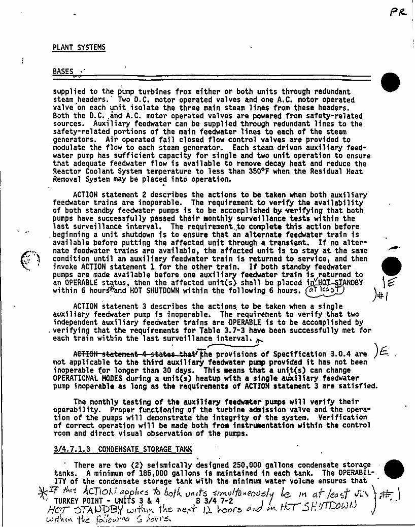
PLANT SYSTEMS
BASES.
supplied to the pump turbines from either or both units through redundantsteam headers. Two D. C. motor operated valves and one A. C. motor operatedvalve on each unit isolate the three main steam lines from these headers.Both the D.C..and A.C. motor operated valves are powered from safety-relatedsources. Auxiliary feedwater can be supplied through redundant lines to thesafety-related portions of the main feedwater lines to each of the steamgenerators. Air operated fail closed flow control valves are provided tomodulate the flow to each steam generator. Each steam driven auxiliary feed-water pump has sufficient capacity for single and two unit operation to ensurethat adequate feedwater flow is available to remove decay heat and reduce theReactor Coolant System temperature to less than 350 F when the Residual HeatRemoval System may be placed into operation.
ACTION statement 2 describes the actions to be taken when both auxiliaryfeedwater trains are inoperable. The requirement to verify the availabilityof both standby feedwater pumps is to be accomplished by verifying that bothpumps have successfully passed their monthly surveillance tests within thelast surveillance interval. The requirement..to complete this action beforebeginning a unit shutdown is to ensure that an alternate feedwater train isavailable before putting the affected unit through a transient. If no alter-nate feedwater trains are available, the affected unit is to stay at the samecondition until an auxiliary feedwater train is returned to service, and theninvoke ACTION statement 1 for the other train. If both standby feedwaterpumps are made available before one auxiliary feedwater train is returned toan OPERABLE status, then the affected unit(s) shall be placed i ANDBYwithin 6 hour&'and HOT SHUTDOWN within the following 6 hours.
ACTION statement 3 describes the actions to be taken when a singleauxiliary feedwater pump is inoperable. The requirement to verify that twoindependent auxiliary feedwater trains are OPERABLE is to be accomplished by
. verifying that the requirements for Table 3.7-3 have been successfully met foreach train within the last surveillance interval.
+he provisions of Specification 3.0.4 are )6 .
not applicable to the third auxiliary feedwater pump provided it has not beeninoperable for longer than 30 days. This means that a unit(s) can changeOPERATIONAL MODES during a unit(s) heatup with a single auxiliary feedwaterpump inoperable as long as the requirements of ACTION statement 3 are satisfied.
The monthly testing of the auxiliary feedwater pumps will verify theiroperability. Proper functioning of the turbine admission valve and the opera-tion of the pumps will demonstrate the integrity of the system. Verificationof correct operation will be made both from instr~ntation within the controlroom and direct visual observation of the pumps.
3/4.7.1.3 CONDENSATE STORAGE TANK
There are two (2) seismically designed 250,000 gallons condensate storagetanks. A minimum of 185,000 gallons is maintained in each tank. The OPERABIL-ITY of the condensate storage tank with the minimum water volume ensures that"' ~'<<'PPI" 'fo hot u-«f~dsi~v~td 'eoudlu 4, nt oj jq«f'.'. ~ ITURKEY POINT - UNITS 3 5 4,,B 3/4 7-2 ( /
ag7- gag, ugey ~ftl»" .,'..~ ',e;—,'.ago-~ a V ~ ~~AllAtua fV'Q ~Oi J>M ~Cf D /'~' ~'
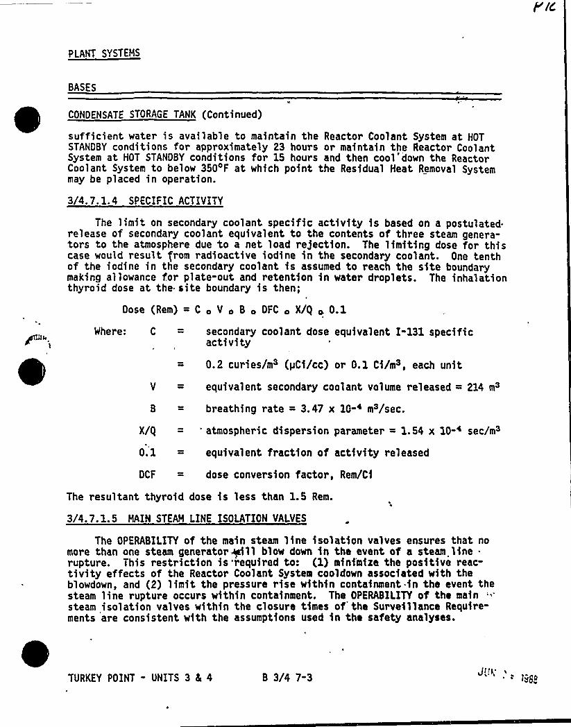
PLANT SYSTEMS
BASES
CONDENSATE STORAGE TANK (Continued)
sufficient water is available to maintain the Reactor Coolant System at HOTSTANDBY conditions for approximately 23 hours or maintain the Reactor CoolantSystem at HOT STANDBY conditions for 15 hours and then cool'down the ReactorCoolant System to below 350'F at which point the Residual Heat Removal Systemmay be placed in operation.
3/4. 7. 1. 4 SPECIFIC ACTIVITY
The limit on secondary coolant specific activity is based on a postulated.release of secondary coolant equivalent to the contents of three steam genera-tors to the atmosphere due to a net load re)ection. The limiting dose for thiscase would result from radioactive iodine in the secondary coolant. One tenthof the iodine in the secondary coolant is assumed to reach the site boundarymaking allowance for plate-out and retention in water droplets. The inhalationthyroid dose at the site boundary is then;
Dose (Rem) = C V c B OFC ~ X/Q + 0.1
Where: C = secondary coolant dose equivalent I-131 specificactivity
0.2 curies/m3 (pCi/cc) or O.l Ci/m3, each unit
V = equivalent secondary coolant volume released = 214 m3
B = breathing rate = 3.47 x 10-~ m3/sec.
X/Q = 'tmospheric dispersion parameter = 1.54 x 10-~ sec/m3
0.1 = equivalent fraction of activity released
DCF = dose conversion factor, Rem/Ci
The resultant thyroid dose is less than 1.5 Rem.
3/4.7.1.5 MAIN STEAM LINE ISOLATION VALVES
The OPERABILITY of the main steam line isolation valves ensures that nomore than one steam generator +11 blow down in the event of a steam line .
rupture. This restriction is required to: (1} minfmiza the positive reac-tivity effects of the Reactor Coolant System cooldown associated with theblowdown, and (2) limit the pressure rise within containment .in the event thesteam line rupture occurs within containment. The OPERABILITY of the mainsteam isolation valves within the closure times of'he Surveillance Require-ments are consistent with the assumptions used in the safety analyses.
TURKEY POINT - UNITS 3 4 4 B 3/4 7-3
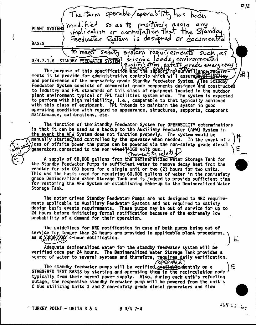
Au..t~~ CF'CT 44/mpeVmoiig 4~S
PLANT SYSTEMYviol'4iD 6'o d.s jo posifivcl~ stvo'icJ ~rg
ii'vp|i'cdisv si- cosil ag~tiovi ~P Qc Qc ink
Fee/~~ ggleann is, dcgi~ocJ LDY'cdiriBASES
S 4 g g CVYi ~isirCSV3/4.7.1.6 STANDBY FEEDWATER SY EN Sc-i rivi« I +~44 Chvi <srini
gus),FI c &isrs p.fa~ rack. esndvy csigThe. purpose of this speci ficati IinAPe s6/@rpngls ll n Ul
ments is to provide for administrative controls which will assure<and performance of the non-safety grade Standby Feedwater System. he Stan yFeedwater System consists of commercial grade components designed nd construct dto industry and FPL standards of this class of equipment located in the outdoo~plant environment typical of FPL facilities system wide. The system is expectedto perform with high reliability, i.e., comparable to that typically achievedwith this class of equipment. FPL intends to maintain the system in goodoperating condition with regard to appearance, structures, supports, componentmaintenance, calibrations, etc.
The function of the Standby Feedwater System for OPERABILITY determinationsis that it can be used as a backup to the Auxiliary Feedwater (AFW) System inthe event the AFW System does not function properly. The system would be ymanually starte and controlled by the operator when needed. In the event of a
g loss of offsite power the pumps can be powered via the non-safety grade diesel)generators. connected to the aon=ii4eeh 416D voig us.,
nm-+e-A supply of 60,000 gallons from the em r zed ater Storage Tank for
the Standby Feedwater Pumps is sufficient water to remove decay heat from thereactor for six (6) hours for a single unit or two (2) hours for two units.This was the basis used for requiring 60,000 gallons of water in the non-safetygrade Demineralized Water Storage Tank and is fudged to provide sufficient timefor restoring the AFW System or establishing make-up to the Demineralized WaterStorage Tank.
The motor. driven Standby Feedwater Pumps are not designed to NRC require-ments applicable to Auxiliary Feedwater Systems and not required to satisfydesign basis events requirements. These pumps may be out of service for up to24 hours before initiating formal notification because of the extremely lowprobability of a demand for their operation.
The guidelines for NRC notification in case of both pumps being out ofserv fo longer than 24 hours are provided in applicabl'e plant procedures,as p ~4-hour notification. E;
Adequate demineralized water for the standby feedwater system will beverified once per 24 hours. The Demineralized Water Storage Tank provides asource of water to several systems and therefore, requi es daily verification.
oP P-N,LEThe standby feedwater pumps will be verifie . onthly on a
STAGGERED TEST BASIS by starting and operating them n the recirculation modetypically from their normal power supply. Also, during each unit's refuelingoutage, the respective standby feedwater pump will be powered from the unit'sC b'us utilizing Units 1 and 2 non-safety grade diesel generators and flow
TURKEY POINT - UNITS 3 8L 4 B 3/4 7-4SU)t:'' "
~ ~ qg g~ ~
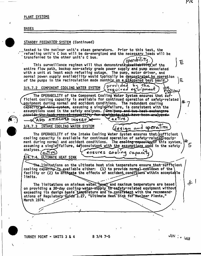
PlANT SYSTEMS
BASES
I ~ ~
aliis)l,
.J
STANDBY FEEDWATER. SYSTEM (Continued)
,tested to the nuclear unit's steam generators. Prior to this test, therefueling unit's C bus will be de-energized and the necessar loads will be
'ransferred to the other unit's C bus.
This surveillance regimen will thus demonstrate f theentire flow path, backup non-safety grade power supp y and pump associatedwith a unit at least each refueling outage. The pump, motor driver, andnormal power; supply availability would typically be dern s r b o erationof the pumps in the recirculation mode month on a a gered test basis.
3/4.7.2 COMPONENT COOLING WATER SYSTEM
EO $47%
The OPERABILITY of the Component Cooling Mater System ensures that suf-ficient cooling capacity is available for continued operation of safety-relatedquipment during normal and accident conditions. The redundant cooling
capac , assuming a singl failure, is consistent with theassumptions used in the safety analyses.
AD~ A tt A~~ l us% LV 4C +C
3/4.7.3, INTAKE COOLING WATER SYSTEM 8CL e ~Ci'OM
The OPERABILITY of the Intake Cooling Water System ensures that sufficientcooling capacity is available for continued operation of safety-relate equip-ment during normal and accident conditions. The o this system,assuming a single failure, 4e consistent with t e assum t e in the safetyanalyses. 'tom cnsupcs cooling co.po.~%~/4.. ULTIMATE HEAT SINK
im~ tions on the ultimate heat sink temperature ensure that-Suf ientcooling capa vailable either: (1) to provide norm e5ldown of thefacility or (2) to m te the effects of accident cond'5 within accepta lelimits.
The limitations on minimum wa er and maximum temperature are basedon providing a 30-day cooling-wat p~ ety-related equipment withouexceeding its design bpsis rature and fs .cons t with the recommend-ations of Regulator-G 1.27, "Ultimate Heat Sfqk for ear Plants,"March 1974.
TURKEY POINT - UNITS 3 8a 4 B 3/4 7-5 JuviQQ8
PLANT SYSTEMS
BASES
Evm~~3/4.7.5 CONTROL ROOM VENTILATION SYSTEM E~ev~~
The OPERABILITY of the Control Room>Ventllatfon System ensures that:(1) the ambient air temperature does not exceed the allowable temperature forcontinuous-duty rating for the equipment and instrumentation cooled by thissystem, and (2) the control room will remain habitable for operations personnelduring and following all credible accident conditions. The OPERABILITY of this,system in conjunction with control room design provisions is based on limitingthe 'radiation exposure to personnel occupying the control room to 5 rems orless whole body, or its equivalent. This limitation is consistent with therequirements of General Design Criterion 19 of Appendix A, 10 CFR Part 50.
System components are not subject to rapid deterioration, having lifetimesof many years, even under continuous flow conditions. Visual inspection andoperating tests provide assurance of system reliability and will ensure earlydetection of conditions which could cause the system to fail. or operateimproperly. The filters performance tests prove that filters have been properlyinstalled,'that no deterioration or damage has occurred, and that all componentsand subsystems operate properly. The tests are performed in accordance withthe methodology and intent of ANSI N510 (1975) and provide assurance thatfilter performance has not deteriorated below returned specification values dueto aging, contamination, or other effects.
3/4.7.6 SNUBBERS
All snubbers are required OPERABLE to ensure that the structural integrityof the Reactor Coolant System and all other safety-related systems is main-tained during and following a seismic or other event initiating dynamic loads.
The visual inspection frequency is based upon maintaining a constant levelof snubber protection to each safety-related system during an earthquake orsevere transient. Therefore, the required, inspection interval varies inverselywith the observed snubber failures and is determined by the number of inoperablesnubbers found during an inspection. Inspections performed before that intervalhas elapsed may be used as a new reference point to dete~ine the next inspection.However, the results of such early inspections performed before the originalrequired time:interval has elapsed (nominal time less 25K) may not be used tolengthen the required inspection interval. Any inspection whose resultsrequire a shorter inspection interval will override'he previous schedule.
When the cause of the rejection of a snubber is visual inspection isclearly established and'emedied for the snubber and for any other snubbersthat may be generically susceptible, and verified operable by inservice func-tional testing, that snubber may be exempted from being counted as inoperablefor the purposes of establishing the next visual inspection interval.Generically susceptible snubbers are those which are of a specific make ormodel and have the same design features directly related to rejection of thesnubber by visual inspection, or are similarly located'or exposed to the sameenvironmental conditions such as temperature, radiation, and vibration.
TURKEY POINT - UNITS 3 5 4 B 3/4 7-6
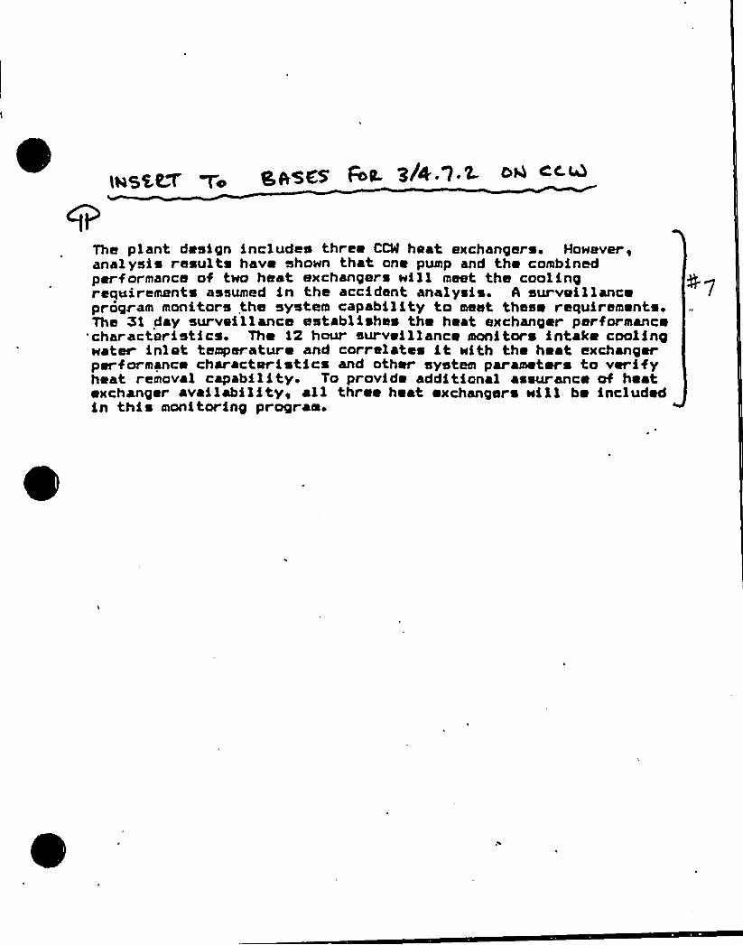
Tha plant design inc)udes three CCM heat exchangars. However,ana)ysis results have shown that one pump and the combinedperformance of two heat exchangers will meet the coolingrequirements assumed in the accident analysis. A surveillanceprogram monitors the system capability to meet these requirements.The 51 day surveillance establishes the heat exchanger performance
'characteristics. The 12 hour surveillance monitors intake coolingwater inlet temperature and correlates it with the heat exchangerperformance characteristics and other system parameters to verifyheat removal capability. To provide additional assurance of heatexchanger availability~ all three heat «xchangers will be includedin this monitoring prograe.
/-.> 7< g~ge~7id~a.!!
~/'
PLANT SYSTEMS
BASES
When a snubber is found inoperable, an evaluation is performed, in addi-tion to the determination of the snubber mode of failure, in order to determineif any Safety Related System or component has been adversely affected by theinoperability of the snubber. The evaluation shall determine whether or notthe snubber mode of failure has imparted a significant effect or degradation onthe supported component or system.
To provide assurance of snubber functional reliability, a representativesample of the installed snubbers will be functionally tested during plantrefueling SHUTDOWNS. Observed failure of these sample snubbers shall requirefunctional testing of additional units.
In cases where the cause of the functional failure has been identifiedadditional testing shall be based on manufacturer's or engineering recommenda-tions. As applicable, this additional testing increases the probability oflocating possible inoperable snubbers without .testing 100K of the safety-related snubbers.
The service life of a snubber is established via manufacturer input andinformation through consideration of the snubber service conditions and asso-ciated installation and maintenance records (newly installed snubbers, sealreplaced, spring replaced, in high radiation area, in high temperature area,etc.). The requirement to monitor the snubber service life is included toensure that the snubbers periodically undergo a performance evaluation in viewof their age and operating conditions. These records will provide statisticalbases for future consideration of snubber service life. The requirements forthe maintenance of records and the snubber service life review are not intendedto affect plant operation.
3/4.7.7 SEALEO SOURCE CONTAMINATION
The limitations on removable contamination for sources requiring leaktesting, including alpha emitters, is based on 10 CFR 70.39(a)(3) limits forplutonium. This limitation will ensure that leakage from Byproduct, Source,and Special Nuclear Material sources will not exceed allowable intake values.
Sealed sources are classified into three groups according to their use,with Surveillance Requirements coaeensurate with the probability of damage to asource in that group. Those sources which are frequently handled are requiredto be tested more often, than those which are not. Sealed sources which arecontinuously enclosed within a shielded mechanism (i.e., sealed sources withinradiation monitoring or boron measuring devices) are considered to be storedand need not be tested unless they are removed from the shielded mechanism.
TURKEY POINT - UNITS 3 8a 4 B 3/4 7-7~Univ' g
PLANT SYSTEHS
BASES
3/4.7.8 FIRE SUPPRESSION SYSTEHS
("
The OPERABILITY of the Fire Suppression Systems ensures that adequatefire suppression capability is available to confine and extinguish firesoccurring in any portion of the facility where safety-related equipment islocated. The Fire Suppression System consists of the water system, spray,/ 8 k1,~fl h f . dy ~ tf hyd . )NLThe collective capability of the Fire Suppression Systems is adequate tominimize potential damage to safety-related equipment and is a major elementin the facility Fire Protection Program.
In the event that portions of the Fire Suppression Systems are inoperable,alternate backup fire-fighting equipment is required to be made available inthe affected areas until the inoperable equipment is restored to service.Mhen the inoperable fire-fighting equipment is intended for use as a backupmeans of fire suppression, a longer period of time is allowed to provide analternate means of fire fighting than if the inoperable equipment is theprimary means of fire suppression.
The Surveillance Requirements provide assurance that the minimum OPERABILITYrequirements of the Fire Suppression Systems are met.
In the-event the Fire Suppression Mater System becomes inoperable,immediate corrective measures must be taken since this system provides themajor fire suppression capability of the plant.
3/4. 7. 9 FIRE RATED ASSEHBLIES
The functional integrity of the fire rated assemblies and barrier penetrationsensures that fires will be confined or adequately retarded from spreading to
adjacer'ortionsof the facility. These design features minimize the possibility of a singfire rapidly involving several areas of the facility prior. to detection and extin-guishing of the fire. The fire barrier penetrations are 8 passive element in thefacility Fire Protection Program and are subject to periodic inspections.
Fire barrier penetrations, including cable penetration barriers, fire doorsand dampers are considered function 1 when the visually .observed condition is thes as the as-desi ne con tion
During periods of time when a barrier is not functional, either: (1) a contin-uous fire watch is required to be maintained in the vicinity of the affected bar~ieor (2) the fire detectors on at least one side of the affected barrier must beverified OPERABLE and an hourly fire watch patrol established until the barrieris restored to functional status.
TURKEY POINT - UNITS 3 4 4 B 3/4 7-8~ ~
3
3/4. 9 REFUELING OPERATIONS
BASES
3/4.9. 1 BORON CONCENTRATION
'he limitations on reactivity conditions during REFUELIN ensure that:(1) the reactor will remain subcritical during CORE ALTERATIONS, and (2) auniform boron concentration is maintained for reactivity control, in the watervolume having direct access to the reactor vessel. These limitations areconsistent with the initial conditions assumed for the boron dilution incidenin the safety analyses. he required valve dur ngrefueling operations-pea'&eden the possibility of uncontrolled bor n dilutionof the filled portion of the RC . This action pr vents flow to the RCS ofunborated water by closing flow paths f ource of unborated water.
~ ~3/4.9.2 INSTRUMENTATION
lS grec vThe OPERABILITY of the our e Range Neutron Flux Monitors ensures that
redundant monitoring capability is available to detect changes in the reactivitycondition of the core. There are four source range neutron flux channels, twoprimary and two backup. All four channels have visual and alarm indication inthe control room and interface with the containment evacuation alarm system.The primary source range neutron flux channels can also generate reactor tripsignals and provide audible indication of the count rate in the control roomand containment. At least one primary source range neutron flux channel toprovide the required audible indication, in addition to its other functions,and one of the three remaining source range channels shall be OPERABLE tosatisfy the LCO.
3/4. 9. 3 DECAY TIME
The minimum requirement for reactor subcriticality prior to movement ofirradiated fuel assemblies in the reactor vessel ensures that sufficient timehas elapsed to'allow the radioactive decay of the short-lived fission products.This decay time is consistent with the assumptions used in the safety analyses.
3/4. 9. 4 CONTAINMENT BUILDING PENETRATIONS
The requirements on containment building penetration closure and OPERABILITYensure that a release of radioactive material within containment will berestricted from leakage to the environment. The OPERABILITY and closurerestrictions are sufficient to restrict radioactive material release from afuel element rupture based upon the lack of containment pressurization potentialwhile in the REFUELING MODE.
3/4.9. 5 COMMUNICATIONS .
The requirement for communications capability ensures that refuelingstation personnel can be promptly informed of significant changes in thefacility status or core reactivity conditions during CORE ALTERATIONS.
TURKEY POINT - UNITS 3 8E 4 B 3/4 9-1
REFUELING OPERATIONS
BASES
3/4.9.6 MANIPULATOR CRANE
The OPERABILITY requirements for the manipulator cranes ensure that:(1) manipulator cranes will be used for movement of drive rods and fuel assem-blies, (2) each crane has sufficient load capacity to lift a drive rod or fuelassembly, and (3) the core internals and reactor vessel are protected fromexcessive lifting force in the event they dna vertently engaged duringlifting operations.
(The requirement that t e Puxiliary jloist goad gndi a r be used to proven
'I fting excessive loads wII squire a manual action .T e juxiliaryPoist goadnNcator does not include a y aut tic h r e edtrical interlocks
that prevent lifting loads in cess 600 pounds.
3/4.9.7 CRANE TRAVEL - SPENT FUEL STORAGE AREAS
The restriction on movement of loads in excess of the nominal weight of afuel and control rod assembly and associated handling tool over other fuelassemblies in the storage pool ensures that in the event this load is dropped:(1) the activity release will be limited to that contained in a single fuelassembly, and (2) any possible distortion of fuel in the storage racks will notresult in a critical array. This assumption is consistent with the activity
~ ~
release assumed in the safety analyses.
3/4.9.8 RESIOUAL HEAT REMOVAL ANO COOLANT CIRCULATION
The requirement that at least one residual heat removal (RHR) loop be inoperation ensures that: (1) sufficient cooling capacity is available to removedecay heat and maintain the water in the reactor vessel below 140 F as requiredduring the REFUELING MOOE, and (2) sufficient coolant circulation is maintainedthrough the core to minimize the effect of a boron dilution incident and preventboron stratification.
The requirement to have two RHR loops OPERABLE when there is less than23 feet of water above the reactor vessel flange ensures that a single failureof the operating RHR loop will not result in a complete loss of residual heatremoval capability. lith the reactor vessel head removed and at least 23 feetof water above the reactor pressure vessel flange, a large'eat sink is avail-able for core cooling. Thus, in the event of a failure of the operatingRHR loop, adequate time is provided to initiate emergency procedures to coolthe core.
0
3/4. 9. 9 CONTAINMENT VENTILATION ISOLATION SYSTEM
The OPERABILITY of this system ensures that the containment ventilationpenetrations will be automatically isolated upon detection of high radiationlevels within the containment. The OPERABILITY of this system is required torestrict the release of radioactive material from the containment atmosphere tothe environment.
TURKEY POINT - UNITS 3 & 4 B 3/4 9-2 J]'QNgy
REFUELING OPERATIONS
BASES
3/4.9. 10 and 3/4.9.11 WATER LEVEL - REACTOR VESSEL AND STORAGE POOL~ ~
The restrictions on minimum water level ensure that sufficient waterdepth's available to remove 99K of the assumed 1(C iodine gap activityreleased from the rupture of an irradiated fuel assembly. The minimum waterdepth is consistent with the assumptions of the safety analysis.-
3/4.9.12 HANDLING OF SPERM FUEL CASK
Limiting spent fuel decay time to a minimum of 1,525 hours prior tomoving a spent fuel cask into the spent fuel pit will ensure that potentialoffsite doses are a fraction of 10 CFR Part 100 limits should a dropped caskstrike the stored fuel assemblies.
The restrjction to allow only a single element cask to be moved into thespent fuel pit will ensure the maintenance of water inventory in the unlikelyevent of an uncoqtgolled cask descent. Use of a single element cask whichnominally weig about twenty-five tons will also increase crane safetymargins by about a facto~ of four.
Requiring that spent fuel decay time be at least 120 days prior to movinga fuel assembly outside the fuel storage pit in a shipping cask will ensurethat potential offsite doses are a fraction of 10 CFR 100 limits should adropped cask and ruptured fuel assembly release activity directly to theatmosphere.
3/4. 9. 13 RADIATION MONITORING
PThe OPERABILITY,of ~containment radiation monitonC censures continuous
monitoring of radiation evels to provide immediate ind~ca ion of an unsafecondition.
)w]
3/4.9. 14 SPENT FUEL STORAGE
The spent fuel storage racks provide safe subcritical storage of fuelassemblies by providing sufficient center-to-center spacin'g or combinationof spacing and poison to assure k ff is equal to or less tha . for normaleff o.95operations and postulated accidents.
The spent fuel racks are divided into two regions. Region I racks havea 10.6 inch center-to-center spacing and Region II racks have a 9.0 inchcenter-to-center spacing. Because of the larger center-to-center spacing andpoison (B~o) concentration of Region I cells, the only restriction for place-ment of fuel is that the initial fuel assembly enrichment is. equal to or lessthan 4.5 weight percent of U-235. The limiting value of U-235 enrichmentis based upon the assumptions in the spent fuel safety analyses and assuresthat the limiting criteria for criticality is not exceeded. Prior to placement
)~f
TURKEY POINT - UNITS 3 8L 4 B 3/4 9-3
REFUELING OPERATIONS
BASES
SPENT FUEL STORAGE (Continued)
in Region II cell locations, strict controls are employed to evaluate burnup ofthe spent fuel assembly, .Upon determination that the fuel assembly meets theburnup requirements of Table 3.9-1, placement in a Region II cell is authorized.These positive controls assure the fuel enrichment limits assumed in the
safety'nalyseswill not be exceeded. "
"This Technical Specification is applicable upon installation of the new two-region high density spent fuel racks.
TURKEY POINT - UNITS 3 8L 4 B 3/4 9-4~ o ~i'
3/4. 10 SPECIAL TEST EXCEPTIONS
BASES
3/4. 10. 1 SHUTDOWN MARGIN~ ~
This special test exception provides that a minimum amount of control rodworth is immediately available for reactivity contr'ol when tests are performedfor control rod worth measurement. This special test exception is required topermit the periodic verification of the actual versus predicted core reactivitycondition occurring as a result of fuel burnup or fuel cycling operations.
3/4. 10. 2 GROUP HEIGHT INSERTION AND POWER DISTRIBUTION LIMITS
This special test exception permits individual control rods to be positionedoutside of their normal group heights and insertion limits during the performanceof such PHYSICS TESTS as those required to measure control rod worth.
3/4. 10. 3 PHYSICS TESTS
This special test exception permits PHYSICS TESTS to be performed at lessthan or equal to SN of RATED THERMAL POWER with the RCS 7@ alkghtly lower
than normally allowed so that the fundamental nuclear characteristics of thecore and related instrumentation can be verified. In order for various charac-teristics to be accurately measured, it is at times necessary to operateoutside the normal restrictions of these Technical Specifications. For instance,to measure the moderator temperature coefficient at BOL, it is necessary toposition the various control rods at heights which may not normally be allowedby Specification 3. 1.3.6 which in turn may cause the RCS ~ to fall slightlybelow the minimum temperature of Specification 3. 1. 1.4.
3/4. 10.4 This s ecification number is not used.
Slq. 10. 5 POSITION INDICATION SYSTEM - SHUTDOWN
This special test exception permits the Position Indica son Systems to beinoperable during rod drop time measurements. The exception is required sincethe data necessary to determine the rod drop time are derived from the inducedvoltage in the position indicator coils as the rod is dropped. This inducedvoltage is small compared to the normal voltage and, therefore, cannot beobserved if the Position Indication Systems remain OPERABLE.
TURKEY POINT - UNITS 3 8E 4 B 3/4 10-1

/ y5 ~ g /p77+pz p(/~Wc l~4/ 6
3/4. 11 RADIOACTIVE EFFLUENTS
BASES
3/4.11.1 LI UID EFFLUENTS
3/4 ~ 11. 1. 1 CONCENTRATION
This specification is provided to ensure that the concentration of radio-active materials released in liquid waste effluents to UNRESTRICTED AREAS willbe less than the concentration levels specified in 10 CFR Part 20, Appendix B,Table II, Column 2. This limitation provides additional assurance that thelevels of radioactive materials in bodies of water in UNRESTRICTED AREAS willresult in exposures within: (1) the objectives of Appendix I, 10 CFR Part 50,to a MEMBER OF THE PUBLIC, and (2) the limits of 10 CFR Part 20.106(e) to thepopulation. The concentration limit for dissolved or entrained noble gases isbased upon the assumption that Xe-135 is the controlling radioisotope and itsMPC in air (submersion) was .converted toian equivalent concentration in water,'sing the methods described in International Commission on Radiological Protec-
t tion (ICRP) Publication 2.
This specification applies to the release of radioactive materials inliquid effluents from all units at the site;The required detection capabilities for radioactive materials in liquid
waste samples are tabulated in terms of the lower limits of detection (LLDs).Detailed discussion of the LLD, and other detection limits can be found inCurrie, L. A., "Lower Limit of Detection: Definition and Elaboration of aProposed Position for Radiological Effluent and Environmental Measurements,"NUREG/CR-4077 (September 1984'), in HASL Procedures Manual, HASL-300 (revisedannually) and in Hartwell, J. K., "Detection Limits for Radioaana ytTcalCounting Techniques," Atlantic Richfield Hanford Company Report ARH-SA-215(June 1975).
3/4. 11. l. 2 DOSE
This specification is provided to implement the requirements of Appendix I,10 CFR Part 50. The Limiting Condition for Operation implements the guidesset forth in Appendix I. The ACTION statements provide the required operat-e
~
~~
~~ ~~ ~ing flexibilityand at the same time implement the guides set forth inppendix I to assure that the releases of radioactive material in liquidfluents to UNRESTRICTED AREAS will be kept "as low as is reasonably achiev-
able." The dose calculation methodology and parameters in the ODCM implementthe requirements in Appendix I that conformance with the guides of Appendix Ibe shown by calculational procedures based on models and data, such that theactual exposure of a MEMBER OF THE PUBLIC through appropriate pathways is .
unlikely to be substantially underestimated. The equations specified in theODCM for calculating the doses due to the actual release rates of radioactivematerials in liquid effluents are consistent with the methodology provided inRegulatory Guide 1.109, "Calculation of Annual Doses to Man from RoutineReleases of Reactor Effluents for the Purpose of Evaluating Compliance with10 CFR Part 50, Appendix I," March, 1976 and Regulatory Guide 1.113, "Estimat-ing Aquatic Dispersion of Effluents from Accidental and Routine Reactor Releasesfor the Purpose of Implementing Appendix I," April 1977.
TURKEY POINT - UNITS 3 4 4 B 3/4 ll-lvv4 ' )95p
RADIOACTIVE EFFLUENTS
BASES
DOSE (Continued)
This specification applies to the release of radioactive materials in liquideffluents from each unit at the site. For units with shared Radwaste Systems,the liquid effluents from the shared system are to be proportional among theunits sharing that system.
3/4.11. 1.3 LI UID RADWASTE TREATMENT SYSTEM
The OPERABILITY of the Liquid Radwaste Treatment System ensures that thissystem will be available for use whenever liquid effluents require treatmentprior to release to the environment. The requirement that the appropriate portionsof this system be used when specified provides assurance that the releases ofradioactive materials in liquid effluents will be kept "as low as is reasonablyachievable." This specification implements the requirements of 10 CFR 50.36a,General Design Criterion 60 of Appendix A to 10 CFR Part 50 and the ob)ectivesgiven in Section II.D of Appendix I to 10 CFR Part 50. The specified limitsgoverning the use of appropriate portions of the Liquid Radwaste TreatmentSystem were specified as a suitable fraction of the dose ob$ ectives setforth in Appendix I, 10 CFR Part 50 for liquid effluents.
This specification applies to the release of radioactive materials inliquid effluents from each unit at the site. For units with shared Radwaste System~the liquid effluents from the shared system are to be proportioned among theunits sharing that system.
TURKEY POINT - UNITS 3 5 4 B 3/4 11-2JUh' f l~g
I
RADIOACTIVE EFFLUENTS
BASES
3/4. 11.2 GASEOUS EFFLUENTS
3/4. 11. 2. 1 DOSE RATE
This specification is provided to ensure that the dose at any time at andbeyond the SITE BOUNDARY from gaseous effluents from all units on the sitewill be within the annual dose limits of 10 CFR Part 20 to UNRESTRICTED AREAS.The annual dose limits are the doses associated with the concentrations of10 CFR Part 20, Appendix 8, Table II, Column I. These limits pr'ovide reasonableassurance that radioactive material discharged in gaseous effluents will notresult in the exposure of a MEMBER OF THE PUBLIC in an UNRESTRICTED AREA,either within or outside the SITE BOUNDARY, to annual average concentrationsexceeding the limits specified in Appendix B, Table II of 10 CFR Part 20(10 CFR Part 20.106(b)). For MEMBERS OF THE PUBLIC who may at times be withinthe SITE BOUNDARY, the occupancy of that MEMBER OF THE PUBLIC will usually besufficiently low to compensate for any increase in the atmospheric diffusionfactor above that for the SITE BOUNDARY. Examples of calculations for suchMEMBERS OF THE PUBLIC, with the appropriate occupancy factors, shall be givenin the ODCM. The specified release rate limits restrict, at all times, thecorresponding gamma and beta dose rates above background to a MEMBER OF THEPUBLIC at or beyond the SITE BOUNDARY to less than or equal to 500 mrems/yearto the whole body or to less than or equal to 3000 mrems/year to the skin.These release rate limits also restrict, at all times, the correspondingthyroid dose rate above background to a child via the inhalation pathway toless than or equal to 1500 mrems/year.
This specification applies to the release of radioactive materials ingaseous effluents from all units at the site.
The required detection capabilities for radioactive material in gaseouswaste samples are tabulated in terms of the lower limits of detection (LLDs).Detailed discussion of the LLD, and other detection limits can be found inCurrie, L. A , "Lower Limit of Detection: Definition and Elaboration of aProposed Position for Radiological Effluent and Environmental Measure tNUREG/ - 077 (September 1984), in HASL Procedures Manual, HASL-300
nd in Hartwell, J.K., "Oetection Limits for Radiosina ayt ca oon sngec nsques," Atlantic Richfield Hanford Company Report ARH-SA-215 (June 1975).
3/4. 11.2. 2 DOSE - NOBLE GASES
This specification is provided to implement the requirements of Appendix I,10 CFR Part 50. The Limiting Condition for Operation implements the guidesset forth in Appendix I. The ACTION statements provide the required operat-ing flexibilityand at the same time implement the guides set forth in Appendix Ito assure that the releases of radioactive material in gaseous effluents toUNRESTRICTED AREAS will be kept "as low as is reasonably achievable." TheSurveillance Requirements implement the requirements in Appendix I thatconformance with the guides of Appendix I be shown by calculational procedures'ased on models and data such that the actual exposure of a MEMBER. OF THEPUBLIC thr ough appropriate pathways is unlikely to be substantially under-estimated. The dose calculation methodology and parameters established
TURKEY POINT - UNITS 3 4 4 8 3/4 11-3
RADIOACTIVE EFFLUENTS
BASES
DOSE-NOBLE GASES (Continued)
in the ODCM for calculating the doses due to the actual release rates ofradioactive noble gases in gaseous effluents are consistent with the methodologyprovided in Regulatory Guide 1.109, "Calculation of Annual Doses to Man fromRoutine Releases of Reactor Effluents for the Purpose of Evaluating Compliancewith 10 CFR Part 50, Appendix I," Harch 1976, and Regulatory Guide 1.111,"Methods for Estimating Atmospheric Transport and Dispersion of GaseousEffluents in Routine Releases from Light-Water Cooled Reactors," Revision 1,July 1977. The ODCM equations provided for determining the air doses at andbeyond the SITE BOUNDARY are based upon the historical average atmosphericconditions.
This specification applies to the release of radioactive materials ingaseous effluents from each. unit at the site. For units with shared radwastetreatment systems, the gaseous effluents from the shared system are proportionedamong the units sharing that system.
3/4. 11.2. 3 DOSE - IODINE-131 IODINE-133 TRITIUM AND RADIOACTIVE MATERIALN UL FORH
This specification is provided to implement the requirements of Appendix I,10 CFR Part 50. The Limiting Conditions for Operation are the guides setforth in Appendix I. The ACTION statements provide the required operatingflexibilityand at the same time implement the guides set forth in Appendix Ito assure that the releases of radioactive materials in gaseous effluents toUNRESTRICTED AREAS will be kept "as low as is reasonably achievable." The ODCM
calculational methods specified in the Surveillance Requirements implement therequirements in Appendix I that conformance with the guides of Appendix I beshown by calculational procedures based on models and data such that the actualexposure of a MEMBER OF THE PUBLIC through appropriate pathways is unlikely tobe substantially underestimated. The ODCM calculational methodology andparameters for calculating the doses due to the actual release rates of thesubject materials are consistent with the methodology provided in RegulatoryGuide 1. 109, "Calculation of Annual Doses to Man from Routine Releases ofReactor Effluents f he Purpose of Evaluating Compliance with 10 CPR Part 60,.Appendix 1," Rare 96 , and Regulatory Guide 1.111, "Rethods for EstimatingAtmospher spor and Dispersion of Gaseous Effluents in Routine Releases
ght-Water Cooled Reactors," Revision 1, July 1977. ~ These equations alsoprovide for determining the actual doses based upon the historical averageatmospheric conditions. The release rate specifications for Iodine-131Iodine-133, tritium, and radionuclides in particulate form with half-livesgreater than 8 days are dependent upon the existing radionuclide pathways toman in the areas at and beyond the SITE BOUNDARY.- The pathways that wereexamined in the development of the calculations wero: (1) individual inhala-tion of airborne radionuclides, (2) deposition of radionuclides onto greenleafy vegetation with subsequent consumption by man, (3) deposition onto grassyareas where milk animals and meat producing animals graze with consumption ofthe milk and meat by man, and (4) deposition on the ground with subsequentexposure of man.
TURKEY POINT - UNITS 3 Si 4 B 3/4 11-4~ > '": E'eak
RADIOACTIVE EFFLUENTS
BASES
DOSE " IODINE-133 TRITIUM ANO RADIOACTIVE MATERIAL IN PARTICULATE FORM
Continued
This specification applies to the release of radioactive materials ingaseous effluents from each unit at the site. For units with shared radwastetreatment systems, the gaseous eff1uents from the shared system are proportionedamong the units sharing that system.
3/4. 11.2.4 GASEOUS RADWASTE TREATHENT SYSTEM
The OPERABILITY of the GAS DECAY TANK SYSTEM and the VENTILATION EXHAUSTTREATHENT SYSTEM ensures that the systems will be available for use whenevergaseous effluents require treatment prior to release to the environment. Therequirement that the appropriate portions of these systems be used, when specified,provides reasonable assurance that the releases of radioactive materials ingaseous effluents will be kept "as low as is reasonably achievable." Thisspecification implements the requirements of 10.CFR 50.36a, General DesignCriterion 60 of Appendix A to 10 CFR Part 50 and the ob)ectives given inSection II.D of Appendix I to 10 CFR Part 50. The specified limits governingthe use of appropriate portions of the systems were specified as a suitablefraction of the dose objectives set forth in. Appendix I, 10 CFR Part 50, forgaseous effluents.
This specification applies to the release of radioactive materials ingaseous effluents from each unit at the site. For units with shared radwastetreatment systems, the gaseous effluents from the shared system are proportionedamong the units sharing that system.
TURKEY POINT - UNITS 3 5 4 B 3/4 11-5 tl I ~ ~)ge
RADIOACTIVE EFFLUENTS
BASES
3/4. 11. 2. 5 EXPLOSIVE GAS MIXTURE
This specification is provided to ensure that the concentration of poten-tially explosive gas mixtures contained in the GAS DECAY TANK SYSTEM (asmeasured in the inservice gas decay tank) is maintained below the flammabilitylimits of hydrogen and oxygen. Maintaining the concentration of hydrogen andoxygen below their flammability limits provides assurance that. the releases ofradioactive materials will be controlled in conformance with the requirementsof General Design Criterion 60 of Appendix A to 10 CFR Part 50.
3/4 11 ~ 2.6 GAS DECAY TANKS
The tanks included in this specification are those tanks for which thequantity of radioactivity contained is not limited directly or indirectly byanother Technical Specification. Restricting the quantity of radioactivitycontained in each Gas Decay Tank provides assurance that in the event of anuncontrolled release of the tank's contents, the resulting whole body exposureto a MEMBER OF THE PUBLIC at the nearest SITE BOUNDARY will not exceed 0.5 rem.
3/4. 11. 3 SOLID RADIOACTIVE WASTES
This specification implements the requirements of 10 CFR 50.36a andGeneral Design Criterion 60 of Appendix A to 10 CFR Part 50. The processparameters included in establishing the PROCESS CONTROL PROGRAM may include,but are not limited to, waste type, waste pH, waste/liquid/SOLIDIFICATIONagent/catalyst ratios, waste oil content, waste principal chemical constituents,and mixing and curing times.
3/4. 11. 4 TOTAL DOSE
This specification is provided to meet the dose limitations of 10 CFRPart 190 that have been incorporated into 10 CFR Part 20 by 46 FR 18525. Thespecification requires the preparation and submittal of a Special Report when-ever the calculated doses due to releases of radioactivity and to radiation fromuranium fuel cycle sources exceed 25 mrems to the whole body or any organ, exceptthe thyroid, which shall be limited to less than or equal to 75 mrems. Forsites containing up to four reactors, it is highly unlikely that the resultantdose to a MEMBER OF THE PUBLIC All exceed the dose limits of 40 CFR Part 190if the individual reactors remain within twice the dose design objectives ofAppendix I, and if direct radiation doses from the units > ~
~
TURKEY POINT - UNITS 3 4 4 B 3/4 11-6
RADIOACTIVE EFFLUENTS
BASES
TOTAL DOSE (Continued)
are kept small. The Special Report will describe a courseof action that should result in the limitation of the annual dose to a MEMBER
OF THE PUBLIC to within the 40 CFR Part 190 limits. For the purposes of theSpecial Report, it may be assumed that the dose commitment to the MEMBER ofthe PUBLIC from other uranium fuel cycle sources is negligible, with theexception that dose contributions from other nuclear fuel cycle facilities atthe same site or within a radius of 8 km must be considered. If the dose toany MEMBER OF THE PUBLIC is estimated to exceed the requirements of 40 CFRPart 190, the Special Report with a request for a variance (provided therelease conditions resulting in violation of 40 CFR Part 190 have not alreadybeen corrected), in accordance with the provisions of 40 CFR 190. 11 and 10 CFR20.405c, is considered to be a timely request and fulfills the requirements of40 CFR Part 190 until NRC staff action is completed. The variance only relatesto the limits of 40 CFR Part 190, and does not apply in any way to the otherrequirements for dose limitation of 10 CFR Part 20, as addressed in Specifi-cations 3. 11. 1. 1 and 3.11.2.1. An individual is not considered a MEMBER OF THEPUBLIC during any period in which he/she is engaged in carrying out any operationthat is part of the nuclear fuel cycle.
TURKEY POINT - UNITS 3 8( 4 B 3/4 11-7

~- @DC/P- In7en(idnal/.~I
/
3/4. 12 RADIOLOGICAL ENVIRONMENTAL MONITORING
BASES
3/4. 12. 1 MONITORING PROGRAM
The Radiological Environmental Monitoring Program required by thisspecification provides representative measurements of radiation and of radio-active materials in those exposure pathways and for those radionuclides thatlead to the highest potential radiation exposure of MEMBERS OF THE PUBLICresulting from the plant operation. This monitoring program implementsSection IV.B. 2 of Appendix I to 10 CFR Part 50 and thereby supplements theRadiological Effluent Monitoring Program by verifying that the measurableconcentrations of radioactive materials and levels of radiation are not higherthan expected on the basis of the effluent measurements and the modeling ofthe environmental exposure pathways.
The required detection capabilities for environmental sample analyses aretabulated in terms of the lower limits of detection (LLDs). The LLDs requiredby Table 4. 12-1 are considered optimum for routine environmental measurementsin industrial laboratories. It should be recognized that the LLD is definedas an a griori (before the fact) limit representing the capability of a measure-
s d ~ i l(ft tt f )ill f pmeasurement.
Detailed discussion of the LLD, and other detection limits, can be foundin Currie, L. A., "Lower Limit of Detection: Definition and Elaboration of aProposed Position for Radiological Effluent and Environmental Measurem tNUREG/ -400? (September 1984), in HASL Procedures Manual, HASL-300 ~itch
and Hartwell, J. K. "Oetection Limits for RadioanaTyytsca Coun snechnsques," Atlantic Richfield Hanford Company Report ARH-SA-215 (June 1975).
3/4. 12.2 LAND USE CENSUS
This specification is provided to ensure that changes in the use of areasat and beyond the SITE BOUNDARY are identified and that modifications to theRadiological Environmental Monitoring Program are made if required by theresults of this census. The best information from the door-to-door survey,from aerial survey or from consulting with local agricultural authoritiesshall be used. This census satisfies the requirements of Section IV.B.3 ofAppendix I to 10 CFR Part 50. Restricting the census to gardens of greaterthan 50 m~ provides assurance that significant exposure pathways via leafyvegetables will be identified and monitored since a garden of this size is theminimum required to produce the quantity (26 kg/year) of leafy vegetablesassumed in Regulatory Guide 1.109 for consumption by a child. To determinethis minimum garden size, the following assumptions were made: (1) 20X of thegarden was used for growing broad leaf vegetation (i.e., similar to lettuce andcabbage), and (2) a vegetation yield of 2 kg/m2.
TURKEY POINT - UNITS 3 8( 4 B 3/4 12-1

RADIOLOGICAL ENVIRONMENTAL MONITORING
BASES
3/4. 12.3 INTERLABORATORY COMPARISON PROGRAM
The requirement for participation in an approved Interlaboratory ComparisonProgram .is provided to ensure that independent checks on the precision andaccuracy of the measurements of radioactive materials in environmental samplematrices are performed as part of the quality assurance program for environ-mental monitoring in order to demonstrate that the results are valid for thepurposes of Section IV. B. 2 of Appendix I to 10 CFR Part 50. This condition issatisfied by participation in the Environmental Radioactivity LaboratoryIntercomparison Studies Program conducted by the Environmental ProtectionAgency (EPA).
0
,TURKEY POINT " UNITS 3 5 4 B 3/4 12-2
SECTION 5.0
DESIGN FEATURES

~ t
@CD)M [ W+CV:9 l p YC<
~~
7" Q C(ln, Q
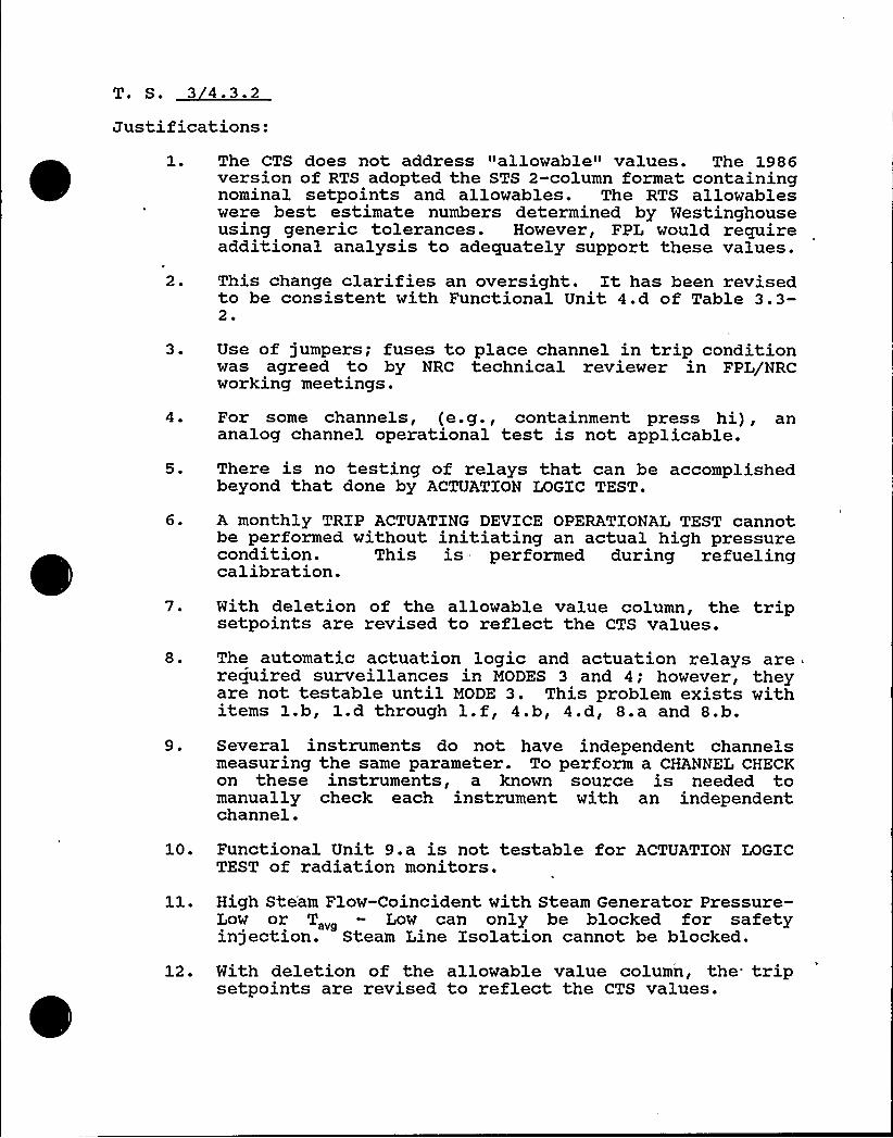
T. S. 3 4.3.2
Justifications:1 ~
2.
The CTS does not address "allowable" values. The 1986version of RTS adopted the STS 2-column format containingnominal setpoints and allowables. The RTS allowableswere best estimate numbers determined by Westinghouseusing generic tolerances. However, FPL would requireadditional analysis to adequately support these values.
This change clarifies an oversight. It has been revisedto be consistent with Functional Unit 4.d of Table 3.3-2 ~
3 ~
4 ~
Use of jumpers; fuses to place channel in trip conditionwas agreed to by NRC technical reviewer in FPL/NRCworking meetings.
For some channels, (e.g., containment press hi), ananalog channel operational test is not applicable.
5. There is no testing of relays that can be accomplishedbeyond that done by ACTUATION LOGIC TEST.
6. A monthly TRIP ACTUATING DEVICE OPERATIONAL TEST cannotbe performed without initiating an actual high pressurecondition. This is performed during refuelingcalibration.
7.
8.
With deletion of the allowable value column, the tripsetpoints are revised to reflect the CTS values.
The automatic actuation logic and actuation relays arerequired surveillances in MODES 3 and 4; however, theyare not testable until MODE 3. This problem exists withitems 1.b, 1.d through l.f, 4.b, 4.d, 8.a and 8.b.
9. Several instruments do not have independent channelsmeasuring the same parameter. To perform a CHANNEL CHECKon these instruments, a known source is needed tomanually check each instrument with an independentchannel.
10. Functional Unit 9.a is not testable for ACTUATION LOGICTEST of radiation monitors.
High Ste'am Flow-Coincident with Steam Generator Pressure-Low or Tzpg Low can only be blocked for safetyinjection. Steam Line Isolation cannot be blocked.
12. With deletion of the allowable value column, the tripsetpoints are revised to reflect the CTS values.
13. BASES — The deleted wording provides no necessaryinformation.
14. There are no control room isolation functions associatedwith high-containment radioactivity monitors during fuelmovement in the spent fuel pool.
Justifications:1 ~ The monitor numbers were removed to prevent making a
License Amendment if instrument make/model changes aremade in the future.
2. Several instruments do not have independent channelsmeasuring the same parameter. To perform a CHANNEL CHECKon these instruments, a known source is needed tomanually check each instrument with an independentchannel.
T. S. 3 4.3.3.3
Justifications:1 ~ Two different specifications exist for the
same'equirement3.3.3.3 and 3.6.5. Specification 3.0.4 isnot applicable to Table 3.3-5, but it is applicable toSpecification 3.6.5. This is a source of confusion thatneeds to be eliminated.
2 ~
3 ~
The accident monitoring instruments do not providetrip/active functions; therefore, there is no need toconduct the ANALOG CHANNEL OPERATIONAL TEST whichrequires simulated input signals to test interlock/alarm/trip functions.
The refueling surveillance is consistent with the STS.
4 ~ The note describes the only possible check that can beperformed because there is no visible indication duringnormal conditions.
5.
6.
This note allows the neutron detector to be excluded fromchannel calibration. This calibration is not practical.Comparing wide range instruments during normal operationis not a meaningful CHANNEL CHECK. A source must be usedto obtain a response. This change is consistent withSTS.
7. This surveillance is inconsistent with the LCO's whichrequire these channels only in Modes 1, 2 and 3.
8. The monitor numbers were removed to prevent making aLicense Amendment if instrument make/model changes aremade in the future.
9. For consistency of reporting requirements, 30 days isallowed for submittal of the report.
Justifications:
0 1 ~ Failure to comply with the ACTION Statement is reportablevia 10 CFR 50.73. This was a CTS requirement, not an STSrequirement.
2.
3
Containment entry to inspect the fire zone is consistentwith the containment temperature surveillance frequency.(4.6.1.5) and is justified based on ALARA considerationsand the likelihood of recognizing fire concerns throughother instrumentation/equipment feedback.
Fire watch patrol has been replaced by additionalinstrumentation as part of Appendix R upgrades.
Justifications:1. The monitor numbers were removed to prevent making a
License Amendment if instrument. make/model changes aremade in the future.
2 ~ Several instruments do not have independent channelsmeasuring the same parameter. To perform a CHANNEL CHECKon these instruments, a known source is needed tomanually check each instrument with an independentchannel.
3 ~ Applicability should be limited to those situations whenreleases are made via these pathways. This is consistentwith CTS (Amendment 103/97).
T. S. 3 4.3.3.6
Justifications:The iodine and particulate samplers are counted filters,not online monitors. Their function is covered in Table4.11-2.
2. Several instruments do not have independent channelsmeasuring the same parameters. To perform a CHANNELCHECK on these instruments, a known source is needed tomanually check each instrument with an independentchannel.
3.
4.
This is a continuous release pathway and should bemonitored daily as well as prior to any release.
Four (4) hours would require upgrades to equipment.Eight (8) hours is a reasonable amount of time to performthis test.
5. The monitor numbers were removed to prevent making aLicense Amendment if instrument make/model changes aremade in the future.


Justifications:1. BASES — This clarification is consistent with the CTS.
Justifications:1. Refer to attached Westinghouse letters.2. The single active failure wording is not applicable to
Turkey Point due to electrical system design.
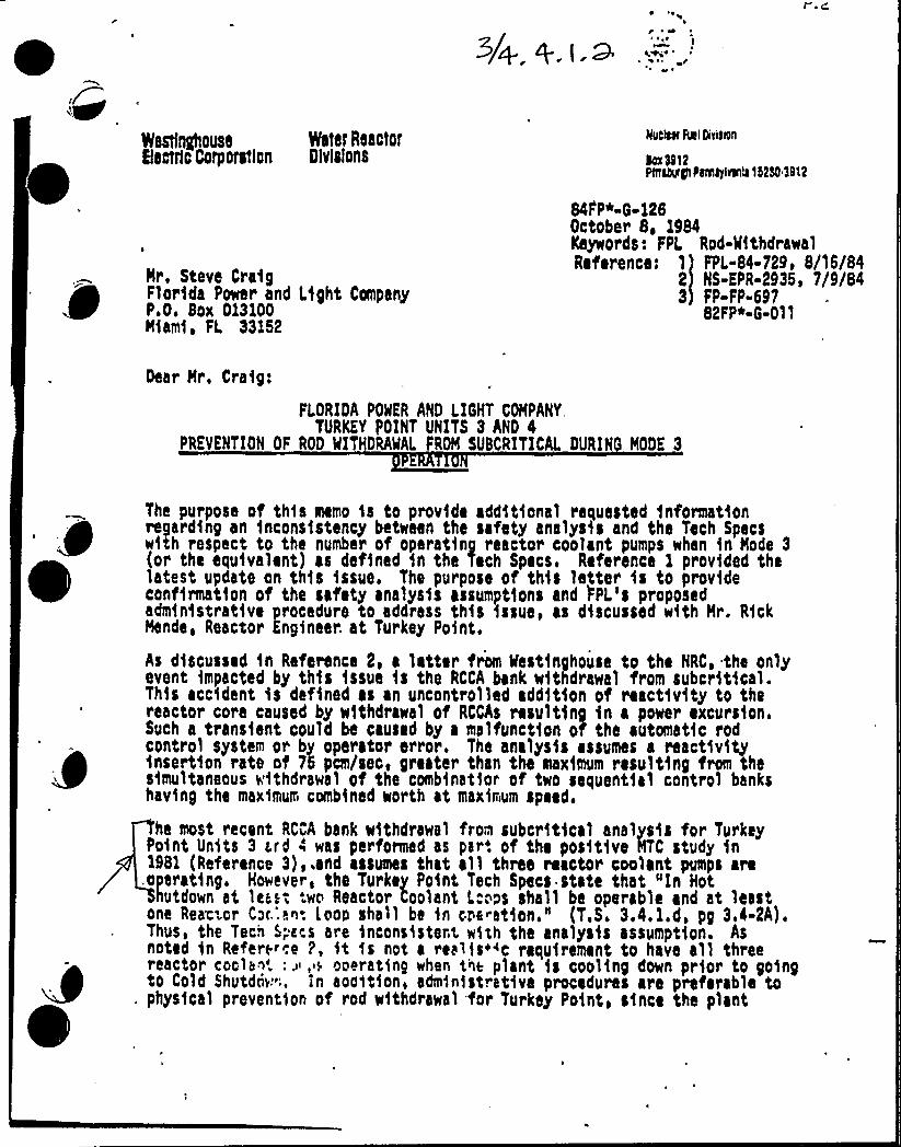
Nestfnghouse Water ReactorBectrlc Corporstlcn Dlvlslons
Nr, Steve CraigFlorida Power and Light CompanyP.O, Box 013100Miami, FL 33}52
Mucker fuel Divigeii
kx Sl12N1thlglPIN4ylrloll15250 $ 912
84F'P*-9-}28October 8, 1984Keywords: FPL Rod-NthdrawalReference: 1 FPL-84-729> 8/15/84
2 NS-EPR-2935) 7/9/843 FP-FP-697
82FP~-G-011
Dear Nr, Craig;
FLORIDA POWER AND LIGHT COMPANY,TURKEY POINT UNITS 3 AND 4
PREVENTION OF ROD MIT DRAWL FROM SUBCRITICAL DURIN MODE 3
The purpose of this memo is to provide additional requested informationregarding an incons1stency between the safety analysis and the Tech Specswith respect to the number of operating reactor coolant pumps when in Node 3(or the equivalent) as defined 1n the Tech Specs. Reference ) provided thelatest update on th1s issue. The purpose of this letter is to provideconfirmation of the safety analys1s assumptions and FPL's proposedadministrative procedure to address this issue, as discussed with Nr. RickMande, Reactor Kngineer. at Turkey Point.
As discussed in Reference 2, a latter from ifestinghouse to the NRC, the onlyevent impacted by this issue is the RCCA bank withdrawal from subcritical.This accident is defined as an uncontrolled addition of reactivity to thereactor core caused by withdrawal of RCChs resulting in a power excur s1on.Such a transient could be caused by a malfunction oT the automat1c rodcontrol system or by operator e~~or. The analysis assumes a react1vityinsert1on rate of 75 pcm/sec, greater than the maximum resulting from thesimultaneous withdrawal of the combinatior of two sequent1al control bankshaving the maximum combined worth at maximum speed.
ha most recent RCCA bank withdrawal from subcr'itical analysis for TurkeyPoint Units 3 hard 4 was performed as par'. of the positive HTC study in1981 (Reference 3),.and assumes that all three reactor coolant pumps are
,operating. However, the Turkey Point Tech Specs state that "In Hothutdown at les.', '.wo Reactor Coolant L."~ps shall ba operable and at least
one Rear-or C~c.'.!~: Loon shall be in cra~at1on." (T.S. 3.4. l.d, pg 3.4-2A).Thus, the Tech 5;a.s are inconsistent w5xh the analysis assumption. Asnoted in Refers«e P, it is not a realms«c requirement to have all threereactor cools~'.: ~, ~ ooerating whar t~~ plant is cooling down prior to goingto Cold Shutdciv''. ln aoait1on, administrative procedures are preferable to
. phys1cal prevention of rod withdrawal for Turkey Point> s1nce the plant
5. 0 DESIGN FEATURES
5. 1 SITE
EXCLUSION AREA
5. 1. 1 The Exclusion Area shall be as shown in Figure 5. . 1
LOW POPULATION ZONE
5. 1. 2 The Low Population Zone shall be as shown in Figure 5.1-1.
MAP DEFINING UNRESTRICTED AREAS AND SITE BOUNDARY FOR RADIOACTIVE GASEOUS ANDLI UID EFFLUENTS
5.1.3 Information regarding radioactive gaseous and liquid effluents, whichwill allow identification of structures and release points as well as defini-tion of UNRESTRICTED AREAS within the SITE BOUNDARY that are accessible toMEMBERS OF THE PUBLIC, shall be as shown in Figure 5.1-1.
5. 2 CONTAINMENT
CONFIGURATION
5.2.1 The containment building is a steel-lined, reinforced concrete buildingof cylindrical shape, with a dome roof and having the following designfeatures:
a. Nominal inside diameter = 116 feet.
b. Nominal inside height = 170.5 feet
c. Minimum thickness of concrete walls = 3.75 feet.
d. Minimum thickness of concrete roof = 3.25 feet.
e. Minimum thickness of concrete floor pad = 10.5 feet.
f. Nominal thickness of steel liner = 0.25 inches.
g. Net free volume = 1 550 000 cubic feet.
DESIGN PRESSURE AND TEMPERATURE
5.2.2 The containment building is designed and shall be maintained for amaximum internal pressure of 59 psig and a temperature of 2834F. The con-tainment building is also structurally designed to withstand an internalvacuum of 2.5 psig.
I
TURKEY POINT - UNITS 3 8 4 5-1 JUl' &;:,a;
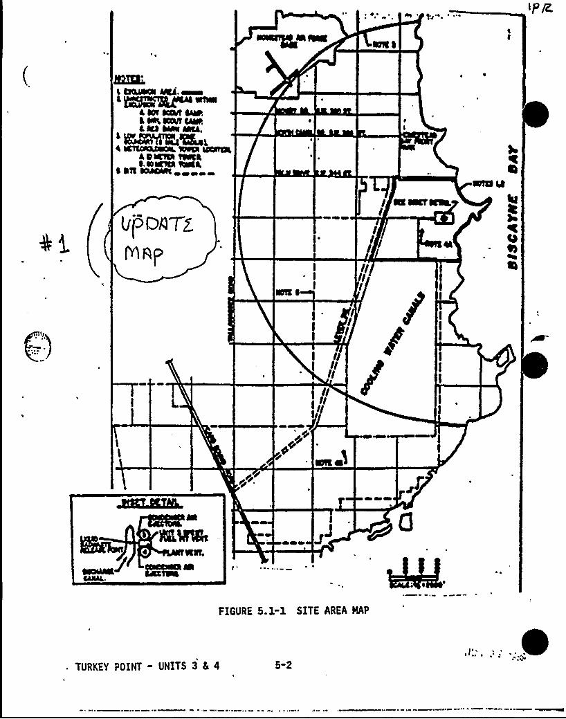
FIGURE 5.1-1 SITE AREA HAP
TURKEY POINT - UNITS 3 5 4 5-2
DESIGN FEATURES
5. 3 REACTOR CORE
FUEL ASSEMBLIES
speci ic relcrrg o r . i q-1
.',ejlP~r".if.'n',
/age gal I bing] 'f ~pi Si <~~KVL'l Q") ig, . s, ' Qg ) ])gp.corbi ~ m; cicu. AoQ <Teei. o( h/ '!'r i rccY'hJ s) <" t 'y'rnf'Q [p, gggI
Omit /PIC-sy-. 'eJ
5.3.1 The core shall contain 157 fuel assam ies with each fuel assembly nomnoll]containing 204 fuel rods clad with Zircaloy-4 The reactor core containsapproximately 71 metric tons of uranium in t form of natural or slightlyenriched uranium dioxide pellets. Each fuel rod shall have a nominal activefuel length of 144 inches. 4
CONTROL ROD ASSEMBLIES
5.3.2 The core shall contain 45 full-length control rod assemblies. Thefull-length control rod assemblies shall contain a nominal 142 inches ofabsorber material. The absorber material shall be silver, in ium, andcadmium. All control rods shall be ad withstainless steel tubing.
5.4 REACTOR COOLANT SYSTEMI ~
DESIGN PRESSURE AND TEMPERATURE
q p ection 4. 1 ofthe FSAR, with allowance for normal degradation pursuant to theapplicable Surveillance Requirements,
b. For a pressure of 2485 psig, and
c. For a temperature of 650 F, except for the pressurizer which is6800F.
5.4. 1 The Reactor Coolant System is designed and shall be maintained:
a. In accordance with the Code re uirements s ecified in S
VOLUME
5.4.2 The nominal water and steam volume of the Reactor Coolant System is9343 cubic feet at a nominal T „ of 574.2 F.
5. 5 METEOROLOGICAL TOWER LOCATION
5.5.1 The meteorological towers shall be located as shown on Figure 5.1-1.
!~!/ ~
i
wr'
URKEY POINT UNITS 3 g 4 5 3L
DESIGN FEATURES
5.6 FUEL STORAGE
5. 6. 1 CRITICALITY.
5.6.1.1 The spent fuel storage racks are designe to provide safestorage of fuel assemblies by providing suffic t center-to-centera combination of spacing and poison and shall maintained with:
subcriticalspacing or
a. A k ff equivalent to less than or equal to 0.95 when flooded witheffunborated water, which includes a conservative allowance of 2.55Xhk/k for uncertainties for single region spent fuel storage racks.
b. A k f equivalent to less than or equal to 0.95 when flooded withunb3rfted water, which includes a conservative allowance in region 1of 2.66K hk/k ance in region 2 of 2.94K 4k/k for uncertainties for tworegion fuel storage racks.
c. A nominal 13.7 inch center-to-center distance between fuel assem-blies placed in the single-region storage racks. A nominal 10.6inch center-to center distance for Region 1 and 9.0 inch center-to-center distance for Region 2 for two region fuel storage racks.
d. Fuel assemblies stored in the single-region spent fuel storage racksshall contain no more than 4.1 weight percent of U-235.
e. After installation, of the two-region high density spent fuel storageracks, the maximum enrichment loading for fuel assemblies is 4.5weight percent of U-235.
5.6.1.2 The racks for new fuel storage are designed to store fuel in a safesubcritical array and shall be maintained with:
a. A nominal 21 inch center-to-center spacing to assure k ff equal toor less than 0.98 for optimum moderation conditions and equal to orless than 0.95 for fully flooded conditions.
b. Fuel assemblies placed in the New Fuel Storage brea shall contain nomore than 4.5 weight percent of U-235.
TURKEY POINT - UNITS 3 & 4
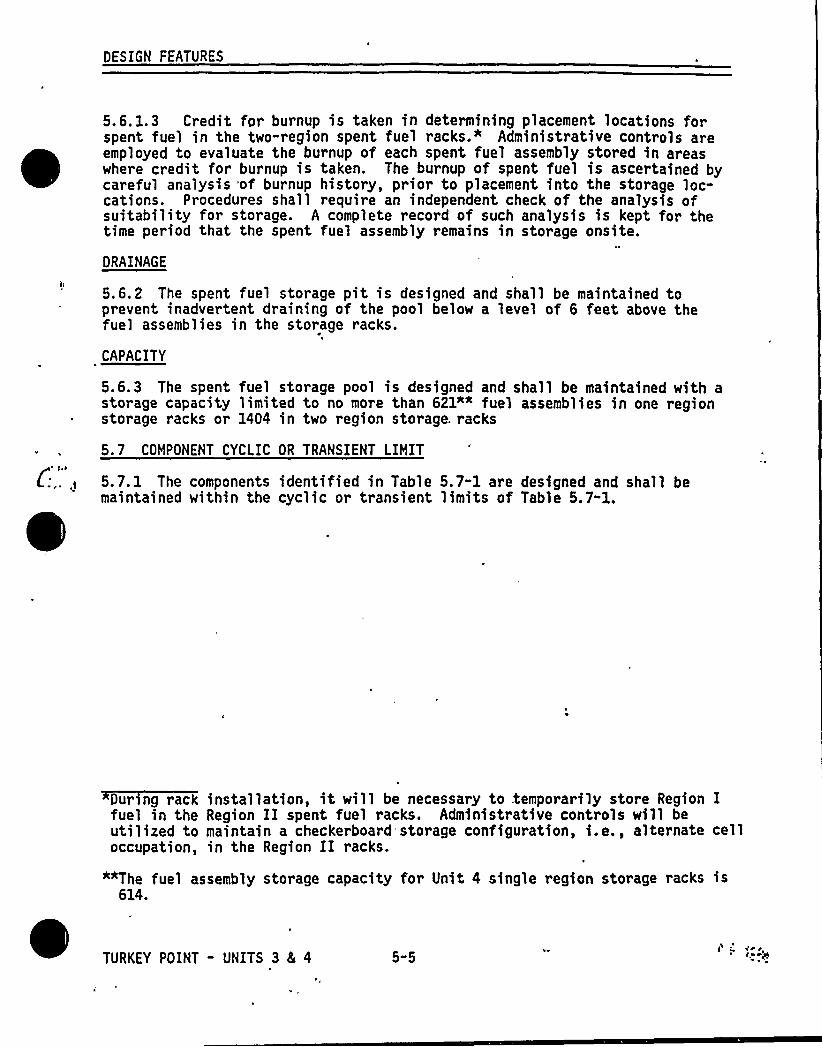
DESIGN FEATURES
5.6.1.3 Credit for burnup is taken in determining placement locations forspent fuel in the two-region spent fuel racks." Administrative controls areemployed to evaluate the burnup of each spent fuel assembly stored in areaswhere credit for burnup is taken. The burnup of spent fuel is ascertained bycareful analysis of burnup history, prior to placement into the storage loc-cations. Procedures shall require an independent check of the analysis ofsuitability for storage. A complete record of such analysis is kept for thetime period that the spent fuel assembly remains in storage onsite.
DRAINAGE
5.6.2 The spent fuel storage pit is designed and shall be maintained toprevent inadvertent draining of the pool below a level of 6 feet above thefuel assemblies in the storage racks.
CAPACITY
5.6.3 The spent fuel storage pool is designed and shall be maintained with astorage capacity limited to no more than 621"" fuel assemblies in one regionstorage racks or 1404 in two region storage. racks
5.7 COMPONENT CYCLIC OR TRANSIENT LIMIT
5.7.1 The components identified in Table 5.7-1 are designed and shall bemaintained within the cyclic or transient limits of Table 5.7-1.
During rack installation, it will be necessary to .temporarily store Region Ifuel in the Region II spent fuel racks. Administrative controls will beutilized to maintain a checkerboard storage configuration, i.e., alternate celloccupation, in the Region II racks.
""The fuel assembly storage capacity for Unit 4 single region storage racks is614.
TURKEY POINT - UNITS 3 4 4 5"5
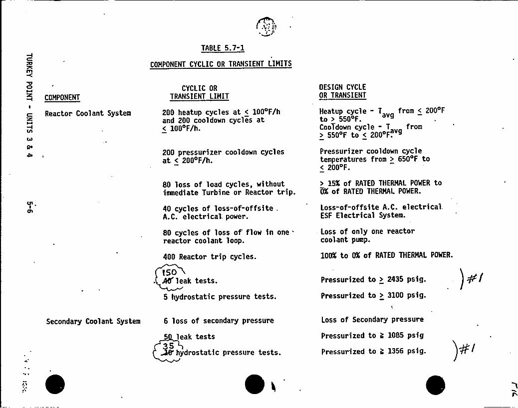
~ l~rTABLE 5.7-1
COMPONENT CYCLIC OR TRANSIENT LIMITS
ClMCOMPONENT
I
Reactor Coolant System
CYCLIC OR
TRANSIENT LIMIT
200 heatup cycles at < 1004F/hand 200 cooldown cycles at< 100 F/h.
200 pressurizer cooldown cyclesat < 2004F/h.
80 loss of load cycles, withoutimmediate Turbine or Reactor trip.
40 cycles of loss-of-offsite .
A.C. electrical. power.
80 cycles of loss of flow in onereactor coolant loop.
400 Reactor trip cycles.
f50AO'eak tests.
5 hydrostatic pressure tests.
DESIGN CYCLEOR TRANSIENT
Heatup cycle - T from < 200 F
to > 550 F
CooTdown cycle - T from> 550'F to < 200 F.
Pressurizer cooldown cycletemperatures from > 6504F to< 200 F.
> 15X of RATED THERMAL POWER toOX of RATED THERMAL POWER.
Loss-of-offsite A.C. electrical.ESF Electrical System.
- Loss of only one reactorcoolant pump.
100X to OX of RATED THERMAL POWER.
Pressurized to > 2435 psig.
Pressurized to > 3100 psig.
Secondary Coolant System 6 loss of secondary pressure
5 leak tests3S~ hydr ostatic pressure tests.
Loss of Secondary pressure
Pressurized to ?; 1085 psig
Pressurized to g 1356 psig.
- ~
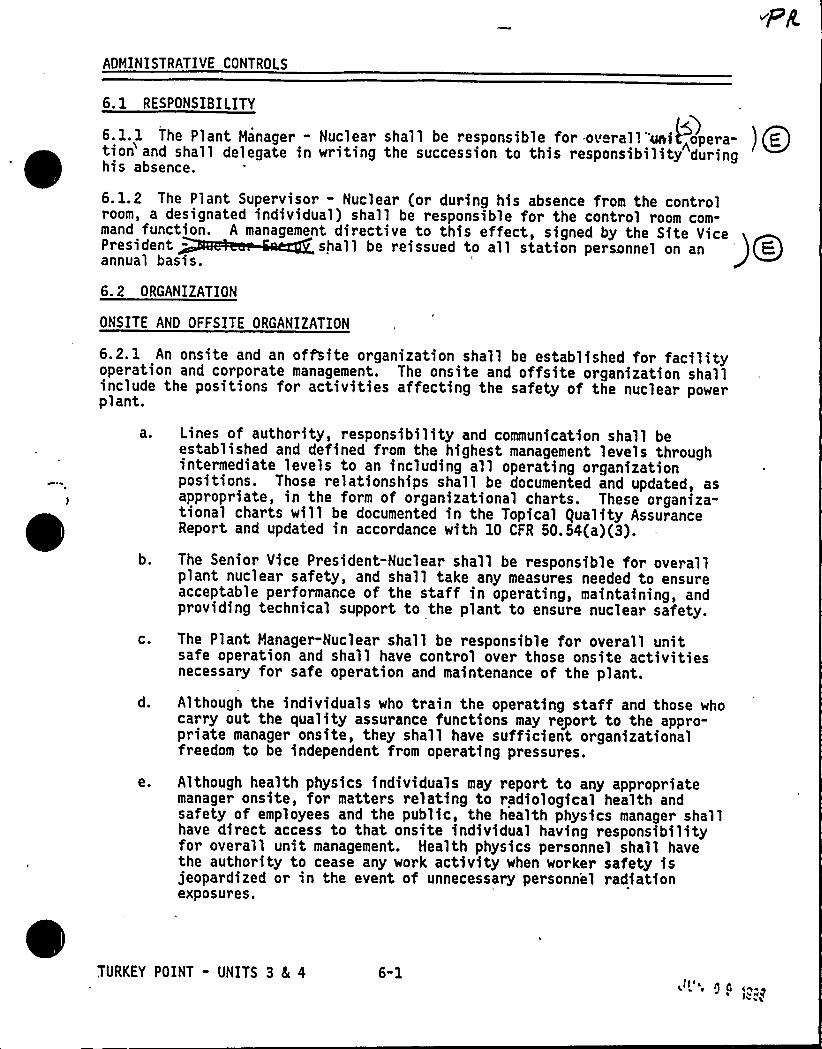
ADMINISTRATIVE CONTROLS
6. 1 RESPONSIBILITY
6. 1. 1 The Plant Manager - Nuclear shail be responsibie for or roll"unit opera- ) QEtion and shall delegate in writing the succession to this responsibility duringhis absence.
6. 1.2 The Plant Supervisor - Nuclear (or during his absence from the controlroom, a designated individual) shall be responsible for the control room com-mand function. A management directive to this effect, signed by the Site VicePresident shall be reissued to ail station personnel on anannual basis.
6. 2 ORGANIZATION
ONSITE AND OFFSITE ORGANIZATION
6.2.1 An onsite and an offsite organization shall be established for facilityoperation and corporate management. The onsite and offsite organization shallinclude the positions for activities affecting the safety of the nuclear powerpl ant.
a ~
b.
C.
d.
e.
Lines of authority, responsibility and communication shall beestablished and defined from the highest management levels throughintermediate levels to an including all operating organizationpositions. Those relationships shall be documented and updated, asappropriate, in the form of organizational charts. These organiza-tional charts will be documented in the Topical guality AssuranceReport and updated in accordance with 10 CFR 50.54(a)(3).
The Senior Vice President-Nuclear shall be responsible for overallplant nuclear safety, and shall take any measures needed to ensureacceptable performance of the staff in operating, maintaining, andproviding technical support to the plant to ensure nuclear safety.
The Plant Manager-Nuclear shall be responsible for overall unitsafe operation and shall have control over those onsite activitiesnecessary for safe operation and maintenance of the plant.
Although the individuals who train the operating staff and those whocarry out the quality assurance functions may report to the appro-priate manager onsite, they shall have sufficient organizationalfreedom to be independent from operating pressures.
Although health physics individuals may report to any appropriatemanager onsite, for matters relating to radiological health andsafety of employees and the public, the health physics manager shallhave direct access to that onsite individual having responsibilityfor overall unit management. Health physics personnel shall havethe authority to cease any work activity when worker safety isjeopardized or in the event of unnecessary personnel radiationexposures.
TURKEY POINT - UNITS 3 8E 4 6"1t s g fin's
i% K

ADMINISTRATIVE CONTROLS
FhciLiTy~ET- STAFF
3~46.2.2 The ~ rganization shall be subject to the following:
a. ach on-duty shift shall be composed of at least the minimum shiftcrew composition shown in Table 6.2-1;
b. At least one licensed Operator shall be in the control room whenfuel is in the reactor.
c. At least two licensed Operators shall be present in the control roomduring reactor startup, scheduled reactor shutdown and duringrecovery from reactor trips. In addition, while the unit is inMODE 1; 2, 3, or 4, at least one licensed Senior Operator shall bein the control room;
d. A Health Physics Technician* shall be on site when fuel is in thereactor;
e. All CORE ALTERATIONS shall be observed and directly supervised byeither a licensed Senior Operator or. licensed Senior Operator Limitedto Fuel Handling who has no other concurrent responsibilities duringthis operation;
9.
A site Fire Brigade of at least five members" shall be maintained onsite at all times. The Fire Brigade shall not include the ShiftSupervisor and the two other members of the minimum shift crewnecessary for safe shutdown of the unit and any personnel requiredfor other essential functions d a fire emergency; and
Cs)Administrative procedures shall developed and implemented tolimit the working hours of unit staff who perform safety-related ) 'CEEIfunctions (e.g., licensed Senior Operators, licensed Operators,health physicists, auxiliary operators, and key maintenance personnel).
or
Adequate shift coverage shall be maintained without routine heavyuse of overtime. The objective shall be to have. operating personnelwork a normal 8-hour day, 40-hour week while the unit is operating.However, in the event that unforeseen problems require substantialamounts of overtime to be used, or dur ing extended periods of shut-down for refueling, major maintenance, or major plant modification,on a temporary basis the following guidelines shall be followed:
The Health Physics Technician and Fire Brigade composition may be less thanthe minimum requirements for a period of time not to exceed 2 hours, in orderto accommodate unexpected absence, provided immediate action is taken to fillthe required positions.
TURKEY POINT - UNITS 3 8E 4 6-2 ~ ~
~ w se'
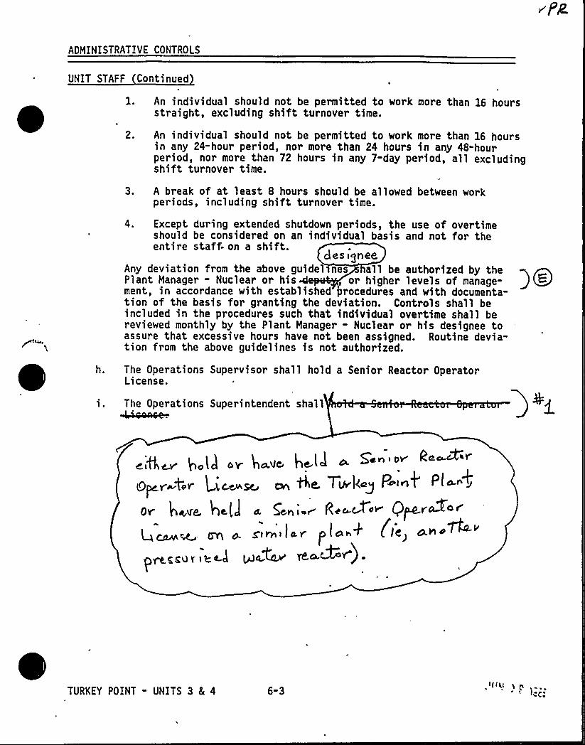
ADMINISTRATIVE CONTROLS
UNIT STAFF Continued
l. An individual should not be permitted to work more than 16 hoursstraight, excluding shift turnover time.
2. An individual should not be permitted to work more than 16 hoursin any 24-hour period, nor more than 24 hours in any 48-hourperiod, nor more than 72 hours in any 7-day period, all excludingshift turnover time.
3. A break of at least 8 hours should be allowed between workperiods, including shift turnover time.
4. Except during extended shutdown periods, the use of overtimeshould be considered on an individual basis and not for theentire staff- on a shift.
des agnesAny deviation from the above guidelsnes all be authorized by thePlant Manager - Nuclear or his, or higher levels of manage-ment, in accordance with established procedures and with documenta-tion of the basis for granting the deviation. Controls shall beincluded in the procedures such that individual overtime shall bereviewed monthly by the Plant Manager - Nuclear or his designee toassure that excessive hours have not been assigned. Routine devia-tion from the above guidelines is not authorized.
h. The Operations Supervisor shall hold a Senior Reactor OperatorLicense.
i. The Operations Superintendent shall
.;e, g.ll ~ 4-.- h-l~ - s'-"g~,g, Q; th Tul<gP ~ Pl
ov i@ave. he[I a Gni r Rc~~<~ Q~v~4<gt~i(ay. (~~+ < IC>
p~gLV I I't~l lk)OM ~~~ )
TURKEY POINT - UNITS 3 8( 4 6-3

TABLE 6.2-1
MINIMUM SHIFT CREW COMPOSITION
POSITION NUMBER OF INDIVIDUALS REQUIRED TO FILL POSITION
BOTH UNITS INMODE 1; 2, 3,
or 4
BOTH UNITS INMODE 5 or 6OR DEFUELED
ONE UNIT IN MODE 1, 2, 3, or 4AND
ONE UNIT IN MODE 5 or 6 or DEFUELED
PSN
SRO none""
RO
AO
3'4
3*
STA none
PSN - Plant Supervisor Nuclear with a Senior Operator licenseSRO - Individual with a Senior Operator license
RO - Individual with an Operator licenseAO - Auxiliary Operator
STA - Shift Technical Advisor
The shift crew composition may be one less than the minimum requirements ofTable 6.2-1 for a period of time not to exceed 2 hours in order to accommodateunexpected absence of on-duty shi 't crew members provided immediate action istaken to restore the shift crew composition to within the minimum requirementsof Table 6.2-1. This provision does not permit any shift crew position to beunmanned upon shift change due to an oncoming shift crewman being late or absent.
During any absence of the Plant Supervisor Nuclear from the control room whilea unit is in MODE 1, 2, 3, or 4, an individual (other than the Shift TechnicalAdvisor) with a valid Senior Operator license shall be designated to assumethe control room command function. During any absence of the Plant SupervisorNuclear from the control room while both units are in MODE 5 or 6, an indi-vidual with a valid Senior Operator license or Operator license shall bedesignated to assume the control room command function.
At east one of the required individuals must be assigned to the designatedposition for each unit.
""At least one licensed Senior Operator or licensed Senior Operator Limitedto Fuel Handling must be present during CORE ALTERATIONS on either unit,who has no other concurrent responsibilities.
*""The STA position shall be manned in MODES 1, 2, 3, and 4 unless the PlantSupervisor Nuclear or the individual with a Senior Operator license meetsthe qualifications for the STA as required by the NRC.
TURKEY POINT - UNITS 3 5 4 6-4 ,ftlgI CQQ
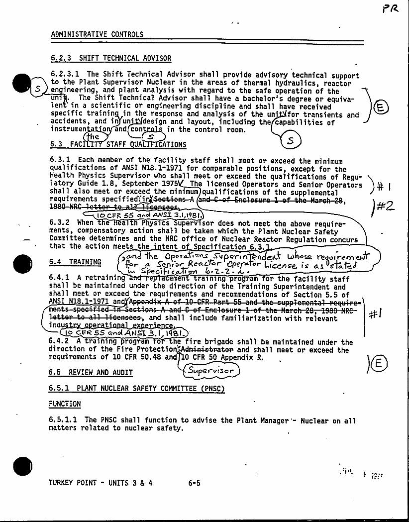
ADMINISTRATIVE CONTROLS
6. 2. 3 SHIFT TECHNICAL ADVISOR
6.2.3.1 The Shift Technical Advisor shall provide advisory technical supportto the Plant Supervisor Nuclear in the areas of thermal hydraulics, reactoren ineering, and plant analysis with regard to the safe operation of theun' The Shift Technical Advisor shall have a bachelor's degree or equiva-len in a scientific or engineering discipline and shall have receivedspecific trainin in the response and analysis of the uni for transients andaccidents, and in un'esign and layout, including the capabilities ofinstrumen 'o and cont ~ in the control room.
S'.
3 FAC STAFF UAL CATIONS
6 .3.1 Each member of the facility staff shall meet or exceed the minimumqualifications of ANSI N18.1-1971 for comparable positions, except for theHealth Physics Supervisor Who shall meet or exceed the qualifications of Regu-latory Guide 1.8, September 1975 The licensed Operators and Senior Operatorsshall also meet or exceed the minimum qualifications of the supplementalifi d'1
i ccFR 55 gnoi <NSX 3, I l98 t.6.3.2 When e ea Physics Superv sor does not meet the above require-ments, compensatory action shall be taken which the Plant Nuclear SafetyCommittee determines and the NRC office of Nuclear Reactor Regulation concursthat the action meets the 'ent o S ecification 6.3
)o.n Qe, Oper~~<~ Svporingeq ~k whoa@ re~oir<rrieP6.4 TRAINING Par A Senior- gea.8c r Qper~tor t i<cnre. is a.s "st~f~JCpLc,i/i cgdlayl 4 2 Z A ~
6.4.1 A retraining em n ra>ning pro ram or the facility staffshall be maintained under the direction of the Training Superintendent andshall meet or exceed the requirements and recommendations of Section 5.5 ofANSI N18.1-1971 an Amen4s-
, and shall include familiarization with relevant ylindu t r
io cue 55 ~~el RASE Z. I, tq8 t.'.
4. 2 A ra n ng program o e fire brigade shall be maintained under thedi 1 f h Fi P 1 "~ d I 11 d hrequirements of 10 CFR 50.48 and 0 CFR 50 Appendix R.
IQe6.5 REVIEW AND AUDIT Super viSor
6.5. 1 PLANT NUCLEAR SAFETY COMMITTEE PNSC
FUNCTION
6.5. l. 1 The PNSC shall function to advise the Plant Manager '- Nuclear on allmatters related to nuclear safety.
TURKEY POINT - UNITS 3 8( 4 6-5
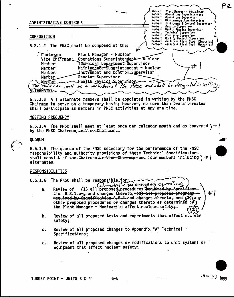
ADMINISTRATIVE CONTROLS
COMPOSITION
6.5.1e2 The PNSC .shall be composed of the:
Member:Member:Henber:Hehber:Henber:Henber:Hehber:Heaber:Mehber:Henber:Menber:Hectber:
Plant Hana9er Ntac (~rOperat1ons Super1ntendentOperations Superv1sorMaintenance Super intendantlnstrugient C Control SupervisorReactor Superv1sorHealth Physics SupervisorTechn1cal SupervisorChenistry SupervisorQuality Control SupervisorAssistant Plant Supt. ElectricalAss1stant Plant Supt. Mechanical
Pa
an:Vice ChaiMember:Member:Member:Member:
r:Tllf'hiis'ada gism (]
Plant Manager - NuclearOperations Superintend uclear
al Depar SupervisorHainte rintendent - Nuclear
rument and Con u ervisorReactor Supervisor
Ph s e or~4.'pypg~ < sf fp ++cQ dpgggsjja//
r/,Q @dan) sfmgvy( IPf Airfv'is)i
~/6.5.1.3 All alternate members shall be appointed in writing by the PNSC
Chairman to serve on a temporary basis; however, no more than two alternatesshall participate as members in PNSC activities at any one time.
HEETING FRE UENCY
QUORUM
~ ~ ~6. 5. 1. 5 The quorum of the PNSC necessary for the performance of the PNSC
responsibility and authority provisions of these Technical Specificationsshall consist of the. Chairman ' and four members including ) oh (alternates.
6.6. 1.4 The PMSC shall meet at least once per calendar month and as convened )dh /by the PNSC Chairman.
RESPONSIBILITIES
6.5.1.6 The PNSC shall be res s b for:„J<,„,> $'sic +HJ e<~psfCy npd'~4t~Q
a. Review of: (1) all proposegprocedures
and ~ anyother proposed procedures or changes thereto as determinfd bythe Plant Manager - Nuclear;
b. Review of all proposed tests and experiments that affect nuclearsafety;
C.
d.
Review of all proposed changes to Appendix "A" TechnicalSpecifications;
Review of all proposed changes or modifications to unit systems orequipment that affect nuclear safety;
s
TURKEY POINT - UNITS 3 8L 4'-6
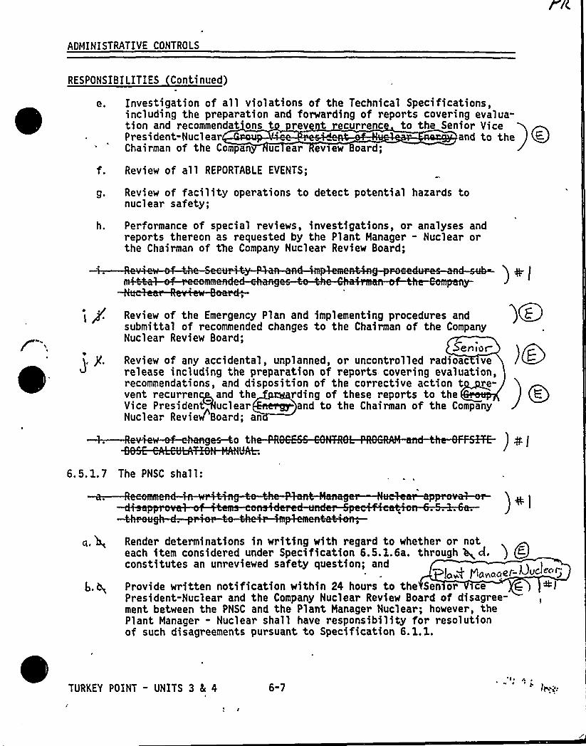
AOMINISTRATIVE CONTROLS
RESPONSIBILITIES Continued)
Investigation of all violations of the Technical Specifications,including the preparation and forwarding of reports covering evalua-tion and recommendat'ons t rev t recurre c to the Senior VicePresident-Nuclear and to theChairman of the Compan uc ear evsew oard;
f. Review of all REPORTABLE EVENTS;
g. Review of facility operations to detect potential hazards tonuclear safety;
h. Performance of special reviews, investigations, or analyses andreports thereon as requested by the Plant Manager - Nuclear orthe Chairman of the Company Nuclear Review Board;
). j(.
Review of the Emergency Plan and implementing procedures andsubmittal of recommended changes to the Chairman of the CompanyNuclear Review Board;
SeniorReview of any accidental, unplanned, or uncontrolled radioac verelease including the preparation of reports- covering evaluation,recommendations, and disposition of the corrective action t re-vent recurrent, and the rding of these reports to theVice President Auclear and to the Chairman of the CompanyNuclear Revie/Board; an
o th
)Q~
) dPI
6.5.1.7 The PNSC shall:
) ih)
Render determinations in writing with regard to whether or noteach item considered under Specification 6.5.1.6a. through Q d. i Qr-
constitutes an unreviewed safety question; andlaA'anacea- L)urea
Provide written notification within 24 hours to the Sen or ice C +lPresident-Nuclear and the Company Nuclear Review Board of disagree-ment between the PNSC and the Plant Manager Nuclear; however, thePlant Manager - Nuclear shall have responsibility for resolutionof such disagreements pursuant to Specification 6.1.1.
TURKEY POINT - UNITS 3 5 4 6"7

ADMINISTRATIVE CONTROLS
RECORDS
6.5.1.8 The PNSC shall maintain written minutes of each PNSC meeting that, ata minimum, document the results of all PNSC activities performed under theresponsibility provisions of these Technical Specifications. Copies shall be
provided to the Senior Vice President-Nuclear and the Company Nuclear Review
)+ (
A>~ Board.[AlSENT ~~
OA6 5 9 COMPANY NUCLEAR REVIEW BOARO CNRB )QE
(p 4;BA) FUNCTION
6.5. P I The CNRB shall function to provide independent review and audit of ) 06
designated activities in the areas of:
a ~
b.C.d.e.f.gh.
Nuclear power plant operations,Nuclear engineering,Chemistry and radiochemistry,Metallurgy,Instrumentation and control,Radiological safety,Mechanical and electrical engineering, andguality assurance practices.
The CNRB shall report to and advise the Executive Vice President on thoseareas of responsibility specified in Specifications 6.5. 2.7 and 6. 5. 2. 8. )„,0COMPOSITION
I
gwS6'W ... CNRB shall be composed he:
Chairman: ior Vice Pre 'dent-NuclearOIL
I t ~~ .. Vic reside ucl ear EnergyMember.Member:Member:Member:Member:Member:MembeMe r:
mber:
Vice P i nt-Engineering Project Management and ConstructionChief er Power Plant EngineeringDir r-qua y Assurance
'ctor-Nuclea icensinganager-Power Pla Engineering
Manager-Nuclear Ener ServicesManager-Nuclear FuelGroup Vice President
ALTERNATES
6.5. p3 All alternate members shall be appointed in writing by the CNRB Chairman ) QF
to serve on a temporary basis; however, no more than two alternates shallparticipate as voting members in CNRB activities at any one time.
, TURKEY POINT - UNITS 3 5 4 6-8 sI] sg
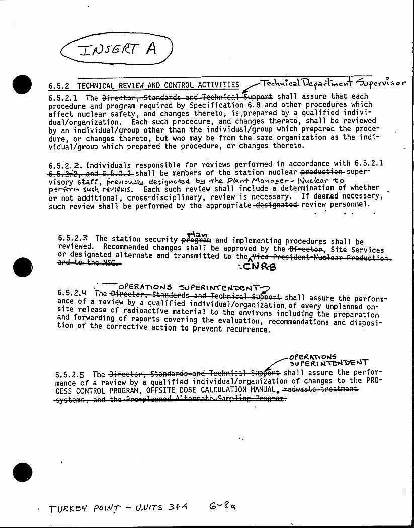
6.5.2 TECHNICAI. REYIEN AND CONTROL ACTIVITIES~Teelb».eaT l3eTaAb»e» Sfytpey'bfbeer
6. 5. 2. 1 The shall assure that eachprocedure and program required by Specification 61 8 and other procedures whichaffect nuclear safety, and changes thereto, is, prepared by a qualified indivi-dual/organization. Each such procedure, and changes thereto, shall be reviewedby an individual/group other than the individual/group which prepared the proce-dure, or changes thereto, but who may be from the same organization as the indi-vidual/group which prepared the procedure, or changes thereto.
6.5.2. 2. Individuals responsible for reviews performed in accordance with 6.5.2. 1
b b" f««f 1»»»'visory staff, prev>ouslg degignc&ct ~Q +4e Plw~+ Wa~~zer - Nuc(eaY- <Ope"&<~ such reY'le~5. Each such review shall include a determination of whetheror not additional, cross-disciplinary, review is necessary. If deemed necessary,
111 f Pby pp pf ~ 1 1
AGvl6.5.2.Z The station security ~~ and implementing procedures shall bereviewed. Recommended changes shall be approved by the ~F4~ Site Servicesor designated alternate and transmitted to the;cH As
A
OPERATiOHS ~APE.Rir4T'E.t4 aOCt4T~6. 5.2.~ Theance of a review bsite release of radioactive m
iew y a qua ified individual/organization. of every unplanned o-t 1 e material to the environs including the preparationne on-
an orwarding of reports covering the evaluation, recommendations and disposi-tion of the corrective action to prevent recurrence.
Of'GkhYE+ADA>PE<> A~<lOG<T
6.5.2.5 The ,'hall assure the perfor-
mance of a review by a qualified individual/organization of changes to the PRO-
CESS CONTROL PROGRAM, OFFSITE OOSE CALCULATION MANUAL
Tumed.V Poidr —0>n-s 34 I

j j
r ~~, .j z P <~l fP Il(f s ~ a, i M/
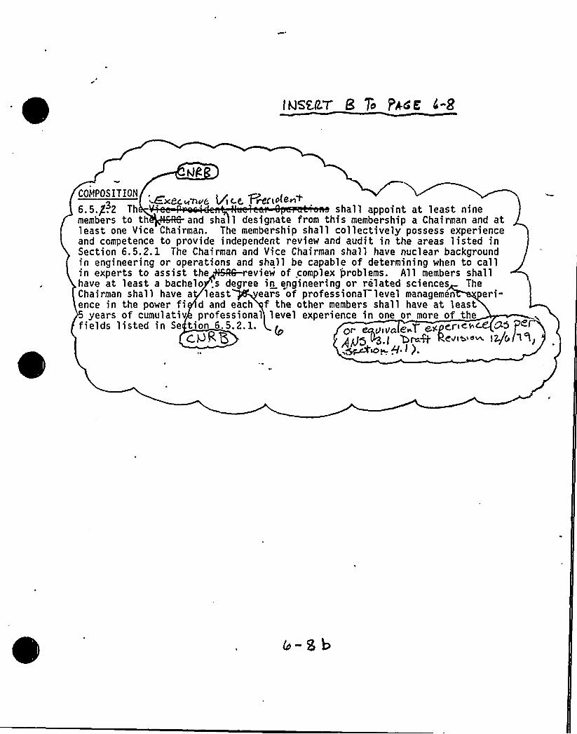
members to th and sha 1 designate from this membership a Chairman and atleast one Vice Chairman. The membership shall collectively possess experienceand competence to provide independent review and audit in the areas listed inSection 6.5.2. 1 The Chairman and Vice Chairman shall have nuclear backgroundin engineering or operations and shall be capable of determining when to callin experts to assist the ~6-review of complex 'problems. All members shallhave at least a bachelo .s degree in engineering or related sciences TheChairman shall have a least eats of professional level managemen eri-ence in the power fi d and each f the other members shall have at least
years of cumulativ professional level experience in one or more of thefields listed in Se tion 6.5,2. 1. Or yiVa 8» eX Cries aS @<I
c.<RQ . QraQ C4t»<m lg&,~uo~ 9. ~ ).

TQ < 4 PA44 l OJ7 %~i~gp~y
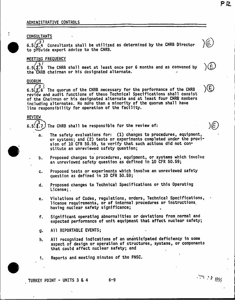
ADMINISTRATIVE CONTROLS
CONSULTANTS
~ ~~
6.5+4 Consultants shall be utilized as determined by the CNRB Director ) OF-
to provide expert advice to the CNRB.
MEETING FRE UENCY
3/6.5 g.5 The CNRB shall meet at least once per 6 months and as convened by ) QE.the RB chairman or his designated alternate.
UORUM
6.5 g.6 The quorum of the CNRB necessary for the performance of the CNRB9f
review and audit functions of these Technical Specifications shall consistof the Chairman or his designated alternate and at least four CNRB membersincluding alternates. No more than a minority of the quorum shall haveline responsibility for operation of the facility.REVIEW
3'.5.$.7 The CNRB shall be responsible for the review of:
The safety evaluations for: (I) changes to procedures, equipment,or systems; and (2) tests or experiments completed under the provi-sion of 10 CFR 50.59, to verify that such actions did not con-stitute an unreviewed safety question;
)O~
b.
C.
e.
Proposed changes to procedures, equipment, or systems which involvean unreviewed safety question as defined in 10 CFR 50.59;
Proposed tests or experiments which involve an unreviewed safetyquestion as defined in 10 CFR 50.59;
Proposed changes to Technical Specifications or this OperatingLicense; .
Violations of Codes, regulations, orders, Technical Specifications,license requireme'nts, or of internal procedures or instructions.having nuclear safety significance;
Significant operating abnormalities or deviations from normal andexpected performance of unit equipment that affect nuclear safety;
g. All REPORTABLE EVENTS;
h. All recognized indications of an unanticipated deficiency in some
aspect of design or operation of structures, systems, or componentsthat could affect nuclear safety; and
Reports and meeting minutes of the PNSC.
TURKEY POINT - UNITS 3 4 4 6-9
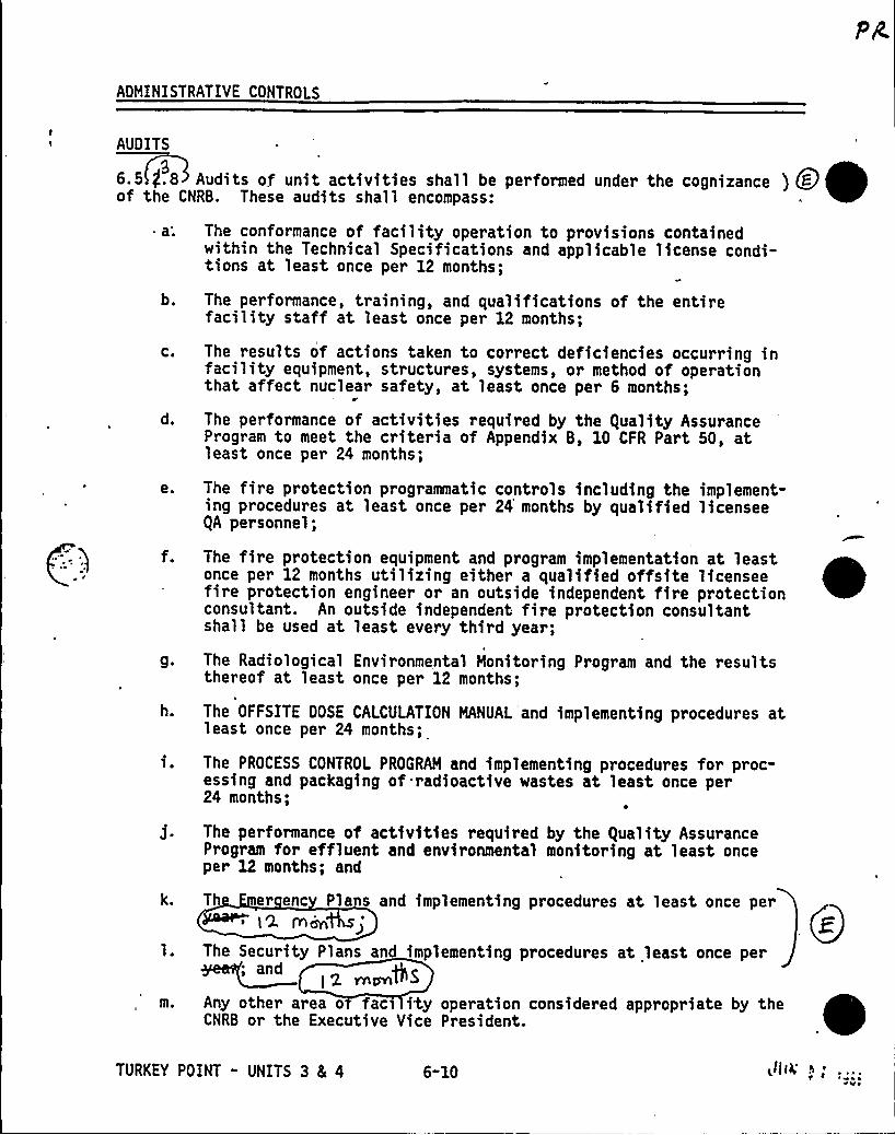
ADMINISTRATIVE CONTROLS
AUDITS
~ ~
~
~ ~36.5 $ .8 Audits of unit activities shall be per forced under the cognizance ) Qdof the CNRB. These audits shall encompass:
as
b.
C.
d.
e.
9.
h.
k.
The conformance of facility operation to provisions containedwithin the Technical Specifications and applicable license condi-tions at least once per 12 months;
The performance, training, and qualifications of the entirefacility staff at least once per 12 months;
The results of actions taken to correct deficiencies occurring infacility equipment, structures, systems, or method of operationthat affect nuclear safety, at least once per 6 months;
The performance of activities required by the guality AssuranceProgram to meet the criteria of Appendix B, 10 CFR Part 50, atleast once per 24 months;
The fire protection programmatic controls including the implement-ing procedures at least once per 24 months by qualified licenseegA personnel;
The fire protection equipment and program implementation at leastonce per 12 months utilizing either a qualified offsite licenseefire protection engineer or an outside independent fire protectionconsultant. An outside independent fire protection consultantshall be used at least every third year;
The Radiological Environmental Monitoring Program and the resultsthereof at least once per 12 months;
The OFFSITE DOSE CALCULATION MANUAL'and implementing procedures atleast once per 24 months;
The PROCESS CONTROL PROGRAM and implementing procedures for proc-essing and packaging of radioactive wastes at least once per24 months;
The performance of activities required by the guality AssuranceProgram for effluent and environmental monitoring at least onceper 12 months; and
Th er enc Plans and implementing procedures at least once per12 Kin
The Security Plans and implementing procedures at least once per@5
Any other area o fac ity operation considered appropriate by theCNRB or the Executive Vice President.
TURKEY POINT - UNITS 3 & 4 6-10 ~l((4'Vo
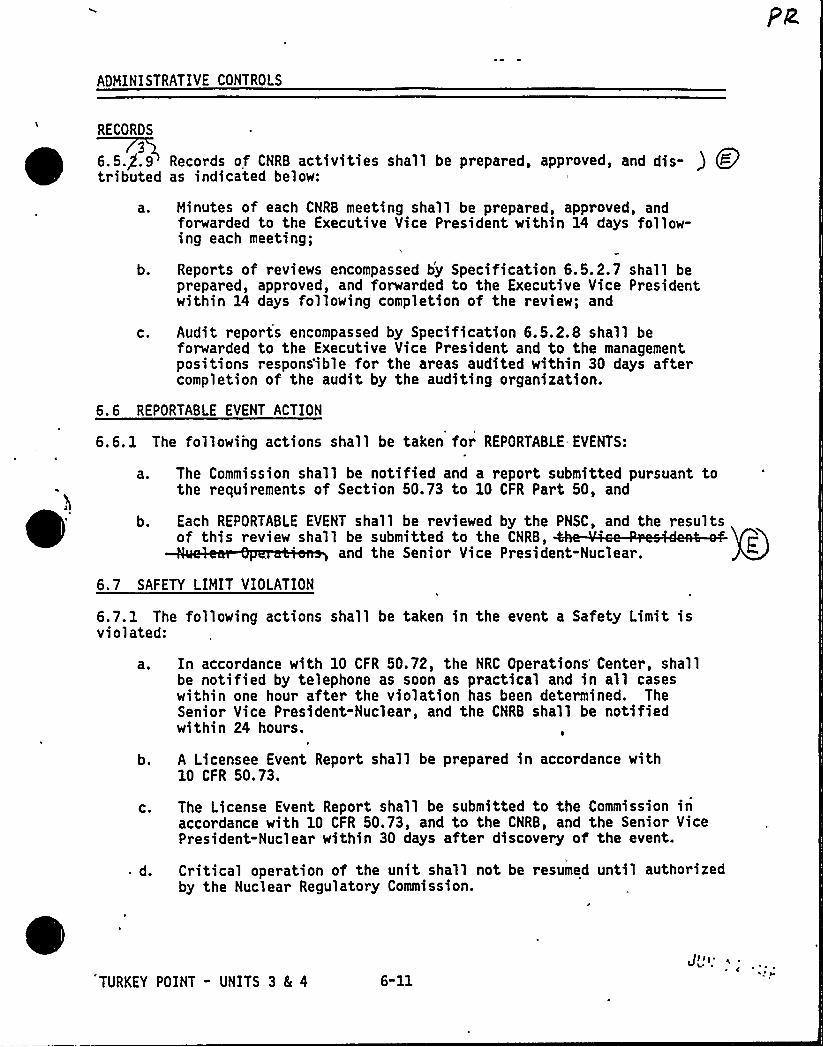
ADMINISTRATIVE CONTROLS
RECORDS
~~
~ ~~ ~
~ ~ ~9
6.5.$ .9 Records of CNRB activities shall be prepared, approved, aod dis- ) Q@
tributed as indicated below:
a. Minutes of each CNRB meeting shall be prepared, approved, andforwarded to the Executive Vice President within 14 days follow-ing each meeting;
b. Reports of reviews encompassed by Specification 6.5.2.7 shall beprepared, approved, and forwarded to the Executive Vice Presidentwithin 14 days following completion of the review; and
C. Audit reports encompassed by Specification 6.5.2e8 shall beforwarded to the Executive Vice President and to the managementpositions respons'ible for the areas audited within 30 days aftercompletion of the audit by the auditing organization.
0
6.6 REPORTABLE EVENT ACTION
6.6. 1 The following actions shall be taken for REPORTABLE. EVENTS:
a. The Commission shall be notified and a report submitted pursuant tothe requirements of Section 50.73 to 10 CFR Part 50, and
b. Each REPORTABLE EVENT shall be reviewed by the PNSC, and the resultsof this review shall be submitted to the CNRB,
and the Senior Vice President-Nuclear. GE
6.7 SAFETY LIMIT VIOLATION
6.7.1 The following actions shall be taken in the event a Safety Limit isviolated:
a. In accordance with 10 CFR 50.72, the NRC Operations'enter, shallbe notified by telephone as soon as practical and in all caseswithin one hour after the violation has been determined. TheSenior Vice President-Nuclear, and the CNRB shall be notifiedwithin 24 hours.
b. A Licensee Event Report shall be prepared in accordance with10 CFR 50.73.
c. The License Event Report shall be submitted to the Commission inaccordance with 10 CFR 50.73, and to the CNRB, and the Senio~ VicePresident-Nuclear within 30 days after discovery of the event.
d. Critical operation of the unit shall not be resumed until authorizedby the Nuclear Regulatory Commission.
TURKEY POINT " UNITS 3 8( 4 6"11
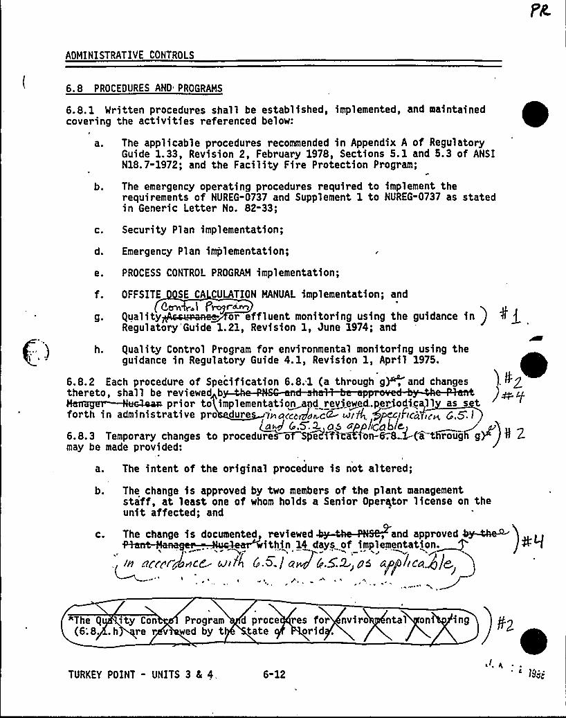
ADMINISTRATIVE CONTROLS
6.8 PROCEDURES AND PROGRAMS
6.8. 1 Written procedures shall be established, implemented, and maintainedcovering the activities referenced below:
a ~
b.
The applicable procedures recommended in Appendix A of RegulatoryGuide 1. 33, Revision 2, February 1978, Sections 5. 1 and 5. 3 of ANSIN18.7-1972; and the Facility Fire Protection Program;
The emergency operating procedures required to implement therequirements of NUREG-0737 and Supplement I to NUREG-0737 as statedin Generic Letter No. 82-33;
c. Security Plan implementation;
d. Emer gency Plan implementation;
e. PROCESS CONTROL PROGRAM implementation;
f. OFFSITE SE CA CULATION MANUAL implementation; andBeen .l P~r~
g. guality or effluent monitoring using the guidance inRegulatory Guide 1.21, Revision 1, June 1974; and
(.) h. guality Control Program for environmental monitoring using theguidance in Regulatory Guide 4. 1, Revision 1, April 1975.
6.8.2 Each procedure of Specification 6.8.1 (a through g), and changesthereto, shall be reviewed b
pi i i,i . iforth in administrative pro dure inarcogar.ciZ turk pcciFird,r~ r,,5: I'n4 (.5.2. as appliCa6lc6.&.3 Temporary changes to procedures o Me iftc'Stion-&.& 6(a tlirough g) ) 9 Zmay be made provided:
a. The intent of the original procedure is not altered;
b. The change is approved by two members of the plant managementstaff, at least one of whom holds a Senior Operator license on theunit affected; and
c. The change is documented, reviewed , and approved &y-tissuithin 14 days of implementation~
;, in iirrrrgncr aria r 5l a+5 5:2.,, pd appl.(eagle
The g sty Con Program(6;8. .h re r vs wed by t d proce res for nviro ntal oni ing
tate orid .
TURKEY POINT - UNITS 3 4 4, 6-12
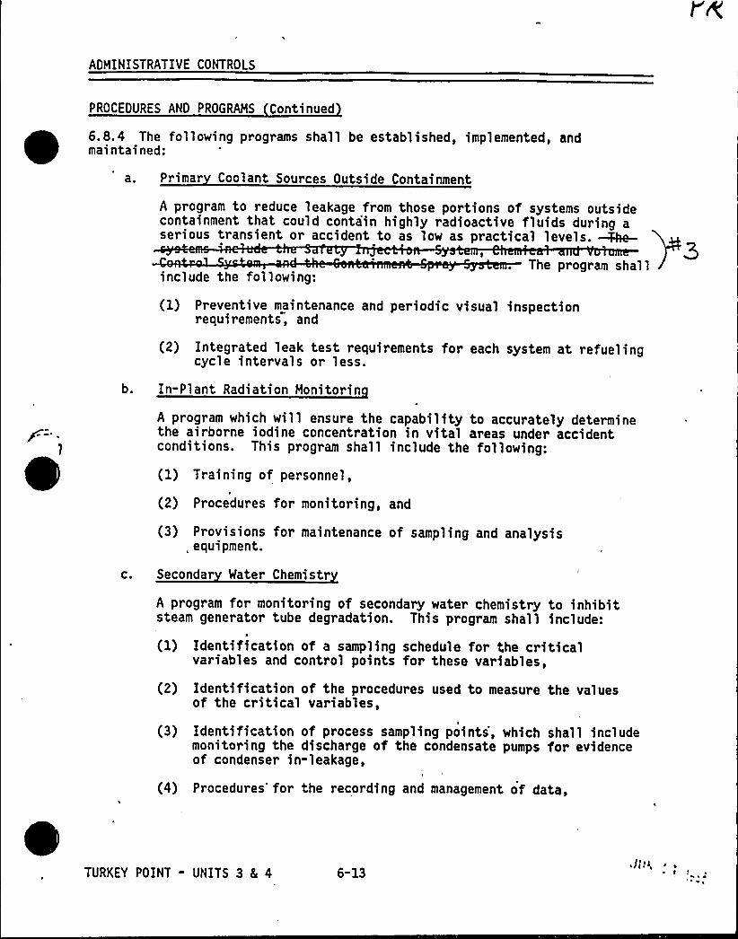
ADHINISTRATIVE CONTROLS
PROCEOURES ANO PROGRAMS Continuedt 6.8.4 The following programs shall be established, implemented, andmaintained:
a. Primar Coolant Sources Outside Containment
A program to reduce leakage from those portions of systems outsidecontainment that could contain highly radioactive fluids during aserious transient or accident to as low as practical levels. Mhe-
The program shallinclude the following:
(1) Preventive maintenance and periodic visual inspectionrequirements, and
(2) Integrated leak test requirements for each system at refuelingcycle intervals or less.
b. In-Plant Radiation Monitorin
C.
A program which will ensure the capability to accurately determinethe airborne iodine concentration in vital areas under accidentconditions. This program shall include the following:
(1) Training of personnel,
(2) Procedures for monitoring, and
(3) Provisions for maintenance of sampling and analysis, equipment.
Secondar Water Chemistr
A program for monitoring of secondary water chemistry to inhibitsteam generator tube degradation. This program shall include:
(1) Identification of a sampling schedule for the criticalvariables and control points for these variables,
(2) Identification of the procedures used to measure the valuesof the critical variables,
(3) Identification of process sampling points, which shall includemonitoring the discharge of the condensate pumps for evidenceof condenser in-leakage,
I
(4) Procedures'for the recording and management of data,
TURKEY POINT - UNITS 3 8L 4 6-13
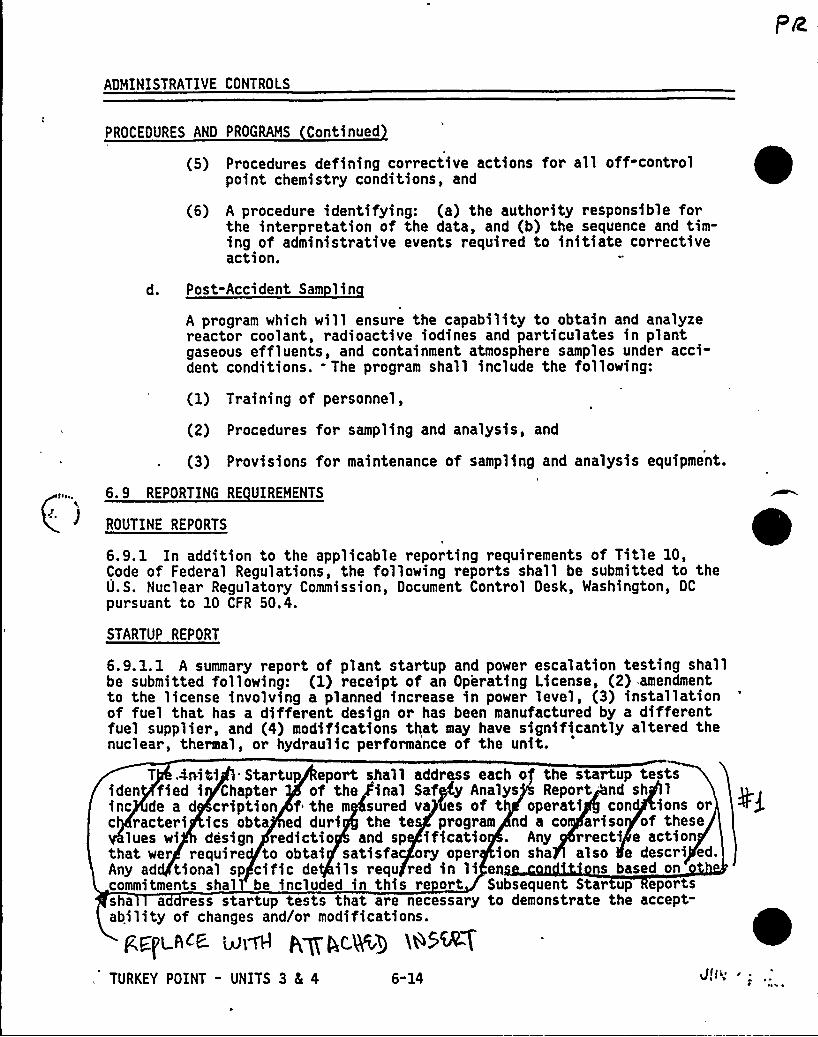
ADMINISTRATIVE CONTROLS
PROCEDURES AND PROGRAMS Continued
(5) Procedures defining corrective actions for all off-controlpoint chemistry conditions, and
(6) A procedure identifying: (a) the authority responsible forthe interpretation of the data, and (b) the sequence and tim-ing of administrative events required to initiate correctiveaction.
d. Post-Accident Sam linA program which will ensure the capability to obtain and analyzereactor coolant, radioactive iodines and particulates in plantgaseous effluents, and containment atmosphere samples under acci-dent conditions. - The program shall include the following:
(1) Training of personnel,
(2) Procedures for sampling and analysis, and
(3) Provisions for maintenance of sampling and analysis equipment.
6.9 REPORTING RE UIREMENTS
) ROUTINE REPORTS
6.9.1 In addition to the applicable reporting requirements of Title 10,Code of Federal Regulations, the following reports shall be submitted to theU.S. Nuclear Regulatory Commission, Document Control Desk, Washington, DC
pursuant to 10 CFR 50.4.
STARTUP REPORT
p,E~ch~e unH p,~p,c,ling W5%7TURKEY POINT - UNITS 3 4 4 6-14 Jl]is r
6.9.1.1 A summary report of plant startup and power escalation testing shallbe submitted following: (1) receipt of an Operating License, (2) amendmentto the license involving a planned increase in power level, (3) installationof fuel that has a different design or has been manufactured by a differentfuel supplier, and (4) modifications that may have significantly altered thenuclear, theraal, or hydraulic performance of the unit.
T .4niQ -. Startup eport squall addr s each of the startup testsiden fied i Chapter of the inal Saf y Analys Report nd sh 1
inc de a d cription f the m sured va es of t operati con ions orc racteri ics obta ed duri the te program nd a co ariso of these
ives wi design redictio and sp ificatio . Any rrecti e actionthat wer require to obtai satisfa ory oper ion sha also e descri ed.Any ad tional sp cific de ils requ red in li en ns based oncommitments shal be inclu ed in this re ort Subsequent Star up eportssha a ress startup tests that are necessary to demonstrate the accept-ability of changes and/or modifications. 0
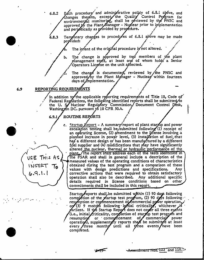
6.9
fch procedure~and admin'ative pol' of 6e8.1 a "ve, and
changes the@ho, excep the Qualit Control Fr gram forenvironmen I monitori, shall be viewed by t PNSC andapproved the Plant anager - Nu ear prior to i plementationand per'ically as ovided by pr dure.
6.8.3 Te orary chases to proced es of 6.8.1 Jove may be madepr ided:
IThe intent of the ori 'lprocedure is not altered.
b. The change is a proved by twa members of the plant
~Operators Lic se on the unit Pouted.
anagement st f, at least one of whom holg a Senior
<c. The chan is documente,'eviewed by, the PNSC andapproved y the Plant M ager - Nuclea within fourteendays of plementation.
REPOR G RE UIRE NTS
the FSAR and shall in general include a description of themeasured values of the operating conditions of characteristicsobtained during the test program and a comparison of thesevalues with design predictions and specifications. Anycorrective actions that were required to obtain satisfactoryoperation shall also be described. Any additional specificdetails required in license conditions based on othercommitments shall be included in this re ort.
l h35%AT
g.9.l. I
g In addition t the applicable reporting requirements of Title 10, Code oXl.
Federal Re lations, the foll ding identified reports shall be submittePothe U. Nuclear Regul ory Commission ~ Document Control sk,Washin 'n DC. pursuant t 10 CFR 50.0.
6.9.1 ROUTINE RE RTS
a. 5tartu e ort - A summaryreport of plant star p and powerescalap on testing shall be<'submitted followin (1) receipt ofan op6rating license, (2) amendment to the 'nse involving aplanned increase in power level, (3) insta tion of fuel:thatha/a different design or has been manuf tured by a differentfidel supplier and (0) modifications that ay have significantlyaltered he nuclear, thermal'or h drau ic'rformance of the
la The repor s a a ress eac o t e tests > en i ie >n
u~E, YH«A~
Startup eports shall be submitted w hin (I') 90 da followingcomp tion of. the artup test pro am, (2) 90 d s following.res ption or co mencement o ommercial p er operation ~'o (3) 9 mon s following i ial criticali, whichever~if .
arliest. If t Startup Rep does not co r all three e ~ts(i.e., initial riticality, co etion of star p test progr andresumpti or 'orn cement of commerci poweroperati, supplement y reports sh be submit d at leastever y three month until all ree events have beencomp eted.
and ~~
~ '5 pi Cj P ) v V 8' V gr, i~", Ifj)
a'>nr r(
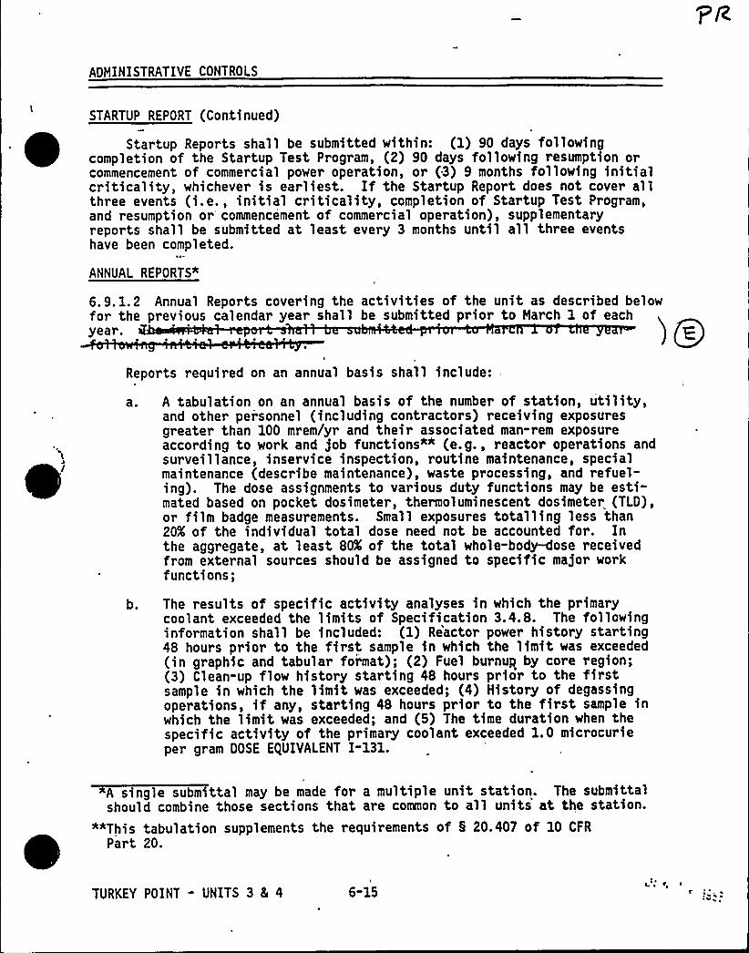
ADMINISTRATIVE CONTROLS
STARTUP REPORT (Continued)
Startup Reports shall be submitted within: (1) 90 days followingcompletion of the Star tup Test Program, (2) 90 days following resumption orcommencement of commercial power operation, or (3) 9 months following initialcriticality, whichever is earliest. If the Startup Report does not cover allthree events (i.e., initial criticality, completion of Startup Test Program,and resumption or'ommencement of commercial operation), supplementaryreports shall be submitted at least every 3 months until all three eventshave been completed.
ANNUAL REPORTS"
6.9. 1.2 Annual Reports covering the activities of the unit as described belowfor the previous calendar year shall be submitted prior to March 1 of eachyear.
Reports required on an annual basis shall include:
'
~ A tabulation on an annual basis of the number of station, utility,and other personnel (including contractors) receiving exposuresgreater than 100 mrem/yr and their associated man-rem exposureaccording to work and job functions"" (e.g., reactor operations andsurveillance, inservice inspection, routine maintenance, specialmaintenance (describe maintenance), waste processing, and refuel-ing). The dose assignments to various duty functions may be esti-mated based on pocket dosimeter, thermoluminescent dosimeter (TLD),or film badge measurements. Small exposures totalling less than20X of the individual total dose need not be accounted for. Inthe aggregate, at least 80X of the total whole-body-dose receivedfrom external sources should be assigned to specific major workfunctions;
b. The results of specific activity analyses in which the primarycoolant exceeded the limits of Specification 3.4.8. The followinginformation shall be included: (1) Reactor power history starting48 hours prior to the first sample in which the limit was exceeded(in graphic and tabular format); (2) Fuel burnup by core region;(3) Clean-up flow history starting 48 hours prior to the firstsample in which the limit was exceeded; (4) History of degassingoperations, if any, starting 48 hours prior to the first sample inwhich the limit was exceeded; and (5) The time duration when thespecific activity of the primary coolant exceeded 1. 0 microcurieper gram DOSE EQUIVALENT I-131.
A single submittal may be made for a multiple unit station. The submittalshould combine those sections that are common to all units at the station.
""This tabulation supplements the requirements of 5 20.407 of 10 CFR
Part 20.
TURKEY POINT - UNITS 3 8L 4 6-15
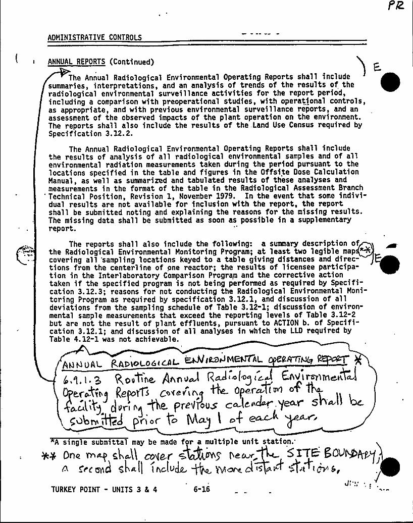
ADMINISTRATIVE CONTROLS
ANNUAL REPORTS (Continued)
The Annual Radiological Environmental Operating Reports shall includesummaries, interpretations, and an analysis of trends of the results of theradiological environmental surveillance activities for the report period,including a comparison with preoperational studies, with operational controls,as appropriate, and with previous environmental surveillance reports, and anassessment of the observed impacts of the plant operation on the environment.The reports shall also include the results of the. Land Use Census required bySpecification 3.12. 2.
The Annual Radiological Environmental Operating Reports shall includethe results of analysis of all radiological environmental samples and of allenvi,ronmental radiation measurements taken during the period pursuant to thelocations specified in the table and figures in the Offsite Dose CalculationManual, as well as summarized and tabulated results of these analyses andmeasurements in the format of the table in the Radiological Assessment Branch
'echnical Position, Revision 1, November 1979. In the event that some indivi-dual results are not available for inclusion with the report, the reportshall be submitted noting and explaining the reasons for the missing results.The missing data shall be submitted as soon as possible in a supplementaryreport.
The reports shall also include the following: a summary description ofthe Radiological Environmental Monitoring Program; at least two legible map "4covering all 'sampling locations keyed to a table giving distances and direc-tions from the centerline of one reactor; the results of licensee participa-tion in the Interlaboratory Comparison Program and the corrective actiontaken if the specified program is not being performed as required by Specifi-cation 3.12.3; reasons for not conducting the Radiological Environmental Moni-toring Program as required by specification 3.12.1, and discussion of alldeviations from the sampling schedule of Table 3.12-1; discussion of environ-mental sample measurements that exceed the reporting levels of Table 3.12-2but are not the result of plant effluents, pursuant to ACTION b. of Specifi-cation 3. 12. I; and discussion of all analyses in which the LLD required byTable 4.12-1 was not achievable.
Q,gytine, PAnva R
ggpp1 5 Qof8V L 4 ~ ~p+~~~~
pygmy <>g~ ~age.adolf". j~Y'e~'4~+<)
F~i.r g~ 5l4g l ~4 ~ g
AQ 6 OAI R,A,g >oL0aicAL ~iMPM~AL Cf~i~6 4(e i<A Entire>tn~pJ
TURKEY POINT - UNITS 3 8 4
A s ngle submittal may be made f r a multiple unit station.
+y Dne n~ gk~A mylar + ~g n~~~ SX'TB:50VNbPgy~<c cME sk II lac.tvJR. +~ ~~ al 5 e'~ 4't+I M &
Jl y) ~
6-16
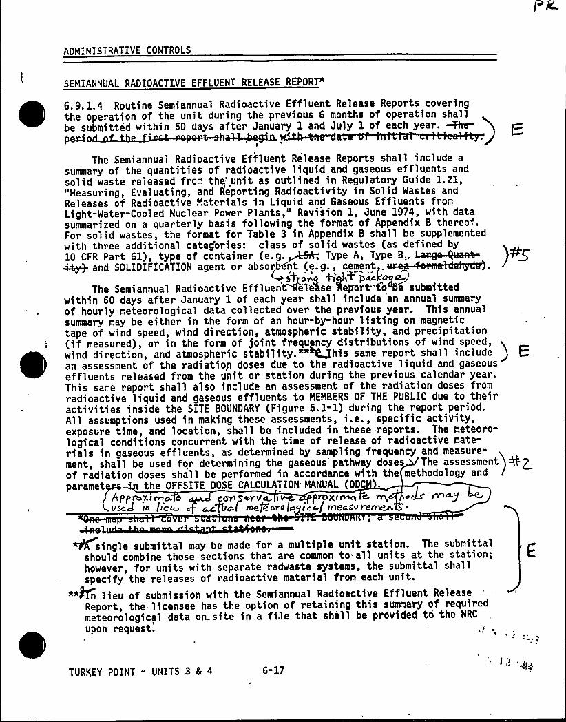
ADMINISTRATIVE CONTROLS
SEMIANNUAL RADIOACTIVE EFFLUENT RELEASE REPORT%
6.9. 1.4 Routine Semiannual Radioactive Effluent Release Reports coveringthe operation of th'e unit during the previous 6 months of operation shallbe submitted within 60 days after January 1 and July 1 of each year. M~
I
The Semiannual Radioactive Effluent Release Reports shall include a
summary of the quantities of radioactive liquid and gaseous effluents andsolid waste released from the'nit as outlined in Regulatory Guide 1.21,"Measuring, Evaluating, and Reporting Radioactivity in Solid Wastes andReleases of Radioactive Materials in Liquid and Gaseous Effluents fromLight-Water-Cooled Nuclear Power Plants," Revision 1, June 1974, with datasummarized on a quarterly basis following the format of Appendix B thereof.For solid wastes, the format for Table 3 in Appendix B shall be supplementedwith three additional categories: class of solid wastes (as defined byI I II,« I T.O., TF A,TFF A.,~
AO I IFI ATION O T,A, . ~A, strong +iqh+ PacLaga~
The Semiannual Radioactive Effluen~eehse Report"to be submittedwithin 60 days after January 1 of each year shall include an annual summaryof hourly meteorological data collected over the previous year. This annualsummary may be either in the form of an hour-by-hour listing on magnetictape of wind speed, wind direction, atmospheric stability, and precipitation(if measured), or in the form of joint frequency distributions of wind speed,wind direction, and atmospheric stability."*~his same report shall include I
an assessment of the radiation doses due to the radioactive liquid and gaseouseffluents released from the unit or station during the previous calendar year.This same report shall also include an assessment of the radiation doses fromradioactive liquid and gaseous effluents to MEMBERS OF THE PUBLIC due to theiractivities inside the SITE BOUNDARY (Figure 5.1-1) during the report period.All assumptions used in making these assessments, i.e., specific activity,exposure time, and location, shall be included in these reports. The meteoro-logical conditions concurrent with the time of release of radioactive mate-rials in gaseous effluents, as determined by sampling frequency and measure-ment, shall be used for determining the gaseous pathway doses The assessmentof radiation doses shall be performed in accordance with the methodology and
paramet 'he OFFSITE DOSE CALCULATION MANUAL (ODC
FiPpFn T~ATFa ~ anrASANvaT.pnoxTn n c Artcc oALs'rT~QVScd 15 /iCci syF ~fig,l NefbrOIo ice-f rneaS~ re~
~el"list single submittal may be made for a multiple unit station. The submittal
should combine those sections that are common to all units at the station;however, for units with separate radwaste systems, the submittal shallspecify the releases of radioactive material from each unit.
*"An lieu of submission with the Semiannual Radioactive Effluent ReleaseReport, the licensee has the option of retaining this summary of requiredmeteorological data on. site in a file that shall be provided to the NRC
upon
request.'URKEY
POINT " UNITS 3 8 4 6-17

ADMINISTRATIVE CONTROLS
SEMIANNUAL RADIOACTIVE EFFLUENT RELEASE REPORT (Continued)
The Semiannual Radioactive Effluent Release Report to be submitted within60 days after January 1 of each year shall also include an assessment ofradiation doses to the likely most exposed HEHBER OF THE PUBLIC from reactorreleases from the previous calendar year<
Acceptable methods for calculating the dose contribution from liquid andgaseous effluents are given in Regulatory Guide 1.109, March 1976.
The Semiannual Radioactive Effluent Release Reports shall include a listand description of unplanned releases from the site to UNRESTRICTED AREAS ofradioactive materials in gaseous and liquid effluents made during the report-ing period.
The Semiannual Radioactive Effluent Release Reports shall include anychanges made during the reporting period to the PROCESS CONTROL PROGRAM (PCP)and to the OFFSITE DOSE CALCULATION MANUAL (ODCM), pursuant to Specifica-tions 6.13 and 6.14, respectively, as well as any major change to Liquid,Gaseous, or Solid Radwaste Treatment Systems pursuant to Specification 6.15.It shall also include a listing of new locations for dose calculations and/orenvironmental monitoring identified by the Land Use Census pursuant to Specifi-cation 3.12.2.
The Semiannual Radioactive Effluent Release Reports shall also includethe following: an explanation as to why the inoperabi ty of liquid or gaseouseffluent monitoring instfumentetion wes not corfecte within the time snecified
) ~in Specification 3.3.3.6 or 3.3.3.7, respectively; description of the eventsleading to liquid holdup tanks or gas storage tanks exceeding the limits ofSpecification 3.11.1.4 or 3. 11.2.6 ,
* rrI
MONTHLY OPERATING REPORTS
6.9. 1.5 Routine reports of operating statistics and shutdown experience,including documentation of all challenges to the PORVs or 'safety valves,shall be submitted on a monthly basis to the U.S. Nuclear Regulatory Commis-sion, Document Control Desk, Washington, D.C. 20555, with a copy to theRegional Administrator of the Regional Office of the NRC, no later than the15th of each month following the calendar month cov'ered by the repor't.
4AOIAN.PEAKING FACTOR LIMIT REPORT Re in« ~ ~~«+(Fr'.
9. l. 6 e „ or RATED THERMAL POWER (F established o
at least each reload core a vailable in the ControlRoom. The e established and implemente o le
TURKEY POINT - UNITS 3 Ec 4 6-18 '
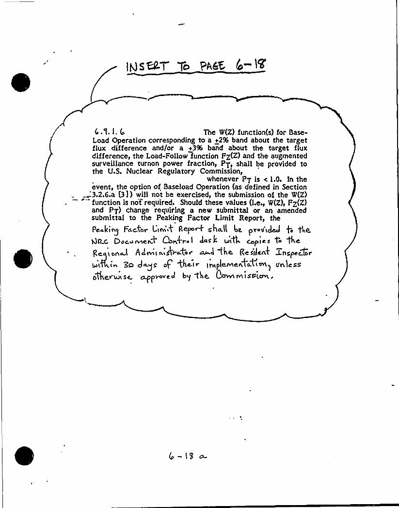
4.%. l. (o The W(Z) function(s) for Base-Load Operation corresponding to a +2% band about the targetflux difference and/or a +3% band about the target fluxdifference, the Load-Follow function FZ(Z) and the augmentedsurveillance turnon power fraction, PT, shall be provided tothe U.S. Nuclear Regulatory Commission,
whenever PT is < 1.0. In theevent, the option of Baseload Operation (as defined in Section3.2.6.a [3]) will not be exercised, the submission of the W(Z)function is not required. Should these values (i.e., W(Z), FZ(Z)and PT) change requiring a new submittal or an amendedsubmittal to the Peaking Factor Limit Report, the
Pea.king Fa.car Liw'~4 Re+'+ saba.'ll 4. prov'cd'd file.gP Q Py~~ ~e~+ Q~fl-a 1 JPi k 4iLC ~p f cs t4 +cgeqyona.l Adwi< r ikaat~r cu 3 the Re sdcnk Znspecforg4,i~ gg Jag@ op <ha(r )wptervteafa<<w) voless04~v.h)L sc. cypovect bg f'ke. ~ 1@ lsd[~.

ping Q ~~~iatOALVY
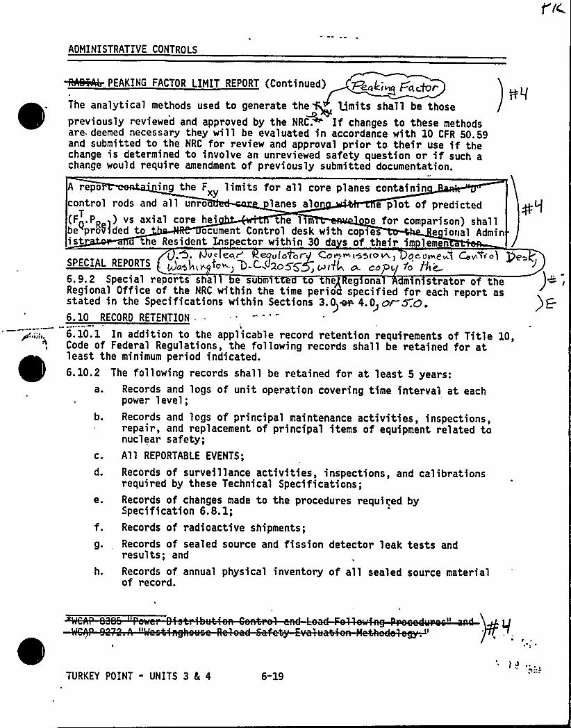
AOMINISTRATIVE CONTROLS
/ ~ ~
WAHAb PEAKING FACTOR LIMIT REPORT (Continued) ~~/;„pz ~~The analytical methods used to generate the ~ Iimits shall be thosepreviously reviewed and approved by the NRC~ If changes to these methodsare deemed necessary they will be evaluated in accordance with 10 CFR 50.59and submitted to the NRC for review and approval prior to their use if thechange is determined to involve an unreviewed safety question or if such achange would require amendment of previously submitted documentation.
A repo ing the F„ limits for all core planes containincontrol rods and all unro lanes alo e plot of predicted(F~.PR ) vs axial core hei e l e for comparison) shallbe prof)ded to ocument Control desk with cop>es e ional Administ the Resident Lnspector within 30 da s of their im lemen
VC e'er'(C Or CO~~ieo<>~ Oeume~l GV ice)SPECIAL REPDRTS goop,rgio ') D CW>oSSg, cud/ o„co6.9.2 Special reports sha e su m e o e eg ona m n strator of theRegional Office of the NRC within the time perio specified for each report asstated in the Specifications within Sections 3.0~~ 4.0>cr WO.6. 10 RECORO RETENTION .
6.10.1 In addition to the applicable record retention requirements of Title 10,Code of Federal Regulations, the following records shall be retained for atleast the minimum period indicated.6. 10.2 The following records shall be retained for at least 5 years:
a. Records and logs of unit operation covering time interval at eachpower level;
b. Records and logs of principal maintenance activities, inspections,repair, and replacement of principal items of equipment related tonuclear safety;
c. All REPORTABLE EVENTS;
d. Records of surveillance activities, inspections, and calibrationsrequired by these Technical Specifications;
e. Records of changes made to the procedures required bySpecification 6.8.1;
f. Records of radioactive shipments;
g. Records of sealed source and fission detector leak tests andresults; and
h. Records of annual physical inventory of all sealed source materialof record.
e»
TURKEY POINT - UNITS 3 4 4 6-19
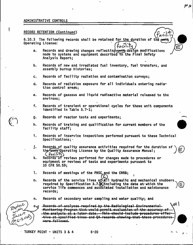
ADMINISTRATIVE CONTROLS
RECORD
6. 10. 3Operati
a.
b.
C.
d.
e.
RETENTION Continued)
Records of facility radiation and contamination surveys;
Records of radiation exposure for all individuals entering radia-tion control areas;
Records of gaseous and liquid radioactive material released to theenvirons;
Records of transient or operational cycles for those unit componentsidentified in Table 5.7-1;
4',IY~The following records shall be retained for the duration of the ~~
ng License: JQcL~l l lQ
Records and drawing changes reflecting des gn modificationsmade to systems and equipment described n the Final SafetyAnalysis Report;
Records of new and irradiated fuel inventory, fuel transfers, andassembly burnup histories;
g. Records of reactor tests and experiments;
h.
k.
m.
n.
Records of training and qualification for current members of thefacility staff;
Records of inservice inspections performed pursuant to these TechnicalSpecifications; .
Recor of quality assurance activities required for the duration ofth 'erating License by the /vilityAssurance Manual;
go.c,l ~qRecor s o7 reviews performed for changes made to procedures orequipment or reviews of tests and experiments pursuant to10 CFR 50.59;
Records of meetings of the PNSC and the CNRB;
Records of the service lives o l hydraulic and mechanical snubbersrequired by Specification 3.7. including the date at which theservice life commences and associated installation and maintenancerecords;
Records of secondary water sampling and water quality; and
TURKEY POINT - UNITS 3 4 4 6-20
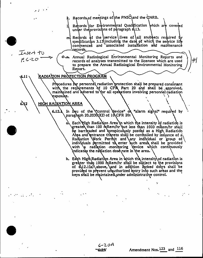
R cords of me tings of the PNS and the CtNRB
Run
or Enrovlsl
ords frth p
ironme tal Qual ication hich arns of p ragraph 13.
cove
RespeCOAl
rdsificati
ence
f the service lives of all snub e('s ren 3.13 includin the dat 'f whic the se
and associated insta ation mai
iredvice liten anc
ords.
6. 2
0~ Annual Radiological Environmental Monitoring Reports andrecords of analyses transmitted to the licensee which are usedto prepare the Annual Radiological Environmental MonitoringReport.
ADIA ON PR CTION PROGR M
P edures r personnel, radiation rotection shall be prepared consistentwit the req 'rements bf 10 CF Part 20 and shall be. approved,main ined and hered to for all ope tions involving personrietradiation
xposu e )
HI RA ATIO AREA1
6.12. In l u of the "control evice" o "alarm signal" requited byparag ph 20.203 2) of 1 CFR 20:
a Each igh Radia 'on Area 'hich e intensity g radiatio isreate than 100 Rem/hrtbut less t an 1000 mRem/hr shall
barr aded and enspicu sly pestItd as a High, RadiatidnA a and ntrance th eto shgl be cont oiled by issbance of a;Ra 'ation Work Per 't and~any indi idual or 'group ofindiv'duals rmitted t enter 'such area shall be provided
'ithradi tion mon oring 'gevice w ich continuously'icat the ra iation do rate in e area.4
b. Ea h Hig Radiati n Area in hich th intensit of radiation isgre ter th 1000 Rem/hr sh ll be siiPject to Pe provisronsof 12.1(a) above, d in a/dition hgked d+rs shall beprovi d to p vent u uthorized hptry ink such areas and thekeys shall be intaine under administrati e control.
POPAmendment Nos.123 and 116

-y <rC
Q
s /I
l~, 1C' 3 (QvtC(/
0

ADMINISTRATIVE CONTROLS
RECORD RETENTION Continued)
p. Records for Environmental gualification which are covered under theprovisions of 10 CFR 50.49.
6. 11 RADIATION PROTECTION- PROGRAM
6. 11. 1 Procedures for personnel radiation protection shall be preparedconsistent with the requirements of 10 CFR Part 20 and shall be approved,maintained, and adhered to for all operations involving personnel radiationexposure.
6. 12 HIGH RADIATION AREA
6. 12. 1 Pursuant to paragraph 20.203(c)(5) of 10 CFR Part 20, in lieu of the"control device" or "alarm signal" required by paragraph 20.203(c), each highradiation area, as defined in 10 CFR Part 20, in which the intensity of radia-tion is equal to or less than 1000 mR/h at 45 cm (18 in.) from the radiationsource or from any surface which the radiation penetrates shall be barricadedand conspicuously posted as a high radiation area and entrance thereto shallbe controlled by requiring issuance of a Radiation Work Permit (RWP). Indi-viduals qualified in radiation protection procedures (e. g., Health PhysicsTechnician) or personnel continuously escorted by such individuals may beexempt from the RWP issuance requirement during the performance of theirassigned duties in high radiation areas with exposure rates equal to or lesst than 1000 mR/h, provided they are otherwise following plant radiation protec-tion procedures for entry into such high radiation areas. Any individual orgroup of individuals permitted to enter such areas shall be provided with oraccompanied by one or more of the following:
a. A radiation monitoring device which continuously indicates theradiation dose rate in the area; or
b. A radiation monitoring device which continuously integrates theradiation dose rate in the area and alarms when a preset integrateddose is received. Entry into such areas with this monitoring devicemay be made after the dose rate levels in the area have been estab-lished and personnel have been made knowledgeable of them; or
c. An individual qualified in radiation protection procedures with aradiation dose rate monitoring device, who is responsible for pro-viding positive control over the activities within the area andshall perform periodic radiation surveillance at the frequencyspecified by the Health Physics Shift Supervisor in the RWP.
'I
6.12.2 In addition to the requirements of Specification 6.12.1, areasaccessible to personnel with radiation levels greater than 1000 mR/h at 45 cm
(18 in.) from the radiation source or from any surface which the radiationpenetrates shall be provided with locked doors to prevent unauthorized entry,and the keys shall be maintained under the administrative control of the shift
. TURKEY POINT - UNITS 3 8c 4: 6"21
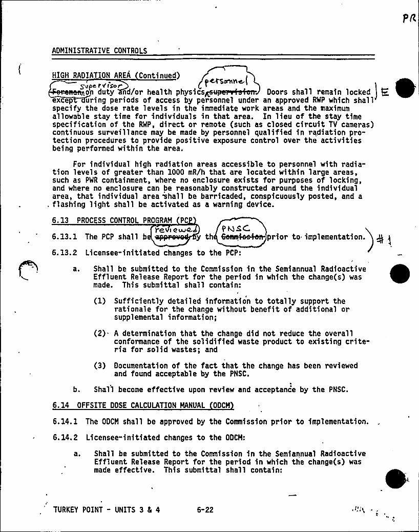
ADMINISTRATIVE CONTROLS
HIGH RADIATION AREA Continued)S vive rfthor pc.rS~oe,(
on duty nd/or health physics Doors shall remain locked pexcep uring periods of access by personnel under an approved RWP which shallspecify the dose rate levels in the immediate work areas and the maximumallowable stay time for individuals in that area. In lieu of the stay timespecification of the RWP, direct or remote (such as closed circuit TV cameras)continuous surveillance may be made by personnel qualified in radiation pro-tection procedures to provide positive exposure control over the activitiesbeing performed within the area.
For individual high radiation areas accessible to personnel with radia-tion levels of greater than 1000 mR/h that are located within large areas,such as PWR containment, where no enclosure exists for purposes of locking,and where no enclosure can be reasonably constructed around the individualarea, that individual area shall be barricaded, conspicuously posted, and a
. flashing light shall be activated as a warning device.
6.13 PROCESS CONTROL PROGRAM PC
re (owe. PNSM6.13.1 The PCP shall b y th prior to implementation.
6.13.2 Licensee-initiated changes to the PCP:
a. Shall be submitted to the Commission in the Semiannual RadioactiveEffluent Release Report for the period in which the change(s) wasmade. This submittal shall contain:
(1) Sufficiently detailed information to totally support therationale for the change without benefit of additional orsupplemental information;
(2) A determination that the change did not reduce the overallconformance of the solidified waste product to existing crite-ria for solid wastes; and
(3) Documentation of the fact that the change has been reviewedand found acceptable by the PNSC.
b. Shall become effective upon review and acceptance by the PNSC.
6.14 OFFSITE DOSE CALCULATION MANUAL ODCM
6.14. 1 The ODCM shall be approved by the Commission prior to implementation.
6.14.2 Licensee-initiated changes to the ODCM:
a. Shall be submitted to the Commission in the Semiannual RadioactiveEffluent Release Report for the period in which the change(s) wasmade effective. This submittal shall contain:
TURKEY POINT - UNITS 3 4 4 6-22
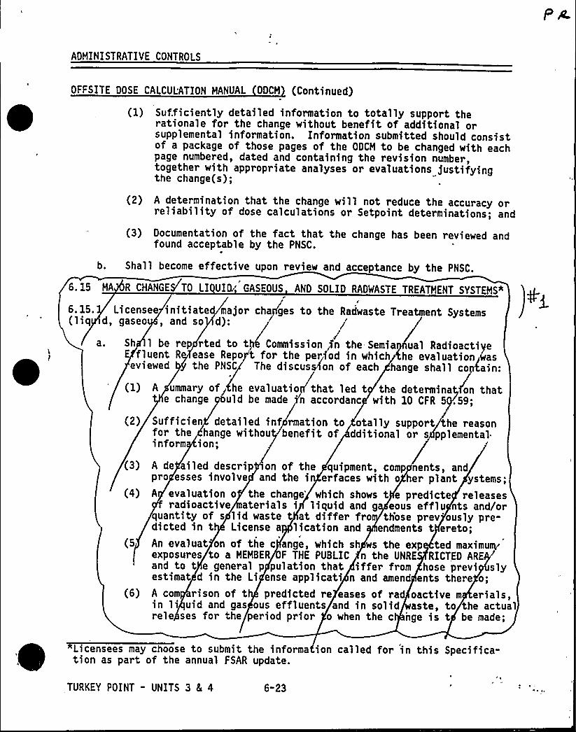
ADMINISTRATIVE CONTROLS
OFFSITE DOSE CALCULATION MANUAL ODCM (Continued)
(1) Sufficiently detailed information to totally support therationale for the change without benefit of additional orsupplemental information. Information submitted should consistof a package of those pages of the ODCM to be changed with eachpage numbered, dated and containing the revision number,together with appropriate analyses or evaluations justifyingthe change(s);
(2) A determination that the change will not reduce the accuracy orreliability of dose calculations or Setpoint determinations; and
(3) Documentation of the fact that the change has been reviewed andfound acceptable by the PNSC.
b. Shall become effective upon review and acceptance by the PNSC.
6. 15 MA R CHANGES TO LI UID/ GASEOUS AND SOLID RADMASTE TREATMENT SYSTEMS"a
6.15. Licensee initiate major cha ges to the Radwaste Treatment Systems(liq d, gaseo , and so d): /a. Sh 1 be rep rted to t Commission,fn the Semia ual RadioactiVe
E fluent R ease Repo t for the period in which he evaluation Lsaseviewed the PNSC The discus on of each hange shall co ain:
(1) A ummary of he evaluatio that led t the determina on thate change uld be made n accordanc with 10 CFR 5 .59;
(2) Sufficien detailed inf rmation to otally support the reasonfor the hange withou benefit of dditional or s pplemental.inform ion;
(3) A de ailed descrip on of the quipment, comp nents, andpro esses involve and the i erfaces with o her plant ystems;
(4) A evaluation o the change'hich shows t e predicte releasesradioactive aterials i liquid and g eous efflu ts and/or
quantity of s lid waste at differ fro th'ose prev'ously pre-dicted in t License a lication and endments t ereto;
(5 An evaluat on of the c ange, which sh ws the exp tedmaximu~'xposuresto a MEMBER F THE PUBLIC n the UNRE RICTED ARE+
and to t e general p pulation that iffer from hose previ slyestimat d in the Li ense applicati n and amend ents there o;
(6) A corn rison of t predicted re eases of ra oactive m erials,in li uid and gas ous effluents and in solid aste, to the actualrele ses for the period prior o when the c nge is t be made;
Licensees may choose to submit the informa ion called for in this Specifica-tion as part of the annual FSAR update.
TURKEY POINT - UNITS 3 8L 4 6-23
ADMINISTRATIVE CONTROLS
MAJOR ANGES T I UID G OUS AND SOI ID RADWASTE TREATMENT SYSTEMS
Co inued
) An es mate of theiexposure t plant opera ng person as a
resu t of the cha6ge; and
(8) Documentatfop'of the fac that the c nge wae n $ ewed andfound acce table by th PNSC.
b. i hall becom effective u n review d accepta e by the SC.
//
4
'URKEY POINT - UNITS 3 4 4 6"24JtJV
Qw
T. S. Number 1. 0
Justification:The new RPI scales take into account the non-linearresponse of the RPI's that would otherwise be accountedfor by the Reference Position. The new scales allow theRCCO to directly compare the RPI position to the stepcounter position without having to refer to the ReferencePosition curve. Removal of the "Reference Position"alleviates some of the-unnecessary workload on the RCCO.
2.
3.
K,<<=0.95 is consistent with Amendment 132/126 (7/18/88) .
A CONTROLLED LEAKAGE definition has been added tocomplement the addition of CONTROLLED LEAKAGErestrictions added to Specification 3.4.6.2.
4 ~
5.
All of our shipments do not go directly to a burial site,some are shipped to a waste processor for volumereduction prior to burial.A limit of 24 months on "refueling" surveillances is amanagement action to limit time between surveillances.

Justifications:1. BASES — Per FSAR Table 4.1-9, the reactor vessel and
pressurizer are designed to the requirements of ASMESection III.
T.S. Number 2.2.1
Justifications:
2 ~
3.
The CTS does not address "allowable" values. The 1986version of RTS adopted the STS 2-column format containingnominal setpoints and allowables. The RTS allowableswere best estimate numbers determined by Westinghouseusing generic tolerances. However, FPL would requireadditional analysis to adequately support these values.
Pzr. pressure: No credit is taken for PORVs in thesafety analysis or the basis in the CTS. (PORVfunctional capability enhances the overall reliabilityof the RCS).
Turbine trip: P-7 blocks reactor trip on turbine trip.4 ~ Items 17.b(1) and 17.d are confusing. P-10 in 17.d,
which allows a block of PR trip during plant startup,should be greater than or equal to 104. P-10 reset pointin 17.b(1), which allows a block of at-power trips duringshutdown, should be less than or equal to 10%. Revisingthe wording to refer to 17.b(1) as the reset of the P-10bistable and 17.d as the tripping of the bistable willclarify the tech spec and better represent instrumentdesign.

Justifications:1 ~ Flexibility required for dual unit shutdown to prevent
a severe transient on the Florida electrical grid. Thiscomment is consistent with previous discussions andagreements during RTS working meetings regarding dualunit shutdown due to electrical components beinginoperable. (Also applies to BASES change.)
T. S. 3.0.6
Justification:1 ~ This comment provides a minor revision, for clarification
only, of CTS 3.0.5. This current specification wasapproved for inclusion in the CTS in Amendment 114/108dated June 27, 1985.
The rewritten portion of the comment closely matches thewording of the NRC letter dated April 10, 1980 to AllPower Reactor Licensees concerning the definition ofOPERABLE.
Although this tech spec is not currently in the deskreference STS, FPL feels that it is important to includethis clarification.(This justification also applies to BASES change.)

T. S. Number 4.0.3 BASES
Justifications:1. This change clarifies that the allowable outage time in
the ACTION Statement begins at the end of the 24 hourallowance.

T. S. Number 4.0.6 BASES
Justifications:1. This change was made to eliminate the need for
unnecessary duplicate testing.
Justifications:1 ~
2 ~
3.
BASES — Revised to reflect actual condition addressed bythe LCO. "Postulated steam line break" appearsinappropriate with RCS temperature below 200F.
Figure 3.1-1: Breakpoints should be shown for operatorclarity.During the first 60 EFPD of a cycle, it is possible thatan adjustment to the letdown curve may not have to bemade if there is good agreement between measured data anddesign figures.

0
0

Justifications:1. The term "equivalent" would mean 100+ pgm of 1950 ppm;this would require 2 charging pumps in Mode 5. No rate
requirements for boration in Mode 5.

Justifications:1. Consistency on reporting requirements. This is a generic
issue on 30 day reporting.
Justifications:1 ~ STS requires temperature verification once per 7 days.
There is no CTS requirement to verify temperature, hence,7 days is more restrictive than CTS.
2 ~ Certain areas of the plant may be inaccessible due toradiological considerations.
Justifications:1.
2 ~
STS requires temperature verification once per 7 days.There is no CTS requirement to verify temperature, hence,7 days is more restrictive than CTS.
Certain areas of the plant may be inaccessible due toradiological considerations.

T. S. Number 3 4.1.2.4
Justifications:1. STS requires temperature verification once per 7 days.
There is no CTS requirement to verify temperature, hence7 days is more restrictive than CTS.
Justifications:1. STS requires temperature verification once per 7 days.
There is no CTS requirement to verify temperature, hence,7 days is more restrictive than CTS.
2 ~ 3/4.1.2 BASES clarified to indicate background for RWSTtemperature; for ope'rator information.
Justifications:1. This change is consistent with related tech specs (i.e.,
3.1.2.1, 3.1.2.2 and 3.1.2.5). There is no CTSrecpxirement to verify temperature.

T. S. Number 3 4.1.3.1
Justifications:1. The new RPI scales take into account the non-linear
response of the RPI's that would otherwise by accountedfor by the Reference Position. The new scales allow thereactor operator to directly compare the RPI position tothe step counter postion without having to refer to theReference Position curve. Removal of the "ReferencePosition" alleviates unnecessary workload on the reactoroperator. (This justification also applies to BASESchange.)
Justifications:1.
2 ~
Revised for consistency with CTS 3.2.2 and related bases:"Reduction in power to 754 (3 loop) . . . will ensurethat design margins to core limits will be maintainedunder both steady-state and anticipated transientconditions." Power reduction for an indicatedmispositioned rod should be the same as a knownmispositioned rod. (Tech. Spec. 3.1.3.1 ACTION c.3.a.)Delete reference to Reference Position. Refer tojustification to 3/4.1.3.1 for further information.

Justifications:1. This surveillance will require a unit shutdown to be
performed. Surveillance 4.1.3.4a and b cover anymaintenance that could affect the rod drop times.
Justifications:1. Comment returns surveillance to STS wording which is
appropriate for Turkey Point.
Justifications:1. Comment returns surveillance to STS wording which is
appropriate for Turkey Point.

0
Justifications:1. Performing surveillance for greater than a 6 hour period
provides negligible information. This comment was agreedto by NRC technical reviewer on April 7, 1988.
Adding a functional test will be consistent with othersurveillances in STS and meets the intent of thesurveillance.
Justifications:1 ~ The NRC proposed STS wording would require FPL to perform
additional analysis to generate the Peaking Factor LimitReport per T.S. 6.9.1.6. Xn addition, the NRC's proposedwording deleted the Augmented Surveillance Tech. Specs.which were approved by NRC on March 17, 1982, as LicenseAmendment 80/74. The Augmented Surveillance Tech. Specs.were developed as a contingency against reductions in theFq margin. FPL has experienced Fq margin reductions dueto steam generator tube plugging, changes in analyticalmethods, and unexpected errors in design codes.Equipment currently in place to implement the AugmentedSurveillance Tech. Spec. would have to be removed if thissurveillance is discontinued.


Justifications:
2.
There is no requirement in the current tech specs toverify the excore QPTR calculation with an incore fluxmap. Monitoring the incore tiltwith a flux map once per24 hours will be significantly more conservative than thecurrent tech spec.
With one power range detector out of service, theremaining power range detectors along with other controlroom instrumentation (i.e., incore T/C, Tavg, flows,etc.) will detect changes in core parameters.
Several plants currently use incore thermocouples todetermine QPTR. Zncore thermocouples provide a rapidmeans of determining the core relative radial powerdistribution for use on an on-line basis. Thermocouplesare currently used in QSPDS. When used in conjunctionwith moveable detector map, incore thermocouples can benormalized to provide accurate relative integrated fuelassembly power distribution measurements.

Justifications:1. The present equipment at Turkey Point does not allow
performing this surveillance without a plant shutdown andcontainment entry behind the biological shield wall.
Justifications:This change reflects the Plant design as shown inattached FSAR Figure 7.2-5. These trips do not applybelow P-7.
2. Provides clarification to operators on required safetyfunction based on increasing and decreasing power, i.e.,automatically enabling trips, etc.
3.
4 ~
This surveillance requires Plant to be in a shutdowncondition. An 18-month surveillance frequency may causeFPL to have to shutdown for refueling early or cause anunnecessary outage.
This surveillance has been revised to create consistencybetween the table and the table notations.
5. There is no LCO which corresponds to this surveillanceand the trip bypass breaker circuit is already tested byNote 13.
6. The Automatic Trip and Interlock Logic is not testableprior to mode 3; therefore, the surveillance requirementhas been removed.
7 ~
8.
Use of jumpers/fuses to place channel in trip conditionwas agreed to by NRC technical reviewer in FPL/NRCworking meetings.
STS wording is adequate to give guidance for 30-75< RTP.
9. Above P-7 and below P-8, 2 RCP "breakers open" arerequired to cause a reactor trip. Based upon Plantdesign, a single underfrequency channel/bus may not leadto a RCP breaker/reactor trip. A requirement for 2/buswill lead to a reactor trip due to an underfrequency oneither bus.
10. The P-10 logic circuitry provides a redundant signal.In the decreasing power mode, two (2) channels to tripare required (see Justification g2 above).
12. In the decreasing power mode, three (3) channels to tripare required (see Justification g2 above).
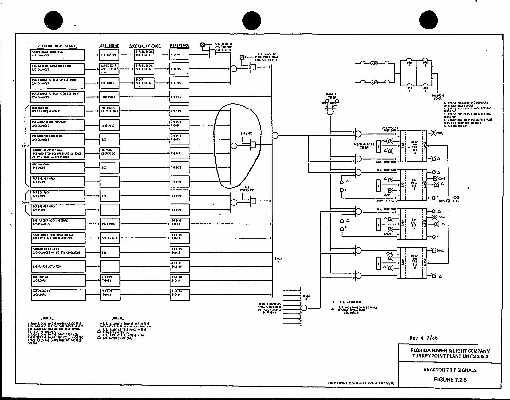
REACTOR TRLP SICNAL
TlVla Iua ales FINI/1 CNOKLS
lal(NIOlllltua( NIOI flaaUt Owen5
1111 CPS
utS pA tItt, hicl4
OTPISUILKI5(C I II Il
~VPISVtcaaI(( I II IC
R F RENC
I.LI IS
t.L (coca lft.a >ctwctI(( I.lI Il
P.L OO(c Ift Ia, PP(a RIK(>141 5(C I.ll IS —~v~c KlI
~CWI Iua( al Kla 10 5CI paielVc ONWC15
~cs(a Iiaa IO fisa NIOI $CI tOI~ 'I
t/ ~ Owenl
ua( INNIK(Os ~ Il INII INO 0
~K5$IRII(ALfu ta5DIKVlOwen5
PKISLI IT(a alCN LIWLVlOwen5
IPNIK laut(0 Slowt/1 NIIO 5'ICP Oil PKSSLR( SelfCKSca KNN ITcp vacwS oo5(0
Icp Uu floet/I LOOPS
,IOCI tOKI
IK (IVIV.10 tillWLI
In) 15 IC
l5 tSICKCKISIIO
acoa5(C I ll 11 ILI IC
Isuls
I 11'I ~I.D.II
I II I~'I PIS
t 1>IK
IIANUALTRIP
LKCIVCLIK(lait Clll
COlL C
NECNAN)CALTRIP b I
DINT liltCOlt
ILV liltC411
~Vl ~ le0
KaC~ IORlilt
laAI
KO OR IKKa(a
I. OTpes5 ocalc(as IIC eoawLTOP(a INO RIO (0 ONIt. DTFI5$ 'I'05(0 aves 1(51 1KIIIIN'I'
IVPI55 'r OOS(0 VKN 'l(511IOIaua re. allfapllaa 10 clo5( 00TN ortISSlci) lillliltPA OR ODINL $(c Cp.lfoat
CO/I,
~ d
Kt OKIKR OKNV) FLIPS
r Act I FLcu
Ul LOCPS
>I ~l Kt K(u(I opcaI/) tcetS
PKSORIT(i NIOI IKSSLR(I/) OWKLS
Sis FLOUFN FI(u NISWI(N uO101 L(v(L I/I STs CCKaaiatl
tN4 151C
5(C I.ll IS
'I ll t4
I%I'llI.O.IS
I ll I)I-D Ii
t. 0tOKI> 151
Ccc
)gs
Dial )lit COIL
ILV. TRIP COll
d'c
01 ~
PI$5~ca
Of~I5$
I
a
COL
CONS
I
K5(1P.L
5TII CCN 10.10 LCWL1/) owens oc U) SNI KKIIIIRS
SI/(ONNTS iCINCITON
IWI ISlOll
IIIINKIC
IOIPIPOIAI
I CNL
OWITOP ~ T
I/) ID(PSI<i tl'I.D.II
Tsl tlI 0 ll
ov(apoKA llt/) IOOPI
NOT( II Tilt STOW 10 TK LICCIVcalia liltCOlt DC (KACINS IK COIL POPtl/0 0/IIK IITOI uO fi(IINO INC 'Tait Stiles10 Tilt INC OKIC(LI lait 5IOW 10 TK 5NNI Tilt COllIKRCIT(5 IK Ssui lait COll. INCKIICfWCC IIALS IK LIIOIIK( OF Ia( lilt5PRINL
I'll'tlTal I~
NOT( I~ PL'5 O05C/ Tilt Il aai ICIIVCOLI aaa OVPISS aaa NC KliPONTOS
t.L OOSI Il l(51 tun ICIIVCRIIN DW UCKD lcct.L IAltIi LP. KIIW~ Ifa~La IICICO la Ca (uf,
I<l tlI-D Ic
I II IN ~ KCIIVI5SIOW5 IXNIIOL10 INOSI IfC(le(0
OI llcia I
'Ilcia0
~ t.L Il Dau(lIL Icu Iaull cu 'IIIIPIKL
la CIRC 5PKL KOII(( IOIC ~
REF DWOT 5610 T LI SH. 2 IREV 81
Rev 4 7/86
FLORIDA POWER SI LIGHTCOMPANYTURKEYPOINT PLANT UNITS 3 Sc 4
REACTOR TRIP SIGNALS
FIGURE 7.2.5

Nr. Steve Cra'g
0
desires to reserve tha option to cock the, rods (shu'.di:wn banks) out ofthe core during Mode 3 for operational flexib) lity.To add~ass the issue, Hr. R)ck Mande has tnd3cated that FPL would 1)ke toknst1tute an administrative control during Node 3 that would require the rodcontrol system to be either 1) placed )n the "bank select" code with ashutdown bank as the bank selected, or 8) d1sabled by opening the reacto~tHp breakers. Nest)nahouse aoraes that th$ s $ s an acceptable means ofprevent)ng'ncontrolle8 rod withdrawal during Node 3, and $ s therefore an:effect$ ve means of rddressfny tha issue on a short-term bas)s.
Please call me 1f you have any questions.
Very truly yours
4.Q.VS.A. PearsonPro)ect Engineer
8AP:kph
cc: R.J. AcostaD,C, Bradford$ .6. Bra)nQ.E, CoeR.A. DeckerJ.A. OeNastryT.G. GrozanD.M. HaaseR.D. HankelJ.A. HandschuhK.N. HarrisJ.A. HughesY.A. Kam<nskasK.R. KnucklesC,U. La)sure
D. NantzR. Hende
J.E, NoabaK.H. NordttiyerO.C. Poteraylsk)G.A. RowanR.J. RodriguezS.H. ShepherdA.E, S5ebeF.H. Southwor th
C, Y)11ardR.bf. 'ifinnar dS.K. HathavanC,S. Smallwood
0@
'pQ jS «i C A « I «I II«
NCNlghaeo %ter ReactorBg&c Qemitlw IvIslons
p i' '«e ~ ~ O
Mcussecs'ayltcaOMse
le VN~t m~ ~mme
~ ~
)fat Kt N ~ Harr'i 5 ~ Vice PresidentTurLey Point NuC'learRorida Power and Ught CoeyanyP. 0. Boa 029100Niaai, Florida 33152
Dear Nr, Noaba:
florida Power I light CompanyTurkey Point Units 3 and I
UPDATE CONSISTENCY IEMEN SAFETY ANALYSISND TECHNICAl SPECIFICATIOiS COHCKQIINO
ER OF REACTOR COOLANT %PS O ERATION
?h June of thi s year you were notified of a potential unrev)ewed safetyquestion cOncerning an inconsistency between the safety analySis and the TechSpecs. This inconsistency applies to the weber of operating reactor coo)antpvips when $ n Me 3 {or the u)va)ent) of the Tech Specs.
Since that t<ie. Vestinghouse has Net w)th the NC staff at their reqveitto present the Vest<nphouse position on this issue and recoivnendatiohsfor resolution. The Iaterial presehted at this seeting is docvaented ih'Astihghouse letter NS-PR-2935. which $ s attached for your $ nfoveat)on(cover letter on1y).
The purpose of this letter is to update yov on the latest infomationconcerning this issue. Vestinghouse w) ll notify you of further developoentsas they occur,
If you have any questions. please contact ae,
Yery rvly yours,
. J, R(cherds, l4nagerPro)acts Depa~entSouth Area
HT/413LAttachient
cc: V. H. Rogers, Jr.K. N. HarrisH. D. itentzP. P. DeRoseH, E. YaegerC. J. Saker
H. N. PaduanoS. Q. BrainD, J. RichardsT. P. SullivanE.. C. Anderson gE. V. Rvtledge

0
0
ATIrlteaefnrIvons
Z/+pi.zNae <aeoogy0heen
Atare)war's N5
July 9, lN4f5 T~O{}3
r
lh. O. Kfsenhut> 1frectot"P~'>,lf,ihh~imMO Mori'olk AvenwQsh$ rgcon. O.C. f0555
3Q}er Two or al I Oi(At the s uest ~
Howe e, the sa ythe reactor coot'e ass nels;-.; .he n|Nber of operant'.ng pays have been note< or
r f rplaning w<ghfn 4+tinQ-y„.. rg gg p4 fn the acDcMAt)o Tba acChdkhts wh1cn
an 1'Ii ng at aero go~. or< >'4awiine brea< ~c 0;oc.ion an-" ~n< ~~ I.
ftgg s~ 'f,'fggl, Qstfnghous„ $ „ reviewed these ac:indents under the reducededitions of one va" ": :.x md Qe..;(~ an. stegsline break events >
Mest$ nghouse his djetarlin.; :.'.: :." inconsista~;y oc:»een the safety ana y1 sis
lear %, Efsenhut:
Nl%ER OF ) MATINS l CTN 00UR'NOBS lh NOE 3
Thfa letter foealfaes the latarfal .oreaente4'on zuni 15< 1984, «fth respectto the consfstency bebeen the Technfcal $yecfffcat<ons and the safety analysisfor the nosher of operatfny reactor coolant plus fn linda S. Thfs ~tiny washeld at the bluest of the NC staff fn order Co 4fsouss the Nestfnohouse detarafnat$ on of a potantfal unrevfee4 safety question for ttiree and I'our loop plantsfOr Wa faaue. EnC1OSed am tan (10) yrOprfetary Cayfea Of the Slf4eS an5 ten{10) ten-proprfeta~ cop<os. Also enclosed are one {1} copy of App1icat<on forllfthho14fny N 9 63 (Nn-proprfeCary} and one {1) copy of Afffdavft (ten-~mp~eea>f.
As part of an fat'oval rev$ m of a utf3fty's Tyrh Specs by the Nh4 Reac:orSys~ Sraneh. the staff asked ~t the safety analysts ass~tfons were concarn<ng the nosher of ooeratfny riactor coolant peys, partÃevtar ly at or neartarO pOWer. iltheuoh tht queathOn WS neVer fOealiy aaka4, Qeat<nghduSe reViewedthe ana1ysfa assertions with rlsyect to the Tech specs.
The muf~nt for oyeratfny reactor coolant plies under these conditions>s contaited fn Specfffoatkon $ .4,>.2 f the Sgehr4 Tech Specs. !n non-StandardTech Specs, the nqu$ ~ene fs contafned fn Speeff<cat<on 3.1. these Soecs statet'zt when x4e plant fs subcr<tial by the yhutdo~ «er;<n beereen 350'F (~HR cut-fn) and S47'F or 117'F {m~load cond$ tfons), there egest be two loops oyeraole,but only one loop has Co be actually operaifny.
v r Net an 1 s!s <n
and the Tech Spec wfll n5t feyaet the conclusfons presented fn the f0', Forthe bank withdrawal Am s*crftfcal event> Mestfnghouse has pirforiid calcv-latfons whfch show that the f85 dasfon basfs my not'e set when on'ty one pmyfs fn operatfon. Thus, the Nargfn of safety as daffned fn the basfs af Che7ech'Specs fs reducid.
Vestfnghouse has a1so peHomef ca'lcu1atfons f'r one puny operatfon assnfng&n.rialf's fc, but stfll consarvatfvi, reactfvfty fnsartfon ratis, The resultsof these calculatf0ns show that the M disfgn basfs fs set. Other 40'~'L)onsand aerials used fn these analyses are fdintfcal Co the FSN aethods of analyifsfor thfs event ~ Thus ~ Qostfnghousa fels that m sfgnfffcant safety hazardaxfsts.
lkstfnghovsa fs currently consfderfng long tate analytfca1 solutfons co ch<sfssue whfch wfll show that the 5IS disfgn basfs can be etc when on>y one reactorcaalanc pmp fs fn operation Io that the Tech Specs w)11 not need Co be changed.However, fn the short tarI, Qestfnghouse raaeeends that Che plants be operatedwfth the save maber of riactor coolant pumps fn operatfon as ms ass+ed fn theanalycfS,, lhtI Chat thfS fS nOt a realfStfe ~ufment when Che aslant fS COOl)ngdown prfor to yofng fnto %de 4 (RN operatfon). partfcularly for chose plantsfor whfch Chi analysfs assess all pcs fn ooaratfon, Thus, an alternatfve cohavfng mre than one puef'n operatfan fs to prevent rod wfthdrawal. Thfs wfllproc)ude the acefdenC fere Cakfne place. Although plysfcal privancfan of wfth-drawa1 wfll aceeplfsh thfs, awfnfstratfva procadwes say be proferable. Tleabflfty Co cack the mds parlay out of tha cora durfng Node 3 prov<des desiredoperatfng Roxfhf1fty. Furthereeri thara fs lN sochanfsm by whfch the soncrolds Can be autoeatfca 1y wfthdrawn fn Ma 3 due to a contro1 sysM errorjIncreased operator awareness during thfs tfm and adheranca Ca procedures weal>
also prevent the accfdent Am occurrfng.
I'fna1ly, whfle Mestfnghouse feels that ft fs approprface co cans<der bank
Hthdrawal when fn Noda 3, Nstfnghausa Res not fntand Co address Ch<s eventfn other mdks of operatfon (Standard Tach Spec Nodes 4 and 5), Sank w<chdriwa>
f~ suhcrftfcal fs a valfd scanarfo when Oofng free Hode 3 Co %de R ~vericonsfderatfon of bank Qthdr awal fn Nndes 4 and 5 fs unrealfstfc and ft fsCuestfonahle as to whether ft fs applfcahlo or ff ft fs a Condfcfon lI event,A9afn fnsmasid operator awareness rust he consf4erid whin avaluacfng Che
approprfaceniss of the event.

a w wE V I'l14V ~ S ~ AC II>lv s ~ ~ < ~ e e r~ ~ W W ~
C4rrespon4fenca «fCh tesPeot t0 She Qestfnghousa aRfdav/t or application~-~ for Athho'lding should v%femce N-$4-53, and should be addressed to
+. R. A. Neseaann, Nanaoar Regulatory and 4yfslat<ve Mfa)m, 1.0. lox 355,P)ttsburyh, Pennsylvania IQ ~ Other corresPondence or questions should bed<i~ecI to Nr. 4. L,. tittle, 4nager, Operatic Plant L,<eens<nI Suppo<i410/$1+5454.
'ery twice/Ours'sT3%NUSE
LKcfaff COQCVTION
N. P. Osbom]44
Enc) osures
, Rahei Jr.uclear Safety Oepartment

, ~RON:
PATE:SUBJECT:
Nuclear Safety DeprrrtmentRisk Assessment Technology284%303October 4> 1984FKlFLA Prevention of Rod Withdrawal in Mode 3
To: 8. A. Pearson
oc: H. Pe Osbornet Po Ae LoftusP. M. RobertsonN. N. Raymond
SOB 2-17
}5C 4-09AMNC 49AMNC 4&9ANNC 4-09A
~ 0
~it~ o A I
~ ~ ~ ~ 'I
Ref> 1. FPI 84-729, 8-'l5-842. HS-EPR 2935) 7-9 843. FP-FP-697)
82FP~~011
, Florida Pmer and Light has requested additional infixation regarding aninconsistency between the ssfety analysis and the Tech Specs with respect to
. the number of operating reactor ooolant peps when in Noae 3 (or theequivalent) ai defined in the Tech Specs. Reference 1 provided the latestupdate on this issue. The purpose of this letter is to provide confirmat$ .on ofthe safety analysis assumptions and FPhl.3s proposed administrative procedure toaddress this issue, as discussed with Rick Monde> Reactor Engineer at TurkeyPoint.
As discussed in Reference 2, a letter from Westinghouse to the NRC, the onlyevent impacted by this issue is the RGB bank withdrawal from subcritioal.
'hisaccident is defined as an mcontrol3,ed addition of reactivity to thereactor core caused by withdrawal of RCCAs resulting in a power excursion.Such a transient could be caused by a malfrirction of the automatic rod controlsystem or by operator error. The ana3ys5a assmes a reactivity insertion rateof 75 pm/sec> greater Chan the maxim'esulting from the simultaneoust withdrawal of the combination of two sequential control banks having themaximus. co-...coined worth at msximmr speed.
The most recent RCCA bank withdrawal from subcritioal analysis for Turkey Po5ntUnite 3 4 4 was pe!'fonaed as part of tn. positive If'tudy ir 1981 (Reference3) f ana assumes tnrgt all three reao.o. ac';iant ymps are oper r Ling. However,the Turkey Point Tech Specs state Chat »ln Hot Shutdown at least two ReactorCoo3ant Loops shall be operabLe end s..'~est one Reactor Cc03c.nt Loop shall be
. in operation"I (T.S. 3.4.1.4> pp:.,~-.'..'hus, the Tech SWcs are inconsistentwitn the smg'psi'.'-'.-pl'ion A; .;:....:. 3'."erence 2', $ t '.::'.,t, a realisticrequirerwnt to hsv; all three reLo~or <«]a... prxrrps operating. wnen the pLant, iscooling cwn prior to going to Cr ic E. ": .. '.. In acax".3cn, r.r~'nistrative
rocedures are preferatQe to phd,;eau „.:.I:,...~.. of rc" w'::,.r a, al for Turkeyint since the pLe>t desires to reser e one option to cocle the rods (shut, down
nenki) outof the,core during Itoce 3 for oocrational fleaioility.
E ~l'"'c issue, Rick Hend':ias in;;;e:cc .net FP44 v Dd liae
i',itut,e an attain$ strative oontrol during Hade 3 that would require the rodcntrol system to be either 1) placed i'n the «bank select«mode vfth s shutdgm
bank as the bank se3.ected> or 2) disabled by opening the reaotor tripbrewkers, Westinghouse agrees that this is an aooeptsble means of gev'entinguncontrolled rod withdrawal during Mode 3, and is therefore an effeotive meansof addressing the issue on a short-tens basis.
The foregoing has been telecopied to FP4L, and their ooaments have beinincorporated. Please fannaQy transmit this information to the oustaaer.Contaot me if there ire any questions.
G. H. HeberlePlant Transient hnalysis
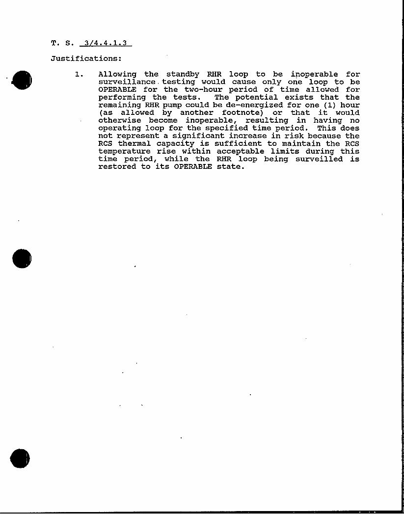
Justifications:1. Allowing the standby RHR loop to be inoperable for
surveillance testing would cause only one loop to beOPERABLE for the two-hour period of time allowed forperforming the tests. The potential exists that theremaining RHR pump could be de-energized for one (1) hour(as allowed by another footnote) or that it wouldotherwise become inoperable, resulting in having nooperating loop for the specified time period. This doesnot represent a significant increase in risk because theRCS thermal capacity is sufficient to maintain the RCStemperature rise within acceptable limits during thistime period, while the RHR loop being surveilled isrestored to its OPERABLE state.
Justifications:1. BASES — The relief capacity of the pressurizer safety
valves is 293,300 lbs/hr per FSAR Table 4.1.3

T. S. 3 4.4.2.2
Justifications:1- This revised action statement allows cooldown of a unit
when safety valves are declared inoperable to performmaintenance. (Cooldown is considered a positivereactivity change.)
2 ~ The definition of RCS pressure boundary is consistentwith OMS protection that provides at least 2.20 squareinches to depressurize the RCS.

T. S. ~34. 4. 3
Justifications:1 ~ BASES — The maximum pressurizer water volume at 92%
indiated water level is 1133 cubic feet.2 ~ This surveillance should not be performed during power
operation.
Justifications:
2.
A revised specification has been proposed which coversonly the PORV block valves.
Reactor Coolant System overpressure protection isprovided by the Pressurizer Safety Valves as addressedin Specification 3/4.4.2.The Steam Generator tube rupture accident does requirea means to depressurize the Reactor Coolant System toreduce coolant leakage to the Secondary Side of the SteamGenerator. The primary means of depressurizing theprimary system is by use of the normal pressurizer spray.Auxiliary pressurizer sprays can be used as a backup.While the PORV can be used as a second backup, it is theleast desirable because it tends to reduce ReactorCoolant System inventory.ACTION has been revised to indicate HOT SHUTDOWN (Mode4) consistent with the APPLICABILITY (Modes 1-3).
T. S. 3 4.4.5
Justifications:1. Specification 3.0.4 provides restriction for MODE change.
Shutdown requirements are provided because Specification3.0.3 would apply if a steam generator becomes inoperableduring operation. Current wording is confusing tooperator because it does not provide all requiredactions.
2 ~
3.
The intent of this surveillance is to inspect everyrefueling interval.Consistency on reporting with 10 CFR 50.73 for LER's.
Justifications:1 ~ The CTS requirement is refueling (recently approved
amendment). Surveillance cannot be performed with unitat power or greater than 200 F due to ALARA and HPrestrictions on dose rates and stay times.
T. S. 3.4.4.6.2
Justifications:1 ~ CONTROLLED LEAKAGE requirements were added to explicitly
control flow from the RCP seals. The wording is similarto the STS.
2. This LCO requirement was revised to be consistent withCTS (NRC Order, dated 4/20/81) restrictions for valveleakage, which are explicitly called out in Table 3.4-1.
3.
4 ~
The added footnote is from CTS 4.17, Reactor CoolantSystem Pressure Isolation Valves. It allows flexibilityin measurement of valve leakage in order to reducepersonnel radiation exposure.
Consistent with CTS and 3.0.3.5. This surveillance was added due to the addition of an LCO
for CONTROLLED LEAKAGE. The wording is similar to theSTS.
6. The added wording excludes the requirement to verifyvalve leakage if work performed on the valve would notreasonably be expected to affect valve leakage; e.g.,painting.
7 ~ BASES —Wording was added to describe CONTROLLED LEAKAGE.The STS words describing safety injection flow were notincluded, as they were not applicable to Turkey Point.
8. BASES — Leakage from the RCS pressure isolation valvesis usually isolated during normal operation due tovarious system line ups. Wording was added to clarifythat only actual mass loss is considered in calculatingthe allowed limit of IDENTIFIED LEAKAGE.
9 ~ A surveillance is added to require testing of the checkvalves after actuation (flow through the valve), similarto the STS.
This testing is required prior to entering Mode 2 becauseoperating pressure is required to conduct the test.

Justifications:1 ~ A representative sample of the RCS can not be obtained
in this condition. This footnote is consistent withrecent FPL/NRC discussions at Turkey Point.
T. S. 3 4 '-8Justifications:
1. BASES — Due to the allowance given for transport ofreleases to site boundary (30 min.) and two (2) hoursfrom sample counting, isotopes with halflives, <10 minwould decay through 12 halflives which would make thedata very inaccurate even if these isotopes were stilldetectable. Industry assumptions are, that after 8 halflifes, the isotope is gone, i.e., <14 of isotopesoriginal activity remains, and after 120 min. (samplingallowance), 12 halflives for an isotope with a 10 min.half life, only .02~ is left.
*.Justifications:
1 ~ The ACTION statement has been reorganized for clarity tominimize confusion and avoid unnecessary thermal cyclingof the Plant.
2 ~ Added plant-specific information regarding specimenlocation and lead factor. Unit 3 capsule "V" has alreadybeen withdrawn.

T. S. 3 4.4.9.2
Justifications:1 ~ The change reflects the current Plant requirements.
2. The ACTION Statement has been reorganized for clarity tominimize confusion and avoid unnecessary thermal cyclingof the Plant.

T. S. 3 4.4.9.3
Justifications:1 As worded now, the Specifications require that HHSI
capability be isolated at exactly 380 F (when coolingdown) and implemented at exactly 380'F (when heating up).This is unnecessarily restrictive on the Plant. Therevised wording provides the Plant desired flexibility.
T. S. 3 4.4.10
Justifications:
'a ~
b.
Components of the Reactor Coolant System were notdesigned to provide access to permit inserviceinspections in accordance with Section XI of theASME Boiler and Pressure Vessel Code (1981 editionand addenda through Winter 1981).
1981 Code was not written when Turkey Point Units3 and 4 were designed.
c ~ The paragraph order has been revised for clarity.2.
a ~
b.
The changes proposed are consistent with applicablecode requirements.
In addition to the referenced changes, all Class l,Reactor Coolant System repairs on components shallmeet the original construction requirements for thatspecific repair.
c ~ Following repair on the RCS pressure boundary, therepaired area receives a hydrostatic presure testin accordance with ASME applicable code requirementswhich assure the structural integrity of therepaired area.
Justifications:1. The surveillance requirement frequency has been changed
to refueling invervals because the Plant must be shutdownto perform the surveillance. The 18 month requirementmay require an unnecessary shutdown and cycling of thePlant.

T. S. Number 3 4.5.1
Justifications:1. A limit of 24 months on "refueling" surveillance is a
management action to limit time between surveillances.

0
T. S. 3 4.5.2
Justification:1 ~ This special report is a duplicate requirement to
10 CFR 50.73 for ESF actuation.
2. As worded now, the tech specs recyire that HHSIcapability be isolated at exactly 380 F (when coolingdown) and implemented at exactly 380'F (when heating up).This is unnecessarily restrictive on the Plant. Therevised wording provides the Plant desired flexibility.
3.
4 ~
5.
Valve *-887 was removed from the list because it isoperated in the fully open position.Valve FCV-*-605 was added to the list because it is usedas an RHR throttle valve when it is necessary to bypassthe heat exchangers or valve HCV-*-758.
This comment has been added to provide flexibilityrequired for dual unit shutdown to prevent a severetransient on the Florida electrical grid. This commentis consistent, with previous discussions and agreementsduring RTS working meetings regarding dual unit shutdownsdue to electrical components being inoperable.
The correct position for valves 866A and B is "closed".FPL drawing 5610-T-E-4510 Sheet 2 shows these valves asnormally closed.
6. The surveillance requirement frequency has been changedto refueling intervals because the Plant must be shutdownto perform the surveillance. The 18 month requirementmay require an unnecessary shutdown and cycling of thePlant.

0
0
Justification:1. This special report is a duplicate requirement to
10 CFR 50.73 for ESF actuation.
2. This requirement states that all High Head SafetyInjection (HHSI) pump motor breakers shall be racked outwhen one or more RCS cold legs is less than or equal to275'F. This is impossible since the system is shared andmay be required operable for the other unit whose RCStemperature is greater than 275'F.

Justification:l. BASES
This change clarifies that the use of portableinstrumentation is acceptable. There is no permanenttemperature monitoring instrumentation installed on theRWST.
Justifications:1 ~ We need capability to test certain components, i.e.,
PASS, where manual containment boundary valves have tobe open.
2 ~
See recently approved amendments 114/108 dated 6/27/85.
Surveillance is not needed. Surveillances 4.6.1.3 ensurecompliance with 3.6.1.3 which maintains containmentintegrity. Also, surveillance is without time frame.
T. S. 3 4 '-1 '
Justifications:1 ~
2 ~
3 ~
L, is an option which Turkey Point does not intend toutilize. (Also applies to BASES.)
ACTION STATEMENT needs to address what must be done ifType B and C leakage exceeds .6 L, in modes 1, 2, 3 and4 (RCS temperature greater than 200'F).
This is consistent with containment integrity Tech Specs.
These surveillances are quoting a portion of 10 CFR 50App J. It has already been clearly established in4.6.1.2.1 that all types A, B, and C, tests will beperformed in accordance with 10 CFR 50 Appendix J. Itis confusing to be quoting "portion" of Appendix Jrequirements. (In fact, Item C.1 as written is inconflict with 10 CFR 50 Appendix J Section III.A.3.b.)law.
Justifications:1. .02L, is much less than is expected and has no basis.
This number, if implemented, would cause numerous unitshutdowns.
This paragraph represents a portion of combined leak rateallowable of 0.6 L,. 0.2 L, represents a value which, ifexceeded, willprovide timely indication of air lock sealfailure. However, the 0.6 L, limit of Tech Spec 3.6.1.1controls the overall containment leakage.
Justifications:1. Revised BASES for consistency with CTS.
Justifications:1. FPL analysis has determined that containment air
temperatures exceeding 120F up to 125F can beaccommodated for limited durations.

Justifications:1 ~ Change is made to maintain consistency on reporting
requirements.
2. Based on Turkey Point's CTS, all requirements foradjacent concrete surfaces have been met. The CTSrequire inspections on the end anchorage concretesurfaces, the mapping of the predominant visible concretecrack patterns, and the measurement of the crack widths.These inspections were done during the StructuralIntegrity Tests one-half year after the SIT and one yearafter the SIT. The inspection report determined that theconditions are satisfactory, therefore, the closeinspections were terminated.
Due to the design of the containment. at Turkey Point, theinspections of individual tendons and adjacent concreteareas are not easily performed. The equipment andpersonnel resources expended for this are not justifiedfor the probable limited benefits. Operations to removegrease from tendons and to inspect tendon wirebuttonheads for corrosion are already performed duringtendon surveillances; inspection of end anchorages andadjacent concrete should be done at the same time, ratherthan requiring an additional mobilization of personneland equiment for a second inspection at the time of ILRT.It is not desirable to perform this operation during anoutage; the need to position a crane near the containmentwill interfere with other outage-related activities.Also, note that the same tendons will not be inspectedat each surveillance; T.S. 4.6.1.6.1 requires randomselection.
Although the 5-year tendon inspection is greater than theILRT interval (40 months), the historical data supportsthis lower inspection frequency. In addition, proceduresare in use at Turkey Point which have acceptancecriteria based on normal containment pressure rather thanILRT pressure.
3. This visual inspection is already required by 10 CFR 50,App J, Section V.A (which is referenced in Tech Spec4.6.1.2.1). Both 10 CFR 50 App J and Reg. Guide 1.35,Sections B and C.3, refer to this as a "general"inspection intended to identify "widespread" problemareas. Therefore, no rigid acceptance criteria areprovided (as none were recommended in the revised TechSpecs). Additional discussion of acceptable inspectiontechniques has been added; requirements for recordkeeping have been added to facilitate the use of data forcomparisons to future inspections.

BASES — Selection of tendons may not be completelyrandom; certain tendons must be eliminated from possibleselection because they are inaccesible or would createhazards to personnel performing the surveillance, e.g.,tendons located near main steam vents.
Proposed Rev. 3 of Regulatory Guide 1.35 recommends theinspection of 24 of each group of tendons (dome, verticaland hoop). For Turkey Point, this equates to 3 dome, 4vertical and 5 hoop tendons.
This change will assure that the appropriate lift-offstress is used for each inspected tendon. Per the FSAR,the averacVe tendon prestress would be less than 0.7 timesthe ultimate strength; however, different tendons (evenwithin the same group) would have different effectiveprestress levels after elastic shortening. Zn addition,time-dependent prestress losses occur (creep, shrinkageand relaxation).The FSAR design stress levels are based on the end of the40-year life of the plant. Comparison of values obtainedat an intermediate point in plant life could result ina non-conservative assessment of prestress adequacy.
Justifications:The tech spec is reworded to clearly identify therequirements and to reflect previous agreements with NRCas noted below.
By letter dated November 28, 1978, the NRC requested alllicensees to respond to generic concerns aboutcontainment purging and venting during normal plantoperation. That letter stated that unlimited purgingduring normal operation would be permitted if licenseesdemonstrated that purge isolation valves were capable ofclosing against the dynamic forces of a design basisloss-of-coolant accident. The November 28, 1978 letteralso required that licensees evaluate the impact ofpurging on ECCS performance, the radiologicalconsequences of any design basis accident requiringcontainment isolation occurring during purge operationsand the containment purge and isolation instrumentationand control circuit designs. Pending completion of theabove, the NRC requested that licensees commit to ceaseor limit purging. FPL committed to limit purging forTurkey Point Units 3 and 4 during power operation ( 24power) to 200 hours per year for the site (200 hourstotal for both units). At that time, FPL stated that itintended to justify unlimited purging.
By letter dated December 13, 1979 (L-79-346), FPLprovided the results of the required evaluations. Theevaluation of the effect of containment purging on ECCSperformance indicated that the effect of purge operationupon the calculated pellet cladding temperatures issmall. An assessment of the incremental increase inradiological dose caused by containment purging duringa postulated loss-of-coolant accident (LOCA) indated thatthe anticipated total LOCA dose to be well within thelimits of 10 CFR Part 100. An evaluation of thecontainment purge instrumentation and control design didnot identify any single failure concerns.
The NRC in an evaluation dated August 31, 1981, indicatedthat the 200 hour purge limit, ECCS analysis, and theinstrumentation and control design, were acceptable. Ina letter dated February 10, 1983, the NRC provided theresults of a generic evaluation of the radiologicalconsequences of accidents while purging or venting atpower. To assure that the generic evaluation was validfor Turkey Point, the NRC verified the adequacy oftechnical specification limits on iodine equilibrium andvalve closure times. That evaluation also indicated thatthe dose contribution through open valves is small, andthat the total accident radiological consequences of such

such accident would be less than the dose guidelines of10 CFR Part 100.
FPL letters dated September 17, 1982 (L-82-407), March4, 1983 (L-83-120), and April 2, 1984 (L-84-86) providedinformation to demonstrate operability of the purge andvent valves. The NRC safety evaluation report datedAugust 17, 1984 concluded (subject to replacement of thebolts in the operators and installation of debrisscreens) that FPL had demonstrated the ability of thevalves to close against the buildup of containmentpressure in the event of a DBA/LOCA.
The August 17, 1984 NRC letter further stated that FPL'sproposed containment purge technical specificationsshould reflect the limitation of the opening angle forthe (48-inch and 54-inch) purge valves, and reflect (inthe basis) that the combined purges for both units willbe about 200 hours per year during power operation forthe site (200 hours total for both units). The proposedtechnical specifications provided by FPL as part of thetechnical specification upgrade project were consistentwith these requirements. Additional restrictions overand above what the NRC has reviewed and accepted are notjustified, and could impose a hardship on plantoperations. The guidelines for the upgrade project wouldpreclude the imposition of such requirements.

T. S. 3 4.6.2.2
Justifications:1. 2000 gpm flow rate cannot be verified during operation
unless the CCW system is put in accident configuration(e.g., two RHR Hx in service, all three ECC's operatingsimultaneously, NCC's isolated, CRDM's isolated, etc.).Plant does not contain individual flow indicators foreach cooling unit. Valve manipulation required tosupport this test would result in need to rebalance theCCW system which can only be done during shutdown.

Justifications:1 ~ This surveillance requires that the plant be in a
shutdown condition. An 18 month surveillance frequencymay cause FPL to have to shutdown for refueling early orcause an unnecessary outage.
T. S. 3 4.6.4
Justification:1 ~
2 ~
This table is derived from the CTS with the exceptionthat the steam generator blowdown valves were deletedfrom this table. The secondary system is considered tobe an extension of containment for containment isolationpurposes, and does not rely on any valves, includingblowdown valves, to provide containment integrity.Of the Table 3.6-1 isolation valves, only the purgevalves are explicitly called out in the LOCA analysis.Specific valve closure times have been eliminated fromthe tech spec.
3 ~ The removal of Notes 2, 5 and 6 is an editorial change.Note 1 was deleted because this information is notspecifically referenced in this tech spec.
Notes 4 and 7 were deleted due to removal of specificisolation times (see 2 above).
Justifications:1. Sample is obtained from the carbon tray after removal.
There is no provision to obtain a sample in accordancewith NRC Reg. Guide 1-52, Sections C.6.b.
2. This surveillance requires that the plant be in ashutdown condition. An 18 month surveillance frequencymay cause FPL to have to shutdown for refueling early orcause an unnecessary outage.

Justifications:1. There is no loop isolation capability from S/G's.
Justifications:1.
2.
This comment has been added to provide flexibilityrequired for dual unit shutdown to prevent a severetransient on the Florida electrical grid. This commentis consistent with previous discussions and agreementsduring RTS working meetings regarding dual unit shutdownsdue to electrical components being inoperable.
This surveillance requires that the plant be in ashutdown condition. An 18 month surveillance frequencymay cause FPL to have to shutdown for refueling early orcause an unnecessary outage.

Justifications:1 ~ Same ACTION Statement and logic train as Auxiliary
Feedwater tech specs.
2 ~ This surveillance requires that the plant be in ashutdown condition. An 18 month surveillance frequencymay cause FPL to have to shutdown for refueling early or,cause an unnecessary outage.
T. S. 3 4.7.1.4
Justifications:1 ~ This footnote is confusing. Zt is FPL s understanding
that an internal NRC position has been taken by sometechnical branches that this footnote should be removedfrom the STS.
T. S. 3 4.7.1.5
Justifications:1 ~ This change will allow reasonable time for corrective
maintenance and represents a 504 reduction from AOTallowed in CTS.
2 ~ Steam demand can exceed steam produced in MODE 3.
Justifications:1 ~ Use of the term "operable" has been modified to reflect
the fact that these pumps are not safety related. Thisconcept is consistent with CTS (Amendment 118/112, 8/86).Due to plant configuration, this path is normallyisolated.
2 ~
3.
This clarification ensures the unit(s) will not beshutdown because of inoperability of non-safety gradeequipment. This comment is consistent with CTS(118/112) .
A limit of 24 months on "refueling" surveillance is amanagement action to limit time between surveillances.

T. N. Number ~34.7.2Justifications:Note:
2 ~
The CCW 'Tech Spec was extensively discussed betweenNRC/FPL in Bethesda on March 15, 1988 (see attached NRCletter to FPL, dated 3/29/88). FPL's comments andjustifications reflect the discussion and agreements madeat that meeting.
The PTN design contains 3 heat exchangers, however, only2 heat exchangers, capable of removing design basis heatloads, are required. Although provisions are availablefor isolating passive failures, a passive failure of aheat exchanger is not a postulated design basis. NRCconcurred with this approach, in particular noting theseverity of the associated ACTION C (plant shutdown — asmarked up) and the extensive heat exchanger surveillanceprogram.
Note that the term "in service" was used and clarifiedvia footnote in lieu of the term "OPERABLE», whoseconventional definition may be misinterpretted in thisapplication."Valves, interlocks, and piping" are considered to beincorporated into the operability requirements for CCWpump/heat exchangers, or the operability of componentsserved by CCW, as appropriate. Accordingly, no specificreference to them is required in the LCO or ACTION.
3. The CCW design incorporated 3-100% capacity pumps. Thechange of AOT from 24 to 72 hours reflects the remotenessof a scenario which would disable the remaining pump(s)and provides additional time which may be required toeffect repairs. Additionally, the requirement tomaintain 3 pumps operable is more conservative thancurrent industry practices and the STS.
4 ~ See Justification 1 above. The wording, as marked up,reflects the LCO and system requirements.
5. With this pump inoperable, the plant still retains 2independent 1004 capacity CCW pumps. The CCW pumps havea good maintenance history and a 30 day AOT isreasonable.
6. These surveillances require the plant to be in shutdowncondition. An 18 month surveillance frequency may causeFPL to shutdown for refueling early or cause anunnecessary outage.
7 ~ BASES is revised to clarify design requirements for CCWand the reasoning behind the SURVEILLANCE wording.
8. Generic dual shutdown concern.

p,ll i(QII(4p
gy ~ gO
UNITED STATES
NUCLEAR REGULATORY COMMISSlONWASHINGTON. O. C. 20555
'tarch 29, 1988
'3/+.7. 0
Docket Nos. 50-?50and 50-251 RECElVED
AIRO5 assFlorida Power and Light Company
Turkey Point Units 3 and 4
LICENSEE:
FACILITY:
SUBJECT:
Nuctear Ucensfnt,
SUHHARY OF HEETING HELD WITH FLORIDA POWER AND
LIGHT COMPANY (FP&L) ON HARCH 15, 1988, REGARDINGTECHNICAL SPECIFICATIONS AND OPERABILITY OF INTAKECOOLING MATER AND COMPONENT COOLING WATER SYSTEHS
REFERENCE: TAC Numbers 63038 and 63039
A meeting was held in Rockville, Haryland on Harch 15, l988 with representativesof Florida Power and Light Company (FP&L) to discuss two matters related to
= Technical Specifications (TS) for,.the- Intake Cooling Mater ( ICM) and ComponentCooling Water (CCW) systems at Turkey Point Units 3 and 4. The first matterconcerned possible interpretations of "operability" of CCM heat exchangers.The second matter related to a revision of the TS for both systems as part ofthe orgoinq TS Revision Project.
2.
~0 erabilit of CCM Heat Exchan ers
In a letter to the licensee (FP&L) dated December 3, 1987, the staffindicated that each CCM heat exchanger should be declared inoperablewhen it becomes known that it cannot remove its design basis heat load(50~ of the required heat removal for the reactor unit). The staff hasnow improved this interpretation to address the matter from a systemsstandpoint. The staff agreed with FP&L that it is sufficient if two CCM
heat exchangers operating together can remove the total design basis heatload of two CCM heat exchangers, provided that a monitoring proqram is inplace to assure this capability continues to exist. The concern is thatfouling of the heat exchanger surfaces could degrade the heat removalcapability. To paraphrase, the staff agreed that it is permissible forthe plant to operate with one operating CCM heat exchanger which is notable to remove all of its design basis heat load, provided that a secondoperating CCM heat exchanger can fully compensate by removing more thanits design basis heat load, and provided that FP&L monitors the heatexchanger capability on a frequent basis. The licensee agreed to providea letter to the staff by Harch 18, 1988 agreeing to .these provisions. Thestaff will then issue a letter clarifying Enclosure 2 of the December 3,1987 letter.
Revision of TS for CCM and ICM
The staff indicated that it could nnt accept a relaxation of TSs whichwould entirely remove Allowable Outage Time (AOT) from the third ICM pump
~
~~
~~ ~
~
and the third CCW pump. This position is based on the current knowledge

of the importance of service water to core melt frequency as identifiedin the Byron PRA and is under generic review by the staff under GenericIssue 130. The staff suggested that simply relaxing the current 24-hourAOT for the ICW pumps to perhaps 72 hours was a better approach. Thestaff also suggested that the ICM strainers should be included in the TSwith an AOT. The licensee agreed to consider possible AOTs for the ICWand CCW pumps and the ICW strainers and propose these at a later date.In addition, the staff agreed that no AOT is necessary for the third CCM
heat exchanger because of the natural incentive for the licensee tomaintain the heat exchanger in an operable condition, and because of theTS interpretation described in (I) above.
The meeting agenda and reference material discussed at the meeting areprovided as Enclosure I to this letter. The attendance list is Enclosure 2.
4
Enclosures: As stated
Gordon E. Edison, Sr, roject Hanager-Project Oirectorate II-2Division of Reactor Projects-I/IIOffice of Nuclear Reactor Regulation
cc w/enclosures:See next page
T. S. Number 3 4.7.3
Justifications:Note:
1 ~
2 ~
The ICW Tech Spec was extensively discussed betweenNRC/FPL in Bethesda on March 15, 1988 (see attached NRCletter to FPL, dated 3/29/88). Unless otherwise notedbelow, FPL's comments and justifications reflect thediscussions and agreements made at that meeting.
"Two headers", as well as "valves, interlocks and piping"are considered to be incorporated into the operabilityrequirements for ICW pumps, or the operability ofcomponents served by ICW, as appropriate. Additionally,due to the open design and operation of the system, aspecific requirement for headers was deemed unnecessary.Accordingly, no specific reference to them is required.
A 3.0.4 exclusion is added, consistent with CCW tech specand NRC/FPL discussions.
3 ~
'4~
The ICW design incorporates 3-1004 capacity pumps. Thechange of AOT from 24 to 72 hours reflects the remotenessof a scenario which would disable the remaining pump(s)and provides additional time which may be required toeffect repairs. Additonally, the requirement to maintain3 pumps operable is more conservative than currentindustry practices and the STS.
These surveillances require the plant to be in a shutdowncondition. An 18 month surveillance frequency may causeFPL to shutdown for refueling early or cause anunnecessary outage.
5. BASES is revised to clarify that design "and operation"of this system ensures required cooling capacity. Thisclarification recognizes that operator actions may berequired in certain scenarios, as previously discussedwith NRC.
6. As discussed between FPL/NRC at the March 15th meeting,FPL is to propose wording regarding the basket strainers.This wording will be provided at a later date.
ill I'tOu%8
)0
I 0
O
UNITEDSTATESNUCLEAR REGULATORY COMMISSlON
WASHINGTON, o. C. 20555
~1arch 29, 1988
Docket Nos. 50-250and 50-251 RECElVKD
APROS N8Florida Power and Light Company
Turkey Point. Units 3 and 4
LICENSEE:
FACILITY:
SUB<>ECT:
Nucfear Uo.nsfnt.
SUMMARY OF MEETING HELD WITH FLORIDA POWER AND
LIGHT COllPANY (FP5L) ON MARCH 15, 1988, REGARDINGTECHNICAL SPECIFICATIONS AND OPERABILITY OF INTAKECOOLING WATER AND COMPONENT COOLING WATER SYSTEMS
TAC Numbers 63038 and 63039REFERENCE:
1. ~0 erabi lit of CCM Heat Exchan ers
In a letter to the licensee FPItL( ) dated December 3, 1987, the staffindicated that each CCW heat exchanger should be declared inoperablewhen it becomes known that it cannot remove its desiqn basis heat load(50" of the required heat removal for the reactor unit). The staff hasnow improved this interpretation to address the matter from a systemsstandpoint. The staff agreed with FphL that it is sufficient if two CCM
heat exchangers operating together can remove the total design basis heatload of two CCM heat exchangers, provided that a monitoring proqram is inplace to assure this capability continues to exist. The concern is thatfouling of the heat exchange surfaces could degrade the heat removalcapability. To paraphrase, the staff agreed that it is permissible forthe plant to operate with one operating CCM heat exchanger which is notable to remove all of its design basis heat load, provided that a secondoperating CCM heat exchanger can fully compensate by removing more thanits design basis heat load, and provided that FP5L monitors the heatexchanger capability on a frequent basis. The licensee agreed to providea letter to the staff by March 18, 1988 agreeing to these provisions. Thestaff will then issue a letter clarifying Enclosure 2 of the December 31987 letter.
S
2. Revision of TS for CCM and ICM
The staff indicated that it could nnt accept a relaxation of TSs whichwould ent.irely remove Allowable Outage Time (AOT) from the third ICMan d the third CCM pump. This position is based on the current knowledge
ir pump
A meeting was held in Rockvi lie, Maryland on March 15, 1988 with represent'ativesof Florida Power and Light Company (FP5L) to discuss two matters -related toTechnical Specifications (TS) for the Intake Cooling Water ( ICQ) and ComponentCooling Water (CCW) systems at Turkey Point Units 3 and 4. The first. matterconcerned possible interpretations of operability" of CCW heat exchangers.The second matter related to a revision of the TS for both systems as art ofthe ongoing TS Revision Project.
ems as par o
of the importance of service water to core melt frequency as identifiedin the Hyron PRA and is under generic review by the staff under GenericIssue 130. The staff suggested that simply relaxing the current 24-hourAOT for the ICM pumps to perhaps 72 hours was a better approach. Thestaff also suggested that the ICM strainers should be included in the TSwith an AOT, The licensee agreed to consider possible AOTs for the IChtand CCM pumps and the ICW strainers and propose these at a later date.In addition, the staff agreed that no AOT is necessary for -the third CCM
heat exchanger because of the natural incentive for the licensee tomaintain the heat exchanqer in an operable condition, and because of theTS interpretation described in (1) above.
The meeting agenda and reference material discussed at the meeting areprovided as Enclosure I to this letter. The attendance list is Enclosure 2.
Enclosures: As stated
cc w/enclosures:See next page
Gordon E. Edison, Sr. Project, ManagerProject Directorate II-2Division of Reactor Projects-I/IIOffice of Nuclear Reactor Regulation
T. S. 3 4.7.4
Justifications:l. The requirements of this tech spec are incorporated into
the CCW tech spec through the requirement to monitor andmaintain in service CCW heat exchangers capable ofremoving design basis heat loads. A tech spec for aspecific ultimate heat sink temperature is inappropriate;ultimate heat sink temperature is one of several factors(i.e., heat. exchanger performance characteristics, flow)involved in determining heat removal capability.
T. S. 3 4.7.5
Justifications:1 ~ As there is only one (1) CREVS, the word "the" was
substituted for "each" for clarity.2 ~
3 ~
4 ~
The added words had been deleted by the NRC. Theirdeletion would imply the requirement to visually inspectthe entire CREVS. This would require a major effort, aslarge parts of the system are not accessible withoutdisassembly.
CTS AOT is 3-1/2 days. STS is seven (7) days for aredundant system (e.g., two (2) independent systems) .
This comment has been added to provide flexibilityrequired for dual unit shutdown to prevent a severetransient on the Florida electrical grid. This commentis consistent with previous discussions and agreementsduring RTS working meetings regarding dual unit shutdownsdue to electrical components being inoperable.
T. S. 3 4.7.6
Justifications:1 ~
2.
This inspection cannot be done at power.
Footnote clarifies "inaccessible".3 ~ A limit of 24 months on "refueling" surveillances is a
management action to limit time between surveillances.

T. S. 3 4.7.8.2
Justifications:Per the Turkey Point Appendix R upgrade, the listedspray/sprinkler systems were superseded for the followingreasons:
a ~ 4160V Switchgear Room Louver Spray —This system wasrendered obsolete when the opening it was protectingwas filled with a 3-hour fire barrier.
b. EDG Building Hater Curtain — This manual system onthe outside of the EDG Building was superseded byan automatic suppression system in the EDG rooms.
c ~ Control Room Guardhouse Sprinkler System — Thissystem protected the old guardhouse, which wasconstructed of combustible materials. A non-combustible guardhouse has since been constructed.

0
0

Justifications:1. These hose stations are not all shared.
Justifications:1. BASES — This evaluation is inconsistent with the
requirements of the LCO.
T. S. 3 4.9.1
Justification:1 ~ RTS wording is revised to 0.95 per Amendment 132/126.
The restriction on K,<< is CTS and has been lessened bythis recent amendment. (This justification also appliesto BASES.)
2 ~
3.
The term "equivalent" would mean 100 gpm of 1950 ppm;this would require 2 charging pumps in Mode 6. No raterequirements for boration in Mode 6.
The tech spec is not requiring valves be "locked closed".

I'ustifications:
l.
2-
Due to expected maintenance activities during this mode,the suggested 4 hour time period may not be achievable.
A limit of 24 months on "refueling" surveillances is amanagement action to limit time between surveillances.
Justifications:1. Due to expected maintenance activities during this mode,
the suggested 4 hour time period may not be achievable.

Justifications:1 ~ Consistent with tech spec 3.3.2 (Table 3.3-2, item 3.c.4)
for ESFAS operability in Modes 1-4.

Justifications:1. There is no need for an upper limit on water level.
Justification:l. All design calculations are based on the time the fuel
was last critical, not the time the fuel was placed inthe Spent Fuel Pool.
2. Wording was clarified to state 120 days of decaynot 120 days in cask.
Justifications:1. Consistent with Tech Spec 3.3.2 (Table 3.3-2, item 3.c.4)
for ESFAS operability in Modes 1-4.
Justification:1 ~ BASES — Current Technical Specification 3.17 specifies
a maximum K,ff of 0. 95 applicable to the proposed two-region spent fuel pools at PTN. This is also discussedin RTS 5.6.1.Refer to Justification 3/4.9.1, g1.
T. S. Number 3 4.10.1
Justifications:1 ~ The term "equivalent" would mean 100+ gpm of 1950 ppm;this would require two (2) charging pumps. Tech Spec
3.1.2.3 ACTION allows two (2) charging pumps to beinoperable for a limited time.

Justification:1. Depending on specific unit configuration, the operating
staff needs flexibility to deal with the LCO withoutpotentially creating an unexpected operating condition.

Justifications:1. Recently approved evaluation by FPL's Fuels Analysis
Group allowed withdrawal of two banks during control rodtesting.
Justifications:1 ~
2 ~
3 ~
The Unit 3 and 4 containment bleed lines constitute asmall release rate to the plant vent. This bleed rateis continuous unless containment isolation occurs, atwhich time the bleed lines are automatically isolated.All realses via this pathway are continuously monitoredby the installed plant vent monitors for noble gas,particulate and iodine activities. This monitoring willaccount for all activity released from the containmentby the bleed line pathway.
Note 6: No need to sample if coolant activity has goneup unless the effluent monitor has also gone up.Therefore, the statement should require both conditions.(This wording is consistent with recently issuedspecifications at St. Lucie and Palo Verde.)
Note 7: FPL's comment returns the wording to a positiveformat where analysis is required when both requirementsare met; with the negative format, it appears analysisis required when either one or both of the conditions arenot met. Without this comment, this tech spec wouldrepresent a significant change to the CTS (Amendment103/97) .
Justifications:1 ~
2.
The plant has the ability to monitor only the in-servicetank, not all 6 tanks simultaneously. This comment isconsistent with previous FPL/NRC discussions.
Footnote has been added for consistency with Table 3.3-8, Item 2 which covers the use of grab samples forinoperability of continuous monitors.
T. S. Number 3 4.11.3
Justifications:1 ~ All of our shipments do not go directly to a burial site,
some are shipped to a waste processor for volumereduction prior to burial.Only "wet" radioactive wastes (not all radioactivewastes) are required to be dewatered or solidified.
Justifications:1 ~ BASES — Turkey Point's outside storage tanks, if
released, will be contained within the site boundary andmixed with our cooling canals which are completelyenclosed.
T. S. Number 3 4.12.1
Justifications:1 ~ The existing requirement (if sample is >1.0 units and >10
times most recent control sample) is consideredappropriate to trigger gamma isotopic analysis ofspecific samples. The monitoring program is conductedby the State of Florida under a joint Turkey Point/St.Lucie contract. This comment provides a consistentapproach between Turkey Point and St. Lucie and reflectsthe requirements of the CTS (RETS Amendment 103/97).

0
T. S. Number 3 4.12.3
Justifications:1. The State Laboratory participates in the EPA Inter-
comparison Program for media, isotopes and analysis notrequired by our program in addition to those that arerequired. The proposed wording would have FPL generatea report if the State chose not to participate in one ormore of the "other" media, isotopes or analysis.

0
T. S. Number 5.1 Fi ure 5.1-1
Justifications:1. This figure willbe redrawn to reflect the required level
of detail. An original of the redrawn figure will beprovided to the NRC.
T. S. Number 5.3
Justifications:1 ~
2.
Initial fuel load enrichment is historical informationand is not required. Reload fuel enrichment will be achanging value and will be adequately documented in thereload analyses provided in the FSAR.
This wording reflects recent CTS Amendment.

T. S. Number 5.7 Table 5.7-1
Justifications:1. These changes are the result of an engineering evaluation
of cyclic loading. An FSAR change is being processedwhich will change these values in FSAR Table 4.1-8.
T. S. Number 6.2
Justifications:The Operations Superintendent is a senior manager withresponsibility for operations, outage scheduling,chemistry, reactor engineering, and health physics. Inthe absence of the Plant Manager, the OperationsSuperintendent normally assumes the duties of the PlantManager. The Turkey Point Plant organization does nothave an Assistant Plant Manager position. The proposedrequirement that the Operations Superintendent eitherhold or have held an SRO license would continue to ensurethat he has the knowledge and experience commensuratewith his level of responsibility. The OperationsSupervisor, who has direct responsibility for operations,will continue to hold a current SRO license. Theserequirements provide rea'sonable assurance that decisionsand actions during normal and abnormal conditions willbe such that the plant will be operated in a safe andefficient manner.
T. S. Number 6.3
Justifications:1. This change is required for consistency with the proposed
change to 6.2.2.i.2. The March 28, 1980 NRC letter has been superseded. RO
and SRO qualifications are now covered by 10 CFR 55 andANSI 3. 1( 1981.
T. S. Number 6.4
Justifications:l. The 10 CFR 55 rec{uirements have been included in the body
of the document, and are no longer in Appendix A. TheMarch 28, 1980 NRC letter has been superseded by 10 CFR55 and ANSI 3.1, 1981.

T. S. Number 6.S
Justifications:
2 ~
These changes were made to reduce management time spenton PNSC activities. The problem of excessive PNSCmeetings and line management involvement was noted by theNRC in Safety Review Team Inspection Report 87-49(attached). In response to this concern, FPL proposesadapting the Palo Verde Unit 3 T.S. regarding technicalreview and control activities. This T.S. removes thedirect responsibility for review of various plantdocuments and programs from the PNSC. FPL believes thatthe delegation of review responsibility adequatelyresponds to the NRC's concern, and is consistent with theNRC's interpretation of PNSC responsibilities (variousmemos attached).
This type of generic composition of the CNRB has beenpreviously approved by the NRC for other plants (e.g.,Fermi II). It will eliminate the need for future licenseamendments due to changes in titles of CNRB members.
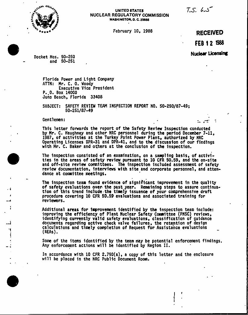
~4 itOy~C p
n4
Docket Nos. 50-250and 50-251
UNITED STATESNUCLEAR REGULATORY COMMISSION
WASHIHOTOlliD. C. 20555
February 10, 1988
7$. Ns
RECFnrED
FEB 12 SINudear uce&IC
Florida Power and Light CompanyATTN: Hr. C. 0. Woody
Execut1ve Vice PresidentP. 0. Box 14000Juno Beach, Florida 33408
SUBJECT: SAFETY REVIEW TEAH INSPECTION REPORT XO. 50-250/87-49)50-251/87-49
Gentlemen:
This letter forwards the report of the Safety Review Inspection conductedby Hr. C. Haughney and other NRC personnel during the period December 7-11,1987, of activities at the Turkey Point Power Plant, authorized by NRCOperating Licenses DPR-31 and DPR-41, and to thc discussion of our findingswith Hr. C. Baker and ot;hers at thc conclusion of the inspection.
The 1nspectfon consisted of an examination, on a sampling basis, of activi-ties fn the areas of safety rev1ew pursuant to 10 CFR 50.59, and the on-siteand off-site review coIIInfttees. The fnspcctfon included assessment of safetyrev1ew documentat1on, interviews with site and corporate personnel, and atten-dance at coaIIfttee meetings.
The inspection team found ev1dence of significant improvement fn the qualityof safety evaluations over the past year. Reaafnfng steps to assure contfnua-tfon of this trend include thc tfmly issuance of your comprehensfve draftprocedure covering 10 CFR 50.59 evaluations and assoc1ated training forreviewers.
Additional areas for improvement fdcntff1ed by the fnspect1on team include:improving the efficiency of Plant Nuclear Safety CoaIIfttee (PNSC) reviews,identffyfng currently valid safety evaluations, classification of guidancedocuments regarding act1ve check valve failures, the retent1on of designcalculations and timely completion of Request for Assistance evaluations(REAs).
Some of the items identified by thc team may be potential enforcement f1ndfngs.Any enforcement actions will be identified by Region II.In accordance with 10 CFR 2.790(a), a copy of this letter and the enclosurew1ll be placed in the NRC Public Document Room.
florida Pawer and Light Ceapany -2- february )0, 1988
Should you have any questions concerning this inspection, please contact eeor Hr. L. Norrhol@ (301-492-0956) of this office.
Steven A. Varga, DirectorDivision of Reactor Pro5ects, I/IIOffice of Nuclear Reactor Regulation
Enclosure: Inspection Report 50-250/87-49; 50-251/87-49
cc w/enclosure: See next page
U.S. NUCLEAR REGULATORY CORIISSIOKOFFICE OF NUCLEAR REACTOR REGULATION
OIVISION OF REACTOR INSPECTION AND SAFEGUAROS
Report No.: 50-250/87-49 and 50-251/87-49
Oocket No.: 50-250 and 50-251
Licensee: Florida Power and Light CeapanyP.O. Box 14000Juno Beach, Florida 33408
Inspection At: Turkey Point Power PlantFlorida City, Florida
Inspection Conducted: December 7-11, 1987
Tea< Leader:ar es . auecial InSp s t n 8 anch, RR
at ne
Teae Members:e . or
Teaa I peO~ d
n isal and Pevelopeent Sec. 1
ivya e gne
/x~ A'. ~ ns, , o ree
Consultant: Gary J. verbeck
ate gne
Approved By:ar es . au , e
Special Inspec i Branch, IS, NRRe gne
This one-week team inspection evaluated safety review activities conductedby the licensee pursuant to Title 10 Code of Federal Regulations part 50.59.Related functions of the Plant Nuclear Safety Cemfttee (pNSC) and thcCorporate Nuclear Review Board (CNRB) were also assessed. The fnspectfonconsisted of record reviews, interviews w1th cognizant personnel, and atten-dance at meet1ngs. The purpose of the inspection was to determine whetherappropriate issues were subjected to 10 CFR 50.59 reviews, whether correctdeterminations were made with respect to unrevfewed safety qucst1ons, andwhether documentation of these reviews were complete 1n describing the basesand rationale for conclusions.
2.0 Sugar of Sf nificant Findin s
Steady improvement in the quality and completeness of 10 CFR 50.59 safetyevaluation documentation was observed over the past year. Further improve-ment and the continuatfon of current skills fn this area should be aided bylicensee initiatives to issue comprehensive procedural guidelines and toprovide training to cvaluators.
In general, recent safety evaluations reviewed were sufficiently detailed todemonstrate, as a stand-alone document, the logic and bases for determinatfonsregarding potential unrcv1ewed safety questions. One notable strength was thcuse of prior 10 CFR 50.59 review and Plant Nuclear Safety Coeafttcc (PNSC)authorization for temporary modifications to the plant. including Jumpersand lifted leads.
Some areas werc identiffed as weaknesses which should receive attention by thelicensee. Despite attempts at mitigation, the volume of material requiringPNSC review has resulted in long and frequent meetings, soee brfcf reviews,and diversion of management from normal duties. Some safety evaluationsreviewed were no longer valid, but no systca was fn place to identify these.Licensee attention should be directed to insuring that Request for EngineeringAss1stance (REA) evaluations were completed fn a tfmely manner. Finally, the .
licensee should reevaluate its position regarding the treatment of check valveactive failures and the retention of design calculations.
3.1 Design Change Process
Licensee procedures for all design and safety analyses performed by the PowerPlant Engineering Department were contained 1n gualfty Instruction JPE-gI-3.2,Revision 3, dated July 30. 1982. The gu1dancc provided in this procedure wasmin1mal with respect to 10 CFR 50.59 evaluations in that the definition ofunreviewed safety question was quoted from the rulc, and an additional statementwas made to the effect that thc discuss1on should clearly indicate the basesfor the conclusions reached.
Station Administrative Procedure 0190.15, Plant Changes and Nodfffcatfons(PC/H), dated October 26. 1987, prov1ded essentially the same informationas JPE-(1-3.2. Station Administrative Procedure 0190.22, Changes, Tests,and Erperiments, dated December 12, 1986, offered some additional guidance
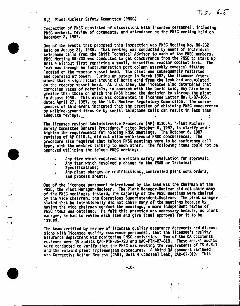
Plant Nuclear Safety Comfttce (PHSC)
Inspection of PHSC consisted of discussions with licensee personnel, includingPNSC members, review of documents, and attendance at the PHSC meeting held onOecember 8, 1987.
One of thc events that prompted this inspection was PNSC Meeting No. 86-232held on August 31, 1986. That meeting was conducted by means of individualtelephone calls from the Sh1ft Technical Advisor to each of the PNSC members.PHSC Meeting 86-232 was conducted to gct concurrence from thc PNSC to start upUnit 4 without f1rst repairing a small, identified reactor coolant leak. Theleak was through an instrumentatfon port column assembly conoseal fitt1nglocated on the reactor vessel head. The plant was subsequently restartedand operated at power, Ourfng an outage fn March 1987, thc licensee deter-mined that a significant amount of boric acid from the leak had accumulatedon the reactor vessel head. At that time. the licensee also dctermfned thatcorrosion rates of materials. fn contact with the boric acid. may have beengreater than those on which the PNSC based the decision to startup the plantin August 1986. This event was documented fn licensee Letter No. L-87-186,dated April 27, 1987, to the U.S. Nuclear Regulatory Coawfssfon.- The conse-quences of this event indicated that thc practice of obtaining PNSC concurrenceby walking-around items or by serial telephone calls can result fn less thanadequate reviews.
The lfcensee revised Administrative Procedure (AP) 0110.4, 'Plant NuclearSafety Coanfttee General Procedure," dated October 6, 1987, to clarify and .
tighten the requirements for holding PHSC meetings. The October 6, 1987rev1sfon of AP 0110.4, dfd not allow walk-around PNSC concurrences. Theprocedure also required that telcon PHSC meetings were to bc conference calltype, with the members talking to each other. The following fteas could not beapproved utflfzfng the telcon PNSC meeting:
Any item which required a written safety evaluation for approval;Any item wh1ch involved a change fn the FSN or TechnicalSpccfffcat1ons;Any plant changes or modfffcatfons, controlled plant work orders,and process sheets.
One of the lfcensce personnel interviewed by the team was the Chafraan of thcPNSC, the Plant Manager-Nuclear. The Plant Manager-Nuclear dfd not cha1r manyof the PHSC meetings; instead, thc ma)ority of the PNSC meetings were chafredby the vice chairman, the Operations Superintendent-Nuclear. The plant managerstated that he intentionally dfd not chair many of the meetings because byhavfng the vice chairman conduct the meetings, a more independent review ofPHSC items was obtained. He felt this practice was necessary because, as plantmanager, he had to review each item and give final approval for ft to beissued.
Thc team verff1ed by review of licensee quality assurance documents and discus-sions with licensee quality assurance personnel, that thc licensee's qualityassurance department was monftorfng PHSC act1vf ties. Two of the gh documentsreviewed were gA audits gAO-PTX-86-723 and gAO-PTN-87-818. These annual auditswere conducted to verify that the PNSC was meeting thc requirements of TS 6.5.1and the related plant 1mplementing procedures. A third QA document reviewedwas Corrective Action Request (CAR), Unit 4 Conoscal Leak, CAR-87-019. This
-10-

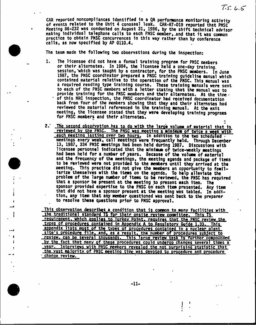
CAR reported noncompl fances 1dent1f1ed 1n a gA per foraance monftor1ng act1v1tyof events related to the Unft 4 conoseal leak. CAR-87-019 reported that PNSCNeet1ng 86-232 was conducted on August 31, 1986, by the sh1ft techn1cal advfsormak1ng 1nd1v1dual telephone calls to each PNSC meaber,.and that 1t was coeaonpract1ce to obta1n PNSC concurrences 1n th1s way rather than 'by conferencecalls, as now spec1f1ed by AP 0110.4.
The team made the follow1ng two observat1ons dur1ng the 1nspect1on:
I. The l1censee d1d not have a formal tra1n1ng program for PNSC membersor the1r alternates. In 1984, the 11censee held a one-day tra1n1ng.sess1on, wh1ch was taught by a contractor, for the PNSC oeabers. In June1987, the PNSC coord1nator prepared a PNSC tra1n1ng gu1del1ne manual wh1chconta1ned mater1al relat1ve to the operat1on of the PNSC. Th1s aanual wasa requ1red read1ng type tra1n1ng course. These tra1n1ng aanuals were sentto each of the PNSC members w1th a letter stat1ng that the manual was toprov1de tra1n1ng for the PNSC members and the1r alternates. At the t1me ~
of th1s NRC 1nspect1on. the PNSC coord1nator had rece1ved documentat1onback from four of the members show1ng that they and the1r alternates hadrev1ewed the mater1al referenced 1n the tra1n1ng aanual. At the ex1tmeet1ng, the 11censee stated that they were develop1ng tra1n1ng programsfor PNSC members and the1r alternates.
2. v ha d w1 h la volume of mat r1al that 1sv e d b NS . Th P n 0
1n ast n over two hour In a 1t1on to t two sche u emeet ngs every wee, ca meet ngs were frequently held. Through December13, 1987, 334 PNSC meetfngs had been held dur1ng 1987. 01scussfons w1th11censee personnel 1nd1cated that the w1n1ae of tw1ce-weekly aeet1ngshad been held for a number of years. Because of the volwe of mater1aland the frequency of the meet1ngs, the meet1ng agenda and package of 1temsto be rev1ewed were not prov1ded to the members unt1l they arr1ved at themeet1ng. Th1s pract1ce d1d not g1ve the members an opportunfty to faw)l-1ar1ze themselves w1th the 1teas on the agenda. To help allev1ate theproblems of the large number of 1tems to be rev1ewed. the PNSC has requ1redthat a sponsor be present at the aeet1ng to present each 1tem. Thesponsor prov1ded expert1se to the PNSC on each 1tea presented. Any 1temthat d1d not have a sponsor present at the meet1ng was tabled. In add1-t1on, any 1tem that any member quest1oned was sent back to the preparerto resolve these quest1ons pr1or to PNSC approval.
Th1s observat1on descr1 s a condft1on h 1 coeeon to man fac111t1 w1thtra t ona s
nd xs roce u 1 e an as a result the number o rocedures sub ect to
ur er c undedh fac tha man f rocedu c ld nd r c an es severa t1mes a
r. Tn rv
chan e rev1ew.
h n r nf n u and ro edure
-11-
In addition to the requirement to revIcw procedures and procedure changes, TS6,5,1,6.f requires a revfew of facf1 1 ty operations to detect potcntfal safetyhazards. Mhcn PNSC members were asked how they conducted such a revfcw theywere fnft1ally unable to respond. After some thought, one member suggestedthat such a revIew was accomplished by the review of Licensee Event Reports(lERs). However, the team pointed out that review of LERs was sere explicitlycovered by TS 6.1.5.6.k, which required review of all reportablc events. Theteam also asked PNSC members whether they had,ever been requested to performspecial reviews and fnvestfgatIons by the CNRB. These revfews are a TSrequirement fn 6.5.1.6.g. None of the PNSC members fntcrvfewcd could recallconductIng such a review. Admittedly. both of these TS requirements are verybroad and thc absence of their rcvIews by the PNSC would not, fn and of itself,constitute a violation of TS. However, the team questioned PNSC members as towhether they had ever made those review requfrements meting agenda Items. Inthe team's view, the PNSC fs so burdened with the extensive revfcw of routineprocedure changes that ft fs effectively unable to devote time to reflect uponbroad safety Issues. This issue fs c ounded b the fact that PNSC membersare kc station mana crs o must v e t e r t se ann act v cs
an ours an su rv s on o e r e ar tmcn s. am cons rs ate c u s n ct vc c cou vc 0
a rnativ fr n ndn f n sCertain t s of ke roccdurcs such as cnc o ratin edu s and
cedurcs c ld vf d bic see n icatcd t at e would c n fd r
x mce fnn T a n n
nstftut n a ro riate adminfstratIve con ro cha es tha would a ow theareduce t c rocc ure review work oa on the NSC.
Based on this lfafted inspection, the team determined the followfng:
The PNSC was conducting adequate revfcws.
Adequate admfnfstratfvc procedures had been fmplemnted to control PNSCactivities so that TS requirements were being mat.
The gA department had performed monftorfng activities and audits ofPNSC activities.
6.B ~dlhThe Inspection team conducted an exit meeting on Decciabcr 11, 1987, to providea sNNaary of issues identified during thc Inspection. The licensee'sreprescntatIves at the ex1t meeting are Identified In Attachment A. The scopeof the inspection was dfscussed, the observations werc presented for each area1nspected, and team members responded to questions from the licenseerepresentatives.
»12-
UNIT50 STAT55NUCI.EAR REQULATORY COMMISSION
IVAN'NCAN,P. C. 200%i
February 16, 1978
Docket No. 50-313
Arkansas Power I Light CompanyATTN: -Nr. Nlliam Cavanaugh. III
Executive Director, Generationand Construction
Post Office Box 551Little Rock, Arkansas 72203
Gentlemen:
By letter dated January 10, 1978, you requested an interpretation ofTechnical Specification 6.5.1.6 for Arkansas Nuclear One - lJnit No. l.This request was the result of a difference in interpretation betweenArkansas Power 5 Light Company staff and NRC Regional Inspection andEnforcement personnel, and concerns the technical specification wordingwhich states that: "The Plant Safety Comaittee (PSC) shall be
responsible for review of ...'. Your interpretation of this require-ment is that items of review for which the PSC is responsible could be
delegated to individuals or groups outside the PSC. You state thatthis interpretation is contrary to that of OINK personnel who requirethat the PSC perform all reviews and investigations.
The proper interpretation of this provision fs as follows:
The PSC may delegate revie~ responsibility to individualsor groups outside of the forwal composition of the PSC.
However, since the PSC is responsible for the performanceof these reviews, the review function is not completeuntil the PSC acts upon the results of the review in a
formal manner and documents such action. Documentation-@ay take the form of a siaple notation in 'the minutes ofa PSC aeeting or may be as elaborate as the preparationof a formal PSC report.
gaA alCig~
~ates
7-~ 6.sUNITED STATES
NUCLEAR REGUI.ATORY COMMISSlONWASHINGTON, D. C. 20555
'April 28, 1978
HEHORANDUH FOR: B. M. Grfer, Director, RIJ. P. O'Ref lly, Dfrector, RIIJ. G. Keppler, Director, RIIIG. L. Hadsen, Acting Director, RIVR. H. Engelken, Director, RV
FROH:
SUBJECT:
J. M. Snfezek, A/D for Field Coordination, DROI, IE
INTERPRETATION OF TECMNICAL SPECIFICATION REQUIREYiENTSFOR ON-SITE COMMITTEE REVIEW FUNCTION
On August 12, 1977, I forwarded a memorandum to all RO5NS Branch Chiefsregarding the on-site committee review function. Included fn thismemorandum was an interpretation by K. R. Goller that was intended toclarify how the on-site conmfttee was intended to function. By memo-randum to Karl Goller dated August 2, 1977, Jfm Hurray said that he .
had reviewed Goller's memorandum of June 27 and could not agree withthe legal conclusions and that he would be unable to support enforce-ment action fn those instances where the On-Site Review Committee dfdnot formally convene a quorum to conduct comfttee business. Sincethat tflie we have held several meetings with NRR and ELD. There appearsto be no conflict regarding the intent of collllfttee review requirements.NRR expects the on-site review committee to act on tasks in their areaof responsibility while the coomtttee fs 1n sess1on and to record theresults of their actions fn coamittee mfnutes. This fs not to saythat the fndfv1duals must meet to review issues, o&n y they must meetto act on the various'ssues and that these actions should be recorded.Certain portions of the on-site corefttee's overall responsfbf11ty maybe reviewed by subcomfttees or individuals who make recommendationsto the on-site colrmlfttee.'he on-site committee must act on theserecoreendatfons; however. ft fs not required that the on-site committeeactually conduct a detailed review of the issue fn question. DROIand ELD concur wfth NRR's views on this matter.
|lith regard to enforceabflfty of current technical specificationrequirements fn this area, we note that the above interpretation ofhow the colmlfttee should function fs completely consistent with NRC'slong standing interpretation of the on-site review function. While wefeel that this fntent fs implicit fn the language of the TS, we cannotdf'sagree with ELD's view that the language of the TS may not be
'I

Regional Directors7.s:
April 28, ] 9]3
enforceable should the matter be taken to a hearing. To resolve thisissue for future plants, NRR intends to revise the language of theSTS. Mith regard .to those facilities that are already licensed, itwas pointed out that the intent of this specification appears to beclearly understood by all but a few licensees. Therefore, to avoidunnecessary TS changes NRR will request licensees who are not meetingthe intent of. the specifications to submit a change to their TS. Inconsideration of the difficulties of a generic resolution to thisissue, we find this approach acceptable.
Please call if you have any questions on this matter.
cc: ROIHS BCs, Regions I-VEnforcement Coordinators,
Regions I-VE. L. JordanJ. Nurray, KLDJ. HcGoughT. J, Carter
H, Sniezek, A/D or FieldCoordination
Division of Reactor OperationsInspection, IE
CONTACT: G. L. Constable(492-8019)

0
P
T. S. Number 6.8
Justifications:1 ~
2 ~
This change reflects the current T.S. wording.
The footnote was deleted because FPL considers itinappropriate to include state regulations in the T.S.This footnote is not in the current T.S.
3 ~ Current T.S. 6.14 contains the same requirements as RTS6.8.4.a; however, no specific systems are identified.FPL's position is that inclusion of systems could beinterpreted as limiting the program to those listedsystems.
4 ~ This change reflects the changes to 6.5.1 and 6.5.2.

0

T. S. Number 6.9
Justifications:The initial startup reports were completed in 1972 and1973, and met the requirements of the original FSAR. TheFSAR has subsequently been revised several times. Itwould not be productive to compare the initial StartupReports to the current FSAR. All subsequent StartupReports will meet or exceed the current FSAR. Theproposed wording is taken from the current T.S.
2 ~
3.
4,
This wording is in the current T.S., and reflects FPL'sNRC-approved response to NUREG-0472.
There are no other uranium fuel cycle sources near theTurkey Point site.This change, which replaces the PS<R version with currentT.S. 6. 9. 3. d (except for reporting requirements), reflectsthe FPL-proposed change to T.S. 3.2.2. The NRC-proposedT.S. would require FPL to obtain additional analysis togenerate the proposed Peaking Factor Limit Report.Current T.S. 6.9.3.d was approved by the NRC onMarch 17, 1982.
5.
6.
These changes were made to conform with 49 CFR.
This is a duplication of the requirements of the AnnualEnvironmental Monitoring Report, and is not part of STS.
7 ~ This change is for consistency with other reportingrequirements of 10 CFR 50.4 and T.S.6.9.1.
T. S. Number 6.10
Justifications:1. These current T.S. words were recently approved
(Amendment 103/97), and are consistent with St. LucieUnits 1 & 2. Any change to these recpxirements wouldresult in program inconsistencies between FPL's nuclearsites.

T. S. Number 6.13
Justifications:1 ~ The current T.S. changed per NUREG-0472, contain the
requirement to have the PCP reviewed by the PNSC priorto implementation.

T. S. Number 6.15
Justifications:l. The NRC safety evaluation for License Amendment 103/97
stated that a specification addressing major changes tothe radwaste treatment systems was not required. Also,the intent of NUREG-0472 recpxirements are met since majorchanges would be reported in the annual FSAR update.

kg
,~5+~i'++'E >
Copyright © 2022 FDOKUMEN