
Revised pages to Tech Specs eliminating refs to part length rods ...
45
. - . . . - _ _ _ O ' # 'o o n .9 . sos - . Commonwealth Edison -. ATTACHMENT 1 | Zion Station Units 1 and 2 i NRC Docket Nos. 50-295 and 50-304 ' Technical Specification Revisions and Basis ! .: I , | | ) . _ _ _ _ . . . _ _ - . _ _ _ - . . - . - , _ . .. .__-
-
Upload
khangminh22 -
Category
Documents
-
view
5 -
download
0
Transcript of Revised pages to Tech Specs eliminating refs to part length rods ...

. - . . _ _ . - _ _ _
O ' # 'o o n .9 . sos-
.Commonwealth Edison
-.
ATTACHMENT 1
| Zion Station Units 1 and 2
i NRC Docket Nos. 50-295 and 50-304
' Technical Specification Revisions and Basis
!
.:
I
,
||
)
. _ _ _ _ . . . _ _ - . _ _ _ - . . - . - , _ . .. .__-

.- .o
ATI'ACEFNI' 1,
*
Technical Specification Revisions and Basis
Page Revision Basis
iii Delete words "and Relief" from Item 3.7.1 of Index Reference to steam generator relief valves was
listing, rerreved in previous license amendments(Amendments No.17 and 14) .
Item 3.7.2 should read " Auxiliary Feedwater Pump Changes index to conform to text on Page 158.Systen" and the associated page number should be158.
Item 3.8.4 has been added. Changes index to conform to text on Page 173.
Item 3.9.4 has "and Bypasses" added to " Main Steam Changes index to conform to text on Page 200.Isolation Valves."
vii Figures 3.4-1 and 4.16-1 are added. Changes index to conform to existing figures.
6 Delete from definition of " Quadrant Power Tilt" Specification 3.2.2.C.2 states that irere thermo-the second sentence, "If one excore ... the couples shall be used to determine quadrant poweraverage." tilt in the event of an inoperable excore detector
channel.
19 Change "part length rods" to "the full-length control Part length rods have been removed from Unit 1 and
rods". Unit 2 during previous refueling outages (thisjustification also applies to revised Pages 41, 42,46b, 47c, 51, 52, 68a, 69a, 72, and 297 described
below):
the statenent on Page 19, however, should not bedeleted because it also applies to the full-lenght rods.

_ _ _ _ _ _ _ _ _ _ _ _ __ _
*. .
,
-2-
.
Page Revision Basis
36 Under PERMISSIVES: P-6 is set relative to the reading from'
For P-6 change channel Calibration the intermediate range neutron channelfrom "R" to "N.A." and Channel and thus should only be calibrated andFunction Test from "M" to "S/U (1)", tested at the same frequency as theadd remark "(1) Not required if intermediate range channel.performed within the previous 7 days."
For P-7 change Channel Calibration There is no instrumentation associatedfrom "R" to "N.A." with this relay and a channel calibration
is not meaningful.
36 For P-8 and P-10 change Channel The instrumentation feeding this relay isCalibration from "R" to "N.A." required to be calibrated under Items 2 and
3 on Page 35 of the Technical Specifice.tions.
40 In Specificatica 3.2.1.C.1 after the To clarify specification so that criticality '
words "always negative" reposition during low power physics tests as well asand place in parenthesis the words all other operating modes, is allowed only"except during low power physics above 500 F as requested by NRC Staff intests." discussions relative to removal of the cold
rod drop test (Amendment No. 47 to DPR-39
and Amendment No. 44 to DPR-48).
41 Change, in Specification 3.2.1.D.3, Same as for Page 19."but one full . . . capability. " to" full length control rods fullyinserted, except for the predictedmost reactive rod."
- _ _ _ - _ _ _ _ _ _ _ _ _ _ _ _ _-_ _ _ _ _ - _ _ _ _ _ _ _ _ _ _ -

_ _ - _ _ _ _ _. _ _ _ _ .
1
1.- .- !
,
-3-.
Page Revision Basis
42 Delete Specification 3.2.1.D.6 Same as for Page 19.
Delete the words "part length rods Same as for Page 19.fully withdrawn" from Specification3.2.2.A.3.
44 In Specification 3.2.1.H, change To conform to existing regulatory agency(2 places) " Atomic Energy Commission name.to "NRC."
46b Delete the words "part length rods fully Same as for Page 19.withdrawn" from Specification 3.2. 2. A.3.
47b Delete this page. No longer used.
47c Convert to Page 47b and delete Same as for Page 19.
Specifications 3.2.2.A.9 and 4.2.2.A.9.
48,49 In Specification 3.2.2.B, Quadrant Power The use of the word " ratio" is redundantTilt Limits, remove the word " ratio" in that the definition of " quadrant powerafter the words " quadrant power tilt." tilt" already includes a ratio.It appears 5 times.
49,50 On Page 49, complete Specification Editorial3.2.2.c l.b by adding from top ofPage 50 words " power for 3 loopoperation." Remove same words fromtop of Page 50.
--___ - _-. .-

_ _ _ _ _ _ _ _ _ _ - _ _ _ _ _ ___ ___ _
'. .,
-4-
.
Page Revision Basis
50 In Specifications 3.2.2.C.2 and To conform to the definition of " quadrant4.2.2.C.2, change the word " balance" power tilt" and to correct a typographical
to " tilt." Also, in Specification omission.
I 3.2.2.C.3.b insert the word " Condition"before the word "immediately."
1
51 In Specification 3.2.3.A.1, delete the Same as for Page 19.words "or part-length."
52 Delete Specifications 3.2.3.B.4 and Same as for Page 19.
4.2.3.B.4.
68a In the second sentence of third Same as for Page 19.
paragraph, delete the words "partlength rods withdrawn from the coreand with."
In the third paragraph, add the words These words were inadvertently left out" error are necessary and indicated of Technical Specification change submitted
deviation" after the words "excore to the NRC on February 2, 1979 concerning
detector." ECCS/LOCA reanalysis and subsequentlyapproved on February 16. 1979 (AmendmentNo. 42 to DPR-39 and Amendment 39 to DPR-48).
69a In the third paragraph, second Same as for Page 19.sentence, delete the words "withoutpart length rods." Also deletethe third and fourth sentences be-ginning with "It is accomplished...power plant demand."
_ _ - _ _ _ _ _ _ _ _ _ _ _ - _ . _ _ - _ _ _ _ _ _ _ _ _ _ _ _ _ _ _ _ _ _ _ _ _ - _ _ _ - _ _ _ -

___ _.
*' ._
-5-.
Page Revision Basis
70 In the last paragraph, remove the words To conform to the Jefinition of " quadrant
"to average" and "The excore current power tilt."tilt is indicated." Also, add the words" quadrant power."
71 Change words " power tilt , " " quadrant To conform to the definition of " quadranttilt" and " maximum-to-average" to power tilt."
" quadrant power tilt" in 8 places.
72 In the first sentence of the fourth Same as for Page 19.
paragraph, delete the words "and part-length rods."
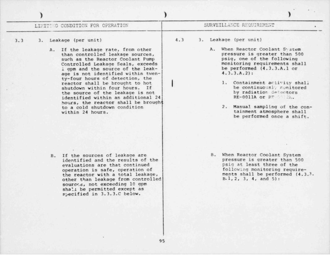
95 In Specification 4.3.3. A.1, remove the Radiation detectors RE-00llA and RE-0012A
word " particulate . " monitor gaseous as well as particulateactivity.
96 In Specification 4.3.3.C., change the Correction of a typographical error.
referenced sections from "4.3.4.A and4.3.4.B" to "4.3.3.A and 4.3.3.B."
156 In Specifications 3.7.1 and 4.7.1, Same as for Page iii
delete the words "and Relief."
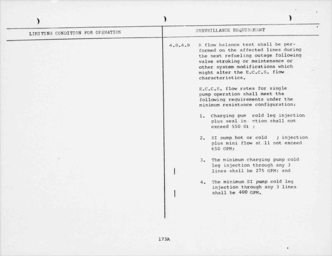
173A In Specification 4.8.4.B.3, change To conform to the minimum ECCS pump flows265 GPM to 275 GPM and in Specifica- used in the current ECCS/LOCA analysis as
tion 4.8.4.B.4 change 432 GPM to 400 approved by the NRC Staff (Amendment No. 42
GPM. to DPR-39 and Amendment No. 39 to DPR-48) .

- .
-6-"
.
Page Revision Basis
187 Add "IEST to RHR Pump Suction Valves" and These valves are required for proper operation ofMOV-PH8700A&B" to RHR canponent list, Table 4.8-3 RHR system but were inadvertently left off of Table 4.8.3.
297 In Specification 5.3, delete the words "and eight Same as for Page 19.part length."
300 Replace Section 6.1.B with the following: Replaces reference to Figure 6.1.1 of Technical Speci-fications with reference to Topical Report CE-1-A
"The corporate management which relates to the (Camonwealth Edison's Quality Assurance Manual) .operaation of this station is as shown in Figure1-6 of CE-1-A 'Ibpical Report. % e DivisionManager, Nuclear Stations has the responsibilityfor the Fire Protection Program."
300 Replace the first two (2) sentences of Section Replaces reference to Figure 6.1.2 of Technical6.1.C with the following five (5) sentences. Specifications with reference to 'Ibpical Report
CE-1-A (Comonwealth Edison's Quality Assurance"%e normal functional organization for operation Manual).of the station shall be as shown in Figure 1-6and Figure A of CE-1-A Topical Report. W e manningfor the station shall be as shown on Figure 6.1.1.The Operating Assistant Superintendent, OperatingEngineer, Shift Engineers, and Shift Forerran shallhave a senior operating license. The Fbel HandlingForeman has a limited Senior Operating License.An Operating Engineer will be responsible forimplernentation of the Fire Protection Program."
300 Change " Administrative Assistant" to " Administrative To conform to existing station organization,and Support Services Assistant Superintendent" inSection 6.1.D. ~
,
_ _ _ _ _ _ _ _ _ _ _ _ _ __.

. _
'. .,
-7-
.
Pace Revision Basis
301 & Change Sections 6.1.G.l.a. and 6.1.G.l.b. (ll) to include To conform to existing corporate organization.302A "Vice President of Nuclear Operations" and
change "Vice President of Construction, .. ." to" Executive Vice President of Construction,..."
302A Change Section 6.1.G.l.C to replace " Executive To conform to existing corporate organization.Vice-President" with "Vice Chairman" and to replace" General Superintendent of Production SystemsAnalysis" with "Vice President of Nuclear Operations."
308 In Fpecifications 6.2.B.1 and 6.2.B.2 (two places), To conform to existing e ' tion organization,change " Maintenance Engineer" to " MaintenanceAssistance Suoerintendent."
329 E Delete Figures 6.1-1 and 6.1-2. The Corporate and Station Organizations are now330 referenced to Figare 1--6 and Figure A of Topical
Report CE-1-A (Connonwealth Edison's QualityAssurance Manual).
331 Revise figure number fran "6.1.3" to "6.1.1". Also 'Ib conform to existing station organization and tochange " Radiation Protection Man" to " Rad-Chan chronological listing of figures.Technician".

. .
.
,
.,
ATP/CINIM 2
Zion Station Units 1 and 2
NRC Docket Mos. 50-295'and 50-304
Proposed Technical Specification Changes
% e following pages have been revised:
iii 42 51 95 301
vii 44 52 96 302
6 46b 68a 156 303
19 47b 69a 173A 308
36 48 70 187 329
40 49 71 297 330
41 50 72 300 331
% e following page has te n added:
302A
We following page has been deleted:
47c
;
1
-- . _ . . _ , _ _ .

'. .
.
*able of Contents (Continued)
SURVEILLANCE .
LI"ITI?!G CONDITIO" FOP OPERATIO'I 7PoUIDPHEt1T PAGE
3.7 Ftean Generator Frergency Feat Roroval M7 156Stean Line Fafoty Valvon 4.7.1 156
I3.7.23.7.2 Auxiliary reedwater Purp Systen e.7.2 | 159Eases
3.o Trarcency Core Coolinc and Core coolinc Furnort 4.c 16M
3.".1 Centrifucal Charnina Purn Fvstem a.o.1 164
3.".2 Fafety Iniection Purp System 2.0.? ]FS3.o.3 Residual Feat onmoval Purp Syster A.o.3 170
costinc of Centrifucal Charcinc, FafetySyster13.".4 In4ection, and Pesidual Fea t P.croval Purp ."" ster s | 4.S.4 | 1733.".5 Accunulator System 4.9.5 174
3.0.6 Cor.ponent Coolina System 4.R.6 175
3.9.7 Service Water System 4.8.7 17R
3.?.R I!ydrocen Control Systems 4.R.8 1RO
3.?.9 Ecuiprent for Fvaluatina Post LOCA d.P.9 Iod
Bases3.0 Containrent Isolation Systers 4.0 147
3.o.1 Isolation Valve Foa3 Pater System t.9.1 197
3.o.2 Penetration Pressurization Systens 4.0.2 loe
3.'.3 Containment Isolation Valves M.9.3 199
| 3.9.4 "ain Stean Isolation Valves and Pvnasses 4.9.4 200'
3.9.3 Containment Intecrity 4.0.5 201 cy 3g;Bases b )
3.10 Containrent Structural Intoarity 4.10 212ate Testing 2.10.1 212 (ar)3.1^.1 Containrent Leakage c __
?.16.2 Containnent Tender Testing 4.3n,2 pig gggg3.19.3 End Anchoraaes and Adjacent Concrete Furfaces
Irspection 4.~10.3 217 (, 93.16.4 Containment Liner Inspection 4.ln.a 21o
535k3.19.5 Containrent Pressure 4.10.5 219
3.In.c Containment Terporature 2.16.F 219bd :b
nases?.11 Padioactive Licuids a.21 2?? -
Eases3.12 Endinactive cases 3.3? 23n $5ED
brases
iii *

'- .
,
.
LIST OF FIGURES (Continued)
Figure Page
3.3.2-1 Reactor Coolant System Heatup Limitations 84.
3.3.2-2 Reactor Coolant System Cooldown Limitations 85
3.3.2-3 Effect of Fluence and Copper Content on Shift of 86OFRT for Reactor Vessel Steels Exposed to 550
NDT^
Temperature
3.3.2-4 Fluence at 1/4T and 3/4T as a Function of Full Power 87Service Years
3.4-1 High Steam Line Flow Setpoint 131a
4.16-1 Location of Fixed Environmental' Radiological 278Monitoring Stations
6.1.1 Zion Shift Manning Chart 331
,
vii
-J

_ _
*, .,
c. ouadrant Dover Tilt K. onerable -
The cuadrant nower til t nor unit is defined Pronerly installed in the systen andas the ratio of the ncximun upner excore canable of nerforninc the intendeddetector current to the averace of the functions in the intended manner asunper excore detector currents or the verified bv testinc and tested atratio of the naximum lower excore detector the frecuency recuired bv thecurrent to the average of the lower excore Technical Snecifications.detector currents whichever is creater.
L. OncratinnH. Pated Therral Pover f
Performina the intended functions'
'
A steady-state reactor core output of in the intended nanner.3250 MFt ner unit.
M. oneratinc CvcleI. Reactor Pressure
The interval between the end of oneThe pressure in the stean snace of maior re#ueling outano and the enda pressurizer. of the next subsequent naior refuelinn
outane oer unit.
J. Refuelino OutaceN. Surveillance Interval
Mhen Refueling Outace is used to-desienate a surveillance interval ner Surveillance intervals, with theunit the surveillance will Fo norformed excention o# shi#t and dail" norinAq,durina the refueline outace or up to six are defined as the socci'ied nerio1 "gronths before the refueline outace. plus or ninus 25t o' the soeci'ied b' 3When a refuelina outace occurs within period,8 ronths of the previous refueline (t.._;)outace for a unit, the surveillance gggjtesting need not be perforned. Themaxirun interval between surveillance b 0tests is 20 months per unit. M
s e)WE523b
6

--___. _. . _ - - . - . . __- . - . _ . - _ _ _ _ - - .- .- __ _. . - . _ .. .--
'" .
.
.
The curves are based on the follovingnuclear hot chanr.cl # actors: (2)
( = 1.55 {l+0.2 (1-P))The hot channel # actors are alsowhere P is the fraction of rated power,
and on a DNB analysis as described in sufficiently larqe to account forthe decree o# maloositioninc o# theReference 3. The c::pression for Pi!p- full-length control rods that is
for o < n < l.0 renrecents the c##cct allowed before the reactor trio seton radial power shapes of the control coints are reduced and rod 'rithdravalrods at the insertion linits. block and load runback r.av be recuired.
(5) Rod withdrawal block and load runbackoccurs if reactor trio set noints areaporoached within a #ixed linit. (6)
R
The Reactor Control and Protection 8
Sustom is desianed to orevent anv b U
anticinated combination of transient 6 9
Mii 6 3
: (2) PSAR Annendix 3A cection 5.3 E352)(3) FFAR Apnendix 3^ 9ection 4.3
ba d(5) PSAR Section 14.1.3
<(6) PSAR Section 7.2.2
b
,
19
4

- -. - . . - - . . . . _ . - . . _ _ - - . . _ - . - - _ _ - -.. - . . - - . _ - _ - . ... - -. _ - - - . .- -.
'. .
.
Reactor Trip channel channel Channel r
Channel Descrintion chock Calibration Function Test Dg arks -
17. Low Stear Generator Level F o "
in Coincidence with FeedFlow Stear Flow Mispatch
18 Low-Low Stear Generator Level S R M
"( }l^. Fafety Tniection ?; . 7 . '? . 7 . (1) vanual SI function chacP
at U only
20 Turbire Trin *: . A . " 7, . ".
r
21. 'ittoratic Reactor Trip.
Locic '! . A . N.A. '! III (1) ggg ggy gDreaker Oooninq
DTR''IFFIFFS
22. P-6 U.7. ?' . A . S /I' II I (1) Vot required if perfor:nedwithin the orevious 7 days
23. P-7 ?! . A . ?! . A . "
u..A..u . n_c .* *. .e.
25. F-10 'I . A . ".A. @"
d!!o te : Specified intervals may be adiusted +25S to accorrodate test schedules.
_
F - Once ner ShiftD - Once per Day h9M - Once per Month M
EPPM- Once Per Effective Full Power Month i i
O - Once per Ouarter h-c d)' 1S/U - Prior to Startup
R.- Once per Defuelina Shutdovn - calibration of these instrurents ray he done as ruch as 7Mronths prior to the start of refueline outace and still se tisf,y this recui rerent. )D
'!. A. - Not Applicable g ,
* Applies to Unit I and Unit II
TABLE 4.1-1 (Sheet 2 of 2) ,
Reactor Protection System Testinc and Calibration Reouirererts 3F
,

_ _ _ _ _ _ _ - _ _ _ _ _ _ - . _ - . _ _ _ _ _
O* O O' --
LIMITINd CONDITION FOR OPERATION SURVEILLANCE REQUIREMENT.
4.2.1.B once a shift while remaining in this con-dition. During heatup, the boron concen-tration in the reactor coolant loops andpressurizer shall be sampled every 4 hours.The reactor coolant loop boron concentra-tion must not decrease by more than 50 ppmbetween successive 4 hour samples. Thepressurizer boron concentration must notbe more than 200 ppm less than the reactorcoolant loop boron concentration.
C. Unit Startup C. Startup
1. Immediatel'y prior to startup, the reactor i. The Tavg of each reactor coolant loopcoolant temperature shall be shown to be shall be logged before attempting togreater than the temperature above which bring a reactor critical.the moderator temperature coefficient isalways negative (except during low powerphysics tests) and greater than 500 *F.
2. When a reactor is approaching criticality, 2. Not Applicable.-the shutdown banks shall be fully with-drawn in sequence (shutdown bank A,B,C,D)before any other rods are withdrawn. The . .
control group rods shall be no further in-serted than the limits shown by Figure3.2-2 for Unit 1 and Figure 3. 2- 4 forUnit 2 for 4-loop operation and Figure3.2-3 for Unit 1 and Figure 3.2-5 forUnit 2 for 3-loop operation when critical-ity is attained.
D. Power Operation D. Power Operation
1. When a reactor is critical, except for 1. Rod operation shall be verified byphysics tests and control rod exercises, partial movement of all rods everythe shutdown rods shall be fully with- two weeks. Rods which have been
exercised within the,
!,
'i!
i 40 j.

> .
). . . .
). .
)- .
LIMITING CCNDITION FOR OPERATION SURVEILLANCE REQUIREMENT.
3.2.1.D.l. drawn and the control group rods 4.2.1.D.l. past two weeks during normalshall be no further inserted than operation need not be verifiedthe limits shown on Figure 3.2-2 Control rod bank positions withfor Unit 1 and Figure 3.2-4 for respect to its insertion limitUnit 2 for 4-loop operation and shall be yerified once perFigure 3.2-3 for Unit 1 and shift.Figure 3.2-5 for Unit 2 for 3-loop ,
operation.
2. Control bank insertion may be 2. Control rod bank worths shall'
further restricted if the measured be measured following eachcontrol rod worth of all rods, refueling outage. ,
less the worth of the most reactive ,
rod (worst case stuck rod), is lessthan the reactivity required toprovide the design value of avail-able shutdown as shown in Figure3.2-1.
-
3. During physics testu and control 3. Not applicable,rod exercises, the insertion limitsneed not be observed, but the lim-its in Figure 3.2-1 must be ob-
-
served except during the low powerphysics test to determine totalcontrol rod worth and shutdownmargin. For this test the reactormay be critical with all. fulllength control rods fully inserted,except for the predicted mostreactive rod.
4. Three reactor coolant pumps per 4. Prior to proceeding from hotunit shall be operating whenever shutdown to hot standby, verifya reactor is critical except that three reactor coolant pumps '
during natural circulation test, are operating except during f(power - 8% full power) or low natural circulation tests orpower physics testing. low power physics testing.
|
|
.
41
_ _ _ _ _ _ - ---__- . - _ _ __ - _ - _ _ _ - _ _ _ _ _ _ _ - _ _ - _ _

_ _ _ _ _ _ - _ _ _ _ _ _ _ _ _ _ _ _- _
.- .
). . . . . .
*<
LIMITING CONDITION FOR OPERATION SURVEILLANCE REQUIREMENT .
3.2.1.D 5. Reactor power shall not be increased 4.2.1.D 5. Not Applicableabove 60% of rated power with onlythree reactor coolant pumps inoperation unless the overtemperature ~
AT trip setpoint and the P-8 inter-lock for three loop operation hasbeen set in accordance with speci- I,
fication 2.1.1.B.4.* .
E. Rod Bank Assignment E. Rod Bank Assignment#
Rod Bank Assignment shall be as Rod Bank Assignment shall bedeline,ated in Figure 3.2-8. Except verified after each refuelingduring physics tests, the sequence of outage, for the refueled unit.withdrawal of the control banks, when
'
:going from zero to 100% power, is A, B,
C, D with control bank overlap.
F. Boric Acid System (per unit) F. Boric Acid System (per unit)
1. A reactor shall not be taken from 1. Surveillance and testing ofhot shutdown to hot standby unless the boric acid system shallthe following conditions exist: be performed as follows:
a. One boric acid tank for that a. Boric acid tank level,
reactor contains at least 5140 concentration and tempera-gallons of 11.5% (but not great- ture shall be verifieder than 13%) by weight boric prior to startup andacid solution at a temperature weekly thereafter.of at least 145*F.
42.
_ _ _ _ _ _ _ _ _ _ _ _ _ _ - _ _ - _ - - - _ _ _ _ - - _ _ _ _

-
). . . .
.. .., .
,
LIF.ITING' CONDITION FOR OPERATION SURVEILLANCE REQUIREMENT.
3.2.1 G. Primary System Boron Concentration 4.2.1 G. Primary System Boron ConcentrationChanges during Cold Shutdown Changes during Cold Shutdown
When a boration or dilution oper- The opera' tion of at least oneation is in progress, at least one reactor coolant pump or onereactor coolant pump or one resi- residual heat removal loop shalldual heat removal loop shall be be verified before the start ofoperating. a boration or dilution operation.
.
H. Reactivity Anomalies H. Reactivity Anomalies
A normalization of the computed Reactivity anomaly evaluations
boron concentration as a function shall be performed followingof 'burnup shall be compared with the startups after shutdowns of 72
actual boron concentration of the hours or longer duration but
coolant. If the difference between shall not be required more thanthe observed and predicted steady- once if more than one such shut-state concentrations reaches the down occurs in a two month, period,equivalent of one percent in
| reactivity, the NRC shall be noti-fied within 24 hours and an evalu-ation as to the cause of.the dis-crepancy shall be,made and reported
|to the NRC within 30 days.
44

!.- .
,
| LIF.ITING CONDITION FOR OPERATION SURVEILLANCE REQUIRDIENT .
\ "
3.2.2.A 4.2.2.A2.2.c (Continued) 2.2.c.
(1) Power between the maximum and (2) A flux dif ference alarm shallminimum limits specified in indicate non-conformance with3.2.2.A.2.2.a. the 3% AI target band for
BASE LOAD operation. If the(2) AI within thc4 I target band alarm is temporarily out of
as per Section 3.2.2.A.4 and service, conformance with the3.2.2.A.5, except use 13% AI applicable limit and the fluxtarget band instead of the +6, difference shall be logged-7% 6I target band. hourly for the first 24 hours
*''2.2.d If any of the requirements of Section
3.2.2.A.2.2.c. are not maintained then2 . 2, . d Not Applicable
power must immediately be reduced tobelow the power limited by APDMS type 4.2.2.A.3surveillance (Section 3. 2. 2. A. 2.1. ) andAPDMS type surveillance must be The reference ecuilibrium indicatedinitiated if the power is above PT* axial flux difference as a function
of power level (called the target3.2.2.A.3
flux difference) shall be determinedThe target flux dif ference at a given at least once per equivalent fullpower level, P is determined byO, power quarter. The target differencenoting the indicated axial flux difference should be updated every effectiveat the power level with equilibrium full p wer month. This may be donexenon conditions established in the using the measured value for thatcore and with the full length rod bank
| ~more than 190 steps withdrawn. P formonth or by linear extrapolationusing the two most recent measured
the purpose of determining the ta getvalues. The initial target flux,
value, should be as high a power leveldifference on a reload may be
as practicable. The target flux dif-determined from design predictions.
ference at any other level, P, is equalmultipled byto the target value of PO
the ratio, P/P - 46b -O.
_ _ _ _ _ _ _ _ _ _ _ _ _ _ _ _ _ _ _ _ - _

____ _
'. .
,
LIMITING CONDITION FOR OPERATION SURVEILLANCE REQUIREMENT -*
3 2.2.A 8. For the purpose of determining 4.2.2.A 8. Not applicable,0
penalties associated withdeviations from the target band,time for use in applying Items 6.1and 7.2 above shall be accumulatedin the following maener:
8.1 For deviations at or below50% power, time shall beaccumulated such that a1 minute actual deviationequals a 1/2 minuteaccumulative penalty inapplying Items 6.1 and 7.2above.
8.2 For deviations above 50%power, time shall beaccumulated in a 1 for 1time basis in applying Items6.1 and 7.2 above.
47b
.
_ . . _ _ _ _ _ _ _ _ _ _ _ _ _ _ _ _ _ _ _ _ _ _ _ _ _ _ _ _ _ _ _

_ __
.- .
* . . . ..
.
SURVEILLANCE REQUIREMENTLIMITING CONDITION FOR OPERATION
3.2.2 B. Quadrant Power Tilt Limits 4.2.2 B. Quadrant Power Tilt Limits1. Quadrant. power tilt shall1. If an indicated quadrant g be calculated and logged
| power tilt exceeds 1.02, exceptI for physics tests, then within along with the individual
2 hours, one of the following upper and lower excore cal-
steps shall be taken: ibrated outputs as follows:
a. Once each shift at powera. Correct the tilt, o r.
levels greater than 50%.
b. Determine by measurementb. Four times a shift andthe core peaking factors
and apply Specification following a load changeof more than 10% power3.2.2.A or at any power level above
c. Restrict core power level , 50% if one or both quad-
so as not to exceed full rant power tilt alarms
rating less 2% for each are inoperable.
percent of quadrant powertilt beyond 1.0.
.
2. Not Applicable.2. If an indicated quadrant power '
tilt exceeds 1.02 for a period
| of 24 hours without known"cause, or if sudden tilt re-occurs intermittently withoutknown cause, the reactor shallbe put in the Hot ShutdownCondition within 8 hours. How-ever, operation below 50% ofrated power, for testing and/orcorrecting the tilt, shall bepermitted.
.
48 .
_ _ _ _ _ _ _ . _ _ _ _ _ _ _ _ _ _ - . _ _ _ _ . _ _ _ _ _ _ _ _ _ _ _ _ _ _ _ _ _ __ _ _ _ _ _ _ _ - _ _ _ _ _ _ _ _ _ _ _ _ _ - _ _ _ _ _ _ _ _ - _ _ _

- _ _ _ _ _ _ _ _ _ __ _
.
LIMITIN3 CCNDITION FOR OPERATION I SURVEILLANCE REQUIREMENT" '
-
} ) -
.
3.2.2.B 3. If an indicated quadrant power 4.2.2.B 3. Mot Applicable .
tilt exceeds 1.09, except forphysics testing, the reactor shallbe put in the Hot Shutdown Con-dition; however, operation belowSOS of rated power, for testingand/cr correcting the tilt, shallbe permitted.
C. Instrumentation (per unit) ? C. Instrumentation (per unit)
1. Excore axial inbalance detector 1. Excore axial imbalancesystem detector systen
u. The excore axial imbalance a.,,Not Applicabledetector system shall berecalibrated at least everythree effective full pover
.non th s. The calibration shallbe cnecked each effective fullpower conth usine the IMCORESYST2:' and recalibrated if thedif ference is > 15 The nin-imum requirements per flu: mapused for the recalibration are:
1. At least 16 different Q!
g%thinble traces, and .
bE2. At least 2 differenct hthinble traces, per
quadrant.
b. If requirement 3.2.2.C.l.a b. Not Applicable cyjgcannot be net, then power shall c==::be linited to 90% of rated cribnower for 4 looo coeration #
'and 60% of rate'd h er for h3 loop operation.
-
.
49
. - _ _ _ _

), . . . .
) ) .. .,
SURVEILLANCE REQUIREMENTLIF.ITING CONDITION FOR OPERATION
3.2.2.C.2. Inoperable Excore Detector Channel 4.2.2.C.2. Inoperable Excore DetectorChannel
If an excore detector channel is If an excore. detector channel
|inoperable, quadrant power tilt .is inoperable, quadrant power
tilt shall be determined byshall be determined by periodically |monitoring incore thermocouples. monitoring at least four
thermocouples per quadrant oncean hour and after any load changegreater than 10% at any power -
level above 50%.
e
3. NIS Detector Temperature Control 3. NIS Detector Temperature Control
a. One of the two reactor cavity a. Reactor cavity ventilation
ventilation fans (Unit I fan operation shall be
1RVO12-1A, 1RVOl3-1B) or (Unit II verified once a shift.2RVO12-2A, 2RVOl3-2B) shall beoperating whenever Tavg is great-er than 145'F.
b. If this condition cannot be met, b. Not Applicable.
the reactor shall be broughtto the Hot Shutdown Conditionimmediately.
S3.
- - - --- -___-

_ _ - _ _ - _ - - _ _ . .
O' O O- -.
LIMITINd CONDITION FOR OPERATION SURVEILLANCE REOUIRE:*.ENT
302.3. Control Rod System Operability (per unit) 4.2.3. Control Rod System Operability (per unit)
A. Rod Misalignment Limitations A. Rod Misalignment Limitations
1. If a full-length control rod 1. A rod malposition check shallis more than 15 inches (24 steps) be made once a shift using bothout of alignment with its bank, the analog and digital displays.then within 2 hours, one of thefollcwing steps shall be taken:
.
a. Realign the rod, or
b.- Determine by measurement thecore peaking factors andapply Specification 3.2.2.Aor
c. Restrict power level to 80%of rated power.-
2. If the misaligned control rod is 2. Not Applicablenot realigned within 8 hours,
ethe rod shall be declared inoper- - .
able and the limitations of i3.2.3.B apply,
3. The provisions of Specifications 3. Not Applicable j
3.2.3.A and 3.2.3.B shall not i_
apply during physics tests inwhich the control rods areintentionally misaligned.
B. Inoperable Rod Limitations B. Inoperabl Rod Limitationss
'3. An inoperable control rod is a 1. Not Applicable
rod which cannot be moved by itsmechanism or which is declaredinoperable by Specification ,
3.2.3.A or 3.2.3.C.
51 j.
_ . _ _ _ _ _ _ _ _ _ _ _ _ _ _ _ _ _ _ _ _ _ _ _ _ _ _ . _ _ _ _ _ . . . . _ . _ _ _ _ _

- . - ___ _ - _ _ _ _ _ _ _ _ - _ _ _ _ _ _ _ _ - _ - _ _
-.
O' O O~
.
LIIIITII;d CONDITION FOR OPERATION SURVEILLA::CE REQUIRE:*ENT .
3.2.3.B 2. Not more than one inoperable 4.2.3.B 2. Not Applicable.control rod shall be permittedduring power operation. Ifmore than one rod is determinedto be inoperable, the reactorshall be placed in the hot shutdowncondition within 4 hours. .
3. If more than one control rod is 3. Not Applicable. .
inoperable because of a Rod UrgentFailure in the rod control system,the provisions of Specifications3.2.3.B.1 and 3.2.3.B.2 aboveshall not apply. If the affectedassemblies cannot be returned toservice within two hours, the reac-tor shall then be placed in the hotshutdown condition within 4 hours.
,
|4. Deleted 4. Deleted
5. If an inoperable full-length rod 5. Not Applicable..
is located above the 200 step leveland is capable of being tripped, ' *
then the insertion limits inFigure 3.2-2 for Unit I and Figure3.2-4 for Unit II shall apply for4 loop operation and the insertionlimits in Figure 3.'2-3 for Unit Iand Figure 3.2-5 for Unit II shallapply for 3 loop operation.
*t
.
.
52 ,

__ -_ _. _ _ _ - _ . _ . - _ _ _ _ - . __ -- _ -. .- _ -_ _ --
'. .
'
The procedures for axial powar distribution conditions for mansuring target flux differenca everycontrol referred to cbove are designed to month. For this reason, the apscification provides '
minimize the effects of xenon redistribu- two methods for updating the target flux difference..
tion on the axial power distribution during The alarms provided are derived from the plant pro-loadfollow maneuvers. Basically control cess computer which determines the one minute averagesof flux difference is required to limit of the operable excore detector outputs to monitorthe difference between the current value oI in the reactor core and alerts the operator whenof Flux Difference ( AI) and a reference AI alarm conditions exist. Two types of alarm messa-value which corresponds to the full power ges are output. Above a preset power level, an alarmequilibrium value of Axial offset (Axial message is output immediately upon determining aOffset =d1I/ fractional power;. The delta flux exceeding a preset band about a targetreference value of flux difference varies delta flux value. Below this preset power level, anwith power level and burnup but expressed alarm message is output if the oI exceeded its allow-as axial offset it varies only with burnup, able limits for a preset cumulative amourt of time '
in the past 24 hours. For periods during which the |The technical specifications on power dis- alarm on flux difference is inoperable, manual sur- '
tribution control assure that the FQ limit veillance will be utilized to provide adequate warn-is not exceeded and xenon distributions ing of significant variations in expected fluxcre not developed which at a later time, differences. However every attempt should be madewould cause greater local power peaking to restore the alarm to an operable condition as sooneven though the flux difference is then as possible. Any deviations from the target bandwithin the limits specified by the proce- during manual logoing shall be treated as deviations '
dure. during the entire preceeding logging interval andapproprate actions shall be taken. This action isnecessary to satisfy NRC requirements; however more
The target (or reference ) value of flux frequent readings may be logged to minimize thedifference is determined as follows. At penalty associated with a deviation from the targetcny time that equilibrium xenon conditions band to justify continued operation at the currenthave been established, the indicated flux power.
| difference is noted with the full lengthrod control rod bank more than 190 steps The times that deviations from the band occur arewithdrawn (i.e. normal full power operating normally accumulated by the computer.
;position appropriate for the time in life,usually withdrawn farther as burnup proceeds).This value, divided by the fraction of fullpower at which the core was operating,is
lthe full power value of the target fluxdifference. Values for all other core powerlevels are obtained by multipl'f ng the fulli
power value by the fractional power. Since_he indicated equilibrium value was noted,
| no allowances for excore detector error are| nncessary and indicated deviation of theA I target band are permitted from the indi-cated reference value. During periods whereextensive load following is required, it may
|be impractical to establish the required core-68a-
- _____ _ -

. ..
.
Significantly dif ferent from those resultingfrom operation within the target brnd. Theinstantaneous consecuences of being outside theband, provided rod insertion limits are observed,is not worse tnan a 10 percent increment inpeaking fLetor for flux dif ference in the range-(/+3) percent (+gpercent to -[ percent in-dicated) increasing by +1 percent for each 2percent decrease in rated powar. Therefore,'hile the deviation exists the po.rer level islimited to 90% of PT or lower depcnding on theindicated flux dif ference.
If, for any reason, flux difference is notcontrolled rithin the AI target bend for as longa period as one hour, then xenon distribution maybe significantly changed :nd opcration et 50percent is re~uired to protect against potentiallyr. ore severe consecuences o-? s ome cccidents.
;s discussed above, the essence of the procedureis to maint=in the xenon distribution in the corea s close to the e~eilibrium full powe.r condition
j as possible. This is accomplished b'; using theboron system to position the fell length controlrods to produce the receired indicated fluxd if ference.
For Condition II events, the core is protectedfrom overpower and a minimum 2:3n of 1.30 byan automatic protection system. Compliance withoperating procedures is assumed es a pre-condition for Condition II transients; however,operator error and equipment malfunctions areseparetely assumed to lend to the cause of
transients considered.
- 69a -

. - - - _ _ _ _ _ __ _
.- . ,
.
In accordance with the approved Westinghouse model DNB Parameters: The limits on the DNB re-as presented in WCAP 8381, no collapses are expected lated paramters assure that each of thethroughout the fuel cycle of operation. The pre- parameters is maintained within the normaldicted minimum times for clad flattening are: steady state envelope of operation assumed
in the transient and accident analyses.Fuel Region EFPH The limits are consistent with the initial
FSAR assumptions and have been analytically1 19,500 demonstrated adequate to maintain a minimum2 > 30,000 DNBR of 1.30 throughout each analyzed3* i 30,000 transient.
for Zion Unit 1. The predicted minimum times to The 12 hour periodic surveillance of thesecollapse for Unit 2 are: parameters thru instrument readout is
sufficient to ensure that the parametersFuel Region EPPH are restored within their limits following
load changes and other expected transient1 27,000 operation. The 18 month periodic measurement of2 > 30,000 of the RCS total flow rate is adequate to3* > 30,000 detect flow degradation and ensure correlation
of the flow indication channels with measuredA design critariam requires that proposed reload flow such that the indicated percent flowf uel region exposure levels expected at the time will provide sufficient verification of flowof discharge not exceed the predicted minimum rate on a 12 hour basis.collapse time. Cperation in the exposure rangein which clad collapse is postulated is not per- A auadrant ocwer tilt will beritted under these technical speci fications. ' indicated
by the excore detectors by the arrangementf the current recorders on the controlThe predicted ninimum time to collapse for all
b rd. Four 2-pen recorders are pro-reload fuel regions is greater than 30,000 effee-tive full power hours. vided, the pens are grouped so that, in
the absence of a quadrant power tilt, the two
*Except that the four (4) Region 3 assebmliesto be used in the Extended Burnup progrr. forZion Unit 2 have a predicted minimum time tocollapse greater than 41000 EFpH.
- 70 -
_ _ _ _ _ _ _ -

.- ,,
ink traces coincide. Any divergence in the traces As described above, an uncertainty fcetor ofandindicate a power tilt. Furthermore, a quadrant 1.08 is included in F H 1.05 in Fg. There-
Ipowertiltalarmisprovidedfortheupperandlow- | fore,"
a limiting quadrant power tilt of 1.025er sets of excore currents. can be tolerated before the margin for uncer-
taintyinF8isdepleted, llowever, a measure-Qundrant power tilt limits are based on the follow- ment uncertainty is associated with the indicateding considerations. Frequent power tilts are not quadrant power tilt. Thus, allowing for a lowanticipated during normal operation since this | measurement of quadrant power tilt, the actionphenomenon is caused by some asymmetric perturba- level of indicated tilt has been set at 1.02,
tion, e.g. rod misalignment, x-y xenon transient, An alarm is set to alert the operator to anor inlet temperature mismatch. A dropped or | indicated quadrant power tilt of 1.02 ormisaligned rod will easily be detected by the Rod greater and that action is required. To avoidPosition Indication System or core instrumentation. unnecessary power changes, the operator is
| A quadrant power tilt by some other means (x-y allowed two hours in which to verify with in-xenon transient, etc.) would not appear instan- core mappinge and/or to determine and correcttoneously, but would build up over several hours the cause of the tilt. Should this action not
| cnd the quadrant power tilt limits are set to be taken, the margin for uncertainty in Fdprotect against this situation. They also se.<e is reinstated by reducing the power by 2 per-as a backup protection against the dropped or mis- cent for each percent of tilt above 1.0, inaligned rod. (8) Operational experience shows accord with the 2:1 slope envelope described
| that normal quadrant power tilts are less than above, or as required by the restriction on1.01. Thus, sufficient time is available to rec- peaking factors.ognize the presence of a tilt and correct thecr.use before a severe tilt could build up. During | The upper limit on the quadrant power tiltstartup and power escalation, however, a large at which hot shutdown is required has beentilt could be initiated. Therefore, the Technical set at 1.09 so as to provide protection againstSpecification has been written so as to prevent excessive linear heat generation rate.escalation above 50 percent power if a large tiltis present. The numerical limits are set to becommensurate with design and safety limits forDNB protection and linear heat generation ratees described below.
The quadrant power tilt of 1.02 at which remedialcnd corrective action is required has been setto as to provide DNB and linear heat generationrate protection with x-y power tilts. Analyseshtve shown that fractional increases in x-ypower peaking factor are less than or equal totwice the increase in the indicated quadrantpower tilt, i.e., an envelope with a 2:1 slope.
71
_ _ - _ _ - - -

- _ _ - _ - - - - . _ -_ -- . _ _ _ _ _ _ _ _ _ - _ _ . __
*. . ,
In the event that an LVDT is not in service,The nuclear ion chambers located outside a the effects of a malpositioned control rodreactor vessel measure the flux distribution are bservable on nuclear and process infor- -
of the top and bottom halves of a core. Core ,
mation displayed in the control room and by,
traverses in a few of the in-core instrument core thermocouples and in-core movable detec-thimbles will establish that the excore flux tors.measurement equipment is properly calibrated.Opsrating experience has established tnat the One inoperable control rod per unit is accep-excore flux measurement system is of a reliable table provided that the power distributiondesign, and that the 10% load reduction, in the limits are met, trip shutdown capabilityevent of a recalibration delay, is an ultra is available, and provided the potentialconservative compensation. hypothetical ejection of the Inoperable rod
is not worse than the case analyzed in theOperating experience at similar PWR plants safety analysis report. The rod ejectionhno shown that quadrant power tilts deter- accident for an isolated fully inserted rodmined by monitoring symmetric thermocouples will be worse if the residence time of the rodare in very good agreement with quadrant is long enough to cause significant non-uni-
,
power tilts determined from power distri- f rm fuel depletion. The 3 day period allowedbution maps using the Movable Detector f r the analysis is short compared with theSystem ~ time interval required to achieve a signifi-
cant non-uniform fuel depletion.Operation of one reactor cavity vent fanper unit ensures an adequate flow rate of The rod drop time of 1.8 seconds is basedcooling air to each NIS Detector (9). g ,g g
used in accident analysis. (11)The various control rod assemblies (shut-|downbanks,controlbanksA, B, C, D) areeach to be moved as a bank, that is, with (1) FSAR - Figure 3.2.1-8all assemblies in the bank within one step (2) FSAR - Table 3.2.1-1(5/8 inch) of the bank position. Position (3) FSAR - Figure 3.2.1-11indication is provided by two methods: a (4) PSAR - Chapter 14digital count of actuation pulses which (5) FSAR - Section 3.1.2shows the demand position of the banks and (6) FSAR - Section 3.1.3a linear position indicator (LVDT) which (7) FSAR - Chapter 14, Appendix Cindicates the actual rod position (10). (8) FSAR - Question 3.8The rod position indicator channel is (9) FSAR - Section 9.10.6sufficiently accurate to detect a mis- (10) FSAR - Section 7.3aligned rod 15 inches away from the demand
[8 "]76 der for Modificationposition of the bank. This 15-inch (24steps) permissible misalignment provides f 1,1 cense,an enforceable limit below which designdistribution is not exceeded.
72
_ ___________ __- - _ _ __ . _ _ ____ _
,
|. .
| ) ) )|
LIMITI?:G CONDITION FOR OPERATION SURVEILLA :CE REQUIRE!ET ,
,_ _ .
3.3 3. Leakage (per unit) 4.3 3. Leakage (per unit)
A. If the leakage rate, from other A. When Reactor Coolant SSstem; than controlled leakage sources, pressure is greater than 500
| such as the Reactor Coolant Pump psig, one of the followingControlled Leakage Seals, exceeds monitoring requirements shall1 gpm and the source of the leak- be performed (4. 3. 3. A.1 orage is not identified within twen- 4.3.3.A.2):ty-four hours of detection, thereactor shall be brought to hot | 1. Containme'nt activity shallshutdown within four hours. If be continuousl/ conitored.
the source of the leakage is not by radiation detectorsidentified within an additional 24 RE-00llA or RD 0^12A.hours, the reactor shall be broughtto a cold shutdown condition 2. Manual sampling of the con-within 24 hours. tainment atmosphere shall
be performed once a shift.
.
B. If the sources of leakage are B. When Reactor Coolant Systemidentified and the results of the pressure is greater than 500evaluations are that continued psig at least three of theoperation is safe, operation of following monitoring require-the reactor with a total leakage, ments shall be performed (4. 3.3.other than leakage from controlled B.1, 2 , 3, 4, and 5):sourecs, not exceeding 10 gpmshall be permitted except asspecified in 3.3.3.C below.
.
95
_ _ _ _ _ _ _ _ - _ _ _ _ _ _ _ _ _ _ _ _ _ _

--_ _
D O O' -'
LIMITII;d CONDITION FOR OPERATION SURVEILLANCE REQUIREMENT.
L
3.3.3.B 4.3.3.B 1. The amount of ReactorCoolant System makeupwater required to maintainpressurizer level andvolume control tank levelshall be recorded.
.
2. Containment sump and,
reactor cavity sump water*
accumulation shall bemonitored daily.
3. Containment pressure,temperature and humidityshall be monitored.
4. The high temperature alarm(TE-401) in the reactorhead flange leakoff piping
-
shall be operable.
S. The Reactor Vcssel Leak -
-
Detection. system (RE-PRl 2A ,RE-PR12B, RY-PRl2A, and
-
associated alarms) shallbe operable.
C. If it is determined that leakage C. If the monitoring performed inexists through a .non-isolable | sections 4.3.3.A and 4.3.3.Bfault which has developed in a indicates significant leakageReactor Coolant System component a detailed investigation shallbody, pipe wall, vessel wall, or be performed to identify the !
pipe weld, the reactor shall be sources and quantity of leakage.brought to a cold shutdown con-dition within 24 hours and correctiveaction taken prior to resumptionof unit operation.
.
- ;
.
96 .!.
|
_ __ _ _ _ _ _ _ _ _ _ _ _ _ _ _ _ _ _ _ _ _ _ _ _ _ _ _ _ _ _ _ - _ - _ __

| O O O~ '-
LIMITINd CONDITION FOR OPERATION SURVEILLANCE RECUIREMENT.
3.7 STEAM GENERATOR EMERGENCY IIEAT REMOVAL 4.7 STEAM GENERATOR EMERGENCY HEAT REMOVAL
Applicability: Applicability:l
f Applies to auxiliary feedwater system and Applies to surveillance of auxiliary| steam generator safety valves, per unit. feedwater system, and steam generator
safety valves per unit.
| Objective: Objective:'
To insure adequate plant cooldown capabil- To insure availability of the aboveity upon loss of norinal feedwater flow and system and valves.loss of main condenser vacuum.
Specification: Specification:
1. Steam Line Safety Valves | 1. Steam Line Safety Valves
A. Twenty ASME code safety valves A. Ten steam ge'nerator safety valves(5 per steam generator) shall be per unit shall be tested for setoperable whenever the reactor is pressure at each refueling' outage.heated above 350*F except as Testing shall be done by a -specified in 3.7.1.C, 3.7.1.D, calibrated auxiliary lifting deviceand 3.7.1.E. or by bench testing on compressed
gas. At least'two of the valvestested shall be from each orificesize ("Q" or "R"). All valves,
on a unit shall have been testedat the end of each second refuelingoutage. The valves and thecorresponding set pressures andorifice sizes are identified inTable 4.7-1.
B. Deleted B. Deleted
,
@
.
156 ,,
______ ________
*
.
(
) ) )*
SURVEILLANCE REQUIRalENTLIMITING CONDITION FOR OPERATION
,
|4.8.4.B A flow balance test shall be per-[
'
formed on the affected lines during| the next refueling outage following|!
valve stroking or maintenance orother system modifications whichmight alter the E.C.C.S. flow
"
characteristics.
E.C.C.S. flow rates for singlepump operation shall meet thefollowing requirements under theminimum resistance configuration:
1. Charging pum cold leg injectionplus seal in. ction shall notexceed 550 GE ;
2. SI pump hot or cold J injectionplus mini flow sL til not exceed650 GPM;
3. The minimum charging pump cold'
leg injection through any 3
| lines shall be 275 GPM; and
4. The minimum SI pump cold leginjection through any 3 linesshall be 400 GPM.
173A
i
_ _ _ _ _ _ _ _ _ _ _ _ _ _ _ _ _ _ _ _ _ _

. _ _ _ ___ ___
. ,
,
_ . .
.
Component Name Component Number
Residual Heat Removal Pump-1A (2A) RH001-1A (2A)Residual Heat Removal Pump-1B (2B) RH002-1B (2B)
Residual Heat Exchanger-1A (2A) RH003-1A (2A)Residual Heat Exchanger-1B (2B) RH004-1B (2B)
Recirculation Sump to RHR Pump MOV-SI8811ASuction Valves MOV-SI8811B
RWST to RHR Pump Suction Valves MOV-RH8700AMOV-RH8700B
Isolation Valves from Reactor MOV-RH8701Coolant System to RHR Pumps MOV-RH8702
Residual Heat Removal Pumps' MOV-SI8812ASuction Valves MOV-SI8812B
Residual Heat Removal Pump System
TABLE 4.8-3
187
_ _ _ _ _ _ _

.
.
'
.
.
All fuel rods are pressurized with helium leak rate test. The structure providesduring fabrication to reduce stresses and biological shielding for both normal andstrains and to increase fatigue life. Design Pasis Accident situations. (1)
| Fifty three full length rod cluster controlassemblies consisting of 20 individual80% Ag - 15% In - 5% Cd alloy stainless 5.4.2 Containment System Structuresteel clad rods are inserted into theguide thimbles at appropriate locations The Reactor Containment is in the shape ofin the core. a cylinder with a shallow domed roof
and a flat foundation slab. The cylin-Burnable poison rods consisting of drical portion is prestressed by a post-Borosilicate glass sealed in stainless tensioning system consisting of horizontalsteel tubes may be used for reactivity and vertical tendons. The dome has aand/or power distribution control. three-way post-tensioning system. The
foundation slab is conventionally rein-
5.4 Containment System forced with high-strength reinforcing steel.The entire structure is lined with one-quar-ter inch welded steel plate to provide vapor
5.4.1 Design Basis tightness.
The reactor containment completely The approximate dimensions of the Reactor
encloses the entire Reactor Coolant Containment are: inside diameter, 140
System and assures that essentially feet; inside height, 212 feet; verticalno leakage of radioactive materials to wall thickness, 3-1/2 feet; dome thickness
the environment would result even if 2'-8"; and the foundation slab thickness,
gross failure of the Reactor Coolant 9 feet. The containment encloses the
System were to occur. The design of pressurized water reactor, steam generators,the containment liner with channels and reactor coolant loops and portions of thethe penetrations permits a much more auxiliary systems and engineered safeguardssensitive and accurate means of systems,
testing the containment leakagestatus more frequently than is
|! possible with a conventional integrated
\
1
297 ,
|_-______--_ _ _ _____--_---- ___- ___
1

_ _ _ _ = _ - ._ - . - _ .- _ _
. .,
6.0 ADMINISTRATIVE CONTROLS
6.1 Organization, Review, Investigation, D. Qualifications of the station management *
and Audit and operating staff shall meet minimumacceptable levels as described in ANSI
A. The Station Superintendent shall have N18.1 " Selection and Training of Nuclearoverall full-time responsibility for Power Plant Personnel," dated March 8,
safe operations of the facility. 1971 with the exception of the Rad-Chem'
During periods when the Station Supervisor who shall meet or exceed theSuperintendent is unavailable, he shall qualifications of Radiation Protectiondesignate this responsibility to an Manager of Regulatory Guide 1.8
established alternate who satisfies September, 1975. The individual fillingthe ANSI N18.1 experience requirements the position of Administrative and Support
Services Assistant Superintendent shallfor plant manager.meet the minimum acceptable level for
B. The corporate management which relates " Technical Manager" as described into the operation of this station is as 4.2.4 of ANSI N 18.1, 1971.
shown in Figure 1-6 of C.E.-1-A TopicalReport. The Division Manager, Nuclear E. Retraining and replacement training ofStations has responsibility for the Station personnel shall be in accordanceFire Protection Program. with ANSI N18.1, " Selection and Training
of Nuclear Power Plant Personnel," dated
C. The normal functional organization for March 8, 1971. A training program for the
operation of the station shall be as Fire Brigade shall be maintained under theshown in Figure 1-6 and Figure A of direction of the Station Fire Marshal andC.E.-1-A Topical Report. The shift shall meet or exceed the requirements ofmanning for the station shall be as Section 27 of the NFPA Code - 1975 exceptshown in Figure 6.1.1. The Operating that Fire Brigade training will be con-Assistant Superintendent, Operating ducted quarterly.Engineer, Shift Engineers, and ShiftForeman shall have a senior operating F. Retraining shall be conducted at intervals
license. The Fuel Handling Foreman not exceeding two years,has a limited Senior Operating License.An Operating Engineer will be responsible G. The Review and Investigative Function andfor implementation of the Fire Protection the Audit Function of activities affecting
Program. A Fire Brigade of at least 5 quality during facility operations shall
members shall be maintained onsite at all be constituted and have the responsibilities
times. The Fire Brigade shall not include and authorities outlined below:the minimum shift crew necessary for safeshutdown of the plant (4 members) or anypersonnel required for other essentialfunctions during a fire emergency.
300

__ _ __. __. _ __. _ _ _ _ ._
.
,
1. '"he Suocrvisor of the Offsite Review and During the ceriods when the Supervisor cf the .
Investigative Function shall be appointed by the Offsite Review and Investigative Functier is un-
' lice-President of Construction, Production, available, he shall designate this rescensibility
Licensing and Environmental Affairs. The Audit to an establishei alternate who satisfies the formalFunction shall be the responsibility of the training and experience requirements fer the supervisor |
Manager of Quality Assurance and shall be of the Offsite Review and Investigative Panction.
independent of operations,
a. Offsite Review a d 'nvestigative Function The responsibilities of the personnel performing thisfunction are stated below. The Offsite Review and
The Supervisor of the Offsite Review and Investigative Function shall review:Investigative function shall:(i) provide directions for the review and (1) The safety evaluations for 1) chances to procedures,
equi rent or systems as described in the safetyand investigative function and appoint a 1
senior participant to provide appropriate analysis report and 2) tests or exoerimentsdirection, (ii) select each participant for corroleted under the provision of 10 CFR Sectionthis function, (iii) select a complement of 50.59 to verify that such actions did not constitute
more than one participant who collectively an unreviewed safety question. Proposed changespossess background and qualifications in the to the cuality Assurance Procram description shallsubject matter under review to provide be reviewed and approved by the Manager of Ouality
~
comprehensive interdisciplinary review coverage Assurance.under this function, (iv) independently review
rocosed changes to procedures, ecuipment orand approve the findings and recommendations (2) o
develooed by personnel performina the review systers which involve an unreviewed safety gaestienand investigative function, (v) approve and as defined in Section 50.59 10 CFR.report in a tirrely manner all findings ofnoncompliance with !K recuirerents and provide (3) Pronosed tests or exoeriments which involve anrecomendations to the Station Superintendent, unreviewd safety question as defined in SectionDivision Manager Nuclear Stations,."anager of 50.59 1C CFR.Quality Assurance, Vice President of ::uclearOperations, and the Fxecutive '/ ice-President (4) Proposed changes in Technical Specifications or ! Eof Construction, Production, Licensinc and operating licenses.Environmental Affaits. U U
0 9
EE5
0 9301 M
Lc57). .
&b

- - _ _ _ _ . . _ _ _ _ . _ _ . - _ . . _ _ . _ -- _ _ _
* *.
Offsite Review and Investigative Function(Continued) *
(5) Noncompliance with NRC requirements, Such responsibility is delegated to theor of internal procedures or Director of Quality Assurance forinstructions having nuclear safety Operating and to the Staff Assistantsignificance. to the Manager of Quality Assurance
- for maintenance quality assurance(6) Significant operating abnormalities or activities.
deviations from normal and expecteaperformance of plant equipment that Either shall approve the audit agenda andaffect nuclear safety as referred checklists, the findings and the reportto it by the Onsite Review and of each audit. Audits shall beInvestigative Function, performed in accordance with the Company
Quality Assurance Progrmn and Procedures.(7) Reportable Occurrences requiring 24 Audits shall be performed to assure
hour notification to the Conmission. that safety-related functions arecovered within a period of two years or
' (- 8 ) - All recognized indications of an as designated below.unanticipated deficiency in someaspect of design or operation of (1) Audit of the Conformance of facilitysafety related structures, systems operation to provisions containedor components. within the Technical Specification
and applicable license conditions(9) Review and report findings and at least once per year.
recommendations regarding allchanges to the Generating Stations (2) Audit of the adherence to procedures,Emergency Plan-prior to implemen- training and qualification of thetation of such change. station staff at least once per year.
(10) Review and report findings and recommen- (3) Audit of the results of actionsdations regarding all items referred by taken to correct deficiencies occuring "3ggthe Technical Staff Supervisor, Station in facility equipment, structures, p 3Suoerintendent, Division Manager - systems or methods of coeration thatNu' clear Stations and Manager of affect nuclear safety at least once b 3Quality Assurance. per six months. 5359
b. Audit Function (4) Audit of the performance of activities(1 9
required by the Quality Assuranceb EbThe Audit Function shall be the responsi- Program to meet the Criteria of
bility of the Manager of Quality Assurance Appendix "B", 10 CPR 50. gg gindependent of the Production Department.
(5) Audit of the Facility Emergency Dlan pcad* - - - - - and implementing procedures. gg
: 302 b

_ _ _ _ _ _ _ - _ _ _-_ ._ _. . - _ _ -._ -. __
* *.
,
.
(6) Audit of the Pacility Security Plan of Quality Assurance or the Supervisorand implementing procedures. of the Offsite Reviev and Investigative
Function has the authority to order(7) Audit onsite and offsite reviews. unit shutdown or request any other
action which he deems necessary to avoid(8) Audit the Facility Fire Protection unsafe plant conditions.
Program and implementing proceduresat least once per 24 months. d. Records
(9) An independent fire protection and (.1) Reviews, audits and recommendationsloss prevention program inspection and shall be documented and distributedaudit shall be performed at least as covered in 6.1.G.I.a and 6.1.G.1.b.once per 12 months utilizing eitherqualified offsite licensee personnel (2) Copies of documentation, reports, andor an outside fire protection firm. correspondence shall be kept on file
at the station.(10) An inspection ~and audit of the fire
protection and loss prevention programshall be performed by a qualifiedoutside fire consultant at leastonce per 36 months.
(11) Report all findings of noncompliancewith NRC requirements and recommen-dations and results of each auditto the Station Superintendent, theDivision Manager-Nuclear Stations,
"T50Manager of Quality Assurance,t' ice President of Suclear Cmrations WDirector of Nuclear Licensing, (__jand to the Executive " ice President of u
Construction, Production, Licensing,and Environmental Affairs. O)
c. Authority $3Ed
g The Manager of Quality Assurance reports b5 c0| to the '.' ice Chairman and the sucervisor
the Offsite Review and Inve'stigative NEEd
Function reports to the Vice President of ]]EDNuclear Operations. Either the Manager g
302A
_ _ _

- _ _ - - _ _ - _ _ _ . .. __ _ -- .-_ __- . _. _. ._ . - _ _ _ _ _ _ _ _ _ . - - _ - _ - .
. ..
.
e. Procedures .
f. EnrsonnelWritten administrative procedures shall beprepared and maintained for the off-site (1) The persons, including consultante,reviews and investigative functions cerforming the review and investi-described in Specifications 6.1.G.l.a. gative function, in addition to theThese procedures shall cover the following: Supervisor of the Offsite Review anf
Investigative Function, shall have(1) Content and method of submission of expertise in one or more of the follow-
presentations to the Supervisor of the ing disciplines as appropriate for theOffsite Review and Investigative Function, subject or subjects being reviewed and
investigated.(2) Use of connittees and consultants.
(a) nuclear power plant technology(3) Review and approval (b) reactor operations
(.c) utility operations(4) Detailed listing of items to be reviewed. (d) power plant design
(e) reactor engineering(5) Method of (a) appointing personnel, (f) radiological safety
(b) performing reviews, investigations, (g) reactor safety analysis(c) reperting findings and recommendations (h) instrumentation and controlof reviews and investigations, (d) approving (i) metallurgyreports, and (e) distributing reports. (j) any other appropriate disciplines
required by unique characteristics(6) Determining satisf actory completion of of the facility.
action required based on approved findingsand reconmendations reported by personnel (2) Individuals performing the Review andperforming the review and investigative Investigative Function shall possess afunction. minimum formal training and experience
as listed below for each discipline.
(a) Nuclear Power Plant Technology_
YEngineering graduate or equiva- glent with 5 years experiencein the nuclear cower field p3
-<design and/or c'peration. EBEd
L -0E?e)
.
~'
W303E533h 1
__ -- _ __ _

._____ - ___ _ -- _- . _ - . _. _ _ _ _ . _ - . . -_
B. 1. Procedures for items identified in C. Temporary changes to procedures 6.2.A ,
Specification 6.2.A and any changes and 6.2.B above may be made provided: '
to such procedures shall be reviewed <
l and approved by the Operating 1. The intent of the original procedureEngineer and the Technical Staff is not altered.Supervisor in the areas of operationand fuel handling, and by the Maintenance 2. The change is approved by twoAssistant Superintendent and Technical members of the plant management staff,Staff Supervisor in the areas of plant at least one of whom holds a Seniormaintenance, instrument maintenance, Reactor Operator's License on theand plant inspection. Procedures for unit affected,
items identified in Spe cification 6.2.Band any changes to such procedures 3. The change is documented, reviewedshall be reviewed and approved by the by the Onsite Review and InvestigativeTechnical Staff Supervisor and the function and approved by the StationRad-Chem Supervisor. At least one Superintendent within 14 days ofperson approving each of the above implementation.procedures shall hold a valid senioroperator's license. In addition, D. Drills of the emergency proceduresthese procedures and changes thereto described in Specification 6.2.A.4 shall
i must have authorization by the Station be conducted quarterly. These drillsSuperintendent before being implemented. will be planned so that during the
course of the year, communication links2. Work and instructions type procedure.n are tested and outside agencies are
which implement approved maintenance contacted.or modification procedures shall beapproved and authorized by theMaintenance Assistant Superintendentwhere the written authority has beenprovided by the Station Superintendent.The " Maintenance / ModificationProcedure" utilized for safety relatedwork shall be so approved only if "TEd,
procedures referenced in the" Maintenance / (__3i
Modification Procedure" have been g gaoproved as required by 6.2.A.
5350Procedures which do not fall within therequirements of 6.2.A or 6.2.B may beapproved by the Department Heads. 6 9
$350
&&A I
308 ggga.
b
_ _ _ _ _

.
. .. ,
:D :MIA"_
.
_Z
bm>v1A4ZOHE*ZDJE* m
NE-%D.1A
DJO4ti.
tnHZEs
t
|!1
?

. .. ,
D**D *0 ~3'.
Fw o) o U.. ._,
s
Wei, '.<Ac)
>AA
b..OHE*%NE4ZH o
mEn MfuWA
MO1b
VeHZEn
|
|

. _ . . . - . - _ . . - - . - - - - _ . - - . ~ . . . . . . . . -...-_ _. .-. . . _ _ - . . . - _ _ . _ .- - . . -- -
* 4
iUnit in Operating Mode (other than 3
Position Nono 1 or 2 1& 2 cold shutdown) <.
Shift Engineeror 1 1 2
Shift Foreman
Nuclear Station Operator 1 2 3
Equipment Operatoror 2 3 4
Equipment Attendant
| Pad-Crem Technician 1 1 1
TOTAL 5 7 10
MINIMUM * 5 6 9
*The minimum number refers only for the case ofshift shortage, caused by a sudden sickness or homeemergency. ;
Notes:
1. SRO shall be present on site at all times when thereis fuel in the reactor.
2. A licensed man shall be in the control room at alltimes whenever fuel is in either reactor.
3. .Two licensed men shall be in the control room duringreactor startups, shutdowns, operation, and otherperiods such as planned control rod manipulations. '3gg
& U4. For the period of Unit 1 and Unit 2 Start up Test
b 3Program, two licensed men per unit shall be in the ,
control room during any operation of the reactor or E35$ |'plant which can cause changes in reactivity which have
not been verified previously by the startup test program. (. 3i
ZION SHIFT MANNING CHART
|Figure 6.1.1 gg g
W331
h
_ _ _ _ _ . _ . _ _ _ _ _ _ _ _ _ , _ _ _ _ - _ . _ .
. -