Forward Assembly Planning Based on Stability
26
Journal of Intelligent and Robotic Systems 19: 411–436, 1997. 411 c 1997 Kluwer Academic Publishers. Printed in the Netherlands. Forward Assembly Planning Based on Stability CARACCIOLO ROBERTO and CERESOLE ENRICO Dept. of Innovation in Mechanics and Management, University of Padova, Via Venezia, 1-35131 Padova, Italy. e-mail: [email protected] Abstract. The paper presents an approach to sequence planning consisting in determining assembly sequences defined in terms of mating and non-mating operations and based on a dynamic expansion of the assembly tree obtained using a knowledge base management system. The planner considers the case of a single-robot assembly workcell. The use of stability and the detailed definition of sequences also by means of several non-mating operations are shown to be powerful instruments in the control of the tree expansion. Forward assembly planning has been chosen, in order to minimize the number of stability checks. Backtracking is avoided by combining precedence relations and stability analysis. Hard and soft constrains are introduced to drive the tree expansion. Hard con- straints are precedence relations and stability analysis. All operations are associated to costs, which are used as soft constraints. The operation based approach enables one to manage even non-mating operations and to easily overcome the linearity constraint. Costs enable the planner to manage the association among tools and components. The first section of the paper concerns Stability Analysis that is subdivided into Static and Dynamic Stability Analysis. The former is mainly involved in analyzing gravity effects; the latter is mainly involved in evaluate inertia effects due to manipu- lation. Stability Analysis is implemented in a simplified form. Fundamental assumptions are: no rotational equilibrium condition is considered; for each reaction force only direction and versus, but not magnitude, are considered; friction is neglected. The second section discusses the structure of the planner and its implementation. The planner is a rule based system. Forward chaining and hypothetical reasoning are the inference strategies used. The knowledge base and the data base of the system are presented and the advantages obtained using a rule based system are discussed. The third section shows two planning examples, showing the performance of the system in a simple case and in an industrial test case, the assembly of a microwave branching filter composed of 26 components. Key words: assembly planning, stability, robot, forward, operations 1. Introduction The paper is based on the consideration that an history independent represen- tation of assembly sequences is insufficient for defining an operative assembly sequence while a complete history dependent representation of all sequences is very impractical. Many efforts have been done in the direction of designing assembly planners more autonomous and closer to reality. A crucial difficulty in this development is the growing up of the data structures containing either information about com- ponents and relations between them, or mounting sequences [1]. Much effort has been spent to automatically acquire information about components and rela- tions (or equivalently about assemblies) as well as to obtain the most compact representation for the assembly sequences. VTEX(Jurgita) PIPS No.:133901 MATHKAP JINT1358.tex; 30/07/1997; 10:55; v.7; p.1
-
Upload
independent -
Category
Documents
-
view
1 -
download
0
Transcript of Forward Assembly Planning Based on Stability
Journal of Intelligent and Robotic Systems 19: 411–436, 1997. 411c© 1997 Kluwer Academic Publishers. Printed in the Netherlands.
Forward Assembly Planning Based on Stability
CARACCIOLO ROBERTO and CERESOLE ENRICODept. of Innovation in Mechanics and Management, University of Padova, Via Venezia,1-35131 Padova, Italy. e-mail: [email protected]
Abstract. The paper presents an approach to sequence planning consisting in determining assemblysequences defined in terms of mating and non-mating operations and based on a dynamic expansionof the assembly tree obtained using a knowledge base management system. The planner considersthe case of a single-robot assembly workcell. The use of stability and the detailed definition ofsequences also by means of several non-mating operations are shown to be powerful instruments inthe control of the tree expansion. Forward assembly planning has been chosen, in order to minimizethe number of stability checks. Backtracking is avoided by combining precedence relations andstability analysis. Hard and soft constrains are introduced to drive the tree expansion. Hard con-straints are precedence relations and stability analysis. All operations are associated to costs, whichare used as soft constraints. The operation based approach enables one to manage even non-matingoperations and to easily overcome the linearity constraint. Costs enable the planner to manage theassociation among tools and components. The first section of the paper concerns Stability Analysisthat is subdivided into Static and Dynamic Stability Analysis. The former is mainly involved inanalyzing gravity effects; the latter is mainly involved in evaluate inertia effects due to manipu-lation. Stability Analysis is implemented in a simplified form. Fundamental assumptions are: norotational equilibrium condition is considered; for each reaction force only direction and versus,but not magnitude, are considered; friction is neglected. The second section discusses the structureof the planner and its implementation. The planner is a rule based system. Forward chaining andhypothetical reasoning are the inference strategies used. The knowledge base and the data base ofthe system are presented and the advantages obtained using a rule based system are discussed. Thethird section shows two planning examples, showing the performance of the system in a simplecase and in an industrial test case, the assembly of a microwave branching filter composed of 26components.
Key words: assembly planning, stability, robot, forward, operations
1. Introduction
The paper is based on the consideration that an history independent represen-tation of assembly sequences is insufficient for defining an operative assemblysequence while a complete history dependent representation of all sequences isvery impractical.
Many efforts have been done in the direction of designing assembly plannersmore autonomous and closer to reality. A crucial difficulty in this developmentis the growing up of the data structures containing either information about com-ponents and relations between them, or mounting sequences [1]. Much efforthas been spent to automatically acquire information about components and rela-tions (or equivalently about assemblies) as well as to obtain the most compactrepresentation for the assembly sequences.
VTEX(Jurgita) PIPS No.:133901 MATHKAPJINT1358.tex; 30/07/1997; 10:55; v.7; p.1
412 CARACCIOLO ROBERTO AND CERESOLE ENRICO
For building up the data structure, Bourjault describes an acquisition pro-cedure based on a structured set of questions and introduces a contact graphcalled ‘Liaisons Graph’ [2] to represent an assembly. A ‘cut set’ is subsequentlydefined to represent the adjacencies which must be cut in order to decomposethe Liaisons Graph into connected graphs representing subassemblies. This workuses a state tree representation for the sequences and is based on a forward plan-ning approach. States are defined by the set of assembled components. A workby De Fazio and Whitney [3] is an evolution of Bourjault’s procedure and definesa diamond graph, obtained from the Bourjault tree imposing the history indepen-dence assumption. The assumption is not restrictive dealing with the Bourjaultstate definition.
A very compact representation for both assemblies and sequences has beenproposed in a work by Homem de Mello and Sanderson [4] which suggests theuse of AND-OR graphs. The same authors presents a comparative analysis [5] offive representation of assembly graphs: attention is focused on correctness andcompleteness of the various representations, which are all based on the history-independence assumption.
Huang and Lee [6] propose an efficient method to represent assemblies basedon two graphs called Feature Mating Operation Graph (FMOG) and GeometricMating Graph (GMG). The former represents components and mating operationsand allows one to manipulate subassemblies. The latter represents precedenceconstraints obtained by disassembly considerations: it is an undirected and com-pletely connected graph associated with a set of polyhedral cones. In anotherwork [7] the same authors present an efficient knowledge acquisition mecha-nism taking as input a CAD description of the product. Automatic acquisition ofgeometric precedence is discussed in details.
Recently, Sukhan Lee [8] introduces the Backward Assembly Planning (BAP)to overcome some limits of the planners based on disassembly: in fact, someassembly sequences cannot be obtained from the reverse of a disassembly se-quence. Lee defines ‘direct subassemblies’ by considering stability, directionalityand handling conditions. The choice of the preferred subassemblies is based ona cost analysis.
In order to obtain a closer to reality plan, auxiliary operations (like reorient-ing, fixturing, changing tools, etc.) need to be considered [9]. These operationsincrease dramatically the number of possible solutions to the planning problem,and even the most compact representations of all possible sequences becomevery difficult to manage.
A new and alternative approach, which seems to be more feasible, consists ingenerating an optimal sequence, without producing all possible solutions beforemaking a choice. Hypothetical Reasoning techniques can be applied to this pur-pose.
A fundamental feature of the presented planner is the use of well-known infer-ence strategies, the best-first search technique and the forward chaining, to avoid
JINT1358.tex; 30/07/1997; 10:55; v.7; p.2
FORWARD ASSEMBLY PLANNING BASED ON STABILITY 413
considering all possible sequences. Therefore, a tree representation is adoptedand hard and soft constraints are introduced to manage its dynamic expansion.The selection of these constraints deeply influences the efficiency of the method.The hard constraints, which have been accounted for, are geometric precedencerelations and stability conditions. On the other hand, the considered soft con-straints are the costs associated to the various operations. Introducing auxiliaryoperations and their associated individual costs leads to the following situation:the global cost, associated to each node of the tree (i.e., to each intermediateassembly configuration) depends on the corresponding path to reach it from theroot. Thus, the proposed approach works without imposing the history indepen-dent assumption.
The implementation of the planner presented in the following sections is ori-ented to robotized assemblies of mechanical products. Thus it is reasonable toaccept working only with sequential plans, as defined by Wolter [10]. In a sequen-tial plan the robot holds one part at a time; this part can be either a componentor a subassembly where no relative motion between subparts can take place. Afurther limit of the planner is that only one workstation is considered. On theother hand, even non-linear plans are considered in the sense of the definitiongiven in [10, 11], because the planner is able to define and use subassemblies.These are defined in such a way that they can be subsequently treated as simplecomponents. In other words, only those subassemblies which are stable under anarbitrarily oriented set of forces are considered to be valid. This is not a seriouslimitation because it is verified in most practical situations in mechanical assem-bly, when a subassembly can be arbitrarily oriented in space. In this case, theplanning of the robot trajectories results to be independent from stability con-siderations. Otherwise, assembly planning could not be separated from trajectoryplanning of the robot gross motion.
Stability analysis is required at each mounting of a single component to verifyits equilibrium condition under gravity effects. It is also required to define validsubassemblies satisfying equilibrium under arbitrarily oriented forces. Stabilityunder gravity is a hard constraint in the development of the tree and it is namedStatic Stability in the following sections. Stability under arbitrarily oriented forcesis necessary in order to define all possible subassemblies and it is named DynamicStability in the following sections.
An interesting work concerning stability under gravity forces in assemblyproblems is due to Boneschanscher et al. [12]. The stability of a subassemblyposed on a table is analyzed taking into account friction forces. Components arerepresented by means of polyhedra.
Stability is insured by simultaneously satisfying the equations expressingtranslational and rotational equilibrium. An accurate analysis should also includefriction effects. Unfortunately, in real applications component geometry can becomplicated and therefore a complete stability verification may become difficultto perform. A possible approach could be to try to exploit the capabilities of
JINT1358.tex; 30/07/1997; 10:55; v.7; p.3
414 CARACCIOLO ROBERTO AND CERESOLE ENRICO
the CAD system, which contains all information about components, to performstability analysis. This would require a sophisticated implementation where theplanner and the CAD system should be fully integrated into each other. Alter-natively, a data structure can be autonomously generated by means of the CADsystem and it can be used as the interface with the planner. This second methodis far simpler to implement, but it prevents the use of some CAD tools, as forinstance the check for a straight line intersecting a surface, which can be veryuseful in stability verifications. A further difficulty is due to the fact that a verylarge amount of data is required to perform complete stability checks and theinterface data structure would greatly grow up.
The present implementation is limited to simplified stability checks whereonly translational equilibrium is involved. Reaction forces are only consideredin terms of their direction and versus. Their numerical values are not takeninto account. Contributions of friction forces are also neglected. However thisimplementation is sufficient to show the power of the proposed approach, andallows one to keep the planner separated from the CAD system with an interfacedata structure limited for size and complexity. The resulting stability analyzeris easy to implement in form of rules. Within the mentioned limits, stability isshown to be a useful hard constraint in the tree dynamic expansion.
Stability analysis suggests a forward approach for the tree expansion: in fact,when a new component is added, it is only necessary to verify the stabilityconditions for the added element and eventually for those components which werestabilized only by gravity in the preceding status. On the contrary, in an approachbased on disassembly, stability verifications are required for all components stillassembled after each removal. For these reasons, a forward approach has beenpreferred to the more usual procedure based on disassembly.
From the point of view of the input data, geometrical and technological fea-tures are automatically acquired from a CAD system and ad hoc procedures havebeen implemented to obtain information about component adjacencies.
The aim of this paper is to propose two complete sets of hard and soft con-straints and a procedure able to manage the dynamic expansion of the assemblytree. Stability analysis is proposed as hard constraint in addition to the classicalgeometric precedence. The sequences are defined in details by adding severalnon-mating operations. The costs associated to all mating and non-mating oper-ations are used as soft constraint. In this way, the introduction of the non-matingoperations, usually considered as a complication, becomes part of the instrumentto make the selection. The selection in the classical sense of evaluation ‘a pos-teriori’ is substituted with a dynamic tree expansion that performs the selectionwithout calculating all possible sequences. The dynamic expansion has been opti-mized designing a knowledge based system that use hypothetical reasoning andforward chaining as inference methods.
The first section of the paper concerns Stability Analysis. Stability Analy-sis has been subdivided into Static Stability Analysis and Dynamic Stability
JINT1358.tex; 30/07/1997; 10:55; v.7; p.4
FORWARD ASSEMBLY PLANNING BASED ON STABILITY 415
Analysis. The former is mainly involved in analyzing a single component undergravity effects; the latter is mainly involved in evaluating one or more compo-nents under the inertia effects due to manipulation. Dynamic Stability Analysisconcerns also the definition of all possible subassemblies that can be arbitrarilymanipulated.
The second section discusses the structure of the planner and its originalimplementation. The planner is structured as a set of rules and a set of objectscontaining data. The system has been designed in order to work with an externalinference engine, typically being inside of the shell the system is using. Inferencestrategies that are required by the proposed planner in order to work property areforward chaining and hypothetical reasoning.
The third section shows two planning examples, showing the performance ofthe system in a simple case and in an industrial test case.
2. Stability Analysis
A set of terms which will be used later on is defined in the Appendix A.Geometric data are got from a B-Representation model: it is possible to assign
technological attributes both to the component and to the single surface of it.The design of a closer to reality assembly planner must account for the forces
acting during the real assembly operations, such as gravity loads and inertia loadsdue to robot manipulation. In other words, it must be analyzed if a Component(or a Subassembly), placed in an intermediate position, is in a stable equilibri-um due to gravity effects, or if a Subassembly can be arbitrarily manipulatedwithout loss of contact between its components. A complete stability analysisrequires two verifications with respect to both translational and rotational equi-librium.
In the present implementation the planner makes use of stability checks involv-ing only translational equilibrium and considering only direction and versus ofthe reaction forces. A more complete stability analyzer, involving rotational equi-librium, will be a next improvement of the planner. The extension requires a morecomplete integration between the CAD system and the planner, but not needsrelevant changes in the planner structure and in its implementation. Howeverthe proposed analyzer is sufficient either to trace a way to study stability, andto show the fundamental role played by stability analysis when used as hardconstraint in solving non-linear assembly planning problems. Friction forces atthe interfaces between components are neglected: this is however a conservativeassumption.
Stability problems are strictly related with the characteristics of the involvedAdjacencies. Therefore, Stability definitions are required for Adjacencies as wellas for Components or Subassemblies. An Adjacency can be stable or can bestabilized by the presence of other stable Adjacencies. A Stable Adjacency isan Adjacency which autonomously maintains its Contacts under the effect of a
JINT1358.tex; 30/07/1997; 10:55; v.7; p.5
416 CARACCIOLO ROBERTO AND CERESOLE ENRICO
set of arbitrarily oriented forces. A Stabilized Adjacency is an Adjacency whichmaintains its Contacts with the aid of the action of other Stable Adjacencies.
The following symbols are adopted:
− any Contact j can be represented by a unit vectorrRj;
− any Adjacency Ai is represented by a set of unit vectors Ui = {rR1, . . . ,
rRk};
− the set of all Adjacencies of a given Component Ck is represented by a setof unit vectors Vk = {U1, . . . ,Um}, composed, of all the U1 systems for
this component; in other words Vk = {rR11, . . . ,
rRk1, . . . ,
rR1m, . . . ,
rRhm}.
TherR j unit vectors are perpendicular to the Contact Surfaces and therefore
they represent the direction of the frictionless constraint reactions. These assump-tions enable one to analyze Adjacencies from the geometrical point of view, byexamining the U systems. This is not always necessary because some standardAdjacencies, as for example the nut-screw coupling, are a priori recognizable tobe Stable Adjacencies.
Stability of Components and Subassemblies should be verified by checkingif the constraint reactions can counteract external forces from the point of viewof the translational equilibrium. This approach can solve a lot of mechanicalproblems.
In the following paragraphs stability definitions for Components and Sub-assemblies are given, together with a set of rules enabling stability verifications.
2.1. STATIC STABILITY ANALYSIS
A Statically Stable Component is a Ci Component which is in a stable equilibriumonce released by the robot and it is indicated by ss[Ci].
Static stability analysis is fundamentally applied to Components when theyare added to the Partial Assembly. This ensures that these Components are in astable equilibrium under the effects of the gravity.
Static Stability Condition. A Component is statically stable if and only ifthe configuration of the unit vectors, representing the constraint reactions, cancounterbalance the action of gravity.
The following rules are defined in the case that stability is not directly insuredby Stable Adjacencies.
Rule SS1. Given the unit vector system Vk = {R1, . . . ,Rn}, representingadjacencies and the gravity vector g, the Component Ck is statically stable ifthere exists at least one unit vector Rj opposite to the vector g.
Rule SS2. Given the unit vector system Vk = {R1, . . . ,Rn} and the gravityvector g, the Component Ck is statically stable if there exist at least two unitvectors Ri, Rj defining a plane parallel to the g vector, such that Ri • g < 0 or
JINT1358.tex; 30/07/1997; 10:55; v.7; p.6

FORWARD ASSEMBLY PLANNING BASED ON STABILITY 417
Figure 1. Graphic representation of Rule SS2.
Figure 2. Graphic representation of Rule SS3.
Rj • g < 0 and such that Ri •w > 0 and Rj •w < 0, where w = (Ri ×Rj)× g(see Figure 1).
Rule SS3. Given the unit vector system Vk = {R1, . . . ,Rn} and the gravityvector g, the Component Ck is statically stable if there exist at least three unitvectors Ri, Rj , Rh of V such that Ri × Rj • Rh 6= 0 and sign(Ri × g • Rh) 6=sign(Ri × g • Rj) for any combination of Ri, Rj , Rh (see Figure 2).
These rules, applied in the proposed order, enable one to perform Static Stabil-ity verifications when respectively one, two or more constraint reactions counter-act gravity effects. The Static Stability condition and the rules SS1, SS2 and SS3can be also applied to a stable Subassembly, in the sense given in Section 3.2.
JINT1358.tex; 30/07/1997; 10:55; v.7; p.7
418 CARACCIOLO ROBERTO AND CERESOLE ENRICO
2.2. DYNAMIC STABILITY ANALYSIS
Dynamic Stability Analysis insures that no change takes place in the relative posi-tions between a Component and a Subassembly or between Components belong-ing to the same Subassembly, under the effect of arbitrarily oriented forces. Thisapproach is somehow restrictive, but it should be observed that, from the practi-cal point of view, three-dimensional rotations of the subassemblies are commonlyemployed in the gross motions. The corresponding trajectory planning problemwould be greatly complicated by the physical constraints due to a less restrictivestability requirement and in most cases mechanical subassemblies easily satisfythis condition.
Dynamic Stability Analysis is applied to a Subassembly to detect if it is possi-ble to arbitrarily reorient it without any change in the relative positions betweenits Components. Dynamic Stability Analysis is used to define dynamically stableComponents and dynamically stable Subassemblies.
Dynamically Stable Components. A Component Ci belonging to the Sub-assembly Sj{.} is Dynamically Stable when all the Adjacencies between it andthe other Components of Sj{.} are stable or stabilized. A dynamically stableComponent is indicated by ds[Ci, Sj{.}].
If stability is not directly insured by stable Adjacencies, considering an arbi-
trarily oriented force F, Dynamic Stability implies thatrF can be expressed as a
linear combination with positive coefficients of the V vectors. In this way, theconstraint reactions can equilibrate the force F. Therefore, the Dynamic Stabilitycondition can be stated as follows:
Dynamic Stability Condition. If stability is not directly insured by stable Adja-cencies, a Component Ci is Dynamically Stable if and only if any vector of R3
can be expressed by a linear combination of the Vi = {R1, . . . ,Rk} vectors ofthe constraint reactions, being all the coefficients positive numbers or zeroes.
Thus, Dynamic Stability of a Component Ci is only determined by the prop-erties of Vi = {R1, . . . ,Rk}. The condition about the sign of the coefficientsmust hold for any vector of R3 to insure generality. We introduce three theoremswhich are then employed to demonstrate the validity of the subsequent rule DS1.The proofs of these theorems are presented in Appendix B.
THEOREM 1. Given a generic unit vector system V = {R1, . . . ,Rk} it can beshown that: if there exists a vector v such that v • Ri < 0 for all i = 1, . . . , kthen there does not exist any set of real numbers l1, . . . , lk > 0 such that v =l1R1 + · · ·+ lkRk.
THEOREM 2. Any vector of R3 can be expressed by a linear combination withpositive coefficients of a set of vectors V = {R1, . . . ,Rk} if and only if there
JINT1358.tex; 30/07/1997; 10:55; v.7; p.8
FORWARD ASSEMBLY PLANNING BASED ON STABILITY 419
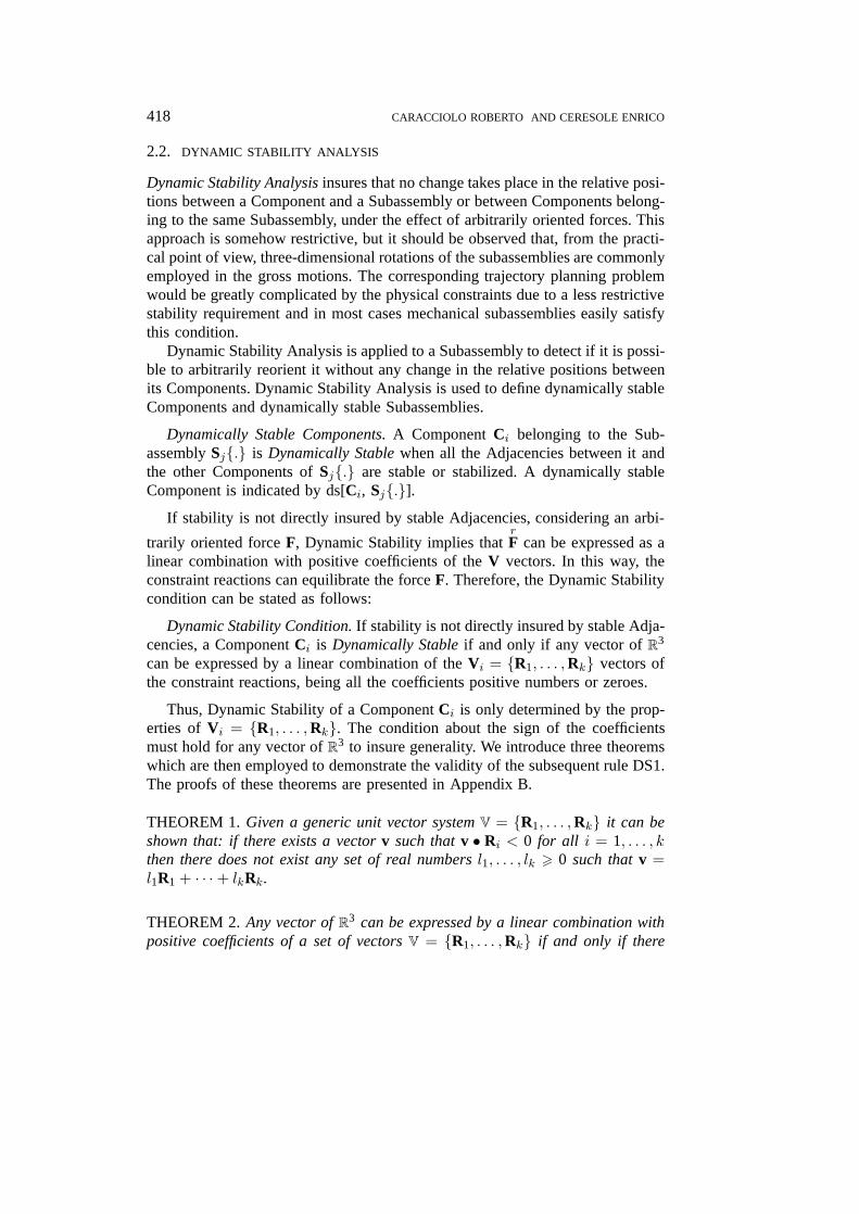
Figure 3. Vectors satisfying the Theorem 3.
does not exist any vector v of R3 such that its dot product with all vectors of Vis positive.
THEOREM 3. Given a unit vector system V = {R1, . . . ,Rk} with k > 4: if thereexist four unit vectors Rs, Rt, Rm, Rn of V such that for all their combinations
Rs × Rt •Rm 6= 0, Rs ×Rt • Rn 6= 0
and
sign(Rs × Rt • Rm) 6= sign(Rs × Rt • Rn)
then there does not exist a vector v of R3 such that v •Ri > 0 for i = s, t,m, n(see Figure 3).
Rule DS1. Given the unit vector system Vr, representing the constraint reac-tions of the Cr Component, if there exists a subset Ma = {Rs,Rt,Rm,Rn} ofVr such that Ri × Rj • Rk 6= 0 for any i, j, k = s, t,m, n; i 6= j 6= k andsign(Rs × Rt • Rm) 6= sign(Rs × Rt • Rn) for all combinations of Rs, Rt, Rm,Rn then the Cr Component is dynamically stable.
The knowledge of all the dynamically stable Components allows one to findthe dynamically stable Subassemblies. In other words, Dynamic Stability of allthe Ci Components belonging to Sj{.} is required to ensure the Dynamic Stabilityof a Subassembly Sj{.}
Dynamically Stable Subassemblies. A Subassembly Sj{.} is dynamically sta-ble if and only if all Components belonging to Sj{.} are dynamically stable.
A Dynamically Stable Subassembly is indicated as ds[Sj{.}]. All Dynami-cally Stable Subassemblies are determined in an efficient way using the above-mentioned Dynamic Stability Condition. A set of rules for faster identifying thedynamically stable Subassemblies can be introduced:
JINT1358.tex; 30/07/1997; 10:55; v.7; p.9
420 CARACCIOLO ROBERTO AND CERESOLE ENRICO
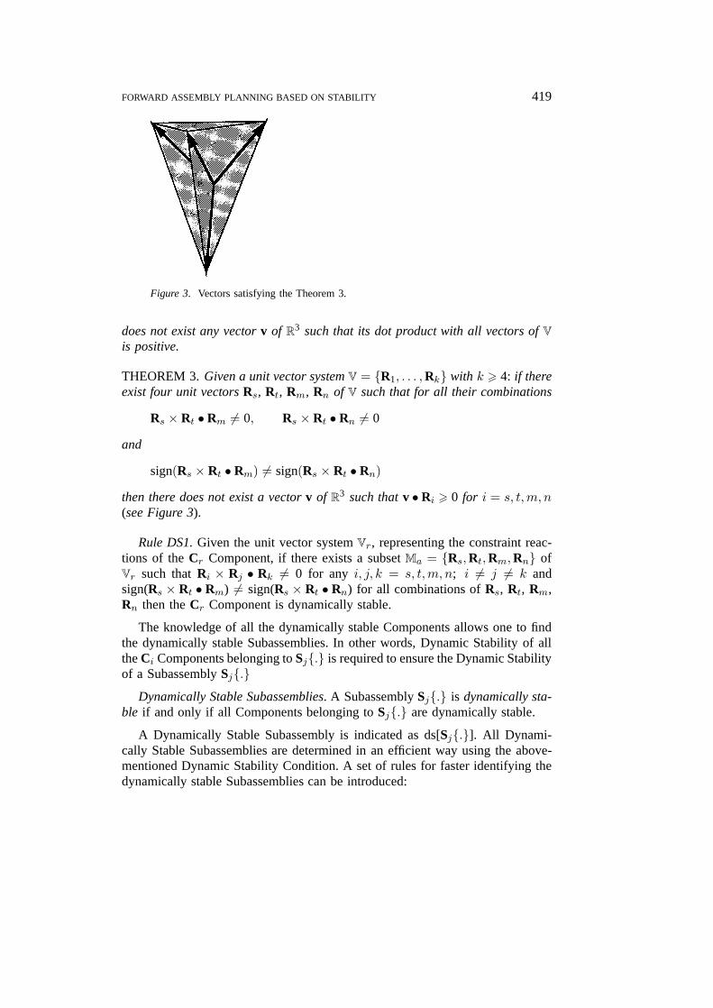
Figure 4. An example of stability graph.
Rule DS2. At least one stable Adjacency must exist in a dynamically stableSubassembly.
Rule DS3. If Sj{.} is not a dynamically stable Subassembly, then the onlyway to obtain a new ds[Sk{.}] is to add a further component establishing a stableAdjacency.
Rule DS4. Let us consider two dynamically stable Subassemblies ds[Sm{.}]and ds[Sn{.}]. If there exist j such that Cj ∈ Sm{.} and Cj ∈ Sn{.}, it followsthat it is ds[Sm{.} ∪ Sn{.}].
These rules allow one to determine all the dynamically stable Subassembliesand they can be applied independently from the assembly sequence. It is rea-sonable to introduce the following assumption: we assume to deal only with
JINT1358.tex; 30/07/1997; 10:55; v.7; p.10

FORWARD ASSEMBLY PLANNING BASED ON STABILITY 421
only those dynamically stable Subassemblies. In this way, Subassemblies can beconsidered as Components because they can be handled in the same manner.
2.3. THE STABILITY GRAPH
The Stability Graph (SG) is the graphic representation of Dynamic Stability. Anode of the SG represents a Component. Any node has one or more Satelliteswhich represent a way to stabilize the Component. A Satellite of a ComponentCj is pointed by the Components that constrain Cj . If a set of Components,capable of stabilizing the node, points to one of its Satellites, this Satellite isactive. All nodes have at least an active Satellite in a SG of a dynamically stableSubassembly.
This representation of Stability can emphasize the Satellites that must beactivated in order to obtain a Dynamically Stable Subassemblies. Therefore, itemphasizes the Adjacencies that must be stabilized. Figure 4 shows an exampleof SG.
3. The Assembly Planner
In this section we describe the importance of stability analysis when solving non-linear assembly planning problems, keeping into account non-mating operations.Information about Components and Adjacencies, obtained from a CAD system,are processed. We analyze pairs of adjacent Components to obtain the elementarymating operations and some of their features.
Geometrical constraints COg can be deduced by an automatic CAD-basedprocedure and then translated into Precedence Relations PR(Ci, COg, OF). Thisprocedure handles data concerning mating operations and Adjacencies to defineone or more possible mating directions. Only straight-line trajectories are con-sidered. This is not a severe limitation because most assembly sequences in themechanical domain make use of straight-line paths. This procedure is based onthe theory presented by Huang and Lee in [7].
Constraints obtained by stability analysis are state-dependent, i.e. do not holdfor every state, and it is difficult to translate them in Precedence Relations whichwould avoid backtracking. Therefore, stability constraints make useless to testwhether it is possible to reach the end of the process after each operation.
Stability criteria are expressed with rules concerning Components and ele-mentary operations. The data to be handled are logical statements and relations;the goal is to determine an optimal operation sequence by using a set of rules.
The assembly planner is a non-algorithmic program built up inside of ansystem shell. The program code is composed of non-ordered sets of objects andrule packets. A set of objects is the data base of the planner and a set of rulepackets represents the knowledge base.
JINT1358.tex; 30/07/1997; 10:55; v.7; p.11
422 CARACCIOLO ROBERTO AND CERESOLE ENRICO
An object contains the instance variables and can represent different enti-ties of the application, thus building the knowledge base. A packet is a set ofrules working on different objects. A rule can modify, create and destroy anobject. Any object has many occurrences and can inherit the features of otherobjects.
The planner uses the inference engine of the shell. The engine works on theobjects by activating different inference strategies, which are the HypotheticalReasoning and the Forward Chaining.
We can consider a search tree, where a path represents a possible problemsolution. Each state along the path is a NODE object. A best-first search methodis used: in this method the activating node is the most promising among the notyet explored nodes. An example of application of this method in the selection ofassembly plans is presented in [13].
The Forward Chaining methodology manages the activation of packets bychecking the priority functions of the rules and the instance variables of theobjects. The main objects of the planner are the NODE object and the OPERA-TION object.
The NODE object represents a state of the assembly and it is defined by a setof instance variables. Most significant variables are:(a) Node: the node identifier.(b) Parent Node: the parent node identifier.(c) Past Cost: the cost to attain the current node from the root.(d) Incremental Cost: the cost to attain the current node from the parent node.(e) Total Cost: the estimated cost from the root to the end of the assembly.(f) Operation: the identifier of the OPERATION object that has determined the
last change of state.(g) Matrix Set: a set of orientation matrices compatible with the current config-
uration.The Matrix Set is obtained by eliminating from the parent’s Matrix Set every
orientation for which the Operation is impossible. This is obtained using Stat-ic Stability criteria. This is an efficient approach to the reorienting problem. Areorienting operation is necessary if the matrix set does not contain any orienta-tion matrix compatible with the next mating operation. The matrix set is updatedwhen a reorienting operation is inserted into the sequence. We suppose that acost is associated with the reorienting operation and that each orientation has thesame priority.
The assembly plan generation is performed by subsequent choices; a changein the assembly state is obtained by means of an OPERATION, selected amonga set of possible operations. The OPERATION object represents the relationexisting between adjacent Components and is described by a set of variables andattributes. Most significant among them are:(a) Operation: the operation identifier.
JINT1358.tex; 30/07/1997; 10:55; v.7; p.12
FORWARD ASSEMBLY PLANNING BASED ON STABILITY 423
(b) Component: the identifier of the Component moved by this operation.(c) Adjacent Component: the identifiers of the Components which establish
elementary relations, i.e. adjacencies, with Component by means of thisoperation.
(d) Operation type: the type of the operation, selected among a set of feasibleoperations (with a given robot).
(e) Operation form: the identifier of another object containing the trajectory,the tool and the grasping matrix.
(f) Local priority: a cost related to the feasibility of the operation.These objects are manipulated by means of rules; rules are grouped in packets.
Each packet solves a specific problem. The inference cycle determines when apacket is to be executed by managing a set of conditions which may changeduring the process.
We can generate different nodes by adding a new Component in the PartialAssembly. In fact, the same operation can be performed in more then one way,corresponding to different Operation Forms.Two fundamental groups of packets compose the developed application:(1) the SUBASSEMBLY SEARCH PACKETS (SSP), based on Dynamic Sta-
bility Analysis, operating autonomously;(2) the PLANNER KERNEL PACKETS, based on Hypothetical Reasoning, main-
ly working on the NODE object, and composed of an EXPAND packet, anEVALUATE packet and a basic inference cycle.
This structure enables the kernel to perform linear assembly planning, becausenon-linearity is a priori solved by the Subassembly Search Module. The ker-nel considers only one workspace and works using Subassemblies as elemen-tary Components. Subassemblies can be processed as elementary Componentsbecause the SSP has already defined all their attributes and because they areDynamically Stable.
3.1. SUBASSEMBLY SEARCH PACKETS
The SUBASSEMBLY SEARCH PACKETS (SSPs) perform Dynamic Stabilityverifications for each Component (ds[Ci,Sj{.}]) in order to determine all possibleDynamically Stable Subassemblies. SSPs make use of the OPERATION objectand of the T LIST object. T LIST is a temporary object used to store Compo-nents during the subassembly search. A specific set of rules is implemented tomanage the T LIST object. This set is called the MANAGE packet and performsthe analysis of the T LIST object: it verifies whether the set of stored Compo-nents can be a Subassembly or not. The main rules of the MANAGE packetare rules DS1, DS2, DS3 and DS4 described in Section 3.2. In the MANAGEpacket these rules are applied for a fast identification of the dynamically stableSubassemblies in the T LIST. Subassemblies are detected by analyzing also themounting possibility. The MANAGE structure is the following:
JINT1358.tex; 30/07/1997; 10:55; v.7; p.13
424 CARACCIOLO ROBERTO AND CERESOLE ENRICO
(a) a rule adds a component into the T LIST object by analyzing compatibili-ty with Precedence Relations and by checking the Adjacency list to verifywhether a new connected subassembly appears;
(b) Dynamic Stability rules are applied to the subassembly composed of theT LIST Components;
(c) a rule verifies whether the proposed Dynamically Stable Subassembly doesnot prevent the assembling of other Components.
A set of Components in the T LIST must be connected, dynamically stable andcompatible with all precedence relations to become a Subassembly. SSPs generatea set of possible Subassemblies sps = {ds[S1{.}], . . . , ds[Sj{.}]}.
3.2. PLANNER KERNEL PACKETS
The EXPAND packet chooses the expanding NODE. The priority function usedfor this choice is the Total Cost associated with the expanding node. The EXPANDstructure is the following:(a) a first rule identifies if the node is a Solution Node. In this case, the best
problem solution is found and the procedure stops;(b) a second rule identifies all the possible nodes and creates the NODE object
instances which represent them.EXPAND performs some verifications while generating the sons of a selectedparent:− the precedence relations, deduced from technological and geometrical con-
straint are applied;− the Static and the Dynamic Stability conditions are verified.
Only those nodes which satisfy these relations and conditions are created.The EVALUATE packet is used to calculate the Incremental Cost and the
Total Cost of the generated node.The static stability conditions defined by rules SS1, SS2 and SS3 in Sec-
tion 3.1 are verified by the STAB CONTROL packet. The dynamic stability isalso verified, comparing the partial assembly with the elements of the sps list,created by the SSP.
In this way the Dynamic Stability verification results simple and can be repeat-ed with low computational costs.
4. Planning Examples
The assembly planner described in this work is implemented in a commercial-ly available expert system shell (KBMS). The planner is an independent non-algorithmic program composed of a data structure and a set of rule packets thatuse the inference engine of the shell, properly initialized.
We describe a planning example regarding a set of simple Components asshown in Figure 5. Five Components are present:
JINT1358.tex; 30/07/1997; 10:55; v.7; p.14
FORWARD ASSEMBLY PLANNING BASED ON STABILITY 425
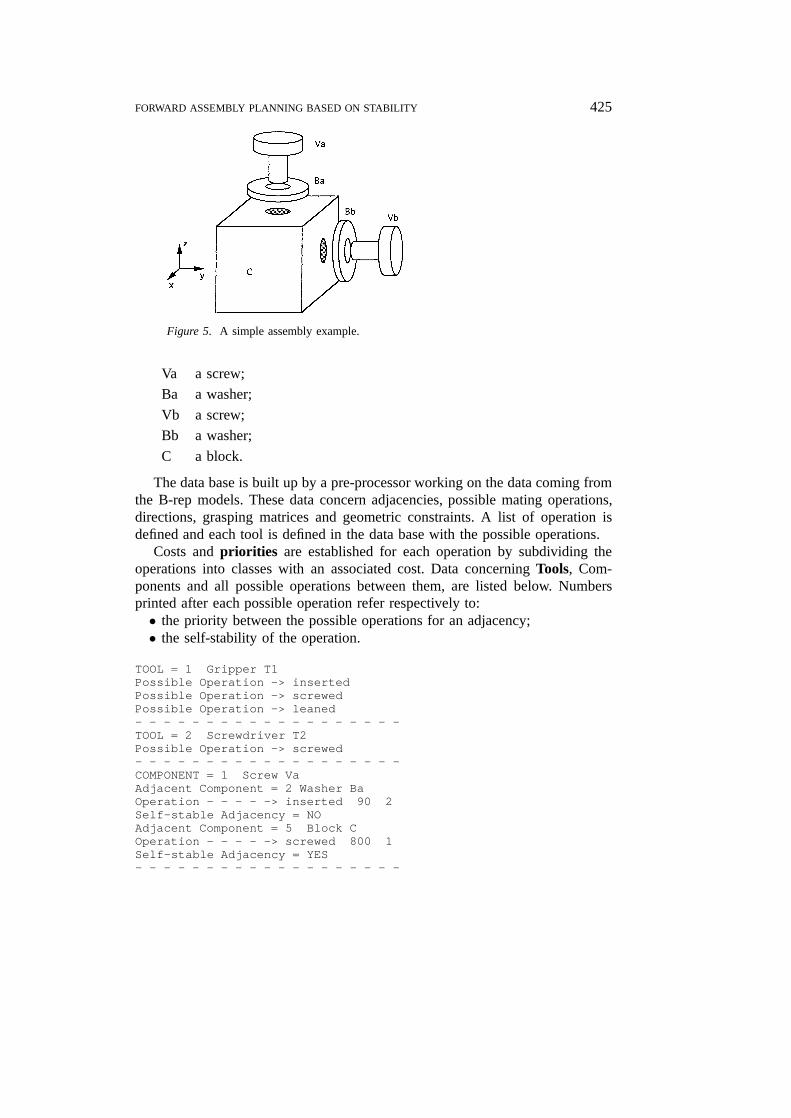
Figure 5. A simple assembly example.
Va a screw;
Ba a washer;
Vb a screw;
Bb a washer;
C a block.
The data base is built up by a pre-processor working on the data coming fromthe B-rep models. These data concern adjacencies, possible mating operations,directions, grasping matrices and geometric constraints. A list of operation isdefined and each tool is defined in the data base with the possible operations.
Costs and priorities are established for each operation by subdividing theoperations into classes with an associated cost. Data concerning Tools, Com-ponents and all possible operations between them, are listed below. Numbersprinted after each possible operation refer respectively to:• the priority between the possible operations for an adjacency;• the self-stability of the operation.
TOOL = 1 Gripper T1Possible Operation -> insertedPossible Operation -> screwedPossible Operation -> leaned- - - - - - - - - - - - - - - - - - -TOOL = 2 Screwdriver T2Possible Operation -> screwed- - - - - - - - - - - - - - - - - - -COMPONENT = 1 Screw VaAdjacent Component = 2 Washer BaOperation - - - - -> inserted 90 2Self-stable Adjacency = NOAdjacent Component = 5 Block COperation - - - - -> screwed 800 1Self-stable Adjacency = YES- - - - - - - - - - - - - - - - - - -
JINT1358.tex; 30/07/1997; 10:55; v.7; p.15
426 CARACCIOLO ROBERTO AND CERESOLE ENRICO
COMPONENT = 2 Washer BaAdjacent Component = 1 Screw VaOperation - - - - -> inserted 90 2Operation - - - - -> leaned 80 2Self-stable Adjacency = NOAdjacent Component = 5 Block COperation - - - - -> leaned 80 2Self-stable Adjacency = NO- - - - - - - - - - - - - - - - - - -COMPONENT = 3 Screw VbAdjacent Component = 4 Washer BbOperation - - - - -> inserted 90 2Self-stable Adjacency = NOAdjacent Component = 5 Block COperation - - - - -> screwed 800 1Self-stable Adjacency = YES- - - - - - - - - - - - - - - - - - -COMPONENT = 4 Washer BbAdjacent Component = 3 Screw VbOperation - - - - -> inserted 90 2Self-stable Adjacency = NOAdjacent Component = 5 Block COperation - - - - -> leaned 80 2Self-stable Adjacency = NO- - - - - - - - - - - - - - - - - - -COMPONENT = 5 Block CAdjacent Component = 1 Screw VaOperation - - - - -> screwed 800 1Self-stable Adjacency = YESAdjacent Component = 2 Washer BaOperation - - - - -> leaned 80 2Self-stable Adjacency = NOAdjacent Component = 3 Screw VbOperation - - - - -> screwed 800 1Self-stable Adjacency = YESAdjacent Component = 4 Washer BbOperation - - - - -> leaned 80 2Self-stable Adjacency = NO
This example has been selected, because it is simple and easy to understand.At the same time it enables one to emphasize some features of the proposedplanner. This assembly necessarily requires a reorienting operation, because themating operations of the Ba and Bb Components are ‘lean’ operations. Theleaned Components Ba and Bb are statically stable only in a particular orienta-tion.
The SSP modules, i.e. the first modules of the planner, determine the follow-ing possible Subassemblies list: sps = {ds[S1{Va,Ba,C}], ds[S2{Vb,Bb,C}]}.When a reorienting operation is required, the planner schedules this opera-tion only if the already assembled Components correspond to a Subassem-bly of sps, i.e. to a dynamically stable Subassembly. The Sa and Sb Com-ponents are screwed; therefore we must change the tool, from the two fin-ger parallel gripper used in the preceding operation (Tool 1), to the screw-
JINT1358.tex; 30/07/1997; 10:55; v.7; p.16
FORWARD ASSEMBLY PLANNING BASED ON STABILITY 427
driver (Tool 2). If the cost related to tool changes is particularly high, it ispossible that the planner does not change the tool and chooses a ‘screwingby hand’ operation (possible under some geometrical and mechanical hypothe-ses).
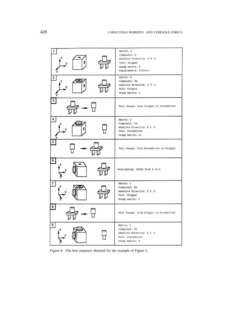
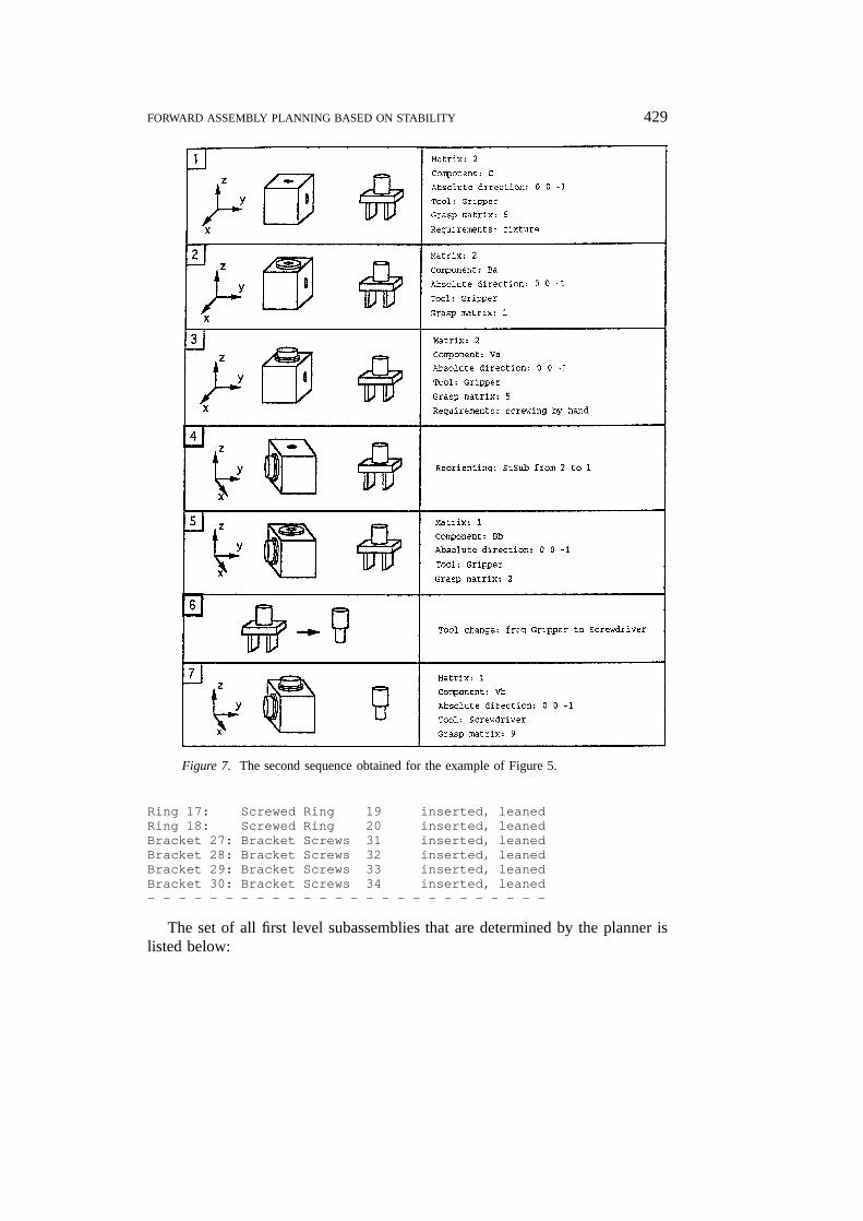
Different costs are attributed to the tool changes for the proposed exampleand two different assembly sequences are obtained. They are shown in Figures 6and 7. The first sequence (Figure 6) consists of nine operations, whereas thesecond sequence is composed of seven operations: two tool changes are avoid-ed using a ‘screwing by hand’ operation. This assembly contains two screwedComponents. In the second sequence different solution are chosen for the twoscrewed Components. The first Component is assembled ‘screwing by hand’using the gripper, avoiding in this way two tool-change operations; instead, thesecond one is assembled by a typical ‘screwing’ operation, because only onetool change is required. In fact, at the end of the sequence the screwdriver is notback substituted to the gripper. Should the whole process be repeated more times,then the result would be a third sequence in which both screwed Componentsare ‘screwed by hand’ with the gripper. In the first case (Figure 6) costs are aspresented in Table I. In this sequence the planner creates 114 nodes and activates107 nodes. In the second case (Figure 7) we update the cost of the ‘Tool changes’operations which becomes now 50 instead of 30. The planner creates now 242nodes and activates 106 nodes.
The possibility of reorienting the Partial Subassembly is determined by com-parison with the set of the possible Subassemblies sps = {ds[S1{.}], ds[S2{.}]}.The necessity of reorienting the Partial Subassembly is determined by the StaticStability condition for the Washers.
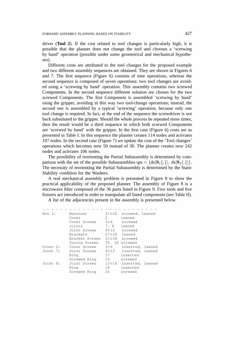
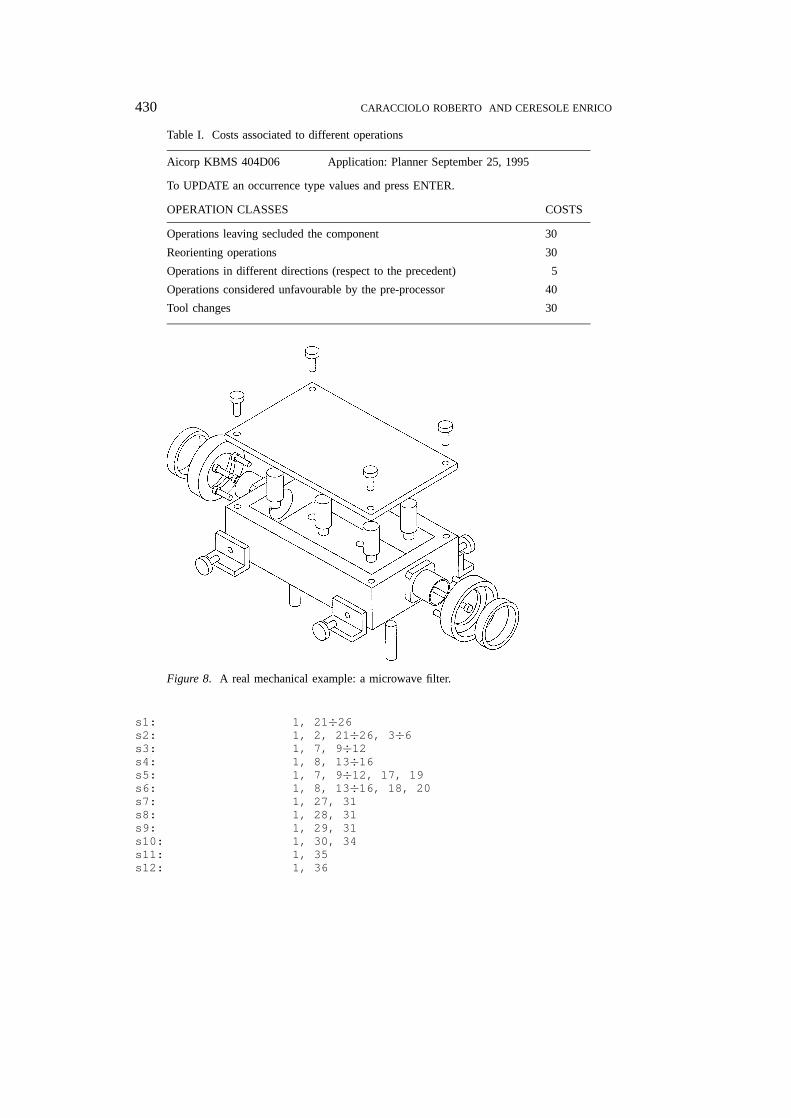
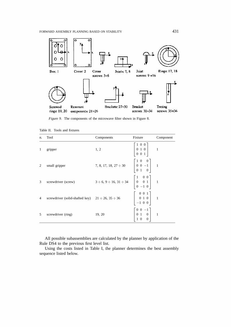
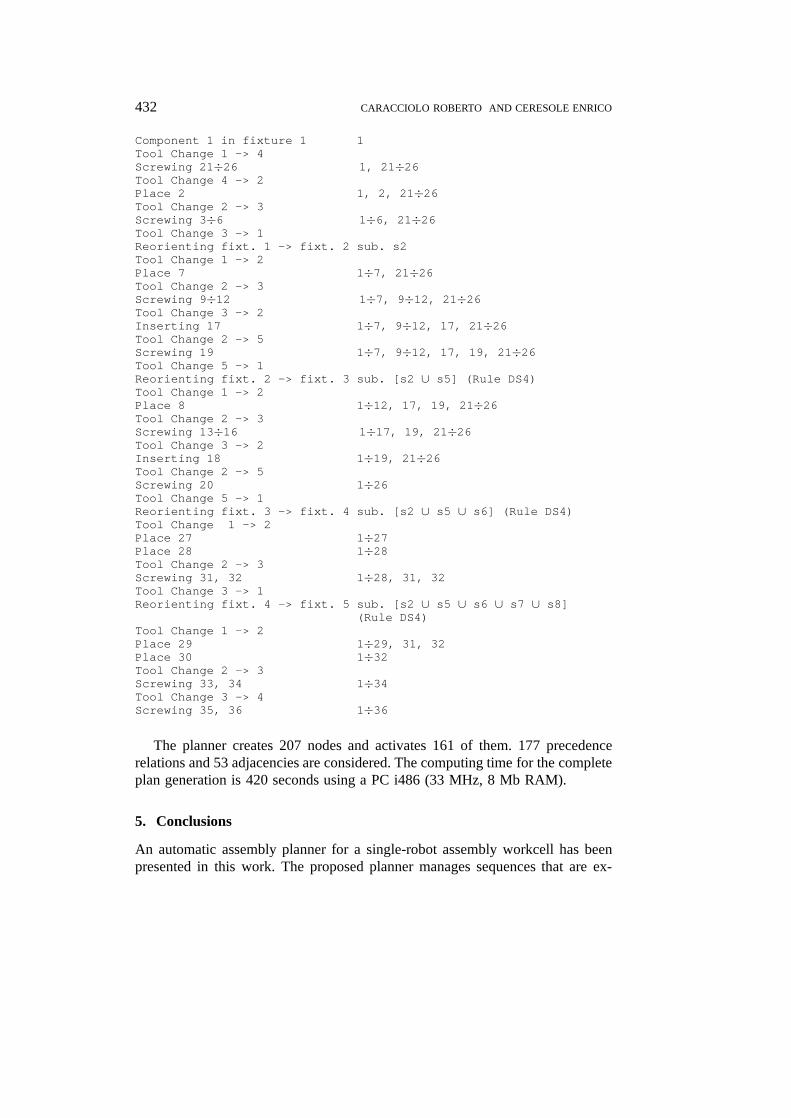
A real mechanical assembly problem is presented in Figure 8 to show thepractical applicability of the proposed planner. The assembly of Figure 8 is amicrowave filter composed of the 36 parts listed in Figure 9. Five tools and fivefixtures are introduced in order to manipulate all listed components (see Table II).
A list of the adjacencies present in the assembly is presented below.
- - - - - - - - - - - - - - - - - - - - - - - - - -Box 1: Resonant 21÷26 screwed, leaned
Cover 2 leanedCover Screws 3÷6 screwedJoints 7, 8 leanedJoint Screws 9÷16 screwedBrackets 27÷30 leanedBracket Screws 31÷34 screwedTuning Screws 35, 36 screwed
Cover 2: Cover Screws 3÷6 inserted, leanedJoint 7: Joint Screws 9÷12 inserted, leaned
Ring 17 insertedScrewed Ring 19 screwed
Joint 8: Joint Screws 13÷16 inserted, leanedRing 18 insertedScrewed Ring 20 screwed
JINT1358.tex; 30/07/1997; 10:55; v.7; p.17
428 CARACCIOLO ROBERTO AND CERESOLE ENRICO
Figure 6. The first sequence obtained for the example of Figure 5.
JINT1358.tex; 30/07/1997; 10:55; v.7; p.18
FORWARD ASSEMBLY PLANNING BASED ON STABILITY 429
Figure 7. The second sequence obtained for the example of Figure 5.
Ring 17: Screwed Ring 19 inserted, leanedRing 18: Screwed Ring 20 inserted, leanedBracket 27: Bracket Screws 31 inserted, leanedBracket 28: Bracket Screws 32 inserted, leanedBracket 29: Bracket Screws 33 inserted, leanedBracket 30: Bracket Screws 34 inserted, leaned- - - - - - - - - - - - - - - - - - - - - - - - - -
The set of all first level subassemblies that are determined by the planner islisted below:
JINT1358.tex; 30/07/1997; 10:55; v.7; p.19
430 CARACCIOLO ROBERTO AND CERESOLE ENRICO
Table I. Costs associated to different operations
Aicorp KBMS 404D06 Application: Planner September 25, 1995
To UPDATE an occurrence type values and press ENTER.
OPERATION CLASSES COSTS
Operations leaving secluded the component 30
Reorienting operations 30
Operations in different directions (respect to the precedent) 5
Operations considered unfavourable by the pre-processor 40
Tool changes 30
Figure 8. A real mechanical example: a microwave filter.
s1: 1, 21÷26s2: 1, 2, 21÷26, 3÷6s3: 1, 7, 9÷12s4: 1, 8, 13÷16s5: 1, 7, 9÷12, 17, 19s6: 1, 8, 13÷16, 18, 20s7: 1, 27, 31s8: 1, 28, 31s9: 1, 29, 31s10: 1, 30, 34s11: 1, 35s12: 1, 36
JINT1358.tex; 30/07/1997; 10:55; v.7; p.20
FORWARD ASSEMBLY PLANNING BASED ON STABILITY 431
Figure 9. The components of the microwave filter shown in Figure 8.
Table II. Tools and fixtures
n. Tool Components Fixture Component
1 gripper 1, 2
1 0 00 1 00 0 1
1
2 small gripper 7, 8, 17, 18, 27÷ 30
1 0 00 0 −10 1 0
1
3 screwdriver (screw) 3 ÷ 6, 9÷ 16, 31÷ 34
1 0 00 0 10 −1 0
1
4 screwdriver (solid-shafted key) 21÷ 26, 35÷ 36
0 0 10 1 0−1 0 0
1
5 screwdriver (ring) 19, 20
0 0 −10 1 01 0 0
1
All possible subassemblies are calculated by the planner by application of theRule DS4 to the previous first level list.
Using the costs listed in Table I, the planner determines the best assemblysequence listed below.
JINT1358.tex; 30/07/1997; 10:55; v.7; p.21
432 CARACCIOLO ROBERTO AND CERESOLE ENRICO
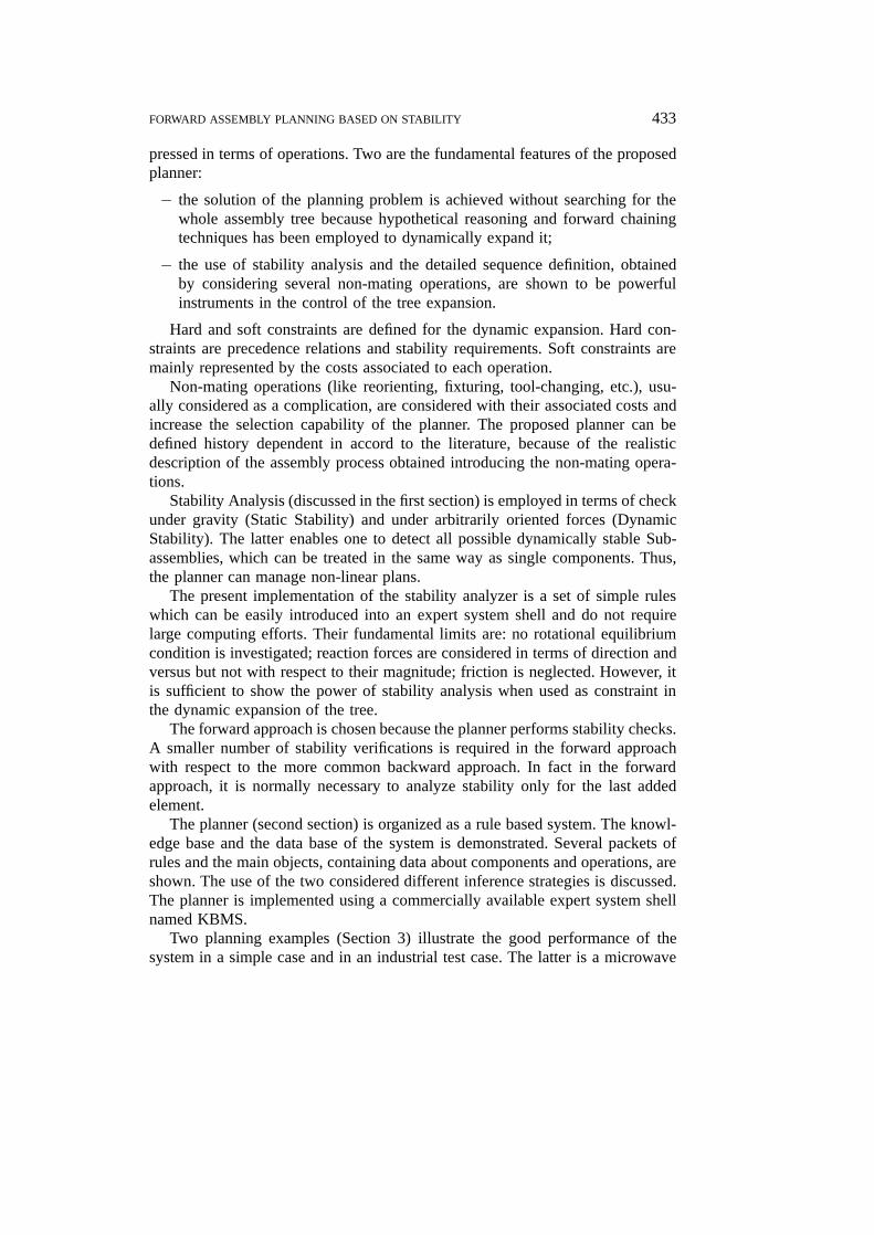
Component 1 in fixture 1 1Tool Change 1 -> 4Screwing 21÷26 1, 21÷26Tool Change 4 -> 2Place 2 1, 2, 21÷26Tool Change 2 -> 3Screwing 3÷6 1÷6, 21÷26Tool Change 3 -> 1Reorienting fixt. 1 -> fixt. 2 sub. s2Tool Change 1 -> 2Place 7 1÷7, 21÷26Tool Change 2 -> 3Screwing 9÷12 1÷7, 9÷12, 21÷26Tool Change 3 -> 2Inserting 17 1÷7, 9÷12, 17, 21÷26Tool Change 2 -> 5Screwing 19 1÷7, 9÷12, 17, 19, 21÷26Tool Change 5 -> 1Reorienting fixt. 2 -> fixt. 3 sub. [s2 ∪ s5] (Rule DS4)Tool Change 1 -> 2Place 8 1÷12, 17, 19, 21÷26Tool Change 2 -> 3Screwing 13÷16 1÷17, 19, 21÷26Tool Change 3 -> 2Inserting 18 1÷19, 21÷26Tool Change 2 -> 5Screwing 20 1÷26Tool Change 5 -> 1Reorienting fixt. 3 -> fixt. 4 sub. [s2 ∪ s5 ∪ s6] (Rule DS4)Tool Change 1 -> 2Place 27 1÷27Place 28 1÷28Tool Change 2 -> 3Screwing 31, 32 1÷28, 31, 32Tool Change 3 -> 1Reorienting fixt. 4 -> fixt. 5 sub. [s2 ∪ s5 ∪ s6 ∪ s7 ∪ s8]
(Rule DS4)Tool Change 1 -> 2Place 29 1÷29, 31, 32Place 30 1÷32Tool Change 2 -> 3Screwing 33, 34 1÷34Tool Change 3 -> 4Screwing 35, 36 1÷36
The planner creates 207 nodes and activates 161 of them. 177 precedencerelations and 53 adjacencies are considered. The computing time for the completeplan generation is 420 seconds using a PC i486 (33 MHz, 8 Mb RAM).
5. Conclusions
An automatic assembly planner for a single-robot assembly workcell has beenpresented in this work. The proposed planner manages sequences that are ex-
JINT1358.tex; 30/07/1997; 10:55; v.7; p.22
FORWARD ASSEMBLY PLANNING BASED ON STABILITY 433
pressed in terms of operations. Two are the fundamental features of the proposedplanner:
− the solution of the planning problem is achieved without searching for thewhole assembly tree because hypothetical reasoning and forward chainingtechniques has been employed to dynamically expand it;
− the use of stability analysis and the detailed sequence definition, obtainedby considering several non-mating operations, are shown to be powerfulinstruments in the control of the tree expansion.
Hard and soft constraints are defined for the dynamic expansion. Hard con-straints are precedence relations and stability requirements. Soft constraints aremainly represented by the costs associated to each operation.
Non-mating operations (like reorienting, fixturing, tool-changing, etc.), usu-ally considered as a complication, are considered with their associated costs andincrease the selection capability of the planner. The proposed planner can bedefined history dependent in accord to the literature, because of the realisticdescription of the assembly process obtained introducing the non-mating opera-tions.
Stability Analysis (discussed in the first section) is employed in terms of checkunder gravity (Static Stability) and under arbitrarily oriented forces (DynamicStability). The latter enables one to detect all possible dynamically stable Sub-assemblies, which can be treated in the same way as single components. Thus,the planner can manage non-linear plans.
The present implementation of the stability analyzer is a set of simple ruleswhich can be easily introduced into an expert system shell and do not requirelarge computing efforts. Their fundamental limits are: no rotational equilibriumcondition is investigated; reaction forces are considered in terms of direction andversus but not with respect to their magnitude; friction is neglected. However, itis sufficient to show the power of stability analysis when used as constraint inthe dynamic expansion of the tree.
The forward approach is chosen because the planner performs stability checks.A smaller number of stability verifications is required in the forward approachwith respect to the more common backward approach. In fact in the forwardapproach, it is normally necessary to analyze stability only for the last addedelement.
The planner (second section) is organized as a rule based system. The knowl-edge base and the data base of the system is demonstrated. Several packets ofrules and the main objects, containing data about components and operations, areshown. The use of the two considered different inference strategies is discussed.The planner is implemented using a commercially available expert system shellnamed KBMS.
Two planning examples (Section 3) illustrate the good performance of thesystem in a simple case and in an industrial test case. The latter is a microwave
JINT1358.tex; 30/07/1997; 10:55; v.7; p.23
434 CARACCIOLO ROBERTO AND CERESOLE ENRICO
branching filter produced by Alcatel-Telettra Company composed of 36 parts.The data structure and the final sequence are reported for this case.
Acknowledgements
This research has been sponsored by the Italian National Research Council C.N.R.as part of the ‘Progetto Finalizzato Robotica’ project. Professors M. Giovagnoniand A. Rossi are gratefully acknowledged for helpful discussions and suggestions.
Appendix A
PRELIMINARY DEFINITIONS
A Component is the basic element considered and is defined by a set of surfaceswhich bound it and correspond to CAD macro-faces.
A Contact is the coincidence of a surface (or a portion of it) of a Componentwith a surface (or a portion of it) of another Component. These surfaces arecalled Contact surfaces and are attributed by a set of features deduced from theCAD representation.
An Adjacency between two Components is established, if there exist one ormore contacts between the considered Components.
The ith Component of the assembly is generally indicated with Ci. If theComponent is assembled, i.e. at least an Adjacency is established, it is indi-cated with Ci. The ith Adjacency between two Components is indicated withAi{Ci,Ck}. The object Ai{. . .} holds the technological attributes associated toeach contact of the Adjacency. An Assembly is a set of Components, connectedby means of Adjacencies established between Component pairs; each Adjacencyrepresents a certain number of Contacts between attributed surfaces.
A Subassembly is a connected portion of an Assembly. The ith Subassemblyis indicated by the object Si{Ci, . . . ,Cr} pointing to a set of n Components.
Elementary Operations, defined as assembly processor actions, i.e. robotactions, are used by the planner. Elementary Operation consists either in estab-lishing one or more Adjacencies (Mating Operation), or in putting a Componentinto an intermediate position (like in non-monotone assembly), or in changingthe tool, or in reorienting a Subassembly.
The Partial Assembly is the particular Subassembly to which a new Com-ponent is added by establishing new Adjacencies. The Partial Assembly is notmoved during a mating operation.
The Operation Form is the way to carry out an elementary operation and isindicated with OF(parameters).
A Constraint CO is a logical statement which may prevent the possibility thata given event happens.
A Geometrical Constraint is indicated as COg.
JINT1358.tex; 30/07/1997; 10:55; v.7; p.24
FORWARD ASSEMBLY PLANNING BASED ON STABILITY 435
Precedence Relations are defined as logical statements PR(Ci, CO, OF(. . .))where Ci is the constrained Component, CO is the Constraint, OF is the OperationForm of the operation executed on the Ci Component. PR(Ci, CO, OF) meansthat the mating operation concerning Ci, defined by the Operation Form OF, isnot feasible if CO is true.
Appendix B
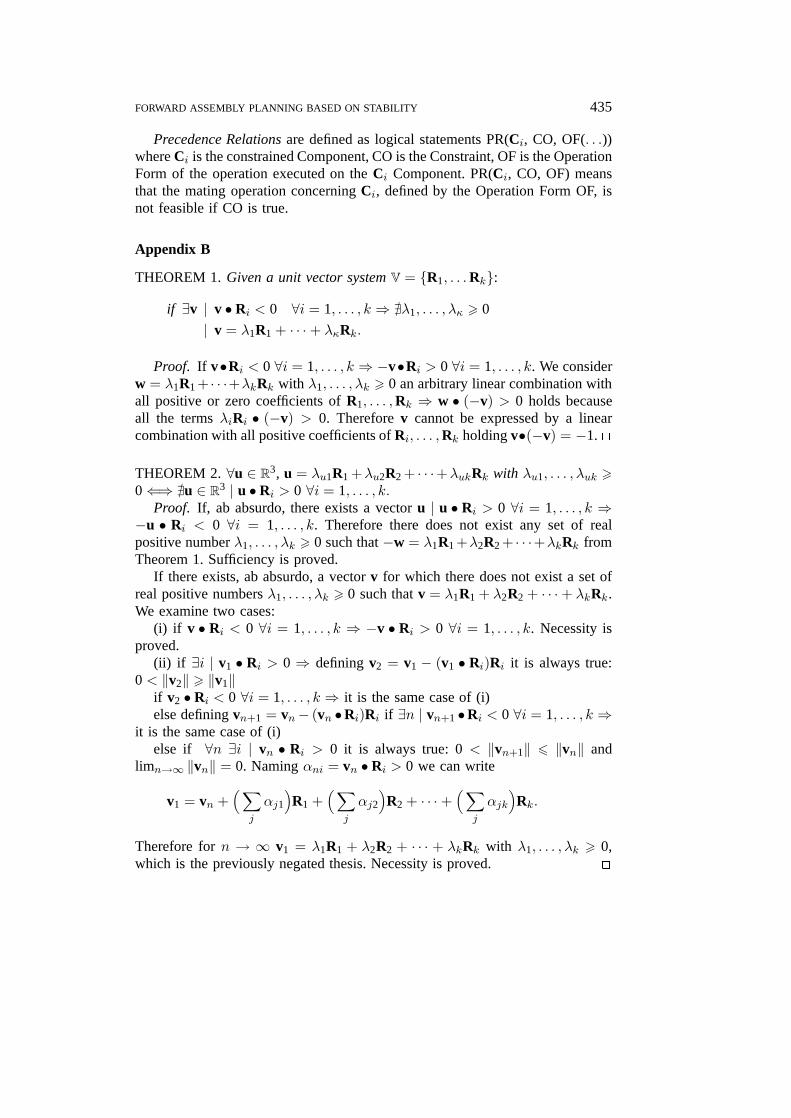
THEOREM 1. Given a unit vector system V = {R1, . . .Rk}:
if ∃v | v • Ri < 0 ∀i = 1, . . . , k ⇒ @λ1, . . . , λκ > 0
| v = λ1R1 + · · ·+ λκRk.
Proof. If v•Ri < 0 ∀i = 1, . . . , k ⇒ −v•Ri > 0 ∀i = 1, . . . , k. We considerw = λ1R1 + · · ·+λkRk with λ1, . . . , λk > 0 an arbitrary linear combination withall positive or zero coefficients of R1, . . . ,Rk ⇒ w • (−v) > 0 holds becauseall the terms λiRi • (−v) > 0. Therefore v cannot be expressed by a linearcombination with all positive coefficients of Ri, . . . ,Rk holding v•(−v) = −1. 2
THEOREM 2. ∀u ∈ R3, u = λu1R1 +λu2R2 + · · ·+λukRk with λu1, . . . , λuk >0⇐⇒ @u ∈ R3 | u •Ri > 0 ∀i = 1, . . . , k.
Proof. If, ab absurdo, there exists a vector u | u • Ri > 0 ∀i = 1, . . . , k ⇒−u • Ri < 0 ∀i = 1, . . . , k. Therefore there does not exist any set of realpositive number λ1, . . . , λk > 0 such that −w = λ1R1 +λ2R2 + · · ·+λkRk fromTheorem 1. Sufficiency is proved.
If there exists, ab absurdo, a vector v for which there does not exist a set ofreal positive numbers λ1, . . . , λk > 0 such that v = λ1R1 + λ2R2 + · · ·+ λkRk.We examine two cases:
(i) if v • Ri < 0 ∀i = 1, . . . , k ⇒ −v • Ri > 0 ∀i = 1, . . . , k. Necessity isproved.
(ii) if ∃i | v1 • Ri > 0 ⇒ defining v2 = v1 − (v1 • Ri)Ri it is always true:0 < ‖v2‖ > ‖v1‖
if v2 • Ri < 0 ∀i = 1, . . . , k ⇒ it is the same case of (i)else defining vn+1 = vn− (vn •Ri)Ri if ∃n | vn+1 •Ri < 0 ∀i = 1, . . . , k ⇒
it is the same case of (i)else if ∀n ∃i | vn • Ri > 0 it is always true: 0 < ‖vn+1‖ 6 ‖vn‖ and
limn→∞ ‖vn‖ = 0. Naming αni = vn • Ri > 0 we can write
v1 = vn +(∑
j
αj1
)R1 +
(∑j
αj2
)R2 + · · · +
(∑j
αjk)
Rk.
Therefore for n → ∞ v1 = λ1R1 + λ2R2 + · · · + λkRk with λ1, . . . , λk > 0,which is the previously negated thesis. Necessity is proved. 2
JINT1358.tex; 30/07/1997; 10:55; v.7; p.25
436 CARACCIOLO ROBERTO AND CERESOLE ENRICO
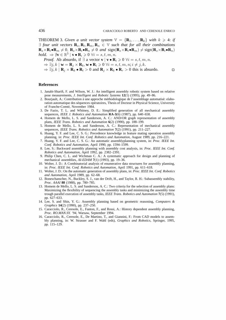
THEOREM 3. Given a unit vector system V = {R1, . . . ,Rk} with k > 4: if∃ four unit vectors Rs,Rt,Rm,Rn ∈ V such that for all their combinationsRs×Rt•Rm 6= 0, Rs×Rt•Rn 6= 0 and sign(Rs×Rt•Rm) 6= sign(Rs×Rt•Rn)hold. ⇒ @v ∈ R3 | v •Ri > 0 ∀i = s, t,m, n.
Proof. Ab absurdo, if ∃ a vector v | v •Ri > 0 ∀i = s, t,m, n.⇒ ∃j, k | w = Rj × Rk,w • Ri > 0 ∀i = s, t,m, n; i 6= j, k.⇒ ∃j, k | Rj × Rk • Rt > 0 and Rj × Rk • Rr > 0 this is absurdo. 2
References
1. Janabi-Sharifi, F. and Wilson, W. J.: An intelligent assembly robotic system based on relativepose measurements, J. Intelligent and Robotic Systems 12(1) (1995), pp. 49–86.
2. Bourjault, A.: Contribution a une approche methodologique de l’assemblage automatise: elabo-ration automatique des sequences operatoires, Thesis of Docteur in Physical Science, Universityof Franche-Comte, November 1984.
3. De Fazio, T. L. and Whitney, D. E.: Simplified generation of all mechanical assemblysequences, IEEE J. Robotics and Automation RA-3(6) (1987), pp. 640–658.
4. Homem de Mello, L. S. and Sanderson, A. C.: AND/OR graph representation of assemblyplans, IEEE Trans. Robotics and Automation 6(2) (1990), pp. 188–199.
5. Homem de Mello, L. S. and Sanderson, A. C.: Representation of mechanical assemblysequences, IEEE Trans. Robotics and Automation 7(2) (1991), pp. 211–227.
6. Huang, Y. F. and Lee, C. S. G.: Precedence knowledge in feature mating operation assemblyplanning, in: Proc. IEEE Int. Conf. Robotics and Automation, August 1989, pp. 216–221.
7. Huang, Y. F. and Lee, C. S. G.: An automatic assemblyplanning system, in: Proc. IEEE Int.Conf. Robotics and Automation, April 1990, pp. 1594–1599.
8. Lee, S.: Backward assembly planning with assembly cost analysis, in: Proc. IEEE Int. Conf.Robotics and Automation, April 1992, pp. 2382–2391.
9. Philip Chen, C. L. and Wichman C. A.: A systematic approach for design and planning ofmechanical assemblies, AI-EDAM 7(1) (1993), pp. 19–36.
10. Wolter, J. D.: A Combinatorial analysis of enumerative data structures for assembly planning,in: Proc. IEEE Int. Conf. Robotics and Automation, April 1991, pp. 611–618.
11. Wolter, J. D.: On the automatic generation of assembly plans, in: Proc. IEEE Int. Conf. Roboticsand Automation, April 1989, pp. 62–68.
12. Boneschanscher, N., Buckley, S. J., van der Drift, H., and Taylor, R. H.: Subassembly stability,Proc. AAAI 88 (1988), pp. 780–785.
13. Homem de Mello, L. S. and Sanderson, A. C.: Two criteria for the selection of assembly plans:Maximizing the flexibility of sequencing the assembly tasks and minimizing the assembly timetrough parallel execution of assembly tasks, IEEE Trans. Robotics and Automation 7(5) (1991),pp. 627–633.
14. Lee, S. and Shin, Y. G.: Assembly planning based on geometric reasoning, Computers &Graphics 14(2) (1990), pp. 237–250.
15. Caracciolo, R., Ceresole, E., Fanton, F., and Rossi, A.: History dependent assembly planning,Proc. RO.MAN.SY. ’94, Warsaw, September 1994.
16. Caracciolo, R., Ceresole, E., De Martino, T., and Giannini, F.: From CAD models to assem-bly planning, in: W. Strasser and F. Wahl (eds), Graphics and Robotics, Springer, 1995,pp. 115–129.
JINT1358.tex; 30/07/1997; 10:55; v.7; p.26