
Formation and Mechanical Characterization of Aminoplast Core/Shell Microcapsules
9
Formation and Mechanical Characterization of Aminoplast Core/ Shell Microcapsules Melanie Pretzl, † Martin Neubauer, † Melanie Tekaat, † Carmen Kunert, † Christian Kuttner, † Ge ́ raldine Leon, ‡ Damien Berthier, ‡ Philipp Erni, ‡ Lahoussine Ouali, ‡ and Andreas Fery* ,† † Department of Physical Chemistry II, University of Bayreuth, Universitä tsstraße 30, D-95447 Bayreuth, Germany ‡ Firmenich SA, Cooperate R&D Division, P.O. Box 239, CH-1211 Geneva 8, Switzerland * S Supporting Information ABSTRACT: This work aims at establishing a link between process conditions and resulting micromechanical properties for aminoplast core/shell microcapsules. The investigated capsules were produced by the in situ polymerization of melamine formaldehyde resins, which represents a widely used and industrially relevant approach in the field of microencapsulation. Within our study, we present a quantitative morphological analysis of the capsules’ size and shell thickness. The diameter of the investigated capsules ranged from 10 to 50 μm and the shell thickness was found in a range between 50 and 200 nm. As key parameter for the control of the shell thickness, we identified the amount of amino resin per total surface area of the dispersed phase. Mechanical properties were investigated using small deformations on the order of the shell thickness by atomic force microscopy with a colloidal probe setup. The obtained capsule stiffness increased with an increasing shell thickness from 2 to 30 N/m and thus showed the same trend on the process parameters as the shell thickness. A simple analytical model was adopted to explain the relation between capsules’ geometry and mechanics and to estimate the elastic modulus of the shell about 1.7 GPa. Thus, this work provides strategies for a rational design of microcapsule mechanics. KEYWORDS: hollow polymer shells, melamine formaldehyde capsules, compression behavior, stability, elastic properties, controlled release, emulsions ■ INTRODUCTION Microcapsules are of broad interest not only in fundamental science 1,2 but also in a wide range of applications. Whenever the functionality of an active substance needs to be protected and/or a controlled release is demanded, microencapsulation is a frequently used solution. 3-10 Industrially relevant wall materials are amino resins, like melamine formaldehyde (MF), because this class of resins is produced from cheap raw materials, widely applicable, and economical to use. 10 In particular, aminoplast core/shell microcapsules are suitable for the encapsulation of pressure sensitive recording materials, 10 perfume fragrances, 11,12 phase change materials, 13,14 self-healing composites, 15,16 agrochemicals, 17 or analytes in biosensor applications. 18 All these applications require a particular mechanical stability, compliance, release, shelf life, and adhesion of the microcapsules. 19,20 Therefore, a rational process design of microcapsules is desired to individually tailor their mechanical properties. 21 To establish correlations between process parameters and the resulting capsule mechanics, methods are favored that allow an investigation of microcapsule mechanics on the single-particle level. 20 So far, reported mechanical characterizations on aminoplast microcapsules were focused on compression experiments with the single capsule compression apparatus described by Keller and Sottos 22 and the micromanipulation technique described by Zhang and co-workers. 23 With both setups, individual microcapsules were deformed in the range of micrometers under applied force loads of millinewtons. Thus, the authors were able to access a deformation regime where rupture forces and the failure of microcapsules can be successfully Received: February 16, 2012 Accepted: May 14, 2012 Published: May 14, 2012 Research Article www.acsami.org © 2012 American Chemical Society 2940 dx.doi.org/10.1021/am300273b | ACS Appl. Mater. Interfaces 2012, 4, 2940-2948
-
Upload
independent -
Category
Documents
-
view
1 -
download
0
Transcript of Formation and Mechanical Characterization of Aminoplast Core/Shell Microcapsules

Formation and Mechanical Characterization of Aminoplast Core/Shell MicrocapsulesMelanie Pretzl,† Martin Neubauer,† Melanie Tekaat,† Carmen Kunert,† Christian Kuttner,†
Geraldine Leon,‡ Damien Berthier,‡ Philipp Erni,‡ Lahoussine Ouali,‡ and Andreas Fery*,†
†Department of Physical Chemistry II, University of Bayreuth, Universitatsstraße 30, D-95447 Bayreuth, Germany‡Firmenich SA, Cooperate R&D Division, P.O. Box 239, CH-1211 Geneva 8, Switzerland
*S Supporting Information
ABSTRACT: This work aims at establishing a link between process conditions and resulting micromechanical properties foraminoplast core/shell microcapsules. The investigated capsules were produced by the in situ polymerization of melamineformaldehyde resins, which represents a widely used and industrially relevant approach in the field of microencapsulation. Withinour study, we present a quantitative morphological analysis of the capsules’ size and shell thickness. The diameter of theinvestigated capsules ranged from 10 to 50 μm and the shell thickness was found in a range between 50 and 200 nm. As keyparameter for the control of the shell thickness, we identified the amount of amino resin per total surface area of the dispersedphase. Mechanical properties were investigated using small deformations on the order of the shell thickness by atomic forcemicroscopy with a colloidal probe setup. The obtained capsule stiffness increased with an increasing shell thickness from 2 to 30N/m and thus showed the same trend on the process parameters as the shell thickness. A simple analytical model was adopted toexplain the relation between capsules’ geometry and mechanics and to estimate the elastic modulus of the shell about 1.7 GPa.Thus, this work provides strategies for a rational design of microcapsule mechanics.
KEYWORDS: hollow polymer shells, melamine formaldehyde capsules, compression behavior, stability, elastic properties,controlled release, emulsions
■ INTRODUCTIONMicrocapsules are of broad interest not only in fundamentalscience1,2 but also in a wide range of applications. Wheneverthe functionality of an active substance needs to be protectedand/or a controlled release is demanded, microencapsulation isa frequently used solution.3−10 Industrially relevant wallmaterials are amino resins, like melamine formaldehyde(MF), because this class of resins is produced from cheapraw materials, widely applicable, and economical to use.10 Inparticular, aminoplast core/shell microcapsules are suitable forthe encapsulation of pressure sensitive recording materials,10
perfume fragrances,11,12 phase change materials,13,14 self-healingcomposites,15,16 agrochemicals,17 or analytes in biosensorapplications.18 All these applications require a particularmechanical stability, compliance, release, shelf life, and adhesionof the microcapsules.19,20 Therefore, a rational process designof microcapsules is desired to individually tailor their
mechanical properties.21 To establish correlations betweenprocess parameters and the resulting capsule mechanics,methods are favored that allow an investigation of microcapsulemechanics on the single-particle level.20
So far, reported mechanical characterizations on aminoplastmicrocapsules were focused on compression experiments withthe single capsule compression apparatus described by Kellerand Sottos22 and the micromanipulation technique describedby Zhang and co-workers.23 With both setups, individualmicrocapsules were deformed in the range of micrometersunder applied force loads of millinewtons. Thus, the authorswere able to access a deformation regime where rupture forcesand the failure of microcapsules can be successfully
Received: February 16, 2012Accepted: May 14, 2012Published: May 14, 2012
Research Article
www.acsami.org
© 2012 American Chemical Society 2940 dx.doi.org/10.1021/am300273b | ACS Appl. Mater. Interfaces 2012, 4, 2940−2948

determined.24−28 To understand how our approach differs fromthe ones used in previous studies, the definition of the terms“small deformation” and “large deformation” is crucial. Ingeneral, the mechanical response of a material can be elastic orplastic. In brief, an elastic response is characterized by a fullrecovery of the material's original shape, whereas a plasticresponse is accompanied by a permanent change of thematerial's shape (e.g., buckling or capsule failure). In materialsciences, small deformations are often referred to compressiontests carried out in the elastic regime. We stress that for ourapproach, the critical parameter used for the definition of smalland large deformations is the microcapsule’s shell thickness andnot the yield point, which describes the transition between theelastic and plastic regime. Hence, small deformations areunderstood in this publication as compressions below or on theorder of the shell thickness and large deformations ascompressions larger than the shell thickness. There is onepioneering paper by Mercade-Prieto29 where finite elementmodeling has been used to estimate the wall thickness to radiusratio and the elastic modulus of individual capsules fromcompression experiments in the elastic regime. We appreciatethe approach of the authors because it offers the possibility toestimate the critical mechanical parameters for individualcapsules. However, for this publication, the included exper-imental data concentrates on fractional deformations betweensmall deformations on the order of the shell thickness and veryhigh deformations.29 In contrast to previous studies, ourinterest is concentrated on the mechanical response of capsulesin the small deformation regime, which refers to a compressionof the capsule on the order of the shell thickness. This regimehas not yet been explored for aminoplast microcapsules, whichis unfortunate, because it offers the possibility to link thecapsules’ mechanical response to its geometric design. Forpolyelectrolyte multilayer capsules it has been shown30 that thisregime is also relevant for adhesion properties. Atomic forcemicroscopy (AFM) is an ideal tool to carry out deformations ofcapsules on the order of the shell thickness, because it offers adisplacement resolution of nanometers and a force resolution ofpiconewtons. The compression apparatuses used in previousstudies show with a resolution of a few hundred nanonewtons asufficient resolution to investigate the elastic response of manycapsule systems. Indeed the limiting factor for smalldeformation experiments is also often not the force resolutionbut the resolution of the induced deformation.Several strategies exist for the synthesis of aminoplast core/
shell microcapsules,10,31 but the most applied and industriallyrelevant is the in situ polymerization,32,33 which sometimes isalso referred to as phase separation method.12 In this emulsion-templated process, the hydrophobic core material is dispersedin form of small oil droplets in the aqueous continuous phase,where the MF prepolymer is dissolved. The polycondensationof the prepolymers starts under acidic conditions and elevatedtemperatures. Formed oligomers are deposited at the oil/waterinterface, where they polymerize to a three-dimensional shellaround the oil droplet.13,34 To control capsule mechanicsprocess parameters are interesting that affect size, shellthickness and the elastic modulus of the wall material.Typically, a polydispersity in size is observed for capsulesmanufactured with the in situ polymerization. These sizedistributions are determined by the produced emulsiondroplets, which serve as soft templates for the buildup of theshell. Key parameters for the adjustment of the emulsiondroplet size are the interfacial tension between core and
continuous phase and the energy dissipation of the stirrer.13,27
In general, the in situ polymerization yields aminoplast core/shell microcapsules between 5 and 50 μm,32 where smallercapsules show narrower size distributions than larger capsules.35
The shell thickness is expected to be between 30 and 300 nm32
and can be adjusted by the ratio of melamine to form-aldehyde,12 the reaction time,24 pH,34 and the core to shellmass ratio per created surface area of the emulsion droplets.13
The elastic modulus of the shell depends on the used wallmaterial36 and can be changed through chemical modificationsand/or the cross-linking density.In this paper, we investigate aminoplast core/shell micro-
capsules and strategies to rationally design their mechanicalproperties. The motivation to focus on aminoplast micro-capsules is based on their regular application in differentindustrial fields.5,11 Challenging for the presented work was thepolydispersity of the studied capsules that is very well reflectingthe actual industrial situation for amino resin microcapsulesproduced by an emulsion-templated in situ polymerization.Structure property relations are often not efficiently resolved bystandard methods employed during industrial quality assurance.Therefore, the characterization on the single particle level iscrucial for such size-dispersed systems. For this reason, we havechosen methods that are able to resolve and quantify thegeometry and mechanics of single microcapsules. In particular,we used transmission electron microscopy (TEM) to determinethe shell thickness from ultrathin sections of Epon-embeddedmicrocapsules. With AFM and a colloidal probe setup westudied the mechanical response of single capsules in the smalldeformation regime, which refers to a capsule compressions onthe order of the shell thickness. Subsequently, we correlated theobtained shell thickness with the process parameters and thenvia a simple analytical model with the resulting capsulemechanics. The full correlation between process parametersand resulting mechanical properties suggests strategies torationally tailor microcapsules produced by an industrialrelevant process.
■ EXPERIMENTAL SECTIONMaterials. The key ingredients for the microcapsules synthesis are
the melamine-formaldehyde resin (Urecoll SMV, BASF); a colloidalstabilizer (Poly(acrylamide 20%, acrylic acid 80%) sodium salt, SigmaAldrich); a formaldehyde scavenger (ethylene urea, Fluka); acetic acidand sodium hydroxide for pH adjustments. The core liquid is amixture of a 5-‘model’ fragrance compound, as described previously:5
hexyl salicylate 20% w/w, (+-)-methyl 2,2-dimethyl-6-methylene-1-cyclohexanecarboxylate 20% w/w (Romascone), 3-(4-tert-butylphen-yl)-2-methylpropanal 20% w/w (Lilial), cis/trans-4-tert-butyl-1-cyclo-hexyl acetate 20% w/w (Vertenex), and (+-)-2-tert-butyl-1-cyclohexylacetate 20% w/w) (Verdox). As dispersant, we used demineralizedwater.
Synthesis of Microcapsules. Standard core/shell capsules weresynthesized according to protocols described previously.12,32,33 Thespecified amounts of the resin, colloidal stabilizer, and water wereintroduced into a 250 mL reactor at room temperature (pH 7.50). Thereaction mixture was sheared at 800 rpm with an anchor stirrer. A resinto oil mass ratio of 0.149 g/g was chosen for the standard core/shellcapsules. Then acetic acid (0.78 g) was added for the adjustment of thepH (pH 5.14). The perfume oil (95.00 g) containing Rhodamine(0.1% w/w, Fluka) was added, and the reaction mixture was warmedup to 40 °C and stirred for 1 h. Afterward the reaction mixture wasstirred at 55 °C for 3 h. Finally, ethylene urea (50% in water w/w,16.00 g) was added, and the reaction mixture was stirred at 60 °C for 1h. Then, the mixture was cooled to room temperature (pH 5.65) and
ACS Applied Materials & Interfaces Research Article
dx.doi.org/10.1021/am300273b | ACS Appl. Mater. Interfaces 2012, 4, 2940−29482941

neutralized with NaOH (30% in water w/w, 0.92 g) to give a final pHof 6.57 in the aqueous dispersion.Morphological Characterization. Size distributions were
determined with a flow particle image analyzer FPIA (Sysmex FPIA-300, Malvern Instruments). Zeta potential measurements (Zetasizer,
Malvern) of the diluted capsule slurries yielded negative values, whichtypically range from −30 to −50 mV (see Table 1). With TEM (ZeissCEM 902) thin sections of about 50 to 60 nm, produced by anultracut microtome (Leica EM UC7), were imaged at 80 eV. The shellthickness was obtained from TEM images by extracting cross-sectional
Table 1. Microcapsules Prepared with Different Amounts of Resin and the Obtained Results from the Morphological andMechanical Characterization: Average Diameter d, Zeta Potential ζ, Measured Shell Thickness hi, Correction Factor f,Corrected Shell Thickness h, and Capsule Stiffness F/D
amino resin (%) perfume (%) d (μm) ζ (mV) hi (nm)a f h (nm) F/D (N/m)a
100 43.5 34 −48 285 ± 71 0.64 182 29 ± 11100 45.3 31 −50 214 ± 61 0.57 122 19 ± 775 43.5 18 −48 122 ± 16 0.63 77 5.2 ± 2.050 44.8 28 −46 103 ± 38 0.63 65 1.7 ± 350 46.4 28 −56 103 ± 38 0.63 65 1.7 ± 325 47.9 43 −28
aThe standard deviation σ of the thickness and stiffness distributions refers to the fit coefficient width w by the following relation σ = w/(21/2).
Figure 1. Optical micrographs and size distributions of the produced aminoplast core/shell microcapsules. For a 25% level of amino resin, theencapsulation process failed and microcapsules with a deformed capsule shape were produced that were not able to form a stable shell around thedispersed oil droplets.
ACS Applied Materials & Interfaces Research Article
dx.doi.org/10.1021/am300273b | ACS Appl. Mater. Interfaces 2012, 4, 2940−29482942

gray value profiles that were analyzed with ImageJ software. The start/end of the shell was determined at 50% decrease/increase of the grayvalue intensity. TEM samples were prepared by mixing the capsulesolution in a 1:1 ratio with 2% aqueous solution of agar (Agar Noble,Difco). After curing, the flexible gel was cut with a scalpel into smallcubes. Next, the agar-embedded capsules were solidified by 1 hincubation with a 2% glutaraldehyde solution (Serva ElectrophoresisGmbH) in phosphate buffer (0.05 M Phophate Buffer, pH 7.4 Merck).Afterward three washing steps with phosphate buffer (0.05 M, pH 7.4,Merck) were used to remove the excess of glutaraldehyde. Then thesamples were dehydrated in ethanol−water mixtures with increasingethanol content (30%/50%/70%/95%) and three times to pureethanol (VWR International). The dehydration exposure time was 15min for each step. Then the dried samples were mixed with Epon 812(Serva Electrophoresis GmbH): Epon 812/ethanol mixture (1:1) for12 h, followed by an Epon 812/ethanol mixture (3:1) for 3−4 h andfinished with three immersion steps (3−4 h) in 100% Epon 812.Mechanical Characterization. Force spectroscopy experiments
were performed in aqueous environment with a commercial AFMsetup: Nanowizard (JPK Instruments, Germany) combined with aninverted optical microscope Axiovert 200 (Zeiss, Germany). Theoptical microscope was used to determine the size of the microcapsulebefore the deformation experiment and to align the cantilever probewith the center of the immobilized microcapsule. During the capsules’compression we used the microinterferometry37 mode of themicroscope to follow in situ the change of the apparent contact areabetween microcapsule and substrate. Only elastic and uniform capsuledeformations were used for evaluation. The deformations were
performed using the colloidal probe technique,38,39 in which silicaparticles (diameter 30−40 μm; Polysciences Inc., USA) were attachedto tipless silicon cantilevers (ACT-TL, kc = 25−75 N/m, fc = 200−400kHz, AppNano). The colloids were attached using a micromanipulator(MP-285; Sutter Instruments) and two-component epoxy glue (UHUPlus Endfest 300, UHU GmbH & Co. KG, Germany). Afterattachment, the colloidal probe cantilevers were cleaned by exposureto atmospheric plasma (5 min, high intensity, Plasma Technology).Spring constants of the cantilevers were determined with the thermalnoise method,40,41 which is implemented in the commercial JPKsoftware. Only cantilevers were used that were in accordance with thefrequency and spring constant range reported by the manufacturer.The experiments in aqueous solution were carried out in liquid cells,made of a plastic ring (diameter 24 mm, height 5 mm) and a coverslip(diameter 24 mm, thickness 0.13−0.16 mm, Menzel). The liquid cellswere cleaned with an isopropanol/ethanol/water mixture (1:1:1) andthrough exposure to an atmospheric plasma (5 min, high intensity,Plasma Technology). To keep the negatively charged microcapsulesimmobilized in the liquid cell we used branched polyethyleneimine(PEI, Mw 25.000 g/mol, 1 g/L aqueous solution, Sigma Aldrich) assurface coating. To obtain individual and separated microcapsules forforce spectroscopy experiments and to remove nonimmobilizedcapsules the sample was washed several times with purified water(Millipore Advantage) in the liquid cell. Reference curves on hardsubstrates were obtained before and after each capsule deformation toensure a constant optical lever sensitivity, which is necessary forreliable and comparable force deformation curves.42
Figure 2. TEM images of embedded microcapsules sectioned with an ultra microtome and the quantified distribution of the measured shellthickness. The number of analyzed sections n is indicated along with the used amount of resin in percentage and the average diameter d.
ACS Applied Materials & Interfaces Research Article
dx.doi.org/10.1021/am300273b | ACS Appl. Mater. Interfaces 2012, 4, 2940−29482943
■ RESULT AND DISCUSSION
Morphology of Aminoplast Core/Shell Microcapsules.Size, shell thickness and the used wall material are importantparameters for the mechanics of microcapsules. A possibleparameter to adjust the shell thickness of aminoplast micro-capsules is the resin concentration.13 For the microcapsulesproduction the fragrance oil is dispersed by emulsification inthe continuous aqueous phase. The melamine formaldehydeprepolymer, which is dissolved in the continuous phase, willstart to form oligomers under acidic conditions and elevatedtemperatures. These oligomers then deposit at the oil/waterinterface of the emulsified droplets and form under furthercondensation an impermeable shell around the fragrant oil. Thetypical amount of MF resin11 used for this encapsulation will bereferred to as '100%' or 'standard amount' in the followingdiscussion. The amount of resin was decreased from 100 to 75to 50 and 25% to obtain microcapsules with thinner shells. Allother process parameters were kept constant.The dispersity in size of the studied microcapsules is typical
for an emulsion droplet based in situ polymerization.Microcapsules with smaller average diameters show a narrowersize distribution than capsules with larger average diame-ters.43,44 Figure 1 presents the optical micrographs and sizedistributions of the produced capsules with a correspondingaverage diameter d for each sample size distributionsummarized in Table 1. The size distributions of two additionalsamples produced from 100 and 50% amount of amino resinare indicated in the Table 1, but not shown in Figure 1. Inparticular, we observed for the produced capsules a meandiameter dmean of about 30 μm. Samples that significantlydeviated from this mean diameter were microcapsules producedfrom 75 and 25% amino resin with an average diameter of 18and 43 μm respectively. Such variations in size are well-knownand reflect the actual situation of the industrial production,which already has been reported previously.13,44 The successand/or failure of the encapsulation process are clearly indicatedin the optical micrographs in Figure 1. Spherically shapedcapsules with an amino resin level of 100, 75, and 50% indicatea successful encapsulation of the oil phase. The shape of themicrocapsules produced from a 25% level of amino resin was incontrast to the other batches strongly deformed. Here theencapsulation process was not successful, and the formed shellwas not stable enough to encapsulate the oil phase.To access the shell thickness of the microcapsules we used
ultrathin sections of Epon-embedded microcapsules, which weanalyzed with TEM. In Figure 2 examples of such sections areshown for capsules produced from different amount of aminoresin. For all investigated samples, we observed a smooth shellwith uniform density and rather uniform thickness. Formicrocapsules produced from 25% amino resin we were notable to obtain any ultrathin sections of the embedded capsules.The measured shell thickness of one section is denoted hi andrefers to an average of six analyzed cross sections, which wereextracted from one TEM image. With this method, we wereable to determine the shell thickness hi with an accuracy of12%. For each microcapsule batch, we used n number ofsections to quantify the shell thickness indicated in thehistograms displayed in Figure 2. From this thicknessdistributions we were able to determine a mean measuredshell thickness hi from the maximum of the gauss fit.In general, we observed a decrease of hi from 285 to 103 nm
when we reduced the amount of amino resin from 100% to
50%. The observed mean shell thickness for each batch issummarized in Table 1. In Figure 2, we grouped our resultsaccording to the employed amount of amino resin and theaverage capsule diameter. The size distribution of the producedcapsules is as important as the resin concentration for the finalshell thickness of the capsules. If the volume of the dispersedphase and the resin concentration were constant, thinner shellswould be expected for batches with smaller capsules comparedto those with larger capsules.13 The change in thickness iscaused through an alteration of the total surface area of thedispersed phase available during the polymerization reaction,which will be larger for smaller emulsion droplets than forlarger droplets. We observed this trend as well for the twosamples produced from 100% amino resin, where the meanshell thickness was reduced from 285 to 215 nm, when theaverage diameter of the capsules decreased from 34 to 31 μm,as indicated in Figure 2. For samples whose average diameterwas reproduced, as for capsules made of 50% amino resin andaverage diameter of 28 μm, no significant difference in the shellthickness was observed. Therefore, we combined hi values ofboth batches in one diagram, shown in Figure 2.When spherical particles are sectioned at random distance
from the center, the measured diameter ri will be smaller thanthe true diameter r and the measured thickness hi will be largerthan the true thickness h. On average, we obtained a standarddeviation of the mean measured shell thickness of about 26%.This deviation is higher than the accuracy of the method of12% and reflects the uncertainty of the random sectioningprocess. Smith and co-workers45 introduced a correction factoraccounting for the thickness artifacts produced by the randomslicing process. They described the shell thickness h as afunction of the slicing angle, the measured radius, and themeasured shell thickness. With an estimated limit for the slicingangle about 80°, we determined the correction factor f to beabout 0.62. The obtained correction factor for each batch andthe corresponding corrected shell thickness h can be found inTable 1.To estimate the available mean total surface area, a mean
diameter of 30 μm, mean mass of 95 g and a density of 0.96 g/mL for the fragrance composition was used. For a constantvolume of the dispersed phase, the total surface area of theemulsion droplets will decrease with increasing particle radius.In eq 1, the change of the total surface area Atotal ofmicrocapsules is shown when their radius is changed from r1to r2. The index 1 refers to capsules characterized by the radiusr1 and index 2 to the capsule characterized by the radius r2. Atotalof the dispersed phase can be described by the surface area A1of the individual oil droplets multiplied by the number n ofdroplets. The number n of particles is obtained by the volumeof the dispersed phase V divided by the volume of the dispersedparticles V1. With regard to the application the volume of thedispersed phase V can be easily controlled at the start of thesynthesis and the mean radius of micrometer-sized capsulesthat is determined by the emulsion droplet size can be assessedby standard techniques for quality assurance. As eq 1 shows, theratio of the total surface area for microcapsules with differentdiameters is the same like the ratio between the two capsuleradii when the volume of the dispersed phase is constant
= = =A
An An A
A
A
rr
VVVV
1,total
2,total
1 1
2 2
1
2
2
1
1
2 (1)
ACS Applied Materials & Interfaces Research Article
dx.doi.org/10.1021/am300273b | ACS Appl. Mater. Interfaces 2012, 4, 2940−29482944
with V1 = V2 = V; Vi = 4/3πri3; and Ai = 4πri
2, it follows that Ai/Vi = (4πri
2)/(4/3πri3) = 3/ri.
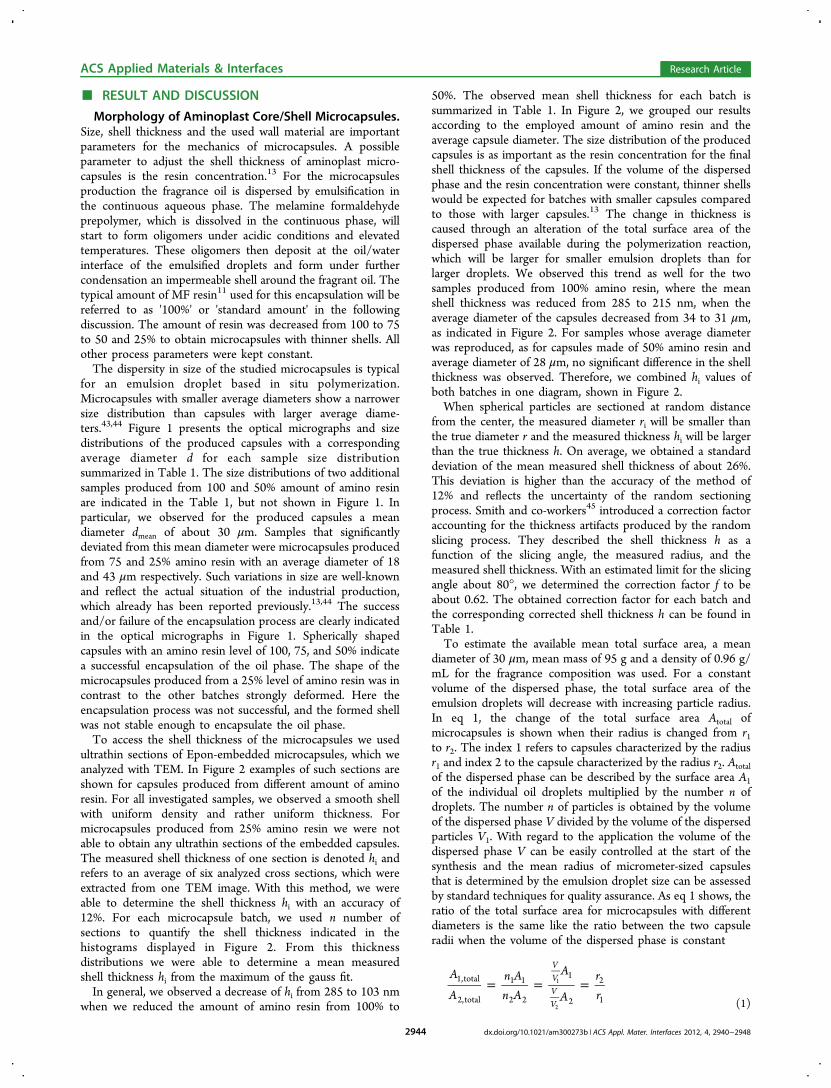
For the production of the studied capsules, the volume of thedispersed phase was constant for the different amounts ofamino resin. For microcapsules that showed a deviation fromthe expected mean radius of 30 μm the average total surfacearea could be corrected by the ratio of the capsule radii, wherer1 refers to the expected mean capsule radius and r2 to theradius of the actual produced microcapsules. Figure 3 describes
the shell thickness as a function of the amount of amino resinper total surface area. Both results of the measured and thecorrected shell thickness are displayed. As a trend, we canobserve an increase of the shell thickness with an increase of theMF amount per total surface area, which was already reportedfor MF microcapsules by Sgraia et al.13 In view of the complexnature of the manufacturing process inherent to theapplication-oriented study and the characterization method,the observed error margins are to be expected. We areconfident that our analysis of a relatively large number ofsections and the performed correction of the randomsectioning process takes these variations into account. Themorphological characterization and the correlation to simpleand accessible process parameters showed that it is possible toadjust and predict the thickness for the investigated process.Both analysis and correlation provide strategies to realize anadjustment of the shell thickness for microcapsules producedby in situ polymerization.Mechanical Properties. The mechanical response of
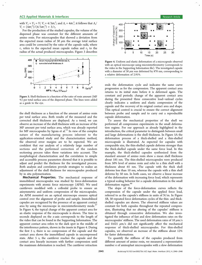
immobilized microcapsules was studied by force-deformationexperiments with atomic force microscopy (AFM). We usedcantilevers modified with a colloidal probe to ensure anaxisymmetric and uniform compression of the microcapsules.An AFM mounted on an optical microscope ensures opticalcontrol over the alignment of probe and sample. Immobilizedcapsules are recognized by the presence of an apparent contactarea by using the microscope in microinterferometry mode.37
In Figure 4, the typical change of the apparent contact area foran elastic response of the microcapsule is shown. The time inseconds displayed on the x-axis corresponds to the length ofthe video that can be found in the Supporting Information. Theapparent contact area refers to the dark spot in the middle ofthe interference pattern, shown in the insets in Figure 4. Duringthe first 5 s, there is no compression of the capsule and thecontact area shows the immobilized capsule in uncompressedstate. After 5 s, the cantilever reaches the capsule and thecontact area linearly increases with further compression untilthe maximum deformation is reached. The cantilever retraction
ends the deformation cycle and indicates the same curveprogression as for the compression. The apparent contact areareturns to its initial state before it is deformed again. Theconstant and periodic change of the apparent contact areaduring the presented three consecutive load−unload cyclesclearly indicates a uniform and elastic compression of thecapsule and the recovery of its original contact area and shape.This optical control is crucial to ensure the correct alignmentbetween probe and sample and to carry out a reproduciblecapsule deformation.To assess the mechanical properties of the shell we
performed all compression experiments in the small deforma-tion regime. For our approach as already highlighted in theintroduction, the critical parameter to distinguish between smalland large deformations is the shell thickness. In Figure 5A thedeformation process of a thick-shelled and a thin-shelledmicrocapsule is illustrated. As expected for capsules withcomparable size, the thin-shelled capsule deforms stronger thanthe thick-shelled capsule under the same force load. In thisexample, the thick-shelled capsules synthesized from thestandard amount of amino resin show a mean shell thicknessabout 185 nm. The thin-shelled microcapsules were producedfrom 50% level of amino resin and refer to a thin shell with athickness about 65 nm. The capsule with the thick shelldeforms less than 10 nm, whereas the capsule with a thin shelldeforms by 50 nm. In both cases, we observe a linear increaseof the deformation with increasing force load, which representsa typical scaling behavior for a capsule deformation in the smalldeformation regime.46
The slope of the force-deformation curves reflects thecompression of the capsule under the applied force load,referred to as the capsule’s stiffness in units of N/m. In Figure5B, 30 repeated force deformation cycles of the thin- and thick-shelled capsules are shown. The observed stiffness values areconstant for both capsules throughout the repeated compres-sion, illustrating that no altering of the capsules’ stiffness isobtained through consecutive deformation. We also inves-tigated the influence of fast and slow deformation rates on themicrocapsules’ stiffness. The used deformation rates of 10 μm/sand 0.625 μm/s did not significantly affect the mechanicalresponse of thick-shelled microcapsules. For thin-shelledcapsules, we observed an increase of the stiffness about 12%for faster deformations.To quantify the stiffness of the capsules produced from
different amount of amino resin, we measured a representativenumber n of aminoplast microcapsules with a slow deformation
Figure 3. Shell thickness is a function of the ratio of resin amount (MF%) per total surface area of the dispersed phase. The lines were addedas a guide to the eye.
Figure 4. Uniform and elastic deformation of a microcapsule observedwith an optical microscope using microinterferometry (corresponds tothe video in the Supporting Information file). The investigated capsulewith a diameter of 30 μm was deformed by 870 nm, corresponding toa relative deformation of 2.91%.
ACS Applied Materials & Interfaces Research Article
dx.doi.org/10.1021/am300273b | ACS Appl. Mater. Interfaces 2012, 4, 2940−29482945

rate of 0.5 μm/s. In Figure 6, the distributions of the measuredstiffness values present a decrease of the mean stiffness fromabout 30 N/m to 2 N/m for a change of the shells thicknessfrom 285 to 103 nm, respectively. The capsules’ stiffnessstrongly depends on the capsules’ diameter. Hence, smallermicrocapsules will be stiffer than larger capsules, if they wereproduced from the same batch and have the same shellthickness. For example, standard core/shell microcapsules witha mean shell thickness of 214 nm showed an increase in thecapsule stiffness from 14 N/m to 35 N/m when the diameter ofthe capsule was decreased from 30 to 14 μm. Therefore, thewidth of the stiffness histograms is also reflecting the sizedistribution of the investigated capsules within one batch. Themean stiffness value determined from the histogram for eachcapsule batch can be found in Table 1.In Figure 7, all results obtained from the morphological and
mechanical characterization of the aminoplast capsules aredisplayed in relation to the used process parameters. Both shellthickness and capsule stiffness increase with the amount ofamino resin per total surface area. It already has been shown30
that properties determined in the small deformation regimeplay an important role for macroscopic properties such as thecapsule’s adhesion. In the case of MF-shelled microcapsules,
with a uniform, closed, and rather strong shell, it would beinteresting to link the results gained from the small deformationregime with the already well investigated rupture force ofaminoplast microcapsules.22,23
Zhang and co-workers23,29 showed that the deformation atburst is one of the key parameters for the rupture of aminoplastmicrocapsules. As discussed before the deformation behavior ofmicrocapsules is strongly linked to the thickness of their shell,
Figure 5. (A) Compression of capsules under the same force will yield larger deformations for thin-shelled capsules compared with thick-shelledcapsules. (B) Microcapsules compression is elastic and the stiffness is constant over thirty load−unload cycles.
Figure 6. Capsules become softer with thinner shells, shown by the decrease of the mean stiffness for capsules with reduced shell thickness.
Figure 7. Summary of the morphological and mechanical character-ization of aminoplast core/shell capsules and the influence of usedprocess parameters.
ACS Applied Materials & Interfaces Research Article
dx.doi.org/10.1021/am300273b | ACS Appl. Mater. Interfaces 2012, 4, 2940−29482946

as shown in Figure 5A, where thin-shelled capsules deformmuch more under an applied load than thick-shelled capsules.Microcapsules burst when a critical compression is reached,which was for MF capsules reported about 70% relativedeformation at burst.36 The force loads needed for a burst willbe reached for smaller force loads in the case of thin-shelledcapsules compared with thick-shelled capsules. Therefore, theobserved correlations present a potential strategy to be furtherlinked with the reported macroscopic rupture forces. Such arelation would be beneficial for the tailoring of aminoplastmicrocapsule mechanics used in various applications with verydifferent requirements.The tendency observed in Figure 7 can be further analyzed to
understand how the shell thickness influences the microcapsulemechanics. The mechanical response obtained from the smalldeformation regime can be used to understand structureproperty relations, because the mechanical response can belinked to the capsule’s geometry and the shell’s materialproperties.20 According to Reissner, the measured stiffness F/Dis a function of the capsules geometric parameters, radius R andthe shell thickness h and the properties of the shell material,elastic modulus E and Poisson ratio ν:
=−
FD
hr
E
v3(1 ) /4
2
2(2)
As described in a previous study46 the regime valid forReissner’s prediction47,48 of a linear scaling behavior of theapplied force F with the resulting deformation D can be easilyestimated based on the shell thickness h and the radius r of thecapsule:
επ
≈ hr4crossover
(3)
A critical relative deformation ε is obtained that refers to thecrossover of the linear deformation regime with thedeformation caused by volume forces, which scales propor-tional to D3. Thus, the morphological characterization can beused to estimate the deformation regime where Reissner’sprediction is valid (see Table S1 in the SupportingInformation).In Figure 8A, the measured stiffness is displayed in relation to
the capsule radius. All samples show an increase in the stiffnesswith decreasing capsule diameter, which is in accordance withReissner’s model. The linear relation is then described by theproportionality factor, which is the square of the shell thickness
and the material constants E and ν. The stiffness ofmicrocapsules with comparable diameters increases withincreasing shell thickness as Figure 8A clearly indicates. Thestiffness normalized by the size plotted versus the shellthickness shows a linear relation that can be used to estimateYoung’s modulus of the microcapsules’ shell (Figure 8B).41,49
The Poisson ratio ν is expected to be between 0.33 for asolidlike material and 0.5 for rubber-like materials. Equation 2describes the impact of Poisson’s ratio on the resulting elasticmodulus. In order to make the impact of ν transparent, wecalculated the elastic modulus for both extremes. From Figure8B, we are able to estimate the elastic modulus of the shellmaterial of about 1.7 GPa for a Poisson ratio of 0.5, which is ingood agreement with the elastic modulus reported recently byMercade-Prieto et al.,29 and for a Poisson ratio 0.33 of about 2.2GPa. However, as Figure 8B displays a certain spread of theindividual data remains even after the normalization of the databy size and shell thickness. One reason for this spread can bedue to differences in the shell density caused by kineticdifferences during the shell formation. Salaun and co-workers50
showed that different surface morphologies of the capsules shellare dependent on the formation of the MF precondensate.They concluded that a rather rapid shell formation will yieldhigher oligomers or even small MF particles in the continuousphase, which will be deposited at the oil/water interface.32,50
The melamine to formaldehyde ratio, pH and temperature wereidentified as important parameters to affect the kinetics of theprecondensate formation. Based on the formed oligomers,which represent the building blocks of the shell, a rougher orsmoother capsule shell is obtained.12 From this perspective andbased on the results of our mechanical characterization, wethink that the size of the formed oligomers and their assemblyto a shell is an important aspect for shell mechanics that wouldbe of interest for further studies.
■ CONCLUSIONIn conclusion, we showed how mechanical properties ofaminoplast microcapsules correlate with process parameters foran industrially relevant microencapsulation process, the in situpolymerization of amino resins. With the help of a thoroughmorphological analysis we were able to determine themicrocapsule’s geometric parameters, radius and shell thickness.The mechanical response of the microcapsules was investigatedin form of small deformations on the order of the shellthickness, using an AFM and the colloidal probe technique.Both results, from geometrical and micromechanical character-
Figure 8. (A) Stiffness displayed in relation to the reciprocal radius clearly indicates an increase in the stiffness for capsules with thicker shell andcomparable radius. (B) Linear relationship displayed in this graph can be correlated to the material constants of the shell material and an elasticmodulus of 1.7 GPa can be estimated.
ACS Applied Materials & Interfaces Research Article
dx.doi.org/10.1021/am300273b | ACS Appl. Mater. Interfaces 2012, 4, 2940−29482947
ization, were explained in the framework of a simple analyticalmodel for microcapsule deformation, the Reissner shell theory.On the basis of the results, we identified the ratio of aminoresin to total emulsion surface area as key parameter forcontrolling the microcapsules geometry and mechanicalproperties. Thus, a rational design of mechanical propertiesof aminoplast microcapsules is in reach.
■ ASSOCIATED CONTENT
*S Supporting InformationAdditional data on the definition of the small deformationregime is available as well as a video recording the capsuledeformation in situ with optical microscopy used in micro-interferometry mode. This material is available free of chargevia the Internet at http://pubs.acs.org/.
■ AUTHOR INFORMATION
Corresponding Author*Tel.: +49 921 55 2753. Fax: + 49 921 55 2059. E-mail:[email protected].
NotesThe authors declare no competing financial interest.
■ REFERENCES(1) Sukhorukov, G.; Fery, A.; Mohwald, H. Prog. Polym. Sci. 2005, 30,885−897.(2) Becker, A. L.; Johnston, A. P. R.; Caruso, F. Small 2010, 6, 1836−1852.(3) Nelson, G. Int. J. Pharm. 2002, 242, 55−62.(4) Madene, A.; Jacquot, M.; Scher, J.; Desobry, S. Int. J. Food Sci.Technol. 2006, 41, 1−21.(5) Jacquemond, M.; Jeckelmann, N.; Ouali, L.; Haefliger, O. P. J.Appl. Polym. Sci. 2009, 114, 3074−3080.(6) Rokka, S.; Rantamaki, P. Eur. Food Res. Technol. 2010, 231, 1−12.(7) Sanchez, L.; Lacasa, E.; Carmona, M.; Rodriguez, J. F.; Sanchez,P. Ind. Eng. Chem. Res. 2008, 47, 9783−9790.(8) Mauldin, T. C.; Kessler, M. R. Int. Mater. Rev. 2010, 55, 317−346.(9) Quellet, C.; Schudel, M.; Ringgenberg, R. Chimia 2001, 55, 421−428.(10) Dietrich, K.; Herma, H.; Nastke, R.; Bonatz, E.; Teige, W. ActaPolym. 1989, 40, 243−251.(11) Haefliger, O. P.; Jeckelmann, N.; Ouali, L.; Leon, G. Anal. Chem.2010, 82, 729−737.(12) Lee, H. Y.; Lee, S. J.; Cheong, I. W.; Kim, J. H. J. Microencapsul.2002, 19, 559−569.(13) Sgraja, M.; Blomer, J.; Bertling, J.; Jansens, P. J. J. Appl. Polym.Sci. 2008, 110, 2366−2373.(14) Su, J.-F.; Wang, L.-X.; Ren, L.; Huang, Z. J. Appl. Polym. Sci.2007, 103, 1295−1302.(15) Yuan, Y. C.; Rong, M. Z.; Zhang, M. Q. Polymer 2008, 49,2531−2541.(16) Balazs, A. C. Mater. Today 2007, 10, 18−23.(17) Sliwka, W. Angew. Chem., Int. Ed. 1975, 14, 539−550.(18) Roitman, D. B. Microcapsule Biosensors and Methods of Usingthe Same. US Patent 07312040, Dec 26, 2007.(19) Esser-Kahn, A. P.; Odom, S. A.; Sottos, N. R.; White, S. R.;Moore, J. S. Macromolecules 2011, 44, 5539−5553.(20) Fery, A.; Weinkamer, R. Polymer 2007, 48, 7221−7235.(21) Chen, P. W.; Erb, R. M.; Studart, A. R. Langmuir 2011, 28,144−152.(22) Keller, M. W.; Sottos, N. R. Exp. Mech. 2006, 46, 725−733.(23) Zhang, Z.; Saunders, R.; Thomas, C. R. J. Microencapsul. 1999,16, 117−124.(24) Hu, J. F.; Chen, H. Q.; Zhang, Z. B. Mater. Chem. Phys. 2009,118, 63−70.
(25) Long, Y.; York, D.; Zhang, Z. B.; Preece, J. A. J. Mater. Chem.2009, 19, 6882−6887.(26) Sun, G.; Zhang, Z. J. Microencapsul. 2001, 18, 593−602.(27) Yang, J.; Keller, M. W.; Moore, J. S.; White, S. R.; Sottos, N. R.Macromolecules 2008, 41, 9650−9655.(28) Caruso, M. M.; Blaiszik, B. J.; Jin, H. H.; Schelkopf, S. R.;Stradley, D. S.; Sottos, N. R.; White, S. R.; Moore, J. S. ACS Appl.Mater. Interfaces 2010, 2, 1195−1199.(29) Mercade-Prieto, R.; Nguyen, B.; Allen, R.; York, D.; Preece, J.A.; Goodwin, T. E.; Zhang, Z. B. Chem. Eng. Sci. 2011, 66, 2042−2049.(30) Elsner, N.; Dubreuil, F.; Fery, A. Phys. Rev. E 2004, 69, 031802.(31) Arshady, R.; George, M. H. Polym. Eng. Sci. 1993, 33, 865−876.(32) Dietrich, K.; Bonatz, E.; Geistlinger, H.; Herma, H.; Nastke, R.;Purz, H. J.; Schlawne, M.; Teige, W. Acta Polym. 1989, 40, 325−331.(33) Hong, K.; Park, S. Mater. Chem. Phys. 1999, 58, 128−131.(34) Alic, B.; Sebenik, U.; Krajnc, M. J. Appl. Polym. Sci. 2010, 119,3687−3695.(35) Yuan, L.; Liang, G. Z.; Xie, J. Q.; Li, L.; Guo, J. Polymer 2006,47, 5338−5349.(36) Sun, G.; Zhang, Z. Int. J. Pharm. 2002, 242, 307−311.(37) Dubreuil, F.; Elsner, N.; Fery, A. Eur Phys J E 2003, 12, 215−221.(38) Butt, H. J. Biophys. J. 1991, 60, 1438−1444.(39) Ducker, W. A.; Senden, T. J.; Pashley, R. M. Nature 1991, 353,239−241.(40) Hutter, J. L.; Bechhoefer, J. Rev. Sci. Instrum. 1993, 64, 1868−1873.(41) Elsner, N.; Dubreuil, F.; Weinkamer, R.; Fischer, F. D.; Wasicek,F.; Fery, A. Prog. Coll. Polym. Sci. 2006, 132, 117−132.(42) Butt, H. J.; Cappella, B.; Kappl, M. Surf. Sci. Rep. 2005, 59, 1−152.(43) Yuan, L.; Gu, A.; Liang, G. Mater. Chem. Phys. 2008, 110, 417−425.(44) Wang, H.; Yuan, Y.; Rong, M.; Zhang, M. Colloid Polym. Sci.2009, 287, 1089−1097.(45) Smith, A. E.; Zhang, Z.; Thomas, C. R. Chem. Eng. Sci. 2000, 55,2031−2041.(46) Fery, A.; Dubreuil, F.; Mohwald, H. New J Phys 2004, 6, 18.(47) Reissner, E. J. Math. Phys.(Cambridge, Mass.) 1946, 25, 279−300.(48) Reissner, E. J. Math. Phys.(Cambridge, Mass.) 1946, 25, 80−85.(49) Zoldesi, C. I.; Ivanovska, I. L.; Quilliet, C.; Wuite, G. J. L.;Imhof, A. Phys. Rev. E 2008, 78, 8.(50) Salaun, F.; Vroman, I. Eur. Polym. J. 2008, 44, 849−860.
ACS Applied Materials & Interfaces Research Article
dx.doi.org/10.1021/am300273b | ACS Appl. Mater. Interfaces 2012, 4, 2940−29482948