Forced convective heat transfer of 45° rib-roughened fin flows
12
Forced convective heat transfer of 45° rib-roughened fin flows K.F. Chiang a , S.W. Chang b, * , P.H. Chen c a Mechanical Engineer Department, National Taiwan University, No. 1, Roosevelet Road Sec. 4, Taipei 10617, Taiwan, ROC b Thermal Fluids Laboratory, National Kaohsiung Marine University, No. 142, Hai-Chuan Road, Nan-Tzu District, Kaohsiung 811, Taiwan, ROC c Thermal MEMS Laboratory, Mechanical Engineer Department, National Taiwan University, Taipei, Taiwan, ROC Received 8 October 2004; accepted 31 December 2004 Abstract The detailed heat transfer measurements in three side-open and bottom-sealed rectangular channels with two opposite walls roughened by 45° full staggered ribs were performed using the infrared radiometer. The present flow configuration simulated an enhanced coolant channel of the fin-type heat-sinks for cooling of electronic chipsets. The hydraulic diameter of three test channels was 14.8 mm with different length-to-gap (L/B) ratios of 21.33, 17.11 and 13.56. The influences of L/B ratio on the local and spatially averaged heat transfers over the rib-roughened surface at Reynolds numbers (Re) of 500, 1000, 2000, 3000 and 3300 were examined. A selection of heat transfer results illustrated the interactive effects between the side-profile leakage-flow and the rib-induced flow phenomena, which were L/B ratio dependent. Heat transfer levels over the rib-roughened surface consistently increased with the increase of Reynolds number or the decrease of L/B ratio. The skewed streamwise ‘‘saw-tooth’’ heat transfer variations gradually emerged over the rib-roughened surface when the Reynolds number systematically increased. Comparing with the heat transfers in the likewise channels but roughened by 90° staggered ribs, the 45° staggered ribs could further enhance heat transfers over 10% for L/B = 21.33 and 50% for L/B = 13.56. Heat transfer correlation for the spatially averaged Nusselt number over a rib-roughened fin surface was generated using Re and L/B ratio as the controlling parameters. A criterion for determining the optimal L/B ratio that could provide the maximum cooling power over a rib-roughened fin surface was subsequently derived to aid the design tools for the heat-sink selection. Ó 2005 Elsevier Inc. All rights reserved. Keywords: Skewed; Rib-roughened; Fin-flow 1. Introduction The core processor of computer has increased its operating frequency during the recent years. This trend of development increases the power consumption and heat flux of the core-processor to the levels above than 100 W and 10 6 W/m 2 respectively. A conventional mea- sure to remain the operating temperatures of these electronic chipsets in the range of 60–80 °C employs the air-cooled fan-fin assembly. Fig. 1(a) typifies the impingement, side-flow and suction types of fan-fin assemblies for this cooling application. As shown in Fig. 1(a), the fan-driven coolant flows circulate in the fin assembly to facilitate forced heat convection. The cooling performance is mainly limited by the fan-power and the thermal resistance of the complete cooling assembly. When the thermodynamic process in the fan is isentropic and the thermal-resistance of heat-sink is zero, the cooling capacity, Q, is limited by the coolant mass flow rate (fan-power), the coolant specific heat and the acceptable temperature difference between the heated-wall and coolant in term of Q ¼ _ m C p ðT chip T coolant Þ. These ideal cooling capacities are respectively featured by lines A and B in Fig. 1(b) for the cases of DP = 2.4 and 7 mm H 2 O, where DP is the pressure difference between the inlet and outlet of fan. 0894-1777/$ - see front matter Ó 2005 Elsevier Inc. All rights reserved. doi:10.1016/j.expthermflusci.2004.12.004 * Corresponding author. Tel.: +886 7 8100888/5216; fax: +886 7 572 1035. E-mail address: [email protected] (S.W. Chang). www.elsevier.com/locate/etfs Experimental Thermal and Fluid Science 29 (2005) 743–754
Transcript of Forced convective heat transfer of 45° rib-roughened fin flows

www.elsevier.com/locate/etfs
Experimental Thermal and Fluid Science 29 (2005) 743–754
Forced convective heat transfer of 45� rib-roughened fin flows
K.F. Chiang a, S.W. Chang b,*, P.H. Chen c
a Mechanical Engineer Department, National Taiwan University, No. 1, Roosevelet Road Sec. 4, Taipei 10617, Taiwan, ROCb Thermal Fluids Laboratory, National Kaohsiung Marine University, No. 142, Hai-Chuan Road, Nan-Tzu District, Kaohsiung 811, Taiwan, ROC
c Thermal MEMS Laboratory, Mechanical Engineer Department, National Taiwan University, Taipei, Taiwan, ROC
Received 8 October 2004; accepted 31 December 2004
Abstract
The detailed heat transfer measurements in three side-open and bottom-sealed rectangular channels with two opposite walls
roughened by 45� full staggered ribs were performed using the infrared radiometer. The present flow configuration simulated anenhanced coolant channel of the fin-type heat-sinks for cooling of electronic chipsets. The hydraulic diameter of three test channels
was 14.8 mm with different length-to-gap (L/B) ratios of 21.33, 17.11 and 13.56. The influences of L/B ratio on the local and spatially
averaged heat transfers over the rib-roughened surface at Reynolds numbers (Re) of 500, 1000, 2000, 3000 and 3300 were examined.
A selection of heat transfer results illustrated the interactive effects between the side-profile leakage-flow and the rib-induced flow
phenomena, which were L/B ratio dependent. Heat transfer levels over the rib-roughened surface consistently increased with the
increase of Reynolds number or the decrease of L/B ratio. The skewed streamwise ‘‘saw-tooth’’ heat transfer variations gradually
emerged over the rib-roughened surface when the Reynolds number systematically increased. Comparing with the heat transfers in
the likewise channels but roughened by 90� staggered ribs, the 45� staggered ribs could further enhance heat transfers over 10% forL/B = 21.33 and 50% for L/B = 13.56. Heat transfer correlation for the spatially averaged Nusselt number over a rib-roughened fin
surface was generated using Re and L/B ratio as the controlling parameters. A criterion for determining the optimal L/B ratio that
could provide the maximum cooling power over a rib-roughened fin surface was subsequently derived to aid the design tools for the
heat-sink selection.
� 2005 Elsevier Inc. All rights reserved.
Keywords: Skewed; Rib-roughened; Fin-flow
1. Introduction
The core processor of computer has increased itsoperating frequency during the recent years. This trend
of development increases the power consumption and
heat flux of the core-processor to the levels above than
100 W and 106 W/m2 respectively. A conventional mea-
sure to remain the operating temperatures of these
electronic chipsets in the range of 60–80 �C employs
the air-cooled fan-fin assembly. Fig. 1(a) typifies the
impingement, side-flow and suction types of fan-fin
0894-1777/$ - see front matter � 2005 Elsevier Inc. All rights reserved.doi:10.1016/j.expthermflusci.2004.12.004
* Corresponding author. Tel.: +886 7 8100888/5216; fax: +886 7 572
1035.
E-mail address: [email protected] (S.W. Chang).
assemblies for this cooling application. As shown in
Fig. 1(a), the fan-driven coolant flows circulate in the
fin assembly to facilitate forced heat convection. Thecooling performance is mainly limited by the fan-power
and the thermal resistance of the complete cooling
assembly. When the thermodynamic process in the fan
is isentropic and the thermal-resistance of heat-sink is
zero, the cooling capacity, Q, is limited by the coolant
mass flow rate (fan-power), the coolant specific heat
and the acceptable temperature difference between the
heated-wall and coolant in term of Q ¼ _m� Cp�ðT chip � T coolantÞ. These ideal cooling capacities are
respectively featured by lines A and B in Fig. 1(b) for
the cases of DP = 2.4 and 7 mm H2O, where DP is thepressure difference between the inlet and outlet of fan.

Nomenclature
A, C, D, n correlative coefficients
a smooth entry length of rib-roughened surface(m)
B gap of test channel (m)
Cp specific heat of coolant (J kg�1 K�1)
Dh hydraulic diameter of test channel (m)
e rib height (m)
kf thermal conductivity of coolant (W m�1 K�1)
L length of test channel
l rib land_m coolant mass flow rate (kg s�1)
Nu local Nusselt number over rib-roughed fin
surface = qDhkf ðTw�T f Þ
Nu spatially averaged Nusselt number over rib-
roughed fin surface
P rib pitch (m)
q convective heat flux (W m�2)
Re Reynolds number based on channel hydraulicdiameter = qV mDh
lTchip processor core temperature (K)
Tf fluid reference temperature (K)
Tw wall temperature at fin surface (K)
Vm mean flow velocity at the immediate entrance
of heat section (m s�1)
W width of test channel (m)
x, y, s coordinates in streamwise, spanwise and rib-wise directions
Greek symbols
l dynamic viscosity of fluid (kg s�1 m�1)
q density of fluid (kg m�3)
744 K.F. Chiang et al. / Experimental Thermal and Fluid Science 29 (2005) 743–754
As indicated by lines A and B in Fig. 1(b), the reduction
of flow resistance for a cooling assembly could further
improve the cooling capacity. With the consideration
of isentropic efficiency of current fans available; while
the thermal resistance of heat-sink still remains zero,
the cooling performances of such fan-fin assembly fall
dramatically from lines A(B) to C. The data points
Fig. 1. Performances and assemblies of typical fan-fin assemblies for coo
electronic chipsets and (b) evaluation of cooling capacities of fan-fin assemb
which constitute line C are generated in accordance with
the experimentally measured flow rates of market fans.
The gap between lines A(B) and C features the future
improvement available by improving the fan design. It
is worth of noting that the flow-rate of operation point
for each fan also depends upon the flow resistance of
various heat-sinks. From the viewpoint of heat transfer,
ling of electronic chipsets. (a) Typical fan-fin cooling assemblies for
lies.

K.F. Chiang et al. / Experimental Thermal and Fluid Science 29 (2005) 743–754 745
the market fan with zero thermal resistance such as line
C in Fig. 1(b) is treated as the upper-bond performance
of a heat-sink. When the thermal resistance of heat-sink
is considered, Fig. 1(b) shows a typical range of data
cluster which indicates the currently achievable cooling
performances. The differences of cooling capacity be-tween the data points collected in Fig. 1(b) and the
upper-bond limit (line C) unravel the available range
for further improvement by reducing the thermal resis-
tance of heat-sink. The improvement of convective heat
transfer rates for each fined channel in a fan-fin assem-
bly could therefore upgrade its cooling performance to-
ward the upper bond limit.
The attempts to reduce the thermal resistance of aforced-convective heat-sink involve the minimizations
of conductive and convective resistances. In the respect
of minimizing conductive thermal resistance, the theo-
retical analysis with assumption of extremely high con-
ductivity of 2000 W m�1 K�1 for heat-sink material [1]
revealed that the cooling performance with augmented
material conductivity was far below than the upper-
bond capability of a heat-sink. Therefore, a number ofresearch efforts were directed toward the development
of forced-convective cooling devices, such as the cold
plate, micro-channels, pin–fin arrays and impingement
flow [2–6]. Among these forced-convective cooling
schemes, there has been considerable heat transfer
improvement demonstrated for the flow impingement
onto pin/fin arrays [4]. When the pressure drops over
the pin/fin arrays were taken into account, the plate-finheat-sinks showed better thermal performance than
those of offset-strips or pin fins [7]. As a result, several
research efforts devoted toward the definition of optimal
placement of fins for a heat-sink. The thickness, gap,
pitch and height of fins in an array were systematically
studied in order to unravel the optimal array geometry
[7–10]. Following the development trend for effective
forced-convective fan-fin scheme, the heat transfer aug-mentation for each individual fin-channel, which was
configured as two side-openings with the bottom-end
sealed as shown in Fig. 1(b), was recently explored using
the surface ribs [6]. Although there were a large amount
of research works looking into the effectiveness of sur-
face ribs on heat transfer enhancement, these periodic
surface ribs with various geometrical features were
mostly employed in the fully confined ducted flows[11–16]. The mechanisms of heat transfer augmentation
attributed to these surface ribs involved the periodically
broken boundary layer, the promotion of near-wall tur-
bulence and mixing and/or the rib-induced secondary
flows. According to the experimental results for ducted
flows, the heat transfer improvements using 60� and45� full ribs were 10–20% higher than those of 90� fullribs [12,14,15]. However the effectiveness of these sur-face ribs on heat transfer augmentation for a fined
channel with two side opens and a sealed bottom-end
has not well addressed in the open literature. There is
no heat transfer data available for the fined channel flow
with the fin surfaces roughened by 45� staggered ribs.The present study investigates the effectiveness of
skewed ribs on heat transfer augmentation for fined
channel flows. The 45� surface ribs were arranged ontwo opposite fin surfaces in the staggered manner. Heat
transfer tests were performed for three rib-roughened test
channels of different height-to-gap ratios with the same
width and gap; therefore the same hydraulic diameter.
The detailed Nusselt number distributions over the rib-
roughened fin surface were measured using the infrared
thermal meter at the Reynolds numbers of 500, 1000,
2000, 3000 and 3300. The spatially averaged heat transferresults were subsequently evaluated to analyze the impact
of channel height-to-gap ratio and Reynolds number on
heat transfer. Empirical heat transfer correlation was de-
rived to evaluate the spatially averaged Nusselt number
over the rib-roughened fin surface. Having acquired the
enhanced heat transfer data and correlation, the strategic
aim of present study diverts toward the development of
design criterion that permits the determination of opti-mal ratio between fin-height and fin-gap, which could as-
sist the design of enhanced fin-type heat-sinks.
2. Experimental details
2.1. Apparatus
Fig. 2 shows the constructional details of experimen-
tal apparatus. The coolant (pressurized air) was fed
from the IWATA SC 175C screw-type compressor to
an air tank. The compressor was integrated with refrig-
erating unit to dehumidify and cool the air to ambient
temperature. The dry and cooled airflow from the air
tank was guided through a set of pressure regulator
and filtering unit, a Tokyo Keiso TF-120 mass flowmeter and a needle valve at which the mass flow rate
of coolant flow was measured and adjusted. Prior to
entering the heat transfer test section, the airflow tra-
versed a 150 mm long flow calming section (1). At the
end of flow calming section (1), two copper plates (2)
were squeezed between the flanges of flow calming sec-
tion (1) and 250 mm long flow settling chamber (3).
The honeycomb and steel meshes were installed betweencalming section (1) and flow settling chamber (3). These
copper bars permitted the direct connection of electri-
cally heating power to the 0.1 mm thick stainless steel
heating foil (4). The two opposite rib-roughened heating
surfaces, simulating the heated fins surfaces in a fin
array, along with the heated bottom wall were formulated
by forging a continuous 100 mm wide, 0.1 mm thick
stainless steel foil. The range of heating powers acrossthe heating foil and the range of wall temperatures over
the heating foils are 12.16 (16.29 A · 0.747 V)–131.2

Fig. 2. Experimental apparatus.
746 K.F. Chiang et al. / Experimental Thermal and Fluid Science 29 (2005) 743–754
(52.7 A · 2.489 V) W and 33.2–219.9 �C respectively.
Also marked in Fig. 2 are the entry, bottom, leading
and trailing edges of the scanned rib-roughened surface
(4). The surface ribs were angled with 45� to the streamcenterline. The continuous stainless steel heating foil (4)
covered two opposite walls of flow settling chamber (3)
with smooth-walled surface. These two 45� rib-rough-ened surfaces were arranged in the staggered manner
and characterized by four dimensionless geometric para-
meters of:
Smooth entry length/channel width ratio (a/W) =4 mm/100 mm = 0.04.
Rib height/channel gap ratio (e/B) = 2 mm/8 mm =
0.25.
Rib pitch/rib height ratio (P/e) = 20 mm/2 mm = 10.
Rib land/rib height ration (l/e) = 2 mm/2 mm = 1.
Rib attack angle (a) = 45�.
The flow settling chamber (3) was fully confined bytwo sets of opposite and side walls. At the exit of flow
settling chamber (3) that is the immediate flow entrance
of heat transfer section (5), two side walls were re-
moved so that the coolant was allowed to flow from
these side opens. This arrangement featured the typical
flow configuration in a fined channel. In order to mea-
sure the coolant temperature at the exit plane of flow
calming section (1), one K-Type thermocouple waspositioned at the geometric center of this cross section.
The isothermal condition of the flow calming section
(1) allows this measured coolant temperature to be rep-
resentative as the flow bulk temperature at the entry
plane of the flow settling chamber (3). After determined
the net convective heat absorbed by the well-confined
ducted-flow in the flow settling chamber (3), the flow
bulk-temperature rise in the settling chamber (3) wasevaluated based on the specific heat of coolant and
the measured mass flow rate. By adding the bulk flow
temperature rise in the flow settling chamber to the
measured flow temperature at the exit plane of flow
calming section (1), the flow entry temperature to the
rib-roughened channel, Tf, was obtained. This flow
entry temperature, Tf, was treated as the fluid reference
temperature to evaluate the Nusselt number and thetemperature-dependent fluids properties such as the
specific heat, thermal conductivity and viscosity.
The bottom sealed-end of heat transfer test section (5)
was made of 10 · 100 · 8 mm Teflon plate (6) in orderto minimize the heat loss. As described previously, a
complete electrical circuit was formed by means of
two copper bars connecting the electrical terminal with
the stainless steel heating foil (4) and secured on theflanges of setting chamber. The adjustment of high-cur-
rent DC power supply enabled the control of heat flux
over the heating surfaces. Thus, the adjustable and
basically uniform heat flux was generated over the
stainless steel foil. The detailed temperature distribu-
tions over the heating surface under each test condition
were imaged by a calibrated two-dimensional NEC
TH3101-MR infrared radiometer (7). For this thermalimage capture system, it took 0.3 seconds to complete
a full-field of 239 · 255 matrix scan. The back surfaceof the heating foil was painted black to minimize the
background refection and to increase the emission.

K.F. Chiang et al. / Experimental Thermal and Fluid Science 29 (2005) 743–754 747
Three heat transfer test sections (5) of length 170.5,
136.9 and 108.5 mm were employed to perform the heat
transfer measurements. The width and gap of these three
heat transfer test sections remained identical so that the
hydraulic diameter of three test sections, Dh, was an
invariant value of 14.8 mm. The hydraulic diameter,Dh, was therefore selected as the characteristic length
scale to evaluate the Nusselt and Reynolds numbers.
The comparisons of various heat transfer performances
acquired from three test channels with different length-
to-gap ratio over a range of Reynolds number revealed
the individual and interactive impacts of channel
length-to-gap ratio and Reynolds number on heat trans-
fer. The geometries of three test sections were character-ized by two additional dimensionless parameters of:
Aspect ratio of cross-sectional shape of test section
(W/B) = 100 mm/8 mm = 12.5.
Channel length/channel gap ratio (L/B) = 13.56,
17.11 and 21.33.
2.2. Program and data processing
The program of present experimental study involved
three phases. The first phase of data generation acquired
the detailed wall temperature distributions over
rib-roughened surface for three different length-to-gap
(L/B) ratios of 21.33, 17.11 and 13.56 at Reynolds num-bers of 500, 1000, 2000, 3000 and 3300. As the various
heating levels could change the reference fluids tempera-
ture, Tf,, the viscosity and density of coolant at the flow
entrance were accordingly varied. In order to control the
Reynolds number at the flow entrance within ±1% dif-
ference from the targeting value, the coolant flow rate
was adjusted to compensate the Re deviation due to
the temperature-induced property variations. This pro-cedure was performed using the on-line monitoring pro-
gram, in which the Reynolds number at the flow
entrance was calculated based on the measured temper-
ature, pressure and mass-flow-rate of coolant flow. The
steady-state measurements were performed for this
phase of study and a steady-state was assumed when
the variations of wall temperatures between several suc-
cessive scans were less than 0.3 �C. In general, the periodfor reaching steady-state was about 30 min. Having
satisfied the steady-state assumption, the on-line infra-
red thermal-image program was activated to record
the full field wall temperature measurements and
transmit to computer for further data analysis in second
phase.
The second phase of data processing converted the
measured raw data into dimensionless forms in termsof Reynolds number at the flow entrance and the local
Nusselt number over the rib-roughened surface. The
local Nusselt number, Nu, were evaluated using Eq. (1).
Nu ¼ qDhkfðT w � T fÞ
ð1Þ
In Eq. (1), the net convective heat flux, q, was calculated
from the total electrical power input to heating foil with
subtraction of heat loss to the ambient. The heat loss
characteristics were determined via a number of calibra-
tion runs. To perform these heat loss calibration runs,
the flow was blocked off and fiberglass thermal insulat-ing material was filled in the flow passage. The power
fed into heating foil was entirely lost to the atmosphere
through the path of conduction via test assemble and
natural convection via back of the exposed heating sur-
face. When the supplied powers and heat losses were
balanced, the amounts of heat loss and the averaged
wall-to-ambient temperature differences were collected
to correlate the equation capable of evaluating the heatloss. The correlation between heat loss and correspond-
ing wall-to-ambient temperature difference revealed the
linear-like functional relation. As the wall-temperature
distribution over the rib-roughened surface was non-
uniform for each heat transfer test, the distribution of
heat loss, and therefore the convective heat flux, over
the heated surface were not uniform. As the external-
heat loss at each measurement spot increases with the in-crease of wall-to-ambient temperature difference, the
heat flux over the heating foil is not perfectly uniform.
The distribution of convective heat flux over the rib-
roughened surface is obtained by subtracting the local
heat loss from the total heat flux supplied. Based on
the results from the heat loss calibration tests, the exter-
nal heat loss increases linearly with the temperature dif-
ference between heated wall and ambient. Thus the localheat loss over each heating surface during the heat
transfer tests is determined by multiplying the local
wall-to-ambient temperature difference to the heat loss
coefficient acquired from the heat loss calibration tests.
A review of the entire data of convective heat flux shows
the maximum non-uniformity in heat flux distribution is
about 9.83% so that the basically uniform heat flux heat-
ing condition is simulated by the present study. Thus thepresent test apparatus simulated a basically uniform
heat flux boundary condition. In this phase of study,
the local Nusselt number distributions over the rib-
roughened surface were obtained for all the test scenar-
ios. The physical interpretation for these heat transfer
results unraveled the impacts of secondary flows induced
by 45� ribs on the fined channel flow with different Reand L/B ratio.The third phase of program analyzed the processed
heat transfer results with the attempt to devise an empir-
ical equation for evaluating the spatially averaged Nus-
selt number with L/B ratio and Re as the controllable
parameters. Along with this deriving process for heat
transfer correlations, the individual and interactive
influences of Re and L/B ratio on the spatially averaged
748 K.F. Chiang et al. / Experimental Thermal and Fluid Science 29 (2005) 743–754
heat transfers were also demonstrated. For the selection
of fin-array assembly which provided the maximum con-
vective heat flux, these correlations for spatially aver-
aged Nusselt numbers over rib-roughened fin surfaces
were employed to identify the optimal L/B ratios at
tested Reynolds numbers. The relation between the opti-mal L/B ratio and Reynolds number was subsequently
correlated to permit the selection of L/B ratio for a cool-
ant flow rate in the Re range examined.
This experimental program has initially attempted to
check the buoyancy effect by performing five different
heating levels at a predefined set of L/B ratio and Rey-
nolds number. The central wall temperatures over each
rib-roughened surface were systematically raised to thelevels of 45, 75, 90, 120 and 145 �C for each heat transfertest. The review of entire heat transfer results generated
with different heating levels showed about 4.2% of heat
transfer variations were incurred due to various buoy-
ancy levels. As a result, the influence of buoyancy on
heat transfer for the present test conditions was negligi-
ble and disregarded from the following presentation.
The maximum uncertainties of Nusselt and Reynoldsnumbers were evaluated using the policy of ASME on
reporting the uncertainties in experimental measure-
ments and results [18]. The major source for attributing
experimental uncertainty was attributing from the tem-
perature measurement. The maximum uncertainty of
the present infrared thermal image system was estimated
as ±0.7 �C from the calibration runs. The maximum
uncertainties associated with the local Nusselt and Rey-nolds numbers were estimated as 12.3% and 6.9%
respectively [18].
3. Results and discussion
3.1. Heat transfer distributions
Fig. 3 collects all the heat transfer data obtained with
L/B = 21.33, 17.11 and 13.56 at Reynolds numbers of
500, 1000, 2000, 3000 and 3300. The individual impacts
of Re and L/B ratio on the Nu profiles over the rib-
roughened surfaces are revealed by comparing the plots
in each column and each row of Fig. 3 respectively. Un-
like the well-confined rib-roughened ducted channel
[16], the side opens along both leading and trailing edgesof a fined channel incur the side-leaking flows. As a re-
sult, the weakening downstream mass flux of coolant
has lead to the streamwise heat transfer decay. It is
worth noting that, as the reference fluid temperature se-
lected to define the Nusselt number is the flow entry
temperature which could not account for the streamwise
flow temperature rise, the decreases of local Nusselt
number in the downstream direction shown in Fig. 3are partially attributed from the selection of Tf as the
reference fluid temperature for Nu definition. The worse
regional heat transfer scenarios thus develop at the bot-
tom edge for each test configuration. The streamwisely
weakened mass flux of coolant flow also affects the
rib-impacts on heat transfer augmentation. In the fined
channel of L/B = 21.33, the streamwise saw-tooth heat
transfer pattern, which shows the spatially high Nu peakon the top surface of each rib, is not established until the
Reynolds number increases to 3000. Relative to the
counterparts at Reynolds numbers of 500, 1000, and
2000 in the channels of L/B = of 17.11 and 13.56, the
lack of traversing flow momentum in the long fin chan-
nel (L/B = 21.33) has prohibited the emergence of
streamwise saw-tooth variation pattern. Unlike the typ-
ical rib-effects on heat transfer for ducted flow, Fig.3(a)–(c) reveal the high heat transfer rings which encom-
pass the entry, leading and trailing edges of the long-fin
surfaces. The high heat transfer region along the entry
edge, which is typical for all the heat transfer results in
the channels of L/B = 21.33, 17.11 and 13.56, features
the influences of developing boundary layers on heat
transfer. While the high regional heat transfer rings
along the leading and trailing edges as shown in Fig.3(a)–(c) are the result of side-leaking flow that directs
the coolant toward the side opens. Nevertheless, the
rib-wise heat transfer decay in the skewed direction of
surface rib proceeds about two pairs of ribs. After flow
traverses the third rib, the rib-wise heat transfer varia-
tions turn to be vague. This phenomenon occurs in all
three tested channels due to the weakened rib-traversing
flow momentum as a result of accumulative side leak-ages and the incompleteness of rib-length. Thus, as dem-
onstrated in Fig. 3, the employment of 45� angled ribson the fin surface could induce the skewed near-wall
flows that results in the asymmetrical heat transfer pro-
files in respect to the streamwise centerline. These re-
peated skewed ribs interact with the side-leaking flows
which require a considerable amount of coolant mass
flux to facilitate the streamwise agitated flows.The physical phenomena in association with the side
leakages for rib-roughened fin flow have distinguished
its heat transfer characteristics from the ducted flow.
Even though the high convective capability could still
occurs in the central region of immediate flow entrance,
which result is similar to the smooth-walled and 90� rib-roughed finned channels [17]; there are two weak con-
vective flow regimes developed adjacent to the entryedge at two upper corners of each fin channel as demon-
strated in Fig. 3. The generation of these two upper-cor-
ner weak convective regions is attributed to the strong
side leaking flows at the upper portion of each fin chan-
nel. As these two regional concave Nu surfaces at two
upper corners are generally asymmetrical to the stream-
wise centerline, the side-leaking mass fluxes from the
leading and trailing edges are different. In this respect,the upper-corner weak convective regions in the
smooth-walled and 90� rib-roughed finned channels

Fig. 3. Heat transfer distributions over 45� rib-roughened fin-channels with L/B ratios of 13.56, 17.11 and 21.33 at Reynolds numbers of 500, 1000,
2000, 3000 and 3300. (a) L/B = 21.33, Nu ¼ 5:5; (b) L/B = 17.11, Nu ¼ 8:5; (c) L/B = 13.56, Nu ¼ 14:7; (d) L/B = 21.33, Nu ¼ 8:9; (e) L/B = 17.11,Nu ¼ 15:0; (f) L/B = 13.56, Nu ¼ 16:9; (g) L/B = 21.33, Nu ¼ 13:7; (h) L/B = 17.11, Nu ¼ 23:6; (i) L/B = 13.56, Nu ¼ 28:3; (j) L/B = 21.33, Nu ¼ 17:3;(k) L/B = 17.11, Nu ¼ 28; (l) L/B = 13.56, Nu ¼ 32:5; (m) L/B = 21.33, Nu ¼ 19; (n) L/B = 17.11, Nu ¼ 27:9; (o) L/B = 13.56, Nu ¼ 37:1.
K.F. Chiang et al. / Experimental Thermal and Fluid Science 29 (2005) 743–754 749
are symmetrical [17]. In the bottom-sealed region,
the Nu values are generally low and the rib-effects
appear to be weakened. This particular heat transfer
feature is the results of weak local flow momentum
750 K.F. Chiang et al. / Experimental Thermal and Fluid Science 29 (2005) 743–754
and incomplete rib length in this bottom-sealed region.
Also indicated in each plot of Fig. 3 is the spatially aver-
aged Nusselt number over the rib-roughened surface.
These spatially averaged Nusselt numbers consistently
increase with the decreased L/B ratio or with the in-
creased Re value.The centerline-streamwise (x/L) and rib-wise (s/w)
heat transfer profiles in three rib-roughened fin channels
with L/B ratios of 21.33, 17.11 and 13.56 at Reynolds
number of 3000 are compared in Fig. 4. The heat trans-
fer results at rib and mid-rib locations are individually
sorted in each plot of Fig. 4. The streamwise coordinate
in terms of x/L could normalize the different fin lengths
so that the Nu data collected from three channels be-comes comparable. Also the x/L ratio embodies the per-
centage of total amount of coolant leakage which is a
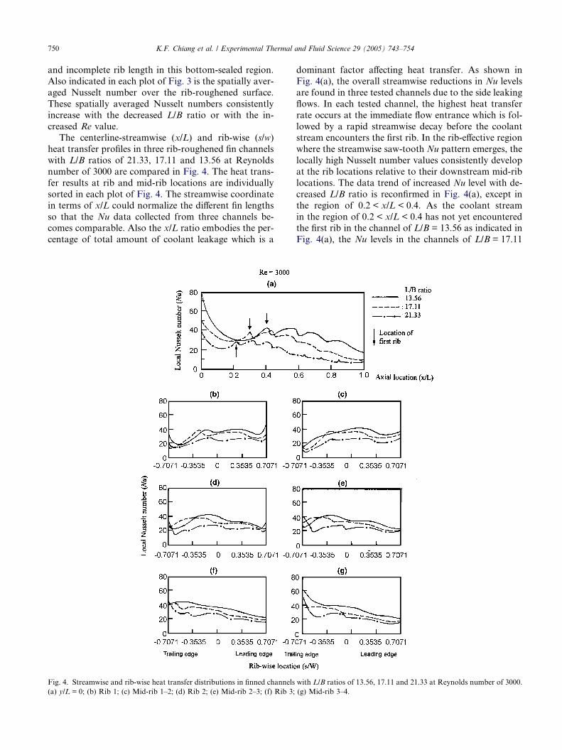
Fig. 4. Streamwise and rib-wise heat transfer distributions in finned channels
(a) y/L = 0; (b) Rib 1; (c) Mid-rib 1–2; (d) Rib 2; (e) Mid-rib 2–3; (f) Rib 3;
dominant factor affecting heat transfer. As shown in
Fig. 4(a), the overall streamwise reductions in Nu levels
are found in three tested channels due to the side leaking
flows. In each tested channel, the highest heat transfer
rate occurs at the immediate flow entrance which is fol-
lowed by a rapid streamwise decay before the coolantstream encounters the first rib. In the rib-effective region
where the streamwise saw-tooth Nu pattern emerges, the
locally high Nusselt number values consistently develop
at the rib locations relative to their downstream mid-rib
locations. The data trend of increased Nu level with de-
creased L/B ratio is reconfirmed in Fig. 4(a), except in
the region of 0.2 < x/L < 0.4. As the coolant stream
in the region of 0.2 < x/L < 0.4 has not yet encounteredthe first rib in the channel of L/B = 13.56 as indicated in
Fig. 4(a), the Nu levels in the channels of L/B = 17.11
with L/B ratios of 13.56, 17.11 and 21.33 at Reynolds number of 3000.
(g) Mid-rib 3–4.
K.F. Chiang et al. / Experimental Thermal and Fluid Science 29 (2005) 743–754 751
and 21.33 are close to the short channel of L/B = 13.56
in the region of 0.2 < x/L < 0.4. For all three tested
channels, it is noticed that the heat transfer elevation
immediately starts after flow traverses the first rib but
could only persist onto the second rib. After the second
rib location, the streamwise heat transfer decay initiates.Also the rib-induced spatially heat transfer oscillations
are most marked in the first two rib region and gradually
faded in the further downstream. In this respect, the
appreciable rib effect on heat transfer elevation in the
90� rib-roughened fin channels is initiated from the sec-ond ribs [17]. Nevertheless, the considerable streamwise
reductions in the oscillating amplitudes of Nusselt num-
ber variation between rib and mid-rib locations typifiedin Fig. 4(a) again demonstrate the impact of accumula-
tive side leakages on heat transfer. After examining all
the versions of Fig. 4(a) over the entire range of Rey-
nolds numbers tested, it is confirmed that the increase
of Reynolds number could considerably magnify the
amplitudes of rib-induced spatial heat transfer
oscillations.
Fig. 4(b)–(g) summarize the rib-wise heat transfervariations in three channels of L/B = 21.33, 17.11 and
13.56 along three different rib and mid-rib skewed lines.
At the locations of rib 1 and mid-rib 1–2, Fig. 4(b) and
(c) reveal the rib-wise heat transfer reduction from the
leading toward the trailing edge. A locally regional heat
transfer increment is spotted at the leading or trailing
edge due to the side leaking flow, which agrees with
the result found in the smooth-walled and 90� rib-rough-ened finned channels [17]. The mechanism was attrib-
uted to the locally improved fluid mixing between
ambient and coolant stream stirred by the side-leaking
flow [17]. When the coolant travels further downstream
toward the bottom edge, the side-leaking flows con-
siderably weaken the downstream momentum. The rib-
induced skewed-flows near the bottom edge are
accordingly moderated. As a result, the skew rates ofrib-wise Nu profiles at the locations of rib 2 and mid-
rib 2–3 as depicted in Fig. 4(d) and (e) are considerably
alleviated from the scenarios found at rib 1 and mid-rib
1–2. Also the local heat transfer recovery at leading edge
becomes vague at mid-rib 2–3 as indicated in Fig. 4(e). It
is felt that the stream momentum near the leading edge
at the location of mid-rib 2–3 is too weak to facilitate
the rib-wise washing flow. Further downstream to thelocations of rib 3 and mid-rib 3–4, the slopes of rib-wise
Nu profile switch over. At the locations after rib 3, the
heat transfers gradually increase in the rib-wise direction
from the leading toward the trailing edge. In this partic-
ular flow region near bottom edge, the weak rib-travers-
ing flow momentum along with the incompleteness of
rib-length has almost prohibited the appearance of rib-
impact. The dominant heat transfer physics in the flowregion after rib 3 are the asymmetric side leaking flow
and the spent flow toward both open ends after the cool-
ant stream impinging onto the bottom-sealed end. Justi-
fied by the rib-wise heat transfer distributions depicted
in Fig. 4(f) and (g), the fluency of spanwise spent flow
toward the trailing edge in the flow region after rib 3
is better than the leading edge counterpart.
A review of all Re versions of Fig. 4 confirms that theheat transfer levels generally decrease with the increase
of channel L/B ratio. The streamwise and rib-wise heat
transfer variations depicted in Fig. 4 are typical for all
the test results, except in the channel of L/B = 21.33 at
Reynolds numbers of 500, 1000 and 2000. The absence
of agitated flow fields in the channel of L/B = 21.33 at
Reynolds numbers of 500, 1000 and 2000, as demon-
strated in Fig. 3(a)–(c), prohibits the rib-associated heattransfer augmentation. Thus the streamwise and rib-
wise Nu profiles for the channel of L/B = 21.33 at Rey-
nolds numbers of 500, 1000 and 2000 are both smooth
curves with the data-trends followed those found in
the channels of L/B = 17.11 and 13.56.
3.2. Heat transfer correlation
The heat transfer results revealed in Figs. 3 and 4
have demonstrated the interactive effects between
skewed ribs and side-leaking flows on local heat trans-
fers. As these thermal fluids phenomena are interactively
controlled by L/B ratio and Re, the inter-correlation
attributed to the coupling L/B–Re effects are expected
in the heat transfer correlation. One of the strategic aims
of the present study is to generate an equation that per-mits the evaluation of convective capabilities over a 45�rib-roughened fin surface so that the cooling duty of a
fan-fin assembly could be predefined. As the operating
temperatures for electronic chipsets are generally far be-
low than the melting temperatures of heat-sink materi-
als, the total cooling duty available for a fin-array is
the focus for this application. Therefore, instead of gen-
erating the correlation for local heat transfer, the equa-tion for evaluating the spatially averaged heat transfer
over the rib-roughened fin surface is derived. The local
Nusselt numbers over each rib-roughened fin surface
with all the Re–L/B options are spatially averaged to ac-
quire the spatially averaged Nusselt number data, Nu,for further data analysis. Three sets of Nu data gener-ated from test channels with L/B ratios of 13.56, 17.11
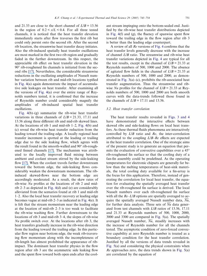
and 21.33 at Reynolds numbers of 500, 1000, 2000,3000 and 3300 are compared in Fig. 5(a). The spatially
averaged Nusselt number, Nu, steadily increases withthe increase of Reynolds number for all the channels
tested. The asymptotic condition of zero-forced convec-
tive capability at zero Reynolds number is treated as a
boundary condition for the heat transfer correlation.
Justified by all the versions of data trends revealed in
Fig. 5(a) and considering the physical constraints whenRe approaches zero, the data trends shown in Fig. 5(a)
are correlated by the equation of
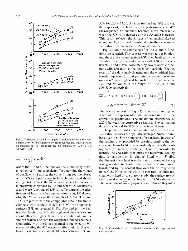
Fig. 5. Variations of spatially averaged Nusselt number with Reynolds
number over 45� rib-roughened, 90� rib-roughened and smooth-walledfin-channels: (a) 45� rib-roughened fin channel, (b) L/B = 21.33,
(c) L/B = 13.56.
Fig. 6. Comparison of correlation results with experimental
measurements.
752 K.F. Chiang et al. / Experimental Thermal and Fluid Science 29 (2005) 743–754
Nu ¼ ALB
� �� Ren
LBf g ð2Þ
where the A and n functions are the numerically deter-
mined curve-fitting coefficients. To determine the values
of coefficients A and n, the curve fitting routines based
on Eq. (2) were performed to fit each data trend shown
in Fig. 5(a). Because the Nu value over each fin surface isinteractively controlled by Re and L/B ratio, coefficients
A and n are functions of L/B ratio. To unravel the effec-
tiveness of heat transfer augmentation using 45� skewedribs, the Nu values in the channels of L/B = 21.33 and13.56 are plotted with the comparable data in the finned
channels with smooth-walled and 90� rib-roughenedsurfaces [17]. As revealed in Fig. 5(b) and (c), the heat
transfer levels over 45� rib-roughened fin surfaces areabout 10–50% higher than those counterparts in the
smooth-walled and 90� rib-roughened finned channels.Comparing with the finned channels roughened by 90�staggered ribs, the 45� staggered ribs could further en-hance heat transfers about 10% for L/B = 21.33 and
50% for L/B = 13.56. As indicated in Fig. 5(b) and (c),
the superiority of heat transfer performances in 45�rib-roughened fin channels becomes more remarkable
when the L/B ratio decreases or the Re value increases.
This result reflects� the impact of enhancing skewedsecondary flow on heat transfer due to the decrease ofL/B ratio or the increase of Reynolds number.
Eq. (2) could be completed after the A and n func-
tions are revealed. This process was carried out by plot-
ting the A and n values against L/B ratio. Justified by the
variation trends of A and n values with L/B ratio, coef-
ficients A and n were correlated by two quadratic func-
tions with L/B ratio as the dependent variable. The net
result of the data analysis generates the empirical heattransfer equation (3) that permits the evaluation of Nuover a 45� rib-roughened fin surface for a given set ofL/B and Re values in the ranges of 13.56–21.33 and
500–3300 respectively.
Nu ¼ 5:3918� 0:5514� LB
� �þ 0:0144� L
B
� �2" #
� Re�1:4425þ0:2316�LBð Þ�0:0064� L
Bð Þ2 ð3Þ
The overall success of Eq. (3) is indicated in Fig. 6,
where all the experimental data are compared with the
correlative predictions. The maximum discrepancy of
±25% between the correlative results and experimental
data are achieved for 90% of experimental results.
The previous results demonstrate that the decrease of
L/B ratio increases the spatially averaged Nusselt num-
bers over the 45� rib-roughened fin surfaces. In view ofthe cooling duty provided by the fin assembly, the de-
crease of channel L/B ratio accordingly reduces the cool-
ing area (fin surface) available. Therefore, in order to
identify the L/B ratio that offers the maximum cooling
duty for a side-open fin channel fitted with 45� ribs,the dimensionless heat transfer data in terms of Nu� L
Bwas generated to feature the overall cooling power
transferred by the coolant flow over the rib-roughenedfin surface. Note, as the width-to-gap ratio of three test
channels is fixed by the present study, the surface area of
each finned channel is the function of L/B ratio only.
The variation of Nu� LB against L/B ratio at Reynolds
K.F. Chiang et al. / Experimental Thermal and Fluid Science 29 (2005) 743–754 753
numbers of 500, 1000, 2000, 3000 and 3300 are showed
in Fig. 7. It is worth mentioning that the asymptotic lim-
it of zero fin length (L = 0) reduces the present applica-
tion to the impingement slot-jet onto heat-sink.
Although the heat transfer over the heat-sink remains
finite for such asymptotic condition, there is no fin effectin this case. The value of Nu� L
B has to be zero when the
fin-length diminishes to zero. As depicted in Fig. 8, the
peak value of Nu� LB in each Re controlled curve locates
at a specific L/B ratio, which is defined as the optimal
L/B ratio, within the range of L/B ratio examined. The
optimal L/B ratio also varies with Reynolds number as
shown in Fig. 7. Justified by the data trends and the
physical constraint of vanished Nu� LB value when L/B
ratio approaches zero, each Re controlled curve shown
in Fig. 7 is correlated into the general form of
Nu� LB¼ C Ref g � L
Bþ D Ref g � L
B
� �2ð4Þ
where C and D are the correlating coefficients for each
Re controlled curve in Fig. 7. The optimal L/B ratio that
provides the maximum value of Nu� LB was obtained
using the usual optimization concept of:
o Nu� LB
� �o L
B
� � ¼ 0) LB
Optimal value
¼ � C Ref g2D Ref g ð5Þ
As C and D coefficients are functions of Re, the optimalL/B ratio that permits the maximum cooling power ac-
quired from a 45� rib-roughened fin surface is Re depen-
Fig. 7. Variations of dimensionless cooling power with L/B ratio of
45� rib-roughened fin-channel at Reynolds numbers of 500, 1000, 2000,3000 and 3300.
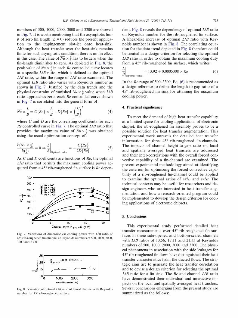
Fig. 8. Variation of optimal L/B ratio of finned channel with Reynolds
number for 45� rib-roughened surface.
dent. Fig. 8 reveals the dependency of optimal L/B ratio
on Reynolds number for the rib-roughened fin surface.
A linear-like increase of optimal L/B ratio with Rey-
nolds number is shown in Fig. 8. The correlating equa-
tion for the data trend depicted in Fig. 8 therefore could
be treated as a design criterion for selecting the optimalL/B ratio in order to obtain the maximum cooling duty
from a 45� rib-roughened fin surface, which writes:LB
Optimal value
¼ 13:92þ 0:0005308� Re ð6Þ
In the Re range of 500–3300, Eq. (6) is recommended asa design reference to define the length-to-gap ratio of a
45� rib-roughened fin sink for attaining the maximumcooling power.
4. Practical significance
To meet the demand of high heat transfer capabilityat a limited space for cooling applications of electronic
chipset, the rib-roughened fin assembly proves to be a
possible solution for heat transfer augmentation. This
experimental work unravels the detailed heat transfer
information for three 45� rib-roughened fin-channels.The impacts of channel height-to-gap ratio on local
and spatially averaged heat transfers are addressed
and their inter-correlations with the overall forced con-vective capability of a fin-channel are examined. The
present experimental methodology aimed at identifying
the criterion for optimizing the forced convective capa-
bility of a rib-roughened fin-channel could be applied
to examine the optimal ratios of W/L and W/B. The
technical contexts may be useful for researchers and de-
sign engineers who are interested in heat transfer aug-
mentation and how a research-oriented program couldbe implemented to develop the design criterion for cool-
ing applications of electronic chipsets.
5. Conclusions
This experimental study performed detailed heat
transfer measurements over 45� rib-roughened fin sur-faces in three side-opened and bottom-sealed channels
with L/B ratios of 13.56, 17.11 and 21.33 at Reynolds
numbers of 500, 1000, 2000, 3000 and 3300. The physi-
cal phenomena in association with the side leakages for
45� rib-roughened fin flows have distinguished their heattransfer characteristics from the ducted flows. The stra-
tegic aims are to generate the heat transfer correlation
and to devise a design criterion for selecting the optimalL/B ratio for a fin sink. The Re and channel L/B ratio
have demonstrated their individual and interactive im-
pacts on the local and spatially averaged heat transfers.
Several conclusions emerging from the present study are
summarized as the follows:

754 K.F. Chiang et al. / Experimental Thermal and Fluid Science 29 (2005) 743–754
1. The side-leaking flows from leading and trailing
edges of a fined channel weaken the downstream
mass flux that incurs the streamwise heat transfer
decay and modifies the rib-impacts on heat transfer.
In the channel of L/B = 21.33, the spatially saw-
tooth Nu pattern is not established until Re reaches3000. Due to the strong side leaking flows at the
upper portion of each fin channel, two asymmetrical
weak convective flow regimes developed at two
upper corners. As a result of accumulative side leak-
ages and the incompleteness of rib-length near the
bottom edge of each finned channel, the skewed
rib-wise heat transfer decay only progresses about
two pairs of ribs. In the region after rib 3, heattransfers gradually increase in the rib-wise direction
from leading toward trailing edge.
2. The spatially averaged Nusselt number over the rib-
roughened fin surface consistently increases with the
decrease of L/B ratio and the increase of Re. Heat
transfer levels in the finned channels fitted with 45�skewed ribs are about 10–50% higher than those
counterparts in the smooth-walled and 90� rib-rough-ened channels. The superiority of heat transfer per-
formances attributing to 45� surface ribs becomesmore remarkable when the L/B ratio decreases or
the Re value increases.
3. Heat transfer correlation for evaluating the spatially
averaged Nusselt number, Nu, over 45� rib-roughenedfin surface is generated to permit the accountancy of
individual and interactive impacts of Re and L/Bratio on heat transfer.
4. The design criterion for determining the L/B ratio of
a finned channel that provides the maximum cooling
duty from the 45� rib-roughened fin surface is
derived. This which reveals that the optimal L/B ratio
moderately increases with Re in the 45� rib-rough-ened fan-fin channel.
References
[1] H.B. Ma, G.P. Peterson, Influence of the thermal conductivity on
the heat transfer performance in a heat sink, ASME J. Electron.
Packaging 124 (2002) 164–169.
[2] C.Y. Liu, Y.H. Hung, Transfer and flow friction characteristic for
compact cold, ASME J. Electron. Packaging 125 (2003) 104–113.
[3] T.J. Lu, Heat transfer efficiency of metal honeycombs, Int. J. Heat
Mass Transfer 42 (1999) 2031–2040.
[4] D.Y. Lee, K. Vafai, Comparative analysis of jet impingement and
microchannel cooling for high heat flux application, Int. J. Heat
Mass Transfer 42 (1999) 1555–1568.
[5] Y. Kondo, H. Matsushima, T. Komatsu, Optimization of pin–fin
heat sink for impingement cooling in electronic packaging, ASME
J. Electron. Packaging 122 (2000) 240–246.
[6] L.M. Su, S.W. Chang, Detailed heat transfer measurements of
impinging jet arrays issued from grooved surfaces, Int. J. Therm.
Sci. 41 (2002) 823–841.
[7] B. Boesmans, F. Christianens, J. Berghmans, E. Beyne, Design of
an optimum heat-sink geometry for forced convection air cooling
of multi-chip modules, in: C.J. Hoogendoorn (Ed.), Thermal
Management of Electronic Systems, Kluwer Academic, 1996, pp.
267–276.
[8] S.B. Sathe, K.M. Kelkar, K.C. Karki, C. Tai, C. Lamb, S.V.
Patankar, Numerical prediction of flow and heat transfer in an
impingement heat sink, Adv. Electron. Packaging ASME, EEP-
Vol. 4 (2) (1994) 893–898.
[9] Y. Kondo, M. Behina, W. Nakayama, H. Matsushima, Optimi-
zation of finned heat sinks for impingement cooling of electronic
packages, ASME J. Electron. Pack. 120 (3) (1998) 259–266.
[10] S. Keiji, H. Mitsuru, N. Atsuo, A. Takayuki, Numerical analysis
of impinging air flow and heat transfer in plate-fin type heat sinks,
ASME J. Electron. Pack. 123 (2001) 315–318.
[11] G. Xiufang, S. Begnt, Heat transfer and pressure drop measure-
ments in rib-roughened rectangular ducts, Exp. Therm. Fluid Sci.
24 (2001) 25–35.
[12] S.C. Lau, R.D. McMillin, J.C. Han, Heat transfer characteristics
of turbulent flow in a square channel with angled discrete ribs,
ASME J. Turbomach. 113 (1991) 367–374.
[13] G. Rau, M. Cakan, D. Moeller, T. Arts, The effect of periodic
ribs on the local aerodynamic and heat transfer performance of a
straight cooling channel, ASME J. Turbomach. 120 (1998) 368–
375.
[14] J.C. Han, J.S. Park, C.K. Lei, Heat transfer enhancement in
channels with turbulence promoters, ASME J. Eng. Gas Turb.
Power 107 (1985) 629–635.
[15] J.C. Han, J.S. Park, Developing heat transfer in rectangular
channels with rib turbulators, Int. J. Heat Mass Transfer 31 (1988)
183–195.
[16] B. Bonhoff, S. Parnix, Experimental and numerical study of
developed flow and heat transfer in coolant channels with 45
degree ribs, Int. J. Heat Fluid Flow 20 (1999) 311–319.
[17] S.W. Chang, L.M. Su, T.L. Yang, S.F. Chiou, Enhanced heat
transfer of forced convective fin flow with transverse ribs, Int. J.
Therm. Sci. 43 (2004) 185–200.
[18] Editorial Board of ASME Journal of Heat Transfer, Journal of
heat transfer policy on reporting uncertainties in experiments and
results, ASME J. Heat Transfer 115 (1993) 5–6.