Analysis of leakage properties and guiding conditions of rib antiresonant reflecting optical...
8
198 JOURNAL OF LIGHTWAVE TECHNOLOGY, VOL 14, NO. 5, MAY 1996 Analysis of Leakage Properties and Guiding Conditions of Rib Antiresonant Reflecting Optical Waveguides Ignacio GarcCs, Francisco Villuendas, Juan A. VallCs, Carlos Dom’nguez, and Mauricio Moreno Abstract- Power leakage properties and guiding conditions of rib antiresonant reflecting optical waveguides (rib-ARROW) have been theoretically and experimentally studied as a func- tion of wavelength and polarization of the light for different geometrical and optical parameters that characterize the rib- ARROW structure. Obtained results show that rib-ARROW’S can only be fabricated with low losses in a wavelength range when determined rib configurations are adopted. Furthermore, these waveguides exhibit a polarization sensitivity that largely depends on the core-substrate refractive index difference. Together with the experimental results, theoretical calculations from different modeling methods are also presented and discussed. I. INTRODUCTION NTIRESONANT reflecting optical waveguides (AR- A ROW) are integrated waveguides in which guided field is confined by antiresonant Fabry-Perot reflections rather than total internal reflections, at least at one of the faces which is usually the substrate cladding [l]. This fact implies some power leakage of antiresonant modes into the substrate although losses may be reasonably low with a convenient design of the structure. Antiresonant waveguides fabricated using the advantages of silicon technology have attracted a great interest lately because they provide single mode operation in the transversal direction with a low index guiding layer (usually SiO2) and a size of the structure that allows good compatibility with single mode optical fibers [2]. Furthermore, ARROW structures have been studied because they present selective losses depending on the wavelength and on the polarization of the light, and accordingly, can be used as integrated wavelength filters and polarizers [3]-[5]. Therefore, conditions for leakage of guided light are achieved by a suitable design of the structure, where ARROW operation is controlled by a proper use of refractive index and thickness of the antiresonant layers. Another advantage is that substrate cladding can be made reasonably thin because of the shielding effect of the antiresonant structure, avoiding the use of thick substrate claddings that require long deposition processes. Manuscript received August 8, 1995; revised January 10, 1996. This work was supported by the Comisidn Interministerial de Ciencia y Tecnologia, project number TIC93-0525. I. GarcBs, is with the Department of Electrical, Electronic, and Communi- cation Engineering, University of Zaragoza, Zaragoza 50015, Spain. F. Villuendas, and J. A. VallBs are with the Department of Physics Application, Universidad de Zaragoza, Zaragoza, Spain. C. Dom’nguez, and M. Moreno are with Centro Nacional de Micro- electrdnica, Campus UAB, Bellaterra, Spain. Publisher Item Identifier S 0733-8724(96)03889-3. Lateral confinement of the slab antiresonant modes is achieved in the waveguides that are subject of this work by means of a rib structure. As much as the ARROW structure provides the conditions for power leakage from the waveguide, rib parameters such as rib depth and waveguide width determine the guiding conditions of the light in the ARROW. The objective of this work is to study, theoretically and experimentally, the behavior of the rib antiresonant modes, taking into account the features pointed out above in both transversal (ARROW) and lateral (rib) directions. Then, the influence of optical properties of the ARROW structure in the radiation power leakage through the high index substrate is analyzed as a function of wavelength and polarization of the light. Rib parameters also have strong influence in the performance of rib-ARROW’S, and if they are not properly controlled, some problems such as the loss of the fundamental mode for narrow waveguides or too high losses may arise for guides with low rib heights. So, the attenuation behavior and the modal distribution are also studied as a function of the parameters of the rib, in particular, as a function of the width and depth of the rib. The theoretical modeling has been performed by successive steps. First, the radiation power leakage through the high index substrate can be analyzed by means of an equivalent slab ARROW structure. Then a simple matrix transfer method has been used for predicting the main features of the power leakage versus wavelength and polarization of the light as a function of the optical properties of the ARROW layers. On the other hand, a scalar 3-D beam propagation method is required for modeling the complete structure, in particular, for studying the main characteristics of the attenuation as a function of the rib parameters. The experimental study of power leakage and guiding conditions of rib waveguides have been carried out on rib- ARROW’S made by a CMOS technology compatible process [6]. Finally, wavelength and polarization attenuation measure- ments as a function of antiresonant layers parameters and for different rib widths and etching depths are also reported, as well as some results concerning modal behavior of propagated modes derived from field distribution measurements. 11. THEORETICAL APPROACH The radiation power leakage into the high index substrate of ARROW structures can be understood from the analysis 0733-8724/96$05.00 0 1996 IEEE Authorized licensed use limited to: Universitat de Barcelona. Downloaded on February 19, 2009 at 07:16 from IEEE Xplore. Restrictions apply.
-
Upload
independent -
Category
Documents
-
view
1 -
download
0
Transcript of Analysis of leakage properties and guiding conditions of rib antiresonant reflecting optical...
198 JOURNAL OF LIGHTWAVE TECHNOLOGY, VOL 14, NO. 5, MAY 1996
Analysis of Leakage Properties and Guiding Conditions of Rib Antiresonant
Reflecting Optical Waveguides Ignacio GarcCs, Francisco Villuendas, Juan A. VallCs, Carlos Dom’nguez, and Mauricio Moreno
Abstract- Power leakage properties and guiding conditions of rib antiresonant reflecting optical waveguides (rib-ARROW) have been theoretically and experimentally studied as a func- tion of wavelength and polarization of the light for different geometrical and optical parameters that characterize the rib- ARROW structure. Obtained results show that rib-ARROW’S can only be fabricated with low losses in a wavelength range when determined rib configurations are adopted. Furthermore, these waveguides exhibit a polarization sensitivity that largely depends on the core-substrate refractive index difference. Together with the experimental results, theoretical calculations from different modeling methods are also presented and discussed.
I. INTRODUCTION NTIRESONANT reflecting optical waveguides (AR- A ROW) are integrated waveguides in which guided field
is confined by antiresonant Fabry-Perot reflections rather than total internal reflections, at least at one of the faces which is usually the substrate cladding [l]. This fact implies some power leakage of antiresonant modes into the substrate although losses may be reasonably low with a convenient design of the structure. Antiresonant waveguides fabricated using the advantages of silicon technology have attracted a great interest lately because they provide single mode operation in the transversal direction with a low index guiding layer (usually SiO2) and a size of the structure that allows good compatibility with single mode optical fibers [2]. Furthermore, ARROW structures have been studied because they present selective losses depending on the wavelength and on the polarization of the light, and accordingly, can be used as integrated wavelength filters and polarizers [3]-[5]. Therefore, conditions for leakage of guided light are achieved by a suitable design of the structure, where ARROW operation is controlled by a proper use of refractive index and thickness of the antiresonant layers. Another advantage is that substrate cladding can be made reasonably thin because of the shielding effect of the antiresonant structure, avoiding the use of thick substrate claddings that require long deposition processes.
Manuscript received August 8, 1995; revised January 10, 1996. This work was supported by the Comisidn Interministerial de Ciencia y Tecnologia, project number TIC93-0525.
I. GarcBs, is with the Department of Electrical, Electronic, and Communi- cation Engineering, University o f Zaragoza, Zaragoza 50015, Spain.
F. Villuendas, and J. A. VallBs are with the Department of Physics Application, Universidad de Zaragoza, Zaragoza, Spain.
C. Dom’nguez, and M. Moreno are with Centro Nacional de Micro- electrdnica, Campus UAB, Bellaterra, Spain.
Publisher Item Identifier S 0733-8724(96)03889-3.
Lateral confinement of the slab antiresonant modes is achieved in the waveguides that are subject of this work by means of a rib structure. As much as the ARROW structure provides the conditions for power leakage from the waveguide, rib parameters such as rib depth and waveguide width determine the guiding conditions of the light in the ARROW. The objective of this work is to study, theoretically and experimentally, the behavior of the rib antiresonant modes, taking into account the features pointed out above in both transversal (ARROW) and lateral (rib) directions. Then, the influence of optical properties of the ARROW structure in the radiation power leakage through the high index substrate is analyzed as a function of wavelength and polarization of the light. Rib parameters also have strong influence in the performance of rib-ARROW’S, and if they are not properly controlled, some problems such as the loss of the fundamental mode for narrow waveguides or too high losses may arise for guides with low rib heights. So, the attenuation behavior and the modal distribution are also studied as a function of the parameters of the rib, in particular, as a function of the width and depth of the rib.
The theoretical modeling has been performed by successive steps. First, the radiation power leakage through the high index substrate can be analyzed by means of an equivalent slab ARROW structure. Then a simple matrix transfer method has been used for predicting the main features of the power leakage versus wavelength and polarization of the light as a function of the optical properties of the ARROW layers. On the other hand, a scalar 3-D beam propagation method is required for modeling the complete structure, in particular, for studying the main characteristics of the attenuation as a function of the rib parameters.
The experimental study of power leakage and guiding conditions of rib waveguides have been carried out on rib- ARROW’S made by a CMOS technology compatible process [6]. Finally, wavelength and polarization attenuation measure- ments as a function of antiresonant layers parameters and for different rib widths and etching depths are also reported, as well as some results concerning modal behavior of propagated modes derived from field distribution measurements.
11. THEORETICAL APPROACH
The radiation power leakage into the high index substrate of ARROW structures can be understood from the analysis
0733-8724/96$05.00 0 1996 IEEE
Authorized licensed use limited to: Universitat de Barcelona. Downloaded on February 19, 2009 at 07:16 from IEEE Xplore. Restrictions apply.
GARCfiS et al.: CONDITIONS OF RIB ANTIRESONANT REEECTING OPTICAL WAVEGUIDES
E 25 _ ,o - g 2 0 _
5 15 _ K 0 .-
C 0) t: 10 _ a
799
. .
TE TM .................................... / ................................................................. .......
* a .
I s i I s i .: . . /
- -. - - - - - - ' 0
i . i : . I
i . i .
.................................... .................................... i ............. ; ..................... :: ................................. 1 / . . . i . i . i .
i .
i . i :
......................................................................... / . ! ......... :. ............................................................
.................................... i ____._: .......................... I .......................... :::& .................................. '. !
, . . . . : . . : . : I
: I ~ - - - - - ---_.__ _*._
. . : . i . : .
1 Si02 IQ= 1.46
Si ns 3.
Slab ARROW Rib-ARROW
Fig. 1. the structures used for theoretical calculations.
Rib-ARROW and slab ARROW structures with the parameters of
3 5 , 1 e . : e - . j nWm= 1.464 I
30 .................................... i ................ ,I ....... .! ........ 1 ......................................................................... . . .
600 700 800 900 1000 Wavelength (nm)
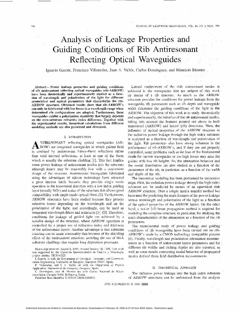
Fig. 2. Fig. 1 for nCOpe = 1.464.
Calculated attenuation for the slab ARROW structure depicted in
of modes propagated through a planar equivalent structure. Slab waveguides and cylindrical optical fibers (actually one dimensional guiding structures) have exact solutions for the propagation constants in the sense that we can speak about strictly guided or leaky modes. As it is well known, slab ARROW's as shown in Fig. 1 are leaky structures which can be solved analytically, leading to modes with complex propagation constants. The imaginary part of the propagation constant accounts for radiation losses through the substrate which are dependent on the wavelength or polarization of the light and are determined by the thickness and refractive index of the ARROW layers. Then, a simple one dimensional transfer matrix method can provide the main features of the power leakage as a function of the parameters of the ARROW structure. Fig. 2 shows calculations performed for the attenuation of the fundamental TE and TM mode against wavelength for a slab ARROW with the structure displayed in Fig. 1. When the wavelength of the light holds the condition for transverse quarter wave, the maximum reflection at these layers and the minimum losses are achieved, while when it holds the half wave condition, the reflection is minimum and the field penetrates into the high index substrate, leading to high radiation losses. These radiation losses are much higher for TM than TE polarization, as it is clearly observed in the figure.
The attenuation peak is determined by the transverse half wave condition, that for both polarizations essentially depends
600 650 700 750 800 850 900 950 1300 Wavelength (nm)
Fig. 3. Slab ARROW attenuation curves for 1.460, 1.464, and 1.480 core refractive indexes, considering a substrate cladding layer with 1.46 refractive index. (a) TM polarization and (b) TE polarization.
on the thickness and refractive index of the high index layer. Notwithstanding, the maximum attenuation value as well as the position shift between TE and TM peaks are governed by the core-substrate cladding refractive index difference. This effect can be observed in Fig. 3, where altenuation curves for TE and TM polarizations are represented as a 'unction of wavelength for several core refractive indexes, considering a substrate cladding layer with a refractive index of 1.46. The maximum value of the attenuation peak repres1:nts the attenuation that would have a similar waiveguide without the antiresonant high index layer, while the low attcnuation values are achieved because of the shielding effect of this layer when the wavelength holds the transversal quarter wave condition. So, ARROW structures allow low radiation losses for relatively thin substrate cladding layers.
The results in this figure also show that as the core rcfractive index becomes higher, the position of the attenuation peaks tends to shorter wavelengths, because the transverse quarter wave condition changes and in different way for TM and TE polarizations, and the maximum attenuation value de creases. This fact is due to exponential decay of the propagatcd mode field distribution in the substrate cladding when its effective propagation index exceeds the refractive index of the znbstrate cladding layer and, accordingly, reaches the silicon znbstrate with lower field amplitude.
It is well known that ARROW's are highly polarization dependent as can also be observed from Figs. 2 and 3 . There
Authorized licensed use limited to: Universitat de Barcelona. Downloaded on February 19, 2009 at 07:16 from IEEE Xplore. Restrictions apply.
800 JOURNAL OF LIGHTWAVE TECHNOLOGY, VOL 14, NO 5 , MAY 1996
......... TM ; ; ........ ,........... I ........... rime= 1.460 ..i ' .
: , : . j . . . ,-. . , : .
E 0
................................................ ............................................... 2
............................................
................................................ ............................................... .........................
c
- . . . _._-- j _..- ............. /
I
4 .......-
600 650 700 750 Wavelength (nm)
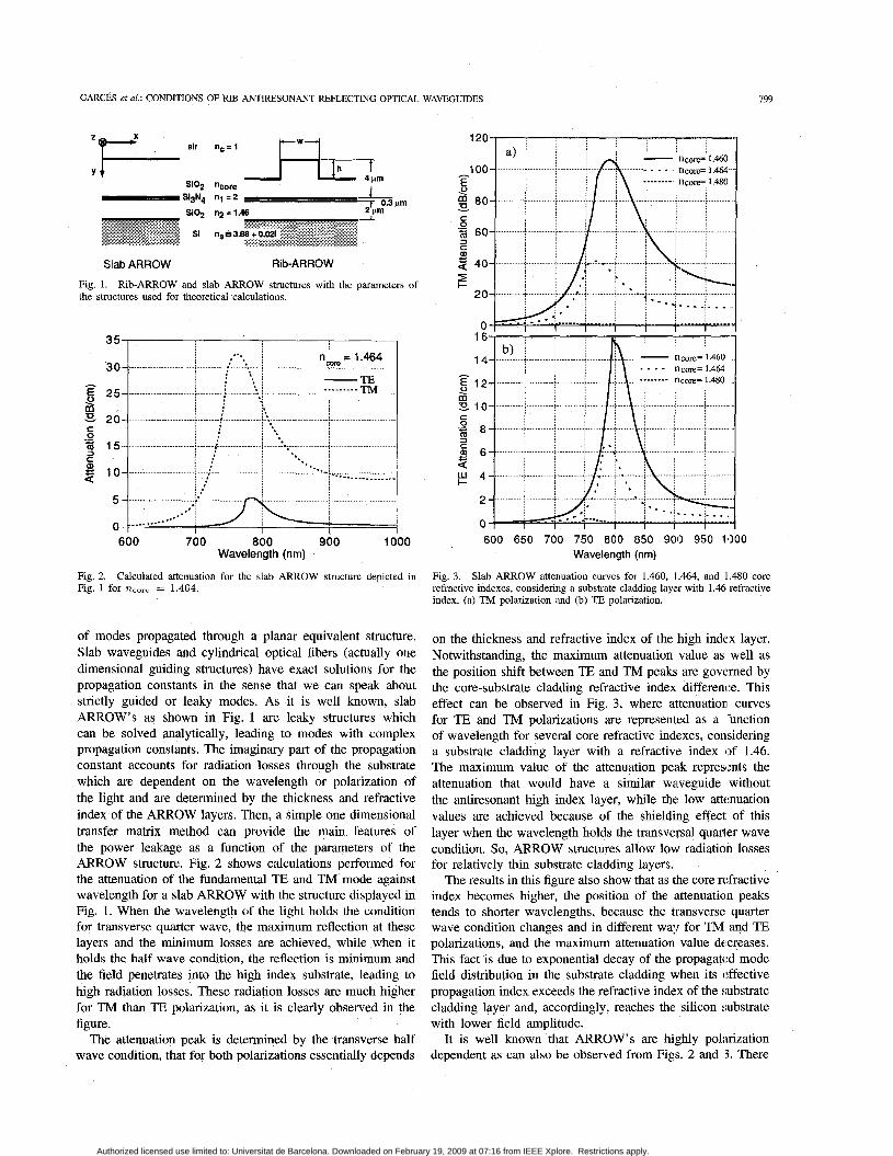
Fig 4 Slab ARROW attenuation for TE and TM polanzations around the low loss wavelength region for core refractive indexes of (a) 1.460 and @) 1 464
is a difference in waveguide losses between TJ3 and TM modes for all wavelengths, being higher at the attenuation peaks than in the low loss wavelength range. Fig. 4(a) and @) show attenuation values near the minimum loss wavelength, that for the parameters given in Fig. 1 and n,,,, = 1.46 is 600 nm, for two different core refractive indexes. Then, a difference in attenuation between polarizations of 0.3 dB is calculated for a 1.464 refractive index core waveguide at this wavelength, while 2 dB is achieved when core and substrate cladding have similar refractive indexes. Then, nearly polarization independent waveguides can only be obtained around the design wavelength if the refractive index of the core is properly chosen. Out of this spectral region, ARROW structures always present high polarization dependence, leading to higher and wider attenuation peaks for the TM polarization.
Besides the power leakage properties, the guiding conditions of ARROW'S in the lateral direction are determined by the rib configuration. Another purpose of this work is to analyze guiding conditions of rib-ARROW'S as a function of the rib parameters, specially waveguide width and etching depth. Rib-ARROW structures have not been extensively studied theoretically, in particular in reference [7], rib-ARROW'S with low rib heights (less than 0.8 pm) were modeled using a commercially available finite element based software. This work points out some specific phenomena, such as the increase
D v
u , 3
Ta
U) U) 0 -
2 5 0
2
1 . 5 t " ' " " " i ' " ' i " " 1 '
0 5 10 15 20 rib width (microns)
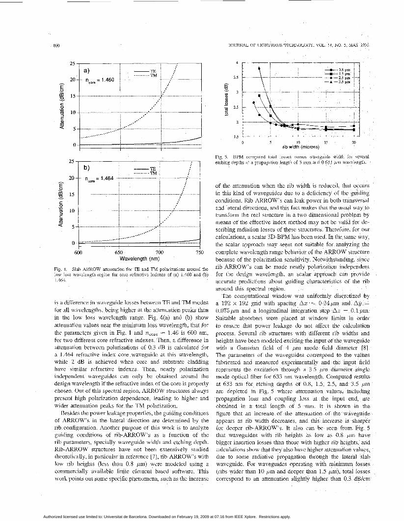
BPM computed total losses versus waveguide width for several Fig. 5. etchmg depths at a propagation length of 5 mm and 0 633 pm wavelength.
of the attenuation when the rib width is reduced, that in this kind of waveguides due to a deficiency of the gu conditions. Rib-ARROW'S can leak power in both trans and lateral directions, and this fact makes that the usual w transform the real structure in a two dimensional problem by means of the effective index method may not be valid for de- scribing radiation losses of these structures. Therefore, for our calculations, a scalar 3D-BPM has been used. In the same way, the scalar approach may seem not suitable for analyzing the complete wavelength range behavior of the ARROW structure because of the polarization sensitivity. Notwithstanding, since rib-ARROW'S can be made nearly polarization independent for the design wavelength, an scalar approach can provide accurate predictions about guiding characteristics of the rib around this spectral region.
The computational window was uniformly discretized a 192 x 192 gnd with spacing Arc = 0.24pm and 0.075pm and a longitudinal integration step Az = 0 Suitable absorbers were placed at window limits in to ensure that power leakage do not affect the calculation process. Several rib structures with different rib widths heights have been modeled exciting the input of the waveg with a Gaussian field of 4 pm mode field diameter [8]. The parameters of the waveguides correspond to the values fabricated and measured experimentally and the input field represents the excitation through a 3.5 pm diameter single mode optical fiber for 633 nm wavelength. Computed results
appears as rib width decreases, and this increase is sharper for deeper rib-ARROW'S. It also can be seen from Fig. 5 that waveguides with rib
Authorized licensed use limited to: Universitat de Barcelona. Downloaded on February 19, 2009 at 07:16 from IEEE Xplore. Restrictions apply.
GARCES et al.: CONDITIONS OF RIB ANTIRESONANT REFLECTING OPTICAL WAVEGUIDES 801
I
10 1 b,
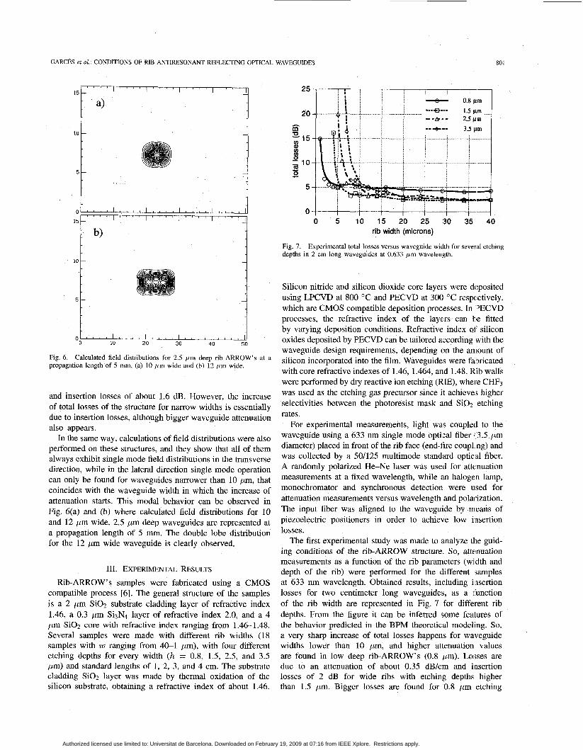
Fig. 6. propagation length of 5 mm, (a) 10 fim wide and (b) 12 pm wide.
Calculated field distributions for 2.5 pm deep rib-ARROW'S at a
and insertion losses of about 1.6 dB. However, the increase of total losses of the structure for narrow widths is essentially due to insertion losses, although bigger waveguide attenuation also appears.
In the same way, calculations of field distributions were also performed on these structures, and they show that all of them always exhibit single mode field distributions in the transverse direction, while in the lateral direction single mode operation can only be found for waveguides narrower than 10 pm, that coincides with the waveguide width in which the increase of attenuation starts. This modal behavior can be observed in Fig. 6(a) and (b) where calculated field distributions for 10 and 12 pm wide, 2.5 pm deep waveguides are represented at a propagation length of 5 mm. The double lobe distribution for the 12 pm wide waveguide is clearly observed.
111. EXPERIMENTAL RESULTS Rib-ARROW' s samples were fabricated using a CMOS
compatible process [6]. The general structure of the samples is a 2 pm Si02 substrate cladding layer of refractive index 1.46, a 0.3 pm Si3N4 layer of refractive index 2.0, and a 4 pm Si02 core with refractive index ranging from 1.46-1.48. Several samples were made with different rib widths (18 samples with w ranging from 40-1 pm), with four different etching depths for every width (h = 0.8, 1.5, 2.5, and 3.5 pm) and standard lengths of 1, 2, 3, and 4 cm. The substrate cladding Si02 layer was made by thermal oxidation of the silicon substrate, obtaining a refractive index of about 1.46.
1.5 wl ..... ---&-- 2.5pm
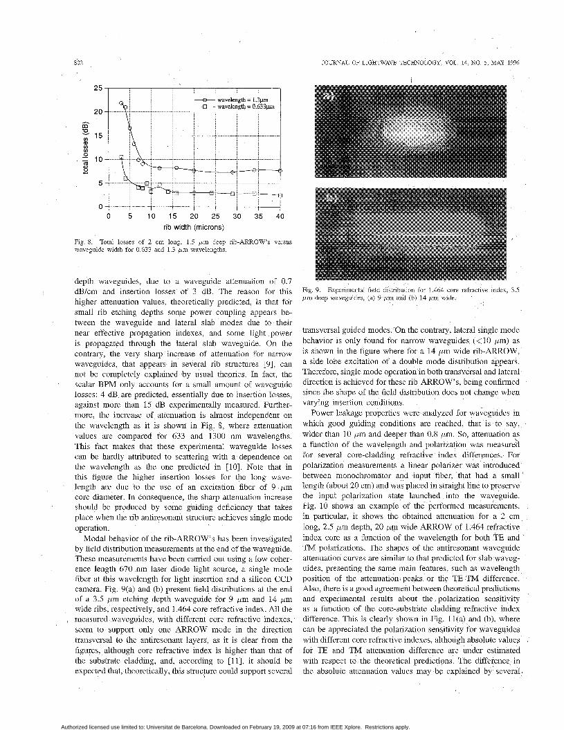
0 5 10 15 20 25 :30 35 40 rib width (microns)
Fig 7 depths In 2 cm long waveguides at 0.633 pm wavelength
Expenmental total losses versus waveguide width for several etching
Silicon nitride and silicon dioxide core layers were deposited using LPCVD at 800 OC and PECVD at 300 "C respectively, which are CMOS compatible deposition processes. In PECVD processes, the refractive index of the layers can t e fitted by varying deposition conditions. Refractive index of silicon oxides deposited by PECVD can be tailored according with the waveguide design requirements, depending on the amount of silicon incorporated into the film. Waveguides were fabricated with core refractive indexes of 1.46, 1.464, and 1.48. Rib walls were performed by dry reactive ion etching (RIE), where CHF3 was used as the etching gas precursor since it achieves higher selectivities between the photoresist mask and Si02 etching rates.
For experimental measurements, light was coupled to the waveguide using a 633 nm single mode optiical fiber I 3.5 pm diameter) placed in front of the rib face (end-lire coup11 ng) and was collected by a 50/125 multimode standard optical fiber. A randomly polarized He-Ne laser was used for attcnuation measurements at a fixed wavelength, while an halogen lamp, monochromator and synchronous detection were used for attenuation measurements versus wavelength and polarization. The input fiber was aligned to the waveguide by means of piezoelectric positioners in order to achieve low insertion losses.
The first experimental study was made to analyze the guid- ing conditions of the rib-ARROW structure. So, attenuation measurements as a function of the rib parameters (width and depth of the rib) were performed for the different samples at 633 nm wavelength. Obtained results, including insertion losses for two centimeter long waveguides, as a junction of the rib width are represented in Fig. 7 for different rib depths. From the figure it can be inferred some features of the behavior predicted in the BPM theoretical modeling. So, a very sharp increase of total losses happens for waveguide widths lower than 10 pm, and higher attenuation values are found in low deep rib-ARROW'S (0.8 pm). Losses are due to an attenuation of about 0.35 dB/cm and insertion losses of 2 dB for wide ribs with etching depths higher than 1.5 pm. Bigger losses are found for 0.8 pm etching
Authorized licensed use limited to: Universitat de Barcelona. Downloaded on February 19, 2009 at 07:16 from IEEE Xplore. Restrictions apply.
802
0 5 10 15 20 25 30 35 40 rib width (microns)
Fig. 8. waveguide width for 0.633 and 1 3 p m wavelengths.
Total losses of 2 cm long, 1.5 p m deep rib-ARROWS versus
JOURNAL OF LIGQTWAVE TECHNOLOGY, VOL. 14, NO. 5 , MAY 1996
depth waveguides, due to a waveguide attenuation of 0.7 dB/cm and insertion losses of 3 dB. The reason for this higher attenuation values, theoretically predicted, is that for small rib etching depths some power coupling appears be- tween the waveguide and lateral slab modes due to their near effective propagation indexes, and some light power is propagated through the lateral slab waveguide. On the contrary, the very sharp increase of attenuation for narrow waveguides, that appears in several rib structures [9], can not be completely explained by usual theories. In fact, the scalar BPM only accounts for a small amount of waveguide losses: 4 dB are predicted, essentially due to insertion losses, against more than 15 dB experimentally measured. Further- more, the increase of attenuation is almost independent on the wavelength as it is shown in Fig. 8, where attenuation values are compared for 633 and 1300 nm wavelengths. This fact makes that these experimental waveguide losses can be hardly attributed to scattering with a dependence on the wavelength as the one predicted in [lo]. Note that in this figure the higher insertion losses for the long wave- length are due to the use of an excitation fiber of 9 pm core diameter. In consequence, the sharp attenuation increase should be produced by some guiding deficiency that takes place when the rib antiresonant structure achieves single mode operation.
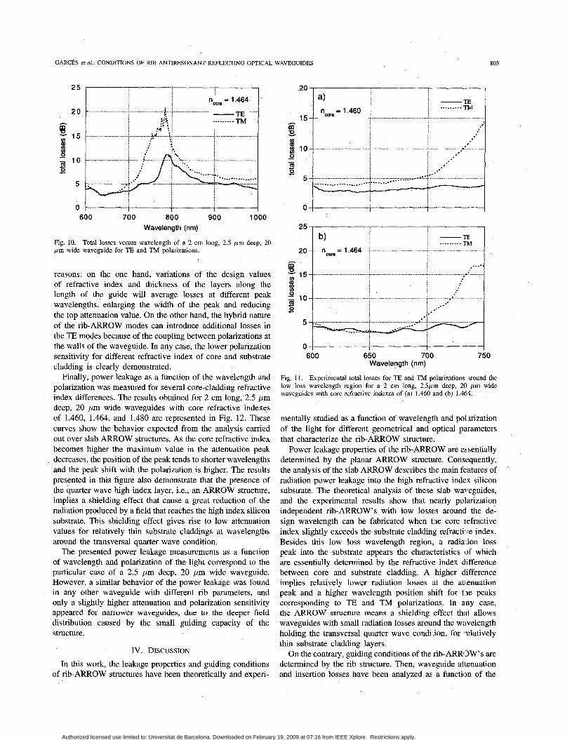
Modal behavior of the rib-ARROW’S has been investigated by field distribution measurements at the end of the waveguide. These measurements have been carried out using a low coher- ence length 670 nm laser diode light source, a single mode fiber at this wavelength for light insertion and a silicon CCD camera. Fig. 9(a) and (b) present field distributions at the end of a 3.5 pm etching depth waveguide for 9 pm and 14 pm wide ribs, respectively, and 1.464 core refractive index. All the measured waveguides, with different core refractive indexes, seem to support only one ARROW mode in the direction transversal to the antiresonant layers, as it is clear from the figures, although core refractive index is higher than that of the substrate cladding, and, according to [11], it should be expected that, theoretically, this strucpre could support several
Fig. 9. p m deep waveguides, (a) 9 p m and (b) 14 pm wide
Experimental field distnbution for 1.464 core refractive index, 3 5
,
transversal guided modes. ’On the contrary, lateral single mode behavior is only found for narrow waveguides (610 pm) as is shown in the figure where for a 14 pm wide rib-ARROW, a side lobe excitation of a double mode distribution appears. Therefore, single mode operation in both transversal and lateral direction is achieved for these rib-ARROW’S, being confirmed since the shape of the field distribution does not change when varying insertion conditions. ,
Power leakage properties were analyzed for waveguides in which good guiding conditions are reached, that is to say, wider than 10 pm and deeper than 0.8 pm. So, attenuation as a function of the wavelength and polarization was measureid for several core-cladding refractive index differences. For polarization measurements a linear polarizer was introduced between monochromator and input fiber, that had a small’ length (about 20 cm) and was placed in straight line to preserve the input polarization state launched into the waveguide. Fig. 10 shows an example of the performed measurements, in particular, it shows the obtained attenuation for a 2 cm long, 2.5 pm depth, 20 pm wide ARROW of 1.464 refractive index core as a function of the wavelength for both TE and TM polarizations. The shapes of the antiresonant waveguide attenuation curves are similar to that predicted for slab waveg- uides, presenting the same main features, such as wavelength position of the attenuation peaks or the TE-TM difference. Also, there is a good agreement between theoretical predictions and experimental results about the polarization sensitivity as a function of the core-substrate cladding refractive index difference. This is clearly shown in Fig. 11(a) and (b), where can be appreciated the polarization sensitivity for waveguides with different core refractive indexes, although absolute values for TE and TM attenuation difference are under estimated with respect to the theoretical predictions. The difference in the absolute attenuation values may be explained by several)
Authorized licensed use limited to: Universitat de Barcelona. Downloaded on February 19, 2009 at 07:16 from IEEE Xplore. Restrictions apply.
GARCES et al.: CONDITIONS OF RIB ANTIRESONANT REEECTING OPTICAL WAVEGUIDES 803
ncom = 1.464
20
5
I I I
600 700 800 900 1000 Wavelength (nm)
Fig. 10. b m wide waveguide for TE and TM polarizations.
Total losses versus wavelength of a 2 cm long, 2.5 p m deep, 20
reasons: on the one hand, variations of the design values of refractive index and thickness of the layers along the length of the guide will average losses at different peak wavelengths, enlarging the width of the peak and reducing the top attenuation value. On the other hand, the hybrid nature of the rib-ARROW modes can introduce additional losses in the TE modes because of the coupling between polarizations at the walls of the waveguide. In any case, the lower polarization sensitivity for different refractive index of core and substrate cladding is clearly demonstrated.
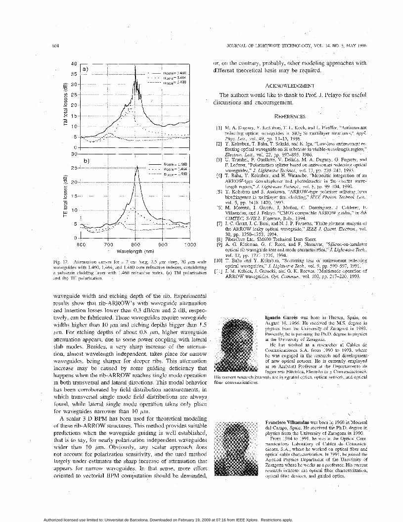
Finally, power leakage as a function of the wavelength and polarization was measured for several core-cladding refractive index differences. The results obtained for 2 cm long, 2.5 pm deep, 20 pm wide waveguides with core refractive indexes of 1.460, 1.464, and 1.480 are represented in Fig. 12. These curves show the behavior expected from the analysis carried out over slab ARROW structures. As the core refractive index becomes higher the maximum value in the attenuation peak decreases, the position of the peak tends to shorter wavelengths and the peak shift with the polarization is higher. The results presented in this figure also demonstrate that the presence of the quarter wave high index layer, i.e., an ARROW structure, implies a shielding effect that cause a great reduction of the radiation produced by a field that reaches the high index silicon substrate. This shielding effect gives rise to low attenuation values for relatively thin substrate claddings at wavelengths around the transversal quarter wave condition.
The presented power leakage measurements as a function of wavelength and polarization of the light correspond to the particular case of a 2.5 pm deep, 20 pm wide waveguide. However, a similar behavior of the power leakage was found in any other waveguide with different rib parameters, and only a slightly higher attenuation and polarization sensitivity appeared for narrower waveguides, due to the deeper field distribution caused by the small guiding capacity of the structure.
IV. DISCUSSION In this work, the leakage properties and guiding conditions
of rib- ARROW structures have been theoretically and experi-
-1 TE 20 14
......... Ttv I .(. ..... .....................................
- 1.460 15 ncoce -
h
E! U) v )
0
m 0
10 _ ................................................ ; ............................................... .............................................. %
: * : . : * - -
! .- c c 5 - ................................................ 1 ................................ .......................................... _ ...-.-- __._e .--.__ -
i /- ___.- --- .____ ,
4
0 I I
20 2 5 4 ~ 1 ......... Thl
.. ncore = 1.464 ..; ............................................... i ...............................................
3 = 15 .................................... U) a
- b - m 0 c c
600 650 700 750 Wavelength (nm)
Fig. 11. Experimental total losses for TE and TM polarizations sound the low loss wavelength region for a 2 cm long, 2.5pnn deep, 20 p m wide waveguides with core refractive indexes of (a) 1.460 and @) 1.464.
mentally studied as a function of wavelength and polarization of the light for different geometrical and optical parameters that characterize the rib-ARROW structure.
Power leakage properties of the rib-ARROW are essentially determined by the planar ARROW structure. Consc:quently, the analysis of the slab ARROW describes the main features of radiation power leakage into the high refractive index silicon substrate. The theoretical analysis of these slab waveguides, and the experimental results show that nearly polarization independent rib-ARROW'S with low losses around the de- sign wavelength can be fabricated when tlhe core refractive index slightly exceeds the substrate cladding refractiire index. Besides this low loss wavelength region, a radial ion loss peak into the substrate appears the characteristics of which are essentially determined by the refractive index difference between core and substrate cladding. A higher difference implies relatively lower radiation losses at the at] enuation peak and a higher wavelength position shift for tlie peaks corresponding to TE and TM polarizations. In any case, the ARROW structure means a shielding effect thxt allows waveguides with small radiation losses around the wavelength holding the transversal quarter wave condition, for -elatively thin substrate cladding layers.
On the contrary, guiding conditions of the rib-ARROW'S are determined by the rib structure. Then, waveguide attenuation and insertion losses have been analyzed as a function of the
Authorized licensed use limited to: Universitat de Barcelona. Downloaded on February 19, 2009 at 07:16 from IEEE Xplore. Restrictions apply.
804
I
nmre= 1.460
“ I 1 I I I
30 I I
b, I - ncore= 1.460
0 1 I I I
6 0 0 700 800 900 1000 Wavelength (nm)
Fig 12 Attenuation curves for a 2 cm long, 2 5 p m deep, 20 p m wide waveguides with 1 460, 1 464, and 1 480 core refractive indexes, considenng a substrate cladding layer with 1460 refractive index (a) TM polanzation and (b) TE polanzation
waveguide width and etching depth of the rib. Experimental results show that rib-ARROW’S with waveguide attenuation and insertion losses lower than 0.3 dB/cm and 2 dB, respec- tively, can be fabricated. These waveguides require waveguide widths higher than 10 pm and etching depths bigger than 1.5 pm. For etching depths of about 0.8 pm, higher waveguide attenuation appears, due to some power coupling with lateral slab modes. Besides, a very sharp increase of the attenua- tion, almost wavelength independent, takes place for narrow waveguides, being sharper for deeper ribs. This attenuation increase may be caused by some guiding deficiency that happens when the rib-ARROW reaches single mode operation in both transversal and lateral directions. This modal behavior has been corroborated by field distribution measurements, in which transversal single mode field distributions are always found, while lateral single mode operation rakes only place for waveguides narrower than 10 pm.
A scalar 3-D BPM has been used for theoretical modeling of these rib-ARROW structures. This method provides suitable predictions when the waveguide guiding is well established, that is to say, for nearly polarization independent waveguides wider than 10 pm. Obviously, any scalar approach does not account for polarization sensitivity, and the used method largely under estimates the sharp increase of attenuation that appears for narrow waveguides. In that sense, more effort oriented to vectorial BPM computation should be demanded,
JOURNAL OF LIGHTWAVE TECHNOLOGY, VOL 14, NO 5, MAY 1996
or, on the contrary, probably, other modeling approaches with different theoretical basis may be required.
ACKNOWLEDGMENT
The authors would like to thank to Prof. J. Pelayo for useful discussions and encouragement.
REFERENCES
M. A Duguay, Y Kokubun, T L Koch, and L Pfeiffer, “Antwesonant reflechng optical waveguides in Si02 Si multilayer structures,” Appl Phys k t t , vol 49, pp 13-15, 1986 Y Kokubun. T Baba, T Sakalu, and K Iga, “Low-loss antiresonant re- flecting optlcal waveguide on Si substrate in visible-wavelength region,” Electron Lett, vol 22, pp 892-893 1986 U Trutshel, F Ouellette, V Delisle, M A Duguay, G Fogarty, and F Lederer, “Polarizahon splitter based on antiresonant reflecting optical waveguides,” J Lightwave Technol, vol 13, pp 239-243, 1995 T Baba, Y Kokubun, and H Watanabe, “Monoliuc integration of an ARROW-type demultiplexer and photodetector in the shorter wave- length region,” J Lightwave Technol, vol 8, pp 99-104, 1990 Y Kokubun and S Asakawa, “ARROW-type polarizer utilizing form blrefnngence in multilayer first cladding,” IEEE Photon Technol Lett, vol 5, pp 1418-1420, 1993 M. Moreno, I GarcBs, J Mufioz, C Domnguez, J Calderer, F Villuendas, and J Pelayo, “CMOS compatible ARROW guides,” in 8th CIMTEC, S-VII2, Florence, Italy, 1994 J C Grant, J C Beal, and N J P Frenette, ‘ Finite element analysis of the ARROW leaky optical waveguide,” IEEE J Qunnt Electron, vol 30, pp 1250-1253, 1994 FiberCOre Ltd SM600 Technical Data Sheet A G Bckman, G T Reed, and F Namavar, “Silicon-on-insulator ophcal nb waveguide loss and mode characteristics,” J Lightwave Tech,
T Baba and Y Kokubun, “Scattering loss of antiresonant reflecting optical waveguides,” J Lightwave Tech, vol 9, pp 590-597, 1991 J M Kubica, J Gazeclu, and G K Reeves, “Mulumode operation of ARROW waveguides, Opt Commun , vol 102, pp 217-220, 1993
VOI 12, pp 1771-1776, 1994
Ignacio Garc6s was boin in Huesca, Span, on August 10, 1966 He received the M S degree in physics from the University of Zaragoza in 1989 Presently, he is puisuing the Ph.D degree in physics at the University of Zaragoza.
He has worked as a researcher at Cables de Comunicaciones S A from 1990 to 1993, where he was engaged in the research and development) of new optical sensors. He is currently employed as an Assistant Professor at the Departamento de Ingeniena Electrica, Electr6nica y Comunicaciones -
His current research interests are integrated optics, optical sensors, and optical fiber communications.
Authorized licensed use limited to: Universitat de Barcelona. Downloaded on February 19, 2009 at 07:16 from IEEE Xplore. Restrictions apply.
G A R C ~ S et al.: CONDITIONS OF RIB ANTIRESONANT REFLECTING OPTICAL WAVEGUIDES 805
Juan A. Vallb was born in Burgos, Spain, on June 12, 1963. He received the B.A. degree in 1986, the M.Sc. degree in 1987, and the Ph.D. degree in physics in 1992, from the University of Zaragoza. His doctoral research centered on a new method for the detection of the hyperfine transitions which are utilized for frequency standards in atomic clocks.
Presently, he is employed as assistant professor at the Applied Physics Department of the University of Zargoza, and his current research interests are
primarily within the field of modeling and characterization of active and passive waveguides.
ing Group in UB
Carlos Dom’nguez received the B.S., M.S., and Ph.D. degrees in chemistry from the Universidad Complutense of Madrid, Spain, in 1980, and 1985, respectively.
He became a Member of the Scientific Staff at the Instituto de Microelectrdnica de Barcelona (IMB-CNM, CSIC) in 1986. Since 1991, he has been a Senior Scientific Researcher at IMB-CNM, CSIC. He is involved in chemical vapor deposition processes and wet and dry etch processes. Currently, he is working on the development of optoelectronics a
technology based on silicon for broad-band telecommunications.
Mauricio Moreno was born in Barcelona, Spain. He received the degree in physics in 1985 from the University of Barcelona (UB), and the Ph.D. degree in sciences, in 1995 from the Polytechnic IJniversity of Catalonia (UPC), where he has worked in the Electronic Engineering Department since 1990.
His fields of interest are integrated optics on silicon substrates, photodetecltors and imaging on standard CMOS technology, and fiber OF tics com- munications. Since 1994, he has been an Associate Professor in the Electronics and Materials Engineer-
Authorized licensed use limited to: Universitat de Barcelona. Downloaded on February 19, 2009 at 07:16 from IEEE Xplore. Restrictions apply.