
FM44-48(93).pdf - Berlin Information-center for Transatlantic ...
92
HEADQUARTERS, DEPARTMENT OF THE ARMY 21 SEP 1993 TACTICS, TECHNIQUES, AND PROCEDURES FOR THE EE©E PEL JO:©©E LIBRARY USA crr iT F "A SEP 161993 ACCESSIONNu _N PO REGISTR DISTRIBUTION RESTRICTION: ApproVbd for public release. Distribution is unlimited. ~~~s t:ssts ;;; ;;; ~;i -:: ~: :~ ~~~~n~~~: ~ ~ ~:~~~i~~~~ ~i~i~~.;5' r~~:s~:~: : 5 : :~:~: : : ::~::::::~:~:~::~:~:ji~i~ii~:::::~::~::: :~: :::~Z~~ i'i;:~:~:~::':'::::" ,,,, ---- - :~ i i8:~:~:::::8::~::~:;:~:~:~:~8~83~ ~~~~ r ~~ ::~::~::~:~::~:~:s~s~:~:s ~:~:~:~ ~:~~:~:~::~:;~:~ S~:~:~:~:~:~;:~:f;S:;SSS ;S:;ff:;~z. :~::::::~i:~~X*~X::::~~8#:1 ' ' -'::~:~::~:~:~::~:ii:l :;: :2.5 i :; .. ;-5 f: :: ~ :: ~t t~2. :~X vz~ :~:;~;:~:::::~:s~::~: :S.:~:St ~2.f..~''":::~::::~::~::::~:~.: "':I ... "iS. :~:~:::t~:~:::~::~:~:::~:: ~:~:~::~:~:~: 1 ::6::~:~.::: s~ss:~,:,:,~,~,:~s~::::~:~:::::~::: :~.:.:.:~ .~.g::~:::~:~:::~~,,,,,,~:~:~, ~:~:~~:~:~8Wx:~ ~:~::s :::~::~:::::x:~s i~:~~::i:::::;:;~;:;~;:r:;:~:~:; ~;:r?-; :;~;:;:~I:~I:~::~:~:~: : :s~:s : xr:::ri~:~:~:~::.:~:~':~~s~:':~:~~~~ns~::.:~:~ :s ~ ~~:"'~:~'~:~:~'~: i"':"~2-~ :s :~:: ~:sc.~~ :~~x ~j~2 su~ :::~:f ~:;:;~;P ~:f::S~:~:::~:~:~:S:l:~:~:~~:~~~81~:~:~:~:P:~:~:~:~:: ~:- :* : ~S ::~I: : P:2 PZ S zz~~s~ XQ~ s~~:st~ :ss~~2 :::. ::. .ss zzt~ 2:55 :~: i:::~:#8~:~:~:~~~;2:";:;:~:~:~:~:~:~:;~: ,~:~:~~,,,,,,,,,,,, ",.,zy~::~X' ~- ::s :::s :~::~:~::~:~:~:ss :~::~::~:j ~ :~:~::i ~:~:~:2;:ss x:~:~:~:~1::~:~::~:~::~:~:~: x. :~: ~:~::~::~1::::::~::::R::~::~8~8~~:: ;""( :': : ~2 5.1~"": " ":""""" 8:~:~::~:~:.:.~'"'~..~ ~ ~ f::~:~: :;:; .,. ;: ~ ~ss :~:s : .~. ~ xs~:~:~:s :s~:~: 5 ; r :22''; s ~s ~ :.:~:~:.:~:~:~~.:~:~:~:~:~~:~~~~~ :r;:~:~ 2.55..5555 :~~5ii~i~i~ ~ ~:~:~:::$iiii~~~i~i~iiiiiiiiijiii~iiiiij 2;:::: :5 ~:5~5 O:~: :;~ ~;:~: :a:~s . xs: :::~:s :::::::~:~:~:~:~:~:~:~:~:~:~ d~~:i ~ ~s~zz.s~;s~~ :,:. ::.r ::. :X : ;tii. z;.i I 18:~:~:~::~:~:~:~:~:~::~:~::~:~:~:~::: ' ~~:~~8~~~~8~~8~:~:~:~:~:3~~~~"~";;;'~""" :l~si , :~:~..::~.:'~:~ ~:~.~:::~:~::::~:::~:~:~::~:~:~:~:~:~:~':'::~:~:~:::~:~:~:~ :~:: :~::i:~:~i~ ~:~:~:::""''~'"";'':';; '" ' ~:~:~:~:~:~::~:' ~:~~R:~:~::::: ;:;~s;:;:;~ :~:~:;:~:t;:r;:;:~X : ~t;~: ':~:~:.'".:~::.:i.~:::R:~:~:~::~::~::::: ss zz.s i.s . : : ~ : : ;: : : ~ xe x :.5:~:~: :r~::::::k.ii 2 5 : 51- : X : ::~:::::~:~:~:::~:::::::~:~:~:~::~::::~: ; .....r ::.r -: rz:. ~- ~: .~5~ : :: :.-i : 5: ~~s x~~~ : : : : ~ : : : : : :.: .s :~:s ~i~iii~i~i~~:~:~.:::::::::~:~:~::'.'~"'" """"""' 2 ~:~::.:~:.:.:2 ~::~.~.: .:~:~:. :~: :~:~: ~ .M'".::#8~"5.:: :ZZi ~+~i~ :+~ X ~ :~:O:~:~: : X :~:~: ::::::~:::~:~::Y:t :s :~:~:~:j~~:~~:~:~:;:.X.:.:.:.:.i.~:.55. 555 555 22 X2 : ~-~;: : ~;:~: :;: X :;:: X :I : XS : ' i. :.~ 5. :S ~.~.~.: ~5 : 5 1 ::.:~:;: :'1: 51:.'.~: : : f: 5"":~i~i~XSC i:~: :~:~:~~8~~:S#18~::~:~:~:~:~:~:~:~:~ "';";'"''~:~:~:E;E;:~:~:~:~::::~::: :::::::: ~ i 2i ;;i 'i;i;zi.;;;;.;';;;; .'.. :~~.:-~11 .(1 ' ' YC.'.:;2~ : : :.:.r. ~.~ ::ii: : :2 : :; i: ~:S~:S~~ ~ :0:~:~ 2:55 ~ :~:~: ~~2:~:::: ;ff5' "i .: :''i i': : :5 ::~:~:~:5 ~::3X~ ~X~O :..:.5' : 7'055.0:52 :SZ XO: :~:+~ ~ :0~ -i ;-i r-ii -- ii -- i - -- ~:~s :~ :~:~:s :~:~:~:s t: x : ~ : :r~~~:,.::. :::. . ~ :"'Z"55: :t : :~:~:.'i.s '~ ~:~:::'~:::~:~ ~::~:;:::~:~:~::::~::: .z.r :::::::':':': :' ':':~:~:':':~: t:2:.ts ::.t :::.r . i.s 2. .rs ; i.s ; ;;~sl~:~X~:~:;~~:O:.X: ~ :~:C ,,.:,,,,~~-~-,~
-
Upload
khangminh22 -
Category
Documents
-
view
3 -
download
0
Transcript of FM44-48(93).pdf - Berlin Information-center for Transatlantic ...
HEADQUARTERS,DEPARTMENT OF THE ARMY
21 SEP 1993
TACTICS, TECHNIQUES, AND PROCEDURESFOR THE
EE©E PEL JO:©©E
LIBRARYUSA crr iT F "A
SEP 161993ACCESSIONNu _N
PO REGISTR
DISTRIBUTION RESTRICTION: ApproVbd for public release. Distribution is unlimited.
~~~s t:ssts ; ;; ; ;; ~;i -: : ~: :~ ~~~~n~~~: ~ ~ ~:~~~i~~~~~i~i~~.;5' r~~:s~:~: : 5 : :~:~: : : ::~::::::~:~:~::~:~:ji~i~ii~:::::~::~::: :~: :::~Z~~ i'i;:~:~:~::':'::::",,,, ---- - :~ i i8:~:~:::::8::~::~:;:~:~:~:~8~83~8::~~~~~~ r ~~ ::~::~::~:~::~:~:s~s~:~:s ~:~:~:~ ~:~~:~:~::~:;~:~ S~:~:~:~:~:~;:~:f;S:;SSS ;S:;ff:;~z. :~::::::~i:~~X*~X::::~~8#:1 ' ' -'::~:~::~:~:~::~:ii:l :;: :2.5 i :; . .;-5 f: : : ~ : :~t t~2. :~X vz~:~:;~;:~:::::~:s~::~: :S.:~:St ~2.f..~''":::~::::~::~::::~:~.: "':I ..."iS. :~:~:::t~:~:::~::~:~:::~:: ~:~:~::~:~:~: 1 ::6::~:~.:::s~ss:~,:,:,~,~,:~s~::::~:~:::::~::: :~.:.:.:~ .~.g::~:::~:~:::~~,,,,,,~:~:~, ~:~:~~:~:~8Wx:~ ~:~::s :::~::~:::::x:~s i~:~~::i:::::;:;~;:;~;:r:;:~:~:; ~;:r?-;:;~;:;:~I:~I:~::~:~:~: : :s~:s : xr:::ri~:~:~:~::.:~:~':~~s~:':~:~~~~ns~::.:~:~ :s ~ ~~:"'~:~'~:~:~'~: i"':"~2-~ :s :~:: ~:sc.~~:~~x ~j~2 su~:::~:f ~:;:;~;P ~:f::S~:~:::~:~:~:S:l:~:~:~~:~~~81~:~:~:~:P:~:~:~:~:: ~:- :* : ~S ::~I: : P:2 PZ Szz~~s~ XQ~ s~~:st~ :ss~~2 :::. ::. .ss zzt~ 2:55 :~:i:::~:#8~:~:~:~~~;2:";:;:~:~:~:~:~:~:;~:,~:~:~~,,,,,,,,,,,, ",.,zy~::~X' ~-::s :::s :~::~:~::~:~:~:ss :~::~::~:j ~:~:~::i ~:~:~:2;:ss x:~:~:~:~1::~:~::~:~::~:~:~: x. :~: ~:~::~::~1::::::~::::R::~::~8~8~~:: ;""( : ': : ~2 5.1~"": " ":"""""8:~:~::~:~:.:.~'"'~..~ ~ ~ f::~:~: :;:; .,. ; : ~ ~ss :~:s : .~. ~ xs~:~:~:s :s~:~: 5 ; r :22''; s ~s ~ :.:~:~:.:~:~:~~.:~:~:~:~:~~:~~~~~ :r;:~:~2.55..5555 :~~5ii~i~i~ ~ ~:~:~:::$iiii~~~i~i~iiiiiiiiijiii~iiiiij 2;:::: :5 ~:5~5O:~: :;~ ~;:~: :a:~s . xs : :::~:s :::::::~:~:~:~:~:~:~:~:~:~:~ d~~:i ~~s~zz.s~;s~~ :,:. ::.r ::. :X : ;tii. z;.i I
18:~:~:~::~:~:~:~:~:~::~:~::~:~:~:~::: ' ~~:~~8~~~~8~~8~:~:~:~:~:3~~~~"~";;;'~""":l~si , :~:~..::~.:'~:~ ~:~.~:::~:~::::~:::~:~:~::~:~:~:~:~:~:~':'::~:~:~:::~:~:~:~ :~:: :~::i:~:~i~ ~:~:~:::""''~'"";'':';; '" ' ~:~:~:~:~:~::~:' ~:~~R:~:~:::::;:;~s;:;:;~ :~:~:;:~:t;:r;:;:~X : ~t;~: ':~:~:.'".:~::.:i.~:::R:~:~:~::~::~::::: ss zz.s i.s . : : ~ : : ;: : : ~ xe x :.5:~:~: :r~::::::k.ii 2 5 : 51- : X :::~:::::~:~:~:::~:::::::~:~:~:~::~::::~: ; . . . . .r ::.r -: rz:.~- ~: .~5~ : :: : .-i : 5: ~~s x~~~ : : : : ~ : : : : : :.: .s :~:s~i~iii~i~i~~:~:~.:::::::::~:~:~::'.'~"'" """"""'2 ~:~::.:~:.:.:2 ~::~.~.: .:~:~:. :~: :~:~: ~ .M'".::#8~"5.:: :ZZi ~+~i~ :+~ X ~ :~:O:~:~: : X :~:~:::::::~:::~:~::Y:t :s :~:~:~:j~~:~~:~:~:;:.X.:.:.:.:.i.~:.55. 555 555 22 X2 : ~-~;: : ~;:~: :;: X :;:: X :I : XS : 'i. :.~ 5. :S ~.~.~.: ~5 : 5 1 : :.:~:;: :'1: 51:.'.~: : : f: 5"":~i~i~XSC i:~: :~:~:~~8~~:S#18~::~:~:~:~:~:~:~:~:~"';";'"''~:~:~:E;E;:~:~:~:~::::~::: :::::::: ~ i 2i ;;i 'i;i;zi.;;;;.;';;;; .'.. :~~.:-~11 .(1 ' ' YC.'.:;2~ : : :.:.r. ~.~ : :ii: : :2 : :; i:~:S~:S~~ ~ :0:~:~ 2:55 ~ :~:~: ~~2:~:::: ;ff5' "i .: : ''i i': : :5 : :~:~:~:5 ~::3X~ ~X~O :..:.5' : 7'055.0:52 :SZ XO: :~:+~ ~ :0~ -i ;-i r-ii -- ii -- i - --~:~s :~ :~:~:s :~:~:~:s t: x : ~ : :r~~~:,.::. :::. . ~ :"'Z"55: :t : :~:~:.'i.s'~ ~:~:::'~:::~:~ ~::~:;:::~:~:~::::~::: .z.r :::: :: :':':': :' ':':~:~:':':~:t:2:.ts ::.t :::.r . i.s 2. .rs ; i.s ; ;;~sl~:~X~:~:;~~:O:.X: ~ :~:C ,,.:,,,,~~-~-,~
Field Manual 44-48
HEADQUARTERSDEPARTMENT OF THE ARMY
Washington, DC, 21 September 1993
TACTICS, TECHNIQUES, AND PROCEDURESFOR THE
DISTRIBUTION RESTRICTION: Approved for public release. Distribution is unlimited.
FM 44-48
FM 44-48
PrefaceThis field manual (FM) describes the tactics, techniques, and procedures (TTP) for the air
defense artillery (ADA) sensor platoon and sections. The purpose of this manual is to describe theorganization and employment of the ADA sensor platoon and sections.
This FM is designed to be used by the divisional forward area air defense (FAAD) battalion,corps ADA brigade FAAD battalion, and ADA sensor platoon and sections. It provides guidanceto the ADA battalion commander, S2, S3, battery commander, and sensor platoon leader in usingthe ADA sensor platoon.
The ADA sensor platoon, commonly referred to as "ADA scouts,"is the interim early warningcomponent of the FAAD program until the fielding of the light and special divisions interim sensor(LSDIS) and the ground-based sensor (GBS). The sensor platoon provides early warninginformation to users throughout the division area. The tactics, techniques, procedures, and conceptsdeveloped in this FM will remain valid after the fielding of the LSDIS or the GBS. The decision toemploy the ADA sensor section with or without a sensor will be made by the ADA battalioncommander based on the tactical situation and his needs. The platoons are organized in tables oforganization and equipment (TOEs) under manual early warning network (MEWN) sections.
The ADA sensor section is a valuable asset to the ADA battalion S2 in planning hisreconnaissance and surveillance (R&S) plan. The 52 coordinates with the ADA battalion S3 andsupported unit commanders to ensure the best use of the ADA sensor section for missionaccomplishment. The concept for the employment of ADA sensor section does call for positioningthem across the forward line of own troops (FLOT). They are best suited for use on the flanks ofthe area of operations (AO), along expected air avenues of approach (AAAs).
The proponent of this publication is USAADASCH. Send comments and recommendationson DA Form 2028 to Commandant, US Army Air Defense Artillery School, ATTN: ATSA-TAC-D,Fort Bliss, TX 79916-0002.
Unless this publication states otherwise, masculine nouns and pronouns do not refer exclusivelyto men.
ContentsPage
Chapter 1 Mission and Organization ............ .. ....................... 1-1
2 Platoon Leader Planning and Command, Control, and Communications .... 2-1
3 Section Employment .............................. .......... 3-1
4 Sensor Section Emplacement, Survivability, and Operations ............. 4-1
5 Identification and Reporting ......................................... 5-1
Appendix A Responsibilities ......................................... A-1
B Observation Techniques ......................................... B-1
C Determining Direction in the Field ................................... C-1
D Stealth ........................................ D-1
E Position Security ................................................... E-1
F Communications Planning and Troubleshooting .......................... F-1
G Sensor Employment ............................................... G-1
H Manual SHORAD Control System .................................... H-1
Glossary ... ........................................................ Glossary-1
References ............................................................ References-1
Index ............................. ............................... Index-1
CHAPTER 1
Mission and OrganizationThis chapter discusses the mission and organization of the
ADA sensor platoon. The mission of the ADA sensor platoon is toprovide alerting and early warning data on aircraft to usersthroughout the battlefield. The sensor platoon replaces the for-ward area alerting radar (FAAR) platoon in ADA battalions.
MISSION DESCRIPTION
The ADA sensor platoon accomplishes its mission byacquiring and identifying aircraft and alerting FAADweapons systems to hostile targets in their area ofresponsibility. In addition, ADA sensor platoon early-warning reports help protect friendly aircraft fromfratricide.
The ADA sensor sections are deployed in support ofthe reconnaissance and surveillance (R&S) plan toobserve critical named areas of interest (NAIs). Thesections are primarily deployed where they can bestprotect the division's area of operations (AO).
ADA sensor sections position themselves wherethey can best cover designated NAIs while maintaining
their security. Positioning the ADA sensor sections acrossthe FLOT is risky and must be METI'-T driven. Crossingthe FLOT exposes the sensor sections to dangers they arenot currently equipped for and requires extensive coordi-nation for passages of line, resupply, and return. Howev-er, mission requirements will dictate their actual position.
The sensor sections' purpose is surveillance; there-fore, they will engage ground or aerial forces only inself-defense or when ordered. ADA sensor sections relyon stealth and experience to infiltrate, escape, evade, andsurvive. The information gathered by the sections andpassed to the ADA commander helps the commandermass ADA fires at the right place and time.
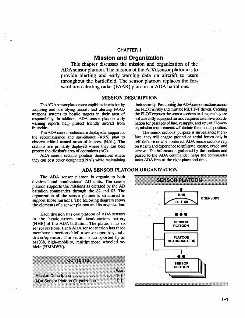
ADA SENSOR PLATOON ORGANIZATIONThe ADA sensor platoon is organic to both
divisional and nondivisional AD units. The sensorplatoon supports the missions as dictated by the ADbattalion commander through the S2 and S3. Theorganization of the sensor platoon is structured tosupport those missions. The following diagram showsthe elements of a sensor platoon and its organization.
Each division has one platoon of ADA sensorsin the headquarters and headquarters battery(HHB) of the ADA battalion. The platoon has sixsensor sections. Each ADA sensor section has threemembers: a section chief, a sensor operator, and adriver/operator. The section is transported by anM1038, high-mobility, multipurpose wheeled ve-hicle (HMMWV).
Mission Descipion..... .......... .... 11ADA Sensor Platoon Organization :. . :..:...., .. . .
"~~aBiiiiii~i~8" x*x*ssa ~8~ 5~8#8~~:~~:35 :~:~:":r":::: ::#8~"~ :fs :s ::~:~ ~55::::::~'~'"':'i j~:~~i~:.~~i~i~~i~~i~~.
6 SENSORS
SENSORPLATOON
PLATOONHEADQUARTERS
,I
1-1
~~:~:~:i ~~:~:~i8ii88:~:~:~:~:~:~:~:~:~
CHAPTER 2
Platoon Leader Planning and Command,Control, and Communications
This chapter discusses the planning, command, control, andcommunications (C3) methods for the employment of the sensorplatoon. ADA sensor tactics depend upon a platoon leader and sec-tion chiefs who can carry out mission-type orders on a constantlychanging battlefield. The ADA sensor platoon leader must under-stand the situation, then prepare and execute a plan.
PLANNINGThe platoon planning cycle follows the military
decision-making process. It begins with the receipt ofa new mission. Time is the most critical resource whena new mission is received. First, the platoon leaderthinks through the task. He coordinates with hisplatoon sergeant (PSG), and keeps him abreast of thesituation. The platoon leader plans the use of availabletime by backward planning from the mission objective.Abuffer is built into the planning sequence to allow forunexpected delays.
ISSUE WARNING ORDERThe platoon leader issues a warning order to the
platoon immediately upon receipt of a warning orderfrom higher headquarters. He tells his platoon whatthe mission is, when it is to take place, what initialpreparations must be made, and when the detailedoperation order (OPORD) will be issued. The warningorder will normally be issued orally, either in person orby radio communications.
INITIATE MOVEMENTMovement will be governed by standing operating
procedures (SOPs). Sections move tactically to theplatoon rally points and perform individual and sectionprecombat inspections.
The platoon leader immediately goes to theADA battalion tactical operations center (TOC) andbecomes involved in the decision-making process.
Page
He keeps the PSG or senior section chief informedof any changes to the mission. The PSG conducts theprecombat inspections and maintains contact withthe platoon leader to adjust to any changes in themission.
ADA CONCEPT
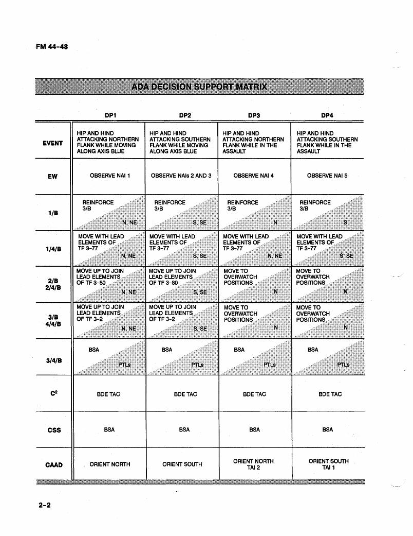
The ADA S3 will show the initial decision supporttemplate (DST) and decision support matrix (DSM) tothe sensor platoon leader. The ADA portion of theinitial DST and DSM may be general, dependent onthe availability of brigade and task force graphics. TheADA DST and DSM will continue to be adjusted basedon brigade or task force rehearsals. This initial DSM(see the ADA Decision Support Matrix illustration onpage 2-2) is intended to be a concept, giving guidanceto the platoon leader on the following:
* The commander's intent.
* ADA concept.
* Aerial intelligence preparation of the battle-field (IPB).
* A2 C2 plan.
* Mission time.
* A/L support plan.Based on these factors, the platoon leader must
pick general positions for the sensor sections whichbest support the ADA scheme of maneuver and theADA R&S plan as developed by the S2. It is imperativethat the sensor platoon leader make direct coordina-tion with the ADAbattalion commander to understandhis intent. As the sensor platoon leader prepares forthe mission, he should go through all establishedtroop-leading procedures along with the ADA batterycommanders.
2-1
-FM 44-48
: I:"::"::':ti:V":"::'i i:"::ti::tiL':" }:1"}}:"l}:':":':"::i""':' ":":"J}::"}:"}}:.il..'."}..L::::. :: V: i :.}'i ::.}.
DPi DP2 DP3 DP4
HIP AND HIND HIP AND HIND HIP AND HIND HIP AND HINDATTACKING NORTHERN ATTACKING SOUTHERN ATTACKING NORTHERN ATTACKING SOUTHERN
EVENT FLANK WHILE MOVING FLANK WHILE MOVING FLANK WHILE IN THE FLANK WHILE IN THEALONG AXIS BLUE ALONG AXIS BLUE ASSAULT ASSAULT
EW OBSERVE NAI 1 OBSERVE NAIs 2 AND 3 OBSERVE NAI 4 OBSERVE NAI 5
REINFORCE REINFORCE REINFORCE REINFORCE3/B 3/B3 3/B 3/B
1B8
N,::iiiiiiiii iiiiiiii NE :::iiii:::iiiiS SE N Siiii
MOVE WITH LEAD MOVE WITH LEAD MOVE WITH LEAD MOVE WITH LEADELEMENTS OF EELEMENTS OF LEMENTS OF ELEMENTS OF ><>
1/4/B TF 3-77 TF 3-77 TF 3-77 ....::;>:4 TF 3-77N' fiJE S <SE ..... ::::V:N'~N 5''E>
MOVE UP TO JOIN MOVE UP TO JOIN MOVE TO MOVE TOLEAD ELEMENTS LEAD ELEMENTS OVERWATCH OVERWATCH
2B OTF380 OF TF 3-80 POSITIONS POSITIONS2/4/B
MOVE UP TO JOIN MOVE UP TO JOIN MOVE TO MOVE TOLEAD ELEMENTS LEAD ELEMENTS OVERWATCH OVERWATCH
3/B OF TF 3-2 OF TF 3-2 POSITIONS POSITIONS4/4/B
BSA ....:::: : BSA *..: BSA BSA
3/4/B
C2 BDE TAC BDE TAC BDE TAC BDE TAC
CSS BSA BSA BSA BSA
CAD RINTNOT OIET OUHORIENT NORTH ORIENT SOUTHCADOIN OT RETSUHTAI 2 TAI 1
2-2
FM 44-48
TENTATIVE SENSOR PLANThe platoon leader must understand the ADA
battalion and supported unit mission and the com-mander's intent. In addition, he must know what ishappening around him and anticipate what will happennext; for example, changing from defense to offense.He must look at the overall tactical picture.
The sensor plan is designed for the best use oflimited sensor sections available to cover critical NAIs.Continuous updating of the IPB will aid in providing aneffective and flexible sensor plan to observe the NAIs.'I develop a collection plan, the platoon leader mustperform several functions.
Analyze Mission, Intent, Situation, and Assistin Developing the R&S Plan
The S3 identifies critical assets in time and spaceby phases of the battle based on his coordination withthe platoon leader. The platoon leader assists the S2in developing the R&S plan by using mission, enemy,terrain, troops, and time available (METIT-T), thecommander's intent, knowledge of the enemy, and theaerial IPB. Estimating the situation is a constant,cumulative process. Using this estimate, the S2,working with the platoon leader, develops a concept forADA coverage for each maneuver course of action.See Appendix A for specific responsibilities.
Develop Best Alternative for CoverageA quick mental war-gaming of surveillance
options versus probable enemy actions helps weighvarious factors and select the best alternative. Theplatoon leader considers the following factors whenselecting sensor section positions:
* Are the sections task-organized to specificsupported units or ADA batteries?
* In the offense, are sensor sections concen-trated in the area of the main effort, and will the sec-tions effectively cover the NAIs?
* In the defense, are sensor sections concen-trated in the area of the suspected enemy main attack,and do they cover the NAIs?
* Are the air avenues of approach on the divi-sion flanks covered?
* Are sensor sections overlapping within 10 to 15kilometers of each other to ensure surveillance coverageand to minimize dead space caused by terrain masking?
* Are sensor sections no closer than 2 kilome-ters from each other and within 5 kilometers of a
high-power radio frequency (RF) source of the sameor similar frequency?
Select Section PositionsOnce the platoon leader has obtained the maneu-
ver graphics, obstacle plan, and has war-gamed theoptions, he then selects the general section positions.Section positions should meet the following require-ments:
* Preselected withdrawal routes. Identifyfriendly obstacles and preplanned positions, if retro-grade operations become necessary. Preplan artilleryfires to enhance survivability.
* Rally points designated for loss-of-contactcontingencies.
* Alternate entrance and multiple-exit routesselected.
* Ability for communications with higher, low-er, and adjacent units. At a minimum, have two radiosthat are man-transportable to provide flexibility.
* Platoon command post (CP) centrally locatedwith respect to the platoon.
Plan for Continuous OperationsA plan must be developed for duty rotation and
shift work. The platoon leader is responsible for theplanning and executing 24-hour operations.Work schedule. When the ADA sensor section isemplaced and operational, work schedules should bemission-dependant. The section members need to berotated through the manual labor positions followed bya rest period, if possible. Work schedules are stated inhours, 4 hours of work and 4 hours of rest. Rest meanssleep or the absence of duties.Sleep plan. It is unlikely that a flawless work scheduleduring the heat of battle will be feasible. However, astrictly enforced sleep plan is vital when possible. Thegoal is for each soldier to get a minimum of 4 hours ofsleep each 24-hour period.
Brief R&S PlanThe ADA battalion S2 will brief the battalion
commander to receive approval of the R&S plan. Atthe time of the briefing, the platoon leader shouldbackbrief the battalion commander and the S2 and S3to verify understanding of the commander's intent andthe overall plan, and to present anticipated problemsand get a commitment for support.
Complete the DSMThe platoon leader prepares his decision support
matrix for the section briefing.
2-3
FM 44-48
Brief SectionsThe platoon leader prepares the platoon fragmen-
tary order (FRAGO). The FRAGO and executionmatrix are briefed to the sections to ensure that allmembers of the platoon are knowledgeable of themission.
PLATOON LEADER COORDINATIONThe platoon leader conducts thorough initial
coordination with the ADA staff to avoid problems ormisunderstandings in the future. Since he participatedin the commander's initial planning session, hebecomes part of the staff's planning session.
S2 SectionThe platoon leader coordinates with the S2 to
obtain the IPB products and the R&S plan. Specifical-ly, the platoon leader must know where the expectedair avenues of approach are with any NAIs, target areasof interest (TAIs), and or decision points the S2 hasrecommended. He also must know the priority intelli-gence requirement (PIR) and search times for criticalNAIs.
IPB is the critical tool to help the platoon leaderestimate when and where the enemy will be. Thisestimate helps the ADA sensor sections find the enemyand the ADA gunners to destroy him.
Predicting how the enemy aircraft will approach atarget is the most difficult part of the IPB. The inherentflexibility of aircraft to avoid the effects of terrainmakes prediction difficult. The best method fordetermining an air avenue of approach uses an analysisof somewhat fixed factors. These factors include thefollowing:
* The known or suspected locations of enemyairfields and staging areas.
* The location of friendly assets (enemy tar-gets).
* The preference of aircraft commanders for di-rect routes; the further an aircraft flies, the more fuelit needs and the less ordnance it can carry.
* That aircraft are limited assets that areemployed quickly to increase sortie generation.
* Aircraft will use more terrain masking and ad-just maximum and minimum ceilings, as locations offriendly air defenses are found.
* The air avenue of approach is more predict-able closer to a target.
The S2's designated NAIs focus the sensorplatoon surveillance effort in large areas of operation.
By knowing what the enemy can do (for example, typeof aircraft) and comparing it with what he is doing(doctrine and activity), the S2 may predict what he willdo next. NAIs are locations normally overlooking airavenues of approach (AAAs) where the S2 expects orestimates the enemy will be. A specific NAI isdesignated to confirm or deny a specific activity orcourse of action. Sensor sections cover NAIs to provideearly warning information to friendly forces and timelyreports to confirm or deny the S2 estimate of what theenemy will do next.
The S2 and air battle management operationscenter (ABMOC) listen to sensor section reports frommany NAIs. Using these reports and coordination withthe S3 help to form the "picture" for the commander.Aerial NAIs normally become TAIs depending uponthe type and number of enemy present, and thepresence of ADA fire units nearby. NAIs which areimportant to the ADA S2 and sensor section includethe following:
* Enemy drop zones (DZs).* Areas masking friendly radar coverage.* Projected forward area rearm/refuel point
(FARP) location.TAIs that are important to the ADA S2 and sensor
section include the following:* Enemy forward alighting area (FAA).
* Enemy forward air controller (FAC).
* Enemy division artillery groups (DAGs).
* Enemy landing zones (LZs).
* Helicopter low-level avenues of approach andchoke points.
The ADA S2 may not be able to cover all NAIswith the ADA sensor platoon and may need to get helpfrom the supported force. He also integrates his planwith the division or corps G2 to avoid duplication ofeffort while still maintaining control of the ADAsensor platoon. The S2 develops the R&S plan inconjunction with the S3 and the sensor platoon leader.The sensor platoon leader positions the sensorsections.
ADA battalion commander PIRs may include, butare not limited to, the following:
* The type and number of aircraft observed inthe vicinity of specific NAIs.
* Enemy ground troop or vehicular movementsseen.
2-4
FM 44-48
* Control centers or command vehicles encoun-tered.
* Type and amount of ordnance used by enemyaircraft.
* Identifying markings on enemy aircraft.* New variations in ground or air vehicles.* NBC activities.
S3 SectionThe sensor platoon leader coordinates with the
operations officer to determine the commander'sintent, to obtain the DST, the DSM, and scheme ofmaneuver. He obtains the OPORD graphics for theupcoming operation. The S3 coordinates for sectionpositions and terrain management.
S4 SectionThe platoon sergeant manages the logistics status
of the platoon. The PSG coordinates with the S4section while the platoon leader coordinates with theS3. The PSG determines the location of the combattrains to coordinate the resupply of the platoon usingthe logistics package (LOGPAC) system. He resolvesany supply problems encountered on the administra-tion/logistics (A/L) net. If problems arise at the combattrains, the PSG advises the platoon leader so he canattempt to resolve resupply problems with the S4.
ISSUE THE FRAGMENTARY ORDERWhen issuing the FRAGO, the platoon leader
makes sure that each soldier knows how the platoon isexpected to accomplish the mission and how he fits intothe plan. There are different techniques for issuing aFRAGO from using a sand table to a terrain walk onthe actual battlefield. The important thing is that everysoldier understands the platoon leader's intent foraccomplishing the mission. The platoon leader shouldbrief the senior section chief and sections using theexecution matrix and the FRAGO. The section chiefsshould transpose all the appropriate graphics and theexecution matrix onto their maps. The backbriefmethod ensures the commander's intent is understoodand clears up any misunderstandings.
The platoon should rehearse the operation usinga map, sand table, or the actual terrain wheneverpossible. Simple rehearsals involve soldiers backbrief-ing individual duties and the platoon leader askingadditional questions. Walk-through and reportingrehearsals also should be conducted. The PSG willverify precombat inspections by the section andsupervise rehearsals. The sections should then beginmovement.
EXECUTE AND SUPERVISECheck and double-check the squads. The best
plan may fail if not supervised.
PLANNING REMINDERSThe platoon leader's planning ensures that his
sections provide the information needed. Use thefollowing reminders to help in making the plan:
* Unless otherwise stated, plan surveillancecoverage during the brigade preparation phase for a24-hour operation. Rehearsing the plan is the best wayto achieve success.
* Integrate the sensor plan into an executionmatrix according to the ADA plan phases.
* Be aggressively involved in the planning pro-cess.
* Plan platoon rally points.
* Create platoon graphics in addition to battal-ion graphics, if needed.
* Get backbriefs.
* Complete the sensor plan portion of ADADSM.
* Establish rapport with the supported taskforce and understand their TOC operations.
* Rehearse limited visibility contingency, whenappropriate.
* Ensure section chiefs understand command-er's intent and your intent to support the battalion.
* Time is critical. Remember the 1/3-2/3 rule.That is, use 1/3 of the time available for planning and2/3 of the time for subordinate's planning and execu-tion.
COMMAND AND CONTROLADA sensor sections are under the operational
control of the ADA sensor platoon leader. The sensorplatoon leader works directly for the ADA battalioncommander, just as a maneuver scout works directly for
the force commander. Control will normally beexercised by the ADA S3 in coordination with the S2.Normally, the ADA sensor platoon is given a generalsupport (GS) mission, but it may be given a direct
2-5
FM 44-48
support (DS) mission to a firing battery. Command andsupport relationships are structured to accomplish the'supported force objectives.
GENERAL SUPPORTWhen the ADA sensor sections are in a GS role,
they are a battalion asset with a GS mission to thedivision or corps. The platoon leader works for theADA battalion commander to accomplish the mission.
DIRECT SUPPORTIn this method, two ADA sensor sections are
allocated as a minimum to each ADA battery support-ing a brigade or task force operation. This affords acontinuous coverage capability. One of the ADAsensor sections can remain in position while the otherdisplaces. The supported unit has the final determina-tion on the employment of ADA sensor sections. Hemakes this determination using the following factors:
* Deployment of supported forces.
* Deployment of fire units.
* The enemy threat, both air and ground.
* Terrain: elevation, hills, valleys, water, et cet-era.
* Electronic warfare environment.
REDUNDANCY
All command and control (C2) must be redundantdue to the distances involved. This prevents lapses inthe early warning coverage and ensures that aircraftare spotted.
CONTINUOUS OPERATIONS"The platoon leader must recognize and exercise
some degree of control over each section's workschedule to prevent fatigue from degrading sectionefficiency. The section's performance and efficiencywill normally begin to deteriorate after 14 to 18 hoursof continuous work and reach a low point after 22 to 24hours. After 24 hours of continuous duty, degradationof the section's performance is evident.
ADA SENSOR EMPLOYMENT GUIDELINESThe ADA sensor platoon leader deploys his
sections to provide continual ADA surveillancecoverage of the supported forces' area of operations.The sections are employed according to the sensor planto develop the air picture by providing maximumcoverage of the most likely AAAs and NAIs. The
sensor sections are also emplaced to avoid directobservation.
High- to medium-altitude air defense (HIMAD)radar dead zones may require surveillance coverage bythe sections. Dead zones are areas that prevent radarsearch and include hills, valleys, mountain passes, andlow areas.
ADA Sensor Sections in the Defense
In the defense, maneuver forces prepare andoccupy fortified, covered, and concealed positions withADA providing air defense. The ADA sensor sectionssupporting defensive operations require protectivecoverage and hardening of their locations. Eachsection should also have a hide location. The locationmust be carefully selected based on METT-T, thesensor plan, and the employment guidelines. Theplatoon leader must ensure the sections are not locatedin engagement areas and that the division A2C2
element and brigade fire support element (FSE) knowthe ADA sensor section locations (especially incross-FLOT operations).
In defensive situations, the sensor platoon willnormally be GS to the division or corps and the ADAsensor sections will be positioned and coordinated bythe S3. He will orient on air avenues of approach andpossibly cover enemy LZs within the area of opera-tions. However, manning considerations may dictatesupported unit asset to cover selected NAIs. Sensorcoverage is planned to ensure the ADA fire units havealert and early warning data in enough time to destroythe enemy. METIT-T could require that the ADAsensor sections be positioned close to the FEBA (2 to5 kilometers). The platoon leader will ensure that theADA sensor section is not left behind if the supportedforce moves from its original position.
ADA Sensor Sections in the Offense
Movement to contact, hasty attacks, deliberateattacks, pursuit, and exploitation are the offensiveoperations used by the division. The supportingADA fire units and the ADA sensor sections mustmove continuously to ensure overwatch protectionof the forward elements. Regardless of the opera-tion, the ADA sensor sections will be positioned toprovide EW to the force's main effort, protecting theflanks of the movement. If more than one ADAbattery is supporting the brigade making the mainattack, the ADA battalion will control the ADAsensor sections' movement.
2-6
FM 44-48
COMMUNICATIONS
The platoon leader should establish a sensorplatoon/section transmission schedule (for C2) beforedeployment. Each ADA sensor section must establishcommunications with the sensor platoon leader andthe ABMOC/BNTOC. Current radio allocations allowthe section to operate on two radio nets (AM and FM).The AM net is the ADA sensor net, which is used tofurnish EW, NAI, TAI, and AAA information to theABMOC. The FM radio net is a command net. This netis normally the sensor platoon net, but it is used totransmit directed EW on the supporting ADA organi-zational command net. When the TSOP requires it andfor EW redundancy, the FM radio can be used totransmit directed EW data to supported units.
DIRECTED EARLY WARNING AND LOCALAIR DEFENSE WARNING
Directed early warning is used to alert a particularunit or units or area of the battlefield. Directed EWdefines the local air defense warning (LADW), stateswhether the aircraft are friendly or unknown, providesa cardinal direction, and if known, states the most likelyaffected asset(s) within the local maneuver force. Forexample, if an EW source reports four enemyrotary-wing aircraft inbound from the east, and 1stBrigade is attacking along the eastern axis during amaneuver force attack, the sensor platoon leadershould report an LADW and directed EW message:"Dynamite! Dynamite! Four HINDS from the eastagainst Axis Blue!" Dynamite is the LADW that alertsthe maneuver force to an attack and that responsemust be immediate. LADWs may differ from unit tounit and the ADA sensor platoon leader must read thedivision TSOP to learn the proper LADWs.
Directed EW must be quick, simple, and redun-dant. It is imperative that all units, including maneuverunits, receive directed EW, especially those units thathave limited ADA coverage. Use of grids and manualSHORAD control system (MSCS) at the ADA sensorsection level may be impractical and time-consumingduring a battle. However, MSCS is still a validprocedure and may be used if time permits.
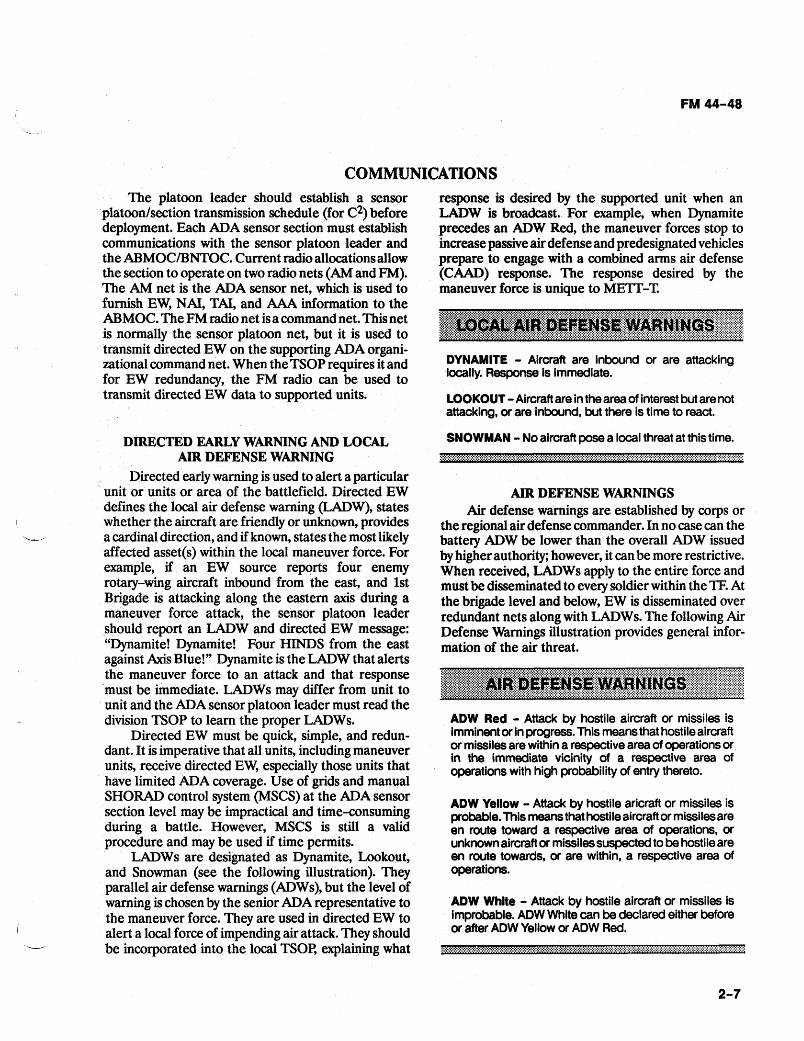
LADWs are designated as Dynamite, Lookout,and Snowman (see the following illustration). Theyparallel air defense warnings (ADWs), but the level ofwarning is chosen by the senior ADA representative tothe maneuver force. They are used in directed EW toalert a local force of impending air attack. They shouldbe incorporated into the local TSOP, explaining what
response is desired by the supported unit when anLADW is broadcast. For example, when Dynamiteprecedes an ADW Red, the maneuver forces stop toincrease passive air defense and predesignated vehiclesprepare to engage with a combined arms air defense(CAAD) response. The response desired by themaneuver force is unique to METT-T.
LOCAL AIR FENSE WARN ING
DYNAMITE - Aircraft are inbound or are attackinglocally. Response is immediate.
LOOKOUT - Aircraft are in the area of interest but are notattacking, or are inbound, but there is time to react.
SNOWMAN - No aircraft pose a local threat at this time.
AIR DEFENSE WARNINGSAir defense warnings are established by corps or
the regional air defense commander. In no case can thebattery ADW be lower than the overall ADW issuedby higher authority; however, it can be more restrictive.When received, LADWs apply to the entire force andmust be disseminated to every soldier within the TF. Atthe brigade level and below, EW is disseminated overredundant nets along with LADWs. The following AirDefense Warnings illustration provides general infor-mation of the air threat.
ADW Red - Attack by hostile aircraft or missiles isimminent or in progress. This means that hostile aircraftor missiles are within a respective area of operations orin the immediate vicinity of a respective area ofoperations with high probability of entry thereto.
ADW Yellow - Attack by hostile aricraft or missiles isprobable. This meansthat hostile aircraftor missiles areen route toward a respective area of operations, orunknown aircraft or missiles suspected to be hostile areen route towards, or are within, a respective area ofoperations.
ADW White - Attack by hostile aircraft or missiles isimprobable. ADW White can be declared either beforeor after ADW Yellow or ADW Red.
2-7
FM 44-48
COMMUNICATIONS EQUIPMENTTo achieve its communications requirements, the
ADA sensor section must have the appropriatecommunications equipment. The ADA sensor sectionoperates the FM radio set ANN/VRC-46 and the AMradio set AN/GRC-213. The objective ADA sensorprogram calls for the current AN/VRC-46 to bereplaced by the AN/VRC-92 SINCGARS radio. TheAN/VRC-92 is a vehicular-mounted, dual, long-rangeradio that has a two-net capability.
SIGNAL OPERATION INSTRUCTIONSThe signal operation instructions (SOI) provides
the ADA sensor section the information required topractice radio operating procedures. The sectionleader will carry and have responsibility for the SOIbecause he will be operating on the command and EWnets. Because of their sensitivity nature, SOI and codeshave special handling procedures prescribed to lessenthe possibility of unauthorized disclosure. Only thenecessary items of an SOI should be included inextracts carried by the section. Critical informationincludes the following:
" Radio call signs and frequencies.
" Sound signals.
" Pyrotechnic and smoke signals.
" Signs and countersigns.
" Operations codes.
" Authentication system.
" Radio frequency assigned.
ELECTRONIC COUNTERMEASURES ANDELECTRONIC COUNTER-COUNTERMEASURES
Electronic countermeasures are all the means andmethods an enemy uses to deny the use of theelectronic spectrum to the force.
Electronic counter-countermeasures (ECCM)are measures used to reduce or eliminate the effectsof an enemy's countermeasures that interrupt radiocommunications. How effective these methods aredepends on the operator and his equipment.
Preventive MeasuresGeneral preventive measures used for ECCM
planning include ADA sensor section equipmentsetting, use of directional antennas, minimum trans-mitting power, traffic control, reporting schedules,proper use of transmitter, and security. Descriptions ofthese preventive measures are in FM 24-33.
Jamming and Operator TrlainingThe most important factor in defense against
electronic countermeasures (ECM) is well-trainedradio operators. Training should be so thorough thatradio operators expect jamming. Inadequate antijam-ming training may result in surprise, confusion, andpanic within the section during an enemy attack. Evenif deliberate jamming is never encountered, training isvaluable because man-made or natural interference ofone kind or another is certain to be encountered duringcommunications. Training to work through jamming isan effective tool for the ADA sensor section. Addition-al measures to employ when training operators to workthrough jamming are in FM 24-33.
2-8

CHAPTER 3
Section EmploymentThis chapter discusses the function of ADA sensor platoon
personnel during movement. Movement includes selection of thesite on which the section will be positioned, preparation of the siteand establishing communications, and local security. Movement isfrequently done to support the sensor plan, because of a change inmission, or for survivability.
MOVEMENT ACTIONSThe ADA sensor platoon leader and section
chiefs must remain informed of current and antici-pated operations in preparing for a movement.Position area, route, and critical time information isgenerated by the mission of the supported unit andthe battery commander when in a DS role or thebattalion S3 when in a GS role. Movement activities
fall into the following sequence:Q Receive the movement warning order.[ Make a map reconnaissance.© Plan the movement.® Deploy, occupy, and improve the position.The following paragraphs discuss actions dealing
primarily with the ADA sensor section activities.
RECEIVE THE MOVEMENT WARNING ORDERThe movement warning order to the ADA sensor
section is issued by the ADA sensor platoon leader orADA battalion S3. The movement warning order isnormally verbal. It may be passed in person or overtactical communications equipment.
The warning order must include the following:* The new mission.
* Time of release for march order, crossing thestart point (SP), and assuming operational status at thenew position.
* Authentication, if passed by radio.
* The coordinates of the new positions.
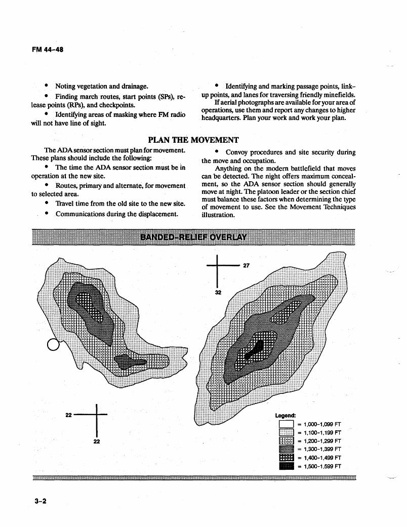
MAKE A MAP RECONNAISSANCEIt is the responsibility of the sensor platoon leader
and section chiefs to analyze the terrain over whichthey must travel and transmit radio traffic. If timepermits, creating a banded relief map of the area ofoperations assists in performing this task. This function
:::.Plan t..he.. M ovem en. .. t 2.. .: .;:. .:. : ::::: . ::.. :::.:::.::::. ..Deploy + 4....... ...... .: ::..:.. .. .: .. ... .: . W 33 :...;
P erim a Patn .. Pos . i.tons . .. . > . . . ...:3 ...4
P i a .nd ....... ate Position.:.......... 3-4
"i:: D... . . .iiiii"iiiiiiii iiiiii .":i:ii "tiiiii:ii ii i i ii i f i iiPtis i n:i >>>>iiiiiiii 3iiiiiiiiii>iiiii~ii!;iiii : :i :: :!iiii: ~i:i iii~ i~ iiii iiii i! i! :i i:::i. ii i ii:i i:!i ! ;i. :ii!.i; . : i i i ii ::.ii:ii...iii i:ii: ::: iiii ii ;: ii i.:
will show possible observation points, steering pointsfor navigation, and if and where FM retransmissionsites are required. It will show areas of radar maskingand where aircraft may use nap-of-the-earth (NOE)flight. The relief map also will indicate the slope of theterrain, and possible hiding places for vehicles will beobservation and listening posts (OPs and LPs). Referto the Banded-Relief Overlay illustration on page 3-2,for an example.
Map reconnaissance includes-
* Ensuring that the route and location of theADA sensor section meet tactical and technical re-quirements.
* Identifying possible ambush locations.
* Avoiding built-up areas, when possible.
* Identifying access and exit routes.
3-1
FM 44-48
" Noting vegetation and drainage.
" Finding march routes, start points (SPs), re-lease points (RPs), and checkpoints.
* Identifying areas of masking where FM radiowill not have line of sight.
" Identifying and marking passage points, link-up points, and lanes for traversing friendly minefields.
If aerial photographs are available for your area ofoperations, use them and report any changes to higherheadquarters. Plan your work and work your plan.
PLAN THE MOVEMENTThe ADA sensor section must plan for movement.
These plans should include the following:" The time the ADA sensor section must be in
operation at the new site.
* Routes, primary and alternate, for movementto selected area.
* Thavel time from the old site to the new site.
" Communications during the displacement.
: : :~(: : : : ::::::::::::R: : : : : : .:: :
~.n. eg:li:i : : :
? ! E a j {3 ni n n n{i " u n ... :::....
. E,::, a n jj n{ ,iE
Eu a nduf :i " : m 21 :
n 1:t a n3 c . '"in {n : n
i..' . E n n n t n ,t n rt u n u n i, , n ""
nlit .n ,n n tn
* Convoy procedures and site security duringthe move and occupation.
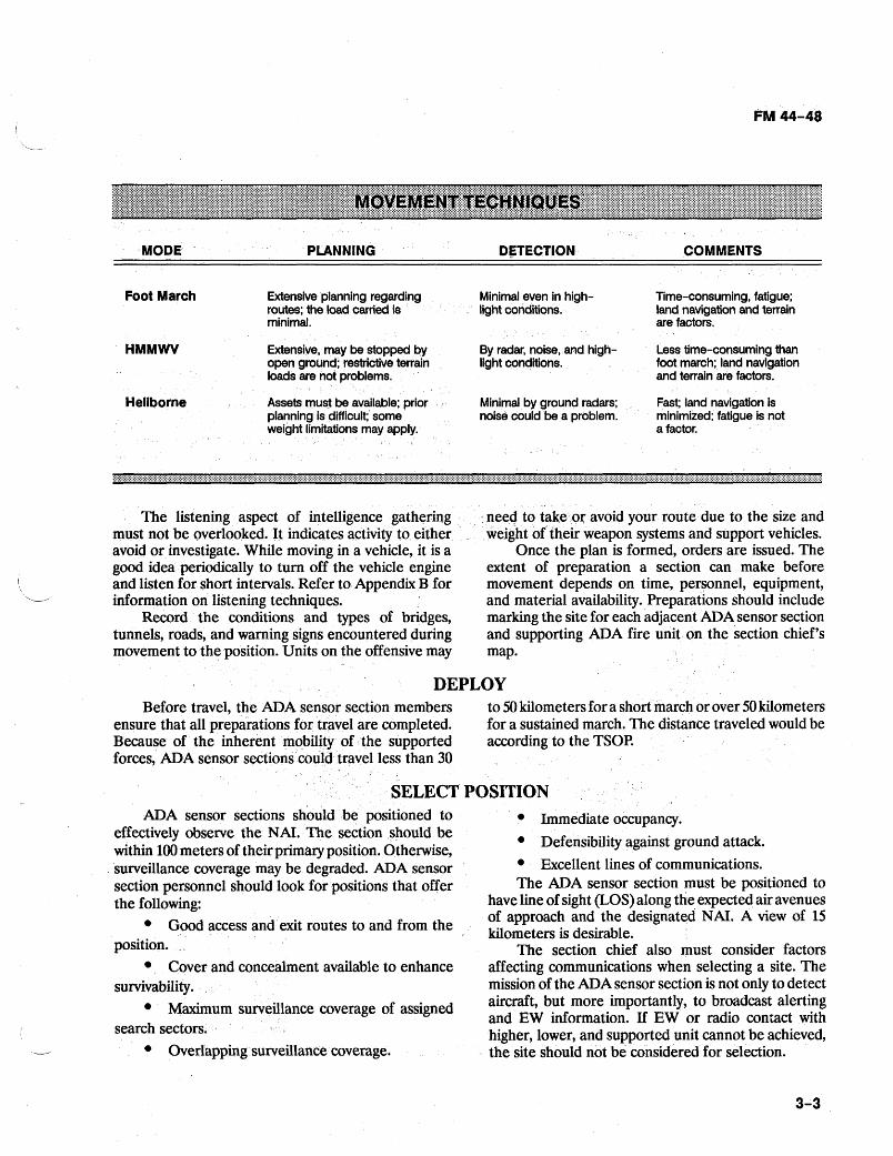
Anything on the modern battlefield that movescan be detected. The night offers maximum conceal-ment, so the ADA sensor section should generallymove at night. The platoon leader or the section chiefmust balance these factors when determining the typeof movement to use. See the Movement Techniquesillustration.
22 iLegend:22 -F 1i i=1,000-1,099 FT
= 1,100-1,199 FT
22 = 1,200-1,299 FTS= 1,300-1,399 FT
~FEEEEEEEEE~ = 1,400-1,499 FT
~8~= 1,500-1,599 FT
3-2
\; ::::::::::::::::::::r~lii~!:~~ii~~lr;. ~ ~~ ;~ ~~ ~~ ~~ ~~ NNn~ \~
::iiiiiiii
\ ::::::::: : : : : :1~ii:11111~::::::::'''':8~ii:i!it~ u6:f:liiijiiiiiiiii
FM 44-48
MODE PLANNING DETECTION COMMENTS
Foot March Extensive planning regarding Minimal even in high- Time-consuming, fatigue;routes; the load carried is light conditions. land navigation and terrainminimal, are factors.
HMMWV Extensive, may be stopped by By radar, noise, and high- Less time-consuming thanopen ground; restrictive terrain light conditions. foot march; land navigationloads are not problems. and terrain are factors.
Heliborne Assets must be available; prior Minimal by ground radars; Fast; land navigation isplanning is difficult; some noise could be a problem. minimized; fatigue is notweight limitations may apply. a factor.
The listening aspect of intelligence gatheringmust not be overlooked. It indicates activity to eitheravoid or investigate. While moving in a vehicle, it is agood idea periodically to turn off the vehicle engineand listen for short intervals. Refer to Appendix B forinformation on listening techniques.
Record the conditions and types of bridges,tunnels, roads, and warning signs encountered duringmovement to the position. Units on the offensive may
need to take or avoid your route due to the size andweight of their weapon systems and support vehicles.
Once the plan is formed, orders are issued. Theextent of preparation a section can make beforemovement depends on time, personnel, equipment,and material availability. Preparations should includemarking the site for each adjacent ADA sensor sectionand supporting ADA fire unit on the section chief'smap.
DEPLOYBefore travel, the ADA sensor section members
ensure that all preparations for travel are completed.Because of the inherent mobility of the supportedforces, ADA sensor sections could travel less than 30
to 50 kilometers for a short march or over 50 kilometersfor a sustained march. The distance traveled would beaccording to the TSOP.
SELECT POSITIONADA sensor sections should be positioned to
effectively observe the NAI. The section should bewithin 100 meters of their primary position. Otherwise,surveillance coverage may be degraded. ADA sensorsection personnel should look for positions that offerthe following:
* Good access and exit routes to and from theposition.
* Cover and concealment available to enhancesurvivability.
* Maximum surveillance coverage of assignedsearch sectors.
* Overlapping surveillance coverage.
* Immediate occupancy.
* Defensibility against ground attack.
* Excellent lines of communications.The ADA sensor section must be positioned to
have line of sight (LOS) along the expected air avenuesof approach and the designated NAI. A view of 15kilometers is desirable.
The section chief also must consider factorsaffecting communications when selecting a site. Themission of the ADA sensor section is not only to detectaircraft, but more importantly, to broadcast alertingand EW information. If EW or radio contact withhigher, lower, and supported unit cannot be achieved,the site should not be considered for selection.
3-3
FM 44-48
PRIMARY AND ALTERNATE POSITIONSIn selecting positions for the section, the ADA The alternate position should meet the require-
sensor section chief must consider movement to ments of the primary position. It is used when theother positions for survivability. The ADA sensor primary position becomes indefensible or unsuitablesection's ability to accomplish rapid emplacement for accomplishing the tactical mission. Although thisand march order enhances its survivability. The position is generally close to the primary position (200primary position should be the best position avail- to 500 meters), it should not be so near that it is alsoable for the ADA sensor section to accomplish the subjected to the same conditions that rendered thetactical mission. primary position indefensible or unsuitable.
3-4
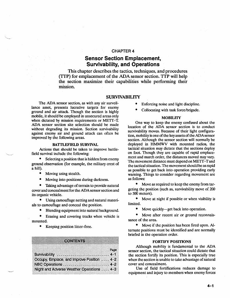
CHAPTER 4
Sensor Section Emplacement,Survivability, and Operations
This chapter describes the tactics, techniques, and procedures(TTP) for emplacement of the ADA sensor section. TTP will helpthe section maximize their capabilities while performing theirmission.
SURVIVABILITYThe ADA sensor section, as with any air surveil-
lance asset, presents lucrative targets for enemyground and air attack. Though the section is highlymobile, it should be employed in unsecured areas onlywhen dictated by mission requirements or METT'-T.ADA sensor section site selection should be madewithout degrading its mission. Section survivabilityagainst enemy air and ground attack can often beimproved by the following areas.
BATTLEFIELD SURVIVALActions that should be taken to improve battle-
field survival include the following:* Selecting a position that is hidden from enemy
ground observation (for example, the military crest ofa hill).
* Moving using stealth.
* Moving into positions during darkness.
* Taking advantage of terrain to provide naturalcover and concealment for the ADA sensor section andits organic vehicle.
* Using camouflage netting and natural materi-als to camouflage and conceal the position.
* Blending equipment into natural background.
* Erasing and covering tracks when vehicle ismounted.
* Keeping position litter-free.
S urvivab ility ................................ .. ...... 4 -Occupy, Emplace, and Improve Position .... 4-2NBCOperations.......................4-2Night and Adverse Weather Operations .. . ..4-3.
rd ::; : : h o .' z hd .. ................:::::::.. . ...............................
..:. .. . :.:. .... ... .. ... ..... : . ....... ..... .. .:: :.:.: : ..: . .:. : ::
* Enforcing noise and light discipline.
* Collocating with task force/brigade.
MOBILITYOne way to keep the enemy confused about the
location of the ADA sensor section is to conductsurvivability moves. Because of their light configura-tion, mobility is one of the key assets of the ADA sensorsection. Although the sensor section will normally bedeployed in HMMWV with mounted radios, thetactical situation may dictate that the sections deployon foot. Though they are capable of rapid emplace-ment and march order, the distances moved may vary.The movement distance must depend on METT-T andthe tactical situation. The movement should be as rapidas possible to get back into operation providing earlywarning. Things to consider regarding movement areas follows:
* Move as required to keep the enemy from tar-geting the position (such as, survivability move of 200to 500 meters).
* Move at night if possible or when visibility islimited.
* Move quickly-get back into operation.
* Move after recent air or ground reconnais-sance of the area.
* Move if the position has been fired upon. Al-ternate positions must be identified and are normallybriefed in the operation order.
FORTIFY POSITIONSAlthough mobility is fundamental to the ADA
sensor section, the tactical situation could dictate thatthe section fortify its position. This is especially truewhen the section is unable to take advantage of naturalcover and concealment.
Use of field fortifications reduces damage toequipment and injury to members when enemy forces
4-1
FM:44-48
locate and attack an ADA sensor section site. Tworestrictions make it difficult for the ADA sensorsection to construct adequate fortifications. One is thelimited number of personnel to do the work. The otheris the time the section has to fortify the position.However, the section should attempt to fortify theposition to the best extent possible. The use ofavailable concertina wire and claymore mines willprovide additional position security.
As a minimum, every section member should planto have an individual prone shelter. The section chief
determines if fortification should be initiated. Positionsshould be improved throughout the section's occupa-tion.
The ADA sensor section chief should choosepositions that cannot be seen by enemy groundobservation posts. Look for areas that provide naturalprotection, such as mounds or depressions. They caneasily be enhanced with sandbags or other materials.The section should obtain dirt and other naturalmaterials at a distance from the position to avoiddisturbing the immediate area.
OCCUPY, EMPLACE, AND IMPROVE POSITIONUpon arriving at the position selected during the
map reconnaissance, the section's primary goal is tobecome operational and provide early warning for theforce. The distribution of tasks and teamwork make theprocess of reaching the primary goal easier andquicker. This means that as members of a section, thesection chief, sensor section operator, and sectiondriver/operator must perform their individual tasksquickly and efficiently.
The following priority phases for the ADA sensorsection should be established for emplacement. Al-though some of them are accomplished simultaneous-ly, each must be completed.
ESTABLISH LOCAL SECURITYEstablish local security and defense against
ground attack by infiltrators or guerrillas. Sectionpersonnel sweep the area and establish guard postswith communications for quick reaction.
EMPLACE THE ADA SENSOR SECTIONSWhen the section arrives at the selected position,
the driver maneuvers the vehicle into a position thatprovides the best natural cover and concealment andallows for coverage of the assigned NAIs. The sensorsection member selects a tactical remote position thatensures an adequate field of vision and good cover and
concealment. Look for areas to emplace the HMMWVand OP/LP on the military crest of a hill, not on the top.
ESTABLISH COMMUNICATIONSEstablish communications and enforce security
procedures at all times. The ADA sensor sectionestablishes all required radio communications, andwhen the tactical situation indicates, begins to transmitover the DEW broadcast net.
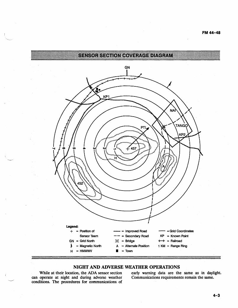
IMPROVE POSITIONSImprove ADA sensor section positions as soon as
time and tactical situation permit. Erase tracks madeby the section and vehicle. Camouflage personnel andequipment using natural material, where possible.Supplement natural camouflage by using artificialmaterial. Hide positions should be established forimmediate use. The section chief should complete anADA sensor coverage diagram that reflects ranges tocritical points on all likely avenues of approach (see theSensor Section Coverage Diagram).
PREPARE ALTERNATE POSITIONAs time allows, select and prepare an alternate
position. This will enable the ADA sensor section tomove to it quickly whenever the primary position iscompromised.
NBC OPERATIONSBoth en route to and while in its tactical position,
the ADA sensor section could be subjected to an NBCattack. The section will be at mission-oriented protec-tion posture (MOPP) level designated by the com-mander. In the event of a chemical or biological attack,the section's first action should be self-protection. Thesection will immediately go to MOPP 4.
Upon attack, NBC 1 observer's report is sent tohigher headquarters. Other section members use
chemical detection kits to detect chemical agents. Ifthe kit indicates that the area is contaminated, turn offall power and disconnect the power cable from thegenerator or other power source. Once the NBC 1 reporthas been sent, decontamination procedures should start.Rinse all exposed surfaces with water, allow to dry, andretest. If you use such decontaminates as DS2, follow thedirections to prevent damage to the equipment.
4-2
FM 44-48
: M.
Legend:+ = Position of
Sensor TeamGN = Grid North
= Magnetic North
H = HMMWV
- = Improved Road
-- = Secondary Road
= Bridge
A = Alternate Position=Town
-Grid CoordinatesKP = Known Point
++= Railroad
1 KM = Range Ring
NIGHT AND ADVERSE WEATHER OPERATIONSWhile at their location, the ADA sensor section
can operate at night and during adverse weatherconditions. The procedures for communications of
early warning data are the same as in daylight.Communications requirements remain the same.
4-3
J:~:::~:~::~:~:::i:~~::::~:~:~:8:~:~:~:: "'"1''"'""':;:*x~:t~: , :r.,s . :. ::::~:.:.: :;: : n:::n:~:~:::::: Ibg:~:::i:: ;;~::::~:::::A ~: rs::~::~:::'f''f';'' ::::88:~::::1:::::1:::::~X:::X:::::Y::::
CHAPTER 5
Identification and ReportingThis chapter describes how identification and reporting are
done in the ADA sensor platoon and section. The identificationand reporting of enemy activities is extremely important to thegathering of information and intelligence. These actions are ac-complished in various ways.
VISUAL AIRCRAFT RECOGNITIONIn the absence of radar and identification, friend
or foe (1FF) devices, the ADA sensor section must beproficient in visual aircraft recognition (VACR) skills.VACR skills are outlined in FM 44-80 and the groundobserver aircraft recognition (GOAR) kit. Other aidsin VACR include graphic training aids (GTAs), such asGTAs 44-2-5, 44-2-6, 44-2-7, and 44-2-8.
Additional sources include current slide photosand updated GTAs as provided by the training andaudiovisual support center (TASC) office for yourorganization. The ADA battalion S2 maintains files foraircraft used in specific regions of the world. Thesefiles and training aids will help focus the training effort
of the ADA sensor sections prior to deployment.Each ADA unit is responsible for conducting
VACR training to standard. The ADA sensor sectionmember must observe and report the types and numberof aircraft found in the NA he is assigned. Thisincludes both friendly and enemy aircraft. His reportsmust be accurate so ADA fire units do not engagefriendly aircraft. He must not only report the numberand type of aircraft, but also the actions taken by theaircraft. For example, the sensor section will report,"Dynamite, Dynamite, three, vicinity TANGO TAvo(NA), heading east, strafing and smoke" to describethree enemy aircraft at NA TANGO TWo.
HOSTILE CRITERIAHostile criteria are those conditions under which
an aircraft or vehicle may be identified as hostile forpurposes of engagement. Hostile criteria consist of, butare not limited to, the following:
0 Aircraft attacking friendly elements (strafing,bombing, or firing rockets).
" Aircraft discharging smoke or spray.
" Aircraft discharging parachutists in excess ofthe normal crew.
Aircraft engaging in mine-laying operations.
....port ......n ......... . .... . ... .+ ...... 5 8~ ':~: '::~":::~:~~:~~1:~.:. ,, ~ ~ i ,.,............. ~iiiiijiiii~j~~~~j~i........ .. ..P. .......................'":::: ~ :':'
...................... .. ... ...................6 .16f ...........................~i~................................::::: i:::::: i::.... ......::: I:: :: ::
P 05i~tli~ii~~~f:~Zi.:,::K:::::::I (:: ::,~ ~sjj~j:~i~~:: :r ~..................................................~~.8............~ ::::::::1:iiiiiiiiiii~ iliiri .....i~ . ..... ............. iiii
. ....................... c::c~i i:::.......... .... J n ........... . ........ ....... .. .........::::::::::::: ~ '''''''' ''''~'''''............ ** ........~ii~~~~...... ...... ..... . .... ...... .....
9 Aircraft making unauthorized entry into re-stricted areas.
0 Aircraft operating at prohibited speed, alti-tude, or direction.
0 Aircraft bearing military markings or configu-rations of known enemies.
* Aircraft replying with improper 1FF response(possible hostile).Note: Discharging flares is not a hostile act.
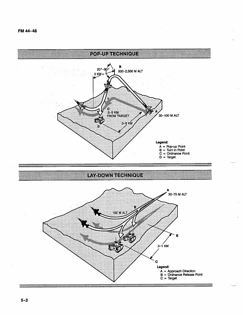
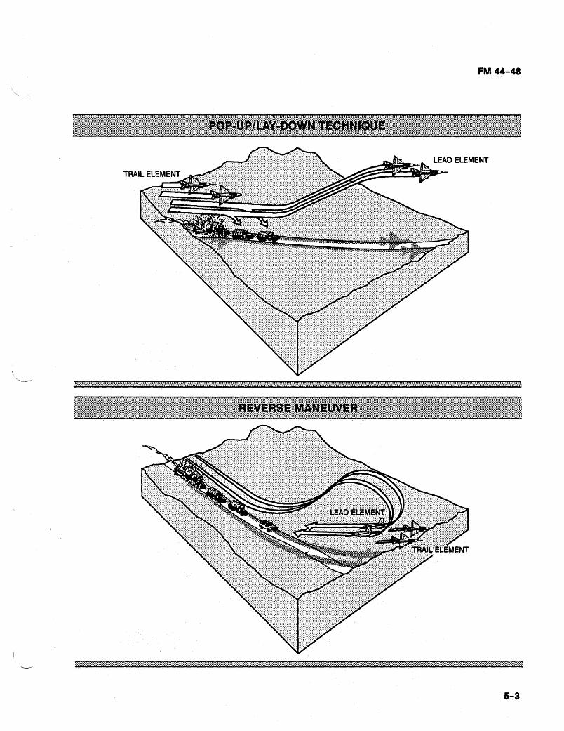
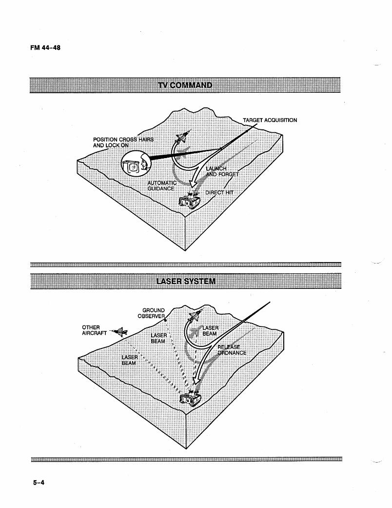
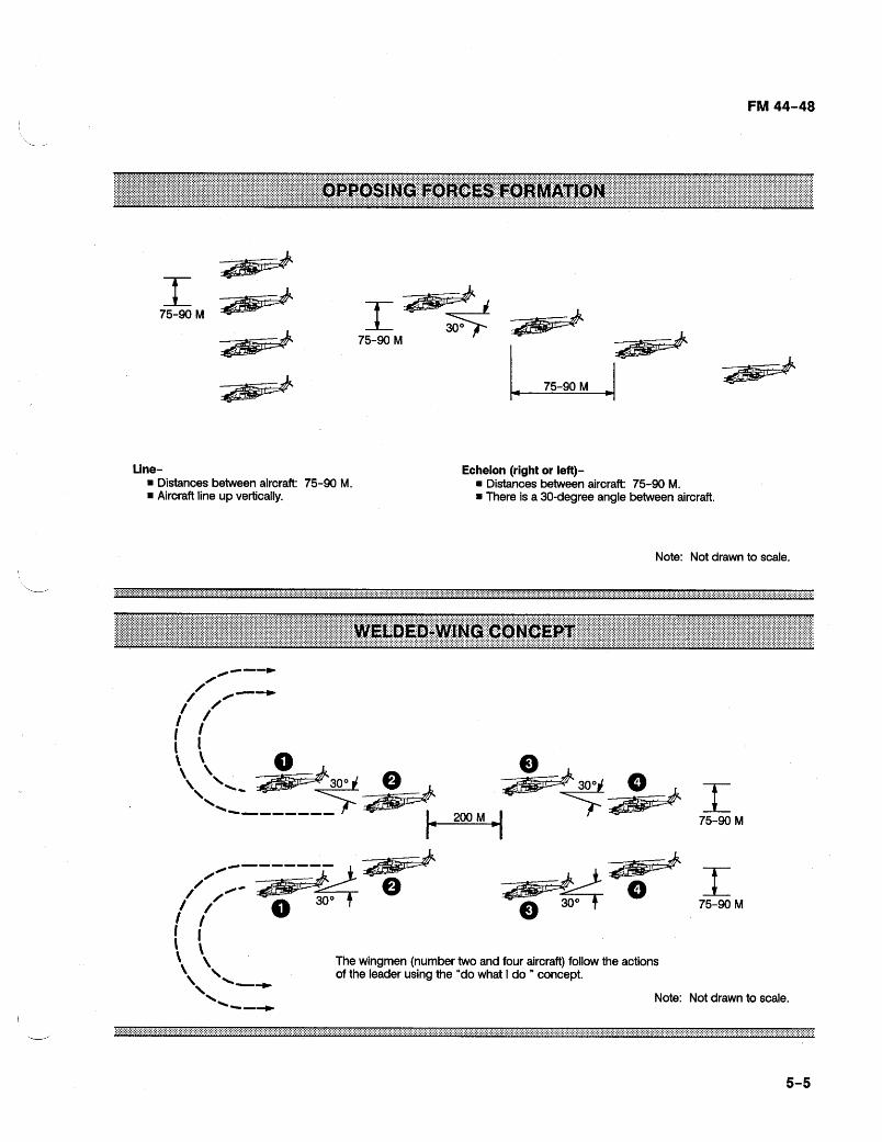
ATTACK PROFILESThe following illustrations show known profiles
for fixed- and rotary-wing formations and deliverymethods for conventional and smart munitions. Theseillustrations help the sensor section member deter-mine the action that an aircraft is conducting.
5-1
FM 44-48
200.B
500-2,500 M ALT
K(30-100 M ALT
Legend:A = Pop-up PointB = Turn in PointC = Ordnance PointD = Target
A30-75 M ALT
_C
Legend:A = Approach DirectionB = Ordnance Release PointC = Target
X -77:::::: i:: :: i~ii: I :....:::::::
5-2
:~:~:~:~::a; ~ :~::::: ~::: : I:~:g.s55.:S::.-i.'~~~:5ri :-~-: .::s:~ss ~--:-.~5------; .5 .~.~.s.~~ :::i # :s~s: a.~z:: ~:::~:. :,..,.... ..r ,,.,,.,,
;~m~c~mc m~'~c m*c"rr~ mC~::1:5 ~: 1::::~:::::::~:::~:::::::~:~:::~::~:~.::L.::U:: :' : : : .: :-. .-.- ~ : : .-. .-i.-:, 5 :,:~:d.::::::~::::::: :::::::~::::.-:: ":.l":':'1: f :1."".:::~:::': :::':'::
:~i:~:Si:~i~i~ig:.:":'f.Of~S~::~::::~~:~XS ::: :55 Si:# :~:X;:;i:::::S '~:~:5 :55..~. ' Y~:~:~ fX: :5 5:'"'"~ :a:ss;,. :: ; ~~: :~~:::~:: :~UR~:j ~:,,~~~ii i~i~j~~i~l8 i:Ti ::,,:,:::,:,:j:~:~:~:iu:f; rt ;~ ~~5 3Sii ~s .s r,- :5~0::::;~;:;:;~;:;:~: XS 5."i.i .i 2 ~:~~ ~:~:~W::5 iS f ;.i 5 i : : ::: f:SS;: :... : ::~~:: I".~ 5:S::::::~ ~:2..5 .1~~1~:~ : : ~ r i~i~i~~ij~ :::I.~:~x~:cb r. ..:.: :.. ..r ; .. ~:x ~: x:~:~:::~:::::::~::~::~:fP.ii:::::::~::~ ."'.'.' :s:: .t . :I :~ .~i..i:.tX f:S.f. ........ :....... ~: ~~:
FM 44-48
....:P Pw PIYu QW .... C.....QU..............*
LEAD ELEMENT
:;r :"::,.:.:.:':,.:'.: :;::;::::::}.:.:.*.:i ::.*:::*.*.: :::::..,'::;:: it:'. . . . . . . . ..::::f +:
.A N :::::
.:: *.*. *.* .*::: ::: ": : ::::::::::} :: ::.:::::*.*::::
5-3
FM 44-48
: XOX : X : : : : : :.: : .~:.XSS~:~:Sf~:~:~:~:::i~i~i~i~i~~::~:~:~:~~S YS X :OX .5'. 1.\'1.5 .'.n":~::~:::~::::~'.. : :~::::~::~:X::.f:Sp:f : ; ff:S : : :::.: li~iji~i~~iji::8::::~~:::::~::s' :~ ~::~:g.~~g*:~:sg:'.~: :t. tz.s . 2. "" ::'":::':~~i~8i:;:;:;: x;::i:~::~:~::::~.... i(iP~ WI :.:.:~.i:S~~f~2~( ~i.~'~ ~.~.~~.........~.6LI:;I ~~IICI~ ~;fC ): : ):f l: ~::::~~:~:C~-:ii8i:~:~:::~i:~:~: ::::::::::::~: ;:~:85i EiXlii~ :::::1::::~:8:~:~::~::::i::~X: 83 ~~ ,,,,,::::::,:,.::g:::~~;:;:': :;:' :~::::::i::::~~::: :~i~ i:~:~:~:~:s;: x;:;:~: ,: ,. i88~8~8~8i1 .... ~r::~zr :~:~:s x::i551;:;ts::~~::~s~:~ ::gg:::::~::.~::~:::: ~: K:~:~:~;:;:;X::;8;:;:::;:~83::~::::K:: i~i~~iJ:3i:~8i85#~i:::~::~::::#iili~gj.5;ff:S;:~: :z.~~s~ :.~ : :;:S'f '2:"': - R'' :~:~x.;': :~' ~ ~ ":::~:::::::~:~:::~:i~i~i~~i~~i~i~~wi~i~ii~i~i~~iii~i~i~~i~i
TARGET ACQUISITION
lASER SYSTEM..
5-4
:~:~:i::::~:::V:~~O::::::::::::~::::~:~:.~ ~. :~:~:~
FM 44-48
........ ....... ic:...: .....f'....'' ..... .................. t ........... :.....:".:...:..:.::.::::::;:::::::::::::::::.::.::::::::::::
I75-90 M
T 300 /75-90 M
75-90 M
Une-* Distances between aircraft: 75-90 M.
Aircraft line up vertically.
Echelon (right or left)-* Distances between aircraft: 75-90 M.* There is a 30-degree angle between aircraft.
Note: Not drawn to scale.
:"::~ '::: .... ::.......::::::::::::::::: ::::::::::::::"::::::::::
I/ ---
I 1
OO 04
- 200 MI75-90 M
I75-90 M
The wingmen (number two and four aircraft) follow the actionsof the leader using the "do what I do " concept.
Note: Not drawn to scale.
5-5
~8#:~:~:i:~85~855i:3~33~:~:~::.~~:5~:~
30
4tE43
GD
FM 44-48
REPORTINGThe ADA sensor section acts as the eyes and ears
of the ADA S2, leaders, and fire units. The ADAsensor section has the responsibility of reporting itemsout of the ordinary on the ground and in the air. Whenreporting on troop or vehicular movements, use thestandard SALUTE report. When reporting unknownaircraft, use the WEFT methods and fin flashdescriptions. If new ordnance is sighted, try to provideas much detail as possible without exaggeration. Suchitems as the size and depth of the crater are helpful, aswell as the type of launcher or platform used.
Under the fully automated FAAD C3I system,tracks will be automatically sent to the A2C 2 andABMOC from the AWACS. That information is thensent to the sensor C 2 nodes who in turn send it out to
their customers, that is, ADA batteries in support oftheir respective maneuver brigades. When resorting tomanual EW using MSCS, the ABMOC receives EWinformation from the sensor sections and the nearestHIMAD source; they correlate it then send it to therespective ADA batteries in support of the maneuverbrigades. This information is broadcasted over theDEW net and command nets. The communicationsused are the AM and FM radios. The AM is the ADAsensor net; it is used to send EW, NAI, TAI, and AAAinformation to the ABMOC. The FM is the commandnet. This net can also be used to send directed earlywarning according to the established SOP andMETI'-T.
5-6
APPENDIX A
ResponsibilitiesThe ADA sensor platoon provides early warning and alerting
information to the maneuver force through the ABMOC/BNTOC.To achieve this, the platoon leader and section members must behighly trained in the accomplishment of all their respective duties.They must have a clear understanding of the capabilities and limita-tions of their personnel and equipment to fully exploit the sensorsection's capabilities.
AIR DEFENSE COORDINATORThe ADCOORD coordinates the EW coverage of element cells know the locations of the sections. He is
HIMAD weapon systems. Also, he is responsible for responsible for providing the corps or division G2 withdeconflicting terrain problems for sensor sections. He the ADA sensor sections' PIRs.ensures that corps or division airspace management
BRIGADE OR TASK FORCE S3The brigade or task force S3 is responsible for
incorporating the sensor sections into the scheme ofmaneuver, when applicable. He assists in the coordina-tion of terrain management for the sections and plots
the location of the sections on the brigade operationsmap. He processes the EW information provided bythe sections for dissemination to maneuver forces.
ADA BATTALION S3The ADA S3 is responsible for planning the air
defense coverage of the maneuver force, anddeveloping the DST and DSM, and in conjunction withthe ADA S2, developing the R&S plan. He coordinatesthe terrain management of sensor sections' positionsand plots their locations on the battalion operationsoverlay. He coordinates the sensor section movementand keeps the ADCOORD informed of the
PageAir Defense Coordinator . .......... . .A.
rigade or Task Force S3 .A.. ... .. .......... . '1
ADA Battalion 53 A 1ADA Battalion S2 A1 1
.. .. . :. . . ........... . ...:: .....
Platoon Sergeant: > < .. a: 2...Section Chief 2 i i . i f . . .ii .iiii ::ii.. . ..i.i ? . .. .. i A
movement. Additionally, he incorporates the sensorsections into the ADA scheme of maneuver.
The ADA battalion S3 disseminates the rules ofengagement for ADA assets and ensures that they areunderstood by all ADA soldiers. He will establish andmaintain communications with the sensor platoon. Heprocesses all information that is provided by the ADAsensor sections.
ADA BATTALION S2The S2 is responsible for the air and ground IPB.
He will develop the air order of battle and assist thecommander in the development of PIRs. He templatespossible enemy FARPs and LZs and identifies NAIsand TAIs. He will integrate the sensor platoon into thebrigade or TF R&S plan and works with the S3 todevelop the ADA battalion R&S plan in consultationwith the battalion commander and sensor platoonleader. The primary purpose of the R&S plan is toanswer the commander's PIRs. In addition, the S2processes the information provided by the sensorsections and updates his IPB, as appropriate.
A-1
FM 44-48
Based upon the intelligence and early warningrequirements, the S2 should accomplish the followingactions in developing the collection plan:
* Break down PIR and information require-ment into specific indicators on which R&S assets cancollect. Each asset should be told exactly what to lookfor ( such as, activation of enemy air defense radars,launching of fixed-wing aircraft, et cetera).
* Associate specific NAI to each indicator.
* Locate grid coordinates or designate pointsfor each NAI.
* Determine the time (not earlier than and notlater than) or trigger point for activation or surveil-lance for collection assets.
* Provide specific orders to each collection asset(such as, reporting format and what to report).
* Maintain a list of available collection agencies(organic, adjacent, and higher) on the collection plan(such as HIMAD, sensor sections, batteries, jointsurveillance target attack radar system (JSTARS),liaison elements, maneuver scouts, and otherintelligence assets).
* Develop an R&S overlay, matrix, or other ap-propriate tool to ensure integration of organic and ex-ternal assets and to preclude gaps in coverage.
* Ensure that appropriate control measures areincluded in maneuver unit plans to protect sensor sec-tions and prevent fratricide by friendly units.
PLATOON LEADERThe sensor platoon leader employs his forces in
coordination with the S2 and S3 to best collectinformation on assigned NAIs. He is responsible forthe discipline and training of his platoon. He isresponsible for developing his soldiers into an effectivefighting force capable of performing its combatmission. Additionally, he is responsible for aiding theS2 in the development of the ADA R&S plan.
The platoon leader works closely, and coordi-nates, with the ADAbattalion S2 and S3 to develop and
implement the R&S plan. He must coordinate theterrain management plan for the positions of hissections.
Once the battalion commander has approved theR&S plan, the platoon leader is responsible forestablishing and maintaining communications links tothe ADA battalion and the sensor sections. Hepositions his sections per the R&S plan. The platoonleader locates on the battlefield where he can bestcontrol his assets.
PLATOON SERGEANTThe platoon sergeant is second in command of the
platoon. He must be proficient in all of the tasksnormally accomplished by the platoon leader. He mustbe prepared to assume the responsibilities of theplatoon leader at a moment's notice. He must ensurethat section members are trained to perform theirduties for their combat mission.
The platoon sergeant is responsible to the platoonleader for the maintenance, logistics, and discipline ofthe platoon. He is responsible for the coordination ofall logistical and maintenance support the platoonrequires. The platoon sergeant must work in closecoordination with the platoon leader to ensure unity ofeffort.
SECTION CHIEFThe section chief is responsible to the platoon
leader and platoon sergeant for the training, discipline,and tactical employment of his sensor sections.Although the platoon leader designates the area forpositioning the sensor sections according to theguidance from the S2 and S3, the section chief isresponsible for the selection of the specific site wherethe section will emplace. He Coordinates with the
platoon sergeant for resupply and maintenance sup-port of his sections. He is responsible for themaintenance of all assigned equipment. He submits alltactical and logistical reports. He is responsible for thereporting of PIRs, NAIs, TAIs, and AAAs, andproviding EW to the ABMOC who in turn will sendthat information to the ADA batteries and theirrespective maneuver brigades.
A-2
APPENDIX B
Observation TechniquesThis appendix is an overview of observation techniques and
equipment. The last part of this appendix deals with tactical usesof night vision devices (NVDs) and training tips. Although theprime reference is night operations, the material also applies tolimited visibility operations (fog, rain, snow, and sandstorms).
OBSERVATION - DAYLIGHT TECHNIQUESAn observer's capability to detect aircraft in-
creases as the size of the search sector assigneddecreases. Detection is more likely if an observer isassigned responsibility for searching a narrow sectorthan if he is responsible for searching the entire areasurrounding his position. If an alert warning system is
~i :::n:~:::% = :: .... ...... ........~i~C.NTENT$
:Page...
Oservation Daylig 'ht Techniques::< B I.:::;0 . ... ... . .:::..: :...;:...;:.:.. .:.; .:. q ... .. . ... .. .... ....
i:~:~:~~8.. ~ x,,.,gn8::.... .......................... ....... . ....:..::.: :.:.. """"'
Observation4 N ight and LoJwLgh...:: : :;> ..::.::.. ....: :: ....... ..... ::..... .. .: ..:.. .. .:::: :::::.::.
015eratIon- .E liprent.<>> > ... 8:<
Q .. P ..:.. ... .... ... .... ... .... ... .... ... .... .. ... :.: ..:
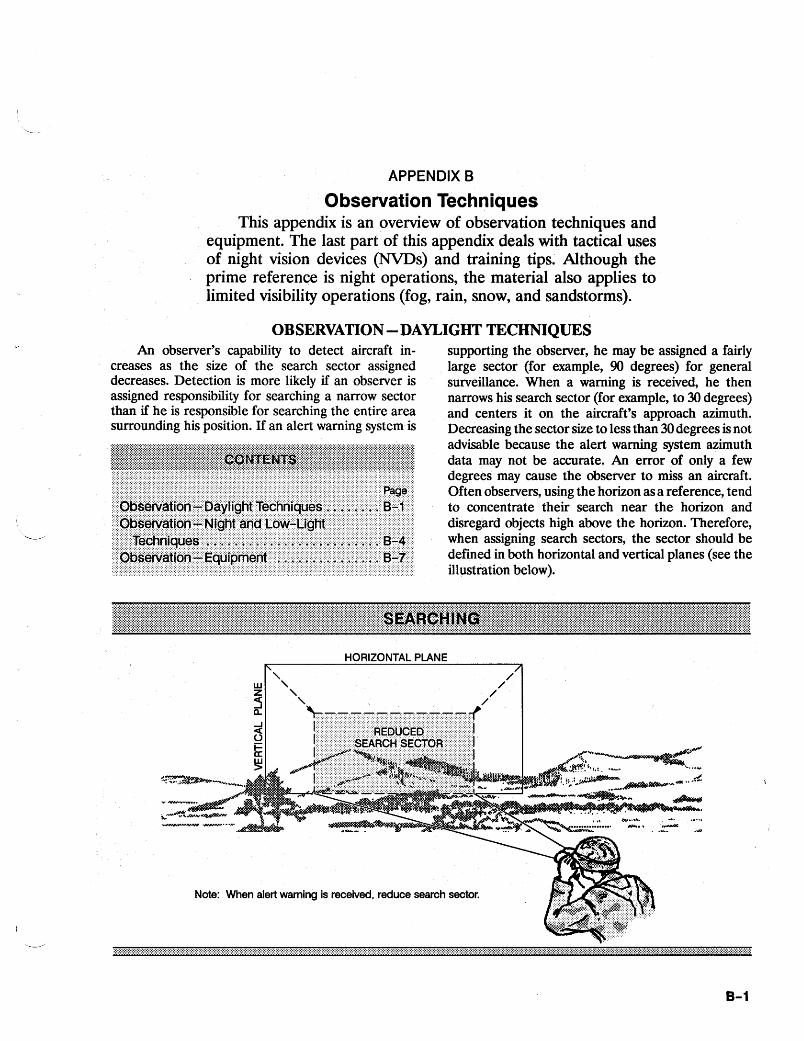
supporting the observer, he may be assigned a fairlylarge sector (for example, 90 degrees) for generalsurveillance. When a warning is received, he thennarrows his search sector (for example, to 30 degrees)and centers it on the aircraft's approach azimuth.Decreasing the sector size to less than 30 degrees is notadvisable because the alert warning system azimuthdata may not be accurate. An error of only a fewdegrees may cause the observer to miss an aircraft.Often observers, using the horizon as a reference, tendto concentrate their search near the horizon anddisregard objects high above the horizon. Therefore,when assigning search sectors, the sector should bedefined in both horizontal and vertical planes (see theillustration below).
~ 2 ~~0~~~9 ."5.2.55..1...2."2"" 2 5 5 2f : a: ::~::::~:8:~:s~:~:::: :s8:~:F:~::: :s #6:~:~:~:~:~:::~:~:~::;: .~:.:~::: ~~0::::::~:~::~:~:~:~8~8~:~:~: ,,,ss :.::~:~::::::~i~i::::::a#,,~:~:~gl::R:::~:~:~~:~::~::~~~~: ~:~~#iiiiii~:~~:~:::~: ~~~.: i"~~:::~:~::~:~:~:~:~:~:~:::i:::w::s::::::::~:~::~::::~kii ;: :::~:~:~~:r#:~s#s3#:~8#.: : xo: :s:: xr : x : : : : : : : ::: :j::::~: ::::::s ~ :::::::::::::: : :s.: : ;: X:~::~:~:~::~:S~W.: : ~a~saxs :~ ,~~~
HORIZONTAL PLANE
Note: When alert warning is received, reduce search sector.
B-1
~:~:~:~:~~~~:~:~:~~:~:~:~~i:~~3~:~85~:~8
FM 44-48
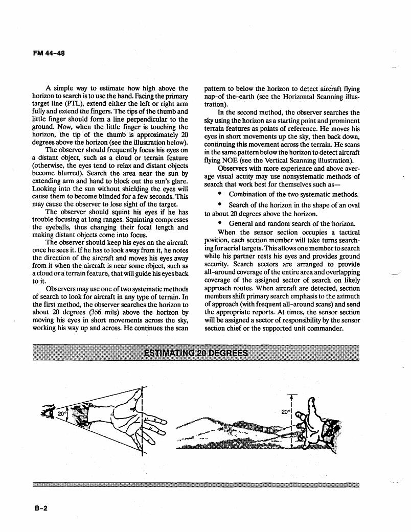
A simple way to estimate how high above thehorizon to search is to use the hand. Facing the primarytarget line (PTL), extend either the left or right armfully and extend the fingers. The tips of the thumb andlittle finger should form a line perpendicular to theground. Now, when the little finger is touching thehorizon, the tip of the thumb is approximately 20degrees above the horizon (see the illustration below).
The observer should frequently focus his eyes ona distant object, such as a cloud or terrain feature(otherwise, the eyes tend to relax and distant objectsbecome blurred). Search the area near the sun byextending arm and hand to block out the sun's glare.Looking into the sun without shielding the eyes willcause them to become blinded for a few seconds. Thismay cause the observer to lose sight of the target.
The observer should squint his eyes if he hastrouble focusing at long ranges. Squinting compressesthe eyeballs, thus changing their focal length andmaking distant objects come into focus.
The observer should keep his eyes on the aircraftonce he sees it. If he has to look away from it, he notesthe direction of the aircraft and moves his eyes awayfrom it when the aircraft is near some object, such asa cloud or a terrain feature, that will guide his eyes backto it.
Observers may use one of two systematic methodsof search to look for aircraft in any type of terrain. Inthe first method, the observer searches the horizon toabout 20 degrees (356 mils) above the horizon bymoving his eyes in short movements across the sky,working his way up and across. He continues the scan
pattern to below the horizon to detect aircraft flyingnap-of the-earth (see the Horizontal Scanning illus-tration).
In the second method, the observer searches thesky using the horizon as a starting point and prominentterrain features as points of reference. He moves hiseyes in short movements up the sky, then back down,continuing this movement across the terrain. He scansin the same pattern below the horizon to detect aircraftflying NOE (see the Vertical Scanning illustration).
Observers with more experience and above aver-age visual acuity may use nonsystematic methods ofsearch that work best for themselves such as-
* Combination of the two systematic methods.
* Search of the horizon in the shape of an ovalto about 20 degrees above the horizon.
* General and random search of the horizon.When the sensor section occupies a tactical
position, each section member will take turns search-ing for aerial targets. This allows one member to searchwhile his partner rests his eyes and provides groundsecurity. Search sectors are arranged to provideall-around coverage of the entire area and overlappingcoverage of the assigned sector of search on likelyapproach routes. When aircraft are detected, sectionmembers shift primary search emphasis to the azimuthof approach (with frequent all-around scans) and sendthe appropriate reports. At times, the sensor sectionwill be assigned a sector of responsibility by the sensorsection chief or the supported unit commander.
.. ESTIMATING 20 DEGRS
B-2
~:~:~8i8~:~:~8~883~:~:~:W~:#X#:~83i
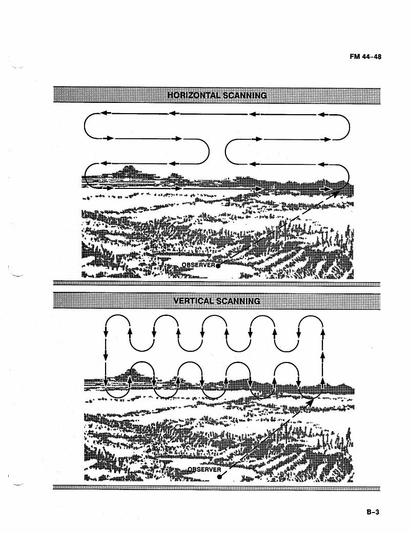
FM 44-48
. ....... ****.*.* *"..:. * .* .. ..... ............ .. .. . . . . . . . . . .**. **... ...
... .. .*.......*......................... ... . ....... ....... ............. K 0 R.......a z ...n......
. . .
VERTICALSCAtEt4IRQ......................
(C> {C> (C> (C>+ + + + + + + + + +It) K) K) K) I
B-3
FM 44-48
WHERE TO SEARCH
A map reconnaissance of the supported unit'sdirection of movement or area of operation will helpto pinpoint areas from which aircraft are most likely toattack the unit. Mark the far sides of wood lines, ridgelines, and significant folds in the terrain out to at least3,000 to 5,000 meters. This is where attack helicopterscan lie in wait at the maximum range of their antitankguided missiles (ATGMs). Mark restricting terrain,defiles, and narrow valleys where the maneuver unitmay be forced to pinch together, becoming lucrativetargets for air attack.
TELL-TALE SIGNATURESMany aircraft have tell-tale signatures which can
lead to early detection. Sensor sections should look forthe following:
" Sun reflection from aircraft canopies or cock-pit windows.
" Blade flash from rotating helicopter blades." Smoke or vapor trails from jet aircraft and mis-
siles or rockets fired from aircraft." Dust or excessive movement of tree tips and
bushes in a particular area." Noise from helicopter blades or from jets
breaking the sound barrier.
OBSERVATION -NIGHT AND LOW-LIGHT TECHNIQUESObservation at night and in low-light conditions
differs greatly from the observation techniques usedduring daylight hours. The following paragraphsdiscuss the impact of night and low-light conditions onthe ADA sensor section.
DARKNESS INCREASESTHE SOLDIER'S SENSE OF FEAR
The ADA sensor section's isolation may lead to afeeing of impending peril. The section memberimagines dangers and may panic under sudden stress.He has a tendency to doubt the unknown. The unseenenemy increases his fear at night. Isolation reducescombat efficiency. During night or limited visibilityconditions, isolation is intensified. Even small dis-tances between individuals are exaggerated at night.
The ability to function and fight at night is directlyrelated to individual skills, unit teamwork, and confi-dence in leaders. Confidence is built through practiceand unit cohesiveness. Skill, will, and teamworkdevelop sections which can operate effectively at night.
PHYSICAL FACTORSOF NIGHT OPERATIONS
Just as the night affects the mind, it also affects thesenses of sight, hearing, and smell. Maximizing thecapabilities of the senses enhances the ability to fightat night. Improving the senses of hearing and smellingrequires training; vision is maximized by understandinghow the eye operates at night and how to efficiently useits capabilities.
Night VisionThe eye's vision at night is different from daytime
vision. At night, it sees with spiral eye cells called rods.
Rods cannot differentiate color and are easily blindedwhen exposed to light. This creates a central blind spotwhich causes larger and larger objects to be missed asdistances increase (see the Central Vision-NightBlind Spot illustration).
Protecting Night VisionWhile working and performing tasks in daylight,
the exposure to light directly affects night vision, andrepeated exposure to bright sunlight has an increasing-ly adverse effect on dark adaptation. Exposure tointense sunlight for two to five hours causes a definitedecrease in visual sensitivity which can persist for aslong as five hours. This effect can be intensified byreflective surfaces such as sand and snow. At the sametime, the rate of dark adaptation and degree of nightvision capability will be decreased. Since these effectsare cumulative and may persist for several days,military neutral density (N-15) sunglasses or equiva-lent filter lenses should be used in bright sunlight whennight operations are anticipated.
Night Vision ScanningDark adaptation or "night vision" is only the first
step toward maximizing the ability to see at night. Nightvision scanning can enable soldiers to overcome manyof the physiological limitations of their eyes and canreduce the visual illusions that so often confuse theobservers. The technique involves scanning from rightto left or left to right using a slow, regular scanningmovement (see the Typical Scanning Patterns illustra-tion). Although both day and night searches employscanning movements, at night it is essential to avoidlooking directly at a faintly visible object when tryingto confirm its presence.
B-4
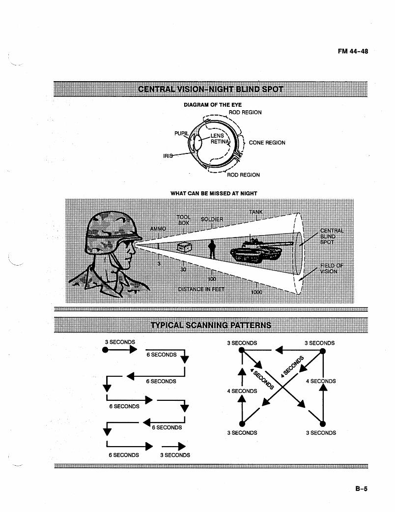
FM 44-48
DIAGRAM OF THE EYEROD REGION
CONE REGION
WHAT CAN BE MISSED AT NIGHT
3 SECONDS
6 SECONDS
6 SECONDS
6 SECONDS
6 SECONDS
6 SECONDS
3 SECONDS 3 SECONDS
4 SECONDS
3 SECONDS 3 SECONDS
3 SECONDS
B-5
::: : ':~::j ::~5:.:.:.:C:i' 1 -55 21 I ~ 1~ ' m-~---~;-- .-: ~ - ~,: rt~ t. ~ t f t 5i .~1: .:~::::::::~::::::::::::::::~::~:: j::::
:~:~:~8:~:~:~::~8~i::8#8~18~:~:~:~:~1#1
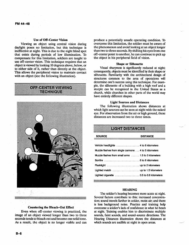
FM 44-48
Use of Off-Center VisionViewing an object using central vision during
daylight poses no limitation, but this technique isineffective at night. This is due to the night blind spotthat exists during periods of low illumination. Tocompensate for this limitation, soldiers are taught touse off-center vision. This technique requires that anobject is viewed by looking 10 degrees above, below, orto either side of it, rather than directly at the object.This allows the peripheral vision to maintain contactwith an object (see the following illustration).
Countering the Bleach-Out EffectEven when off-center viewing is practiced, the
image of an object viewed longer than two to threeseconds tends to bleach out and become one solid tone.As a result, the object is no longer visible and can
produce a potentially unsafe operating condition. Toovercome this limitation, the soldier must be aware ofthe phenomenon and avoid looking at an object longerthan two to three seconds. By shifting his eyes from oneoff-center point to another, he can continue to pick upthe object in his peripheral field of vision.
Shape or SilhouetteVisual sharpness is significantly reduced at night;
consequently, objects must be identified by their shape orsilhouette. Familiarity with the architectural design ofstructures common to the area of operations willdetermine one's success using this technique. For exam-ple, the silhouette of a building with a high roof and asteeple can be recognized in the United States as achurch, while churches in other parts of the world mayhave entirely different shapes.
Light Sources and DistancesThe following illustration shows distances at
which light sources can be seen at night with the nakedeye. For observation from the air or high ground, thesedistances are increased two to three times.
SOURCE DISTANCE
Vehicle headlights ................. 4 to 8 kilometers
Muzzle flashes from single cannons ... 4 to 5 kilometers
Muzzle flashes from small arms ...... 1.5 to 3 kilometers
Bonfire ........................ 6 to 8 kilometers
Flashlight ...................... up to 2 kilometers
Lighted match .................... up to 1.5 kilometers
Lighted cigarette .................. 0.5 to 0.8 kilometers
HEARINGThe soldier's hearing becomes more acute at night.
Several factors contribute to this: increased concentra-tion; sound travels farther in colder, moist air; and thereis less background noise. Practice and training helpovercome a soldier's lack of confidence in what he hearsat night. Training enables him to discriminate multiplesounds, faint sounds, and sound-source directions. TheHearing Distances illustration shows the distances atwhich sounds are audible at night in open areas.
B-6
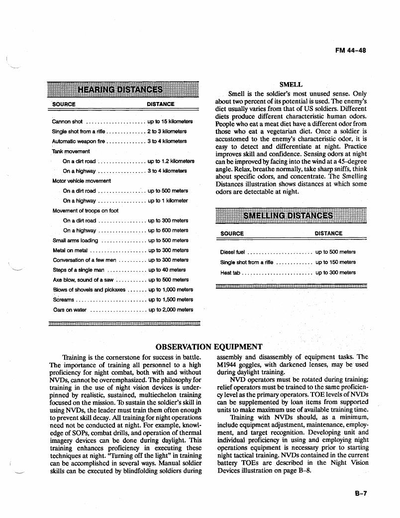
FM 44-48
SOURCE DISTANCE
Cannon shot ................. up to 15 kilometers
Single shot from a rifle .............. 2 to 3 kilometers
Automatic weapon fire .............. 3 to 4 kilometers
Tank movement
On a dirt road .............. up to 1.2 kilometers
On a highway ............... 3 to 4 kilometers
Motor vehicle movement
On a dirt road ................. up to 500 meters
On a highway .............. up to 1 kilometer
Movement of troops on foot
On a dirt road ................ up to 300 meters
On a highway ................. up to 600 meters
Small arms loading ................ up to 500 meters
Metal on metal ................ up to 300 meters
Conversation of a few men .......... up to 300 meters
Steps of a single man ............. up to 40 meters
Axe blow, sound of a saw ......... up to 500 meters
Blows of shovels and pickaxes ....... up to 1,000 meters
Screams ........................ up to 1,500 meters
Oars on water .................... up to 2,000 meters
::: :::: ::: ::: ::: :::: :::: ::: ::: ::: :::: ::: ::: ::: :::: :::: ::: ::: ::: :::: :::
SMELLSmell is the soldier's most unused sense. Only
about two percent of its potential is used. The enemy'sdiet usually varies from that of US soldiers. Differentdiets produce different characteristic human odors.People who eat a meat diet have a different odor fromthose who eat a vegetarian diet. Once a soldier isaccustomed to the enemy's characteristic odor, it iseasy to detect and differentiate at night. Practiceimproves skill and confidence. Sensing odors at nightcan be improved by facing into the wind at a 45-degreeangle. Relax, breathe normally, take sharp sniffs, thinkabout specific odors, and concentrate. The SmellingDistances illustration shows distances at which someodors are detectable at night.
SMELLN.G DI$TANCE$
SOURCE DISTANCE
Diesel fuel .................... up to 500 meters
Single shot from a rifle ............. up to 150 meters
Heat tab ....................... up to 300 meters
* : ::8 : :x: : : : : ! ::::::: :
OBSERVATION EQUIPMENTTraining is the cornerstone for success in battle.
The importance of training all personnel to a highproficiency for night combat, both with and withoutNVDs, cannot be overemphasized. The philosophy fortraining in the use of night vision devices is under-pinned by realistic, sustained, multiechelon trainingfocused on the mission. To sustain the soldier's skill inusing NVDs, the leader must train them often enoughto prevent skill decay. All training for night operationsneed not be conducted at night. For example, knowl-edge of SOPs, combat drills, and operation of thermalimagery devices can be done during daylight. Thistraining enhances proficiency in executing thesetechniques at night. "Turning off the light" in trainingcan be accomplished in several ways. Manual soldierskills can be executed by blindfolding soldiers during
assembly and disassembly of equipment tasks. TheM1944 goggles, with darkened lenses, may be usedduring daylight training.
NVD operators must be rotated during training;relief operators must be trained to the same proficien-cy level as the primary operators. TOE levels of NVDscan be supplemented by loan items from supportedunits to make maximum use of available training time.
Training with NVDs should, as a minimum,include equipment adjustment, maintenance, employ-ment, and target recognition. Developing unit andindividual proficiency in using and employing nightoperations equipment is necessary prior to startingnight tactical training. NVDs contained in the currentbattery TOEs are described in the Night VisionDevices illustration on page B-8.
B-7
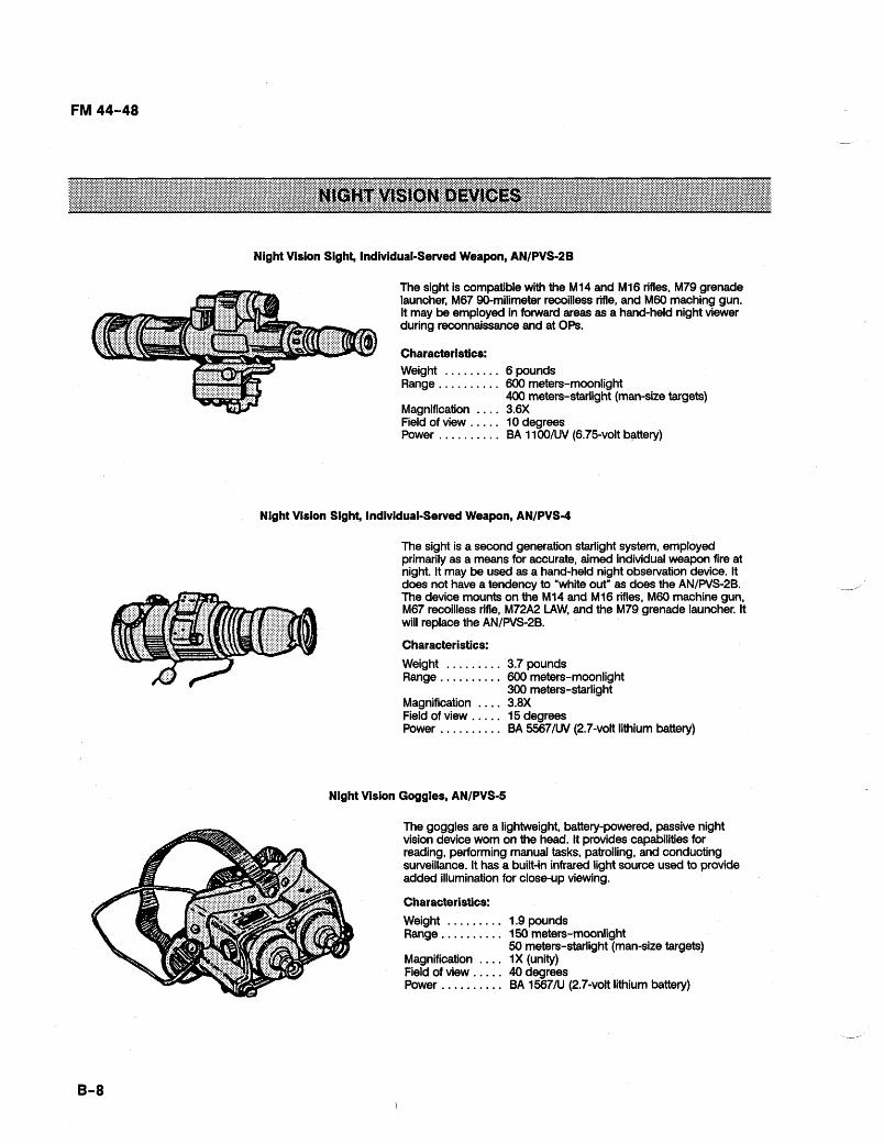
FM 44-48
If .~..; : -- " - -m lr :.:rst. . .s :. ..i.r .i. ....rr ..:.:.:.:.:. ~..2 ..: :~s;: ~::::ns~i83~:s~:~:~ ~:p::::::::ii: ;f.hr:ss~::~:::::~:::::::: XS :::~::~: ;: 5 : :f; ~;: ~;: :2 5 .;5 : : : : X :: : : : i ~5 ; XC ~~ ~: 55 :i 5 2.i~~~ : : rX.r: : :I: 5 ' ;;;:;XiX : :~~~~: : : f: : ~;:;: : : ~~ f: ~f: iX~j ~i:#i8i::X::: ~:~i~~jiiiii~~~iii~ ~~~:S#a;~::~:~:~:::.:~::;x :~::::~:.~iiii fX.rX~.~:~.2.5~2 i~0:~S 5'~:t' \s .2";iI: ~zz.s -: 5~~~~:;:~f.:.~ : ' ' 5::.r :: 3 :a:~."2. ~~P:f ~i8ii8S:~xr: :x: ' ' : :
Night Vision Sight, Individual-Served Weapon, AN/PVS-2B
The sight is compatible with the M14 and M16 rifles, M79 grenadelauncher, M67 90-milimeter recoilless rifle, and M60 maching gun.It may be employed in forward areas as a hand-held night viewerduring reconnaissance and at OPs.
Characteristics:Weight .........Range..........
Magnification ....Field of view .....Power ..........
6 pounds600 meters-moonlight400 meters-starlight (man-size targets)3.6X10 degreesBA 1100/UV (6.75-volt battery)
Night Vision Sight, Individual-Served Weapon, AN/PVS-4
The sight is a second generation starlight system, employedprimarily as a means for accurate, aimed individual weapon fire atnight. It may be used as a hand-held night observation device. Itdoes not have a tendency to "white out" as does the AN/PVS-2B.The device mounts on the M14 and M16 rifles, M60 machine gun,M67 recoilless rifle, M72A2 LAW, and the M79 grenade launcher. Itwill replace the AN/PVS-2B.
Characteristics:
Weight .........Range..........
Magnification ....Field of view .....Power ..........
3.7 pounds600 meters-moonlight300 meters-starlight3.8X15 degreesBA 5567/UV (2.7-volt lithium battery)
Night Vision Goggles, AN/PVS-5
The goggles are a lightweight, battery-powered, passive nightvision device worn on the head. It provides capabilities forreading, performing manual tasks, patrolling, and conductingsurveillance. It has a built-in infrared light source used to provideadded illumination for close-up viewing.
Characteristics:
Weight .........Range ..........
Magnification ....Field of view .....Power ..........
1.9 pounds150 meters-moonlight50 meters-starlight (man-size targets)1X (unity)40 degreesBA 1567/U (2.7-volt lithium battery)
B-8
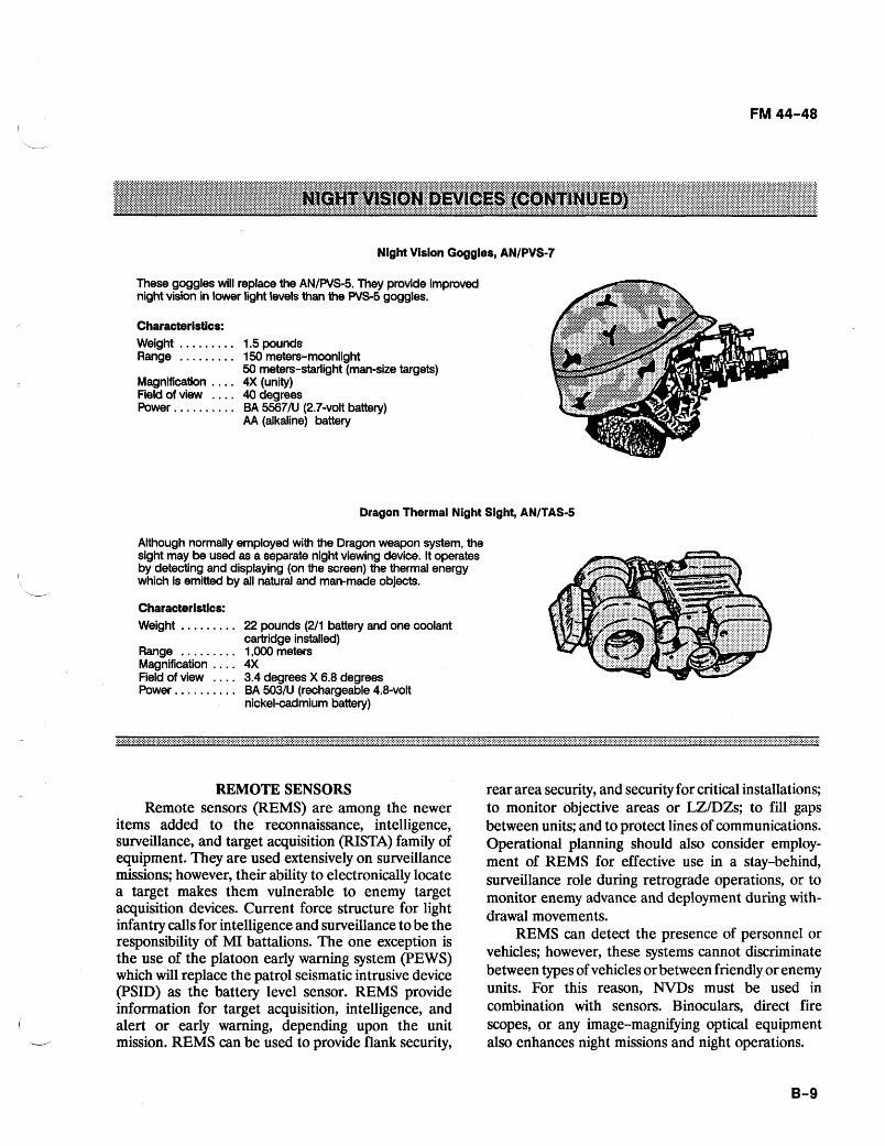
FM 44-48
Night Vision Goggles, AN/PVS-7
These goggles will replace the AN/PVS-5. They provide improvednight vision in lower light levels than the PVS-5 goggles.
Characteristics:Weight .........Range .........
Magnification ....Field of view ....Power ..........
1.5 pounds150 meters-moonlight50 meters-starlight (man-size targets)4X (unity)40 degreesBA 5567/U (2.7-volt battery)AA (alkaline) battery
Dragon Thermal Night Sight, AN/TAS-5
Although normally employed with the Dragon weapon system, thesight may be used as a separate night viewing device. It operatesby detecting and displaying (on the screen) the thermal energywhich is emitted by all natural and man-made objects.
Characteristics:Weight .........
Range .........Magnification ....Field of view ....Power ..........
22 pounds (2/1 battery and one coolantcartridge installed)1,000 meters4X3.4 degrees X 6.8 degreesBA 503/U (rechargeable 4.8-voltnickel-cadmium battery)
REMOTE SENSORSRemote sensors (REMS) are among the newer
items added to the reconnaissance, intelligence,surveillance, and target acquisition (RISTA) family ofequipment. They are used extensively on surveillancemissions; however, their ability to electronically locatea target makes them vulnerable to enemy targetacquisition devices. Current force structure for lightinfantry calls for intelligence and surveillance to be theresponsibility of MI battalions. The one exception isthe use of the platoon early warning system (PEWS)which will replace the patrol seismatic intrusive device(PSID) as the battery level sensor. REMS provideinformation for target acquisition, intelligence, andalert or early warning, depending upon the unitmission. REMS can be used to provide flank security,
rear area security, and security for critical installations;to monitor objective areas or LZ/DZs; to fill gapsbetween units; and to protect lines of communications.Operational planning should also consider employ-ment of REMS for effective use in a stay-behind,surveillance role during retrograde operations, or tomonitor enemy advance and deployment during with-drawal movements.
REMS can detect the presence of personnel orvehicles; however, these systems cannot discriminatebetween types of vehicles or between friendly or enemyunits. For this reason, NVDs must be used incombination with sensors. Binoculars, direct firescopes, or any image-magnifying optical equipmentalso enhances night missions and night operations.
B-9
Z.'.'.'.'"'Z:.'.555' f 5:5 :5 XSS : f: ~lf:SS XS X ::~:~:~g~:~i ~fZ ":" ~:::~~:s~s : ... :;,,,,:::::. ::::,,,~.'f~ ~:~;S~S : ~.:.:.m:.:tS.: j~*:~t;:;:; ;~.~~.sis.;..'.5".'5'.'.'~:.:.: : : ~ : X : : f: : 1~~~ : : :;: :s.: :;:n :;: s:~8~~:~I:i .xs~s ~*~ .~; .~XS f: I: : 5'".'.555:.Xs.:~:~:.:~:~:~: X::~:~:::~:~:: :~::~::~::~::~::~::~::~:~:~::: :5 :5 : :55::~:::::~:~;X~ ~ZZ tl S Y~i~ii~i~.~i:I~i~:~:~:~:~:~:~:~:~:~:~~~:~ 'f: :;: : :~:~::l::68~8" ~.::sE:3:~::::::~:~~i:~s:i:i:3::~P"s::e:5:~:~i8::::::::::::::::::~:::::::
- ~i~ ~t r ~,,..,&~?~ ~~ .nB" ' i ~- I 1~2.~ .s
:::~:~:~:~:~:~:~:~:~:~:'~:~:~: : :~:~:s .s~~ ~~r; :Fr ~~S : ::: .:.:.-............... .;. ::::::::il:::l;..rs.:~~ ~i ; ;.i..~~1::81 ;ui~~~$iS~ ;i~:~~.:i:~~ ~: ": :"":'~ ~ "~~i~i~i ~:~~:~:: :~8~8ii8i:~895igi:i:Sii:::i :: :~ ~~~~~;~:~~~ ~-~rz.S~X~~ z.s~5~::~:~:~:~:~:::::~::~::~::::~::~:~:~:: : ~5 ~ ~::::~:~::~:::::~:8:::::::::8:::::: :~::::::::::::R:::::::::::::::::::~::~:: t ~t :~: ::::::i:::i:~::::~~:~i::::::::::5:3i8~8
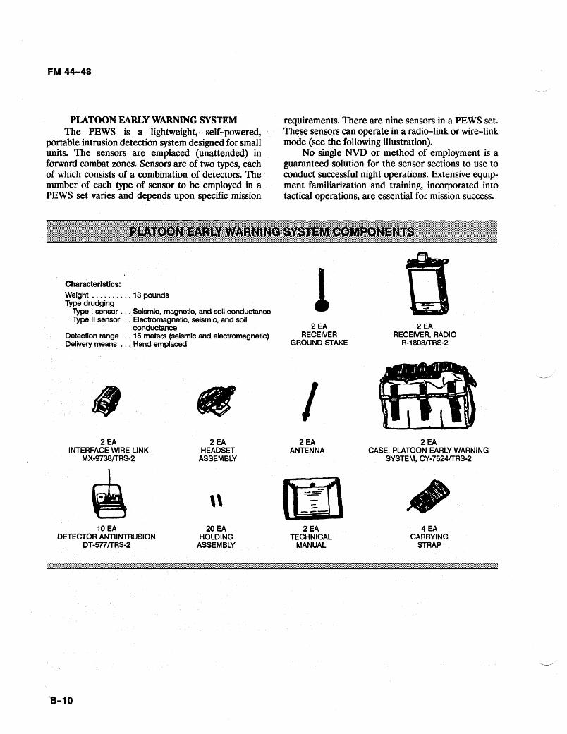
FM 44-48
PLATOON EARLY WARNING SYSTEMThe PEWS is a lightweight, self-powered,
portable intrusion detection system designed for smallunits. The sensors are emplaced (unattended) inforward combat zones. Sensors are of two types, eachof which consists of a combination of detectors. Thenumber of each type of sensor to be employed in aPEWS set varies and depends upon specific mission
requirements. There are nine sensors in a PEWS set.These sensors can operate in a radio-link or wire-linkmode (see the following illustration).
No single NVD or method of employment is aguaranteed solution for the sensor sections to use toconduct successful night operations. Extensive equip-ment familiarization and training, incorporated intotactical operations, are essential for mission success.
22~~":~~ 3 ~ ~~~~~ ~s~ ~; : :fs sx: :f :;:~: I:s~:.: :~:~:;:;: .~ z;r~~ ~~ ~~~: ~R~~ ~s~ W ~~f :~:;5 .f22 5 :~:.::~:~:~~~::~:::~ :~:;:;:~::~:j:::~~8~:~:~:~:::~::~:~::::~ :; : ~f~ : :.X : ~ :~: f : i ;: :S : X :.: :r~ ~ X:5 ~~:~:~i#18:: :5 :~:Q:~~ : :S ~': ::~:~:~:b;f5';. OXS ?L~ ~ .: :f.:;:S S :S ii ~5fS ;";:."s :~::~:)#: xs~: :~.Q:~#:~:: :s;:;: :a:~:sx: ~: .:~ ~;X~g~:~,:~5 "~*:~:fs:~.:~:~:~:~:~::~:~:.~:Sb~:~:~:~:.~..;~;~ :Ss:.:~2.:.st .i.ns f : z'z:2:~2:~izz''''"- s.z.s~p ~5 ~ r.ss~w~i: ::::~:,,:;~;:;:,,z~t;:~., ,:.:.~:~ri ~: : 5 ~Rr~ ~':~:'~:~::~:::~: ~ :s:~gl:::#8#~
Characteristics:Weight .......... 13 poundsType drudging
Type I sensor ... Seismic, magnetic, and soil conductanceType II sensor .. Electromagnetic, seismic, and soil
conductanceDetection range .. 15 meters (seismic and electromagnetic)Delivery means ... Hand emplaced
2 EARECEIVER
GROUND STAKE
I2 EA
RECEIVER, RADIOR-1808/TRS-2
2 EAINTERFACE WIRE LINK
MX-9738/TRS-2
10 EADETECTOR ANTIINTRUSION
DT-577/TRS-2
2 EAHEADSETASSEMBLY
20 EAHOLDING
ASSEMBLY
2 EAANTENNA
2 EATECHNICAL
MANUAL
2 EACASE, PLATOON EARLY WARNING
SYSTEM, CY-7524/TRS-2
4 EACARRYING
STRAP
B-10
Is ~:::::~8i8~::::~::8~8:~183i:::::~:~
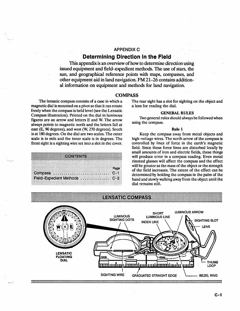
APPENDIX C
Determining Direction in the FieldThis appendix is an overview of how to determine direction using
issued equipment and field-expedient methods. The use of stars, thesun, and geographical reference points with maps, compasses, andother equipment aid in land navigation. FM 21-26 contains addition-al information on equipment and methods for land navigation.
COMPASSThe lensatic compass consists of a case in which a
magnetic dial is mounted on a pivot so that it can rotatefreely when the compass is held level (see the LensaticCompass illustration). Printed on the dial in luminousfigures are an arrow and letters E and W. The arrowalways points to magnetic north and the letters fall ateast (E, 90 degrees), and west (W, 270 degrees). Southis at 180 degrees. On the dial are two scales. The outerscale is in mils and the inner scale is in degrees. Thefront sight is a sighting wire set into a slot in the cover.
Compa.s....C..F i e l d -E x p e d i e n t M e t h o d.
C . .s~,~~::~ l .......... ....... Ne ................~s:i:~3~:~~:i
.~~z " ". ~ : :X .:::'5....... .... .... ... .... .... .... ..... . . . . . .. . . . . . . .. . . . . . . .. . . . . . .. . . . . . . .. . . . . ... . . . . . .. . . . . . ..
........ .......... ........................... .. .. .. ............. ..I. ... .... .. ... ....... ...... ... ... ... ... .. . ... ... ... ... .. .. . .. . ... ...... .. . ...... ... ... .. . ... ... ........................................ I ....................................................................................................................................... ..............................................::... .. .. .. .. ... ..... ... .... ..... ... .... ... ..... .... ... .... .... .... .... .. ... ..... I ... ... .... ... ... .... .. .... ... ... ....... .... ... .. ... . .. .. ..... ... . .. .. ... .. .... ... . ... .. ... . .. .. . ... . .... .. ... ... . .... ... .. .. .. .. .... .. ... ... ........ .... ... .... ..... .... ........... .... ........ .. ........ ... ....... ....... ... .
The rear sight has a slot for sighting on the object anda lens for reading the dial.
GENERAL RULESTwo general rules should always be followed when
using the compass.
Rule 1Keep the compass away from metal objects and
high-voltage wires. The north arrow of the compass iscontrolled by lines of force in the earth's magneticfield. Since these force lines are disturbed locally bysmall amounts of iron and electric fields, these thingswill produce error in a compass reading. Even metalrimmed glasses will affect the compass and the effectwill be greater as the mass of the object or the strengthof the field increases. The extent of the effect can bedetermined by holding the compass in the palm of thehand and slowly walking away from the object until thedial remains, still.
.... . ...~ 5:.2.,,:::~:: a...................... .....r~~i::;''" ........ 2 .~.2.. '5.::::: ~ lfi:: ::8:::~::~::::::::~:::W::::W : ~ ~ ~ ... ...... .. 0::~~~::::::::::::::::::::::~: ::~:i::::~~:x:::::~::~,, ~,,,.,,~ s:::~:s~x::~:~::~X;:::~ tI xe:.. ..... .................. ...... X 2 .55 15. ;i :;r~d:2 ~i~r~~ :. .. t... ... .... :X' ::XOi.~~p ~ ~: :8:::~:~:y:::8~::2.................. ................. N X ~ ii.' L: Li.:X ::: 5 :: ::Q:~~:::~:::.S::::::: c :xr:s:xxr:x~r ~f:.:~:
C-1
8:~::~:~i ~:8::~~~~:8~ :~~:~::X.
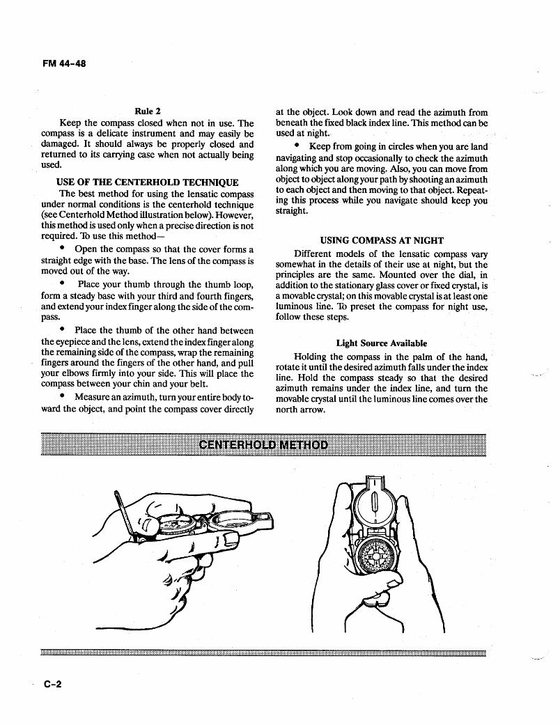
FM 44-48
Rule 2Keep the compass closed when not in use. The
compass is a delicate instrument and may easily bedamaged. It should always be properly closed andreturned to its carrying case when not actually beingused.
USE OF THE CENTERHOLD TECHNIQUEThe best method for using the lensatic compass
under normal conditions is the centerhold technique(see Centerhold Method illustration below). However,this method is used only when a precise direction is notrequired. To use this method-
* Open the compass so that the cover forms astraight edge with the base. The lens of the compass ismoved out of the way.
* Place your thumb through the thumb loop,form a steady base with your third and fourth fingers,and extend your index finger along the side of the com-pass.
* Place the thumb of the other hand betweenthe eyepiece and the lens, extend the index finger alongthe remaining side of the compass, wrap the remainingfingers around the fingers of the other hand, and pullyour elbows firmly into your side. This will place thecompass between your chin and your belt.
* Measure an azimuth, turn your entire body to-ward the object, and point the compass cover directly
at the object. Look down and read the azimuth frombeneath the fixed black index line. This method can beused at night.
* Keep from going in circles when you are landnavigating and stop occasionally to check the azimuthalong which you are moving. Also, you can move fromobject to object along your path by shooting an azimuthto each object and then moving to that object. Repeat-ing this process while you navigate should keep youstraight.
USING COMPASS AT NIGHT
Different models of the lensatic compass varysomewhat in the details of their use at night, but theprinciples are the same. Mounted over the dial, inaddition to the stationary glass cover or fixed crystal, isa movable crystal; on this movable crystal is at least oneluminous line. To preset the compass for night use,follow these steps.
Light Source AvailableHolding the compass in the palm of the hand,
rotate it until the desired azimuth falls under the indexline. Hold the compass steady so that the desiredazimuth remains under the index line, and turn themovable crystal until the luminous line comes over thenorth arrow.
CNTEHOLM METH
C-2
~::::~:::::::r::::r8:::::::::::::ii::lil:
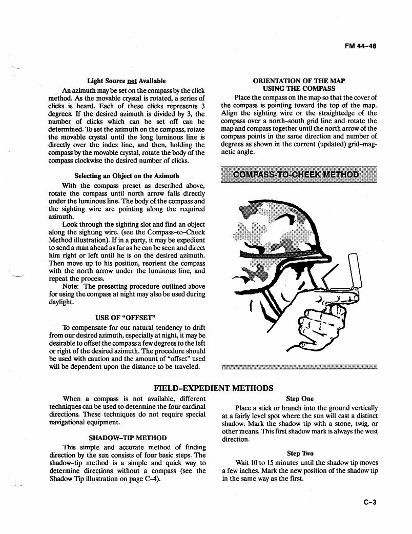
FM 44-48
Light Source not AvailableAn azimuth may be set on the compass by the click
method. As the movable crystal is rotated, a series ofclicks is heard. Each of these clicks represents 3degrees. If the desired azimuth is divided by 3, thenumber of clicks which can be set off can bedetermined. To set the azimuth on the compass, rotatethe movable crystal until the long luminous line isdirectly over the index line, and then, holding thecompass by the movable crystal, rotate the body of thecompass clockwise the desired number of clicks.
Selecting an Object on the AzimuthWith the compass preset as described above,
rotate the compass until north arrow falls directlyunder the luminous line. The body of the compass andthe sighting wire are pointing along the requiredazimuth.
Look through the sighting slot and find an objectalong the sighting wire. (see the Compass-to-CheekMethod illustration). If in a party, it may be expedientto send a man ahead as far as he can be seen and directhim right or left until he is on the desired azimuth.Then move up to his position, reorient the compasswith the north arrow under the luminous line, andrepeat the process.
Note: The presetting procedure outlined abovefor using the compass at night may also be used duringdaylight.
USE OF "OFFSET"
To compensate for our natural tendency to driftfrom our desired azimuth, especially at night, it maybedesirable to offset the compass a few degrees to the leftor right of the desired azimuth. The procedure shouldbe used with caution and the amount of "offset" usedwill be dependent upon the distance to be traveled.
ORIENTATION OF THE MAPUSING THE COMPASS
Place the compass on the map so that the cover ofthe compass is pointing toward the top of the map.Align the sighting wire or the straightedge of thecompass over a north-south grid line and rotate themap and compass together until the north arrow of thecompass points in the same direction and number ofdegrees as shown in the current (updated) grid-mag-netic angle.
M S& a In hai~::~::n:j~ ~~ '~nt:n: :s~~ ::s s:::ats:. ..
FIELD-EXPEDIENT METHODSWhen a compass is not available, different
techniques can be used to determine the four cardinaldirections. These techniques do not require specialnavigational equipment.
SHADOW-TIP METHODThis simple and accurate method of finding
direction by the sun consists of four basic steps. Theshadow-tip method is a simple and quick way todetermine directions without a compass (see theShadow Tip illustration on page C-4).
Step OnePlace a stick or branch into the ground vertically
at a fairly level spot where the sun will cast a distinctshadow. Mark the shadow tip with a stone, twig, orother means. This first shadow mark is always the westdirection.
Step TioWait 10 to 15 minutes until the shadow tip moves
a few inches. Mark the new position of the shadow tipin the same way as the first.
C-3
----: ';'-' : ';: :;: :5;: X :.: :S : : :.: ' i:i ' "' ' ' ' : : :5 : : : : : : : : :...::::5: ::~: : : : ~ : 5: : : : : : : : : : : : : : : :C : :::~ r::::::::::S. ::::::::::::. . ... :i :5:::: ; :5 : : : : :
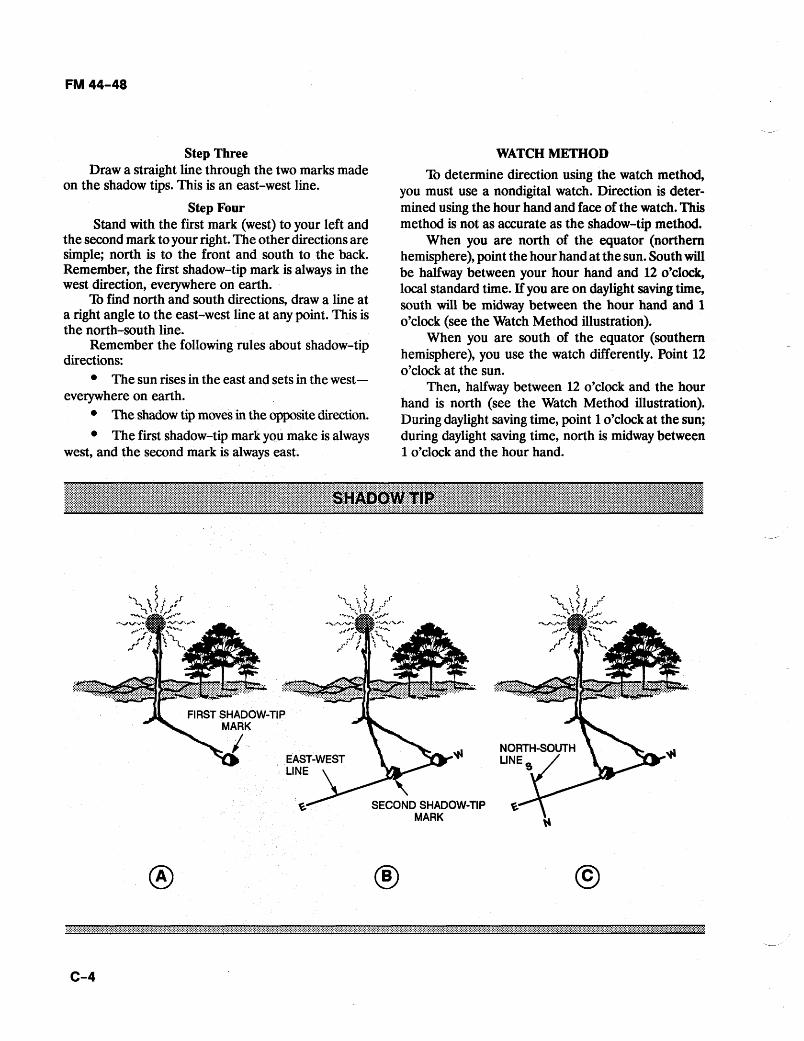
FM 44-48
Step ThreeDraw a straight line through the two marks made
on the shadow tips. This is an east-west line.
Step FourStand with the first mark (west) to your left and
the second mark to your right. The other directions aresimple; north is to the front and south to the back.Remember, the first shadow-tip mark is always in thewest direction, everywhere on earth.
To find north and south directions, draw a line ata right angle to the east-west line at any point. This isthe north-south line.
Remember the following rules about shadow-tipdirections:
" The sun rises in the east and sets in the west-everywhere on earth.
" The shadow tip moves in the opposite direction.
" The first shadow-tip mark you make is alwayswest, and the second mark is always east.
WATCH METHOD
To determine direction using the watch method,you must use a nondigital watch. Direction is deter-mined using the hour hand and face of the watch. Thismethod is not as accurate as the shadow-tip method.
When you are north of the equator (northernhemisphere), point the hour hand at the sun. South willbe halfway between your hour hand and 12 o'clock,local standard time. If you are on daylight saving time,south will be midway between the hour hand and 1o'clock (see the Watch Method illustration).
When you are south of the equator (southernhemisphere), you use the watch differently. Point 12o'clock at the sun.
Then, halfway between 12 o'clock and the hourhand is north (see the Watch Method illustration).During daylight saving time, point 1 o'clock at the sun;during daylight saving time, north is midway between1 o'clock and the hour hand.
~~f~-~~ ::~:I~i-~::~:~::~:~P:~:~:~:::: ::: ~~~~~~ n,:: ~ a~:~~u~:~ :.: ::::~::~:~:~g:~:,~,~,::::~:::::::~:a a ~ ':':':'f"':~:~:~::~::::w:~~8~ :::~:~::"::::~::~:::~::::''' i ~~~o~~~W~~~~s8:~.rz. 2;~x :~:x~82~:ss~s ~::~~~::::::~tzaa Ix;~i: xo:~ ~: t:saxa:~ .5~~~~.w~~;ss :il::~8~:~:~:~::.:i ~~1t.~Uj:s~s :nxs ' z;ss~aJsssa~ 5~: ;s;s ;rr ; txs';';s tgl:::slp; .,_,,,.., .~ s~z:s :~:::;:~:~::,:s xs~: ::~.~::~:~:.::::::Z: : ; : : ;~i:.~.':S i ~ : .~11K~;~';~ "jrr~~s~~~ .~;s :~~::: : VS::;:~:;~;:;~S':':~X::: ~w~x. t: ~i :~:~:~:~:: r ~:::::~:~;:s~:~::::~::::~:;~"""";"-s'l~i~~:*.~r'.i - ~i~:nr~:~:~: ~ : : ~5 : ~ : ~ ~~ :~:~:~::::::;::~;:w: X~I'.X ~2 .~:~g~: ~ ~n~ n::sa: ~:~:~: : : x:::~:~:~:~:~:~: ~~ x: .~W~i~i~ :~~~";:;";";:~~:~: "': "S ''S~~i~0 ~~i8~:~:~:~:~~~:~:~:;I: : ~3F5F ;s ~9:~:~::~:~:~:::::X;: x,:s t s :~: :~-~ s :ss:~.ss .:;:,,,:::::::t. ~"~."~' : ~;: :.I::::::::::: .:: : : : : i:~:3:~: ii~i~lllll~l~~~~~~i~~ls ::: Iliii ~ 2~ ;. ....::::~:::x r : :s:~x~ ~;: ~a: :::~:~::::~8:~f:.:.~:: :~:~iiaijiiiiiiiiii~i~~~i~ii~.~:~:~:~:~:5Y X;:~:~::SS : ~:~:~::~::~::~:~:~:~:~::~:~~x ~ss~:~:~ :~:s ~::s~:~::: ~Z ~ : 'LZ : : :" z.sz.s..s.... ;. t. .. i. ...ss~z.s~ ~:s : : ~"~ ::::::~:~:~8~:~i~j:~:~:~:~::::::::' x9~
SECOND SHADOW-TIP .'
MARK
©
C-4
xe-
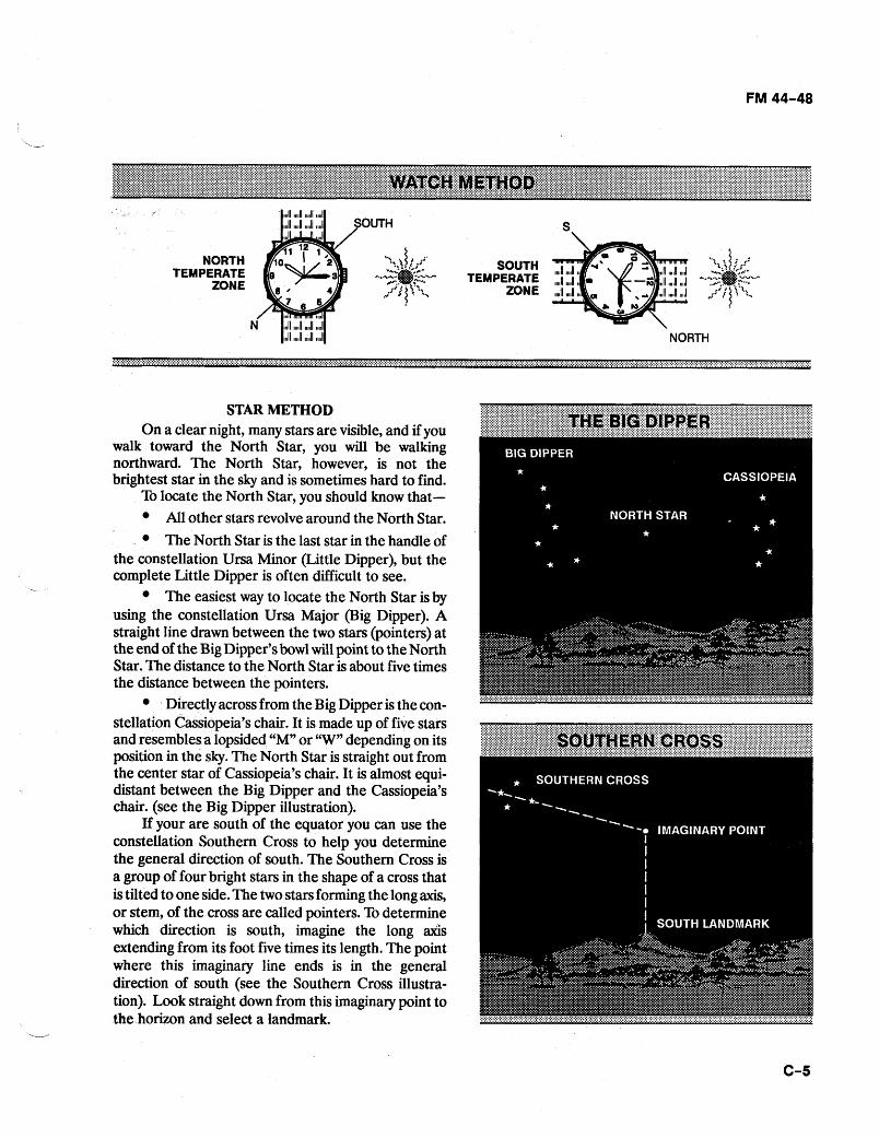
FM 44-48
II .... II-....II-....I O UTH
OUSOHTH1111 U
NJORTH NT ~ .: 1 / U
TEMPERATE TEMPERATE a IIZONE ," .... ... II
111ZON1E ....II NORTIIH
N II ...II ...II....
II ...II .;.II .I NORTH
STAR METHODOn a clear night, many stars are visible, and if you
walk toward the North Star, you will be walkingnorthward. The North Star, however, is not thebrightest star in the sky and is sometimes hard to find.
To locate the North Star, you should know that--
" All other stars revolve around the North Star.
" The North Star is the last star in the handle ofthe constellation Ursa Minor (Little Dipper), but thecomplete Little Dipper is often difficult to see.
* The easiest way to locate the North Star is byusing the constellation Ursa Major (Big Dipper). Astraight line drawn between the two stars (pointers) atthe end of the Big Dipper's bowl will point to the NorthStar. The distance to the North Star is about five timesthe distance between the pointers.
" Directly across from the Big Dipper is the con-stellation Cassiopeia's chair. It is made up of five starsand resembles a lopsided "M" or "W" depending on itsposition in the sky. The North Star is straight out fromthe center star of Cassiopeia's chair. It is almost equi-distant between the Big Dipper and the Cassiopeia'schair. (see the Big Dipper illustration).
If your are south of the equator you can use theconstellation Southern Cross to help you determinethe general direction of south. The Southern Cross isa group of four bright stars in the shape of a cross thatis tilted to one side. The two stars forming the long axis,or stem, of the cross are called pointers. To determinewhich direction is south, imagine the long axisextending from its foot five times its length. The pointwhere this imaginary line ends is in the generaldirection of south (see the Southern Cross illustra-tion). Look straight down from this imaginary point tothe horizon and select a landmark.
C-5
APPENDIX D
StealthThis appendix brings into focus the need to plan for movement
by vehicle and for movement by foot so that the probability of de-tection is minimized. Stealth is one of the primary factors in the sur-vivability of the ADA sensor sections.
MOVEMENT PLANNINGNight operations depend upon direction, control,
and surprise for success. Direction in the attackfacilitates a coordinated effort to maximize combatpotential. Control ensures that units are mutuallysupporting and that the proper NAIs are observed.Surprise, through speed and secrecy, is the key tominimizing the enemy's ability to react or to focuscombat power against the sensor section. The ability tosuccessfully conduct these operations places emphasison small unit skills to navigate and move silentlythrough dense terrain.
NAVIGATIONNavigation at night is different from daylight
navigation. Shapes and sizes are distorted and colorsfade. However, towns and radio towers may be easierto recognize. Night navigation, like day navigation,uses terrain association and or dead reckoning. Terrainassociation uses a general direction of travel coupledwith the recognition of prominent map and groundfeatures. Dead reckoning uses a compass direction andspecific distances or legs. The basic requirement whilemoving at night is to remain oriented. Resection helpsdetermine location while moving. Proficiency in resec-tion results from a thorough map and terrain analysis.Map and terrain analysis is critical due to the distancedistortion which occurs at night. Distance is judgedpartly by object size, color, depth perception, and otherfactors which are degraded at night. As a result, smallobjects seem farther away and large objects seemcloser. Bright objects seem closer than dull ones.Forests or groves of trees seen from a distance mayappear to be hills in dim light.
Movement Planning .D....Movement (Manually) ....... .2Light and Nose Discipline .... . 3
iii iI i!! ii~ii i iiiii i iiiiii i ii~ii !ii!i ii iiiiiiii ii ii I i ii! iiii......................iii iiiiiiiii.. .. .. .........ii~ ilii~i L f !a N~i D !: i~ii~i~iii~iiii~ii!iii ........D.. i~i ~iiiiiiii : ~ iiiiiiii~iii~iiii i !iii~iii~iiiiiiii~iiiiiiiiiiii~i ii~iiii!!iiiii~!!i~~~ii~~~ii~iiii~iiiiiiiiii!iiii~i!!i...........iiii~i!i~ii!iii
MAP ANALYSISWhen a sensor section enters a new area, the
section chief must orient the map to the terrain to getthe "lay of the land": local drainage and relief,dominant terrain features, how the terrain looks fromother features, and most importantly, how the arealooks at night. To know the area, the section chief mustwalk it in all directions, both day and night.
TERRAIN ANALYSISDuring a reconnaissance, the sensor section chief
compares the terrain with the mental images devel-oped during map analysis. This confirmation andmodification of the initial analysis fixes the landpatterns and important features in memory.
ROUTE SELECTION
METT-T is the criterion used to determine theroute used for night movement. Since more than oneroute may satisfy the requirements for METT-T, selectthe one that offers ease of navigation. Night travel isstrenuous, often done when soldiers are tired, addingto physical and psychological stress. Ease of navigationcontributes both to maintaining direction and control.
The selected route is subjected to further analysisusing the factors of observation and fields of fire, coverand concealment, obstacles, key terrain, and avenuesof approach (OCOKA). METT-T may make one ofthese factors more critical, such as terrain, cover, oravenues of approach.
As the route is analyzed, it is divided into segmentsor legs. Legs represent a way to maintain control. Eachleg begins and ends either with a change in direction ora prominent terrain feature. The location where theleg begins is a checkpoint. Checkpoints provide asequential series of guides to use for orientation andcontrol. As before, each leg is analyzed using OCOKA.OCOKA helps determine probable hasty ambush sites,likely areas the enemy may use for movement, andwhere observation may improve.
D-1
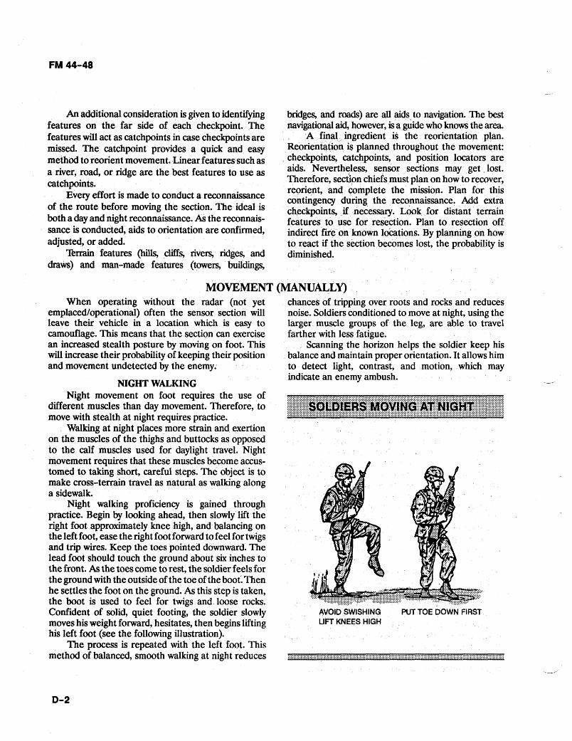
FM 44-48
An additional consideration is given to identifyingfeatures on the far side of each checkpoint. Thefeatures will act as catchpoints in case checkpoints aremissed. The catchpoint provides a quick and easymethod to reorient movement. Linear features such asa river, road, or ridge are the best features to use ascatchpoints.
Every effort is made to conduct a reconnaissanceof the route before moving the section. The ideal isboth a day and night reconnaissance. As the reconnais-sance is conducted, aids to orientation are confirmed,adjusted, or added.
Terrain features (hills, cliffs, rivers, ridges, anddraws) and man-made features (towers, buildings,
bridges, and roads) are all aids to navigation. The bestnavigational aid, however, is a guide who knows the area.
A final ingredient is the reorientation plan.Reorientation is planned throughout the movement:checkpoints, catchpoints, and position locators areaids. Nevertheless, sensor sections may get lost.Therefore, section chiefs must plan on how to recover,reorient, and complete the mission. Plan for thiscontingency during the reconnaissance. Add extracheckpoints, if necessary. Look for distant terrainfeatures to use for resection. Plan to resection offindirect fire on known locations. By planning on howto react if the section becomes lost, the probability isdiminished.
MOVEMENT (MANUALLY)When operating without the radar (not yet
emplaced/operational) often the sensor section willleave their vehicle in a location which is easy tocamouflage. This means that the section can exercisean increased stealth posture by moving on foot. Thiswill increase their probability of keeping their positionand movement undetected by the enemy.
NIGHT WALKINGNight movement on foot requires the use of
different muscles than day movement. Therefore, tomove with stealth at night requires practice.
Walking at night places more strain and exertionon the muscles of the thighs and buttocks as opposedto the calf muscles used for daylight travel. Nightmovement requires that these muscles become accus-tomed to taking short, careful steps. The object is tomake cross-terrain travel as natural as walking alonga sidewalk.
Night walking proficiency is gained throughpractice. Begin by looking ahead, then slowly lift theright foot approximately knee high, and balancing onthe left foot, ease the right foot forward to feel for twigsand trip wires. Keep the toes pointed downward. Thelead foot should touch the ground about six inches tothe front. As the toes come to rest, the soldier feels forthe ground with the outside of the toe of the boot. Thenhe settles the foot on the ground. As this step is taken,the boot is used to feel for twigs and loose rocks.Confident of solid, quiet footing, the soldier slowlymoves his weight forward, hesitates, then begins liftinghis left foot (see the following illustration).
The process is repeated with the left foot. Thismethod of balanced, smooth walking at night reduces
chances of tripping over roots and rocks and reducesnoise. Soldiers conditioned to move at night, using thelarger muscle groups of the leg, are able to travelfarther with less fatigue.
Scanning the horizon helps the soldier keep hisbalance and maintain proper orientation. It allows himto detect light, contrast, and motion, which mayindicate an enemy ambush.
AVOID SWISHINGLIFT KNEES HIGH
PUT TOE DOWN FIRST
D-2
-... . -~--i-r... .. i. ..... . -.--.....-i--.;.. . .....-..-.......--.. -..... iiii... ..... ....88:sj:~:ggg::::j::::a:~::::8#8~:~:~:a:
FM 44-48
STALKINGStalking is best described as night walking in a
crouch; but, very slowly. The soldier is usually watchingthe enemy, stalking him by eyesight. When close to theenemy, squinting helps conceal light reflected by theeyes. Breathe slowly and through the nose. If theenemy looks in the direction of the stalker, the stalkerfreezes, balanced or not. Movement should takeadvantage of the background to blend with shadowsand prevent glare or contrast. Movement is bestconducted during distractions such as gusts of wind,vehicles moving, loud talking, or nearby weapons fire.
CRAWLINGAll crawling techniques feel awkward at first.
Practice increases expertise. Crawling is more comfort-able when pads are used on the knees and elbows;however, ensure that the binders or tapes holding thepads on do not cut off blood circulation.
The fastest crawl uses the single-side, hand-and-foot method. Movement is accomplished by pressingthe right or left hand and foot against the ground andeither pushing or pulling forward. This methodsacrifices noise discipline and is the least useful in thefinal phase of stalking.
A second method involves using the opposite handand foot. This is done by pressing down with an arm anda foot on the opposite side and resting on one hip. In thisway, the body is pulled forward with the left hand andright foot. As the soldier reaches forward again he isresting on his left hip. He then pulls his body forwardusing the right hand and left foot, and rests on his righthip. This method is slower and quieter than the firstmethod.
The slowest and quietest technique uses theelbows and toes of the boots. It is executed by lifting thebody up on elbows and toes of the boots, slowly pushingthe body forward, resting, and repeating the process.Each movement is measured in inches.
The position of the head is important whilecrawling. Before moving, always look to the front forobstructions and or enemy activity. Lift the head slowlyoff of the ground, look to the front, from left to right,and low to high. Squint with the eyelids to preventundue light reflection off the eyes. Then lower thehead to the ground, facing either to the left or right.Another precaution before moving is to feel to thefront for obstructions such as roots that may snagclothing and twigs and rocks that may make noise.Remove or go around them.
LIGHT AND NOISE DISCIPLINEThe chief factor which gives away a position is the
lack of light and noise discipline. Tob overcome thisshortfall, the section must practice light and noisediscipline and the section chief must check.
Communications at night calls for the section chiefto use different methods than during daylight. Forinstance, arm-and-hand signals used during the day maynot be visible during darkness. Signals are used to passinformation, identify locations, control formations, orinitiate activity. The key to tactical communications issimplicity, understanding, and practice. Signals should bean integral part of the unit SOP. Signals should be madeas simple as possible to avoid confusion.
The most common signals relate to the senses:hearing, feeling, and seeing. Audio signals includeradio, wire telephones, messengers, and the grating orclicking of objects together.
Control at night involves some verbal communica-tions, but do not talk in a natural tone of voice--whisp-er instead. Tob do this, take a normal breath, exhale halfof it, and then whisper into the other person's ear usingthe remainder of the breath.
The radio and telephone may not be suitable atnight. If either is used, take certain precautions.
Noise travels farther at night. So will the static ofthe radio, the passing of messages, and the ringing ofthe telephone. These are violations of noise discipline.They can be reduced by planned signals or clicks.Headphones also reduce the amount of noise by bothdevices.
Rocks and other objects may be used to transmitaudible signals. Rocks may be tapped or scrapedtogether; they can be scraped against a tree or riflestock to pass a message. These signals are rehearsed.There is a signal and a reply to indicate the signal wasreceived. Other audible signals are whistles, bells,sirens, clackers or "crickets," and horns. The device ormethod chosen depends on simplicity and security.
Visual signals are an alternative to audio signals.These signals may be active or passive and include awide range of alternatives. The key to visual signals isto ensure they are noticed and identifiable. Somepassive signals are-
* Sticks indicating a direction.
* Light paint.
* Tape.
D-3
FM 44-48
" Rock formations." Markings in the ground." Powder.
" Luminous tape.Conversely, active signals include-s Flares.
" Flashlights.
" Illumination rounds (M203,artillery).
" Chemical lights.
mortar, and
* Infrared strobe lights
" Strobe lights." PVS-5, NVD.* Burning fuel (saturated sand in a can)." Luminous compass dial.These signals can be used to identify a critical trail
junction, initiate an attack, mark caches, or report thata danger area is clear. White powder can be used to
indicate direction at a confusing trail intersection; starclusters can signal the initiation of an attack or raid;chemical lights can signal a unit cache; and a flashlightwith a blue filter (using an X cut out of the filter) cansignal all clear to a unit crossing a danger area. Thepossibilities are endless; but the section chief ensuresthat each signal used is understood by each soldier inthe section.
The last type of signal deals with the sense of feel.Communications to a trail watcher out from anobservation point (OP), without disclosing positions,may employ wire, string, or rope as signal devices.
The wire is usually secured to the arm or leg; usingprearranged signals, activity is relayed between themain body and the security elements. Two pulls on thewire may mean ground-mounted force approaching,while three pulls may indicate a convoy.
Regardless of the type of signal used, it must besimple, easy to understand, and practical. Signals atnight aid in control, enhance security, and supportsurprise. Plan the type of signals based upon sectionactivity and desired results. Then brief the soldiers andhave them practice the signals.
D-4
APPENDIX E
Position SecurityThis appendix discusses measures for security of the ADA sen-
sor section position. One of the primary tasks for the ADA sensorsection chief is to plan the defense of the section or individual posi-tion. Such things as setting up reference points, assigning sectorsof fire, and placing claymore mines, are a part of the section chief'sresponsibility.
NIGHT SECURITY
Sensor section chiefs address security, targetdetection, engagement of targets, fire support, illumi-nation, and fighting positions in their defensivescheme. Security of the section night defensiveposition (NDP) consists of both active and passivemeasures.
ACTIVE MEASURESPhysical security is all of the measures which keeps
the section from being surprised. This includes securityin all directions. Rock-filled cans suspended on barrierwire or across suspected avenues of approach canprovide intrusion warning. The section chief should
control the section fires with tracer fire. All sectionmembers should engage the targets marked by thesection chief. Each position should have an NVD.These allow the chief to be proactive instead ofreactive. This ensures that every man adjusts to thechanging light and noise conditions, and is dressed,equipped, and ready for action.
PASSIVE MEASURESPassive measures include camouflage of positions,
control of movement, light and noise discipline, andlimiting radio traffic. Soldiers must also pick up theirlitter.
NIGHT TARGET DETECTIONTarget detection during the day is easier than at
night since terrain feature references can be seen. Atnight, two reference methods are range cards and agrid matrix.
RANGE CARDSA range card is a rough sketch of the terrain
around a weapon. It is prepared for each weaponsystem and sensor. The card shows sectors of fire, finalprotective line (FPL), or principal direction of fire(PDF) of the weapons, targets, and ranges to them.
C<P >:::.:
Night Security E 1
Engagement of Targets . 2 ...
• --- '''''''''iiii!! i:n i: iN:e} i :i:i: iiiiiiiii iiiiiiiiii:iiii:iii}iiiiii! :
i i~ iiiii~ii~ iiiii i~ii iii~ ii~ iii ii~i iii iii~ ~ii iii iiliiiiiiiiii~ii~ii{ ~i i~ii~ii { iiii~i~~i~~i~i~iiii~iiiiii:ii:iiiii:i:
Each soldier prepares at least two copies of arange card for his position. The soldier keeps one copyat the position and gives one copy to the section chief.The section chief makes a section sector sketch, usingthe individual position's range cards.
GRID MATRIXA grid is created using luminous tape or chemical
lights with minimal light exposure. The best grid is athree-spot by two-spot grid per sector (see the GridMatrix for Target Reference illustration on page E-2).The spots serve two purposes: reference points fortargets, and a method to adjust the height of direct fire(the lower the rounds, the more effective they are). Oncethe sector is established, have each section membermemorize the terrain. The luminous markers helpidentify terrain. When sounds are heard, a target locationcan be referenced. Oftentimes, targets cannot be seen,but the direction can be determined and fire placed on it.
E-1
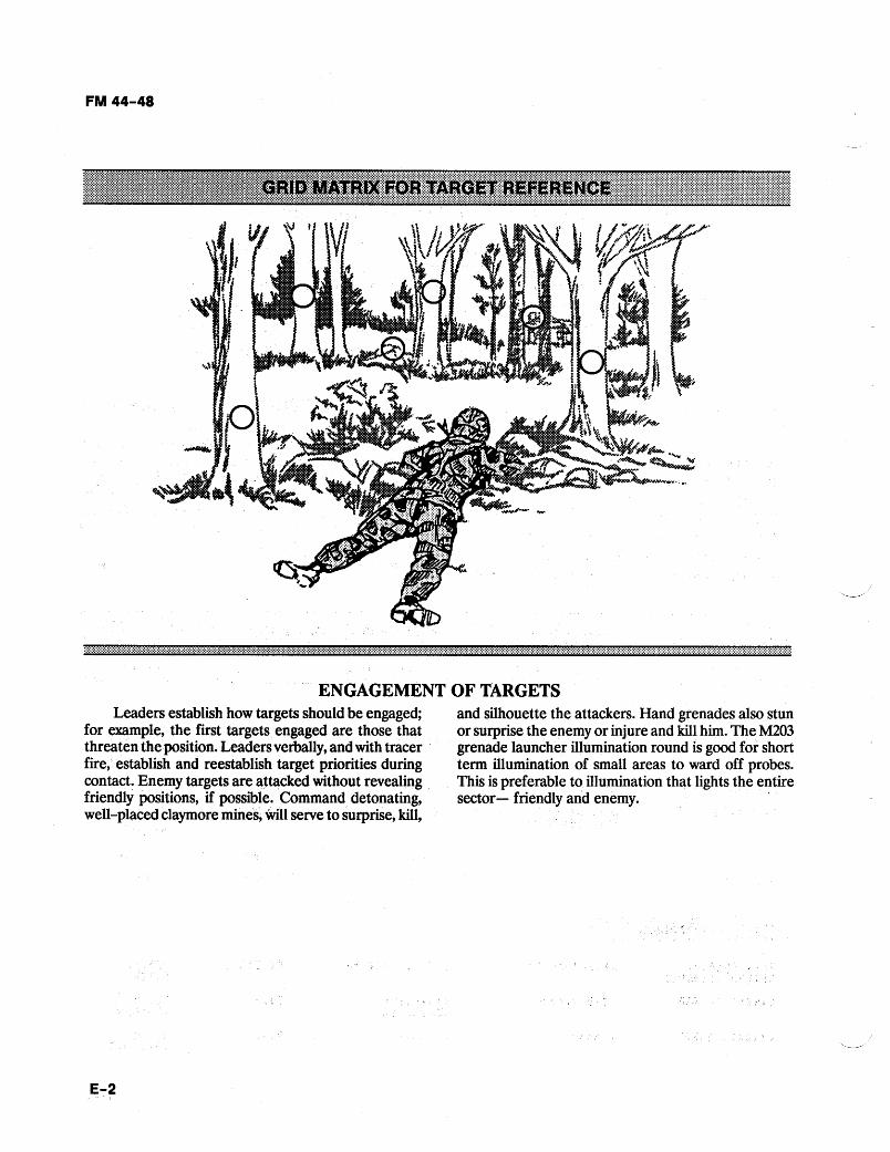
FM 44-48
ijjiij i. i i i, ir Ne,- ::::~~~: I::~~~ ~, .,,~~~:~~ ::~~ :;.':~::~::~:~I < : ::~ ::~::~~: z~s S~SR , .. . . .. ,,,:~~
ENGAGEMENT OF TARGETSLeaders establish how targets should be engaged;
for example, the first targets engaged are those thatthreaten the position. Leaders verbally, and with tracerfire, establish and reestablish target priorities duringcontact. Enemy targets are attacked without revealingfriendly positions, if possible. Command detonating,well-placed claymore mines, will serve to surprise, kill,
and silhouette the attackers. Hand grenades also stunor surprise the enemy or injure and kill him. The M203grenade launcher illumination round is good for shortterm illumination of small areas to ward off probes.This is preferable to illumination that lights the entiresector- friendly and enemy.
E-2
:~:~~:~:~:~:~:~:~:~:~~~:~:~:~:~:~:~:~5~:
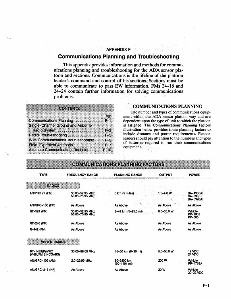
APPENDIX F
Communications Planning and TroubleshootingThis appendix provides information and methods for commu-
nications planning and troubleshooting for the ADA sensor pla-toon and sections. Communications is the lifeline of the platoonleader's command and control of his sections. Sections must beable to communicate to pass EW information. FMs 24-18 and24-24 contain further information for solving communicationsproblems.
COMMUNICATIONS PLANNING
Sige.ChannelGrouandand Airborni 1*e « >
.... :....:.:.:::. .:.::: .:...:.::::::::..::....::.::..:::5 :::I~:::. ..............
RadaiTroubieshoting :.}.:. i:.fWieComncations: Troubl eshootin r ". F->:5
ied-ExpedientAnten...enasAl:ternt CWf:ommunii.catioQns, Techdniques .... ;.1<
The number and types of communications equip-ment within the ADA sensor platoon vary and aredependent upon the type of unit to which the platoonis assigned. The Communications Planning Factorsillustration below provides some planning factors toinclude distance and power requirements. Platoonleaders should pay attention to the numbers and typesof batteries requied to run their communicationsequipmenit.
c.~~~~~:'~:y:MUekNSPtt'NKQPATOS........TYPE~~~~~~.~~ FREQUENC RAG LNIN AG UTU OE
AN/PRC 77 (FM)
AN/GRC-160 (FM)
RT-524 (FM)
RT-246 (FM)
R-442 (FM)
30.00-52.95 MHz53.00-75.95 MHz
As Above
30.00-52.95 MHz53.00-75.95 MHz
As Above
As Above
8 km (5 miles)
As Above
8-41 km (5-25.5 mi)
As Above
As Above
RT-1439(P)NRC(VHM/FM SINCGARS)
AN/GRC-106 (AM)
AN/GRC-213 (HF)
30.00-88.00 MHz
2.0-29.99 MHz
As Above
15-50 km (9-30 mi)
80-2400 km(50-1491 mi)
As Above
1.5-4.0 W
As Above
8.0-35.0 W
As Above
As Above
BA-4386/UBA-398/UBA-5398/U
As Above
VehiclePP-2953PP-665
As Above
As Above
5.0-50.0 W
200 W
20 W
12 VDC24 VDC
VehiclePP-4763A
Vehicle20-32 VDC
F-1
;.i~z~ .si~~ zsss.~. .ss ...s~ ~t I' ' '2 ' '-' 2'-' ' '~: : : ::~:::;:;~: ~~~~SfS ~ .5 .~sr ; ..~p,,;s ;s x ; tt;~f: *~~~nxs x
AA 0l .$ii~i;:~:~::L: :''''"'
t:::;: :::.: ':"; : .:. : : : : ;:::i:::;'::::::::::::::::::::::::::::: .:: : .:::: .:::::: ::1.:. ..:. ::~. '.::: : : : : : : : : : : : : : : : : :.: :.;.; ; ::: ; ; ;:;.;:; ; ; ;'; ;'; : ; :.: : : : : : : : : : : : : : : : : : : : .............. .................
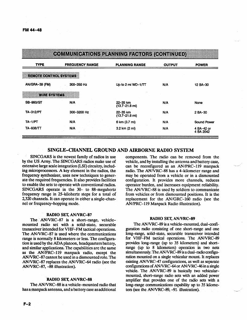
FM 44-48
:LANEH FACTOR (C NTINUE.
TYPE FREQUENCY RANGE PLANNING RANGE OUTPUT POWER
AN/GRA-39 (FM) 300-350 Hz Up to 2 mi WD-1/77 N/A 12 BA-30
SB-993/GT N/A 22-35 km N/A None(13.7-21.8 ml)
TA-312/PT 300-3200 Hz 22-35 km N/A 2 BA-30(13.7-21.8 mi)
TA-1/PT N/A 6 km (3.7 mi) N/A Sound Power
TA-838[17 N/A 3.2 km (2 ml) N/A 4 BA-42 or4 BA 2042
SINGLE-CHANNEL GROUND AND AIRBORNE RADIO SYSTEMSINCGARS is the newest family of radios in use
by the US Army. The SINCGARS radios make use ofextensive large scale integration (LSI) circuitry, includ-ing microprocessors. A key element in the radios, thefrequency synthesizer, uses new techniques to gener-ate the required frequencies. It also provides facilitiesto enable the sets to operate with conventional radios.SINCGARS operate in the 30- to 88-megahertzfrequency range in 25-kilohertz steps for a total of2,320 channels. It can operate in either a single-chan-nel or frequency-hopping mode.
RADIO SET, AN/VRC-87The AN/VRC-87 is a short-range, vehicle-
mounted radio set with a solid-state, securabletransceiver intended for VHF-FM tactical operations.The AN/VRC-87 is used where the communicationsrange is normally 8 kilometers or less. The configura-tion is used by the ADA platoon, headquarters battery,and similar applications. The capabilities are the sameas the AN/PRC-119 manpack radio, except theAN/VRC-87 cannot be used in a dismounted role. TheAN/VRC-87 replaces the AN/VRC-64 radio (see theAN/VRC-87, -88 illustration).
RADIO SET, ANNRC-88The AN/VRC-88 is a vehicle-mounted radio that
has a manpack antenna, and a battery case as additional
components. The radio can be removed from thevehicle, and by installing the antenna and battery case,can be reconfigured as an AN/PRC-119 manpackradio. The AN/VRC-88 has a 4-kilometer range andmay be operated from a vehicle or in a dismountedconfiguration. It provides more channels, reducesoperator burden, and increases equipment reliability.The AN/VRC-88 is used by soldiers to communicatefrom vehicles or from dismounted positions. It is thereplacement for the AN/GRC-160 radio (see theAN/PRC-119 Manpack Radio illustration).
RADIO SET, ANNRC-89The AN/VRC-89 is a vehicle-mounted, dual-confi-
guration radio consisting of one short-range and onelong-range, solid-state, securable transceiver intendedfor VHF-FM tactical operations. The AN/VRC-89provides long-range (up to 35 kilometers) and short-range (up to 8 kilometers) operation in two netssimultaneously. The AN/VRC-89 is a dual-radio configu-ration mounted on a single vehicular mount. It replacesexisting AN/VRC-47 configurations, as well as separateconfigurations of ANIVRC-64 or AN/VRC-46 in a singlevehicle. The AN/VRC-89 is basically two vehicular-mounted, short-range radio sets with an added poweramplifier that provides one of the radio sets with along-range communications capability up to 35 kilome-ters (see the AN/VRC-89, -91. illustration).
F-2
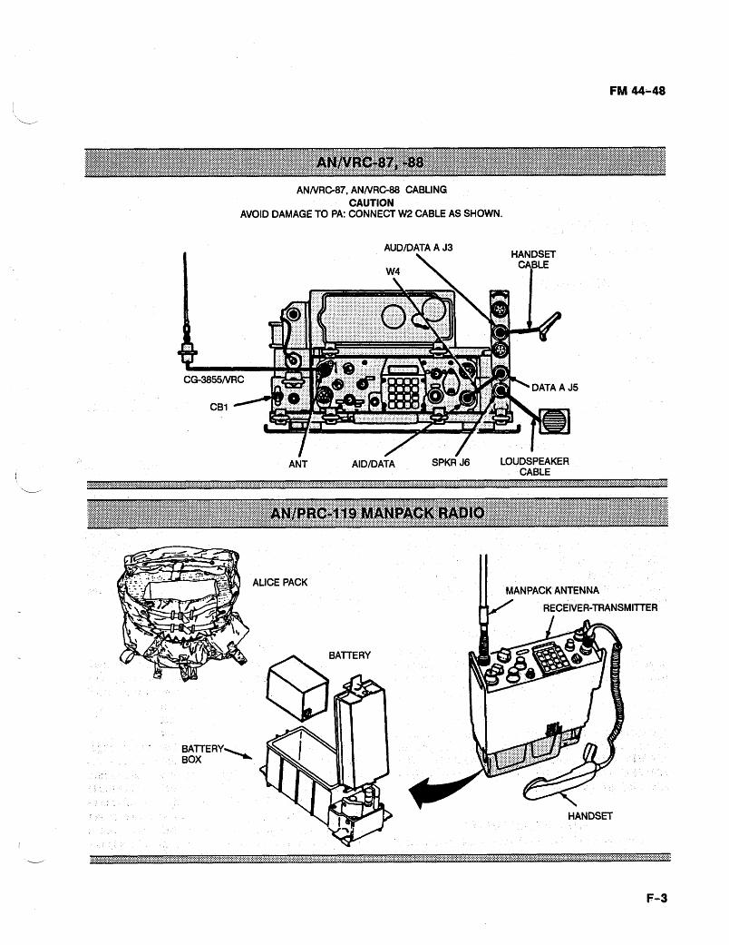
FM 44-48
:~: t ~ :~:zt:::.::x::o::: ~ .:::
.~~. ANNC-87 ANNRC-88 CABLING :~5SiCAUTIONy X: s.5.1::r~~; S : S~::~~ ~AVOI DAMAG TO PA: CONNECT W2 CABLE AS SHOWN.:
ANT AID/DATA SPKR J6 LOUDSPEAKERCABLE
AH/ PRCWi 1$ MA*4PACI( RADI
ALICE PACK
BATTERYBOX
HANDSET
F-3
55fSY. *:; fl;f~;~;: : :::::~: :5 2 2 2 : ~ L; L;.;. i 5 : t;f ~ .2~ ; 2~::~:::~:::::::~~~~:::::~:::::~:~:::~:::~:~:~1~:~:~:~:~:~:~: "~ "'."; S.f"SSS'"L";f'"f';.i'i.- ; i 5 i i i ::::::::::::::~:R:::: i i ~yLL. : : iS i : W i f i i ~ ~ : ~:~:::~:~:~::;5 :~:~:::~:~:~:;~;~;8~8:~:::: :55555. 5
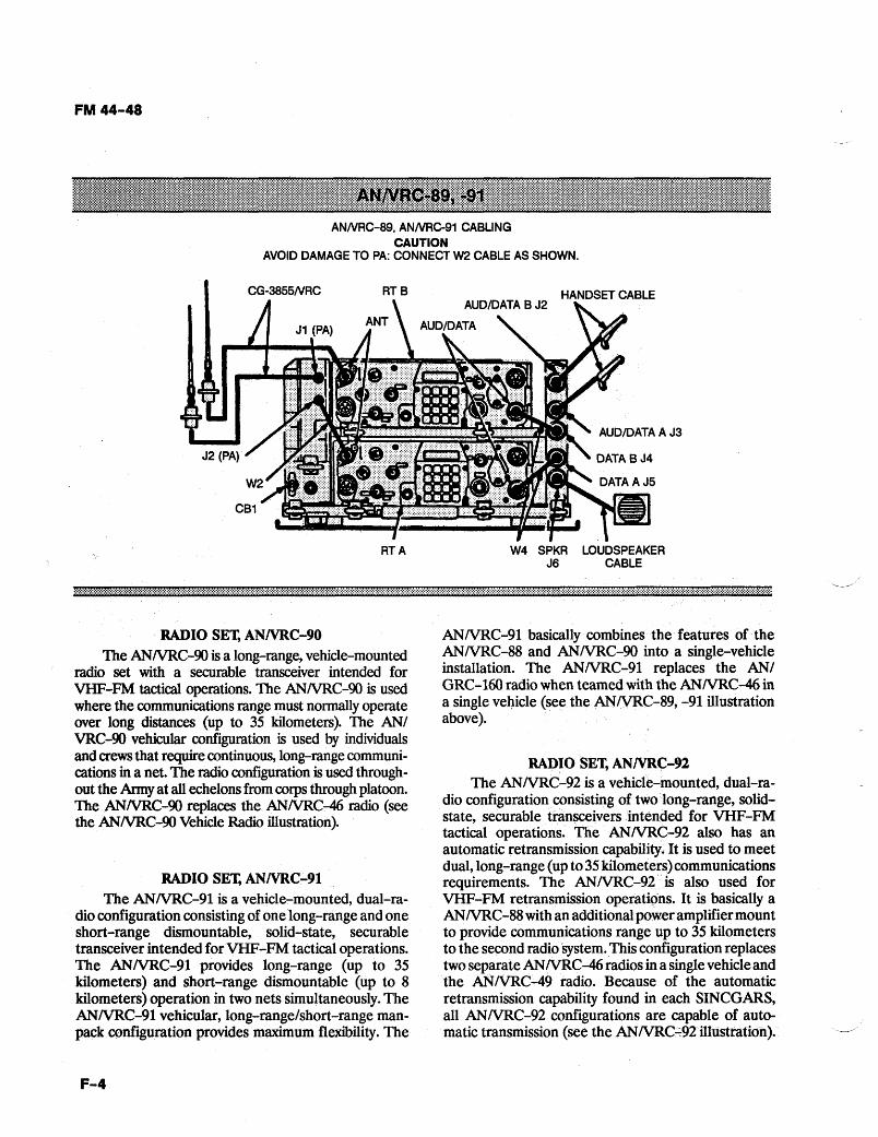
FM 44-48
ANNRC-89, ANNRC-91 CABLINGCAUTION
AVOID DAMAGE TO PA: CONNECT W2 CABLE AS SHOWN.
RT A W4 SPKR LOUDSPEAKERJ6 CABLE
RADIO SET, AN/VRC-90The AN/VRC-90 is a long-range, vehicle-mounted
radio set with a securable transceiver intended forVHF-FM tactical operations. The AN/VRC-90 is usedwhere the communications range must normally operateover long distances (up to 35 kilometers). The AN/VRC-90 vehicular configuration is used by individualsand crews that require continuous, long-range conmuni-cations in a net. The radio configuration is used through-out the Army at all echelons from corps through platoon.The AN/VRC-90 replaces the AN/VRC-46 radio (seethe AN/VRC-90 Vehicle Radio illustration).
RADIO SET, ANNRC-91
The AN/VRC-91 is a vehicle-mounted, dual-ra-dio configuration consisting of one long-range and oneshort-range dismountable, solid-state, securabletransceiver intended for VHF-FM tactical operations.The AN/VRC-91 provides long-range (up to 35kilometers) and short-range dismountable (up to 8kilometers) operation in two nets simultaneously. TheAN/VRC-91 vehicular, long-range/short-range man-pack configuration provides maximum flexibility. The
AN/VRC-91 basically combines the features of theAN/VRC-88 and AN/VRC-90 into a single-vehicleinstallation. The AN/VRC-91 replaces the AN/GRC-160 radio when teamed with the AN/VRC-46 ina single vehicle (see the AN/VRC-89, -91 illustrationabove).
RADIO SET, ANVRC-92The AN/VRC-92 is a vehicle-mounted, dual-ra-
dio configuration consisting of two long-range, solid-state, securable transceivers .'intended for VHF-FMtactical operations. The AN/VRC-92 also has anautomatic retransmission capability. It is used to meetdual, long-range (up to 35 kilometers) communicationsrequirements. The AN/VRC-92 is also used forVHF-FM retransmission operations. It is basically aAN/VRC-88 with an additional power amplifier mountto provide communications range up to 35 kilometersto the second radio system. This configuration replacestwo separate AN/VRC-46 radios in a single vehicle andthe AN/VRC-49 radio. Because of the automaticretransmission capability found in each SINCGARS,all AN/VRC-92 configurations are capable of auto-matic transmission (see the AN/VRC=92 illustration).
F-4
:~:.f~ ~;:;~;: :~:;:;:~:~:~:5 ~;I;~ :;~; ' ""2;';":'""' ~;f:;:;: : :S : '~;: : fX "'~; ;~r.~5~~f t;s zz: : : : ~ :5.: : :.: :~:: ::5 :~:5 : : :5':5
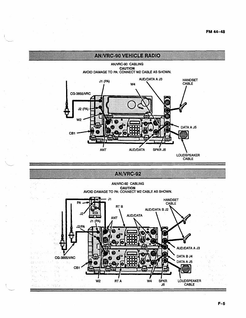
FM 44-48
{." "" "."" "." " " r." 'Jrr:.: rM ....... ....~5~ t.s ~t"
"Yr: r r". . r: .1Y.'J: V~rr: : J:: r: "."r:: r:: r::::::: ".."::: r."::":":"" "r: " " ": "
ANNRC-90 CABLINGCAUTION
AVOID DAMAGE TO PA: CONNECT W2 CABLE AS SHOWN.
AUD/DATA A J3 HANDSETCABLE
5 DATA A J5
LOUDSPEAKERCABLE
1: iii:':":":"}}:'::"} :: J::':":":":':'::". t::'}}:.:"}:......*.....*............... AWVRC
ANNRC-92 CABLINGCAUTION
AVOID DAMAGE TO PA: CONNECT W2 CABLE AS SHOWN.
AUD/DATA A J3
W2 RT A W4 SPKR LOUDSPEAKERJ6 CABLE .
F-5
~:~~:~:~:~:~:~:~:~:~828:~:~::::~:~::~8t5 .is . .51....... ;''i I:'"' 5;L: ;'~'2''-"'-'-'-'~S ::~:5:"::~:':5:' fS: XS.f::::i:8:::S0:5 .~XQX:S;~X;~~:.s~z. ~-z. ; ' '~:~::~:::::::::~:~:~::~ ::~::~::~::::~I::::::::~:::
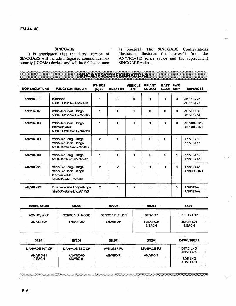
FM 44-48
SINCGARSIt is anticipated that the latest version of
SINCGARS will include integrated communicationssecurity (ICOMS) devices and will be fielded as soon
as. practical. The SINCGARS Configurationsillustration illustrates the crosswalk from theAN/VRC-112 series radios and the replacementSINCGARS radios.
RT-1523 VEHICLE MP ANT BATT PWRNOMENCLATURE FUNCTION/NSN/LIN (C) /U ADAPTER ANT AS-3683 CASE AMP REPLACES
AN/PRC-1 19 Manpack 1 0 0 1 1 0 AN/PRC-25
5820-01-267-9482/Z55944 AN/PRC-77
ANNRC-87 Vehicular Short-Range 1 1 1 0 0 0 ANNRC-535820-01-267-9480-/Z56085 ANNRC-64
ANNRC-88 Vehicular Short-Range 1 1 1 1 1 0 AN/GRC-125Dismountable AN/GRC-1605820-01-267-9481-/284229
ANNRC-89 Vehicular Long-Range 2 1 2 0 0 1 ANNRC-12Vehicular Short-Range ANNRC-475820-01 -267-9479/Z561 53
ANNRC-90 Vehicular Long-Range 1 1 1 0 0 1 ANNRC-435820-01-268-5105/Z56221 ANNRC-46
ANNRC-91 Vehicular Long-Range 2 2 2 1 1 1 ANNRC-46Vehicular Short-Range AN/GRC-160Dismountable5820-01-9478/Z56289
ANNRC-92 Dual Vehicular Long-Range 2 1 2 0 0 2 ANNRC-455820-01 -267-9477/Z81 496 ANNRC-49
1B8591/14980 BH202 BF203 BB281 BF2O1
ABMOC/ A2C2 SENSOR C2 NODE SENSOR PLT LDR BTRY CP PLT LDR CP
ANNRC-92 ANNRC-92 ANNRC-91 ANNRC-91 ANNRC-912 EACH 2 EACH
BF2O1 BF2O1 BH2O1 BG2O1 B4981 /BB21 1
MANPADS PLT CP MANPADS SEC OP AVENGER FU MANPADS FU DTAC LNOANNRC-89
ANNRC-91 ANNRC-88 ANNRC-91 ANNRC-912 EACH ANNRC-91 BDE LNO
ANNRC-91
F-6
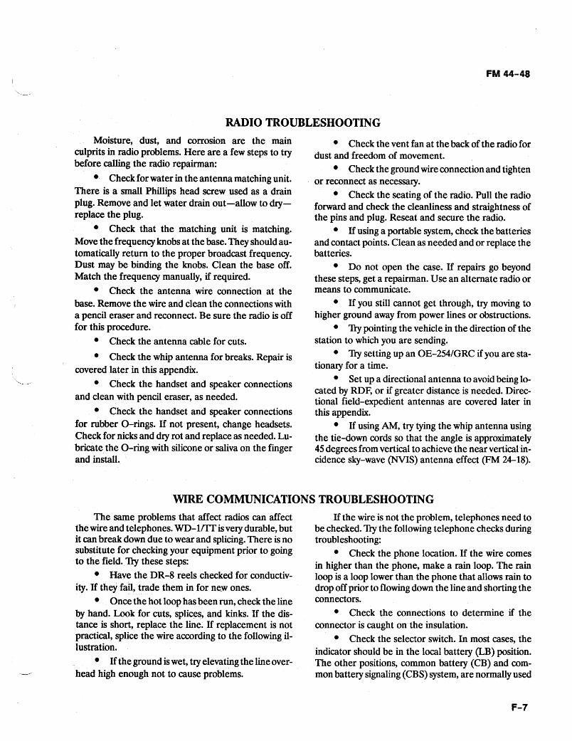
FM 44-48
RADIO TROUBLESHOOTING
Moisture, dust, and corrosion are the mainculprits in radio problems. Here are a few steps to trybefore calling the radio repairman:
* Check for water in the antenna matching unit.There is a small Phillips head screw used as a drainplug. Remove and let water drain out-allow to dry-replace the plug.
* Check that the matching unit is matching.Move the frequency knobs at the base. They should au-tomatically return to the proper broadcast frequency.Dust may be binding the knobs. Clean the base off.Match the frequency manually, if required.
* Check the antenna wire connection at thebase. Remove the wire and clean the connections witha pencil eraser and reconnect. Be sure the radio is offfor this procedure.
* Check the antenna cable for cuts.
* Check the whip antenna for breaks. Repair iscovered later in this appendix.
" Check the handset and speaker connectionsand clean with pencil eraser, as needed.
* Check the handset and speaker connectionsfor rubber O-rings. If not present, change headsets.Check for nicks and dry rot and replace as needed. Lu-bricate the O-ring with silicone or saliva on the fingerand install.
* Check the vent fan at the back of the radio fordust and freedom of movement.
* Check the ground wire connection and tightenor reconnect as necessary.
* Check the seating of the radio. Pull the radioforward and check the cleanliness and straightness ofthe pins and plug. Reseat and secure the radio.
* If using a portable system, check the batteriesand contact points. Clean as needed and or replace thebatteries.
* Do not open the case. If repairs go beyondthese steps, get a repairman. Use an alternate radio ormeans to communicate.
* If you still cannot get through, try moving tohigher ground away from power lines or obstructions.
* Try pointing the vehicle in the direction of thestation to which you are sending.
* Try setting up an OE-254/GRC if you are sta-tionary for a time.
* Set up a directional antenna to avoid being lo-cated by RDF, or if greater distance is needed. Direc-tional field-expedient antennas are covered later inthis appendix.
* If using AM, try tying the whip antenna usingthe tie-down cords so that the angle is approximately45 degrees from vertical to achieve the near vertical in-cidence sky-wave (NVIS) antenna effect (FM 24-18).
WIRE COMMUNICATIONS TROUBLESHOOTING
The same problems that affect radios can affectthe wire and telephones. WD-1/IT is very durable, butit can break down due to wear and splicing. There is nosubstitute for checking your equipment prior to goingto the field. Try these steps:
* Have the DR-8 reels checked for conductiv-ity. If they fail, trade them in for new ones.
* Once the hot loop has been run, check the lineby hand. Look for cuts, splices, and kinks. If the dis-tance is short, replace the line. If replacement is notpractical, splice the wire according to the following il-lustration.
* If the ground is wet, try elevating the line over-head high enough not to cause problems.
If the wire is not the problem, telephones need tobe checked. Try the following telephone checks duringtroubleshooting:
* Check the phone location. If the wire comesin higher than the phone, make a rain loop. The rainloop is a loop lower than the phone that allows rain todrop off prior to flowing down the line and shorting theconnectors.
* Check the connections to determine if theconnector is caught on the insulation.
* Check the selector switch. In most cases, theindicator should be in the local battery (LB) position.The other positions, common battery (CB) and com-mon battery signaling (CBS) system, are normally used
F-7
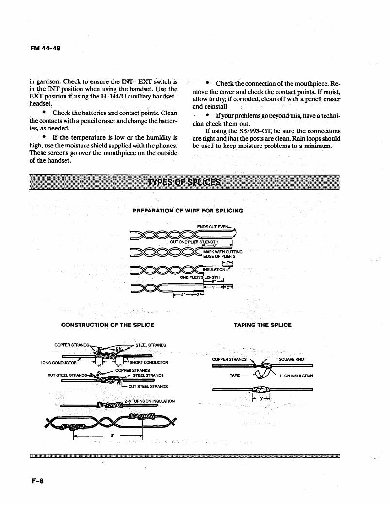
FM 44-48
in garrison. Check to ensure the INT- EXT switch isin the INT position when using the handset. Use theEXT position if using the H-144/U auxiliary handset-headset.
* Check the batteries and contact points. Cleanthe contacts with a pencil eraser and change the batter-ies, as needed.
* If the temperature is low or the humidity ishigh, use the moisture shield supplied with the phones.These screens go over the mouthpiece on the outsideof the handset.
* Check the connection of the mouthpiece. Re-move the cover and check the contact points If moist,allow to dry; if corroded, clean off with a pencil eraserand reinstall.
* If your problems go beyond this, have a techni-cian check them out.
If using the SB/993-GT, be sure the connectionsare tight and that the posts are clean. Rain loops shouldbe used to keep moisture problems to a minimum.
' ' : :Q 1222 2222 : 2 ::::t: : : :~: : : X ~ : :~I:~:~:l:8 : ::~:~::~:~:~:~:~:~ ~:~1~:~:~:lb5 ::: f:.~;~;~; :~:~5:~::::::: :~:1.: : :555.55 2 5 ::::~BX~:~~:~Sf :S.:~: t;~~~~*:S :.: ;.~:~ ~~s k~~:f" .~x~ ~~~ "":~:~:~::~:X:~::~::~:::~:~~81 .~.~1~ 2 5~i~f~~~ ~ '.'"::tS.~;~SS~Xs..~l~t :~:;:~s~sSS~S~S :55~ t;s ~st. : ~~~s 2. ~~~15 :5~ ~~v; 2. :P ~:~X :Q:~:~:::~:;~ : :~:::~:~::~ 55~.:.: ~:iiii~k~~~J~ ~:::: xs ::::~::::~:::~"'::~:fif:s : x:~::5SfSSS 5' ii~~i~il~:~i~i%:~:::::~, ,~::::::s:~:sl~::~:~.~ I~ ~I~~~ ':~:S.~::~:: : X:~:~:~:::~:5;:~~ ~~X~ ~Xf X ~s ~:~~:~:~:~:::~'::~:~5 :~~~:~:;::~ ~: ii~ : :i; :~':':"::~:~:~''~.8,,-,-- 'i:'::~:~r::~::;:~.:::::::::~:::,: .;,,;...,....1,~:~i :~:~:~ ~:l~:::~::8:t~~r~2~:St: ~'~ ~ ~b. . .L.. '.''2:::::~:~:.:5~~5s ~~~~ ~~~,~:~i~.~t:lt:~:~:~:~i~, .;lf:~:;,~,,.::~:~s.:~:s.:~:~:s : :~:~:~ ~ ~:sa~xhv~~,~~ ~ ; ~zi;ziz~~ .n i~S ~~?~t:2~ ~.;~is.. ..: : :s : ~:~s~:~~:~:~:~ W~~~ :~:ssss::::~:~: :s~:s~:~:::.:S.:::::::::
PREPARATION OF WIRE FOR SPLICING
ENDS CUT EVEN
CUT ONE PUERdLENGTH 4
SMARK WITCUTTINGEDGE OF PLIER'S
2"41
ONE PUER'S LENGTH
4" * 2-
'4" 2 C2
CONSTRUCTION OF THE SPLICE
COPPER STRAN ANDS . STEEL STRANDS
LON 1O4jR! kSHORT CONDUCTOR
LONGCONUCTR 41/4F7"1/4 ;COPPER STRANDS
CUT STEEL STRAN r STEEL STRANDS
CUT STEEL STRANDS
2-3 TURNS ,ON INSULATION
TAPING THE SPLICE
COPPER STRANDSPE 1UARE KNOT
TAPE V Y ION INSULATION
F-B
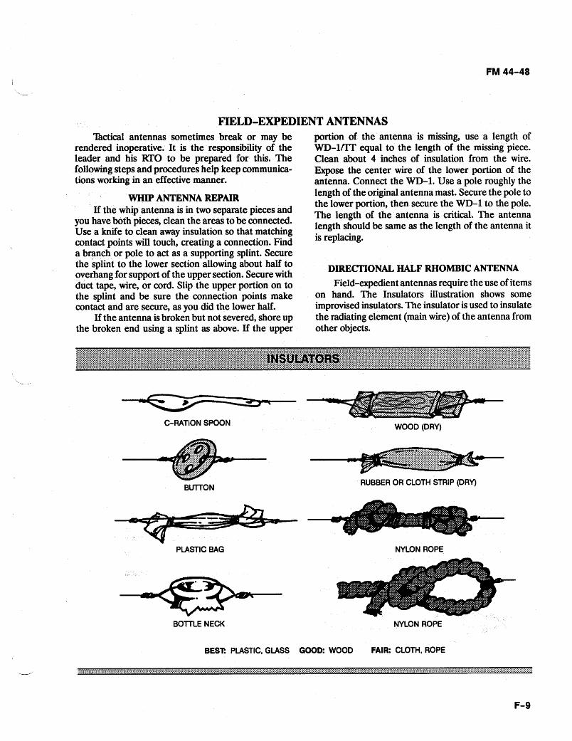
FM 44-48
FIELD-EXPEDIENT ANTENNASTactical antennas sometimes break or may be
rendered inoperative. It is the responsibility of theleader and his RTO to be prepared for this. Thefollowing steps and procedures help keep communica-tions working in an effective manner.
WHIP ANTENNA REPAIRIf the whip antenna is in two separate pieces and
you have both pieces, clean the areas to be connected.Use a knife to clean away insulation so that matchingcontact points will touch, creating a connection. Finda branch or pole to act as a supporting splint. Securethe splint to the lower section allowing about half tooverhang for support of the upper section. Secure withduct tape, wire, or cord. Slip the upper portion on tothe splint and be sure the connection points makecontact and are secure, as you did the lower half.
If the antenna is broken but not severed, shore upthe broken end using a splint as above. If the upper
portion of the antenna is missing, use a length ofWD-lflT equal to the length of the missing piece.Clean about 4 inches of insulation from the wire.Expose the center wire of the lower portion of theantenna. Connect the WD-1. Use a pole roughly thelength of the original antenna mast. Secure the pole tothe lower portion, then secure the WD-1 to the pole.The length of the antenna is critical. The antennalength should be same as the length of the antenna itis replacing.
DIRECTIONAL HALF RHOMBIC ANTENNA
Field-expedient antennas require the use of itemson hand. The Insulators illustration shows someimprovised insulators. The insulator is used to insulatethe radiating element (main wire) of the antenna fromother objects.
C-RATION SPOON
BUTTON
PLASTIC BAG
BOTTLE NECK
WOOD (DRY)
RUBBER OR CLOTH STRIP (DRY)
NYLON ROPE
NYLON ROPE
BESTE PLASTIC, GLASS GOOD: WOOD FAIR: CLOTH, ROPE
F-9
55' 55~5 ~ ~~: ~~~ ":~:~:~:~:~:~::~:~:~s~:s~:~:~:~r~:::~: : ~-- 5 ~~~2~ ::~:~:~:~:~:~:~::~IF:::~::~ ~ :s ~:;~;:;.~:::~:~:~::" r ~~g W:~:~::~4~~~.~::~:::~ ~:( XS X ~ : ~: i i "2 ::~:~:::::~::~:~::~.:.:~:sss :s~:~ ::::~:~:~:~:~:;: : tr ~;1 lr~:;::::; ~;~;1 :::~:~:::~:~:~:::~,;,,,,~:~:~:n ~~ u~~ P~ ~~ px~s~~
:~:~:~:~:~:~:~:~:~:~~::::~;~~:~:~:~:~i~f ~ru~r~u~ d L_..X ~l*.ii~S ~lb *~~I~'2- rrv.s .s~z~~S~t:~3~ ~~fg~~.~.2 ~ zz~ .2 ~ ::~s~:5:~:~:: :::5::~::~ :s~ :~:~::~:~:~:~:;Z;~;:;f~S;:;fl~8 X ~~X~55~ ~~5::~::~:::~ .. zt~ t~ . f:~"ZZ X~ .5'.'. 55 ~ 222~2. :~:~:;:~:;: :~:;~:::::~:~:~:~:~:~:~:~ :~X~~S~. z~SSS ~ :~:~:S;~;: X~ ~~ ~j
rzttn ttr ~ ~ s~z~s.52 s~x~:.~::::::::~Y~::b ~ .:..":2""----------- - -
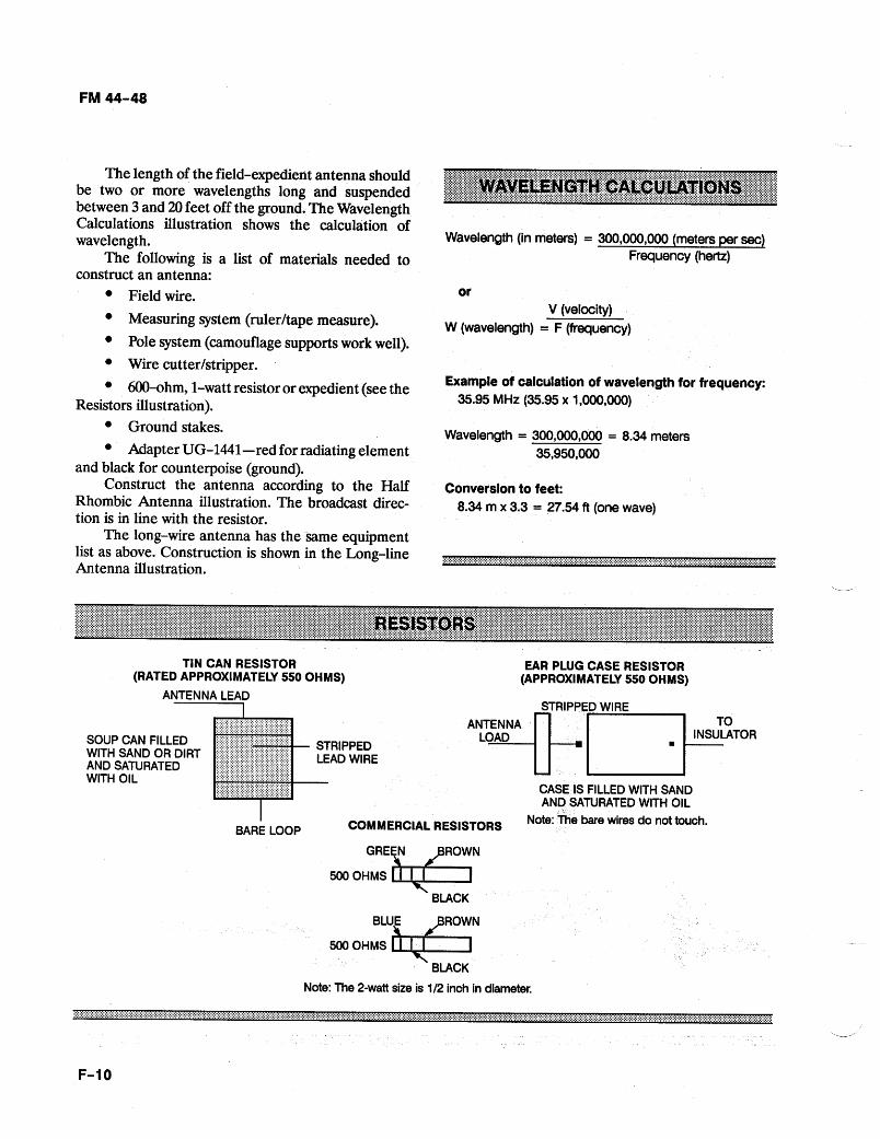
FM 44-48
The length of the field-expedient antenna shouldbe two or more wavelengths long and suspendedbetween 3 and 20 feet off the ground. The WavelengthCalculations illustration shows the calculation ofwavelength.
The following is a list of materials needed toconstruct an antenna:
" Field wire.
" Measuring system (ruler/tape measure).
* Pole system (camouflage supports work well).
" Wire cutter/stripper.
" 600-ohm, 1-watt resistor or expedient (see theResistors illustration).
" Ground stakes.
" Adapter UG-1441-red for radiating elementand black for counterpoise (ground).
Construct the antenna according to the HalfRhombic Antenna illustration. The broadcast direc-tion is in line with the resistor.
The long-wire antenna has the same equipmentlist as above. Construction is shown in the Long-lineAntenna illustration.
Wavelength (in meters) = 300,000,000 (meters per sec)Frequency (hertz)
orV (velocity)
W (wavelength) = F (frequency)
Example of calculation of wavelength for frequency:35.95 MHz (35.95 x 1,000,000)
Wavelength = 300,000,000 = 8.34 meters35,950,000
Conversion to feet:8.34 m x 3.3 = 27.54 ft (one wave)
. . . *. ~ *.xr *.*.* ..* * .. .*.* ** *.*..*. * : . .*.*..* *.. *.*..**.*..* * * . ..* ** STO R S:r :;:;~5~::::~: ~::8:::::::~:"'~~~~~~~~~~~~~~~.................................................:::x ..8:". ~: g;'K:)(:~~~~):B...........................................
TIN CAN RESISTOR(RATED APPROXIMATELY 550 OHMS)
SOUP CAN FILLEDWITH SAND OR DIRTAND SATURATEDWITH OIL
BARE LOOP
EAR PLUG CASE RESISTOR(APPROXIMATELY 550 OHMS)
STRIPPED WIREANTENNA TO
LOAD IINSULATORSTRIPPED LLEAD WIRE
CASE IS FILLED WITH SANDAND SATURATED WITH OIL
COMMERCIAL RESISTORS Note: The bare wires do not touch.
GRE N ROWN
500 OHMSBLACK
BLUE ROWN
500 OHMSBLACK
Note: The 2-watt size is 1/2 inch in diameter.
F-10
::::: :.:.:.:.~.:.:s :s::::::::::::::::: ..r : x 1..... .~::: .. . x .t ~;~::~~:.: ,8:~:::::::8:~:::i:::::i:
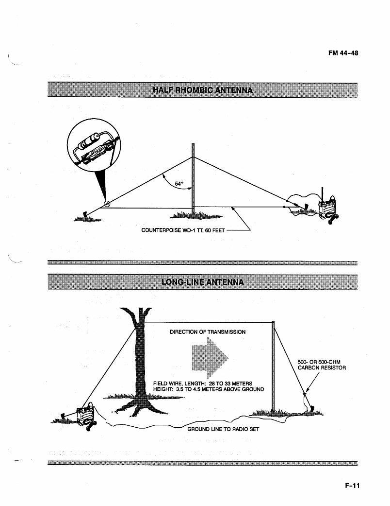
FM 44-48
HALF U ..~~ AftifA.............
500- OR 600-OHMCARBON RESISTOR
F-il
wiip *U ..
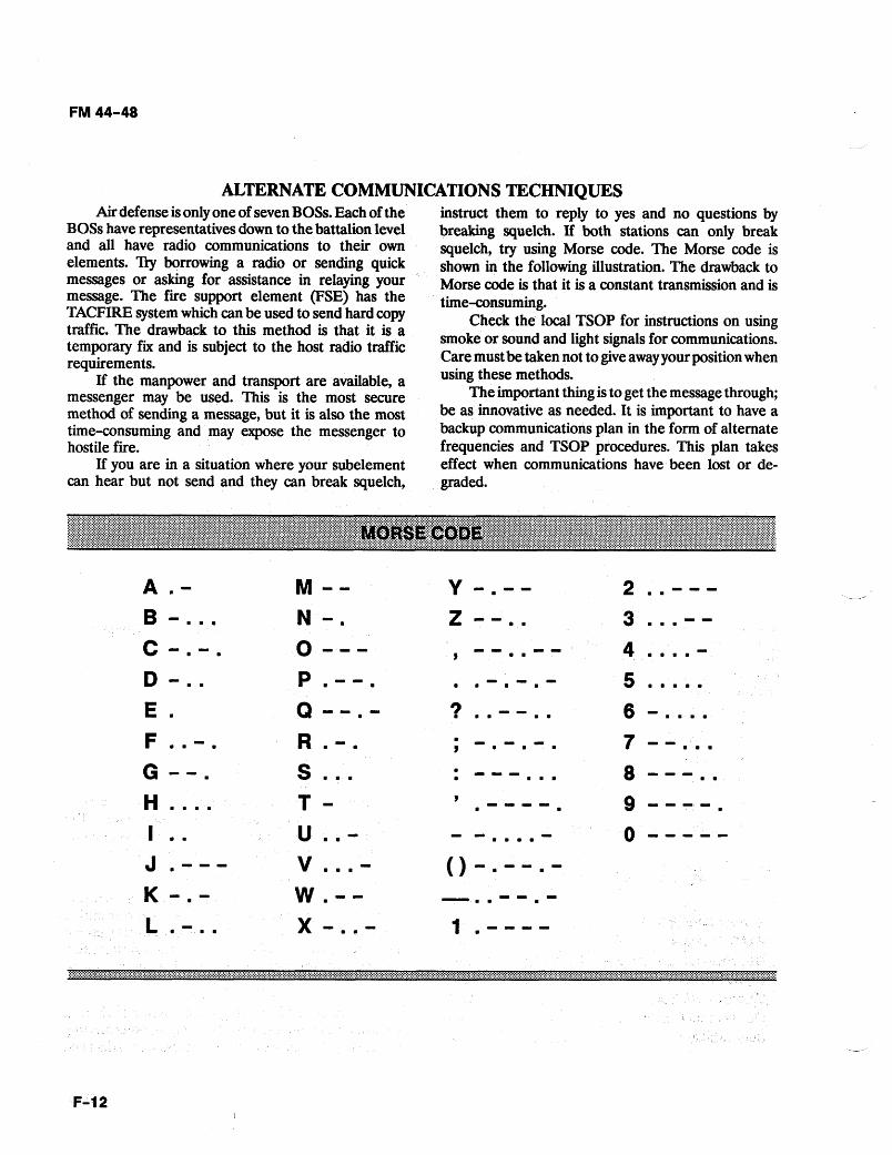
FM 44-48
ALTERNATE COMMUNICATIONS TECHNIQUESAir defense is only one of seven BOSs. Each of the
BOSs have representatives down to the battalion leveland all have radio communications to their ownelements. I~y borrowing a radio or sending quickmessages or asking for assistance in relaying yourmessage. The fire support element (FSE) has theTACFIRE system which can be used to send hard copytraffic. The drawback to this method is that it is atemporary fix and is subject to the host radio trafficrequirements.
if the manpower and transport are available, amessenger may be used. This is the most securemethod of sending a message, but it is also the mosttime-consuming and may expose the messenger tohostile fire.
if you are in a situation where your subelementcan hear but not send and they can break squelch,
instruct them to reply to yes and no questions bybreaking squelch. if both stations can only breaksquelch, try using Morse code. The Morse code isshown in the following illustration. The drawback toMorse code is that it is a constant transmission and istime-consuming.
Check the local TSOP for instructions on usingsmoke or sound and light signals for communications.Care must be taken not to give away your position whenusing these methods.
The important thing is to get the message through;be as innovative as needed. It is important to have abackup communications plan in the form of alternatefrequencies and TSOP procedures. This plan takeseffect when communications have been lost or de-graded.
" :~:~:;~.~;:5;:;:~:~:~:~:~;! "55~ :SS~S*~St~ ~"~~~ :~:~:i;~:~:~:~l:~:~:~~~~:~:~:~:.:s:5~~~~ ~~:~:::s~:~:~:::,.~:~::~:~:~::f.~:':':':': ~ :5~~~~~ ~~~ ~~:~.:~: ~:~~~:~;:~.~SS;:~SSS5fs t.~~*~~. t:::: ~ i~~~~:~~ x~W~~Xsss~ 5~~ .:.~.::~::.:~ : : r :il'''''';:::.::::~.~~:ssz ~i ::::: :~:~t:~:~:~~::::~:;~::~:s ::s~v rgg~~ ~~:~:~:~:~:~:::~:~:.:~:~:~. :~. ~ ~s~i~~, " '~~2'~:::~:~:~::~::::~:z~il ~~ ::::::::~:~:::~::~4;:;~:~:5 ~.::::~:S:~:r.ss . 2~ w:ii~S~S 2 ~5325~ ~5 5~ .~x~~ ~2.~S.~ ~~i~S ~ ~t. B~i
~: :.:.:~;:;,:::~: ~.~.~ :c :;l: : ::::~:~i~~~~sss 55~~~f~~ "2".'. ~~il~~ :::~:~::::,:~::~:~::~i:~:j ~~~ :~~:~~ ~s~. ~ ~.~.. i.;i i ~X~~KS ~
2..---
4
56 -
7 -8---9 ----0-----
.
1 --
B..
C-
D -.E.F.-G --
N-0 ---P.--Q--R.-
U..-
K-I.-~ x...W .--
X
-
F-12
~~ t~.s~:~ x t~ :s;ssz~ .-.-.-.-.-...~.~. .~.s . ~s~ ~s xs:f S~:SS~S~:f ~ss:::~::~::~:~::~:~:~ ~ .~;: , S~."''"':s~::::~::::~: f: ~SSS :5 : ~:55~::~~ - : :~:~:~~I~C ;S:~:~:~:::~:~:::~:~:~::::~:~ a~~ 5 :~:~:~:~:5 S X:~::::~:~:~~:~:~:~:~:~:~:~:~:~:~ 5 S.:~:~:5~;5 2; X f;5 ;l ti
Z -- ..
~II Ilriri
3 ~1 .
Iir
Ill. ..

APPENDIX G
Sensor EmploymentThis appendix describes how the ADA sensor supports FAAD
units during combat operations. It covers the light and special divi-sions interim sensor (LSDIS) that will be fielded with all FAAD unitsin support of light infantry units.
The mission of the supported unit is a prime factor influencingADA employment. However, the basic mission of the ADA sensor ineach employment is similar: provide time-sensitive radar alertingand tentative identification data for FAAD fire units and provide arearadar coverage.
This data is used to alert the air battle management operations cen-ter (ABMOC) of local air targets. It provides tentative aircraft identifi-cation. It also provides aircraft location so observers at the weapons canbe cued to visually search a relatively small sector of airspace.
SENSOR DESCRIPTIONA sensor is a device that is used to detect and
monitor aircraft, troops, and equipment. These devicesprovide information concerning locations and move-ments. They in turn alert and cue personnel andsystems to potential targets. Sensors are typically of thefollowing types:
* Optical.
* Infrared.
* Radar.
* Laser.
* Acoustical.
* Olfactory (chemical detection).
.ensor Description ............... 1FAAD Sensors.......... .G-2.
.Reconnaissance and Surveillance Plan . ... 2eptoyment Methods ................. G 3
Employment Guidelines ................ 3Operational Considerations .... ..... . .G 4Survivability G ....- 4
..... * .......... .......... .......... .......... .......... ........... .... .... ... . .... .... .... .... .... .... .... .... .... ....::~::~:~:~:~;' ss ;......................................... .............................5 2 f::~::~::~:~::.ss........................ ...................................... .s ... .: .. : .............................:............... .............. ..............::::::::::::::::................ :::
... .. ... .. ... .. ... .. ............. .. ... .. ..... ... .. ... .. ... .. ... .. ... .. ... .. ... ..iiiiii~~;~............ . ..................~i
M ot::i :::.... .. ........ii::~l::~ j:::i::.: :::i: 2 :: : ,..:::...
..... P .-P 9 ... i *.M ii~~~ijjiiiiiiiiiii iiiiiiiiiiiiii~ :iii~~~.......... ::: ~iii:i:::::~iii:'''':: :~ ::::
* Auditory.ADAweapon systems, whether missile or gun, use
sensors for the following:
* Early warning.
* Detection.
* Acquisition.
* Identification.
* Tracking.
* Surveillance.Target information is obtained by sensors, surveil-
lance and locating devices, and personnel. Theeffectiveness of countering an attack may depend onthe accuracy and timeliness of this information.
EARLY WARNINGEW equipment may be integrated with weapon
systems. EW is provided to operation centers and tothe ADA fire units. EW is the use of sensors (humanor electronic) to perform the function of providingsufficient warning of a threat attack to tactical units.
DETECTIONDetection is discovering the existence of aircraft,
troops, or equipment. This discovery permits alertingand cueing of friendly forces to the presence and location
G-1
FM 44-48
of potentially hostile forces. Enemy locations, for exam-ple, C2 facilities, radars, and enemy weapon positions, canbe accurately determined by the following:
* Electronic direction-finding equipment.
* Weapons-locating radars.
* Moving target-locating radars.
* Laser range finders and designators.
* Laser target acquisition devices.
" Infrared sensors.Refer to FMs 6-121 and 6-30 (Appendix C) for
additional information.
ACQUISITIONAcquisition is the gaining of information concern-
ing forces, both friendly and hostile, and their actions.The means of acquisition varies with each ADA system.
IDENTIFICATIONIdentification of potentially hostile targets is
accomplished using visual, electronic, oral, or printingdevices. Identification procedures are critical to pre-vent fratricide.
Identification, friend or foe (IFF) interrogatorsare used to electronically challenge aircraft transpond-ers to determine whether aircraft are friend orunknown. Certain ADA systems use visual identifica-tion as a backup or double verification of an aircraftstatus.
TRACKINGThe capability to track aircraft using a sensor(s) is
accomplished either manually or automatically. Track-ing an aircraft can involve slewing, moving the sensor,or being stationary to cover a designated area.
SURVEILLANCESurveillance is the watching of someone or
something by using devices or humans to monitor andreport on actions or operations. Surveillance is eitheractive or passive and employs techniques proven overtime to be effective to gather information concerningovert and covert operations. Surveillance sensorsprovide information on activities. The informationgathered is used to aid in planning, target designation,alerting, and cueing.
FAAD SENSORSLSDIS provides ADA battalions with a sensor
device meeting all-weather surveillance and detectionrequirements. LSDIS is the interim FAAD sensor forall light infantry ADA units. LSDIS is a lightweight,man-portable, rugged, EW sensor that provides FAADunits with cueing, alerting, and other EW information.
LSDIS capabilities are as follows:* Detects one square meter targets out to a
range of 20 kilometers and from 0 to 3,000 metersabove ground level.
* All weather.
* FAAD C3I/IFF compatible.
* Acquires high-speed maneuvering FW air-craft.
* Acquires hovering and pop-up helicopters upto 8 kilometers.
* Provides azimuth and range resolutions of 8
RECONNAISSANCE ANDA platoon of six sensor sections is organic to the
FAAD battalion. These sections are deployed insupport of the Bradley Stinger Fighting Vehicle
degrees or less and 1,500 meters or less, respectively.* Provides visual display of target location in azi-
muth and range.* Uses military power sources to include organic
vehicle power sources.* TIo-man emplacement or march order.
* Operable by one man.* Airdroppable or parachutable and transport-
able by medium helicopters and HMMWVs.The LSDIS platoon will be assigned to the
headquarters and headquarters battery (HHB) of theFAAD battalion. The platoon will have six LSDIS fordeployment.
The LSDIS section consists of three crew mem-bers: a section chief, a sensor operator, and anoperator/driver. The current employment conceptrequires that the LSDIS be transported by theHMMWV.
SURVEILLANCE PLAN(BSFV), Chaparral, Avenger, and Stinger fire units toprovide EW and assist the engagement process.
G-2
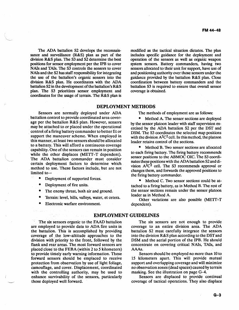
FM 44-48
The ADA battalion S2 develops the reconnais-sance and surveillance (R&S) plan as part of thedivision R&S plan. The S3 and S2 determine the bestpositions for sensor employment per the IPB to coverNAIs and TAIs. The S3 controls the sensors to coverNAIs and the S2 has staff responsibility for integratingthe use of the battalion's organic sensors into thedivision R&S plan. He coordinates with the ADAbattalion S2 in the development of the battalion's R&Splan. The S3 prioritizes sensor employment andcoordinates for the usage of terrain. The R&S plan is
modified as the tactical situation dictates. The planincludes specific guidance for the deployment andoperation of the sensors as well as organic weaponsystem sensors. Battery commanders, having twosensors allocated to their unit for support, have use ofand positioning authority over those sensors under theguidance provided by the battalion R&S plan. Closecoordination between battery commanders and thebattalion S3 is required to ensure that overall sensorcoverage is obtained.
DEPLOYMENT METHODSSensors are normally deployed under ADA
battalion control to provide coordinated area cover-age per the battalion R&S plan. However, sensorsmay be attached to or placed under the operationalcontrol of a firing battery commander to better fit orsupport the maneuver scheme. When employed inthis manner, at least two sensors should be allocatedto a battery. This will afford a continuous coveragecapability. One of the sensors can remain in positionwhile the other displaces (METI-T dependent).The ADA battalion commander must considercertain deployment factors to determine whichmethod to use. These factors include, but are notlimited to-
* Deployment of supported forces.
* Deployment of fire units.
* The enemy threat, both air and ground.
* Terrain: level, hills, valleys, water, et cetera.
* Electronic warfare environment.
The methods of employment are as follows:* Method A. The sensor sections are deployed
by the sensor platoon leader with staff supervision ex-ercised by the ADA battalion S2 per the DST andDSM. The S3 coordinates the selected map positionswith the division A2C2 cell. In this method, the platoonleader retains control of the sections.
* Method B. IWo sensor sections are allocatedto each firing battery. The firing battery recommendssensor positions to the ABMOC OIC. The S3 coordi-nates these positions with the ADAbattalion S2 and di-vision A2C2 cell. The S3 recommends approval orchanges them, and forwards the approved positions tothe firing battery commander.
* Method C. Two sensor sections could be at-tached to a firing battery, as in Method B. The rest ofthe sensor sections remain under the sensor platoonleader as in Method A.
Other variations are also possible (METI-Tdependent).
EMPLOYMENT GUIDELINESThe six sensors organic to the FAAD battalion
are employed to provide data to ADA fire units inthe battalion. This is accomplished by providingcoverage of the low-altitude approaches to thedivision with priority to the front, followed by theflank and rear areas. The most forward sensors areplaced close to the FEBA (within 2 to 5 kilometers)to provide timely early warning information. Theseforward sensors should be emplaced to receiveprotection from observation by use of light foliage,camouflage, and cover. Displacement, coordinatedwith the controlling authority, may be used toenhance survivability of the sensors, particularlythose deployed well forward.
The six sensors are not enough to providecoverage to an entire division area. The ADAbattalion S2 must carefully integrate the sensorsinto the division R&S plan according to the DST andDSM and the aerial portion of the IPB. He shouldconcentrate on covering critical NAIs, TAIs, andAAAs.
Sensors should be employed no more than 10 to15 kilometers apart. This will provide mutualsupport and overlapping coverage and will minimizeno observation zones (dead spaces) caused by terrainmasking. See the illustration on page G-4.
Sensors are displaced to provide continualcoverage of tactical operations. They also displace
G-3
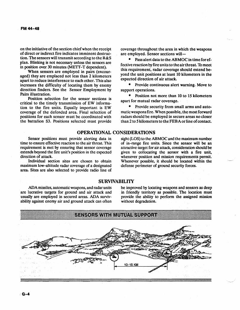
FM 44-48
on the initiative of the section chief when the receiptof direct or indirect fire indicates imminent destruc-tion. The sensors will transmit according to the R&Splan. Blinking is not necessary unless the sensors arein position over 30 minutes (METT-T dependent).
When sensors are employed in pairs (encour-aged) they are emplaced not less than 2 kilometersapart to reduce interference to each other. This alsoincreases the difficulty of locating them by enemydirection finders. See the Sensor Employment byPairs illustration.
Position selection for the sensor sections iscritical to the timely transmission of EW informa-tion to the fire units. Equally important is EWcoverage of the defended area. Final selection ofpositions for each sensor must be coordinated withthe battalion S3. Positions selected must provide
coverage throughout the area in which the weaponsare employed. Sensor sections will-
* Pass alert data to the ABMOC in time for ef-fective reaction by fire units to the air threat. To meetthis requirement, radar coverage should extend be-yond the unit positions at least 10 kilometers in theexpected direction of air attack.
* Provide continuous alert warning. Move tosupport operations.
* Position not more than 10 to 15 kilometersapart for mutual radar coverage.
* Provide security from small arms and auto-matic weapons fire. When possible, the most forwardradars should be employed in secure areas no closerthan 2 to 5 kilometers to the FEBA or line of contact.
OPERATIONAL CONSIDERATIONSSensor positions must provide alerting data in
time to ensure effective reaction to the air threat. Thisrequirement is met by ensuring that sensor coverageextends beyond the fire unit's position in the expecteddirection of attack.
Individual section sites are chosen to obtainmaximum low-altitude radar coverage of a designatedarea. Sites are also selected to provide radio line of
sight (LOS) to the ABMOC and the maximum numberof in-range fire units. Since the sensor will be anattractive target for air attack, consideration should begiven to collocating the sensor with a fire unit,whenever position and mission requirements permit.Whenever possible, it should be located within thedefense perimeter of ground security forces.
SURVIVABILITYADA missiles, automatic weapons, and radar units
are lucrative targets for ground and air attack andusually are employed in secured areas. ADA surviv-ability against enemy air and ground attack can often
be improved by locating weapons and sensors as deepin friendly territory as possible. The location mustprovide the ability to perform the assigned missionwithout degradation.
~f~i~ ~~~~ s~ : :s~: ::~:~:~:~:~:~:::~::~:::~:~.:: :~:~:;xs;:;W""Zx~ ~ : : ~ :~:'s.xr;:fs : ::~:~:~:~:~:~:~:~:~:~::~:~:~::":~:~ ~------- --.. ~SS2. ~ f: :Sf~:S~i::t'i: : 2' :S '2: Zz: '21::rrr. i. ;. ;i zz.s z.s:.~.~S.:.:2. . z. .i ... ''""~i~i~i~~5~s t~ ~~''"~i:fr:~xa:,,,,,,,,, *~rs*r"ra~rp~
.u~C ~'2~ ~ ; t;~;s ; ~ssssss~z.~; ~~~r~s~~ ~ ~ ~s~:~:s~:;~::::~::~:::::::~::: ,,~~i~~K ~t~~ t~fff~'i'". .2: :: i - ~3~ :S :SS~:St~::~:~:SS~:~: ~ ly~::~S f:::: ~5~ rv.: ~~f~SS 2.s sss~s ws~~s~sss~s ~~ ;: :~:~:W;:;:;:;:;:~:;:~:~::~X:::::::: '.f"::~:~:~:~~:~:~:#:~i:::~:~:~:~:~.:i~i~:::1: :::~; :~; ; : ;:::::~~kli~~i:si~: :~........~.:.~ ~:~;~::~::~l;f(~P~~:~;:sssssss~.ss z.s~;ss~:.: XS ~;: :: .:.t 2; :~: :' .sss: r~:t ::~:~:~:~:~:~:~ 88~:~:~: ~~ :::~::x : :s~::g I : I t; ;.~::~XS: ;:SS~XS ,:ss; x~:~x ~:~~Y:~:~:~ :::~:~:~:~:~:~ii~:~:':~:~:~::~:~:~'~is : : : :~:~:~::~: .2~ 2. 5 ~;: ~5 :;:~;:;~:~::~::~::::: ;s ~ :S '''''f ' '
G-4
2~ ~.~t~~~~ r.~ ~ .v:::::~:::~:~:~:~~:~:j : : : xs sst~:is 2 :.:~: ~: : : :s.:~ss~~ ~sssss. ~~~~ ~ss~ .~.t.r.t.ss ;.;zz;zz. ~; :21:::~:~:~:~:::::~::~:~::~:::~:::~:::~:
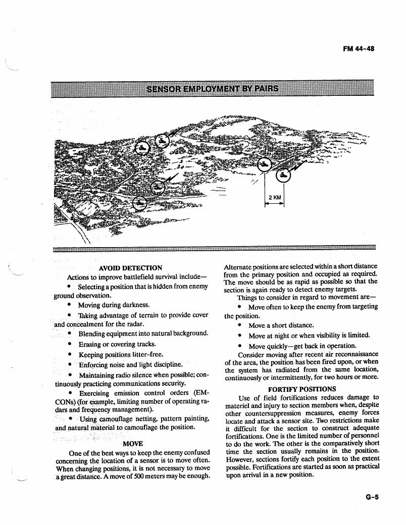
FM 44-48
... .. ...... ...... ...... ...... ...... ...... ...... ...... ..... . ...... ...... ...... ...... ...... ...... ...... ...... ...... ..... ..... ......"...... l.........'.i". Vi:.::fl .i s :::" i. }} i .
ti:'~ ~ s~~,,:::~ ss. i ~ ;.~ 5\~. 5::~5 . :. S:::::::-~~::~~:::5
AVOID DETECTIONActions to improve battlefield survival include--
* Selecting a position that is hidden from enemyground observation.
* Moving during darkness.
* Thking advantage of terrain to provide coverand concealment for the radar.
* Blending equipment into natural background.
* Erasing or covering tracks.
* Keeping positions litter-free.
* Enforcing noise and light discipline.
* Maintaining radio silence when possible; con-tinuously practicing communications security.
* Exercising emission control orders (EM-CONs) (for example, limiting number of operating ra-dars and frequency management).
* Using camouflage netting, pattern painting,and natural material to camouflage the position.
MOVEOne of the best ways to keep the enemy confused
concerning the location of a sensor is to move often.When changing positions, it is not necessary to movea great distance. A move of 500 meters may be enough.
Alternate positions are selected within a short distancefrom the primary position and occupied as required.The move should be as rapid as possible so that thesection is again ready to detect enemy targets.
Things to consider in regard to movement are-
* Move often to keep the enemy from targetingthe position.
* Move a short distance.
* Move at night or when visibility is limited.
* Move quickly-get back in operation.Consider moving after recent air reconnaissance
of the area, the position has been fired upon, or whenthe system has radiated from the same location,continuously or intermittently, for two hours or more.
FORTIFY POSITIONSUse of field fortifications reduces damage to
materiel and injury to section members when, despiteother countersuppression measures, enemy forceslocate and attack a sensor site. nlo restrictions makeit difficult for the section to construct adequatefortifications. One is the limited number of personnelto do the work. The other is the comparatively shorttime the section usually remains in the position.However, sections fortify each position to the extentpossible. Fortifications are started as soon as practicalupon arrival in a new position.
G-5
s ; ; .s t ' .5' C Xi~;~;::: : tS :S;~:~:~:~:~:~:~:~~~~~5S~:~~ixa:~:::::1:~g: ' '"'"f:::::::~:::::~:n::::::::::::::~:~:~:~:~5~:~:~:~:~:~:~:~:W~i~ ';"'''5'''5:~:'':~:~:~:~:~:::: :~::~::~iw~'~:~:'~;~':axs x'"^ "'"'";a; .t
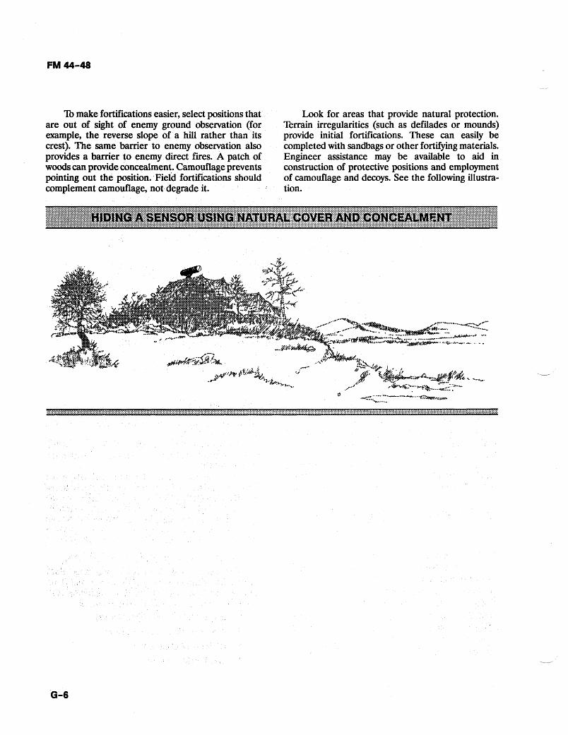
FM 44-48
Tb make fortifications easier, select positions thatare out of sight of enemy ground observation (forexample, the reverse slope of a hill rather than itscrest). The same barrier to enemy observation alsoprovides a barrier to enemy direct fires. A patch ofwoods can provide concealment. Camouflage preventspointing out the position. Field fortifications shouldcomplement camouflage, not degrade it.
Look for areas that provide natural protection.Terrain irregularities (such as defilades or mounds)provide initial fortifications. These can easily becompleted with sandbags or other fortifying materials.Engineer assistance may be available to aid inconstruction of protective positions and employmentof camouflage and decoys. See the following illustra-tion.
" BIiNG A SENSOR USING NATURAL COVER AND CONCEALMENT
e'1
*yi"i ~ t:A&.4 t. . -
:~bB0 -'
G-6
APPENDIX H
Manual SHORAD Control SystemThis appendix provides standardized procedures for the man-
ual SHORAD control system (MSCS). The objectives of the MSCSare to provide near real-time transmission of EW information toFAAD and other divisional units and weapons control informationto the FAAD unit organic to the division. It also integrates ADAdata into the division airspace management effort.
EW data is available to any unit which is capable of receivingit. This includes ADA units, the divisional maneuver units, andcombat support or combat service support units.
ADA fire units (FUs) are more effective if they are providedaccurate, timely, and reliable EW EW serves two purposes- alert-ing and cueing. Alerting information tells the user that an aircraftis approaching his position or the assets he is defending. Cueing in-formation tells the user from which direction the aircraft will becoming, its positional location, and its tentative identification in atimely manner. This enables the user to focus his attention in thatdirection to detect the aircraft at a greater range. To obtain this in-formation, FAAD units use a manual control system that providesalerting, but very limited cueing.
MSCS NETS ANDThe MSCS uses various communications nets and
components to provide timely, accurate, and reliableEW information. The MSCS is implemented throughthree communications nets.
The air defense coordination net (ADCN)provides EW information to the FAAD battalion fromHIMAD systems or Air Force sources. It also
. ~~::~::::~~::, ~ r~~s~ ::~~:~~:s~#::~I.............~xt~x ~ ~ :~:. ............. .. ........ .~:a : Z:#~ : ............... ... ..... ..xix~ ~s ~ :ol~~:~............ .........:~:::ua~:~:s:::~:~:::~:~:::::::::~ ~": i~:~.... ...... .. .. .......... :::a; a::s~x............... .. ...............:~:
....................................................................... .. ... .. ... .. ... .. ... .. .. ... ... .. .. ... .. ... .. ... .. ... .... .. ... .. ....... .. ....... ........ ....... ....... ........ ....... ................. .. .. .. .. .. .. .. .. .. . .. .. .. .. .. .. .. .. .. .. .. .. .. . .. .. .. .. .. .. .. .. .. .. .. .. .. .... .. ...... ....... ..... ........ ... ... ... .... ...... ...... ....... ...... ...... .. .. .. ... .... .... ...... .. .. ... ... .. .... .. . .. .. .. . .. .. . .. .. . .. ... .. . .. .. . .. . .. .. ... .. . .. ... .. . .. .. . .. . .. .. . .. ............ .......... .............................. .......... .............. ................... J ::.. .. .... ...... .. .. . .... .. ... ... .. ... . ..... .... .. ... ... .. ... . .. ... .. ...... . ......... .... .... .... .... ..... .... .... .... .... ..... .... .... .... .... ..... .... .... .... .. .... .. .. .. .. .. .. .. .. .. .. .. .. .. .. .. .. .. .. .. .. .. .. .. .. .. .. .. .. .. .. .. .. .. .. .. .. .. ........ ...........................................
..... .... ... .. . .... ..... ....nc. m p i....,n n s,*""*,*""*",**""*"""",*",*"""""'t ... ..... ........... ...........H ... 1 : ......... ....... .. ...... .. ...... .. .. ......... .. ..... ... .I ..... .. ........ ....... .................. .... .... .. .... I .... .... .. ..............................
.. .... ... .. .. .... ... ... .. .... ... .... ... ..... .......................... .......,:~~:~::~:~~ij~~i,;,:;:liiiiiiiigii-~:,:~~. ......... ::::::i.............:::::: :: :::::::::::.d i"""'*"'t**"""'*"""S **""'*"' ... ....:: : : : :: :e ..4 la ...........................:....... .......... 11 -0 T ..r .. Jq ... 10 M .....................~i~jj~i~ii;~i~........................................................I .......................................................................................................... :::::::::::::: i... .............................::i~i
COMPONENTSfacilitates command and control with those whomonitor the ADCN.
The division early warning (DEW) net dissemi-nates a standardized form of manual EW within thedivision MSCS.
The sensor net is used to pass those air tracks thatare in the LSDIS 20-kilometer alert threshold, to theABMOG/BNTOG, which will be correlated with thenearest HIMAD source and distributed to its custom-ers, that is, battery, platoons, section and FUs, andassociated maneuver elements. A nearby elementwithin LOS can monitor the sensor net if so desired.
AIR DEFENSE COORDINATION NET (AM)This net is used to transmit long-range track
information, weapons control information, and facili-tate command and control to the FAAD battalion TOGby communicating with the following sources:
" Brigade TOG LNOs (maneuver).
" Sensor platoon leader/sensors.
" Division TAC CP LNO.
* Local HIMAD source.
H-1
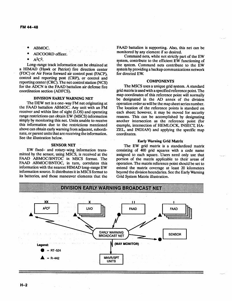
FM 44-48
* ABMOC.
* ADCOORD officer.
* A2C2 .Long-range track information can be obtained at
a HIMAD (Hawk or Patriot) fire direction center(FDC) or Air Force forward air control post (FACP),control and reporting post (CRP), or control andreporting center (CRC). The net control station (NCS)for the ADCN is the FAAD battalion air defense firecoordination section (ADFCS).
DIVISION EARLY WARNING NETThe DEW net is a one-way FM net originating at
the FAAD battalion ABMOC. Any unit with an FMreceiver and within line of sight (LOS) and operatingrange restrictions can obtain EW (MSCS) informationsimply by monitoring this net. Units unable to receivethis information due to the restrictions mentionedabove can obtain early warning from adjacent, subordi-nate, or parent units that are receiving the information.See the illustration below.
SENSOR NETEW fixed- and rotary-wing information trans-
mitted by the sensor, using MSCS, is received at theFAAD ABMOC/BNTOC in MSCS format. TheFAAD ABMOC/BNTOC, in turn, correlates thisinformation with the nearest HIMAD long-range EWinformation source. It distributes it in MSCS format toits batteries, and those maneuver elements that the
FAAD battalion is supporting. Also, this net can bemonitored by any element if so desired.
Command nets, while not strictly part of the EWsystem, contribute to the efficient EW functioning ofthe system. Command nets contribute to the EWsystem by providing a backup communications networkfor directed EW.
COMPONENTSThe MSCS uses a unique grid system. A standard
grid matrix is used with a specified reference point. Themap coordinates of this reference point will normallybe designated in the AD annex of the divisionoperation order as will be the map sheet series number.The location of the reference points is standard oneach sheet; however, it may be moved for securityreasons. This can be accomplished by designatinganother intersection as the reference point (forexample, intersection of HEMLOCK, INSECT, HA-ZEL, and INDIAN) and applying the specific mapcoordinates.
Early Warning Grid MatrixThe EW grid matrix is a standardized matrix
consisting of 400 grid squares with a code nameassigned to each square. Users need only use thatportion of the matrix applicable to their areas ofoperation. The matrix reference point should be set toextend the matrix coverage at least 20 kilometersbeyond the division boundaries. See the Early WarningGrid System Matrix illustration.
...... .... .... ;~~~:::...:. T~::~:::.~5'~~ i ;;~ I ii i ~-- ~ 5-555... .........:::.-,I. .~:~~:.1: p~1: :~..."5; 5~~~
XX
SENSORLegend:
0 = RT-524
A = R-442
H-2
;r rxs t zz;ozz;s -; ; ;t :::g::~:::~:g:::~:::~::::::::~:,,,:.:. :.x*x z.rss~.s~. . 5~~ :55 : ::~:~:~:~~:::~:~::::: X.: :~: 2: :. r.~. . :SS ? ~ ff:s .sWSS~5 : : s~.s ;.s: 2. :~:~: ff~ 555' 5~2;.1.:.,:1.:.-..-.::::~:: "'~s 2 :r .~ "':':"':':'-""" ~ ~ ~ .,%. t; ; ; ;ss ; ; :5~~j t.s .
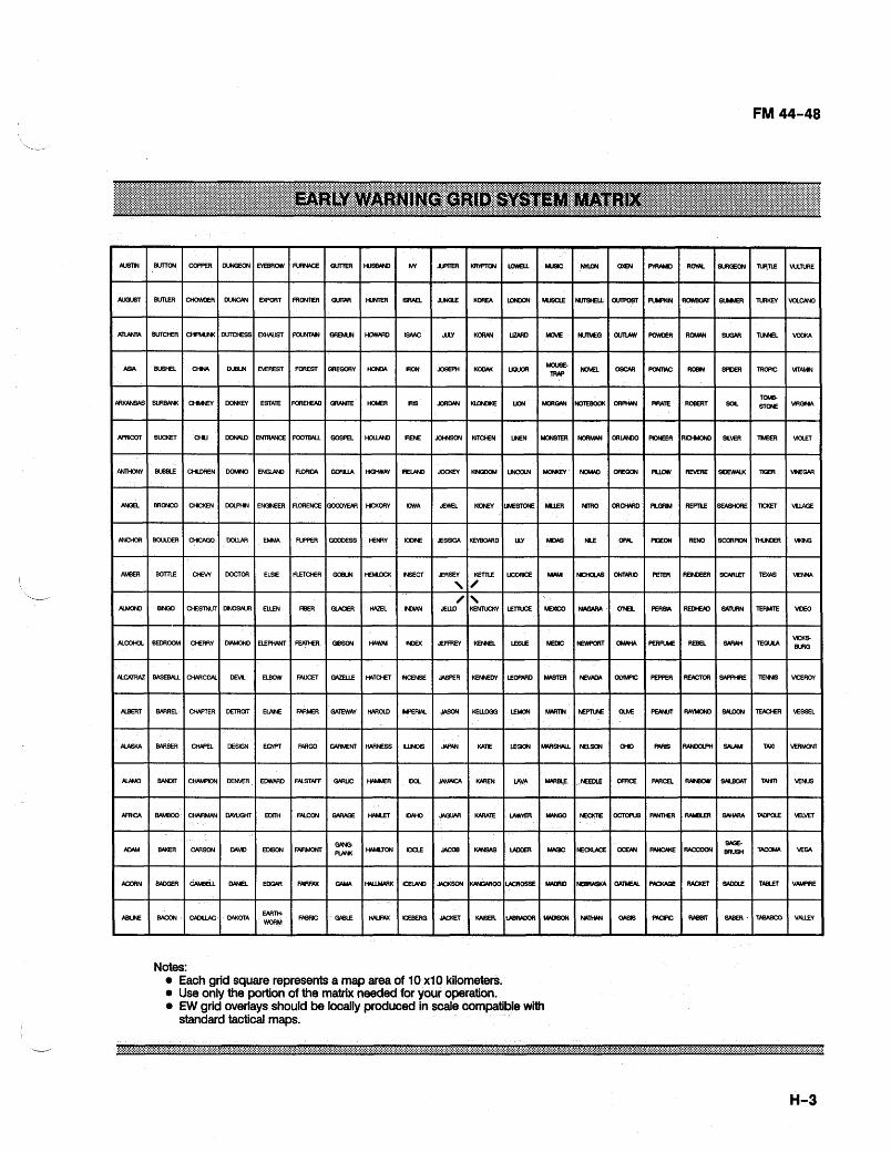
FM 44-48
AUSTIN BUTTON COPPER DUNGDEON EYEBROW FRINACE GUTTER HKUSBAND NY JUITER KRYPTON LOAWEUL MAUSIC NYLON OXEN PYRAMID ROYAL SURGSEON TUTL1E VIJTURBE
ALKNJST BUTLER CHOWDER DIJICAN EXPORT PRONTIER GIITAR HKUNTER ESRAEL .BJNG.E KOREA LONDON MUSJCLE NUITSHELL OUTIPOST PUM.CKIN ROWABOAT SUMMER TURKSIEY VOLCANNO
ATLANTA BUATCHER CHIPMUNK DUTC-E 55 ESHLAUST FOLEITAIN GREMLIN HOWARD ISAAC JLY KORAN LIZARD MOVE NUTM.EG OUTLAW PONDiER ROMAN SUGAR TUNNEL. VODKA
ASL -BUSHEI. CHNA DUBLLH EVEREST FOREST GREGORY HONDA HRON JOSEPH KODAK LIQUOR NOEL OSCAR PONTIAC ROBIN SPIOER TROPIC ITAMIN
ARKANAS BUBANKTOMB-ARASSBSBU(CIMNEY DONK1EY ESTATE FORHEAD GRLANIE HOMER HRIS JORDAN KLODKE LION MORGAN NOTEBOOK ORPHAN PIRATE ROBERT SOL. STONIE VIRGNI
APRICOT BUCKET Clii DONALD ENTRANCE FOOTBALL GOSPEL HOUNADI HENE JOIHNSON KITCHEN LINEN MONSTER NORMAN ORLANDO PIONIEER RICHMAONDS SILVER TUBSER VIOLET
ANTHONY BUISBLE CILOREN DONOO ENGLAND LRDA GORILLA HAIHAY IRELSAD JOCKEY KINGDOM LHNCOLN MONKEY NOMAD OREGON PELLOW REVERE SIDEWALK TIGER VENEGAR
ANGEL BRONCO OC EN DOLPHI-N ENGIREER FLORENCE GOODYEAR HICKORY IOWA JEWEL KIONEY LIMESTONE MILLER NITRO ORCHARD PILGRBM REPTIEE SEASHORE TICKET VILLAGE
ANCHOR BOUBDER CHICAGO DOLLAR EMMBA FLPPER GODDESS IHENRY IORIE JESSICA KEYBOARD LEY MIDAS NBE OPAL PIGEON RENO SCORPION THIANDER VIIN
AMBEER BOTTLE ClEVY DOCTOR ELSIE FLETCH-ER GOBLIN I-SMOCK ISECT JERSEY KETTLE LICORICE MYA NICHOLAS ONTARIO PETER REIDEER SCARLET TEXAS VIENNA
ALMOND. BIGW CHESTNUJT DNOSAURA ELLEN PEBER GL.ACIER HASEL. INDIAN JELLO KENTUCKYA LETTUCE MEMCO NIAGARA OPEL PERSI REDHIEAD SATURBN TERARE VIO
ALCOHOL BEDROOM CIHERRY DIAMOND) ELEPHANT. FEATHER. GISON HAWAN IKX JEFFREY KENNEL LESLE MEDIC NEWAPORT OMAHA PERPLME REBEL SARA TEOLBA WICRG
ALCATRAZ BASEBALL. CHARCOAL DEVI. ELBOW FAUCET GAZELLE HATCH-ET ICENSE JASPER KENNEDOY LEOPARD MIASTER NEVADA OLYMP~IC PEPPER REACTOR SAPPIRE TEFNS VICEROY
ALBERT BARREL CHAPTER DETROIT ELSINE FARMER GATEWAY HAROLD IMERAL JASON KELLOGG LEMON MARTB NEPTUNE OLIVE PEANEIT RAYMOND) SALOON TEACH-ER VESSEL
ALASKA BARBER CHAPEL DESIGN EGYPT FARGO GARMENT HARNESS ILLIOIS JAPAN KATE LEGION MARSHAL NELSON 0OH0 PARIS RADIOLPH SALAMI TAXI VERMONT
ALAMO BANIT CHAMPION DENIER EDWARD FALSTAFF GARUIC HAMMER COL. JAMAICA KAREN LAVA MARBLE PEEDLE OFFICE PARCEL RAIBOW SALBOAT TAII VENUS
AFRICA BAMBOO' CHIRMAN DAYLIJIT EDISH FALCON GARAGE H-AMET LWJ-IO JAPGUAR KARATE LAWYER MANGO NECKTIE OCTOPUS PANITHER RAMIBLER SAHARA TADPOLE VELVET
GANG- IEADAM BAKER CARSON DAVID EDISON FAIMONIT PLN HAMI.TON ICICLE JACOB KANSAS LADDER MAGI NECKLACE OCEAN PANCAKE RACCOON BRUS TACOMA VEGA
ACORN SADGER CAMBELL DANIEL EDGAR FAIRA GAMA HALLMARK ICELAND JACKSON KANGAROO LACROSSE MAI)HE) NEBRASKA OATMIEAL PACKAGE RACKET SADDLE TABLET VAMPIRE
ABIBE BACON CADILLAC- DAKOTA RT M FABRIC GABLE HALFAX ICEBERG JACKET KAISER, LABRADOR MADISON NATHAN OASIS PACIFI RABBIT SABER -TABASCO VALLEY
Notes:" Each grid square represents a map area of 10 x10 kilometers." Use only the portion of the matrix needed for your operation." EW grid overlays should be locally produced in scale compatible with
standard tactical maps.
H-3
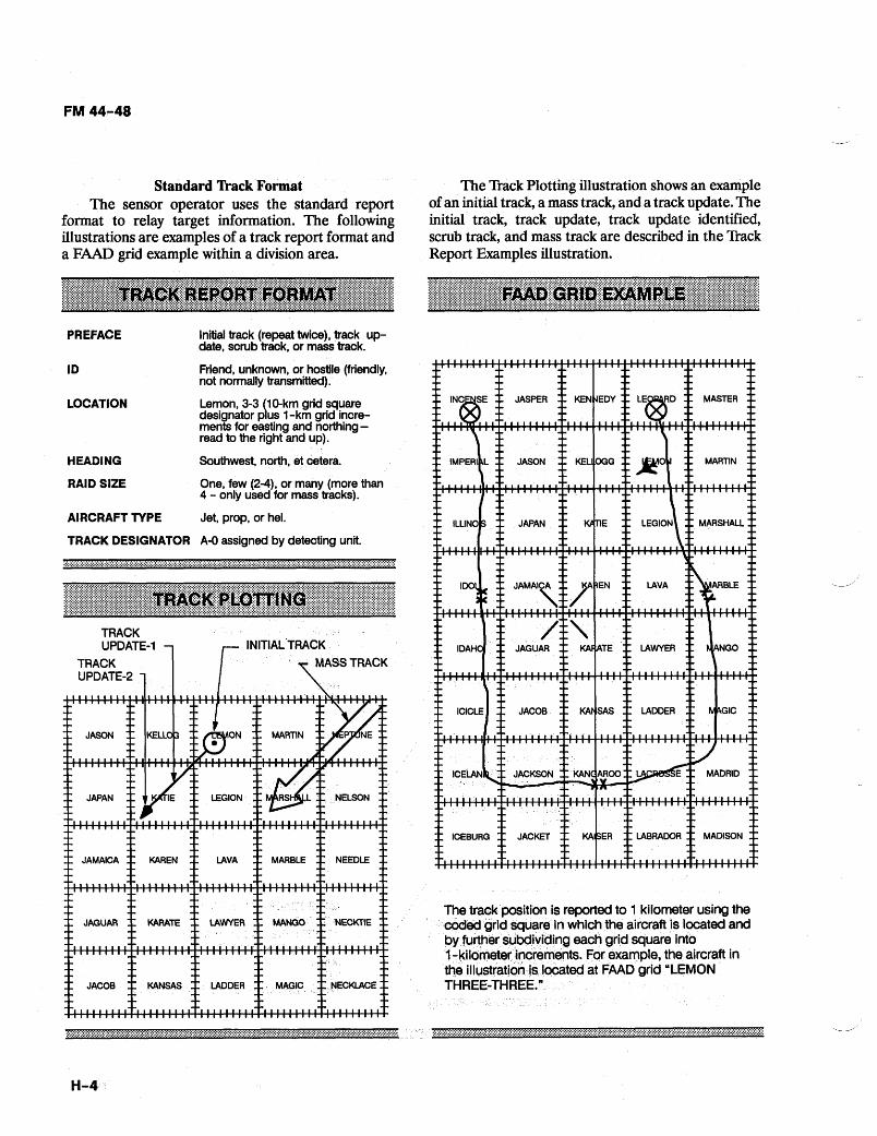
FM 44-48
Standard ITack FormatThe sensor operator uses the standard report
format to relay target information. The followingillustrations are examples of a track report format anda FAAD grid example within a division area.
TRACK REPORT FORMATi~.~lj~~j~~
PREFACE Initial track (repeat twice), track up-date, scrub track, or mass track.
ID Friend, unknown, or hostile (friendly,not normally transmitted).
LOCATION Lemon, 3-3 (10-km grid squaredesignator plus 1-km grid incre-ments for easting ard northing -read to the right and up).
HEADING Southwest, north, et cetera.
RAID SIZE One, few (2-4), or many (more than4 - only used for mass tracks).
AIRCRAFT TYPE Jet, prop, or hel.
TRACK DESIGNATOR A-0 assigned by detecting unit.
.. ".. ii i: : ::: : :1 : 'i':'''': :: : : i: : ?
TRACKUPDATE-i INITIAL TRACK
TRACK MASS TRACKUPDATE-2
JASON KELLC 32 ON MARTIN P NE0
JAPAN IE LEGION RS NELSON
JAMAICA KAREN LAVA MARBLE NEEDLE
JAGUAR KARATE LAWYER MANGO NECKTIE
JACOB KANSAS LADDER MAGIC NECKLACE
*----1- ±1-144-- 1-141414414
The Track Plotting illustration shows an exampleof an initial track, a mass track, and a track update. Theinitial track, track update, track update identified,scrub track, and mass track are described in the TrackReport Examples illustration.
lo o l l a f f l c t e d l o l l 1 1 1 2 1 1 0 1
INC SE JASPER KEN EDY LE RD MASTER
IMPERI L JASON KEL G "4D MARTIN
ILLINO JAPAN E LEGION MARSHALL
IDO JAMAIQ~~, ,/A EN LAVA ARBLE
IDAH JAGUAR KA ATE LAWYER NGO
1-14+H+141-1441-1- +141-H o 41144'
ICICLE JACOB KA SAS LADDER GIC
ICLN JACKSON fKAN AROO :U;RSE MADRID
ICEBURG JACKET KA ER LABRADOR MADISON
The track position is reported to 1 kilometer using thecoded grid square in which the aircraft is located andby further. subdividing each grid square into1-kilometer increments. For example, the aircraft inthe illustration is located at FAAD grid "LEMONTHREE-THREE."
H-4
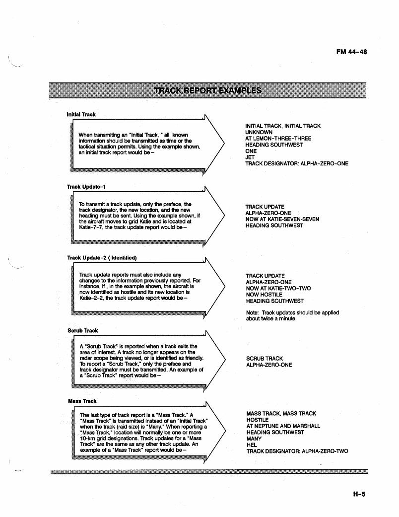
FM 44-48
s~ s~s'SSS~S~i~i~-ii~i~iii~i~i~:~:~:~~~:~s .~z.s ~5..~;~ ss .zt~ . : ~':':5'~'~':~:"::~ ~5 ~5 : :5:t.s 555~i:fs~,I:~~~~i::::::~s~~~,, ~Z~~ ;;,;.,.,..ss~:~:::~::j~:~:~:~:~:;:~:~:~:::~:::: :~:~:~:~:~::~:~:~:~:~::~:~:~:~:~:~ pu::s~~ :::~:::.:~:::::~I~::~,~,:5~:~: ~ ~ xsx ... ~.s .sss .ss .ss ... 5:. . ~..~.:.:..,,,,~,8 i~i~i~#:~:~~:~:~::~:~:::i:::~:~:~:~:;~;:~:~:~:~:~: :~:~t~; ,,., :sxz:~:s::::.:::::::::::55' ~~~~ ::;:;:~:;~:~:~::~:~:~:: :5555':55.. :~:~:;:5~:~:~:~~:~:~~:5;:~: ~~ :55. Wss~s~~ ;~t~ :~:~."bs :ss~,~::~:~~i~~~~S~:X:S~:~:~:~:~:~:~ ~SZ: ~:~:~: : .~. . 2~ ~ .2~z.ss ss:~:~:~~:~:~:~~i~ii~i~i~i xa~ss~ss .~ :~:~: ~:::~:~:~:X:~:~
Initial Track
When transmiting an "Initial Track, all knowninformation should be transmitted as time or thetactical situation permits. Using the example shown,an initial track report would be-
Track Update-iI To transmit a track update, only the preface, thetrack designator, the new location, and the newheading must be sent. Using the example shown, ifthe aircraft moves to grid Katie and is located atKatie-7-7, the track update report would be-
.....t
INITIAL TRACK, INITIAL TRACKUNKNOWNAT LEMON-THREE-THREEHEADING SOUTHWESTONEJETTRACK DESIGNATOR: ALPHA-ZERO-ONE
TRACK UPDATEALPHA-ZERO-ONENOW AT KATIE-SEVEN-SEVENHEADING SOUTHWEST
Track Update-2( Identified)
Track update reports must also include anychanges to the information previously reported. Forinstance, if , in the example shown, the aircraft isnow identified as hostile and its new location isKatie-2-2, the track update report would be-
Scrub Track
A "Scrub Track" is reported when a track exits thearea of interest. A track no longer appears on theradar scope being viewed, or is identified as friendly.To report a "Scrub Track," only the preface andtrack designator must be transmitted. An example ofa "Scrub Track" report would be-
Mass Track
The last type of track report Is a "Mass Track." A"Mass Track" is transmitted instead of an "Initial Track"when the track (raid size) is "Many." When reporting a"Mass Track," location will normally be one or more10-km grid designations. Track updates for a "MassTrack" are the same as any other track update. Anexample of a "Mass Track" report would be-
TRACK UPDATEALPHA-ZERO-ONENOW AT KATIE-TWO-TWONOW HOSTILEHEADING SOUTHWEST
Note: Track updates should be appliedabout twice a minute.
SCRUB TRACKALPHA-ZERO-ONE
MASS TRACK, MASS TRACKHOSTILEAT NEPTUNE AND MARSHALLHEADING SOUTHWESTMANYHELTRACK DESIGNATOR: ALPHA-ZERO-TWO
H-5
::~::::~:~::~:~:~j~::'~:::~::M~::::::~:~ ~:~ :.:5.:.: ~s~r~zz~ fS 5t SS : :SSS ::t. ::~::::~::jR:::::R:~:::::~::::::::::::~: Y i : : : :XS:~:~::::::::::8:::C:::::::~::~::~
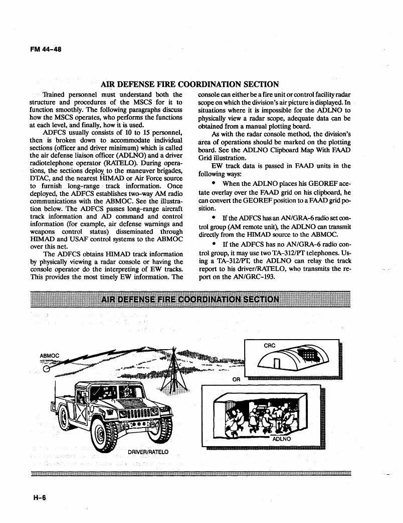
FM 44-48
AIR DEFENSE FIRE COORDINATION SECTION.flBained personnel must understand both the
structure and procedures of the MSCS for it tofunction smoothly. The following paragraphs discusshow the MSCS operates, who performs the functionsat each level, and finally, how it is used.
ADFCS usually consists of 10 to 15 personnel,then is broken down to accommodate individualsections (officer and driver minimum) which is calledthe air defense liaison officer (ADLNO) and a driverradiotelephone operator (RATELO). During opera-tions, the sections deploy to the maneuver brigades,DTAC, and the nearest HIMAD or Air Force sourceto furnish long-range track information. Oncedeployed, the ADFCS establishes two-way AM radiocommunications with the ABMOC. See the illustra-tion below. The ADFCS passes long-range aircrafttrack information and AD command and controlinformation (for example, air defense warnings andweapons control status) disseminated throughHIMAD and USAF control systems to the ABMOCover this net.
The ADFCS obtains HIMAD track informationby physically viewing a radar console or having theconsole operator do the interpreting of EW tracks.This provides the most timely EW information. The
console can either be a fire unit or control facility radarscope on which the division's air picture is displayed. Insituations where it is impossible for the ADLNO tophysically view a radar scope, adequate data can beobtained from a manual plotting board.
As with the radar console method, the division'sarea of operations should be marked on the plottingboard. See the ADLNO Clipboard Map With FAADGrid illustration.
EW track data is passed in FAAD units in thefollowing ways:
When the ADLNO places his GEOREF ace-tate overlay over the FAAD grid on his clipboard, hecan convert the GEOREF position to a FAAD grid po-sition.
" If the ADFCS has an AN/GRA-6 radio set con-trol group (AM remote unit), the ADLNO can transmitdirectly from the HIMAD source to the ABMOC.
" If the ADFCS has no AN/GRA-6 radio con-trol group, it may use two TA-312/PT telephones. Us-ing a TA-312/PT, the ADLNO can relay the trackreport to his driver/RATELO, who transmits the re-port on the AN/GRC-193.
:~:: : rQ:~::~::~:~:~ ;~:::::: ~~~ :~:~r~:3~:.~~~:~:~:~:;:~:::~:.:.5~:~:: ~f~ :s ~ :~:~:~~: : ~ ~s;~;:;~ :~::::~:::I~:~::~: ::~II::~:~:::~:::~:~~~::~W S;:~:;:;Sf :b:~:~:.~.~ ~::::~:~i~::.S ::S ::~:~ :~:iii~i~i~xf x:~:~ ~s~::::~:~::::~: : :::: :S ;: ~ :~:s.::~:~~: :~8:::~ :::~:~:~~s~:::~i~:~:n:fn:s~:8~1:~:~~:~2.~~f~~ -o~t;
~~i~c~t~~j~ ii : t~iriia 3 ~~~8~~~:::..~~I~:5~,,w~z~~zz.t :55 :5~ - ~ixt:~~n: ~~-t:s ;~::~:~ ~sk:~:~::~::~:s:::::~::: ~:
ABMOC
DRIVER/RATELO
H-
i8~i~:~:~:~:~:.~~:~~:~:~:~:~:~:~:~:~:~1~
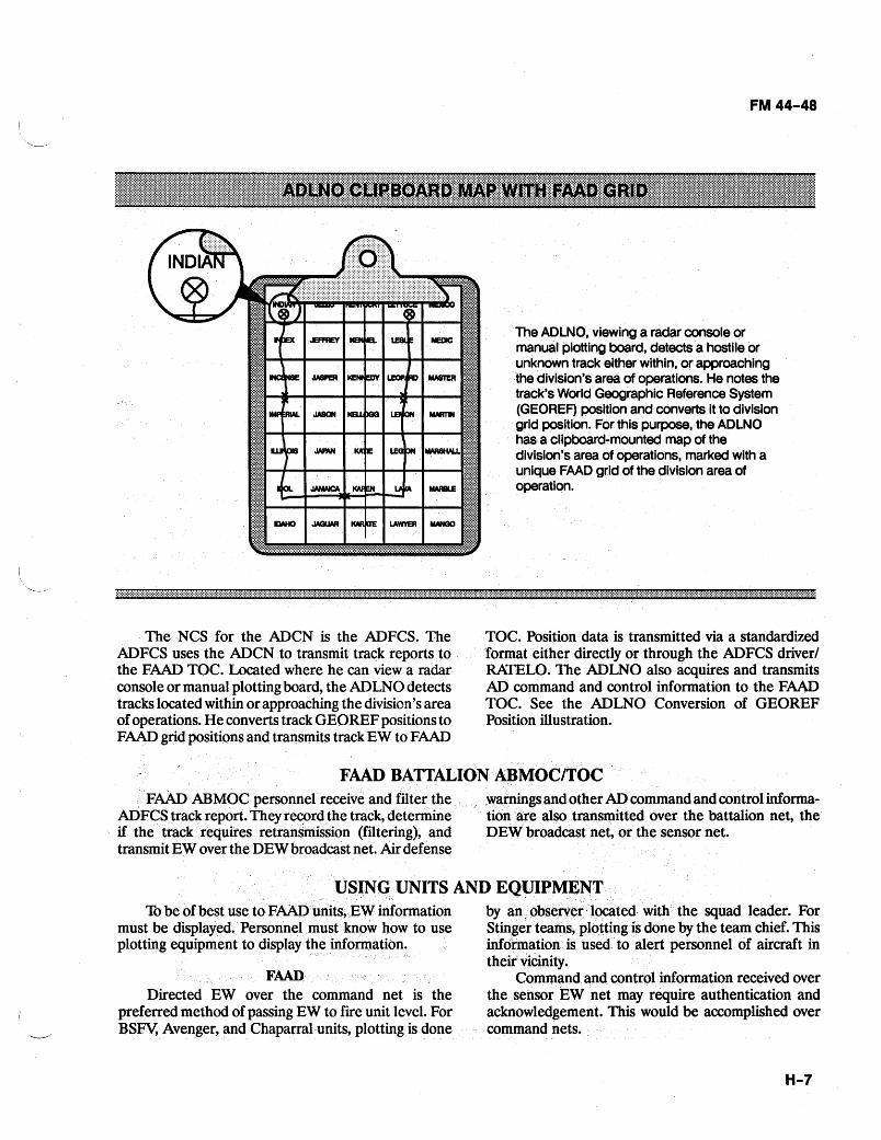
FM 44-48
~:~:~:~:~:~:~~8~8:::~:~:~::~ ":~' 5' ' '~ 'L" '~55~ ~a~:~~:::,: ,,, ~~~.~ : ~: :~~~:~:~~xa:~:s~:~s~:s.:~f~ :~:~~:~ ~s~ ~~~~s~s.x :~: ~.~ ~x~t~~ c; r; z.'f~ :~::~:~:~:~:~:~::::~:~:~:s .. x Izs.s ~ ~ ~ r0:~:~:f:~ ~~w r~w ~c~r~: ~ ~ :s ~s~:2 i ~ ~S :S K~ X :5 ~:""" .5x i :IL~~pii~~l~5 ~55:~. f"5-.~.~'r."?.~..T;:~~~:~::~~: :.X3~:fSQ:~S~:~:S~:~QT~I :S T :S : 5: T : 5 ~:.:.~.::~:~~0:~:~:~:~:;t~:M ~S 71 i:~:gZZ.~ 5555W:.~.: :::~:::::~::~::~::R:~:~1 I~:SX~S f::t~~XS~:S~S S~f: ~:::::~:~::~:::::~::::: ::~::~:::~:~::~:~ :55 ~ : ::~:~:~. ;
The ADLNO, viewing a radar console ormanual plotting board, detects a hostile orunknown track either within, or approachingthe division's area of operations. He notes thetrack's World Geographic Reference System(GEOREF) position and converts it to divisiongrid position. For this purpose, the ADLNOhas a clipboard-mounted map of thedivision's area of operations, marked with aunique FAAD grid of the division area ofoperation.
The NCS for the ADCN is the ADFCS. TheADFCS uses the ADCN to transmit track reports tothe FAAD TOG. Located where he can view a radarconsole or manual plotting board, the ADLNO detectstracks located within or approaching the division's areaof operations. He converts track GEOREF positions toFAAD grid positions and transmits track EW to FAAD
TOG. Position data is transmitted via a standardizedformat either directly or through the ADFCS driver/RATELO. The ADLNO also acquires and transmitsAD command and control information to the FAADTOG. See the ADLNO Conversion of GEOREFPosition illustration.
FAAD BATTALION ABMOC/TOCFAAD ABMOC personnel receive and filter the
ADFCS track report. They record the track, determineif the track requires retransmission (filtering), andtransmit EW over the DEW broadcast net. Air defense
warnings and other AD command and control informa-tion are also _transmitted over the battalion net, the'DEW broadcast net, or the sensor net.
USING UNITS AND EQUIPMENTTo be of best use to FAAD unitsEW information
must be displayed. Personnel must know how to useplotting equipment to display the information.
FAADDirected EW over the command net is the
preferred method of passing EW to fire unit level. ForBSFV Avenger, and Chaparral units, plotting is done
by an observer located with the squad leader. ForStinger teams, plotting is done by the team chief. Thisinformation is used 'to alert personnel of aircraft intheir vicinity.
Command and control information received overthe sensor EW net may require authentication andacknowledgement. This would be accomplished overcommand nets.
H-7
f::~:S XS~~~: :~~SSS.XQ:S~~ :~:~:~~~:S
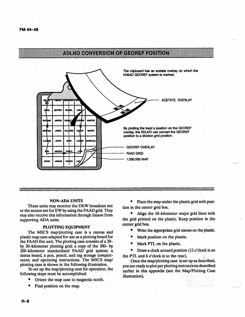
FM 44-48
:.f~:~:~: :;:~:~::2~.~~ 4''t ~~ - l r~ t:SSf IZC~~ Z~ IZ B Zi 5~ ~:~:~:~ ~:~::~:~:::~:~l::~r~~~::~~"SS~:~;s~..5.~5555557.. .s~.ss~:~:~:~: .~.~ .sss~.~.s~.s-. .s~:;~ f: ~ ~ ~5 %~Zf ''~s ~:;~:~::~::~::~:;~::;:;:~ ~;~:;~~ ::::: ~ :~I 'f' :~;:~;:~ ~~,~, ~2 '~~; ss~
:~: ~ :t~c~'.'~:.~:~'Z;P~:~:s s ~"'~ a; ; ; : tss~ .:~:s2~:,: X~S~:.~S ~~ ~i~S~~~i~i~i~X~s~ ~~ ~:;:~:~:~:::::~:::::~:~:~ ~:.~i~::~:::: 22. 2. :~f:':~:;. 255 ~ :S;~;:5~ :': :f:~:~:~:~:~;~ ~:S;: X:ss-:s-2~% ~TS~Z~C~ ~i~~'" ~:S~.s ~ss ~f~~s~ Msr:s :s.s :s
The clipboard has an acetate overlay on which theHIMAD GEOREF system is marked.
> ACETATE OVERLAY
By plotting the track's position on the GEOREFoverlay, the ADLNO can convert the GEOREFposition to a division grid position.
NON-ADA UNITSThese units may monitor the DEW broadcast net
or the sensor net for EW by using the FAAD grid. Theymay also receive this information through liaison fromsupporting ADA units.
PLOTTING EQUIPMENTThe MSCS map/plotting case is a canvas and
plastic map case adapted for use as a plotting board forthe FAAD fire unit. The plotting case consists of a 30-by 30-kilometer plotting grid; a copy of the 200- by200-kilometer standardized FAAD grid system; astatus board, a pen, pencil, and rag storage compart-ment; and operating instructions. The MSCS map!plotting case is shown in the following illustration.
To set up the map/plotting case for operation, thefollowing steps must be accomplished:
" Orient the map case to magnetic north.
" Find position on the map.
* Place the map under the plastic grid with posi-
tion in the center grid box.
" Align the 10-kilometer major grid lines with
the grid printed on the plastic. Keep position in thecenter grid box.
* Write the appropriate grid names on the plastic.
* Mark position on the plastic.
* Mark PTL on the plastic.
* Draw a clock around position (12 o'clock is on
the PTL and 6 o'clock is to the rear).Once the map/plotting case is set up as described,
you are ready to plot per plotting instructions describedearlier in this appendix (see the Map/Plotting, Caseillustration).
H-8
LA "
~zi ;.~. .:tt.s~.s~;s~.5:.,t.s .r.:~ ~~:;~ :;::f:sf ~~~S~t~;: : :s :r~~: : tt:s xS ~ :s.: : ::;:~: :~:~:;:;::r:;: : : ~; ...;~ i 2.t f:S~S~: z.s ; t"'r' :~:~:.:S.XS.:S :.: :S 5""'IZ;'ffn"';'L 'ns'z:
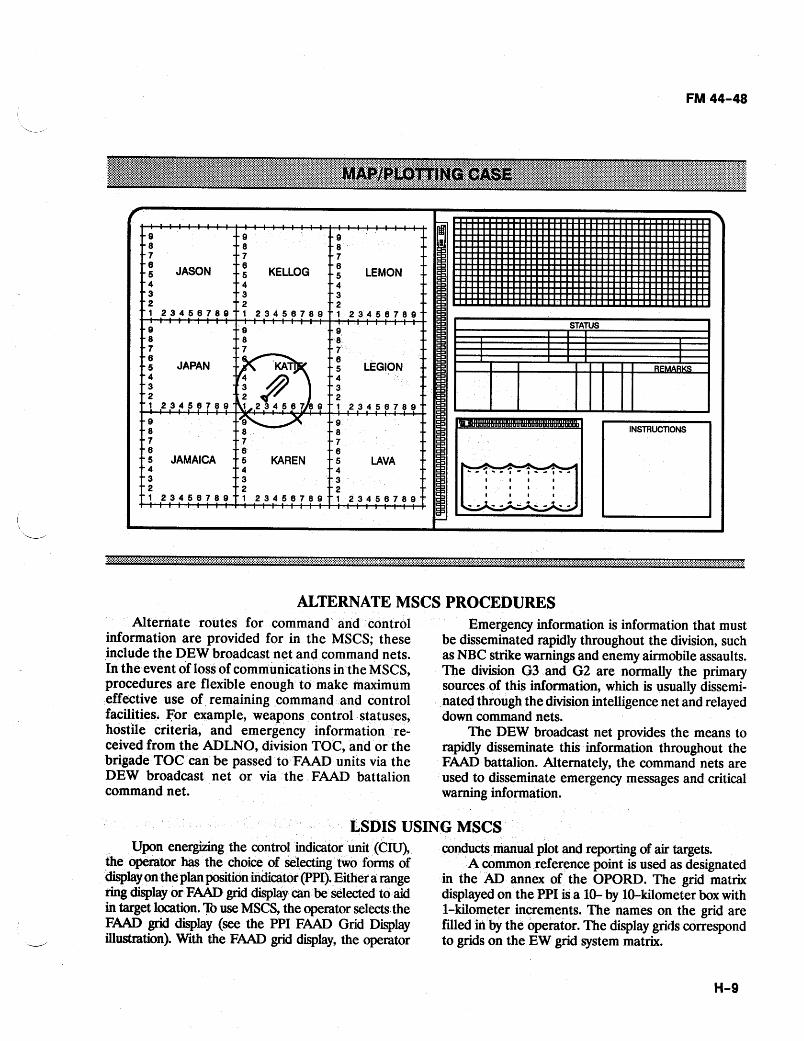
FM 44-48
ALTERNATE MSCS PROCEDURESAlternate routes for command ' and control
information are provided for in the MSCS; theseinclude the DEW broadcast net and command nets.In the event of loss of communications in the MSCS,procedures are flexible enough to make maximumeffective use of remaining command and controlfacilities. For example, weapons control statuses,hostile criteria, and emergency information re-ceived from the ADLNO, division TOC, and or thebrigade TOC can be passed to FAAD units via theDEW broadcast net or via the FAAD battalioncommand net.
Emergency information is information that mustbe disseminated rapidly throughout the division, suchas NBC strike warnings and enemy airmobile assaults.The division G3 and G2 are normally the primarysources of this information, which is usually dissemi-nated through the division intelligence net and relayeddown command nets.
The DEW broadcast net provides the means torapidly disseminate this information throughout theFAAD battalion. Alternately, the command nets areused to disseminate emergency messages and criticalwarning information.
LSDIS USING MSCSUpon energizing the control indicator unit (CIU),
the operator has the choice of selecting two forms ofdisplay on the plan position indicator (PPI). Either a rangering display or FAAD grid display can be selected to aidin target location. Tolb use MSCS, the operator selects theFAAD grid display (see the PPI FAAD Grid Displayillustration). With the FAAD grid display, the operator
conducts manual plot and reporting of air targets.A common reference point is used as designated
in the AD annex of the OPORD. The grid matrixdisplayed on the PPI is a 10- by 10-kilometer box with1-kilometer increments. The names on the grid arefilled in by the operator. The display grids correspondto grids on the EW grid system matrix.
H-9
::~:~:;~~;::::n::;pagl:K~:~:~:~:~:~:#: :.:.~ :~:;:S X :lx :*X;~;X~ : : ::~:~:::::U:~::S:~:: :5;::::~:::::::~:::~:~:::s I :~:~:s~: i~~::: ~ :~~~ ' E fSf~ ::S :.X ~ ~ : : : :~: :.: ~~ :~:~: ~ ~ : ~ : : : ~ ~ :5 :::~:~:::~:~::::~JI~~:~:~ ~~;~;~;~:;~;~i~ S :SS ~.f;S ZZS.i.:.:2 55~ ~ :2~;:::~:~:~:;~;: ~s ~ :;:;~'; ;';r::::: .ii ~ ..~ ~zt.- ~~ss ::~:::::~:~:::::~~:'~i~:~~ ~~~ ~~i~i~ .s:a~#n ~:~~ :~:s ::~:t :;i;i~;~z~s ~tt~f~ :5~~~% 7~5~ ~::~:~:~::~:~::::~j:~:~::s t~stt~st~ .i--~ ; ~5 P: : ~5 *:~:~~;~;~;'2 5~;:l;t;~;,:5555 :~:~:~::~ ~:~: t~ t : ~ :~~~ :S :fiYn::::~:~:~' .~. .ratt;5 ss~5~Zi 5 5 2 51 ~5~::5;~;:~;::~:::::~:~:~:~:~:S~Z~.zz..t :i : :~: : :SSS5Sf O~ ~S X ~W~~ssss z~s ~~s~:~~5 ~~~ .s
I ,:S ~~S~SS~i ~ ~ X~S~ ~t:~:i:::SSi:.XSi:;:;:S;XP .~~ :S~: : :~: X.: f: ~ f: :.:S. X f: .-.-.-- .szsiss~s-:-~~ii ss~.s~s~~:i ii : : :zz:s :: I l l I.5 ' L CS'.' :I~ .~.-. . .si 5 L 55~f f ;55 2 5 ; 5
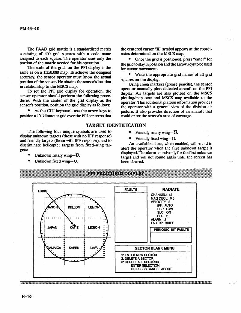
FM 44-48
The FAAD grid matrix is a standardized matrixconsisting of 400 grid squares with a code nameassigned to each square. The operator uses only theportion of the matrix needed for his operation.
The scale of the grids on the PPI display is thesame as on a 1:250,000 map. lb achieve the designedaccuracy, the sensor operator must know the actualposition of the sensor. He obtains the sensor's locationin relationship to the MSCS map.
b set the PPI grid display for operation, thesensor operator should perform the following proce-dures. With the center of the grid display as thesensor's position, position the grid display as follows:
" At the CIU keyboard, use the arrow keys toposition a 10-kilometer grid over the PPI center so that
the centered cursor "X" symbol appears at the coordi-nates determined on the MSCS map.
* Once the grid is positioned, press "enter" forthe grid to stay in position and the arrow keys tobe usedfor cursor movement.
* Write the appropriate grid names of all gridsquares on the display.
Using china markers (grease pencils), the sensoroperator manually plots detected aircraft on the PPIdisplay. Air targets are also plotted on the MSCSplotting/map case and MSCS map available to theoperator. This additional platoon information providesthe operator with a general view of the division airpicture. It also provides direction of an aircraft thatcould enter the sensor's area of coverage.
TARGET IDENTIFICATIONThe following four unique symbols are used to
display unknown targets (those with no IFF response)and friendly targets (those with IFF response), and todiscriminate helicopter targets from fixed-wing tar-gets:
" Unknown rotary wing-U.
" Unknown fixed wing-U.
* Friendly rotary wing-O.
" Friendly fixed wing-O.An available alarm, when enabled, will sound to
alert the operator when the first unknown target isdisplayed. The alarm sounds only for the first unknowntarget and will not sound again until the screen hasbeen cleared.
~ '" ' '''':':':~"' :~5:~::~:::: :a: :~:::5 55~ 55'~ : ~ : ::~~~~~ ~~f~~: : 5;~55Sf ::5 :~.~.sXS : :~:~:2~' ' ' ' Mg :~:'''5' i:~:~:~:~:~:~.~:#XB:~::::~:~:j~::~:~: :': :~:I"':S~:":"''''5 S~~f:;;S z...s..i "S~:~::::~:~:~::~i~':~i:~::::~:U:is..S..~.:~: 5s~ ~.:s~:s :sa::: ':' ~~~'*ss~.~ ~ ~l~t. ':.~.:.:Q~::::::~:~:"S :S : ~S:~:~::l:~: ~:~::S:::::::::~ .i x :~; ~~~~,.~'C : :SC : ~i~:~I~v~:.:.:.~ ~s~~ ~f~~ ~j~~ ~~ :~ sf~~~~~l.~x :': ;~:~s~W$::~s~s:::~::::w:~:~:~:~~~:~:~"~~~1:~j~ ~:ss :8::: :5~~~~:~::::";"'..' :~C~~~:;~~~ :~~SPZ~c~":q:~:~:~:~):cf~~: ;;::::::...~. 2~ ; :::~:~:~:~:;: xs:::~:~:~~:~:~.:'.::5~:~:~.~: ~~C~~~:s r~ :s ~r:~~~~ O~~ ::~:~:~::~::~i:~::.:~:~IS~ :~:s :~:~: : : :~:~::~:j:~ ;.;s .i ~ .~:~::~::: ~:~:::851i~X: :ss;: gl~~"~~
FAULTS RADIATECHANNEL: 12MAG DECL: 0.5VELOCITY: 2
IFF: AUTOPRF: LOWSLC: ONSOJ: 2
ALARM: JFAULTS: BRIEF
PERIODIC BIT FAULTS
MAICA KAREN LAVA SECTOR BLANK MENU
1: ENTER NEW SECTOR2: DELETE A SECTOR3: DELETE ALL SECTORS
ENTER SELECTIONOR PRESS CANCEL ABORT
H-10
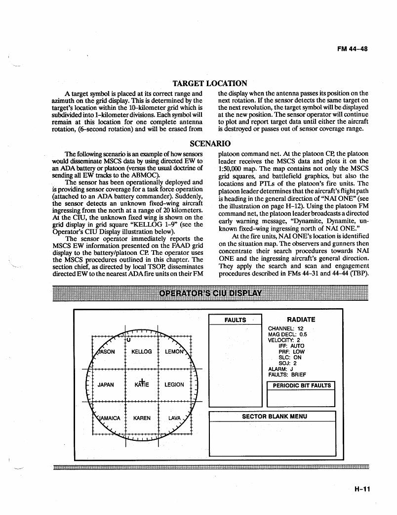
FM 44-48
TARGET LOCATIONA target symbol is placed at its correct range and
azimuth on the grid display. This is determined by thetarget's location within the 10-kilometer grid which issubdivided into 1-kilometer divisions. Each symbol willremain at this location for one complete antennarotation, (6-second rotation) and will be erased from
the display when the antenna passes its position on thenext rotation. If the sensor detects the same target onthe next revolution, the target symbol will be displayedat the new position. The sensor operator will continueto plot and report target data until either the aircraftis destroyed or passes out of sensor coverage range.
SCENARIOThe following scenario is an example of how sensors
would disseminate MSCS data by using directed EW toan ADA battery or platoon (versus the usual doctrine ofsending all EW tracks to the ABMOC).
The sensor has been operationally deployed andis providing sensor coverage for a task force operation(attached to an ADA battery commander). Suddenly,the sensor detects an unknown fixed-wing aircraftingressing from the north at a range of 20 kilometers.At the CIU, the unknown fixed wing is shown on thegrid display in grid square "KELLOG 1-9" (see theOperator's CIU Display illustration below).
The sensor operator immediately reports theMSCS EW information presented on the FAAD griddisplay to the battery/platoon CP. The operator usesthe MSCS procedures outlined in this chapter. Thesection chief, as directed by local TSOP, disseminatesdirected EW to the nearest ADA fire units on their FM
platoon command net. At the platoon CP, the platoonleader receives the MSCS data and plots it on the1:50,000 map. The map contains not only the MSCSgrid squares, and battlefield graphics, but also thelocations and PTLs of the platoon's fire units. Theplatoon leader determines that the aircraft's flight pathis heading in the general direction of "NAI ONE" (seethe illustration on page H-12). Using the platoon FMcommand net, the platoon leader broadcasts a directedearly warning message, "Dynamite, Dynamite, un-known fixed-wing ingressing north of NAI ONE."
At the fire units, NAI ONE's location is identifiedon the situation map. The observers and gunners thenconcentrate their search procedures towards NAIONE and the ingressing aircraft's general direction.They apply the search and scan and engagementprocedures described in FMs 44-31 and 44-44 (TBP).
OP.AQ~ ........ 0
H-11
:;:~:ixSS;:;~l:;:W: f:S1:;xi: :s~~;X ":.X.5 ss :5 x : : ' ' : : ~: ~;~ i - 2: ; x : z; : z: ; ::: ;o;s zz; :.:.:.:d:.:S.:~XZ: : :S X : X :.:~X::t;st. .X t.s z.s ~X~ : :z..~z..s:ii.ss:.5~..2.5
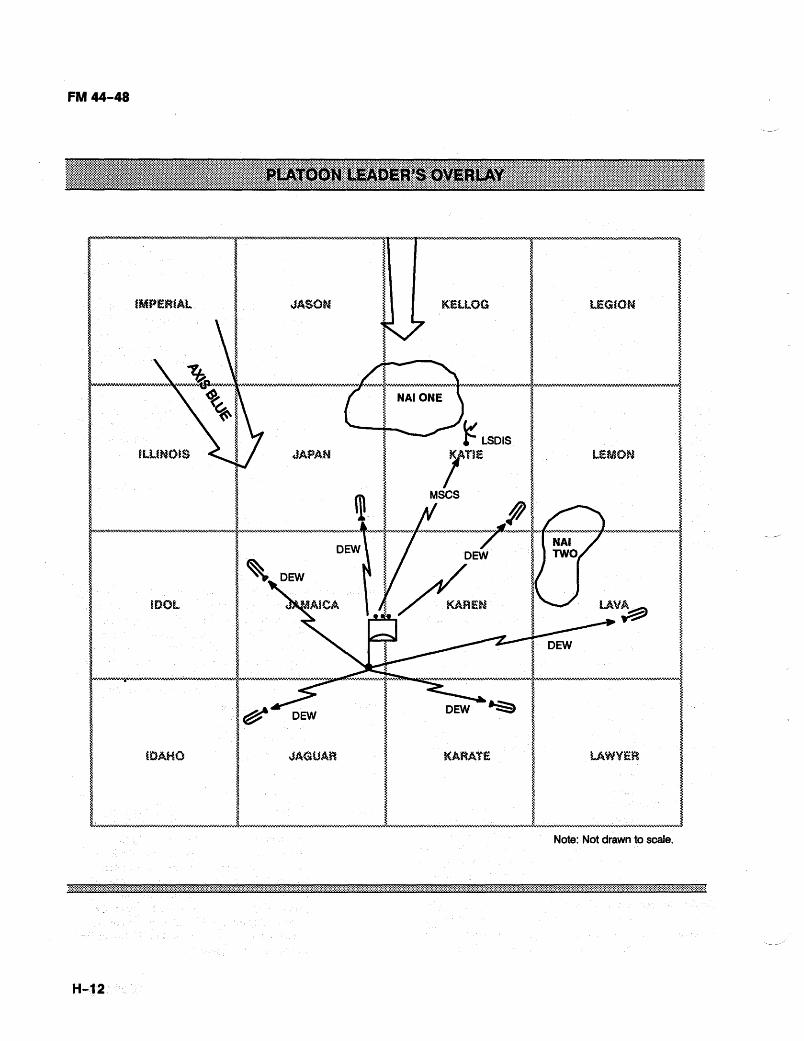
FM 44-48
i:}r:v}:i'}:::tti}":":::::fl::U:{:::,::;{;}$}::,"{D::': flVA {{ } IAV. YFPLT O ic!1 : 4":T n"" ""'T i!!m p.y.. ... '.......s: ...
Note: Not drawn to scale.
H-1-2
Glossary
A2C2 Army Airspace Command and ControlAA size of batteryAAA air avenue of approachAAM air to air missileABMOC Air Battle Management Operations Centeractive air defense direct defensive action taken to destroy attack-
ing enemy aircraft or missiles or to nullify or re-duce the effectiveness of such attack. It includessuch measures as the use of aircraft, interceptormissiles, air defense weapons artillery, non-airdefense weapons in an air defense role, and elec-tronic countermeasures and counter-countermea-sures. (JCS Pub 1-02)
AD air defenseADA air defense artilleryADCN air defense coordination netADCOORD air defense coordinatorADCS air defense coordination sectionADFCS air defense fire coordination sectionADLNO air defense liaison officerADW air defense warningAH attack helicopterair battle management a fundamental task of air defense com-
mand and control and airspace management whichencompasses the principles for the control andcoordination of both tactical air and ground-basedair defense resources. Air battle management isexercised through positive and procedural meth-ods.
air corridor a restricted air route of travel specified for use byfriendly aircraft and established for the purpose ofpreventing friendly aircraft from being fired uponby friendly forces.
air defense (AD) all measures designed to nullify or reduce theeffectiveness of attack by hostile aircraft or guidedmissiles both before and after they are airborne.
air defense artillery (ADA) ground-based, surface-to-air weapons,including guns and surface-to-air missiles and sup-port equipment, for engaging air targets.
air recon aerial reconnaissanceairspace control a service provided in the combat zone to increase
operational effectiveness by promoting the safe,efficient, and flexible use of airspace. Airspacecontrol is provided to permit greater flexibility ofoperations, while authority to approve, disapprove,or deny combat operations is vested only in theoperational commander.
airspace management the coordination, integration, and regula-tion of the use of airspace of defined dimensions.
air strike an attack on specific objectives by fighter, bomber,or attack aircraft on an offensive mission.
A/L
ALB
alert
administrative/logistics
AirLand Battle
a warning signal of a real or threatened danger,such as an air attack; to forewarn; to prepare foraction.
allocation (1) the translation of the apportionment into totalnumber of sorties by aircraft type available foreach operation task and (2) an apportionment of adefinite quantity of supplies, space, services, per-sonnel, or productive facility for a specific use.
alt altitude
alternate position the position given to a weapon, unit, or individ-ual to be occupied when the primary position be-comes untenable or unsuitable for carrying out itstask. The alternate position is located so that theweapon can continue to fulfill its original task.
AM
AMC
AMO
ant
AO
AP
amplitude modulation
at my command-a method of control for fire sup-port
air movement officer
antenna
area of operations
armor piercing
area air defense commander within an overseas unified command,subordinate unified command, or joint task force,.the commander will assign overall responsibilityfor air defense to a single commander. Normally,this will be the Air Force component commander.Representation from the other service componentsinvolved will be provided, as appropriate, to thearea air defense commander's headquarters.
ARM
ASM
ASP
AT
ATGM
attach
antiradiation missile
air-to-surface missileaim smart munitions
ammunition supply point
antitank
antitank guided missile
the placement of units or personnel in an organi-zation where such placement is relatively tempo-rary. Subject to limitations imposed by theattachment order, the commander of the forma-tion, unit, or organization receiving the attach-ment will exercise the same degree of commandand control thereover as he does over units andpersons organic to his command. However, theresponsibility for transfer and promotion of per-sonnel will normally be retained by the parent for-mation, unit, or organization.
Glossary-1
FM 44-48
attack an offensive action characterized by fire and ma-neuver and culminating in a violent assault or, inan attack by fire; in the delivery of intensive directfires from an advantageous position. Its purpose isto direct a decisive blow at the enemy to hold him,destroy him in place, or force him to capitulate.
attn attention
AWACS Airborne Warning and Control SystemBAI battlefield air interdictionbasic load (ammunition) that quantity of nonnuclear ammunition
that is authorized and required by each service tobe on hand a unit to meet combat needs until re-supply can be accomplished. It is expressed inrounds, units, or units of weight as appropriate.
batt battery
battle position positions on which the main effort of the defense isconcentrated. A battle position is made up of asystem of defensive sectors that support oneanother.
battlefield operating system (BOS) the major functions occurringon the battlefield and performed by the force tosuccessfully execute operations. The seven systemsare (1) maneuver, (2) fire support, (3) air defense,(4) command and control, (5) intelligence, (6) mo-bility and survivability, and (7) combat service sup-port. NBC must be integrated throughout eachBOS.
BC battery commanderBCS battery computing systemBCU battery coolant unitbde brigade
bn battalion
BNTOC battalion tactical operations centerBOS battlefield operating systemboundary in land warfare, a line by which areas of responsi-
bility between adjacent units/formations are de-fined.
bounding overwatch a movement technique used when contactwith enemy forces is expected. The unit moves bybounds. One element is always halted in positionto overwatch another element while it moves. Theoverwatching element is positioned to support themoving unit by fire or fire and maneuver.
BSA battalion support areaBSFV Bradley Stinger Fighting Vehiclebtry batteryCAAD combined arms air defense(c) control
CAS close air support
C2 command and controlC2I
C3
C31I
command, control, and intelligencecommand, control, and communicationscommand, control, communications, and intelli-gence
close air support (CAS) air action against hostile targets which are
CB
CBS
CBU
CFA
CFF
CIU
cmd
collection plan
in proximity to friendly forces and which requiredetailed integration of each air mission with thefire and movement of those forces.
common batterycommon battery signaling systemcluster bomb unit
covering force area
call for fire
control indicator unit
command
a plan that provides a framework used to deter-mine and evaluate intelligence needs. It helps thecommander to see as deep in space and time aspossible.
combat support elements those elements whose primary missionsare to provide combat support to the combatforces and which are a part, or prepared to be-come a part, of a theater, command, or task forceformed for combat operations.
combat trains the portion of unit trains that provides the combatservice support required for immediate responseto the needs of forward tactical elements.
COMINT communications intelligence
combat support fire support and operational assistance providedto combat elements. It includes artillery, air de-fense artillery, aviation (less air cavalry and attackhelicopter), engineer, military police, signal, mili-tary intelligence, and chemical.
combat service support the essential logistics functions, activities,and tasks necessary to sustain all elements of anoperating force in an area of operations. Combatservice support includes, but is not limited to, theassistance provided operating forces primarily inthe fields of administrative services, chaplain ser-vices, civil affairs, finance, legal services, healthservices, military police, supply, maintenance,transportation, construction, troop construction,acquisition and disposal of real property, facilitiesengineering, topographic and geodetic engineeringfunctions, food service, graves registration, laun-dry, dry cleaning, bath, property disposal, and oth-er logistics services.
command the authority that a commander in the militaryservice lawfully exercises over subordinates by vir-tue of rank or assignment. Command includes theauthority and responsibility for effectively usingavailable resources and for planning the employ-ment of, organizing, directing, coordinating, andcontrolling military forces for the accomplishmentof assigned missions. It also includes responsibilityof health, welfare, morale, and discipline or as-signed personnel. (JCS Pub 1-02)
Glossary-2
FM 44-48
command and control the exercise of authority and direction by aproperly designated commander over assignedforces in the accomplishment of the mission. Com-mand and control functions are performedthrough an arrangement of personnel, equipment,communications, facilities, and proceduresemployed by a commander in planning, directing,coordinating, and controlling forces and opera-tions in the accomplishment of the mission (JCSPub 1-02).
command post a unit's or subunit's headquarters where the com-mander and the staff perform their activities. Incombat, a unit's or subunit's headquarters is oftendivided into echelons; the echelon in which theunit or subunit commander is located or fromwhich he operates is called a command post.
communications security the protection resulting from all mea-sures designed to deny unauthorized persons infor-mation of value which might be derived from thepossession and study of telecommunications, or tomislead unauthorized persons in their interpreta-tion of the results of such possession and study.
continuity continuity implies the responsibility of ensuring anoperation is not affected by an interruption of sup-port or by unforeseen events.
control authority that may be less than full command exer-cised by a commander over part of the activities ofsubordinate or other organizations.
COSCOM corps support command
counterair operations air operations conducted to attain andmaintain a desired degree of air superiority by thedestruction or neutralization of enemy forces.Both offensive and defensive actions are involved.The former range throughout enemy territory andare generally conducted at the initiative of friendlyforces. The latter are normally conducted near orover friendly forces and are generally reactive tothe initiative of the enemy air forces.
CP command postCRC
CRP
control and reporting centercontrol and reporting post
CS combat support
CSS combat service support
cueing providing specific and timely position data withtentative identification of aircraft within a desig-nated range of a fire unit.
CY calendar year
DA Department of the Army
DAG division artillery group
DC District of Columbia (Washington)
decisive engagement an engagement in which a unit is consideredfully committed and cannot maneuver or extricateitself. In the absence of outside assistance, the ac-tion must be fought to a conclusion and eitherwon or lost with the forces at hand.
defend
DEW
divDISCOM
DP
DS
DSM
DST
DSU
DTAC
DTG
DZ
E
ea
a mission assigned to a unit which requires it todestroy an attacking enemy force or stop it frompenetrating the assigned sector or battle position.Subunits of the defending unit may have such mis-sions as defend, delay, or counterattack.division early warningdivisiondivision support commanddecision pointdirect supportdecision support matrixdecision support templatedirect support unitdivision tactical (operations center)date-time group
drop zoneeasteach
early warning (EW) early notification of the launch or approach ofunknown weapons or weapon carriers.
ECCM electronic counter-countermeasuresECM electronic countermeasuresEEI essential elements of informationelectronic warfare military action involving the use of electromag-
netic energy to determine, exploit, reduce, or pre-vent hostile use of the electromagnetic spectrumand action which retains friendly use of electro-magnetic spectrum.
ELINT electronic intelligenceelectronic counter-countermeasures (ECCM) that division of elec-
tronic warfare involving actions taken to ensurefriendly effective use of the electromagnetic spec-trum despite the enemy's use of electronic war-fare.
electronic countermeasures (ECM) that division of electronic war-fare involving actions taken to prevent or reducean enemy's effective use of the electromagneticspectrum.
EMCON emission control
engage in air defense, a fire control order used to director authorize units and or weapon systems to fireon a designated target.
engagement area (killing area or zone) an area in which a com-mander plans to force the enemy to concentrate soas to destroy him with conventional weapons.
EWBN early warning broadcast net
EW early warningF frequencyFA field artilleryFAAFAADFAARFACFACP
forward alighting areaforward area air defenseforward area alerting radarforward air controller
forward air control post
Glossary-3
FM 44-48
FARP
FDC
FDO
FEBA
FFE
field of fire
forward area rearm/refuel pointfire direction centerfire direction officerforward edge of the battle areafire for effectthe area which a weapon or group of weapons maycover effectively with fire from a given position.
field trains the portion of the unit trains that provides thecombat service support not required for immedi-ate response to the needs of tactical elements.They are located rearward to prevent interferencewith the tactical operation. Field trains, displacedindependently from the supported tactical unit,achieve security through passive measures.
fire and maneuver tactical technique, usually an extension ofbounding overwatch, used once contact with theenemy is gained. One element moves while anoth-er provides a base of fire.
fire support coordination line (FSCL) a line established by theappropriate ground commander to ensure coordi-nation of fire not under his control but which mayaffect current tactical operations. The fire supportcoordination line is used to coordinate fires of air,ground, or sea weapons systems using any type ofammunition against surface targets. The FSCLshould follow well-defined terrain features.
fire support coordinator the senior field artillery officer at eachechelon above maneuver platoon level who servesas the principal advisor to the commander for theplanning and coordination of all available fire sup-port.
fire support element (FSE) a functional portion of a force tacticaloperations center that provides centralized target-ing, coordination, and integration of fires, deliv-ered by fire support means under the control of,or in support of, the force on surface targets.
fire support team (FIST) in fire support operations, a team com-prised of a team chief (FA lieutenant) and the nec-essary additional personnel and equipmentrequired to request, coordinate, and direct firesupport efforts for company-size units.
FIST fire support team
FLOT forward line of own troops
forward line of own troops (FLOT) a line which indicates the mostforward positions of friendly forces in any kind ofmilitary operation at a specific time.
fluid events easily changed or tending to change.
FM frequency modulationfield manual
FO forward observer
forward area rearm and refuel point (FARP) a temporary facilityorganized, equipped, and deployed by an aviationunit commander and normally located closer tothe area of operation than the aviation unit's com-bat service area to provide fuel and ammunition
Glossary-4
necessary for the employment of helicopter unitsin combat. The forward arming and refuelingpoint permits combat aircraft to rapidly refuel andrearm simultaneously.
forward edge of the battle area (FEBA) the foremost limits of aseries of areas in which ground combat units are
FPF
FPL
FRAGO
fragmentary
FSCL
FSE
ft
FU
FW
GBS
GMET
GN
GOAR
GEOREF
GS
GSR
G2
G3
GTA
HE
hel
HF
HHB
HHC
HIMAD
HMMWV
deployed, excluding the areas in which the cover-ing or screening forces are operating, designatedto coordinate fire support, the positioning offorces, or the maneuver of units.
final protection fires
final protective line
fragmentary order
order (FRAGO) an abbreviated form of an operationorder, usually issued on a day-to-day basis, thateliminates the need for restating information con-tained in a basic operation order. It may be issuedin sections.
fire support coordination line
fire support element
foot
fire unit
fixed wing
ground-based sensor
graphical munitions effectiveness table
grid north
ground observer aircraft recognition
World Geographic Reference System
general support
general support reinforcing
division intelligence officer
division operations officer
graphic training aid
high explosives
helicopter
high frequency
headquarters and headquarters battery
headquarters and headquarters company
high- to medium-altitude air defense
high-mobility multipurpose wheeled vehicle
hostile criteria description of conditions under which an aircraftor vehicle may be identified as hostile for engage-ment purposes.
Hz hertz
ICM improved capabilities missile
ICOM integrated communications security
ID identification
identification, friend, or foe (IFF) a system using electromagnetictransmissions which equipment carried by friendlyforces automatically responds; for example, byemitting pulses, thereby distinguishing themselvesfrom enemy forces.
IFF identification, friend, or foe
FM 44-48
improvisation the art of continuing effective operations in unusu-al circumstances or in a degraded mode; it is theability to react to the unanticipated.
indirect fire fire delivered on a target that is not itself used as apoint of aim for the weapons or the director.
insertion (1) placement of troops and equipment into anoperational area in airmobile operations; and (2)the placement of observation posts, patrols, orraiding parties either by helicopter or parachute.
INT-EXT internal and external
intelligence preparation of the battlefield (IPB) a continuous, inte-grated, and comprehensive analysis of the effectsof terrain, weather, and enemy capabilities on op-erations. Using overlays, graphic displays, andtemplating techniques, the IPB process increasesthe accuracy and timeliness of the intelligenceavailable to the commander. It should start wellbefore combat operations begin.
IPB intelligence preparation of the battlefield
IRS infrared seeker
jamming the deliberate radiation, reradiation, or reflectionof electromagnetic energy to prevent or degradethe receipt of information by a receiver. It in-cludes communications jamming and noncommu-nications jamming.
JMEM joint munitions effectiveness manual
kHz kilohertz
kw kilowatt
km kilometer
LADW local air defense warning
LAW light antitank weapon
LB local battery
Idr leader
LG laser guided
liaison that contact or intercommunications maintainedbetween elements of military forces to ensure mu-tual understanding and unity of purpose and ef-fort.
LIN line item number
linkup a meeting of friendly ground forces (such as whenan advancing force reaches an objective area pre-viously seized by an airborne or air assault force;when an encircled element breaks out to rejoinfriendly forces; or when converging maneuverforces meet).
linkup point an easily identifiable point on the ground wheretwo forces conducting a linkup meet. When oneforce is stationary, linkup points normally are es-tablished where the moving force's routes of ad-vance intersect the stationary force's securityelements. Linkup points for two moving forces areestablished on boundaries where the two forcesare expected to converge.
LNO liaison officer
logistics package (LOGPAC) a daily resupply of normallyClasses I, III, and V as well as medical and ADA-peculiar items
LOGPAC logistics package
LOS line of sight
LP listening postLSDIS light and special divisions interim sensor
LSI large scale integration
LZ landing zonem meter
mm millimeter
MACLOS manual control to line of sight
mag decl magnetic north declination
main attack the principal attack or effort into which a com-mander throws the full weight of the offensivecombat power at his disposal. An attack directedagainst the chief objective of the campaign orbattle.
MANPADS man-portable air defense systemmask clearance (1) the absence of any obstruction in the path of a
trajectory; and (2) the amount of clearance bywhich a projectile passes over any object betweenthe weapon and its target.
METT-T mission, enemy, terrain, troops, and time availableMEWN manual early warning network
mi miles
MHz megahertz
mnvr maneuver
MOPP mission-oriented protection posture
movement technique manner of traversing terrain (for example,traveling, traveling overwatch, and bounding over-watch). The likelihood of enemy contact deter-mines which technique is used.
movement to contact an offensive operation designed to gain ini-tial ground contact with enemy or to regain lostcontact. (In NATO, the term "advance to contact"is used.)
MP manpack
MPH miles per hour
MRE meals, ready-to-eat
MSCS manual SHORAD control system
msl missile
mutual support that support which units render each other againstan enemy, because of their assigned tasks, theirposition relative to each other and to the enemy,and their inherent capabilities.
N north
N/A
NAI
NATO
NBC
NCS
NDP
not applicablenamed area of interestNorth Atlantic 'lteaty Organizationnuclear, biological, chemicalnet control stationnight defensive position
Glossary-5
FM 44-48
NE
NOE
northeast
nap of the earth
NSN national stock number
NVD night vision device
NVIS near vertical incidence sky-wave antenna
obscuration fire a category of fire using smoke or other obscu-rants directly on or near the enemy with the pri-mary purpose of suppressing observers andminimizing the enemy's vision both within and be-yond their position area.
OCOKA observation and fields of fire, cover and conceal-
ment, obstacles, key terrain, and avenues of ap-proach
OIC officer in charge
OP observation post
OPCOM operational command
OPCON operational control
operation overlay overlay showing the location and strength offriendly forces involved in an operation. It mayindicate predicted movements and locations ofenemy forces. It is usually substituted for an oper-ation map at the lower echelons as an essentialpart of an operation order.
operational command (OPCOM) the authority granted to a com-mander to assign missions or tasks to subordinatecommanders, to deploy units, to reassign forces,and to retain or delegate operational and or tacti-cal control as may be deemed necessary. It doesnot of itself include responsibility for administra-
tion or logistics. May also be used'to denote the
forces assigned to a commander.
operational control (OPCON) transferable command authoritywhich may be exercised by commanders at any
echelon at or below the level of unified or speci-fied combatant commands. It normally providesfull authority to organize commands and forcesand to employ those forces as the commander inoperational control considers necessary to accom-plish assigned missions. Operational control does
not, in and of itself, include authoritative directionfor logistics or matters of administration, disci-pline, internal organization, or unit training.
operation plan (OPLAN) a plan for a single or series of connected
operations to be carried out simultaneously or in
succession. It is usually based upon stated assump-tions and is the form of directive employed by
higher authority to permit subordinate command-ers to prepare supporting plans and orders. Thedesignation "plan" is usually used instead of "or-
der" in preparing for operations well in advance.
An operation plan may be put into effect at a pre-scribed time, or on signal, and then becomes the
operation order.
Glossary-6
operation order (OPORD) a directive issued by a commander tosubordinate commanders for the purpose of effect-ing the coordinated execution of an operation.
OPLAN operation planOPORD operation orderoverwatch (1) a tactical technique in which one element is
positioned to support the movement of anotherelement with immediate direct fire, and (2) thetactical role of an element positioned to supportthe movement of another element with immediatedirect fire.
passage point a place where units will pass through one anothereither in an advance or withdrawal. It is locatedwhere the commander desires subordinate units tophysically execute a passage of lines.
passive air defense all measures, other than active defense, takento minimize the effects of hostile air action. Thesemeasures include the use of cover, concealment,camouflage, deception, dispersion, and the use ofprotective construction.
PDF principal direction of firePEWS platoon early warning systemPIR priority intelligence requirementpit platoonPOL petroleum, oils, and lubricantspop-up point the location at which aircraft quickly gain altitude
for target acquisition and engagement.
positive control a method of airspace control that relies on posi-tive identification, tracking, and direction of air-craft within an airspace, conducted with electronicmeans by an agency having this authority and re-sponsibility therein.
PPI plan position indicator
PRF pulse repetition frequencyprimary position that location which provides the best means to
accomplish the assigned mission.procedural control a method of airspace control that relies on a
combination of previously agreed and promulgatedorders and procedures.
PSG platoon sergeantPSID patrol seismatic intrusive device
PTL primary target linepwr powerPZ pickup zoneR reinforcingRATELO radiotelephone operatorRCG radio command guided (antiradiation missile)RDF radio direction finding
remotely piloted vehicle (RPV) an unmanned vehicle capable ofbeing controlled from a distant location through acommunications link. It is normally designed to berecoverable. See unmanned aerial vehicle.
REMS remote sensorresponsiveness the ability to meet changing requirements quickly.
FM 44-48
RF radio frequency
RH radar homing
RISTA reconnaissance, intelligence, surveillance, and tar-get acquisition
ROE rules of engagement
RP release point
RPV remotely piloted vehicle
R&S reconnaissance and surveillance
R/T receiver/transmitter
RTO radiotelephone operator
rules of engagement (ROE) directives issued by competent mili-tary authority which delineate the circumstancesand limitations under which forces will initiate andor continue combat engagements with other forcesencountered. In air defense, directives that delin-eate the circumstances under which weapons mayfire at an aircraft. The right of self-defense is nev-er denied.
rotary wing
south
semiautomatic command to line of sight
size, activity, location, unit, time, and equipment
surface to air missile
solid armor piercing
southeast
section
intelligence officer
plans and operations officer
logistics officer
single-channel ground and airborne radio system
side-looking airborne radar
side lobe cancellor
signal operation instructions
standoff jammer
standing operating procedure
start point
support
support area a designated area in which combat service supportelements, some staff elements, and other elementslocate to support a unit.
supporting attack an offensive operation carried out in conjunc-tion with a main attack and designed to achieveone or more of the following: deceive the enemy,destroy or pin down enemy forces which couldinterfere with the main attack, control groundwhose occupation by the enemy will hinder themain attack, or force the enemy to commit re-serves prematurely or in an indecisive area.
suppression temporary or transient degradation of the per-formance of a weapons system, below the levelneeded to fulfill its mission objectives, by an op-
posing force.
surveillance the systematic observation of aerospace, surface orsubsurface areas, places, persons, or things, by vi-sual, natural, electronic, photographic, or othermeans.
TACFIRE tactical fire
TAI target area of interesttactical operations center (TOC) an element within the main com-
mand post which consists of those staff activitiesinvolved in sustaining current operations and inplanning future operations.
TASC training and audiovisual support center
task organization a temporary grouping of forces designed to ac-complish a particular mission. Thsk organizationinvolves the distribution of available assets to sub-ordinate control headquarters by attachment or byplacing assets in direct support or under the op-erational control of the subordinate.
TBP to be publishedTF task force
TM technical manual
TOC tactical operations center
TOE table of organization and equipment
TOT time on target
traveling a movement technique used when speed is neces-sary and contact with enemy forces is not likely.All elements of the unit move simultaneously withthe unit leader located where he can best control.
traveling overwatch a movement technique used when contactwith enemy forces is possible. The lead elementand trailing element are separated by a shortdistance which varies with the terrain. The trailingelement moves at variable speeds and may pausefor short periods to overwatch the lead element. Itkeys its movement to terrain and the lead element.It overwatches at a distance such that enemyengagement of the lead element will not preventthe trailing element from firing or moving tosupport the lead element.
TSOP tactical standing operating procedure
TTP tactics, techniques, and procedures
UAV unmanned aerial vehicle
unmanned aerial vehicle (UAV) an air vehicle that is remotely orautomatically controlled. See remotely pilotedvehicle.
u
US
USAADASCH
USAFUSMCUSN
V
VAVACRveh
unitUnited States
United States Army Air Defense Artillery School
United States Air Force
United States Marine Corps
United States Navy
velocityvolts
vertical anglevisual aircraft recognitionvehicle
Glossary-7
RW
S
SACLOS
SALUTE
SAM
SAP
SE
sec
S2
S3
S4
SINCGARS
SLAR
SLC
SOI
SOJ
SOP
SP
spt
FM 44-48
VHF very high frequencyvdc volts direct circuitVT variable timeW wavelength
westWCS weapons control statusweapons control status (WCS) the degree of fire control imposed
upon Army units having an air defense mission inthe combat zone. Weapons control status termsnormally used are as follows: WEAPONS FREE,WEAPONS TIGHT, and WEAPONS HOLD.
weapon engagement zone in air defense, airspace of defined di-mensions within which the responsibility for en-gagement normally rests with a particular weaponsystem.
weapons control the varying degrees of formal control an areadefense commander exercises over all air defenseweapons in his area of responsibility.
WEAPONS FREE in air defense, a weapons control order impos-ing a status whereby weapons systems may be firedat any target not positively recognized as friendly.
WEAPONS HOLD in air defense, a weapons control order impos-ing a status whereby weapons systems may be firedin self-defense or in response to a formal order.
WEAPONS TIGHT in air defense, a weapons control order im-posing a status whereby weapons systems may befired only at targets recognized as hostile.
WEFT wing, engine, fuselage, tailWP white phosphorusyd yard
Glossary-8
References
SOURCES USEDThese are the sources quoted or paraphrased in this publication.
FM 6-20. Fire Support in the AirLand Battle. 17 May 1988. FM 44-31. Tlctics, Techniques, and Procedures for Avenger
FM 6-30. Thctics, Tecnhniques, and Procedures for Observed Squad Operations. 13 June 1990.
Fire. 16 July 1991.FM 44-44. Avenger Platoon/Squad. (TBP).
FM 7-8. Infantry Rifle Platoon and Squad. 22 April 1992.FM 90-3. Desert Operations. 19 August 1977.
FM 21-26. Map Reading and Land Navigation.30 September 1987.
FM 100-5. Operations. 5 May 1986.FM 21-75. Combat Skills of the Soldier. 3 August 1984.
FM 21-76. Survival. 5 June 1992. FM 101-5-1. Operational Terms and Symbols. 21 October 1985.
FM 44-1. US Army Air Defense Artillery Employment. STP 21-1-SMCT. Soldier's Manual of Common Thsks.9 May 1983 (Change 1, August 1984). Skill Level 1, 1 October 1990.
DOCUMENTS NEEDEDThese documents must be available to the intended users of this publication.
DA Form 12-11-E. Subscription Numbers, Part V (FMs, MQSs, FM 44-63 FAAD/SHORAD Battalion Operations, HeavySTPs, and TCs). March 1988. Divisions. 31 March 1992.
DA Form 2028. Recommended Changes to Publications and FM 44-100. US Army Air Defense Operations.Blank Forms. February 1974. 22 November 1988.
READINGS RECOMMENDEDThese readings contain relevant supplemental information
FM 6-121. 'Ihctics, Techniques, and Procedures for Field ArtilleryThrget Acquisition. 25 September 1990.
FM 22-100. Military Leadership. 31 July 1990.
FM 24-18. IThctical Single-Channel Radio CommunicationsTechniques. 30 September 1987.
FM 24-33. Communications Techniques: ElectronicCounter-Countermeasures. 17 July 1990.
FM 24-35. Signal Operation Instructions "The SOI."26 October 1990.
FM 44-80. Visual Aircraft Recognition. 20 July 1993.
FM 44-81. Combined Arms Air Defense. (TBP).
GTA 44-2-5. Soviet and Warsaw Pact Forward Area Air (Poster).
GTA 44-2-6. Aircraft Recognition Playing Cards.
GTA 44-2-7. Military Markings You Should Know (Poster).
GTA 44-2-8. Free World Forward Area Aircraft (Poster).
TC 24-24. Signal Data References: Communications-ElectronicsEquipment. 30 October 1988.
References-1
Indexair avenue of approach (AAA), 2-3 thru 2-7, 3-3, 5-6, A-2, G-3
air defense coordination net (ADCN), H-i, H-2, H-7
air defense coordinator (ADGOORD), A-i, H-2
air defense fire coordination section (ADFCS), H-2, H-6, H-7
air defense liaison officer (ADLNO), H-6 thru H-9
air defense warning (ADW), 2-7, H-6, H-7
aircraftattack helicopters, 2-2, 2-4, 2-7, 5-5, B-4, G-2, H-10attack profiles, 5-i thru 5-5
alert and early warning, 2-6, 2-7, 4-3, A-i, B-i, B-9, G-4
alerting, 1-1, 3-3, A-i, G-i, G-2, G-4, H-1
alternate position, 3-4, 4-i thru 4-3, G-5
antennadirectional, 2-8, F-7field-expedient, F-7, F-10, F-11manpack, F-2, F-3NVIS effect, F-7PEWS, B-10rotation and target location, H-11troubleshooting, F-7
Army Airspace Command and Control (A2 C2)division cell, G-3elements, 2-6in ADCN, H-2in DEW broadcast net, H-2plan, 2-iSINCGARS equipment, F-6with FAAD C31, 5-6
battlefield operating system (BOS), F-12
battlefield survival, 4-i, G-5
blinking, G-4
call sign, 2-8
camouflage, 4-i, 4-2, D-2, E-i, F-10, G-3, G-5, G-6
catchpoint, D-2
collection plan, 2-3, A-2
combined arms air defense (CAAD), 2-2, 2-7
combat service support (CSS), 2-2, H-i
combat support (CS), H-i
command and control (C2), 2-2, 2-5 thru 2-7, 5-6, F-i, F-6,G-2, H-1, H-6, H-7, 1-9
command, control, and communications (C3 ), 2-i
command, control, communications, and intelligence (C31), 5-6,G-2
commander's intent, 2-i, 2-3, 2-5
communicationsequipment, 2-7, 2-8, F-i thru F-6night, 4-3, D-3redundancy, 2-6, 2-7
cover and concealment, 3-3, 4-i, 4-2, D-i, G-5, G-6
cueing, G-i, G-2, H-i
decision support matrix (DSM), 2-i thru 2-5, A-i, G-3
decision support template (DST), 2-i, 2-5, A-i, G-3
defensive operations, 2-3, 2-6, 2-8, 3-3, 4-2, E-i
direct support (DS), 2-5, 2-6, 3-1
directed early warning (DEW), 2-7, 4-2, 5-6, H-i, 11-2, 1-7thru 1-9, H-i1, H-12
directionaircraft, 5-2, B-2aircraft prohibited, 5-icardinal, 2-7using a compass, C-i thru C-3using field-expedient methods, C-3 thru C-S
early warning (EW)ADCOORD coordination, A-ias mission, goal, or purpose, 4-2, H-idefined, G-iequipment, B-10, G-i, G-2grid matrix, 1-2, H-3, 1-9in AM net, 2-7, 2-8, 5-6, H-7in command net, 1-2in DSM, 2-2information and reports, 1-1, 2-4, 2-7, 3-3, 5-6, A-i, A-2,
B-9, G-i, G-2, H-i, 1-2, 1-6, 1-7lapses in coverage, 2-6manual, 5-6, H-1 thru 1-12night procedures, 4-3redundancy, 2-7requirements, A-2timely, 2-6, 4-i, G-3, G-4, H-i
electronic counter-countermeasures (ECCM), 2-8
Index-i
FM 44-48
electronic countermeasures (ECM), 2-8
employment guidelines, 2-i thru 2-8, 3-1 thru 3-4, 4-1 thru 4-3,G-3, G-4
execution matrix, 2-4, 2-5
fire support, E-i
fire support element (FSE), 2-6, F-12
forward area alerting radar (FAAR), 1-1
forward edge of the battle area (FEBA), 2-6, G-3, G-4
forward line of own troops (FLOT), 1-1, 2-6
fragmentary order (FRAGO), 2-4, 2-5
general support (GS), 2-5, 2-6, 3-1
grid matrix, H-2, H-3, H-9
hostile criteria, 5-i, H-9
identification, friend, or foe (1FF), 5-i, G-2, H-10
intelligence preparation of the battlefield (IPB), 2-1, 2-3, 2-4,A-i, G-3
jamming, 2-8
light and special divisions interim sensor (LSDIS), G-1, G-2, 1-i,H-9, H-10, H-12
limited visibility, 2-5, B-i, B-4
line of sight (LOS), 3-2, 3-3, G-4, H-2
local air defense warning (IADW), 2-7, H-6
logistics package (LOGPAC), 2-5
maneuver, 2-3, 2-5, 2-7, 5-6, A-i, A-2, B-4, H-i, H-2, H-6
manual SHORAD control system (MSCS), 2-7, 5-6, H-i thruH-12
mission, 1-1, 2-i, 2-3 thru 2-7, 3-i, 3-3, 3-4, 4-i, A-2, B-7,B-9, B-10, D-2, G-1, G-4
mission, enemy, terrain, troops, and time available (METIT-T),1-1, 2-3, 2-6, 2-7, 4-i, 5-6, D-i, G-3, G-4
mission-oriented protection posture (MOPP), 4-2
mobility, 3-3, 4-i
movement
activities included, 3-b, G-5best conditions for, D-3distance, 4-i, G-5enemy, 2-4, B-7, D-i, G-ifor survivability, 3-4, 4-i, 4-2, D-2, G-5in DSM, 2-2in planning, 2-i, 3-2, 3-3, D-i, D-2manual, D-2, D-3night, 3-2, 4-i, D-i thru D-3, E-i, G-5recording or reporting, 3-3, 5-6, A-isensor section, 2-5, 2-6, A-i, G-4supporting force, 2-6, B-4techniques, 3-3, D-2, D-3to contact, 2-6using catchpoints, D-2warning order, 3-1withdrawal, B-9
named area of interest (NAI), 1-1, 2-2 thru 2-4, 2-6, 2-7, 3-3,4-2, 4-3, 5-i, 5-6, A-i, A-2, D-i, G-3, H-11, H-12
navigation, 3-i, 3-3, C-i, C-3, D-i, D-2
night operations, 3-2, 4-i, 4-3, B-i, B-4 thru B-10, C-2, C-3,C-5, D-i thru D-4, E-i, G-5
night vision device (NVD), B-i, B-7 thru B-10, D-4, E-i
nuclear, biological, chemical (NBC), 2-5, 4-2, H-9
observationavoiding direct enemy, 2-i, 4-i, 4-2, G-3, G-5, G-6daylight techniques, B-i thru B-4equipment, B-7 thru B-10in route selection, D-inight and low-light techniques, B-4 thru B-7point, 3-i, D-4zones, G-3
observation and fields of fire, cover and concealment, obstacles,key terrain, and avenues of approach (OCOKA), D-i
offensive operations, 2-3, 2-6,;3-3
operation order (OPORD), 2-i, 2-5, 4-i, H-2, H-9
operationscontinuous, 2-3, 2-6, F-4, G-3 thru G-5defensive, 2-3, 2-6, 2-8, 3-3, 4-2, E-inight, 3-2, 4-i, 4-3, B-i, B-4 thru B-10, C-2, C-3, C-5,
Index-2
FM 44-48
D-1 thru D-4, E-1, G-5offensive, 2-3, 2-6, 3-3
orderfragmentary (FRAGO), 2-4, 2-5operation (OPORD), 2-i, 2-5, 4-i, H-2, H-9warning, 2-i, 3-i
organization, 1-1, G-2
planningADA S3's responsibility, A-icommander's initial, 2-4communications, 2-7, 2-8, F-i, F-2for continuous operations, 2-3for ECCM, 2-8for REMS, B-9movement, 2-i, 3-2, 3-3, D-i, D-2platoon, 2-i thru 2-8reminders, 2-5surveillance, G-2
platoon (see sensor platoon)
platoon early warning system (PEWS), B-9, B-10
plotting, A-i, H-4 thru H-12
positionacross the FLOT, 1-1alternate, 3-4, 4-i thru 4-3, G-5based on mission requirements, 1-1, 3-i, G-4close to the FEBA, 2-6communications from dismounted, F-2factors in selecting, 2-3, 3-3, 3-4, 4-i, 4-2, A-2,
G-3 thru G-5fortify, 4-i, 4-2, G-5, G-6general, 2-iGEOREF to FAAD grid, H-6 thru H-8in defense, 2-6in direct support, 2-6in movement, 3-i, 3-3, 3-4, 4-i, D-2in offense, 2-6locators, D-2occupy, emplace, & improve, 4-2, B-2overwatch, 2-2preplanned, 2-3primary, 3-3, 3-4, 4-2, G-5S3 coordination, 2-5, G-3, G-4security and survivability, D-3, D-4, E-1, E-2, F-i2,
G-5, G-6terrain management of, A-i, A-2
radio(s)antenna, 2-8, F-2, F-3, F-7, F-10, F-i1, H-u.authentication, .3-i
borrowing, F-12call signs and frequencies, 2-8equipment, 2-8, F-i thru F-6limiting traffic, D-3, E-i, G-5line of sight, 3-2, G-4minimum for sections, 2-3, 2-7nighttime use of, D-3operating procedures, 2-8SINCGARS, 2-8, F-2 thru F-6troubleshooting, F-7, F-8warning order, 2-i
range card, E-i
reconnaissanceair or ground of position, 4-i, G-5map, 3-i, 4-2, B-4route, D-2terrain, D-iusing AN/PVS-2B, B-8
reconnaissance and surveillance (R&S) plan, 1-1, 2-i, 2-3, 2-4,A-i, A-2, G-2 thru G-4
reconnaissance, intelligence, surveillance, and target acquisition(RISTA), B-9
report(ing)changes to map recon, 3-2clear danger areas, D-4EW, 1-1, 2-7from ADLNO, H-6from driver/RATELO, H-6in collection plan, A-2in surveillance, G-3NBC-i observer's, 4-2platoon leader, 2-7rehearsal, 2-5schedule, 2-8section chief's responsibility in, A-2sensor section, 2-4, 5-1, 5-5, B-2track format, H-4, H-5WEFT method, 5-6
reverse maneuver, 5-3
scheme of maneuver, 2-i, 2-5, A-i
searchestimating height of, B-2in scenario, H-11methods of, B-2night, B-4radar, 2-6sectors, 3-3, B-i, B-2times, 2-4where to, B-4
section (see sensor section)
Index-3
FM 44-48
securitycommunications, F-6, G-5critical installations, B-9elements, D-4flank, B-9ground, B-2, G-4local, 3-1, 4-2night, D-4, E-inoise discipline in, D-3position, 1-1, 4-2, E-i, G-4preventive for ECCM, 2-8procedures, 4-2rear area, B-9site, 3-2
self-defense, 1-1
sensor plan 2-3, 2-5,2-6, 3-i
sensor platoonemployment, 2-ifragmentary order (FRAGO), 2-4leader, 2-i, 2-3 thru 2-7, 3-i, 3-2, A-i, A-2, F-i, G-3,
H-i, H-i1, H-12LSDIS, G-2mission, 1-1net, 2-7, H-11organization, 1-1rally points, 2-i, 2-5sergeant (PSG), 2-i, 2-5, A-2signal operation instructions (SOI), 2-8
sensor section
briefing, 2-3 thru 2-5chief, 1-1, 2-i, 2-5, 3-i thru 3-4, 4-2, A-2, B-2, D-i
thru D-4, E-i, G-2, G-4, G-5, H-11deployed, 1-1, 2-i, 2-3, 2-6, 3-3, 4-1, G-2, G-3, H-6employment, 3-i, 4-iin the defense, 2-6
in the offense, 2-6LSDIS, G-2operational control of, 2-5organization, 1-1, G-2position, 2-3 thru 2-6, 3-1, 3-3, 3-4, 4-1 thru 4-3, A-i,
A-2, B-2, E-1, G-4
precombat inspection, 2-i, 2-5purpose, 1-ireports, 2-4, 5-1, 5-6survivability, 4-1transmission schedule, 2-7work schedule, 2-3, 2-6
single-channel ground and airborne radio system (SINCGARS),2-8, F-2 thru F-6
size, activity, location, unit, time, and equipment (SALUTE), 5-6
sleep plan, 2-3
target area of interest (TAI), 2-2, 2-4, 2-7, 5-6, A-i, A-2, G-3
terrain analysis, D-1
trainingaids, 5-ifor night operations, B-4, B-6, B-7, B-10jamming and operator, 2-8platoon leader's responsibility, A-2section chief's responsibility, A-2VACR, 5-i
warning order, 2-1, 3-1
wing, engine, fuselage, and tail (WEFT), 5-6
work schedule, 2-3, 2-6
Index-4
FM 44-4821 SEPTEMBER 1993
By Order of the Secretary of the Army:
GORDON R. SULLIVANGeneral, United States Army
Chief of Staff
Official:
MILTON H. HAMILTONAdministrative Assistant to the
Secretary of the Army04855
DISTRIBUTION:
Active Army, USAR, and ARNG: To be distributed in accordance with DA Form 12-11-E. Requirementsfor FM 44-48, Tactics, Techniques, and Procedures for the Sensor Platoon (Qty rqr block number 4980).
*U.S. G.P.O.:1993-728-027:80010