Plagiarism Checker X - Report - Sekolah Tinggi Teknologi ...
Upload
khangminh22Category
view
4download
0
EAD 330079-00-0602
June 2015
FLOOR FIXING ASSEMBLY FOR USE IN CHECKER PLATE OR
OPEN BAR GRATING
©2015

European Assessment Document - EAD 330079-00-0602 2/15
©EOTA 2015
The reference title and language for this EAD is English. The applicable rules of copyright refer to the document elaborated in and
published by EOTA.
This European Assessment Document (EAD) has been developed taking into account up-to-date technical and scientific
knowledge at the time of issue and is published in accordance with the relevant provisions of Regulation (EU) No 305/2011 as a
basis for the preparation and issuing of European Technical Assessments (ETA).
European Assessment Document - EAD 330079-00-0602 3/15
©EOTA 2015
4. Contents
1. SCOPE OF THE EAD .................................................................................................................4
1.1 Description of the construction product 4 a) Type 1 Fixing ....................................................................................................................4 b) Type 2 Fixing ....................................................................................................................4 c) Type 3 Fixing ....................................................................................................................5 d) Type 4 Fixing ....................................................................................................................5
1.2 Information on the Intended Use(s) of the Construction Product 6 1.2.1 Intended Use(s) .................................................................................................................6 1.2.2 Working Life/Durability ......................................................................................................6
1.3 Specific terms used in this EAD 7 1.3.1 Ft,Rk ....................................................................................................................................7 1.3.2 Ft,Rd ....................................................................................................................................7 1.3.3 Fs,Rk ....................................................................................................................................7 1.3.4 Fs,Rd ....................................................................................................................................7
2 ESSENTIAL CHARACTERISTICS AND RELEVANT ASSESSMENT METHODS AND CRITERIA .................................................................................................................................................8
2.1 Essential characteristics of the product 8
2.2 Methods and Criteria for Assessing the Performance of the Product in Relation to Essential Characteristics of the Product 9
2.2.1 Tensile Resistance of the Assembly .................................................................................9 2.2.2 Slip Resistance of the Assembly .......................................................................................9 2.2.3 Mechanical Properties of the Cast Iron Parts ....................................................................9 2.2.4 External Soundness of the Cast Iron Parts .......................................................................9 2.2.5 Mechanical Properties of the Carbon/Stainless Steel Parts .............................................9 2.2.6 Mechanical Properties of the Structural Fasteners ........................................................ 10 2.2.7 Reaction to Fire .............................................................................................................. 10 2.2.8 Durability ......................................................................................................................... 10
3 Assessment and verification of constancy of performance 11
3.1 System(s) of assessment and verification of constancy of performance to be applied 11
3.2 Tasks of the Manufacturer 11
3.3 Tasks of the Notified Body 12
4. REFERENCE DOCUMENTS ................................................................................................... 13
ANNEX A – TESTING ........................................................................................................................... 14
European Assessment Document - EAD 330079-00-0602 4/15
©EOTA 2015
1. SCOPE OF THE EAD
1.1 Description of the construction product
The product is a range of floor fixing assemblies suitable for either checker plate flooring or open bar grating. The assemblies are installed from above, eliminating the need for access to the underside of the flooring. There are four types of assembly covered by this EAD:
Type 1: A screw fastened two or three part assembly for checker plate flooring
Type 2: A screw fastened three-part assembly for bar grating
Type 3: A single part spring clip for bar grating
Type 4: A cast stainless steel fixing disc with a countersunk hole
a) Type 1 Fixing
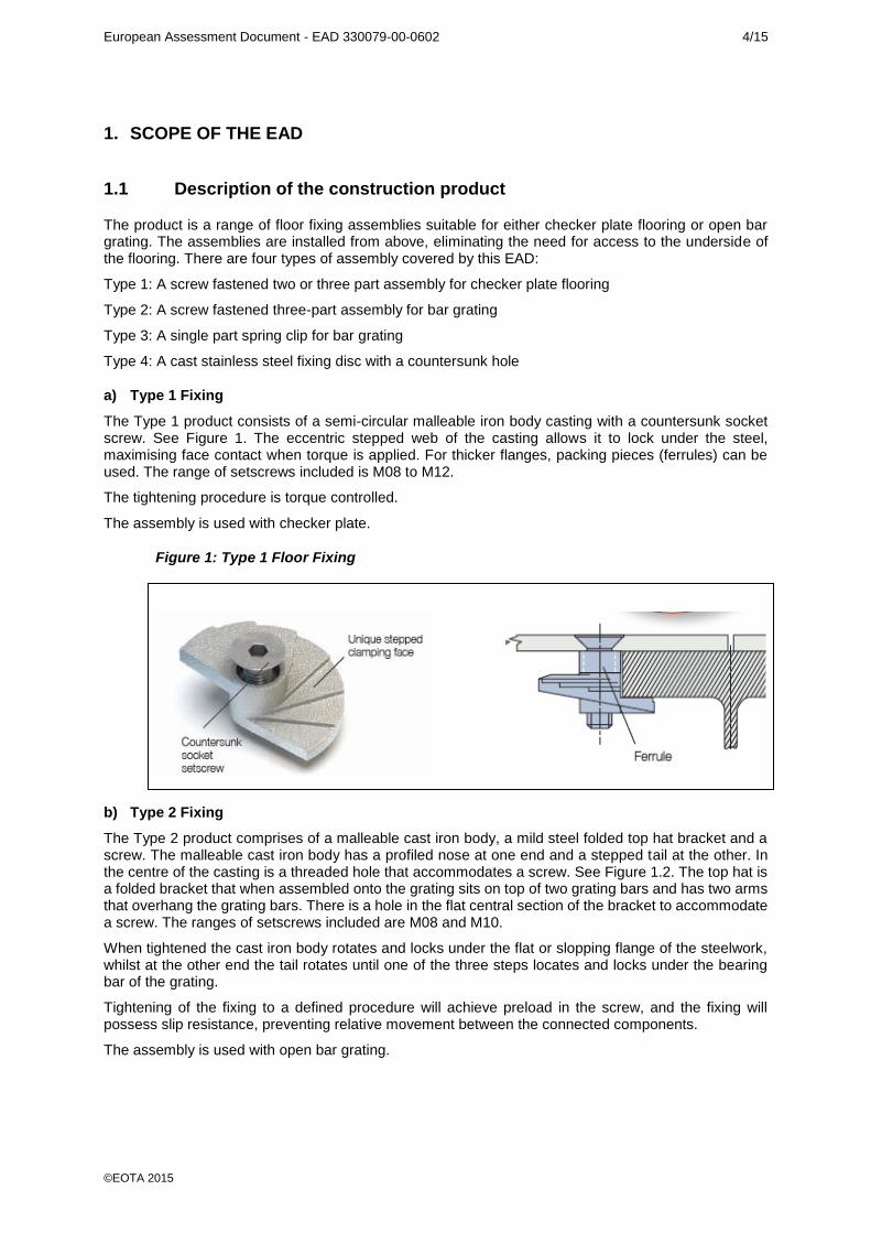
The Type 1 product consists of a semi-circular malleable iron body casting with a countersunk socket screw. See Figure 1. The eccentric stepped web of the casting allows it to lock under the steel, maximising face contact when torque is applied. For thicker flanges, packing pieces (ferrules) can be used. The range of setscrews included is M08 to M12.
The tightening procedure is torque controlled.
The assembly is used with checker plate.
Figure 1: Type 1 Floor Fixing
b) Type 2 Fixing
The Type 2 product comprises of a malleable cast iron body, a mild steel folded top hat bracket and a screw. The malleable cast iron body has a profiled nose at one end and a stepped tail at the other. In the centre of the casting is a threaded hole that accommodates a screw. See Figure 1.2. The top hat is a folded bracket that when assembled onto the grating sits on top of two grating bars and has two arms that overhang the grating bars. There is a hole in the flat central section of the bracket to accommodate a screw. The ranges of setscrews included are M08 and M10.
When tightened the cast iron body rotates and locks under the flat or slopping flange of the steelwork, whilst at the other end the tail rotates until one of the three steps locates and locks under the bearing bar of the grating.
Tightening of the fixing to a defined procedure will achieve preload in the screw, and the fixing will possess slip resistance, preventing relative movement between the connected components.
The assembly is used with open bar grating.
European Assessment Document - EAD 330079-00-0602 5/15
©EOTA 2015
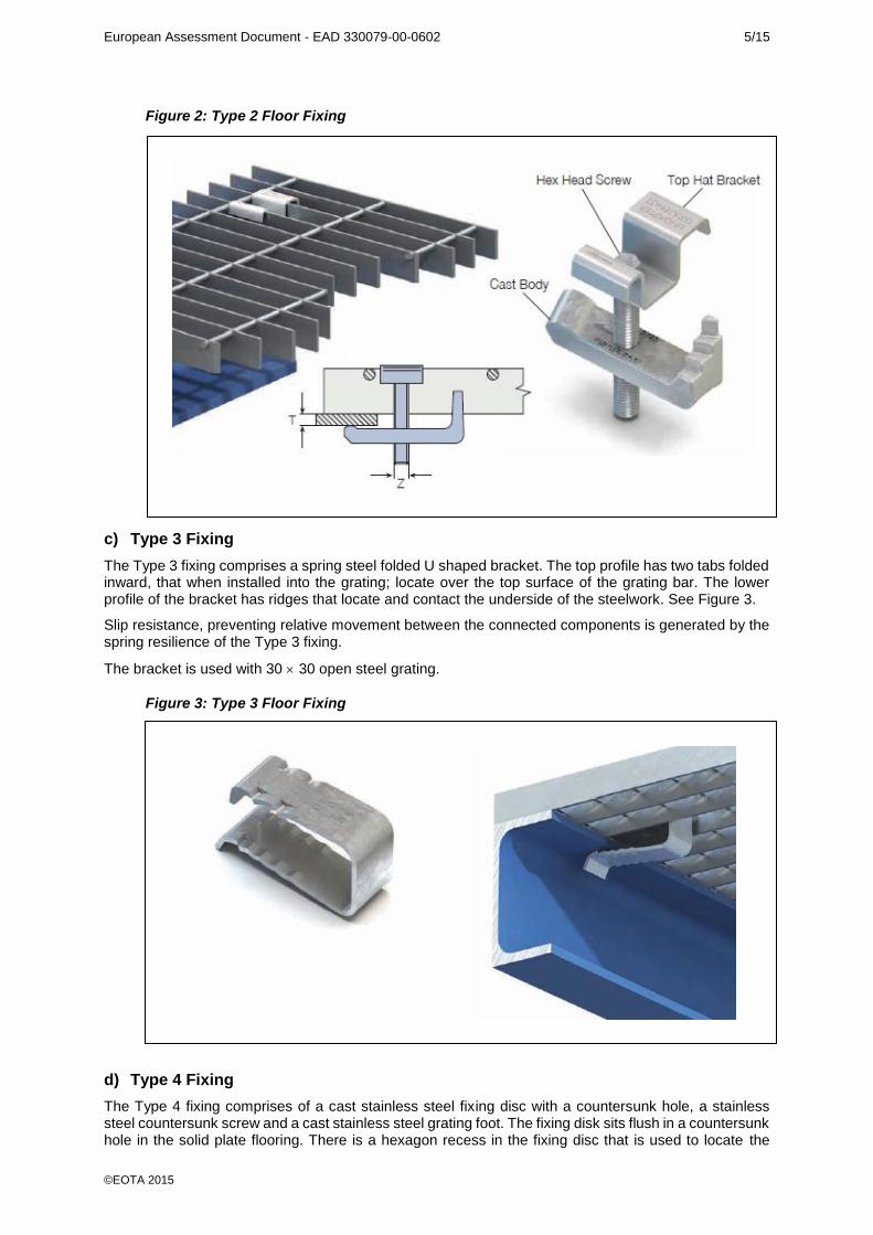
Figure 2: Type 2 Floor Fixing
c) Type 3 Fixing
The Type 3 fixing comprises a spring steel folded U shaped bracket. The top profile has two tabs folded inward, that when installed into the grating; locate over the top surface of the grating bar. The lower profile of the bracket has ridges that locate and contact the underside of the steelwork. See Figure 3.
Slip resistance, preventing relative movement between the connected components is generated by the spring resilience of the Type 3 fixing.
The bracket is used with 30 30 open steel grating.
Figure 3: Type 3 Floor Fixing
d) Type 4 Fixing
The Type 4 fixing comprises of a cast stainless steel fixing disc with a countersunk hole, a stainless steel countersunk screw and a cast stainless steel grating foot. The fixing disk sits flush in a countersunk hole in the solid plate flooring. There is a hexagon recess in the fixing disc that is used to locate the

European Assessment Document - EAD 330079-00-0602 6/15
©EOTA 2015
screw and foot into the correct position prior to tightening. When tightened the grating foot locates to the underside of the grating bar.
Tightening of the fixing to a defined procedure will achieve preload in the screw, and the fixing will possess slip resistance, preventing relative movement between the connected components. The screw has a locking adhesive on the threads to prevent loosening.
The assembly is used to fix solid plate flooring to open mesh or open grid flooring.
Figure 4: Type 4 Floor Fixing
The product is not covered by a harmonised European standard (hEN).
Concerning product packaging, transport, storage, maintenance, replacement and repair it is the responsibility of the manufacturer to undertake the appropriate measures and to advise his clients on the transport, storage, maintenance, replacement and repair of the product as he considers necessary.
It is assumed that the product will be installed according to the manufacturer’s instructions or (in absence of such instructions) according to the usual practice of the building professionals.
Relevant manufacturer’s stipulations having influence on the performance of the product covered by this European Assessment Document shall be considered for the determination of the performance and detailed in the ETA.
1.2 Information on the Intended Use(s) of the Construction Product
1.2.1 Intended Use(s)
The product is intended to provide a secure connection between the checker plate or open bar grating and the supporting steelwork. It is assembled from the top therefore no access is required to the underside of the flooring during assembly.
1.2.2 Working Life/Durability
The assessment methods included or referred to in this EAD have been written based on the manufacturer’s request to take into account a working life of the Floor Fixing Assembly for the intended use of 25 years when installed in the works (provided that the Floor Fixing Assembly is subject to appropriate installation. These provisions are based upon the current state of the art and the available knowledge and experience.
When assessing the product the intended use as foreseen by the manufacturer shall be taken into account. The real working life may be, in normal use conditions, considerably longer without major
degradation affecting the basic requirements for works1.
The indications given as to the working life of the construction product cannot be interpreted as a guarantee neither given by the product manufacturer or his representative nor by EOTA when drafting
1 The real working life of a product incorporated in a specific works depends on the environmental conditions to which that
works is subject, as well as on the particular conditions of the design, execution, use and maintenance of that works.
Therefore, it cannot be excluded that in certain cases the real working life of the product may also be shorter than referred
to above.
European Assessment Document - EAD 330079-00-0602 7/15
©EOTA 2015
this EAD nor by the Technical Assessment Body issuing an ETA based on this EAD, but are regarded only as a means for expressing the expected economically reasonable working life of the product.
1.3 Specific terms used in this EAD
1.3.1 Ft,Rk
Characteristic value of tension resistance as defined in section 2.2.1
1.3.2 Ft,Rd
Design value of tension resistance as defined in section 2.2.1.1
1.3.3 Fs,Rk
Characteristic value of slip resistance as defined in section 2.2.2
1.3.4 Fs,Rd
Design value of slip resistance as defined in section 2.2.2.1
European Assessment Document - EAD 330079-00-0602 8/15
©EOTA 2015
2 ESSENTIAL CHARACTERISTICS AND RELEVANT ASSESSMENT METHODS AND CRITERIA
2.1 Essential characteristics of the product
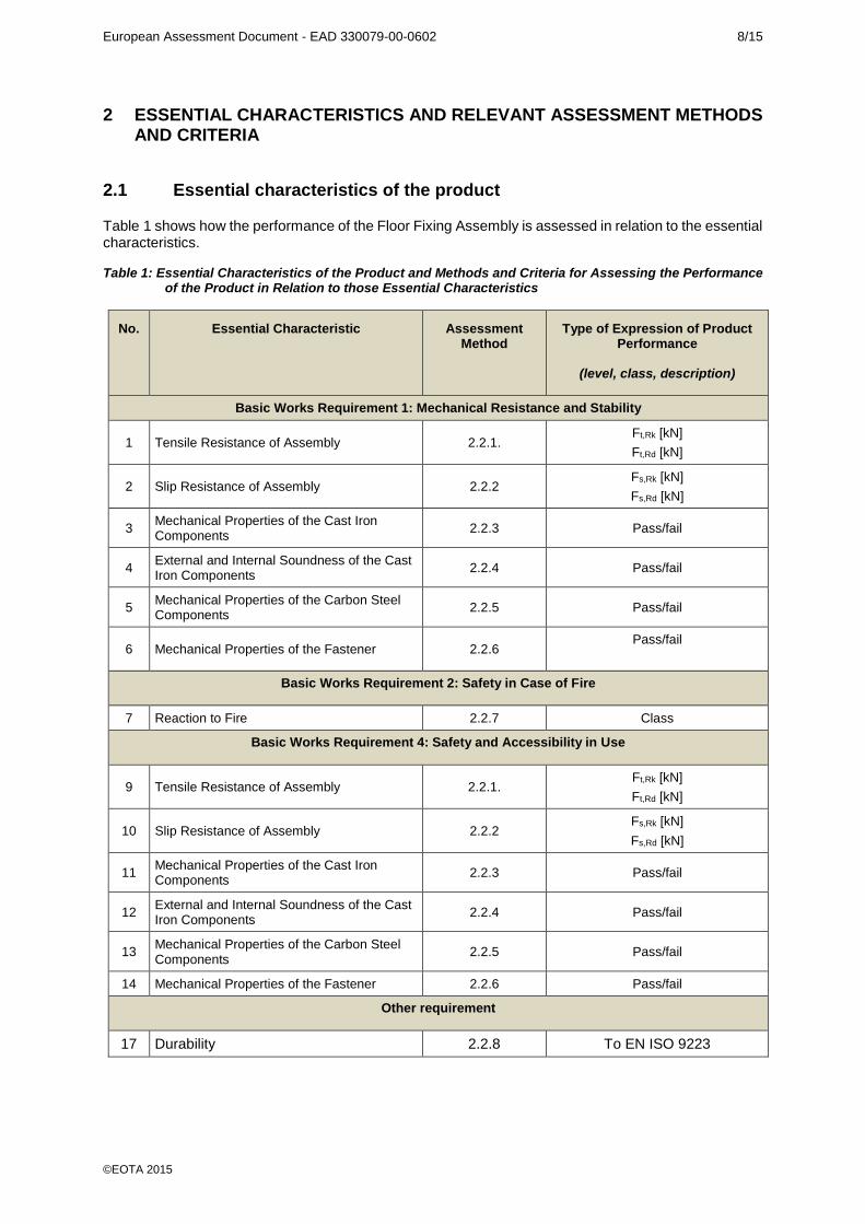
Table 1 shows how the performance of the Floor Fixing Assembly is assessed in relation to the essential characteristics.
Table 1: Essential Characteristics of the Product and Methods and Criteria for Assessing the Performance of the Product in Relation to those Essential Characteristics
No. Essential Characteristic Assessment Method
Type of Expression of Product Performance
(level, class, description)
Basic Works Requirement 1: Mechanical Resistance and Stability
1 Tensile Resistance of Assembly 2.2.1. Ft,Rk [kN]
Ft,Rd [kN]
2 Slip Resistance of Assembly 2.2.2 Fs,Rk [kN]
Fs,Rd [kN]
3 Mechanical Properties of the Cast Iron Components
2.2.3 Pass/fail
4 External and Internal Soundness of the Cast Iron Components
2.2.4 Pass/fail
5 Mechanical Properties of the Carbon Steel Components
2.2.5 Pass/fail
6 Mechanical Properties of the Fastener 2.2.6 Pass/fail
Basic Works Requirement 2: Safety in Case of Fire
7 Reaction to Fire 2.2.7 Class
Basic Works Requirement 4: Safety and Accessibility in Use
9 Tensile Resistance of Assembly 2.2.1. Ft,Rk [kN]
Ft,Rd [kN]
10 Slip Resistance of Assembly 2.2.2 Fs,Rk [kN]
Fs,Rd [kN]
11 Mechanical Properties of the Cast Iron Components
2.2.3 Pass/fail
12 External and Internal Soundness of the Cast Iron Components
2.2.4 Pass/fail
13 Mechanical Properties of the Carbon Steel Components
2.2.5 Pass/fail
14 Mechanical Properties of the Fastener 2.2.6 Pass/fail
Other requirement
17 Durability 2.2.8 To EN ISO 9223
European Assessment Document - EAD 330079-00-0602 9/15
©EOTA 2015
2.2 Methods and Criteria for Assessing the Performance of the Product in Relation to Essential Characteristics of the Product
2.2.1 Tensile Resistance of the Assembly
At least four tests shall be carried out for each size of fixing and for Type 1 and Type 2 fixings, for every nominal size of bolt size as described in EN 1990 Annex D (there is no set screw for a Type 3 fixing). The test load shall be increased until failure of the fixing
The material properties are to be documented using inspection documents 3.1, according to EN 10204. The material properties shall correspond to the material specifications given by the manufacturer.
An example for the test principle is shown in Annex A.1.
The results of the tests, according to 2.2.1 (failure loads), shall be evaluated statistically (determination of the 5% fractile, confidence level 75%). Generally a normal distribution can be assumed.
The corrected and statistically evaluated test results (5% fractile) of the tests according to 2.2.1 are the characteristic values of the tension resistance of the assembly, Ft,Rk..
Determination of Design Tension Resistance
The design values Ft.Rd of the tension resistance are the characteristic values of the tension resistance
according to 2.2.1 divided by the recommended partial safety factor gM given in the national regulations
of the Member State where the floor fixings are to be used. In cases where no value is given then gM =
1.33 should be used.
2.2.2 Slip Resistance of the Assembly
At least four slip resistance tests shall be carried out for each fixing size. For Type 1 and Type 2 fixings the setscrews shall be tightened with a torque moment specified for each type and size. The test load shall be increased until slipping of the assembly of > 0.1 mm, failure of at least one setscrew or clamp or plastic deformation of at least one setscrew occurs. The respective failure modes as well as the fixing size shall be documented in the test report.
The material properties should be documented by means of inspection documents 3.1 according to EN 10204 and shall correspond to the material specifications given by the manufacturer.
The test results of the test according to 2.2.2 (failure loads) shall be evaluated statistically (determination of 5% fractile, confidence level 75 %). Generally, a normal distribution can be assumed.
The corrected and statistically evaluated test results (5% fractile) of the tests according to 2.2.2 are the characteristic values of slip resistance of the assembly, Fs,Rk.
Determination of Design Slip Resistance
The design values Fs.Rd of the slip resistance are the characteristic values of the slip resistance according
to 2.2.2 divided by the recommended partial safety factor gM given in the national regulations of the
Member State where the floor fixings are to be used. In cases where no value is given then gM = 1.33
should be used.
An example for the test principle is shown in Annex A.2.
2.2.3 Mechanical Properties of the Cast Iron Parts
The mechanical properties of the cast iron parts shall be proved by an inspection certificate 3.1 according to EN 10204 and shall be in accordance with EN 1562 for malleable cast iron.
2.2.4 External Soundness of the Cast Iron Parts
The external and internal soundness of the cast iron parts shall be verified by visual inspection.
2.2.5 Mechanical Properties of the Carbon/Stainless Steel Parts
The mechanical properties of the carbon/stainless steel parts shall be proved by an inspection certificate 3.1 according to EN 10204 and shall be in accordance with EN 10111, EN 10132, EN 10139, EN 10297 and EN 10255.
European Assessment Document - EAD 330079-00-0602 10/15
©EOTA 2015
2.2.6 Mechanical Properties of the Structural Fasteners
The mechanical properties of the fasteners shall be proved by an inspection certificate 3.1 according to EN 10204 and shall be in accordance with EN ISO 3506, EN ISO 10642 and BS 4762.
2.2.7 Reaction to Fire
The product shall be classified according to Commission Delegated Regulation (EU) 2016/364. The Floor Fixing Assembly is considered to satisfy the requirements for performance Class A1 of the characteristic reaction to fire, in accordance with the Decision 1996/603/EC (as amended) without the need for further testing on the basis of its conformity with the specification of the product detailed in that Decision and its intended end use application being covered by that Decision.
2.2.8 Durability
The product shall have a verified durability expressed as a Corrosivity Classification (C1 to C5) in accordance with EN ISO 9223. The durability of the product in relevant environmental conditions shall be declared in the ETA. Where a protective coating is provided, its product specification and application shall be in accordance with the information given the ETA.
European Assessment Document - EAD 330079-00-0602 11/15
©EOTA 2015
3 Assessment and verification of constancy of performance
3.1 System(s) of assessment and verification of constancy of performance to be applied
For the products covered by this EAD the applicable European Legal Act is: Decision 1997/176/EC
The System is: 2+
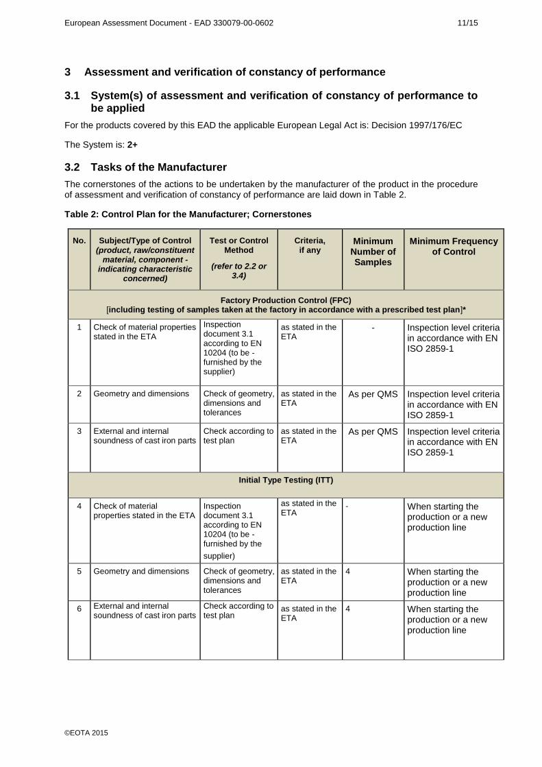
3.2 Tasks of the Manufacturer
The cornerstones of the actions to be undertaken by the manufacturer of the product in the procedure of assessment and verification of constancy of performance are laid down in Table 2.
Table 2: Control Plan for the Manufacturer; Cornerstones
No. Subject/Type of Control
(product, raw/constituent material, component -
indicating characteristic concerned)
Test or Control Method
(refer to 2.2 or 3.4)
Criteria, if any
Minimum Number of Samples
Minimum Frequency of Control
Factory Production Control (FPC) [including testing of samples taken at the factory in accordance with a prescribed test plan]*
1 Check of material properties stated in the ETA
Inspection document 3.1 according to EN 10204 (to be - furnished by the supplier)
as stated in the ETA
- Inspection level criteria in accordance with EN ISO 2859-1
2 Geometry and dimensions Check of geometry, dimensions and tolerances
as stated in the ETA
As per QMS
Inspection level criteria in accordance with EN ISO 2859-1
3 External and internal soundness of cast iron parts
Check according to test plan
as stated in the ETA
As per QMS
Inspection level criteria in accordance with EN ISO 2859-1
Initial Type Testing (ITT)
4 Check of material properties stated in the ETA
Inspection document 3.1 according to EN 10204 (to be - furnished by the
supplier)
as stated in the ETA
- When starting the production or a new production line
5 Geometry and dimensions Check of geometry, dimensions and tolerances
as stated in the ETA
4 When starting the production or a new production line
6 External and internal soundness of cast iron parts
Check according to test plan
as stated in the ETA
4 When starting the production or a new production line

European Assessment Document - EAD 330079-00-0602 12/15
©EOTA 2015
3.3 Tasks of the Notified Body
The cornerstones of the actions to be undertaken by the Notified Body in the procedure of assessment and verification of constancy of performance for Floor Fixing Assembly is laid down in Table 3.
Table 3: Control Plan for the Notified Body; Cornerstones
No. Subject/Type of Control
(product, raw/constituent material, component - indicating
characteristic concerned)
Test or Control Method
(refer to 2.2 or 3.4)
Criteria, if any
Minimum Number of Samples
Minimum Frequency of Control
Initial Inspection of the Manufacturing Plant and of Factory Production Control (for Systems 1+, 1 and 2+ only)
1. Inspection of Factory and Factory Production Control
- - - Before Certification
2. Inspection of Manufacturers Test Facility
- - - Before Certification
Continuous Surveillance, Assessment and Evaluation of Factory Production Control (for systems 1+, 1 and 2+ only)
1. Surveillance of Factory and Factory Production Control
- - - 2/Year
2. Surveillance of Manufacturers Test Facility
- - - 2/Year
European Assessment Document - EAD 330079-00-0602 13/15
©EOTA 2015
4. REFERENCE DOCUMENTS
As far as no edition date is given in the list of standards thereafter, the standard in its current version at the time of issuing the European Technical Assessment, is of relevance.
EN ISO 898-1 Mechanical properties of fasteners made of carbon and alloy steel. Bolts, screws and studs
EN ISO 3506-1 Mechanical properties of corrosion-resistant stainless steel fasteners - Part 1: Bolts, screws and studs
EN 1990 Basis of structural design EN 1993-1-1 Eurocode 3: Design of steel structures EN ISO 10642 Socket Countersunk Setscrew EN ISO 4762 Socket Head Capscrew EN ISO 2081 Metallic and other inorganic coatings. Electroplated coatings of zinc with
supplementary treatments on iron or steel EN 10111 Continuously hot rolled low carbon steel sheet and strip for cold forming.
Technical delivery conditions EN 10088 Stainless Steels EN 10132 Cold rolled narrow steel strip for heat treatment EN 1090-2 Execution of steel structures and aluminium structures - Part 2:
Technical requirements for steel structures EN 1562 Founding - Malleable cast iron BS 3146-2 Investment casting in metals EN 10255 Non-alloy steel tubes suitable for welding and threading EN 10204 Metallic products - Types of inspection documents BS 4921 Sheradized coatings on iron and steel EN 10139 Cold rolled uncoated mild steel strip for cold forming. EN 10297 Seamless circular steel tubes for mechanical and general engineering
purposes EN ISO 4762 Socket Head Capscrews EN ISO 1461 Hot Dip Galvanising and Chromate Passivate EN ISO 2081 Electroplated coating of zinc EN ISO 2859-1 Part Sampling schemes indexed by AQL for Lot-by- Lot inspection EN ISO 9223 Corrosion of metals and alloys EN ISO 9001 Quality systems – Model for quality assurance in design, development,
production, installation and servicing. ASTM B695 Standard specification for coatings of zinc mechanically deposited on iron and
steel
European Assessment Document - EAD 330079-00-0602 14/15
©EOTA 2015
ANNEX A – TESTING
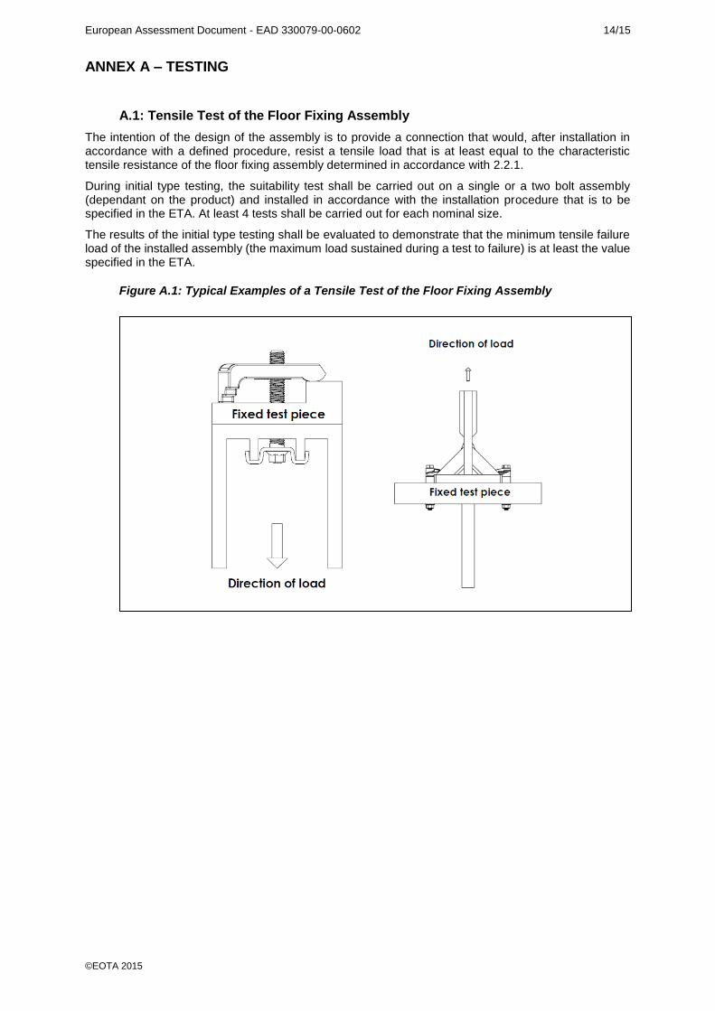
A.1: Tensile Test of the Floor Fixing Assembly
The intention of the design of the assembly is to provide a connection that would, after installation in accordance with a defined procedure, resist a tensile load that is at least equal to the characteristic tensile resistance of the floor fixing assembly determined in accordance with 2.2.1.
During initial type testing, the suitability test shall be carried out on a single or a two bolt assembly (dependant on the product) and installed in accordance with the installation procedure that is to be specified in the ETA. At least 4 tests shall be carried out for each nominal size.
The results of the initial type testing shall be evaluated to demonstrate that the minimum tensile failure load of the installed assembly (the maximum load sustained during a test to failure) is at least the value specified in the ETA.
Figure A.1: Typical Examples of a Tensile Test of the Floor Fixing Assembly
European Assessment Document - EAD 330079-00-0602 15/15
©EOTA 2015
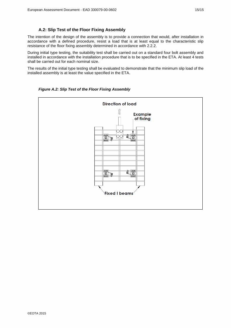
A.2: Slip Test of the Floor Fixing Assembly
The intention of the design of the assembly is to provide a connection that would, after installation in accordance with a defined procedure, resist a load that is at least equal to the characteristic slip resistance of the floor fixing assembly determined in accordance with 2.2.2.
During initial type testing, the suitability test shall be carried out on a standard four bolt assembly and installed in accordance with the installation procedure that is to be specified in the ETA. At least 4 tests shall be carried out for each nominal size.
The results of the initial type testing shall be evaluated to demonstrate that the minimum slip load of the installed assembly is at least the value specified in the ETA.
Figure A.2: Slip Test of the Floor Fixing Assembly
Copyright © 2022 FDOKUMEN