
Floating Storage and Regasification Unit (FSRU) for Natural ...
94
UNIVERSITY OF WEST ATTICA SCHOOL OF ENGINEERING MSc in Oil and Gas Process Systems Engineering Dissertation Title: Floating Storage and Regasification Unit (FSRU) for Natural Gas supply Postgraduate Student: Paraskevi Botsi Student ID: 20190011 Supervisor: Dr. Dionyssia Kyriakopoulou Date: March 2021
-
Upload
khangminh22 -
Category
Documents
-
view
0 -
download
0
Transcript of Floating Storage and Regasification Unit (FSRU) for Natural ...

UNIVERSITY OF WEST ATTICA
SCHOOL OF ENGINEERING
MSc in Oil and Gas Process Systems Engineering
Dissertation
Title: Floating Storage and Regasification Unit (FSRU) for Natural Gas supply
Postgraduate Student: Paraskevi Botsi
Student ID: 20190011
Supervisor: Dr. Dionyssia Kyriakopoulou
Date: March 2021

MSc Oil and Gas Process Systems Engineering Floating Storage and Regasification Unit (FSRU) for Natural Gas supply
DISSERTATION ASSESSMENT AND GRADING COMMITTEE
Dr. Dionyssia Kyriakopoulou, Chief Process Engineer, Asprofos Engineering
(Name) (Signature)
Dr. Emilia Kondili, Professor, Department of Mechanical Engineering
(Name) (Signature)
Dr. John (Ioannis) K. Kaldellis, Professor, Head of Department of Mechanical
Engineering
(Name) (Signature)
March 2021 2

MSc Oil and Gas Process Systems Engineering Floating Storage and Regasification Unit (FSRU) for Natural Gas supply
DECLARATION OF AUTHORSHIP
I, Paraskevi Botsi, confirm that the report entitled “Floating Storage and Regasification Unit
(FSRU) for Natural Gas supply” is my own work. I have not copied other material verbatim
except in explicit quotes, and I have identified the sources of the material clearly.
Athens, March 2021
(Signature) (Place and Date)
ΔΗΛΩΣΗ ΣΥΓΓΡΑΦΕΑ ΜΕΤΑΠΤΥΧΙΑΚΗΣ ΕΡΓΑΣΙΑΣ
Η κάτωθι υπογεγραμμένη Μπότση Παρασκευή του Σπυρίδων, με αριθμό μητρώου
20190011, φοιτήτρια του Προγράμματος Μεταπτυχιακών Σπουδών “Βιομηχανικά
Συστήματα Πετρελαίου και Φυσικού Αερίου” του Τμήματος Μηχανολόγων Μηχανικών, της
Σχολής Μηχανικών του Πανεπιστημίου Δυτικής Αττικής, δηλώνω ότι:
«Είμαι συγγραφέας αυτής της μεταπτυχιακής εργασίας και ότι κάθε βοήθεια την οποία είχα
για την προετοιμασία της, είναι πλήρως αναγνωρισμένη και αναφέρεται στην εργασία.
Επίσης, οι όποιες πηγές από τις οποίες έκανα χρήση δεδομένων, ιδεών ή λέξεων, είτε
ακριβώς είτε παραφρασμένες, αναφέρονται στο σύνολό τους, με πλήρη αναφορά στους
συγγραφείς, τον εκδοτικό οίκο ή το περιοδικό, συμπεριλαμβανομένων και των πηγών που
ενδεχομένως χρησιμοποιήθηκαν από το διαδίκτυο. Επίσης, βεβαιώνω ότι αυτή η εργασία έχει
συγγραφεί από μένα αποκλειστικά και αποτελεί προϊόν πνευματικής ιδιοκτησίας τόσο δικής
μου, όσο και του Ιδρύματος.
Παράβαση της ανωτέρω ακαδημαϊκής μου ευθύνης αποτελεί ουσιώδη λόγο για την
ανάκληση του πτυχίου μου».
Η Δηλούσα
March 2021 3
MSc Oil and Gas Process Systems Engineering Floating Storage and Regasification Unit (FSRU) for Natural Gas supply
Abstract
The aim of this Master thesis is the study of Floating Storage and Regasification Unit (FSRU)
in order to supply Natural Gas (NG) to end users.
In this context the structure of the dissertation is as follows. Chapter 1 introduces Floating
Storage and Regasification Units (FSRUs) where Liquefied Natural Gas (LNG) is regasified
in order to be distributed to end users. We identify the advantages and disadvantages of these
units compared to the corresponding liquefied natural gas onshore terminals.
In Chapter 2 we focus on the description and analysis of the processes that take place in
FSRUs, from the transfer of liquefied natural gas to the unit, its storage, its regasification and
its delivery to the end user.
In Chapter 3 we attempt to outline the basic design of a floating unit with storage and
regasification capabilities, designing the process flow diagram, simulating two cases of
different delivery pressure of natural gas, analyzing the mass-energy balances, identifying the
equipment required and examining the safety issues of the station, staff and environment.
Finally, the most important key advantages of FSRUs are summarized and the current
situation for FSRUs in Greece is presented.
Keywords LNG, NG, FSRU
March 2021 4

MSc Oil and Gas Process Systems Engineering Floating Storage and Regasification Unit (FSRU) for Natural Gas supply
Περίληψη
Ο στόχος αυτής της μεταπτυχιακής εργασίας είναι η μελέτη του Πλωτού Σταθμού
Επαναεριοποίησης και Αποθήκευσης Υγροποιημένου Φυσικού Αερίου με σκοπό την παροχή
Φυσικού Αερίου (ΦΑ) στον τελικό χρήστη.
Στο πλαίσιο αυτό, η διάρθρωση της διπλωματικής διατριβής είναι η ακόλουθη. Στο
Κεφάλαιο 1 γίνεται μια εισαγωγή αναφορικά με τους πλωτούς σταθμούς επαναεριοποίησης
και αποθήκευσης υγροποιημένου φυσικού αερίου, όπου το Υγροποιημένο Φυσικό Αέριο
(ΥΦΑ) υφίσταται επαναεριοποίηση προκειμένου να διανεμηθεί στους τελικούς χρήστες.
Εντοπίζουμε τα πλεονεκτήματα και τα μειονεκτήματα των μονάδων αυτών σε σύγκριση με
τους αντίστοιχους χερσαίους σταθμούς επαναεριοποίησης και αποθήκευσης υγροποιημένου
φυσικού αερίου.
Στο Κεφάλαιο 2 επικεντρωνόμαστε στην περιγραφή και ανάλυση των διεργασιών που
λαμβάνουν χώρα στους πλωτούς σταθμούς επαναεριοποίησης και αποθήκευσης
υγροποιημένου φυσικού αερίου, από την μεταφορά του υγροποιημένου φυσικού αερίου στον
σταθμό, την αποθήκευση, την επαναεριοποίηση και την παράδοση του στον τελικό χρήστη.
Στο Κεφάλαιο 3 επιχειρούμε να δώσουμε το περίγραμμα του βασικού σχεδιασμού μιας
πλωτής μονάδας με ικανότητα αποθήκευσης και επαναεριοποίησης, σχεδιάζοντας το
διάγραμμα ροής των διεργασιών, προσομοιώνοντας δύο περιπτώσεις διαφορετικής πίεσης
παροχής φυσικού αερίου, αναλύοντας τα ισοζύγια μάζας-ενέργειας, εντοπίζοντας τον
απαιτούμενο εξοπλισμό και εξετάζοντας τα θέματα ασφάλειας του σταθμού, του προσωπικού
και του περιβάλλοντος. Τέλος, συνοψίζονται τα σπουδαιότερα βασικά πλεονεκτήματα των
πλωτών σταθμών αποθήκευσης και επαναεριοποίησης ΥΦΑ και παρουσιάζεται η τρέχουσα
κατάσταση των σταθμών αυτών στην Ελλάδα.
Λέξεις- κλειδιάΥΦΑ, ΦΑ, Πλωτός Σταθμός Επαναεριοποίησης και Αποθήκευσης ΥΦΑ
March 2021 5
MSc Oil and Gas Process Systems Engineering Floating Storage and Regasification Unit (FSRU) for Natural Gas supply
ACKNOWLEDGEMENTS
First and foremost, I am extremely grateful to my supervisor, Dr. Dionyssia Kyriakopoulou
for her continuous help, ingenious suggestions, time and patience during this dissertation. I
would like to thank the Postgraduate Course Directors Dr. J. K. Kaldellis and Dr. E. Kondili,
as well as Mr. E. Demenegas, Dr. F. Karagiannis, Dr. D. Kyriakopoulou, Dr. S. Lattas, Dr V.
Mpouras, Dr. J. Mponis, Mr. A. Nazos, Dr M. Papazoglou, Dr. Ph. Spanidis, Mr. A.
Stefanakis, Dr. T. Tsolakis for sharing all their unparalleled knowledge and expertise in their
field of science, during this Course. Finally, on a personal note, I would like to express my
deep gratitude to my mother, Chrysoula, for her unconditional support and encouragement.
ACKNOWLEDGMENT - Sponsors
I would like to express my gratitude to the MSc Oil and Gas Process Systems Engineering
sponsors HELLENIC PETROLEUM SA, Aspropyrgos Municipality and the University of
West Attica for their funding and continuous support. The attendance and success of this
Course would not be possible without their invaluable contribution.
March 2021 6
MSc Oil and Gas Process Systems Engineering Floating Storage and Regasification Unit (FSRU) for Natural Gas supply
Table of Contents
Declaration of authorship 2
Abstract 4
Περίληψη 5
Acknowledgements 6
Table of Contents 7
Glossary of terms and acronyms 9
List of Figures 11
List of Tables 13
List of Pictures 14
Chapter 1: Introduction to LNG & the Floating Storage and Regasification Unit 15
1.1 Liquefied Natural Gas 15
1.2 Liquefied Natural Gas Value Chain 19
1.3 Floating Storage Regasification Unit 20
1.4 Key drivers for FSRU 36
Chapter 2: FSRU Process Description 41
2.1 FSRU Process Flow 43
2.2 LNG transfer to FSRU Vessel 43
2.2.1 Ship to jetty to FSRU 44
2.2.2 Side by side using flexible hoses 44
2.2.3 Side by side through loading arms 45
2.3 LNG Storage 46
2.4 LNG Pumping 50
2.5 LNG Evaporation/Regasification 51
2.6 Boil-Off Gas (BOG) compression 58
2.7 Natural Gas delivery to shore 59
Chapter 3: FSRU Basic Design 61
3.1 Basic Design Data 61
3.2 Process Description 63
March 2021 7
MSc Oil and Gas Process Systems Engineering Floating Storage and Regasification Unit (FSRU) for Natural Gas supply
3.3 Process Simulation 66
3.3.1 Boil-Off Gas (BOG) Simulation 67
3.3.2 FSRU Simulation 69
3.3.2.1 FSRU Simulation - Low Pressure Delivery System 69
3.3.2.2 FSRU Simulation - High Pressure Delivery System 75
3.4 FSRU Required Utilities 83
3.5 Venting & Blowdown Philosophy 84
3.6 Health & Safety Design considerations 84
Discussion of results 87
Conclusions 88
References 91
March 2021 8

MSc Oil and Gas Process Systems Engineering Floating Storage and Regasification Unit (FSRU) for Natural Gas supply
GLOSSARY OF TERMS AND ACRONYMS
AAV – Ambient Air Vaporizer
BOG – Boil-Off Gas
BOR – Boil-Off Rate
CAPEX – Capital Expenditure
DFDE – Dual-Fuel Diesel Electric
EPC – Engineering, Procurement and Construction
ESD – Emergency Shutdown System
ETA – Event Tree Analysis
FEED – Front End Engineering Design
FSRU – Floating Storage and Regasification Unit
FSU – Floating Storage Unit
GCV – Gross Calorific Value
HP – High Pressure
IFV – Intermediate Fluid Vaporizer
IGU – International Gas Union
IMA – International Maritime Associates
IMO – International Maritime Organization
LNG – Liquefied Natural Gas
LNGC – Liquefied Natural Gas Carrier
LP – Low Pressure
MTPA – Million Tonnes Per Annum
NPSHR – Net Positive Suction Head Required
NIMBY – Not in My Back Yard
NG – Natural Gas
OPEX – Operating Expenditure
ORV – Open Rack Vaporizer
PCHE – Printed Circuit Heat Exchanger
PLEM – Pipeline End Manifold
PPE – Personal Protective Equipment
RAE – Regulatory Authority for Energy
March 2021 9
MSc Oil and Gas Process Systems Engineering Floating Storage and Regasification Unit (FSRU) for Natural Gas supply
SCV – Submerged Combustion Vaporizer
STS – Ship to Ship (Transfer)
TEG – Triethylene Glycol
TFDE – Tri-Fuel Diesel Electric
$ – US Dollar
$/mmbtu – US Dollars per million btus
m3 – cubic metres
m3/h – cubic metres per hour
kW – Kilowatt
MW – Megawatt
March 2021 10
MSc Oil and Gas Process Systems Engineering Floating Storage and Regasification Unit (FSRU) for Natural Gas supply
List of Figures
Figure 1: LNG process flow diagram 18
Figure 2: Configuration of the LNG Value Chain 19
Figure 3: FSRUs, a critical link in the LNG value chain 20
Figure 4: FSRU 21
Figure 5: Current FSRU fleets by Shipowner companies 21
Figure 6: Current and Forecasted projects 2008-2020 and beyond 26
Figure 7: Cumulative Growth in LNG Regasification Capacity (Includes terminals under construction) (Source: IMA/WER database, International Gas Union, GIIGNL, company records) 27
Figure 8: Number of Regasification Markets by Type, 2000-2025 27
Figure 9: IMO classification of LNG vessels 29
Figure 10: Typical FSRU Flow Scheme 31
Figure 11: Jetty-type mooring system, side-by-side mooring configuration between FSRU and LNGC 34
Figure 12: Conceptual layout of an FSRU 42
Figure 13: Example of proposed conceptual design 42
Figure 14: Process flow of a typical LNG receiving and regasification terminal 43
Figure 15: GTT Mark III membrane system 48
Figure 16: GTT NO96 concept 48
Figure 17: Moss tank 49
Figure 18: Moss Tank concept 49
Figure 19: Pressure - Temperature LNG diagram 51
Figure 20: Combined open/closed loop with seawater and steam heating 52
Figure 21: Closed-loop propane with seawater as heating medium 54
Figure 22: Direct seawater vaporizers 54
Figure 23: Closed-loop TEG/water and steam 55
Figure 24: Closed-loop TEG/water and seawater 55
Figure 25: Shell and Tube type heat exchanger 56
Figure 26: Flow configurations to and from FSRU tanks via recondenser 59
Figure 27: FSRU Installation 61
March 2021 11
MSc Oil and Gas Process Systems Engineering Floating Storage and Regasification Unit (FSRU) for Natural Gas supply
Figure 28: FSRU Installation Schematic 65
Figure 29: Simulation of BOG production in DWSIM 68
Figure 30: Simulation Flowsheet in DWSIM - Low pressure delivery at 12 bar 72
Figure 31: Simulation Flowsheet in DWSIM - High pressure delivery at 80 bar without recondensing - 1 stage Compressor 78
Figure 32: Simulation Flowsheet in DWSIM - High pressure delivery at 80 bar without recondensing - 3 stages Compressor 79
Figure 33: Simulation Flowsheet in DWSIM - High pressure delivery at 80 bar with recondensing 80
Figure 34: Structure of the Event Tree Analysis (ETA) 86
March 2021 12
MSc Oil and Gas Process Systems Engineering Floating Storage and Regasification Unit (FSRU) for Natural Gas supply
List of Tables
Table 1: Composition (%) of LNG and classification in Light, Medium, Heavy LNG by densities 16
Table 2: LNG quality specifications by Hellenic Gas Transmission Operator S.A. DESFA 17
Table 3: Global Active LNG/FSRU Fleet, Year-End 2019 25
Table 4: Comparison of Onshore LNG Terminal and FSRU 38
Table 5: CAPEX Comparison for Onshore Terminal and FSRU 39
Table 6: Preliminary Guide - Decision factors regarding the choice of FSRU and onshore LNG plant installation 40
Table 7: LNG Vaporization Option Qualitative Comparison 57
Table 8: Process flow diagram symbols for simulation in DWSIM 66
Table 9: Heat input from ambient 67
Table 10: Heat And Material Balances from DWSIM Simulation - Low pressure delivery at 12 bar 73
Table 11: List of Equipment Low pressure delivery at 12 bar 74
Table 12: Heat And Material Balances from DWSIM Simulation - High pressure delivery at 80 bar with recondensing 81
Table 13: List of Equipment - High pressure delivery at 80 bar with recondensing 82
Table 14: Fire and explosion accidents for an Event Tree Analysis (ETA) 86
March 2021 13
MSc Oil and Gas Process Systems Engineering Floating Storage and Regasification Unit (FSRU) for Natural Gas supply
List of Pictures
Picture 1: Membrane Tanks with regasification facilities on the deck Source: Courtesy Excelerate Energy 30
Picture 2: FSRU Toscana with Moss type tanks 30
Picture 3: Permanently moored FSRU 32
Picture 4: New cargo is ready to be transferred to FSRU through the LNG carrier 32
Picture 5: LNG transfer from carrier to FSRU 33
Picture 6: Continuous regasification process on FSRU and sending high-pressure NG to the shore 33
Picture 7: Tower Yoke Mooring System 34
Picture 8: Conventional Buoy Mooring system 35
Picture 9: Single Point Mooring System 35
Picture 10: Turret Mooring System 36
Picture 11: Fugro’s SEAWATCH Wavescan buoy with met mast 41
Picture 12: Ship to jetty to FSRU transfer, jetty is equipped with regasification plant 44
Picture 13: LNG transfer side by side using flexible hoses 45
Picture 14: LNG transfer side by side through loading arms 45
Picture 15: Water curtain during STS transfer 46
Picture 16: Interior of a non-spherical, Technigaz Mark III stainless steel membrane, LNG tank 47
Picture 17: Construction of regasification section by Saipem SA at FSRU Toscana 53
Picture 18: Natural gas is discharged via high-pressure gas offloading arm 60
Picture 19: Natural Gas is discharged through a subsea buoy linked to a subsea pipeline 60
March 2021 14
MSc Oil and Gas Process Systems Engineering Floating Storage and Regasification Unit (FSRU) for Natural Gas supply
Chapter 1: Introduction to LNG & the Floating Storage and Regasification
Unit
In this Chapter LNG properties, LNG supply chain, general description of FSRU, FSRU
global market up to the end of 2019 and key drivers and limitations of these units are
presented.
1.1 Liquefied Natural Gas
When Natural Gas (NG) is being cooled at -162ºC and pressured slightly above atmospheric
pressure (1 atm), it is liquefied to a state called Liquefied Natural Gas (LNG). This leads to
volume reduction six hundred (600) times. This is the reason why LNG is preferred for
shipment and storage purposes.
LNG is a cryogenic, liquid substance which consists, depending upon its origin, of a mixture
of light hydrocarbons, mainly Methane CH4 (87% - 98%), Ethane C2H6 (1.4% - 9.5%),
Propane C3H8 (0.4% - 2.5%), Butane C4H10 (0.1% - 0.5%), Pentane C5H12 and Nitrogen N2 as
inert (0.1% - 1%) [2].
The classification of LNG could be made based on chemical composition (methane and
nitrogen amount), density, heating value, Wobbe index but usually we refer to light, medium
or heavy LNG due to its density.
LNG is colourless, odorless, non-toxic, non-corrosive, non-flammable, not carcinogenic but
it could be asphyxiant in a vapour cloud formation. The flash point is around -188ºC and the
boiling point -160ºC [1, p. 68].
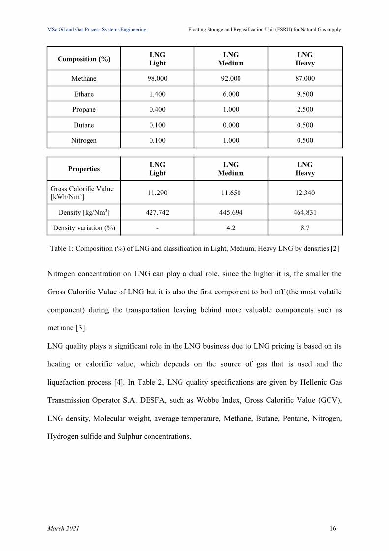
Composition of LNG, classification in Light, Medium, and Heavy LNG by densities and
Gross Calorific Value are given in Table 1.
March 2021 15
MSc Oil and Gas Process Systems Engineering Floating Storage and Regasification Unit (FSRU) for Natural Gas supply
Composition (%)LNG Light
LNG Medium
LNG Heavy
Methane 98.000 92.000 87.000
Ethane 1.400 6.000 9.500
Propane 0.400 1.000 2.500
Butane 0.100 0.000 0.500
Nitrogen 0.100 1.000 0.500
PropertiesLNG Light
LNG Medium
LNG Heavy
Gross Calorific Value [kWh/Nm3]
11.290 11.650 12.340
Density [kg/Nm3] 427.742 445.694 464.831
Density variation (%) - 4.2 8.7
Table 1: Composition (%) of LNG and classification in Light, Medium, Heavy LNG by densities [2]
Nitrogen concentration on LNG can play a dual role, since the higher it is, the smaller the
Gross Calorific Value of LNG but it is also the first component to boil off (the most volatile
component) during the transportation leaving behind more valuable components such as
methane [3].
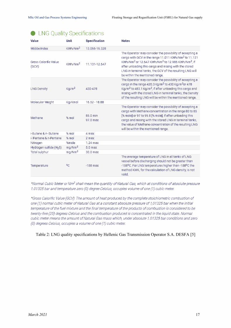
LNG quality plays a significant role in the LNG business due to LNG pricing is based on its
heating or calorific value, which depends on the source of gas that is used and the
liquefaction process [4]. In Table 2, LNG quality specifications are given by Hellenic Gas
Transmission Operator S.A. DESFA, such as Wobbe Index, Gross Calorific Value (GCV),
LNG density, Molecular weight, average temperature, Methane, Butane, Pentane, Nitrogen,
Hydrogen sulfide and Sulphur concentrations.
March 2021 16
MSc Oil and Gas Process Systems Engineering Floating Storage and Regasification Unit (FSRU) for Natural Gas supply
Table 2: LNG quality specifications by Hellenic Gas Transmission Operator S.A. DESFA [5]
March 2021 17
MSc Oil and Gas Process Systems Engineering Floating Storage and Regasification Unit (FSRU) for Natural Gas supply
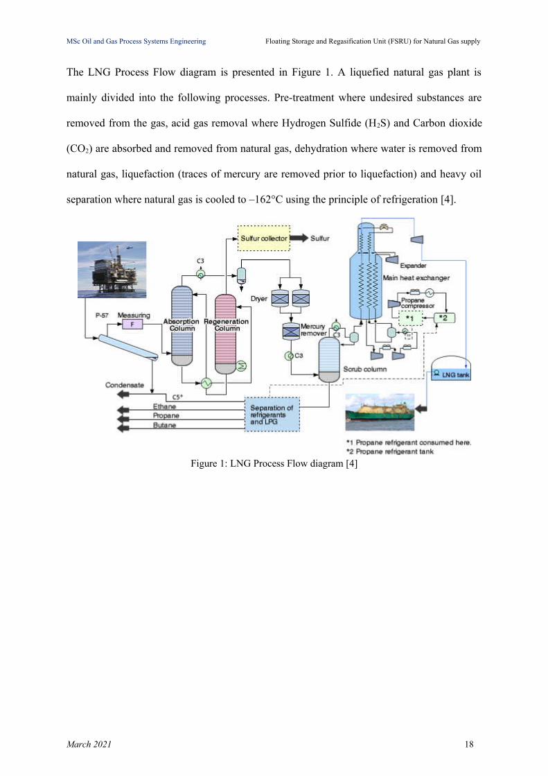
The LNG Process Flow diagram is presented in Figure 1. A liquefied natural gas plant is
mainly divided into the following processes. Pre-treatment where undesired substances are
removed from the gas, acid gas removal where Hydrogen Sulfide (H2S) and Carbon dioxide
(CO2) are absorbed and removed from natural gas, dehydration where water is removed from
natural gas, liquefaction (traces of mercury are removed prior to liquefaction) and heavy oil
separation where natural gas is cooled to –162°C using the principle of refrigeration [4].
Figure 1: LNG Process Flow diagram [4]
March 2021 18
MSc Oil and Gas Process Systems Engineering Floating Storage and Regasification Unit (FSRU) for Natural Gas supply
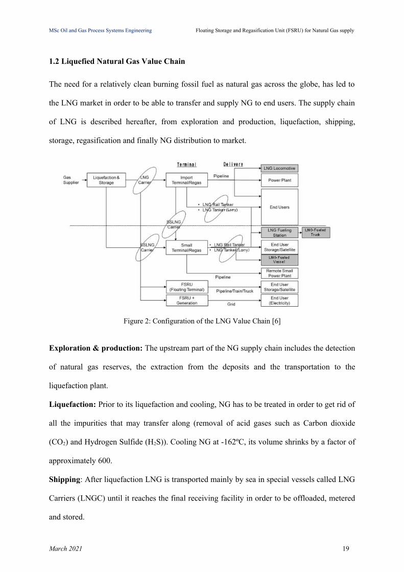
1.2 Liquefied Natural Gas Value Chain
The need for a relatively clean burning fossil fuel as natural gas across the globe, has led to
the LNG market in order to be able to transfer and supply NG to end users. The supply chain
of LNG is described hereafter, from exploration and production, liquefaction, shipping,
storage, regasification and finally NG distribution to market.
Figure 2: Configuration of the LNG Value Chain [6]
Exploration & production: The upstream part of the NG supply chain includes the detection
of natural gas reserves, the extraction from the deposits and the transportation to the
liquefaction plant.
Liquefaction: Prior to its liquefaction and cooling, NG has to be treated in order to get rid of
all the impurities that may transfer along (removal of acid gases such as Carbon dioxide
(CO2) and Hydrogen Sulfide (H2S)). Cooling NG at -162ºC, its volume shrinks by a factor of
approximately 600.
Shipping: After liquefaction LNG is transported mainly by sea in special vessels called LNG
Carriers (LNGC) until it reaches the final receiving facility in order to be offloaded, metered
and stored.
March 2021 19
MSc Oil and Gas Process Systems Engineering Floating Storage and Regasification Unit (FSRU) for Natural Gas supply
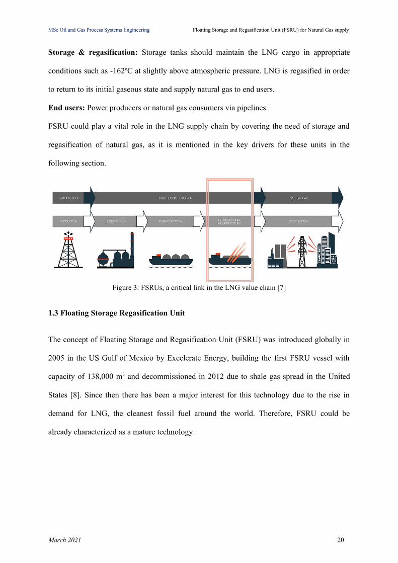
Storage & regasification: Storage tanks should maintain the LNG cargo in appropriate
conditions such as -162ºC at slightly above atmospheric pressure. LNG is regasified in order
to return to its initial gaseous state and supply natural gas to end users.
End users: Power producers or natural gas consumers via pipelines.
FSRU could play a vital role in the LNG supply chain by covering the need of storage and
regasification of natural gas, as it is mentioned in the key drivers for these units in the
following section.
Figure 3: FSRUs, a critical link in the LNG value chain [7]
1.3 Floating Storage Regasification Unit
The concept of Floating Storage and Regasification Unit (FSRU) was introduced globally in
2005 in the US Gulf of Mexico by Excelerate Energy, building the first FSRU vessel with
capacity of 138,000 m3 and decommissioned in 2012 due to shale gas spread in the United
States [8]. Since then there has been a major interest for this technology due to the rise in
demand for LNG, the cleanest fossil fuel around the world. Therefore, FSRU could be
already characterized as a mature technology.
March 2021 20

MSc Oil and Gas Process Systems Engineering Floating Storage and Regasification Unit (FSRU) for Natural Gas supply
Figure 4: FSRU [9]
As it is mentioned by International Gas Union (IGU) in the 2020 World LNG report and it is
depicted in Figure 5, there are currently 34 FSRUs around the globe (see Table 3),
constituting 6.3% of the global fleet [10, p. 32].
Figure 5: Current FSRU fleets by Shipowner companies [10]
March 2021 21
MSc Oil and Gas Process Systems Engineering Floating Storage and Regasification Unit (FSRU) for Natural Gas supply
“The key players in the global FSRU market are Excelerate Energy (U.S), Hoegh LNG
(Bermuda), Golar LNG (Bermuda), BW gas (Norway), Gazprom FLEX LNG (U.K), Exmar
(Belgium), Maran Gas Maritime Inc. (Greece), Offshore LNG Toscana SpA (Italy), Mitsui
O.S.K. Lines (Japan) Bumi Armada (Malaysia), Teekay Lng Partners, L.P. (Bermuda)” [11].
The Middle East Region is a key player in the FSRU market by possessing the maximum
number of these units and moreover with its LNG reserves, that can meet the demand for
LNG across the world [11]. It is estimated that the global FSRU market will increase from 85
Million Tonnes Per Annum (MTPA) in 2018 to 230 MTPA in 2023 at a compound annual
growth rate of approximately 13.88% due to the globally increasing NG demand [11].
Global Floating Storage and Regasification Unit (FSRU) market can be segmented based on
storage i.e. large, medium and small, construction i.e. newly built and converted, end users
i.e. power generation, industrial, others and region i.e. North America, Europe, Asia Pacific,
Middle East, and Latin America [12].
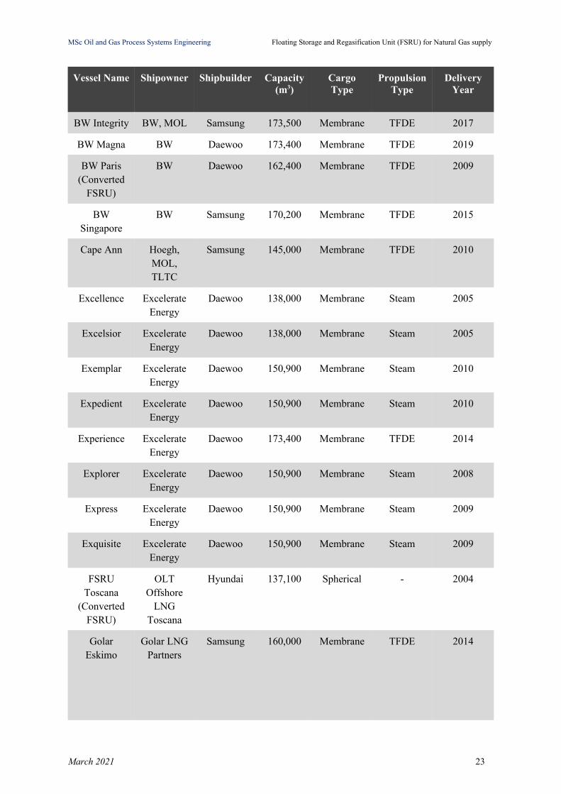
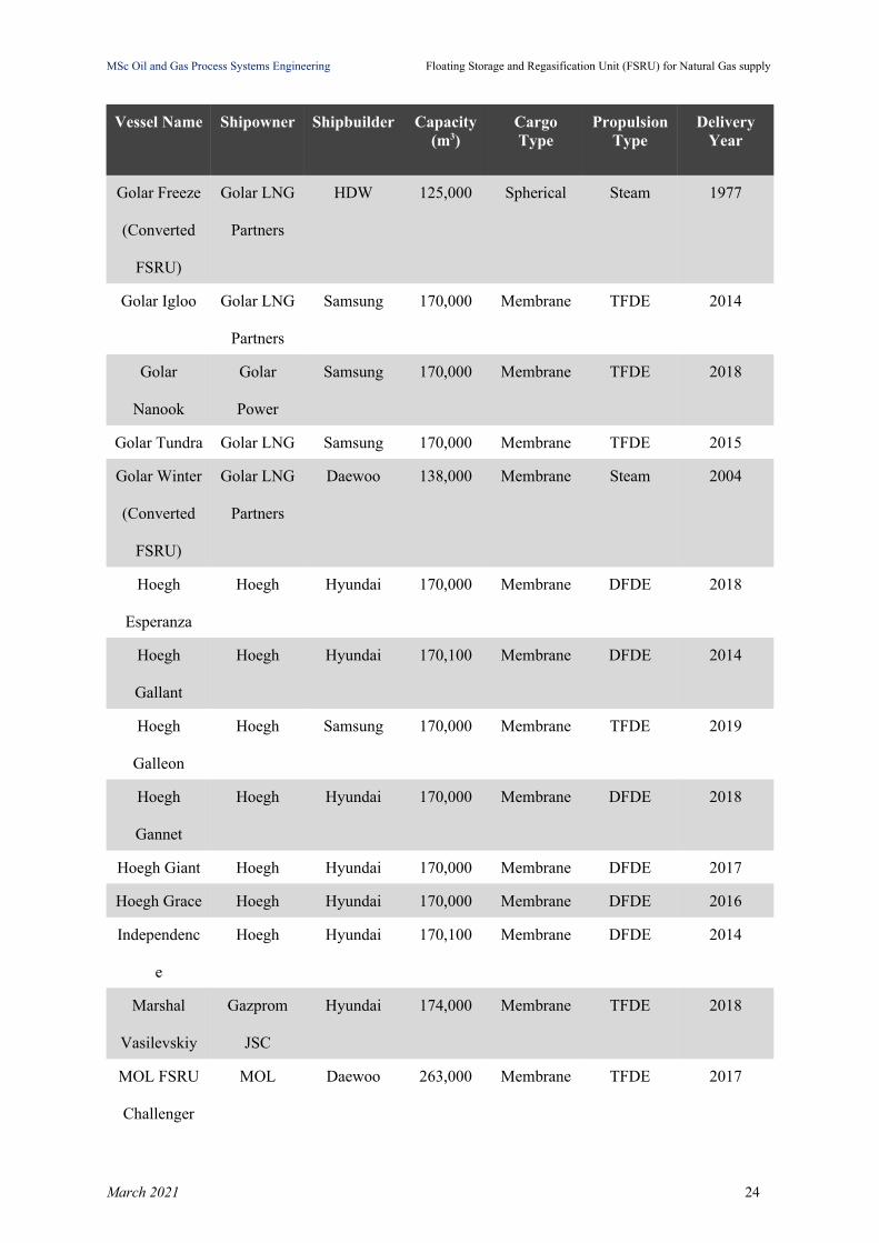
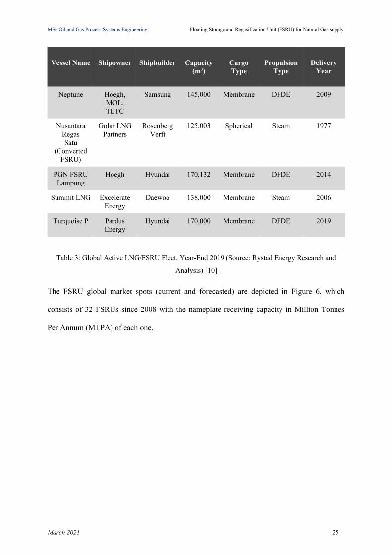
The global active LNG/FSRU fleet by the end of 2019 is given in Table 3, presenting the
vessel’s name, the shipowner company, the shipbuilder company, the capacity of the vessel,
the cargo type i.e. storage options, membrane or spherical, the propulsion type and the year of
delivery.
As we can observe in Table 3, a typical storage capacity of an FSRU is approximately
170,000 m3 of LNG, equivalent to 100 million cubic meters of natural gas. The smallest
storage capacity of these units is 125,000 m3 which is often due to conversion of an LNG
carrier.
March 2021 22
MSc Oil and Gas Process Systems Engineering Floating Storage and Regasification Unit (FSRU) for Natural Gas supply
Vessel Name Shipowner Shipbuilder Capacity(m3)
CargoType
PropulsionType
DeliveryYear
BW Integrity BW, MOL Samsung 173,500 Membrane TFDE 2017
BW Magna BW Daewoo 173,400 Membrane TFDE 2019
BW Paris(Converted
FSRU)
BW Daewoo 162,400 Membrane TFDE 2009
BWSingapore
BW Samsung 170,200 Membrane TFDE 2015
Cape Ann Hoegh,MOL,TLTC
Samsung 145,000 Membrane TFDE 2010
Excellence ExcelerateEnergy
Daewoo 138,000 Membrane Steam 2005
Excelsior ExcelerateEnergy
Daewoo 138,000 Membrane Steam 2005
Exemplar ExcelerateEnergy
Daewoo 150,900 Membrane Steam 2010
Expedient ExcelerateEnergy
Daewoo 150,900 Membrane Steam 2010
Experience ExcelerateEnergy
Daewoo 173,400 Membrane TFDE 2014
Explorer ExcelerateEnergy
Daewoo 150,900 Membrane Steam 2008
Express ExcelerateEnergy
Daewoo 150,900 Membrane Steam 2009
Exquisite ExcelerateEnergy
Daewoo 150,900 Membrane Steam 2009
FSRUToscana
(ConvertedFSRU)
OLTOffshore
LNGToscana
Hyundai 137,100 Spherical - 2004
GolarEskimo
Golar LNGPartners
Samsung 160,000 Membrane TFDE 2014
March 2021 23
MSc Oil and Gas Process Systems Engineering Floating Storage and Regasification Unit (FSRU) for Natural Gas supply
Vessel Name Shipowner Shipbuilder Capacity(m3)
CargoType
PropulsionType
DeliveryYear
Golar Freeze
(Converted
FSRU)
Golar LNG
Partners
HDW 125,000 Spherical Steam 1977
Golar Igloo Golar LNG
Partners
Samsung 170,000 Membrane TFDE 2014
Golar
Nanook
Golar
Power
Samsung 170,000 Membrane TFDE 2018
Golar Tundra Golar LNG Samsung 170,000 Membrane TFDE 2015
Golar Winter
(Converted
FSRU)
Golar LNG
Partners
Daewoo 138,000 Membrane Steam 2004
Hoegh
Esperanza
Hoegh Hyundai 170,000 Membrane DFDE 2018
Hoegh
Gallant
Hoegh Hyundai 170,100 Membrane DFDE 2014
Hoegh
Galleon
Hoegh Samsung 170,000 Membrane TFDE 2019
Hoegh
Gannet
Hoegh Hyundai 170,000 Membrane DFDE 2018
Hoegh Giant Hoegh Hyundai 170,000 Membrane DFDE 2017
Hoegh Grace Hoegh Hyundai 170,000 Membrane DFDE 2016
Independenc
e
Hoegh Hyundai 170,100 Membrane DFDE 2014
Marshal
Vasilevskiy
Gazprom
JSC
Hyundai 174,000 Membrane TFDE 2018
MOL FSRU
Challenger
MOL Daewoo 263,000 Membrane TFDE 2017
March 2021 24
MSc Oil and Gas Process Systems Engineering Floating Storage and Regasification Unit (FSRU) for Natural Gas supply
Vessel Name Shipowner Shipbuilder Capacity(m3)
CargoType
PropulsionType
DeliveryYear
Neptune Hoegh,MOL,TLTC
Samsung 145,000 Membrane DFDE 2009
NusantaraRegasSatu
(ConvertedFSRU)
Golar LNGPartners
RosenbergVerft
125,003 Spherical Steam 1977
PGN FSRULampung
Hoegh Hyundai 170,132 Membrane DFDE 2014
Summit LNG ExcelerateEnergy
Daewoo 138,000 Membrane Steam 2006
Turquoise P PardusEnergy
Hyundai 170,000 Membrane DFDE 2019
Table 3: Global Active LNG/FSRU Fleet, Year-End 2019 (Source: Rystad Energy Research and
Analysis) [10]
The FSRU global market spots (current and forecasted) are depicted in Figure 6, which
consists of 32 FSRUs since 2008 with the nameplate receiving capacity in Million Tonnes
Per Annum (MTPA) of each one.
March 2021 25

MSc Oil and Gas Process Systems Engineering Floating Storage and Regasification Unit (FSRU) for Natural Gas supply
Figure 6: Current and Forecasted projects 2008-2020 and beyond [13]
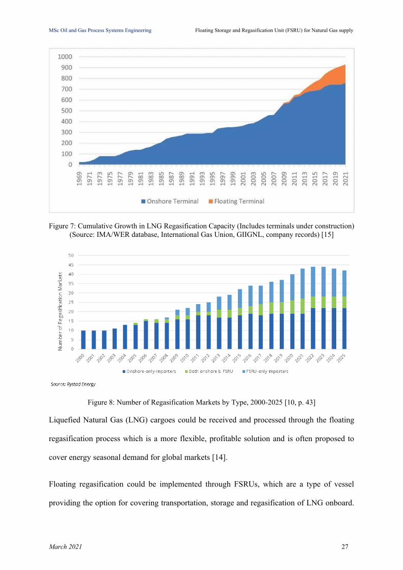
The floating regasification since its beginning starts to gain ground gradually over the
onshore permanent regasification facilities as it is exhibited in Figure 7 and Figure 8 [14].
March 2021 26
MSc Oil and Gas Process Systems Engineering Floating Storage and Regasification Unit (FSRU) for Natural Gas supply
Figure 7: Cumulative Growth in LNG Regasification Capacity (Includes terminals under construction)(Source: IMA/WER database, International Gas Union, GIIGNL, company records) [15]
Figure 8: Number of Regasification Markets by Type, 2000-2025 [10, p. 43]
Liquefied Natural Gas (LNG) cargoes could be received and processed through the floating
regasification process which is a more flexible, profitable solution and is often proposed to
cover energy seasonal demand for global markets [14].
Floating regasification could be implemented through FSRUs, which are a type of vessel
providing the option for covering transportation, storage and regasification of LNG onboard.
March 2021 27
MSc Oil and Gas Process Systems Engineering Floating Storage and Regasification Unit (FSRU) for Natural Gas supply
FSRUs could be either new purpose-built vessels or refurbished, converted gas carriers i.e.
LNG vessels with the suitable adjustments, such as regasification module, in order to meet all
the processes which take place in an LNG terminal and they can be classified either as ships
or as offshore installations [17].
The key specifications of an FSRU are its length, its breadth moulded, its depth, the cargo
tank capacity, the gas send-out rate and the send-out pressure. FSRU as LNG import
terminals, can be placed either offshore if shore access is not available or be moored against a
jetty, a berth or a purpose-built dolphin. LNG Carriers (LNGC) moor alongside the FSRU
and LNG is being transferred through cryogenic flexible hoses or hard loading arms to the
storage units.
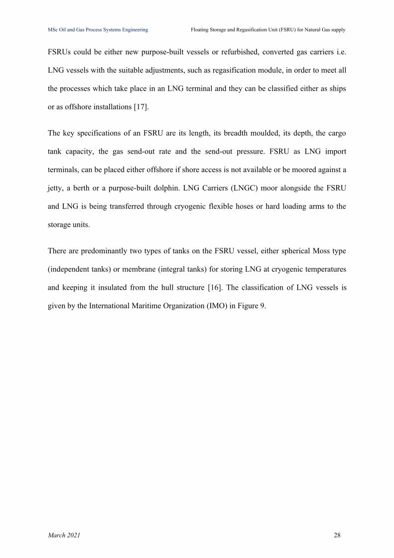
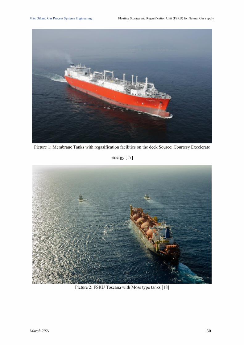
There are predominantly two types of tanks on the FSRU vessel, either spherical Moss type
(independent tanks) or membrane (integral tanks) for storing LNG at cryogenic temperatures
and keeping it insulated from the hull structure [16]. The classification of LNG vessels is
given by the International Maritime Organization (IMO) in Figure 9.
March 2021 28

MSc Oil and Gas Process Systems Engineering Floating Storage and Regasification Unit (FSRU) for Natural Gas supply
Figure 9: IMO classification of LNG vessels [16]
On Moss type tanks (see Picture 2) the regasification unit could be placed either between the
tanks or on the bow. One of the advantages of the membrane concept is the better storage
capacity between same size vessels, i.e. generally smaller gross tonnage. Membrane tanks
(see Picture 1) could also provide unrestricted navigation visibility compared to Moss type
tanks.
March 2021 29
MSc Oil and Gas Process Systems Engineering Floating Storage and Regasification Unit (FSRU) for Natural Gas supply
Picture 1: Membrane Tanks with regasification facilities on the deck Source: Courtesy Excelerate
Energy [17]
Picture 2: FSRU Toscana with Moss type tanks [18]
March 2021 30
MSc Oil and Gas Process Systems Engineering Floating Storage and Regasification Unit (FSRU) for Natural Gas supply
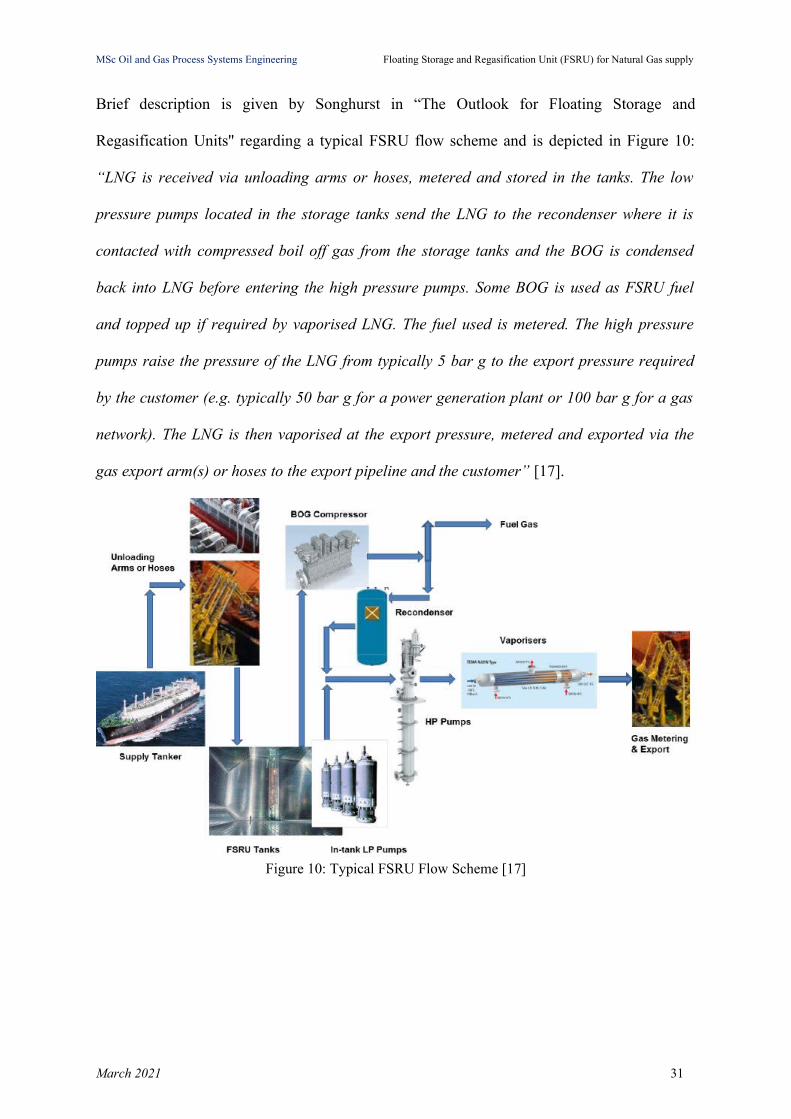
Brief description is given by Songhurst in “The Outlook for Floating Storage and
Regasification Units'' regarding a typical FSRU flow scheme and is depicted in Figure 10:
“LNG is received via unloading arms or hoses, metered and stored in the tanks. The low
pressure pumps located in the storage tanks send the LNG to the recondenser where it is
contacted with compressed boil off gas from the storage tanks and the BOG is condensed
back into LNG before entering the high pressure pumps. Some BOG is used as FSRU fuel
and topped up if required by vaporised LNG. The fuel used is metered. The high pressure
pumps raise the pressure of the LNG from typically 5 bar g to the export pressure required
by the customer (e.g. typically 50 bar g for a power generation plant or 100 bar g for a gas
network). The LNG is then vaporised at the export pressure, metered and exported via the
gas export arm(s) or hoses to the export pipeline and the customer” [17].
Figure 10: Typical FSRU Flow Scheme [17]
March 2021 31
MSc Oil and Gas Process Systems Engineering Floating Storage and Regasification Unit (FSRU) for Natural Gas supply
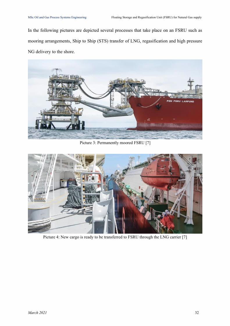
In the following pictures are depicted several processes that take place on an FSRU such as
mooring arrangements, Ship to Ship (STS) transfer of LNG, regasification and high pressure
NG delivery to the shore.
Picture 3: Permanently moored FSRU [7]
Picture 4: New cargo is ready to be transferred to FSRU through the LNG carrier [7]
March 2021 32
MSc Oil and Gas Process Systems Engineering Floating Storage and Regasification Unit (FSRU) for Natural Gas supply
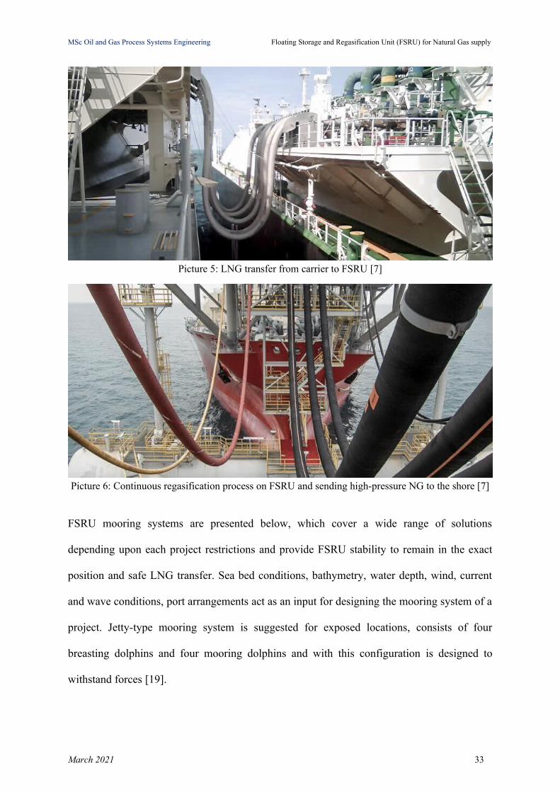
Picture 5: LNG transfer from carrier to FSRU [7]
Picture 6: Continuous regasification process on FSRU and sending high-pressure NG to the shore [7]
FSRU mooring systems are presented below, which cover a wide range of solutions
depending upon each project restrictions and provide FSRU stability to remain in the exact
position and safe LNG transfer. Sea bed conditions, bathymetry, water depth, wind, current
and wave conditions, port arrangements act as an input for designing the mooring system of a
project. Jetty-type mooring system is suggested for exposed locations, consists of four
breasting dolphins and four mooring dolphins and with this configuration is designed to
withstand forces [19].
March 2021 33

MSc Oil and Gas Process Systems Engineering Floating Storage and Regasification Unit (FSRU) for Natural Gas supply
Figure 11: Jetty-type mooring system, side-by-side mooring configuration between FSRU and LNGC[19]
Tower yoke mooring system consists of a tower fixed at the seabed and a yoke connected
both to tower and the unit and it is proposed for shallow water environments [20].
Picture 7: Tower Yoke Mooring System [19]
The Conventional Buoy mooring system consists of multiple buoys that are fixed to the
seabed and it is typically designed for nearshore applications and ideally swallow waters (up
to 30m depth) [22].
March 2021 34

MSc Oil and Gas Process Systems Engineering Floating Storage and Regasification Unit (FSRU) for Natural Gas supply
Picture 8: Conventional Buoy Mooring system [21]
Single point mooring buoy system consists of a single buoy that is fixed to the seabed. This
mooring configuration is proposed for harsher environments by allowing the unit to
weathervane [19].
Picture 9: Single Point Mooring System [19]
March 2021 35
MSc Oil and Gas Process Systems Engineering Floating Storage and Regasification Unit (FSRU) for Natural Gas supply
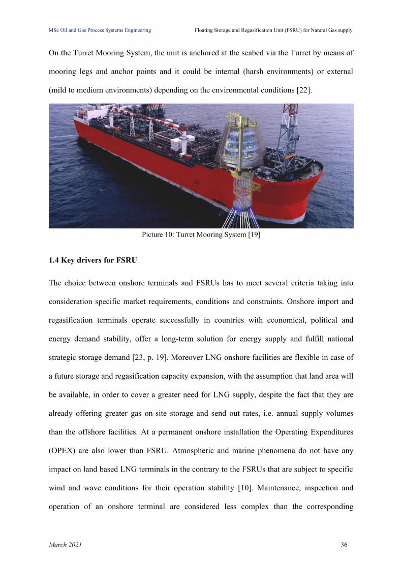
On the Turret Mooring System, the unit is anchored at the seabed via the Turret by means of
mooring legs and anchor points and it could be internal (harsh environments) or external
(mild to medium environments) depending on the environmental conditions [22].
Picture 10: Turret Mooring System [19]
1.4 Key drivers for FSRU
The choice between onshore terminals and FSRUs has to meet several criteria taking into
consideration specific market requirements, conditions and constraints. Onshore import and
regasification terminals operate successfully in countries with economical, political and
energy demand stability, offer a long-term solution for energy supply and fulfill national
strategic storage demand [23, p. 19]. Moreover LNG onshore facilities are flexible in case of
a future storage and regasification capacity expansion, with the assumption that land area will
be available, in order to cover a greater need for LNG supply, despite the fact that they are
already offering greater gas on-site storage and send out rates, i.e. annual supply volumes
than the offshore facilities. At a permanent onshore installation the Operating Expenditures
(OPEX) are also lower than FSRU. Atmospheric and marine phenomena do not have any
impact on land based LNG terminals in the contrary to the FSRUs that are subject to specific
wind and wave conditions for their operation stability [10]. Maintenance, inspection and
operation of an onshore terminal are considered less complex than the corresponding
March 2021 36
MSc Oil and Gas Process Systems Engineering Floating Storage and Regasification Unit (FSRU) for Natural Gas supply
procedures at an FSRU. In case of dry docking of the ship in order to perform inspection and
maintenance, that could last a significant amount of time, depending on the location of the
docking facility [24].
On the other hand FSRU projects, depending on the location, have to face fewer
environmental impacts and licensing restrictions than the enormous land areas that onshore
terminals need. They are also facing fewer social opposition in comparison to the
development of an onshore facility, which tend to provoke severe ‘Not In My Back Yard
(NIMBY)’ reactions from the local community [17]. FSRUs can cover short term gas market
needs, they are proposed as a fast track solution and in many cases they are reusable assets,
since they can be moved to supply natural gas to another market around the globe.
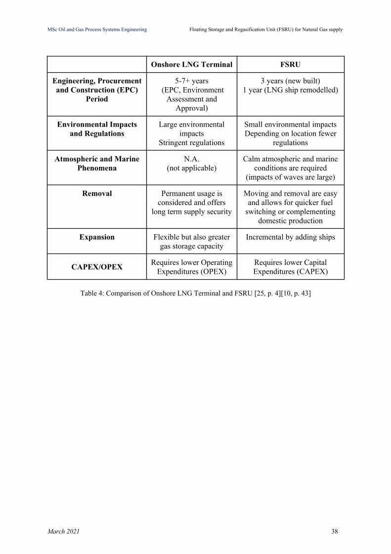
Furthermore, FSRUs as is depicted in Table 5 require lower Capital Expenditures (CAPEX)
due to the common practice of chartering FSRUs from third parties. In addition the
Engineering, Procurement and Construction (EPC) period is significantly shorter and this is a
good reason for covering the need for LNG supply sooner in a new market. Finally, on
environmental scope FSRUs contribute to a lighter environmental footprint.
March 2021 37
MSc Oil and Gas Process Systems Engineering Floating Storage and Regasification Unit (FSRU) for Natural Gas supply
Onshore LNG Terminal FSRU
Engineering, Procurementand Construction (EPC)
Period
5-7+ years (EPC, Environment
Assessment andApproval)
3 years (new built)1 year (LNG ship remodelled)
Environmental Impactsand Regulations
Large environmentalimpacts
Stringent regulations
Small environmental impactsDepending on location fewer
regulations
Atmospheric and MarinePhenomena
N.A.(not applicable)
Calm atmospheric and marineconditions are required
(impacts of waves are large)
Removal Permanent usage isconsidered and offers
long term supply security
Moving and removal are easyand allows for quicker fuel
switching or complementingdomestic production
Expansion Flexible but also greatergas storage capacity
Incremental by adding ships
CAPEX/OPEXRequires lower Operating
Expenditures (OPEX)Requires lower CapitalExpenditures (CAPEX)
Table 4: Comparison of Onshore LNG Terminal and FSRU [25, p. 4][10, p. 43]
March 2021 38
MSc Oil and Gas Process Systems Engineering Floating Storage and Regasification Unit (FSRU) for Natural Gas supply
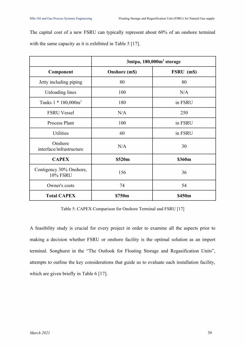
The capital cost of a new FSRU can typically represent about 60% of an onshore terminal
with the same capacity as it is exhibited in Table 5 [17].
3mtpa, 180,000m3 storage
Component Onshore (m$) FSRU (m$)
Jetty including piping 80 80
Unloading lines 100 N/A
Tanks 1 * 180,000m3 180 in FSRU
FSRU Vessel N/A 250
Process Plant 100 in FSRU
Utilities 60 in FSRU
Onshoreinterface/infrastructure
N/A 30
CAPEX $520m $360m
Contigency 30% Onshore,10% FSRU
156 36
Owner's costs 74 54
Total CAPEX $750m $450m
Table 5: CAPEX Comparison for Onshore Terminal and FSRU [17]
A feasibility study is crucial for every project in order to examine all the aspects prior to
making a decision whether FSRU or onshore facility is the optimal solution as an import
terminal. Songhurst in the “The Outlook for Floating Storage and Regasification Units”,
attempts to outline the key considerations that guide us to evaluate each installation facility,
which are given briefly in Table 6 [17].
March 2021 39

MSc Oil and Gas Process Systems Engineering Floating Storage and Regasification Unit (FSRU) for Natural Gas supply
Feature FSRU Onshore Comments
Send-out < 6 mtpa ✓ Some FSRUs are capable of peak send-out > 6 mtpabut not guaranteed. 8 mtpa may be possible with
newer vessels. Option for 2 FSRUs.
Additional capacityrequired in future
✓ Expanding FSRU capacity not realistic – space ononshore site allows additional vaporisers to be easily
added
Storage > 170,000 m3 ✓ Max vessel size 170,000 m3. Qmax option isavailable at 266,000 m3 but this would be bespoke.
Could add FSU.
Additional storagerequired in future
✓ Expanding FSRU capacity is not realistic – space ononshore sites allows for further tanks. Could consider
adding FSU.
Strategic storagerequired
✓ FSRU is a flexible (removable) option
No existing harbouravailable
✓ Offshore FSRU with pipeline to shore best option asharbour/breakwater construction expensive
Water depth < 14 m atharbour entrance
✓ Dredging expensive and ongoing OPEX. OffshoreFSRU with pipeline to shore possible best low cost
option
Onshore permittingdifficult - NIMBY
✓ Onshore terminals are major construction projectsinvolving major earth moving and heavy construction
materials
Short term gas marketneed
✓ Possibly while longer term onshore terminal plannedor just to meet seasonal needs
Fast track need for gasmarket
✓ Onshore terminals typically take 4 years to construct.Recent Ain Sokhna 2 terminal operational in just 5
months
Financing difficult andlack of capital
✓ FSRU can be leased but still need to finance harbourworks and pipeline connection to customers/grid
No land available foronshore terminal
✓ Land reclamation may be possible but is anexpensive option
High local contentneeded
✓ Limited local content with FSRU likely built in FarEast shipyard albeit some local work likely for
harbour and infrastructure
Table 6: Preliminary Guide - Decision factors regarding the choice of FSRU and Onshore LNG plantinstallation [17]
March 2021 40
MSc Oil and Gas Process Systems Engineering Floating Storage and Regasification Unit (FSRU) for Natural Gas supply
Chapter 2: FSRU Process Description
In this Chapter the main processes that take place in an FSRU will be presented.
Each project design consists of the following stages: Conceptual design, Feasibility Study,
Front End Engineering (FEED), Basic Design, Detailed Design, Procurement &
Construction, Start-Up and Operation. For each FSRU project several environmental factors
should be considered, which are subjected to the location’s selection for FSRU deployment.
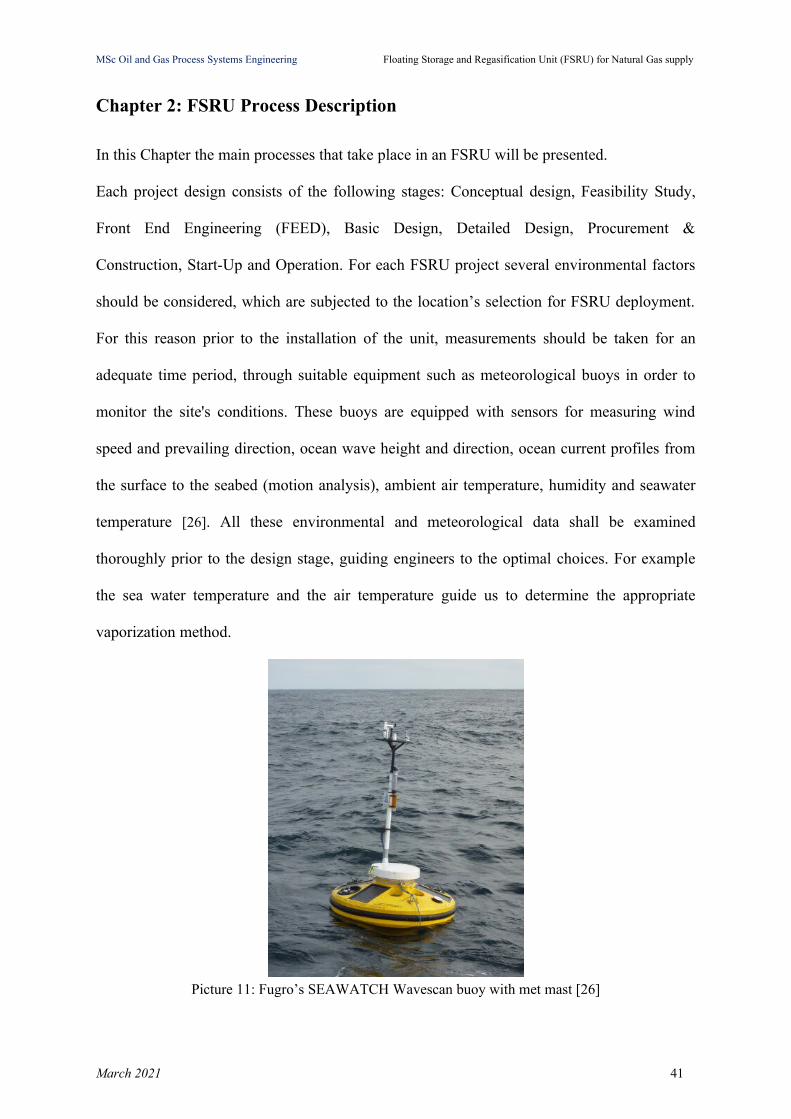
For this reason prior to the installation of the unit, measurements should be taken for an
adequate time period, through suitable equipment such as meteorological buoys in order to
monitor the site's conditions. These buoys are equipped with sensors for measuring wind
speed and prevailing direction, ocean wave height and direction, ocean current profiles from
the surface to the seabed (motion analysis), ambient air temperature, humidity and seawater
temperature [26]. All these environmental and meteorological data shall be examined
thoroughly prior to the design stage, guiding engineers to the optimal choices. For example
the sea water temperature and the air temperature guide us to determine the appropriate
vaporization method.
Picture 11: Fugro’s SEAWATCH Wavescan buoy with met mast [26]
March 2021 41
MSc Oil and Gas Process Systems Engineering Floating Storage and Regasification Unit (FSRU) for Natural Gas supply
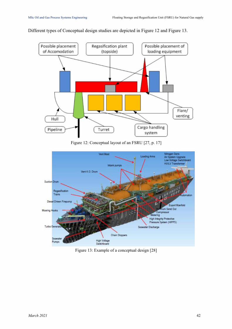
Different types of Conceptual design studies are depicted in Figure 12 and Figure 13.
Figure 12: Conceptual layout of an FSRU [27, p. 17]
Figure 13: Example of a conceptual design [28]
March 2021 42

MSc Oil and Gas Process Systems Engineering Floating Storage and Regasification Unit (FSRU) for Natural Gas supply
2.1 FSRU Process Flow
The Process Flow of a typical LNG Terminal is presented in Figure 14.
Figure 14: Process Flow of a typical LNG receiving and regasification terminal [29, p. 17]
Adopting this approach in FSRU, the process flow steps are presented in the sections
hereafter.
2.2 LNG transfer to FSRU Vessel
Ship-to-Ship LNG transfer operation can be either side by side, through a jetty, or in tandem
and either be through hard loading arms or flexible cryogenic hoses. Flexible cryogenic hoses
are the most affordable solution but they are responsible for generating more Boil-Off Gas
(BOG) and the offloading procedure takes longer to complete [17]. Hard loading arms fitted
on the FSRU tend to be the most frequent option for transferring LNG [17]. It is known that a
certain amount of LNG is vaporized when LNG is being transferred between the carrier and
the FSRU, due to the heat exchange with the storage system. For this reason the boil-off
redirection process has to take place in order to prevent overpressure in the storage tank of
the FSRU and pressure drop in the LNG storage tank carrier. The undesirable scenario of
March 2021 43

MSc Oil and Gas Process Systems Engineering Floating Storage and Regasification Unit (FSRU) for Natural Gas supply
overpressure may lead to gas release into the atmosphere through the relief valves or the
collapse of the structure [30, p. 5].
2.2.1 Ship to jetty to FSRU
The transfer of LNG from an LNG Carrier (LNGC) takes place through a jetty to the FSRU.
The jetty is equipped with fixed loading arms in order to connect in both vessels and allow
the offloading - loading procedure.
Picture 12: Ship to jetty to FSRU transfer, jetty is equipped with regasification plant [31, p. 20]
2.2.2 Side by side using flexible hoses
Flexible cryogenic hoses are used to discharge LNG as an alternative to more expensive
mechanical arms and take place through double-banking between the LNGC and the FSRU.
March 2021 44
MSc Oil and Gas Process Systems Engineering Floating Storage and Regasification Unit (FSRU) for Natural Gas supply
Picture 13: LNG transfer side by side using flexible hoses [31]
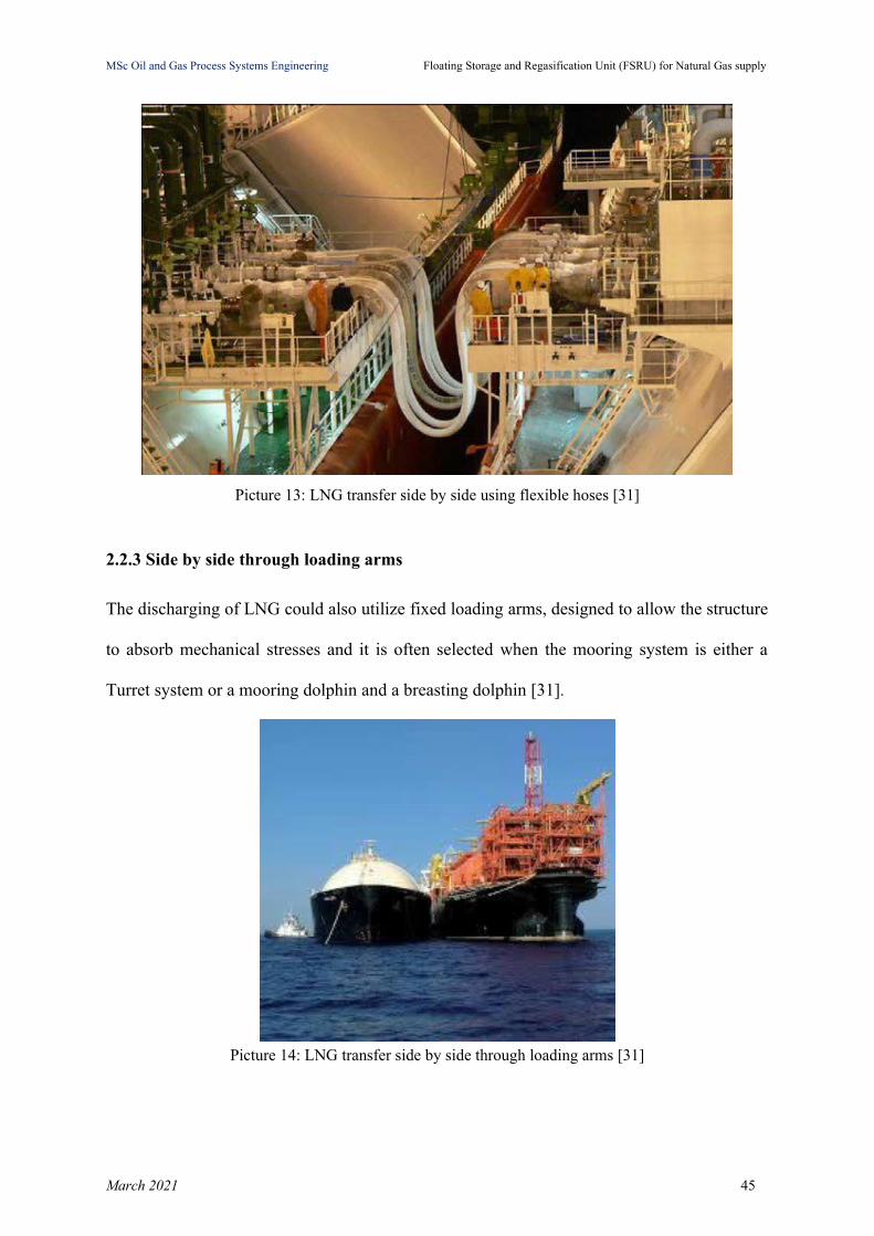
2.2.3 Side by side through loading arms
The discharging of LNG could also utilize fixed loading arms, designed to allow the structure
to absorb mechanical stresses and it is often selected when the mooring system is either a
Turret system or a mooring dolphin and a breasting dolphin [31].
Picture 14: LNG transfer side by side through loading arms [31]
March 2021 45
MSc Oil and Gas Process Systems Engineering Floating Storage and Regasification Unit (FSRU) for Natural Gas supply
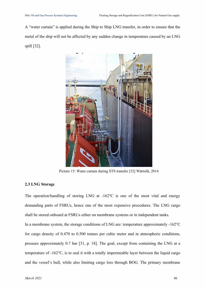
A “water curtain” is applied during the Ship to Ship LNG transfer, in order to ensure that the
metal of the ship will not be affected by any sudden change in temperature caused by an LNG
spill [32].
Picture 15: Water curtain during STS transfer [32] Wärtsilä, 2014
2.3 LNG Storage
The operation/handling of storing LNG at -162℃ is one of the most vital and energy
demanding parts of FSRUs, hence one of the most expensive procedures. The LNG cargo
shall be stored onboard at FSRUs either on membrane systems or in independent tanks.
In a membrane system, the storage conditions of LNG are: temperature approximately -162℃
for cargo density of 0.470 to 0.500 tonnes per cubic meter and in atmospheric conditions,
pressure approximately 0.7 bar [31, p. 18]. The goal, except from containing the LNG at a
temperature of -162°C, is to seal it with a totally impermeable layer between the liquid cargo
and the vessel’s hull, while also limiting cargo loss through BOG. The primary membrane
March 2021 46

MSc Oil and Gas Process Systems Engineering Floating Storage and Regasification Unit (FSRU) for Natural Gas supply
shall be Stainless steel 304L - 1.2 mm, Fe-36%Ni alloy and the secondary shall be composite
materials or Fe-36%Ni alloy. Manufacturing companies of membrane systems have to
guarantee an indicative Boil-Off Rate (BOR) but it is also project dependent due to vessel
size, tank arrangement and reinforcements [33]. Membrane tanks by GTT (Gaztransport &
Technigaz) such as No.96 tanks and Mark III tanks with their characteristics (material of
construction, insulation) are presented in Picture 16, Figure 15, Figure 16.
Picture 16: Interior of a non-spherical, Technigaz Mark III stainless steel membrane, LNG tank [34]
March 2021 47

MSc Oil and Gas Process Systems Engineering Floating Storage and Regasification Unit (FSRU) for Natural Gas supply
Figure 15: GTT Mark III membrane system [35]
Figure 16: GTT NO96 concept [36]
Among the independent tanks (type A, type B, type C) as exhibited in Figure 9, IMO
classification of LNG vessels, type B-Spherical Moss systems are primarily preferred in
FSRUs, which are constructed of either aluminum or 9% nickel steel.
March 2021 48

MSc Oil and Gas Process Systems Engineering Floating Storage and Regasification Unit (FSRU) for Natural Gas supply
Figure 17: Moss tank [37]
Moss is owned by Norwegian Company Moss Maritime. They are insulated with
polyurethane foam which is purged with nitrogen (N2). Normal operating pressure of Moss
Tanks is around 220 mbar (22kPa) [38].
Figure 18: Moss Tank concept [39]
As we have already mentioned, LNG is a multi-component mixture of hydrocarbons and
nitrogen, which is being stored at a gauge pressure of some 0.10 to 0.24 bar and temperature
March 2021 49
MSc Oil and Gas Process Systems Engineering Floating Storage and Regasification Unit (FSRU) for Natural Gas supply
of approximately -162°C in suitable tanks. Despite storage tanks insulation, a certain amount
of heat from the environment is being transferred eventually inside the tanks causes the
evaporation of the most volatile components (lowest boiling points) such as nitrogen and
methane, producing vapor (BOG), changing the initial LNG’s composition and properties and
leading to a mechanism known as “weathering” or “ageing”. As a consequence the
composition of stored LNG is altered through a time period affecting in fact cargo’s density
and forming separate layers within a storage tank, i.e. stratification takes place, leading to a
phenomenon known as “rollover”, which has safety and environmental issues associated with
it. Stratification will also occur when loading or unloading a storage tank with for example a
“light” and a “heavy” LNG due to different densities and then it is most likely for rollover
phenomenon to appear [40, p. 8].
2.4 LNG Pumping
LNG is stored as we have already mentioned at pressures near atmospheric but the gas
delivery from the FSRU has to comply with gas operator’s requirements, which indicate NG
delivery at elevated pressures. Pumping a liquid than compressing a gas is easier and more
cost- and energy-effective, thus LNG is pumped to the required send-out pressure prior to its
regasification [41, p. 16].
Usually two stages of pumping are taking place, one inside the storage tanks (in-tank pump)
and the other in the process area, as topside modules or as hull-integrated system. The first
stage of pumps (Low Pressure pumps, LP) supply LNG with discharge pressure around 7-8
bar. The send-out gas needs usually to be delivered onshore in elevated pressures of
approximately 80 to 100 bar, in case for example it is injected in the gas distribution system.
To achieve these pressures booster pumps (High Pressure pumps, HP) are required in order to
take LNG from the first stage pump and increase the pressure prior to the vaporizers at the
required pressure [42]. The right pressure of HP pumps should be set taking into
March 2021 50
MSc Oil and Gas Process Systems Engineering Floating Storage and Regasification Unit (FSRU) for Natural Gas supply
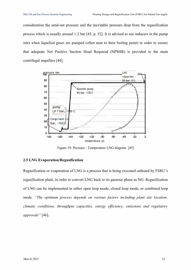
consideration the send-out pressure and the inevitable pressure drop from the regasification
process which is usually around 1-2 bar [43, p. 52]. It is advised to use inducers in the pump
inlet when liquefied gases are pumped (often near to their boiling point) in order to ensure
that adequate Net Positive Suction Head Required (NPSHR) is provided to the main
centrifugal impellers [44].
Figure 19: Pressure - Temperature LNG diagram [45]
2.5 LNG Evaporation/Regasification
Regasification or evaporation of LNG is a process that is being executed onboard by FSRU’s
regasification plant, in order to convert LNG back to its gaseous phase as NG. Regasification
of LNG can be implemented in either open loop mode, closed loop mode, or combined loop
mode. “The optimum process depends on various factors including plant site location,
climatic conditions, throughput capacities, energy efficiency, emissions and regulatory
approvals” [46].
March 2021 51

MSc Oil and Gas Process Systems Engineering Floating Storage and Regasification Unit (FSRU) for Natural Gas supply
Figure 20: Combined open/closed loop with seawater and steam heating [47]
In an open loop regasification system, seawater is used for heating the LNG, which is
continuously provided to the FSRU for the heat exchange process, circulated through the heat
exchangers and subsequently is dumped overboard [46]. Heat exchange process could be
implemented either between seawater (as the heating source) and an intermediate fluid
(propane), or between propane and LNG [46]. Open loop regasification is a preferred
technology worldwide, it is simpler compared to the close loop and offers lower greenhouse
gas generation emissions [46]. Closed loop regasification is implemented by using gas-fired
steam boilers in order to heat circulating water within the FSRU. Replenishment of water is
typically made annually for maintenance purposes or if the system is switched to open loop
mode [46]. Compared to open loop, it offers a better regasification performance for seawater
temperatures below 15ºC and has lower intake and discharge needs for seawater. The
disadvantages of this technology for regasification are the higher capital investment cost due
to the provision of boilers and the higher operating costs [46]. Similar to the open loop
regasification is also the combined loop with continuous provision of seawater but in this
mode the seawater is now heated via steam from gas-fired boilers prior to reaching the
regasification system on the FSRU [46].
March 2021 52
MSc Oil and Gas Process Systems Engineering Floating Storage and Regasification Unit (FSRU) for Natural Gas supply
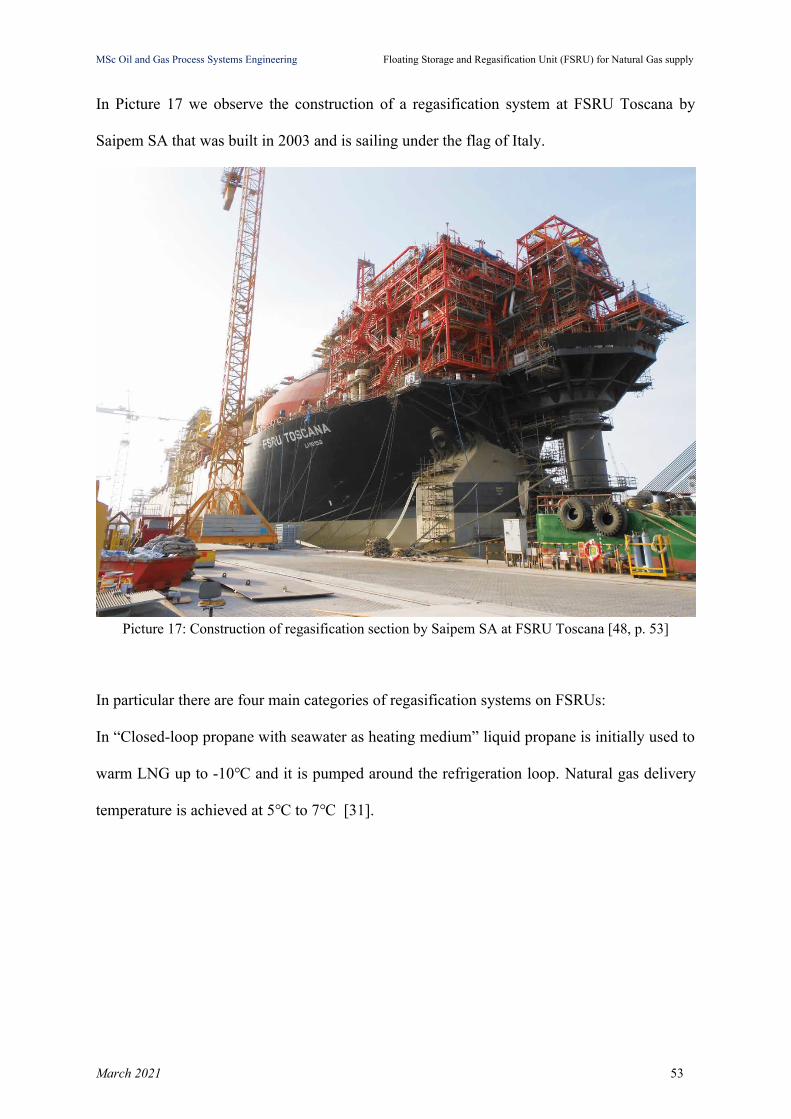
In Picture 17 we observe the construction of a regasification system at FSRU Toscana by
Saipem SA that was built in 2003 and is sailing under the flag of Italy.
Picture 17: Construction of regasification section by Saipem SA at FSRU Toscana [48, p. 53]
In particular there are four main categories of regasification systems on FSRUs:
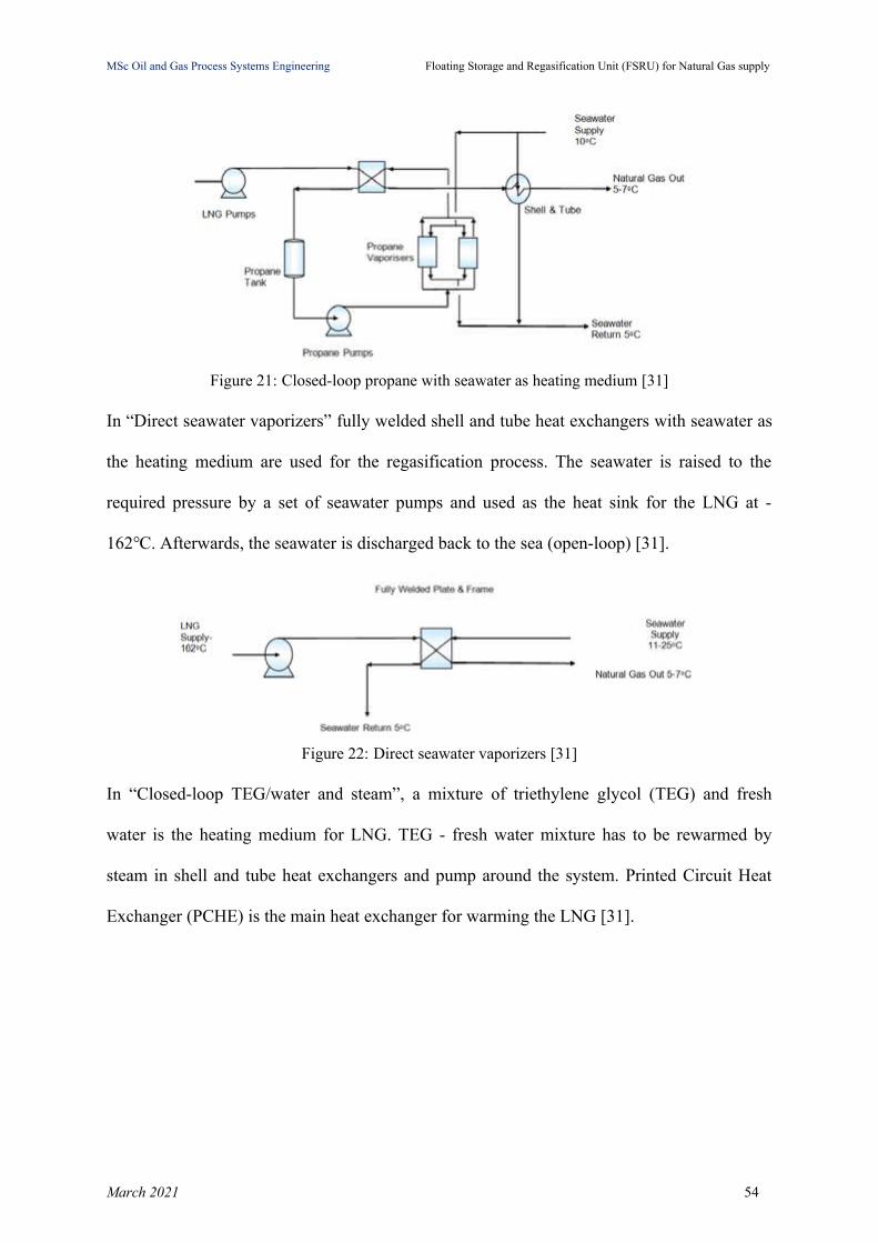
In “Closed-loop propane with seawater as heating medium” liquid propane is initially used to
warm LNG up to -10℃ and it is pumped around the refrigeration loop. Natural gas delivery
temperature is achieved at 5℃ to 7℃ [31].
March 2021 53
MSc Oil and Gas Process Systems Engineering Floating Storage and Regasification Unit (FSRU) for Natural Gas supply
Figure 21: Closed-loop propane with seawater as heating medium [31]
In “Direct seawater vaporizers” fully welded shell and tube heat exchangers with seawater as
the heating medium are used for the regasification process. The seawater is raised to the
required pressure by a set of seawater pumps and used as the heat sink for the LNG at -
162℃. Afterwards, the seawater is discharged back to the sea (open-loop) [31].
Figure 22: Direct seawater vaporizers [31]
In “Closed-loop TEG/water and steam”, a mixture of triethylene glycol (TEG) and fresh
water is the heating medium for LNG. TEG - fresh water mixture has to be rewarmed by
steam in shell and tube heat exchangers and pump around the system. Printed Circuit Heat
Exchanger (PCHE) is the main heat exchanger for warming the LNG [31].
March 2021 54

MSc Oil and Gas Process Systems Engineering Floating Storage and Regasification Unit (FSRU) for Natural Gas supply
Figure 23: Closed-loop TEG/water and steam [31]
In a “closed-loop TEG/water and seawater system”, LNG reaches the required temperature
by a mixture of TEG and fresh water which is warmed by seawater. PCHE is also present in
this system heating up the LNG [31].
Figure 24: Closed-loop TEG/water and seawater [31]
In Figure 25, we observe a shell and tube heat exchanger with seawater as a heating medium,
which heats LNG up to 8ºC in the outlet. In order to prevent corrosion due to seawater, tubes
are protected with anti-corrosion material. When direct heating with seawater as the heating
medium for regasification is chosen, it is advised that shell and tube heat exchangers must use
6% molybdenum, a material that can withstand seawater conditions [49]. The need for this
durable material should be considered in the feasibility study of the project, since it is four
times more expensive than stainless steel [49].
March 2021 55

MSc Oil and Gas Process Systems Engineering Floating Storage and Regasification Unit (FSRU) for Natural Gas supply
Figure 25: Shell and Tube type heat exchanger [47]
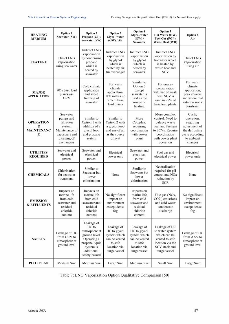
Patel et al. in their study [50] compare six vaporizer options based on different heating
mediums in terms of their application, operation and maintenance, utility and chemical
requirements, environmental impacts and relative plot sizes and they are presented in Table 7.
The six options considered in their study are Open Rack Vaporizer (ORV) uses seawater as
heating medium, second option uses propane as the intermediate fluid with seawater as the
heating source, third option uses glycol water as the intermediate fluid with air as the heating
source, fourth option uses glycol water as the intermediate fluid with seawater as the heating
source, fifth option uses Submerged Combustion Vaporizer (SCV) using fuel gas and waste
heat from cogeneration plant and sixth option uses Ambient Air Vaporizer (AAV) [50]. The
optimum vaporization option was examined by the ambient locations, for warm ambient
locations where the site ambient temperature is above 18°C and the most desirable is Option
3 (IFV (GW/Air)) and cold ambient locations where ambient temperature drops below 18°C
and the most desirable option is a combination of seawater heating and SCV [50].
March 2021 56
MSc Oil and Gas Process Systems Engineering Floating Storage and Regasification Unit (FSRU) for Natural Gas supply
HEATINGMEDIUM
Option 1Seawater (SW)
Option 2Propane (C3) /Seawater (SW)
Option 3Glycol-water(GW) / Air
Option 4Glycol-water
(GW) /Seawater
Option 5Hot Water (HW)Fuel Gas (FG)) /
Waste Heat (WH)
Option 6Air
FEATUREDirect LNGvaporization
using sea water
Indirect LNGvaporization
by condensingpropanewhich isheated byseawater
Indirect LNGvaporization
by glycolwhich is
heated by airfin exchanger
Indirect LNGvaporization
by glycolwhich is
heated byseawater
Indirect LNGvaporization byhot water which
is heated bywaste heat and
SCV
Direct LNGvaporization
using air
MAJORAPPLICATION
70% base loadplants use
ORV
Cold climateapplicationand avoidfreezing ofseawater
For warmclimate
application.IFV makes up5 % of baseload plants
Similar toOption 3except
seawater isused as thesource ofheating
For energyconservation
with use of wasteheat. SCV is
used in 25% ofbase load plants
For warmclimate
application,peak shavers
and where realestate is not a
constraint
OPERATION &
MAINTENANCE
Seawaterpumps andfiltrationsystem
Maintenance ofvaporizers and
cleaning ofexchangers
Similar toOption 1 withaddition of aglycol loopand propane
system
Similar toOption 2 witha glycol loopand use of airas the source
of heat
MoreComplex,requiring
coordinationwith power
plant
More complexcontrol. Need tobalance waste
heat and fuel gasto SCVs. Require
coordinationwith power plant
operation
Cyclicoperation,requiring
adjustment ofthe defrosting
cycle accordingto ambient
changes
UTILITIESREQUIRED
Seawater andelectrical
power
Seawater andelectrical
power
Electricalpower only
Seawater andelectrical
power
Fuel gas andelectrical power
Electricalpower only
CHEMICALSChlorinationfor seawatertreatment.
Similar toSeawater but
lowerchlorination
None
Similar toSeawater but
lowerchlorination
Neutralizationrequired for pHcontrol and NOx
reduction bySCR
None
EMISSION & EFFLUENTS
Impacts onmarine lifefrom cold
seawater andresidualchloridecontent
Impacts onmarine lifefrom cold
seawater andresidualchloridecontent
No significantimpact on
environmentexcept dense
fog
Impacts onmarine lifefrom cold
seawater andresidualchloridecontent
Flue gas (NOx,CO2 ) emissionsand acid water
condensatedischarge
No significantimpact on
environmentexcept dense
fog
SAFETY
Leakage of HCfrom ORV toatmosphere atground level
Leakage ofHC to
atmosphere atground level.Operating a
propane liquidsystem isadditional
safety hazard
Leakage ofHC to glycolsystem whichcan be vented
to safelocation viasurge vessel
Leakage ofHC to glycolsystem whichcan be vented
to safelocation viasurge vessel
Leakage of HCto water systemwhich can bevented to safe
location via theSCV stack and
surge vessel
Leakage of HCfrom AAV toatmosphere atground level
PLOT PLAN Medium Size Medium Size Large Size Medium Size Small Size Large Size
Table 7: LNG Vaporization Option Qualitative Comparison [50]
March 2021 57
MSc Oil and Gas Process Systems Engineering Floating Storage and Regasification Unit (FSRU) for Natural Gas supply
2.6 Boil-Off Gas (BOG) compression
LNG as we have already mentioned is stored in insulated tanks in liquid form at a
temperature of -162°C, close to the vaporization temperature and any amount of external heat
lead to natural evaporation of LNG, i.e. Boil-Off Gas. The amount of BOG per hour depends
mainly on the size of the tanks, the load level of the LNG, the ambient temperature and the
quality of the LNG tank insulation. The formation of boil-off gas is unavoidable due to the
natural cargo heating and operations (transfer, storage) and has to be removed from the tanks
in order to maintain the cargo tank pressure (during ship-to-ship LNG transfer, a certain
amount of BOG that has been created due to this process, is redirected through a vapour
return valve to LNGC). For this reason boil-off gas needs to be monitored by the BOG
handling system. BOG handling system is responsible for either providing BOG as fuel gas,
that is compressed by low duty compressor up to the required pressure or by redirecting BOG
to the recondenser for recondensation [51, p. 21]. Moreover, due to the regasification process,
a certain amount of LNG boils off and creates boil-off gas which is compressed by BOG
compressors and is commonly added to the NG send-out [1].
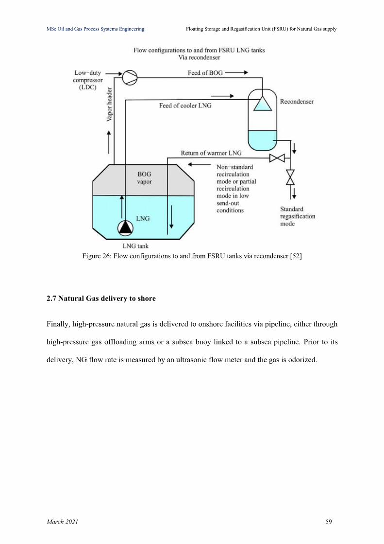
When the amount of BOG exceeds the amount to fill the empty volume in LNG storage
tanks, BOG compressor has to gather this boil-off gas and redirect it to BOG recondenser.
The most important variable about BOG compressors is discharge pressure and the value is
determined for maximum efficiency. BOG production rate in each FSRU project indicates the
optimum capacity of the BOG compressor [43]. The BOG recondenser has to handle the
excess of BOG that is not used in DFDE‐type (dual‐fuel diesel electric) for power generation,
by recovering and liquefying BOG with sub-cooled LNG.
March 2021 58
MSc Oil and Gas Process Systems Engineering Floating Storage and Regasification Unit (FSRU) for Natural Gas supply
Figure 26: Flow configurations to and from FSRU tanks via recondenser [52]
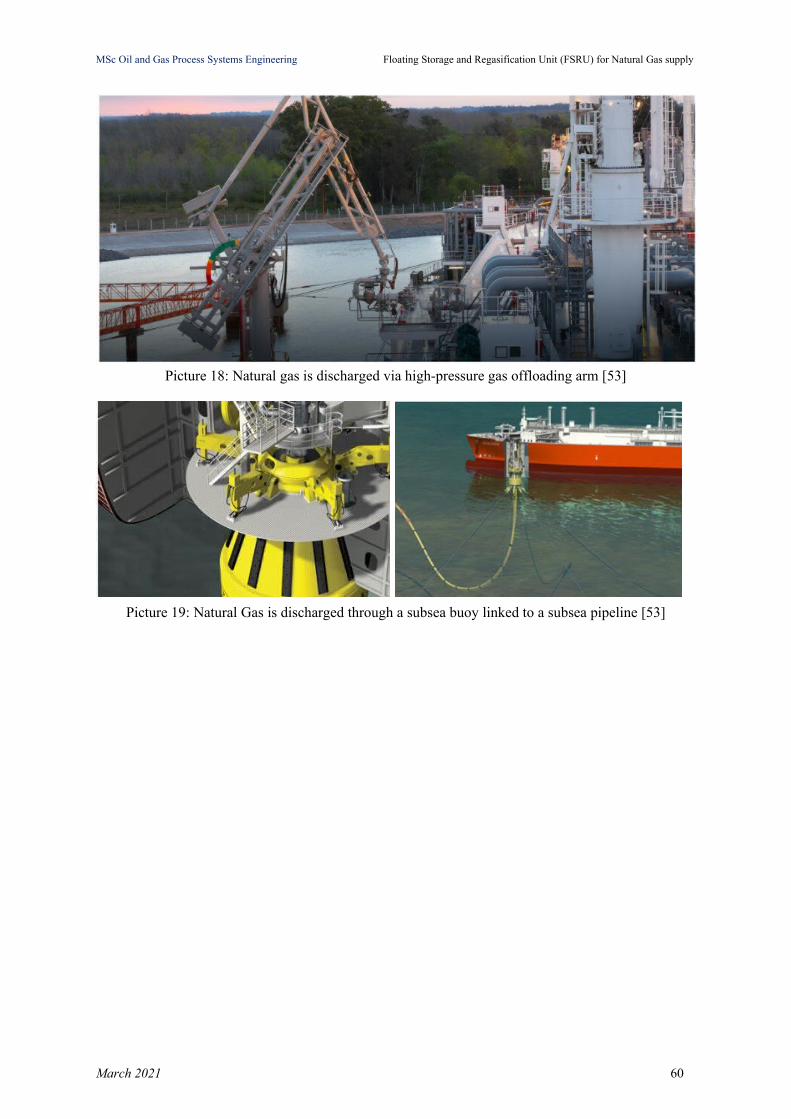
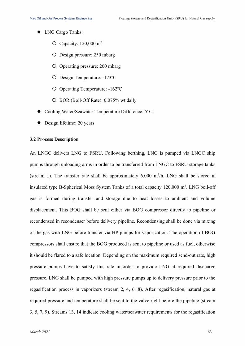
2.7 Natural Gas delivery to shore
Finally, high-pressure natural gas is delivered to onshore facilities via pipeline, either through
high-pressure gas offloading arms or a subsea buoy linked to a subsea pipeline. Prior to its
delivery, NG flow rate is measured by an ultrasonic flow meter and the gas is odorized.
March 2021 59
MSc Oil and Gas Process Systems Engineering Floating Storage and Regasification Unit (FSRU) for Natural Gas supply
Picture 18: Natural gas is discharged via high-pressure gas offloading arm [53]
Picture 19: Natural Gas is discharged through a subsea buoy linked to a subsea pipeline [53]
March 2021 60

MSc Oil and Gas Process Systems Engineering Floating Storage and Regasification Unit (FSRU) for Natural Gas supply
Chapter 3: FSRU Basic Design
In this Chapter the Basic Design on an FSRU Project will be presented with emphasis on key
process parameters of FSRU and connection to delivery system. Two different delivery
pressure requirements will be examined: a High Pressure one (at 80 bar) and a Low Pressure
one (at 12 bar) in order to show constraints and technologies to be used in each case.
3.1 Basic Design Data
An FSRU installation (as shown in Figure 27) shall consist of:
a Floating Storage Regasification Unit (FSRU)
a Mooring system
a Pipeline system connecting the FSRU to the National Gas Transmission System.
FSRU vessel shall be permanently moored and have a high pressure natural gas
transfer system, transmitting the gas through flexible risers to the Pipeline End
Manifold (PLEM), where the gas transmission pipeline is connected.
Figure 27: FSRU Installation [32]
March 2021 61

MSc Oil and Gas Process Systems Engineering Floating Storage and Regasification Unit (FSRU) for Natural Gas supply
The following Basic Design Data for FSRU installation shall be considered.
Typical LNG composition (mole fractions) [43]:
❏ Methane: 0.9133
❏ Ethane: 0.0536
❏ Propane: 0.0214
❏ Isobutane: 0.0047
❏ N-butane: 0.0046
❏ Isopentane: 0.0001
❏ N-pentane: 0.0001
❏ Nitrogen: 0.0022
Terminal Send-out Rate to Pipeline: 4 x 400 m3/h LNG
Two delivery systems of LP and HP will be examined:
HP System:
Design Send-out Pressure: 100 bar
Operating Send-out Pressure: 80 bar
Design Send-out Temperature: 50oC
Operating Send-out Temperature: 5oC
LP System:
Design Send-out Pressure: 15 bar
Operating Send-out Pressure: 12 bar
Design Send-out Temperature: 50oC
Operating Send-out Temperature: 5oC
Offloading System:
Ship: 120,000 m3
Offloading Rate to FSRU: 6,000 m3/h
March 2021 62
MSc Oil and Gas Process Systems Engineering Floating Storage and Regasification Unit (FSRU) for Natural Gas supply
LNG Cargo Tanks:
Capacity: 120,000 m3
Design pressure: 250 mbarg
Operating pressure: 200 mbarg
Design Temperature: -173oC
Operating Temperature: -162oC
BOR (Boil-Off Rate): 0.075% wt daily
Cooling Water/Seawater Temperature Difference: 5°C
Design lifetime: 20 years
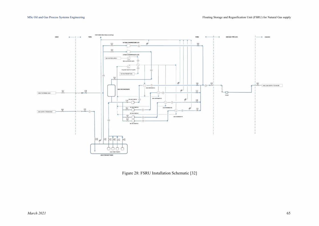
3.2 Process Description
An LNGC delivers LNG to FSRU. Following berthing, LNG is pumped via LNGC ship
pumps through unloading arms in order to be transferred from LNGC to FSRU storage tanks
(stream 1). The transfer rate shall be approximately 6,000 m3/h. LNG shall be stored in
insulated type B-Spherical Moss System Tanks of a total capacity 120,000 m3. LNG boil-off
gas is formed during transfer and storage due to heat losses to ambient and volume
displacement. This BOG shall be sent either via BOG compressor directly to pipeline or
recondensed in recondenser before delivery pipeline. Recondensing shall be done via mixing
of the gas with LNG before transfer via HP pumps for vaporization. The operation of BOG
compressors shall ensure that the BOG produced is sent to pipeline or used as fuel, otherwise
it should be flared to a safe location. Depending on the maximum required send-out rate, high
pressure pumps have to satisfy this rate in order to provide LNG at required discharge
pressure. LNG shall be pumped with high pressure pumps up to delivery pressure prior to the
regasification process in vaporizers (stream 2, 4, 6, 8). After regasification, natural gas at
required pressure and temperature shall be sent to the valve right before the pipeline (stream
3, 5, 7, 9). Streams 13, 14 indicate cooling water/seawater requirements for the regasification
March 2021 63
MSc Oil and Gas Process Systems Engineering Floating Storage and Regasification Unit (FSRU) for Natural Gas supply
process. At every stage, NG shall be measured in order to estimate the losses. A vent mast
shall be present in order to ensure safe disposal of hydrocarbon vapors which may occur in
the regasification process and in the BOG handling system at abnormal operation.
Operating Modes of the FSRU terminal shall be:
● FSRU Loading with Send-out
● Send-out without FSRU Loading
● Holding (zero Send-out/no Loading)
A typical process flow diagram for an FSRU is shown in Figure 28 with LNG and NG
Streams.
March 2021 64
MSc Oil and Gas Process Systems Engineering Floating Storage and Regasification Unit (FSRU) for Natural Gas supply
Figure 28: FSRU Installation Schematic [32]
March 2021 65

MSc Oil and Gas Process Systems Engineering Floating Storage and Regasification Unit (FSRU) for Natural Gas supply
3.3 Process Simulation
The simulation of the above mentioned process has been performed using DWSIM steady
state simulator. DWSIM is a chemical process simulator that allows the user to model process
plants by using rigorous thermodynamic and unit operations models [54]. For this simulation,
the thermodynamic model which is selected is the Peng-Robinson (PR) property package that
uses the Peng-Robinson cubic equation of state and is recommended for use with
hydrocarbons. In Table 8 the main symbols along with their description used in DWSIM are
given.
Symbol Symbol description Symbol Symbol description
Material stream Tank
Energy stream Stream mixer
Pump Stream splitter
Compressor Heat exchanger
Cooler Gas-liquid separator
Table 8: Process flow diagram symbols for simulation in DWSIM [54]
In order to simulate the processes that take place in an FSRU, we formulate in blocks the
main processes such as storage of LNG in the FSRU tanks, BOG handling, regasification and
natural gas supply to pipeline.
March 2021 66

MSc Oil and Gas Process Systems Engineering Floating Storage and Regasification Unit (FSRU) for Natural Gas supply
3.3.1 Boil-Off Gas (BOG) Simulation
The Boil-Off Gas (BOG) is composed only of methane and nitrogen, in analogies depending
on LNG composition. It is transferred from the FSRU tank via a BOG compressor either to
the delivery system or to recondenser for vaporization.
BOG is the gas generated from LNG mainly due to the following factors:
● heat loss to ambient (BOR - Boil-Off Rate) in FSRU tank
● liquid level displacement during the loading mode.
The capacity of the vessel and the loading rate affect the amount of the BOG formation i.e.
the larger the vessels and the greater the loading rates, the higher the BOG formation. In
order to calculate the BOG amount (stream 10), we simulate the BOG production as it is
presented in Figure 29 hereafter. The simulation will result in the maximum BOG production
during FSRU Loading Mode to be considered for sizing the BOG Compressor.
First, we have to calculate the heat input in kW from the ambient to the vessel (heat ingress to
FSRU tank). We need to define the vessel size (m3), the vessel’s BOR (% wt daily), the
methane heat of vaporization (kJ/kg), the methane density at -162°C and 1 atm and pure
methane vaporization (kg/h) since the BOG is expressed in terms of pure methane mixture. In
particular for a vessel of 120,000 m3 the calculated heat input is 224.5 kW.
Ship Size(m3)
Ship BOR(% wt daily)
Methane HeatOf
Vaporization(kJ/kg)
MethaneDensity @ -162°C and 1
atm
PureMethane
Vaporization
(kg/h)
CalculatedHeat Input
(kW)
120,000 0.075 510.15 422.46 1584.2 224.5
Table 9: Heat input from ambient
This calculated input is introduced in the tank simulation block as heat input that would result
into a flash and production of BOG (the composition of the BOG is presented in Figure 29).
March 2021 67

MSc Oil and Gas Process Systems Engineering Floating Storage and Regasification Unit (FSRU) for Natural Gas supply
Then, an equivalent volume of 6,000 m3/h of the same BOG quality is introduced to simulate
the vapour displacement due to liquid level increase inside the tank.
Figure 29: Simulation of BOG production in DWSIM
From the simulation results, it is clear that the amount of BOG produced during FSRU
loading is 6,851.24 m3/h of gas (12,902 kg/h) of the following quality:
● Methane: 94.15%
● Nitrogen: 5.85%
This result will be introduced in the general simulation model of the FSRU.
March 2021 68

MSc Oil and Gas Process Systems Engineering Floating Storage and Regasification Unit (FSRU) for Natural Gas supply
3.3.2 FSRU Simulation
The most demanding operation of the FSRU, FSRU Loading and Maximum Send-out, is
simulated using DWSIM in order to size major pieces of equipment. There is a set of four (4)
HP Pumps and four (4) Vaporizers to achieve the Maximum Send-out rate of 4 x 400 = 1,600
m3/h LNG. A cooling water pump is also present in order to provide seawater to the
vaporizers and a BOG Compressor for BOG handling from FSRU Tank.
We examine in FSRU simulation the following cases:
Low Pressure delivery at 12 bar
High Pressure delivery at 80 bar
The developed flowsheets for both cases are presented in Figure 30, Figure 33 and the results
of the simulation in the form of heat and material balances are shown in Table 10, Table 12
hereafter.
3.3.2.1 FSRU Simulation - Low Pressure Delivery System
For a Low Pressure delivery system at 12 bar, a BOG compressor is added in simulation to
transfer the produced BOG generated directly to the delivery system. The compressor is sized
for the maximum BOG production case that is the FSRU Loading mode without Send-out. It
is the maximum BOG production case since the vapour displacement is maximum in this
case.
The BOG compressor is modeled for the following conditions:
● Suction Pressure: almost atmospheric
● Discharge Pressure: 12 bar
● Capacity: 12,902 kg/h as calculated in the previous section
● BOG Quality: Methane: 94.15% mol, Nitrogen: 5.85% mol as calculated in the
previous section
March 2021 69

MSc Oil and Gas Process Systems Engineering Floating Storage and Regasification Unit (FSRU) for Natural Gas supply
● Efficiency: 75% (typical)
The results of the simulation give a compressor machine with the following characteristics:
● Discharge Temperature: -32oC
● Required Power: 872 kW
The compressor discharge BOG is mixed with the evaporated LNG and sent to the delivery
system. Part or all of it could be used for power generation requirements in the FSRU and the
remaining gas could be sent to the delivery system instead of flaring it.
For the LNG vaporization, a set of 4 pumps is used to transfer LNG to vaporizers that operate
by means of cooling water.
These pumps are located inside the tank and are of type vertical centrifugal pumps. They are
designed for the following data:
● Suction Pressure: almost atmospheric with static head depending on tank level
● Discharge Pressure: 13 bar
● Pressure Increase (Head): 12 bar
● Capacity: 400 m3/h
● Efficiency: 75% (typical)
● Required Power: 177.6 kW
Four (4) vaporizers, one per pump are simulated for the vaporization of the LNG to NG via
cooling water. The allowable pressure drop per vaporizer is 1 bar and the cooling water
required, for Temperature Difference DT = 5oC and inlet cooling water temperature of 15oC,
is estimated to 6,425 m3/h per vaporizer. The vaporizers outlet temperature of the NG is 5oC,
higher than the NG dew point.
The water pump for cooling water purposes are also vertical centrifugal pumps with the
following design characteristics:
● Suction Pressure: almost atmospheric
March 2021 70

MSc Oil and Gas Process Systems Engineering Floating Storage and Regasification Unit (FSRU) for Natural Gas supply
● Discharge Pressure: 3 bar
● Pressure Increase (Head): 2 bar
● Capacity: 25,700 m3/h
● Efficiency: 75% (typical)
● Required Power: 1,891 kW
The simulation flowsheet and the Heat & Material Balances are shown hereafter.
March 2021 71
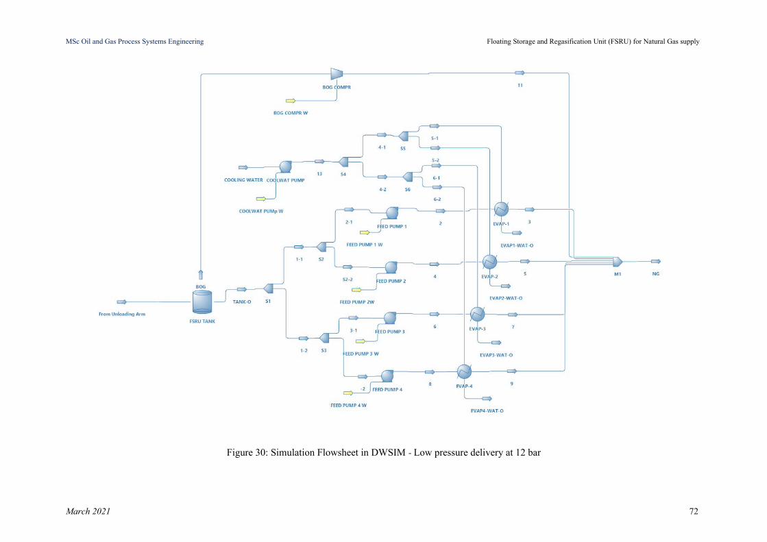
MSc Oil and Gas Process Systems Engineering Floating Storage and Regasification Unit (FSRU) for Natural Gas supply
Figure 30: Simulation Flowsheet in DWSIM - Low pressure delivery at 12 bar
March 2021 72

MSc Oil and Gas Process Systems Engineering Floating Storage and Regasification Unit (FSRU) for Natural Gas supply
Stream
1 2 3 4 5 6 7 8 9 10 11 12
Seawatersupply
13 14
LNG fromLNGC to
FSRU
LNG fromPump 1 toVaporizer
1
NG fromVaporizer1 to valve(before
pipeline)
LNG fromPump 2 toVaporizer
2
NG fromVaporizer2 to valve(before
pipeline)
LNG fromPump 3 toVaporizer
3
NG fromVaporizer3 to valve(before
pipeline)
LNG fromPump 4 toVaporizer
4
NG fromVaporizer4 to valve(before
pipeline)
BOG fromFSRU to
compressor
BOG atcompressordischarge
Total NGat delivery
pipeline
Inlet Seawater for
regasification
OutletSeawater fromregasification
Liquid Flow(m3/h) 1,600 400 - 400 - 400 - 400 - - - - 25,700 25,700 25,700
Gas Flow(m3/h)
- - 18,220 - 18,220 - 18,220 - 18,220 6,851 1,229 74,123 - - -
Phase Liquid Liquid Gas Liquid Gas Liquid Gas Liquid Gas Gas Gas Gas Liquid Liquid Liquid
Pressure(bar) 1 13 12 13 12 13 12 13 12 1 12 12 1 3 3
Temperature (C) -162 -161 5 -161 5 -161 5 -161 5 -161 -32 4.3 15 15 10
Table 10: Heat And Material Balances from DWSIM Simulation - Low pressure delivery at 12 bar
March 2021 73
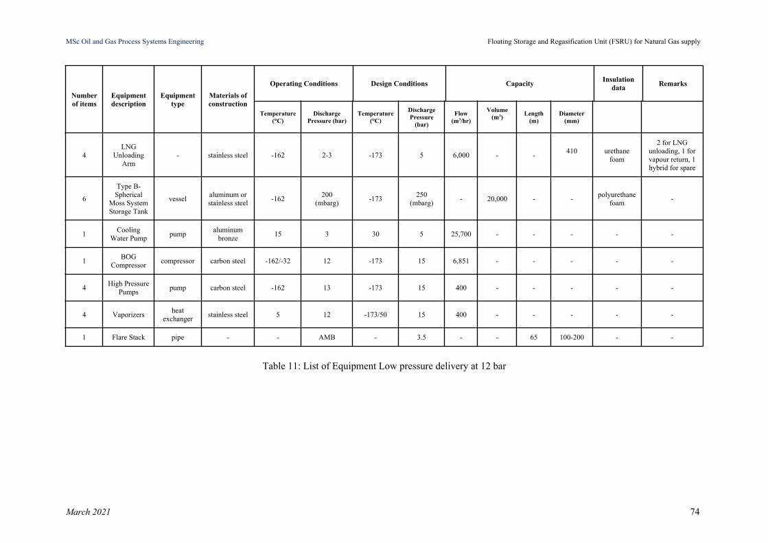
MSc Oil and Gas Process Systems Engineering Floating Storage and Regasification Unit (FSRU) for Natural Gas supply
Numberof items
Equipmentdescription
Equipmenttype
Materials ofconstruction
Operating Conditions Design Conditions CapacityInsulation
dataRemarks
Temperature(°C)
DischargePressure (bar)
Temperature(°C)
DischargePressure
(bar)
Flow(m3/hr)
Volume(m3)
Length(m)
Diameter(mm)
4LNG
UnloadingArm
- stainless steel -162 2-3 -173 5 6,000 - -410 urethane
foam
2 for LNGunloading, 1 forvapour return, 1hybrid for spare
6
Type B-Spherical
Moss SystemStorage Tank
vesselaluminum orstainless steel
-162200
(mbarg)-173
250(mbarg)
- 20,000 - -polyurethane
foam-
1Cooling
Water Pumppump
aluminumbronze
15 3 30 5 25,700 - - - - -
1BOG
Compressorcompressor carbon steel -162/-32 12 -173 15 6,851 - - - - -
4High Pressure
Pumpspump carbon steel -162 13 -173 15 400 - - - - -
4 Vaporizersheat
exchangerstainless steel 5 12 -173/50 15 400 - - - - -
1 Flare Stack pipe - - AMB - 3.5 - - 65 100-200 - -
Table 11: List of Equipment Low pressure delivery at 12 bar
March 2021 74

MSc Oil and Gas Process Systems Engineering Floating Storage and Regasification Unit (FSRU) for Natural Gas supply
3.3.2.2 FSRU Simulation - High Pressure Delivery System
In this simulation we set the delivery pressure of NG at 80 bar. The BOG Compressor has to
handle the BOG generation on Loading Mode i.e. 12,902 kg/h at 80 bar delivery pressure.
The compressor discharge temperature depends on the polytropic efficiency and the selected
pressure difference (inlet, outlet). By specifying the compressor outlet pressure (80 bar) and
polytropic efficiency (75%), we manage to deliver the outlet stream of the compressor
(Stream 11) at 127°C with 2 MW power required for the compressor’s operation. Despite the
fact that in simulation a compressor with this required pressure increase could work (see
Figure 31), in reality it is unfeasible and such a machine cannot exist.
For this reason, we simulate the case with a set of three compressors and air-cooled
intercoolers that sequentially could achieve the required pressure difference as presented in
Figure 32. This layout with compressors and intercoolers could be feasible with respect to
equipment requirements, but it is an installation that requires a lot of space in order to be
arranged and in our case it could not be a feasible solution from the construction point of
view and for the space available in a ship. In FSRU installation, the high pressure delivery
requires recondensing due to high compressor machine requirements.
Therefore, we examine the case with recondensation as presented in the following section.
Recondensation is preferable based on the design heuristic that: better pump a liquid than
compress a gas. Indeed the power required for the pressure increase is higher in the gas phase
compared to the liquid phase. The recondensation is based on the concept of mixing the BOG
with a quantity of LNG to get a liquid mixture that will be further vaporized. The recondenser
is a mixing drum of typically 4 m3. The recondensing will require two levels of pumping. A
set of LP Pumps at a pressure that will be also the BOG Compressor delivery pressure and
the HP Pumps to bring LNG to the final delivery pressure prior to vaporization.
March 2021 75
MSc Oil and Gas Process Systems Engineering Floating Storage and Regasification Unit (FSRU) for Natural Gas supply
The LP pumps are of type vertical centrifugal pumps. They are designed for the following
data:
● Suction Pressure: almost atmospheric
● Discharge Pressure: 8 bar
● Pressure Increase (Head): 7 bar
● Capacity: 400 m3/h
● Efficiency: 75% (typical)
● Required Power: 104 kW
The HP pumps are of type vertical centrifugal pumps. They are designed for the following
data:
● Suction Pressure: 8 bar
● Discharge Pressure: 81 bar
● Pressure Increase (Head): 73 bar
● Capacity: 413 m3/h
● Efficiency: 75% (typical)
● Required Power: 1,116 kW
Four (4) vaporizers, one per HP pump are simulated for the vaporization of the LNG to NG
via cooling water. The allowable pressure drop per vaporizer is 1 bar and the cooling water
required, for Temperature Difference DT = 5oC and inlet cooling water temperature of 15oC,
is estimated to 5,462 m3/h per vaporizer. The vaporizers outlet temperature of the NG is 5oC,
higher than the NG dew point.
The water pump for the cooling water purposes are also vertical centrifugal pumps with the
following design characteristics:
● Suction Pressure: almost atmospheric
● Discharge Pressure: 3 bar
March 2021 76

MSc Oil and Gas Process Systems Engineering Floating Storage and Regasification Unit (FSRU) for Natural Gas supply
● Pressure Increase (Head): 2 bar
● Capacity: 21,850 m3/h
● Efficiency: 75% (typical)
● Required Power: 1,608 kW
March 2021 77
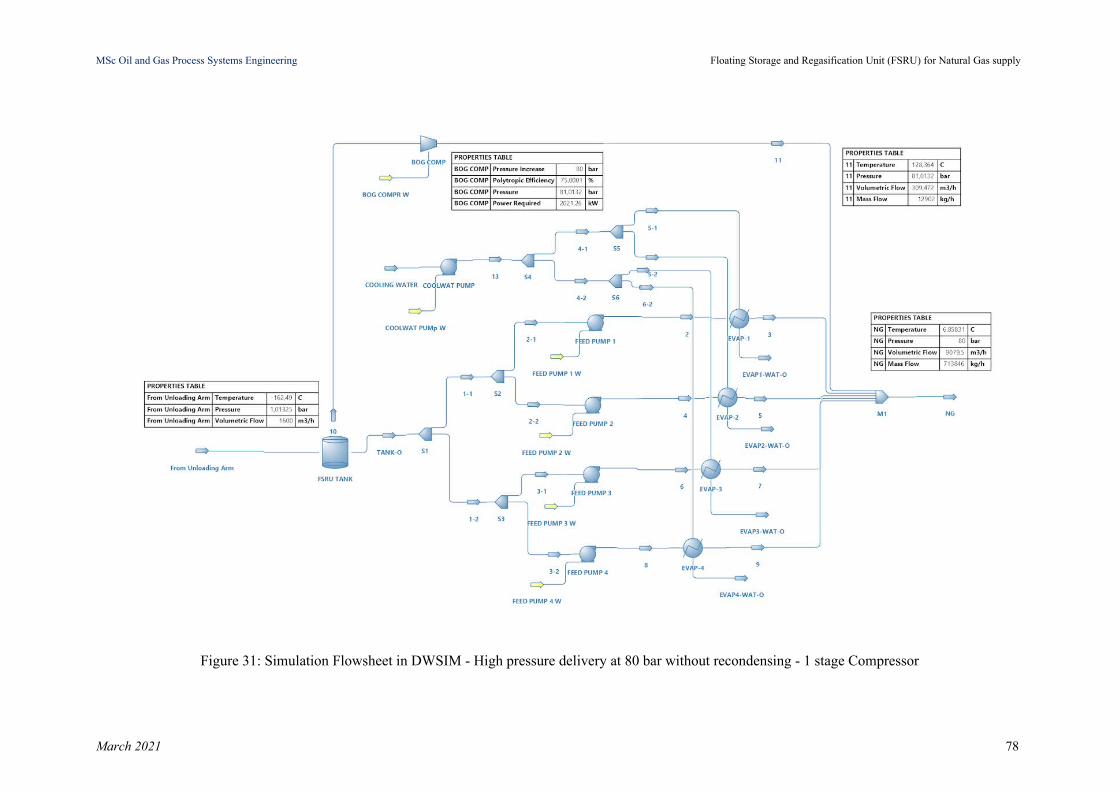
MSc Oil and Gas Process Systems Engineering Floating Storage and Regasification Unit (FSRU) for Natural Gas supply
Figure 31: Simulation Flowsheet in DWSIM - High pressure delivery at 80 bar without recondensing - 1 stage Compressor
March 2021 78
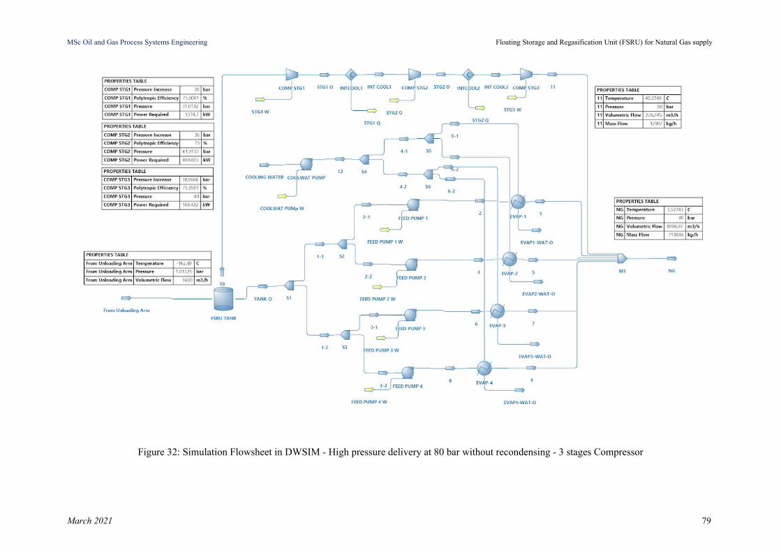
MSc Oil and Gas Process Systems Engineering Floating Storage and Regasification Unit (FSRU) for Natural Gas supply
Figure 32: Simulation Flowsheet in DWSIM - High pressure delivery at 80 bar without recondensing - 3 stages Compressor
March 2021 79
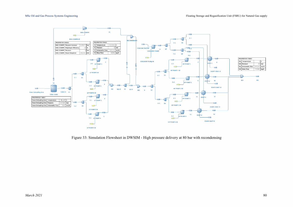
MSc Oil and Gas Process Systems Engineering Floating Storage and Regasification Unit (FSRU) for Natural Gas supply
Figure 33: Simulation Flowsheet in DWSIM - High pressure delivery at 80 bar with recondensing
March 2021 80
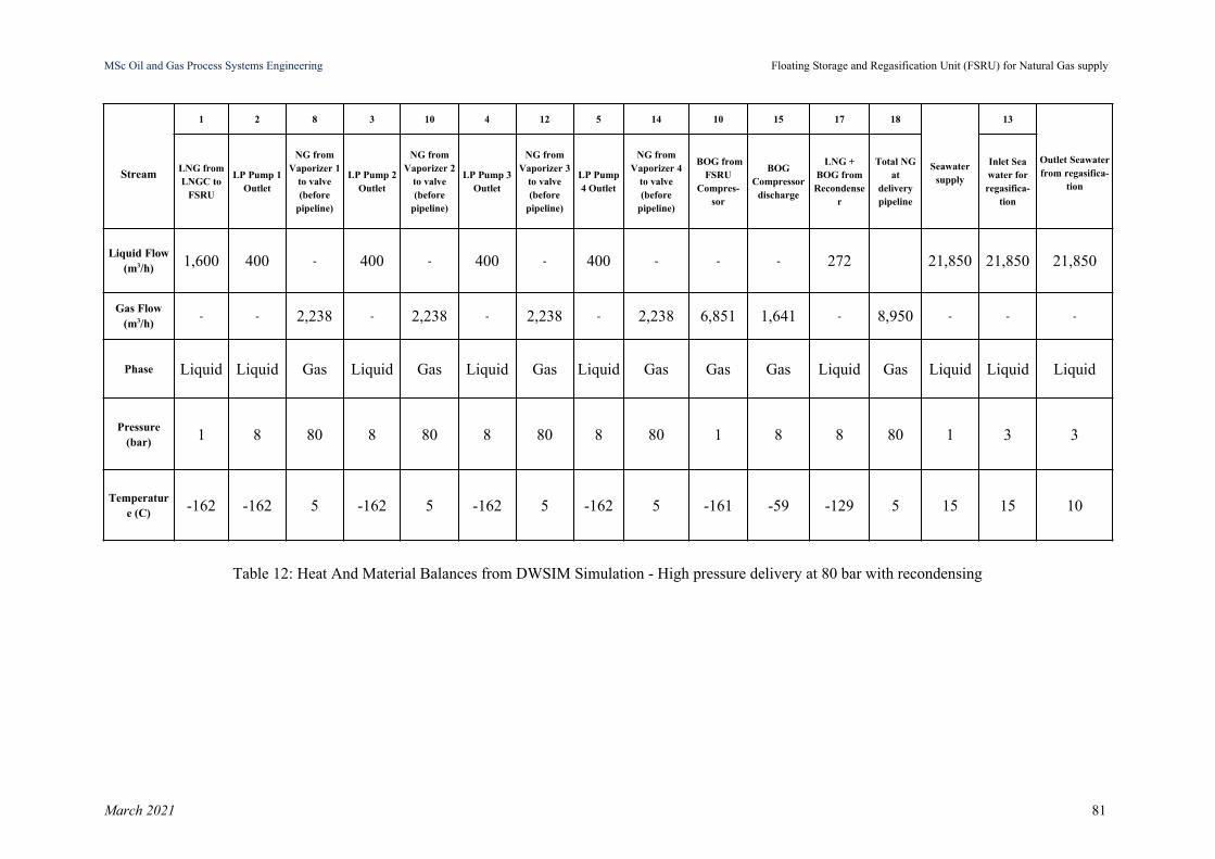
MSc Oil and Gas Process Systems Engineering Floating Storage and Regasification Unit (FSRU) for Natural Gas supply
Stream
1 2 8 3 10 4 12 5 14 10 15 17 18
Seawatersupply
13
Outlet Seawaterfrom regasifica-
tion
LNG fromLNGC to
FSRU
LP Pump 1Outlet
NG fromVaporizer 1
to valve(before
pipeline)
LP Pump 2Outlet
NG fromVaporizer 2
to valve(before
pipeline)
LP Pump 3Outlet
NG fromVaporizer 3
to valve(before
pipeline)
LP Pump4 Outlet
NG fromVaporizer 4
to valve(before
pipeline)
BOG fromFSRU
Compres-sor
BOGCompressor
discharge
LNG +BOG fromRecondense
r
Total NGat
deliverypipeline
Inlet Seawater forregasifica-
tion
Liquid Flow(m3/h) 1,600 400 - 400 - 400 - 400 - - - 272 21,850 21,850 21,850
Gas Flow(m3/h)
- - 2,238 - 2,238 - 2,238 - 2,238 6,851 1,641 - 8,950 - - -
Phase Liquid Liquid Gas Liquid Gas Liquid Gas Liquid Gas Gas Gas Liquid Gas Liquid Liquid Liquid
Pressure(bar) 1 8 80 8 80 8 80 8 80 1 8 8 80 1 3 3
Temperature (C) -162 -162 5 -162 5 -162 5 -162 5 -161 -59 -129 5 15 15 10
Table 12: Heat And Material Balances from DWSIM Simulation - High pressure delivery at 80 bar with recondensing
March 2021 81

MSc Oil and Gas Process Systems Engineering Floating Storage and Regasification Unit (FSRU) for Natural Gas supply
Numberof items
Equipmentdescription
Equipment type
Materials ofconstruction
Operation Conditions Design Conditions CapacityInsulation
dataRemarks
Temperature(°C)
DischargePressure
(bar)
Temperature(°C)
DischargePressure
(bar)
Flow(m3/hr)
Volume(m3)
Length(m)
Diameter(mm)
4LNG
UnloadingArm
- stainless steel -162 2-3 -173 5 6,000 - -410 urethane
foam
(2 for LNG unloading,1 for vapour return, 1
hybrid for spare)
6
Type B-Spherical MossSystem Storage
Tank
vesselstainless steelor aluminum
-162200
(mbarg)-173
250 (mbarg)
- 20,000 - -polyuretha-
ne foam-
1Cooling Water
Pumppump
aluminumbronze
15 3 30 5 21,850 - - - - -
1BOG
Compressorcompres-
sorcarbon steel -59 8 -173 15 6,851 - - - - -
4Low Pressure
Pumpspump carbon steel -162 8 -173 15 400 - - - - -
4High Pressure
Pumpspump carbon steel -158 80 -173 100 413 - - - - -
4 Vaporizersheat
exchangerstainless steel 5 80 -173/50 100 413 - - - - -
1 Recondenser drum - -129 8 -173 15 272 4 - - - -
1 Flare Stack pipe - - AMB - 3.5 - - 65 100-200 - -
Table 13: List of Equipment - High pressure delivery at 80 bar with recondensing
March 2021 82
MSc Oil and Gas Process Systems Engineering Floating Storage and Regasification Unit (FSRU) for Natural Gas supply
3.4 FSRU Required Utilities
The following utilities are required in order to support and ensure safety for FSRU’s
processes leading to the proper operation of the unit:
Emergency Power Generation System: FSRUs have their own power generation
systems. Dual fuel type power generators can operate on both boil-off gas as fuel gas,
under the normal operation of the unit and diesel oil under start-up or maintenance or
under emergency conditions. For this reason a diesel power generator should also be
provided on the FSRU Vessel [55].
Diesel Oil Storage System: storage unit for diesel oil which is used mainly for power
generation and other operations onboard [55].
Lubricating Oil Storage System: storage unit for lube oil which is used for the power
generation prime movers and for major rotating equipment [55].
Nitrogen generators: nitrogen generation for the purpose of inert gas purging (purging
the unloading arms of LNG before disconnecting during LNG transfer) [55].
Cooling medium: seawater for the regasification process [55].
Instrument Air System: redundant air compressors will be provided to generate the
utility and instrument air for the FSRU [55].
Fire and gas system protection and leak detection system
Gas detection devices
Control Room which includes the instrument control panel, flow computers and the
SCADA telemetry computer.
Wobbe Index correction system shall be installed onboard at the FSRU facility in
order to provide flexibility for receiving various types of LNG by correcting the LNG
characteristics, so the final product would comply with the requirements of each
county gas grid operator [56].
March 2021 83
MSc Oil and Gas Process Systems Engineering Floating Storage and Regasification Unit (FSRU) for Natural Gas supply
Temporary storages for hazardous waste and waste management systems.
3.5 Venting & Blowdown Philosophy
At normal conditions there is not any need for hydrocarbon’s disposal in the atmosphere. A
venting mast (flare system) of approximate height 65m and pipe diameter 0.1m - 0.2m,
which disposes the excess boil-off gas shall be present in FSRU, ensuring safe disposal of
hydrocarbon vapors in abnormal and emergency situations (during start-up, emergency
shutdown, maintenance activities, operational upsets). BOG handling needs to be adequate in
order to minimize the losses of the fuel which is routed to the venting mast. Blowdown
system shall also be present in FSRU in order to mitigate the consequences of equipment and
piping failure during emergency conditions, by enabling blowdown valves - emergency
depressurization valves and shutdown valves.
3.6 Health & Safety Design considerations
Emergency Shutdown System (ESD) monitors the FSRU’s safety system. The ESD system
has to provide safety actions and mitigate directly and efficiently the consequences of an
accident or major event such as hydrocarbon leakage (LNG) / gas dispersion, fire in case of
LNG is ignited, rapid phase transition if large leak of LNG occurs to sea, toxic or flammable
chemical leakage (e.g. diesel stored at the FSRU). Moreover, ESD has to respond also in
natural hazards such as excessive sea movements due to cyclones, storms, hurricanes creating
waves of up to several meters high, seismic activity, tsunami, earthquakes. A risk assessment
has to be conducted in the early phase of the design of the FSRU unit including a systematic
and thorough identification of potential hazards that could directly or indirectly result in loss
of life, fire and explosion, cryogenic release, loss of structural integrity, escape or evacuation
[57, p. 28].
March 2021 84
MSc Oil and Gas Process Systems Engineering Floating Storage and Regasification Unit (FSRU) for Natural Gas supply
The main risks for safety and environment are related to the handling of liquefied natural gas
and pressurized natural gas. Personal Protective Equipment (PPE) shall be used by the crew
members in order to conduct with adequate safety all the operations in hazardous areas.
FSRU shall have emergency procedures in the event of pollution, fire and explosion, gas
releases and it is required to have an automatic system of fire and gas detection, escape or
evacuation.
Park et al. conduct an Event Tree Analysis (ETA), developing fire and explosion scenarios
which may occur by different events in an FSRU and they are listed in Table 14. “Three sizes
of leakage holes (small, ≤10 mm; medium, 10–50 mm; and large, 50–150 mm) are
considered in accordance with the International Association of Oil & Gas Producers. The
outcomes of the event-tree are categorized into five severities, where IB has the smallest
degree of severity and NINB has the largest. Even if isolation and blowdown fail, the
presence or absence of detection cause a major or massive effect” [49].
March 2021 85
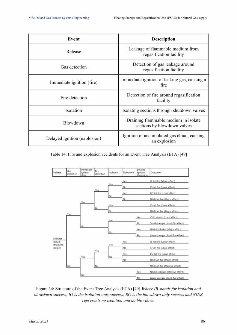
MSc Oil and Gas Process Systems Engineering Floating Storage and Regasification Unit (FSRU) for Natural Gas supply
Event Description
ReleaseLeakage of flammable medium from
regasification facility
Gas detectionDetection of gas leakage around
regasification facility
Immediate ignition (fire)Immediate ignition of leaking gas, causing a
fire
Fire detectionDetection of fire around regasification
facility
Isolation Isolating sections through shutdown valves
BlowdownDraining flammable medium in isolate
sections by blowdown valves
Delayed ignition (explosion)Ignition of accumulated gas cloud, causing
an explosion
Table 14: Fire and explosion accidents for an Event Tree Analysis (ETA) [49]
Figure 34: Structure of the Event Tree Analysis (ETA) [49] Where IB stands for isolation andblowdown success, IO is the isolation-only success, BO is the blowdown-only success and NINB
represents no isolation and no blowdown
March 2021 86
MSc Oil and Gas Process Systems Engineering Floating Storage and Regasification Unit (FSRU) for Natural Gas supply
Discussion of results
The technology of Floating Storage Regasification Unit for Natural Gas supply has been
analyzed in this thesis with a focus on the design process of the unit, mainly with process
simulation as a guiding tool. In process simulation of natural gas supply through an FSRU,
two delivery systems of Low Pressure at 12 bar and High Pressure at 80 bar have been
examined in order to simulate the main processes that take place in an FSRU and size major
pieces of equipment. Constraints and restrictions in case of High Pressure delivery have been
identified and a solution has been proposed and implemented.
March 2021 87

MSc Oil and Gas Process Systems Engineering Floating Storage and Regasification Unit (FSRU) for Natural Gas supply
Conclusions
In this thesis, LNG and the role of FSRU as an alternative to an onshore storage and
regasification unit for NG supply have been studied.
According to International Maritime Associates (IMA) / World Energy Reports and their 12-
month assessment of the floating and regasification market, global demand for natural gas is
expected to grow at an annual rate of 1.5% to 2.5%, mainly due to the economic and
environmental advantages of natural gas as fuel for heat and power generation [15]. Also the
fast transition to the use of renewable energy sources will boost the consumption of natural
gas as an intermediate/alternative energy source, instead of other forms of fossil fuels (coal -
oil), until this transition will be completed. But even after the transition, natural gas will be
used for electricity production, mainly as a stabilization factor to the power grid, considering
the daily/seasonal variation of renewable sources.
Since the introduction of the first FSRU in 2005 in the gulf of Mexico, there has been a
significant pick up in deployment of the technology leading to optimization of costs and
capability and access to new markets all over the globe. Currently the global FSRU fleet
consists of more than 30 vessels and many more to be commissioned in next years.
As described in Chapter 1 of this thesis, FSRU offers some key advantages compared to
onshore terminals and we are going to focus mainly on:
Lower capital cost: The capital cost of a new FSRU can typically represent 60% of an
onshore terminal but special attention needs to be given in the operation expenditures
which have to be considered in a feasibility study of an FSRU investment. Typically
OPEX can be between 0.4 to 0.7$/mmbtu depending on commercial terms [58].
March 2021 88
MSc Oil and Gas Process Systems Engineering Floating Storage and Regasification Unit (FSRU) for Natural Gas supply
Shorter lead time: Typically FSRUs can be delivered in half time of an onshore
terminal, since there is a minimal need of onshore infrastructure development and
often fewer permitting issues, which usually drive up the lead time. A new FSRU
takes about 2.5 to 3 years to be completed, while a conversion of a LNG vessel to
FSRU around 1.5 years. Moreover lead times can be significantly accelerated by
utilizing an existing FSRU [58].
Greater flexibility: The multipurpose use of an FSRU (as floating storage and
regasification terminal, floating storage unit or as conventional LNGC) can provide
additional options to the investor and add significant value and opportunities to
exploit any future opportunity given the right market conditions. FSRU gives the
ability to ‘retire’ and re-use the vessel at relatively low cost, a feature which adds
even greater commercial flexibility. Finally FSRU can provide an early gas option to
markets which are considering building an onshore facility [58].
FSRUs have matured as a proven technology over the last years, offering the opportunity for
new countries to become LNG importers in the last decade. In Greece, Revithoussa LNG
Terminal is now the only land-based operating terminal that receives LNG cargoes, stores,
regasifies and supplies NG to the National Natural Gas Transmission System. Revithoussa is
located on the islet of Revithoussa, in the gulf of Pachi at Megara, 45 km west of Athens and
has a storage capacity of 225,000 m3 LNG and a regasification capacity of 1,250 m3/h. [59]
FSRU terminal is about to be introduced in Greece with the “Alexandroupolis Independent
Natural Gas System” with a storage capacity of up to 170,000 m3 of LNG and a regasification
capacity of 1,600 m3/h and it will be located south-west of Alexandroupolis in the sea of
Thrace (Aegean Sea) [60]. The commercial operation date for the project is planned for 2023.
[61] Another FSRU project, Independent Natural Gas System “DIORYGA GAS” has
obtained a license from Regulatory Authority for Energy (RAE) in order to be implemented
March 2021 89

MSc Oil and Gas Process Systems Engineering Floating Storage and Regasification Unit (FSRU) for Natural Gas supply
in Corinth, west of Athens. This project is proposed to have a storage capacity of 170,000 m3
LNG and a regasification capacity of 300 to 500 m3/h [62]. The commercial operation
estimated date for the project is planned for December 2022 [63].
March 2021 90

MSc Oil and Gas Process Systems Engineering Floating Storage and Regasification Unit (FSRU) for Natural Gas supply
References
[1] “Knight Piésold Consulting Project Description-Chapter 2.” Available: https://www.scribd.com/document/441980709/CHAPTER-2-PROJECT-DESCRIPTION (accessed Sep. 02, 2020).
[2] A. Benito, “Accurate determination of LNG quality unloaded in Receiving Terminals: An Innovative Approach,” p. 20.
[3] C. Caswell, “Liquefied Natural Gas (LNG),” https://www.spegcs.org/media/files/page/bf3787c6/On_LNG_And_FLNG.pdf
[4] “Liquefied Natural Gas (LNG): Exploration & Production Process – Manjur Khan (19N) | Bangladeshi Mariners.” http://bdmariners.org/liquefied-natural-gas-lng-exploration-production-process-manjur-khan-19n/ (accessed Nov. 01, 2020).
[5] “LNG Quality Specifications |.” https://desfa.gr/en/regulated-services/lng/users-information-lng/quality-specifications (accessed Oct. 20, 2020).
[6] T. Uemura and K. Ishigami, “Chapter 3. LNG supply chain infrastructure configuration,” p. 15.
[7] “Höegh LNG - Our Business.” Available: https://www.hoeghlng.com/our-business/default.aspx (accessed Oct. 19, 2020).
[8] “Excelerate Energy – Gulf Gateway Deepwater Port,” Excelerate Energy. Available: https://excelerateenergy.com/project/gulf-gateway-deepwater-port-2/ (accessed Oct. 18, 2020).
[9] “What Is A Floating Storage Regasification Unit (FSRU)?,” Marine Insight, Jan. 31, 2019. https://www.marineinsight.com/types-of-ships/what-is-floating-storage-regasification-unit-fsru/ (accessed Sep. 02, 2020).
[10] “2020-World-LNG-Report.pdf.” Available: https://www.igu.org/app/uploads-wp/2020/04/2020-World-LNG-Report.pdf
[11] “FSRU Market Research Report –Global Forecast to 2023| MRFR.” https://www.marketresearchfuture.com/reports/fsru-market-6158 (accessed Nov. 09, 2020).
[12] “Floating Storage and Regasification Unit (FSRU) Market- Opportunity & Forecast, 2027.” http://masterfoxconsultinggroup.com/reports/product/floating-storage-and-regasification-unit-fsru-market-report (accessed Nov. 09, 2020).
[13] “FSRU 2020,” FSRU 2020. https://www.oilandgasiq.com/events-fsrusummit/downloads/the-fsru-market-2020-and-beyond (accessed Oct. 19, 2020).
[14] “Floating LNG regasification is used to meet rising natural gas demand in smaller markets - Today in Energy - U.S. Energy Information Administration (EIA).” https://www.eia.gov/todayinenergy/detail.php?id=20972 (accessed Oct. 09, 2020).
[15] “FLNG & FSRU Market Otlook,” Offshore Engineer Magazine, Feb. 05, 2019. https://www.oedigital.com/news/462491-flng-fsru-market-otlook (accessed Feb. 26, 2021).
[16] “LNG vessel construction -Advantages of membrane technology.” http://www.liquefiedgascarrier.com/LNG-vessel-construction.html (accessed Nov. 07, 2020).
[17] B. Songhurst, “The Outlook for Floating Storage and Regasification Units (FSRUs),” Oxford Institute for Energy Studies, Jul. 2017. doi: 10.26889/9781784670894.
[18] “FSRU TOSCANA.” https://gcaptain.com/worlds-first-fsru-toscana-delivered-offshore-livorno/fsru-toscana-4/ (accessed Oct. 19, 2020).
[19] K. A. A. Watté, “The feasibility of standardization of a mono-pile mooring facility for FSRU’s,”
March 2021 91
MSc Oil and Gas Process Systems Engineering Floating Storage and Regasification Unit (FSRU) for Natural Gas supply
[20] Yonghui (Allen) Liu, “2007-ISOPE-The-Exact-Solutions-of-Tower-Yoke-Mooring-Systems.pdf.”
[21] “Conventional Buoy Mooring (CBM) system – Bluewater.” Available: https://www.bluewater.com/products-technology/mooring-systems/turret-mooring-systems/soft-yoke-tower/ (accessed Nov. 01, 2020).
[22] “An Overview of SBM Mooring Systems OTEO Overview of SBM Mooring Systems OTEO Conference ... •Overview of SBM Mooring Systems ... Wide range of Mooring Systems Single Point Mooring,” pdfslide.net. https://pdfslide.net/documents/an-overview-of-sbm-mooring-systems-oteo-overview-of-sbm-mooring-systems-oteo-conference.html (accessed Mar. 02, 2021).
[23] “comparative-research-on-lng-receiving-terminals-and-fsru.pdf.” Available: https://www.scribd.com/document/438384855/Comparative-Research-on-Lng-Receiving-Terminals-and-Fsru (accessed Nov. 01, 2020).
[24] Houari, Rayah. (2018). IGU LNG Committee - SG1 FLNG Report 2015-2018-04. [25] T. Uemura and K. Ishigami, “Chapter 6. Investment in LNG supply chain infrastructure
estimation,” p. 15.[26] “Wavescan-buoy-flyer.pdf.” Available: https://www.fugro.com/about-fugro/our-
expertise/technology/seawatch-metocean-buoys-and-sensors (accessed Nov. 01, 2020)[27] “FLNG compared to LNG carriers.pdf.” Available:
https://publications.lib.chalmers.se/records/fulltext/162630.pdf[28] “Chapter 2-Description of Project.pdf.” Accessed: Sep. 24, 2020. [Online]. Available:
https://www3.opic.gov/environment/eia/pakistangasport/Chapter%202-Description%20of%20Project.pdf.
[29] M. I. Khan, “Comparative Well-to-Tank energy use and greenhouse gas assessment of natural gas as a transportation fuel in Pakistan,” Energy Sustain. Dev., vol. 43, pp. 38–59, Apr. 2018, doi: 10.1016/j.esd.2017.12.004.
[30] M. R. Martins, M. A. Pestana, G. F. M. Souza, and A. M. Schleder, “Quantitative risk analysis of loading and offloading liquefied natural gas (LNG) on a floating storage and regasification unit (FSRU),” J. Loss Prev. Process Ind., vol. 43, pp. 629–653, Sep. 2016, doi: 10.1016/j.jlp.2016.08.001.
[31] “Floating Storage and Regasification Units report_Version 1.2_September 2016_LM.pdf.” https://www.scribd.com/document/457307640/Floating-Storage-and-Regasification-Units-report-Version-1-2-September-2016-LM-2
[32] “EDP_Addendum.pdf.” Available: https://www3.opic.gov/Environment/EIA/energia/Marine_ESIA/EDP_Addendum.pdf (accessed Nov. 01, 2020).
[33] “GTT | NO96 system.” https://www.gtt.fr/en/technologies/no96-systems (accessed Nov.09, 2020).
[34] “LNG carrier,” Wikipedia. Nov. 01, 2020, Accessed: Nov. 07, 2020. [Online]. Available: https://en.wikipedia.org/w/index.php?title=LNG_carrier&oldid=986516311.
[35] “Mark III systems,” GTT. https://www.gtt.fr/en/technologies/markiii-systems (accessed Nov. 09, 2020).
[36] “NO96 system,” GTT. https://www.gtt.fr/en/technologies/no96-systems (accessed Nov. 09, 2020).
[37] “Independent Tank - an overview | ScienceDirect Topics.” https://www.sciencedirect.com/topics/engineering/independent-tank (accessed Nov. 09, 2020).
[38] V. Singh, “Latest trends - FSRU and FSU,” Accessed: Nov. 09, 2020. [Online]. Available: https://silo.tips/download/latest-trends-fsru-and-fsu
[39] Saurabh Agarwal, “Lng vessels,” Accessed: Nov. 09, 2020. [Online]. Available:
March 2021 92
MSc Oil and Gas Process Systems Engineering Floating Storage and Regasification Unit (FSRU) for Natural Gas supply
https://pt.slideshare.net/SaurabhAgrawal113/lng-vessels/11[40] “rollover_in_lng_storage_tanks_public_document_low-res.pdf.” Available:
https://giignl.org/sites/default/files/PUBLIC_AREA/Publications/rollover_in_lng_storage_tanks_public_document_low-res.pdf
[41] R. R. Tarakad, LNG receiving and regasification terminals: an overview of design, operation, and project development considerations. Houston, Tex: Zeus Development Corp, 2000.
[42] D. A. Coyle and V. Patel, “PROCESSES AND PUMP SERVICES IN THE LNG INDUSTRY,” p. 7, 2005.
[43] “A Study on the Design and Operation of LNG-FSRU Topside Processes using Dynamic Simulation.” https://s-space.snu.ac.kr/handle/10371/119736
[44] “Cryogenic Pumps for LNG/LPG/FSRU.” http://www.intramare.gr/products/cargo-handling-systems-for-lng-lpg/product/110-cryogenic-pumps-for-lng-lpg-fsru (accessed Nov. 12, 2020).
[45] M. Sagau, M. Panaitescu, F.-V. Panaitescu, and S. Alexandru-Andrei, “A new consideration about floating storage and regasification unit for liquid natural gas,” p. 6, 2013.
[46] “GIJPP EES Chapter 3 Project development_0.pdf.” Available: https://www.gasimportprojectvictoria.com.au/sites/default/files/2020-07/GIJPP%20EES%20Chapter%203%20Project%20development.pdf (accessed Nov. 04, 2020).
[47] “DongHwa Entec,” DongHwa Entec | No.1 Heat-Exchanger Manufacturer, Jul. 29, 2016. http://www.dh.co.kr (accessed Nov. 09, 2020).
[48] “2880LNG_LIQUEFACTION.pdf.” Available: https://www.scribd.com/document/460126944/2880LNG-LIQUEFACTION (accessed Nov. 04, 2020).
[49] S. Park, S. Kim, Y. Yoon, I.-B. Lee, and E. S. Jung, “A Comparative Evaluation of Heating Method Options for Floating Storage Regasification Units Using Life Cycle Cost Analysis with Risk Expenditure,” J. Chem. Eng. Jpn., vol. 52, no. 9, pp. 751–765, Sep. 2019, doi: 10.1252/jcej.18we124.
[50] D. Patel, “LNG VAPORIZER SELECTION BASED ON SITE AMBIENT CONDITIONS,” p. 15.
[51] “PreFeasibilityReport.pdf.” Available: https://documents.pub/document/fsufsru-based-lng-terminal-at-rev-2-based-lng-terminal-at-hooghly-estuary-west.html
[52] M. Kulitsa and D. A. Wood, “Enhanced application for FSRU recondensing equipment during periods of low or no gas send out to minimize LNG cargo losses,” Petroleum, vol. 4, no. 4, pp. 365–374, Dec. 2018, doi: 10.1016/j.petlm.2018.01.002.
[53] “Excelerate Energy – FSRU Technology,” Excelerate Energy. https://excelerateenergy.com/fsru-technology/ (accessed Nov. 04, 2020).
[54] “DWSIM – The Open Source Chemical Process Simulator.” https://dwsim.inforside.com.br/new/ (accessed Feb. 17, 2021).
[55] “0359722_Annex5B.pdf.” Accessed: Jan. 27, 2021. [Online]. Available: https://www.epd.gov.hk/eia/register/report/eiareport/eia_2562018/HTML/Section%205/0359722_Annex5B.pdf.
[56] “LNG quality correction_OLT,” OLT Offshore LNG Toscana. https://www.oltoffshore.it/en/terminal/terminal-plus/ (accessed Oct. 19, 2020).
[57] “144._TN_016_-_FSRU_Safety_International_classification_and_regulation.pdf.” Accessed: Nov. 08, 2020. [Online]. Available: https://s3.ap-southeast-2.amazonaws.com/hdp.au.prod.app.vic-engage.files/6016/0221/7084/144._TN_016_-_FSRU_Safety_International_classification_and_regulation.pdf.
[58] “How FSRU’s are impacting LNG market evolution,” Timera Energy, Jul. 09, 2018.
March 2021 93
MSc Oil and Gas Process Systems Engineering Floating Storage and Regasification Unit (FSRU) for Natural Gas supply
https://timera-energy.com/how-fsrus-are-impacting-lng-market-evolution/ (accessed Feb. 26, 2021).
[59] “LNG Facility |.” https://desfa.gr/en/national-natural-gas-system/lng-facility (accessed Feb. 26, 2021).
[60] “The floating LNG reception, storage and regasification unit.” http://www.gastrade.gr/en/alexandroupolis-ings/the-floating-lng-reception,-storage-and-regasification-unit.aspx (accessed Feb. 26, 2021).
[61] “Alexandroupolis LNG Terminal,” Global Energy Monitor, Feb. 08, 2021. https://www.gem.wiki/Alexandroupolis_LNG_Terminal (accessed Feb. 26, 2021).
[62] “Dioryga Gas.” Accessed: Feb. 26, 2021. [Online]. Available: https://www.iene.eu/articlefiles/satras.pdf
[63] “Independent Natural Gas System (INGS) DIORYGA GAS.” Accessed: Feb. 26, 2021. [Online]. Available: https://www.desfa.gr/userfiles/5fd9503d-e7c5-4ed8-9993-a84700d05071/%CE%9A%CE%B5%CE%AF%CE%BC%CE%B5%CE%BD%CE%BF%20%CE%B3%CE%B9%CE%B1%20%CE%91%CE%BD%CE%AC%CF%81%CF%84%CE%B7%CF%83%CE%B7%20%CE%94%CE%99%CE%A9%CE%A1%CE%A5%CE%93%CE%91%20GAS-en-250719.pdf
March 2021 94