flfllfllfllfl.fll l I lflfllflfflfllflfflo Ehhhmhhhomhhhuo Ehmhhmhhhhmuo I ...
269
RD-A1i5i 81 THE SYSTEMATIC INTEGRATION OF VERY LARGE SCALE 1/3 INTEGRATED CIRCUIT COMPUTE..(U) AIR FORCE INST OF TECH WRIGHT-PATTERSON AFB OH SCHOOL OF ENGI. UNLSSIFIED T R VERNILLION DEC 84 AFIT/GE/ENG/84D-68 F/G 9/2 N INL E flfllfllfllfl.fll l I lflfllflfflfllflfflo Ehhhmhhhomhhhuo Ehmhhmhhhhmuo I fllfllfllfllfllofflf
-
Upload
khangminh22 -
Category
Documents
-
view
3 -
download
0
Transcript of flfllfllfllfl.fll l I lflfllflfflfllflfflo Ehhhmhhhomhhhuo Ehmhhmhhhhmuo I ...

RD-A1i5i 81 THE SYSTEMATIC INTEGRATION OF VERY LARGE SCALE 1/3INTEGRATED CIRCUIT COMPUTE..(U) AIR FORCE INST OF TECHWRIGHT-PATTERSON AFB OH SCHOOL OF ENGI.
UNLSSIFIED T R VERNILLION DEC 84 AFIT/GE/ENG/84D-68 F/G 9/2 N
INL E flfllfllfllfl.fll lI lflfllflfflfllflffloEhhhmhhhomhhhuoEhmhhmhhhhmuo
I fllfllfllfllfllofflf

... -a. 1
136L
1 5 LA.111
MICROCOPY RESOLUTION TEST CHARTNATIONAL BUREAU OF STANDARDS- 1963-A
ila

:44
00
'HE SYSTEMATIC INTEGRATION OF VERY LARGE;CALE INTEGRATED CIRCUIT COMPUTER-AIDEDDESIGN TOOLS INTO A TOOLKIT OPTIMIZED
FOR ACADEMIC APPLICATIONS
THESIS
,FIT/GE/ENG/84D-68 Thomas R. VermillionCaptain USAF
Q_
DTICFMLECTED
,.. DEPARTMENT OF THE AIR FORCE
CAIR UNIVERSITY
AIR FORCE INSTITUTE OF TECHNOLOGY4i
Wright-Patterson Air Force Base, Ohio
t O. -" 03 . 102.!j":)j~X3 .4"N0l3AOD IV Q33Qkjd3H

AFIT/GE/ENG/84D-68
THE SYSTEMATIC INTEGRATION OF VERY LARGESCALE INTEGRATED CIRCUIT COMPUTER-AIDEDDESIGN TOOLS INTO A TOOLKIT OPTIMIZED
FOR ACADEMIC APPLICATIONS
THESIS
AFIT/GE/ENG/84D-68 Thomas R. VermillionCaptain USAF V
DTICSI
Approved for public release; distribution unlimited. i
i~r:.. ... ,., , . ... . ... .. . . . . . . . .. .

I'.-
AFIT/GE/ENG/84D-68
THE SYSTEMATIC INTEGRATION OF VERY LARGE SCALE
INTEGRATED CIRCUIT COMPUTER-AIDED DESIGN TOOLS
INTO A TOOLKIT OPTIMIZED FOR ACADEMIC APPLICATIONS
THESIS
Presented to the Faculty of the School of Engineering
of the Air Force Institute of Technology
Air University
in Partial Fulfillment of the
Requirements for the Degree ofMaster of Science Accession For
NTIS C-RA&TDTIC T~vUnannouncedJustif icatio__ ---
" -O P B y _ _ __ _DNSPECTED Distribution/
AvailabilitV Codes
:Avail ana/orDist Special
* A-Iby
Thomas R. Vermillion, B.S.
Captain USAF
Graduate Electrical Engineering
December 1984
Approved for public release; distribution unlimited.
. . . ... .._,. . .. . . .. " .. . . " ". .• "

Preface
I began my search for a thesis topic with the intention
of identifying and solving an engineering problem of inter-
national scope. Fortunately, those more learned and exper-
ienced in the solution of engineering problems directed me
toward a more realistic goal. The desire to address a
substantive problem was encouraged and remained.
The need to develop a completely integrated set of VLSI
CAD tools became clear to me in the wee hours of a Spring
morning as I struggled to complete a VLSI design project
using two incompatible CAD tools.
Perhaps this work is not as revolutionary as I had
envisioned but I believe it provides a solid basis for the
development of the elusive integrated toolkit of VLSI CAD
tools. I have learned much and have developed a high regard
for those who have made VLSI technology available to all of
us.
Many of the ideas developed during the characterization
of the CAD toolkit were developed during a review of Paul
Losleben's excellent and comprehensive paper on VLSI (171.
I am indebted to Hal Carter, my thesis advisor, for
permitting this project and for his enthusiastic approach to
my work, his concise suggestions, and tactful criticisms. I
offer a special thanks to Bill Sutton for his prompt and
careful reviews of the segmented drafts that preceded this
final product.
Tom Vermillion
.ii
"o',0'..............................•. m.-........ .° . .
: . -,m, - ° ° ° ' ' ' " ° ' " " " " . . . . ° . " "" , " .-

* Contents
Page
Preface............................................
List of Figures ........................... viiI
Abstract ................................. ** * ......... viii
I . Introduction. . ................ .........-
Background. . .. ........... ............ -
Problem .............................. -5Assumpti ons........................ -Summary of Current Knowledge ........... -7Approach .................... ....... -Sequence of Presentation .................. -10
Ii. VLSI Design Methods ....................... 1111
4Chronology of VLSI Development ............ -1Approaches to the Design of Integrated
The Early Design Approaches ........... -4Current Design Approaches ............. -6Future Design Approaches .................- 10
Summary ................................... -12
III. General Characteristics of a VLSI CAD
Introduction . .. .. .. .. .. .............. . -1General Properties of VLSI CAD Toolkits andToolkit Components . .. ......... .. .. .. .. . .. -1
A Useful VLSI CAD Toolkit/ToolkitComponent. .. .. .. .. .. .. .. .. .. ........... -2A Complete VLSI CAD Toolkit ........... -2A Maintainable VLSI CAD Toolkit ....... -2
General organization of a VLSI CAD Toolkit. -3The Too kCustodian ......... -4Design Management Drawer....... -7Design Tool Drawers.............. -8Information Storage Drawers .............- 9A Typical Design Session with anIntegrated CAD Toolkit ................. -9
IV. Specific Characteristics of a VLSI CADToolkit ................................ IV-1

Detailed Custodian Specifications ......... IV-1User Interface ........................ -i..1Access Control ......................... -2Information Control ..................... -2Resource Management ..................... -3
Detailed Design Tool Drawer Specifica-tions ....................................... -4
Architectural Drawer.................. -4Logic Drawer ........................... -4Floorplan Drawer ....................... -5Layout Drawer ..................... -5Interconnection Drawer ............. -5Topological Analysis Drawer .......... -6Extraction Drawer ....................... -6Timing Analysis Drawer .................. -6Electrical Analysis Drawer............. -7Mask Data Generation Drawer ......... -7Design Verification Drawer .............. -7Design Presentation Drawer ............. -8Utility Drawer ......................... -8
Detailed Design Management Drawer Specifi-cations ................................ .- 8
Configuration Drawer .................. -8Data Translation Drawer.............. -9Resource Management Drawer ............ -9Data Analysis Drawer.................. -10Documentation Management Drawer ....... -10Environment Control Drawer ............ -10Data Archival Drawer.............. -10Data Access Control Drawer ............. -10Data Security Drawer..... -11Data Storage Management Drawer ........ -11Report Generation Drawer ........ -11Standards Management Drawer............ -11Library Management Drawer ....... -11Schedule Management Drawer -11
Detailed Information Management DrawerSpecifications ......... ............. -12
Temporary Storage Drawer ................ -12Permanent Storage Drawer ............... -12
Summary ............... ............... -12
V. A Systematic Method for Integrating VLSICAD Tools .................................. V-i
Introduction ................. -1Philosophy of This Integration Method.. -1The General Integration Methodology .... -2Toolkit Integration Mechanics .......... -3
Step 1: Identification of DesiredCharacteristics ........... -4
Step 2: Definition of the Eval-uation Metrics ............ -4
iv
sr

Specific CAD Tool MetricCharacteristics ............ V-6Metric Scales ............. -6The Metric Formulas ....... -7
Step 3: High-Level Custodian Design -9Step 4: Collect Existing CAD Tools. -10Step 5: Identify Empty Toolkit
Drawers .................... -10Step 6: Complete the Toolkit Struc-
ture .......................... -10Step 7: Toolkit Evaluation ......... -12Step 8: Remove or Modify Components -13Step 9: Completion of the Custodian -13
Summary ..................................... -14
VI. Discussion of the Prototype Implementation.. VI-i
Introduction ................................ -1High-Level Design of the ToolkitCustodian.................................. -2
Goals .............................. -2Contents ........................ -2Comments ...................... -3
Implementation of the Toolkit Frameworkand Drawer Structure ................. -4
Goals ......................Contents ............................ -4Comments.......... ..... -5
Custodian Source Code .......... -7Goals.......... ..... -7Contents............. . .. . ... . ..... -7
Comments ............. .. .. .. .. .. .. . .. -8
Evaluation of the Prototype Custodian ... -10Goals.................. -10Contents ............................ -11Comments....................... . -11
Summary......................... -14
VII. Conclusion and Recommendations .............. VII-1
Synopsis..................... -1
Conclusions ...................... -iRecommendations..................... -3
Bibliography. ....................................... BIB-1
APPENDIX A: High-Level Design of a PrototypeToolkit Custodian.................... A -i
Node Index .................... -2CUS-0 ........................... -3
9CUSO .........................- 5CUSoi.................... .... -... -7C Us2 ....................... ... . -9
v.oo..o~oe ... oee.. o...ooo.
. . " .ooooo oooooo o. ooe o- -oo

CUS3 ............................ A-iCUS4 -13Data Dictionary ............... -15
APPENDIX B: Structure of A Prototype AFIT VLSICAD Toolkit .............................. B-i
Prototype Implementation ofToolkit Drawer Structure UsingUNIX Hierarchical Directories .... -1Hierarchical Toolkit DirectoryStructure..... ......... ....- 4The UNIX "C-Shell" Script Usedto Build The Toolkit HierarchicalDirectory Structure ................. -5Distribution of AFIT IC CAD Toolsin the Prototype VLSI CAD Toolkit -7
APPENDIX C: Source Code for a Prototype VLSICAD Toolkit Custodian................. C-I
Program 1: A "C-Shell" Custodian -iProgram 2: A "C" Program Used toProtect The Toolkit ............. -27
APPENDIX D: Application of the Evaluation Metricsto the Prototype Toolkit Custodian.... D-I
AFIT VLSI CAD Toolkit EvaluationFormulas. ........................ -i
Drawer Component EvaluationFormula ...................... -1Drawer Evaluation Formula ... -iToolkit Evaluation Formula... -2
Evaluation Scales ........ -2Evaluation of the PrototypeCustodian.................... -3
Component Evaluations ......... -4Overall Drawer Rating ........ -21
vi
. . . ... o. . . . .. ..

List of Figures
Figure Page
II-1 VLSI CAD Toolkit Characterization ............111-5
111-2 Custodian Span of Control.................... 111-6
A-1 .SADT for Custodian Node CUS-O................ A-4
A-2 SADT for Custodian Node CUSO .............. A-6
A-3 SADT for Custodian Node CUSi .................. A-8
A-4 SADT for Custodian Node CUS2................. A-10
*.A-S SADT for Custodian Node CUS3 ................. A-12
A-6 SADT for Custodian Node CUS4 ................ A-14
vii

AFIT/GE/ENG/84D-68
Abstract
The literature indicates that the success of future
VLSI design efforts is contingent upon the evolution of a
new design philosophy and upon the production of a special
kind of engineer, a VLSI design engineer. 4he lack of an
integrated, compatible set of VLSI CAD tools has been sug-
gested as a serious problem which prohibits the optimization
of the academic curricula necessary to produce the required
VLSI design engineers.
This thesis proposes that the CAD tool problem may be
solved through the development of a VLSI CAD -Otoolkit": The
characteristics of an integrated, technically complete,
academically-oriented VLSI CAD toolkit have been presented.,
A systematic method to integrate CAD tools was developed and
supported through the design of a set of CAD tool evaluation
metrics. Finally, a prototype VLSI CAD toolkit and its
custodt were designed, implemented, and evaluated.
The characterization of the integrated toolkit, though
not complete, appears to constitute a solid basis for future
work. The evaluation metrics and methodology were simple to
implement and provided absolute and relative measurements of
the "level of presence" of desired characteristics in tool-
kit components. The evaluation metrics show promise but
further applicati n of the metrics to collections of CAD
tools will be required if a high level of confidence is to
be assured. , ; -' ," " 1,
viii

I%
THE SYSTEMATIC INTEGRATION OF VERY LARGE SCALE
INTEGRATED CIRCUIT COMPUTER-AIDED DESIGN TOOLS
INTO A TOOLKIT OPTIMIZED FOR ACADEMIC APPLICATIONS
I. Introduction
Background
The successful defense of the United States is predi-
cated upon a deterence of conflict through possession of
military systems that are more capable and survivable than
those possessed by potential opponents. Today, the enhance-
ment of military systems primarily requires the reduction of
their cost, size, weight, and power requirements while si-
multaneously increasing their speed, intelligence, reliabil-
ity, and survivability. The enhancements are being imple-
mented chiefly through the replacement of manual and semi-
automatic electro-mechanical sub-systems with intelligent,
fully automatic, electronic modules.
Current technology provides the capability to construct
electronic modules composed of many active and passive elec-
tronic devices arranged on a very small piece or chip of
siYicon. The silicon electronic modules require very little
power and are housed in extremely small packages. These
microelectronic modules, implemented through the integration
of many electronic devices, are known as integrated circuits
(ICs). Integrated circuits are classified according to the
"....

density of individual devices integrated on a single silicon
chip. The generally agreed upon classifications of IC inte-
gration are:
Small Scale Integration (SSI) : 1 - 10 dev.Medium Scale Integration (MSI) : 10 - 100 dev.Large Scale Integration (LSI) : 100 - 100,000 dev.Very Large Scale Integration (VLSI): 100,000+ dev.
One author proposes an expansion of the IC classifica-
tion system to accommodate a new classification, Ultra Large
Scale Integration (ULSI) [271. The expanded classification
system defines VLSI as 200,000+ devices and ULSI as
10,000,000+ devices.
The development and integration of VLSI circuits into
military systems are essential elements of the successful
defense of the United States. The U.S. Department of
Defense fDOD) has underscored this assertion through its
$400 million program for the research and development of
Very High-Speed Integrated Circuits (VHSIC). The VHSIC
program has been called the most ambitious and important
Federal program since the United States began the explora-
tion of space [33]. The VHSIC program's goal is the devel-
opment of high-speed, reliable, silicon chips that will
ensure continued U.S. superiority in defense electronics
[33].
The implementation of VLSI-based defense systems will
necessitate many changes within the DOD and within the
organizations and companies that provide support to the DOD.
Perhaps the most important changes will be required in
academic institutions where curricula must be revised to
1-2
._ . . . .. .. , . .. . ; -. . . E

- - - - - , : -- = ,- -wt- Y-r 1w- - L - - - - ,- L < o
-- J,
-. produce a new type of engineer, the VLSI design engineer
(61.
Paul Drongowski, in a paper describing the VLSI curric-
ulum at Case Western Reserve University, suggests that VLSI
design engineers fall into two categories: 1) "tall-thin"
engineers capable of spanning VLSI design from architecture
to circuit analysis, and 2) "short-fat" engineers who are
particularly adept at some specific design task [9]. The
successful design of future VLSI circuitry requires the
education and hiring of a new class of engineers, "tall-
thin" VLSI engineers, with broad backgrounds in electronics,
system architecture, software, and computers.
The early development of integrated circuitry was ac-
complished by people primarily skilled in the physics and
materials of solid state devices. The initial growth of IC
density (hence functional complexity) was much slower than
that being experienced today. Historically, the design of
ICs and the translation of IC designs into actual hardware
has been done by teams of "short-fat" engineers using manual
techniques. The teaching and use of manual design and
implementation techniques has been a satisfactory, although
laborious, method of creating SSI, MSI, and LSI integrated
circuits. Unfortunately, previous IC design methods and
implementation techniques are less effective with VLSI de-
signs.
qThe increased functional complexity and device density
(with its attendant reduction in geometrical tolerances)
1-3
................... ...................... .... ...-...... ......

associated with VLSI circuitry have necessitated a reevalua-
tion of the current approaches to IC design and production.
It is generally recognized that computer-aided design (CAD)
equipment and programs are critically important elements of
future VLSI design methodologies [4,17,19,28,34,40]. Educa-
tional institutions are presently faced with rapidly imple-
menting new curricula to address these design issues at a
time when the industrial community is attracting the most
qualified teachers [33]. The U.S. Air Force, and its engi-
neering school, the Air Force Institute of Technology
(AFIT), have not escaped the need for curricula changes nor
the loss of qualified instructors.
AFIT has expanded its graduate-level electrical-engi-
neering curriculum to include courses and individual re-
search efforts designed to produce engineers and managers
qualified in the design and evaluation of VLSI circuits and
systems. The importance of automated design and evaluation
philosophies and their associated techniques are fundamental
themes of each VLSI course, laboratory, and research pro-
ject. The success of the AFIT VLSI curriculum rests in the
ability to expose engineers and managers to the methodolo-
gies and processes associated with VLSI design in a very
short period of time (typically 3 courses). The availabili-
ty of high quality VLSI CAD programs is essential if AFIT
students are to rapidly and effectively acquire a useful
background in VLSI design.
The current generation of CAD programs, often referred
1-4
• • - .o • .- - - -.- . -, j ° * * * - - .• . - , .- .•, • ° • b o , oo . ° ° . • • .

- to as "tools", evolved during independent academic, commer-
cial, and DOD projects. Those concerned with VLSI circuitry
developed and implemented the CAD tools necessary to achieve
their specific goals. This independent growth of CAD tools
has led to the establishment of generally disjoint sets of
*application-specific tools with various levels of compati-
bility. The willingness of several universities to share
their locally developed tool collections with AFIT has
* substantially decreased the time needed to develop a VLSI
curriculum at AFIT. Although the use of these tools has
5 been very beneficial over the past years; a problem has been
observed which must be corrected if the AFIT VLSI curriculum
is to fully achieve its goals.
Problem
The problem is twofold. First, the tools, which are
widely varied in form,function, and complexity, require too
much time to learn their effective use. Second, design
projects, the most highly productive and instructive compo-
nents of the VLSI curriculum, are limited to a low level of
complexity. The projects are limited because the systematic
access to the broad spectrum of CAD tools, essential for
realistic, complex VLSI design efforts, is not possible with
the the current arrangement of AFIT CAD tools. Although
there is a wide range of powerful CAD tools available to
AFIT students, the tools reside in different, and frequently
incompatible, tool collections. The time required to com-
1-5
u *~ : . * * *. . . *

pensate for tool incompatibilities inhibits student use of
many tools.
The basis of the problem is the lack of an integrated,
compatible set of VLSI CAD tools, which may be easily
learned, and utilized. This serious problem prohibits the
optimal use of the time available to produce the high quali-
ty VLSI engineers and managers necessary to meet the chal-
lenges facing the DOD in the next few years.
The solution to the problem is the integration of
available VLSI CAD tools into a technically complete "tool-
kit" which is easy to learn, to use, to update, and to
manage.
This thesis will describe the characteristics and com-
ponents of an integrated, technically complete,
academically-oriented VLSI CAD toolkit. The attributes of
an academically sound VLSI CAD toolkit and its components
will be identified. A set of evaluation metrics (mathemati-
cal relationships to measure and weight the desirable attri-
butes) will be developed. Furthermore, a systematic method,
based upon the attributes and metrics described above, will
be proposed to enable selection of the most suitable tool-
kit components from a generally disjoint VLSI CAD tool
inventory.
Assumptions
Several assumptions have been made to reduce the scope
• of this thesis to a level manageable in the few months
. .•available. It is assumed that:
1-6
0 A4

1. That the reader has an understanding of the fabri-
cation processes used to create the fundamental components
of silicon-based integrated circuits.
2. That the reader has a good background in semicon-
ductor devices and technologies.
3. That the reader has a good background and working
skills in at least one high-level computer language that
permits the use of structured programming techniques.
4. A subjectively developed set of CAD tool attributes
and evaluation metrics will be acceptable to the reader as
rigorous and comprehensive enough to demonstrate that the
toolkit component selection methodology is sound.
5. Tailoring the tool evaluation metrics to suit the
needs of academic institutions does not nullify their value
when using them to evaluate commercially-developed CAD
tools.
6. The characteristics of a VLSI CAD tool can be ade-
quately observed by using a simple test input and sequen-
tially exercising all of the tool options on that input.
7. Discrepancies and deficiencies noted in an eval-
uated tool are caused by the tool structure as advertised
and documented and not by improper installation of the tool
or undetected local modification of the tool.
Summary of Current Knowledge
The critical importance of CAD tools to the successful
design of VLSI circuitry is well documented. CAD software
I-7
• ° .- ° .. . . . .... . . . . S ". " -o . . ° •° - .

has been referred to as the "backbone" of modern VLSI design
[28]. One theme present in much of the literature reviewed
is that continued CAD tool improvements are absolutely es-
sential to make VLSI design available to people not neces-
sarily skilled in semiconductor technologies. Access to
VLSI design by the disciplines that support or use VLSI
circuitry is required if the major problems impeding VLSI
evolution are to be resolved. [13,20,31].
Much work has been reported concerning the development
and improvement of specific CAD tools. Several discussions
of the future of VLSI design address the need to develop a
connectivity between the various design levels (usually in
the form of a centralized database).
The proceedings of recent design automation DA) con-
ferences indicate there are three major areas where work is
being concentrated: 1) identification and refinement of
technologies that permit an increase in IC component densi-
ty, 2) development of specific CAD tools to cope with in-
creased design complexities and 3) identification of IC
design methodologies which will increase the productivity of
IC designers.
Many efforts to establish metrics for software evalua-
tion have been reported. Most of the metrics observed were
based upon the detailed constructs inherent in a particular
language or class of languages. One particularly valuable
source of metric development information was found in a
report prepared by Dean and McCune concerning the evaluation
1-8
.- 011,

- of advanced tools for software maintenance [8].
Few efforts were found that addressed the specific,
central issue of this thesis, a methodology for VLSI CAD
tool integration. One effort to integrate engineering de-
sign tools, a project to create a Designer's Workbench by
Bell Laboratories, was reviewed. Several useful ideas have
been found in a report on the delivery of CAD tools for the
Designer's Workbench [13]. If a single philosophy or view-
point seems to prevail throughout this thesis, it has emerg-
ed from a review of the excellent, comprehensive discussion
of VLSI CAD tools prepared by Paul Losleben [17].
Approach
This thesis approaches the IC CAD tool integration from
an academic viewpoint. The methods developed are intended
for application in the academic arena. However, some may be
useful to the industrial community.
First, past and current discussions concerning VLSI
design methods will be reviewed. Next, a review of publish-
ed literature and documentation pertinent to the use and
evolution of VLSI-oriented CAD tools will be performed. The
information obtained from the reviews will provide the basis
for the development and presentation of: 1) Support for a
VLSI design philosophy which incorporate an integrated CAD
toolkit, 2) the metrics necessary to evaluate a VLSI CAD
toolkit and its component tools, and 3) a methodology to use
the metrics developed to construct an integrated, VLSI CAD
1-9
. -- .. . . . -, - - . A -..-L --- . . T. L. - " ' . . . " - -,. L " - .- , - - . . ...-

[4
toolkit which will adequately support aggressive VLSI cur-
ricula.
The metrics and methodology developed will be evaluated
through a partial application of them to the VLSI CAD tools
currently available at AFIT. A prototype toolkit will be
suggested to support the soundness of the methodology. Mis-
sing tools will be identified and the high level design of
the program necessary to control the toolkit will be com-
pleted.
Finally, recommendations will be made for future work
concerning the integration of VLSI CAD tools.
Sequence of Presentation
Chapter II opens with a brief chronology of the evolu-
qu tion of VLSI circuits and a review of IC design methodolo-
gies. The prevailing IC design philosophy and its applica-
bility to VLSI requirements is discussed. The essential
characteristics of a viable VLSI design methodology are
summarized. Finally, the critical VLSI design role of inte-
grated IC CAD tools is established.
Chapter III establishes the general structure of an
ideal kit of VLSI CAD tools and illustrates the use of the
toolkit by outlining a "typical" design session.
Chapter IV completes the characterization of a useful,
complete, maintainable, integrated VLSI CAD toolkit by pre-
senting a detailed description of the ideal toolkit struc-
ture.
Chapter V details the development of the metrics that
I-10

". . . . -. - w-- u w -c... .... u- ,. . -. S- ' - _r _ .r r ,, - JT.- . T & V . % - , r r' -. .' t . ,-. ,,. -. '.
will be used for toolkit and tool evaluation. The mechanics
of CAD tool integration are also presented.
Chapter VI provides a discussion of the work done to
create the examples provided in the appendices and should
serve as a first-level evaluation of the validity of the
integration method presented herein.
Chapter VII Provides summary of this author's work and
recommendations for future work concerning the integration
of IC CAD tools.
3 I-il
JJ

II. VLSI Design Methods
Chronology of VLSI Development
The evolution of the integrated circuit, and certainly
the VLSI circuit, was not a miraculous occurrence but was a
rather difficult effort marked by many engineering and
scientific milestones.
Several significant milestones in the evolution of VLSI
circuits are summarized below [35].
1947 (Dec): Bell Laboratory physicists Walter H.Brattain and John Bardeen, following suggestionsmade by physicist William Shockley, demonstratedelectrical amplification by using the propertiesof electric fields near the surface of agermanium-based "point-contact" device. John R.Pierce calls the device a "transistor".
1947: Immediately following the demonstration ofthe "point-contact" transistor, Shockley suggeststhe possibility of transistor action in a struc-ture that sandwiched an n-type semi-conductorbetween two p-type semiconductors. Shockley callsthe structure a "junction transistor". Shockleycould not prove his theory because there was noway to construct the "junction transistor" at thattime.
1948 (June): The military decides there is noneed to classify the transistor and BellLaboratory holds first public demonstration of thetransistor. Public response is somewhat indiffer-ent.
1953 (June): Through the leadership of the ArmySignal Corps, standards for transistor operatingcharacteristics were proposed.
1954: Texas Instruments Inc. (TI) announces thefirst transistor made of silicon.
1956: Shockley, Brattain, and Bardeen are awardedthe Nobel Prize in physics for research in semi-conductors and for the invention of the transis-tor.
Il-i
• . -.. " < < . - .< . . . .- -.. -. - . . .. .. . .- - ,-,, • --- ,-., . .-..... . . . ..-..

1957: John T. Wallmark, working at Radio Corpora-tion of America (RCA) laboratories, is awarded apatent for the field-effect transistor (FET).
1958: Fairchild Camera and Instrument Corporationproduces the first device built by diffusion, thediffused-base, mesa transistor. The device wascalled a mesa transistor because of the "stacked"construction of the transistor's base, emitter,and collector regions.
1958: Jean Hoerni, a physicist with Fairchild,invents the planar process for transistor con-struction and suggests a metal deposition tech-nique for component inter-connections.
1958: Jack Kilby, an engineer working for TI,assembles the first "integrated circuit" (IC).The all silicon circuit was a phase-shift oscilla-tor constructed with mesa transistors.
1959 (January): Robert Noyce of Fairchild Semi-conductor Inc. enters in his notes a descriptionof an "integrated circuit" which would incorporatediffused resistors and evaporated metallic inter-connections. Noyce and Kilby are considered inde-pendent inventors of the IC.
1959 (March): Kilby designs and builds a flip-flop using monolithic germanium. The "solid cir-cuit" was unveiled at the Institute of Radio Engi-neers show.
1961: The first commercially available monolithicintegrated circuit is marketed by Fairchild. TheIC was a flip-flop built using resistor-transistorlogic (RTL) and contained four bipolar transistorsand two resistors.
1962: Steven Hofstein and Frederic P. Heiman,young engineers working for RCA, produced thefirst metal oxide semi-conductor FET (MOSFET).They demonstrate the usefulness of the MOSFET bybuilding a MOSFET-based, multi-purpose logicblock. The logic block contained 16 MOSFETs on a2,500-square-mil-chip of silicon.
1965 (August): Fairchild announces the dual in-line (DIP) IC package.
1965: Robert Widlar, a designer with Fairchild,develops the first practical integrated circuitoperational amplifier (opamp), the uA709. Widlaralso designed the uA702, uA710, and the uA741
11-2
.*~~~~ .* . . . . . . . .. .* . . . ... . . . . -

opamps.
1966: Autonetics delivers the first silicon-on-sapphire (SOS) chip to the Massachusetts Instituteof Technology. The chip was a matrix of 6,144diodes for a character generator in a display.
1967: Fairchild announces the first read-onlymemory (ROM) chip. The ROM was a 64 bit MOSmemory.
1971: Intel Corporation unveils the first micro-processor(uP), the 4 bit 4004. The chip was asilicon-based, p-channel MOS design and measured110 by 150 mils.
1971: Intel Corporation announces the first 8-bitmicroprocessor, the 8008. The chip used MOSFETcircuitry and contained approximately 2,900 de-vices.
1979: IBM announces the first 64-K (65,536 bits)dynamic random-access memory. This chip has beencalled the first VLSI circuit.
*Approaches to the Design of Integrated Circuitry
The evolution of integrated circuitry has been accompa-
nied by a non-linear increase in chip complexity. In 1964,
Gordon E. Moore, then director of research at Fairchild
Semiconductor Inc., was the first to predict the growth of
IC complexity when he suggested that the complexity would
double every year [26]. No significant departure from that
prediction has been observed. In fact, Moore's prediction
is often referred to as "Moore's Law" (17,26]. Demands upon
the resources required to accomplish an IC design have
increased in a non-linear manner proportional to the in-
crease in IC complexity. The design philosophies and ap-
proaches used to manage and develop IC design resources have
not matured sufficiently to meet VLSI requirements The
I11-3

remainder of this chapter focuses on the current approaches
to IC design and what must be done to extend these approach-
es to encompass VLSI design requirements.
The Early Design Approaches. The approach taken to
design the first IC in 1958 prevailed through the mid 1970s.
The experience necessary to accomplish electronic design
resided primarily in those scientists and engineers familiar
with solid-state physics [201. Electronic design was an art
applied to the sciences that provided the basis for elec-
tronics [18]. The early IC chips were designed by one or
two people who had few constraints placed on their designs
or their design methodology [17]. Co,:unications between IC
designers and the designers of systems employing ICs were
very poor consequently, both groups established essentially
independent goals. Most major IC design efforts were pro-
jects to assemble a family of chips that encompassed all the
basic functions of boolean logic. Few chips contained com-
plex functions and system designers were faced with the task
of integrating large numbers of the SSI ICs to perform a
complex task. The IC development process from conception to
production was a manual one.
The design process is simply summarized. A chip's
4 architecture was dictated by the desired logic function.
Once a function had been selected, the function variables
were manually minimized and translated into logical and
* electrical diagrams. The resulting electrical circuit was
physically built on a "brass-board" and tested. If the
11-4

tests proved successful, the layers representing the elec-
trical elements were manually drawn or "layed-out" on a grid
that represented the surface of the silicon chip. Masks
were created by copying the layer artwork onto a material
known as Rubylith (a polyester-base covered by a strippable
red plastic). The red plastic was manually removed in those
areas where exposure of the silicon was desired. The Ruby-
lith artwork was photo-optically reduced to produce masks
suitable in size for direct contact masking of the silicon
chip. The silicon chip was exposed via a sequential appli-
cation of the masks and a planar-processed IC resulted.
Manual drafting and Rubylith artwork were the primary
design tools well into the 1970s [17]. In the mid-1970s the
complexity of ICs reached a level that necessitated drastic
changes in the approaches to IC design.
There began a movement from the "single" designer ap-
proach to a design team approach. The design teams were
composed of "short-fat" engineers, engineers highly special-
ized in one facet of IC design. A stratified approach to
design was initiated and the teams were assembled in compa-
tible hierarchies to address the distinct levels associated
with the design. Large companies automated some of the
design tasks (notably logic minimization and mask genera-
tion) and design automation (DA) became a major discipline
in computer science. The changes were not without conse-I~ . quence. Creation of the design teams were accompanied by
the conflicts inherent with the division of labor [24].
11-5

There was a lack of communication between adjacent design
hierarchies which led to wasteful iterations of design
steps. The separation between chip designer and system
designer continued. There was resistance to the implementa-
tion of automated design aids [17,40]. The reluctance to
use CAD programs was partly due to numerous software fail-
ures [17]. The advancement of DA was hindered by proprie-
tary interests of companies developing in-house design aids
[18].
In spite of the problems, IC design progressed during
the 70s and the chip complexities grew in accordance with
"Moore's Law". Sophisticated chips, microprocessors and
memories, emerged which found applications in nearly every
industry. With the appearance of the "first" VLSI chip in
1979 came the realization that major improvements in IC
design management and design automation techniques were
required. That realization was the seed of the dynamic
change that characterizes the current approaches to IC de-
sign.
Current Design Approaches. Today's methods of IC
design are widely varied, rapidly changing, refinements of
the approaches that emerged from the major modifications of
the mid 1970s. Present industrial and academic approaches
to IC design incorporate semi-automated improvements of
early IC design methods.
Industrial IC design is evolving in a manner aimed at
11-6

minimizing what has been called the biggest deterent to VLSIL development today, non-recurring design costs [6]. The
primary goal of minimizing non-recurring design costs is but
one of the four chief goals of a modern design team. The
remaining industrial design team goals are: 1) to shorten
the product development cycle, 2) to minimize design risks,
and 3) to produce an error-free design [6].
The academic approach to IC design does not radically
differ from that found in industry but the differences are
worthy of discussion. The objective of modern academic IC
design curricula is to produce qualified students capable
of: 1) performing VLSI-oriented research, and 2) succeeding
as industrial VLSI designers [9]. Preparation of students
for VLSI research environments necessitates the use of a
VLSI design approach which emphasizes the flexibility (or
inflexibility) of the design approach itself. These stu-
dents will be the people who produce the innovative changes
necessary to continue effective evolution of the VLSI design
process. Design approaches used in research-oriented cur-
ricula may vary, perhaps from one course to another. Re-
search-oriented curricula may suggest approaches to VLSI
design that are "risky" in the industrial sense but which
may lead to the creation of innovative changes to the design
process. The preparation of students for a successful in-
dustrial career requires curricula with VLSI design philoso-
phies which parallel those found in industrial VLSI design.
Most curricula contain a combination of both approaches.
11-7

1 -0-.
Although current industrial and academic VLSI design
approaches differ in the importance placed upon specific
design objectives, their design approaches have many common-
alities. Decomposition of the design process into its fun-
damental levels of abstraction is the key to understanding
the current design philosophies.
The general design process may be decomposed from many
different viewpoints. One decomposition details two funda-
mental levels or structures in the design process: function-
al design and physical design [17]. Another decomposition
identifies five domains or levels of abstraction: 1) the
architectural level, 2) the organizational level, 3) the
logic level, 4) the geometry level, and 5) the electrical
level [9]. There are other decompositions [40]. The com-
monalities of modern industrial and academic VLSI design
approaches, hence the current design philosophy, have been
illustrated below through the application of the various
decomposition schemes to the design approaches.
A modern VLSI design task is usually approached at two
levels: a functional design level and a physical design
level. The design team approach is used both by industry
and academic institutions. It is not unusual for industry
to have design teams at each level or several design teams
within these levels. The academic approach, which encour-
ages the development of "tall-thin" designers, seems to
favor a single design team spanning both levels. At each
level, the design process is hierarchical in nature. That
11-8
6" " " . . . .. ." ". . ." ' ' - - - - -" " ' ' " . ' " " ." " - • " " - - " " " " " "

is, design problems are successively decomposed into smaller
problems while synthesizing small design elements into lar-
ger functional elements [9]. The decomposition and synthe-
sis are iterated until an acceptable design is achieved.
The functional design level includes the architectural
and logical design tasks. Current approaches to these tasks
are essentially manually implemented. The architectural task
is concerned with: 1) the specification of system behavior,
2) the identification of data and control flow throughout
the system, and 3) identification of system-level test re-
quirements. The goal at the architectural level is to
provide a configuration that best satisfies the specified
behavior [40]. The logical design task is also three-fold:
1) the desired system behavior is translated into a set of
primitive building blocks sufficient to implement the de-
sired behavior, 2) the primitive building blocks are synthe-
sized into the largest blocks possible, and 3) the logical
design is tested to verify implementation of the desired
behavior. The logical design effort should produce logic
diagrams and/or boolean equations which implement the de-
sired behavior and whose primitive implementations are
available using current VLSI technology [40]. In summary,
the functional design level should produce a satisfactory
specification of desired system behavior and the logical
means to implement the behavior using current VLSI technolo-
gies.
Most of the changes seen in the evolving IC design
11-9
-

process have occurred at the physical design level and were
initiated to address IC complexities at the VLSI level. The
physical design level includes the following design tasks:
1) floor plan development, 2) layout or translation of the
logica-l design blocks into physically equivalent device
assemblies, 3) interconnection of the on-chip devices, 4)
topological analysis of the chip layout, 5) timing and
electrical analysis of the chip layout, 6) verification that
the layout implements the specified logical design, and 7)
translation of the chip layout information into a form
usable by chip fabrication facilities. Many of the physical
design tasks have been automated or are supported by CAD
tools. The physical design level should produce the data
necessary to correctly fabricate an IC that implements the
original system specification. Many contributions have been
made by the academic community at the physical design level.
Most of these contributions have been in the development of
CAD tools to simplify the various design tasks.
The design methods summarized above were best described
by M.F. Oakes when he said: "Today's methods have not been
designed, they have evolved" [27].
Future Design Approaches. The future of VLSI hardware
rests in the number of electronic applications where VLSI
offers a cost-effective alternative to existing electronics.
The number of future applications for VLSI hardware will be
functions of VLSI design costs (non-recurring costs in par-
ticular) and design time [17]. The needed reduction in VLSI
II-10
4 q
° f° . % " .. ,mo .- ° '. •
"° "°"" 2 "" , E . . .. ,. o ... . . - h- • .• . I o

design costs and time can be achieved through the scientific
DESIGN of a VLSI design methodology.
A complete characterization of the ideal VLSI design
methodology has yet to be developed. Many published works
propose design methods which address one or several of the
issues which must be resolved if VLSI design is to meet
future challenges. Many of the proposed methods share com-
mon components. A scientific evaluation of the common com-
ponents should lead to a VLSI design methodology which will
support the design complexities required by future IC appli-
cations. A review of the frequently proposed components of
future VLSI design processes is provided below.
It is generally agreed that future VLSI design methods
must be hierarchical in nature and that future methods must
approach IC design from a system-level viewpoint
[4,9,17,29,40]. Another essential characteristic of the
ideal VLSI design process is a well-defined connectivity
between the levels of design abstraction [4,9,18,27,29,31].
The usual approach proposed to provide the required connec-
tivity is the use of a single, centralized database or data
structure throughout the entire design process. A thorough
and effective design management technique must be incorpor-
ated into the ideal design method. A recurring issue in
proposed VLSI design techniques is the need to make VLSI
design accessible to people whose skills lie in disciplines
that either support or utilize VLSI circuitry. Finally,
throughout the proposals for improvements in VLSI design
II-1
*j 11 , .-... "" . . " . " . . • ', . " , - li" ' - . " , - .

Z ~~W . ... .. . . . . . ... . . . M M -.
methods, one component surfaces as the most critical and
essential element of the ideal VLSI design process:
INTEGRATED CAD TOOLS [6,12,17,18,20,22,27,28,29,34,40,41].
It is believed that proper integration of IC CAD tools will
open VLSI design to a broad range of disciplines that have
major contributions to make to future VLSI development. An
integrated set of CAD tools, sharing a common database, will
provide the inter-level connectivity and design management
capability essential for the success of future VLSI design
efforts.
Academic institutions have long realized the importance
of CAD tools to successful IC design. Consequently, many,
if not most, of the IC CAD tools in use today were developed
in the academic arena. The academic CAD tools are freely
shared and improvements are nearly continuous. Carver Mead,
a pioneer in the development of IC CAD tools, believes much
of the thrust for new innovation in VLSI design is coming
from the universities [22]. Thus, it seems appropriate that
the universities should address and meet the CAD tool inte-
gration challenge.
Summary A chronology of VLSI evolution has been presented
* to develop an appreciation of the effort expended to reach
production of the first VLSI chip. A summary of past and
present IC design methods was provided to demonstrate the
slow evolution of the IC design process from a single-
designer, manual effort to a team-oriented, partially auto-
* 11-12
- .... 7 *w

mated approach. The essential elements of future VLSI de-
sign methodologies have been examined and the need for
integrated VLSI CAD tools is proposed as the most critical
and essential of all the required elements. This thesis
addresses the need for integrated VLSI CAD tools and will
provide one systematic, perhaps scientific, method to inte-
grate the tools.
11-13
..4 ", - " ; ' - ; ' - , -i . . " _ ' " ." - . . - '. . " " "" " " ' - . .

Ill. General Characteristics of a VLSI CAD Toolkit
Introduction
The importance of VLSI circuitry to the DOD has been
established. It has been shown that the design methodolo-
gies used to implement SSI, MSI, and LSI designs are not
sufficient to meet VLSI design requirements. A review of
current literature indicated that the emerging VLSI design
methodology will emphasize automation of design tasks and
that improved CAD tools are critically important to the
success of future VLSI design tasks. Access to VLSI design
for people with wide variations in technical backgrounds and
increased designer productivity were stated as the primary
goals of VLSI CAD tool development. Integration of VLSI CAD
* tools into a single toolkit was identified as a central
task in the development of a VLSI design methodology that
will meet academic requirements.
This chapter describes the general properties and char-
acteristics of an integrated, academically-oriented, VLSI
CAD toolkit and its components. Also, a typical design
session using the toolkit is outlined. The toolkit de-
scribed below and in subsequent chapters is not the ultimate
VLSI CAD toolkit. The intention here is to develop a basis
for systematic CAD tool integration with emphasis placed
upon academic requirements.
General Properties of VLSI CAD Toolkits and Toolkit_ Components
Throughout the remainder of this section, references to
'I III-i
Iq
. . *

a VLSI CAD toolkit are also references to individual toolkit
components.
A VLSI CAD toolkit must be useful, complete, and main-
tainable. These toolkit properties are examined below.
A Useful VLSI CAD Toolkit/Toolkit Component. A VLSI
CAD toolkit may be considered useful if it possesses the
following characteristics:
1. The toolkit's capabilities, limitations, inputformats, output formats, and command syntax areeasy to learn.
2. The toolkit is easy to select and execute.
3. The toolkit is easy to install on the hostcomputer system.
4. The toolkit substantially increases the pro-ductivity of the user.
5. The toolkit effectively uses design resources.
6. The toolkit makes incompatibilities in subor-dinate components transparent to the user.
7. The toolkit provides a mechanism to controldesign information, correctness, and security.
8. The toolkit can be used effectively by peoplewith wide variations in design abilities and tech-nical expertise.
A Complete VLSI CAD Toolkit. The VLSI design method-
ology reviewed in chapter 2 was decomposed into two funda-
mental design levels: a functional level and a physical
level. The functional and physical levels were further
decomposed into several, sub-ordinate design levels. A
complete VLSI CAD toolkit possesses the characteristics of a
4 useful toolkit at each level of design.
A Maintainable VLSI CAD Toolkit. A maintainable VLSI
111-2
• • ,. +-. +° • . • . ++ - . + + + o , ° - - +. ,. . .. + , , . -• . . .- " - " . - . ' o o . " _ . o

CAD toolkit is one which includes mechanisms to prevent
degradations in the toolkit usefulness and completeness. In
particular, a VLSI CAD toolkit is maintainable if it posses-
ses the following characteristics:
1. Additional tools/features may be easily added.
2. Component tools/features may be easily modi-fied without changing the fundamental toolkitstructure.
3. Toolkit documentation contains the following
information:
a. Documented source code.
b. Diagrams that depict the overall struc-ture of the toolkit.
c. Diagrams that depict the flow of informa-tion through the toolkit.
d. Diagrams that depict the flow of controlthrough the toolkit.
e. Implementation specific information con-cerning the toolkit.
5. Toolkit documentation may be easily updated,reproduced, and distributed.
6. The toolkit is transportable between similarcomputer systems.
7. Test cases and examples sufficient to demon-strate both the operation of the toolkit and thetasks necessary to perform all maintenance opera-tions.
General Organization of a VLSI CAD Toolkit
The VLSI CAD toolkit organization presented below rep-
resents a toolkit configuration which is useful, complete,
and maintainable.
. One way to describe the organization of a VLSI CAD
111-3

toolkit is to develop an analogy between a VLSI CAD toolkit
and toolkits commonly found in modern workshops.
A toolkit may be represented as a collection of draw-
ers, each of which contains tools useful for a particular
task or a group of closely related tasks. Access to the
drawers and their contents is controlled by a toolkit custo-
dian.
A VLSI CAD toolkit may be viewed as a collection of
VLSI CAD tools which reside in "drawers" and which are
controlled by a single custodian. The toolkit drawers may
be partitioned into three groups: 1) design management
tools, 2) design tools, and 3) information storage. Figures
1 and 2 illustrate such a toolkit and depict the custodian's
• span of control, respectively. The contents of each drawer
partition and the general responsibilities of the toolkit
custodian are described below.
The Toolkit Custodian. The custodian of a VLSI CAD
toolkit must:
1. Provide the only user interface to the tool-kit.
2. Control access to each toolkit drawer.
3. Control access to each drawer component.
4. Control the flow of information into, within,
and out of the toolkit.
5. Control the sequence in which toolkit drawersare opened and closed.
6. Control the sequence in which drawer compo-nents are used.
7. Control the parameters used during the execu-tion of component tools.
111-44

(VLSI CAD TOOLKIT)
__ Custoian
GEMENT T INFORMATION STORAGE
~DRAWERS j . DRAWERS . DRAWERS
Configuration TEMPORARYGE Architectural
Data Translation DRAWER Logic
Resource Mgmt. FloorplanDocumentation
Data Analysis Libraries LayoutStatistics
Documentation Mgmt. Schedules InterconnectionDesign Data
Environment Ctrl. Source Code Topolog. Anal.Aux Data
Data Archival I Extraction
Data Access Ctrl. Timing Analysis(PERMANENT
Data Security STORAGE Electrical Anl.DRAWER
Data Strg. Maint. Mask Data Gen.
Report Generation Documentation Design Verif.Libraries
Stds. Management Statistics Design Present.Schedules
Library Management Design Data UtilitiesSource Code
Schedule Management Aux Data
Figure III-I VLSI CAD Toolkit Characterization
111-5
i - i i / i ?/ i > " , -

User
mTemporary |
IA
N Storage DA EG SE I
E NNT
Permanent TT 00 Storage 0o LLS
Legend:
: Toolkit Boundaries
==t> : Flow of Messages and Data
Q : Flow Directly Controlled by Custodian
O : Flow Indirectly Controlled by Custodian
Figure 111-2 Custodian Span of Control
111-6
• . :'. .' '- -" -. ." ". . ., ..-. . r . . -" " .. ... -. -... . .' "

8. Control additions and modifications to thetoolkit drawers and their components.
Design Management Drawers. The toolkit must include
drawers containing the tools necessary to accomplish the
design management tasks listed below. [2,17]
1. Configuration Management: Management of thetoolkit structure, operating system interface, andcomponent relationships.
2. Data Translation: Translation of input/outputdata into useful formats.
3. Resource Management: Management of the tool-kit's use of computer system resources.
4. Data Analysis: Analysis of data to ensurecompatibility with user and toolkit requirements.
5. Documentation Management: Management of de-sign and toolkit documentation.
6. Environment Control: Management of the userand toolkit operating environment during a designsession.
7. Data Archival: Management of the movement oftemporary design information to the toolkit perma-nent design storage area.
8. Data Access Control: Control of user accessto the toolkit, its components, and archived data.
9. Data Security: Management of user's abilityto modify toolkit data.
10. Data Storage Maintenance: Control of thespace and method used to store temporary and perm-anent data.
11. Report Generation: Generation of reportsconcerning toolkit structure, utilization, andcapability.
12. Design Standards Management: Management ofthe structure and documentation of temporary andpermanent design information.
13. Design Library Management: Management of thepermanent design cells used by toolkit components.
111-7

14. Design Schedule Management: Scheduling aidsfor tracking user-established design milestonesand for toolkit maintenance activities.
Design Tool Drawers. The toolkit must include drawers
containing the necessary tools to accomplish the general
categories of design tasks listed below.
1. Architectural: System level design con-siderations.
2. Logic: Translation of system design intologic building blocks.
3. Floorplan: Functional partitioning of ICsurface.
4. Layout: Translation of logic blocks into de-vices.
5. Interconnection: Connection of devices.
6. Topological Analysis: Analysis of device lay-out and interconnection scheme to ensure compati-bility with fabrication techniques.
7. Extraction: Extracting device information foruse by other analysis tools.
8. Timing Analysis: Analysis of on-chip signaltiming relationships.
9. Electrical Analysis: Analysis of individualdevice electrical characteristics as well as sys-tem level electrical characteristics.
10. Mask Data Generation: Conversion of layoutand interconnection data to data usable by auto-mated fabrication equipment.
11. Design Verification: Verification at eachdesign level that the implementation meets thedesign specification at the previous level.
12. Design Presentation: Presentation of thedesign in a format (usually graphical) easilyinterpreted visually.
13. Utilities: Accessory tools needed to accom-plish minor design tasks.
111-84"

Information Storage Drawers. The toolkit must include
drawers for the temporary and permanent storage of informa-
tion in the categories listed below.
1. Toolkit and component tool documentation: In-cludes source code, data and control flow dia-grams, textual descriptions, and learning aids.
2. Design libraries: These libraries containpreviously designed devices and circuits (oftencalled "cells") which are common to many systemarchitectures. These cells are intended to beincorporated into a system design during the lay-out step.
3. Toolkit utilization statistics and history.
4. Design schedules: User schedules and toolkitmodification schedules.
5. Design data: Data produced by tools at anydesign level which represents that level's imple-mentation of the design specification.
6. Design documentation: Documentation support-qing the design data.
7. Auxiliary data required by component tools:Data needed for operating system interface, tool-to-tool interconnections, etc.
8. Auxiliary data required by toolkit custodian:Operating system parameters, user interface data,data access information, etc.
Typical Design Session with an Integrated CAD Toolkit
The functional organization of the integrated CAD tool-
kit described above may be illustrated by outlining a typi-
cal design session which uses the toolkit.
One effective way to visualize the design process is to
consider the toolkit drawers as distinct magnetic disk stor-
age areas and to treat any toolkit component as an executa-
* :ble computer program. Hence, any reference to "opening a
"4 , -
*., - . . . . - o . ., - - . 2 -,°, * * .- ., *- .•
- r. -. - - . . . . .

drawer" signifies an action to access that drawer's storage
area and any reference to an action on the part of the
custodian signifies the execution of a program residing in
one of the particular "drawers".
The sequence of events expected to occur in a "typical"
VLSI design session are presented below.
1. The user requests toolkit access from the cus-todian.
2. The custodian unlocks the toolkit and assumescontrol.
3. The temporary and permanent information stor-age drawers are opened.
4. A temporary toolkit session log is created andplaced in the temporary information storage draw-er. All further custodian and toolkit activitieswill be recorded in this log.
5. The data access drawer is opened. All furtherrequests for access to tools or data are processedvia this drawer of tools.
6. The user's access authorizations are estab-lished.
7. If the user is not authorized access to thetoolkit then the toolkit is closed and locked (see16 below) otherwise the session continues.
8. The custodian queries the user to obtain theinformation necessary to meet the user's require-ments for this session.
9. The resource management drawer is opened.
10. The custodian determines whether or not thenecessary design resources are available. If theresources are not available the user is given theopportunity to place his request in a toolkitqueue for processing at a later time (determinedby the custodian). If the user elects to stopworking the toolkit is closed and locked (see 16below).
411. If the necessary design resources are availa-ble then the custodian opens the environment con-
III-10
•4 ' ' ° - "" "' ' ' -,J " ' - " . . " ' 2 ' . . . " - " • • " . " " " - . " " - ,

trol and data security drawers. The components ofthese two drawers will be used to: 1) set theresource environment parameters to match thoserequired to interface with the user's externalenvironment and 2) to identify the data which maybe used and modified by the user during the ses-sion.
12. The data translation drawer is opened. Thecomponents of this drawer will be used to processuser-specified input data and to process datagenerated by toolkit components during the comple-tion of user-specified tasks.
13. At this point the custodian opens the appro-priate design tool drawers and executes the toolsnecessary to accomplish the user-specified tasks.During this stage other design management drawersmay be opened and closed as necessary to ensureproper management of the design and toolkit.
14. The toolkit components are executed until theuser-specified tasks are completed or until thecustodian identifies a problem.
15. If a problem occurs, the custodian will iden-tify the problem and suggest a course of actionfor the user. The toolkit is then closed andlocked (see below).
16. When the custodian closes and locks the tool-kit the user session history is concluded andincorporated into the toolkit history (maintainedin the permanent information storage drawer). Allexecuting toolkit design tools are brought tograceful terminations. The temporary informationstorage drawer is emptied either by discarding theinformation stored there or by moving the informa-tion to permanent storage if appropriate. Alltoolkit drawers are then closed. If a conditionhas occurred during this session which warrantsthe attention of the person(s) responsible formaintaining the toolkit, appropriate messages aregenerated (sent) to notify the responsible per-
0 son(s). The toolkit is locked when the custodiancompletes execution.
Summary
- The first step toward the characterization of a useful,
complete, and maintainable VLSI CAD toolkit has been com-
.. ll--

pleted. The proposed VLSI CAD toolkit was partitioned into
three sections of drawers: design management tools, design
tools, and information storage drawers. A custodian was
identified and given responsibility for the control and
management of the toolkit. The properties and characteris-
tics of the toolkit, toolkit components, and the toolkit
drawers were generally described and were illustrated by
outlining a typical VLSI design session. This general de-
piction of the VLSI CAD toolkit establishes the basis for
the development of a more specific toolkit characterization.
A more specific definition of the VLSI CAD toolkit will
be presented in the next chapter. Subsequent chapters will
draw heavily on that detailed description for the formula-
tion of the weighting metrics and development of the tech-
nique that will be used to methodically develop a VLSI CAD
toolkit by integrating individual CAD tools.
111-12
" 4 . 4.... ...

IV. Specific Characteristics of a VLSI CAD Toolkit
An integrated VLSI CAD toolkit has been described as a
collection of drawers of tools managed by a single custo-
dian. *The general properties of a VLSI CAD toolkit and the
toolkit components have been discussed.
This chapter completes the characterization of the
toolkit by describing the specific characteristics and capa-
bilities that the custodian and each toolkit drawer must
possess. This discussion is more detailed than that in the
previous chapter however, the level of detail has been
purposely limited to retain applicability of this descrip-
tion to a wide selection of automated design resources.
Detailed Custodian Specifications. The toolkit custodian
must possess the characteristics and capabilities described
below.
User Interface. The custodian must be the only user
interface to the toolkit. The user interface must provide:
1. The capability to easily select toolkit com-ponents at any design level.
2. On-line help and aid to the user at each deci-sion point.
3. Meaningful feedback concerning user entries.
4. Logical, syntactical, and physical error de-tection as well as the ability to recover from er-rors.
5. The capability to select an interface display*I that matches user equipment.
6. Full access to user-selectable options in com-
IV- 1
I.

ponent tools.
7. The ability to identify user-selectable datarequired by component tools.
8. An interface that is simple enough to servicevery inexperienced users and flexible enough tomeet the demands of expert users.
9. Selectable levels of input assistance.
10. Meaningful feedback during the execution oftoolkit components.
11. Command names which may be customized foruser convenience.
12. The ability to identify a file of commandswhich are to be executed as though they were real-time user inputs.
13. The ability to tailor output messages to in-clude user specified data.
14. Verification that the data and tools nece-ssary to fulfill user requests are available inthe toolkit.
Access Control. The custodian must provide absolute
control of access to the toolkit, the toolkit drawers, and
the drawer components. Specifically, the custodian must:
1. Control access to the toolkit, individualdrawers, and individual drawer components on auser-to-user basis.
2. Verify a potential user's access authoriza-tions in a manner that does not reveal the methodused to determine access nor the access authoriza-tions of other toolkit users.
3. Provide an audit trail of repeated attempts to
access the toolkit by an unauthorized user.
4. Maintain a history of all toolkit sessions.
Information Control. The toolkit custodian must con-
trol the flow of information into, within, and out of the
toolkit. This task is the most important of all custodian
IV-2
• -> i. .i~ ~i> i-i .? ."ii -i- ' .." "i " " "-i 'i' ." i->. ">' ' ." -.. -' " - .' .'- ' -." " ' .- ", .. ..',

responsibilities. The information management tasks shown
below must be included:
1. Input data must be analyzed to ensure that itis in a format which is compatible with the tool-kit formats or in a format which is acceptable tothe data translation tools available in the tool-kit. Improperly formatted data must be rejected.
2. All user input data must be treated as tempor-ary or transient data. User requests to add,delete, or modify permanent toolkit data must bestored by the custodian for review by the per-son(s) responsible for the toolkit configuration.
3. Once data has been moved to permanent storage,the custodian will prevent modification of thedata by any user in subsequent design sessions.
4. Once acquired, user input data will be inter-nally controlled and translated as needed for tooluse.
5. Access to any and all temporary or permanentdata, either by the user or by a resident toolwill be controlled by the custodian.
6. All data output during a design session will
be delivered via the custodian.
Resource Management. The custodian must provide con-
tinuous management of design resources during any design
session. The custodian must be responsive to resource
needs of other system users and is responsible for the
resource management tasks described below.
1. Controlling a queueing system which will pro-vide user access to toolkit resources on a priori-ty basis.
2. Management of temporary and permanent diskstorage space required for toolkit execution andmaintenance.
3. Management of toolkit-generated CPU loads.
4. Management of toolkit-generated peripheral
IV-3
........ .. **... . . . ..... . , .... . ' .-.. .s- -' ." • .'. . . '- -"-" - '-

device loads.
5. Management of toolkit-generated CPU temporarymemory storage loads.
Detailed Design Tool Drawer Specifications. The toolkit
custodian manages three collections of toolkit drawers. One
set of drawers, the design tool drawers, are used to perform
the actual design. The design tool drawers are described
below.
Architectural Drawer. The architectural drawer must
contain tools which enable the accomplishment of the follow-
ing tasks:
1. Capture of the system functional specifica-tion.
2. Creation and capture of a hierarchical designat the system level. Captured design data mustinclude inputs, outputs, flow of data, and flow ofcontrol for the system and each subsystem.
3. Storage of captured design in a format compa-
tible with the toolkit data translation tools.
Logic Drawer. The logic drawer must contain tools
which enable the accomplishment of the following tasks:
1. Translation of the system functional specifi-cation into logic building blocks which implementthe desired system architecture and which lendthemselves to functional verification via auto-mated methods.
2. Minimization of the logic gates within a logicbuilding block.
3. Synthesis of logic building blocks into thehighest level blocks compatible with the systemspecification.
4. Storage of logic block construction data in a*format compatible with the toolkit data transla-
tion tools.
IV-4

Floorplan Drawer. The floorplan drawer must contain the
tools necessary to accomplish the following tasks [161:
1. Estimation of total chip area required by eachlogic building block.
2. Estimation of the total chip area required bythe interconnection wiring.
3. Estimation of the total wire length requiredto interconnect logic blocks.
4. Estimation of the total wire length requiredby the design.
5. Estimation of the total area required to lay-out the design.
6. Assistance with the placement of logic blocksto minimize surface area requirements and wirelengths.
7. Assistance in the placement and ordering ofpads.
8. Assistance with the placement of power andWV ground busses.
9. Storage of the floorplan data in a formatcompatible with the toolkit design presentationtools.
10. Accept logic block data either directly orvia the toolkit data translation tools.
Layout Drawer. The layout drawer must contain the
tools necessary to accomplish the following tasks:
1. The manual specification and single or itera-tive placement of individual wires, individualdevices, and multiple devices (logic blocks orcells) through the use of symbols and/or a high-level "language".
2. Automatic placement of pre-designed logicblocks or cells.
3. Storage of the layout data in a format compa-tible with the toolkit data translation tools.
Interconnection Drawer. The interconnection drawer
IV-5
Iv-.

must contain the tools necessary to accomplish the following
tasks:
1. Automatic connection of signal, power, andground paths between devices and logic blocks.
2. Automatic minimization of interconnection wirelengths.
3. Assistance in the relocation of devices andlogic blocks to effect minimal wiring lengths andsurface area requirements.
4. Storage of the interconnection data in a for-mat that is compatible with the toolkit datatranslation tools.
Topological Analysis Drawer. The topological analysis
drawer must contain the tools necessary to accomplish the
following tasks:
1. Analysis of device,logic block and connectionwiring layout to ensure there are no violations ofan externally specified set of topological designrules.
2. Storage of the analysis data in a format thatis compatible with the toolkit data translationtools.
Extraction Drawer. The extraction drawer must contain
the tools necessary to accomplish the following tasks:
1. Extract device, logic block, and wiring de-scriptions that are compatible with the toolkittiming analysis and electrical analysis tools.
Timing Analysis Drawer. The timing analysis drawer must
contain the tools necessary to accomplish the following
tasks:
1. Perform a static analysis of on-chip signalrelationships given an external description of thetiming signals.
2. Estimate signal propagation delays by device,logic block, and interconnection.
IV-6

3. Estimate point-to-point signal propagationdelays through multiple devices, logic blocks, andinterconnections.
4. Store the analysis and estimation data in aformat that is compatible with the toolkit datatranslation tools.
Electrical Analysis Drawer. The electrical analysis
drawer must contain the tools necessary to accomplish the
following tasks:
1. Determine the average, RMS, and peak powerconsumption of the chip.
2. Determine the voltage and phase relationshipsbetween nodes on the chip.
3. Determine the capacitance between any twonodes on the chip.
4. Determine the frequency response between anytwo nodes on the chip.
5. Determine the rise and fall times of s signalat any node on the chip.
6. Store the analysis data in a format that iscompatible with the toolkit data translationtools.
Mask Data Generation Drawer. The mask data generation
drawer must contain the tools necessary to convert the
design description from a locally stored format to a format
compatible with automated mask generation equipment.
Design Verification Drawer. The design verification
drawer must contain the tools necessary to accomplish the
following tasks: P
1. Verify that the system architecture meets allsystem functional specifications.
2. Verify that the logic design implements thesystem functional specification. U
3. Verify that the layout implements the logic
IV-7

*F .r- -r. - - _N -- . 6
4
design.
W. 4. Verify that the layout meets the timing re-quirements established in the system specifica-tion.
5. Verify that the layout meets the electricalrequirements established in the system specifica-tion.
6. Verify that the mask generation data imple-ments the desired layout.
7. Verify that the fabricated device implementsthe desired system specification (must be used inconjunction with external hardware).
Design Presentation Drawer. The design presentation
drawer must contain the tools necessary to accomplish the
following tasks:
1. Provide a real-time graphical representationof the design at any design level.
2. Provide a "hard-copy" representation of thedesign at any design level.
3. Provide a representation of the design at anydesign level which is transportable to compatiblecomputers.
Utility Drawer. The utility drawer may contain tools
to accomplish the types of tasks described below.
1. Scale a completed device, cell, or design.
4I
Detailed Design Management Drawer Specifications The custo-
dian manages past, in-progress, and planned designs through
the use of the design management drawers. The design man-
agement drawers are described below.
Configuration Drawer. The configuration drawer must
contain the tools necessary to: 1) manage the additions,
deletions, and modifications to the toolkit drawers and 2)
IV-84

manage modifications to the toolkit custodian.
Data Translation Drawer. The data translation drawer
is one of the most important drawers in the toolkit. All
translation and reformatting of data used by the toolkit is
performed by the tools in this drawer. The following trans-
lation capabilities must be provided:
1. Translation of design data input by the userinto a format compatible with the toolkit data-bases and toolkit component tools.
2. Translation of tool-generated data to permitinter-drawer data transfer.
3. Translation of tool-generated data into for-mats compatible with toolkit databases.
4. Translation of output data into a format se-lected by the user.
* Resource Management Drawer. The resource management
drawer must contain the tools necessary to ensure effective
custodial management of design resources. The following
resource management tasks must be included:
1. Analysis of temporary and permanent storagecapacities to ensure user and tool demands do notexceed toolkit allocations.
2. Analysis of CPU usage requirements to ensurethat user and tool demands will not exceed toolkitCPU allocations.
3. Analysis of temporary and permanent storageallocations to remove redundant data.
4. Analysis of toolkit usage on a user basis toensure usage does not exceed the allocations forthat user.
5. Analysis of existing resources to ensure userand tool demands can be met prior to any attemptto meet the demands.
6. Maintenance of a "queue" to ensure all users
IV-9

have equitable access to toolkit resources.
Data Analysis Drawer. The data analysis drawer must
contain the tools necessary to provide the custodian and
users with statistics concerning toolkit and design data.
The scope of the analysis capability must be sufficient for
the custodian to properly assess the status of toolkit data
in order to fulfill management functions. The scope of the
analysis capability must also be sufficient to permit users
to make decisions at each design level.
Documentation Management Drawer. The tools in this
drawer must provide the custodian with absolute control over
the documentation of designs, drawers, and tools which are
permanent residents of the toolkit.
Environment Control Drawer. The environment control
drawer must contain the tools necessary to maintain all
toolkit interfaces. This drawer must include:
1. Toolkit-to-operating system interface informa-tion and management tools.
2. Toolkit-to-peripheral interface informationand management tools.
3. Inter-drawer interface information and manage-
ment tools.
Data Archival Drawer. This drawer must contain the
tools necessary to provide the custodian with absolute con-
trol over the temporary design data that is incorporated
into the permanent toolkit database.
Data Access Control Drawer. This drawer must provide
the custodian with the tools necessary to exercise absolute
control, on an individual user basis, to user access to
Iv-lo

9
toolkit data and tool drawers.
Data Security Drawer. This drawer must contain the
tools necessary for the custodian to exercise absolute con-
trol, on an individual user basis, over the user's ability
to modify toolkit data either directly, or indirectly
through the use of tools.
Data Storage Management Drawer. This toolkit drawer
must contain the tools necessary to manage size and format
of the temporary and permanent toolkit design databases.
The capability to selectively extract data from the data-
bases must be provided to the custodian and to authorized
users.
Report Generation Drawer. This drawer must contain the
tools necessary to generate reports concerning toolkit usage
and contents.
Standards Management Drawer. This drawer must contain
the tools necessary to ensure user input data, tool-gene-
rated data, data resident in toolkit databases, and toolkit
output data meet a predetermined set of standards concerning
format and content.
Library Management Drawer. This drawer must contain
the tools necessary to manage toolkit libraries of cells
which are intended to be incorporated into future designs.
Schedule Management Drawer. This toolkit drawer must
contain tools sufficient to permit the establishment and
tracking of user-created design schedules and custodian-
generated schedules. Schedule management must be provided
IV-11

for single-user designs, multi-user designs, and long and
short term custodian schedules.
Detailed Information Management Drawer Specifications The
third set of drawers used by the toolkit custodian are the
information management drawers. These drawers are used to
store the temporary and permanent information necessary to
accomplish and manage VLSI designs. A description of the
information management drawers is provided below.
Temporary Storage Drawer. This toolkit drawer will be
used for the temporary storage of data required by the
custodian or by any toolkit drawer. This drawer will not be
accessible for storage by any toolkit user and will be
emptied when the custodian closes the toolkit.
Permanent Storage Drawer. This drawer will be used for
the permanent storage of data required by the custodian or
any toolkit drawer.
Summary
This chapter concludes the characterization of a use-
ful, complete, maintainable, integrated VLSI CAD toolkit.
The level of detail in this characterization has been pur-
posely limited to retain applicability of this description
to a wide spectrum of design resources.
The need for a toolkit of this nature has been estab-
lished. This characterization of the toolkit as a collec-
tion of drawers managed by a custodian will provide the
basis for development of a method to integrate individual
IV-12

CAD tools into such a toolkit. Subsequent chapters will
detail the integration method, categorize the CAD tools
available at AFIT, and apply the integration method to the
AFIT tools.
I
IV-13
44

V. A Systematic Method for Integrating VLSI CAD Tools
Introduction
Discussions in previous chapters have established the
importance of integrated CAD tools to the success of future
VLSI design efforts. A "toolkit" of integrated VLSI CAD
tools was described as a collection of drawers managed by a
"custodian". The general and specific characteristics of a
useful, complete, and maintainable CAD toolkit were present-
ed. The definition and description of an integrated VLSI
CAD toolkit represent the bulk of the effort necessary to
actually achieve such a toolkit. What remains is the need
for a systematic method to collect, develop and combine CAD
tools in such a manner as to obtain the desired toolkit
characteristics. The goal of this chapter is to present
that systematic method.
Philosophy of This Integration Method
This chapter will present a general, reasonably flexi-
ble method suitable for constructing a useful, complete, and
maintainable VLSI CAD toolkit. It has been stated many
times throughout the course of this thesis that emphasis
will be placed upon academic needs. That emphasis surfaces
during this development as a departure from the rigid pur-
suit of a fully integrated toolkit.
Any pragmatic approach to the systematic integration of
CAD tools for academic purposes must permit the establish-
ment of a lesser goal than the implementation of a useful,
V-1

complete, and maintainable toolkit. Most academic institu-
tions simply do not possess, and cannot rapidly obtain, the
resources required to implement a fully-integrated toolkit.
The lack of resources is compounded by the urgent need for
graduates skilled in VLSI design methods and tools. The
approach presented here is designed to meet the academic
short-term goal, the rapid construction of a usable,
partially-integrated toolkit, as well as the long-term goal
of implementing a fully-integrated toolkit.
The goal of obtaining a useful, complete, and maintain-
able toolkit must never be ignored but may be delayed with
the reality of academic requirements and resources in mind.
The interests of the long term toolkit goal are preserved by
the requirement that any components of a "lesser" toolkit
must be subsets of the set needed to implement a fully
integrated VLSI CAD toolkit.
The integration technique presented here is meant to be
a meaningful guideline for CAD tool integration. This tech-
nique is neither absolute nor infallible and may not be
suitable for each and every CAD tool collection. The method
permits, in fact requires, tailoring and optimization by
each toolkit architect. The reader should leave this chap-
ter with a picture of a useful integration procedure that
is receptive to future refinement and expansion.
The General Integration Methodology
This CAD tool integration method is similar to any
design effort in that it is an iterative process with inher-
V-2
.. ,-.

ent feedback. There are nine general tasks that must be
accomplished sequentially during the integration process.
The first eight tasks must be iterated until a toolkit of
acceptable "quality" is realized. The ninth task, implemen-
tation of the toolkit control mechanism (custodian) com-
pletes the integration. The tasks are:
1. Identify a set of characteristics which com-pletely described the desired toolkit.
2. Define a set of metrics sufficient to measurethe presence of desired toolkit characteristics.
3. Perform the high-level design of the controlmechanism that will be used for toolkit managementand operation (the custodian).
4. Collect existing CAD tools and position themin their logical places (drawers) within the tool-kit structure.
I 5. Identify the drawers in the toolkit structurewhich have no components.
6. Complete the toolkit structure by : 1) obtain-ing new tools, 2) creating new tools, or 3) mod-ifying existing tools.
7. Evaluate the toolkit quality as a function ofthe previously developed metrics.
8. Remove or modify those components which failthe evaluation.
9. Complete the custodian design and implementthe custodian.
Toolkit Integration Mechanics
The mechanics of CAD tool integration are detailed
below. These mechanical steps, when tailored for
application-specific requirements, will lead to a useful,
complete, and maintainable VLSI CAD toolkit.
v-3

Step 1. Identification of Desired Characteristics.
The characteristics established to describe a desired tool-
kit and any toolkit component must be non-overlapping, rea-
sonably exhaustive, and sufficient to permit evaluation [5].
The characteristics selected must encompass those necessary
to ensure the toolkit will be useful, complete, and main-
tainable. The toolkit's architect and users must realize at
the outset of an integration effort that this step is per-
haps the most difficult step of all. The major problem is
that many of the individual characteristics of quality are
in conflict: for example, added efficiency is obtained at
the expense of portability, accuracy, understandability, and
maintainability; added accuracy decreases portability due to
dependence upon the computer word size; conciseness often
reduces understandability [5]. Users often have difficulty
in quantifying their preferences in such conflict situations
[5].
The high level characteristics of an integrated VLSI
CAD toolkit have been described in previous chapters of this
thesis. Much of the motivation for the effort spent in the
development of those characteristics was the desire to pro-
vide a useful baseline intended to reduce the effort spent
at this integration step by those who follow. What remains
is the need for the toolkit architect to define the charac-
teristics of the individual drawer components.
Step 2: Definition of the Evaluation Metrics. An
understanding of the general characteristics of evaluation
V-4

metrics is necessary if the rapid development of useful
metrics is to be accomplished. Several important metric
characteristics were summarized in a recent study concerning
the evaluation of software quality [5]. Among those charac-
teristics were:
1. There is no single metric which can give auniversally useful rating of software quality.
2. One is generally interested in where and howrather than how often a product is deficient.Therefore the most valuable metrics are thosewhich flag deficiencies and anomalies rather thanjust producing numbers.
3. For all simple quantitative metric formulas,it is easy to find counter-examples which chal-
4 lenge their credibility.
4. The software field is developing too rapidlyto establish metrics in some areas.
5. At best, a prospective (metric) user couldreceive a useful rating system by furnishing thequality rating system with a thorough set ofchecklists and priorities.
6. Since metrics are not exhaustive, the overallrating obtained using them would be more sugges-tive rather than conclusive or prescriptive.
Some readers may interpret the metric characteristics
presented above as indicators of the uselessness of software
metrics. Metrics, with all their limitations, provide the
only means available to practically and methodically eval-
uate software. A careful consideration of the metric char-
acteristics listed above should help explain and prevent
much of the indecisiveness associated with attempts to quan-
titatively identify what is "best". The metric definition
4 technique presented below is intended to identify software
products (tools) that are "probably most suitable".
V-5
9 , . . " . ." "., ," '" .. . .. " " . . " "V

Specific CAD Tool Metric Characteristics Each
metric developed to measure a toolkit component must possess
three fundamental characteristics: 1) The metric must re-flect the essentiality of the characteristic to the success-
ful integration of the toolkit (essentiality value : EV)
2) The metric must reflect the "level" to which the de-
sired characteristic is present while simultaneously signal-
ling the presence of anomalies or deficiencies (characteris-
tic level: CL), and 3) The metric must be easy to compute.
These characteristics provide the guidelines necessary to
construct the metric scales and formulas that will be used
to compute numeric indicators of the "quality" of a toolkit
component.
Metric Scales The scales shown below provide a
range of values sufficient to identify the essentiality of a
toolkit component and to indicate the degree to which a
component possesses a desired characteristic.
The scale shown below provides a measure of the
essentiality of a characteristic to the success of toolkit
integration. A non-linear, increasing scale will place
emphasis on the more essential characteristics. Although
many other scales may have been constructed, it is believed
that this scale is sufficient for the purposes of this
thesis.
Essentiality Essentiality of CharacteristicValue (EV) To Successful Integration
32 Extremely important to success(Certain failure if missing)
V-6

IJ
16 Important to success. . (Probable failure if missing)
8 Fairly important to success(Possible failure if missing)
2 Has some impact upon success(No predictable impact uponsuccess if missing but lessthan optimum integration isprobable)
1 Slight impact upon success(No predictable impact uponsuccess if missing but lessthan optimum integration iscertain)
The scale shown below provides a measure of the
presence of a desired characteristic. The negative values
were included to provide a "penalty" for anomalities and
deficiencies.
Characteristic Degree to Which CharacteristicLevel (CL) is Present in this Component
3 The desired characteristic isentirely present.
2 The desired characteristic ismostly present.
1 The desired characteristic issomewhat present.
0 The desired characteristic iscompletely absent.
-1 Characteristics are presentwhich are somewhat detrimental
-2 Characteristics are presentwhich are very detrimental
-3 Characteristics are presentwhich are unacceptable
The Metric Formulas The formulas presented below
V-7
4N--.-

-- 4
are designed to compute numeric values which will be used as
indicators of the relative quality of the toolkit, any
toolkit drawer, and each of the drawer components.
The overall quality of any component, drawer, or the
toolkit is defined by these formulas. The formulas will be
used during the evaluation step detailed in subsequent para-
graphs.
Drawer Component Evaluation Formula:
i
DCQ = [ EV(i) x CL(i)
(EQ 1)n
Where
DCQ = Drawer Component Quality (overall)EV = Essentiaiity Value of characteristic
iCL = Characteristic Level of
characteristic in = Number of characteristics being
evaluated
Drawer Evaluation Formula:
i
DQ = Z [ EV(i) x DCQ(i)
(EQ 2)n
Where
DQ = Drawer Quality (overall)DCQ = Drawer Component Quality of drawer
component i
V-8
4 0...,h

"7
EV = Essentiality Value of drawercomponent i
n = Number of drawer components
Toolkit Evaluation Formula:
i
TQ = [ EVli) x DQli)1
(EQ 3)n
Where :
TQ = Toolkit Quality (overall)DQ = Drawer Quality of drawer iEV = Essentiality Value of drawer in = Number of drawers
Step 3: High-Level Custodian Design The design
of the toolkit custodian must be accomplished in a hier-
archical fashion. At this level the design is concerned
with the custodian architecture and with the flow of control
and data within the toolkit. The design should be document-
ed using a combination of text and charts which clearly
indicate the flow of data and control. Use of the Struc-
tured Analysis and Design Technique (SADT) technique (devel-
* oped by SofTech Corp.) is highly recommended.
Care must be taken during this level of design to
ensure the design is implementation independent. The design
documentation should be sufficiently detailed to enable the
toolkit architect to clearly illustrate the toolkit struc-
ture to potential users and those tasked to implement the
toolkit.
The custodian design should be performed with a
V-9

* - - o -- -, , - , . ¥ U .wh'_r . , -. • 4 ; % j.:- o r 4 -
constant awareness of the desired characteristics and con-
tinuous reference to the evaluation metrics which have been
previously established for those characteristics.
A representative high level custodian design,
based upon the characteristics described in previous chap-
ters, has been performed and is included as Appendix A to
this thesis.
Step 4: Collect Existing CAD Tools At this step
in the integration process, all existing CAD tools which
appear to have a useful place in the VLSI CAD toolkit are
collected and placed in appropriate drawers. It is possible
that a versatile CAD tool may fit into one or more drawers
and should be so placed. Caution should be observed when
evaluating a single tool appearing in multiple drawers to
ensure that only those features of the tool which are perti-
nent to its CURRENT drawer are evaluated. The best approach
is to place a tool in a drawer even though its usefulness is
questionable. The tool will be eliminated during evaluation
if it is of no real value.
An example of this step has been performed using
the CAD tools currently available to AFIT. The distribution
is provided as appendix B to this thesis.
Step 5: Identify Empty Toolkit Drawers Identifi-
cation of empty toolkit drawers is the easiest step in the
integration process. Filling the empty drawers may be one
of the more time-consuming steps.
Step 6: Complete the Toolkit Structure During
V-10

this step, empty toolkit drawers are filled in one of the
following manners: 1) Obtaining new tools, 2) Creating new
tools, or 3) Modifying existing tools.
This is the first decision point concerning wheth-
er or not to pursue the implementation of a fully integrated
toolkit. It is believed that most academic institutions
will not have sufficient resources to complete the toolkit
the first time integration is performed. At this point, the
goal may be reduced to creating a toolkit which is immedi-
ately usable. If a fully integrated toolkit is not desired
or possible immediately, then complete only those drawers
necessary to make the toolkit usable. The empty drawers
should be marked for completion at a later date (perhaps
during subsequent courses or thesis activity). The next
decision point of similar consequence occurs during the
evaluation step.
If a fully integrated toolkit is immediately re-
quired then the drawers must be filled before proceeding.
The first step in the process to complete the drawers should
be a careful re-examination of the existing tools. Perhaps
a tool possessing the necessary characteristics has been
overlooked. Check all other drawer components. Local crea-
tion of new tools has a high probability of success (since
the desired characteristics and evaluation criteria are
known). However, software creation is a time-consuming and
laborious process requiring proper resources. Obtaining
(purchasing) additional tools is the final option. If pos-
V-I

sible, purchase contracts should include the desired charac-
teristics and the evaluation metrics as a formal part of the
component specification.
Step 7: Toolkit Evaluation The toolkit evalua-
tion is a critical step in the integration process. The
evaluation should be accomplished by those responsible for
the toolkit implementation, those responsible for toolkit
maintenance and by as many of the potential users as possi-
ble. The evaluation should be performed under the guidance
of the single person or group that has the overall responsi-
bility for the toolkit. The person or group that has the
overall toolkit responsibility must be the final authority
in all decisions concerning the toolkit.
The evaluation process is a six-stage process
consisting of:
1. Assigning essentiality values (EV) toeach desired characteristic of the drawercomponents, drawers, and the toolkit.
2. Determining characteristic level values(CL) for each drawer component.
3. Computing the drawer component qualityvalue (DCQ) for each of the drawers.
4. Computing the drawer quality value (DQ)for each of the drawers.
5. Computing the toolkit quality value (TQ)for the toolkit.
6. Determining if the toolkit quality value(TQ) is acceptable.
The second decision point concerning whether or
not to pursue a fully integrated toolkit occurs when the
V-120

toolkit quality value is examined. Acceptance of a "less-
than-optimum" toolkit is an alternative available to those
who wish to have a usable toolkit immediately available even
though the toolkit is not complete or maintainable. A
realistic view of the current state of most academic insti-
tutions indicates this may be the case.
If the decision is made to accept a toolkit which
is not fully integrated, then a commitment must be made to
vigorously pursue complete integration. Although a partial-
ly integrated, controlled set of CAD tools is preferable to
unorganized tools, the goals stated early in this thesis
cannot be achieved without a useful, complete, and maintain-
able VLSI CAD toolkit.
An example of the evaluation process, an evalua-
tion of a sample custodian constructed for use at AFIT
(contained in appendix C), is included as appendix D to this
thesis.
Step 8: Remove or Modify Components The decision
to remove or modify those components which fail evaluation
must be the responsibility of those tasked to implement the
toolkit. Removal of components necessitates a reiteration
of the integration process. Modification of a component or
components necessitates only a reiteration of the evaluation
step.
Step 9: Completion of the Custodian Completion
of the custodian is necessarily the last step in the inte-
gration process. At this point in the process all other
V-13

* -. toolkit components have been favorably evaluated. The cus-
todian will provide the control and cohesion necessary to
make the toolkit function as a single entity.
During this step the high-level design of the
custodian is reviewed and corrected to correlate with the
toolkit structure remaining after the last evaluation.
Next, the high-level custodian design is implemented using
an available language. Preference should be given to high-
level languages and to languages which enforce structured
programming techniques since they are more likely to enable
the creation of maintainable software.
A sample custodian, written in the UNIX "C Shell"
language, is provided as appendix C to this thesis.
Summary
The mechanics of CAD tool integration have been pre-
sented. The nine-step method has been proposed which repre-
sents a general but flexible way to implement the type of
toolkit specified in previous chapters. A set of metrics
has been presented which will provide a satisfactory way to
systematically rate the toolkit and its components. The
reader was shown the decision points where the integration
method permits the user to postpone full integration to
obtain a partially-integrated but usable collection of
tools.
In the interest of improving the readability of this
work, several examples, intended to illustrate the integra-
V-14

tion process steps have been moved to the appendices. These
examples are essential elements of this work and must not be
overlooked or excluded if the reader is to obtain a full
understanding of the VLSI CAD tool integration process.
The next chapter will provide a discussion of the work
done to create the examples contained in the appendices and
should serve as a first-level evaluation of the validity of
the methods suggested herein. The final chapter will sum-
marize this author's work and will include recommendations
for future work.
qu
V-i5.

VI. Discussion of the Prototype Implementation
Introduction
The inability to optimize time-limited, VLSI-oriented
academic curricula has been identified as a problem which
seriously hinders the education and production of the types
of engineers that will be required to meet future VLSI
design challenges. The background surrounding this problem
has been presented in Chapters 1 and 2 of this thesis. The
availability of an integrated, technically-complete, academ-
ically-oriented VLSI CAD toolkit has been identified as a
possible solution to the optimization problem. Chapters 3
and 4 have presented the general and specific characteris-
tics of the required toolkit. Chapter 5 detailed a systema-
tic method and a set of CAD tool evaluation metrics proposed
as sufficient to implement an integrated VLSI CAD toolkit.
An effort has been made to evaluate the proposed tool-
kit structure and the integration methodology through the
implementation of a prototype toolkit structure and its
custodian. The details of the prototype implementation have
been provided as appendices A, B, C, and D. This chapter
presents a discussion of the prototype effort.
The appendices have been provided to serve two pur-
poses: 1) to illustrate the proposed toolkit structure and
integration methodology and 2) to provide enough information
to enable a rudimentary evaluation of the utility of the
9toolkit structure and the integration methodology. The
appendices will be discussed in their order of appearance
VI-1
"-'a - ' - ''''' ' - ''' ' ' '" t - . - . 't : . ' , '' "" -. , .

which has been arranged to follow the actual sequence of
steps used during the construction of the prototype toolkit.
High-Level Design of the Toolkit Custodian
The high-level design of the toolkit custodian is pre-
sented as appendix A.
Goal. The goal of the work presented in this appendix
was the illustration of the technique and documentation
required during the functional requirements analysis phase
of any high-level design of a VLSI CAD toolkit custodian
program.
Contents. This appendix contains the products of a
partial, high-level design of a prototype toolkit custodian.
The design was accomplished using the Structured Analysis
and Design Technique (SADT). The SADT technique is the
recommended design technique and the products provided in
this appendix illustrate those required at this design
level. The products provided include: 1) SADT diagrams and
the necessary accompanying text pages, 2) a node index, and
3) a data dictionary. The reader is alerted to an unusual
page numbering method employed in thi: appendix. The pages
containing the text associated with the SADT diagrams have
been numbered on the front while the text has been provided
on the reverse side of the page. This method was used to
ensure the text and SADT diagrams would face each other
(required by SADT documentation standards).
Comments. It should be clear that the high-level de-
VI-2

sign of a program does not begin and end with the products
provided in this appendix. The design begins with a clear
statement of requirements which are completely understood
and agreed upon by the designer and the originators of the
requirements. The requirements for this design were ex-
tracted from the VLSI CAD toolkit characterization developed
in Chapters 3 and 4 of this document.
The SADT technique is used to transform user require-
ments into a high-level design which clearly depicts the
design structure and which is easily analyzed and understood
by both the user and the designer. The combination of
graphical and textual materials in the design documentation
* -appear to be very effective when used during design reviews.
The design documented in Appendix A is a partial,
hierarchical design developed only a few levels deep.
Normally, the design would be developed to a level of detail
just above that which requires implementation-dependent
information. The reader should observe the hierarchical
nature of the design and the utility of the SADT method in
presenting both the form and content of the design.
The successful completion of this design phase is a
- - critical milestone in the toolkit integration process. It
is at this level that the potential user has the best oppor-
tunity to ensure the toolkit structure will satisfy require-
ments. From the designer/integrator perspective, this de-
sign phase affords the best opportunity to resolve re-0
quirement and design conflicts. The SADT documentation
VI-3
0--

technique also forces the designer to develop and organize a
logical design approach. The completion of this design
phase does not signal the end of the design task. A proper
approach to the design of the custodian, and any other piece
of complex software, should include a systems design phase
and a detailed design phase.
Although the systems and detailed design phases were
incorporated in the prototype custodian design, time did not
permit their formal documentation. When the high-level
design was finished, a prototype toolkit framework and its
drawer structure were implemented.
Implementation of Toolkit Framework and Drawer Structure
A prototype implementation of the proposed toolkit
structure and its "drawers" is presented as Appendix B.
Goal. The goals of this portion of the prototype
effort were twofold: 1) to illustrate one method of actual-
ly implementing the proposed toolkit and its "drawers" and
2) to evaluate the practicality of the proposed structure.
Contents. Appendix B documents the prototype toolkit
structure as it was implemented using the hierarchical di-
rectory feature of the AFIT VAX 11/780 UNIX (Bell Laborator-
ies) operating system. The toolkit structure is documented
in four parts: 1) a description of the mapping that was
employed to map the toolkit drawer names to UNIX directory
names, 2) a graphical depiction of the toolkit structure
using the UNIX directory names assigned to the toolkit
drawers, 3) the source code for the UNIX command language
VI-4

* ("C Shell") program which was used to created the toolkit
structure on the AFIT VAX 11/780 and 4) a detailed listing
of a first-effort to distribute existing AFIT VLSI CAD tools
within the prototype toolkit structure.
Comments. The hierarchical directory feature of UNIX
lends itself nicely to the implementation of the suggested
toolkit. The composition and execution of the program to
build the directories was very straightforward. The avail-
ability of hierarchical directories should not be viewed as
a "convenient" and isolated feature available only to this
author. The early and continuing emphasis of this thesis has
been to create an "academically-oriented" toolkit. The UNIX
operating system has found favor with many academic institu-
* tions and certainly with those interested in the development
of VLSI CAD tools. The hierarchical directory feature is
also emerging in the new generations of micro-computer oper-
ating systems.
The structure of the "directory-oriented" toolkit is
easy to observe and understand. Modifications to the struc-
ture should be simple and easily accomplished.
The distribution of existing CAD tools proved to be a
major task. The listing provided in the latter part of this
appendix clearly demonstrates the magnitude of the task.
The tool distribution effort revealed the need to identify
several partitions to the task. The distribution of exist-
ing tools must be partitioned into the following subordinate
tasks:
VI-5
1 7

1. The tool distribution list should be indepen-dently formed by several people familiar with thecapabilities and limitations of the CAD tools.This method should ensure correct tool distribu-tion using "corporate memory" and should optimizetool placement through the identification of toolscapable of providing multiple functions.Assignment of the distribution task to anindividual or a very limited group of peopleinvites failure.
2. Once the tool distribution has been ac-complished, the implementation-specific portionsof the source code for each tool must be modifiedto reflect the new "location" of the tool and thenew "location" of tools and data required by thetool. This task must be accomplished by peopleintimately familiar with the tool's source codelanguage, the support computer operating system,and the tool itself. Although the requirementsfor this step appear to be very demanding, thenecessary expertise may be found in most academicinstitutions.
The distribution of the current AFIT CAD tools has
revealed the areas or drawers of the proposed toolkit for
which there are no exiting tools. These drawers are: 1)
Configuration, 2) Resource Management, 3) Environmental
Control, 4) Data Access Control, 5) Data Security, 6) Report
Generation, 7) Standards Management, 8) Schedule Manage-
ment, 9) Architectural, 10) Floorplan, and 11) Interconnec-
tion. Several iterations of the distribution process using
the technique suggested above will certainly eliminate some
of the empty drawers. The lack of components for the Stan-
dards Management drawer is of particular significance. The
implementation of uniform standards for toolkit components
and data will require the development of a database struc-
ture for design data (including libraries of data) and the
creation of programs sufficient to manage the database.
VI-6
40
* .* . 2 ' ' * **a: : . - < * . . :*

Observation of the quantity and diversity of the VLSI
CAD tools currently available at AFIT supports the sugges-
tion that a method must be implemented to rapidly provide
students with easy and effective access to the tools.
A copy of the program used to build the prototype
toolkit structure and a copy of the distribution listing
have been placed in the directory named
"/usr/local/cad/trv" on the AFIT VAX 11/780. The distribu-
tion listing was created using the current, complete UNIX
path names to the existing tools. The intention was to
facilitate the construction of a UNIX "C Shell" program
which could use the listing to actually find and move the
existing tools to the toolkit structure.
Custodian Source Code
A prototype implementation of the toolkit custodian is
presented in Appendix C.
Goals. The goals of this prototype task were: 1) to
illustrate the structure of a useful toolkit custodian and
2) to provide a toolkit drawer which could be evaluated
using the methodology and metrics developed in this thesis.
Contents. Appendix C contains the source code for a
prototype toolkit custodian program written using the UNIX
"C Shell" command language. The line numbers are provided
for easy reference during this discussion and must be re-
moved prior to attempting to use the code. A copy of the4
* . custodian has been placed in the directory named
VI-7
4...-. "'" .,,,, ., ' " ." " " v ." , " , .' - , " ., , - . -". . -" .. ' - ," - . " , -" . " " " -

"/usr/local/cad/trv" on the AFIT VAX 11/780. Also included
in the directory are a small number of files which are
sufficient to permit a demonstration of the custodian.
Throughout the remainder of this section discussions of
custodian features will be referenced to the source code by
including the appropriate source code line numbers in paren-
theses.
Comments. The prototype custodian implements most of
the structure presented in Appendix A as node "CUSO". The
high-level design identifies four major custodian tasks or
processes. The prototype incorporation of each of the pro-
cesses is discussed below.
1. Assign User Access Level (CUSi): This processis implemented in the prototype toolkit throughthe use of lists stored in disk files. Threelists of UNIX "login names" were created. Eachlist represents a different level of access to thetoolkit. The lists are stored in the "Data AccessControl" drawer (36-47). Three levels of accesswere established with level 1 representing thelowest level and level 3 the highest. Level 3represents the level of access which would beprovided those responsible for toolkit design andmaintenance. A user's access level is establishedearly in the execution of the custodian (168-227).The access level is used frequently throughout thecustodian during the presentation of menus andduring the validation of menu selections (312,317, 322, 619, 623, 729, 753, 777, 807, 1050).The access level is also used to determine whetheror not a user is permitted to execute a particulartoolkit component (373-379). Three lists of tool-kit components are maintained in the "Data AccessControl" drawer. The lists are segregated accord-ing to access level. List 1 contains those toolswhich may be executed by users with access level1, list 2 contains tools accessible to users withlevel 2 access, etc. Some user permissions areverified via the operating system ( 145, 149, 478,520, 562, 938, 977, 1075, 1097, 1135 ).
VI-8

2. Open Toolkit (CUS2): This major process was.. designed using two subordinate processes: 1) open
for authorized user and 2) record unauthorizeduser access attempt. Both processes were addres-sed in the prototype custodian. The first step inthe "opening" is the disabling of the user's abil-ity to interrupt the custodian program (8-13).The second step is the creation of a temporary logof the session (110-227). During the creation ofthe session log, each session is assigned a uniquesession ID composed of the date and the process IDassigned to the current execution of the custo-dian. Also, the user access lists (same as theaccess level lists described above) are scanned tosee if the current user is authorized access. Ifthe current user's "login name" does not appear inany of the access lists, then the attempted accessis recorded in a security log (187-192). The in-formation recorded in the log identifies the user,the time of the security violation, and the ses-sion ID. Any attempt to gain access by an unauth-orized user results in a message to the useradvising him of the steps necessary to gain access
' authorization. The instructions to the user in-clude the name and location of the person respon-sible for toolkit management (199-211). The tool-kit is gracefully closed following an unauthorizedaccess attempt. If the user is permitted access,then the toolkit remains open, user interruptcapability is restored (228) (jumps to gracefulclose on interrupt), and the user is presentedwith the first menu (231).
3. Provide Toolkit (CUS3): This portion of thecustodian was designed with four primary processesin mind: 1) obtain user input, 2) analyze userinput, 3) respond to user input, and 4) analyzeresponse. Each of the processes above were incor-porated in the prototype custodian. The userinput is obtained primarily as a response to amenu of options. Six selection menus are provided(231-249, 291-333, 603-630, 811-824, 912-929,1048-1065). The analysis of a user's response isaccomplished through the use of "case" statementswith a "default". If an invalid input is detec-ted, the default case statement displays the con-tents of a "help" file to the user. Other userinputs are obtained as needed. The custodianresponse to a user input consists of messages tothe user, tests for the existence and access per-mission to user requested data, execution of userrequested tools, and log entries. A typical cus-todian response is shown in the component execu-tion portion of the program (344-444). Finally,
VI-9
e4 :. I" . .- .. - . . >. -'--- . , , '.-- , .

the custodian "analyzes" a component execution- - response by displaying the status code assigned to
the execution by the operating system. The statuscode is shown to the user and is also stored inthe toolkit log (398).
4. Close Toolkit (CUS4): The prototype custodianincludes the necessary steps to "gracefully" closethe toolkit (1180-1247). The beginning of the"closing" is identified by a program label(close-kit). This label is the re-entry point inthe custodian immediately following a user attemptto interrupt custodian execution. The closingprocess performs 4 steps: 1) Temporary storagespace used by this user session is cleared (1228-1232), 2) the toolkit management data is updated(1193-1223), 3) the temporary session log that wascreated for this user session is appended to thepermanent toolkit history log (1226), and 4) theuser is notified that the toolkit is closed andalso of any processes that remain in execution asa result of this user session (1237-1244).
The custodian program, implemented in the UNIX "C
Shell" is rather limited since the implementation language
I- does not permit the use of "structured" programming tech-
niques. The structure and content of the prototype custo-
dian may be converted to a more powerful language (eg. "C").
The prototype custodian is comprehensive enough to demon-
strate its flexibility and utility and is complex enough to
evaluate using the evaluation methodology and metric pro-
posed as part of this thesis.
Evaluation of the Prototype Custodian
An evaluation of the prototype custodian is presented
as appendix D.
Goals. The goals of this evaluation are to illustrate
the evaluation of a typical toolkit drawer or drawer compo-
nent and to test the utility of the evaluation metrics and
VI-10
4 , . , ,• , • , • . . ,. ... • .. , .., , . . ..

formulas.
Contents. Appendix D contains a review of the evalua-
tion metrics and formulas that were developed in Chapter 5.
The appendix also contains an evaluation of the prototype
custodian described above. The component descriptions and
desired characteristics that were used during the evaluation
are based upon the custodian characteristics presented in
Chapters 3 and 4. In this case, the toolkit drawer being
evaluated is the custodian and the drawer components are the
desired custodian characteristics. In the general case, the
drawer being evaluated could be any toolkit drawer and the
components would be the individual contents of the drawer
(eg. programs). This evaluation method may also be applied
to the drawer components themselves.
Comments. The evaluation presented in this appendix is
admittedly biased. A strong effort has been made to reduce
the effects of the bias so they have an insignificant effect
upon the general outcome of the evaluation. The application
of the evaluation metrics to the custodian was relatively
simple. Perhaps the simplicity of the evaluation is due to
the fact that only a single person was involved and that
person was very familiar with the component being evaluated.
The evaluation was conducted in three steps: 1) es-
sentiality values (EV) or "priorities" were assigned to each
desired component characteristic, 2) the prototype custodian
was examined and a characteristic level (CL) or "presence"
level was assigned to each characteristic, 3) the evaluation
VI-11

formulas were applied.
A summary of the component ratings is presented on page
D-19. The summary provides a means of comparison between
the maximum attainable ratings (calculated by assigning the
characteristic level "3" to each characteristic being rated)
and the ratings actually obtained. The results of the
evaluation are encouraging. Two useful measures emerged
from the evaluation: 1) an absolute measure of the
strengths and weaknesses of the component and 2) a relative
measure which may be used to evaluate the component against
a different component evaluated using the same set of de-
sired characteristics.
The absolute measure of component strengths and weak-
nesses may be identified by establishing meaningful "cutoff"
values within the range of possible rating values. In this
case, the following values were selected: 1) a component
characteristic was considered missing if the actual rating
was zero, 2) a component characteristic was considered to be
present but "weak" if the actual rating was less than 50
percent of the maximum possible rating, and 3) a component
characteristic was considered to be present and "strong" if
the actual rating was greater than 80 percent of the maximum
possible rating.
Using the values established above the prototype custo-
dian possesses the strengths and weaknesses listed below.
1. Absent Characteristics:
a. Selectable levels of user assistance.b. Ability to customize command names.
VI-12
-7.j
.4 t:: ..::":: .'- . " 'T - ; -j; .'- t;, < ';.iL:. -.:. ...'-' :¢ ,.:-.- " " .-, -< .. ' . ", , ,:

c. Ability to execute commands input fromdisk files.
d. Ability to tailor output messages to suitthe user.
e. Storage of requests by the user to add,delete, or modify the toolkit in thetoolkit temporary storage area.
2. Characteristics present but "weak":
a. On-line help and aid to the user at eachdecision point.
b. Input data format analysis.c. Treatment of all user input data as
temporary data.d. Complete control of all data after it has
been identified as input data.e. Complete control of the parameters used during
component execution.
3. Characteristics present and "strong":
a. Capability to easily select toolkitcomponents.
b. The user can easily identify user-selectable data needed for componentexecution.
c. User access levels are verified in amanner that does not reveal theverification method.
d. A history is maintained for all toolkitsessions.
e. The custodian controls access to alldrawer components.
f. The user cannot modify data resident inpermanent storage.
g. The custodian controls the sequence ofdrawer usage.
h. The custodian controls the sequence ofcomponent execution.
The second, and most useful, measure that emerged
during the evaluation was the relative measure of the compo-
nent. This measure is described in the evaluation as the
drawer quality (DQ). This measure identifies the level of
success in achieving all the desired drawer components. In
this case, the level of success was approximately 67 per-
cent. This value, when compared to other evaluations done
VI-13
,* . .. 2 . " * • . . '.. . . . .-- - .. ~

- .I -0C K T -
using the same set of desired characteristics, can be used
to select the "best" drawer from a collection of similar
drawers. Selection could be based upon the drawer with the
highest drawer quality.
This evaluation technique shows promise. The technique
is simple enough to be used by technical and non-technical
users. Further testing of the method is required. Perhaps
a useful approach would be to permit several potential
users, designers, and maintainers to perform the evaluation.
The collection of evaluation data could then be statistical-
ly averaged and a generally agreed-upon set of ratings
established for the drawer.
Summary
A prototype toolkit and its custodian have been design-
ed, implemented, and evaluated with the intention of illus-
trating and evaluating the proposed CAD tool integration
methodology. The tasks involved in the prototype task have
been discussed and a preliminary evaluation of integration
methodology has been presented.
Implementation of a prototype toolkit and its custodian
have indicated the general utility of the proposed methods.
It is clear that the task of integrating a collection of CAD
tools is not a trivial task. Some portions of the task will
require highly skilled people (eg. the distribution of
existing tools). Other portions of the task are relatively
easy but will be time-consuming and tedious (eg. evaluation
VI-14
• '-~~~~~~~~~~~~~~~~~~~.--.-. .. .....-... . .. ' -........-..-... ,... - :.....,... ....... . -.... ]

R X r Z- -
of each toolkit drawer and its components). The component
evaluation technique and its associated metrics produced
absolute and relative measures of the success in achieving a
desired set of drawer characteristics. These measures can
be useful when considering the internal strengths and weak-
nesses of a drawer and when selecting the "best" drawer from
a collection of similar drawers.
The following chapter concludes this document and pre-
sents this author's conclusions and recommendations for
future work.
VI-15~. . ~ ~ N |
N .N .. N

Vii. Conclusions and Recommendations
Synopsis
It has been proposed and exemplified that the success
of future VLSI design efforts is contingent upon the evolu-
tion of a new design philosophy and upon the production of
"tall-thin" VLSI design engineers. The lack of an inte-
grated, compatible set of VLSI CAD tools has been identified
as a serious problem which prohibits the optimization of the
academic programs necessary to produce the required VLSI
design engineers.
This thesis proposes that the CAD tool problem may be
solved through the development of a VLSI CAD "toolkit". The
characteristics of an integrated, technically complete,
1academically-oriented VLSI CAD toolkit have been presented.A systematic method to integrate CAD tools has been detailed
and supported through the development of a set of CAD tool
evaluation metrics. Finally, a prototype VLSI CAD toolkit
and its custodian were designed, implemented, and evaluated.
Conclusions
It is this author's opinion that all complex entities
have evolved from simplistic principles. The development of
a complex, intricate structure or idea clearly must begin
with the recognition and clear description of its simple
basis. This philosophy prevailed throughout this work.
The description of a VLSI CAD toolkit as a simple
collection of drawers established a most useful basis for
S VII-l
, S -- , , -... , ," . . - . - ,. - . ... , . --. . . . • .'* ,...- ., • .,..- * - S . . - ', v ,

the detailed toolkit characterization that followed. Desir-
able toolkit characteristics and properties were assembled
from the published comments of VLSI design experts, conver-
sations with AFIT faculty and students, and from this
author's limited personal experience with VLSI CAD tools.
Admittedly, the toolkit characterization may be biased
toward the parochial interests of the author and AFIT.
Certainly, the characterization is incomplete since no
direct input was obtained from other academic institutions
with similar VLSI programs. Although biased and incom-
plete, the toolkit characterization touches the major needs9of VLSI designers as seen in the literature and should
* -* provide a viable foundation for future work.
The methodology proposed for the systematic integration
of CAD tools also has its basis in simplicity. No new or
startling ideas are seen in the proposed integration
methods. Rather, the reader will find a logical progression
of tasks that form the simple basis of any product evalua-
tion. The complex metrics found so often in software eval-
uation projects have purposely been avoided. Mathematically0
naive metrics were presented which were easy to assign, to
- calculate, and to revise. The proposed metrics appear to
have substantial utility as indicators of the "level of
presence" of desired toolkit characteristics. The evalua-
tion of the prototype toolkit custodian revealed the
strengths and weaknesses of the program that were known to
this author a priori. Further application of the metrics by
VII-29

disinterested parties must be accomplished if the true
utility of the metrics is to be determined.
The suggested VLSI CAD toolkit structure evolved in
part from this author's exposure to the UNIX computer oper-
ating system developed at the Bell Laboratories. The tool-
kit structure is not dependent upon the presence of that
operating system. The toolkit configuration is dependent
upon an computer which supports hierarchical directory
structures. It is not believed that the toolkit dependence
upon hierarchical directory structures is a limitation since
the trend in modern computer operating systems seems to
favor those structures.
The integration of a collection of VLSI CAD tools into
a complete toolkit should be a simple task but it will not
* -""be a trivial one. The quantity of work and the spectrum of
-."expertise required will be substantial. The successful
• ,implementation of a VLSI CAD toolkit, using the methodology
suggested in this work, will enable academic institutions to
optimize their VLSI curricula and to produce the types of
VLSI design engineers the future demands.
Recommendations
The simple basis of an integrated VLSI CAD toolkit has
* been provided. The successful evolution of such a toolkit
will require substantial future efforts. The tasks de-
scribed below should be included in those efforts.
S1. The productivity of some VLSI courses (and the* ,'..,--'major thrust of this thesis) should be evaluated
through the use of the prototype toolkit and its
.- -VII-3
eL

associated custodian.
2. The toolkit characterization must be com-pleted. First, all locally interested partiesshould be provided the opportunity to contributeto the characterization. Second, input to thetoolkit characterization should be obtained fromall other academic institutions with VLSI curricu-la.
3. The toolkit metrics proposed herein should becarefully examined. It is recommended that theevaluation of the prototype custodian be accom-plished by a group of actual and potential usersof VLSI CAD tools. The group should not be lim-ited to those intimately familiar with VLSI designor CAD tools. The intention is to make VSLIdesign available to many disciplines.
4. The prototype custodian should be rewritten ina language that is generally transportable (eg."C") and provided to interested parties for theirevaluation.
5. The distribution of AFIT CAD tools should beindependently accomplished by a group of peoplewho are intimately familiar with the CAD tools.
VII-4

Bibliography
1. Ayres, Ronald F. VLSI: Silicon Compilation and the Artof Automatic Microchip Design. Englewood Cliffs, NewJersey: Prentice-Hall, Inc., 1983.
2. Bennett, Jack. "A Database Management System for DesignEngineers," Proceedings of the ACM IEEE Nineteenth DesignAutomation Conference. 26-8-27. New York: The Instituteof Electrical and Electronics Engineers Inc., 1982.
3. Bernhard, Robert. "VLSI/LSI Components," IEEE Spectrum,19 (1): 49-54 (January 1982).
4. Beyls, A.M. and others. "A Design Methodology BasedUpon Symbolic Layout and Integrated CAD Tools," Proceedingsof the ACM IEEE Nineteenth Design Automation Conference.872-878. New York: The Institute of Electrical andElectronics Engineers Inc., 1982.
5. Boehm, B.W. and others. "Quantitative Evaluation ofSoftware Quality," Models and Metrics for SoftwareManagement and Engineering, edited by Victor R.Basili. NewYork: The Institute of Electrical and Electronics EngineersInc., 1980.
6. Bracco, A.M. "VLSI In the 80's and 90's, An IndustryPerspective," Proceedings of the First Annual Workshop onInteractive Computing: CAD/CAM: Electrical EngineerinEducation. 21-28. Silver Spring, Maryland: Institute ofElectrical and Electronics Engineers Computer Society Press,1982.
7. Breuer, Melvin A. "A Survey of the State-of-the-Art ofDesign Automation," Proceedings of the ACM IEEE NineteenthDesign Automation Conference. New York: The Institute ofElectrical and Electronics Engineers Inc., 1982.
8. Dean, Jeffery S. and Brian P. McCune. Advanced Toolsfor Software Maintenance. Technical report number RADC-TR-8-313. Contract number F30602-80-C-0176. Rome AirDevelopment Center, Griffiss AFB, New York, December 1982.
9. Drongowski, Paul J. "Teaching The Architectural Designof VLSI Systems" Proceedings of the Second Annual Workshopon Interactive Computing: CADTCAM: Electrical EngineerinEducation. 11-17. Silver Spring, Maryland: Institute ofElectrical and Electronics Engineers Computer Society Press,1983.
I
BIB-i
.2.,

10. Dryer, J.A. "Electronics Design Automation in the1980's, A View from the Production Side" Proceedings of theFirst Annual Workshop on Interactive Computing: CAD/CAM:Electrical Engineering Education. 31-35. Silver Spring,Maryland: Institute of Electrical and Electronics EngineersComputer Society Press, 1982.
11.Fischetti, Mark A. "VLSI/LSI Components," IEEESpectrum, 20 (1): 43-47 (January 1983).
12. Fischetti, Mark A. "Solid State." IEEE Spectrum, 21(1): 58-63 (January 1984).
13. Friedenson, R.A. and others. "Designers Workbench:Delivery of CAD Tools," Proceedings of the ACM IEEENineteenth Design Automation Conference. 15-22. New York:The Institute of Electrical and Electronics Engineers Inc.,1982.
14. Kingsley, Chris. Earl: An Integrated Circuit DesignLanguage: Technical Report # 5021. Contract number N00014-
OI 79-C-0597. Computer Science Department, CaliforniaInstitute of Technology, Pasadena, California, June 1982.
15. Leath,Charles L. and Steven J. Ollanik. "SoftwareArchitecture for the Implementation of a Computer-AidedEngineering System," Proceedings of the ACM IEEE 20thDesign Automation Conference. 137-142. New York: T-eInstitute of Electrical and Electronics Engineers Inc.,1983.
16. LeBlond, Andre. "CAF: A Computer-Assisted FloorplanningTool," Proceedings of the ACM IEEE 20th Design AutomationConference. 747-753. New York: The Institute ofElectrical and Electronics Engineers Inc., 1983.
17. Losleben, Paul. "Computer Aided Design for VLSI," VerLarge Scale Intejration (VLSI), Fundamentals an2lca--t1ons, V6ume 5, ed3lted "by D.F. Barbe. 89-127.
Berlin Heidelberg: Springer-Verlag, 1980.
18. Mayo, John S. "Design Automation - Lessons of thePast, Challenges for the Future," Proceedings of the ACMIEEE 20th Design Automation Conference. 1-2. New York:The Institute of Electrical and Electronics Engineers Inc.,1983.
19. Mayo Robert N. and others. 1983 VLSI Tools: SelectedWorks by the Original Artists. Computer Science Division,EECS Department, University of California at Berkeley,March 1983.
BIB-2
- 7 *.o-0*~* * . .. K

20. McDonald, J.F. and others. "Use of CAD/CAM in VLSI,"
Proceedings of the First Annual Workshop on Interactive* Computing: CAD/CAM: E ectrical En neering Education. 85-92.
Silver Spring, Maryland: Institute of Electrical andElectronics Engineers Computer Society Press, 1982.
21. Mead, Carver and Lynn Conway. Introduction to VLSISystems. Reading, Massachusetts: Addison-Wesley PublishingCompany, 1980.
22. Mead, Carver A. "VLSI and Technological Innovations,"VLSI 81, Very Large Scale Integration, Proceedings of theTIrst International Conference on Very Large ScaleIntegration. 3-11. New York: Academic Press, 1981.
23. Meindl, James D. "Microelectronic Circuit Elements,"Scientific American, 237 (3): 70-81 (September 1977).
24. Mudge, J. Craig. "VLSI Chip Design at the Crossroads,"VLSI 81, Very Large Scale Integration, Proceedings of thefirst International Conference on Very Large ScaleIntegration. 205-215. New York: Academic Press, 1981.
25. North, Stephern C. Molding Clay: A Manual for the CI_1Layout Language: VLSI Memo 3. Department of E-gec-tricalEngineering and Computer Science, Princeton University,Princeton, New Jersey July 1983.
26. Noyce, Robert N. "Microelectronics," ScientificAmerican, 237 (3): 62-69 (September 1977).
27. Oakes, M.F. "The Complete VLSI Design System," VLSI,The Coming revolution in Applications and Design, edite-yRex Rice. 189-197. New York: The Institute of Electricaland Electronics Engineers Inc., 1980.
28. Pucacco, Leo R. and others. "Computer Aided DesignIntegrated in the Electrical Engineering Curriculum,"Proceedings of the First Annual Workshop on InteractiveComputing: CAD/CAM: Electrical Engineering Education. 51-54. Silver Spring, Maryland: Institute of Electrical andElectronics Engineers Computer Society Press, 1982.
29. Rice, Rex. VLSI, The Coming Revolution in Applicationsand Design New York: The Institute of Electrical andElectronics Engineers Inc., 1980.
30.Richardson, Fontaine K. "Important Criteria inSelecting Engineering Work Stations," Proceedings of theACM IEEE Nineteenth Design Automation Conference. 440-444.New York: The Institute of Electrical and ElectronicsEngineers Inc., 1982.
BIB-34

AD-Ai5i 813 THE SYSTEMATIC INTEGRATION OF VERY LARGE SCALE 2/3INTEGRATED CIRCUIT COMPUTE__(U) AIR FORCE I NST OF TECHWRIGHT-PATTERSON RFB OH SCHOOL OF ENGI.
UNCASSFIE T VEMILIONDEC 84 AFIT/GE/ENG/84D-68 F/6 9/2 N
IEIIIEEIIEEEEESlfllflflflflllll
IllEEEllllllEEEmllhhhlhlhlhlhE
Slflfllflllllll..I mBhmhmhmhhhmh.

111 1.0 ko *28 12 5
JJa 1.8L
111111.25 1111 .4 I 1. 6
MICROCOPY RESOLUTION TEST CHARTNATIONAL BUJREAU OF STANDARDS 1963-A
* *:*. . ~2 .%

31. Sapiro, Steve. "Engineering Workstations: Tools orToys?" Proceedings of the ACM IEEE 20th Design AutomationConference. 79-80. New York: The Institute of Electricaland Electronics Engineers Inc., 1983.
32. Smith, Kent F. and others. "Student-Designed VLSI atthe University of Utah," Proceedings of the Second AnnualWorkshop on Interactive Comuing: CAD7CAM: ElectricalEnqineering Education. 26-30. Silver Spring, Maryland:Institute of Electrical and Electronics Engineers ComputerSociety Press, 1983.
33. Summey, Larry W. "VHISC: a status report," IEEESpectrum, 19 (12); 34-39 (December 1982).
34. Szygenda, S.A. "VLSI - A Challenge to CAD,"Proceedings of the International Conference on ComputerAided Design and Manufacture of Electronic Components,Circuits, and Systems. 1-6. Institution of ElectricalEngineers, London, 9717.
35. "The Solid State Era," Electronics, 53 (9): 215-270,April 1980.
36. Thompson, T. J. "A Utilitarian Approach to CAD,"Proceedings of the ACM IEEE Nineteenth Design AutomationConference. 23-29. New York: The Institute of Electricaland Electronics Engineers Inc., 1982.
37. "Thoughts on VLSI Design". Paper distributed in EE6.95, VLSI Design Laboratory I, School of Engineering, AirForce Institute of Technology, Wright-Patterson AFB, Ohio,March 1983.
38. Tomkinson, James H. "UCAD: Building Design Automationwith General Purpose Software tools on UNIX," Proceedingsof the ACM IEEE 20th Design Automation Conference. 774-787.New York: The Institute of Electrical and ElectronicsEngineers Inc., 1983.
39. UW/NW VLSI Consortium. VLSI Design Tools ReferenceManual. Department of Computer Science, University oTWashigton, Seattle, Washington, June 1984.
40. vanCleemput, W. M. "The Role of Design Automation inthe Design of Digital Systems," Computer-Aided Design Toolsfor Digital Systems. New York: The Institute of Electric-an-d Electronics Engineers Inc., 1979.
41. vanCleemput, W.M. "Design Automation Requirements forVLSI," VLSI, The Coming revolution in Applications andDesign, edited by Rex Rice. 184-188. New York: TheInstitute of Electrical and Electronics Engineers Inc.,1980.
BIB-4
* :

42. "VLSI Design Tools". Air Force Institute ofTechnology, Wright-Patterson AFB, Ohio, January 1983.
BIB-5

7 -7 1- - - - - --V
-Appendix A
High-Level Design of the Toolkit Custodian
A-1

Node Index
Al CUS-O Provide Toolkit CustodianA2 CUSO Provide Toolkit CustodianA3 CUSi Assign User Access LevelA4 CUS2 Open ToolkitA5 CUS21 Open for Authorized UserA6 CUS22 Record Unauthorized User Access
AttemptA7 CUS3 Provide ToolkitA8 CUS31 Obtain User InputA9 CUS32 Analyze User InputA10 CUS33 Respond to User InputAll CUS34 Analyze ResponseA12 CUS4 Close ToolkitA13 CUS41 Purge Temporary StorageA14 CUS42 Update Toolkit Management DataA15 CUS43 Append Temporary Log to Permanent
LogA16 CUS44 Send Closing Messages
%I
q A- 2
.... "" '"" " ' " '. ' " " " "'" *,i"

See Reverse Side for SADT Text
A-3
A-.]
.*>§ <*§i... .id~~22..:* :. - -. .... ~ *~

-- p
04))E
. 4
4 ) U)
-'45
> c
U),4 4j
0
0 Ea4j 0
40
**z 41 4
0
0 U
-4
*4 j -4tD0
0 4) 04)
C) to4) W
4) C
H) 4- 4-4
0o t
ojt
4J ) E-4 4J U~1
X tr-4 CO 44
0 "1 .4 ..4

00
J41
000 0
!!i2
--
w E-4
(I-
..- "-4
z .1
. A-4

See evere Sie fo SAD Tex
4
4 A- 5
- ~ ~ ~ ~ ~ ~ *7:.~....*.. .

0) 44 U) 0)U) >) )) U)1(WA LO ) ))(nUU) 1)(U)
E- j 0 0 . U 4 4 4 4 0 U4J 1 U
2 44 .- 4 E r > >4> a) m~0 : Q)) 4J M~j a) U) :3 )
-4 U) u 0oN~ :3 *O 13u U) (a. V 0) Lo 4-
4j 4j- --0)U U ) ~4(0 *d )u Q) V. -E- U).O 0)0 4 -40 0 04
0 ) 0 (A4 a 10 U) 04441 a) 44) ) 0 w w E41 4
(a~~ M Q0) *4 0)n~ 44J) 0 04a )cto 4JC 4 0 Q - U)
0 41 U)0 4)J..4 r41 w > i 0 ( -A
0. 0 4.sE4 .,- 0- - - 0-
q) M) ' 4J wU~00O w 00 0 ) O 4X 4 m0
o 1 0d' 4) ~ 0)) U4 0a) 4)u)> U r- 0.j' 41 ~
40)0 wH U 00 CA U)0) E4U41- E0~s ) : J m >:390 r'
0 4- :5 U i 0 U)4 W 4r 0).H 4)0 ~ 0)4) 0 U) w ) 4
44 -0V 44 41~ 0 r44): > 41~ $. 0) 0 4) W 4J W ) 4H (n
0 0 4 >U4 5z U4) :3 0) 40) W4
-440) - >1'U ) u~ ) 0 44 (a r. 0U)> ) 4 ) r 4 41U 4)0 0
4V 04 ri 4-)E Uw$-40 1
Q) :3 (U C, 4 r0w) > $414 M( *H) &c:-r4 4 0 p n J -1 Q)., 4 4 a'o ) U 4
U)4Jr a) o -4 (a 4)5 :3 ) S4 W : 4r-4).- 4.o *Hro)Q . UE - ) -*4 * QU) 44 -H . O 0 >1
4) ) 4)4WHU 4, -4EHO4U ) 0- 00)10 V)
0 UF- ) E - ,> 0 nV ' 4 (a 0 w
UO ~ 4 )0 04 E 0 U4H -00 0 (D 4- -4 4) )40 co) 4) O.4)
r. ()- U)> >14 4) -E J 0 U)
0U U) 4J ~4 4J rI m 4J).H 0 01 4z j
0 r_~ 0) o 4 0 fa24. -0) W40 ) ) CUW U04 H~). 0U) Q) :30 r )
-40)W U'- W-00 U)4 .. $u 0 0-4 IVo ~~~ ~~ 4)4 -4U)UW >,. o -)0E r*$q)~.~~0U)~ ~ ~ ~ 0 U)U 44) >00. )'$0 MJ0-40)4). (V~r W
.0~( 44 0$0*0 U ~00U0U .00.4041 . 0 004.6). U-0..4-40- 'o -4 E)E0 u ~0)w
tA >44 V (n 1 o Oo (aCM

C -i
w
4)
-0 C)
U)
-+ u"U,)
-4- D
-00
-otC)n-4,
* nLn
A-6~

WI See Reverse Side for SADT Text
A-7

-~~~~T T R. W- T - . --- - -
00 a Ma M7
) ~-4 )-
UU4Q)
> -4
CA .. 44 r-I.
a) 0)0
U. 0 4-1
4-4 ) aw4.4
o to 04
41 a) Ca
W u o 4)
00 0
rj ~44.U) E- .)
EO - W 4-)
* ) 0 0 U)
0
U a),., 0
0-44
U)j .-
U 4 4~.-
~.4 o
4. U)4
Ca Eo 'a 4d
U U Q) -I
4 Ca04J
4l 0 ) 0-) r q.:3 4O*-E- L

* ;. ~~ r~vrrc .~ * '-- 7 7- -7 77. -.- .
IJ
cor
wU
wV
Q) 0W '44
C'-J
4:c J
ELI
LL
'A-

See Reverse Side for SADT Text
A-9

-C 4 v-1 :3UEC). 4~J4 ()Q)
SU) A( 0 10 4
(1) ~ 0 4U ) '- 4J 2
E 0 WN0 ) '
>1 fn 4- _4 U a 4 u>
4~ ~ ~ E- E43u 4 uC )0
H -rj 0 o -0 ) :U) ~ 0 ) -
0 U 4i Q) u . ( o4U
0) ~ . 4I ~4J U):3 0 a
Z:4 0 No
41 -4 ::1.:: ~ ~ :: U) -4V : 4
40 r 41 U
*H 0 ) H .~ a)U) 04 0 C:U)
a)4>U 4 -4 E40
a) 1 ) (1)
U) a 0 4j
a 4j 41 0oJ E * )oH-)
o ) :3 44 OV 4-1(1 40 ()0) ri) r-4 u
0. 4. U) U) :3 . *H4 4a 4)o 4 >1 10 4 1 ) Q 44
>O ~ ~ H ' .J 0 U u0)Q)U-4 4-) O :34 4- Q) 0 U
N -4 E. 4 (N 4~4O (N 0
41) U) ~4jO 0 a).O. En-4 E- C(aQ)
4- 4 (0 ~- - U N U)
44: 4r Wa D_ 1

w
4JCC
F.-
0w 0)z
Ow
w
0
- E-4
w .4J
I->
tooOuii
0.
A- 10

See Reverse Side for SADT Text
A-li

Sq4~4 4U) 0() fnU)r0 V >1 cl 00U u w ww C4 M 0 W -4.U C W - 4 *,- 4 H C: 4 J 0 a0 Q(a 41.::-44EU u U) 4J a) (Uc~~~ (0~ U0) 4- 0 - -
Q) 3 U 4JO 4-41 >1 1-0 4-U~J 0),~> cV~
:3 0 4 0 U44J o 4 U)o 4 U '-I 0 )Q
,Q 4 jl 0 4
4)-44 >C r-4) ~j 04 w00 w.z 0 4 C
)- 1 )Q) ~ j j W 0) U) U U U (0 0 U
t4->) 0a 4C140U Z~44 w >1~ w0 4u
(U ri 4W ' - 4- - U)0~4~ Q) r. 44~ o cu )O cu 0Q) r-~4 U4 Cll) 0 0 r 4 U
0o- ) 4 J4 .4 0 )C EO-.0( 0 o ~l 0 w 0Q0 . O-i0 w 3V uU 0 )0a r .)r 1 -
ro 41Q) w 04. 0C: r D)a) a.a 0404 > o41 n41 U) o10 W a 4
41 04 -H 4 40 M >1 0 E J; 4~0 U)E~Q -3430 (a 0.0 *~V )
z 4 " >,4 U) Q) o 0 a 4 jg. 0a) Q)~~C 0 .,..4 00 w~EU4 a) 0 4
Q) > 4 .jU0 04-J. - U)vu 0 a) . (oC 0u 0
FV 0 0 Ua 04(43 ~)ir > 0 ra Q) 4 o 44)U0 ) ) )0 W 0 Q)
ul j 4.aO4Q)0 W0.-r $4 ~04 0 u (D
.~~ 04c~ 41 .40 4Q40u 4 i 0~ - O~ 0 (n) 4J CO4-
0 4 .1 4 Cu Cu 4J a U) ~ ., 04
F c) .4C 0 .d1u -4 4- 0 r.,40. 0 ro)40(ar .4 t w '4 ME000 0 J44 4 0 )
00' Q 4 o0 j _ M 0*4 43 1r-4 4j 0 Q r% 4 U 3 0 0 4 0 ,
0 V w 4En 3 0 WU 00
0t~4u J 00 a) 0j4 0'0 )r 0 0 to 4 O0 U Q,) 4J 4
.ro 4.0 0 ) *.4 4 .1.1 M-4 w 4 0M~~~~4 0 a) 40)1 )( 4 4 lQ 44 4. U1(
E) U U) (00Q )4'O 10 0 43 C 4 a) (aa) 0U)3 C) w 0 4 U) -- I~ 04 t E4
U~uuVO43 40~. u >~-U -- Er ; , )>0oA E 4J o0
a) 0 440 > 0 r- x 1En U4 )cn 01 o a)u . :'' Qu
,- D _4u 04 04~ (n0 : 01 0 4O
-Pg U)4 4 ) mr aU ) 0u -43 0 4 W 4J0 .04 a) Ls) 00 -4 A c _4 44 J4
44 0 ) uV Cu z4_E-M 0,C-0 ' 4 1 U) 4. 4J 44- 0U.) 04. 0 4441:U
U) Zl Co 0 V 410 1 A4- )) 0 E~~U M Q) 0 U~ 0r
0 0 0a Q) M 0. c)o- 0 a)0 E
r-0 1r- o -, U 0J 0)0 4 0) ,1C:u~4 (a~ 4 0 U) C (V~ q) -A -U4~l 4J X UC~ 0> W4J
04- 4 4 J 0 4 4-) M0 C 4 3 0) 0 00-C444JC1 'HW <41.1 :
4'C~~ -4 n a)_4) a w 4c0C41(araQ r, r' 40 0 U) 4J>Q 3 00 m -Hu.H
4) 00 '-0-,0 -4 U) 00 00 C 00 0 (I)C O441 u* ) .Q 40 04 4J W (V E- 0 1 44
*: U) Q) 44 4l) U U44343- flC '0 U0 4~ C J4J W 4J:1U)4 4- D 1f
- ~ Q *Q)7 . -4 Q4 -. . . . . . .rj 1

C
UI~l
1I -09a
Cl0.
00
aj-toU
0 cl0
41 V)
+ 4- - 4'
cooI1-
+j
042(3
Al-2
.- *r* *. *'. .. ., .. .

I 6- T,-6- K 1- 7 .
See Reverse Side for SADT Text
A-13
S~~~ . . . .-~ . .. . . .

0 f V- tN -H ;> 0 - L4 Q) . .-
I0 -4 -4P- Q)> 4 EJQJ-1Q3:
0 rU 4J 2 0 0c: 4 a) >14- 0Q) 0 Q) 4- 3 m r 0 - )0
4- 4 . u Q)O -W U Q -J4
(a o-)' 0->4 0
U)0ti) CflU) 0Qr0 QQ' ( U II 4. i4Jo
Q) 4 E ).4 4 4 :3 ) Q 0 a
>1 0' H - c
0 0) 4- 4) U) 41 E
fu4 P - .i( .Q W~ 0 W Cr- H -H 0 o4 1 Q 4.3 4.) .)
a)4. 4Q) : ( 04) u - 4 E
4.1 V fu o4.. r , f )
E~~~UQ -0n.)E n ) 41 0
4-) U). V H0
0. O Cl) U) aU 4U 3 (Ufa 0 U)j0 0 E(U 1) .,4J 14 -
C En 0n
U 0 ( D 4J 4- 4 r.a 04-) .00Q 4~( W 0
4 4 ) 0 . 4 nU)..4-M fa 4OJ M j 0 ) Hza) E -* 4- E U)U Q1 0 41 E
0 Q) r)U 144a)( H0tw 0H U) Q) Un 0~ 0
Q) rOEUo o'H) 0 1 ) 0 ( 4
4) U) 04Q) p 4-' V) u Q)L ) '4 4 - o
0) Q) U) ' M '- )
'U U ' QQ) ZW' H .f0) E'-4 0 os~ U) 4 ' ) 0
QC ) ) r4 UU4-' r. co4J- OC 'o U '-4
0 "-N 04'~ * .- .- E .. I ( r A f

Vo N
CA
~~(T)
Cl)
La z 0
±0 04 -
LA )%A U)
.4- 0 a
o~t cc*4J
0, -
0~ w) I.
1
LU
4 -

Data Dictionr
A1II
F --
K -I

TYPE: ACTIVITYDATE: 10 October 1984NUMBER: CUS-0NAME: Provide Toolkit CustodianINPUTS: Sys Progs,Msgs, Data
User Msgs & DataOUTPUTS: Msgs & Data to User Terminal
Msgs & Data to Disk FilesMsgs & Data to Computer Peripherals
CONTROLS: None.MECHANISMS: AFIT VAX 11/780 with Unix Os.DESCRIPTION: Environment Node for the VLSI CAD ToolkitCustodian. This custodian provides the interface betweenthe toolkit and the outside world. The custodian alsoprovides complete control of the toolkit execution anddataflow.RELATED REQUIREMENT NUMBER: N/AALIASES: None.
A-16

TYPE: ACTIVITYDATE: 10 October 1984
NUMBER: CUSINAME: Assign User Access LevelINPUTS: None.OUTPUTS: User Access levelCONTROLS: User Access Lists
User IdMECHANISMS: None.DESCRIPTION: This process performs a single function;assignment of an access level code to the user requestingaccess to the VLSI CAD toolkit. The access level will bedetermined by searching pre-established lists of authorizedusers for the presence of the requester's user id. In theevent the requester's user id appears in more than one list,the access code will reflect an access level whichencompasses the access permitted by all matching lists.RELATED REQUIREMENT NUMBER: N/AALIASES: None.
A1
o A- 17
*. . . . . . . . . .

-. -.-.-. *. ' -
TYPE: ACTIVITYDATE: 10 October 1984NUMBER: CUS2NAME: Open ToolkitINPUTS: Toolkit Mgt DataOUTPUTS: Templog Entry
Toolkit Mgt DataStatus Msgs
CONTROLS: User Access LevelMECHANISMS: None.DESCRIPTION: The first activity of this process is thecreation of a temporary log in which will be recorded allsignificant activity during this toolkit session. Thisprocess then examines the access level of the user and, ifthe user is an authorized user, performs the activitiesnecessary to ensure that the system environment, the userinterface, and the toolkit components are available andconfigured to ensure successful execution of all the toolkitcomponents accessible by the user. If the user is notauthorized access, the user is counseled concerning thesteps necessary to gain access and an entry is made in thetoolkit security log concerning this execution attempt.RELATED REQUIREMENT NUMBER: N/AALIASES: None.
A1
6
I A- 18

.,W 7W
,
TYPE: ACTIVITYDATE: 10 October 1984NUMBER: CUS21NAME: Open for Authorized UserINPUTS: Toolkit Mgt DataOUTPUTS: Templog Entry
Toolkit Mgt DataStatus Msgs
CONTROLS: User Access LevelMECHANISMS: None.DESCRIPTION: This process performs the necessary activitiesto open the toolkit for use by an authorized toolkit user.Those components of the toolkit management data which areaffected by an authorized toolkit access are updated andappropriate entries are made in the temporary log. Statusmessages are provided the user to ensure the requiredfeedback is provided.RELATED REQUIREMENT NUMBER: N/AALIASES: None.
4 A-19

TYPE: ACTIVITYDATE: 10 October 1984NUMBER: CUS22NAME: Record Unauthorized User Access AttemptINPUTS: None.OUTPUTS: Status Msgs
Security Log EntryCONTROLS: User Access LevelMECHANISMS: None.DESCRIPTION: This process records an attempt to open thetoolkit by an unauthorized user. The user is providedinstructions concerning the steps necessary to gain accessauthorization.RELATED REQUIREMENT NUMBER: N/AALIASES: None.
-A-20

S .-. TYPE: ACTIVITYDATE: 10 October 1984NUMBER: CUS3NAME: Provide ToolkitINPUTS: Toolkit Mgt Data
Sys Progs, Msgs, DataUser Msgs & Data
OUTPUTS: Templog EntrySecurity Log EntryData & MsgsToolkit Mgt Data
CONTROLS: User Access LevelMECHANISMS: None.DESCRIPTION: This process forms the core of the custodian.At this level the user requests are obtained and analyzed.If the analysis detects an error in the syntatical orlogical structure of a request, then action is taken toresolve the error. Verification of resource availabilityoccurs during the analysis of the user requests. If theuser requests successfully pass the analysis step, then thea response to the requests is selected and the appropriatetoolkit components are executed. The toolkit response tothe user requests in analyzed following completion of theresponse. Throughout this process appropriate statistics,messages, and data are generated and stored.RELATED REQUIREMENT NUMBER: N/AALIASES: None.
A-21
• '" . . - " " " . ,. *,'7- .-.. " . ,. - " . -, . .'"." -.. "-" . " . .. -'.' , -' , .5 , -'.' . . .'-'5

"-"- TYPE: ACTIVITYDATE: 10 October 1984NUMBER: CUS31NAME: Obtain User InputINPUTS: User Msgs & DataOUTPUTS: InLog_Entry
In SecurEntryPrompts & Msgs
CONTROLS: Analysis CodeUser Access Level
MECHANISMS: None.DESCRIPTION: This process performs the activities necessaryto ascertain the skill level of the user, present selectionoptions to the user, and actually obtain the user's input.The selection options provided to the user are based upon ananalysis of the last toolkit response to a user request aswell as the current status of the toolkit's operatingenvironment. Appropriate log entries are stored. Attemptsto violate the security of the toolkit are detected andrecorded. Help is provided as necessary.
4RELATED REQUIREMENT NUMBER: N/AALIASES: None.
A
U A- 22

TYPE: ACTIVITYDATE: 10 October 1984NUMBER: CUS32NAME: Analyze User InputINPUTS: Toolkit Mgt Data
Sys Progs, Msgs, DataUser Msgs & DataUser Input
OUTPUTS: In AnalEntryInAnal Sec EntryIn Anal StatsAcTion Code
CONTROLS: User Access LevelMECHANISMS: None.DESCRIPTION: This process parses the user input andanalyzes the input for syntatical and logical errors.Attempts to violate toolkit security are detected andrecorded. An action code is generated which corresponds tothe user's component selection and statistics are generatedconcerning the user selection and the parameters selected bythe user for use during the execution of the selectedcomponent. Help is provided as necessary.RELATED REQUIREMENT NUMBER: N/AALIASES: None.
A2
Ki
4 A- 23
' ' " ' ''".. .. . . . . . . ". . . . . . -..--- ' '" .'" ' " -'- o - - . ." .' " _" " . " ".. - . -." " . ""

TYPE: ACTIVITYDATE: 10 October 1984NUMBER: CUS33NAME: Respond To User InputINPUTS: Toolkit Mgt Data
Sys Progs, Msgs, DataUser Msgs & DataParsed Input
OUTPUTS: Output Data & MsgsResponse CodeResponse Stats
CONTROLS: Action CodeMECHANISMS: None.DESCRIPTION: This process executes the toolkit componentsnecessary to effect a complete response to the user input.This process manages and controls the execution sequence anddata flow until the response is completed. Continuousfeedback is provided the user during component execution. Aresponse code is generated which reflects whether or not theresponse was successfully completed. If an error isdetected during a response, an attempt is made to recoverfrom the error. Help is provided as necessary.RELATED REQUIREMENT NUMBER: N/AALIASES: None.
A-24
. . . ..-

"2 TYPE: ACTIVITYDATE: 10 October 1984
NUMBER: CUS34NAME: Analyze ResponseINPUTS: Toolkit Mgt Data
Sys Progs, Msgs, DataUser Msgs & DataResponse Stats
OUTPUTS: Analysis CodeAnalysis MsgsClose Sequense
"* CONTROLS: Response Code*" MECHANISMS: None.* DESCRIPTION: The process performs the activities necessary
to examine and analyze the latest toolkit response to a userrequest. If the response was terminated due to an error,detailed information concerning the error is provided to theuser. Help is provided to the user to aid in theinterpretation and correction of the error. An analysiscode is generated which reflects the overall successfulnessof the response.RELATED REQUIREMENT NUMBER: N/AALIASES: None.
4A-25
* . .. . . . . . . . . . .. . * .* . . . *I

• oTYPE: ACTIVITYDATE: 10 October 1984NUMBER: CUS4NAME: Close ToolkitINPUTS: Templog
PermlogToolkit Mgt Data
OUTPUTS: MsgsToolkit Mgt DataPermlog
CONTROLS: Close SequenceMECHANISMS: None.DESCRIPTION: This process "gracefully" closes the toolkit.Storage space which was temporarily reserved for thissession is purged. The toolkit management data is updatedand stored. The temporary log opened to record thissession's activity is appended to the permanent toolkit log.A closing message is generated and the custodian ceasesexecution.RELATED REQUIREMENT NUMBER: N/AALIASES: None.
A-26
. . . . 4

TYPE: ACTIVITYDATE: 10 October 1984NUMBER: CUS41NAME: Purge Temporary StorageINPUTS: None.OUTPUTS: Storage RequestCONTROLS: Close SequenceMECHANISMS: None.DESCRIPTION: This process purges the toolkit temporarystorage are of all files generated during this session whichare no longer required. Some files may remain if the user
-. has requested that they be added to the permanent storagearea. If files remain for addition to the permanent storagearea, then an appropriate storage request is generated.This message will be presented to those responsible for the
*toolkit configuration and maintenance.RELATED REQUIREMENT NUMBER: N/AALIASES: None.
0
A-27
- -- -- - - .- ... '.-.- -.- .- .- - - -- ...- .-. ,- . "--- ' ..- ' ,- .....-. "........ '. -.

" :TYPE: ACTIVITYDATE: 10 October 1984NUMBER: CUS42NAME: Update Toolkit Management DataINPUTS: Toolkit Mgt DataOUTPUTS: Usage Stats
Toolkit Mgt DataCONTROLS: Storage Request
Close SequenceMECHANISMS: None.DESCRIPTION: This process performs the activities necessaryto bring all of the toolkit management data up-to-date withrespect to the activities that occurred during this usersession. The toolkit management data includes requests tomove temporary storage files to the permanent storage area.Session statistics are provided to the user.RELATED REQUIREMENT NUMBER: N/AALIASES: None.
4A-28
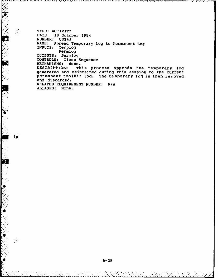
TYPE: ACTIVITYDATE: 10 October 1984NUMBER: CUS43NAME: Append Temporary Log to Permanent LogINPUTS: Templog
PermlogOUTPUTS: PermlogCONTROLS: Close SequenceMECHANISMS: None.DESCRIPTION: This process appends the temporary loggenerated and maintained during this session to the currentpermanent toolkit log. The temporary log is then removedand discarded.RELATED REQUIREMENT NUMBER: N/AALIASES: None.
-A-29
-7 -7
S * ° * ..
° -S -
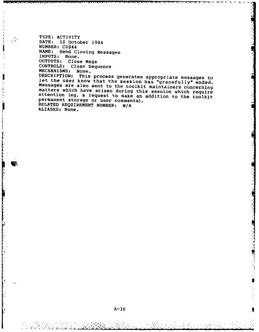
TYPE: ACTIVITYDATE: 10 October 1984NUMBER: CUS44NAME: Send Closing MessagesINPUTS: None.OUTPUTS: Close MsgsCONTROLS: Close SequenceMECHANISMS: None.DESCRIPTION: This process generates appropriate messages tolet the user know that the session has "gracefully" ended.Messages are also sent to the toolkit maintainers concerningmatters which have arisen during this session which requireattention (eg. a request to make an addition to the toolkitpermanent storage or user comments).RELATED REQUIREMENT NUMBER: N/AALIASES: None.
I
A- 30

TYPE: DATA ELEMENTDATE: 10 October 1984NAME: Sys Progs, Msgs, DataDESCRIPTION: Executable programs, data, and messages whichare integral parts of the support computer operating system.SOURCES: Support Computer Operating SystemDESTINATIONS: CUSO CUSI CUS3COMPOSITION: Executable Programs, Data generated by theexecutable programs, data stored in system-level disk filesor system-level operating system variables, and messagesgenerated by the executable programs or by the operatingsystem.DATA CHARACTERISTICS: Executable Programs are binary. Allother data is composed of binary representations ofcharacters (ASCII) or numbers.ALIASES: None.
A-31

*-. 7
TYPE: DATA ELEMENT" DATE: 10 October 1984
NAME: User Msgs & DataDESCRIPTION: Data and messages, directly accessible to theuser, which are received from the user terminal or whoselocation is identified by the user.SOURCES: User TerminalDESTINATIONS: CUSO CUS3COMPOSITION: Data generated by user-accessible executableprograms, stored in user-accessible disk files or user-owned, system-level variables, and messages generated bythe executable programs or manually by the user.DATA CHARACTERISTICS: All data and messages are composedof binary representations of characters (ASCII) or numbers.ALIASES: None.
A- 32
4I

TYPE: DATA ELEMENTDATE: 10 October 1984NAME: Msgs & Data To User TerminalDESCRIPTION: Messages and data sent directly to the user'sterminal.SOURCES: CUSODESTINATIONS: User TerminalCOMPOSITION: Data generated by toolkit components, storedin toolkit-accessible disk files or in toolkit or system-level variables, and messages generated by toolkitcomponents.DATA CHARACTERISTICS: All data and messages are composedof binary representations of characters (ASCII) or numbers.ALIASES: None.
A-33
** **
,~~ *.,o .o °° , *°o• . . . * m " " . - - ' • - "•
'•
'J, , ° " " " " " "

TYPE: DATA ELEMENTDATE: 10 October 1984NAME: Msgs & Data to Disk FilesDESCRIPTION: Messages and data sent to disk filesSOURCES: CUSODESTINATIONS: Disk FilesCOMPOSITION: Data generated by toolkit components, storedin toolkit-accessible disk files or in toolkit or system-level variables, and messages generated by toolkitcomponents.DATA CHARACTERISTICS: All data and messages are composedof binary representations of characters (ASCII) or numbers.ALIASES: None.
4
i
A- 34

"" TYPE: DATA ELEMENT•". DATE: 10 October 1984
NAME: Msgs & Data to Computer PeripheralsDESCRIPTION: Messages and data sent to the peripheralsattached to the support computer system or to the userterminal.SOURCES: CUSODESTINATIONS: Peripherals attached to the support computersystem or to the user terminal.COMPOSITION: Data generated by toolkit components, storedin toolkit-accessible disk files or in toolkit or system-level variables, and messages generated by toolkitcomponents.DATA CHARACTERISTICS: All data and messages are composedof binary representations of characters (ASCII) or numbers.ALIASES: None.
A-35I-

a- -! q.. T.. - - rrt ' . -* C ' r W l f-].. -V
TYPE: DATA ELEMENTDATE: 10 October 1984
NAME: Msgs & Data to Computer PeripheralsDESCRIPTION: Messages and data sent to the peripheralsattached to the support computer system or to the userterminal.SOURCES: CUSODESTINATIONS: Peripherals attached to the support computersystem or to the user terminal.COMPOSITION: Data generated by toolkit components, storedin toolkit-accessible disk files or in toolkit or system-level variables, and messages generated by toolkitcomponents.DATA CHARACTERISTICS: All data and messages are composedof binary representations of characters (ASCII) or numbers.ALIASES: None.
F."
-'" A-35

TYPE: DATA ELEMENTDATE: 10 October 1984NAME: User Access ListsDESCRIPTION: Lists of unique user identifiers (user ids)which are segregated according to the various levels oftoolkit access permitted the users.SOURCES: Resident in the support computer disk storagearea.DESTINATIONS: CUSICOMPOSITION: Unique user identifiersPART OF: Sys Progs, Msgs, DataDATA CHARACTERISTICS: ASCII charactersVALUES: Range of values permitted by the host computeroperating system for the unique identification of users.ALIASES: None.
4
A-36
. .."" .. . ... .. . . . . ... . 9.*.*. ." - ,- - , , .,'..

TYPE: DATA ELEMENTDATE: 10 October 1984NAME: User IdDESCRIPTION: The unique identifier assigned by theoperating system for the current user. Usually stored in anoperating system variable.SOURCES: Support Computer Operating System.DESTINATIONS: CUSICOMPOSITION: Unique user identifierDATA CHARACTERISTICS: ASCII charactersVALUES: Range of values permitted by the host computeroperating system for the unique identification of users.ALIASES: None.
A
! A- 37
r4 .< IT- -'- .". -< .' . ., '' .- T .: - ."" ." "- .'- , .. . .-- .' ,, '. v .. .,. ., .- ,..,. . -.. .
' .b' , -'-" -" ". " -. .- 'J "." ." " - " . ..'.-- .'"''' -' "'.* .; " ' .*. ." . ." '' " . "-. " " -,"-*."..'

TYPE: DATA ELEMENTDATE: 10 October 1984
NAME: User Access LevelDESCRIPTION: Descriptor which indicates the level of access
that is to be given the current toolkit user. This level ofaccess is used to determine: 1) which toolkit componentsmay be executed by the user, 2) the types and quantities oftoolkit data that will be accessible to the user, and 3) thepriority of this user's requests relative to other toolkitprocessing tasks (including other user requests).SOURCES: CUS1DESTINATIONS: CUS2 CUS21 CUS22 CUS3 CUS31 CUS32COMPOSITION: A number is used to represent the level ofaccess.DATA CHARACTERISTICS: A single integer.VALUES: 0 : No access permitted - TBD based upon highestlevel of access.ALIASES: None.
4 A-38
'.= "- .' "* ' J ' " '' "- - ; I " -' " - - : 'L" - .. " " - " " . . S ° " _ .".. . . . . .'

TYPE: DATA ELEMENT
DATE: 10 October 1984NAME: Templog EntryDESCRIPTION: Message generated by the toolkit custodianwhich indicates the occurrence of a toolkit "event". Thisentry is stored in the temporary log assigned to the currentuser session.SOURCES: CUS2 CUS21 CUS3DESTINATIONS: Toolkit temporary logCOMPOSITION: Message describing the occurrence of a toolkit"event".
PART OF: Msgs & Data to Disk FilesDATA CHARACTERISTICS: All messages are composed of binaryrepresentations of characters (ASCII) or numbers.ALIASES: None.
A-39
Ihj-i

TYPE: DATA ELEMENTDATE: 10 October 1984NAME: Toolkit Mgt DataDESCRIPTION: Data necessary to manage toolkit componentexecution, the toolkit configuration, and all toolkitresources.SOURCES: Resides in support computer system disk files andvariables. Is updated/modified by CUS2 CUS3 CUS4DESTINATIONS: CUS2 CUS3 CUS4COMPOSITION: Toolkit access data, user request data,toolkit resource data, operating system resource data,toolkit component performance data, and toolkit maintenancedata and attention flags.PART OF: Msgs & Data to Disk FilesDATA CHARACTERISTICS: All data and attention flags arecomposed of binary representations of characters (ASCII) ornumbers.ALIASES: None.
A-40
a

TYPE: DATA ELEMENT. "DATE: 10 October 1984
NAME: Security Log EntryDESCRIPTION: Message generated by the toolkit custodianwhich indicates the occurrence of a toolkit security"event". This entry is stored in the toolkit security log.SOURCES: CUS2 CUS3DESTINATIONS: Toolkit security logCOMPOSITION: Message describing the occurrence of a toolkitsecurity "event".PART OF: Msgs & Data to Disk FilesDATA CHARACTERISTICS: All messages are composed of binaryrepresentations of characters (ASCII) or numbers.ALIASES: None.
A- 41

TYPE: DATA ELEMENTDATE: 10 October 1984NAME: Status MsgsDESCRIPTION: Messages generated that provide the user withfeedback concerning the tasks being processed by the toolkitcustodian when the toolkit is being opened for use.SOURCES: CUS2 CUS21 CUS22DESTINATIONS: User TerminalCOMPOSITION: Message describing the current task beingprocessed by the toolkit custodian.PART OF: Msgs & Data to User TerminalDATA CHARACTERISTICS: All messages are composed of binaryrepresentations of characters (ASCII) or numbers.ALIASES: None.
A
~A- 42
. .. K 7 %* ~ . .

ITYPE: DATA ELEMENT
* DATE: 10 October 1984NAME: Data & MsgsDESCRIPTION: Data and messages generated by the toolkit whenperforming the tasks necessary to process a user's request.SOURCES: CUS3DESTINATIONS: User terminal
Disk filesComputer peripherals attached to the supportcomputer or to the user terminal.
COMPOSITION: Data generated by toolkit components, storedin toolkit-accessible disk files or in toolkit or system-level variables, and messages generated by toolkitcomponents.PART OF: Msgs & Data to User Terminal
Msgs & Data to Disk FilesMsgs & Data to Computer Peripherals
DATA CHARACTERISTICS: All data and messages are composedof binary representations of characters (ASCII) or numbers.ALIASES: None.
A-43
" .' . . "" " - . - ". . .-' '" .- *-".. ". . ". ". ". ". " -. """". . . - i":2"2" "

* TYPE: DATA ELEMENT• "DATE: 10 October 1984
NAME: Close SequenceDESCRIPTION: An ordered sequence of codes which identifythe tasks which are to be accomplished by the toolkitcustodian when closing the toolkit.SOURCES: CUS3 CUS34DESTINATIONS: CUS4 CUS41 CUS42 CUS43 CUS44COMPOSITION: An ordered sequence of task codes.DATA CHARACTERISTICS: Binary representations of characters(ASCII) or numbers.VALUES: TBD - Task codes to be assigned during toolkitconstruction.ALIASES: None.
A-44
-"J

TYPE: DATA ELEMENTDATE: 10 October 1984
NAME: TemplogDESCRIPTION: A diskfile containing entries describingtoolkit "events". A toolkit event is any user entry,toolkit output message, or toolkit activity which would playan essential part in any reconstruction of the user session.The entries are maintained in the order-of-arrival and maybe date/time stamped. Used to maintain the "history" of aparticular user toolkit session.SOURCES: Resides in the temporary storage area of thetoolkit. One log is created for each user session.DESTINATIONS: CUS4 CUS43COMPOSITION: InLog Entry
Templog EntryIn Anal EntryAnalysis Msgs
PART OF: Msgs & Data to Disk FilesDATA CHARACTERISTICS: All messages are composed of binaryrepresentations of characters (ASCII) or numbers.ALIASES: Temporary Log
A-45
L , m - - - -.,..,_ , .,.. ,.. h .. a - , .- " -. " "' ' ". . . . .. . . . .

TYPE: DATA ELEMENT- DATE: 10 October 1984
NAME: PermlogDESCRIPTION: A diskfile containing entries describingtoolkit events. The entries are maintained in the order-of-arrival and may be date/time stamped. Used to maintain the"history" of the toolkit for a particular period ofinterest.SOURCES: Resides in the permanent storage area of thetoolkit. One log is maintained for each toolkit historicalsegment (eg. by month or by quarter or by year).DESTINATIONS: CUS4 CUS43COMPOSITION: Concattenated "temporary logs" (Templog):
InLog_EntryTemplog EntryInAnalEntryAnalysis Msgs
PART OF: Msgs & Data to Disk FilesDATA CHARACTERISTICS: All messages are composed of binaryrepresentations of characters (ASCII) or numbers.ALIASES: Permanent Log
I
" A- 46
p- *:. i. . Si . - -. . .. i . - i " , . 'i"- i -: " . , ? i i i ' l. - i . ~ . i- : -

r - -: - b - q - " " • • . - - . . -. • . . V, - . w ,r ,
TYPE: DATA ELEMENTDATE: 10 October 1984NAME: MsgsDESCRIPTION: Messages generated during the closing of thetoolkit that provide the user with feedback concerning thestatus of the toolkit and their toolkit session.SOURCES: CUS4DESTINATIONS: User TerminalCOMPOSITION: Message describing the status of the toolkitand the current toolkit session.PART OF: Msgs & Data to User TerminalDATA CHARACTERISTICS: All messages are composed of binaryrepresentations of characters (ASCII) or numbers.ALIASES: None.
A-47
'I "! " " " " " ' " " ", " " " "" "" "" " " " " - ' " " , -" .-." ", --- --." .? ' -' < .-- :.< .? ? .;. --°. - i?? . . -i .: - .;r:- , J ..-2 ;..2 . .-.'.;',.)1 ; 2'Y.. - °.. -. •-.

TYPE: DATA ELEMENTDATE: 10 October 1984NAME: InLog_EntryDESCRIPTION: Message generated by the toolkit custodianwhich indicates the occurrence of a toolkit "event" duringacquisition of the user input and messages. This entry isstored in the temporary log assigned to the current usersession.SOURCES: CUS31DESTINATIONS: Toolkit temporary logCOMPOSITION: Message describing the occurrence of a toolkit"event" during acquisition of user input data and messages.PART OF: Templog EntryDATA CHARACTERISTICS: All messages are composed of binaryrepresentations of characters (ASCII) or numbers.ALIASES: None.
A-48
A

TYPE: DATA ELEMENTDATE: 10 October 1984NAME: InSecur_EntryDESCRIPTION: Message generated by the toolkit custodianwhich indicates the occurrence of a toolkit security "event"during acquisition of the user input and messages. Thisentry is stored in the temporary log assigned to the currentuser session.SOURCES: CUS31DESTINATIONS: Toolkit security logCOMPOSITION: Message describing the occurrence of a toolkitsecurity "event" during acquisition of user input data and messages.PART OF: Security Log EntryDATA CHARACTERISTICS: All messages are composed of binaryrepresentations of characters (ASCII) or numbers.ALIASES: None.
A-49

'p
TYPE: DATA ELEMENTS". DATE: 10 October 1984
NAME: Prompts & MsgsDESCRIPTION: Prompts and messages generated during theacquisition of user input messages and data that provide theuser with: I) selection options, 2) feedback concerninginput selections, 3) Input assistance, and 4) errorresponses.SOURCES: CUSIDESTINATIONS: User TerminalCOMPOSITION: Messages and data which originate from: 1)the custodian, 2) toolkit variables, 3) toolkit helpfiles, and 4) the user (echoed from user input).PART OF: Data & MsgsDATA CHARACTERISTICS: All messages are composed of binaryrepresentations of characters (ASCII) or numbers.ALIASES: None.
A
'. ~.
A-SO
S..~' . -• . . . . . . . . 4

" TYPE: DATA ELEMENT- DATE: 10 October 1984
NAME: Analysis CodesDESCRIPTION: Codes which identifies the level of successachieved by the toolkit during a response to a user request.As a minimum, the codes must identify whether or not the
, response was successful or failed. Ideally, the codes willindicate the portions of the user request that weresuccessfully completed and those which were not completed.If portions of the user request were not successfullycompleted, then the codes should identify the reasons for
•- failure.- * SOURCES: CUS34S"-DESTINATIONS: CUS31
COMPOSITION: Codes identifying the success or failure ofeach toolkit response to a user request.DATA CHARACTERISTICS: Binary representations of characters(ASCII) or numbers.VALUES: TBD - Analysis codes to be assigned during toolkitconstruction.ALIASES: None.
.- 5
---
-0
A- 5
V" .>2..K.:.K:..::

TYPE: DATA ELEMENTDATE: 10 October 1984NAME: User InputDESCRIPTION: The exact input acquired from the userterminal.SOURCES: CUS31DESTINATIONS: CUS32COMPOSITION: The exact input acquired from the userterminal.DATA CHARACTERISTICS: Binary representations of characters(ASCII) or numbers.ALIASES: None.
I.
.
U ~A- 52
*'" " . " ' . . 4 .A4.r < " - " , . ' " • - " "' " "•'-"-.''°- , "-4 .. "'" - " -".".- . -,. . ,• .. -. , . . .,. . - - -""" ,. -. -' " " "" .-- '-

TYPE: DATA ELEMENTDATE: 10 October 1984NAME: In AnalEntryDESCRIPTI-ON: Message generated by the toolkit custodianwhich indicates the occurrence of a toolkit "event" duringanalysis of the user input and messages. This entry isstored in the temporary log assigned to the current usersession.SOURCES: CUS32DESTINATIONS: Toolkit temporary logCOMPOSITION: Message describing the occurrence of a toolkit"event" during analysis of user input data and messages.PART OF: Templog EntryDATA CHARACTERISTICS: All messages are composed of binaryrepresentations of characters (ASCII) or numbers.ALIASES: None.
A-53

TYPE: DATA ELEMENT- "DATE: 10 October 1984
NAME: In Anal Sec_EntryDESCRIPTI-ON: -Message generated by the toolkit custodianwhich indicates the occurrence of a toolkit security "event"during analysis of the user input and messages. This entryis stored in the temporary log assigned to the current usersession.SOURCES: CUS33DESTINATIONS: Toolkit security logCOMPOSITION: Message describing the occurrence of a toolkitsecurity "event" during analysis of user input data andmessages.PART OF: Security Log EntryDATA CHARACTERISTICS: All messages are composed of binaryrepresentations of characters (ASCII) or numbers.ALIASES: None.
A-5
A-54

TYPE: DATA ELEMENTDATE: 10 October 1984NAME: InAnalStatsDESCRIPTION: These are statistics developed during theanalysis of a particular user input.SOURCES: CUS32COMPOSITION: Statistics concerning: 1) individual usercomponent selections, 2) errors detected in the userinput, 3) status of support computer resources at the timeof the user input request, and 4) status of the toolkitresources at the time of the user input request.PART OF: Toolkit Mgt DataDATA CHARACTERISTICS: All statistics are composed ofbinary representations of characters (ASCII) or numbers.Ideally, the statistics will be represented as a collectionof unique names with appropriate codes or frequenciesattached to each name as the result of this analysis.ALIASES: None.
A-55
, . , ._,= -* ,. .. ... ... ... . . . . - -.

- : - : . . k . . . . ... . , _ . . .. . . . . , . . . . . < . .. . . . . . .- . - , -_ - ,
TYPE: DATA ELEMENTDATE: 10 October 1984NAME: Action CodesDESCRIPTION: An ordered sequence of codes which identifythe responses which are to be accomplished by the toolkitcustodian when responding to a user request.SOURCES: CUS32DESTINATIONS: CUS33COMPOSITION: An ordered sequence of response codes.DATA CHARACTERISTICS: Binary representations of characters(ASCII) or numbers.VALUES: TBD - Response codes to be assigned during toolkitconstruction.ALIASES: None.
A-56
• . - - . .- .. .- .''<. T .-, - - -. .. • . . .- :. / - -..' . .,- -. .- . .:-. . . .- -.
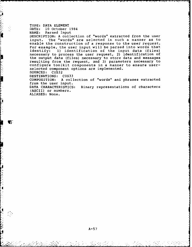
TYPE: DATA ELEMENTDATE: 10 October 1984NAME: Parsed InputDESCRIPTION: A collection of "words" extracted from the userinput. The "words" are selected in such a manner as toenable the construction of a response to the user request.For example, the user input will be parsed into words thatidentify: 1) identification of the input data (files)necessary to process the user request, 2) identification ofthe output data (files) necessary to store data and messagesresulting from the request, and 3) parameters necessary toconfigure toolkit components in a manner to ensure user-selected component options are implemented.SOURCES: CUS32DESTINATIONS: CUS33COMPOSITION: A collection of "words" and phrases extractedfrom the user input.DATA CHARACTERISTICS: Binary representations of characters(ASCII) or numbers.ALIASES: None.
A
q
A- 57
I - . -' ' " ' " .. . . -, . - , i ;:.. :: :i , ,i ~ .... , .- i i ! ii;~ ~i

TYPE: DATA ELEMENTDATE: 10 October 1984NAME: Output Data & MsgsDESCRIPTION: Data and messages generated by the toolkit whenperforming the tasks necessary to respond to a user'srequest.SOURCES: CUS33DESTINATIONS: User terminal
Disk filesComputer peripherals attached to the supportcomputer or to the user terminal.
COMPOSITION: Data generated by toolkit components, storedin toolkit-accessible disk files or in toolkit or system-level variables, and messages generated by toolkitcomponents.PART OF: Data & MsgsDATA CHARACTERISTICS: All data and messages are composedof binary representations of characters (ASCII) or numbers.ALIASES: None.
A5
I
A-58
* ..
. . .. . . . . . . . . .. .*.* . . .. . . . . . . . . . . . . . . . . . . . . . . . . . . .. . . . . . . . . . .

S .TYPE: DATA ELEMENT" DATE: 10 October 1984
NAME: Response CodesDESCRIPTION: Codes which identifies the completion statusof each task generated during a response to a user request.If a task or tasks were not successfully completed, then thecode should identify the individual reasons for failure.SOURCES: CUS33DESTINATIONS: CUS34COMPOSITION: Codes identifying the success or failure ofeach toolkit task generated in response to a user request.DATA CHARACTERISTICS: Binary representations of characters(ASCII) or numbers.VALUES: TBD - Response codes to be assigned during toolkitconstruction.ALIASES: None.
A-59
S"" " " '"------

TYPE: DATA ELEMENT,.' DATE: 10 October 1984
NAME: Response StatsDESCRIPTION: These are statistics developed during thetoolkit response to a user input.SOURCES: CUS33DESTINATIONS: CUS34COMPOSITION: Statistics concerning: 1) individual componentexecution times, 2) errors detected during componentexecution, 3) status of support computer resources at thebeginning and end of each component execution and 4) statusof the toolkit resources at the beginning and end of eachcomponent execution.PART OF: Toolkit Mgt DataDATA CHARACTERISTICS: All statistics are composed ofbinary representations of characters (ASCII) or numbers.Ideally, the statistics will be represented as a collectionof unique names with appropriate codes or frequenciesattached to each name as the result of the current response.ALIASES: None.
A-60
~...... ...... ..........,............. ... - -_•..•. ...... '_ . .- "

TYPE: DATA ELEMENTDATE: 10 October 1984NAME: Analysis MsgsDESCRIPTION: Messages generated during the analysis of thetoolkit response to the last user request. These messagesprovide the user with feedback concerning toolkit responsesduring their toolkit session and also act as input entriesinto the session "history".SOURCES: CUS34DESTINATIONS: User Terminal Disk FilesCOMPOSITION: Message describing the analysis of a toolkitresponse to a user request.PART OF: Data & Msgs
Templog EntryDATA CHARACTERISTICS: All messages are composed of binaryrepresentations of characters (ASCII) or numbers.ALIASES: None.
A-61

TYPE: DATA ELEMENTDATE: 10 October 1984NAME: Storage RequestDESCRIPTION: A three-component indicator that the user wishesto have data currently residing in temporary storage movedto the toolkit permanent storage area.SOURCES: CUS41DESTINATIONS: CUS42COMPOSITION: Contains three parts: The date/time of therequest, the unique user id of the user requesting thestorage transfer, and the name of the data that is to bemoved. The request is contained on a single line with eachcomponent separated by a single space.DATA CHARACTERISTICS: All requests are composed of binaryrepresentations of characters (ASCII) or numbers.ALIASES: None.
A-62
. .. . . . . . . . . .

TYPE: DATA ELEMENTDATE: 10 October 1984NAME: Usage StatsDESCRIPTION: These are statistics developed during a aparticular user session which are provided to the user atthe end of the session. The intention is to provide theuser with a "snapshot" of the session and the resourcesrequired during the session.SOURCES: CUS42COMPOSITION: Although the actual collection of statisticsmay vary at the request of the user, as a minimum thefollowing statistics will be provided: 1) componentselection frequencies, 2) The total number of errorsdetected during user inputs, 3) status of support computerresources at the beginning and end of the toolkit sessionand 4) status of the toolkit resources at the beginning andend of the toolkit session.PART OF: MsgsDATA CHARACTERISTICS: All statistics are composed ofbinary representations of characters (ASCII) or numbers.Ideally, the statistics will be represented as a collectionof unique names with appropriate codes or frequenciesattached to each name as the result of this analysis.ALIASES: None.
A-63
04

" - TYPE: DATA ELEMENTDATE: 10 October 1984
. NAME: Close MessagesDESCRIPTION: Messages generated during the closing of thetoolkit. These are messages sent to the user reporting thatthe toolkit has been successfully closed and that control isbeing returned to the support computer operating system.SOURCES: CUS44DESTINATIONS: User terminalCOMPOSITION: Messages generated by the custodian.PART OF: MsgsDATA CHARACTERISTICS: All messages are composed of binaryrepresentations of characters (ASCII) or numbers.ALIASES: None.
A-6
ra
I. A- 64
,I .. " .. ' .. . -* . '-.* o" .. ,' *.*.- .. .-* ' " , ,.'.' .

Appendix B: Structure of A Prototype AFIT VLSI CAD Toolkit
Prototype Implementation of ToolKit Drawer StructureUsing UNIX Hierarchica1 irectores
A prototype implementation of the VLSI CAD toolkit
drawer structure has been accomplished on the AFIT VAX
11/780 computer. This AFIT computer system employs the UNIX
operating system which permits the construction of hier-
archical disk directories. The directory feature of UNIX
was exploited to create a toolkit whose drawers are actually
UNIX directories. The drawer-to-UNIX directory mappings for
each toolkit compartment are shown below. The directory
hierarchy is presented in the next section.
TOOLKIT COMPONENT NAME UNIX DIRECTORY NAME
VLSI CAD TOOLKIT vlsi tool kit
MANAGEMENT TOOLS mgttoolsDRAWERS
Configuration configuration
Data Translation data transl
Resource Management resource mgt
Data Analysis data-analysis
Documentation Management docmgt
Environmental Control environ ctrl
Data Archival data archival
Data Access Control data access
Data Security data-security
Data Storage Management datasto_mgt
Report Generation report_gen
B-1
..........................................
.. . . . . . . . . . . . * * . . . . . . . . .

MANAGEMENT TOOLS (Contd.)
Standards Management standsmgt
Library Management lib mgt
Schedule Management schedmgt
TOOLKIT COMPONENT NAME UNIX DIRECTORY NAME
DESIGN TOOLS design_toolsDRAWERS
Architectural architecture
Logic logic
Floorplan floorplan
Layout layout
Interconnection connection
Topological Analysis topoanalysis
Extraction extraction
Timing Analysis timing_analy
Electrical Analysis elect analy
Mask Data Generation maskdata_gen
Design Verification design_verify
Design Presentation designpresent
Utilities utilities
INFORMATION STORAGE info storage
DRAWERS
TEMPORARY STORAGE tempstorage
DRAWER
Documentation temp doc
Libraries temp_libs
Statistics tempstats
B-2

TEMPORARY STORAGE (Contd.)
Schedules temp_sched
Design Data tempjdata
Source Code temp_sources
Aux Data temp_aux-data
TOOLKIT COMPONENT NAME UNIX DIRECTORY NAME
PERMANENT STORAGE perm-storageDRAWER
Documentation perm doc
Libraries perm-libs
Statistics perm-stats
Schedules perm-sched
Design Data perm data
Source Code perm-sources
Aux Data perm aux data
B-3

Hierarchical Toolkit Directory Structure
The hierarchical srtucture of the of VLSI CAD toolkit
is shown in the diagram that follows. The lines connecting
directories or groups of directcries represent a change in
level to that directory (group). Directories listed without
,. intervening lines are at the same level.
The highest level directory is the Ovlsitoolkit"
level. The toolit custodian should "reside" at the highest
level directory in the toolkit structure.
A prototype directory structure is represented by the
diagram that follows.
vlsi tool kitf: - I ------ I I
mgt tools info storage designtools[ -II I
temp_storage per i!.storage
cofigrto temp I conctoconfiguration temp_doc permdoc architecturedata transl temp_libs permlibs logicresource mgt temp_stats permstats floorplandata analysis temp sched per. sched layoutdocMgt temp data perm data connectionenvironctrl tempsources permsources topoanalysisdataarchival temp_auxdata permauxdata extractiondata access timing analydata-security elect analydata stomgt maskdata_genreport_gen design_verifystands mgt designpresentlibpmgt utilitiessched_mgt
4B-4
.. %

The UNIX "C-Shell" Script Used to Build The Toolkit Hier-archical Directory Structure
# UNIX C-SHELL Script to build hierarchical directories for the# VLSI CAD TOOL KIT (drawers)
# Written by: Capt Thomas R. Vermillion# AFIT/EN : GE84D# 1 October 1984
#echo 'echo 'VLSI CAD TOOLKIT DIRECTORY CONSTRUCTION SCRIPT V 1.0'echo 'echo -n 'Creating Main Toolkit Directory ...# main tool kit directory - custodian lives heremkdir vlsi tool kitchmod go+rxw vlgi_toolkitecho 'DONE'echo -n 'Creating Major Drawer Directories ...#cd vlsi tool kit# major drawer sections
mkdir mgt_toolsmkdir info storagemkdir design_toolschmod go+rwx *echo 'DONE'echo -n 'Creating Individual Management Tool Directories.#Imanagement tools drawerscd mgt_tools#individual management tools#mkdir configurationmkdir data translmkdir resource mgtmkdir dataanaTysismkdir doc_mgtmkdir environ ctrlmkdir data archivalmkdir data accessmkdir data security
4 mkdir data-stor_mgtmkdir report_genmkdir standsMgtmkdir lib_mgtmkdir sched_mgtchmod go+rwx *
4 echo 'DONE'echo -n 'Creating Information Storage Directories#cd
B-5

cd info storage# information storage drawers#mkdir tempstoragecd temp_storagemkdir temp docmkdir templibsmkdir temp_statsmkdir temp_schedmkdir temp_datamkdir temp_sourcesmkdir temp_auxdatachmod go+rwx *cdmkdir permstoragecd permstoragemkdir perm docmkdir perm-libsmkdir permstatsmkdir perm schedmkdir perm_datamkdir perm sourcesmkdir permauxdatachmod g+rwx *cd .
* chmod g+rwx *echo 'DONE'echo -n 'Creating Individual Design Tool Directories ...#cdcd design_tools
mkdir architecturemkdir logicmkdir floorplanmkdir layoutmkdir connectionmkdir topoanalysismkdir extractionmkdir timing_analymkdir elect analymkdir maskdata_genmkdir design_verifymkdir design presentmkdir utilitieschmod g+rwx *cdcdecho 'DONE'echoecho 'VLSI CAD Toolkit Directory Construction Completed.'echo '
B-6

*1
Distribution of AFIT IC CAD Tools in the PrototypeVLSI CAD Toolkit
Distribution of existing CAD tools into their appro-
priate toolkit drawers is one of the major tasks associated
with toolkit integration. This step has been performed for
the AFIT CAD tools and the results are presented below. The
results are presented on a drawer-by-drawer basis begiining
at the top of the toolkit hierarchy. The tools are identi-
fied by using the complete UNIX pathname CURRENTLY assigned
to the tools on the AFIT VAX 11/780.
DRAWER: VLSI CAD ToolkitUNIX DIRECTORY: vlsi tool kit- TOOL LIST -
custodian
DRAWER: Management Tools DrawersUNIX DIRECTORY: mgttools- TOOL LIST -
DRAWER: ConfigurationUNIX DIRECTORY: configuration- TOOL LIST -
DRAWER: Data TranslationUNIX DIRECTORY: data transl
Le - TOOL LIST -/usr/local/cad/bin/cif2ca/usr/local/cad/bin/clipcif/usr/local/cad/bin/clman/usr/local/cad/bin/ca2db/usr/local/cad/bin/ucfilt/usr/local/cad/bin/db2cif/usr/local/cad/bin/presim/usr/local/cad/bin/forfor/usr/local/cad/bin/simfilter/usr/local/cad/bin/spcpp/usr/local/cad/bin/rsort/usr/local/cad/bin/window/usr/local/cad/bin/sim2spice/usr/local/cad/bin/pspice
B-7
-... ,.. . -.-. .- -. ....- .-.... :. * ! :,:.* ._ * " " . " ;: . :

DRAWER: Data TranslationUNIX DIRECTORY: data transi- TOOL LIST - (Contd.)/usr/ local/cad/uw/bin/netlist
* /usr/local/cad/uw/bin/presim/usr/local/cad/uw/bin/spcpp/usr/ local/cad/uw/bin/pspice/usr/ local/cad/uw/bin/ca2db/usr/ local/cad/uw/bin/simfilter/usr/ local/cad/uw/bin/spice2g6/usr/ local/cad/uw/bin/forfor
* /usr/ local/cad/uw/bin/prescp* /usr/local/cad/stanford/src/PIPELINE83/SRC/BANE/wildow* /usr/local/cad/stanford/src/PIPELINE83/SRC/BANE/xy2co
/usr/ local/cad/stanford/src/PIPELINE83/SRC/BANE/coflcat/usr/local/cad/stanford/src/PIPELINE83/SRC/BANE/err2co/usr/local/cad/stanford/src/PIPELINE83/SRC/RPLOT/blockout
* /usr/local/cad/stanford/src/PIPELINE83/SRC/RPLOT/convert/usr/ local/cad/stanford/src/PIPELINE83/SRC/RPLOT/merge/usr/local/cad/stanford/src/PIPELINE83/SRC/RPLOT/rplt wd.bin/usr/ local/cad/stanford/src/PIPELINE83/SRC/RPLOT/ulc~flvert/usr/local/cad/stanford/src/PIPELINE83/SRC/RPLOT/rsort/usr/ local/cad/stanford/src/PIPELINE83/SRC/RPLOT/wildow
* /usr/ local/cad/stanford/src/PIPELINE83/SRC/CIFLOAD/cifar* /usr/ local/cad/stanford/src/PIPELINE83/SRC/CIFLOAD/cif load
/usr/ local/cad/stanford/ src/PIPELINE83/SRC/CIFLOAD/scif load/usr/local/cad/stanford/src/PIPELINE83/SRC/CIFLOAD/splitfile/usr/local/cad/bin/blam/usr/ local/cad/bin/cifout-cat/usr/ local/cad/bin/convert/usr/local/cad/bin/splitfile/usr/ local/cad/bin/unconvert/usr/ local/cad/bin/rtsyms/usr/ local/cad/bin/cifcat/usr/local/cad/uw/bin/xsimspc
DRAWER: Resource ManagementUNIX DIRECTORY: resource-mgt
-TOOL LIST-
DRAWER: Data AnalysisUNIX DIRECTORY: data analysis-TOOL LIST-/usr/local/cad/bin/cifstat
DRAWER: Documentation ManagementUNIX DIFFCTORY: doc mgt
* - TOOL LIST-/usr/local/cad/bin/cadman/usr/local/cad/uw/bin/man/usr/local/cad/uw/bin/whatis
B-8

DRAWER: Documentation ManagementUNIX DIRECTORY: doc mgt- TOOL LIST - (ContJ.)/usr/local/cad/uw/lib/whatis/usr/local/cad/uw/man/MAKE
DRAWER: Environmental ControlUNIX DIRECTORY: environ ctrl- TOOL LIST -
DRAWER: Data ArchivalUNIX DIRECTORY: data archival- TOOL LIST -
/usr/local/cad/bin/cifload/usr/local/cad/bin/cifar/usr/local/cad/uw/lib/libutil.a
DRAWER: Data Access ControlUNIX DIRECTORY: data-access- TOOL LIST -
DRAWER: Data Security
UNIX DIRECTORY: datasecurity- TOOL LIST
DRAWER: Data Storage ManagementUNIX DIRECTORY: datastomgt- TOOL LIST -
/usr/local/cad/bin/dir
DRAWER: Report GenerationUNIX DIRECTORY: report_gen-TOOL LIST -
DRAWER: Standards ManagementUNIX DIRECTORY: stands_mgt- TOOL LIST -
DRAWER: Library ManagementUNIX DIRECTORY: lib-mgt- TOOL LIST -
/usr/local/cad/bin/cifload/usr/local/cad/bin/cifar/usr/local/cad/uw/lib/libutil.a/usr/local/cad/lib/earl/lib status
B-94 A
.. . . . . . . . .

DRAWER: Schedule ManagementUNIX DIRECTORY: sched mgt- TOOL LIST -
DRAWER: Design Tools DrawersUNIX DIRECTORY: designtools- TOOL LIST -
DRAWER: ArchitecturalUNIX DIRECTORY: architecture- TOOL LIST -
DRAWER: LogicUNIX DIRECTORY: logic- TOOL LIST -
/usr/local/cad/bin/plasort/usr/local/cad/bin/eqntott/usr/local/cad/bin/mkpla/usr/local/cad/bin/presto/usr/local/cad/bin/peg/usr/local/cad/bin/plagen/usr/local/cad/bin/plague/usr/local/cad/bin/changeo/usr/local/cad/bin/tpla/usr/local/cad/bin/quilt/usr/local/cad/bin/solve/usr/local/cad/uw/bin/presto/usr/local/cad/stanford/src/PLAGEN/PLAGUE/plague/usr/local/cad/bin/plaid/usr/local/cad/bin/mintopla
DRAWER: FloorplanUNIX DIRECTORY: floorplan- TOOL LIST -
DRAWER: LayoutUNIX DIRECTORY: layout- TOOL LIST -
/usr/local/cad/bin/bane/usr/local/cad/bin/bane.old/usr/local/cad/bin/plap/usr/local/cad/bin/cll/usr/local/cad/bin/cll2/usr/local/cad/bin/earl/usr/local/cad/bin/clay/usr/local/cad/uw/bin/plap/usr/local/cad/uw/bin/plap3
B-10

DRAWER: LayoutUNIX DIRECTORY: layout-TOOL LIST - (Contd.)/usr/ local/cad/stanford/src/bane/usr/ local/cad/stanford/src/PIPELINE83/SRC/CLL2/c112/usr/ local/cad/stanford/src/PIPELINE83/SRC/BANE/bane
DRAWER: InterconnectionUNIX DIRECTORY: connection-TOOL LIST-
DRAWER: Topological AnalysisUNIX DIRECTORY: topoanalysis
-TOOL LIST-/usr/ local/cad/bin! lyra/usr/ local/cad/bin/rulec/usr/ local/cad/bin/drcscript/usr/ local/cad/bin/alldrc/usr/ local/cad/bin/fastdrc
4/usr/local/cad/bin/drc/bin and/usr/ local/cad/bin/drc/bin-andnot/usr/local/cad/bin/drc/bin-chk/usr/local/cad/bin/drc/bin coal/usr/ local/cad/bin/drc/bin-con
* __ /usr/ local/cad/bin/drc/bin errU) /usr/local/cad/bin/drc/biniexp
/usr/local/cad/bin/drc/bin filter-*/usr/ local/cad/bin/drc/bin -gen
/usr/ local/cad/bin/drc/bin hasnone/usr/local/cad/bin/drc/binihassome/usr/local/cad/bin/drc/bin or/usr/ local/cad/bin/drc/ciftorect/usr/local/cad/bin/drc/drc.back
/usr/ local/cad/bin/drc/drcscp/usr/local/cad/bin/drc/edgetcif/usr/local/cad/bin/drc/edgeo7 i/usr/local/cad/bin/drc/mult/usr/local/cad/bin/drc/olmr
/usr/local/cad/bin/drc/recttocif/usr/local/cad/bin/drc/sedscript/usr/local/cad/bin/drc/enddrc
* /usr/local/cad/bin/drc/add94sO /usr/local/cad/lib/bane/drc* /usr/local/cad/lib/bane/drc/drc filter.bak
/usr/local/cad/lib/bane/drc/drcl1* /usr/local/cad/lib/bane/drc/drc.cmos
/usr/local/cad/lib/barie/drc/drc.doc/usr/local/cad/lib/bane/' drc/drc.nmos
4 _/usr/local/cad/lib/bane/drc/drc filter* /usr/local/cad/lib/bane/drc/drcmiask.doc* /usr/local/cad/lib/bane/drc/drcold.sa
B-li

DRAWER: Topological AnalysisUNIX DIRECTORY: topoanalysis
-TOOL LIST - (Contd.)!usr/ local/cad! lib/bane/drc/butconexp/usr/ local/cad/ lib/bane/drc/butcondrop/usr/ local/cad/ lib/bane/drc/frontsort/usr/ local/cad/ lib/bane/drc/fullexp/usr/local/cad/lib/bane/drc/iipchk/usr/ local/cad/ lib/bane/drc/ornmos/usr/ local/cad/ lib/bane/drc/nniosextr/usr/ local/cad/lib/bane/drc/rectexp/usr/ local/cad/ lib/bane/drc/rinbutconlusri local/cad/ lib/bane/drc/ sepdpch/usr/local/cad/ lib/bane/drc/sepchk/usr/local/cad/lib/bane/drc/sepdpbur/usr/ local/cad/ lib/bane/drc/tranburied/usr/ local/cad/ lib/bane/drc/trpol/usr/local/cad/lib/bane/drc/trdiff/usr/ local/cad! lib/bane/drc/ciuosextr/usr/ local/cad/ lib/bane/drc/csort/usr/ local/cad! lib/bane/drc/diodechk/usr/ local/cad! lib/bane/drc/isect excIusr/ local/cad! lib/bane/drc/orcmos/usr/local/cad/ lib/bane/drc/pnbuttcon/usr/ local/cad! lib/bane/drc/pplusdiff/usr/ local/cad! lib/bane/drc/pwellchk/usr/ local/cad! lib/bane/drc/trandiff/usr/local/cad/lib/barte/drc/twoint exc!usr/local/cad/lib/bane/drc/bool!usr/local/cad/lib/bane/drc/boolf!usr/local/cad/lib/bane/drc/bsort
* /usr/local/cad/lib/bane/drc/conv/usr/ local/cad! lib/bane/drc/cover/usr/ local/cad! lib/bane/drc/exp
* /usr/local/cad/lib/bane/drc/errout/usr/local/cad/lib/bane/drc/expand/usr/local/cad/lib/bane/drc/intersect
* !usr/local/cad/lib/bane/drc/separate!usr/local/cad/lib/bane/drc/sepone/usr/local/cad/lib/bane/drc/shrink/usr/local/cad/lib/bane/drc/tranexp/usr/local/cad/lib/bane/drc/twocover/usr/local/cad/bin/clldrc.lib/usr/local/cad/bin/clldrc.lib/bool/usr/local/cad/bin/clldrc. lib/atol/usr/local/cad/bin/clldrc.lib/boolf/usr/local/cad/bin/clldrc.lib/bsort!usr/local/cad/bin/clldrc.lib/btoa/usr/local/cad/bin/clldrc. lib/butconexp/usr/local/cad/bin/clldrc. lib/conchk/usr/local/cad/bin/clldrc. lib/concov
* !/usr/local/cad/bin/clldrc. lib/consep/usr/local/cad/bin/clldrc.lib/conv/usr/local/cad/bin/clldrc.lib/ibl
B-i12

DRAWER: Topological AnalysisUNIX DIRECTORY: topoanalysis
-TOOL LIST - (Contd.)/usr/local/cad/bin/clldrc. lib/drcfilter/usr/local/cad/bin/clldrc. lib/exp/usr/ local/cad/bin/cl ldrc. lib/extr/usr/local/cad/bin/clldrc. lib/frontout/usr/local/cad/bin/clldrc.lib/frontsort/usr/local/cad/bin/clldrc. lib/fullexp/usr/local/cad/bin/clldrc. lib/inipchk/usr/ local/cad/bin/cl ldrc. lib/niinwidth/usr/local/cad/bin/clldrc. lib/ordrc/usr/local/cad/bin/clldrc. lib/pl/usr/local/cad/bin/clldrc.lib/rectexp/usr/local/cad/bin/clldrc. lib/rmbutcon/usr/local/cad/bin/clldrc.lib/sepchk/usr/local/cad/bin/clldrc. lib/sepdpch/usr/ local/cad/bin/cl ldrc. lib/tranexp/usr/local/cad/bin/clldrc. lib/trpol/usr/local/cad/bin/clldrc. lib/widchk/usr/ local/cad/uw/bin/drcscript
4 /usr/ local/cad/uw/bin/drcpgms/usr/ local/cad/uw/bin/drcpgms/bin and/usr/ local/cad/uw/bin/drcpgms/bin andnot/usr/ local/cad/uw/bin/drcpgms/biri chk/usr/ local/cad/uw/bin/drcpgms/bin -coal/usr/local/cad/uw/bin/drcpgms/biri con
qu /usr/local/cad/uw/bin/drcpgns/bin err/usr/ local/cad/uw/bin/drcpgms/bin -exp/usr/local/cad/uw/bin/drcpgis/bin -filter/usr/ local/cad/uw/bin/drcpgms/bingen/usr/ local/cad/uw/bin/drcpgms/bin -hasnone/usr/local/cad/uw/bin/drcpgms/bin~hassome/usr/ local/cad/uw/bin/drcpgms/bin -or/usr/local/cad/uw/bin/drcpgrns/ciftorect/usr/ local/cad/uw/bin/drcpgnis/recttocif/usr/ local/cad/uw/bin/drcpgius/edgetocif/usr/ local/cad/uw/bin/add94s/usr/ local/cad/uw/bin/enddrc/usr/ local/cad/uw/bin/drc
7- /usr/local/cad/stanford/src/DRCB3/drc.cmos/usr/ local/cad/stanford/src/DRC83/drc filter/usr/ local/cad/stanford/src/DRC83/drc:.1/usr/local/cad/stanford/src/DRC83/Makefile/usr/local/cad/stanford/src/DRC83/drcold.sa/usr/ local/cad/stanford/src/DRCB3/butconexp/usr/ local/cad/stanford/src/DRC83/butcondrop/usr/ local/cad/stanford/src/DRC83/drc .nnios/usr/ local/cad/stanford/src/DRC83/drc .doc/usr/local/cad/stanford/src/DRC83/frontsort/usr/ local/cad/stanford/src/DRC83/fullexp
4 ~/usr/local/cad/stanford/src/DRC83/impchk:. /usr/local/cad/stanford/src/DRC83/ornmos
/usr/ local/cad/stanford/src/DRC83/nmosextr
B- 13

DRAWER: Topological Analysis* UNIX DIRECTORY: topoanalysis
-TOOL LIST - (Contd.)/usr/ local/cad/stanford/src/DRC83/rectexp/usr/local/cad/stanford/src/DRC83/rmbutcon/usr/local/cad/stanford/src/DRC83/sepdpch/usr/local/cad/stanford/src/DRC83/sepchk/usr/local/cad/stanford/src/DRC83/sepdpbur/usr/local/cad/stanford/src/DRC83/tranburied/usr/ local/cad/stanford/src/DRC83/trpol/usr/local/cad/stanford/src/DRC83/trdiff/usr/local/cad/stanford/src/DRC83/cmosextr/usr/local/cad/stanford/src/DRC83/csort/usr/local/cad/stanford/src/DRC83/diodechk/usr/local/cad/stanford/src/DRC83/isect exc/usr/ local/cad/stanford/src/DRC83/orcmos/usr/local/cad/stanford/src/DRC83/pnbuttcon/usr/local/cad/stanford/src/DRC83/pplusdiff/usr/ local/cad/stanford/src/DRC83/pwellchk
* /usr/local/cad/stanford/src/DRC83/drcmask.doc/usr/ local/cad/stanford/src/DRC83/trandiff
*/usr/local/cad/stanford/src/DRC83/twoint exc/usr/local/cad/stanford/src/DRC83/booI/usr/local/cad/stanford/src/DRC83/boolf/usr/local/cad/stanford/src/DRC83/bsort/usr/local/cad/stanford/src/DRC83/conv/usr/ local/cad/stanford/src/DRC83/cover/usr/local/cad/stanford/src/DRC83/exp
* /usr/local/cad/stanford/src/DRC83/errout/usr/local/cad/stanford/src/DRC83/expand/usr/local/cad/stanford/src/DRC83/intersect/usr/local/cad/stanford/src/DRC83/separate/usr/local/cad/stanford/src/DRC83/sepone/usr/ local/cad/stanford/src/DRC83/shrink
* /usr/local/cad/stanford/src/DRC83/tranexp/usr/local/cad/stanford/src/DRC83/twocover
DRAWER: ExtractionUNIX DIRECTORY: extraction-TOOL LIST-/usr/local/cad/bin/mextra
* /usr/local/cad/bin/netlist* /usr/local/cad/bin/cifplot
DRAWER: Timing AnalysisUNIX DIRECTORY: timing_analy
-TOOL LIST -
/usr/local/cad/bin/crystal/usr/Alocal/cad/bin/rnl
B- 14

* .. DRAWER: Electrical AnalysisUNIX DIRECTORY: elect-analy
-TOOL LIST -
/usr/ local/cad/bin/powest/usr/ local/cad/bin/erclusri local/cad/bin/ercscript/usr/local/cad/uw/bin/erc/usr/ local/cad/uw/bin/ercscript
DRAWER: Mask Data GenerationUNIX DIRECTORY: mask-data _gen
-TOOL LIST -
* /usr/ local/cad/bin/cli/usr/ local/cad/bin/cl 12/usr/ local/cad/bin/cifplot
DRAWER: Design VerificationUNIX DIRECTORY: design_verify
-TOOL LIST -
/usr/ local/cad/bin/esim/usr/ local/cad/bin/spice2g6
* /usr/ local/cad/bin/spice/usr/ local/cad/bin/crystal/usr/ local/cad/bin/rnl/usr/local/cad/uw/bin/rnl
DRAWER: Design Presentation* UNIX DIRECTORY: design_present,
-TOOL LIST -
/usr/local/cad/bin/cifplot/usr/ local/cad/bin/fastcif/usr/ local/cad/bin/vdmp/usr/ local/cad/bin/print/usr/ local/cad/bin/vpltdmp/usr/ local/cad/bin/rrplot/usr/ local/cad/bin/penplot/usr/ local/cad/bin/vdump/usr/ local/cad/bin/mcp/usr/ local/cad/uw/bin/vic/usr/local/cad/uw/bin/ 7221/urloa/adu/in78
/usr/local/cad/uw/bin/pen80o/usr/local/cad/uw/bin/mpnpo
*/usr/local/cad/uw/bnr/tp IELN8/SCALO/po/usr/local/cad/stanford/src/PIPELINE83/SRC/RPLOT/rplot/usr/ local/cad/stanford/src/PIPELINE83/SRC/RPLOT/rrplot
/usr/ local/cad/bin/ listnode/usr/ local/cad/bin/mdump
* /usr/local/cad/bin/7221/usr/ local/cad/bin/rrplot .bin/usr/ local/cad/bin/ listesym
B- 15

716
DRAWER: Design PresentationUNIX DIRECTORY: design -present
-TOOL LIST - (Contd.)/usr/ local/cad/bin/mprint/usr/ local/cad/uw/bin/ ispice/usr/ local/cad/bin/vlsifont/usr/ local/cad/bin/dbdi/usr/ local/cad/bin/pattern/usr/ local/cad/bin/patterni
DRAWER: UtilitiesUNIX DIRECTORY: utilities- TOOL LIST -
/usr/ local/cad/bin/uc/usr/ local/cad/bin/chksum/usr/local/cad/bin/tvitest/usr/local/cad/bin/inuse/usr/local/cad/stanford/src/PIPELINE83/SRC/CLL2/TEST/usr/ local/cad/bin/sleeper/usr/ local/cad/bin/vprm.old/usr/ local/cad/bin/rsleeper/usr/ local/cad/bin/inter/usr/ local/cad/bin/ic/usr/ local/cad/bin/cater/usr/ local/cad/bin/xsimspc/usr/local/cad/bin/cif/usr/ local/cad/bin/merge/usr/ local /cad/uw/bin/apropos/usr/ local/cad/bin/mas/usr/ local/cad/bin/cmem/usr/ local/cad/bin/smm/usr/ local/cad/bin/Cl/usr/ local/cad/bin/snp/usr/ local/cad/bin/sne/usr/ local/cad/bin/motd/usr/ local/cad/bin/xx/usr/ local/cad/uw/bin/status/usr/ local/cad/uw/bin/pattern/usr/ local/cad/uw/bin/patterni/usr/ local/cad/uw/bin/reset om/usr/local/cad/uw/bin/statuis om/usr/ local/cad/uw/bin/scope/usr/ local/cad/uw/bin/pass2
DRAWER: Information Storage DrawersUNIX DIRECTORY: info-Storage-TOOL LIST-
B- 16
PL- -0 ..... '1,

DRAWER: Temporary Storage DrawerUNIX DIRECTORY: temp_storage
-TOOL LIST -
DRAWER: DocumentationUNIX DIRECTORY: temp_doc
-TOOL LIST -
DRAWER: LibrariesUNIX DIRECTORY: temp_libs
-TOOL LIST -
DRAWER: StatisticsUNIX DIRECTORY: temp_stats
* - TOOL LIST -
* DRAWER: SchedulesUNIX DIRECTORY: temp-sched
-TOOL LIST-
DRAWER: Design DataUNIX DIRECTORY: temp_data-TOOL LIST -
/usr/ local/cad/sos/sos* /usr/local/cad/test/ciffile.cif* /usr/local/cad/test/pla.cll
/usr/local/cad/test/spla.cif/usr/local/cad/test/pla.cif/usr/ local/cad/test/ciffile.drc/usr/local/cad/test/ciffile. log
* /usr/ local/cad/test/pla .nodes-~ /usr/local/cad/test/pla.sim
/usr/ local/cad/ test/pla .names/usr/ local/cad/test/pla.cap
* /usr/local/cad/test/pla.spice
DRAWER: Source CodeUNIX DIRECTORY: temp sources-TOOL LIST -
DRAWER: Aux DataUNIX DIRECTORY: temp aux data
-TOOL LIST-
B- 17

DRAWER: Permanent Storage DrawerUNIX DIRECTORY: perm-storage
-TOOL LIST-
DRAWER: DocumentationUNIX DIRECTORY: perm-doc- TOOL LIST-/usr/ local/cad/uw/doc/usr/local/cad/uw/doc/whj .let/usr/ local/cad/uw/doc/Makefile/usr/local/cad/uw/doc/cells/usr/local/cad/uw/doc/README/usr/local/cad/uw/doc/netlist/usr/ local/cad/uw/doc/plaplusri local/cad/uw/doc/make .out/usr/ local/cad/uw/doc/presim/usr/ local/cad/uw/doc/src/usr/ local/cad/uw/doc/ src/ intro *tblms/usr/local/cad/uw/doc/src/README
* /usr/local/cad/uw/doc/src/cells.tblms/usr/local/cad/uw/doc/src/spice.tbleqnms
*/usr/local/cad/uw/doc/src/README_-UW* /usr/local/cad/uw/doc/src/presimems
/usr/local/cad/uw/doc/src/netlist.ms/usr/local/cad/uw/doc/src/rnl .ms/usr/local/cad/uw/doc/src/rnlbrief.ms/usr/ local/cad/uw/doc/src/plap.tblms/usr/local/cad/uw/doc/src/plapsrc/usr/ local/cad/uw/doc/ src/plapsrc/Makefile/usr/local/cad/uw/doc/src/plapsrc/plap.O/usr/local/cad/uw/doc/src/plapsrc/READ_-ME/usr/local/cad/uw/doc/src/plapsrc/plap.1/usr/local/cad/uw/doc/src/plapsrc/plap. 2/usr/local/cad/uw/doc/src/plapsrc/plap.3/usr/local/cad/uw/doc/src/plapsrc/plap.4/usr/local/cad/uw/doc/src/plapsrc/plap.5/usr/local/cad/uw/doc/src/plapsrc/plap.6/usr/local/cad/uw/doc/src/plapsrc/plap.7/usr/local/cad/uw/doc/src/plapsrc/plap.8
* /usr/local/cad/uw/doc/src/plapsrc/plap.9
/usr/local/cad/uw/doc/src/plapsrc/plap.macros/usr/local/cad/uw/doc/src/cellsrc/usr/local/cad/uw/doc/src/cellsrc/READ ME/usr/local/cad/uw/doc/src/cellsrc/cellTb.3
* /usr/local/cad/uw/doc/src/cellsrc/Makefile/usr/local/cad/uw/doc/src/cellsrc/cellib.O/usr/local/ca4/uw/doc/src/cellsrc/cellib.1/usr/local/cad/uw/doc/src/cellsrc/cellib.2/usr/local/cad/uw/doc/src/cellsrc/cellib.4
* /usr/local/cad/uw/doc/src/cellsrc/cell.macros/usr/local/cad/uw/doc/src/layout.tblms/usr/local/cad/uw/doc/src/title.ms/usr/local/cad/uw/doc/rnlbrief
B- 18

DRAWER: DocumentationUNIX DIRECTORY: perm doc
-TOOL LIST - (Contd.)/usr/ local/cad/uw/doc/intro/usr/ local/cad/uw/doc/ layout/usr/ local/cad/uw/doc/spice/usr/ local/cad/uw/doc/whj .let .bak/usr/ local/cad/uw/doc/title/usr/ local/cad/manlusri local/cad/man/cati/usr/ local/cad/man/catl/cadman.1/usr/ local/cad/man/catl/peg. 1/usr/local/cad/man/catl/uc .1/usr/ local/cad/man/catl/cifplot. 1/usr/ local/cad/man/catl/vdump. 1lusri local/cad/man/catl/chksum. 1/usr/ local/cad/man/catl/cif.1/usr/ local/cad/man/catl/cif2ca.1/usr/ local/cad/man/catl/cifar .1/usr/ local/cad/man/cati/cif load.1/usr/local/cad/man/catl/cifstat.1/usr/ local/cad/man/catl/clipcif.1/usr/local/cad/man/catl/cll .1/usr/local/cad/man/catl/clldrc. 1/usr/ local/cad/man/catl/crystal .1/usr/ local/cad/man/catl/eqntott.1/usr/ local/cad/man/catl/esim.1
e /usr/local/cad/man/catl/intro.1/usr/ local/cad/uian/catl/ lyra.1/usr/ local/cad/man/catl/mcp. 1/usr/local/cad/man/catl/mextra.1/usr/ local/cad/man/catl/mkpla. 1/usr/ local/cad/uian/catl/plagen. 1/usr/ local/cad/man/catl/plague.1lusri local/cad/man/catl/clay. 1/usr/local/cad/man/catl/quilt.1/usr/local/cad/man/catl/rsort. 1/usr/local/cad/mari/catl/rulec.1/usr/ local/cad/man/catl/sim2spice .1
* /usr/local/cad/man/catl/tpla.1/usr/ local/cad/man/catl/ucfilt.1/usr/local/cad/rnan/catl/vlsifont. 1/usr/ local/cad/man/catl/window. 1/usr/ local/cad/man/catl/blam. 1/usr/ local/cad/man/catl/presto. 1
* /usr/local/cad/man/catl/clman.1/usr/ local/cad/man/catl/dir .1/usr/ local/cad/man/catl/solve.1/usr/ local/cad/man/catl/ar.1/usr/ local/cad/man/cat2/usr/ local/cad/man/cat3/usr/ local/cad/man/cat3/tpack. 3/usr/ local/cad/man/cat4/usr/ local /cad/man/cat5
B- 19

DRAWER: DocumentationUNIX DIRECTORY: permdoc
-TOOL LIST - (Contd.)/usr/ local/cad/rnan/cat5/cadrc .5
* /usr/ local/cad/man/cat5/cifout.5* /usr/local/cad/man/cat5/intro.5
/usr/local/cad/man/cat5/tpla.5/usr/local/cad/rnan/manl/usr/ local/cad/man/manl/rulec.1lusri local/cad/man/tnanl/ lyra. 1/usr/ local/cad/man/ 1ianl/crystal .1/usr/local/cad/ian/manl/cadian. 1/usr/ local/cad/man/manl/solve .1/usr/local/cad/man/manl/esim.1/usr/local/cad/man/manh/vlsifont.1/usr/local/cad/man/manl/chksum. 1
* /usr/local/cad/man/manl/quilt.1/usr/ local/cad/tnan/manl/tpla. 1/usr/ local/cad/man/manh/intro. 1/usr/ local/cad/man/manl/ucfilt. 1/usr/ local/cad/man/manl/clipcif. 1/usr/local/cad/man/manl/cifstat.1/usr/ local/cad/ man/manl/mextra.1/usr/local/cad/uian/manl/mkpla.1/usr/ local/cad/man/manl/cif2ca.1/usr/ local/cad/iuan/manl/mcp. 1
* /usr/ local/cad/man/manl/cifplot .1/usr/local/cad/man/tuanl/ar.1/usr/local/cad/nian/manl/peg.1/usr/ local/cad/inan/manl/eqntott. 1
* /usr/local/cad/man/manl/sim2spice.1* /usr/local/cad/man/inanl/vdump.1
/usr/local/cad/man/manl/cif.1/usr/ local/cad/man/manl/cifar. 1
- - /usr/local/cad/man/manl/cifload.1- * /usr/local/cad/man/manl/cll.1
/usr/local/cad/man/manl/clldrc. 1/usr/local/cad/uan/,nanl/plagen. 1/usr/ local/cad/man/manl/plague.1
* /usr/local/cad/man/nianl/rsort.1/usr/ local/ cad/ man/niani/window. 1/usr/ local/cad/man/manl/presto.1/usr/ local/cad/man/ manl/blam. 1/usr/ local/cad/man/manl/dir.1/usr/ local/cad/man'manl/clman.1
* /usr/local/cad/man/manl/uc.1/usr/ local/cad/fnan/nianl/clay. 1/usr/ local/cad/man/manl/cifar .say
* /usr/local/cad/man/manl/powest.li/usr/local/cad/man/manl/erc.li/usr/local/cad/man/manl/spcpp.li/usr/local/cad/rnan/man5/usr/local/cad/man/man5/cadrc.5/usr/local/cad/man/man5/tpla.5
B- 20

*~~ 7 . --
DRAWER: DocumentationUNIX DIRECTORY: perm doc
-TOOL LIST - (Contd.)/usr/local/cad/man/man5/intro.5/usr/local/cad/man/nian5/cifout.5/usr/local/cad/man/tmac/usr/ local/cad/man/tmac/tmac.anc .prnt/usr/local/cad/man/tmac/ReadMe/usr/local/cad/man/tmac/tmac .anc/usr/local/cad/man/tmnac/tmac.anc.new/usr/local/cad/man/man3/usr/local/cad/man/nian3/tpack.3/usr/local/cad/man/man.proto/usr/local/cad/man/save.manlusri local/cad/man/man4/usr/ local/cad/uw/man/usr/ local/cad/uw/man/manl/usr/ local/cad/uw/man/manh/mexnodes .li/usr/local/cad/uw/man/manh/drc.li/usr/local/cad/uw/man/manl/erc.li/usr/local/cad/uw/man/manh/spice.li/usr/local/cad/uw/man/manh/penplot.li/usr/ local/cad/uw/man,/ manl/ laytools.li/usr/ local/cad/uw/man/manl/mtp.li/usr/ local/cadf uw/ man/manl/db2cif.li/usr/ local/cad/uw/man/manl/presin.li/usr/ local/cad/uw/man/manh/plap.li/usr/local/cad/uw/nian/manh/pspice.li
* /usr/local/cad/uw/man/manl/vic.li/usr/local/cad/uw/man/man/siifilter.li/usr/local/cad/uw/man/manl/ca2db.li/usr/local/cad/uw/man/manl/reset om.1/usr/local/cad/uw/ian/nianl/sittols.li
* /usr/local/cad/uw/man/manh/presto.li/usr/local/cad/uw/man/man/ril.li/usr/local/cad/uw/man/manl/spcpp.li/usr/local/cad/uw/man/manl/netlist.li/usr/local/cad/uw/man/manl/nl .li/usr/local/cad/uw/man/man3/usr/local/cad/uw/mari/man3/om.3/usr/local/cad/uw/man/man3/om driver.3/usr/ local/cad/uw/man/man3/omdrnmacros .3/usr/ local/cad/uw/man/man3/om omacros .3/usr/local/cad/uw/man/man3/status-om.3/usr/local/cad/uw/man/man3/on_example.3/usr/local/cad/uw/man/man5/usr/local/cad/uw/man/man5/tec.5i/usr/local/cad/uw/man/man5/siifile.5i/usr/local/cad/uw/man/man5/technology.5i/usr/local/cad/uw/man/man.proto/usr/local/cad/uw/man/README/usr/ local/cad/uw/man/catl-/usr/local/cad/uw/man/catl/plap.li/usr/local/cad/uw/inan/catl/cifplot.li
4B- 21

DRAWER: DocumentationUNIX DIRECTORY: perm doc-TOOL LIST - (Contd.)
* /usr/local/cad/uw/man/catl/rnl.li/usr/local/cad/uw/man/catl/prestO.li/usr/local/cad/uw/rnan/catl/presim.li/usr/ local/cad/uw/rnan/catl/drc i/usr/local/cad/uw/rnan/catl/ca2db.li*/usr/ local/cad/uw/man/catl/nexlodes. i/usr/local/cad/uw/man/catl/netlist.li/usr/local/cad/uw/man/catl/penplot. i/usr/ local/cad/uw/man/catl/db2cif .li/usr/ local/cad/uw/man/catl/spice.li/usr/local/cad/uw/man/catl/pspice.li/usr/ local/cad/uw/man/catl/ laytools .li/usr/ local/cad/uw/nian/catl/vic.li/usr/local/cad/uw/man/catl/erc.li
/usr/local/cad/uw/man/catl/reset on.1/usr/local/cad/uw/man/catl/tpla.lfij/usr/local/cad/uw/man/catl/mtp.li/usr/local/cad/uw/man/cat3/usr/local/cad/uw/nian/cat3/epath.3i/usr/local/cad/uw/man/cat5/usr/local/cad/uw/man/cat5/tech.5i/usr/local/cad/uw/man/cat5/tec.5i/usr/local/cad/uw/man/cat5/technology.5ij/usr/local/cad/uw/man/cat5/simfile.5i
lu /usr/ local/cad/uw/CONTENTS/usr/local/cad/uw/README
* /usr/ local/cad/uw/directory/usr/local/cad/uw/lib/tmac/VLSIman. tmacI/usr/local/cad/lib/earl/cpads.doc
* /usr/local/cad/lib/earl/npads.doc/usr/local/cad/stanford/src/DRC83/READ ME/usr/local/cad/stanford/src/PIPELINEB37READ ME/usr/ local/cad/stanford/src/PIPELINE83/SRC/CIF/READ ME/usr/ local/cad/stanford/src/PIPELINE83/SRC/CIFLOAD/REEADME/usr/local/cad/stanford/src/PIPELINE83/SRC/CIFLOAD/cifar.1/usr/local/cad/stanford/src/PIPELINE83/SRC/CLL2/DOC
* /usr/ local/cad/stanford/src/PIPELINE83/SRC/CLL2/README* /usr/local/cad/stanford/src/PIPELINE83/SRC/APLOT/README
/usr/local/cad/stanford/src/PIPELINE83/SRC/RPLOT/README* /usr/local/cad/stanford/src/PLAGEN/PLA/pla.1* /usr/local/cad/stanford/src/PLAGEN/PLA/lex.l
/usr/local/cad/stanford/src/PLAGEN/PLAGUE/plague. 1/usr/local/cad/stanford/src/PLAGEN/PLAGUE/plague..
DRAWER: Libraries* UNIX DIRECTORY: perm-libs
-TOOL LIST-/usr/ local/cad! lib/usr/local/cad/lib/s ext.cll/usr/local/cad/mosis
B- 22

4
DRAWER: LibrariesUNIX DIRECTORY: perm libs
-TOOL LIST - (Contd.)/usr/local/cad/mosis/40p69x68 .cif/usr/local/cad/mosis/40p69x68. list/usr/ local/cad/mosis/64p69x68 .cif/usr/local/cad/mosis/64p69x68.list/usr/ local/cad/ lib! lyra/usr/ local/cad! lib! lyra/nmosBERK.r/usr/ local/cad/ lib/ lyra/cmos-pwJPL.r/usr/ local/cad! lib/ lyra/nniosBERK/usr/local/cad/ lib/lyra/Lyra.proto/usr/ local/cad/lib/lyra/nmosMC.r/usr/ local/cad/ lib/ lyra/Ruleci/usr/ local/cad! lib/ lyra/DEFAULTS/usr/ local/cad! lib/tpla/usr! local/cad! lib/tpla/Makefile!usr/ local/cad! lib/tpla/p-Tcis .tp!usr/local/cad/ lib/tpla/p-lMtrans .tp!usr/local/cad! lib/tpla/p-Mcis .tp/usr/ local/cad! lib/tpla/p-Btrans .tp/usr/local/cad/lib/tpla/p-Bcis.tp!usr/ local/cad! lib/tpla/ReadMe/usr/local/cad/lib/tpla/p. tp/usr/ local/cad! lib/tpla/p-Ttrans .t/usr/ local/cad! lib/quilt
* ~-- /usr/ local/cad/lib/quilt/q-vlsifont.tp!usr/local/cad/lib/slang/usr/local/cad/lib/slang/simuacs.1!usr! local/cad! lib/slang/try3 .1/usr/local/cad/lib/slang/try2.1/usr/local/cad/lib/slang/tryl .1/usr/local/cad/lib/slang/sproject.l!usr/local/cad/lib/slang/simscr. 1!usr! local/cad! lib/slang! jkfuiacs.l!usr/local/cad/lib/slang/slang.spec.h/usr/ local/cad! lib/ext.cll!usr! local/cad! lib/displays!usr! local/cad! lib/tpack. lib/usr/local/cad! lib/tpack.h/usr! local/cad! lib/extname!usr/ local/cad! lib/tfil 1!usr/ local/cad! lib/ufil 1!usr/local/cad! lib/vf ill/usr! local/cad! lib/hp/usr/local/cad/lib/trilog/usr! local/cad! lib/mcpl/usr/ local/cad! lib/cifwindow!usr! local/cad! lib/cifflatten!usr/local/cad/lib/fix.6!usr! local/cad! lib/pat.unknown
* _ !usr/local/cad/lib/pat.nmos/usr! local/cad! fib! pat. jpl!usr/ local/cad! fib/pat .cmos .info
B-23

AD-fl15i Bi3 THE SYSTEMATIC INTEGRATION OF VERY LARGE SCALE 3/3INTEGRATED CIRCUIT COMPUTE..(U) AIR FORCE INST OF TECHWRIGHT-PATTERSON AFB OH SCHOOL OF ENGI..
UNCLASSIFIED T R VERMILLION DEC 84 AFIT/GE/ENG/84D-68 F/G 9/2 NL
I llfllflffl lffllf
sonlll~llllfffffmhhmhmmh

1111.0 "I 12o 2
- 32-
IIII..
1-I25 111 11 .
MICROCOPY RESOLUTION TEST CHARTNATIONAL BUREAU Of STANDARDS 1963-A
-%..o°. .. ,. . . .o° .. . .,. . ° . . . .. .• . . . . . .. .. .. .-. ... . °.. . . . . . °• ..,'..•." .,.% ",,... _,, - '.•. •. . . . . . _ , , . _ '

DRAWER: Libraries* .*. UNIX DIRECTORY: perni libs
- TOOL LIST - (Contd.)/usr/local/cad/mosis/40p69x68 .cif/usr/ local/cad/mosis/40p69x68. list/usr/ local/cad/iuosis/ 64p69x68 .cif/usr/ local/cad/mosis/ 64p69x68. list
- /usr/ local/cad/ lib/ lyra/usr/ local/cad/ lib/lyra/ninosBERK.rlusri local/cad/ lib/ lyra/cmos-pwJPL.rlusri local/cad/ lib/ lyra/nmosBERKlusri local/cad/ lib/ lyra/Lyra .proto/usr/ local/cad/ lib/ lyra/nmosKC.r/usr/ local/cad/lib/ lyra/Ruleci/usr/ local/cad/ lib/ lyra/DEFAULTS/usrl local/cad/ lib/tplaIusr/ local/cad/ lib/tpla/Makefile/usr/ local/cad/ lib/tpla/p-Tcis .tp/usr/ local/cad/ lib/ tpla/p-Mtrans .tp/usr/local/cad/lib/tpla/p-mcis .tp
4/usr/ local/cad/ lib/ tpla/p-Btrans .tp/usr/local/cad/lib/tpla/p-Bcis.tp/usr/ local/cad/ lib/ tpla/Read~e/usr/local/cad/ lib/tpla/p.tp/usr/ local/cad/lib/tpla/p-Ttrans.tp/usr/ local/cad/ lib/quiltlusri local/cad/ lib/quilt/q-vlsifont .tp/usr/local/cad/lib/slang/usr/ local/cad/ lib/slang/siimacs. 1/usr/ local/cad/ lib/slang/try3. 1/usr/ localicadi lib/slang/try2 .1/usr/local/cad/lib/slang/tryl. 1/usr/local/cad/lib/slang/sproject. 1/usr/local/cad/lib/slang/simscr.l/usr/ local/cad/ lib/slang/ jkfmacs.1/usr/local/cad/ lib/slang/slang. spec .h/usr/local/cad/ lib/ext.clllusri local/cad/ lib/displays/usr/local/cad/lib/tpack. lib/usr/local/cad/ lib/tpack.h/usr/ local/cad/ lib/extname/usr/local/cad/ lib/tf ill/usr/local/cad/lib/ufill/usr/ local/cad/ lib/vf ill/usr/ local/cad/ lib/hp
* /usr/local/cad/lib/trilog/usr/ local/cad/ lib/mcpl/usr/ local /cad/ lib/cifwindow/usr/ local/cad/ lib/cifflatten/usr/local/cad/ lib/fix.6/usr/ local/cad/ lib/pat .unknown
9 /usr/local/cad/lib/pat.nios/usr/local/cad/lib/pat. jpl/usr/ local/cad/ lib/pat .cmos .info
B-23

DRAWER: LibrariesUNIX DIRECTORY: perm libs-TOOL LIST - (Contd.)
/usr/local/cad/ lib/pat.cmos/usr/local/cad/lib/extract/usr/ local/cad/ lib/extpass3Iusr/ local/cad/ lib/PlaStaticrIn.ne/usr/ local/cad/ lib/ log/usr/local/cad/lib/libs .cif/usr/ local/cad/ lib/ libs *lib/usr/ local/cad/ lib/libplap.a/usr/ local/cad/ lib/tmnac/usr/local/cad/lib/pshell .p/usr/local/cad/lib/s ext.cll.old/usr/ local/cad/ lib/save .tmp/usr/ local/cad/ lib/ libs. lib.new/usr/local/cad/lib/PlaStaticln.ol/usr/local/cad/uw/lib/cellib/usr/local/cad/uw/lib/cellib/nmos/usr/local/cad/uw/lib/cellib/nmos/28p23x34.att/usr/local/cad/uw/lib/cellib/rimos/28p23x34 .caIusrllocal/cadluw/lib/cellib/nmos/28p23x34.syi/usr/ local/cad/uw/lib/cellib/nmos/28p46x34.att/usr/ local/cad/uw/ lib/cel lib/nmos/ 28p46x34 .ca/usr/local/cad/uw/ lib/cellib/nmos/28p46x34 .sym/usr/local/cad/uw/lib/cellib/nmos/40p46x34 .att/usr/local/cad/uw/lib/cellib/nmos/40p46x34.ca/usr/local/cad/uw/lib/cellib/nmos/40p46x34.sym/usr/local/cad/uw/lib/cellib/nmos/40p46x68.att/usr/local/cad/uw/lib/cellib/nmos/40p46x68.ca/usr/ local/cad/uwl lib/cel lib/nmos/ 40p46x68 .sym/usr/local/cad/uw/lib/cel.±b/nmos/40p69x68.att/usr/ local/cad/uw/ lib/cellib/nmos/ 40p69x68 .ca/usr/local/cadluw/ lib/cel lib/numos/40p69x68 .synm/usr/local/cad/uw/lib/cellib/nmos/64p46x68.att/usr/local/cad/uw/lib/cellib/nmos/64p46x68.ca/usr/local/cad/uw/lib/cellib/nmos/64p46x68.sym/usr/local/cad/uw/lib/cellib/nmos/64p69x68.att/usr/local/cad/uw/lib/cellib/nmos/64p69x68.ca/usr/local/cad/uw/lib/cellib/rnos/64p69x68 .sym/usr/local/cad/uw/lib/cellib/nmos/64p79x92.att/usr/local/cad/uw/lib/cellib/rimos/64p79x92.ca/usr/local/cad/uw/lib/cellib/nmos/64p79x92.syU
* - /usr/local/cad/uw/lib/cellib/rimos/84p69x68.att/usr/local/cad/uw/lib/cellib/nmos/84p69x68.ca
* /usr/local/cad/uw/lib/cellib/nmos/84p69x68.sym/usr/local/cad/uw/lib/cellib/nmos/84p79x92 .att/usr/local/cad/uw/lib/cellib/nios/84p79x92.ca/usr/local/cad/uw/lib/cellib/nmos/84p79x92.sym
* /usr/local/cad/uw/lib/cellib/nios/ClkLogic.att/usr/ local/cad/uw/ lib/cel lib/nnios/ClkLogic .ca
* _ /usr/local/cad/uw/lib/cellib/nmuos/ClkLogic.sym/usr/local/cad/uw/lib/cellib/nios/PLAbin.att/usr/local/cad/uw/lib/cellib/nmnos/PLAbin.ca
B-24

* . DRAWER: LibrariesUNIX DIRECTORY: permn libs-TOOL LIST - (Contd.)
/usr/local/cad/uw/lib/cellib/nios/PLAbin.syulusri local/cad/uw/lib/cellib/nmos/PLAbout.att/usr/ local/cad/uw/ lib/cel lib/nmos/PLAbout .ca/usr/local/cad/uw/lib/cellib/nmos/PLAbout.symlusri local/cad/uw/ lib/cellib/nmos/PLAbpl lp.att/usr/local/cad/uw/lib/cellib/nios/PLAbpllp.ca/usr/local/cad/uw/lib/cellib/nnos/PLAbpllp.sym/usr/local/cad/uw/lib/cellib/nmos/PLAcell .att/usr/local/cad/uw/lib/cellib/nios/PLAcell .ca/usr/local/cad/uw/lib/cellib/nmos/PLAcell.syi/usr/local/cad/uw/lib/cellib/nmos/PLAcon.att/usr/local/cad/uw/lib/cellib/nmos/PLAcon.ca/usr/local/cad/uw/lib/cellib/nmos/PLAcon.syi/usr/local/cad/uw/lib/cellib/nmos/PLAground.att/usr/local/cad/uw/lib/cellib/nios/PLAground.ca/usr/ local/cad/uw/ lib/cel lib/nmos/PLAground .syin/usr/ local/cad/ uw/ lib/cel lib/nmos/PLAin.att/usr/ local/cad/uw/ lib/cellib/nmos/PLAin.ca/usr/local/cad/uw/lib/cellib/nmos/PLAin.sym/usr/local/cad/uw/lib/cellib/nmos/PLAjog.att/usr/ local/cad/uw/ lib/cellib/nmos/PLAjog.ca/usr/ local/cad/uw/lib/cellib/nmos/PLAjog.sym/usr/local/cad/uw/lib/cellib/nmos/PLAmxjog.att/usr/local/cad/uw/lib/cellib/nuos/PLAmxjog.ca/usr/local/cad/uw/lib/cellib/nmos/PLAmxjog.sym/usr/local/cad/uw/lib/cellib/nmos/PLAout.att/usr/local/cad/uw/lib/cellib/nmos/PLAout.ca/usr/local/cad/uw/lib/cellib/nmos/PLAout.sym/usr/local/cad/uw/ lib/cellib/niuos/PLApllp.att/usr/local/cad/uw/lib/cellib/nmos/PLApllp.ca/usr/ local/cad/uw/ lib/cellib/nmos/PLApllp.sym/usr/local/cad/uw/lib/cellib/nmos/PLAspace.att/usr/local/cad/uw/lib/cellib/nmos/PLAspace.ca/usr/ local/cad/uw/lib/cellib/nmos/PLAspace.sym/usr/local/cad/uw/lib/cellib/nmos/PLAtee.att/usr/ local/cad/uw/ lib/cellib/nmos/PLAtee.ca/usr/ local/cad/uw/ lib/cel lib/nmos/PLAtee .sym/usr/local/cad/uw/lib/cellib/nmos/Pad3State~att/usr/local/cad/uw/lib/cellib/nmos/Pad3State~ca/usr/local/cad/uw/lib/cellib/nmuos/Pad3State.syi/usr/ local/cad/uw/ lib/cel lib/ntnos/PadBlank .att/usr/local/cad/uw/lib/cellib/nmos/PadBlank.ca
* /usr/local/cad/uw/lib/cellib/nmos/PadBlank.sym/usr/local/cad/uw/lib/cellib/rnos/PadClkBar.att/usr/local/cad/uw/lib/cellib/nmuos/PadClkBar.ca/usr/local/cad/uw/lib/cellib/rnos/PadClkBar.sym/usr/ local/cad/uw/lib/cellib/nmos/PadClkO.att/usr/ local/cad/uw/ lib/cel lib/nmos/PadClkO.ca
* /usr/local/cad/uw/lib/cellib/nmnos/PadClko.sym/usr/local/cad/uw/lib/cellib/nnios/PadDriver.att/usr/local/cad/uw/lib/cellib/nnos/PadDriver.ca
B- 25

DRAWER: LibrariesUNIX DIRECTORY: perm-libs-TOOL LIST - (Contd.)
/usr/local/cad/uw/lib/cellib/nmos/PadDriver.symlusri local/cad/uw/ lib/cellib/nmos/PadGround.att/usr/local/cad/uw/lib/cellib/nmos/PadGround.ca/usr/local/cad/uw/lib/cellib/nmos/PadGround.symIusr/ local/cad/uw/ lib/cellib/nmos/Padln.att/usr/ local/cad/uw/ lib/cellib/nmos/Padln.ca/usr/local/cad/uw/lib/cellib/ruuos/Padln.sym/usr/local/cad/uw/lib/celljb/nmos/PadOut.att/usr/ local/cad/uw/ lib/cel lib/nmos/Padout .ca/usr/local/cad/uw/lib/cellib/nmos/PadOut.sym/usr/local/cad/uw/lib/cellib/nmos/PadVdd.att/usr/local/cad/uw/lib/cellib/nmos/PadVdd.ca/usr/local/cad/uw/lib/cellib/nios/PadVdd.sym/usr/local/cad/uw/ lib/cellib/nmos/gb.att/usr/ local/cad/uw/ lib/cellib/nmos/gb.ca/usr/ local/cad/uw/ lib/cellib/nmos/gb.sym/usr/local/cad/uw/lib/cellib/nmos/greast.att/usr/ local/cad/uw/ lib/cellib/nmos/greast.ca
4 /usr/local/cad/uw/lib/cellib/niuos/greast.sym/usr/local/cad/uw/lib/cellib/nmos/makefile/usr/ local/cad/uw/ lib/cel lib/nuios/nmos .doc
* /usr/local/cad/uw/lib/cellib/nmos/pulldownE.att/usr/local/cad/uw/lib/cellib/nmos/pulldownE.ca/usr/ local/cad/uw/ lib/cellib/nmuos/pulldownE .sym/usr/local/cad/uw/lib/cellib/nmos/pulldownN.att
* /usr/local/cad/uw/lib/cellib/nmos/pulldownN.ca* /usr/local/cad/uw/lib/cellib/nmos/pulldownN.syn
/usr/local/cad/uw/lib/cellib/nmos/pulldownS.att/usr/local/cad/uw/lib/cellib/nmos/pulldownS.ca/usr/local/cad/uw/lib/cellib/nmos/pulldownS.sym/usr/ local/cad/uw/ lib/cel lib/nmos/pul ldownw.att/usr/local/cad/uw/lib/cellib/nmos/pulldownW.ca/usr/local/cad/uw/lib/cellib/nmos/pulldownW.syi/usr/local/cad/uw/lib/cellib/nmos/rb.att
* /usr/local/cad/uw/lib/cellib/nmos/rb.ca/usr/local/cad/uw/lib/cellib/nmos/rb.sym
* /usr/local/cad/uw/lib/cellib/nmos/synboll.att* /usr/local/cad/uw/lib/cellib/nmos/symboll.ca
/usr/local/cad/uw/lib/cllib/inmos/symboll.syn/usr/local/cad/uw/lib/cellib/nmos/synbol3.cat/usr/local/cad/uw/lib/cellib/nmos/symbol3.cyt/usr/local/cad/uw/lib/cellib/cnos/spw l.y/usr/local/cad/uw/lib/cellib/cmospw/2p63.t
* /usr/local/cad/uw/lib/cellib/cmospw/28p46x34.cat* /usr/local/cad/uw/lib/cellib/cmospw/28p46x34.yu
/usr/local/cad/uw/lib/cellib/cmospw/2binttlbu.att/usr/local/cad/uw/lib/cellib/cmospw/2binttlbuf.cat
* _ /usr/local/cad/uw/lib/cellib/cmospw/2binttlbuf.sym* /usr/local/cad/uw/lib/cellib/cmospw/40p46x68u.tt* /usr/local/cad/uw/lib/cellib/cmospw/40p46x68.cat
B-26

* DRAWER: Libraries-ft ~.'UNIX DIRECTORY: perm libs
-TOOL LIST - (Contd.)Iusr/ local/cad/uw/ lib/cel lib/crnospw/40p46x68 .syrn/usr/local/cad/uw/lib/cellib/cmospw/40p69x68.att/usr/local/cad/uw/lib/cellib/cmospw/40p69x68.ca/usr/local/cad/uw/lib/cellib/cmospw/40p69x68 .sym/usr/local/cad/uw/lib/cellib/cinospw/64p69x68 .att/usr/ local/cad/uw/lib/cellib/cmospw/64p69x68.ca/usr/local/cad/uw/lib/cellib/cmospw/64p69x68 .sym/usr/local/cad/uw/lib/cellib/cmospw/64p79x92.att/usr/ local/cad/uw/ lib/cel lib/crnospw/ 64p79x92 .ca/usr/local/cad/uw/lib/cellib/cnospw/64p79x92.sym/usr/local/cad/uw/lib/cellib/cmospw/84p79x92.att/usr/ local/cad/uw/ lib/cel lib/cmospw/ 84p79x92 .ca/usr/local/cad/uw/lib/cellib/cmospw/84p79x92.sym/usr/local/cad/uw/lib/cellib/cmospw/_.att/usr/local/cad/uw/lib/cellib/cuospw/_.ca/usr/local/cad/uw/lib/cellib/cmospw/_.sym/usr/local/cad/uw/lib/cellib/cmospw/- att/usr/local/cad/uw/lib/cellib/cmospw/__ .ca/usr/local/cad/uw/lib/cellib/ciospw/ .symn/usr/local/cad/uw/lib/cellib/cmospw/_-arrest.att/usr/local/cad/uw/lib/cellib/cmospw/_arrest.ca/usr/local/cad/uw/lib/cellib/cmospw/arrest.syi/usr/local/cad/uw/lib/cellib/cmospw/ -bin-buf.att/usr/ local/cad/uw/ lib/cel lib/cmospw/ bin-buf .ca/usr/local/cad/uw/lib/cellib/cmospw/ bin-buf.sym/usr/ local/cad/uw/ lib/cel lib/cmospw/-bin-buf 2.att/usr/local/cad/uw/lib/cellib/cmospw/_bin-buf2.ca/usr/local/cad/uw/lib/cellib/cmospw/ bin-buf2 .syni/usr/local/cad/uw/lib/cellib/cuospw/ d.att/usr/ local /cad/uw/l1ib/cel lib/cmospw/ dmn.ca/usr/local/cad/uw/lib/cellib/ciospw/ dui.sym/usr/local/cad/uw/lib/cellib/cmospw/ driveh.att/usr/local/cad/uw/lib/cellib/ciospw/ driveh.ca/usr/local/cad/uw/lib/cellib/cmospwdriveh.sym/usr/local/cad/uw/lib/cellib/cmospw/ drivel .att/usr/local/cad/uw/lib/cellib/cinospw-drivel.ca/usr/ local/cad/uw/ lib/cel lib/cmospw/ drivel. syin/usr/ local/cad/uw/ lib/cel lib/cmospw/_gatel .att/usr/local/cad/uw/lib/cellib/cmospw/_gatel.ca
/us/loalcaduwlibcelibcmspwgtels9/usr/local/cad/uw/lib/cellib/cmospw/_-gate2.att/usr/local/cad/uw/lib/cellib/cmospw/_gate2.cat/usr/local/cad/uw/lib/cellib/cmospw/_gate2.syi
j /usr/local/cad/uw/lib/cellib/cmospw/_gate3.att/usr/local/cad/uw/lib/cellib/cmospw/_gate3.cat
* /usr/local/cad/uw/lib/cellib/cmospw/_gate3.sym/usr/local/cad/uw/lib/cellib/cmospw/ gate4.att*~~~~~~~~~~~ /u9lc l c d u / i / e l b c i s w g t 4 c/usr/local/cad/uw/lib/cellib/cnospw/ gate4.sym/usr/local/cad/uw/lib/cellib/crnospw/g4ate4.a/usr/local/cad/uw/lib/cellib/cmospw/_gate5.cam
B- 27

DRAWER: LibrariesUNIX DIRECTORY: perm libs-TOOL LIST - (Contd.)/usr/local/cad/uw/lib/cellib/ciospw/_gate5.syi/usr/local/cad/uw/lib/cellib/cmospw/_gate7.att
* /usr/local/cad/uw/lib/cellib/cmospw/_gate7.ca/usr/local/cad/uw/lib/cellib/cmospw/_gate7.syi/usr/local/cad/uw/lib/cellib/cmospw/_gate8.att/usr/local/cad/uw/lib/cellib/cmospw/_gate8.ca/usr/local/cad/uw/lib/cellib/cinospw/_gate8.sym/usr/local/cad/uw/lib/cellib/cmospw/_inpro.att/usr/local/cad/uw/lib/cellib/cmospw/_inpro.ca/usr/local/cad/uw/lib/cellib/CMoDspw/_inpro.syu/usr/local/cad/uw/lib/cellib/cinospw/_out-buf.att/usr/local/cad/uw/lib/cellib/cmospw/ out-buf.ca/usr/local/cad/uw/lib/cellib/ciuospw/_-out-buf.sym/usr/local/cad/uw/lib/cellib/ctuospw/_padpart.att
* /usr/local/cad/uw/lib/cellib/cniospw/_padpart.ca,/usr/local/cad/uw/lib/cellib/cmospw/_padpart.sym/usr/local/cad/uw/lib/cellib/cmospw/_plug.att/usr/local/cad/uw/lib/cellib/cmospw/_plug.ca/usr/local/cad/uw/lib/cellib/cmospw/_plug.sym
* /usr/local/cad/uw/lib/cellib/cinospw/_pm.att/usr/local/cad/uw/lib/cellib/cmospw/_-pm.ca/usr/local/cad/uw/lib/cellib/cmospw/_pm.syi
* /usr/local/cad/uw/lib/cellib/cmospw/_pm2.att/usr/local/cad/uw/lib/cellib/ciospw/_pn2.ca
P /lusr/local/cad/uw/lib/cellib/cmospw/_pi2.syn/usr/local/cad/uw/lib/cellib/cmospw/_pm3.att/usr/local/cad/uw/lib/cellib/cmospw/_pm3.ca/usr/local/cad/uw/lib/cellib/cuospw/_pm3.sym
* /usr/local/cad/uw/lib/cellib/cmospw/_pwt.att/usr/local/cad/uw/lib/cellib/cmospw/_pwt.ca/usr/local/cad/uw/lib/cellib/cmospw/_pwt.sym/usr/local/cad/uw/1ib/ce11ib/cmospw/_resistor.att/usr/local/cad/uw/lib/cellib/cmospw/_resistor.ca
*/usr/local/cad/uw/lib/cellib/cmospw/_-resistor.sym/usr/local/cad/uw/lib/cellib/cmospw/_tri-buf.att
* /usr/local/cad/uw/lib/cellib/cmospw/_tri-buf.ca/usr/local/cad/uw/lib/cellib/cmospw/_tri-buf.sym/usr/local/cad/uw/lib/cellib/cmospw/_ttl-driveh.at/usr/local/cad/uw/lib/cellib/cmo:spw/ ttl-driveh.ca/usr/local/cad/uw/lib/cellib/ciospw/_ttl-driveh.sy/usr/local/cad/uw/1ib/cel1ib/cmospw/binttlbuf.att/usr/local/cad/uw/lib/cellib/cmospw/binttlbuf.ca
* /usr/local/cad/uw/lib/cellib/cmospw/binttlbuf.sym/usr/local/cad/uw/lib/cellib/cmospw/gb.att/usr/local/cad/uw/lib/cellib/cmospw/gb.ca/usr/local/cad/uw/lib/cellib/cmospw/gb.sym/usr/local/cad/uw/lib/cellib/cmospw/makefile/usr/local/cad/uw/lib/cellib/cmospw/outttlbuf.att/usr/local/cad/uw/lib/cellib/cmospw/outttlbuf.ca/usr/local/cad/uw/lib/cellib/cmospw/outttlbuf.syi/usr/local/cad/uw/lib/cellib/cmospw/padl.att
B- 28

r **.DRAWER: LibrariesUNIX DIRECTORY: perm libs,
-TOOL LIST - (Contd.)/usr/ local/cad/uw/ lib/cellib/cmospw/padl.ca/usr/local/cad/uw/lib/cellib/cmospw/padl.sym/usr/local/cad/uw/lib/cellib/cuospw/padlbin-ttl .at/usr/local/cad/uw/lib/cellib/cmospw/padlbin-ttl.ca/usr/local/cad/uw/lib/cellib/cmospw/padlbin-ttl.sy/usr/ local/cad/uw/lib/cellib/cmospw/padlbil.att/usr/local/cad/uw/lib/cellib/cmospw/padlbin.ca/usr/local/cad/uw/lib/cellib/cmospw/padlbin.syu/usr/local/cad/uw/lib/cellib/cmospw/padlgnd.att/usr/local/cad/uw/lib/cellib/cmospw/padlgnd.ca/usr/local/cad/uw/lib/cellib/cmospw/padlgnd.sym/usr/ local/cad/uw/ lib/cellib/cmospw/padlin.att/usr/ local/cad/uw/lib/cellib/cmospw/padlin.ca/usr/local/cad/uw/lib/cellib/cmospw/padlin.sym/usr/local/cad/uw/lib/cellib/cmospw/padlout-ttl.at/usr/local/cad/uw/lib/cellib/cmospw/padlout-ttl.calusri local/cad/uw/ lib/cel lib/cmospw/padlout-ttl .sy/usr/ local/cad/uw/ lib/cel lib/cmospw/padlout .att/usr/local/cad/uw/lib/cellib/cmospw/padlout.ca/usr/local/cad/uw/lib/cellib/cniospw/padlout.symIusr/ local/cad/uw/lib/cellib/cmospw/padlspace.att/usr/local/cad/uw/lib/cellib/cmospw/padlspace.ca/usr/ local/cad/uw/lib/cellib/cmospw/padlspace.syn/usr/local/cad/uw/lib/cellib/cmospw/padlts.att
ou /usr/local/cad/uw/lib/cellib/crnospw/padlts.ca/usr/ local/cad/uw/ lib/cellib/cmospw/padlts .sym/usr/local/cad/uw/lib/cellib/cinospw/padlvdd.att/usr/ local/cad/uw/ lib/cel lib! cmospw/padlvdd .ca/usr/local/cad/uw/lib/cel lib/cinospw/padlvdd. sym/usr/ local/cad/uw/ lib/cel lib/cmospw/pad2 .att/usr/local/cad/uw/lib/cellib/ctuospw/pad2.ca/usr/ local/cad/uw/l1ib/cell1ib/ctnospw/pad2 .sym/usr/local/cad/uw/lib/cellib/cmospw/pad2bin-ttl .at/usr/local/cad/uw/lib/cellib/cmospw/pad2bil-ttl.ca/usr/ local/cad/uw/ lib/cellib/cmospw/pad2bin-ttl .sy/usr/ local/cad/uw/ lib/cel lib/cmospw/pad2bin .att/usr/ local/cad/uw/ lib/cel lib/cinospw/pad2bin .ca/usr/local/cad/uw/lib/cellib/ciospw/pad2bin.sym/usr/local/cad/uw/lib/cellib/cmospw/pad2gnd.att/usr/local/cad/uw/lib/cellib/cmospw/pad2gnd.ca/usr/local/cad/uw/lib/cellib/cmospw/pad2gnd.sym/usr/local/cad/uw/lib/cellib/cmospw/pad2in.att
4 /usr/local/cad/uw/lib/cellib/cmospw/pad2in.ca/usr/local/cad/uw/lib/cellib/cmospw/pad2in.sym/usr/local/cad/uw/lib/cellib/cmospw/pad2space.att/usr/local/cad/uw/lib/cellib/ciospw/pad2space.ca/usr/local/cad/uw/lib/cellib/cniospw/pad2space.sym/usr/local/cad/uw/lib/cellib/cmospw/pad2vdd.att/usr/local/cad/uw/lib/cellib/cmospw/pad2vdd.ca/usr/local/cad/uw/lib/cellib/cmospw/pad2vdd.sy'/usr/local/cad/uw/lib/cellib/cmospw/pad3.att
B- 29

DRAWER: LibrariesUNIX DIRECTORY: perm libs
-TOOL LIST - (Contd.)/usr/local/cad/uw/lib/cellib/cmospw/pad3.ca
/usr/local/cad/uw/lib/cellib/cmospw/pad3.sym/usr/local/cad/uw/lib/cellib/cmospw/pad3gnd.attI/usr/local/cad/uw/lib/cellib/cmospw/pad3gnd.ca/usr/local/cad/uw/ lib/cellib/cmospw/pad3gnd.syi/usr/local/cad/uw/lib/cellib/cmospw/pad3in.att
* /usr/local/cad/uw/lib/cellib/cmospw/pad3in.ca/usr/local/cad/uw/lib/cellib/cmospw/pad3in.sym/usr/local/cad/uw/ lib/cellib/cmospw/pad3space.att/usr/local/cad/uw/lib/cellib/cmospw/pad3space.ca/usr/local/cad/uw/lib/cellib/cmospw/pad3space.sym/usr/local/cad/uw/lib/cellib/cmospw/pad3vdd.att/usr/local/cad/uw/lib/cellib/cmospw/pad3vdd.ca
* /usr/local/cad/uw/lib/cellib/cmospw/pad3vdd.sym/usr/local/cad/uw/lib/cellib/cmospw/project.att/usr/local/cad/uw/lib/cellib/clnospw/project.ca/usr/local/cad/uw/lib/cellib/cmospw/project.sym/usr/ local/cad/uw/lib/cellib/cmospw/rb.att/usr/local/cad/uw/lib/cellib/cmospw/rb.ca/usr/local/cad/uw/ lib/cellib/cmospw/rb.sym/usr/local/cad/uw/lib/cellib/cmospw/sO.att/usr/local/cad/uw/lib/cellib/cmospw/s_-O.ca/usr/local/cad/uw/lib/cellib/cuiospw/sO.sym
quo /usr/local/cad/uw/lib/cellib/cmospw/s_1.att/usr/local/cad/uw/lib/cellib/cmospw/s_1.ca/usr/local/cad/uw/lib/cellib/crnospw/s_1.sym
* /usr/local/cad/uw/lib/cellib/cmospw/s_1O.att/usr/local/cad/uw/lib/cellib/cmospw/s_1O.ca/usr/local/cad/uw/lib/cellib/cmospw/s1.syi/usr/local/cad/uw/lib/cellib/cmospw/s_2.att/usr/local/cad/uw/lib/cellib/cmospw/s_-2.ca/usr/local/cad/uw/lib/cellib/cmospw/s-2.syu/usr/local/cad/uw/lib/cellib/cmospw/s_3.att/usr/local/cad/uw/lib/cellib/cmospw/s_3.ca
*/usr/local/cad/uw/lib/cellib/cmospw/s_-3.sym* /usr/local/cad/uw/lib/cellib/cmiospw/s_4.att
/usr/local/cad/uw/lib/cellib/cmospw/s_4.ca/usr/local/cad/uw/lib/cellib/cmospw/s_4.sym/usr/local/cad/uw/lib/cellib/cnospw/s_5.att/usr/local/cad/uw/lib/cellib/cmospw/s_5.ca/usr/local/cad/uw/lib/cellib/cmospw/s_5.sym
* /usr/local/cad/uw/lib/cellib/cmospw/s_6.att/usr/local/cad/uw/lib/cellib/cniospw/s_6.ca/usr/local/cad/uw/lib/cellib/cmospw/s6.syi/usr/local/cadfuw/lib/cellib/cmospw/s_7.att/usr/localfcad/uw/lib/cellib/cmospw/s_7.ca/usr/local/cad/uw/lib/cellib/cmospw/s_-7.sym
* /usr/local/cad/uw/lib/cellib/cmospw/s_8.att/usr/local/cadfuw/lib/cellib/cmospw/s_-8.ca/usr/local/cad/uw/lib/cellib/cmiospw/s_8.sym
* /usr/local/cad/uw/lib/cellib/cmospw/s_9.att
UB- 30
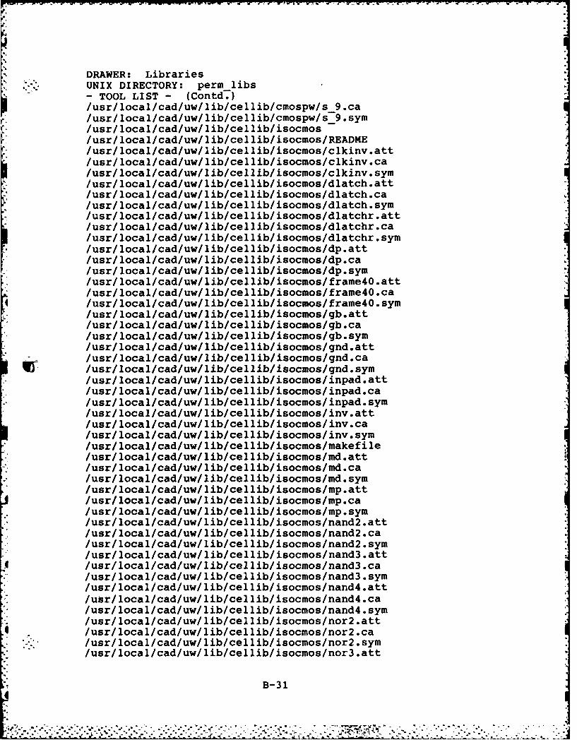
DRAWER: Libraries* UNIX DIRECTORY: perm libs
-TOOL LIST - (Contd.)/usr/local/cad/uw/lib/cellib/cmospw/s_9.ca/usr/local/cad/uw/lib/cellib/cmospw/s_9.sym/usr/local/cad/uw/lib/cellib/isocmos/usr/local/cad/uw/lib/cellib/isocmos/README/usr/local/cad/uw/lib/cellib/isocmos/clkinv.att/usr/local/cad/uw/lib/cellib/isocmos/clkinv.ca/usr/local/cad/uw/lib/cellib/isocmos/clkinv. sym/usr/local/cad/uw/lib/cellib/isocmos/dlatch.att/usr/local/cad/uw/lib/cellib/isocmos/dlatch.ca/usr/local/cad/uw/lib/cellib/isocmos/dlatch.sym/usr/local/cad/uw/lib/cellib/isocmos/dlatchr.att
* /usr/local/cad/uw/lib/cellib/isocmos/dlatchr.ca/usr/local/cad/uw/lib/cellib/isocmos/dlatchr.sym/usr/local/cad/uw/lib/cellib/isocmos/dp.att
* /usr/local/cad/uw/lib/cellib/isocmos/dp.ca/usr/local/cad/uw/lib/cellib/isocmos/dp.sym
* /usr/local/cad/uw/lib/cellib/isocmos/frame4O.att/usr/local/cad/uw/lib/cellib/isocmios/framne4O.ca
4 /usr/local/cad/uw/lib/cellib/isocmos/framne4O.sym/usr/local/cad/uw/lib/cellib/isocmos/gb.att/usr/ local/cad/uw/ lib/cellib/isocmos/gb.ca/usr/local/cad/uw/lib/cellib/isocmos/gb.sym/usr/local/cad/uw/lib/cellib/isocmos/gnd.att/usr/local/cad/uw/lib/cellib/isocnos/gnd.ca
WI /usr/local/cad/uw/lib/cellib/isocmos/gnd.sym* /usr/local/cad/uw/lib/cellib/isocmos/inpad.att
/usr/local/cad/uw/lib/cellib/isocmos/inpad.ca/usr/local/cad/uw/lib/cellib/isocuios/inpad.sym
* /usr/local/cad/uw/lib/cellib/isocmos/inv.att/usr/local/cad/uw/lib/cellib/isocios/inv.ca/usr/local/cad/uw/ lib/cellib/isocuios/inv. syin/usr/local/cad/uw/lib/cellib/isocmos/iakefile/usr/local/cad/uw/lib/cellib/isocnios/md.att/usr/local/cad/uw/lib/cellib/isocmos/md.ca/usr/local/cad/uw/lib/cellib/isocmos/md.syi/usr/local/cad/uw/lib/cellib/isocmos/mp.att/usr/ local/cad/uw/lib/cellib/isocmos/mp.ca/usr/local/cad/uw/lib/cellib/isocmos/mp.sym/usr/local/cad/uw/lib/cellib/isocios/nand2.att/usr/local/cad/uw/lib/cellib/isocmos/nand2.ca/usr/local/cad/uw/lib/cellib/isocmos/nand2.sym
* /usr/local/cad/uw/lib/cellib/isocmos/nand3.att4 /usr/local/cad/uw/lib/cellib/isocios/nand3.ca
/usr/local/cad/uw/lib/cellib/isocios/nand3.syn/usr/local/cad/uw/lib/cellib/isocmos/nand4.att/usr/local/cad/uw/lib/cellib/isocmos/nand4.ca/usr/local/cad/uw/lib/cellib/isocmos/nand4.sym
* /usr/local/cad/uw/lib/cellib/isocios/nor2.att/usr/local/cad/uw/lib/cellib/isocmos/nor2.ca/usr/local/cad/uw/ lib/cellib/isocmos/nor2 .sym/usr/ local/cad/uw/ lib/cel lib/isocnios/nor3 .att
B -31

DRAWER: LibrariesUNIX DIRECTORY: perm-libs- TOOL LIST - (Contd.)/usr/local/cad/uw/lib/cellib/isocmos/nor3 .ca/usr/local/cad/uw/lib/cellib/isocmos/nor3.sym/usr/local/cad/uw/lib/cellib/isocios/nor4.att/usr/local/cad/uw/lib/cellib/isocnos/nor4.ca/usr/local/cad/uw/lib/cellib/isocnos/nor4.sym/usr/local/cad/uw/lib/cellib/isocmos/on.attlusri local/cad/uw/ lib/cellib/isocmos/on.ca/usr/local/cad/uw/lib/cellib/isocios/on.syu/usr/local/cad/uw/lib/cellib/isocmos/op.att/usr/local/cad/uw/lib/cellib/isocios/op.ca/usr/local/cad/uw/ lib/cellib/isocmos/op.sym/usr/local/cad/uw/lib/cellib/isocmos/outpad.att/usr/local/cad/uw/lib/cellib/isocmos/outpad.ca/usr/local/cad/uw/lib/cellib/isocmos/outpad.sym/usr/local/cad/uw/lib/cellib/isocmos/pvs.att/usr/local/cad/uw/lib/cellib/isocmos/pvs.ca/usr/local/cad/uw/lib/cellib/isocmos/pvs.sym/usr/local/cad/uw/lib/cellib/isocmos/rb.att/usr/local/cad/uw/lib/cellib/isocios/rb.ca/usr/local/cad/uw/lib/cellib/isocmos/rb.sym/usr/local/cad/uw/lib/cellib/isocmos/sel2inv.att
/usr/local/cad/uw/lib/cellib/isocmos/svd~iattc/usr/local/cad/uw/lib/cellib/isocios/svd~ivcay/usr/local/cad/uw/lib/cellib/isocmos/svd.sym/usr/local/cad/uw/lib/cellib/isocmos/trd.at/usr/local/cad/uw/lib/cellib/isocnos/tripd.cam/usr/local/cad/uw/lib/cellib/isocmos/tripad.sym/usr/local/cad/uw/lib/cellib/isocuos/tripadm.ca/usr/local/cad/uw/lib/cellib/isocuos/tripad.sya/usr/local/cad/uw/lib/cellib/isocmos/tripadm.sym/usr/local/cad/uw/lib/cellib/isocmos/vdidmtt/usr/ local/cad/uw/ lib/cellib/isocmos/vrdd~sa/usr/local/cad/uw/lib/cellib/isocmos/vdd.sym/usr/local/cad/uw/lib/cellib/isocmos/xo2.cat/usr/local/cad/uw/lib/cellib/isocnos/xor2.sy/usr/local/cad/uw/lib/cellib/isocmos/xor2.aym/usr/local/cad/uw/lib/rnhl/plo1 /or.
*/usr/local/cad/uw/lib/rnll/uwsmosxo2/usr/local/cad/uw/lib/rnl/uwstd.1
* /usr/local/cad/ulib/n/uwsbc./usr/local/cad/ulib/n/nvtcl
* /usr/local/cad/lib/bane/libac.ai/usr/local/cad/lib/bane/liblocl/usr/ local/cad/ lib/bane/sipple.c/usr/ local/cad/ lib/bane/siples .h/usr/local/cad/lib/bane/csetp.c/usr/local/cad/lib/bane/stipples.x
/usr/local/cad/lib/bane/aedcolors.h/usr/local/cad/lib/bane/cllmap.cmos
B- 32

DRAWE: LibrariesUNIX DIRECTORY: perm libs-TOOL LIST - (Contd.)/usr/local/cad/lib/bane/cl lmap.nrnos!usr/ local/cad/ lib/bane/cllmap.pmos/usr/local/cad/lib/bane/s-ext.cll/usr/local/cad/ lib/bane/ libs .cifIusr/ local/cad! lib/bane/cifmap.cmos/usr/ local/cad! lib/bane/cifmap.nnos/usr! local/cad! lib/bane/cifniap.dmos/usr/ local/cad! lib/bane/cifrnap.pmos/usr/ local/cad! lib/bane/font.h/usr/ local/cad/lib/bane/font.GouldB/usr/local/cad/lib/bane/libs. lib/usr/local/cad/lib/bane/READ ME/usr/local/cad/lib/clay/ciflfb/H bothdiff/usrl local/cad! lib/clay/ciflib/V -bothdiff/usr/loca 1/cad! lib/clay/ciflib/bottoidiff/usr/ local/cad! lib/clay/ciflib/diff/usr! local/cad! lib/clay/ciflib/dpcontact/usr! local/cad! lib/clay/ciflib/dpcontacthd/usr/ local/cad! lib/clay/ciflib/dpcontactvd/usr! local/cad! lib/clay/ciflib! leftdiff!usr/local/cad/lib/clay/ciflib/rndcontact/usr! local/cad/lib/clay/ciflib/netal!usr! local/cad! lib/clay/ciflib/mpcontact
quo usr! local/cad! lib/clay/cif lib/poly/usr/ local/cad! lib/clay/ciflib/pulldown/usr! local/cad! lib/clay/ciflib/pulldownr/usr/ local/cad! lib/clay/ciflib/pullup/usr/ local/cad! lib/clay/ciflib/pul lupvg!usr! local/cad! lib/clay/ciflib/rightdiff/usr/ local/cad! lib/clay/ciflib/topdiff/usr! local/cad! lib/earl/CMOS.head/usr/local/cad/lib/earl/CI4OS.head.cif!usr! local/cad! lib/earl/NMOS.head/usr/local/cad/lib/earl/Nt4OS.head.old/usr/ local/cad! lib/earl/clap/usr/local/cad/lib/earl/cnos/usr/ local/cad! lib/earl/cpads .e/usr! local/cad! lib/earl/nmos!usr! local/cad! lib/earl/npadexaip.e!usr/ local/cad! lib/earl/npads .e/usr! local/cad! lib/earl/old/usr/ local/cad! lib/earl/outpad .cif/usr/ local/cad! lib/earl/patterns!usr! local/cad! lib/earl/river.e!usr/ local/cad! lib/earl/sospads.e/usr/local/cad/Iib/earl/test .head!usr! local/cad! lib/earl/tripad .cif/usr/local/cad/stanford/src/PIPELINE83/SRC/CIF/TEST/CMOS
- /pmostest.cif/usr/local/cad/stanford/src/PIPELINE83/SRC/CIF/TEST/CMOS
/RESULTS/pmostest .co
B- 33

L DRAWER: LibrariesUNIX DIRECTORY: perm libs
T OOL LIST - (Contd.)/usr/local/cad/stanford/src/PIPELINE83/SRC/CIF/TEST/CMOS
/RESULTS/cmostest. Co* /usr/local/cad/stanford/src/PIPELINE83/SRC/CIF/TEST/CMOS
/crnostest.cif/usr/loca:/cad/stanford/src/PIPELINE83/SRC/CIF/TEST/NMOS
/RESULTS/nmostest .co* /usr/ local/cad/stanford/src/PIPELINE83/SRC/CIF/TEST/N4OS
/nmostest .cif/usr/ local/cad/stanford/src/PIPELINE83/SRC/CIF/cif/usr/ local/cad/stanford/src/PIPELINE83/SRC/CIFLOAD/TEST
/NMOS/RESULTS/nmostest .cif/usr/local/cad/stanford/src/PIPELlNE83/SRC/CIFLOAD/TEST
/NMOS/nmostest .ci/usr/ local/cad/stanford/src/PIPELINE83/SRC/CIFLOAD/TEST
/CMOS/RESULTS/cmostest .cif/usr/local/cad/stanford/src/PIPELINE83/SRC/CIFLOAD/TEST
/CMOS/cmostest .ci/usr/local/cad/stanford/src/PIPELINE83/SRC/CLL2/cllmap.cmos
* /usr/local/cad/stanford/src/PIPELIt4E83/SRC/APLOT/TEST/nmostest.co
/usr/ local/cad/stanford/src/PIPELINE83/SRC/RPLOT/TEST/cmostest .co
/usr/ local/cad/stanford/src/PIPELINE83/SRC/RPLOT/cmos ts .cll/usr/local/cad/stanford/src/PIPELINE83/SRC/RPLOT/rrplot.bin/usr/local/cad/stanford/src/PIPELINE83/SRC/RPLOT/cnostest.co/usr/local/cad/stanford/src/PIPELINE83/SRC/RPLOT/old rplt.bin/usr/local/cad/stanford/src/PIPELINE83/SRC/RPLOT/rrplot.bin.deb/usr/local/cad/stanford/src/PLAGEN/PLA/TEST/test.pla/usr/local/cad/stanford/src/PLAGEN/PLAGUE/TEST/test.plg/usr/local/cad/stanford/src/PLAGEN/PLAGUE/TEST/RESULTS/test.pla/usr/ local/cad/stanford/src/aedcolors .h/usr/ local/cad/stanford/src/stipples .x/usr/ local/cad/stanford/cell libB3/usr/ local/cad/stanford/celllib83/libs.ciflusri local/cad/stanford/lib/ libacc.a/usr/ local/cad/stanford/ lib/ liblocal .a
DRAWER: StatisticsUNIX DIRECTORY: perm stats
-TOOL LIST-
DRAWER: SchedulesUNIX DIRECTORY: perm-sched
-TOOL LIST -
0 -DRAWER: Design Data* UNIX DIRECTORY: perm-data
-TOOL LIST-
B- 34

DRAWER: Source Code* . UNIX DIRECTORY: perm-sources
- TOOL LIST-/usr/local/cad/starkford/src/DRC83/Makefile.bac
* /usrl local/cad/stanford/src/PIPELINE83/SRC/CIF/Makefile/usr/local/cad/stanford/src/PIPELINE83/SRC/CIF/Protomake.bak/usr/local/cad/stanford/src/PIPELINE83/SRC/CIF/Makefile.bak/usr/local/cad/stanford/src/PIPELINE83/SRC/CIF/Protomakej/usr/local/cad/stanford/src/PIPELINE83/SRC/CIFLOAD/makefile/usr/local/cad/stanford/src/PIPELINE83/SRC/CIFLOAD/Protomake/usr/ local/cad/stanford/src/PIPELINE83/SRC/CLL2/tMakefile/usr/local/cad/stanford/src/PIPELINE83/SRC/CLL2/Protoiake/usr/ local/cad/stanford/src/PIPELINE83/SRC/APLOT/tMakefile/usr/local/cad/stanford/src/PIPELINE83/SRC/APLOT/Protomake/usr/local/cad/stanford/src/PIPELINE83/SRC/RPLOT/Protomake/usr/local/cad/stanford/src/PIPELINE83/SRC/RPLOT/Makefile/usr/local/cad/stanford/src/PLAGEN/PLA/Makefile/usr/local/cad/stanford/src/PLAGEN/PLAGUE/Makefile/usr/ local/cad/stanford/ lib/tMakefile
* /usr/local/cad/stanford/lib/tmake* /usr/local/cad/stanford/lib/Makefile.bak
/usr/ local/cad/bin/nnakeIusr/ local/cad/bin/makesm
* /usr/local/cad/include* /usr/local/cad/include/plap
/usr/ local/cad/ include/plap/gconst .h- . /usr/local/cad/include/plap/gtype.h
/usr/local/cad/include/plap/gvar.h/usr/local/cad/include/plap/rnacros.h/usr/local/cad/include/plap/primitive.h/usr/ local/cad/ include/plap/prog .h/usr/ local/cad/ include/plap/nodes .h/usr/ local/cad/include/plap/error.i/usr/ local/cad/include/plap/error .h/usr/local/cad/uw/include/usr/local/cad/uw/include/sys/usr/local/cad/uw/include/sys/on-consts.h/usr/local/cad/uw/include/sys/om -dmacros.h/usr/local/cad/uw/include/sys/om-oiacros.h
* /usr/local/cad/uw/include/plap3/usr/local/cad/uw/include/plap3/gconst.h/usr/local/cad/uwfinclude/plap3/gtype.h/usr/local/cad/uw/include/plap3/gvar.h/usr/ local/cad/uw/include/plap3/user.h/usr/local/cad/uw/include/plap3/setup.h
* /usr/local/cad/uw/include/plap3/attribute.h* /usr/local/cad/uw/include/plap3/bblocks.h
/usr/local/cad/uw/include/plap3/primitive.h/usr/local/cad/uw/include/plap3/macros.h
* /usr/local/cad/uw/include/plap3/nodes.h/usr/local/cad/uw/include/plap3/error.h/usr/local/cad/uw/include/plap3/nnos.h
* /usr/local/cad/uw/include/plap3/isocmos.h/usr/local/cad/uw/include/plap3/i2l.h
B- 35

DRAWER: Source CodeUNIX DIRECTORY: perm sources-TOOL LIST - (Contd.)/usr/local/cad/uw/include/plap3/i2ltype.h/usr/ local/cad/uw/include/plap3/ciospw.h/usr/ local/cad/uw/include/plap3/i2lext.h/usr/ local/cad/uw/include/plap3/nmosext.h/usr/local/cad/uw/include/plap3/isocmosext.h/usr/ ]ocal/cad/uw/include/plap3/cmospwext.h/usr/l]ocal/cad/uw/include/plap3/isocells .h/usr/ local/cad/uw/include/plap3/isopads .hlusri locallcad/lib/clay/PLA.c/usr/local/cad/lib/clay/PLA funcs.h/usr/ local/cad/ lib/clay/README/usr/local/cad/lib/clay/ext-def.h/usr/ local/cad/ lib/clay/ logic .c/usr/ local/cad/lib/clay/header.h/usr/local/cad/lib/clay/new def.h/usr/ local/cad/ lib/clay/ river.c/usr/ Jocal/cad/ lib/clay/clayread .h/usr/local/cad/lib/clay/trans.c
* /usr/local/cad/lib/clay/claywrite.h/usr/local/cad/ Jib/clay/sci.h/usr/local/cad/lib/clay/system -_NMOS.h/usr/ local/cad/ lib/clay/systeniheader-h/usr/ local/cad/ lib/clay/trace.h/usr/local/cad/lib/clayluser NMOS.h
~J. /usr/Jlocal/cad/ lib/clay/user-header.h/usr/local/cad/stanford/src/DRC83/bool .c/usr/ local/cad/stanford/src/DRC83/boolf .c/usr/ local/cad/stanford/src/DRC83/bsort .c/usr/ local/cad/stanford/src/DRC83/btopen.c/usr/local/cad/stanford/src/DRC83/butcondrop.c/usr/local/cad/stanford/src/DRC83/butconexp.c/usr/ local/cad/stanford/src/DRC83/cuosextr .c
* /usr/locaJ./cad/stanford/src/DRC83/conv.c/usr/local/cad/stanford/src/DRC83/cover.c/usr/ Jocal/cad/stanford/src/DRCS3/csort.c/usr/ local/cad/stanford/src/DRCB3/diodechk.c
9. /usr/local/cad/stanford/src/DRC83/errout.c/usr/local/cad/stanford/src/DRC83/exp.c/usr/ local/cad/stanford/src/DRC83/expand.c/usr/local/cad/stanford/src/DRC83/frontsort.c/usr/local/cad/stanford/src/DRC83/fullexp.c/usr/local/cad/stanford/src/DRC83/iopchk.c/usr/local/cad/stanford/src/DRC83/intersect.c/usr/local/cad/stanford/src/DRC83/isect exc.c/usr/local/cad/stanford/src/DRC83/mask.E/usr/local/cad/stanford/src/DRC83/nmosextr.c/usr/local/cad/stanford/src/DRC83/orcmos.c/usr/local/cad/stanford/src/DRC83/ornmos.c/usr/local/cad/stanford/src/DRC83/pnbuttcon.c/usr/ local/cad/stanford/src/DRC83/pplusdiff .c/usr/ local/cad/stanford/src/DRCB3/pwellchk .c
B- 36

DRAWER: Source CodeUNIX DIRECTORY: perm sources
-TOOL LIST - (Contd.)/usr/ local/cad/stanford/src/DRC83/rectexp.c/usr/local/cad/stanford/src/DRC83/rmbutcon.c/usr/local/cad/stanford/src/DRC83/sep.c/usr/ local/cad/stanford/src/DRCB3/separate .c/usr/local/cad/stanford/src/DRC83/sepchk.c/usr/local/cad/stanford/src/DRC83/sepdpbur.c/usr/local/cad/stanford/src/DRC83/sepdpch.c/usr/local/cad/stanford/src/DRC83/sepone.c
* /usr/local/cad/stanford/src/DRC83/shrink.c/usr/local/cad/stanford/src/DRC83/tranburied.c
* /usr/local/cad/stanford/src/DRC83/trandiff.c/usr/local/cad/stanford/src/DRC83/tranexp.c/usrl local/cad/stanford/src/DRC83/trdiff .c/usr/ local/cad/stanford/src/DRC83/trpol .c/usr/local/cad/stanford/src/DRC83/twocover.c/usr/local/cad/stanford/src/DRC83/twoint exc.c/usr/1ocal/cad/stanford/src/PIPELINE83/S7RC/CLL2/add depend.c/usr/local/cad/stanford/src/PIPELINE83/SRC/CLL2/c112.c
* /usr/local/cad/stanford/src/PIPELINE83/SRC/CLL2/cll2.h/usr/local/cad/stanford/src/PIPELINE83/SRC/CLL2/cll2b.c
* * /usr/local/cad/stanford/src/PIPELINE83/SRC/CLL2/cll2gram.c/usr/local/cad/stanford/src/PIPELINE83/SRC/CLL2/cll2gra'.h/usr/local/cad/stanford/src/PIPELINE83/SRC/CLL2/cll2gran.y/usr/local/cad/stanford/src/PIPELINE83/SRC/CLL2/cllopt.C/usr/local/cad/stanford/src/PIPELINE83/SRC/CLL2/cstartact.c/usr/local/cad/stanford/src/PIPELINE83/SRC/CLL2/diuensiofl.c/usr/local/cad/stanford/src/PIPELINE83/SRC/CLL2/intfunc.c/usr/local/cad/stanford/src/PIPELINE83/SRC/CLL2/matrix.c/usr/local/cad/stanford/src/PIPELINEB3/SRC/CLL2/newcll.c/usr/local/cad/stanford/src/PIPELINE83/SRC/CLL2/pwidth.c/usr/local/cad/stanford/src/PIPELINE83/SRC/CLL2/s ext.cll/usr/local/cad/stanford/src/PIPELINE83/SRC/CLL2/set ext.c/usr/local/cad/stanford/src/PIPELINE83/SRC/CLL:2/set pass.c/usr/local/cad/stanford/src/PIPELINE83/SRC/CLL2/switchtab.c/usr/local/cad/stanford/src/PIPELINE83/SRC/CLL2/yymain.c/usr/local/cad/stanford/src/PIPELINE83/SRC/CLL2/cllmap.nmos
* /usr/local/cad/stanford/src/PIPELINE83/SRC/CLL2/clluap.pmos/usr/local/cad/stanford/src/PIPELINE83/SRC/CLL2/ncll2.c/usr/ local/cad/stanford/src/PIPELINE83/SRC/CLL2/nnew.c/usr/ local/cad/stanford/src/PIPELINE83/SRC/CLL2/Protomake .bak
* /usr/ local/cad/stanford/src/PIPELINE83/SRC/CLL2/errorfile/usr/local/cad/stanford/src/PIPELINE83/SRC/CLL2/Makefile.bak
* /usr/local/cad/stanford/src/PIPELINE83/SRC/CLL2/acll2.c/usr/ local/cad/stanford/src/PIPELINE83/SRC/CLL2/aadd depend.c
* /usr/local/cad/stanford/src/PIPELINE83/SRC/CLL2/acll2.h* /usr/local/cad/stanford/src/PIPELINE83/SRC/CLL2/acll2b.c
/usr/local/cad/stanford/src/PIPELINE83/SRC/CLL2/acll2gram.c/usr/local/cad/stanford/src/PIPELINE83/SRC/CLL2/acll2gral.h
9 /usr/local/cad/stanford/src/PIPELINE83/SRC/CLL2/acll2gram.y/usr/local/cad/stanford/src/PIPELINE83/SRC/CLL2/acllOpt.c/usr/local/cad/stanford/src/PIPELINE83/SRC/CLL2/acstartact.c
B-37

DRAWER: Source CodeUNIX DIRECTORY: perm sources-TOOL LIST - (Contd.)/usr/local/cad/stanford/src/PIPELINE83/SRC/CLL2/adiiension.c/usr/local/cad/stanford/src/PIPELINE83/SRC/CLL2/aintfunc.c/usr/local/cad/stanford/src/PIPELINE83/SRC/CLL2/amatrix.c/usr/local/cad/stanford/src/PIPELINE83/SRC/CLL2/anewcll.c/usr/local/cad/stanford/src/PIPELINE83/SRC/CLL2/c112 h.bak/usr/local/cad/stanford/src/PIPELINE83/SRC/CLL2/apwiath.c/usr/ local/cad/stanford/src/PIPELINE83/SRC/CLL2/aset-ext.c/usr/local/cad/stanford/src/PIPELINE83/SRC/CLL2/aset pass.c/usr/local/cad/stanford/src/PIPELINE83/SRC/CLL2/ayyiain.c/usr/local/cad/stanford/src/PIPELINE83/SRC/BANE/concat.c/usr/ local/cad/stanford/src/PIPELINE83/SRC/BANE/err2co.c
* /usr/local/cad/stanford/src/PIPELINE83/SRC/BANE/bane.1/usr/local/cad/stanford/src/PIPELINE83/SRC/BANE/lock.c/usr/ local/cad/stanford/src/PIPELINE83/SRC/BANE/nktelp.c/usr/local/cad/stariford/src/PIPELINE83/SRC/BANE/window.c/usr/local/cad/stanford/src/PIPELINE83/SRC/BANE/xy2co.c/usnl local/cad/stanford/src/PIPELINE83/SRC/BANE/err2co.1/usr/local/cad/stanford/src/PIPELINE83/SRC/BANE/spathnames.h
-4 /usr/local/cad/stanford/src/PIPELINE83/SRC/BANE/IMakefile/usr/local/cad/stanford/src/PIPELINE83/SRC/BANE/Protomake/usr/local/cad/stanford/src/PIPELINE83/SRC/BANE/bane.c/usr/local/cad/stanford/src/PIPELINE83/SRC/BANE/err2co.1/usr/local/cad/stanford/src/PIPELINE83/SRC/BANE/xy2co.1/usr/ local/cad/stanford/src/PIPELINE83/SRC/BANE/README
IT /usr/local/cad/stanford/src/PIPELII4E83/SRC/BANE/ lex.yy.c/usr/local/cad/stanford/src/PIPELINE83/SRC/BANE/spathnames.hba/usr/local/cad/stanford/src/PIPELINE83/SRC/APLOT/aplot.c/usr/local/cad/stanford/src/PIPELINE83/SRC/APLOT/plot.c/usr/ local/cad/stanford/src/PIPELINE83/SRC/APLOT/plot.h
* /usr/local/cad/stanford/src/PIPELINE83/SRC/RPLOT/backupconcat.c/usr/ local/cad/stanford/src/PIPELINE83/SRC/RPLOT/blockout.c
* /usr/local/cad/stanford/src/PIPELINE83/SRC/RPLOT/coflvert.c
/usr/local/cad/stanford/src/PIPELINE83/SRC/RPLOT/mrplo.c/usr/local/cad/stanford/src/PIPELINE83/SRC/RPLOT/rspot.c/usr/local/cad/stanford/src/PIPELINE83/SRC/RPLOT/tlort.c/usr/local/cad/stanford/src/PIPELINE83/SRC/RPLOT/rpcont.c/usr/local/cad/stanford/src/PIPELINE83/SRC/RPLOT/windowv.c/usr/local/cad/stanford/src/PIPELINE83/SRC/RPLOT/fiont.ol/usr/local/cad/stanford/src/PIPELINE83/SRC/RPLOT/font.hold/usr/local/cad/stanford/src/PILEPL/SRac/RLTfn/usr/local/cad/stanford/src/PLAGEN/PLA/pas.
4 ~ /usr/local/cad/stanford/src/PLAGEN/PLA/plar.h/usr/ local/cad/stanford/lib/PLifout-ioplac/usr/ local/cad/stanford/lib/ckfout-n.c/usr/ local/cad/stanford/ lib/cwdp.c/usr/local/cad/stanford/ lib/cdt.c/usr/ local/cad/stanford/lib/dir.c/usr/local/cad/stanford/lib/findrgs/usr/local/cad/stanford/lib/flsbufg.c/usr/local/cad/stanford/lib/getaed.c
B- 38

DRAWER: Source CodeUNIX DIRECTORY: perm sources
-TOOL LIST - (Conitd.)/usr/ local/cad/stanford/lib/nialloc.c/usr/local/cad/starxford/lib/pathtail.c/usr/local/cad/stanford/lib/pen _plot.c/usr/local/cad/stanford/lib/permalloc.c/usr/ local/cad/stanford/ lib/scale.c/usr/ local/cad/stanford/ lib/ scanswitch .c/usr/local/cad/stanford/ lib/setext.c/usr/ local/cad/stanford/lib/stipples.c/usr/local/cad/stanford/ lib/stipples .h/usr/ local/cad/stanford/ lib/swtab.h/usr/local/cad/stanford/src/PIPELINE83/SRC/CIF/cif.c/usr/ local/cad/stanford/src/PIPELINE83/SRC/CIF/user act.c/usr/ local/cad/stanford/src/PIPELINE83/SRC/CIF/yymain.c/usr/local/cad/stanford/src/PIPELINE83/SRC/CIF/cif.h/usr/local/cad/stanford/src/PIPELINE83/SRC/CIF/cifgram.y/usr/ local/cad/stanford/src/PIPELINE83/SRC/CIF/scaiswitch.c/usr/ local/cad/stanford/src/PIPELINE83/SRC/CIF/cifgram.h/usr/local/cad/stanford/src/PIPELINE83/SRC/CIF/cifgram.c/usr/ local/cad/stanford/src/PIPELINE83/SRC/CIFLOAD/cifar.c/usr/ local/cad/stanford/src/PIPELINE83/SRC/CIFLOAD/cif load .c/usr/ local/cad/stanford/src/PIPELINE83/SRC/CIFLOAD/scifloader.c/usr/local/cad/stanford/src/PIPELINE83/SRC/CIFLOAD/splitfile.c/usr/ local/cad/stanford/src/PIPELINE83/SRC/CIFLOAD/cifload.h/usr/ local/cad/ stanford/src/PLAGEN/PLA/parse .y/usr/local/cad/bin/rrplot.c
DRAWER: Aux DataUNIX DIRECTORY: pern-aux-data- TOOL LIST -
/usr/local/cad/uw/ lib/usr/local/cad/uw/lib/libdb.a/usr/ local/cad/uw/ lib/libzgp.a/usr/ local/cad/uw/ lib/ libom.aIusr/ local/cad/uw/ lib/ libplap3 .a/usr/ local/cad/uw/ lib/ libplnmos .a/usr/local/cad/uw/lib/libpli2l .a/usr/ local/cad/uw/ lib/ libplisocmos .a/usr/local/cad/uw/lib/libplcnospw.a/usr/local/cad/uw/lib/libplisocell.a/usr/local/cad/uw/lib/libplisopad.a/usr/local/cad/uw/lib/psh/usr/local/cad/uw/lib/psh/cells.psh/usr/ local/cad/uw/ lib/psh/cmospw.psh/usr/local/cad/uw/lib/psh/12l.psh/usr/local/cad/uw/lib/psh/isocmos.psh
* /usr/local/cad/uw/lib/psh/nmos.psh/usr/local/cad/uw/lib/psh/pads.psh/usr/local/cad/uw/lib/technology
* /usr/local/cad/uw/lib/technology/nmos.tec
B- 39

DRAWER: Aux Data _ _I*UNIX DIRECTORY: perm-aux -data- TOOL LIST - (Contd.)/usr/local/cad/uw/lib/technology/nmos.cmp/usr/local/cad/uw/lib/technology/nmos. tec2/usr/local/cad/uw/lib/technology/cmospw.tec
* /usr/local/cad/uw/lib/technology/cmospw.cup/usr/local/cad/uw/lib/technology/cmospw.tec2/usr/local/cad/uw/lib/technology/i2l.tec
* /usr/local/cad/uw/lib/technology/isocmos.tec/usr/ local/cad/uw/ lib/technology/ isocmos .cmp/usr/local/cad/uw/lib/technology/isocmos.tec2/usr/local/cad/uw/bin/db2cif/usr/ local/cad/uw/bin/db7221/usr/ local/cad/uw/bin/db7580/usr/ local/cad/stanford/src/DRC83/mask.h/usr/ local/cad/stanford/src/DRC83/TEST/N4OS/Testburied.c11
* lusri local/cad/stanford/src/DRC83/TEST/N4OS/Testburied .co/usr/ local/cad/stanford/src/DRC83/TEST/N4OS/RESULTS
* /usr/local/cad/stanford/src/DRC83/TEST/NMOS/RESULTS/Test.drc/usr/local/cad/stanford/src/DRC83/TEST/NMOS/RESULTS/Testburied.drc/usr/local/cad/stanford/src/DRC83/TEST/COS/cmuos.cif/usr/local/cad/stariford/src/DRC83/TEST/CMOS/cmos.cll/usr/local/cad/stanford/src/DRC83/TEST/CMOS/cmos.co/usr/local/cad/stanford/src/DRC83/TEST/CMOS/RESULTS/Cmos.drc/usr/local/cad/stanford/src/PIPELINE83/SRC/BANE/errorfile/usr/local/cad/bin/nmos.tec/usr/local/cad/bin/nmos .cmp/usr/local/cad/bin/db7221
B-40

Appendix C: Source Code for a Partially ImplementedVLSI CAD Toolkit Custodian
A prototype VLSI CAD toolkit Custodian has been
designed to operate on the AFIT VAX 11/780. The custodian
has been implemented using two programs: 1) A UNIX "C-
Shell" script which contains the actual custodian code and
2) A program written in the "C" language designed to permit
the author of the custodian "script" to specially condition
the "script". The special conditioning is required so that
the toolkit components may be accessed only via the
custodian. Any attempts to read, write, or execute toolkit
components without use of the custodian will be denied. The
programs are presented in the two separate sections that
follow.
C-1
K.

Program 1: A "C-Shell" Custodian The program shown on
r- the following pages will function as the "custodian" for the
AFIT VLSI CAD Toolkit. This version is a prototype in the
truest sense of the word and is provided to illustrate the
structure and power of the toolkit custodian. To improve
the program readability, the source code is printed in
- small type so that each statement may be displayed on a
single line. Each line of the source code is numbered for
easy reference. The reader is cautioned to delete the line
numbers when transcribing the source to a format suitable
for execution.
l-
1'" C-24
* *- - . -*-. • -/ ° ., .. "" .., . .• "1".• .. %

I U! Ibn/csh2 1 CUSTODIAN Version 1.0 29 Nov 19943 1 Thomas R. Vermillion, Capt. USAF4 # AFIT/ENG Wright-Patterson AFB, Ohio5 # reset the terminal& setenv TERMCAP Ietcltrmcap7 tset ))& /dev/null9 # set interrupt, suspend and quit to be the same as interrupt to prevent9 # the user from interrupting the custodian
12 #interruption of the custodian is not permitted yet
13 onintr-14 # enable metacharacter filenase expansions15 unset noglob16 #17 alias cd cd # just in case there is a strange alias in user environI8 # set to ignore eof chars19 set ignoreeof20 121 clear22 echo ' AFIT VLSI CAD TOOLKIT CUSTODIAN - Version 1.0 - 22 September 1994'23 echo' '24 echo ' Unlocking VLSI CAD toolkit. There are 7 steps required.'25 echo' '26 echo '- STEP - Remarks'27 echo -n '- 01 - You are29 #29 130 #I-------- BEGIN VARIABLE INITIALIZATION AREA ----------31 # PATH TO TOP-LEVEL DIRECTORY FOR THE VLSI TOOLKIT32 set TOOLKIT z/usr/Iocal/cad/trv/vlsi tool kit33 #34 # FILE NAMES/PATHS35 set tempath z STOOLKIT/info storage/temp storage/temp data/%ft$36 set data -access z STOOLKIT/mgt tools/data -access37 set perm area a TOOLKIT/infostorage/pers~storage39 set templog z Stempath'.Iog*39 set permlog z dataaccess/'permanent.Iag'40 set permdoc z Spermarealpers doc
441 set securlog z$TO0LKIT/mgttos/data securitysecurity.log42 set toolkit -stats *Spermaremlperm stats/usage stats43 set bakgnd~ok-list $dataaccess/'bakgnd.list'44 145 # set users to contain a list of the FILENAMES46 # Nhich are of lists of users.47 set users ='cat $data-access/userlists'
- .49 1
49 # GET USER IDENTIFICATION50 set userid = 'whoami'51 echo Suserid
c- 3
..i 4- - .

* 52 153 echo -n '- 02 - Opening Toolkit Drawers54 i55 I TOOLKIT MANAGER IDENTIFICATION56 set @grid : 'hcarter'57 set egrname = 'Lt. Col H. Carter'58 set ngraddr a 'Bldg. 640, Room 2xx'59 set ngrphone z'255 - xxxx'60 #61 I STANDARD VARIABLES62 set true = t63 set false 064 set bell # t ASCII DELL character65 set main menu = '0'
66 set done main = Sfalse67 set done-skill x $false68 set done main-menu z false69 set access : 070 set skill z 071 set open-time z 'date'72 set printfil =73 set backgrnd =false74 # set the statistics75 # the stat file has two entries per statistic, the first entry is76 # the stat descriptor and the second is the stat value. The first77 # argument in the stat file is a descriptor.78 # the statistics variable structure is:
- 790 90 I stats(l) z 'Current Active Toolkit Sessions:'81 # stats(2) = number of active sessions
S92 # stats[3] z "Total Toolkit Sessions:'83 1 stats[4] = total number of sessions84 # stats(5] 'Total.Security.Violations;'85 1 stats(63 z total number of security violations86 set stats 'cat Stoolkit stats'87 #99 I TOOLKIT MANAGEMENT VARIABLES69 #90 # DUNY VARIABLES91 set dum-a = 092 set dumb z 093 set duo c = 094 set dud = 095 set dummy = '96 #97 set process S i process id of this invocation99 set toolselect z
" 99 set flagsu' 'S100 set infiles * '
101 set outfiles '102 set redirect =103 I104 I -------- END VARIABLE INITIALIZATION AREA -
+ 105 echo 'DONE.'
C-4
*, -.- . . *, ", .' . " . . .. . *.,... ... .,* - . .. *... ,,* .- ,-.- fl .. <.. *. N_',.. "q,_

L ' -" . . - - . . - ' '-. 9-- . " - - = .: ' -" - - - -" " "" "-'+ " "
106 1107 echo -n'- 03 - Session ID :108 set session id Sopentime(3]$open~tioe[2]$process109 echo $session-id110 echo -n '- 04 - Creating Session Log
111 I112 # open temporary log113 echo ' ' Itemplog114 echo 'S: ' >} $templog115 echo -n 'SESSION OPENED AT : ' Stemplog116 echo Sopentime ) Stemplog117 echo 'Session ID : 'session id ))Stemplog118 echo 'User ID : 'Suserid Stemplog119 echo 'User Terminal Type : 'STERN ) Stemplog120 echo 'User Directory : 'Scud )) $tesplog121 echo ' ' )) Stemplog
122 echo 'Opening status of system storage : ' )} Stemplog123 # save system status snapshot124 w Suserid )) Steeplog125 df )) Stemplog126 echo ' ' )) Stemplog127 1128 #129 echo 'TOOLKIT STATISTICS: At session opening :' )> Stemplog130 $loop through stat variables and save them131 @ duema z I132 while ($dumea (a Sstiats)133 *dum b = lduma I134 echo SstatslSdum a]' : 'Sstats[SduobI )) Steoplog135 1 duma a Sdum a + 2136 end I while loop137 # done with stat var save138 echo' ' )) Steplog139 echo 'DONE.'140 echo -n '- 05 - Testing Your Directory
141 i142 I Test to see if toolkit can access directory calling this143 I program if no access is allowed then error message144 I145 if !( -r Scd ) then146 set done main =Strue147 endif I test if user can read his directory148 #149 if !( -m Scud ) then150 set done main z $true151 endif I test if user can write to his directory152 #153 if !(done main) then154 echo 'DIRECTORY ACCESS VERIFIED.'155 else156 echo 'ACCESS DENIED : No access to CUD.' )) Stemplog157 set done main aStrue158 echo Sbell'INPROPER DIRECTORY ACCESS.'159 echo 'You must have READ & WRITE permission to Current Directory.'
c-5
• , - ,- 4% - . , C - ." .-. . .-. . . . . " . , . , , . + : , . . - -. . + . . , . , !

160 echo -n ' PRESS (RETURN> TO RETURN TO OPERATING SYSTEM -- >'
161 set dummy (10162 echo -n ' PLEASE WAIT DO NOT DEPRESS ADDITIONAL KEYS.'163 goto close-kit164 endif I CUD test165 I166 I167 if !(Sdone main then169 i Establish User access Level169 I170 1 Check each user LIST identified in the variable 'users'171 I
172 echo -n '- 06 - Toolkit Access is173 1 access - 0174 1 duoma = l175 1 dumeb = Susers # Number of user lists176 while ($duo a (z $duo b)177 i duoc = 'fgrep -x -c Suserid $data access/Suserstduo al'179 # if the user is in this list then give his access level of list179 if ($duoc >= 1) then18O 0 access = Sduoa191 endif182 1 duema z Sdue a +I183 end # while loop184 I185 if '($access) then-. I echo 'ACCESS DENIED. Not found in access lists.' )> Stemplog187 echo ' ' $securlog188 echo 'ILLEGAL ACCESS ATTEMPT : ' )> Ssecurlog189 echo ' User : 'Suserid >) Isecurlog190 echo ' Time : 'Sopentime >) $securlog191 echo ' Session Id : '$session-id )) Ssecurlog192 echo ' ' )) Ssecurlog193 set done main z $true194 # security violation - update stats195 0 stats[6) a $stats[C6 + 1196 echo $stats )! $toolkit stats I update the stat file197 echo -n Shell199 echo Sbell'DENIED.'199 echo 'You are not on the access list.'200 echo 'You must have pre-established access permission to use'201 echo 'the toolkit. To obtain toolkit access, you must do one'202 echo of the following:'203 echo ' 1: Send a request via system mail to user : 'Sogrid204 echo ' 2: Personally contact the following person:'205 echo ' '$sgrnaoe206 echo ' 'Sograddr207 echo ' 'Smgrphone208 echo''209 echo -n ' PRESS (RETURN) TO RETURN TO OPERATING SYSTEM -- >'
210 set dummmy ((" - 211 echo -n ' PLEASE WAIT .. DO NOT DEPRESS ADDITIONAL KEYS.'
212 goto closekit213 else
C-6

214 # new session - update stats
215 @ stats[2] = Sstats[2] + I # number of active users216 @ stats(41 Sstats[4] + I # total number of sessions217 echo $stats )! Stoolkit stats I update the stat file21 echo 'GRANTED, level : '$access219 echo 'Toolkit access granted, level : '$access >) Stemplog220 echo '- 07 - Toolkit is OPEN. Please record your session ID'221 echo ' for use in the event you must refer to this session.'222 echo223 echo -n Shell' PRESS (RETURN> and wait for menu.'224 set dummy = (1)225 echo -n ' PLEASE WAIT .. DO NOT DEPRESS ADDITIONAL KEYS.'226 endif laccess response messages227 endif # access test228 # NOW ALLOW USER INTERRUPTS .. BUT THEY JUMP TO GRACEFUL CLOSE229 onintr close kit230 #231 1 OBTAIN SKILL LEVEL232 set skill menu = '0'233 while ( !($done-skill) && !($done ain) )234 clear235 echo' SHH SK I L L EVEL eee '236 echo '237 echo ' 1. FIRST TIME User of Toolkit.'238 echo239 echo ' 2. SOMEWHAT FAMILIAR with Toolkit.'240 echo ''241 echo ' 3. VERY FAMILIAR with Toolkit.'242 echo '243 echo ' 4. EXPERT User.'
244 echo ' '245 echo ' '246 echo -n ' Enter Your Choice and press (RETURN> ->247 set skill menu = ($()248 I249 echo -n Sbell' PLEASE WAIT. DO NOT DEPRESS ADDITIONAL KEYS.'250 switch ($skill menu)251252 case '1':253 echo 'Skill select : level '$skillmenu )> Stemplog254 set skill = $skill menu255 set done skill zStrum256 breaks*257258 case '2':259 echo 'Skill select : level '$skillmenu }> Steeplog260 set skill = $skill menu261 set done skill = Strue262 breaksw263
- 264 case '3':265 echo 'Skill select : level '$skill-menu Stemplog266 set skill z Sskill menu267 set done skill $true
C-7
, . . , : . . .: . , .. •. • . ... ,. . .. . . .. . ..

268 breaksw269270 case '4':271 echo 'Skill select level '$skill menu )> $teeplog272 set skill = Sskill menu273 set done skill z Strue274 breaksw275276 default:277 echo 'Skill select : input error -> '4skill menu )> Stemplog278 clear279 echo ' - Skill selection help being provided.' )> Steeplog280 more -d $peredoclskillhelp
291 echo ' '282 echo -n ' Press (RETURN) to continue ->283 set dummy z (SO
284 echo'285 echo -n $bell' PLEASE WAIT. DO NOT DEPRESS ADDITIONAL KEYS.'286 breaksw287 ends # skill level288 #289 end # skill level while loop290 1291 1 MA IN MENU LOOP292 I
I 293 while ( !($done main menu) UI !($done main) I294 set main menu z '0'295 clear296 echo ' MIICICH N A I N M E N U *tf**@t4'297 echo '298 echo ' 1. EXIT and return to Unix.'299 echo '300 echo ' 2. EXECUTE a toolkit component.'301 echo ''302 echo ' 3. DISPLAY your directory contents.'303 echo ''304 echo ' 4. CHANGE your working directory.'305 echo ''306 echo ' 5. VIEW or PRINT a file.'307 echo '308 echo ' 6. Get HELP.'309 I310 1 user access to these menu options depends upon access level311 I312 if ($access 1) then313 echo314 echo ' 7. Generate REPORTS from the toolkit.'315 endif # access level > 1 options316317 if (Saccess >= 2) then
319 echo319 echo ' 8. Execute a toolkit UTILITY program.'320 endif I access >= 2321
S C-8
• . -.-.

322 if (Saccess)= 3) then323 echo ' '324 echo ' 9. MODIFY the toolkit.'325 endif I access level 3 option326 1327 echo ' '328 echo , ,329 echo -n ' Enter Your Choice and press (RETURN) -)330 set main-menu (S(
C,..331 1
332 echo''333 echo -n Sbell' PLEASE WAIT. DO NOT DEPRESS ADDITIONAL KEYS.'334335 #336 switch (nailm enu)337338 case 'I':339 echo 'Main select EXIT to Unix.' Stexplog340 set done-main aStrue341 goto close-kit342 breaksw343344 case '2':345 clear346 echo 'Main select : EXECITE tool described below: ' $templog
l -, 347 set command348 set component349 set infiles350 set outfiles351 set flags352 I for highly skilled users353 if ($skill )z 3) then354 echo 'Enter the complete command line for the component '355 set component - (S()356 # for the less experienced users357 else358 echo -n 'Enter the nome of the tool to execute -)359 set component a ($360 echo -n 'Enter the names of all input files ->
361 set infiles = ((10362 echo -n 'Enter the name of the output file ->
363 set outfiles (()364 echo -n 'Enter the command flags -)365 set flags Z (SO366 endif I skill ): 3367 echo368 echo -n Shell' PLEASE WAIT. DO NOT DEPRESS ADDITIONAL KEYS.'369 clear370 I have complete input now in the variable - command
q 371 set command = "lcomponent Vflags Sinfiles Soutfiles'372 echo $command >) Steplog
- 373 I test to see if allowed to execute this component374 I authorized lists maintained as 'toolsi' where the I
- 375 # represents the user access level
C-9
....................................... "."-..i':-:.. :" -" ' .- " -- -"':-'"•--: :" " " '" '-. - :. ":.+

376 set duoma 'fgrep -x -c Scomponent[l] IdataaccessltoolsSaccess'377 if ($duima) then378 echo ' - Execution Authorized.' )> $teoplog379 # nom see if tool exists
380 I381 set dum b = 'find STOOLKIT -name Scomponent(l] -print'
382 echo ' - Tool location is: ' Steoplog
383 echo ' - '$dub )) Stemplog384 if ( -e $dumb ) then
385 echo386 echo -n 'EXECUTE in the F(oreground) or BOackground) ?
387 set dummy a ($(
389 echo '
389 echo -n Sbell' PLEASE WAIT. DO NOT DEPRESS ADDITIONAL KEYS.'
390
391 switch (dummy)392 case 'F':
393 clear394 set backgrnd Sfalse
395 echo ' - Executing in foreground.' >) Stemplog396 echo 'Executing - '$cosponent(ll397 $command
399 echo ' - Execution coapleted, status ='$status )) Steoplog399 echo 'Execution completed, status = 'Istatus
400 breaksw I foreground
q401402 case 'B':403 clear
404 set duema = 'fgrep -x -c Sdumb $bakgndok list'
405 if ($dum-a) then
406 echo ' - Background Execution Authorized.' >) Stemplog
407 set backgrnd =Strue
408 echo ' - Executing in background.' )> Stemplog409 echo -n 'Executing in background : as Process Number -)'
410 Scomoand& I execute the job
411 else
412 echo ' - Background Execution NOT Authorized.' )> Stemplog
413 echo ' - EXECUTION ABORTED.' )) Stemplog414 echo SbelI'EECTION ABORTED. - Background Execution NOT Authorized.'
415 echo
416 echo -n ' Press (RETURN) to continue ->
417 set dummy = (418 echo
419 echo -n Sbell' PLEASE WAIT. DO NOT DEPRESS ADDITIONAL KEYS.'420 endif I see if background execution is ok
421 breaksw I background422
423 default:424 clear
425 echo ' - EXECUTION ABORTED. No User Selection.' )> $templog
426 breaksw I background default
427428 endsw I foreground or background
429 else I tool cannot be executed
C-10

430 clear431 echo 'Can not execute - 'Scomponent(li Stesplog432 echo 'Can not execute - 'Scomponentl]433 endif # -e duab existence test434 else I user is not authorized to execute this tool435 clear436 echo ' - Not an authorized execution - 'Scoaponent[l] )> Stemplog437 echo 'Not an authorized execution - 'Scoeponent(l]438 endif I due-a execution test439 echo440 echo -n ' Press (RETURN) to continue -'441 set dummy a ($S)442 echo ' ,443 echo -n $bell' PLEASE WAIT. DO NOT DEPRESS ADDITIONAL KEYS.'444 breaksw445446 case '3':447 echo 'Main select : DISPLAY directory.' )> Steeplog448 clear449 STOOLKIT/designtools/utilitiesldir -la : more -d # prints directory450 echo , ,451 echo -n ' Press (RETURN) to continue ->
452 set dummy = (S<)453 echo''454 echo -o $bell' PLEASE WAIT. DO NOT DEPRESS ADDITIONAL KEYS.'455 breaksw456457 case '4':458 # NOTE CANNOT USE SOME 'NILDCARD' SUBSTITUTIONS HERE459 echo 'Main select : CHANGE directory to >' ) Stemplog460 clear461 echo -n 'Enter NEW directory na -)'
* 462 set dummy : ($()463 echo464 echo -n $bell' PLEASE WAIT. DO NOT DEPRESS ADDITIONAL KEYS.'465 echo ' - '$dumey )) Steeplog466 if (Sduuay = '0') then467 set dummy : 'pod'468 endif I safety factor for only a return469470 if ( $duly 2= " ) then471 set dummy 2 SHONE472 endif I safety factor for only a tilde473474 if (Idumay . then475 set dully = 'pod'
476 endif i safety factor for only a period477470 if !( -r $dummy ) then479 clear490 echo ' - DIRECTORY CHANGE IGNORED : Cannot change.' ) Iteeplog481 echo402 echo Sbell'CHANGE IGNORED. Cannot change to selected directory.'483 else
C-11
~~~~~~..... ....... " ..- 1.... ...... .. - ,*. . ...... , . ... , . ..

484 cd $dummy485 echo486 echo 'Directory CHANGED to : '$dummy487 echo ' - Directory changed.' )) Stemplog
488 endif I read authorization test for new dir489 echo
490 echo -n ' Press (RETURN) to continue -)491 set dummy = (S(492 echo '
493 echo -n $bell' PLEASE WAIT. DO NOT DEPRESS ADDITIONAL KEYS.'
494 breaks**495
496 case '5':
497 clear498 echo 'Main select : VIEW or PRINT files' >) Stemplog499 echo -n 'Do you wish to V(iew) or P(rint) files? -)'
500 set dummy = (S<)501 echo -n $bell' PLEASE WAIT. DO NOT DEPRESS ADDITIONAL KEYS.'502 switch ($dummy)503504 case 'P': I UPPER CASE REQUIRED FOR ACCURACY505 echo 'Main select : PRINT file listed below:' >) Steplog506 clear507 echo 'Enter the exact name(s) of the filels) you wish to print and press (RETURN).508 echo509 set prntfile IS)510 echo ''511 echo -n $bell' PLEASE WAIT. DO NOT DEPRESS ADDITIONAL KEYS.'512 clear513 if (!!prntfile == '0') then I invalid request514 echo 'You should enter a filename.'Ibell
515 echo ' - NO filename arguments.' )) Steeplog516 else517 echo ' - 'Sprntfile )) Stemplog519 I test to see if user has read access before printing519 foreach duema ($prntfile)520 if ( -r $duema ) then521 # print only ordinary files522 if I -f $duea ) then523 echo ' - Printing.' >) Stemplog524 echo 'Printing -525 echo -n ' - '4du a526 vpr $duo a527 echo ' - DONE PRINTJN.'Sbell526 echo ' - DONE Printing.' )) Stemplog
529 else530 echo ' - PRINT ABORTED: File is not printable.' )) Steplog
531 echo ' - PRINT ABORTED: File is not printable.'Sbell532 endif I printable test for file533 else
534 echo 'PRINT ABORTED: You may not read the specified file.'$bell535 echo ' - PRINT ABORTED: User does not have read access to specified file.' )> $teplog536 endif I read access test537 end Iforeach file name entered
C-12
" ." -"- .-- --'.'-." .:- ,")."-"- ."- ."-"'"" '"'"'"'•."-'.'- -'--''-"-' ':: . -'-'" "'4 - - '.,%

[, 7 T.W- . - . -
538 endif I number of filenaes entered539 echo540 echo -n ' Press (RETURN> to continue ->541 set dummy ($S)542 echo''543 echo -n $bell' PLEASE WAIT. DO NOT DEPRESS ADDITIONAL KEYS.'544 breaksw I print545
546 case 'V': I UPPER CASE REQUIRED FOR ACCURACY
547 echo 'Main select : VIEW files listed below:' )) Stmplog548 clear549 echo 'Enter the exact name(s) of the file(s) you wish to view and press (RETURN). '
550 echo551 set viefile = ($<)552 echo ' '
553 echo -n Sbell' PLEASE WAIT. DO NOT DEPRESS ADDITIONAL KEYS.'554 clear555 if ( $ivieofile :: '0' ) then I no arguments556 echo 'You should enter a filenae.'ibell557 echo ' - NO filename arguments.' )) Stemplog558 else
559 echo ' - 'Sviewfile )> Stemplog560 1 test to see if user allowed to view the files561 foreach duema (Sviewfile)562 if ( -r $dumsa ) then
q , 563 I view only ordinary files564 if ( -f $duema I then565 echo ' - Viewing. ' >> Stemplog566 echo 'VIEWING : 'Sdum-a567 more -d Sduma568 echo ' - DONE Viewing.' )) Stemplog569 else570 clear571 echo ' - VIEW ABORTED: '$dum a' is not ASCII.' >> Stemplog572 echo Sbell'VIEW ABORTED: 'Sdua' is not ASCII.'573 endif I printable test for file574 else575 clear576 echo Sbell'VIEW ABORTED: You may not view the specified file.'Sbell577 echo ' - VIEW ABORTED: User may not view the specified file.' >) Stemplog578 endif # read access test579 echo580 echo -n ' Press (RETURN> to continue -)
5o1 set dummy : (S(582 echo
583 echo -n Shell' PLEASE WAIT. DO NOT DEPRESS ADDITIONAL KEYS.'594 end I foreach duoa in dummy585 endif I number of filenames entered586 breaksw I view
-- 587589 default:599 echo 'VIEW or PRINT : Invalid option. You must use UPPER CASE.'590 echo 'VIEW or PRINT : Invalid option -> '$dummy >> Stemplog591 echo
C-13

592 echo -n ' Press (RETURN> to continue ->593 set dummy (S)
594 echo '
595 echo -n Shell' PLEASE WAIT. DO NOT DEPRESS ADDITIONAL KEYS.'596 breaks. i default view or print597 ends* I view or print598 breaksw I main case 5599600 case '6':601 echo 'Main Select : HELP' )) Stemplog602 set donelearn a Sfalse603 I HELP Menu604 while !(Sdonelearn)605 clear606 set infoselect z '0'
607 echo eeoe I NST RUC T IONS foe'608 echo609 echo ' 1. EXIT the HELP Node.'610 echo611 echo ' 2. Search UNIX Manuals by KEYWORD.'612 echo '613 echo 3. Read a particular UNIX manual entry.'614 echo615 echo 4. Read help information for a particular COURSE.'616 echo'617 echo , 5. Read HELP information for a particular TOOL.'618 echo '619 if (Saccess 1) then620 echo ' 6. Read HELP for toolkit REPORTS.'621 echo '622 endif # access ) I623 if (Saccess) 2) then624 echo ' 7. Read HELP for toolkit MODIFICATIONS.'625 echo ''626 echo ' B. Read HELP for toolkit UTILITY programs.'627 echo '628 endif I access ) 2629630 echo -n ' Enter Your Choice then press (RETURN) -'631 set infoselect (SO632 echo633 echo -n Sell' PLEASE BAIT. DO NOT DEPRESS ADDITIONAL KEYS.'634635 switch ( Sinfoselect636637 case '':638 echo 'Help Select : EXIT HELP' )) Stemplog639 set donelearn =Strum640 breaks*641642 case '2':643 echo -n 'Help Select : Unix Key Search using - ' ) Stemplog644 clear645 echo -n 'Enter Keyword(s) -)
C-14
4 , ' . .. - -.. . . " , ' " .. . . , .- - , .-. . - . . . . . , - , -, .^ .. .- - . , . .

- i . .- e .u: . ,. . .: < . : - .U _ .- . -, . • . - r , . . . . - .
646 set dummy (SO647 echo $dummy >) Steaplog649 clear649 echo 'Searching UNIX manuals ... please wait.'650 echo
651 man -k $duumy : more652 echo
653 echo -n ' Press (RETURN) to continue -)
654 set dummy a (SO655 echo ''656 echo -n Sbell' PLEASE WAIT. DO NOT DEPRESS ADDITIONAL KEYS.'657 breaks658659 case '3':660 echo -n 'Help Select : Read UNIX manual - ' )) Stemplog661 clear
662 echo -n 'Enter UNIX Manual 11 -)
663 set dummy = (S)664 echo $dummy )> Steeplog665 clear
666 echo 'Locating UNIX manual -) 'Sdummy' ... please wait.'667 echo668 man $dummy
669 echo
670 echo -n ' Press (RETURN) to continue -)
671 set dusy a (S)672 echo''
673 echo -a Shell' PLEASE WAIT. DO NOT DEPRESS ADDITIONAL KEYS.'674 breaks
675676 case '4':
677 echo -n 'Help Select : Course - ' Stemplog678 clear
679 echo -n 'Enter Course ID ->680 set dummy = (S)681 echo $dummy )) Stemplog682 clear
683 echo 'Searching for HELP for course -> '$dummy' ... please wait.'684 echo ' '
685 if ( -e Spermdoc/Sdumy'.help' ) then686 clear
687 echo ' - HELP for course : '$dummy' presented.' )> Stesplog688 echo 'HELP for course -) '$dummy
689 echo ''690 more -d SperedcSdumy'.help'691 else
692 echo 'Help for course '$dummy' is not available.'693 echo ' - Help for course '$dummy' not available.' >> Stemplog694 endif I look for the help file695 echo''696 echo -n ' Press (RETURN> to continue ->
* 697 set dummy z (S)698 echo''
699 echo -n $bell' PLEASE WAIT. DO NOT DEPRESS ADDITIONAL KEYS.'
C-15

700 breaksw701702 case '5':703 echo -ni 'Help Select :Tool - ) tesplog704 clear705 echo -n 'Enter Tool Name -
706 set dummy =(SO)707 echo $dummy )) Stemplog709 clear709 echo 'Searching for HELP for tool - 'dummy' .. please wait.'710 echo'711 if I -e Speradoc/$dummy'_help' ) then712 clear713 echo '-HELP for tool : '$dummy' presented.' > Stemplog714 echo 'HELP for tool -) 'Sdummy715 echoI716 more -d Sperdoc/dumy'_help'717 else719 echo Sbell'Help for tool 'Suamy' is not available.'
4719 echo ' - Help for tool '$dummy' not available.' )) Stemplog720 endif I look for the help file721 echo722 echo -a Press (RETURN) to continue -
723 set dummy x ($(0724 echo725 echo -n $bell' PLEASE WAIT. DO NOT DEPRESS ADDITIONAL KEYS.'726 breaks*727729 case '6':729 if ($access M1 then730 echo 'Help Select : toolkit REPORTS ' )> Stemplog731 clear732 echo 'Locating HELP for toolkit REPORTS ... please wait.'733 echo'734 if ( -e $per mdoc /'reports~hel p' ) then735 clear736 echo '-HELP for REPORTS presented.' >> Stemplog
*737 echo 'HELP for REPORTS738 echo'739 more -d Spermdoc/'reportshelp'740 else741 echo SbelI'Help for REPORTS is not available.'742 echo ' - Help for REPORTS not available.' )> Stemplog
*743 endif # look for the help file744 echo745 echo -n 'Press <RETURN) to continue -
746 set dummy z (SO)747 echo749 echo -n Sbell' PLEASE WAIT. DO NOT DEPRESS ADDITIONAL KEYS.'749 endif # access ) I750 breakso751752 case '7':753 if (Saccess > 2) then
C-16

754 echo 'Help Select : toolkit MODIFICATIONS' Stemplog755 clear756 echo 'Locating HELP for toolkit MODIFICATIONS ., please wait.'757 echo758 if I -e $permdoc/'modshelp' ) then759 clear
760 echo ' - HELP for MODIFICATIONS presented.' >) Steeplog761 echo 'HELP for MODIFICATIONS
762 echo763 more -d $perdocl'modshelp'764 else765 echo Sbell'Help for MODIFICATIONS is not available.'766 echo ' - Help for MODIFICATIONS not available.' )) Stemplog767 endif I look for the help file768 echo769 echo -n ' Press (RETURN) to continue ->770 set dummy = (S
771 echo772 echo -n Sbell' PLEASE WAIT. DO NOT DEPRESS ADDITIONAL KEYS.'773 endif I access > 2774 breaksw775776 case '8':777 if ($access 2) then778 echo 'Help Select : toolkit UTILITIES' 5) $teaplog779 clear780 echo 'Locating HELP for toolkit UTILITIES ... please wait.'781 echo782 if ( -e tpermdocl'utilshelp' I then783 clear784 echo ' - HELP for UTILITIES presented.' >) Stesplog795 echo 'HELP for UTILITIES786 echo787 more -d $peredoc/'utilshep'788 else789 echo Sbell'Help for UTILITIES is not available.'790 echo ' - Help for UTILITIES not available.' > Stemplog791 endif # look for the help file792 echo''793 echo -n ' Press (RETURN> to continue ->794 set dummy = ((795 echo''796 echo -n Sbell' PLEASE WAIT. DO NOT DEPRESS ADDITIONAL KEYS.'797 endif I access > 2798 breaksw 7
799 endsm I help menu switch
r00 end I help menu while loop801 breaksw I main menu switch for HELP802 1
903 i back to main menu case choices- 904 I
805 case '7':806 set donereportz Sfalse807 if (faccess 1) then
c-17
4.
.-% .' .,, ". •. * . % .- .... . .- . -.. , ,- - -* . , .. • . I -,. ."•• • x > " ... . . 'o

808 while !($donejeport)809 clear810 echo 'Main select: - Generate REPORTS.' )>Stemplog811 i REPORTS MENU812 set reptselect x '0'913 echo ' 0eee TOOLKIT REPORT MENU #ite'814 echo815 echo '
816 echo ' 1. USER ACTIVITY report for specific users.'817 echo ' ,818 echo ' 2. SESSION count for particular month.'819 echo ' '820 echo ' 3. EXIT report menu.'821 echo ' '822 echo -n ' Select ONE option then press (RETURN) ->
823 set reptselect x (SO924 echo -n Shell' PLEASE WAIT. DO NOT DEPRESS ADDITIONAL KEYS.'825 switch (Sreptselect)826827 case 'I':828 echo 'Report select : USER ACTIVITY' )> Stemplog829 clear830 echo 'Enter the complete path to filenam with target users.'831 set duoa832 set due a = (S()833 echo''834 echo -n 'Please wait ... reading your list -
835 if (Sdum a 0) then836 if ( -e $duema) then837 set dum b = 'cat Sduema'838 echo 'DONE.'839 I open a temp file to hold report840 echo ' ece USER ACTIVITY REPORT *eeeee' >) Stempath'.act'841 echo ' ' )> Stepath'.act'842 echo -n ' As of ' )) Steopath'.act'843 date )) Stempath'.act"844 echo ' ' )) Stepathl.act"845 echo 'User ID Activity' )) Stempath'.act'846 echo ' ' )) Stempath'.act'847 I send the report to user terminal848 clear849 echo ' ccciii USER ACTIVITY REPORT iiiici'850 echo851 echo -n ' As of852 date853 echo954 echo 'User ID Activity'955 echo856 foreach dumc (duomb)857 set due d = 'fgrep -x -c 'User ID : 'Sduoc Sperolog'858 echo $duoc' 'dumd )) Stempath'.act'
859 echo Sduomc' 'dum-d860 end I foreach961 echo''
C-18
.. .

"* " 862 echo -n 'PLEASE WAIT - printing report -'
863 vpr Steepath'.act'864 echo Sbell'DONE.'
865 echo ' - Report completed.' )> Iteoplog866 else867 echo Sbell'Cannot open your user list.'868 echo ' - Cannot open user list.')> Stemplog869 endif I read user list
870 else I not enough arguments871 echo Sbell'NO FILE NAME of users to examine.'872 echo ' - NO FILE NAME of users to examine.' )>) Stemplog873 endif #arguments test074 echo''
875 echo -n ' Press (RETURN> to continue ->876 set dummy = (SO
877 echo878 echo -n Sbell' PLEASE WAIT. DO NOT DEPRESS ADDITIONAL KEYS.'
879 breaks.
880981 case '2':
882 echo - 'Report select SESSION COUNT for - ' Steplog
883 clear884 echo -n 'Enter the three-letter abbreviation for month -,
885 set duea = (SO
886 echo '
i 887 echo Sduea >> Stemplog
888 set dumb a 'egrep -c 'Session ID : ..'Sduima $permlog'
889 echo''890 echo 'There were '$duomb' sessions in 'Sduoma >> Stemplg891 echo 'There were '$dumob' sessions in 'Sduma
892 echo''893 echo -n ' Press (RETURN> to continue ->994 set dummy (SO)895 echo896 echo -n $bell' PLEASE WAIT. DO NOT DEPRESS ADDITIONAL KEYS.'
097 breaks.898
899 case '3':900 set done report Strue
901 echo 'Report select: - EXIT.' >) Stemplog
902 breaks. I exit report menu903904 default:905 echo 'Report select : INVALID selection.' >> Stemplog906 breaks.907 ends. I report menu908 end # report while loop
909 endif I access ) I910 breaksw
911912 case '8':
913 I UTILITIES MENU914 if (Saccess >2) then
915 clear
C-19

916 set utilselect '0'917 echo # iee UT L IT Y P R06 R AH NE NU #ee#919 echo919 echo920 echo '1. ADD to An Authorized User List'921 echo'922 echo ' 2. DELETE from An Authorized User List'923 echo''924 echo ' 3. VIEW Toolkit STATISTICS'925 echo926 echo'927 echo -n 'Select ONE option then press (RETURN) -
928 set utilselect =(SO)929 echo -n $bell' PLEASE WAIT. DO NOT DEPRESS ADDITIONAL KEYS.'930 switch (tutilselect)931 case '1':932 echo 'Util Select : ADD to User List' >> Stemplog933 clear934 echo -n 'Additions filename -
935 set dummy =(SO936 echo ' - Additions list is :'$dummy )) Stemplog937 echo 'Please Wait. Testing List.'939 if ( -r $dummy) then939 set due -a z 'cat $dummy'940 echo -n 'List Read. Add these users to access level (1-3) -
941 set dummy =(SO3942 echo '-Add to user list f or level '$dummy >> Stemplog943 clear944 echo 'PROCESSING ADDITIONS :Please Wait.'945 echo946 foreach duemb ($duma)947 set duomc 'fgrep -x -c $duo b $data access/SsersCSdumey]'948 if (Sdumc <1) then949 echo idum b )) $data access/SusersCtdummy]950 echo *dumb' - added to 'SusersCSdummy]951 echo $duom)' added to 'SusersCSdummy] )) Stemplog952 else953 echo *dusmb' - ignored ... already in list.'954 endif I duomc test955 end I foreach dum-b956 echo957 echo 'Additions Completed.'Sbell958 echo '-Additions Completed.' )> Stemplog959 else960 echo 'ADD ABORTED: Could not read specified file.'Sbell961 echo 'ADD ABORTED: Could not read specified file.' >) Stemplog962 endif I test for read access963 echo964 echo -n 'Press (RETURN> to continue -
965 set dummy =(S(O966 echo'967 echo -n Ibell' PLEASE WAIT. DO NOT DEPRESS ADDITIONAL KEYS.'968 breaks.969
C- 20

970 case '2':971 echo 'Util Select : DELETE from User List' >) Stemplog972 clear973 echo -n 'Deletions filename ->
974 set dummy -(- )975 echo 'Please Wait. Testing list.'976 echo ' - Deletion list is: '$dummy )) Stemplog977 if ( -r $dummy) then978 set duma = 'cat $dummy'979 echo -n 'List Read. What access level (1-3) are these users ->
980 set dummy = ()981 echo ' - Delete from user list for level '$dummy > Steoplog
982 clear983 echo 'PROCESSING DELETIONS. Please Wait.'984 echo ' '
985 set dum-b 'cat Sdata access/users[Sdummy]'986 echo -n ' ' > $tempath'.lst' i create a temp list
987 foreach dumic (Mduia)988 foreach duemd ($dumb)989 if (Mduid :Idugc then990 echo ' - '$due c' deleted.' )) $templog991 echo Sdum c' - deleted.'
992 else993 echo $duod )> *tempath'.lst'994 endif I duemd test995 end # foreach duo d
996 set dum b z 'cat $tempath'.st"997 re -f Stempath'.lst'998 end i foreach duoc999 rm -f $dataaccessSuserstidumy]1000 echo $dueb > Sdatamaccess/lusers[Sdummy]1001 echo 'Deletions Completed.'1002 echo ' - Deletions Completed.' )) Stemplog1003 else1004 echo 'DELETE ABORTED: Could not read specified file.'Sbell
1005 echo 'DELETE ABORTED: Could not read specified file.'>) $teeplog
1006 endif I read access test
1007 echo ' '
1008 echo -n ' Press (RETURN> to continue -)
1009 set dummy (1)1010 echoloil echo -n $hell' PLEASE WAIT. DO NOT DEPRESS ADDITIONAL KEYS.'
1012 breaksw10131014 case '':1015 echo 'Util Select: VIEW Statistics' > Stemplog1016 clear1017 echo -n 'TOOLKIT STATISTICS: As of1018 date1019 echo ' ' Steoplog1020 echo -n 'TOOLKIT STATISTICS: As of ' >) $templog1021 date >) Stemplog1022 echo1023 1 duoa I
C-21
~ . "..

1024 while Sdum a (: Sstats)
1025 1 duemb = $duma + l11026 echo Sstats[ldum a]' : '$stats[iduemb]
1027 echo Istatst(dum a]' : '$statstS1deb1 )) Stemploq1028 e due a = $duea + 21029 end I while loop1030 echo '
1031 echo -n ' Press (RETURN) to continue -)1032 set dummy =(3)
1033 echo1034 echo -n Shell' PLEASE WAIT. DO NOT DEPRESS ADDITIONAL KEYS.'1035 breaks*
10361037 default:1038 echo ' - No util menu selection.' ) Stemplog1039 breaksw # default util menu104010411042 ends. I utility menu switch1043 endif I access )= 21044 breaks* I main case 81045104610471048 case '9':
' 1049 # MODIFICATION MENU1050 if ($access) 2) then1051 clear1052 set modselect '0'1053 echo ' 0*4D MODIFICATION XENU f*1*'1054 echo '
1055 echo1056 echo ' 1. ADD a toolkit component.'1057 echo1058 echo ' 2. DELETE a toolkit component.'1059 echo1060 echo ' 3. MOVE a toolkit component.'1061 echo '1062 echo '1063 echo -n ' Select ONE option then press <RETURN) -'1064 set modselect (1(1065 echo -n $bell' PLEASE WAIT. DO NOT DEPRESS ADDITIONAL KEYS.'1066 switch ($modselect)10671068 case 'I':1069 clear1070 echo 'Nods select: ADD component.' )) Stemplog1071 echo 'Enter complete current path to component:'1072 set dum-a (()1073 echo 'Enter complete destination path for component:'1074 set dueb :(10)1075 if ( -r $duema ) then1076 echo 'Adding new component:'1077 echo ' From: '$duema
C-22
* *. .- . . . . * * * °. . **

1078 echo ' To: '$dum b1079 echo 'Adding new component:' Steoplog1080 echo ' From: '$duia )> Steoplog1081 echo ' To: '$dum b )) $teoplog1082 cp $dumoa Sdumb1083 echo $bell' COMPONENT ADDED.'1084 endif I -r read test1085 echo ' '1086 echo -n ' Press (RETURN) to continue -)1087 set dummy % (S1088 echo1089 echo -n Shell' PLEASE WAIT. DO NOT DEPRESS ADDITIONAL KEYS.'1090 breaksw10911092 case '2':1093 clear1094 echo 'Nods select: DELETE component.' ) Stemplog1095 echo 'Enter complete current path to component:'1096 set duma z 1$()1097 if ( -t Sdum-a ) then1098 echo 'Deleting component: 'Sdum-a1099 echo 'Deleting component: 'Sdumsa )> Stemplog1100 echo -n 'ARE YOU SURE ? Ytes) N(o) -)1101 set dummy z ($)1102 switch (Sdumy)11031104 case Y':1105 echo 'Deletion verified.' ) Stemplog1106 rm -f Sduoma1107 echo Sduma' removed.'1108 echo Sduma' removed.' >) Stemplog1109 breaksw1110111 default:1112 echo 'CAPITAL Y not entered.'1113 echo 'Deletion ABORTED at user request.'1114 echo 'Deletion ABORTED at user request.' >) Steoplog1115 breaks*1116 endsw i dummy1117 else1118 echo 'Deletion ABORTED : Could not delete.' >) Steplog1119 echo 'Deletion ABORTED : Could not delete.'1120 endif I -v write test1121 echo1122 echo -n ' Press (RETURN) to continue ->1123 set dummy z (W)1124 echo1125 echo -n Shell' PLEASE WAIT. DO NOT DEPRESS ADDITIONAL KEYS.'1126 breaksN11271128 case '3':1129 clear1130 echo 'Nods select: MOVE component.' )> Stemplog1131 echo 'Enter complete current path to component:'
C-23
. . . N.

1132 set dum-a ($<)1133 echo 'Enter complete destination path for component:'
1134 set dum-b =($()1135 if ( -r $duma ) then1136 echo 'moving component:'1137 echo ' From: 'Sduo a1138 echo ' To: 'dumeb1139 echo 'Roving component:' >> $teplog
1140 echo ' From: '$duma >) $templog
1141 echo ' To: '$duemb )) Stemplog1142 mv $dum a Sdueb1143 echo $bell'OVE COMPLETED.'1144 else1145 echo 'Hove ABORTED : Cannot read source.' )> $templog
1146 echo 'Hove ABORTED : Cannot read source.' )) $templog
1147 endif # -r read test1148 echo ' ,1149 echo -n ' Press (RETURN) to continue ->
1150 set dummy z ($()1151 echo I ,
- 1152 echo -n $bell' PLEASE WAIT. DO NOT DEPRESS ADDITIONAL KEYS.'
1153 breaks.11541155 default:1156 echo No mod menu selection.' ) Stemplog
1157 breaks* I default mods11581159 ends. I mod menu1160 endif I access ) 21161 breaks. I main menu case 911621163 default:1164 echo 'User being provided HELP with MAIN select.' )> Steplog
1165 clear1166 more -d Spermdoc/mainhelp1167 echo1168 echo -n ' Press (RETURN> to continue ->
1169 set dummy x((1
1170 echo1171 echo -n $bell' PLEASE WAIT. DO NOT DEPRESS ADDITIONAL KEYS.'
1172 breaks*11731174 ends. I main menu switch
*J 11751176 end I main menu while loop1177 I1178 I END OF MAIN SELECTION LOOP1179 11180 close kit: I label for jump after user interrupt of program1181 i #ose NEXT COMMAND REMOVES INTERRUPT CAPABILITY TO SHELL1182 6 UNTIL THE TOOLKIT IS CLOSED
* 1183 onintr -
1184 i1195 clear
C-24UJ

1196 if (Wmin menu I='' &&Mone main: '1') then
1187 echo 'I NT ER RU P TED0- YUSER' f)templog1198 echo fbell' I NT E RRU P TE D - YUSER'
* 1189 echo'*1190 endif I report interrupt
1191 echo ' Locking VLSI CAD toolkit. There are 5 steps required.'1192 echo1193 echo '-STEP - Remarks'1194 echo -n '-01 - Saving System Status
* ... 1195 echo ' )Stemplog
1196 echo -n 'SESSION CLOSED AT :'))teoplog1197 date )) Stemplog1199 w -u )> ttemplog
* 1199 echo ' >stemplog1200 echo 'Closing status of system storage : >Stemplog1201 df >) Stemplog1202 echo 'SAVED.'1203 echo -n '- 02 - Updating Statistics1204 if (Saccess) then1205 1 statsC?] = $stats[2l - I # number of active users reduced by I1206 endif # delete one user if there was a valid user session1207 echo Sstats ) Itoolkit stats # update the stat file1208 echo 'UPDATED.1209 echo -n '- 03 - Closing Session Log
*1210 echo ' ' Stemplog1211 echo 'TO0LKIT STATISTICS: At session close:' >> ftemplog1212 @Iduema =11213 while (6dum-a (z ffstats)1214 @ dum-b xdue-&+1I1215 echo Sstats(Idum-al' :'Sstats(Sdumb1 Stemplog1216 1 duma x dua + 21217 end I while loop1218 echo ' ) teaplog1219 if (Sbackgrnd) then
%1220 set dum-a z'ps'1221 echo $dum -a )) S templog1222 echo '') templog1223 endif # save process status to see what jobs were running1224 echo '- - )ftemp log1225 #1226 cat Stemplog )>Spermlog1227 echo 'DONE.' # closing the logs1229 1 remove all temporary files created during this session1229 echo -n 1- 04 -Removing Temporary Files
01230 #1231 ra -f 6tempatht1232 echo 'DONE.'1233 echo -n '- 05 -Returning control to the operating system ... '
1234 # end session - update stats1235 stty intr 'A?' susp '^l' quit ~\
61236 clear1237 if (Sbackgrnd) then1238 echo 'You initiated background jobs during this session'
* .1239 echo
C- 25

* 1240 echo 'Here is the status of your current processes:'1241 echo1242 echo Sdumla1243 echo '1244 endif I print process status just in case job is still running1245 I1246 I1247 # END OF CUSTODIAN 'C -SHELL I PRO6RAN
C-26. . ...,. . .'.. - .- . ,.. . . ., . . . .. . . . . . . . . . . . .,.... . .. . . . . .. . .. . , . ,.- .. -.". -. ,: ,. ., : ,., .: .' .. ,,'- .- .. ', .. - . ,* : , . *,,*. .. , -.. ' , .-. . .. - , ." ... , ,, . . : . , . _ .. . . .

Program 2: A "C" Program Used to Protect The Toolkit
The program listed below, written in the "C" language,
has been provided to this author courtesy of Mr Joe Hamlin,
AFIT/AD. The manager of the toolkit may effectively "hide"
the toolkit from direct access by other users by performing
two tasks: 1) giving read, write, and execute permission
for all toolkit components only to the "owner" of the custo-
dian script and 2) conditioning the custodian script with
the program provided below. The program, setu.c, condi-
tions a script by setting the script's user permissions so
that the script will respond to a user as if the user were
its "owner". In this way, users may access toolkit compo-
nents via the custodian and its "conditioned" permissions
even though the users do not possess operating system per-
missions to directly access toolkit components.
/*************** BEGIN setu.c ************/
main(argc, argv, envp)int argc;char *argv(], **envp;(char *strcat(;char cmd[100];
cmd[0]='\O';strcat(cmd, "/usr/local/cad/trv/vlsi toolkit/scr.");strcat(cmd, argv[0]);setgid(31);execve(cmd, argv, envp);3
/****************END setu.c ***************/
The implementation of this protection program is
. " .accomplished as shown below:
C-27
S " .- - .- .

[.r
1. Edit setu.c so that it contains the correctpath name to your script. Like:/usr/local/cad/trv/vlsi cad toolkit/scr.custodian.
2. The script should have a name likescr. name
3. The first line in the script must be#1 /bin/csh
4. Compile setu.c withcc -o setu setu.c
5. Set special protection bits withchmod 4711 setu
6. Move to the directory where the script is tobe used.
7. Type: "ln setu name". 'This links "setu" withthe script "name". When the script "name" isexecuted, it will execute as though the user hadownership permissions.
C-28
C.i4"
- - - - - - - . ">

Appendix D: Application of the Evaluation Metricsto the Prototype Custodian
AFIT VLSI CAD Toolkit Custodian Evaluation Formulas
The evaluation formulas and scales provided below, cop-
ied from chapter 5, have been used to evaluate the prototype
custodian detailed in Appendix C.
Drawer Component Evaluation Formula:
i
DCQ = [ EV(i) x CL(i)1(EQ 1)
n
Where :
U DCQ = Drawer Component Quality (overall)EV = Essentiality Value of characteristic
iCL = Characteristic Level of
characteristic in = Number of characteristics being
evaluated
Drawer Evaluation Formula:
4 i
DQ = [ EV(i) x DCQ(i) I
(EQ 2)n
Where -
DQ = Drawer Quality (overall)DCQ = Drawer Component Quality of drawer
component iEV = Essentiality Value of drawer
component in = Number of drawer components
D-1
:i ,:. i. i:.[ .. . [" i. . .,. .. . ,-.... . ... .... . . . * . -, . ... . . a, . .. , ., .. ., .

Toolkit Evaluation Formula:
i
TQ = [ EV(i) x DQ(i)
(EQ 3)n
Where :
TQ = Toolkit Quality (overall)DQ = Drawer Quality of drawer iEV = Essentiality Value of drawer in = Number of drawers
Evaluation Scales:
The scale shown below provides a measure of the essen-
tiality of a characteristic to the success of toolkit inte-
quo gration.
Essentiality Essentiality of CharacteristicValue (EV) To Successful Integration
32 Extremely important to success(Certain failure if missing)
16 Important to success(Probable failure if missing)
8 Fairly important to success(Possible failure if missing)
2 Has some impact upon success(No predictable impact uponsuccess if missing but lessthan optimum integration isprobable)
1 Slight impact upon success(No predictable impact uponsuccess if missing but lessthan optimum integration is
- certain)
D-2
<*::~c*:>.~ c. >~.* -

The scale shown below provides a measure of the pre-
sence of a desired characteristic.
Characteristic Degree to Which CharacteristicLevel (CL) is Present in this Component
3 The desired characteristic isentirely present.
2 The desired characteristic ismostly present.
1 The desired characteristic issomewhat present.
0 The desired characteristic iscompletely absent.
-1 Characteristics are presentwhich are somewhat detrimental
-2 Characteristics are presentwhich are very detrimental
-3 Characteristics are presentwhich are unacceptable
Evaluation of the Prototype Custodian:
The evaluation of the prototype custodian is provided
below. This evaluation is intended to illustrate the tech-
nique for evaluating drawer components as well as the
drawer itself. A comparison is provided between the maximum
possible scores and the scores computed based upon this
author's evaluation. The maximum possible Drawer Component
Quality (DCQ) for each drawer component was computed by
assigning the Characteristic Level (CL) value "3" (the high-
est possible value) to each characteristic being rated. The
41 maximum Drawer Quality (DQ) was computed using the maximum
possible DCQ for each component.
D-3
1- .

Component Evaluations:
A. Custodian - User Interface Components:
Component Description Rating Data
1. The custodian provides the only user in-terface to the toolkit.
EVDesired Component Characteristics EV CL xCL
la. No toolkit component can be viewed 16 3 48without custodian assistance.
lb. No toolkit component can be printed 16 3 48without custodian assistance.
ic. No toolkit component can be executed 32 3 96without custodian assistance.
id. No toolkit component can be moved or 32 3 96copied without custodian assistance.
Highest Possible DCQ: 72Overall Drawer Component Quality (DCQ): 72Essentiality Value (EV) for component: 32
Component Description Rating Data--------------------------------------------------- -------------2. The custodian provides the capability toeasily select toolkit components at anydesign level.
EV
Desired Component Characteristics EV CL xCL
2a. Selection of toolkit components is 8 1 8possible via a hierarchy of menus.
2b. Selection of components is adaptable 16 1 16to suit user familiarity with the toolkit(eg: fully menu-driven for novice andreduced menu presentation for expert).
2c. The custodian can provide access to 32 3 96all toolkit components.
2d. The custodian provides access to 16 2 32toolkit components with a minimum numberof user keystrokes.
D-4
!-

6m-
Highest Possible DCQ: 54Overall Drawer Component Quality (DCQ): 38Essentiality Value (EV) for component: 16
Component Description Rating Data
3. The custodian provides on-line help andaid to the user at each decision point.
EVDesired Component Characteristics EV CL xCL
3a. User help is available for the cus- 32 1 32todian-user interface.
3b. User help is available for each 8 1 8toolkit drawer.
3c. User help is available for each 16 1 16drawer component.
3d. User help is available at the user's 32 0 0request at any time prior to a responseto a custodian-generated question.
3e. User help for error resolution is 2 0 0YJ' available immediately following any error
condition arising from the execution of atoolkit component.
Highest Possible DCQ: 54Overall Drawer Component Quality (DCQ): 11.2Essentiality Value (EV) for component: 8
Component Description Rating Data
4. The custodian provides meaningful feed-back concerning user entries.
EVDesired Component Characteristics EV CL xCL
4a. The custodian echoes user inputs to 2 0 0* custodian-generated questions.
4b. The custodian requests user verifi- 16 2 32cation for "dangerous" requests (eg:deletion of a file).
+ 4c. The custodian identifies input er- 8 0 0rors to the nearest word containing theerror.
D-5
4 o - .- ".

EV
Desired Component Characteristics EV CL xCL
4d. Immediately following a user input 8 2 16the custodian advises the user that theinput is being processed.
4e. Custodian-generated error messages 16 2 32are complete sentences.
4f. Feedback is provided for each user 32 2 64requested action.
Highest Possible DCQ: 41Overall Drawer Component Quality (DCQ): 24Essentiality Value (EV) for component: 16
Component Description Rating Data
5. The custodian provides logical, syntacti-cal, and physical error detection as well asthe ability to recover from errors.
EVDesired Component Characteristics EV CL xCL
5a. The custodian permits the user to 16 0 0edit an input which contained an errorand does not require the user to re-enterthe entire input.
5b. The custodian screens all user input 16 1 16arguments for correctness prior to anyattempt to execute a toolkit componentwhich requires the input arguments.
5c. The custodian does not cease execu- 32 2 64tion if an error occurs in the user inputdata.
5d. The custodian does not cease execu- 32 2 64tion if a component aborts execution dueto an error.
5e. The custodian always ceases execu- 32 2 64tion in a "graceful" manner.
Highest Possible DCQ: 76.8Overall Drawer Component Quality (DCQ): 41.6Essentiality Value (EVI for component: 32
D-6

Component Description Rating Data
6. The custodian provides the capability toselect an interface display that matches userequipment.
EVDesired Component Characteristics EV CL xCL
6a. The custodian provides the user with 16 0 0the ability to select a terminaldefinition from a menu of terminals.
6b. The custodian provides a means for 16 0 0the user to test their terminalselection.
6c. The custodian will permit toolkit 32 3 96operation from a non-video terminal.
6d. The custodian permits the use of 8 3 24user-written custom terminal descrip-tions.
Highest Possible DCQ: 54Overall Drawer Component Quality (DCQ): 30Essentiality Value (EV) for component: 16
Component Description Rating Data
7. The custodian provides full access touser-selectable options in component tools.
EVDesired Component Characteristics EV CL xCL
7a. The custodian prompts the user for 8 2 16entry of the minimum number of argumentsneeded to execute a requested tool.
7b. The user is prompted for optional 8 2 16arguments when a tool execution is re-quested.
7c. No allowable tool option is filtered 32 3 96from the user input stream by thecustodian.
Highest Possible DCQ: 48Overall Drawer Component Quality (DCQ): 42.7
_ Essentiality Value (EV) for component: 32
D-7
4"

Component Description Rating Data
8. The custodian provides the ability toidentify user-selectable data required bycomponent tools.
EV
Desired Component Characteristics EV CL xCL----------------------------------------- ------ ---8a. The custodian permits the user to 32 3 96identify files containing data for useduring tool execution.
Highest Possible DCQ: 96Overall Drawer Component Quality (DCQ): 96Essentiality Value JEV) for component: 32
Component Description Rating Data
9. The custodian provides an interface thatis simple enough to service very inexperien-ced users and flexible enough to meet thedemands of expert users.
EVDesired Component Characteristics EV CL xCL
-- -- -- -- -- -- -- -- -- -- -- -- -- -- --- --- -- -_
9a. The custodian permits the user to 32 3 96identify their level of toolkit exper-tise.
9b. The custodian considers the user- 16 1 16identified level of toolkit expertise
. * each time a message is sent to the user"' terminal.
Highest Possible DCQ: 72Overall Drawer Component Quality (DCQ): 56Essentiality Value (EV) for component: 8
Component Description Rating Data
10. The custodian provides selectable levelsof input assistance.
EVDesired Component Characteristics EV CL xCL
---------------------------------------------------- --- --- ---10a. The custodian generates help mes- 32 0 0
-.. . saqes based upon the user-identifiedlevel of toolkit expertise.
D-80

Highest Possible DCQ: 96Overall Drawer Component Quality (DCQ): 0Essentiality Value (EV) for component: 8
Component Description Rating Data
11. The custodian provides meaningful feed-back during the execution of toolkit compo-nents.
EVDesired Component Characteristics EV CL xCL
-- -- -- -- -- -- -- -- -- -- -- -- -- -- --- --- -- -_
11a. The custodian signals the start of 16 2 32execution of any toolkit component.
lb. The custodian signals the comple- 16 2 32tion of the execution of any toolkitcomponent.
lc. The custodian advises whether or 32 1 32not any toolkit component execution wassuccessfully completed.
lid. The custodian signals the start and 2 0 0finish of every custodian activity.
9 Highest Possible DCQ: 49.5Overall Drawer Component Quality (DCQ): 24Essentiality Value (EV) for component: 8
Component Description Rating Data
12. The custodian provides command nameswhich may be customized for user convenience.
EVDesired Component Characteristics EV CL xCL
-- - - - -- -- - - - - - - -- - - - - - -- m--- ----
12a. The custodian permits the user to 32 0 0identify a series of ASCII characters tobe associated with a user-selected name.
12b. The custodian provides automatic 32 0 0substitution of user-specified characterswhenever a user-defined command is en-countered.
Highest Possible DCQ: 96
Overall Drawer Component Quality (DCQ): 0Essentiality Value (EV) for component: 2
D-9
.. . *

Component Description Rating Data--------------------------------------------------- -------------13. The custodian provides the ability toidentify a file of commands which are to beexecuted as though they were real-time userinputs.
EVDesired Component Characteristics EV CL xCL
13a. The custodian will read a user 32 0 0specified file and examine each line ofthe file as though it was a toolkit com-mand sequence.
13b. The custodian executes valid com- 32 0 0mands extracted from a user-specifiedfile as though they were input directlyfrom the user terminal.
Highest Possible DCQ: 96Overall Drawer Component Quality (DCQ): 0Essentiality Value (EV) for component: 2
Component Description Rating Data
14. The custodian provides the ability totailor output messages to include user speci-fied data.
EVDesired Component Characteristics EV CL xCL
-- -- -- -- -- -- -- -- -- -- -- -- -- -- --- --- -- -_
14a. The custodian provides the user 32 0 0with the ability to select additionalmessage data.
14b. The custodian includes user-select- 32 0 0ed additional output data in all custo-dian-generated messages to the user.
Highest Possible DCQ: 96Overall Drawer Component Quality (DCQ): 0Essentiality Value (EV) for component: 2
Component Description Rating Data
15. The custodian provides verification thatthe data and tools necessary to fulfill userrequests are available to the toolkit.
D-10
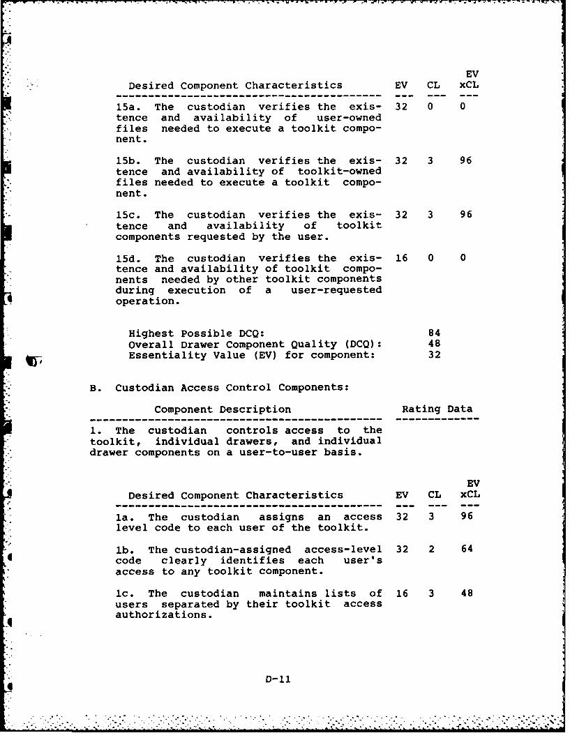
EVDesired Component Characteristics EV CL xCL
-- -- -- -- -- -- -- -- -- -- -- -- -- -- --- --- -- -_
15a. The custodian verifies the exis- 32 0 0tence and availability of user-ownedfiles needed to execute a toolkit compo-nent.
15b. The custodian verifies the exis- 32 3 96tence and availability of toolkit-ownedfiles needed to execute a toolkit compo-nent.
15c. The custodian verifies the exis- 32 3 96tence and availability of toolkitcomponents requested by the user.
15d. The custodian verifies the exis- 16 0 0tence and availability of toolkit compo-nents needed by other toolkit componentsduring execution of a user-requestedoperation.
Highest Possible DCQ: 84Overall Drawer Component Quality (DCQ): 48Essentiality Value (EV) for component: 32
B. Custodian Access Control Components:
Component Description Rating Data--------------------------------------------------- -------------1. The custodian controls access to thetoolkit, individual drawers, and individualdrawer components on a user-to-user basis.
EVDesired Component Characteristics EV CL xCL
-- -- -- -- -- -- -- -- -- -- -- -- -- -- --- --- -- -_
la. The custodian assigns an access 32 3 96level code to each user of the toolkit.
lb. The custodian-assigned access-level 32 2 64code clearly identifies each user's
access to any toolkit component.
Ic. The custodian maintains lists of 16 3 48users separated by their toolkit accessauthorizations.
D-11

EV
Desired Component Characteristics EV CL xCL
id. The custodian permits the users with 16 3 48authorization to modify toolkit compo-nents with the ability to modify the useraccess lists.
Highest Possible DCQ: 72Overall Drawer Component Quality (DCQ): 64Essentiality Value (EV) for component: 32
Component Description Rating Data
2. The custodian verifies a potential user'saccess authorizations in a manner that doesnot reveal the method used to determine ac-cess nor the access authorizations of othertoolkit users.
EVDesired Component Characteristics EV CL xCL
2a. User access lists are accessible 32 3 96only to those users authorized to changethe lists.
2b. User access lists are not displayed 32 3 96or referenced in any message during ac-cess verification
Highest Possible DCQ: 96Overall Drawer Component Quality (DCQ): 96Essentiality Value (EV) for component: 32
Component Description Rating Data
3. The custodian provides an audit trail ofrepeated attempts to access the toolkit by anunauthorized user.
EVDesired Component Characteristics EV CL xCL
3a. The custodian can determine if a 32 0 0user access list has been compromised.
3b. The custodian stores information 32 3 96which is sufficient to identify any un-authorized user who attempts to accessthe toolkit.
D-12

3c. The list of unauthorized users is 16 2 32maintained with the same securityconstraints as the lists of authorizedusers.
Highest Possible DCQ: 80Overall Drawer Component Quality (DCQ): 42.7Essentiality Value (EV) for component: 8
Component Description Rating Data
4. The custodian maintains a history of alltoolkit sessions.
EVDesired Component Characteristics EV CL xCL
4a. The custodian maintains a log of all 16 3 48user activity, on a user-by-user basis,during each toolkit session.
4b. The toolkit history identifies each 16 3 48execution of the toolkit on a user-by-user basis.
4c. The toolkit history identifies the 32 3 96date and time that each user sessionbegan and ended.
4d. The toolkit history identifies each 16 3 96toolkit component executed during a usersession.
4e. The toolkit history identifies the 16 0 0date and time that each toolkit componentexecution began and ended.
4f. The toolkit history identifies the 8 3 24status of the system load and storagecapacities at the beginning and end ofeach user session.
4g. The toolkit history identifies the 16 2 32number of times the toolkit has beenaccessed during any particular period oftime.
4h. The toolkit history identifies the 16 2 32number of times any particular user orgroup of users has accessed the toolkitduring any particular period of time.
D-13
A2.L 4 k.

EVDesired Component Characteristics EV CL xCL
-- -- -- -- -- -- -- -- -- -- -- -- -- -- --- --- -- -_
4i. The toolkit history identifies the 16 2 32number of times that any particular tool-kit component has been accessed duringany particular period of time.
4j. The toolkit history identifies the 32 0 0date that any particular toolkit compo-nent was last modified.
Highest Possible DCQ: 55.2Overall Drawer Component Quality (DCQ): 40.8Essentiality Value (EV) for component: 32
Component Description Rating Data
5. The custodian controls access to eachdrawer component.
EVDesired Component Characteristics EV CL xCL
5a. No drawer component may be executed 32 3 96without custodian assistance.
5b. No drawer component may be printed 16 3 48without custodian assistance.
5c. No drawer component may be viewed 16 3 48without custodian assistance.
5d. No drawer component may be moved or 32 3 96copied without custodian assistance.
5e. No drawer component may be changed 32 0 0without custodian assistance.
Highest Possible DCQ: 76.8Overall Drawer Component Quality (DCQ): 57.6Essentiality Value (EV) for component: 32
C. Information Control Components:
Component Description Rating Data--------------------------------------------------- -------------1. The custodian controls the flow of infor-mation into, within, and out of the toolkit.
D-14
-0*o. - .O o ° - ... oo o o

EVDesired Component Characteristics EV CL xCL
-- -- -- -- -- -- -- -- -- -- -- -- -- -- --- --- -- -_
la. All information required for the 32 2 64execution of any toolkit component eitherresides in the toolkit, is identified bythe user in response to custodian ques-tions, or is a integral part of the oper-ating system of the computer supportingthe toolkit.
lb. The existence and availability of 16 1 16all information needed to execute atoolkit component is verified by thecustodian prior to the execution of thecomponent.
Highest Possible DCQ: 72Overall Drawer Component Quality (DCQ): 40Essentiality Value (EV) for component: 32
Component Description Rating Data
2. Input data is analyzed to ensure that itis in a format which is compatible with thetoolkit formats or in a format which is ac-ceptable to the data translation tools avail-able in the toolkit. Improperly formatteddata is rejected.
EVDesired Component Characteristics EV CL xCL
-- -- -- -- -- -- -- -- -- -- -- -- -- -- --- --- -- -_
2a. User-identified data, needed for 32 0 0component execution, is checked to ensureit is in a format compatible with thecomponent or with a toolkit datatranslation tool.
EVDesired Component Characteristics EV CL xCL
-- -- -- -- -- -- -- -- -- -- -- -- -- -- --- --- -- -_
2b. Unacceptable input data is rejected 32 1 32and the reason for rejection is identi-fied to the user.
Highest Possible DCQ: 96Overall Drawer Component Quality (DCQ): 16Essentiality Value (EV) for component: 32
D-15

Component Description Rating Data
3. All user input data is treated as tempor-ary or transient data.
EVDesired Component Characteristics EV CL xCL
-- -- -- -- -- -- -- -- -- -- -- -- -- -- --- ---- ---
3a. All non-resident, user-identified 16 0 0data needed for the execution of a custo-dian action or toolkit component is cop-ied to the toolkit temporary storagedrawer prior to utilization.
3b. Data residing in the toolkit tempor- 16 1 16ary storage drawer is removed when nolonger needed for the execution of atoolkit component.
Highest Possible DCQ: 48Overall Drawer Component Quality (DCQ): 8Essentiality Value (EV) for component: 8
Component Description Rating Data
4. User requests to add, delete, or modifypermanent toolkit data are stored by thecustodian for review by the person(s) respon-sible for the toolkit configuration.
EVDesired Component Characteristics EV CL xCL
-- -- -- -- -- -- -- -- -- -- -- -- -- -- --- --- -- -_
4a. User requests to modify the toolkit 32 0 0data are stored in the toolkit temporarystorage drawer.
4b. When the toolkit is accessed by a 16 0 0user who is authorized to modify thetoolkit, user-requested toolkit modifica-tions are presented to that user prior tothe execution of any toolkit component.
Highest Possible DCQ: 72Overall Drawer Component Quality (DCQ): 0Essentiality Value (EV) for component: 32
Component Description Rating Data--------------------------------------------------- -------------5. Once data has been moved to permanentstorage, the custodian prevents modificationof the data by any user in subsequent designsessions.
D-16

EVDesired Component Characteristics EV CL xCL
-- -- -- -- -- -- -- -- -- -- -- -- -- -- --- --- -- -_
5a. Only those users with proper access 32 3 96levels may view, copy, or modify dataresiding in the toolkit permanent storagedrawer.
Highest Possible DCQ: 96Overall Drawer Component Quality (DCQ): 96Essentiality Value (EV) for component: 32
Component Description Rating Data
6. Once acquired, user input data is in-ternally controlled and translated as neededfor tool use.
EVDesired Component Characteristics EV CL xCL
-- -- -- -- -- -- -- -- -- -- -- -- -- -- --- ---- ---
6a. The custodian is aware of the data 32 0 0formats required by each of the toolkitcomponents.
6b. User access to data stored in the 16 2 32toolkit temporary storage drawer is de-nied while that data is being used by atoolkit component.
Highest Possible DCQ: 72Overall Drawer Component Quality (DCQ): 16Essentiality Value (EV) for component: 16
Component Description Rating Data
7. Access to any and all temporary or perma-nent data, either by the user or by a resi-dent tool is controlled by the custodian.
EVDesired Component Characteristics EV CL xCL
--- -- -- -- --- -- -- -- --- -- -- -- -- --- -- - ---
7a. Access to all resident data by a 32 3 96user is controlled by the custodian.
7b. Access to all resident data by a 32 1 32toolkit component is controlled by thecustodian.
Highest Possible DCQ: 96Overall Drawer Component Quality (DCQ): 64Essentiality Value (EV) for component: 32
D-17

Component Description Rating Data
8. All data output during a design sessionis delivered via the custodian.
EVDesired Component Characteristics EV CL xCL
8a. No data is delivered to a storage 32 2 64area outside the toolkit unless thestorage area is identified and approvedby the custodian. Data paths which areintegral to toolkit component structuresare approved by the custodian.
Highest Possible DCQ: 96Overall Drawer Component Quality (DCQ): 64Essentiality Value (EV) for component: 32
D. Drawer Sequence Control Components:
Component Description Rating Data
1. The custodian controls the sequence inwhich toolkit drawers are opened and closed.Toolkit components which access other toolkitdrawers due to their integral structure areconsidered to be controlled by the custodian.
EVDesired Component Characteristics EV CL xCL
la. No toolkit drawer is accessed unless 32 3 96access is accomplished via the custodianor due to the integral structure of atoolkit component.
Highest Possible DCQ: 96Overall Drawer Component Quality (DCQ): 96Essentiality Value (EV) for component: 32
E. Sequence Control Components:
4 1. The custodian controls the sequence inwhich toolkit components are executed. Tool-kit components which execute other toolkitcomponents due to their integral structureare considered to be controlled by the custo-dian.
D-18

I.II..
I-.|
EVDesired Component Characteristics EV CL xCL
-- -- -- -- -- -- -- -- -- -- -- -- -- -- --- - 0-- m---
la. No toolkit component is executed 32 3 96unless execution is accomplished via thecustodian or due to the integral struc-ture of a toolkit component.
Highest Possible DCQ: 96Overall Drawer Component Quality (DCQ): 96Essentiality Value (EV) for component: 32
F. Parameter Control Components:
Component Description Rating Data
1. The custodian controls the parametersused during the execution of component tools.
EVDesired Component Characteristics EV CL xCL
la. Whenever possible the custodian as- 2 0 0signs default component execution para-meters prior to requesting user-specified
WY parameters.
lb. User specified parameters have 32 0 0precedence over custodian-assigned de-fault parameters.
1c. The value of all parameters needed 32 1 32for the execution of a toolkit componentare established via custodian actionprior to the execution of any component.
Highest Possible DCQ: 66Overall Drawer Component Quality (DCQ): 10.7Essentiality Value (EV) for component: 16
G. Toolkit Modification Components:
Component Description Rating Data
1. The custodian controls additions andmodifications to the toolkit drawers andtheir components.
D-19
, -" ' ' - :' , : ' :- , " ,- , -. ,,". - :- . - . ,, -, ." " "," ",' - -, .. , , , ,

'j.[ EVDesired Component Characteristics EV CL xCL
la. No addition can be made to the tool- 32 2 64kit without the assistance of the custo-dian.
EVDesired Component Characteristics EV CL xCL
lb. No modification can be made to the 32 1 32toolkit without the assistance of thecustodian.
Highest Possible DCQ: 96Overall Drawer Component Quality (DCQ): 48Essentiality Value (EV) for component: 32
Overall Drawer Rating
Summary of Drawer Component Qualities (DCQ)
Where: EV = Essentiality Value of the COMPONENT.
Component Max Actual Max Actualn Identifier DCQ DCQ EV x DCQ EV x DCQ
1 Al 72 72 2304 23042 A2 54 38 864 6083 A3 54 11.2 432 89.64 A4 41 24 656 3845 A5 76 41.6 2432 1331.26 A6 54 30 864 4807 A7 48 42.7 1536 1366.48 A8 96 96 3072 30729 A9 72 56 576 44810 A10 96 0 768 011 All 49.5 24 396 19212 A12 96 0 192 013 A13 96 0 192 014 A14 96 0 192 015 A15 84 48 2688 153616 B1 72 64 2304 204817 B2 96 96 3072 307218 B3 80 42.7 640 341.619 B4 55.2 40.8 1766.4 1305.620 B5 76.8 57.6 2457.6 1843.2
- 21 Cl 72 40 2304 128022 C2 96 16 3072 512
D-20
_A2

IT
Component Max Actual Max Actualn Identifier DCQ DCQ EV x DCQ EV x DCQ
23 C3 48 8 384 6424 C4 72 0 2304 025 C5 96 96 3072 307226 C6 72 16 1152 25627 C7 96 64 3072 204828 C8 96 64 3072 204829 D1 96 96 3072 307230 El 96 96 3072 307231 F1 66 10.7 1056 171.632 G1 96 48 3072 1536
Computation of Drawer Quality (DQ)
1) Maximum Drawer Quality Possible:
n = 32
Sum of all Max DCQ x EV = 56108
Using EQ 2:
56108Max Possible DQ - - 1753.38
32
2) Actual Drawer Quality:
n =32
Sum of all actual DCQ x EV = 37553.2
Using EQ 2:
37553.2Actual DQ = - 1173.54
I32
3) Ratio of Actual DQ to Maximum Possible DQ:
Actual DQ 1173.54- .67
Max DQ Poss 1753.38
4) Actual DQ Percentage of Maximum DQ Possible: 67%
D-21
q

VITA
Thomas R. Vermillion was born on August 22, 1948 in
Wheeling, West Virginia. He graduated from Central Catholic
highschool in Wheeling in 1966 and attended Wheeling College
until 1968 when he enlisted in the U.S. Air Force. In 1969
he graduated with honors from the Telecommunications Systems
Control Course, USAF Technical Training Center, Keesler AFB,
Miss. From 1969 through 1977 he performed duties as a
Telecommunications Systems Control Technician (AFSC 307x0)
at locations in West Germany, the Phillipines, Illinois,
Ohio, and Texas. He was selected for the USAF Airman Educa-
tion and Commissioning Program in 1977 and was assigned to
the Ohio State University to pursue an undergraduate degree
in Electrical Engineering. While at Ohio State, he received
the Schaffstall scholarship for academic excellence. Ohio
State awarded him a Bachelor of Science Degree in Electrical
Engineering in June 1980. Upon graduation from Ohio State,
he entered the USAF Officer Training School and graduated as
a member of the Honor Squadron and the Honor Flight in
September 1980. Upon graduation, he was commissioned a
second lieutenant in the USAF and assigned to Headquarters,
Electronic Security Command, Kelly AFB, Texas where he
worked as a Command Control Communications Countermeasures
Engineer. In June 1983, he entered the Air Force Institute
of Technology to pursue a Master's Degree in Electrical
Engineering. He is a registered Engineer-in-Training in
Ohio and is a member of Etta Kappa Nu and Tau Beta Pi.
. .. o , . ,, - . . . .- . . . . . -. .. . -, --. . .. .% .-.. .. . °

SECURITY CLASSIFICATION OF THIS PAGE
[UNCLASIFIEDREPORT DOCUMETAION PAGEI.RE*-ORT SECURITY CLASSIFICATION It) RESTRICTIVE MARKINGS
2a. SECURITY CLASSIFICArtON AUTHORITY 3. OISTRI BUTION,AVAI LABILITY OF REPORT
___________________________________ Approved for public release;2b. OECLASSIFICATON,DONGRADiNG SCHEDULE distribution unlimited.
4. PERFORMING ORGANIZATION REPORT NUMBER'tS) 5. MONITORING ORGANIZATION REPORT NUMBER(S)
AFIT/GE/EiNG/84P-68
6a. NAME OF PERFORMING ORGANIZATION 5b. OFFICE SYMBOL 7a. NAME OF MONITORING ORGANIZATIONifJppicabie I
JSchool of Engineering AFIT/ENJG
6c. ADDRESS ic't'. State id tiP Code, 7b ADDR~ESS .City, qiate anid 71p r.',de'
Air Force Institute of TechnologyWright-Patterson Air Force Base, OH 45433
go. 14AME OF FUNDING,SPONSORING Bb. OFFICE SYMBOL 9. PROCUREMENT INSTRUMENT IDENTIFICATION NUMBERORGANIZATION Wf applicablei
8c. ADDRESS 0( , State and 1iP Code) 10. SOURCE OF FUNDING N40S.
PROGRAM PROJECT TASK W ~ORK UNIT
ELEMENT NO NO, NO. NO,
11. TI TLE Inctuie Security C:.a.,.,icati,,ni
See Block 191.PERSONAL AUTHOR(S)
iThomas R. Vermillion Capt, USAFa TYPE OF REPORT 13b. T'OAE COVERED 14. DATE OF REPORT Yr MoI.. DaNyi 1. PAGE COUNT
MS Thesis- FRM84__ O____ December 14 7 2701.SUPPLE MENTAR Y NOTATION
Prepared in Partial Fulfillment of the Requirements for the Degree of Master ofScience
* 17 COSATI CODES x Is SUBJECT TERMS 'C.ntine n %e if ',ecessa- and ide'ntify by block number)
FIELD TGROUP SUB.GR C 0' RCOPUTER AIDED DESIG COMPUTER PROGRAM VERIFICATIONlCOMPUTER PROGRAMS, INTEGRATED CIRCUITSC -
19. ABSTRACT Co~ntinue on '-eterse if necessary and iden tity by bloc,? 'm'ibers
Title: THE SYSTEMATIC IN1TEGRATION OF VERY LARGE SCALE INITEGRATED CIRCUIT COMPUTER4AIDED DESIGN' TOOLS IN1TO A TOOLKIT OPTIMIZED FOR ACADEMIC APPLICATION1S.
*Thesis Advisor: Lt Col Hatol.1 . Carter, JSAF
ILd 1019 19P7
I litlhnM '
0 7_ 4i, TCN A A.ILAdIL, Th 1S71~ 21 ABSTRACT iECURITVry SF AIc.
i.~C AiIE ~ ~ . AME Azi APT r C , iES lj:4 1 1 A I FE I *.
.a. NAME )F RESPONSBLE INDIVIDUAL 22b rSLEP-CNE NUMBER ~22 OFFICE SYMBOLb ~I.-hude % I-ia (.,dI.
Lt Col 5aod~J ~tv SP13-255-691.3 ArFI T/E "IG
00 FORM 1473, 83 APR SITICN OF 1 .AN 73 S ZESOLETE. HC AcS I1 FISECURITY CLASSIFICATION OF THIS PAGE *N
* -- . *- -~- 'A

UNC LASS I FI ED
SECURITY CL-%SSiFICATION OF THIS PAGE0!The characteristics of an integrated, technically complete,
academically-oriented VLSI CAD toolkit are presented. A system-atic method to integrate CAD tools is developed and supportedthrough the design of a set of CAD tool evaluation metrics. Aprototype VLSI CAD toolkit and its custodian written in the UNIX"C" shell are included.
U '11CLLAS S F I EDSIECURITY CLASSIFCATION OF THIS PAGE
":.:'' .' .- ..'." "? L .' ." .' :' "". - " ": ". . ,:?' .. ' '. ' " . .. "."'" " ' " "' "" "- " ' ' '" . ..I.

FILMED
5-85
DTIC