Flexural performance and cost efficiency of carbon/basalt ...
31
1 Flexural performance and cost efficiency of carbon/basalt/glass hybrid FRP composite laminates Dongdong Chen 1 , Guangyong Sun 1, 2,* , Maozhou Meng 3 , Zhi Xiao 1 , Qing Li 2 1 State Key Laboratory of Advanced Design and Manufacture for Vehicle Body, Hunan University, Changsha, 410082, China 2 School of Aerospace, Mechanical and Mechatronic Engineering, The University of Sydney, Sydney, NSW 2006, Australia 3 School of Engineering, Plymouth University, Plymouth, United Kingdom Abstract This study investigates the interply hybridization of carbon fibre reinforced polymer (CFRP) composite laminate to improve the flexural performance and cost efficiency. Carbon layers were replaced partially by basalt and/or glass fibres to explore the effects of hybrid ratio and stacking sequence on the flexural behaviour and material usage. Hybrid laminates were manufactured by vacuum assisted resin transfer molding (VARTM) process. Three-point bending tests were carried out to characterize the flexural properties and failure mechanisms of the hybrid composite laminates. The fracture surfaces were examined by scanning electron microscopy (SEM). The results showed that flexural strength and modulus of the hybrid laminates decreased with the increase in the hybrid ratio of basalt fibres ranging from 0 to 50%; however negligible effects on flexural properties were observed when hybrid ratio increased further up to 75%. A higher flexural modulus can be obtained by placing carbon layers at both tensile and compressive sides symmetrically, and a higher flexural strength can be achieved by placing basalt or glass fibre through a sandwich-like stacking sequence with a hybrid ratio of 50%. The finite element modelling and classic laminate theory (CLT) analysis were also conducted through validation against the experimental results, which enabled to reveal the details of strain, damage and fracture subject to bending. The study showed a better material efficiency for glass/carbon hybrid laminates in terms of strength/cost and modulus/cost ratio; and the benefit of such cost efficiency of hybridization were discussed for potential applications. Keywords: Carbon fibre, basalt fibre, glass fibre, hybrid, flexural, classic laminate theory, * Corresponding Author: Tel: +86-13786196408; Email: [email protected].
-
Upload
khangminh22 -
Category
Documents
-
view
2 -
download
0
Transcript of Flexural performance and cost efficiency of carbon/basalt ...

1
Flexural performance and cost efficiency of carbon/basalt/glass hybrid
FRP composite laminates
Dongdong Chen1, Guangyong Sun1, 2,*, Maozhou Meng3, Zhi Xiao1, Qing Li2
1State Key Laboratory of Advanced Design and Manufacture for Vehicle Body,
Hunan University, Changsha, 410082, China
2School of Aerospace, Mechanical and Mechatronic Engineering, The University of
Sydney, Sydney, NSW 2006, Australia
3School of Engineering, Plymouth University, Plymouth, United Kingdom
Abstract
This study investigates the interply hybridization of carbon fibre reinforced polymer
(CFRP) composite laminate to improve the flexural performance and cost efficiency. Carbon
layers were replaced partially by basalt and/or glass fibres to explore the effects of hybrid
ratio and stacking sequence on the flexural behaviour and material usage. Hybrid laminates
were manufactured by vacuum assisted resin transfer molding (VARTM) process. Three-point
bending tests were carried out to characterize the flexural properties and failure mechanisms
of the hybrid composite laminates. The fracture surfaces were examined by scanning electron
microscopy (SEM). The results showed that flexural strength and modulus of the hybrid
laminates decreased with the increase in the hybrid ratio of basalt fibres ranging from 0 to
50%; however negligible effects on flexural properties were observed when hybrid ratio
increased further up to 75%. A higher flexural modulus can be obtained by placing carbon
layers at both tensile and compressive sides symmetrically, and a higher flexural strength can
be achieved by placing basalt or glass fibre through a sandwich-like stacking sequence with a
hybrid ratio of 50%. The finite element modelling and classic laminate theory (CLT) analysis
were also conducted through validation against the experimental results, which enabled to
reveal the details of strain, damage and fracture subject to bending. The study showed a better
material efficiency for glass/carbon hybrid laminates in terms of strength/cost and
modulus/cost ratio; and the benefit of such cost efficiency of hybridization were discussed for
potential applications.
Keywords: Carbon fibre, basalt fibre, glass fibre, hybrid, flexural, classic laminate theory,
* Corresponding Author: Tel: +86-13786196408; Email: [email protected].

2
cohesive zone theory, finite element analysis

3
1. Introduction
Lightweight design is becoming more and more important, particularly in train, wind
energy and automotive industry, in which fibre reinforced polymer (FRP) composites have
been widely used thanks to its excellent strength to weight ratio, good fatigue resistance and
elevated chemical stability compared to traditional engineering materials[1-3]. Carbon fibre
reinforced polymer (CFRP) composites exhibit irreplaceability in a range of engineering
structures such as ships, sport equipment and aircraft, which have particularly higher
lightweight requirements [4-7]. However, its material and manufacturing cost largely restricts
its applications in traditional engineering field such as automobile industry [8, 9]. In the
meantime, CFRP composites are susceptible to stress concentration due to the inherent
brittleness. Even minor accidental impact or static overload could potentially cause the severe
damage to the structure, such as matrix cracking or delamination, sacrificing load carrying
capacity. Often, catastrophic failure can take place without sufficient warning due to the poor
residual strength [10].
A variety of strategies have been proposed to improve the brittleness of CFRP over
decades. One of the prevalent ways is to toughen the polymer matrix by adding nano-scale
reinforcement or to replace the thermosetting matrix with thermoplastics[11]. It has been
shown that the mechanical properties and multi-functionality of matrix can be improved by
adding a small amount of carbon nanotubes (i.e. 0.5wt %) [12, 13]. Thermoplastic matrices
exhibit appealing advantages to composite materials, including more environmental friendly
properties and recycling efficiencies [14, 15]. Compared to traditional thermoset resins,
thermoplastic matrix has been investigated and proven to be effective for improving
resistance to impact damage [16].
Hybridization with some high elongation fibres is an alternative way to improve the
performance of CFRP composites [11]. In this fashion, the advantages of carbon fibres can be
maintained whereas the disadvantages can be alleviated, and the material cost of carbon fibres
can be reduced by introducing low cost fibres. The toughness of composite can be improved
when the brittle carbon fibres are partially replaced by ductile fibres such as glass/basalt fibres
[9, 17]. In practice, fracture of brittle fibres in the hybrid composites can be used for health
monitoring purpose [18] or as a warning sign prior to final catastrophic failure [19]. From
material perspective, hybrid structural configurations can be categorized in three scales,
namely layer-by-layer, yarn-by-yarn and fibre-by-fibre [11]. The layer-by-layer technique has
exhibited its advantages on relatively lower cost of material by replacing high cost carbon
fibre with other lower ones.
Glass fibre has been considered to be an applicable hybrid material candidate due to its

4
higher strain-to-failure quotient over the carbon fibre for unidirectional/woven composites [10,
17, 19-22], exhibiting enhanced strength and modulus of hybrid composite through a proper
stacking configuration of carbon and glass layers. Flexural properties of bidirectional hybrid
epoxy composites reinforced by E-glass and T700S carbon fibres with an inter-ply
configuration has been studied in [20], which showed the advantage of balancing 2-D flexural
properties for various loading directions. Kalantari et al. [21] conducted an optimal analysis
for unidirectional composite laminate hybrid with S-glass and T700S carbon fibre under
flexural loading; and interestingly, they found that the optimal configurations was not always
in the critical hybrid ratio with the maximum flexural strength or hybrid effect.
To further understand flexural behavior of laminated composites, substantial numerical
studies have been conducted in literature. For example, Meng et al. [23] investigated the
effects of carbon fibre layup on fracture initiation in laminated composites using
three-dimension (3D) finite element (FE) analysis and classic laminate theory (CLT), by
simulating damage initiation under bending. Ullah et al. [24, 25] introduced a cohesive zone
element in two-dimensional (2D) FE model for predicting the delamination behavior of
carbon/glass FRP composite under large-deflection bending, showing the capability of
modelling damage initiation and propagation. Jalalvand et al [26, 27] also used the cohesive
elements at the interface of carbon/glass fibre to model the delamination in the hybrid
laminates with different layup in tension. Dong and co-workers [28, 29] studied the effects of
flexural modulus, flexural strength and stress distribution of carbon/glass hybrid laminates in
their FE analyses. Note that there exist fairly complex failure mechanisms in the flexural
loading process of hybrid laminates that involves fibre fracture on the compressive side,
matrix crack and delamination etc. The effects of hybridization on flexural failure mechanism
have remained demanding and under-studied in literature to date.
Basalt fibre has been classified to be the material for military applications traditionally
and has been extensively used since its discovery [30]. Due to its redundant resource and
unique manufacturing process, basalt fibre is cheaper and more environment-friendly than
glass/carbon fibres [31]. Due to the low price and intermediate mechanical properties, one of
the potential applications of basalt fibre is to combine with other composite materials for
lightweight structures, enabling to reduce usage of CFRP while maintaining the high
mechanical properties. In several recent studies [9, 32-34], basalt fibre has been introduced as
a substitute of glass fibre to mix with carbon fibre. In this regard, the study was conducted on
tensile fatigue behavior of various fibre reinforced polymer composites, such as carbon, glass,
polyparaphenylenl benzobisoxazole (PBO), basalt fibre as well as the hybrid laminates with
carbon/glass and carbon/basalt fibres [35]. It was found that the fatigue resistance was
improved by using hybrid basalt/carbon fibres in comparison with net basalt fibre. The effect

5
of stacking sequences of carbon and basalt fabrics on flexural properties was explored in [9],
which showed that higher flexural strength and modulus were achieved by placing carbon
fibre on the compressive side. Transverse impact characteristics of carbon/basalt fibres hybrid
laminates were reported in [32, 34], which demonstrated that the impact performance
increased with increasing hybrid ratio, while flexural modulus depended on their composition.
A series of experimental tests including tensile, flexural, interlaminar shear and weight drop
impact, were conducted for laminate hybrid laminates with carbon, basalt and flax fibres [33].
The above literature studies on flexural behavior of laminate hybrid with carbon/basalt
fibres were mainly for woven fabrics; where little attention has been devoted to unidirectional
fibre. Further, it is noted that one purpose of using a hybrid composite configuration is to
lower the materials cost, however the existing studies on hybridization are concentrated on the
mechanical properties without specifically taking into account this criterion.
This study aimed to explore both the flexural properties and cost efficiency of interply
hybrid carbon/glass/basalt composite laminates. The effects of hybrid ratio, stacking sequence
and fibre combination on flexural properties were systematically investigated. In this paper,
the classic laminate theory (CLT) was adopted to predict the flexural modulus of hybrid
laminate. Scanning electron microscopy (SEM) was utilized to analyse the fracture surface.
Finite element (FE) model was developed to simulate the damage onset and progression in
each layer of hybrid laminate under transverse loading.
2. Materials and Methods
2.1. Materials
The layer by layer mixtures of three types of fibres were reinforced by the same epoxy
resin in this study. Carbon fibre (T700-12K, unidirectional, surface density 235 g/m2) and
glass fibre (600 tex, unidirectional, surface density 202 g/m2) were supplied by Weihai
Guangwei Composites Co., Ltd, while the basalt fibre (600 tex, unidirectional, surface density
300 g/m2) was supplied by Sichuan Aerospace Tuoxin Basalt Industrial Co., Ltd. The resin
matrix was a blend of epolam 5015(resin)/ epolam 5014(hardener), provided by Sino
Composite Co., Ltd.
2.2. Sample preparation
Square hybrid composite plates were fabricated by vacuum-assisted resin transfer
molding (VARTM) process shown in Fig. 1. The unidirectional fabrics were cut into pieces
with a dimension of 330 mm 330 mm first, and then were placed on the plate mold with 8
plies with proper stacking sequences shown in Fig. 2. The epoxy resin was degassed before

6
being mixed with the hardener in an epoxy/hardener ratio of 3:1, and then the mixture was
injected into the fabrics through the resin inlet position after sealing the mold. A pressure of
-0.1 MPa created by the vacuum pump was maintained through impregnation and curing
process for 24 hours at a constant temperature about 28℃.
Fig. 1. Schematic of the VARTM process. (a) unidirectional weaves; (b) fabric to pieces, layup; (c)
vacuum bagging.
Fig. 2. Laminate codes of stacking sequences.
Three hybrid factors were considered here as shown in Fig. 2, i.e. hybrid ratio, hybrid
stacking sequence and fibre type. Hybrid ratio (𝑟𝑓) was defined based on the volume ratio of
substitutive fibre (glass or basalt) to the carbon fibre. For example, ‘𝑟𝑓 =0’ indicates pure

7
carbon fibre fabric, while ‘1.0’ indicates completed replacement of carbon fibre by either
glass or basalt fibre.
Effects of layup sequence were analyzed using several commonly-used composite
structures (sandwich-like types shown in Fig. 2) with the various proportion of carbon fibre
content. All the hybrid laminates were constructed with 8 plies to achieve the consistent
laminate thickness. Fibre weight fraction was measured as around 68% after curing.
2.3. Flexural testing
The rectangular samples with a dimension of 90 15 mm were cut from the composite
plates fabricated by VARTM technology mentioned above. The flexural test with a
span-to-thickness ratio of 32 was performed at a constant speed of 5 mm/min at room
temperature according to ASTM D7264. At least three repeats were conducted for each
laminate configuration. As reported in [11] that hybrid fibre plies showed a strong effect on
mechanical properties and failure mechanisms. Three variables are considered to evaluate
such hybrid effect according to the following equations [36]:
22
3
wh
PL (1)
3
3
4wh
mLE (2)
2
6
L
h (3)
where , and represent the maximum flexural stress (flexural strength), mid-span
deflection and maximum strain at the outer surface of the mid-span, respectively. The flexural
secant modulus of elasticity (E) is also presented here. P, L, w, h and m are maximum flexural
load, support span, width of specimen, thickness of the specimen and slope of the secant of
the initial force-deflection curve.
2.4. Characterization and analysis
2.4.1. Classical lamination theory (CLT)
The flexural modulus and stress distribution across each hybrid laminate were calculated
using classical lamination theory as reported in [23, 28, 29]. Fig. 3 shows the neutral
mid-plane of the laminate which contains the coordinate system and detailed loading
information. As illustrated in Fig. 3, a global x-y-z coordinate system was defined based upon
the x-y plane located within the lamination plane, and z axis across the thickness direction.
The mid-plane is located at the half thickness of the hybrid laminate (z=0). The fibre angle of
each ply was arranged to be zero along the x direction.

8
A 3D CLT formula was used to estimate the stress components here. Assuming that the
symmetric yz-plane remains the same and is normal to the x-axis before and after bending
tests [37], the strain distributes in the z direction is given by:
z 0 (4)
where 0 is the strain vector and is the curvature of the mid-plane. For a specimen
subjected to three-point bending with a symmetric ply sequence, the constitutive equations
can be simplified in Eq. (5).
00
DB
BA
M (5)
N
kkkkij zzQA
11)()( (6)
N
kkkkij zzQB
1
21
2 )()(2
1 (7)
N
kkkkij zzQD
1
31
3 )()(3
1 (8)
where the bending moment vector is TxxMM 00 as shown in Fig. 3. Strains 0 and
curvature at the mid-plane can be calculated by the external load P. Q is the stiffness
matrix of each ply varies with material type that can be evaluated from the compliance matrix
S [23] given in Eq. (9).
12
12
23
2223112
2232112
1121121
/100000
0/10000
00/1000
000/1//
000//1/
000///1
G
G
G
EEE
EEE
EEE
S
(9)
where 1E , 2E represent the longitudinal and transverse elastic modulus; 12 and 23 are
the in-plane and transverse Poisson’s ratios. 12G and 23G are in-plane and transverse shear
moduli.
With the 3D CLT formulas, the flexural modulus of laminate can be calculated according
to Eq. (10) [37]. For a symmetric laminate, the strain zx and longitudinal stress z
1 are

9
given as [23].
113
12
dhE CLT (10)
w
zPLdzx
411 (11)
w
zPLdE k
z
411
1 (12)
11d is the first element of the inverse matrix of D and kE is the elastic modulus of the
k-th ply (the same to that of 1E as defined in Table 1). With the properties given in Table 1
that followed the in-house material tests as per the ASTM standards [38, 39], the flexural
properties of hybrid laminates can be predicted by this 3D classical lamination theory.
Fig. 3. Schematic profiles of the hybrid composite specimen in the three-point bending setup.
Table 1 Mechanical properties of the carbon/glass/basalt lamina. The compressive modulus and strength
are empirically calculated as 90% and 65% of their tension according to [40].
Symbol tE 1
(GPa)
cE 1
(GPa)
2E
(GPa) 12 23 12G
(GPa)
23G
(GPa)
t11
(MPa)
c11
(MPa)
CFRP 120 108 8 0.21 0.42 5 3 2200 1430
GFRP 40 32 4 0.26 0.52 3 3 500 425
BFRP 33.1 29.8 6 0.5 0.25 3 3 560 364
2.4.3. SEM characterization
The area close to the fracture position was of particular interest, which was sectioned
from the composite laminate for microscopic analysis. The fracture surface along the fibre
direction was inspected by a scanning electron microscope (SEM, JSM-IT300LA), which
exhibited various failure modes in the hybrid composites.

10
3. Results and Discussion
3.1. Comparison of flexural properties
In this study, carbon fibre was hybridized by basalt fibre and glass fibre, whose
elongations are much higher. Although these two fibres are of lower modulus than the carbon
fibre, their cost is much lower. The flexural properties of the hybrid laminates were
investigated through the 3-point bending tests. Apart from the hybridization of basalt and
glass fibres with the carbon fibre, a blend of these three fibre types, had also been analyzed,
i.e. BGC4GB and C2BG2BC2. The average flexural strength, flexural modulus and strain at
peak values are shown in Fig. 4.
Fig. 4. Comparison of different hybrid configuration: (a) average flexural strength, flexural modulus (b)
and strain at peak values.
Effect of hybrid ratio on the apparent flexural modulus/strength was investigated through
five different stacking configurations, namely CFRP (0), B2C6 (25%), B4C4 (50%), B6C2
(75%) and BFRP (100%). It could be observed from Fig. 4(a) that the flexural modulus and
(a)
(b)
11
strength shows a decreasing trend with increase of the hybrid ratio. In contrast, there is no
significant change of peak strain with the different hybrid ratios as shown in Fig. 4(b),
indicating that carbon fibre dominated failure mode of these hybrid laminates in bending.
Different stacking sequences of carbon fibre laminates hybrid with glass or basalt fibre were
compared with the same hybrid ratio of 50%. The test results shown in Fig. 4 for the three
representative configurations (B2C4B2, C2B4C2 and BCBC2BCB) shows that the stacking
sequence mainly affected the flexural modulus and strain at peak, while the flexural strength
remained a stable value. As for glass/carbon hybrid laminates, stacking sequence shows a
rather opposite effect on flexural properties.
3.2. Hybrid effect on flexural performance
3.2.1. Effects of hybrid ratio
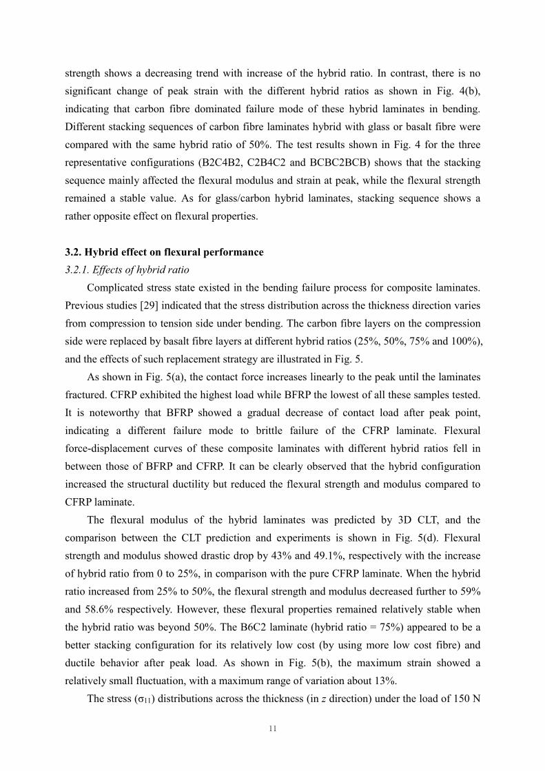
Complicated stress state existed in the bending failure process for composite laminates.
Previous studies [29] indicated that the stress distribution across the thickness direction varies
from compression to tension side under bending. The carbon fibre layers on the compression
side were replaced by basalt fibre layers at different hybrid ratios (25%, 50%, 75% and 100%),
and the effects of such replacement strategy are illustrated in Fig. 5.
As shown in Fig. 5(a), the contact force increases linearly to the peak until the laminates
fractured. CFRP exhibited the highest load while BFRP the lowest of all these samples tested.
It is noteworthy that BFRP showed a gradual decrease of contact load after peak point,
indicating a different failure mode to brittle failure of the CFRP laminate. Flexural
force-displacement curves of these composite laminates with different hybrid ratios fell in
between those of BFRP and CFRP. It can be clearly observed that the hybrid configuration
increased the structural ductility but reduced the flexural strength and modulus compared to
CFRP laminate.
The flexural modulus of the hybrid laminates was predicted by 3D CLT, and the
comparison between the CLT prediction and experiments is shown in Fig. 5(d). Flexural
strength and modulus showed drastic drop by 43% and 49.1%, respectively with the increase
of hybrid ratio from 0 to 25%, in comparison with the pure CFRP laminate. When the hybrid
ratio increased from 25% to 50%, the flexural strength and modulus decreased further to 59%
and 58.6% respectively. However, these flexural properties remained relatively stable when
the hybrid ratio was beyond 50%. The B6C2 laminate (hybrid ratio = 75%) appeared to be a
better stacking configuration for its relatively low cost (by using more low cost fibre) and
ductile behavior after peak load. As shown in Fig. 5(b), the maximum strain showed a
relatively small fluctuation, with a maximum range of variation about 13%.
The stress (σ11) distributions across the thickness (in z direction) under the load of 150 N

12
are showed in Fig. 5(e). A significant stress reduction appeared when the carbon layers were
replaced on the compressive side by the basalt layers, due to the lower modulus of basalt
layers. Stress state in each lamina was also changed due to the introduction of basalt layer.
The jump of stress distribution across the hybrid laminates section mainly appeared in the
interface between different materials as observed from Fig. 5(e). It can be found that the
B2C6 (hybrid ratio = 25%) and BFRP laminates presented the minimum tensile and
compressive stresses at outsides among all the specimens separately. With increase in the
hybrid ratio, the stress distribution across the laminate increased on the tensile side but
decreased on the compressive side. Values of tensile stress for the hybrid laminates on the
tensile side increased while flexural strength decreased due to a lower strength of basalt layer.

13
Fig. 5. Effect of hybrid ratio on flexural properties: (a) force-displacement curves, (b) flexural strength, (c)
strain at peak, (d) comparison of flexural modulus between the experiment and CLT evaluation, and (e)
stress (σ11) distribution across the thickness under the transverse load of 150 N.
3.2.2. Effects of stacking sequence
Strong effect of hybrid stacking sequence on the flexural properties was reported in [9,
10]. In our present study, all the composite laminates were unidirectional and have relatively
larger gap of the mechanical properties of these two types of fibres, which differs from the
(a) (b)
(c) (d)
(e)

14
work in [9, 10]. In this study, four basalt layers and four carbon layers were utilized with the
stacking sequences outlined in the schematic shown in Fig. 2 for the hybrid ratio of 50%.
Inserting basalt layers into carbon layers improved the ductile property of the hybrid
laminates but downgraded the flexural modulus and strength, as discussed in section 3.2.1. It
can be observed from Fig. 5(a) and Fig. 6(a) that the stacking sequence mainly affected the
slope of load-displacement curves before peak. Placing 2 carbon layers on the both top and
bottom respectively, and the other 4 basalt layers in the central layers yielded the highest
flexural modulus and strength of all the hybrid samples (C2B4C2), which were found to be
about 28.2% and 37.9% lower in the flexural modulus and strain at peak in comparison with
those of CFRP. This is because the top and bottom carbon layers borne higher load under
bending. Interestingly, non-linear behavior is observed when the bottom side (tension) carbon
fibres were partially replaced by basalt fibres, such as BCBC2BCB and B2C4B2. Similar
results can also be also found in [9] when the top and bottom carbon layers were replaced by
basalt layers with high elongation. It is noteworthy that B2C4B2 showed the maximum strain
to peak load which was even higher than that of pure BFRP or CFRP. When the basalt layers
were placed homogeneously on both the tensile and compressive sides, i.e. BCBC2BCB, the
strain at peak showed an increasing trend (good ductility) but the flexural strength decreased.
Fig. 6(e) shows the CLT evaluation of stress (σ11) distribution for the symmetric stacking
configurations of basalt layers. When the carbon layers near the compressive and tensile sides
were replaced by basalt layers (B2C4B2), stress reduction can be observed in the basalt layers.
At the meantime, B2C4B2 showed the highest strain at peak for its lower modulus. As for
BCBC2BCB, it exhibited a large variation in stress distribution across the laminates and the
maximum stress appeared on the second lamina on the both tensile and compressive sides. In
contrast, the stress distribution within C2B4C2 laminate only showed a small reduction near
the central plane, and the load state within carbon layers were almost the same as that of
CFRP. This implies that replacing the central carbon layers by basalt layers with lower
modulus leads to “small reduction” of flexural properties.

15
Fig. 6. Comparisons of flexural behavior of hybrid laminates with different stacking sequences with
carbon/basalt fibres in terms of (a) force-displacement curves, (b) flexural strength, (c) strain at peak, (d)
flexural modulus of experiment and CLT calculation, and (e) stress distribution of σ11 through the thickness
under the load of 150 N.
3.2.3. Effects of fibre type
The flexural modulus and flexural strength of glass fibre fall in between basalt and
carbon fibres. The hybridization of these three types of fibres (BGC4GB and C2BG2BC2)
(a) (b)
(c)
(d)
(e)

16
was also prepared for exploring the hybrid effects on their flexural properties. The comparison
between the experimental results and CLT estimation is presented in Fig. 7.
As can be seen from Fig. 7, the GFRP laminate had a higher ultimate flexural strain than
those of BFRP and CFRP, about 122% and 27.3% increase in the ultimate flexural strain
relative to that of BFRP. It is interesting to note that the sandwich-like stacking configurations,
G2C4G2 and C2G4C2, exhibited very different flexural behavior to those of B2C4B2 and
C2B4C2. With such two glass layers located symmetrically on the tensile and compressive
sides, G2C4G2 achieved a higher flexural strength (about 15% higher than that of C2G4C2).
It is also found that while the C2G4C2 laminate presented a higher flexural modulus, the final
elongation of G2C4G2 was much greater due to the higher ductility of glass layers.
The symmetric stacking sequence of hybrid laminates with three types of fibres,
BGC4GB and C2BG2BC2, were chosen for the further analysis. Note that these laminates
have the same amount of 4 carbon layers, 2 basalt layers and 2 glass layers respectively. As
can be seen from Fig. 7(b) and (d), the flexural strength of these two laminates were almost
the same; while the C2BG2BC2 laminate showed a much higher flexural modulus (about two
times of BGC4GB). Compared with G2C4G2, the flexural strength and flexural modulus of
BGC4GB showed 35.3% and 24% reduction if replacing one glass layer on the tensile and
compressive sides with the basalt layers, respectively. On the other hand, the replacement of
glass layers by basalt layers near the central plane (e.g. from C2G4C2 to C2BG2BC2), only
about 16.7% and 20.7% reduction of flexural modulus and flexural strength can be found
from the bending tests.
For the sandwich-like stacking configurations, i.e. G2C4G2 and C2G4C2, the stress
distribution trend was similar to those of B2C4B2 and C2B4C2. According to Fig. 7(d),
C2G4C2 showed a relatively smaller reduction in the flexural modulus than that of G2C4G2
compared to CFRP laminate, since stress state near the central plane has less influence on the
structural response. With partial substitution of carbon lamina on the tensile/compressive
sides, the stress state of glass laminate through the thickness direction showed a more
‘efficient’ distribution because of its high elongation. Thus more efficient use of carbon/glass
layers can be achieved while reducing the number of carbon layers in the laminate.

17
Fig. 7. Comparisons of flexural behavior of hybrid laminates with different fibres in terms of (a)
force-displacement curves, (b) flexural strength, (c) strain at peak, (d) flexural modulus of experiment and
CLT calculation, and (e) stress distribution of σ11 through the thickness under the load of 150 N.
3.3. Failure mechanisms
The damage distribution of the hybrid laminates was inspected by visible method, and
the common failure modes under flexural loading observed include compressive failure,
tensile failure, shear and/or delamination [28]. Of these, the compressive failure was the most
(a) (b)
(c) (d)
(e)

18
common failure mode in the present cases, which includes fibre kinking, micro-buckling and
delamination. According to the hybrid configurations, i.e. fibre type, stacking sequence,
hybrid ratio, the compressive failure shifted from surface plies into the central plies [17].
Fig. 8. Failure surface of laminates after the flexural testing.
Fig. 8 shows the representative optical images on the top and bottom surface of none
hybrid laminates (i.e. CFRP, GFRP and BFRP). A penetrated crack on the compressive side
can be seen from the CFRP laminate, but no crack was found on the tension side. This
indicates onsite of brittle fracture from the compressive side in bending, leading to a
catastrophic failure of the entire laminate. Compared to the CFRP laminate, BFRP and GFRP
laminates exhibited both tensile and compressive cracks, exhibiting different failure modes,
such as fibre pull-out in the BFRP laminate and micro-buckling in the GFRP laminate. On the
compressive side, the BFRP laminate showed a straight crack and kinking band after the fibre
fracture, while the GFRP laminate exhibited fibre kinking and micro-buckling. Such a similar
failure phenomenon were also reported in [28].
Some typical SEM images of the laminates with the hybrid ratios of 0 and 0.5 are shown
in Fig. 9. Onsite of fibre fracture and transverse cracks can be seen first on the compressive
side for the CFRP laminate, then propagated across the thickness; finally delamination
between the adjacent plies caused ultimate failure, thereby leading to a sudden drop of load
carrying capacity. However, no visual kinking band can be found in the CFRP laminate.
The BFRP laminate exhibited somewhat different failure modes compared with the
CFRP laminate. Shear failure and fibre fracture appeared first on both the compressive and
tensile sides, and followed by crack propagation, leading to complete loss of load carrying

19
capacity. Due to combination of ply splitting (delamination) and fibre fracture, the adjacent
plies on the compressive side failed, leading to the appearance of kink band. The extension of
fracture area was significantly larger than that of CFRP due to a poor fibre/matrix interface
and a larger diameter of fibre yarn (13 m for BFRP and 6.8 m for CFRP).
Fig. 9. Failure micrograph of hybrid laminates with three magnifications.
As for B4C4, exhibited crack initiated from the compressive side. Micro-buckling and

20
shear failure can be also observed among BFRP layers. A closer inspection revealed that
delamination existed in the interface of carbon and basalt layers, combining with partial fibre
fracture in carbon plies. A lower stress state existed on the compressive side in the B4C4
laminate and thus caused reduction in the flexural modulus and strength by about 18.9% and
26% respectively compared to CFRP. Due to the much higher failure strain within the B4C4
laminate, the kink band transferred the flexural load so that a ductile failure mode appeared as
shown in Fig.9.
Different failure modes have also been observed from the laminates in the sandwich-like
stacking sequences shown in Fig. 9, such as C2B4C2 and B2C4B2. Only compressive failure
appeared when the carbon layers were placed on the compressive/tensile sides respectively. It
is observed that the shear crack happened at the first two carbon plies together with
delamination between the interface of carbon and basalt layers. This phenomenon can be
validated by examining the stress distribution across the thickness as shown in Fig. 6(e). Since
the damage was only restricted by the carbon layers on the compressive side, only a small
reduction in the flexural modulus of the B2C4B2 laminate was observed. When the basalt
layers were placed symmetrically on the compressive/tensile sides, respectively, failure
appeared mainly on the compressive side, which is similar to B4C4, but the laminate showed
a much better ductile behavior.
4. Numerical Simulation
Failure mechanism of fibre-reinforced composite laminates is indeed rather complicated
due to their heterogeneous properties that cause various cracking and delamination. Therefore,
prediction of these complicated damage modes is of great implication. In this section, the FE
model was developed to simulate the damage onset of hybrid carbon/basalt composite
laminates, in which the cohesive interface element was employed to characterize the
interaction between the neighbouring plies.
4.1. Finite element modelling
The FE model of the hybrid carbon/basalt reinforced laminate was developed using
ABAQUS/Explicit, a commercial explicit dynamic FE code. The edge effects were neglected
in the model, therefore stress distribution along the width was assumed to be uniform. Fig. 10
shows the set-up of the FE model specifically for the B2C4B2 laminate, where the top and
bottom layers were the basalt layers. The loading cell and two supports were considered to be
the rigid bodies. The continuum shell elements (SC8R) were employed in the FE model.
The mesh density at vicinity of the contact area (20 mm 15 mm) was refined. A

21
convergence study on discretization was conducted together with test of model parameters, i.e.
mesh size and loading rate; and the results are showed in Fig. 11. Mesh subdivision in z
direction represents double density of grid across the thickness direction, while mesh size at
contact region was refined to be 0.25 mm (half of non-refined elements) for subdivision in xy
plane. Negligible effect appears on force-displacement curves for these two subdivision
method from Fig. 11(a). For computing efficiency, mesh density of 0.5 mm at contact area and
one element across each ply were chosen in the present work.
Fig. 10. FE model for the B2C4B2 hybrid composite laminate and configuration of bending simulation.
Cohesive zone method has been commonly used to model adhesives and bonded
interfaces [41], in which the zero-thickness cohesive elements were placed onto the adjacent
plies to simulate the possible delamination failure in the composite laminates [24, 25]. The
nonlinear constitutive behavior of the cohesive element can be defined by a bilinear
traction-separation law [42]. Once a damage initiation criterion is met, linear softening
behavior is triggered to simulate the decohesion of the interface elements [41]. The maximum
nominal stress criterion was employed to characterize the damage initiation by combining the
stress components ratio in the present work. Then, the damage evolution for delamination
failure was simulated by the energy law in terms of energy release rate and fracture toughness
under mixed-mode loading [24]. The Benzeggagh-Kenane (BK) fracture criterion was used to
govern the mixed-mode fracture [41],
C
tsn
tsCn
Cs
Cn G
GGG
GGGGG
))(( (13)
where nG , sG and tG refer to the fracture energies induced by the normal, the first and the
second shear forces. CnG , C
sG and CtG represent the critical fracture energies required to
initiate the crack in the different directions respectively. is the power coefficient.

22
Fig. 11. Convergence study on (a) the CFRP for mesh refinement, (b) ratio of compressive to tensile
modulus (c) and loading rate.
It has been shown that the simulation results can be influenced by fluctuation of the
damage parameters within around 15% [43]. These damage parameters include interlaminar
normal strength (30 MPa), shear strength (50 MPa), fracture toughness of mode I (0.26 N/mm)
and mode II (0.52 N/mm), respectively [44].
Only the damage initiation of carbon/basalt fibre, rather than damage progress, was
modelled here, as the unidirectional composite laminates could fail rapidly once damage
initiates. The material properties of the CFRP, BFRP and GFRP laminates have been
summarized in Table 1. The compressive strength was taken as 65% of tensile strength
empirically [40]. As in [40], failure in the unidirectional laminate was initiated by the
compressive strain in bending due to the relatively lower compressive modulus. Effects of
compressive to tensile modulus ratio on the force-displacement were investigated as shown in
Fig. 11(b). The fluctuation of numerical curves is due to the progressive contact between the
load cell and specimen. It can be observed that the peak bending force increased with the
increase in the compressive to tensile modulus ratio. Ratio of compressive to tensile modulus
was adopted as 90% in the present work.
A displacement-controlled load was applied by the load cell while the two supports were
(a) (b)
(c)

23
simply supported. Quasi-static analysis was performed due to its high efficiency for highly
nonlinear and large deformation problems. Effect of loading rate was shown in Fig. 11(c); and
negligible difference can be seen in terms of force-displacement curves. Thus, an average
loading rate of 1 m/s was adopted for the following analyses.
4.2. Validation and analysis
Typical force-displacement curves of the hybrid composite laminates obtained from the
FE simulation and experiment are plotted in Fig. 12 for several representative configurations.
A good agreement can be found for those the non-hybrid (CFRP, BFRP and GFRP) laminates,
however, the ultimate flexural force of hybrid laminate C2B4C2 in the experiment was
considerably lower than that of the FE simulation. This is first due to the high sensitivity of
carbon fibre on the compressive surface in the three-point bending, which has been
systematically discussed in [40]. Second, the C2B4C2 hybrid laminate had a significantly
higher ductility when the carbon layers failed on the compressive surface in the experiment,
which differ from the FE simulation. It is noted that the stress distribution of composite
laminates fluctuated across thickness, particularly near the interface between the carbon and
basalt layers as plotted in Fig. 6(e); and it appeared that the hybrid laminates had a higher
fluctuation than the non-hybrid counterparts.
Fig. 12. Comparisons of force-displacement curves between experimental and numerical results.
Fig. 13 illustrates the compressive damage factor of three representative hybrid
composite laminates (B4C4, B2C4B2 and C2B4C2) at the moment of damage initiation. For
the hybrid laminate with carbon layers on the top, i.e. C2B4C2, the compressive damage
initiated from the compressive surface underneath the loading cell; and then propagated
rapidly across the ply thickness, leading to fracture. When placing ductile layers on the top, i.e.
B4C4 and B2C4B2, the damage factor showed a relatively smooth distribution across the ply
thickness, the lower plies were still able to carry certain load even though the top ply failed,
(a) (b)

24
exhibiting better ductility.
Fig. 13. Damage distribution at the time of failure initiation under three-point bending.
Fig. 14 shows the distribution of flexural stress 11 under the transverse load of 150 N.
Interestingly the bending stress showed an uneven distribution across the ply thickness, due to
the unequal compressive/tensile moduli ( 9.0/ 1111 tc EE ) and different fibre materials.
Apparently, the flexural stress of the top surface is lower than that of the bottom surface. Due
to a much lower ratio of compressive to tensile strength ( 65.0/ 1111 tc ), laminates are
vulnerable to fail by a compressive stress. Compared to C2B4C2, the other two hybrid
laminates appeared a gradual change of flexural compressive stress where damage grew
among fibre layers on the compressive side.
Fig. 14. Contour of bending stress 11 under the load of 150 N.
From the above analysis, the stress distribution status was dependent on the stacking
sequences of carbon/basalt hybrid laminates, thus resulting in different mechanical responses
in bending. It is noted that a smaller reduction on flexural modulus was achieved by placing
the carbon fibre layers on the upper and lower laminate surface due to a relatively lower stress
near the central plane. So the further investigation was conducted with hybrid C2B4C2
laminate.

25
4.3. Effects of mechanical properties at external sides
Apart from the C2B4C2 laminate that had a large deviation of flexural strength between
experiment and FEA, the FEA for other hybrid composite laminates well matched with the
experimental results. For this reason, further parametric analysis for C2B4C2 was conducted
to explore the effects of Young’s modulus, lamina strength, and cohesive elements.
Fig. 15 shows the comparison of experiment and FEA for C2B4C2, in which different
Young’s modulus, strength and cohesive properties were tested. It can be seen that there is
negligible difference at the peak force (determining the flexural strength), but strain at peak
and the slope of curves decreased with decreasing Young’s modulus (Fig. 15(a)). As shown in
Fig. 15(b), reduction in the strength led to a large variation in the peak flexural force. It is
noted that the results on obtained by the FE model with 40% strength reduction agreed well
with the experimental data. Negligible effect can be seen from Fig. 15(c) when changing the
cohesive properties (cohesive strength and fracture toughness). In all the three cases as shown
in Figs. 15 (a)-(c), the laminate exhibited brittle fracture in the FE simulation, which differs
from a progressive failure in the experiment. This is because the FE model has overestimated
the compressive strength of carbon layers, and the underneath basalt layers fractured suddenly
once the carbon layers failed, showing a catastrophic laminate breakage in bending.
Fig. 15. Comparison of experimental and numerical results with the sensitivity analysis: (a) Young’s
modulus, (b) tensile strength and (c) cohesive properties.
(a) (b)
(c)

26
5. Cost analysis
Table 2 summarizes the material cost for individual hybrid composite laminate, which
was normalized to the cost of CFRP laminate. For the non-hybrid laminates, CFRP was the
most expensive, about 10.1 and 7.5 times higher than BFRP and GFRP, respectively. This
section investigates how to balance the cost and performance of hybrid composite laminate
for engineering applications.
The criteria for cost analysis included the ratios of strength/cost and modulus/cost, as
plotted in Fig. 16. The bar chart in the figure represents the performance of specific hybrid
laminate with the unit cost. While the carbon fibre has much higher performance, glass and
basalt fibres did exhibit better cost efficiency (strength/cost and modulus/cost). It is observed
that replacing few carbon fibre layers with basalt fibre on the compressive side led to
reduction in cost effectiveness (B2C6, B4C4) compared to CFRP laminate according to Fig.
16, however this trend reversed if more carbon layers were replaced (B6C2).
Table 2 Comparison of material cost. The hybrid laminates have been normalized to CFRP laminate.
Stacking sequence CFRP cost ($) BFRP cost ($) GFRP cost ($) Total cost ($)
CFRP 100.0% 0.0% 0.0% 100.0%
B2C6 74.9% 2.4% 0.0% 77.3%
B4C4 49.8% 4.7% 0.0% 54.9%
B6C2 24.7% 7.5% 0.0% 32.2%
BFRP 0.0% 9.8% 0.0% 9.8%
B2C4B2 49.8% 4.7% 0.0% 54.9%
C2B4C2 49.8% 4.7% 0.0% 54.9%
BCBC2BCB 49.8% 4.7% 0.0% 54.9%
C2G4C2 49.8% 0.0% 6.7% 56.5%
G2C4G2 49.8% 0.0% 6.7% 56.5%
C2BG2BC2 49.8% 2.4% 3.1% 55.7%
BGC4GB 49.8% 2.4% 3.1% 55.7%
GFRP 0.0% 0.0% 13.3% 13.3%
Stacking sequence had small effect on the strength/cost but large effect on modulus/cost.
With carbon layers at both tensile/compressive surfaces e.g. C2B4C2, C2G4C2 and
C2BG2BC2 (hybrid ratio 50%), there is very good cost efficiency. Of these, C2G4C2 showed
the best cost efficiency in terms of modulus/cost and strength/cost ratios due to the high

27
elongation and intermediate modulus/strength that basalt fibre provided.
Fig. 16. Comparison of strength/cost and modulus/cost.
Fig. 17. Performance - cost analysis of hybrid composite laminates. The hybrid laminates have been
normalized to CFRP laminate.
In real engineering practice, often designers need to ensure the specific structural
performance before considering cost reduction. It would be more effective to combine the
performance and cost together at the design stage. Fig. 17 shows a radar chart for the hybrid
composite laminates by considering the cost, flexural strength, modulus and ductility (strain).
As shown in Fig. 16, pure BFRP composite showed much higher cost efficiency than CFRP,

28
however it is unlikely to employ this material in high-end large structural components such as
wind turbine blade and aircraft fuselage owing to its lower mechanical properties. On the
other hand, for some intermediate structural components, such as civilian vehicle body which
requires high cost efficiency and material ductility but less sensitivity of modulus, the hybrid
laminates C2BG2BC2 and C2G4C2 can be potential candidates.
6. Conclusion
A systematic study has been carried out to investigate the flexural performance of hybrid
carbon/glass/basal fibres by using experimental, analytical and numerical approaches. With
significant difference of material properties among the three fibres, the flexural performance
of hybrid laminates (flexural modulus, flexural strength and ductility) compromised with
different hybrid ratios and stacking sequences. With increase in the hybrid ratio, flexural
modulus and flexural strength decreased while ductility increased. In general, the glass fibre
presented better performance than basalt fibre in the hybrid composite laminates.
The surface plies carried more load under bending, thus dominated the failure modes of
the hybrid composite laminates. All the laminates failed by compression in three-point
bending tests regardless of hybrid ratio and stacking sequence, which has not been reported in
the previous literature. Through a FEA parametric study this was confirmed to be a result of
the unequal compressive/tensile moduli and strengths. Further, the stacking sequence played
an important role on the progressive failure of laminates after the damage initiation, meaning
that investigation into the damage evolution can help to understand the mechanical behavior
of the hybrid composites. C2GB2GC2 and C2G4C2 hybrid laminates, for instance, have a
small reduction of load carrying capacity but a massive improvement of ductility and cost
efficiency, making them a potential candidate for many structural components subject to
bending, such as vehicle chassis.
Note that the material cost of these three fibres are nonlinear to their respective
mechanical performance, therefore the cost analysis can provide better understanding to
balance the performance and cost. This is particularly important to the applications with less
sensitivity of strength to weight, such as marine structures. The present study suggested a
radar chart approach by considering four factors (cost, strength, modulus and strain) to
analyze the performance to cost efficiency of the hybrid composites. As the 3D CLT analysis
and FEA model have been validated by the experimental results, future studies can be carried
out by using these two ‘low cost’ approaches to complement the radar chart.

29
Acknowledge
This work is supported by National Natural Science Foundation of China (51575172,
51475154). Dr Guangyong Sun is a recipient of Australian Research Council (ARC)
Discovery Early Career Researcher Award (DECRA) in the University of Sydney.
References
1. Zhu, G., et al., Energy absorption of metal, composite and metal/composite hybrid structures under
oblique crushing loading. International Journal of Mechanical Sciences, 2018. 135: p. 458-483.
2. Sun, G., et al., On crashing behaviors of aluminium/CFRP tubes subjected to axial and oblique
loading: An experimental study. Composites Part B: Engineering, 2018. 145: p. 47-56.
3. Zhu, G., et al., Modeling for CFRP structures subjected to quasi-static crushing. Composite
Structures, 2018. 184: p. 41-55.
4. Huda, Z. and P. Edi, Materials selection in design of structures and engines of supersonic aircrafts:
A review. Materials & Design, 2013. 46: p. 552-560.
5. Paiva, J.M.F.d., A.D.N.d. Santos, and M.C. Rezende, Mechanical and morphological
characterizations of carbon fiber fabric reinforced epoxy composites used in aeronautical field.
Materials Research, 2009. 12(3): p. 367-374.
6. Zhang, K., et al., Mechanical characterization of hybrid lattice-to-steel joint with pyramidal CFRP
truss for marine application. Composite Structures, 2017. 160: p. 1198-1204.
7. Leone, C., et al., Investigation of CFRP laser milling using a 30W Q-switched Yb:YAG fiber laser:
Effect of process parameters on removal mechanisms and HAZ formation. Composites Part A:
Applied Science and Manufacturing, 2013. 55: p. 129-142.
8. Xu, J., Q. An, and M. Chen, A comparative evaluation of polycrystalline diamond drills in drilling
high-strength T800S/250F CFRP. Composite Structures, 2014. 117: p. 71-82.
9. Ary Subagia, I.D.G., et al., Effect of stacking sequence on the flexural properties of hybrid
composites reinforced with carbon and basalt fibers. Composites Part B: Engineering, 2014. 58: p.
251-258.
10. Prusty, R.K., et al., Experimental optimization of flexural behaviour through inter-ply fibre
hybridization in FRP composite. Construction and Building Materials, 2016. 118: p. 327-336.
11. Swolfs, Y., L. Gorbatikh, and I. Verpoest, Fibre hybridisation in polymer composites: A review.
Composites Part A: Applied Science and Manufacturing, 2014. 67: p. 181-200.
12. Yang, Z., et al., Effect of matrix glass transition on reinforcement efficiency of epoxy-matrix
composites with single walled carbon nanotubes, multi-walled carbon nanotubes, carbon
nanofibers and graphite. Composites Part B: Engineering, 2012. 43(4): p. 2079-2086.
13. Shin, M.K., et al., Synergistic toughening of composite fibres by self-alignment of reduced
graphene oxide and carbon nanotubes. Nat Commun, 2012. 3: p. 650.
14. Taniguchi, N., et al., Dynamic tensile properties of carbon fiber composite based on thermoplastic
epoxy resin loaded in matrix-dominant directions. Composites Science and Technology, 2009.
69(2): p. 207-213.
15. Hufenbach, W., et al., Determination of strain rate dependent through-thickness tensile properties
of textile reinforced thermoplastic composites using L-shaped beam specimens. Composites

30
Science and Technology, 2011. 71(8): p. 1110-1116.
16. Sonnenfeld, C., et al., Thermoplastic/thermoset multilayer composites: A way to improve the
impact damage tolerance of thermosetting resin matrix composites. Composite Structures, 2017.
171: p. 298-305.
17. Zhang, J., et al., Hybrid composite laminates reinforced with glass/carbon woven fabrics for
lightweight load bearing structures. Materials & Design (1980-2015), 2012. 36: p. 75-80.
18. Wu, Z., et al., Electrical and mechanical characterization of hybrid CFRP sheets. Journal of
composite materials, 2006. 40(3): p. 227-244.
19. Czél, G. and M.R. Wisnom, Demonstration of pseudo-ductility in high performance glass/epoxy
composites by hybridisation with thin-ply carbon prepreg. Composites Part A: Applied Science and
Manufacturing, 2013. 52: p. 23-30.
20. Dong, C. and I.J. Davies, Flexural strength of bidirectional hybrid epoxy composites reinforced by
E glass and T700S carbon fibres. Composites Part B: Engineering, 2015. 72: p. 65-71.
21. Kalantari, M., C. Dong, and I.J. Davies, Multi-objective analysis for optimal and robust design of
unidirectional glass/carbon fibre reinforced hybrid epoxy composites under flexural loading.
Composites Part B: Engineering, 2016. 84: p. 130-139.
22. Pandya, K.S., C. Veerraju, and N.K. Naik, Hybrid composites made of carbon and glass woven
fabrics under quasi-static loading. Materials & Design, 2011. 32(7): p. 4094-4099.
23. Meng, M., et al., 3D FEA modelling of laminated composites in bending and their failure
mechanisms. Composite Structures, 2015. 119: p. 693-708.
24. Ullah, H., et al., Finite-element modelling of bending of CFRP laminates: Multiple delaminations.
Computational Materials Science, 2012. 52(1): p. 147-156.
25. Ullah, H., A.R. Harland, and V.V. Silberschmidt, Experimental and Numerical Analysis of Damage
in Woven GFRP Composites Under Large-deflection Bending. Applied Composite Materials, 2012.
19(5): p. 769-783.
26. Jalalvand, M., G. Czél, and M.R. Wisnom, Numerical modelling of the damage modes in UD thin
carbon/glass hybrid laminates. Composites Science and Technology, 2014. 94: p. 39-47.
27. Jalalvand, M., M. Fotouhi, and M.R. Wisnom, Orientation-dispersed pseudo-ductile hybrid
composite laminates – A new lay-up concept to avoid free-edge delamination. Composites Science
and Technology, 2017. 153: p. 232-240.
28. Dong, C., H.A. Ranaweera-Jayawardena, and I.J. Davies, Flexural properties of hybrid composites
reinforced by S-2 glass and T700S carbon fibres. Composites Part B: Engineering, 2012. 43(2): p.
573-581.
29. Kalantari, M., C. Dong, and I.J. Davies, Numerical investigation of the hybridisation mechanism in
fibre reinforced hybrid composites subjected to flexural load. Composites Part B: Engineering,
2016. 102: p. 100-111.
30. Dhand, V., et al., A short review on basalt fiber reinforced polymer composites. Composites Part B:
Engineering, 2015. 73: p. 166-180.
31. Fiore, V., et al., A review on basalt fibre and its composites. Composites Part B: Engineering, 2015.
74: p. 74-94.
32. Dorigato, A. and A. Pegoretti, Flexural and impact behaviour of carbon/basalt fibers hybrid
laminates. Journal of Composite Materials, 2013. 48(9): p. 1121-1130.
33. Nisini, E., C. Santulli, and A. Liverani, Mechanical and impact characterization of hybrid
composite laminates with carbon, basalt and flax fibres. Composites Part B: Engineering, 2017.

31
127: p. 92-99.
34. Najafi, M., S.M.R. Khalili, and R. Eslami-Farsani, Hybridization effect of basalt and carbon fibers
on impact and flexural properties of phenolic composites. Iranian Polymer Journal, 2014. 23(10): p.
767-773.
35. Wu, Z., et al., Tensile fatigue behaviour of FRP and hybrid FRP sheets. Composites Part B:
Engineering, 2010. 41(5): p. 396-402.
36. Astm, D.D., Standard Test Method for Flexural Properties of Polymer Matrix Composite Materials.
Astm, 2010.
37. Kaw, A.K., Mechanics of composite materials. 2005: CRC press.
38. Standard, A., Standard test method for tensile properties of polymer matrix composite materials.
ASTM D3039/D M, 2008. 3039: p. 2008.
39. Standard, A., Standard Test Method For In-Plane Shear Response of Polymer Matrix Composite
Materials by Tensile Test of a±45 Laminate. ASTM D 3518/D 3518, 2001. 94.
40. Meng, M., et al., The effects of unequal compressive/tensile moduli of composites. Composite
Structures, 2015. 126: p. 207-215.
41. Version, A., 6.13, Analysis User’s Manual. Dassault Systemes Simulia Corp., Providence, RI,
2013.
42. Tan, W., et al., Predicting low velocity impact damage and Compression-After-Impact (CAI)
behaviour of composite laminates. Composites Part A: Applied Science and Manufacturing, 2015.
71: p. 212-226.
43. Sokolinsky, V.S., K.C. Indermuehle, and J.A. Hurtado, Numerical simulation of the crushing
process of a corrugated composite plate. Composites Part A: Applied Science and Manufacturing,
2011. 42(9): p. 1119-1126.
44. Shin, D.K., H.C. Kim, and J.J. Lee, Numerical analysis of the damage behavior of an
aluminum/CFRP hybrid beam under three point bending. Composites Part B: Engineering, 2014.
56: p. 397-407.