Flexafix - UvA-DARE (Digital Academic Repository)
179
UvA-DARE is a service provided by the library of the University of Amsterdam (https://dare.uva.nl) UvA-DARE (Digital Academic Repository) Flexafix: The development of a new dynamic external fixation device for the treatment of distal radial fractures Goslings, J.C. Publication date 1999 Link to publication Citation for published version (APA): Goslings, J. C. (1999). Flexafix: The development of a new dynamic external fixation device for the treatment of distal radial fractures. General rights It is not permitted to download or to forward/distribute the text or part of it without the consent of the author(s) and/or copyright holder(s), other than for strictly personal, individual use, unless the work is under an open content license (like Creative Commons). Disclaimer/Complaints regulations If you believe that digital publication of certain material infringes any of your rights or (privacy) interests, please let the Library know, stating your reasons. In case of a legitimate complaint, the Library will make the material inaccessible and/or remove it from the website. Please Ask the Library: https://uba.uva.nl/en/contact, or a letter to: Library of the University of Amsterdam, Secretariat, Singel 425, 1012 WP Amsterdam, The Netherlands. You will be contacted as soon as possible. Download date:16 Jul 2022
-
Upload
khangminh22 -
Category
Documents
-
view
1 -
download
0
Transcript of Flexafix - UvA-DARE (Digital Academic Repository)
UvA-DARE is a service provided by the library of the University of Amsterdam (https://dare.uva.nl)
UvA-DARE (Digital Academic Repository)
Flexafix: The development of a new dynamic external fixation device for thetreatment of distal radial fractures
Goslings, J.C.
Publication date1999
Link to publication
Citation for published version (APA):Goslings, J. C. (1999). Flexafix: The development of a new dynamic external fixation devicefor the treatment of distal radial fractures.
General rightsIt is not permitted to download or to forward/distribute the text or part of it without the consent of the author(s)and/or copyright holder(s), other than for strictly personal, individual use, unless the work is under an opencontent license (like Creative Commons).
Disclaimer/Complaints regulationsIf you believe that digital publication of certain material infringes any of your rights or (privacy) interests, pleaselet the Library know, stating your reasons. In case of a legitimate complaint, the Library will make the materialinaccessible and/or remove it from the website. Please Ask the Library: https://uba.uva.nl/en/contact, or a letterto: Library of the University of Amsterdam, Secretariat, Singel 425, 1012 WP Amsterdam, The Netherlands. Youwill be contacted as soon as possible.
Download date:16 Jul 2022


1
Contents
Flexafix
The development of a new dynamic external fixationdevice for the treatment of distal radial fractures
2
The publication of this thesis was supported by:AO Development Institute, Disphar International BV, Johnson & Johnson Medical BV,Mathys Medical Nederland BV, Nederlandse Vereniging voor Traumatologie, OldelftBenelux BV, Rätia Mechanik AG, Stichting “Anna Fonds”, Stichting “De Drie Lichten”,Stichting “Michaël-van Vloten Fonds” and Stryker BV.
Layout: C. Bor (Medische fotografie en illustratie, AMC)Cover: A. Groot, M. van GurpIllustrations: J.P. Imken, I.E.M. KosPrinted by: Thela Thesis Publishers Amsterdam
© J.C. Goslings, Amsterdam, the Netherlands.All rights reserved. No part of this thesis may be reproduced or transmitted in any formor by any means, electronic or mechanical, including photography, recording or anyinformation storage and retrieval system, without the prior permission in writing fromthe author.
ISBN 90-9012569-8

3
Contents
Flexafix
The development of a new dynamic external fixationdevice for the treatment of distal radial fractures
Academisch proefschrift
ter verkrijging van de graad van doctoraan de Universiteit van Amsterdam,op gezag van de Rector Magnificus
Prof. dr. J.J.M. Franseten overstaan van een door het College voor Promoties ingestelde
commissie in het openbaar te verdedigen in de Aula der Universiteitop vrijdag 21 mei 1999 te 10.00 uur
door
Johan Carel Goslings
geboren te Leiden

4
Promotor:Prof. Dr. H. Obertop
Co-promotores:Dr. H. BoxmaDr. J.N. Keeman
Promotiecommissie:Prof. Dr. K.E. BosMevr. Dr. F.M.M. GriffioenProf. Dr. H.J.Th.M. HaarmanProf. Dr. R.K. MartiProf. Dr. S.M. Perren

5
Contents
“A great responsibility rests on the surgeon who introduces a new method of treatment.The desire to have a new idea published is so great (…) that the method is often broadcastbefore it has been proved worthwhile and before the technique has been perfected.”
Marius N. Smith-Petersen (1886 - 1953)Archives of Surgery 1931
Ter nagedachtenis aanTom Broekhuizen

6

7
Contents
Contents

8
Chapter 1: Rationale of the study1.1 The fractured distal radius 121.2 Dynamic external fixation 131.3 The problem 131.4 The Flexafix project 141.5 Aim of the study 15
Chapter 2: Anatomy of the wrist2.1 Introduction 172.2 Bones and joints 182.3 Ligaments 192.4 Neurovascular supply 202.5 Radiographic anatomy 212.6 Kinematics 222.7 Functional wrist motion 252.8 Conclusion 26
Chapter 3: General aspects of distal radial fractures3.1 Introduction 293.2 History 303.3 Mechanism of injury 313.4 Epidemiology 343.5 Risk factors 353.6 Trauma mechanism 353.7 Fracture classifications 363.8 Treatment options 413.9 Complications 433.10 Conclusion 45
Chapter 4: External fixation in distal radial fractures4.1 Introduction 474.2 History 484.3 Principle of technique 494.4 Indications 504.5 Operative technique for rigid external fixators 514.6 Results of treatment in the literature 534.7 Complications specific for external fixation 564.8 Recent developments: dynamic external fixation 584.9 Conclusion 62

9
Contents
Chapter 5: The development of a new dynamic wrist fixator5.1 Introduction 655.2 The development of a first prototype 665.3 First clinical experience 705.4 Continued development 735.5 Patent 745.6 The development of an aiming device 745.7 Maintenance of the device 765.8 Conclusion 76
Chapter 6: Biomechanical cadaver study of pin loads6.1 Introduction 776.2 Materials and methods 786.3 Results 816.4 Discussion 836.5 Conclusion 84
Chapter 7: Kinematics of the wrist with the Flexafix device7.1 Introduction 857.2 Materials and methods 877.3 Results 897.4 Discussion 937.5 Conclusion 96
Chapter 8: Operative technique8.1 Introduction 978.2 Required materials 988.3 Operative technique 988.4 Conclusion 111
Chapter 9: The Flexafix device in clinical practice9.1 Introduction 1139.2 Patients and methods 1149.3 Results 1158.4 Discussion 1219.5 Conclusion 125

10
General discussion 127
Summary and conclusions 133
Samenvatting en conclusies 137
References 141
Appendix A: Study protocol 153
Appendix B: Case histories 159
Appendix C: A special application for the Flexafix device 167
Dankwoord / Acknowledgements 173
Curriculum vitae 176

11
Rationale of the study
Rationale of the study
Chapter 1
Chapter 1
12
1.1 The fractured distal radius
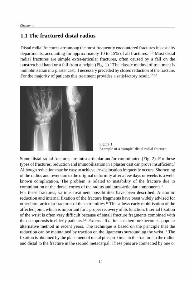
Distal radial fractures are among the most frequently encountered fractures in casualtydepartments, accounting for approximately 10 to 15% of all fractures.1,2,3 Most distalradial fractures are simple extra-articular fractures, often caused by a fall on theoutstretched hand or a fall from a height (Fig. 1).4 The classic method of treatment isimmobilisation in a plaster cast, if necessary preceded by closed reduction of the fracture.For the majority of patients this treatment provides a satisfactory result.3,5,6,7
Figure 1.Example of a ‘simple’ distal radial fracture.
Some distal radial fractures are intra-articular and/or comminuted (Fig. 2). For thesetypes of fractures, reduction and immobilisation in a plaster cast can prove insufficient.8
Although reduction may be easy to achieve, re-dislocation frequently occurs. Shorteningof the radius and reversion to the original deformity after a few days or weeks is a well-known complication. The problem is related to instability of the fracture due tocomminution of the dorsal cortex of the radius and intra-articular components.9
For these fractures, various treatment possibilities have been described. Anatomicreduction and internal fixation of the fracture fragments have been widely advised forother intra-articular fractures of the extremities.10 This allows early mobilisation of theaffected joint, which is important for a proper recovery of its function. Internal fixationof the wrist is often very difficult because of small fracture fragments combined withthe osteoporosis in elderly patients.8,11 External fixation has therefore become a popularalternative method in recent years. The technique is based on the principle that thereduction can be maintained by traction on the ligaments surrounding the wrist.12 Thefixation is obtained by the placement of metal pins proximal to the fracture in the radiusand distal to the fracture in the second metacarpal. These pins are connected by one or

13
Rationale of the study
more crossbars. In this way, the wrist joint and thus the fracture fragments areimmobilised, usually for six to eight weeks.
1.2 Dynamic external fixation
The described method of external fixation does not allow any movement of the wristduring the treatment. This could result in persistent stiffness and pain in the wrist jointand post-traumatic arthrosis.13 The latter occurs in between 7 to 65% of cases, dependingon the length of follow-up.14,15,16 On the other hand, early active motion showed beneficialeffects on the healing and regeneration of articular cartilage as compared toimmobilisation.13 The search for a fixation method which allows early mobilisation ofthe wrist joint during treatment of a distal radial fracture has led to the development ofseveral so-called ‘dynamic’ external fixation devices. The main feature of these typesof fixators is the presence of some sort of joint in the fixator. This gives the possibilityof movement of the hand during the period that the fixator is mounted on the wrist. Inother words, an early functional treatment.
1.3 The problem
In the past few years several types of dynamic external fixation devices for use on thewrist have been developed and are currently in use.17,18,19,20 In most of them, thearticulating part consists of one or more ball joints.17,19,20 These ball joints allow freedomof movement about all three axes while the centre of rotation of these movements is
Figure 2.Example of a comminuted, intra-articular distal radial fracture.

Chapter 1
14
located in the ball joint itself. However, the centre of rotation of the wrist is located inthe carpus (Fig. 3).21 During movement, therefore, the centre of rotation of a ball jointcan only be in accordance with the centre of rotation of the wrist in one axis. From abiomechanical point of view this is not the optimal situation.A mechanism which allows motion of the wrist around all three axes while keeping thecentre of rotation at one point would be a better solution. To obtain this, the centre ofrotation of the dynamic part should not be in the device itself but in a point outside thedevice, i.e. the wrist.
Figure 3.Dynamic external fixator with twoseparate centres of rotation: one in theball joint and one in the wrist.
1.4 The Flexafix project
To enable mobilisation of the wrist during treatment of a distal radial fracture by meansof a dynamic external fixator with favourable biomechanical properties the Flexafixproject was initiated. In a combined research project of the Department of Surgery(Traumatology) of the Academic Medical Centre in Amsterdam (the Netherlands) andthe Department of Biomechanics of the AO Research Institute in Davos (Switzerland) theabove mentioned problem was studied. The starting point of the project was the smallexternal fixator of the Swiss AO/ASIF (Arbeitsgemeinschaft für Osteosynthesefragen /Association for the Study of Internal Fixation), developed in 1980 and widely usedsince then.22

15
Rationale of the study
1.5 Aim of the study
The aim of the study was the development of a dynamic external fixation device withits centre of rotation coincident with the natural centre of wrist rotation around all threeaxes while at the same time maintaining fracture alignment. Further goals were theevaluation of the biomechanical, kinematic and clinical properties of the device in cadavermodels and patients.

Chapter 1
16

17
Anatomy of the wrist
Anatomy of the wrist
Chapter 2
2.1 Introduction
The wrist joint is situated between the forearm and the hand. The word wrist is derivedfrom the old teutonic word ‘wraestan’ which means ‘to twist’. Considering the wrist asa functional unit, it allows motion in all three planes. These include flexion and extensionin the sagittal plane and radio-ulnar deviation in the frontal plane, both taking place inthe radiocarpal joint. In the transverse plane, pronation and supination are afforded bythe two-bone configuration of the forearm with the proximal and distal radio-ulnarjoints. Altogether the wrist is a stable but highly movable universal joint. This chapterrecapitulates the anatomy of the wrist in relation to distal radial fractures. It is based ondescriptions in standard clinical textbooks.23,24,25,26

Chapter 2
18
2.2 Bones and joints
The distal radius provides a large articular surface for the carpus. It has three concavearticular surfaces: the scaphoid fossa, the lunate fossa and the sigmoid notch. Theseprovide articulations with the scaphoid, the lunate and the ulnar head respectively (Fig.4). On the dorsal side of the distal radius a longitudinal prominence named Lister’stubercle can be palpable. The metaphyseal part of the distal radius starts approximatelytwo centimetres from the articular surface. Here the cortex gets thinner and the amountof cancellous bone increases.The distal radio-ulnar joint provides the distal point for axial rotation of the forearm inpronation and supination. With its approximately circular cross section the ulnar headcan rotate in the sigmoid notch of the radius through an arc of approximately 160°. Thedistal articular surface of the ulna is covered by the triangular fibrocartilage. Thisfibrocartilage attaches to the distal margin of the sigmoid notch and to the radial base ofthe ulnar styloid (see below).The proximal surface of the carpus articulates with the distal radial articular surfaceand triangular fibrocartilage. The palmar aspect of the carpus at this point is concaveand establishes the floor and walls of the carpal tunnel. The carpal bones can be groupedinto rows or columns, each of variable composition. In one view, the proximal rowconsists of the scaphoid, lunate, triquetrum and pisiforme; the distal row of the trapezium,trapezoid, capitate and hamate bones. In this concept, the scaphoid can be regarded a
Figure 4. Bones of the wrist (dorsal view). Eachbone is indicated by the first letter(s) of its name.

19
Anatomy of the wrist
structural support of the carpal rows. The trapezium acts as a base for the independentlymobile and opposable thumb, whereas the capitate and the trapezoid support the secondand third metacarpals. The hamate supports the bases of the mobile fourth and fifthmetacarpals. Another concept was proposed by Navarro and divides the carpus intothree columns.27 The first is a ‘central or flexion-extension column’ formed by the lunate,capitate and hamate. The second, a ‘lateral or mobile column’, is formed by the scaphoid,trapezium and trapezoid, whereas the third, a ‘medial or rotation column’, is formed bythe triquetrum and pisiform bones. The division of the carpus into rows and columnsand their subsequent modifications have been used to describe and analyse the motionof the separate bones comprising the wrist joint but do not fall within the scope of thepresent study. Detailed descriptions of the carpus can be found elsewhere.23,25,26
2.3 Ligaments
The wrist joint has a fibrous capsule which is interlaced by strengthening ligaments.There are many descriptions of these ligaments and new manuscripts that investigatethe ligaments of the wrist and their function are still being published.23,25,26,28,29 Theligaments on the palmar side of the wrist are much stronger than those on the dorsalside, which possibly is the result of the plantigrade and brachiate activities of our remoteancestors in evolution.23 Two ligamentous systems can be distinguished: firstly, theextrinsic ligaments which extend from the radius to the carpal bones (the radiocarpalgroup) or from the carpal bones to the metacarpals (the carpo-metacarpal group); andsecondly, the intrinsic ligaments which run between the different carpal bones. On thevolar side of the distal radius, there are four radiocarpal ligaments: the radial collateral,the radio-scapho-capitate, the radio-scapho-lunate and the radio-lunate. On the dorsalside, the radiocarpal ligament is also strong. It originates at the dorsal rim of the radiusand inserts into the scaphoid, lunate and triquetrum. Three ligaments can be distinguishedhere: the radio-scaphoid, the radio-lunate and the radio-triquetral (Fig. 5).The intrinsic ligaments connect the carpal bones to each other. All adjacent carpal boneshave interosseous ligamentous connections except the lunate and capitate. The ligamentsare named by the two bones that are connected, in a proximal to distal or radial to ulnardirection. The scapholunate ligament and lunotriquetral ligament are strong and resist thedistraction imposed by the distal carpal row during axial loading and rotatory motion.Further, on the dorsal side the dorsal intercarpal ligament (DIC) conects the triquetrumwith the scaphoid and trapezoid. The interosseous ligaments of the proximal carpal roware closely associated with the radiocarpal ligaments. Their strength and distribution areof considerable importance in the kinematics of the joint. On the ulnar side the ulnocarpal

Chapter 2
20
complex or triangular fibrocartilage complex is situated. Much confusion exists aboutthe structures forming this complex. One of the reported compositions is a combinationof the triangular fibrocartilage, the ulnar collateral ligament, the ulno-lunate ligament,the triangular fibrocartilage and the sheat of the extensor carpi ulnaris tendon. Thedistal radio-ulnar joint is supported by the dorsal and volar radio-ulnar ligaments.
2.4 Neurovascular supply
The nerve and blood supplies of the wrist are derived from the regional nerves and vessels.Sensory and motor function come from the median, ulnar and radial nerves. The superficialsensory branches of the median, ulnar and radial nerves are susceptible to damage bylacerations and incisions. They are, however, easily visualised and should thus be protected.The potential for a neuralgic pain syndrome is common to all of them. The sensory branchof the radial nerve in particular is clinically important when external fixation is used at thewrist. It emerges dorsally from underneath the brachioradialis tendon about five centimetresproximal to the radial styloid (Fig. 6).Circulation is provided by the two terminal branches of the brachial artery (the radial andulnar arteries) and by the anterior and posterior interosseous arteries. Several of these arteries
Figure 5. Ligaments of the wrist (a: volar side, b: dorsal side). The radiocarpal ligaments are indicatedaccording to their origin and insertion. See text for further explanation.
a b

21
Anatomy of the wrist
Figure 6. Course of the sensory branch of the radial nerve (RN). EPL: ext. pollicis brevis, APL: abd.pollicis longus, ECRL: ext. capri rad. longus, BR: brachioradialis.
usually join to form a palmar arch. There is often concern about the maintenance of adequateblood supply to the scaphoid and the lunate because both are susceptible to ischemic changes,for example following trauma. Most of the blood supply of each bone enters the bone in thedistal half. The venous system of the wrist consists of both deep and superficial veins,running together with the arteries.
2.5 Radiographic anatomy
Three radiographic measurements are most often used in the anatomical evaluation of thedistal end of the radius (Fig. 7).3,30,31 On the lateral radiograph, the dorsal angle (alsocalled dorsal tilt) of the distal end of the radius is the angle between a line perpendicularto the long axis of the radius and a line drawn from the volar to the dorsal margin of thedistal radial articular surface. Normally there is a palmar angulation of 11 to 12 degreesrather than a dorsal angulation. The radial angle (also called radial deviation) is measuredon the anteroposterior radiograph and is represented by the angle between a lineperpendicular to the long axis of the radius and a line drawn from the radial styloid to theulnar border of the distal radial articular surface. The average radial angle is 22 to 23degrees. Radial length, also measured on the anteroposterior radiograph, is representedby the distance from the tip of the radial styloid to a parallel line drawn at the distalarticular surface of the ulna. The normal length of the radius averages 11 to 12 millimetres.Others have suggested that radial length should be measured from the distal radial to thedistal ulnar articular surfaces.32 A fourth radiographic measurement that might have

Chapter 2
22
prognostic value in assessing fractures is radial width or radial shift. This is the distancebetween a line drawn through the longitudinal axis of the radius and the most lateral tip ofthe radial styloid process. It is measured on the anteroposterior radiograph and comparedwith the contralateral side.30
2.6 Kinematics
Wrist motions are complex because of the difficult relationship between the participatingbones and joints, the ligaments and the muscles around the joint. The wrist can move ineither a dorsal-palmar plane or a radio-ulnar plane and also allows circumduction, butits natural motion is a composite of these with the preferred arc being from extensionand radial deviation to flexion and ulnar deviation.23 Dorsal extension of the wristaverages 70° and palmar flexion averages 75°. This wide range also allows the actionsof the tendons of the fingers to be augmented. The range of motion is achieved bysynchronous motion at both the radiocarpal and intercarpal joints. Each joint accountsfor approximately half of the angular motion of the wrist. The proximal carpal row canbe seen as an intercalated articular segment and has no direct tendinous support toguide its motion. Therefore, its synchronous motion with the distal row during flexionand extension depends on the geometry and the ligamentous support afforded to thejoint. When the support is interrupted, the intercalated segment tends to undergo azigzag collapse under compressive stress. The scaphoid, lying in the sagittal planeobliquely between the apparent centres of rotation of the proximal and distal carpalrows, acts as a stabilising “crank” to prevent this collapse. The integrity of the scaphoidbone and its ligamentous attachments are essential for this stability.23,33 In the radiocarpaljoint, 60% of the load is transmissitted by the scaphoid and 40% by the lunate. This hasbeen concluded from experiments with pressure-sensitive film.34
Figure 7. Radiographic measurements.

23
Anatomy of the wrist
Radial deviation is possible to approximately 15 to 25° and ulnar deviation is possibleto 30 to 60°, both taking place in the frontal plane. This motion occurs at both theradiocarpal joint and the intercarpal joints, the respective amounts varying amongindividuals. To achieve this motion, the proximal carpal row undergoes dorsiflexionduring ulnar deviation and palmar flexion during radial deviation. The arc of motion isinfluenced by the radiocarpal extensors pulling in a dorsoradial direction during radialdeviation and by the ulnocarpal flexors pulling in a palmar-ulnar direction during ulnardeviation.23
The individual motions of the carpal bones may be studied with the help of severaltechniques. Uniplanar radiographs, light emitting diodes, three-space motion tracking,biplanar stereoradiography cineradiography as well as other techniques have all beenused.28 Cineradiography is a popular technique because it offers a qualitative opportunityto assess the relative motions. However, it is difficult to assign exact quantitative valuesbecause of the difficulty of identifying three specific points on each bone in at least twoplanes, a condition necessary for exact spatial differentiation.35
Controversy exists concerning the location of the normal centre of rotation for radialand ulnar deviation of the wrist.36 Kapandji stated that this centre lies between thelunate and the capitate, whereas MacConaill, Volz and Von Bonin said that it remains inthe head of the capitate.37,38,39,40 Wright believed that the centre is in the head of thecapitate for radial deviation.41 Linscheid and Dobyns stated that the centre remains inthe neck of the capitate, whereas Landsmeer located it in the body of the capitate.42,43
The centre of rotation for flexion and extension motion of the hand is also unclear. Fickand Kapandji believed that there are two parallel and closely spaced axes of rotationlocated in the radiocarpal and midcarpal joints.37,44 MacConaill and Volz stated thatthere is a single axis of rotation that remains in the head of the capitate.38,39 Wright alsobelieved that the centre of rotation is located in the head of the capitate during flexion,but stated that for extension the centre lies at the intercarpal joint.41
In an often cited experimental investigation, Youm et al studied the kinematics of thewrist during radio-ulnar deviation and flexion-extension in several ways.21 In this study,the forearms of six fresh cadaver wrists were fixed in full pronation and each motionwas constrained to one plane utilising a specially designed planar motion constraintdevice. Two metal markers were placed in each of the metacarpals, as well as in theradius and all of the carpal bones except the pisiform and trapezium. Radio-ulnardeviation and flexion-extension movements in these wrist were studiedroentgenographically. In the wrists of six normal volunteers, a similar roentgeno-graphicanalysis was carried out and the trajectories of wrist motions were also studied usinglight emitting diodes. Finally, roentgenographic measurements were made on 100 wristsof normal subjects.
Chapter 2
24
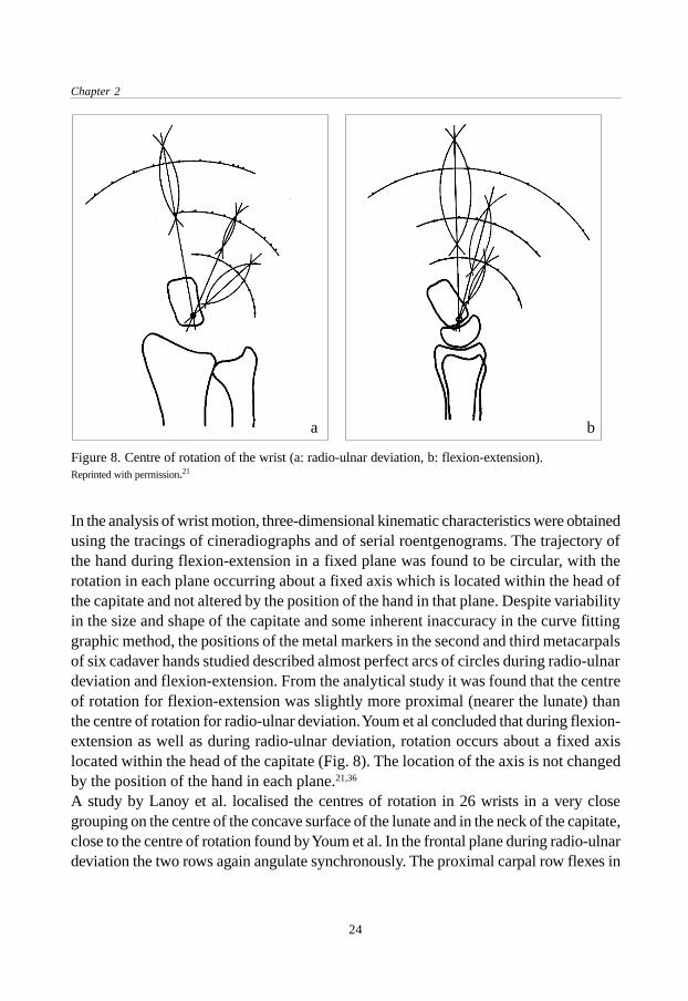
In the analysis of wrist motion, three-dimensional kinematic characteristics were obtainedusing the tracings of cineradiographs and of serial roentgenograms. The trajectory ofthe hand during flexion-extension in a fixed plane was found to be circular, with therotation in each plane occurring about a fixed axis which is located within the head ofthe capitate and not altered by the position of the hand in that plane. Despite variabilityin the size and shape of the capitate and some inherent inaccuracy in the curve fittinggraphic method, the positions of the metal markers in the second and third metacarpalsof six cadaver hands studied described almost perfect arcs of circles during radio-ulnardeviation and flexion-extension. From the analytical study it was found that the centreof rotation for flexion-extension was slightly more proximal (nearer the lunate) thanthe centre of rotation for radio-ulnar deviation. Youm et al concluded that during flexion-extension as well as during radio-ulnar deviation, rotation occurs about a fixed axislocated within the head of the capitate (Fig. 8). The location of the axis is not changedby the position of the hand in each plane.21,36
A study by Lanoy et al. localised the centres of rotation in 26 wrists in a very closegrouping on the centre of the concave surface of the lunate and in the neck of the capitate,close to the centre of rotation found by Youm et al. In the frontal plane during radio-ulnardeviation the two rows again angulate synchronously. The proximal carpal row flexes in
Figure 8. Centre of rotation of the wrist (a: radio-ulnar deviation, b: flexion-extension).Reprinted with permission.21
ba

25
Anatomy of the wrist
radial deviation and extends in ulnar deviation. The centre of rotation for radio-ulnardeviation lies near the capitate neck. According to Youm et al. it lies a few millimetres fromthe centre of rotation in the sagittal plane. Lanoy et al., however, noted individual variationsof this centre of rotation in 26 clinical subjects.45
Bressina et al. studied wrist motion using CT (computed tomography) scans of thewrist and an advanced electromagnetic tracker/digitizer system. A computer aided designsystem was then used to evaluate human wrist kinematics based on the data obtainedfrom the measurements. The centre of rotation of the wrist was found to translate alonga curvilinear path close to the proximal part of the capitate for both radio-ulnar deviationand flexion-extension.46
2.7 Functional wrist motion
Very little data exist in the literature regarding the wrist motion that is required foractivities of daily living (ADL).47 Although normal maximum motion of the wrist hasbeen previously documented with the use of standard hand goniometry, it was not untilrecently that instrumentation was developed to assess normal wrist motion duringactivities.48 Palmer et al. used a tri-axial goniometer to measure functional wrist motion.47
Wrist motion was evaluated in ten normal subjects who performed 52 standardisedtasks. Twenty-four standardised tasks that simulate personal hygiene, culinary skillsand miscellaneous ADLs were performed as wrist motion was simultaneously analysedin three axes, i.e. flexion-extension, radio-ulnar deviation and rotation. Wrist motionthat is involved in performing the activities of a carpenter, a housekeeper, a mechanic,a secretary and a surgeon was evaluated in a similar manner. The wrist joint was foundto have three degrees of freedom: flexion-extension, radio-ulnar deviation and rotation.The normal functional range of wrist motion was found to be 5 degrees of flexion, 30°of extension, 10° of radial deviation and 15° of ulnar deviation. Although some tasksrequire a moderate amount of motion, the majority require a minimum of wrist motion.Interestingly, 21of 24 tasks were mostly performed with the wrist in extension and 15of 24 tasks with the wrist in ulnar deviation. In fact, of all groups of tasks or occupationsstudied, only the activities of a surgeon consistently required flexion and ulnar deviation.There was no group of tasks which required predominantly flexion and radial deviation.Ryu et al. examined 40 normal subjects (20 women and 20 men) to determine the idealrange of motion required to perform activities of daily living.48 The amount of wristflexion and extension, as well as radial and ulnar deviation, was measured simultaneouslyby means of a bi-axial wrist electrogoniometer. The first category of tested activitiesincluded seven ‘palm placement’ positions in which the subject was asked to touch the

Chapter 2
26
top of the head, back of the head, front of the neck, chest, waist, sacrum and right foot.The second category involved personal care and hygiene; the third diet and foodpreparation and the fourth important work functions (writing, driving, telephone use,hammering, using a screwdriver and turning a key or doorknob). The entire battery ofevaluated tasks could be achieved with 60 degrees of extension, 54 degrees of flexion,40 degrees of ulnar deviation and 17 degrees of radial deviation, which reflects themaximum wrist motion required for daily activities. The majority of the hand placementand range of motion tasks that were studied in this project could be accomplished with70 percent of the maximal range of wrist motion. This converts to 40 degrees each ofwrist flexion and extension and 40 degrees of combined radio-ulnar deviation. Ulnardeviation and extension were found to be the most important positions for wrist activities.The range of wrist motion from this study is significantly larger than that reported byPalmer.47 The difference between these studies may be related to different data reductionmethods and the difference in wrist goniometer design and application.Recently, Nelson criticised the previous studies because they determined the range ofwrist motion that was used during certain activities.49 In his point of view, that is not thesame as the range of motion that is needed to perform these activities. Therefore, heperformed a study in which subjects had to wear a splint that limited wrist motion tofive degrees of flexion, six degrees of extension, seven degrees of radial deviation andsix degrees of ulnar deviation. All of the 123 selected ADLs could be performedsuccesfully by the subjects with a minimal degree of difficulty or frustration.49
2.8 Conclusion
The wrist joint is a highly movable universal joint. It is formed by the distal radius andthe distal ulna which provide an articular surface for the proximal carpal row. The latterconsists of the lunate and triquetrum and is supported by the schaphoïd bone. The wristhas a fibrous capsule which is interlaced by strong ligaments. Several of these ligamentsextend from the distal end of the radius to the carpal bones, which is of clinical importancefor the use of external fixation. The innervation of the wrist area comes from branchesof the ulnar, median and radial nerve. The sensory branch of the radial nerve is prone tosurgical damage when external fixation is used. Injuries to the distal radius areradiographically evaluated by measurement of the dorsal angle, radial angle and radiallength.Normal flexion and extension occur in the sagittal plane and average 75 and 70 degreesrespectively. Radial deviation takes place in the sagittal plane and is possible toapproximately 15 to 25°; ulnar deviation is possible to 30 to 60°. The normal range of

27
Anatomy of the wrist
wrist motion needed to perform activities of daily living (ADL) is approximately 35 to 40degrees of combined flexion and extension and 25 to 40 degrees of combined radio-ulnardeviation. Various studies to determine the centre of rotation of the wrist have beenperformed. From these studies it can be concluded that the centre of rotation for flexion-extension and for radio-ulnar deviation is located approximately in the head of the capitatebone, with small variations which might be due to individual anatomical differences andmethods of analysing wrist motion.

Chapter 2
28
29
General aspects of distal radial fractures
General aspectsofdistal radial fractures
Chapter 3
3.1 Introduction
Distal radial fractures are seen very frequently at casualty departments, usually bydoctors who are in the beginning of their specialist training. Although most of thesefractures are routinely treated by the application of a plaster cast there seems to bemore to say about this type of injury. The description of fractures of the distal radiuscarries a long history, which goes back to the ancient times of Hippocrates. Manyexperiments have been done to explain the mechanism of injury and about as manyclassification systems have been developed. The literature shows a large number ofarticles about treatment options and their results. This chapter will give an overview ofseveral of these general aspects concerning the distal radial fracture.

Chapter 3
30
3.2 History
From the time of Hippocrates to the eighteenth century, fractures of the distal end of theradius were mistaken for dislocations of the wrist.50 It is interesting that the Greekphysicians of classical antiquity used procedures to reduce these “dislocations”, forexample by combined traction and manipulation, that are practised in almost exactlythe same manner today. The great French surgeons of the Middle Ages and Arabicauthors made detailed descriptions of wrist dislocations without mentioning the existenceof a fracture.50
In 1814 the Irish surgeon Abraham Colles (1773-1843) published his classical descriptionon the fracture that bears his name (Fig. 9).51 In a time period before the invention of X-rays he wrote on the typical location of the fracture with its dorsal dislocation, thediagnosis and the treatment. Colles recognised the importance of restoring anatomywith a splint to prevent the distal radius being drawn backwards. If this failed the patientwas doomed to endure for many months considerable lameless and stiffness of thelimb, accompanied by severe pains on attempting to bend the hand and fingers. On theother hand, he found that eventually most patients regained a good and pain-free wristfunction.51 In France, Claude Pouteau (1725-1775), chief surgeon in Lyon, also describedthe fracture of the distal end of the radius with posterior tipping or displacement of thedistal fragment. His work was posthumously published in 1783.52 Since little attentionwas paid to Pouteau’s work outside France, Colles was unaware of it when he publishedhis paper “On the fracture of the carpal extremity of the radius”.53
Figure 9.Abraham Colles (1773-1843).

31
General aspects of distal radial fractures
Jean-Gaspar-Blaise Goyrand (1803-1866) clarified the anatomical features of thesecommon fractures. He found that in most cases the distal fragment was displaced dorsally,but in some cases the fragment was displaced toward the palm.54,55 Robert WilliamSmith (1807-1783) also described this phenomenon of palmar dislocation and his namewas linked to this type of fracture.56 In the United States, John Rhea Barton (1794-1871) described a subluxation of the wrist, consequent to a fracture through the articularsurface of the carpal extremity of the radius.57 The fracture could be either on the dorsalor palmar side of the radius and the subluxation or dislocation could displace in eitherdirection. These descriptions have led to the term volar and dorsal Barton fracture.Alfred Armand Velpeau (1795-1866) termed the usual deformity seen in fractures ofthe distal end of the radius the ‘talon de fourchette’ which can be translated as ‘dinner-fork deformity’.53
From this historical review it follows that it is improper to refer to all distal radialfractures as Colles’ fractures. The fracture Abraham Colles described in 1814, wasextra-articular and showed dorsal displacement.51 Since only some of the fractures atthe distal end of the radius are of the type that Colles described, one could thereforebetter refer to this type of fractures as distal radial fractures.
3.3 Mechanism of injury
Experiments to study the mechanism of injury were already done by Auguste Nelaton(1807-1873).58 The forearms of fresh cadavers were disarticulated and the olecranonremoved. With the hand fixed in dorsal or palmar flexion and the forearm vertical, thedistal forearm was struck by a hammer. The resulting fractures of the radius weredissected and it was found that the type of fracture correlated with the mechanism ofinjury. After the discovery of X-rays in 1895 the extent and great variability of individualfractures became clear. The results from Lilienfeldt’s study have increased ourunderstanding about the mechanism of wrist injuries.59,60 It was demonstrated that thetype of injury could be varied by manipulating two factors, namely the position of thehand and the angle between the forearm and the surface of impact. His experimentaldesign was simple. The specimen was exarticulated at the shoulder and suspended insuch a way that the position of the hand and forearm could be adjusted. In each positionthe investigator fell onto the arm with the weight of his body. Using this technique,Lilienfeldt was able to produce fractures of the distal radius if the angle between theforearm and the surface of impact was between 60° and 90°. The fracture ran throughthe radial styloid process if the hand was in ulnar deviation; the ulnar styloid processwas fractured if the hand was in radial deviation. Lilienfeldt produced one fracture with

Chapter 3
32
volar displacement by a trauma directed against the back of the hand. The scaphoïdbone fractured if the angle between the forearm and the surface of impact was morethan 90° with the hand in dorsal flexion and radial deviation. These experimentsdemonstrated which type of wrist injury resulted from a traumatic force in a specificdirection.Frykman also performed a biomechanical study to determine the amount of force neededto produce distal radial fractures under static and dynamic loading.61 Clinical types ofdistal radial fractures were produced with great regularity when the dorsal flexion ofthe hand was between 40 and 90 degrees. Fractures of the proximal forearm occurredwhen the dorsal flexion was less than 40 degrees; fractures of the carpal bones when itwas more than 90 degrees. A greater amount of force was required to produce distalradial fracture in specimens from male individuals (mean 282 kNm-2) compared withthose of females (mean 195 kNm-2). The type of fracture produced depended on theposition of the wrist, the direction of the force and the magnitude of the force.In fractures with dorsal displacement, the generally sharp fracture on the palmar aspectof the radial metaphyseal area suggests that the radius may first fracture in the tensionarea on its palmar surface, with the fracture propagating dorsally where bending momentforces induce compression stress. This results in comminution of the dorsal cortex withcancellous bone being compacted, further reducing dorsal stability.23 Smith reportedfractures with volar displacement to be the result of a fall on the back of the hand.56 Afall with the forearm in supination followed by pronation around a fixed extended wristhas been suggested as a more frequent mechanism of injury.62,63,64 The lunate, in particular,can exert a compressive force on the distal radius, producing a so-called die-punchfracture (Fig. 10).62,65 Porter used the term pilon fracture because of the resemblancewith pilon fractures of the distal tibia.66 Concomitant ulnar styloid fractures result froma force transmitted through an intact triangular fibrocartilage complex, whereas radialstyloid fractures result from an avulsion force through the palmar radiocarpal ligaments.62
Figure 10.Schematic drawing of a die-punch fracture.Reprinted with permission.65
Lunate
Compressiveforce
Die-punchfragment

33
General aspects of distal radial fractures
The fracture of the distal radius can be accompanied by ligamentous injury. Fontesperformed a systematic wrist arthrogram afer distal radial fractures and found that thetraingular fibrocartilage complex was torn in two thirds of all kinds of fractures. Extra-articular radius fractures were associated with an intracarpal ligamentous tear in 25%.67
Richards used arthroscopy to assess the soft tissues in 118 patients with a distal radialfracture. The triangular fibrocartilage complex was torn in 35% of intra-articular fracturesand in 53% of extra-articular fractures. Lunotriquetral ligament injuries were presentin 7% of intra-articular fractures and in 13% of extra-articular fractures. Scapholunateligament injuries were seen in 22% of intra-articular fractures and in 7% of extra-articular fractures.68
There are three main theories as to the detailed fracture mechanism at the distal radius,which are outlined below.6,61
1. Blow and counter-blow theory.This theory suggests that the bodyweight generates a counter-blow from the surface ofimpact and is thereby transmitted through the carpal bones directly to the distal radius.The fracture produced is typically located in that portion of the bone where the cortex isthinnest. This theory was first proposed by Dupuytren and later adopted by Nelaton andMalgaigne and afterwards also by Bähr.58,69,70,71 Towards the end of the century Destotand Gallois supported the theory with first röntgenologic data.72 They showed that whenthe hand is in dorsiflexion, the carpal bones come up against the surface of impact at themoment of fracture while the head of the radius is pressed against the humerus, thusallowing the force to continue directly to the lower end of the radius.2. Avulsion theory.This theory was first proposed by Linhart and later analysed more closely by Lecomte,who pointed out that the design of the olecranon gives the ulna much more intimatecontact than the radius with the humerus and that consequently the ulna is probablyalone in absorbing the impact of a fall on the hand.73,74 The force must be transmitted insome way to the radius. According to Lecomte, this must occur via the interosseousmembrane and the ligaments, particularly the strong volar apparatus. The resultantfracture is then produced by avulsion due to traction to the strong volar radio-carpalligament. Löbker and Bähr criticised this theory because if avulsion is the primarymechanism, one would expect the fracture to run a volar-proximal to dorsal-distal course,whereas in fact it generally does the opposite.71,75 This argument invalidated the theorybut Löbker also objected to the blow and counter-blow theory as the only explanationof the fracture because, in that case, comminution of the joint surface of the radiusshould be more common than it is. He therefore concluded that a combination of bothmechanisms was most likely.

Chapter 3
34
3. Bending fracture theory.Meyer stated that the course of the fracture in the individual case is determined by threefactors: the position of the hand, the surface of impact and the magnitude of the force.76
If tension simultaneously occured in the ulnar collateral ligament, the radial fracturewould always be accompanied by a fracture in the ulnar styloid process. The bendingfracture theory was later supported by Lewis. After experiments with cadavers heconcluded that with a fall, kinetic energy causes the forward energy of the body tocontinue, the wrist becomes hyperextended and the patient falls ‘over’ the hand. Thisloads the volar ligament (which is not disrupted) and the radius is pressed against thecarpal articular surface, the force being stopped by the scaphoïd and lunate bones. It isthen transmitted to the radius, which fractures at its weakest point like a bow that isloaded beyond the limit of its elasticity.77
3.4 Epidemiology
Fractures of the distal end of the radius are among the most commonly encountered fractures.The frequency of report is about 10% to 15 of all fractures.2,3,78 Figures differ markedlybetween various authors due to differences in composition of the patient population, inparticular age and sex distribution. Falck Larsen found an incidence of 27 per 10.000 peryear (males 16 per 10.000, females 37 per 10.000) in Denmark.79 The age- and sex-specificincidence rates showed a clear rise in the incidence of the fracture in women after 50 yearsof age (Fig. 11). Solgaard found an incidence of 35 per 10.000 in Danish women and 9 per
Figure 11.Age- and sex-specific incidence rates of distal radialfractures per 10.000 inhabitants.Reprinted with permission.79

35
General aspects of distal radial fractures
10.000 in men.4 Bengnér reviewed 1914 fractures of the distal forearm in Sweden. He alsofound a large increase in incidence in women after the age of 50; in men there was a smallerincrease after the age of 70.80 In Rochester, Minnesota, Owen reviewed 1235 distal radialfractures. The overall incidence in males was 8 per 10.000 and in women 41 per 10.000.1 Nodetailed data are available on the incidence of distal radial fractures in the Netherlandsbecause there is no protocol for the registration of these fractures.The female to male ratio varies between 3:1 among the 35-44 year olds to about 7:1 for theage groups above 70 years.1 There are considerable seasonal variations in incidence, with acumulation during the winter months.81 Apart from the age group 60 to 79 years, where left-sided fractures dominate, there is no significant difference in fracture side.82
3.5 Risk factors
The development of post-menopausal osteoporosis has been mentioned as a criticalrisk factor because the incidence of distal radial fractures is highest in elderly women.This has been opposed by investigators who have suggested that women with distalradial fractures had nearly the same mineral content of bone as age-matched controlswithout fracture.83,84,85 Another explanation suggests that fracture incidence is related tothe pattern of falling in the ageing population. Postural instability or ‘sway’ could beimportant factors in developing a distal radial fracture.85
Other studies on risk factors for distal radial fractures have shown that heavy alcoholconsumption and low relative weight increase women’s risk for wrist fractures. In men,cigarette smoking, alcohol consumption, body height and relative weight were notcorrelated to the risk of wrist fracture but left-handers had a relative risk for distal radialfracture of 1.56 that of right-handers. Men who reported that they had been forced tochange from left-handed to right-handed had a relative risk 2.47 times higher thanright-handers.86
3.6 Trauma mechanism
The mechanism of injury is a fall on the ground in 87% of the female and 64% of themale patients. The rest of the fractures are caused mainly by traffic accidents and fallsfrom a height.4 The first one usually occurs in the older women, whereas the latter two(more violent accidents) more often occur in young adults.9 Lawson documented all thesports-related distal radial fractures presenting to a trauma unit in Scotland over a five

Chapter 3
36
year period. There were 154 males (mean age 27 years) and 67 females (mean age 40years) with 225 fractures. Football was the cause of almost 50% of the total number ofinjuries. Other frequent causes were skiing (12%; artificial slope), rugby (7%) and icesports (6%). These figures are influenced by cultural and geographic factors as well aslocal facilities available.87 With their increasing popularity, skeelers (four or five wheelsmounted in series on a frame attachted to a skating boot) might become a significantcause of distal radial fractures in the near future. In a review of injuries due to in-lineskates, wrist injuries were the most common (32%); 25 percent of all injuries werewrist fractures.88
3.7 Fracture classifications
Eponyms such as Colles, Smith or Barton fractures have been used to describe fracturesof the distal end of the radius and are still being used. This inaccurate method ofclassification has at times resulted in conflicting data with regard to treatmentrecommendations and expected outcome.3 Several classification systems have beendeveloped in the past to classify distal radial fractures. The use of different clinical factorsas a basis for these classifications has resulted in such a wide variety of classificationsthat some authors have warned that this leads to confusion.61,89 The sometimes extremelydetailed nature of these classifications (one classification distinguished no less than 34groups) is the reason that a lot of them appear to have been used in practice only by theirinventors. Factors upon which published classifications have been based are the following:site of the fracture line, degree of joint involvement, direction and degree of displacement,presence of injury to the distal radio-ulnar joint and mechanism of injury. A selection ofthe classification systems will be discussed briefly.
3.7.1 Gartland and WerleyIn their classic article from 1951, Gartland and Werley noted that distal radial fractureswere not always exact the same injury. Some were fractures outside the radiocarpal joint(extra-articular, type I) whereas others were within the joint (intra-articular). They furtherfound that articular fractures could be undisplaced (type II) or displaced (type III) withrespect to the radiocarpal joint.5 Solgaard and Sarmiento added a fourth subdivision, thenon-displaced extra-articular fracture, to the original classification.90,91
3.7.2 LidströmLidström in 1959 described six fracture types based on the above mentioned factorswhich determine the type of fracture. Type I: Fractures with no appreciable displacement.

37
General aspects of distal radial fractures
Type II-A: Fractures with merely dorsal angulation, not involving the joint space. TypeII-B: Fractures with merely dorsal angulation, involving the joint but withoutcomminution of the articular surface. Type II-C: Complete displacement, not involvingthe joint surface. Type II-D: Complete displacement, involving the joint but withoutcomminution of the articular surface. Type II-E: Fractures with complete displacementand comminution of the articular surface.6
3.7.3 OlderIn 1965 Older published a classification system that not only graded dorsal angulation,the presence and extent of comminution and the direction and extend of displacement,but also identified the presence of shortening of the distal radial fragment in relation tothe ulna. Type I: Non-displaced. Type II: Displaced with minimal comminution. TypeIII: Displaced with comminution of the distal radius. Type IV: Displaced with severecomminution of the radial head.92
3.7.4 FrykmanFrykman introduced a comprehensive classification system in 1967 (Fig. 12).61 It isbased on the distinction between extra- and intra-articular fractures of the distal radius.In addition, consideration is given to whether or not there is also a fracture of the distalulna, the reason for this being the deleterious effects which such fractures had on theprognosis of the distal radius in his series. No attempt is made to ascertain the degree ofcomminution or direction of initial displacement, although this is important. As otherauthors have noted, radial displacement and dorsal angulation are the two principaldeformities, and the functional result is related to the reduction of both of them.30 Theclassification introduced by Frykman is the most commonly used one in publicationsabout distal radial fractures. Table 1 describes the complete system of classification asintroduced by Frykman.

Chapter 3
38
TypeI : Extra-articular fracture without a fracture of the distal ulna.
II : Extra-articular fracture accompanied by a fracture of the distal ulna.III : Intra-articular fracture involving the radiocarpal joint but without a fracture of the distal ulna.IV : Intra-articular fracture involving the radiocarpal joint accompanied by a fracture of the distal ulna.V : Intra-articular fracture involving the distal radio-ulnar joint but without a fracture of the distal ulna.
VI : Intra-articular fracture involving the distal radio-ulnar joint accompanied by a fracture of the distal ulna.VII : Intra-articular fracture involving both the radio-carpal and distal radio- ulnar joint but without a
fracture of the distal ulna.VIII : Intra-articular fracture involving both the radio-carpal and distal radio-ulnar joint accompanied by a
fracture of the distal ulna.
Table 1. Fracture types distinguished by Frykman.
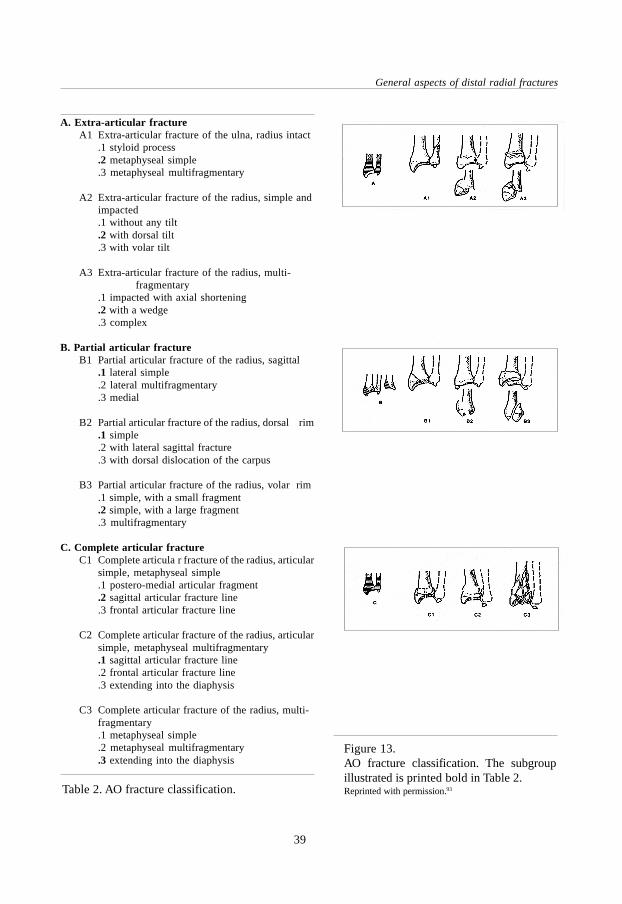
3.7.5 AOAnother frequently used classification system is that of the Swiss AO/ASIF-group(Arbeitsgemeinschaft für Osteosynthesefragen / Association for the Study of InternalFixation).93 The fundamental principle of this classification is the division of all fracturesof a bone segment into three types and their further subdivision into three groups andtheir subgroups (Fig. 13). With the AO-classification, the fracture types are arranged inascending order of severity according to the morphologic complexities of the fracture,the difficulties inherent in their treatment and their prognosis. Type A1 indicates thesimplest fracture with the best prognosis and C3 the most difficult fracture with theleast favourable prognosis. The complete AO classification of distal radial and/or ulnafractures is described in Table 2.
Figure 12.Frykman fracture classification.Reprinted with permission.96
I II III IV
V VI VII VIII
39
General aspects of distal radial fractures
Figure 13.AO fracture classification. The subgroupillustrated is printed bold in Table 2.Reprinted with permission.93Table 2. AO fracture classification.
A. Extra-articular fractureA1 Extra-articular fracture of the ulna, radius intact
.1 styloid process
.2 metaphyseal simple
.3 metaphyseal multifragmentary
A2 Extra-articular fracture of the radius, simple andimpacted.1 without any tilt.2 with dorsal tilt.3 with volar tilt
A3 Extra-articular fracture of the radius, multi-fragmentary
.1 impacted with axial shortening
.2 with a wedge
.3 complex
B. Partial articular fractureB1 Partial articular fracture of the radius, sagittal
.1 lateral simple
.2 lateral multifragmentary
.3 medial
B2 Partial articular fracture of the radius, dorsal rim.1 simple.2 with lateral sagittal fracture.3 with dorsal dislocation of the carpus
B3 Partial articular fracture of the radius, volar rim.1 simple, with a small fragment.2 simple, with a large fragment.3 multifragmentary
C. Complete articular fractureC1 Complete articula r fracture of the radius, articular
simple, metaphyseal simple.1 postero-medial articular fragment.2 sagittal articular fracture line.3 frontal articular fracture line
C2 Complete articular fracture of the radius, articularsimple, metaphyseal multifragmentary.1 sagittal articular fracture line.2 frontal articular fracture line.3 extending into the diaphysis
C3 Complete articular fracture of the radius, multi-fragmentary.1 metaphyseal simple.2 metaphyseal multifragmentary.3 extending into the diaphysis

Chapter 3
40
3.7.6 MeloneFurther refinement of the classification for intra-articular fractures was proposed byMelone, who recognised that many intra-articular fractures not only had instability butspecific patterns of displacement.94 He identified that most intra-articular distal radialfractures have four fracture components (shaft, radial styloid, dorsal medial, palmarmedial). In his classification, Melone proposed five subclassifications (Fig. 14). Type I:Undisplaced fractures without comminution. Type II: ‘Die punch’ fractures - unstablefractures with moderate or severe displacement of the medial complex as a unit andcomminution of both the anterior and posterior cortices of the radius. Type III: Spikefractures - unstable fractures that demonstrate displacement of the medial complex aswell as displacement of an additional spike from the comminuted radial shaft. Type IV:Split fractures. These are unstable fractures in which the medial complex is severelycompressed by the lunate, resulting in wide separation or rotation of the dorsal andpalmar medial fragments. The injury causes a major bi-articular disruption and is alwaysaccompanied by serious soft tissue damage. Type V: Explosion fractures. These fracturesresult from a severe force comprising both compression and crush that causes extensivecomminution, often extending from the articular surface to the diaphysis.
3.7.7 FernandezFernandez subdivided fractures of the distal end of the radius based on the mechanismof injury.95 Type I: Bending fractures - the metaphysis fails to tensile stress. Type II:Compression fractures - a fracture of the joint surface with impaction of subchondraland metaphyseal bone (die punch). Type III: Shearing fractures - fractures of the jointsurface. Type IV: Avulsion fractures - fractures of ligament attachments (ulnar styloidand radial styloid).
Figure 14. Melone fracture classification.Reprinted with permission.94

41
General aspects of distal radial fractures
3.7.8 DiscussionAny classification is of limited value, unless it provides guidelines to treatment orprognosis.23 The classification systems descibed above have in common the fact thatthe severity of the fracture increases with the presence of intra-articular fragments and/or comminution but only sometimes it is linked to a treatment strategy. Most classificationsystems distinguish three to five fracture types, which are further subdivided, with theAO classification as the most detailed but also elaborate system.Almost none of the described classification systems pays attention to accompanyingsoft-tissue damage of the triangular fibrocartligae disc and the radiocarpal, ulnocarpaland intercarpal ligaments, although they can be a cause of dissatisfactory subjectiveand functional results in spite of good fracture healing. Demonstration of soft-tissuedamage is nevertheless difficult if not impossible in an emergency situation.96
Frykman's classification is particularly helpful by identifying intra-articular fractures(type III to VIII), which are typically prone to complications. The more complex thefracture, the higher the number and the more likely the complications of fracture healing.The disadvantage is that the classification does not make a distinction between displacedand non-displaced intra-articular fractures. The AO classification is more detailed in itsdescription of the fracture and part of a universal classification system for fractures.Both the Frykman classification and the AO classifcation are well known and widelyused. For this reason these classification systems were used in this study.
3.8 Treatment options
The best treatment of distal radial fractures is controversial. Various options have beendescribed. This indicates that no method is completely satisfactory. Also, the method ofevaluation for the treatment result and the optimal length of follow-up are subject ofdiscussion. The two main criteria are the anatomic result and the (objective or subjective)functional result. There is no unanimity about the relationship between these two. Aselection of treatment options is briefly discussed below.
3.8.1 Plaster of paris cast supportThe classic method of treatment is closed reduction and plaster of paris cast support.23
This remains the accepted method for 75 to 80 per cent of fractures of the distal end ofthe radius.3,5,6,7 Usually the wrist is held in mild flexion (10°-20°) and ulnar deviation(15°).62 Immobilisation in both pronation and supination has been advocated, butprospective trials comparing the two have not demonstrated any significant differencein results.30,31 Although for most of the fractures of the distal radius closed reduction

Chapter 3
42
and plaster immobilisation offer satisfactory results, this form of treatment is insufficientto maintain length and prevent secondary displacement in the so-called unstablefractures.8 Therefore, only fractures with no or little displacement and/or comminutionare recommended to be treated with plaster immobilisation.62
3.8.2 Functional bracingFunctional bracing, as recommended by Sarmiento, provides a method of stabilisationin which motion of the elbow and volar flexion are permitted while pronation andsupination as well as dorsal flexion are prevented.90 Sarmiento reported improved earlyresults in stable fractures with this method as compared to the literature.90,97 Othershave demonstrated no functional or anatomic advantage of this form of treatment.98 Ina prospective study performed by de Bruijn 196 patients were treated with a below-the-elbow functional brace. This method of treatment offered little advantage overconventional plaster of paris immobilisation as measured by the functional andanatomical results.99
3.8.3 Pins and plasterThe use of pins and plaster was described by Böhler in 1929 as a treatment for those fracturesthat cannot be held reduced by closed treatment methods.31,65,100,101,102 In this method proximaland distal transverse pins are held in plaster in order to provide fixed traction and to preventshortening. While the length of the radius is reconstituted, often palmar tilt is not restored.The alignment of displaced intra-articular fragments may be maintained, but many times anacceptable position is not obtained.102 Pin complications are reported in nearly all series,even leading to a re-operation rate as high as 16%.31,103 Other problems such as tie-down ofthe muscle by distal pins, problems with the access to open wounds, complications withcircumferential plaster and difficulty of positioning the Kirschner wires in the plaster hasled to dissatisfaction with pins and plaster.31
3.8.4 Percutaneous K-wire fixationPercutaneous pinning was reported by DePalma. This technique has been applied inmany ways with a variety of implants.104 It is limited to those fractures in which closedanatomic reduction can be obtained and in which no more than two intra-articularfragments are present.31 DePalma used a percutaneous pin technique in which the pinswere inserted obliquely through the distal ulna into the reduced fracture fragment of theradius to maintain alignment. This approach was chosen to avoid injury to the sensorybranch of the radial nerve, as well as to provide stability for the pin by passing it throughboth cortices of the ulna. At the end of the procedure the wrist was immobilised by aplaster splint.

43
General aspects of distal radial fractures
3.8.5 Open reduction and internal fixationOpen reduction and rigid internal fixation with screws and/or a plate are appropriate forless comminuted displaced intra-articular fractures.11 This method is not feasible in anarea of severe comminution, which is present in many intra-articular fractures.8
Furthermore, distal radial fractures often occur in elderly patients with osteoporosis,which results in problems with reduction and stabilisation.18 It may be advisable toperform open reduction and internal fixation for shear fractures with displacement of avolar or dorsal intra-articular fragment (i.e. as described by Barton) because thesefractures are very unstable.3,57
3.8.6 Skeletal repair system™Skeletal Repair System™, is an injectable, fast setting, high strength bone mineralsubstitute for bone repair. Inorganic calcium and phosphate sources are combined toform a paste that is surgically implanted by injection. Under physiological conditions,the material hardens in minutes, providing support for fracture fragments. After 12hours the strength is equal to bone. Animal studies provide evidence that the material isremodelled and gradually replaced by human bone. Clinical invesigations with the newbiomaterial in extra-articular distal radial fractures suggest improved anatomical outcomeand hand function when compared to current standard methods of fracture fixation.105 Apossible complication could be the spill of paste into the soft tissue compartments(particularly of the median nerve) or the joint space.106
3.8.7 External fixationExternal fixation of distal radial fractures is a treatment method in which a distractionforce is applied to the carpus to align the fracture fragments. This principle is calledligamentotaxis and was initially described by Vidal.12 The features of external fixationare the subject of this study and will be discussed in the following chapters.
3.9 Complications
Abraham Colles stated: “One consolation only remains, that the limb will at some remoteperiod again enjoy perfect freedom in all its motions, and be completely exempt frompain…”51 Despite this optimistic outlook, the management of distal radial fractures isfrequently accompanied by complications. In a large retrospective series of 565 fractures,Cooney reported a complication rate of more than 31%.107 The complications includeddysfunction of the median nerve, malposition, arthritis of the radiocarpal or radio-ulnarjoint, stiffness of the fingers, rupture of a tendon, reflex sympathetic dystrophy and

Chapter 3
44
Volkmann ischemic contracture. Some of these complications were the sequelae oftreatment rather than of the original fracture. A number of studies have highlighted theimportance of the distal radio-ulnar joint in the functional outcome after distal radialfracture.14,61,107 This joint can be involved both by diastasis due to direct injury and byresidual deformity of the distal end of the radius. The resulting pain, instability and lossof rotation of the forearm can be disabling.61 Post-traumatic arthrosis is reported tooccur in 6 to 65% of cases, probably depending on definition criteria and length offollow-up.5,6,14,107,108 It is mostly seen in intra-articular fractures and failure to achieve ormaintain congruity of the articular surface of the distal part of the radius at the time ofunion of the fracture is the most important factor in the development of post-traumaticarthrosis.14,107
Complications after fractures of the distal end of the radius can roughly be divided intofracture related complications, soft tissue related complications and treatment relatedcomplications (Table 3). Early and adequate reduction is thought to be the most effectivemeans of preventing complications.109
Fracture related complications:- loss of reduction and secondary deformity- depressed major articular fragments- distal radio-ulnar (sub-) luxation- (unrecognised) associated carpal injury- non-union- radiocarpal arthrosis
Soft tissue related complications:- tendon damage or rupture- median or ulnar nerve stretch, contusion or compression- muscle weakness, stiff hand- reflex sympathetic syndrome
Treatment related complications:- post-reduction swelling, constrictive dressings, compartment syndrome- errors in external or internal fixation- nerve damage caused by operative procedure- pin tract infection
Table 3. Potential complications following a distal radial fracture.

45
General aspects of distal radial fractures
3.10 Conclusion
Descriptions of injuries of the wrist go back to ancient history. The recent history startsin the nineteenth century with papers from Colles, Pouteau, Smith and Barton. Thetype of injury to the wrist is determined by the direction of the traumatic force, with afall with the hand in 40 to 90 degrees of dorsal extension resulting in a fracture of thedistal radius. The incidence is highest in women above the age of 50, which is probablyrelated to osteoporosis and postural instability. In the majority of the patients a fall onthe ground or a fall from a height is the cause of the fracture.The fracture of the distal end of the radius can be classified according to a range ofclassification systems. Their common feature is an increasing severity in the presenceof intra-articular fragments and/or comminution but clear guidelines for the treatmentof the fracture can often not be related to the classification. Frykman’s classification issimple, clearly structured and widely used. Other systems also may have good propertiesbut are more complicated or less frequently used. The optimal treatment of the distalradius fracture is unclear. Plaster of paris is the simplest method with good results instable fractures. Additional or alternative fixation methods include the use of Kirchnerwires, plate osteosynthesis, bone substitues and external fixation. These techniques areadvised for more ‘complex’ fracture types but can be accompanied by severalcomplications like technical problems, infection and nerve damage. Other complicationsof distal radial fractures include secondary deformity, loss of function and radiocarpalarthrosis. Pain and stiffness can occur in up to 30% of the treated patients; post-traumaticarthrosis can be seen in 6 to 65% of the patients, partly depending on the length offollow-up.In summary, the distal radial fracture is a common injury which usually can be treated bysimple methods with good results but is also a fracture with many possible pitfalls.

Chapter 3
46

External fixation in distal radial fractures
47
External fixationindistal radial fractures
Chapter 4
4.1 Introduction
For unstable fractures of the distal radius that cannot be treated successfully in plaster,external fixation is one of the possible alternatives. It is a method of treatment thatoriginally was used for other fractures but after its usefulness had been proved, externalfixators were also tried at the wrist. Since then a wide range of different types of fixatorshave been developed. Although overall results of treatment are reported to be good, themethod also carries a considerable risk of serious complications. To prevent these andto improve results the development of new external fixators is still going on. This chapterwill give an overview of the characteristics of external fixation for distal radial fractures.At the end the principle of dynamic external fixation will be introduced and discussed.
Chapter 4
48
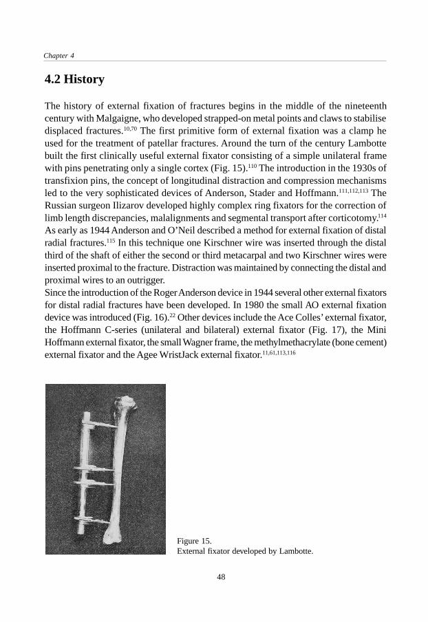
Figure 15.External fixator developed by Lambotte.
4.2 History
The history of external fixation of fractures begins in the middle of the nineteenthcentury with Malgaigne, who developed strapped-on metal points and claws to stabilisedisplaced fractures.10,70 The first primitive form of external fixation was a clamp heused for the treatment of patellar fractures. Around the turn of the century Lambottebuilt the first clinically useful external fixator consisting of a simple unilateral framewith pins penetrating only a single cortex (Fig. 15).110 The introduction in the 1930s oftransfixion pins, the concept of longitudinal distraction and compression mechanismsled to the very sophisticated devices of Anderson, Stader and Hoffmann.111,112,113 TheRussian surgeon Ilizarov developed highly complex ring fixators for the correction oflimb length discrepancies, malalignments and segmental transport after corticotomy.114
As early as 1944 Anderson and O’Neil described a method for external fixation of distalradial fractures.115 In this technique one Kirschner wire was inserted through the distalthird of the shaft of either the second or third metacarpal and two Kirschner wires wereinserted proximal to the fracture. Distraction was maintained by connecting the distal andproximal wires to an outrigger.Since the introduction of the Roger Anderson device in 1944 several other external fixatorsfor distal radial fractures have been developed. In 1980 the small AO external fixationdevice was introduced (Fig. 16).22 Other devices include the Ace Colles’ external fixator,the Hoffmann C-series (unilateral and bilateral) external fixator (Fig. 17), the MiniHoffmann external fixator, the small Wagner frame, the methylmethacrylate (bone cement)external fixator and the Agee WristJack external fixator.11,61,113,116

External fixation in distal radial fractures
49
Figure 16.The small AO external fixator.
Figure 17.The Hoffmann Unilateral externalfixator.
4.3 Principle of technique
The management of distal radial fractures by means of external fixation is based on theprinciple of ligamentotaxis.12 The term ligamentotaxis was introduced by Vidal andrefers to the principle of distraction of comminuted fractures of various joints like thehip, the knee, the ankle and the wrist. He obtained the best results when it was used atthe wrist joint. When traction is applied across the wrist joint by distraction, the capsuleand ligaments of the wrist joint are placed under tension. These distracted soft tissuesthen provide a compressive force on the adjacent bone fragments, hence they tend tomaintain the reduction of the distal radial fracture.Since the fracture fragments are aligned by intact ligaments, the strength of theseligaments is of obvious importance because their integrity permits successful use oftraction to maintain reduction.94 It was demonstrated experimentally that even with themost severely comminuted fractures, the ligaments of the wrist remain intact.104 On theother hand, as some authors have experienced during open reduction, injury to these

Chapter 4
50
soft tissues has commonly been noted.31,67 A study in which arthroscopy was performedin patients with distal radial fractures showed tears in the ligaments of the wrist in 7 to22% of the fractures.68
Theoretically ligamentotaxis across the wrist joint to maintain reduction could result ina delayed return of motion by stretching or tightening of the wrist capsule. Rapidrestoration of function might be due to the fact that the distal fixator pins were placed inthe distal fracture fragment(s) instead of the second metacarpal in a small series publishedby Forgon.117 However, this method of pin placement does not apply the principle ofligamentotaxis and can be difficult in comminuted fractures. Also, at least one studyshowed that the range of movement was not influenced by the fact whether the fixatorcrossed the radiocarpal joint or not.118
4.4 Indications
Since external fixation has gained popularity in the treatment of distal radial fractures,various indications have been suggested in the literature. Most authors agree thatexternal fixation is the treatment method of choice in a number of situations (Table4).8,118,119,120,121,122,123,124
1. Unstable fractures.A fracture is defined as unstable- if there is an inability to maintain satisfactory fracture alignment at the time of reduction- in the presence of severe comminution (i.e. Frykman type III-VII)- in the presence of intra-articular fragments- if there is severe displacement and difficulties are expected in maintaining fracture reduction by cast
support alone (more than 20° dorsal angulation and more than 10 mm radial shortening prior toreduction).120
2. Loss of reduction following treatment by closed reduction and casting techniques.
3. Open fractures and fractures with associated nerve-, vessel- and muscle damage.To provide a free approach to the wound in the post-operative period.
4. Bilateral fracturesFor reasons of patient comfort.
Optional indications:1. Fractures of the distal radius associated with a fracture-luxation of the carpal bones.2. Distal radial fractures combined with proximal fractures of the forearm or elbow, or with combined
injuries to the hand (soft-tissue, bone).
Table 4. Indications for external fixation of distal radial fractures.8,118,119,120,121,122,123,124

External fixation in distal radial fractures
51
The period after which an initial treatment with plaster support can be converted toexternal fixation varies between one day and three weeks, with an average of oneweek.17,125,126 It is more difficult to reduce the fracture when the fixator is applied morethan a week after the trauma.A relative contra-indication for the use of external fixation is the age of the patient.Several authors exclude older patients (i.e. over 65 years) to avoid the problem of pinloosening in osteoporotic bone.17,127 The use of external fixation requires optimum follow-up and co-operation and therefore the technique should be restricted to co-operativeand well motivated patients.17,128
4.5 Operative technique for rigid external fixators
The surgical technique for application of an external fixator at the distal radius can besubdivided into several standardised steps. International consensus is developing especiallyfor the critical parts such as the insertion of the fixator pins, which can cause iatrogeniccomplications. In this paragraph the main features of the procedure for the application ofa conventional, rigid external fixator for the treatment of fractures of the distal end of theradius are outlined. The description can be used as a general guideline but variationsaccording to a specific fracture and personal preferences can be added if required.
4.5.1 Pin placementAfter gross re-alignment of the limb, landmarks such as the second metacarpal, theradial shaft and the expected course of the sensory branch of the radial nerve aredetermined and possibly drawn on the skin.129 The desired incisions for placement ofthe fixator pins are determined with the forearm in neutral pro-supination. Usually twoproximal pins are placed in the radius and two distal pins in the second (possibly alsothird) metacarpal. The diameter of these threaded Kirschner wires varies between 2.5and 4.0 mm.17,22,120 A biomechanical study comparing distal pin placement in four, sixor eight cortices showed that the pull-out strength when six cortices are used is morethan twice as high as when four cortices are used.130 Four incisions of 1.5 to 2.0 centimetreslong are made. The pins in the second metacarpal are best inserted with a flexed metacarpo-phalangeal joint to assure unrestricted flexion of the finger after the operation. In theradius careful subcutaneous dissection is essential to protect the sensory branch of theradial nerve. Recently, a ‘limited open surgical approach’ for the placement of the pinswas proposed.131 This technique allows direct visualisation of the bone to avoid injury tothe soft tissues and redrilling due to for example eccentric pin placement (Fig. 18).

Chapter 4
52
Insertion of the fixator pins requires predrilling because otherwise unexpectedly hightemperatures are generated, leading to bone necrosis which predisposes to infectionand pin loosening. The only technique which does not carry this risk is insertion of thepins by hand force. It is, however, in this case difficult to drill an exact circular hole.During drilling, drill sleeves should be used to protect the soft tissues. Correct axialalignment of the pins is essential particularly when single bar constructions are planned.Preloading or pretensioning of the pins does increase the stiffness of the constructionand may enhance the purchase in the bone, although too little is known about the amountof stiffness really needed. Experimental studies have shown that pretension createsextremely high pressures, cortical crush and necrosis which predisposes to infectionand loosening.132,133,134 Controlled preload also results from axial mismatch between thehole and the pin, which, if correctly chosen, may be all that is needed. For example, a2.5 mm pin is advised to be inserted in a 2.0 mm drill hole without further pretensioningof the pin.129 To prevent pintract infection, the skin around the fixator pins should befree of tension in every position of the forearm.
4.5.2 ReductionDepending on the type of fixator, the reduction should be performed before or afterinsertion of the fixator pins and assemblance of the frame. The current opinion is thatanatomical or near anatomical reduction of the articular surfaces is desirable, withaccepted maximum steps of 2 millimetres.14 Normal or near normal radial length, palmarand radial angle are aimed for.129
Figure 18.Limited open surgicalapproach.Reproduced by the kindpermission of ChurchillLivingstone.131
Surgical Approach:Proximal Pin Site
Skin Incision
Exposed Site
Surgical Approach:Distal Pin Site
Skin Incision
Periosteal Elevation
Exposed Site
ECRL
BR

External fixation in distal radial fractures
53
If distraction and closed manipulation alone do not result in adequate reduction, Kirschnerwires can be used for supplemental fixation of the fracture fragments. Only in exceptionalcases it is necessary to add a cancellous bone graft to maintain the reduction in thepresence of a cortical defect or an unstable articular fragment.129,135 Recently, bonegrafting for every comminuted fracture of the distal radius was recommended to avoidcollapse of the fracture and to shorten the period of external fixation.136 After anatomicalreduction and sufficient stabilisation of the fracture fragments a near physiologicalposition of the wrist is sought.129
4.5.3 Post operative careThe fixation is generally stable enough to allow rehabilitation without any supportivesplinting.129 If the distal radio-ulnar joint is severely comminuted or if the distal ulna issubluxated dorsally, a dorsal splint maintaining the forearm in supination may be neededfor additional immobilisation.62 Early, active motion of digits, elbow and shoulder areimportant to reduce swelling and stiffness.23 Forearm pro-supination is generally notadvocated to allow healing of associated ulna-radial and ulna-carpal ligament injuries andbecause movement is limited by the proximal fixator pin to soft tissue interface.129 Pintract infection most often occurs at the proximal pins, where soft tissue movement is at itsgreatest. The patient is instructed to inspect and clean the pin sites at least once a day. Avariety of agents is reported for cleaning the pin sites, but manipulation of the pin-skininterface to clean away the crust is probably more important than the agent being used.137
Weekly evaluations allow early detection of problems. Abnormal pain is an importantearly symptom of reflex sympathetic dystrophy.129
Two or three weeks after surgery the distraction should be terminated by adjustment offixator parts. If distraction is maintained beyond this period a sympathetic dystrophy ismore likely to occur.138 Generally, the fixator can be removed six to eight weeks afterthe operation without anaesthesia.120 Staged retrieval, for instance by removing the fixatorat six weeks and the percutaneous Kirschner wires at eight weeks is possible in caseswhere additional K-wire fixation was used and allows earlier rehabilitation of the wrist.
4.6 Results of treatment in the literature
Over the last 12 years more than 50 studies on external fixation of distal radial fractureshave been published. It is difficult to compare the results of these (mainly retrospective)studies because they differ in many aspects such as number of patients, the externalfixation device that was used, the fracture types included, the method of evaluation andthe length of follow-up.

Chapter 4
54
A frequent subject of discussion is the importance of the anatomical result. Still there isno unanimity on whether the anatomical results are directly related to the functionalresults. In Bacorn’s study of over 200 fractures, a direct relationship between residualdeformity and mean disability was found.139 This has been confirmed more recently bydifferent authors.90,102,120,140 Others have not found such a relationship.141,142 The majorityof authors, however, agree that the results of treatment correlate directly with restorationof normal anatomy.31
Several systems to evaluate the result of treatment have been developed. For functionalresults the system from Gartland and Werley is most often used, a point system whichtakes into account the residual deformity, the subjective evaluation of the patient, theobjective findings and the complications arising directly from the fracture.5 The resultingpoint ranges for an excellent, good fair or poor result provide a rigid, constant methodfor evaluating a patient.
Author Cooney D’Anca Vaughan Schuind
Year 1979 1984 1985 1989
Number pat. 60 87 52 225
Female/ 53 67 38 149
male 7 20 14 76
Age (mean) 63 55 52 50
Device Roger Anderson Hoffmann C Roger Anderson Hoffmann C
Follow-up
(years, mean) 2 1.5 4 0.5
Fracture types 52% I-VI 27% I-VI 20% IV-VI 57% I-II
(Frykman) 48% VII-VIII 73% VII-VIII 80% VII-VIII 43% III-VIII
Results
Lidström (%)
excellent 55 78 47 68
good 33 16 47 19
fair 12 6 3 3
poor 0 0 3 0
Gartland (%)
excellent 32 63 29 no data
good 55 31 60
fair 13 4 11
poor 0 2 0
Table 5. Results of distal radial fractures treated with rigid external fixators.9,16,119,120,122,124,143,144
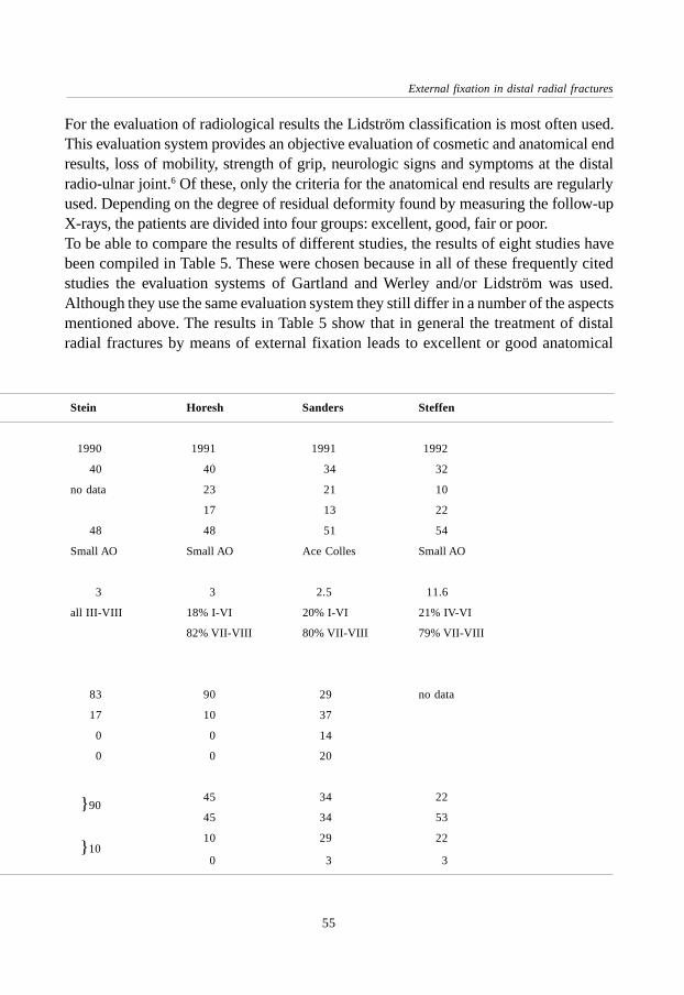
External fixation in distal radial fractures
55
For the evaluation of radiological results the Lidström classification is most often used.This evaluation system provides an objective evaluation of cosmetic and anatomical endresults, loss of mobility, strength of grip, neurologic signs and symptoms at the distalradio-ulnar joint.6 Of these, only the criteria for the anatomical end results are regularlyused. Depending on the degree of residual deformity found by measuring the follow-upX-rays, the patients are divided into four groups: excellent, good, fair or poor.To be able to compare the results of different studies, the results of eight studies havebeen compiled in Table 5. These were chosen because in all of these frequently citedstudies the evaluation systems of Gartland and Werley and/or Lidström was used.Although they use the same evaluation system they still differ in a number of the aspectsmentioned above. The results in Table 5 show that in general the treatment of distalradial fractures by means of external fixation leads to excellent or good anatomical
Stein Horesh Sanders Steffen
1990 1991 1991 1992
40 40 34 32
no data 23 21 10
17 13 22
48 48 51 54
Small AO Small AO Ace Colles Small AO
3 3 2.5 11.6
all III-VIII 18% I-VI 20% I-VI 21% IV-VI
82% VII-VIII 80% VII-VIII 79% VII-VIII
83 90 29 no data
17 10 37
0 0 14
0 0 20
45 34 22
45 34 53
10 29 22
0 3 3
} 90
} 10

Chapter 4
56
results in 66 to 100% of the patients. Functional results are graded excellent or good in68 to 94% of the patients. In the two studies with a follow-up of at least four years thefunctional results were slightly worse than in those with a shorter follow-up, whichmay be related to the late onset of post-traumatic arthrosis.9,16
Approximately 5 to 35% of the patients treated with a rigid external fixator have a fairor poor result, either anatomically or functionally. This could be due to the type offracture and/or to the form of treatment and its possible complications. The complicationswhich can influence the outcome will be discussed below.
4.7 Complications specific for external fixation
Complications occurring during the treatment of distal radial fractures with externalfixation are reported to range from 15% to over 60%.145 There are procedure relatedcomplications such as pin-tract infections and injury to the soft tissues and fracture-type related problems like osteoporosis and post-traumatic arthrosis. The followingcomplications can be recognised:
4.7.1 Pin and pin-tract problemsThese include pin-tract infection, pin loosening, pin breakage and pin site fracture andoccur in about 20% of the patients.9,118,122,126,146,147 Pin-tract infection is the most commoncomplication of this category. Reported percentages vary widely because the definitionof infection differs in the various studies. Horesh reported 5% pin-tract infections in 40patients, Kongshom 6% in 69 patients, Riis 40 % in 20 patients and Jenkins 28% in 32patients.119,126,146,147 Necrosis of soft tissues around the pin, excessive pressure at the pin-bone interface and thermal damage to the bone during insertion are factors which arelikely to contribute to the development of pin-tract infections.137 Usually pin-tract infectionsresolve with local wound care (antiseptics); occasionally antibiotics are warranted. Inmost cases there is no need to remove the pins.145
4.7.2 Neuro(-vascular) injuryDue to its position, the dorsal sensory branch of the radial nerve is susceptible to injury.137
This temporary or even permanent complication is reported in 2 to 17% of thepatients.124,126,127,146,147,148,149 Others do not report this complication at all.122 This couldbe related to the technique of proximal pin placement and to the method of registrationof complications. Carpal tunnel syndrome occurs in 0 to 4% but is probably not relatedto the external fixator.118,146 No reports of vascular injury as a result of pin placementhave been found in the literature.

External fixation in distal radial fractures
57
4.7.3 Post-traumatic arthrosisA reliable estimation of the incidence of post-traumatic arthosis is difficult to presentbecause it is influenced by the type of definition used and the length of follow-up.Furthermore, radiological signs of arthrosis are not necessarily accompanied bysymptoms and vice versa.In one study of 100 patients treated by external fixation, 3% had developed post-traumaticarthrosis after a follow-up of less than two years.118 A more recent study reported arthrosisin 7%.15 However, in order to observe the development of arthrosis, patients must befollowed for a longer period.31 After an average follow-up of 6.7 years, evidence of post-traumatic arthrosis was found in 65% of the complete study group and in 91% of thepatients who showed an incongruity of the articular surface of the distal part of the radiusat the time of union.14 The occurrence of a die-punch fragment adversely affected theoutcome. A survey by Smaill noted that 10 of 41 patients had radiographic signs of arthrosisfive to six years after the fracture, but only three had symptoms.150 Over a seven-yearfollow-up Overgaard found that 30 percent of 56 patients had radiographic evidence ofosteophytes and 14 percent had advanced radiographic changes.108 In his classic studyFrykman found a high rate (19%) of arthrosis of the distal radio-ulnar joint, which wasoften symptomatic.61 A recent review by Steffen reported 59% of mild to severe post-traumatic arthrosis after 12 years.16
4.7.4 Reflex sympathetic dystrophyMany names have been given to this syndrome such as Sudeck’s dystrophy,algodystrophy, shoulder-hand syndrome and others.151 Reflex sympathetic dystrophycan be a major problem and can result in permanent loss of function.123,152 Potentialsymptoms are pain, swelling, change in colour and edema. Also, a limited active rangeof motion is most frequently reported in relation with trauma or surgery.151 Thepathogenesis has been associated with the sympathetic system but remains unclear.Reflex sympathetic dystrophy is reported to occur more frequently if distraction bymeans of external fixation is maintained for more than three weeks.138 In a retrospectivestudy of 26 patients, Kaempffe suggested that the functional outcome was significantlyadversely affected as the duration of distraction increased but the data were inconclusivesince only some parameters of outcome were significantly different.153 Various studieshave reported reflex sympathetic dystrophy to occur in 0%, 5% and up to 18% and itseems obvious that the frequency depends on the definition.9,118,146,154
4.7.5 OsteoporosisSeveral authors reported high percentages (up to 60%) of osteoporosis.2,122 Fractureswith a higher Frykman score (i.e. more intra-articular components) showed a more

Chapter 4
58
pronounced bone mineral loss.155 The osteoporosis usually resolves once motion isregained and therefore it is not a true complication but rather a transient problemassociated with immobilisation in general.122,123
4.7.6 Other complicationsLess common complications include loss of reduction, rupture of the extensor pollicis longustendon, irritation of the median or ulnar nerve and pinsite synostosis.120,122,123,145,147,156
Associated lesions of the triangular fibro-cartilage and the ulno-carpal ligament complexleading to residual subluxation of the distal radio-ulnar joint, associated scapho-lunaror lunato-triquetral dissociation and entrapment or laceration of tendons and nerves canbe reasons for complications and poor results.12,23,144,157
4.8 Recent developments: dynamic external fixation
To allow early functional recovery and to overcome some of the problems associatedwith prolonged immobilisation, a new form of external fixation for the treatment ofdistal radial fractures has recently been introduced.17 It is called ‘dynamic externalfixation’ because the external fixation device allows motion at the wrist during treatmentof the fracture. The early mobilisation of intra-articular fractures has been advisedextensively but is technically difficult at the wrist.8,10,11,13,158 Potential advantages of thedynamic external fixators could be an earlier and improved functional outcome and thereduction of pain and stiffness in the wrist. Also, the enhancement of circulation of synovialfluid promotes the restoration of joint cartilage, which is an important factor in preventingthe development of post-traumatic arthrosis.13 Several devices have been developed overthe past decade and will be discussed below.
4.8.1 Clyburn dynamic external fixatorIn 1987 Clyburn reported the first study using a dynamic external fixation device (theClyburn Dynamic External Fixator).17 The rationale for the design of the device wasbased on a study of the kinematics of the wrist.21 The results of this study showed thatflexion-extension and radial-ulnar deviation occur about a fixed axis, located in thehead of the capitate. Using this information, an external fixator with ball joint at thatlevel was developed (Fig. 19). Flexion and extension could thus occur while the fracturewas held in anatomic position. To permit the ulnar deviation which occurs during normalflexion, a pistoning device was added to the fixator.Thirty patients with distal radial fractures (Frykman type VII-VIII) were treated withthis device and followed for two years. In the first fifteen patients, full flexion and

External fixation in distal radial fractures
59
extension was allowed immediately following the operation. The wrists of these patientsgradually lost volar tilt. For this reason, extension was allowed after four weeks in theother 15 patients, while flexion was allowed immediately following the operativeprocedure. This group had better functional and radiological results. One patientdeveloped a reflex sympathetic dystrophy. The device made it possible to maintain thereduction of the fragments and allowed early return of a functional range of movementof the wrist.Lennox also reported the use of the Clyburn Dynamic Colles Fixator.159 Using Gartlandand Werley’s evaluation system for functional recovery (as modified by Sarmiento) 14patients were graded excellent, 4 good, and 2 fair. There were no poor results. Onepatient developed a reflex sympathetic dystrophy. No detailed data on the radiologicalfollow-up were available.Merchan treated 35 patients, 20 to 45 years of age, with the Clyburn dynamic externalfixator and used a group of 35 patients treated in plaster as controls.160 All patients inthe study sustained comminuted fractures of types III to VIII according to Frykman. Inaddition to the fixator, a dorsal splint was applied for the first three postoperative weeks.Active flexion from neutral position was encouraged; however, extension was notpermitted until four weeks. The device was removed after seven weeks, at which therewas about 60° of motion of the wrist and normal motion of the digits. Functional resultsin the fixator group were 18 excellent, 10 good, 6 fair and 1 poor; anatomical resultswere 19 excellent, 12 good, 3 fair and 1 poor. The loss of radial angle after seven weekswas 0.2 degrees, the loss of radial length 0.5 mm. Pin-tract infections occurred in threepatients, pin loosening in three patients. The external fixator generated significantlybetter anatomical and functional results than the treatment with plaster.Sommerkamp conducted a prospective, randomised study to compare the results ofdynamic external fixation (the Clyburn Dynamic External Fixator) with those of staticexternal fixation (AO small external fixator).161 In the dynamic fixator group mobilisationof the wrist from neutral to 30 degrees of flexion was started at approximately two
Figure 19.Clyburn Dynamic External Fixator.Reproduced by the kind permission of ChurchillLivingstone.11

Chapter 4
60
Figure 20.Asche Dynamic Hand Fixator.
weeks and ‘full motion’, allowing 30 degrees of extension was allowed at approximatelyfour weeks. The fixators were kept in place for 10 weeks. Motion in the dynamic fixatorgroup resulted in a significant loss of radial length compared with that of the staticfixator (4 mm vs. 1 mm). Mobilisation of the wrist in the dynamic fixator group providedlittle gain in the mean motion of the wrist at one, six and twelve months follow-up.Complications, especially pin site infections, were more frequent in the dynamic fixatorgroup. The study can be criticised because of the 73 patients entered in the study 25were lost to follow-up or otherwise excluded. Five of the dynamic fixators had amechanical failure which might have attributed to the poor result.
4.8.2 Richards dynamic external fixatorYen published the results of 87 patients treated with the Richards dynamic externalskeletal fixator.19 This device consists of two metal bars connected by a ball joint. Thelatter was aligned with the level of the anatomical snuffbox during the procedure, whichon average was reported to take only 15 minutes. The ball joint was unlocked six weekspostoperatively; two weeks later the fixator was removed. All fractures treated wereintra-articular fractures, 77% of which were displaced. At the end of the follow-upperiod (6 to 24 months) the radial length had on average decreased by 9% as comparedto the uninjured side. Functional recovery was measured by comparing range of motionand grip strength to the uninjured side. These were 85% and 52% at six monthsrespectively. The report does not provide details about the anatomical data and it isdebatable whether six weeks can be seen as early mobilisation.
4.8.3 Asche dynamic hand fixatorIn 1990 Asche reported the use of the Dynamic Hand Fixator.18 This device used asliding mechanism instead of a ball joint. The semi-circular sliding mechanism allowsflexion and extension only (total range of motion 35°) and is used in combination withthe Hoffmann external fixator (Fig. 20). The pilot study reported six patients treatedwith this device. It was found that swelling of the hand was less than in patients with a

External fixation in distal radial fractures
61
rigid external fixator but this can only be seen as an impression of the author regardingthe small series. After removal of the device motion was only slightly limited andphysiotherapy was necessary for a very short period. No movement of the fracturefragments had occurred.In a later prospective study, 102 patients were treated with this fixator and compared toa historical control group.162 The fracture types were mostly comminuted and/or intra-articular. Clinical results were graded excellent or good in 91% and moderate in 2%.Radiological results were excellent or good in 98% and moderate in 2%. Radialshortening was less than two millimetres in 92% of the patients. The sooner motionwas initiated, the better the results were during the follow-up. However, no data aboutsubgroups with different times of dynamisation were presented. All parameters such asX-ray evaluation, clinical evaluation, pain, strength and motion improved when comparedto a static (non-dynamic) fixator when motion was allowed after two weeks. Thetreatment time with this device was said to be reduced by two weeks compared to astatic fixator. In a study with 30 patients Dienst reported 6 excellent, 20 good and 4 fairfunctional results. The radiological result was excellent in 15 patients, good in 14 andfair in 1 patient.163
4.8.4 Pennig dynamic wrist fixatorPennig introduced a dynamic external fixation device with a double ball joint (the PennigDynamic Wrist Fixator) in 1990.20 The centre piece of the fixator is a double ball jointwhich connects the two metal fixator modules (Fig. 21). After the fixator is mounted at thewrist, the fracture is reduced and the distal ball joint aligned with the centre of the anatomicalsnuffbox. At the end of the procedure both ball joints are locked. After three weeks the distalball joint is unlocked and flexion and extension are initiated.20
Klein reported 38 patients with distal radial fractures treated by this fixator.164 Functionalresults according to Gartland and Werley were 12 excellent, 15 good, 9 fair and 1 poor; forone patient no data on function were available. Radiological results according to Lidströmwere 16 excellent, 16 good, 3 fair and 3 poor.
Figure 21.Pennig Dynamic Wrist Fixator.
Chapter 4
62
4.9 Conclusion
The technique of external fixation is based on the principle of ligamentotaxis, whichmeans that the reduction of the fracture fragments can be held by the distracted softtissues (i.e. ligaments). The main indications for the use of an external fixator are intra-articular, comminuted and/or unstable fracture types. The functional and radiologicalresults are excellent or good in approximately 68 to 95% of patients. Complicationsduring treatment with external fixation are common and are often related to the use ofexternal fixation instead of the fracture itself. They can directly affect the clinicaloutcome, leading to poor end results. It may be possible to reduce the rate ofcomplications by improving the pin insertion technique (for example the ‘limited opensurgical approach’), pin care and the external fixation devices themselves.Dynamic external fixation offers the possibility of early functional treatment of fracturesof the distal end of the radius. The advantages could be the reduction of pain andstiffness of the wrist after treatment and a positive effect of motion on the circulation ofsynovial fluid and the restoration of joint cartilage. The latter is an important factor inthe development of post-traumatic arthrosis. Several devices have been developed andtested, mostly in small studies. It is not yet clear what is the best time to allow formobilisation and whether there is an advantage compared to static fixators. The functionaland radiological results are influenced by the design of the device and can possibly beimproved.

65
The development of a new dynamic wrist fixator
The developmentof a newdynamic wrist fixator
Chapter 5
5.1 Introduction
Rigid internal fixation of the fracture fragments, with early motion of the adjacentjoints, has been widely advocated for the treatment of intra-articular fractures.10
Prolonged immobilisation of synovial joints results in arthrosis, persistent stiffness andpain.13 Often intensive and prolonged physical therapy is required.17,18,165 On the otherhand, early active motion showed beneficial effects on the healing and regeneration ofarticular cartilage, as compared to immobilisation.6,10,13 It can be hypothesised that theinjured wrist joint in intra-articular fractures also would benefit from early mobilisation.20
The first surgeon who suggested a benefit of early motion after a fracture of the distalradius was Championière. In 1867 he introduced early, passive motion in minimallydisplaced fractures. He stated that in intra-articular fractures, early motion was necessaryto recover full function of the wrist.20,166
J.C. Goslings, S. Tepic, A.H. Broekhuizen †, R.P. Jakob, S.M. Perren. Injury 1994;25(suppl. 4):85-89.

Chapter 5
66
At the wrist, however, when there is severe comminution of the distal radius, internalfixation of the fracture fragments is difficult, if not impossible, to achieve.8,11 The intra-articular fracture of the distal end of the radius is one of the few fractures commonly seenfor which no early motion can be achieved easily. Rigid immobilisation of the fracturefragments for as long as ten weeks has been advocated. To prevent some of thecomplications mentioned earlier, the need for a method of mobilising the wrist at an earlystage seems evident.102,141,146 The need for a way to mobilise the wrist during treatmentof a distal radial fracture has lead to the idea of modifying the small AO external fixationdevice to provide a means of dynamic external fixation.
5.2 The development of a first prototype
In order to achieve this goal, a research project was initiated in a coöperative effortbetween the department of Surgery of the Academic Medical Centre in Amsterdam andthe department of biomechanics of the AO Research Institute (former Laboratory forExperimental Surgery) in Davos. The idea was discussed in a team formed by amechanical engineer, a senior trauma-surgeon and a medical student. The project wasnamed Flexafix.It was felt that a mechanism which allows motion about all three axes, while keepingthe centre of rotation at one point, would be a good solution. A ball joint, as some otherdynamic external fixation devices have (see Chapter 4), does not meet with these criteriabecause the centre of rotation of a ball joint can only be in accordance with anothercentre of rotation (i.e. that of the wrist) about one axis. This means that in a device witha ball joint only one type of movement (either flexion-extension or radial-ulnar deviation)can be in accordance with the centre of rotation of the wrist. To overcome thisdisadvantage, a design in which the centre of rotation could be located outside thedevice (i.e. in the wrist) was developed. Detailed technical drawings of this idea weremade (Fig. 22), after which a first prototype, named the Flexafix device, was
Figure 22.Technical drawingof the design.

67
The development of a new dynamic wrist fixator
manufactured (Fig. 23). It was made of stainless steel and machined by hand by theworkshop of the Product and Development Department of the AO/ASIF-group.The prototype has the following features. The device consists of a kinematic pair. Thefirst part is a section of a spherical shell with a diameter of 100 millimetres. The sectionof the shell is ring shaped with an outer diameter of 60 millimetres and an inner diameterof 21 millimetres. A second part, consisting of two metal discs, linked together by ascrew through the hole in the section of the shell, is attached to the shell. This results ina sliding mechanism with its centre of rotation in the centre of the sphere, that is, 50millimetres from the surface of the shell (Fig. 24). To enhance sliding, the metal shell ispolished; Teflon rings were inserted in the discs. This sliding mechanism allows rotationabout all three axis without a change of the centre of rotation. Universal four millimetrediameter rods of the small AO external fixation device are attached to both parts of thesliding mechanism.
Figure 23. The first prototype of new dynamic external fixator.
Figure 24.Drawing of first prototype of the newdynamic external fixator showing the centreof rotation of the wrist coincident with thecentre of rotation of the device.
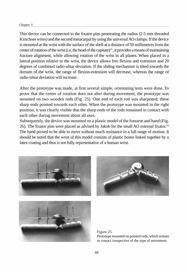
Chapter 5
68
This device can be connected to the fixator pins penetrating the radius (2.5 mm threadedKirschner wires) and the second metacarpal by using the universal AO clamps. If the deviceis mounted at the wrist with the surface of the shell at a distance of 50 millimetres from thecentre of rotation of the wrist (i.e. the head of the capitate)21, it provides a means of maintainingfracture alignment, while allowing rotation of the wrist in all planes. When placed in alateral position relative to the wrist, the device allows free flexion and extension and 20degrees of combined radio-ulnar deviation. If the sliding mechanism is tilted towards thedorsum of the wrist, the range of flexion-extension will decrease, whereas the range ofradio-ulnar deviation will increase.
After the prototype was made, at first several simple, orientating tests were done. Toprove that the centre of rotation does not alter during movement, the prototype wasmounted on two wooden rods (Fig. 25). One end of each rod was sharpened; thesesharp ends pointed towards each other. When the prototype was mounted in the rightposition, it was clearly visible that the sharp ends of the rods remained in contact witheach other during movement about all axes.Subsequently, the device was mounted on a plastic model of the forearm and hand (Fig.26). The fixator pins were placed as advised by Jakob for the small AO external fixator.22
The hand proved to be able to move without much resistance in a full range of motion. Itshould be noted that the wrist of this model consists of plastic bones linked together by alatex coating and thus is not fully representative of a human wrist.
Figure 25.Prototype mounted on pointed rods, which remainin contact irrespective of the type of movement.
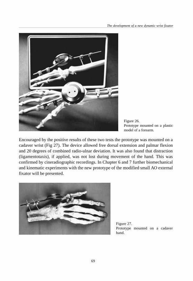
69
The development of a new dynamic wrist fixator
Encouraged by the positive results of these two tests the prototype was mounted on acadaver wrist (Fig 27). The device allowed free dorsal extension and palmar flexionand 20 degrees of combined radio-ulnar deviation. It was also found that distraction(ligamentotaxis), if applied, was not lost during movement of the hand. This wasconfirmed by cineradiographic recordings. In Chapter 6 and 7 further biomechanicaland kinematic experiments with the new prototype of the modified small AO externalfixator will be presented.
Figure 26.Prototype mounted on a plasticmodel of a forearm.
Figure 27.Prototype mounted on a cadaverhand.
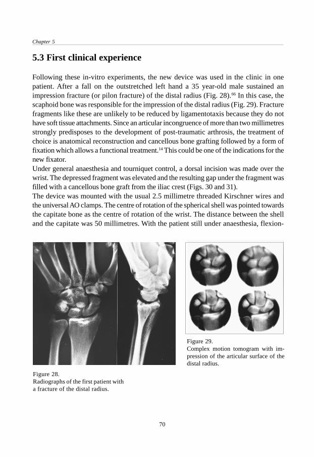
Chapter 5
70
5.3 First clinical experience
Following these in-vitro experiments, the new device was used in the clinic in onepatient. After a fall on the outstretched left hand a 35 year-old male sustained animpression fracture (or pilon fracture) of the distal radius (Fig. 28).66 In this case, thescaphoid bone was responsible for the impression of the distal radius (Fig. 29). Fracturefragments like these are unlikely to be reduced by ligamentotaxis because they do nothave soft tissue attachments. Since an articular incongruence of more than two millimetresstrongly predisposes to the development of post-traumatic arthrosis, the treatment ofchoice is anatomical reconstruction and cancellous bone grafting followed by a form offixation which allows a functional treatment.14 This could be one of the indications for thenew fixator.Under general anaesthesia and tourniquet control, a dorsal incision was made over thewrist. The depressed fragment was elevated and the resulting gap under the fragment wasfilled with a cancellous bone graft from the iliac crest (Figs. 30 and 31).The device was mounted with the usual 2.5 millimetre threaded Kirschner wires andthe universal AO clamps. The centre of rotation of the spherical shell was pointed towardsthe capitate bone as the centre of rotation of the wrist. The distance between the shelland the capitate was 50 millimetres. With the patient still under anaesthesia, flexion-
Figure 28.Radiographs of the first patient witha fracture of the distal radius.
Figure 29.Complex motion tomogram with im-pression of the articular surface of thedistal radius.

71
The development of a new dynamic wrist fixator
extension and radio-ulnar deviation were tested through the full range of motion withoutproblems. The operative result was checked by image intensifier and showed normalmovement of the carpus without collapse of the fracture fragment. At the end of theprocedure, a second bar was mounted to create a temporary rigid fixation for the firstthree post-operative weeks. With this extra bar the fixator was locked and the wristimmobilised (Fig. 32).The cross-bar was removed after three weeks and the patient was encouraged to move hiswrist again (Fig. 33). After one week of exercising with the fixator in place, dorsal extension
Figure 30.Operative view. Articular surfaceimpressed (arrow) by the scaphoidbone.
Figure 31.Situation after elevation of thefragment and cancellous bonegraft.
Figure 32.Device mounted at the wrist and lockedby cross-bar.

Chapter 5
72
was found to be unrestricted but palmar flexion was not yet optimal. There was 20 degreesof radio-ulnar deviation in total. Pronation and supination were slightly reduced (Fig. 34).The patient was able to play his guitar again. After three weeks with a locked fixator ananother three weeks with a dynamised fixator, the device was removed. The end resultwas a fully functional recovery.
Figure 33. Patient playing his guitar with Flexafix in situ.
Figure 34. Situation after one week of exercising (four weeks post-operatively). Left: Flexion andexension. Right: Pronation and supination.

73
The development of a new dynamic wrist fixator
5.4 Continued development
After evaluation of the first clinical case it was decided to continue the Flexafix projectand improve the design of the modified small AO external fixator. The first prototype ofthe Flexafix had several inconveniences. Having been made by hand, its constructionwas labour-intensive. The parts were made from stainless steel which is a relativelyheavy material. The sliding properties were not optimal, in spite of the inserted Teflonrings. This could result in a form of resistance felt by the patient during exercising.Further, the screw linking together the two discs could not be locked optimally. Therefore,the discs were able to unlock and thus cause a mechanical failure of the device. Thestandard AO four millimetre diameter rods were fixed by welding to the slidingmechanism and could not be varied in length. Another important problem to be solvedwas the elaborate positioning of the fixator due to the absence of an aiming device.Furthermore, the sliding mechanism could only be locked by mounting a second crossbarover the device.Based on these experiences the design was adjusted. The parts were designed in such away that they could be produced by machine (Fig. 35). Instead of steel a choice wasmade for aluminium because of its mechanical properties (i.e. stiffness and slidingproperties), weight, cost and ability to be machined. The parts were to be made on anumerically controlled turning machine. This is a computer guided turning machinewhich, after programming, automatically converts a chosen piece of aluminium intothe desired shape. To further enhance the sliding of the discs on the ring, the aluminiumparts were to undergo a special process called ‘ematalieren’. During this process thealuminium surface is hardened and coated by anodising. After assembling the parts, thescrew linking together the disc would be locked with glue (Araldit epoxy AY 103,hardener HY 951). The sliding mechanism was supplied with a hole in which standardrods from the small AO external fixator set in any desired length could be fixed bytightening a hexagonal allen screw.To be able to lock the sliding mechanism, a small extra aluminium disc was added tothe device. It was placed between the upper disc and the middle part of the slidingmechanism (that is, the ring-shaped section of a spherical shell). By adding two threadedholes to the upper disc with a small allen screw in them, the sliding mechanism couldbe locked by tightening the allen screws, which would press the extra aluminium discto the middle part. This gave the possibility of locking and unlocking the slidingmechanism and improving the stability and strength of the fixator in the period in whichit was not dynamised.On the edge of the upper disc a rim was made to be able to attach an aiming device tothe sliding mechanism. Finally, a hole with a diameter of one millimetre was made

Chapter 5
74
exactly in the middle of every part of the sliding mechanism. This hole has a role to playduring the positioning of the device at the operation (see below).
5.5 Patent
The design of the sliding mechanism, accompanied by explanation with drawings andtext, has been patented by the European Patent Office in Munich, Germany (pat. nr.92917550.3-2305) and the United States Patent and Trade Mark Office in Washington,D.C. (pat. nr. 5437666).
5.6 The development of an aiming device
For an optimal functioning of the dynamic fixator it is necessary that during the operationthe device is positioned in such a way that the centre of rotation of the sliding mechanismis coincident with the head of the capitate bone as the centre of rotation of the wrist.This means that this point has to be found in three planes. To accomplish this, an aimingdevice was designed (Fig. 36). This device consists of a ring with a rectangular barattached to the side of it (Fig.37). In the outrigged bar, there is a one millimetre diameterhole through which a Kirschner wire can be slid. This hole was made at exactly 50millimetres from the surface of the shell in the sliding mechanism. Several versions invarious materials, including plastic and aluminium, were made by hand and by machine.The aiming device is attached to the upper disc by clamping it over the rim on this disc.Next, one Kirschner wire with a diameter of one millimetre is slid through the hole inthe side-bar of the aiming device and another Kirschner wire is slid through the hole inthe centre of the sliding mechanism. In this way, both Kirschner wires are pointing to
Figure 35. Modified parts of the Flexafix device.

75
The development of a new dynamic wrist fixator
the centre of rotation of the dynamic fixator, irrespective of the position of the discsrelative to the shell. If both wires were pushed forward they would touch each otherexactly in the centre of rotation of the spherical shell.During the actual operation the wires of the aiming device would not be pushed in sofar but only until they touch the skin. The imaginary point of intersection of the twowires, however, is still located exactly in the centre of rotation of the device. Prior to theexact positioning of the device, the anatomical snuffbox (tabatière anatomique) and thelong axis of the third metacarpal can be marked as a reference point for the location ofthe capitate bone and thus for the direction of the wires. With the use of an imageintensifier, the two wires will be seen and the device can be manipulated until theimaginary intersection of the wires is located in the head of the capitate bone. If thefixator is mounted at the lateral side of the wrist and the image intensifier view is madein the antero-posterior direction, the fixator will be in the right position in the frontaland sagittal planes. The correct position in the transversal plane is then found by aimingthe wire through the centre of the sliding mechanism at the central part of the wrist asseen from a lateral view. The procedure of aiming will be explained further in theoperative instructions for the Flexafix device (see Chapter 8).
Figure 37.The aiming device.
Figure 36.Technical drawing of design ofaiming device.

Chapter 5
76
5.7 Maintenance of the device
The sliding mechanism can be sterilised according to standard hospital procedures.The aiming device may be sterilised up to a temperature of 120 degrees Celsius. Highertemperatures could result in damage or breaking of the aiming device. When the fixatoris dynamised, it is advisable to apply a thin layer of silicone spray between the shelland the discs of the sliding mechanism to improve the sliding properties.
5.8 Conclusion
The Flexafix project resulted in the development of an external fixation device with specialproperties. The sliding mechanism provides three degrees of freedom of movement whileat the same time the centre of rotation of all these movements is located in one point. Theconstruction with the shells is the explanation for its main feature, this being a slidingmechanism with its centre of rotation located outside the device itself. In this way there isa possibility of combining the centre of rotation of the wrist and the centre of rotation ofthe dynamic external fixator. If mounted correctly, this should result in a technique whichprovides a method of maintaining fracture alignment, while permitting movement of thewrist in all planes.After a successful application of the Flexafix prototype in an initial clinical test case,the design was further improved and adjusted. In addition, an aiming device wasdeveloped to facilitate the application of the fixator.
77
Biomechanical cadaver study of pin loads
Biomechanical cadaverstudy of pin loads
Chapter 6
6.1 Introduction
Several types of dynamic external fixators are available at the moment. As described inChapter 4, most of them are based on a mechanism with a ball joint located in thedevice but outside the wrist.17,19,20 Little is known about the biomechanical properties ofthe dynamic external fixators for the treatment of distal radial fractures.Since the construction of the newly designed Flexafix dynamic external fixator isbasically different from types with a ball joint, it is of importance to see how the forcesacting on the wrist during the use of a dynamic fixator vary between these two types offixators. These forces could possibly cause dislocation of the fracture fragments. Forthis reason, a biomechanical study with two types of dynamic external fixators wasperformed.
J.C. Goslings, S.J. Ferguson, R.A. Perren, S. Tepic.The Journal of Trauma 1999;46:407-412.
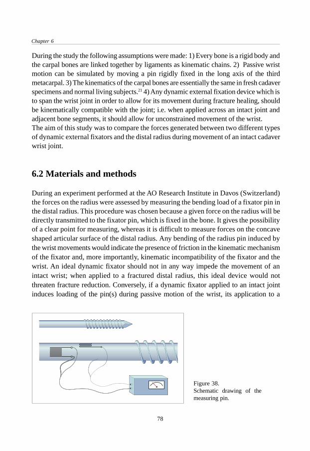
Chapter 6
78
During the study the following assumptions were made: 1) Every bone is a rigid body andthe carpal bones are linked together by ligaments as kinematic chains. 2) Passive wristmotion can be simulated by moving a pin rigidly fixed in the long axis of the thirdmetacarpal. 3) The kinematics of the carpal bones are essentially the same in fresh cadaverspecimens and normal living subjects.21 4) Any dynamic external fixation device which isto span the wrist joint in order to allow for its movement during fracture healing, shouldbe kinematically compatible with the joint; i.e. when applied across an intact joint andadjacent bone segments, it should allow for unconstrained movement of the wrist.The aim of this study was to compare the forces generated between two different typesof dynamic external fixators and the distal radius during movement of an intact cadaverwrist joint.
6.2 Materials and methods
During an experiment performed at the AO Research Institute in Davos (Switzerland)the forces on the radius were assessed by measuring the bending load of a fixator pin inthe distal radius. This procedure was chosen because a given force on the radius will bedirectly transmitted to the fixator pin, which is fixed in the bone. It gives the possibilityof a clear point for measuring, whereas it is difficult to measure forces on the concaveshaped articular surface of the distal radius. Any bending of the radius pin induced bythe wrist movements would indicate the presence of friction in the kinematic mechanismof the fixator and, more importantly, kinematic incompatibility of the fixator and thewrist. An ideal dynamic fixator should not in any way impede the movement of anintact wrist; when applied to a fractured distal radius, this ideal device would notthreaten fracture reduction. Conversely, if a dynamic fixator applied to an intact jointinduces loading of the pin(s) during passive motion of the wrist, its application to a
Figure 38.Schematic drawing of themeasuring pin.

79
Biomechanical cadaver study of pin loads
fractured radius would result in undesirable, potentially disruptive loading of the fracture.For the purpose of the study, a fixator pin with two perpendicularly mounted straingauges. (CEA-06-125UN-120, Precision Strain Gauge, Measurements Group Inc.,Raleigh N.C., U.S.A.) are composed of very small resistors (120 Ohm +/- 0.3% at24°C, gauge factor 2.080), which change in length by mechanical deformation of thepin. This change in resistance is converted into an electrical signal (Fig. 38). Themagnitude of the signal is a measure for the load of the pin and thus for the force on theradius. Using this method, comparative measurements can be made with a high gradeof precision and reliability. Important factors are the quality and careful mounting ofthe strain gauge.A mechanical testing machine (model 4302, Instron, Canton, Massachusetts, U.S.A.)was used for the calibration of the measuring pin. The magnitude of the electrical signalwas measured with a strain indicator (Model P-3500, Instruments Division, Raleigh,North Carolina, U.S.A.). The measuring pin was fixed in the Instron testing machineand subsequently loaded by the machine. Three series of measurements with increasingloads were done for each strain gauge.For the experiment, a fresh cadaver forearm with an intact distal radius was placed in aholding device allowing unrestricted movement of the hand (Fig. 39). To be able toperform passive movements of the hand, a Kirschner wire was drilled in the long axis ofthe third metacarpal. Pronation and supination were blocked by a Steinmann pin throughthe proximal part of the radius and ulna. The 3.0 millimetre threaded Kirschner wiresupplied with strain gauges was fixed in the radius approximately 5 centimetres proximalfrom the distal articular surface. Using a single pin for fixation to the radius allowedfor direct, higher sensitivity estimation of the loads. Two 3.0 millimetre threadedKirschner wires were drilled in the second metacarpal in the usual way. The position ofthe pins was checked by X-ray. To be able to compare the results of the measurements,
Figure 39.Experiment set-up.
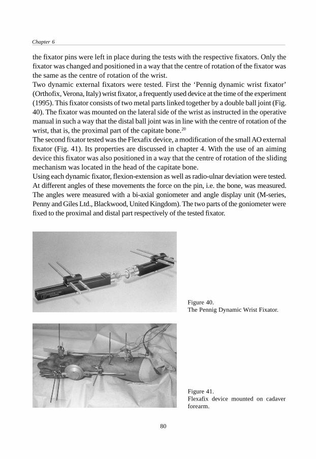
Chapter 6
80
the fixator pins were left in place during the tests with the respective fixators. Only thefixator was changed and positioned in a way that the centre of rotation of the fixator wasthe same as the centre of rotation of the wrist.Two dynamic external fixators were tested. First the ‘Pennig dynamic wrist fixator’(Orthofix, Verona, Italy) wrist fixator, a frequently used device at the time of the experiment(1995). This fixator consists of two metal parts linked together by a double ball joint (Fig.40). The fixator was mounted on the lateral side of the wrist as instructed in the operativemanual in such a way that the distal ball joint was in line with the centre of rotation of thewrist, that is, the proximal part of the capitate bone.20
The second fixator tested was the Flexafix device, a modification of the small AO externalfixator (Fig. 41). Its properties are discussed in chapter 4. With the use of an aimingdevice this fixator was also positioned in a way that the centre of rotation of the slidingmechanism was located in the head of the capitate bone.Using each dynamic fixator, flexion-extension as well as radio-ulnar deviation were tested.At different angles of these movements the force on the pin, i.e. the bone, was measured.The angles were measured with a bi-axial goniometer and angle display unit (M-series,Penny and Giles Ltd., Blackwood, United Kingdom). The two parts of the goniometer werefixed to the proximal and distal part respectively of the tested fixator.
Figure 41.Flexafix device mounted on cadaverforearm.
Figure 40.The Pennig Dynamic Wrist Fixator.

81
Biomechanical cadaver study of pin loads
6.3 Results
Before the measurements on the cadaver wrist were started, the fixator pin with thestrain gauges was calibrated. It was loaded with a given force at a given distance fromthe fixation point of the pin (expressed as bending moment). The resulting deformationof the pin and thus of the strain gauges is expressed in microstrains (10-6 m/m). Asexpected, a linear relationship between the force exerted on the pin and the measuredstrain was found (Fig. 42). The data from the calibration were used to translate the measuredelectrical signal (i.e. strain gauge deformation) during movement of the hand into a bendingmoment of the pin. Summarised briefly, the bending moment of the pin is a measure for thepin load and therefore also for the pressure on the articular surface of the distal radius.
Figure 42.Calibration results of themeasuring pin.
6.3.1 Flexion and extensionWith both fixators, three series of measurements during flexion and extension of thehand were done. These measurements were done with increments of two degrees. Thepin load gradually showed to increase, especially near the maximal range of motion.The pin load between approximately 30 degrees of flexion and 30 degrees of extensionwas about constant for the Flexafix device and ranged between zero and 0.40 Nm. (Fig.43). The Orthofix device showed a more gradual increase in loading of the pin, rangingfrom zero to 0.35 Nm (Fig. 44) With both types of fixator extreme positions of the handresulted in high loads.
6.3.2 Radio-ulnar deviationAlthough in their instruction manual Orthofix advises only to exercise flexion-extension,in our opinion there is no guarantee that a patient will restrict movement to exactly onesingle plane.20 Besides, the ball joint has a certain amount of play in itself. For this

Chapter 6
82
Figure 45.Pin load during radio-ulnardeviation with the Flexafixdevice compared to theOrthofix device. Each sphere ortriangle represents a singlemeasurement.
Figure 44.Pin load during flexion andextension with the Orthofixdevice. Each sphere repre-sents a single measurement.
Figure 43.Pin load during flexion andextension with the Flexafixdevice. Each sphere repre-sents a single measurement.

83
Biomechanical cadaver study of pin loads
reason radio-ulnar deviation was also tested with the Pennig wrist fixator. For the Flexafixdevice there are no restrictions concerning the movements patients are allowed to make.The Flexafix device allows a range of 20 degrees of combined radio-ulnar deviation.There was no considerable pin load during these movements during each of the threeseries of measurements that were done. In contrast, with the Orthofix device even verysmall movements caused a high pin load (above 1 Nm); with this device applied to aforearm with a fractured distal radius, radio-ulnar deviation would produce high forceson the fracture area (Fig. 45).
6.4 Discussion
The data from these experiments showed that during flexion and extension the force onthe distal radius was comparable with both tested devices. The measured pin loadsvaried between zero and 0,40 Nm. This can be explained by the fact that with thesemovements, the centre of rotation of the Orthofix device ( the ball joint) as well as thecentre of rotation of the Flexafix sliding mechanism is in line with the centre of rotationof the wrist. However, in radio-ulnar deviation the centre of rotation with the Orthofixdevice is again, by definition, located in the ball joint instead of in the wrist. If radio-ulnar deviation occurs (with the ball joint on the lateral side of the wrist), even withsmall angles, there is movement around an unnatural point of rotation. Themeasurements show the resulting high loads of the pin. With the device applied to afractured distal radius, these forces may result in fracture dislocation. In contrast tothis, the centre of rotation of the Flexafix device is always located in the wrist whenproperly positioned. This is due to the fact that the centre of rotation of the device isnot located in the device itself but at a point outside the device. In the prototype thispoint lies 50 millimetres from the surface of the shell in the sliding mechanism.Consequently, with the newly designed Flexafix device, there is no considerable pinloading when radio-ulnar deviation is performed. This might decrease the risk ofdislocation during the period in which the fixator is dynamised.Part of the interpretation of the results of this study is difficult because to our knowledgeno reference data are available from normal pin loads, especially with dynamic fixators.Patterson performed a cadaver study to analyse the effect on wrist kinematics of twodynamic external fixation devices (Clyburn and Orthofix) with a ball joint.167 It wasconcluded that carpal motion with both fixators was abnormal and likely to cause abnormalloading conditions in the wrist. This indicates that there is a risk of fracture dislocationwith these two types of dynamic external fixators.
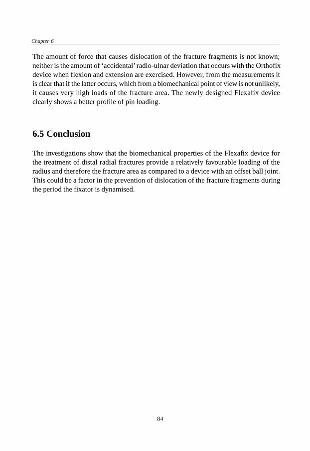
Chapter 6
84
The amount of force that causes dislocation of the fracture fragments is not known;neither is the amount of ‘accidental’ radio-ulnar deviation that occurs with the Orthofixdevice when flexion and extension are exercised. However, from the measurements itis clear that if the latter occurs, which from a biomechanical point of view is not unlikely,it causes very high loads of the fracture area. The newly designed Flexafix deviceclearly shows a better profile of pin loading.
6.5 Conclusion
The investigations show that the biomechanical properties of the Flexafix device forthe treatment of distal radial fractures provide a relatively favourable loading of theradius and therefore the fracture area as compared to a device with an offset ball joint.This could be a factor in the prevention of dislocation of the fracture fragments duringthe period the fixator is dynamised.
Kinematics of the wrist with the Flexafix device
85
Kinematics ofthe wrist with theFlexafix device
Submitted for publication.
Chapter 7
7.1 Introduction
As described in Chapter 2, various methods have been used in the past to describe themotion of the radius, ulna, carpal and metacarpal bones in relation to each other. Inearlier days X-rays were used to study the angles between the bones in differentpositions of the hand.168,169,170 This technique was also used to describe patterns ofcarpal movement in cineradiographs of the wrist.171,172 However, these methods providedindirect information about planar movements. In order to obtain more direct informationabout the three-dimensional aspect of wrist motion, carpal bones have been implantedwith metal markers after which biplanar radiography was performed. 173,174,175 Withthis technique the XYZ-coordinates and thus the position and orientation of therespective bones could be determined. Others have used light emitting diodes or sonicdigitizers to analise the three-dimensional properties of the wrist. 21,176,177 The techniquesmentioned above were based on a sequential static analysis of motion, whereas thedynamic aspect of wrist motion could not be addressed.

Chapter 7
86
At the University of Texas Medical Branch in Galveston (Texas, U.S.A.) a technique forkinematic analysis of the wrist has been developed and validated.178,179,180 The techniquecombines data acquired from high-speed video images and three-dimensionalreconstructions of CT-scans, which results in a visual animation of the actual motionpattern. In this way, the motions of the carpal bones can be calculated in a dynamicmode. This method has added to the knowledge of the normal kinematics of the wristand can be applied to help understand abnormal clinical conditions such as carpalinstabilities, degenerative diseases and distal radial fractures.Until recently, most external fixators for the treatment of unstable distal radial fracturesdid not allow motion at the wrist. The introduction of dynamic external fixators in1987 has given the possibility of early functional treatment, i.e. movement of the wristduring the period the fixator is mounted.17 Early motion of joints after fracture treatmentmay facilitate the repair of articular cartilage and could possibly reduce thecomplications of joint immobilisation.10,13 It is important to address attention to theeffect of this new treatment modality on the kinematics of the wrist. A dynamic externalfixation device for the treatment of distal radial fractures should be kinematicallycompatible with the joint, allowing unconstrained movement of the wrist. However,Patterson et al. have shown that several commercially available dynamic externalfixation devices for the treatment of distal radial fractures do not replicate the normalkinematics.167 Any device that does alter normal kinematics brings the risk with it offorcing the carpal bones into an abnormal pattern of movement or displacement offracture fragments.Also, distal radial fractures can be accompanied by ligamentous injury. Richardsperformed arthroscopy in 118 patiens with acute, intra- and extra-articular distal radialfractures.68 A tear of the scapholunate ligament was present in 22% of intra-articularfractures and in 7% of extra-articular fractures. Lunotriquetral ligament injuries wereseen in 7% of intra-articular fractures and in 13% of extra-articular fractures. Geisslerdiagnosed scapholunate tears in 32% and lunotriquetral injuries in 15% of intra-articularfractures in 60 patients.181 However, the effect on carpal kinematics of dynamic externalfixation in the case of a distal radial fracture accompanied by ligamentous injury hasnot been studied.While most available dynamic external fixation devices have an articulating part thathas its centre of rotation in the device itself (i.e. outside the wrist), the Flexafix dynamicexternal fixator is a new device which permits motion in three planes while the centre ofrotation of all the movements is located at a point outside the device.17,19,20 During theoperation this centre of rotation of the device can be positioned within the anatomicspace of the wrist. The aim of this study was to analyse the effect of the Flexafix deviceon wrist kinematics under various conditions.

Kinematics of the wrist with the Flexafix device
87
7.2 Materials and methods
7.2.1 Specimen preparationFour fresh frozen cadaver upper extremities without visible or radiographicallyidentifiable abnormalities were used. All specimens (two left arms and two rightarms) were from men; the average age was 46 years (range 32 to 56 years). Underimage intensifier control triad pins were placed in the radius, scaphoid, lunate, capitateand third metacarpal bones in a way that they would not touch each other duringmovement of the wrist. Care was taken not to place the pins through tendons or othersoft tissues involved in wrist motion to avoid altering or otherwise influencing motion.These rigid pins have three spheres of approximately 5 millimetres in diameter placedin a cruciform arrangement on top. To enhance their reflective properties, the sphereswere coated with photoreflective paint.The flexor carpi ulnaris, flexor carpi radialis, and extensor carpi ulnaris tendons werethen dissected and each of their end sutured to form a total of three loops. The extensorcarpi radialis longus and brevis were looped together to form the fourth loop. Theflexor and extensor tendon loops on the radial side of the wrist were then connectedby wires to a free-floating pulley; this procedure was repeated for the loops on theulnar side of the wrist. These two pulleys were both weighted by 5 lb. (2.27 kg) andallowed the tendon pairs to move synergistically during motion while the weightsimulated muscle tone.167,180 The upper arm was placed into a jig with the elbowflexed 90° and the forearm in neutral orientation while allowing free wrist motion.With the help of an aiming device (pointing towards the centre of rotation of thesliding mechanism) and 2.5 mm threaded Kirschner wires the Flexafix dynamic externalfixator was applied at the radial side of the wrist with the centre of rotation of thedevice positioned in the proximal part of the capitate bone. Its position was checkedwith an image intensifier.After obtaining normal kinematic data was obtained in all four wrists, in two specimensa scapholunate ligament (SL) injury was simulated. The dorsal capsule of the wristwas opened, the scapholunate ligament was completely transected and the DICligament was freed from the lunate (see Figure 5, p.20). After the SL tear was madethe dorsal capsule was repaired with a suture.
7.2.2 Three-dimensional carpal bone reconstructionTransverse images of the wrist and triad pins were obtained with a CT scanner (GE9800, General Electric Medical Systems, Milwaukee, Wisconsin, U.S.A.) generatingslices 1.5 millimetres thick. The 3-D shape of the bones was extracted using a softwareprogram developed at UTMB running on a SunSparc 2 workstation (Sun Microsystems
Chapter 7
88
Inc., Mountain View, California, U.S.A.). In each CT slice, the boundaries of the boneswere digitally tracked in an interactive process. The data obtained from all the sliceswere collected and grouped by the program, after which the boundaries of each bonewere assembled as a 3-D model using the Application Visualisation System (AVS Inc.,Dallas, Texas, U.S.A.) running on a Graphic Workstation (Evans & Sutherland Corp.,Salt Lake City, Utah, U.S.A.).167,179,180
7.2.3 Kinematic data collectionEach wrist was moved passively through several flexion-extension and radio-ulnardeviation cycles by a Kirschner wire inserted in the third metacarpal bone. Four blackand white video cameras (High performance CCD cameras, Cohu Inc., San Diego,California, U.S.A.), arranged around the wrist, tracked the triad pins’ reflective surfacesthroughout the motion cycles, creating motion path files. The three-dimensional pathsfor the triad pins were determined by combining the video data, collected at 60 framesper second (Expert Vision System, Motion Analysis Corp., Santa Rosa, California,U.S.A.).167,180 The specimens were tested twice; once in the normal condition andonce with the Flexafix device mounted. Two specimen were tested four times: oncewithout the fixator, once with the Flexafix device mounted, once after transection ofthe scapholunate ligament and once after application of the Flexafix device in thepresence of the ligament injury.
7.2.4 AnimationThe three-dimensional geometric reconstructions and the kinematic path data werecombined to create an animation of the actual wrist motion. This provides a visualcheck to validate the calculated motion of the bones, as well as a simple, understandableway to display the data. From the kinematic analysis, measurements that werehypothesised to characterise carpal bone motion were calculated. These includedglobal wrist angle and Euler angles between the bones.167,180 Global wrist angle describesthe global motion of the wrist and is measured as the angle between the long axis ofthe third metacarpal and the long axis of the radius. Euler angles represent the angleof one body to another body during motion in relation to a coordinate system. Of thethree resulting Euler angles, only the angles in the plane of the motion that was testedwere analyzed.If mounted on the radial side of the wrist, due to its design the Flexafix device allowsmore flexion extension than radio-ulnar deviation; in this position the latter is limitedto 20 degrees (see Chapter 5). Carpal motions (i.e. radiolunate, capitolunate andscapholunate angles) were analysed between 40° of flexion, 40° of extension, 5° ofradial deviation and 15° of ulnar deviation. The data for each position of the hand of

Kinematics of the wrist with the Flexafix device
89
were for the wrists tested averaged (at one degree intervals) and the standard deviation(SD) of these averages was calculated, including minimal and maximal SD. Thecarpal angles were plotted relative to the position (i.e. global wrist angle) of the hand.
7.3 Results
7.3.1 Flexion-extensionMeasurement of the radiolunate angle results in a negative value when the lunate isflexed relative to the radius; a positive value corresponds to extension of the lunate. Ina movement of both 40 degrees of flexion and 40 degrees of extension, the radiolunateangle in the normal wrist was -31.2° in wrist flexion and 21.3° in wrist extension(mean SD 4.0°, range 2.0° - 5.8°). With the fixator, these values were -29.5° and 20.0°respectively (mean SD 4.3°, range 3.1° - 6.2°). The difference in the position of thecurves was less than two degrees during the entire range of motion tested (Fig. 46).When the capitate is flexed relative to the lunate, the capitolunate angle is expressed bya positive value; extension of the capitate relative to the lunate results in a negativevalue. The capitolunate angle was 12.6° in wrist flexion and -14.8° in wrist extension(mean SD 7.5 range 6.4 - 8.4) in the normal wrist compared to 16.6° and -13.6° (meanSD 6.5° range 5.1° - 8.2°) after application of the fixator. The curve diplaying the wristwith the fixator was situated one to four degrees above the curve for the normal wristwith the most close relation between neutral and 25° of flexion (Fig. 47).In the normal wrist the scapholunate angle was 15.2° in wrist flexion and -2.9° inwrist extension (mean SD 5.2°, range 4.2° - 6.4°) with a positive value representingthe scaphoid flexed relative to the lunate and a negative value with the scaphoidextended relative to the lunate. In the wrist with the Flexafix device attached these
Figure 46.Radiolunate angle during flexion andextension.

Chapter 7
90
values were 14.8° and -3.1° (mean SD 7.8°, range 4.7° - 9.2°). The plotted curveswere closely together during the range of motion tested with a maximum difference inposition between the curves of two degrees (during extension) (Fig. 48).
Figure 47.Capitolunate angle during flexion andextension.
Figure 48.Scapholunate angle during flexion andextension.
Table 6 shows the three carpal joint angles in different positions of the hand and theranges of these angles during wrist motion between 40° of flexion and 40° of extension.The ranges describe the shape of the carpal angle curves rather than the position of thecurves relative to each other as described above.
7.3.2 Radio-ulnar deviationDuring movement of the hand from 15 degrees of ulnar deviation to 5 degrees of radialdeviation the radiolunate angle is negative with the lunate in ulnar deviation relative tothe radius and positive with the lunate in radial deviation. In the normal condition, theradiolunate angle was -8.1° in ulnar deviation and 1.4° in radial deviation (mean SD4.7°, range 3.6° to 7.1°), compared to -9.7° and -0.2° (mean SD 4.6, range 4.2 to 5.8)

Kinematics of the wrist with the Flexafix device
91
respectively after application of the fixator. The curve of the fixator was consistentlyapproximately three degrees below the normal curve (Fig. 49).A positive value for the capitolunate angle represents ulnar deviation of the capitaterelative to the lunate, a negative value radial deviation relative to the lunate. Thecapitolunate angle was 5.4° in ulnar deviation and -4.7° in radial deviation (mean SD4.3°, range 4.0° to 5.5°) in the normal wrist versus 9.6° and -2.8° (mean SD 2.9, range
radlun caplun scalunn sln n sln n sln
normal flex -40 -31.2 -20.5 12.6 19.6 15.2 26.7flex -20 -21.4 -14.1 4.7 6.0 9.7 22.7neutral -6.2 -4.6 -1.5 -4.6 6.0 11.0ext 20 10.2 9.0 -7.1 -11.0 1.1 0.4ext 40 21.3 19.0 -14.8 -20.8 -2.9 -6.2
-40°/40° range 52.5 39.5 27.4 40.4 18.1 32.9
fix slfix fix slfix fix slfix
fixator flex -40 -29.5 -22.1 16.6 17.9 14.8 25.9flex -20 -19.6 -12.4 6.4 7.5 9.7 24.1neutral -5.7 -3.7 0.4 -4.1 6.4 11.7ext 20 10.1 10.3 -3.8 -10.0 3.1 0ext 40 20.0 19.4 -13.6 -20.5 -3.1 -5.5
-40°/40° range 49.5 41.5 30.2 38.4 17.9 31.4
delta normal-fixator 3.0 -2.0 -2.8 2.0 0.2 1.5
Table 6.Range of carpal motion (in degrees) around X-axis (flexion-extension) during movement from -40° offlexion to 40° of extension. Normal = uninjured wrist; fixator = wrist with Flexafix device applied; sln= wrist with scapholunate ligament transected; slfix = Flexafix device applied to wrist with scapholunateinjury. Radlun= radiolunate angle, caplun= capitolunate angle, scalun= scapholunate angle.
Figure 49.Radiolunate angle during radial deviation andulnar deviation.

Chapter 7
92
1.3 to 5.1) respectively with the fixator (Fig 50). The difference in position betweenthe curves was less than two degrees except near maximum ulnar deviation tested(four degrees).The scapholunate angle was not determined during radio-ulnar deviation since out ofplane motions for this carpal angle were larger than the motions in the principal planeof motion, caused by flexion-extension movements of the scaphoid.
7.3.3 Scapholunate ligament injuryAfter transection of the scapholunate ligament (SL) in two wrists, the mean radiolunateangle in a flexion-extension movement (40°/40°) was -20.5° in wrist flexion and 19.0° inwrist extension, which is less than before SL transection (Table 6). Application of thefixator in presence of the SL injury resulted in a radiolunate angle from -22.1° in flexionand 19.4° in extension (Fig. 51).The mean capitolunate angle was 19.6° in flexion and -20.8° in extension without thefixator; with the fixator the values were 17.9° and -20.5° (Fig. 52). The mean scapholunateangle after transection of the SL ligament was 26.7° in flexion and -6.2° in extension
Figure 51.Radiolunate angle during flexion andextension. Normal = uninjured wrist; fixator= normal wrist with Flexafix device applied;sl-normal = wrist with scapholunate ligamenttransected; sl-fixator = Flexafix device appliedto wrist with scapholunate injury.
Figure 50.Capitolunate angle during radial deviationand ulnar deviation.

Kinematics of the wrist with the Flexafix device
93
without the fixator compared to 25.9° and -5.5° with the Flexafix device (Fig. 53). Boththe capitolunate and scapholunate angles were increased compared to the angles prior toSL transection. The difference in the position of the curves for the two conditions (SLinjury only and SL injury in presence of the fixator) was less than two degrees for all threeangles measured during the entire range of motion tested.
7.4 Discussion
This study was designed to analyse the effect of a new dynamic external fixationdevice developed for the treatment of distal radial fractures on wrist kinematics. It isimportant to know these effects because any device which is kinematically incompatiblewith the wrist could possibly lead to abnormal loading conditions. Of all the availabletechniques to study kinematics a relatively new method was used because this techniqueprovides information about the dynamic aspect of the motion studied. Other radiographicstudies, such as standard X-rays, biplanar X-rays, CT-scans and MRI-scans are limited
Figure 53.Scapholunate angle during flexion andextension. Normal = uninjured wrist; fixator= normal wrist with Flexafix device applied;sl-normal = wrist with scapholunate ligamenttransected; sl-fixator = Flexafix device appliedto wrist with scapholunate injury.
Figure 52.Capitolunate angle during flexion andextension. Normal = uninjured wrist; fixator= normal wrist with Flexafix device applied;sl-normal = wrist with scapholunate ligamenttransected; sl-fixator = Flexafix deviceapplied to wrist with scapholunate injury.

Chapter 7
94
to the gross approximation of dynamic motion by repeated static positioning. Thepresent study used reflective triad pins rigidly fixed to the bones and high-speedvideo data collection of wrist kinematics, combined with 3-D reconstructions of CTimages. The forearm was stabilised and the wrist was allowed to move freely. Theflexor and extensor tendons were loaded with weights, the wrist was moved passively.Another method could have been to move the wrist by active tendon loading withcalibrated springs according to physiological cross-sectional area.174,182 Since the aimof this study was to compare several conditions, this would probably not have changedthe outcome. The technique used in this study has its limitations; it is performed invitro and implantation of triad pins could potentially disturb normal motion, althoughcare was taken to avoid this.The range of motion of the wrists tested was to some extend limited by the Flexafixdevice. When applied to the radial side of the wrist, the device theoretically allowsfree flexion and extension and 20 degrees of combined radio-ulnar deviation. Themean range of motion with the device in the wrists tested was 121° (70° of flexionand 51° of extension), which is close to the normal range of motion and more thanother dynamic external fixation devices tested previously which showed a ROMvarying between 94° and 107°.167 Also, this range provides most of the range ofmotion needed to perform activities of daily living.47,48
The main aspect of the study was to determine the effect of the Flexafix dynamicexternal fixator on carpal bone motion. A change, induced by the device, in thenormal angles between the individual bones could result in impingement and/ordistraction between the bones in parts of the range of motion. In addition, with thedevice applied to a forearm with a fractured distal radius, the abnormal kinematicsmay result in fracture dislocation. Further, abnormal loading conditions have beenrelated to the development of arthrosis. On the other hand, it seems unlikely that thiswill develop during the four weeks that the fixator is used in the dynamic mode, sincemost authors start the dynamisation two or three weeks after the operation.20,160,161,163
Nevertheless, a dynamic external fixator which is to be used in its dynamic modeshould allow unconstrained movement of the wrist.There are several means to interpret the measured angles and the differences betweenthe curves in the conditions tested. The difference in the position of the curves can becaused by the fixator altering the normal position and movement of the carpal bones.The differences found during flexion-extension were generally small with a maximumof 4 degrees. Other possible explanations for a higher of lower position of the curvecould be slightly different loading conditions between the normal wrist and afterapplication of the fixator. The fixator was mounted on the wrist in an unloaded state,after which it was loaded for testing.

Kinematics of the wrist with the Flexafix device
95
The pattern of the movements displayed by the carpal bones that were studied wascomparable for both conditions as shown by the ranges of the carpal angles duringflexion-extension tested. In the limited flexion-extesion motion tested (40°/40°), therange of the radiolunate angle was decreased by 3.0 degrees after application of thefixator, whereas the range of the capitolunate angle increased with 2.8 degrees. Thisphenomenon could be explained by the observation from recent studies that the centreof rotation for flexion-extension migrated through the capitate, whereas the slidingmechanism of the fixator has a fixed centre of rotation in the capitate.167 During radio-ulnar deviation the differences were slightly more pronounced, especially near themaximum range of radial and ulnar deviation allowed by the fixator. The interpretationof the carpal angles during radio-ulnar deviation is partly impeded by the occurenceof out of plane motions, i.e. motion in the flexion-extension or pro- and supinationplane. In contrast, during flexion-extension the out of plane motions were minimal,as was also noted by other authors.173,174,183
A comparison of the absolute figures with the results obtained with the Orthofix,Clyburn and Agee Wrist Jack dynamic external fixators in a previous report is difficultsince the testing circumstances were different with respect to cadaver, loading, typeof motion and the range of motion tested.167 In general however, for flexion-extensionthe results obtained in this study resemble those earlier results which showed carpalangle differences up to 3 degrees. Radio-ulnar deviation with dynamic external fixatorshas not been reported previously.After transection of the scapholunate ligament the lunate tended to flex less duringflexion compared to normal, whereas during extension the change was small. The40°/40° range was 39.5° after transection vs 52.5° in the normal wrist. The contributionof the capitolunate angle to flexion increased as a compensation for the reducedflexion of the lunate (27.4° normal vs 40.4° after transection of the SL ligament). Thegradual increase in scapholunate angle was also more pronounced in flexion whilethe 40°/40° range increased from 18.1° in the normal wrist to 32.9° after SL transection.From these results it seems that during flexion of the hand after transection of thescapholunate ligament, the lunate remains in a relatively extended position while thescaphoid flexes, thereby increasing the scapholunate angle. During extension, thescaphoid comes back to the lunate and thus decreases the scapholunate angle to(near) normal values.The data obtained in the experiments confirm the results of the biomechanicalinvestigations with the Flexafix device described in Chapter 6 in which pin loadswere measured during motion with two different types of dynamic external fixators.Apart from biomechanical considerations related to the offset centre of rotation indevices with one or more ball joints, a possible advantage of the device tested in this
Chapter 7
96
study is that in addition to a considerable range of flexion-extension a small amountof radio-ulnar deviation (20°) is also permitted by the device. This could allow for amore normal wrist motion since active flexion and extension are accompanied byradio-ulnar deviation respectively. Future studies could focus on the events occuringin the fracture area at the distal end of the radius during movement of the hand inpresence of a dynamic external fixator. The theoretical advantage of early motion forfracture treatment by means of dynamic external fixation can only be confirmed inclinical studies. However, clinical results obtained with dynamic external fixators canonly be expected to be good if the design of the device that is used is sufficientlycompatible with the wrist.
7.5 Conclusion
In this cadaver study the kinematical properties of the Flexafix dynamic externalfixator designed for the treatment of distal radial fractures were studied. The deviceinfluenced carpal kinematics to a limited extent. In presence of a scapholunate ligamentinjury the altered kinematics were the same with and without the fixator applied to thewrist. Compared to other types of dynamic external fixators the new device showed asimilar kinematic pattern. Additional research is needed to determine the effect ofdynamic external fixation with a simulated distal radial fracture. Clinical studies willhave to elucidate a presumed beneficial effect over other methods of treatment fordistal radial fractures.
97
Operative technique
Operative technique
Chapter 8
8.1 Introduction
The newly developed external fixation device requires precise mounting on the wrist ofthe patient in order to achieve correspondence of the two important centres of rotation,that is, the centre of rotation of the wrist and the centre of rotation of the slidingmechanism. This goal can be achieved by the use of the parts of the standard small AOexternal fixator set in combination with the Flexafix device and the aiming devicedesigned for this purpose. Based on laboratory tests with plastic forearm models andcadaver specimens an operative technique was developed especially for the applicationof the new prototype. After the first case history the operative procedure was evaluatedand adjusted where necessary. The specific requirements for the application of theFlexafix device are described.

Chapter 8
98
8.2 Required materials
The equipment that is used (in addition to standard operation facilities) for the operativeprocedure is listed in Table 7.
* Flexafix device* Aiming device with two guide wires (Kirschner wires, 1.0 mm diameter)* Small AO external fixator set* Drill equipment* Allen key 1.5 mm* Waterproof marking pen* Image intensifier
Table 7. Required materials for the operative procedure.
8.3 Operative technique
The basic operative technique for the application of external fixators on the distal endof the radius (as described in Chapter 4) is used. However, it should be noted that theapplication of the sliding mechanism is a new and extra component. The operation is atechnical procedure which requires a good understanding of the biomechanicalbackground of the fixator and a careful preoperative planning. The placement of theFlexafix device on the wrist determines two important factors. Firstly, the stability ofthe fracture fragments which can be influenced by position and concordance of theabove mentioned centres of rotation. Secondly, the range of motion during the time thefixator is dynamized. As described in Chapter 4, the device allows free flexion andextension and 20 degrees of combined radio-ulnar deviation when placed in a lateralposition relative to the wrist. If the sliding mechanism is tilted towards the dorsum ofthe wrist, the range of flexion-extension will decrease, whereas the range of radio-ulnar deviation will increase. With regard to the functional wrist motion required forstandard tasks of daily living, we think that the patient will experience the greatestbenefit from a maximum range of flexion-extension and a relatively smaller range ofradio-ulnar deviation.Below a step-by-step description of the application of the Flexfix device will be given.The procedure has also been recorded on video tape at the AO Research Institute inDavos, Switzerland (tape nr. 60060).

99
Operative technique
Figure 54.Anaesthesia, disinfection anddraping. A tourniquet may beapplied prior to disinfection.
Figure 55 a and b.Modelling and manipulation of thefracture region and subsequentreduction.
55 b

Chapter 8
100
Figure 56 a and b.Insertion of Kirschner wires in thedistal radius (one from styloidprocess obliquely to proximalmedial cortex, if necessary anotherfrom proximal to distal/medialcortex)
Figure 57 a and b.Control of the position of theKirschner wires with image inten-sifier.
56 b

101
Operative technique
Figure 58.The Kirschner wires are cut and thehand is placed in a neutral position.
Figure 59.Marking of the anatomical snuff-box (tabatière ana-tomique) with apencil.
57 b

Chapter 8
102
Figure 60.From the anatomical snuff-box, aline is drawn over the dorsal sideof the wrist.
Figure 61.Marking of the long axis of thethird metacarpal.
Figure 62.Fixator pin nr. 3 (2.5 mm diameter,threaded) is drilled in metacarpal II(1.5 cm distal to the palpable tuber-culum to prevent that the pin laterinterferes with the sliding mechanismafter dynamisation of the fixator) Pre-drilling is advised. The pin is insertedat an angle of ±20° from the frontalplane. Id.: Pin nr 1 will be insertedproximally in the radius; nr 4 distallyin metacarpal II.

103
Operative technique
Figure 63.Determination of the location of pinnumber 2 (±4 cm proximal of thefracture). This pin is placed with alimited open surgical approach (seeChapter 4).
Figure 64.Skin incision and blunt dissection ofthe soft tissues. Special attention isgiven to the sensory branch of theradial nerve (see Figs. 6 and 18).
Figure 65.Dissection is continued until thecortex of the radius is visible.

Chapter 8
104
Figure 66.After predrilling (2.0 mm), a fixatorpin (2.5 mm, threaded) is insertedin the radius with the use of a tissueprotector sheath.
Figure 67.The Flexafix is held along-side thewrist and the length of the fixatorbars is deter-mined.
Figure 68.A fixator bar (4.0 mm diameter) ofrequired length is inserted into thehole.

105
Operative technique
Figure 69.The bar should not be inserted toodeeply, as this may impede optimalmovement at a later stage.
Figure 70.A standard small AO screw driveris used to tighten the bar.
Figure 71.The Flexafix, with the discspreferably fixed in a neutral position,is attached to the fixator pins.

Chapter 8
106
Figure 72 a and b.The aiming device is connected tothe upper disc of the slidingmechanism.
Figure 73.A guide wire (1.0 mm dia-meter) isinserted through the central hole inthe fixator until it touches the skin atthe site of the anatomical snuff-boxmarking.Another guide wire (1.0 mmdiameter) is placed through the holeat the distal end of the aiming device.
72 b

107
Operative technique
Figure 74.The fixator is manipulated until thefirst (central) guide wire is at thecentre of the snuffbox and thesecond wire in line with the longaxis of the third metacarpalmarking. In most cases, the fixatoris now positioned almost correctly.
Figure 75.With a spanner wrench, the fixatorclamps are now somewhattightened, and the top allen screwsin the upper disc are fastened usingan allen key.
Figure 76.The position of the slidingmechanism is checked with animage intensifier. The imaginaryintersection of the guide wiresshould be within the centre of theproximal pole of the capitate bone.The position of the slidingmechanism may be adjusted ifnecessary. When the centre ofrotation is in the correct posistionthe clamps are definitively secured.

Chapter 8
108
Figure 77a and b.Fixator pin nr. 1 (proximal into theradius) is similarly inserted as pinnr. 2 (limited open approach), andcon-nected with the rest of the fixator.
Figure 78.Fixator pin nr. 4 is inserted distallyfrom pin nr. 3 in the secondmetacarpal.
77 b

109
Operative technique
Figure 79a and b.Function testing of flexion andextension may be performed afterloosening the allen screws.
79 b
Figure 80a and b.Similarly, radial- and ulnar deviationmay be tested.

Chapter 8
110
Figure 81.Two fixator bars (4.0 mm diameter)of around 8 to 10 centimetres oflength are connected with a clampand placed over the fixator.
Figure 82.The fixator pins are cut to requiredlength, after which the incisions aredressed with gauze.
80 b

111
Operative technique
8.4 Conclusion
The operative technique for the application of the Flexafix device can be divided in twoparts. The first steps are the standard preparations, reduction of the fracture and theinsertion of the fixator pins. Special care should be taken to choose the right point ofinsertion for the two pins close to the fracture. Injury of the superficial branch of theradial nerve should be prevented by the use of a half open technique.The second part consists of the positioning of the sliding mechanism. For a properapplication of the Flexafix device a thorough understanding of its biomechanicalconstruction and at the same time knowledge of the aiming device are prerequisites.The stepwise instructions presented in this chapter will help the surgeon to perform theoperation.

Chapter 8
112

The Flexafix device in clinical practice
113
The Flexafix devicein clinical practice
Chapter 9
9.1 Introduction
After the development of the first prototype, the successful application of the new dynamicexternal fixator in one patient and the subsequent modifications of the prototype, aclinical trial was initiated. This study should reveal the problems and positive eventsassociated with the use of the device. Problems with the device might be related to thesize, positioning and locking of the device. Potential post-operative problems could berelated to the maintenance of fracture reduction. Positive findings could be related tothe time interval between the operation and the time of maximum functional recovery,and to the occurrence of post-operative complications. To achieve this goal, the clinicaland radiological outcome of distal radius fractures treated with the new dynamic externalfixator (Flexafix) were evaluated during a follow-up period of at least four months.
J.C. Goslings, A.H. Broekhuizen †, H. Boxma, E.J. Hauet, Y.E.A. van Riet,J.N. Keeman.Accepted for publication by Injury.

Chapter 9
114
9.2 Patients and methods
The study was designed as a prospective, non-comparative study. It started with a pilotseries at the department of surgery of the Academic Medical Centre in Amsterdam (theNetherlands); hereafter at different time intervals the departments of surgery of theZuiderziekenhuis Rotterdam, the Academic Hospital at the University of Utrecht and theSint Lucas-Andreas Ziekenhuis in Amsterdam also participated in the study. Included inthe study were patients over 18 years of age, able to give informed consent and availablefor a follow-up of at least four months. Fracture types which would otherwise be treatedby rigid external fixation were included in the study, i.e. unstable fractures (judged by thedegree of comminution, displacement and intra-articular fragments), re-dislocated fractures,open fractures and bilateral fracutres.120 Fractures were classified according to Frykman.61
In addition to standard operative equipment, small AO external fixator sets, Flexafix devices,and a dynamometer (Jamar Dynamometer, model 2a, Asimov Engineering, Santa Monica,USA) were used. The fixator was applied in a standard configuration with two pins proximalto the fracture in the radius (placed with a limited open surgical approach) and two pins inthe second metacarpal.131 The Flexafix device was positioned in a way that the centre ofrotation of the device was located in the centre of rotation of the wrist, i.e. the proximalpart of the capitate.21 Before a surgeon from a participating clinic started with the use ofthe device an operating manual and instruction videotape were supplied. The first procedurein each clinic was performed in attendance of the senior trauma-surgeon from thedevelopment team and/or the author. After the operation a standard protocol for the post-operative management was used. Patients were seen after one or two days, 14 days, six toeight weeks, two weeks after removal of the fixator, after four months and at the time ofcompletion of follow-up. Two weeks after the operation the fixator was dynamised andthe patient encouraged to use the hand. Range of motion and complications were registeredat these visits.Standard antero-posterior and lateral X-rays were made two weeks after the operation(when the fixator was dynamised), after six to eight weeks, after four months and at theend of follow up. The primary end points of the study were the functional result accordingto the criteria described by Gartland and Werley (modified by Sarmiento), a grading systemwhich takes into account residual deformity, the subjective evaluation of the patient, theobjective findings and the complications directly arising from the fracture.5,90 This resultsin an excellent, good, fair or poor score. The radiological result was classified accordingto Lidström (modified by Sarmiento).6,97 Depending on the degree of residual deformityfound by measurement of dorsal angle, radial angle and radial length on the follow-up X-rays the patients were divided into four groups: excellent, good, fair or poor (see AppendixA). The clinical and radiological data were converted into median values and interquartile
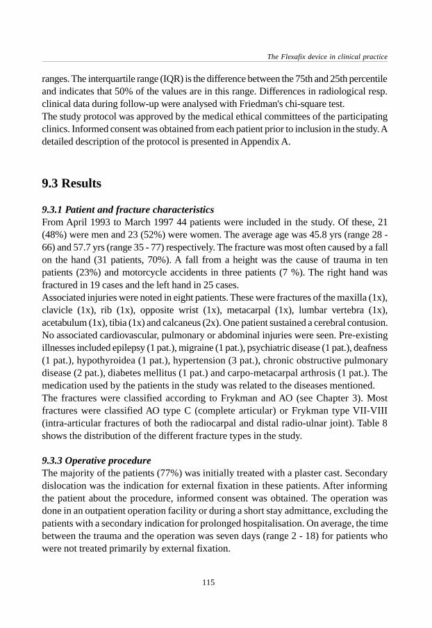
The Flexafix device in clinical practice
115
ranges. The interquartile range (IQR) is the difference between the 75th and 25th percentileand indicates that 50% of the values are in this range. Differences in radiological resp.clinical data during follow-up were analysed with Friedman's chi-square test.The study protocol was approved by the medical ethical committees of the participatingclinics. Informed consent was obtained from each patient prior to inclusion in the study. Adetailed description of the protocol is presented in Appendix A.
9.3 Results
9.3.1 Patient and fracture characteristicsFrom April 1993 to March 1997 44 patients were included in the study. Of these, 21(48%) were men and 23 (52%) were women. The average age was 45.8 yrs (range 28 -66) and 57.7 yrs (range 35 - 77) respectively. The fracture was most often caused by a fallon the hand (31 patients, 70%). A fall from a height was the cause of trauma in tenpatients (23%) and motorcycle accidents in three patients (7 %). The right hand wasfractured in 19 cases and the left hand in 25 cases.Associated injuries were noted in eight patients. These were fractures of the maxilla (1x),clavicle (1x), rib (1x), opposite wrist (1x), metacarpal (1x), lumbar vertebra (1x),acetabulum (1x), tibia (1x) and calcaneus (2x). One patient sustained a cerebral contusion.No associated cardiovascular, pulmonary or abdominal injuries were seen. Pre-existingillnesses included epilepsy (1 pat.), migraine (1 pat.), psychiatric disease (1 pat.), deafness(1 pat.), hypothyroidea (1 pat.), hypertension (3 pat.), chronic obstructive pulmonarydisease (2 pat.), diabetes mellitus (1 pat.) and carpo-metacarpal arthrosis (1 pat.). Themedication used by the patients in the study was related to the diseases mentioned.The fractures were classified according to Frykman and AO (see Chapter 3). Mostfractures were classified AO type C (complete articular) or Frykman type VII-VIII(intra-articular fractures of both the radiocarpal and distal radio-ulnar joint). Table 8shows the distribution of the different fracture types in the study.
9.3.3 Operative procedureThe majority of the patients (77%) was initially treated with a plaster cast. Secondarydislocation was the indication for external fixation in these patients. After informingthe patient about the procedure, informed consent was obtained. The operation wasdone in an outpatient operation facility or during a short stay admittance, excluding thepatients with a secondary indication for prolonged hospitalisation. On average, the timebetween the trauma and the operation was seven days (range 2 - 18) for patients whowere not treated primarily by external fixation.
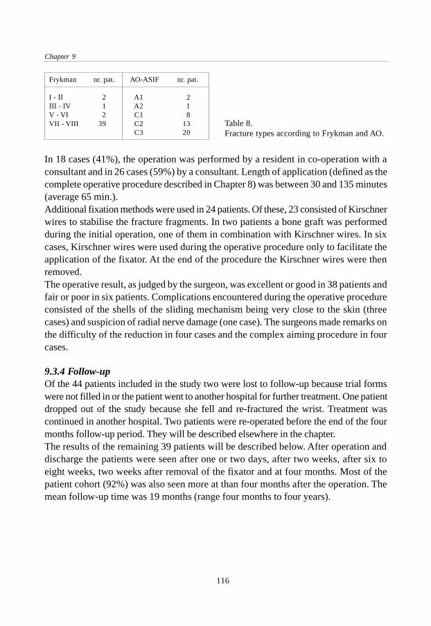
Chapter 9
116
In 18 cases (41%), the operation was performed by a resident in co-operation with aconsultant and in 26 cases (59%) by a consultant. Length of application (defined as thecomplete operative procedure described in Chapter 8) was between 30 and 135 minutes(average 65 min.).Additional fixation methods were used in 24 patients. Of these, 23 consisted of Kirschnerwires to stabilise the fracture fragments. In two patients a bone graft was performedduring the initial operation, one of them in combination with Kirschner wires. In sixcases, Kirschner wires were used during the operative procedure only to facilitate theapplication of the fixator. At the end of the procedure the Kirschner wires were thenremoved.The operative result, as judged by the surgeon, was excellent or good in 38 patients andfair or poor in six patients. Complications encountered during the operative procedureconsisted of the shells of the sliding mechanism being very close to the skin (threecases) and suspicion of radial nerve damage (one case). The surgeons made remarks onthe difficulty of the reduction in four cases and the complex aiming procedure in fourcases.
9.3.4 Follow-upOf the 44 patients included in the study two were lost to follow-up because trial formswere not filled in or the patient went to another hospital for further treatment. One patientdropped out of the study because she fell and re-fractured the wrist. Treatment wascontinued in another hospital. Two patients were re-operated before the end of the fourmonths follow-up period. They will be described elsewhere in the chapter.The results of the remaining 39 patients will be described below. After operation anddischarge the patients were seen after one or two days, after two weeks, after six toeight weeks, two weeks after removal of the fixator and at four months. Most of thepatient cohort (92%) was also seen more at than four months after the operation. Themean follow-up time was 19 months (range four months to four years).
Frykman nr. pat. AO-ASIF nr. pat.
I - II 2 A1 2III - IV 1 A2 1V - VI 2 C1 8VII - VIII 39 C2 13
C3 20Table 8.Fracture types according to Frykman and AO.

The Flexafix device in clinical practice
117
9.3.5 Functional resultsTwo weeks after the operation, the fixating cross-bar was removed and the slidingmechanism was unlocked. The patient was then stimulated to use the hand again. Thirty-two patients (82%) received physical therapy during the dynamised period or afterremoval of the fixator.Four weeks after dynamisation of the fixator, the median amount of flexion with the Flexafixdevice still mounted was 30 degrees (IQR 14 to 40°) and the amount of extension 18° (IQR9 to 30°). These values significantly increased to 40° (IQR 30 to 50°) and 40° (IQR 20 to50°) resp. two weeks after removal of the fixator, 45° (IQR 40 to 55°) and 50° (IQR 40 to60°) at four months follow-up and finally 60° of flexion (IQR 40 to 68°) and 60° of extension(IQR 50 to 70°) at the time of end follow up (Fig. 83).Four weeks after dynamisation the median radial deviation with the fixator on the wristwas 0 degrees (IQR -4 to 5°); the median ulnar deviation was 20 degrees (IQR 10 to20°). This progressed to 15° (IQR 6 to 20°) and 20° (IQR 11 to 35°) resp. two weeksafter removal of the fixator, 15° (IQR 10 to 25°) and 25° (IQR 20 to 30°) at four months,and 20° (IQR 15 to 25°) and 40°(IQR 30 to 45°) at the time of end follow-up (Fig. 84).
Figure 83. Flexion and extension in relation to time-interval after the trauma.
The median amount of pronation four weeks after dynamisation was 50 degrees (IQR32 to 70°) compared to 30° (IQR 10 to 45°) of supination. Two weeks after removal ofthe fixator these values were 75° (IQR 58 to 90°) and 43° (IQR 20 to 66°) resp., at fourmonths 80° (IQR 70 to 90°) and 70° (IQR 55 to 80°) resp. and at the end of follow-up 90°(IQR 78 to 90°) and 75° (IQR 63 to 80°) (Fig. 85).The functional results according to the criteria described by Gartland and Werley (modifiedby Sarmiento) showed 10 (28 %) excellent, 16 (46%) good, 8 (23%) fair and 1 (3 %)
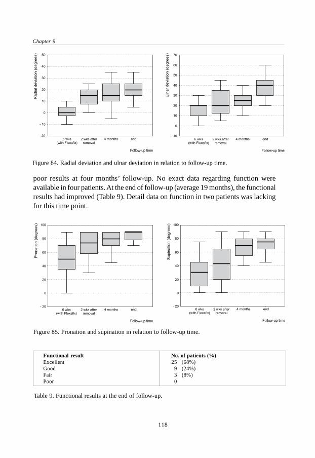
Chapter 9
118
poor results at four months’ follow-up. No exact data regarding function wereavailable in four patients. At the end of follow-up (average 19 months), the functionalresults had improved (Table 9). Detail data on function in two patients was lackingfor this time point.
Figure 85. Pronation and supination in relation to follow-up time.
Figure 84. Radial deviation and ulnar deviation in relation to follow-up time.
Functional result No. of patients (%)Excellent 25 (68%)Good 9 (24%)Fair 3 (8%)Poor 0
Table 9. Functional results at the end of follow-up.

The Flexafix device in clinical practice
119
9.3.6 Radiological resultsSince the sliding mechanism of the fixator was usually located on the lateral side of thewrist, it was not possible to perform reliable measurements (e.g. dorsal angulation) onthe lateral X-rays until the fixator was removed. This problem was not seen on theantero-posterior X-rays. Therefore radial length and radial angle could be measured onall these X-rays.Two weeks after the operation, the median radial length was 11 mm (IQR 9 to 13 mm),compared to 2 mm (IQR 0 to 8 mm) directly after the trauma. During the period ofdynamisation, radial length remained the same with 11 (IQR 8 to 13 mm) at six weeks(removal of the fixator). In the time following, radial length tended to decrease slightly toa median of 10 mm (IQR 8 to 13 mm) after four months (not significant). At the end offollow-up (average 19 months), the median radial length was 10 mm (IQR 8 to 13 mm)(Fig. 86).
The median radial angle was 13 degrees (IQR 8 to 19°) at the time of fracture and 24degrees (IQR 20 to 28°) after two weeks. Six weeks after the operation the medianradial angle was 26° (IQR 22 to 28°), after four months 26° (IQR 22 to 29°) and at thetime of end follow-up 24° (IQR 20 to 26°) (Fig. 87). Dorsal angulation, as explainedbefore, could only be measured at the time of trauma and after removal of the fixator.The median dorsal angle after the trauma was 26 degrees (IQR 9 to 36°). At six weeksthe median dorsal angle was 2° (IQR -4 to 10°), at four months 4° (IQR -4 to 10°) andat the time of end follow-up 0° (IQR -4 to 8°) (Fig. 88).When classified according to Lidström, at four months the radiological result wasexcellent in 11 cases (30%), good in 19 cases (51%), fair in two cases (5%) and poor infive cases (14 %). For two patients no radiological data at this time point were available.
Figure 86. Progress in time of radial length.
Chapter 9
120
Table 10 shows the radiological result at the end of follow-up (average 19 months). For onepatient no X-ray data were available at that time point. To give an impression of the courseof treatment in individual patients in Appendix B four case histories are presented.
Figure 88. Progress in time of dorsal angle.
Figure 87. Progress in time of radial angle.
9.3.7 ComplicationsAt each visit the occurrence of complications was noted. These consisted of pin tractinfections (nine patients, 22%), nerve impairment (seven patients, 17%), symptoms ofreflex sympathetic dystrophy (four patients, 10%), mechanical problems (two patients,5%), delayed union (one patient, 2%), re-operation (three patients, 7%, including thetwo patients who dropped out of the study).
Radiological result no. of patients (%)Excellent 12 (32%)Good 19 (50%)Fair 2 (5%)Poor 5 (13%)
Table 10. Radiological results at the end of follow-up.

The Flexafix device in clinical practice
121
The pin tract infections were all treated using conservative measures: moist bandages,elevation, pin care instructions and antibiotics (eight patients). None of the fixator pinshad to be removed for reasons of infection but in one patient the Kirschner wires wereremoved due to infective complications. Nerve complications were frequently seen andoccurred in the area of the superficial branch of the radial nerve. Most of the affectedpatients complained of reduced sensibility of the thumb. The hypesthesia was temporaryin six patients and permanent in one patient. Mechanical problems consisted of decreasedsliding capacities of the fixator. None of the sliding mechanisms broke down but severalshowed signs of wear during the period of dynamisation (Fig. 89).Three patients were re-operated after the initial operation, two of them before theyreached the four months’ follow-up time and one five months after the initial operation.Of these patients, one showed a persistent dorsal angulation of 22 degrees which wasnot corrected at the time of fixator placement. This was the fifth patient who was includedin the trial. A correction osteotomy was performed and a plate was applied. Two patientshad severe pain in the distal radio-ulnar joint. Revision of the initial X-rays showed aluxation of the ulna for which a resection of the distal ulna was performed.
Figure 89 Example of wear at the surface of the shells of the sliding mechanism (left: overview, right:detail).
9.4 Discussion
The fracture of the distal radius can be a difficult fracture to treat, especially in the caseof comminution or a secondarily dislocated fracture which is operated on a week ormore after the trauma. The use of an external fixator is an accepted method to stabiliseunstable fractures and to maintain the length of the radius. This form of treatment hasbecome popular because of the versatility of the devices and the good results of treatment.On the other hand, studies with a long-term follow-up show a high percentage of post-

Chapter 9
122
traumatic arthrosis, sometimes in excess of 50%.14,16 Others have pointed out theimportance of motion in a joint and the circulation of synovial fluid.13 A generallyaccepted goal in the treatment of articular fractures is early mobilisation of the affectedjoint. It is remarkable that this goal is often not reached in fractures involving a joint asimportant as the wrist. The development of external fixators that provide a way ofstability for the fracture in combination with the possibility of early mobilisation is anattempt to improve the recovery of an intra-articular and/or comminuted distal radialfracture.In this study a newly designed and developed dynamic external fixation device for thetreatment of severe distal radial fractures was used. The design of this dynamic externalfixation device tested differs significantly from other dynamic fixators in that it allowsthree degrees of freedom while the centre of rotation of all these movements is in onepoint, located outside the device. This centre of rotation of the device can be brought inconcordance with the assumed centre of rotation of the wrist. Previous devices hadeither ball-joints as dynamic part of the fixator or a sliding mechanism with only onedegree of freedom.17,18,19,20 The main goals of the present study were to gain experiencewith the Flexafix fixator and to reveal potential problems associated with its use.The operative procedure took 65 minutes on average, which maybe somewhat longerthan needed for the application of a standard external fixation device. This is explainedby the part of the operation in which the sliding mechanism is positioned. The aimingwith the help of the aiming device and image-intensifier can be difficult since thereduction has to be held while at the same time the wires of the aiming device arepointed towards the capitate bone (i.e. the centre of rotation) and the bolts are tightened.In six patients, the reduction was temporarily held by two Kirschner wires in the distalradius, which were removed at the end of the operation. This facilitated the application ofthe sliding mechanism. A certain disadvantage of the present aluminium construction ofthe Flexafix device is the fact that lateral image-intensifier and X-ray views are largelyobstructed by the device. Therefore the operative result is sometimes hard to judge.After the cross-bar was removed at the fourteenth day post-operatively, the patientsstarted to move the injured wrist. Although some of the patients were afraid to use theirhand or experienced pain, the majority were enthusiastic about the mobility of theirhand soon after the injury. To enhance the sliding silicon spray was applied between theshells of the sliding mechanism when the fixator was dynamised. Several patientsreported successful use of sunflower oil at home in order to keep the sliding propertiesgood. It is not yet clear whether the moment chosen for dynamistion of the fixator (14days post-operatively) is ideal. Pennig advised the Orthofix device to be released afterthree weeks, whereas Asche advises to start with movements as early as the third post-operative day.18,20 More research is needed to select the best moment.

The Flexafix device in clinical practice
123
During the period of dynamisation, with a median flexion of 30 degrees, extension of18 degrees, radial deviation of 0 degrees and ulnar deviation of 20 degrees, the range ofmotion needed to perform activities of daily life is approached. Palmer reported thenormal functional range of motion used to perform these activities of daily living to be5° of flexion, 30° of extension, 10° of radial deviation and 15° of ulnar deviation.47 Ryufound that the majority of the evaluated tasks could be performed with 40° of combinedflexion extension and 40° of combined radio-ulnar deviation.48
The functional result at the end of follow-up (average 19 months) of the patients in thisstudy was excellent or good in 92% and fair or poor in 8%. These results are comparableto results published in reports using rigid external fixators.9,16,119,120,122,124,143,144 There wereeleven patients whose functional result at the last follow-up was better than at fourmonths follow-up, implicating that the function can still improve after four months.From these data we cannot conclude that the dynamic fixator is superior to rigid externalfixators. However, only two weeks after removal of the fixator the median range ofmotion was 40° of flexion, 40° of extension, 15° of radial deviation and 20° of ulnardeviation, which seems a good result for a short period after removal of the fixator. Incomparison with other dynamic external fixators the results of the Flexafix device arecertainly not inferior. Functional results were graded as excellent or good in 92% of ourpatients, compared to 73 to 90% in other studies (Table 11).159,160,161,162,163,164
The radiological results were excellent or good in 82% and fair or poor in 18%. Theseresults are also comparable to reports with other dynamic external fixators (Table11).159,160,161,162,163,164 When the three radiological measurements in the course of follow-up are evaluated it is seen that the radial angle in our study was restored from 13degrees (median) at the time of fracture to 24 degrees after operation. This was notsignificantly different at time of completion of follow-up. Average dorsal angulationafter the trauma was 20.5 degrees compared to 1.0° at the time of end follow-up. Radiallength was 2 mm (median) directly after the trauma and 11 mm at two weeks. Duringdynamisation it decreased only minimally to 10 mm at the end of follow-up (notsignificant). From these data we can conclude that in spite of the early mobilisationwith the fixator still on the wrist, reduction was maintained.Sommerkamp et al. in their study with the Clyburn dynamic external fixator observed anaverage radial length of 5 millimetres before the operation, 15 millimetres after applicationand 11 millimetres at the time of removal.161 This means a loss of radial length of 4millimetres between application and removal of the fixator. Dorsal angulation was 28degrees before, 7° after the operation and 8° at the time of removal. Radial deviation was7° before reduction, 23° after application of the fixator and 23° on removal of the fixator.
The radiological results obtained with the Flexafix device used in this study are hard toreview in part because the lateral X-rays are obstructed by the Flexafix device. Therefore,

Chapter 9
124
the dorsal angulation cannot be measured accurately until the fixator is removed. Thisproblem is not seen with the antero-posterior views. Theoretically, it is possible that asub-optimal radiological result was caused by a technical failure during the positioningof the sliding mechanism. A close review of the X-rays of the patients with a fair orpoor radiological result revealed that in these cases the positioning of the device wasprobably not optimal. One cannot expect a good radiological end result if the radiologicalresult (i.e. reduction) is not good at the time of operation. This means that consertedefforts should be made to obtain a good reduction and to carefully position the deviceduring the operative procedure. Others have advised to achieve reduction with less than20° of dorsal angulation, more than 10° of radial angulation and loss of radial length of lessthan 6 mm.163 Additional Kirschner wire fixation of the fracture fragments could providemore stability but in the present study the functional and radiological results of the patientswith and without additional K-wire fixation were equal. This could possibly be explainedby the severity of the fracture types that were treated with additional K-wires.As Vaughan found in his study, the patient group can be split in a two groups: elderlypatients (above 55 years) who most often sustain a low-energy accident like a fall on thehand, and a younger group (below 55 years) who often sustain a more violent accidentlike motor vehicle accidents or falls at work from a height.9 Radiological results in thepresent study were not substantially different between patients younger than 55 years and
Author Lennox Merchan Klein Sommerkamp Asche Dienst present studyYear 89 92 92 94 95 95 98Number pat. 20 35 38 24 102 30 39Female/ 65% 20% 40% 42% 69% 80% 52%male 35% 80% 60% 58% 31% 20% 48%Age (mean) 55 37 46 34 54 45 52Device Clyburn Clyburn Pennig Clyburn Asche Asche FlexafixFollow-up 16 12 20 12 7 6 19(months,mean)Fracture type all all 56% 75% 62% 63% 89%(Frykman) VII - VIII III - VIII VII-VIII VII-VIII III-VIII III-VIII VII-VIIIResults (%)Functional
excellent 70 51 32 32 20 68good 20 29 41 44 67 24fair 10 17 24 24 91 13 8poor 0 3 3 0 0 0
Radiologicalexcellent no data 54 42 4 98 50 32good 34 42 56 47 50fair 9 8 12 2 3 5poor 3 8 28 0 0 13
Table 11. Comparison of results with various dynamic external fixators. 159,160,161,162,163,164

The Flexafix device in clinical practice
125
those above 55 years of age. The functional results were excellent or good in 96% of thepatients younger than 55 years compared with 81% in the group older than 55 years.Complications were rather frequent in the present series. Pin-tract infections occurredin 22% of the patients. The majority of these infections were at the site of the pins in theradius. A possible explanation could be the interaction between the soft tissues and thepin during the period of dynamisation. All infections were treated by pin care measures,drainage and/or antibiotics. One patient had loosening of the pins with loss of reduction.Other studies with dynamic external fixators reported varying percentages of infections,possibly due to different classification. Klein found only three pin-tract infections in 56patients; Merchan found four infections in 35 patients.160,164 In his series of 34 patientsSommerkamp found a much higher rate with 13 of 24 patients showing signs of infection.161
Despite the use of a limited open surgical approach for pin placement, seven patientshad paresthesia of the superficial branch of the radial nerve. Of these, six resolved and1 was persistent. This could mean that either the surgical technique was inadequate orthat mechanical irritation of the nerve occurred at the site of the pin. The rate of nervecomplications was comparable to other studies, in which incidences varied between 2and 17% (see Chapter 4).124,126,127,146,147,148,149
Although the device use in this study was newly designed, there was only one case inwhich the fixator could not be dynamised because of mechanical problems. Some fixatorshad minor problems with the sliding properties. This can be explained by the metalsurfaces sliding over each other in the sliding mechanism or by the presence of blood inthe device. Klein encountered four dislocations of the ball joint in the Orthofix devicein 56 patients, after which the device was adjusted.164 Lennox reported one failure ofthe Clyburn device in 20 patients.159
9.5 Conclusion
The present study reports experience with a new biomechanical concept of dynamicexternal fixation of distal radial fractures. The radiological result was excellent or good in82% of the patients and the functional result was excellent or good in 92% of the cases.These figures are comparable to the treatment results with other dynamic and static externalfixation devices. Regarding the severity of the fracture types and the fact that a newdevice was used this can be regarded as a positive conclusion. Also, it is important thatreduction was maintained in spite of the early dynamisation of the injured wrist.A beneficial effect of the dynamic aspect of the fixator could not be demonstratedclearly since the study was non-comparative. As mentioned before, the range of motiontwo weeks after removal of the fixator seems relatively good. Also, the response with

Chapter 9
126
regard to this device was very positive in the majority of the patients though the effectof dynamisation on the quality of life is a point for further research. To show a distinctadvantage of dynamic external fixation over static external fixation a prospective studywith a long-term follow-up would be needed because none of the present availablestudies meets these criteria when critically reviewed. Only the long-term results canpossibly show a presumed decrease in the rate of post-traumatic athrosis and disuseosteopenia explained by the advantage of early radiocarpal motion. Before we canconclude that dynamic external fixation is either advantageous or unnecessary, the designof the dynamic fixators needs to be be optimal.The Flexafix dynamic external fixation device is a new acquisition in the range ofavailable dynamic external fixators for the treatment of distal radial fractures. The newbiomechanical construction and the first treatment results are encouraging. However,the device needs further development, especially to allow lateral X-ray views. The useof different materials or surface treatment methods could also further enhance the slidingproperties of the fixator.

127
General discussion
General discussion

128

129
General discussion
This study describes the development of a new dynamic external fixation device for thetreatment of distal radial fractures. Fractures of the distal radius are commonly seen inemergency departments and most often treated by means of closed reduction andapplication of a plaster cast. Although this method of treatment is usually sufficient forso-called stable fracture types the reduction is often not maintained in fractures withintra-articular components and/or comminution. For these unstable fractures of the distalradius several treatment options have been proposed in the past with external fixationcomprising one of the most frequently used methods.One disadvantage of the use of external fixation on the wrist is the fact that with most ofthe currently available devices the wrist is rigidly fixed without the possibility ofmobilisation. This might be a factor in the occurrence of prolonged pain and stiffness inthe wrist and later in the development of post-traumatic arthrosis. Reported incidencesof problems related to the immobilisation differ widely due to the length of follow-up,criteria for definition and the fact that radiological signs of arthrosis do not necessarilyhave to be accompanied by clinical symptoms. Recent long-term studies have shownradiological signs of arthrosis in 59 to 91 percent of the patients, who were treated byvarious methods.
Treatment consisting of anatomic reduction and internal fixation of intra-articularfractures with early mobilisation of the adjacent joints has been widely advised formany years. The circulation of synovial fluid by means of early motion of the joint hasbeen shown to have beneficial effects on the regeneration of articular cartilage ascompared to immobilisation. It is remarkable that in a fracture occurring so frequently,it has up til now been so difficult to achieve early mobilisation, especially with intra-articular fractures. This problem has resulted in the idea and subsequent developmentof dynamic external fixators which have in common the presence of some sort of jointin the fixator to allow motion at the wrist during treatment of the fracture. Severaldevices have been developed since 1987, most often with one or more ball joints as thearticulating part. One dynamic fixator used a one-dimensional sliding mechanism withits centre of rotation in the wrist. The development of the dynamic external fixators isoften based on studies which located the centre of rotation of the wrist in the proximalpart of the capitate bone. It can be argued that this is too much a simplification of thecomplex wrist joint but for practical purposes it might be sufficient.
The problem leading to the present study was the fact that none of the available dynamicexternal fixation devices allows motion around all three axes with the centre of rotationof all these movements located in the wrist. A ball joint located in the fixator can onlycorrespond with the centre of rotation of the wrist during one type of movement (usually

130
flexion-extension if mounted on the lateral side of the wrist). The purpose of the presentstudy was the development of a dynamic external fixation device which allows motionin all three planes while the centre of rotation of all these movements was located in thewrist instead of in the device. In a combined research project, clinically andbiomechanically oriented researchers have worked together on a solution to the problem.This has resulted in the development of a sliding mechanism which meets all the abovementioned criteria. This could be achieved by the use of a newly designed and patentedmechanism with spherical shells. With the fixator mounted properly, the centre of rotationof the device, which is located 50 millimetres from the surface of the sliding mechanism,corresponds with the centre of rotation of the wrist. The design of the sliding mechanismhas been patented.
The biomechanical properties of the new device, called Flexafix, have been tested incomparison to a frequently used dynamic external fixator with a double ball joint as itsarticulating part. The forces on the distal radius during movement of the hand, asmeasured by the forces on a fixator pin, were about the same during flexion and extension.During radio-ulnar deviation the fixator with ball joints showed a high pin load whereasthe Flexafix device showed no considerable pin load. An explanation for this is the factthat with the ball joints, during radio-ulnar deviation the wrist is forced to rotate aroundthe ball joint, which is located approximately five centimetres away from the naturalcentre of rotation of the wrist. Although its manufacturer advises to exercise flexion-extension only, it is difficult for a patient to consciously restrict wrist motion to exactlya single plane. Furthermore, the device has some play in the ball joints, allowingmovements in another plane. Due to its biomechanical construction, in the cadavermodel the newly designed Flexafix device displayed a relatively favourable load pattern,thereby confirming the theoretical advantage.
Any dynamic external fixator which does not allow unconstrained movement of thewrist will change the normal pattern of carpal movement, which could possibly resultin dislocation of fracture fragments if applied to a fractured distal radius. Therefore, asecond cadaver study was conducted in order to obtain more direct information aboutthe kinematic properties of the Flexafix device. Methods to study the motion of thewrist that have been applied in the past used a sequential analysis of wrist motion todescribe a dynamic process. In the kinematic study described in this thesis, data acquiredfrom high-speed video images and three-dimensional reconstructions of CT-scans werecombined and reconstructed into a 3-dimensional visual animation of the actual motionpattern. By calculating the range of motion and three carpal angles, a selection of possibleparameters was chosen to describe the kinematics of the wrist. The interpretation of

131
General discussion
motion data is complex and subject to confusion. Angles of carpal bones for examplecan be described as an angle relative to a starting position or with respect to anotherbone (as in this study).The study was limited in several aspects: a relatively small number of specimens wastested, the hand was moved passively (although the tendons were loaded) and acomparison with other studies is difficult. The main goal however, was to test thekinematic compatibility of the Flexafix device in an intact forearm using each wrist asits own control. The study showed that between 40 degrees of flexion and 40 degrees ofextension no statistically significant changes in radiolunate, capitolunate or scapholunateangles could be detected after application of the Flexafix device. The introduction of ascapholunate ligament injury, which frequently accompanies intra-articular distal radialfractures, influenced the carpal angles mostly during flexion. These altered kinematicwere not further deteriorated after application of the fixator. Since no reference data areavailable as to which differences in kinematics are acceptable in order to benefit fromthe early motion without impeding the reduction of the fracture fragments, more researchin needed on this subject.
After further development of the Flexafix device the properties were evaluated in aclinical study. The functional and radiological results in the patients with mainly severefracture types were excellent or good in most patients and are certainly comparable tothose with rigid and other dynamic external fixators in the literature, although it isdifficult to compare the results of different studies using various criteria for evaluationof the result. Considering that the clinical experience with the newly developed devicewas limited, these results of treatment can be regarded as positive. The early mobilisationof the unstable fractures was generally not followed by a loss of reduction, which maybe related to the sound biomechanical concept of the device. A good reduction of thefracture at the time of operation and a correct positioning of the sliding mechanismseem to be important factors determining the anatomical result. The positioning of thedevice requires a good understanding of the kinematics of both the sliding mechanismand the wrist.The range of motion achieved with the dynamised fixator still on the wrist was close tothe range of motion needed to perform activities of daily living. Patients resumed theiractivities with the dynamised fixator on the wrist and the subjective judgement of themajority of the patients was enthusiastic. Although no special effort was made to quantifythe quality of life and the possibility to perform activities of daily living, the new devicemade a very favourable impression. It seems an advantage that the patient is already onthe way regaining wrist mobility instead of having to start with a stiff wrist joint whena rigid fixator is removed after six to eight weeks. The optimal moment for the
132
dynamisation of the fixator is still subject to debate. Future studies and increasingexperience with dynamic external fixators will have to give an answer to this question.Despite the early mobilisation some patients showed signs of reflex sympatheticdystrophy but considering the relative small number of patients that was studied and thefact that the criteria for the diagnosis of dystrophy were not defined clearly beforehandno conclusions can be drawn from these data. It seems likely that part of the infectivecomplications observed in the study are due to the interaction between the soft tissuesand the proximal fixator pins during dynamisation. The aluminum construction of thedevice proved sufficient but the fact that the present device is not radiolucent is adisadvantage because the reduction of the fracture cannot be assessed clearly on thelate-ral image intensifier or X-ray views. This problem could possibly be solved by theuse of a carbon fibre construction but this may have consequences regarding the stiffnessand size of the device. To be able to show an advantage of dynamic external fixationover static external fixation a prospective, randomised study with a long period of follow-up would be necessary. Until then what we do have is a new device with favourablebiomechanical properties and the theoretical advantage of the possibility to allow earlymobilisation of the wrist during treatment of a severe distal radial fracture.

133
Summary and conclusions
Summaryandconclusions
134
In Chapter 1 the aim of this thesis is outlined. Although most simple, extra-articulardistal radial fractures can be treated with a plaster cast, this form of treatment is ofteninsufficient for unstable, intra-articular fractures. External fixation is an alternativemethod to provide stability for these fractures but has a risk of prolonged stiffness andpain due to the immobilisation of the wrist joint. Dynamic external fixation providesthe possibility of early functional treatment. There are definite possibilities for improvingthe construction of these fixators.In a combined research project of the Academic Medical Centre in Amsterdam and theAO Research Institute in Davos a better solution for the biomechanical design of adynamic external fixator was studied and subsequently evaluated.
Chapter 2 gives an overview of the anatomy of the wrist in relation to fractures of thedistal end of the radius. The bones and joints, their connecting ligaments, neurovascularsupply and the radiographic anatomy are described. Studies on functional wrist motionhave shown that the normal range of wrist motion needed to perform activities of dailyliving is approximately 35 to 40 degrees of combined flexion and extension and 25 to40 degrees of combined radio-ulnar deviation. The kinematics of the wrist joint arediscussed with special attention to the centre of rotation of the wrist joint, which islocated in the capitate bone.
Chapter 3 describes general aspects of distal radial fractures. The history goes back toancient times and the fracture mechanism has been studied extensively since then. Theincidence is about 35 per 10,000 for women and 10 to 15 per 10,000 for men with a risein the incidence in women after the age of 50, most probably related to osteoporosis. Afall at flour level or a fall from a height is the cause of the fracture in the majority ofpatients. Different fracture classification systems are discussed. Treatment optionsinclude plaster of paris, bracing, percutaneous pinning, open osteosynthesis and externalfixation, indicating that an ideal standard treatment is still not found. Complicationslike pain and stiffness can occur in up to 30% of treated patients. Post-traumatic arthrosiscan be seen in 6 to 65% of the patients, partly depending on the length of follow-up.
In Chapter 4 external fixation for the treatment of distal radial fractures is discussed.The technique is based on the principle of ligamentotaxis, which means that the reductionof the fracture fragments can be held by the distracted ligaments. The main indicationsare intra-articular, comminuted and/or unstable fracture types. Functional andradiological results are excellent or good in approximately 68 to 95% of patients butcomplications are common.

135
Summary and conclusions
Dynamic external fixation gives the possibility of early functional treatment. Theadvantages could be the reduction of pain and stiffness of the wrist and a positive effecton the restoration of joint cartilage. The latter is an important factor in the developmentof post-traumatic arthrosis. Several devices with a ball joint as the articulating part havebeen developed and tested, mostly in small studies. It is not yet clear what the best timeis to allow for mobilisation and whether there is an advantage compared to static fixators.
Chapter 5 describes the development of a new dynamic external fixator. A slidingmechanism with three degrees of freedom of movement was developed. The centre ofrotation of all these movements is located in one point outside the device, in contrast toa ball joint with its centre of rotation in the device itself. If mounted correctly, the thecentre of rotation of the wrist and the centre of rotation of the dynamic external fixatorare the same. This results in a technique which provides a method of maintaining fracturealignment, while permitting movement of the wrist in all planes.After a successful application of the Flexafix prototype in a first clinical test case, thedesign was further improved and adjusted. A patent was obtained and in addition anaiming device was developed to facilitate the accurate application of the fixator.
Chapter 6 shows the results of a biomechanical cadaver study. The load of the radiusduring flexion-extension and radio-ulnar deviation with the Flexafix device was comparedto a dynamic external fixator with a ball joint. The investigations showed that thebiomechanical properties of the Flexafix device provided a relatively favourable loadingof the radius and therefore the fracture area as compared to a device with an offset balljoint, especially during radio-ulnar deviation. This could be a factor in the prevention ofdislocation of the fracture fragments during the period that the fixator is dynamised.
Chapter 7 describes the kinematic properties of the new dynamic external fixator.Using a combination of data obtained from CT-scans and high-speed video images a 3-dimensional reconstruction of carpal motion was made. In order to describe the carpalmotion, the radiolunate, capitolunate and scapholunate angles were measured duringflexion-extension and during radio-ulnar deviation. During both types of movementsthe device changed normal carpal kinematics to a limited extend although the kinematicpattern with the Flexafix device was not signifficantly different from normal. The resultsfor flexion-extension correspond with data from previously published studies with otherdynamic external fixators. However, since the new device allows both flexion-extensionand radio-ulnar deviation, in contrast to other dynamic external fixation devices, withthe Flexafix device the normal kinematics can be more closely approached.

136
In Chapter 8 a stepwise operative technique for the application of the Flexafix deviceis presented. After standard preparations and reduction of the fracture the of the fixatorpins are inserted. It is important to prevent injury to the superficial branch of the radialnerve by the use of a limited open approach during placement of the fixator pins. Next,the sliding mechanism is positioned with the help of the aiming device. The Flexafixdevice is locked by allen screws in the sliding mechanism and a cross bar connectingthe fixator pins.
Chapter 9 describes the results of a prospective study initiated to gain experience withthe Flexafix device. Forty-four patients with unstable fractures of the distal radius wereincluded in the study. During the period of dynamisation, with a median flexion of 30degrees, extension of 18 degrees, radial deviation of 0 degrees and ulnar deviation of 20degrees the range of motion needed to perform activities of daily life was approached.In spite of early mobilisation, started two weeks after the operation, reduction wasmaintained. The radiological result was excellent or good in 82% of the patients and thefunctional result was excellent or good in 92% of the cases. These figures are comparableto the treatment results with other dynamic and static external fixation devices. Abeneficial effect of the dynamic aspect of the fixator was not demonstrated clearly; forthat a longer follow-up is necessary. Based on the experiences of the study the deviceneeds to be developed further. The use of different (radiolucent) materials and surfacetreatment methods could further enhance the sliding properties of the fixator.

137
Samenvatting en conclusies
Samenvattingenconclusies

138
In Hoofdstuk 1 wordt het doel van dit proefschrift besproken. Hoewel het grootstedeel van de eenvoudige, extra-articulaire distale radiusfracturen in gips behandeld kanworden is deze behandelingsmethode vaak onvoldoende voor instabiele, intra-articulairefracturen. Externe fixatie is een alternatieve methode om de stabiliteit te vergrotenmaar heeft het risico van langdurige pijn en stijfheid in de pols ten gevolge van deimmobilisatie. Dynamische externe fixatie geeft de mogelijkheid van een vroege,functionele behandeling maar de constructie van de huidige dynamische externe fixateurskan mogelijk verbeterd worden.In een samenwerkingsproject van het Academisch Medisch Centrum in Amsterdam enhet AO Research Institute in Davos werd naar een beter biomechanisch ontwerp gezochtdat vervolgens werd getest.
Hoofdstuk 2 geeft een overzicht van de anatomie van de pols in relatie tot distaleradiusfracturen. De ossale componenten, de ligamenten, de neurovasculaire structurenen de radiologische anatomie worden beschreven. Studies naar de functionele aspectenvan polsbewegingen hebben aangetoond dat voor activiteiten van het dagelijks leveneen beweeglijkheid van ongeveer 30 to 40 graden gecombineerde flexie-extensie en 25tot 40 graden gecombineerde radio-ulnairdeviatie nodig is. De kinematische aspectenvan de pols worden besproken met speciale aandacht voor het draaipunt van de pols,wat zich in het capitatum bevindt.
Hoofdstuk 3 beschrijft algemene aspecten van distale radiusfracturen. De geschiedenisgaat terug tot de tijd van Hippocrates en het fractuurmechanisme is sinds die tijduitgebreid onderzocht. De incidentie bij vrouwen is ongeveer 35 per 10.000 en bijmannen 10 tot 15 per 35.000 waarbij er een sterke stijging in de incidentie is bij vrouwenboven de 50 jaar, waarschijnlijk gerelateerd aan osteoporose. De meest voorkomendoorzaken van de fractuur zijn een val op de grond en een val van hoogte. Verschillendeclassificatiesystemen worden besproken.Er zijn vele behandelingsmogelijkheden waaronder gips, brace, percutane Kirschner-draden, open osteosynthese en externe fixatie. Dit duidt erop dat er geen overeenstemmingover een standaardmethode is. Tot 30% van de behandelde patiënten krijgt complicatieszoals pijn en stijfheid; post-traumatische arthrose kan bij 6 tot 65% van de patiëntenworden gezien, deels afhankelijk van de follow-up duur.
In Hoofdstuk 4 wordt de externe fixatie van distale radius fracturen besproken. Detechniek is gebaseerd op het principe van ligamentotaxis, waarbij de repositie van defractuurfragmenten d.m.v. tractie aan de ligamenten wordt behouden. De belangrijksteindicaties zijn intra-articulaire, comminutieve en/of instabiele fracturen. Functionele

139
Samenvatting en conclusies
en radiologische resultaten zijn goed tot uitstekend bij ongeveer 68 tot 95% van depatiënten maar complicaties komen frequent voor.Dynamische externe fixatie geeft de mogelijkheid van een vroege functionelebehandeling. De voordelen zouden kunnen liggen in een vermindering van pijn enstijfheid van de pols en in een mogelijk positief effect op het herstel van hetgewrichtskraakbeen. Dit laatste is een belangrijke factor bij de ontwikkeling van post-traumatische arthrose. Diverse typen dynamische externe fixateurs met kogelgewrichtjesals scharnierpunt zijn ontwikkeld en getest, meestal in kleine studies. Het is nog nietduidelijk wat het beste moment is om de fixateur te dynamiseren en of er een voordeelis ten opzichte van statische fixateurs.
Hoofdstuk 5 beschrijft de ontwikkeling van een nieuwe dynamische externe fixateur.Er werd een mechanisme met bewegingsmogelijkheden in 3 dimensies ontwikkeld.Het draaipunt ligt bij alle bewegingen in één punt buiten het apparaat, in tegenstellingtot dynamische fixateurs met een kogelgewricht waarbij het draaipunt in het apparaatzelf ligt. Als het apparaat op de juiste wijze wordt gemonteerd komen het draaipunt vande pols en dat van de dynamische fixateur met elkaar overeen. Zodoende ontstaat eentechniek die de mogelijkheid biedt de positie van de fractuurfragmenten te behoudenterwijl de pols in alle vlakken kan bewegen.Na de succesvolle toepassing van het Flexafix protoype in een eerste klinische casuswerd het ontwerp verder verbeterd en aangepast. Er werd een patent op het ontwerpverkregen en tevens werd er een richtapparaat ontwikkeld om de montage van de fixateurte vereenvoudigen.
Hoofdstuk 6 toont de resultaten van een biomechanische cadaverstudie. De belastingvan de radius tijdens flexie-extensie en radio-ulnairdeviatie met de Flexafix werdvergeleken met een dynamische externe fixateur met een kogelgewricht. Het onderzoekliet zien dat de biomechanische eigenschappen van de Flexafix zorgden voor een relatiefgunstig belastingspatroon van de radius en dientengevolge van het fractuurgebied invergelijking met een apparaat met een kogelgewricht. Dit was met name duidelijk tijdensradio-ulnairdeviatie. Deze eigenschappen zouden een rol kunnen spelen bij hetvoorkómen van dislocatie van fractuurfragmenten tijdens de periode waarin de fixateuris gedynamiseerd.
Hoofdstuk 7 beschrijft een analyse van de bewegingseigenschappen van de nieuweexterne fixateur. Door gebruik te maken van een combinatie van CT-scan en high-speedvideo data werd een 3-dimensionale reconstructie van bewegingen in de pols gemaakt.De hoeken tussen respectievelijk radius en lunatum, capitatum en lunatum, en scaphoid

140
en lunatum werden tijdens flexie-extensie en radio-ulnairdeviatie gemeten om het carpalebewegingspatroon te beschrijven. Tijdens beide soorten bewegingen traden in beperktemate veranderingen op in het normale carpale bewegingspatroon hoewel de verschillenniet significant waren. De resultaten voor flexie-extensie komen overeen met eerdergepubliceerde studies waarin andere dynamische externe fixateurs werden getest. Doordatmet de Flexafix zowel flexie-extensie als radio-ulnairdeviatie mogelijk zijn, integenstelling tot met andere dynamische externe fixateurs, kan de normale bewegingvan de pols echter beter benaderd worden.
In Hoofdstuk 8 wordt een stapsgewijze operatietechniek voor het aanbrengen van deFlexafix gepresenteerd. Na de standaard voorbereidingen en repositie van de fractuurworden de fixateurpennen ingebracht. Beschadiging van de sensibele tak van de nervusradialis kan daarbij voorkomen worden door gebruik te maken van een ‘half open’operatietechniek. Daarna wordt de dynamische fixateur met behulp van het richtapparaatgepositioneerd. Het bewegingsmechanisme wordt met behulp van inbusschroefjes eneen extra fixateurstaaf vastgezet.
Hoofdstuk 9 beschrijft de resultaten van een prospectieve studie die werd opgezet omervaring met de Flexafix op te doen. Vierenveertig patiënten met instabiele distaleradiusfracturen werden in de studie geïncludeerd. Gedurende de periode waarin defixateur was gedynamiseerd was de mediane flexie 30 graden, extensie 18 graden, radiairdeviatie 0 graden en ulnair deviatie 20 graden. Dit benadert de bewegingsmogelijkhedendie nodig zijn om activiteiten van het dagelijks leven uit te voeren. Ondanks de vroegemobilisatie, die twee weken na de operatie werd gestart, werd de repositie behouden.Het anatomische resultaat was uitstekend of goed in 82% van de patiënten en hetfunctionele resultaat was uitstekend of goed in 92% van de patiënten. Deze uitkomstenzijn vergelijkbaar met die van andere dynamische en statische externe fixateurs. Eenvoordelig effect van de dynamisatie kon niet duidelijk worden aangetoond; daarvoor iseen langere follow up nodig. Op grond van de opgedane ervaringen dient het apparaatnog verder te worden verbeterd. Het gebruik van (Röntgen doorlaatbare) materialen enfabricagemethoden zou de glij-eigenschappen van het bewegingsmechanisme kunnenbevorderen.

141
References
References

142
1. Owen RA, Melton LJ, Johnson KA, Ilstrup DM, Riggs BL. Incidence of Colles fracture in aNorth American community. Am J Publ Health 1982;72:605-607.
2. Ricciardi L, Diquigiovanni W. The External fixation treatment of distal articular fractures of theradius. Orthopedics 1984;7:637-641.
3. Jupiter JB. Current concepts review. Fractures of the distal radius. J Bone J Surg 1991;73-A:461-469.
4. Solgaard S, Petersen VS. Epidemiology of distal radius fractures. Acta Orthop Scand1985;56:391-393.
5. Gartland JJ, Werley CW. Evaluation of healed Colles’ fractures. J Bone Joint Surg 1951;33-A:895-907.
6. Lidström A. Fractures of the distal end of the radius. A clinical and statistical study of endresults. Acta Orth. Scand 1959; supplement 41:5-118.
7. Cooney WP. Management of Colles' fractures (editorial). J Hand Surg 1989;14-B:137-139.
8. Fernandez DL, Jakob RP, Büchler U. External fixation of the wrist. Current indications andtechnique. Ann Chir Gynaecol 1983;72:298-302.
9. Vaughan PA, Lui SM, Harrington IJ, Maistrelli GL. Treatment of unstable fractures of the radiusby external fixation. J Bone Joint Surg 1985;67-B:385-389.
10. Müller ME, Allgöwer M, Schneider R, Willenegger H. Manual of internal fixation. Techniquesrecommended by the AO-ASIF group. Berlin-Heidelberg-New York: Springer-Verlag, 1991.
11. Frykman GK, Tooma GB, Boyko K, Henderson R. Comparison of eleven external fixators fortreatment of unstable wrist fractures. J Hand Surg 1989;14-A:247-254.
12. Vidal J, Buscayret C, Fischbach C. Une méthode originale dans le traitement des fracturescomminutives de l’extrémité inférieure du radius: “Le taxis ligamentaire”. Acta Orth Belg 1977;43(6):781-789.
13. Salter RB. The biologic concept of continuous passive motion of synovial joints. The first 18years of research and its clinical application. Clin Orthop 1989;242:12-25.
14. Knirk JL, Jupiter JB. Intra-articular fractures of the distal end of the radius in young adults. JBone Joint Surg 1986;68-A:647-659.
15. Jakim I, Pieterse HS, Sweet MBE. External fixation for intra-articular fractures of the distalradius. J Bone Joint Surg 1991;73-B:302-306.
16. Steffen Th, Eugster Th, Jakob RP. Twelve years follow-up of fractures of the distal radius treatedwith the external fixator. Injury 1994;25(suppl 4):44-54.
17. Clyburn TA. Dynamic external fixation for comminuted intra-articular fractures of the distalend of the radius. J Bone Joint Surg 1987;69-A:248-254.

143
References
18. Asche G. Die dynamische Behandlung von handgelenksnahen und gelenkbeteiligendenSpeichenbrüchen mit einem neuartigen bewegungsfixateur. Akt Traumatologie 1990;20:6-10.
19. Yen ST, Hwang CH, Hwang MH. A semi-invasive method for articular Colles’ fractures. ClinOrthop 1991;263:154-164.
20. Pennig D. Dynamic external fixation of distal radius fractures. Hand Clin 1993;9(4):587-602.
21. Youm Y, McMurtry RY, Flatt AA, Gillespie TE. Kinematics of the wrist. An experimental study ofradio-ulnar deviation and flexion-extension. J Bone Joint Surg 1978;60-A:423-431.
22. Jakob RP. Die Distraktion einer instabielen distalen Radiustrümmerfraktur mit einem FixateurExterne - ein neuer Behandlungsweg. Z Unfallmed Berufskrankh 1980;73:115-120.
23. Dobyns JH, Linscheid RL. Fractures and dislocations of the wrist. In: Rockwood CA, GreenDP (eds): Fractures in adults. Lippincott, Philadelphia 1984:411-509.
24. Palmer AK. Fractures of the distal radius. In: DP Green. Operative hand surgery, Ed. 2, vol. 2.New York: Churchill Livingstone, 1988:1006-1007.
25. Sennwald G. The wrist. Berlin-Heidelberg-New York: Springer-Verlag 1987:13-47.
26. Taleisnik J. The wrist. New York: Churchill Livingstone, 1985:5-78.
27. Navarro A. Anatomia y fisiologica del carpo. An Inst Clin Quirurg Cirugia Exper 1935;1:162-250.
28. Ritt MJPF. Biomechanical studies on ulnar-sided ligaments of the wrist. Thesis. AmsterdamThe Netherlands 1995.
29. Berger RA. The ligaments of the wrist. A current overview of anatomy with considerations oftheir potential functions. Hand Clin 1997;13:63-82.
30. Van der Linden W, Ericson R. Colles’ fracture. How should its displacement be measured andhow should it be immobilized? J Bone Joint Surg 1981;63-A:1285-1288.
31. Szabo RM, Weber SC. Comminuted intra-articular fractures of the distal end of the radius. ClinOrthop 1988;230:39-48.
32. Warwick D, Prothero D, Field J, Bannister G. Radiological measurement of radial shorteningin Colles’ fracture. J Hand Surg 1993;18-B:50-52.
33. Linscheid RL, Dobyns JH, Beabout JW, Bryan RS. Traumatic instability of the wrist: diagnosis,classification and pathomechanics. J Bone Joint Surg 1972;54-A:1612-1632.
34. Viegas SF, Patterson RM. Load mechanics of the wrist. Hand Clin 1997;13:109-128.
35. Linscheid RL. Kinematic considerations of the wrist. Clin Orthop 1986;202:27-39.
36. Youm Y, Flatt AE. Kinematics of the wrist. Clin Orthop 1980;149:21.
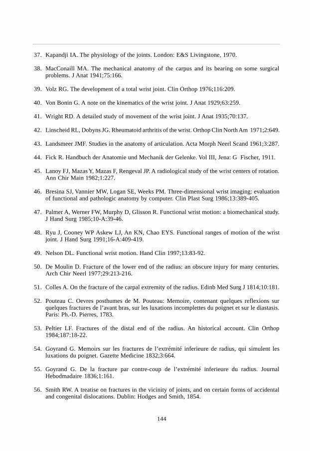
144
37. Kapandji IA. The physiology of the joints. London: E&S Livingstone, 1970.
38. MacConaill MA. The mechanical anatomy of the carpus and its bearing on some surgicalproblems. J Anat 1941;75:166.
39. Volz RG. The development of a total wrist joint. Clin Orthop 1976;116:209.
40. Von Bonin G. A note on the kinematics of the wrist joint. J Anat 1929;63:259.
41. Wright RD. A detailed study of movement of the wrist joint. J Anat 1935;70:137.
42. Linscheid RL, Dobyns JG. Rheumatoid arthritis of the wrist. Orthop Clin North Am 1971;2:649.
43. Landsmeer JMF. Studies in the anatomy of articulation. Acta Morph Neerl Scand 1961;3:287.
44. Fick R. Handbuch der Anatomie und Mechanik der Gelenke. Vol III, Jena: G Fischer, 1911.
45. Lanoy FJ, Mazas Y, Mazas F, Rengeval JP. A radiological study of the wrist centers of rotation.Ann Chir Main 1982;1:227.
46. Bresina SJ, Vannier MW, Logan SE, Weeks PM. Three-dimensional wrist imaging: evaluationof functional and pathologic anatomy by computer. Clin Plast Surg 1986;13:389-405.
47. Palmer A, Werner FW, Murphy D, Glisson R. Functional wrist motion: a biomechanical study.J Hand Surg 1985;10-A:39-46.
48. Ryu J, Cooney WP Askew LJ, An KN, Chao EYS. Functional ranges of motion of the wristjoint. J Hand Surg 1991;16-A:409-419.
49. Nelson DL. Functional wrist motion. Hand Clin 1997;13:83-92.
50. De Moulin D. Fracture of the lower end of the radius: an obscure injury for many centuries.Arch Chir Neerl 1977;29:213-216.
51. Colles A. On the fracture of the carpal extremity of the radius. Edinb Med Surg J 1814;10:181.
52. Pouteau C. Oevres posthumes de M. Pouteau: Memoire, contenant quelques reflexions surquelques fractures de l’avant bras, sur les luxations incomplettes du poignet et sur le diastasis.Paris: Ph.-D. Pierres, 1783.
53. Peltier LF. Fractures of the distal end of the radius. An historical account. Clin Orthop1984;187:18-22.
54. Goyrand G. Memoirs sur les fractures de l’extrémité inferieure de radius, qui simulent lesluxations du poignet. Gazette Medicine 1832;3:664.
55. Goyrand G. De la fracture par contre-coup de l’extrémité inferieure du radius. JournalHebodmadaire 1836;1:161.
56. Smith RW. A treatise on fractures in the vicinity of joints, and on certain forms of accidentaland congenital dislocations. Dublin: Hodges and Smith, 1854.

145
References
57. Barton JR. Views and treatment of an important injury to the wrist. Med Examiner 1838;1:365.
58. Nelaton A. Elements de pathologie chirurgicale. Paris, Germer Bailliere, 1844.
59. Lilienfeldt A. Über den klassischen Radiusbruch. Arch Klin Chir 1907;82:166-190.
60. Lilienfeldt A. Über die Erzeugung der typischen Verletzungen der Handwurtzelknochen und desRadiusbruches auf direktem Wege an der Leiche und ihre Entstehungsart, erläutert durch denMechanismus der Handgelenkbewegungen. Ztschr Orthop Chir 1908;20:437-454.
61. Frykmann GK. Fracture of the distal radius including sequelae, shoulder hand syndrome,disturbance in the distal radio-ulnar joint and impairment of nerve funtion. A clinical andexperimental study. Acta Orthop Scand 1967;suppl 108:5-159.
62. Szabo RM. Fractures of the distal radius. In: Chapman M.W. (ed) Operative orthopaedics.Philadelphia: Lippincott Company 1988:1279-1289.
63. Thomas FB. Reduction of Smith’s fractures. J Bone J Surg 1957;39-B:463-470.
64. Ellis J. Smith’s and Barton’s fractures: a method of treatment. J Bone Joint Surg 1965;47-B:724.
65. Scheck M. Long term follow up of the treatment of comminuted fractures of the distal end ofthe radius by transfixation Kirschner wires and cast. J Bone J Surg 1962;44-A:337-351.
66. Porter ML, Tillman RM. Pilon fractures of the wrist. Displaced intra-articular fractures of thedistal radius. J Hand Surg 1992;17-B:63-68.
67. Fontes D, Lenoble E, de Somer B, Benoit J. Lesions ligamentaires associees aux fracturesdistales du radius. Ann Chir Main Memb Super 1992;11:119-25.
68. Richards RS, Bennett JD, Roth JH, Milne K Jr. Arthroscopic diagnosis of intra-articular softtissue injuries associated with distal radial fractures. J Hand Surg 1997;22-A:772-776.
69. Dupuytren G. Des fractures de l’extrémité inférieure du radius simulant les luxations du poignet.Leçons orales de clinique chirugicale. Paris 1839;1:140.
70. Malgaigne JF. Traité des fractures et des luxations. Paris 1847;1:603.
71. Bähr F. Die typische Radiusfraktur und ihre Entstehung. Zentrallbl Chir 1894;21:841.
72. Destot E, Gallois E. Recherches physiologiques et expérimentales sur les fractures de l’extrémitéinférieure du radius. Rev Chir, Paris 1898;18:886.
73. Linhart von W. Die Brüche der unteren Epiphyse des Radius durch Gegenstoss. Z Ärzte Wien1852.
74. Lecomte O. Recherches nouvelles sur les fractures de l’extrémité inférieure du radius. ArchGén Méd 1860-1861;5:641.

146
75. Löbker K. “Sitzung des medizinschen Vereins zu Greifswald” Dtsch Med Wchnschr 1855;27:457.
76. Meyer H. Der klassische Speichenbruch. Klin Wchnschr 1925;4:554.
77. Lewis RM. Colles’ fracture - causative mechanism. Surgery 1950;27:427.
78. Golden GN. Treatment and prognosis of Colles’ fractures. Lancet 1963;1:511.
79. Falck Larsen C, Lauritsen J. Epidemiology of acute wrist trauma. Int J Epid 1993;22:911-916.
80. Bengnér U, Johnell O. Increasing incidence from forearm fractures. A comparison ofepidemiologic patterns 25 years apart. Acta Orthop Scand 1985;56:158-160.
81. Mallmin H, Ljunghall S. Incidence of Colles’ fracture in Uppsala. A Prospective study of aquarter-million population. Acta Orthop Scand 1992;63:213-215.
82. Falch JA. Epidemiology of fractures of the distal forearm in Oslo, Norway. Acta Orthop Scand1983;54:291-295.
83. Krolner B, Tondervold E, Toft B. Bone mass of the axial and the appendicular skeleton inwomen with Colles’ fracture: its relation to physical activity. Clin Physiol 1982;2:147-157.
84. Lamke B, Sjöberg HE, Sylven M. Bone mineral content in women with Colles’ fracture: effectof calcium supplementation. Acta Orthop Scand 1978;49:143-146.
85. Graff S, Jupiter J. Fracture of the distal radius: Classification of treatment and indications forexternal fixation. Injury 1994;25(suppl.4):14-25.
86. Hemenway D, Azrael DR, Rimm EB, Feskanich D, Willett WC. Risk factors for wrist fracture:effect of age, cigarettes, alcohol, body height, relative weight, and handedness on the risk fordistal forearm fractures in men. Am J Epid 1994;140:361-367.
87. Lawson CM, Hajducka C, McQueen MM. Sports fracture of the distal radius - epidemiologyand outcome. Injury 1995;26:33-36.
88. Schieber RA, Branche-Dorsey CM, Ryan GW, Rutherford GW, Stevens JA, O’Neil J. Riskfactors for injuries from in-line skating and the effectiveness of safety gear. N Engl J Med1996;335:1630-1635.
89. Chandler FA. Fractures of the distal end of the radius. J Iowa St med Soc 1950;11:518.
90. Sarmiento A, Pratt GW, Berry NC, Sinclair WF. Colles’ fractures. J Bone Joint Surg 1975;57-A:311-317.
91. Solgaard S. Classification of distal radius fractures. Acta Orthop Scand 1984;56:249-252.
92. Older TM, Stabler EV, Cassebaum WH. Colles fracture:evaluation and selection of therapy. JTrauma 1965;5:469-476.
93. Müller ME, Nazarian S, Koch P, Schatzker J. The comprehensive classification of fractures oflong bones. Berlin-Heidelberg-New York: Springer-Verlag, 1990.

147
References
94. Melone CP. Distal radius fractures. Patterns of articular fragmentation. Orthop Clin North Am1993;24(2):239-25.
95. Fernandez DL. Fractures of the distal radius: operative treatment. Instr Course Lect 1993;42:73-88.
96. Pfeiffer KM. Einteilung und therapeutische Indikationen der Frakturen am distalen Unterarm.In: Buck-Gramcko D. Frakturen am distalen Radiusende. Stuttgart: Hippokrates Verlag, 1987,15-25.
97. Sarmiento A, Zagorski JB, Sinclair WF. Functional bracing of Colles’ fractures. Clin Orthop1980;146:175-183.
98. Stewart HD, Innes AR, Burke FD. Functional cast-bracing for Colles’ fractures. A comparisionbetween cast-bracing and conventional plaster casts. J Bone Joint Surg 1984;66:749-753.
99. Bruijn de HP. Functional treatment of Colles fracture. Acta Orthop Scand 1987;58(suppl 223).
100. Böhler L. Die Technik der Knochenbruchbehandlung. Wien: W. Maudrich, 1929.
101. Dabezies EJ, Chuinard RG, Kitziger RF. Distraction pinning for radial metaphysis fractures.Orthopaedics 1978;1:294-298.
102. Green DP. Pins and plaster treatment of comminuted fractures of the distal end of the radius. JBone Joint Surg 1975;57-A: 304-310.
103. Chapman DR, Bennett JB, Bryan WJ, et al. Complications of distal radius fractures: pins andplaster treatment. J Hand Surg 1982;7:509-512.
104. DePalma AF. Comminuted fractures of the distal end of the radius treated by ulnar pinning. JBone Joint Surg 1952;34-A:651-662.
105. Constantz BR, Ison IC, Fulmer MT, Poser RD, Smith ST, VanWagoner M, Ross J, GoldsteinSA, Jupiter JB, Rosenthal DI. Skeletal repair by in situ formation of the mineral phase of bone.Science 1995;267:1796-1799.
106. Broekhuizen AH. Personal communication. 1996.
107. Cooney WP, Dobyns JH, Linscheid RL. Complications of Colles’ fractures. J Bone Joint Surg1980;62-A:613-619.
108. Overgaard S, Solgaard S. Osteoarthritis after Colles’ fracture. Orthopaedics 1989;12:413-416.
109. Dobyns JH, Linscheid RL. Complications of treatment of fractures and dislocations of thewrist. In: Epps C.H. (ed): Complications in orthopaedic surgery. Philadelphia: Lippincott,1978:271-352.
110. Lambotte A. Le traitement des fractures. Masson, Paris, 1907.
111. Anderson R. An ambulatory method of treating fractures of the shaft of the femur. Surg GynObstet 1936;70:865-873.

148
112. Stader O. A preliminary announcement of a new method of treating fractures. North Am Vet1937;18:37.
113. Hoffmann R. Ostéotaxis, ostéosynthese externe par fiches et rotules. Acta Chir Scand1954;107:72.
114. Ilizarov GA, Kaplunov AG, Degtarev VE, Ledyaev VI. Treatment of pseudarthroses and ununitedfractures, aggravated by purulent infection by the method of compression-distractionosteosynthesis. Ortop Traumatol Protez 1972;33:10-14.
115. Anderson R, O’Neil G. Comminuted fractures of the distal end of the radius. Surg Gyn Obst1944;78:434-440.
116. Agee JM. External fixation. technical advances based upon multiplanar ligamentotaxis. OrthopClin North Am 1993;24(2):265-274.
117. Forgon M, Mammel E. The external fixator in the management of unstable Colles’ fractures. IntOrthop. 1981;5:9.
118. Cooney WP. External fixation of distal radius fractures. Clin Orthop 1983;180:44-49.
119. Horesh Z, Volpin G, Hoerer D, Stein H. The surgical treatment of severe intra-articular fracturesof the distal radius with the small AO external fixation device. Clin Orthop 1991;263:147-153.
120. Cooney WP, Linscheid RL, Dobyns JH. External pin fixation for unstable Colles’ fractures. JBone Joint Surg 1979;61-A:840-845.
121. Chamay A. Indications for external fixation in wrist fractures. Z Unfallheilk VersicherungsmedBerufskr 1988;81:254-261.
122. D’Anca AF, Sternlieb SB, Byron TW, Feinstein PA. External fixator management of unstableColles’ fractures. Orthopaedics 1984;7:853-859.
123. Foster DE, Kopta JA. Update on external fixators in the treatment of wrist fractures. Clin Orthop1986;204:177-183.
124. Schuind F, Donkerwolcke M, Rasquin C, Burny F. External fixation of fractures of the distalradius: a study of 225 cases. J Hand Surg 1989;14-A:404-407.
125. Prince H, Worlok P. The small AO fixator in the treatment of unstable distal forearm fractures.J Hand Surg 1988;13-B:294-297.
126. Riis J, Fruensgaard S. Treatment of unstable Colles’ fractures by external fixation. J Hand Surg1989;14-B:145-148.
127. Howard PW, Steward HD, Hind RE, Burke FD. External fixation or plaster for severely displacedcomminuted Colles’ fractures? J Bone Joint Surg 1989;71-B:68-73.
128. Grana WA, Kopta JA. The Roger Anderson device in the treatment of fractures of the distal endof the radius. J Bone Joint Surg 1979;61-A:1234-1238.

149
References
129. Hertel R, Jakob RP. The small AO external fixator - a versatile device. Injury 1994;25(suppl4):28-34.
130. Seitz WH jr, Froimson AI, Brooks DB, Postak BD, Parker RD, LaPorte JM, Greenwald AS.Biomechanical analysis of pin placement and pin size for external fixation of distal radiusfractures. Clin Orthop 1990;251:207-212.
131. Seitz WH jr, Putnam MD, Dick HM. Limited open surgical approach for external fixation ofdistal radius fractures. J Hand Surg 1990;15-A:288-293.
132. Perren SM, Ganz R, Rüter A. Oberflächliche Knochenresorption um Implantate. Med OrthopTech. 1975;95:6-10.
133. Perren SM, Huggler A, Russenberger M, Allgöwer M, Mathys R, Schenk. The reaction of corticalbone to compression. Acta Orthop Scand Suppl 1969;125:17.
134. Perren SM, Huggler A, Russenberger M, Straumann F, Müller ME, Allgöwer M. A method ofmeasuring the change in compression applied to living cortical bone. Acta Orthop Scand Suppl1969;125:5.
135. Jakob RP, Fernandez DL. The treatment of wrist fractures with the small AO external fixationdevice. In: Uhthoff HK, ed. Current concepts of external fixation of fractures. Berlin-Heidelberg-New York: Springer-Verlag, 1982,307-314.
136. Leung KS, Shen WY, Leung PC, Kinninmouth AWG, Chang JCW, Chan GYP. Ligamentotaxisand bone grafting for comminuted fractures of the distal radius. J Bone Joint Surg 1989;71-B:838-842.
137. Green SA. Complications of external fixation. In: Uhthoff HK, ed. Current concepts of externalfixation of fractures. Berlin Heidelberg New York: Springer-Verlag, 1982,43-52.
138. Vidal J, Buscayret C, Paran M, Melka J. Ligamentotaxis. In: Mears DC. External skeletal fixation.Baltimore: William & Wilkins, 1983,493-496.
139. Bacorn RW, Kurtzke JF. Colles’ fracture. A study of two thousand cases from the New YorkState Workman’s Compensation Board. J Bone J Surg 1953;35-A:643-658.
140. McQueen M, Caspers J. Does the anatomical result affect the final function? J Bone Joint Surg1988;70B:649-651.
141. McAuliffe TB, Hilar KM, Coates CJ, Grange WJ. Early mobilization of Colles’ fractures. JBone Joint Surg 1987;69-B:727-729.
142. Roumen RMH, Hesp WLEM, Bruggink EDM. Unstable colles’ fracture in elderly patients. JBone Joint Surg 1991;73-B: 307-311.
143. Stein H, Volpin G, Horesh Z, Hoerer D. Cast or external fixation for fracture of the distal radius.A prospective study of 126 cases. Acta Orthop Scand 1990;61:453-456.

150
144. Sanders RA, Keppel FL, Waldrop JI. External fixation of distal radius fractures: Results andcomplications. J Hand Surg 1991;16-A:385-391.
145. Weber SC, Szabo RM. The severely comminuted distal radius fracture as an unsolved problem:complications associated with external fixation and pins and plaster techniques. J Hand Surg1986;11-A:157-165.
146. Jenkins NH, Jones DG, Johnson SR, Mintowt-Czyz WJ. External fixation of Colles’ fractures.An anatomical study. J Bone Joint Surg 1987;69-B:207-211.
147. Kongsholm J, Olerud C. Plaster cast versus external fixation for unstable intra-articular Colles’fractures. Clin Orthop 1989;241:57-65.
148. Delaere O, Hoang Ph. Le fixateur externe dans les fractures instables de l’extremite distale duradius; revue de la litterature recente. Acta Orthop Belg 1991;57:374-381.
149. Solgaard S. External fixation or a cast for Colles’ fracture. Acta Orthop Scand 1989;60:387-391.
150. Smaill GB. Long-term follow-up of Colles; fracture. J Bone Joint Surg 1965;47-B:80-85.
151. Veldman PHJM. Clinical aspects of reflex sympathetic dystrophy. Thesis. Nijmegen, theNetherlands 1995.
152. Goris GN. Treatment of reflex symptomatic dystrophy with hydroxyl radical scavengers.Unfallchirurg 1985;88:330-332.
153. Kaempffe FA, Wheeler DR, Peimer CA, Hvisdak KS, Ceravolo J, Senall J. Severe fractures ofthe distal radius: Effect of amount and duration of external fixator distraction on outcome. JHand Surg 1993;18-A:33-41.
154. Cronier P, Talha A, Toulemonde JL, Jaeger F, Guntz M. Résultats de la distraction par fixateurexterne métacarporadial dans les fractures de l’extrémité distale du radius. A propos de 97 cas.J Chir (Paris) 1991;128:8-12.
155. Abbaszadegan H, Adolphson P, Dalen N, Jonsson U, Sjöberg HE, Kalen S. Bone mineral lossafter Colles’ fracture. Plaster cast and external fixation equivalent. Acta Orthop Scand1991;62:156-158
156. Roth JH, Vandersluis R. Pin-site radioulnar synostosis after external fixation of a distal radialfracture: two case reports. Can J Surg 1993;36(2):137-140.
157. Hertel R, Ballmer FT. Complications of external fixation of the wrist. Injury 1994;25(suppl4):39-43.
158. Seiler H, Omlor G, Betz A. Zur operativen Therapie bei der frischen distalen Radiusfraktur.Unfallheilkunde 1981;84:139-149.
159. Lennox JD, Page BJ, Mandell RM. Use of the Clyburn external fixator in fractures of the distalradius. J Trauma 1989;29:326-331.

151
References
160. Merchan EC, Breton AF, Galindo E, Peinado JF, Beltran J. Plaster cast versus Clyburn externalfixation for fractures of the distal radius in patients under 45 years of age. Orthop Rev1992;21:1203-1209.
161. Sommerkamp TG, Seeman M, Silliman J, Jones A, Patterson S, Walker J, Semmler M, BrowneR, Ezaki M. Dynamic external fixation of unstable fractures of the distal part of the radius. JBone Joint Surg 1994;76-A:1149-1161.
162. Asche G. Die Behandlung von Speichenbrüche mit einem neu entwickelten dynamischenBewegungsfixateur. Zentralbl Chir 1995;120(12):952-958.
163. Dienst M, Wozasek GE, Seligson D. Dynamic external fixation for distal radial fractures. ClinOrthop 1997;338:160-171.
164. Klein W, Dée W. Erste Erfahrungen mit einem neuen Handgelenkfixateur zur Behandlung distalerRadiusfrakturen. Handchir Mikrochir Plast Chir 1992;24:202-209.
165. Dias JJ Wray CC, Jones JM, Gregg PJ. The value of early mobilisation in the treatment ofColles’ fractures. J Bone Joint Surg 1987;69-B:463-467.
166. Championière JL. Traitement des fractures par le massage et la mobilisation. Paris 1895.
167. Patterson RM, Nicodemus CL, Viegas SF, Elder KW, Rosenblatt J. Normal wrist kinematics andthe analysis of the effect of various dynamic external fixators for treatment of distal radius fractures.Hand Clin 1997;13:129-141.
168. Bunnell S. The normal hand. In: Surgery of the hand, Ed 3. Philadelphia: JB Lippincott, 1956:34-37.
169. Fisk GR. Carpal instability and the fractured scaphoid. Ann R Coll Surg Engl 1970;46:63-76.
170. Sarrafian SK, Melamed JL, Goshgarian GM. Study of wrist motion in flexion and extension. ClinOrthop Rel Res 1997;126:153-159.
171. Arkless R. Cineradiography in normal and abnormal wrists. Am J Roentg 1966;96:837-844.
172. Kauer JMG. The interdependence of carpal articulation chains. Acta Anat 1974;88:481-501.
173. Lange de A, Kauer JMG, Huiskes R. Kinematic behavior of the human wrist joint: a röntgen-stereofotogrammatic analysis. J Orthop Res 1985;3:56-64.
174. Ruby LK, Cooney WP, Linscheid RL, Chao EYS. Relative motion of selected capal bones: Akinematic analysis of the normal wrist. J Hand Surg 1988;13-A:1-10.
175. Sommer HG, Miller NR. A technique for kinematic modelling of anatomical joints. J BiomechEng 1980;102:311-317.
176. Berger RA, Blair WF, Crowninshield RD. The scapholunate ligament. J Hand Surg 1982;7:87-91.
177. Andrews JG, Youm YA. A biomechanical investigation of wrist kinematics. J Biomech 1979;12:83-93.

152
178. Viegas SF, Hillman GR, Elder KW, Stoner D, Patterson RM. Measurement of carpal bone geometryby computer analysis of three-dimensional CT images. J Hand Surg 1993;18-A:341-349.
179. Tagare HD, Elder KW, Stoner DM, Patterson RM, Nicodemus CL, Viegas SF, Hillman GR.Location and geometric description of carpal bones in CT images. Ann Biomech Eng 1993;21:715-726.
180. Patterson RM, Nicodemus CL, Viegas SF, Elder KW, Rosenblatt J. High-speed, three-dimensionalkinematic analysis of the normal wrist. J Hand Surg 1998;23-A:446-453.
181. Geissler WB, Freeland AE, Savoie FH, MCIntyre LW, Whipple TL. Intra-carpal soft-tissue injuriesassociated with an intra-articular fracture of the distal end of the radius. J Bone J Surg1996;78A:357-365.
182. Gross RM, Chao EYS, An KN, Linscheid RL. Quantitative analysis of the forearm and wristmuscles. Proceedings of the 23rd annual meeting of the ORS. Las Vegas, 1977:215.
183. Short WH, Werner FW, Fortino MD, Mann KA. Analysis of the kinematics of the scaphoidand lunate in the intact wrist joint. Hand Clin 1997;13:93-108.

153
Study protocol
Study protocol
Appendix A
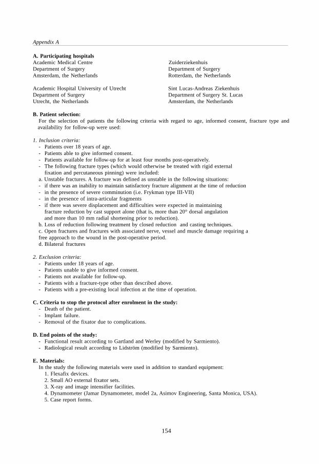
154
Appendix A
A. Participating hospitalsAcademic Medical Centre ZuiderziekenhuisDepartment of Surgery Department of SurgeryAmsterdam, the Netherlands Rotterdam, the Netherlands
Academic Hospital University of Utrecht Sint Lucas-Andreas ZiekenhuisDepartment of Surgery Department of Surgery St. LucasUtrecht, the Netherlands Amsterdam, the Netherlands
B. Patient selection:For the selection of patients the following criteria with regard to age, informed consent, fracture type andavailability for follow-up were used:
1. Inclusion criteria:- Patients over 18 years of age.- Patients able to give informed consent.- Patients available for follow-up for at least four months post-operatively.- The following fracture types (which would otherwise be treated with rigid external
fixation and percutaneous pinning) were included:a. Unstable fractures. A fracture was defined as unstable in the following situations:- if there was an inability to maintain satisfactory fracture alignment at the time of reduction- in the presence of severe comminution (i.e. Frykman type III-VII)- in the presence of intra-articular fragments- if there was severe displacement and difficulties were expected in maintaining
fracture reduction by cast support alone (that is, more than 20° dorsal angulationand more than 10 mm radial shortening prior to reduction).
b. Loss of reduction following treatment by closed reduction and casting techniques.c. Open fractures and fractures with associated nerve, vessel and muscle damage requiring afree approach to the wound in the post-operative period.d. Bilateral fractures
2. Exclusion criteria:- Patients under 18 years of age.- Patients unable to give informed consent.- Patients not available for follow-up.- Patients with a fracture-type other than described above.- Patients with a pre-existing local infection at the time of operation.
C. Criteria to stop the protocol after enrolment in the study:- Death of the patient.- Implant failure.- Removal of the fixator due to complications.
D. End points of the study:- Functional result according to Gartland and Werley (modified by Sarmiento).- Radiological result according to Lidström (modified by Sarmiento).
E. Materials:In the study the following materials were used in addition to standard equipment:
1. Flexafix devices.2. Small AO external fixator sets.3. X-ray and image intensifier facilities.4. Dynamometer (Jamar Dynamometer, model 2a, Asimov Engineering, Santa Monica, USA).5. Case report forms.

155
Study protocol
F. Pre-operative assessmentAfter a patient was entered in the study, a pre-operative assessment comprising the followingelements was carried out:- Medical history.- X-ray of the left and right forearm and hand (antero-posterior and lateral).- Fracture classification according to AO and Frykman (see Chapter 3)- Radiographic measurements (dorsal angle, radial angle and radial length; see Chapter 2)
G. Operative techniqueThe operative technique is described in Chapter 8. Before a participating clinic started withthe use of the device an operating manual and instruction videotape were supplied. The first procedure in eachhsopital was performed in attendance of the senior traumasurgeon from the development team and/or the author.
H. Post-operative evaluation and instructionsAfter the operation a standard protocol for the post-operative management was used.At each evaluation, the data obtained as described below and possible complications or adverseevents were noted on the case report form.
1. Day 1-2:- Wound and pin site inspection.- Positioning of the hand (raised).- Analgesics if necessary.- Exercise of fingers, elbow and shoulder.- Discharge from hospital if possible.
2. Day 14:- X-ray (AP and lateral).- Wound and pin site inspection.- Dynamisation of the fixator.- Encouragement of wrist movement (activities of daily living).- Commencement of physical therapy if desired.
3. Week 6-8:- X-ray (AP and lateral).- Measurement of wrist function (with and without fixator).- Removal of the fixator.- Encouragement of wrist movement.
4. Two weeks after removal of the fixator:- Measurement of wrist function.
5. Month 4:- X-ray (AP and lateral).- Clinical evaluation according to Gartland and Werley (mod. Sarmiento).- Radiological evaluation according to Lidström (mod. Sarmiento).
6. End of follow up:- X-ray (AP and lateral).- Clinical evaluation according to Gartland and Werley (mod. Sarmiento).- Radiological evaluation according to Lidström (mod. Sarmiento).

156
Appendix A
I. Evaluation criteria for clinical resultFor the evaluation of the clinical result the criteria described by Gartland and Werley, modifiedby Sarmiento, was used. The complete evaluation system is as follows:
Result PointsResidual deformity
No residual deformity 0Prominent ulnar styloid 1Residual dorsal tilt 2Radial deviation of hand 2 - 3
Subjective evaluationExcellent. 0(No pain, disability or limitation of motion).Good. 2(Occasional pain, slight limitation of motion, no disability).Fair. 4(Occasional pain, some limitation of motion, feeling of weaknessin the wrist, no particular disability if careful, activities slightly restricted)Poor. 6(Pain, limitation of motion, disability, activities more or less markedly restricted).
Objective evaluationNormal function 0Dorsal flexion less than 45° 5Ulnar deviation less than 15° 3Supination less than 50° 2Palmar flexion less than 30° 1Radial deviation less than 15° 1Loss of circumduction 1Pain in distal radio-ulnar joint 1Grip strength 60% or less than opposite side 1Loss of pronation 2
ComplicationsArthritic change
Minimal 1Minimal with pain 3Moderate 2Moderate with pain 4Severe 3Severe with pain 5
Nerve complications 1 - 3Poor finger function 1 - 2
End result point rangesExcellent 0 - 2Good 3 - 8Fair 9 - 20Poor ³ 21

157
Study protocol
J. Evaluation criteria for radiological resultThe anatomical result was evaluated according to the system proposed by Lidström and latermodified by Sarmiento. Depending on the degree of residual deformity found by measurements on the follow-up X-rays (dorsal angle, radial angle and radial length, see Chapter 2), the patients were divided into fourgroups:
Excellent.No or insignificant deformity:- dorsal angulation not exceeding 0° (neutral),- radial shortening less than 3 mm.- loss of radial angle not exceeding 4°.
Good.Slight deformity:- dorsal angulation 1 - 10°,- radial shortening 3 - 6 mm.- loss of radial angle 5 - 9°.
Fair.Moderate deformity:- dorsal angulation 11 - 14°,- radial shortening 7 - 11 mm.- loss of radial angle 10 - 14°.
Poor.Severe deformity:- dorsal angulation exceeding 15°,- radial shortening of at least 12 mm.- loss of radial angle more than 15°.

158
Appendix A

Case histories
159
Case histories
Appendix B
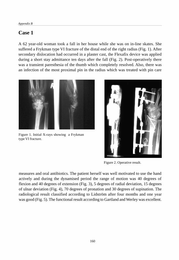
Appendix B
160
Case 1
A 62 year-old woman took a fall in her house while she was on in-line skates. Shesuffered a Frykman type VI fracture of the distal end of the right radius (Fig. 1). Aftersecondary dislocation had occurred in a plaster cast, the Flexafix device was appliedduring a short stay admittance ten days after the fall (Fig. 2). Post-operatively therewas a transient paresthesia of the thumb which completely resolved. Also, there wasan infection of the most proximal pin in the radius which was treated with pin care
Figure 1. Initial X-rays showing a Frykmantype VI fracture.
Figure 2. Operative result.
measures and oral antibiotics. The patient herself was well motivated to use the handactively and during the dynamised period the range of motion was 40 degrees offlexion and 40 degrees of extension (Fig. 3), 5 degrees of radial deviation, 15 degreesof ulnar deviation (Fig. 4), 70 degrees of pronation and 30 degrees of supination. Theradiological result classified according to Lidström after four months and one yearwas good (Fig. 5). The functional result according to Gartland and Werley was excellent.
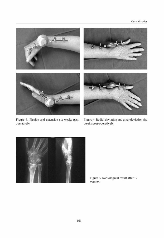
Case histories
161
Figure 3. Flexion and extension six weeks post-operatively.
Figure 4. Radial deviation and ulnar deviation sixweeks post-operatively.
Figure 5. Radiological result after 12months.

Appendix B
162
Case 2
This 48 year-old housewife fell from a horse, resulting in a Frykman type VII fracture(Fig. 6). After re-dislocation in plaster the Flexafix was applied (Fig. 7). The post-operative period was uneventful with 30 degrees of flexion, 40 degrees of extension,10 degrees of radial deviation, 20 degrees of ulnar deviation, 45 degrees of pronationand 10 degrees of supination after six weeks, with the fixator still on the wrist. Afterremoval of the fixator a persistent dorsal angulation was noted. The radiologicalresult according to Lidström after four months and one year was poor (Fig. 8); thefunctional result according to Gartland and Werley was good.
Figure 6. Initial X-rays showing a Frykman type VIIfracture.
Figure 7. Operative result, suggestingpersis-tent dorsal angulation.
Figure 8. Radiological result after four months.

Case histories
163
Case 3
This patient was a 48 year-old female who fell on ice and sustained a Frykman typeVII fracture of the distal end of the left radius (Fig. 9). The fracture was initiallytreated by closed reduction and plaster but re-dislocated. Twelve days after traumathe Flexafix was mounted (Fig. 10). A defect in the articular surface was acceptedduring the operation.With the fixator dynamised, the patient was able to return to her work as a goldsmith(Fig. 11). The range of motion with the fixator in place was 40 degrees of flexion, 15degrees of extension, zero degrees radial deviation, 20 degrees of ulnar deviation and 40degrees of pronation and supination each. After four months and one year follow-upboth the radiological result graded according to Lidström and the functional resultaccording to Gartland and Werley were excellent (Fig. 12).
Figure 9. Initial X-rays showing a Frykman type VIIfracture.
Figure 10. Operative result.

Appendix B
164
Figure 12. Radiological result after 12 months.
Figure 11. Patient during activities as a goldsmith.
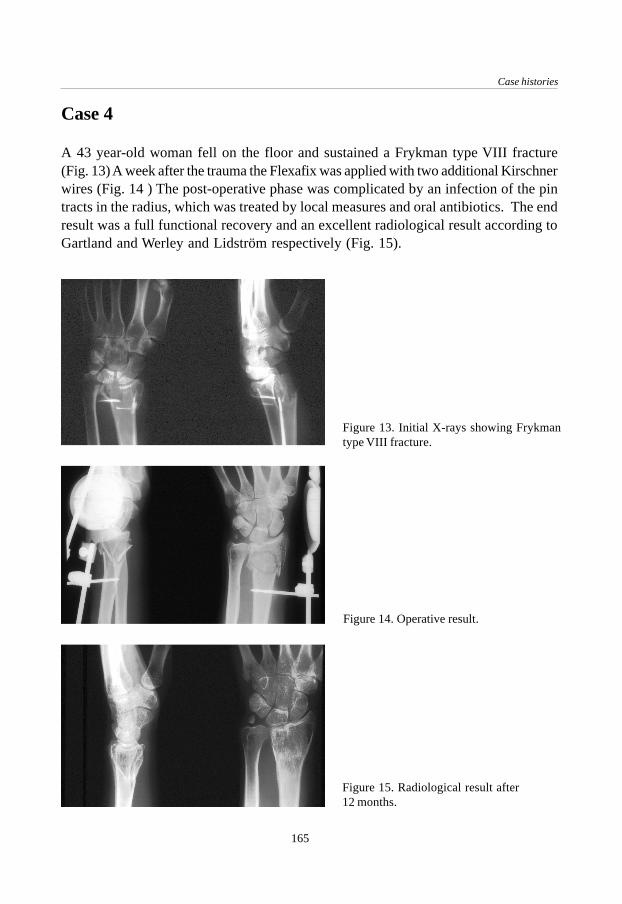
Case histories
165
Case 4
A 43 year-old woman fell on the floor and sustained a Frykman type VIII fracture(Fig. 13) A week after the trauma the Flexafix was applied with two additional Kirschnerwires (Fig. 14 ) The post-operative phase was complicated by an infection of the pintracts in the radius, which was treated by local measures and oral antibiotics. The endresult was a full functional recovery and an excellent radiological result according toGartland and Werley and Lidström respectively (Fig. 15).
Figure 14. Operative result.
Figure 15. Radiological result after12 months.
Figure 13. Initial X-rays showing Frykmantype VIII fracture.

Appendix B
166

167
A special application for the Flexafix device
A special applicationfor the Flexafix device
Appendix C
J.C. Goslings, A.H. Schuurman, A.H. Broekhuizen †.Accepted for publication by Techniques in Hand and Upper Extremity Surgery.
Introduction
In 1910, Robert Kienböck published his study ‘Traumatic malacia of the semilunarbone’.9 Since his classic description, neither the cause nor a reliable treatment forlunatomalacia has been established with certainty.2 Although the etiology oflunatomalacia, also called osteonecrosis, is clearly related to avascular changes, asKienböck suspected, the actual cause leading to this vascular impairment has remainedunclear. The interruption of blood supply to the lunate has been attributed to primarycirculatory problems, to traumatic interference with circulation or ligament injury, or,more frequently, to single or multiple fractures resulting in secondary vascularimpairment.2 Once the lunate is affected by avascular necrosis, continued loadingultimately results in fragmentation, collapse of the lunate with altered carpal kinematicsand finally arthrosis.20
168
Appendix C
The diagnosis is often suspected by the presence of pain and stiffness of the wrist, someswelling and tenderness localised on the dorsal side of the lunate and a striking weaknessof grip. The diagnosis is confirmed by radiographs. Bone scintigraphy and computedtomography can also provide diagnostic information.2 Magnetic resonance imaging hasshowed a high specificity in early stages of the disease.15 Kienböck’s disease is commonlystaged according to Lichtman.10,11 Present available treatment options includeimmobilisation, “joint-levelling” procedures (radial shortening or ulnar lengthening),re-vascularisation procedures, various intracarpal arthrodeses, lunate excision with orwithout replacement, wrist denervation and salvage procedures, including proximalrow carpectomy and wrist arthrodesis.2 Ruby treated patients with Lichtman stages I, IIand III Kienböck’s disease with a combination of cancellous bone grafting and externalfixation.20
Recently a new form of external fixation for the treatment of distal radial fractures hasbeen introduced. It is called “dynamic external fixation” because the external fixationdevice allows motion at the wrist during treatment of the fracture. To permit earlyfunctional treatment, the small AO external fixator has been supplemented by a jointallowing three degrees of rotational freedom. The centre of rotation is located at a pointoutside the device and lies approximately in the head of the capitate. Details of this newdevice, which is also called Flexafix, have been described elsewhere.5 This case reportdescribes the combination of three dimensional dynamic external fixation and bonegrafting for the treatment of Kienböck’s disease.
Case report
A 62 year-old right-dominant man with a symbrachydactylia (a congenital defor-mationin which the fingers are short and adherent) of the left hand presented with increasingpain in his right wrist since one year. There had been no previous trauma to the rightwrist, nor was there a history of rheumatoid arthritis. The erythrocyte sedimentationrate was normal; rheumatoid factors were not present. The range of motion was 50degrees of flexion and 50 degrees of extension. Pain was elicited on palpation of thelunate. Standard X-rays of the wrist showed a cyst in the lunate without collapse(Lichtman stage II) (Fig. 1). An MRI scan showed an abnormal intensity of the signalwith a cyst in the lunate bone (Fig. 2). The T1 and T2 weighted images indicated thepresence of avascular necrosis in the lunate bone.

169
A special application for the Flexafix device
During the operation under general anaesthesia the lunate was opened. The cyst wasexcochleated and filled with cancellous bone from the iliac crest. To unload the lunatepostoperatively, the Flexafix dynamic external fixator was placed on the wrist (Fig. 3).Two weeks later, the fixator was unlocked and the patient was encouraged to exerciseflexion and extension. The fixator was removed six weeks post-operatively. The X-rayshowed the onset of bone healing. At four months follow-up the patient was satisfiedand reported less pain than pre-operatively. The range of motion was 50 degrees offlexion and 40 degrees of extension; radial deviation, ulnar deviation, pronation andsupination were the same as pre-operatively. The X-ray at this time showed an almostcomplete bone healing of the defect with a remaining cortical interruption in the proximalpart of the lunate (Fig. 4).
Figure 1. Standard X-rays of the right wrist with acyst in the lunate.
Figure 2. MRI showing cyst of the lunate.

170
Appendix C
Figure 3. Post-operative situation aftercurettage, bone graft and dynamic externalfixation.
Figure 4. X-ray four months after theoperation.
DiscussionKienböck’s disease is still a condition with an unclear etiology and no optimal treatment.Joint-levelling procedures probably are most frequently performed at this time.20 Long-term results show good pain relief but little, if any, change in the course of slowlyprogressive lunate collapse.2,14,19 The main attraction of the levelling techniques is thatthe carpus is left undisturbed. On the other hand, the carpus is the site of the problem.Re-vascularisation procedures have been reported with good results.3,7 However, thepresent re-vascularisation procedures are technically demanding and long-term follow-up data are lacking.2,20 Partial carpal fusions have also been proposed for the treatmentof lunatomalacia but their effectiveness is unclear.1,2,6,17
Because of the lack of predictable results of the different procedures Ruby proposedcancellous bone grafting in combination with a period of ‘lunate unloading’.20 This isthought to result in re-vascularisation of the lunate. He considered this technique simplerwith more predictable results. In his point of view, possible advantages are the fact that

171
A special application for the Flexafix device
it does not significantly limit the range of motion and that the technique does not changecarpal kinematics (as compared to joint-levelling procedures and arthrodeses). Further,other procedures can still be performed afterwards. Satisfactory results were achievedin 71% of 17 patients.20 However, a static external fixator was used for an average of9.8 weeks.The combination of cancellous bone grafting and external fixation seems logical becausethe problem is treated at an important site, i.e. the lunate itself. However, in a personwho already has a disturbed wrist function it is unattractive to immobilise the wristjoint for 6 to 10 weeks with the possible risk of increased pain and stiffness. Since ourpatient only had one functional wrist, it was imperative to maintain wrist function. Atthe same time however, it is important to temporarily decrease the load of the lunate,which normally transmits 40% of the axial load on the wrist, to admit regeneration ofthe bone and the surrounding cartilage.18 Besides that has the beneficial effect of motionon the regeneration of articular cartilage been known for a long time.12 Motion cantransform granulation tissue and fibrous cells into cartilage cells.13 Dynamic externalfixation could thus add a new advantage to the proposed treatment. The Flexafix deviceprovides a means of distraction while at the same allowing active use of the hand.The patient in this case report had a good clinical and radiological result of the operation.A minor disadvantage of the Flexafix device used in this case is the relative complexityof the positioning during the operative procedure as compared to the application of arigid external fixator. The case presented is of special interest with respect to the factthat the patient had a symbrachydactylia on the other side. Therefore, it was essentialthat the integrity of the lunate was restored to prevent collapse and that he was able touse the hand on the operated side as soon as possible. With the Flexafix device thepatient was able to use his hand two weeks post-operatively.
Conclusion
The combination of cancellous bone grafting and external fixation seems to be a new,logical and attractive option in the treatment of Kienböck’s disease. In the case presented,a patient with only one functional hand and a Lichtman stage II lunatomalacia benefitedfrom the dynamic aspect of the Flexafix device. The functional and radiological resultsin this case were good. Further studies to evaluate the use of dynamic external fixationin the treatment of Kienböck’s disease could provide more data but these are difficult toconduct, considering the low incidence of this condition.

172
Appendix C
References
1. Allieu Y, Chammas M, Lussiez B, Toussaint B, Benichou M, Canovas F. Place de l’arthrodèsescapho-trapézo-trapézoidienne dans le traitement de la maladie de Kienböck. A propos de onzeobservations. Annales de Chirurgie de la Main 1991;10: 22-29.
2. Amadio P C, Taleisnik J. Kienböck’s disease. In: Green DP. Operative Hand Surgery. New York:Churchill Livingstone, 1993, Vol. 1: 832-842.
3. Braun RM. Pronator pedicle bone grafting in the forearm and proximal carpal row. Orthop Trans1983;7:35
4. Gelberman RH, Bauman TD, Menon J, Akeson WH (1980). The vascularity of the lunate boneand Kienböck’s disease. J Hand Surg 1980;5A: 272-278
5. Goslings JC, Tepic S, Broekhuizen AH, Jakob RP, Perren SM. Three-dimensional dynamic AOexternal fixation of distal radial fractures. A preliminary report. Injury 1994;25, suppl. 4, 85-89.
6. Graner O, Lopes EI, Costa Carvalho B, Atlas S. Arthrodesis of the carpal bones in the treatmentof Kienböck’s disease, painful un-united fractures of the navicular and lunate bones with avascularnecrosis, and old fracture-dislocations of carpal bones. J Bone Joint Surg 1966;48A: 767-774.
7. Hori Y, Tamai S, Okuda H, Sakamoto H, Takita T, Masuhara K. Blood vessel transplantation tobone. J Hand Surg 1979;4A: 23-33.
8. Hultén O. Über anatomische Variationen der Handgelenkknochen. Acta Radiologica 1928;9:155-168.
9. Kienböck R. Über traumatische Malazie des Mondbeins und Ihre Folgestustände:Entartungsformen und Kompressionsfrakturen. Fortschr Roentgenstr 1910;16: 77-103.
10. Lichtman DM, Mack GR, MacDonald RI, Gunther SF, Wilson JN. Kienböck’s disease: The roleof silicone replacement arthroplasty. J Bone Joint Surg 1977;59A: 899-908.
11. Lichtman DM, Alexander AH, Mack GR, Gunther SF. Kienböck’s disease. Update on siliconereplacement arthroplasty. J Hand Surg 1982;7: 343-347.
12. Salter RB. The biologic concept of continuous passive motion of synovial joints. The first 18years of research and its clinical application. Clin Orthop Rel Res 1989;242: 12-25.
13. Scapinelli R, Little K. Observations on the mechanically induced differentiation of cartilagefrom fibrous connective tissue. J Pathol 1970;101:85-91.
14. Schattenkerk ME, Nollen A, van Hussen F. The treatment of lunatomalacia. Radial shortening orulnar lengthening? Acta Orthop Scand 1987;58: 652-654.
15. Sowa DT, Holder LE, Patt PG, Weiland AJ. Application of magnetic resonance imaging to ischemicnecrosis of the lunate. J Hand Surg 1989;14A:1008-1016.
16. Taleisnik J. Kienböck’s disease. The wrist. New York: Churchill Livingstone, 1985: 169.17. Trumble TE, Irving J. Histologic and magentic resonance imaging correlations in Kienböck’s
disease. J Hand Surg 1990;15A: 879-884.18. Viegas SF, Patterson RM. Load mechanics of the wrist. Hand Clin 1997;13:109-128.19. Weiss AP, Weiland AJ, Moore JR, Wilgis EF. Radial shortening for Kienböck disease. J Bone
Joint Surg 1991;73A: 384-391.20. Zelouf D S, Ruby L K (1996). External fixation and cancellous bone grafting for Kienböck’s
disease: a preliminary report. Journal of Hand Surgery, 21A: 746-753.

Dankwoord / Acknowledgements
173
DankwoordAcknowledgements

174
Nu het proefschrift af is zou ik op de eerste plaats mijn bijzonder grote dank enbewondering willen uitspreken voor wijlen Dr. A.H. Broekhuizen, die aan de basis vandit proefschrift heeft gestaan. Zijn idee voor de ontwikkeling van de Flexafix bracht mijnaar de AO in Davos om de wachttijd voor mijn co-schappen op te vullen, waarna hetproject werd voortgezet als promotieonderzoek. Beste Tom, ik zal nooit vergeten wat jevoor me hebt gedaan.Dr. H. Boxma, beste Han. Onze goede contacten die sinds de antibiotica-trial bestaanzijn voor mij altijd erg waardevol geweest. Woord voor woord heb je alles doorgelezenen zo nodig van opmerkingen of vragen voorzien. Ik ben je zeer dankbaar voor het feitdat je de begeleiding van Tom hebt willen overnemen.Dr. J.N. Keeman. Al sinds mijn co-schappen heb ik een bijzondere waardering voor U.Ik ben er trots op dat ik als laatste promovendus op Uw tinnen bierpul kom te staan endat U heeft bijgedragen aan mijn opleiding in het St. Lucas-Andreas Ziekenhuis.Professor Dr. H. Obertop. Hopelijk was dit Traumatologische proefschrift een welkomeafwisseling op de voorgaande proefschriften die U begeleidde; Uw kritische commentaarheeft de helderheid in ieder geval aanzienlijk vergroot. Het is een voorrecht om bij U temogen promoveren.
In het AMC gaat mijn dank verder met name uit naar de medewerksters van de polikliniekTraumatologie en in het bijzonder ‘zuster Nel’. Vele woensdagmiddagen hielpen ze mijmet de nacontroles en met het zoeken naar statussen en fotomappen, welke ik meestalveel te laat terugbracht. Excuses hiervoor. Ook ben ik veel dank verschuldigd aan allechirurgen en assistenten van de afdeling Chirurgie die hebben bijgedragen aan hetopereren van de patiënten en het invullen van de trialformulieren.In het Sint Lucas-Andreas Ziekenhuis (locatie St. Lucas) in Amsterdam gaat mijn dankuit naar alle chirurgen, in het bijzonder mijn opleider Dr. R.M.J.M. Butzelaar, en decollega-assistenten voor de mogelijkheid die ze mij hebben gegeven om tussen de normalewerkzaamheden door tijd aan het onderzoek te besteden. Tevens dank ik het hoofd vande Medische Bibliotheek, Marjan van Weegen, die elke keer weer kans zag niet alleende meest recente maar ook de historische literatuur voor mij op te zoeken. Hans Moinat,fotograaf, bedank ik voor de vele ‘dynamische’ foto’s en dia’s van de diverse prototypen,de patiënten en röntgenfoto’s.In het Zuiderziekenhuis in Rotterdam heeft Erik Jan Hauet samen met Han Boxma eengroot deel van het patiëntenwerk gedaan. De zorgvuldige medewerking, ook op de polikliniekbij de nacontroles, heeft me erg geholpen bij de bewerking van de gegevens.In het Academisch Ziekenhuis Utrecht hebben Professor Dr. Chr. van der Werken enYvonne van Riet een waardevolle bijdrage aan het patiëntenmateriaal geleverd. Decoördinatie verliep niet altijd even makkelijk maar voor mij betekende elke patiënt er

Dankwoord / Acknowledgements
175
toch weer één. Arnold Schuurman wil ik graag bedanken voor zijn bijdrage aan despeciale casus beschreven in Appendix C.De leden van de promotiecommissie ben ik erkentelijk voor het kritisch doorlezen vanhet manuscript.
Dr. S. Tepic, dear Slobodan. At the AO Research Institute in Davos I had one of themost exciting times of my life when I had the opportunity to combine research withan overdose of sports. I remain impressed by your bright ideas and it was a greatpleasure to work with you on the development of the new fixator. The enthusiasm ofthe people and the atmosphere in the Institute were an important source of stimulationfor me. I would like to thank Professor Dr. S.M. Perren for his continuous supportthroughout the project and Stephen Ferguson for his help with the biomechanicalstudy performed in Davos.Dr. R.M. Patterson, dear Rita. It has been an enormous pleasure for me to work with youon the motion analysis study at the University of Texas Medical Branch in Galveston.Your enthusiasm and expertise, the help of your collegues and the availability of excellenttechnical facilities enabled me to complete an important addition to this thesis.Lieve Karin. Dankzij al jouw geslaagde pogingen om mij af te leiden kon ik steedsweer de concentratie opbrengen om deze klus af te maken. CK One forever!
176
Curriculum vitae
The author of this thesis was born in Leiden, the Netherlands, in 1968. After completingsecondary school he studied medicine at the University of Amsterdam (1986 -1991). Asa student the author worked at the Department of Surgery-Traumatology (head: Dr.A.H. Broekhuizen†), where he became interested in surgery. Before and during hisinternships he twice worked four months at the AO Research Institute in Davos,Switzerland (head: Prof. Dr. S.M. Perren). During these two periods the basis of thisthesis was made at the Department of Biomechanics (head: Dr. S. Tepic). After hisgraduation in 1993 the author fulfilled his military service as a medical officer forUNPROFOR (United Nations Protection Force) near Vitez, Bosnia-Herçegovina. In1995 he returned to Amsterdam and started his general surgical training in the SintLucas-Andreas Ziekenhuis (head: Dr. R.M.J.M. Butzelaar) continuing on in 1998 atthe Department of Surgery of the Academic Medical Centre (head: Prof. Dr. H. Obertop).In 1998 the author worked for three months as a research fellow at the University ofTexas Medical Branch in Galveston, Texas, U.S.A. where this thesis was completed atthe Department of Orthopaedic Surgery and Rehabilitation, Division of BiomechanicsResearch (mentor: Dr. R.M. Patterson). Running, cycling and skating are among hisfavourite activities in his spare time.

Stellingen
1. De toepassing van dynamische externe fixateurs voor de behandeling van distaleradiusfracturen vereist een speciale aandacht van de operateur voor dergelijkefracturen.
2. Gelet op de biomechanica en de kinematica hoort het draaipunt van een dynamischeexterne fixateur in de pols te liggen en niet in de fixateur zelf.
3. Een Röntgen-doorlaatbare versie van de Flexafix zou de operatietechniekeenvoudiger maken en de kans op een goed anatomisch resultaat vergroten.
4. Voordat een fixateurpen in de radius wordt geboord dient de cortex à vue te zijn.
5. De behandeling van een instabiele distale radiusfractuur met behulp van de Flexafixdynamische externe fixateur leidt in het algemeen tot een goed functioneel enanatomisch resultaat.
6. Het meest geschikte moment om een dynamische externe fixateur te dynamiserenis nog onduidelijk.
7. Het functionele eindresultaat van de behandeling van patiënten met een distaleradiusfractuur is vier maanden na het trauma nog niet bereikt.
8. Voor de waarneming van eventuele gunstige effecten van dynamische externe fixatieop het voorkomen van post-traumatische arthrose is een langdurige follow-up nodig.
9. Het nut van dynamische externe fixatie bij de behandeling van distale radiusfracturenis nog niet onomstotelijk bewezen. Er dient daarom een prospectieve,gerandomiseerde studie te komen waarin een biomechanisch goed ontworpendynamische externe fixateur wordt vergeleken met een statische externe fixateur.
10. De grote waarde die een hoogtestage bij de AO in Davos voor een onderzoekheeft, zit hem mede in de sportieve mogelijkheden die de omgeving biedt.
11. Bij een patiënt met stamvaricosis berustend op insufficiëntie van de sapheno-femorale overgang dient een crossectomie altijd vergezeld te gaan van eenzogenaamde ‘korte strip’.

12. De EMSB (Emergency Management of Severe Burns) is een noodzakelijkeaanvulling op de ATLS (Advanced Trauma Life Support) en dient te wordengeïmplementeerd als standaard voor de opvang van patiënten met ernstigebrandwonden.
13. De juiste positie van een repositieklem wordt gekenmerkt door het feit dat dezeprecies op de plek staat waar men een plaat of schroef had willen aanbrengen.
14. Design artikelen zijn opvallend vaak duur en niet handig.
15. Als je een tweedehands auto koopt kun je toch iets nieuws krijgen.
Stellingen behorende bij het proefschrift “Flexafix. The development of a new dynamicexternal fixation device for the treatment of distal radial fractures.”Amsterdam, 21 mei 1999 J.C. Goslings