First Results from the ERL Prototype (ALICE) at Daresbury
33
First Results from the ERL Prototype (ALICE) at Daresbury David Holder, on behalf of the ALICE team. LINAC'08 Victoria, BC LINAC 08 Victoria, BC
-
Upload
khangminh22 -
Category
Documents
-
view
0 -
download
0
Transcript of First Results from the ERL Prototype (ALICE) at Daresbury

First Results fromthe ERL Prototype
(ALICE) at DaresburyDavid Holder, on behalf of the ALICE team.
LINAC'08 Victoria, BCLINAC 08 Victoria, BC
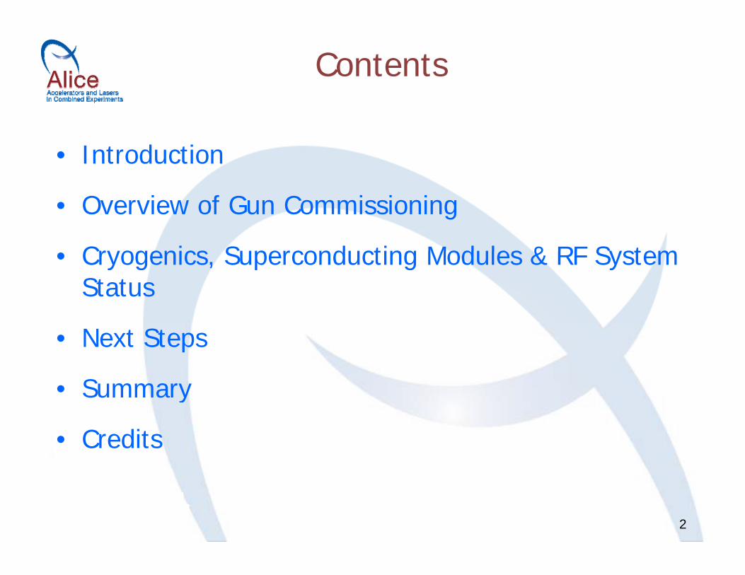
Contents
• Introduction
• Overview of Gun Commissioning
Cryogenics Superconducting Modules & RF System• Cryogenics, Superconducting Modules & RF System Status
• Next Steps
• SummarySummary
• Credits
2

• Introduction:– New Name– ALICE & EMMA Layout
• Overview of Gun Commissioning• Cryogenics, Superconducting Modules & RF System
Status• Next Steps• Summary• Credits
3

New Name
ERLP (Energy Recovery Linac Prototype) – conceived as a prototype of an energy recovery-based 4th generation
light source...now called...
ALICE (A l t d L I C bi dALICE (Accelerators and Lasers In Combined Experiments)– An R&D facility dedicated to accelerator science and technology y gy
development;– Offering a unique combination of accelerator, laser and free-electron
laser sources;;– Enables studies of photon beam combination techniques;– Provides a suite of photon sources for scientific exploitation.
4
No, not THAT ALICE…

ALICE & EMMA Layout
• Nominal Gun Energy 350 keV
• Injector Energy 8.35 MeV
• Beam Energy 35 MeV
• RF Frequency 1.3 GHz
• Bunch Rep Rate 81.25 MHz
• Nom Bunch Charge 80 pC
• Average Current 6.5 mA( th 100 b h t i )(over the 100 µs bunch train)
5

• Introduction• Overview of Gun Commissioning
– Photoinjector– Gun Problems
G Di ti L t– Gun Diagnostic Layout– Gun Commissioning Results– Gun Commissioning Summary– Gun Commissioning Summary
• Cryogenics, Superconducting Modules & RF System StatusStatus
• Next Steps• Summary
6
• Summary• Credits

Photoinjector
Gun ceramic – major source of delay – at Daresbury (~1 year late)
Copper brazedCopper brazed joint
(Fi t l t
7
(First electrons August 2006)

Gun Problems
• High voltage breakdown problems after cathode caesiation and from braze disintegration;g ;
• Vacuum failures during bake-out of large diameter flange seals, feedthrough, valve and braze (again!);g g ( g )
• Contamination (caesium again?) and hydrocarbons;– impaired XHV conditions, field emission, halo, poor
cathode lifetime.
8

Gun Diagnostic Layout
Injector commissioned with dedicated diagnostic line (now removed):
DE
LASERTRANSVERSEKICKER
A FARADAYCUPS
CDIPOLEBUNCHER
CSOLENOID 1 SOLENOID 2
9
B

Gun Commissioning Results (1 of 3)
RMS emittance b h h
Bunch length (at 10% ofpeak value) vs.bunch charge
rad)
vs. bunch charge5
met
res)
35
40ASTRA
bunch charge
pi-m
m-m
r HorizontalVertical
3
4
1(m
icro
m
25
30
35
ASTRA
mitt
ance
(
2ng
th @
0.
15
20
RMS
em
0
1
0
10 30 50 70
Bunc
h le
0
5
10
10
0 0
10 20 30 40 50 60 70 80Bunch Charge, pC
0 10 20 30 40 50 60 70 80Bunch Charge, pC

Gun Commissioning Results (2 of 3)
40
Energy spread (at
25
30
35
@ 0
.1 ,
keV
TOTAL
MODEL
MODEL
gy p (10% of peak value) vs. bunch charge
15
20
25
GY
SPR
EAD
@ MODEL
5
10
15
ENER
G
COMPENSATED
Compensated =
0
5
0 10 20 30 40 50 60 70 80
BUNCH CHARGE pC
buncher ON
11
BUNCH CHARGE, pC

Gun Commissioning Results (3 of 3)
Beam size vs. solenoid 1 & 2 current, at Q=54 pC,compa ed to ASTRA modelcompared to ASTRA model
15
20
SQRT (XY)FWHM (Astra)
( )
5
6
7
SQRT (XY)FWHM (Astra)
10
QR
T (X
Y),
mm
3
4
5
(XY
), m
m
5
SQ
1
2
3SQ
RT
(
12
0300 320 340 360 380 400
B1, G
0200 220 240 260 280 300 320
B2, G

Gun Commissioning Summary• Results:
– The gun can now be routinely HV conditioned to 450kV;– QE above ~3% is normally achieved after cathode activations Q y
(bunch charges of well above 100pC have been achieved);– The beam was fully characterised (emittance, bunch length, etc.)
for bunch charges between 1 to 80pC;– A good agreement between the ASTRA simulations and the
experimental data was found for the bunch length and the energy spread but not for the emittance;B nch cha acte istics e e in estigated at t o diffe ent lase– Bunch characteristics were investigated at two different laser pulses of 7ps and 28ps:
• At low Q<20pC, no significant difference was observed;The importance of a smooth longitudinal laser profile for minimisation– The importance of a smooth longitudinal laser profile for minimisation of the beam emittance was demonstrated.
• Remaining gun-related issues: Ens e the absence of FE spots on the cathode
13
– Ensure the absence of FE spots on the cathode;– Increase the cathode lifetime with QE >1.5%;– Resolve transverse emittance discrepancy (FE? QE non-uniformity?).

• Introduction• Overview of Gun Commissioning• Cryogenics, Superconducting Modules & RF
System Status:– Cryosystem Commissioning– Booster Module & RF Layout
Module Commissioning Results– Module Commissioning Results– Field Emission Radiation Issue– Mitigating StrategiesMitigating Strategies
• Next Steps• Summary
14
• Summary• Credits

Cryosystem Commissioning• Partial system procured from Linde;• 4 K commissioning completed May 06;
SRF M d l d li A il d J l 06• SRF Module delivery April and July 06;• Problems with excessive system heat leaks (lack of
capacity) and heater failure;capacity) and heater failure;• Cryosystem output:
– Specification 118 W at 2 K with 1 mbar stability;– Measured 118 W at 2 K with ± 0.03 mbar stability in
May 07;St ti l d• Static load: – Specification < 15 W per module;– Measured 5 W for both modules (i e ~2 5 W each);
15
Measured 5 W for both modules (i.e. ~2.5 W each);• System has operated successfully at 1.8 K – needs further
optimisation.

Booster (8 MeV )8 MeV
Booster Module & RF LayoutBooster (8 MeV )
Cavity 2 @ 2 9 MV/m Cavity 1 @ 4 8 MV/m350 keV8.35 MeV
8 MeV
350 keV8.35 MeVCavity 2 @ 2.9 MV/m Cavity 1 @ 4.8 MV/m InOut InOut
Circulator LoadCirculator Load
Cavity 1, 4.8 MV/mCavity 2, 2.9 MV/m
C cu ato(incl. Load)
3dB Hybrid
Circulator (incl. Load)
3dB Hybrid
Directional CouplerCPI CHK51320W
30 kW CW IOT
Directional CouplerCPI CHK51320W
30 kW CW IOT
16
E2V 116LS 16 kW CW IOT
E2V 116LS16 kW CW IOT
E2V 116LS 16 kW CW IOT
E2V 116LS16 kW CW IOT
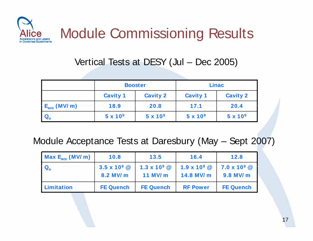
Module Commissioning Results
Vertical Tests at DESY (Jul – Dec 2005)
20 8
Cavity 2
18 9
Cavity 1
Booster
20 417 1E (MV/m)
Cavity 2Cavity 1
Linac
5 x 10⁹
20.8
5 x 10⁹
18.9
5 x 1095 x 109Qo
20.417.1Eacc (MV/m)
7 0 x 109 @1 9 x 10⁹ @1 3 x 10⁹ @3 5 x 10⁹ @Q
12.816.413.510.8Max Eacc (MV/m)
Module Acceptance Tests at Daresbury (May – Sept 2007)
7.0 x 10⁹ @ 9.8 MV/m
1.9 x 10⁹ @ 14.8 MV/m
1.3 x 10⁹ @ 11 MV/m
3.5 x 10⁹ @ 8.2 MV/m
Qo
FE QuenchRF PowerFE QuenchFE QuenchLimitation
17
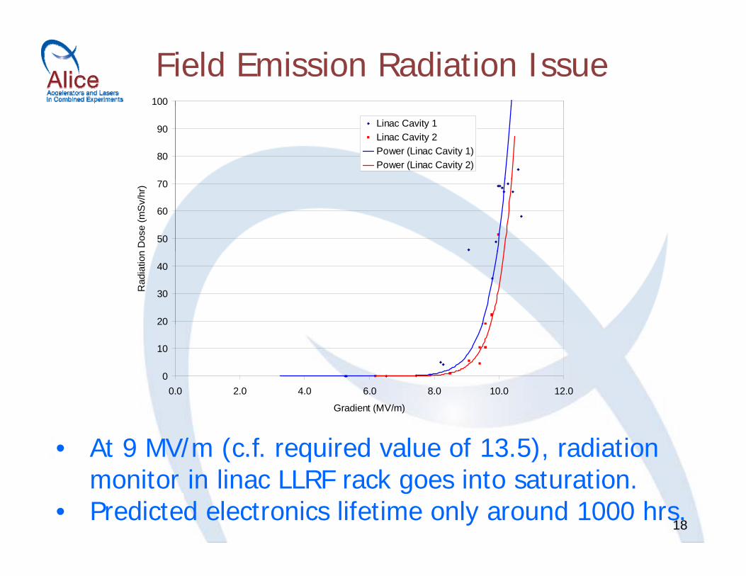
Field Emission Radiation Issue100
80
90 Linac Cavity 1Linac Cavity 2Power (Linac Cavity 1)Power (Linac Cavity 2)
50
60
70
n D
ose
(mS
v/hr
)
20
30
40
Rad
iatio
n
0
10
20
0.0 2.0 4.0 6.0 8.0 10.0 12.0
• At 9 MV/m (c.f. required value of 13.5), radiation i i li LLRF k i i
Gradient (MV/m)
18
monitor in linac LLRF rack goes into saturation.• Predicted electronics lifetime only around 1000 hrs.

Mitigating Strategies
• Lead shielding installed around linac;• New linac module (collaborative design);• Further aggressive processing:
Over longer conditioning periods;– Over longer conditioning periods;
– Varying frequency, pulse widthy g q y, pand pulse repetition rate;
– CW conditioning (only possible at lower power levels);CW conditioning (only possible at lower power levels);
– Possibly condition the cavity when warm;
19– Introduce helium into the vacuum (risky!)

SC Module Commissioning Summary
• All 5 IOTs are successfully commissioned;• All 4 cavities show unexpected limitations due to field
i iemission;• ALICE operation at 35 MeV is still possible;• Measurements of cryogenic losses at intermediate gradients• Measurements of cryogenic losses at intermediate gradients
show significant reduction compared with vertical test results;• High levels of FE radiation measured and mitigating strategies
implemented. Maximum
measuredRequired
Cavity 1 10.8 4.8 MV/m Booster
Cavity 2 13.5 2.9 MV/m
Cavity 1 16.4 13.5 MV/mLinac
20
Cavity 1 16.4 13.5 MV/mLinac
Cavity 2 12.8 13.5 MV/m
• Introduction• Overview of Gun Commissioning• Cryogenics, Superconducting Modules & RF System
Status• Next Steps:
– Accelerator (short term)– Science Programme– Accelerator Developments
EMMA– EMMA
• Summary• Credits
21
• Credits

Accelerator (short term)
• First energy recovery (Fall 2008):– Without FEL, installation planned Spring 2009;
• Fine tuning: – Injector tuning for minimum emittance;
O ti i ti f t i l b– Optimisation of energy recovery at nominal beam parameters;
– Beam diagnostics;Beam diagnostics; • Short pulse commissioning stage:
– Longitudinal dynamics, electro-optical diagnostic studies;• Energy recovery with FEL (Spring 2009):
– First light!
22
– Energy recovery of a disrupted beam.• Then the fun really starts…

Science Programme
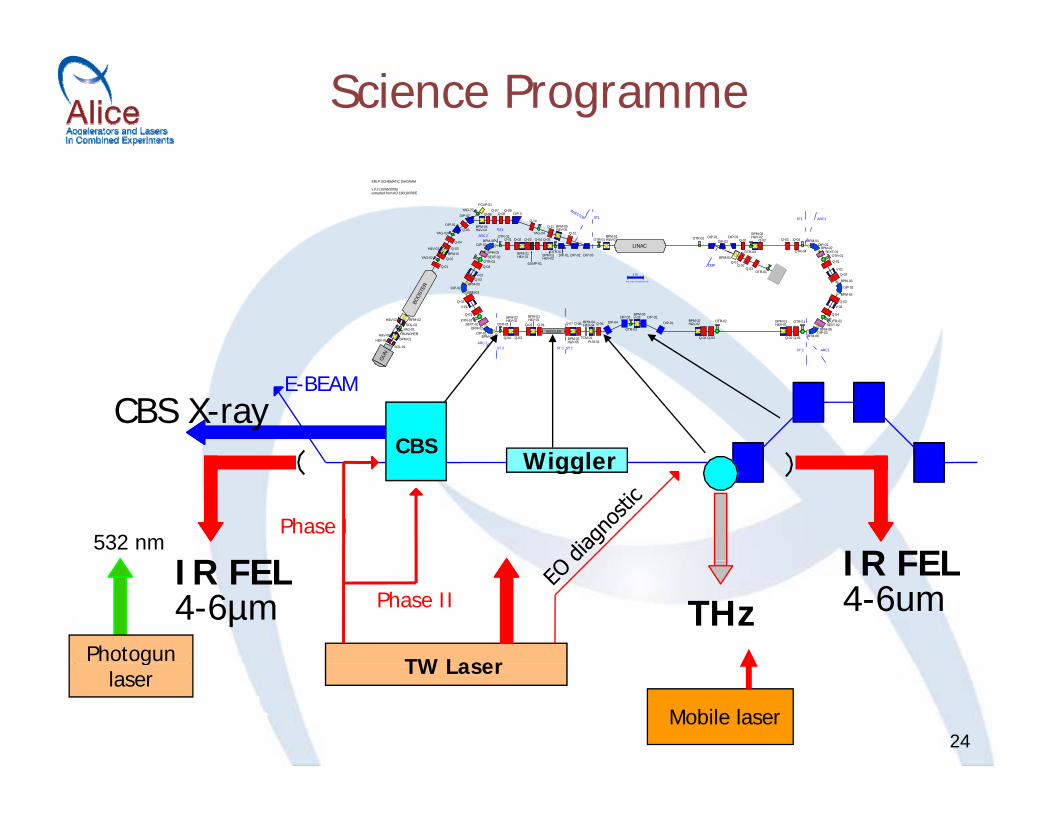
IR FEL, CBS x-ray source and terahertz radiation research programme, including pump–probe research programme with all ALICE light sources:
Terawatt laser ( 10TW 100 / 35 fs 10Hz);– Terawatt laser (~10TW, 100 / 35 fs, 10Hz);– Infrared FEL (~4µm, ~15MW peak, ~1ps, ~10mJ);– Femptosecond tunable laser;Femptosecond tunable laser;– Terahertz radiation (broadband);– CBS x-ray source (15-30keV, 107 – 108 photons/pulse, y ( , p /p ,
<1ps);– Tissue Culture Laboratory (TCL).
23
Science Programme
LINACBPM 03
H&V-03 Q-03
Q-04
YAG-03
DIP-01Q-05
DIP-02YAG-??
FCUP-01
BPM-04H&V-04
Q-06Q-07
Q-08Q-09
DIP-3
Q-10
YAG-04
Q-11 BPM-05H&V-05
Q-12
INJECTOR
OTR-01BPM-01H&V-01
ST1
OTR-02 DIP-01DIP-02
DIP-03Q-01
OTR-03
BPM-02H&V-02
Q-02 Q-03 Q-04
OTR-04
BPM-01DIP-01
BPM-02SEXT-01
ST1 ARC1
BPM-05
DIP-03BPM-06
ARC 2ST4
OTR-01Q-01 Q-02
BPM 01
Q-03 Q-04 Q-05
OTR-02
ERLP SCHEMATIC DIAGRAM
v.0.2 (15/06/2006)extracted from AO-180/10078/E
BOOS
TER
UN
SOL-01
H&V-01H&V-06
BPM-01BUNCHERYAG-01
SOL-02H&V-02 BPM-02
Q-01
YAG-02 Q-02BPM-03 OTR 03 SEXT 01
OTR-01
ARC1
Q-01
V-01Q-02
BPM-03
DIP-02
BPM-04
Q-03V-02
Q-04
OTR-02SEXT-02
BPM-05DIP-03
BPM-06
OTR-01
Q-01Q-02
BPM-01H&V-01
OTR-02
Q-03Q-04
BPM-02H&V-02DIP-01
DIP-02BPM-03V-03
OTR-03
DIP-03DIP-04Q-05
ST 2ST 2ARC 2 PLM-01
TCM-01
BPM-04H&V-04
BPM-05H&V-05
BPM-01H&V-01
Q-06Q-07
WIGGLER
ST 3ST 3
Q-01Q-02
Q-03Q-04
OTR-01
BPM-02H&V-02
BPM-01DIP-01
BPM-02SEXT-01
OTR-01Q-01
V-01Q-02
BPM-03DIP-02
BPM-03Q-03V-02
Q-04OTR-02
SEXT-02BPM 05 BPM-01
H&V-01
DUMP-01
BPM-02H&V-02
OTR 02DIP-01 DIP-02 DIP-03
BPM-01Q-01
Q-02Q-03
OTR-01
DMP
1 m
Note: scale is for guidance only
GU
CBSWiggler
E-BEAMCBS X-ray
Phase I
Wiggler
IR FEL IR FEL532 nm
TW Laser
Phase IIIR FEL4-6µm THz
IR FEL4-6um
Photogun
24Mobile laser
TW Laserglaser

Accelerator Developments
• Accelerator physics research:– Photocathode research and testing (upgraded load-lock
t f th d h & ti ti )system for cathode exchange & activation);– New linac module;– Re-establishment of gun diagnostic line– Re-establishment of gun diagnostic line.
• EMMA - Electron Machine with Many Applications:• EMMA Electron Machine with Many Applications:– Non-scaling fixed field alternating gradient accelerator;
Why FFAG ? Why Non Scaling ?Why FFAG ?• fast acceleration (e.g. muons)• high power beam acceleration• variable electron energy
Why Non-Scaling ?• compact beamline vacuum chamber• hence, compact magnets
25
• variable electron energy
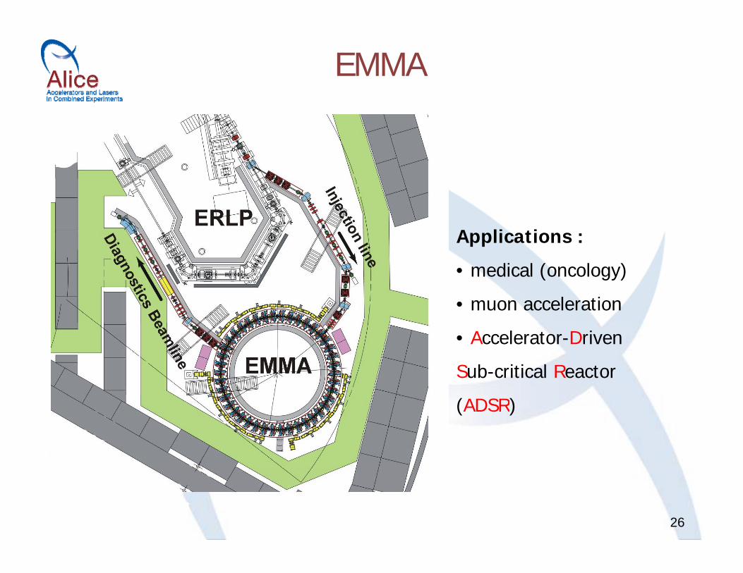
EMMA
Applications :
• medical (oncology)
• muon acceleration
• Accelerator-Driven
Sub-critical Reactor
(ADSR)
26

• Introduction• Overview of Gun Commissioning• Cryogenics, Superconducting Modules & RF System
Status• Superconducting Module Status• Next Steps• Summary• Credits
27

Summary
• Accelerator commissioning has now reached a critical stage;• ALICE has provided the UK with an opportunity to developALICE has provided the UK with an opportunity to develop
generic technologies and skills important for the delivery of advanced accelerator-driven facilities, including:
Ph t i j t SCRF i di ti h i ti– Photoinjector, SCRF, cryogenics, diagnostics, synchronisation etc.
• ALICE will provide a unique R&D facility in Europe, dedicated toALICE will provide a unique R&D facility in Europe, dedicated to accelerator science & technology development:– Offering a unique combination of accelerator, laser and free-
l t lelectron laser sources; – Enabling essential studies of beam combination techniques;– Providing a suite of photon sources for scientific exploitation
28
– Providing a suite of photon sources for scientific exploitation.

• Introduction• Overview of Gun Commissioning• Cryogenics, Superconducting Modules & RF System
Status• Superconducting Module Status• Next Steps• Summary• Credits
29

Credits• The ALICE technical team:
– Controls: Brian Martlew et al.– Vacuum: Tom Weston & Keith Middleman et al.– Installation engineering: Phil Atkinson et al.Installation engineering: Phil Atkinson et al.– Mechanical engineering: Neil Bliss et al.– Electrical engineering: Steve Griffiths et al.– Diagnostics: Rob Smith et al.– FEL: Jim Clarke et al.FEL: Jim Clarke et al.– Compton Back Scatter: Gerd Preibe et al. – THz Science: Mark Surman et al.– Running, Safety: Stephen Hill et al.– Photoinjector laser: Steve Jamison & Graeme Hirst et al.Photoinjector laser: Steve Jamison & Graeme Hirst et al.– Elaine Seddon, Mike Poole and Paul Quinn
• Our international collaborators including:– J Lab (George Neil, Fay Hannon, Kevin Jordon, Carlos Hernandez-Garcia, Tom
Powers et alPowers et al.– FZD Rossendorf (Peter Michel, Frank Gabriel et al.) – Cornell (Bruce Dunham)– Stanford University (Todd Smith)
30
y ( )– Institute of Semiconductor Physics, Novosibirsk (Alex Terekhov)

h k f lThanks for listening
31
l dSpare slides
32
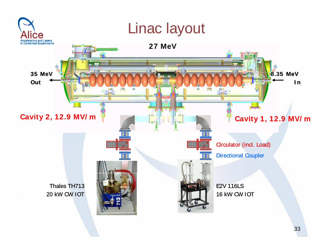
Linac layoutLi (26 7 M V )27 MeVLinac (26.7 MeV )
Cavity 2 @ 12 9 MV/m Cavity 1 @ 12 9 MV/m8.35 MeV35 MeV
27 MeV
8.35 MeV35 MeVCavity 2 @ 12.9 MV/m Cavity 1 @ 12.9 MV/m InOut InOut
Cavity 2, 12.9 MV/m Cavity 1, 12.9 MV/m
Directional Coupler
Circulator (incl. Load)
Directional Coupler
Circulator (incl. Load)
E2V 116LS 16 kW CW IOT
Thales TH71320 kW CW IOT
E2V 116LS 16 kW CW IOT
Thales TH71320 kW CW IOT
33