First Principles Mechanical Engineering Drawing
222
-
Upload
khangminh22 -
Category
Documents
-
view
1 -
download
0
Transcript of First Principles Mechanical Engineering Drawing


FIRST PRINC IPLES
ME CHANI CAL
ENGINEERING DRAWING
A COURSE OF STUD" ADAPTED TO THE SELF-INSTRUCTION OF
STUDENTS AND APPRENTICES TO MECHANICALENGINEERING IN ALL ITS BRANCHES
AND FOR THE USE OF TEACHE R S IN TECHNICAL AND MANUALINSTRUCTION SCHOOLS
H . HOLT BUTTERFILL, ME .
FORMERL" A MEMBER OF TH E INSTITUTION OF M ECHANICAL ENG INEER S AND
INSTITUTION OF NAVAL ARCH ITECTS0
WITH UPWARDS OF 350 DIAGRAM S IN ILLUSTRA TION OF THE
PRINCIPLES OF THE SUBJECT
LONDON : CHAPMAN AND HALL,LIM ITED
1 89 7


PR E FA C E
TH E greater part Of the subject matter Of this book appeared in a
series Of articles in the M echanical World. The purpose in writing itis SO fully explained in the Introduction that a Preface is hardlyrequired. A S the forms given to the various part s Of a machine or
engine are on analysis invariably found to be combinations Of certaingeometrical Solids , a knowledge Of how each Of these Should be drawnwhen in any position should be first acquired by the student draughtsman. TO this end a series Of problems is given in the following pages ,commencing with the construction of those Simple geometrical figureswhich form the surfaces Of the solids which give Shape to mechanicaldetails
,and subsequently the method adopted in representing the solids
themselves,singly and in combination.
A S no amount Of copying" drawings Of mechanical details will
ever give the student a knowledge Of the reasons w hy they are madeto take the special forms given to them ,
SO in the earlier stages Of thestudy Of mechanical drawing it is impossible for him to acquire thepower to draw the Simplest solids in different positions correctlywithout a knowledge Of the principles Of " O rthographic Projection ,which is the basis Of the representation Of all solid Objects . In thispart Of the subject an extended series Of problems is given, the solutionOf which Should enable the student to draw any Simple Objec t withoutfurther help .
In the method Of studying the contents Of this work, the student isadvised to take the different parts Of the subject in the order in whichthey are arranged , as he will thereby be led to ac quire a mastery Of itin a w ay that will impress upon his mind the connection that eachpart bears to that which follows . The order Of study may not be thatusually followed , bu t it is such as an assoc iation Of many years withdraughtsmen and students has proved to the author to be the best forthe acquisition Of the preliminary knowledge necessary to the successfulpractice Of the draughtsman’s art .
This work is not intended as a treatise on either Plane or SolidGeometry, but as much Of these subjects is given as will be requiredby the student tO attain to an easy comprehension Of the first principlesOf mechanical drawing as herein exemplified . Their actual applicationto the delineation Of machine elements and engine details may possiblyform the subject Of a further work.
H . H OLT—BUTTERFILL.
Greenwich, 1 897 .


C ON TE N T S
Introduction— THE VALUE OF A K NOWLEDGE OF DRAWING TO TH E STUDENT
CHAPTER ITHE TOOLS AND MATER IALS REQUIRED B" THE STUDENT
Drawing-Board — Tee-Square -Adjustable Bladed Square— S et-SquaresPencils— Drawing Pins— Paper— Rubber— Ink— Drawing Instru
ments
CHAPTER II
MECHANICAL AND FREEHAND DR AWING : THEIR DIFFERENCEAND USES
The meaning Of Freehand Drawing— HOW Objects are made visibleW hat a Perspective is— H OW a Perspective Drawing is obtainedThe use Of a Perspective Drawing to theworkman— AnOrthographicProjection, and hOW Obtained— The meaning of Plan and Elevation
CHAPTER III
PRACTICAL GEOMETRY AND MECHANICAL DRAWINGThe meaning Of the term Geometry -The difference between Plane and
Solid Geometry~Definition Of Geometrical terms used in the work
Plane Geometrical Figures
CHAPTER IV
PLANE GEOMETRY PROBLEM Sdivide a straight line into two equal parts —TO erect a perpendicularto a given straight line— TO let fall a perpendicular to a straightline— TO bisect a given angle— TO draw a line parallel to a given line
— TO draw an angle equal to a given angle -TO draw a line makingan anglewith a given line
PAGE
1 1 1
1 2 — 1 6
1 7— 22
23— 27

vfi i C ONTENTS
CHAPTER VPLANE GEOMETR ICAL FIGURE S
To construct an equilateral triangle, an isosceles triangle, a scalene triangle— TO construct a square, a rectangle, a rhombus, a rhomboid, a. tra
pezium,a regu lar pentagon, a hexagon, a regular octagon
CHAPTER VI
ORTHOGRAPHIC PROJECTION
The Planes of Projection— The difference between a vertical and a per
pendicu lar plane— The relative position Of the planes of projection
The projections Of a. point and a straight line— The projections of a
line inclined to the planes Of projection
CHAPTER VIIPROJECTION OF PLANE FIGURE S
The Projection of the Triangle— The square- The pentagon and the
hexagon, etc .
CHAPTER VIIITHE PROJECTION OF SOLID S
Definitions Of the Plane Solids— The cube, the prism,the pyramid, etc .
Models of the Solids necessary to the Student for a thorough knowledge Of their projection— Elevations Of Objects given to find theirplans — Meaning Of section
,side elevation, sectional plans and eleva
tions
CHAPTER IX
PROJECTION IN THE UPPER PLANE
The front elevation given, to find the Side elevation— The sectional elevations of the solid and hollow cube, prism and pyramid
CHAPTER XPROJECTION FROM THE LOWER To THE UPPER PLANE
The plans of Objects given, to find their elevations and sectional elevations
CHAPTER XILINING-IN DRAWINGS IN INK
The kind of lines to be used— The direction inwhich the light is supposedto fall on the object represented— To find the angle that the rays Oflight make w ith the planes of projection— W hy different qualities Oflines are used inMechanical Drawing— The importance Of correctnessin their application— HOW ink for lining-in a drawing shou ld bemade— And how to fi ll the drawing-
pen
PAGE
28— 34
35 4 1
42— 46
4 7 — 58
59 70
71— 76
77— 84

C ONTENTS ix
PAC E
CHAPTER XIITH E PROJECTION OF CURVED LINE S
The definition Of a curved line— The front elevation of a curved line beinggiven, to find its side elevation and plan— HOW tofind the projectionsOf a line of double curvature— The projections Of combined curvedandright lines— The plan Of a circular plate being given, tofind its elevation— To draw an ellipse 85— 97
CHAPTER XIIITHE PROJECTION or SOLID S WITH CURVED SURFAC ES
The definitions of the cylinder, the cone, and the sphere— The plan Of acylinder given, to find its elevation in various positions— The planof a cone given, to find its elevation in different positions 98— 102
CHAPTER XIVTHE PROJECTION OF THE SECTIONS OF A CYLINDER
The elevation of a cylinder given, to find its sectional elevation and
plan 103— 105
CHAPTER XVTH E PROJECTION OE THE CONIC SECTIONS
The definitions of the sections of a cone— The plan andelevation Of aconebeing given, to find its sectional projection— TO find the true form Of
any section Of a cylinder or cone— The sections Of a Sphere and theirprojections— Definitions Of the subsidiary solids Of revolution— The
lining-in in ink of solids with curved surfaces -How the light fallsupon them 106— 1 19
CHAPTER XVITHE PROJECTION OF OB JECTS INCLINED To THE PLANES OF
PROJECTIONfind theprojection of a point, and line lying Onan inclined plane— The
projection of plane figureswhen inclinedtotheplanesof projectionThe projectionof a solidwhen inclined to the planes of its projection
-The projections of the solid and hollow cube,the pyramid, and
cone, when inclined to the planes of their projection— The projections of a six-sided nut, when inclined to the planes of projection 120— 1 4 1
CHAPTER XVIITHE PENETRATION AND INTERSECTION or SOLIDS
The penetration of prisms by prisms at right angles to each other- Thepenetration of prisms having their axes inclined to each other 142— 152

X C ONTENTS
PAGECHAPTER XVIII
THE INTER SECTIONS OF PLANE SOLID S (continu ed)The penetration of a prism by a pyramid— The penetration Of pyramids
by pyramids 153— 1 63
CHAPTER XIXTHE INTER SECTIONS OF SOLIDS
'
HAVING CURVED SURFACE SThe intersections of equal-Sized cylinders at right angles to each other
The intersection of unequal-sized cylinders— The intersection Of in
elined cylinders— The intersection of the cylinder and cone— The
intersection of cones by cylinders and cones— The intersection Of the
Sphere by prisms and pyramids— The intersection Of the Sphere bythe cone and cylinder 1 64 1 86
CHAPTER XXTHE DEVELOPMENT OF TH E SURFACE S OF SOLID S
WVhat a developmentmeans— W hat isa developable surface— The development of plane-surfaced solids — The development of the surface Of a
pyramidal-shaped solid, having a curved surface— The developmentO f the Obliqu e pyramid— The development Of the surface Of a rightcylinder, and the frustum of a right cylinder— The development Ofthe surface Of an Oblique cylinder, and Of a right and Oblique coneThe development Of the surface of the Sphere and hemisphere 1 87 21 1

INTR OD U C T ION
THE FIRST PRINCIPLES OF MECHANICAL AND ENGINEERINGDRAWING
IT being incumbent on every one who aspires to become a reallyefii cient Engineer, that he Should possess a thorough practical knowledge Of the M echanical Draughtsman’s art
,w e would in the outset
Of an attempt to explain the fundamental principles which govern itsoperations, Observe, that the inducement to undertake such a task isthe desire to place within the reach Of every earnest engineering studentand apprentice, a means Of enabling him to read and to make suchdrawings as are placed before him in an engine factory to work from ,
and to prepare him for the subsequent study Of engine and machinedesign .
It is assumed by the majority of engineering students and appren
tices, that the drawing practised in the Drawing Office will be taughtthem upon their first admission to it
,but an experience Of many years
in some of the principal Offices in England,has made the writer alive
to the fact, that SO far as the "
principles which underlie thepractice Ofthe draughtsman’s art are concerned
,absolutely nothing is tonight the
student, and that if he ever acquires a knowledge Of them ,it will be
by his own una ided study, independent Of any drawing-Offi ce help .
With a view,then , to the acquisition by the student of thi s all
important knowledge, in the best possible way, w e have in the followingpages formulated a method Of imparting it
,which from practical
experience as a draughtsman,and teacher, w e have found answers
every requirement . Whether that method is an improvement on anynow adopted
, is left to those who earnestly follow its exposition todetermine.
Before proceeding with that exposition, w e would, however, putbefore the student, some facts bearing upon the study Of drawing (andM echanical Drawing more particularly) , which may help him toappreciate the necessity that exists for his acquiring the ability to
draw, if he desires to rise in his profession . Without wishing in theleast to under-estimate the great worth Of a really first- class skilledworkman, w ho may have little or no knowledge Of drawing, it is still

INTRODUCTION
a fact very generally admitted that j ust in proportion to the knowledgeOf drawing possessed by one workman over his fellow, SO is he superiorto him ; and it follows that those ignorant of that art must hold alower position as workmen, than those having a knowledge of it .
The utility Of the power to draw may not present itself to themind of the workman on its first suggestion to him , but a little thoughtabout the matter will soon make it clear that it has a much closerconnection with his daily work than he had any idea Of. Neitherspoken nor written language can at all times convey ideas that w e wishto impart to another, and recourse must be had to some other means
,
more especially if those ideas relate to theform and position Of materialsubstances . To assist us in making ou r meaning clear, w e must makeu se Of what has been aptly called the " language Of mechanics,
” OrDrawing— a language which appeals at once to the eye for the truthOf its assertions, and which enables us, without further assistance, toj udge Of the form
‘
,appearance, and dimensions Of bodies .
TO the intelligent mechanic, a real power Of drawing is a pricelessadvantage, as it enables him to either reproduce a true representationOf forms
,that upon a c asual inspection may have made an impression
on his mind or, on the other hand, to transfer to paper what he mayhave conceived , but which has not as yet had any ex istence. Manya valuable invention has been lost to posterity through the want Of thepower to draw,
on the part Of the would-be inventor.Again
,a knowledge of the graphic art is now demanded Of all who
are in any way connected with mechanical constructions Of any kind,
and no one can now hope to Obtain any position Of trust that anengineer fills, w ho has not acquired the power Of correct drawing . Itw as long a fallacy with many, that draughtsmen were born,
not madethat although a youth, or a man
,may be taught to write— or C opy
letters— the law did not hold good as regarded drawing . This fallacyhas happily gone the way Of many others, and it is now held that thosew ho will give to the study Of Drawing the necessary concentration Ofthought, coupled with persistent effort, will undoubtedly attain itsmastery and achieve success .

FIRST PRINCIPLES
MECHANICAL ENGINEERING DRAWING
CHAPTER I
THE TOOLS AND MATERIALS REQU IRED B" THE STUDENT
1 . Drawing-Board.
— A S all drawings Of M echanical and Engineeringsubjects are made on flat surfaces, and as the most suitable materialon which such drawings may be made is paper, the first requisite of
the student is a drawing—board,on which to lay or stretch the paper.
The board Should be made Of well- seasoned pine, Of a convenient Sizesay 23 in . by 1 7 in.
,w hich will take half-a- sheet of Imperial paper,
leaving J2n in. margin all round in. in thickness
,and fitted at the
back , at right angles to its longest side,with a couple Of hardwood
battens,about 2 in . wide and g in. thick ; the u se Of these battens
being to keep the board from casting or winding, and to allow Of itsexpansion or contraction through changes Of temperature. This latterpurpose, however, is Only effected by attaching the battens to the backOf the board in the following manner — A t the middle Of the length Ofeach batten— which Should be I in . less than the width Of the boarda stout well-fi tting wood screw is firmly inserted into it, and made to
penetrate the board for about 5 in.
, the head Of the screw being madeflush with the surface Of the batten . On either side Of this centralscrew two others
,about 31
gin. apart, are passed through Oblong holes
in the battens,and screwed into the body Of the board until their
heads are flush with the central one fitted in this way the board itselfcan expand or contract lengthwise or crosswise, while its surface isprevented from warping or bending .
The working surface Of the board— or its front side— Should beperfectly smooth , but instead Of being quite fiat it Should have a verySlight camber
, or rounding, breadthways , this latter feature in its construction being to prevent the possibility Of a Sheet Of paper whenstretched upon its surface having any vacuity beneath it. The fouredges Of the board need not form an exact rectangle, as much valuabletime is Often wasted in the attempt to produce such a board ' bu t i t

2 FIRST PRINC IPLES OF
will answer every purpose Of the draughtsman SO long as the adj acent
edges at the lower left-hand corner Of it are at right angles to eachother, or Square. TO produce really good work in the Shape Of amechanical drawing, one perfectly straight edge only is required on adrawing-board
,and that the left One, which is always known as the
w orking edge ; but for the convenience Of being able to draw a longline across the board at right angles to its lower edge, this edge made
truly square with that On the left Side Of the board .
A further improvement in such a drawing-board as above described
is made by cutting— lengthways— a series Of narrow grooves in the backOf it and inserting in its working edge a strip of ebony, to help inkeeping it true, and to serve as a guide to the stock Of the drawingsquare . Such an improved board is shown in Fig. A . There are
other kinds Of drawing-boards in u se ; but as the one described hasstood the test Of many years
’ service, and finds most favour indrawing Offices, a detailed description Of them is not necessary here .
A reason for giving at such length a description Of the kind of
drawing-board SO universally in u se in modern engineering drawingOfii ces is that it may be the means Of inducing students and apprenticescapable Of handling joiners
’ or patternmakers ’ tools to make such aboard for themselves, which , if made Of good well-seasoned pine, freefrom knots and shakes, will retain its Specially good features for years .
Those, however, who may be unable to accomplish such a feat, maypurchase such
‘ boards at a reasonable price from manufacturers Of
drawing materials , who make them a Speciality .
2 . Tee- Square .
— The next most important adjunct to the draw inoboard is the drawing or tee- square. Some inexperienced youths
,ano
deven those Of larger growth , have a notion that anything will do for atee- square but
,if correctwork is to be done , the tee- square is as import
ant to the draughtsman as the drawing-board . It need not, however,be an expensive one, provided a knowledge of what constitutes a reallyserviceable and efficient tool is possessed by its intended user. As its

MECHANICAL AND ENGINEER ING DRAWING
4 FIRST PR INC IPLES or
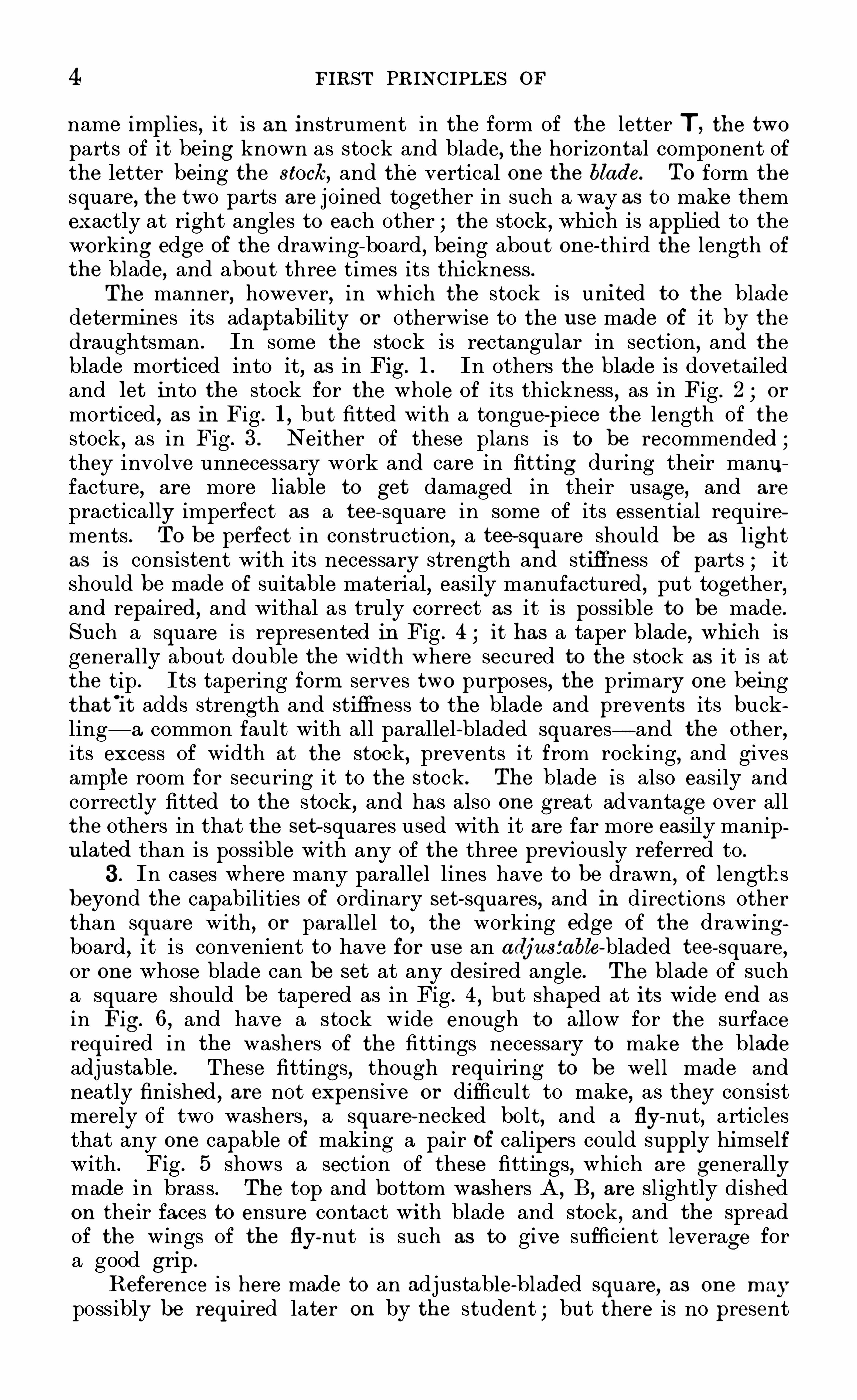
name implies , it is an instrument in the form Of the letter T ,the tw o
parts Of it being known as stock and blade, the horizontal component Ofthe letter being the stock, and the vertical one the blade. TO form the
square, the two parts are j oined together in such a way as to make themexactly at right angles to each other the stock , whi ch is applied to theworking edge Of the drawing-board
,being about one-third the length Of
the blade, and about three times its thi ckness .The manner, however, in which the stock is uni ted to the blade
determines its adaptability or otherwise to the u se made of it by thedraughtsman . In some the stock is rectangular in section , and theblade mort iced into it, as in Fig . 1 . In others the blade is dovetailedand let into the stock for the whole Of its thickness , as in Fig . 2 or
morticed , as in Fig . 1,but fitted with a tongue-piece the length Of the
stock,as in Fig . 3. Neither Of these plans is to be recommended ;
they involve unnecessary work and care in fitting during their manufacture, are more liable to get damaged in their usage, and are
practically imperfect as a tee- square in some Of its essential requirements . TO be perfect in construction, a tee- Square should be as lightas is consistent with its necessary strength and stiffness Of parts ; itShould be made Of suitable material
,easily manufactured
,put together
,
and repaired,and withal as truly correct as it is possible to be made .
Such a square is represented in Fig . 4 it has a taper blade, whi ch isgenerally about double the width where secured to the stock as it is atthe tip . Its tapering form serves tw o purposes
,the primary one being
that'
it adds strength and stiffness to the blade and prevents its buckling— a common fault with all parallel-bladed squares— and the other
,
its excess Of width at the stock, prevents it from rocking,and gives
ampl e room for securing it to the stock . The blade is also easily andcorrectly fitted to the stock , and has also one great advantage over allthe others in that the set— squares used with it are far more easily manipu lated than is possible with any Of the three previously referred to .
3. In cases where many parallel lines have to be drawn, Of lengthsbeyond the capabilities Of ordinary set- squares, and in directions otherthan square with , or parallel to, the working edge Of the drawingboard
,it is convenient to have for u se an adj nsfable-bladed tee- square,
or one whose blade can be set at any desired angle. The blade Of sucha square should be tapered as in Fig. 4
,but shaped at its wide end as
in Fig. 6 , and have a stock wide enough to allow for the surfacerequired in the washers Of the fittings necessary to make the bladeadjustable . These fittings
,though requiring to be well made and
neatly finished,are not expensive or difficult to make, as they consist
merely Of two washers , a square-necked bolt,and a fly-nut
,articles
that any one capable Of making a pair Of calipers could supply himselfwith . Fig . 5 shows a section Of these fittings
,which are generally
made in brass . The top and bottom washers A,B
,are slightly dished
on their faces to ensure contact wi th blade and stock , and the spreadOf the wings Of the fiy
-nut is such as to give sufficient leverage fora good grip.
R eference is here made to an adjustable-bladed square, as one maypossibly be required later on by the student ; but there is no present

MECHANICAL AND ENGINEER ING DRAWING 5
necessity for the provision Of such a tool , as all lines that may berequired other than those drawn with the tee and set- squares inconjunction
,are easily put in by a proper manipulation Of the set
squares, which will be explained in due course .
Set-Squares.
— Of the set-squ ares used conjointly with the tee
square, those Of 45° and 60° are all that are required by the student in
the earlier stages Of study. A 6- in. 4 5° and an 8 - in. 60
°
set- squaresare the most useful Sizes . Framed ones , well made, Of foreign manufacture, may now be Obtained at a reasonable price, but the kind most
generally in u se are made Of vulcanite . Those, however, Of thismaterial made with the middle part cut ou t to imitate framed woodenones should be avoided , as they are very liable to fracture at theangles
,and it is impossible to repair them .
The other requirements Of the student Of mechanical graphics,
apart from what are known as instruments, are Some pencils, drawingpins
,rubber, paper, and ink . A few words descriptive Of the qualities
that should Obtain in each of these articles,that satisfactory work may
be done, will be Of advantage to him .
Pencils — The present great demand for pencils has , notw ith
standing the millions that are annually made and sold , added few tothe number that are specially suited to the wants Of the mechanicaldraughtsman . M any erroneously assume that any sort Of pencil wil lsuit a learner. NO greater mistake can be made . If he is to acquirea draughtsman’s habit Of work
,his first necessity will be a good
,
serviceable, reliable pencil — one that is neither too hard nor too soft,and that will retain a good point for a considerable time. The pencilsnow generally used in drawing Offices are Of Faber’s make, which canbe had Of different degrees Of hardness from H to six H
’
s,the cedar
covering Of the lead being hexagonal in form ,instead Of round . But
such pencils are too expensive for students’ u se. A good , serviceablepencil
,made by Cohen , and known as the " Alexandra H pencil,
” hasbeen in u se by the writer for some years
,and costs about half the price
Of Faber’s . They are, however, Of the ordinary round form , which isinimical to the draughtsman, it tending to cause them to be constantlyrolling Off his board and damaging their points . To obviate this, thewriter’s practice is to cut a flat side on the pencil throughout its wholelength
,taking care not to bend the pencil in doing this for fear Of
breaking the lead . If neatly done a perfectly fi at side is produced ,which serves as a guide to the way in which the pencil should be
pointed and held , and will prevent any tendency to rolling, even if thedrawing-board is much inclined . TO do away
,however, with the
necessity for constantly sharpening the pencil, and thereby reducingits length at every such Operation , pencils with movable leads havebeen in u se in drawing Offices for some years . They are far to bepreferred , as the part Of the pencil which is held by the fingers neveralters in length , and the lead can be used to the last quarter Of aninch . This kind Of pencil is known as " Faber’s artist ’s pencil , i shexagonal in outside form ,
and thus partly prevented from rolling.
The acme Of perfection In this class Of pencil has, however, only latelybeen introduced , the part for holding the lead being triangular in

6 FIR ST PR INC IPLES OF
section, which renders it easy to hold without turning in the fi ngers,
and rolling Off the drawing-board is impossible. It is made by H ardtmuth
,Of V ienna, bu t can be purchased Of any photographic chemist
or artists ’ colourman .
4 . Drawing-Pins.
— I II the study Of mechanical drawing in its
Fig. B
earlier stages, and even in the making Of working drawings for shopu se, it is not necessary or essential that the paper on which the
drawing is made Should be secured to the drawing-board In any otherway than by pinning it . This is effected by the u se Of draw ingp ins.
There are, however, several kinds Of drawing-pins to be had,and their
variety is Often the cause Of difficulty in choosing, to the u ninitiateduser . A pin that would answer well the purpose Of the free—handdraughtsman in putting a Sheet Of paper on his drawing-board , mightbe the very worst that a mechanical draughtsman could possibly u se.
The former, not needing a tee- square in the practice Of his art , if hedoes not stretch his paper, pins it down to his board with any drawingpins that are at hand . These may possibly be pins with heads asixteenth Of an inch thick
,beautifully milled on their edges and
perfectly flat on their under and upper Sides . Such pins wo'
uld beshunned by any mechanical draughtsman who wished to keep the
edges Of his tee and set- squares intact and free from notches . Pro
jecting the whole thickness Of their heads from the surface Of thepaper, they would foul the edges Of the tee and set squares and causedamage. The only kind Of drawing0 -
pin a mechanical draughtsmanshould u se Should have a head as thin as possible, without cutting atits edge, Slightly concave on the under Side or that next to the paper,and only SO much convexity on its upper surface as will give itsufficient central thickness to enable the pin to be properly secured toit . There is neither sense nor reason in making the head Of a drawingpin half-an-inch in diameter if its circumferential edge does not bearon the paper when its pin is as far into the board as it will gO . The
purpose Of the pin is to keep its head from rising from the surface Of
the paper, and it need only be long enough and strong enough to effectthis . It is better practice to u se four small , good -holding drawingpins as shown in Fig . B
,along the edge Of a Sheet Of paper, than one
large, clumsy, badly-made pin at each end Of it . Suitable drawing-pinswhich answer every purpose required Of them by the draughtsman are
now to be Obtained for half-a—crown per gross .
5. Paper— A S the student from the very commencement Of learn
ing to draw Should study to acquire the good draughtsman’s habits Of
work , and as one Of these is the making of clear, sound lines inhisdrawing, whether in ink or pencil
,it is advisable that he should
accustom himself to draw on fairly-
g(food paper. It is not meant by

8 FIRST PRINC IPLES OF
drawings,the only way tO ensure its being the real article is to Obtain
it from a bond fi de importer. The best mathematical instrumentmakers are generally importers Of it . It is Sold in hexagonal sticks
,
as shown in Fig . C , and is expensive, but small oval and round sticksOf it are to be had C osting about a shilling each .
6 . Before noticing the few" instruments ” that are necessary when
commencing the study Of mechanical drawing, w e think it advisable toShow
,in a combined sketch (Fig. D) , the special tools -viz .
,drawing
board,tee and set- squares— recommended , that the student may note
the position they each should assume when in u se. The tee— squareshould only be used in the two positions indicated by its Outline in fulland dotted lines . In the latter it will seldom be required . All lines atrigh t angles to its edge, when in the first position , should be drawnwith the 60
°
set- square applied , as Shown . The 45°
set- square is placedas it would be applied when a line is required at that angle near theleft edge Of the sheet Of paper. Care Should be taken, when drawingby lamp or gaslight , that the light is in such a position as to cause littleor no Shadow to be cast on the paper by the edges Of the tea or set
squares . This is important , as such shadows Often cause errors in liningin,
w hether in ink or pencil . W e may mention that the draw ing-boardand tee-square recommended for u se are known as " S tanley’sImproved , they having been introduced many years ago by M r. W. FStanley, Of London .
Instruments - The D raw ing Instruments required by the studentdraughtsman are few in number, and should be acquired as the neces
sity for their u se arises . NO greater mistake can be made than that Ofpurchasing a
" box Of instruments ,” as it generally contains some articles
that are never required , and is wanting in those that are necessary forthe special kind Of drawing practised . All that the student requires foru se for some time is a pair Of 6- in. compasses with a pen-and-pencil leg,

MECHANICAL AND ENGINEERING DRAWING 9
pen-and-pencil bows
,a ruling or drawing-
pen,and a set Of drawing
seales . For futu re service, everything depends on a proper choice intheir purchase, more particularly if their u se is to be continuous ;and as w e assume throughout this work that the student has little,if any
,previous knowledge Of the subject, it is especially necessary
that he should know what constitutes a good serviceable instrument ,as the possession Of inferior ones will be a constant source Of annoyancetO him .
7 . In giving the characteristics Of a good instrument, it is Of thefirst importance to understand the u se to which it is applied . Withdraughtsmen
,a pair of compasses and a pair Of dividers serve two very
different purposes , and are therefore differently constructed, but theirnames and uses are Often misunderstood .
" Compasses are never usedfor dividing
,nor are dividers ” applicable to compass-work . Beginners
Should therefore note that the former are Specially intended for puttingin circular lines in pencil or ink , and that the proper and only u se Ofthe latter is the division or measuring- Off Of lines and spaces . Theseseparate and distinct purposes give at once a clue to their proper formand constru ction . They are both instruments with tw o movable legs,j oined together by a forked end,
and secured by a pin and washer, asshown in Figs . 7 and 8 at A,
A . The compasses , however, ben usedto draw circular lines , or lines described about a point everyw here equidistant from it
,should have j ointed legs, one with a knee-j oint at B , and
the other with a socket, as at C ,to enable it to be easily removed
and replaced by the ink or pencil -points D ,E
, Fig . 10, when requi red .
The purpose Of the knee- j oints shown at B in the compasses, and b b
in the pen and pencil points , is to enable the lower parts attached tothem to be adjusted perpendicular to the surface Of the paper, In
order to Obtain a truly circular line, and to allow both nibs Of the
inking-point to bear fairly upon it .
D ividers, which are not necessary to the student for some.
tIme
forward in his study,should have legs Of equal length , but
.without
joints,as in Fig . 8
,their lower parts being made Of steel Of tri angular
section to within gin. Of the ends , which should be gradually workedOff into nicely-rounded points, as shown . This latter feature is one that
should Obtain in the points Of compasses , bow s , etc . Triangu lar-
pointedinstruments shou ld» never be used, as their points act
" the part of a;

10 FIR ST PR INC IPLE S OF
rimer, cutting their w ay through‘
the paper into the drawing—board ,making unsightly holes
,and causing them to describe anything but true
circles .
Pen-andp encil Bow s are compasses intended for putting in smallercircles and circular arcs . S ingle- j ointed ones
,such as are shown in Fig.
9,will serve all the present wants Of the student, if well made . The
socket in the pencil-bow should be tubular, and Of a size to take leads ,and not lead -pencils . As these two instruments will be much Oftenerused than any other, it is advisable that the student should supply himself with the best to be afforded , as they will amply repay any presentoutlay.
What are known as half sets,shown in Fig . 10
,are now specially
made by drawing- instrument makers,for the u se Of students . They
comprise compasses, lengthening bar, pen and pencil point, and knifekey, and are a very serviceable outfit if well made .
Penc il Point D . Pen Point E .
Fig. 1 0
In selecting the foregoing instruments,care should be taken that
they are all sector- j ointed with double- leaves and well made ; thereshould be no shake or Slackness in any Of them
,and they Should be
equally stiff in the j oints at any point from being full Open to closing .
The test for a pair Of compasses is to Open ou t their legs well apart andthen to fold each lower half-leg together— if the points meet each othertruly
,they are correct in the j oints if they cross one another, the j oints
are not properly made.
D raw ing or Ru lingp ens are Of two kinds — viz,those made with a
j ointed nib, as in Fig . 1 1, and those without a j oint, as in Fig . 1 1A . The
former, though' more expensive, is to be preferred, on account Of the
facility in cleaning and Sharpening bu t the latter is a very serviceable

MECHANICAL AND ENGINEERING DRAWING
pen,if well made and finished. It will be observed in the Sketch of the
fi rst,that the under or fixed nib is much straighter and thicker than the
hinged one ; this is so made to resist the pressure of the hand upon itwhen drawn along the edge of the tee or set- squares . In all ordinarypens the nibs are of equal thickness, and the hand-pressure tends toclose them and prevent the flow of the ink ; but by providing a stoutspringless inner nib this tendency is overcome. The stem or handle Ofthis pen,
it will be noticed , is squared, to indicate how it should be heldby the fingers when in u se.
Fig. 1 1
Fig. 1 1 a
The D raw ing- scales recommended for present u se by the student are
a set of three lately introduced by M essrs . Jackson Bros, of Leeds ,
made of pliable varnished beech,and giving twelve scales of the
standard units of measurement generally used in engineering drawing .
They are decidedly to be preferred to any cardboard— scale, as the dividingis well done and there is no tendency to double up or get dirty by u se .
When the student acquires a more perfect knowledge of the u se
of instruments and scales, he can add to his stock already in possessionwhatever is necessary, always bearing in mind that a good tool inthe hands of one who knows how to u se it will invariably dobetter work
,and is to be preferred to one of inferior quality ; in
the meantime,those herein recommended are all-su fficient for present
requirements .

CHAPTER II
MEC HANICAL AND FREE IIAND D RAWING : THEIR D IFFERENC E AND USE S
8 . BEFORE proceeding with an exposition of the principles on whichthe practice of mechanical
,
drawing is based , it is necessary that thestudent— w ho is assumed to have no previous knowledge of the subjectshould thoroughly understand the radical difference, in character andapplication which ex ists between it and that kind of drawing known as" freehand .
The generic term " drawing,strictly Speaking, is the art of
representing Objects on a surface— generally fiat— by means of linesshowing their forms and general contour, independent of colour Orshading ; for the latter, without form ,
would be meaningless andincapable of expressing anything . Freehand drawing is the prac tice ofthe art of drawing by means of the hand , the eye alone controlling and
guiding the tool or instrument used for delineation . The hand guidedby the eye can , however, only picture or draw what is seen from one
position at a time for were it otherwise, a distorted view of the Objectwould be the result
,as its appearance to the eye from one point of view
would be different to that from any other.
All Objects are made visible to the sense of seeing by the agencyof light, whether natural or artificial , for without light it would beimpossible to distinguish one Object from another. To the artist or
draughtsman,light is a stream of matter given off by a luminous
body, travelling from its source in thin straight l ines— or rags— to
the object illumined, from which it is reflected or transmitted in thesame way to his eye . What is seen , or is apparent to his sense of sight ,he depicts or draws on his paper. If he changes his position withrespect to the illumined object, he sees it differently, and obtains adifferent view Of it ; each such view, i f correctly drawn , is knownas a " perspective,
” and would agree with that Obtained in the follow ingmanner.
In the diagram (Fig . 1 2) let H P represent a flat surface, suchas a piece of ground or a floor
, exposed to sunlight, and VP a sheetof glass set up on H P, in a vertical position . At any distance tothe left of VP,
and parallel to it,is erected a piece of fencing 00
,
having its top and bottom edges parallel to HP,and its side edges

MECHANICAL AND ENG INEER ING DRAWING
Fig. 1 2
13

1 4 FIR ST PR INC IPLE S OF
perpendicular to it . At a given distance to the right of VP,and
perpendicular to HP,a staff S , surmounted by a small rectangular
plate of any Opaque material , and pierced with a sight-hole is fixed ;the height of this sight—hole from H P being supposed to equalthat of an Observer’s eye from the ground . The sheet Of glassVP being transparent, it is evident that the spectator
, on lookingthrough the sight-hole, will see the whole of the piece Of fencing,and can j udge of its appearance from the position occupied by his eye .
If he wish for a record of this appearance he can Obtain it by drawingon the glass what he sees through the Sight-hole. The view he
would get would be a perspective of the original object 00,or
the fence. But its contour or outline on the glass , although similar,would be much smalleI than its original . H ow much smaller,would entirely depend upon the distance between the eye at sighthole, the Sheet of glass VP, and the fencing 00. It is evident thatthe nearer VP is to C O
,the eye remaining in the same position , the
larger would be its image or picture upon VP,and the converse Of thi s
would obtain were the conditions reversed .
It will be seen from the diagram that the perspective view of the
Original object is Obtained by finding where the luminous or visual rays— represented by broken lines— proceeding from its principal points ,are intercepted on VP in their passage to the eye, and then joiningsuch points by right lines as in the original . Now
,as these visual rays ,
or proj ectors,”are the means by which the view of the Objec t is
proj ected or thrown on VP,such a view is called a "
projection ,” and in
the special case w e are considering a perspective projection .
” In sucha delineation it is apparent that al l rays proceeding from the visualpoints in the object form a pyramid , the vertex Of which is the pointwhere they meet in the eye ; and from this fact it will at once beseen that a perspective drawing of an Object can serve no otherpractical purpose than that of showing its appearance when viewedfrom a certain fixed position, for its boundary lines alter ing withthe altered position of the Spectator, it is difficult to determine theiractu al lengths, as they only bear a relative proportion to their originals .
A S they cannot be measured with an ordinary rule or scale, it wouldbe impossible to construct a machine or erect a building from suchdrawings . In perspective drawing, HP in the diagram is known asthe horizontal or groandplane, and
0
VP the perspective or pictu re plar ,ie
which latter is always supposed to be transparent, although actuallyrepresented by the artist’s Sheet Of drawing-paper or canvas .
9 . As , then , a perspective , or freehand drawing, does not fulfilthe requirements of the workman , in that he cannot determ ine at sightthe actual form ,
dimensions,or arrangement of the piece of work he I S
called upon to execute, some other method of delineation becomes anecessity. This want is supplied in what is generally known as a" mechanical drawing, or a drawing Obtained by the correct appl icationof the principles of a kind of projection called " orthographic ,
” whichgives results differing widely from that already explained , in that itaffords a means of at once determining the actual form
,Size , and
disposition of every part of the obj ect represented , and gives an adept

1 6 MECHANICAL AND ENGINEER ING DRAWING
projectors parallel among themselves and perpendicular to VP are
shown proceeding from the corners A,B
,C,D
,Of the bar penetrating
VP in a, b, c, d. As the edges of the original Object, or the
rectangular bar F,are all straight, it follows that if a
, b, c , d on VP
be j oined by straight lines, an orthographic projection of the faceA, B, C, D , of the bar will have been obtained , which will
, on
measurement, be found to be an exact counterpart Of it. But thisprojection only gives the length and depth of the bar ; and as it isnecessary to know its other dimension
,or w idth, a view Showing that
dimension must be obtained . Now it is evident that a view of the
bar, looking at it from above and in the direction of the arrow,will
supply the information required . If,then, visual rays , or projectors,
proceed as before from the four corners of the face of the bar seenfrom above, to the plane HP below,
they will penetrate that plane atthe points a ’
, b’
, e,f , and these points being j oined as before— as the
same conditions Obtain— there i s produced on H P an orthographic
projection of t he top face of the bar which determines its width .
With these two projections, or views of the original, it will be seen thata workman could produce any number of such bars without the
assistance of a model or other guide. To distinguish the two pro
jections of the same Object,the one Obtained on VP is known as an
"elevation or vertical projection, and that obtained on H P is calleda " plan or horizontal projection .

CHAPTER III
PRACTICAL GEOMETRY AND MEC HANICAL DRAWING
A s it has been necessary,in explaining the difference between a
mechanical and a freehand or perspective drawing,to make u se of
terms which pre— suppose a knowledge of geometry by the student whichhe may not possess
,and as it is advisable to take nothing for granted
in the exposition of ou r subject, it will be necessary at this stage todefine the meaning Of the geometrical terms that will be made u se
of as w e proceed,and to Show/how
,by a special combination Of
lines, those geometrical figures are constructed which form the
surfaces of Objects whose delineations are subsequently to be Obtainedby orthographic projection .
The term " geometry,” in its generally-accepted sense
,means the
science or knowledge of magnitu de reduced to system ,and has to do
with the measurement of lines,surfaces, and solids . It has, like other
sciences,two Sides or branches
,one
" theoretical , which demonstratesor proves its principles
,and the other " practical
,
”or that which
applies those principles to construction . Theoretical geometry, or
Euclid,will seldom be referred to in the course of th is work, as
most of the demonstrations used are self-evident but practicalgeometry— a sub divison of which is the basis of our subject— mustbe understood by the student
' to such an extent as will enable himto work ou t the problems that will arise in the exposition of it.
The tw o parts into which practical geometry is divided are Planegeometry
,which has reference only to the solution of questions relating
to points , lines , and figures, Situated in one plane and solid geometry,which Shows by special representations on tw o or more defined planes,the relations of the points
,lines
,and surfaces of bodies having length ,
breadth,and thickness .
W e would,in passing, guard the student, on his entering on the
study of geometrical drawing,against wasting valuable time in
working ou t the problems— many of which will be of no u se tohim — given in most text-books on the two subjects of plane andsolid geometry
,as all that is absolutely necessary for him to know
in connection with either will be explained to him as occasion arises .A s w e cannot form a conception of the magnitu de of any material
1 7 C

1 8 FIRST PR INC IPLE Sor
object without reference to one or more of its dimensions,and as each
of these involves the idea of extension in some direction, the word
length, or its representative," a line,
” would appear to be the firstterm used in geometry requiring definition , but as a line can haveno ex istence till it is generated or drawn
,our first term must be that
of the generator, or point .
” W e therefore defineA point, as having no magnitude
,that it is used to denote
" position ” only, and is represented geometrically by a dot or markmade by any pointed instrument, such as a pen,
pencil, etc .
A line,as the path made by a point moving over a surface.
It may be straight, crooked , or curved, according to the direction inwhich the point travel s or moves .A straight line, as the Shortest path that can be made by a point
moving from one position to another, or the nearest distance betweentwo points
,as the line A between points 1 and 2 .
A crooked line, as the path of a point that has changed its directionafter moving in a straight line for a given distance — l to 2
,—as the
line B from 1 to 3.
A cu rved line, as the path of a point that continually changes itsdirection , as the line C from 4 to 5 .
If the path of a moving point changes in such a way as to enclose acertain amount of surface, then the enclosed surface is called a " figure
,
”
and the path its boundary line, as in Fig . 1 4,where the " point path
from a, through b, c, d, defines the form’
of the figure.
If a point move continuously in such a w ay as to be always at agiven distance from some fixed point, then the surface enclosed by the" point path ” becomes the figure called a " circle
,
” as the continuousline ABC (Fig . any point in which is equi-distant from D,
which iscalled its centre.
It is evident from the foregoing that two straight l ines cannot enclosea surface, or form a figure, but that one such line in combination witha curved or a crooked line will effect this, as Shown in Figs . 1 6 and 1 7 ,where w e have in one case a straight line and a crooked one
,and in
the other a straight and a curved line, combined to form figures .
A surface is a magnitude that has ex tension in two directions only-viz .
,lengthwise and crosswise. Its dimensions— with one or two
exceptions— fi are given as length and breadth .
A plane su rface is one that a perfectly straight edge will touchor coincide with if applied to it in any direction . A mathematical orperfectly true plane does not ex ist— it can only be imagined .
Parallel straight lines are the point paths of two lines on a planesurface that are everywhere equi—distant from one another, as the linesA and B .
C onverging straight lines are the point paths Of two lines On a planesurface, which , if continued , meet and cross each other as the lines C, D .
When the paths or lines increase their distance from each other as theyleave the meeting point, they are said to diverge.
An angle is formed when two straight lines meet each other in apoint
,as
'
D meets F in d (Fig . If the inclination of one l ine tothe otherb e such that the angles are equal on both Sides of the meeting

ME CHANICAL AND ENGINEERING DRAWING
fi y l "’
1 9

20 FIR ST PRINC IPLES OF
point, then the angle formed by the lines D and F is a right angle. Ifthey are not equal , as in the meeting of E and F in (I
,then the smaller
of the two, or angle a,will be an acu te angle, and the larger, or angle b,
will be an obtu se angle. And as the line D makes equal angles on bothsides of it with the line F,
the two lines D and F are perpendicu lar toeach other.
1 1 . As angles cannot be measu red without a knowledge of the partsand divisions of the circle (Fig . w e must, before giving furtherdefinitions of plane figures
,explain these. The boundary line ABC of
this figure is called its circumference. Any straight line drawn throughD
,its centre, and touching the circumference on both sides, is a diameter.
H alf of such a line is called a radiu s. Any portion of the circumference, such as from A to B
,would be an arc, and a straight line
j oining A and B the chord of that are ; the space enclosed by the arcAB and its chord is called a segment, and that by the are AC and thetwo radii AD
,CD , a sector. One quarter of the whole figure or circle
is a qu adrant, and one half of it a semi -circle. For the measurement ofangles
,arcs
,chords
,etc .
,the circumference of every circle is supposed
to be divided into 360equal parts called degrees, which are indicatedwhen speaking of them by attaching a small circle to the right of thenumber stated— as etc . (or 30 degrees, 60 degrees, A
quadrant, therefore, contains 90degrees , and a semi- circle 1 80degrees .
The Size of any angle is determined by the number of degrees containedin the arc subtending the angle, described about the angular point d,as a centre (Fig . The complement of the angle a is the number ofdegrees it is wanting to make it a right angle, and its sumolement is thenumber of degrees contained in the angle b.
Circles are concentric when they have the same centre as in Fig . 1 9,
and eccentri c when their centres are different, as in Fig . 20.
A tangent is a straight line which touches a circle or a curve in one
point,and when produced does not cut it
,as in Fig . 21 .
Tangent circles and tangent cu rves are those which touch each otherin one point, but do not cut as in Fig . 22 .
The point of contact is that point where a tangent touches a circleor a curve, or where two tangent curves touch, as a in Fig . 22 .
1 1a . In continuing ou r definitions Of plane figures,w e take first
those constructed with the least number of stra ight lines that willenclose a Space, which is three. Such figures are called triangles orthree-angled , and are named according to the disposition of their sidesand quality of their angles .An equ ilateral triangle has equal sides and equal angles, which are
all acute,as in Fig. 23.
An isosceles triangle has two sides equal and tw o of its angles alwaysacute, the thi rd angle being acute or obtuse, dependent on the length ofits third side, as Figs . 24 and 25
,the latter having one obtuse angle at a .
A right-angled triangle has one Of its angles a right angle, the other
two being acute, as Fig . 26 .
A scalene triangle has three unequal sides, as Fig. 27 ; an obtu se
angled triangle has one obtuse angle, as Fig . 28 ; and an acu te-angled
triangle has all its angles acute.

MECHANICAL AND ENGINEERING B RAWIN
22 MECHANICAL AND ENG INEERING DRAWING
Of four- Sided figures bounded by straight linesA squ are has all its sides equal , and its angles right angles, as in
FIg. 29 . A rectangle has Opposite Sides pairs, and parallel, and itsangles right angles, as in Fig . 30. A parallelogram,
or rhomboid, hastwo pairs of parallel sides, as Fig . 31 . A 7 hombu s has all its Sidesequal, two of its angles being acute, as Fig . 32 . A trapezoid has onlytwo Sides parallel, as Fig . 33. A trapez ium is an irregular figure of
four Sides,none of which are parallel, as Fig . 34 .
A regu lar polygon is a figure having all its Sides and angles equal .One of five sides is a pentagon,
as Fig . 35. One of six, a hexagon, as
Fig . 36 . One of eight Sides, an octagon, as Fig . 37 . An irregu lar
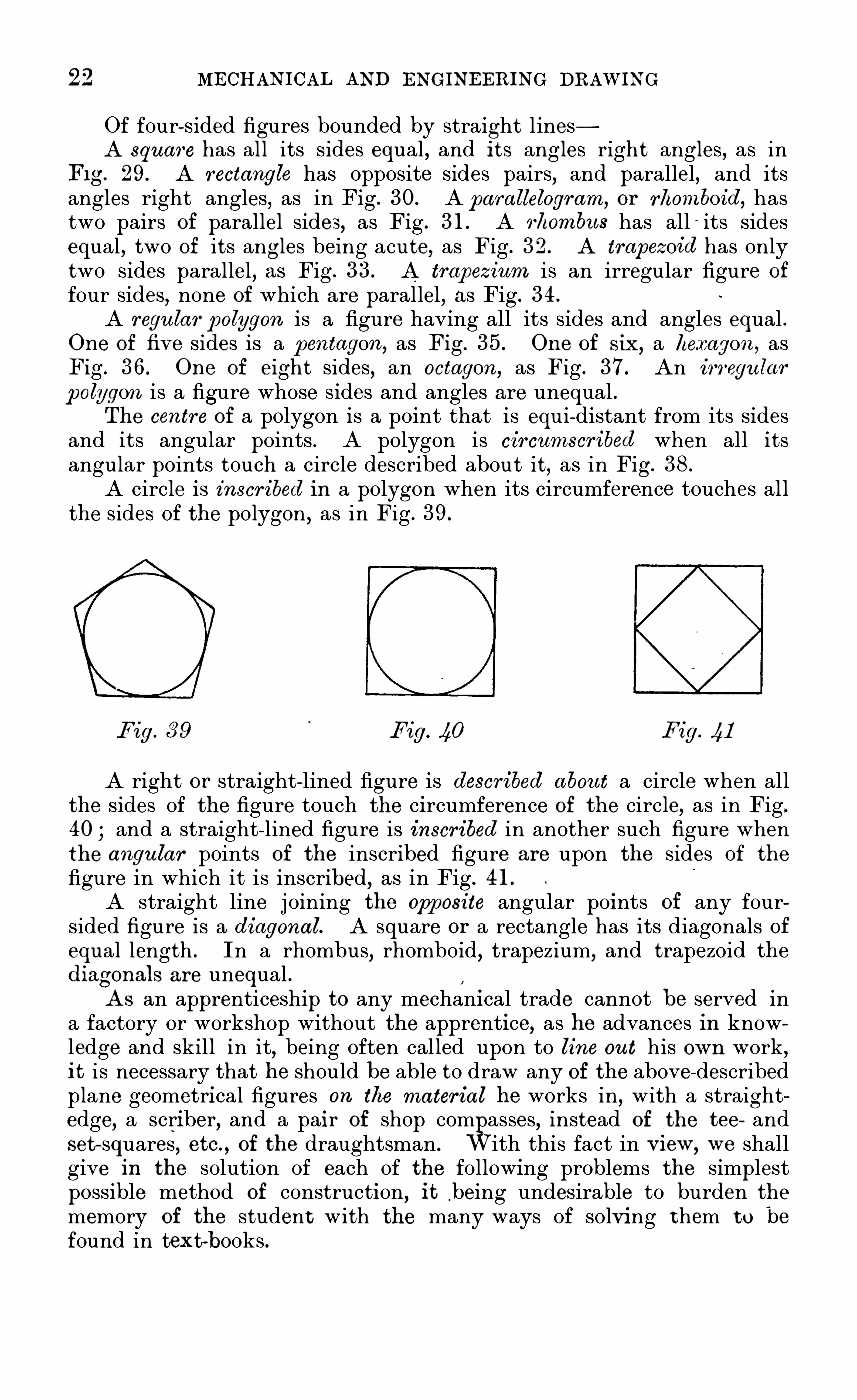
polygon is a figure whose sides and angles are unequal .The centre
o
of a polygon is a point that is equi-distant from its Sidesand its angular points . A polygon is circumscribed when all itsangular points touch a circle described about it, as in Fig . 38 .
A circle Is inscribed In a polygon when its circumference touches allthe sides of the polygon , as in Fig . 39 .
F ig . 39 Fig. 40 Fig . 41
A right or straight- lined figure is described abou t a circle when allthe Sides of the figure touch the circumference of the circle, as in Fig.
40 and a straight- lined figure is inscribed in another such figure whenthe angu lar points of the inscribed figure are upon the sides Of thefigure in which it is inscribed, as in Fig . 4 1 .
A straight line j oining the opposite angular points of any foursided figure is a diagonal. A square or a rectangle has its diagonals ofequal length . In a rhombus
,rhomboid
,trapezium,
and trapezoid the
diagonalso
are unequal .O
A S an apprenticeship to any mechanical trade cannot be served ina factory or workshop without the apprentice, as he advances In knowledge and skill in it, being Often called upon to line ou t his ow n work,it is necessary that he should be able to draw any of the above-describedplane geometrical figures on the material he works in, with a straightedge, a scriber, and a pair of shop com asses, instead of the tee andset- squares, etc . , of the draughtsman . With this fact in VICW ,
w e shallgive in the solution of each of the following problems the simplestpossible method of construction, it ,
being undesirable to burden thememory of the student with the many ways Of solving them to be
found in text-books .

24 FIRST PRINC IPLES OF
Problem 2 (Fig.— A t a givenpoint C , in a straight line, to erect
a perpendicu lar.
H ere the point'
may be near the middle of the line or near the end
of it . If the former, as at C, in the line AB,and if AB be near the
edge of the material, proceed as follows z— Set Off from C,on either side
of it, equal distances, as CD , C E , and from D and E as centres, with a
radius greater than half the distance between D and E,draw arcs
cutting each other in F, then a line drawn through F and C will beperpendicular to AB . If the given point is near the end of the lineand the edge of the material, as A in BD (Fig. then from anypoint a
,above BD ,
and with a radius equal to a A,describe an arc
CAT,passing through A, and cutting B D in T . Draw a line from
T through a, and produce it till it cuts the are in C . A line from Cthrough A will be perpendicular to BD at A.
Problem 3 (Fig.— From a given point A , above a straight line
DC , to letfall a perpendicu lar to that line.
H ere the point may be nearly over the middle, or over the end of
the given line. If in the first position,with any radius greater than
the distance from the point A to the line BC, describe an are cuttingBC in D and E ,
and from points D and E as centres,with a radius
greater than half the distance between D and E ,draw arcs cutting each
other in a and b ; then a line drawn through the given point ,A and
the intersections of the arcs in a and b will be the required perpendicular. If the point is nearly over the end of the given line
,as b in
Fig . 4 6 is over AB ,from b, draw a line intersecting AB in C, and
bisect it in S ; with SC as radius and S as centre, describe an are
cutting AB in D,j oin b and D ,
and the line will be perpendicular toAB . The student will notice that the construction in the second casesof Problems 2 and 3 is similar. This arises from the fact that the linedrawn to the given point has in each case to be at right angles to thegiven line, and as the angle in a semi-circle is always a right angle, theproblem is to draw a semi - circle that shall contain the three angularpoints of a right-angled triangle, one of which is the given point in theproblem .
Problem 4 (Fig .— To bisect (or divide into two equal parts) a given
When speaking of an angle, it is usual to name it by affix ing eithera single letter at the angular point
,or a letter to each of its lines and
the angular point, the one denoting the latter being always the second.In the problem ,
let BAC be the given angle. With any convenientradius set Off from A equal distances on BA and CA in the points Dand E ,
and from these points,with a radius greater than half the
distance across from D to E,draw arcs intersecting in F ; a line
through F and A will bisect the angle BAC . This constru ction, it

MECHANICAL AND ENGINEER ING DRAWING
F lg. 47
Fig . 52

26 FIRST PR INC IPLES OF
will be seen , is tantamount to bisecting a line from D to E,and
drawing a line through its bisection and point A,the only requisite
condition being that the two points D and E in the lines forming theangle must be equi-distant from the angular point A .
Problem 5 (Fig .— To draw a line parallel to a given line at a given
distaneefroni it.
H ere it is evident that if from any two points C and D in the givenline AB, arcs be drawn, of a radius equal to the given distance the tw olines are to be apart
,and a line EF be drawn tangent to those arcs, then
the line EF ‘
w ill be parallel to the given line AB . This is the simplestpossible solution of the problem ,
involving the least work , but requirescare in drawing the parallel line exactly tangent to the arcs . Anothersolution , requiring much more work in the construction , is the following— A t the points C and D
,in line AB (Fig. erect two perpendiculars
to AB, and set off on each of them from C and D the distance theparallel lines are to be apart . Through the two points Obtained draw aline, and it will be parallel to the given line AB .
Problem 6 (Fig .— Through a point P , to draw a line parallel to a
given line AB .
With P as a centre and any convenient radius, describe an arc EC ,
cutting the given line AB in C,and from C as a centre, with the same
radius,draw an are through P
,cutting AB In D . Set Off the distance
PD on the arc EC,and through P and E draw a line ; it will be parallel
to the given line A B .
Problem 7 (Fig .— To draw an angle equ al to a given angle A .
This means that two lines are to be drawn having the same inclination to each other that tw o given lines have. W e must therefore firstfind the inclination Of the given lines . To do this w e have only todraw on the given angle an arc of any convenient radius, with A ascentre, such as BC . The length of its chord is the distance subtendedby the lines forming the angle at the radius AB orAC . If, then , frompoint a
,in the line DE
,and with a radius equal to AB ,
w e describean are be, and from c set off a distance on be equal to the chord of the
arc BC,then a line drawn through b and a will makethe same angle
with DE that AB does with AC in the given angle, which solves theproblem .
Problem 8 (Fig .— To draw a line making a given angle
— say 60°
— w ith a given line.
The solution of this problem involves the relation that the rad ius ofany circle has to the chord of an are which subtends an angle of 60° inthe circle. To solve it, let AB be the given line, and C a point in it atwhich it is desired to draw a line making an angle of 60° , with AB .

MECHANICAL AND ENGINEER ING DRAWING 27
From C,as centre, and with a convenient radius, draw the arc DE
,
cutting AB in E from E with the same radius cut DE in D,then a
line drawn through D and C will make an angle of 60° with the line
AB . If the circle were completed with the same radius , it would befound
,on stepping the radius round it, that it exactly divides it into
six equal parts, and as every C ircle for geometrical purposes (as beforeexplained) is divided into one- sixth of the circle must contain 60°
or the angle which the two lines in the problem have to make witheach other. K nowing this specific relation subsisting between the
radius and the chord of an arc of 60° of a circle, w e are enabled to laydown any angle with the assistance of a scale of chords
,
” which willbe found on one of the set of drawing- scales previously recommended .
TO Show its u se, let u S take, for example
Problem 9 (Fig — To draw a line, malring an angle of , say,
w ith a given line at a givenpoint in it.
Let AB be the given line, and a the given point in it. From the
zero point,on the extreme lef t of the scale of chords
,and with a radius
in the compasses equal to the distance from that point to the one marked60—
7 with the arrow over it— ou the scale,draw with a
,on the line AB
as a centre, the are be, cutting AB in c, and from c as a centre, with aradius equal to 70
°
on the scale of chords,cut the are be in b. A line
,
drawn through b and a will make, with the given line AB,an angle Of
and SO with any other angle,always remembering that from zero
to 60 on the scale of chords is the radius with which the first are in theconstruction is to be drawn .

CHAPTER V
PLANE GEOMETR ICAL FIGURE S
13 . IT may be noted, before passing on to the construction Of the
plane geometrical figures which form the surfaces of the plane solidswhose projections w e shall next Show how to obtain, that as the anglesmost generally chosen for the surfaces of mechanical details are thosewhich contain some multiple Of it is not necessary to u se even ascale of chords in laying them down on paper or other material , as mostof them can be obtained by simple geometrical construction, which hasfewer chances Of error than even measuring from a scale . A few ofsuch angles are etc .
,and are thus
ob tained For bisect 60° for bisect 30° for bisect 90°
for u se radius for add 15° to 60° for mark off radiustwice for take 4 5° from a semi- circle. With these simple constru ctions committed to memory
,and the u se of a scale Of chords for
any angle not easily Obtained otherwise, the student will be able to laydown any angle that may be required . W e may now proceed with theconstruction of plane figures, taking first
Problem 10(Fig.— To constru ct an equ ilateral triangle on a given
base.
(Note The base Of any triangle is that Side of it on which it standsthe vertex
,the point immediately over the base ; and the altitu de the
height Of the vertex from the base. ) With the given base AB as aradius , and from A and B as centres, describe arcs cutting each otherin C , the vertex ,
j oin AC and BC,and the triangle is constructed . If
the altitude only be given as CD (Fig . Then , as the sum of the
angles of any triangle are together equal to two right angles, or
and as the triangle required is equi-angular, the angle at its vertex willbe one-third of or TO construct it, draw EF
,GH through
C and D at right angles to CD,and from C
,with any convenient
radius , describe a semi-circle cutting EF in a and c with the sameradius , and from a and c as centres, cut the semi-circle in d and e,
draw lines through Cd and C e, and produce them to meet GH in g andh, then gCh is an equilateral triangle having an altitude CD .
28

D ENGINEERING DRAWING

30 FIRST PRINC IPLES OF
Problem 1 1 (Fig .— To constru ct an isosceles triangle, the base AB
and one of the equ al sides CD being given.
With CD as a radius,and from A and B as centres
,draw arcs inter
secting in a, j oin dA and aB,and the triangle is constru cted . If the
base AB and the altitude ab are given (Fig . 56) Bisect the baseAB in b
,and at b erect a perpendicular and make it equal to ab, j oin
aA and aB,then A aB is the required isosceles triangle .
Problem 12 (Fig.— To constru ct a scalene triangle, the sides being
given.
Take the longest side AB for the base,and with the shortest as a
radius,and from B as a centre, describe an arc then with the length
of the third side as radius , and from A as centre, cut the are describedfrom B in b, j oin b and A,
and b and B,then A bB is the required
triangle.
Problem 13 (Fig.— To constru ct a squ are on a given line AB as
a side.
E rect at A a perpendicular to AB ,and from it cut Off AC equ al
‘
to
AB ; then from C and B as centres, and with AB as radius,draw
arcs intersecting at D ,j oin C and D and B and D
,and the square is
constructed . If the given line be a diagonal and not a Side : Bisectthe diagonal AB (Fig . 59 ) in a ,
by a perpendicular b, a, c , and from a
set off ab, ac, equal to aA ,or
J
aB,j oin A b, bB ,
B e, cA , and the squareis constructed on the given diagonal AB .
Problem 14 (Fig .— To constru ct a rectangle, the length of two
adj acent sides being given.
Let the line AB be one of those sides . At A erect a perpendicularto AB
,and cut Off from it in C
,a length equal to the other given side
from B as centre, and with a radius equal to AC, draw an arc,and
from C as centre, with a radius equal to AB,draw another intersecting
the first in D ,j oin CD and DB
,and the required rectangle is con
structed .
Problem 15 (Fig.— To constru ct a rectangle, a diagonal AB and
one side B C being given.
As the diagonal of a rectangle divides it into two right— angledtriangles , if it is made a diameter
,and on it a circle is described
,the
circle will contain the two right-angled triangles which will form the
rectangle sought . Therefore, bisect the given diagonal AB in a, andfrom a
,with aB as radius
,describe the circle ABCD from B as a
centre, and with BC as radius , cut the circle in C , and from A,with
the same radius,cut it in D,
j oin ACBD,and it is the required
rectangle.

32 FIRST PR INC IPLE S OF
exterior angle, or that formed‘
by one side with the other produced,is
always equal to 360° divided by the number of the sides of the polygon ,
and the interior angle, or that formed by the meeting of the twoadj acent sides, is 1 80
° minus the exterior angle. The angle at thecentre (or central angle) of a regular polygon is equal to the exteriorangle. With these simple facts committed to memory
,the student or
apprentice can , with a scale Of chords— now generally found on allpocket ru leS
,— lay down at Once on his work any regular polygon
having either an Odd or an even number Of Sides . TO apply these factsw e will take
Problem 19 (Fig. 67 ) — To constru ct a regu lar pentagon w ith a given
length of side.
H ere 360°
5 equals the exterior angle ; and 1 80°L 72
°
the interior. Let AB be the given side, produce it (say to the
left) at A,draw the line AC
,making an angle of 72
° with AB produced,
and of a length equal to AB ; bisect AB and AC by perpendicularsintersecting in S
,then S is the centre Of the circumscribing circle .
Describe it , and from C ,with AB as a distance
,set off on it the points
D,E
,j oin CD
,DE
,EB
,and A C DEB is the required pentagon .
If the pentagon has to be inscribed in a given circle, then from itscentre— which will be the centre of the pentagon— draw any radiusas SA (Fig . 67 ) at S , draw a line making with SA an angle Ofand cutting the circle in B ,
j oin A and B,then AB is one side Of the
required pentagon ; set Off the distance AB from A or B round thecircle
,and it will give points C, D ,
E j oin A CDEB,and the pentagon
is constructed in the given circle.
Problem 20 (Fig.— To constru ct a regu lar hexagon w ith a given
length of side.
H ere 360°
6 equals and 1 80°
60°
Let AB be
the given Side, produce it, and draw AC,making with AB produced
an angle Of 60°
make AC equal tO AB ,bisect them by perpendiculars
intersecting in S,which is the centre of the circumscribing circle ;
describe it , and set Off the distance AB round it from C,in points
D,E
,F
,j oin CD
,DE
,EF
,FB
,and the required hexagon is constructed .
If a hexagon has to be inscribed in a given circle, the central anglewill be 60
°
this angle laid down with the centre Of the circle as theangular point will give A
,B (Fig . points in the circle
,and the
l ine j oining them will be a Side Of the hexagon step this length roundthe circle in points C, D ,
E,F
,j oin AC
,CD
,etc .
,and the required
hexagon is inscribed in the given C ircle . A S the side Of a hexagon isthe chord of an arc of and is equal to the radius Of the circumscribingcircle
,that radius set Off round the circle will divide it into six equal
parts,and if the points Of division be j oined by right lines they would
form the inscribed hexagon as before.

MECHANICAL AND ENG INEER ING DRAWING

34 MECHANICAL AND ENGINEERING DRAWING
Problem 21 (Fig. 69 ) — To constru ct a regu lar octagon, w ith a given
length of side.
H ere 360°
8 and 1 80°
45°
Let AB be the
given side. Produce it in both directions,and at A and B draw lines
A E,BF
, of the same length as AB,and making with AB produced
angles of 4 5° bisect the angles formed at A and B
,and their inter
section at S will be the centre of the circumscribing circle. With SAor SB as radius, describe this circle, step AB round it from E to F inthe points 1 , 2 , 3, 4 ; j oin E 1
,2,3,4 F
,and the required octagon is
constructed . To inscribe an octagon in a given circle Draw two radii
(Fig . 69 ) at an angle of 4 5°
to each other,and they will cut the circle
in points A and B join AB,and it will be a side of the octagon . Its
length stept round the C ircle will give the same points as in the previousconstruction j oin them,
and an octagon will be inscribed in the givencircle.
15. The same principle Of construction as used in the last threeproblems is applicable to any regular polygon , whatever may be thenumber of its Sides but in practice it is preferable to subdivide theSides of those w e have given— if the division will give the requirednumber of sides - than to lay down an independent construction
,the
chances Of not Obtaining the exact length Of the side of the polygonrequired increasing as the number Of sides increase. On paper
,and
with the assistance of tee and set- squares, many of the figures alreadygiven can
,of course
,be easily and quickly constructed ; but, as before
Observed,the ability to draw them w ithou t such aids is absolutely
essential,when w e consider the calls Often made upon the workman
for the practical application of such knowledge .
As figures,or solids
,having more than eight Sides or plane surfaces
are seldom m et with in mechanical construction,and as those w e have
given include all that form the surfaces Of the plane solids intended tobe used as Objects for projection
,w e shall now proceed to show how
their projections are Obtained .

CHAPTER VI
ORTHOGRAPH IC PROJECTION
16 . A CAREFUL study of the preceding chapters,and the solution
of the problems contained in the two last,will have prepared the
student for entering upon that more important part Of ou r subjectviz .
,
" Orthographic Projection,”or that special kind of delineation
which,when applied to the representation Of mechanical subjects
, en
ables the engineer or machinist to determi ne at sight the actual dimen
sions and arrangement Of any part of an engine or machine. As,how
ever,a part of a piece of mechanism is but a compound of simple forms
made up of what are known as plane solids and solids of revolutionalone or combined— it is at once manifest that to be able to draw anypart of a machine
,the would-be draughtsman must first master the
delineation Of its component parts , and as these resolve themselves intosolids
,with either plane or curved surfaces, having straight or curved
lines for their boundaries, the question of their ultimate accuraterepresentation as a whole becomes one Of the correct proj ection in thefirst stage Of the study, of the lines bounding the su 7f aces Of solids ;and as straight lines and flat surfaces are more easy of projection thancurved ones
,w e commence this part of the subject by an illustration Of
its principles in the projection Of points,straight lines
,and the simple
figures wh ich form the surfaces of those plane solids used in givingshape to machine and engine details .By a reference to the latter part of Chapter II .
,it will be noted
that to Obtain the views of an Object required for the purposes Ofmanufacture its . projections are determined on two planes , at rightangles to each other— that is, their relative positions are as shown inFig . 13 ; that lettered VP being a plane assumed to be vertical, andthe other H P a horizontal plane perpendicular to VP. These twoplanes are called the vertical and horizontal " planes Of projection,
”
and will throughout the exposition of the subject of " projection ”be
denoted by the letters VP and H P.
1 7 . The student should be particular to note the precise differenceOf meaning ex isting between a vertical line or plane and one that is"
perpendicular.”
One line or plane may be perpendicular tO anotherline or plane, and yet neither Of them be vertical . A vertical line is a
35

36 FIRST PR INCIPLES OF
plumb line, or the position a weighted line assumes when freelysuspended . A horizontal line is one which is parallel to the horizon ,and
,therefore, perpendicular to a vertical one. A "
vertical plane,”
then , is one with which a plumb line will coincide, and similarly a" horizontal plane ” is one parallel to the earth’s surface taken as a
plane, and is at right angles to the vertical .A plane, strictly defined, is nothing more than a perfectly flat sur
face,” without any reference to su bstance ; but as it cannot be dealt
with for explanatory purposes without being assumed to be materialand inflex ible, it will, when spoken Of, or used for that purpose in thiswork
, be considered as having such a thickness as would be repre
sented by a line. Assuming this, the edge view of a plane will , under
any circumstance of position, be a perfectly straight line. If,then
,two
planes intersect or meet each other at an angle,as the " planes of pro
jection w e are about to deal with do, their meeting will be in a line,which forms a boundary or dividing line between them,
and is called
Fig . 70
the " intersecting line of the planes . This line will throughout thesubject have IL for its distinguishing letters .
K nowing, then, the true relative position of the " planes Of proj ection ”
on which w e wish to Obtain the representations Of an Object,w e will first proceed to find the projections Of a " straight line ” indifferent positions with respect to those planes . Let its position atfirst be perpendicular to the VP.
H ere, as the thing to be projected is a " line having ends or points ,before w e can Obtain its projections w e must first know how to find
those of a " point .” Let, then, A on the left in the diagram Fig . 70be
a point in space, such as a small bead invisibly suspended, and let itbe required to find its vertical and horizontal projections— that is, itsprojections on the VP and HP.
TO Obtain these, w e have to find the points in the VP and HPwhere a visual ray or projector perpendicular to each of the planes, anddrawn through A, would penetrate them . This
,it will be seen in the
diagram, is i na in the VP, and a' in the HP,
and therefore they are

MECHANICAL AND ENGINEERING DRAWING 37
the required projections, a being an elevation or vertical projection ofA
,and a
' its plan or horizontal projection . If it were required to findfrom its projections the position of the original point A with respect tothe VP and H P, then perpendiculars to those planes let fall from its
projections a and a' would intersect in A, giving it as the position Of
the original point.K nowing how to Obtain the projections of a point, w e shall now be
able to find the projections of a straight line.
l st. Let the line AB (Fig. 70) beperpendicu lar to the VP .
H ere AB being perpendicular to the VP, will be parallel to theHP ; therefore, from its position with respect to the VP, its projection on that plane will become a point a
,as the eye being directly
opposite the end of it,the visual ray or projector proceeding from the
eye will travel along the . line itself, coinciding with it, and penetratethe VP in a
,then a is the "
elevation ” Of the line AB . TO find its" plan or projection on the H P
,let fall projectors perpendicular to
the HP from both ends Of AB,and the points a’
b, where these pro
jectors penetrate the HP, will be projections of the ends A and B of
the line AB,and if a
’
b be j oined,then a
'
b will be the plan or horizontal projection Of the original line.
2nd. Let CD (Fig. 70) be the given line, and let it be perpendicu larto the HP , and i tsproj ections requ ired.
In this case CD is parallel to the VP,and its projection on that
plane will be Obtained by letting fall from C, D its ends,projectors to
the VP, and the points c d, where these fall on that plane, will be thevertical projections of C and D in it ; then , if c and at be j oined , c d
is the elevation Of the line CD . A s the given line is perpendicularto the H P
,its plan will be a point Obtained by producing a visual ray
passing through and coinciding w ith CD itself, until it penetrates theHP in d
’
.
3rd. l et FF be the given line (Fig. and let it be parallel to both the
VP and the HP ,and itsproj ections requ ired.
H ere EF being parallel to both planes,by letting fall projectors
from E and F to the VP,w e Obtain points e and f , and to the HP
points e' and f
’
, then of and eff” being j oined will be the requi red
projections . It will be noted here that the projections of the originalline EF are two lines Of the same length as their original . This isOwing to the relative positions Of the original line, and the planes onwhich its projections were required . H ad the line been in any otherposition with respect to those planes, a different result would have beenObtained , as will be seen by the following problem ,

38 FIRST PRINC IPLES OF
4 th. Let G’H be the given line, and let it beparallel to the VP , bu t inclined
to the HP , and its proj ections requ ired.
H ere GH being parallel to the VP,its vertical projection or eleva
tion is found by letting fall projectors from G and H to the VP,giving
points g and h, which , when j oined,will be a line of the same
length as GH but its horizontal proj ection,obtained by letting fall
projectors from the same points G and H on to the HP,givingg
’
h'
,will
be found to be projected into g'h
'
,a much shorter line than its original .
The diagram Fig. 70, the student must note, i s drawn in what isknown as "
quasi -perspective, and is adopted as a simple and readymeans of showing the two planes of projection in their relative positions
,
and the positions of the lines given in the foregoing problems in relation
Fig. 7 1
to those planes . It is in no sense an orthographic projectiondiagram ,
although used to explain the application Of the principles of that kindOf projection .
17 .
'
TO convert the actual relative positions of the two planes Of
projection,as shown in the diagram Fig . 70, into the positions they
occupy on the sheet Of drawing-paper when laid on his board,the
student has to suppose the" upper plane
,or that w e have named the
VP,turned backwards on the IL (intersecting line) as a hinge, until it
i s on the same level w ith the " lower ”one or the HP,
the two planesthus becoming one flat surface, as in Fig . 7 1 , with the IL dividing them ,
and theplans and elevations Of the lines in the problems shown on themas obtained by projection .
Assuming that the student has found no difficulty in understandingthe explanations already given of the w ay in which the projections of aline when it is in either of the suggested positions
,with respect to the

40 FIR ST PRINC IPLES or
the latter being a line having one Of its ends C, in the HP, and the otherend p a given distance above that plane. Cp is also the projected lengthof the hypothenuse (or longest side) of a right-angled triangle, havingC t for its base, and a line equal to the vertical height ofp from the HP
for its perpendicular . With these two sides given, w e can find the thirdside
,or the actual line Of which Cp is the projection . Therefore, at t in
the line C t, and perpendicular to it, draw a line indefinitely, and from itcut Off in h, a length. th equal to the height that p in the line Cp is abovethe H P or IL
,j oin C and h then Ch is the real length of the original
line,Of which Cp and C t are its projections . This is self-evident, for if
the right-angled triangle C th, which may be assumed to be lying on theH P,
with its base line coinciding with C t, be raised to a vertical position ,moving on C t as a hinge, its base and hypothenuse will then be coincidentWith C t
,and its third side ht is a vertical line perpendicular to the HP
represented by the point t.
Fig. 723.
The other position a line may have, with respect to the planes Of itsprojection
,is that Of being parallel to the HP,
but making an angle withthe VP. Putting this in the form of a problem,
w e will say
6th. Let a given line beparallel to the HP , bu t inclined to the VP , and its
proj ections reqilired.
In this case,let the given line at first be perpendicular to the VP
its elevation when in that position in the VP will be a point as e, andits plan a line EF at right angles to the IL . But as EF is perpendicularto the VP it is parallel to the H P. While keeping it so, let it be conceived to swing on its end F as a j oint in its direction Of the arrow
,
until it makes any desired angle w ith the VP or IL, or until, say, E

MECHANICAL AND ENGINEER ING DRAWING 4 1
has moved into the positionf its elevation in that position is found bydrawing a projector through f , perpendicular to the IL,
and a linethrough 6 parallel to it to cut the projector fromf in g, then the line egis the vertical projection Of EF when making the angle LFf with theVP. H ere it is again seen that the projected length of a line, althoughparallel to one Of its planes of projection
,is determined on the other
plane by the amount Of its inclination to that plane for had the givenline EF in this case been moved through any greater or less angle thanthe one assumed in the diagram ,
its projected length in the VP wouldhave been greater or less than eg, directly in proportion to its alteredposition with respect to the VP. If EF had been swung so far roundon F until it had coincided with Ff ,
then its projection in the VP
would be eg’
,or a line equal in length to the given line EF.
18 . In the foregoing problems in this chapter, w e have given all thepositions which it is possible for a line to occupy with reference to itsplanes of projection
,and w e could at once proceed to the projection of
planefigur es, were it not necessary at this stage that the student shouldthoroughly understand the true significance Of the line lettered IL inprevious and all future diagrams throughout this work .
This line,w e have already Shown
,is the line Of intersection of the
two " planes of projection ”
; but it is much more than this . The VP
and HP,being for all the future purposes Of the student drau ghtsman
represented by the one flat surface Of his sheet Of paper, with the ILeither Shown on it or assumed to be there
,dividing its surface into two
planes,it becomes— when shown in on a drawing or explanatory diagram
-at one and the same time the representative, not only of the IL,but
of the VP and HP as well,for it is a plan of the VP and an elevation of
the HP,and as these it is a datum line from which heights above the
HP,or distancesfrom the VP
,may be measured or set Off.
These facts,it will be seen
,are verified by a reference to Fig. 72 .
H ere the IL is for all the figures,a plan Of the VP,
showing the line A bby its plan to be parallel to the VP
,and in front of it
,at a distance
equal to A a . S imilarly C,the lower end Of the line Cp, is shown
tou ching the VP,while its upper end p,
projected into t in the HP,
stands ou t from the VP a distance equal to tt’
,and above the HP a
height equal to t'
p . Then again Fe is the height of the line EF abovethe HP
,the end F touching the VP in e
,and the end E being a distance
equal to EF from the VP when in the first position, and a distance equalto fh when in the second . In the two last cases
,it will be seen that the
IL is a plan of the VP and an elevation Of the HP. With the foregoingexplanation of the projection Of lines thoroughly digested, the studentshould have no difficulty in finding the projection of plane figures, towhich w e now proceed .

CHAPTER VI I
PROJECT ION OF PLANE FIGURE S
19 . K NOWING how to find the projections Of a line having anybcriven
position with respect to the planes of its projection,w e can now proceed
to the projection of those straight— sided plane figures which form the
surfaces of the solids used in giving Shape to machine details . As thesame principles apply to the projection of all plane figures, whether theirsides are few or many
,it is only necessary that their application Should
here be shown in the case of one Of each class Of figure chosen . Commenc ing with that figure having the least number of sides— the triangle— w e Shall give as additional subjects for projection the square, rectangle,pentagon
,and hexagon
,or those which usually form the sides and ends
Of the plane solids w e have before referred to . Our first problem in thissubject is
Problem 22 (Fig.
— The line a c is the plan of an equ ilateral
triangle, w ith its base resting on the HP , and parallel to the VP i t
is requ ired tofin dits elevation or vertical proj ection.
H ere, as the base Of the triangle is parallel to the VP and itsplan is represented by a line, the triangle itself is parallel to the VP,
and therefore perpendicular to the HP. To find its elevation, througha and c draw projectors perpendicular to the IL,
cutting it in A and Cthrough A and C with the 60° set- square draw lines intersecting in B ,
j oin A,C
,and the figure ABC is the required vertical projection of the
triangle Of which the line a c is the plan . The projection , it will be seen ,is an equ ilateral triangle, for all the sides Of the triangle being by theconditions of the problem parallel to the VP,
they are projected on thatplane into lines Of the same length .
Problem 23 (Fig.— To fi nd the elevation of the triangle obtained
in the previou s problem when it is inclined 45°
to the VP ,its plan
being the line a c, as before.
H ere the IL may be considered as a plan of the VP. If w e drawa line (with the 45
°
set- square) Of a length equal to a c, at an angle Of
4 2

MECHANICAL ENGINEERING DRAW ING 43

FIRST PR INC IPLES OF
45° with the IL
,that line will be a plan Of the triangle ABC when at
that angle with the VP . Bisect ac in b, through b draw a projectorperpendicular to the IL
,and from B
,in Fig . 73, another parallel to it,
cutting the one drawn from b in b'
. Then , from a and c draw projectorsto the IL
,cutting it in a
' and c’
,j oin a
'
b'
, a'
o'
, c'b
'
the figure a’b
'
c’ i s
the required elevation of the given triangle inclined 45° to the VP. In
this case it will be noticed that the elevation obtained is an isoscelestriangle
,resulting from the altered position of its original with respect
to the VP,the plane Of its projection . The line ac is bisected in b to
find the plan Of the vertex B of the triangle ABC, Fig. 73 ; and thevertical projector through this bisection b determines, by its intersectionwith a parallel one through B ,
the elevation b’ Of the vertex in its newposition .
Problem 24 (Fig . 75) — The line a c is the elevation of an equ ilateral
triangle having its base tou ching the VP and parallel to the HP ; to
find itsplan or horizontal proj ection.
The position Of the original figure, of which the line a c is the elevation
,is in this case the converse Of that in Fig . 73. H ere a 0 being a
line in the VP parallel to the IL,the triangle whose projection it is
must be parallel to the HP. To Obtain its plan let fall from a and 0,
its ends,projectors perpendicular to the IL
,cutting it in A and C
,and
through AC with the 60° set-square draw lines intersecting in B,then
the figure ABC is the required plan Of the triangle Of which a c is the
elevation .
Problem 25 (Fig.— Let the triangle obtained in the last problem
be inclined to the HP at its base resting on that plane at right
angles to the VP , and one angu lar point tou ching the VP ; to findi tsproj ections in thatposition.
Assume the position of the triangle at first to be perpendicular toboth the VP and HP ; its elevation will then be a line perpendicular tothe IL, equal to the altitude of the triangle, as Cp ; and its plan, a lineAC, also perpendicular to the IL and equal to the base Of the triangle.
If, then, the triangle be moved on AC as a hinge (to the right) throughits elevation at that angle is found by drawing— with the 4 5° set
square— through C a line CB equal to Cp . TO find the plan,bisect AC
in a, and through a draw a line parallel to the IL : let fall from B a
projector perpendicular to the IL to cut the line drawn through a in b,
j oin C b and A b, and the figure CA b is the projection of the triangleABC (Fig . 75) when inclined at 4 5
°to the H P.
Problem 26 (Fig .— Given a straight line b c parallel to the IL as
the plan of a squ are resting w ith one of its sides on the H P ; tofi ndi ts elevation.
Theo
plan Of the square being a line parallel to the IL,the square
Itself W l ll be parallel tO the VP and perpendicular to the HP ; there

MECHANICAL AND ENGINEERING DRAWING 45
fore, from 6 and c draw projectors perpendicular to the IL,cutting it
in A and D set off on one of them a distance AB equal to be in theplan
,and through B draw BC parallel to the IL j oin AD
,and the
figure ABCD is the required elevation of the square whose plan is theline 6 0.
Problem 27 (Fig .— To fi nd the elevation of the square obtained in
the lastproblem when it is inclined at 30°
to the VP ,its plan being a
line b c , as before.
Draw in the HP (with the 60°
set-square) a line b c— the plan of
the square— making an angle of 30° with the IL ; and from b and c
draw projectors cutting the IL in a’ and d’
,make a
'
b'
equal to be, andthrough b'draw b
'
c'parallel to ad ,
then the figure is the elevationrequired .
Problem 28 (Fig.— A squ are w ith one of its sides tou ching the
VP is represented in elevation by a line 6 0parallel to the IL tofi nditsplan.
From 6 and c let fall projectors perpendicular to the IL make ABequal to bc, and 1through B draw BC parallel to the IL, j oin ABCD,
and it is the required plan of the square.
Problem 29 (Fig .— The squ are AB CD obtained in the last prob
lem is inclined at 60°
and 30°
to the HP , w ith one of its sides
tou ching the VP and an adj acent side the H P to fi nd its planand elevation in thosepositions.
At B in the IL, draw BC, B C'
(both equal to AB) with the 60°set
square, making angles of 60° and 30° with the IL 3 then BC, BC
’are
the required elevations of the square at those angles . From d'
, drawBA
,dc, d
'
c'
,perpendicular to the IL, and each equal to BC and A 00
parallel to it then BA cd BA c'
d’
are the plans of the given square
when inclined at 60° and 30° to the H P. The projections of the rect
angle are not given,as the method of obtaining them is in all respects
the same as that for the square, but allowing for the difference of lengthof adjacent sides .20. The method of obtaining the projections of a pentagon and
hexagon in different positions with respect to the VP and H P i s fullyshown in Figs . 8 1 — 88
,and will not need explanation further than to
say that the elevations in Figs . 8 1 and 85— shown with reference lettersin capitals— must be drawn first, according to the constructi on rules
given in Problems 1 9 and 20, before their plans can be found ; in allother respects the procedure i s the same as in the previous figures
.
To make himself thoroughly conversant with the appli cati on of .
the
principles of projection to the delineation of plane figures , whi ch i t i s
most important he should be before passing on to the pI‘
OJGC tIOH ,
Ofsolids
,the student should draw all the foregoing plane figures at least
twice,making them three times the size here given .

MECHANICAL AND ENGINEE ii iNG DRAWING

FIRST PRINC IPLES or
Regu lar prisms and pyramids have " regular figures for theirbases .
The axis of a prism,or pyramid, is an imaginary line j oining the
centres of the bases of the former, and the centre of the base and theapex of the latter, as the dotted lines AA in Figs . 90 and 9 1 .
A right prism,or pyramid, has its ax is perpendicular to its base, as
Figs . 90and 9 1 . If its axis is inclined to its base,the prism or pyramid
is obliqu e, as in Figs . 92 and 93.
A truncated pyramid, or prism,is the part of the solid left when its
upper part is cut away by a plane, and is called afrustum . The cuttingplane may be either parallel or inclined to the base of a pyramid
,but
only inclined to the bases of a prism . In Figs . 94 and 95,A and B
are frustums .
Fig. 93 Fig. 95
As all the sides of a prism are parallel to its axis, the edges of thesides connecting its bases are perpendicular to the bases in a " right ”
prism,and inclined to them in an " oblique
”one.
In a right pyramid all its sides are isosceles triangles, and its axis isperpendicular to its base. If the base is a regular fi gure and the ax isperpendicular to it, the sides of the pyramid will all be equal andsimilar isosceles triangles, bu t if the ax is be inclined to the base, thenthe sides become unequal triangles and the pyramid an oblique one .
Both prisms and pyramids are named according to the figures oftheir bases . If the base is a triangle, square, pentagon, hexagon, oroctagon
,then the solid becomes a triangular, square, pentagonal, hexa
gonal,or octagonal pyramid or prism ,
as the case may be.
There are other plane solids , such as the tetrahedron, octahedron,etc .
,etc .
,but such forms are seldom adopted by the engineer ormachinist
in his constructions . Their special features may, however, be studiedto advantage by the student draughtsman in his spare time.
22 . The working ou t of the problems in Chapter VI I . will haveshown how the projections of the figures chosen are obtained , and asthey form the su rfaces of the solids used in giving shape to machinedetails
,ou r next step is to show how to obtain the projections of such
solids in any given position . Now,as a sketch is often a much more
satisfactory means of explaining a method of procedure than m anywords
,w e give in Fig . 96 a perspective view of the planes of projection ,
and the construction or working lines, showing how the plans andelevations of a few simple objects (all bounded by plane surfaces) are

MECHANICAL AND ENGINEERING DRAWING 4 9
obtained, which will, w e think,materially assist the student in his study
of the application of the principles involved . The objects chosen forthe illustration of these principles are simple prismatic solids, or a combination of such
,and only require for the comprehension of the method
of their projection , such a knowledge of principles as the student — fromwhat has gone before— should have now acquired .
The diagram is so plain that it hardly requires explanation but asit is important that the procedure in obtaining the projections shouldbe thoroughly understood , w e will at the risk of repetition endeavour tomake it
,if possible, stil l more intelligible. The constructions to the
lef t of the diagram are a repetition of the three first problems in Fig .
70, but show more fully, by means of the arrows,the direction of the
projectors or visu al rays with respect to the VP and H P. Af ter thevery full explanation given in Chapter V I . of the w ay of obtaining theprojections of a straight line in any position , nothing more need be saidin reference to it here than that the positions of the lines given in thoseproblems are the positions of the edges - which are all straight linesof the prismatic solids given in the diagram as the subjects forprojection .
The first solid,whose projections in the VP and HP of the
diagram are figured I,l,is that of a right prism (of any material
substance— say wood) ; its bases or ends are rectangles , square withits sides, and its position with respect to the planes of projection issuch
,that its sides are perpendicular and its ends parallel to the VP,
its upper and under sides are parallel to the H P, while its othertwo sides are perpendicular to it ; its ends being parallel to the
VP are also perpendicular to the H P. As the sides and ends ofthe solid are plane rectangular surfaces , and in known position withrespect to the VP and H P
,their projections on those planes are
obtained in the same w ay as those of any plane figures of the sameform , and in the same position .
23. At this stage in ou r subject it will have become apparentto the would-be draughtsman that he must either be possessed of aperfect knowledge of the f orms of the solids he is attempting todelineate, or have model s of them to guide him in his delineationsin other words
,he must have either a true conception or a possession
of the object he wishes to draw,for it - i s evident from the diagram
w e are proceeding to explain,that without a model of the object to
be delineated,or its conceived counterpart, neither plan nor elevation
of it could be obtained . This is one great reason why an earneststudent of mechanical drawing should at this stage in his studypossess himself of a convenient set of models of the solids enumeratedin a previous paragraph, for no greater mi stake can be made in thestudy of the " projection of solids ” than that
,of making a servile
copy of any diagram or drawing to be found in text-books on thissubject. With this slight digression— which has been necessary inthe interest of students of projection— w e proceed with the explanationof ou r diagram .
The form and dimensions of the solid having been predetermined,and its position w ith respect to the VP and H P known, its
E

50 FIRST PRINCIPLES or
projections— plan and elevationm — are obtained as shown . Projectors,
or visua l rag/s (shown by the dotted lines in the digram) , are let
fall perpendicularly, as shown by the arrows, from the principal pointsin the object -" which are the ends of the lines or edges boundingit — upon the VP and HP. The points on these planes wherethe projectors fall are each the plan , or elevation
,as the case may
be, of the original line end, or edge end,and these points or
projections being j oined by what their originals are connected with— viz .
,straight lines- give the plan and elevation required . The
other objects in the diagram, whose projections are numbered 2,2 ;
3,3 ; 4 , 4 , are all prismatic in form
,and represent a carpenter’s
pencil, a hollow wooden tube, and the lower end of a square post .Their projections are all obtained in the same way as those j ustexplained , numbered 1
,1,
so there is no necessity for theirdemonstration . The actual rendering of the true projections of the
four objects chosen for illustrating the subject of this chapter willnow be given with the sheet of drawing-paper as one plane surface.
To obtain the correct projection of the four objects shown in thediagram Fig. 96, w e must assume that w e have their exact model sbefore us, and are able to draw in the VP on the sheet of papera full- size view of each of their ends— such
,in fact
,as are shown at
A,B
,C,D
,Fig. 9 7 . Each of these views is an end elevation,
or vertical projection , of the" original object ” or model
,and will be
found to agree with those shown in the diagram Fig. 96,on the
" Vertica l Plane of Projection,
” and numbered 1 , 2, 3, 4 . The heightof these views above the IL on the sheet of paper is immaterial ;but whatever it is
,it should be understood that the objects represented
by A,B
,C,D are the same height above the HP as these end views
of them are above the IL of the VP and H P. H aving these end
views given , and knowing by measurement the length of the models,w e can find their " plans or projections in the HP.
Now A,B
,C,D are the front end views of objects in front of
the VP,and as the objects are a given length , their back ends must
either be assumed to touch the VP,or to be a given distance from
it._
Assume them to be as in the diagram Fig . 96— viz . , a certaindistancefrom the VP ; in this case the ends will all be in a straightline that distance from the IL, for, as before shown , the IL is a " planof the VP. Taking
,then
,the IL as a datum line, set off from it the
distance it is intended the back ends of the objects shall be fromthe VP,
and through the point set off draw with the tee- square a faintline parallel to the IL, as b, e ; then as the objects are assumed tobe of the same length , and their front ends (or those nearest theeye) are parallel to their back ends
,set off from the line 6, e, a distance
equal to the length of the objects, and at this distance draw anotherfaint line j ; e, parallel to b, e ; then the plans of the front ends of
A,B
,C,D will, in the HP,
be in the linef, e, and of their back endsin the l ine b, e. From the points 1 , 2 of A,
in the VP,let fal l
projectors perpendicular to the IL into the H P,cutting the faint
lines b, e and f, e in points 1 2 ; j oin these by straight lines as
shown,and the plan , or horizontal projection of the object, whose

MECHANICAL AND ENGINEERING DRAWING

52 FIRST PRINCIPLES or
end elevation is A in the VP, is obtained ; for two of the sides andthe two ends of the object being vertically disposed to the HP,
andtheir edges only seen from above
,their horizontal projections become
severally the lines I a,for the sides
,and l
’
,22 ; 1 , 2, for the
ends . The exact shape of the object’s upper surface as viewed inthe direction of the arrow,
is truly shown in the plan by the dispositionof its bounding edges obtained by projection .
As the plans of the other three original objects represented inelevation by B ,
C , D,in Fig . 97 , are obtained in the same way as the
plan of A,all the necessary construction lines for obtaining them
being shown in, nothing further need here be said of the method of
their projection , it being advisable that the student should think itou t for himself that it may be the better remembered . In thisexercise in projection, which w e will call Sheet 1
,the elevation of
objects being given,and their plans requ ired, the subject is called
" Projection from the U pper to the Lower Plane the examplesb0'iven
should be drawn to as large a scale as a half- imperial sheet of drawing
paper will admit of, leaving a fair margin all round ; the fourelevations A
,B
,C
,D should be disposed in a row (suitably spaced)
the long w ay of the paper,and the lengths of the objects may be
assumed to be such as will occupy about tw o thirds of the spacebetween the IL and the lower edge of the sheet of paper.
24 . In ou r explanation of the method of obtaining the actualprojections of the simple objects shown in perspective in the diagram
(Fig . w e purposely ignored the fact that all the objects depictedwere not " solid ” in the sense of their having perfect solidity, althoughprismatic in form . Our reason for this was to prevent confusion inthe mind of the student on his first introduction to the study of thispart of our subject ; but as it will be necessary for him to know howto obtain other views of objects than their mere outside plan andelevation (as shown in Figs . 9 6 and w e will
,before proceeding
further,explain what those views are
,as they will in part be required
for the completion of the problems given in Sheet 2.
On referring to the object in the diagram (Fig . whoseprojections in the VP and H P are figured 2
,2,it i s stated in the
description of it that it represents a carpenter’s pencil , or an articlecomposed of two material substances- wood and plumbago . Inmanufacturing such an article it would be important to know howmuch of each of the substances which go to make a pencil i s to beput into it. To decide this
,w e must have such a view of it as would
show how far the lead or plumbago extends into the wood coveringit . Such a view is called a " section
,
” and is obtained by supposingthe pencil to be cut— horizontally
,in the case before u s— right through
the middle of its depth from end to end,the cutting plane dividing
the pencil into two halves . This cutting, when the upper part of thepencil is removed will show at once the extent of the lead, as theplane of section will have passed through it. H ow to give a view
of the section of the pencil after being cut will be shown furtheron. The principle involved in obtaining it is that of assuming the
plane of projection— or the sheet of drawing-paper— to be transparent

MECHANICAL AND ENGINEERING DRAWING
S heet 1
Sheet 2 Fig. 9 7
53

54 FIRST PRINC IPLES or
with the object beneath it, the visual rays from all its principal pointsbeing projected on that plane in points which are afterwards j oinedby right lines . Such a view when obtained is called a " sectionalplan
,
”the plane of its projection being the original HP
,the position
of the object only with respect to that plane having been reversed .
A similar plan of the object whose projections are figured 3,3,
in Fig . 96, wil l have quite a different appearance to that given of
it in Fig. 97 . It is,w e are told
,a hollow wooden tube
,whose
thickness is Shown in its end elevation on the VP. When looked atfrom above, in the direction of the arrow,
its appearance is the same asif it were merely a rectangular prism of solid material throughout
,
with its sides inclined to the HP : bu t if a cutting plane be caused topass through it horizontally from end to end
,it would then be seen
(on the removal of the part cut off ) that its interior is hollow ,and
its " sectional plan ” something very different from that before obtained .
What that view would be w e shall see later on.
25. Now,in addition to the simple plan and front elevation of
an object being given , it is necessary, before its exact Shape andconstruction can be understood
,to have one or more " side views
or side elevations of it,for there is hardly anything— in mechanical
constructions,at any rate— which is of the same shape when viewed
from the side and end. To show how such views are obtained , let VPand H P in the sketch (Fig . 98 ) represent the two planes of projection,as before, in their normal position— that is
,at right angles to each
other— and let it be assumed that the VP i s in two parts, A and B ,
hinged together at c d, and that the part A is capable of being swunground on c d until it is at right angles to the part B . When so swungw e have virtually three " planes of projection
,two of which are
vertical and one horizontal, and each at right angles to the other.With planes in these positions it is evident that three difierentprojections of an object may be obtained on them . Let the objectbe, say, a simple prismatic solid, as S , and let its position be such thattwo of its sides are respectively parallel to the two vertical planesA and B ; then the view obtained on A, looking in the directionof the arrow 3 , will be a side elevation of S ; and that on B ,
in thedirection of f, a front elevation ; the plan P of the object in the
HP being obtained as Shown by the projectors to that plane. If,then,
the part A of the VP,with its obtained Side view of S
,be swung
back on c d into its original normal position with respect to the part B ,
w e should have in the VP a front and side elevation of the originalobject S
,and in the HP the plan P or view obtained when
looking in the direction of the arrow t. On turning down the VP onthe IL as a hinge until it and the H P become, as before explained ,the one flat surface of the sheet of drawing—paper, the three trueprojections— via
, the front and side elevations and the plan of S‘
— will appear as shown in Fig . 99 . In that figure the assumedmotion of the part A of the VP into the position of being at rightangles to the part B ,
is shown by the dotted arcs and arrows , thewinged arrow indicating the assumed motion of the plane A,
and thebarbed ones the transference of the projections .
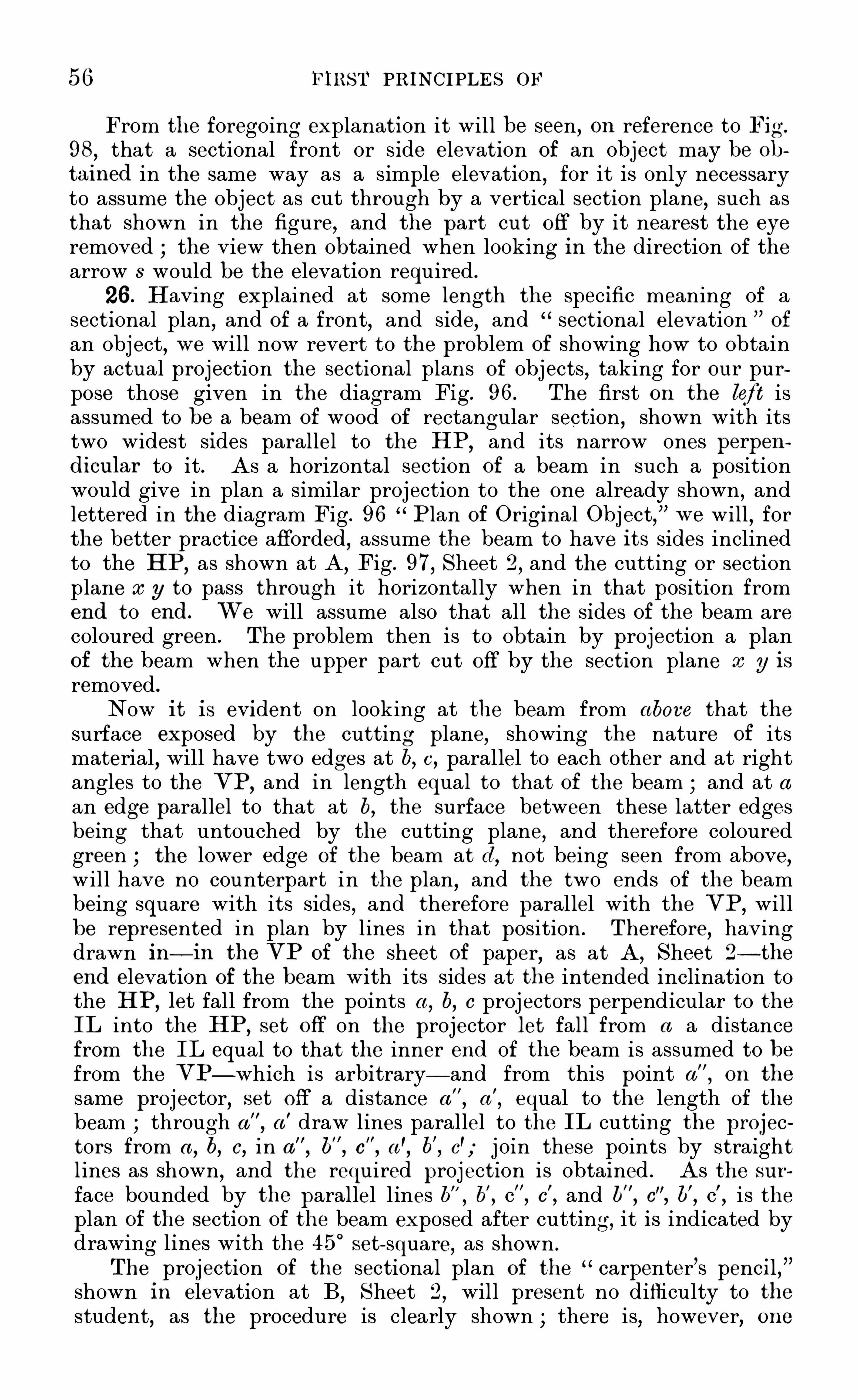
56 FIRST PRINCIPLES or
From the foregoing explanation it will be seen,on reference to Fig.
98,that a sectional front or side elevation of an object may be ob
tained in the same way as a simple elevation,for it is only necessary
to assume the object as ou t through by a vertical section plane, such asthat shown in the figure, and the part cut off by it nearest the eye
removed the view then obtained when looking in the direction of thearrow 3 would be the elevation required .
26 . H aving explained at some length the specific meaning of asectional plan
,and of a front
,and side
,and " sectional elevation ”
of
an object,w e will now revert to the problem of showing how to obtain
by actual projection the sectional plans of objects,taking for ou r pur
pose those given in the diagram Fig . 96. The first on the left isassumed to be a beam of wood of rectangular section , shown with itstwo widest sides parallel to the H P
,and its narrow ones perpen
dicu lar to it . As a horizontal section of a beam in such a positionwould give in plan a similar projection to the one already shown
,and
lettered in the diagram Fig . 96 Plan of Original Object,w e will
,for
the better practice afforded,assume the beam to have its sides inclined
to the HP,as shown at A
,Fig . 97
,Sheet 2
,and the cutting or section
plane at g to pass through it horizontally when in that position fromend to end. W e will assume also that all the sides of the beam are
coloured green . The problem then is to obtain by projection a planof the beam when the upper part cut off by the section plane x g is
removed .
Now it is evident on looking at the beam from above that thesurface exposed by the cutting plane
,Showing the nature of its
material,will have two edges at b, c , parallel to each other and at right
angles to the VP,and in length equal to that of the beam and at a
an edge parallel to that at b,the surface between these latter edges
being that untouched by the cutting plane,and therefore coloured
green ; the lower edge of the beam at d,not being seen from above,
will have no counterpart in the plan,and the two ends of the beam
being square with its sides , and therefore parallel with the VP,will
be represented in plan by lines in that position . Therefore,having
drawn in— in the VP of the sheet of paper,as at A
, Sheet 2 -the
end elevation of the beam with its sides at the intended inclination tothe HP
,let fall from the points a
,b,c proj ectors perpendicular to the
IL into the H P,set off on the projector let fall from a a distance
from the IL equal to that the inner end of the beam is assumed to befrom the VP— which is arbitrary— and from this point a
”
,on the
same projector,set off a distance a
"
,a
'
,equal to the length of the
beam through a”
,a' draw lines parallel to the IL cutting the projec
tors from a, b, c , in a b
"
, c"
,a’, b
'
,c'; j oin these points by straight
lines as shown,and the required proj ection is obtained . As the sur
face bounded by the parallel l ines b’
,c”
,c'
,and b", c
”, b
'
,c’,i s the
plan of the section of the beam exposed after cutting, it is indicated bydrawing lines with the 4 5
°
set- square, as shown .
The projection of the sectional plan of the " carpenter’s pencil ,shown in elevation at B
,Sheet 2
,will present no difficulty to the
student, as the procedure is clearly shown ; there is, however, one

MECHANICAL AND ENGINEERING DRAWING 57
point in reference to it to which his attention is to be directed . The
pencil being made of two kinds of material,this is indicated in the
projection by drawing the sectional lines referred to in the last problem in Opposite directions across the materials, as shown . This pointwill
,however, be more fully enlarged upon later on.
From the projection of the pencil w e pass on to that of the hollowtube, whose elevation is given in Sheet 2 in the VP at C
,the section
plane being shown by the line a y. Now in the plan of this object,
given in Fig . 97 Sheet 1,it will be noted that as there are only
three side edges,and the tw o ends
,seen from above
,its " plan ” is
obtained by the projection of these edges into the lower plane or H P,
and j oining them up,as shown . But in the problem before us the
upper part of the tube is assumed to be cu t away, leaving the sectionof two of its Sides exposed , together with part of its interior. To findits plan under these conditions w e proceed as follows — From a and bin the elevation C, let fall projectors perpendicular to the IL into theH P and as the tube is assumed to be of the same length as the beamand pencil, and its back end the same distance from the VP as theirends are, at this distance from the IL
,and parallel to it
,draw the line
a"
b"
,cutting the proj ectors from a and b in those points and parallel
to this line and at a distance a”a'
equal to the length of the tube fromit draw the line a
'b’
. W e have so far obtained the bounding lines ofthe plan sought . For the plan of the parts of the tube cut by thesection plane cc y, let fall projectors from points 1
,2,3,4 in the eleva
tion,cutting the lines a" b"
,a'
b’, in the plan in points l ”,4” j oin these points by lines as shown
,and the surfaces
between each of these pairs of l ines will be the plan of the parts of thesides of the tube seen from above when the upper part cut off by theplane as y is removed . By its removal, however, a part of the in
terior of the tube is now seen when viewed from above, and thismust be indicated in the plan . The part seen is the angle formed bythe meeting of the two bottom inside surfaces of the tube immediatelyover the point lettered c , and as these are plane surfaces, their intersection forms a line the plan of which is found by letting fall a pro
jector from c cutting the lines a" b”, a'b’
,in c
”c'
,and joining them by
a straight line. With the section lining of the parts cut by the plane(I; y, the
" sectional plan of the original object,”or hollow tube C, is
completed .
The projection of the sectional plan of the object represented inend elevation by D
,in Sheet 1
,would give little useful practice to the
student if kept in the same position as there shown , all its surfacesbeing either parallel or perpendicular to the HP,
and therefore resulting in a very trifling change in the plan (got by a horizontal section of
it) from that previously obtained ; it i s consequently shown with itsprincipal surfaces inclined to the H P,
thereby giving a more diffi cult,but more useful , problem in projection . With the original object inthis altered position the student will at once be struck with the
identity in appearance of its elevation with that of the hollow tube inthe last problem ,
and he will perhaps be momentarily pu zzled to understand how two apparently similar end vi
qw s are the vertical projections

58 MECHANICAL AND ENGINEERING DRAW ING
of two such different objects . H ere w e have an instance showingthe absolute necessity of a pre- conceived knowledge of the form of
the object to be delineated , or the possession of a model of it . H avingeither
,little difficulty would be experienced in fully understanding the
similarity of the two views in the diagram . The object representedby D in elevation (Sheets 1 , 2) i s merely a combination of two prismsof different dimensions cut from one solid piece of material
,from which
a portion is cut off by a plane— such as a saw -blade— throughout itswhole length
,the cut being a horizontal one ; and the problem is to
Show the actual appearance of the remaining part of the post whenlooked at from above
,after the part cut off is removed .
To do this,let a: y in the elevation D (Sheet 2) be the section
plane,as before ; let fall projectors from a and d into the HP,
andassuming the back end of the object to be the same distance from the
VP as those of the pencil and tube,draw parallel to the IL a line
cutting the projectors from a and d in a"d"
; from a on the pro
jector from a,set off a a
'
,the length of the thick end of the post
which is arbitrary— and through a' draw a faint line a
'
d’ parallel toa" then from b and c in the elevation D let fall projectors into the
HP,cutting the line drawn through a
'
d’
,in b
'
c'
,and from these last
points set off on their projectors in the points b" c’'
the length of the
small part of the post ; then a line drawn through b"c ,parallel to
a"c
,will give the bounding lines of the plan of the post . For the
sectional part of it, let fall projectors from points 1 and 4 , and 2 and 3,in the elevation D
,the former to cut the line a
”d”
in points 1 ’ andthe latter the faint line a
'
d' in points - 2
’
3' through 1 ' 4 ' draw lines
parallel and equal to a" a'
; and through 2'
3' lines parallel and equal
to b' b" ; the surface enclosed by the last drawn lines is that made bythe cutting plane a: y, and is indicated as such by the section lining.
As the post is of solid material,the edges formed by the meeting of its
u nder sides in e andf will not be seen from above, and are, therefore,not shown in the projection.

CHAPTER IX
PRO JE CTION IN TH E UPPER PLANE
27 . HAVING carefully worked ou t the problems given in Sheets 1and 2
,and studied
,with the assistance of Figs . 98 and 99
,and the
descriptive matter in connection with them ,the principles involved in
obtaining the sectional plans and elevations of objects, the studentshould find no difficulty in solving the problems in the projection ofsolids which are now to follow.
The first subject w e take — it being the simplest of all the planesolids — is the " cube ”
; but although simple, it is necessary that thestudent should fully comprehend the specific relations of its variousfaces and edges to each other
,before starting to find its projections .
This solid is defined as one having six equal sides or faces, all of them
Fig . 99a
squares . It follows from this that adj acent sides must be at rightangles to each other and opposite faces parallel ; the adjacent andopposite edges of the solid having the same relative positions . Bearing these facts in mind, the projections of the cube are easily ob
tained. To put the original object on the paper as required in th eproblems
,it is necessary to note the difference between the diagonal of
aface of a cube, and a diagonal of the cube itself. The first is a linej oining the opposite corners of any one of its faces (as (l, Fig. 99a) , andthe latter is an imaginary line j oining the vertices of any two of itsopposite solid angles, or those formed by the j unction of three adjacent
59

60 FIRST PRINCIPLES or
faces of the solid,as the dotted line D in Fig. 99a . Our first problem
in the projection of this simple solid is— f
Problem 30.— Given the front elevation of a cu be, w ith the di agonal
of one of its faces parallel to the VP , and perpendicu lar to the HP ,
tofi nd its side elevation, or a view of i t looking in the direction ofthe arrow a
'
. To solve it
Draw in on the left side of the sheet of paper,with the 45°
set
square, the square A,B
,C,D (Fig . with its diagonal AC at
right angles to the IL,as shown . This figure will be the front
elevation of the given cube in the position stated in the problem . Tofind its side elevation
,through points A
,B
,C,draw proj ectors of in
definite length parallel to the IL,and as the back face of the cube is
parallel to its front one and the VP,draw a line at right angles to the
IL,cutting the projectors from A,
B,C,in a
, b, 0 thi s line will re
present the back face of the cube . Then,as the edges of a cube are all
of the same length , set off from a,on the projector drawn through it, a
distance a a'
, equal to the length of a side of the cube,as AB
,and
through a'draw the line a’ b'
c' parallel to a b c the four bounding lines ,
a c , c c'
, c'
a’
,a'a
’
,and the line b b'when j oined up as shown give the
side elevation (Fig . 101 ) of the cube when looked at in the direction of
the arrow or. Next
Problem 31 .— L et the cube be cu t by a pl ane through its diagonal A C
'
,
and let it be requ ired to give a side elevation of i t when the part to
the left of the cu tting plane is removed.
H ere the part of the cube to the left of the diagonal AC beingremoved , only four edges of the part left are seen . These are the topedge from point A to the point beyond it nearest to the VP,
and thecorresponding bottom edge from point C ; also the two edges of thefront and back faces of the cube, cut through by the section plane.
Therefore,in the projector drawn through A
,Fig . 100
,at any con
venient point (say d) , draw,as in Fig. 102, at right angles to the IL,
the line d e,and parallel
'
to it,at a distance equal to the length of the
side of the cube,the line d'
e' j oin the points d d'
,e e
'
,as shown , and
the required projection is obtained . Again
Problem 32.
— Let the original obj ect— the cu be— be cu t by a section
plane, as SP ,and a side elevation of i t be requ ired, af ter the part
cu t of to the left of the cu tting plane is removed.
In this case the section plane cuts through two adjacent sides of
the cube, leaving parts of those sides, as SA and PC,in View . To
obtain the projection required , at any convenient point (sayf in theprojector drawn through A
,Fig. 100
,draw a line fg perpendicular to
the IL, and parallel to it at a distance ff”
,equal to the length of a
side of the cube, the line fg through the points A S , PC ,and parallel
to the IL,draw the l ines jf
’
, ss'
, pp'
, gg'
,and the required projection
is obtained . A s in Fig . 102,the section obtained is that produced by

MECHANICAL AND ENGINEER ING DRAWING 61

62 FIRST PRINCIPLES oF
the cutting of the cube through the plane of one of its diagonals,it is
evident that no greater section could be got, and therefore its wholesurface must be section - lined , as shown . In Fig. 103
,however
,as the
cutting plane SP leaves a portion of the faces AB,BC of the cube
untouched,section- lining is only required on the part of the cube
actually cut.through by that plane
,as shown .
As some further problems in connection with the projections ofthe cube will follow,
it will be well at this point to more fully explainthe significance of the lines obtained in the three preceding projections,as upon their correct comprehension depends the ease or difficulty withwhich subsequent ones will be found .
As in Fig . 100,the points A
,B
,C,D are the front ends of four
edges of the cube perpendicular to the VP,and parallel to the HP,
any edge produced by a section or cutting plane passing through thecube in a direction perpendicular to the VP,
and making any anglewith the HP,
will be a line parallel to the HP,and at right angles
c)
to
the lines representing in projection the two faces of the cube which are
parallel to the VP. A nd as these faces are distant from each othera space equal to the length of a Side of the cube
,the projection of
these faces will in all cases be lines parallel to each other at thatdistance apart
,their projected lengths being dependent upon the angle
the cutting or section plane makes with the H P.
This reasoning will be verified on applying it to the three projections given in Figs . 101 , 102, and 103. In these figures the linesac, a
'
o’
; de,d e fg, f
’
g’
,are the projections of the front and back
faces of the cube, the three parallel lines aa'
bb'
, cc' in Fig . 101 being
the projections of the three edges of the cube at right angles to thosefaces , and the equal parallel lines dd
'
, ee'
the projections of the topand bottom edges of the cube, of which A and C in Fig . 100 are the
front ends . In Fig . 103 the boundary lines of the projection are the
same as in Fig. 101 , but the part of the cube exposed by the action of
the section plane SP,is that between the parallel lines ss
'
, p p'
,and
has to be section- lined, as shown . H ad all the faces of the cube beencoloured, only those parts of the tw o seen when looking in the direc
tion of the arrow x— viz .
,from the edge at S to that at A,
and fromP to that at C — would Show of that colour ; the surface exposed bythe section being, of course, that of the material of which the cube ismade. The faces of the cube parallel to the VP in Fig . 100are, ofcourse
,in Fig. 103 seen only as lines , as at fg, f
’
g'
,and as the cube is
of solid material the edge of it at D,directly opposite to that at B , will
not be seen in the side elevation .
As further problems in the projection of solids in the " upperplane
,
”w e give those shown in Figs . 105, 106, and 107 , where the
original object or cube, Fig. 104,is cut by section planes a
,3,
making different angles with0
the H P,but all of them perpendicular to
the VP. A s there is really no material difference of procedure inobtaining such projections of the solid from that already so fullyexplained in the previous problems
,it is not necessary here to go
through the process in detail,as the construction lines given in con
nection with each figure are sufficient to enable the student to work

64 FIRST PRINCIPLES OF
out the problems without further explanation . H e has only to bearin mind
,as before advised , the relationship of the faces and edges of
the original object— the cube— to each other, and knowing this, nopossible diffi culty should be met with in obtaining the required projections . A couple of sheets of paper should at the least be devoted tothese projections, varying the direction of the plane of section in eachproblem,
so as to thoroughly master any apparent diffi culty that mightarise in any similar problem in the future.
29 . Advancing from the simple to the more difficult,w e again take
the cube as the original object, but instead of it being solid throughou t
,as in the last problems, it is now hollow and of an equal thickness
of material all over . To indicate this, in drawing in on the sheet of
paper a front or other elevation of the'
object, w e have to resort to theu se of " dotted ” lines . In mechanical drawings especially
,such lines
are invariably used to indicate those parts of an object not directly insight
,and it will be found, as w e proceed in the study of this special
kind of drawing, that although appropriated more especially to thispurpose
,their u se is indispensable to the draughtsman
,for by their
proper application an insight is given— ou the mere inspection of adrawing— into the internal structure of the object depicted . In thecase before us , w e indicate by their u se the thickness and disposition ofthe material of which the object is made, for, being opaque, its outwardappearance would be the same whether solid or hollow. Drawing in
,
then,as in Fig. 100, Sheet 3, the front elevation of a cube with one of
its diagonals perpendicular to the IL, and indicating by dotted lines asshown in Fig . 108, Sheet 4 , the thickness of the material of which it ismade
,w e proceed to obtain by projection the various elevations required .
Let the first be
Problem 33.— The front elevation of a hollow cu be being given,
tofi ndi ts side elevation
,or a view of it when looked at in the direction of
the arrow an
For convenience,letter the four corners of the front face of the
cube Fig. 108 as in Fig. 100, and obtain a side elevation of it as inFig . 101 , lettering it in the same way. The two views
,so far
,are
identical ; but to show that the cube represented by Fig . 108 is hollow,
set off from points b, b'
the thickness b b 5 of the cube equal to t
in Fig . 108 . Through 5” draw dotted lines parallel to ac
,a'
o'
; andfrom points 3
,4 (Fig. 108) draw projectors to cut the dotted lines
drawn through 5” in points 3
,4,4' dot in the lines between
the last-named points,and the required elevation (Fig . 109) is
obtained . Next
Problem 34 .— Let the cu be Fig. 1 08 be cu t by a planepassing through
its diagonal AC ,and an elevation of i t be requ ired, when the part
to the lef t (f the cu tting plane is removed.
Proceed as before to obtain,as in Fig. 102
,the bounding lines
dd’
,
'
e'
, c'
c'
,e’
d of the section ; set off at 5' 5" from de,d
’
e'
— the

MECHANICAL AND ENGINEERING DRAWING 65
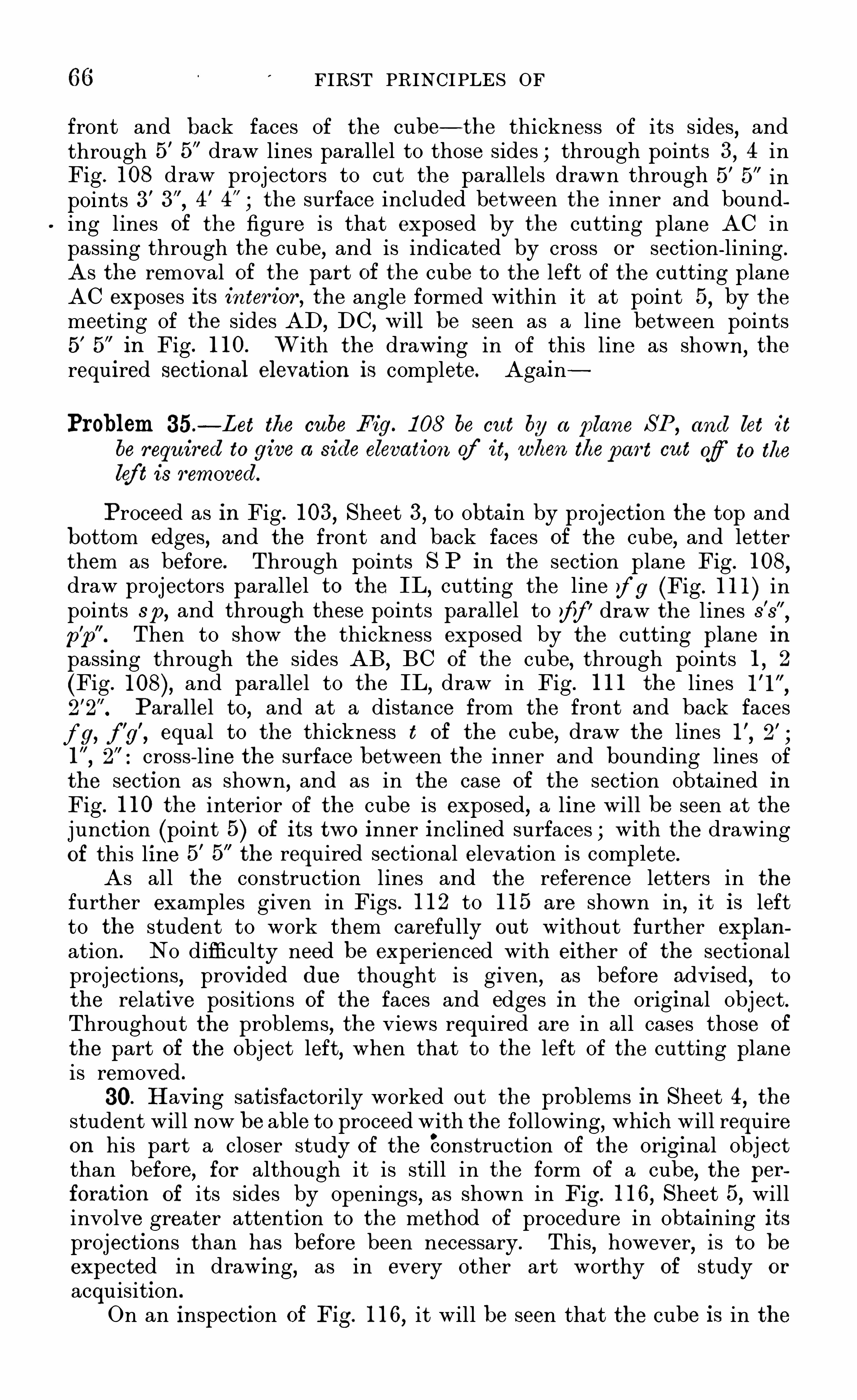
66 FIRST PRINCIPLES OF
front and back faces of the cube— the thickness of its sides, andthrough 5' 5” draw lines parallel to those sides through points 3
,4 in
Fig . 108 draw projectors to cut the parallels drawn through 5' 5” inpoints 3' 4
'
the surface included between the inner and bounding lines of the figure is that exposed by the cutting plane AC inpassing through the cube
,and is indicated by cross or section lining .
As the removal of the part of the cube to the left of the cutting planeAC exposes its interior, the angle formed within it at point 5
,
0
by themeeting of the sides AD ,
DC,
o
w ill be seen as a line between points5 5
”in Fig . 1 10. With the drawing in of this line as shown
, the
required sectional elevation is complete. Again
Problem 35.— Let the cu be Fig. 1 08 be cu t by a plane SP ,
and let it
be requ ired to give a side elevation cy’ it
,when thepart ou t of to the
lef t is removed.
Proceed as in Fig . 103,Sheet 3
,to obtain by projection the top and
bottom edges, and the front and back faces of the cube,and letter
them as before. Through points S P in the section plane Fig . 108,
draw projectors parallelz”
to the IL,cutting the line fg (Fig . 1 1 1 ) in
points 3p,and through these points parallel to ff’ draw the lines s's
pp Then to showb
the thickness exposed by the cutting plane inpassing through the sides AB, BC of the cube, through points 1 , 2
(Fig . and parallel to the IL,draw in Fig . 1 1 1 the lines
Parallel to,and at a distance from the front and back faces
fg, f’
g’
,equal to the thickness t of the cube
,draw the lines 2
’
I”
,cross- line the surface between the inner and bounding lines of
the section as shown, and as in the case of the section obtained inFig . 1 10 the interior of the cube is exposed, a line will be seen at thej unction (point 5) of its tw o inner inclined surfaces with the drawingof this line 5
'
5 the required sectional elevation is complete.
As all the construction lines and the reference letters in the
further examples given in Figs . 1 12 to 1 1 5 are shown in,it is left
to the student to work them carefully ou t without further explan
ation . No difficulty need be experienced with either of the sectionalprojections, provided du e thought is given
,as before advised
,to
the relative positions of the faces and edges in the original object.Throughout the problems, the views required are in all cases those of
the part of the object left, when that to the left of the cutting planeis removed .
30. H aving satisfactorily worked out the problems in Sheet 4, the
student will now be able to proceed with the following,which will require
on his part a closer study of the construction of the original objectthan before
,for although it is still in the form of a cube
,the per
foration of its sides by:
openings, as Shown in Fig. 1 1 6,Sheet 5, will
involve greater attention to the method of procedure in obtaining itsprojections than has before been necessary. This
,however
,is to be
expected in drawing,as in every other art worthy of study or
acquisition .
On an inspection of Fig. 1 1 6,it will be seen that the cube is in the

MECHANICAL AND ENGINEERING DRAWING 67
same position with respect to the VP and HP as in the '
two last sheetsof problems— that is to say, the diagonals of its front and back facesare respectively perpendicular and parallel to the H P,
the faces themselves being parallel to the VP. E ach side of the cube, however,instead of being, as in the last problems, solid, has now a square holethrough it
,the sides of the holes being parallel to the sides of the cube.
It is therefore possible to see right through the cube from any of itssix sides . The consideration of these simple facts in connection withthe original object will be found of service in the attempt to obtainany required projection of it. Let the first be
Problem 36 .— Given the front elevation of a hollow cu be, w ith squ are
openings in a central position in each of i ts sides, and a diagonal
of its frontface perpendicu lar to the HP ,to fi nd its side elevation
when viewed in the direction of the arrow on the left.
First draw in the front elevation of the cube,Showing the thick
ness of the material by dotted lines, as in Fig. 108, Sheet 4 . Letter the
corners of it A B C D as before. Divide each of the edges AB,BC
,
of the cube into three equal parts, in the points I , 2, 3, 4 , and throughthese points draw faint lines parallel to the edges BC
,AB respectively
across it. The square a b c d formed by the intersection of these fourlines gives the Opening on that face of the cube, and the one directlybehind it
,and the position of those on the other four faces is shown by
the parts of the same four lines which cross the thickness of the sidesof the cube at the points 1 to 8 in their edges . On putting in thesquare a b c d in full lines, and dotting in those last referred to, theelevation of the cube shown in Fig . 1 1 6
,Sheet 5, is that specified in the
problem .
To give the side elevation required , proceed to obtain first,as in
Fig. 109 , an elevation of the cube w ithou t Openings in its sides . Then,to show the openings that will be seen when looking in the direction ofthe arrow a
'
,w e have to remember that only two faces of the cube (of
which AB,BC
,are the front edges) are in sight
,and that therefore
only the two Openings figured I , 2 ; 3, 4 are Seen . Now,as the sides
of these Openings are one-third the length of the sides of the cube, andas the four edges of these openings figured I , 2, 3, 4 will be seen of
their actu al lengths, to Show them in the position they occupy on thecube, set off in points y z from the lines ac, a
'
c’
(Fig . 1 1 7 — the frontand back faces of the cube— the distance (a 1 or b 3) th at the edges ofthe square opening a b c d are from the edges of the cube . Throughthese points draw short lines in the upper and lower half of the figureparallel to ac a
'
c"
,and from points 1 , 2, 3, 4 (Fig. and parallel
to aa’
or cc’
(Fig. 1 1 7 ) draw lines cutting those drawn through y z in1'
2’
3'
3”4
’
The ou ter edges of the two openings seen fromac will thus have been obtained . Two of their inner edges , one at 6 andanother at f , are also seen, the first at c being that of the top side ofthe upper Opening, and that at f the corresponding edge of the loweropening. Projecting these points over on Fig. 1 1 7 , and drawing in thelines they represent, will give their elevation . To complete the View of

68 FIRST PRINCIPLES OF
the cube required , w e have yet to show the position of the two Openings in its front and back faces, represented in Fig. 1 16 by the squarea b c d. This is found by drawing in in dotted lines in Fig . 1 1 7 the
projection of the two corners a and c of that square the other cornersb and d being directly behind the edge of the cube at B ,
and coincidingwith it
,will not be seen in the required elevation .
Figs . 1 18 and 1 1 9 are sectional side elevations of the same originalobject, the first being that of the cube cut by a plane passing throughts diagonal AC, and the second by a similar plane at SP parallel tothat diagonal . With the foregoing explanation
,showing how the ou t
side view of the cube is obtained,and the assistance of Fig . 1 10
,
together with that given by having all the principal projectors shownin for each figure, the attentive student should be able to obtainwithout further aid or assistance the two elevations of the cube shownin the figures referred to .
In Fig. 1 20 is given an elevation of the same hollow cube in the
same position as that shown in Fig. 1 1 6 but the sectional side elevations of it required by planes cutting through it at 1 , 2, 3, and shownin Figs . 1 21 , 1 22, and 1 23, although found in exactly the same way asFigs . 1 1 8 and 1 1 9 , necessitate much closer attention on the part of thestudent in obtaining them, the section planes being purposely drawn insuch directions as to make the resulting projections a test of his abilityin applying the principles which have previously been so fully ex
plained to him .
In obtaining the three sections required, the only likely diffi cultyto be met with may possibly occur at that part of each projection wherethe cutting plane crosses an opening in one or other of the sides of thecube. No . 1 section plane, it will be noticed , is shown to cut threesuch openings — viz .
,the one immediately in front and its fellow one at
the back of the cube, and the lower opening at f ; No. 2 plane cutsthrough the upper left-hand opening at b, the lower right—hand one atd, and the front and back ones, dividing the cube into two equal partsand No . 3 plane cuts through the u pper right-hand Opening at g, andacross the corners of the front and rear openings .
31 . In showing the parts of the sides of the cube in section in thethree views
,care must be taken to note especially where the section
plane enters and leaves the solid parts of the object, and crosses theopen parts, for these points determine what parts are in section andseen
,and what are not . In Fig . 1 2 1 the upper part of the projection
is shown as being solid right across,because the section plane cuts
through a solid part of the cube’s side. The same is seen in the low erpart of Fig . 1 23 but in the oppositeparts of each of these figures thesection plane has cut through an opening in that side of the cube, andthis is indicated by the gaps shown . The same reasoning will explainthe projection obtained at Fig . 1 22
,only in this instance the section
plane has equally divided the four openings it passes through . Wi ththe foregoing explanation
,the three sectional elevations of the original
object should be obtained without difficulty, projectors being shown inthe front
,elevation of it (Fig . partly drawn in , from all the
important points ou t through by the section planes .
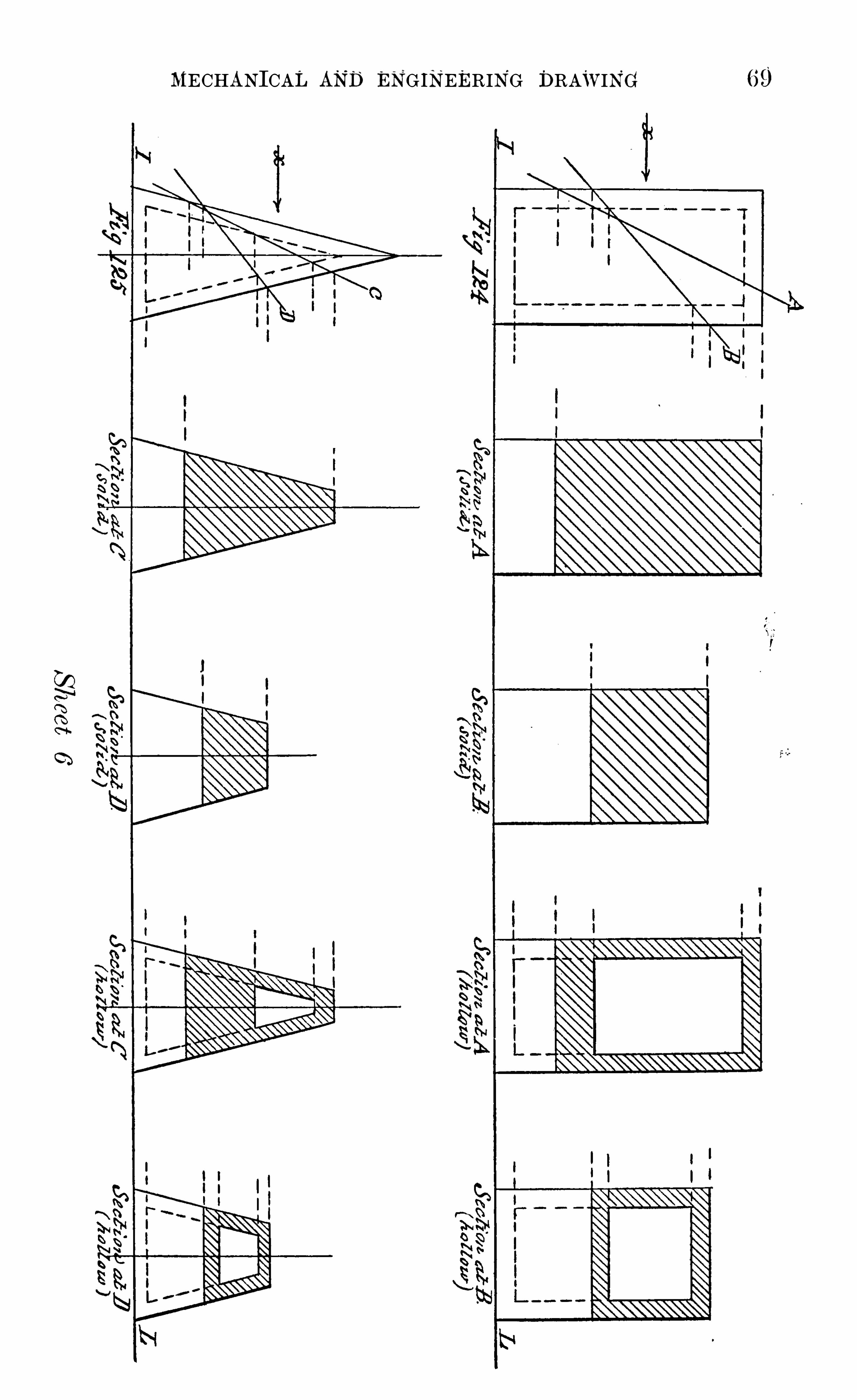
MECHANICAL AND ENGINEERING DRAWING 69

70 MECHANICAL AND ENGINEERING DRAW ING
As the side elevations of the prism and the pyramid are obtained inthe same way as those of the cube— so fully shown in Sheets 3, 4 , and5,
—a few problems in their projection are given in Sheet 6, for thestudent to solve without further aid than that afforded by the con
struction lines shown in the diagrams .Fig. 1 24 is the elevation of a square prism ,
assumed to be solid inthe first instance
,with its base resting on the H P
,and two of its sides
— adjacent ones— respectively parallel and perpendicular to the VP.
It is required to give side elevations of the prism— looking in the
direction of the arrow x— when cut by the section planes A and B .
Then,assuming the prism to be hollow,
but with closed ends, as shownby the dotted lines in Fig. 1 24
,side elevations of it are required when
ou t by the same section planes as before.
Fig. 125 is the elevation of a square pyramid , with its axisvertical, and two adjacent edges of its base respectively parallel andperpendicular to the VP. S ide elevations— as in the previous problems— are required of the sections produced by the cutting planes C, Dfirst
,assuming the pyramid to be solid
,and then hollow.
D
In obtainingthe projections of the pyramid
,the student must not forget that as
each of its sides are triangles,their width at any height from the base
varies with that height, and must be found accordingly.
After some further practice in projection in the upper plane, bydevoting a sheet or two of paper to finding the projections of the cube ,prism
,and pyramid
,cut by planes drawn in other directions than those
given in the problems, the student will be enabled to enter upon the
next stage in advance in our subject .

72 FIRST PRINCIPLES OF
slab is resting on the H P,set off its thickness on the projector from A
,
from the IL ,as at a
'
,and through a
' draw a line parallel to ILbetween a
' and c' then Fig . X will be the elevation required .
But if the slab is not resting on the HP,but is assumed to be
some distance above it, then on the projector from A set off from the
IL the assumed distance that the top surface of the slab is from the
HP,say at a ; through a draw a line parallel to the IL cutting the
projectors from B C in be ; then a b c will be the elevation of the
points A B C in the plan,and the l ine drawn through them that of the
top surface of the slab . Set off from a,on its projector towards the
IL,the thickness of the slab ; through this point draw a line parallel
to a b c , or the IL,and Fig. " will be the . required elevation . The
corner D of the slab will of course not be seen in the elevation ; butto show that the form and position of the slab are understood by thestudent
,he should indicate its position by a dotted line
,as shown .
Our next object is that of a solid with inclined sides, and the
problem is
Problem 38.— Given the plan of a fru stum of a square pyramid w ith
its base on the HP,and i ts base edges inclined to the VP ; to
find its elevation.
Let Fig. 1 27 be the plan of the frustum in the position specified ,A B C D being the four corners of the base
,and let its height be equal
to the length of the side ab of its upper surface,shown in plan . Find
the elevation of the points A B C in the plan,by projectors to the IL
,
cutting it in points A '
,B
'
,C
'
. On the projector from A produced , setup from the IL the height of the frustum in point a
”
,and through it
draw indefinitely a line parallel to the IL then the points a ’
, b'
, c' in
this line, where the projectors from a,b,c in the plan cut it
,will be the
elevations of the three corners of the upper face of the frustum,seen
when'
looking at it in the direction of the arrow ac. Join a'
A'
,b' B
,
c'
C' by straight lines
,as shown
,and the required elevation is obtained .
Proceeding from the simple to the more difficult,our next problem
Problem 39 .— Given the plan of the fru stum of a squ are pyramid
resting on the HP ,and su rmounted by a cu be, its sides being inclined
to the VP requ ired its elevation.
Let Fig . 1 28 be the plan of the combined solid,in the position
given in the problem ,and let the height of the frustum be equal to the
length of a side of the cube . Then,
o
having found the elevation of thefrustum
,as in the last problem
,find by projectors from points 1
,
in the plan the elevation of the th i ee corners of the cube,seen when
looking in the direction of the arrow . On the projector from point1 in the plan set off from the upper face of the frustum
,or the line
a'
b’ c'
,the height of the cube, and through the point I
’ draw the line1’
2' and the required elevation is obtained . The elevation of any
of the regular plane solids from their plan is found in the same way .
For example

MECHANICAL AND ENGINEERING D RAWING 73

74 FIRST PRINCIPLES OF
Problem 40.— Let Fig. 1 29 , Sheet 8 , be the plan of an hexagonal prism
w ith its axis vertical and its base on the HP , and let i ts height be
equ al to tw ice the diameter of the inscribed circle of its base requ ired
its elevation.
In the position in which the object is standing with respect to theVP
,three of its sides and four of its vertical edges will be seen . Find
the elevation of these edges by projectors through the points A B C Don the one through A set up the height of the prism equal to twice a
'
,
and at this height and parallel to the IL, draw a line cutting the
projector from D in d,and the required elevation is obtained . Again
Problem 4 1 .— Let Fig. 1 30 be the plan of a squ are pyramid, its axis
vertical, its base resting on the HP ,and its height equ al to tw ice
the length of the diagonal of its base find its elevation.
As the solid is resting with its base on the HP,the elevation of its
three base corners that will be seen— viz .
,A B C — will be found in
a b c on the IL . Its apex i s the point p in the plan where the twodiagonal lines- which are the plans of its side edges— intersect . Findthe elevation of the axis by a projector through p set off on this fromthe IL upwards the height of the pyramid in the point p
'
, and j oin p'
by right lines with points a'
b'
c'
on the IL, and the required elevationis Obtained .
The sectional elevation of an object is obtained from its plan bysimilar methods .
Problem 42.— Let Fig. 1 31 be the plan of a solid cu be resting
w ith one of its f aces on the HP ,and let it be cu t by a plane SP
perpendicu lar to the HP , and an elevation of it be requ ired, when
thepart X, cu t of by the plane, is removed.
Projectors being drawn from the points A S P C, into the upperp i ane, as shown, and the height of the cube set off from the IL in pointa
’
; on the one drawn through A a line through a’
,parallel to the IL,
cutting the projector from C in c and the cross- lining of the part cu tthrough by the section plane
,completes the elevation required .
Again
Problem 43.— Let Fig. 132 be the pl an of a hollow square pyramid,
i ts height being tw ice the length ofo a side of its base, and a sectionalelevation of it on the line SP be requ ired.
As the cutting plane passes through the axis of the pyramid , itssection will be a triangle. First find the elevation of this triangle,making its altitude the given height stated then to Show the thicknessof the material cut through by the plane, find the elevation of the
points 1,2 in the plan on the IL, and through these points 1
’ andparallel to the sides of the triangle, draw lines meeting in the ax is in

MECHANICAL AND ENGINEERING DRAW ING 75

76 MECHANICAL AND ENGINEERING DRAWING
the point a, cross- line the part out by the section plane as shown andthe required sectional elevation is obtained .
From the foregoing problems it wil l be seen that to obtain the
elevation of an object from its plan alone,without other important
data,would be impossible, as the heights and conformation of its
different surfaces not seen in the plan must be known before its correctelevation can be attempted .
It being necessary, at this stage of the student’s progress in thestudy of ou r subject
,that he should know something about the correct
lining- in of his work in ink,w e shall next explain the proper applica
tion of the different kinds of lines used in mechanical drawings, thathe may be able to practise in spare moments on the sheets of drawingsin pencil the results of his study, which it is assumed he has preserved .

CHAPTER XI
LiNiNG-IN DRAW INGS IN INK
33. ALTHOUGH the student, up to the present stage in his study, hasnot been called upon to draw anything to scale— which necessitates agreater amount of exactness in the u se of his pencil and instrumentsthan he may yet have exercised —he should still have acquired a sufficientability in their manipulation to enable him to put in fairly sound andfine lines when necessary. But as the permanence and practical u se ofa drawing— especially one of any engineering subject— are matters ofnecessity and great importance, it must be committed to paper in abetter medium for its preservation than that Offered by the u se of
plumbago . The lead-pencil is only employed for the rapid committalto the paper of the ideas embodied in the drawing
,but for the preser
vation of these, and for constructive purposes , the design must befixed in some coloured pigment or ink . As previously stated atthe commencement of this work
,China or India ink is the special
pigment used by the mechanical draughtsman for this purpose,and it is
now intended to explain the proper application of the different kindsof lines used in inking or lining-in an outline mechanical drawing.
W e may state at the outset in this part of our subject that in whatare known as ordinary, workshop, or
" shop drawings,
” only one kindof line is used in inking them in, and that is a firm ,
sound,black line
,
about31
1of an inch in thickness . In all good modern workshops
,no
workman is allowed to decide by measurement with his rule the dimen
sions of any part of a piece of mechanism shown on a drawing,as all
such parts are, or should be, dimensioned with figures on the drawingitself before it leaves the drawing offi ce. But for the purposes served bya drawing in outline
,or one not intended for shop u se
,different thick
nesses of lines are necessary to enable it to be properly read andunderstood . These lines are generally of three degrees of thickness
,
and are defined as fi ne, medium,and shadow or thick lines . Their u se
,
however, without some well-defined rule of application, would be futileas the very reverse effect of that intended would be produced by theincorrect u se of either Of them .
34 . Now,as the proper application of these lines is directly con
cerned with the effect caused by light falling on an object, it is amatter of importance in this special kind of drawing that a uniform
7 7

78 F IRST PRINCIPLES OF
rule be adopted with respect to the direction in which the light issupposed to fall upon the object represented . With the free-handdraughtsman or artist, this direction is optional, as he can adapt it tothe way he thinks most conducive to effect in showing up any particular Object in his picture but with the mechanical draughtsman
,as his
drawings are not representations of objects as they appear to the eye,but are projections obtained by parallel rays from all parts of themfalling upon certain planes having definite relations to each other
,but
represented by his sheet of paper, he has to adopt some rule of illuminating the visible surfaces of his Objects, in accordancewith the systemhe uses in projecting their outlines .Although the illuminant is the sun, and its light is diffused equally
around,it is generally assumed that w e see Objects by light coming from
above and behind u s bu t it is evident that if the light shone directlyfrom behind , the spectator would be in his ow n light, and part of theobject would be in shade. The light must then be assumed to come
either from the right side or the left. As a rule, the rays of light arealways assumed to come over the left shoulder of the draughtsman in
parallel lines, and to strike the planes of projection— or the VP and HP— of the drawing at an appar ent angle of 45
° with the IL, or intersecting l ine of those planes . The actu al direction of the rays isgraphically Shown in the diagram Fig. 133.
Let VP and HP represent the two planes of projection , and theline IL the intersecting line dividing them . In these planes draw inABCD to represent the elevation, and the plan Of a cube.
In the position shown, the front and back faces of the cube are parallelto the VP,
and all the others perpendicular to it . Through C in the
elevation, and c' in plan
,draw lines EC
,ec
'
,making angles of 45
° withthe IL ; then EC and cc
' will represent the plan and elevation of aray of light and the apparent direction in which it falls upon the VP
and HP. The actu al direction, or path of the ray, is from the upperanterior or front corner of the cube at A,
to the lower posterior or backcorner of the cube behind C . In other words, the ray Of light isassumed to travel in a direction coinciding with the diagonal of thecube, drawn between point A and the point beyond C .
To find the actual angle that this ray of light makes with the
planes of projection At point A in the elevation of the cube erect atA
,a perpendicular to AC on this set Off from A a length A d equal to
a side of the cube ; j oin d and C ; then the angle A Cd is that madeby the ray of light with the planes of projection VP and HP. Forif the right-angled triangle dA C be supposed to turn on its base AC asa hinge until its plane coincides with AC, then the angular point dwil l coincide with A,
and the hypothenuse dC of the triangle dA Cwill become, as before stated , the path of the ray of light. The anglemade by this ray with the VP and HP will be found to be, both bymeasurement and calculation
, one of 35°
To make the rule — adopted by the mechanical draughtsman— as tothe assumed direction of the light falling on a body still more clear,let the student cut ou t in stiff paper a model , allowing a strip for gumming, as in sketch A, of the right-angled triangle dA C , Fig. 133

80 FIRST PRINCIPLES OF
fold over the strip on the model , on line AC, until it is at right anglesto the triangular part, gum the strip on its under side and apply the
model to the elevation of the cube, making the lines AC 011 eachcoincide. Then prepare a similar model of the triangle and apply itto the plan of the cube on the line a
’
c’
. With the sheet of paper on
which the plan and elevation of the cube are drawn,flat on the drawing-board
,the triangular model s will both stand perpendicular to the
plane of the paper . If new the VP be bent overforwards on the ILas a hinge until it is at right angles to the H P,
the direction of the
ray of light with respect to both planes Of projection will at once beseen, for the hypothenuses of the triangles with which the ray of lightcoincides are parallel to each other, and make equal angles with the
VP and H P . It will also be proven by the aid of the model, that aline drawn in the VP and H P at an angle of 4 5
°
with the IL,cor
rectly represents the elevation and plan Of a ray of light when makingan angle of 35° 1 6" with those planes .
35. W e have now to explain why a distinction should be made in the
quality of the lines used in inking- in an outline mechanical drawing .
It will be readily understood on looking at any illumined Object thatthere are some boundaries in its surfaces on which the light willfall direct, and others on which it will not so fall, but will cause themto cast a Shadow on some other surface beyond them . Of the former,some are often so much in the light that the edges bounding the su r
faces are almost imperceptible ; all such must of necessity be repre
sented byfi ne lines . Those on which the light does not fall direct, butwhich cast a shadow on some more distant surface, are represented bythick lines . A medium thickness of line i s only used under exceptionalconditions of position of the bounding edges of surfaces ; but of theiru se w e shall speak later on . For the present w e Shall deal only with
fi ne lines, and thick or shadow lines, and their application to planesurfaced solids, or such as the student has already drawn- in in pencil .K nowing all theforms of the solids which have been taken as subjectsfor projection , their proper inking~in should present no diffi culty. Allthat has to be determined in connection with the pencilled- in lines iswhat each represents - that is to say, is it an edge or bounding line onwhich the light falls direct, or does it cast a shadow
’
.l This decided
,
the line can be drawn- in in ink .
Taking the two projections of a cube— given in the diagram Fig.
133 as an explanatory example— let it be determined how they shouldbe inked in . To begin with the elevation , and knowing the directionin which the light falls upon the object, it is evident that on two of itsfront edges -A B and A D — the light is falling direct their representative lines — A B and A D — must therefore be fi ne ones . It is equallyobvious that the edges BC and DC will cast a shadow on the VP
against which the cube is resting, therefore the lines BC and DC, representing these edges
,must be thick, or shadow lines . Three other edges
of the cube are also affected by the light— viz .
, those of which A, Band D are the front ends ; but this cannot be indicated in the ele
vation . The cube whose plan is shown in the diagram is for explan
atory purposes set forward some distance from the IL, and must not

MEC IIANICAL AND ENGINEERING DRAWING 8 1
therefore be taken as that of the cube given in elevation . In thiscase it is assumed to be standing with one of its faces
'
on the HP. Inthat position two of its top edges— a
’
d' and a
'
b — are directly in the
light,and will therefore have to be fi ne lines,
‘
w li ile the correspondingopposite edges b
'
c' and ed ,
as they will cast a shadow on the HP,
must be thick, or shadow lines . Of the " cast Shadows ” thrown on
the VP and H P by the cube in the positions shown,w e shall speak
later on.
36 . To show the importance of correctness in the u se of fine andthick lines in an outline drawing, w e give in Fig . 1 35 a very simpledrawing which may be made, by a different application of such lines, torepresent totally different Objects . The figure being drawn-in altogetherin fine l ines may represent anything ; say a square thin plate of anymaterial, with a small square lined- in on its surface . To give anidea of substance or thickness in the plate
,this would be effected
by thickening the lines from A to B and B to D ,as in Fig . 136 . The
inner square would represent a" recess in the plate by thickening the
lines ac and ed, as in Fig . 1 36 ; but if the Opposite sides, ab, bd, of thissmall square were thick lines, then this square would represent a" projection ”
on the surface of the plate or slab as shown in Fig. 137 .
That Figs . 136 and 137 are plans or horizontal projections of Objects i sevidenced by the position of their shadow,
or thick lines,the shadows
cast by their projecting edges— shown in— indicating the direction inwhich the light falls upon them . The original drawing, Fig. 135
,may
be either a plan i or elevation , there being nothing in its l ining to showwhich is intended . The student should be careful to note that even inthis simple drawing of only eight lines, the reversing of the positionsof the thick lines bounding two of the sides of the inner squareproduces not only a different appearance in the Object, bu t gives quite adifferent reading as to its construction .
37 . From the foregoing explanation of the u se and applicationof a fine and thick line in defining the meaning of an outline drawing,it will not surprise the student to find that an alteration in the positionof an obj ect with respect to the light falling upon it may
,and possibly
will,affect its lining-in. To show the effect of such an alteration
in position,let E and P in the diagram Fig . 1 34 be the elevation
and plan of a cube, with four of its faces vertical , and makingangles of 4 5
° with the VP. In this position the light falls wholly anddirectly upon the vertical face A e C c
'
,leaving its parallel and opposite
one wholly in shade, while the face eB c’
D and its opposite one are
in the plane of the light. In this case the lining- in Of both plan andelevation Of the cube becomes quite different to that of the same Objectswhen differently placed with respect to the light falling upon them .
As in the previous figure, in elevation , the under side of the cube isassumed to be some distance above the H P,
but in plan it is supposedto have that side resting upon it. The correct lining- in of the twoviews in accordance with their altered position will then be asfollows —Tu elevation
,the top front edges A e, eB , forming one
line, being directly in the light, must be a fine line. The verticaledge AC
, being " in the plane of the light,” must also be a fine line.
G

82 FIRST PRINCIPLES OF
The edge eé is in the plane of the light, but it being so near tobecoming one that would either cast a shadow or be fully in the light, amedium thickness of line would be most appropriate. As the verticaledge BD of the cube would cast a definite shadow on any surfacebehind it, it must of course be a thick line. The same applies to the twolower front edges of the cube C e’ c
’
D,forming one l ine, which must also
be a thick one. Practice among mechanical draughtsmen varying as tothe appropriate u se of a medium thickness of line in a drawing, it maybe remarked in the case here presented that if " colour ” were usedto assist the eye in determining the form of the object representedin elevation by E in the diagram , the tint would be dark near the edgeee
'
, and gradually lighten Off as it approached the edge BD ,although
the latter would cast a shadow on any surface behind it. For thisreason a medium thickness of line seems best suited to the position . Asto the lining-in of the plan P of the cube, it will at once be seen from itsposition that only one edge, or that between points f and b, will casta Shadow
,and it must therefore be made a thick line. The other three
— two in the plane of the light and one having light falling direct uponit— must be fine lines .
38. To prevent the misreading by the student of some engravingsof mechanical subjects in outline still to be met with , it is as well hereto observe that in England some draughtsmen and engravers line- in
both plans and elevations of Objects as if they were situated in the same
plane, and cast their shadows in the same directions ; but that thisis contrary to the principles upon which their projections were Obtainedmay at once be seen from a study of the shadows cast by the cubein plan and elevation in Fig. 1 33. As the planes of projection are
at right angles to each other, it would be impossible for the shadowsto fall in the same direction in both planes, unless the light fell upon theobjects represented in two totally different directions at one and the
same time, which would be absurd . In all representations of Objects ,therefore, throughout this work, where any difference in the lining isshown
,w e shall recognize the ex istence of the two planes of projection ,
in their proper relative positions, and apply the rules for such liningin accordance with the principles before explained .
As the study of the projection of solids having cu rved surfaces willbe the next division of our subject that will occupy attention , a fewwords only are here necessary with reference to the lining- in of suchobjects in ink . As a general rule, only one kind of line— thefi ne lineis applicable to the outline representation of the curved surface of thesolids of this class— the cylinder, the cone, and the sphere — with whichw e shall deal , consequent on the fact that the particular part of the
curved surface of each which w ou ld' cast a shadow on any adjacentsurface, falls w ithin the bounding lines of its representation, and cannotbe expressed by a line, as in the case of bodies having plane surfaces .
W e shall, however, before completing our explanation of the projectionof such solids
,give all necessary information as to inking them in .
39 . Before leaving this part of ou r subject a few words are
necessary for the guidance of the student in reference to the mixingand usage of the ink w ith which he will line-in his drawings . Although

MECHANICAL AND ENGINEERING DRAWING 83
liquid ink for this purpose is now to be purchased , it is advisable forthe student to know how to make suitable ink for himself. H e will not
,
of course, without some considerable practice, succeed in making reallyserviceable ink, but such as he will be able to produce will suffi cientlyserve his present purpose.
To prepare the ink for u se,let the student provide himself with a
medium- sized colour saucer— sold in nests of half-a;dozen by any artists’
colourman— and having procured a stick of good India- ink and acamel’s-hair water-brush, proceed as follows z— Charge the brush withclean water, and by its means put as much of it in the saucer as wouldhalf-fi ll an egg
- spoon . With the stick of ink held vertically,and with
one end in the saucer, rub it in a circular direction, applying a gentlepressure at first, until the water has attained a dark brown colour andbegun to thicken ; continue rubbing, gradually adding water in
‘
drops
from the water-brush,until a sufficient quantity of liquid ink is made.
To test its blackness and consistency,blow steadily into the saucer : if
the ink is a good black all through,the bottom of the saucer will not be
seen ; but if too thin, it will come in sight, and the rubbing must becontinued . For the ink to be in working order it should be neither toothin nor too thick . To bring it to a proper consistency, about a quarterof an hour’s rubbing will be required . If it is found at any time tohave thickened by evaporation of the water in it
,add more in drops
by the u se of the water-brush , keeping it well stirred while doing so.
Some writers on this subject advise the student to always u se freshru bbed ink, taking care to wash out the saucer before making it . Thisis by no means the practice in many of the largest drawing Officesin the kingdom . On the contrary
,good ink is never wasted , but is
improved by being worked up afresh . The writer’s practice for yearshas been to keep by him in his instrument-box a home-made indiarubber pestle, similar in shape to a diminutive Indian club. With theu se Of this and a few drops of clean water added as required in the inksaucer, he is able to produce an ink of equal density and colourthroughout
,and which does not contain a particle of anything held in
suspension in it that would be liable to clog the drawing-
pen.
Special unglazed saucers are now to be purchased for the rapidmaking of India- ink
,but these the writer finds very extravagant sub
stitu tes for patience and the expenditure Of a few minutes of time. Amore suitable saucer would be one made of glass of the same shape asnow used, bu t with its inner surface finely ground . Through want ofpatience on the part of the draughtsman , and the application of toomuch pressure while rubbing, the ink is liable to break away from the
stick in small lumps,which are never thoroughly reduced to the liquid
state, bu t cause constant annoyance by clogging the pen. With a
properly-ground glass saucer this tendency of the ink- stick to fray awayin particles would be avoided . One great mistake made by manydraughtsmen is the practice Of dipping the rubbing end of the ink— stickin water before starting to make their ink . By so doing it becomessoddened, and when dry will be found to be cracked all over at thatend
,and ready to break away in pieces on the least pressure being
applied . The rubbing end of the ink-stick should always be wiped dry

84 MECHANICAL AND ENGINEERING DRAWING
directly it is done with,if it is wished to keep it in good order for u se
and the ink saucer should only be uncovered while filling the pen. Thislatter operation is best effected by capillary attraction, and not by theu se of a brush . When more ink is required, first pass a piece of softwash- leather between the nibs of the pen,
to remove any deposit,and
before dipping in the ink draw it through the lips, which will givesufficient moisture to cause the ink to flow freely between its nibs
,and
so fill it . The u se of a brush is Objectionable, on the ground of i ts
being liable to pass into the pen any sediment that may have collectedin the ink- saucer.With reference to the drawing-
pen and how to u se it— the compassor bow pens will not at present be required— the student will rememberthe explanation of its construction given at the commencement of thiswork
,and from that will understand that in using it, it must be
held nearly upright,keeping its strong nib in contact— without pressure
— with the edge of the tee or set- square that all horizontal lines mustbe drawn from left to right
,and vertical ones upwards
,or from bottom
to top of the board . The drawing-
pen when purchased should be set
for u se,and its satisfactory manipulation will soon be acquired if du e
care is taken not to damage its points .

CHAPTER XII
THE PROJECT ION OF CURVED LINE S
40. U P to the present stage in ou r subject w e have purposelyrefrained from dealing with figures having cu rved bounding lines, orsolids with cu rved surfaces, knowing how important it is for the studentto thoroughly understand the projection of straight- lined plane figuresand plane- surfaced solids
,before attempting anything in which a curved
line or surface occurs . Assuming that he has mastered all that has nowbeen explained, he will be the better able to apply himself to that partof the subject to which w e next proceed— viz . ,
the projection of solidshaving " curved surfaces . A S this, however, involves a knowledge ofthe projection of cu rved lines, this must first be acquired .
From ourdefinition— Chapter I I I — of a curved line— viz .
,that it is
the path Of a point which is continually changing its direction— it willat once be manifest that its projection cannot be obtained in the same
way as that of a straight line, in that all that is here required is to findthe projections of its ends and join them by a right line. As thegenerating point of a curved line is moving in a different direction atall parts of its path
,it follows that the only way in which its projection
can be obtained is by getting the projection of that point in several ofits positions, and j oining them by a line passing through them, whi chwill be the projection sought To obtain this
,however, it is first
necessary to have a perfect knowledge of the original curved lineand its varying direction , as it may be a line lying wholly in a plane,or
, on the other hand , one of such a character that no part of it wouldcoincide with or lie in a plane. For a first example in curved lineprojection w e take as ou r problem
Problem 44 (Fig .— G
’iven the front elevation AB of a cu rved
line in a plane parallel to the VP ,it is requ ired to fi nd its side
elevation and plan, or view s (go it when looked at in the direction of
the arrows.
H ere the line being a simple curve, it is evident, on looking in thedirection of the arrow on the left
,that its projection will be a straight
line ab,No . 1
,as all the points in the curve are in one and the same
85

86 F IRST PRINCIPLES OF
plane. For the same reason,the plan of this curve will be the straight
line a’
b'
,NO . 2
,obtained by letting fall projectors from its two ends
AB into the HP,and joining them by a right line.
Now,let the plan of this curved line— or a
'
b’
,No . 2— be assumed
to make an angle of 40°
with the VP,and its front and side elevation
be required . To obtain these,w e must know the position of some
points in the curve with respect to a fixed datum line,from which
measurements may be taken . Let the points in the curve of whicha
’
b'
is the plan be A,a,3,B
,in the elevation
,and let the line CB
,
drawn through B at right anogles to the IL, be the datum line
,which
is assumed to be in the same plane as AB . Through A,1,2,3,B
,
draw lines parallel to the IL,cutting CB in points C
,u 3
,B . Now
the line a"h’
in the HP is the plan of the curved line AB in elevation,
moved through an angle of 4 5°
with the VP,the point a" being nearest
the eye, and b' farthest from it . To find the plans of the intermediate
points a,3,in the curve AB
,set Off from b
'
in the plan the distancesCA
,1 2 3 3 ,
in elevation in the points a”
, x, y, 2 . Through thesedraw projectors i nto the VP,
cutting those from A,l,2,3,in c , d,f , g.
Then a line drawn through these points to B will be the requiredelevation of the curve.
To find its side elevation , take a new datum line C'
B'
,NO . 3
,parallel
to CB,and produce the projectors drawn through A
,a,3,B
,in the
original curve line AB,NO . 1
,to cut it in points C
'
,4,5,6,B ’
,
each of these set Off in points c', d'
, f’
, g'
the distances— measured fromthe datum line— that their corresponding points a”
,r, y, z , in the plan
NO . 2i
are from a'b
’
,measured on the projectors drawn through them ;
then a line drawn through the points so obtained, as shown in No . 3,
will be the side elevation of this curved line in its new position .
If the given line of which the projections are required is one of
double curvature, but still in one plane, its projections are obtained inthe same way as those of a simple plane curve. As an example w e
will take a very common double- curved line known as the ogee mouldingand let the problem be
Problem 4 5 (Fig.— Given the front elevation of a line of dou ble
cu rvatu re AB , No. 1 , tofi nd its plan and side elevation, the plane ofthe cu rve being parallel to the VP .
In this case,as every point in the curve is at an equal distance
from the VP,its plan will be a straight line a
'b', No . 2,parallel to the
IL,and its projected length will equal the distance between projectors
let fall from its ends A and B into the HP. Its side elevation willalso be a straight line ab, at right angles to the IL,
for as every pointin it is equi—distant from the VP,
it will coincide with or lie in a planewhich w e are told in the problem is parallel to the VP, and thereforeperpendicular to the H P.
To find the elevation of the line AB when the plane in which itlies makes any given angle with the VP,
proceed as followsChoose any convenient points— other than its two ends— in the
curve as A , 3, 4 , No . 1 . Through these let fall projectors into the

88 F IRST PRINC IPLES OF
H P to cut a'
b'
,No . 2
,the plan of AB in the points At
b'
,in this plan
,draw a line making with a
'
b’ an angle equal to that
say 4 5°— the plane containing the curve line is to make with the VP
Transfer— by arcs struck from b'
— the points 4'
in a'
b' to
a”b'
,and through these draw projectors into the VP
,cutting those
drawn through A,l,2,3,4,No . 1
,to the datum line CB in c, d, e, f,
g a curve drawn through these points, as Shown , will be the elevationrequired . In this way the elevation of any curved line lying in a planemaking any angle with the VP,
may be found,for the line
,or the plane
in which it is supposed to lie,may be assumed to rotate round the
datum line as an axis,carrying with it all its points, the position of
which with respect to the VP may always be easily determined,and
from them the projections of the lines in which they lie may be found .
4 1 . To find the projections of a compound curved line, or one nopart of which would coincide with or lie in a plane
,the process is some
what more difficult,as its appearance in two directions at right angles
to each other must be known,or given , before a third view of it can be
Obtained . As an example

MECHANICAL AND ENGINEERING DRAWING 89
Let AB ,No. 1 (Fig . be the elevation of such a curved line,
and ab, NO . 2,another elevation of the same line
,at right angles to
the first . It is evident that such a line could not coincide with aplane
, yet if the relation of any points in it with the planes of itsprojection be known, or can be determined, then the plan or horizontalprojection of the l ine can be found . Let, then, the line ab, No. 2
,be
the front elevation of the line, the VP being behind it, and AB ,No . 1
,
its side elevation, looking in the direction of the arrow a. Then theend A or a of the line is nearest the VP,
or farthest from the eye ;and the end B or b the converse. To prove this
,through A
,No. 1
,
and b, NO . 2,draw the lines Ap, cb, perpendicular to the IL ; then Ap
will represent an end elevation or edge view of the VP— looking in thedirection of the arrow x— and cb that of a plane at right angles to theVP. With the assistance of these as datum planes w e can determinethe distance of any point in the line AB from each of them
,and thus
obtain its horizontal projection . A line drawn through a series of
points thus found will be the plan of the curved line sought .To find it
,choose a suitable number of points in the given line AB
,
No . 1 , say at 1 , 2, 3, 4 project these over on to ab,NO . 2
,and produce
the projectors to meet the datum plane cb, as shown the exact positionin plan of any of these points can now be fixed . From a
,
b,NO . 2
,let fall projectors into the lower plane, or HP,
and on these,in NO . 3
,set off from the IL the distances that the corresponding
points in AB,NO . 1 , are from Ap ; through the points thus found draw
the line a'
b’
,and it will be the plan of the given compound curved line
sought . By letting fall similar projectors from the points in AB,No .
1,and setting off on them the distances that their corresponding points
in ab, NO . 2,are from the datum plane cb, a similar plan of the com
pound curved line will be obtained,as shown at a
'B'
,NO . 4 , to that
found in No . 3,but at right angles to it
,as AB
,No . 1
,is at right
angles to ab,No. 2 .
From the foregoing explanation the student should be enabled toapply the principles involved to the projection of any single curvedline
,whether simple or compound but to Show the actual appearances
the same curved line will assume in projec tion when occurring indifferent positions, w e give one problem in this connection before passing on to the projection of curve-bounded figures .By w ay of making the problem more interesting, and of practical
application , w e will take an ordinary curve— such as is given to the
foot of a square or six -sided column— combined with a straight line,and let the problem be
Problem 46 .— Given the elevation of a combined cu rved and right
lineparallel to the VP , tofi nd its plan and elevation when i t makes
any given angle w ith the VP or HP .
Let AB C, No . 1 (Fig. 1 40a) , be the elevation of the combined line.
Being parallel to the VP,every part of it is equi-distant from it . Its
plan , in this position , will be the straight line a'
b'
,NO . 2
,parallel to
the IL,its length being determined by projectors from A and B in the

90 FIRST PRINCIPLES OF
elevation . Produce BC,No . l — the straight part of the line— verti
cally to c'
, and let c'
C be assumed as an ax is round which the curvedline can be turned through any given angle and also as a datum linefrom which measurements may be taken . In A B — the curved part ofthe line— take any convenient points 1
,2,3,4 and through them and
A draw projectors parallel to the IL,to meet the ax is
,or datum line
,
in c'
,Now
,suppose ABC to rotate on the axis line c
'
B C,
from its normal position— parallel to the VP— through any givenangle ; then its plan at that angle will still be a straight line, but itwill be at an angle with the IL — OI
‘ with its plan when in its firstposition— equal to that it has been turned through . Let this anglebe one of Then to find its elevation in this new position
,proceed
as directed in solving Problem 45 by first projecting over on to ab inplan the points in the curve
,transferring them by arcs to a"b', and
from thence by projectors into the upper plane,cutting those drawn
through A,1,2, 3, 4 , B ,
in the points shown ; then a line through a’
and these points to B will be the elevation of the curve in its newposition .
Next,let this newly- found elevation of the combined line be inclined
to the HP in such a way that the axial line— and with it the part BCof the combined line— makes an angle of 4 5°
with the HP or IL andlet its plan when in that position be required .
To put on the paper the new elevation,No. 3
,in the required posi
tion,draw in the ax ial line at the requi red angle, and to it transfer the
points in the same l ine, No . 1 through these draw ordinates as shown,
and on them set Off in points a'
, 1 , 2, 3, 4 , the corresponding lengthsof the same lines in NO . 1
,and draw in the curve. To Obtain its plan
in this position,let fall projectors from the several points in it in the
elevation, and through the corresponding points in the plan,No . 2
,
draw projectors parallel to the IL,cutting those let fall from No . 3 ;
a line drawn through the points of intersection of these projectors will
give a'BC
,NO . 4
,the plan of the l ine required .
In the foregoing,Nos . 1 to 4
,the ax ial line about which the com
bined line has been supposed to rotate has in each case been assumedto be parallel to the VP. Let it now be supposed, while still inclinedto the H P at the same angle as before, to be also inclined to the VPat an angle say, of and let an elevation of the combined line inthis position be required .
To obtain this,w e must first show in on the paper
,the plan of the
combined line in its new position with respect to the VP or IL,
before w e can proceed with its elevation . This means that the lastObtained plan of the combined line must be moved from its presentposition— viz
,that of having the assumed ax ial line c
’ C parallel to theVP — to one in which that l ine will make an angle of 45
° with the VPor IL ; and is tantamount to swinging the line on its end C, as a pivot,through an arc of 4 5° in such a w ay that each point in it while beingswung is kept at the same height— in its plane of rotation— above theH P . This new position of the last- found plan of the line is thereforecorrectly shown
,by drawing a line— the assumed ax ial one— at an angle
of 45° with the IL
,and transferring to it, as w as done in the case of

92 FIRST PRINCIPLES OF
No. 3,the various points
,ordinates, etc .
,of No . 4
,as given in No . 5 .
Its elevation is then obtained by producing the projectors drawnthrough the points a
’
,1,2,3,4,BC
,NO . 3
,and intersecting them by
those drawn through the corresponding points in the plan No. 5. Aline drawn through the points where these projectors intersect Will givethe line a
’
B C,No . 6
,which is the required elevation .
42. To familiarize himself with the principles involved in this veryinteresting part of ou r subject— viz .
,the projection of curved lines in
any position— the student should accustom himself to make wiretemplets, of copper or lead
,bent to the exact shape of the lines
given for projection . Such models,when posed before him in the
positions stated in the problems,would materially assist him in
Obtaining the correct projections required, as he would be able tofollow the movements of any points in them in the different positionsthey assume . Practice with such models is all the more advisable inview Of the more diffi cult problems that will have to be mastered in theprojection of solids having curved surfaces
,when inclined, or otherwise,
to the planes of their projection .
After the foregoing full explanation of the application of the
principles of projection to curved lines,the projection of curved
bounded figures,to which w e now pass
,will present little or no
difficulties .As the simplest possible curve-bounded figure is the circle
,its
projections claim first attention . W e have defined such a figure as thepath described by a moving point that is always at the same distancefrom a fixed point, around which it moves . When such a figure is cutou t of any material substance, such as a piece of metal plate
,or card
,it
is called a disc . Looked at in various directions,it assumes different
forms . The exact form taken is obtained by projection . Our firstproblem in connection with it is
Problem 4 7 .— Given the plan of a circu lar plate, to fi nd its front
and side elevation.
Let the straight line AB,Fig . 1 4 1 , NO . 1 , be the given plan . Now
as the edge view of a disc,looked at from above, is a straight line, w e
see that if AB is such a view,the plate must be perpendicular to the
plane of its projection,or the H P,
and being parallel to the IL everypart of its surface must be parallel to the VP ; therefore its elevationwill be a circle and have its bounding- curved line everywhere equidistant from its centre. To find this bisect AB in C, and through Cdraw a proj ector into the upper plane at right angles to the IL . Takeany convenient point in this projector at a greater distance from the
IL than half A B — say a'
— and through a’ draw a line parallel to the
IL . With a' as a centre and AC
,NO . 1
,as a radius
,describe the circle
acbd, No . 2,which w ill be the front elevation of the circular plate. If
correctly drawn , vertical proj ectors through A and B in the plan shouldcut the diametral line drawn through the centre a
’
of the circle in the
points a and b in that line. Then as the surface of the plate is parallel
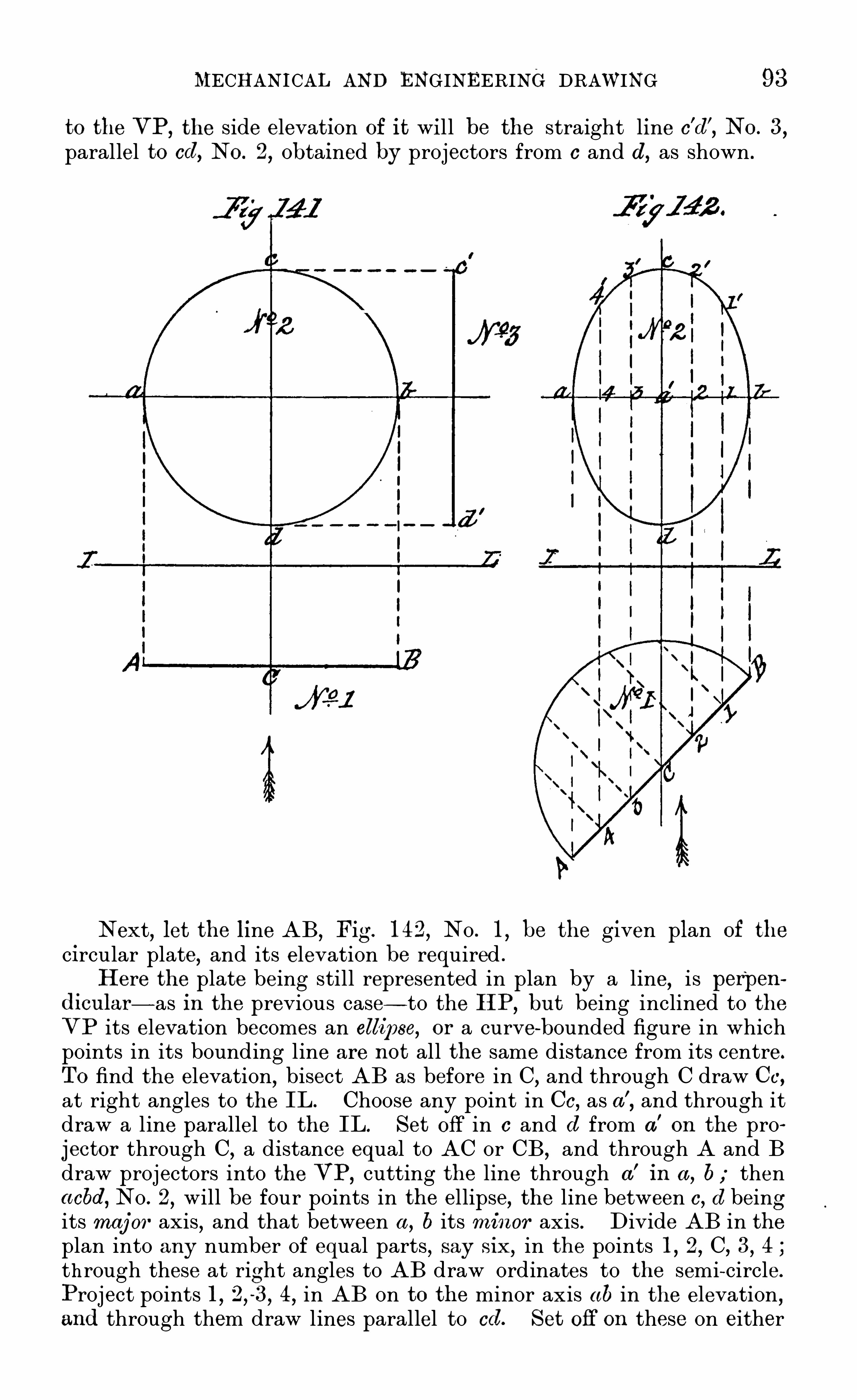
MECHANICAL AND ENGINEERING DRAWING 93
to the VP,the side elevation of it will be the straight line c
’
d’
,NO . 3
,
parallel to cd, NO . 2,Obtained by projectors from c and d, as shown .
Next,let the line AB
,Fig. 1 42
,No . 1
,be the given plan of the
circular plate,and its elevation be required .
H ere the plate being still represented in plan by a line, is perpendicu lar— as in the previous case— to the H P, bu t being inclined to theVP its elevation becomes an ellipse, or a curve-bounded figure in whichpoints in its bounding line are not all the same distance from its centre.
TO find the elevation,bisect AB as before in C, and through C draw C c,
at right angles to the IL . Choose any point in C c,as a'
,and through it
draw a line parallel to the IL. Set off in c and d from a’
on the pro
jector through C, a distance equal to AC or CB ,and through A and B
draw projectors into the VP,cutting the line through a
’
in a , b thenacbd, No . 2
,will be four points in the ellipse
,the line between c , d being
its maj or ax is, and that between a , b its minor axis . Divide AB in theplan into any number of equal parts , say six
,in the points 1 , 2, C, 3, 4
through these at right angles to AB draw ordinates to the semi~circle.
Project points 1,
4,in AB on to the minor ax is ab in the elevation ,
and through them draw lines parallel to cd. Set off on these on either

9 4 FIRST PRINCIPLES OF
side of ab,the length of the corresponding ordinates to the semi-circle in
NO . 1,and through the points thus Obtained draw the curve of the ellipse
as shown in No. 2,which will be the required elevation of the circular
plate in its new position .
43. For the better comprehension of this last problem by the student,before passing to the next a few words in further explanation of itssolution is desirable. It has been shown in previous problems in the
projection of curved lines that if the position of points in the curve canbe determined the problem is virtually solved . In the case of the circlein Fig . 1 4 1 it would have been quite possible to have first found anynumber of points in the bounding line and then to have j oined themby a line passed through them
,and thus have produced the circle, bu t
the u se of the compass obviated the necessity. In the problem beforeus, the necessity ex ists for finding exactly several points in the requiredelevation of the object in the readiest possible w ay. The original Objectbeing a circle, a regular figu re— as distinguished from an irregular one
— whose surface is readily divisible into parts, it is apparent that byturning down one half of that surface on the line AB in No . 1 as adiameter, and drawing lines upon it at right angles to AB,
through anypoints in the semi-circle
,w e can at once find the actual length of those
lines and transfer them to their vertical projections in No . 2 . The
solution of this problem may also be reasoned out in another way . The
original line AB,No . 1
,is in fact— as w as shown in the previous
problem— a curved line,although presented to the eye as a straight
one,every point in it
,on either side of that at C, being farther from the
eye the farther it is to the right or left of C . As the actual length of aline drawn across the circle at C
,through its centre to the Opposite
edge, is known to be equal to AB ,or twice C c, so can the distance
across the circle through any other point in AB be ascertained in thesame way. For
,as the ordinate C c is measured at right angles to AB ,
so any other, as 2, is equal to half the distance from the point 2'
across the circle to the corresponding Opposite point in its edge.
With this explanation the following problem Should present nodiffi culty in its solution .
Problem 4 8 (Fig .-Given the plan of a circu l ar plate as a
circle ; tofind its proj ections in the VP and HP when making a
given ang le w ith either plane.
Let the circle ABCD,NO . 1
,be the given plan , the diametral line
AB being parallel to the IL,and the similar line CD perpendicular to
it. Bisect each quarter Of the circle in the points 1 , 2, 3, 4 . A S
shown , the surfaces Of the plate are evidently parallel to the HP. Let
it now be inclined to that plane at an angle of keeping the
d iametral line AB parallel to the H P,and the point C uppermost, or
nearest to the eye . To obtain its elevation when in that position, anedge view of it— looking in the direction of the arrow a— must first begiven, which will be a line equal in length to CD ,
inclined to the IL atthe required angle. Draw in this line CD as in NO . 2 , and bisect it inthe point B
,which will be the end of the diametral line AB, nearest

96 FIRST PRINCIPLES or
similar in size and similarly figured,be cut ou t in card and laid upOn
NO . 1 with a pin through the centres,it will be found
,on turning the
card disc through an angle of that all the points on it will haveshifted through that angle
,bringing A and B where C and D now are
,
thus showing the projection No . 4 to be correct .44 . Before leaving this part of ou r subject, as elliptical figures
will be very frequently required , w e here give a Simple method of
drawing such a figure,which is sufficiently near the true form for all
the practical purposes of the draughtsman,and which obviates the
necessity of finding all the points in the curve . Premising that thestudent understands that an ellipse differs from the circle in having itsdiameters of unequal length, and that the sum of the distance of anypoint in its curved-bounding line
,from tw o fixed points— called its
foci— in its longest diameter is always the same, then draw an ellipseby the method above referred to
Let the line AB ,No . 1 (Fig. be its maj or or longest diameter
or axis, and CD,drawn at the mid- length of and at right angles to
AB,its m inor or shortest diameter or ax is . Anywhere on the sheet
of drawing paper draw two lines,as ac , be, No . 2 making an angle
with each other— say 30°
— intersecting at c . On a c set Off with thecompasses from c , half the length of AB,
NO . 1,and describe the arc
(le,and on be with half CD as radius
,and from the same centre
,
describe the arc fg, j oin df by a right line, and parallel to it drawlines through c and g, cutting ac in point 1 , and be in point 2. Thenon the major axis AB,
NO . 1,set off from A and B the distance c l ,

MECHANICAL AND ENGINEERING DRAWING 97
NO . 2,in the points l l
’
,and with it as a radius from l l
'
as centres,
draw arcs of about 30° through A and B . On the minor ax is CD set
Off from C and D ,the distance c2, No . 2
, in the points m m’
,and
with it as a radius and m m ’ as centres draw through C and D arcssimilar to those drawn through A and B . For intermediate pointstake a straight-edged slip of paper SP and mark on its edge with a finepointed pencil in points 1 and 3, half the longer ax is aA
,or aB
,No .
1 , and in point 2— measured from point l — half the shorter ax is aC,
or aD . If,then
,this slip of paper be laid on the figure No . l and
moved over it in such a w ay that point 2 in its edge is always on themajor ax is
,while point 1 is on the minor, point 3 will describe, if
carried through a whole revolution , a perfect ellipse . A s,however
,
only a few points are required between the ends of the arcs alreadydrawn
,these can be marked off from the edge of the slip of paper by
moving it in the desired consecutive positions .

CHAPTER XIII
THE PROJECTION OF SOL IDS W ITH C URVED SURFAC ES
45 TH E particular solids with which w e have here to deal arethose known as " solids of revolution ,
” which are assumed to begenerated,
”or produced, by the revolution of certain geometrical
figures round one of their bounding lines as an axis ; the other linesin their circling round this ax is enclosing a space— assumed to be
material é — Of a certain form ,dependent upon that of the generat
ing figure . A " solid of revolution ” therefore implies an Objecthaving curved-bounding surfaces . Of such solids there are threeprimary ones Of which machine details are made up
— viz .
,thecylinder,
the cone, and the sphere— the subsidiary ones being generated by
figures which are portions of plane sections of the first two primaryones .
A Cylinder is a Solid generated by the revolution of a rectangleabout one of its sides as an axis . If ABCD ,
Fig . 1 4 5, be the rect~
angle, then if it be caused to revolve round AB as an ax is, making onecomplete circuit, the sides AD ,
DC,CB will generate the solid called a
" cylinder,
” having a height, or length , equal to DC, a diameter equalto twice AD ,
and its ends E ,F
,circular flat surfaces, at right angles
to its ax is AB .
A Cone.
— If one half of the rectangle— divided diagonally— Fig.
1 4 6, be removed, leaving the right-angled triangle ABC remaining ;then , if this triangle be revolved on AB as an axis, as before, the sol idgenerated will be a " cone
,
”as in Fig. 1 4 6, its base DC being a C i rcular
flat surface at right angles to its axis AB .
98

100 FIRST PRINCIPLES OF

MECHANICAL AND ENGINEERING DRAWING 101
elevation of the ax is, and then finding by projection the two ends ofthe cylinder upon it, and drawing in its sides as shown in No . 6 .
For the projections of the cone the first problem is
Problem 50 (Fig .— Given the plan of a cone, having i ts axis
perpendicu lar to the HP ,and an altitu de equ al to tw ice the diame
ter of i ts base, tofi nd its elevation.
Let the circle No . 1 , Fig . 1 4 9,be the given plan of the cone ; its
centre a as in the cylinder will be the plan of,
its ax is . Find by pro
jection the elevation of this ax is , and on it set off from the IL thealtitude of the cone in point a’
. Through a,the centre of the circle in
No . I,draw AB parallel to the IL. Find by projection the elevation
of points A and B — in the base of the cone— on the IL,and join these
by right lines with point a’
on the ax is a ’
a . The triangle A a’ B will
be the required elevation .
Next, let the base of the cone be inclined to the HP at an angle ofkeeping i ts axis parallel to the VP , and its plan be requ ired.
H ere, an elevation of the cone at the given angle must first bedrawn in
,as in No . 3 ; then find the plan of its ax is, which, being
parallel to the VP,will be a line parallel to the IL, as in No . 4 .
Obtain by projection the plan of the base of the cone, which is anellipse, its major ax is being CD and its minor AB ,
No . 4 ; then findthe plan of the apex a
'
,NO . 3
, of the cone in a'
,No . 4
,and j oin it by
right lines to points C and D ; the required plan of the cone in theposition stated will thus have been obtained .
Again,let the axis of the cone be parallel to the HP , bu t inclined to the
VP , at an angle of 4v5°
; and its elevation be requ ired.
To obtain this,draw- in the plan of the cone in the position
stated,then find the elevation of its ax is, and on this, by projection
from the plan, draw- in the base, which will be an ellipse j oin the twoends of its major ax is with the projected apex as shown in NO . 6, andit will be the required elevation .
As a " sphere,” when looked at from any direction , is a circle,
when projected, w e shall defer any problems in connection with itu ntil w e come to consider the projections of its sections— which willfollow those of the cylinder and cone, to which w e next give attention .

10d MECHANI CAL AND ENGINEERING DRAWING ’

104 FIRST PRINCIPLES OF

MECHANICAL AND ENGINEERING DRAWING 105
The portion Of the cylinder left in this case is called an u ngu la ,and
the required elevation and plan of the section are obtained in a similarW ay to No . 3 and NO 4 . First, to find the elevation . choose, asbefore
,a convenient number of points in the line K P
,from them
let fall proj ectors, cutting the plan of the cylinder No. 6,as was
done in No . 2 . S imilarly, from the same points draw- parallel tothe IL - projectors through the axial line No . 7 , and on these set Off
,
in their proper order, the lengths of the corresponding lines foundin NO . 6 ; a line drawn through the points thus found will give theelevation or contour of the section made by the cutting plane K P
,
in its altered position, which is a portion of an elongated ellipse.
The plan of’ this section of the cylinder Shown in No . 8
,differs
little from that of No . 3 ; the section plane K P,passing ou t of the
cylinder w ithin its base at K , cuts off a portion of the base, as shownby the line cc
'
.
A s the projections of all the possible sections of a cylinder are
obtained in the same w ay as the foregoing, further examples neednot be given, and w e can now proceed to consider those of the cone.

CHAPTER XV
TH E PROJECTION OF TH E C ONIC SECT IONS
4 7 . TH E same preliminary remarks may be made in reference tothe simple sections of a " cone ” as were made in the case of the
cylinder.
’
From the definition "given Of a cone,and its assumed mode
of generation,it will be at once seen that any section of it taken
through its apex to its base will be a triangle. while a section parallelto its base— or at right angles to its ax is— will be a circle. Admittingthese as self-evident truths
,w e have then to define those other
sections of the cone not taken in the directions mentioned , and to
show how their projections are Obtained .
The three most important sections of a cone— other than the twomentionedfl—are the "
ellipse,
”the parabola
,
” and the hyperbola .
If a cone be cut by a plane inclined to its ax i s,or its base
,the
section is an ellipse, or a regular closed curve having diametersdiffering in length .
If the section of a cone be made by a plane parallel to its axis,but not coinciding with it
,then the section is a hyperbola .
If a cone be cut by a plane parallel to its slant side, then the
section is a parabola . From its definition it will be readily understoodthat the elevation of a cone when standing with its ax is vertical is atriangle, and its plan a circle. Before attempting the projection of anyof its sections
,it must first be known how to find the plan, or
elevation— either being given— Of a point on its surface, as this willmaterially assist in finding its sections .In Fig . 1 51 : If No . 1 be the plan of a cone
,No. 2 its elevation ,
and x in No . 1 a given point on its surface, it will be seen from itsassumed mode of generation that this point must lie somewhere in theslant side of its triangular generator a
’
A b, NO . 2 . Now every pointin this line— it may be assumed to be made up of points— in itsrevolution about the axis a
'
a of the cone describes a circle, and the
circle in which x must lie will have a radius equal to the distancebetween it and a ; therefore in No. 1 , with a as a centre and a x
as radius,describe a circle cutting the diametral line AB in x’
. Again,through the given points x and a in No . I , draw the line are, cuttingthe base AB of the cone in c . Find in No . 2 the elevation c
’
of c
106

108 FIRST PRINCIPLES OF

MECHANICAL AND ENGINEERING DRAWING 109
produce it into the HP. Choose any convenient points, as , 1 , 2,I
,4,
5,in LS , NO . 1 , and through them , parallel to the IL, draw l ines to
cut the Sides A a’
,B a
'
,of the cone . These, being parallel to its base,
will each be the edge-view of a circle or base of a small cone. To findthe distance through the cone at the points 2 , 3, 4 , in LS , No. 2 — forthis is What is wanted to be known - let fall from them proj ectorsinto NO . 1
, parallel to the axial line aa’
; then from a, NO . 1
,as
centre,and with radii equal to half the length of the lines drawn
through 2,3,4,No . 2
,draw arcs
,cutting the projectors let fall from
these points in No . 1,the length between which
is the distance through the cone at their corresponding points inNo . 2 .
Then,for the contour of the section , project over on to the ax ial
l ine No. 3,the points 1 and 5 in LS , NO . 2
,and from the other points
2,3,4,draw projectors parallel to the IL through the ax is NO . 3 . On
these,set Off the lengths taken from NO . 1
,and
through the points thus found draw the curve of the ellipse. Withthe radius aA
,or aB
,NO . 1
,set off from the ax ial line on the IL
,
NO . 3,the base of the cone in CD ; j oin these with points and
the required elevation is Obtained . Thegplan of the section obtained
in No . 3,will be the ellipse
,found by drawing a line through the
intersections of the arcs and double ordinates in NO . 1 . To Show thisin its correct position as a projection of No . 3
,transfer th e points and
lines in it to No . 4,as shown
,and it will then be seen that projectors
let fall from the points in the section No . 3 will fall upon theirtransferred plans in NO . 4 . A line drawn through these points will bethe required plan of the cone when ou t by the section plane LS , No . 2 .
The student must remember that tlfe view No . 3 being at right anglesto that of NO . 2
,the plan No . 4 is necessarily in the same position
with respect to No . 1 .
Next, let the cone be cu t by a plane parallel to its axis, and its
sectional proj ections be requ ired.
4 8 . In this case the projected section will be a true " hyperbola,as the view obtained of it will be directly at right angles to thecutting plane. Let NO . 5 and No . 6
, Eig. 152,be the given elevation
and plan of the cone, and LS , No. 5,the line of ,
section . The simplestw ay to obtain the required elevation will be to cut up the cone - fromthe point where the cutting plane enters it— into horizontal sections
,and
then find where the plane of section enters and leaves their horizontalsurfaces . To do this
,draw lines at suitable distances apart, as 1
2 3 4 parallel to the IL,as shown in No. 5 . These will all be
edge-views of circular planes perpendicular to the VP. The circleACBD , No . 6, is the plan Of the cone ; to find where the sectionplane passes through it
, produce the line LS , No . 5,and it will cut the
circle in a line p p’ parallel to CD . The part of the cone to the left of
the section plane may now be supposed to be removed, showing whenlooked at in the direction of the arrow on the left the exact contour ofthe section . To find this
,all that is required to be known is the

1 10 F IRST PRINCIPLES OF
width across the face of the section at the heights of the circularplanes 1
,2,3,4,NO . 5 . Draw in
,as in NO . 7 , the side elevation of
the cone . Project over from NO . 5 on to its ax ial line the point 1,
where the cutting plane first enters the side of the cone — which will bethe highest point in the curve — through points 2
,3,4,in LS
,NO . 5 ;
draw lines in NO . 7 , parallel to the IL or CD . In No. 6,with a as
a centre, and the half- lengths of the lines drawn through 2,3,4,
No . 5,as radii
,draw arcs cutting the line pp
’
,No. 6
,in the points
2 3 4 the distances between these points severally will bethe distances across the face of the section at the heights of theircorresponding points in NO . 5 . Set these distances off on the linesdrawn in No . 7 ; then a curve drawn through the points
.
thus foundwill be the required sectional elevation of the cone
,cut by a plane in
the position given . This curve is a true hyperbola, because the planeof the section of the cone producing it is parallel to the cone’s axis andto that of the plane of its projection . The plan of this section
,from
its position with respect to the H P— viz .
,perpendicular to it— becomes
a straight line,wh ich
,combined with the part of the cone not affected
by the cutting plane, will appear as shown in NO . 8 .
Again, let the cone be cu t by a plane parallel to its slant side, and the
sectional proj ections, elevation,and plan be requ ired.
Let NO . 1 and No. 2 (Fig . 1 53) be the elevation and plan of the
cone,and LS the cutting plane
,drawn parallel to its slant Side A a
'.
H ere the tru e form of the section will be a parabola,but the plane
of the section being inclined to that of its projection , or the VP,the
view obtained of it,looking in the direction of the arrow
,will be its
apparent and not its true form ; but this point will be explainedfurther on.
TO'
find the sectional elevation,first choose
,as before, suitable
points,such as 1
,2,3,4,in the line LS
,No . 1 ; through them and
point S draw lines parallel to A B -the base of the cone— to touch bothof its slant sides A a
’
,Ba
’
. These lines,as in the last problem ,
Will beedge-views Of circular planes . From the points S
,1,
’
2,3,4,L
,let fall
projectors on to the plan No . 2,parallel to the ax ial line a
’
a . Withthe half- lengths of the lines first drawn through S
,1,2,3,4,as radii
,
and a,No . 2
,as centre
,cut the vertical projectors let fall from these
points in Through the corresponding points in theelevation No .
’
I draw horizontal projectors through the ax ial line a’
a,
No . 3,and on them set off the distances— taken from NO . 2 — between
the points then a line drawn through the pointsthus found will give the elevation required .
The plan Of this section , as shown at No . 4,is Obtained in the same
w ay as the plan Of the hyperbola No . 6 (Fig . 1 52) — viz .,by transferring
to No . 4 the points obtained by the intersection of the arcs and doubleordinates in No . 2
,and through them drawing the parabolic curve, as
shown .
By the same method of procedure as shown in the three foregoing
problems, the proj ection of any possible plane section of the cone can beobtained . Nor is the method confined to the sections made by a plane

1 1 2 FIRST PRINCIPLES OF

MECHANICAL AND ENGINEERING DRAWING 1 13
the student a fuller insight into the methods of procedure in such acase
,is the one adopted .
Now,as the cylinder is shown as vertical and the section plane
inclined at 4 5°
to its ax is,to bring this plane perpendicular to the H P
it must be moved through an angle of For the purpose Of theprojection it is assumed that the upper part of the cylinder above the
section plane is removed . To bring the lower part into the requiredposition it must be turned through a vertical arc of To do this
,at
the point D in its base draw indefinitely to the right and left linesmaking angles of 45° with the IL . On the one to the right
,set off Dp
equal to DP and on that to the left,D c equal to DC— the diameter of
the base of the cylinder at c draw cs equal to C S , the long side Of thecylinder, at right angles to cD j oin sp,
then D csp will be the lowerend of the cylinder when the plane of section SP is vertical, or at rightangles to the VP and H P . The true form of the section can now befound . First draw in No . 2 the plan of the cylinder in its verticalposition . Divide its diametral line AB into four equal parts in points1,
through these draw double ordinates and projectors to cut CD ,
No . 1 , in 1 , 2, 3 . Transfer by arcs points 1 , 2, 3 in CD ,NO . 1
,to cD
,
and through these last draw lines parallel to cs to cut sp in points

1 1 4 FIRST PRINC IPLES OF
For the form of the section sp draw in, in No . 3,the axial
line a’a ; project over to it from sp ,
NO . 1 , the points 3’ and p
’
,and
from 3'
in sp draw projectors through a’
a ,NO . 3. On these set
off the length of the corresponding double ordinates drawn through1,2,3,No. 2
,and through the points thus found draw the ellipse
S 2p2, No . 3,which is the required tru e form of the section at the line
SP,No . 1 .
50. A S Opportunities Will occur as w e proceed with this part of oursubject of Obtaining the true form of section of any solid in anotherw ay than that j ust explained , w e pass on to the sections Of the third ofthe primary solids with which w e are dealing- via
,the " sphere .
”
Now,as the sphere is generated by the revolution of a semi-ci rcle
about its diametral line— or chord — as an ax is,it follows that any plane
section of the generated solid must be a circle, whether it pass throughthe ax is or not, for any and every point in the curved-bounding line ofthe semi-circle not only describes in its circuit round the axis a tru ecircle
,bu t is at the same time at an equal distance from the centre of
the solid which is generated . It follows from this that all the sectionsof a sphere, by planes passing through its centre, are equal circles ,having the same diameter and centre as that of the sphere. Suchcircles are known as " great circles of the sphere, and their projections ,if taken at right angles to the plane of section, are circles equal to theiroriginals . If, however, a sectional projection of a sphere is required atan angle to the plane of section, then the projection becomes an ellipse,and is Obtained in the same w ay as that of any circular plane or discwhen at an angle to the plane of its projection . As all such sections ofa sphere would in projection be ellipses , only one problem is given inthis connection , which will show the difference between the sections ofthe same sphere when ou t by a plane at varying angles to its plane ofprojection . The problem is
Problem 54 .— Given theplan of a sphere and the line of section, tofind
its sectional elevation.
Let AB,No . 1 (Fig. be the plan of the sphere, and SP the
line of section,the axis a’ or pole Of the sphere being perpendicular to
the HP. H ere SP being parallel to the axis a’ and to the VP,
the
section of the sphere by it will be a circle . To find its elevation,first
show in that of the sphere AB,No . 2 . Project over point 1
,in SP,
NO . 1, to l in AB ,
NO . 2 ; then in NO . 2,with s as centre and 3 1 as a
radius,describe the circle 1 , 2, and it will be
‘
the sectional elevationrequired . For SP,
No. 1, being parallel to the VP, the circular section
made by it will be concentric with the great circle A B,NO . 2
,and
therefore their centres will be coincident ; and as SP cuts the greatcircle AB
,No . 1 , in points 1 and 2, the elevation of the section made
by SP will be a circle, having a diameter equal to the distance betweenthose points, as shown by its projection in NO . 2.
Next, let the sphere be turned on its axis in the direction of the arrow in
No. 1 , until the section plane SP is at an angle— as in NO. 3— w ith
the VP,and its elevation be requ ired.

1 16 FIRST PRINCIPLES OF
H ere, SP being inclined to the VP,the elevation of the section will
be an ellipse. To find it,first get the,
elevation of the sphere,as in No.
4,having a
’
a for its ax ial line . Bisect the distance between 1,2 in SP
,
No . 3,in the point b, and through it draw a projector to cut AB,
No . 4,
in b’; also project over points 1 , 2 in SP,NO . 3
,to points 1
,2 in AB
,
No . 4 . Now the true section of the sphere made by SP is a circle of adiameter equal to the distance between points 1 and 2 in that line, andit is the elevation of this circular section inclined to the VP,
as shown,
that is here required . It is left to the student without further explan
ation to find the resulting elliptic section,as was done in Problem 4 8
,
Fig. 1 4 3.
Again,let the problem be
Problem 55.
— Given the elevation of a sphere cu t by a plane inclined
to the HP, to find i ts sectional proj ections.
Let No. 5,Fig . 1 56
,be the elevation of the sphere
,and SP the line
of section . To find the side elevation , first draw the outline of thesphere
,as in NO . 7 . Then as the true section of the Sphere by SP is a
circular plane,find by Problem 4 8 its vertical projection when inclined
as in NO . 5,which will be an ellipse as shown in NO . 7 . For the plan
of NO . 7 in its correct position , proceed as was done in the case o f thecone NO . 1
,Problem 52
,by finding the plan of the points in the contour
of the section , as in NO . 6,and transfer them to No . 8 ; then a line
drawn through the points so found will give,as in NO . 8
,the required
sectional plan of No . 7 .
In the same way as here shown can the projection of any possiblesection of the Sphere be obtained, no matter how the line of section bedrawn
,or whether it is straight or curved , as the same rule holds good
in this case as in that of the cylinder and the cone— viz .
,Find the
ictual distance across the face of the cut surface Of the section,from
my points on the surface of the solid— in the line of section — nearest
the eye, to those directly behind them on the opposite sidefarthest fromthe eye, and the problem of its projection is solved
,for the points
denoting the distances thus found have only to be put in on the paperin their proper places, and a line drawn through them will give the
sectional projection sought .51 . H aving shown how the sectional projections of the three primary
solids— the cylinder, the cone, and the sphere— are found,w e now pass
on to the consideration of those subsidiary solids of revolution whichare generated by parts of the sections of the primary ones .
The particular solids of this class which assist in giving shape tomachinery details are the " spheroid ,
”the " conoid
,
”the " cylindroid ,
”
the Spindle,and the " oval ” and they are thus defined
A spheroid is, a solid generated by the revolution of a semi-ellipseabout one of its diameters . If about its longer one
,it is a prolate
spheroid if about its shorter one, an oblate spheroid .
A conoid is a solid generated by the revolution of half : of a conicsection about its axis, and becomes an "
ellipsoid,
” " paraboloid,
”or

MECHANICAL AND ENG INEERING DRAWING 1 1 7
hyperboloid , according as its generating figure is half an ellipse,
parabola,or hyperbola .
A cylindroid is a cylindrical solid having elliptical ends .
A spindle is a solid generated by the revolution Of an arc or portionof a curve cut off by a chord or double ordinate
,around wh ich it
revolves as an ax is . It is circular,elliptic
,parabolic
,or hyperbolic,
according as the generating arc,or curve
,is a portion of a circle
,ellipse
,
parabola,or hyperbola .
An oval is an egg- shaped solid
,and may be conceived to be com
pounded of half a sphere and a like portion of an elliptic conoid .
As all the above-defined solids are assumed to be generated by therevolution of a particular figure about an ax is
,it follows that a cross
section — at right angles to its ax is— Of any one of them will be a circle,
while a section through its ax is will be a simi lar figure to that of whichits generator formed a half-part . A n oblique section through the ax isof all of them would be a figure of elliptic form ,
while one which didnot cut the ax is would partake of the form of its ax ial section . U nderthese circumstances
,as the finding of any required section of one or all
of them merely involves the application of methods of procedure alreadyexplained
,it is unnecessary here to further elaborate them . All that
is required by the student for the mastery of this part Of our subject,is to thoroughly appreciate the exact form and mode of generation ofthe different solids enumerated . This attained
,there will be no difficulty
in the solution of any problem that may arise in connection with theirprojection .
Before concluding this chapter,and with it the subject of the
Projection of Solids with Curved Surfaces , it w ill be necessary toShow
,how the principles explained in Chapter XI .
,on the Lining- in of
Drawings in Ink,
”are to be applied to representations of this class of
solids .
It has been shown in Chapter XI .
,that the projections of rays of
light, in the direction they are assumed (in M echanical drawing) to fallupon the Object illumined , are parallel right lines in plan and elevation
,
making an equal angle of 4 5° with the intersecting line of the planes
of projection . To determine then how to line- in the representationof a curved- surfaced solid
,w e have to find how the light falls upon it .
Now to do this,let the circle eedb in NO . 1
,Fig . 156a
,be the plan
of a cylinder,and the rectangle ABCD No . 2 its elevation . Through
a,the ax is in NO . I
,draw lines at an angle of 45° with the IL,
cuttingthe circle in points 6 and c ; and through b draw a line parallel to ca .
Also through b and c , in NO . 1,draw lines in No . 2, perpendicular to
the IL, and produce them to meet AB , the top-end of the cylinder inc and 6. Now the lines drawn through b
,and ea in No . 1
,are the
plans of two planes of rays of light the former touchingthe cylinderthroughout its length in the line bb’ and the latter striking it in theline cc
’
(NO . The line bb’ is know n as the " line of shade, as itdivides the cylindrical surface in the light from that part which is inthe shade
, and is moreover the darkest part of the visible surface. The
brightest part of the cylindrical surface will be the" line Of light cc
’
,
as it is here that the l ight shines directly upon it .

1 1 8 FIRST P RINCIPLES OF
It follows from the foregoing considerations , that in lining-in the
representation of a cylindrical surface in ink, fi ne lines only Should be
used, as either a medium or Shadow line would be inappropriate, thelightest
,and darkest
,parts of the surface of such a solid alw ays falling
w ithin the outlines of its representation , as shown at bb’
,and cc
’
,in the
elevation NO . 2, Fig. 156a. The same rule also applies to either conicalor spherical Surfaces
,as Shown in Nos. 4 and 6
,in the figure where it
is seen that the " lines of shade — obtained in the same way as in thecase of the cylinder— are well within the outlines of the solids
,and
must therefore be pu t in, in fine lines .It would, however, be correct to shade- line the end of a cylinder,
or the base of a cone— if inverted -as a part of their edges wouldthrow a shadow . To determine how much would do so : in No. 1
,
Fig. 156a,produce the line drawn through b, a to e and that through
c,a to d. Now as all the rays of light falling on the cylinder, and its
upper end AB,are parallel to the one drawn through c
,a,d,it follows
,
that the semi- circular edge ecb in No. 1 wi ll be directly in the lightand will cast no Shadow ,
while the opposite similar edge edb will do so,either on the HP or VP,
— according to its position with respect tothose planes— and must therefore be Shade- lined . But as the semicircular edge edb— of the cylinder end— would cast different intensitiesof shadow
, the shade-line from c through d to b must be of varyingthickness (as shown in the diagram) , its thickest part being at d.
If the cylinder be hollow— as represented in No. l — then that partof its inside top-edge, or the semi-circle 1 , 2, 3, will throw a shadow on
the Opposite inside surface, and must be shade- lined as shown , thethickest part of the line being directly opposite the similar part of theouter semi- circle edb. In the Sphere and other entirely curved- surfacedsolids
,no shader lining is admissible in inking them in, fine lines being
the only prOper ones to be u sed for the purpose.

C HAPTER XVI
TH E PROJEC TION OF OB JECTS INC LINED TO TH E PLANES OF PROJECTION
52 . FOR the more immediate purpose of representing anything inprocess of manufacture in the workshop
,it will be readily understood ,
from what has already been explained in these chapters,that the only
drawings absolutely necessary to the w orkman are those in which the
plans, elevations, and sections of the Objects he is called upon tomakeare correctly shown . But as many of the elements which go to makeup a machine
,or engine
,are Often inclined to the vertical and horizontal
positions,it is essential that the draughtsman should know how to
draw the plan or elevation of an object,however intricate
,when inclined
to the VP or HP,at any angle other than a right angle . Before
showing how the principles of projection are applied in this part of ou rsubject
,w e would guard the student against accepting as true, the
notion entertained by some,that it is a different kind of drawing to
that which has preceded it,and that a knowledge of it is more difficult
to acquire . The projections of an object inclined to the planes of itsprojection
,certainly differ in appearance to those of it when not so
placed , but the method of finding such projections involves no new
departure in principle,as the " planes of projection — the VP and H P
— are still in the same relative position as before— via,at right angles
to each other— although the " object is inclined to both . The " proj ections
,
” therefore, of an Object/so placed , are nothing more than itsappearances when viewed at right angles to those planes .
To Show this graphically, let A,No . 1 (Fig. be the plan of a
wooden block,with its u nder side resting on a flat plate abcd, lying on
the H P, and its sides inclined to the VP,or IL
,as shown . A front
elevation— or V i ew in the direction of the arrow e— Oi the block in thisposition would be B
,No . 3. Now
,assume the plate— with the block
upon it — to be raised through an angle, moving on its edge ab, as ahinge ; the elevation of the block in this position would then appearlike C ,
No. 3 for its upper face would become more and more visibleas the angle made between the plate on which it rests and the HPincreased
,until the plate had attained a vertical position, when it
would again appear as shown in'
plan at A,NO . 1 but as an elevation .
W e therefore see that its " appearance ” when inclined to the planes1 20

MECHANICAL AND ENGINEERING DRAWING
of its projection, although radically different to either its plan A, No . 1,
or its elevation B ,NO . 3
,is still nothing more than an ordinary pro
jection of the original Object when in its changed position . This isfu rther shown in No . 2 (Fig . where a side view is given of the
plate with the block upon it , such as would be seen when looked at in .
the direction of the arrow f ,NO . 1 . Then by the aid of a few projectors
from No . 2 and NO . 1,it is seen that C , NO . 3
,and D
,No. 4
,are j ust
ordinary projections,differing little from those which have preceded
them,and certainly no more difficult to obtain than some which the
student has already projected or drawn . A s the proj ections of the
object given in this figure form a problem for solution later on , w e
defer showing how they are exactly Obtained until w e have , as inprevious instances
,explained how the projections of simple " figures ”
in similar positions are found .
53. Now,to facilitate the process of finding the projections of an
Object when inclined to the VP and H P,w e have to introduce into
the construction an imaginary inclined plane interposed between the
V P and H P,on which the object whose projections are required is
assumed to rest . This plane is represented in Fig . 157 by the line OP ,
NO . 2,and is the only new feature in our subject of study, it being not
a fixed plane like the VP or H P,but one that may assume any desired
angle with those planes . Such a view_
of an object as is shown inNO . 2 (Fig . 157 ) could of cou rse be given without the assistance of theline OP ; but as it determines the inclination of the Object to thevertical or horizontal
,it is of material help in finding its projections,
as will be seen as w e proceed .
Throughout the problems that will be given in this part of ou r
subject the original Object whose projections are required is to balways understood as resting on a horizontal plane, and the view first
given of it, is its plan or horizontal projection , such as A,No . 1 (Fig .
which shows all that would be seen of such an Object when lookedat from above .
Now, to find the projection of a point situate in a plane which isinclined to the VP and H P,
w e must know the angle made by theplane— in which the point lies — with either the VP or HP. Our firstproblem is
Problem 56 .— Given the plan of a point, i t is requ ired to fi nd its
elevation when the plane in which it lies is inclined to the HP at an
angle ofLet a (Fig. 1 58 ) be the plan of the given point, IL being the inter
sec ting line. At 0 draw a line OP,making with the IL an angle of
Through the point a draw a projector into the VP. Set off onOP from O , a distance Oa
'
, equal to that which point a is from the .
IL . Through a’
draw a l ine parallel to the IL,cutting the proj ector
from a in plan in point a then a is the required elevation . In the
same way, the elevation of a line lying on a plane inclined to the VPand H P is found , for w e have only to find the vertical projection of its
’
ends , and j oin them by a right line, and the desired elevation isobtained .

1 22 FIRST PRINCIPLES OF
Problem 57 .- Given the plan of a line, to fi nd its elevation when the
plane in which it lies is equ ally inclined to the VP and HP.
Let AB (Fig . 159) be the plan,IL being the intersecting line as
before. As the plane on which the line AB is to lie equally inclines tothe vertical and horizontal
,its angle with either will be one of
Therefore, at any point in the IL, say 0,draw a line OP at that angle
with it. Now OP,w e have before said, is a side view of the inclined
plane on which the Object— in this case a line— is to lie the view w e
shall obtain of the object in elevation will be one looking in the direc
tion of the arrow x,and the position of the VP with respect to OP can
be either in front of or behind it . If in front,it would be represented
by a line drawn through O perpendicular to the IL if behind,then a
similar line through P . Generally, OP is assumed to be interposedbetween the VP and H P,
and therefore a side view of the three planeswould be correctly represented by the right-angled triangle PxO in thediagram the vertical projection or elevation of the inclined objectbeing made on Px or the VP,
and the horizontal one, or plan, on Ox,
or the H P.
W e can now proceed with the solution of the problem before u s.
H aving the inclination of the plane on which the line AB is lying, tofind a front elevation of it w e require to know the exact position of itstwo ends with respect to the foot of the plane on which it is lying .
Now, the intersection of two planes is a straight line therefore, as the
inclined plane OP in the figure intersects the HP in O , the plan of thatintersection will be a straight line parallel to the VP or the IL andassuming the VP to be as far from the foot of the inclined plane OP asx is from 0
,set off from the IL a distance equal to Ox, and through
the point so found draw the line DL parallel to the IL, and it will bethe plan of the intersection of the H P with the inclined plane OP. Itis from this line that all measurements of points in the plans of originalobjects have to be taken , when giving their elevations on the inclined
plane OP. Then to find the required elevation of the line AB,set Off
from O on the line OP in b and a,the distances dA and Bb, that its
ends A and B are from DL,and through them parallel to the IL draw
projectors to ou t those drawn from A and B in the plan in the pointsA
’
B’
j oin these by a right line and it will be the elevation required .
Then,as lines are the boundaries of " figures, the projection of a
figure in a similar position with respect to the VP and H P is obtainedin the same way. One problem in this Connection will be sufficient toshow the application of the principle. Let it be this
Problem 58 .— G
’iven the plan of a triangle, and the inclination of
the plane OP ; tofi nd the elevation of the triangle.
Let ABC (Fig. 1 60) be the plan of the triangle, and the inclinationof the plane OP be 30° with the HP. Draw in the line OP at the
given angle with the IL and the line DL as in the last problem . Findthe position of the angular points ABC on the plane OP, and through

1 24 FIRST PRINCIPLES OF
them draw projectors parallel to the IL,cutting those drawn through
the corresponding points in the plan . The intersections of these pro
jectors A’B ’C’ will be the elevations of the angular points of the
triangle ; j oin these by right lines and the triangle ABC' will be the
elevation required .
If the plan of the original figure in its new position be required aswell as its elevation, this is found in a similar way. Let the problembe
Problem 59 .— Given the plan of a rectangu lar plate and the inclina
tion of the plane OP ; tofi nd itsproj ections.
Let A,NO . 1 (Fig . be the given plan of the plate, and the
inclination of OP be 30° with the H P. Draw OP
,NO . 2
,at the given
angle with the IL,and the line DL as before . Number the corners of
the plate 1,2,3,4,as shown in NO . 1 . Find the position of these
points on OP,No . 2
,and from them Obtain , by projection , the elevation
of the plate shown at B ,NO . 3. To find the plan of the plate in its
inclined position, let fall projectors from points 1 , 2, 3, 4 , in the lineOP
,NO . 2
,perpendicular to the IL ; then the corners of the plate in
plan will lie in these projectors, and the problem is to decide where.
The line DL,below the original plan of the plate at A,
No . 1,is
,w e
have shown, the plan of the intersection of the inclined plane OP withthe H P ; then a line dl, drawn through 0,
No . 2,at right angles to
the IL,as shown in No . 4
,will also be a plan of the same intersection .
As the distances of the points 1 , 2, 3, 4 , in A ,No . 1
,from the line DL
,
were set Off on OP,NO . 2
,the position of this plane— with the plate
upon it— will be at right angles to that of A,No . 1 therefore, its plan
No . 4 — or the view of it looking in the direction of the arrow as,No . 2
-will be in the same position with reference to A,NO . 1 . Then if . the
points where the projectors drawn through 1 , 2 , 3, 4 , in A,NO . 1
,cut
the IL,be transferred to the line all, No . 4
,and lines be drawn through
them at right angles to that line, their intersections with the projectorslet fall from 1
,2,3,4,No . 2
,will give 1 , 2, 3, 4 , No . 4 ; j oin these by
right lines, and the required plan Of the plate in its inclined position isObtained .
54 . As the projection of any plane figure, inclined to both the
planes of projection,is found in the same way as here shown , w e can
without further example proceed with the application of the principlesinvolved , to the proj ection of solid Objects similarly placed . Now, asolid object, such as the block of wood taken for explanatory purposesin Fig . 157 , has not only length and breadth, but thickness also, andeach of these dimensions has its representative lines in the projectionsthat are obtained of it
,when it is inclined to both the VP and H P.
The actual thickness of an Object— or its measurement from surface tosurface— is the distance through it at right angles to the surface fromwhich it is measured . If the thicknes s be represented by a line, thenthe line will be perpendicular to that surface, and its proj ections willdepend upon its position with respect to the planes of projection .
In Fig . 1 62, if the plan of a line be represented by the point a ,
then, when the plane to which the line is assumed to be perpendicular

MECHANICAL AND ENGINEERING DRAWING 1 2

1 26 FIRST PRINCIPLES OF
is inclined,say, 30
°
to the horizontal , its side elevation on that planeOP will be a
’
b. To find its front elevation , w e draw a projector througha perpendicular to the IL, and from a
’ and b— the two ends of the line- projectors parallel to the IL, to cut the one through a in a
”
b’
; then aline j oining these points is the front elevation of the original line a
’
b
when inclined to both planes of projection . To apply this reasoning tothe projection of such an Object as the ; rectangular block of wood inFig . 1 57 proceed as follows -First draw
i ’
in its plan as at A,No . 1
,
and number the four corners as shown . Each of these will be_
the end
of a line perpendicular to the H P, Of ‘
a length equal to the thickness ofthe block . On OP,
NO . 2, drawn at an angle of 30
°
with the IL,give
an elevation of the block , looking at it in the direction of the arrow f,remembering the position of its corners and top surface with respect tothe plane on which it is assumed to be standing . H aving drawn inthis view,
proceed to find by projection that of C,No. 3 . This is best
and most correctly done by numbering both top and bottom . ends ofthe lines representing the angular corners of the block in No . 2 . The
Fig . 1 62
intersection Of horizontal projectors drawn through these points, andtheir corresponding vertical ones in No . 1 , will give the position of allthe corners of the block that will be seen looking in the direction ofthe arrow x in No . 2, and the j oining of these by straight lines, asshown in C
,No. 3
,will give the required elevation.
To find the " plan of the block when inclined as shown,let fall
vertical projectors from all the corners of it seen from above in NO . 2,
when looking in the direction of the arrow g ; transfer the pointswhere the vertical projectors from 1 , 3
,4,No . 1 , cut the IL,
to theprojector drawn through the foot of the incl ined plane at O ,
as shownin Fig . 161 previously, and through these draw projectors to cut thoselet fall from 1
,2,3,4,No . 2 then the intersections of these projectors
will be the plans of the corners of the block seen from above it, which ,on being joined by straight lines , wil l give D ,
NO . 4 , the plan of the
block,when inclined in the position shown in side elevation at No. 2
,
and front elevation at No. 3.
55. As a test of the correctness of the two last- found projections,all the lines in the original Object A that are parallel to each other

1 28 FIRST PRINC IPLES OF .
No. 1 , in points 1 , 2, 3, 4 , NO . 4 ; j oin these by right lines, and the
plan of the tOp face Of the cube is found . For the plan of its tw oinclined faces
,seen from above
,produce the horizontal projectors drawn
through the three corners 2,3,4 of the top face— j ust found— and
s
byvertical projectors from points 4 ’ and in No. 2
,cut the produced
horizontal ones in points 3’ No . 4 j oin points 2
,2
’
3,3’
4,4
’
and 3’ by right lines as shown
,and No . 4 is the required plan
of the cube in its given inclined position .
56 . Before proceeding to show how the sectional projections of thecube are found , it is advisable here— to save repetition later on— to
explain the reasoning which has directed the process of solving thefi rst part of this problem . Taking the " original ” Object— the cubeas the first subject of thought, w e have to note its special for m
,and the
shape and relative position of its six faces and their bounding edges, asupon the correct realization of these features depends in a great mea
sure the truth or falsity of its projections . For whatever relative position its sides have . to each other in the original
,they cannot
,as long as
they remain uncut, have any other than the same relationship in theirprojections . A second consideration is the position of the Object
,and
its faces, with respect to the plane on which it is assumed to be standing ; and a further one
"
is that of the inclination this plane eventuallyassumes with respect to the planes of projection .
Now,the cube i s standing with one of its faces on the HP,
therebymaking its four corner edges, figured I , 2, 3, 4 , No . l
,in the diagram ,
at right angles to that plane,and the top face Of the cube parallel to
it . It follows from this that however much the plane on which the
cube rests is inclined to the horizontal, the position of the faces andcorner edges of the cube with respect to that plane will remain exactlyas before its inclination . Therefore, in setting the cube on the inclined
plane OP in the diagram ,all its vertical edges will be perpendicular to
OP,and its horizontal ones parallel to it . Then as to its projections
No . 3 and NO . 4,
’although the cube itself in its new position No. 2
is inclined to the VP and H P,this has not in any w ay altered the
relative position of the bounding edges of its faces in the projections,
as the lines 1 , 1’
2,2
’
3,
4,
are still parallel to each other, aswell as those representing the top and bottom edges of the cube.
To assist the student to a more complete realization of the positionof the "
planes of projection ” with respect to the original Object,in
Fig . 1 63 let a line be drawn perpendicular to the IL through point 3'
of the cube in NO . 2 . This line would then represent an end elevationof the VP
,with the corner 3’
of the oc llbO touching it . If,then
,the
inclined plane OP,with the cube u pon it
,together with this vertical
plane,be imagined to swing round on the HP through the view of
the cube shown at No. 3 would be identical with its appearance on theinclined plane when viewed at right angles to the VP.
57 . W ith the foregoing explanation of the reasoning applied infinding the projection of the cube in its u ncut state when inclined tothe VP and H P at a given angle, there should now be no difficulty inObtaining its sectional projections required by the problem,
as theseare nothing more than similar views to those already found, with the

MECHAN ICAL AND ENGINEERING DRAWING 1 29

130 FIRST PRINCIPLES OF
exception that a portion of the solid is assumed to be removed, exposingthe cut surface .
The fact of the cube being in the same position as before, reducesthe pi oblem to the finding of the projections of its exposed cut surface,when the part to the left of the cutting plane is removed . For the
sectional elevation, draw in fi rst— in faintc
lines— to the right of No 2 asimilar view of the cube to that given in No . 3. The cutting plane ac ,
it will be seen, passes throughfi ve of the faces of the cube, entering itat c on its top face, passing through its two back and front faces, andleaving it at a in its foremost edge.
Now,the position of the cube in NO . 3
,with respect to the VP, is
that Of having its tw o front and back faces making equal angles withit
,and it follows from this that a plane passing through the cube, as
ac is assumed to do, will cut opposite facesof it in parallel lines . Therefore to find the projection of the section in No . 5
,made by ac in No . 2
,
through c draw a horizontal projector to cut the back top edges of thecube in c’ c
,No. 5
,and similar projectors through 6 and a ,
the former tocut the side edges 2, 2
’
4’ in b b', and the latter the front edge in a .
Then j oin by right lines in NO . 5 the points ab, be, cc’
, cb’
, b’
a thusfound
,and the space enclosed by them will be the sectional surface of
the cube cut by the plane ac . Put in,in full lines
,the remaining
uncut part of the cube,and the complete view,
as at No. 5,thus
obtained w ill be the required sectional elevation of the cube .
Then as this last-found view is one looking at the cube in NO . 2, inthe direction of the arrow on its left, when the portion on that sideof the cutting plane ac is removed , the plan now required is a viewof this remaining part when looked at from above, and as the positionOf No. 2 is at right angles to that of NO 5
,the plan of this latter;
which is what has now to be found , will be in the same position withrespect to No. 4 .
Now,the Simplest w ay to obtain this view is to make u se of the
assumed VP,previously drawn in No. 2
,touching the corner 3
’ of thecube. As NO . 5 is a view of the cube directly at right angles to thatat NO .
~2,this assumed VP will be behind it in No . 5
,and a plan of
it in that position will be a line in the HP parallel to the IL. Drawsuch a line as x y, No . 6 ; then all the points and lines seen in NO . 2
from above can be set off from this line. The back lower corner of thecube i s touching it
,and w e know its position is behind NO . 5
,
therefore let fall first a vertical projector from this point to x y, No . 6 ,in point and similar projectors from points 2' and Set Off fromx y on the projector through and similar projectors from points 2'
and Set off from x y on the projector through the distance3
’
3 equal to that of point 3,NO . 2
,from the assumed VP
,and on
those let fall from 2'
NO . 5,in points 2' b, 4
’
b,the distances that
their corresponding points in NO . 2 are from the same assumed VP .
Join points 2’ and 4' with 3
’ by right lines , and parallel to themdraw two others indefinitely through point 3 . The plan of the linec’
c , No . 5,is next required . This may be found in two ways : E ither
by setting Off from xy on the projector through the distance thatc in NO . 2 is from the assumed VP,
and drawing a line through the

1 82 FIRST PR INC IPLES OF

MECHANICAL AND ENGINEERING DRAWING
reference figures are purposely omitted that the student may feel lessdependent upon such helps as he proceeds .In views Nos. 5 and 6 (Fig . the only point likely to cause
difficulty in a first attempt at getting the sectional elevation and planof the object w ill be at the change of the plane of section on the linec
’
c . This,however, Should be thought ou t by the student, as it only
involves the finding of the exact position of the two ends of this lineon opposite faces of the cube . If it is borne in mind that it is the inter~secting line of tw o plane surfaces, and that one of its ends is repre
sented in elevation— c in NO . 2— by a point, it is known at once thatit must be a line passing through c
,parallel to the HP,
and thereforeto the IL. Then, as it is parallel to the HP,
its ends must be of
equal height from the bottom face of the cube. This height is evidentlythe perpendicular distance between c and the plane OP or the depththrough the cube along the line c
’
c,square with its bottom face .
With these data,the position of its ends should be easily determined
without further guidance. H aving found the elevation of this line,
its plan offers no difficulty, as it may be got in one of two waysalready explained .
A S a test of the knowledge of ou r subject the draughtsman inembryo should by this time have acquired
,w e give for solution
,without
assistance other than that afforded by the few projectors shown in theviews of the object, the following problem
Problem 62 (Fig . 1 65) — Given the plan of a hollow cu be, w ith squ are
holes,centrally situ ated in all its sides tofi nd i ts proj ections, w hen
the plane on which i t rests inclines 30°
to the horizontal, and its
sectional proj ections at the same inclination, when cu t by a plane
along a given line.
The view No . 1 (Fig . 1 65) is the given plan of the cube, and the
line sp in NO . 2 the line Of section . The different views should bedrawn in on the sheet of paper in the order of their numbers, as theyare consecutive projections
,each one of which
,when correctly found
,
enables that which follows to be more easily comprehended and drawn .
This problem , with the one that follows it, may be looked upon by theyoung student
'
as the pons asinorum in this particular part of the sub
ject, which, when ably surmounted , may be regarded by him as one
landmark passed on the road to his success as a practical draughtsman .
59 . The problem referred to in the last paragraph is that of findingthe projections of a skeleton cube
,whose plan is given, resting on a
plane inclined at an angle to both planes of projection .
In Fig . 1 66 is given the several views that would be Obtained of
such an object when in the assumed position,but without construction
lines or any explanation of the process of finding its projections ; theproblem being intended as a test of the student’s ability in applyingthe methods of procedure in its solution
,which have previously been so
fully dealt with . The order in which the several views should be drawnis the same as that shown in the three previous problems, Figs . 163
,
1 64, and 1 65 and as the bounding edges of the different members of

1 34 FIRST PR INC IPLES OF

1 36 FIRST PRINCIPLES OF
the original Object are all straight ones,and their surfaces plane
,the
finding of its projections should Offer no difficulty to the learner whohas attentively followed the development of the subject to its presentstage .
The projections of the prism and pyramid, or other plane- surfacedsolid
,when similarly inclined
,should also be found without trouble
,
their surfaces being in most cases plane figures having straight bounding lines or edges . As
,however
,it is Often necessary to obtain a view
of an inclined Object, when turned through any given angle, to showthe method of procedure in such a case, the following problem is given,as it combines the projection of both the prism and pyramid wheninclined to both planes of projection .
Problem 63 (Fig .— Given the plan No. 1 , and elevation No. 2
,
of a hexagonal pyramid, w ith a similar shaped prismatic base, to
fi nd i tsproj ections ; first, when its axis is inclined to the HP , and
parallel to the VP ; and again when it is inclined to both the VP
and HP .
If the inclination of the plane on which the given Object is to restbe
,say, 30
° to the horizontal,this at once determines the angle made
by its axis with the H P as one of the one angle being the complement of the other. Then the elevation NO . 2 being given
,to find
the projections first required , show as in No. 3 a view of the Object ona plane inclined to the HP at This is nothing more than atransfer of the view given in No. 2
, directly to this plane, as the samefaces of the object seen in No . 2 will be seen in No. 3
,the former view
having been obtained by direct projection from its plan NO . 1,before,
and not after, its inclination, as in previous problems . The plan of No .
3,given in No . 4
,is found, as before, by projection from NO . 3 and
No. 1 .
Then to find the projections of the Object when inclined to both theVP and HP,
as required in the second part of the problem,assuming
the angle its ax is is to make with the VP is known,w e proceed as
follows — Draw in,in the HP,
a line as ab,No. 5
,making the same
angle with the IL that the ax is of the solid is to make with the VPsay one of To this line— which is a plan of the axis of the solidtransfer the view Obtained in No. 4
,and from it
,and No . 3
,find by
projection that given in NO . 6, then will the views Nos. 3, 4 , 5 and 6,Fig . 1 67 , be the required projections of the original Object, representedin plan and elevation by Nos. 1 and 2 iii the figure. In the same w ayas here explained may the plan or elevation of any plane solid in anydesired inclined position be Obtained .
60. Passing to the projection of solids bounded by curved surfacesinclined to both the VP and HP,
a similar combination of the cone andcylinder is taken as the Object for projection, the problem being
Problem 64 (Fig.-Given the plan No. 1 and elevation No. 2
of a cone having a cylindrical base, its proj ections are requ ired, first
when it rests on a plane inclined to the HP at w ith its axis

MECHANICAL AND ENGINEERING DRAWING

1 38 FIRST PRINCIPLES OF

1 40 FIRST PR INC IPLES OF

MECHANICAL AND ENGINEERING DRAWING 1 4 1
square of draw lines tangential to the outer circle in the positionsshown
,and the resultant hexagon, with its inscribed circles, will be the
plan of the intended nut when resting on the HP.
TO find its elevation in this position, project over into the VP the
four corner edges of the nut seen when looked at in the direction of thearrow in plan . These will
,of course
,be lines perpendicular to the IL .
Now,as the thickness, or height, of an ordinary nut generally equals the
diameter of its bolt, set Off this diameter as a height— from the IL
and through it draw a line parallel to the IL . This line will representthe top face of the nut, and were it a plane-faced one and not chamfered
,
its elevation would be completed by making this line to cut the fou rperpendiculars previously drawn in . The chamfering is represented inelevation by the three circular arcs and the two short lines at an angleof tangent to the outer arcs
,the reason for which will be fully
explained when treating of screws , nuts, etc .
,later on .
The plan and elevation of the nut being thus given , its projectionsas required in the problem are now to be found . Assuming the angleof the plane surface on which the nut is supposed to rest to be one of
30° to the horizontal , draw in a line making with the IL such an angle .
Transfer to this line the view of the nut given in NO . 2,and obtain by
projection its plan in this inclined position,as shown in No . 4 . Then
to find its elevation when swung through a horizontal angle— say of 45°
— draw in its axial line in the HP making that angle with the IL,and
transfer to it the plan of the nut found in No. 4,giving the view of it
shown in No . 5 . From this plan,and the elevation NO . 3
,find by
projection the view given in No. 6, and the requirements of the givenproblem will be fulfilled .
An infinite variety of problems might be given in this very interesting part of ou r subject, but as they would only involve in their solutionthe correct application of principles which have been fully explained , w e
pass on to the elucidation of projection as applied to the penetration ”
and " intersection ”of solids
,a knowledge of which is of the first import
ance to the would-be draughtsman .

CHAPTER XVII
THE PENETRATION AND INTERSE CTION OF SOLID S
61 . U P to the present stage in our subject,all the objects chosen as
examples to illustrate the application of the principles of projectionhave consisted of simple solids
,with either plane or curved surfaces— or
both— and have each been treated independently . They have not,of
course, included all the elementary forms which,in combination
,give
shape to machine and engine details but they have been such as willenable the student to delineate correctly any subsidiary solid — generallyderived from one of the primary ones— which may enter into the con
struction of a complete mechanical structure .
A S in the details of such a structure,some of the solids , which have
so far been dealt with singly,are j oined to
,or made to penetrate
,one
another, their surfaces by such j unction or penetration produce a line orlines which require accurate delineation in any drawing having pretensions to truthfulness . Such lines are, however, not only required for thecorrect representation of the objects in combination , but they are necessary to be known before the objects represented could be constructed inany material . It is then to the solution of problems— by the aid ofprojection— presented by such combinations
,that attention is now to be
directed .
In determining the lines of intersection of two solids, the simplestpossible method of procedure— so long as it gives correct results— shouldbe aimed at and although plane- surfaced solids are probably not sooftenmet with in combination in mechanical details as they are in buildingconstructions, yet it is necessary that their intersections should bethoroughly understood by the draughtsman . The introductory problems in this part of the subject Will therefore consist of those inwhich the intersections of plane-surfaced solids only are required to befound .
62 . One of the first facts realized by the student in commencing thestudy of Projection, was that the intersection of two planes at any angleproduced a straight line. It follows from this that the intersections ofplane solids must also be straight lines , as the surfaces which intersect are planes . This consideration
,then, is the key to the solution of
any problem in which the intersections of plane- surfaced solids are
1 4 2

1 44 FIRST PRINCIPLES OF
concerned ; for if through tw o such intersecting solids a sectionis passed ,
the points where that plane cut s the surfaces of bothw il l be at once shown . If, then , the two solids be imagined to be c u t
simu ltanemzsly by a number of planes , and the points of intersec tion oftheir surfaces by those planes be noted
,a. line drawn through those
point s wi ll be the line of penetration of one solid by the other. Asthe plane solids usually met w ith in machine details are prisms andpyramids
,w ith their frustums
,the problems in this connection wi ll deal
first with j n‘ism s penetra ted by jn
‘isms . The first
Problem 66 (Fig .— G
'
iven the plan No. 1, of two squa re prisms
A and B , of eqw zl length, one penetrating the other at right angles
tofi nd their elevat ion and lines of pene tration.
A S shown in the plan,A is the penetrated, and
‘ B the penetratingprism the former having tw o of its sides parallel to the VP,
whi le allfour sides of the latter are perpendicular to it. The lines of intersectionof the tw o
,therefore, will only be seen on thefront side of A
,or that
neare st to the eye in elevation . A s that side is parallel to the VP, and
the prism B penet rates it at right angles, the lines of penetration willcoincide with those forming the front end of that prism . Therefore
,
find by projection the elevati on of the prism s, in the positions shown inplan
,and the lines ab
,be
,cd, da in No. 2 will— although represent ing
the front end of prism B — be the lines of penetrat ion sought . In thi sproblem ,
as the four sides of the penetrating prism B are planes ofintersection w ith the tw o sides— or the one nearest. to, and that , farthestfrom the VP— Of the penetrated one A,
the use of any section planes infinding the lines of penetration is unnecessary.
Next, let the twoprisms be moved on the axis of A — as shown in No. 3
u ntil that ofB makes an angle of 30°
w ith the IL,and their elevation
and lines of penetrationbe requ ired.
H ere, although the axes of the prisms are in the same relative position as before, that of B,
be ing inclined to the VP, brings the verti calsides of both at an angle with that plane, and w ill , in elevation, show— as in No. 4 — tw o
‘ sides of A and only one of B, and consequently butone actual line of penetration, or that formed by th e intersection of theplane of the side a , b, c , d of the prism B,
with the side e, f, g ,
h. of the
prism A. To Show this line, draw a projector through point x in the
plan No. 3 into th e VP,and it will cut the lines a , b, c , d in No. 4
x’
, y, whi ch is the line sought. The oth er lines of penetration of A byB cannot be seen, as they are covered by those representing the frontedges of B,
and the back ones do not come into vi ew at all .To find the lines of penetration of tw o inte rsecting square prisms
when the axi s of one of them is inclined to both planes of projection ,the procedure is as shown in Nos. 5
,6, 7 , and 8 , Fig. 1 70. First draw
in the elevation— as at No. 5— of the prism s with th e axi s of the penetrating one B,
parallel to the VP,and at the angle it is to make with
the HP, and find their plan in thi s position. Swing thi s plan, No. 6 ,
round on the ax is of the prism A until that of B makes the requi red
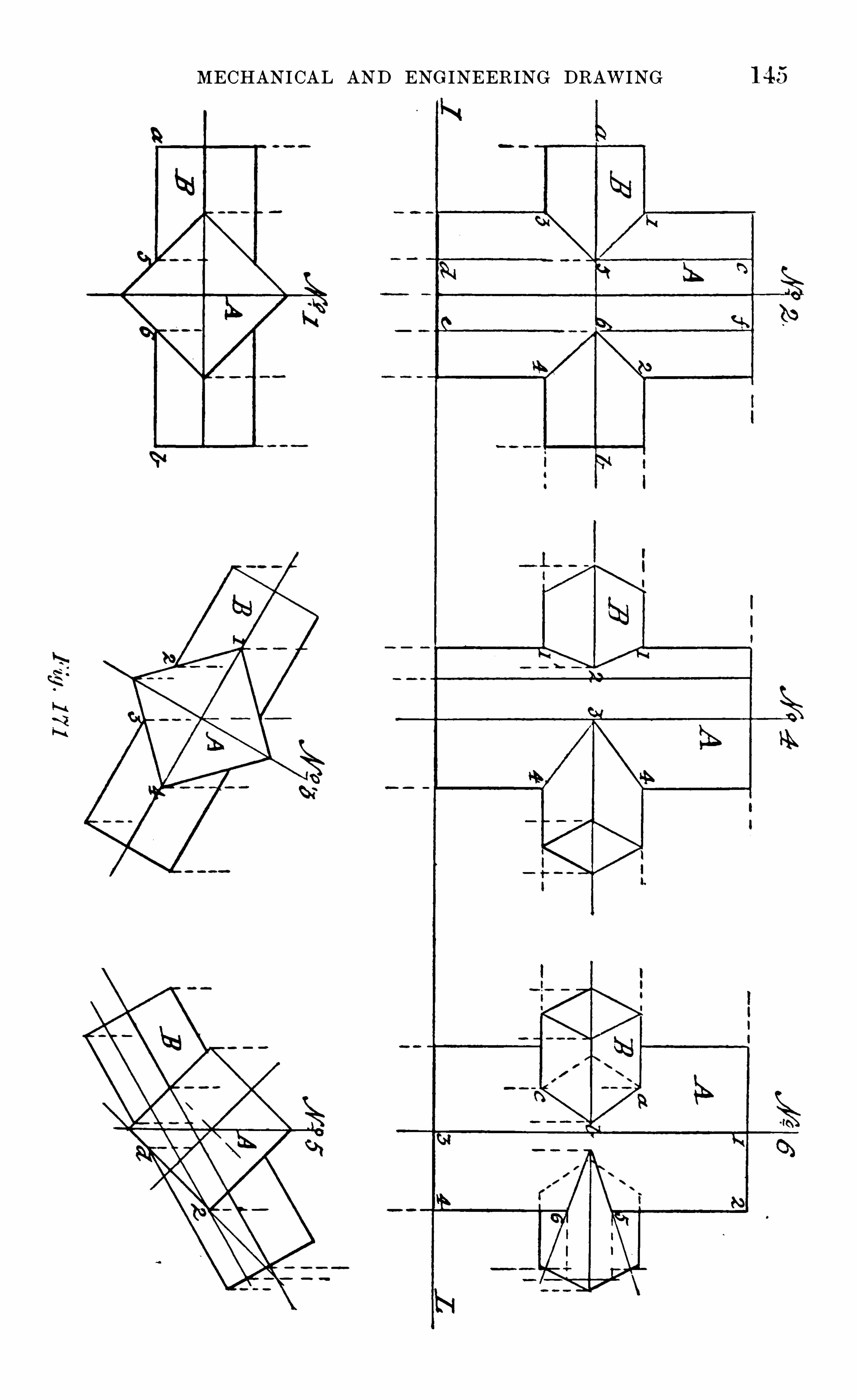
MECHANI CAL AND ENG INEERING DRAWING 1 45

1 4 6 FIRST PRINCIPLES or
angle— say of 45°— with the VP or IL . Then with this plan,No . 7 ,
and the elevation, No . 5,find by projection the elevation of the prisms
in their new position , as shown in No . 8 . Thus posed,but two lines of
penetration will be seen - via,where the prism B passes through the
side a , b, c , cl of A ,— and are found by projectors drawn through e and
f in No . 5,and g and h in No . 7 . The l ines of penetration of A by B
on the side opposite to a , b, c , d— shown in dotted lines— are found bysimilar projectors from points e
’
, f’ in No . 5
,and g
'
,h
’ in No . 7 .
The next problem is a case in which a diagonal of the intersectedprism is in the same plane as that of a diagonal of the prism intersecting it .
Problem 67 (Fig .
— Given the plan of two sgum e pi isms ofequ al length , penetrating each other at right angles, thei i axes and a
diagonal of each being i n one and the same plane, to fi nd their linesof penetaation.
First,let the axes of both prisms be parallel to the VP,
then No . 1
(Fig . 1 7 1 ) will be their plan . From this,first find the elevation of the
prism A,making it equal in height to the length —
given in the planof B . At the middle of this height draw in the ax ial line of B ,
and onit project over from the plan No . 1
,the two ends of that prism . Now
the lines of penetration of A by B may be found in two ways, either byprojecting over to the elevation the points of intersection of the visibleedges of B with A,
seen in plan , or by the u se of section planes . By thefirst method it will be seen at a glance, that in elevation only two sideswith their three edges of the prism B will be seen as penetrating A .
These are the top, bottom,and front edges, the tw o former of which
intersect the right and left vertical edgestD
of A In points 1,2,3,4 . To
find where the front edge of B entersb
and leaves A, project over fromthe plan of this edge the l ine ab No . l
,to its elevation ab No . 3
,the
points 5,6 ; j oin points 1 , 5 5
,3 2
,6 6
,4 by straight lines
,and they
will be the lines of penetration sought .
63 . To find the same lines by the u se of intersecting planes,it will
be seen at once that if a plane be caused to pass through the axes ofboth prisms parallel to the VP,
it would intersect the prisms in’
the
points 1,2,3,4,No . 2 ; and if a second plane, parallel to the first and
tangent to the edge ab of the prism B,be passed through A,
it wouldintersect the edge ab
,No . 1
,in the points 5 and 6, as the section of A
made by this plane would be the parallelogram cdef shown in faint linesin No . 2
,the points of intersection of the edge ab by it being 5 and 6,
which,j oined to 1 and 3 and 2 and 4
,give the same lines of penetratiori
as by the first method . It will be seen , on studying this figure, thatthe resultant lines of penetration are nothing more nor less than the
intersections of pairs of planes at an angle, and it is in the j udiciousapplication of such section planes that the whole art of finding the linesof penetration of solids consists . I t will
,however, be evident that In
the problem just solved , and that which follows it, their u se in practicewould be dispensed with , as the lines sought can be found at once bysimple projection from the plans of the objects ; but, as it is advisable

1 4 8 FIRST PRINCIPLES or

MECHANICAL AND ENGINEERING DRAWING 1 459
by right lines to the vertical projection of point d in the plan , give'
the
same lines of penetration as before obtained .
65. H ad the prisms in the foregoing problems been egu al pairs, theresultant lines of penetration would of course have been different . Insuch case, when seen in elevation as in No . 6 , Fig . 1 7 2, there would beno lines of penetration at all
,as the two visibles faces are in one and
the same plane, and therefore show no juncture . If, ,however, their
sides were inclined to the planes of projection— their axes being still atright angles and in one plane parallel to the VP— then the lines of
penetration would be as shown in No. 2,Fig . 1 72, taking the form of
a cross,due to their surfaces intersecting each other equally . This
may be proved to exactness by the u se of section planes . Let No . 1,
Fig. 172, be the plan of two equal- sized prisms A and B,intersecting
each other at right angles , and with their axes in one and the sameplane, and let it be required to find their lines of penetration .
From the position,shown in plan
,in which the prisms are with
respect to each other,it is evident that a section plane passing vertically
through both their axes,would give equal rectangular sections of each
,
and four points of intersection with the prism B a and 6 being thoseof entering, and c and d those of leaving it . Then as the prisms are
equal , it follows that any number of parallel planes passing simu ltaneou sly through both of them would give equal sections and points of
intersection ; lines, therefore, drawn through these points, taken inorder, will give the l ines of penetration of one solid by the other.
To find these lines in the given problem,obtain by projection from
the plan No . 1, an elevation
,as in No . 2
,of the prisms as if they were
entire . Parallel to the ax is of B in No . I,draw ‘
the lines 1 2 3
which will be the edge view,or plan
, of the section planes to be used .
Find the elevation of each of the sections of the prism A, produced bythese planes, by vertical projectors from the points 4 5 6 inNo . 1 then as the prisms are equal, and the section planes are assumedto pass through both, the horizontal one B will give similar sections tothat of A. To find their bounding lines, produce the axial line a g of
the prism B in No . 2 to the left, and on it draw in a half-end view ofthat prism looked at in the direction of the arrow on the left . On thisset off from the line ef the distances that the lines 1 2 3 in
plan No . 1 are from the ax is of B,and through the points thus found
draw vertical lines to meet the two sides of the triangles in the points1 2 3 Then parallel to the IL,
and through these last- foundpoints, draw lines from end to end of the prism B
,as shown in No . 2 .
The points where these lines cut the corresponding vertical ones drawnthrough points 4 5 6 in No . 1
,will be points in the lines of
penetration of the two prisms . On drawing lines through these points,they will be found to be straight ones
,crossing each other at the point
z , where the two frontmost edges of the prisms intersect . Althoughthese lines might have been at once obtained by j oining the points a d,b c , in No . 2
, by straight lines, it is advisable that the student shouldbe able to prove that they become straight
,rather than take the matter
for granted .
If the axis of one of such equal prisms be inclined to the VP,

FIRST PRINCIPLES OF

1 52 MECHAN ICAL AND ENGINEERING DRAWING
plane will be correctly represented by a line — as a b in No. 2— parallelto the IL . It is evident such a plane will pass through the twodiagonals of the ends of the prisms— seen from above in the directionof the arrows— which are parallel to the VP. H aving found the planas shown in No . 2
,the lines of penetration of the prisms are now required .
These in elevation will be the intersections at equal angles of the frontsides of the prisms . The points of intersection of the edges of the prismsare those between which the lines of penetration will pass, and as theprisms are equally inclined to each other, those lines will pass throughpoint a: in No . 1 at right angles to each other, as shown . In the planNo . 2
,only two such lines will be seen— viz .
,my, and the one directly
behind it in elevation— but which,on account of their position— both
being in one plane— merge into one line tog a"
,shown in No . 2 . Now
,
as such junctions of prisms as are shown in No. 1 (Fig . 1 73) oftenoccur with their axes in a plane at an angle with the VP,
w e give suchan instance in the following problem
Problem 70 (Fig . 1 73) — Given the plan of the equ al squ are prisms
w i th their asses inclined to each other at the same angle as in the
l ast problem to find their elevation and lines of penetration, when the
plane of their acres is inclined to the VP at an angle ofThe position the prisms will now assume will be tantamount to
swinging the two together as shown in No . 1 (Fig . 1 7 on the cornerfigured of the left-hand one, through a horizontal angle of Ifthen the plan of the prisms obtained in No. 2 be drawn in with theline a 6, making that angle with the IL , as shown in No . 3
,then the
elevation of the prisms in this position may be obtained by di rectprojection from No . 3 and No . 1
,care being taken that the projectors
used in doing so are drawn from corresponding points in each . If du econsideration be given to the relative position of the edges of the prismsto each other, no diffi culty should be experienced in obtaining a correctprojection of
' them ,as shown in No . 4 . The lines of penetration in
elevation do not, of course, in this case show as being at right angles toeach other, although they are virtually in that position .
Nos . 5 and 6 in Fig . 1 73 show the application of the same methodof procedure to the case of the penetration of triangular prisms asto those of square section ; which require no further explanation thanthat afforded by the projectors shown in the diagram . One side of thepenetrating prism is shown as coinciding with and passing through theax is of the penetrated one. In each case the cross- section of the prismis an equilateral triangle, the size of the penetrating one being shown bythe end views given at A and B . As a multiplicity of similar examplesto the foregoing would only show the application of the same principlesin determining the lines of penetration of prisms by prisms
,a few
problems will now be taken in which the intersections of pyramidsare involved .

CHAPTER XVIII
THE INTERSECTIONS or PLANE SOL IDS (continu ed) .
66 . BEFOR E passing directly to the finding of the lines of penetrationof one pyramid by another, the solution of such a problem will come
much easier to the student if some preliminary practice is had with thecase of a pyramid penetrating a prism. A s such a combination is oftenused in practice, in giving form to simple ventilators , cowls, etc .
,w e
give as problems in this connection those in which the two solids are
combined for such purposes .The first combination
,Shown in plan and elevation in No . 1 and No .
2 (Fig . is the simplest possible, it being that of a square prism ,
with its ax is vertical and sides parallel and perpendicular to the VP,
penetrated by a square pyramid . the axis of which is parallel to’
boththe VP and HP
,and in the same p i ane as that of the prism .
From the relative position of the two solids , as show n in the figureit is evident that neither in plan nor elevation will any lines of penetration be visible in this case
,as the two faces a and b of the prism ,
whichare penetrated by all fou r faces of the pyramid , are in plan andelevation — through being perpendicular to both planes of projectioneach represented by one straight line only
,with which the actual lines
of penetration coincide, and therefore cannot be seen . H ad the faces ofthe prism, however, been in the least inclined to the VP— still remaining perpendicular to the HP,
— then one line of penetration only wouldhave come into view, dependent upon the inc lination of the ax is of thepyramid to the VP.
For all purposes where combinations of solids are used to give formto mechanical details, it is usual in practice to so combine them thattheir intersections Shall be symmetrical . That is to say, that when theform of the article to be made requires that one solid Should penetrateanother, the penetration is made in such a way that an axial planepassed through the solids shall divide each of them into equ al parts .
This, although it necessitates the axes of both solids being in one andthe same plane, does not necessarily prevent either the axes or sidesof the solids from being inclined to the VP or H P. As instances w emay take the following cases put in the form of problems
153

1 54 FIRST PRINCIPLES OF

1 56 FIRST PRINCIPLES OF

MECHANICAL AND ENGINEERING DRAWING 157
their j unction . This line or edge In No . 5 will be a a'
,that part Of it
where it passes through the prism being ou t of sight . From this planNO . 5
,find by projection the elevation NO . 6 Of the solids as if they
were entire . For the lines Of penetration that will be visible, drawprojectors from the points 1 , 2, in the line ba
’ in NO . 5,to cut b
”
a'’
in
NO 6 In the points A then lines drawn from these last found pointsto 3, 3 ; 4 , or where the upper and lower edges Of the pyi am identer and leave the prism,
will be the lines of penetration required .
67 . Although,as stated in a previous paragraph, it is usual in
practice to make the intersections Of solids in the design of mechanicaldetails symmetrical
,cases may sometimes arise in which this symmetry
cannot be adhered to . Through the ex igencies of position Of the solidpenetrated
,it may be impossible to bring the axes Of both into one and
the same plane, although at right angles to each other . To meet sucha case the following problem
"
will show the method of procedure indetermining the lines of penetration .
Problem 73 (Fig . 1 7 — Given the plan of a square prism , pene
trated by a squ arepyramid, their axes being in diferent planes re
qu ired the elevation and lines ofpenetration of the solids.
From NO . 1 (Fig . which is the given plan of the solids, it i sseen that the ax is d
,a
’
of the pyramid passes through the prism in adirection parallel to two of its Oppo
'
site Sides, but some distance infront of its axis . To find the lines of penetration when in such a position, Obtain by projection the elevation of the solids as if they wereentire, both of them being of the same dimensions as in the previousproblems . As a vertical plane passed through the axis of the pyramidwould divide it into two equal triangular ones, and give an isoscelestriangle for the section made by the cutting plane, it is evident thatany vertical plane passing through the apex of the pyramid would givea similar— t hough not equal— triangular section .
Now, in looking in the direction of the arrow in No . 1 , it is seenthat the frontmost edge d
’
a of the pyramid enters the left visible faceof the prism at point 1
,and leaves it on the right face at point 2 .
These points projected over to the corresponding edge of the pyramidin NO . 2
, give To find where the vertical edge bb’ of the prism— seen in elevation in No . 2— enters and leaves the two front faces ofthe pyramid , draw (in NO . 1 ) a line through a
',its apex
,and the
corner b of the prism,and produce it to cut the base line a c of the
pyramid in the point 3. W e have then to find by projection the elevation Of the section thus made
,to enable us to Obtain the points re
quired . Taking this line, 3 ba’
,as the edge view, or plan , of a verti
cal plane passed through the pyramid, it will give a triangle for thesection . To determine it w e must first get an end view (in elevation)of the base of thefront half of the pyramid . Now
,its whole base is a
square, with diagonals equal in length to the line‘
c d a — in NO . l — one
of them being vertical and the other horizontal . To draw the halfbase requ i i ed,
0
find the elevation of the vertical diagonal of the base Ofthe pyramid, represented In No. 2, by the faint line drawn between the

1 58 F IRST PRINCIPLES OF
points d and d'
, they being the top and bottom ends Of that line ;produce the ax is a a
’
of the pyramid,and on it draw the half-square
d x d'
as Shown .
Now the assumed section plane, represented by the line 3,ba
’ inN O . 1
,cuts through the base of the pyramid at the distance d 3 from
its vertical diagonal . To find the line on the half-base so made,through d in NO . 1 draw a line indefinitely, parallel to the IL with das centre and radius d a, draw an arc
,cutting the line through d pro
du ced, in the point x, and from the same centre, with a radius equal tod 3
,describe an are cutting x d in As the line x d
,NO . 1
,is a plan
of the half- square d x d'
,NO . 2
,swung round on its diagonal d
,d
’ as ahinge
,until it is parallel to the IL
,on this half- square— or front half
base of the pyramid— can now be found the exact length of the baseof the isosceles triangle produced by the cutting plane, and from it thesection itself, and the lines Of intersection Of the sides Of the prism andpyramid .
For the triangular section,draw a projector into the VP through
point in the line x d,NO . 1
,and it will cut the lines x d and x d
' inNO . 2
,in points 3
,3
’
the distance between which is the length of thebase of the triangular section . For its sides, cut by projectors drawnthrough points 3
,parallel to the IL
,the lines d a, a d
’
,in points 4
,
and through these and the apex a’ drawfaint l ines as shown in NO . 2
then the points 5, where these faint lines— or edges Of the triangular section— cut the vertical edge bb’ Of the prism ,
are two of the
points sought . Join 1 ’ in the line a a’ to these points by straight lines
,
and they will be the lines of penetration on the left front face of theprism . For those on its right face, find by projection the elevation ofthe points — 2 and 6— in the edges of the pyramid where they leavethat face
,and j oin these as before by the straight lines 6 2
’ andthey will be the lines of penetration seen on that face. For the corresponding lines on the back faces Of the prism— not seen , but showndotted — the same method of determining them is employed as for thosethat are directly in view .
68. A S an example of the case Of the penetration Of a prism by apyramid
,when the axes Of the two solids are in one plane
,but not at
right angles to each other,w e give in Nos . 3
,4,5,6 (Fig . 1 75) the re
su ltant projections and lines of penetration of the solids when havingthese relative positions . NOS . 3 and 4 show the plan and elevation Of
the sol ids when the plane of their axes is parallel to the VP,and
therefore perpendicular to the HP ; and NOS'
. 5 and 6,those Of the
same solids when that plane is inclined to the VP,but still in the
vertical position . As the required prdjections and lines of penetrationshould now be found by the student without further assistance thanthat given— by the projectors— in the diagram ,
w e pass on to the determination of the lines of penetration of one pyramid by another.
The first case is that Of the penetration of a square pyramid by asimilar one of equal size, the axes Of both being inone plane, parallel tothe VP,
and at right angles to each other.
First,let the penetrated solid be in such a position that th
diagonals of its base are respectively parallel and perpendicular to

1 60 FIRST PRINCIPLES OF

MECHAN ICAL AND ENGINEERING DRAWING 1 61"
shown in faint lines in NO . 5— and it will be found to cut the frontedge x b of the prism B In points 2
,5 j oin these by straight lines to
points 1,3 and 4
,6— previously found — and they will be the required
lines of penetration of the two solids seen in elevation .
To find the plans of these l ines, let fall projectors from points 2,5
and 1,4,in No . 5
,to cut the corresponding edges of the prism B in
No . 6,and they will give points L
,4,5
,j oi n these as before by
straight lines as shown , and they will be the plans of the two lines ofpenetration 1
,2,4,5 previously found in No . 5.
On looking upon the two pyramids , in the direction of the arrowShown in NO . 5
,two pairs of lines Of penetration will be seen . These
are the two front ones A 4,5 ; and the two, 1 , 4
,imme
diately behind them ,shown In No . 6 . To Show the position Of the four
lines of penetration made by the two lower inclined sides Of pyramid B ,
let fall projectors from points 3,6 in No. 5
,to cut the corresponding
edge of the same pyramid in 3,6 in NO . 6 j oin these points by dotted
lines to 2,2'
5,5
’ respectively, and they will be the plans Of the lower,or retu rn lines of penetration of the tw o solids .
Should the two prisms have such a relative position that their axesare inclined to each other at some angle other than a right angle, in aplane common to both , the procedure for finding their lines of penetration would still be the same . As a test of its application, let the twopyramids in the last problem penetrate each other in such a way thatthe ax is of the penetrating one is inclined at an angle of 30
° to thehorizontal
,While that of the penetrated remains vertical , and let it be
required to find their projection and lines of penetration when the ax ialplane Of the solids is parallel to the VP,
and also when that plane isinclined to the VP at a given angle.
As the solids in the fi rst-named position have their ax ial planeparallel to the VP
,and the ax is of one of them is inclined to the H P,
their elevation,as if they were entire
,must first be drawn . H aving
done this as shown in NO . 1 (Fig . from it find by projection theirplan— also as if entire— as given in NO . 2 . The points of intersectionof the upper and lower edges of the pyramid B with A are at once seenin NO . 1
, to be 1 , 2, 3, 4 . Proceed as in the previous problem to findthe section of A
,by a vertical plane passing through it tangent. to the
front edge of B ,and the points in that edge ou t by it ; j oin these up
to the first found points’
by straight lines as before, and they will bethe lines of penetration in elevation . On finding the plans of theselines as before explained and shown in No . 2
,the
,
first part of the
problem is solved . For its latter part,draw in as shown in NO . 3 in
the figure, a repeat of No. 2 , but having its ax ial line a b at the requiredangle— say 30
°
— with the VP or IL ; and from it and No . 1 find byprojection the elevation of the pyramids and lines of penetration intheir new position . This view
,if Obtained In accordance with the pro
cedure already explained in a previous problem,will give No . 4 (Fig .
1 77 ) as the result .
70. As a concluding problem in the penetration Of plane surfacedsolids, w e give in NO 5 and No . 6 (Fig . 1 77 a case in connection withpyramids which sometimes occurs in practice— viz . that wherein a
M

1 62 FIRST PRINCIPLES OF

CHA PTER XIX
TH E INTERSECTIONS OF SOLIDS HAVING CURVED SURFAC ES
7 1 . A s the cost Of any engine, or machine detail , depends in a greatmeasure upon the number of processes involved in its production
,it
will readily occur to the student of engineeri ng that the simplest possible form ,
and one requiring the least amount of machining, to fit it forthe purpose to which it is to be applied, will be that which is producedby a revolving motion Of the material to be acted upon by the cuttingtool which gives it shape. The product of this motion
,a " solid of
revolution,
” has also a larger cross— sectional area within the same
bounding line than any plane-surfaced solid ; and for this reason , itwill be found on studying the construction Of engines , machines, andall ordinary steam generators, that the cylinder, the cone, and the
sphere — all of them solids having curved surfaces— enter much morelargely into their design than do any other Of the solids . A knowledgeof the Way in which their surfaces intersect when in combination istherefore highly essential
,not only to the draughtsman who is called
upon to design such details, bu t to the skilled workman w ho will produce them .
This knowledge is the more necessary, as upon the correct application of the principles of projection to the determining of the actua l
intersections of such solids,depends the truth or otherwise Of the
results arrived at when finding the " developments of their surfaces — a
subject which immediately follows that now being considered , and one
which includes within its scope the determination of the exact shapethe material should take when the article to be produced is one madeentirely of metal plates .
The preliminary problems in connection with the intersections ofcurved - surfaced solids are those in which cylinders are penetrated bycylinders . The first is
Problem 75 (Fig.-Given the plan of two equ al
-sized right
cylinders, w ith axes at right angles in one plane parallel to the VP ,
and penetrating each other ; tofind their lines of intersection.
Now,from the way in which a right cylinder is generated , it is
known that an axial section Of the solid is a rectangle,and any other
1 64

MECHANICAL AND ENGINEERING DRAWING 1 65

1 66 FIRST PRINCIPLES OF

F IRST PRINC IPLE S OF

MECHANICAL AND ENGINEERING DRAWING 1 69
Problem 76 (Fig .-Given the plan of tw o cylinders of u nequ al
diameter intersecting each other,w ith their axes at right angles and
in one plane parallel to the VP tofi nd their elevation and lines ofpenetration.
The plan of the two cylinders in the position stated in the problemwill be that shown in NO . 1 (Fig . the penetrating one beinghorizontal . From this plan
,find by projection the elevation of the
cylinders as if entire, making them both Of the same length,with the
horizontal intersecting the vertical one at the middle Of its height .
Then to find the visible lines of intersection of the solids in elevation,
draw in — ~as in the last problem— the plans of the intended verticalsection planes to be used ; and Obtain by projection the elevation Ofthe sections Of the vertical cylinder made by these planes . Also drawin
,in NO . 2
,on the ax is of the horizontal cylinder produced, an end
view Of the r nt half of that cylinder . On this,show In— as in the
previous pI Oblem — the lines made by the vertical section planes inpassing through that cylinder, and from the points in the semi- circle,or end view
, ou t by these l ines, Obtain as before the front elevation ofthe sections of the horizontal cylinder ; then the points where thesesections cut the corresponding ones Of the vertical cylinder, will bepoints in the lines of penetration of one solid by the other. On j oiningthese by lines drawn through them
,they will be found to be (as shown
in No . 2,Fig . 1 79 ) symmetrical curves ; the highest and lowest points
in them being determined by the intersections of the bounding lines Ofthe two solids
,at 1
,2,3,4,while the middle ones, a
’
b'
,are the vertical
projections Of a b in No. 1 , or where the frontmost part of the horizontalcylinder is seen to enter and leave the vertical one.
Should the axial plane Of the two cylinders be at any given anglewith the VP— as in No . 3 — instead of being parallel thereto
,the lines
of their intersection would still be found in the same way as beforeshown, but they will not be symmetrical curves as in the problemjust solved, but such as are seen in fu ll lines in NO . 4 (Fig . 1 7
the dotted ones being the return lines of intersection of the penetrating-Or horizontal— cylinder, with the surface of the vertical one, which is
ou t of sight . As the correct finding of the intersecting lines— shownfull, and dotted in NO . 4 — of the two cylinders is but a matter of
careful projection by the student, no further assistance than that givenin the diagram will be required by him .
73. The next case is that of the intersections Of unequal cylinders,at an angle other than a right angle, and having their axes in different
planes at a given distance apart . The problem is
Problem 7 7 (Fig .— Tw o cylinders of u nequ al diameter
,w i th
their axes i n parallel planes, i ntersect each other at an angle ofi t is requ ired tofi nd the proj ections and lines of penetration of thesolids
,w hen the axis of one of them is vertical
,and the other paral
lel to the VP .

1 70 FIRST PRINCIPLES OF

1 7 F IRST PRINCIPLES OF

MECHANI CAL AND ENGINEERING DRAWING 1 73
number Ofparallel planes to pass simultaneously through both solids , allthe points of the intersection required may be found by making the
cutting planes divergent.74 . In a previous chapter it w as shown that all the sections of a cone
made by a plane passed through its apex to its base, gave triangles forthose sections . If, then, in the problem under solution , cutting0f planesare assumed to pass through the apex of the cone in varying directions
,
cutting it and the cylinder simultaneously, it i s evident that all the
sections of the tw o solids will be similar to those obtained by the axia lsection— viz
,rectangles and triangles , each Of which will give four
points in the lines of intersection sought .To find these points in No . 2 (Fig . through f, the apex Of the
cone in No . 1,draw the linesf1 , f2, f 3, and let them,
with ef and hf ,be the plans Of vertical section planes passing through both solids in thedirections Shown . Then find by projection the rectangular sections ofthe cylinder produced by the cutting planes , as shown in faint dottedlines In NO 2 . For the corresponding sections of the cone by the sameplanes
,on its base line eg in No . 2 as a diameter
,and h as centre
,
describe the semi-circle e x g, which will be the front half of the base ofthe cone looked at from the left . On the line x h
,measuring from h
,
transfer the distances e 1 , e 2 e 3 In No . 1,and through the points thus
found draw lines parallel to eg, to cut the semi circle In 1 2 3 3 ;project these points over to e g, and through them draw faint lines tothe apex f The triangles formed by these lines will then be the
sections of the front half Of the cone, made by the same planes that cutthrough the cylinder, and the points of intersection of these respectivelywill be the points in the l ines of penetration sought .
Should the ax is of the cone be inclined to the V P,as in NO . 3
,that
of the cylinder still remaining vertical, and the lines of intersection berequired, the process of finding them is exactly the same as before. The
l ines will,however, assume a different form of curve
,du e to the altered
position Of the cone with respect to the plane Of its projection,the V P .
This alteration,it will be noted, brings the base of the cone into view,
but causes the surface of the cylinder penetrated by its small end topass ou t of sight . As the ax is of the cone in the previous figure w as
parallel to the VP,the lines of intersection Of its back half with
the surface of the cylinder being directly behind those in front,could
not be shown,but the cone being now inclined to the VP,
it is possibleto indicate exactly the form Of the return curve of penetration . This Isshown by the dotted line l
,Obtained by projecting over the points 4 , 5,
6, in i h
,NO . 3
,and finding as before the corresponding sections Of the
back halves of the cone and cylinder, which give the points required .
75. H ad the penetrating solid been but a portion of a cone — say afrustum — then the lines of intersection of the two may be got in twoways . If the apex of the cone i s accessible, the method already explainedwould be the simplest and best ; but if the taper Of the cone be onlyslight
,and its apex ou t of reach or at an inconvenient distance, then the
procedure would be as shown in Fig. 1 82 .
First, let it be assumed that the ax is of the penetrating solid isparallel to the VP,
and at right angles to that of the

1 74 FIRST PRINCIPLES OF
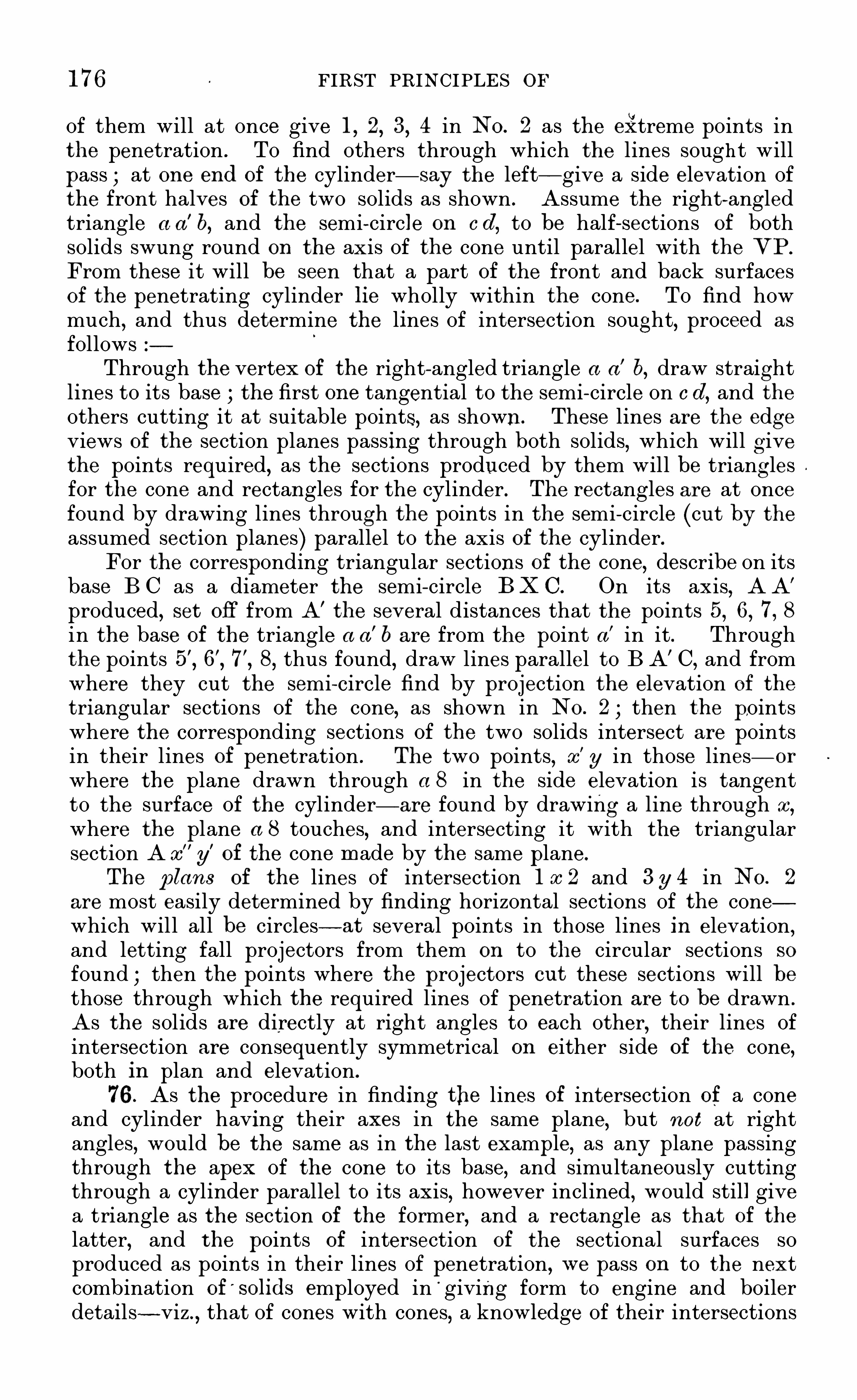
1 76 FIRST PRINCIPLES OF
of them will at once give 1,2,3,4 in NO . 2 as the extreme points in
the penetration . To find others through which the lines sought willpass at one end of the cylinder— say the left— give a side elevation ofthe front halves of the two solids as shown . Assume the right-angledtriangle a a
’
b, and the semi—circle on c d,to be half- sections of both
solids swung round on the ax is Of the cone until parallel with the VP.
From these it will be seen that a part of the front and back surfacesOf the penetrating cylinder lie wholly within the cone . To find howmuch
,and thus determine the lines of intersection sought, proceed as
followsThrough the vertex of the right-angled triangle a a
’
b,draw straight
lines to its base the first one tangential to the semi- circle on c d,and the
others cutting it at suitable points, as shown. These lines are the edgeviews Of the section planes passing through both solids, which will givethe points required, as the sections produced by them will be trianglesfor the cone and rectangles for the cylinder . The rectangles are at oncefound by drawing lines through the points in the semi- circle (cut by theassumed section planes) parallel to the ax is of the cylinder.For the corresponding triangular sections of the cone, describe on its
base B C as a diameter the semi- circle B K G. On its ax is,A A’
produced, set off from A’
the several distances that the points 5, 6, 7 , 8in the base of the triangle a a
’
b are from the point a’ in it . Throughthe points 8
,thus found
,draw lines parallel to B A’ C
,and from
where they cut the semi- circle find by projection the elevation Of the
triangular sections Of the cone, as shown in NO . 2 ; then the pointswhere the corresponding sections Of the two solids intersect are pointsin their lines of penetration . The two points
,x
'
y in those lines— or
where the plane drawn through a 8 in the side elevation is tangentto the surface Of the cylinder— are found by drawing a line through x
,
where the plane a 8 touches, and intersecting it with the triangularsection A x
”
y’
of the cone made by the same plane.
The plans of the lines of intersection 1 x 2 and 3 y 4 in NO . 2
are most easily determined by finding horizontal sections of the conewhich will all be circles— at several points in those lines in elevation,and letting fall projectors from them on to the circular sections so
found ; then the points where the projectors ou t these sections will bethose through which the required lines of penetration are to be drawn .
As the solids are directly at right angles to each other,their lines Of
intersection are consequently symmetrical on either side Of the cone,both in plan and elevation .
76 . As the procedure in finding the lines of intersection of a coneand cylinder having their axes in the same plane, but not at rightangles
,would be the same as in the last example, as any plane passing
through the apex Of the cone to its base, and simultaneously cuttingthrough a cylinder parallel to its axis
,however inclined, would still give
a triangle as the section of the former, and a rectangle as that Of the
latter, and the points of intersection of the sectional surfaces soproduced as points in their lines of penetration
,w e pass on to the next
combination Of'
solids employed in' giving form to engine and boiler
details - viz,that of cones with cones
,a knowledge of their intersections

MECHANICAL AND ENGINEERING DRAWING 1 77
being the more important, as combined conical surfaces enter intoalmost all designs where metal plates are used as the material of con~
struction. A s a problem in this connection take
Problem 80 (Fig .— A cone w ith i ts axis in a vertical posi tion
is penetrated by another cone having i ts axis horizontal andparallel
to the plane of proj ection ; requ ired the lines of penetration in
plan and elevation of the two solids in the posi tion given.
Draw in first the plan and elevation of the two cones as if entire .
Then,as a series of planes passing through the apex of one of the cones
to’ its base would give triangles for the sections made of that particularcone only, bu t hyperbolas for those of the cone in combination
,it ' is
evident that the finding of the lines of intersection of the tw o solidsby the u se of section planes in such a w ay would be a long process andvery liable to error. What has to be aimed at, is to so u se a sectionplane that it will, in the problem to be here solved, give simi lar
sections of both cones . To effect this, a triangu lar plane is assumedto pass through the apices Of both simultaneously, and to be swungon one of its sides— its hypothenuse— as a hinge through varyingan les.g
TO apply this principle to the problem to be solved (in the elevationOf NO . 1
,Fig . produce the base line h e of the horizontal cone
indefinitely in both directions then draw a line through the apices ofboth cones to cut the produced base line in the point x’ and the ILin point x . Then will the produced base of the horizontal cone fromx
’ to the IL at B be the perpendicu lar, the line Bx the base, and thatdrawn through the apices of the cones from x
’ to x the hypothenu se, ofthe right-angled triangular section plane for finding the lines ofintersection Of the two solids . Such a plane in its normal position— Or parallel to the VP and perpendicular to the H P— at once gives 1
,
2,3,4
‘
in NO . 1 as the extreme points in the lines of penetration .
TO find others through which these lines will pass, the‘ positions Of the
triangular plane x’
Bx in its swinging on the line x’
x as a hinge havenext to be shown .
To do this,describe on the base h e of the horizontal cone as a
diameter,a semi—circle, then through the vertex x
’
of the right-angledtriangle x
’
Bx,draw straight lines, the outermost one x
’
3 tangentialto the semi-circle
,and the others , x
’
2,x
’
l , at about equal distancesapart . These lines are the end elevations of the perpendicular edgeOf the triangular plane x
’
Bx,when swung on its hypothenuse x
’
x as ahinge . Its ou ter position
,represented by the line x 3
,is drawn
tangent to the front surface Of the horizontal cone, to find the points5 and 6 in the lines of penetration . To determine their exact positionand that of other points in these lines, describe on the base CE Of thevertical cone as a diameter, the semi-circle CDE transfer the points1,2, 3 on the IL by arcs
,as shown
,to on the produced base
l ine Of the horizontal cone, and through these last- found points drawlines
'
to x,intersecting the semi-circle last drawn in the pointsf,g, h,
and i , j , It . Find by projection from these points and those made by

"
1 78 FIRST PRINCIPLES or
the same section plane, in the semi-circle drawn on the base h e of thehorizontal cone, the corresponding vertical sections of the two cones,and the points where they intersect will be points through which theirl ines of penetration will pass, as shown in No . 1 (Fig . To findthe plans of these lines, the simplest method , and one involving the
least confusion of lines in the diagram,is that shown in No. 2
,where
the triangular sections of the vertical cone made by the planes x’
3,
x’
2,x
’
l,are first found, the points required being then projected over
from No . 1 to their corresponding sections in the plan,and lines of
penetration drawn through them ,as shown in No . 2 .
Should the ax is of the penetrating cone be at an angle with the
VP,and an elevation of the solids with their lines of penetration be
required, this would be obtained by transferring the plan of themalready found in No . 2
,to such a position in the HP as would bring
the axis of the horizontal cone to make the required angle with the
VP or IL the required elevation is then found by direct projectionfrom the plan of the solids No . 2 (in their new position) and the
elevation given in No . 1 .
In finding such a view of the two solids,the student is to be
reminded that great care is necessary in projecting over the variouspoints in both plan and elevation
,so as to ensure the correct
representation of the solids themselves,as well as their lines of
intersection .
7 7 . A s the same procedure would be followed in finding the linesof penetration of two cones, when the ax is of the penetrating one isinclined to both the VP and HP— the only difference being
,that
the triangular section plane used in finding the points in the linesof intersection of the solids in the first part of the solution
,would not
be right but acute-angled— the student is left to work ou t sucha problem himself, and w e now pass to the finding of the l ines of
penetration or intersection of the sphere, with such of the solids as are
generally used in combination with it .
Premising that it has not been forgotten by the student that anyplane section of the sphere when viewed at right angles to the plane of
section is a circle,and when seen at an angle to that plane, an ellipse,
it is assumed that the intersections of the sphere by any of the
plane- surfaced solids will present little difficulty, and therefore will notnecessitate more than two or three such problems being given forsolution . The intersections of the sphere by solids having curvedsurfaces
,being much more difficult, will require a close attention to
the procedure followed in determining them . The first problem ,
therefore, in this connection is
Problem 81 (Fig .—A sphere i s penetrated vertically and
centrally by a squ are prism w hose sides make equ al angles w i th the
VP i t is requ ired to find the lines of penetration qf the solids,
in plan and elevation.
H ere, it is evident from the w ay in which the sphere is penetrated ,that its ax is
,and that of the prism,
coincide. Therefore, to find the

1 80 FIRST PRINCIPLES or

MECHANICAL AND ENGINEERING DRAWING 1 8 1
c draw a line perpendicular to the ax is of the frustum,and on it set off
from d— where the axes intersect— on either side,a distance equal
to c,a or c
,b,which is half the major ax is of the elliptic section .
For the minor ax is, project over to that of the frustum the points a, bin its right side or edge then With these lengths
,and the paper
trammel,mark off a few points at either end, and through them draw
the elliptic arcs to the right and left edges of the front face of the
frustum,and they will be the lines of penetration of the solids seen
in elevation .
For the plans of these lines on the upper surface of the sphere, letfall projectors from points 1 , 2, in No . 1
, to cut the corresponding slantedges of the frustum (in No . 2) in points 1 2 2
' and for pointsb b
’
,5 in the same diagram,
set off from x, on the two lines drawn
through it at right angles to each other, the distance that b or b’
,in
No . 1, is from the ax ial line— or point 5 5 then curved lines drawn
through the points thus found, as shown in No . 2,will be the l ines
of penetration on the upper surface of the sphere by the frustum .
The corresponding lines on its u nder surface, if required, are found inthe same way. If the sides of the frustum are equally inclined to theVP
,as in the case of the square prism in Fig . 1 85
,and an elevation
of the solids In this position be required, then , as in previous problems,ti ansfer the plan No. 2 to the required position shown In No. 3, andfrom it and the elevation No. 1 find by direct projection the viewgiven in No . 4 . The dotted lines and projectors show how the majoraxes of the elliptical portions of the intersections are obtained, theline 0 c
’
,in which the minor ones lie, being a projector drawn through
d in No. 1 .
78. A s a sphere penetrated centrally by a cylinder or cone wouldin each case ' give circles as the lines of intersection, becoming in
projection either straight lines, circles, or ellipses, according to their
positions with respect to the planes of projection, it is considered
unnecessary to give any problems for solution with the solids so
combined, as the truth of the statement is self~evident withoutillustration . It must not
,however, be forgotten by the student that
such combinations of the sphere With the cylinder or cone, or both,more frequently occur in practice than any other , as
,for instance,
in many kinds of cocks and valves, tee-pi eces, handrails, stanchions,boiler mountings, etc . A S cases
,however, arise where these three solids
are in such combination that their axes are not coincident, or even inone plane, the remaining problems in this part of the subject will havereference to instances in which these infrequent j unctions occur.
Problem 83 (Fig . l 87 ) . -A sphere is penetrated by a cylinder whose
axis is vertical and parallel to that of the sphere ; requ ired the
lines of intersection of the solids, when their axes are a given
distance apart, in a vertical plane inclined at an amgle to the VP .
Let No. 1 (Fig. 187) be a plan of the solids, the larger circle beingthat of the Sphere, and the line vp,
drawn through its axis a, and thatof the cylinder 0
,a plan of a vertical plane at an assumed angle of


1 84 FIRST PRINCIPLES or

MECHANICAL AND ENGINEERING DRAWING 1 85
No. 2,the latter giving points x y, which will determine the actual
positions of the points sought on the conical surface, with the solids, asoriginally placed . To fix these, find in No. 2 the elevation c b
’ of theline from c to b in No . 1 , and to it project over— parallel to the ILthe points (x y) last found, cutting it in 5 and 6, which are those re
quired , the projecting over of x and y being tantamount to turning thecone back on its ax is to its original position . For other points in thelines of penetration
,take a few horizontal sections— which will all be
circles— of both solids,between those already found , and through their
points of intersection , in plan and elevation , draw lines, and they willbe the lines of intersection of the surfaces of the cone and sphere, asrequired in the problem ,
and shown in No . 1 and No . 2 (Fig .
.79 . The next problem will Show that although sections of the twosolids might be taken in such a way that they would produce circlesfor both cone and sphere
,and give apparently an easy solution of it, it
is necessary for the draughtsman to exercise j udgment in decidingupon his method of procedure. The problem is
Problem 85 (Fig .— A sphere is penetrated by a cone horizon
tally ; requ ired the lines of penetration in plan and elevation,
when the axes of both solids are in a plane parallel to the VP ,and
at right angles to each other,bu t that of the cone not passing
through the centre of the sphere.
Draw in first, as if entire, the plan of a sphere penetrated by acone, having its ax is parallel to the IL ,
and passing through that ofthe sphere, as shown in No . 1 (Fig. From this plan get an ele
vation of the solids , Showing the ax is of the cone some distance abovethe centre of the sphere. Now , if sections of the solids be taken byplanes parallel to the axis of the sphere
- which is assumed to be
vertical— and at right angles to the VP,the sections would in reality
be circles for both solids,but only straight lines in projection in
both plan and elevation,which would be useless in determining their
intersections .Again, sections taken through both solids parallel to the ax is of
the cone, although giving circles for the sphere, would still give hyper
bolas for the cone, which are not desirable. The simplest method insolving the problem will therefore be to assume vertical section planesto be taken through the apex of the cone in varying directions andpassing through both solids simultaneously. These would give triangles for the cone and circles for the sphere the latter, however,being at an angle to the VP
,would in elevation be projected into
ellipses . Therefore in No. 1 (Fig. 189) draw in , through a’
the vertexof the cone, to its base, as many lines— say three— a
’
l a’
2 a’
3,as it
is intended to u se section planes . Next find in No . 2 the elevationof the triangular sections produced by these planes, as in previousproblems . Then , so far as the sections of the sphere are concerned, allthat is required is to find the points in the ellipses— into which theC i rcular sections of the sphere are projected— which intersect the

1 86 MECHAN ICAL AND ENGINEERING DRAWING
triangular sections of the cone,for it is through them that the lines of
penetration of the sphere by the cone will pass .To determine these points, there is no necessity to draw in the
elliptic projections , as they may be found very readily by the u se of
the paper trammel before mentioned . H aving numbered the sectionplanes
,in plan and elevation
,as in No . 1 and No . 2 in the figure
,and
noted the points 4 , 5, 6, 7 , where they cut the great circle of the
sphere in No . 1,draw in
,in No . 2 through line c s
,which passes
through the centre of the sphere, the l ines in which the maj or axes ofthe ellipses will lie. One of these only— viz
,that from x in No . l — is
drawn in,in the diagram ,
so as to prevent confusion . Then with halfthe major and projected half of the minor axes of each ellipse— therebeing one for each section taken— on the trammel, manipulated asexplained
,all the points in the lines of intersection
, except the
extreme ones, are found as Shown in elevation No . 2 . For the plansof these lines that will be seen from above— shown in No . l — let fallprojectors from the points in the lines 1 , 2, 3, 4 , in No . 2
,to cut the
corresponding ones in No . 1 , and through the intersections draw the
curved lines as shown, which will be the ones required .
Shou ld'
the axis’
of the cone be inclined to the VP,still remaining
parallel to the H P,and the l ines of intersection of the two solids be
required, when in this position, proceed as in previous cases to transferthe plan No . 1 to such a position in No . 3 as will bring the axis of thecone to make the required angle with the IL ,
and then from it and theelevation No . 2 obtain by direct projection the view Shown in No . 4 .
From the problems which have been glven In this part of the sub
ject, the student will be able to appreciate the endless variety of positions -the solids in combination may be made to assume, bu t as it is notour object to multiply examples, but to give only such combinations asare likely t o occur in practice, w e pass on now to the last section inthe application of the principles of projection — viz
,the Development
of the Surfaces of Solids,” a subject of the highest importance, not
only to the draughtsman, bu t to all who have to shape or fashion anything constructed of sheet metal.
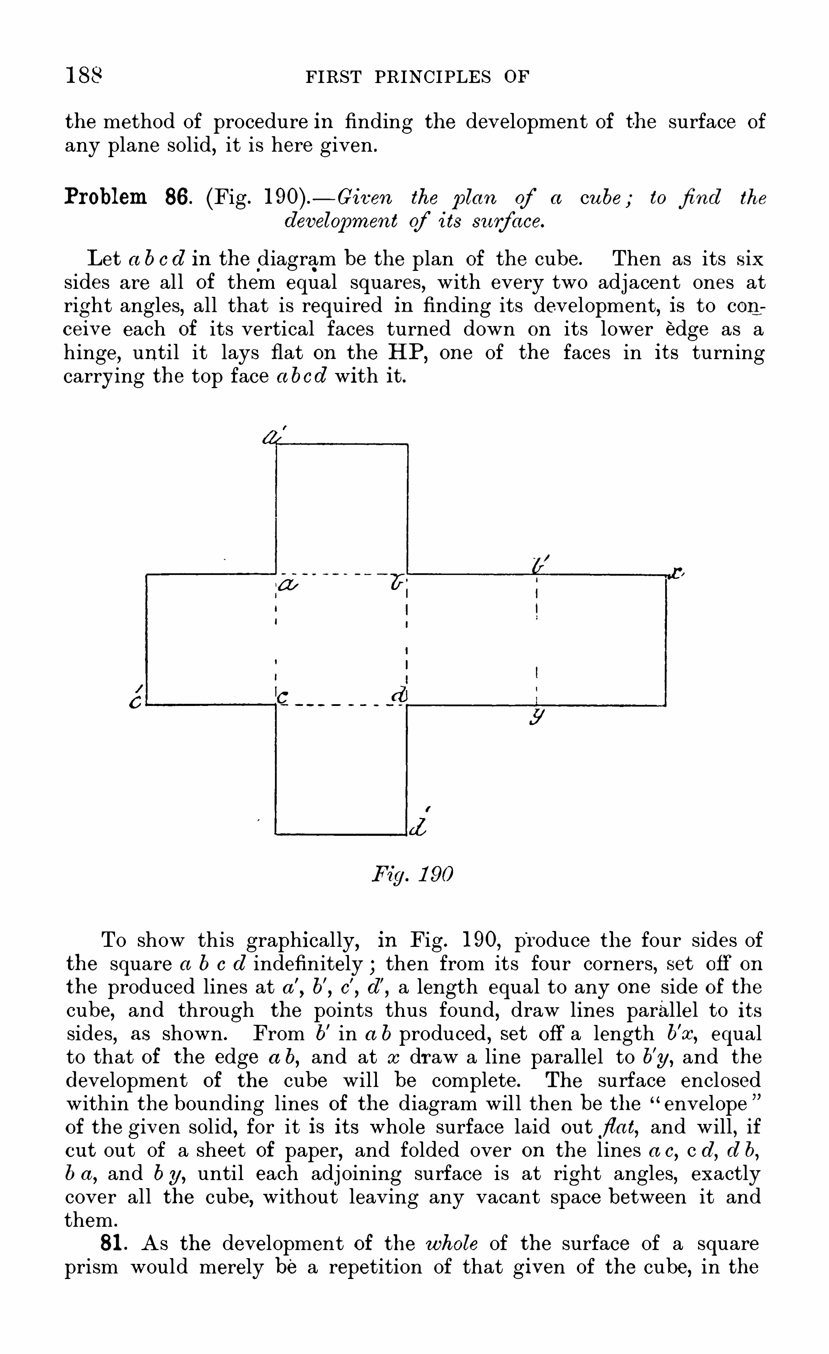
1 88 FIRST PRINCIPLES or
the method of procedure in finding the development of the surface of
any plane solid, it is here given .
Problem 86. (Fig .— Given the plan of a cu be ; to fi nd the
development Qf i ts surface.
Let a b c d In the diagram be the plan of the cube. Then as its six
sides are all of them equal squares, with every two adj acent ones atright angles, all that is required in finding its development, is to con
ceive each of its vertical faces turned down on its lower edge as ahinge
,until it lays flat on the HP,
one of the faces in its turningcarrying the top face a bcd with it.
To Show this graphically,in Fig . 1 90
,produce the four sides of
the square a b c d indefinitely ; then from its fou r corners, set off on
the produced lines at a ’
,b’
,c’
,d
’
,a length equal to any one Side of the
cube, and through the points thus found, draw lines parallel to itssides
,as Shown . From b
’ in a b produced , set off a length b’x, equalto that of the edge a b
,and at x draw a line parallel to b
’
y, and the
development of the cube will be complete. The surface enclosedwithin the bounding lines of the diagram will then be the "
envelopeof the given solid, for it is its whole surface laid ou t flat, and will , ifou t out of a Sheet of paper, and folded over on the lines a c
, c d, d b,b a
,and by, until each adj oining surface is at right angles, exactly
cover all the cube, without leaving any vacant space between it andthem .
81 . As the development of the w hole of the surface of a squareprism would merely be a repetition of that given of the cube, in the

MECHANICAL AND ENGINEERING DRAWING
next problem only a part of a prism is taken, as the solid whose deve10pment is required .
Problem 87 (Fig .
- Given the elevation of a truncated squ are
prism ,tofi nd the development of i ts surface.
Fig. 1 91
Let No . 1 (Fig. 19 1) be the side elevation of the prism, Standing on
its base in a vertical position . A S its base is square, its vertical Sideswill all be of the same width therefore on the line c d produced inde~finitely, draw in first an elevation of the prism
,looking at it in the dirco
tion of the arrow . From c and c’
in‘
it,set off in points2
,2
’ a distanceequal to c d in No . 1
,and through them draw vertical lines, and cut
them in points 3 and by'
a projector from a. Join b’ 3 and b
For the base, and top surface of the prism,produce the lines c’b’, c b,
in both directions indefinitely. Then with c’
as centre,and c
’
2 asradius
,cut b’c’ produced in point 1 and from b
’
,with b’ 3 as radius,
cut the same line in point 4 , and complete the rectangle 4b (above)and the square c
’
l (below) as shown . From point’
2 in c d producedset off a length 2
’
y, equal to c2’
,and through p oint y draw y x,
parallel to 2’
3’
-j oin_
3’ and x
,and the development is completed . If
the resultant figure (the envelope of the prism) be cut ou t in paper,and treated in the same way as that of the cube, it will be found to fitthe solid exactly.
82. As the Surface of an oblique rism is often found to be moredifficult of development by the stu cfent draughtsman than that of aright one, the next problem will Show how it may be correctly found .

FIRST PRINCIPLES OF

1 9' PRINCIPLES OF

MECHANICAL AND ENGINEERING DRAWING 1 93
Problem 89 (Fig .— Given the elevation of a squ are pyramid; to
fi nd the development of i ts surface.
Let ABC, No . 1,in Fig . 1 93
,be the elevation of the pyramid . As
all its sides are alike, and incline equally to its apex ,it is first necessary
to know the actu al length of one of its Side edges . To find this,at B
in No . I,draw a line perpendicular to the IL . With B as centre
,and
BA — the length of a side of the pyramid— as radius,describe an arc
cutting the perpendicular line in a . From B,set off in b, a length
equal to half BC, and j oin a,b then aB will be the length of a side of
the pyram id, and a b that of one of its edges .For the development, at a convenient distance from No . I
, draw aline perpendicular to the IL, and project over to it in a
’
the point a inNo . 1 . Then with a
’
as centre, and a b in No. 1 as radius, describe anarc indefinitely, which will cut the IL in points b
’
c’
. From b’, set offou the arc— in b
” a length equal to b’
c’
,and from c
’
the same lengthtwice in c
” and b j oin c’
c”
; and draw lines from a’ to these
points . For the base, construct a square on b’
c’ as Shown
,and the
development is complete the figure enclosed within the boundary linesof No . 2 being the envelope of the given pyramid .
A development of the same surface of the form shown in the smal ldiagram No. 3
,may also be found by turning down the four sides of
the pyramid on their respective base edges . If, however, such anobject— if large —were made in metal plate, this development wouldinvolve a great waste of material, and necessitate more seams than are
required .
84 . A S the frustum of a hollow pyramid is often combined withparts of other solids in metal plate constructions, a problem in findingthe development of such a surface is next given .
Problem 90 (Fig.— Given
_the elevatio n of the fru stum of a
hollow squ are pyramid; tofi nd the development of i ts su rface.
Let A BCD ,No . 1
,Fig . 1 94
,be the elevation of" the frustum . Pro
duce its edges A B and CD,till they meet in "
a,and find the actual
length of one Side, and an edge of the pyramid of which it is a part,as
in the last problem . Then draw in, as in No . 2,the development of
the base edges of the frustum . For its top edges, through A and C inNo . 1
,draw faint lines across the front face of the pyramid, parallel to
its base BD ,and with arcs struck from B as centre, transfer the points
A and x in Ba to the vertical line B a’
,and project them over to C ’
A’
in the line a'
b. Then from a’ in No . 2
,set off on the corresponding
lines of the pyramid, the distances that C’
,A’
,are from a
’ in the linea
’
b in No . 1 j oin the points thus found by straight lines as shown inNo. 2
,and they will be the development of the edge required . By
connecting A ’
B’
; A”B
”— at the ends of the diagram— by lines as
shown,the development of the whole surface of the hollow frustum will
be completed .
85. A S solids of a pyramidal form,with cu rved, in place of plane
0

1 9 14 FIRST PRINCIPLES or
sides, are often used in giving shape to mechanical details,the solution
of the following problem will Show how the development of theof such solids is found .
Problem 91 (Fig. l 95) . — G’iven the plan and elevation of a squ are
pyramidal-shaped solid ; tofi nd the development of its su rface.
Let A BCD,No . 1
,Fig . 195
,be the plan
,and A aB
,No . 2, the
elevation of the solid , its axis aa’ being perpendicular to its base .
D ivide the side aB,No . 2
,into any number— say five
— of equal parts ,and through 1 , 2, 3, 4 , the points of division , draw lines parallel toA B and BD . Through a
’— the axis— inNo . I
,draw a line indefinitely,
cutting BD in x ; from x set off in this line the equal parts that aB ,

1 96 FIRST PRINCIPLES or

MECHANICAL AND ENGINEERING DRAWING 1 97
right and left in B and B’
,half the length of one edge of the base
of the pyramid, then the line B’
B will be the development of the edgeB
’
B in No . 2 . Join B and B ’ with A’ by straight lines,then will
the triangle A’
B’
B be the development of the longest face of the
pyramid .
For the adjacent faces BA ’
C,and with BB ’ as radius and
B,B
’ as centres, describe arcs to right and left, and from A’ as centrewith the actual length of the edge AC in No . 1 as radius
,cut the arcs last
drawn in C and C’
. Join A ’
O’ and A ’
O by right lines,and the triangles
A’
C’
B’ and A ’
B C will be the development of the front and back facesof the pyramid . For the shortest face— or that to the right in No . 1
of the'
pyramid in No. 3,with C as centre, and CB as radius, describe
an arc,and from A ’ as centre
,with AC as radius
,cut that arc in C ’
j oin A ’
C” with a right line
,and the development of the four faces of the
pyramid when laid out flat is complete.
The actual length of A’
O in No . 3 is the hypothenu se of a rightangled triangle, of which the line AC in No . 2 is the base, and the
vertical height of the pyramid — or A x in No. 1 — the perpendicu lar .
This hypothenuse is shown by a dotted line drawn from A to y inNo . 1
,the length xy being equal to AC in No . 2.
For the development of the frustum BbcC of the pyramid , as its topedges are parallel to the base BC, it is only necessary to set off the
length A b in No . 1 from A’
in No . 3,in the point a
,and through it
draw a line parallel to B ’
B,cutting A ’
B’
,and A ’
B in b’ and b ; thenparallel to BC B
’
C’ and CC’ draw b c, b
’
c’
,and c
'
c”
,and the develop
ment is complete. The dotted arcs in No. 3 show the direction thedeveloped Side and end surfaces would move in to form the covering of
the solids .
87 . The foregoing examples of the development of the surfaces ofplane solids being sufficient to Show the principle on which they are
obtained, w e pass on to the consideration of those which are boundedby developable cu rved surfaces, such as the cylinder and cone, withtheir frustums .
Problem 93 (Fig.— Given the plan and elevation of a right
cylinder ; tofi nd the development of i ts cu rved surface, and that ofa given point, and line on that surface.
Let the circle No . 1 , Fig . 1 97 , be the plan of the cylinder, the rectangle bcde, No . 2, its elevation, and the line a a
’ its ax is . Also let x and
y be two given points in its front surface . Now ,a cylinder has been
defined to be a solid generated by the revolution of a rectangle aboutone of its sides as an axis ; or its surface may be conceived to begenerated by the motion of a straight line around another which isfixed ; the former being always parallel to the latter, and '
at a givendistance from it
,thereby causing every point in it to lie in the
cylindrical surface throughout its motion . Thz'
S surface being 'generated
in one complete revolution, it is evident that it may be developed or
laid ou t flat,by causing
,as it we
‘re,the solid to give up its surface while
rolling on a plane through one revolution .

1 98 FIRST PRINC IPLES OF

200 FIRST PRINCIPLES or
Problem 94 (Fig .— Given a stra ight line e g, drawn on the
envelope d ef g of the cylinder ; requ ired the proj ection of tha t line
on the solid i tself:
To find this,divide the length of the given envelope into any
number— say l 6— of equal parts, and assume the circle of No . 1
,and the
rectangle d efg of No . 2,Fig . 1 97 , to be the plan and elevation of the
cylinder whose envelope is given . Divide the circumferential line ofNo . 1 into the same number of equal parts, that the length of the
envelope is divided into,and through the point-s of division draw
meridians as in No . 2 . On to each of these meridians in consecutiveorder, project over the points where the given line e g cuts its corresponding meridian drawn in No . 3 . E ight of these— from 1 to 8 — willbe on thefront Side of the cylinder in No . 2
,the remaining eight being
on its rear Side.
Now,if through the points in the meridians — 1 to 8 in No . 2— pro
jected over from No . 3,a line be drawn, it will be that part of the
projected line required, which will be on the front side of the cylinder .
For the part on its rear side, project over the remaining eight points9 to 1 6 — in the line eg in No . 3
,on to the corresponding meridians in
No . 2,and through them draw a dotted line— it being out of sight— and
the Spiral line thus produced will be the projection of the straight linee g in No . 3
,when the surface on which it is drawn is wrapped round
the cylindrical solid represented in elevation by No . 2,Fig . 1 97 .
In the same way as above shown,may be found — by projection
the delineation on the sol id itself of any line drawn on its envelope,the
method of doing it being merely the converse of that adopted in findingthe development of a given line drawn on a sol id .
89 . As frustums of a cylinder constantly occur in pipe connections,when it is desirable to alter the direction, or lead of a pipe
,the solu
tion of the next problem will Show how a plate has to be Shaped toform such a connection .
Problem 95 (Fig.
— Given the elevation of the fr ustum of a
right cylinder, the plane of section being at an angle w i th the axisofthe solid ; tofi nd the development of the surface of thefru stum .
Let a b c d, No .
'
1,Fig . 1 98
, be the elevation of the frustum . H ere,
as the plane of section a d of the cylinder is at right angles to the VP,
the height of any point in the edge of the section nearest the VP willbe the same as that of a point direc tly in front of it
,in the opposite
edge ; it is therefore only necessary to give a plan of the front half ofthe frustum,
to enable the whole of its development to be found .
Consequently, on the base b e of the frustum as a diameter, describe asemi-circle and divide it into any number of equal parts say eightand through the points of division draw in the meridians on the
frustum . Next produce its base l ine b c indefinitely, and set off on itfrom c
,the eight equal part s into which the semi-circle on b c is divided .
Through the points of division, draw lines parallel to the S ides of the

MECHAN I CAL AND ENGINEERING DRAWING 201
frustum , and number them as Shown . Then from each of the points inthe line ad
, where the meridians drawn on the front side of the frustumintersect it, draw projectors parallel to b e produced, to cut its corresponding meridian in No . 3. A line drawn through the points ofintersection of the projectors and meridians, will then give the development of the front half of the frustum .
For the back half,produce the projectors drawn through the points
1 to 7 in ad,to cut the corresponding meridians on the back face of the
frustum then a line drawn through their intersections as Shown in No .
2,will give the development of the top edge of the frustum . For the
side and bottom edges,draw in
,in full
, the lines d c,d
’
c’
, c c’
,and the
required development is complete .
90. A S parts of the surface of an obliqu e cylinder sometimes enterinto the design of boilerflu eS
,uptakes , air shafts, etc .
,it is necessary
that the difference between its development and that of a right cylindershould be understood by the student .
The particular difference between the two solids , the right and theoblique cylinder, is , that in the former its ax is is perpendicular to itsbases or ends whereas in the latter it is inclined to them the ends inboth cases being circular and parallel to each other. There is
,however,
another important difference,which affects their developments viz .
, thata section of either, taken parallel to its ends
,is a circle ; while a
section at right angles to the ax is of either is a circle for the right
cylinder, and an ellipse for the obliqu e one . This difference in crosssection
,it may interest the student to know,
is the reason why all circu lar vessels or pipes intended to withstand an internal pressure whenin u se
,are right cylinders , while those employed as mere conduits for
the passage of air,smoke, or light gases, not under pressure, may be
made in whole or in part of oblique cylinders . The solution of the following problem will show how the development of the surface of anoblique cylinder is found .
Problem 96 (Fig . 1 99 -To fi nd the development of the su rface ofanobliqu e cylinder a given diameter and length, and havi ng its
axis inclined at a given angle.
Let the inclination of the axis of the cylinder be 60° then to findthe development of its surface
,w e must first draw its elevation .
Assuming it to be resting on one of its ends on a horizontal plane,take the IL as that plane
,and at any convenient point in it, as a in
No . 1,Fig . 1 99
,draw a line making with the IL an angle of With
a as centre, and half of the intended diameter of the base of the
cylinder as radius,describe a semi- circle cutting the IL in b and c
and through those points draw lines parallel to a a’
. On the axiall ine
,set off from a the intended length of the cylinder, and through
the point thus given,draw the l ine d 0parallel to b c then d b c e will be
the elevation of the cylinder.Next
,divide the semi-circle into any number— say eight— of equal
parts, and through each point of division draw a line—
perpendicularto b e to cut b c in the points 1 , 2, 3, etc . ; and through these draw

20 FIRST PRINCIPLES or

204 F IRST PRINCIPLES OF
one revolution, all the points in its base edge will together form the
arc of a circle hav ing the apex of the cone as its centre,and the length
of its Slant side as radius the length of the arc so struck or producedbeing equal to the circumference of the base of the rolling cone . If,then — as in the case of the cylinder— the cone be conceived to give offits surface during one complete revolution, while roll ing on a plane,the surface of that plane actually rolled over by it, will be its de
veloped surface. To Show this graphically will be to solve the problemabove given .
Let A B C,Fig . 200
,be the elevation of the cone
,A being its apex,
the line BC its base,and that through A a its ax is . Then to find the
development of its curved surface, with a as centre, and half BC asradius
,describe a semi-circle, which will be a plan of the front half of
the cone . Divide this semi- circle into any number of equal parts— saye ight — and number them 1
,2,3,etc . With A — the apex of the cone
— as centre, and AC its Slant side as radius , describe from C — indefini
tely— the arc of a circle,and on it from C
,set off in C’
,tw ice the num
ber of equal parts that the semi-circle on BC is divided into . Join C’
with A , and the sector included by the two radii AC, A C’
,and the
arc CBC’
,will be the development required .
From the foregoing it will at once be seen, how the surface of afrustum of a right cone may be readily found, for it is only necessary to set off vertically from the base line BC of the cone the intendedheight or depth of the frustum
,through the point thus given to draw
a line parallel to BC, as b c in Fig . 200,and with A as a centre, and
A c as radius,to describe an arc from c
,cutting AC’ in c
’
,then the
figure included between the concentric arcs CC’
,c c’
,and the lines C
’
c,
C c,will be the developed surface of the frustum .
If the line of section of a right cone be inclined to its base as s l inFig . 200 is to BC, then the development of the frustum s curvedsurface is found as follows : Through the points of division1,2,3, etc .
,of the semi- circle on BC
,draw lines perpendicular to BC
to cut it in etc . j oin these with A,the apex of the cone, by
right lines, and they will be meridians on its surface at these points .
Then, from the points set off on the arc drawn from C to C’
, drawlines to A
,and they will be the development of the meridians both on
the front and back surface of the cone . Number these from C to B '
,
and B ’
to C’ as Shown . On to the slant side, AC of the cone, projectover parallel to BC
,the several points where the line s l is cut by
meridians drawn from points etc .,in BC to A then from A
as centre,and the distances of the points j ust found in the slant side
AC from it as radii,cut the corresponding meridians drawn on the
development of the cone as shown, commencing on the one drawnthrough AB
’
,with A s as radius
,which will give the low est point 8
’
in the curve. The surface enclosed by a continuous line drawnthrough the points thus found, with the arc CB ’C ’
,and the lines
C l’
,C l
, will then be the development of the surface of the frustumrequired .
92 . A S the oblique cone and its frustums play as important a partin giving Shape to fi ues, uptakes, funnel bases, etc .
,as the oblique

MECHAN ICAL AND ENG INEERING DRAWING 205
cylinder and pyramid, the solution of the following problem will Showhow the development of their surfaces is found .
Problem 98 (Fig .—An obliqu e cone of a given diameter of
base and vertical height, has i ts axis inclined to i ts base a trequ ired i ts elevation and the development of i ts cu rved su rface,together w ith that of afru stum of the same solid of a given height.
Assuming the cone to be resting with its base on the HP,to draw
its elevation,take any convenient point, a in the IL as a centre, and
with half the intended diameter of its base as radius,describe a semi
circle cutting the IL in B and C . At a draw a line, making with BCan angle of and another perpendicular to it . On the perpen
dicu lar line set off from a in a’
the intended vertical height of the cone,
and through a’ parallel to BC draw a projector to cut the inclined line
from a in A,which will be the apex of the intended cone. Join
B and C with A by right lines, and the triangle ABC wil l be the
elevation .
To find the development of its curved surface, divide the semicircle drawn on BC into any number— say eight— of equal parts, andfrom A let fall a vertical projector to the IL — or base BC of the coneproduced— to cut it in x . Now it is evident that the longest andShortest meridians that can be drawn on the surface of the cone
,will
be its bounding lines AB and AC then to determine the lengths ofany intermediate ones— for that is what is required to be known
proceed as followsFrom x in BC produced, draw right lines to the several points of
division in the semi-circle, and take each of these lines as a radius,

200 FIRST PRINCIPLES or
and x as centre,and describe arcs to cut BC in points 1
,2,4, etc .
Join each of these by right lines with A,the apex ,
then will they be— taken in order— the actual lengths of meridians drawn on the frontsurface of the cone
,from A its apex to the points 1 , 2, 3, etc .
,in its
base edge . The axis of the cone being in a plane parallel to the VP,
or plane of the paper,the meridians on its back surface will be of the
same length as those on the front one, being directly behind them .
93. To make the finding of the actual lengths of meridians 011 anoblique cone
’s surface as clear as possible to the student, let h im con
ceive a right-angled triangular plane (having a . constant altitude, or
perpendicular, as A x in the figure,but a varying base, of lengths equal
to the distances between x and the points 1 , 2, 3, etc .
,in the semi
circle on BC) to swing on its perpendicular edge A x as a hinge,
through the arcs drawn between the points 1,2,3,etc .
,in BC
,to the
corresponding one in the semi- circle drawn on BC,it will then be
seen that the hypothenuse of such a trianglar plane would coincidewith
,and be of exactly the same length, as a line drawn on the cone
’ssurface from its apex to the point in its base corresponding with thatof the particular plane taken . For instance
,take the plane having a
base x3’ in No . 1
,then the line A S
’ will be the actual length of
a meridian drawn on the surface of the cone from point 3 in its baseedge to its apex ,
and so with any other of the planes .
H aving th us found the length of any meridian drawn on the cone’ssurface, its development offers no difficulty. To find it
,draw a line in
definitely in No. 2,Fig . 201
,parallel to A x in No . 1
,and project over
to it the point A ; on this line set off from A the distance AB, equal
to the length of AB,No . 1 . On either side of B,
No. 2,draw an arc of
a radius equal to the length between B and point 7 in the semi—circleon BC in No . 1
,and from A in No. 2
,with the distance between A
and point 7 in BC, No. 1 , as radius, draw arcs cutting those struckfrom B in points 7 , and join these points with A by faint lines asShown . From 7 and 7
’ as centres,strike arcs of the same radius as
from B ; and from A with A 6’ in No . 1 as radius, cut the arcs lastdrawn in points 6, j oin these points with A by right lines
,and repeat
the process till AC in No . 1,as radius, is reached ; then join C and C
’
with A,and the figure A C ’
ECA will be the complete development ofthe whole surface of the oblique cone, of which A B C ,
No . 1 , is theelevation .
For the development of the surface of the frustum bB C c,No. 1
, ofthe same cone, w e have in effect to cut off from that j ust found so
much of the surface as will cover the smaller oblique cone in No. 1 ,having the line of section b e for base, and A for vertex . With the
meridians already drawn in, all that is required to be done is tomeasure off on each of them respectively, its length from the vertex Ato . the point in b c in No . 1
,where that meridian crosses it, and
transfer it to its corresponding meridian in No . 2 then a continuousline, as c
’
b c,drawn through the points thus found , will be the de
velopment of the tOp edge of the frustum , giving the remaining lowerpart of the figure in No . 2 as the required development of the surfaceof the frustum bBC c, given in elevation in No . 1
, Fig . 201 .

208 FIRST PRINCIPLES OF

MECHANICAL AND ENGINEERING DRAWING 209
to Pp . On either side of ' Pp, on these l ines , set off in points 3 4
5 the actual lengths of the arcs drawn between the merid ians 21 in No. 1 and through them and p ,
draw curved lines . M ake thelength of these— measured along
’
them from p to 2— equal to p x,
and through 2,x,
draw the curved line Shown . Then the sphericaltriangle p2 1
’
, will be the development of the surface of one-sixth ofthe hemisphere.
The greater the number of gores, or parts the surface of the
hemisphere is divided into the nearer will they— when properly bentand j oined together— approach the true spheric form .
95. In practice, where a hemispherical surface is required, as, forinstance
,in egg
-ended boilers, tops of floating buoys, dome-Shapedcoverings
,etc .
,it would not be possible to make it of plates cut to
the shape of a perfect gore, as the plates could not be riveted togetherat their upper or pointed ends . In such case, it is usual to cut thegores short of the required length, and fit a dished circular crownplate to which the upper ends of all the gores are riveted . In thehemisphere given in the problem this crown plate would about equalin diameter the smallest circle shown in the plan No . 1 , necessitatingthe gores being cut at their top ends, to the curve of an arc— showndotted— struck from p ,
of a radiu s‘
to suit the crown plate .
In many curved surfaced structures of hemispherical form— to saveexpense and much labour in construction— the covering adopted is thatof a spherical polyhedron, having a great number of faces ; each facebeing tangent to a hemispherical surface, the touching part being a
straight line, coinciding with, and falling on a meridian, which dividesthe face into two equal parts throughout its length . In the case of
the covering of a truly hemispherical surface, each gore would not onlyhave to be bent lengthwise, to the arc of a circle of the radius of thesphere, bu t it would also require to be bent crosswise, or dished, whichwould necessitate special care, so as to ensure the same curvature in all .By adopting the polyhedron surface, the covering material only needsbending in one direction- lengthwise— as each gore is a part of acylindric surface and therefore developable. To develop such a
surface proceed as followsLet the circle A BCD
,No . 4 (Fig. be the plan of a hemisphere
to'
be covered by a surface of the form of a spheric polyhedron of
twelve faces or sides, and let the lines AB and CD— which are at rightangles to each other— be meridians on the hemisphere. Divide the
quadrant AC into six equal parts, and at the points of division drawfaint lines to the centre, or pole p . Also divide the arc CB intothe same number . of equal parts, numbering the points of division 1 , 2,3,etc . ,
as shown in No . 4 . From p,draw radials through points
5,6 ; and at C, a tangent to the circle, to cut them ; then -wi ll the
triangle p, 5, 6 in No . 4 , be the plan of one of the gores of thegiven surface .
To find its development, parallel to the diameter AR No . 4 , andthrough the points 1 , 2, 3, etc .
, in the arc CB,draw lines to cut "the
two radials p 5, p 6 ; produce the diameter CD indefinitely— upwards
— and on it from C, set off to p’
, the equal parts into which the arc CBP

210 FIRST PRINCIPLES OF
i s divided, and through the points of division draw lines parallel to thetangent drawn through C . Then from the points of division in the
radials p 5, p 6, cut by the l ines drawn from points 1 , 2, 3, etc ., in the
arc CB No . 4,draw projectors parallel to CD produced , to cut the lines
drawn through it in the points 1 2 3 etc . Through these lastfound points and p
’
,draw curved lines as shown, and the triangular
figure p’
6 5 will be the development of the gore required .
96 . If a hemispherical or dome- Shaped surface is of large area,a different method of covering it would be resorted to . Instead ofdividing the spherical surfaces into gores, that of " zones or circularbelts cut into convenient- sized sections would be the form given to thematerial . The method of finding the proper shape of such sections isshown in Fig . 203
,and is as follows
With p,in the given straight line AC in the figure as centre, and
with pA as radius, describe the circle A BCD . Let the upper half ofit
,No . 1 , be the elevation , and the lower half, No . 2
, the plan , of thefront part of a given hemisphere, whose surface is required to becovered by material in the form of zones or belts . Divide the arc AB ,
of the semi- circle A BC ,into any number of equal parts, say four ; and
I t the points of the division 1 , 2, 3, draw lines parallel to AC .
Produce the d iametral line BD — upwards— indefinitely, and throughthe points A , 1 , in the arc AB,
draw a line to cut this produced line inx . Through points 1 and 2
,and 2 and 3
,draw similar lines to cut
BD produced in y and Then with xA ,and x l
,as radii
,draw arcs
indefinitely, and repeat the process with y and z as centres, and yl , y2z 2
,z3, as rad ii . Now the surface enclosed between each of the pairs
of concentric arcs, struck from x, y, z , as centres, are portions of the
surfaces of frustums of cones, having those centres as their apices, andthe lines AC, 1 2 3 as their bases the heights of the frustums,and the slope of their sides, being determined by the number of partsinto which the arc AB of the semi-circle ABC is divided .
The,lengths of each of the covering pieces in the zones or belts are
determined by the number into which the belt is to be divided . Let
this number be four ; then to show their position and length on the
spheric surface, find by projection on thep lan of the front half of thehemisphere in No . 2
,the plans of the lines 1 2 3 3
’ in No . 1 , whichwill be semi-circles as shown . Now the radial line pD divides each ofthe semi-circular belts into two parts, and as four such parts of eachbelt will cover the hemisphere — with the exception of the crown plate— the length of one of them in each, taken in order, will be the lengththat each of the strips E ,
F, G ,in No: 2, must be. Therefore on each
of the ou ter arcs drawn from x, y, z , set off the actual lengths in
points,d, j ; g ,
of their corresponding arcs in the quadrant Ap,D,
No . 2 ; and through d, j ; g, draw lines radiating to x, y, z , to cut the
inner arcs, or edges of each belt as shown .
In arranging the plates for covering such a surface, they would forstrengthening and other important reasons be made in practice to" break joint,
”as shown by the Short radiating thick lines in the half
plan of the hemisphere No . 2 in the figure .
By one or the other of the methods shown and explained in