Fire Safety Design for Schools - GOV.UK DfE consultations
119
Fire Safety Design for Schools Building Bulletin 100 (revised) Draft for consultation May 2021
-
Upload
khangminh22 -
Category
Documents
-
view
1 -
download
0
Transcript of Fire Safety Design for Schools - GOV.UK DfE consultations

Fire Safety Design for Schools Building Bulletin 100 (revised)
Draft for consultation
May 2021

2
Contents List of Tables 5
Executive Summary 6
About this guidance 6
Expiry or review date 6
Who is the guidance for? 6
Key points 6
Section 1: Introduction 8
How to use this guidance 8
Scope 9
Part One: Compliance with the Building Regulations 12
Overall considerations 12
Requirement B1: Means of warning and escape 12
Section 2: Fire detection and alarm systems 12
Section 3: Means of escape 15
Section 4: Horizontal escape route design 16
Discounting exits 21
Corridors 23
Dead-end corridors 25
External escape routes 25
Security 26
Section 5: Vertical escape route design 26
Number of escape stairs 26
Single escape stairs 26
Width and capacity of escape stairs 27
Section 6: General provisions for means of escape 35
Requirement B2: Internal fire spread (linings) 40
Section 8: Wall and ceiling linings 41
Section 9: Variations and special provisions 42
Section 10: Thermoplastic materials 43
Requirement B3: Internal fire spread (structure) 46
Performance 46

3
Section 11: Loadbearing elements of structure 47
Section 12: Compartmentation 48
Section 13: Construction of compartment walls and floors 49
Section 14: Cavities 54
Section 15: Protection of openings and fire-stopping 58
Requirement B4: External fire spread 63
Section 16: Regulation 7 63
Section 17: Fire suppression systems 64
Section 18: Construction of external walls 64
Section 19: Space separation 66
Section 20: Roof coverings 71
Requirement B5: Access and facilities for the Fire and Rescue Service 75
Section 21: Facilities appropriate to a specific building 75
Section 22: Fire mains and hydrants 76
Section 23: Vehicle access 77
Section 24: Access to buildings for fire-fighting personnel 80
Part Two: School-specific design considerations 83
Storage areas 83
Laboratories and technology rooms 83
Kitchens 84
Corridors and circulation areas 84
Cloakrooms 84
Boiler rooms 84
Temporary and reusable accommodation 85
Section 26: Inclusive design 86
Overall considerations 86
Horizontal Circulation 87
Vertical circulation 88
Refuges 88
Section 27: Special schools 90
Overall considerations 90
Fire suppression systems 91

4
Section 28: Boarding schools 92
Overall considerations 92
Fire detection and alarm systems 92
Fire suppression systems 92
Fire compartmentation 93
Internal linings 93
External wall and cladding materials 93
Part Three: Property protection 94
Section 29: School fires 94
Section 30: Improving the security of school buildings and grounds 95
Section 31: Building Construction 97
External walls 97
Cladding 97
Compartment floors 97
Section 32: Automatic fire suppression systems 98
Sprinklers 98
Enhanced availability sprinkler systems 98
Water mist systems 99
Gas extinguishing systems 99
Part Four: Fire safety management 101
Section 33: Regulation 38 101
Simple buildings 102
Complex buildings 102
Section 34: The Regulatory Reform (Fire Safety) Order 2005 103
Appendix A: Fire detection and alarm systems 105
Appendix B: Evacuation lifts 108
Appendix C: Fire doors 110
Appendix D: Protection of openings and fire stopping 114
Appendix E: Fire extinguishers 115
Appendix F: Regulations 3, 4 and 7 of the Building Regulations 117

5
List of Tables Table 1: Maximum travel distances 17
Table 2: Occupant capacity in rooms or areas 18
Table 3: Minimum number of escape routes and exits from a room, tier or storey 18
Table 4: Escape route width and exit capacity 21
Table 5: Minimum effective clear widths of doors, recommended in AD M 22
Table 6: Capacity of a stair for simultaneous evacuation of the building according to width of stairs and number of storeys served 28
Table 7: Classification of linings 41
Table 8: Limitations applied to thermoplastic roof lights and lighting diffusers in suspended ceilings and to Class D-s3, d2 plastic roof lights 44
Table 9: Maximum dimensions of compartments within schools 48
Table 10: Maximum dimensions of cavities 56
Table 11: Maximum nominal internal diameter of pipes passing through a compartment wall/floor 59
Table 12: Recommended product selection for fire-stopping gaps 62
Table 13: Provisions for external surfaces or walls 65
Table 14: Permitted unprotected areas in small buildings or compartments 70
Table 15: Limitations on roof coverings 72
Table 16: Class D-s3, d2 plastic roof lights: limitations on use and minimum distance from any point on relevant boundary to roof light 72
Table 17: TP(a) and TP(b) plastic roof lights: limitations on use and minimum distance from any point on relevant boundary to roof light 74
Table 18: Fire and Rescue Service vehicle access to school buildings not fitted with fire mains 79
Table 19: Typical Fire and Rescue Service vehicle access route specification 80

6
Executive Summary
About this guidance This non-statutory guidance on fire safety shows how new school buildings can be designed to reduce the risk of fire and to ensure the safety of pupils, staff and visitors if a fire occurs.
Expiry or review date This guidance will be reviewed no later than the end of 2026.
Who is the guidance for? It is intended for all those concerned with fire safety design for schools, such as designers, contractors, building control officers (or equivalent) and fire safety officers.
School staff may find it of interest, particularly the section on fire safety management. However, there is other guidance available which may be more useful for day to day management1.
Key points BB 100 covers life safety (compliance with the Building Regulations), school-specific fire risks, property protection and fire safety management. This new edition contains updated information and advice on all these issues. It also covers boarding accommodation for the first time. Other significant changes from 2007 are that this guidance now:
• sets minimum levels of automatic fire detection and alarm systems provision • recommends that single escape stairs should not be allowed in new construction
and that lifts in multi-storey schools should be evacuation level standard • increases the allowable fire compartment sizes to match the general levels for
educational buildings set by MHCLG • raises the standards required for external wall cladding • places further restrictions on the provision of noticeboards in teaching spaces
It also recommends that automatic fire suppression systems should be installed in all:
1 For example, the government’s “Fire safety risk assessment, educational premises”

7
• new school buildings that have a storey with a finished floor level over 11m above ground level
• new special schools • new boarding accommodation

8
Section 1: Introduction
How to use this guidance
1.1. In this guidance a school is defined as “a place of education for children older than 2 and younger than 19 years and includes nursery schools, primary schools and secondary schools as defined in the Education Act 1996”.
1.2. Functional requirements for life safety are covered by the Building Regulations
and supporting technical guidance with respect to fire. A degree of property protection is an implicit consequence of the measures necessary to protect life. However, where a school suffers problems with break-ins and arson, additional measures are likely to be needed.
1.3. When using this guidance designers should refer to the latest version of any referenced guidance or British Standards applicable at the time, unless there is a specific contract condition to use the version of standard or guidance that was applicable at the start of the design process/ tender submission, etc. Where the designer is contractually obliged to use an earlier form of guidance, but compliance with that earlier guidance would cause the completed works to breach current guidance, this should be notified to the Employer as soon as possible.
1.3.1. Part One provides detailed design guidance, which if followed, will achieve a fire strategy for a school design that satisfies the requirements of Part B of the Building Regulations, 2010. Whilst guidance appropriate to each of the requirements B1 – B5 of the Building Regulations is set out separately in this document, many of the provisions are closely interlinked. Therefore, the guidance in the document should be considered as a whole package aimed at achieving an acceptable standard of fire safety.
1.3.2. Part Two looks at school-specific design considerations for fire safety. These include places of special fire hazard, such as laboratories, some design technology rooms, kitchens and plant rooms. There are also sections on inclusive design, special schools and boarding accommodation.
1.3.3. Part Three sets out why property protection is such an important consideration for schools. It covers how to improve the security of the school buildings and site, including how to minimise the risk of arson, and wider property protection considerations. It looks in detail at fire suppression systems, particularly sprinklers, and aspects of building construction.
1.3.4. Part Four covers aspects of fire safety management. This includes the fire safety information that a contractor should give to the school on completing a building
9
project, together with Regulation 38 requirements. It also explains the obligations for a school under the Regulatory Reform (Fire Safety) Order, including fire risk assessments.
Scope
1.4. This guidance on fire safety design covers all schools in England. It applies to schools maintained by local authorities2, sixth form colleges and independent schools, including academies and free schools.
1.5. Approved Document B3 (AD B) Purpose Group 5 (Assembly & Recreation) covers
sixth form colleges designated as Institutions of Further Education, but this guidance provides useful supplementary advice on the design of educational buildings for students up to the age of 19.
Building Regulations
1.6. BB 100 supports requirements B1 to B5 of Schedule 1 to the Building Regulations 2010 as well as regulations 6(3), 7(2) and 38. The functional requirements of Part B can be summarised as follows:
B1: To ensure satisfactory provision of means of warning and escape for persons in the event of fire in a building.
B2: To ensure the spread of fire over the internal linings of buildings is inhibited.
B3: To ensure the stability of buildings in the event of fire; to ensure that there is a sufficient degree of fire separation within buildings and between adjoining buildings; and to inhibit the unseen spread of fire and smoke in concealed spaces in buildings.
B4: To ensure external walls and roofs have adequate resistance to the spread of fire over the external envelope and that spread of fire from one building to another is restricted.
2 Nursery, community, community special, foundation, foundation special and voluntary schools and to pupil referral units. 3 MHCLG is undertaking a technical review of AD B.

10
B5: To ensure satisfactory access for fire appliances to buildings and the provision of facilities in buildings to assist fire fighters in the saving of life of people in and around buildings.
1.7. In Part One, each of the Requirements is dealt with in detail in sections 1 – 23. The regulation is reproduced at the start of the relevant section, followed by detailed design guidance. Regulation 7 is described in Section 16 and Appendix F, while Regulation 38 is covered in Part Four.
Material Alterations
1.8. Regulation 3 of the Building Regulations defines ‘building work’ and this includes the material alteration of a building or a controlled service or fitting.
1.9. Regulation 4 states that the building work should be carried out in such a way that when the work is complete:
• for work on a new building or work on a building that complied with the applicable requirements of the Building Regulations, the building still complies with them
• for work on an existing building that did not comply with the applicable requirements of the Building Regulations –
o The work itself must comply with the applicable requirements (B1, B3, B4, B5) of the Building Regulations.
o The building must be no more unsatisfactory in relation to those requirements than before the work was carried out
(See Appendix F for more details on regulations 3 and 4)
The Regulatory Reform (Fire Safety) Order
1.10. The Regulatory Reform (Fire Safety) Order 2005 (RRO) requires schools to undertake risk assessments to identify the general fire precautions needed to safeguard the safety of occupants in case of fire, including their safe means of escape. These will include ensuring procedures are in place to reduce the likelihood of fire, maintaining fire detection and alarm systems, and familiarising staff and pupils with emergency evacuation procedures. These risk assessments must be reviewed regularly, particularly when circumstances change (see Part Four).
Third-party certification and robust construction
1.11. Third-party certification schemes exist for both fire safety systems and construction elements with a fire safety function. The use of third-party accreditation is encouraged, but is not a mandatory building regulations requirement. However, when achieved for a product or design, it is evidence that

11
the supplier is attempting to achieve a higher standard than the minimum requirement, and that they have recognised quality assurance procedures. Specifying third party certification is also a way for the designer to try to ensure that the client is getting a product fit for purpose. Building Control bodies are also likely to accept the use of third-party schemes, as evidence of compliance with relevant standards. Third-party certification typically comprises the following:
• Product4 certification – these certification schemes vary according to the terms of individual schemes, but essentially include verification of the test evidence and scope of application or use of the product or schemes. They also include a regular audit of the factory quality assurance (QA) system to ensure the product or schemes as supplied to the contractor is to the same design or formulation as the original test samples
• Installer certification – third-party certification for installers is a process whereby the contracting company employs appropriately trained, competent staff to install the required fire protection system. Their work is independently audited by site inspections from the third-party organisation and a full record system is required as part of the scheme
1.12. School buildings need to be robust to cope with the heavy treatment they receive
some of the time. This applies equally to fire safety measures. For example, fire resisting timber doors are best rated Heavy Duty5 -Class 3 in BS EN 1192: 2000.
4 Tests and assessments on the fire performance of materials, products and structures should be carried out by organisations with the necessary expertise – e.g. organisations listed as ‘notified bodies’ in accordance with the European Construction Products Regulation, or laboratories accredited by the United Kingdom Accreditation Service (UKAS) for the relevant test can be assumed to have the necessary expertise. 5 Note that applied intumescent fire protection is vulnerable to accidental damage.

12
Part One: Compliance with the Building Regulations
Overall considerations
BB 100 provides advice and an accepted method for school buildings to satisfy the functional requirements for life safety of Building Regulations 2010. In many ways it follows the guidance in the AD B, but it also contains advice specific to schools. While guidance appropriate to each of the requirements B1-B5 is set out separately in Part One, many of the provisions are closely interlinked. Part One should therefore be considered as a whole package of advice that, if followed, will achieve an acceptable standard of fire safety.
Requirement B1: Means of warning and escape The building shall be designed and constructed so that there are appropriate provisions for the early warning of fire, and appropriate means of escape in case of fire from the building to a place of safety outside the building capable of being safely and effectively used at all material times.
Performance
The Requirement B1 will be met if:
• early warning of fire is given to people using the building • all people can escape to a safe place without external assistance • escape routes are sufficient in number, of adequate capacity and are suitably located • where necessary, the routes are sufficiently protected from the effects of fire • escape routes are adequately lit and exits are suitably signposted • there are appropriate provisions to either limit the ingress of smoke to escape routes
or to restrict the spread of fire and remove smoke
Section 2: Fire detection and alarm systems 2.1. All schools should be provided with a suitable electrically operated fire warning
system in accordance with BS 5839-1, which specifies 3 categories of system, i.e. category ‘M’ for manual alarm systems; category ‘L’ for the protection of life; and category ’P’ for property protection.
2.2. The fire alarm may be used as a class change signal in schools to indicate start or finish of pre-determined periods. To avoid the risk of confusion the duration of such class change signals should not exceed five seconds. This dual use can be difficult to arrange, as the sound levels that are acceptable for a fire alarm are too high for class change.
13
2.3. A voice alarm system can also be used. Such a system could form part of a public address system and give both an audible signal and verbal instructions in the event of fire. The fire-warning signal should be distinct from other signals that may be in general use and be accompanied by clear verbal instructions. If a voice alarm system is to be installed, it should comply with BS 5839-8.
2.4. In general, a category M (manual call points only) system will satisfy the Building Regulations and other statutory requirements for schools. However, it is now common practice for schools to be protected with automatic fire detection, as well as manual call points to raise the alarm.
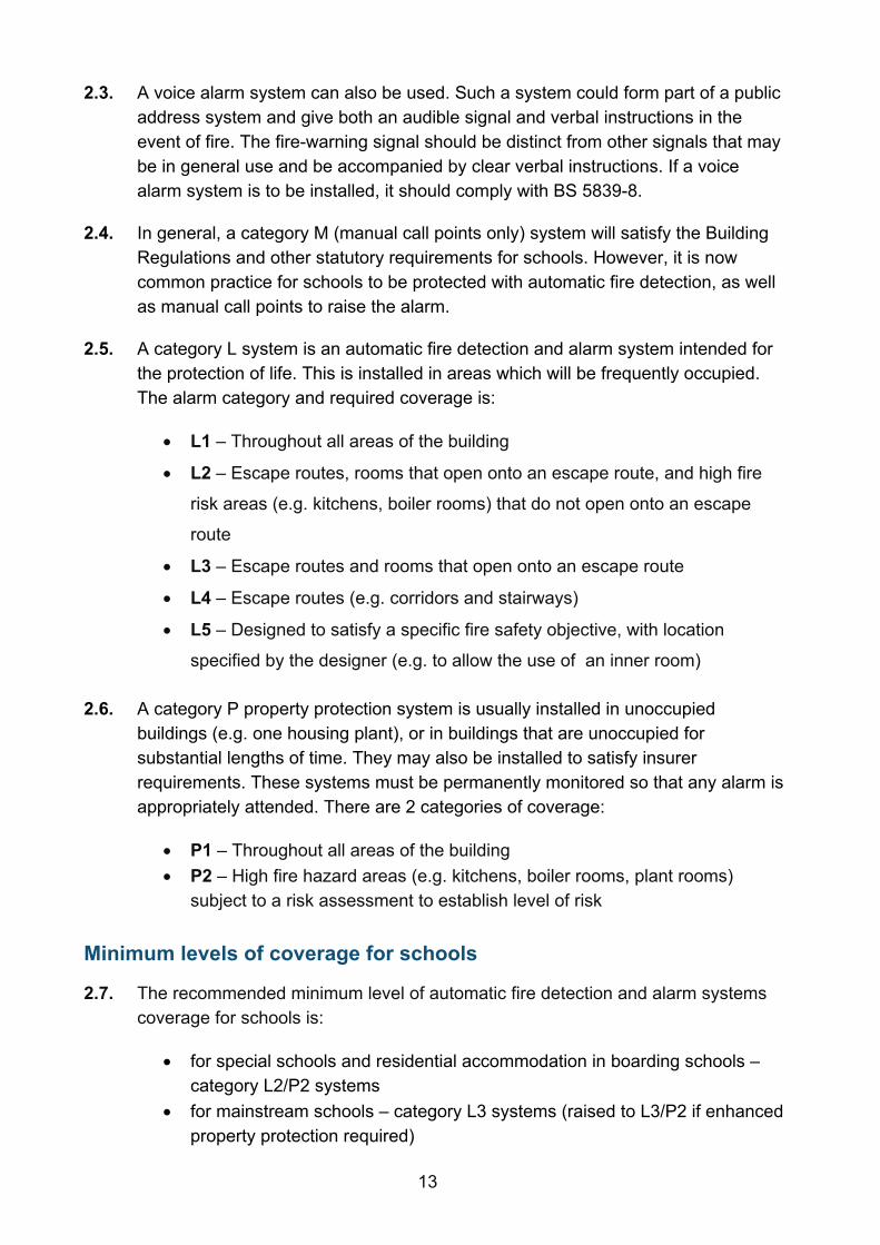
2.5. A category L system is an automatic fire detection and alarm system intended for the protection of life. This is installed in areas which will be frequently occupied. The alarm category and required coverage is:
• L1 – Throughout all areas of the building
• L2 – Escape routes, rooms that open onto an escape route, and high fire
risk areas (e.g. kitchens, boiler rooms) that do not open onto an escape
route
• L3 – Escape routes and rooms that open onto an escape route
• L4 – Escape routes (e.g. corridors and stairways)
• L5 – Designed to satisfy a specific fire safety objective, with location
specified by the designer (e.g. to allow the use of an inner room)
2.6. A category P property protection system is usually installed in unoccupied buildings (e.g. one housing plant), or in buildings that are unoccupied for substantial lengths of time. They may also be installed to satisfy insurer requirements. These systems must be permanently monitored so that any alarm is appropriately attended. There are 2 categories of coverage:
• P1 – Throughout all areas of the building • P2 – High fire hazard areas (e.g. kitchens, boiler rooms, plant rooms)
subject to a risk assessment to establish level of risk
Minimum levels of coverage for schools
2.7. The recommended minimum level of automatic fire detection and alarm systems coverage for schools is:
• for special schools and residential accommodation in boarding schools – category L2/P2 systems
• for mainstream schools – category L3 systems (raised to L3/P2 if enhanced property protection required)

14
Appendix A gives more details of fire detection and alarm systems in schools.
Manual call points
2.8. Call points for electrical alarm systems should comply with Type A of BS EN 54-11 and these should be installed in accordance with BS 5839-1.
2.9. Wherever possible manual call points should be in places where they are less prone to misuse or vandalism. This may be achieved by ensuring that they are in open view of staff. BS EN 54-11 covers two types of call points:
Type A direct operation (single action) in which the change to the alarm condition is automatic (i.e. without the need for further manual action) when the frangible element is broken or displaced
Type B indirect operation (double action) in which the change to the alarm condition requires a separate manual operation of the operating element by the user after the frangible element is broken or displaced. If manual call points are considered vulnerable to misuse, it is acceptable for a transparent, hinged cover to be fitted
2.10. Manual call points should be located so that the travel distance from any part of the building to the nearest one is not more than 45m. The recommended height is 1.4m above finished floor level. A lower mounting height is acceptable where there is a high likelihood that the first person to raise an alarm of fire will be a wheelchair user. There should be at least one call point per floor. There should also be a call point in or near places of high hazard and in the main hall.
Warnings for deaf or hard of hearing people
2.11. Deaf or hard of hearing people may not be aware that an alarm has been sounded if they are not with other people. Flashing beacons are required in toilets and any other areas identified as places where people may be on their own (see Section 26.4).
Design and installation of systems
2.12. Where a fire alarm system is installed, an installation and commissioning certificate should be provided6. Alarm systems should be standardised across a school, but systems in different buildings may be self-contained.
6 Third party certification schemes for fire protection products and related services are an effective means of providing the fullest possible assurances, offering a high level of quality, reliability and safety.

15
2.13. Fire detection and fire alarm systems are sometimes used to initiate the operation, or change of state, of other systems, such as release arrangements for electrically held-open fire doors and electrically powered locks on exit doors. Where any part of BS 7273 applies to actuation of other systems, the recommendations of that standard should be followed. For example, electronic access controls fitted to fire exit doors should fail-safe open not in the closed position.
Remote monitoring
2.14 As noted in 2.6, a school with a P2 fire alarm system needs to have it monitored by a permanently manned alarm receiving centre (ARC) unless the building is continuously occupied. The ARC will call the Fire and Rescue Service (FRS) immediately, unless a filtering procedure has been agreed with the school. As schools are unoccupied for extensive periods of time generally, all schools should have in place arrangements for remote monitoring even if they only have a category L fire alarm system installed (see Appendix A for more detail).
Section 3: Means of escape 3.1. In an emergency such as a fire, all the occupants should be able to reach a place
of safety without delay. Enough exit routes and doors are needed to allow everyone to get to the final exit and then away from the building. The corridor, staircase and exit width sizes given in this document are based on simultaneous evacuation, where all occupants leave the building on sounding of the fire alarm. They are the minimum requirements for means of escape purposes. However, doors, corridors and stairs may need to be wider to facilitate pupil movement between lessons and at break times.
3.2. Where practical, the escape routes should be the same as those used for normal circulation to avoid providing alternative means of escape that are only used in an emergency. This will also ensure that all pupils, especially the youngest ones, are already familiar with how to leave the school quickly. This will minimise their anxiety in an emergency, particularly while the fire alarms are sounding.
3.3. This guidance has been prepared on the basis that, in an emergency, the occupants of any part of a building should be able to escape safely without any external assistance7.
7 Some people, for example those who use wheelchairs, may not be able to use stairs without assistance. See Section 26 for guidance.

16
Criteria for means of escape
3.4. The basic principles for the design of means of escape are:
• that there should be alternative means of escape, other than where a single means of escape is allowed
• it should be possible to reach a final exit or place of relative safety, such as a protected stairway, within a reasonable travel distance
For all occupants, the ultimate place of safety is in the open air, clear of the effects of the fire and from where onward travel can be made safely.
Section 4: Horizontal escape route design 4.1. Means of escape should be provided from any point on a floor to an exit from the
floor. The general principle is that any person confronted by a fire within a building can turn away from it and escape safely.
4.2. In certain conditions, typically classrooms, a single direction of escape (a dead end condition) can be accepted as providing reasonable safety providing that the recommendations of Table 1 on travel distances in a single direction is met and the occupancy of the space is limited to 60.
Number of escape routes and exits, and limits on travel distance
4.3. The number of escape routes and exits to be provided depends on the number of occupants in the room, tier or storey in question and the limits on travel distance to the nearest exit given in Table 1.
4.4. It is only the distance to the nearest exit that needs to meet the recommendations. The other exits may be further away and in multi-storey buildings, more than one stair will be needed for escape.
4.5. In many cases, there will not be an alternative at the beginning of the route. For example, there may be only one exit from a room to a corridor, from which point escape is possible in two directions. A single route is acceptable for parts of a floor from which a storey exit or escape in two directions can be reached within the travel distance limit for travel in one direction set in Table 1. Figure 1 shows an example of a dead-end condition in an open plan layout.
4.6. Very young children (nursery, reception and infant class) will move more slowly than older children or adults and require constant supervision and direction during egress. Having direct access to an external place of safety from their classrooms is an advantage.

17
Location
Where travel is possible in one direction only (m)
Where travel is possible in more than one direction (m)
Places of special fire hazard 9 18 Areas with seating in rows 15 32 Areas not listed above 18 45 Ground storey of small premises with a single exit
27 N/A
Table 1: Maximum travel distances
Note:
1. The dimensions in the table are travel distances. If the internal layout of partitions, fittings, etc., is not known when plans are deposited, direct distances may be used for assessment. The direct distance is taken as 2/3rds of the travel distance.
Figure 1: Travel distance in dead end condition
Number of occupants and exits
4.7. The value used for the number of occupants will normally be that specified as the basis for the design. When the number of occupants likely to use a room, tier or storey is not known, the capacity should be calculated according to the appropriate floor space factors (see Table 2).

18
Room/Areas Occupant capacity based on floor space factor (m2/person) or design intent
Classroom/Lecture Room/Study Room Maximum design capacity (e.g., no. of seats)
Dining Room 0.9 Assembly Hall/Dual Purpose Area 0.45 Sports Hall (not used for assembly or examinations, etc.)
5.0
Storeroom 30.0 Office 6.0 Staff Common Room 1.0
Table 2: Occupant capacity in rooms or areas
Table 3 gives the minimum number of escape routes and exits from a room or storey according to the number of occupants. The number of exits may have to be increased to comply with the limits on travel distances given in Table 1.
Maximum number of persons Minimum number of escape routes/exits 60 1 600 2 more than 600 3
Table 3: Minimum number of escape routes and exits from a room, tier or storey
Alternative escape routes
4.8. A choice of escape routes is of little value if two or more are likely to be disabled simultaneously. Alternative escape routes should therefore satisfy the following criteria:
• they are in directions 45º or more apart (see Figure 1); or • they are in directions less than 45º apart, but are separated from each other
by fire-resisting construction
Inner rooms
4.9. A room from which the only escape route is through another room is called an inner room. Classrooms can be inner rooms when the corridor that they escape into is used as a teaching space or for other purposes, rather than just for circulation. The risk is that if a fire starts in the access room it could prejudice escape from the inner room. Such an arrangement is acceptable providing that the following conditions are satisfied:
• the occupant capacity of the inner room does not exceed 60 and the access room is not a place of special fire hazard
• the escape route from the inner room does not pass through more than one access room

19
• the travel distance from any point in the inner room to the exit(s) from the access room does not exceed the appropriate limit given in Table 1
• one of the following arrangements is made: o the enclosures (walls or partitions) of the inner room are stopped at
least 500mm below the ceiling; or o a suitably sited vision panel not less than 0.1m² is located in the door
or walls of the inner room, to enable occupants of the inner room to see if a fire has started in the outer room; or
o the access room is fitted with a suitable automatic fire detection and alarm system to warn the occupants of the inner room of the outbreak of a fire in the access room
Open Plan
4.10. Escape routes should not be within 4.5m of open connections between floors. Where an open-plan space connects more than one storey, rooms accessed from the space should be treated as inner rooms with the space/balcony regarded as the access room. Any escape routes should not be compromised by openings in floors and this will be achieved by ensuring that:
• the direction of travel is away from the opening (e.g. A-B in Figure 2a); or • there is an alternative escape route that does not pass within 4.5m of the
opening (e.g. the rooms with alternative exits in Figure 2b)
If the opening passes through a compartment floor (see Section 13), the guidance given in Annex B of BS 9999, “Recommendations for atria”, should be followed for fire precautions in atria.
4.11. In schools fitted with sprinklers, rooms which are accessed by an open balcony less than 4.5m wide, and which do not have an alternative escape route away from the balcony, should satisfy the following conditions (see Figure 2b):
• escape from any point on the balcony should be available in at least two directions
• the travel distance along the balcony should not exceed 18m

20
Figure 2a: Open figure connections and balconies (non – sprinkler protected schools)
Figure 2b: Open connections and balconies

21
Access to stairways
4.12. Unless the doors to a protected stairway and any associated exit passageway are fitted with an automatic release mechanism, the stairway and any associated exit passageway should not form part of the primary circulation route between different parts of the building at the same level. This is because the self-closing fire doors are more likely to be rendered ineffective because of their constant use by, for example, being wedged open or having their closers removed.
Escape routes and exits
4.13. The minimum clear headroom height in escape routes should not be less than 2m, except in doorways.
4.14. For escape purposes, the minimum corridor width of 1200mm recommended by AD M is sufficient if the corridor is not expected to serve as means of escape for more than 250 people. If the number of people is greater than this, the minimum width should be increased by an additional 50mm for each additional 10 persons (or part of 10). However, larger corridor widths will generally be needed in schools to cope with class changeovers and inclusion of lockers.
4.15. The aggregate width of all the escape routes should be not less than that required to accommodate the maximum numbers of people likely to use them. Where the maximum number of people likely to use the escape route and exit is not known, the appropriate capacity should be based on the occupant capacity (see Table 2).
Discounting exits
4.16. Where a storey or room has more than one exit, it must be assumed that a fire might prevent the occupants from using one of them. Therefore, when deciding on the total width of exits needed the largest exit should be discounted. Table 4 gives the required exit width against a maximum number of persons. It should be noted that the required storey exit width can affect the required stair width because stairs need to be at least as wide as any storey exit leading onto them. Table 5, provides the minimum clear width of doors, recommended in AD M.
Maximum number of persons Minimum width mm(1) 60 750 110 850 220 1050 More than 220 50mm for each additional 10 persons or
part of 10(2) Table 4: Escape route width and exit capacity
Notes:
1. Widths less than 1050mm should not be interpolated. 2. 50mm for each additional 10 persons (or part of 10) does not apply to an opening serving less than 220 persons.

22
Direction and width of approach New buildings (mm)
Existing buildings (mm)
Straight on (without a turn or oblique approach)
800 750
At right angles to an access route at least 1500mm wide
800 750
At right angles to an access route at least 1200mm wide
825 775
External doors to buildings used by the general public
1000 775
Table 5: Minimum effective clear widths of doors, recommended in AD M
Notes: Where there are many pupils with special educational needs (SEN), a clear open width of 900mm is recommended. The total number of persons that two or more available exits can accommodate (after discounting) is found by adding the maximum number of persons that can be accommodated by each exit width. For example, three exits each 850mm wide will accommodate 3 x 110 = 330 persons, but if one is discounted the allowable occupancy per floor reduces to 220.
4.17. Where a ground floor storey exit shares a final exit with a stair via a ground floor lobby, the width of the final exit should be sufficient to enable a maximum evacuation flow rate equal to or greater than that from the storey exit and stair combined (see Figure 3).

23
This can be calculated from the following formula:
𝑊𝑊 =𝑁𝑁
2.5 + (60𝑆𝑆)80
Figure 3: Merging flows at final exit
Where:
W = width of final exit, in metres
N = number of people served by ground floor storey exit
S = stair width in metres
Note: Where the number of persons (N) entering the lobby from the ground floor is more than 60 then the distance from the foot of the stair, or the storey exit, to the final exit should be a minimum of two metres (see Figure 3). Where this cannot be achieved then the width of the final exit (W) should be no less than the width of the stair plus the width of the storey exit.
Worked example
A ground floor storey exit serving 250 persons shares a common final exit with a 1.2m wide stair.
Required final exit =2502.5 + (60 ∗ 1.2)
80 = 2.150 meters.
Corridors
4.18. Where a corridor is used for means of escape, but it is not a protected corridor and is enclosed by non-fire-resistant partitions, the partitions should be carried up to the soffit of the floor above, or to a suspended ceiling. They will then provide some defence against the spread of smoke in the early stages of a fire, but the rooms do not need to be provided with fire doors.
4.19. If a corridor provides access to alternative escape routes, there is a risk that smoke will spread along it and make both routes impassable. To avoid this, every corridor more than 12m long that connects two or more storey exits, should be sub-divided by one or more self-closing fire doors and any necessary associated screens. The fire doors (and any associated screens) should be positioned approximately mid-way between the two storey exits to effectively safeguard the

24
route from smoke, taking account of the layout of the corridor and any adjacent fire risks, see Figure 4.
4.20. Where a cavity exists above the enclosures to such a corridor, because the enclosing materials are not carried up to the underside of the floor or roof above, cavity barriers should be fitted on the line of the enclosures to and across the corridor to prevent smoke bypass. Any door that could provide a path for smoke to bypass the sub-division should be made self-closing, but need not necessarily be fire-resisting.
a. Where the corridor is a protected escape route, cavity barriers may also be required in any floor void beneath the corridor enclosure. See Section 14 b. Plan showing sub-division of storey by fire resisting construction as required at a compartment wall

25
Figure 4: Sub-division of corridors
Dead-end corridors
4.21. Dead-end corridors should be avoided when it is practical to do so, but where they are present, they should be enclosed in fire resistant construction up to the point that escape becomes available in two directions. The need to provide a protected corridor does not apply to short recesses of less than 2m; or longer corridors serving rooms with limited fire risk, e.g. toilet accommodation.
4.22. When a dead-end corridor is longer than 4.5 m it should be provided with self-closing fire doors (with smoke seals) to separate it from where escape becomes available in more than one direction, or where the corridor continues past one storey exit to another.
External escape routes 4.23. Where an external escape route (other than a stair) is beside an external wall of
the building, that part of the external wall within 1800mm of the escape route
Floor void

26
should be of fire-resisting construction, up to a height of 1100mm above the paving level of the route.
Security 4.24. Security is an important consideration for school buildings, leading to the need for
doors to be secured against entry, including when the school is occupied. This is acceptable, as long as these doors are provided with suitable emergency hardware, often referred to as ‘panic hardware’ to ensure that they can be opened whenever the need arises. Electrically powered locks should fail-safe open on alarm and loss of power or by the activation of a manual release unit (Type A) to BS 7273-4, positioned on the side of the door that the escaping occupants are approaching.
Section 5: Vertical escape route design 5.1. An important aspect of means of escape in multi-storey buildings is the availability
of enough adequately sized and protected escape stairs. Helical stiars, spiral stairs and fixed ladders cannot be used as part of an escape route for pupils in schools, or for members of the public, and single steps should be avoided. Only firefighting lifts complying with BS EN 81-72 (and prior to firefighters’ arrival) and evacuation lifts complying with BS EN 81-20, BS EN 81-70 and Annex G of BS 9999, should be used for escape purposes – see Section 26 and Appendix B.
Number of escape stairs 5.2. The number of escape stairs needed in a building (or part of a building) will be
determined by satisfying travel distances requirements, while allowing for the possibility that a stair may have to be discounted for escape purposes because of fire or smoke.
5.3. In buildings with an occupied storey 7.5m above Fire and Rescue Service access level, some escape stairs will also need to form part of a fire-fighting shaft. (See Section 24).
Single escape stairs
5.4. New, multi-storey school buildings must have at least two staircases. Single escape stairs are not acceptable.

27
Width and capacity of escape stairs
5.5. The tables and exit sizes given in this document are based on simultaneous evacuation, where all occupants leave the building on sounding of the fire alarm. Most schools follow simultaneous evacuation, even when the site comprises separate buildings, because it offers the advantages of simplicity and enables all the occupants to be quickly accounted for at the assembly point. However, for special schools where the occupants may require more assistance, progressive horizontal evacuation (PHE) or phased evacuation may be appropriate. This is where only the occupants in immediate danger are evacuated - typically to an adjacent compartment. This enables staff to concentrate their efforts where it is most needed. Should it be deemed desirable to follow PHE or phased evacuation, specialist advice should be sought on the sizing of escape stairs and exits.
5.6. For simultaneous evacuation, each stair should be wide enough to accommodate the number of persons needing to use it in an emergency, with the minimum width of 1100mm, serving up to 220 people. When designing for greater numbers of people, the capacity of stairs of widths from 1100 to 1800mm is given in Table 6.
5.7. Where the maximum number of people needing to use the escape stairs is not known, the occupant capacity should be calculated based on the appropriate floor space factors as set out in Table 2.
5.8. The width of escape stairs should:
• not be less than the storey exits serving them • not reduce in width at any point on the way to a final exit
5.9. To follow the guidance in AD M, and to satisfy general circulation requirements in schools, the minimum widths may need to be increased. For example, a minimum stair width of 1600mm is commonly recommended for new secondary schools for circulation purposes. Where the width of the stair is more than 1800mm, the stair should be provided with a central handrail (for safety reasons in accordance with the guidance in AD K) and the capacity of each side of the stair should be considered separately. When appropriate a second handrail at low height should be provided for younger children.
Discounting of stairs
5.10. Where two or more stairs are provided, it should be assumed that one of them might not be available due to fire. Therefore, it is necessary to discount each stair in turn to ensure that the capacity of the remaining stair(s) is adequate for the number of persons needing to escape. This applies to a building with or without a fire suppression system.

28
5.11. It is not necessary to discount a stair when they or the building have one of the following additional fire protection measure:
• the stairs are protected by a smoke control system designed in accordance with EN 12101-6, or
• each stair is approached on each storey through a protected lobby (a protected lobby need not be provided on the topmost storey for this exception still to apply)
In such cases, the likelihood of a stair not being available is significantly reduced and it is not necessary to discount one, but a storey exit should still be discounted.
Number of storeys served
1100 mm wide
1200 1300 1400 1500 1600 1700 1800
1 220 240 260 280 300 320 340 360 2 260 285 310 335 360 385 410 435 3 300 330 360 390 420 450 480 510 4 340 375 410 445 480 515 550 585
Table 6: Capacity of a stair for simultaneous evacuation of the building according to width of stairs and number of storeys served
Note:
1. Should it be necessary to go above four storeys the designer is recommended to use the table on stair capacities in AD B.
5.12. Stair widths for escape derived from Table 6 may often be less than that required for safe carry down, 1600mm for three person and 1700mm for 4 man carry down. In these circumstances, the school should recognise this and ensure that additional equipment is provided to enable safe carry down (see Section 25 for more detail).
Protected stairways, access lobbies and corridors
5.13. Every internal escape stair should be a protected stairway within a fire-resisting enclosure. An unprotected accommodation stair may form part of an internal route to a storey exit or final exit, provided that the distance of travel and the number of people involved are limited.
5.14. An escape stair needs the added protection of a protected lobby or protected corridor, except for the top storey, where:
• the stair is a fire-fighting stair or • it is needed so that one stairway is not discounted when calculating stair
widths, or • where the building is designed for phased evacuation

29
A protected lobby should also be provided between an escape stair and a place of special fire hazard. In this case, the lobby should have not less than 0.4 m² of permanent ventilation.
Provision of refuges and evacuation lifts
5.15. The school fire safety management plans need to ensure that there are adequate provisions and resources to be able to assist mobility-impaired people to a place of safety outside the building.
5.16. It is best practice to provide an evacuation lift, which offers a safer and more dignified way for evacuating occupants with limited mobility from upper floors, and this is now a requirement. The lift installation will need to be appropriately sited and protected and may need to contain a number of safety features that are intended to ensure that the lift remains usable for evacuation purposes during the fire (see Appendix B).
5.17. The minimum number of evacuation lifts and the minimum inner dimensions of lift cars in mainstream schools should be related to the number of pupils and storeys served:
• for schools with no more than two storeys and fewer than 900 pupils, a single evacuation lift of 1400mm x 1100mm (internally)
• for larger schools on at least three floors and 900 pupils or more, a single two wheelchair lift of 2000mm x 1400mm, or two lifts of 1400mm x 1100mm (internally) adequately separated on plan
5.18. Depending on the layout of the school, it may be necessary to provide refuges as well. These are places of safety where mobility-impaired people can wait until they are escorted out of the building and these are usually in a protected stairway or lobby (see Figure 5). They should be a minimum of 900mm x 1400mm – see Section 26 for more details.
5.19. For special schools, the evacuation lift provision should be determined on an individual basis, but subject to a default minimum of:
• for all multi-storey special schools, a lift of 2000mm x 1400mm (internally) • for all non-ambulant8 special schools, a two wheelchair lift of 2400mm x
1400mm (internally)
8 As defined in BB 104

30
Figure 5: Refuge formed in a protected stairway
Note: In this example, the landing is larger to allow access to the wheelchair space without disrupting the flow of persons escaping.
Use of space within protected stairways
5.20. A protected stairway needs to be free of potential sources of fire and only the following facilities may be incorporated into them:
• sanitary accommodation or washrooms, so long as the accommodation is not used as a cloakroom. A gas water heat or sanitary towel incinerator may be installed in the accommodation, but no other gas appliances
• a lift well if it is not a firefighting stair • a reception desk or enquiry office area at ground or access level, if it is not
in the only stair serving the building or part of the building. The reception or enquiry office area should not exceed 10m² in size
• cupboards enclosed with fire-resisting construction, if they are not in the only stair serving the building or part of the building
Construction of escape stairs
5.21. The flights and landings of escape stairs should be constructed of materials achieving Class A2-s1,d0 or better in the following situations:

31
• if the escape stair is within a basement storey • if the escape stair serves any storey that has a floor level more than 18m
above ground or access level • if the escape stair is a firefighting stair • if the escape stair is external, except where the stair connects the ground
floor or ground level with a floor or flat roof a maximum of 6m above or below ground level
Materials achieving Class B-s3,d2 or worse may be added to the top horizontal surface, except in firefighting stairs.
5.22. Risers should generally not be more than 160mm, with treads between 250mm and 280mm (preferred in Part M), and there should be between 3 and 16 treads per flight. The length of any landing on a staircase should be at least the width of the stair, and there should be a change of direction at least every two flights.
External walls of protected stairways
5.23. With some configurations, a fire in one part of a building could subject the external wall of a protected stairway to heat - for example, where the two are adjacent at an internal angle in the facade as shown in Figure 6. If the external wall of the protected stairway has little fire resistance, there is a risk that this could prevent the safe use of the stair. Therefore if a protected stairway projects beyond, is recessed from, or is in an internal angle of the adjoining external wall of the building, the distance between any unprotected areas in the external enclosures to the building should be at least 1800mm from any unprotected area in the enclosure to the stairway.

32
Figure 6: External protection to protected stairways

33
External escape stairs
5.24. Some of the escape routes from a storey or part of the building may be by way of an external escape stair, if there is at least one internal escape stair from every part of each storey, excluding plant areas.
5.25. Where external stairs are acceptable as forming part of an escape route, they should meet the following provisions:
• all doors giving access to the stair should be fire-resisting and self-closing, except at the head of any stair leading downwards where there is only one exit from the building onto the top landing
• any part of the external envelope of the building within 1800mm of (and 9m vertically below), the flights and landings of an external escape stair should be of fire-resisting construction, except that the 1800mm dimension may be reduced to 1100mm above the top level of the stair (see Figure 7)
• there is protection by fire-resisting construction for any part of the building (including any doors) within 1800mm of the escape route from the stair to a place of safety, unless there is a choice of routes from the foot of the stair that would enable the people escaping to avoid exposure to the effects of the fire in the adjoining building
• any stair more than 6m in vertical extent is protected from the effects of bad weather
• glazing in areas of fire-resisting construction mentioned above should also be fire-resisting and of normal integrity performance. Additional insulation performance will be required where a risk assessment indicates that the potential fire hazard requires protection against heat in the post flashover phase

34
Figure 7: Fire resistance to areas adjacent to external stairs
35
Section 6: General provisions for means of escape
Protection of escape routes
Fire resistance of enclosures
6.1. Generally, a 30-minute standard is sufficient fire resistance for the protection of means of escape9. The exceptions to this are when greater fire resistance is required by the guidance on Requirements B3 or B5, or some other specific instance to meet Requirement B1.
6.2. All walls, partitions and other enclosures that need to be fire-resisting to meet the provisions in this document (including roofs that form part of a means of escape), should have the appropriate performance given in Appendix B of AD B.
Fire resistance of doors
6.3. Details of fire resistance test criteria and standards of performance are set out in Appendix C.
Fire resistance of glazed elements
6.4. Where glazed elements in fire-resisting enclosures and doors are only able to satisfy the relevant performance in terms of integrity, the use of glass is limited. These limitations depend on whether the enclosure forms part of a protected shaft and the relevant performance criteria10. Where the relevant performance can be met in terms of both integrity and insulation, there is no restriction on the use or amount of glass.
Door fastenings
6.5. Doors on escape routes (both within and from the building) should be readily openable. In general, doors on escape routes (whether or not the doors are fire doors), should either not be fitted with locks, latches or bolts, or they should only be fitted with simple fastenings that can be easily operated from the side approached by people making an escape without using a key. However, doors may be locked when the rooms are empty. Note that hold-open devices should not be fitted to fire doors on protected stairways.
9 Details of fire resistance text criteria and standards of performance are given in Appendix A of AD B. 10 As set out in Appendix B of AD B.
36
6.6. For good security, final exit doors may be fitted with locks that are used only when the building is empty. In these cases, good management procedures need to be in place to ensure their safe use.
6.7. Where a secure door is operated by a code, combination, swipe or proximity card, biometric data or similar means, it should also be capable of being overridden from the side approached by people making their escape.
6.8. Electrically powered locks should return to the unlocked position under any of the following conditions:
• when the fire alarm is activated • when there is loss of power or a system error • on activation of a manual door release unit (type A to BS 7273-4)
positioned at the door on the side approached by people making their escape. Where the door provides escape in either direction, a unit should be installed on both sides of the door
6.9. Doors on escape routes from rooms with an occupant capacity of more than 60 should either not be fitted with lock, latch or bolt fastenings, or be fitted with panic fastenings in accordance with BS EN 1125.
Doorway openings
6.10. The door of any doorway or exit should be hung to open in the direction of escape, if reasonably practicable. They must open that way when they are likely to be used by more than 60 occupants or they are exits from places of special fire risk. All doors on escape routes should be hung to open not less than 90 degrees with a swing that is clear of any change of floor level. Doors should be hung and sufficiently recessed to prevent their swing from reducing the required stairway or corridor width.
Vision panels in doors
6.11. Generally, vision panels are fitted to doors to all teaching and learning spaces in schools. For safety, vision panels are needed where doors on escape routes sub-divide corridors, or where any doors are hung to swing both ways. If non-insulating fire-resistant glazing is used, the vision panels should be less than 10% of the door area, and not be less than 500mm above the floor (500mm is the minimum height above the floor in AD M 3.10h. Guidance on the size of vision panels suitable for use by disabled people is given in Section 10 of AD K). If fire resistant glazing that meets insulation values is provided, there is no limitation on its use or size.

37
General provisions
Headroom
6.12. All escape routes should have a clear headroom of not less than 2m and there should be no projection below this height (except for doorframes).
Floors
6.13. The floor finishes of all escape routes (including the treads of steps and surfaces of ramps and landings) should be chosen to minimise their slipperiness when wet.
Ramps and sloping floors
6.14. Inclines and ramps may be preferable to stairs, particularly where the change in level is slight, or where wheelchair access is a requirement. The gradient of the incline or ramp should not exceed 1:12, although consideration will also need to be given to landings, handrails and length of ramp. Further details are provided in AD M.
Final exits
6.15. Every protected stairway should discharge directly to a final exit, or by way of a protected exit passageway to a final exit. Any such protected exit passageway should have the same standard of fire resistance and lobby protection as the stairway it serves.
6.16. The width of final exits should not be less than the minimum width required for the escape routes they serve. They should be sited to ensure rapid dispersal of persons from the vicinity of the building so that they are no longer in danger from fire and smoke. Direct access to a street, passageway, walkway or open space should be available. The route clear of the building should be well defined and, if necessary, have suitable guarding.
6.17. Adequate provision should be made for the safe assembly of the school’s occupants in areas that will not be affected by smoke or the effects of fire damage. Final exits to enclosed courtyards are not suitable and assembly points should not hinder access for the Fire and Rescue Service.
6.18. Final exits should be well defined, which is particularly important where they open off a stair that continues past the level of egress. Exits should not present an obstacle to wheelchair users and other people with disabilities.
Lighting of escape routes
6.19. All escape routes should have adequate artificial lighting provided, including emergency lighting, complying with BS 5266-1 and BS EN 1838. Emergency lighting does not have to be provided in:

38
• accommodation open on one side to view sport or entertainment during
normal daylight hours • toilet facilities that have a window and a floor area of no more than 8m²
Lighting to escape stairs in boarding accommodation should be on a separate circuit from that supplying any other part of the escape route11.
Exit signs
6.20. Every doorway or other exit providing access to an escape route, other than those in ordinary use (e.g. main entrances), should be distinctively and conspicuously marked by an emergency exit sign12 in accordance with BS ISO 3864-1 and BS 5499-4. Suitable signs should also be provided for refuges.
Lifts
Fire protection of lift installations
6.21. Because lifts connect floors, there is the possibility that they may compromise escape routes. To safeguard against this, lift wells should be either:
• contained within the enclosures of a protected stairway; or • enclosed throughout their height with fire-resisting construction if they might
otherwise prejudice the means of escape
A lift well connecting different compartments should form a protected shaft.
Mechanical ventilation and air-conditioning systems
6.22. Any system of mechanical ventilation should be designed to ensure that, when a fire breaks out, the ductwork does not assist in transferring fire and smoke through the building. Any exhaust points should be sited so that they do not further jeopardize the building, (for example, they should be located away from doors and windows).
6.23. Ventilation ducts supplying or extracting air directly to or from a protected escape route, should not also serve other areas. A separate ventilation system should be
11 See BS 5266-1 12 Advice on fire safety signs, including emergency escape signs, is given in an HSE publication: Safety Signs and Signals: Guidance on Regulations. Further guidance is given in RRO “Fire safety risk assessment – educational premises” - Part 2, section 6 on safety signs and notices.

39
provided for each protected stairway. Where the ductwork system serves more than one part of a sub-divided escape route, a fire and smoke damper13 should be provided where ductwork enters each section of the escape route, operated by a smoke detector or suitable fire detection system. The fire dampers should close when smoke is detected.
6.24. In the case of a system that recirculates air, smoke detectors14 should be fitted in the extract ductwork before the point of separation of the recirculated air and discharge to open air, and before any filters or other air cleaning equipment. Such detectors should cause the system to shut down immediately. Mechanical ventilation, unless specifically designed for smoke extraction, should be shut down as soon as smoke is detected in the duct, or upon operation of the fire alarm.
6.25. Non-domestic kitchens and plant rooms should have separate and independent extraction systems and the extracted air should not be recirculated.
Refuse and recycling storage
6.26. Refuse and recycling facilities should be situated in an external compound sited away from the main building exterior and with locked doors. They should not be located within protected stairways or protected lobbies.
13 Fire dampers activated only by fusible links are not suitable for protecting escape routes. However, an ES classified fire and smoke damper which is activated by a suitable fire detection system may be used. 14 Guidance on the provision of smoke detectors in ventilation ductwork is given in BS 5839-1

40
Requirement B2: Internal fire spread (linings)
Performance
The Requirements of B2 are met by achieving a restricted spread of flame over internal linings. The building fabric should make a limited contribution to fire growth, including a low rate of heat release.
Requirement B2 does not include guidance on:
• generation of smoke and fumes
• upper surfaces of floors and stairs
• furniture and fittings
Section 7: Fire spread and lining materials
7.1. The choice of materials for walls, linings and ceilings can significantly affect the spread of a fire and its rate of growth, even though they are not likely to be the materials first ignited. This is particularly important in circulation spaces where linings may offer the main means by which fire spreads and where rapid spread across linings is most likely to prevent occupants from escape.
7.2. Several properties of lining materials influence fire spread. These include the ease of ignition and the rate at which the lining material gives off heat when burning.
7.3. These provisions do not apply to the floor finishes and coverings, because they will not become significantly involved in a fire until it is well developed. Thus, floor finishes and coverings do not generally contribute to fire spread during the escape period. This does not apply to firefighting shafts, where the flammability of the floor linings is controlled (see Section 24).
.
(1) To inhibit the spread of fire within the building, the internal linings shall:
a. adequately resist the spread of flame over their surfaces
b. have, if ignited, a rate of heat release or a rate of fire growth, which is reasonable in the circumstances.
(2) In this section ‘internal linings’ mean the materials or products used in lining any partition, wall, ceiling or other internal structure.

41
Furniture and fittings
7.4. Furniture and fittings can have a major effect on fire spread, but it is not possible to control them through Building Regulations and they are not dealt with in this document. Fire characteristics of furniture and fittings may be controlled in some buildings under legislation that applies to a building in use, such as licensing conditions.
Classification of performance
7.5. The European classifications are described in BS EN 13501–1 “Fire classification of construction products and building elements”.
Section 8: Wall and ceiling linings 8.1. The surface linings of walls and ceilings should meet the classifications in Table 7,
other than where variations and special provisions apply, see Section 3.3.
Location European Class(1)
Small rooms(1) of area not more than 30m² or 4m² in residential accommodation
D-s3, d2
Other rooms(1) C-s3, d2 Other circulation spaces B-s3, d0
Table 7: Classification of linings
Notes:
1. When a classification includes ‘s3, d2’, this means that there is no limit set for smoke production and/or flaming droplets/particles.
Definitions
8.2. Regarding the performance of wall linings, a wall includes:
• the internal surface of internal and external glazing (except glazing in doors)
• any part of a ceiling that slopes at an angle greater than 70º to the horizontal
However, a wall does not include:
• doors and door frames • window frames and frames in which glazing is fitted • architraves, cover moulds, picture rails and skirtings • fitted furniture
42
8.3. For the purposes of the performance of ceiling linings, a ceiling includes:
• the surface of glazing • any part of a wall which slopes at an angle of 70º or less to the horizontal • the underside of a mezzanine or gallery • the underside of a roof exposed to the room below
However, a ceiling does not include:
• trap doors and their frames • the frames of windows or roof lights and frames in which glazing is fitted • architraves, cover moulds, picture rails, exposed beams and similar narrow
members
Section 9: Variations and special provisions
Walls
9.1. Parts of walls in rooms may be of a lesser performance than that specified in Table 7 (but not poorer than Class D-s3, d2 provided the total area of those parts in any one room does not exceed 50 % of the floor area of the room; and subject to a maximum of 60m².
9.2. Noticeboards in teaching spaces should not extend more than 2.5m without having a break between them of at least 0.4m and should be located away from potential sources of ignition. The total area of noticeboards should not exceed 20% of the wall area or, if sprinklers are installed, should not exceed 50% of the wall area, subject to a maximum area of noticeboards of 60m² in either case. Any noticeboards exceeding 1m² in area should be fire tested as a complete item to pass smouldering ignition source 0 (cigarette test) and flaming source 1 (match test), in accordance with BS 5852 (under Clause 12: “Methods of test for the ignitability of complete items of furniture”).
9.3. Noticeboards in corridors and circulation areas on escape routes should be covered by glass or polycarbonate and should be no more than 3m long. There should be a gap of at least 1m between noticeboards.
Roof lights
9.4. Non-plastic roof lights should meet the relevant classification in Table 7. However plastic roof lights with at least a Class D-s3, d2 rating may be used where a higher standard is called for, provided the limitations in Table 8 and Table 17 are observed.

43
Special applications
9.5. Guidance on the use of PTFE15 based materials for tension-membrane roofs and structures is given in a BRE report “Fire safety of PTFE-based materials used in buildings” (BR 274, BRE).
Section 10: Thermoplastic materials 10.1. Thermoplastic materials that cannot meet the performance given in Table 7 may
be used in windows, roof lights and lighting diffusers in suspended ceilings if they comply with the provisions described in Section 4. Flexible thermoplastic material may be used in panels to form a suspended ceiling if it complies with the guidance in Section 4.
Windows and internal glazing
10.2. External windows to rooms (though not to circulation spaces) may be glazed with thermoplastic materials if the material can be classified as a TP(a) rigid product. Internal glazing should meet the provisions in Table 7.
Roof lights
10.3. Roof lights to rooms and circulation spaces (except for protected stairways) may be constructed of a thermoplastic material if:
• the lower surface has a TP(a) (rigid) or TP(b) classification • the size and disposition of the roof lights accords with the limits in Table 8
Minimum classification of lower surface
Use of space below diffusers or roof light
Maximum area of each diffuser panel or roof light(1)
(m²)
Max total area of diffuser panels and roof lights as percentage of floor area of the space in which the ceiling is located (%)
Minimum separation distance between diffuser panels or roof lights(1) (m)
TP(a) Any, except protected stairway
No limit (2) No limit No limit
Class D-s3, d2(3) or TP(b)
Rooms 5 50(4) 3
15 Polytetrafluoroethylene

44
N/A Circulation spaces except protected stairways
5 15(4) 3
Table 8: Limitations applied to thermoplastic roof lights and lighting diffusers in suspended ceilings and to Class D-s3, d2 plastic roof lights
Notes:
1. Smaller panels can be grouped together provided that the overall size of the group and the space between one group and any others satisfies the dimensions shown in Figure 8. 2. Lighting diffusers of TP(a) flexible rating should be restricted to panels of not more than 5m2 each. 3. There are no limits on D-s3, d2 material in small rooms. See Table 7. 4. The minimum 3m separation specified in Figure 8 between each 5m2 must be maintained. Therefore, in some cases it may not also be possible to use the maximum percentage quoted.
Figure 8: Layout restrictions on Class 3 plastic roof lights, TP(b) roof lights and TP(b) lighting diffusers
Lighting diffusers
10.4 Lighting diffusers are translucent or open-structured elements that allow light to pass through. They may be part of a luminaire or used below roof lights or other sources of light. The following provisions apply to lighting diffusers which form part of a ceiling and are not concerned with diffusers of light fittings which are attached to the soffit of, or suspended beneath, a ceiling (see Figure 9).
10.5. Ceilings to rooms and circulation spaces (but not protected stairways) may incorporate thermoplastic lighting diffusers if the following provisions are observed:

45
• wall and ceiling surfaces exposed within the space above the suspended ceiling (other than the upper surfaces of thethermoplastic panels) should comply with the general provisions of this section and Table 7, according to the type of space below the suspended ceiling If the diffusers are of classification TP(a) (rigid), there are no restrictions on their extent
• if the diffusers are of classification TP(b), they should be limited in extent as indicated in Table 8 and Figure 8
Figure 9: Lighting diffuser in relation to ceiling

46
Requirement B3: Internal fire spread (structure) (1) The building shall be designed and constructed so that, in the event of fire, its stability will be maintained for a reasonable period.
(2) A wall common to two or more buildings shall be designed and constructed so that it adequately resists the spread of fire between those buildings.
(3) Where reasonably necessary to inhibit the spread of fire within the building, measures shall be taken, to an extent appropriate to the size and intended use of the building, comprising either or both of the following:
(a) sub-division of the building with fire-resisting construction and/or
(b) installation of suitable automatic fire suppression systems.
(4) The building shall be designed and constructed so that the unseen spread of fire and smoke within concealed spaces in its structure and fabric is inhibited.
Performance
Requirements of B3 will be met:
• if the loadbearing elements of structure of the building can withstand the effects of fire for a defined period without loss of stability
• if the building is sub-divided by elements of fire-resisting construction into compartments
• automatic fire suppression is provided where it is necessary
• if any openings in fire-separating elements are suitably protected to maintain the integrity of the element (i.e. the continuity of the fire separation)
• if any hidden voids in the construction are sealed and sub-divided to inhibit the unseen spread of fire and products of combustion, in order to reduce the risk of structural failure and the spread of fire, in so far as they pose a threat to the safety of people in and around the building
The extent to which any of these measures are necessary is dependent on the use of the building and, in some cases its size, and on the location of the element of construction.
Fire resistance
Fire resistance is a measure of the following:

47
• resistance to collapse, i.e. the ability to maintain loadbearing capacity (which applies to loadbearing elements only) (R)
• resistance to fire penetration, i.e. an ability to maintain the integrity of the element (E)
• resistance to excessive heat transfer, i.e. an ability to provide insulation from high temperatures (I)
Section 11: Loadbearing elements of structure 11.1. ‘Elements of structure’ is the term applied to the main structural loadbearing
elements, such as structural frames, beams, columns, floors and loadbearing walls. Compartment walls are treated as elements of structure although they are not necessarily loadbearing. External walls, such as curtain walls or other forms of cladding which transmit only self-weight and wind loads and do not transmit floor load, are not regarded as loadbearing for the purposes of this section, although they may need fire resistance to satisfy requirement B4.
11.2. Loadbearing elements may or may not have a fire-separating function. Similarly, fire-separating elements may or may not be loadbearing. Premature failure of the structure can be prevented by providing the necessary minimum standard of fire resistance to loadbearing elements.
Fire resistance standard
11.3. Elements of structure are required to achieve 60 minutes fire resistance. For more details see Tables B3 and B4 in Appendix B of AD B.
Exclusions
11.4. The following are excluded from the definition of element of structure for the purposes of these provisions:
• a structure that only supports a roof, unless: o the roof performs the function of a floor, or as a means of escape o the structure is essential for the stability of an external wall that needs to
have fire resistance • the lowest floor of the building • a platform floor • a loading gallery, fly gallery, stage grid, lighting bridge, or any gallery
provided for similar purposes or for maintenance and repair

48
Section 12: Compartmentation 12.1. When a building is constructed to prevent the spread of fire from another part of
the same building or an adjoining building, it is said to be compartmented. The compartments may consist of single or multiple rooms, spaces or storeys. The compartments should be constructed so that their relevant boundaries are fire-resisting.
12.2. The purpose of compartmentation is to contain fire and limit its extent to the place of origin. The objectives are therefore to:
• prevent rapid fire spread which could trap occupants of the building • limit the size of a fire • provide protected zones linked by protected escape ways to place of safety
outside the building
12.3. The appropriate degree of sub-division depends on:
• the use of and fire load in the building, which affects the potential for fires and the severity of fires, as well as the ease of evacuation
• the height to the top storey in the building, which is an indication of the ease of evacuation and the ability of the Fire and Rescue Service to intervene effectively
• whether an automatic fire suppression system is fitted, which will affect the growth rate of the fire and may suppress it altogether
Compartments
12.4. The maximum dimensions of compartments within schools are given in Table 9. These apply to the floor area of any one storey in a school or any one storey in a compartment.
Multi-storey schools Single storey schools No AFSS – 2000m² No AFSS – No limit With AFSS – 4000m² With AFSS – No limit
Table 9: Maximum dimensions of compartments within schools
Note: ‘AFSS’ means that the school is fitted throughout with an approved automatic fire suppression system.
Special forms of compartmentation
12.5. There are special forms of compartmentation to which particular construction provisions apply. These are:
• walls common to two or more buildings • walls dividing buildings into separated parts

49
• construction enclosing places of special fire hazard
Protected shafts
12.6. Spaces that connect compartments, such as stairways and service shafts, need to be protected to restrict fire spread between the compartments and they are termed protected shafts. Any walls or floors bounding a protected shaft are considered to be compartment walls or floors.
Junctions
12.7. For compartmentation to be effective, there should be continuity at the junctions of the fire-resisting elements enclosing a compartment and any openings from one compartment to another should not present a weakness.
12.8. Excessive deflections should be prevented, as these will tend to jeopardise the requirement for compartment integrity. Large deflections16 will also make it more difficult to successfully carry out building refurbishment following a fire.
Section 13: Construction of compartment walls and floors 13.1. All compartment walls and compartment floors should form a complete barrier to
fire between the compartments they separate and provide a minimum 60 minutes fire resistance.
13.2. Compartment walls should run the full height of the storey in which they are situated, including any roof space above the false ceiling on the top storey.
13.3. Timber beams, joists, purlins and rafters may be built into or carried through a masonry or concrete compartment wall if the openings for them are kept as small as practicable and then fire-stopped. If trussed rafters bridge the wall, they should be designed so that failure of any part of the truss due to a fire in one compartment will not cause failure of any part of the truss in another compartment.
13.4. Where services are incorporated within the construction that could provide a potential source of ignition, measures should be taken to ensure the risk of fire developing and spreading prematurely into adjacent compartments is controlled.
16 LPC Design Guide for the fire protection of buildings.

50
Junctions with walls
13.5. Where a compartment wall or compartment floor meets another compartment wall or an external wall, the junction should maintain the fire resistance of the compartment.
13.6. At the junction of a compartment floor with an external wall that has no fire resistance (such as a curtain wall) the external wall should be restrained at floor level to reduce the movement of the wall away from the floor when exposed to fire.
13.7. It is important that fire-resistant fire stopping is securely fixed between the floor and the external wall.
13.8. Compartment walls should be able to accommodate the predicted deflection17 of the floor above by either:
• having a suitable head detail between the wall and the floor, that can deform but maintain the integrity of the junction when exposed to fire, or the wall may be designed to resist the additional vertical load from the floor above as it sags under fire conditions and thus maintain integrity
Junctions with roofs
13.9. A compartment wall should be taken up to meet the underside of the roof covering or deck, with fire-stopping where necessary at the wall/roof junction to maintain the continuity of fire resistance. The compartment wall should also be continued across any eaves cavity.
13.10. If a fire penetrates a roof near a compartment wall there is a risk that it will spread over the roof to the adjoining compartment. To reduce this risk, a zone of the roof 1500mm wide on either side of the wall should have a covering classified as BROOF(t4) on a substrate or deck of a material rated Class A2-s3, d2 or better, as set out in Figure 10a. Thermoplastic roof lights are not suitable for use in that zone.
13.11. Used as a substrate to the roof covering in buildings not more than 15m high, wood wool slabs, or timber tiling battens, may be carried over the compartment wall provided that they are fully bedded in mortar or other suitable material over
17 Where compartment walls are located within the middle half of a floor between vertical supports, the predicted deflection may be assumed to be 40mm unless a smaller value can be justified by assessment. Outside this area the limit can be reduced linearly to zero at the supports. For steel beams that do not have the required fire resistance, reference should be made to SCI Publication 288 Fire safe design: A new approach to multi-storey steel-framed buildings (Second Edition) (ISBN: 1 85942 169 5).

51
the width of the wall (see Figure 10b).
Figure 10: Junction of compartment wall with roof

52
Glazing in compartment walls
13.12. Glazed apertures in compartment walls must maintain the fire separation period. All fire-resisting glass types only function as intended when installed as part of the whole fire-resisting system, which includes matched components. The whole system must be fire-resisting and have relevant evidence of fire performance provided in an appropriate fire test report. Approved fire-resisting glazed systems must be installed as specified in the test report, and there should be no changes without appropriate authorisation from the glass manufacturer.
Other openings in compartment walls
13.13. Other openings in compartment walls should be limited to those for:
• doors which have the fire resistance stated in Appendix C • the passage of pipes, ventilation ducts, service cables, chimneys, appliance
ventilation ducts or ducts encasing one or more flue pipes which meet the provisions set out in this section
• protected shafts that meet the relevant provisions in 13.16 below
Doors
13.14. Information on fire doors is shown in Appendix C.
Uninsulated glazed screens
13.15. An uninsulated glazed screen may be incorporated in the enclosure to a stair and a lobby or corridor that is entered from the stair, providing that the enclosure conforms to Diagram 8.4 of AD B and meet all of the following conditions:
• the standard of fire resistance required for the protected stairway is not more than REI 60
• the glazed screen complies with the following – o it achieves a minimum rating of E 30. o it complies with the guidance on limits on areas of uninsulated
glazing in Appendix B, Table B5 of AD B • the lobby or corridor is enclosed with fire resisting construction achieving a
minimum rating of REI 30
Where the measures in Diagram 8.4 of ADB are not provided, then both of the following apply.
• the enclosing walls should comply with Appendix B of AD B • the doors should comply with Appendix C, Table C.1

53
Openings into protected shafts
13.16. Openings in other parts of the enclosure to a protected shaft should be limited as follows:
a) where part of the enclosure to a protected shaft is a wall common to two or more buildings, only the following openings should be made in that wall:
• a door which is needed to provide a means of escape in case of fire; and which has the same fire resistance as that required for the wall; and/or
• the passage of a pipe that meets the provisions in Section 15 b) other parts of the enclosure (other than an external wall) should only have
openings for • doors which have the appropriate fire resistance • the passage of pipes which meet the provisions in Section 15 • inlets to, outlets from and openings for a ventilation duct, (if the shaft
contains or serves as a ventilating duct) which meet the provisions in Section 15; and/or
• the passage of lift cables into any lift machine room. If the machine room is at the bottom of the shaft, the openings should be as small as practicable
Figure 11 shows examples of protected shafts and openings into them. All the doors shown should be fire doors.
Figure 11: Protected Shafts

54
Section 14: Cavities 14.1. Cavities in the construction of a building provide a ready route for the spread of
smoke and flame. For example, hidden routes for fire spread include concealed spaces above suspended ceilings and therefore vertical fire separation must continue up to the underside of the soffit to ensure compartmentation is achieved.
Provision of cavity barriers
14.2. To reduce the potential for fire spread, cavity barriers should be provided for both the following:
• to divide cavities • to close the edges of cavities
Pathways around fire-separating elements
Junctions and cavity closures
14.3. Cavity barriers should be provided at all the following locations:
• to close the edges of cavities, including around openings (such as windows, doors and entry/exit points for services)
• at the junction between an external cavity wall and every compartment floor and compartment wall (except where the cavity wall complies with Figure 12)
• at the junction between an internal cavity wall and every compartment floor, compartment wall, or other wall or door assembly that forms a fire-resisting barrier (except where the cavity wall complies with Figure 12)
14.4. Compartment walls should be carried up full storey height to a compartment floor or to the roof as appropriate (i.e. through a ceiling void or roof cavity) to maintain the standard of fire separation. A line of compartmentation cannot be completed by fitting cavity barriers above them.

55
Figure 12: Cavity wall excluded from provisions for cavity barriers
Protected escape routes
14.5. For a protected escape route, a cavity that exists above or below any fire-resisting construction (because the construction is not carried to full storey height or, in the case of a top storey, to the underside of the roof covering) should either be:
• fitted with cavity barriers on the line of the enclosure(s) to the protected escape route; or
• for cavities above the fire-resisting construction, enclosed on the lower side by a fire-resisting ceiling that extends throughout the building, compartment or separated part
Double-skinned corrugated or profiled roof sheeting
14.6. Figure 13 shows where cavity barriers should be provided between double-skinned corrugated or profiled insulated roof sheeting and where they do not need to be provided. In Figure 13a, cavity barriers need not be provided where the
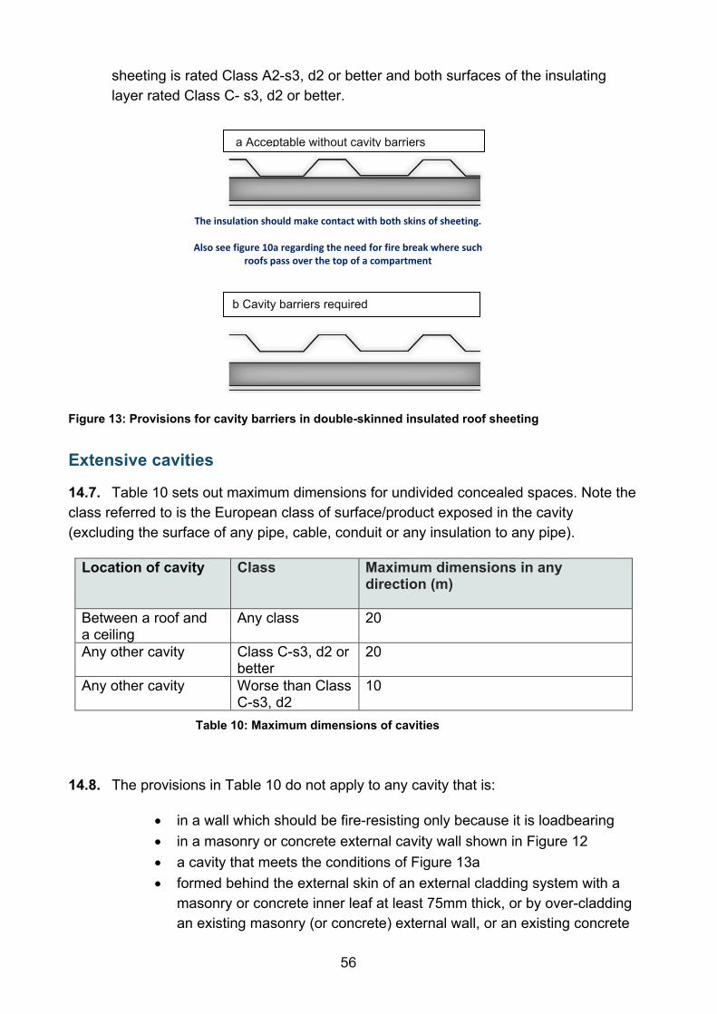
56
sheeting is rated Class A2-s3, d2 or better and both surfaces of the insulating layer rated Class C- s3, d2 or better.
Figure 13: Provisions for cavity barriers in double-skinned insulated roof sheeting
Extensive cavities
14.7. Table 10 sets out maximum dimensions for undivided concealed spaces. Note the class referred to is the European class of surface/product exposed in the cavity (excluding the surface of any pipe, cable, conduit or any insulation to any pipe).
Location of cavity Class
Maximum dimensions in any direction (m)
Between a roof and a ceiling
Any class 20
Any other cavity Class C-s3, d2 or better
20
Any other cavity Worse than Class C-s3, d2
10
Table 10: Maximum dimensions of cavities
14.8. The provisions in Table 10 do not apply to any cavity that is:
• in a wall which should be fire-resisting only because it is loadbearing • in a masonry or concrete external cavity wall shown in Figure 12 • a cavity that meets the conditions of Figure 13a • formed behind the external skin of an external cladding system with a
masonry or concrete inner leaf at least 75mm thick, or by over-cladding an existing masonry (or concrete) external wall, or an existing concrete
a Acceptable without cavity barriers
b Cavity barriers required
The insulation should make contact with both skins of sheeting.
Also see figure 10a regarding the need for fire break where such roofs pass over the top of a compartment

57
roof, provided that the cavity does not contain materials achieving Class B-s3,d2 or worse
• below a floor next to the ground or oversite concrete, if the cavity is less than 1000mm in height or if the cavity is not normally accessible by persons, unless there are openings in the floor such that it is possible for combustibles to accumulate in the cavity (in which case cavity barriers should be provided and access should be provided to the cavity for cleaning)
14.9. Where any single room with a ceiling cavity or underfloor service void exceeds the dimensions given in Table 10, cavity barriers need only be provided on the line of the enclosing walls/partitions of that room, subject to:
• the cavity barriers being no more than 40m apart • the surface of the material/product exposed in the cavity being Class C-
s3, d2 or better
14.10. Where the concealed space is an undivided area that exceeds 40m (this may be in both directions on plan) there is no limit to the size of the cavity if:
• the room and the cavity together are compartmented from the rest of the building
• an automatic fire detection and alarm system meeting the relevant recommendations of BS 5839-1 is fitted in the building. Detectors are only required in the cavity to satisfy BS 5839-1
• the cavity is used as a plenum and the recommendations about recirculating air distribution systems in BS 9999 Section 32.5.3, “air handling voids” are followed
• the surface of the material/product used in the construction of the cavity which is exposed in the cavity is Class B-s3, d2 or better and the supports and fixings in the cavity are Class A1
• the flame spread rating of any pipe insulation system is Class C-s3, d2 or better
• any electrical wiring in the void is laid in metal trays, or in metalconduit • any other materials in the cavity are rated Class A2-s3, d2 or better
Construction and fixings for cavity barriers
14.11. Every cavity barrier should be constructed to provide at least 30 minutes fire resistance -30 minutes integrity (E30) and 15 minutes insulation (I15). Cavity barriers in a stud wall or partition, or provided around openings may be formed of:
a. steel at least 0.5mm thick b. timber at least 38mm thick

58
c. polythene-sleeved mineral wool, or mineral wool slab, in either case under compression when installed in the cavity, or
d. calcium silicate, cement-based or gypsum-based boards at least 12mm thick
Cavity barriers around openings may be formed by window or door frames if the frame is constructed of steel or timber of at least the minimum thickness in a and b above.
14.12. A cavity barrier should, wherever possible, be tightly fitted to a rigid construction and mechanically fixed in position. Where this is not possible (for example, in the case of a junction with slates, tiles, corrugated sheeting or similar materials) the junction should be fire-stopped.
14.13. Cavity barriers should also be fixed so that their performance is unlikely to be made ineffective by:
• movement of the building due to subsidence, shrinkage or temperature change and movement of the external envelope due to wind
• collapse in a fire of any services penetrating them • failure in a fire of their fixings (but see note below) • failure in a fire of any material or construction that they abut
Note: Where cavity barriers are provided in roof spaces, the roof members to which they are fitted are not expected to have any fire resistance for supporting the cavity barrier(s).
14.14. Any openings in a cavity barrier should be limited to those for:
• doors which have at least 30 minutes fire resistance • the passage of pipes which meet the provisions in Section 15 • the passage of cables or conduits containing one or more cables • openings fitted with a suitably mounted automatic fire damper • ducts, which (unless they are fire-resisting) are fitted with a suitably
mounted automatic fire damper where they pass through the cavity barrier
Section 15: Protection of openings and fire-stopping 15.1. If a fire-separating element is to be effective, every joint or imperfection of fit, or
opening to allow services to pass through the element, should be adequately protected by sealing or fire-stopping so that the fire resistance of the element is not impaired.

59
Openings for pipes
15.2. Pipes that pass through a fire-separating element, unless the pipe is in a protected shaft, should meet the appropriate provisions in options A, B or C below.
Option A: Proprietary seals (any pipe diameter)
Provide a proprietary, tested sealing system that will maintain the fire resistance of the wall, floor or cavity barrier.
Situation Non-combustible Material(1)
Lead, aluminium, aluminium alloy, uPVC(2), fibre cement
Any other material
1. Structure (but not a wall separating buildings) enclosing a protected shaft which is not a stairway or a lift well
160mm 110mm 40mm
2. Any other situation 160mm 40mm 40mm
Table 11: Maximum nominal internal diameter of pipes passing through a compartment wall/floor
Notes:
1. Any non-combustible material (such as cast iron, copper or steel) which, if exposed to a temperature of 800°C, will not soften or fracture to the extent that flame or hot gas will pass through the wall of the pipe. 2. uPVC pipes complying with BS 4514 and uPVC pipes complying with BS 5255.
Option B: Pipes with a restricted diameter
Where a proprietary sealing system is not used, firestop around the pipe, keeping the opening for the pipe as small as possible. The nominal internal diameter of the pipe should not be more than the relevant dimension given in Table 11.
Option C: Sleeving
A pipe of lead, aluminium, aluminium alloy, fibre-cement or uPVC, with a maximum nominal internal diameter of 160mm, may be used with a sleeving of non-combustible pipe as shown in Figure 14. The specification for non-combustible and uPVC pipes is given in the notes to Table 11.

60
Figure 14: Pipes penetrating structure
Ventilation ducts, flues, etc.18
15.3. Where air-handling ducts pass through fire separating elements the integrity of those elements should be maintained using one or more of the following four methods. In most ductwork systems a combination of the 4 methods is best.
• Method 1 thermally activated fire dampers • Method 2 fire-resisting enclosures • Method 3 protection using fire-resisting ductwork • Method 4 automatically activated fire and smoke dampers triggered by
smoke detectors
Methods 1 and 4 are not suitable for extract ductwork serving kitchens. This is due to the likely build-up of grease within the duct that can adversely affect the effectiveness of any dampers.
Ducts passing through protected escape routes
15.4. Method 1 should not be used for extract ductwork passing through the enclosures of protected escape routes, as large volumes of smoke can pass thermal devices without triggering them.
18 Further information on fire-resisting ductwork is given in the Association for Specialist Fire Protection (ASFP) Blue Book: Fire-resisting ductwork 19 ASFP Grey Book: Fire and smoke resisting dampers
61
15.5. An ES classified19 fire and smoke damper activated by a suitable fire detection system (Method 4) may also be used for protected escape routes.
Fire dampers
15.6. To be effective the fire dampers must be installed and maintained in accordance with manufacturer’s instructions. They should be fixed to solid construction, with the adjacent ductwork provided with a large enough access panel to facilitate damper inspection and testing. It is also necessary to ensure that, in a fire, expansion of the ductwork would not push the fire damper through the structure.
15.7. Fire dampers should conform to BS EN 15650 and have a minimum E classification of 60 minutes or to match the integrity rating of the fire resisting elements, whichever is higher.
Boarding accommodation
15.8. Where the use of a building involves a sleeping risk, fire dampers or fire and smoke dampers should be activated by both of the following:
• smoke detector-controlled automatic release mechanisms • thermally activated devices
There are exceptions to this – see Appendix D.
Flues, etc.
15.9. If a flue, or duct containing flues or appliance ventilation duct(s), passes through a compartment wall or compartment floor, or is built into a compartment wall, each wall of the flue or duct should have a fire resistance of at least half that of the wall or floor in order to prevent the by-passing of the compartmentation.
Fire-stopping
15.10. For fire separation to be effective, there should be continuity at the junctions of the fire-resisting elements enclosing a compartment or protected space, and any opening from one fire zone to another should not present a weakness.
15.11. Recommendations for fire stopping ‘accidental’ gaps between various building materials are summarised in Table 12. This table defines the use of rigid intumescent sealants (RI), flexible non-intumescent (FN) sealants and flexible intumescent (FI) sealants. The recommendations consider the response to fire of the materials bounding the gap (e.g. whether they erode, shrink, expand, bow)
19 ‘E’ represents integrity, ‘S’ represents the smoke seal.

62
and the influence this will have on the seals. However, the orientation of the gap will also affect how well the material stays in place and consideration will need to be given to whether the product selected will have high or low adhesive qualities and whether the life of the seal can be influenced by the orientation.
15.12. In addition to any other provisions in this document for fire-stopping:
• joints between fire-separating elements should be fire-stopped • all openings for pipes, ducts, conduits or cables to pass through any
part of a fire-separating element should be: o kept as few as possible o kept as small as practicable o fire-stopped (which in the case of a pipe or duct, should allow
thermal movement)
15.13. To prevent displacement, materials used for fire-stopping should be reinforced with (or supported by) materials rated Class A2-s3, d2 or better in the following circumstances:
• in all cases where the unsupported span is greater than 100mm • in any other case where non-rigid materials are used (unless they have
been tested and shown to be satisfactory)
15.14. Proprietary fire-stopping and sealing systems (including those designed for service penetrations) which have been shown by test to maintain the fire resistance of the wall or other element, are available and may be used. The use of third-party accredited systems and installers should help to ensure that the specified fire stopping performs as required in an actual fire.
Masonry Concrete Timber Gypsum Fire protected steel
Steel
Masonry RI/FN(2) RI/FN(2) Fl RI RI(2) N/A Concrete N/A RI/FN(2) Fl RI RI(2) N/A Timber N/A N/A Rl FI FI(2) N/A Gypsum N/A N/A N/A FI FI(2) N/A Fire Protected Steel(3)
N/A N/A N/A N/A RI(2) FI(2)
Steel(1) * * * * * FN Table 12: Recommended product selection for fire-stopping gaps
Notes:
(1) restricted to 30min applications (2) whilst an RI material or FN material can be used, FI would be beneficial (3) may be non-intumescent if protection does not degrade at all during heating * treat as a functional linear gap seal

63
Requirement B4: External fire spread (1) The external walls of the building shall adequately resist the spread of fire over the walls and from one building to another, having regard to the height, use and position of the building.
(2) The roof of the building shall adequately resist the spread of fire over the roof and from one building to another, having regard to the use and position of the building.
Performance
The Requirements of B4 will be met:
• if the external walls are constructed so that the risk of ignition from an external source and the spread of fire over their surfaces is restricted, by making provision for them to have low rates of heat release
• if the amount of unprotected area in the side of the building is restricted to limit the amount of thermal radiation that can pass through the wall, taking the distance between the wall and the boundary into account
• if the roof is constructed so that the risk of spread of flame and/or fire penetration from an external fire source is restricted
In each case, this is to limit the risk of a fire spreading from the building to a building beyond the boundary, or vice versa.
The extent to which this is necessary is dependent on the use of the building, its distance from the boundary and, in some cases, its height and the provision of fire suppression systems.
Section 16: Regulation 7 16.1. Regulation 7(2) sets requirements in respect of external walls and specified
attachments20 in relevant buildings. It applies to any building with a storey at least 18m above ground level (measured from ground level on the lowest side of the building to the top of the floor surface of the top storey – see Appendix D of AD B), which includes residential accommodation. It requires that all materials that become part of an external wall, or specified attachments, achieve Class A2-s1,d0 or Class A1, other than those exempted by Regulation 7(3) (see Appendix F).
20 For example, balconies

64
16.2. In this guidance a relevant building includes a school with a top storey at least 18m above ground level, even if it does not contain residential accommodation.
Section 17: Fire suppression systems 17.1. To give added protection in multi-storey buildings, automatic fire suppression
systems should be installed in new school buildings with a storey over 11m above ground level. The height is measured from ground level on the lowest side of the building to the top of the floor surface of the top storey.
Section 18: Construction of external walls 18.1. The construction of external walls and the separation between buildings to prevent
external fire spread are closely related. The chances of fire spreading across an open space between buildings and the consequences if it does, depends on:
• the size and intensity of the fire in the building concerned • the distance between the buildings • the fire protection given by their facing sides • the risk presented to people in the other building(s)
18.2. Provisions are made in this section for the external walls of the building to have sufficient fire resistance to prevent fire spread across the relevant boundary. The provisions are closely linked with those for space separation, which sets out limits on the amount of unprotected area of wall. As the limits depend on the distance of the wall from the relevant boundary, it is possible for some or all the walls to have no fire resistance, except for any parts that are load bearing.
18.3. External walls are elements of structure and the relevant period of fire resistance (specified in Appendix B of AD B) depends on the use, height and size of the building concerned. If the wall is 1000mm or more from the relevant boundary, a reduced standard of fire resistance is accepted in most cases and the wall only needs fire resistance from the inside.
18.4. Provisions are also made to restrict the combustibility of external walls of schools. This is to reduce the surface’s susceptibility to ignition from an external source and to reduce the danger from fire spread up the external face of the building.
18.5. In the guidance to Requirement B3, provisions are made for internal and external load-bearing walls to maintain their load-bearing function in the event of fire.
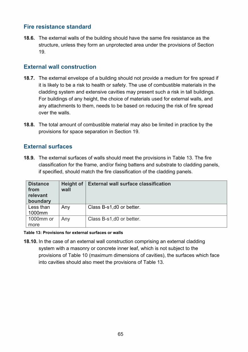
65
Fire resistance standard
18.6. The external walls of the building should have the same fire resistance as the structure, unless they form an unprotected area under the provisions of Section 19.
External wall construction
18.7. The external envelope of a building should not provide a medium for fire spread if it is likely to be a risk to health or safety. The use of combustible materials in the cladding system and extensive cavities may present such a risk in tall buildings. For buildings of any height, the choice of materials used for external walls, and any attachments to them, needs to be based on reducing the risk of fire spread over the walls.
18.8. The total amount of combustible material may also be limited in practice by the provisions for space separation in Section 19.
External surfaces
18.9. The external surfaces of walls should meet the provisions in Table 13. The fire classification for the frame, and/or fixing battens and substrate to cladding panels, if specified, should match the fire classification of the cladding panels.
Distance from relevant boundary
Height of wall
External wall surface classification
Less than 1000mm
Any Class B-s1,d0 or better.
1000mm or more
Any Class B-s1,d0 or better.
Table 13: Provisions for external surfaces or walls
18.10. In the case of an external wall construction comprising an external cladding system with a masonry or concrete inner leaf, which is not subject to the provisions of Table 10 (maximum dimensions of cavities), the surfaces which face into cavities should also meet the provisions of Table 13.

66
18.11. Note that BS 9999 sets different requirements for accommodation only used by pupils and school staff from that also used by the wider community21.
Section 19: Space separation 19.1. The provisions in this section are based on a number of assumptions:
• that the size of a fire will depend on the compartmentation of the building, so that a fire may involve a complete compartment, but will not spread to other compartments
• that the intensity of the fire is related to the use of the building (i.e. purpose group), but that it can be moderated by an automatic fire suppression system
• that there is a building on the far side of the boundary that has a similar elevation to the one in question and that it is at the same distance from the common boundary
• that the radiated heat passing through any part of the external wall that has fire resistance may be discounted (provided that where there is glazing, the fire-resisting glass has a measure of insulation performance of at least 15 minutes)
Where a reduced separation distance is desired (or an increased amount of unprotected area is) it may be advantageous to construct compartments of a smaller size or introduce compartment floors.
Boundaries
19.2. The distance is measured to the boundary, rather than to another building, because it makes it possible to calculate the allowable proportion of unprotected areas, regardless of whether there is a building on an adjoining site. However, in some circumstances, when the site boundary adjoins a space where further development is unlikely, such as a road, then part of the adjoining space may be included as falling within the relevant boundary for the purposes of this section. The meaning of the term boundary is explained in Figure 15.
19.3. A wall is treated as facing a boundary if it makes an angle with it of 80º or less (see Figure 15).
21 Accommodation used only by staff and pupils is rated A2 (‘awake and familiar with the building’) and there is no restriction on external surfaces of materials used. However, that used by the wider community is rated B2 (‘awake and unfamiliar with the building’) and requires an external wall classification of class B-s3, d2 or better.

67
Relevant and notional boundaries
19.4. The boundary that a wall faces, whether it is the actual boundary of the site or a notional one, is called the relevant boundary (see Figure 15 and Figure 16). Notional boundaries can be assumed to exist between different buildings on the same site. However, for school premises it is only necessary to consider the potential for fire spread between buildings on the same site for property protection, or where they are under separate ownership.
Figure 15: Relevant boundary

68
Figure 16: Notional boundary
External walls of protected stairways
19.5. Any part of an external wall of a stairway in a protected shaft is excluded from the assessment of unprotected area (see Figure 6 – External protection to protected stairways).
Status of combustible surface materials as unprotected area
19.6. If an external wall has the appropriate fire resistance, but has materials more than 1mm thick as its external surface with a reaction to fire performance worse than Class B-s3,d2 (noted as ‘combustible material’ in Figure 17), then that wall is counted as an unprotected area amounting to half the actual area of the materials.
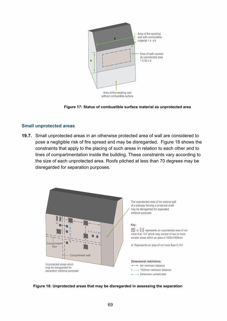
69
Figure 17: Status of combustible surface material as unprotected area
Small unprotected areas
19.7. Small unprotected areas in an otherwise protected area of wall are considered to pose a negligible risk of fire spread and may be disregarded. Figure 18 shows the constraints that apply to the placing of such areas in relation to each other and to lines of compartmentation inside the building. These constraints vary according to the size of each unprotected area. Roofs pitched at less than 70 degrees may be disregarded for separation purposes.
Figure 18: Unprotected areas that may be disregarded in assessing the separation

70
External walls within 1000mm of the relevant boundary
19.8. A wall situated within 1000mm of any point on the relevant boundary and including a wall coincident with the boundary, will meet the provisions for space separation if:
• the only unprotected areas are those shown in Figure 18 • the rest of the wall is fire-resisting from both sides
External surface materials facing the boundary should be Class B-s3,d2 or better.
External walls 1000mm or more from the relevant boundary
19.9. A wall situated at least 1000mm from any point on the relevant boundary will meet the provisions for space separation if:
• the extent of unprotected area does not exceed that given by one of the methods referred to below
• the rest of the wall (if any) is fire-resisting from the inside of the building
Method for calculating acceptable unprotected area
19.10. A simple method is given in Table 14 for calculating the acceptable amount of unprotected area in an external wall that is at least 1000mm from any point on the relevant boundary and the building or compartment does not exceed 10m in height22.
Minimum distance between side of building and relevant boundary (m)
Maximum total percentage of unprotected area (%)
1 8 2.5 20 5 40 7.5 60 10 80 12.5 100
Table 14: Permitted unprotected areas in small buildings or compartments
Notes:
a. Intermediate values may be obtained by interpolation.
22 There are other more precise methods described in a BRE report External fire spread: Building separation and boundary distances (BR187,BRE). This can be used instead of the simple method given in Table 14.

71
b. The total percentage of unprotected area is found by dividing the total unprotected area by the area of a rectangle that encloses all the unprotected areas and multiplying the result by 100.
Each side of the building will meet the provisions for space separation if:
• the distance of the side of the building from the relevant boundary accords with Table 14 and the extent of unprotected areas are within the appropriate limits given in Table 14
• any parts of the side of the building that have more than the maximum unprotected area are fire-resisting
Section 20: Roof coverings 20.1. If a fire starts outside a building or breaks out of a building, there is a danger that it
might spread to adjacent buildings. For this reason, regulatory guidance limits the use of roof coverings that will not give adequate protection against the spread of fire over them near a boundary, see Table 15 below.
20.2. The term roof covering is used to describe construction, which may consist of one or more layers of material, but does not refer to the roof structure as a whole. The provisions in this section are principally concerned with the performance of roofs when exposed to fire from the outside.
Classification of performance
20.3. The performance of roof coverings is designated by reference to the test method specified in BS EN 13501-5: (as described in Appendix B of AD B), which also contains the notional performance of some common roof coverings. Roof lights are controlled on a similar basis.
Separation distances
20.4. The separation distance is the minimum distance from the roof (or part of the roof) to the relevant boundary, which may be a notional boundary.
20.5. Table 15 sets out separation distances according to the type of roof covering. There are no restrictions on the use of roof covering designated BROOF(t4).
20.6. In addition, the following roof covering products and/or materials can be considered to fulfil all of the requirements for performance characteristic ‘external fire performance’ without the need for testing:
• Slates (natural slates, stone slates) • Tiles (stone, concrete, clay, ceramic or steel)

72
• Fibre reinforced cement (flat and profiled sheets, slates) • Profiled metal sheets ≥4mm thick (aluminium, aluminium alloy, copper,
copper alloy, zinc, zinc alloy, uncoated steel, stainless steel, galvanised steel)
• Flat metal sheets ≥4mm thick (aluminium, aluminium alloy, copper, copper alloy, zinc, zinc alloy, uncoated steel, stainless steel, galvanised steel)
These roof covering products (can be used without restriction.
Classification of covering or part of roof Minimum distance from any point on relevant boundary
BROOF(t4) No limit CROOF (t4), DROOF(t4) and EROOF(t4) Not less than 6m FROOF(t4) Should be at least 20m
Table 15: Limitations on roof coverings
Notes
a not acceptable on any buildings with a cubic capacity exceeding 1500m³.
b acceptable on buildings not listed in ‘a’ if part of the roof is no more than 3m² in area and is at least 1500mm from any similar part, with the roof between the parts covered in a material rated Class A2-s3,d2 or better.
Plastic roof lights
20.7. Table 16 sets out the limitations on the use of plastic roof lights that have at least a Class D-s3, d2 lower surface and Table 17 sets out the limitations on the use of thermoplastic materials with a TP(a) rigid or TP(b) classification (see also Figure 19). The method of classifying thermoplastic materials is given in Appendix B of AD B.
Minimum classification on lower surface(1)
Space which roof light can serve
EROOF(t4) or DROOF(t4)
FROOF(t4)
Class D3 – s3, d2
a. Balcony, b. Detached swimming pool c. Outbuilding with a minimum floor area of 40m²
6m 20m
Class D3 – s3, d2
d. Circulation space(2) (except a protected stairway) e. Room(2)
6m(3) 20m(3)
Table 16: Class D-s3, d2 plastic roof lights: limitations on use and minimum distance from any point on relevant boundary to roof light
Notes
None of the above designations are suitable for protected stairways – see section 3.4.2.

73
Polycarbonate and PVC roof lights that achieve Class C-s3, d2 rating by test may be regarded as having a BROOF(t4) classification.
Where figure 10a or 10b applies, roof lights should be at least 1.5m from the compartment wall.
Products may have upper and lower surfaces with different properties if they have double skins or are laminates of different materials, in which case the more onerous distance applies.
1. See also the guidance to B2 (see section 3.3.2 and 3.4.2). 2. Single skin roof light only, in the case of non-thermoplastic material. 3. The roof light should also meet the provisions of Figure 19.
Figure 19: Limitations on spacing and size of plastic roof lights having a Class D-s3, d2 (European class) or TP(b) lower surface
Minimum classification on lower surface(1)
Space which roof light can serve
TP(a) TP(b)
1. TP(a) rigid Any space except a protected stairway
6m(2) N/A
2. TP(b) a. Balcony, b. Detached swimming pool
N/A 6m

74
Minimum classification on lower surface(1)
Space which roof light can serve
TP(a) TP(b)
c. or outbuilding, with a maximum floor area of 40m2
N/A d. Circulation space(3) (except a protected stairway) e. Room (2)
Not applicable 6m
Table 17: TP(a) and TP(b) plastic roof lights: limitations on use and minimum distance from any point on relevant boundary to roof light
Notes:
None of the above designations are suitable for protected stairways. Polycarbonate and PVC roof lights that achieve a Class B rating by test may be regarded as having an AA designation. Where Figure 10a and b applies, roof lights should be at least 1.5m from the compartment wall. Products may have upper and lower surfaces with different properties if they have double skins or are laminates of different materials; in which case the greater distance applies. 1. See also the guidance to B2 (see Sections 3.4.1 and 3.4.2). 2. No limit in the case of any space described in 2a, b and c. 3. Single skin roof light only, in the case of non-thermoplastic material. 4. The roof light should also meet the provisions of Figure 19.
Unwired glass in roof lights
20.8. When used in roof lights, unwired glass at least 4mm thick can be regarded as having BROOF(t4) (European class) classification.

75
Requirement B5: Access and facilities for the Fire and Rescue Service (1) The building shall be designed and constructed so as to provide reasonable facilities to assist firefighters in the protection of life.
(2) Reasonable provision shall be made within the site of the building to enable fire appliances to gain access to the building. The Requirements of B5 will be met:
• if there is sufficient means of external access to enable fire appliances to be brought near to the building for effective use
• if there is sufficient means of access into and within the building for fire-fighting personnel to operate effectively
• if the building is provided with sufficient internal fire mains and other facilities to assist firefighters in their tasks
• if there is ventilation of heat and smoke from a fire in a basement
Intention
These access arrangements and facilities are only required in the interests of the health and safety of people in and around the building and the extent to which they are required will depend on the use and size of the building.
The guidance given here covers the selection and design of facilities for protecting life by assisting the Fire and Rescue Service. To assist the Fire and Rescue Service some or all the following facilities may be necessary, depending mainly on the size of the building:
• vehicle access for fire appliances • access for firefighting personnel • the provision of fire mains within the building • the provision of adequate water supplies
If it is proposed to deviate from the general guidance here, it would be advisable to seek advice from the relevant Fire and Rescue Service at the earliest opportunity, even where there is no statutory duty to consult.
Section 21: Facilities appropriate to a specific building 21.1. The main factor determining the facilities needed to assist the Fire and Rescue
Service is the size of the building. In most buildings, the combination of personnel
76
access facilities offered by the normal means of escape23, and the ability to work from ladders and appliances around the perimeter, will generally be adequate without special internal arrangements. Vehicle access will generally need to be to a percentage of the perimeter depending on the size of the building, but for small buildings it is usually only necessary to ensure that the building is sufficiently close to a point accessible to Fire and Rescue Service vehicles. For larger buildings, it may be necessary to provide internal fire mains.
Section 22: Fire mains and hydrants 22.1. Fire mains are installed in a building and equipped with valves so that the Fire and
Rescue Service may connect hoses for water to fight fires inside the building. They may be of the ‘dry’ type, which are normally empty and are connected to a Fire and Rescue Service pumping appliance when needed, or ‘wet’ type where they are kept full of water and supplied from tanks and pumps in the building. There should be a facility to allow a wet system to be replenished from a pumping appliance in an emergency.
22.2. Buildings with firefighting shafts should be provided with fire mains in those shafts and, where necessary, in protected escape stairs. Fire mains may also be provided in other buildings where vehicle access is not provided in accordance with Table 18.
22.3. The outlets from fire mains should be located within the protected enclosure of a stairway or a protected lobby where one is provided (see Figure 22).
Provision of private hydrants
22.4. Where a building with a compartment of 280m² or more in area is being erected more than 90m from an existing fire hydrant, additional ones should be provided as follows:
• Buildings provided with fire mains – hydrants should be provided within 90m of dry fire main inlets
• Buildings not provided with fire mains – hydrants should be provided within 90m of an entry point to the building and not more than 90m apart
Each fire hydrant should be clearly indicated by a plate affixed nearby in a conspicuous position, in accordance with BS 3251. Guidance on the provision of fire hydrants is given in BS 9990.
23 Where an alternative approach outside the scope of this document has been used to justify the means of escape it may be necessary to consider additional provisions for fire-fighting access.

77
Section 23: Vehicle access 23.1. Vehicle access to the exterior of a building is needed to enable high reach
appliances, such as turntable ladders and hydraulic platforms, to be used and to enable pumping appliances to supply water and equipment for firefighting, search and rescue activities. Access requirements increase with building size and height.
23.2. In buildings fitted with fire mains, pumping appliances need access to the perimeter at points near the mains, where firefighters can enter the building and where in the case of dry mains, a hose connection will be made from the appliance to pump water into the main.
23.3. Vehicle access routes24 and hard standings should meet the criteria described below, where they are to be used by Fire and Rescue Service vehicles.
Buildings not fitted with fire mains
Small buildings
23.4. There should be vehicle access for a pump appliance to small buildings (those of up to 2,000m² with a top storey up to 11m above ground level) to either:
• 15% of the perimeter or • within 45m of every point on the projected plan area (or ‘footprint’, see
Figure 20) of the building; whichever is the less onerous25
24 Note – Requir ements cannot be made under the Building Regulations for work to be done outside the site of the works shown on the deposited plans, building notice or initial notice. In this connection it may not always be reasonable to upgrade an existing route across a site to a small building. The options in such a case, from doing no work to upgrading certain features of the route, e.g. a sharp bend, should be considered by the designers in consultation with the Building Control Body and the Fire and Rescue Service. 25 If these provisions cannot be met, a fire main should be provided in accordance with Section 22 and vehicle access should meet Section 23.

78
Figure 20: Example of building footprint and perimeter
Large buildings
23.5. Vehicle access to buildings that do not have fire mains (other than small buildings described above) should be provided in accordance with Table 18.
Total floor area(1) of building m2
Height of floor of top storey above ground (m)
Provide vehicle access(2)(4) to:
Type of Appliance
up to 2,000 Up to 11 See Note(3) Pump up to 2,000 Over 11 15% of perimeter(5) High reach 2,000-8,000 Up to 11 15% of perimeter(5) Pump 2,000-8,000 Over 11 50% of perimeter(5) High reach 8,000-16,000 Up to 11 50% of perimeter(5) Pump

79
Total floor area(1) of building m2
Height of floor of top storey above ground (m)
Provide vehicle access(2)(4) to:
Type of Appliance
8,000-16,000
Over 11 50% of perimeter(5) High reach
16,000-24,000 Up to 11 75% of perimeter(5) Pump 16,000-24,000 Over 11 75% of perimeter(5) High reach over 24,000 Up to 11 100% of perimeter(5) Pump over 24,000 Over 11 100% of perimeter(5) High reach
Table 18: Fire and Rescue Service vehicle access to school buildings not fitted with fire mains
Notes:
1. The total floor area is the aggregate of all floors in the building. 2. An access door not less than 750mm wide is required to each elevation to which vehicle access is provided, which gives access to the interior of the building. 3. Access to be provided for a pump appliance to either (a) 15% of the perimeter, or (b) within 45m of every point on the projected plan area of the building whichever is the less onerous. 4. Access includes any road or vehicle way that satisfies the provisions of Table 19. 5. Perimeter is described in Figure 20.
Buildings fitted with fire mains
23.6. Buildings fitted with dry fire mains should provide access for a pumping appliance to within 18m of each fire main inlet connection point, typically on the face of the building. The inlet should be visible from the appliance.
23.7. In the case of a building fitted with wet mains the pumping appliance access should be to within 18m, and within sight of, a suitable entrance giving access to the main and in sight of the inlet for the emergency replenishment of the suction tank for the main.
Design of access routes and hard standings
23.8. A vehicle access route may be a road or other route which, including any inspection covers and the like, meets the standards in Table 19 and the following paragraphs.
23.9. Where access is provided to an elevation in accordance with Table 18 for buildings up to 11m in height (excluding small buildings covered above), there should be access for a pump appliance adjacent to the building for the percentage of the total perimeter specified.
23.10. Should hardstanding be required for a high reach pump than the relationship between it and the building should follow the guidance in Diagram 15.2 of AD B.

80
23.11. Turning facilities should be provided in any dead-end access route that is more than 20m long (see Figure 21). This can be by a hammerhead or turning circle, designed based on Table 19.
Appliance type
Minimum width of road between kerbs (m)
Minimum width of gateways (m)
Minimum turning circle between kerbs (m)
Minimum turning circle between walls (m)
Minimum carrying capacity (tonnes)
Pump 3.7 3.1 16.8 19.2 12.5 High Reach
3.7 3.1 26.0 29.0 17.0
Table 19: Typical Fire and Rescue Service vehicle access route specification
Notes:
1. Fire appliances are not standardised. Some fire services have appliances of greater weight or different size. In consultation with the Fire Authority, the Designers and the Building Control Body may adopt other dimensions in such circumstances.
2. Because the weight of high reach appliances is distributed over a number of axles, and they are only used occasionally they should not cause any damage to a carriageway or route designed to 12.5 tonnes rather than the full 17 tonnes capacity.
Figure 21: Turning facilities
Section 24: Access to buildings for fire-fighting personnel 24.1. In low-rise buildings, access requirements for firefighting personnel will be met by
a combination of the normal means of escape and the measures for vehicle access, which facilitate ladder access to upper storeys. In other buildings, the problems of reaching the fire, and working near the fire, necessitate the provision of additional facilities to avoid delay and to provide a sufficiently secure operating base to allow effective action to be taken. These include firefighting stairs and

81
firefighting lobbies, which are combined in a protected shaft known as the firefighting shaft (see Figure 22).
Figure 22: Components of a fire-fighting shaft
Provision of firefighting shafts
24.2. Buildings with a storey of 900m² or more in area, where the floor is at a height of more than 7.5m above Fire and Rescue Service vehicle access level, should be provided with at least two fire-fighting shafts. Firefighting shafts should serve all floors through which they pass.
24.3. If the building is not fitted with sprinklers then every part of every storey should be no more than 45m from a fire main outlet contained in a protected stairway and

82
60m from a fire main in a firefighting shaft, measured on a route suitable for laying hose26.
24.4. If the building is fitted throughout with an automatic fire suppression system, sufficient firefighting shafts should be provided such that every part of every storey is no more than 60m from a fire main outlet in a firefighting shaft, measured on a route suitable for laying hose.
Design and construction of fire-fighting shafts
24.5. Every firefighting stair and firefighting lift should be approached from the accommodation through a firefighting lobby. All firefighting shafts should be equipped with fire mains having outlet connections and valves at every storey. For most school buildings, a firefighting lift installation is unlikely to be required, as the top storey is unlikely to be more than 18m from fire brigade access27.
24.6. The flammability of floor coverings are controlled in a firefighting shaft and, when tested to BS 4790, should not ignite. They should be secured to the floor with non-water soluble adhesive and be interrupted at all doors on the threshold with a metal or non-combustible strip not less than 35mm wide.
26 To meet the 45m hose criterion it may be necessary to provide additional fire mains in escape stairs. This does not imply that these stairs need to be designed as fire-fighting shafts. 27 Should a fire fighting lift be required further guidance on the required standards are given in BS EN 81-72 and BS 9999.

83
Part Two: School-specific design considerations Section 25: Places of special fire hazard Overall considerations 25.1. This section deals with areas needing special consideration as they may either
accommodate ‘hot’ activities, thus having the potential to be a high-risk area, or may offer opportunities for arson if not carefully designed.
25.2. Places of special fire hazard that require the additional protection of being enclosed in 30-minute fire resistant construction include the following:
• boiler rooms • storage space for fuel or other highly flammable substances, such as
chemicals • kitchens • oil-filled transformer and switch-gear rooms (note that this is only likely
to apply in the refurbishment of older schools, as modern practice is not to use oil-filled electrical equipment within buildings)
• rooms housing a fixed internal combustion engine
Storage areas
25.2. Waste materials should be stored in wheelie bins in locked stores well away from the main buildings. If they do not have a dedicated compound, they should be secured to a wall away from the main buildings by a padlock and chain.
25.3. Storage areas within a building should be secure. Flammable sports mats must be stored in locked cupboards or stores.
Laboratories and technology rooms
25.4. Science laboratories and preparation rooms have often been treated as places of special fire hazard, but with the changes in legislation concerning the control of dangerous and hazardous substances the risk of a significant fire has been reduced. Precautions should therefore concentrate on practical measures, such as locking laboratory doors shut and turning off gas supplies when not in use.
25.5. Laboratories, preparation rooms, and some design technology areas are commonly fitted with gas supplies. Advice is given in the Institute of Gas Engineers’ publication UP11, “Gas installations for educational establishments”. Each laboratory should be fitted with a lockable isolating valve to enable gas supplies to gas taps on benches to be shut off at the end of the day.

84
25.6. Fume cupboards should have a powered extract system and fire-resisting ductwork to extract hot smoke in case a fire occurs within them.
25.7. Generally, heat detectors are preferred in these spaces, as some experiments and processes may inadvertently trigger smoke detectors (see Appendix A).
Kitchens
25.8. Consideration should be given to providing a proprietary extinguishing system in cooker hoods.
25.9. Where gas cookers are provided in classrooms (e.g. food technology), the room should be fitted with a lockable isolating valve to enable gas supplies to cookers to be shut off at the end of the day.
Corridors and circulation areas
25.10. Noticeboards are commonly provided in circulation routes and may be used for displaying pupils’ work. However, they should only be provided in corridors if covered by a suitable material (e.g. glass or polycarbonate). The covers should be top hung so that they cannot be left jutting out and impeding escape routes.
25.11. If a corridor is lined with lockers then these should be made from materials rated Class A2-s3,d2 or better (and any rooms off the corridor should be regarded as inner rooms with the corridor treated as the access room).
Cloakrooms
25.12. The 2007 version of BB 100 included cloakrooms as high-risk areas, because of the relatively large number of daytime arson fires that occurred in them in secondary schools at the time, and due to the nature of the fire load (coats). It is unlikely that cloakrooms will be provided in new schools, but they may well exist in refurbishment projects. If they are retained for their original use, consideration should be given to the provision of lockers made from materials rated Class A2-s3, d2 or better, rather than just having rows of coat hooks.
Boiler rooms
25.13. Boiler rooms are treated as places of higher fire risk and the following fire safety precautions are required for all new schools and for where an existing boiler/plant room is being refurbished:
• means of automatically shutting off the fuel supply in the event of a fire. This should include an emergency shut-off push-button at the entrance.

85
The system should shut off the electrical power to the plant.In the event of a genuine alarm, the system should require manual resetting, but if it is purely a power failure and appropriate self-proving devices are in place, then automatic resetting is appropriate to prevent the risk of pipes freezing during weekends or holiday periods. Alternatively, a system of alarm notification to remote key holders can be used. See BS 6644 clause 6.8 “Additional safety controls” (Note: many existing boiler rooms are fitted with a manual isolating valve on the fuel supply. Therefore the requirement for automatic isolation of the gas supply to new buildings is not intended to be a retrospective measure applied to existing buildings)
• heat detection linked to the fire alarm system to raise the alarm. Heat detection is preferable to smoke detection in a boiler room as smoke detection is more likely to cause false alarms
• for boiler rooms with difficult access or located inside or connected to a building, a foam inlet point and sometimes smoke vents are often required. With large installations (200kW and above) and especially with oil tanks within the building, foam spray heads are required with a pipe to outside for connection by the Fire and Rescue Service
25.14. In addition, a carbon monoxide or carbon dioxide detection system is often required in boiler/plant rooms for all fuel types, particularly where a boiler/plant room forms part of the school building itself. The detection system should both raise an alarm and isolate the fuel supply.
25.15. For gas-fired boilers it is recommended that the detection system is combined with an unburned gas detection system that is appropriately located within the boiler/plant room depending on the fuel type (natural gas at high level and Liquefied Petroleum Gas at low level). Again, the detection system should both raise an alarm and isolate the fuel supply.
Temporary and reusable accommodation
25.16. Temporary accommodation that remains in place for less than 28 days is not subject to the Building Regulations. Nevertheless, there is a still a duty to provide a good standard of fire safety to meet the duties of the Regulatory Reform (Fire Safety) Order and the same fire standards that apply to a permanent structure should be followed. Generally temporary accommodation is in place for much longer than 28 days, so Building Regulations compliance will be needed. To prevent combustible material accumulating underneath this accommodation, it is advisable to consider fitting ‘skirts’ (e.g. boarding material) around the bases of these buildings.

86
Section 26: Inclusive design Overall considerations
26.1. School buildings need to be designed to ensure that all staff and pupils can exit safely and with dignity in the event of an emergency. The wider community may also use schools out of hours, and everyone attending must be provided with safe means of escape, regardless of disability or age.
26.2. Inclusive design for escape considers the wide range of user needs as an integral part of the design process, including the needs of people with sensory, cognitive, and/or mobility impairments and wheelchair users. Disabled people may have complex needs that cannot simply be itemised in a checklist and providing an accessible means of escape should be an integral part of the fire safety management process.
26.3. Consideration will need to be given to the anticipated school occupants, as some children may have additional support frames, larger wheelchairs or other mobility aids that may have an impact on the suitable size of corridors, stairs, doors or lifts, above those required by AD M and BS830028.
26.4. Deaf or hard of hearing people may not be aware that an alarm has been sounded if they are not with other people. Flashing beacons are required in toilets and any other areas identified as places where people may be on their own. However, these may not be suitable for all pupils, so buddy systems or vibrating pagers linked to the fire alarm system could be considered in such circumstances.
26.5. Visually impaired people need good, clear signage, tactile information, continuous handrails on stairs and landings, visual contrast along the route, audible information or signals and clear, simple routes around buildings, free from obstacles.
Management of evacuation
26.6. A member of staff or pupil who has specific access requirements should have a Personal Emergency Evacuation Plan (PEEP) that sets out the details of how they will evacuate the building. PEEPs need to be updated if changes are made to the building or an individual’s needs change. In addition, General Emergency Evacuation Plans (GEEPs) should be developed for anyone who may visit the
28 BS 8300-2:2018 “Design of an accessible and inclusive built environment. Buildings. Code of Practice”

87
school and require assistance. All procedures for evacuation require suitable numbers of trained staff to be available at any given time.
26.7. If the procedures involve carry down, the school should also ensure that suitable equipment is provided to make sure that the method used for evacuation is suitable for those involved and the width of stairs.
Horizontal Circulation
Doors
26.8. Doors on evacuation routes should meet the following requirements:
• where a door must be pulled, there needs to be an unobstructed space of 300mm on the pull side of the door between the leading edge and the return wall to allow a wheelchair user to open the door
• it should be possible to operate any door furniture with a closed fist • door furniture should visually contrast with the door • the door frame should contrast with the surrounding wall • the clear opening width should meet the requirements set out in Table 5 • emergency break glass panels and door releases should be mounted
between 1000mm and 1200mm from the floor so they are accessible for disabled people. In door leaves and side panels wider than 450mm, vision panels should be provided towards the leading edge of the door. These should provide, as a minimum, the zone or zones of visibility between 500mm - 1500mm above floor level (if necessary, interrupted between 800mm – 1150mm above the floor – see diagram 10.1 of AD K)
Door closers
26.9. Door closers should only be provided where they are essential as they create access difficulties for people with limited upper body strength, particularly children. Where closers are provided, they should have an opening force at the leading edge of the door of no more than 30 Newtons29 (N) from 0° (closed) to 30° and not more than 22.5N at the leading edge from 30° to 60°. It is likely that fire doors, security doors or any particularly heavy doors will not meet these requirements and alternative methods of creating easily accessible routes should be considered, including hold-open devices or automation.
29 International System of Units (SI) derived unit of force

88
Vertical circulation
Stairs
26.10. Stairs should have:
• a level landing at the top and bottom of the steps with an unobstructed length of not less than 1200mm
• all nosings visually contrasting with the main step to a depth of 55mm. However, it is preferable to have steps without nosings. If this cannot be avoided, the nosing should project no more than 25mm over the tread below (see diagram 6 of AD M)
• a maximum rise of 160mm and minimum going of 280mm • a suitable, continuous handrail to each side of the flight and landings
26.11. Some individuals may be able to exit independently, at their own pace. Others may require assistance in the form of guidance or carry down in existing buildings. Carry down is not a preferred option as it is not suitable for all, may lack dignity and presents risk to those being carried or those carrying. Where carry-down procedures are necessary, this can be done in a variety of ways including using the person’s own wheelchair, using a dedicated evacuation chair, or using powered stair climbers.
26.12. An evacuation lift provides a safer and easier means of evacuating individuals who may have difficulty using stairs. General characteristics of an accessible evacuation lift are set out in Appendix B and BS EN 81-7030.
Refuges
26.13. Refuges are temporary waiting areas of relative safety where a person may wait for the next part of their evacuation to a place of ultimate safety. Refuges should:
• be provided within each protected stairway lobby at each storey • enable effective and accessible communication between those in the
refuge and those who are organising the evacuation. This is normally provided by an Emergency Voice Communication system complying with BS 5839 Part 9, with an outstation located in each refuge reporting to the incoming station, which is typically located in the same location as the main fire alarm panel
30 BS EN 81-70, “Safety rules for the construction and installation of lifts. Particular applications for passenger and goods-passenger lifts. Accessibility to lifts for persons including persons with a disability”.

89
• be located to allow individuals easy access to stairs and/or evacuation lifts
• protected from smoke and fire • have simple accessible signage to indicate that the area is a refuge and
provide simple instructions • include a fold-down chair to allow a rest place for someone who may
have difficulty standing
Both of the following are examples of satisfactory refuges:
• an enclosure such as a compartment, protected lobby, protected corridor or protected stairway
• an area in the open air, such as a flat roof or balcony, that is protected (or remote) from any fire risk and has its own means of escape
Refuges should not reduce the width of the escape route or obstruct the flow of people escaping.

90
Section 27: Special schools
Overall considerations
27.1. Much of the advice contained in the previous section, Section 26, will apply to special schools.
27.2. Building Bulletin (BB) 10431 advises that, although special schools cater for varying needs that can change over time, they can be broadly divided between those that cater predominantly for ambulant pupils and those that are specifically set up to accommodate pupils with severe physical disability (PD) and profound and multiple learning difficulties (PMLD). For simplicity, BB 104 refers to the first as ‘ambulant’ special schools and the second as ‘non-ambulant’ special schools.
27.3. Ambulant special schools typically provide for one of the following:
• a range of predominantly ambulant needs (moderate learning difficulties - MLD, severe learning difficulties - SLD and autism), with pupils taught together in groups of 8 to 12. There are often a few places for pupils with greater needs, such as those associated with severe autism or social emotional and mental health difficulties, who are taught in smaller groups with a higher staff to pupil ratio
• severe social emotional and mental health difficulties (SEMH), where pupils require greater personal space to avoid conflict. They have the capability to follow a curriculum similar to that in a mainstream school and pupils are taught in groups of 6 to 8
• significant difficulties associated with autism (ASD), where pupils require greater personal space and high levels of adult supervision. Pupils are taught in groups of 6 to 8
27.4. Non-ambulant special schools typically provide for one of the following:
• a broad range of needs with 10% to 60% of pupils being non-ambulant (requiring specialist equipment and facilities). Pupils with moderate learning difficulties (MLD), severe learning difficulties (SLD) and autism are taught in groups of 8 to 10, while pupils with PMLD or severe autism are taught in groups of 4 to 6
31 BB 104, “Area guidelines for SEND and alternative provision

91
• a broad range of needs with 60% to 90% of pupils being non-ambulant (requiring specialist equipment and facilities)
27.5. In special schools there is often more flexibility across the key stages than in mainstream schools and pupils may be placed according to their level of functioning, rather than age. Where a special school caters for a broad range of needs, pupils are likely to be grouped to suit their needs. For example, those with profound learning difficulties, who need intensive stimulation, are likely to be grouped speparately from pupils with autism, who need low sensory stimulus. Pupils who exhibit boisterous or aggressive behaviour may be taught separately from those who are vulnerable.
27.6. While the importance of maintaining business/educational continuity is highly important for all schools should a fire occur, there will be particular challenges in achieving this with special schools. Because of the space requirements, specialist equipment and facilities needed in these schools, they are more vulnerable to the effects of a significant fire than mainstream schools. It is likely to be extremely difficult to find suitable alternative or temporary accommodation for pupils displaced by the fire and, at the very least, their education will suffer. They are also likely to find the disruption caused more difficult to handle than mainstream pupils.
Fire suppression systems
27.7. To give added protection to these premises, and minimise disruption in the event of fire, automatic fire suppression systems should be installed in all new special schools.

92
Section 28: Boarding schools
Overall considerations
28.1. Guidance on how residential accommodation in schools should comply with Building Regulations Part B is currently covered in AD B, Purpose Group 2a – “Residential Institutional”. Since BB 100 is the schools’ guide to fire safety design, advice on boarding schools is also included here.
28.2. Because occupants will spend significant time asleep, residential accommodation poses different fire safety risks from those associated with daytime school premises. Where the two uses are housed in separate blocks, the design challenges are relatively simple to resolve. Where a building is in mixed use, with part of it being residential, it should be designed wherever practicable so that the residential and non-residential uses are separated and independent of each other.
28.3. If bedroom doors in boarding accommodation are locked, lock override functions will be needed if the fire alarm is activated. Security requirements must not compromise means of escape.
28.4. In boarding accommodation, the occupance of an inner room should not exceed 30 persons (as stated in AD B for purpose group 2a – residential (institutional) buildings).
Fire detection and alarm systems
28.5. A minimum category of L2 automatic fire detection and alarm system should be provided in residential accommodation in schools. An L2 system covers escape routes, rooms opening onto escape routes and places of special fire hazard, such as kitchens and boiler rooms. For additional property protection, this should be raised to L2/P2.
Fire suppression systems
28.6. To give added protection to residential areas, particularly sleeping accommodation, automatic fire suppression systems should be installed in all new boarding school buildings in the following ways:
• where the dormitory blocks are separate from the main school areas, only the dormitory blocks need have fire suppression systems
• where the two uses are contained in one building, the whole building should have fire suppression systems fitted

93
Fire compartmentation
28.7. Residential accommodation should be in a separate fire compartment from the rest of the school. The sleeping areas should be constructed so that:
• bedrooms are separated from each other with 30-minute fire-resisting construction, with corridors outside them also fire protected; or
• instead of fire protecting individual bedrooms, the common corridors outside them have a minimum of 30-minute fire-resisting construction
28.8. Simultaneous evacuation is required for residential accommodation.
Internal linings
28.9. All linings in circulation spaces should achieve a minimum of Class B- s3,d0.
External wall and cladding materials
28.10. The residential areas of boarding schools should have external walls, including external surfaces of walls, constructed of materials achieving Class A2-s1,d0 or better (this excludes gaskets, sealants and similar).

94
Part Three: Property protection
Overall considerations
While schools are low risk for fire safety, the damage caused to buildings and contents by a significant fire can have long term consequences. The data indicates that the number of fires that have an impact on whole buildings or entire schools is very low. However, the time taken to repair or replace the buildings may cause disruption to educational continuity and affect the morale of both pupils and staff, particularly if the fire is due to arson.
This section includes advice on the effects of a fire, how to improve school security to reduce the risk of arson and details of property protection measures, including fire suppression systems.
Section 29: School fires 29.1. Accidental fires can start anywhere, but they usually start inside a room (90% of
school fires are limited to the item first ignited and/or the room of origin). They seldom occur in escape routes, as correct fire safety management should ensure that these are kept clear of combustible materials. Deliberate fires (including arson)32 can be started anywhere both inside and outside of buildings, and often in places out of view. In recent years, around 22% of school fires were classified as deliberately set33 according to government statistics.
29.2. Early on in a fire, the main danger for occupants will be from the effects of smoke and the other products of combustion. Smoke is often the first thing to be noticed in a building by occupants and usually causes the first alarm. If a fire does break out, of course the primary concern is for the safety of pupils, teachers and all the other users of school buildings. Schools are very safe places regarding fire. They are also low risk in terms of fire safety compared with other building.
29.3. A large fire will have a significant effect on a school, disrupting continuity of education and lowering morale in addition to the more obvious financial losses, not all of which will be covered by insurance. Disruption to education may be caused
32 Deliberate fires are those where the motives for the fires are thought to be, or suspected to be, deliberate. They include arson, but also fire started intentionally that get out of hand. Arson is defined under the Criminal Damage Act 1971 as “an act of attempting to destroy or damage property and/or in doing so, to endanger life.” 33 Over 30% in secondary schools and about half that proportion in primary schools.

95
by loss of coursework and teaching material as well as loss of time in school. Uninsured losses may include:
• the additional costs of transporting pupils to another school site • loss of personal items owned by pupils and staff • increased security requirements and insurance costs
29.4. Property protection is an important factor in the design and management of school buildings. Complying with the requirements of Part B and the Regulatory Reform (Fire Safety) Order will go a long way in achieving this, but there is also much more that can be done. There are design strategies to lower the risk of deliberate fires being started, focussing on security, and to minimise the effect of a fire however it starts.
Section 30: Improving the security of school buildings and grounds 30.1. Schools need clear, well defined and secure boundaries to help control who gains
access to their sites and buildings, and to ensure that vulnerable pupils are safe. The level and type of boundary treatment will vary from site to site and will need to be appropriate to their location as well as to the level and type of security risk(s) . A security risk assessment will help here and should take account of the merits of different types of fencing, hedges and defensive landscaping. In some cases, buildings may form part of the boundary. On large sites it may be more practical to enclose an inner perimeter, perhaps excluding sports pitches from the secure core as these will be supervised when in use.
30.2. Where a school is co-located on a site with another school or a community building, secure access arrangements applicable to each school or building need to be clearly defined.
30.3. Generally, the security of school buildings is enhanced by:
• limiting the numbers of entrances to site and buildings • having effective access control to site and buildings • avoiding overly complex external building envelope forms, which may
create areas that cannot be easily supervised • not having recessed doorways and alcoves • designing canopies, low roofs and drainpipes so that they do not
provide access to high level windows and roof lights • locating windows to provide good passive supervision of external areas
from spaces that are occupied much of the time, such as staff and administrative offices
• only using external lighting where necessary for safety and security

96
• ensuring physical barriers and landscaping do not obstruct views towards or away from school buildings and grounds
• securing external waste storage and recycling areas
30.4. The use of security technology should be discreet wherever possible, with the more visible methods being restricted to vulnerable areas where the obvious provision of detection devices may help deter crime. Thick planting areas close to the building should be avoided as these could provide cover from security cameras.
30.5. Where out of hours community use of school facilities takes place, these areas need to be zoned so that those areas of the school not available to the community can be secured easily.

97
Section 31: Building Construction
External walls
31.1. While complying with the Building Regulations, external wall construction may incorporate flammable polymeric materials, usually as insulation, which if ignited will contribute to or exacerbate the consequences of a fire. For example, expanded polystyrene or polyurethane rigid insulation boards burn relatively freely, whereas polyisocyanurate or phenolic foam insulation will perform much better in a fire. Similarly, expanded PU foam is commonly used to fill gaps, though there are better performing retardant sealants that can be used.
31.2. For enhanced property protection, and as detailed above, the use of insulation materials with better fire performance is recommended. A small change in specification could result in a school building that offers greater resistance to the risks and effects of fire.
31.3. Plastic fittings in external walls can act as weak spots where an external fire occurs either as an accidental or deliberate act. Such fittings include airbricks, vent covers, ducts and waste pipes. These vulnerabilities would generally apply to ground floor walls only, so consideration should be given to using alternative materials in these situations (see FPA’s “RISCAuthority” website for more details).
Cladding
31.4. Recommendations for cladding are covered in sections 16 and 18 and 28. Section 16 says that cladding on a school building with a storey 18m above ground level should achieve Class A2-s1,d0 or better. Section 18 covers school buildings below that height and says that the cladding must achieve Class B-s1,d0 or better. However, where school buildings are prone to vandalism, as determined by a security risk assessment at feasibility stage, any cladding to ground floor external walls should achieve Class A2–s1,d0 or better. Section 28 covers boarding schools and requires that the residential areas of these schools should have external walls, including the external surfaces of walls, constructed of materials achieving Class A2-s1,d0 or better.
Compartment floors
31.5. To reduce the extent of property damage in a fire, all floors in unsprinklered school buildings should be constructed as compartment floors. This will often help satisfy requirements for acoustics and thermal mass as well.

98
Section 32: Automatic fire suppression systems 32.1. The two main fire suppression systems are sprinklers and water mist. Both
systems usually include tanks from which water is pumped to the individual heads. This is because the pressure of water supplied from the mains generally cannot be relied on to ensure the systems operate effectively.
Sprinklers
32.2. Sprinklers are thermally operated devices, which work when there is enough heat immediately adjacent to the sprinkler head to cause a bulb or link to fracture. The numbers of heads that will further operate are those required to control the fire. In general, they will operate at an early stage, with typically less than three heads operating to suppress and control the fire. A sprinkler system designed, installed and maintained in accordance with BS EN 12845 will provide protection for people and property should a fire occur.
Enhanced availability sprinkler systems
32.3. A sprinkler system requiring additional measures for resilience is detailed in BS EN 12845 Annex F, “Additional measures to improve system reliability and availability”. These additional measures are known as providing an “enhanced availability” system (once termed a ‘life safety’ system). Generally, the designs for a standard and enhanced availability system will be the same so far as the number and layout of sprinkler heads are concerned. The additional features that enhanced availability systems require for a secondary school34 include:
• being a “wet” pipe system • having quick response sprinkler heads • water supplies must be reliable, with the system having at least one
superior single water supply • twin pump sets rather than one • four valve sets rather than one
Such a system would not normally be installed in a school. It would only be provided if it formed part of the fire strategy for ensuring life safety.
34 Example is for a 6FE secondary school with a 220 place sixth form.

99
Water mist systems
32.4. In comparison with sprinklers, water mist systems generate smaller droplets with larger surface areas that have a greater ability to absorb the heat from a fire. In theory, less water should be required to fight a fire than with an equivalent sprinkler system. In practice, this benefit is mainly seen in applications to extinguish high temperature surface fires, such as flammable fuels and deep fat fryers. Fires involving carbon-based combustibles, such as paper and wood, will require more water to control them.
32.5. Water mist systems are bespoke solutions and each manufacturer’s product is distinctly different. Water mist design standards do not contain prescriptive design rules, but provide a generic design methodology and performance requirements. BS 8489-1 covers the design and installation of industrial and commercial water mist systems and companion fire test protocols have been published as other parts of BS 848935. BS 8489-7 provides the fire test protocols for the protection of low hazard occupancies, which includes school classrooms. Fire performance tests suitable for the intended application are critical in determining the water mist system’s design and component characteristics.
32.6. Water mist systems have been successfully designed and installed in schools. They do offer space saving, with a smaller water storage tank. They should discharge less water than an equivalent sprinkler system and therefore cause less water damage when triggered. However, this does depend upon the nozzle layout and on how long the mist system must operate to control a fire compared with sprinklers.
Gas extinguishing systems
32.7. End users may be reluctant to allow sprinklers in server/communicationsrooms, because of concerns regarding water damage. The actual risk of discharge is low, but it is acceptable to omit sprinklers from server rooms providing that they are separated from other school accommodation by 60-minute fire resistant construction.
32.8. A gas extinguishing system could be used as an alternative to fire separation, which will also provide fire protection to the room contents. However, while these systems are relatively simple installations, comprising high-pressure gas bottles and a piped distribution system, their effectiveness is dependent on a high standard of room integrity. Additionally, they require controls to ensure that they
35 A prEN (provisional) 14972 water mist standard is in the final stages of preparation.

100
can be locked off to prevent operation when the room is occupied. Providing a gas extinguishing system would impose a high maintenance burden on a school and should only be considered if it has been justified using the risk assessment methodology given in BS 6266. This methodology only recommends automatic suppression when the data held is critical, not backed-up remotely, or the equipment itself is bespoke and expensive to replace.

101
Part Four: Fire safety management
Section 33: Regulation 38 33.1. At the completion of a building project the contractor must provide the school
management with enough fire safety information to enable them to:
• understand and implement the fire safety strategy of the building • maintain any fire safety systems provided in the building • carry out an effective fire risk assessment of the building
Much of this is covered in Regulation 38 of the Building Regulations. However, this is only the beginning. Fire safety management must cover the life of a building and many of the responsibilities for this are set out in the Regulatory Reform (Fire Safety) Order 2005.
33.2. Regulation 38 requires that, where building work involves the erection or extension of a relevant building, or a relevant change of use of a building, fire safety information shall be given to the responsible person at the completion of the project or when the building or extension is first occupied.
33.3. A ‘relevant building’ is a building to which the Regulatory Reform (Fire Safety) Order 2005 applies, or will apply after the completion of building work, and covers most premises. ‘Fire safety information’ means information relating to the design and construction of the building or extension, and the services, fittings and equipment provided in or in connection with the building or extension which will assist the responsible person to operate and maintain the building or extension with reasonable safety. Responsible person’ has the meaning given in Article 3 of the Regulatory Reform (Fire Safety) Order 2005 (see section 17 below). A ‘relevant change of use’ is a material change of use where, after the change of use takes place, the Regulatory Reform (Fire Safety) Order 2005 will apply, or continue to apply, to the building.
33.4. The fire safety information should be given to the responsible person at one of the following times:
• when the project is complete • when the building or extension is first occupied
Below is a guide to the information that should be provided. For clarity, the guidance is given in terms of simple (most schools) and complex buildings (for example, large secondary schools, some special schools and boarding schools, buildings that contain different uses including a school), but the level of detail required should be considered on a case-by-case basis.

102
Simple buildings
For most buildings, basic information on the location of fire protection measures may be all that is necessary. An as-built plan of the building should be provided showing:
• protected escape routes, final exits and muster points outside the building
• compartmentation and separation, including cavity barriers • fire doors, self-closing fire doors and other doors equipped with relevant
hardware (e.g. panic locks) • locations of smoke or heat detectors, alarm call points, detection and
alarm control boxes, alarm sounders, fire safety signage, emergency lighting, fire extinguishers, dry or wet fire mains and other firefighting equipment, hydrants outside the building
• any higher risk areas (e.g. heating machinery, bio-mass stores)
33.5. Information should also be provided covering any assumptions in the design of fire safety arrangements regarding the management of the building, particularly on the evacuation of occupants requiring assistance. This information can then be used for developing PEEPs.
33.6. Details and specifications will be needed of any fire safety systems provided, including sprinkler isolating valves if fitted, fire dampers, any smoke control systems or ventilation systems and hydrants outside the building. Information on routine inspection, testing and maintenance schedules should also be provided.
Complex buildings
33.8. For more complex buildings, the information provided should also include:
• the fire safety strategy, including all assumptions in the design of the fire safety systems (such as fire load)
• any risk assessments or risk analysis • procedures for operating and maintaining any fire protection measures,
including active fire safety measures if included. This should include an outline cause and effect matrix/strategy for the building
• all assumptions in the design of the fire safety arrangements regarding the management of the building
• any high-risk areas (e.g. plant rooms) and hazards • as-built plans of the building showing the locations of the above
103
Section 34: The Regulatory Reform (Fire Safety) Order 2005 34.1. To achieve compliance with Article 9 of the Fire Safety Order, the ‘responsible
person’ must ensure that a suitable and sufficient assessment of the fire safety risks to which the relevant persons associated with that building are exposed to is carried out. The responsible person, as defined in Article 3 of the Order, is generally the employer, the person who has control of the premises or the owner (for schools, this means the Responsible Body). As part of these duties the responsible person must also ensure that the assessment and the recommended actions in this assessment are implemented by a ‘competent person’.
34.2. While no specific qualification is required to be established as a competent person, he or she can be considered as competent where they have enough training and experience or knowledge. Where there is a competent person under the employment of the responsible person, under Article 18 of the Order, they must appoint that person in preference to an externally sourced person.
34.3. The fire risk assessment is undertaken to enable the responsible person to ensure that all reasonable steps and measures have been taken to protect the relevant persons, i.e. anyone who is lawfully on the premises or anyone who is in the immediate vicinity of the premises who is at risk from fire within the premises. The results of the assessment identify the general precautions the responsible person needs to make to comply with the Fire Safety Order and are used in the formation of appropriate emergency plans. The local Fire and Rescue Service are responsible for enforcing the Order in schools.
34.4. The aims of fire risk assessments are to:
• identify the fire hazards, i.e. anything that has the potential to cause harm
• reduce the risk of those hazards causing harm to a reasonable level • decide what fire precautions are needed to ensure the safety of people
in the school if a fire breaks out
34.5. The Fire Safety Order says that fire risk assessment must be reviewed and updated regularly, particularly where there is reason to suspect it is no longer valid or where significant changes to the premises or use take place. For example, it should be reviewed when additional accommodation has been constructed to cope with rising numbers, or the age range of the intake has changed.
34.6. Guidance for schools on the Fire Safety Order is contained in the government’s “Fire safety risk assessment: educational premises”. This includes extensive guidance on fire risk assessments and fire precautions. It also contains useful advice on fire safety training for staff and pupils and on fire drills. Appendix A of the guide includes an example of a fire safety maintenance checklist, covering

104
daily and weekly checks through to annual ones. The second part of the appendix has an example form for recording significant findings.
Table 20: Five basic steps for carrying out a risk assessment
34.7. The five basic steps to carrying out a fire risk assessment are shown in Table 20.
34.8. The Fire Safety Bill currently before Parliament will reform the Fire Safety Order; once the law is ratified and implemented, the Department will consider whether and how the guidance should be further updated to reflect the new legislation.
FIRE SAFETY RISK ASSESSMENT
1 Identify the hazards Identify: Sources of ignition Sources of fuel Sources of oxygen
2 Identify people at risk Identify People in and around the premises People especially at risk
3 Evaluate, remove, reduce and protect from risk Evaluate the risk of a fire occurring Evaluate the risk to people from fire Remove or reduce fire hazards Remove or reduce the risks to people
• detection and warning • firefighting • escape routes • lighting • signs and notices • maintenance
4 Record, plan, inform, instruct and train Record significant finding and action taken Prepare an emergency plan Inform and instruct relevant people; co-operate and co-ordinate with others Provide training
5 Review Keep assessment under review Revise where necessary
Remember to keep your fire risk assessment under review

105
Appendix A: Fire detection and alarm systems
Detectors and false alarms
Smoke detectors should not be installed in potentially smoky or dusty environments such as kitchens, laboratories and design technology rooms as they may be triggered without a fire occurring. Heat detectors should be installed in these spaces to prevent false alarms, as they perform better in those conditions.
Multi-sensor detection may be provided in areas that present a high false alarm risk. For example, optical-heat-carbon monoxide (CO) multi-sensor detection could be used in kitchens, which are likely to have smoke present and to experience rapid thermal changes (e.g. due to opening ovens). It may not be necessary to locate these throughout the kitchen, but just in problem areas.
New fire alarm systems can be programmed to:
• Switch between a day and night mode to allow a reduction in the sensitivity of detectors during the daytime
• Use a timed delay during the daytime to allow staff to investigate the source of the detector activation before triggering the alarm. During the night and other times schools are closed,alarm activation should be immediate
Remote monitoring
A school with a P2 fire alarm system needs to have it monitored by a permanently manned alarm receiving centre (ARC) unless the building is continuously occupied. The ARC will call the Fire and Rescue Service (FRS) immediately, unless a filtering procedure has been agreed with the school.
A filtering procedure should follow the steps outlined in BS 8591 Code of Practice, “Remote centres receiving signals from alarm systems.” The ARC will attempt to contact the premises that sent the fire alarm signal and:
• if no response is received within 30 seconds, the ARC will call the FRS; or • if voice communication is established and the signal is not clearly confirmed to
be false within 60 seconds, the ARC will call the FRS; or • the ARC will call the FRS if authorised by a person on site
Maintenance
Inadequate maintenance of fire detection and alarm systems can result in them not working when a fire breaks out.

106
Fire Alarm System Inspection and testing requirement
Daily testing Staff should be trained so that they are familiar with the fire alarm panel and are able to complete daily inspections of the system – check the fire alarm panel is in normal operation, and any faults recorded the previous day received attention.
Weekly test Each week a different manual call point should be operated during normal working hours. It should be confirmed that the control equipment can process a fire alarm signal and provide an output to the fire alarm sounders. Where the fire alarm system is monitored by an Alarm Receiving Centre (ARC), it should be confirmed that the fire alarm signal is correctly received at the ARC to which fire alarm signal is transmitted. Note: An ARC should be contacted immediately before and after the weekly test to clarify the intent of the test. The duration for which any fire alarm signal is given at the time of the weekly test by the user should be at least 5 seconds, but should not exceed 60 seconds, so that in the event of a fire during the weekly test, occupants are warned by the prolonged operation of the fire alarm devices. Voice alarms should be tested weekly in accordance with BS 5839-8.
Monthly test If an automatically started emergency generator is used as part of the standby power supply, it should be started up each month by simulating failure of the normal supply for one hour. At the end of the test, fuel tanks should be left filled, and the oil and coolant levels should be checked and topped up as necessary. If vented batteries are used as a standby power supply, a visual inspection of the batteries and their connections should be made to ensure that they are in good condition. Action should be taken to rectify any defect, including low electrolyte level.
Six-monthly test Six monthly testing of fire detection and alarm system by competent persons in accordance with clause 45.3 of BS 5839-1. Certificate of testing is required.

107
Note: If six monthly testing is not completed, it should be considered that the system is no longer compliant with BS 5839-1.
Yearly test More extensive inspection should be completed each year, which is in addition to the required six-monthly testing.
Inspection and performance test by a competent person should be completed every year in accordance with clause 45.4 of BS 5839-1.
Table A1: Maintenance requirements of fire alarm systems

108
Appendix B: Evacuation lifts Design standards
An evacuation lift, where provided, should always be available for evacuation purposes. Wherever practicable it should be a lift used routinely as a passenger lift and not one used solely for evacuation or occasionally as a lift for transporting goods. This will help staff to identify a lift needing maintenance before the lift is required in an emergency.
Evacuation lifts should be designed and installed in accordance with the relevant provisions in BS EN 81-20 and BS EN 81-70.
The arrangements for cable specification, routing and installation, automatic changeover devices between primary and secondary circuits and the fire protection of any enclosures should be in accordance with BS 8519 recommendations.
Power supply
Evacuation lifts should be provided with an alternative power supply from a separately fused circuit fed directly from the main incoming electrical supply to the building, located in a fire protected enclosure.
The alternative power supply for an evacuation lift is specified in BS 5588-8 “Fire precautions in the design, construction and use of buildings - Code of practice for means of escape for disabled people”. BS 5588-8 was replaced by BS 9999 in 2008, with the section for evacuation lifts incorporated into Annex G.2 of BS 9999 (which contains the same alternative power supply requirements as in the original BS 5588-8).
The alternative power is provided via a secondary power cable. In case of a fire within the main incoming electrical supply room (e.g. the LV switch room), the fire is expected to be contained in that fire protected enclosure for minimum 30 minutes. This should allow adequate time for the occupants to evacuate from the building (away from the fire origin).
The alternative power may be provided via a generator or a backup battery if enhanced resilience is required in case of a power failure.
Impact on architectural layout
Note the following:
• protected enclosures are required consisting of the lift well itself and a protected lobby at each storey served by the lift. The layout should provide evacuation lift users with a protected route from the evacuation lift lobby at the final exit level to a final exit
• evacuation lift lobbies should provide space for a clearly identified refuge and therefore need to be large enough to provide for the refuge without limiting the width of the escape route (in the same way as in a stairway)

109
• evacuation lifts should where possible be associated with a protectedescape stair. That may affect normal space planning as it is often the case that a standard lift, with no restrictions on location, might be located centrally on plan and adjacent to a main entrance. This area might have a communication stairway, but not a protected stair with a protected route to a final exit
110
Appendix C: Fire doors All fire doors should have the appropriate performance given in Table C.1 and should be classified in accordance with BS EN 13501-2, “Fire classification of construction products and building elements. Classification using data from fire resistance tests (excluding products for use in ventilation systems)”. They are tested to the relevant European method from the following:
• BS EN 1634-1, “Fire resistance tests for door and shutter assemblies. Fire doors and shutters”
• BS EN 1634-2, “Fire resistance tests for door and shutter assemblies. Fire door hardware”
• BS EN 1634-3, “Fire resistance tests for door and shutterassemblies. Smoke control doors”
The performance requirement is in terms of integrity (E) for a period of minutes. An additional classification of Sa is used for all doors where restricted smoke leakage at ambient temperatures is needed.
At present though, the national standard is still in use - BS 476-22, “Fire tests on building materials and structures. Methods for determination of the fire resistance of non-loadbearing elements of construction”. It forms the basis of many third-party accreditation schemes and most existing schools’ evidence of door performance will be based on BS 476. Therefore, it is equally as acceptable to specify doors, based on this classification, noting that on escape routes doors must have the added S suffix, which denotes restricted smoke leakage at ambient temperature.

111
Position of door Minimum fire resistance of door in terms of integrity (minutes) when tested to the relevant European Standard BS EN 1634-1
1. In a compartment wall separating buildings
As for the wall in which the door is fitted, but a minimum of 60 minutes
2. In a compartment wall: a. Enclosing a protected shaft forming a stairway situated wholly or partly above the adjoining ground; b. Enclosing a protected shaft forming a lift or service shaft; c. Not described in (a), (b) or (c) above
Half the period of fire resistance of the wall in which it is fitted, but 30 minutes minimum and with suffix Sa(1) Half the period of fire resistance of the wall in which it is fitted, but 30 minutes minimum As for the wall it is fitted in, but add Sa(1) if the door is used for progressive horizontal evacuation under the guidance to B1
3. Forming part of the enclosures of: a. a protected stairway; or b. a lift shaft (see section 2.14.4.1); which does not form a protected shaft in 2(a), (b) or (c) above
Half the period of fire resistance of the wall in which it is fitted, but 30 minutes minimum and with a suffix Sa(1) E30
4. Forming part of the enclosure of: a. a protected lobby approach (or protected corridor) to a stairway; b. any other protected corridor; or c. a protected lobby approach to lift shaft (see section 2.14.4.1)
E30 Sa(1) E20 Sa(1) E30 Sa(1)
5. Affording access to an external escape route
E30
6. Sub-dividing: a. corridors connecting alternative exits; or b. dead end portions of corridors from the remainder of the corridor
E20Sa
7. Any door within a cavity barrier E30 8. Any door forming part of the enclosure to a place of special fire risk
Half the period of fire resistance of the wall in which it is fitted, but 30 minutes minimum and with a suffix Sa(1)
Table C.1: Provision of fire doors in school buildings
Notes:
1. meet the additional classification requirement of Sa when tested on BS EN 1634-3, Fire resistance tests for door and shutter assemblies, Part 3 – Smoke control doors.

112
BS 8214 gives recommendations for the specification, design, construction, installation and maintenance of standard timber-based fire doors.
Guidance on timber fire-resisting door sets, in relation to the European test standard, may be found in “Timber Fire-Resisting Door sets: maintaining performance under the new European test standard”, published by the Timber Research and Development Association (TRADA).
Hardware used on fire doors can significantly affect performance in fire. Notwithstanding the guidance in this document, guidance is available in Hardware for fire and escape doors published by members of the Door and Hardware Federation (DHF) and Guild of Architectural Ironmongers (GAI).
Best practice for inspection and maintenance
The following table shows the inspection and maintenance procedures recommended in BS 9999.
Fire door testing frequency Inspection and testing requirement
Daily testing Doors held open by automatic release mechanisms should be released daily. Any fire doors being held open to stop the self-closer mechanism, e.g. with a doorstop, should be closed.
Monthly test Automatically opening doors – test the operation of fail-safe mechanisms by simulating mains power supply failure or by “breaking out” the door set. Doors on hold-open devices – test the operation of the hold-open device by simulating failure of the mains power supply or on activation of the fire alarm system. Emergency and panic escape doors – test the operation of all emergency and panic escape devices, especially on external doors not used for other purposes. Weather conditions can affect the door and frame relationship . Check emergency and panic escape doors. A visual inspection of the doors is recommended at the same time as door closers are tested.

113
Six-monthly test A competent person should inspect all fire doors every six months – in addition to the daily and monthly tests to be completed by staff.
Table C.2: Inspection and maintenance requirements
The six-monthly test should ensure that:
• heat-activated seals and smoke seals are undamaged • door leaves are not structurally damaged or excessively bowed or deformed • gaps between the door leaf and frame are not so small as to bind, or so large
as to prevent effective fire and smoke sealing • hanging devices, securing devices, self-closing devices and automatic release
mechanisms are operating correctly
Fire doors needing maintenance can have parts replaced without compromising the certificate36 of the door, provided the replacements are like for like. The correct, compatible components should be listed on the installation instructions of the fire certificate data sheet. The fire door label37 includes manufacturer contact details if confirmation is needed for the correct components.
Common defects in fire doors
The following defects should be used as a checklist for visual inspections of fire doors:
• excessive gaps between the door leaves and frame (more than 3mm) and below the doors (typically a maximum of 8mm is allowed for fire resistance only, or a maximum of 3mm for fire and smoke resistance) – subject to BS 8214 or the manufacturer’s installation requirements
• smoke seals not provided on the doors • lack of intumescent strips on fire doors • no identification of the fire door rating and certificate (i.e. no fire doorsticker or
identification plug) • fire door does not close properly • a poorly adjusted or damaged self-closer may cause the door to align with the
frame incorrectly
36 A fire door must have a certificate of performance, which should be included in the fire safety information provided by the contractor at handover. 37 Normally located on top of the door leaf.

114
Appendix D: Protection of openings and fire stopping
Fire dampers for sleeping risk
AD B 2019 clarified requirements for fire dampers, or fire and smoke dampers, in buildings containing residential accommodation. It says that where the use of a building involves a sleeping risk such dampers should be activated by both of the following:
• smoke detector-controlled automatic release mechanisms • thermally activated devices
However, if all occupants of the building can be expected to make an escape unaided and an L1 fire detection and alarm system is installed (in accordance with BS 5839-1), the following exceptions can be made:
• If the fire alarm system signals the immediate evacuation of all occupants of the building, the fire dampers and/or fire and smoke dampers do not need to be activated by smoke detectors
• If the building is divided into fire compartments and the fire alarm system is set up to signal the immediate evacuation of all the occupants of the fire compartment in which the fire is detected, smoke detector-operated fire dampers or fire and smoke dampers need only be provided where the ductwork enters or leaves the fire compartment
Fire-stopping
The Association for Specialist Fire Protection (ASFP) has produced some useful guides. Its “Ensuring Best Practice for Passive Fire Protection in Buildings” describes in detail the best practice to be followed from a project’s inception through design, build and commissioning to maintenance. It was written specifically to cover passive fire protection for the lifetime of a building. It has dedicated sections on fire-stopping, penetration seals, linear joint seals and cavity barriers. The guide also outlines the roles and responsibilities of, for example, designers, specialist manufacturers and suppliers, maintenance contractors, regulators and enforcers.
ASFP’s Red Book, “Fire-stopping and penetration seals for the construction industry”, covers testing, certification and approval of products and systems for fire-stopping within buildings. It also provides a comprehensive guide to third-party certificated and CE marked products which are manufactured and/or marketed by ASFP members.
Third-party certification of all fire-stopping product or systems is recommended.

115
Appendix E: Fire extinguishers The choice of fire extinguisher depends on the nature of the risks likely to be encountered.
Classes of fire
Fires can generally be classified into five groups, see BS EN 2: 1992 (including amendment 2004). Fire extinguishers provided should be appropriate to the specific risks found in the premises in accordance with Table E.1,while Table E2 provides guidance on fire extinguisher type for typical locations.
Class of fire Description Class A Fires involving solid materials such as wood, paper or textiles Class B Fires involving flammable liquids such as petrol, diesel or oils Class C Fires involving gases Class D Fires involving metals Class F Fires involving cooking oils such as in deep-fat fryers
Table E.1: Classes of Fire
In general, two 13A rated extinguishers should be provided on every floor, more if the floor area exceeds 400m2. Additional extinguishers should be provided to cover different types of risk.
Type Location Water Design and technology spaces
Stages of every assembly hall On escape routes, so that the walking distance to the nearest extinguisher does not exceed 30m
Foam Laboratories(1)(2)
Food technology(2)(3) Kitchens Boiler rooms where oil fuel is used
Wet chemical Kitchens/Food technology for deep fat fires(3) Carbon dioxide (4) Electrical switch rooms and places where live electrical
equipment is known or thought to be present, e.g., stage lighting control areas and ICT classrooms
Fire blankets Adjacent to fire extinguisher in kitchens, laboratories, design technology practical spaces and assembly halls
Table E.2: Recommended type and location of fire-fighting apparatus
Notes:
1. In some laboratories where very volatile liquids are used or fragile equipment is installed, carbon dioxide may be preferable to foam. 2. In laboratories and food technology rooms, the capacity of extinguishers should be for water about 9 litres (13A rated), and for carbon dioxide not less than 2.5 kg. 3. Where there is no fixed frying equipment, a Class F extinguisher (wet chemical) or foam may be preferable. 4. Carbon dioxide does not conduct electricity.

116
Number of extinguishers required
Typically, for the Class A fire risk, the provision of one water-based extinguisher for approximately every 200m2 of floor space, with a minimum of two extinguishers per floor, will normally be adequate.
Where it is determined that there are additionally other classes of fire risk, the appropriate type, number and size of extinguisher should be provided. Further information is available in BS 5306-8.
Positioning of extinguishers
In school buildings, fire extinguishers should only be positioned in locations that can be easily accessed by trained members of staff. They are also needed to protect specific higher risk areas. Ideally no one should have to travel more than 30m to reach a fire extinguisher, but subject to the risk assessment this criterion can be varied to avoid locating them in areas where they could be open to misuse or vandalism, e.g. within protected stairs.
A bracket should be provided for every extinguisher and should preferably be either specially designed to prevent it being dislodged or sited in a recess. Where the wall will not support a bracket, a purpose-built stand is permitted. Brackets and stands should be located so that the handle or carrying device of the extinguisher is 1m above floor level for larger extinguishers (with a total weight greater than 4kg) and 1.5m above the floor for smaller extinguishers.
For further information on fire extinguishers and other portable fire-fighting equipment, refer to the MHCLG “Fire safety risk assessments: educational premises”, Part 1 section 3.4.2 and Part 2 Section 3.1.

117
Appendix F: Regulations 3, 4 and 7 of the Building Regulations
Regulation 3
A ‘material alteration’ of a building is defined in Regulation 3 as the work, or any part of it, that would at any stage result:
• in a building not complying with a relevant requirement where previously it did; or
• in a building which before the work commenced did not comply with a relevant requirement being more unsatisfactory in relation to such a requirement
For fire safety, Regulation 3 defines the ‘relevant requirement’ applying to:
• B1 (means of warning and escape) • B3 (internal fire spread – structure) • B4 (external fire spread) • B5 (access and facilities for the fire service)
Regulation 4
For work on an existing building, Regulation 4 requires that any building work in relation to a material alteration of a building should be carried out so that after it is completed:
• where the building did comply with the relevant requirements, the work itself must comply with the applicable requirements of the Building Regulations (B1, B3, B4 and B5 requirements); and
• where the building did not comply with any such requirements, it is no more unsatisfactory in relation to those requirements than before the work was carried out
Regulation 7
Regulation 7(2) sets requirements for external walls and specified attachments in relevant buildings.
It requires that all materials that become part of an external wall or specified attachment achieve Class A2-s1,d0 or Class A1, other than those exempted by Regulation 7(3)38.
38 For example, door frames and doors, window frames and glass, electrical installations.

118
A relevant building means one with a storey at least 18m above ground level (not including roof-top plant areas or any storey consisting exclusively of plant rooms) and which:
• contains one or more dwellings • contains an institution • or contains a room for residential purposes (excluding any room in a hostel,
hotel or boarding house)
The 18m height is measured from the lowest ground level adjoining the outside of the building to the top of the floor surface of the storey.
As stated in Section 5.2, in BB 100 a relevant building includes a school of that height, even if it does not contain residential accommodation.

119
© Crown copyright 2021
This publication (not including logos) is licensed under the terms of the Open Government Licence v3.0 except where otherwise stated. Where we have identified any third-party copyright information you will need to obtain permission from the copyright holders concerned.
To view this licence:
visit www.nationalarchives.gov.uk/doc/open-government-licence/version/3
email [email protected]
write to Information Policy Team, The National Archives, Kew, London, TW9 4DU
About this publication:
enquiries www.education.gov.uk/contactus
download www.gov.uk/government/publications
Follow us on Twitter: @educationgovuk
Like us on Facebook: facebook.com/educationgovuk