Fire precautions in the design and construction of buildings
10
BRITISH STANDARD BS 5588-4: 1978 (Reprinted, incorporating Amendment No. 1) Fire precautions in the design and construction of buildings — Part 4: Code of practice for smoke control in protected escape routes using pressurization UDC 614.841.334:699.815:721.052.2 Licensed copy:IMPERIAL COLLEGE, 16/09/2004, Uncontrolled Copy, © BSI
-
Upload
khangminh22 -
Category
Documents
-
view
0 -
download
0
Transcript of Fire precautions in the design and construction of buildings
BRITISH STANDARD BS 5588-4:1978(Reprinted, incorporating Amendment No. 1)
Fire precautions in the
design and
construction of
buildings —
Part 4: Code of practice for smoke control in protected escape routes using pressurization
UDC 614.841.334:699.815:721.052.2
Licensed copy:IMPERIAL COLLEGE, 16/09/2004, Uncontrolled Copy, © BSI

BS 5588-4:1978
This British Standard, having been prepared under thedirection of the Codes of Practice Committee for Building was published under the authorityof the Executive Board on30 June 1978
© BSI 01-1999
The following BSI references relate to the work on this standard:
Committee reference FSM/14
Draft for comment 76/12178 DC
ISBN 0 580 10260 2
Code drafting committee BLCP/24 Precautions against fire
Most of the work on this code was undertaken while the reference number of the responsible committee was BLCP/24. The reference number was changed to FSB/14 in December 1977, but the member ship was not altered because of the change in committee reference.
Former members
Committee Chairman P G Robinson Health and Safety Executive
HM SeniorChemicalInspector ofFactories
Fire Advisor
Association of Metropolitan Authorities I Riley
British Fire Services’ Association C G Durrant
British Gas Corporation K J D Brady Home Office P G Robinson
Chief and Assistant Chief Fire Officers Association G Karran
Incorporated Association of Architects and Surveyors P Mitchell
Concrete Society Limited R D Anchor D J Edge
Consumers’ Standards Advisory Committee of BSI Mrs C Davis OBE
Institute of Building Control
A R Oxley
E P Cavanaugh Institution of Fire Engineers
I J Reader
Department of Education and Science D H Griffin
Institution of Gas Engineers K J D Brady
Department of Health and Social Security R D Gajjar
Institution of Structural Engineers J M Brighton
Department of the Environment (PSA)
K Elvin D E Steadman
D Andrews Multiple Shops Federation J E Aitken
Department of the Environment, Building Research Establishment, Fire Research Station G M E Cooke
National Coal Board Dr W G Kaye
A J M Heselden National Council of Building Materials Producers P Jackman
Department of the Environment, Housing and Construction A P Roach
Royal Institute of British Architects A C Parnell
Electricity Supply Industry in England and Wales G R Galaway
Royal Institution of Chartered Surveyors A Solomons
Fire Insurers Research and Testing Organization R W Pickard
T D Hogg
Fire Offices’ Committee G C Ackroyd Scottish Development Department M R Miller
Fire Protection Association R W Fisher
Greater London Council K A Cockman
M J Doherty
Chief and Assistant Chief Fire Officers’ Association R T Ford
Fire Protection Association The Director
Consumer Standards Advisory Committee of BSI J C Maxwell OBE
Institution of Structural Engineers J C M Forrest
T N Watkins OBE National Council of Building Material Producers N M Chaldecott
Amendments issued since publication
Amd. No. Date of issue Comments
5377 September 1986
Indicated by a sideline in the margin
Licensed copy:IMPERIAL COLLEGE, 16/09/2004, Uncontrolled Copy, © BSI
BS 5588-4:1978
© BSI 01-1999 i
Contents
Page
Code Drafting Committee Inside front cover
Foreword ii
1 Scope 1
2 References 1
3 Definitions 1
4 The building 2
5 The system 7
6 The installation and equipment 29
7 General 32
Appendix A A worked example 35
Figure 1 — Pressurizing staircase only 4
Figure 2 — Deleted
Figure 3 — Pressurizing staircase and lift lobby 5
Figure 4 — Leakage paths in series 11
Figure 5 — Leakage paths in parallel 11
Figure 6 — Steps in obtaining the equivalent resistance of acombination of series and parallel paths of air leakage 12
Figure 7 — Diagram of leakage from lift landing doors 16
Figure 8 — Diagram of airflow conditions listed in Table 8 20
Figure 9 — Diagram of airflow conditions listed in Table 9 21
Figure 10 — Diagram of airflow conditions listed in Table 10 22
Figure 11 — Plan of building for worked example 35
Table 1 — Pressurization levels 9
Table 2 — Values of (P)1/N for N = 2 and N = 1.6 10
Table 3 — Typical leakage areas for four types of door 13
Table 4 — Air leakage data for doors 14
Table 5 — Air leakage data for windows 15
Table 6 — Values of factor F for various vent sizes 17
Table 7 — Values of K 18
Table 8 — Airflow through an open door: staircase onlypressurized: staircase/accommodation door open 20
Table 9 — Airflow through an open coor: staircase and liftlobby pressurized to same level: airflow when onelobby/accommodation door is open 21
Table 10 — Airflow through two open doors: staircase andlift lobby pressured to same level: two lobby doors (stairwell/lobby and lobby/accommodation) open on same floor 22
Table 11 — Minimum total length of window cracks(per floor) for satisfactory venting of the pressurizing air 27
Table 12 — Suggestions for choice of venting system 28
Publications referred to Inside back cover
Licensed copy:IMPERIAL COLLEGE, 16/09/2004, Uncontrolled Copy, © BSI

BS 5588-4:1978
ii © BSI 01-1999
Foreword
This new code of practice was prepared under the direction of the Fire Standards Committee.
In addition to the existing BS 5588-1.1, BS 5588-2, BS 5588-3 and BS 5588-5, other parts will include new codes for the precautions to be taken in places of assembly, for means of escape for disabled people, for ventilation and air conditioning ducts, for enclosed shopping complexes and the revision ofCP 3:Chapter IV-1, which will appear as BS 5588-1.2
This code offers a method for keeping protected escape routes clear of smoke by pressurizing these routes and so creating a pattern of airflow away from them. The objects of this code are to state general principles and to give both planning and technical data concerning pressurization of protected escape routes. Pressurization is one of several methods of smoke control in buildings in the event of fire and it is not suggested that it is the only effective method in all circumstances. It has however certain advantages inasmuch as it offers greater flexibility of layout than other methods and in some cases reduced costs stemming from this flexibility.
Designers will need to offer the system described in this code to the building control authority as an alternative to the natural ventilation that may be required by specific legislation. Protected escape routes may include corridors, lobbies, staircases and other communication spaces connecting to a final exit. Unprotected routes include spaces within rooms or open storeys and corridors where travel distances apply. The travel distances as specified in other codes or regulations should not be modified because smoke control is employed as described in this code.
Once inside a protected route, people in a building should be able to make their way to a final exit and safety in the open air. It is smoke and toxic gases, rather than flame, that will in the first instance inhibit this movement and the exclusion of smoke and gases from the protected routes is thus of great importance.
In normal fire-prevention design the intention always will be to confine the fire within a fire compartment and, although this may be effective in limiting the spread of fire, smoke will readily spread to adjacent spaces through the various leakage openings that occur in the compartment enclosure, such as cracks, openings around pipes, ducts, airflow grilles and doors. In good building practice the leakage at some of these points will be minimized but it is not generally possible to seal them completely.
There are two main factors that determine the movement of smoke arising from a fire in a building. These are:
a) the mobility of smoke that results from its consisting of hot gases less dense than the surrounding air;
b) the normal air movement (which may have nothing to do with the fire) that can carry smoke, sometimes slowly, sometimes quickly, to all parts of the building.
Air movement is itself controlled by:
a) the stack effect (see 3.1.4);
b) the wind, all buildings having some air leaks and wind action contributing to air movement through the leaks;
c) any mechanical air-handling system installed in the building.
Licensed copy:IMPERIAL COLLEGE, 16/09/2004, Uncontrolled Copy, © BSI

BS 5588-4:1978
© BSI 01-1999 iii
Pressurization provides pressure differences that oppose and overcome those generated by the factors causing movement of smoke. In pressurization, air is injected into the protected escape routes, i.e. into staircases, lobbies or corridors, to raise their pressure slightly above the pressure in adjacent parts of the building. Consequently smoke or toxic gases will be unlikely to find their way into escape routes.
The use of a system to extract air from spaces that are pressurized is very strongly deprecated because it will render the maintenance of the required pressure in the escape routes extremely difficult.
It is necessary to determine not only where the fresh air supply for pressurization is to be introduced into a building but also where that fresh air will leak out and what paths it will take in the process. The aim will be to establish a pressure gradient (and thus an airflow pattern) with the protected escape routes at the highest pressure and the pressure progressively decreasing in areas remote from the escape routes. The design criteria given in detail in clause 5 deal with the various ways in which the escape of pressurized air can be arranged.
A pressurization system for smoke control should:
a) give positive smoke control in the protected escape routes;
b) be readily available when a fire starts;
c) be reliable and capable of functioning for a period corresponding to the standard of fire resistance of the elements of structure in a building;
d) be simple and economic.
Some of the advantages that can be expected from the use of pressurization are:
a) staircases and lobbies need not be placed on external walls;
b) smoke shafts may not be required as a means of alternative ventilation;
c) it may be possible to omit some “smoke stop” doors from escape routes;
d) the additional staircase considered necessary in calculating the number of staircases required in relation to the population density when other methods of smoke control are used may possibly be omitted;
e) conservation of energy.
Diagrams that accompany the text in this code are intended only to clarify points made in the text. It should not be assumed that the arrangements shown are more satisfactory than others that may be devised.
Consultation with the building control authority at an early stage is recommended, to check not only that proposals for means of escape are satisfactory but also that other building regulations, concerned for example with ventilation of parts of the building for public health purposes, are satisfied.
This code does not contain all the necessary information for the satisfactory design of a pressurization scheme, which should be undertaken by a competent person.
A British Standard does not purport to include all the necessary provisions of a contract. Users of British Standards are responsible for their correct application.
Compliance with a British Standard does not of itself confer immunity from legal obligations.
Summary of pagesThis document comprises a front cover, an inside front cover, pages i to iv, pages 1 to 38, an inside back cover and a back cover.
This standard has been updated (see copyright date) and may have had amendments incorporated. This will be indicated in the amendment table onthe inside front cover.
Licensed copy:IMPERIAL COLLEGE, 16/09/2004, Uncontrolled Copy, © BSI

ivb
lan
k
Licensed copy:IMPERIAL COLLEGE, 16/09/2004, Uncontrolled Copy, © BSI
BS 5588-4:1978
© BSI 01-1999 1
1 Scope
This code of practice gives guidance on the use of pressurization in buildings for the purpose of smoke control in protected escape routes.
The code is intended to apply to new buildings, though there is no reason why the principles should not be used when existing buildings are to be altered or adapted. it is intended initially for application to protected escape routes in flats and maisonettes, and in offices and shops.
The principles stated in the code may be used for other occupancies and purpose groups where the fundamental aim is to keep the protected escape route clear of products of combustion.
This code is not intended to apply to shopping malls and town centre redevelopments. Information on these will be found in HMSO publication “Fire Prevention Guide 1: Fire Precautions in Town Centre Redevelopments”.
2 References
The titles of the publications referred to in this code are listed on the inside back cover.
3 Definitions
For the purposes of this code, the definitions given in BS 4422, together with the following, apply.
3.1 air duct
a passageway for the transmission of air
3.2 air escape or air venting
the movement of air out of a building through a low-resistance path provided by incidental or specially provided apertures, the air movement being caused by pressure differences developed in the building
3.3 air leakage
the movement of air, generally from a pressurized space through openings that have relatively small cross-sectional area
3.4 air supply
a mechanically driven current of air lead by suitable ductwork or impelled by the direct action of a fan
3.5 buoyancy
an upward force exerted on a fluid when it is surrounded by a denser fluid
3.6 leakage area
the cross-sectional area of the air leakage path, measured normally to the direction of airflow and generally integrated into a total area for a particular building component (such as a door or a window)
3.7 lobby
a space in a building used to separate one part of the building from another part, usually separating a staircase from the general accommodation
3.8 plenum
a compartment or chamber or space to which one or more air ducts are connected and that forms part of an air distribution system
3.9 pressure differential
the difference in pressure between two adjacent spaces in a building
Licensed copy:IMPERIAL COLLEGE, 16/09/2004, Uncontrolled Copy, © BSI

BS 5588-4:1978
2 © BSI 01-1999
3.10 pressurized space
a space in a building in which the air pressure is maintained at a higher value than that in the rest of the building by direct input of an air supply
3.11 pressurization
a method of protecting escape routes against the ingress of smoke by maintaining the air within them at pressures higher than those in adjacent parts of the building
3.12 pressurization level
the pressure difference between the pressurized space and the accommodation served by the pressurized escape route [expressed in pascals (Pa)]1)
3.13 simple lobby
a lobby that has no door opening out of it other than a door to a staircase and a door (or doors) leading to the accommodation
NOTE A lobby that has doors to toilets or doors to lifts is not a simple lobby.
3.14 stack effect
the pressure differential caused by the air inside the building being at a temperature different from that of the air outside the building, which, when there are openings top and bottom, will promote natural airflow through the building, upwards when the building air is warmer than the outside air and downwards when it is cooler
4 The building
4.1 General
4.1.1 General principle of pressurization. The spaces to be pressurized will be those that constitute the protected escape routes. These are the staircase(s), the lobbies and in some cases the corridors. One or more of these spaces will be pressurized and the general principle is that smoke control will only be satisfactory for those spaces that are pressurized, i.e. that have an input of pressurizing air (air supply). Thus the extent to which smoke encroachment is to be prevented will determine the spaces to be pressurized.
4.1.2 Single-stage or two-stage pressurization. The pressurization system can be designed to operate only in an emergency. This is called a single-stage system. Alternatively, a continuously operating low level of pressurization of the appropriate spaces can be incorporated as part of the normal ventilation with provision for an increased level of pressurization to be brought into operation in an emergency. This is called a two-stage system. (See 5.2.1.)
The two-stage system is generally regarded as preferable because some measure of protection is always operating and therefore any smoke spread in the early stages of fire will be prevented. However, either method will be acceptable subject to any special circumstances dealt with in this code.
4.1.3 Combustible material in protected escape routes. It is important that any staircase, lobby or corridor of a protected escape route should contain or be likely to contain, a minimum of combustible material in which a fire could occur.
4.2 Methods of pressurizing the spaces to be pressurized
4.2.1 Method 1. Pressurizing staircase(s) only. The protection given by this method is entirely confined to the vertical part of the escape route. It is only appropriate in buildings where no smoke control is needed for the horizontal part of the escape route on each floor of the building and, in general, it should be used only when a staircase is approached directly from the accommodation area or through a simple lobby. By definition (see 3.13) this lobby should not give access to lifts or other rooms (e.g. toilets) that could constitute an appreciable leakage path and allow the pressurizing air to bypass its required direction of flow.
1) 1 Pa = 1 N/m2.
Licensed copy:IMPERIAL COLLEGE, 16/09/2004, Uncontrolled Copy, © BSI
BS 5588-4:1978
© BSI 01-1999 3
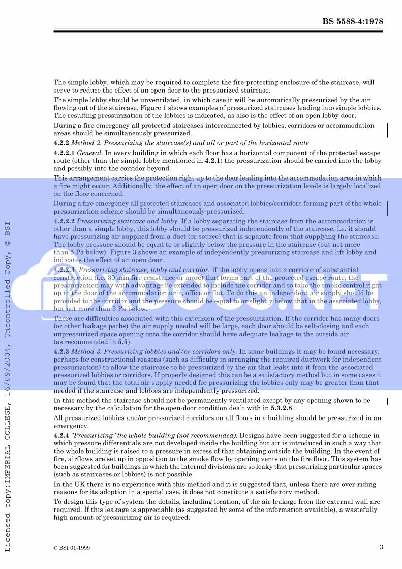
The simple lobby, which may be required to complete the fire-protecting enclosure of the staircase, will serve to reduce the effect of an open door to the pressurized staircase.
The simple lobby should be unventilated, in which case it will be automatically pressurized by the air flowing out of the staircase. Figure 1 shows examples of pressurized staircases leading into simple lobbies. The resulting pressurization of the lobbies is indicated, as also is the effect of an open lobby door.
During a fire emergency all protected staircases interconnected by lobbies, corridors or accommodation areas should be simultaneously pressurized.
4.2.2 Method 2. Pressurizing the staircase(s) and all or part of the horizontal route
4.2.2.1 General. In every building in which each floor has a horizontal component of the protected escape route (other than the simple lobby mentioned in 4.2.1) the pressurization should be carried into the lobby and possibly into the corridor beyond.
This arrangement carries the protection right up to the door leading into the accommodation area in which a fire might occur. Additionally, the effect of an open door on the pressurization levels is largely localized on the floor concerned.
During a fire emergency all protected staircases and associated lobbies/corridors forming part of the whole pressurization scheme should be simultaneously pressurized.
4.2.2.2 Pressurizing staircase and lobby. If a lobby separating the staircase from the accommodation is other than a simple lobby, this lobby should be pressurized independently of the staircase, i.e. it should have pressurizing air supplied from a duct (or source) that is separate from that supplying the staircase. The lobby pressure should be equal to or slightly below the pressure in the staircase (but not more than 5 Pa below). Figure 3 shows an example of independently pressurizing staircase and lift lobby and indicates the effect of an open door.
4.2.2.3 Pressurizing staircase, lobby and corridor. If the lobby opens into a corridor of substantial construction (i.e. 30 min fire resistance or more) that forms part of the protected escape route, the pressurization may with advantage be extended to include the corridor and so take the smoke control right up to the door of the accommodation unit, office or flat. To do this an independent air supply should be provided to the corridor and the pressure should be equal to or slightly below that in the associated lobby, but not more than 5 Pa below.
There are difficulties associated with this extension of the pressurization. If the corridor has many doors (or other leakage paths) the air supply needed will be large, each door should be self-closing and each unpressurized space opening onto the corridor should have adequate leakage to the outside air (as recommended in 5.5).
4.2.3 Method 3. Pressurizing lobbies and/or corridors only. In some buildings it may be found necessary, perhaps for constructional reasons (such as difficulty in arranging the required ductwork for independent pressurization) to allow the staircase to be pressurized by the air that leaks into it from the associated pressurized lobbies or corridors. If properly designed this can be a satisfactory method but in some cases it may be found that the total air supply needed for pressurizing the lobbies only may be greater than that needed if the staircase and lobbies are independently pressurized.
In this method the staircase should not be permanently ventilated except by any opening shown to be necessary by the calculation for the open-door condition dealt with in 5.3.2.8.
All pressurized lobbies and/or pressurized corridors on all floors in a building should be pressurized in an emergency.
4.2.4 “Pressurizing” the whole building (not recommended). Designs have been suggested for a scheme in which pressure differentials are not developed inside the building but air is introduced in such a way that the whole building is raised to a pressure in excess of that obtaining outside the building. In the event of fire, airflows are set up in opposition to the smoke flow by opening vents on the fire floor. This system has been suggested for buildings in which the internal divisions are so leaky that pressurizing particular spaces (such as staircases or lobbies) is not possible.
In the UK there is no experience with this method and it is suggested that, unless there are over-riding reasons for its adoption in a special case, it does not constitute a satisfactory method.
To design this type of system the details, including location, of the air leakage from the external wall are required. If this leakage is appreciable (as suggested by some of the information available), a wastefully high amount of pressurizing air is required.
Licensed copy:IMPERIAL COLLEGE, 16/09/2004, Uncontrolled Copy, © BSI

BS
5588-4
:1978
4©
BS
I 01
-19
99
Fig
ure
1 —
Pre
ssu
riz
ing
sta
irca
se
on
ly
Licensed copy:IMPERIAL COLLEGE, 16/09/2004, Uncontrolled Copy, © BSI