Scale-dependent homogenization of random composites as micropolar continua
Upload
independentCategory
view
2download
0
Arch. Mech., 57, 4, pp. 251–264, Warszawa 2005
Finite element solution of mixed convection micropolar fluid
flow between two vertical plates with varying temperature
L. KUMAR1), R. BHARGAVA1), P. BHARGAVA2), H. S. TAKHAR3)
1)Department of Mathematics,Indian Institute of Technology Roorkee, India
2)Department of Civil Engineering,Indian Institute of Technology Roorkee, India
3)Department of Engineering,Manchester Metropolitan University,Manchester, M1 5 GD. U.K.e-mail: [email protected]
This paper presents a finite element solution for the mixed convection micropolarfluid flow between two parallel plates with varying temperature. The governing differ-ential equations are solved numerically using the finite element method. The effect ofimportant parameters, namely pressure gradient, micropolar parameter and surface,condition parameter on velocity, microrotation as well as on temperature functionshas been studied. It is noticed that the micropolar fluids act as a cooling agent aswell as a drag reducing fluids.
Notations
f dimensionless velocity function,g dimensionless microrotation,T temperature,ge gravitational acceleration,N microrotation,P pressure,
∆P dimensionless pressure gradient,Q volumetric flow rate,c varying temperature factor,x streamwise coordinate,y normal coordinate,u velocity along the x-axis,A dimensionless microrotation parameter,R dimensionless micropolar parameter,wi arbitrary test functions,kf coefficient of thermal conductivity,2L distance between the plates,

252 L. Kumar, R. Bhargava, P. Bhargava, H. S. Takhar
S dimensionless wall heat parameter,m wall heat ratio parameter; change in m produces unequal
temperatures at the walls.
Greek letters
η dimensionless coordinate perpendicular to the plates,µ dynamic viscosity,ρ density of the fluid,κ gyro-viscosity coefficient,γ micropolar parameter,θ dimensionless temperature,β volumetric coefficient of thermal expansion,ψi interpolation functions.
1. Introduction
Eringen [1] introduced the concept of microfluids, which deals with a classof fluids, exhibiting certain microscopic effects arising from the local structureand micro-motions of the fluid elements. These fluids can support stress momentsand body moments and are influenced by the spin inertia. Later Eringen [2]developed a subclass of these microfluids, called micropolar fluids, where themicro-rotational effects and micro-rotational inertia exist but they do not sup-port stretch. They can support couple stresses and body couples only. Physicallysome polymeric fluids, fluids containing small amounts of polymeric additives,blood, paints, lubricating oils, liquid crystals, colloidal fluids and suspension fluidmay be represented by the mathematical model, underlying micropolar fluids.An excellent review of micropolar fluids and their applications were provided byAriman et al. [3].
Hoyt and Fabula [4] have shown experimentally that the fluids containingminute polymeric additives indicate considerable reduction of the skin friction(about 25–30%); a concept, which is well explained by the theory of micropolarfluids. As an application, these fluids with microstructure are also capable ofrepresenting the body fluids.
The problems of micropolar fluid flow between two vertical plates (channel)are of great technical interest. A lot of attention has been given by many re-searchers. Sastry and Rao [5] have studied the effect of suction in the laminarflow of a micropolar fluid in a channel, considering the Poiseuille flow at theentry of the channel. Bhargava and Rani [6] have examined the convectiveheat transfer in micropolar fluid flow between parallel plates. Its extension tofree and forced convection is an interesting area of research including liquid crys-tals, dilute solutions of polymer fluids and many types of suspensions, since inmany configurations in the technology and nature, one continually encountersmasses of fluid rising freely in an extensive medium due to the buoyancy ef-

Finite element solution of mixed convection micropolar... 253
fects. Agarwal and Dhanapal [7] analyzed free convection micropolar fluidflow between two parallel porous vertical plates. The problem of fully developedfree convection of a micropolar fluid in vertical channels has been discussed byChamkha et al. [8]. Srinivasacharya et al. [9] have investigated the problemof unsteady Stokes flow of micropolar fluid between two parallel porous plates.In a forced convection situation, natural convection effects are also present in thepresence of gravitational body forces. The situation where both the natural andforced convection effects are of comparable order is called mixed or combinedconvection.
Gorla et al. [10] studied the fully developed laminar mixed convection flowof a micropolar fluid between two vertical parallel plates maintained at uniformbut different temperatures. Excellent applications can be found in Nigam et al.
[11], where the authors discussed the problem of micropolar fluid film lubricationbetween two parallel plates with reference to human joints. One of the recentbut excellent papers demonstrating the basic theories of micropolar fluids andits applications is that given by Łukaszewicz [12].
The purpose of the present paper is to analyze the mixed convection flow ofa micropolar fluid between two vertical parallel plates with varying temperature.Such type of study may be applicable in nuclear reactors, heat exchangers andvarious electronic devices. Perhaps the most important question here is the effectof buoyancy on the forced convection transport rates. The buoyancy forces mayaid or oppose the forced flow causing an increase or decrease in the heat transferrates.
In this paper, the set of coupled nonlinear differential equations governingthe flow, microrotation and temperature fields are solved by the finite elementmethod and the results have been compared with those obtained by Gorlaet al. [10]. A discussion is provided for the effect of the pressure gradient pa-rameter, micropolar parameter and surface condition parameter on the flow,microrotation and temperature profiles. The influence of temperature on thesefunctions, when it varies linearly along the x-axis, has been also discussed.
2. Mathematical analysis
Consider steady, laminar mixed convection flow of an incompressible mi-cropolar fluid passing between two infinite vertical parallel plates. The platesare kept at a distance 2L apart, parallel to the direction of the gravitationalbody force. The x-axis extends along the plate and is located along the cen-terline of the channel, while the y-axis is normal to the plates. ‘u’ is the ve-locity component along the x-axis, N – the component of microrotation andT – the temperature. Temperature is varying linearly along the x-axis with cxand mcx being the temperatures of the left (y = −L) and the right-hand plate

254 L. Kumar, R. Bhargava, P. Bhargava, H. S. Takhar
(y = L) respectively. Thus the governing equations of this type of flow can bewritten as:Momentum:
(2.1) (µ+ κ)d2u
dy2+ κ
dN
dy− dP
dx+ ρgeβT = 0.
Angular momentum:
(2.2) γd2N
dy2− κ
du
dy− 2κN = 0.
Energy equation:
(2.3) kfd2T
dy2+(
µ+κ
2
)
(
du
dy
)2
+κ
2
(
du
dy+ 2N
)2
+ γ
(
dN
dy
)2
= 0.
The question of boundary conditions for structured fluids deserves some ad-ditional comments. Eringen suggested the no-spin boundary condition as beingequivalent to a no-slip condition. This condition corresponds to strong concen-tration of microelements in the vicinity of the boundary. The physical interpre-tation is that there is a fluid-solid interface with strong interactions such thatthe microstructure does not rotate with respect to the surface.
The other boundary condition, suggested by Ahmadi [13], corresponds tothe condition that the antisymmetric part of the stress is zero on the surface,which requires that the particle spin should be equal to fluid vorticity at theboundary. In other words, in the neighborhood of a rigid boundary the effect ofmicrostructure must be negligible since the suspended particles cannot get closerto the boundary than their radius. For example in the case of blood flow, it isobserved that the red cells do not get very close to the boundary. Therefore, inthe neighborhood of the boundary the only rotation is due to fluid shear andtherefore, the gyration vector must be equal to the angular velocity. Dahlerand Scriven [14] demonstrated that the general boundary conditions may haveimportant applications.
Kirwan [15] analysed a general linear relation between the microrotationrate and vorticity at the rigid boundaries given by:
N (x, 0) = −s(
∂u
∂y
)
y=0
,
where s is the surface condition parameter and it varies from 0 to 1.Another important type of boundary condition explained by Peddieson
[16] is the non-vanishing angular velocity at the boundary. Using this result,
Finite element solution of mixed convection micropolar... 255
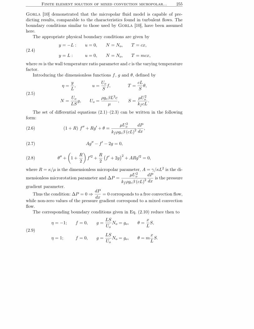
Gorla [10] demonstrated that the micropolar fluid model is capable of pre-dicting results, comparable to the characteristics found in turbulent flows. Theboundary conditions similar to those used by Gorla [10], have been assumedhere.
The appropriate physical boundary conditions are given by
(2.4)y = −L : u = 0, N = No, T = cx,
y = L : u = 0, N = No, T = mcx,
wherem is the wall temperature ratio parameter and c is the varying temperaturefactor.
Introducing the dimensionless functions f , g and θ, defined by
(2.5)
η =y
L, u =
Uo
Sf, T =
cL
Sθ,
N =Uo
LSg, Uo =
ρgeβL3c
µ, S =
µU2o
kfcL.
The set of differential equations (2.1)–(2.3) can be written in the followingform:
(2.6) (1 +R) f ′′ +Rg′ + θ =µU2
o
kfρgeβ (cL)2dP
dx,
(2.7) Ag′′ − f ′ − 2g = 0,
(2.8) θ′′ +
(
1 +R
2
)
f ′2 +R
2
(
f ′ + 2g)2
+ARg′2 = 0,
where R = κ/µ is the dimensionless micropolar parameter, A = γ/κL2 is the di-
mensionless microrotation parameter and ∆P =µU2
o
kfρgeβ (cL)2dP
dxis the pressure
gradient parameter.
Thus the condition: ∆P = 0 ⇒ dP
dx= 0 corresponds to a free convection flow,
while non-zero values of the pressure gradient correspond to a mixed convectionflow.
The corresponding boundary conditions given in Eq. (2.10) reduce then to
(2.9)
η = −1; f = 0, g =LS
UoNo = go, θ =
x
LS,
η = 1; f = 0, g =LS
UoNo = go, θ = m
x
LS.

256 L. Kumar, R. Bhargava, P. Bhargava, H. S. Takhar
The differential equations (2.14)–(3.5) with the boundary conditions as thosegiven in (3.7) have been solved numerically using the finite element method forthe different parameters, namely the pressure gradient parameter ∆P , micropo-lar parameter R, surface condition parameter go and variable x.
3. Method of solution
3.1. Finite element method
The set of differential equations given in Eqs. (2.14)–(3.5) are highly nonlineartherefore it cannot be solved analytically. Hence finite element method has beenused in obtaining their solution. The steps involved in the finite-element analysisare as follows:
1. Division of the domain into linear elements, called the finite element mesh.2. Generation of the element equations using variational formulations.3. Assembly of the element equations as obtained in steps (2).4. Introduction of the boundary conditions to the equations obtained in (3).5. Solution of the assembled algebraic equations.The assembled equations can be solved by any of the numerical technique viz.
Gaussian elimination, LU Decomposition method etc. The details of the methodused here can be studied in the paper given by Reddy [17].
3.2. Variational formulation:
The variational form associated with Eqs. (2.14) to (3.5) over a typical two-node linear element (ηe, ηe+1) is given by
ηe+1∫
ηe
w1
{
(1 +R) f ′′ +Rg′ + θ − ∆P}
dη = 0,(3.1)
ηe+1∫
ηe
w2
{
Ag′′ − f ′ − 2g}
dη = 0,(3.2)
ηe+1∫
ηe
w3
{
θ′′ + (1 +R) f ′2 + 2Rf ′g + 2Rg2 +ARg′2}
dη = 0,(3.3)
where w1, w2 and w3 are the arbitrary test functions which may be viewed asthe variations in the functions f, g and θ, respectively.

Finite element solution of mixed convection micropolar... 257
3.3. Finite element formulation
The finite element model may be obtained from (3.10)–(3.3) by substitutingthe finite element approximations of the form
(3.4) f =
2∑
j=1
fjψj , g =
2∑
j=1
gjψj , θ =
2∑
j=1
θjψj
withw1 = w2 = w3 = ψi (i = 1, 2, )
where ψi are the shape functions for a typical element (ηe, ηe+1) which areassumed in the form:
ψ(e)1 =
ηe+1 − η
ηe+1 − ηe, ψ
(e)2 =
η − ηe
ηe+1 − ηe, ηe ≤ η ≤ ηe+1.
The finite element model of the equations thus formed is the following:
(3.5)
[
K11] [
K12] [
K13]
[
K21] [
K22] [
K23]
[
K31] [
K32] [
K33]
{f}{g}{θ}
=
{
r1}
{
r2}
{
r3}
.
Here [Kmn] and [rm] (m,n = 1, 2, 3 ) are the matrices of order 2 × 2 and2 × 1 respectively, hence each matrix element is of the order 6 × 6 . The matrix[K23] is the null matrix, while the matrices [K11], [K13], [K22] and [K33] aresymmetric matrices. All these matrices are defined as follows:
(3.6)
K11ij = − (1 +R)
ηe+1∫
ηe
dψi
dη
dψj
dηdη, K12
ij = R
ηe+1∫
ηe
ψidψj
dηdη,
K13ij =
ηe+1∫
ηe
ψiψjdη K21ij = −
ηe+1∫
ηe
ψidψj
dηdη,
K22ij = −A
ηe+1∫
ηe
dψi
dη
dψj
dηdη − 2
ηe+1∫
ηe
ψiψjdη, K23ij = 0,
K31ij = (1 +R)
ηe+1∫
ηe
ψidf
dη
dψj
dηdη + 2R
ηe+1∫
ηe
ψigdψj
dηdη,

258 L. Kumar, R. Bhargava, P. Bhargava, H. S. Takhar
(3.6)[cont.]
K32ij = 2R
ηe+1∫
ηe
ψigψjdη +AR
ηe+1∫
ηe
ψidg
dη
dψj
dηdη,
K33ij = −
ηe+1∫
ηe
dψi
dη
dψj
dηdη, r1i =
ne+1∫
ne
∆P ψidη − (1 +R)
(
ψidf
dη
)ne+1
ηe
,
r2i = −A(
ψidg
dη
)ne+1
ηe
, r3i = −(
ψidθ
dη
)ne+1
ηe
,
where
f =2∑
i=1
fiψi, g =2∑
i=1
giψi.
The system of equations after assembly of the elements is nonlinear, thereforean iterative scheme is used to solve it. The system is linearized by incorporatingthe functions f and g, which are assumed to be known. Since the whole domainis divided into a set of 40 intervals of equal length, say 0.05, thus we obtain a setof 123 equations with 6 boundary conditions. After applying the given boundaryconditions, only a system of 117 equations remains for the solution, which isperformed iteratively maintaining an accuracy of 0.0005.
4. Results and discussion
The velocity, microrotation and temperature functions have been computedby using the finite element method and the results are shown graphically inFigs. 1–12. The values of material parameters S, L and A are taken to be fixedat 1.0 each, while m is kept to be fixed at 2.0, and the effect of other importantparameters, namely pressure gradient parameter ∆P , micropolar parameter Rand surface condition parameter go upon these functions has been studied.
Figures 1, 5 and 9 depict the variation of velocity, microrotation and temper-ature functions with pressure gradient parameter ∆P , while other parametersx, R and go are assumed to be fixed as 1.0, 1.0 and 3.0 respectively. Figures 2, 6and 10 illustrate the variation of these functions with x, while other parameters∆P, R and go are taken to be fixed as 1.0, 1.0 and 3.0, respectively. Figures3, 7 and 11 show the variation of these functions with micropolar parameter Rwhile other parameters ∆P, x and go are fixed as 1.0, 1.0 and 3.0 respectively.Figures 4, 8 and 12 represent the variation of these functions with the surfacecondition parameter go while the other parameters ∆P, x and R are assumed tobe fixed as 1.0 each.

Finite element solution of mixed convection micropolar... 259
0
0.3
0.6
0.9
1.2
1.5
1.8
-1 -0.5 0 0.5 1
f
P
0
1
2
3
h
D
0
0.5
1
1.5
2
2.5
-1 -0.5 0 0.5 1ø
f
x
2
1
0
0h
Fig. 1. Velocity distribution for different∆P (x = 1, R = 1, g◦ = 3).
Fig. 2. Velocity distribution for different x(∆P = 1, R = 1, g◦ = 3).
0
0.5
1
1.5
2
2.5
-1 -0.5 0 0.5 1÷
f
R
4
3
2
1
0
h
0
0.2
0.4
0.6
0.8
1
1.2
1.4
-1 -0.5 0 0.5 1
f
go
3
-3
2
-2
h
Fig. 3. Velocity distribution for different R(∆P = 1, x = 1, g◦ = 3).
Fig. 4. Velocity distribution for differentg◦(∆P = 1, R = 1, x = 1).
0
0.5
1
1.5
2
2.5
3
-1 -0.5 0 0.5 1
Ø
g
ØP
0
1
2
3
h
D
0
0.5
1
1.5
2
2.5
3
-1 -0.5 0 0.5 1
Ø
g
x
2
1
0
h
Fig. 5. Microrotation distribution for different∆P (x = 1, R = 1, g◦ = 3).
Fig. 6. Microrotation distribution for differentx(∆P = 1, R = 1, g◦ = 3).

260 L. Kumar, R. Bhargava, P. Bhargava, H. S. Takhar
0
0.5
1
1.5
2
2.5
3
-1 -0.5 0 0.5 1Ø
g
R
4
3
2
1
0
h-3
-2
-1
0
1
2
3
-1 -0.5 0 0.5 1
Ø
g
go
3
2
-2
-3h
Fig. 7. Microrotation distribution for differentR(∆P = 1, x = 1, g◦ = 3).
Fig. 8. Microrotation distribution for differentgo(∆P = 1, R = 1, x = 1).
0
1
2
3
4
5
6
7
8
-1 -0.5 0 0.5 1`
`
` P
0
1
2
3
h
D
q
0
1
2
3
4
5
6
7
8
9
10
-1 -0.5 0 0.5 1�
�
x
2
1
0
h
q
Fig. 9. Temperature distribution for different∆P (x = 1, R = 1, g◦ = 3).
Fig. 10. Temperature distribution for differentx(∆P = 1, R = 1, g◦ = 3).
0
5
10
15
20
25
-1 -0.5 0 0.5 1ð
ð
R
4
3
2
1
0
h
q
h
0
1
2
3
4
5
6
7
-1 -0.5 0 0.5 1`
`
go
-3
3
-2
2
h
q
Fig. 11. Temperature distribution for differentR(∆P = 1, x = 1, g◦ = 3).
Fig. 12. Temperature distribution for differentg◦(∆P = 1, R = 1, x = 1).

Finite element solution of mixed convection micropolar... 261
Figure 1 represents the variation of velocity with the pressure gradient pa-rameter ∆P . The velocity decreases with increases in the pressure gradient pa-rameter ∆P . It is also clear from the figure that with an increase of ∆P , themaxima are shifted towards the right-hand plate (η = 1). From Figs. 2, 3 and 4,it is observed that the velocity increases with an increase in x, micropolar para-meter R and with the absolute value of surface condition parameter go. However,the velocity for the Newtonian case (R = 0) is sufficiently small as compared tothe micropolar fluids (R 6= 0). Obviously an increase in go shifts the maximatowards the right-hand plate while with increase in the negative value of go, themaxima are shifted towards the left-hand plate; which depicts the behaviour ofmaximum velocity with variable go.
Figures 5, 6, 7 and 8 depict the variation of microrotation. Figure 5 shows thatin the first half-region, microrotation increases with an increase of the pressuregradient parameter, while it decreases in the second half-region, which is oppositeto x and micropolar parameter R as shown in Figs. 6 and 7. From Fig. 8 itis clear that microrotation increases with the increase of the surface conditionparameter go. It is also clear from the Fig. 8 that for the positive value ofgo, microrotation decreases continuously, until it reaches the minima and thenincreases continuously, while with the negative value of go microrotation increasescontinuously, until it reaches the maxima and then decreases continuously. Thusthe pattern is different for negative and positive values of go.
The distribution for the temperature function has been shown in the Figs. 9,10, 11 and 12. Temperature decreases with the increase of the pressure gradientparameter, while it increases with increasing x the micropolar parameter andwith the absolute value of surface condition parameter. Temperature is muchlower for Newtonian fluids (R = 0 ) as compared to the micropolar fluids. Thetemperature distribution is nearly linear for viscous fluids. It is clear from thefigures that maximum temperature remains in the first half-region while fromFig. 12 it is observed that for large negative value of go, maximum temperaturecan be obtained in the second half-region.
The variation of skin friction and the rate of heat transfer on both plateswith respect to the pressure gradient parameter, micropolar parameter, surfacecondition parameter and with x are given in Table 1 and 2, respectively.
It is clear from Table 1 that the skin friction numerically decreases with anincrease of the pressure gradient parameter ∆P , while it numerically increaseswith an increase in x, the micropolar parameter R and with the absolute value ofsurface condition parameter go. Thus the skin friction can be effectively reducedby introducing the pressure gradient.
From Table 2 it is observed that the rate of heat transfer numerically de-creases with an increasing ∆P , while it increases numerically with the increaseof x, the micropolar parameter R and with the absolute value of the surface con-

262 L. Kumar, R. Bhargava, P. Bhargava, H. S. Takhar
Table 1. Table for the skin friction {f ′}η=−1, 1 with different values of thepressure gradient parameter ∆P , micropolar parameter R, surface condition
parameter go and with x.
S = L = A = 1.0, m = 2.0 {f ′}η=−1, 1
R = x = 1, go = 3
∆Pη
0 1 2 3
−1 2.4154 1.5319 0.8200 0.20321 −3.2501 −2.4446 −1.7931 −1.2270
∆P = R = 1, go = 3
xη
0 1 2
−1 0.5626 1.5319 2.94541 −1.4165 −2.4446 −3.8744
∆P = x = 1, go = 3
Rη
0 1 2 3 4
−1 0.3514 1.5319 2.2379 2.7486 3.17181 −0.6375 −2.4446 −3.2543 −3.7725 −4.1720
∆P = x = R = 1
go
η−3 −2 2 3
−1 2.2681 1.1315 0.5656 1.53191 −1.6482 −0.6964 −1.2930 −2.4446
Table 2. Table for the Nusselt number {−θ′}η=−1, 1 with different valuesof the pressure gradient parameter ∆P , micropolar parameter R, surface
condition parameter go and variable x.
S = L = A = 1.0, m = 2.0 {−θ′}η=−1, 1
R = x = 1, go = 3
∆Pη
0 1 2 3
−1 −20.4989 −16.2988 −13.7162 −12.03561 11.7847 9.8791 9.0607 8.8509
∆P = R = 1, go = 3
xη
0 1 2
−1 −12.2673 −16.2988 −24.44161 9.3425 9.8791 13.3187
∆P = x = 1, go = 3
Rη
0 1 2 3 4
−1 −0.5672 −16.2988 −37.4175 −62.0292 −89.77581 −0.4011 9.8791 20.7529 32.5027 45.2981
∆P = x = R = 1
go
η−3 −2 2 3
−1 −10.6699 −4.6916 −6.3802 −16.29881 15.2722 5.3884 3.7797 9.8791
dition parameter go. Thus these parameters can be used for controlling the rateof heat transfer. If the plate temperature is higher than the fluid temperature,then the increase in the rate of heat transfer shows that more and more heat is

Finite element solution of mixed convection micropolar... 263
transferred from the plate to the fluid. This physically means that the coolingeffect on the plates increases. Thus fast cooling can be achieved by increasingthe micropolar parameter, surface condition parameter and with an increasein x. That is required in polymer industry where after generation of very hightemperature, fast cooling is required to achieve a regular structure.
5. Conclusions
1. Velocity decreases with an increase of the pressure gradient parameter,while it increases with an increase in x, with the micropolar parameterand with the absolute value of surface condition parameter. Thus the flowof the fluid can be controlled by simulating these parameters.
2. Pressure gradient parameter ∆P can be used effectively for controlling/si-mulating the rise in the temperature field.
3. Skin friction numerically increases with increasing values of x, R and gowhile it decreases with ∆P . Thus the drag forces can be reduced by usingthe pressure gradient parameter.
4. The rate of heat transfer numerically decreases with increasing ∆P , whileit increases with an increase in x, micropolar parameter R and with theabsolute value of surface condition parameter go. Thus fast cooling of theplate can be achieved by increasing the micropolar parameter, the surfacecondition parameter and with an increase in x. Thus this problem may bevery useful in various engineering applications.
Acknowledgment
One of the authors, Lokendra Kumar, is grateful to CSIR, New Delhi forproviding a Senior Research Fellowship.
References
1. A.C. Eringen, Simple microfluids, Int. J. Engng. Sci., 2, 205–217, 1964.
2. A.C. Eringen, Theory of micropolar fluids, J. Math. Mech., 16, 1–18, 1966.
3. T. Ariman, M.A. Turk and N.D. Sylvester, Review article-Applications of micro-continuum fluid mechanics, Int. J. Engng. Sci., 12, 273–293, 1974.
4. J.W. Hoyt and A.G. Fabula, The effect of additives on fluid friction, U.S. NavalOrdnance Test Station Report, 1964.
5. V.U.K. Sastry and V.R.M. Rao, Numerical solution of micropolar fluid flow in achannel with porous walls, Int. J. Engng Sci., 20, 631–642, 1982.
6. R. Bhargava and M. Rani, Numerical solution of heat transfer in micropolar fluid flowin a channel with porous walls, Int. J. Engng. Sci., 23, 409–413, 1985.

264 L. Kumar, R. Bhargava, P. Bhargava, H. S. Takhar
7. R.S. Agarwal, and C. Dhanapal, Numerical solution of free convection micropolarfluid flow between two parallel porous vertical plates, Int. J. Engng. Sci., 26, 1247–1255,1988.
8. A.J. Chamkha, T. Groşan and I. Pop Fully developed free convection of a micropolarfluid in a vertical channel, Int. Comm. Heat and Mass Transfer, 29, 1119–1127, 2002.
9. D. Srinivasacharya, J.V.R. Murthy and D. Venugopalam, Unsteady stokes flowof micropolar fluid between two parallel porous plates, Int. J. Engng Sci., 39, 1557–1563,2001.
10. R.S.R. Gorla, B. Ghorashi and P. Wangskarn, Mixed convection in vertical internalflow of a micropolar fluid, Int. J. Engng Sci., 27, 1553–1561, 1989.
11. K.M. Nigam, K. Manohar and S. Jaggi, Micropolar fluid film lubrication between twoparallel plates with reference to human joints, Int. J. Mech. Sci., 24, 661–671, 1982.
12. G. Łukaszewicz, Micro polar fluids-Theory and Applications, Birkhauser Boston, 1999.
13. G. Ahmadi, Self-similar solution of incompressible micropolar boundary layer flow overa semi-infinite plate, Int. J. Engng Sci., 14, 639–646, 1976.
14. J.S. Dahler and L.E. Scriven, Theory of structured continua, Proc. Roy. Soc., A-275,504, London 1963.
15. A.D. Kirwan Jr., Boundary conditions for micropolar fluids, Lett. Appl. Engng. Sci.,24, 1237–1242, 1986.
16. J. Peddieson Jr., An application of the micropolar fluid model to the calculation of aturbulent shear flow, Int. J. Engng. Sci., 10, 23–32, 1972.
17. J.N. Reddy, An introduction to the finite element method, McGraw-Hill InternationalEditions, 1984.
Received June 21, 2004; revised version October 29, 2004.
Copyright © 2022 FDOKUMEN