FINITE ELEMENT ANALYSIS OF THE PSEUDO-ELASTIC BEHAVIOR OF SHAPE MEMORY ALLOY TRUSS AND BEAM...
16
Archive of SID International Journal of Advanced Structural Engineering, Vol. 2, No. 1, Pages 11-26, July 2010 © Islamic Azad University, South Tehran Branch Published online July 2010 at (http://journals.azad.ac.ir/IJASE) 11 FINITE ELEMENT ANALYSIS OF THE PSEUDO-ELASTIC BEHAVIOR OF SHAPE MEMORY ALLOY TRUSS AND BEAM Kamal M. Bajoria 1 and Surajit Das 2 Department of Civil Engineering, Indian Institute of Technology Bombay, Mumbai, India Received 13 January 2010 Revised 7 June 2010 Accepted 13 June 2010 The pseudo-elastic behavior of Shape memory alloy (SMA) truss and cantilever beam are investigated. Brinson’s one-dimensional material model, which uses the twinned and detwinned martensite fractions separately as internal variables, is applied in the algorithm to establish the SMA stress-strain characteristics. This material model also incorporates different young’s modulus for austenitic and martensite phase to represent the true SMA characteristics. In this model, a cosine function was used to express the evolution of the stress induced martensite fractions during the forward and reverse martensite phase transformation. A finite element formulation for the SMA truss member considering the geometric nonlinearity is proposed and the results are compared with the corresponding linear analysis. As a step forward, a finite element formulation for an SMA cantilever beam with an applied end moment is proposed. The load displacement characteristic for both the loading and unloading phases are considered to check the full pseudo-elastic hysteretic loop. In the numerical investigation, the stress-strain variation along the beam depth is also examined during the loading and unloading process to investigate the forward and reverse martensite phase transformation phenomena. Newton-Raphson’s iterative method is applied to get convergence to the equilibrium for each loading steps. During a complete loading-unloading process, the temperature is kept constant as the model is essentially an isothermal model. Numerical simulation is performed considering two different temperatures to demonstrate the effect of temperature on the hysteretic loop. Keywords: shape memory alloy (SMA), austenite, martensite, martensite fraction, twinned martensite, detwinned martensite, hysteresis loop, smart structure 1 Associate Professor 2 Research Scholar Correspondence to: Dr. Kamal M. Bajoria, Department of Civil Engineering, Indian Institute of Technology Bombay, Room No. 137, Powai, Mumbai 400076, India, E-mail: [email protected] www.SID.ir
Transcript of FINITE ELEMENT ANALYSIS OF THE PSEUDO-ELASTIC BEHAVIOR OF SHAPE MEMORY ALLOY TRUSS AND BEAM...

Archi
ve o
f SID
International Journal of Advanced Structural Engineering, Vol. 2, No. 1, Pages 11-26, July 2010
© Islamic Azad University, South Tehran Branch
Published online July 2010 at (http://journals.azad.ac.ir/IJASE)
11
FINITE ELEMENT ANALYSIS OF THE PSEUDO-ELASTIC BEHAVIOR OF SHAPE MEMORY ALLOY TRUSS AND BEAM
Kamal M. Bajoria1 and Surajit Das2 Department of Civil Engineering, Indian Institute of Technology Bombay, Mumbai, India
Received 13 January 2010
Revised 7 June 2010 Accepted 13 June 2010
The pseudo-elastic behavior of Shape memory alloy (SMA) truss and cantilever beam are investigated. Brinson’s one-dimensional material model, which uses the twinned and detwinned martensite fractions separately as internal variables, is applied in the algorithm to establish the SMA stress-strain characteristics. This material model also incorporates different young’s modulus for austenitic and martensite phase to represent the true SMA characteristics. In this model, a cosine function was used to express the evolution of the stress induced martensite fractions during the forward and reverse martensite phase transformation. A finite element formulation for the SMA truss member considering the geometric nonlinearity is proposed and the results are compared with the corresponding linear analysis. As a step forward, a finite element formulation for an SMA cantilever beam with an applied end moment is proposed. The load displacement characteristic for both the loading and unloading phases are considered to check the full pseudo-elastic hysteretic loop. In the numerical investigation, the stress-strain variation along the beam depth is also examined during the loading and unloading process to investigate the forward and reverse martensite phase transformation phenomena. Newton-Raphson’s iterative method is applied to get convergence to the equilibrium for each loading steps. During a complete loading-unloading process, the temperature is kept constant as the model is essentially an isothermal model. Numerical simulation is performed considering two different temperatures to demonstrate the effect of temperature on the hysteretic loop. Keywords: shape memory alloy (SMA), austenite, martensite, martensite fraction, twinned martensite, detwinned martensite, hysteresis loop, smart structure
1 Associate Professor 2 Research Scholar Correspondence to: Dr. Kamal M. Bajoria, Department of Civil Engineering, Indian Institute of Technology Bombay, Room No. 137, Powai, Mumbai 400076, India, E-mail: [email protected]
www.SID.ir

Archi
ve o
f SID
K. M. Bajoria et al.
/ IJASE: Vol. 2, No. 1, July 2010 12
1. Introduction
Shape Memory Alloys (SMA) is a special class of alloy materials that displays an unusual property of sustaining a large strain without inducing permanent deformation. Funakubo (1987), Otsuka and Wayman (1998), Bhattacharya (1992) demonstrated that this special characteristic at the macroscopic level is the manifestation of a solid to solid, diffusion-less, self-accommodative crystallographic forward and reverse phase transformation between a highly symmetric crystal lattice structure (austenite phase) and a comparatively lower symmetric crystal lattice structure (martensite phase), within a particular stress-temperature domain. Another important fact is that if the strain recovery is constrained, considerably large forces can develop. These stresses may reach the order of magnitude of 1000 MPa. However, for actuator applications with a large number of load cycles, one should reduce the stress to ~200 MPa in order to prevent premature fatigue. Hollerbach et al. (1992) demonstrated that, compared to other actuating systems, the high work output achievable with these materials becomes even more pronounced when the dimensions and weight of the specimen decrease. A detailed experimental analysis of thermo-mechanical behavior of NiTi alloys is presented by Shaw and Kyriakides (1995). Duerig et al. (1999) and Lagoudas et al. (1999) discussed that due to this large strain recovery phenomenon, SMA have been found in a vast application areas ranging from aerospace industry, automobile industry, structural vibration control systems, different sensors and actuator systems, to even the medical field.
The stress induced forward and reverse phase transformation phenomena, known as pseudo-elasticity, results in high damping capacity. Seelekce (2002) proposed a mathematical model for dynamic behavior of SMA. The damping property of SMA is potentially useful with respect to civil structures like buildings and bridges which need an efficient seismic isolation or protection against wind induced vibrations. The related applications are discussed by Aizawa et al. (1998), Wilde et al. (2000) and DesRoches and Delemont (2002).
The present work investigates this pseudo-elastic behavior of NiTi based SMA truss and cantilever beam. This article is divided into five sections. After the introduction in section 1, a brief review of internal variable based one dimensional SMA constitutive model is presented in section 2. Section 3 presents a nonlinear finite element formulation for a two-node SMA truss element. Total Lagrangian formulation is expressed in one-dimensional finite element form considering both the material and geometric nonlinearity and Newton-Raphson’s iterative form is applied. As a numerical example, a SMA truss member is considered with two different loading conditions. The loading-unloading curves and the results are compared with the analysis results of the same structure considering the material nonlinearity alone. As a step forward, in section 4, a FE formulation for a two-node SMA cantilever beam element is proposed. A numerical
www.SID.ir

Archi
ve o
f SID
Finite Element Analysis of the Pseudo-Elastic Behavior of Shape Memory Alloy Truss and Beam
IJASE: Vol. 2, No. 1, July 2010 / 13
example of the two-node SMA cantilever beam is presented. Lastly, a comparative study of the pseudo-elastic behavior of the truss and beam is presented. 2. Review of SMA Constitutive Laws
Extensive investigations on the mechanism of martensite phase transformation phenomena have revealed that the material stress-strain-temperature relationship, which is highly nonlinear in nature, changes with the evolution of the transformation process. A detailed survey of different approaches for deriving the SMA constitutive law is presented by Prahalad and Chopra (2001) and Seelecke and Müller (2004). A model originally developed by Achenbach and Müller (1985), Achenbach et al. (1986) and Achenbach (1989) is particularly important for SMA actuator application emphasizing the thermo-mechanical coupling and simulation of actuator behavior. Tanaka and Nagaki (1982), Tanaka (1986) and Tanaka et al. (1986) proposed a model that uses the fraction of martensite (ξ ) as an internal variable and gives a phenomenological equation of state which depends on the stress and temperature in the form of an exponential function. This model provided the basis for a related model suggested by Liang and Rogers (1990), who found a cosine law for the evolution of the martensite fraction to be more convenient. However, both the exponential and cosine functions were only applicable to the high temperature case of pseudo-elasticity. The material phase state, presented by the internal variable called martensite volume fractionξ , varies from '0 ' , signifying fully austenite state, to '1' , for fully martensite state. Brinson (1993) introduced a decomposition of the martensite fraction (ξ ) into twinned (ξT ) and detwinned martensite (ξS ), that the quasiplastic behavior could be described as well. At any state,
ξ + ξ = ξS T (1)
Due to the phase diagram necessary to distinguish between the different branches of the martensite fraction equation, these models are also called state-space models, which were generalized by Bekker and Brinson (1997). All these models are purely mechanical in the sense that the temperature is considered as a parameter.
The internal variable approach described by Brinson to establish the SMA constitutive law has a number of advantages over the others for its simple mathematical expression. This methodology includes only quantifiable engineering variables and material parameters in its expression. The constitutive law derived by Brinson (1993) is briefly reviewed here for clarity.
Based on the energy balance equation, the basic differential form of the stress-strain-temperature relationship was derived as,
( , , ) ( , , ) ( , , )ε ε ε= ξ +Ω ξ ξ +Θ ξSdS D T dE T d T dT (2)
www.SID.ir
Archi
ve o
f SID
K. M. Bajoria et al.
/ IJASE: Vol. 2, No. 1, July 2010 14
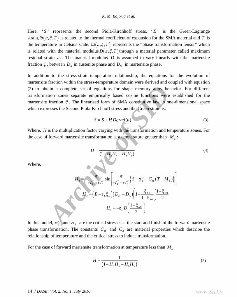
Here, ‘ S ’ represents the second Piola-Kirchhoff stress, ‘ E ’ is the Green-Lagrange strain, ( ), ,ε ξΘ T is related to the thermal coefficient of expansion for the SMA material and T is the temperature in Celsius scale. ( ), ,ε ξΩ T represents the “phase transformation tensor” which is related with the material modulus ( ), ,ε ξD T through a material parameter called maximum residual strain ε L . The material modulus D is assumed to vary linearly with the martensite fraction ξ , between AD in austenite phase and MD in martensite phase.
In addition to the stress-strain-temperature relationship, the equations for the evolution of martensite fraction within the stress-temperature domain were derived and coupled with equation (2) to obtain a complete set of equations for shape memory alloy behavior. For different transformation zones separate empirically based cosine functions were established for the martensite fraction ξ . The linearised form of SMA constitutive law in one-dimensional space which expresses the Second Piola-Kirchhoff stress and the Green strain is:
( )= +S S H Dgrad u (3)
Where, H is the multiplication factor varying with the transformation and temperature zones. For the case of forward martensite transformation at a temperature greater than SM :
3 4 3 5
1(1 )
=− −
HH H H H
(4)
Where,
( ){ }3 sinπ π⎡ ⎤= − −σ − −⎢ ⎥
σ −σ σ −σ⎢ ⎥⎣ ⎦
crf M Scr cr cr cr
S f S f
H S C T M
( )( ) 0 04
0
111 2
⎛ ⎞ξ − ξ= − ε ξ − −⎜ ⎟− ξ⎝ ⎠
T SSL M A
S
H E D D
05
12−ξ⎛ ⎞= −ε ⎜ ⎟
⎝ ⎠S
LH D
In this model, σ crS and σ cr
f are the critical stresses at the start and finish of the forward martensite phase transformation. The constants MC and AC are material properties which describe the relationship of temperature and the critical stress to induce transformation.
For the case of forward martensite transformation at temperature less than SM
( )4 6 5 6
11
=− −
HH H H H
(5)
www.SID.ir
Archi
ve o
f SID
Finite Element Analysis of the Pseudo-Elastic Behavior of Shape Memory Alloy Truss and Beam
IJASE: Vol. 2, No. 1, July 2010 / 15
Where, ( )6 sinπ π⎡ ⎤= − −σ⎢ ⎥
σ −σ σ −σ⎢ ⎥⎣ ⎦
crfcr cr cr cr
S f S f
H S
For the case of reverse martensite transformation
( )1 2
11
=−
HH H
(6)
Where,
1 sin⎡ ⎤⎛ ⎞
= − − −⎢ ⎥⎜ ⎟⎢ ⎥⎝ ⎠⎣ ⎦
AA S
A A
a SH a T AC C
( )( ) 0 02 2 2
ξ ξ= − ε ξ − − ε S
SL M A LH E D D D
π=
−Af S
aA A
In the above equations for transformation kinetics an over-bar is provided to denote the current value of the respective quantity. Lastly, ( )grad u denotes the increment of the infinitesimal strain. 3. Shape Memory Alloy Truss
A nonlinear finite element formulation for a two-node SMA truss element is proposed. The truss element is considered to be in one-dimensional space. The total Lagrangian formulation is applied in an incremental form to obtain the displacement corresponding to each axial load increment. To simplify the problem the load is assumed to be independent of the deformation. 3.1. Finite Element Formulation
In the total Lagrangian formulation all quantities are measured with respect to the initial configuration as derived by Zinno and Barbero (1995), Bathe (2005), and Reddy (2005), in which the weak form of the virtual work principle was expressed as
( ) ( )0 0 0
0 0 00 0 0 0 0 0 0( ) ( )t t t t
ijkl kl ij ij ij ij ijV V V
C e e d V S d V R S e d V+Δδ + δ η = δ − δ∫ ∫ ∫ (7)
The SMA constitutive model is used for the evaluation of stress ( )0t
ijS and the tangent stress-strain matrix ( )0 ijklC . In equation (7) the linear tangent stiffness matrix is obtained from the first term and the nonlinear tangent stiffness matrix is derived from the second term. The total displacement tu and u are interpolated within an element as:
www.SID.ir

Archi
ve o
f SID
K. M. Bajoria et al.
/ IJASE: Vol. 2, No. 1, July 2010 16
{ } { }1 21⎛ ⎞ ⎛ ⎞ ⎡ ⎤= − + = Δ⎜ ⎟ ⎜ ⎟ ⎣ ⎦⎝ ⎠ ⎝ ⎠t
t t
x xu u u NL L
(8)
{ } [ ]{ }1 20 01⎛ ⎞ ⎛ ⎞= − + = Δ⎜ ⎟ ⎜ ⎟⎝ ⎠ ⎝ ⎠
t t t tx xu u u NL L
(9)
Here, tL and 0L are the element length at the load stage t and at the initial stage respectively. After some simplification the linear strain-displacement matrix [ ]LB takes the form:
[ ] [ ]1 20 0
1 1 1 1⎛ ⎞
= − + −⎜ ⎟⎝ ⎠
t t
L t
u uBL L L
(10)
Also the nonlinear strain-displacement matrix [ ]NLB is expressed as:
[ ] [ ]1 1 1= −NL tBL
(11)
The resulting incremental finite element equation for a single truss element for a particular loading step is
[ ] [ ]( ){ } { } { }t t tL NLK K R F+Δ+ Δ = − (12)
Where,
20 0
1 20 2 0 0
1 11
1 1−⎛ ⎞ ⎡ ⎤
= − +⎜ ⎟ ⎢ ⎥−⎣ ⎦⎝ ⎠
t t
L t
u uA LK CL L L
( )0 0
0 11 2
1 11 1
−⎡ ⎤= ⎢ ⎥−⎣ ⎦
tNL t
A LK SL
( )0 0
1 20 0 110 0
11
1−⎛ ⎞ ⎧ ⎫
= − + ⎨ ⎬⎜ ⎟⎩ ⎭⎝ ⎠
t tt t
t
u uA LF SL L L
Finally, Newton-Raphson iterative form was applied for each load increment to solve the assembled form of Equation (12) for incremental displacements. For i th iteration within a load increment the iterative form is expressed as
{ }( )it t t t tK R F+Δ +ΔΔ = − (13)
{ }( )( ) ( 1)+Δ +Δ −= + Δ it t i t t iU U (14)
+Δt tK is the global tangent stiffness matrix, ( )+Δt t iU is the total nodal displacement vector for the load incremental stage + Δt t . The out-of-balance load vector of equation (13), t t tR F+Δ − is a
www.SID.ir

Archi
ve o
f SID
Finite Element Analysis of the Pseudo-Elastic Behavior of Shape Memory Alloy Truss and Beam
IJASE: Vol. 2, No. 1, July 2010 / 17
load vector that n is not yet balanced by element stresses, and hence the total nodal displacement vector is updated through solving the equation (14). This updating is continued until the out-of-balance load and/or the incremental nodal displacement values are small enough in comparison to the assumed tolerance value. 3.2. Numerical Study
A shape memory alloy truss member is considered; with cross sectional area 1 2mm and the other geometric properties as given in figure 1 presents the material properties of the truss member taken. The analysis is performed applying both small and large displacement theories, considering SMA material properties in both cases, and the results are compared.
Figure 1: Shape memory alloy truss
Before loading, the truss material is assumed to be in fully austenite phase and the loading is applied maintaining a constant temperature of 050 C , which is above the austenite finish temperature ( )049=fA C for the SMA material taken. A full loading-unloading cycle is simulated and the displacement at the point of load application is calculated at different load level during the cycle, to demonstrate the pseudo-elastic behavior. Two load cases are examined. In the first case, the axial load is assumed to act asymmetrically along the truss length as shown in Figure 1. In the second case, the same load is considered centered in the truss length.
Table 1. Material properties of the SMA (NiTi) structural members
Moduli, Density Transformation Temperature
Transformation Constants Maximum Residual Strain
367 10AD MPa= × 9= ofM C 18 o
MC MPa C −= 0.067ε =L 326.3 10MD MPa= × 18.4= o
SM C 113.8 oAC MPa C−=
10.55 oMPa C−Θ = 34.5= oSA C 100cr
S MPaσ = 36448.1 −ρ = kgm 49= o
fA C 170crf MPaσ =
www.SID.ir

Archi
ve o
f SID
K. M. Bajoria et al.
/ IJASE: Vol. 2, No. 1, July 2010 18
3.3. Results and Observations
For the SMA truss member a nonlinear finite element analysis method has been applied to depict the one dimensional force displacement behavior and the characteristics of the hysteretic loop. Total Lagrangian formulation is used in the finite element formulation to obtain the element equation. The applied loading is assumed to be conservative in nature. At each iteration of the nonlinear analysis, the prediction of the Green-Lagrange strain from the previous step is utilized to calculate the corresponding value of second Piola-Kirchhoff stress. Due to the coupled nature of the SMA constitutive equations, this task was accomplished by the addition of a subprogram which separately calculates the values and the contributions of the martensite internal variable to the stress value, given the corresponding strain and temperature values from the main program. The novelty in this derivation process is that to include the effect of the change of element length, the total and incremental displacement fields are interpolated through two different sets of shape functions. The total displacement is interpolated within the initial element length whereas for incremental displacements the element length of that particular loading stage is considered. The axial force-displacement curves in figures 4 and 5, and the displacement values shown in table 2, at different loading stages, showing small differences in the results of small and large displacement analysis. When a truss member is subjected to axial load its cross-sections go through translation only, without rotation and, as a result, no significant changes occur in the Piola-Kirchhoff stress and the corresponding strain values. Also, the geometry remains almost unaltered except length, and consequently both the material nonlinear analysis and the material-geometric nonlinear analysis give almost the same results.
Figure 2. Convergence of the maximum displacement Figure 3. Convergence of the maximum value (small displacement) displacement value (large displacement)
www.SID.ir

Archi
ve o
f SID
Finite Element Analysis of the Pseudo-Elastic Behavior of Shape Memory Alloy Truss and Beam
IJASE: Vol. 2, No. 1, July 2010 / 19
Figure 4. Pseudo-elastic recovery for Figure 5. Pseudo-elastic recovery for
asymmetrically placed axial force symmetrically placed axial force
Table 2. Comparison of results between small and large displacement analysis
Axial
Load
(N)
Displacement (mm) Percent
Change
Displacement Vector Norm Percent
Change Small
Displacement
Large
Displacement
Small
Displacement
Large
Displacement
Loading Phase
750 0.141 0.151 7.10 0.207 0.219 5.79
800 0.363 0.365 0.55 0.530 0.532 0.38
950 0.414 0.401 -3.14 0.604 0.584 -3.31
Unloading Phase
950 0.438 0.418 -4.56 0.638 0.609 -4.54
750 0.414 0.396 -4.35 0.603 0.577 -4.31
450 0.368 0.352 -4.35 0.537 0.513 -4.47
4. Shape Memory Alloy Cantilever Beam
For the analysis of SMA cantilever beam the classical Euler-Bernoulli beam theory is adopted. According to this beam theory, it is assumed that the plain beam cross sections remain plain, and normal to the beam axis. The beam is considered to be in two dimensional ‘x-y’ plain which is a plain of symmetry for the problem, the beam can undergo deflection only within this plain.
www.SID.ir

Archi
ve o
f SID
K. M. Bajoria et al.
/ IJASE: Vol. 2, No. 1, July 2010 20
4.1. Kinematic Field
The beam kinematics and deformation are defined as:
( ) ( )0 0′= −u u x yv x (15)
( )0=v v x (16)
0 ( )ε ′′−= yv xò (17)
For this particular case the values of ( )0u x and ‘ò’ are zero as a symmetry of tensile and compressive characteristics of the beam material is assumed in the material model adopted. 4.2. Equilibrium Equations
The beam equilibrium equations are derived introducing the kinematical assumptions into the principle of virtual displacement as:
{ ( )} { } { ( )} { }δ ε σ δ ′=∫ T T
VdV v M (18)
Where, in the right hand side of equation (18), vector { }M represents the applied end moment. The vector ( ){ }vδ ′ denotes the first derivatives of the virtual displacements at the point of moment applied. Two-node beam element is considered for the finite element analysis of the problem. Interpolation functions assumed for the displacement field are:
3 2
1 3 2
2 3 1= − +x xN
L L
2 2
3 22= − +
x xN xL L
3 2
3 232 3−
= +x xN
L L
3
4
2
2= −x xNL L
Applying equation (18), the element equilibrium equation takes the form:
[ ] [ ] [ ] { }20 [ ] { }
⎡ ⎤′′ ′′ ′Δ =⎢ ⎥
⎣ ⎦∫ ∫
T T
A L
C y dA N N dx N M (19)
www.SID.ir

Archi
ve o
f SID
Finite Element Analysis of the Pseudo-Elastic Behavior of Shape Memory Alloy Truss and Beam
IJASE: Vol. 2, No. 1, July 2010 / 21
For this particular case of end moment, the term [ ]′ TN on the right hand side of equation (19) is evaluated at =x L . For a particular loading step, + Δt t the element equation can be solved for i th iteration as:
( ) ( ) ( 1){ }t t i i t t t iK R F+ +Δ −Δ = − (20)
and, ( ) ( 1) ( ){ }+ + −= + Δt t i t t i iU U (21)
Here, ( )+Δ it tK , is the tangent stiffness matrix for the i th iteration, ( )+Δ it tU is the total displacement vector, ( )1itF − is the balancing resisting force vector and t tR+Δ is the external applied force vector. The incremental nodal displacement vector is:
( ) ( ) ( ) ( ) ( )0 1 0 1 0 2 0 2{ } θ θ⎡ ⎤Δ = ⎣ ⎦
Ti i i i iv v (22)
In the above equations, two distinct features are to be noticed. First, since the material modulus value is not linear with strain, it varies along the depth of the beam and also with the change of loading; the integration on the left hand side is performed numerically. In the present case, for each iteration, the beam section is divided into twenty strips and composite Simpson's rule applied to evaluate the integration. Secondly, to account for the material nonlinearity, the external loading is assumed to be applied in several pseudo time steps and the equilibrium has been achieved at each loading step by iteration. In the present case Newton-Raphson iterative scheme has been applied to achieve convergence in each loading steps. The resisting moment is obtained applying composite Simpson's rule along the beam cross-sectional strips. 4.3. Convergence Criteria
The Newton-Raphson iterations are continued until the out-of-balance is ‘sufficiently small’ thereby indicating equilibrium at each pseudo loading steps. In the present work, the tolerance used to assess whether convergence has been achieved is denoted by Fε , which is used as:
( ) ( )t t t t i t t t iFR F R F+Δ +Δ +Δ− ≤ ε − (23)
Crisfield (1992) demonstrated that typical values of εF should lie between 0.001 and 0.01, to get a good convergence.
www.SID.ir

Archi
ve o
f SID
K. M. Bajoria et al.
/ IJASE: Vol. 2, No. 1, July 2010 22
4.4. Numerical Study
A cantilever beam made of shape memory alloy (NiTi) (figure 6), is taken for numerical study. The material properties are given in table 1. The loading is an end moment which is independent of the beam deflection, that is, conservative in nature. The response of the beam is studied for both the loading and unloading phase. Initially, before applying the end moment, the beam material is assumed to be in fully austenitic stage. A constant temperature is maintained during the whole loading and unloading process to demonstrate the pseudo-elastic property of SMA material.
Figure 6. Shape memory alloy cantilever beam 4.5. Results and Observations
Figures 7 and 8 demonstrate the hysteresis loops formed as a result of the pseudo-elastic behavior of the SMA cantilever beam. The moment-curvature curves show good agreement with the results presented by Auricchio and Taylor (1999). After complete unloading, the beam almost fully recovered its deflected shape. The numerical simulation of the loading-unloading phenomena is conducted considering two temperature values which are kept constant during the whole loading-unloading process, as the material model used is essentially isothermal. From the two curves, corresponding to two different constant temperature values, it is evident that with higher temperature, the amount of residual strain increases which agrees with the experimental results reported by Otsuka and Ren (1999). Also, the transformation stress values increase with temperature.
Figures 9 and 10 present the strain and stress variation along the depth of the beam during the loading process. From the stress variation curve it is evident that during the loading process the phase transformation starts from outermost fiber as and when its stress value reaches the critical phase transformation stress and propagates towards the neutral axis of beam cross-section. Immediately after the completion of forward phase transformation into the outer portion of cross-section, there exists three distinct stress zones. While the outermost portion reaches to martensite phase, some portion near the neutral axis remains in austenitic phase and the middle portion goes through the phase transformation process. As the transformation progresses, the transformation zone and the austenitic zone shorten and finally the whole beam section reaches to fully martensite phase. During the loading process the outermost fibre of the beam reaches a large
www.SID.ir

Archi
ve o
f SID
Finite Element Analysis of the Pseudo-Elastic Behavior of Shape Memory Alloy Truss and Beam
IJASE: Vol. 2, No. 1, July 2010 / 23
strain value (in the present case, 13.5 %), which can fully be recovered during the unloading process unless the plastic limit of the beam material is reached. It is to be noted that the material model used here does not consider the zone beyond the plastic limit of the material.
Figure 7. Deflection vs. applied end moment Figure 8. Curvature vs. applied end moment
Figure 9. Strain vs. distance from N. A. (for loading) Figure 10. Stress vs. distance from N. A.
(for loading)
Figures 11 and 12 present the strain and the stress variations along the beam cross-section during the unloading process. As unloading starts and the stress reaches the critical value, the reverse phase transformation starts at the outermost fiber and gradually propagates towards the inner portion, and finally, the whole cross-section transforms to the austenitic state. The stress-curve shows that the innermost part in which no forward phase transformation occurred during the loading process become stiffer, i.e. it develops larger stress corresponding to smaller strain.
www.SID.ir

Archi
ve o
f SID
K. M. Bajoria et al.
/ IJASE: Vol. 2, No. 1, July 2010 24
Figure 11. Strain vs. distance from N. A. (for unoading) Figure 12. Stress vs. distance from N. A.
(for unloading)
5. Conclusion
For the nonlinear analysis of the SMA truss member, the axial force-displacement curves and the displacement values at different loading stages, showing small differences in the results of small and large displacement analysis. When a truss member is subjected to axial load its cross-sections go through translation only, without rotation, and as a result no significant changes occur in the Piola-Kirchhoff stress and the corresponding strain values. Also the geometry remains almost unaltered except length, and consequently both the material nonlinear analysis and the material-geometric nonlinear analysis give almost the same results. For the pseudo-elastic recovery of a SMA cantilever beam the maximum strain recovery is 13.5%. Unlike axial deformation, in this case of bending, the whole beam cross section does not undergo phase transformation simultaneously, which results in a gradual change in deformation as compared to the truss problem that shows a sudden change in the deformation. The material model used in the formulation is isothermal, which necessitates the temperature to remain constant. Also the model is essentially quasi-static in nature, which implies that the load should be static. Material models that overcome these limitations are to be expressed in incremental form so that they can be used to include temperature variation and a variation in the strain rate. The numerical simulation is performed considering two different temperatures to demonstrate a change of the hysteretic loop due to a change in temperature, which suggests the need for further investigation in this direction. References
Achenbach M. and Müller I. (1985), “Simulation of material behavior of alloys with shape memory”, Arch. Mech, Vol. 37, No. 6, Pages 573-585.
Achenbach M., Atanackovic T. and Müller I. (1986), “A model for memory alloy in plain strain”, Int. J. Solids Struct, Vol. 22, No. 2, Pages 171-193.
www.SID.ir

Archi
ve o
f SID
Finite Element Analysis of the Pseudo-Elastic Behavior of Shape Memory Alloy Truss and Beam
IJASE: Vol. 2, No. 1, July 2010 / 25
Achenbach M. (1989), “A model for an alloy with shape memory”, Int. J. Plast, Vol. 5, Pages, 371-395.
Aizawa S., Kakizawa T. and Higashino M. (1998), “Case Studies of Smart Materials for Civil Structures”, Smart Mater. Struct, Vol. 7, No. 5, Pages 617-626.
Auricchio, F. and Taylor, R. L. (1999), “A Temperature-Dependent Beam for Shape-Memory Alloys: Constitutive modeling, Finite-Element Implementation and Numerical Simulations”, Computer Methods in Applied Mechanics and Engineering, Vol. 174, No. 1-2, Pages 171-190.
Bathe, K. J. (2005), “Finite Element Procedures”, Prentice-Hall, India, New Delhi.
Bekker A. and Brinson L. C. (1997), “Temperature-induced phase transformation in a shape memory alloy: Phase diagram based kinetics approach”, J. Mech. Phys. Solids, Vol. 45, No. 6, Pages 949–988.
Bhattacharya, K. (1992), “Self-accommodation in Martensite”, Arch. Rational Mech. Anal, Vol. 120, Pages 201-244.
Brinson L. C. (1993), “One-dimensional constitutive behavior of shape memory alloys: Thermomechanical derivation with non-constant material functions and redefined martensite internal variable”, J. Intell. Mater. Syst. Struct, Vol. 4, Pages 229–242.
Crisfield, M. A. (1992), “Non-Linear Finite Element Analysis of Solids and Structure, Vol.1: Essentials”, John Wiley & Sons, London, UK.
DesRoches R and Delemont M. (2002), “Seismic retrofit of simply supported bridges using shape memory alloys”, Eng. Struct, Vol. 24, Pages 325-332.
Duerig, T.M., Pelton, A. and Stöckel, D. (1999), “An overview of Nitinol medical applications”, Mater Sci Eng A, Vol. 273–275, Pages 149–160.
Funakubo, H. (1987), “Shape Memory Alloys (translated from the Japanese by J. B. Kennedy)”, Gordon and Breach Science Publishers, Newyork, USA.
Hollerbach, J. M., Hunter I. W. and Ballantyne J. (1992), “A Comparative analysis of Actuator Technologies for Robotics”, MIT Press, Vol. 2, Pages 299-342.
Lagoudas, D.C., Rediniotis, O.K. and Khan, M.M. (1999), “Applications of shape memory alloys to bioengineering and biomedical technology”, 4th international workshop on mathematical methods in scattering theory and biomedical technology, Perdika, Greece.
www.SID.ir

Archi
ve o
f SID
K. M. Bajoria et al.
/ IJASE: Vol. 2, No. 1, July 2010 26
Liang C. and Rogers C. A. (1990), “One-dimensional thermomechanical constitutive relations for shape memory materials”, J. Intell. Mater. Syst. Struct, Vol. 1, Pages 207–234.
Otsuka K. and Wayman CM. (1998), “Shape Memory Materials (eds)”, Cambridge University Press, UK.
Otsuka, K. and Ren, X. (1999), “Recent Developments in the Research of Shape Memory Alloys”, Intermetallics, Vol. 7, Pages 511-528.
Prahalad, H. and Chopra, I. (2001), “Comparative Evaluation of Shape Memory Alloy Constitutive Models with Experimental Data”, Journal of Intelligent Material Systems and Structures, Vol. 12, Pages 383-395.
Reddy, J. N. (2005), “An Introduction to Nonlinear Finite Element Analysis”, Oxford University Press, Great Britain.
Seelekce, S. (2002), “Modeling the Dynamic Behavior of shape memory alloys”, Int. J. Non-Linear Mech, Vol. 37, Pages 1363-1374.
Seelecke, S. and Müller, I. (2004), “Shape Memory Alloy Actuators in Smart Structures: Modeling and Simulation”, Applied Mechanics Review, Vol. 57, No. 1, Pages 23-45.
Shaw, J.A. and Kyriakides, S. (1995), “Thermomechanical Aspects of NiTi”, J. Mech. Phys. Solids, Vol. 43, No. 8, Pages 1243–1281.
Tanaka K. and Nagaki S. (1982), “A thermomechanical description of materials with internal variables in the process of phase transition”, Ingenieur Archiv Arch Appl Mech, Vol. 51, Pages 287-299.
Tanaka K. (1986), “A thermomechanical sketch of shape memory effect: One-dimensional tensile behavior”, Res. Mech., Vol. 18, Pages 251-263.
Tanaka K., Kobayashi S., and Sato Y. (1986), “Thermomechanics of transformation, pseudoelasticity and shape memory effect in alloys”, Int. J. Plast., Vol. 2, Pages 59–72.
Wilde K., Gardoni P. and Fujino Y. (2000), “Base Isolation System with Shape Memory Alloy Device for Elevated Highway Bridges”, Engg. Struct., Vol. 22, Pages 222-229.
Zinno, R. and Barbero, E. J. (1995), “Total Lagrangian Formulation for Laminated Composite Plates Analyzed by Three Dimensional Finite Elements with Two Dimensional Kinematics Constants”, Material Science and Engineering A, Vol. 57, No. 3, Pages 455-466.
www.SID.ir