Fingerprints and Other Ridge Skin Impressions - Esalq
283
-
Upload
khangminh22 -
Category
Documents
-
view
3 -
download
0
Transcript of Fingerprints and Other Ridge Skin Impressions - Esalq


CRC PR ESSBoca Raton London New York Washington, D.C.
Fingerprints and OtherRidge Skin Impressions
CHRISTOPHE CHAMPOD,CHRIS LENNARD, PIERRE MARGOT,
and MILUTIN STOILOVIC
I N T E R N A T I O N A L F O R E N S I C S C I E N C EA N D I N V E S T I G A T I O N S E R I E S
© 2004 by CRC Press LLC

This book contains information obtained from authentic and highly regarded sources. Reprinted materialis quoted with permission, and sources are indicated. A wide variety of references are listed. Reasonableefforts have been made to publish reliable data and information, but the author and the publisher cannotassume responsibility for the validity of all materials or for the consequences of their use.
Neither this book nor any part may be reproduced or transmitted in any form or by any means, electronicor mechanical, including photocopying, microfilming, and recording, or by any information storage orretrieval system, without prior permission in writing from the publisher.
The consent of CRC Press LLC does not extend to copying for general distribution, for promotion, forcreating new works, or for resale. Specific permission must be obtained in writing from CRC Press LLCfor such copying.
Direct all inquiries to CRC Press LLC, 2000 N.W. Corporate Blvd., Boca Raton, Florida 33431.
Trademark Notice:
Product or corporate names may be trademarks or registered trademarks, and areused only for identification and explanation, without intent to infringe.
Visit the CRC Press Web site at www.crcpress.com
© 2004 by CRC Press LLC
No claim to original U.S. Government worksInternational Standard Book Number 0-415-27175-4
Library of Congress Card Number 2003067458Printed in the United States of America 1 2 3 4 5 6 7 8 9 0
Printed on acid-free paper
Library of Congress Cataloging-in-Publication Data
Fingerprints and other ridge skin impressions / Christophe Champod ... [et al.].p. cm.
Includes bibliographical references and index.ISBN 0-415-27175-41. Fingerprints. 2. Fingerprints--Identification. 3. Criminal investigation. 4. Forensic
sciences. I. Champod, Christophe.
HV6074.F564 2004363.25
′8−−
dc22 2003067458
TF1345_C00.fm Page 4 Monday, March 22, 2004 11:12 AM
© 2004 by CRC Press LLC

Preface
Our aim with this book was to place, under the same roof, two distinct but intertwinedaspects of the use of fingerprinting for personal identification and criminal investi-gation: (1) the aspects associated with the visualization, detection, and recording offriction ridge skin impressions and (2) the issues regarding the identification orindividualization of unknown marks when compared with known prints. In 1978,Robert Olsen (1978) published one of the rare books where both aspects werecovered with equal weight. Two of us published an overview of fingerprint detectiontechniques, putting significant emphasis on detection sequences (Margot and Len-nard 1994); however, the identification process was only briefly covered. In recentyears, we have all been involved in various research projects on fingerprint detectiontechniques as well as identification issues. We have tried to reflect these dual aspectsthrough our mandate to regularly update the forensic community on the field for thetriennial Interpol Forensic Science Symposiums in Lyon (Margot and Lennard 1993;Champod and Margot 1997b, 1998; Meuwly and Margot 2001). We have observeda field that is in rapid progress on both detection and identification issues and, inlight of the recent debate on the admissibility of fingerprint evidence in U.S. courts,we have decided to bring together both sides of this discipline within the samevolume and to give them the evenhanded critical analysis they deserve.
Our chapters are arranged as follows:In Chapter 1, we give a brief overview of the current state of knowledge on the
morphogenesis of friction ridge skin. Our objective is to embed the identificationprocess on a firm ground of understanding of biological uniqueness. We are partic-ularly grateful here to Prof. Michio Okajima, who has shared with one of us histime, extensive knowledge, and photographic material during a wonderful summerafternoon in Tokyo in 1996.
In Chapter 2, we investigate the nature of the identification process. We havetried to step beyond the well-known ACE-V protocol, which does not completelyfulfill the requirements — as described by van Koppen and Crombag (2000) — of(a) a fully articulated descriptive model, (b) a detailed and systematic account ofthe variation of the features, and (c) a transparent decision model. Consequently, weput some effort into making explicit the available knowledge, with special emphasison the documented selectivity of fingerprint features. We have also made a deliberateattempt to reconcile the two main approaches to the identification process: anapproach based on an empirical numerical standard (a predefined number of points)and a holistic approach. We believe that most of the antagonism of this debate fadesaway when an appropriate perspective is adopted on the concept of identificationstandards: a sound professional framework founded on a sound corpus of scientificdata, high standards of quality management, proficiency testing, performance mon-itoring, and blind testing.
TF1345_C00.fm Page 5 Monday, March 22, 2004 11:12 AM
© 2004 by CRC Press LLC

Chapter 3 presents the knowledge of chemistry, optics, and photography thatis necessary to develop skills and understanding in detection techniques. We feltthat it was important to draw special attention to the use of filters, optical enhance-ment techniques, and also digital image processing. Following the creation of theSchool of Forensic Science (Institut de Police Scientifique) at the University ofLausanne in 1909, Prof. R.-A. Reiss taught pioneer forensic scientists to maximizeand secure the recovery of evidential marks through the expert use of photographictechniques (Reiss 1903). The importance of the recording process can never beoverstressed.
In Chapter 4, the major fingerprint detection techniques are reviewed accordingto the type of surface encountered. The chapter starts with information regardingthe composition of fingermark residue, allowing an understanding of the nature ofthe components targeted by the detection techniques and the added value of detectionsequences as opposed to a single treatment. It is not intended to provide an exhaustiveaccount of all optical, physical, or chemical techniques that have been proposed inthe literature, but rather to provide a consistent and optimized set of techniques thathave shown good potential in operational casework.
Chapters 5 and 6 bring the book to its conclusion. They provide the reader withan insight into fingerprint-related matters such as age determination, forgeries, and themanagement of errors. We also made an attempt at setting a standard nomenclature.
In developing this book, we have made some choices that the reader needs tobe aware of. First, we decided to give no account of the history of the use offingerprinting in criminal investigation. We consider that the chapter from John Berryand the relevant section in David Ashbaugh’s book are very complete accounts forfingerprint examiners (Ashbaugh 1999b; Berry and Stoney 2001). In addition, recentpublications have covered these historical aspects and brought to the table importantsociological perspectives (Cole 1998, 1999, 2001), reaffirmed the contribution ofDr. Henry Faulds (Beavan 2001), and documented the essential development of themethod in India during the 19th century and its influence in Britain (Sengoopta2003).
Although the reader will find significant material in the above references, westrongly felt the need to complement this view by presenting a European perspectivethat remains largely unknown and poorly documented. Among the active forensicscientists during the transition period between anthropometry (Bertillon) and dac-tyloscopy (Faulds, Galton, Henry, and Vucetich), little credit is generally given toDr. Edmond Locard and Prof. R.-A. Reiss. Locard (who later became head of theforensic science laboratory in Lyon) heralded from the famous medico-legal schoolof Lyon under the direction of Prof. A. Lacassagne. This group of researcherspioneered the optimization of detection techniques for bloodstains and fingermarks(Florence 1885, 1889; Coutagne and Florence 1889; Frécon 1889). The early workof Galton became well known in France in 1891 through the publication of deVarigny (1891). Locard (1903) was immediately impressed by the simplicity andefficiency of dactyloscopy, but was still hesitant to replace bertillonnage. A thesisby France’s Yvert (1904) gave Locard all the arguments necessary to push dacty-loscopy forward. Locard then engaged himself in the review of all the systems ofpersonal identification available at that time, covering Bertillon’s anthropometry as
TF1345_C00.fm Page 6 Monday, March 22, 2004 11:12 AM
© 2004 by CRC Press LLC

well as the various dactyloscopic systems proposed worldwide (Locard 1906). Thisfirst book by Locard is a key contribution in the development of fingerprint science,providing a fair and comparative assessment of anthropometry and the dactyloscopicsystems of Vucetich, on the one hand, and Galton-Henry on the other. By 1909,Locard was convinced of the superiority of fingerprinting over anthropometry as aworldwide means of personal identification (Locard 1909). The between-user vari-ability of recorded measurements was indeed one of the weakest points of anthro-pometry.
The main debate at that time revolved around the efficiency of the classificationsystem. Bertillon’s system offered a versatile means of classifying hundreds ofthousands of cards, whereas, at that time, fingerprints suffered from a lack ofstandardization. That view was held by Bertillon himself, followed by R.-A. Reiss(1909a, b, c). There was no doubt that fingermarks offered a fantastic tool for criminalinvestigation (as Faulds first suggested), but the application of fingerprinting as theonly record for personal identification was initially viewed with skepticism. Bertillonis often portrayed as a dogmatic opponent to the development of fingerprint identi-fication. We believe that the reality is more subtle. Bertillon in fact embracedfingerprints very early and recorded fingerprints on the anthropometric cards from1894. Around 1900, Bertillon worked on the development of easy and efficientdetection techniques for revealing fingermarks at crime scenes. Indeed, Bertillon isknown for one of the first identifications, that of a murderer, based on marks securedwith powder at the crime scene; the Scheffer’s case (October 10, 1902) is known asthe earliest conviction (March 15, 1903) for homicide in Europe that relied onfingerprint evidence (Sannié 1950). In 1903, Bertillon produced a classificationsystem very close to the Vucetich system, and he suggested using fingerprints as asubsidiary (to anthropometry) classification system.
Bertillon did indeed publish the now-infamous prints modified to display whatcould be viewed as 16 points in agreement (Bertillon 1912), but this publication wasnever intended by Bertillon to be a warning or a barrier against fingerprint evidence(Champod et al. 1993). Bertillon was forward-looking and, despite his strong char-acter and dedication to his anthropometric system, he contributed enormously to thedevelopment of fingerprinting as a new tool for identification purposes. The slowdevelopment of dactyloscopy is certainly due to the lack of international standard-ization regarding a classification system, whereas Bertillon’s system was applieduniformly in the identification bureaus. This state of affairs was deplored by all themain actors during the sixth conference on criminal anthropology in Turin, Italy, in1906, but we had to wait until the first conference devoted to
police judiciaire
inMonaco in 1914 to see some international resolution toward standardization (Roux1926). (The proceedings of this meeting were published much later due to the FirstWorld War.) It is fair to say that international exchanges are still not fully optimizedtoday. Although it is difficult to cover the development of fingerprinting in allcountries, the work of Heindl (1927), a famous German dactyloscopist, deserves aspecial mention here. Heindl’s book remains the most complete reference for itstime (Heindl 1927).
The second option chosen for this book was to avoid a chapter on the develop-ment and use of automatic fingerprint identification/recognition systems
TF1345_C00.fm Page 7 Monday, March 22, 2004 11:12 AM
© 2004 by CRC Press LLC

(AFIS/AFRS). Nowadays, these systems are used operationally as very successfuland decisive sorting devices, but they have no impact on the identification processitself. In other words, the identification of an unknown fingermark remains unaffectedby whether or not the potential corresponding prints have been put forward to thefingerprint expert through a “standard” police inquiry or following a search withina database of millions of fingerprint records. Of course, this is not to say thatautomatic techniques have no impact on fingerprint matters; they represent decisivetools for the criminal justice system, moving fingerprint bureau practices from a few“cold hits” a week to dozens a day. In addition, we believe that automated processeswill contribute significantly to the validation of the field in the very near future.Interested readers should refer to the historical accounts by Foote (1977) and Moore(1991). Surveys describing relevant research and the implementation of automatedsystems have recently been published, respectively, by Peterson (1996) and by Jainand Pankanti (2001), and recent books and dissertations portray a very active researchcommunity (Hong 1998; Jain et al. 1999b; Prabhakar 2001; Bazen 2002; Maltoniet al. 2003). Fingerprint technology cannot be separated from other biometric sys-tems that are receiving very close attention nowadays (Jain et al. 1999a), and in thefuture, we will undoubtedly see the development of integrated systems combiningmultiple characteristics (e.g., fingerprints, DNA, face, and voice).
Finally, we would like to express our gratitude to all those who have providedassistance and advice in the elaboration of this book. Our special thanks go toAlexandre Anthonioz, David Ashbaugh, Les Bush, Nicole Egli, Eric Sapin (authorof the photographs illustrating Chapter 3.6), Kasey Wertheim, and James Robertson.Our thanks also to our respective families for their patience and understanding whilethis book was being put together.
Lausanne, Switzerland, and Canberra, Australia
TF1345_C00.fm Page 8 Monday, March 22, 2004 11:12 AM
© 2004 by CRC Press LLC

Contents
Chapter 1
Friction Ridge Skin
1.1 Structure of the Skin 1.2 Morphogenesis of Friction Ridge Skin — Primary Dermal Ridge
Development 1.3 Factors Affecting the General Pattern and the Configuration
of Minutiæ 1.4 Morphogenesis of Friction Ridge Skin — Secondary Dermal Ridge
Development and Dermal Papillae 1.5 Summary of the Stages of Friction Ridge Skin Morphogenesis —
Relationship with Durability or Permanency and Uniqueness
Chapter 2
The Friction Ridge Identification Process
2.1 Analysis 2.2 Comparison 2.3 Evaluation
2.3.1 Historical Milestones 2.3.2 Current Views and Practices 2.3.3 Transparency of the Individualization Decision 2.3.4 Range of Conclusions in the Field 2.3.5 Statistics as a Key to Transparency
2.4 Verification
Chapter 3
Chemistry, Light, and Photography
3.1 Standard Weights and Measures3.2 Chemistry Theory 3.3 Light Theory
3.3.1 Introduction 3.3.2 Wave Theory 3.3.3 Particle Theory 3.3.4 White Light and Colored Light 3.3.5 Spectral Sensitivity of the Human Eye 3.3.6 Absorption and Reflection of Light 3.3.7 Photoluminescence 3.3.8 Optical Filters 3.3.9 Absorption Mode 3.3.10 Diffused Reflection Mode 3.3.11 Episcopic Coaxial Illumination
TF1345_bookTOC.fm Page 9 Wednesday, March 17, 2004 8:57 AM
© 2004 by CRC Press LLC

3.3.12 Photoluminescence Mode3.3.13 Time-Resolved Imaging 3.3.14 Ultraviolet Illumination Techniques
3.4 Forensic Light Sources and Their Application 3.5 Photography
3.5.1 Introduction 3.5.2 Image Formation 3.5.3 Photosensitive Materials and Image Sensors3.5.4 Black and White Film (35 mm) 3.5.5 Sensitometry 3.5.6 Camera Lenses 3.5.7 Shutter and Diaphragm 3.5.8 Resolution3.5.9 Depth of Field3.5.10 Photography in the Photoluminescence Mode
3.6 Digital Imaging3.6.1 Introduction 3.6.2 Data Compression 3.6.3 Image Processing Techniques 3.6.4 Legal Requirements 3.6.5 Standard Procedures for Fingerprint Imaging 3.6.6 Case Example
Chapter 4
Fingerprint Detection Techniques
4.1 Types of Fingerprint Evidence 4.1.1 Visible Fingermarks 4.1.2 Latent Fingermarks
4.2 Surface Characteristics4.2.1 Porous Surfaces 4.2.2 Nonporous Surfaces 4.2.3 Semiporous Surfaces
4.3 Optical Detection Techniques4.3.1 Absorption 4.3.2 Luminescence 4.3.3 Diffused Reflection 4.3.4 Ultraviolet Imaging
4.4 Detection Techniques for Porous Surfaces 4.4.1 Ninhydrin 4.4.2 Ninhydrin Analogs4.4.3 Diazafluorenone (DFO) 4.4.4 Physical Developer (PD)4.4.5 Multimetal Deposition (MMD) 4.4.6 Recommended Detection Sequence
4.5 Detection Techniques for Nonporous Surfaces 4.5.1 Fingerprint Powders
TF1345_bookTOC.fm Page 10 Wednesday, March 17, 2004 8:57 AM
© 2004 by CRC Press LLC

4.5.2 Small-Particle Reagent 4.5.3 Cyanoacrylate Fuming 4.5.4 Vacuum Metal Deposition (VMD) 4.5.5 Recommended Detection Sequence
4.6 Miscellaneous Techniques for Latent Fingermark Detection 4.6.1 Iodine/Benzoflavone 4.6.2 Dimethylaminocinnamaldehyde (DMAC)4.6.3 Osmium Tetroxide (OsO
4
) and Ruthenium Tetroxide (RTX)
4.6.4 Silver Nitrate 4.7 Fingermark Detection on Semiporous Surfaces 4.8 Fingermark Detection on Human Skin
4.8.1 Powdering 4.8.2 Transfer Techniques4.8.3 Physico-Chemical Methods 4.8.4 Recommended Detection Sequence
4.9 Fingermark Detection on Adhesive Surfaces 4.9.1 Gentian Violet4.9.2 Sticky-Side Powder 4.9.3 Cyanoacrylate Fuming 4.9.4 Recommended Detection Sequence
4.10 Fingermark Detection on Firearms and Cartridge Cases 4.10.1 Cyanoacrylate Fuming 4.10.2 Gun Blue 4.10.3 Miscellaneous Techniques
4.11 Enhancement of Fingermarks in Blood 4.11.1 Optical Techniques4.11.2 Protein Stains4.11.3 Diaminobenzidine (DAB) 4.11.4 Miscellaneous Techniques 4.11.5 Recommended Detection Sequence
4.12 Fingermark Detection at the Crime Scene 4.13 Effect of Fingerprint Detection Techniques on Subsequent
DNA Profiling 4.14 Laboratory Safety
4.14.1 Hazardous Substances 4.14.2 Light Sources
Chapter 5
Issues Related to the Exploitation of Fingerprint Evidence
5.1 Terminology 5.2 Use of Finger Impressions
5.2.1 Print-to-Print Comparison 5.2.2 Trace-to-Record or Trace-to-Print Comparison5.2.3 Trace-to-Trace Comparison 5.2.4 Combining Evidence Types
TF1345_bookTOC.fm Page 11 Wednesday, March 17, 2004 8:57 AM
© 2004 by CRC Press LLC

5.3 Relevance5.4 Age Estimation of Latent Marks 5.5 Forged and Fabricated Fingerprint Evidence
5.5.1 Forgeries Committed by Law-Enforcement Personnel 5.5.2 Forgeries Committed by Criminals 5.5.3 Detection of Forged Marks
5.6 Errors 5.6.1 Error Types 5.6.2 Quality Assurance
Chapter 6
Conclusions
6.1 Fingerprint Detection 6.2 Fingerprint Identification
Appendix 1
Statistical Data for General Fingerprint Patterns
Appendix 2
Statistical Data on Minutiæ
A2.1 The Model A2.2 Minutiæ Considered A2.3 Sample and Data Acquisition A2.4 Statistical Findings
A2.4.1 Minutiæ DensityA2.4.2 Localized Relative Frequencies of Minutiæ Types A2.4.3 Relative Orientation of Minutiæ A2.4.4 Length of Combined Minutiæ
Appendix 3
Fingerprint Detection Sequences
A3.1 General A3.2 Recommended Fingerprint Detection Sequences
A3.2.1 Porous Surfaces A3.2.2 Nonporous Surfaces A3.2.3 Semiporous Surfaces A3.2.4 Adhesive Surfaces A3.2.5 Fingermarks in Blood A3.2.6 Human Skin A3.2.7 Crime Scene
Appendix 4
Preparation and Application of Reagents
A4.1 Amido Black (AB) A4.1.1 Surfaces A4.1.2 Preparation A4.1.3 Application
TF1345_bookTOC.fm Page 12 Wednesday, March 17, 2004 8:57 AM
© 2004 by CRC Press LLC

A4.2 Cyanoacrylate — Basic Yellow 40 StainA4.2.1 Surfaces A4.2.2 Preparation A4.2.3 Application
A4.3 Cyanoacrylate — Rhodamine 6G StainA4.3.1 Surfaces A4.3.2 Preparation A4.3.3 Application
A4.4 Diaminobenzidine (DAB) A4.4.1 Surfaces A4.4.2 Preparation A4.4.3 Application
A4.5 Diazafluorenone (DFO) A4.5.1 Surfaces A4.5.2 Preparation A4.5.3 Application
A4.6 Dimethylaminocinnamaldehyde (DMAC) A4.6.1 Surfaces A4.6.2 Preparation A4.6.3 Application
A4.7 Gentian Violet A4.7.1 SurfacesA4.7.2 Preparation A4.7.3 Application
A4.8 Gun Blue A4.8.1 Surfaces A4.8.2 Preparation A4.8.3 Application
A4.9 Indanedione A4.9.1 Surfaces A4.9.2 Preparation A4.9.3 Application
A4.10 Iodine/Benzoflavone A4.10.1 Surfaces A4.10.2 Preparation A4.10.3 Application
A4.11 Multimetal Deposition I (MMDI) A4.11.1 SurfacesA4.11.2 PreparationA4.11.3 Application
A4.12 Multimetal Deposition II (MMDII)A4.12.1 Surfaces A4.12.2 Preparation A4.12.3 Application
A4.13 Ninhydrin A4.13.1 Surfaces
TF1345_bookTOC.fm Page 13 Wednesday, March 17, 2004 8:57 AM
© 2004 by CRC Press LLC

A4.13.2 Preparation A4.13.3 Application
A4.14 Ninhydrin — Metal Salt Treatment A4.14.1 SurfacesA4.14.2 Preparation A4.14.3 Application
A4.15 Physical Developer (PD)A4.15.1 Surfaces A4.15.2 PreparationA4.15.3 Application
A4.16 Ruthenium Tetroxide (RTX) A4.16.1 Surfaces A4.16.2 PreparationA4.16.3 Application
A4.17 Silver Nitrate A4.17.1 Surfaces A4.17.2 PreparationA4.17.3 Application
A4.18 Small-Particle Reagent (SPR) A4.18.1 Surfaces A4.18.2 Preparation A4.18.3 Application
A4.19 Sticky-Side Powder A4.19.1 Surfaces A4.19.2 Preparation A4.19.3 Application
References
TF1345_bookTOC.fm Page 14 Wednesday, March 17, 2004 8:57 AM
© 2004 by CRC Press LLC

1
Friction Ridge Skin
The aim of this chapter is to provide a brief summary of the basic elements offriction ridge skin morphogenesis and their relationship to friction ridge skin vari-ability. More extensive accounts for latent fingerprint examiners can be found inAshbaugh (1999b), Wertheim and Maceo (2002), and Bush (2002). These contribu-tions, with their associated references, constitute the essential material required togain an understanding of the biological basis for friction ridge pattern variability.They complement and extend the work undertaken by earlier pioneers such as Wilderand Wentworth (1932) and Cummins and Midlo (1961).
Two cornerstones to the use of fingerprints as a mean of personal identificationare the permanence (persistency or durability) and the uniqueness of friction ridgeskin. Both of these foundations have been extensively challenged and confirmedthrough 100 years of fingerprint identification practice, but their scientific basis lieswithin biological research.
Unless examiners have a good understanding of friction ridge skin morphogen-esis (the biological development of form), the basic tenet for individuality is oftenresolved by using standard, shallow statements such as “nature never repeats itself.”We cannot accept that the justification for individualization essentially revolvesaround the tautological argument that every entity in nature is unique. The selectivityof friction ridge skin should be fully understood from a biological perspective andthen applied in assessing latent fingermark comparisons.
1.1 STRUCTURE OF THE SKIN
Skin is an essential organ of the human body. Finger, palm, and sole areas of theepidermis display a series of friction ridges taking various forms and shapes. Thesevolar areas of the skin are known to display friction ridge skin. Depending on thesurface considered, we generally refer to them as fingerprints, palmprints, andsoleprints. It is postulated that the essential function of having friction ridge skin isto increase grip.
The skin is usually divided into two distinct layers. The outer layer (Figure 1.1),called the epidermis, is a stratified epithelium of five sublayers, listed as followsfrom bottom to top:
• Basal generating layer (
stratum germinativum
)• Spinous layer (
stratum spinosum
)• Granular layer (
stratum granulosum
)• Transitional hyalin layer (
stratum lucidum
)• Horny cornified layer (
stratum corneum
)
TF1345_C01.fm Page 1 Thursday, March 18, 2004 12:51 PM
© 2004 by CRC Press LLC

The layer under the epidermis is called the dermis and is 15 to 40 times thicker thanthe epidermis and constitutes the primary mass of the skin.
The cornified layer exposed to the environment is made up of 15 to 20 layersof flat dead cells that are regularly shed through abrasion and replaced by keratini-zation. All these cells originate from initial cuboidal-shaped cells formed on thebasal layer (cells just above the basal lamina) that migrate through the epidermallayers up to the horny layer. The cells move upward simultaneously with surroundingcells. The basal cells do not migrate and remain firmly attached to the generatinglayer. During this process, cells change shape, reduce their activity, and take upkeratin (a water-repellent protein). All cells of the epidermis therefore originate fromthe basal layer at the interstice between the dermis and the epidermis. The
FIGURE 1.1
Structure of the epidermis from basal lamina to horny layer. (Reproduced fromMontagna, W. and Parakkal, P.F. [1974],
The Structure and Function of Skin
, 3rd ed., London:Academic Press. With permission.)
TF1345_C01.fm Page 2 Thursday, March 18, 2004 12:51 PM
© 2004 by CRC Press LLC

permanency of the friction ridge pattern is largely due to this generative process,whereby the cells constituting the epidermis (and thus its shape) are produced onthe inner protected basal layer just above the dermis. Only damage to the basal layerwill result in permanent scars on the epidermis.
1.2 MORPHOGENESIS OF FRICTION RIDGE SKIN — PRIMARY DERMAL RIDGE DEVELOPMENT
The morphogenesis of friction ridge skin starts during the very first weeks ofgestation. In fact, we can only speak of estimated gestational age (EGA).
The hand starts to develop from 5 to 6 weeks EGA. The first fingers appeararound 6 to 7 weeks. At that time, volar pads appear on the palm (interdigital padsfirst, followed by thenar and hypothenar pads). Volar pads are transient swellings ofmesenchymal tissue under the epidermis on the volar surfaces of the fetus. Volarpads appear on each finger at 7 to 8 weeks (Figure 1.2). These pads remain clearlyvisible until 10 weeks, when the growth of the hand overtakes the pads, renderingthem not visible by week 16 EGA. This phenomenon is often described as the“regression” stage of the volar pads. It is between weeks 11 and 20 that the majordevelopment of friction ridge skin occurs. The volar pads provide the bedding forthat development.
At around 10 weeks EGA, cells on the basal layer start to proliferate. Prior toridge development, the embryonic epidermal surface — the periderm — is three orfour cell layers thick and smooth on its outer surface (Figure 1.3). The location of
FIGURE 1.2
Volar pads as they appear on the surface of the hand. The first to appear arethe second, third, and fourth interdigital pads (II to IV), followed by the apex finger pads.(Reproduced from Ashbaugh, D.R. [1999b],
Qualitative-Quantitative Friction Ridge Analysis— An Introduction to Basic and Advanced Ridgeology
, V.J. Geberth, Ed., Boca Raton, FL:CRC Press. With permission.)
5
43
2
1
H T
IVIII II
TF1345_C01.fm Page 3 Thursday, March 18, 2004 12:51 PM
© 2004 by CRC Press LLC
the initial proliferations seems coincident with sweat gland development, but it couldalso be associated with the arrangement of superficial dermal nerves (Merkel cellclusters and Meissner corpuscles) organized in an approximately two-dimensionalhexagonal grid that orchestrates the spacing and general arrangement of the papillaryridges (Dell and Munger 1986). These cells, each associated with a sweat gland,multiply rapidly and fuse into ridges called “ledges” (Hale 1952). These ridges,called primary dermal ridges, are still immature and will start to mature by devel-oping downward within the dermis. Individual dermal ridges are not yet differenti-ated on the areas surrounding these focal areas; rather, the dermis presents a pri-mordial crepe-like appearance (Figure 1.3). The latter is predictive of the basicorientation of the ridge structure to be manifested there later (Okajima and Newell-Morris 1988).
The first obvious manifestation of friction ridge skin is primary ridges on thedermis with fully formed minutiæ (ridge endings or bifurcations). The configurationcan be viewed as a series of ridge units (each associated with a sweat pore) that havefused together into ridges of various lengths — lengths being defined by the numberof ridge units between two minutiæ, the smallest ridge being a single ridge unit.
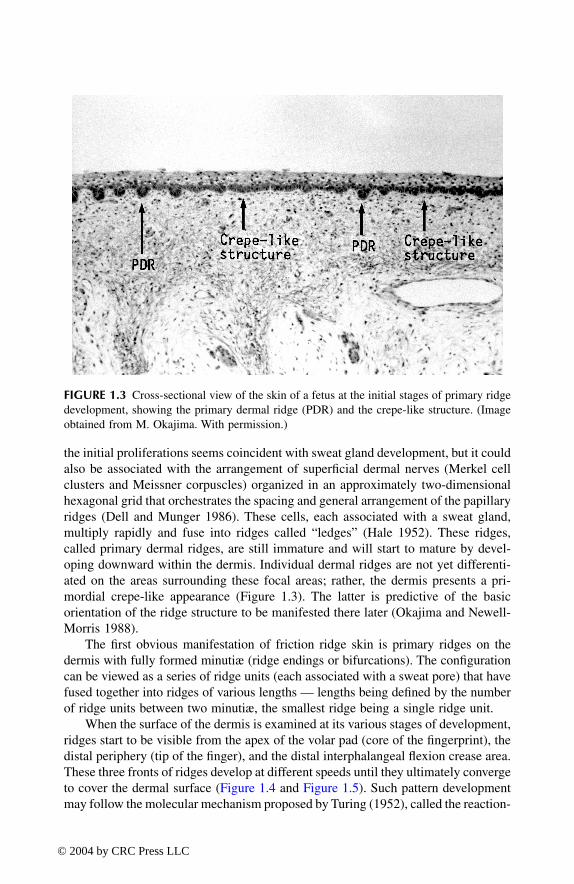
When the surface of the dermis is examined at its various stages of development,ridges start to be visible from the apex of the volar pad (core of the fingerprint), thedistal periphery (tip of the finger), and the distal interphalangeal flexion crease area.These three fronts of ridges develop at different speeds until they ultimately convergeto cover the dermal surface (Figure 1.4 and Figure 1.5). Such pattern developmentmay follow the molecular mechanism proposed by Turing (1952), called the reaction-
FIGURE 1.3
Cross-sectional view of the skin of a fetus at the initial stages of primary ridgedevelopment, showing the primary dermal ridge (PDR) and the crepe-like structure. (Imageobtained from M. Okajima. With permission.)
TF1345_C01.fm Page 4 Thursday, March 18, 2004 12:51 PM
© 2004 by CRC Press LLC
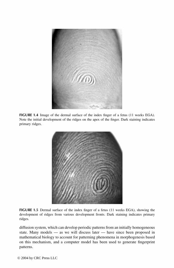
diffusion system, which can develop periodic patterns from an initially homogeneousstate. Many models — as we will discuss later — have since been proposed inmathematical biology to account for patterning phenomena in morphogenesis basedon this mechanism, and a computer model has been used to generate fingerprintpatterns.
FIGURE 1.4
Image of the dermal surface of the index finger of a fetus (11 weeks EGA).Note the initial development of the ridges on the apex of the finger. Dark staining indicatesprimary ridges.
FIGURE 1.5
Dermal surface of the index finger of a fetus (11 weeks EGA), showing thedevelopment of ridges from various development fronts. Dark staining indicates primaryridges.
TF1345_C01.fm Page 5 Thursday, March 18, 2004 12:51 PM
© 2004 by CRC Press LLC

1.3 FACTORS AFFECTING THE GENERAL PATTERN AND THE CONFIGURATION OF MINUTIÆ
The general pattern taken by the ridges seems to be dependent on following inter-related factors (Bonnevie 1924; Cummins 1926; Penrose 1969; Babler 1987):
• Shape (symmetry) and size of the volar pads (Penrose hypothesized thatthe flow of the ridges follows the lines of curvature of the skin on thevolar pad [Penrose and O’Hara 1973]; research in mathematical biologyconfirmed this hypothesis [Smith 1979; Mardia et al. 1992])
• Timing between the regression of the volar pads and the onset of primaryridge formation
• Relative speed of the three development fronts• Bone morphology (Babler 1991)
It is important to recognize that the basic form of the general pattern is set beforethe initial development of the primary dermal ridge (Figure 1.7). Wertheim andMaceo (2002) have provided detailed examples of the various general patternsassociated with the behavior of the above-mentioned variables, with excellent ani-mations at the following Web site: http://www.clpex.com/animation.htm.
It is well documented that the general pattern taken by ridges is indirectlyinherited (Holt 1968). Relative frequencies of general pattern types have been exten-sively studied in various populations (Mavalwala 1977) and in relation to numerouschromosomal deficiencies and diseases (Wertelecki et al. 1979; Loesch 1983; Plato
FIGURE 1.6
Dermal surface of the index finger of a fetus (14 weeks EGA), showing thefinal friction ridge pattern.
TF1345_C01.fm Page 6 Thursday, March 18, 2004 12:51 PM
© 2004 by CRC Press LLC

et al. 1991; Durham et al. 2000). This research area (often without a direct relation-ship to forensic science) is named
dermatoglyphics
. The general pattern taken bythe ridges offers some selectivity, but the main contribution to selectivity stems atthis stage from the configuration of the minutiæ (types and relative position).
The exact random process governing minutiæ formation is still unknown. Hale(1952) suggested that, due to the growth of the surface, ridges separate and createroom for the formation of new ridges. It is postulated that ridge endings are formedwhen a new ridge is formed between two existing ridges, with bifurcations resultingfrom ridge units developing on the side of a host ridge. Alternatively, minutiæ andthe full ridge structure might be formed at the outset of the proliferation but remaintransient until becoming clearly visible through the maturation on the dermis. Verylittle research is available to articulate more precisely the stochastic process ofminutiæ generation. Nevertheless, we are attracted by theories of mathematicalbiology (Meinhardt 1982; Murray 1993) offering models for various pattern forma-tion in nature such as zebra’s stripes or stripes on tropical fishes (Kondo and Asal1995; Meinhardt 1995). Building on mathematical biology, Sherstinsky and Picard(1994) used a Turing’s reaction-diffusion model (Turing 1952) to design restorationand enhancement algorithms for fingerprints. Another paper by Kosz (2000) men-tioned such methods to model (and then compress) fingerprint patterns and especiallyminutiæ. Some researchers are even suggesting the use of computer-generated fin-gerprint images (Figure 1.8) to test automatic fingerprint recognition systems (Cap-pelli et al. 2000).
Most of the research effort in dermatoglyphics has been focused on studyinggeneral patterns and various ridge counts, but it also offers very good insight intothe morphogenesis. The fact that these features are under genetic control is welldocumented (Chakraborty 1991). However, valuable research has been carried out
FIGURE 1.7
Dermal surface of the index finger of a fetus (11 weeks EGA), showing theinitial development of dermal ridges in the center as well as the crepe-like appearance on theother regions setting the general pattern.
TF1345_C01.fm Page 7 Thursday, March 18, 2004 12:51 PM
© 2004 by CRC Press LLC

looking at minutiæ distribution for clinical use. Forensic research pertaining tominutiæ and their statistical behavior is presented in Chapter 2. Okajima studiedthe occurrence of basic minutiæ on prints from twins in various populations andnoted higher correlations on the number of minutiæ for monozygotic twins asopposed to dizygotic twins. More minutiæ are observed on prints from malescompared with prints from females, but no bilateral difference (right vs. left) wasobserved (Okajima 1966, 1967). Correlations between the presence or absence ofpattern area and number of minutiæ have also been investigated (Loesch 1973).Dankmeijer and coworkers (1980) confirmed that the number of minutiæ wascorrelated to the finger number and pattern type, but no bilateral difference wasnoted. From these results, it appears that the number of minutiæ is a hereditarytrait. Dermatoglyphic studies on the various types of minutiæ are limited, but theytend to show that the frequency of bifurcation (forks) depends on the sex and thedigit number, hence suggesting the existence of a genetic role (Okajima 1970,1977). However, the number of minutiæ tends to be uncorrelated to the frequencyof bifurcations (forks) (Okajima 1984).
1.4 MORPHOGENESIS OF FRICTION RIDGE SKIN — SECONDARY DERMAL RIDGE DEVELOPMENT AND DERMAL PAPILLAE
Although the general pattern and minutiæ are fully determined by the primary dermalridge development, which is set very early in the development process, the primarydermal ridges continue to develop within the dermis until 15 to 16 weeks. Their size
FIGURE 1.8
Image of fingerprint generated using the program SFinGE developed by Cap-pelli et al. (2000) and available on-line at http://bias.csr.unibo.it/research/biolab/sfinge.html.
Generated by Sfinge - © 2000 Bio LabUniversity of Bologna - ITALY
TF1345_C01.fm Page 8 Thursday, March 18, 2004 12:51 PM
© 2004 by CRC Press LLC

and progression within the dermis are fully related to the development of the sizeof the fetus (assessed by the crown-to-rump length) (Babler 1987). At that time (16weeks), the pattern is permanently set. In a cross section of the skin (Figure 1.9),we can see the downward penetration of primary dermal ridges within the dermis,with a proliferation of cells under a groove being the initial manifestation of a sweatgland.
Between 15 and 17 weeks EGA, secondary ridges commence to develop betweenprimary ridges and mature until 24 weeks (Babler 1991). Secondary ridges increasethe surface area of attachment to the dermis (Figure 1.10). Primary ridges do notdevelop any further in the dermis at that time (24 weeks).
Further maturation leads to the formation of bridges between the apex of primarydermal ridges and secondary ridges, cordoning off sections of dermal ridges referredto as papillae pegs (Hale 1952) or dermal papillae. Their differentiation is composedof microridges and compartments that develop with advancing age. The papillae areformed for the purpose of increasing the anchorage, exchange, and surface area atthe dermal–epidermal interface. Some of them will accommodate the insertion ofMeissner corpuscles (allowing the detection of tactile stimuli) (Okajima 1979).
At 24 weeks EGA, the development of the dermis is finalized. The epidermisis gradually formed by cell development from the dermis into five layers (as shownin Figure 1.1). The friction ridge pattern in its final stage is a projected image ofthe structure on the dermis. The primary deeply formed dermal grooves correspondto the ridges on the epidermis, and the furrows coincide with the secondary dermal
FIGURE 1.9
Cross-sectional view of the skin of a fetus at the initial stages of primary ridgedevelopment. PER stands for “primary epidermal ridge.” PDR stands for “primary dermalridge.” “Groove” is the term used by Okajima to denote the penetration into the dermis, theterm “ridge” being reserved for the friction surface of the dermis. The proliferation of cellsunder the second dermal groove from the right is the precursor of a sweat gland. (Imagecourtesy of M. Okajima.)
TF1345_C01.fm Page 9 Thursday, March 18, 2004 12:51 PM
© 2004 by CRC Press LLC

ridges. The dermal papillae are therefore arranged in a double row (parallel to theprimary ridge) and define the shape and form of the epidermal friction ridge. Eachsweat duct on the epidermis is connected to an eccrine sweat gland via a canal ofcells. Research has shown that dermal papillae evolve with age, tending to multiplyin order to anchor the skin structure (Figure 1.11) (Okajima 1979).
Incipient (called also secondary or subsidiary [Ashbaugh 1992]) ridges followthe same development process but, due to timing constraints, remain only partiallydeveloped. Although these ridges received some attention from an anthropologicalperspective (Wendt 1956), it has been shown recently that, during the course of alifetime, new incipient ridges can develop (although never disappear). It is postulatedthat this development corresponds to a compensation for the degenerative change(loss of sensitivity) that occurs with age or activity (Stücker et al. 2001). It has beenfound that these ridges are associated with Meissner corpuscles (Kyeck 2003).
Flexion creases also share the same principles of morphogenesis (Ashbaugh1991b; Kimura 1991). Their development starts between 7 and 9 weeks EGA.
1.5 SUMMARY OF THE STAGES OF FRICTION RIDGE SKIN MORPHOGENESIS — RELATIONSHIP WITH DURABILITY OR PERMANENCY AND UNIQUENESS
Okajima (1975a, b, 1982) presented a series of useful sketches to summarize thefriction ridge skin morphogenesis process (Figure 1.12, Figure 1.13, and Figure1.14). These sketches show that the friction ridge skin on the epidermal surface is
FIGURE 1.10
Cross-sectional view of the skin of a fetus at the final stages of primary andthe initial secondary dermal ridge development. The sweat duct connecting the groove of theprimary dermal ridge and the eccrine gland is clearly visible. (Image courtesy of M. Okajima.)
TF1345_C01.fm Page 10 Thursday, March 18, 2004 12:51 PM
© 2004 by CRC Press LLC

the consequence of a constant proliferation of cells from a basal generating layer, ablueprint, on the very top of the dermis. The configuration of the ridges (with theminutiæ) mimics, as a mirror image, the configuration defined by the dermal primaryand secondary ridges. On the epidermis, the ridges will display sweat ducts (pores)spaced almost evenly — but to varying degrees — along the ridges. Each porecorresponds originally to a ridge unit associated with a sweat gland. The shape and
FIGURE 1.11
Views of: (A) the epidermal surface (ridges on a dark background) of an 82-year-old man with orifices for sweat gland ducts and (B) the dermal surface of the same volarsection. (Reproduced from Okajima, M. [1979], Dermal and epidermal structures of the volarskin, in
Dermatoglyphics — Fifty Years Later,
Vol. XV, No. 6, W. Wertelecki, C.C. Plato, andN.W. Paul, Eds., New York: Alan R. Liss, pp. 179–198. With permission.)
FIGURE 1.12
Diagrams illustrating ridge differentiation: (A) primary development and (B)secondary development. (Reproduced from Okajima, M. [1982], A methodological approachto the development of epidermal ridges on the dermal surface of fetuses, in
Progress inDermatoglyphic Research,
Vol. 84, C.S. Bartsocas, Ed., New York: Alan R. Liss, pp. 175–188.With permission.)
ABGlandular fold
(Primary ridge)Glandular fold(Primary ridge)
Furrow fold(Secondary ridge)
Primary ledge(Primary dermal ridge)
Secondary ledges(Secondary dermal ridges)
PeridermIntermediatelayer
Str. basaleDermis
GrooveGroove Furrow
EpidermalridgeStr. corneumStr. spinosumStr. basale
Dermis
TF1345_C01.fm Page 11 Thursday, March 18, 2004 12:51 PM
© 2004 by CRC Press LLC

structure translated on the surface by each ridge unit depends on the shape andstructure on the dermis obtained following the maturation process. The forms of thepores and ridge edges add to the selectivity of friction ridge skin. The relationshipbetween the friction ridge arrangement of the dermis and the friction ridge skin onthe epidermis is the basis for the durability of the fingerprint pattern. Early anecdotalevidence of permanency can be found in the work of Sir William Herschel used byF. Galton (1892). However, a detailed knowledge of the structure of the skin permitsan understanding as to why the fingerprint pattern is reproduced to the exact imageof the dermis. Superficial damage to the epidermis will have no bearing on thepattern (if we allow its restoration), with visible scars only being acquired when thedermis is damaged.
With the sum of stochastic processes dictating, in turn, the general pattern, theconfiguration of ridges (with their minutiæ) and their shapes and structures is suchthat chance duplication is considered to be impossible. We have here the fundamentalpremise of the individuality of friction ridge skin. Ashbaugh (1991c, pp. 82–83)summarized the premise of friction ridge skin uniqueness very elegantly:
The friction ridges are constructed of ridge units. The number of ridge units that makeup a ridge is established at random. Where one ridge starts and stops, the factors thatdesignate its length are completely dependent on differential growth. The location ofthe ridge unit where a branching develops is also established at random. Due to theplethora of genetic and physical variances the ridge units are subjected to during ridgeformation and the number of units involved, the paths of friction ridges are unique tothat area of friction skin.
FIGURE 1.13
Diagram of the final dermal surface, illustrating the dermal papillae and thecorresponding mirror-image epidermal development. (Reproduced from Okajima, M. [1975b],Technical aspects of dermatoglyphic examination in primates, in
Contemporary Primatology:Proceedings of the Fifth International Congress of Primatology
, S. Kondo, M. Kawai, andA. Ehara, Eds., New York: S. Karger, pp. 49–53. With permission.)
Groove
Furrow
Papillae in doublerow arrangement
Epidermis
TF1345_C01.fm Page 12 Thursday, March 18, 2004 12:51 PM
© 2004 by CRC Press LLC

The ridge units are not only subjected to differential growth factors whiledeveloping into rows and growing, they are also subjected to a random growth factorin relation to their shapes. Therefore, ridge units may vary in shape, size, alignment,and whether they fuse to the next ridge unit or not. For example, some units arethinner than others, some have bulges on one side, and some misalign with the nextridge unit or fail to develop to maturity. Friction ridge surfaces are three-dimensionaland, due to the variables along the friction ridge surface, they are unique, even in avery small area. The location of the pore opening on a ridge unit is also establishedby random forces through differential growth. The random placement of pore open-ings on the friction ridge is another factor that enhances the uniqueness of frictionskin.
FIGURE 1.14
Diagrammatic representation of dermal ridge morphogenesis based on pub-lished studies. C.R. is crown rump. (Reproduced from Okajima, M. [1975a], Developmentof dermal ridges in the fetus,
J. Medical Genet.
, 12, 243–250. With permission.)
C.R.(mm)20 40 60 100 150 200
Age(wk)6 10 12 16 20 24 28Birth Adult
Pads
Pads
Sweat duct
Papillae
Primary dermal ridgeand groove
Secondary dermal ridgeand furrow
TF1345_C01.fm Page 13 Thursday, March 18, 2004 12:51 PM
© 2004 by CRC Press LLC

2
The Friction Ridge Identification Process
Friction ridge identification procedures have been widely discussed in the literatureand in other forums. Good literature coverage of the issues has been given by Cowger(1983), Grieve (1988, 1990a), Ashbaugh (1999b), and Wertheim (2000). The Internetis also a valuable source of information regarding the identification process. EdwardGerman’s site (http://www.onin.com/fp) is a reference on these matters, coveringthe basic concepts and a discussion of some known cases of wrong identifications.Finally, the acceptability of fingerprint evidence as being scientific in nature hasbeen subject to a
Daubert
hearing in the U.S. (
U.S. v. Mitchell
, U.S. District Courtfor the Eastern District of Pennsylvania, Criminal No. 96-00407). This hearing ledboth parties to present their views on the underlying principles of fingerprint iden-tification. The
Mitchell
case has been followed by more than 20
Daubert
hearingsin the U.S. (the most recent being
U.S. v. Llera Plaza
, U.S. District Court of theEastern District of Pennsylvania, Criminal No. 98-362-10,11,12), with unprece-dented press coverage (e.g., the article by Specter [2002]) as well as strong reactionsfrom a lawyer (Faigman 2002) and a social scientist (Cole 2000). The outcome ofall hearings was that fingerprint evidence passed the
Daubert
test. Judicial noticewas given to the fact that fingerprints are permanent and unique. All the documentsassociated with these hearings can be found on German’s Internet site. We alsowould like to draw attention to the excellent paper by Epstein (2002), the federaldefender in both the
Mitchell
and
Llera Plaza
cases.Useful protocols and flow charts have been published as step-by-step descriptions
of the comparative identification process (Smith et al. 1993; Olsen and Lee 2001).The flow charts presented by Olsen will serve as a reference for this chapter as wellas the protocol published by Drews (2002). The aim of this chapter is to encapsulatethe detailed procedure within the generic methodology or protocol known as “ACE-V,” as adopted by Ashbaugh (1991a) in the early 1990s and presented by Tuthill(1994), and more recently discussed during the
Daubert
hearings as the state-of-the-art methodology for the identification process. The Royal Canadian Mounted Police(RCMP) should be recognized as the organization that developed (Huber 1959, 1972)and adopted the ACE-V protocol to fingerprints. The ACE-V (analysis, comparison,evaluation, and verification; Figure 2.1) methodology is outlined in the following foursections. An initial critical analysis can be found in Clark (2002).
2.1 ANALYSIS
This initial step calls for an analysis of the recovered mark to assess (a) the realityof its ridge formations and (b) their clarity. The analysis is focused solely on the
TF1345_C02.fm Page 15 Thursday, March 18, 2004 1:01 PM
© 2004 by CRC Press LLC

unknown mark in order to determine, in total objectivity (without having access toa reference print), what information is visible and reliable, taking into account theclarity of the image and considering the effects of pressure, distortion, media, anddevelopment techniques. We will distinguish three levels of information that can berecorded: level 1, level 2, and level 3 as proposed by Ashbaugh (1999a). These threelevels describe features visible in the mark without any
a priori
assessment of theselectivity of the features. Table 2.1 provides a short definition for each level.
Note that some practitioners are suggesting a distinction into three levels accord-ing to the magnification required to visualize the features (Wertheim 2000). Level1 features are visible without magnification, level 2 features require 5
×
to 10
×
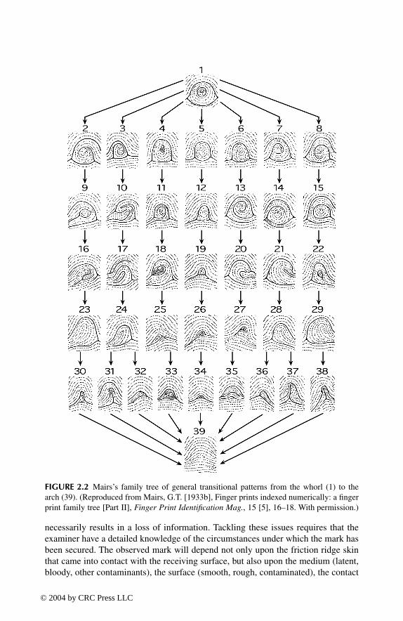
magnification, whereas the visualization of level 3 features benefits from highermagnification. Hence, depending on its size and clarity, features of an incipient ridgemay fall into level 1, 2, or 3. In our view, the convention used to divide betweencategories of features has no significant impact on the following discussion. Thesethree levels are illustrated in Table 2.2. Figure 2.2 shows Mairs’s family tree oftransitional fingerprint patterns (Mairs 1933b).
During the analysis phase, it is expected that the examiner has categorized allthe features that are visible in the mark, with an assessment of their reality and theconditions under which the mark has been left. The examiner should annotate themark accordingly, displaying, when visible, the flow of the ridges, the minutiæ, andthe level 3 features. This process may be seen as very time-consuming, and it isacknowledged that some quicker analysis may be carried out on marks of highclarity, but that this process is essential for all poor-quality marks.
When the features visible in the mark have been identified, the examiner canassess the mark’s intrinsic value, i.e., its capacity to define a unique source. Indeed,some practitioners will retain for the comparison stage only marks displaying fea-tures allowing, in their opinion, an individualization following a comparison withthe appropriate known material. Others will retain all marks suitable for a compar-ison, keeping in mind that a mark may be insufficient for identification but decisivefor exclusion. Even if, in theory, all marks could be retained for the comparison
FIGURE 2.1
ACE-V methodology in a flow diagram.
Analysis
Comparison
Evaluation
Verification
TF1345_C02.fm Page 16 Thursday, March 18, 2004 1:01 PM
© 2004 by CRC Press LLC

stage, practitioners have adopted various working policies to cope with the workloadand thereby reduce the number of required comparisons. A flow chart of the aboveprocess is given in Figure 2.3.
Addressing the questions outlined in the flow chart (Figure 2.3) requires a deepknowledge of the factors affecting the transition from the three-dimensional friction
TABLE 2.1Definition of the Three Levels of Friction Ridge Skin Features
Level Definition
Level 1 Level 1 refers to the overall pattern formed by the flow of papillary ridges on the papillary surface. Traditionally, the general pattern formed on the fingertips has been classified into generic classes. Various classification schemes were developed in the early days of dactyloscopy, aimed at offering a classification system to enable a ten-print card search. The most widespread classification systems are by Vucetich (1904) and by Galton (1892) and Henry (1900), distinguishing arches (and tented arches), loops, and whorls. We have to recognize that any partitioning scheme is a simplification of the continuum of papillary flow patterns that fingerprints may possess, as emphasized by Mairs (1933a, b) (Figure 2.1). This continuum is also recognized among the computer scientists who are developing the automatic fingerprint identification system. (AFIS) . After devoting much effort at mimicking an exclusive fingerprint classification system based on a small number of classes, scientists are now focusing their efforts on capturing the full spectrum of general forms (Cappelli et al. 1999).
In addition to the forms taken by the flow of the ridges, some measurements can be classed as level 1 features, such as ridge counting and ridge tracing. Both of these measures were implemented within classification systems to increase the discriminative power of the systems. They are well described, for example, in the FBI’s manual on fingerprint science (U.S. Department of Justice and FBI 1984).
The general flow of papillary ridges on the palm has been the subject of a recent and important publication (Tietze and Witthuhn 2001). This work allows examiners to gain an understanding of the various flow structures that friction skin ridges form in palmar areas. Examiners can use this knowledge to quickly reposition unknown palm marks.
Level 2 Level 2 refers to major ridge path deviations, also known as minutiæ, points of identification, or Galton characteristics. Basic forms are ridge endings, bifurcations, and dots (Olsen 1981). Additional types of minutiæ (combinations of the basic minutiæ) have been identified in the literature as being more specific than their basic components. For these features, the nomenclature in the literature is not standardized (Saviers 1987, 1989), and it is safer to work with illustrations.
Occasional features such as warts, scars, creases, and wrinkles are also referred to as level 2, incipient, or subsidiary ridges (Ashbaugh 1992) and flexion creases (Ashbaugh 1991b).
Level 3 Level 3 refers to intrinsic or innate ridge formations: the alignment and shape of each ridge unit, pore shape, and relative pore positions are level 3 features.
TF1345_C02.fm Page 17 Thursday, March 18, 2004 1:01 PM
© 2004 by CRC Press LLC

skin structure to a mark (most of the time, a two-dimensional outcome). Ashbaugh(1999b, p. 172) refers to this transition as the “clarity bridge.” It is essential to realizethat the transfer process from a three-dimensional organ to a two-dimensional mark
TABLE 2.2Illustrations of the Three Levels of Friction Ridge Skin Features
Level Illustration
Level 1 Mairs’s family tree is illustrated in Figure 2.2; basic general patterns are illustrated below:
Simple arch Tented arch Right loop Left loop Whorl
Level 2 Ridge endings, bifurcations, and dots are the basic minutiæ (ridges are shown in black); all other types are combinations of these:
Ridge ending Bifurcation DotBelow are illustrations of wrinkles, creases and warts, and scars:
Level 3
Inked impression showing succession of pores and specific shapes of edges (friction ridges are in black ink)
TF1345_C02.fm Page 18 Thursday, March 18, 2004 1:01 PM
© 2004 by CRC Press LLC
necessarily results in a loss of information. Tackling these issues requires that theexaminer have a detailed knowledge of the circumstances under which the mark hasbeen secured. The observed mark will depend not only upon the friction ridge skinthat came into contact with the receiving surface, but also upon the medium (latent,bloody, other contaminants), the surface (smooth, rough, contaminated), the contact
FIGURE 2.2
Mairs’s family tree of general transitional patterns from the whorl (1) to thearch (39). (Reproduced from Mairs, G.T. [1933b], Finger prints indexed numerically: a fingerprint family tree [Part II],
Finger Print Identification Mag.
, 15 [5], 16–18. With permission.)
TF1345_C02.fm Page 19 Thursday, March 18, 2004 1:01 PM
© 2004 by CRC Press LLC

pressure, the duration of contact, distortion, and the fingerprint developmenttechnique employed. Little has been published on this topic (Singh 1963), withassessment relying heavily on the examiner’s experience. However, Ashbaugh(1999b) has presented numerous cases that will help any examiner with this process.The procedure requires the examiner to assess not only the clarity and visibility ofthe mark, but also the tolerances that need to be taken into account during thecomparison phase. These tolerances must allow for the mechanisms and constraintsof the deposition process. The analysis phase therefore involves the collecting ofinformation concerning the crime scene mark(s). Questions of the following typeare hopefully answered (adapted from Mary Beeton [formerly Drews];http://www.ridgesandfurrows.homestead.com/identification.html):
• Where was the mark found?• What was used to enhance the print (e.g., black powder, white powder,
ninhydrin, or perhaps the impression was made in dust and then photo-graphed)?
• How has the surface from which the print was lifted affected the appear-ance of the lift?
• How has the enhancement process affected the appearance of the frictionridges?
FIGURE 2.3
Flow diagram of the analysis stage.
Analysis
Is the mark a frictionridge impression?
How is the mark?(Define tolerances)
Is the mark of sufficientquality for a comparison?
yes
yes
yes
noSTOP
noSTOP
Comparison (1)
∑ Is the mark in two or three dimensions, positive or negative?∑ How is the substrate?∑ Any other marks in an anatomical sequence?∑ How is the matrix (sweat, blood, paint, water, etc.)?∑ What part of the palmar or plantar surface deposited the matrix?∑ What is the developing medium?∑ How was the deposition pressure?∑ Any pressure distortion or slippage?∑ What is the level of clarity of the mark?∑ What features are visible on the mark?∑ How may these features be affected by the identified pressure, distortion, substrate or matrix?
TF1345_C02.fm Page 20 Thursday, March 18, 2004 1:01 PM
© 2004 by CRC Press LLC

• What type of distortion is present (many different kinds may be apparentin one lift)?
• How does the clarity or lack of clarity affect the amount of detail that ispresent in the unknown print?
• How does the clarity or lack of clarity affect the level of tolerance for anyridge formation discrepancies that may exist between the unknown andthe known print in the comparison phase?
• Is there sufficient quality and quantity of information to proceed to thecomparison step in the identification process?
2.2 COMPARISON
Basically, the comparison process is an iterative comparison between the unknownmark and a known print, focusing successively on level 1, level 2, and level 3 features(when they have been identified in the mark) and taking into account the tolerancesdictated by the quality of the mark. As the clarity of the unknown mark is generallyinferior to the quality of the known print, when both images are compared (especiallywhen looking at the print then at the mark), our suggestive brain tends to compensatefor any differences. Ashbaugh reiterates the capacity of our brain to reconstruct poor-quality images based on our prior representation of the reality (Ashbaugh 1991a).This phenomenon may lead an examiner to believe that some features are concordantbetween a mark and a print, whereas their visibility can only be ascertained in theprint and not in the mark. Knowledge of the known material may provide theexaminer with expectations that may distort his/her judgment on the visibility offeatures in the mark, leading to inappropriate, expectation-led observations (Norby1992). To ensure maximum objectivity during the comparison process, the examinershould avoid any prior knowledge of the known print under examination. For thatreason, the analysis stage is essential, and the comparison process should in theorybe focused primarily on features that have been identified previously, during theindependent assessment of the mark. In any case, the comparison should alwaysbegin with an observed feature in the mark that serves as a control measure to betested against the known print. The comparison process, as outlined in the flowcharts in Figure 2.4 and Figure 2.5, should be unidirectional from the mark to theprint.
The outcome of the comparison process could be a charted comparison betweenthe two images, emphasizing the concordances but also the differences revealedbetween the mark and the print. All available areas of the mark should be comparedat the various levels identified and within the tolerances defined during the analysis.
2.3 EVALUATION
After the comparison between a mark and a print, the examiner faces a set ofobservations from which an inference about the identity of source must be drawn.An exclusion decision logically follows when discrepancies are observed that cannotbe explained other than by the hypothesis of different sources. Such discrepancies
TF1345_C02.fm Page 21 Thursday, March 18, 2004 1:01 PM
© 2004 by CRC Press LLC

can be observed at any level of the comparison between the mark and the print. Intheory, one significant dissimilarity is enough for the examiner to declare anexclusion (Thornton 1977), irrespective of the number of concordances that havebeen revealed before the dissimilarity is noted. In practice, the difficulty lies at
FIGURE 2.4
Flow diagram (part 1) of the comparison stage.
FIGURE 2.5
Flow diagram (part 2) of the comparison and identification stages.
Comparison (1)
Comparison (2)
EXCLUSION
Is the print ofsufficient qualityfor comparison?
Is there agreementat level 1?
yes
no
EXCLUSION Is there agreementat level 2?
yes
yes
no
no Can additionalprints beobtained?
noSTOP
∑ Select two or three reference points on the unknown mark or any other target: e.g. innermost recurbing ridge, group of minutiæ, type lines, occasional feature (scars, warts, etc.).∑ Can this configuration be found within tolerances on the known print with the same relative position, orientation and length in terms of ridge unit?∑ If yes, pursue the comparative procedure, adding into the process a new point visible on the mark.∑ Continue this iterative process until all ridges visible on the mark have been examined and compared.∑ Run comparatively ridges (establish the route of each friction ridge) and furrows.
yes
yes
Comparison (2)
Evaluation
Verification
noEXCLUSION Is there agreement
at level 3?
• Select a configuration of level 3 features visible on the mark (pore structures or ridge edges).• Can this configuration be found within tolerances on the known print?• If yes, continue the comparative procedure, adding into the process a new configuration visible on the mark.• Continue this iterative process until all ridge units visible on the mark have been examined and compared.
TF1345_C02.fm Page 22 Thursday, March 18, 2004 1:01 PM
© 2004 by CRC Press LLC

defining what a significant difference is (Thornton 1997b). The number of docu-mented case reports discussing the assessment of differences in a comparison islimited (Puri 1962, 1964; Ferguson 1992). The ability to distinguish between dis-tortion and dissimilarity is essential and relies mainly on the examiner’s experience(Leo 1998). In fact, consideration of the clarity of the mark dictates the level oftolerance defined during the analysis process. The greater the clarity, the lower isthe tolerance, and vice versa. An ideal way of gathering reliable experience forinterpreting differences is through the setting up of controlled experiments wheremarks of known donors are deposited and revealed under various conditions. Thestudy of such sets allows a calibration of the examiner and could even lead to anassessment of the examiner’s proficiency.
Exclusion decisions are obvious deductions when, for example, the dissimilarityat level 1 or level 2 is unambiguous thanks to a mark of excellent clarity. However,we should keep in mind the possibility of a wrong exclusion due to a hasty exam-ination (without a proper analysis phase) focused on level 1 detail (Saviano 2003).As soon as the mark lacks clarity, and distortion induces possible differences at alllevels, the assessment is much more difficult. Due to the popular belief that a wrongexclusion is more acceptable than a wrong identification, the exclusion process hasreceived little attention. As Bertillon (1912) rightly pointed out, the examiner shouldin fact be more focused on dissimilarities than on concordances.
When no significant differences (the concept of significant being defined by thetolerances obtained from the analysis stage) have been noted between the mark andthe print, the value of the match has to be assessed. The concept of identification isclosely related to the selectivity of the features at the various levels, taking intoaccount the level of tolerance set initially. The term
identification
as used heregenerally denotes individualization. Individualization is probably what distinguishesforensic science from other scientific endeavors (Kirk 1963). Tuthill (1994, p. 21)defined individualization as follows:
The individualization of an impression is established by finding agreement of corre-sponding individual characteristics of such number and significance as to preclude thepossibility (or probability) of their having occurred by mere coincidence, and estab-lishing that there are no differences that cannot be accounted for.
In the fingerprint field, the term
identification
is used synonymously with
indi-vidualization
. It represents a statement of certainty that a particular mark was madeby the friction ridge skin of a particular person. This is the sense in which we willuse the word
identification
throughout this book.In the literature, this problem of identity of source is often treated by distin-
guishing “class” characteristics from “individual” characteristics. Level 1 featureswould normally be referred to as class characteristics, whereas levels 2 and 3 dealwith individual characteristics. Leaving aside the conclusion of exclusion of a com-mon source drawn when significant differences are observed, the identificationprocess is then articulated as follows:
TF1345_C02.fm Page 23 Thursday, March 18, 2004 1:01 PM
© 2004 by CRC Press LLC

1. A comparison between a recovered mark and a known print that leads toagreement in class characteristics only (without significant differences)will lead to an inconclusive statement.
2. Only when sufficient agreement of individual characteristics are observed,in conjunction with class characteristics, can a conclusion of positiveidentification or individualization be drawn.
The task of distinguishing between these two categories is critical if wrongindividualizations are to be avoided. However, the problem of inferring identity ofsource is more complex than this simple dichotomy. It has to be recognized that thedistinction between “class” and “individual” characteristics is just a convenient,oversimplified way of describing selectivity. Selectivity is a measure on a continuumthat can hardly be reduced to two categories without more nuances. The term
individual characteristic
is particularly misleading, as a concordance of one minutia(leaving aside any consideration of level 3 features) would hardly be considered asenough to express uniqueness. The problem with this binary categorization is thatit encourages the examiner to disregard the complete spectrum of feature selectivitythat ranges from low to high. It is proposed, then, that selectivity at each featurelevel be studied without any preconceived classification of its identification value.Indeed, nothing should prevent a specific general pattern — such as, for example,an arch with continuous ridges from one side to the other (without any minutiæ) —from being considered as unique, since no such pattern has been observed to date.
Table 2.3 defines selectivity for the three levels of friction ridge skin features.With an awareness of the selectivity of the features considered during a comparison,we can now return to the evaluation process.
Following a comparison between a mark (recovered, for example, in associationwith a crime) and a known print (control print associated with a suspect), supposethat the examiner observes a complete agreement between the mark and the printwithout any significant discrepancy. Considerable confusion exists among laymen,indeed also among fingerprint examiners, on the use of words such as
unique
,
identical
,
same,
and
identity
. Although the phrase “all fingerprints are unique” hasbeen used to justify fingerprint identification opinions, it is no more than a statementof the obvious. Every entity is unique; no two entities can be “identical” to eachother because an entity can only be identical to itself. Thus, to say that “this markand this print are identical to each other” is to invoke a profound misconception:the two might be indistinguishable, but they cannot be identical. In turn, the notionof “indistinguishability” is intimately related to the quantity and quality of detailthat has been revealed. The question for the fingerprint examiner is not, “Is thismark and that print identical?” The proper question is, “Given the detail that hasbeen revealed and the comparison that has been made, what inference might bedrawn in relation to the propositions that I have set out to consider?” We have, then,to distinguish between the source variability that we have explored under the term
selectivity
(information derived from good-quality prints) and the expressed vari-ability in the mark, which can be partial, distorted, or blurred (Stoney 1989). Hencewe remain skeptical when facing arguments such as “nature never repeats itself”(McRoberts 1996) to ascertain the value of fingermark identifications. Such a
TF1345_C02.fm Page 24 Thursday, March 18, 2004 1:01 PM
© 2004 by CRC Press LLC

TABLE 2.3Selectivity of the Three Levels of Friction Ridge Skin Features
Level Selectivity
Level 1 The contribution of the general pattern (and basic measures such as ridge counting or ridge tracing) as a means of differentiation is well known through widespread experience with fingerprint classification systems. Extensive statistical data can be obtained from these collections. For example, we can observe that ulnar loops are more frequent than simple arches. Some published data are available to examiners for each finger taken individually or for groups of fingers (e.g., Cowger 1983). More up-to-date and case-specific data can be obtained through appropriate queries submitted to an AFIS system. Level 1 features have also been the subject of extensive studies dealing with the distribution of these features according to sex, race, or various genetic syndromes. Such studies represent the core of a discipline known as dermatoglyphics (see Chapter 1). In Appendix I, the reader will find the statistics for general patterns obtained from the FBI collection as per 1993 (according to the NCIC [National Crime Information Center] classification scheme). Data on palmar level 1 features have been published by Tietze and Witthuhn (2001). The authors provide extensive statistical data on the relative frequencies of defined general patterns.
Level 2 The selectivity of level 2 features, especially the selectivity of minutiæ configurations, was the main argument in favor of the adoption of fingerprinting as a mean of personal identification (over Bertillon’s anthropometry) at the turn of the 19th century. Galton was probably the first to apply statistical analysis to minutiæ (Galton 1892; Stigler 1995). Statistical data are a solid ground for exploring the selectivity of level 2 features (see Appendix 2). Most past studies have been reviewed by Stoney (2001). Stoney (1985) extended the work of previous authors and was followed by Champod (1996; Champod and Margot 1997a). This selectivity is also corroborated by the enormous experience of practitioners over more that a century, especially when we consider manual “cold” searches in large databases. The knowledge stems then from the stochastic morphogenesis of fingerprint patterns (see Chapter 1) and the success of AFIS systems at retrieving potential candidates based on complete unknown prints or partial questioned marks (see also the recent paper by Pankanti et al. [2001]). For fingerprint examiners, level 2 details in combination (without discrepancies) have individualizing power.
Level 3 The extreme selectivity of pore forms and pore relative positions was first postulated by Locard (1912, 1913), who later received a very favorable echo in the U.S. (Wilder and Wentworth 1932). The possibility of using edge structures to discriminate between fingerprints was first proposed by Chatterjee and Hague (1988) but was also mentioned by Locard. All related aspects were initially merged under the term
ridgeology
by Ashbaugh (1982a), but it is fair to say that today ridgeology has a much wider mandate, covering all aspects of the identification process without being restricted to level 3 features (Ashbaugh 1999b). Experience is the first basis for support of the high selectivity of these features. Additional knowledge comes from morphogenesis data (see Chapter 1) and a number of statistical studies. Ashbaugh (1982b) was the first to propose a model to express pore variability, and this model has been refined recently by Stosz, Roddy, and coworkers (Stosz and Alyea 1994; Roddy and Stosz 1997, 1999). However, it must be recognized that, at present, the amount of structured data relative to pores and edge structures is limited. As with level 2 features, fingerprint examiners consider combinations of level 3 features (without discrepancies) as having individualization capabilities.
TF1345_C02.fm Page 25 Thursday, March 18, 2004 1:01 PM
© 2004 by CRC Press LLC
paradigm may add to our knowledge on the variability of the source, but it does notaddress the crucial issue of the clarity or representation of the mark. This takes usback to the “clarity bridge” and to the importance of the analysis phase.
The ultimate question is often expressed as follows (provided that no differencehas been observed): “how many similarities are required to conclude to an identifi-cation?” The aims of this section are (a) to explore this question by reviewing indetail international views and practices and (b) to update earlier reviews by Kingstonand Kirk (1965) and the FBI (Anon. 1972) and Champod (2000a).
2.3.1 H
ISTORICAL
M
ILESTONES
The first rules establishing the minimum number of minutiæ necessary for finger-mark identification can be attributed to the famous Frenchman Edmond Locard(1911, 1912). Locard suggested a tripartite rule, which followed from the discoveryof poroscopy. It can be summarized as follows (Locard 1914):
1. If more than 12 concurring points are present and the fingermark is sharp,then the certainty of identity is beyond debate. (The imperative require-ment for the absence of significant differences is implicit.)
2. If 8 to 12 concurring points are involved, then the case is borderline, andthe certainty of identity will depend on:• The sharpness of the fingermark• The rarity of its type• The presence of the center of the figure (core) and the triangle (delta)
in the exploitable part of the mark• The presence of pores• The perfect and obvious identity regarding the width of the papillary
ridges and valleys, the direction of the lines, and the angular value ofthe bifurcations
In these instances, certainty can only be established following discussionof the case by at least two competent and experienced specialists.
3. If a limited number of characteristic points are present, the fingermarkcannot provide certainty for an identification, but only a presumptionproportional to the number of points available and their clarity.
Locard based his tripartite rule on various sources of information: the discoveryof poroscopy, the limited (at that time) practical experience gathered by the identi-fication bureaus around the world, and the statistical evaluation by Balthazard (1911),Galton (1892), and Ramos. (Galdino Ramos published statistical work in a bookentitled
Da Identificação
[Rio de Janeiro, 1906] that we were unable to locate.) Thisapproach persists throughout the extensive writings of Locard (1931). His consid-erations (principally the first two) were largely taken up by the most eminentfingerprint researchers of the first half of the century, notably Wilder and Wentworth(1932), Cummins and Midlo (1943), Heindl (1927), and Bridges (1963).
TF1345_C02.fm Page 26 Thursday, March 18, 2004 1:01 PM
© 2004 by CRC Press LLC

2.3.2 C
URRENT
V
IEWS
AND
P
RACTICES
On the fringe of this early view, the practice of fingerprint identification is nowadaysconfined to two distinct positions:
1. The empirical criterion is based solely on a quantitative thresholdexpressed by the number of concordant minutiæ between the mark andthe known print.
2. The holistic criterion is a combined assessment of quantitative and qual-itative aspects of the corresponding features.
In 1998, the Interpol European Expert Group on Fingerprint Identification (IEE-GFI), created with the mandate to assess the feasibility of formulating a Europeanfingerprint standard, came to the same conclusion (Interpol 2000). Although thesetwo schools may appear drastically opposed, we feel compelled to stress that anyquality standard will be found to be either a defined empirical criterion or a definedholistic criterion. Quality will be achieved by the publication and endorsement oftransparent and detailed procedures describing the identification process and asso-ciated quality assurance measures. We believe that, as soon as the identificationprocess is encapsulated within a strict regime of documented procedures and qualitycontrol measures, then the whole debate between these two schools (empirical vs.holistic) will disappear. The driver toward quality is, we believe, transparency.
2.3.2.1 Predetermined Minimum Number of Minutiæ — An Empirical Standard
The majority of European fingerprint experts favor a purely quantitative approach,ignoring in the decision process the potential contribution of concordant qualitativeaspects (such as level 3 features), by fixing a numerical standard — a minimumnumber of minutiæ necessary to establish an identification. The numerical standardrepresents a lower limit; above this value, the identification is beyond doubt regard-less of the type of minutiæ that are discerned. The interpretation of the concept ofa numerical standard may vary from agency to agency (or even from examiner toexaminer), as illustrated by a few examples (Table 2.4) based on Almog (1986), arecent review by Interpol (Interpol 1995), and an updated table published in
Fin-gerprint Whorld
(Anon. 2002). Despite the systematic use of a numerical standard, various countries (e.g.,
Finland, Greece, Holland, Israel, and Portugal) have developed methods to bypassthe rigid threshold when particularities (such as visibility of pores, ridge structures,or rare combinations of minutiæ) are observed during the comparison. The adoptionof a range from 8 (or 10) to 12 points was found to be a way to relax an otherwiserigid threshold. In 1983, an addendum was even made to the “16-point standard” inthe U.K., stating that in extremely rare cases an expert with long experience andhigh standing in the profession can offer an opinion on an identification that doesnot meet the nationally accepted standard.
TF1345_C02.fm Page 27 Thursday, March 18, 2004 1:01 PM
© 2004 by CRC Press LLC

TABLE 2.4Overview of Some Empirical Standards and Their Origins
CountryPoints
Criterion Origin
Italy 16–17 The criterion is based on the questionable probabilistic calculation by Balthazard dating back to 1911 (Balthazard 1911). The minimum standard is expressly mentioned from jurisprudence referring to Balthazard’s work (Pirone 1976, 1991). The jurisprudence is constant (according to decisions from 1954 to 1989). This situation is quite paradoxical because Sorrentino, head of the School of Police Science in Rome in the 1950s, was advocating against the consideration of a predetermined minimum number of minutiæ (Sorrentino 1948, 1952, 1956).
Germany, Sweden, Holland, Switzerland
8–12 This criterion is in agreement with Locard, even though sometimes, in practice, there is a clear tendency to respect a 12-point rule (Walder 1976). The practice in Germany is a generalization of Locard’s first two rules (Section 2.3.1), asking the examiner to fully balance the quantity of minutiæ with qualitative aspects of the mark (visibility of pores, specificity of the minutiæ, etc.). Hence if, for example, the mark displays poor level 1 features, the examiner may reach an identification conclusion only after having noticed more than 12 concordant minutiæ without discrepancy (Steinwender 1958b). Holland is operating on an analogous regime between 10 and 12 points.
U.K. (before 2001) 16 The origins of this standard (adopted by New Scotland Yard in 1924) dates back to an erroneous interpretation of a paper published by Bertillon in 1912 (Bertillon 1912; Champod et al. 1993). Up to a recent date, the numerical standard was virtually impossible to circumvent and had been adopted nationally in 1953 and confirmed in 1984. If simultaneous impressions were available, the identification was allowed if there were at least 10 points in each mark. The purpose of the standard was to guarantee a high level of quality and faultlessness in the matter of fingerprint identifications (Lambourne 1984, 1986). The 16-point standard, however, has proved to be inadequate as an ultimate safeguard against error, as attested by the recent disclosure of erroneous identifications (Grieve 1999b).
South Africa 7 According to Sherratt (1979)Belgium, Finland, France, Israel, Ireland, Greece, Poland, Portugal, Romania, Slovenia, Spain, Turkey, Japan, South American countries
12 Criterion probably derived from the consideration of Locard’s first rule (Section 2.3.1)
Note:
The empirical standards may be different for the identification of simultaneous marks in anatomicalsequences or for marks showing separate parts.
TF1345_C02.fm Page 28 Thursday, March 18, 2004 1:01 PM
© 2004 by CRC Press LLC
2.3.2.2 No Predetermined Numerical Standard — A Holistic Approach
In 1970, a commission of experts from the International Association for Identification(IAI) was established to study the question of the relevancy of a fixed numericalstandard for fingerprint identification (Anon. 1970, 1971). The work of this com-mittee led to a review of the state of empirical and scientific knowledge at that time(Santamaria Beltran 1953; Osterburg and Bloomington 1964; Gupta 1968). As aresult of this process, excellent review papers were published by Hess (1971a, b, c,d). Hess stressed the fact that some types of minutiæ were more selective than others(for example, a double bifurcation in the periphery of the pattern is six times lessfrequent than two separate bifurcations). Qualitative features (such as level 3 fea-tures) may be added to minutiæ in the decision process. Finally, the absence of anyminutiæ may be as decisive as their presence. It would be very exceptional to observea core area or a delta area where the ridges do not display any minutiæ. Theobservation of such a particularity would provide strong support for an identity ofsource.
To conclude the work of this ad hoc committee, the following resolution wasadopted by the IAI in 1973 (Anon. 1973, p. 8):
[The International Association for Identification], based upon a 3-year study by itsStandardisation Committee, hereby states that no valid basis exists for requiring apredetermined minimum number of friction ridge characteristics that must be presentin two impressions in order to establish positive identification.
Another powerful argument against any numerical standard stems from knowl-edge of the morphogenesis of the papillary lines (see Chapter 1). The various stressesinvolved in this process (regression of the volar pads, development of size, meetingof multiple development fronts) induce a stochastic formation of minutiæ (in termsof form and positioning). Around the 25th week of gestation, the development ofpapillary lines is finished on the dermis and has been projected onto the epidermallayer of the skin. From that moment, a final differentiation occurs on the papillaepegs, which dictates the form of the gland ducts and ridge edges. This final stageproduces a strictly individual pattern. The nature of this papillary individualityprevents any justification for a predefined minimum number of ridge characteristicsthat must be in agreement (without significant differences) in order to conclude toan identification. Indeed, the extent of specific features is much broader than minutiæalone.
In 1995, during a conference on fingerprint detection and identification tech-niques hosted by the Israel National Police in Ne’urim, Israel, 28 fingerprint expertsand scientists (representing 11 countries) unanimously approved a slightly actualizedvariation of the IAI 1973 resolution (Margot and German 1996):
No scientific basis exists for requiring that a pre-determined minimum number offriction ridge features must be present in two impressions in order to establish a positiveidentification.
TF1345_C02.fm Page 29 Thursday, March 18, 2004 1:01 PM
© 2004 by CRC Press LLC

The individualization process cannot therefore be reduced to counting minutiæ;each identification represents a unique set of circumstances, and the judgment ofthe value of concurring features between a mark and a print depends on a varietyof conditions that automatically exclude any minimum standard. It is not justifiable(or even scientific) to reduce the issue of fingerprint individuality to numbers ofcorresponding minutiæ alone. The identification process is a holistic assessment,balancing both quantitative (number of minutiæ) and qualitative aspects (generalpattern, type of minutiæ, pores, edges) visible in the mark. This qualitative/quanti-tative approach is at the heart of Ashbaugh’s view of the identification process(Ashbaugh 1999b), which he previously placed under the term
ridgeology
. Thisquality/quantity balance is also well described by Vanderkolk (1999, 2001).
Of course, when simultaneous marks are available (e.g., marks left by fingersin anatomical sequence), the full information can be used, provided that the analysisstage established the fact that the marks were associated. A good description of theprocess for dealing with simultaneous impressions is given by Ostrowski (2001).
In practice, most fingerprint examiners recognize that the counting of matchingpoints up to a number determined by policy does not precede the identification. Onthe contrary, it is usually the case that the expert reaches a state of personal convictionabout the identification, based on a wide spectrum of features, before the point countis conducted. As indicated in Table 2.5, various countries have adopted the practiceendorsed by the IAI/Ne’urim resolution.
The review undertaken by a committee in the U.K. has been a determining factorin the recent move toward the adoption of the IAI resolution by other countries. In1989, Evett and Williams conducted a collaborative study among 130 fingerprintexaminers in England and Wales. They sent to each participant ten mark/printcomparisons (nine associations and one exclusion), asking each examiner to markthe number of concordant minutiæ and to express an opinion with respect to theidentification. No misidentification was reported. But, when examining genuine pairsof prints, examiners varied widely in the number of points of comparison they found.In the case of one print, the number varied from 11 to 40. In other words, someexaminers would not have gone to court with this pair of impressions, although mostwould have done so (Evett and Williams 1995). A comparable survey was undertakenin Switzerland in 1997, leading to worrisome results, especially with regard to falseexclusions. Evett and Williams’ study led to the following main conclusions:
• The dogma adopted by numerous fingerprint examiners that fingerprintidentification is an “exact” science is a misconception. The essence ofscience is inductive inference. Inference is a mental process that cannotbe exact (or deductive). Fingerprint identification is scientific in that sense(Evett 1996).
• The precision implied by any number (12, 16, etc.) is also a lure. Thedetermination of individual minutiæ or features is highly subjective. Theuse of any rigid numerical standard favors the process of gleaning suffi-cient points (“teasing the points”) to reach the magic number (Tiller 1983).
• As a means of achieving quality, a numerical standard alone is poor. Theway forward is to concentrate on professional standards rather than on
TF1345_C02.fm Page 30 Thursday, March 18, 2004 1:01 PM
© 2004 by CRC Press LLC

rules about numbers of minutiæ. A quality management scheme is requiredthat includes training, certification testing, performance testing, file audits,and blind trials.
2.3.3 T
RANSPARENCY
OF
THE
I
NDIVIDUALIZATION
D
ECISION
When a fingerprint expert concludes to an identification, he or she indeed reachesa decision threshold. However, this threshold is highly subjective, whether thecriterion is a minimum number of concordant minutiæ or, in addition to this quan-
TABLE 2.5Overview of Some Holistic Approaches and Their Origins
Country Comments
U.S. and Canada
Since 1973, following the IAI resolution.
Scandinavian countries (Finland, Sweden, Denmark, Iceland, and Norway)
To our knowledge, Norway was the first European country to move toward the abandonment of the 12-point numerical standard. The other Scandinavian countries followed.
U.K. (from 2001)
In 1988, a committee was formed by the ACPO (Association of Chief Police Officers) and the Home Office to undertake a review of the origin and relevancy of the 16-point standard. Following this review (Evett and Williams 1995), the committee recommended abandonment of the numerical standard. Since 1996, a project group (ACPO National Fingerprint Evidence Standard Project Board) worked at implementing the change from the 16-point practice to no numerical standard. This was also in the light of new rules for disclosure, and the establishment of appropriate quality assurance mechanisms and procedures as well as training requirements. A 1999 appeals court decision
R v. Buckley
(1999) 163 JP 561 (Moenssens 2002) paved the way toward the abandonment of the numerical standard by discussing and allowing a comparison with only eight minutiæ. The practice without a numerical standard was implemented beginning June 11, 2001. The change was well received by courts and legal writers (O'Doherty 2001).
Australia In 1996, the “12-point rule” adopted in 1975 was abandoned in favor of the IAI resolution. A working party was formed to examine various issues such as a National Fingerprint Accreditation Board (NFAB) for education and competency assessment and other quality assurance issues. In 2000, the NFAB adopted a resolution excluding any numerical standard, making this policy uniform across Australia.
Switzerland Taking advantage of the debate in the U.K. and in Australia, and following the Ne’urim declaration, a committee has undertaken to manage the change toward a nonnumerical practice. In 1997, after a survey analogous to the one undertaken in the U.K., the abandonment of the 12-point numerical standard was adopted by the heads of the fingerprint bureaus as a long-term objective. Current practice is, however, still focused on a 12-point rule.
TF1345_C02.fm Page 31 Thursday, March 18, 2004 1:01 PM
© 2004 by CRC Press LLC

titative element, qualitative factors are taken into account. As Ashbaugh (1999b, p.103) stated, “The opinion of individualization or identification is subjective.”
With the extensive use of probability-based DNA evidence and the evolvingrequirements for the admissibility of scientific evidence in the U.S., older identifi-cation fields such as fingerprints are being subjected to more rigorous scrutiny andare under the pressure of a growing demand for “scientific” data to underpin theidentification process (Saks and Koehler 1991; Jonakait 1994; Saks 1994, 1998).Even forensic scientists are calling for the acquisition of statistical data (Menzel1997; Thornton 1997a). A natural evolution of this trend is the claim that thefingerprint identification discipline is not rooted in science (Stoney 1997). That wasthe line of argument taken by the defense during the recent
Daubert
hearings in theU.S. To us, the crux of the matter would appear to be more on the transparency ofthe process than on its scientific merits.
Courts traditionally welcomed the apparent transparency of a numerical standardwith open arms, and the fingerprint has become the gold standard by which othertypes of evidence are measured. However, we must recognize that the apparenttransparency afforded by “
x
points” was an illusion. As previously mentioned, therewas never any scientific justification for the number chosen; furthermore, what isconsidered a “point” by one expert might not be a “point” to another.
We applaud the contribution that Ashbaugh (1999b) has made to the establish-ment of fingerprint identification as an applied science. These are the studies andarguments that form the body of scientific knowledge that any expert can draw onwhen explaining fingerprint individuality in court. However, when it comes to thecore issue of drawing inference from a comparison, Ashbaugh (1999b, p. 103) states:
Finding adequate friction ridge formation in sequence that one knows are specificdetails of the friction skin, and in the opinion of the friction ridge identificationspecialist that there is sufficient uniqueness within those details to eliminate all otherpossible donors in the world, is considered enough.
Here we arrive at the core of the matter. It is the expert who forms the opinionthat there is “sufficient uniqueness … to eliminate all other possible donors in theworld.” Ashbaugh does not clarify how this inference is to be drawn. It has beenargued that the decision process must be inductive (Champod 1999, 2000b), asalready rightly underlined by Kwan (1977), whose thesis is an essential contributionto forensic science. The expert is, however imprecisely, forming a view about theentire world when he cannot possibly have considered more than a subsample. Thequotation from Ashbaugh therefore illustrates two points:
1. The opinion is based on inductive reasoning. (It follows inevitably that itmust be probabilistic.)
2. The process by which the expert arrives at an opinion is ultimatelyobscure. The process relies undoubtedly on extensive and reliable expe-rience, but it is not fully articulated.
TF1345_C02.fm Page 32 Thursday, March 18, 2004 1:01 PM
© 2004 by CRC Press LLC

The point is that Ashbaugh evokes the need to eliminate all other possible donorsin the world, but does not say how this can be done. Essentially, this is because itcannot be done. Certainly it cannot be done by scientific means but, even leavingscience to one side, no one person can attain and retain comprehensive knowledgeof the prints of every person in the world. It has to be an inference, be it scientific(which it cannot be) or otherwise. The conclusion has to be, as Stoney (1991)eloquently put it, “a leap of faith”; as such, it is ultimately obscure. Indeed, Stoney(1991, pp. 197–198) gave a very illustrative description of this process for fingerprintexamination:
Beginning with a reference point in one pattern, a corresponding point in a secondpattern is sought. From this initial point the examiner then seeks neighbouring detailsthat correspond in their form, position and orientation. These features have an extremevariability, that is readily appreciated intuitively, and which becomes objectively obvi-ous upon detailed study. When more and more corresponding features are foundbetween two patterns, scientist and lay person alike become subjectively certain thatthe patterns could not possibly be duplicated by chance. What has happened here issomewhat analogous to a leap of faith. It is a jump, an extrapolation, based on theobservation of highly variable traits among a few characteristics, and then consideringthe case of many characteristics. Duplication is inconceivable to the rational mind andwe conclude that there is absolute identity. The leap, or extrapolation, occurs (infingerprinting) without any statistical foundation, even for the initial process where thefirst few ridge details are compared.
The conclusion of certainty derives from the examiner’s personal conviction thatthe chance of a match between the crime mark and any person other than X is sosmall that it can be ignored. Effectively, the expert sets a personal threshold thatrounds the probability assigned to the identification to 100%. This position appears,through custom and practice, to be acceptable to courts in all situations wherestatistical analyses are not possible: fingerprints, handwriting, toolmarks, footwearimpressions, etc. The fingerprint expert’s reasoning is based on the idea that theprobability that another person would match the mark is so small that it can bediscounted. Greater transparency in this process could be obtained if a match prob-ability were to be assigned by means of a database constructed from a suitablesurvey. But — in a fingerprint field dominated by categorical opinion and the refusalof any corroborative statements — any discussion about a probabilistic approach isrejected on principle (see Section 2.3.4) by the fingerprint profession (Stoney 1997).To progress toward transparency, our duty is twofold: first, we need to explore theframework of conclusions used in the field (see Section 2.3.4), and second, we needto discuss probabilistic data pertaining to fingerprints (see Section 2.3.5).
2.3.4 R
ANGE
OF
C
ONCLUSIONS
IN
THE
F
IELD
The present state of affairs, then, is that fingerprint experts have taken the positionnot to report opinions in terms of probabilities. The examination of a fingermarkretained for comparison leads either to a categorical opinion of identification orexclusion, or the mark is judged as insufficient to reach any conclusion. This has
TF1345_C02.fm Page 33 Thursday, March 18, 2004 1:01 PM
© 2004 by CRC Press LLC

been termed the doctrine of “positivity”; see, for example, Manners (1996) orKnowles (2000), with a reply by Taroni and Margot (2000). All comparisons thatfall outside the extremes of definite inclusion and definite exclusion are classifiedas “inconclusive.” In a case where, perhaps because of the limited quality (or clarity)of a mark, the weight of evidence is not sufficient to convince the expert of acategorical opinion, there may be corroborative evidence of less weight that mightstill provide useful guidance to the court. A report containing such phrases as“inconclusive,” “consistent with,” “points consistent with,” or “the investigated per-son cannot be excluded as the donor of the mark” fails to offer an expression of thevalue of the evidence. If, for the sake of the argument, a practice is adopted basedon a numerical standard of 16, it is clear that an inconclusive conclusion for acomparison showing 14 concordant minutiæ (and no discrepancy) provides strongerevidence than an inconclusive conclusion regarding a comparison with 3 concordantpoints. It would be preferable that the terminology used by the fingerprint expertrenders explicit these contrasted values in a more effective way than “inconclusive.”This concept is recognized to be central to the reporting of other fields of forensicscience, such as the examination of handwriting, toolmarks, footwear impressions,etc. In this sense, Locard’s third directive (see Section 2.3.1) is fundamental andpermits the placement of fingerprint evidence in the same line as for other types oftransfer traces.
The idea that fingerprint evidence could provide a presumptive link precededLocard, notably in a case work dating back to the beginning of the century performedby Reiss at the Institut de Police Scientifique et de Criminologie (IPSC) in Lausanne,Switzerland. At present, very few identification bureaus in Switzerland leave thispossibility open. However, according to a recent European survey conducted byInterpol (1995), some countries are leaving open the possibility to use fingerprintevidence as corroborative evidence. For example, in Belgium, when between 8 and12 points of agreement are noted between a questioned fingermark and a fingerprint(without discrepancies), it is stated that “the fingerprint could be at the origin of thefingermark in examination.”
Steinwender, a German fingerprint expert, was the first to widely publish hisrefusal to consider fingerprint evidence as anything but absolute proof (Steinwender1958a, b, 1960). This point of view was largely followed by Bridges (1963), theFBI (Anon. 1972), and Olsen (1978), and then by the whole profession. In 1979,during the annual IAI conference in Phoenix, AZ, the assembly unanimouslyapproved Resolution VII prohibiting members from giving testimony on qualifiedidentifications (likely, possible, probable, etc.) (Anon. 1979). Identification, accord-ing to the IAI, can only be negative, impossible, or certain. This resolution openedthe way for a large debate (Champod 1995) before it was revised and accepted atthe annual IAI meeting in Ottawa, ON, in 1980 (Anon. 1980). At this meeting, theIAI experts rejected the idea of using fingerprints as corroborative evidence in thefollowing terms (Resolution VII Amended or Resolution V):
[The delegates of the IAI] state unanimously that friction ridge identifications arepositive, and officially oppose any testimony or reporting of possible, probable or likelyfriction ridge identifications found on hands and feet.
TF1345_C02.fm Page 34 Thursday, March 18, 2004 1:01 PM
© 2004 by CRC Press LLC

This approach means that, in countries using numerical standards (e.g., Switzer-land), a fingerprint comparison with 12 concordant minutiæ is an identification,whereas a comparison presenting only 11 points has no probative value and will notbe presented in court. Such a rule can easily lead to difficult situations when, forexample, a suspect arrested and identified in one country on the basis of an identifi-cation with 12 points is to be judged in a neighboring country where 16 points areexplicitly required. This example highlights all the difficulties but also the challengeof harmonizing forensic science at the international level (Sprangers and Nijboer 2000).
There appear to be three arguments that are constantly used by practitioners againstprobabilistic considerations. The first argument stipulates that probabilities cannot beused in the field because of the individuality of friction skin arrangements. It generallytakes the following form (Vanderkolk 1993; Grieve 1999a; Wertheim 2000):
Any probabilistic statement would imply a possibility for duplication. But biologicaluniqueness prevents any duplication. Hence probabilities do not apply to fingerprints.
It is axiomatic that no two fingerprints are identical; indeed, no two entities ofany kind can be identical to each other. The crux of the matter is not the individualityof the friction skin ridges but, rather, the ability of the examiner to recognizesufficient information for the disclosure of identity from a small, distorted latentfingerprint fragment that may reveal only limited information in terms of quantityor quality (Grieve 1990b). It is the examiner’s capacity to reveal individuality froma papillary impression that is at question, and not the individuality of the skin surfacethat produced it. This concept encapsulates a continuum of values, in that anexpressed feature in a mark may have the capacity to distinguish sources at variousdegrees, depending on its clarity. These various degrees of a mark have a probabilisticnature.
The second argument is that probabilistic opinions should be avoided until adedicated tool for assessing match probabilities is made available to the examiner(Ashbaugh 1999b). Whereas a cautious approach is to be commended, it presents apeculiar state of affairs. An opinion of individualization means that the knownindividual is singularized with regard to the world population. But, paradoxically, afraction of a second earlier in the comparison process, when the information gatheredis judged by the examiner as insufficient to individualize, it is suggested that theexaminer cannot give any opinion. In other words, the leap of faith is presented asa transition from a state of an absence of knowledge to a state of certainty. Thisapproach is incompatible with the logic of the inference of identity of source. Ifexaminers are able to provide opinions regarding individualization, they should alsohave an equal capacity to position themselves with reliability in cases where thevolume of information is viewed as insufficient for an identification.
The third argument is that the admission of probabilistic statements wouldweaken the value of fingerprint evidence (Hazen 2002). The perception is that thefingerprint pursuit should remain absolute, accepting no shades of gray. But this ismore a cultural view than one that has derived from any scientific reasoning. Nodoubt, most fingerprint experts see probabilistic arguments as a threat that couldundermine the profession. That is not the intention. There is no dispute concerning
TF1345_C02.fm Page 35 Thursday, March 18, 2004 1:01 PM
© 2004 by CRC Press LLC

the power and utility of fingerprint examination. Indeed, a probabilistic approachseeks to expand the potential of the pursuit.
Some will no doubt argue that judges expect fingerprint evidence to be unequiv-ocal and without compromise. This idea is false. It is obvious that all judges wouldprefer indisputable forms of proof, but judges would also wish to be informed ofany evidence that can lead them closer to the truth. Fingerprints have already beenconsidered by jurists from a probabilistic point of view (Finkelstein and Fairley1970; Tribe 1971) and, indeed, from a Bayesian point of view, as advocated todayto interpret most forensic types of evidence (Aitken 1995; Robertson and Vignaux1995). For jurists, fingermarks can be perfectly classed with all other forms ofevidential material in the judicial system (Eggleston 1983). This issue has also beenaddressed by the Court of Appeal of New Zealand (
R v. Buisson
[1990] 2 NZLR542 [CA]). The court not only ruled that no numerical standards exist for an iden-tification, but also stated that much useful evidence was being kept out of the courtsbased on decisions made by experts.
This reporting practice in the fingerprint field is a policy that is opposed to thescientific principles governing the interpretation of scientific evidence (Robertsonand Vignaux 1994; Champod 1995; Stoney 1997). As Tuthill (1994, p.61) puts it,“It is simply one of the aberrations that have been developed within the disciplineof fingerprint identification.” The evidential value of fingerprints cannot be soextreme and clear-cut; there is an increasing scale that runs from exclusion toidentification. In fact, there is no logical reason to suppress gray levels betweenwhite (exclusion) and black (identification). Evidence becomes relevant when ittends to make the matter at issue more or less probable than otherwise (Lempert1977). Even if there is no certainty, evidence should not be ignored; the term
inconclusive
does not offer an adequate nuance. There is no logical reason to avoidprobability statements. The refusal to give qualified opinions is a policy decision,even if the distinction between the arguments (policy based or scientific) is not soclear in the literature. We strongly argue against the dogmatic statement proposedrecently by the North American working group on fingerprint identification (SWG-FAST) (McRoberts 2002, p. 312):
Probable, possible, or likely identification are outside the acceptable limits of thescience of friction ridge identification.
Champod and Evett (2001) recently wrote in support of a probabilistic approach.The proposal did generate some reaction in both camps (Crispino 2001; McKasson2001). Because we believe that probabilities and inductive reasoning indeed have aplace in the field of fingerprint identification, it is worth reviewing several statisticalstudies pertaining to this field (see Section 2.3.5), as they represent the key towardtransparency.
2.3.5 S
TATISTICS AS A KEY TO TRANSPARENCY
One of the most frequent questions posed to statisticians regarding fingerprintsis of the kind, “If a comparison between a mark and a print shows a given set of
TF1345_C02.fm Page 36 Thursday, March 18, 2004 1:01 PM
© 2004 by CRC Press LLC

features in agreement without discrepancies, could you demonstrate statisticallythe identity of the source?” The quick answer is no. As Stoney (1991) puts it,“You cannot achieve individualization through statistics.” All that statistics cando is provide (a) a model for assigning a match probability in a given case and(b) guidance on setting that match probability in some kind of relevant populationframework, the latter leading to some kind of inference as to the probability ofthe mark and the print being from the same person. But statistics can do no morethan provide a probability. It is for others to decide on whether that probabilityis small enough to conclude identity of source. For a complete discussion, seeChampod (2000b).
Some may argue that the random match probabilities for fingerprints are so smallthat, whatever the framework, the probability of the identification will be so closeto 100% that there is no need to disclose a specific number to the court. During therecent Daubert hearing in the U.S. v. Mitchell case, the FBI provided calculationsbased on experiments carried out on an AFIS system. (The model is described inStoney 2001.) For complete fingerprints, a random match probability of 10–97 wasclaimed. For partial marks, the match probability was given as 10–27. Such figures,at first sight, appear to relegate the argument that we are presenting to the status ofnitpicking. The figure of 10–97 transcends reality to the extent that it is amazing thatit was admitted into evidence. It is entirely unsupportable. This extraordinary numberwas obtained by a model-based formula that took the probability density of extremepoints of a postulated probability distribution. Wayman (2000) has pointed out theweakness of this argument.
We should not have unrealistic expectations of statistical studies, and thequoting of extravagantly extreme numbers is, ultimately, not productive. It followsthat it is not possible to prove that a given mark must have been left by a particularregion of friction ridge skin. The process is, as we have said, essentially inductive,and absolute certainty is not logically and philosophically attainable throughmathematical methods. Nevertheless, this limitation does not prevent statisticsfrom offering a highly powerful tool for assessing fingerprint evidence. Limitedstatistical investigations (Galton 1892; Henry 1900; Balthazard 1911) were madeat the time that fingerprints were gaining acceptability. These studies were far toosmall and were based on unrealistic assumptions to provide anything more thanperipheral support for the technique. These earlier models assumed that each typeof minutiæ appeared evenly on the fingertip surface, each with the same probabilityand independently one from the other. The limitations of these assumptions werequickly brought to light (Anon. 1911; De Ryckere 1912; Sannié and Guérin 1940),and other, more sophisticated models were proposed (Roxburgh 1933a, b; Amy1946, 1947, 1948). Research was then devoted to models where the assumptionof equal probability between the types of minutiæ was relaxed (Santamaria Beltran1953; Gupta 1968; Osterburg et al. 1977; Lin et al. 1982a, b; Edzhubov 1996).But all failed initially to recognize the fact that minutiæ were not evenly distributedon the papillary surface, and that some zones (like the center or the delta) aremore rich in minutiæ than peripheral regions. Kingston (1964) was the first topropose a probabilistic model addressing both issues. He was followed by Sclove(1979, 1980), Stoney (1985; Stoney and Thornton 1986, 1987), Champod (1996;
TF1345_C02.fm Page 37 Thursday, March 18, 2004 1:01 PM
© 2004 by CRC Press LLC

Champod and Margot 1996, 1997a), and more recently, Pankanti et al. (2001).These studies cover research on level 2 features and especially minutiæ. Studieson pore arrangements have also recently been carried out (Roddy and Stosz 1997,1999) and remain peripheral.
Statistical studies on minutiæ provide extremely valuable knowledge, but theycannot yet be deployed for large-scale, case-specific calculations. As underlined byStoney (2001), none of the proposed models has been subjected to extended empir-ical validation studies.
Up until now, no statistical models have incorporated the various factors ofindividuality (general pattern, major ridge deviations, ridge edges, or pores). Themodels are simplifying the complexity by adopting a restricted atomistic view ofthe overall factors, with emphasis on the study of the statistical behavior of minutiæ.However, the imperfection of any model — in the sense that it does not capture allthe elements of the holistic approach — does not preclude its use in the fingerprintscience if its robustness has been extensively demonstrated and the model has beensubjected to scientific scrutiny. Statistical data, even gathered through myopic mod-els, can only help the discipline work toward more reliable and transparent methodsof assessing evidential value.
The most extensive study to date has been carried out on a sample of around1000 fingerprints from distinct individuals (Champod 1996; Champod and Margot1996, 1997a). This study provides valuable knowledge concerning the statisticalbehavior of various types of minutiæ, for example:
• The probability of observing a given number of minutiæ on a given areaof ridge skin
• The relative frequencies of various types of minutiæ and how these fre-quencies depend on minutiæ location within the fingerprint pattern
• The relative frequencies of minutiæ orientations in the ridge path• The relative frequencies of lengths of combined minutiæ
However, the studies undertaken up to this point in time do not provide a robusttool for assessing match probabilities associated with all configurations of featureson all fingers and for all general patterns. This is because:
• The actual models employed do not capture the spatial relationshipbetween minutiæ.
• The robustness of the independence assumptions at the core of each modelhas not been fully explored.
• The studies are focused on the estimation of the match probability, witha weak account for tolerances due to distortion or clarity of the marks,including connective ambiguities.
• The effect of other variables such as the general pattern, the finger number,the sex, or the ethnic origin of the source have rarely been addressed.
• None of the proposed models has been subjected to an extended empiricalvalidation.
TF1345_C02.fm Page 38 Thursday, March 18, 2004 1:01 PM
© 2004 by CRC Press LLC

The gap between DNA statistics and fingerprint statistics is huge, emphasizingthe need for further research. Ultimately, the benefits from statistics applied to thefingerprint identification field will include (Champod 2002):
1. A new body of scientific research that will empirically support the extremevariability of the features that are used by latent print examiners duringthe examination process. This will provide another method of justifyingopinions of identity in court.
2. A way to assess the statistical value of marks declared insufficient foridentification. A model should allow probabilities to be assigned to partialmarks, e.g., assessing the chance of finding another finger showing alimited number of matching features.
In the meantime, as proposed by Kingston (1970), such studies provide valuabledata to verify the subjective judgments of experts concerning the rarity of givenfingerprint features. Osterburg and Bloomington (1964) explored the discrepanciesthat can be observed between examiners in assessing the relative frequencies ofvarious types of minutiæ. Such variations have to be minimized, and statisticalsurveys provide an excellent baseline. Results from the study by Champod (1996)are provided in Appendix 2 and offer curent statistical knowledge from level 2features on loops and whorls. This provides some basis for the interpretation of theidentification potential or value of potential marks.
2.4 VERIFICATION
We are emphasizing the subjective nature of the fingerprint evaluation stage. Thehighly subjective recognition process exploits the extraordinary power of the humaneye–brain combination, and the ability of the examiner is crucial (Wertheim 1996).But this is not to say that fingerprint identification is unreliable. Nevertheless, suchsubjective judgments should be monitored in a structured and disciplined environ-ment. There are various ways to achieve this, and each has been explored by thefingerprint profession (see, for example, the initiatives under the SWGFAST group[McRoberts 2002]):
• Selection processes for fingerprint examiners• Quality assurance program and standard operating procedures• Program of collaborative studies, proficiency tests, and internal/external
audits
These initiatives would allow forensic scientists to convince the court of theirexpertise, not by referring to years of service or thousands of comparisons completed,but by presenting a detailed portfolio recording their proficiency in a long series ofindependently conducted proficiency tests. Reliability therefore stems from trainingstandards, competency assessment, and proficiency testing.
In addition, a principal safeguard against error is obtained through independentverification procedures for each comparison, by at least two experienced examiners.
TF1345_C02.fm Page 39 Thursday, March 18, 2004 1:01 PM
© 2004 by CRC Press LLC

This form of peer review is a fundamental part of any scientific process. Thisprocedure should be documented, and the processes to resolve any disagreementshould be declared and applied. A practical difficulty is to ensure that this verificationprocess is done blindly, avoiding any confirmation bias.
To conclude this chapter, it is clear to us that, at present, the whole identificationprocess is dominated by dogmatic positions rather than by a structured and docu-mented approach. We have mentioned the benefits that a statistical approach canbring to the field, but we also insist on the need for fully documented proceduresensuring transparency. We would like to see the development of a corpus of standardoperating procedures detailing:
• The identification process, from analysis to verification (with a cleardescriptive model of the features used and an explicit inferential model)
• The process of note-taking from analysis to verification• The procedures used to handle disputes and/or errors• The processes for casefile auditing and proficiency testing of fingerprint
experts, and the potential associated actions
We understand that the Interpol European Expert Group on Fingerprint Identification[IEE-GFI] is currently working toward this end (Zeelenberg 2003).
The fingerprint profession needs to operate with an ethical and unbiased culture,in a free environment offering adequate reward mechanisms. Training, continuouseducation, and appraisal systems should all be in place. We will elaborate more onthis in Chapter 5, which deals with errors in fingerprint identification. And finally,we call for the development of well-supported research programs directed at allaspects of fingerprint identification.
TF1345_C02.fm Page 40 Thursday, March 18, 2004 1:01 PM
© 2004 by CRC Press LLC

3
Chemistry, Light, and Photography
For a complete understanding of fingerprint detection techniques and their applica-tion, a good knowledge of chemical and physical phenomena (including a study oflight and its interaction with matter) is required. The aim of this chapter is to givesome general background theory that will aid the reader in comprehending thedevelopment methods described in this book. In addition to basic chemistry andlight theory, the chapter also includes a discussion on forensic light sources (FLS),general photography, and digital image enhancement.
3.1 STANDARD WEIGHTS AND MEASURES
The science of measurement is known as metrology. From three fundamental quan-tities — length, mass, and time — all other mechanical quantities (e.g., area, volume,acceleration, and power) can be derived. A comprehensive system of practical mea-surement should include at least three other bases, taking in the measurement ofelectromagnetic quantities, of temperature, and of intensity of radiation. Accordingly,the 11th General Conference of Weights and Measures, held in Paris in 1960, adopteda number of quantities and units
as the bases upon which was established theInternational System of Units (SI units). The SI units constitute an internationaldecimal system of weights and measures derived from and extending the metricsystem of measurement. The seven basic units, from which other units are derived,are as follows (with their respective symbols):
1. Length, the meter (m)2. Mass, the kilogram (kg)3. Time, the second (sec)4. Electric current, the ampere (A)5. Luminous intensity, the candela (cd)6. Amount of substance, the mole (mol)7. Thermodynamic temperature, the Kelvin (K)
A prefix is used to specify a multiplier for a measurement unit (Table 3.1). Forexample, a kilometer is equal to 1000 m (10
3
m), and a millimeter is equal to one-thousandth of a meter (10
–3
m). Our eye can distinguish details down to about 250
µ
m (10
–6
of a meter) (called visual acuity), while the light microscope can permitthe visualization of biological structures smaller than 1
µ
m (such as the details onthe surface of a grain of pollen; this is called the optical resolution). Modern electronmicroscopes can obtain images of structures up to even 100,000 times smaller, thus
TF1345_C03.fm Page 41 Thursday, March 18, 2004 1:03 PM
© 2004 by CRC Press LLC

permitting us to distinguish atoms whose diameter barely exceeds one ten-millionthof a meter (10
–10
m, sometimes called 1 Å = 1 angström) (Figure 3.1).
3.2 CHEMISTRY THEORY
All solid matter is composed of pure elements or combinations of elements calledcompounds. An element is a substance that cannot be decomposed into simplersubstances by chemical or physical treatment. Examples of common elements arecarbon, hydrogen, oxygen, and nitrogen. There are currently 112 known chemicalelements; however about 20% of these do not exist in nature (or are only present intrace amounts) and are known only because they have been synthesized in thelaboratory. The known chemical elements are typically displayed in the form of atable — the periodic table (Figure 3.2) — that groups the elements according tosimilar structure and properties.
All elements are composed of very small units called atoms. All the atoms of asingle element are the same as each other in terms of their size, weight (with theexception of isotopes), and chemical properties, but are different from those of everyother element. Each element can be represented by a symbol that is short notationderived from the element’s scientific name (e.g., S for sulfur, C for carbon, O for oxygen,and Si for silicon). Sometimes the symbol is derived from the Latin name (e.g., Au for
aurum,
gold; Fe for
ferrum
, iron; and Na for
natrium
, sodium) or from other linguisticroots (e.g., W for
wolfram
, tungsten; from the German name “Wolf Rahm”).Every atom consists of a central core (or nucleus) of subatomic particles called
protons (positively charged) and neutrons (neutral or uncharged) in various numbers,surrounded by a cloud of negatively charged electrons circulating around the nucleuslike planets around the Sun (Figure 3.3). It is these electrons, and the ease withwhich they may be shared with (or donated to) other atoms, that determine thechemical reactivity of the element. The lightest of all atoms, hydrogen, has a diameter
TABLE 3.1Standard Prefixes for the Designation of Decimal Multiples or Fractions of Base Measurement Units
Multiplier Prefix Length Weight Volume
1,000,000,000 10
9
giga gigameter (Gm) gigagram (Gg) gigaliter (Gl)1,000,000 10
6
mega megameter (Mm) megagram (Mg) megaliter (Ml)1,000 10
3
kilo kilometer (km) kilogram (kg) kiloliter (kl)1 10
0
— meter (m) gram (g) liter (l or L)0.1 10
–1
deci decimeter (dm) decigram (dg) deciliter (dl)0.01 10
–2
centi centimeter (cm) centigram (cg) centiliter (cl)0.001 10
–3
milli millimeter (mm) milligram (mg) milliliter (ml)0.000001 10
–6
micro micrometer (
µ
m) microgram (
µ
g) microliter (
µ
l)0.000000001 10
–9
nano nanometer (nm) nanogram (ng) nanoliter (nl)0.0000000001 10
–10
— angstrom (Å) — —0.000000000001 10
–12
pico picometer (pm) picogram (pg) picoliter (pl)
TF1345_C03.fm Page 42 Thursday, March 18, 2004 1:03 PM
© 2004 by CRC Press LLC

of approximately 1
×
10
–10
m (0.1 nm; one angström [Å]) and weighs 1.7
×
10
–24
g.The diameter of an atom is 10,000 times larger than that of its nucleus.
Each element has a unique atomic number that indicates the number of protonspresent in the nucleus of each atom of that element. In their normal, uncharged state,each atom of an element has an equal number of protons and electrons. For example,carbon has the atomic number 6, indicating that there are six electrons and sixprotons in its atomic structure. Atoms with the same atomic number but differentatomic masses differ in the number of neutrons contained in their nuclei, and theseare called isotopes. Isotopes have identical chemical properties, yet they can havevery different nuclear properties. The nuclear properties of an atom include possibleradioactivity, magnetic properties, and weight. The element potassium (K, atomicnumber 19), for example, has two natural isotopes,
39
K (nucleus contains 19 protonsand 20 neutrons) and
40
K (nucleus contains 19 protons and 21 neutrons). They formexactly the same compounds, but
40
K is radioactive and decays into another element.Because isotopes have the same number of protons, all of the isotopes of a givenelement occupy the same place in the periodic table of elements (Figure 3.2). Mostelements have stable isotopes.
FIGURE 3.1
Scale of dimensions (in meters).
Distance tonearest star
Distance toSaturn
Distance toSun
Sun
Distance toMoon
Earth
Moon
Mt. Everest
Eiffel Tower
House
Human
Mouse
Lake Geneva
Cherry
Flea
Blood cell
Bacterium
Virus
Atom
Grain of sand
Large molecule
Small molecule
1016
1017
1013
1012
1011
1010
109
108
106
105
107
104
103
102
101
100
10-1
10-3
10-4
10-2
10-5
10-6
10-7
10-8
10-9
10-10
TF1345_C03.fm Page 43 Thursday, March 18, 2004 1:03 PM
© 2004 by CRC Press LLC

FIGURE 3.2
Periodic table of the elements.
helium(4.003)
neon(20.18)
krypton(83.80)
xenon(131.30)
radon(222)
argon(39.95)
fluorine(19.00)
bromine(79.90)
iodine(126.90)
astatine(210)
chlorine(35.45)
oxygen(16.00)
selenium(78.96)
tellurium(127.60)
polonium(209)
sulfur(32.06)
nitrogen(14.01)
arsenic(74.92)
antimony(121.75)
bismuth(208.98)
phosphorus(30.97)
carbon(12.01)
germanium
(72.59)
tin(118.69)
lead(207.19)
silicon(28.09)
boron(10.81)
gallium(69.72)
indium(114.82)
thallium(204.37)
aluminium(26.98)
zinc(65.38)
cadmium(112.41)
mercury(200.59)
copper(63.55)
silver(107.87)
gold(196.97)
nickel(58.71)
palladium(106.4)
platinum(195.09)
cobalt(58.93)
rhodium(102.91)
iridium(192.2)
iron(55.85)
ruthenium
(101.07)
osmium(190.2)
manganese(54.94)
technetium
(98.91)
rhenium(186.2)
chromium(52.00)
molybdenum
(95.94)
tungsten(183.85)
vanadium(50.94)
niobium(92.91)
tantalum(180.95)
titanium(47.90)
zirconium(91.22)
hafnium(178.49)
scandium(44.96)
yttrium(88.91)
lanthanum(138.91)
beryllium(9.01)
(24.31)magnesium
calcium(40.08)
strontium(87.62)
barium(137.34)
radium(226.03)
hydrogen(1.008)
lithium(6.94)
sodium(22.99)
potassium(39.10)
rubidium(85.47)
caesium(132.90)
francium(223)
PERIODIC TABLE OF THE ELEMENTS 2
5 6 7 8 9 10
1
3 4
11 12 13 14 15 16 17 18
19 20 21 22 23 24 25 26 27 28 29 30 31 32 33 34 35 36
37 38 39 40 41 42 43 44 45 46 47 48 49 50 51 52 53 54
55 56 57* 72 73 74 75 76 77 78 79 80 81 82 83 84 85 86
TRANSITION ELEMENTS
* LANTHANIDES
** ACTINIDES
58 59 60 61 62 63 64 65 66 67 68 69 70 71
90 91 92 93 94 95 96 97 98 99 100 101 102 103
87 88 89**
actinium(227)
cerium(140.12)
praseodymium
(140.91)neodymium
(144.24)promethium
(145)samarium(150.35)
europium(151.96)
gadolinium
(157.25)terbium(158.93)
dysprosium
(162.50)holmium(164.93)
erbium(167.26)
thulium(168.93)
ytterbium(173.04)
lutetium(174.97)
thorium(232.04)
protoactinium
(223)uranium(238.03)
neptunium
(237.05)plutonium
(244)americium
(243)curium(247)
berkelium(247)
californium
(251)einsteinium
(254)fermium
(257)mendelevium
(258)nobelium
(259)lawrencium
(260)
HeH
Li Be B C N O F Ne
Na Mg Al Si P S Cl Ar
K Ca Sc Ti V Cr Mn Fe Co Ni Cu Zn Ga Ge As Se Br Kr
Rb Sr Y Zr Nb Mo Tc Ru Rh Pd Ag Cd In Sn Sb Te I Xe
Cs Ba La Hf Ta W Re Os Ir Pt Au Hg Tl Pb Bi Po At Rn
Ce Pr Nd Pm Sm Eu Gd Tb Dy Ho Er Tm Yb Lu
Th Pa U Np Pu Am Cm Bk Cf Es Fm Md No Lr
Fr Ra Ac
TF1345_C
03.fm Page 44 T
hursday, March 18, 2004 1:03 PM
© 2004 by CRC Press LLC

The term
atomic weight
, or
atomic mass
, refers to the mass of a fixed numberof atoms of an element. The standard scientific unit for dealing with atoms inmacroscopic quantities is the mole (abbreviated to mol), which is defined arbitrarilyas the amount of a substance with as many atoms or other units as there are in 12grams of the carbon isotope
12
C (carbon-12). The number of atoms in a mole iscalled Avogadro’s number, the value of which is approximately 6
×
10
23
. The atomicmass of an element, commonly expressed as atomic mass units (amu), is the numberof grams in one mole of the element. (Neutrons and protons have relative weightsof approximately one amu, whereas an electron is only about 1/2000 as heavy.) Theatomic mass of a given element, as indicated in the periodic table (Figure 3.2), isthe weighted average of the different isotopes that naturally occur for that element.For example, chlorine has two common isotopes,
35
Cl and
37
Cl, and a weightedaverage atomic mass of 35.5 amu. Therefore, 35.5 g of chlorine will contain approx-imately 6
×
10
23
individual chlorine atoms, being a mixture of the two commonisotopes. (Chlorine is a mixture of approximately three parts of chlorine-35 for everyone part of the heavier chlorine-37 isotope.)
In their uncharged state, atoms have an equal number of protons and electrons.An imbalance between the number of protons and electrons in an atom results in
FIGURE 3.3
The atomic structures of hydrogen, carbon, nitrogen, and oxygen.
= electrons= protons= neutrons
hydrogen (H)
carbon (C)
nitrogen (N) oxygen (O)
TF1345_C03.fm Page 45 Thursday, March 18, 2004 1:03 PM
© 2004 by CRC Press LLC

the formation of an ion, which can be either positively charged (i.e., a cation; moreprotons than electrons) or negatively charged (i.e., an anion; more electrons thanprotons).
The atoms of nearly every element can combine with other atoms to formmolecules by chemical interaction. For example, a molecule of water (H
2
O) is formedby the interaction of two atoms of hydrogen (H) with one atom of oxygen (O). Amolecule can be defined as the smallest unit of a compound that retains the chemicalcharacteristics of the original substance. The molecular weight of a pure compoundsuch as water is calculated by taking the sum of atomic weights for the elementspresent. For example, the molecular weight of carbon dioxide (CO
2
) — one atomof carbon (atomic weight of 12) plus two atoms of oxygen (atomic weight of 16)— is 44. Therefore, 44 grams of carbon dioxide will contain approximately 6
×
10
23
individual CO
2
molecules.When two atoms come into contact and share electrons, a combined electron
cloud enveloping both atoms results, and a chemical covalent bond is said to havebeen formed. Depending on the number of electrons that have been shared, thecovalent bond that is formed may be either single (one pair of electrons), double(two pairs of electrons), or triple (three pairs of electrons).
If an atom completely loses one or more electrons to another atom (i.e., the“bonding” electrons are no longer shared but are completely taken by one of theatoms), then an ionic bond results. Sodium chloride (NaCl), common table salt, isan example of an ionically bonded compound that can be represented as Na
+
Cl
–
. Inthe case of NaCl, each atom of chlorine has taken one electron from a sodium atom,resulting in a negatively charged chlorine atom and a positively charged sodiumatom, with the atoms being held together in the final compound by the naturalattraction between positively and negatively charged bodies.
Because of the specific number and arrangement of electrons around the nucleusof each atomic element, that element will prefer to combine with other atoms inparticular ratios. For example, oxygen and carbon atoms may combine to give eithercarbon dioxide (CO
2
), which constitutes about 0.03% of the air we breathe, or carbonmonoxide (CO), the toxic gas emitted by imperfect combustion such as from a car’sexhaust system. Gases such as hydrogen, oxygen, and nitrogen do not exist for verylong as single or free atoms and prefer to be in combination with other atoms. Forexample, two atoms of hydrogen (H) will combine with each other to form arelatively stable diatomic molecule (i.e., having two atoms) of hydrogen gas, repre-sented by the chemical formula H
2
. When hydrogen is oxidized, two diatomicmolecules of hydrogen combine with one diatomic molecule of oxygen to form twomolecules of water. The chemical reaction can be written as follows:
Compounds can be represented by their numerical or empirical formulas — suchas H
2
O, CO
2
, and O
2
— or by structural formulas in which lines are used to representthe sharing of electrons by the atoms of a molecule (Table 3.2). The lines representthe forces or bonds between the atoms of elements making up the molecule. A single
2H O 2H O2 2 2+ →
TF1345_C03.fm Page 46 Thursday, March 18, 2004 1:03 PM
© 2004 by CRC Press LLC

line indicates that one pair of electrons is shared (i.e., a single bond), two linesindicate two shared pairs (i.e., a double bond), and three lines mean three pairs (i.e.,a triple bond). In this way, the structural formula shows not only how many atomsare in a molecule, but in what order they are arranged and the nature of the chemicalbonds between them, thus providing a great deal of information in a small space.Rings of carbon atoms containing 2
n
+ 2 carbons (i.e., 4, 6, 8, 10, etc.) and havingalternating single and double bonds (also called
π
-bonds) are termed aromatic rings.An example of an aromatic ring is benzene (C
6
H
6
), which forms the basis of manyorganic compounds and can be represented by any of the structures depicted inFigure 3.4.
TABLE 3.2Some Empirical and Structural Formulas
Chemical Name Empirical Formula Structural Formula
hydrogen
oxygen
nitrogen
carbon dioxide
water
ammonia
methane
ethane
ethanol
ethylene
acetylene
H2
O2
N2
CO2
H2O
NH3
CH4
C2H6 (CH3CH3)
(CH3CH2OH)
(CH2CH2)
(CHCH)
C2H6O
C2H4
C2H2
H H
O O
C C
O C O
N N
C C
OH H
H H
H H
H H
H
H
H
CH H
H
H
H
H
CH
H H
HC
H
H
H
H
CH OHC
N
TF1345_C03.fm Page 47 Thursday, March 18, 2004 1:03 PM
© 2004 by CRC Press LLC
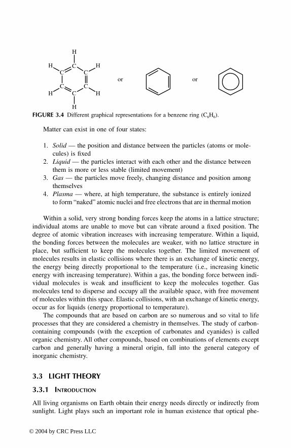
Matter can exist in one of four states:
1.
Solid
— the position and distance between the particles (atoms or mole-cules) is fixed
2.
Liquid
— the particles interact with each other and the distance betweenthem is more or less stable (limited movement)
3.
Gas
— the particles move freely, changing distance and position amongthemselves
4.
Plasma
— where, at high temperature, the substance is entirely ionizedto form “naked” atomic nuclei and free electrons that are in thermal motion
Within a solid, very strong bonding forces keep the atoms in a lattice structure;individual atoms are unable to move but can vibrate around a fixed position. Thedegree of atomic vibration increases with increasing temperature. Within a liquid,the bonding forces between the molecules are weaker, with no lattice structure inplace, but sufficient to keep the molecules together. The limited movement ofmolecules results in elastic collisions where there is an exchange of kinetic energy,the energy being directly proportional to the temperature (i.e., increasing kineticenergy with increasing temperature). Within a gas, the bonding force between indi-vidual molecules is weak and insufficient to keep the molecules together. Gasmolecules tend to disperse and occupy all the available space, with free movementof molecules within this space. Elastic collisions, with an exchange of kinetic energy,occur as for liquids (energy proportional to temperature).
The compounds that are based on carbon are so numerous and so vital to lifeprocesses that they are considered a chemistry in themselves. The study of carbon-containing compounds (with the exception of carbonates and cyanides) is calledorganic chemistry. All other compounds, based on combinations of elements exceptcarbon and generally having a mineral origin, fall into the general category ofinorganic chemistry.
3.3 LIGHT THEORY
3.3.1 I
NTRODUCTION
All living organisms on Earth obtain their energy needs directly or indirectly fromsunlight. Light plays such an important role in human existence that optical phe-
FIGURE 3.4
Different graphical representations for a benzene ring (C
6
H
6
).
H
H
C
C
C
C
C
CH
H H
H
or or
TF1345_C03.fm Page 48 Thursday, March 18, 2004 1:03 PM
© 2004 by CRC Press LLC

nomena have been studied since the earliest times. Cavemen, watching the flickeringflames of a fire, thought that the yellowish light was a magical, mysterious spirit.The ancient Greeks knew that when a ray of light is reflected from a mirror, theangle of incidence is equal to the angle of reflection. Various theories of light havebeen formulated throughout the centuries. Today, it is known that light is a form ofenergy that is dualistic in nature, having both wave
and particle properties. Whenlight interacts with macroscopic objects (bulk matter), it is regarded as a beam ofelectromagnetic waves. When light interacts with microscopic objects (e.g., atomsor molecules), it is regarded as a beam of energy particles known as photons.
The perception of color and of photoluminescence emission represents the obser-vation of physical phenomena due to the interaction of light with matter. To explainand to efficiently employ the observed phenomena, it is essential that some funda-mental properties of light be understood. Light is a form of electromagnetic energy,part of a group that includes x-rays, microwaves, and radio waves. (The term
electromagnetic
refers to the fact that light energy has both electric and magneticcomponents.) Visible radiation, which makes up white light, forms only a small partof the electromagnetic spectrum (Figure 3.5).
3.3.2 W
AVE
T
HEORY
In the early 19th century, Thomas Young found strong evidence to support the wavetheory of light. The electromagnetic wave model was subsequently established.Electromagnetic energy propagates in the form of waves that can be described bytheir wavelength
λ
(measured in units of nanometers [nm], 10
–9
m) or their frequency
ν
(oscillations per unit time, measured in units of hertz [Hz]) (Figure 3.6). Thefrequency
ν
can be calculated from the wavelength
λ
using the formula
ν
= c/
λ
where c, the speed of light, is a constant (c is approximately 300 million m/sec).
3.3.3 P
ARTICLE
T
HEORY
Max Planck and Albert Einstein, Nobel Prize winners in physics, proposed that light,which usually travels in waves, sometimes behaves as if it were made up of a streamof small energy particles or
photons
traveling at the speed of light (Figure 3.7). Lightis always emitted or absorbed as a number of whole photons. The intensity of a lightsource is equal to the number of emitted photons per second.
FIGURE 3.5
The electromagnetic spectrum. Light consists of three parts: ultraviolet (UV),visible, and infrared (IR). Visible light is a very small portion in this region.
X-Rays
U V I R Micro & radio waves
Visiblelight
1 pm 0.1 nm 10 nm 1000 nm 10 mm 1 mL i g h t
Cosmic &γ rays
TF1345_C03.fm Page 49 Thursday, March 18, 2004 1:03 PM
© 2004 by CRC Press LLC
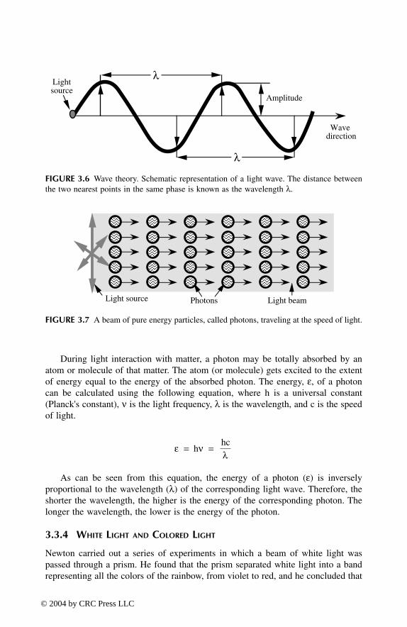
During light interaction with matter, a photon may be totally absorbed by anatom or molecule of that matter. The atom (or molecule) gets excited to the extentof energy equal to the energy of the absorbed photon. The energy,
ε
, of a photoncan be calculated using the following equation, where h is a universal constant(Planck's constant),
ν
is the light frequency,
λ
is the wavelength, and c is the speedof light.
As can be seen from this equation, the energy of a photon (
ε
) is inverselyproportional to the wavelength (
λ
) of the corresponding light wave. Therefore, theshorter the wavelength, the higher is the energy of the corresponding photon. Thelonger the wavelength, the lower is the energy of the photon.
3.3.4 W
HITE
L
IGHT
AND
C
OLORED
L
IGHT
Newton carried out a series of experiments in which a beam of white light waspassed through a prism. He found that the prism separated white light into a bandrepresenting all the colors of the rainbow, from violet to red, and he concluded that
FIGURE 3.6
Wave theory. Schematic representation of a light wave. The distance betweenthe two nearest points in the same phase is known as the wavelength
λ
.
FIGURE 3.7
A beam of pure energy particles, called photons, traveling at the speed of light.
Wave direction
Amplitude
Lightsource
λ
λ
Light source Photons Light beam
ε νλ
h hc
= =
TF1345_C03.fm Page 50 Thursday, March 18, 2004 1:03 PM
© 2004 by CRC Press LLC

white light consists of a mixture of various colors. The colors — identified as violet,indigo, blue, green, yellow, orange, and red — represent the visible spectrum. Thehuman eye only sees “visible” light, which is any electromagnetic radiation fallingwithin the wavelength range of approximately 400 to 700 nm. Color perception isrelated to wavelength; for example, radiation at 450 nm is observed as blue light, at550 nm as green, and at 650 nm as red. When each color (wavelength) of the visiblespectrum is present with the same relative intensity, we have white light (Figure 3.8).If each color (wavelength) in the visible region is not present at the same intensity— such is the case when some colors are absent — then we have colored light.(Black is the “color” perceived by the brain when no visible light is present, but thisdoes not preclude the presence of nonvisible radiation such as ultraviolet, infrared,or x-rays.)
Colored light can be polychromatic (many colored) or monochromatic (singlecolored). When only one single wavelength is present, we have pure monochromaticlight. When a narrow range of colors (visible wavelengths) is present, we have amonochromatic band of light (Figure 3.9). It is obvious that the narrower the band,the purer the color will be (i.e., more monochromatic). A band of light is definedby its central wavelength (CW) and its bandwidth (BW).
FIGURE 3.8 When each color (wavelength) of the visible spectrum is present with the samerelative intensity, we have white light.
FIGURE 3.9 When a narrow range of colors (visible wavelengths) is present, we have amonochromatic band of light.
I
I n
t e
n s
i t y
Red
Ora
nge
Yel
low
Gre
en
Blu
e
Vio
let
400 450 500 550 600 650 700 Wavelength [nm]
I
I n
t e n
s i
t y
Bandwidth (BW)
400 450 500 550 600 650 700 nmSingle line Central Wavelength (CW)
Yel
low
Band of light
TF1345_C03.fm Page 51 Thursday, March 18, 2004 1:03 PM
© 2004 by CRC Press LLC

Light that is composed of two or more monochromatic bands is referred to aspolychromatic. For example, a blue band combined with an orange/red band willproduce polychromatic light that will be perceived by the human eye as being purplein color (Figure 3.10). Incidentally, this is the color of fingerprints developed withninhydrin.
3.3.5 SPECTRAL SENSITIVITY OF THE HUMAN EYE
The search for forensic evidence can sometimes require examination through theentire visible region (i.e., from 400 to 700 nm) as well as, in some cases, nonvisibleregions such as the ultraviolet and infrared. It is important to understand that thehuman eye has limitations, the most important of which is restricted spectral sensi-tivity. From the spectral sensitivity curve (Figure 3.11), it can be seen that the humaneye has the highest sensitivity at around 550 nm (green/yellow region). Sensitivityis very low in the violet region, below 450 nm, and in the red region, above 650nm. This should be taken into account when working at these wavelengths. Similarly,when recording marks, the specialist needs to be aware of the spectral sensitivity ofthe photographic film being used, which may differ considerably from that of theeyes.
Sometimes quite useful forensic evidence is rejected, as it does not “look good”when observed with the naked eye. A typical example is a weak fingermark in bloodon a lightly colored surface. Violet light can be used to enhance the mark, as bloodhas an absorption peak in this wavelength range. The human eye has a very lowsensitivity in the violet region, and a fingerprint in blood may not “look good” underthese conditions. When photographed, however, an excellent image may be pro-duced, as photographic film is very sensitive in this region. The film “sees” thefingermark very well under violet light, much better than the human eye.
3.3.6 ABSORPTION AND REFLECTION OF LIGHT
At a macroscopic level, a light beam directed onto a surface is either reflected,absorbed, or transmitted. For example, if the material is transparent, most of the
FIGURE 3.10 A blue band combined with an orange/red band will produce polychromaticlight that will be perceived by the human eye as being purple in color.
400 450 500 550 600 650 700
W a v e l e n g t h [nm]
I n
t e
n s
i t y
Red
Ora
nge
Blu
e
P u r p l e
TF1345_C03.fm Page 52 Thursday, March 18, 2004 1:03 PM
© 2004 by CRC Press LLC

light is transmitted, some is absorbed, and the rest is reflected. The total energy ofthe system is conserved so that the irradiating intensity Iinc is equal to the sum ofthe reflected intensity Irefl, the absorbed intensity Iabs, and the transmitted intensityItrans (Figure 3.12).
For a nontransparent surface, It = 0 and all light not absorbed is reflected. Thereflected light is the light seen by our eyes (or camera or photosensitive detector),which gives us a colored image of the object observed. If the object appears whiteunder white light, then the surface reflects all of the wavelengths of the visiblespectrum to an equal extent: there is no selective absorption and the surface willappear to be the same color as the incident light.
One of the fundamental laws of reflection is that the angle of incidence of thelight beam (α in Figure 3.12) is equal to the angle of the reflected light (β). Thisangle is measured with respect to a line perpendicular to the surface (normal to thesurface) at the point of incidence. For a perfectly flat, shiny surface (e.g., a mirror),
FIGURE 3.11 The spectral sensitivity of an average human eye.
FIGURE 3.12 Transformation of incident light after irradiation of an object.
S e
n s
i t i
v i t
y
400 500 600 700
Red
Ora
nge
Yel
low
Gre
enBlu
e
Vio
let
Wavelength [nm]
Medium A
Medium B
Medium A
β
γ
α
αI
I
I
I inc
refl
trans
abs
The perpendicular line to the surface (The normal to the surface)
TF1345_C03.fm Page 53 Thursday, March 18, 2004 1:03 PM
© 2004 by CRC Press LLC

all rays will be reflected in the same direction. This is termed specular reflection(Figure 3.13A). A rough surface gives randomly oriented reflected rays (due to therandom orientation of the normals to the surface), producing what is termed diffusedreflection (Figure 3.13B).
When the incident light is white but the reflected light is colored, we have thephenomenon of selective absorption: certain wavelengths are absorbed or trans-mitted while others are reflected — our eyes only perceive the latter. For example,if an object appears red under white light, all wavelengths have been absorbedexcept for the red, which is reflected and perceived. Under a green or blue light,the same object will appear black (all incident light is absorbed), while under ared light it will appear red (all incident light is reflected). It must be noted that inthis latter case (red incident light), a white object will also appear red, since mostof the incident light is reflected. As a result, a red object cannot be distinguishedfrom an identical, but white, object under red lighting. This phenomenon isrecognized in police circles when it comes to describing the color of an objectunder different lighting conditions. For example, a yellow car seen at night underartificial light will be difficult to distinguish from a similar white car observedunder the same conditions.
3.3.7 PHOTOLUMINESCENCE
Luminescence is a general term that incorporates phenomena such as thermolumi-nescence (light emission that results from the absorption of heat energy), biolumi-nescence (light emission from a biological process), chemiluminescence (light emis-sion from a chemical process), as well as photoluminescence (light emission thatresults from the absorption of light energy). The correct term in the context of thisbook is therefore photoluminescence.
When light interacts with matter, a photon of light may be absorbed by amolecule (or atom) of that matter (Figure 3.14). After absorption of the photon, themolecule has an excess of energy, equal to the energy of the absorbed photon, and
FIGURE 3.13 (A) Specular reflection from a flat surface. (B) Diffused reflection from arough surface.
Specularreflection
(A)
Diffusedreflection
(B)
TF1345_C03.fm Page 54 Thursday, March 18, 2004 1:03 PM
© 2004 by CRC Press LLC

is no longer in its normal (ground) state. The molecule (or atom) is promoted to ahigher energy (excited) state. The molecule tends to rapidly return to its ground state(the state before absorption of the photon) by releasing the excess energy in someform. This process is complex, and necessary simplification/schematization high-lights parts of the phenomena that are useful in fingerprint detection. To release theexcess energy, the molecule may undergo a chemical change, may transfer the energyto other molecules through collision or vibration (producing heat), or emit the energyas another photon (Figure 3.14).
All these processes compete with each other, and a return to the ground stateseldom occurs through a single pathway. Our particular interest is the process ofemission of another photon. Before emission of another photon takes place, somefaster processes, in which the molecule loses part of its extra energy, are occurring.The molecule shares a part of its extra energy with immediate neighbors. Sharedenergy spreads out to other molecules in the form of increased vibration (increasedheat). The molecule then emits the remainder of its extra energy in the form of asecondary photon (Figure 3.14). The process involving the emission of a secondaryphoton upon absorption of a primary photon is called “photoluminescence.”
The energy of an emitted photon is smaller than the energy of an absorbedphoton by the amount of shared energy. This means that the photoluminescence
FIGURE 3.14 Absorption and emission of a photon — photoluminescence. (1) A moleculein its normal (ground) state just before absorption of a photon. (2) The molecule becomesexcited by the amount of absorbed energy. It immediately shares some of its extra energywith its nearest neighbors. Shared energy spreads out to other molecules. (3) The moleculeis less excited by the amount of the shared energy. (4) The molecule releases (emits) its extraenergy in the form of a photon. (5) The molecule returns to its ground state.
Outer neighbors
Outer neighbors
Immediateneighbor
Molecule inground state
Molecule inground state
5
41 2 3
Releasedphotonenergy
Photon tobe absorbedenergy
Immediateneighbor
ε1ε2
>
<λ λ1 2
ε ε1 2
TF1345_C03.fm Page 55 Thursday, March 18, 2004 1:03 PM
© 2004 by CRC Press LLC

emission has a longer wavelength (lower energy) compared with the absorbed lightthat was used to excite the molecule (the “excitation” light). It is said that thephotoluminescence emission is “red-shifted” in comparison to the excitation light.Emission can proceed either directly (Figure 3.15A) or indirectly, i.e., when a smalleramount of extra energy is further shared and the molecule falls into a “metastable”state (Figure 3.15B). Direct emission is known as “fluorescence,” while emissionthrough a metastable state is known as “phosphorescence.” Because it is the resultof a direct transition, the fluorescence process is fast, and fluorescence emissionoccurs only during exposure of the matter to the excitation light. When the excitationlight is removed, fluorescent emission ceases.
In the phosphorescence process, the molecule is in a lower excited state thanthe first excited state due to energy loss during transition to the metastable state.This means that phosphorescence is red-shifted in comparison to fluorescence emis-sion, or further red-shifted in comparison to the excitation light. The nature of themetastable state is such that the molecule stays much longer in this state, andtransition does not take place immediately as with fluorescence. Phosphorescenceemission continues for a fraction of a second to several seconds (sometimes minutes)after the excitation light has been removed, and it is known as “afterglow.” Onlysome photoluminescent compounds have the property of phosphorescence; most ofthem exhibit only or mostly fluorescence. The general term photoluminescencecovers both fluorescence and phosphorescence processes.
In summary, a photoluminescent material absorbs light at a particular wavelengthand then reemits the absorbed energy as light at a longer wavelength. Photolumi-nescence can occur as either fluorescence (light emission only occurs during exci-tation) or phosphorescence (light emission continues to occur for a short period afterexcitation). Elsewhere in this book, where the general term luminescence isemployed, this should be taken to mean “photoluminescence.”
FIGURE 3.15 The molecule in stage 4 (first excited state) has two possibilities of returningto the ground state: directly, or indirectly by further sharing its extra energy. The latter processtakes longer and leads to phosphorescence emission.
The first excitedstate
The metastableexcited state
Fluorescence Phosphorescence
The ground state The ground state
5
4b
5
4
4a
OR
OR
ε2 ε3
TF1345_C03.fm Page 56 Thursday, March 18, 2004 1:03 PM
© 2004 by CRC Press LLC

3.3.8 OPTICAL FILTERS
There are three principal modes of acquiring information from a surface or objectusing light:
• Absorption mode• Diffused reflection mode• Photoluminescence mode (based on the detection of a photoluminescent
material)
The majority of illumination techniques used for forensic examinations employ oneof these three modes. The implementation of these optical enhancement methods isheavily dependent on the use of optical filters. An optical filter is a device designedto select specific colors (wavelengths) of light from the range of colors (wavelengths)available.
Filters can be classified, according to their transmission characteristics, aseither short pass, long pass, or bandpass. A short pass filter is designed to transmitshorter wavelengths while rejecting longer wavelengths (Figure 3.16). The mid-point between transmitted and rejected regions is called the edge wavelength(EW). The edge wavelength (in nanometers) is labeled on each filter as thecharacteristic of that filter. The transmission is limited on the left side (shorterwavelengths) by the substrate of which the filter is made. For example, if a glasssubstrate is used, the transmission falls sharply below 380 nm. A long pass filteris designed to transmit longer wavelengths while rejecting shorter wavelengths(Figure 3.17).
A bandpass filter is designed to transmit over a wavelength range while rejectingall other wavelengths (Figure 3.18). In this way the bandpass filter creates a mono-chromatic band of light. The combination of a long pass filter and a short pass filterwith overlapping transmission bands will result in a bandpass filter. The basiccharacteristics of a bandpass filter are as follows:
FIGURE 3.16 Typical transmission characteristics of a short pass filter.
Tra
nsm
issi
on %
20
40
60
80
100
200 300 400 500 600 700 2,000 nmEW (Edge Wavelength)
The
sub
stra
te l
imit
sth
e tr
ansm
issi
on o
nth
is s
ide
Maximum transmission
R e j e c t e d
50% of maximumtransmission
Tra
nsm
itte
d
TF1345_C03.fm Page 57 Thursday, March 18, 2004 1:03 PM
© 2004 by CRC Press LLC

• Central wavelength (CW) — the wavelength that corresponds to themidpoint of the band as measured at 50% of maximum transmission
• Half-bandwidth (HBW) — the width of the transmission band measuredat 50% of maximum transmission
• Passband — the width of the transmission band measured between the5% transmission points on each side of the band
• Blocking region — the attenuation of transmitted radiation in specifiedspectral regions outside the passband. Blocking is specified by the per-centage of transmitted light. For a good filter, transmission should not behigher than 0.0001% (10–4%) in this region.
When the transmission band of a long pass filter is compared with that of arelevant bandpass filter, it can be seen that the long pass filter transmits significantlymore light (energy) but is less selective (Figure 3.19). This should be taken intoaccount when selecting an observation filter (barrier filter) for a particular applica-
FIGURE 3.17 Typical transmission characteristics of a long pass filter.
FIGURE 3.18 Typical transmission characteristics of a bandpass filter.
Tra
nsm
issi
on %
20
40
60
80
100
200 300 400 500 600 700 2,000 nmEW (Edge Wavelength)
The
sub
stra
te li
mit
s th
etr
ansm
issi
on o
n th
is s
ide
Transmitted
Maximum transmission
R e j e c t e d
50% of maximum transmission
Tra
nsm
issi
on %
20
5
40
60
80
100
200 300 400 500 600 700 2,000 nmCW (Central Wavelength)
Maximum transmission
R e j e c t e d R e j e c t e d
50% of maximumtransmission
HBW
TF1345_C03.fm Page 58 Thursday, March 18, 2004 1:03 PM
© 2004 by CRC Press LLC

tion, especially in cases where a colored or photoluminescent background preventsthe recording of satisfactory results.
With regard to the process of wavelength rejection, there are two different typesof optical filters: energy absorbing and energy reflecting. Energy absorbing filtersare based on the absorption of some wavelengths by colored matter present in thefilter. When a light beam passes through a colored substance, certain wavelengthsare absorbed and the rest are transmitted (Figure 3.20). Since light is pure energy,and the energy conservation law applies, the absorbed light is converted into heat.The filter must dissipate this absorbed energy at the same rate as it receives it;otherwise, the temperature of the filter increases. Increased temperature can causedestruction of the filter. The manufacturing of energy-absorbing filters is relativelysimple and inexpensive. A suitable colored matter is embedded into glass, gelatin,plastic, or dissolved in a liquid. The two major disadvantages of these filters are:(a) often it is difficult or impossible to find a colored matter to suit particularwavelength requirements; and (b) due to heat buildup, they cannot be used withhigh-intensity light. Energy-absorbing filters can be successfully employed as barrierfilters in front of the eyes or a camera.
FIGURE 3.19 Transmission characteristics of a long pass filter (KV550) compared withtransmission characteristics of a bandpass filter (IF590/40).
FIGURE 3.20 White light filtered through an energy-absorbing filter.
Tra
nsm
issi
on %
20
40
60
80
100
400 450 500 550 600 650 700
W a v e l e n g t h [nm]
Transmissioncharacteristic ofa long pass filter
Transmissioncharacteristic ofa bandpass filter
Colored matter
Transmitted colored light
Incident white light
TF1345_C03.fm Page 59 Thursday, March 18, 2004 1:03 PM
© 2004 by CRC Press LLC

A typical example of an energy-reflecting filter is the interference filter. Inter-ference filters are made by deposition of alternating thin layers of material with highand low refracting index under high vacuum. There are several types of interferencefilters with regard to the materials that are used in the manufacturing process, e.g.,metal-dielectric-metal, metal-dielectric, and all dielectric. The two types of all-dielectric filters, known as “soft coated” and “hard coated,” are the most commonlyused filters. Hard-coated filters are manufactured by using metal oxides; they areinsensitive to moisture, hard wearing, and very long lasting. Soft-coated filters aremanufactured by using zinc sulfide (refractive index = 2.35) and cryolite (refractiveindex = 1.35). To obtain a good “square” transmission characteristic with an uprightrejection ratio out of the transmission band, it is required to deposit many alternatethin layers of zinc sulfide and cryolite on a glass substrate under high vacuum (Figure3.21). Both zinc sulfide and cryolite are colorless, and therefore the absorption oflight within the filter is minimal. The required wavelength band is obtained by theinterference of transmitted light through the filter. The range of transmitted wave-lengths depends only on the thickness of the filter layers. By varying the layerthickness, an interference filter can be designed and manufactured to give specificfilter characteristics. The number of layers influences the shape of the transmissioncurve. Better-quality interference filters, with a multilayered construction, havetransmission curves that display a better defined pass band (much sharper cut-off–cut-on edges).
An interference filter transmits or reflects light, while absorption is negligible.This property of interference filters allows them to be used with high-intensity lightwithout significant risk of overheating and filter damage. All three types of filtersmentioned in the previous section (bandpass, short pass, and long pass) can be madein the form of interference filters. However, due to the complex manufacturingprocess required, interference filters are very expensive.
The standard transmission characteristics of an interference filter refer to the casewhere the incident light beam is perpendicular to the filter’s surface (Figure 3.22A).In this case, the normal to the filter's surface and the incident light beam are paralleland it is said that the angle of incidence is 0°. When the incident angle increases (i.e.,when the filter is tilted with respect to the light beam), the central wavelength isshifted toward shorter wavelengths due to a longer light path through the filter layers
FIGURE 3.21 An interference filter is made from many alternate layers of zinc sulfide andcryolite. Beams with different light paths through the filter interfere with each other, whichleads to only certain wavelengths appearing in the transmitted light.
Zinc sulfide, n = 2.35
Cryolite, n = 1.35
TF1345_C03.fm Page 60 Thursday, March 18, 2004 1:03 PM
© 2004 by CRC Press LLC

(Figure 3.22B). The shift depends on the transmitted wavelength and is proportionalto the incident angle. The shape of the transmission curve and the transmissionintensity do not change significantly during the “down-tuning” process. A maximumwavelength shift of about 30 nm (visible region) can be achieved for an incident angleof 45° (Figure 3.23). This fine-tuning property of interference filters can be ofsignificant benefit in some forensic applications (e.g., for attenuating backgroundinterference when recording weakly luminescent fingerprints).
3.3.9 ABSORPTION MODE
The method of acquiring information from a surface based on color difference (orselective absorption) is known as the absorption mode. Selective absorption can be
FIGURE 3.22 (A) Conventional use of an interference filter compared with (B) down-tuning,where the filter is tilted with respect to the incident beam. The light path through the filterlayers becomes longer, resulting in a shift of the band toward shorter wavelengths.
FIGURE 3.23 Tilting of an interference filter results in the shifting of its passband towardshorter wavelengths (wavelength down-tuning).
Incidentbeam
Transmittedbeam
Normal to the surfaceTilted angle
(A) (B)
CW oftuned filter
CW ofuntuned filter
Tra
nsm
issi
on %
20
40
60
80
400 500 600 700
W a v e l e n g t h [nm]
TF1345_C03.fm Page 61 Thursday, March 18, 2004 1:03 PM
© 2004 by CRC Press LLC

demonstrated by considering how colored spots — blue, yellow, and red — on awhite background will appear under different bands of colored light or when visu-alized through different bandpass filters (Table 3.3).
A colored object or stain can be readily visualized by enhancing the colordifference against the background substrate. A colored band of light is chosenthat is opposite to the color of the object (or stain) in question. Enhancement isachieved because the object is “darkened” due to selective absorption properties.For example, illuminating an orange stain on a blue surface with a blue band oflight can enhance the orange stain. The stain will appear dark against a lightbackground because the blue light is absorbed by the stain but reflected by thesurface. Alternatively, the surface can be illuminated with white light but visu-alized through a blue filter. The only requirement for enhancement is that thebackground and the object do not absorb at exactly the same wavelength (evenif the color is similar). The use of absorption and reflection properties of matteris the basis of colorimetric techniques (i.e., techniques based on the measurementof color). Such techniques are among the most practical, but they are less sensitivethan methods based on photoluminescence, which are described later. For afingermark, approximately 100 ng of reactant product is necessary to obtain asignificant colorimetric signal.
TABLE 3.3 Absorption Mode Demonstrated Using Three Colored Spots (Blue, Yellow, and Red) on a White Substrate
Observation Conditions Appearance Effect
White incident light(no observation filter)
White substrate will appear white (reflects allcolors). Blue spot will appear blue (reflectsblue, absorbs all other colors). Yellow spotwill appear yellow (reflects yellow, absorbsall other colors). Red spot will appear red(reflects red, absorbs all other colors).
White substrate will appear blue, Blue spotwill appear blue, Yellow spot will appearblack (absorbs blue, no reflected light). Redspot will appear black (absorbs blue, noreflected light).
White substrate will appear yellow, Bluespot will appear black (absorbs yellow, noreflected light). Yellow spot will appearyellow. Red spot will appear black (absorbsyellow, no reflected light).
White substrate will appear red. Blue spotwill appear black (absorbs red, no reflectedlight). Yellow spot will appear black(absorbs red, no reflected light). Red spotwill appear red.
Blue incident light(no observation filter)or white incident lightwith observation througha blue bandpass filter
Yellow incident light(no observation filter)or white incident lightwith observation througha yellow bandpass filter
Red incident light(no observation filter)or white incident lightwith observation througha red bandpass filter
blue yellow red
blue yellow red
blue yellow red
blue yellow red
TF1345_C03.fm Page 62 Thursday, March 18, 2004 1:03 PM
© 2004 by CRC Press LLC

As a general rule, the selection of a filter, or a colored incident light, to improvecontrast can be made with the aid of a color wheel (Figure 3.24). Opposite (com-plementary) colors on this wheel will darken the color observed (i.e., increase thecontrast), while adjacent colors will lighten the observed color (i.e., reduce thecontrast). The absorption mode improves photographic contrast and is relativelysimple to implement (Barker 1999). It requires any white light source and a bandpassfilter compatible with an absorption band of the colored object of interest. In simpleterms, the bandpass filter should be opposite in color to the color of the object whilebeing as close in color to the background substrate as possible.
To illustrate the implementation of the absorption mode, consider a red finger-print on a white surface. The simplest way to photographically enhance the print isto use the absorption mode. The absorption mode can be implemented in two ways:(a) with an appropriate filter (a blue–green filter in this case) in front of the camera,or (b) with the same filter in front of the light source. The filter used in front of thecamera is known as the barrier filter. The method with a filter in front of the camera(Figure 3.25) can be used in all situations, even if daylight or artificial light is present.If an appropriate barrier filter is not available but is incorporated into the light source,the absorption mode can be implemented by using this band of light (Figure 3.26).In this latter case, the room must be darkened for optimum results.
Enhancement using the absorption mode may be unsuccessful if the surface issimilar in color to the object of interest. Changing the wavelength of the band oflight can sometimes produce better results. (A light source with fine-tuning capa-bilities will be an advantage in such cases.) If the color of the object is pale, or ifthe object appears transparent, the absorption mode may not offer satisfactoryenhancement, and other modes (or chemical treatment to modify the colorimetricproperties of the object) should be exploited to achieve possible enhancement.
A ninhydrin-developed fingerprint, when viewed under white light, will appearpurple in color. Some wavelengths will be absorbed by the print, while other are
FIGURE 3.24 The color wheel can be used for the selection of a filter to improve contrast.Colors that are opposite on the wheel are complementary.
Orange
Blue
Violet
Purple
Green Blue
(B)
Adjacentcolors
Opposite colors
Red
Ora
nge
Yel
low
Gre
en
Blu
e
Vio
let
Yellow—green
Orange—red
400 500 600 700
Red
(A)
Blue—green
IndigoYellow
Wavelength [nm]
TF1345_C03.fm Page 63 Thursday, March 18, 2004 1:03 PM
© 2004 by CRC Press LLC

reflected. The combination of reflected wavelengths (principally in the blue and redregions) is perceived by the human eye as being purple in color. The purple coloris due to a compound known as Ruhemann’s purple, which is formed when ninhydrinreacts with a latent fingerprint. The absorption characteristics of Ruhemann’s purpleneed to be taken into consideration if the best contrast is to be obtained using theabsorption mode.
A typical absorption spectrum for a ninhydrin-developed fingerprint is depictedin Figure 3.27. It can be seen that there are two absorption bands: a narrow bandwith a maximum at around 410 nm (violet region) and a broad major band with a
FIGURE 3.25 Schematic representation of the absorption mode with the appropriate filterused in front of the camera. This method can be used in all situations in the presence orabsence of daylight or artificial light.
FIGURE 3.26 Schematic representation of the absorption mode with the appropriate filterin front of a light source. This method can be used only in dark or semidark situations.
White light source
White light
Developedfingerprint or mark
SUBSTRATE
Colored lightthat passesthrough the filter
Reflected white light from the substrate
Filter to be compatible with maximum absobtion
of the ridges
Reflectedcolored lightfrom ridges
Reflected coloredlight fromthe substrate
Developedfingerprintor mark
SUBSTRATE
Coloredlight
White lightsource
Filter to suitmaximum absorption
from fingerprint ridges
TF1345_C03.fm Page 64 Thursday, March 18, 2004 1:03 PM
© 2004 by CRC Press LLC

maximum in the region of 560 to 580 nm (green–yellow region). The best contrastcan be obtained by using a bandpass filter in front of the camera, or in front of thelight source, that suits one maxima (560 to 580 nm) or the other (410 nm) in theabsorption spectrum.
When working in the violet or red regions of the spectrum, it must be remem-bered that the human eye has low sensitivity at these wavelengths. Enhancementunder such conditions may appear poor but will generally be significantly improvedin any photographic images.
3.3.10 DIFFUSED REFLECTION MODE
This method of acquiring information is based on diffused reflection from a roughobject on a surface that is dark or that is flat and shiny (Figure 3.28). In such a case,more diffusely reflected light from the object will reach the camera than reflectedlight from the surface. The object will therefore appear light against a dark back-ground. This method can be used for the observation and photography of an objectthat is on top of, or indented into, a surface. Classical examples include a finger orfootwear mark in blood on a dark or a flat and shiny surface, a footwear impressionin dust, or a greasy fingerprint on a smooth shiny surface. The light beam used forillumination should be directed at an angle to the surface (starting at 45°, then varyingthe angle as required), with the working area darkened.
In the case of a colored object, a monochromatic light band of similar color tothe object should be used to enhance the diffused reflection. In the case of a coloredsurface, a monochromatic light band with a color opposite to the color of the surfaceshould be used to darken the surface (i.e., increase the contrast between the objectand the surface). Oblique lighting (i.e., light beam almost parallel to the surface) isrequired in some cases (e.g., footwear impressions in dust or cyanoacrylate-devel-oped fingerprints).
FIGURE 3.27 A typical absorption spectrum for a ninhydrin-developed fingerprint. Thereare two absorption bands: a narrow band with a maximum at around 410 nm (violet region)and a broad major band with a maximum at around 560 to 580 nm (green–yellow region).
380 400 420 440 460 480 500 520 540 560 580 600 620 640 660 680 700
W a v e l e n g t h [nm]
Rel
ativ
e A
bsor
ptio
n
1020
405060708090
30
100
R E F L E C T E D
A B S O R B E D
TF1345_C03.fm Page 65 Thursday, March 18, 2004 1:03 PM
© 2004 by CRC Press LLC

Used in the transmission mode, this technique is the basis of dark-field illumi-nation in light microscopy. The phenomenon is observed when the incident lightrays are diffused and refracted differently by a sample on a transparent surface suchas glass. A fingerprint on glass, with transmitted oblique lighting, will be observedas light ridges against a dark background (Figure 3.29).
This method, already documented 100 years ago (Reiss 1903), can be usedto efficiently image marks on glass surfaces. Diffused transmission techniquescan also be utilized for the fast screening of cyanoacrylate-developed prints onclear plastic bags. The light beam from a forensic light source is directed ontoone side of the bag, with examination done from the other side. Care should beexercised to ensure that the eyes are not exposed to the direct beam from thelight source!
FIGURE 3.28 A schematic representation of the diffused reflection mode.
FIGURE 3.29 The diffused reflection mode as applied to a transparent substrate. Note thatthe incident light is directed at an angle from underneath the object.
Filter to suitmaximum reflectionfrom ridges and/ormaximum absorptionby the substrate
Colored light
Reflec
ted co
lored lig
ht
from a
shiny su
rface
Diffused reflectionfrom ridges
White lightsource
SUBSTRATE
Incident light
Transparent substrate
Fingerprint on the surface
Diffused light
TF1345_C03.fm Page 66 Thursday, March 18, 2004 1:03 PM
© 2004 by CRC Press LLC

3.3.11 EPISCOPIC COAXIAL ILLUMINATION
Episcopic coaxial illumination is a special implementation of the diffusion reflectionmode. The incident light is directed along the camera lens axis (i.e., perpendicularto the surface). This effect can be achieved by mounting a semitransparent mirror(or flat piece of glass) in front of the camera at an angle of 45° toward the lensaxis/light path (Figure 3.30). The incident light beam is directed onto the mirror atan angle of 45° toward the mirror. To avoid “hot” spots, a diffuser is recommendedin front of the light source. Part of the incident beam is reflected from the semi-transparent mirror and travels along the lens axis toward the exhibit. The other partof the incident beam passes through the mirror and is trapped by a black surface.The incident light is reflected more from the flat surface (specular reflection) thanfrom the ridges (diffused reflection), producing the opposite result to the conven-tional diffused reflection mode (i.e., it results in a dark image against a light back-ground). Episcopic coaxial illumination can be successfully used for photographinglatent fingerprints, fingerprints in blood, or cyanoacrylate-developed fingerprints onsmooth shiny surfaces (e.g., glass, metal, plastic) (Pfister 1985; Ziv and Springer1993). The surface must be as flat as possible to obtain optimum results.
3.3.12 PHOTOLUMINESCENCE MODE
Photoluminescence emission is always very weak compared with the excitation light,and it is shifted toward the red end of the spectrum (Figure 3.31). If white light isused for excitation, weak photoluminescence emission cannot be seen, as it isswamped by the incident light.
The chemical compounds of interest to us usually have one main absorption(excitation) band and will absorb only those wavelengths (colors) that match thisband. White light can be reduced to the wavelengths of interest by placing a bandpass
FIGURE 3.30 A schematic representation of episcopic coaxial illumination. (From Pfister,R. [1985], The optical revelation of latent fingerprints, Fingerprint Whorld, 10, 64–70. Withpermission.)
Bla
ck s
urfa
ceas
a li
ght t
rap
Diffusely reflectedlight from ridges
Cross section offingerprint ridges
Reflected beam Lightsource
Incident beamDiffuser
Substrate bearing a fingerprint
Reflected light from substrate
Semitransparent mirror
TF1345_C03.fm Page 67 Thursday, March 18, 2004 1:03 PM
© 2004 by CRC Press LLC

filter in front of the light source. The bandpass filter should match the absorptionband (Figure 3.32).
A barrier filter is then required in front of the eyes (or camera) that will rejectthe very strong excitation light reflected from the surface while transmitting theweak photoluminescence emission. The barrier filter should therefore match theemission band without overlapping with the excitation band (Figure 3.33). Thismethod of gathering information based on the photoluminescence emission of amaterial is known as the photoluminescence mode.
In practice, the choice of appropriate filters is made according to excitation andemission spectra of the photoluminescent compound of interest (Figure 3.33). Anexcitation spectrum shows the change in emission intensity vs. excitation wave-lengths for a fixed emission wavelength. In general, this spectrum corresponds tothe absorption spectrum of the compound. The emission spectrum shows the change
FIGURE 3.31 Absorption and emission curves for a theoretical photoluminescent materialwith white incident light.
FIGURE 3.32 Absorption and emission curves for a theoretical photoluminescent materialwith choice of appropriate excitation and barrier filters.
I n
t e n
s i
t y %
20
40
60
80
100
400 450 500 550 600 650 700Absorption of light Photoluminescent emission
W h i t e i n c i d e n t l i g h t
Vio
let
Blu
e
Gre
en
Yel
low
Ora
nge
Red
Wavelength [nm]
Absorption of light Photoluminescent emission400 450 500 550 600 650 700
Barrier bandpass filterExcitation bandpass filter
I n
t e n
s i
t y %
20
40
60
80
100
Wavelength [nm]
TF1345_C03.fm Page 68 Thursday, March 18, 2004 1:03 PM
© 2004 by CRC Press LLC

in emission intensity vs. emission wavelength for a fixed excitation wavelength.Excitation and emission spectra for a given material are often displayed on the samegraph.
To implement the photoluminescence mode, two filters are necessary: one infront of the light source and another in front of the eyes (or camera) (Figure 3.34).The only exception to this is when a monochromatic light source (e.g., laser orforensic light source [FLS]) is employed. In this case, only a barrier filter is required.Due to the weak light emission that results, all observation and recording in thismode must be done under darkened conditions (as dark as possible). In addition,the excitation source should be powerful, and the barrier and excitation filters must
FIGURE 3.33 Excitation and emission spectra for a ninhydrin-developed latent fingerprintpost-treated with cadmium nitrate (as an example) with the choice of appropriate filters forexcitation and emission.
FIGURE 3.34 Arrangement for photoluminescence observation.
I n
t e n
s i
t y %
Excitationbandpass filter
Emissionbandpass filter
Excitation(absorption)
spectrum
Photoluminescenceemission spectrum
400 440 480 520 560 600 640 680
Wavelength [nm]
Coloredlight
White lightsource
Excitationfilter
Barrier filterReflected light
Photoluminescentlight
SUBSTRATE
TF1345_C03.fm Page 69 Thursday, March 18, 2004 1:03 PM
© 2004 by CRC Press LLC
be compatible (i.e., the barrier filter should not transmit any of the excitation light).Under ideal conditions, a photoluminescent object will produce a light image (lumi-nescent) against a dark background (nonluminescent). In reality, a substrate alwaysshows some photoluminescence, and the background may be more or less dark, butrarely black. The photoluminescence of the substrate has to be taken into accountduring recording, and conditions must be optimized to obtain the best possiblecontrast.
The intensity of photoluminescence emission depends on temperature. As thetemperature decreases, some of the competing processes mentioned above (e.g.,energy loss by molecular vibration) are attenuated, thus enhancing the photolumi-nescence pathway. Sometimes this enhancement is dramatic, as is the case for theRuhemann's purple–cadmium complex. At room temperature, photoluminescenceof the complex is negligible, while at the temperature of liquid nitrogen (77 K or–196˚C), photoluminescence is very strong and has an excellent practical applicationfor the enhancement of weak ninhydrin-developed latent fingerprints.
The main advantage of the photoluminescence mode is its sensitivity. Whenused under optimum conditions, picograms (pg = 10–12 g) of a substance can bedetected, while in the absorption mode (colorimetric techniques), detection limitsare typically in the nanogram range (ng = 10–9 g). It is for this reason that significantresearch has been conducted over the last 20 years directed at the development ofluminescence techniques for the detection of latent fingerprints.
3.3.13 TIME-RESOLVED IMAGING
The photoluminescence mode offers enhanced sensitivity compared with othermodes employed for latent fingerprint detection and recording. However, this is thecase only if the luminescence emission from the fingerprint is stronger than theluminescence of the background. When the luminescence of the fingerprint is equalto or weaker than the luminescence of the background, the extraction of fingerprintdetail is generally no longer possible. Menzel has suggested a number of methodsthat exploit phosphorescence (delayed fluorescence) as a solution to this problem(Menzel 2001): time-resolved and phase-resolved imaging. (The latter is still beingdeveloped and may not be easy to apply.) To date, we do not have a routine fingerprintreagent that develops luminescent fingerprints with significant phosphorescence.However, the basic principles of time-resolved imaging are of interest.
Let us assume that a developed fingerprint shows some phosphorescence prop-erties (i.e., it continues to emit light for some time after removal of the excitationsource). In most cases, the background exhibits fluorescence properties only (i.e., itstops emitting light as soon as the excitation source is removed). All we need in thissituation is to watch the fingerprint at a time when the light source is off. A classicalphosphoroscope (Figure 3.35), a device used for phosphorescence measurements,can be used to achieve these conditions.
The exhibit is placed within a large cylinder with two opposite slots. When thecylinder rotates, the exhibit is exposed to a light flash at one time, and the phospho-rescence emission is picked up by a camera some time later. The limitation of thephosphoroscope approach is that a large cylinder is needed to accommodate large
TF1345_C03.fm Page 70 Thursday, March 18, 2004 1:03 PM
© 2004 by CRC Press LLC

exhibits. Menzel (2001) has suggested as an alternative a pulsed laser and anelectronically gated video camera, with the camera opening its shutter in betweenlaser pulses. Another option for gathering phosphorescence emission is to use twoalternatively driven fast liquid-crystal shutters (Figure 3.36), one placed in front ofthe light source and the other in front of the camera.
3.3.14 ULTRAVIOLET ILLUMINATION TECHNIQUES
A range of ultraviolet (UV) illumination techniques are available that can be gen-erally classified as follows:
UV–VIS photoluminescence — illuminating the surface with UV light (short-or long-wavelength UV) while observing luminescence emission in thevisible (VIS)
UV–UV photoluminescence — illuminating the surface with short-wave-length UV light (200 to 300 nm; UV B) while observing luminescenceemission in the long-wavelength UV region (300 to 400 nm; UV A)
UV reflection — illuminating the surface with UV light (short- or long-wavelength UV) while observing light reflected in the same wavelengthregion
Working with any UV illumination technique poses a number of hazards to theoperator, in addition to technical difficulties, when recording results. The human eyeis insensitive to UV light, so any observation in the UV region cannot be achieved
FIGURE 3.35 A phosphoroscope can be used for the recording of a phosphorescent finger-print.
Camera
Rotating cylinder
Forensiclight source
Sample with the fingerprintof interest
TF1345_C03.fm Page 71 Thursday, March 18, 2004 1:03 PM
© 2004 by CRC Press LLC

directly (a photographic or video camera is required). Due to its high energy, UVlight can cause significant eye and skin damage, so personal protection is required.Short-wavelength UV lamps generate ozone that can be hazardous to the operator.Glass absorbs short-wavelength UV light, so any observation in this region cannotbe achieved using conventional glass lenses, thus requiring the use of very expensiveoptical components (quartz, fluorite, etc.). (Glass also absorbs a large proportion oflong-wavelength UV light, so quartz optical components are also recommendedwhen working in this region.) Conventional photographic film generally shows poorsensitivity below 400 nm. While these difficulties can be largely overcome, partic-ularly with respect to recent technological advances, they have limited the wide-spread use of UV illumination techniques at the crime scene.
UV–VIS photoluminescence is the simplest mode to apply, in that the observa-tion of results is conducted in the visible region and therefore can be achieved withthe naked eye. The technique can be used to locate items that are luminescent inthe visible spectrum when illuminated with UV light. Optical brighteners used intextile fibers, paper, and paint typically show strong photoluminescence emissionunder such conditions. Alternatively, the technique can be used to locate UV-absorb-ing materials (e.g., blood) on highly luminescent surfaces. Photography (or videocapture) should be conducted with a filter on the camera that transmits in the visiblebut blocks any reflected UV light (Figure 3.37).
UV–UV photoluminescence requires illumination of a surface with short-wave-length UV light. A photographic or video camera, fitted with a barrier filter that onlytransmits long-wavelength UV light, is required for image capture. It has beendetermined that a range of biological fluids (including latent fingerprint deposits)can photoluminesce under such conditions (Bramble et al. 1993; Springer et al.
FIGURE 3.36 Two alternatively driven fast liquid-crystal shutters, one placed in front of thelight source and the other in front of the camera, can be used to gather phosphorescenceemission.
Camera
Forensiclight source
Sample with the fingerprintof interest
Controller
Liquid- crystal shutter
Liquidcrystal shutter
TF1345_C03.fm Page 72 Thursday, March 18, 2004 1:03 PM
© 2004 by CRC Press LLC

1994). In general, photoluminescence emission in the UV is very weak, and it isdifficult to capture an image on conventional film or using a CCD (charge-coupleddevice) camera. The problem can be overcome by either (a) using a CCD camerawith image integration capabilities, or (b) using a light-intensifier device, in whichcase information is not acquired directly from the object but from the phosphorscreen of the image intensifier.
UV reflection requires the use of either a short- or long-wavelength UV lampand a photographic or video camera fitted with a barrier filter that only transmits inthis region (i.e., either short- or long-wavelength UV) (Figure 3.38). It is importantthat only reflected light is recorded, not light reemitted at longer wavelengths (i.e.,photoluminescence emission). If light reflected in the short-wavelength region isbeing recorded, quartz objectives must be employed. Reflected UV techniques havebeen demonstrated to be effective for the visualization of untreated fingermarks andfootwear impressions, in addition to the recording of wounds or bruising on humanskin (West et al. 1990).
3.4 FORENSIC LIGHT SOURCES AND THEIR APPLICATION
Specialized light sources, including lasers and high-intensity filtered lamps, havebeen employed for many years as an aid to fingerprint enhancement and crime sceneexamination in general. The term forensic light source (or FLS) is commonly usedto refer to an illumination system adapted for such use. Numerous forensic lightsources, from a number of manufacturers, are now available on the market. Whenused correctly, an FLS can facilitate the search for a range of evidence types includingfootwear impressions, hairs and fibers, firearm discharge residues, lubricant stains,biological material (e.g., blood, semen, urine, and saliva), and latent fingerprints(both pre- and post-treatment).
FIGURE 3.37 Typical setup for the photoluminescence mode with excitation in theUV region and observation in the visible region.
Ultravioletlight source
Ultravioletlight
SUBSTRATE
UV-inducedluminescent emission
UV-reflectedlight
UV blocking filter,e.g., KodakTM 2A
TF1345_C03.fm Page 73 Thursday, March 18, 2004 1:03 PM
© 2004 by CRC Press LLC

An interest in the forensic application of lasers was initiated in 1977 whenDalrymple and coworkers (1977) reported on the detection of untreated latent fin-gerprints using photoluminescence techniques. The development of high-intensityfiltered lamps as more versatile, cost-effective alternatives to the laser was subse-quently pursued in the early 1980s in Australia, Great Britain, and Canada. Anonlaser forensic light source is sometimes referred to as an alternate light source(ALS).
It is not the purpose of this section to compare the forensic light sources currentlyavailable on the market. Consideration will only be given to the basic requirementsfor a multipurpose light source designed for forensic use. An FLS needs to beportable, yet powerful enough for use under a range of conditions. To cover allpotential forensic applications, the light source must be versatile, offering a rangeof different light bands from the ultraviolet through to the red end of the visiblespectrum. Ideally, these bands should be as narrow as possible (typically less than50 nm in width) while maintaining sufficient light intensity. This is particularlyimportant if the photoluminescence mode is to be employed.
Since the late 1970s, lasers have been proposed for the detection and enhance-ment of a wide range of evidence types, including latent fingermarks, footwearimpressions, paint, fibers, and biological stains (Creer 1982; Menzel 1987). Thelaser (light amplification by stimulated emission of radiation) offers high lightintensity and precisely delimited operating wavelengths (monochromatic laser lines).However, lasers tend to suffer from a lack of flexibility (for a given type of laser,only a limited number of wavelengths are available) and a relatively high cost(Watkin and Misner 1990). Lasers were traditionally large, fixed laboratory instru-ments but are now available as portable units. During the 1980s, different researchgroups around the world independently developed nonlaser light sources as more
FIGURE 3.38 Implementation of the UV reflection mode.
Ultravioletlight source
Ultravioletlight
Ultraviolettransmitting
filter
Quartz lens TV monitor
Videoprinter
Reflectedultravioletlight
SUBSTRATEC
CD
TF1345_C03.fm Page 74 Thursday, March 18, 2004 1:03 PM
© 2004 by CRC Press LLC

versatile, cost-effective alternatives to the laser (Stoilovic et al. 1987; Watkin 1987;Haylock 1989). Comparisons between different light sources have been reported bya number of authors (Warrener et al. 1983; Auvdel 1988; Wilkinson and Watkin1994).
The forensic light sources on the market are typically designed around a strongwhite-light source (e.g., xenon arc lamp) fitted with a range of filters that allow forthe selection of a particular monochromatic band of light. The power of the lightsource and the characteristics of the filters (e.g., bandwidth and transmission at thecenter wavelength) determine the light intensity. The quality of the filters (e.g., lightrejection outside the bandpass region) is critical if optimum results are to be achieved.The use of high-quality interference filters has the advantage that such filters canbe tilted in the light path to shift the transmission band to shorter wavelengths. (Thisfine-tuning capability can be particularly important in cases where backgroundphotoluminescence creates a contrast problem.) A schematic diagram of a typicalnonlaser FLS is given in Figure 3.39. The essential components are as follows:
• Lamp — The lamp (lightbulb) determines the initial power available andshould be of a long-lasting type (e.g., arc lamp). The lamp output shouldadequately cover the UV and the entire visible spectrum. The minimumrecommended power is 300 W.
• Cold mirror — A cold mirror is used to reject infrared radiation (heat)by reflection and transmit UV and visible light. The mirror should havea high transmittance in the UV and visible regions. If infrared output isrequired, then the cold mirror needs to be bypassed. A cold mirror maynot be necessary if hard-coated filters are employed.
• Bandpass filters — Bandpass filters determine the monochromatic bandsof light that can be selected. The filters have to be of high quality,preferably hard-coated multilayer interference filters with an antireflectivecoating. The color of a band is determined by the filter’s central wave-length (CW), while the half-bandwidth (HBW) and maximum transmis-sion determine the purity and power. Requirements for higher purity of aband result in the lowering of the transmitted power. Therefore a com-promise has to be made for each band.
FIGURE 3.39 Schematic representation of a forensic light source.
*
Lightbulb
Light guideColdmirror
Bandpassfilter
Condensing lensassembly
Focusinglens
TF1345_C03.fm Page 75 Thursday, March 18, 2004 1:03 PM
© 2004 by CRC Press LLC
• Collimating lens assembly — The collimating lens assembly should focusthe colored light beam onto a small spot at the entrance of the light guide.The lens should be highly efficient, with an antireflective coating.
• Light guide — The light output should be delivered through a light guideso that the beam can be readily directed at an area of interest. Single-coreliquid light guides (7 to 10 mm diameter) are favored, as they have amuch higher transmission efficiency compared with fiber-optic bundles.High transmittance is required from the UV through the entire visibleregion.
• Focusing lens — A focusing lens at the end of the light guide should beable to focus the light spot with sharp edges in order to achieve a uniformlight field. Uniformity of the light spot is of utmost importance for suc-cessful photography. It should be possible to focus the beam over a largearea for rapid screening or over a small area (several square centimeters)for the photography of a small subject such as a photoluminescent finger-print.
Before the recording of an object using illumination from an FLS, the light spotneeds to be focused and its size correctly adjusted. The spot size is adjusted byvarying the distance between the light guide and the object. The focusing can thenbe done with the lens attached to the end of the light guide. When photographingan object (e.g., fingerprint), it is important that the light spot covers the entire fieldof view of the camera; otherwise, the automatic exposure will not be correct.
A dedicated forensic light source for crime scene applications should be able toprovide a narrow band of intense light at any wavelength of interest to the investi-gator. The essential bands for an FLS are represented in Table 3.4.
Other bands may be beneficial under particular circumstances. A list of recom-mended barrier filters and goggles is given in Table 3.5. Given the high intensity oflight produced by modern light sources, suitable eye protection must be worn andprecautions taken to ensure that the eyes are never directly exposed to the fullintensity of the beam. Care must therefore be exercised when examining highlyreflective surfaces using an FLS, and manufacturers’ recommendations should becarefully observed.
3.5 PHOTOGRAPHY
3.5.1 INTRODUCTION
The word photography comes from two ancient Greek words: phôtos, for “light,”and graphein, for “writing.” Photography can therefore be described as “writingwith light.” When a photograph is made, light or some other form of radiant energy,such as x-rays, is used to record a picture of an object or scene on a light-sensitivesurface. The two types of light-sensitive surfaces currently in use are based on: (a)the photochemical reaction of a light-sensitive material (classical photography), and(b) the photoelectrical effect on a light-sensitive chip (digital photography). Lightis the essential ingredient in all forms of photography, and therefore the physical
TF1345_C03.fm Page 76 Thursday, March 18, 2004 1:03 PM
© 2004 by CRC Press LLC

principles of the technique are governed by the physics of light. A number of goodtextbooks exist (e.g., Jacobson et al. [2000]) that give a thorough treatment of thematerial outlined in this section. Only the more critical parameters are summarizedhere for the benefit of fingerprint detection specialists.
3.5.2 IMAGE FORMATION
An image can be formed on a flat surface using either a pinhole (Figure 3.40) or alens (Figure 3.41). A pinhole forms an image using a single ray from each objectpoint. The number of rays coming from the object is therefore drastically reduced,resulting in a very faint and somewhat blurred image due to diffraction effects. Verysensitive photographic media and/or long exposure times are needed to record suchan image. Much better images can be obtained using a lens. Lenses can focus lightrays, producing much sharper images. Due to a much larger aperture (lens openingequal to the approximate diameter of the lens), light throughput through the lens isseveral thousands times higher than that of a pinhole.
A simple lens suffers from a number of limitations, called “aberrations,” thatprevent the formation of a perfectly focused image. Two of the most importantlimitations are spherical and chromatic aberrations. Spherical aberration is the phe-nomenon whereby perimeter rays bend more (i.e., focus at shorter distances) thanaxial rays (Figure 3.42). The spherical aberration effect can be reduced by masking
TABLE 3.4Recommended Output Bands for a Forensic Light Source (FLS)
Central Wavelength (nm)
Half- Bandwidth
(nm) ApplicationsWhite light — Visible fingermarks or stains, impressions in dust (oblique
lighting), trace evidence on smooth surfaces (oblique lighting), general searching
350 50–80 Latent fingerprints on UV-luminescent surfaces, prints dusted with UV-luminescent powder, semen stains, firearm discharge residues, textile fibers, paint flakes, lubricants
415 30–40 Dried bloodstains, fingermarks in blood, semen stains, firearm discharge residues, textile fibers, lubricants
450 60–100 Inherent fingerprint luminescence, general searching in the luminescence mode, semen stains, firearm discharge residues, textile fibers, lubricants
500 30–50 Semen stains, firearm discharge residues, enhancement of metal-salt-treated ninhydrin prints (absorption mode)
550 30–50 Semen stains, enhancement of ninhydrin prints (absorption mode)600 30–50 Enhancement of blood marks stained with amido black or
fingermarks developed with iodine/benzoflavone (absorption mode)
TF1345_C03.fm Page 77 Thursday, March 18, 2004 1:03 PM
© 2004 by CRC Press LLC

the perimeter rays through the introduction of a diaphragm in front of the lens (Figure3.43). Chromatic aberration is the phenomenon whereby shorter wavelengths bendmore (i.e., focus at shorter distances) than longer wavelengths (Figure 3.44).
Although modern camera lenses are made of many sophisticated components,aberrations can only be reduced (not eliminated), and the effects may still be apparentin some situations. It is important to be aware of the limitations imposed by theseaberrations and to take precautions, where possible, to limit their effects.
TABLE 3.5Recommended Barrier Filters and Goggles for Use with a Forensic Light Source (FLS)
Bandpass FiltersCentral Wavelength (nm) Half-Bandwidth (nm)
410–420 30–40550–570 30–50580–600 30–50
Long Pass (Cutoff) FiltersEdge Wavelength (nm) Color
400–420 clear460–480 yellow490–520 yellow530–570 orange580–600 red620–650 red
GogglesEdge Wavelength (nm) Color
400–420 clear480–520 yellow560–580 orange600–650 red
FIGURE 3.40 Formation of an image using a pinhole.
Object
Image
Recording medium
TF1345_C03.fm Page 78 Thursday, March 18, 2004 1:03 PM
© 2004 by CRC Press LLC

FIGURE 3.41 Formation of an image using a lens.
FIGURE 3.42 Schematic representation of spherical aberration.
FIGURE 3.43 A diaphragm in front of the lens reduces the lens aperture, thus reducing thespherical aberration effect.
FIGURE 3.44 Schematic representation of chromatic aberration.
Object
Lens
Image
Recording medium
Focal point of axial raysFocal point of perimeter rays
White light
Blue rays
Red rays
TF1345_C03.fm Page 79 Thursday, March 18, 2004 1:03 PM
© 2004 by CRC Press LLC

3.5.3 PHOTOSENSITIVE MATERIALS AND IMAGE SENSORS
Many substances are light sensitive, but silver halides (silver combined with elementsof the halogen group: bromine, chlorine, and iodine) offer properties that made themmaterials of choice for conventional photography. The process involves the use ofcomplex emulsions of silver halides, and other chemicals, suspended in gelatin. Atransparent and inert support (e.g., glass or plastic film) is uniformly coated with thisgelatin mixture, and an excellent light-sensitive medium is achieved once the gelatinhardens. When the medium is exposed to light, silver halide crystals suspended inthe emulsion undergo chemical changes to form what is known as a latent image —an invisible image that can be developed. The light exposes nuclei of metallic silveron the silver halide grains that are subsequently amplified up to a billion times duringdevelopment to produce a visible image. Film resolution comes from the randomdistribution of the silver halide grains through the emulsion layer. Grain size isgenerally not homogeneous, but the grains are extremely small, with the largest grainsbeing only about 2 µm in diameter (grain size is generally in the range 0.03 to 1.5 µm).
When the photographic medium is processed in a chemical agent called a“developer,” particles of metallic silver form in areas that were exposed to light.Once an image is developed, a “fixer” is used to remove all unreacted silver halides.Intense exposure to light produces a high concentration of silver particles, whileweak exposure causes few to form. The relation is linear over a certain range ofexposures, but with very low- or very high-intensity light, exposure deviation isobserved, and this is called reciprocity-law failure. The linear range is the usefulrange of a film; however, this range may be modified by development conditionsthat can be adapted in order to obtain contrast within a specific imaging zone.
The image produced in this manner is called a “negative” because the tonalvalues of the object photographed are reversed (i.e., areas that were relatively darkappear light, and areas that were bright appear dark). The tonal values of the negativeare reversed again in the photographic printing process. This is achieved by shininglight through the negative onto another light-sensitive medium (usually photographicpaper), which is then developed and fixed.
A certain quantum of energy is required to sensitize the silver halide particles,and the energy needed is in the UV–violet–blue region of the electromagneticspectrum. (It is for this reason that older films were not sensitive to yellow or red.)In order to approach the spectral sensitivity of the human eye, dye molecules areintroduced that reduce the relevant energy levels required for silver halide sensiti-zation, and a colored (yellow) layer is used to filter the excess UV–blue radiationreaching the sensitive crystal layer. Similarly, infrared-sensitive films will containother dyes that will bridge the energy gap and shift the spectral sensitivity towardthe red–infrared (IR) region of the spectrum. The use of IR-sensitive film will resultin incorrect tonal reproduction, but it may lead to the detection of marks barelyvisible to the naked eye.
Color photography is much more complex than black-and-white photography.Today’s color light-sensitive materials are made as three layers of dye-sensitizedsilver compounds, each one sensitive to either red, green, or blue radiation (RGB;primary colors). During the development process the silver is bleached out and
TF1345_C03.fm Page 80 Thursday, March 18, 2004 1:03 PM
© 2004 by CRC Press LLC

removed, leaving the color dyes behind. Any color in the visible spectrum can beobtained by combination of these three primary colors.
As well as the conventional two-step photographic process, where the first imageproduced is a negative, a one-step process also exists. A positive latent image iscreated when higher light intensities produce lighter tones and lower light intensitiesproduce darker tones, forming an image that looks the same as the subject. Whenthe latent image is developed and fixed, a photographic positive is obtained in onestep. For example, color-reversal film, when processed, produces a positive trans-parency in which the colors match those of the original subject. Positive transpar-encies can be viewed by the transmitted light from a light box, or they can bemounted as a color slide for projection.
Instant or self-processing film, such as that produced by Polaroid, is availablefor taking both color and black-and-white photographs. With this type of film, thechemicals necessary to develop the latent image on the emulsion and produce afinished print are included in the film itself. The chemicals, present in the form ofmicrocapsules, are automatically activated when the film is removed from the cam-era. Development may take place very rapidly — within a matter of seconds —depending on the particular make of film and the ambient temperature. Althoughthis “instant” photography may be satisfactory in many situations, the quality ofthese photographs is inferior to those obtained by two-step image formation.
Digital images are created by light falling on an electronic receptor, generallya charge-coupled device (CCD) that converts light into an electrical signal that isthen processed by a computer to form an image. CCDs are made up of individualpicture elements (pixels) that generally present a square shape of uniform size tothe incoming light. The resulting image is a mosaic of minute blocks of color. CCDswith large numbers of pixels generally produce higher resolution images than thosewith lower pixel counts. The size of each pixel determines the sensitivity of theCCD chip: CCDs with large pixels can gather more light per pixel and thereforehave a higher light sensitivity than CCDs with smaller pixels. Chips with largerpixels also have a greater dynamic range (exposure latitude) than those with smallpixels. Overall image quality is therefore determined by both the total pixel countof the CCD and the size of the individual pixels. Professional digital cameras employlarge image sensors (CCDs) with large pixels, while consumer digital camerastypically have very small CCDs with small pixels (Brown 2000). Linear CCD arraysgenerally replace two-dimensional arrays for scanning devices andprofessional backs for some studio cameras.
For the recording of digital images, a number of different file formats exist (e.g.,TIFF, JPEG, GIF, and many others), which can lead to difficulties in transferringimages from one platform to another. The need for standards and intersystem com-patibility demanded by users has led manufacturers to adopt widely accepted for-mats. File sizes can be very large, particularly with high-resolution images, anddigital images can quickly overload storage media. Data compression techniquesare generally required for efficient storage and rapid transfer capabilities. Forensicimaging applications generally require compression techniques where no data lossoccurs (i.e., a decompressed image should be identical to the original image),resulting in a need for large storage capacities.
TF1345_C03.fm Page 81 Thursday, March 18, 2004 1:03 PM
© 2004 by CRC Press LLC

3.5.4 BLACK AND WHITE FILM (35 MM)
The features and quality of modern black-and-white films make them suitable forboth general and enhanced fingerprint photography. This type of film is thereforeconsidered in more detail in this section. A 35-mm film is created when a photo-sensitive silver halide emulsion is spread, in the form of a thin translucent gelatinlayer, on one side of a 35-mm-wide acetate or polyester strip. The other side of thestrip is covered with a layer of dyed gelatin (dark green, gray, or brown) that isremoved during the development process. The treated strips are perforated alongeach edge so that the camera sprockets can advance the film after each shot (Figure3.45). The standard image size for this film is 36 mm (width) by 24 mm (height).
Although the silver halide crystals are very small and not visible to the nakedeye, they pack randomly over each other, creating agglomerates. These agglomeratesare visible in an enlarged photograph as a grainy structure in the film. Many modernfilms are manufactured in a way to reduce the size of these agglomerates. Such filmsmay require special developers and development conditions to further reduce thegraininess.
The film speed (sensitivity) is an important characteristic of the film and isindicated by an ISO number that combines two previous standards: ASA and DIN.The speed of the film is determined by regulated procedures created by the AmericanStandards Association (hence ASA) using a linear arithmetic scale and/or by theGerman industrial norms (DIN, Deutsche Industrie Normen) using a logarithmicscale. In 1974, the ISO (International Standardization Organization) standards wereformulated by adopting the American ASA system and the German logarithmic DINsystem, usually given with a degree symbol (e.g., DIN 22˚ [ASA 125]). The typicalISO film sensitivity sequence is as follows:
… 40/17˚, 50/18˚, 64/19˚, 80/20˚, 100/21˚, 125/22˚, 160/23˚, 200/24˚, 250/25˚, 320/26˚, 400/27˚, 500/28˚, 640/29˚, 800/30˚, 1000/31˚…
It can be seen that the film speed sequence progresses in intervals of one-third.The effect of this is that every third number in the series is doubled. The speednumber is directly related to sensitivity (i.e., film rated as ISO 200/24˚ is twice asfast as film rated as ISO 100/21˚), and sensitivity doubles as the ASA value doublesor when the DIN value increases by 3˚.
FIGURE 3.45 A strip of 35-mm film.
Perforation Photosensitive layer
35 m
m
TF1345_C03.fm Page 82 Thursday, March 18, 2004 1:03 PM
© 2004 by CRC Press LLC

The two characteristics of speed and graininess are generally correlated, and itis very important to consider the relationship when choosing a film. In principle,the slow films (below ISO 80/20˚) have a fine grain, produce very sharp images withhigh contrast, and cannot tolerate large exposure variations (i.e., have a narrowdynamic range). The fast films (above ISO 400/27˚) have a coarse grain, producesoft images, and can tolerate large exposure variations (i.e., have a wide dynamicrange). Mid-range films — 100/21˚ to 400/27˚ — combine medium grain with goodsharpness and contrast, and can tolerate good exposure variations. However,improvements in film technology and development procedures may change not onlythe dynamic range, but also graininess and contrast.
An image is produced on a film by exposing the film to light, with the lengthof this exposure being the exposure time. The amount of light that falls on the film(exposure) depends on the intensity of the light and the exposure time. The amountof light needed to produce a useful image is inversely proportional to the film speed(i.e., the faster the film, the shorter the exposure time) and should fall within thelinear range of the sensitometric curve (see Section 3.5.5). Underexposure producespale images, reduced contrast and sharpness, and a loss of detail. Overexposure alsoreduces the sharpness of an image and may render the film useless. During overex-posure, an extra amount of light travels sideways through the emulsion layer and/orreflects from the back of the film, producing a “halo” effect. Overexposure of thistype is known as an “irradiation” or “burning in” effect and must be avoided at allcost.
Under normal conditions, film exposure obeys the reciprocity law, which statesthat the exposure effect remains constant as long as the product of exposure timeand intensity of light is constant. This means that if light intensity is reduced byhalf, then the exposure time should be doubled. With extreme light conditions (e.g.,low light levels or extremely bright light), requiring exceptionally longer (more than10 sec) or shorter (less than 1/10,000 sec) exposure times, the emulsion acts withreduced sensitivity, producing reciprocity-law failure. To compensate for this effect,the exposure time should be increased, or a larger diameter lens (with higher lightthroughput) should be employed.
For fingerprint work, many fingermarks will show adequate contrast with thesurface and will give reasonable results using photographic conditions within themanufacturer’s working range. Nevertheless, there are often less-than-ideal caseswhere deviations from standard working procedures may increase the dynamic rangeof the film and help improve overall results (e.g., by choosing to increase contrastin certain ranges of the film). Unfortunately, the professional training required toapply such techniques is often lacking within most fingerprint bureaus.
3.5.5 SENSITOMETRY
The inherent sensitivity to light of the various films, CCD sensors, and the humaneye may differ considerably. It is worthwhile documenting sensitivity data for thedifferent materials used within a service (fingerprint bureau, forensic science labo-ratory, crime scene imaging, etc.). This can then be compared with the spectral datafrom different detection techniques to ensure that the film or sensors in use properly
TF1345_C03.fm Page 83 Thursday, March 18, 2004 1:03 PM
© 2004 by CRC Press LLC

record the wavelengths of light coming from a mark. Color films will usually bemanufactured to have a color balance mimicking the sensitivity of the eye, but thisis not generally the case for black-and-white films. Film and CCD camera manu-facturers generally have comprehensive technical data that can be obtained on requestor that is available via the Internet.
Sensitometry can be used to measure objectively the response of an imagingsystem to light. Film manufacturers demonstrate the response of a film via a stan-dardized response curve, plotting the density (units of blackening) against exposureto light (amount of light per unit time) expressed logarithmically. This so-calledcharacteristic curve helps determine certain qualities of the light-sensitive materialemployed. The time needed for a certain amount of light to give a reproducibledensity in the recording medium is an indication of sensitivity (film speed). Theslope of the linear portion of the curve (when an increase in light exposure reproducesa proportional change in density) is called the Gamma (γ). When this slope makesan angle of 45˚ with the horizontal axis, γ = 1, and the contrast of the image iscomparable to the visual differences in the original scene. When this angle increases,a small increase in light exposure is expressed by a larger density difference in theimage. This is an indication of the contrast of the light-sensitive material. The higherthe contrast, the lesser is the detail in the image (at the extreme, all gray zones willbe changed into black or white). It is usual for photographic films to work with a γof 0.7, the image being of less contrast than the object, with a large range of grayzones to give fine detail. Desired contrast can then be introduced when processingthe primary image. The length of the linear portion of the curve is an indication ofexposure latitude (i.e., the range over which an increased exposure does not simul-taneously limit detail in the image highlights).
Depending on purpose, the photographer will be able to select films with specificcharacteristic curves (high contrast, high speed, low contrast, etc.), and may changethe characteristic curve by changing development conditions or signal treatment.Film manufacturers describe all these characteristics extensively in their technicaldata. It must be noted that modern films have been developed that do not have alinear γ and whose contrast can be changed on the upper or lower part of the curve.This can be used to advantage in the imaging of poor-quality marks.
Sensitometric curves will vary with wavelength (color), and it is important toknow the response of the light-sensitive material in the wavelength range employed,especially when filtered light is being used, which is common with advanced fin-gerprint detection techniques. The manufacturer’s information generally will notcover UV or IR sensitivity to the same extent as for the visible range. As a result,experimentation may be necessary when imaging marks in these domains.
To date, there is no standard method for characterizing the light sensitivity ofdigital cameras, but sensitometric parameters can be determined using calibratedgray scales; the camera CCD is used as a photometer, and the output in pixel valuefor each step of the gray scale can be plotted from 0 (black) to 255 (white). As thereis an instantly visible response when using a digital camera, an image taken outsidethe useful exposure range will be obvious and can be taken again. In addition,contrast can be modified by treating the primary image with image-processingsoftware such as Adobe Photoshop®.
TF1345_C03.fm Page 84 Thursday, March 18, 2004 1:03 PM
© 2004 by CRC Press LLC

3.5.6 CAMERA LENSES
Camera lenses are often referred to in generic terms such as wide-angle, normal,and telephoto. These terms refer to the “focal length” of the lens, which is typicallymeasured in millimeters. Focal length is defined as the distance from the center ofthe lens to the image it forms when the image source is at infinity. In practice, focallength affects the field of view, magnification, and depth of field of a lens. In 35-mm photography, lenses with focal lengths from 20 to 35 mm are considered wide-angle lenses. They provide greater depth of field and encompass a larger field (orangle) of view but provide relatively low magnification. Extreme wide-angle, or fish-eye, lenses provide fields of view of 180° or more. Lenses with focal lengths from45 to 55 mm are referred to as normal lenses because they produce an image thatapproximates the field of view of the human eye. Lenses with longer focal lengths,called telephoto lenses, constrict the field of view and decrease the depth of fieldwhile greatly magnifying the image. For a 35-mm camera, lenses with focal lengthsof 85 mm or more are considered telephoto. A fourth generic lens type, the zoomlens, is designed to have a variable focal length, which can be adjusted continuouslybetween two fixed limits. These lenses allow continuous control of image scalebetween the two limits.
In fingerprint work, there is a further lens type that should be used in most cases— the close-up macro lens, which usually has a focal length of approximately 50mm. This allows close-up photography. It is standard practice to use extension ringsto come even closer to the mark that is being documented. This allows full-sizereproduction using the whole image field (for single fingerprint photography), per-mits more concentrated print illumination (more effective use of the light source),guarantees maximum resolution, and particularly for luminescent prints, limits lightdispersion, thus resulting in a sharper image.
3.5.7 SHUTTER AND DIAPHRAGM
The shutter is a mechanical device in the camera that, on command, opens the lightpath toward the film for a preselected time (shutter speed) so that the film can beexposed. The shutter speed determines the exposure time and is given in numbersthat represent the reciprocal value of the shutter opening time in seconds. Commoncamera shutter speeds are given in Table 3.6.
When the shutter is open, the light flux through the lens and onto the film iscontrolled by a diaphragm consisting of several overlapping metal or plastic leavesthat control the lens aperture (A = active lens diameter). The diaphragm is usually
TABLE 3.6Common Shutter Speeds
Shutter speed
1 2 4 8 15 30 60 125 250 500
Exposure time (sec)
1 _ _ 1/8 1/15 1/30 1/60 1/125 1/250 1/500
TF1345_C03.fm Page 85 Thursday, March 18, 2004 1:03 PM
© 2004 by CRC Press LLC

mounted within the lens itself. The relative aperture, defined as the ratio betweenthe focal length of the lens and the aperture, is used to represent the amount of lightreaching the film. The relative aperture is known as the “f-number” or “f-stop” (for“stopping down,” reducing the amount of light), and a series of consecutive f-numbers (f-stops) is represented on a knurled ring on each lens. Each consecutivenumber in this series represents half the amount of light as the previous one (i.e.,increasing the f-number decreases the diaphragm opening). The maximum relativeaperture (the first number in the series) depends on the lens characteristics, maximumaperture (diameter), and focal length; therefore, each type of lens has its own series.An example of an f-numbers series is given in the Table 3.7.
A proper exposure is obtained by adjusting the shutter speed and the diaphragmaperture. These settings are directly proportional: a one-increment change in shutterspeed is equal to a change of one f-stop. A one-stop adjustment in exposure canrefer to a change in either shutter speed or aperture setting; the resulting change inthe amount of light reaching the film will be the same. Thus, if the shutter speed isincreased, a compensatory increase must be made in aperture size to allow the sameamount of light to reach the film.
The aperture of a camera lens, given as the ratio “1:maximum f-number,” isgenerally written on the front of the lens. The focal length is the maximum f-numbermultiplied by the lens diameter. For example 1:1.4 for a 50-mm lens means that thefocal length of the lens is 1.4 times the lens diameter. The ratio between focal lengthand f-number is known as the speed of the lens (or relative light-gathering power).For example, a lens f/2 is twice as fast (i.e., capable of capturing twice as muchlight) as a lens f/2.8.
3.5.8 RESOLUTION
The resolution of a camera system represents the ability of that system to reproducetwo closely spaced points as separate images. The resolution depends on the opticalsystem of the camera and the recording medium.
According to wave optics, the image of a distant small point origin producedby a lens is not a point, but, rather, a typical diffraction pattern consisting of a smalldisk (known as an Airy disk) surrounded by alternating dark and progressively fainterlight rings, known as Airy rings (Figure 3.46A). In the case of two closely spaceddistant point origins, there will be two closely spaced diffraction images (Figure3.46B). As two point origins approach each other, their diffraction images overlapuntil they blend into one image (Figure 3.46C).
TABLE 3.7A Series of Common f-Numbers
f-number (f-stop)
1 1.4 2 2.8 4 5.6 8 11 16 22
Amount of light (%)
100 50 25 12.5 3.13 1.56 0.78 0.39 0.2 0.1
TF1345_C03.fm Page 86 Thursday, March 18, 2004 1:03 PM
© 2004 by CRC Press LLC

According to Rayleigh’s criterion, two images are just resolved when the centerof one Airy disk falls in the middle of the first minimum of the Airy pattern of theother point origin. The minimum distance between the centers of Airy disks repre-sents the theoretical resolution limit for the image (RLimage) and it is approximatelygiven by the following formula:
where d is the image distance from the lens, A the lens aperture diameter, and λ thewavelength of light.
It can be seen that resolution increases with decreasing wavelength of light (i.e.,better resolution can be achieved by using light of shorter wavelengths) and/orincreasing the aperture of the optical system (i.e., increasing the diameter of the lens).
The reciprocal value of the resolution limit is known as the resolving power (RP):
More importantly, the resolution of a camera system depends on the recordingmedium used in the camera. In the case of conventional film, resolution is limitedby the average distance between the two nearest grains embedded in the emulsion.If the average distance between two nearest grains is 5 µm, the resolution limit istwice this distance, i.e., RL = 10 µm (Young 1984). In the case of a digital camera,the distance between the two nearest pixels will determine the resolution limit. Takefor example a 4-megapixel camera chip that contains an array of 2272 × 1704 RGBpixels packed onto a chip of size 1 × 1.8 in. (2.5 × 4.5 cm). To find the distance Dbetween two nearest red (or blue, or green) pixels (there are 1/3 of 2272 red pixels= 757), we can perform the following simple calculation:
FIGURE 3.46 Image of a distant small point origin produced by a lens, typical diffractionpattern consisting of a small disk (known as an Airy disk).
Airy disk
Airy s rings
(A) (B) (C)
RL 1.22 image = dA
λ
RP =RL
= 1.22 image
image
1 A
d λ
D = ≈4.5 cm
75759 mµ
TF1345_C03.fm Page 87 Thursday, March 18, 2004 1:03 PM
© 2004 by CRC Press LLC

Thus the resolution limit of the red pixels is approximately 120 µm, over ten timesworse than for the film.
It is common for a camera system to use resolving power expressed in resolvablelines per millimeter. Let us calculate resolving power for the two recording mediadiscussed above:
The actual resolving power of a digital camera system is three times better inthe case of white light (RP for RGB = 3 × 8.3 = 25), but it is certainly reduced ifa bandpass filter is used in front of the camera. The resolving power of the camerasystem comprises the resolution limit of the lens system and the resolution limit ofthe recording medium, and it will be limited by the larger resolution limit of the two.
There are physical measurements that can be made on optical systems to deter-mine their limits of resolution taking into consideration wavelength (color), aperture,and refractive index of the medium. However, for all practical purposes, the use ofresolving power test charts is the most straightforward process. These charts aremade of sequences of bar arrays of varying sizes, the smallest detectable array givinga measure of the smallest distance separating two objects that can be discriminatedby the optical system. This conveniently combines film, development, and opticalqualities of the imaging system and can be considered as a practical indication ofimage quality.
3.5.9 DEPTH OF FIELD
The “depth of field” (or “zone of focus”) refers to the area from near to far in thepicture in which objects will be sharply focused. The depth of field is inverselyproportional to both the camera–object distance and the lens aperture (i.e., the closerthe object, the smaller the depth of field; and the smaller the aperture, the larger thedepth of field). This aspect is of utmost importance in close-up photography, suchas the recording of fingerprints, when the camera–object distance is typically lessthan 20 cm. The depth of field is so shallow that any unevenness in the object surfacecan result in part of the fingerprint being out of focus at larger apertures (e.g., f-stop4). To increase the depth of field in such close-up photography, it is recommendedto use f-stop 8 or higher. On all SLR (single lens reflex) cameras, the lens ringcontains a depth-of-field scale that shows the approximate sharp-focus zone for thedifferent aperture settings. This scale is not valid if an extension ring is employed.
3.5.10 PHOTOGRAPHY IN THE PHOTOLUMINESCENCE MODE
In the case of latent fingermarks developed with a photoluminescence technique,the photoluminescence mode produces light-emitting ridges that appear white in ablack-and-white photograph (Figure 3.47). With weakly developed fingermarks,photoluminescence from the ridges is very faint, and the camera shutter must be leftopen for several seconds to several minutes for successful photography.
Film: CCD:
RP1
RL 0.01 mm= = =
1100 RP
1RL 0.12 mm
= = =1
8 3.
TF1345_C03.fm Page 88 Thursday, March 18, 2004 1:03 PM
© 2004 by CRC Press LLC

The recording of photoluminescent objects is somewhat different than conven-tional photography. First, we are dealing with a very weak light emission that isdifficult to measure with conventional light meters. The low light levels requireexposures much longer than 1 sec, which is usually the longest automatic exposuretime available with conventional cameras. Second, we are often dealing with smallphotoluminescent objects (e.g., fingerprint ridges) against a more or less dark back-ground. When this weak light is averaged over 70% of the frame (which mostcameras use to measure the amount of light reaching the film) the camera’s microchipreads this as being much fainter than is actually present. This can result in heavilyoverexposed images with blurred contours and loss of detail.
To avoid overexposure and to maximize resolution, the image frame should becomposed in such a way that the photoluminescent object (e.g., fingerprint) occupiesmore than 70% of the viewing field. Images should be recorded using a macro lens(for small objects) and an aperture setting of not less than f8 in order to obtain sharpphotographic detail. When using a conventional camera, a minimum exposure timeshould be estimated, based on experience, and then a series of photographs taken,each time doubling the previous exposure time (e.g., 2, 4, 8, 16, and 32 sec).Bracketing the exposures in this manner should provide at least one acceptableexposure.
Some cameras (e.g., Olympus OM-4) feature a light-off-the-film (LOTF) meter-ing system. (Note that the OM-4TI was the last conventional film camera thatOlympus produced. Olympus now manufactures only digital cameras.) This meteringsystem was developed for photography under very low light levels (e.g., starrynights). A LOTF camera has two metering systems, one for conventional photogra-phy (exposures up to 1 sec) and another for low-light photography (exposures over1 sec). If the camera’s microchip detects low light levels with the first light meteringsystem, it switches exposure control to the second light metering system. When theLOTF system is activated and the shutter opened, a light-sensitive diode inside the
FIGURE 3.47 Latent fingerprint developed with a photoluminescence technique.
TF1345_C03.fm Page 89 Thursday, March 18, 2004 1:03 PM
© 2004 by CRC Press LLC

camera measures the amount of light reflected off the film surface. The camera’smicrochip holds the shutter open until the internal sensor has received sufficientlight. While not perfect, the system is well suited for the photography of weakphotoluminescent images requiring exposure times up to several minutes. A LOTFmetering system alone is not a guarantee that correct exposures will always beobtained, and it is therefore recommended that exposures be bracketed. This can beachieved by taking five exposures, with the exposure compensation dial on “0”(normal exposure), “+1” (2× exposure), “+2” (4× exposure), “–1” (0.5× exposure),and “–2” (0.25× exposure).
The setup for photography in the photoluminescence mode must always incor-porate a barrier filter to suit the emission band of the photoluminescent material.The film to be used should fulfill certain requirements: it should have adequatesensitivity, have a fine grain, and exhibit a relatively flat spectral sensitivity curvefrom at least 400 nm to 650 nm (preferably up to 700 nm). Color film is generallynot recommended, except to demonstrate the color of the photoluminescenceemission.
If high contrast is required, Kodak Technical Pan 2415 black-and-white film (orsimilar) is recommended. The spectral sensitivity of this film is quite wide, from300 nm to nearly 700 nm. Light sensitivity can be varied from 25/15° to 400/27°ISO, and the contrast altered from very high to moderate, depending on the condi-tions and developer employed. The recommended sensitivity setting is 64/19° ISO,with development using Kodak HC-110 developer, dilution D, for 10 min at 20°C.
For moderate contrast, Kodak T-Max 100 black-and-white film (or similar) isrecommended. This film can be used from about 400 nm to nearly 650 nm, althougha sharp fall in sensitivity occurs around 650 nm. For the photography of very redphotoluminescence emission (650 to 700 nm), the use of Kodak Technical Pan filmis advised. T-Max film should be developed under the conditions recommended byKodak. (Frair and coworkers [1989] proposed the use of Kodak T-Max 400 film forthe recording of UV reflection and luminescence photographs.)
Note that the information in this section is rapidly becoming out of date, but itis presented here because some offices still use analog techniques for image recordingand may need another two to three years before changing to digital techniques. Withphotographic negatives, there was a need for results with reasonable sensitometricbalance that could only be checked much later in the process (i.e., after development,enlargement, etc.), the risk being that the whole process would need to be repeated(when at all possible) if results were unsatisfactory. This is now largely obsolete,since results can be observed in real time and current imaging sensors are muchmore sensitive than conventional film. Furthermore, an observed signal can beaccumulated over long periods of time if required.
3.6 DIGITAL IMAGING
3.6.1 INTRODUCTION
Digital imaging technology is quickly replacing traditional film-based photographyfor the recording of forensic evidence such as fingerprints. The ability to enhance
TF1345_C03.fm Page 90 Thursday, March 18, 2004 1:03 PM
© 2004 by CRC Press LLC

digital images will continue to advance as hardware costs fall while resolution,processing speeds, and software technologies improve.
Detail present in an image may not be discernible to the human eye, but it canbe extracted using digital enhancement procedures. Digital recording systems andadvancements in information technology also permit the remote capturing of images,with subsequent transmission of such data to any destination in the world. With suchtechnology, when applied in the forensic arena, comes the responsibility of ensuringthat the original image is protected from any alteration. Any enhancement must beconfined to a copy of the original image, with each step in the enhancement processbeing documented and repeatable. Procedures must be adopted that safeguard theoriginal evidence and maintain an unbroken “digital image chain of custody” thatdemonstrates the production of an enhanced image (Berg 1996, 2000). In this respect,modern digital cameras automatically incorporate metadata into the image, whichare like tags giving information that documents the resources used when taking theimage. EXIF (exchangeable image file) is a standard developed by JEIDA (JapanElectronic Industry Development Association) for storing interchange informationin image files. The file format incorporates technical information related to the imagerecording process at the time of image capture (date, time, geographical location[GPS data], lens, exposure time, diaphragm, resolution, size, etc.; seehttp://www.exif.org). Under some conditions, these “tags” may stay with each imagethrough the various treatments that are applied. This follows standards that havebeen proposed through international agreement (e.g., Dublin Core Metadata Initia-tive; see http://www.dublincore.org).
The term resolution refers to the amount of discernible detail in a digital image.A digital image is composed of an array of discrete picture elements known aspixels. Spatial resolution, also referred to as spatial density, is a measure of thenumber of pixels in a digital image. The term samples per inch (spi) is used todescribe image capture resolution, pixels per inch (ppi) to describe display resolution,and dots per inch (dpi) to describe hard-copy output resolution (Berg 1996, 2000).Higher-resolution images contain more information and therefore require more stor-age space and more image processing power than lower-resolution images.
Once a digital image has been captured, it needs to be saved in an appropriatedigital image file format. An image file format defines a particular data storageprotocol. There are probably over 100 different file formats for digital images. Someof these file formats are unique to specific programs, while others are general formatsthat extend over several platforms. Standard file formats allow for the exchange andmanipulation of digital images by image processing systems from different manu-facturers. The two things to consider when discussing file formats are the represen-tation scheme (how the computer interprets data to reproduce it) and the compressionscheme (how the computer utilizes memory to store the image). The simplest bitmapimage files will have two or three parts: the header, bitmap data, and optionally, thefooter. The header contains important information to prepare the computer for thedata that follows. Bitmap data make up the bulk of the file and consist of values foreach pixel in the image. The computer reads these values and, using the informationfrom the header, reproduces them in the proper place in the image. The footer is anoptional addition to the format.
TF1345_C03.fm Page 91 Thursday, March 18, 2004 1:03 PM
© 2004 by CRC Press LLC

Off-the-shelf personal computers, image-capture devices, and affordable soft-ware packages can be combined to form a digital enhancement system that can beused to significantly improve weak or obstructed evidence (German 1991; Dalrympleand Menzies 1994). (Section 3.6.6 provides an example of this process.) This canbe achieved because the digitization of an image affords the operator much greatercontrol over each individual picture element (pixel) than is possible with a conven-tional photographic (analog) image. The computer is able to differentiate between256 separate values of gray in a grayscale image (8-bit images have pixel valuesfrom black [0] to white [255]). In addition, it is possible to separate images intodifferent color ranges (RGB — red, green, blue) and treat the tonal range for eachcolor individually before combining the various signals together. By comparison,the human eye can only differentiate approximately 32 separate gray values.
3.6.2 DATA COMPRESSION
Compression manages the image data so that less space is required to store theimage. Most compression schemes fall into one of two categories: lossless and lossy.Lossless compression means that no data is irreparably altered in the process ofshrinking and expanding a file. Lossy compression, on the other hand, does changethe original data. In most cases, the changes are insignificant, and rarely can thenaked eye make them out even when magnified to several times normal size. How-ever, lossy compression can result in degradation of image quality and, in somecases, the introduction of artifacts. The advantage of lossy over lossless is that lossyschemes usually offer much better compression ratios.
Some of the more common cross-platform file formats for the storage andmanipulation of digital images include the following:
Bitmap (BMP): This is a widely recognized format made popular byMicrosoft Windows and IBM OS/2. It supports several data types rangingfrom black-and-white all the way up to 24-bit true color. Although the BMPformat supports compression, most programs do not take advantage of it.
Tagged image file format (TIF): This file format was released in 1986 froma joint venture between Aldus Corporation (now merged with Adobe) andMicrosoft (Berg 1996). TIF is a standard file format for most imagingprograms, supporting all data types from monochrome up to 24-bit truecolor, as well as many color models and compression schemes. An evenmore powerful aspect of TIF is that its files can move easily betweenplatforms (e.g., DOS, Windows, UNIX, and Macintosh), making it an idealformat for storing image data. The lossless TIF format is recommended forrecording of all prints.
JPEG file interchange format (JPG): The JPEG (Joint Photographic ExpertsGroup) format was developed to create a standard for sending images overdigital communication lines. Although it is a lossy compression method,most digital images compressed with it show little or no degradation, thusit is becoming one of the most popular ones in use today. The JPEG formatis best suited for digital photographs and other natural-looking images. It
TF1345_C03.fm Page 92 Thursday, March 18, 2004 1:03 PM
© 2004 by CRC Press LLC

is not as good for precise artwork such as line art. This is because someaveraging takes place during compression, and edges may become blurred.In photographs, this is not so noticeable because such sharp edges are rare.JPEG uses a lossy compression method to achieve compression ratios ofup to 100 to 1. This is far better than 10 to 1, which may be the best thatmost other compression methods produce. This format supports grayscaleand true color data types, while black-and-white data types do not reproducewell and are not supported. One interesting feature of this format is thatyou can vary the degree of compression. This makes it possible to select alevel of data retention vs. space savings that is best for a particular appli-cation.
3.6.3 IMAGE PROCESSING TECHNIQUES
Mathematical operations can be readily performed on digital images. Individualpixel values can be modified by addition, subtraction, or multiplication, for example.The dynamic range of some characteristics can be changed (mostly extended) toimprove certain qualities. Image brightness or contract can be adjusted, as can colorbalance. Two or more images can be combined to produce a composite image. Digitalfilters can be applied to an image to produce effects such as blurring, sharpening,and contour enhancement. Pixel-by-pixel modification of an image is also possible,but this can be tedious and time-consuming. Image geometry can also be modified(e.g., adjusting size/scaling, rotating/changing orientation, inverting images/mirrorimage) (Russ 2001). The use of subtraction is well documented (Dalrymple andMenzies 1994; Comber 2003). Watling (1994) showed the benefits of using coloracquisition.
Sometimes valuable forensic information in an image (such as a fingerprint) isobscured by background interference. Sophisticated background suppression tech-niques can be employed to remove repetitious substrate patterns. The fast Fouriertransform (FFT) is a useful software routine that converts a spatial image to thefrequency domain. The converted image, or power spectrum, gives a representationof the image that makes it relatively easy to recognize and eliminate periodicbackground noise (Kaymaz and Mitra 1992, 1993; Sherlock et al. 1992; Watling1993; Bramble and Jackson 1994; Bramble and Fabrizi 1995; Bullard and Birge1996; Moler et al. 1998). FFT methods should be used with great care and appro-priate expertise. Methods to remove nonperiodic patterns have also been proposed(Capel et al. 1998).
3.6.4 LEGAL REQUIREMENTS
New imaging technologies are raising questions as to the validity and acceptabilityof “photographic” evidence presented in court. There are generally two types ofimages used in evidence, those that are visually verifiable and those that are analyzedand treated (enhanced). The first category is usually without problem; whatever thetechnology used, these are images that document a state, such as crime scenephotographs, and are used to describe or illustrate statements. This does not mean
TF1345_C03.fm Page 93 Thursday, March 18, 2004 1:03 PM
© 2004 by CRC Press LLC

that manipulation cannot be made, but this is mostly independent of the technologyemployed. On the other hand, images that are analyzed and transformed in someway may generate questions as to the validity of the evidence highlighted by thistreatment. Is the evidential image a transformation that has been fabricated to supporta speculative position, or is it highlighting latent information that constitutes evi-dence? Standard operating procedures are required to provide quality assurance andcompatibility with legal requirements by offering the opportunity to track (andreproduce) the whole analysis and transformation process.
In a similar fashion to traditional photography, the primary image taken with adigital camera is a set of highly structured data that constitutes a “data folder” thatis vulnerable, analogous to the latent image recorded on photographic film. Thisprimary image needs to be “fixed” onto a physical support (in the same way asdeveloper and fixing agents are required to obtain a negative in standard photogra-phy). This can be done using a replicating tool that will duplicate this primary imageas a nonopened file on a nonmodifiable support (such as a numbered CD-WORM[write once read many]). Some users recommend two such records on separatesystems. The number and index of such records should be kept in separate andprotected files (Blitzer and Jacobia 2002). This will be called the original (or master)image that is a complete and faithful replicate of the primary captured image, in thesame file format. This constitutes a string of highly structured and complex digitaldata that can then be copied an unlimited number of times without loss of quality.
An original, noncompressed image should be kept in archives. Copies for datatreatment, which can be opened and edited, are working copies that should beincrementally recorded with a documentation trail that details each treatment step.The final image is the image used for demonstration purposes; this is printed, insertedinto reports, or projected on a screen.
A complete script of all treatment steps should be recorded (e.g., engraved ona CD-ROM, preferably duplicated, with one copy kept in archives) and retained withthe case notes, thus offering the possibility for the whole process to be independentlyverified. This is a professional approach that should satisfy scrutiny by the courts.Blitzer and Jacobia (2002) have extensively covered the problems associated withdigital images as evidence in their recent publication.
When employing new recording technologies, one worry concerns the perma-nence of records or of systems capable of reading these records. At present, thelifetime of a new technology can be as short as 3 to 5 years, and planning bymanagement has to take into account technological evolution and compatibility ofsystems over an extended period of time. Successive generations of software andhardware may need to be retained. This is one difficulty with rapidly evolvingtechnologies that few agencies have foreseen and few have planned for.
3.6.5 STANDARD PROCEDURES FOR FINGERPRINT IMAGING
While standard operating procedures for digital imaging can vary significantlybetween agencies, they should always account for the appropriate filing of originalimages. An example of an image treatment sequence is presented in Section 3.6.6.This example illustrates a possible stepwise routine to be used for fingerprint imaging
TF1345_C03.fm Page 94 Thursday, March 18, 2004 1:03 PM
© 2004 by CRC Press LLC

and image treatment using Adobe Photoshop®. It is imperative that a record be keptof the software version used in the treatment of the data. The size of the evidentialmark and its image must be documented prior to treating the image, and the minimumrequirements allow for the development and use of scripts that will help manage theentire process.
For efficiency gains, a script should allow for the visualization and return toindividual treatments applied, the recording of each separate treatment step (includ-ing a record of all relevant parameters/settings), and the automatic batch treatmentof images that need identical processing. The use of scripts ensures the consistentapplication of standard protocols and ensures reproducibility. Scripts also allow forthe efficient management and treatment of the large files that are required, for qualityassurance purposes, in forensic science applications. The reason for this is that:
1. Script execution uses relatively short machine time (much shorter thanthe opening of each individual variant in a series of treated images).
2. Page setup for reporting can be handled in the same way.
Within any given service (fingerprint bureau, forensic science laboratory, crimescene imaging, etc.), all treatment steps should be structured to take into accountthe complete process from capture of the original image through to the end product.This can be viewed as an arborescence or a treelike stepwise and/or hierarchicalincremental and/or iterative process. An illustration of this is provided through thecase example that follows. The complexity and the almost infinite possibilitiesoffered by digital imaging in forensic science make this a whole new specialty,requiring well-trained professionals and documented quality assurance processes.
3.6.6 CASE EXAMPLE
This example relates to an extremely serious case. A fingermark had been detectedon the nonadhesive side of a brown plastic tape a number of years ago (initialtreatment unknown). An image was taken at the time on black-and-white film understandard white light illumination. When the case was reopened years later in 2003,the images from the negative showed poor detail (Figure 3.48A). After scanning andnumerical treatment, details could be dramatically improved (Figure 3.48B).
The object from which the initial image had been recorded was still available,and new images were taken using an S2Pro from Fuji. Optically, the best resultswere obtained under blue light (450 nm, Polilight), and both the background andthe mark were intensely luminescent (Figure 3.49A). Recording was not made inthe luminescence mode (using a barrier filter), as this would have limited the signaltreatment to a specific wavelength range.
The case treatment illustrated in this example is based on a protocol establishedby Eric Sapin, photography specialist at the School of Forensic Science, Universityof Lausanne (Switzerland). Figure 3.50 and Figure 3.51 illustrate the arborescenceand the four major steps in the structured treatment of the image.
Part of the EXIF file in the “informations” folder illustrates the metadata fromthe camera itself. The initial image previously mentioned (Figure 3.49A) does not
TF1345_C03.fm Page 95 Thursday, March 18, 2004 1:03 PM
© 2004 by CRC Press LLC

seem to contain much useful data. However, by separating each color (RGB) layer,adjusting the dynamic range according to the “sensitometric” type curves illustrated(and recorded in the background) (Figure 3.49B, Figure 3.49C, and Figure 3.52) foreach layer, reducing the importance of the red layer (0%), enhancing another layer(green 80%), and so on, one can appreciate the data contained in each of these layers.
The RGB layers are finally recombined, after treatment, to give a grayscalepicture whose contrast curve can be further modified to reach the best possible detailand contrast for the detected mark (Figure 3.53).
A stencil (equivalent to a transparency with circles and arrows) can be combinedwith the image to highlight visible minutiæ and evaluate the quality of the mark,prior to comparison with reference prints (Figure 3.54A). Finally, the image can beinserted within the format used for reporting in the given organization (Figure3.54B).
This case example demonstrates the complexity involved and the professionalismrequired to master the complete spectrum of digital imaging possibilities, which, ifused properly, may give exceedingly good results.
TF1345_C03.fm Page 96 Thursday, March 18, 2004 1:03 PM
© 2004 by CRC Press LLC

FIGURE 3.48 (A) Case example — image from negative. Highlighted square is used todemonstrate the change in tonal density. (B) Results of the image enhancement on the casepicture.
(A)
(B)
TF1345_C03.fm Page 97 Thursday, March 18, 2004 1:03 PM
© 2004 by CRC Press LLC

FIGURE 3.49 (A) Image of trace under blue light — raw original image. (B) State of separatecolor channels defining the image. (C) Illustration of the signals in each separate layer.
(A)
(C)
(B)
TF1345_C03.fm Page 98 Thursday, March 18, 2004 1:03 PM
© 2004 by CRC Press LLC

FIGURE 3.50 (A) Standard protocol for organization of the image files (original image andimages for treatment). (B) Image file transformation protocol and management of imageversions.
TF1345_C03.fm Page 99 Thursday, March 18, 2004 1:03 PM
© 2004 by CRC Press LLC

FIGURE 3.51 (A) Image treatment protocol and treatment chain management. (B) Finalimage for demonstration purposes is treated to fit size:portfolio organization according tolaboratory standard.
TF1345_C03.fm Page 100 Thursday, March 18, 2004 1:03 PM
© 2004 by CRC Press LLC

FIGURE 3.52 Comparison of the original image (top) with the intermediate image (center)and the final image (bottom) demonstrates the influence of treatment on each color layer andthe result obtained after combining individually modified layers. The right-hand side of thefigure shows the protocol, three histograms illustrating the change levels, and the channelmixer, which was obtained in gray.
TF1345_C03.fm Page 101 Thursday, March 18, 2004 1:03 PM
© 2004 by CRC Press LLC

FIGURE 3.53 Final treated image (black and white).
TF1345_C03.fm Page 102 Thursday, March 18, 2004 1:03 PM
© 2004 by CRC Press LLC

FIGURE 3.54 (A) Overlay of highlighted minutiæ and (B) 1:1 size used for reporting.
(A)
(B)
TF1345_C03.fm Page 103 Thursday, March 18, 2004 1:03 PM
© 2004 by CRC Press LLC

4
Fingerprint Detection Techniques
4.1 TYPES OF FINGERPRINT EVIDENCE
There are two general categories to describe the fingerprint evidence that may befound at a crime scene or on an item related to a criminal matter: visible fingermarksand latent fingermarks. These categories are not mutually exclusive, since an itemor surface can carry both visible and latent marks. Any search for fingerprint evidencemust take into consideration the possible presence of both types of fingermark. Forexample, a visible fingermark (e.g., a blood mark) should not be enhanced to theexclusion of any latent fingermarks that may also be present on the item or surfaceunder examination.
4.1.1 V
ISIBLE
F
INGERMARKS
Visible fingermarks, as the term suggests, are visible without any particular treat-ment. Such marks may be:
• Positive, where an image is formed by fingerprint ridges contaminatedwith a colored substance such as blood, ink, paint, etc.
• Negative, where the fingerprint ridges remove surface material such asdust and soot
• Indented (molded/plastic), caused by the contact of the finger with amalleable substance (putty, candle wax, wet paint, etc.) that subsequentlyretains a three-dimensional image of the print
The fingermark is visible as long as there is sufficient contrast between the markand its support; it may be necessary to use colored or oblique lighting to observeweakly visible marks. Fingermarks in blood are a common example, and these canbe enhanced using specific optical techniques or by the application of an appropriatestaining procedure or chemical treatment. On some metal surfaces such as aluminumand brass (e.g., cartridge cases), corrosion processes may take place between themetal and some salts and acids in the fingerprint residue to produce a visiblefingermark (Bobev 1995).
Indented fingermarks may be difficult to visualize or record photographically,and good lighting techniques are usually required (oblique lighting, for example);powdering (to improve contrast) or casting may sometimes be advantageous. Siliconecasting material, as used for recording toolmarks, can be successfully employed insome cases.
TF1345_C04.fm Page 105 Thursday, March 18, 2004 1:16 PM
© 2004 by CRC Press LLC

4.1.2 L
ATENT
F
INGERMARKS
The term
latent
literally means “present and capable of becoming though not nowvisible, obvious, or active” (from Latin
latent-
,
latens,
from present participle of
latere
, to lie hidden; Merriam-Webster’s Collegiate Dictionary, 2002). The latentfingermark is the most common form of fingerprint evidence and also the one thatposes the most problems: it is present but invisible. The application of an optical(e.g., UV [ultraviolet] imaging), physical (e.g., powdering), or chemical treatment(e.g., ninhydrin) is required in order to visualize a latent fingermark. This is wherea detailed knowledge of the human secretions, and of the environment in whichthe samples have been stored, are essential in order to choose the optimumtechniques for fingerprint development — the techniques that will give the bestchance of fingerprint detection. It is interesting to note that certain detectiontechniques, still valid today, were originally proposed for the study of perspirationfluids and secretions before fingerprints became used for personal identification.Aubert (1877–78), for example, had already published in 1878 the reactionbetween alkaline salts in the sweat and silver nitrate and the absorption of iodinevapor by sebaceous secretions.
The latent fingermark, deposited by the ridge of the finger or palm, is a complexmixture of natural secretions and contaminants from the environment. Three typesof glands are responsible for the natural secretions of the skin: the sudoriferouseccrine and apocrine glands, and the sebaceous glands. These three types of glandshave well-defined functions, and the composition of their secretions varies in con-sequence. The sudoriferous glands are distributed all over the body and produce thesweat that is more than 98% water. The secretory body of each gland is in the formof a long coiled tube situated in the subcutaneous layers of the skin. The glandstraverse the epidermal layers to open at the summits of the papillary ridges to form“sweat” or sudoriferous pores. The sweat is produced by the cells of the secretorybody, without loss of cell cytoplasm in the case of the eccrine glands, in contrast toapocrine glands. This explains the differences in chemical composition betweenthese two types of secretions.
The palms of the hands and the soles of the feet produce only eccrine glandsecretions, whereas the apocrine glands are located in the groin, in the armpits, inthe perianal regions (where they generally open at the hair follicles), the lips of thevagina, the glands of the penis, and the mammary areolae. These belong to theapocrine glands. The sebaceous glands are found on the chest and the back (wherethey are associated with hair roots), and on the forehead. These glands secrete anoil (the sebum) that serves to protect the skin and hair against water, to act as alubricant, and also to help absorb fat (lipid) soluble substances.
As the ridges of the hands are covered exclusively by eccrine glands, eccrinegland secretions are present to some degree in every latent fingermark at the momentof deposition. Contamination by sebaceous gland secretions is also very common,due to activities such as combing the hair and touching the face, whereas that fromthe apocrine glands is infrequent but may be important in certain crimes (e.g., crimesof a sexual nature).
TF1345_C04.fm Page 106 Thursday, March 18, 2004 1:16 PM
© 2004 by CRC Press LLC

The major chemical constituents of the natural secretions are given in Table 4.1(Knowles 1978; Ramotowski 2001). Secretions from eccrine and apocrine glandsare mixtures of inorganic salts and water-soluble organic components that result ina water-soluble deposit (WSD). Secretions from sebaceous glands consist of asemisolid mixture of fats, waxes, and long-chain alcohols that result in a non-water-soluble deposit (NWSD). The chemical composition of these natural secretions hasbeen extensively reviewed by Ramotowski (2001).
Latent fingerprints deposited by children have been found to have a differentchemical composition than deposits from adults (Buchanan et al. 1996; Bohanan1998; Mong et al. 2001). Children leave considerably less residue on a surface, aslittle as 1/20 that of adults, and the lipid portion of their latent prints is more volatilein nature (Mong et al. 2001). As a result, latent fingermarks from children tend todegrade more rapidly than prints left by adults (Bohanan 1998). No gender differ-ences in chemical composition of fingerprint residue have been highlighted (Asanoet al. 2002).
TABLE 4.1Main Chemical Constituents of the Glandular Secretions
Constituents
Source Location Inorganic Organic
Eccrine glands All over the body, but the only type of glands on the palms of the hands and the soles of the feet
ChlorideMetal ions (Na
+
, K
+
, Ca
2+
)SulfatePhosphateBicarbonateAmmoniaWater (>98%)
Amino acidsProteinsUreaUric acidLactic acidSugarsCreatinineCholine
Apocrine glands In the groin and the armpits; associated with hair follicles around the genitals and mammary glands
IronWater (>98%)
ProteinsCarbohydratesSterols
Sebaceous glands All over the body, except on the palms of the hands and the soles of the feet; highest concentration is on the forehead and on the back; associated with hair roots
— Glycerides (30–40%)Fatty acids (15–25%)Wax esters (20–25%)Squalene (10–12%)Sterol esters (2–3%)Sterols (1–3%)
Adapted from: Knowles, A.M. (1978), Aspects of physicochemical methods for the detection oflatent fingerprints,
J. Physics Ser. E: Sci. Instruments
, 11, 713–721; and from Ramotowski, R.S.(2001), Composition of latent print residue, in
Advances in Fingerprint Technology
, 2nd ed., H.C.Lee and R.E. Gaensslen, Eds., Boca Raton, FL: CRC Press, pp. 63–104.
TF1345_C04.fm Page 107 Thursday, March 18, 2004 1:16 PM
© 2004 by CRC Press LLC
4.2 SURFACE CHARACTERISTICS
Few studies have considered the interaction between the friction ridge skin, thesecretions, and the surface at the moment of deposition, or the later interactionbetween the deposited material and the substrate. Thomas (1978) reviewed finger-print physics, with an emphasis on the mechanics of latent print formation, and theresults of microscopic observations that shed some light on the interaction of fin-gerprints with flat surfaces. More recently, Bobev (1995) considered latent fingerprintformation as a physico-chemical process on the border or contact area between theridged skin and the print-receptive surface. When the fingers touch a solid surface,secretions are transferred, depending on a number of factors, including:
• Temperature of the surface (sebaceous material adheres better to a surfacethat is cooler than the human body)
• Surface structure (the rougher the surface, the greater are the adhesiveforces)
• Electrostatic forces on the print-receptive surface
Surface phenomena play an important role, and Bobev (1995) presented a numberof observations made on different surfaces under different environmental conditions.
In general, all surfaces bearing latent fingermarks can be divided into threegroups: porous, semiporous, and nonporous (Table 4.2). Properties of an unknownsurface have to be considered before any attempt is made to develop latent finger-marks. This may mean evaluating a proposed detection sequence on test samples ofthe same type of surface before proceeding with the treatment of evidential items.
4.2.1 P
OROUS
S
URFACES
Any surface that tends to absorb the latent fingerprint deposit very quickly can beclassified as a porous surface (e.g., paper). The
water-soluble deposit (WSD) is takeninto the first few layers of the surface within seconds of deposition (Figure 4.1).During absorption, water evaporates, leaving a mixture of residues behind, includingamino acids, urea, and chlorides (sodium chloride in particular). An image of thelatent fingermark is produced in the form of residual, water-soluble components.How deeply the latent fingermark deposit penetrates into the surface depends verymuch on the environmental conditions, in particular the relative humidity, and thedegree of porosity of the surface. Once absorbed into the surface, the latent imagebased on the WSD will be relatively well preserved under normal conditions, cannotbe rubbed away, but can be easily destroyed (washed away or diffused) with water.
As the fingermark ages, the amino acids will remain relatively stable providedthat the porous substrate is stored under normal environmental conditions (relativehumidity <80%). Other components such as urea and sodium chloride, however,will tend to migrate continuously, depending on the environmental conditions (rel-ative humidity in the first instance). The higher the relative humidity, the faster isthe migration. Under normal conditions (relative humidity <80%), minimal diffusionwill be evident over the first week after deposition. Older marks will tend to show
TF1345_C04.fm Page 108 Thursday, March 18, 2004 1:16 PM
© 2004 by CRC Press LLC
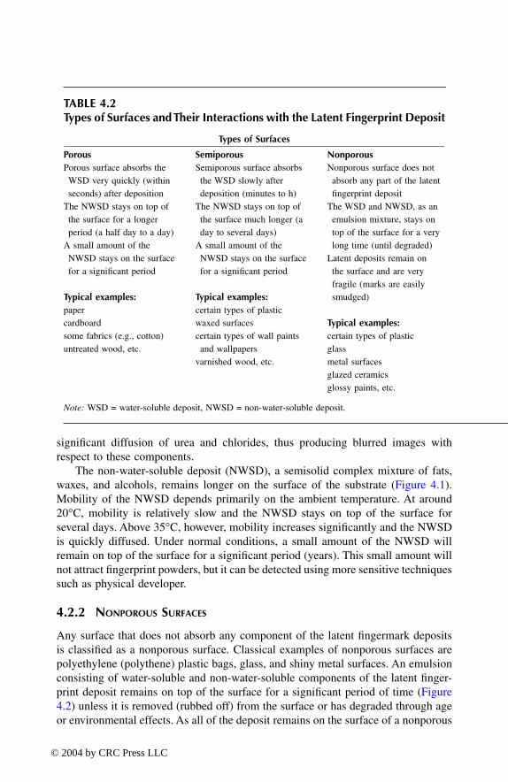
significant diffusion of urea and chlorides, thus producing blurred images withrespect to these components.
The non-water-soluble deposit (NWSD), a semisolid complex mixture of fats,waxes, and alcohols, remains longer on the surface of the substrate (Figure 4.1).Mobility of the NWSD depends primarily on the ambient temperature. At around20
°
C, mobility is relatively slow and the NWSD stays on top of the surface forseveral days. Above 35
°
C, however, mobility increases significantly and the NWSDis quickly diffused. Under normal conditions, a small amount of the NWSD willremain on top of the surface for a significant period (years). This small amount willnot attract fingerprint powders, but it can be detected using more sensitive techniquessuch as physical developer.
4.2.2 N
ONPOROUS
S
URFACES
Any surface that does not absorb any component of the latent fingermark depositsis classified as a nonporous surface. Classical examples of nonporous surfaces arepolyethylene (polythene) plastic bags, glass, and shiny metal surfaces. An emulsionconsisting of water-soluble and non-water-soluble components of the latent finger-print deposit remains on top of the surface for a significant period of time (Figure4.2) unless it is removed (rubbed off) from the surface or has degraded through ageor environmental effects. As all of the deposit remains on the surface of a nonporous
TABLE 4.2Types of Surfaces and Their Interactions with the Latent Fingerprint Deposit
Types of Surfaces
Porous Semiporous Nonporous
Porous surface absorbs the WSD very quickly (within seconds) after deposition
The NWSD stays on top of the surface for a longer period (a half day to a day)
A small amount of the NWSD stays on the surface for a significant period
Typical examples:
papercardboardsome fabrics (e.g., cotton)untreated wood, etc.
Semiporous surface absorbs the WSD slowly after deposition (minutes to h)
The NWSD stays on top of the surface much longer (a day to several days)
A small amount of the NWSD stays on the surface for a significant period
Typical examples:
certain types of plasticwaxed surfacescertain types of wall paints and wallpapers
varnished wood, etc.
Nonporous surface does not absorb any part of the latent fingerprint deposit
The WSD and NWSD, as an emulsion mixture, stays on top of the surface for a very long time (until degraded)
Latent deposits remain on the surface and are very fragile (marks are easily smudged)
Typical examples:
certain types of plasticglassmetal surfacesglazed ceramicsglossy paints, etc.
Note:
WSD = water-soluble deposit, NWSD = non-water-soluble deposit.
TF1345_C04.fm Page 109 Thursday, March 18, 2004 1:16 PM
© 2004 by CRC Press LLC

substrate, the latent marks are very fragile, and care must be taken when handlingor packaging such items. In addition, such marks are readily removed by the actionof organic solvents. While water will tend to remove any water-soluble material, thewater-insoluble component will be unaffected.
FIGURE 4.1
Aging of a latent fingermark on a porous substrate (e.g., paper).
FIGURE 4.2
Aging of a latent fingermark on a nonporous substrate (e.g., glass).
porous surface
porous surface
porous surface
Emulsion of water-soluble and water-insoluble components
(A) Cross section of latent deposit immediately after deposition
Water-insoluble component Water-soluble component
(B) Minutes/hours after deposition
(C) Weeks/months after deposition
Water-insoluble component Amino acids Urea, salt, etc.
(A) Cross section of latent deposit immediately after deposition
(B) Several weeks/months after deposition
nonporous surface
nonporous surface
TF1345_C04.fm Page 110 Thursday, March 18, 2004 1:16 PM
© 2004 by CRC Press LLC

4.2.3 S
EMIPOROUS
S
URFACES
Any surface with intermediate characteristics that does not fit well into the porousor nonporous groups is generally classified as semiporous. Typical examples of thistype of surface are some painted surfaces, polymer banknotes, and waxed wrappingpaper. The surface absorbs the water-soluble component, but more slowly than forporous surfaces. The non-water-soluble component remains on top of the surfacemuch longer than it does on a porous surface, but not as long as for a nonporoussurface.
4.3 OPTICAL DETECTION TECHNIQUES
Optical detection methods have the advantage of being nondestructive withrespect to the latent fingermark deposit. As a result, these techniques do notpreclude the later application of conventional fingerprint development proce-dures. The simple observation of an object under white light may disclose avisible fingermark that can be photographed without any further treatment. Thecontrast in marks contaminated with a colored material such as blood can besignificantly enhanced using selective absorption techniques. On the other hand,more complex optical detection methods can reveal otherwise invisible marksthat may not be developed by other techniques. A fingerprint detection sequenceshould therefore always commence with an optical examination using differentillumination techniques as dictated by the surface type and any likely fingermarkcontamination.
4.3.1 A
BSORPTION
The absorption mode can be useful for the enhancement of visible fingermarks. Ifthe fingers are contaminated with a colored material, deposited fingermarks mayhave characteristic absorption properties that can be exploited to improve contrast.For example, dry blood has a strong absorption peak at 415 nm. This characteristicabsorption can be used to optically enhance fingermarks in blood. Similarly, acolored fingermark that is the result of a particular detection technique (e.g., ninhy-drin treatment to produce a purple print) can be optically enhanced using selectiveabsorption.
When enhancing colored marks, consideration must be given not only to thecolor of the fingermark but also the color of the surface. The color wheel (Figure3.24; see Section 3.3.9) should be used to select an illumination wavelength thatwill darken the print (favor absorption) and lighten the surface (favor reflection). Asan example, a blue fingermark on a red surface can be significantly enhanced ifviewed under orange-red illumination (e.g., around 600 nm), as this color will bestrongly absorbed by the print but totally reflected by the surface. Alternatively,white light illumination can be used and the fingermark viewed through an orange-red filter. Only the light reflected by the surface will be transmitted through the filter,thus giving the impression of a light background.
TF1345_C04.fm Page 111 Thursday, March 18, 2004 1:16 PM
© 2004 by CRC Press LLC

4.3.2 L
UMINESCENCE
Lasers have, since the late 1970s, been proposed for the detection of untreatedfingermarks on nonluminescent surfaces (Dalrymple et al. 1977). Four principaltypes of lasers have been employed to detect inherently luminescent fingerprints —the argon ion, the copper vapor, the Nd:YAG, and the tunable dye laser. Accordingto Menzel (1980, 1985, 1999), positive results have been obtained on many surfaces,including metal (e.g., firearms), human skin, and polystyrene foam. It must be notedthat the high success rates originally reported for this technique could not be achievedin practice, and good results have mostly been obtained with fingermarks contami-nated by luminescent products picked up from the environment (Salares et al. 1979;Creer 1996).
Despite the relatively low success rate of the technique in actual casework, asearch for inherently luminescent fingerprints should always precede the applicationof a destructive detection method. The evidential object should be illuminated atdifferent wavelengths using a suitable high-intensity light source (not necessarily alaser) while observing through appropriately filtered goggles. A good starting pointis to use high-intensity blue light (e.g., a filtered light source operating at 450 nm)while wearing yellow/orange goggles. Such an examination must be conducted underdarkened conditions (total darkness if possible); otherwise, weakly luminescentmarks will not be detected.
4.3.3 D
IFFUSED
R
EFLECTION
Light tends to be diffusely reflected from a latent fingermark deposit. This propertycan be used for the detection of latent marks on smooth, shiny surfaces such asglass, plastic (e.g., credit cards), and polished metal. Oblique lighting on shinysurfaces can sometimes reveal latent fingermarks, fingermarks contaminated withmaterial such as dust, or fingermarks already developed by other techniques (e.g.,powdering or cyanoacrylate fuming). Under these conditions, marks will be visibleas light images against a dark background due to the light diffusely reflected fromthe fingerprint ridges.
Episcopic coaxial illumination is a specific optical setup that is particularlyeffective for this application (Pfister 1985). The technique involves the use of asemitransparent mirror to observe the reflection of light perpendicular to the surface(see Section 3.3.10), with illumination, reflection, and observation being along thesame coaxial path. The light is diffused by the fingerprint deposit but specularlyreflected by the surface, and therefore the fingermark is visible as dark ridges againsta light background. As well as detecting untreated latent marks, the technique canalso give excellent results for the enhancement of prints developed by techniquessuch as cyanoacrylate fuming and vacuum metal deposition (Lennard and Margot1988; Ziv and Springer 1993; Bullock et al. 1994).
4.3.4 U
LTRAVIOLET
I
MAGING
Japanese workers (cited by German [1987]) originally proposed the optical detec-tion of latent fingermarks by shortwave UV reflection. This technique requires
TF1345_C04.fm Page 112 Thursday, March 18, 2004 1:16 PM
© 2004 by CRC Press LLC

the use of a UV-sensitive CCD (charge-coupled device) camera (equipped witha quartz lens) and a source of UV light (West et al. 1990). The Hamamatsucompany has marketed, for several years, a complete Reflected UV ImagingSystem (RUVIS) for the detection of trace evidence, including fingerprints, foot-wear impressions, and bite marks on skin. Less expensive units have recentlybecome available, including the KrimeSite
™
Scope marketed by Sirchie
®
and the SceneScope
™
marketed by the SPEX Forensic Group. This unit has been eval-uated by Saferstein and Graf (2001), who confirmed that the detection of latentfingermarks by RUVIS was a practical and worthwhile undertaking, particularlyon smooth, nonporous surfaces.
The technique is based on the contrast between the surface, which may absorbor reflect UV light, and the fingerprint deposit that absorbs some UV radiation anddiffusely reflects the remainder. The technique may therefore give either light ridgeson a dark background or dark ridges on a light background, depending on the natureof the surface and the composition of the fingerprint deposit (Wang 1996). The typeof UV lamp employed and the angle of incidence of the UV illumination are bothcritical factors for obtaining satisfactory results.
Keith and Runion (1998) found that the routine casework application of real-time shortwave UV imaging was a valuable supplement to conventional white lightand forensic light source examinations. The authors indicated that RUVIS can beextremely helpful when working with cyanoacrylate-fumed, dye-stained surfacesthat luminesce excessively when excited with a forensic light source at wavelengthsbetween 400 and 580 nm.
The Serious Crimes Unit (SCU) in London has routinely used reflection tech-niques in both the long- and shortwave UV region on a range of surfaces (Creer1993, 1996). In addition, they have reported that the illumination of latent prints onpaper using the 266-nm radiation from a frequency-quadrupled Nd:YAG laser, withphotographic detection of their UV luminescence (emission in the long-wave UVregion of 300 to 400 nm), can produce images with good ridge detail (Bramble etal. 1993). In a laboratory evaluation, they recorded a detection rate of 69% for latentfingermarks sampled from 34 individuals. Johnson and coworkers (1991) concludedthat the aromatic amino acids tyrosine and tryptophan account for about 80% of theUV luminescence from finger sweat extracts. Fraval et al. (1996) provided someconfirmation. Creer (1993) reported that the technique is far from being of practicaluse in routine work, as approximately 2 h are needed to search for fingermarks onan A4 sheet of paper by the procedure described. In addition, almost all of thefingermarks detected by UV luminescence could be enhanced by conventional chem-ical treatment. Springer et al. (1994) have confirmed that a range of different bodyfluids, including blood, semen, and saliva, can be readily detected by shortwave UVluminescence.
The design of an illumination-imaging system for the observation of shortwaveUV luminescence, based on a portable mercury-xenon lamp and a cooled CCDcamera, has been described (Ben-Yosef et al. 1998). The system was evaluated forthe detection of latent fingermarks and various body fluid stains. Of the eccrine-richlatent marks examined in the study, only a small number (around 10%) exhibitedsignificant luminescence.
TF1345_C04.fm Page 113 Thursday, March 18, 2004 1:16 PM
© 2004 by CRC Press LLC

Some surfaces, such as white glossy paper, absorb UV light and produce a strongluminescence emission in the visible spectrum due to the presence of optical bright-eners. The illumination of such surfaces with UV light can sometimes reveal latentmarks, particularly if such marks are contaminated with UV-absorbing material.Marks of this type will be seen as dark images against a bright luminescent back-ground (Creer 1996). No special equipment other than a UV lamp is required.
4.4 DETECTION TECHNIQUES FOR POROUS SURFACES
4.4.1 N
INHYDRIN
4.4.1.1 General
Ninhydrin reacts with primary and secondary amines (including amino acids, pro-teins, and peptides) to give a dark purple product known as Ruhemann’s purple (RP)(Figure 4.3). As the eccrine component of a latent mark deposit contains aminoacids, this reaction can be exploited as a means of developing fingermarks on poroussurfaces such as paper and cardboard. The use of ninhydrin as a fingermark detectionreagent was first proposed in 1954 by Odén and von Hofsten (1954). Since then,ninhydrin has become the most popular technique for fingermark detection on poroussubstrates.
Eccrine glands secrete a range of different amino acids that may ultimately bepresent in a latent fingermark deposit (Hamilton 1965; Ramotowski 2001) (see Table4.3 and Figure 4.4). Ninhydrin is a nonspecific amino acid reagent in that it reactsin the same manner with different amino acids. In this way, each amino acid presentin the latent fingermark deposit will contribute to the developed fingermark image.Amino acids are stable compounds that, due to an affinity for cellulose, do notmigrate to any significant extent through dry paper substrates. As a result, very oldlatent marks can be developed with ninhydrin (the development of 40-year-old markshas been recorded), and the revealed marks are normally of good quality. In addition,the amino acid composition of the eccrine secretion appears to remain relativelyconstant. Due to these qualities, the use of amino acid reagents (ninhydrin andninhydrin analogs, including 1,8-diazafluoren-9-one [DFO]) constitutes an effectivechemical technique for the development of latent fingermarks on paper surfaces.
FIGURE 4.3
Chemical reaction between ninhydrin and a primary or secondary amine, result-ing in the formation of a dark purple product known as Ruhemann’s purple.
O
O
OH
OH
O
O
N
O
H2N
R
CH R'
amineninhydrin(colorless)
Ruhemann’s purple(dark purple)
–O
TF1345_C04.fm Page 114 Thursday, March 18, 2004 1:16 PM
© 2004 by CRC Press LLC

TABLE 4.3Quantities of Major Amino Acids Found in a Single Wet Thumb Print
Amino Acid
Amount (
µµµµ
mol)
Serine Ratio
Serine 0.106 100Glycine 0.071 67
Ornithine 0.034 32Alanine 0.029 27
Aspartic acid 0.023 22Threonine 0.018 17Histidine 0.018 17
Valine 0.013 12Proline 0.011 10Leucine 0.011 10Lysine 0.011 10
From: Hamilton, P.B. (1965), Amino-acids on hands,
Nature
, 205, 284–285; and from Ramo-towski, R.S. (2001), Composition of latent print residue, in
Advances in Fingerprint Technology
,2nd ed., H.C. Lee and R.E. Gaensslen, Eds., Boca Raton, FL: CRC Press, pp. 63–104.
FIGURE 4.4
Structures of the major amino acids found in a typical latent fingermark deposit.
OH
O
HO OH
NH2 NH2
NH2
NH2 NH2
CH3
CH3
NH2 NH2
H2N H2N
H3C
H3C
Serine (Ser) Glycine (Gly) Ornithine (Orn)
OH
OHHO HOOH
O
OH
HN OH
O O
OH
N
Alanine (Ala) Asparticacid (Asp)
Threonine (Thr)
Histidine (His) Valine (Val)
OO
O
O O
TF1345_C04.fm Page 115 Thursday, March 18, 2004 1:16 PM
© 2004 by CRC Press LLC

The ninhydrin reaction is much more complex than the simplified processdepicted in Figure 4.3. The mechanism for the reaction with amino acids is givenin Figure 4.5 (Grigg et al. 1986; Lennard 1986; Wilkinson 2000a). Ninhydrin reactsin its triketone form to produce an intermediate imine. Subsequent decarboxylationgives an amine that reacts with a second molecule of ninhydrin to produce Ruhe-mann’s purple. Due to this complex mechanism, reaction conditions must be tightlycontrolled if the optimum yield of Ruhemann’s purple is to be obtained. The reactionrate will depend on temperature, relative humidity, and pH (acidity). It has beenshown that an optimum reaction rate will be obtained under slightly acidic condi-tions, around pH 5 (Lamothe and McCormick 1972).
Paper items are generally treated with ninhydrin by briefly dipping in a solutionof the reagent (typical concentration 0.5% w/v in a mixture of organic solvents). Asan alternative to dipping, the reagent can be applied with a brush or spray. The itemsare then air-dried and the development allowed to proceed at room temperature over24 to 48 h. The reaction is the most efficient when the relative humidity is between
FIGURE 4.5
Mechanism for the reaction between ninhydrin and an amino acid.
O
+
Ruhemann’s purple(dark purple)
amino acid
+ ninhydrin
ninhydrin
NH2
+ H2O
+ H2O
– H2O
– CO2
H2N
– H2O
CO2HC
H
R
N CH C O
OH
RO
O
O
O
O
O
O
O –O
N CH
R
O CH
R+
N
O
O
OH
OH
O
O
O +
TF1345_C04.fm Page 116 Thursday, March 18, 2004 1:16 PM
© 2004 by CRC Press LLC

50 and 80%. Heating the items to accelerate development is generally not recom-mended as this can lead to a background coloration that is due to a reaction betweenninhydrin and the substrate itself. If rapid results are required for operational reasons,special-purpose ninhydrin development cupboards can be employed where the tem-perature and humidity are precisely controlled (80˚C with 65% relative humidity;development time approximately 5 min [Kent 1998]). While the ninhydrin techniquecan develop latent fingermarks on a wide range of porous substrates, some papersurfaces (e.g., certain types of banknote paper) react strongly with the reagent, andits use is limited in such cases.
A ninhydrin-developed fingermark is dark purple in color due to the formationof Ruhemann’s purple along the ridge impressions. The absorption spectrum ofRuhemann’s purple on paper (Figure 4.6A) shows two absorption maxima: a narrowband centered at 415 nm (violet region) and a broad, main band centered around560 nm (green–yellow region). Photography of ninhydrin-developed latent prints isbest achieved using the absorption mode. To achieve the best contrast when photo-graphing ninhydrin-developed prints, the main absorption band of Ruhemann’s pur-ple (i.e., 560 nm) should be exploited. This is achieved using white light illuminationand a green–yellow bandpass barrier filter in front of the camera (e.g., centralwavelength [CW] = 540 to 580 nm; half-bandwidth [HBW] = 40 to 50 nm; Figure4.6B). In cases where a colored background prevents good contrast from beingobtained under these conditions, it is possible to utilize the 415-nm Ruhemann’spurple absorption band (Figure 4.6). Some forensic light sources are fitted with aviolet filter (e.g., CW = 415 nm; HBW = 40 nm) that can be used for this purpose.Photography should be conducted in a darkened room with the prints illuminatedwith the violet band from the light source. No barrier filter is required on the camerain this case.
4.4.1.2 Ninhydrin Formulations
Amino acid reagents such as ninhydrin are generally made up in a solution thatcontains the reagent itself, a small amount of polar solvent (generally ethanol ormethanol) to keep the reagent in solution, acetic acid (to ensure that the reactiontakes place under slightly acidic conditions), and a carrier solvent that makes up thebulk of the solution. Other solvents may be added to increase the stability of theworking solution. Ideally, the carrier solvent should be volatile (to quickly evaporatefrom treated surfaces), nontoxic, nonflammable, nonpolar (to minimize ink runningon treated documents), and cost effective.
The solvent 1,1,2-trichlorotrifluoroethane (sold under various names such asArklone P, Fluorisol, Freon 113, CFC113, etc.) has generally been favored as theideal carrier solvent for fingerprint reagents. The first such formulation was NFN(nonflammable ninhydrin), proposed by Morris and Goode in 1994 and widely usedsince that time (Morris and Goode 1975). Unfortunately, due to its harmful effectson the Earth’s ozone layer, CFC113 is no longer manufactured, and its use is nowprohibited in most countries. This is a direct result of the 1987 Montreal Protocolthat placed restrictions on substances that deplete the ozone layer.
TF1345_C04.fm Page 117 Thursday, March 18, 2004 1:16 PM
© 2004 by CRC Press LLC

Research into replacements for CFC113 has been underway since the early1990s. Jungbluth (1992, 1993) reported good results with the solvents Genesolv2020 (a mixture of dichlorofluoroethane and dichlorotrifluoroethane) and Genesolv2000 (dichlorofluoroethane; HCFC 141b). However, both of these solvents are basedon hydrochlorofluorocarbons (HCFC) that are also in the process of being phasedout due to their ozone-depleting potential (albeit lower than that of CFC113). Anumber of authors have reported success with formulations based on hexane, hep-tane, or petroleum ether as carrier solvents (Watling and Smith 1993; Hewlett andSears 1997). The flammability of such solvents, however, means that they are not asafe alternative for most operational laboratories. Formulations based on these sol-vents should only be used if laboratory facilities are adequate (e.g., availability offume cupboards certified for flammable liquid use).
To date, the two most promising replacement solvents for CFC113 have provedto be the hydrofluoroether (HFE) 1-methoxynonafluorobutane (HFE7100) from3M, and the hydrofluorocarbon (HFC) 1,1,1,2,3,4,4,5,5,5-decafluoropentane(HFC4310mee; Vertrel XF) from Dupont (Kent 1996). These solvents have a zeroozone depletion potential (ODP) and are nonflammable (Table 4.4). Operational
FIGURE 4.6
(A) Relative absorption of spectrum of a ninhydrin-developed fingerprint onpaper; (B) Recommended bandpass filters for observation in the absorption mode.
Rel
ativ
e A
bsor
ptio
n [%
]R
elat
ive
Abs
orpt
ion
[%]
10
20
40
50
60
70
80
90
30
100
10
20
40
50
60
70
80
90
30
100(A)
(B)
380 400 420 440 460 480 500 520 540 560 580 600 620 640 660 680 700
380 400 420 440 460 480 500 520 540 560 580 600 620 640 660 680 700W a v e l e n g t h [nm]
415/40 565/40
TF1345_C04.fm Page 118 Thursday, March 18, 2004 1:16 PM
© 2004 by CRC Press LLC

TABLE 4.4Chemical Properties of CFC113 (Arklone, Fluorisol) and a Number of Alternative Carrier Solvents
CFC113 HFC4310 HFE7100 HFE71DE Heptane Cyclohexane
Other names arklone, fluorisol Vertrel XF — hydrofluoroether azeotrope
— —
Chemical name
1,1,2-trichlorotrifluoroethane
decafluoropentane methyl nonafluorobutyl ether(1-methoxynonafluorobutane)
50% methyl nonafluorobutyl ether
50% 1,2-dichloroethylene
— —
Boiling point (
°
C)48 54 61 41 98 81
Density (g/cm
3
) 1.56 1.58 1.52 1.37 0.68 0.78Flash point (
°
C)none none none none –3.9 –18.3
Exposure (8-h avg. in ppm)
600 200 750 750/200 500 300
Ozone depletion potential (ODP)
0.8 0 0 0 0 0
TF1345_C
04.fm Page 119 T
hursday, March 18, 2004 1:16 PM
© 2004 by CRC Press LLC

trials have indicated that ninhydrin formulations based on either of these twocarrier solvents perform at least as well as, if not better than, CFC113-basedformulations (Hewlett et al. 1997; Hewlett and Sears 1999; Petruncio 2000; Rajtar2000). While HFE7100 and HFC4310mee are the currently recommended carriersolvents, their high cost (around U.S.$1000 per 20-l drum) may be problematicfor some laboratories.
4.4.1.3 Secondary Metal Salt Treatment
Fingermarks developed with ninhydrin can be further enhanced by treatment witha zinc (Zn) or cadmium (Cd) metal salt solution. This treatment results in a colorchange, orange for zinc and red for cadmium, that is due to the formation of a 1:1coordination complex between the Ruhemann’s purple (the product from the ninhy-drin reaction) and the metal salt (Lennard 1986; Lennard et al. 1987) (Figure 4.7).These complexes show stronger absorption properties than Ruhemann’s purple itself,and this may be useful in the absorption mode when the background color leads topoor contrast after initial ninhydrin development.
Absorption spectra for the RP-Zn and RP-Cd complexes are shown in Figure4.8A. Post-treatment with zinc nitrate changes the purple color of ninhydrin-devel-oped prints to orange, with the maximum absorption shifted to around 490 nm.Enhancement photography of zinc post-treated prints can therefore be achieved inthe absorption mode with a 490-nm bandpass barrier filter in front of the camera(or using illumination from a forensic light source operating at this wavelength)(Figure 4.8B). Post-treatment with cadmium nitrate changes the purple color ofninhydrin-developed prints to red, with the maximum absorption shifted to around505 nm. Enhancement photography of cadmium post-treated prints can therefore beachieved in the absorption mode with a 505-nm bandpass barrier filter in front ofthe camera (or using equivalent illumination from a forensic light source) (Figure4.8C).
FIGURE 4.7
Treatment of Ruhemann’s purple with certain metal salts results in the formationof a coordination complex. (From Lennard, C.J., Margot, P.A., Sterns, M., and Warrener, R.N.[1987], Photoluminescent enhancement of ninhydrin developed fingerprints by metal com-plexations: structural studies of complexes formed between Ruhemann’s purple and GroupIIb metal salts,
J. Forensic Sci.
, 32, 597–605. With permission.)
O O
M = Zn, Cd, MgX = Cl, I, NO3
H2O
H2O
OH2
MX2
–OO
O
O
N
O
O
M
N
TF1345_C04.fm Page 120 Thursday, March 18, 2004 1:16 PM
© 2004 by CRC Press LLC

Of more significance than the color change is the luminescence that is producedby zinc or cadmium post-treatment. The luminescence emission, which is very weakunder normal conditions, is significantly enhanced at low temperature. This can beconveniently achieved by cooling the prints with liquid nitrogen (–196
°
C; 77 K).
FIGURE 4.8
(A) Relative absorption spectra of Ruhemann’s purple and its complexes withzinc and cadmium; (B) Recommended bandpass filter for observation in the absorption modein the case of the zinc complex; (C) Recommended bandpass filter for observation in theabsorption mode in the case of the cadmium complex.
10
20
40
50
6070
80
90
30
100
380 400 420 440 460 480 500 520 540 560 580 600 620 640 660 680 700
490/40
12
Rel
ativ
e A
bsor
ptio
n [%
]
2. Ruhemann's purple + ZnCl1. Ruhemann's purple
2
(B)
380 400 420 440 460 480 500 520 540 560 580 600 620 640 660 680 700
Rel
ativ
e A
bsor
ptio
n [%
]
3 1. Ruhemann's purple
3. Ruhemann's purple + CdNO 3
2. Ruhemann's purple + ZnCl2
(A)
1
2
10
20
40
50
6070
80
90
30
100
380 400 420 440 460 480 500 520 540 560 580 600 620 640 660 680 700
Rel
ativ
e A
bsor
ptio
n [%
]
2
2. Ruhemann's purple + CdNO 3
1. Ruhemann's purple
(C)W a v e l e n g t h [nm]
10
20
40
50
6070
80
90
30
100
1
505/40
TF1345_C04.fm Page 121 Thursday, March 18, 2004 1:16 PM
© 2004 by CRC Press LLC

Typical luminescence spectra for a ninhydrin-developed fingerprint post-treated withzinc nitrate are shown in Figure 4.9A. Typical luminescence spectra for a ninhydrin-developed fingerprint post-treated with cadmium nitrate are shown in Figure 4.10.Considerable enhancement of ninhydrin-developed fingerprints can be obtained byexploiting the luminescence properties of these complexes (Herod and Menzel 1982;Kobus et al. 1983; Stoilovic et al. 1986).
If the relative humidity is low (<50%), exposure to the breath or to steam maybe necessary to complete the reaction, particularly in the case of cadmium treatment.(As shown in Figure 4.7, water is a necessary component for the formation of thecoordination complex.) Early research indicated that treatment with a cadmium saltis preferred, since the complex formed is more stable than the corresponding zinccomplex, and the final result is less dependent on the conditions used for the
FIGURE 4.9
(A) Luminescence spectra recorded at liquid nitrogen temperature for a ninhy-drin developed print post-treated with zinc nitrate; (B) Recommended filters for excitation(*) and observation (#) in the luminescence mode.
10
20
30
40
50
60
70
80
90
100
Rel
ativ
e I
nten
sity
[%
]
Excitationspectrum
Emissionspectrum
360 380 400 420 440 460 480 500 520 540 560 580 600 620 640 660 680 700
10
20
30
40
50
60
70
80
90
100
Rel
ativ
e I
nten
sity
[%
]
Emissionspectrum
490/40*
360 380 400 420 440 460 480 500 520 540 560 580 600 620 640 660 680 700W a v e l e n g t h [nm]
Long pass filterKV550#
560/40#
(A)
(B)
Excitationspectrum
TF1345_C04.fm Page 122 Thursday, March 18, 2004 1:16 PM
© 2004 by CRC Press LLC

ninhydrin development (Stoilovic et al. 1986). However, the high toxicity of cad-mium salts must be taken into consideration. Zinc treatment can sometimes lead tothe formation of a red complex, particularly if strong ninhydrin development hasoccurred and/or moisture levels are too high. It has been established that the redcomplex is in fact a 2:1 RP-Zn complex that can be formed under certain reactionconditions (Davies et al. 1995). The formation of a red complex in treated prints onpaper has been associated with reduced luminescence yield and hence poor finger-print enhancement (Kobus et al. 1983; Liberti et al. 1995).
After metal salt treatment, the sample is inspected under a forensic light sourceoperating at a suitable wavelength. To favor the luminescence, the sample is cooledto liquid nitrogen temperature (–196
°
C), which is achieved by placing the samplein an insulated container (such as a polystyrene foam tray) and covering it with athin layer of liquid nitrogen (Figure 4.11). The complex formed with zinc(II) has a
FIGURE 4.10
(A) Luminescence spectra recorded at liquid nitrogen temperature for a nin-hydrin developed print post-treated with cadmium nitrate; (B) Recommended filters forexcitation (*) and observation (#) in the luminescence mode.
1020304050
60708090
100
Excitationspectrum
Emissionspectrum
360 380 400 420 440 460 480 500 520 540 560 580 600 620 640 660 680 700
Rel
ativ
e I
nten
sity
[%
]
(A)
1020304050
60708090
100
505/40* 590/40#
Excitationspectrum
Emissionspectrum
360 380 400 420 440 460 480 500 520 540 560 580 600 620 640 660 680 700W a v e l e n g t h [nm]
Rel
ativ
e I
nten
sity
[%
]
(B)
TF1345_C04.fm Page 123 Thursday, March 18, 2004 1:16 PM
© 2004 by CRC Press LLC

maximum absorption in the blue–green (
λ
= 490 nm), while the complex formedwith cadmium(II) absorbs in the green (
λ
= 505 nm). The luminescence emissionoccurs in the green–yellow for the first complex (
λ
= 550 nm) and in the orange forthe second (
λ
= 590 nm). Filters that transmit these wavelengths are placed in frontof the camera (or the eye) to record the resulting luminescence. Best results areobtained using high-quality interference filters with a half bandwidth of approxi-mately 40 nm. The fingerprint luminescence is often weak, and therefore photo-graphic recording generally requires long exposure times (from a few seconds toseveral minutes).
Menzel and Mitchell (1990) investigated the complex formed between Ruhe-mann’s purple and europium chloride. The organo–rare earth complex that results(EuRP
2
, orange in color) exhibits europium(III) luminescence at 615 nm with alifetime of 0.4 msec. This emission, excited in the long-wave UV region (330 to360 nm), has a lifetime that is much longer than that of the usual backgroundluminescence. Terbium-Ruhemann’s purple complexes, studied by Mekkaoui Alaouiand Renzel (1994), are best excited in the range 310 to 330 nm and have an emissionmaximum at 545 nm with an emission lifetime of 1.3 msec. These properties makelanthanide complexes suitable for time-resolved luminescence imaging, which canresult in the extraction of useful fingerprint detail even on highly luminescentsurfaces (Mekkaoui Alaoui and Renzel 1993; Murdock and Menzel 1993). Withcurrent technology, however, time-resolved imaging remains an expensive and rel-atively complicated procedure that has not found routine application.
4.4.2 N
INHYDRIN
A
NALOGS
Ninhydrin analogs are amino acid–specific reagents that are structurally similar toninhydrin itself, but where different functional groups have been introduced with
FIGURE 4.11
General luminescence mode set-up for the recording of ninhydrin developedprints post-treated with a metal salt (zinc or cadmium).
Blue-greenlight
Glass cover
Barrierfilter
Reflection
Luminescenceemission
Hot air
Developedfingerprints
Exhibit
FLS
Styrofoam tray
TF1345_C04.fm Page 124 Thursday, March 18, 2004 1:16 PM
© 2004 by CRC Press LLC

the purpose of improving fingermark detection capabilities. The requirements for anideal replacement for ninhydrin are good initial color, superior luminescence prop-erties (preferably without the need for metal salt treatment or cooling with liquidnitrogen), low cost, good solubility in a range of solvents (preferably nonpolar), andlow toxicity (Ramotowski et al. 1997). Excellent reviews on the synthesis andapplications of ninhydrin and its analogs have been published by Joullié et al. (1991)and Almog (2001).
Almog and colleagues, in Israel in the early 1980s, were the first to explorethe potential of ninhydrin analogs and thereby inspire other research groupsaround the world (Almog et al. 1982). Some of the more promising compoundsthat were synthesized at that time included benzo[f]ninhydrin (Almog et al. 1982)and 5-methoxyninhydrin (Lennard et al. 1986, 1988) (Figure 4.12). Thesereagents develop latent fingermarks on paper with a sensitivity similar to that ofninhydrin but, after metal salt treatment, offer considerably stronger lumines-cence emission, even at ambient temperature. This is particularly an advantageon surfaces that are luminescent at liquid nitrogen temperature (such as manilapaper and yellow envelopes). The different spectral characteristics of marksdeveloped with these compounds also permit better selectivity on certain surfaceswhere there is an interference with ninhydrin (Table 4.5). For example, the red-shifted absorption and emission from benzo[f]ninhydrin-developed marks can beparticularly useful on cardboard and yellow paper, as these surfaces are highlyluminescent at the same wavelengths as the RP-zinc(II) and RP-cadmium(II)complexes. Both benzo[f]ninhydrin and 5-methoxyninhydrin are now commer-cially available, but they are expensive alternatives to ninhydrin itself (Table 4.5).Almog and coworkers (2000) concluded that, due to high cost and low solubility,the advantages displayed by benzo[f]ninhydrin were insufficient to justify routineuse.
More recently, the synthesis of a number of amino-substituted ninhydrin analogshas been reported (Almog et al. 1991). Of these, the compound 5-aminoninhydrin(Figure 4.13) showed some promise as a fingerprint reagent, producing strong roomtemperature luminescence in developed marks, even without secondary metal salttreatment. However, Pounds and Allman (1992) found that the reagent produced ahighly luminescent background that tended to obscure developed marks. Sulfur-containing groups at position 5 were subsequently investigated and were found to
FIGURE 4.12 Chemical structures for (A) ninhydrin and the ninhydrin analogs,(B) benzoninhydrin, and (C) 5-methoxyninhydrin.
(A) (B) (C)O
O
OH
OH
O
O
OH
OH
O
O
OH
OH
CH3O
TF1345_C04.fm Page 125 Thursday, March 18, 2004 1:16 PM
© 2004 by CRC Press LLC

exhibit excellent properties as fluorogenic reagents for fingermark detection on paper(Almog et al. 1992). Preliminary experiments indicated that 5-methylthioninhydrin(Figure 4.13B) showed a sensitivity that markedly exceeded that of ninhydrin andeven that of 5-methoxyninhydrin.
A number of analogs composed of extended aromatic rings, bi-ninhydrins, andsulfur-containing compounds were synthesized by Joullié’s group at the Universityof Pennsylvania (Cantu 1993). The sulfur-containing analogs 5-methylthioninhydrin,thieno[f]ninhydrin, and 5-(2-thienyl)-ninhydrin (Figure 4.13B, C, and D) were foundto be very sensitive reagents for latent fingerprint detection, particularly after metalsalt treatment. It was suggested that these analogs were at least as sensitive as DFO(and in some cases more sensitive) for the detection of fingerprints on paper. Similarresults were independently reported (Pounds and Allman 1992). However, Hark andcoworkers (1996) indicated that the estimated cost of manufacturing analogs suchas 5-(2-thienyl)-ninhydrin would likely limit their widespread distribution and use.
TABLE 4.5Spectroscopic Data from Developed Marks and Approximate Costs for the Reagents Ninhydrin, Benzoninhydrin, and 5-Methoxyninhydrin
Ninhydrin Benzoninhydrin 5-MethoxyninhydrinApproximate cost (U.S.$ per gram)
<$1 $500 $250
Zinc complex:ExcitationEmission
490 nm550 nm
530 nm590 nm
505 nm540 nm
Cadmium complex:ExcitationEmission
505 nm590 nm
550 nm635 nm
520 nm585 nm
FIGURE 4.13 Chemical structures for the ninhydrin analogs (A) 5-aminoninhydrin, (B) 5-methylthioninhydrin, (C) thieno[f]ninhydrin, and (D) 5-(2-thienyl)-ninhydrin.
O
O
OH
OH
O
O
OH
OH
O
O
OH
OHS
O
O
OH
OH
S
(A) (B)
(C) (D)
H2N CH3S
TF1345_C04.fm Page 126 Thursday, March 18, 2004 1:16 PM
© 2004 by CRC Press LLC

Cantu and coworkers (1993) compared ten amino acid reagents (ninhydrin, eightninhydrin analogs, and DFO) in their ability to visualize spots of the amino acidglycine on paper. The evaluation considered parameters such as color development,luminescence, luminescence after zinc(II) treatment, and background interference.The role of acetic acid in the reagent formulations was also evaluated. Of the reagentstested, the analog thieno[f]ninhydrin was found to be the most sensitive visualizingreagent when zinc(II) treatment was employed. The study also confirmed that Ruhe-mann’s purple combines with zinc(II) in a 1:1 ratio under normal circumstances.
Nitrophenylninhydrin, benzo[f]furoninhydrin, and six ninhydrin analogs con-taining oxygen, sulfur, and selenium substituents at position 5 were evaluated asfingerprint development reagents by Kobus and coworkers (2002). The analogs allshowed good color development, but this was not superior to that obtained withninhydrin itself. The reaction product obtained with benzo[f]furoninhydrin showedstrong room temperature luminescence following zinc complexation. Of the com-pounds evaluated by this group, the benzo[f]furo analog (Figure 4.14) showed thegreatest potential as a fingerprint reagent, with results comparing favorably withthose obtained with DFO.
In 1997, Ramotowski and colleagues from the U.S. Secret Service and theUniversity of Pennsylvania introduced 1,2-indanediones as a new class of aminoacid visualizing compounds (Ramotowski et al. 1997; Hauze et al. 1998). Severalsubstituted 1,2-indanediones as well as the unsubstituted 1,2-indanedione parentcompound (Figure 4.15) were evaluated for their ability to detect glycine spots ofvarying concentration on paper. Results were compared with those obtained usingDFO. Most of the 1,2-indanediones evaluated produced a light pink initial color as
FIGURE 4.14 Structure of benzo[f]furoninhydrin.
FIGURE 4.15 Chemical structures for (A) ninhydrin in its anhydrous form, (B) 1,2-indanedi-one, and (C) 5,6-dimethoxy-1,2-indanedione.
O
OH
OHO
O
O
O
O
O
O
O
O
(A) (B) (C)
CH3O
CH3O
TF1345_C04.fm Page 127 Thursday, March 18, 2004 1:16 PM
© 2004 by CRC Press LLC

well as a strongly luminescent reaction product (at room temperature), in some caseswithout secondary metal salt treatment. The most effective compound appeared tobe the 5,6-dimethoxy derivative (Figure 4.15C). The luminescence produced by thiscompound (without zinc salt treatment) was comparable to DFO, while the zinc-treated sample showed a significant advantage over DFO luminescence.
Almog and coworkers (1999) synthesized and evaluated unsubstituted 1,2-indanedione and a number of mono- and dimethoxy- derivatives as fluorogenicreagents for fingerprint detection on paper. The authors found that 1,2-indanedione,with its ease of preparation, good solubility in nonpolar solvents, and high sensitivityrelative to DFO, made it a good candidate for use as a routine fingerprint reagent.An independent evaluation reported by Roux and colleagues (2000) confirmed thisview. More recently, Wiesner and colleagues (2001) treated a large number of actualexhibits (used bank checks) and found that 1,2-indanedione developed 46% moreidentifiable prints than the sequence DFO–ninhydrin. It was found that acetic acidin the formulation did not improve the results and, in fact, had a detrimental effecton print clarity. Optimal development conditions were found to be 100°C for 20min with 60% relative humidity. Indanedione is now commercially available, and ithas been adopted for operational use by the Division of Identification and ForensicScience (DIFS), Israel Police. The Florida Department of Law Enforcement has alsovalidated the technique for routine use (Kasper et al. 2002).
Wilkinson (2000a) conducted spectroscopic studies on 1,2-indanedione usingnuclear magnetic resonance (NMR) spectroscopy and mass spectrometry (MS).These studies indicated that when 1,2-indanedione is dissolved in methanol, a stablehemiketal is formed similar to that proposed for DFO when it is dissolved inmethanol. In contrast to DFO, where reactivity to amino acids appears to be enhancedby hemiketal formation, the reactivity of 1,2-indanedione toward amino acids isdiminished. Alcohols, particularly methanol, should therefore be avoided when for-mulating 1,2-indanedione as a fingerprint reagent (Wilkinson 2000a; Wiesner et al.2001).
4.4.3 DIAZAFLUORENONE (DFO)
The compound 1,8-diazafluoren-9-one (DFO) (Figure 4.16) is an amino acid–sen-sitive reagent that gives a reaction product that is pale purple in color (lighter thanthe color obtained with ninhydrin). The advantage of the reagent is that, withoutany secondary treatment, developed marks show a strong room temperature lumi-nescence (Pounds et al. 1990). Heat is required for the reaction to proceed, butresults are obtained within a very short period of time (less than 30 min). Thechemical reaction involved is believed to be similar to the reaction between ninhydrinand the amino acids present in the fingerprint deposit. Grigg and coworkers (1990)trapped and characterized a number of reaction intermediates and were able to detaila possible reaction scheme (Figure 4.16). The final reaction product proposed bythis group has since been identified by x-ray crystallography (Wilkinson 2000b).
The development process is simple and rapid: the document is dipped in asolution of DFO, dried, and then heated at 100˚C for 20 min. As an alternative,Stoilovic (1993) has shown that 20 to 30 sec at 160˚C or 10 sec at 180˚C (e.g., using
TF1345_C04.fm Page 128 Thursday, March 18, 2004 1:16 PM
© 2004 by CRC Press LLC

an ironing press) produces superior development (at least twice the fingerprintluminescence with less background development). The color of DFO-developedlatent fingerprints is faint, and only strong latent fingerprints will develop a goodcolor sufficient for photography in the absorption mode. The absorption maximumis around 560 nm. Detection of DFO-treated prints is much more sensitive in theluminescence mode. Weak prints can often be further enhanced by repeating theDFO process (i.e., re-treatment with DFO solution and reheating).
DFO-developed latent marks produce excellent photoluminescence without anypost-treatment or cooling. The excitation spectrum is very broad and covers theregion from 430 to 580 nm, with maxima at 460, 530, and 560 nm (Figure 4.17A).The best luminescence can be produced by excitation between 540 and 570 nm (i.e.,the main excitation region). If excitation at the main maximum produces a highlyluminescent background, one of the other two excitation bands (530 nm or 460 nm)can also be used for excitation. The emission band is quite broad and covers theregion between 560 and 620 nm (Figure 4.17). It must be noted that the luminescenceis at its maximum immediately after the heating process and then decreases slightlywith time due to the absorption of ambient humidity. The luminescence can berestored to its original intensity by reheating the prints. Secondary metal salt treat-ment has only a minimal effect on the luminescence of DFO-treated prints, althoughit has been shown that metal complexes are formed (Conn et al. 2001).
Operational trials on casework material have shown that DFO reveals approxi-mately two to three times more latent fingermarks than ninhydrin (McComiskey1990; Pounds and Allman 1991). However, a high-powered light source with appro-priate filtration is required for the visualization of developed marks. If such a lightsource is not available, the advantages of using DFO over ninhydrin may be lost,as weak fingerprints will not be detected (Hardwick et al. 1993). Fingermarksdeveloped with DFO can be further treated with ninhydrin.
Hardwick and coworkers (1993) modified the original DFO formulation (Poundset al. 1990) to obtain a solution that is easier to produce and stable for severalmonths. Their suggested formulation, however, is based on the ozone-depletingsolvent CFC113. Masters and coworkers (1991) proposed the use of a petroleumether/xylene formulation. Didierjean and colleagues (1998) evaluated a DFO for-mulation based on HFE7100 as the carrier solvent to replace CFC113. Their
FIGURE 4.16 Suggested reaction between DFO and an amino acid to produce a luminescentproduct. (Wilkinson, D. [2000b], Study of the reaction mechanism of 1,8-diazafluoren-9-onewith the amino acid l-alanine, Forensic Sci. Int., 109, 87–103. With permission.)
NN
O N
N
N
N
H
DFO reaction product
amino acid
DFO
N
+
-
TF1345_C04.fm Page 129 Thursday, March 18, 2004 1:16 PM
© 2004 by CRC Press LLC

proposed formulation is reported to be stable at room temperature for several weeksafter preparation, with fingermark detection results at least as good as those obtainedusing a CFC113-based solution. A similar formulation has been proposed by thePolice Scientific Research Branch (Kent 1998). Wilkinson (2000b) confirmed that
FIGURE 4.17 (A) Luminescence spectra for a DFO developed fingerprint on paper; (B, C)Recommended filters for excitation (*) and observation (#) in the luminescence.
440 460 480 500 520 540 560 580 600 620 640 660420 700(A)
(B)
W a v e l e n g t h [nm](C)
Rel
ativ
e In
tens
ity [
%]
Excitationspectrum
Emissionspectrum
20
40
60
80
100
Rel
ativ
e In
tens
ity [
%]
555/30*
Excitationspectrum Emission
spectrum
600/40#
440 460 480 500 520 540 560 580 600 620 640 660420 700
Long pass filterOG590#
20
40
60
80
100
Rel
ativ
e In
tens
ity [
%]
530/40*
Excitationspectrum Emission
spectrum
590/40#
440 460 480 500 520 540 560 580 600 620 640 660420 700
Long pass filterOG570#
20
40
60
80
100
TF1345_C04.fm Page 130 Thursday, March 18, 2004 1:16 PM
© 2004 by CRC Press LLC

methanol is an important component of the DFO formulation, as this appears toresult in the formation of an unstable hemiketal that is the reactive species.
Bratton and Juhala (1995) reported the application of DFO in the dry state forthe development of latent marks on papers. The technique does not use any petroleumether, heptane, or Freon in the working solution. The technique involves the appli-cation of DFO from DFO-soaked filter papers and processing with a steam ironfilled with a 5% acetic acid solution before heating in a mounting press at 100°Cfor 10 min. The authors reported that the “DFO-dry” procedure provides the sameluminescence intensity as conventionally applied DFO, without ink running, damageto documents, or background-induced luminescence due to the DFO solution.
4.4.4 PHYSICAL DEVELOPER (PD)
Physical developer (PD) is a fingermark processing technique for porous surfacesthat was developed in the 1970s by the Atomic Weapons Research Establishment(AWRE) under contract to the Police Scientific Development Branch (PSDB), U.K.(Hardwick 1981; Goode and Morris 1983). The technique is sensitive to water-insoluble components of the latent fingerprint deposit, and therefore PD can beeffective even if the surface has been wet. Fingermarks developed by this procedureare visible as dark gray to black images due to the deposition of silver metal alongthe print ridges.
PD, based on a photographic physical developer, is an aqueous solution con-taining silver ions, a ferrous/ferric redox (reduction/oxidation) system, a buffer (citricacid), and a cationic surfactant (generally n-dodecylamine acetate). The ferrous(Fe2+) ions in solution reduce the silver (Ag+) ions to silver metal (Ag0), with ferric(Fe3+) ions being present to hold back the reaction (Figure 4.18). Citric acid isrequired to complex with the ferric ions and to maintain a low pH. The action ofthe surfactant is to inhibit the premature deposition of silver metal by trappingrandomly generated silver particles, as they are formed, within positively chargedspheres of surfactant molecules known as micelles (Figure 4.19). The micelles repelthe positive silver ions in solution, thereby blocking further silver formation (Jonkeret al. 1969; Cantu 2001; Cantu and Johnson 2001). The PD solution is therefore adelicate balance of ferrous, ferric, and silver ions stabilized by the presence of citricacid and a surfactant.
When a document is placed in the PD reagent, silver slowly deposits fromsolution. This deposition generally is heavier on areas of surface contamination suchas fingerprint residue. Developed marks generally appear as dark gray images againsta light gray background. A conclusive explanation as to why the stabilized PDreagent can selectively develop latent marks on paper has yet to be found, althoughseveral theories have been expressed (Cantu 2001; Cantu and Johnson 2001).
FIGURE 4.18 The redox (reduction/oxidation) reaction that is the chemical basis of thephysical developer (PD) process.
+Fe2+(aq)
Fe3+(aq)(aq)
Ag+(s)
Ag0+
TF1345_C04.fm Page 131 Thursday, March 18, 2004 1:16 PM
© 2004 by CRC Press LLC

Development time can be anywhere from 10 to 60 min, and items must be removedfrom the solution when good contrast is obtained, as overdevelopment cannot bereversed. Some paper substrates that have alkaline binders and fillers react stronglywith PD. An acid prewash, typically using a solution of maleic acid, can be used toneutralize alkaline papers and thus improve the PD development of marks (Ramo-towski 1996b, 2000; Cantu 2001; Cantu and Johnson 2001).
Contrary to ninhydrin and DFO, the PD reagent is sensitive to components inthe latent mark that are not soluble in water (i.e., sebaceous secretions or water-soluble materials trapped within a water-insoluble emulsion). On wet paper or paperthat has been wet, PD is one of the only techniques that can permit the satisfactorydevelopment of latent fingermarks. The reagent can also be used as a treatment afterDFO or ninhydrin if these techniques fail to reveal useful marks on paper surfacesthat have not been wet. PD is complementary to amino acid reagents, and it cantherefore reveal ridge detail not detected by more conventional techniques.
PD-developed marks can, in some cases, be further enhanced by re-treatmentwith the PD reagent and/or treatment with a sodium hypochlorite solution (dilutehousehold bleach). Treatment with bleach solution lightens the background and
FIGURE 4.19 In the PD reagent, cationic surfactant molecules form positively chargedmicelles, each encapsulating a negatively charged silver colloid (silver colloid surrounded bynegatively charged citrate ions). These positively charged micelles stabilize the reagent byrepelling nearby silver ions and other micelles. (From: Cantu, A.A. [2001], Silver physicaldevelopers for the visualization of latent prints on paper, Forensic Sci. Rev., 13, 29–64; andfrom Cantu, A.A. and Johnson, J.L. [2001], Silver physical development of latent prints, inAdvances in Fingerprint Technology, 2nd ed., H.C. Lee and R.E. Gaensslen, Eds., BocaRaton, FL: CRC Press, pp. 242–247. With permission.)
-
-
---
-- -
--
--
- --
-++
+
+
+
++
+
+
+
+
+
+
+
+
+
Ag
TF1345_C04.fm Page 132 Thursday, March 18, 2004 1:16 PM
© 2004 by CRC Press LLC

darkens the print due to the formation of silver oxide (Phillips et al. 1990; Cantu2001; Cantu and Johnson 2001). This can be particularly effective for improvingcontrast on dark surfaces such as brown paper. The application of radioactive 35Stoning has also been explored for the elimination of complex background patternssuch as those encountered on paper banknotes (Goode and Morris 1983). Thisprocess involves the conversion of the silver metal deposited by the PD reagent intoradioactive silver sulfide. Autoradiography is then used to image the radioactivemarks. While this toning process can be particularly effective, its use is restrictedto specialized laboratories that are authorized to handle radioactive materials. Ascanning electron microscope (SEM) can also be used to improve the contrast inPD-developed marks using the backscatter electron image mode (Nolan et al. 1984).This method is, however, limited to small samples that can be placed in the SEMsample chamber.
The PD technique presents some major inconveniences: it is delicate and time-consuming to prepare (good-quality reagents and clean glassware must beemployed); it is relatively expensive; the working solution has a short shelf life(generally less than 2 weeks); and the process is destructive (documents are perma-nently stained and no further fingermark treatment is possible). Despite these res-ervations, PD is a sensitive technique that can give results where other techniquesfail. Research is currently under way within the U.S. Secret Service to develop acopper-based physical developer (to reduce overall reagent costs) and to render PD-developed marks luminescent (Ramotowski and Cantu 2001).
4.4.5 MULTIMETAL DEPOSITION (MMD)
Multimetal deposition (MMD), developed by Saunders (1989), involves a two-stepprocess, the first being immersion of the item in a colloidal gold solution (pHapproximately 2.7). Colloidal gold, consisting of negatively charged gold particlesdue to the adsorption of citrate ions, is prepared by treating a solution of tetrachlo-roauric acid (gold chloride) with sodium citrate and a detergent. The negativelycharged colloidal gold particles are attracted to organic residues that contain positivegroups at low pH. (The use of colloidal gold is an established technique in biochem-istry for the detection of proteins and peptides.) Gold subsequently deposits on anyfingerprint residue on the item being treated. Weak marks will be barely visible atthis stage, while stronger marks may be pale salmon pink in color. The second stepinvolves the treatment of fingermarks developed by the colloidal gold process witha modified physical developer (MPD) solution. The bound colloidal gold providesnucleation sites around which silver precipitates from the MPD solution. This stepgreatly amplifies the visibility of treated marks that, after this second treatment, canvary in color from light gray to almost black.
Many types of surfaces — porous or nonporous, wet or dry — can be treatedby this technique (e.g., wet and dry paper, plastic, glass, expanded polystyrene, andboth sides of adhesive tape). Fingermarks in blood can also be enhanced by thetreatment. Allman and coworkers (1992) found that MMD showed promise in devel-oping marks on nonporous substrates that in the past have proved difficult (forexample, masking tape, beer bottle labels, and plastic gloves).
TF1345_C04.fm Page 133 Thursday, March 18, 2004 1:16 PM
© 2004 by CRC Press LLC

The MMD process has been further optimized by Schnetz and Margot to improveits sensitivity and specificity (Schnetz 1999; Schnetz and Margot 2001). Theoptimized process, known as MMDII, recommends the use of silanized glassware(see Appendix 4, Section A4.12.2.1) and 14-nm colloidal gold particles (the originalformulation resulted in 30-nm particles). In addition, a physical developer based onsilver acetate and hydroquinone is preferred over the original formulation based onsilver nitrate and a ferrous/ferric redox system. Jones (2002) confirmed that MMDIIproduces superior fingermark detail compared with the original MMD formulationand found that it was particularly effective on a number of semiporous surfaces(latex and nitrile gloves, expanded polystyrene, and waxed paper).
MMD (and MMDII) may prove useful on surfaces where more conventionaltechniques are ineffective. However, MMD suffers from some of the disadvantagesof conventional PD: the reagent is delicate and time-consuming to prepare and apply,the chemicals required are expensive, and the process can only be used at the endof a detection sequence.
4.4.6 RECOMMENDED DETECTION SEQUENCE
The recommended sequence of techniques for fingermark detection and enhance-ment on porous surfaces is given in Figure 4.20. This and the other detectionsequences in this book should be considered as only a general guide that willgive satisfactory results in 70 to 80% of cases. Different situations and surfaceswill necessitate the consideration of modified sequences or the application ofother techniques.
All detection sequences should start with an optical detection step that involvesan examination of the surface under different lighting conditions. For example, whitelight examination may reveal visible fingermarks, while an examination in theluminescence mode may reveal inherently luminescent marks that might go unde-tected by other techniques. Potentially identifiable marks detected at any point in asequence of examinations should be recorded photographically before proceedingwith the next treatment.
If the porous surface (paper, cardboard, etc.) is or has been wet, then the water-soluble component of the latent print deposit will no longer be available for finger-mark detection. For example, the amino acids will have been washed away ordiffused, hence the application of an amino acid reagent such as DFO or ninhydrinwould serve no purpose. In this case, the preferred treatment is with physicaldeveloper (PD). While multimetal deposition (MMD) could be used instead of PD,comparative studies have indicated that more consistent results are generallyobtained with conventional physical developer. However, if a particular paper surfaceis found to be unsuitable for PD treatment, then MMD should be evaluated as apotential alternative.
DFO is generally considered to be the best routine technique for the lumines-cence detection of latent marks on paper surfaces. Conventional ninhydrin process-ing, or application of a ninhydrin analog, can follow the DFO treatment. In somecases, particularly on paper surfaces that exhibit a high background luminescence,DFO treatment is ineffective, and better results may be obtained with ninhydrin.
TF1345_C04.fm Page 134 Thursday, March 18, 2004 1:16 PM
© 2004 by CRC Press LLC
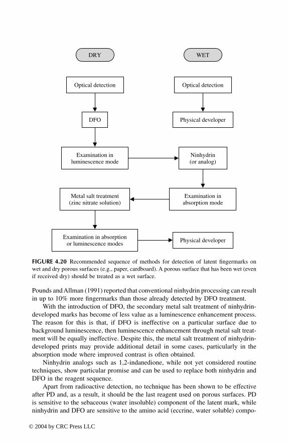
Pounds and Allman (1991) reported that conventional ninhydrin processing can resultin up to 10% more fingermarks than those already detected by DFO treatment.
With the introduction of DFO, the secondary metal salt treatment of ninhydrin-developed marks has become of less value as a luminescence enhancement process.The reason for this is that, if DFO is ineffective on a particular surface due tobackground luminescence, then luminescence enhancement through metal salt treat-ment will be equally ineffective. Despite this, the metal salt treatment of ninhydrin-developed prints may provide additional detail in some cases, particularly in theabsorption mode where improved contrast is often obtained.
Ninhydrin analogs such as 1,2-indanedione, while not yet considered routinetechniques, show particular promise and can be used to replace both ninhydrin andDFO in the reagent sequence.
Apart from radioactive detection, no technique has been shown to be effectiveafter PD and, as a result, it should be the last reagent used on porous surfaces. PDis sensitive to the sebaceous (water insoluble) component of the latent mark, whileninhydrin and DFO are sensitive to the amino acid (eccrine, water soluble) compo-
FIGURE 4.20 Recommended sequence of methods for detection of latent fingermarks onwet and dry porous surfaces (e.g., paper, cardboard). A porous surface that has been wet (evenif received dry) should be treated as a wet surface.
DRY WET
Optical detection
DFO Physical developer
Optical detection
Examination inluminescence mode
Ninhydrin(or analog)
Metal salt treatment(zinc nitrate solution)
Examination inabsorption mode
Examination in absorptionor luminescence modes Physical developer
TF1345_C04.fm Page 135 Thursday, March 18, 2004 1:16 PM
© 2004 by CRC Press LLC

nent. Since the proportions of these two components in the latent mark are notcorrelated and vary widely for different donors, PD is often an effectivecomplementary reagent for the enhancement of marks already developed with DFOand/or ninhydrin. In a number of casework examples, the authors have developedidentifiable marks with PD that were not detected by ninhydrin/metal salt treatment.
While PD is generally recommended as the final technique in this sequence,MMD (and particularly MMDII) may give better results on some paper surfaces.Experience and experimentation will generally dictate when MMD should be con-sidered.
Thermal and carbonless papers need special consideration due to the nature ofthe substrate (Stimac 2003). Dye capsules are generally damaged or react with thepolar solvents used as carriers for fingermark reagents. Various options are availableon these surfaces, including vapor-based reagents such as DMAC (see Section 4.6.2),modified ninhydrin formulations that involve dissolution in nonpolar solvents(Takatsu et al. 1991), reformulating ninhydrin stock solutions using HFE-711PA®,or using 1,2-indanediones (Stimac 2003). Excellent results have also been reportedwhen ninhydrin is sublimed under reduced pressure (Schwarz and Frerichs 2002).No comparative analysis has been undertaken to this point in time.
4.5 DETECTION TECHNIQUES FOR NONPOROUS SURFACES
4.5.1 FINGERPRINT POWDERS
The traditional fingermark detection technique for treating smooth nonporous sur-faces is powdering. Fingerprint powders are generally reserved for crime scene useon fixed surfaces or on objects that cannot be readily transported back to thelaboratory. The process is a physical one, with powder particles adhering to thehumid, sticky, or greasy substances in the latent fingerprint deposit. The applicationof powder is relatively simple and inexpensive, and little experience is necessary toobtain satisfactory results. Prints developed by powdering can also be convenientlylifted using adhesive tape or gel lifters. Despite these advantages, powdering is aninsensitive detection method and only relatively fresh fingerprints will normally bedeveloped. The reason for this is that, over time, the fingerprint deposit dries outand loses its stickiness. Difficulties also arise with certain surfaces that give highbackgrounds when treated with a fingerprint powder. Powdering is not suitable forporous substrates, as the fingerprint deposit is quickly absorbed into the surface.Among the multitude of powders and brushes available, the choice is often madeaccording to experience or personal preference. When the choice of a powder is notclear, it is recommended that different powders be tested on an identical surfacebefore proceeding with the evidential object.
Fingerprint powdering has been used as a detection technique since the early1900s. Over this period, many fingerprint powder formulations have been in use,with each formula generally consisting of a colorant for contrast and a resinousmaterial for good adhesion (Lee and Gaensslen 2001a). Metallic oxides, sulfides,
TF1345_C04.fm Page 136 Thursday, March 18, 2004 1:16 PM
© 2004 by CRC Press LLC

and carbonates have commonly been used as colorants, offering a wide range ofpossible colors for different applications. Lead- and mercury-based formulationswere once quite common but are now rarely employed because of their toxicity. Inaddition to the numerous powder formulations that are available, fingerprint brushescome in various styles that are generally distinguished by the types of fibers usedto make them (e.g., synthetic fibers, natural fibers, glass fibers, etc.). The powdertechnique for latent fingerprint detection has been reviewed by Sodhi and Kaur(2001).
The most often used fingerprint powder, recommended by Thomas (1973, 1975,1978), is aluminum powder (also known as “argentoratum”). James and coworkers(1991a) confirmed that this is indeed the most effective powder for fingerprintdetection. Aluminum flake, employed as a metallic paint pigment, is manufacturedby passing aluminum grit through a ball mill, where stearic acid is added as a millingagent. The final product is composed of flat, platelike particles of aluminum (5 to10 µm long and about 0.5 µm thick) containing from 3 to 5% w/w stearic acid. Theresearch group was able to produce an even more efficient fingerprint powder byincreasing the stearic acid content to about 10% w/w. It was found that this modifiedaluminum powder gave a lower background and thus better contrast in developedfingerprints.
The use of fluorescent powders (that are typically luminescent under UVillumination) has advantages on reflective or multicolored surfaces where contrastmay be a problem with conventional powders. A wide range of fluorescentpowders is available on the market, and again the choice generally comes downto experience and personal preference. Background colors and substrate lumines-cence should be taken into consideration when selecting an appropriate fluores-cent powder.
Magnetic powders, generally made by mixing course iron grit with eitheraluminum or copper flake powder, are applied using a magnetic wand. The coarsemagnetic particles form the “brush,” while the fine powder develops the prints. Theuse of magnetic powders avoids the brushing, and hence destruction, of fragilelatent fingermarks (James et al. 1991b). However, the technique is difficult to applyon vertical surfaces. James and coworkers (1991c) found that an improved magneticpowder could be produced by passing the iron grit through a ball mill to give ironflakes with diameters in the range 10 to 25 µm and stearic acid contents of 3 to5% w/w. These flat, platelike iron particles are more efficient for fingerprint devel-opment than the iron grit normally employed in commercial magnetic powders(James et al. 1993). New magnetic applicators have also been produced that incor-porate powerful rare-earth magnets rather than conventional permanently magne-tized steel rods (James et al. 1992). The new applicators, used in association withmagnetic flake powders, provide a rapid and efficient means of developing printsover large surface areas. In addition, the magnetic flake attached to the fingerprintresidue (and possibly the support itself) can be completely removed by touchingthe surface with a clean rare-earth magnetic applicator. In this manner, relativelysmooth surfaces can be cleared of virtually all traces of powder after fingerprintdevelopment. Optimized magnetic flake powders and applicators are now commer-cially available, with field trials indicating that this new powdering technology can
TF1345_C04.fm Page 137 Thursday, March 18, 2004 1:16 PM
© 2004 by CRC Press LLC

develop marks in some cases where conventional fingerprint powders do not work(Milne 1996; Moorcroft 1996).
4.5.2 SMALL-PARTICLE REAGENT
Latent fingerprints may be made visible by immersion in an aqueous suspension ofan insoluble powder followed by rinsing with water. The powder suspension iscommonly referred to as small-particle reagent (SPR), and the technique is essen-tially a wet powdering method. The powder suspension is sensitive to the sebaceous(water insoluble) components of the latent fingerprint and can be used on a widerange of nonabsorbent surfaces. SPR is effective on surfaces that are wet, a conditionthat excludes the use of conventional powders or reagents sensitive to the eccrine(water soluble) components of the latent print. Treatment with the suspension is byimmersion or vaporization (using a handheld garden spray, for example); the sampleis then rinsed with water to remove any excess reagent.
Conventional SPR is a suspension of dark gray molybdenum disulfide particles(Goode and Morris 1983), the fine crystalline structure of which is critical foreffective fingerprint development. The results obtained using molybdenum disulfidefrom different sources are strongly influenced by variations in this structure. Goodresults have been obtained using Rocol AS Powder and Molibond. Molybdenumdisulfide obtained from other sources should be tested and compared with SPR ofknown quality.
In 1989, Haque and coworkers (1989) proposed the use of a suspension of ironoxide powder in place of molybdenum disulfide. While the use of iron oxide powdermay improve contrast in some cases, comparative tests indicated that the modifiedSPR lacked sensitivity and selectivity compared with the original formulation(Irrausch 1990).
Franck and Almog (1993) proposed a white SPR formulation based on zinccarbonate powder. This formulation is designed for use on dark surfaces. As withmolybdenum disulfide, it was found that the dimensions of the zinc carbonateparticles had a significant influence on the quality of the fingerprint development.Aerosol sprays containing this white SPR formulation have been developed in Israeland have given excellent results in the field. More recently, Springer and Bergman(1995) reported the development of a fluorescent SPR. This was achieved by theaddition of an ethanol solution of basic yellow 40 (BY40) to the SPR stock solution.Prints developed with BY40 SPR can be visualized in the luminescence mode withexcitation at 450 nm and observation using a 550-nm cutoff barrier filter.
4.5.3 CYANOACRYLATE FUMING
4.5.3.1 Conventional Cyanoacrylate Fuming
Cyanoacrylate esters (generally the ethyl ester) are colorless, monomeric liquidssold commercially as rapid, high-strength glues (e.g., “Superglue”). Cyanoacrylateliquid forms a vapor that reacts with certain eccrine and sebaceous components ina latent fingerprint. The vapor selectively polymerizes on the fingerprint ridges toform a hard, white polymer known as polycyanoacrylate (Figure 4.21). Greasy
TF1345_C04.fm Page 138 Thursday, March 18, 2004 1:16 PM
© 2004 by CRC Press LLC

fingerprints (i.e., prints with a high sebaceous component) appear to be particularlysensitive to cyanoacrylate vapor, although the glue also reacts with the moistureand some water-soluble (eccrine) components in the deposit (Lewis et al. 2001).The cyanoacrylate fuming technique, effective on most nonporous substrates suchas glass and plastic, was first devised by the Criminal Identification Division of theJapanese National Police Agency in 1978 (Lee and Gaensslen 1984). Since then,cyanoacrylate fuming has become the most widely used process for the laboratorydevelopment of fingerprints on nonporous surfaces.
Numerous methods for cyanoacrylate (CA) treatment have been proposed, andmany commercial units are now available on the market. Simple homemadesystems can be constructed at minimal cost. These generally consist of a chamber,such as a glass aquarium, that can be sealed up to contain the cyanoacrylate vaporgenerated by means of a suitable heat source (e.g., modified soldering irons or atemperature-controlled hot plate). Items to be treated are suspended or placed inthe chamber, and a small quantity of liquid cyanoacrylate is heated to around 80to 100˚C to produce sufficient vapor. A container of water may also be placed inthe tank to ensure sufficient humidity for the development process, as low humiditytends to produce weakly developed prints that show poor contrast. Excess heatshould be avoided and fingerprint development regularly inspected to avoid over-development. It is good practice to place a control fingerprint, on a glass micro-scope slide for example, next to the objects to be treated. When the control printis sufficiently developed, the objects should be removed from the tank and checkedfor ridge detail.
Commercial cyanoacrylate chambers show advantages over homemade systemsbut are generally quite expensive. Advantages include better temperature control,more efficient vapor circulation leading to more even development, and automaticremoval of the cyanoacrylate vapor when the process is finished. Some systems alsohave humidity control.
Cyanoacrylate vapor is classified as an eye and respiratory tract irritant, thereforeexposure to the vapor should be minimized (Hughes 1993). Mock indicated that, ifthe glue is heated to temperatures above approximately 220˚C, toxic hydrogencyanide gas may be formed. Therefore, whenever heat is used to generate cyanoacry-late vapor, care must be taken to ensure that elevated temperatures of this magnitudeare avoided. Cyanoacrylates are also reported to have a flashpoint just over 90˚C,which means that CA vapors could ignite under certain circumstances (Mock 1985).
FIGURE 4.21 Cyanoacrylate polymerization reaction that results in the formation of a hardwhite polymer known as polycyanoacrylate.
H
H
R C
polymerization
CCCC C
cyanoacrylate(colorless) polycyanoacrylate (white solid)
CO2RCO2R CO2R CO2R
CN
H
H
H
HCN CN
C C
n
H
HCN
R'
TF1345_C04.fm Page 139 Thursday, March 18, 2004 1:16 PM
© 2004 by CRC Press LLC

Masters (2002) reported that cyanide gas is formed when cured (polymerized orhardened) cyanoacrylate is heated above 205˚C.
Portable fuming wands, first proposed by Weaver and Clary (1993), have beeninvestigated for field use, and a number of commercial systems are now available.The fuming wand is based on a butane torch on which is placed a commerciallymanufactured cartridge containing solidified cyanoacrylate. When ignited, the torchheats the cartridge, and cyanoacrylate vapor is rapidly released. The fumes aredirected onto the item to be processed until developed prints become visible to thenaked eye. A comparison of this system with conventional chamber developmentindicated that the portable wand gives inferior results and is generally not recom-mended (Froude 1996). Fingerprint development with a portable wand can be dif-ficult to control, typically leading to uneven development or overdeveloped prints.Another portable fuming device known as a Handy Fumer™ was evaluated by Gellerand coworkers (1998) and was found to give results comparable with those obtainedusing a conventional fuming cabinet. Tissier et al. (1999) described a portable casethat can be used to generate cyanoacrylate vapor that, in turn, is fed through a hoseinto a motor vehicle that requires fingerprint processing. The vapor generator canalso be used to provide cyanoacrylate fumes for plastic tents built around itemsrequiring treatment. More recently, commercial cyanoacrylate generators havebecome available (e.g., the SUPERfume™ portable cyanoacrylate fuming kit manu-factured by Mason Vactron Ltd., U.K.), providing a safe and reliable means ofapplying the cyanoacrylate fuming process in the field.
Relatively small surfaces, or a particular area of an object, can be treated withcyanoacrylate by a relatively simple procedure proposed by Jian and Dao-An (1991).A solution of cyanoacrylate ester is prepared by mixing liquid cyanoacrylate gluewith diethyl ether in proportions from 1:1 to 1:2. A piece of filter paper of appropriatesize is then soaked with the cyanoacrylate–ether solution and allowed to dry forseveral minutes. The treated filter paper (saturated with cyanoacrylate ester) is thenplaced on the surface under investigation. Any latent fingerprints in close proximityto the paper will be developed by the cyanoacrylate fumes that are emitted. Depend-ing on the surface and the quality of the prints, the filter paper is left in place from5 to 60 min. The authors claim that the technique has been used in more than 1000cases since 1987, and good results are reported on surfaces such as plastic, metal,silk fabric, currency, leather, and skin (Jian and Dao-An 1991).
Burns and coworkers (1998) analyzed cyanoacrylate-fumed fingerprints by Fou-rier transform infrared (FTIR) spectrometry as a nonsubjective means of estimatingpolymer deposition. The greatest degree of polymer deposition that was observedin the study was the result of prior exposure of the latent prints to ammonia followedby fuming with methyl cyanoacrylate vapor. Base activation and/or rehumidificationas a pretreatment step for developing otherwise unresponsive latent prints withcyanoacrylate vapor warrants further investigation.
4.5.3.2 Vacuum Cyanoacrylate Fuming
A vacuum cyanoacrylate (VCA) fuming technique was first developed by Watkin forthe National Research Council of Canada (Watkin and Misner 1990; Campbell 1991b).
TF1345_C04.fm Page 140 Thursday, March 18, 2004 1:16 PM
© 2004 by CRC Press LLC
Development is achieved by placing the evidential objects in a large metal chamber,together with a small quantity of liquid cyanoacrylate glue; then the pressure is reducedto approximately 200 mtorr (i.e., 0.2 torr, compared with standard atmospheric pressureof 760 torr) using a rotary pump. At this pressure, the evaporation of the cyanoacrylateis accelerated and the development time subsequently reduced. The contents of thechamber are kept under reduced pressure, in the presence of cyanoacrylate, for about20 min; then air is admitted and the objects checked for fingerprint development.
The vacuum cyanoacrylate method is claimed to give more uniform fingerprintdevelopment than the traditional cyanoacrylate procedure. In addition, fingermarksdeveloped by the vacuum process tend to show sharper ridge and pore detail (Neri1992; LeRoy 1993; Bentsen et al. 1996). There is also less risk of fingerprintoverdevelopment, and the operator is not exposed to cyanoacrylate vapor. Undervacuum, CA vapor spreads quickly to all parts of the chamber, hence fingerprintscan be developed on surfaces that are not exposed directly to the fumes, such as theinside of sealed plastic bags, making it unnecessary to open and suspend such items.This can be of significant practical benefit when large quantities of plastic wraps(e.g., from drug seizures) require processing. Certain items, such as cans and bottlesof soft drink, cannot be treated by vacuum CA fuming, as they may explode whenplaced under reduced pressure. Also, any object that is wet must be thoroughly driedbefore being placed in the VCA chamber.
Prints developed by VCA tend to be translucent and only weakly visible to thenaked eye. Care must therefore be taken to avoid overlooking weak prints. To obtaingood contrast, enhancement of VCA-developed prints with a luminescent stain isgenerally required. Scanning electron micrographs of prints developed in a conven-tional heat/humidity CA chamber indicate that the CA polymer formed under theseconditions is fibrous in appearance. On the other hand, the polymer formed undervacuum has a smooth, more continuous appearance (Watkin et al. 1994). Theseobservations explain why prints developed by VCA fuming do not appear as whiteas prints fumed in a conventional CA chamber. Lewis and coworkers (2001) havereported that the formation of a translucent polymer can be attributed to the dehy-dration of the fingerprint deposit under vacuum during processing.
The VCA fuming process does not generally require the heating of thecyanoacrylate glue to achieve adequate fingerprint development. However, Grady(1999) has reported that CA fuming using heat and vacuum can produce moreuniform results, particularly on highly irregular surfaces, with no danger of overde-velopment or background interference. This modification to the VCA procedure alsoreduces fuming times without compromising the excellent ridge detail that is acharacteristic of vacuum development.
The original vacuum cyanoacrylate chambers manufactured by the NationalResearch Council of Canada were priced at around U.S.$10,000 each. A range ofcommercial units is now available from several manufacturers. A number of authorshave also provided information on the construction of inexpensive homemade sys-tems (Jorgensen 1991; Mills 1993; Yamashita 1994; Harvey et al. 2000).
There is some debate concerning the perceived benefits of vacuum cyanoacrylatefuming, with some authors claiming that the technique offers no obvious advantageover a system operating at atmospheric pressure (Kent and Winfield 1996). The
TF1345_C04.fm Page 141 Thursday, March 18, 2004 1:16 PM
© 2004 by CRC Press LLC

general view, however, is that the operational advantages (no suspension of itemsnecessary; better ridge detail obtained) outweigh the disadvantages (luminescentstain required; higher cost of equipment). The use of VCA is therefore recommendedwhen the necessary equipment is available.
4.5.3.3 Enhancement of CA-Developed Prints
Solid cyanoacrylate polymer does not have any significant absorption band from thenear ultraviolet through the visible to the infrared, but diffusely reflects most wave-lengths over this range. The choice of illumination therefore depends on the colorof the particular exhibit, i.e., the illumination band should be opposite to the colorof the exhibit’s surface. This results in light ridges against a dark background. Whitelight and/or the 450-nm band from a forensic light source are recommended for theinitial examination of CA-developed fingerprints. No barrier filter or goggles arerequired for this examination, and quite often it is necessary to use oblique light forthe detection of developed prints. On white or multicolored surfaces, the coaxialillumination method can be very effective for searching and photography. In the caseof plastic bags, an embroidery hoop can be used to produce a flat surface. Enhance-ment of cyanoacrylate-developed prints can also be achieved using a reflected ultra-violet imaging system (RUVIS).
The contrast produced by fingerprints developed with cyanoacrylate can beenhanced by the application of a colored or luminescent stain. To obtain the bestresults with these stains, the cyanoacrylate development must be precisely controlledand overexposure rigorously avoided. In addition, to limit the risk of washingcyanoacrylate-developed prints off the surface with the staining solution, the printsshould be left overnight to allow the white polymer to harden on the fingerprintridges before application of the stain. The choice of a particular staining techniquewill depend on the color and luminescence properties of the surface to be treated.If in doubt, tests should be conducted on a similar surface before treatment of theevidential article.
Staining involves treating the CA-developed prints with a stain formulation thatcontains a colored or luminescent material dissolved in a solvent mixture. Thesolvents used in the stain solution are critical in that they must soften the CA polymerto allow penetration of the stain itself without damaging the fingerprint image. Inmost cases, the article needs to be rinsed with water after stain application in orderto remove excess stain (i.e., de-stain the background). Colored stains such as gentianviolet can be used to enhance CA-developed prints, but their use is generallyrestricted to lightly colored surfaces. The use of luminescent stains is preferred forall nonluminescent surfaces, as the process is more sensitive and can produce resultson dark or multicolored surfaces. However, the use of a luminescent stain requiresthe use of an appropriate light source for luminescence visualization. The mostpopular luminescent stains for this application include rhodamine 6G, Ardrox 970-P10, and basic yellow 40.
Rhodamine 6G is a multipurpose luminescent compound that has a particularlyhigh quantum yield (luminescence efficiency). Luminescence spectra for CA-devel-oped prints stained with rhodamine 6G are represented in Figure 4.22A. The
TF1345_C04.fm Page 142 Thursday, March 18, 2004 1:16 PM
© 2004 by CRC Press LLC

FIGURE 4.22 (A) Luminescence spectra for a cyanoacrylate-delivered fingerprint stainedwith rhodamine 6G; (B, C) recommended filter combinations for excitation (*) and observa-tion (#) mode.
10
20
30
40
5060
70
80
90
100
400 420 440 460 480 500 520 540 560 580 600 620 640 660 680
505/40* 565/40#
Excitation spectrum
Emission spectrum
Rel
ativ
e In
tens
ity [
%]
Long pass filterOG 550#
10
2030
40
5060
70
80
90
100
Rel
ativ
e In
tens
ity [
%]
400 420 440 460 480 500 520 540 560 580 600 620 640 660 680
Excitation spectrum
Emission spectrum
10
2030
40
50
60
70
80
90
100
Rel
ativ
e In
tens
ity [
%]
W a v e l e n g t h [nm] 400 420 440 460 480 500 520 540 560 580 600 620 640 660 680
590/40#530/40*
Excitation spectrum
Emission spectrum
Long pass filterOG570#
(A)
(B)
(C)
TF1345_C04.fm Page 143 Thursday, March 18, 2004 1:16 PM
© 2004 by CRC Press LLC

excitation spectrum is relatively broad, with excitation maxima at 490 and 530 nm.The emission spectrum comprises a single band with a maximum at 565 nm. Treatedprints can generally be visualized using an excitation in the 450- to 550-nm range(Figure 4.22B and C), with observation in the 550- to 600-nm region. Two filtercombinations are suggested in Figure 4.22 and, in general, either will produce anexcellent result. There may be special circumstances where one particular filtercombination works better than another (e.g., if there is interference from backgroundluminescence). Prints treated with rhodamine 6G are only weakly luminescent underUV light. Initial reports suggesting that rhodamine 6G is carcinogenic have provedto be largely unfounded according to information provided by Masters (1990, 1992).Rhodamine 6G is not a human carcinogen, although it is toxic.
Ardrox 970-P10 is a fluorescent penetrant sold by Ardrox Limited, Canada. Theproduct is a highly luminescent oily liquid that can be diluted to give an efficientstaining solution for CA-developed prints (Lennard and Margot 1988; McCarthy1990; Olenik 1992; Gamboe and O'Daniel 1999). Ardrox-treated prints can bevisualized using an excitation in the 250- (UV) to 500-nm range, with observationin the 450- to 650-nm region. An advantage with Ardrox is that a simple UV lamp(short or long wavelength) can be used for the detection of treated prints. The UV-excited luminescence is stronger than that observed with rhodamine 6G or basicyellow 40.
Basic yellow 40 (BY40, Panacryl Brilliant Flavine 10 GFF, Maxilon Flavine10 GFF) is a nontoxic dye currently being used in a number of countries includingthe U.K. (Kent 1986; Hardwick et al. 1990). It is reported to produce half theemission intensity of rhodamine 6G. Luminescence spectra for CA-developedfingerprints stained with basic yellow 40 are represented in Figure 4.23A (togetherwith a recommended filter combination B). The excitation spectrum is broad,with a maximum at 445 nm. The emission spectrum is relatively narrow, with amaximum at 495 nm.
Many other luminescent stains have been evaluated as stains for the enhance-ment of CA-developed prints. Examples include: basic red 28 [λex = 495 nm, λem
= 585 nm] (Mazzella and Lennard 1995), safranine O [λex = 520 nm, λem = 560nm] (Hardwick et al. 1990), [4-(4-methoxybenzylamino-7-nitrobenzofurazan)](MBD) (Cummings et al. 1990), Nile red (Day and Bowker 1996), and thenoyleuropium chelate [λex = 350 nm, λem = 614 nm] (Misner et al. 1993; Wilkinsonand Watkin 1993; Lock et al. 1995). A number of authors have also proposed theuse of mixed-dye solutions that may have advantages on some surfaces (Cum-mings et al. 1993; Mazzella and Lennard 1995; Olenik 1997).
Stain solutions cannot be applied to some surfaces (e.g., certain semiporoussurfaces), as the substrate itself strongly absorbs the stain, and de-staining withwater is ineffective. In addition, no enhancement is obtained with luminescentstains if the surface itself is highly luminescent. In such cases, fingerprint powderscan be used to improve the contrast in CA-developed prints. Black magneticpowder is recommended due to its easy application and the excellent ridge claritythat can be obtained. After powdering, the enhanced prints can also be lifted,which is an advantage on multicolored or curved surfaces. Luminescent powderscan be used as an alternative to conventional powders, offering much greater
TF1345_C04.fm Page 144 Thursday, March 18, 2004 1:16 PM
© 2004 by CRC Press LLC

sensitivity (as long as the surface itself is not luminescent) but requiring the useof an appropriate light source. In a recent study, Brennan and coworkers (2001)found that the spray application of a silicone casting material could be used toreplicate CA-developed prints on some surfaces. This may be an option if otherenhancement processes are unsuccessful.
4.5.4 VACUUM METAL DEPOSITION (VMD)
Fingerprint contamination on a surface can hinder the deposition of metallic filmsfollowing metal evaporation under vacuum. This phenomenon has been known fora long time, but it is only relatively recently that it has been applied to the detection
FIGURE 4.23 (A) Luminescence spectra for a cyanoacrylate-developed fingerprint stainedwith Basic Yellow 40; (B) Recommended filter combination for excitation (*) and obser-vation (#).
380 400 420 440 460 480 500 520 540 560 580 600 620 640 660 680 700
20
40
60
80
100
1 2 1. Excitation spectrum2. Emission spectrum
(A)
Rel
ativ
e In
tens
ity [
%]
(B)
Rel
ativ
e In
tens
ity [
%]
380 400 420 440 460 480 500 520 540 560 580 600 620 640 660 680 700W a v e l e n g t h [nm]
20
40
60
80
100
440/40* 505/40#
1
2
1. Excitation spectrum2. Emission spectrum
Long pass filterGG 495#
TF1345_C04.fm Page 145 Thursday, March 18, 2004 1:16 PM
© 2004 by CRC Press LLC

of latent fingerprints (Theys et al. 1968; Kent et al. 1976; Thomas 1978). It is nowaccepted that vacuum metal deposition (VMD) is an extremely sensitive and usefultechnique for fingermark detection on a variety of surfaces, and it can be employedin conjunction with other development techniques (such as cyanoacrylate fuming).
Gold is evaporated under vacuum to form a very thin layer of metal on thesurface under examination (this layer is invisible to the naked eye). A second layerof zinc or cadmium (the latter is rarely used because of its toxicity) is deposited inthe same manner. The gold film is uniformly deposited across the surface of thesample and penetrates the fingerprint deposit. The zinc is deposited preferentiallyon the exposed gold but does not penetrate the fingermark deposit. The ridges aretherefore left transparent, while the background becomes plated with a layer of zinc(Figure 4.24). Excellent fingermark detail can be obtained in this way, with bestresults generally being obtained on nonporous surfaces such as plastic and glass.Fresh fingermarks (<48 h old) have also been developed on cloth and paper banknotesusing this technique.
Under normal circumstances, VMD treatment produces negative marks, as zincdeposits on the background substrate and not the print ridges themselves. A phe-nomenon of reverse development, when zinc deposits onto the print ridges and notthe background, has been reported by many authors, but until recently, its cause hadnot been conclusively identified (Kent et al. 1976; Grant et al. 1996; Masters andDeHaan 1996). Jones and coworkers have extensively studied the VMD developmentof latent marks on a range of different polymer substrates (Jones et al. 2001a, 2001b;Jones 2002). It was determined that reverse development would only occur on certainpolymer types (such as low-density polyethylene), and then only under specific VMDconditions. The quality of VMD development was found to depend to a significantextent on the polymer type and the amount of deposited gold. The amount ofdeposited gold therefore needs to be accurately controlled. No one set of VMDconditions will result in good fingerprint development in all situations. Pretreatmentof items by CA fuming will also affect the quality of VMD development, with CApretreatment being particularly beneficial for certain polymer types (such as poly-ethylene terephthalate [PET] and polyvinyl chloride [PVC]). Guidelines have beendeveloped for optimizing the VMD development of latent marks on various polymersubstrates (Jones et al. 2001b).
FIGURE 4.24 Principle of fingerprint development by vacuum metal deposition.
fingerprint ridges gold layer
zinc layer
nonporous surface
TF1345_C04.fm Page 146 Thursday, March 18, 2004 1:16 PM
© 2004 by CRC Press LLC

Vacuum metal deposition can sometimes reveal fingerprint detail when all othertechniques have failed. Excellent results have also been obtained using VMD aftercyanoacrylate development followed by luminescent staining (Yong 1986; Yong etal. 1986; Taroni 1990; Taroni et al. 1990; Murphy 1991). Misner (1992), workingfor the Royal Canadian Mounted Police, compared the relative performance of VMDand vacuum cyanoacrylate fuming for the detection of latent fingermarks on low-density polyethylene. Although only a relatively small sample size was employed,the study suggested that VMD is a more sensitive fingermark detection technique,particularly with older marks (79% success rate for VMD, compared with 62% forVCA treatment). According to Misner, the high capital costs associated with vacuummetal deposition negates its widespread use in Canada. Cyanoacrylate combinedwith the use of a luminescent stain remains the technique of choice for routinecasework, with VMD being reserved for major cases. Batey and coworkers (1988)have summarized the VMD technique and provided a number of examples to illus-trate how VMD has proved to be extremely useful in several high-profile cases.
Masters and DeHaan compared VMD and CA fuming for the detection of agedlatent marks that had been deposited on glass slides (Masters and DeHaan 1996).VMD was found to be more sensitive for the detection of older marks (>24 monthsold) than CA fuming alone. For fresh latent marks (<2 months old), VMD and CAfuming showed similar sensitivity. The authors concluded that cyanoacrylate fumingfollowed by VMD treatment may yield more identifiable detail than either techniquealone, but care must be taken to avoid losing ridge detail already developed.
In a preliminary study, Flynn and coworkers (1999) determined that vacuummetal deposition was one of the few techniques that could reliably detect aged latentmarks on polymer banknotes. A more extensive study completed in 2002 confirmedthese results, with an optimized fingermark detection sequence being established(Jones 2002; Jones et al. 2003). Polymer banknotes represent a semiporous surfacethat does not respond well to conventional fingermark detection techniques. Finger-print powders or cyanoacrylate fuming alone will generally only detect latent markson this surface that are less than 1 week old. On the other hand, VMD treatment,applied after CA treatment and before the application of a luminescent stain, candevelop latent marks that are more than 6 months of age.
4.5.5 RECOMMENDED DETECTION SEQUENCE
The recommended sequence of techniques for fingermark detection and enhance-ment on nonporous surfaces is given in Figure 4.25. Where possible, a wet nonporoussurface should be allowed to dry at room temperature and then treated as a drysurface. If fingermark detection is required while the surface is still wet, then —after a general examination — a small-particle reagent (SPR) should be applied.
A dry nonporous surface can undergo a detailed examination using differentoptical techniques. This is generally followed by cyanoacrylate fuming as the routinelaboratory technique for processing nonporous surfaces such as plastic and glass.The diffused reflection mode (e.g., using episcopic coaxial illumination) can be veryeffective for the recording of superglue-developed marks. Further enhancement canbe achieved using a luminescent stain followed by observation and recording in the
TF1345_C04.fm Page 147 Thursday, March 18, 2004 1:16 PM
© 2004 by CRC Press LLC

luminescence mode. The enhancement of cyanoacrylate-developed marks with aluminescent stain is unsuccessful on some surfaces due to either background lumi-nescence or luminescence quenching. In such cases, vacuum metal deposition(VMD) can be used after the cyanoacrylate treatment and before the application ofthe luminescent stain to eliminate these background effects.
Some authors have suggested that VMD should be applied before cyanoacrylatefuming (e.g., the sequences proposed by Kent [1998]). Other studies, however, havepresented the operational advantages of using VMD as an enhancement process forcyanoacrylate-treated items (Jones 2002). Not all laboratories have access to VMD,while cyanoacrylate fuming is a widespread technique. With the sequence proposedin Figure 4.25, all labs can conduct routine CA processing with only certain itemsbeing submitted to a central laboratory for VMD enhancement. Provided that itemsare not overdeveloped with cyanoacrylate, VMD processing is not precluded and is,in fact, enhanced in most cases. Jones and coworkers have demonstrated that thecyanoacrylate preprocessing of some polymer surfaces results in better VMD devel-opment (Jones et al. 2001a; Jones 2002).
FIGURE 4.25 Recommended sequence of methods for the detection of latent fingermarkson wet and dry nonporous surfaces (e.g., plastic, glass, gloss-painted surfaces). Where pos-sible, wet surfaces should be allowed to dry at room temperature before proceeding.
DRY WET
Observation and recording in the luminescence mode
Optical detection
Cyanoacrylate fuming
Examination indiffused reflection mode
Small-particle reagent
Vacuum metaldeposition
Optical detection
Examination indiffused reflection mode
Application of aluminescent stain
TF1345_C04.fm Page 148 Thursday, March 18, 2004 1:16 PM
© 2004 by CRC Press LLC

4.6 MISCELLANEOUS TECHNIQUES FOR LATENT FINGERMARK DETECTION
4.6.1 IODINE/BENZOFLAVONE
Iodine treatment is one of the oldest known techniques for the development of latentfingermarks Iodine vapor is absorbed by the lipids (sebaceous material) present inthe latent fingermark deposit to produce a brownish image of the mark. It is areversible physical process rather than a chemical reaction that, in principle, doesnot exclude the later application of other techniques. While the technique is simple,rapid, and economic, fingermarks developed with iodine are difficult to recordbecause the contrast is generally poor and transitory (due to the reevaporation ofiodine) unless the marks are chemically fixed. The technique can be applied to awide range of porous and nonporous surfaces (such as paper, wood, plastic, andglass), but, due to its limited sensitivity, marks older than 3 to 5 days are unlikelyto be detected. In addition, iodine vapor is toxic and corrosive; prolonged exposureto iodine fumes must be avoided. Because of these limitations, iodine vapor treatmentis now rarely used as a routine fingerprint detection technique.
Two simple systems can be used for the development of fingermarks using iodinevapor:
1. Small items can be exposed to iodine vapor in an enclosed glass chamber(or similar transparent container). The vapor is provided by a few crystalsof iodine placed at the bottom of the chamber (iodine readily sublimes atroom temperature), and the exposure time is determined by visual assess-ment of the fingermark development.
2. To treat specific areas or large immovable surfaces, portable iodine fumingpipes are commercially available or can be easily constructed using stan-dard laboratory equipment. Iodine vapor is generated by gently passingair through a hand-warmed glass pipe containing iodine crystals. Thecontinuous supply of iodine vapor using this system allows rapid finger-mark development over relatively large surfaces.
The application of iodine followed by transfer to a silver plate has had limitedsuccess for the detection of fresh latent fingermarks on skin and leather, but theresults are difficult to reproduce and depend on factors difficult to control (Adcock1977; Gray 1978; Arndt 1985). To apply the technique, marks are fumed with iodineuntil brown marks are observed. These marks are then immediately transferred to ahighly polished silver plate by firm contact over approximately 5 sec. The transferredmarks are then visualized by exposure of the silver plate to a strong white lightsource or UV lamp. This results in the formation of a dark image of the latent printagainst the shiny surface of the silver plate. It is recommended that preliminary testsbe performed on fresh control marks before using this technique in actual casework.
Fingermarks developed with iodine fade quickly and usually show poor contrast;it is therefore advantageous to chemically fix the marks by the application of areagent that will increase both the contrast and the stability. Several reagents have
TF1345_C04.fm Page 149 Thursday, March 18, 2004 1:16 PM
© 2004 by CRC Press LLC

been proposed, but the best results have generally been obtained using a solution of7,8-benzoflavone (α-naphthoflavone). The solution can be applied with a pipette orby immersion. Marks fumed with iodine and fixed with 7,8-benzoflavone are gen-erally dark blue–purple in color and relatively stable (Mashiko and Hizaki 1977;Haque et al. 1983). Wilkinson and coworkers (1996a, b) evaluated a range offingermark detection techniques on human skin and found that iodine fuming fol-lowed by the spray application of a 7,8-benzoflavone solution gave the most con-sistent results.
The use of a mixed solution of iodine and 7,8-benzoflavone has been suggestedfor the development of latent fingermarks at the crime scene on surfaces such aswallpaper, emulsion-painted walls, and aged gloss-painted surfaces. The solutioncan be applied with a spray, a paintbrush, or a paint roller, and it has been used withgood success by the Serious Crimes Unit (SCU) of Scotland Yard. A few minutesafter application of the reagent, treated marks become visible as dark blue ridges.Using a technique originally proposed by Haque and coworkers (1983), Pounds andHussain (1987) have developed a system that is relatively simple to apply. Becausethe mixed reagent is not stable, it is prepared on-site by mixing a solution of iodinewith a solution of 7,8-benzoflavone just before use. The technique is particularlyeffective for revealing fresh marks less than a week old. Marks more than about aweek old are less efficiently developed. A more recent study indicated that the spraytechnique is more effective for revealing fingermarks at the crime scene (on thesurfaces mentioned above) than either ninhydrin or iodine/benzoflavone solutionapplied with a brush (Pounds et al. 1992). Developed marks need to be photographedimmediately, as they will fade over time.
4.6.2 DIMETHYLAMINOCINNAMALDEHYDE (DMAC)
Because urea is a major component of the eccrine secretion, the urea-sensitivereagent 4-dimethylaminocinnamaldehyde (DMAC) received significant attention inthe 1970s as a possible technique for latent fingerprint detection (Sasson and Almog1978; Goode and Morris 1983). A solution of DMAC can be used to develop latentfingermarks on porous surfaces such as paper. The reaction is rapid, giving a darkred reaction product that also has luminescence properties (Menzel 1980). Therapidity of the reaction, the relative abundance of urea in the latent mark, and thelow concentration of urea in most paper surfaces are principal advantages of thetechnique. Unfortunately, urea migrates rapidly through porous substrates, andblurred images are generally the rule for DMAC-developed marks older than a fewdays. Sasson and Almog (1978) described the scope and limitations of the reagentand concluded that its main advantage was for the quick development of relativelyfresh fingermarks (up to 72 h old).
More recently, Brennan and coworkers found that, when DMAC was used as afuming agent, good ridge detail could be developed on a wide selection of substrates,and the technique can be included in routine sequential examination procedures.Items can be treated by exposure to the fumes generated by heating DMAC crystalsto between 150 and 200°C (Brennan et al. 1995; Brennan 1996). After treatment,the items are then left to stand overnight at ambient temperature and humidity.
TF1345_C04.fm Page 150 Thursday, March 18, 2004 1:16 PM
© 2004 by CRC Press LLC

Developed marks are initially visualized under white light and then in the lumines-cence mode with excitation in the 450- to 530-nm range and observation using a550-nm cutoff filter. Fingermarks more than 4 months old have been developed usingthis procedure. In addition, tests have indicated that DMAC fuming can be effectivelyemployed in sequence with DFO, ninhydrin, and physical developer. DMAC vapor-phase treatment shows particular promise for the detection of fingermarks on prob-lematic surfaces such as thermal paper.
A DMAC dry-transfer process has also been reported as an alternative to thefuming process (Ramotowski 1996a). In a study conducted by Francis (2002), dry-transfer sheets were prepared by treating sheets of clean copy paper in 0.25% w/vDMAC in methanol. The sheets are allowed to air dry and are then sealed in a plasticbag and stored in a refrigerator. Exhibits are treated by placing them between dry-transfer sheets in a cold press for up to 1 h. Developed marks are left overnight andare then examined in the luminescence mode (Figure 4.26). Excellent caseworkprints have been achieved using this technique on thermal paper.
4.6.3 OSMIUM TETROXIDE (OSO4) AND RUTHENIUM TETROXIDE (RTX)
Osmium tetroxide (OsO4) is a volatile oxidant that reacts with the double bondspresent in the unsaturated organic components of the fingerprint deposit (sebaceousgland secretion) to give a black product. The treatment is by simple exposure of theobject to the vapor given off by crystals of the reagent in an enclosed glass container(as for iodine development). Development time ranges from 1 to 12 h, and darkgray–black fingermark images are formed (Olsen 1978). Good results have beenachieved on both porous and nonporous surfaces, but the technique is particularlyuseful on porous surfaces such as paper banknotes that react strongly with ninhydrin.However, osmium tetroxide exposure can be fatal if the compound is inhaled,swallowed, or absorbed through the skin. The reagent must therefore be used withgreat care and only in specialized laboratories!
Ruthenium tetroxide (RuO4) has also been proposed as a sensitive technique forfuming latent marks. The reaction with fatty substances in the fingermark depositis the same as for osmium tetroxide. However, unlike osmium tetroxide, rutheniumtetroxide does not become gaseous at or near room temperature. Previous fumingmethods called for a potentially hazardous application of heat in order to volatilizethe crystals (RuO4 decomposes explosively at 108˚C) (Olsen 1978). More recently,Japanese workers proposed a safe procedure for the generation of RuO4 vapor: RTX(ruthenium tetroxide) (Mashiko et al. 1991). Equal volumes of 0.1% ruthenium(III)chloride hydrate solution and 11.3% ceric ammonium nitrate solution are mixedtogether at room temperature in a closed container; ruthenium tetroxide fumes aregenerated chemically by the oxidation of ruthenium chloride. Any latent marks thatcome into contact with these fumes are developed as dark gray images over about10 to 20 min, depending on the surface. (Longer development times may be requiredfor surfaces such as wood or aluminum.) The developed marks have a similar aspectto those obtained by OsO4 treatment. RTX works well when sebaceous material ispresent in the latent fingermark, but it is generally ineffective on eccrine secretions.A 4% sodium hypochlorite solution clears RTX-developed marks.
TF1345_C04.fm Page 151 Thursday, March 18, 2004 1:16 PM
© 2004 by CRC Press LLC

Small objects can be enclosed in a glass or plastic container and treated withthe RTX fumes generated by the mixing of the two solutions. Relatively largesurfaces, such as doors, can be fumed using several milliliters of each solution addedto a plastic wash bottle. By gently squeezing the wash bottle, the RuO4 fumes thatare produced can be directed from the nozzle toward the surface under investigation.(It may nevertheless take a significant time to develop marks over a large area bythis procedure.) Using either of these methods, marks can be developed on bothporous and nonporous surfaces. Another method by which fingermarks can bedeveloped by RTX is by direct immersion of the object in the mixed solution. Thisprocedure is very efficient in that fingermark development is practically immediate
FIGURE 4.26 (A) Luminescence spectra for a DMAC-developed fingerprint; (B) Recom-mended filter combination for excitation (*) and observation (#).
(A)
10
20
30
40
50
60
70
80
90
100
Rel
ativ
e I
nten
sity
[%
]
700 600 500 400340
(B)
10
20
30
40
50
60
70
80
90
100
700 600 500 400340
Long pass filterGG495#
505/40#
W a v e l e n g t h [nm]
Rel
ativ
e I
nten
sity
[%
]
440/40#
Emission spectrum
Excitation spectrum
Emission spectrum
Excitation spectrum
TF1345_C04.fm Page 152 Thursday, March 18, 2004 1:16 PM
© 2004 by CRC Press LLC

(Benzoni 1994). The direct immersion technique works best for nonporous surfaces,as porous surfaces tend to give a high background reaction.
Mashiko and coworkers (1991) have reported good results with the RTX tech-nique on a variety of surfaces including paper, plastic, and human skin. Other authorshave reported only limited success using RTX to develop latent marks on skin(Hébrard and Donche 1994; Wilkinson et al. 1996a). The method is simple andrelatively rapid, and no special lighting is required to record developed marks. RTXshows particular promise for fingermark detection on a number of difficult surfaces,including thermal paper, expanded polystyrene, adhesive surfaces (such as adhesivetape), untreated wood, PVC, and certain types of glossy paper where conventionaltechniques do not perform adequately.
In 1998, Mashiko and Miyamoto (1998) proposed a modification to the RTXprocedure that employs a developing solution made up of ruthenium tetroxidedissolved in a hydrofluorocarbon solvent (such as tetradecafluorohexane) at a con-centration of 0.25% w/v. The result is a deep yellow, transparent, nonflammablereagent that does not dissolve any of the sebaceous components in the fingermarkdeposit. The fumes from the solution have an ozonelike odor. The solution is sprayeddirectly onto the surface of interest, and treated latent marks soon appear as brown-ish-black images. Where contrast is insufficient, the reagent can be reapplied. As analternative to spraying, items can be treated by direct immersion in the solution.Regardless of the application method, RTX must be used with great care, as it isreported to be toxic by inhalation or skin contact (Blackledge 1998).
4.6.4 SILVER NITRATE
Silver nitrate reacts with the chloride component of the latent fingermark (eccrinesecretion) to form light-sensitive silver chloride. Upon exposure to light, silverchloride, which is white in color, is decomposed to silver metal (Figure 4.27),producing a black image of the fingermark. The technique is effective on most papersurfaces and untreated wood. However, loss of fingermark detail tends to be observedwith relatively old marks (>1 week) developed with silver nitrate due to the diffusionof chlorides through the substrate. This phenomenon was proposed by Angst (1962)as a method for determining the age of a fingermark on paper. Although simple toapply, the method is destructive, causing a strong background reaction that resultsin a darkening of the substrate with time. Silver nitrate is also an expensive chemicalreagent.
FIGURE 4.27 Silver nitrate reacts with chloride in the print deposit to form silver chloride.In the presence of light (hν), silver chloride decomposes to silver metal.
+NaCl + AgCl
Ag
AgNO3 NaNO3
hv
TF1345_C04.fm Page 153 Thursday, March 18, 2004 1:16 PM
© 2004 by CRC Press LLC

A typical working solution is 2% (w/v) silver nitrate in methanol. The solutionmay be applied by immersion or with a spray. After treatment, the article is exposedto a UV light source (sunlight, arc lamp, or UV lamp) until the best contrast betweenthe developed fingerprints and the substrate is observed. Developed marks shouldbe photographed immediately and treated items stored in the dark. Price and Stow(1998) have recommended the use of a stopping solution to slow down the back-ground discoloration that occurs on items processed with silver nitrate. The silvernitrate technique can sometimes be effective for improving the contrast in weakninhydrin-developed fingermarks. This can be particularly effective on raw wood.Dilute physical developer (PD) can be used to intensify weak silver nitrate-developedmarks (Lennard and Margot 1988).
4.7 FINGERMARK DETECTION ON SEMIPOROUS SURFACES
Fingermark detection techniques generally fall into two groups: those that work beston porous surfaces (e.g., DFO, ninhydrin) and those that work best on nonporoussurfaces (e.g., cyanoacrylate fuming, VMD). Intermediate, semiporous surfaces aresometimes problematic. Such surfaces include waxed paper, glossy paper, matte-painted substrates, and some rubber/latex gloves. Single techniques that may besuccessful on such surfaces include iodine/benzoflavone spray and multimetal dep-osition (MMD). For example, Jones (2002) found that MMDII was particularlyeffective on surfaces such as latex and nitrile gloves, expanded polystyrene, andwaxed paper. Otherwise, the best general approach is to use a combination oftechniques applied in a logical sequence. One such sequence is depicted in Figure4.28. Given the unusual nature of some semiporous surfaces, tests should be con-ducted on a similar surface before proceeding with the treatment of an evidentialitem.
4.8 FINGERMARK DETECTION ON HUMAN SKIN
Human skin is probably the most difficult surface on which to develop latent fin-germarks. The major problem lies in the fact that the same secretory compoundsfound in the latent fingerprint deposit, and exploited for latent fingerprint detection,also exist on the surface of the skin. This results in a very poor signal-to-noise ratio.In addition, while the eccrine/sebaceous emulsion that constitutes a latent fingerprintdeposit may essentially solidify on a cold surface, this same deposit will remainliquid and diffuse rapidly when deposited on warm skin. Despite these obviousdifficulties, certain cases warrant an attempt to detect marks on skin. For example,a case of manual strangulation would justify an attempt to develop marks on theneck of the victim.
Many techniques have been proposed in the literature for revealing latent printson human skin (Shin and Argue 1976; Delmas 1988; Allman and Pounds 1991b;Bettencourt 1991; Hébrard and Donche 1994; Sampson 1996, 1997; Sampson et al.1998). Some of the suggested detection methods are described here, and all have
TF1345_C04.fm Page 154 Thursday, March 18, 2004 1:16 PM
© 2004 by CRC Press LLC

been shown to produce results under ideal laboratory conditions. However, therehave been very few reported successes in actual cases, and it is generally consideredthat only very fresh marks of good quality (less than a few h old) or contaminatedwith a foreign material have any real chance of being detected. It has been estimatedthat the probability of recovering an identifiable fingermark on the skin of a cadaver
FIGURE 4.28 Recommended sequence of methods for the detection of latent fingermarkson wet and dry semiporous surfaces (e.g., wax paper, glossy paper). Where possible, wetsurfaces should be allowed to dry at room temperature before proceeding. (*Skip if item hasbeen wet.)
Optical detection
Cyanoacrylate fuming
Examination indiffused reflection mode
Physical developer orsmall-particle reagent
*Ninhydrin(or analog)
Optical detection
*Metal salt treatment(zinc nitrate solution)
*Examination in absorptionand/or luminescence modes
*Examination inabsorption mode
Vacuum metaldeposition
Observation and recording in the luminescence mode
Examination indiffused reflection mode
Application of aluminescent stain
DRY WET
TF1345_C04.fm Page 155 Thursday, March 18, 2004 1:16 PM
© 2004 by CRC Press LLC

is around 15 million to 1 (Sampson 1996). While certain cases justify a search forfingermarks on skin, it is important to remain realistic as to the chances of successon this surface. Human skin will always remain a difficult substrate for fingermarkdetection and, despite the research that has already been undertaken, further studiesare required if higher success rates are to be obtained in the future.
4.8.1 POWDERING
The application of magnetic powder has been successful in several cases accordingto Haslett (1983). Any developed prints are photographed before being lifted usingfingerprint lifting tape. Hébrard and Donche (1994) concluded that the direct pow-dering of fingerprints on skin should only be envisaged if the marks have alreadybeen localized.
Fingermarks on skin can sometimes be revealed by dusting with fine lead powderfollowed by application of an x-ray detection technique. The method is highlyspecialized, and both lead powder and x-rays are extremely hazardous to the health.Details of the technique can be found in the literature (Graham and Gray 1966;Graham 1969; Winstanley 1977).
4.8.2 TRANSFER TECHNIQUES
One approach to developing marks on skin is to transfer the latent fingermarks ontoanother surface before processing. A commonly cited technique is the transfer oflatent marks onto glossy paper (Kromekote cards, for example). Unexposed butfixed photographic paper can also be used. After transfer, the marks can be processedwith magnetic powder (or any other suitable powder or development technique).
Glass is one of the best surfaces on which to detect latent fingermarks. For thisreason, Sampson (1992, 1995) proposed the use of a clean glass sheet as a supportfor the lifting of latent fingermarks from skin (glass recovery investigative technique[GRIT]). After the transfer procedure, various techniques (physical or chemical) canbe applied to reveal any ridge detail (episcopic coaxial illumination, cyanoacrylate,etc.).
Hoyser (1992) suggested an alternative GRIT technique. In this case, marks arelifted from the skin surface onto a sheet of plastic film. (The sheet should be relativelythick but pliable enough to easily conform to most body contours.) The transferredmarks can then be fumed with cyanoacrylate or dusted with conventional powder.Guo and Xing (1992) indicated that latent prints can be lifted from human skin usinga semirigid polyethylene terephthalate (PET) sheet. The plastic sheet is electrostat-ically charged by vigorous rubbing and then pressed onto the surface of interest.Any dust present in the latent mark will be attracted by the static electricity in thecharged sheet. The transferred marks are visualized on the plastic sheet by obliquelighting. The authors claim good results using this method for the detection of latentmarks over a week old on skin.
Laboratory experiments on live subjects and cadavers, under ideal conditions,have indicated that only very fresh prints (<15 min) can be consistently detectedusing these transfer techniques (Hébrard and Donche 1994). The value of these
TF1345_C04.fm Page 156 Thursday, March 18, 2004 1:16 PM
© 2004 by CRC Press LLC

procedures must therefore be questioned, even though more optimistic results havebeen reported in other studies. For example, Reichardt et al. (1978) detected finger-marks after 1.5 h; Hammer (1980) and, later, Hamm (1988) claimed to have revealedfour exploitable fingermarks using the Kromekote process on the forearm of avictim 18 h after the commission of the crime.
When ridge detail is visibly impressed into the skin (in the case of strangulation,for example), this can be photographed using oblique lighting. A silicone castingmaterial can then be used to lift the mark in a similar way as for tool marks. Othertechniques (as listed here) can then be applied to the impression in order to obtainadditional ridge detail. Immamura and Asahida (1981) cite a case where this castingprocedure was successfully applied on a person murdered by strangulation.
4.8.3 PHYSICO-CHEMICAL METHODS
4.8.3.1 Iodine/Silver Plate Transfer and Iodine/Benzoflavone
A portion of the skin is fumed with iodine vapor over approximately 30 sec. Thepossible presence of a latent fingermark is indicated by the formation of a brownishstain (no ridge detail can normally be discerned at this stage). A highly polishedsilver plate is then pressed directly against this processed area. The plate is removedafter a few seconds and exposed to strong light (direct sunlight, UV lamp, arc lamp,etc.). A dark brown image of the lifted mark is formed on the silver plate (Adcock1977; Gray 1978). The results are variable, and contradictory opinions are expressedin the literature concerning the performance of this technique. Hébrard and Donche(1994) determined that fingermarks deposited on warm cadavers that were subse-quently kept in a cold room (6˚C) gave the best results. Exploitable prints couldeven be developed up to 14 h after deposition (according to other reported studies:from 2 to 108 h after deposition).
Wilkinson and coworkers (1996a) compared the iodine/silver plate transferprocess with iodine fuming followed by treatment of the skin surface with asolution of 7,8-benzoflavone. This latter treatment produces a dark blue reactionproduct that can be clearly seen against the skin. The iodine/silver-plate transferprocess only developed partial ridges and proved very awkward when searchingfor marks on bony regions of the body. On the other hand, the iodine/benzoflavonetechnique showed great promise. The technique demonstrated excellent selectiv-ity, providing that care was taken to ensure that excess iodine was allowed toevaporate from the background skin before the application of the benzoflavonesolution. The authors of that study reported that iodine fuming followed bybenzoflavone treatment consistently developed fresh marks deposited on skin andthat further research on the use of this technique was warranted (Wilkinson etal. 1996a).
4.8.3.2 Cyanoacrylate
Skin fragments or body parts can be treated in a conventional cyanoacrylate tank.If a complete body must be processed, then this can be placed in a tent constructed
TF1345_C04.fm Page 157 Thursday, March 18, 2004 1:16 PM
© 2004 by CRC Press LLC

from plastic sheeting and subsequently fumed with heat-generated cyanoacrylatevapor (commercially available cyanoacrylate pads can also be used). Aftercyanoacrylate processing and photography of any ridge detail, the skin surface canbe treated with a luminescent stain (rhodamine 6G or BY40, for example). The skinis then examined using a suitable light sources (laser or filtered arc lamp). Ifnecessary, the surface can be washed with water or methanol to reduce backgroundluminescence. As an alternative to the application of a luminescent stain, marksdeveloped by cyanoacrylate fuming can be enhanced by the application of blackmagnetic powder (Fortunato and Walton 1998).
The advantage of this technique is that any latent marks that may be present canbe rapidly fixed at the crime scene before the cadaver is transported and placed ina cold room. (In the case of a body that has already been kept in a cold room, watercondensation over the skin surface normally excludes any fingermark developmentby cyanoacrylate fuming.) Secondary treatment can be conducted at a later stage inthe laboratory. Delmas (1988) has reported the cyanoacrylate development of exploit-able fingermarks on three bodies (out of five) after 5 h; Hamilton and Dibattista(1985) cite a success in an actual case involving a 5-year-old child; Misner et al.(1993) have reported on successful experiments involving the detection of finger-marks on six cadavers after 24 h.
4.8.3.3 Ruthenium Tetroxide (RTX)
Mashiko and coworkers have reported good results on skin using ruthenium tetroxide(RTX) (Mashiko et al. 1991; Mashiko and Miyamoto 1998). Tests conducted byDolci (1992) indicated that the technique can successfully develop latent marks onskin up to at least 8 h after their deposition. However, the results obtained by Hébrardand Donche (1994) indicate that adequate ridge detail can only be obtained forfingermarks deposited using very light fingertip pressure on the skin. This observa-tion therefore implies that the chances of success with this technique, when used inactual casework, are very low. The RTX technique can be applied after the iodine/sil-ver-plate transfer method.
4.8.4 RECOMMENDED DETECTION SEQUENCE
The processing of a cadaver for fingermark evidence should ideally be conductedwhere the body is found, as any movement or unnecessary time delay is likely tofurther reduce the likelihood of success. On live subjects, the rapid diffusion of latentfingermarks into the hydrolipid layer on the skin surface normally excludes anychance of detection.
Fingermark detection on human skin first requires a meticulous examinationof the skin surface under different lighting conditions (white light, UV, monochro-matic light [laser or filtered lamp], etc.) in order to detect any weakly visible orluminescent marks (caused by contamination of the fingers, for example). Anydetail should be recorded photographically before proceeding with any othertreatment.
TF1345_C04.fm Page 158 Thursday, March 18, 2004 1:16 PM
© 2004 by CRC Press LLC
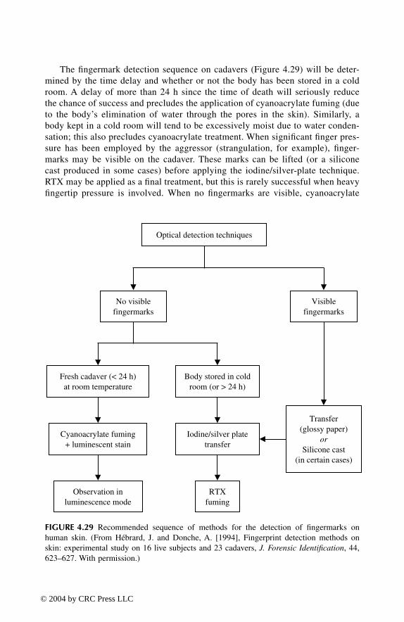
The fingermark detection sequence on cadavers (Figure 4.29) will be deter-mined by the time delay and whether or not the body has been stored in a coldroom. A delay of more than 24 h since the time of death will seriously reducethe chance of success and precludes the application of cyanoacrylate fuming (dueto the body’s elimination of water through the pores in the skin). Similarly, abody kept in a cold room will tend to be excessively moist due to water conden-sation; this also precludes cyanoacrylate treatment. When significant finger pres-sure has been employed by the aggressor (strangulation, for example), finger-marks may be visible on the cadaver. These marks can be lifted (or a siliconecast produced in some cases) before applying the iodine/silver-plate technique.RTX may be applied as a final treatment, but this is rarely successful when heavyfingertip pressure is involved. When no fingermarks are visible, cyanoacrylate
FIGURE 4.29 Recommended sequence of methods for the detection of fingermarks onhuman skin. (From Hébrard, J. and Donche, A. [1994], Fingerprint detection methods onskin: experimental study on 16 live subjects and 23 cadavers, J. Forensic Identification, 44,623–627. With permission.)
Optical detection techniques
Observation inluminescence mode
Cyanoacrylate fuming+ luminescent stain
Iodine/silver platetransfer
Fresh cadaver (< 24 h)at room temperature
Body stored in coldroom (or > 24 h)
Transfer(glossy paper)
orSilicone cast
(in certain cases)
RTXfuming
No visiblefingermarks
Visiblefingermarks
TF1345_C04.fm Page 159 Thursday, March 18, 2004 1:16 PM
© 2004 by CRC Press LLC

can be employed in the case of fresh cadavers (<24 h) that have not been placedin a cold room. Otherwise, the only possibility remaining is the iodine/silver-plate technique followed by RTX.
As for the other detection sequences that have been presented in this chapter,this sequence is only one of many possible combinations that may be effective in agiven set of circumstances. The sequence should be used as a general guide only,and the use of other techniques, such as powdering or iodine/benzoflavone, mustalso be considered. Experience and experimentation will dictate the sequence oftechniques that should be applied in any specific case.
4.9 FINGERMARK DETECTION ON ADHESIVE SURFACES
Adhesive surfaces, such as the sticky side of self-adhesive tape, can be very pro-ductive for fingermark detection due to their receptive nature (essentially pullingsecretions and skin debris off the fingertip surface when touched) and the fact thatit is difficult to manipulate adhesive tape while wearing gloves. A number of tech-niques have been proposed for treating adhesives surfaces, the most notable beinggentian violet (crystal violet) staining solutions and, more recently, sticky-side pow-der. Midkiff and coworkers have extensively reviewed the range of techniquesavailable for the development of latent marks on adhesive tape (Midkiff 1994;Midkiff and Codell 1995; Midkiff et al. 1997).
One of the operational difficulties associated with the treatment of adhesivesurfaces such as adhesive tape is the fact that such materials often have to beseparated from another surface, or themselves, before processing. Various techniqueshave been proposed in the literature for separating or unraveling sections of adhesivetape (Choudhry and Whritenour 1990; Campbell 1991a; Stimac 2000). Suggestedmethods have included freezing, heating, and the application of a solvent. Careshould be exercised with the application of such methods to limit any unnecessarydamage to the latent marks that may be present. It has recently been shown that theuse of the product Un-Du® (a heptane-based adhesive neutralizer) to remove stampsand labels will not adversely affect the detection of latent fingermarks on thesesurfaces (Schwartz et al. 2003).
4.9.1 GENTIAN VIOLET
Gentian violet (crystal violet) is a fat-soluble stain that is extremely effective forthe examination of the adhesive surface of pressure-sensitive tapes such as clearSellotape, paper masking tape, and PVC insulation tape. The conventional pro-cedure involves treating the adhesive side of the tape with a solution of gentianviolet that contains phenol to assist the absorption of the stain by the sebaceousmaterial in the print deposit. Treatment can be by dipping, by floating the tape(adhesive side down) on the stain solution, or by application with a pipette. Excessreagent is then removed by washing with water. The sebaceous component of thefingerprint deposit is stained dark purple by this process, and therefore printsbecome visible as dark purple ridges against a lightly stained background. The
TF1345_C04.fm Page 160 Thursday, March 18, 2004 1:16 PM
© 2004 by CRC Press LLC

degree of background staining is dependent on the nature of the tape and anycontamination present. Paper-backed tapes or labels may stain heavily and shouldbe tested before treatment. The procedure can be extended to darkly colored tapesusing a lifting technique in which marks developed with gentian violet aretransferred to a clean gelatin surface. This is achieved by firmly pressing theadhesive surface of the tape, after treatment with the stain, onto a fixed andwashed sheet of photographic paper; diffusion of the stain into the gelatin occursrapidly (Wilson and McCloud 1982; Kent 1986).
Extreme caution must be used when handling solutions that contain phenol, asthis compound is highly toxic and carcinogenic. Gloves must be worn and theprocessing conducted within a fume hood. Phenol-free gentian violet formulationshave been proposed (Gray 1996), but it is generally considered that the formulationcontaining phenol gives superior results (Tuthill 1997).
Gentian violet staining produces a dark purple coloration; therefore, observationof treated marks is generally conducted in the visible region. Ziv and Springer (1993)reported that coaxial illumination can be a useful optical enhancement procedurefor marks developed with gentian violet on the adhesive side of self-adhesive tape.Bramble and coworkers (2000) studied the deep red to near-infrared luminescencecharacteristics of gentian violet-treated latent marks. The luminescence data recordedin their study was used to optimize a relatively inexpensive viewing system for theobservation and capture of the luminescence emission. Given the additional sensi-tivity offered by the luminescence mode, the authors found that the system permittedthe visualization of both treated marks on dark surfaces and weakly developed markson light surfaces.
As an alternative to gentian violet, Menzel (1989) proposed the use of basicfuchsin (rosaniline chloride). This stain was evaluated by Howard (1993) for theprocessing of black electrical tape. The staining procedure is similar to that of gentianviolet, but the developed marks are luminescent when visualized under a forensiclight source (observation conditions are as for rhodamine 6G). Using both water-and methanol-based stain formulations, results were found to be comparable withthose produced using gentian violet or cyanoacrylate/rhodamine 6G. Midkiff andCodell (1995) used an aqueous solution of basic fuchsin (0.015 g per 100 ml) andreported good results on a range of adhesive tapes.
4.9.2 STICKY-SIDE POWDER
Sticky-side powder, a suspension of black fingerprint powder in a detergent solution,is an extremely simple but effective technique for the detection of latent fingermarkson the sticky side of adhesive tape. The technique was developed in Japan in theearly 1990s and is now widely employed throughout the world (Yamashita et al.1993; Burns 1994). To prepare the suspension, equal parts of Photoflo® detergent(Kodak) and water are mixed with a small amount of black powder until a consistencysimilar to thin paint is achieved. This suspension is then painted onto the adhesivesurface using a soft brush (e.g., camel-hair fingerprint brush). After 10 to 15 sec,the adhesive surface is gently rinsed under running tap water. Treated marks aredark gray to black in color. The process can be repeated if development is weak.
TF1345_C04.fm Page 161 Thursday, March 18, 2004 1:16 PM
© 2004 by CRC Press LLC
Burns (1994) reported good results on a range of adhesive surfaces including theadhesive side of duct tape, masking tape, surgical tape, paper-backed labels, clearplastic tapes, and reinforced packing tapes. Gray (1996) evaluated the sticky-sidepowder technique and found that it generally outperformed gentian violet on theadhesive surfaces tested (although it should be noted that a phenol-free aqueoussolution of gentian violet was employed in the study).
Bratton and Gregus (1996, 1997) evaluated a number of detergent/powder com-binations and found that a formulation based on Lightning Black™ Powder and Liqui-Nox™ glassware detergent was the most effective on a broad range of adhesive tapes.It was determined that this method was superior to both the original sticky-sidepowder formulation and conventional gentian violet processing. The authors suggestthat this should be the method of choice for adhesive surfaces and that attempts toapply other methods first may render the powder method ineffective. Sneddon (1999)explored the use of the Liqui-Nox™/black powder method for processing the adhesiveside of duct tape. It was confirmed that excellent results could be obtained and thatthe powder suspension produced better overall results on this surface compared withresults obtained with gentian violet.
The standard sticky-side powder method yields poor results on black electricaltape due to insufficient contrast. Martin (1999) reported that white or ash gray powdercould be used instead of black powder in the sticky-side formulation for use onblack electrical tape. This simple alternative was found to produce excellent resultson the adhesive side of this tape. Parisi (1999) also reported success using powdersuspensions produced by mixing fluorescent or white fingerprint powders with Liqui-Nox™ and water. This approach has obvious advantages on dark adhesive surfaces,where black powder gives poor contrast. As suggested by Kimble (1996), a rangeof conventional fingerprint powders can be used in suspension to develop latentmarks on adhesive surfaces. The use of titanium dioxide has recently been proposedfor the preparation of white sticky-side powder for the detection of latent marks ondark adhesive surfaces (Wade 2002).
4.9.3 CYANOACRYLATE FUMING
Morris (1992) proposed the use of low-level superglue fuming followed by stainingwith basic yellow 40 as an alternative to gentian violet for processing the adhesiveside of tape. Similarly, Isaac (1993) compared a number of techniques and reportedthat cyanoacrylate fuming, followed by either rhodamine 6G or MBD staining, canbe very effective for developing marks on a range of self-adhesive tapes.
Midkiff and Codell (1995) evaluated several techniques and found that cyanoacry-late fuming alone gives highly variable results, depending on the type of tape. Differ-ences in the type, thickness, or consistency of the adhesive are believed to account forthe observed variability in fingermark development. Some tapes were found to beeasily overdeveloped, resulting in a loss of fingermark detail and poor contrast.
4.9.4 RECOMMENDED DETECTION SEQUENCE
Detection techniques applied to an adhesive surface must be used in sequence withmethods that will also develop latent marks on any nonadhesive surfaces that are
TF1345_C04.fm Page 162 Thursday, March 18, 2004 1:16 PM
© 2004 by CRC Press LLC

also present. For example, the processing of adhesive tape must take into consider-ation the detection of latent fingermarks on both the nonadhesive and adhesive sidesof the tape. Typically, any latent marks present on the nonadhesive side of the tapeshould be developed and photographed before proceeding with the treatment of theadhesive surface.
A recommended sequence for the detection of latent fingermarks on adhesivesurfaces is given in Figure 4.30. While MMD is not included in this sequence, itsuse may be considered in some cases, as it is capable of developing marks on bothadhesive and nonadhesive surfaces as well as for both porous and nonporous back-ings. The choice of a technique for the adhesive surface itself (e.g., adhesive sideof adhesive tape) will depend on experience and experimentation. Certain adhesivetapes, for example, respond better to a particular technique. No one techniqueperforms better than the others on all adhesive surfaces. For any given case, therefore,tests should be conducted in a systematic manner to determine the most appropriatemethod to apply.
FIGURE 4.30 Recommended sequence of methods for the detection of latent fingermarkson adhesive surfaces.
Optical detection techniques
Apply techniques for the processing of the nonadhesivesurfaces first (e.g., nonadhesive side of adhesive tape)
Choose a technique for the adhesive side
Gentian violet Cyanoacrylate fumingSticky-side powder
Transfer ontophotographic paper
(dark surfaces)
Luminescent stain
TF1345_C04.fm Page 163 Thursday, March 18, 2004 1:16 PM
© 2004 by CRC Press LLC

4.10 FINGERMARK DETECTION ON FIREARMS AND CARTRIDGE CASES
The detection of latent fingermarks on fired cartridge cases is problematic, and lowsuccess rates are generally encountered in actual casework. The cartridge casesurface itself is not the cause, as marks can be developed on unfired rounds usinga range of techniques. The possible reasons for low success rates on fired roundshave been reviewed by Wiesner and coworkers (1996) and include the following:
• Friction between the surface of the cartridge case and surfaces of thefirearm at different stages of the firing process (e.g.. loading of the mag-azine, the introduction of the live round into the chamber, and the ejectionof the empty case after firing)
• High temperature and pressure generated within the cartridge case at themoment of firing
• Exposure of the surface of the cartridge case to the combustion gases anddischarge residues generated at the moment of firing
Studies conducted on each of these effects indicated that, while each factor playsa role, the main cause of fingermark deterioration is the friction between the surfaceof the cartridge case and the chamber at the moment of ejection (Wiesner et al.1996). At the moment of firing, the diameter of the cartridge case increases due tothe high internal pressure that is generated. As a result, friction is more pronouncedon ejection of the fired round rather than upon introduction of the live round priorto firing. Given the smearing of latent marks that can result from this friction, lowsuccess rates will tend to be encountered regardless of the detection techniquesemployed.
While a range of detection techniques can be applied, it should be appreciatedthat latent marks on brass cartridge cases may sometimes spontaneously developover time due to a process of differential tarnishing (Saunders and Cantu 1996). Acareful visual examination should therefore be conducted, and any ridge detailrecorded, before proceeding with any other treatment.
Fingermark detection on the firearms themselves can also present difficulties,depending on factors such as the nature of the surface (e.g., metal, wood, or plastic),any surface finish or pattern, surface contamination (e.g., gun oil and dischargeresidues), and how the firearm has been handled and packaged. Barnum and Klasey(1997) have reviewed the reasons why it can be difficult to obtain identifiable printsfrom firearms. Despite the inherent problems, the authors claim that, in their expe-rience, identifiable marks are encountered almost 10% of the time.
4.10.1 CYANOACRYLATE FUMING
Sampson (1993) investigated the application of cyanoacrylate fuming for the detec-tion of latent marks on both brass and nickel cartridge cases. Nickel cartridge caseswere found to yield good overall results, while the results achieved on brass cartridgecases were generally poor. Donche and Musy (1994) found that the results obtained
TF1345_C04.fm Page 164 Thursday, March 18, 2004 1:16 PM
© 2004 by CRC Press LLC

with cyanoacrylate on plastic shotgun cartridges was generally satisfactory, whilethe technique gave limited results on metallic casings.
Bentsen and coworkers (1996) evaluated a range of techniques on fired cartridgecases, including both atmospheric-pressure and vacuum cyanoacrylate fuming fol-lowed by treatment with a luminescent stain. It was determined that both cyanoacry-late systems were effective, although the vacuum method gave sharper ridge defini-tion. Of the luminescent stains evaluated, BY40 was found to give better overallresults.
Klasey and Barnum (2000) evaluated vacuum cyanoacrylate fuming for finger-mark detection on a range of different firearms. Prints developed with the vacuumprocess were found to be not as white as those developed under atmospheric con-ditions. However, overdevelopment of fingermark evidence was avoided, makingthis a good first choice for processing firearms. Virtually none of the test marks inthis study were enhanced by a second treatment by vacuum cyanoacrylate fuming.However, subsequent atmospheric-pressure cyanoacrylate fuming enhanced some ofthese marks.
4.10.2 GUN BLUE
While most fingerprint detection techniques are dependent on a reaction with thefingermark deposit, the gun blueing process involves a reaction with the substrate.The principal active ingredients in gun blue include selenious acid (H2SeO3) and acupric salt in an acid solution. Both selenious acid and cupric ions can oxidize certainmetals (e.g., zinc, aluminum, and iron). When these two components are reduced inthe presence of such metals, a black copper-selenide coating is formed (Migron andMandler 1997; Cantu et al. 1998). This coating will only form on a clean metalsurface; no deposit will occur if the surface is contaminated with a greasy or oilymaterial, as is the case when a sebaceous fingermark is present. Dilute gun bluesolution can therefore be used to treat certain metal surfaces, such as brass cartridgecases, to reveal latent marks as transparent images against a dark background.
A selenious acid process reported by Bentsen and coworkers (1996) involvedthe immersion of cartridge cases in a 0.4% aqueous solution of selenious acid untiloptimum ridge detail is observed. Treated cartridge cases are then rinsed thoroughlywith water and dried. Developed marks can be preserved by dipping the cartridgecases in clear varnish to prevent further surface oxidation (alternatively, the surfacecan be coated with protective oil). Developed marks should be photographed imme-diately, as further oxidation can destroy ridge detail. The results are dependent onthe composition of the cartridge case; selenious acid treatment was reported to beineffective on aluminum- and nickel-coated brass cases. While the method is highlysensitive, propellant by-product contamination can limit results on some spent cases(Bentsen et al. 1996).
Saunders and Cantu (1996) evaluated several techniques for developing latentmarks on both unfired and fired cartridge cases. Treatment with dilute gun bluesolution gave better overall results compared with cyanoacrylate fuming. However,superior results were obtained with cyanoacrylate fuming followed by gun bluetreatment compared with gun blue solution alone. (This suggests that a possible
TF1345_C04.fm Page 165 Thursday, March 18, 2004 1:16 PM
© 2004 by CRC Press LLC

sequence for processing cartridge cases would be as follows: cyanoacrylate fuming→ selenious acid → luminescent stain.) The authors were unable to develop anyridge detail on oily or dirty cartridges, even after the application of degreasing orwashing techniques.
Both etching and blueing techniques were evaluated by Schütz and coworkers(1999) and the results compared with those obtained with multimetal deposition(MMD). (Etching involves the acid-based dissolution of the metal surfaces, whereasblueing involves both an acid-based dissolution and the formation of a dark metalcomplex.) The best efficiency for latent fingermark detection on brass cartridge caseswas generally observed with gun blue treatment, particularly for sebaceous finger-marks. However, on aluminum cartridge cases, better results were obtained withMMD. Only the modified physical developer step of the MMD treatment appearedto contribute to the fingermark detection. Lacquered steel cartridge cases wereproblematic, and the authors recommended cyanoacrylate fuming for this surface.
Cantu and coworkers (1998) determined that a mixture of acetic acid and hydro-gen peroxide could be used to remove excess gun blue deposit from metal cartridgecases that had been overdeveloped by gun blue treatment. It was also found that theacidified hydrogen peroxide solution could be used to visualize latent marks oncartridge cases by an etching process and that such marks could be enhanced bysubsequent gun blue treatment.
Vouk (1996) has warned that the use of gun blue solution for the detection oflatent marks can result in a loss of detail in the individual toolmarks left on thecartridge case by the firearm. Such markings on a cartridge case should thereforebe recorded by a firearms examiner before proceeding with the gun blue treatment.
4.10.3 MISCELLANEOUS TECHNIQUES
Migron and coworkers investigated palladium deposition techniques for the develop-ment of latent fingermarks on brass cartridge cases (Migron et al. 1996, 1998; Migronand Mandler 1997). Treatment is by immersion in an aqueous solution of eitherdipotassium hexachloropalladate or disodium tetrachloropalladate for 40 sec, fol-lowed by rinsing in distilled water. The reaction with the metal surface is a displace-ment process that involves the oxidation of zinc and, to a lesser extent, copper,resulting in the deposition of palladium. A dark metallic deposit forms on the exposedmetal surface (including the fingermark valleys), while the ridges remain golden-brass in color (Migron and Mandler 1997). A number of experiments were alsoconducted where iodine was used to etch the metal surface of the cartridge to sensitizeit for subsequent palladium deposition. This etching step was found to significantlyimprove fingermark visualization (Migron et al. 1996; Migron and Mandler 1997).
Overall, the palladium deposition technique was found to be a very promisingmethod for fingermark detection on unfired cartridge cases. The technique is rela-tively simple to apply, producing good fingermark detail in a reproducible fashion.However, while application of the method on spent cartridge cases gave an indicationthat latent fingermarks were still present after firing, the developed images wererarely of good quality. It was confirmed in a further study that, under laboratoryconditions, substantial parts of latent fingermarks on some cartridge cases could
TF1345_C04.fm Page 166 Thursday, March 18, 2004 1:16 PM
© 2004 by CRC Press LLC

remain intact after firing. In such cases, metal vapor deposition and the careful useof illumination can enable fingermark visualization. The authors also proposed amodel for the structural changes to latent fingermarks due to the firing process(Migron et al. 1998).
4.11 ENHANCEMENT OF FINGERMARKS IN BLOOD
Fingermarks in blood are often encountered in cases of violent crime where theoffender’s hands are contaminated with the blood of the victim. A fingermarkidentified as being from the suspect, deposited in the blood of the victim (as sug-gested by DNA profiling evidence) constitutes very powerful evidence. Every effortshould therefore be made to enhance any fingermark in blood, for fingerprint iden-tification purposes, without compromising the possibility of obtaining a DNA profilefrom the blood (see Section 4.13). Nondestructive optical enhancement proceduresshould be employed before proceeding with another treatment. Where possible,heavily bloodstained areas that are unlikely to yield ridge detail should be sampledfor DNA profiling purposes before processing the surface for fingerprint evidence.
There are a number of blood- or protein-specific enhancement techniques (e.g.,amido black and diaminobenzidine) that will not develop any latent fingermarks thatmay be present and are likely, in fact, to destroy such marks. This must be takeninto consideration when processing an item for fingerprint evidence. An appropriatesequence of methods is required that will both develop any latent fingermarks thatare present and enhance any fingermarks in blood. A sequence that exploits onlythe blood-contaminated prints will be to the detriment of any latent marks that mayalso be present on the evidential item.
In some cases it may be of interest to determine whether a fingermark in bloodis from a finger contaminated with blood or is a latent fingermark already on thesurface that has been developed by the blood. Creighton (1997) conducted a numberof experiments where blood was allowed to flow over a series of latent impressions.The results suggested that preexisting latent impressions would not develop intovisible fingermarks in blood by incidental or direct contact with blood. The observedeffect was that the latent deposit tended to repel the blood. Further studies wereconducted by Huss and coworkers (2000), who confirmed that: (a) blood will notvisualize a previously deposited eccrine fingermark and (b) blood may reveal apreviously deposited sebaceous (greasy) fingermark, although the print will bereversed, as blood will tend to be repelled by the ridges and hence accumulate inthe furrows.
4.11.1 OPTICAL TECHNIQUES
Although blood has a broad absorption spectrum in the entire light region (UV–vis-ible–IR), it exhibits a strong and narrow absorption maximum at 415 nm (Figure4.31A) (Stoilovic 1991). The enhancement of untreated blood marks can be per-formed in either the absorption or reflection modes. The absorption mode is recom-mended for lightly colored or luminescent surfaces, while the diffused reflectionmode is recommended for dark or shiny surfaces. Optical enhancement techniques
TF1345_C04.fm Page 167 Thursday, March 18, 2004 1:16 PM
© 2004 by CRC Press LLC
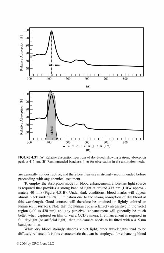
are generally nondestructive, and therefore their use is strongly recommended beforeproceeding with any chemical treatment.
To employ the absorption mode for blood enhancement, a forensic light sourceis required that provides a strong band of light at around 415 nm (HBW approxi-mately 40 nm) (Figure 4.31B). Under dark conditions, blood marks will appearalmost black under such illumination due to the strong absorption of dry blood atthis wavelength. Good contrast will therefore be obtained on lightly colored orluminescent surfaces. Note that the human eye is relatively insensitive in the violetregion (400 to 420 nm), and any perceived enhancement will generally be muchbetter when captured on film or via a CCD camera. If enhancement is required infull daylight (or artificial light), then the camera needs to be fitted with a 415-nmbandpass filter.
While dry blood strongly absorbs violet light, other wavelengths tend to bediffusely reflected. It is this characteristic that can be employed for enhancing blood
FIGURE 4.31 (A) Relative absorption spectrum of dry blood, showing a strong absorptionpeak at 415 nm. (B) Recommended bandpass filter for observation in the absorption mode.
(B)
300 400 500 600 700 800W a v e l e n g t h [nm]
(A)
300 400 500 600 700 800
70
60
50
80
90
100
Rel
ativ
e A
bsor
ptio
n [%
]
70
60
50
80
90
100
Rel
ativ
e A
bsor
ptio
n [%
]
415/
40
415 nm
TF1345_C04.fm Page 168 Thursday, March 18, 2004 1:16 PM
© 2004 by CRC Press LLC

marks on dark or shiny surfaces. An illumination wavelength is chosen that is outsidethe violet region; for example strong blue light at 450 nm produces good results inmost cases. Working under dark conditions, the blood mark is observed perpendicularto the surface, without any barrier filter, while the incident light angle is varied untilthe best contrast is obtained. The incident light will either be strongly absorbed orreflected by the surface, depending on whether the surface is dark or shiny. The bloodmark will diffusely reflect the light, and hence the mark will appear as a light imageagainst a dark background. In the case of a colored substrate, selecting an illuminationband that is opposite to the substrate color will generally enhance the contrast.
Springer and colleagues have reported that UV luminescence techniques (short-wave UV excitation; observation in the long-wave UV region) can be particularlyeffective for detecting and enhancing marks in blood, semen, and saliva (Springeret al. 1994). Care must be exercised with such techniques, however, due to the dangerassociated with the use of shortwave UV light and the possible detrimental effectthat it may have on subsequent DNA profiling.
4.11.2 PROTEIN STAINS
Before proceeding with any chemical treatment such as the application of a proteinstain, blood marks need to be “fixed” to prevent the blood from washing away ordiffusing. Two effective blood-fixing agents are methanol and 5-sulfosalicylic acidsolution (Hussain and Pounds 1988; Sears and Prizeman 2000). The average fixingtime is generally 5 min, although heavy deposits should be fixed for longer periods,15 min or more, before applying the enhancement process.
The protein stain amido black (naphthol blue black B; acid black 1) has longbeen a recommended treatment for fingermarks in blood on both porous and non-porous surfaces (Kent 1986; Hussain and Pounds 1988; Sears and Prizeman 2000).Such marks are generally treated by immersion in a solution of amido black. Afterapproximately 30 sec in the staining solution, the sample is washed successively inthree different solutions to clear (de-stain) the background, thereby improving thefingerprint contrast. Treated marks are visible as dark blue ridges against a lightblue or colorless background (depending on the nature of the support). The conven-tional amido black formulation is methanol based and may not be suitable on somesurfaces or as a crime scene technique. Sears and Prizeman (2000) investigatedalternative formulations and proposed a new ethanol/water-based system. This newformulation is suitable for application both in the laboratory and in the field. Warrick(2000) has described a case where marks in blood on cotton fabric were stainedwith amido black and then digitally enhanced, ultimately leading to the identificationof a suspect in a murder investigation.
Coomassie blue is also a protein stain, giving results comparable to amido black.The same staining procedure is employed, and treated marks are blue but of a lightercolor than that obtained with amido black. McCarthy and Grieve (1989) comparedamido black with both Crowle’s stain and coomassie blue. It was concluded that,of the three protein stains evaluated, amido black is generally the best choice fortreating fingermarks in blood and that cyanoacrylate preprocessing is not deleteriousfor most substrates that are subsequently processed with amido black. Cyanoacrylate
TF1345_C04.fm Page 169 Thursday, March 18, 2004 1:16 PM
© 2004 by CRC Press LLC

preprocessing on nonporous surfaces is recommended, as it can preserve latentimpressions that are not subsequently visualized by the staining technique.
Sears and coworkers (2001) conducted a systematic evaluation of a range ofprotein stains — including fuchsin acid (Hungarian red) (Velders 1997) — for theenhancement of fingermarks in blood on surfaces typically encountered at crimescenes. Of the stains tested, two were found to show potential and warrant furtherinvestigation through operational trials. The first of these, acid violet 17 (coomassiebrilliant violet), is an absorbing stain that produces a visible enhancement of bloodmarks; this stain may serve as a possible replacement for amido black. The secondcandidate, benzoxanthene yellow, was found to induce a luminescence in weak blooddeposits on nonporous surfaces. This property may be an advantage on dark, non-luminescent, nonporous surfaces, where absorbing stains such as amido black areless effective.
4.11.3 DIAMINOBENZIDINE (DAB)
Work by Allman and Pounds (1991a, 1992a) has shown that the reagent diaminoben-zidine (DAB) is a sensitive alternative to protein stains for the enhancement of bloodmarks both in the laboratory and at the crime scene. The reaction between diami-nobenzidine and hydrogen peroxide is catalyzed by the peroxidase activity of blood(heme) to give a dark brown insoluble product. In contrast to protein staining, thereaction shows good specificity for blood and produces little background coloration;no de-staining of the surface is required. Before treatment, the blood marks are firstfixed with a solution of 5-sulfosalicylic acid over several minutes. After being rinsedwith water, the marks are then developed with a buffered solution of DAB overapproximately 4 min. The revealed impressions are then rinsed with water andallowed to dry. The method is therefore quite rapid, with blood enhancementachieved in less than 10 min. Diaminobenzidine is considered safe to use, unlikethe carcinogenic parent compound benzidine and some of its derivatives. The tech-nique is particularly effective on porous surfaces, where protein stains tend to givea high background coloration. As a crime scene technique, application of DAB canbe via reagent-saturated paper towels. This can be effective on a variety of surfaces,including doors and painted or wallpapered walls.
Sahs (1992) evaluated diaminobenzidine for the enhancement of blood marksand also proposed a DAB-MBD combined process. In this modified procedure, MBD(a luminescent stain proposed for the enhancement of cyanoacrylate-developedprints) is added to the sulfosalicylic acid fixing solution. While Sahs reported thatresults were inconsistent, luminescence was induced in some blood marks aftertreatment with the modified fixing solution. The addition of MBD to the fixingsolution did not have any observable detrimental effect on the subsequent DABreaction. However, marks enhanced with DAB were no longer luminescent; inter-mediate results must therefore be recorded before proceeding.
4.11.4 MISCELLANEOUS TECHNIQUES
Caldwell and coworkers (2000) proposed the use of ABTS [2,2′-azino-di-(3-ethyl-benzthiazolinesulfonate) diammonium salt] as an effective alternative to DAB for
TF1345_C04.fm Page 170 Thursday, March 18, 2004 1:16 PM
© 2004 by CRC Press LLC

the enhancement of fingermarks in blood on porous surfaces. The authors found thatthe bright green color of the oxidized ABTS was an advantage on certain coloredsurfaces where the dark brown color of DAB-treated prints showed poor contrast.For blood marks on glass, better results were obtained with DAB. Treatment withABTS did not interfere with subsequent DAB processing, indicating that the twotechniques can be used in sequence if desired.
The amino acid reagent DFO has been found to be particularly effective for thetreatment of fingermarks in blood on porous surfaces such as paper (Stoilovic 1991).Such marks, after development with DFO, show a strong room-temperature lumi-nescence. In addition, the application of DFO (or ninhydrin) to blood marks doesnot preclude the later use of a protein stain such as amido black. DFO or ninhydrinpreprocessing on porous surfaces is always recommended, as latent marks notcontaminated with blood will not be revealed by a staining procedure. (Reagentssuch as DFO or ninhydrin cannot be employed after the application of a proteinstain.)
A number of heme-reacting chemicals have been proposed for the enhancementof blood marks. These include reagents such as leucomalachite green, phenolphtha-lein, fluorescein, and tetramethylbenzidine (Lee 1984a, b; Shipp et al. 1994; Cheese-man and DiMeo 1995). In general, heme-reacting chemicals are extremely sensitive,being able to detect blood down to extremely low concentrations. This added sen-sitivity may be an advantage in some circumstances. The transfer of fingermarks inblood, enhanced by either leucomalachite green (LMG), leucocrystal violet (LCV),or diaminobenzidine (DAB), has been investigated (Jaret et al. 1997). It was foundthat fixed black-and-white photographic paper could be successfully used to transferblood marks treated with LMG or LCV. This may be an advantage on dark surfaces,where contrast is poor, or for marks located in areas that are difficult to photograph.The transfer of DAB-enhanced impressions was not successful.
Dark surfaces are certainly a challenge for the detection of bloody fingermarks.Bergeron (2003) recently reported very good success using a methanol-based sus-pension of titanium dioxide, without any detrimental effects on the DNA profile.
4.11.5 RECOMMENDED DETECTION SEQUENCE
A recommended sequence of methods for the detection and enhancement of finger-marks in blood is given in Figure 4.32. Depending on the nature of the surface, othertechniques should be included at appropriate points within this sequence to ensurethat any latent fingermarks are also detected and enhanced.
4.12 FINGERMARK DETECTION AT THE CRIME SCENE
Fingermark detection at the crime scene should logically begin with a detailed visualexamination of all appropriate surfaces. The application of different optical tech-niques, using various light sources (strong white light, UV lamp, laser or filteredarc lamp, etc.), can reveal latent fingermarks or enhance weakly visible marks. Smallobjects or pieces of evidence should be removed from the crime scene, with all thenormal precautions (proper packaging, labeling, etc.), for optimum fingermark treat-
TF1345_C04.fm Page 171 Thursday, March 18, 2004 1:16 PM
© 2004 by CRC Press LLC

ment back at the laboratory. Nontransportable objects and fixed surfaces should thenbe processed using a suitable detection sequence.
Allman and Pounds (1992b) have elaborated a sequence of reagents for devel-oping both latent and blood marks on various surfaces (both porous and nonporous)at the crime scene (Figure 4.33). This sequence was constructed after experimentsperformed on a range of different surfaces that may be encountered at a crimescene (including paper, wallpaper, wood, gloss paint, emulsion or matt paint, glass,polyethylene, and metal). After visual examination of the surface, the combinediodine/benzoflavone solution is applied with an air brush or paint spray (Pounds
FIGURE 4.32 Recommended sequence of methods for the detection and enhancement offingermarks in blood.
Protein stain(e.g., amido black)
ordiaminobenzidine
DFO
Examination inluminescence mode
Dark or shiny background Light background
Observation indiffused reflection mode
Observation inabsorption mode (425 nm)
Marks will show up as lightridges against a dark background
Marks will show up as darkridges against a light background
poroussurfacesonly
TF1345_C04.fm Page 172 Thursday, March 18, 2004 1:16 PM
© 2004 by CRC Press LLC

et al. 1992). Depending on the nature of the surface, marks can be further treatedwith either aluminum powder (nonporous surfaces) or ninhydrin (porous surfaces).While these authors preferred aluminum powder due to its high sensitivity, otherpowders may be employed depending on the personal choice and experience ofthe scene examiner. Powdered marks can be lifted in the conventional way evenafter the iodine spray treatment. Because ninhydrin reacts with the amino acidfraction of the latent fingermark, while iodine is absorbed by the fatty components,additional fingermarks may be developed by the use of ninhydrin subsequent toiodine/benzoflavone. However, Allman and Pounds (1992b) reported that theiodine spray generally reveals marks equal in quality to those developed withaluminum powder, and it is consistently better than ninhydrin at detecting markson porous surfaces such as wallpaper.
After powdering or ninhydrin, fingermarks in blood can be enhanced with eitherdiaminobenzidine (DAB) or amido black. If blood is known to be present, fingerprintpowder should be applied with care: excessive brushing may affect the integrity ofa blood mark and excessive powder may decrease the effectiveness of the bloodreagent. Because blood grouping and DNA profiling can be adversely affected bythe enhancement procedures, samples required for biological testing should be takenprior to treatment with DAB or amido black (and preferably before the applicationof any fingerprint reagent).
FIGURE 4.33 Recommended sequence of methods for the exploitation of latent and bloodyfingermarks at the crime scene. (From Allman, D.S. and Pounds, C.A. [1992b], Sequence ofReagents To Be Used To Develop Fingerprints at a Scene of Crime, Technical CRSE No.747, Central Research and Support Establishment, Home Office Forensic Science Service,Aldermaston, U.K. With permission.)
Optical detection techniques
Iodine/benzoflavone spray
Aluminum powder Ninhydrin
Diaminobenzidine (or amido black)
Nonporous surfaces Porous surfaces
TF1345_C04.fm Page 173 Thursday, March 18, 2004 1:16 PM
© 2004 by CRC Press LLC

4.13 EFFECT OF FINGERPRINT DETECTION TECHNIQUES ON SUBSEQUENT DNA PROFILING
DNA profiling techniques have become increasingly more sensitive and are now anintegral component of the criminal investigation process. The recovery and analysisof DNA is not only possible when there is visible biological material present, suchas blood and semen stains, but also where items may have been touched and traceamounts of DNA deposited. In this latter case, the deposited DNA is as a result ofthe skin cells that are naturally shed from the epidermis. The valuable evidence thatmay be obtained via DNA profiling cannot be ignored, and the fingerprint technicianmust therefore take into consideration the possible effects that fingerprint detectiontechniques may have on subsequent DNA analysis. While numerous studies havebeen undertaken on the profiling of DNA from blood marks that have undergonefingerprint examination, few studies are available where the recovery of DNA fromtreated latent marks has been considered.
Lee and coworkers (1989) subjected dried bloodstains on cotton cloth to finger-print enhancement procedures that included cyanoacrylate fuming, iodine,rhodamine 6G, gentian violet, ninhydrin, silver nitrate, and laser light illumination(488 to 514 nm). The bloodstains were subsequently DNA profiled using a restrictionfragment length polymorphism (RFLP) procedure. While high-molecular-weightDNA was recovered in nearly all cases, reagents such as silver nitrate appeared toreduce the DNA yield, and iodine fuming led to noticeable DNA degradation. In asimilar study, Shipp and coworkers (1993) studied the effects of forensic light sourceillumination (argon ion laser and alternative light source, operating at differentwavelengths) and cyanoacrylate fuming. It was found that none of the conditionsevaluated were detrimental to the DNA pattern obtained by RFLP analysis.
Presley and coworkers (1993) considered the analysis of DNA from salivapresent on envelopes, stamps, and cigarette butts that had been treated with ninhy-drin, DFO, or physical developer (PD). DNA analysis was conducted by polymerasechain reaction (PCR)-based typing of the HLA DQ alpha region. No detectable DNAwas recovered from the samples processed with PD. The authors suggested thateither the chemicals used in the PD reagent had a degrading effect on the DNA, orthe DNA was diluted by the PD processing to the extent that insufficient DNAremained for recovery. On the other hand, ninhydrin or DFO treatment did notadversely affect subsequent DNA recovery and profiling.
RFLP and PCR-STR (short tandem repeat) DNA typing was performed by Steinand coworkers (1996) on bloodstains and saliva on various supports after treatmentwith common fingerprint detection techniques, including black powder, ninhydrin,cyanoacrylate fuming, and gentian violet. It was determined that the fingerprinttreatments did not adversely affect DNA extraction, quality, or profiling. Caseworksuccess has been reported where a PCR-STR result was obtained from the blade ofa knife that had already been processed with cyanoacrylate and black powder (Newallet al. 1996).
Andersen and Bramble (1997) described a study designed to investigate theeffects of different light sources used for fingermark enhancement on the subsequentPCR-STR analysis of bloodstains. While four out of the five light sources evaluated
TF1345_C04.fm Page 174 Thursday, March 18, 2004 1:16 PM
© 2004 by CRC Press LLC

had no significant effect on subsequent quadruplex PCR analysis, exposure of thebloodstains to shortwave UV for more than 30 sec precluded successful DNA typing.A study reported by Roux and coworkers (1999) investigated the effects of a rangeof common fingerprint detection techniques on bloodstains deposited on a numberof surfaces. DNA typing performed using PCR amplification (D1S80 and CTTprimers) was adversely affected by magnetic fingerprint powder, multimetal depo-sition (MMD), and UV radiation. The remaining fingerprint detection techniquesevaluated had no significant effect on the analysis of DNA using the PCR-CTTsystem.
A study reported by von Wurmb and coworkers (2000) investigated whether ornot cyanoacrylate (CA) fuming had an effect on the relative efficiency of threedifferent forensic PCR systems: mtDNA, Y-STR determination, and the ProfilerPlus kit. Results obtained from blood and saliva stains on glass slides indicatedthat the amount of specific PCR products is reduced when typing CA-treated sam-ples. However, no difference in genotyping results was observed. Frégeau andcoworkers (2000) evaluated a range of blood enhancement reagents (amido black,Crowle’s double stain, DFO, Hungarian red, leucomalachite green, luminol, andninhydrin) to determine their effect on the subsequent Profiler Plus PCR-STR anal-ysis of fresh and aged blood marks on various porous and nonporous substrates.The study revealed that, while DNA typing was still reliable after fingerprint pro-cessing, some loss of biological material can take place, particularly with techniquesthat require de-staining steps, such as amido black, Crowle’s double stain, andHungarian red. Caution is therefore recommended in cases where the amount ofbiological material is limited.
Studies reported by Zamir and coworkers (2000a, b) have looked at the effectsof different fingerprint detection techniques on subsequent PCR-STR profiling.Previous treatment of envelopes and stamps with DFO was found to have no adverseeffect on subsequent DNA profiling using STR loci after phenol-chloroform extrac-tion. DNA was successfully extracted from adhesive tapes and profiled after thetapes had undergone fingerprint processing using a forensic light source, cyanoacry-late fuming, basic yellow 40 staining, and crystal violet staining. STR profiles canbe successfully obtained from envelopes and stamps previously treated with 1,2-indanedione provided that the DNA extraction is conducted as soon as possible afterthe fingerprint treatment (Azoury et al. 2002). SPR treatment also has not causedadverse effect on DNA profiling (Zamir et al. 2002).
4.14 LABORATORY SAFETY
4.14.1 HAZARDOUS SUBSTANCES
During any work involving the manipulation of chemicals, all reasonable precautionsshould be taken to prevent accidental or long-term exposure. Appropriate trainingmust be provided to staff to ensure that there is general knowledge in the workplaceregarding the hazards associated with particular chemicals and the safe work prac-tices to be adopted. The laboratory itself must also be properly equipped withappropriate storage and handling facilities for any hazardous materials in use. Pro-
TF1345_C04.fm Page 175 Thursday, March 18, 2004 1:16 PM
© 2004 by CRC Press LLC

tective clothing (laboratory coats, safety glasses, and disposable gloves, for example)must also be provided, with usage enforced.
Occupational Health and Safety (OH&S) checklists are available in the special-ized literature and should be used in the course of regular safety audits. Typicalrequirements include the following (CCH Australia Ltd. 1992):
• Inventory of all chemicals stored in the laboratory is up to date.• Material Safety Data Sheets (MSDS) are available for all hazardous sub-
stances stored or used in the laboratory.• All chemicals and containers are clearly labeled (with hazard warning
symbols where appropriate).• Chemicals are stored in compatible containers.• Leakage of chemicals onto storage shelving is controlled.• Storage of flammable material in domestic refrigerators is prohibited.• Storage areas are separated depending on chemical compatibility (e.g.,
solvents separated from corrosives, fuels separated from oxidizing mate-rials, etc.).
• Procedures are in place for handling hazardous materials.• Personnel handling chemicals are required to wear protective equipment
(gloves, glasses, aprons, etc.) when needed, in accordance with the appro-priate MSDS.
• Personnel are trained in the operation and use of safety and emergencyequipment where provided.
• Occupants of the laboratory are aware of what to do in the event of anemergency involving a chemical spill.
• Dry-powder fire extinguishers are readily available.• Chemical spill kits are readily available.• Emergency eye wash and safety showers are readily available.• Basic first-aid kits are readily available.• The laboratory has adequate ventilation.• Fume cupboards are available for the handling of hazardous volatile
substances.• Biohazard cabinets are available for the handling of items contaminated
with biological material.• Eating, drinking, smoking, and the application of makeup is prohibited
in the laboratory area.• Appropriate hand-washing facilities are available for staff.• Chemical waste is disposed of in a responsible manner and in accordance
with local legislation.
Material Safety Data Sheets for hazardous chemicals are available directly fromthe manufacturer or distributor. The laboratory should have a complete collectionof these documents, representing all hazardous materials stored and used in theworkplace. The MSDS collection must be accessible to all laboratory users, andstaff should be encouraged to review the data sheets before handling any hazardoussubstance. Each MSDS should contain the following information (Masters 2002):
TF1345_C04.fm Page 176 Thursday, March 18, 2004 1:16 PM
© 2004 by CRC Press LLC

• Name and contact details of the manufacturer• Identity of the substance (the chemical name, chemical formula, and
common name for each component of the material)• Physical and chemical properties• Physical hazards (including any potential for fire and explosion)• Reactivity and incompatibility data• Health hazards (including routes of entry, symptoms of exposure, permis-
sible exposure or threshold limits, acute and chronic effects of exposure,and first-aid procedures)
• Precautions related to safe handling and storage (recommended personalprotective equipment, ventilation requirements, procedures for dealingwith a leak or spill, and waste disposal information)
All chemicals, including purchased or prepared reagents, must be stored inappropriate containers that are clearly labeled. Labels should include the chemicalname and any appropriate hazard warning symbols and/or hazard warning keywords(e.g., flammable, toxic, corrosive, etc.). For prepared reagents (e.g., ninhydrinsolution), the label should give the name of each component, the concentration ofeach component, the name of the person who prepared the reagent, the date ofpreparation, and the expiry date. A standard classification scheme for dangerousgoods is given in Table 4.6 (CCH Australia Ltd. 1992).
The following materials are commonly encountered in the fingerprint laboratory,and the specific hazards listed should be noted:
Acetic acid — causes burns; avoid inhalation of vapor and contact with theskin; flammable
Cyanoacrylate vapor — avoid prolonged exposure; long-term effects of expo-sure to this vapor are not well documented
Cyclohexane, diethyl ether, petroleum ether, and ethyl acetate — highlyflammable solvents; vapors can create explosive mixtures with air
Dichloromethane and chloroform — chlorinated organic solvents are toxicby inhalation; carcinogenic
Ethanol and methanol — flammable; methanol is toxicFingerprint powders — prolonged inhalation should be avoided; use a dust
mask if possibleGentian violet (crystal violet) — toxic by inhalation and contact with the skinHalogenated carrier solvents (e.g., HFE, HFC, CFC, HCFC) — create a
heavy vapor that can displace air in enclosed spaces; risk of asphyxiation;good ventilation required
Iodine — toxic by inhalation; corrosiveLiquid nitrogen — cryogenic material with a temperature of –196˚C; skin
and eye protection required; do not pour down the sinkPhenol — toxic by inhalation, contact with the skin, and ingestion; causes
burns; carcinogenic; use extreme cautionReagents used for fingerprint development — generally stain the skin; may
cause inflammations; and are harmful if swallowed (e.g., ninhydrin, DFO)Silver nitrate — toxic and corrosive
TF1345_C04.fm Page 177 Thursday, March 18, 2004 1:16 PM
© 2004 by CRC Press LLC

TABLE 4.6Dangerous-Goods Classification Scheme
Class Description1. Explosives Substances that are manufactured or used to produce explosions or pyrotechnic effects, or are
explosive by reason of their chemical nature2. Gases
2.1 Flammable gases2.2 Nonflammable, nontoxic gases2.3 Toxic gases
Gases that ignite on contact with an ignition sourceGases that within themselves are not flammable when exposed to an ignition sourceGases that are liable to cause death or serious injury to human health if inhaled
3. Flammable liquids Liquids that ignite on contact with a source of ignition4. Flammable solids Solids that can be easily ignited by external sources such as sparks and flames5. Oxidizing agents and organic peroxides
5.1 Oxidizing agents
5.2 Organic peroxides
Substances that, although not necessarily combustible themselves, may increase the risk and intensity of fire in other materials (may cause a fire when brought into contact with combustible materials)
May react dangerously with other substances; may be sensitive to impact or friction; may explode under long exposure to fire or heat
6. Toxic and infectious substances6.1 Toxic substances
6.2 Infectious substances
Substances that are liable to cause death or serious injury to human health if swallowed, inhaled, or by skin contact
Substances that are known, or reasonably believed, to cause disease in plants or animals7. Radioactive substances Materials or combinations of materials that spontaneously emit radiation8. Corrosive substances Substances that possess, in their original state, the common property of being able to severely
damage living tissue; can also damage or destroy other materials, especially metals9. Miscellaneous dangerous goods Substances that present a danger not covered by other classes; generally present a relatively low
hazard or an environmental hazard
From CCH Australia Ltd. (1992).
TF1345_C
04.fm Page 178 T
hursday, March 18, 2004 1:16 PM
© 2004 by CRC Press LLC
4.14.2 LIGHT SOURCES
Lasers and other high-intensity light sources (such as filtered arc lamps and ultra-violet systems) are now an integral part of fingerprint detection and enhancementprocedures. While the different forensic light sources on the market differ in outputpower and operating wavelength, they all pose potential health hazards that must betaken into consideration. Direct or reflected beams can cause permanent skin andeye damage, and appropriate safety measures must be employed. Adequate skin andeye protection must be enforced when working with these systems, with particularreference to any recommendations given by the manufacturer.
Damage to the eye can be avoided through the use of appropriate viewing filters,safety glasses, goggles, or face shields. Most light-source manufacturers providesuch equipment. High-intensity light should never be viewed directly at short dis-tances, even for a fraction of a second, without eye protection (Hardwick et al. 1990).In addition, high-intensity light can burn the skin, so gloves and long-sleeve labo-ratory coats should always be worn.
Ultraviolet radiation poses a particular hazard due to its high energy and the factthat it is invisible to the naked eye. It is the UV component of sunlight that causessunburn and skin cancer. When working with UV lamps, safety goggles/glasses thatfilter UV wavelengths must be employed. For the examination of reflective surfaces,use of a UV-protective face shield is recommended (Masters 2002).
TF1345_C04.fm Page 179 Thursday, March 18, 2004 1:16 PM
© 2004 by CRC Press LLC

5
Issues Related to the Exploitation of Fingerprint Evidence
Technical issues related to automated fingerprint identification systems and associ-ated computer technologies for database searching are important, but they needseparate treatment because such systems are only tools for the extraction of relevantinformation from a large amount of data. (See, for example, the book chapters byMoore [1991] and Jain and Pankanti [2001].) On the other hand, there are manyprofessional issues that directly affect dactyloscopists in their daily activities, suchas the information content (not simply the identification potential) of friction ridgeskin impressions, the relevancy of traces (their age, the potential for forgeries andtheir detection), identification errors, and training and education requirements forfingerprint specialists. These issues, which are rarely covered in any detail in thegeneral literature, are addressed in this chapter. Some of these issues are difficult toaddress, and some are controversial, but they are introduced to show that the fieldis not stale and that there is room for further discussion and advancement. Certainly,many questions raised may not have complete or satisfactory answers, but we hopethat the mere fact of raising the issues will prompt relevant research and developmentefforts.
5.1 TERMINOLOGY
The use of ridge skin patterns for the purpose of identification has gone throughrapid developments throughout the 20th century, resulting in sometimes conflictingopinions as to who preceded whom and what the proper terminology was supposedto be. Although it might be quite clear what is meant within the specialist languagein a given geographical/sociocultural environment, differences have led to inconsis-tent uses and abuses, misunderstandings, and a flourishing of words to express orspecify aspects of the “science of fingerprinting.” Terminology has ranged from
finger prints
(Galton 1892) to
icnophalangometry
(Vucetich 1904 [reported byLocard 1931]);
dactyloscopy
(Latzina [reported by Locard 1931]);
lophoscopy
(Lam-bert 1990);
cretoscopy
,
ridgeoscopy
,
ridgeology
(Ashbaugh 1982a);
poroscopy
(Locard 1913);
chiroscopy
,
pelmatoscopy
(referred to by Locard [1931]);
frictionridge skin
(Cowger 1983); etc. In addition, terms such as
stains
,
prints
,
traces
, or
marks
could be used without distinction to express the cause of the trace (pattern,details) and the trace itself (marks and their characteristics). These terms have mostlybeen created (neologisms) and are based on some descriptive aspects of the subject
TF1345_C05.fm Page 181 Thursday, March 18, 2004 1:22 PM
© 2004 by CRC Press LLC

matter, sometimes even without reference to a more or less universal etymologicalroot. In scientific circles (botany, zoology, etc.), it is habitual to use a Greek or Latindescriptive root that can have universal acceptance and will give a general key forsimilarly constructed words. The further advantage of this is that these roots arefound in all modern Indo-European languages and can be readily translated.
The most general and universal term is therefore
lophoscopy
, from the Greekroot
lophos
, meaning “crest” or “ridge,” and
skopein
, meaning “study” or “exami-nation.” Both roots are commonly encountered, the first in the naming (taxonomy)of plants (e.g.,
Lopho
phora
, a kind of cactus with crests) and animals (e.g.,
Bi
lo-pho
sauria
, a dinosaur with two crests), the second to describe instruments used toobserve or examine (e.g.,
micro
scope
, used to study small objects). In use in Franceand Belgium (according to Interpol),
lophoscopy
is translated (official EuropeanCouncil translation) into “ridge pattern analysis” in English and would correspondto the “ridgeoscopy” of Ashbaugh.
Ridgeoscopy
as a term has the merit of clarityin English, but it is etymologically heterogeneous, mixing both English and Greekroots. It is therefore advocated that
lophoscopy
be adopted as the generic termdefining the study of ridges. This was adopted by the International Criminal PoliceOrganisation (ICPO) (Lambert 1990).
Similarly,
dactyloscopy
has been coined from
dactylos
(a Greek root meaning“digit” or “finger”) and was proposed by a journalist (Dr. Francisco Latzina) whopublished a report in the journal
La Nacion
(Buenos Aires [reported by Locard1931]) after visiting Vucetich. He used the term
dactiloscopia
(in Spanish), referringto what Vucetich was calling
icnophalangometria
.
Dactyloscopy
has since beenadopted in most languages (
la dactyloscopie
[Spanish and French],
die Daktylosk-opie
[German], etc.), but English has remained faithful to the “finger print” of Galton.Unfortunately, with the advent of modern analytical chemistry, DNA technology,biochemistry, etc., the term
fingerprint
has been so widely employed that it isimpossible to make a database search (Internet, scientific indexes, etc.) for “finger-print” without finding thousands of references that have nothing to do with the studyof fingers (or of fingerprints, for that matter!). It is time to adopt a unique identifier,
dactyloscopy
being the obvious choice. Some fingerprint specialists erroneously usethe term
dactylography
(“writing with fingers”), which is widely used for “typewrit-ing.” This latter word introduces additional confusion and should be avoided.
Dac-tyloscopy
has such a wide usage that it covers all aspects of detection, comparison,and identification of finger impressions and is equated in many countries with themisnomer of “fingerprint science.” A dactyloscopic file/card is a ten-print card, anda monodactyloscopic file is a classification based on a one-finger-specific print file(e.g., right thumb prints only).
Finally, ridge skin is not found only on fingers, and
chiroscopy
is the properdescriptor for the study of palms (the root
chiros
is found in
chiro
practic
, meaning“healing by using palms” or “massages,” and in
chiro
mancy
, meaning “divinationusing the crease lines of palms” or “palmistry”). Crease or flexion lines of the palmcan also be used for comparison or identification, and these belong in the realm ofchiroscopy, even if few reports exist since the work of Claps in 1931 (referred toby Locard [1931]). Specialists mostly use crease lines as landmarks for orientingpalm prints. Similarly, “pelmatoscopy” is the study of the soles of the feet. (There
TF1345_C05.fm Page 182 Thursday, March 18, 2004 1:22 PM
© 2004 by CRC Press LLC

are few widely used words with
pelmatos
as a root, except in the area of foot medicine[podiatry]).
Poroscopy (from the root
poros
, meaning “pore”), first described by Locard[1913], is usually discussed in relation to ridge skin, and rightly so, since poresprotrude and open on the surface of ridges. Nevertheless, it may have wider appli-cation, as pores are present everywhere on the skin surface, and it may be possibleto map (like an astronomical map, using the expression of Locard) other skin surfacesthat have been in contact with an object (see discussion of
dermatoglyphics
below).In fact, cases are known where such a mapping has been used as evidence in court,although this is fraught with difficulties and remains rather an academic exercise.
This nomenclature, which clearly defines the object of study (ridges) and itslocalization (fingers, palms, or soles of the feet), was already clearly established atthe beginning of the 20th century. It is now proposed that such a nomenclature bewidely adopted to avoid further confusion. The proposed terminology is listed inTable 5.1.
The term
dermatoglyphics
(from the roots
derma
, meaning “skin,” and
gluphein
,meaning “engrave”) was introduced by Cummins (1926) as the science of the studyof skin patterns as a clinical instrument. Used commonly at the time in the study ofthe morphogenesis of skin patterns, this term is not quite synonymous with
lophos-copy
.
Dermatoglyphics
is a more generic term that covers other skin patterns, suchas the netlike arrangements seen at the back of the hands, patterns that, incidentally,are being thoroughly researched in China for their identification potential.
A further confusion in terminology concerns the distinction between a “fingerprint” and a “finger mark.” The first term should clearly be employed for a recordor comparison print taken for identification, exclusion, or database purposes (some-times referred to as a “known” print), whereas the second should only concern tracesleft (unknowingly) by a person on an object (sometimes referred to as the “unknown,”“latent,” or “questioned” mark). Almost by definition, the mark implies a lesserquality impression that includes latent, partial, distorted, reversed (tonally or later-ally), or superimposed impressions.
TABLE 5.1Proposed
Terminology
Proposed Terminology Equivalent To Avoid
Chiroscopy Ridge pattern analysis of palms —Dactyloscopy Ridge pattern analysis from
fingers; fingerprintingScience of fingerprinting
Dactyloscopist Fingerprint specialist —Dermatoglyphics Skin pattern analysis —Lophoscopy Cretoscopy; ridgeology, ridge
pattern analysis; ridgeoscopyScience of fingerprinting
Pelmatoscopy Ridge pattern analysis from the soles of the feet
—
Poroscopy Study of pores —
TF1345_C05.fm Page 183 Thursday, March 18, 2004 1:22 PM
© 2004 by CRC Press LLC

5.2 USE OF FINGER IMPRESSIONS
Fingerprints are not recorded for a systematic identification of the population,although this has been advocated in the past. The gathering of systematic recordsfor a national register (national database) was first introduced by law in Argentinaon July 20, 1916, but this led to violent opposition, and the law was suspended onMay 28, 1917, and the register destroyed. Ecuador introduced a national register in1924 without apparent opposition, and such registers were advocated throughout theworld but were rejected on the basis of human rights (privacy laws, individual rights,etc.).
On the other hand, registers of offenders are widely employed. Other registers,restricted to certain sections of the population, exist in some countries (e.g.,migrant/refugee registers). Access to these databases is usually narrowly defined forspecific purposes, such as to avoid multiple requests for refugee status under falsepretense at different border entry points, etc. Many countries also have registers formilitary, security, special agents, and law enforcement personnel to aid in the iden-tification of casualties in military actions or for the identification of marks inadvert-ently left on the scene of a crime. (It is not uncommon for up to 30% of marksfound at crime scenes to have been made by police officers, according to Mark[1996]). All such registers are subject to specific laws within the frameworks oflocal legal systems. Similar laws have been introduced for DNA records, and insome instances, the laws regulating the taking of fingerprint records have beenextended to include other biometric markers such as DNA, offender photographs,and descriptive characteristics (remnants of the anthropometric system of Bertillon[1885]). Systematic records of newborn babies and other such practices have notfound wide support and are mostly not applied.
Other uses cover the proof of identity by the application of a fingerprint (usuallya thumb or an index print) on identification documents such as passports and identitycards (there is always a legal basis for these applications) or, in the last few years,as a morphometric or biometric means of identification in access control systemsfor computers, doors, safes, etc. (Shenk 2003). Recent interest in automatic accesscontrol is leading to the creation of records or files whose legality is often notestablished. Such database construction occurs on the basis of agreement or con-sensus decision only. Registers of this type may become the source of prints usefulfor identification purposes in large-scale disaster victim identification (DVI) or forthe investigation of specific computer crimes (unauthorized access, fraudulent filemodifications, etc.).
Finger impressions have been suggested as a replacement for signatures oncivil documents, bank checks, or works of art, but reports of such applicationsare mostly anecdotal. Historically, this usage of fingermarks was widespread inAsia (China, India) (Xiang-Xin and Chun-Ge 1988; Li 2003), leading to laterdevelopments by both Herschel (1887 letter from India called Hoogly Letter) andFaulds (1890).
TF1345_C05.fm Page 184 Thursday, March 18, 2004 1:22 PM
© 2004 by CRC Press LLC

5.2.1 P
RINT
-
TO
-P
RINT
C
OMPARISON
Print-to-print or print-to-record comparisons do not create special difficulties.The quality of prints and the amount of information available (finger number,position, central pattern, deltas, ridge counts, not to mention a multitude ofminutiæ) make the process of exclusion very easy, with often only a cursoryglance at the comparison prints being required. The process of identification ishardly more difficult to the trained observer, even if this is now largely machine-processed using automated fingerprint identification systems (AFIS), with remoteoperation possible using live-scan input stations. Such a comparison is mostlyrequired in a procedure of confirmation (e.g., that the print on an identificationdocument, or in a register of habitual offenders, corresponds to the print of theperson under control, going through customs, or arrested in the course of aninvestigation). It must be noted that the quality of the print is mostly not at issuehere, and sometimes this leads to sloppy print taking; the amount of informationavailable is generally such that even if parts of the prints are not clear, or areobliterated, the identification process is not significantly impeded. Unfortunately,this is often a neglected aspect of print taking that affects the identification processwhen comparison is made with imperfect impressions found at crime scenes.Quality control in the taking of reference prints should therefore be an essentialpart of specialist training, and utmost care should be taken to have the higheststandard prints for storage in AFIS databases.
5.2.2 T
RACE
-
TO
-R
ECORD
OR
T
RACE
-
TO
-P
RINT
C
OMPARISON
Forensic science is the art of working with imperfect data/samples/information. Atrace is by essence a mark or material indicative of a source and/or action. Theproduction of the trace is a limiting process: imperfections can be minimal to thepoint where the trace is deemed comparable to the reference material, or they canbe great enough that it is difficult to even identify the possible source type for thetrace. In dactyloscopy, a trace could be a smudge that may or may not be the markof a finger, or it may be possible to identify the trace as a fingermark but withoutridge detail. The position of a fingermark may give information on the event,probable handedness of the donor, etc. A general ridge pattern may be visible, withan approximate indication of ridge count, or ridge detail may be visible withoutknowing from which part of the ridge skin it originated (e.g., a partial mark thatcould be from a finger, a palm, or a foot sole). There may be sufficient informationto determine which finger is responsible for a mark (e.g., the right index in a normalanatomical sequence), but with little detail other than a possible pattern and approx-imate ridge count. Finally, it may be possible to identify which finger is responsiblefor the mark and, with sufficient ridge detail, to determine the identity of the personwhose finger made the trace.
Whatever sample or information is available at the crime scene, however imper-fect, there may still be exclusion value important in the resolution of the case. Theprocess of identification is discussed elsewhere (Chapter 2), but there is always a
TF1345_C05.fm Page 185 Thursday, March 18, 2004 1:22 PM
© 2004 by CRC Press LLC

need to evaluate — at the scene — the pertinence or the relevance of the mark tothe case or to the investigation, or to the activity of the criminal who the investigatoris trying to identify.
5.2.3 T
RACE
-
TO
-T
RACE
C
OMPARISON
Problems linked with the quality of the traces are compounded in this case becauseeach trace can suffer from all the faults that a single trace may have. Depending onposition and pattern types, it may be possible to determine whether one or moreauthors committed the crime, which part of the action can be identified with oneauthor, and a partial reconstruction of the events. This is the usual primary obser-vation made at the scene. More importantly, a trace may be identified at more thanone crime scene, thereby creating a link between otherwise separate events. Thisprovides the investigator with one of the strongest pieces of information one couldobtain in the analysis of serial and high-volume crimes. Trace-to-trace comparisonstherefore have a very high operational value when investigating such crimes (e.g.,serial burglaries [Ribaux and Margot 1999]) and should be considered as a potentialinvestigative tool. However, preliminary results show that, unlike with DNA —where each trace contains the total information from the source — the number ofinstances with partial-print matches is usually low (Aguzzi 2002; Anthonioz et al.2003).
Out of 1001 identifications (of 867 authors) using AFIS in Switzerland in2001, only 11 criminals (mostly burglars) were identified at several crime scenesthrough fingermarks. Ten of these cases were checked, and no mark-to-mark matchwas found. It must be noted that, in practice, not all marks found are submittedfor AFIS searching. Typically, only the best mark in an anatomical sequence orgood-quality marks — only about half the marks obtained — are filed in thedatabase, thus reducing the potential use of fingerprints in serial and volume crimeinvestigation.
5.2.4 C
OMBINING
E
VIDENCE
T
YPES
One issue that is bound to influence the work of fingerprint experts is the advent ofextremely sensitive DNA methods (Findlay et al. 1997; van Oorshot and Jones 1997;Gill 2001) that can be successfully applied to determine a DNA profile on smudgedor superimposed marks. Such marks may be identified to be from the criminalbecause of their positions at the crime scene, but they may lack ridge characteristicsof sufficient quality for dactyloscopic treatment. Increased sensitivity in DNA tech-nology creates the risk of profiling nonpertinent biological traces (background noise)(Lowe et al. 2002; Wickenheiser 2002), but applied to traces such as smudgedfingermarks, it is bound to bring about valuable results in a reasonable percentageof marks (Schulz and Reichert 2002). One requirement, however, is that the finger-print detection and enhancement process does not adversely affect the DNA analysis(see Section 4.13). It must be stressed that research on contact DNA is in its earlydays, and contamination issues have to be considered very carefully (Sutherland etal. 2003).
TF1345_C05.fm Page 186 Thursday, March 18, 2004 1:22 PM
© 2004 by CRC Press LLC

One issue might become the comparison of marks of less than perfect qualitycombined with incomplete DNA profiles to give an overall value for the evidencecollected. This is an issue that most fingerprint specialists view with suspicion. Theirskepticism is focused on the loss of the “positivity” that has pervaded the field foralmost a century, rather than seeing a new lifeblood for a whole range of marks thatwere otherwise deemed insufficient to be used in evidence. The issue of combiningless than perfect fingerprint evidence with other evidence types has already beenraised (Champod 1995), but without much support from fingerprint specialists. Theresistance probably arises from a perceived loss of control over one’s disciplinethrough the introduction of new dimensions that may require a different and morecomplex training and education program for identification specialists than in the past.
5.3 RELEVANCE
The determination of relevance usually comes from proper documentation of wherethe mark was found in relation to the event, on which surface, and when and howthe scene was preserved. This aspect of proper trace evidence management anddocumentation has an essential impact in criminal investigations. If the trace (afingermark) is identified to a person that had no reason to be at the crime scene atthe time of the incident, it becomes essential to know if it was on a mobile or afixed surface; whether the location, orientation, and position could fit the perceivedevent; etc. Allegations questioning the validity of the evidence — that the trace wasnot found where it is alleged to have been found, that case notes were mixed fromtwo or more scenes by overworked personnel, or that the mark was placed therebefore (or after) the event under investigation — can usually be laid to rest throughproper case management and documentation. Poorly handled contested cases cancreate massive amounts of work to reconstitute the source of a trace (e.g., goingback to the scene, documenting surface patterns to match with lifted marks, etc.).If the relevance of a mark is contested and unsuccessfully demonstrated, doubts canbe cast on the value of the evidence.
There are three very important parameters that have to be discussed in relationto the relevance of evidence based on lophoscopy: the first concerns the date or theage of the evidence; the second concerns false traces (forged, fabricated, planted,etc.); and the third concerns the errors, or error rates, in deciding on an identification.The remainder of this chapter focuses on these three parameters.
5.4 AGE ESTIMATION OF LATENT MARKS
An estimation of the age of a particular trace is of both theoretical and practicalimportance, as it can indicate whether or not that trace is related to the offense underinvestigation. Numerous studies have been carried out aimed at developing tech-niques capable of determining the absolute (true) age, or at least the relative age, ofparticular items of evidence (Margot 2000). Examples include the dating of inksand documents, blood samples, footwear and tool marks, firearm discharge residues,and, of course, fingermarks. For all of these traces, attempts at determining anapproximate age can be both a difficult and controversial matter (Howorka 1989;
TF1345_C05.fm Page 187 Thursday, March 18, 2004 1:22 PM
© 2004 by CRC Press LLC

Baniuk 2000). A recent review of the state of the art for fingerprint age determinationhas been published by Wertheim (2003).
Intuitively, a fresh fingermark will show better ridge detail than an equivalentfingermark that has been exposed to environmental conditions over a certain periodof time. One must consider, however, the parameters that influence this loss infingermark detail. The aging process involves the drying out of the latent mark,resulting in:
• Dulling of the sweat–grease deposit• Loss of stickiness• Narrowing of the fingerprint ridges• Loss of continuity along the fingerprint ridges
The rate of dehydration of the latent mark will depend on many factors, includingthe amount of fatty material contained in the deposit, the temperature and relativehumidity, air currents, exposure to the sun, the nature of the surface (porous ornonporous, rough or smooth), etc. (Figure 5.1) (Holyst 1987). In addition to thedehydration of the latent mark, a loss of legibility may result from the effects of dust,atmospheric pollution, precipitation, bacterial action, oxidation and decompositionof the deposit, diffusion of the fingerprint material through the surface, and so on.
As far as the age of fingermarks is concerned, there are very few systematicstudies published in the literature. In 1961, Angst (1962) proposed a technique fordetermining the age of latent fingermarks on paper. His method was based of theuse of silver nitrate (Section 4.6.4) to evaluate the diffusion of the chloride compo-nent of the fingermark through the paper support. He claimed that an age determi-nation could be performed by studying the fingerprint images produced both on therecto and verso sides of the document after silver nitrate treatment, and then com-paring these images with those produced under controlled conditions. Despite hisdetailed study of fingermark aging on paper, the technique suffers from obviousdrawbacks, notably those related to the use of silver nitrate as a detection technique.The diffusion of chlorides through a document will obviously depend on the structureand composition of the paper and the degree of humidity. It would be impossible toreproduce the exact conditions under which a document has been stored. In addition,and as with all fingermark age determination techniques,
the quality and compositionof a particular latent mark at the time of its deposition is unknown
. More recentaging studies on fingermark residues using thin-layer and high-performance liquidchromatography (Duff and Menzel 1978; Dikshitulu et al. 1986) are of academicinterest but do not propose a realistic solution to the age determination problem.
One of the most complete studies on fingermark aging is probably that describedby Holyst (1987), which forms the basis of the age-estimation technique used bythe dactyloscopy department in Warsaw (Baniuk 1990). In this study, extensive testswere carried out on fingerprints deposited on various nonporous surfaces (glass,metal, and plastic) that were subsequently aged both indoors and outdoors. A largenumber of factors, including temperature, humidity, dust concentration, and exposureto water, were taken into account. The studies revealed that traces keep longest onglass, whereas their survival on plastics is short because of the material’s electrostatic
TF1345_C05.fm Page 188 Thursday, March 18, 2004 1:22 PM
© 2004 by CRC Press LLC

charge, which attracts dust. A distinction was made between sweat marks (i.e., higheccrine component) and sweat–grease marks (i.e., high sebaceous component), withthe latter preserving about five times as long (Table 5.2). The publication is ofparticular value as it shows that temperature, humidity, dust content in the air, andthe type of object carrying the trace are factors of considerable impact on the agingprocess.
Holyst listed the following conclusions at the end of his article:
• Greasy marks are about five times more durable than sweaty marks.• Latent fingermarks conserve best on smooth, nonporous surfaces.• The lifetime of a latent mark depends on many factors, including temper-
ature, humidity, precipitation, dust levels, and atmospheric pollution.• The average lifetime of a fingermark kept indoors is about 15 times that
of a similar mark kept outdoors.• The aging process is not regular but depends on: accelerating factors such
as high temperature, low humidity, and exposure to light and dust; anddecelerating factors that include low temperature and high fat (sebaceous)content in the latent mark.
• To avoid errors in the determination of a fingermark’s age, factors includ-ing the conditions of deposition (contamination of the fingers, fingertippressure at the time of deposition, contact time, etc.) and conservation(temperature, humidity, dust, exposure to light, etc.) must all be consid-ered.
FIGURE 5.1
A typical fingerprint dehydration curve relating temperature to average dryingtime (in months) under controlled conditions (relative humidity = 50%).
0 1 2 3 4 5 6 7
time (months)
0
10
20
30
40
50
tem
pera
ture
(°C
)
TF1345_C05.fm Page 189 Thursday, March 18, 2004 1:22 PM
© 2004 by CRC Press LLC

Baniuk (1990) has described the technique for fingermark age determinationemployed by the dactyloscopy department of the main police headquarters inWarsaw, Poland. Poland is probably the only country where a department of thepolice’s criminal investigation bureau routinely analyzes the age of fingermarks.Their method is based on the study of fingermarks on smooth nonporous surfaces,both indoors (enclosed spaces) and outdoors (open spaces). The basis for inferringthe age of a fingermark at the crime scene is as follows:
• Reconstruction of the conditions under which the evidential traces wereformed
• Comparative examination of evidential traces with fingermarks of thesuspect (accused) that have undergone experimental aging in a givenenvironment
• Knowledge and experience of an expert in skin physiology and in themechanism of formation and aging of fingermarks
According to Baniuk, more than 100 expert opinions have been given over a10-year period by the dactyloscopy department in Warsaw, in which:
• In 85% of cases, due to the expert’s opinion, the version given by theaccused concerning the time when the fingerprint traces were left at thescene was rejected.
• In 10% of cases, the version given by the accused was confirmed, as aresult of which he was acquitted by the court.
• In 5% of cases, there was no basis on which to formulate a precise opinionregarding the age of a fingermark (i.e., the available data did not make itpossible to either confirm or reject one of the two preceding variants).
TABLE 5.2Average Lifetime of Sweaty and Greasy Latent Fingermarks on Different Nonporous Surfaces
Outdoors (days)
Indoors (weeks)
Glass Metal Plastic Glass Metal Plastic
Sweaty fingermarks (high eccrine content)
5.8 4.2 3.3 12.2 10.1 7.5
Greasy fingermark (high sebaceous content)
25.8 20.5 19.5 73.2 47.6 28.2
Comparison between sweaty and greasy marks (row 2 divided by row 1)
4.5 4.8 5.9 5.9 4.7 3.8
Source:
Holyst, B. (1987), Kriminalistische Abschätzung des Spurenalters bei Fingerpapillarlinien,
Archiv für Kriminologie
, 179, 94–103.
TF1345_C05.fm Page 190 Thursday, March 18, 2004 1:22 PM
© 2004 by CRC Press LLC

The estimation of fingermark age has become a true discipline in Poland, withresults based on probabilities. This has recently been disputed by Marcinowski(2000), who feels that the absence of categorical conclusions creates doubts ratherthan clarification. Marcinowski argues that “fingerprint science” can only be seenas science if it can offer absolute and categorical conclusions. A strong rejoinder byBaniuk (2000) rejects this dogma that categorical opinions are the tenet of scientificdiscovery and affirms the probabilistic nature of scientific discovery that allows fora range of useful conclusions. This view is consistent with the debate discussed inChapter 2 concerning conclusions of identity.
Additional information concerning the estimation of the age of a latent finger-mark can be found in the form of case reports, some of which have been publishedin the literature. These are mostly based on limited empirical experiments that donot allow for a general estimation and are often designed without much knowledgeof fingerprint chemistry and/or physics. For example, O’Brien (1984) describes thecase of a double murder that occurred in New Zealand in 1981. A young couplewas murdered while asleep in their bedroom. At the scene, fingerprint evidence wascollected from 71 different locations. A suspect was apprehended, and his finger-prints were found to be identical with marks collected from eight different locationsat the murder scene, including a mark on the outside of the back door. In the opinionof the fingerprint experts involved, this mark was “very fresh.” The defense’s expla-nation for the fingerprint evidence was that the suspect had left these marks whenhe was an occupant of the property over six months before the murders had beencommitted. Extensive tests were subsequently carried out on good-quality test marksdeposited on both the inside and the outside of the back door in question. It wasconcluded that fingermarks placed on the outside of the back door would not remainin good condition for more than a few weeks. On the other hand, some test markson the inside of the door remained in excellent condition even after 40 days! Viathe painstaking identification of nearly all the prints from the 71 locations, it waspossible to show that none of the marks belonged to any of the persons known tohave been in the house up to the end of the suspect’s occupancy (with the exceptionof the suspect himself). Experimentation showed that the chances of the offender’smarks surviving from his previous occupation, while those of his family and friendsdid not, were almost nil. The chances of eight marks surviving such a time wereimpossible. The accused was found not guilty of murder on grounds of insanity.
Schwabenland (1992) described a case of double murder where a suspect’sthumb mark had been developed on an empty aluminum beer can using blackmagnetic powder. The beer can had been found in an open field, close to the bodiesof the two victims. Both victims appeared to have died within the previous 24 h.The suspect admitted to having been at the scene with the two victims (where theyhad eaten fried chicken and drank some beers) but claimed that the occurrence hadbeen one week previously. It therefore appeared important to determine the age ofthe thumb mark found on the beer can in question. Testing was subsequently con-ducted on marks deposited on similar beer cans. Control marks were aged underconditions chosen to simulate those presumed to have influenced the evidential mark(for example, the amount of sunlight exposure and the fact that the suspect’s fingershad probably been contaminated with grease from the fried chicken). Schwabenland
TF1345_C05.fm Page 191 Thursday, March 18, 2004 1:22 PM
© 2004 by CRC Press LLC

had concluded, from the results of his experiments, that clear marks, comparable tothe evidential thumb mark, could only be detected up to 48 h after deposition. Hefound that marks of this quality could not have resulted after outdoor exposure forone week. The results therefore refuted the suspect’s version of the events. Schwa-benland claimed that his experiment was a major factor in California’s Fifth DistrictCourt of Appeal trial that led to the defendant being found guilty on two counts ofsecond-degree murder.
The case report described by Schwabenland was subsequently reviewed byMcRoberts and Kuhn (1992), who concluded as follows:
Conceptually, what the author was attempting to accomplish is worthwhile. Unfortu-nately, the guidance he followed and the approach he utilised lacked a thoroughconsideration of all the recognized factors for a complete and integrated study. Anyexaminer considering similar experiments should be cautioned to consider all relevantfactors, follow scientific protocols, and limit conclusions to the extent supported bythe study.
The scientific certainty and acceptability must be gained within the field ofFriction Ridge Skin Identification prior to presenting testimony in a court of law
[emphasis added]
.
In addition to these criticisms, it was also determined that Schwabenland’sexperiment had never been mentioned in the trial under discussion, despite what theauthor had claimed in his article (Anon. 1992).
Almog (1992) has also reported a case in Israel where a fingermark ageestimation was required. A lady was found dead in her Jerusalem apartment, andthe pathologist estimated that she had been murdered the day before she wasfound. The principal suspect had had a romantic relationship with the deceased,and his fingermarks were found in two places in the apartment where the murdertook place: on a porcelain tile in the kitchen and on a white painted door in thelaundry. The suspect claimed that these fingermarks had been left there from hislast visit, which was seven or eight months prior to the murder. According to theaccused, he had not visited the apartment or seen the deceased since that time.The field technician, based on his experience, estimated that the evidential marks(that he had developed with aluminum powder) were “fresh.” In addition, it wasstated that the victim was obsessively clean and that it was not plausible thatfingermarks would be left in such prominent places for seven or eight months.The Jerusalem Division of Identification and Forensic Science conducted labora-tory tests on fingermarks deposited on a clean porcelain tile and on a door, bothtaken from the victim’s apartment. It was found that good-quality marks deterio-rated to a point that no detail remained after four months. The evidential marks,however, showed good contrast and resolution of the ridge patterns as well as amassive adherence of powder, all indicating the “freshness” of the marks. On thebasis of the fingerprint evidence, in addition to evidence relating to bite marksfound on the back of the victim, the accused was found guilty.
Despite these documented cases, there are no presently known scientific toolsavailable for determining the age of a fingerprint deposit. As a result, it is generallyconsidered that the determination of the age of a latent finger or palm mark on a
TF1345_C05.fm Page 192 Thursday, March 18, 2004 1:22 PM
© 2004 by CRC Press LLC

particular piece of physical evidence is not possible. Midkiff (1993) has reviewedwhat little information is available concerning fingermark aging, and he underlinedthe need for continued research in this area. He even goes so far as to suggest thatattorneys should contest the value of fingermarks as a means of proving the guiltof an individual. One of the easiest ways of countering dactyloscopic evidence isto establish previous legitimate access to the place at which the fingermarks werefound.
An age estimation should never be based solely on the quality of a developedmark (for example, Involdstad [1976] reported developing a good-quality finger-mark on one page of a book that had not been touched for over 30 years). Insome cases, however, it may be conceivable to put limits on the age of a particularmark using results from well-designed aging experiments. In order to justify suchan estimation, aging studies should be conducted corresponding as closely aspossible to the case under investigation (type of surface, temperature, humidity,sunlight, etc.). Obviously, the same fingerprint detection technique should beemployed as was used to develop the evidential mark. As some parameters areimpossible to determine and control (for example, the quality and compositionof the latent fingermark at the moment of deposition), these should be criticallyevaluated. In addition, and as an indirect method of age determination, best useshould be made of various types of background information that may identifythe time a trace was formed. In this way, it may be possible to identify themaximum age of a particular finger mark (Cowger 1983). For example, if it canbe shown that a particular surface is thoroughly cleaned at least once a week,then a mark found on that surface could not be more than a week old. In the caseof a fingermark on a manufactured item, the date of manufacture (if it can bedetermined) will obviously indicate an upper limit for the age of the mark. Thisrelies on the search for anachronisms (as is done in questioned documents exam-ination) — material evidence that precludes the possibility of an evidential itembeing placed outside a certain time frame. Any allegation to the contrary mustthen be false.
Current research on the chemical composition of fingerprint residues (Bramble1995; Jacquat 1999; Jones et al. 2000) and their chemical degradation over time,such as the kinetics of decomposition and oxidation, should help determine usefulaging markers (Jones 2002), although surface effects may play a more significantrole than originally expected.
5.5 FORGED AND FABRICATED FINGERPRINT EVIDENCE
Planted or fabricated evidence can completely change police conclusions concerningthe scenario of a crime. Documented cases of fingermark forgery are known sincethe beginning of the 20th century. Now DNA is being subjected to the same threatwith the blind trust given to this type of evidence (however it was recovered). Thereis an obvious resistance to admit the possibility of police investigators and the courtsbeing fooled. Little research has been done to establish the extent of the phenomenon
TF1345_C05.fm Page 193 Thursday, March 18, 2004 1:22 PM
© 2004 by CRC Press LLC

and how to detect it. Forgery covers reproduction, modification, or alteration withthe intent to deceive. It includes counterfeiting, which is imitating with the intentionthat the imitation will be deceptively believed to be genuine.
Some fingerprint experts consider the phenomenon of fingerprint forgery onlyas an annoying curiosity; others, however, see it as a serious potential problem. Thecases that do exist are few and far between, and documentation is rarely compre-hensive, with many unsubstantiated allegations. When describing cases of this typeof forgery, some sources omit important details, while the reliability of other sourcesraises questions. Information retrieval and evidence collection on this subject is notsimple. Although the number of well-recorded and properly documented cases offingerprint forgery is relatively small, there are reasons to believe that the real numberof cases is higher and probably cannot be accurately estimated.
Cases of fingermark forgery fall into two main groups:
1. Forgery committed by law enforcement officers, police specialists, andfingerprint experts
2. Forgery committed by a criminal (or on behalf of the criminal)
In both instances, the intent is to frame or direct the attention on a person thathas not left fingermarks where they were reportedly recorded. There is a thirdcategory of fingerprint imitation/modification, where scientists and experts attemptto reproduce alleged or admitted modus operandi by forgers. This is generally forresearch purposes or in order to detect forgeries and determine ways to avoid beingfooled by them.
5.5.1 F
ORGERIES
C
OMMITTED
BY
L
AW
-E
NFORCEMENT
P
ERSONNEL
In the early days of dactyloscopy, publications on the topic of fingerprint forgerywere rare. The field was still fairly novel with, very often, passionate experts, andit had not yet developed to the industrial level we have today. Fingerprint identifi-cation was a craft, rewarding when successful, and acknowledged as a help for policeinvestigators, but still marginal compared with traditional policing and evidencegathering. The earliest reported case of forgery is one made by a government officialin 1903 to prove a suspect’s contact with a crime scene (the manner of forgery isnot documented).
This highlights the temptation for officials who deal with finger traces on a dailybasis to “help” solve difficult or high-profile, emotive cases to demonstrate one’sown importance, for reward, etc. This is observed throughout the century, the worldover, with cases in America, Europe, and Asia. It is telling that the first report comesfrom India, where fingerprints had been used extensively in contracts, official deals,etc. (Hooghly Letter [Herschel 1887]). Probably a longer history of forgery couldbe found in China, since fingerprints had been used to prove authorship, as “official”and judicial seals/signatures, since the sixth century (at least) under the T’angDynasty. It would be rather strange if no instances of forgery were found in historicaldocuments there, even if there was a certain “magical” dimension given to the actof signing by fingerprint.
TF1345_C05.fm Page 194 Thursday, March 18, 2004 1:22 PM
© 2004 by CRC Press LLC

With recent reports (Wertheim 1998; Geller et al. 2001) and the multiplicationof documented cases, it is difficult to know whether more forgeries are occurring,or simply more are being reported. What can be safely said is that technical evidenceis required more often than ever. Pressure on officers/experts is thus increasing, anda lack of ethics and control might lead the weakest to “prove” their worth anddemonstrate their efficiency by helping put “good” suspects behind bars (much likethe fireman who sets a fire so that he can demonstrate courage and self-sacrifice inputting it out). It makes for rewarding statistics and promotion opportunities, andobvious “bad characters” are kept in check. It may also be a (bad) response to theincreased political pressure on police to obtain results while following “humanrights” principles in their investigations, thus resulting in fewer admissions of guiltby suspects.
Reported cases from the U.S. have had a significant impact amongdactyloscopists because of the openness with which these cases were discussed andbecause of the wide audience the relevant professional journals have across theworld. The De Palma case and the Trooper Harding case are sensational stories thathave left traces within the profession (Geller et al. 1999) and led to integrity-assurance measures focused on personnel requirements (selection, hiring and reten-tion, dismissal of problem employees, and a commitment to ethics and integrity),structural adjustments (independence of the identification unit to avoid external andoperational pressure), and the need for proper documentation and continuity ofevidence (Wertheim 1998).
5.5.2 FORGERIES COMMITTED BY CRIMINALS
The number of documented cases of forgeries committed by criminals is very limited.This may be due to the successful stratagems adopted by criminals or, more probably,due to the lack of preparation, time, and perhaps intelligence to adopt a successfulstrategy of fooling investigators. The majority of cases concern confidence tricks orillusion-based trickery used to obtain financial gains. The planting of evidence toincriminate an innocent person is exceedingly rare due to the lack of opportunitiesto obtain a “model” for the forgery (unless there is a spontaneous opportunity). Anyattempt at forgery would likely remain largely undetected, as was shown throughlimited experiments with specialists (Cummins 1938), and especially because, inmany countries, the trust in fingerprint evidence is so high that it is almost neverdisputed.
5.5.3 DETECTION OF FORGED MARKS
Most forged marks will be found on smooth, plain, and easily accessible surfaces.The aim of the forger is for the mark to be readily found and for it to be of goodquality, so that it is used as evidence. Performed by law enforcement personnel, thestaging is relatively easy, with improperly documented lifts either mislabeled ortaken from known prints allegedly lifted from the crime scene. Such activities canbe difficult to even suspect let alone detect. High print quality — forgeries are almostalways present as a single, clean mark — and a lack of proper photographic docu-
TF1345_C05.fm Page 195 Thursday, March 18, 2004 1:22 PM
© 2004 by CRC Press LLC

mentation could raise suspicion. The key issue here is that photographic documen-tation of the scene should be systematic, with illustrations of the marks prior tolifting, thus documenting the material on which the mark was found and ensuringa proper chain of evidence (labeling of lifts, use of proper case management, barcodes, etc.). Professional practices such as these should make forgery a difficult andrisky activity with a high chance of discovery if contested.
The criminal who would like to direct suspicion toward another individual willhave less opportunity to access good-quality prints. The temptation will thereforebe to employ some form of cast as a template. This can give surprisingly goodresults, as was shown by Groenendal (1996), and more recently by Matsumoto(2002), who showed that this technique can fool biometric access systems.
5.6 ERRORS
To err is human, but humans hate to be found at fault. Fingerprint specialists are nodifferent, and the usual stance is to lay the responsibility for a mistake on individualsrather than identifying the risks that everyone faces when confronted with evidencerequiring an interpretation. Reports of errors in the fingerprint field are few, dem-onstrating that fingerprint evidence is reliable and has helped satisfactorily resolvemany criminal cases. This has been demonstrated time and again throughout acentury of practice, and no one can credibly cast doubt on the value of fingerprintevidence. The doctrine of infallibility became the hallmark of fingerprint identifica-tion, which in turn became the icon for all other types of identification evidencewith a high power of discrimination (approaching 100%). This has led to the mis-nomers “DNA fingerprinting,” the “fingerprint” region of an infrared spectrum,“voiceprints,” and “shoeprints,” to name just a few. Many of the scientists whohandled fingerprints at the beginning were well aware of the risks of matching amark to a print when the mark was less than perfect, and they recognized theprobabilistic nature of identifying the source of a mark as being the same as thesource of a print. This is the basis of Locard’s third rule and the arguments discussedin Chapter 2 concerning the process of identification and its subjectivity in deter-mining identity. Court acceptance without much scrutiny in adversarial legal systemshas led to an almost blind faith in fingerprint evidence (Saks 1998). This may alsobe so in other legal systems, although the door is open for judges in inquisitorialsystems to use one of the major principles of European continental law — “la libreappréciation” or “freedom of appreciation,” which implies that judges have a freehand in determining the value of each piece of evidence submitted to them. Further,they have an obligation to review and integrate — in order to critically accept orreject even what might be seen as rock-solid evidence by specialists.
Nevertheless, mistakes have been documented, and results from proficiencytesting have shown less than satisfactory performance, stupefying a profession that,in most cases, still prefers to single out black sheep rather than admit that mistakesare an integral part of all human activities. Errors have occurred and will continueto occur; the rarer the occurrence of error, the more difficult it is to detect. Admissionof this paves the way for the establishment of control mechanisms that should limitthe number of errors, detect errors before their release, and correct those that are
TF1345_C05.fm Page 196 Thursday, March 18, 2004 1:22 PM
© 2004 by CRC Press LLC

identified. This is a sign of maturity for any human endeavor. Recently, closerattention has been given to wrong identifications, and these are documented anddiscussed on the Internet (http://www.onin.com/fp/problemidents.html andhttp://www.cplex.com/). We recommend that all fingerprint examiners study thesecases carefully.
There have been many important changes in the last 20 years that have broughtto the fore the possibility of mistakes in the field of dactyloscopy. For most of the20th century, with manual searches and local offender collections, identificationbureaus were rarely at the forefront of the investigation, and cold hits were rareoccurrences. Identification was generally a matter of confirming the results of aninvestigation by bringing solid physical evidence to otherwise mostly circumstantialcombinations of elements collected from witnesses, observations, and other tradi-tional police sources. At the beginning, most specialists were also enthusiasts,confident in the value of their trade and quite happy, in some cases, to demonstratethat the investigation had gone astray by showing that the evidence marks were notmade by the main suspect! This meant mostly routine identification procedures,confirming or consolidating cases. In many instances, this led to a lackluster situationfor dactyloscopists, who were perceived as secundary assistants of “true” or “real”investigators. This led, in some instances, to the punishing of bad investigators byplacing them in fingerprint bureaus where they might make good technicians aftersome intensive reskilling. This was never formally acknowledged and was certainlynot the case overall, but it had a significant impact on the work of many identificationservices.
What brought about change was the introduction of AFIS. Suddenly, access tolarge national collections was possible even for very small units. Cold hits becamecommon, and the trade changed from a backroom craft to an industrial productionline that created new pressure and new approaches. The development of new detec-tion methods also brought in more marks over a broad range of quality. This increasein scale created a need for a change in organization, for more checks and controls,and for new training schemes. Proficiency tests, which were mostly resisted by theprofession until the first reports of errors came out in the open, and surveys, suchas those discussed in Chapter 2, demonstrated the subjectivity of the process ofidentification using fingerprint patterns and ridge details.
The awareness and acceptance of the possibility of errors, even if extremelylimited in occurrence, is already a sign of progress and is an insurance against morewidespread errors. In the future, we hope to see disputes handled and resolved in aframework of agreed procedures, specified at the outset of the comparison process,rather than through the use of post hoc empty statements such as “fingerprintcomparison is a matter of opinion.”
5.6.1 ERROR TYPES
One always imagines errors whereby a person is identified as the author of a markfound at a crime scene when in fact the mark was made by someone else’s finger.This is the dreaded false identification, such as those reported at the U.K. NationalFingerprint Conference in October 2001 (Ritchie 2002) and those that have occurred
TF1345_C05.fm Page 197 Thursday, March 18, 2004 1:22 PM
© 2004 by CRC Press LLC

over the last 15 years on both sides of the Atlantic. This is the most feared errorbecause it can have serious consequences for the innocent person, who may havedifficulty defending his innocence, especially in view of possible past criminalrecords.
There is a second type of error that deserves much more scrutiny because of the“no harm done” attitude toward it. This is the mark that can be used for exclusionpurposes but is erroneously discounted. It is our contention that there are manymarks that have exclusion power (i.e., capable of excluding the possibility that itwas made by a certain individual’s fingers) but are branded as inconclusive, whenindeed they have much value in exonerating potential suspects. This is one of thevalues attributed to DNA but is equally valid for fingerprints. Proficiency testing hasshown that this error is not uncommon, and it is our contention that such errors arejust as serious as the false identifications. Such errors demonstrate a certain lack ofunderstanding of the principles of identification as they should be professionallyapplied. This is an issue that rests with the teaching and training of specialists.
5.6.2 QUALITY ASSURANCE
The changes of perspective from a craft to an industry, and from a confirmatory roleto an investigative- and intelligence-led activity, introduce new demands on theoverall quality of the service provided by dactyloscopy. Three main areas need tobe considered:
1. Fingerprint examiners/specialists2. Processes3. Results or products
All three aspects need periodic review, both internally and externally.
5.6.2.1 Fingerprint Examiner
5.6.2.1.1 RecruitmentLittle has been done in the past to consider specific recruitment requirements fordactyloscopists. Even now, in most countries and jurisdictions, the recruitment offuture sworn police officers is made on the basis of standard police work rather thanon identification skills or, for civilians, on the basis of standard administrative skills.Initial recruitment should be based on two important skills:
• Observation skills — the capacity to extract shapes and forms from com-plex designs, to connect similar patterns and details, and to discriminatedissimilar ones. Although this is something that can be trained, individualswith such qualities can rapidly become dependable identification special-ists.
• Technical skills — efficiently detecting and recording traces and marksrequires a basic knowledge of chemistry and physics, as well as aptitudesat image treatment (e.g., photography and digital imaging). This requires
TF1345_C05.fm Page 198 Thursday, March 18, 2004 1:22 PM
© 2004 by CRC Press LLC

a certain level of education, at least at laboratory technician or basicscientific degree level, which can be reached through an appropriateeducation program.
Certain qualities such as patience, curiosity, and critical thinking should also befavored.
Clearly, there is a need to set up tests based on such selection criteria. Then, asa standard procedure in law enforcement structures, selected candidates can befurther checked for personality, honesty, integrity, commitment, and pride. Variousagencies have developed selection criteria along the above lines, such as the image-recognition recruitment test as used by the National Identification Bureau in theNetherlands.
5.6.2.1.2 Education and TrainingThere is no unique or fail-safe education model valid for all circumstances; humandiversity and nature help develop new skills and create new knowledge and workingmethodologies. However, an ideal education model would include sound foundationsin science and technology (chemistry, physics, mathematics, computing), both the-oretical and practical, in order to understand detection methods and the recordingof evidence using advanced techniques. Additional requirements include a basicknowledge of the laws of the country and a thorough knowledge on the use ofphysical evidence in the legal system (criminal law, criminal procedure, laws ofevidence) in order to understand the requirements of the courts. Specific educationshould cover crime types (criminology, criminal psychology), methods of investi-gation starting from the scene of the crime, the evidence types that can be collected,systematic methods for crime scene investigation, documentation requirements, andthe systematic stepwise and professional treatment of detected evidence. Trainingshould be imparted through multiple full-scale mock investigations, starting withsimple collection and documentation of evidence to the full treatment of complexscenes. Each case should be fully completed by the individual. By controlling theevidence before (setting up the scenario) and after the investigation (check com-pleteness, quality, and recording), it is possible at all stages to evaluate the progressof candidates and ensure a competence level that satisfies the highest expectations.A basic knowledge of general forensic science ensures that identification proceduresare not applied to the detriment of other evidence types. By having full control overcollection, the trainee is made aware of the relative position of traces; the way markswere placed; and the handedness, position, and finger type that made each mark.This evaluation is essential, and adequate documentation provides a comprehensivechain of custody, with scene images recording the surface type on which the evidencehas been collected. Such training provides good insurance against tampering, mixing,or mislabeling traces, or even planting evidence.
The correct application of laboratory techniques, enhancement procedures, andimaging methods — with specific care taken to have the highest sensitivity and thehighest selectivity for a particular situation — ensure that the best possible marksare documented. Only then does the identification process begin, i.e., searchingthrough databases and comparing evidential marks with suspects’ prints. It is not
TF1345_C05.fm Page 199 Thursday, March 18, 2004 1:22 PM
© 2004 by CRC Press LLC

sufficient to be able to observe comparable features; the specialist has to be able tohighlight them, make them evident to others (judges, juries, lawyers), and discussthe weight that is attributed to these features and why. The specialist must be ableto describe the whole identification process starting from initial observations throughto the subjective appraisal described in Chapter 2.
Such an education and training program may take several years to complete, butit ensures a solid foundation upon which the identification process and the courtscan rely. This is the basis of the training program developed at the University ofLausanne in Switzerland, which is further completed with an additional year oftraining on other evidence types.
Specialists trained in this manner quickly adapt to real-life cases and are highlyregarded in their professional environments and by the courts. Lophoscopy needsprofessionals who have a sound foundation and knowledge well above the strictdrills and experience that are the key elements of most training programs.
5.6.2.1.3 Portfolio and Competency AssessmentEach examiner should have a personal portfolio highlighting career developmentand achievements, internal assessments, and periodic evaluations, both internal andexternal, to demonstrate competence and potential for career advancement. TheCouncil for the Registration of Forensic Practitioners in the U.K. is adopting aproposal made by the U.K. Fingerprint Task Force to assess the competence offingerprint examiners. This mostly follows and encapsulates certification require-ments elsewhere (International Association for Identification, national registers) andneed not be detailed here (Kershaw 2001).
5.6.2.2 Processes
This section addresses the internal management structures to be set up in agreementwith local regulations and organizational needs. The following are necessary require-ments to guarantee transparent quality assurance measures.
A set of written case-handling procedures should detail basic requirements forscene work (documentation, detection, photographic records, evidence collection,labeling rules, chain-of-custody requirements), laboratory work (enhancement,imaging, documenting), identification and checking procedures, and reporting(including the necessity for written statements of exclusion).
Concerning verification procedures, over 90% of identifications are generallynot problematic. Consequently, we do not believe that systematic double-blindchecks are necessary; they are time consuming and unnecessarily consume signifi-cant personnel resources. More important is that potentially problematic marks bechecked routinely, and the verification structure should cater to this need. Theprimary responsibility lies with the specialists themselves to have these markschecked independently (i.e., the supervisor chooses another examiner to go throughthe whole identification procedure, without knowledge of conclusions reached bythe first examiner). All contested identifications should also be checked and analyzedindependently as a matter of course.
TF1345_C05.fm Page 200 Thursday, March 18, 2004 1:22 PM
© 2004 by CRC Press LLC

Proficiency tests should ensure that the general quality is up to the standardsrequired. This avoids the systematic, time-consuming, routine double-checks thatintroduce bad working habits (such as complacency). Proficiency tests also reinforceindividual responsibility and increase the motivation of each specialist. The occa-sional and rare errors should only arise from problematic traces, and these shouldbe identified through the independent verification process.
Managers should be ready for a full audit if doubts are cast on any one aspectof the work produced by the service and should be amenable to changes due toweaknesses identified by this process. Any identified error should lead to such anaudit, with corrective measures proposed when the problem is identified. Rather thansystematically identifying a scapegoat or a black sheep for good conscience andconvenience, efforts should be made to identify and rectify the root cause (e.g.,reviewing the staff selection process, education requirements, training and compe-tency-testing program, etc.).
5.6.2.3 The Product
Various measures of performance have been proposed in the past, mostly comingfrom the industrial management of processes (number of marks collected, numberof marks identified, number of exclusions). Such measurements are useful manage-ment tools but may introduce undue pressure that could have serious consequencesin the judicial process. Meaningful performance indicators are usually more difficultto set up than simply calculating numerical values. For example, a difficult butpertinent mark identified in a complex case may not change the numbers dramati-cally, but it may be a significant event (and a significant performance indicator) fora given specialist.
Identification is not an industrial item; it requires competence, qualifications,trust, and responsibility. External pressure may introduce bias and encourage sloppywork to fit requested target numbers while decreasing job satisfaction and generatingnegative attitudes toward work. There is a delicate balance that relies heavily on thepersonalities of the individuals chosen to manage such service delivery. Audits orreviews may show deficiencies in this respect, and corrective measures may includea change of manager.
TF1345_C05.fm Page 201 Thursday, March 18, 2004 1:22 PM
© 2004 by CRC Press LLC

6
Conclusions
To conclude this book, we would like to outline and explore what the future mayhold for the area of fingerprint detection and identification. We will concentrate firston the detection side and then on identification.
6.1 FINGERPRINT DETECTION
It is clear from what is contained in the preceding chapters that there has been aproliferation of research and an extremely rapid development in the field of finger-print detection over the last 25 years. This has followed from a renewed understand-ing of the value of fingerprints as a form of evidence by major laboratories andresearch institutions such as the U.K. Forensic Science Service (FSS; including theirSerious Crime Unit), the Police Scientific Development Branch (PSDB, U.K.), theDivision of Identification and Forensic Science (DIFS, Israel), the U.S. SecretService, and the School of Forensic Science at Lausanne University (IPS — Institutde police scientifique). Such a revival is of immense benefit to practicing dactylos-copists, increasing the standing of their work.
It is difficult to foresee what new techniques will make a future impact in thefield of latent fingerprint detection. Some of the more recent advances, includingthe use of the ninhydrin analog diazafluorenone (DFO), indanediones, and multim-etal deposition, have rapidly proved to be viable alternatives to conventional tech-niques. Overall, we would like to see the development of methods that can:
• Offer increased sensitivity and signal-to-noise ratio• Be readily deployed at crime scenes• Be introduced in sequences of detection techniques or in sequence with
other forensic investigation methods (e.g., DNA profiling)• Simplify the detection process by reducing the number of steps or allowing
automation• Reduce the overall cost of fingerprint processing• Avoid the use of hazardous chemicals
The potential for advancement in the fingerprint detection field is foreseen inthe following areas:
• Any optical device or imaging technique that permits rapid, noninvasivedetection should be given research priority. Recent advances in chemical
TF1345_C06.fm Page 203 Thursday, March 18, 2004 1:23 PM
© 2004 by CRC Press LLC

imaging systems, for example, have offered new methods for detectinglatent marks prior to any treatment (Roux 2003).
• Physical nondestructive methods, such as the use of high-voltage-inducedplasmas, may also permit the creation of luminescent species in thefingerprint deposit to increase the sensitivity of detection, even if prelim-inary results do not yet indicate a significant revolution in fingerprintdetection (Meylan et al. 1990; Halahmi et al. 1997).
• Further research on powdering processes (in either dry or liquid state)could lead to an improved understanding of this detection method andincreased detection sensitivities. The U.S. Secret Service is currentlyfunding research on magnetic nanoflake powders (Ramotowski and Cantu2001).
• Several research groups have worked at developing a one-step fluorescentcyanoacrylate technique (Yong 1986; Weaver and Clary 1993; Spring etal. 1995). Only limited success has been achieved to date, and furtherresearch is required given the potential benefits from such an approach.
• The detection of fingermarks on human skin represents a significant chal-lenge that remains analogous to the quest for the “holy grail.” Furtherresearch is required if success rates on this surface are to be improved.
• While indanediones now offer increased sensitivity for the detection oflatent fingermarks on paper substrates, the improvement in sensitivityover reagents such as DFO is, at best, only marginal. Continuedresearch into additional ninhydrin, DFO, and indanedione analogs islikely to result in only incremental improvements in detection limits.Any significant improvement in detection sensitivity using chemicalreagents is likely to require a completely different approach that, asyet, has not been identified.
• Microchip techniques show promise as a means of increasing knowledgeof the chemistry of the fingerprint deposit and the identification of poten-tial chemical markers (Valussi 2003).
6.2 FINGERPRINT IDENTIFICATION
When it comes to identification issues, it is clear that the criminal justice system isapproaching fingerprint evidence with a much more critical eye than in the past.Certainly, the highly debated introduction of DNA evidence and its systematiccomparison with fingerprint evidence has promoted such renewed critical interest.We welcome this regain of interest, as it will force the profession to analyze itsfoundations critically. Judge Louis H. Pollak, in his opinion in
U.S. v. C.I. LleraPlaza, W. Martinez Acosta and V. Rodriguez
(Cr No. 98-362-10,11,12 – March 13,2002), invited research in the area (pp. 49–50) in the following way:
With those findings in mind, I am not persuaded that courts should defer admissionof testimony with respect to fingerprinting – which Professors Neufeld and Scheckterm “[t]he bedrock forensic identifier of the 20th century” – until academic inves-tigators financed by the National Institute of Justice have made substantial headway
TF1345_C06.fm Page 204 Thursday, March 18, 2004 1:23 PM
© 2004 by CRC Press LLC

on a “verification and validation” research agenda. For the National Institute of Justice,or other institutions both public and private, to sponsor such research would be all tothe good. But to postpone present court-utilization of the “bedrock forensic identifier”pending such research would be to make the best the enemy of the good.
We agree with him and would like to see the development of strong researchinitiatives on the statistical aspects of fingerprint evidence. For research focused onlevel 2 features, the following lines are particularly appealing:
• Refine the available statistical models (such as that presented by Champod[1996]) by incorporating consideration of the arrangement of minutiæ.Also, there is a need for validation on extensive databases.
• Use extensively the power of automated fingerprint identification systemsto explore the statistical behavior of fingerprint features. More systematicanalysis of within- and between-source variability using marks of varyingnumbers of features could provide valuable data to support the identifi-cation process. The approach taken by Daugman on iris recognition is anexcellent example (Daugman 1999; Daugman and Downing 2001; Daug-man 2003). However, the output of automatic systems will have to beexpressed in a form that truly represents the weight of the evidence. Webelieve that using a likelihood ratio is the key here (Champod and Meuwly2000). Such research could also pave the way toward the more extensiveuse of fingerprint evidence as a probabilistic intelligence tool.
• Explore the potential contribution of mathematical morphology to explainthe friction ridge skin arrangement. Validating available generating models(Cappelli et al. 2000; Kosz 2000) against real fingerprint data is a prom-ising line of research.
We also invite research on level 3 features. This is an area where the systematicdescription of the features is not fully available, and knowledge about within- andbetween-source variability is very sparse. Finally, creases and secondary (incipient)ridges have not been considered from a statistical perspective. A structured collectionof data would certainly help to validate the judgment of latent fingerprint examiners.
The above considerations deal mainly with the source-attribution issue. However,it is fair to say that fingerprint examiners are asked more often to comment andprovide guidance on other issues such as timing (fingerprint age estimation) andactivities associated with the deposition of finger marks. Fingerprint examiners havetraditionally been reluctant to comment on issues other than identification, but weforesee a growing demand from the criminal justice system for advice on “activity”issues. To systematically approach such questions as, “When was that mark depos-ited?” “Which was first — the fingermark or the blood?” “What manipulation ledto the observed distribution of marks?” the scientist is not equipped with an adequatebody of background research. We have discussed the age estimation question inChapter 5, and it is obvious that further research is required. The issue of order ofdeposition has been recently explored (Huss et al. 2000), but further work would bebeneficial.
TF1345_C06.fm Page 205 Thursday, March 18, 2004 1:23 PM
© 2004 by CRC Press LLC
Appendix 1
Statistical Data for General Fingerprint Patterns
Data obtained from the FBI fingerprint collection have been collated by the NationalInstitute of Standards and Technology (NIST). The collection has been sorted accord-ing to the finger number (finger #1 to finger #5 for the right hand [thumb to auricular— the little finger, as the one most easily inserted in the ear (
Oxford EnglishDictionary
)], and finger #6 to finger #10 for the left hand) and the NCIC (NationalCrime Information Center) classification. These data can be found at http://www.der-matoglyphics.com.
An explanation of the NCIC codes is given in Table A1.1.Rules for the general pattern classification, ridge count, and ridge tracing can
be found in the description of the Galton/Henry classification used by the FBI (U.S.Department of Justice and FBI 1984). A very good guide is also available on theInternet at http://brazoria-county.com/sheriff/id/fingerprints/.
For each finger, the distribution of the general patterns in terms of total countsand relative frequencies (rounded to three decimal places) is given in Table A1.2and Table A1.3 for male and female fingerprint forms, respectively. The data in TableA1.2 are based on 17,951,192 ten-print forms from male donors. The data in TableA1.3 are based on 4,313,521 ten-print forms from female donors.
TF1345_C07.fm Page 207 Wednesday, March 17, 2004 9:14 AM
© 2004 by CRC Press LLC

TABLE A1.1NCIC Classification Scheme
Pattern Type Subgroup NCIC Fingerprint Code
Arches Plain and tented AA and TTLoops Ulnar loop Two numbers indicating the actual ridge
count; an ulnar loop with ridge count of 7 will be entered as 07
Loops Radial loop 50 + actual ridge count of the loop; if the ridge count is 13, the radial loop will be classified as 63
Plain whorl Inner, meeting, and outer ridge tracing
PI, PM, and PO
Central pocket loop whorl
Inner, meeting, and outer CI, CM, and CO
Double loop whorl Inner, meeting, and outer DI, DM, and DOAccidental whorl Inner, meeting, and outer XI, XM, and XOMissing/amputated finger
Preexisting condition XX
Scarred/mutilated pattern
Preexisting condition SR
TF1345_C07.fm Page 208 Wednesday, March 17, 2004 9:14 AM
© 2004 by CRC Press LLC
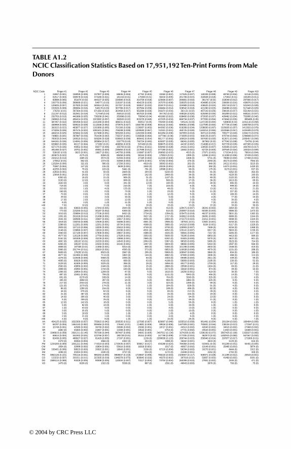
TABLE A1.2NCIC Classification Statistics Based on 17,951,192 Ten-Print Forms from Male Donors
NCIC Code Finger #1 Finger #2 Finger #3 Finger #4 Finger #5 Finger #6 Finger #7 Finger #8 Finger #9 Finger #101 24067 (0.001) 158059 (0.009) 157907 (0.009) 68636 (0.004) 47762 (0.003) 33360 (0.002) 117626 (0.007) 140339 (0.008) 69760 (0.004) 61146 (0.003)2 62517 (0.003) 338978 (0.019) 373189 (0.021) 181419 (0.01) 175609 (0.01) 90434 (0.005) 261799 (0.015) 318948 (0.018) 175942 (0.01) 193283 (0.011)3 82889 (0.005) 351074 (0.02) 444137 (0.025) 234080 (0.013) 314759 (0.018) 123926 (0.007) 284801 (0.016) 361747 (0.02) 218048 (0.012) 297660 (0.017)4 105770 (0.006) 368689 (0.021) 546771 (0.03) 318187 (0.018) 464229 (0.026) 167079 (0.009) 330925 (0.018) 434885 (0.024) 290656 (0.016) 438976 (0.024)5 126605 (0.007) 327820 (0.018) 560614 (0.031) 337307 (0.019) 569537 (0.032) 203479 (0.011) 334989 (0.019) 436625 (0.024) 305718 (0.017) 501943 (0.028)6 153326 (0.009) 288084 (0.016) 540178 (0.03) 307786 (0.017) 637564 (0.036) 246464 (0.014) 328542 (0.018) 421280 (0.023) 284086 (0.016) 517440 (0.029)7 176251 (0.01) 287364 (0.016) 571383 (0.032) 302458 (0.017) 653399 (0.036) 293372 (0.016) 361131 (0.02) 467143 (0.026) 298106 (0.017) 552264 (0.031)8 211197 (0.012) 332561 (0.019) 717548 (0.04) 350515 (0.02) 687023 (0.038) 357762 (0.02) 448326 (0.025) 625069 (0.035) 381809 (0.021) 668161 (0.037)9 232763 (0.013) 441989 (0.025) 736208 (0.041) 353698 (0.02) 709543 (0.04) 401993 (0.022) 638400 (0.036) 672635 (0.037) 428482 (0.024) 752895 (0.042)
10 248063 (0.014) 456414 (0.025) 1023382 (0.057) 363533 (0.02) 815229 (0.045) 422325 (0.024) 666734 (0.037) 977053 (0.054) 474840 (0.026) 899485 (0.05)11 387467 (0.022) 396499 (0.022) 1141366 (0.064) 388231 (0.022) 893517 (0.05) 705494 (0.039) 545141 (0.03) 1147239 (0.064) 538838 (0.03) 1041116 (0.058)12 446969 (0.025) 509524 (0.028) 1112046 (0.062) 475976 (0.027) 1046780 (0.058) 803142 (0.045) 689361 (0.038) 1127595 (0.063) 677736 (0.038) 1306708 (0.073)13 391622 (0.022) 483877 (0.027) 1161866 (0.065) 701306 (0.039) 1136957 (0.063) 642662 (0.036) 618289 (0.034) 1208000 (0.067) 1029935 (0.057) 1412833 (0.079)14 473206 (0.026) 397575 (0.022) 1091501 (0.061) 706338 (0.039) 1200693 (0.067) 742321 (0.041) 460725 (0.026) 1163214 (0.065) 1022666 (0.057) 1425599 (0.079)15 449216 (0.025) 325842 (0.018) 917488 (0.051) 565269 (0.031) 1181509 (0.066) 641954 (0.036) 347853 (0.019) 997113 (0.056) 765277 (0.043) 1334172 (0.074)16 739801 (0.041) 287887 (0.016) 754109 (0.042) 735237 (0.041) 1146558 (0.064) 1077461 (0.06) 273928 (0.015) 840126 (0.047) 970744 (0.054) 1299848 (0.072)17 783533 (0.044) 190010 (0.011) 509285 (0.028) 638563 (0.036) 969442 (0.054) 981777 (0.055) 160624 (0.009) 587600 (0.033) 813071 (0.045) 1009457 (0.056)18 644161 (0.036) 114041 (0.006) 305864 (0.017) 532778 (0.03) 766724 (0.043) 626307 (0.035) 86041 (0.005) 367962 (0.02) 677042 (0.038) 724781 (0.04)19 626882 (0.035) 66117 (0.004) 171652 (0.01) 408056 (0.023) 537438 (0.03) 589675 (0.033) 44192 (0.002) 214698 (0.012) 507728 (0.028) 467305 (0.026)20 627174 (0.035) 40952 (0.002) 99377 (0.006) 355759 (0.02) 374011 (0.021) 506460 (0.028) 24161 (0.001) 130555 (0.007) 425906 (0.024) 306769 (0.017)21 491480 (0.027) 19701 (0.001) 45581 (0.003) 238450 (0.013) 217598 (0.012) 377280 (0.021) 10462 (0.001) 62725 (0.003) 287645 (0.016) 163324 (0.009)22 539102 (0.03) 9022 (0.001) 19627 (0.001) 140756 (0.008) 116987 (0.007) 266693 (0.015) 4515 (0) 27971 (0.002) 173234 (0.01) 78816 (0.004)23 403673 (0.022) 4175 (0) 8268 (0) 88458 (0.005) 58164 (0.003) 178924 (0.01) 1999 (0) 12656 (0.001) 111008 (0.006) 37439 (0.002)24 234212 (0.013) 1995 (0) 3574 (0) 61569 (0.003) 27195 (0.002) 112330 (0.006) 1008 (0) 5731 (0) 78068 (0.004) 17468 (0.001)25 175812 (0.01) 842 (0) 1373 (0) 34368 (0.002) 11974 (0.001) 67262 (0.004) 476 (0) 2294 (0) 45174 (0.003) 7564 (0)26 115284 (0.006) 321 (0) 580 (0) 17256 (0.001) 4819 (0) 38363 (0.002) 262 (0) 946 (0) 24212 (0.001) 3215 (0)27 70387 (0.004) 147 (0) 215 (0) 9639 (0.001) 1930 (0) 20226 (0.001) 128 (0) 392 (0) 14474 (0.001) 1420 (0)28 42255 (0.002) 76 (0) 103 (0) 5441 (0) 781 (0) 10588 (0.001) 99 (0) 175 (0) 9179 (0.001) 637 (0)29 22933 (0.001) 41 (0) 50 (0) 2829 (0) 294 (0) 5230 (0) 48 (0) 91 (0) 5352 (0) 353 (0)30 13558 (0.001) 26 (0) 27 (0) 1949 (0) 162 (0) 2660 (0) 36 (0) 66 (0) 4220 (0) 193 (0)31 6363 (0) 16 (0) 21 (0) 906 (0) 51 (0) 1107 (0) 36 (0) 49 (0) 2122 (0) 100 (0)32 3193 (0) 12 (0) 11 (0) 608 (0) 21 (0) 506 (0) 17 (0) 36 (0) 1613 (0) 69 (0)33 1503 (0) 3 (0) 9 (0) 341 (0) 13 (0) 190 (0) 14 (0) 30 (0) 995 (0) 33 (0)34 719 (0) 2 (0) 7 (0) 210 (0) 7 (0) 104 (0) 6 (0) 9 (0) 599 (0) 19 (0)35 310 (0) 1 (0) 4 (0) 125 (0) 6 (0) 48 (0) 7 (0) 13 (0) 412 (0) 21 (0)36 150 (0) 1 (0) 0 (0) 73 (0) 1 (0) 23 (0) 5 (0) 11 (0) 227 (0) 15 (0)37 73 (0) 0 (0) 3 (0) 21 (0) 1 (0) 12 (0) 5 (0) 4 (0) 106 (0) 14 (0)38 29 (0) 1 (0) 3 (0) 16 (0) 0 (0) 5 (0) 1 (0) 4 (0) 77 (0) 10 (0)39 17 (0) 2 (0) 2 (0) 12 (0) 1 (0) 3 (0) 3 (0) 4 (0) 35 (0) 4 (0)40 9 (0) 3 (0) 1 (0) 11 (0) 1 (0) 5 (0) 17 (0) 7 (0) 22 (0) 10 (0)
>40 7 (0) 10 (0) 11 (0) 9 (0) 16 (0) 15 (0) 13 (0) 22 (0) 33 (0) 30 (0)51 331 (0) 93833 (0.005) 17043 (0.001) 2644 (0) 824 (0) 413 (0) 129475 (0.007) 36341 (0.002) 3364 (0) 847 (0)52 773 (0) 215260 (0.012) 30187 (0.002) 6309 (0) 1958 (0) 915 (0) 293857 (0.016) 60305 (0.003) 5986 (0) 1473 (0)53 1010 (0) 239894 (0.013) 27236 (0.002) 8432 (0) 2734 (0) 1284 (0) 325475 (0.018) 49237 (0.003) 5831 (0) 1382 (0)54 1331 (0) 251618 (0.014) 21498 (0.001) 11358 (0.001) 3527 (0) 1727 (0) 343812 (0.019) 35091 (0.002) 6080 (0) 1344 (0)55 1541 (0) 198586 (0.011) 15687 (0.001) 14017 (0.001) 4056 (0) 2083 (0) 272173 (0.015) 21011 (0.001) 6098 (0) 1324 (0)56 1818 (0) 138233 (0.008) 12639 (0.001) 16496 (0.001) 4561 (0) 2595 (0) 187531 (0.01) 12801 (0.001) 6233 (0) 1322 (0)57 2288 (0) 112261 (0.006) 12261 (0.001) 18734 (0.001) 4588 (0) 3085 (0) 141516 (0.008) 9164 (0.001) 6117 (0) 1329 (0)58 2829 (0) 107113 (0.006) 13205 (0.001) 20410 (0.001) 4749 (0) 3730 (0) 120903 (0.007) 7409 (0) 6234 (0) 1368 (0)59 3148 (0) 128890 (0.007) 13018 (0.001) 20296 (0.001) 4531 (0) 4052 (0) 120141 (0.007) 6017 (0) 5603 (0) 1236 (0)60 3460 (0) 127130 (0.007) 17836 (0.001) 19607 (0.001) 4386 (0) 4545 (0) 93601 (0.005) 7157 (0) 5205 (0) 1177 (0)61 4577 (0) 116128 (0.006) 17759 (0.001) 17028 (0.001) 3353 (0) 5935 (0) 70295 (0.004) 6853 (0) 4413 (0) 996 (0)62 5162 (0) 165309 (0.009) 15228 (0.001) 13998 (0.001) 2865 (0) 6282 (0) 91803 (0.005) 5570 (0) 3622 (0) 901 (0)63 4667 (0) 185107 (0.01) 15233 (0.001) 14543 (0.001) 2064 (0) 5387 (0) 98320 (0.005) 5585 (0) 3523 (0) 754 (0)64 5065 (0) 185107 (0.01) 14103 (0.001) 10142 (0.001) 1447 (0) 5804 (0) 98692 (0.005) 5410 (0) 2597 (0) 566 (0)65 4958 (0) 187306 (0.01) 11968 (0.001) 5914 (0) 899 (0) 5390 (0) 101298 (0.006) 4933 (0) 1548 (0) 419 (0)66 5966 (0) 201744 (0.011) 10619 (0.001) 4595 (0) 573 (0) 6853 (0) 116638 (0.006) 4679 (0) 1231 (0) 288 (0)67 5609 (0) 176202 (0.01) 8523 (0) 2847 (0) 295 (0) 5969 (0) 105947 (0.006) 3840 (0) 834 (0) 186 (0)68 4677 (0) 142483 (0.008) 7113 (0) 1802 (0) 144 (0) 4882 (0) 87465 (0.005) 3306 (0) 498 (0) 113 (0)69 4278 (0) 110548 (0.006) 5568 (0) 1055 (0) 83 (0) 4403 (0) 69385 (0.004) 2611 (0) 339 (0) 59 (0)70 4005 (0) 90926 (0.005) 4310 (0) 668 (0) 63 (0) 4198 (0) 59959 (0.003) 2195 (0) 230 (0) 52 (0)71 3129 (0) 62405 (0.003) 3225 (0) 358 (0) 29 (0) 3456 (0) 40177 (0.002) 1703 (0) 117 (0) 29 (0)72 2583 (0) 40856 (0.002) 2446 (0) 198 (0) 15 (0) 2886 (0) 25508 (0.001) 1304 (0) 69 (0) 21 (0)73 1908 (0) 25992 (0.001) 1734 (0) 100 (0) 10 (0) 2174 (0) 15632 (0.001) 874 (0) 49 (0) 10 (0)74 1306 (0) 16854 (0.001) 1208 (0) 47 (0) 5 (0) 1610 (0) 10250 (0.001) 619 (0) 30 (0) 7 (0)75 887 (0) 10461 (0.001) 799 (0) 38 (0) 6 (0) 1111 (0) 5943 (0) 466 (0) 14 (0) 7 (0)76 601 (0) 6278 (0) 538 (0) 14 (0) 3 (0) 764 (0) 3240 (0) 325 (0) 11 (0) 4 (0)77 345 (0) 3858 (0) 397 (0) 14 (0) 6 (0) 493 (0) 1882 (0) 225 (0) 9 (0) 5 (0)78 217 (0) 2533 (0) 278 (0) 11 (0) 3 (0) 324 (0) 1096 (0) 99 (0) 5 (0) 3 (0)79 121 (0) 1579 (0) 174 (0) 5 (0) 1 (0) 184 (0) 628 (0) 91 (0) 4 (0) 0 (0)80 86 (0) 1290 (0) 154 (0) 8 (0) 0 (0) 108 (0) 496 (0) 82 (0) 4 (0) 5 (0)81 34 (0) 676 (0) 82 (0) 6 (0) 5 (0) 80 (0) 212 (0) 28 (0) 6 (0) 3 (0)82 21 (0) 487 (0) 56 (0) 1 (0) 0 (0) 25 (0) 155 (0) 19 (0) 0 (0) 1 (0)83 14 (0) 306 (0) 40 (0) 3 (0) 0 (0) 24 (0) 94 (0) 13 (0) 0 (0) 0 (0)84 5 (0) 209 (0) 25 (0) 1 (0) 0 (0) 13 (0) 49 (0) 11 (0) 0 (0) 1 (0)85 12 (0) 142 (0) 18 (0) 0 (0) 0 (0) 5 (0) 56 (0) 8 (0) 1 (0) 1 (0)86 5 (0) 82 (0) 14 (0) 0 (0) 1 (0) 5 (0) 34 (0) 1 (0) 1 (0) 0 (0)87 1 (0) 43 (0) 9 (0) 0 (0) 0 (0) 4 (0) 13 (0) 1 (0) 0 (0) 0 (0)88 3 (0) 35 (0) 5 (0) 0 (0) 0 (0) 2 (0) 13 (0) 2 (0) 0 (0) 1 (0)89 3 (0) 18 (0) 3 (0) 1 (0) 1 (0) 1 (0) 4 (0) 0 (0) 0 (0) 0 (0)90 2 (0) 21 (0) 1 (0) 0 (0) 0 (0) 3 (0) 5 (0) 1 (0) 0 (0) 2 (0)
>90 4 (0) 8 (0) 8 (0) 1 (0) 1 (0) 15 (0) 26 (0) 9 (0) 5 (0) 7 (0)AA 454125 (0.025) 1022300 (0.057) 755815 (0.042) 200535 (0.011) 127095 (0.007) 829907 (0.046) 1035510 (0.058) 961491 (0.054) 281194 (0.016) 166404 (0.009)TT 66787 (0.004) 1464143 (0.082) 599484 (0.033) 176441 (0.01) 114881 (0.006) 99534 (0.006) 1447009 (0.081) 793601 (0.044) 238104 (0.013) 171547 (0.01)XX 15748 (0.001) 42580 (0.002) 39766 (0.002) 29586 (0.002) 25582 (0.001) 18727 (0.001) 44513 (0.002) 42640 (0.002) 34615 (0.002) 27968 (0.002)SR 4482 (0) 33463 (0.002) 24367 (0.001) 11508 (0.001) 10542 (0.001) 6753 (0) 27731 (0.002) 23543 (0.001) 11923 (0.001) 10469 (0.001)PI 1046615 (0.058) 2601211 (0.145) 787299 (0.044) 997497 (0.056) 94061 (0.005) 2407512 (0.134) 1074206 (0.06) 1296150 (0.072) 3567425 (0.199) 1163027 (0.065)CI 66614 (0.004) 551942 (0.031) 123766 (0.007) 180728 (0.01) 35151 (0.002) 147798 (0.008) 277035 (0.015) 362973 (0.02) 1482915 (0.083) 567567 (0.032)DI 82436 (0.005) 488927 (0.027) 81429 (0.005) 17197 (0.001) 1139 (0) 2206636 (0.123) 266744 (0.015) 256940 (0.014) 297877 (0.017) 171900 (0.01)XI 2379 (0) 48364 (0.003) 3584 (0) 4302 (0) 343 (0) 1998 (0) 16032 (0.001) 3619 (0) 5120 (0) 616 (0)
PM 1234283 (0.069) 1001221 (0.056) 774319 (0.043) 1733535 (0.097) 300817 (0.017) 434288 (0.024) 784084 (0.044) 533591 (0.03) 551268 (0.031) 94491 (0.005)CM 1954 (0) 32999 (0.002) 15804 (0.001) 55616 (0.003) 18318 (0.001) 1017 (0) 40927 (0.002) 13149 (0.001) 25495 (0.001) 5874 (0)DM 105401 (0.006) 58523 (0.003) 26302 (0.001) 18043 (0.001) 3106 (0) 67116 (0.004) 56294 (0.003) 19270 (0.001) 6444 (0) 1912 (0)XM 1098 (0) 20264 (0.001) 2180 (0) 3737 (0) 553 (0) 1172 (0) 21848 (0.001) 3162 (0) 1702 (0) 309 (0)PO 3962126 (0.221) 735116 (0.041) 985263 (0.055) 3908637 (0.218) 1728667 (0.096) 780220 (0.043) 2105657 (0.117) 506971 (0.028) 211295 (0.012) 20543 (0.001)CO 123232 (0.007) 201011 (0.011) 322305 (0.018) 1348378 (0.075) 600842 (0.033) 40379 (0.002) 367016 (0.02) 53857 (0.003) 41469 (0.002) 8181 (0)DO 1589114 (0.089) 93328 (0.005) 90598 (0.005) 120034 (0.007) 73117 (0.004) 74704 (0.004) 260399 (0.015) 27801 (0.002) 2445 (0) 471 (0)XO 1470 (0) 8236 (0) 1322 (0) 5538 (0) 887 (0) 1591 (0) 49643 (0.003) 3976 (0) 793 (0) 75 (0)
TF1345_C07.fm Page 209 Wednesday, March 17, 2004 9:14 AM
© 2004 by CRC Press LLC

TABLE A1.3NCIC Classification Statistics Based on 4,313,521 Ten-Print Forms from Female Donors
NCIC Code Finger #1 Finger #2 Finger #3 Finger #4 Finger #5 Finger #6 Finger #7 Finger #8 Finger #9 Finger #101 9304 (0.002) 47886 (0.011) 44982 (0.01) 25112 (0.006) 21403 (0.005) 12406 (0.003) 39362 (0.009) 47795 (0.011) 27818 (0.006) 29720 (0.007)2 23876 (0.006) 98841 (0.023) 103227 (0.024) 62741 (0.015) 74681 (0.017) 33517 (0.008) 83424 (0.019) 103235 (0.024) 66149 (0.015) 88610 (0.021)3 31518 (0.007) 100427 (0.023) 120687 (0.028) 76997 (0.018) 121633 (0.028) 44724 (0.01) 86464 (0.02) 111189 (0.026) 78239 (0.018) 126046 (0.029)4 39800 (0.009) 103419 (0.024) 140961 (0.033) 94907 (0.022) 162749 (0.038) 57822 (0.013) 92544 (0.021) 122504 (0.028) 93035 (0.022) 161398 (0.037)5 46910 (0.011) 97944 (0.023) 146025 (0.034) 96144 (0.022) 184848 (0.043) 68697 (0.016) 93017 (0.022) 121560 (0.028) 92146 (0.021) 170009 (0.039)6 57109 (0.013) 95773 (0.022) 151430 (0.035) 91247 (0.021) 196070 (0.045) 83870 (0.019) 96177 (0.022) 122643 (0.028) 87007 (0.02) 171784 (0.04)7 65274 (0.015) 99889 (0.023) 165017 (0.038) 89769 (0.021) 193963 (0.045) 97153 (0.023) 104401 (0.024) 135457 (0.031) 90501 (0.021) 175561 (0.041)8 77218 (0.018) 108181 (0.025) 199216 (0.046) 100876 (0.023) 200233 (0.046) 115325 (0.027) 114696 (0.027) 166534 (0.039) 108873 (0.025) 196787 (0.046)9 85057 (0.02) 150105 (0.035) 202730 (0.047) 103696 (0.024) 203809 (0.047) 126463 (0.029) 162617 (0.038) 171769 (0.04) 119493 (0.028) 210672 (0.049)
10 90499 (0.021) 160259 (0.037) 299721 (0.069) 112958 (0.026) 230174 (0.053) 129840 (0.03) 167705 (0.039) 261756 (0.061) 133352 (0.031) 243413 (0.056)11 135005 (0.031) 135869 (0.031) 333261 (0.077) 121114 (0.028) 242246 (0.056) 199104 (0.046) 127022 (0.029) 295934 (0.069) 147174 (0.034) 262831 (0.061)12 154482 (0.036) 158784 (0.037) 288862 (0.067) 134541 (0.031) 272526 (0.063) 214351 (0.05) 141932 (0.033) 250181 (0.058) 161591 (0.037) 302531 (0.07)13 134441 (0.031) 146358 (0.034) 300551 (0.07) 204884 (0.047) 282707 (0.066) 166701 (0.039) 118346 (0.027) 262490 (0.061) 251220 (0.058) 308311 (0.071)14 157148 (0.036) 118402 (0.027) 272750 (0.063) 210571 (0.049) 284717 (0.066) 179102 (0.042) 84839 (0.02) 240687 (0.056) 245728 (0.057) 295957 (0.069)15 143972 (0.033) 92467 (0.021) 215778 (0.05) 158690 (0.037) 267954 (0.062) 147260 (0.034) 58461 (0.014) 192088 (0.045) 166947 (0.039) 260734 (0.06)16 217956 (0.051) 72893 (0.017) 162367 (0.038) 192451 (0.045) 248317 (0.058) 215863 (0.05) 40234 (0.009) 146830 (0.034) 196021 (0.045) 237221 (0.055)17 212146 (0.049) 45470 (0.011) 103792 (0.024) 167713 (0.039) 198424 (0.046) 174719 (0.041) 21965 (0.005) 95715 (0.022) 162210 (0.038) 173126 (0.04)18 160462 (0.037) 26552 (0.006) 60474 (0.014) 144309 (0.033) 149107 (0.035) 101972 (0.024) 10897 (0.003) 56990 (0.013) 134988 (0.031) 119335 (0.028)19 145229 (0.034) 14499 (0.003) 31868 (0.007) 109338 (0.025) 97567 (0.023) 85341 (0.02) 5263 (0.001) 30968 (0.007) 100232 (0.023) 72705 (0.017)20 130014 (0.03) 8030 (0.002) 16557 (0.004) 89707 (0.021) 64651 (0.015) 65169 (0.015) 2554 (0.001) 16754 (0.004) 79543 (0.018) 45011 (0.01)21 93898 (0.022) 3717 (0.001) 7232 (0.002) 61093 (0.014) 35356 (0.008) 43130 (0.01) 1042 (0) 7836 (0.002) 53933 (0.013) 22888 (0.005)22 83984 (0.019) 1641 (0) 3131 (0.001) 38196 (0.009) 17249 (0.004) 26732 (0.006) 478 (0) 3360 (0.001) 34360 (0.008) 10671 (0.002)23 55421 (0.013) 749 (0) 1262 (0) 24433 (0.006) 8081 (0.002) 15705 (0.004) 205 (0) 1405 (0) 22304 (0.005) 4901 (0.001)24 29297 (0.007) 290 (0) 493 (0) 15660 (0.004) 3583 (0.001) 8610 (0.002) 111 (0) 563 (0) 14767 (0.003) 2096 (0)25 18808 (0.004) 144 (0) 209 (0) 8905 (0.002) 1497 (0) 4421 (0.001) 69 (0) 200 (0) 9360 (0.002) 885 (0)26 10556 (0.002) 61 (0) 77 (0) 4900 (0.001) 529 (0) 2093 (0) 26 (0) 94 (0) 5355 (0.001) 343 (0)27 5590 (0.001) 26 (0) 41 (0) 2650 (0.001) 206 (0) 971 (0) 19 (0) 38 (0) 3213 (0.001) 151 (0)28 2905 (0.001) 19 (0) 25 (0) 1632 (0) 88 (0) 511 (0) 22 (0) 33 (0) 2088 (0) 52 (0)29 1373 (0) 8 (0) 14 (0) 845 (0) 36 (0) 211 (0) 11 (0) 15 (0) 1227 (0) 34 (0)30 692 (0) 3 (0) 9 (0) 603 (0) 22 (0) 85 (0) 7 (0) 16 (0) 999 (0) 17 (0)31 277 (0) 3 (0) 5 (0) 217 (0) 2 (0) 40 (0) 4 (0) 4 (0) 444 (0) 5 (0)32 141 (0) 2 (0) 1 (0) 169 (0) 2 (0) 12 (0) 2 (0) 5 (0) 330 (0) 4 (0)33 56 (0) 2 (0) 2 (0) 80 (0) 1 (0) 8 (0) 0 (0) 5 (0) 181 (0) 2 (0)34 20 (0) 1 (0) 2 (0) 51 (0) 0 (0) 1 (0) 1 (0) 4 (0) 115 (0) 0 (0)35 9 (0) 2 (0) 2 (0) 30 (0) 1 (0) 2 (0) 0 (0) 2 (0) 69 (0) 1 (0)36 7 (0) 0 (0) 0 (0) 15 (0) 0 (0) 0 (0) 1 (0) 2 (0) 31 (0) 0 (0)37 1 (0) 0 (0) 0 (0) 8 (0) 0 (0) 0 (0) 2 (0) 0 (0) 17 (0) 1 (0)38 0 (0) 0 (0) 1 (0) 1 (0) 0 (0) 0 (0) 1 (0) 1 (0) 5 (0) 2 (0)39 0 (0) 0 (0) 0 (0) 4 (0) 0 (0) 0 (0) 0 (0) 0 (0) 4 (0) 0 (0)40 3 (0) 2 (0) 1 (0) 2 (0) 1 (0) 1 (0) 5 (0) 2 (0) 1 (0) 1 (0)
>40 0 (0) 2 (0) 4 (0) 3 (0) 3 (0) 0 (0) 7 (0) 4 (0) 1 (0) 3 (0)51 111 (0) 20323 (0.005) 2860 (0.001) 693 (0) 238 (0) 183 (0) 33950 (0.008) 10467 (0.002) 1627 (0) 415 (0)52 264 (0) 40729 (0.009) 4521 (0.001) 1712 (0) 615 (0) 462 (0) 70212 (0.016) 16264 (0.004) 2935 (0.001) 740 (0)53 412 (0) 40455 (0.009) 3561 (0.001) 2248 (0.001) 841 (0) 727 (0) 71439 (0.017) 12474 (0.003) 2988 (0.001) 768 (0)54 541 (0) 36039 (0.008) 2400 (0.001) 2714 (0.001) 936 (0) 912 (0) 66130 (0.015) 8271 (0.002) 3268 (0.001) 781 (0)55 660 (0) 27682 (0.006) 1717 (0) 3260 (0.001) 993 (0) 1198 (0) 49740 (0.012) 4998 (0.001) 3413 (0.001) 692 (0)56 846 (0) 19742 (0.005) 1437 (0) 3826 (0.001) 1062 (0) 1519 (0) 35089 (0.008) 3278 (0.001) 3261 (0.001) 756 (0)57 961 (0) 16295 (0.004) 1399 (0) 4040 (0.001) 1021 (0) 1883 (0) 27015 (0.006) 2431 (0.001) 3191 (0.001) 719 (0)58 1168 (0) 14925 (0.003) 1460 (0) 4190 (0.001) 979 (0) 2165 (0.001) 22413 (0.005) 2170 (0.001) 3256 (0.001) 696 (0)59 1325 (0) 18771 (0.004) 1421 (0) 3938 (0.001) 840 (0) 2397 (0.001) 24951 (0.006) 2015 (0) 2882 (0.001) 665 (0)60 1563 (0) 19951 (0.005) 1831 (0) 3487 (0.001) 769 (0) 2720 (0.001) 23181 (0.005) 2273 (0.001) 2610 (0.001) 602 (0)61 1790 (0) 18371 (0.004) 1797 (0) 3040 (0.001) 568 (0) 3408 (0.001) 18876 (0.004) 2114 (0) 2153 (0) 542 (0)62 1931 (0) 24006 (0.006) 1503 (0) 2203 (0.001) 450 (0) 3635 (0.001) 24435 (0.006) 1949 (0) 1676 (0) 410 (0)63 1664 (0) 26108 (0.006) 1459 (0) 1994 (0) 302 (0) 3174 (0.001) 27081 (0.006) 1822 (0) 1630 (0) 306 (0)64 1640 (0) 26655 (0.006) 1263 (0) 1332 (0) 196 (0) 3170 (0.001) 28059 (0.007) 1720 (0) 1147 (0) 219 (0)65 1463 (0) 26146 (0.006) 1032 (0) 724 (0) 96 (0) 2899 (0.001) 27956 (0.006) 1529 (0) 685 (0) 131 (0)66 1675 (0) 26197 (0.006) 924 (0) 509 (0) 67 (0) 3484 (0.001) 30114 (0.007) 1421 (0) 523 (0) 85 (0)67 1349 (0) 22390 (0.005) 743 (0) 322 (0) 32 (0) 3075 (0.001) 26613 (0.006) 1200 (0) 321 (0) 56 (0)68 975 (0) 18314 (0.004) 601 (0) 185 (0) 24 (0) 2338 (0.001) 22038 (0.005) 999 (0) 202 (0) 30 (0)69 793 (0) 13858 (0.003) 405 (0) 99 (0) 7 (0) 2070 (0) 17137 (0.004) 778 (0) 119 (0) 21 (0)70 722 (0) 11293 (0.003) 364 (0) 59 (0) 7 (0) 1783 (0) 14105 (0.003) 678 (0) 74 (0) 17 (0)71 529 (0) 7900 (0.002) 263 (0) 37 (0) 9 (0) 1318 (0) 9072 (0.002) 446 (0) 47 (0) 4 (0)72 353 (0) 5298 (0.001) 169 (0) 18 (0) 1 (0) 1037 (0) 5938 (0.001) 345 (0) 23 (0) 5 (0)73 266 (0) 3336 (0.001) 109 (0) 11 (0) 1 (0) 726 (0) 3577 (0.001) 238 (0) 11 (0) 2 (0)74 160 (0) 2139 (0) 77 (0) 10 (0) 1 (0) 469 (0) 2295 (0.001) 174 (0) 12 (0) 1 (0)75 110 (0) 1393 (0) 83 (0) 6 (0) 2 (0) 342 (0) 1355 (0) 105 (0) 6 (0) 0 (0)76 52 (0) 881 (0) 46 (0) 7 (0) 1 (0) 215 (0) 704 (0) 78 (0) 3 (0) 0 (0)77 32 (0) 526 (0) 24 (0) 1 (0) 0 (0) 126 (0) 430 (0) 55 (0) 6 (0) 2 (0)78 21 (0) 306 (0) 29 (0) 0 (0) 0 (0) 72 (0) 247 (0) 34 (0) 2 (0) 1 (0)79 13 (0) 234 (0) 12 (0) 1 (0) 0 (0) 31 (0) 157 (0) 15 (0) 3 (0) 0 (0)80 6 (0) 182 (0) 12 (0) 2 (0) 1 (0) 32 (0) 108 (0) 10 (0) 1 (0) 0 (0)81 5 (0) 69 (0) 8 (0) 0 (0) 0 (0) 12 (0) 37 (0) 6 (0) 1 (0) 0 (0)82 4 (0) 62 (0) 3 (0) 0 (0) 0 (0) 7 (0) 30 (0) 4 (0) 1 (0) 1 (0)83 3 (0) 26 (0) 3 (0) 0 (0) 0 (0) 4 (0) 20 (0) 1 (0) 0 (0) 0 (0)84 0 (0) 29 (0) 2 (0) 0 (0) 0 (0) 1 (0) 6 (0) 3 (0) 0 (0) 0 (0)85 0 (0) 17 (0) 3 (0) 0 (0) 0 (0) 1 (0) 11 (0) 0 (0) 0 (0) 0 (0)86 0 (0) 8 (0) 1 (0) 0 (0) 0 (0) 1 (0) 5 (0) 0 (0) 0 (0) 0 (0)87 0 (0) 2 (0) 1 (0) 0 (0) 0 (0) 0 (0) 1 (0) 0 (0) 0 (0) 0 (0)88 0 (0) 6 (0) 1 (0) 0 (0) 0 (0) 0 (0) 1 (0) 0 (0) 0 (0) 1 (0)89 1 (0) 3 (0) 0 (0) 0 (0) 0 (0) 0 (0) 2 (0) 0 (0) 0 (0) 0 (0)90 0 (0) 2 (0) 0 (0) 0 (0) 0 (0) 2 (0) 1 (0) 0 (0) 0 (0) 0 (0)
>90 0 (0) 2 (0) 2 (0) 0 (0) 0 (0) 2 (0) 3 (0) 3 (0) 2 (0) 1 (0)AA 226462 (0.053) 354903 (0.082) 249975 (0.058) 80551 (0.019) 65882 (0.015) 344675 (0.08) 386139 (0.09) 369727 (0.086) 121814 (0.028) 91403 (0.021)TT 23597 (0.005) 300826 (0.07) 137833 (0.032) 58682 (0.014) 46731 (0.011) 32443 (0.008) 362593 (0.084) 243941 (0.057) 93831 (0.022) 76408 (0.018)XX 824 (0) 2447 (0.001) 2277 (0.001) 1789 (0) 1684 (0) 935 (0) 2307 (0.001) 2219 (0.001) 1824 (0) 1693 (0)SR 857 (0) 4433 (0.001) 3374 (0.001) 1598 (0) 1494 (0) 1023 (0) 3901 (0.001) 3373 (0.001) 1645 (0) 1448 (0)PI 176056 (0.041) 516946 (0.12) 102657 (0.024) 131562 (0.03) 11562 (0.003) 513877 (0.119) 226992 (0.053) 249219 (0.058) 733130 (0.17) 241970 (0.056)CI 12180 (0.003) 103400 (0.024) 14569 (0.003) 33061 (0.008) 6059 (0.001) 33603 (0.008) 61533 (0.014) 80154 (0.019) 355477 (0.082) 132491 (0.031)DI 12893 (0.003) 75349 (0.017) 7942 (0.002) 1763 (0) 120 (0) 467944 (0.108) 49061 (0.011) 38013 (0.009) 41593 (0.01) 19485 (0.005)XI 369 (0) 7935 (0.002) 469 (0) 463 (0) 30 (0) 551 (0) 2324 (0.001) 601 (0) 1157 (0) 145 (0)
PM 249538 (0.058) 264070 (0.061) 130160 (0.03) 286478 (0.066) 45842 (0.011) 138410 (0.032) 189608 (0.044) 121402 (0.028) 145809 (0.034) 31994 (0.007)CM 473 (0) 8000 (0.002) 2544 (0.001) 14582 (0.003) 4634 (0.001) 448 (0) 9464 (0.002) 4409 (0.001) 11504 (0.003) 3516 (0.001)DM 27868 (0.006) 14337 (0.003) 3858 (0.001) 2424 (0.001) 566 (0) 25295 (0.006) 11948 (0.003) 3464 (0.001) 1112 (0) 409 (0)XM 242 (0) 3554 (0.001) 260 (0) 670 (0) 83 (0) 537 (0) 4537 (0.001) 721 (0) 474 (0) 102 (0)PO 739816 (0.172) 197879 (0.046) 177728 (0.041) 768509 (0.178) 244097 (0.057) 244236 (0.057) 500646 (0.116) 125241 (0.029) 56460 (0.013) 6228 (0.001)CO 27018 (0.006) 53649 (0.012) 57656 (0.013) 321550 (0.075) 102323 (0.024) 16434 (0.004) 102705 (0.024) 18030 (0.004) 17877 (0.004) 3656 (0.001)DO 371200 (0.086) 25023 (0.006) 15716 (0.004) 20763 (0.005) 7785 (0.002) 23021 (0.005) 50008 (0.012) 5013 (0.001) 475 (0) 61 (0)XO 262 (0) 1379 (0) 190 (0) 1146 (0) 134 (0) 557 (0) 11288 (0.003) 958 (0) 189 (0) 24 (0)
TF1345_C07.fm Page 210 Wednesday, March 17, 2004 9:14 AM
© 2004 by CRC Press LLC

Appendix 2
Statistical Data on Minutiæ
The main statistical findings from the study by Champod are presented in thisappendix (Champod 1996; Champod and Margot 1996).
A2.1 THE MODEL
The study aimed at exploring the validity of a statistical model to compute matchprobabilities associated with level 2 features reduced to minutiæ. The postulatedmodel suggests that the probability of a configuration of minutiæ, Pr(C), can becomputed using the following equation:
wherePr(
N
) = probability of a given number of minutiæ on the surface consideredPr(
T
) = probability of the observed types of minutiæ (obtained by the multipli-cation of the probability of each minutia type)
Pr(
S
) = probability of the orientations of the minutiæ (obtained by the multipli-cation of the probability of the orientation for each minutia)
Pr(
D
) = probability of the length of minutiæ (when applicable, obtained by the multiplication of the probability of each minutia length)
Pr(
A
) = probability of the arrangement of the minutiæ
The probabilities for the number, type, orientation, and length of minutiæ —Pr(
N
), Pr(
T
), Pr(
S
), and Pr(
D
), respectively — have been studied.
A2.2 MINUTIÆ CONSIDERED
Two types of minutiæ are considered as fundamental points: ridge endings andbifurcations. From these two basic forms, it is possible to consider compoundminutiæ resulting from the specific arrangement of these two fundamental points.Compound minutiæ are described in Table A2.1. For each instance of combined
Pr Pr Pr Pr Pr PrC N T S D A( ) = ( ) ◊ ( ) ◊ ( ) ◊ ( ) ◊ ( )
TF1345_C08.fm Page 211 Wednesday, March 17, 2004 9:15 AM
© 2004 by CRC Press LLC

minutiæ, maximum distance is used as a threshold to distinguish between the com-bined type and two distinct fundamental points.
A2.3 SAMPLE AND DATA ACQUISITION
The sample available for the study breaks down in Table A2.2. The algorithms used(fully described by Champod [1996]) involved the following steps:
1. From an 8-bit gray-scale image of the fingerprint scanned at 800 dpi, abinary image is obtained by applying an adaptive threshold.
2. The image is then reduced to a skeleton and checked by an operator forits reliability.
TABLE A2.1Minutiæ Considered in the Study
Bifurcation opposed with an ending
Illustration Particular Case
Ridge ending
Bifurcation
Island (short ridge) and point or dot (particular case)
Lake (enclosure)
Opposed bifurcations and cross
Bridge
Double bifurcation and the trifurcation
Hook (or spur)
TF1345_C08.fm Page 212 Wednesday, March 17, 2004 9:15 AM
© 2004 by CRC Press LLC

3. The skeleton is then searched (walked through) for basic and combinedminutiæ. Decisions on categories are deterministically based on the num-ber of branches and leaves and their angles.
4. For each detected minutia, its Cartesian coordinates from the core and thenumber of ridges from the core are recorded as well as the orientationdefined relative to the vertical axis and the length of the minutiæ (forcombined minutiæ only).
A2.4 STATISTICAL FINDINGS
A2.4.1 M
INUTIÆ
D
ENSITY
It was found that the density of minutiæ on the prints varied considerably —consistent with latent fingerprint examiner’s expectations — the delta and core areabeing more dense in terms of minutiæ than the rest of the pattern. The process wasmodeled using a Poisson distribution of parameter
l
being based on the density anddepending only on the position of the minutiæ on the print. Table A2.3 shows theaverage density estimations according to the main positioning on the print.
This may seem obvious to fingerprint examiners, but this is the first time thatthe extent of this variation has been quantified. Also, modeling this distributionthrough a Poisson process allows us to predict the probability Pr(
N
) and, hence, notonly the chance of a positive number of minutiæ in a given area but also the absenceof minutiæ in a given area. This highlights the fact that the absence of minutiæ overan extensive surface (an open field of uninterrupted ridges) also provides selectivity.
A2.4.2 L
OCALIZED
R
ELATIVE
F
REQUENCIES
OF
M
INUTIÆ
T
YPES
From the core of the fingerprint pattern, minutiæ frequencies were analyzed withina ridge count radius of about 13. Further zones in the periphery (ridge counts from11 to 25 from the core) were investigated above the core. It was observed that regionscorresponding to the core or the delta presented more compound minutiæ than theperiphery of the print. So, when assessing the relative frequency of minutiæ, thelocation on the fingerprint pattern has to be considered. The frequencies were shownnot to vary with finger number, depending instead on the complexity of the pattern
TABLE A2.2Breakdown of the Sample According to General Pattern and Ridge Count (RC)
Description Number
Ulnar loops from right index finger (ridge count i: RC = 3–6) 217Ulnar loops from right index finger (ridge count o: RC = 12–16) 104Ulnar loops from right middle finger (ridge count i: RC = 3–6) 185Ulnar loops from right middle finger (ridge count o: RC = 12–16) 180Ulnar loops from left middle finger (ridge count i: RC = 3–6) 118Whorls from right middle finger (ridge tracing meet) 173
TF1345_C08.fm Page 213 Wednesday, March 17, 2004 9:15 AM
© 2004 by CRC Press LLC

(presence of one or two deltas). The independence assumptions postulated in themodel were shown to be robust for most minutiæ types except the short ridge.
Table A2.4 and Table A2.5 summarize the findings for the 804 loops and the173 whorls, respectively.
A2.4.3 R
ELATIVE
O
RIENTATION
OF
M
INUTIÆ
Relative orientations were studied in 45
∞
sectors about the core, excepting the deltaareas (where the relative orientation was ill defined). Orientation was defined withreference to the vertical axis; minutiæ creating ridges to the right were defined aspositive, and minutiæ creating ridges to the left were classified as negative. Theresults showed that negative orientation was more frequent for ulnar loops on theright hand and that the reverse was true for the ulnar loops on the left hand. In fact,
the relative orientations depend crucially on the presence of one or more deltas. Assoon as this mirroring effect was taken into account for the loops, the orientationwere shown to depend slightly on the minutiæ type but were not affected by the
TABLE A2.3Average Minutiæ Densities on the Core/Delta Area and Outside These Focal Points
Region Considered Density of Minutiæ per mm
2
Core/delta area 0.49Out of core/delta area 0.18
TABLE A2.4Actual Counts and Relative Proportions of the Various Types of Minutiæ Recorded in Three Areas of 804 Loops
Minutiæ TypeWithin Delta
ZoneOutside Delta
Zone Periphery
Ridge ending 2763 (0.374) 6842 (0.455) 7070 (0.584)Bifurcation 1002 (0.135) 3301 (0.22) 2515 (0.208)Island 993 (0.134) 2313 (0.154) 1667 (0.138)Lake 331 (0.045) 518 (0.034) 146 (0.012)Opposed bifurcations 40 (0.005) 208 (0.014) 49 (0.004)Bridge 523 (0.071) 231 (0.015) 121 (0.01)Double bifurcation 688 (0.093) 716 (0.048) v52 (0.004)Hook 665 (0.09) 579 (0.039) 451 (0.037)Bifurcation opposed with ridge ending
390 (0.053) 321 (0.021) 39 (0.003)
TF1345_C08.fm Page 214 Wednesday, March 17, 2004 9:15 AM
© 2004 by CRC Press LLC

finger number. Orientation results were obtained for 804 ulnar loops (Table A2.6)and 173 whorls (Table A2.7).
A2.4.4 L
ENGTH
OF
C
OMBINED
M
INUTIÆ
The length (in millimeters) of combined minutiæ was studied for given intervals(D1 to D5) defined in Table A2.8, depending on their type. The results in Table A2.9show that, as soon as some conditioning was adopted for the short ridges (a functionof their position within the delta pattern area), the length showed good independencebehavior in the face of the number or orientation of the points.
TABLE A2.5Actual Counts and Relative Proportions of the Various Types of Minutiæ Recorded in Three Areas of 173 Whorls
Minutiæ TypeWithin Delta
ZoneOutside Delta
Zone Periphery
Ridge ending 1383 (0.422) 1308 (0.529) 1371 (0.635)Bifurcation 595 (0.181) 521 (0.211) 393 (0.182)Island 482 (0.147) 354 (0.143) 274 (0.127)Lake 193 (0.059) 30 (0.012) 18 (0.008)Opposed bifurcations 49 (0.015) 25 (0.01) 8 (0.004)Bridge 62 (0.019) 18 (0.007) 17 (0.008)Double bifurcation 197 (0.06) 105 (0.042) 7 (0.003)Hook 223 (0.068) 79 (0.032) 62 (0.029)Bifurcation opposed with ridge ending
96 (0.029) 33 (0.013) 10 (0.005)
TABLE A2.6Actual Counts and Relative Proportions of the Orientations of Minutiæ Recorded in Three Areas of 804 Loops
Minutiæ Type Above Delta Opposite Delta Beside Delta
Ridge ending + 661 (0.31) 486 (0.33) 429 (0.17)Ridge ending – 1461 (0.69) 967 (0.67) 2038 (0.83)Bifurcation + 427 (0.41) 224 (0.21) 197 (0.22)Bifurcation – 619 (0.59) 847 (0.79) 710 (0.78)Other minutiæ + 126 (0.39) 23 (0.21) 83 (0.22)Other minutiæ – 200 (0.61) 89 (0.79) 297 (0.78)
TF1345_C08.fm Page 215 Wednesday, March 17, 2004 9:15 AM
© 2004 by CRC Press LLC

TABLE A2.7Actual Counts and Relative Proportions of the Orientations of Minutiæ Recorded in Three Areas of 173 Whorls
Minutiæ Type Above Left Delta Above Right Delta
Ridge ending + 113 (0.16) 407 (0.7)Ridge ending – 612 (0.84) 176 (0.3)Bifurcation + 47 (0.18) 185 (0.71)Bifurcation – 215 (0.82) 74 (0.29)Other minutiæ + 21 (0.38) 14 (0.27)Other minutiæ – 35 (0.63) 37 (0.73)
TABLE A2.8Definition of the Interval D1 to D5 in Function of the Type of Combined Minutiæ
D1 D2 D3 D4 D5
Island 0–0.65 0.66–1.27 1.28–1.90 1.91–2.54 2.55–3.18Lake 0–0.96 0.96–1.90 1.91–2.85 2.86–3.81 3.82–4.76Other combined minutiæ 0–0.44 0.45–0.89 0.90–1.33 1.34–1.79 1.80–2.22
TABLE A2.9Actual Counts and Relative Proportions of the Length of Minutiæ According to Their Type
D1 D2 D3 D4 D5
Island (outside delta zone)
2563 (0.76) 333 (0.1) 211 (0.06) 142 (0.04) 143 (0.04)
Island (within delta zone)
442 (0.59) 96 (0.13) 75 (0.1) 79 (0.11) 58 (0.08)
Lake 272 (0.25) 418 (0.39) 195 (0.18) 116 (0.11) 71 (0.07)Other combined minutiæ
267 (0.11) 497 (0.21) 517 (0.22) 530 (0.23) 536 (0.23)
TF1345_C08.fm Page 216 Wednesday, March 17, 2004 9:15 AM
© 2004 by CRC Press LLC

Appendix 3
Fingerprint Detection Sequences
A3.1 GENERAL
The application of more than one technique or reagent for the detection of latentfingerprints can often increase the number of prints found or improve the quality ofthose already developed. However, it is imperative that reagents be employed in asystematic, predetermined order (Lennard and Margot 1988). The incorrect choiceor application of one method can preclude the later use of another technique orlessen its effectiveness. Goode and Morris (1983) and the Home Office PSDB (Kent1986, 1998) have proposed an extensive range of reagent sequences for the detectionof latent prints on various surfaces. A number of systematic approaches to fingerprintdevelopment have also been suggested by Lee and Gaensslen (1988, 2001b). Inaddition, Allman and Pounds (1992b) reported on a recommended sequence ofreagents for the development of both latent and blood marks at the crime scene.Ribaux and coworkers (1993) presented a computer-based approach to assist in thechoice of a fingerprint detection sequence. The computer program, based on expertsystem technology, calculated an appropriate sequence of techniques based on anumber parameters supplied by the user. Factors such as surface porosity, color,luminescence, fingerprint age, and whether or not the surface is or has been wetdetermined the choices made by the system. Unfortunately, the prototype systemwas never commercialized.
The proposed sequences for fingerprint detection and enhancement on par-ticular surfaces, as presented in this book, should be considered as generalrecommendations only that will give satisfactory results in 70 to 80% of cases.Different situations and surfaces will necessitate the consideration of modifiedsequences or the application of other techniques. Operational laboratories shouldadapt sequences of this type to their own needs, based on available resources andconditions (techniques and instruments at hand, time limitations, etc.). In seriouscases, where all possible means must be exploited regardless of cost or time,specialized laboratories should be contacted to apply more sophisticated finger-print detection procedures (for example, vacuum metal deposition, radioactiveenhancement, or computer image analysis).
A fingerprint detection sequence should, in all cases, commence with a nonde-structive optical examination (such as with a forensic light source) before the appli-
TF1345_C09.fm Page 217 Wednesday, March 17, 2004 9:16 AM
© 2004 by CRC Press LLC

cation of any other treatment. Standard safeguards should be employed, and printsdeveloped at any stage in a sequence should be photographed under optimumconditions before proceeding. In this respect, the possibilities offered by moderndigital image recording and enhancement should also be taken into consideration.
The use of exhaustive reagent sequences, as presented here, provides the greatestchance of latent fingerprint detection. This approach is recommended in all caseswhere the results obtained by one technique are insufficient. A relevant sequenceshould be followed until no further possibilities remain. Only then is it true to saythat there are no detectable fingerprints.
A3.2 RECOMMENDED FINGERPRINT DETECTION SEQUENCES
A3.2.1 P
OROUS
S
URFACES
A3.2.1.1 Examples
Paper, cardboard, raw (untreated) wood.
A3.2.1.2 Recommended Sequence
Figure A3.1 shows the recommended sequence of methods for the detection of latentfingermarks on wet and dry porous surfaces. A porous surface that has been wet(even if received dry) should be treated as a wet surface.
A3.2.2 N
ONPOROUS
S
URFACES
A3.2.2.1 Examples
Glass, plastic, metal, gloss-painted surfaces.
A3.2.2.2 Recommended Sequence
Figure A3.2 shows the recommended sequence of methods for the detection of latentfingermarks on wet and dry nonporous surfaces. Where possible, wet surfaces shouldbe allowed to dry at room temperature before proceeding.
A3.2.3 S
EMIPOROUS
S
URFACES
A3.2.3.1 Examples
Glossy paper, wax paper, matte-painted surfaces.
A3.2.3.2 Recommended Sequence
Figure A3.3 shows the recommended sequence of methods for the detection of latentfingermarks on wet and dry semiporous surfaces. Where possible, wet surfacesshould be allowed to dry at room temperature before proceeding.
TF1345_C09.fm Page 218 Wednesday, March 17, 2004 9:16 AM
© 2004 by CRC Press LLC

A3.2.4 A
DHESIVE
S
URFACES
A3.2.4.1 Examples
Adhesive side of self-adhesive tape, adhesive labels, etc.
A3.2.4.2 Recommended Sequence
Figure A3.4 shows the recommended sequence of methods for the detection of latentfingermarks on adhesive surfaces.
A3.2.5 F
INGERMARKS
IN
B
LOOD
A3.2.5.1 Examples
Fingermarks in blood, deposited on porous, semiporous, and nonporous surfaces.
FIGURE
A3.1
Recommended sequence of methods for detection of latent fingermarks onwet and dry porous surfaces (e.g., paper, cardboard). A porous surface that has been wet (evenif received dry) should be treated as a wet surface.
DRY WET
Optical detection
DFO Physical developer
Optical detection
Examination inluminescence mode
Ninhydrin(or analog)
Metal salt treatment(zinc nitrate solution)
Examination inabsorption mode
Examination in absorptionor luminescence modes Physical developer
TF1345_C09.fm Page 219 Wednesday, March 17, 2004 9:16 AM
© 2004 by CRC Press LLC

A3.2.5.2 Recommended Sequence
Figure A3.5 shows the recommended sequence of methods for the detection andenhancement of fingermarks in blood.
A3.2.6 H
UMAN
S
KIN
A3.2.6.1 Examples
Fingermarks deposited on human skin (generally cadavers, as the chance of successon warm skin is extremely low).
A3.2.6.2 Recommended Sequence
Figure A3.6 shows the recommended sequence of methods for the detection offingermarks on human skin.
FIGURE
A3.2
Recommended sequence of methods for the detection of latent fingermarkson wet and dry nonporous surfaces (e.g., plastic, glass, gloss-painted surfaces). Where pos-sible, wet surfaces should be allowed to dry at room temperature before proceeding.
DRY WET
Observation and recording in the luminescence mode
Optical detection
Cyanoacrylate fuming
Examination indiffused reflection mode
Small-particle reagent
Vacuum metaldeposition
Optical detection
Examination indiffused reflection mode
Application of aluminescent stain
TF1345_C09.fm Page 220 Wednesday, March 17, 2004 9:16 AM
© 2004 by CRC Press LLC

FIGURE
A3.3
Recommended sequence of methods for the detection of latent fingermarkson wet and dry semiporous surfaces (e.g., wax paper, glossy paper). Where possible, wetsurfaces should be allowed to dry at room temperature before proceeding. (*Skip if item hasbeen wet.)
Optical detection
Cyanoacrylate fuming
Examination indiffused reflection mode
Physical developer orsmall-particle reagent
*Ninhydrin(or analog)
Optical detection
*Metal salt treatment(zinc nitrate solution)
*Examination in absorptionand/or luminescence modes
*Examination inabsorption mode
Vacuum metaldeposition
Observation and recording in the luminescence mode
Examination indiffused reflection mode
Application of aluminescent stain
DRY WET
TF1345_C09.fm Page 221 Wednesday, March 17, 2004 9:16 AM
© 2004 by CRC Press LLC

A3.2.7 C
RIME
S
CENE
A3.2.7.1 Examples
Fingermarks on fixed surfaces (porous and nonporous) at the crime scene.
A3.2.7.2 Recommended Sequence
Figure A3.7 shows the recommended sequence of methods for the exploitation oflatent and bloody fingermarks at the crime scene.
FIGURE A3.4
Recommended sequence of methods for the detection of latent fingermarkson adhesive surfaces.
Optical detection techniques
Apply techniques for the processing of the nonadhesivesurfaces first (e.g., nonadhesive side of adhesive tape)
Choose a technique for the adhesive side
Gentian violet Cyanoacrylate fumingSticky-side powder
Transfer ontophotographic paper
(dark surfaces)
Luminescent stain
TF1345_C09.fm Page 222 Wednesday, March 17, 2004 9:16 AM
© 2004 by CRC Press LLC

FIGURE
A3.5
Recommended sequence of methods for the detection and enhancement offingermarks in blood.
Protein stain(e.g., amido black)
ordiaminobenzidine
DFO
Examination inluminescence mode
Dark or shiny background Light background
Observation indiffused reflection mode
Observation inabsorption mode (425 nm)
Marks will show up as lightridges against a dark background
Marks will show up as darkridges against a light background
poroussurfacesonly
TF1345_C09.fm Page 223 Wednesday, March 17, 2004 9:16 AM
© 2004 by CRC Press LLC

FIGURE
A3.6
Recommended sequence of methods for the detection of fingermarks onhuman skin. (From Hébrard, J. and Donche, A. [1994], Fingerprint detection methods onskin: experimental study on 16 live subjects and 23 cadavers,
J. Forensic Identification
, 44,623–627. With permission.)
Optical detection techniques
Observation inluminescence mode
Cyanoacrylate fuming+ luminescent stain
Iodine/silver platetransfer
Fresh cadaver (< 24 h)at room temperature
Body stored in coldroom (or > 24 h)
Transfer(glossy paper)
orSilicone cast
(in certain cases)
RTXfuming
No visiblefingermarks
Visiblefingermarks
TF1345_C09.fm Page 224 Wednesday, March 17, 2004 9:16 AM
© 2004 by CRC Press LLC
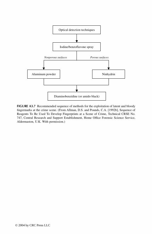
FIGURE A3.7
Recommended sequence of methods for the exploitation of latent and bloodyfingermarks at the crime scene. (From Allman, D.S. and Pounds, C.A. [1992b], Sequence ofReagents To Be Used To Develop Fingerprints at a Scene of Crime, Technical CRSE No.747, Central Research and Support Establishment, Home Office Forensic Science Service,Aldermaston, U.K. With permission.)
Optical detection techniques
Iodine/benzoflavone spray
Aluminum powder Ninhydrin
Diaminobenzidine (or amido black)
Nonporous surfaces Porous surfaces
TF1345_C09.fm Page 225 Wednesday, March 17, 2004 9:16 AM
© 2004 by CRC Press LLC

Appendix 4
Preparation and Application of Reagents
A4.1 AMIDO BLACK (AB)
A4.1.1 S
URFACES
Amido black is a protein stain used specifically for the enhancement of fingermarksin blood on both porous and nonporous surfaces.
A4.1.2 P
REPARATION
A4.1.2.1 Methanol-Based Formulation
Methanol-based formulation from Kent (1998):
A4.1.2.2 Ethanol/Water-Based Formulation
Ethanol/water-based formulation from Sears and Prizeman (2000):
Staining solution:
amido black (2 g) is dissolved inmethanol (900 ml) andacetic acid (100 ml)
Washing solutions
: A: methanol, acetic acid (9:1)B: distilled water, acetic acid (95:5)C: distilled water
Fixing solution
: 5-sulfosalicylic acid (20 g) is dissolved in distilled water (1000 ml)
Staining solution:
amido black (1 g) is dissolved in ethanol (250 ml), acetic acid (50 ml), and distilled water (700 ml)
Washing solution:
ethanol (250 ml) is mixed with acetic acid (50 ml) and distilled water (700 ml)
TF1345_C10.fm Page 227 Wednesday, March 17, 2004 9:17 AM
© 2004 by CRC Press LLC

A4.1.3 A
PPLICATION
A4.1.3.1 Methanol-Based Formulation
Fingermarks in blood should be fixed by treatment with methanol for 5 min beforestaining. Treatment with amido black is achieved by immersion in the stainingsolution for 3 to 4 min. The sample is then washed successively in the three washingsolutions to clear the background and improve fingerprint contrast. Developed marksare visible as dark blue ridges.
A4.1.3.2 Ethanol/Water-Based Formulation
Articles should be treated with the fixing solution for 5 min and then stained for 5min. Treated surfaces should then be de-stained using the washing solution. Severalchanges of solution may be required to remove all excess stain. After a final waterwash, the surface should be allowed to dry. The ethanol/water-based solution isnonflammable and nontoxic, making it suitable for use on all surfaces at the crimescene.
A4.2 CYANOACRYLATE — BASIC YELLOW 40 STAIN
A4.2.1 S
URFACES
Basic yellow 40 is a luminescent stain for the enhancement of cyanoacrylate-developed marks on nonporous and semiporous surfaces.
A4.2.2 P
REPARATION
A4.2.3 A
PPLICATION
1. Immerse the cyanoacrylate-treated item in the staining solution for 10 to20 sec (or apply the staining solution to the surface of the item using apipette).
2. Wash thoroughly with running water.3. Dry at room temperature.4. Examine in the luminescence mode: excitation 440 to 450 nm, observation
from around 500 nm (e.g., OG515 long pass barrier filter).
A4.3 CYANOACRYLATE — RHODAMINE 6G STAIN
A4.3.1 S
URFACES
Rhodamine 6G is a luminescent stain for the enhancement of cyanoacrylate-devel-oped marks on nonporous and semiporous surfaces.
Working solution:
basic yellow 40 (1.5 g) is dissolved inmethanol (1000 ml) — (filter if necessary)
TF1345_C10.fm Page 228 Wednesday, March 17, 2004 9:17 AM
© 2004 by CRC Press LLC
A4.3.2 P
REPARATION
A4.3.3 A
PPLICATION
1. Immerse the cyanoacrylate-treated item in the staining solution for 10 to20 sec (or apply the staining solution to the surface of the item using apipette).
2. Wash thoroughly with running water.3. Dry at room temperature.4. Examine in the luminescence mode: excitation 500 to 530 nm, observation
from around 550 nm (e.g., KV550 long pass barrier filter).
A4.4 DIAMINOBENZIDINE (DAB)
A4.4.1 S
URFACES
Diaminobenzidine (DAB) is a reagent specifically for the enhancement of finger-marks in blood on both porous and nonporous surfaces.
A4.4.2 P
REPARATION
Stock solution:
rhodamine 6G (0.4 g) is dissolved in isopropanol (400 ml) and methyl ethyl ketone (600 ml)
Working solution:
stock solution (250 ml) is diluted with distilled water (750 ml)
Stock solutions:
A: 2% (w/v) 5-sulfosalicylic acid in distilled water (store at room temperature in a dark glass bottle)
B: vials of buffer solution prepared by diluting 1
M
phosphate buffer pH 7.4* (10 ml) with distilled water (80 ml) (stored at room temperature) *(1
M
phosphate buffer pH 7.4 can be prepared as follows: potassium dihydrogen phosphate [26.8 g] and sodium hydrogen phosphate [142.9 g] dissolved in distilled water [1000 ml])
C: aliquots of DAB solution prepared by dissolving diaminobenzidine tetrahydrochloride dihydrate (0.1 g) in distilled water (10 ml) (store at –20˚C)
D: 30% hydrogen peroxide solution
Working solution:
One aliquot of DAB solution (solution C) is mixed with one vial of buffer solution (solution B), to which is then added 0.5 ml of 30% hydrogen peroxide solution (solution D) (the working solution is not stable and therefore should be made up just before use)
TF1345_C10.fm Page 229 Wednesday, March 17, 2004 9:17 AM
© 2004 by CRC Press LLC

A4.4.3 A
PPLICATION
Fingermarks in blood are first fixed by immersion in the solution of 5-sulfosalicylicacid (solution A) for 5 min followed by washing with distilled water. Enhancementis then carried out by treatment of the marks with the DAB working solution overapproximately 4 min. The developed marks, stained dark brown in color, are thenwashed with water and allowed to air dry.
For fixed surfaces at the crime scene, or on large objects, a paper towel can beoverlaid on the surface to be treated to act as a reagent reservoir. After applicationof each solution, the paper towel is removed and discarded. A fresh paper towel isused for each treatment.
A4.5 DIAZAFLUORENONE (DFO)
A4.5.1 S
URFACES
1,8-Diazafluoren-9-one (DFO) is an amino acid reagent for the detection of latentfingermarks on porous surfaces. Because heat is required for development, heat-sensitive articles cannot be treated with this reagent.
A4.5.2 P
REPARATION
A4.5.2.1 HFE7100 Formulation
HFE7100 formulation from Kent (1998):
A4.5.2.2 HFC4310 Formulation
HFC4310 formulation from Stoilovic and Lennard (2000):
Working solution:
to a solution ofDFO (0.25 g) inmethanol (30 ml) andacetic acid (20 ml) is addedHFE71DE (275 ml) andHFE7100 (725 ml)
Stock solution:
to a solution ofDFO (4.0 g) indichloromethane (150 ml) is addedmethanol (320 ml) andacetic acid (30 ml)
Working solution:
DFO stock solution (90 ml) is diluted withHFC4310 (to 1000 ml)
TF1345_C10.fm Page 230 Wednesday, March 17, 2004 9:17 AM
© 2004 by CRC Press LLC

A4.5.2.3 Petroleum Ether Formulation
Petroleum ether formulation from Stoilovic and Lennard (2000):
A4.5.3 A
PPLICATION
Items to be treated are briefly dipped in the working solution and then allowed todry. Development is achieved by heating in an oven at 100˚C for 20 min or heatingin a clothes press (between sheets of absorbent paper) at 180˚C for 10 sec. Stronglatent marks may be visible under white light as pale pink/purple marks.
Treated marks are luminescent at room temperature using excitation in the 450-to 570-nm range with observation in the 550- to 650-nm region. Various wavelengthcombinations for the excitation and observation should be evaluated to obtain thebest contrast with the surface. Possible filter combinations include excitation at 530nm with observation at 590 nm, and excitation at 555 nm with observation at 610 nm.
The heating can be repeated if the luminescence has decreased over time due toquenching from the absorption of ambient humidity. In addition, weak marks cansometimes be enhanced by re-treatment with the DFO working solution and reheating.
A4.6 DIMETHYLAMINOCINNAMALDEHYDE (DMAC)
A4.6.1 S
URFACES
The dry-transfer DMAC process can be applied to any paper surface, but it isparticularly recommended for thermal paper (where reagents such as ninhydrin andDFO cannot be applied).
A4.6.2 P
REPARATION
A4.6.3 A
PPLICATION
The dry-transfer method is implemented by placing one transfer sheet on each sideof the exhibit. Aluminum foil is then placed on each side, and the “sandwich” placed
Stock solution:
to a solution ofDFO (1.8 g) indichloromethane (120 ml) is addedmethanol (240 ml) andacetic acid (140 ml)
Working solution:
DFO stock solution (100 ml) is diluted withpetroleum ether (to 1000 ml)
DMAC solution:
DMAC (0.25 g) is dissolved inmethanol (100 ml)
Dry-transfer sheets:
Soak clean sheets of copy paper in the DMAC solutionRemove and allow to dry at room temperatureStore the sheets in a snap-seal plastic bagStore in a refrigerator (may be kept up to 12 months)
TF1345_C10.fm Page 231 Wednesday, March 17, 2004 9:17 AM
© 2004 by CRC Press LLC

in a cold press for 30 to 60 min. While pale red marks may be visible after thetreatment, examination and photography should be conducted in the luminescencemode, with excitation in the range 400 to 450 nm and observation in the range 470to 530 nm. Developed marks should be reexamined after 24 hours, as luminescenceintensity will generally increase over this period. (Dry-transfer sheets can be reusedseveral times and then discarded.)
A4.7 GENTIAN VIOLET
A4.7.1 S
URFACES
Gentian violet is a stain that can be used to develop latent fingermarks on adhesivesurfaces such as the adhesive side of plastic-, paper-, and fabric-backed adhesivetapes.
A4.7.2 P
REPARATION
A4.7.3 A
PPLICATION
The solution can be applied with a pipette or by immersion. Tapes with a porousbacking (paper or cloth) should be drawn across the surface of the solution, adhesive-side down. Excess reagent is removed by washing under a running tap. Latentfingermarks on the adhesive side of the tape are stained dark purple.
Fingermarks developed with gentian violet on dark surfaces are often difficultto visualize due to poor contrast. Such marks can be transferred onto photographicpaper as follows. Prepare a solution of detergent: one drop of concentrated detergentin 1 l of tap water. After development of the marks with gentian violet, the adhesivetape is briefly immersed in the detergent solution. The excess solution is drainedfrom the tape; the adhesive side of the tape is placed in contact with a sheet of fixedand washed white photographic paper (care should be taken that no air bubbles areformed between the adhesive side of the tape and the photographic paper); and thecombined tape/paper is placed for 1 h in a press. The tape is peeled off the photo-graphic paper; purple fingermark images should be visible on the paper due todiffusion of the gentian violet into the gelatin. If the transfer is of poor quality (badcontrast, for example), the transfer process can be repeated with a longer period inthe press (up to 12 h).
Stock solution:
gentian violet (5 g) andphenol* (10 g) are dissolved inethanol (50 ml)*(caution: phenol is very toxic)
Working solution:
stock solution (1 ml) is diluted withdistilled water(add additional water if a gold film remains aftermixing)
TF1345_C10.fm Page 232 Wednesday, March 17, 2004 9:17 AM
© 2004 by CRC Press LLC

A4.8 GUN BLUE
A4.8.1 S
URFACES
Dilute gun-blue solution can be used to develop latent fingermarks on brass cartridgecases. The process can be applied after cyanoacrylate fuming and before the appli-cation of a luminescent stain.
A4.8.2 P
REPARATION
A working solution is prepared by diluting commercial gun-blue solution withdistilled or deionized water. The dilution factor will depend on the brand and strengthof the commercial reagent. As a guide, Birchwood-Casey “Super Blue” has beensuccessfully used as a 1-in-20 dilution (e.g., 1 ml of “Super Blue” diluted with 19ml water). Experiments should be conducted with different dilutions before process-ing the evidential items.
A4.8.3 A
PPLICATION
Immerse the cartridge case in the gun-blue working solution and remove whensufficient fingerprint contrast is observed (typically 30 sec to 2 min). After treatment,the cartridge case is rinsed thoroughly with distilled or deionized water and dried.To limit further oxidation of the brass, the treated item should be sealed with varnishor coated with protective oil (e.g., “Ballistol” gun oil spray). Developed marks shouldbe photographed immediately. If the gun-blue treatment is used in sequence aftercyanoacrylate fuming and before application of a luminescent stain, then treatmentof the cartridge case with varnish or oil is omitted.
A4.9 INDANEDIONE
A4.9.1 S
URFACES
1,2-Indanedione is an amino acid reagent for the detection of latent fingermarks onporous surfaces. Developed marks are luminescent at room temperature withoutfurther treatment.
A4.9.2 P
REPARATION
Working solution:
(Wiesner et al. 2001)a solution ofindanedione (2 g) inethyl acetate (70 ml) is diluted withHFE7100 (to 1000 ml)
Alternative:
(http://www.bvda.com/EN/prdct-inf/en_ind_1.html)
a solution ofindanedione (1 g) inethyl acetate (90 ml) andacetic acid (10 ml) is diluted withpetroleum ether (to 1000 ml)
TF1345_C10.fm Page 233 Wednesday, March 17, 2004 9:17 AM
© 2004 by CRC Press LLC

Note that, according to our preliminary results, the alternative solution that containsacetic acid gives better results, but the solution is unstable.
A4.9.3 A
PPLICATION
Items are dipped in the solution and then allowed to dry at room temperature.Recommended development is 100
∞
C for 20 min at 60% relative humidity. Devel-oped marks should be examined and photographed in the luminescence mode:excitation at 530 nm with observation through a 550-nm cutoff filter (Wiesner et al.2001).
A4.10 IODINE/BENZOFLAVONE
A4.10.1 S
URFACES
Iodine/benzoflavone spray can be applied at the crime scene on both porous andnonporous surfaces (e.g., wallpaper, matte and glossy painted surfaces, smoothbrickwork/concrete, plasterboard, etc.).
A4.10.2 P
REPARATION
A4.10.3 A
PPLICATION
The reagent is applied as a fine spray (commercial paint spray system or gardenspray). Treated latent marks appear as dark blue images after evaporation of thesolvent.
Caution:
The spray reagent should only be used in a well-ventilated area withappropriate safety equipment (e.g., safety goggles, charcoal filter mask). When usingflammable carrier solvents such as cyclohexane or methyl cyclohexane, the reagentmust not be used near an ignition source.
S t ock so lu t i ons(brush):
A: 7,8-benzoflavone (12 g) is dissolved in dichloromethane (100 ml)
B: iodine (1 g) is dissolved incarrier solvent (1000 ml)(possible carrier solvents includeCFC113 [Arklone],HFE7100,cyclohexane, ormethyl cyclohexane [Brennan 2002])
Working solution:
solution A (2 ml) is mixed withsolution B (100 ml) and thecombined reagent allowed to stand for 5 min, thenfiltered before use(the working solution should be prepared at the crimescene just before use)
TF1345_C10.fm Page 234 Wednesday, March 17, 2004 9:17 AM
© 2004 by CRC Press LLC

A4.11 MULTIMETAL DEPOSITION I (MMDI)
A4.11.1 S
URFACES
Multimetal deposition (MMD) can develop latent fingermarks on a wide range ofporous, semiporous, and nonporous surfaces. However, the reagents are time-con-suming to prepare and apply, which limit their routine application. MMD may beeffective on difficult surfaces (e.g., some semiporous substrates such as latex andnitrile gloves) where other techniques are ineffective.
A4.11.2 P
REPARATION
A4.11.2.1 Colloidal Gold
All solutions should be prepared using ultrapure, bidistilled water.
Stock solutions:
A: tetrachloroauric acid (gold chloride, 1 g) is dissolved in distilled water (10 ml)
B: sodium citrate (1 g) is dissolved indistilled water (100 ml)
C: citric acid (9.6 g) is dissolved in distilled water (100 ml)
Working solution:
1. Solution A (gold chloride, 1 ml) is added to distilled water (1000 ml)
2. Bring to a boil and add solution B (sodium citrate, 15 ml)
3. Boil gently for 10 min; the solution should be a deep ruby-red color
4. While still hot, stir in Tween 20 or Tween 80 (detergent, 5 ml); let the solution cool
5. Check the pH of the solution (pH meter) and add solution C (citric acid), 1 ml at a time, until a pH of 2.7 is obtained
6. Restore the volume to 1000 ml and check that the pH is still 2.7; store in a clean glass container
TF1345_C10.fm Page 235 Wednesday, March 17, 2004 9:17 AM
© 2004 by CRC Press LLC

A4.11.2.2 Modified Physical Developer (PD)
A4.11.3 A
PPLICATION
Treatment should be performed in a series of clean glass trays under artificial light(not under direct sunlight).
1. In the first dish, the article to be treated is washed with distilled water(about 10 min for nonporous items and 30 min for porous items). Fordirty objects, several changes of water may be required.
2. After washing, the article is immersed in the colloidal gold solution (dish2). The solution is gently agitated to aid development, which may takefrom 30 to 120 min, depending on the type of surface and the quality ofthe latent prints. Overdevelopment should be avoided, as this can lead tosignificant background coloration after the PD treatment. Prints developedat this stage are generally pale pink in color.
3. The sample is rinsed in distilled water (dish 3) — briefly for nonporoussurfaces, about 15 min for porous items with, in this latter case, severalchanges of water.
4. The article is immersed in the freshly prepared modified PD solution (dish4). Silver deposition will commence immediately and should be allowedto proceed until the best contrast between the prints and the surface isobserved (this typically takes from 1 to 2 min).
5. The item should be thoroughly rinsed in distilled water (dishes 5 and 6)to remove excess PD. Tap water can be used for the final rinse.
6. The article is air-dried and the marks photographed. Developed markswill generally be dark gray to black in color.
Redox solution:
The following chemicals are dissolved in distilled water (1000 ml), with constant stirring,
in the order that they are listed
:1. ferric nitrate (16 g)2. ferrous ammonium sulfate (44 g)3. citric acid (11 g)4. 1% Tween 20 (0.25 ml)
Silver nitrate solution:
Silver nitrate (20 g) is dissolved in distilled water (100 ml)
Working solution:
This should be made up just before use as it is only stable for about 10 min.
1 part silver nitrate solution is mixed with 99 parts redox solution (example: 1 ml silver nitrate solution + 99 ml redox solution)
TF1345_C10.fm Page 236 Wednesday, March 17, 2004 9:17 AM
© 2004 by CRC Press LLC

A4.12 MULTIMETAL DEPOSITION II (MMDII)
A4.12.1 S
URFACES
Multimetal deposition (MMD) can develop latent fingermarks on a wide range ofporous, semiporous, and nonporous surfaces. However, the reagents are time-con-suming to prepare and apply, which limits their routine application. MMD may beeffective on difficult surfaces (e.g., some semiporous substrates such as latex andnitrile gloves) where other techniques are ineffective. MMDII is generally consideredto be more sensitive than MMDI.
A4.12.2 P
REPARATION
A4.12.2.1 Silanized Glassware
Silanization is recommended for all glassware used to prepare and employ theMMDII reagents. This can be achieved as follows:
1. Soak glassware overnight in a bath of 10% Extran (Niaprooof Type 8;sodium 2-ethylhexyl sulfate).
2. Rinse well in hot water and then cold water.3. Dry in an oven at 100
∞
C.4. Remove from oven and cool to room temperature.5. Soak for 5 sec in a treatment solution prepared from 4 ml of 3-aminopro-
pyl-triethoxysilane in 200 ml acetone.6. Rinse twice in acetone.7. Rinse twice in distilled water.8. Dry in an oven overnight at 42
∞
C.
Glassware that is silanized in this manner is resistant to numerous washings.
A4.12.2.2 Colloidal Gold
All solutions should be prepared using ultrapure, bidistilled water.
Stock solutions:
A: tetrachloroauric acid (gold chloride, 1 g) is dissolved in distilled water (10 ml)
B: sodium citrate (1 g) is dissolved in distilled water (100 ml)
C: citric acid (9.6 g) is dissolved in distilled water (100 ml)
D: tannic acid (1 g) is dissolved in distilled water (100 ml)
TF1345_C10.fm Page 237 Wednesday, March 17, 2004 9:17 AM
© 2004 by CRC Press LLC

A4.12.2.3 Modified Physical Developer
All solution should be prepared using ultrapure, bidistilled water.Citrate buffer is prepared by mixing 24 parts citric acid solution (255 g citric
acid in 1 l distilled water), 22 parts sodium citrate solution (235 g sodium citrate in1 l distilled water), and 50 parts distilled water. The buffer should have a pH of 3.8(add citric acid solution or sodium citrate solution to adjust the pH if necessary).
A4.12.3 A
PPLICATION
The treatment should be performed in a series of silanized glass trays.
1. Wash the item before treatment:• Nonporous surfaces — pass quickly through distilled water• Porous surfaces — soak for approximately 2 min in distilled water
2. Immerse the exhibit in the colloidal gold solution for 5 to 15 min (gentlyagitate over this period).
3. Rinse in distilled water.4. Soak for 2 to 5 min in the hydroquinone rinse.
Working solution:
1. Solution A (0.5 ml) is added to distilled water (400 ml)2. Separately mix distilled water (75 ml), solution B
(20 ml), and solution D (0.1 ml)3. Heat the two mixtures separately to 60
∞
C4. At 60
∞
C, quickly add the second solution (sodium citrate and tannic acid) to the first (tetrachloroauric acid) while mixing vigorously
5. Bring the mixture to boiling point; the solution should turn orange
6. Allow to cool to room temperature7. Adjust the volume back to 500 ml with distilled water8. Allow to cool to room temperature; store in a plastic
bottle in the fridge at 4
∞
C9. Restore to room temperature immediately before use10. Add Tween 20 or Tween 80 (0.5 ml) with stirring11. Adjust the pH to 2.7 with solution C
Stock solutions:
A: silver acetate (0.2 g) is dissolved indistilled water (100 ml)
B: hydroquinone (1 g) is dissolved in citrate buffer (200 ml)
Hydroquinone rinse
Solution B (100 ml) is diluted withdistilled water (100 ml)
PD working solution:
Solution A (100 ml) is mixed withSolution B (100 ml)(prepare just before use)
TF1345_C10.fm Page 238 Wednesday, March 17, 2004 9:17 AM
© 2004 by CRC Press LLC

5. Transfer the item to freshly prepared PD solution and soak for approxi-mately 18 min at room temperature (the solution will become dark grayafter 10 to 20 min, but this will not affect results).
6. Rinse in distilled water.7. Fix with photographic fixer (diluted 1:9 with water) for 2 to 5 min.8. Rinse with tap water.9. Air-dry the article and photograph the marks. Developed marks will
generally be dark gray in color.
A4.13 NINHYDRIN
A4.13.1 S
URFACES
Ninhydrin is an amino acid reagent for the detection of latent fingermarks on poroussurfaces.
A4.13.2 P
REPARATION
A4.13.2.1 HFE7100 Formulation (Kent 1998)
A4.13.2.2 HFC4310 Formulation (Stoilovic and Lennard 2000)
A4.13.2.3 Petroleum Ether Formulation (Margot and Lennard 1994)
Stock solution:
ninhydrin (25 g) is dissolved inethanol (225 ml),ethyl acetate (10 ml), andacetic acid (25 ml)
Working solution:
ninhydrin stock solution (52 ml) is diluted withHFE7100 (1000 ml)
Stock solution:
ninhydrin (40 g) is dissolved inethanol (350 ml),ethyl acetate (50 ml), andacetic acid (100 ml)
Working solution:
ninhydrin stock solution (50 ml) is diluted withHFC4310 (to 1000 ml)
Working solution:
ninhydrin (4 g) inmethanol (20 ml) is addedethyl acetate (70 ml),acetic acid (10 ml), andpetroleum ether (to 1000 ml)
TF1345_C10.fm Page 239 Wednesday, March 17, 2004 9:17 AM
© 2004 by CRC Press LLC

A4.13.3 A
PPLICATION
Items to be treated are briefly immersed in the solution, removed, and air-dried. (Forlarge items, the ninhydrin solution can be applied with a brush or spray.) Develop-ment should be allowed to proceed at room temperature, preferably in the dark, witha relative humidity of 50 to 80% over 24 to 48 h.
Ninhydrin-developed marks should be photographed under white light using ayellow bandpass filter (approx. 570 nm) in front of the camera. Ruhemann’s purpleshows a maximum absorption under these conditions, and thus improved contrastcan normally be achieved.
A4.14 NINHYDRIN — METAL SALT TREATMENT
A4.14.1 S
URFACES
Metal salt treatment is used for the enhancement of ninhydrin-developed marks onporous surfaces. This treatment can improve contrast in the absorption mode as wellas inducing luminescence, particularly at liquid nitrogen temperature (–196
∞
C).While both zinc and cadmium salts can be used, zinc metal salt treatment is preferreddue to the toxicity of cadmium. Ninhydrin-developed marks should be photographedbefore proceeding with metal salt treatment.
A4.14.2 P
REPARATION
Suggested carrier solvents are HFC4310, HFE7100, pentane, or petroleum ether.Note that if the solution goes cloudy, more ethanol should be added with stirring.
A4.14.3 A
PPLICATION
Treat the ninhydrin-developed marks with the zinc nitrate solution by immersion orby application with a pipette. As the solvent evaporates, a color change (from purpleto orange) should be observed, with the maximum absorption shifting to around 490nm. Enhancement photography of zinc post-treated marks can therefore be achievedin the absorption mode with a 490-nm bandpass barrier filter in front of the camera(or using illumination from a forensic light source operating at this wavelength).
Of more significance than the color change is the luminescence produced by thezinc complex that is formed. The sample is inspected under a forensic light sourceoperating at 490 nm, with observation using a 550- to 570-nm bandpass filter or a550-nm long pass filter. To favor the luminescence, the sample is cooled to liquidnitrogen temperature (–196
∞
C), which is achieved by placing the sample in aninsulated container (such as a polystyrene foam tray) and covering it with a thinlayer of liquid nitrogen. The fingermark luminescence is often weak, and thereforephotographic recording generally requires long exposure times (from a few secondsto several minutes).
Stock solution:
to a solution of zinc nitrate (8 g) in ethanol (180 ml) is addedacetic acid (20 ml)
Working solution:
stock solution (6 ml) is diluted with carrier solvent (to 100 ml)f
TF1345_C10.fm Page 240 Wednesday, March 17, 2004 9:17 AM
© 2004 by CRC Press LLC

A4.15 PHYSICAL DEVELOPER (PD)
A4.15.1 S
URFACES
Physical developer (PD) can be used for the detection of latent fingermarks on poroussurfaces that are or have been wet (a condition that precludes amino acid reagents).
A4.15.2 P
REPARATION
All glassware used must be scrupulously clean and free from any contamination.Only good-quality distilled or deionized water should be employed to prepare thesolutions. The solutions should only be prepared and manipulated in glass receptaclesand away from direct sunlight.
A4.15.3 A
PPLICATION
Treatment should be performed in a series of clean glass trays under artificial light(not under direct sunlight).
1. Wash the sample in distilled (or deionized) water to remove dirt or othersurface contamination. This may need to be repeated several times withfresh distilled water if the samples are particularly dirty or if they havebeen previously treated with ninhydrin or DFO.
2. Soak the sample in the maleic acid solution for 5 min.3. Rinse the sample in distilled (or deionized) water.
Detergent solution:
N-dodecylamine acetate (4 g) andSynperonic N (4 g) are dissolved inwater (1000 ml)(store at least 24 hours before use)
Silver nitrate solution:
silver nitrate (10 g) is dissolved inwater (50 ml)
Redox solution:
ferric nitrate (30 g),ferrous ammonium sulfate (80 g), andcitric acid (20 g) are added successively (in that order) towater (900 ml) with stirringafter dissolution, add detergent solution (40 ml) and stir for 2 min
Maleic acid solution:
maleic acid (25 g) is dissolved inwater (1000 ml)
Working solution:
silver nitrate solution (50 ml) is added slowlywith stirring to redox solution (940 ml)(stable for up to 1 week if stored in a clean, darkbottle)
TF1345_C10.fm Page 241 Wednesday, March 17, 2004 9:17 AM
© 2004 by CRC Press LLC

4. Introduce the sample into the PD solution — any latent marks on thesurface should develop as dark gray images against a light gray back-ground (the optimum development time ranges from 10 to 30 min). Thesample is removed when the best fingermark contrast is observed.
5. Rinse the sample in distilled (or deionized) water.6. Repeat the water rinse several times until the rinse water is clear.7. Allow the sample to dry at room temperature.
Samples can be re-treated with the reagent, but any developed fingermark mustbe photographed before proceeding with a second treatment. Avoid overdevelopmentwith PD, as the treatment cannot be reversed.
Contrast in marks developed with PD on dark surfaces (such as brown paper)can sometimes be improved by immersion of the article in a solution of 50%household bleach and 50% tap water for 2 to 3 min. After treatment, the item isthoroughly rinsed with water and dried.
A4.16 RUTHENIUM TETROXIDE (RTX)
A4.16.1 S
URFACES
Ruthenium tetroxide (RTX) vapor reacts with sebaceous material in the latent fin-germark deposit and can be used to develop marks on a range of porous, semiporous,and nonporous surfaces. Developed marks are dark gray in color.
A4.16.2 P
REPARATION
A4.16.3 A
PPLICATION
Equal volumes of solutions A and B are mixed together in an enclosed container(plastic wash bottle or glass fuming chamber). Items to be treated are exposed tothe RTX fumes that are slowly generated from the mixed solution. Using a plasticwash bottle, the fumes can be directed from the nozzle onto the surface underinvestigation. Fingermarks generally develop as dark gray images after several min-utes (typically 10 to 20 min in the case of a glass fuming chamber).
On some surfaces, fingermarks may develop by direct immersion in the mixedsolution. This is especially the case for nonporous surfaces such as plastic. Thispossibility should be tested on a similar surface before treating the evidential item.
The treatment should be conducted in a laboratory fume hood (or with adequateventilation), as RTX vapor is irritating to the eyes and respiratory tract. Treatmentwith RTX may preclude any subsequent fingermark development by conventionaltechniques such as cyanoacrylate and DFO.
Solution A:
ruthenium(III) chloride hydrate (1 g) is dissolved indistilled water (1000 ml)
Solution B:
ceric ammonium nitrate (113 g) is dissolved in distilled water (1000 ml)
TF1345_C10.fm Page 242 Wednesday, March 17, 2004 9:17 AM
© 2004 by CRC Press LLC

A4.17 SILVER NITRATE
A4.17.1 S
URFACES
Silver nitrate reacts with chlorides in the fingermark deposit and can be used onporous surfaces such as paper and untreated wood.
A4.17.2 P
REPARATION
A4.17.3 A
PPLICATION
The solution can be applied with a pipette, by immersion, or by spraying. Aftertreatment, the article is exposed to a source of UV light (such as sunlight, light froma xenon arc lamp, or a UV lamp) until the best contrast between the developedmarks and the background is observed. Developed marks, usually dark brown toblack in color, must be photographed immediately, and the treated items stored inthe dark. (The darkening of the surface with time will be more pronounced withexposure to light.)
A4.18 SMALL-PARTICLE REAGENT (SPR)
A4.18.1 S
URFACES
Small-particle reagent (SPR) is a wet powdering technique for the detection of latentfingermarks on wet nonporous surfaces (glass, plastic, paint, metal, etc.).
A4.18.2 P
REPARATION
A4.18.3 A
PPLICATION
The best method for application of SPR is by spraying (using a handheld gardenspray, for example). The spray bottle must be shaken well before application, sincethe molybdenum disulfide particles tend to settle on the bottom of the spray bottle
Working solution:
silver nitrate (2 g) is dissolved inmethanol (100 ml)(light sensitive; store in a dark bottle)
Detergent solution:
Tergitol 7 (4 ml) is mixed withwater (500 ml)
Stock solution:
molybdenum disulfide powder* (15 g) is mixed withdetergent solution (100 ml)*(Rocol AS powder, Molibond, or equivalent)
Working solution:
stock solution (100 ml) is diluted withwater (900 ml)
TF1345_C10.fm Page 243 Wednesday, March 17, 2004 9:17 AM
© 2004 by CRC Press LLC

when not in use. After treatment with SPR, the surface is rinsed with water to removeexcess. The treatment can be repeated several times, if necessary, to obtain sufficientcontrast. Marks developed with this method can be dried and lifted as for marksdeveloped using conventional powder.
A4.19 STICKY-SIDE POWDER
A4.19.1 S
URFACES
Sticky-side powder is a thick powder suspension for the development of latentfingermarks on the sticky side of adhesive tape. The method can develop excellentfingermarks and is recommended as an effective replacement for gentian violet onmost adhesive surfaces.
A4.19.2 PREPARATION
A4.19.3 APPLICATION
1. Paint the adhesive surface with the powder suspension using a soft brush.2. Leave for 10 sec to 1 min.3. Rinse the tape gently under slowly running cold water.4. Repeat steps 1 to 3 if necessary.5. Dry the tape at room temperature.6. Photograph the developed prints in the absorption mode.
Detergent solution: Photoflo™ 200 (10 ml) is mixed withwater (10 ml)
Working solution: black fingerprint powder (e.g., Lightning Black™ Powder) is mixed with sufficient detergent solutionto form a suspension that has the consistency of paint
Author: Trademark?
TF1345_C10.fm Page 244 Wednesday, March 17, 2004 9:17 AM
© 2004 by CRC Press LLC

References
Adcock, J.M. (1977), The development of latent fingerprints on human skin: the silver platemethod,
J. Forensic Sci.
, 22, 599–605.Aguzzi, A. (2002), Le Potentiel des Traces Digitales pour Lier les Cas, technical report,
Institut de Police Scientifique et de Criminologie, Université de Lausanne, Swit-zerland.
Aitken, C.G.G. (1995),
Statistics and the Evaluation of Evidence for Forensic Scientists
, V.Barnett, Ed., Chichester: John Wiley & Sons.
Allman, D.S. and Pounds, C.A. (1991a), Diaminobenzidine: A Simple, Safe and SensitiveMethod for the Enhancement of Blood Marks at Scene of Crime and in theLaboratory, Technical CRSE No. 773, Central Research and Support Establishment,Home Office Forensic Science Service, Aldermaston, U.K.
Allman, D.S. and Pounds, C.A. (1991b), Detection of fingerprints on skin,
Forensic Sci.Rev.
, 3, 83–89.Allman, D.S., Maggs, S.J., and Pounds, C.A. (1992), The Use of Colloidal Gold / Multi-
Metal Deposition for the Detection of Latent Fingerprints — A Preliminary Eval-uation, Technical No. 747, Central Research and Support Establishment, HomeOffice Forensic Science Service, U.K.
Allman, D.S. and Pounds, C.A. (1992a), The Specificity of Diaminobenzidine for theDetection of Blood, Technical CRSE No. 771, Central Research and SupportEstablishment, Home Office Forensic Science Service, Aldermaston, U.K.
Allman, D.S. and Pounds, C.A. (1992b), Sequence of Reagents To Be Used To DevelopFingerprints at a Scene of Crime, Technical CRSE No. 747, Central Research andSupport Establishment, Home Office Forensic Science Service, Aldermaston, U.K.
Almog, J., Hirshfeld, A., and Klug, J.T. (1982), Reagents for the chemical developmentof latent fingerprints: synthesis and properties of some ninhydrin analogues,
J.Forensic Sci.
, 27, 912–917.Almog, J. (1986), personal communication.Almog, J., Hirshfeld, A., Sterling, J., and Leonov, D. (1991), Aminoninhydrins: fingerprint
reagents with direct fluorogenic activity — preliminary studies,
J. Forensic Sci.
, 36,101–110.
Almog, J. (1992), personal communication.Almog, J., Hirshfeld, A., Franck, A., Grant, Z., and Ittah, Y. (1992), 5-Methylthio-ninhydrin
and related compounds: a novel class of fluorogenic fingerprint reagents,
J. ForensicSci.
, 37, 688–694.Almog, J., Springer, E., Wiesner, S., Frank, A., Khodzhaev, O., Lidor, R., Bahar, E.,
Varkony, H., Dayan, S., and Rozen, S. (1999), Latent fingerprint visualisation by1,2-indanedione and related compounds: preliminary results,
J. Forensic Sci.
, 44,114–118.
Almog, J., Sears, V.G., Springer, E., Hewlett, D.F., Walker, S., Wiesner, S., Lidor, R.,and Bahar, E. (2000), Reagents for the chemical development of latent fingerprints:scope and limitations of benzo[f]ninhydrin in comparison to ninhydrin,
J. ForensicSci.
, 45, 538–544.
TF1345_Ref.fm Page 245 Thursday, March 18, 2004 1:23 PM

246
Fingerprints and Other Ridge Skin Impressions
Almog, J. (2001), Fingerprint development by ninhydrin and its analogues, in
Advances inFingerprint Technology,
2nd ed., H.C. Lee and R.E. Gaensslen, Eds., Boca Raton,FL: CRC Press, pp. 177–209.
Amy, L. (1946), Valeur de la preuve en dactyloscopie,
J. Société Statistique Paris
, 87, 80–87.Amy, L. (1947), Valeur de la preuve en dactyloscopie II,
J. Société Statistique Paris
, 88,189–195.
Amy, L. (1948), Recherches sur l'identification des traces papillaires,
Annales MédecineLégale
, 28, 96–101.Andersen, J. and Bramble, S. (1997), The effects of fingermark enhancement light sources
on subsequent PCR-STR DNA analysis of fresh bloodstains,
J. Forensic Sci.
, 42,303–306.
Angst, E. (1962), Procédés pour la détermination de l’âge d’empreintes dactyloscopiquessur le papier,
Revue Internationale Criminologie Police Technique
, 16, 134–146.Anon. (1911), No two finger prints alike,
Sci. Am.
, 166–167.Anon. (1970), Convention action,
Identification News
, 20, 10–11.Anon. (1971), Standards committee,
Identification News
, 21, 14–15.Anon. (1972), An analysis of standards in fingerprint identification,
FBI Law EnforcementBull.
, 39, 7–11.Anon. (1973), International Association for Identification: standardization committee report,
FBI Law Enforcement Bull.
, 42, 7–8.Anon. (1979), Resolution VII,
Identification News
, 29, 12.Anon. (1980), Resolution VII amended,
Identification News
, 30, 3.Anon. (1992), Editorial comment,
J. Forensic Identification
, 42, 218Anon. (2002), European fingerprint standards (a “pointless” exercise),
Fingerprint Whorld
,28, 19.
Anthonioz, A., Aguzzi, A., Girod, A., Egli, N., and Ribaux, O. (2003), Potential use offingerprint in forensic intelligence: crime scene linking,
Z Zagadnien Nauk Sadowych— Probl. Forensic Sci.
, 51, 166–170.Arndt, C.B. (1985), Iodine silver plate transfer method,
RCMP
Gaz.
, 47 (5), 19–21.Asano, K.G., Bayne, C.K., Horsman, K., and Buchanan, M.V. (2002), Chemical compo-
sition of fingerprints for gender determination,
J. Forensic Sci.
, 47, 805–807.Ashbaugh, D.R. (1982a), Edgeology / poroscopy / ridgeology — our next evaluative step,
RCMP
Gaz.
, 44 (2), 4–6; 45 (2), 12–17; 45 (3), 10–14.Ashbaugh, D.R. (1982b), Poroscopy,
Fingerprint Whorld
, 19, 5–12.Ashbaugh, D.R. (1991a), Ridgeology,
J. Forensic Identification
, 41, 16–64.Ashbaugh, D.R. (1991b), Palmar flexion crease identification,
J. Forensic Identification
, 41,255–273.
Ashbaugh, D.R. (1991c), Ridgeology — modern evaluative friction ridge identification,
Fingerprint Whorld
, 17, 14–16.Ashbaugh, D.R. (1992), Incipient ridges and the clarity spectrum,
J. Forensic Identification
,42, 106–114.
Ashbaugh, D.R. (1999a), A science in transition, in
First International Conference onForensic Human Identification in the Next Millennium
, London: The Forensic ScienceService; www.forensic.gov.uk.
Ashbaugh, D.R. (1999b),
Qualitative-Quantitative Friction Ridge Analysis — An Introductionto Basic and Advanced Ridgeology
, V.J. Geberth, Ed., Boca Raton, FL: CRC Press.Aubert, P. (1877–1878), Des modifications subies par la sécrétion de la sueur dans les
maladies de la peau,
Annales Dermatologie Syphiligraphie
, 9, 359–373.Auvdel, M.J. (1988), Comparison of laser and high-intensity quartz arc tubes in the detection
of body secretions,
J. Forensic Sci.
, 33, 929–945.
TF1345_Ref.fm Page 246 Thursday, March 18, 2004 1:23 PM

References
247
Azoury, M., Zamir, A., Oz, C., and Wiesner, S. (2002), The effect of 1,2-indanedione, alatent fingerprint reagent on subsequent DNA profiling,
J. Forensic Sci.
, 47,586–588.
Babler, W.J. (1987), Prenatal development of dermatoglyphic patterns: associations withepidermal ridge volar pad and bone morphology,
Collegium Antropologicum
, 11,297–303.
Babler, W.J. (1991), Embryologic development of epidermal ridges and their configurations,in
Dermatoglyphics — Science in Transition,
Vol. 27 (2), C.C. Plato, R.M. Garruto,B.A. Schaumann, and N.W. Paul, Eds., New York: Wiley-Liss, pp. 95–112.
Balthazard, V. (1911), De l'identification par les empreintes digitales,
Comptes Rendus desSéances de l'Académie des Sciences
, 152, 1862–1864.Baniuk, K. (1990), Determination of age of fingerprints,
Forensic Sci. Int.
, 46, 133–137.Baniuk, K. (2000), Importance of laboratory experiment in fingerprint age determination,
Problemy Kryminalistyki
, 228, 69–72.Barker, D.A. (1999), Contrast from the past,
J. Forensic Identification
, 49, 589–593.Barnum, C.A. and Klasey, D.R. (1997), Factors affecting the recovery of latent prints on
firearms,
J. Forensic Identification
, 47, 141–147.Batey, G.W., Copeland, J., Donnelly, D.L., Hill, C.L., Laturnus, P.L., McDiarmid, C.H.,
Miller, K.J., Misner, A.H., Tario, A., and Yamashita, A.B. (1988), Metal depo-sition for latent print development,
J. Forensic Identification
, 48, 165–175.Bazen, A.M. (2002),
Fingerprint Identification — Feature Extraction, Matching and Data-base Search
, Enschede, Netherlands: Twente University Press.Beavan, C. (2001),
Fingerprints — The Origins of the Crime Detection and the Murder Casethat Launched Forensic Science
, New York: Hyperion.Bentsen, R.K., Brown, J.K., Dinsmore, A., Harvey, K.K., and Kee, T.G. (1996), Post
firing visualisation of fingerprints on spent cartridge cases,
Sci. Justice
, 36, 3–8.Ben-Yosef, N., Almog, J., Frank, A., Springer, E., and Cantu, A.A. (1998), Short UV
luminescence for forensic applications: design of a real-time observation system fordetection of latent fingerprints and body fluids,
J. Forensic Sci.
, 43, 299–304.Benzoni, M. (1994), Evaluation du RTX pour la Révélation des Empreintes Digitales,
technical report, Institut de Police Scientifique et de Criminologie, Université deLausanne, Switzerland.
Berg, E. (1996), Digital enhancement and transmission of latent prints — who will set thestandards?
J. Forensic Identification
, 46, 573–580.Berg, E. (2000), Legal ramifications of digital imaging in law enforcement,
Forensic Sci.Commun.
, 2 (4), http://www.fbi.gov/hq/lab/fsc/backissu/oct2000/berg.htm.Bergeron, J. (2003), Development of bloody prints on dark surfaces with titanium dioxide
and methanol, J. Forensic Identification, 53, 149–161.Berry, J. and Stoney, D.A. (2001), The history and development of fingerprinting, in
Advances in Fingerprint Technology, 2nd ed., H.C. Lee and R.E. Gaensslen, Eds.,Boca Raton, FL: CRC Press, 1–40.
Bertillon, A. (1885) Instructions signaletiques, Imprimerie administrative, Melun, France.Bertillon, A. (1912), Notes et observations médico-légales — les empreintes digitales,
Archives d’Anthropologie Criminelle, de Médecine Légale et de Psychologie Normaleet Pathologique
, 27, 36–52.Bettencourt, D.S. (1991), A compilation of techniques for processing deceased human skin
for latent prints,
J. Forensic Identification
, 41, 111–120.Blackledge, R.D. (1998), Re: “Latent print processing by the ruthenium tetroxide method”
[letter plus editor's reply],
J. Forensic Identification
, 48, 557–559.
TF1345_Ref.fm Page 247 Thursday, March 18, 2004 1:23 PM

248
Fingerprints and Other Ridge Skin Impressions
Blitzer, H.L. and Jacobia, J. (2002),
Forensic Digital Imaging and Photography
, San Diego:Academic Press.
Bobev, K. (1995), Fingerprints and factors affecting their conditions,
J. Forensic Identifica-tion
, 45, 176–183.Bohanan, A.M. (1998), Latents from pre-pubescent children versus latents from adults,
J.Forensic Identification
, 48, 570–573.Bonnevie, K. (1924), Studies on papillary patterns of human fingers,
J. Genet.
, 15, 1–115.Bramble, S.K., Creer, K.E., Qiang, G., and Sheard, B. (1993), Ultraviolet luminescence
from latent fingerprints,
Forensic Sci. Int.
, 59, 3–14.Bramble, S.K. and Jackson, G.R. (1994), Operational experience of fingermark enhance-
ment by frequency domain filtering,
J. Forensic Sci.
, 39, 920–932.Bramble, S.K. (1995), Separation of latent fingermark residue by thin-layer chromatography,
J. Forensic Sci.
, 40, 969–975.Bramble, S.K. and Fabrizi, P.M. (1995), Some observations on the effects of image
processing functions on fingermark data in the fourier domain, in
Investigative andTrial Image Processing
, San Diego, Cal.: SPIE (International Society for OpticalEngineering), pp. 138–144.
Bramble, S.K., Cantu, A.A., Ramotowski, R.S., and Brennan, J.S. (2000), Deep red tonear infrared (NIR) fluorescence on gentian violet-treated latent prints,
J. ForensicIdentification
, 50, 33–49.Bratton, R.M. and Juhala, J.A. (1995), DFO — dry,
J. Forensic Identification
, 45, 169–172.Bratton, R.M. and Gregus, J. (1996), A Black Powder Method to Process Adhesive Tapes,
in
Proceedings of the International Symposium on Fingerprint Detection and Iden-tification
, Israel National Police, Ne’urim, Israel, June 26–30, 1995, pp. 143–147.Bratton, R.M. and Gregus, J. (1997), Development of a black powder method to process
adhesive tapes,
Fingerprint Whorld
, 27, 21–23.Brennan, J.S., Bramble, S.K., Crabtree, S., and Wright, G. (1995), Fuming of latent
fingerprint using dimethylaminocinnamaldehyde,
J. Forensic Identification
, 45,373–380.
Brennan, J.S. (1996), The Development of Fingerprints by Fuming with Dimethylamino-cinnamaldehyde (DMAC), in
Proceedings of the International Symposium on Fin-gerprint Detection and Identification
, Israel National Police, Ne’urim, Israel, June26–30, 1995, pp. 85–90.
Brennan, J.S., Davies, L.M., Bramble, S.K., Rollins, V., and Rollins, A. (2001), IsomarkSpray: A novel method for the replication of marks,
J. Forensic Identification
, 51,572–580.
Brennan, J.S. (2002), personal communication.Bridges, B.C. (1963),
Practical Fingerprinting
, New York: Funk and Wagnalls.Brown, M. (2000), Is digital better than film,
Digital Photogr. Design
, autumn, 22–27.Buchanan, M.V., Asano, K., and Bohanon, A. (1996), Chemical characterization of fin-
gerprints from adults and children, in
Forensic Evidence Analysis and Crime SceneInvestigation
, Boston: SPIE (International Society for Optical Engineering), pp.89–95.
Bullard, B. and Birge, B. (1996), Applications of a digital darkroom in the forensiclaboratory, in
Forensic Evidence Analysis and Crime Scene Investigation
, Boston:SPIE (International Society for Optical Engineering), pp. 75–82.
Bullock, K.M., Harris, J.S., and Latumus, P.L. (1994), Use of a simple coaxial lightingsystem to enhance fingerprint and handwriting evidence,
Can. Soc. Forensic Sci. J.
,27, 69–80.
TF1345_Ref.fm Page 248 Thursday, March 18, 2004 1:23 PM

References
249
Burns, D.S. (1994), Sticky side powder: the Japanese solution,
J. Forensic Identification
,44, 133–138.
Burns, T.D., Brown, J.K., Dinsmore, A., and Harvey, K.K. (1998), Base-activated latentfingerprints fumed with a cyanoacrylate monomer: a quantitative study using fourier-transform infra-red spectroscopy,
Analytica Chimica Acta
, 362, 171–176.Bush, L. (2002), Golden Hands and Silver Feet, technical report, Australian Federal Police,
Canberra.Caldwell, J.P., Henderson, W., and Kim, N.D. (2000), ABTS: a safe alternative to DAB
for the enhancement of blood fingerprints,
J. Forensic Sci.
, 45, 785–794.Campbell, B.M. (1991a), Separation of adhesive tapes,
J. Forensic Identification
, 41,102–106.
Campbell, B.M. (1991b), Vacuum chamber cyanoacrylate technique evolution,
RCMP
Gaz.
,53 (12), 12–16.
Cantu, A.A. (1993), Ninhydrin analogues, in
International Symposium on the ForensicAspects of Latent Prints
, FBI Academy, Quantico, VA.Cantu, A.A., Leben, D.A., Joullié, M.M., Heffner, J., and Hark, R.R. (1993), A compar-
ative examination of several amino acid reagents for visualizing amino acid (glycine)on paper,
J. Forensic Identification
, 43, 44–62.Cantu, A.A., Leben, D.A., Ramotowski, R.S., Kopera, J., and Simms, J.R. (1998), Use
of acidified hydrogen peroxide to remove excess gun blue from gun blue-treatedcartridge cases and to develop latent prints on untreated cartridge cases,
J. ForensicSciences
, 43, 294–298.Cantu, A.A. (2001), Silver physical developers for the visualization of latent prints on paper,
Forensic Sci. Rev.
, 13, 29–64.Cantu, A.A. and Johnson, J.L. (2001), Silver physical development of latent prints, in
Advances in Fingerprint Technology,
2nd ed., H.C. Lee and R.E. Gaensslen, Eds.,Boca Raton, FL: CRC Press, pp. 242–247.
Capel, D., Zisserman, A., Bramble, S., and Compton, D. (1998), An automatic methodfor the removal of unwanted non-periodic patterns from forensic images, in
Inves-tigation and Forensic Science Technologies
, Boston: SPIE (International Society forOptical Engineering), pp. 274–284.
Cappelli, R., Lumini, A., Maio, D., and Maltoni, D. (1999), Fingerprint classification bydirectional image partitioning,
IEEE Trans. Pattern Analysis and Machine Intelli-gence
, 21, 402–421.Cappelli, R., Erol, A., Maio, D., and Maltoni, D. (2000), Synthetic Fingerprint-Image
Generation, in
Proceedings of the International Conference on Pattern Recognition(ICPR2000)
, Barcelona, pp. 475–478.Chakraborty, R. (1991), The role of heredity and environment on dermatoglyphic traits, in
Dermatoglyphics — Science in Transition,
Vol. 27 (2), C.C. Plato, R.M. Garruto,B.A. Schaumann, and N.W. Paul, Eds., New York: Wiley-Liss, pp. 151–191.
Champod, C., Lennard, C., and Margot, P.A. (1993), Alphonse Bertillon and dactyloscopy,
J. Forensic Identification
, 43, 604–625.Champod, C. (1995), Locard, numerical standards and probable identification,
J. ForensicIdentification
, 45, 132–159.Champod, C. (1996), Reconnaissance Automatique et Analyse Statistique des Minuties sur
les Empreintes Digitales, Ph.D. thesis, Institut de Police Scientifique et de Crimi-nologie, Université de Lausanne, Switzerland.
TF1345_Ref.fm Page 249 Thursday, March 18, 2004 1:23 PM

250
Fingerprints and Other Ridge Skin Impressions
Champod, C. and Margot, P.A. (1996), Computer Assisted Analysis of Minutiæ Occur-rences on Fingerprints, in
Proceedings of the International Symposium on FingerprintDetection and Identification
, Israel National Police, Ne’urim, Israel, June 26–30,1995, pp. 305–318.
Champod, C. and Margot, P.A. (1997a), Analysis of Minutiæ Occurrences in Fingerprints— the Search for Non-combined Minutiæ, in
Current Topics in Forensic Science— Proceedings of the 14th Meeting of the International Association of ForensicSciences
, Shunderson Communications, Ottawa, pp. 55–58.Champod, C. and Margot, P.A. (1997b), Marks and impressions, in
Proceeding of the 11thInterpol Forensic Science Symposium
, Lyon, France: Forensic Sciences FoundationPress, pp. 161–182.
Champod, C. and Margot, P.A. (1998), Fingermarks, shoesole impressions, ear impressionsand toolmarks: a review (September 1995 – August 1998), in
Proceeding of the12th Interpol Forensic Science Symposium
, Lyon, France: Forensic Sciences Foun-dation Press, pp. 303–331.
Champod, C. (1999), The inference of identity of source: theory and practice, in
FirstInternational Conference on Forensic Human Identification in the Next Millennium
,London: The Forensic Science Service; http://www.forensic.gov.uk.
Champod, C. (2000a), Fingerprints (dactyloscopy): standard of proof, in
Encyclopaedia ofForensic Science
, J. Siegel, P. Saukko, and G. Knupfer, Eds., London: AcademicPress, pp. 884–890.
Champod, C. (2000b), Identification / individualization: overview and meaning of ID, in
Encyclopaedia of Forensic Science
, J. Siegel, P. Saukko, and G. Knupfer, Eds.,London: Academic Press, pp. 1077–1083.
Champod, C. and Meuwly, D. (2000), The inference of identity in forensic speakerrecognition,
Speech Communication
, 31, 193–203.Champod, C. and Evett, I.W. (2001), A probabilistic approach to fingerprint evidence,
J.Forensic Identification
, 51, 101–122.Champod, C. (2002), Statistics and fingerprint examination,
The Detail
, 22;http://www.clpex.com/Articles/TheDetail/TheDetail22.htm.
Chatterjee, S.K. and Hague, R.V. (1988),
Finger Print or Dactyloscopy and Ridgeoscopy
,Calcutta: M.K. Mukerjee Temple Press.
Cheeseman, R. and DiMeo, L.A. (1995), Fluorescein as a field-worthy latent bloodstaindetection system,
J. Forensic Identification
, 45, 631–646.Choudhry, M.Y. and Whritenour, R.D. (1990), A new approach to unraveling tangled
adhesive tape for potential detection of latent prints and recovery of trace evidence,
J. Forensic Sci.
, 35, 1373–1383.Clark, J.D. (2002), ACE-V: is it scientifically reliable and accurate?
J. Forensic Identifica-tion
, 52, 401–408.Cole, S. (1998), Witnessing identification: latent fingerprinting evidence and expert knowl-
edge,
Soc. Stud. Sci.
, 28, 687–712.Cole, S. (1999), What counts for identity? The historical origins of the methodology of
latent fingerprint identification,
Sci. in Context
, 12, 139–172.Cole, S. (2000), The myth of fingerprints,
Lingua Franca
, 10, 54–62.Cole, S. (2001),
Suspect Identities: A History of Fingerprinting and Criminal Identification
,Cambridge, MA: Harvard University Press.
Comber, B.A. (2003), Reduction of background features in images of fingerprints usingcombinations of images acquired under different lighting conditions,
J. ForensicIdentification
, 53, 198–208.
TF1345_Ref.fm Page 250 Thursday, March 18, 2004 1:23 PM

References
251
Conn, C., Ramsay, G., Roux, C., and Lennard, C.J. (2001), The effect of metal salttreatment on the photoluminescence of DFO-treated fingerprints,
Forensic Sci. Int.
,116, 117–123.
Coutagne, H. and Florence, A. (1889), Les empreintes dans les expertises judiciaires,
Archives d'Anthropologie Criminelle et des Sciences Pénales
, 4, 25–56.Cowger, J.F. (1983),
Friction Ridge Skin: Comparison and Identification of Fingerprints
,New York: Elsevier Science Publishing.
Creer, K.E. (1982), Some applications of an argon ion laser in forensic science,
ForensicSci. Int.
, 20, 179–190.Creer, K.E. (1993), Detection and Photography of Latent Marks Using Specialised Lighting
and Imaging Techniques, in
International Symposium on the Forensic Aspects ofLatent Prints
, FBI Academy, Quantico, VA.Creer, K.E. (1996), Detection and Enhancement of Latent Marks Using Specialised Lighting
and Imaging Techniques, in
International Symposium in Fingerprint Detection andIdentification
, Israel National Police, Ne’urim, Israel, June 26–30, 1995, pp. 25–35.Creighton, J.T. (1997), Visualisation of latent impressions after incidental or direct contact
with human blood,
J. Forensic Identification
, 47, 534–541.Crispino, F. (2001), Comments on
JFI
51(3),
J. Forensic Identification
, 51, 449–456.Cummings, H., Hollars, M., Peigare, F., and Trozzi, T. (1990), BBD and MBD: multi-
purpose reagents for latent print detection, J. Forensic Identification, 40, 334–340.Cummings, H., Hollars, M., and Trozzi, T. (1993), Getting the most from cyanoacrylate
dyes, J. Forensic Identification, 43, 37–43.Cummins, H.H. (1926), Epidermal ridge configurations in developmental defects, with
particular references to the ontogenetic factors which condition ridge direction,American J. Anat., 38, 89–151.
Cummins, H.H. (1938), Experimental work of fingerprint forgery, J. Criminal Law, Crim-inology Police Sci., 28, 666–671.
Cummins, H.H. and Midlo, C. (1943), Finger Prints, Palms and Soles, Philadelphia:Blakiston.
Cummins, H.H. and Midlo, C. (1961), Finger Prints, Palms and Soles, 2nd ed., New York:Dover Publications.
Dalrymple, B.E., Duff, J.M., and Menzel, E.R. (1977), Inherent fingerprint luminescence— detection by laser, J. Forensic Sci., 22, 106–115.
Dalrymple, B.E. and Menzies, T. (1994), Computer enhancement of evidence throughbackground noise suppression, J. Forensic Sci., 39, 537–546.
Dankmeijer, J., Waltman, J.M., and De Wilde, A.G. (1980), Biological foundations forforensic identifications based on fingerprints, Acta Morphol. Neerl.-Scand., 18,67–83.
Daugman, J. (1999), Recognizing persons by their iris patterns, in Biometrics — PersonalIdentification in Networked Society, A.K. Jain, R. Bolle, and S. Pankanti, Eds.,Norwell, MA: Kluwer Academic Publishers, pp. 103–121.
Daugman, J. and Downing, C. (2001), Epigenetic randomness, complexity, and singularityof human iris patterns, Proc. R. Soc. — Biological Sci., B 268, 1737–1740.
Daugman, J. (2003), The importance of being random: statistical principles of iris recog-nition, Pattern Recognition, 36, 279–291.
Davies, P.J., Kobus, H.J., Taylor, M.R., and Wainwright, K.P. (1995), Synthesis andstructure of the zinc(ii) and cadmium(ii) complexes produced by photoluminescentenhancement of ninhydrin developed fingerprints using group 12 metal salts, J.Forensic Sci., 40, 565–569.
TF1345_Ref.fm Page 251 Thursday, March 18, 2004 1:23 PM

252 Fingerprints and Other Ridge Skin Impressions
Day, K.J. and Bowker, W. (1996), Enhancement of cyanoacrylate developed latent printsusing Nile red, J. Forensic Identification, 46, 183–187.
Dell, D.A. and Munger, B.L. (1986), The early embryogenesis of papillary (sweat duct)ridges in primate glabrous skin: the dermatotopic map of cutaneous mechanorecep-tors and dermatoglyphics, J. Comp. Neurology, 244, 511–532.
Delmas, B.J. (1988), Postmortem latent print recovery from skin, J. Forensic Identification,38, 49–56.
De Ryckere, R. (1912), Lettre de Belgique, Archives d'Anthropologie Criminelle, de Méde-cine Légale et de Psychologie Normale et Pathologique, 27, 937–941.
De Varigny, H. (1891), Les empreintes digitales d'après Galton, Revue Scientifique, 17,557–562.
Didierjean, C., Debart, M.-H., and Crispino, F. (1998), New formulation of DFO inHFE7100, Fingerprint Whorld, 24, 163–167.
Dikshitulu, Y.S., Prasad, L., Pal, J.N., and Rao, C.V.N. (1986), Aging studies on fingerprintresidues using thin layer and high performance liquid chromatography, Forensic Sci.Int., 31, 261–266.
Dolci, D. (1992), Révélation des Empreintes Digitales sur la Peau, technical report, Institutde Police Scientifique et de Criminologie, Université de Lausanne, Switzerland.
Donche, A. and Musy, C. (1994), Development of latent fingerprints on cartridge casings,Fingerprint Whorld, 20, 13–19.
Drews, M. (2002), Friction ridge identification process — proposed scientific methodology, TheDetail, 28 ; http://www.clpex.com/Articles/Methodology.htm; http://www.clpex.com/Articles/TheDetail/TheDetail28.htm.
Duff, J.M. and Menzel, E.R. (1978), Laser-assisted thin-layer chromatography and lumi-nescence of fingerprints: an approach to fingerprint age determination, J. ForensicSci., 23, 129–134.
Durham, N.M., Fox, K., and Plato, C.C., Eds. (2000), The State of Dermatoglyphics: theScience of Finger and Palm Prints, Vol. 2, New York: E. Mellen Press.
Edzhubov, L.G. (1996), National standards of fingerprint identification, Fingerprint Whorld,22, 153–160.
Eggleston, R. (1983), Evidence, Proof and Probability, 2nd ed., R. Stevens, W. Twining,and C. McCrudden, Eds., London: G. Weidenfeld & Nicolson.
Epstein, R. (2002), Fingerprints meet Daubert: the myth of fingerprint “science” is revealed,South. Calif. Law Rev., 75, 605–655.
Evett, I.W. and Williams, R.L. (1995), A review of the sixteen points fingerprint standardin England and Wales, Fingerprint Whorld, 21, 125–143.
Evett, I.W. (1996), Expert evidence and forensic misconceptions of the nature of exactscience, Sci. Justice, 36, 118–122.
Faigman, D.L. (2002), Is science different for lawyers? Science, 297, 339–340.Faulds, H. (1880), On the skin-furrows of the hand, Nature, 22, 605.Ferguson, N. (1992), Minutiæ discrepancy in the delta area, Fingerprint Whorld, 18, 110.Findlay, I., Taylor, A., Quirke, P., Frazier, R., and Urquhart, A. (1997), DNA fingerprinting
from single cells, Nature, 389, 555–556.Finkelstein, M.O. and Fairley, W.B. (1970), A Bayesian approach to identification evidence,
Harv. Law Rev., 83, 489–517.Florence, A. (1885), Les Taches de Sang, Leur Signification en Médecine Judiciaire, Ph.D.
thesis No. 256, Faculté de Médecine, Lyon, France.Florence, A. (1889), Les taches de sang, leur signification, leur importance en médecine
judiciaire, Annales d'Anthropologie Criminelle et des Sciences Pénales, 19.
TF1345_Ref.fm Page 252 Thursday, March 18, 2004 1:23 PM

References 253
Flynn, J., Stoilovic, M., and Lennard, C.J. (1999), Detection and enhancement of latentfingerprints on polymer banknotes: a preliminary study, J. Forensic Identification,49, 594–613.
Foote, R.D. (1977), Fingerprint Identification: A Survey of Present Technology, AutomatedApplications and Potential for Future Development, Criminal Justice Monograph,Vol. 5 (No. 2), Institute of Contemporary Corrections and the Behavioral Sciences,Sam Houston State University, Huntsville, TX.
Fortunato, S.L. and Walton, G. (1998), Development of latent fingerprints from skin, J.Forensic Identification, 48, 704–717.
Frair, J.A., West, M.H., and Davies, L.E. (1989), A new film for ultraviolet photography,J. Forensic Sci., 34, 234–238.
Francis, 2002, personal communication.Franck, A. and Almog, J. (1993), Modified SPR for latent fingerprint development on wet,
dark objects, J. Forensic Identification, 43, 240–244.Fraval, H., Bennett, A., and Springer, E. (1996), UV Detection of Untreated Latent
Fingerprints, in Proceedings of the International Symposium on Fingerprint Detectionand Identification, Israel National Police, Ne’urim, Israel, June 26–30, 1995, pp.51–58.
Frécon, A. (1889), Des Empreintes en Général, Ph.D. thesis, Imprimerie Storck, Biblio-thèque d'Anthropologie Criminelle et des Sciences Pénales, Lyon, France.
Frégeau, C.J., Germain, O., and Fourney, R.M. (2000), Fingerprint enhancement revisitedand the effects of blood enhancement chemicals on subsequent Profiler Plusfluorescent short tandem repeat DNA analysis of fresh and aged bloody fingerprints,J. Forensic Sci., 45, 354–380.
Froude, J.H. (1996), The Super Glue fuming wand: a preliminary evaluation, J. ForensicIdentification, 46, 19–31.
Galton, F. (1892), Finger Prints, London: MacMillan and Co.Gamboe, M. and O'Daniel, L. (1999), Substitute Ardrox formula, J. Forensic Identification,
49, 134–141.Geller, B., Springer, E., and Almog, J. (1998), Field devices for cyanoacrylate fuming: a
comparative analysis, J. Forensic Identification, 48, 442–450.Geller, B., Almog, J., Margot, P., and Springer, E. (1999), A chronological review of
fingerprint forgery, J. Forensic Sci., 44, 963–968.Geller, B., Almog, J., and Margot, P. (2001), Fingerprint forgery — a survey, J. Forensic
Sci., 46(3), 731–733.German, E.R. (1987), Computer Image Enhancement of Latent Print and Hard Copy Output
Devices, in Proceedings of the International Forensic Symposium on Latent Prints,FBI Academy, Quantico, VA, pp. 151–152.
German, E.R. (1991), Analog digital image processing of latent fingerprints, in Advancesin Fingerprint Technology, H.C. Lee and R.E. Gaensslen, Eds., New York: Elsevier,pp. 193–210.
Gill, P. (2001), Application of low copy number DNA profiling, Croatian Medical J., 42,229–232.
Goode, G.C. and Morris, J.R. (1983), Latent Fingerprints: A Review of Their Origin,Composition and Methods for Detection, Technical AWRE Report No. 022/83,Atomic Weapons Research Establishment, Aldermaston, U.K.
Grady, D.P. (1999), Cyanoacrylate fuming: accelerated by heat within a vacuum, J. ForensicIdentification, 49, 377–397.
Graham, D. and Gray, H.C. (1966), The use of x-ray electrography and autoelectrographyin forensic investigations, J. Forensic Sci., 11, 124–143.
TF1345_Ref.fm Page 253 Thursday, March 18, 2004 1:23 PM
254 Fingerprints and Other Ridge Skin Impressions
Graham, D. (1969), Some technical aspects of the demonstration and visualisation offingerprints on human skin, J. Forens. Sci., 11, 124–143.
Grant, H., Springer, E., and Ziv, Z. (1996), Vacuum Metal Deposition Inhibition onPolythene Bags, in Proceedings of the International Symposium on FingerprintDetection and Identification, Israel National Police, Ne’urim, Israel, June 26–30,1995, pp. 203–215.
Gray, C. (1978), The detection and persistence of latent fingerprints on human skin: anassessment of the iodine-silver plate method, J. Forensic Sci. Soc., 18, 47–52.
Gray, M.L. (1996), Sticky-side powder versus gentian violet: the search for the superiormethod for processing the sticky side of adhesive tape, J. Forensic Identification,46, 268–272.
Grieve, D.L. (1988), The identification process: attitude and approach, J. Forensic Identifi-cation, 38, 211–224.
Grieve, D.L. (1990a), The identification process — the quest for quality, J. Forensic Iden-tification, 40, 109–113.
Grieve, D.L. (1990b), Reflections on quality standards — an American viewpoint, Finger-print Whorld, 15, 108–111.
Grieve, D.L. (1999a), The identification process: TWGFAST and the search for science,Fingerprint Whorld, 25, 315–325.
Grieve, D.L. (1999b), Built by many hands, J. Forensic Identification, 49, 565–579.Grigg, R., Malone, J.F., Mongkolaussavaratana, T., and Thianpatanagul, S. (1986),
Cycloaddition reactions relevant to the mechanism of the ninhydrin reaction: x-raycrystal structure of protonated Ruhemann's purple, a stable 1,3-dipole, J. Chem.Soc.: Chem. Commun., 421–422.
Grigg, R., Mongkolaussavaratana, T., Pounds, C.A., and Sivagnanam, S. (1990), 1,8-Diazafluorenone and related compounds — a new reagent for the detection of alpha-amino acids and latent fingerprints, Tetrahedron Lett., 31, 7215–7218.
Groenendal, H. (1996), Forged Latent Prints, in Proceedings of the International Symposiumon Fingerprint Detection and Identification, Israel National Police, Ne’urim, Israel,June 26–30, 1995, pp. 373–379.
Guo, Y.-C. and Xing, L.-P. (1992), Visualisation method for fingerprints on skin byimpression of a polyethylene terephthalate (PET) semirigid sheet, J. Forensic Sci.,37, 604–611.
Gupta, S.R. (1968), Etude statistique des caractéristiques papillaires, Revue InternationalePolice Criminelle, 5 (218), 130–134.
Halahmi, E., Levi, O., Kronik, L., and Boxman, R.L. (1997), Development of latentfingerprints using a corona discharge, J. Forensic Sci., 42, 833–841.
Hale, A. (1952), Morphogenesis of volar skin in the human fetus, Am. J. Anat., 91, 3–43.Hamilton, J. and Dibattista, J. (1985), Cyanoacrylate ester — latent print from murdered
body, Fingerprint Whorld, 11, 18–19.Hamilton, P.B. (1965), Amino-acids on hands, Nature, 205, 284–285.Hamm, E.D. (1988), A latent from human skin or is it? Fingerprint Whorld, 14, 56–57.Hammer, H.J. (1980), Methods of detecting latent fingerprints on the human skin, Forensic
Sci. Int., 16, 35–41.Haque, F., Westland, A., and Kerr, F.M. (1983), An improved non-destructive method for
the detection of latent fingerprints on documents with iodine-7,8-benzoflavone,Forensic Sci. Int., 21, 79–83.
Haque, F., Westland, A.D., Milligan, J., and Kerr, F.M. (1989), A small particle (ironoxide) suspension for detection of latent fingerprints on smooth surfaces, ForensicSci. Int., 41, 73–82.
TF1345_Ref.fm Page 254 Thursday, March 18, 2004 1:23 PM

References 255
Hardwick, S.A. (1981), User Guide to Physical Developer — a Reagent for DetectingLatent Fingerprints, Technical User Guide No. 14/81, Home Office Police ScientificDevelopment Branch, Sandridge, U.K.
Hardwick, S.A., Kent, T., and Sears, V.G. (1990), Fingerprint Detection by FluorescenceExamination: A Guide to Operational Implementation, Sandridge, U.K.: HomeOffice Police Scientific Development Branch.
Hardwick, S.A., Kent, T., Sears, V.G., and Winfield, P. (1993), Improvements to theformulation of DFO and the effects of heat on the reaction with latent fingerprints,FBI Law Enforcement Bull., 19, 65–69.
Hark, R.R., Hauze, D.B., Petrovskaia, O., and Joullié, M.M. (1996), Chemical Detectionof Fingerprints — Synthesis of Arylated Ninhydrin Analogues, in Proceedings ofthe International Symposium on Fingerprint Detection and Identification, IsraelNational Police, Ne’urim, Israel, June 26–30, 1995, pp. 127–135.
Harvey, K.K., Dinsmore, A., Brown, J.K., and Burn, D.S. (2000), Detection of latentfingerprints by vacuum cyanoacrylate fuming — an improved system, FingerprintWhorld, 26, 29–31.
Haslett, M. (1983), Fingerprints from skin using the Magnabrush technique, FingerprintWhorld, 8, 118–119.
Hauze, D.B., Petrovskaia, O., Taylor, B., Joullié, M.M., Ramotowski, R.S., and Cantu,A.A. (1998), 1,2-Indanediones: new reagents for visualizing the amino acid com-ponents of latent prints, J. Forensic Sci., 43, 744–747.
Haylock, S.E. (1989), The light fantastic, Fingerprint Whorld, 14, 113–115.Hazen, R.J. (2002), Book review: quantitative-qualitative friction ridge analysis, J. Forensic
Identification, 52, 475–476.Hébrard, J. and Donche, A. (1994), Fingerprint detection methods on skin: experimental
study on 16 live subjects and 23 cadavers, J. Forensic Identification, 44, 623–627.Heindl, R. (1927), System und Praxis der Daktiloskopie, 3rd ed., Berlin und Leipzig: Walter
de Gruyter & Co., Vereiningung Wissenschaftlichen Verleger.Henry, E.R. (1900), Classification and Uses of Finger Prints, 4th ed., London: Georges
Routledge.Herod, D.W. and Menzel, E.R. (1982), Laser detection of latent fingerprints: ninhydrin
followed by zinc chloride, J. Forensic Sci., 27, 513–518.Hess, J. (1971a), The reference shelf, Finger Print Identification Mag., 53 (3), 12–14.Hess, J. (1971b), The reference shelf, Finger Print Identification Mag., 53 (5), 11–13.Hess, J. (1971c), The reference shelf, Finger Print Identification Mag., 53 (6), 13.Hess, J. (1971d), The reference shelf, Finger Print Identification Mag., 53 (4), 17.Hewlett, D.F. and Sears, V.G. (1997), Replacements for CFC113 in the ninhydrin process:
part 1, J. Forensic Identification, 47, 287–289.Hewlett, D.F., Sears, V.G., and Suzuki, S. (1997), Replacements for CFC113 in the
ninhydrin process: part 2, J. Forensic Identification, 47, 300–306.Hewlett, D.F. and Sears, V.G. (1999), An operational trial of two non-ozone depleting
ninhydrin formulations for latent fingerprint detection, J. Forensic Identification, 49,388–396.
Holt, S.B. (1968), The Genetics of Dermal Ridges, Vol. 492, I. Newton Kugelmass, Ed.,Springfield, IL: Charles C. Thomas.
Holyst, B. (1987), Kriminalistische abschätzung des spurenalters bei fingerpapillarlinien,Archiv für Kriminologie, 179, 94–103.
Hong, L. (1998), Automatic Personal Identification Using Fingerprints, Ph.D. thesis, Mich-igan State University, Computer Science and Engineering.
TF1345_Ref.fm Page 255 Thursday, March 18, 2004 1:23 PM

256 Fingerprints and Other Ridge Skin Impressions
Howard, S. (1993), Basic fuchsin — a guide to a one-step processing for black electricaltape, J. Forensic Sci., 38, 1391–1403.
Howorka, H. (1989), Questions relating to the determination of the age of objects assumingrelevance in criminal investigations, Fingerprint Whorld, 15, 23–28.
Hoyser, R.L. (1992), An alternative G.R.I.T. technique, J. Forensic Identification, 42,219–220.
Huber, R.A. (1959), Expert witness, Criminal Law Q., 2, 276–295.Huber, R.A. (1972), The philosophy of identification, RCMP Gaz., July-August, 9–14.Hughes, J.G. (1993), Under the COSHH, Fingerprint Whorld, 19, 4.Huss, K., Clark, J., and Chisum, W.J. (2000), Which was first — fingerprints or blood?
J. Forensic Identification, 50, 344–350.Hussain, J.I. and Pounds, C.A. (1988), The Enhancement of Marks in Blood, Part 1, 5-
Sulphosalicylic Acid: A Convenient and Effective Fixative for Marks Made inBlood, Technical CRSE No. 649, Central Research and Support Establishment,Aldermaston, U.K.
Immamura, M. and Asahida, M. (1981), Fingerprints lifted from cadaver skin surface,Identification News, 31, 13–14.
Interpol (1995), European Fingerprint Standards, 24th European Regional Conference, Ljubl-jana, Slovenia, May 10–12.
Interpol (2000), Interpol European Expert Group on Fingerprint Identification (IEEGFI),29th European Regional Conference, Reykjavik, Iceland, May 17–19.
Involdstad, H. (1976), How long will a fingerprint last? Fingerprint and Identification Mag.,57 (9), 4–5.
Irrausch, F. (1990), L'Utilisation de l'Oxyde de Fer dans le Réactif de Microparticules,technical report, Institut de Police Scientifique et de Criminologie, Université deLausanne, Switzerland.
Isaac, K.L. (1993), A review on detection of latent prints on self-adhesive tapes, FingerprintWhorld, 19, 89–96.
Jacobson, R.E., Ray, S.F., Attridge, G.G., and Axford, N.R. (2000), The Manual ofPhotography: Photography and Digital Imaging, 9th ed., Oxford, U.K.: Focal Press.
Jacquat, A. (1999), Evolution des Substances Grasses des Empreintes Digitales au Coursdu Temps — Analyse par TLC et GC-MS, technical report, Institut de PoliceScientifique et de Criminologie, Université de Lausanne, Switzerland.
Jain, A.K., Bolle, R., and Pankanti, S., Eds. (1999a), Biometrics — Personal Identificationin Networked Society, Norwell, MA: Kluwer Academic Publishers.
Jain, L.C., Halici, U., Hayashi, I., Lee, S.B., and Tsutsui, S., Eds. (1999b), IntelligentBiometric Techniques in Fingerprint and Face Recognition, L.C. Jain and I.E. Fel-low, Eds., Boca Raton, FL: CRC Press.
Jain, A.K. and Pankanti, S. (2001), Automated fingerprint identification and imagingsystems, in Advances in Fingerprint Technology, 2nd ed., H.C. Lee and R.E.Gaensslen, Eds., Boca Raton, FL: CRC Press, pp. 275–326.
James, J.D., Pounds, C.A., and Wilshire, B. (1991a), Flake metal powders for revealinglatent fingerprint, J. Forensic Sci., 36, 1368–1375.
James, J.D., Pounds, C.A., and Wilshire, B. (1991b), Obliteration of latent fingerprints, J.Forensic Sci., 36, 1376–1386.
James, J.D., Pounds, C.A., and Wilshire, B. (1991c), Magnetic flake fingerprint technology,J. Forensic Identification, 41, 237–247.
James, J.D., Pounds, C.A., and Wilshire, B. (1992), New magnetic applicators and magneticflake powders for revealing latent fingerprints, J. Forensic Identification, 42,531–542.
TF1345_Ref.fm Page 256 Thursday, March 18, 2004 1:23 PM

References 257
James, J.D., Pounds, C.A., and Wilshire, B. (1993), Magnetic flake powders for fingerprintdevelopment, J. Forensic Sci., 38, 391–401.
Jaret, Y., Heriau, M., and Donche, A. (1997), Transfer of bloody fingerprints, J. ForensicIdentification, 43, 38–41.
Jian, Z. and Dao-An, G. (1991), A modified cyanoacrylate technique utilizing treated neutralpaper for developing latent fingerprints, Forensic Sci. Int., 52, 31–34.
Johnson, G.A., Creaser, C.S., and Sodeau, J.R. (1991), Fluorescence spectroscopic andHPLC studies of intrinsic fingerprint residues, in Analytical Applications of Spec-troscopy 2, A.M.C. Davies and C.S. Creaser, Eds., Cambridge, UK: The RoyalSociety of Chemistry, Thomas Graham House, pp. 207–212.
Jonakait, R.N. (1994), The meaning of Daubert and what that means for forensic science,Cardozo Law Rev., 15, 2103–2117.
Jones, N., Davies, L.M., Brennan, J.S., and Bramble, S.K. (2000), Separation of visiblyexcited fluorescent components in fingerprint residue by thin-layer chromatography,J. Forensic Sci., 45, 1286–1293.
Jones, N., Mansour, D., Stoilovic, M., Lennard, C.J., and Roux, C. (2001a), The influenceof polymer type, print donor and age on the quality of fingerprints developed onplastic substrates using vacuum metal deposition, Forensic Sci. Int., 124, 167–177.
Jones, N., Stoilovic, M., Lennard, C.J., and Roux, C. (2001b), Vacuum metal deposition:factors affecting normal and reverse development of latent fingerprints on polyeth-ylene substrates, Forensic Sci. Int., 115, 73–88.
Jones, N. (2002), Metal Deposition Techniques for the Detection and Enhancement of LatentFingerprints on Semi-Porous Surfaces, Ph.D. thesis, University of Technology,Department of Chemistry, Forensic Science Programme, Sydney, Australia.
Jones, N. (2002), personal communication.Jones, N., Kelly, M., Stoilovic, M., Lennard, C.J., and Roux, C. (2003), The development
of latent fingerprints on polymer banknotes, J. Forensic Identification, 53, 50–77.Jonker, H., Molenaar, A., and Dippel, C.J. (1969), Physical development recording systems:
III, physical development, Photographic Sci. Eng., 13, 38–44.Jorgensen, D. (1991), Home-made vacuum chamber wins out, RCMP Gaz., 53 (6), 14–16.Joullié, M.M., Thompson, T.R., and Nemeroff, N.H. (1991), Ninhydrin and ninhydrin
analogs: synthesis and applications, Tetrahedron, 47, 8791–8830.Jungbluth, W.O. (1992), Replacement for Freon 113, Fingerprint Whorld, 18, 26–29.Jungbluth, W.O. (1993), Replacement for Freon 113, J. Forensic Identification, 43, 226–233.Kasper, S.P., Minnillo, D.J., and Rockhold, A.M. (2002), Validating IND (1,2-indanedi-
one), Forensic Sci. Commun., 4 (4); http://www.fbi.gov/hq/lab/fsc/backissu/oct2002/kasper.htm.
Kaymaz, E. and Mitra, S. (1992), Analysis and Matching of Degraded and Noisy Finger-prints, in SPIE Proceedings — Applications of Digital Image Processing XV, SanDiego, CA, pp. 498–509.
Kaymaz, E. and Mitra, S. (1993), A novel approach to fourier spectral enhancement oflaser-luminescent fingerprint images, J. Forensic Sci., 38, 530–541.
Keith, L.V. and Runion, W. (1998), Short-wave UV imaging casework applications, J.Forensic Identification, 48, 563–569.
Kent, T., Thomas, G.L., Reynoldson, T.E., and East, H.W. (1976), A vacuum coatingtechnique for the development of latent fingerprints on polythene, J. Forensic Sci.Soc., 16, 93–101.
Kent, T., Ed. (1986), Manual of Fingerprint Development Techniques, 1st ed., London:Home Office Scientific Research and Development Branch, Brightman & StrattonLtd.
TF1345_Ref.fm Page 257 Thursday, March 18, 2004 1:23 PM

258 Fingerprints and Other Ridge Skin Impressions
Kent, T. (1996), Two new solvents for ninhydrin, Fingerprint Whorld, 22, 108.Kent, T. and Winfield, P. (1996), Superglue Fingerprint Development — Atmospheric
Pressure and High Humidity, or Vacuum Evaporation? in Proceedings of the Inter-national Symposium on Fingerprint Detection and Identification, Israel NationalPolice, Ne’urim, Israel, June 26–30, 1995, pp. 59–66.
Kent, T., Ed. (1998), Manual of Fingerprint Development Techniques, 2nd ed., London:Home Office Scientific Research and Development Branch, White Crescent PressLtd. Luton.
Kershaw, A. (2001), Standards in evidence: the register of forensic practitioners, FingerprintWhorld, 27, 73–77.
Kimble, G.W. (1996), Powder suspension processing, J. Forensic Identification, 46,273–280.
Kimura, S. (1991), Embryologic development of flexion creases, in Dermatoglyphics —Science in Transition, Vol. 27 (2), C.C. Plato, R.M. Garruto, B.A. Schaumann,and N.W. Paul, Eds., New York: Wiley-Liss, pp. 113–129.
Kingston, C.R. (1964), Probabilistic Analysis of Partial Fingerprint Patterns, D. Crim.Dissertation, University of California, Berkeley.
Kingston, C.R. and Kirk, P.L. (1965), Historical development and evaluation of the twelvepoint rule in fingerprint identification, Int. Criminal Police Rev., 20 (186), 62–69.
Kingston, C.R. (1970), The law of probabilities and the credibility of witness and evidence,J. Forensic Sci., 15, 18–27.
Kirk, P.L. (1963), The ontogeny of criminalistics, J. Criminal Law, Criminology Police Sci.,54, 235–238.
Klasey, D.R. and Barnum, C.A. (2000), Development and enhancement of latent prints onfirearms by vacuum and atmospheric cyanoacrylate fuming, J. Forensic Identifica-tion, 50, 572–580.
Knowles, A.M. (1978), Aspects of physicochemical methods for the detection of latentfingerprints, J. Physics Ser. E: Sci. Instruments, 11, 713–721.
Knowles, R. (2000), The new (non-numeric) fingerprint evidence standard — is it pointless?Sci. Justice, 40, 120–121.
Kobus, H.J., Stoilovic, M., and Warrener, R.N. (1983), Simple luminescent post-ninhydrintreatment for the improved visualisation of fingerprints on documents in cases whereninhydrin alone gives poor results, Forensic Sci. Int., 22, 161–170.
Kobus, H.J., Pigou, P.E., Jahangiri, S., and Taylor, B. (2002), Evaluation of some oxygen,sulfur, and selenium substituted ninhydrin analogues, nitrophenylninhydrin andbenzo[f]furoninhydrin, J. Forensic Sci., 47, 254–259.
Kondo, S. and Asal, R. (1995), A reaction-diffusion wave on the skin of the marine angelfishPomacanthus, Nature, 376, 765–768.
Kosz, D. (2000), New Numerical Methods of Fingerprints Recognition Based on Mathe-matical Description of Arrangement of Dermatoglyphics and Creation of Minutiae;http://www.optel.com.pl/software/english/method.htm.
Kwan, Q.Y. (1977), Inference of Identity of Source, Ph.D. thesis, University of California,Department of Forensic Science, Berkeley, CA.
Kyeck, S. (2003), personal communication.Lambert, J.L.F. (1990), International Illustrated Vocabulary of French-English Fingerprint
Terminology with a Short Index in Six Languages (Serbian, Japanese, Dutch, Italian,Spanish, German), 2nd ed., Ottawa: Ministry of the Solicitor General, RoyalCanadian Mounted Police.
Lambourne, G.T.C. (1984), Fingerprints standards, Med., Sci. Law, 24, 227–229.
TF1345_Ref.fm Page 258 Thursday, March 18, 2004 1:23 PM

References 259
Lambourne, G.T.C. (1986), Stop and think about errors (CD tillers) [letter to editor],Fingerprint Whorld, 11, 87.
Lamothe, P.J. and McCormick, P.G. (1972), Influence of acidity on the reaction of ninhydrinwith amino acids, Anal. Chem., 44, 821–825.
Lee, H.C. (1984a), TMB as an enhancement reagent for bloody prints, Identification News,34 (3), 10–11.
Lee, H.C. (1984b), Benzidine or o-tolidine, Identification News, 34 (1), 13–14.Lee, H.C. and Gaensslen, R.E. (1984), Cyanoacrylate fuming — theory and procedures,
Identification News, 34 (6), 8–14.Lee, H.C. and Gaensslen, R.E. (1988), The new technology in latent print detection and
comparison, Fingerprint Identification Mag., 60 (1), 3–9.Lee, H.C., Gaensslen, R.E., Pagliaro, E.M., Guman, M.B., Berka, K.M., Keith, T.P., and
Philipps, P. (1989), The effect of presumptive test, latent fingerprint and some otherreagents and materials on subsequent serological identification, genetic marker andDNA testing in bloodstains, J. Forensic Identification, 39, 339–358.
Lee, H.C. and Gaensslen, R.E., Eds. (2001a), Advances in Fingerprint Technology, 2nd ed.,B.A.J. Fisher, Ed., Boca Raton, FL: CRC Press.
Lee, H.C. and Gaensslen, R.E. (2001b), Methods of latent fingerprint development, inAdvances in Fingerprint Technology, 2nd ed., H.C. Lee and R.E. Gaensslen, Eds.,Boca Raton, FL: CRC Press, pp. 105–175.
Lempert, R.O. (1977), Modeling relevance, Mich. Law Rev., 75, 1021–1057.Lennard, C.J. (1986), New Amino Acid Specific Fingerprint Reagents, Ph.D. thesis,
Australian National University, Department of Chemistry, Canberra, Australia.Lennard, C.J., Margot, P.A., Stoilovic, M., and Warrener, R.N. (1986), Synthesis of
ninhydrin analogues and their application to fingerprint development: preliminaryresults, J. Forensic Sci. Soc., 26, 323–328.
Lennard, C.J., Margot, P.A., Sterns, M., and Warrener, R.N. (1987), Photoluminescentenhancement of ninhydrin developed fingerprints by metal complexations: structuralstudies of complexes formed between Ruhemann's purple and Group IIb metalsalts, J. Forensic Sci., 32, 597–605.
Lennard, C.J. and Margot, P.A. (1988), Sequencing of reagents for the improved visual-ization of latent fingerprints, J. Forensic Identification, 38, 197–210.
Lennard, C.J., Margot, P.A., Stoilovic, M., and Warrener, R.N. (1988), Synthesis andevaluation of ninhydrin analogues as reagents for the development of latent finger-prints on paper surfaces, J. Forensic Sci. Soc., 28, 3–23.
Leo, W.F. (1998), Distortion versus dissimilarity in friction skin identification, J. ForensicIdentification, 48, 125–129.
LeRoy, H. (1993), Metal Vacuum Deposition and Vacuum Cyanoacrylate Developmentof Latent Prints, in International Symposium on the Forensic Aspects of Latent Prints,FBI Academy, Quantico, VA.
Lewis, L.A., Smithwick, R.W.I., Devault, G.L., Bolinger, B., and Lewis, S.A.S. (2001),Processes involved in the development of latent fingerprints using the cyanoacrylatefuming method, J. Forensic Sci., 46, 241–246.
Li, J., J. Forensic Sci., in press.Liberti, A., Calabro, G., and Chiarotti, M. (1995), Storage effects on ninhydrin-developed
fingerprints enhanced by zinc complexation, Forensic Sci. Int., 72, 161–169.Lin, C.H., Liu, J.H., Osterburg, J.W., and Nicol, J.D. (1982a), Fingerprint comparison I:
similarity of fingerprints, J. Forensic Sci., 27, 290–304.
TF1345_Ref.fm Page 259 Thursday, March 18, 2004 1:23 PM

260 Fingerprints and Other Ridge Skin Impressions
Lin, C.H., Liu, J.H., Osterburg, J.W., and Nicol, J.D. (1982b), Fingerprint comparison II:on the development of a single fingerprint filing and searching system, J. ForensicSci., 27, 305–317.
Locard, E. (1903), La dactyloscopie: identification des récidivistes par les empreintesdigitales, Mémoire de l'Académie des Sciences, Belles-lettres et Arts de Lyon,147–161.
Locard, E. (1906), Le sixième congrès d'anthropologie criminelle, Archives d'AnthropologieCriminelle, de Médecine Légale et de Psychologie Normale et Pathologique, 21,865–873.
Locard, E. (1909), L'Identification des Récidivistes, Paris: A. Maloine.Locard, E. (1911), Les laboratoires de police, Archives Internationales de Médecine Légale,
2, 105–117.Locard, E. (1912), L'identification des criminels par l'examen des glandes sudoripares,
Province Médicale, 1–12.Locard, E. (1913), La poroscopie — identification par les orifices sudoripares, Archives
d'Anthropologie Criminelle, de Médecine Légale et de Psychologie Normale etPathologique, 28, 528–546.
Locard, E. (1914), La preuve judiciaire par les empreintes digitales, Archives d'AnthropologieCriminelle, de Médecine Légale et de Psychologie Normale et Pathologique, 29,321–348.
Locard, E. (1931), Traité de Criminalistique, Vol. I à VII, Lyon: Joannès Desvigne et FilsEditeurs.
Lock, E.R.A., Mazzella, W.D., and Margot, P.A. (1995), A new Europium chelate as afluorescent dye for cyanoacrylate pretreated fingerprints — EuTTAPhen: Europiumthenoyltrifluoro-acetenone ortho-phenanthroline, J. Forensic Sci., 40, 354–358.
Loesch, D.Z. (1973), Minutiae and clinical genetics, J. Mental Deficiency Res., 17, 97–105.Loesch, D.Z. (1983), Quantitative Dermatoglyphics: Classification, Genetics and Pathology,
Oxford: Oxford University Press.Lowe, A.L., Murray, C., Whitaker, J.P., Tully, G., and Gill, P. (2002), The propensity of
individuals to deposit DNA and secondary transfer of low level DNA from indi-viduals to inert surfaces, Forensic Sci. Int., 129, 25–34.
Mairs, G.T. (1933a), Finger prints indexed numerically: a finger print family tree (Part I),Finger Print Identification Mag., 15 (4), 16–18.
Mairs, G.T. (1933b), Finger prints indexed numerically: a finger print family tree (Part II),Finger Print Identification Mag., 15 (5), 16–18.
Maltoni, D., Maio, D., Jain, A.K., and Prabhakar, S., Eds. (2003), Handbook of FingerprintIdentification and Verification, New York: Springer Verlag.
Manners, J. (1996), Time for change — the value of the fingerprint system, FingerprintWhorld, 22, 57–68.
Marcinowski, M. (2000), Evaluation of fingerprint age determination methods, ProblemyKryminalistyki, 228, 62–68.
Mardia, K.V., Li, Q., and Hainsworth, T.J. (1992), On the Penrose hypothesis on fingerprintpatterns, J. Math. Appl. Med. Biol., 9, 189–194.
Margot, P. and Lennard, C.J. (1993), Traces et empreintes: le point sur les nouvellestechniques, Revue Internationale Police Criminelle, 48 (441), 10–18.
Margot, P. and Lennard, C. (1994), Fingerprint Detection Techniques, 6th rev. ed., Lausanne,Switzerland: Institut de Police Scientifique et de Criminologie, Université de Lau-sanne.
TF1345_Ref.fm Page 260 Thursday, March 18, 2004 1:23 PM

References 261
Margot, P. and German, E. (1996), Fingerprint Identification Breakout Meeting, in Pro-ceedings of the International Symposium on Fingerprint Detection and Identification,Israel National Police, Ne’urim, Israel, June 26–30, 1995, p. 21.
Margot, P. (2000), A question of time, Sci. Justice, 40, 64–71.Mark, Y. (1996), Policemen's Fingerprints at the Scene of Crime, in Proceedings of the
International Symposium on Fingerprint Detection and Identification, Israel NationalPolice, Ne’urim, Israel, June 26–30, 1995, pp. 411–417.
Martin, B.L. (1999), Developing latent prints on the adhesive side of black electrical tapes,J. Forensic Identification, 49, 127–129.
Mashiko, K. and Hizaki, M.I. (1977), Latent fingerprint processing: iodine 7,8-benzoflavonemethod, Identification News, 27 (11), 3–5.
Mashiko, K., German, E.R., Motojima, K., and Colman, C.D. (1991), RTX: a newruthenium tetroxide fuming procedure, J. Forensic Identification, 41, 429–436.
Mashiko, K. and Miyamoto, T. (1998), Latent fingerprint processing by the rutheniumtetroxide method, J. Forensic Identification, 48, 279–290.
Masters, N.E. (1990), Rhodamine 6G: taming the beast, J. Forensic Identification, 40,265–269.
Masters, N.E., Morgan, R., and Shipp, E. (1991), DFO, its usage and results, J. ForensicIdentification, 41, 3–10.
Masters, N.E. (1992), Rhodamine 6G: disarming the beast, Fingerprint Whorld, 18, 62–75.Masters, N.E. and DeHaan, J.D. (1996), Vacuum metal deposition and cyanoacrylate
detection of older latent prints, J. Forensic Identification, 46, 32–45.Masters, N.E. (2002), Safety for the Forensic Identification Specialist, 2nd ed., Jacksonville:
Lightning Powder Co.Matsumoto, T. (2002), Importance of Open Discussion on Adversarial Analyses for Mobile
Security Technologies — A Case Study for User Identification, in ITU-T Workshopon Security, Seoul, Korea.
Mavalwala, J. (1977), Dermatoglyphics, an International Bibliography, Chicago: MoutonPublishers.
Mazzella, W.D. and Lennard, C.J. (1995), An additional study of cyanoacrylate stains, J.Forensic Identification, 45, 5–18.
McCarthy, M.M. and Grieve, D.L. (1989), Preprocessing with cyanoacrylate ester fumingfor fingerprint impressions in blood, J. Forensic Identification, 39, 23–32.
McCarthy, M.M. (1990), Evaluation of ardrox as a luminescent stain for cyanoacrylateprocessed latent impressions, J. Forensic Identification, 40, 75–80.
McComiskey, P. (1990), DFO: a simple and quick method for the development of latentfingerprints, Fingerprint Whorld, 16, 64–65.
McKasson, S. (2001), I think therefore I probably am, J. Forensic Identification, 51, 217–221.McRoberts, A.L. and Kuhn, K.E. (1992), A review of the case report — “Determining
the evaporation rate of latent impressions on the exterior surfaces of aluminumbeverage cans,” J. Forensic Identification, 42, 213–218.
McRoberts, A.L. (1996), Nature never repeats itself, The Print, 12, 1–3;http://www.iinet.com/market/scafo/library/120501.html.
McRoberts, A.L. (2002), Scientific working group on friction ridge analysis, study andtechnology, J. Forensic Identification, 52, 263–348.
Meinhardt, H. (1982), Models of Biological Pattern Formation, London: Academic Press.Meinhardt, H. (1995), Dynamics of stripe formation, Nature, 376, 722–723.Mekkaoui Alaoui, I. and Renzel, E.R. (1993), Spectroscopy of rare earth-Ruhemann's purple
complexes, J. Forensic Sci., 38, 506–520.
TF1345_Ref.fm Page 261 Thursday, March 18, 2004 1:23 PM

262 Fingerprints and Other Ridge Skin Impressions
Mekkaoui Alaoui, I. and Renzel, E.R. (1994), Emission enhancement in terbium-Ruhe-mann's purple complexes, Forensic Sci. Int., 66, 203–211.
Menzel, E.R. (1980), Fingerprint Detection with Lasers, New York: Marcel Dekker.Menzel, E.R. (1985), Comparison of argon-ion, copper-vapor, and frequency-doubled
noedymium:yttrium aluminum garnet (nd:yag) lasers for latent fingerprint develop-ment, J. Forensic Sci., 30, 383–397.
Menzel, E.R. (1987), Laser Fingerprint Detection and Development, in Proceedings of theInternational Forensic Symposium on Latent Prints, FBI Academy, Quantico, VA,pp. 25–38.
Menzel, E.R. (1989), Pretreatment of latent prints for laser development, Forensic Sci. Rev.,1, 43–66.
Menzel, E.R. and Mitchell, K.E. (1990), Intramolecular energy transfer in the europium-Ruhemann's purple complex: application to latent fingerprint detection, J. ForensicSci., 35, 35–45.
Menzel, E.R. (1997), On the identification of fingerprints, J. Forensic Identification, 47,29–33.
Menzel, E.R. (1999), Fingerprint Detection with Lasers, 2nd ed., New York: Marcel Dekker.Menzel, E.R. (2001), Fingerprint detection with photoluminescent nanoparticles, in
Advances in Fingerprint Technology, 2nd ed., H.C. Lee and R.E. Gaensslen, Eds.,Boca Raton, FL: CRC Press, pp. 211–240.
Meuwly, D. and Margot, P.A. (2001), Fingermarks, Shoesole and Footprint Impressions,Tire Impressions, Ear Impressions, Toolmarks, Lipmarks and Bitemarks: A Review(September 1998 – August 2001), in Proceedings of the 13th Interpol ForensicScience Symposium, Lyon, France, Washington, DC: U.S. Department of Justice,pp. 1–52.
Meylan, N., Lennard, C.J., and Margot, P.A. (1990), Use of a gaseous electrical dischargeto induce luminescence in latent fingerprints, Forensic Sci. Int., 45, 73–83.
Midkiff, C.R. (1993), Lifetime of a latent: How long? Can you tell? J. Forensic Identifi-cation, 43, 386–392.
Midkiff, C.R. (1994), Development of prints on tape, Fingerprint Whorld, 20, 5–7.Midkiff, C.R. and Codell, D.E. (1995), Development of latent prints on tape, Part II,
Fingerprint Whorld, 21, 21–26.Midkiff, C.R., Codell, D., and Chapman, J. (1997), Development of prints on tape, Part
III, Fingerprint Whorld, 23, 83–86.Migron, Y., Mandler, D., Frank, A., Springer, E., and Almog, J. (1996), Is a Fingerprint
Left on a Fired Cartridge? The Development of Latent Fingerprints on MetallicSurfaces by Palladium Deposition, in Proceedings of the International Symposiumon Fingerprint Detection and Identification, Israel National Police, Ne’urim, Israel,June 26–30, 1995, pp. 217–225.
Migron, Y. and Mandler, D. (1997), Development of latent fingerprints on unfired cartridgesby palladium deposition: a surface study, J. Forensic Sci., 42, 986–992.
Migron, Y., Hocherman, G., Springer, E., Almog, J., and Mandler, D. (1998), Visualizationof sebaceous fingerprints on fired cartridge cases: a laboratory study, J. ForensicSci., 43, 543–548.
Mills, B.W. (1993), A cyanoacrylate vacuum chamber — on a budget, RCMP Gaz., 55(3), 16–17.
Milne, R. (1996), Magnetic fingerprint powder —a field trial of K9 magneta flake powder,Fingerprint Whorld, 22, 113–116.
TF1345_Ref.fm Page 262 Thursday, March 18, 2004 1:23 PM
References 263
Misner, A., Wilkinson, D., and Watkin, J. (1993), Thenoyl europium chelate: a newfluorescent dye with a narrow emission band to detect cyanoacrylate developedfingerprints on non-porous substrates and cadavers, J. Forensic Identification, 43,154–165.
Misner, A.H. (1992), Latent fingerprint detection on low density polyethylene comparingvacuum metal deposition to cyanoacrylate fuming and fluorescence, J. ForensicIdentification, 42, 26–33.
Mock, J.P. (1985), Cyanoacrylates and heat — a word of caution, Fingerprint Whorld, 11,16–17.
Moenssens, A.A. (2002), Fingerprint Evidence in the UK, http://www.forensic-evi-dence.com/site/ID/Buckley_UK.html.
Moler, E., Ballarin, V., Pessana, F., Torres, S., and Olmo, D. (1998), Fingerprint identi-fication using image enhancement techniques, J. Forensic Sci., 43, 689–692.
Mong, G., Walter, S., Cantu, A.A., and Ramotowski, R.S. (2001), The chemistry of latentprints from children and adults, Fingerprint Whorld, 27, 66–69.
Montagna, W. and Parakkal, P.F. (1974), The Structure and Function of Skin, 3rd ed.,London: Academic Press.
Moorcroft, B. (1996), K9 powder, Fingerprint Whorld, 22, 109–112.Moore, R.T. (1991), Automatic fingerprint identification systems, in Advances in Fingerprint
Technology, H.C. Lee and R.E. Gaensslen, Eds., New York: Elsevier SciencePublishing, pp. 163–191.
Morris, A.D. (1992), Superglue as an option to gentian violet on adhesive side of tape,Fingerprint Whorld, 18, 101–102.
Morris, J.R. and Goode, G.C. (1975), NFN — an improved ninhydrin reagent for detectionof latent fingerprints, Police Res. Bull., 1974, 45–53.
Murdock, R.H. and Menzel, E.R. (1993), A computer interfaced time-resolved lumines-cence imaging system, J. Forensic Sci., 38, 521–529.
Murphy, M. (1991), A vacuum metal identification, J. Forensic Identification, 41, 318–320.Murray, J.D. (1993), Mathematical Biology, Berlin: Springer-Verlag.Neri, R. (1992), Détection des Empreintes Digitales au Cyanoacrylate: Technique “sous
Vide” vs. Traditionelle, technical report, Institut de Police Scientifique et de Crim-inologie, Université de Lausanne, Switzerland.
Newall, P.J., Richard, M.L., Kafarowski, E., Donnelly, W.J., Meloche, G.E., and Newman,J.C. (1996), Homicide case report: successful amplification and STR typing ofbloodstains subjected to fingerprint treatment by cyanoacrylate fuming, J. Can. Soc.Forensic Sci., 29, 1–5.
Nolan, P.J., Brennan, J.S., Keeley, R.H., and Pounds, C.A. (1984), The imaging ofdeveloped fingerprints using the scanning electron microscope, J. Forensic Sci. Soc.,24, 419.
Norby, J.J. (1992), Can we believe what we see, if we see what we believe? — expertdisagreement, J. Forensic Sci., 37, 1115–1124.
O'Brien, W.J. (1984), My fingerprints? Of course, I lived there! Australian Police J., October–December, 142–147.
Odén, S. and von Hofsten, B. (1954), Detection of fingerprints by the ninhydrin reaction,Nature, 173, 449–450.
O'Doherty, S. (2001), The myth of fingerprints, Justice of the Peace, 165, 896–898.Okajima, M. (1966), Anthropologische und erbbiologische Untersuchung der Minutiae bei
Deutschen und Japanern — Ihre Häufigkeit in calcanearen Teil der Fussabdrücke,Zeitschrift für Morphologie und Anthropologie, 58, 1–37.
TF1345_Ref.fm Page 263 Thursday, March 18, 2004 1:23 PM

264 Fingerprints and Other Ridge Skin Impressions
Okajima, M. (1967), Frequency of epidermal-ridge minutiae in the calcar area of Japanesetwins, Am. J. Hum. Gen., 19, 660–673.
Okajima, M. (1970), Frequency of forks in epidermal-ridge minutiae on the finger print,Am. J. Phys. Anthropology, 32, 41–48.
Okajima, M. (1975a), Development of dermal ridges in the fetus, J. Medical Genet., 12,243–250.
Okajima, M. (1975b), Technical aspects of dermatoglyphic examination in primates, inContemporary Primatology: Proceedings of the Fifth International Congress of Pri-matology, S. Kondo, M. Kawai, and A. Ehara, Eds., New York: S. Karger, pp.49–53.
Okajima, M. (1977), Epidermal-ridge minutia in the hallucal area, Mitteilungen der Anthro-pologischen Gesellschaft in Wien, 57, 135–139.
Okajima, M. (1979), Dermal and epidermal structures of the volar skin, in Dermatoglyphics— Fifty Years Later, Vol. XV, No. 6, W. Wertelecki, C.C. Plato, and N.W. Paul,Eds., New York: Alan R. Liss, pp. 179–198.
Okajima, M. (1982), A methodological approach to the development of epidermal ridgeson the dermal surface of fetuses, in Progress in Dermatoglyphic Research, Vol. 84,C.S. Bartsocas, Ed., New York: Alan R. Liss, pp. 175–188.
Okajima, M. (1984), Quantitative and genetic features of epidermal ridge minutiae on thepalm of twins, Hum. Heredity, 34, 285–290.
Okajima, M. and Newell-Morris, L. (1988), Development of dermal ridges on the volarskin of fetal pigtailed macaques (Macaca nemastrina), Am. J. Anat., 183, 323–337.
Olenik, J.H. (1992), Ardrox: an alternate solvent system, J. Forensic Identification, 42,513–516.
Olenik, J.H. (1997), A simple three dye blend, J. Forensic Identification, 47, 530–533.Olsen, R.D. (1978), Scott’s Fingerprint Mechanics, Springfield, IL: C.C. Thomas.Olsen, R.D. (1981), Friction ridge characteristics and points of identity: an unresolved
dichotomy of terms, Identification News, 31 (11), 12–13.Olsen, R.D. and Lee, H.C. (2001), Identification of latent prints, in Advances in Fingerprint
Technology, 2nd ed., H.C. Lee and R.E. Gaensslen, Eds., Boca Raton, FL: CRCPress, pp. 41–61.
Osterburg, J.W. and Bloomington, S.A. (1964), An inquiry into the nature of proof: theidentity of fingerprints, J. Forensic Sci., 9, 413–427.
Osterburg, J.W., Parthasarathy, T., Raghavan, T.E.S., and Sclove, S.L. (1977), Develop-ment of a mathematical formula for the calculation of fingerprint probabilities basedon individual characteristics, J. Am. Stat. Assoc., 72, 772–778.
Ostrowski, S.H. (2001), Simultaneous impressions: revisiting the controversy, The Detail,13; http://www.clpex.com/Articles/TheDetail/TheDetail13.htm.
Pankanti, S., Prabhakar, S., and Jain, A.K. (2001), On the Individuality of Fingerprints, inIEEE Computer Vision and Pattern Recognition (CVPR) Conference, Hawaii, pp.805–812.
Parisi, K.M. (1999), Getting the most from fingerprint powders, J. Forensic Identification,49, 494–498.
Penrose, L.S. (1969), Dermatoglyphics, Sci. Am., December, 72–84.Penrose, L.S. and O'Hara, P.T. (1973), The development of epidermal ridges, J. Medical
Genet., 10, 201–208.Peterson, J.L. (1996), The Status of AFIS Systems Worldwide: Issues of Organizations,
Performance and Impact, in Proceedings of the International Symposium on Finger-print Detection and Identification, Israel National Police, Ne’urim, Israel, June26–30, 1995, pp. 233–254.
TF1345_Ref.fm Page 264 Thursday, March 18, 2004 1:23 PM

References 265
Petruncio, A.V. (2000), A comparative study for the evaluation of two solvents for use inninhydrin processing of latent print evidence, J. Forensic Identification, 50, 462–469.
Pfister, R. (1985), The optical revelation of latent fingerprints, Fingerprint Whorld, 10,64–70.
Phillips, C.E., Cole, D.O., and Jones, G.W. (1990), Physical developer: a practical andproductive latent print developer, J. Forensic Identification, 40, 135–147.
Pirone, G. (1976), Impronte digitali: legge e tecnica, La Giustizia Penale, 155–160.Pirone, G. (1991), La Polizia Scientifica — Criminologia e Indagini Tecniche, Rimini, Italy:
Maggiolini.Plato, C.C., Garruto, R.M., Schaumann, B.A., and Paul, N.W., Eds. (1991), Dermatoglyph-
ics — Science in Transition, Vol. 27 (2), New York: Wiley-Liss.Pounds, C.A. and Hussain, J.J. (1987), Biologic and Chemical Aspects of Latent Fingerprint
Detection, in Proceedings of the International Forensic Symposium on Latent Prints,FBI Academy, Quantico VA, pp. 9–13.
Pounds, C.A., Griggs, R., and Mongkolaussavaratana, T. (1990), The use of 1,8-diazaflu-oren-9-one (DFO) for the fluorescent detection of latent fingerprints on paper: apreliminary evaluation, J. Forensic Sci., 35, 169–175.
Pounds, C.A. and Allman, D.S. (1991), The Use of 1,8-Diazafluoren-9-one for the Fluo-rescent Detection of Latent Fingerprints on Paper: Results of Laboratory and Oper-ational Trials, Technical CRSE No. 740, Central Research and SupportEstablishment, Aldermaston, U.K.
Pounds, C.A. and Allman, D.S. (1992), A Preliminary Assessment of Thienoninhydrin, 5-Methylthioninhydrin and 5-Aminoninhydrin for Revealing Latent Fingerprints asFluorescent Images, Technical CRSE No. 750, Central Research and SupportEstablishment, Aldermaston, U.K.
Pounds, C.A., Allman, D.S., and Wild, F.M. (1992), The Development of Latent Finger-prints Using an Iodine Spray Technique, Technical CRSE No. 746, Central Researchand Support Establishment, Aldermaston, U.K.
Prabhakar, S. (2001), Fingerprint Classification and Matching Using a Filterbank, Ph.D.thesis, Michigan State University, Computer Science and Engineering, Chicago.
Presley, L.A., Baumstark, A.L., and Dixon, A. (1993), The effects of specific latentfingerprint and questioned document examinations on the amplification and typingof the HLA DQ alpha gene region in forensic casework, J. Forensic Sci., 38,1028–1036.
Price, D. and Stow, K. (1998), A method for stopping overdevelopment of silver nitratetreated finger and footwear marks, Fingerprint Whorld, 24, 107–110.
Puri, D.K.S. (1962), Réflexions dactyloscopiques, Revue Internationale Police Criminelle,17 (160), 225–227.
Puri, D.K.S. (1964), Complément à quelques réflexions dactyloscopiques, Revue Interna-tionale Police Criminelle, 19 (178), 130–134.
Rajtar, P.E. (2000), 3M Novec engineered fluid HFE-7100, Fingerprint Whorld, 26,143–152.
Ramotowski, R.S. (1996a), Fluorescence Visualization of Latent Fingerprints on PaperUsing p-Dimethylaminocinnamaldehyde (PDMAC), in Proceedings of the Interna-tional Symposium on Fingerprint Detection and Identification, Israel National Police,Ne’urim, Israel, June 26–30, 1995, pp. 91–97.
Ramotowski, R.S. (1996b), Importance of an acid prewash prior to the use of physicaldeveloper, J. Forensic Identification, 46, 673–677.
TF1345_Ref.fm Page 265 Thursday, March 18, 2004 1:23 PM

266 Fingerprints and Other Ridge Skin Impressions
Ramotowski, R.S., Cantu, A.A., Joullié, M.M., and Petrovskaia, O. (1997), 1,2-Indanedi-ones: a preliminary evaluation of a new class of amino acid visualizing compounds,Fingerprint Whorld, 23, 131–140; correction in FW 24, 136.
Ramotowski, R.S. (2000), A comparison of different physical developer systems and acidpre-treatments and their effects on developing latent prints, J. Forensic Identification,50, 363–384.
Ramotowski, R.S. (2001), Composition of latent print residue, in Advances in FingerprintTechnology, 2nd ed., H.C. Lee and R.E. Gaensslen, Eds., Boca Raton, FL: CRCPress, pp. 63–104.
Ramotowski, R.S. and Cantu, A.A. (2001), Recent latent print visualisation research at theUS Secret Service, Fingerprint Whorld, 27, 59–65.
Reichardt, G.J., Carr, J.C., and Stone, E.G. (1978), A conventional method for lifting latentfingerprints from human skin surfaces, J. Forensic Sci., 23, 135–141.
Reiss, R.-A. (1903), La Photographie Judiciaire, Paris: Mendel.Reiss, R.-A. (1909a), Les méthodes modernes d'identification de criminels, Wissen und
Leben, 15 Janvier, 338–345.Reiss, R.-A. (1909b), Les méthodes modernes d'identification de criminels II: la fiche
dactyloscopique, Wissen und Leben, 1 Février, 385–389.Reiss, R.-A. (1909c), Les méthodes modernes d'identification de criminels III: le portrait
parlé, Wissen und Leben, 15 Février, 439–452.Ribaux, O., Lennard, C., Dugerdil, P., and Margot, P. (1993), Goldfinger: an expert
computer system for the determination of fingerprint detection sequences, J. ForensicIdentification, 43, 468–480.
Ribaux, O. and Margot, P. (1999), Inference structures for crime analysis and intelligence:the example of burglary using forensic science data, Forensic Sci. Int., 100, 193–210.
Ritchie, A.T. (2002), An update on some recent Manchester cases, Fingerprint Whorld, 28,11–17.
Robertson, B. and Vignaux, G.A. (1994), The interpretation of fingerprints, Expert Evidence,3, 3–8.
Robertson, B. and Vignaux, G.A. (1995), Interpreting Evidence — Evaluating ForensicScience in the Courtroom, Chichester: John Wiley & Sons.
Roddy, A.R. and Stosz, J.D. (1997), Fingerprint features — statistical analysis and systemperformance estimates, Proc. IEEE, 85, 1390–1421.
Roddy, A.R. and Stosz, J.D. (1999), Fingerprint feature processing techniques and poros-copy, in Intelligent Biometric Techniques in Fingerprint and Face Recognition, L.C.Jain, U. Halici, I. Hayashi, S.B. Lee, and S. Tsutsui, Eds., Boca Raton, FL: CRCPress, pp. 35–105.
Roux, C., Gill, K., Sutton, J., and Lennard, C. (1999), A further study to investigate theeffect of fingerprint enhancement techniques on the DNA analysis of bloodstains,J. Forensic Identification, 49, 357–376.
Roux, C., Jones, N., Lennard, C.J., and Stoilovic, M. (2000), Evaluation of 1,2-indanedioneand 5,6-dimethoxy-1,2-indanedione for the detection of latent fingerprints on poroussurfaces, J. Forensic Sci., 45, 761–769.
Roux, C. (2003), personal communication.Roux, J.A. (1926), Actes du Premier Congrès de Police Judiciaire Internationale, Paris:
Marchal et Billard, G. Godde succ.Roxburgh, T. (1933a), Galton's work on the evidential value of finger prints, Sankhya:
Indian J. Statistics, 1, 50–62.Roxburgh, T. (1933b), On the evidential value of finger prints, Sankhya: Indian J. Statistics,
1, 189–214.
TF1345_Ref.fm Page 266 Thursday, March 18, 2004 1:23 PM

References 267
Russ, J.C. (2001), Forensic Uses of Digital Imaging, Boca Raton, FL: CRC Press.Saferstein, R. and Graf, S.L. (2001), Evaluation of a reflected ultraviolet imaging system
for fingerprint detection, J. Forensic Identification, 51, 385–393.Sahs, P.T. (1992), DAB: an advancement in blood print detection, J. Forensic Identification,
42, 412–420.Saks, M.J. and Koehler, J.J. (1991), What DNA fingerprinting can teach the law about the
rest of forensic science, Cardozo Law Rev., 13, 361–372.Saks, M.J. (1994), Implications of the Daubert test for the forensic identification science,
Shepard's Expert Sci. Evidence, 1, 427–434.Saks, M.J. (1998), Merlin and Solomon: lessons from the law's formative encounters with
forensic identification science, Hastings Law J., 49, 1069–1141.Salares, V.R., Eves, C.R., and Carey, P.R. (1979), On the detection of fingerprints by laser
excited luminescence, Forensic Sci. Int., 14, 229–237.Sampson, W.C. (1992), Glass recovery investigative technique: G.R.I.T., J. Forensic Iden-
tification, 42, 96–100.Sampson, W.C. (1993), An inquiry into the methodology of preserving and developing
latent prints on expended cartridge casings, J. Forensic Identification, 43, 4–12.Sampson, W.C. (1995), Glass recovery investigative technique: G.R.I.T., Fingerprint
Whorld, 21, 55–56.Sampson, W.C. (1996), Latent fingerprint evidence on human skin, Part 1, J. Forensic
Identification, 46, 188–195.Sampson, W.C. (1997), Sequential applications in the development and recovery of latent
fingerprint evidence from human skin, Fingerprint Whorld, 23, 94–97.Sampson, W.C., Sampson, K.L., and Shonberger, F. (1998), Recovery of Latent Fingerprint
Evidence from Human Skin: Causation, Isolation and Processing Techniques, Salem:Lightning Powder Co. and Lynn Peavey Co.
Sannié, C. and Guérin, D. (1940), Eléments de Police Scientifique, Vol. 4, Paris: Hermann& Cie.
Sannié, C. (1950), Alphonse Bertillon et la dactyloscopie: l'affaire Scheffer, Revue Inter-nationale Police Criminelle, 5 (41), 255–262.
Santamaria Beltran, F. (1953), Une Nouvelle Méthode d'Évaluation des Points Caractéris-tiques des Crêtes Papillaires, in Assemblée Générale de la Commission Internationalede Police Criminelle, Oslo, Norway, June 24–29.
Sasson, Y. and Almog, J. (1978), Chemical reagents for the development of latent finger-prints, 1: scope and limitations of the reagent 4-dimethylaminocinnamaldehyde, J.Forensic Sci., 23, 852–855.
Saunders, G.C. (1989), Multimetal Deposition Technique for Latent Fingerprint Develop-ment, in 74th IAI Educational Conference Proceedings, Pensacola, FL, June.
Saunders, G.C. and Cantu, A.A. (1996), Evaluation of Several Techniques for DevelopingLatent Prints on Expended Cartridge Casings, in Proceedings of the InternationalSymposium on Fingerprint Detection and Identification, Israel National Police,Ne’urim, Israel, June 26–30, 1995, pp. 155–160.
Saviano, J. (2003), The significance of using Level 1 detail in latent print examinations, J.Forensic Identification, 53, 209–218.
Saviers, K.D. (1987), Friction Skin Characteristics: A Study and Comparison of ProposedStandards, in Proceedings of the International Forensic Symposium on Latent Prints,FBI Academy, Quantico, VA, pp. 157–163.
Saviers, K.D. (1989), Friction skin characteristics: a study and comparison of proposedstandards, J. Forensic Identification, 39, 157–163.
TF1345_Ref.fm Page 267 Thursday, March 18, 2004 1:23 PM

268 Fingerprints and Other Ridge Skin Impressions
Schnetz, B. (1999), La Révélation des Empreintes Digitales par l'Or Colloïdal: l'Amplifi-cation par des Techniques Biochimiques, Ph.D. thesis, Institut de Police Scientifiqueet de Criminologie, Université de Lausanne, Switzerland.
Schnetz, B. and Margot, P.A. (2001), Technical note: latent fingermarks, colloidal gold andmultimetal deposition (MMD): optimisation of the method, Forensic Sci. Int., 118,21–28.
Schulz, M.M. and Reichert, W. (2002), Archived or directly swabbed latent fingerprintsas a DNA source for STR typing, Forensic Sci. Int., 127, 128–130.
Schütz, F., Bonfanti, M., and Champod, C. (1999), La révélation des traces papillaires surles douilles par les techniques de etching et de blueing et comparaison avec ladéposition multimétallique, J. Can. Forensic Sci. Soc., 33, 65–81.
Schwabenland, J.F. (1992), Determining the evaporation rate of latent impressions on theexterior surfaces of aluminum beverage cans, J. Forensic Identification, 42, 84–90.
Schwartz, R.L., Higginbotham, L.C., and Smith, D.R. (2003), The effect of Un-Du® onlatent print development, Fingerprint Whorld, 29, 66–73.
Schwarz, L. and Frerichs, I. (2002), Advanced solvent-free application of ninhydrin fordetection of latent fingerprints on thermal paper and other surfaces, J. Forensic Sci.,47, 1274–1277.
Sclove, S.L. (1979), The occurrence of fingerprint characteristics as a two dimensionalprocess, J. Am. Stat. Assoc., 74, 588–595.
Sclove, S.L. (1980), The occurrence of fingerprint characteristics as a two dimensionalPoisson process, Commun. Statistics — Theor. Methods, A7, 675–695.
Sears, V.G. and Prizeman, T.M. (2000), Enhancement of fingerprints in blood, Part 1: theoptimization of amido black, J. Forensic Identification, 50, 470–480.
Sears, V.G., Butcher, C.P.G., and Prizeman, T.M. (2001), Enhancement of fingerprints inblood, Part 2: protein dyes, J. Forensic Identification, 51, 28–38.
Sengoopta, C. (2003), Imprint of the Raj — How Fingerprinting Was Born in Colonial India,London: Macmillan.
Sherlock, B.G., Monro, D.M., and Millard, K. (1992), Algorithm for enhancing fingerprintimages, Electron. Lett., 28, 1720–1721.
Sherratt, J. (1979), UFOS (unfounded fingerprint opinions) as evidence in South Africa:when is a point not a point? South Afr. Law J., 96, 287–289.
Sherstinsky, A. and Picard, R.W. (1994), Restoration and Enhancement of FingerprintImages Using M-Lattice — A Novel Non-Linear Dynamical System, in Proceed-ings of the International Conference on Pattern Recognition, Jerusalem, pp. 195–200.
Shin, D.H. and Argue, D.G. (1976), Identification of fingerprints left on human skin, J.Can. Soc. Forensic Sci., 9, 81–84.
Shipp, E., Roelofs, R., Togneri, E., Wright, R., Atkinson, D., and Henry, B. (1993), Effectsof argon laser light, alternate source light, and cyanoacrylate fuming on DNA typingof human bloodstains, J. Forensic Sci., 38, 184–191.
Shipp, E., Fassett, M., Wright, R., and Togneri, E. (1994), Tetramethylbenzidine to therescue, J. Forensic Identification, 44, 159–164.
Singh, P. (1963), Pressure distortions in finger printing, Fingerprint Identification Mag., 44(9), 3–6.
Smith, C.A.B. (1979), Note on the forms of dermatoglyphic patterns, in Dermatoglyphics— Fifty Years Later, Vol. XV, No. 6, W. Wertelecki, C.C. Plato, and N.W. Paul,Eds., New York: Alan R. Liss, pp. 43–52.
Smith, W.C., Kinney, R.W., and DePartee, D.G. (1993), Latent fingerprints — a forensicapproach, J. Forensic Identification, 43, 563–570.
TF1345_Ref.fm Page 268 Thursday, March 18, 2004 1:23 PM

References 269
Sneddon, N. (1999), Black powder method to process duct tape, J. Forensic Identification,49, 347–356.
Sodhi, G.S. and Kaur, J. (2001), Powder method for detecting latent fingerprints: a review,Forensic Sci. Int., 120, 172–176.
Sorrentino, U. (1948), La preuve dactyloscopique devant les magistrats, Revue InternationaleCriminologie Police Technique, 2, 14–16.
Sorrentino, U. (1952), Empreintes digitales, Revue Internationale Police Criminelle, 7,329–337.
Sorrentino, U. (1956), Identity of digital prints, Fingerprint Identification Mag., 37, 3–5.Specter, M. (2002), Do fingerprints lie? The gold standard of forensic evidence is now
being challenged, New Yorker, 27 May, 96–105.Sprangers, W. and Nijboer, H. Eds. (2000), Harmonisation in Forensic Expertise, Amster-
dam: Thela Thesis.Spring, M., Gros, L., and Deinet, W. (1995), Visualisation of Latent Fingerprints with
Cyanoacrylates — Summary of the Research Projects of the Private FreseniusTechnical College / University of Idstein, commissioned by the BundeskriminalamtWiesbaden, Technical KI2, Bundeskriminalamt, Wiesbaden.
Springer, E., Almog, J., Frank, A., Ziv, Z., Bergman, P., and Gui Qiang, W. (1994),Detection of dry body fluids by inherent short wavelength UV luminescence,Forensic Sci. Int., 66, 164–168.
Springer, E. and Bergman, P. (1995), A fluorescent small particle reagent (SPR), J. ForensicIdentification, 45, 164–168.
Stein, C., Hyeck, S.H., and Henssge, C. (1996), DNA typing of fingerprint reagent treatedbiological stains, J. Forensic Sci., 41, 1012–1017.
Steinwender, E. (1958a), L'identification dactyloscopique, Revue Internationale Criminolo-gie Police Technique, 12, 128–140.
Steinwender, E. (1958b), Der daktyloskopische Identitätsnachweis, Kriminalistik, 12,186–194.
Steinwender, E. (1960), Dactyloscopic identification, Fingerprint Identification Mag., 41,3–16.
Stigler, S.M. (1995), Galton and identification by fingerprints, Genetics, 140, 857–860.Stimac, J.T. (2000), Adhesive tape separation with Un-Du®, Fingerprint Whorld, 26,
153–157.Stimac, J.T. (2003), Thermal and carbonless papers: a fundamental understanding for latent
friction ridge development, J. Forensic Identification, 53, 185–197.Stoilovic, M., Kobus, H.J., Margot, P.A., and Warrener, R.N. (1986), Improved enhance-
ment of ninhydrin developed fingerprints by cadmium complexation using lowtemperature photoluminescence techniques, J. Forensic Sci., 31, 432–445.
Stoilovic, M., Margot, P.A., and Lennard, C.J. (1987), Design of a Versatile Light Sourcefor Fingerprint Detection and Enhancement, in Proceedings of the InternationalForensic Symposium on Latent Prints, FBI Academy, Quantico, VA, pp. 153–154.
Stoilovic, M. (1991), Detection of semen and blood stains using Polilight as a light source,Forensic Sci. Int., 51, 289–296.
Stoilovic, M. (1993), Improved method for DFO development of latent fingerprints, ForensicSci. Int., 60, 141–153.
Stoilovic, M. and Lennard, C.J. (2000), personal communication.Stoney, D.A. (1985), Quantitative Assessment of Fingerprint Individuality, Ph.D. thesis,
University of California, Berkeley.Stoney, D.A. and Thornton, J.I. (1986), A method for the description of minutiæ pairs in
epidermal ridge patterns, J. Forensic Sci., 31, 1217–1234.
TF1345_Ref.fm Page 269 Thursday, March 18, 2004 1:23 PM
270 Fingerprints and Other Ridge Skin Impressions
Stoney, D.A. and Thornton, J.I. (1987), A systematic study of epidermal ridge minutiæ,J. Forensic Sci., 32, 1182–1203.
Stoney, D.A. (1989), Source individuality versus expressed individuality — discussion of“Probability analysis and the evidential value of bolt arrangements” [letter to editor],J. Forensic Sci., 34, 1295–1296.
Stoney, D.A. (1991), What made us ever think we could individualize using statistics? J.Forensic Sci. Soc., 31, 197–199.
Stoney, D.A. (1997), Fingerprint identification, §21-2, in Modern Scientific Evidence: TheLaw and Science of Expert Testimony, Vol. 2, D.L. Faigman, D.H. Kaye, M.J.Saks, and J. Sanders, Eds., St. Paul, MN: West Publishing, pp. 55–78.
Stosz, J.D. and Alyea, L.A. (1994), Automatic system for fingerprint authentication usingpores and ridge structures, in Automatic Systems for the Identification and Inspectionsof Humans, San Diego, CA: SPIE (International Society for Optical Engineering),pp. 210–223.
Stücker, M., Geil, M., Hyeck, S., Hoffman, K., Rochling, A., Memmel, U., and Altmezer,P. (2001), Interpapillary lines — the variable part of the human fingerprint, J.Forensic Sci., 46, 857–861.
Sutherland, B., Cordiner, S., Bright, J.-A., and Walsh, S.J. (2003), Comments on: “TraceDNA: a review, discussion of theory and application of the transfer of tracequantities of DNA through skin contact” [with author's response], J. Forensic Sci.,48, 467–468.
Takatsu, M., Kageyama, H., Hirata, H., Akashi, S., Yoko Ta, T., and Shiitana, M. (1991),Development of a new method to detect latent fingerprint on thermal paper witho-alkyl derivatives of ninhydrin, Rep. Natl. Inst. Police Sci. (Jpn.), 44, 1–6.
Taroni, F. (1990), Cyanoacrylate et Déposition Métallique: Comparaison de Leur Efficacitédans la Révélation des Empreintes Digitales, technical report, Institut de PoliceScientifique et de Criminologie, Université de Lausanne, Switzerland.
Taroni, F., Lennard, C. J., and Margot, P. A. (1990), Latent Fingerprint Detection on Non-Porous Surfaces: Comparison between Metal Deposition and Cyanoacrylate Fum-ing, in 12th Meeting of the International Association of Forensic Sciences, Adelaide,Australia.
Taroni, F. and Margot, P.A. (2000), Fingerprint evidence evaluation: is it really so differentto other evidence types? [letter to editor], Sci. Justice, 40, 277–278.
Theys, P., Turgis, Y., Lepareux, A., Chevet, G., and Ceccaldi, P.F. (1968), Nouvelletechnique de révélation de traces papillaires latentes (sur le papier) par métallisationsous vide, Revue Internationale Police Criminelle, 23 (217), 106–108.
Thomas, G.L. (1973), The physics of fingerprints, Criminology, 8, 21–38.Thomas, G.L. (1975), The resistivity of fingerprints, J. Forensic Sci. Soc., 15, 133–135.Thomas, G.L. (1978), The physics of fingerprints and their detection, J. Phys. Ser. E: Sci.
Instruments, 11, 722–731.Thornton, J.I. (1977), The one-dissimilarity doctrine in fingerprint identification, Int. Crim-
inal Police Rev., 32 (306), 89–95.Thornton, J.I. (1997a), The DNA statistical paradigm vs. everything else, J. Forensic Sci.,
42, 758–759.Thornton, J.I. (1997b), The general assumptions and rationale of forensic identification,
§20, in Modern Scientific Evidence: The Law and Science of Expert Testimony, Vol.2, D.L. Faigman, D.H. Kaye, M.J. Saks, and J. Sanders, Eds., St. Paul, MN: WestPublishing, pp. 1–49.
Tietze, S. and Witthuhn, K. (2001), Papillarleisten-Struktur der menschlichen Handinnen-fläche, Vol. 9, Neuwied: Luchterhand.
TF1345_Ref.fm Page 270 Thursday, March 18, 2004 1:23 PM

References 271
Tiller, C.D. (1983), Fingerprint identification in United Kingdom — Do they really need16 points? Can. Identification Soc. Newsl., 6, 5–8.
Tissier, P., Didierjean, C., Prud'Homme, C., Pichard, J., and Crispino, F. (1999), A“cyanoacrylate case” for developing fingerprints in cars, Sci. Justice, 39, 163–166.
Tribe, L.H. (1971), Trial by mathematics: precision and ritual in the legal process, Harv.Law Rev., 84, 1329–1393.
Turing, A.M. (1952), The chemical basis of morphogenesis, Philos. Trans. R. Soc., B237,37–72.
Tuthill, H. (1994), Individualization: Principles and Procedures in Criminalistics, Salem:Lightning Powder Co.
Tuthill, H.H. (1997), Re: “Sticky-side powder versus gentian violet” [letter to editor withauthor’s response], J. Forensic Identification, 47, 4–10.
U.S. Department of Justice, Federal Bureau of Investigation (1984), The Science of Finger-prints, Washington, DC: U.S. Government Printing Office.
Valussi, S. (2003), Microfluidic Systems for the Chemical Analysis of Fingerprint Residues,Ph.D. thesis, Imperial College London, Department of Chemistry, London.
Vanderkolk, J.R. (1993), Class characteristics and could be results, J. Forensic Identification,43, 119–125.
Vanderkolk, J.R. (1999), Forensic individualization of images using quality and quantityof information, J. Forensic Identification, 49, 246–256.
Vanderkolk, J.R. (2001), Levels of quality and quantity in detail, J. Forensic Identification,51, 461–468.
van Koppen, P.J. and Crombag, H.F.M. (2000), Oren, lippen en vingers: de waarde vanoud en nieuw identificatiebewijs, Nederlands Juristenblad, 75, 6–12.
van Oorshot, R.A.H. and Jones, M.K. (1997), DNA fingerprints from fingerprints, Nature,387, 767.
Velders, M.J.M. (1997), Blutspuren, Kriminalistik, 51, 349–352.von Wurmb, N., Meissner, D., and Wegener, R. (2000), Influence of cyanoacrylate on the
efficiency of forensic PCRs, Forensic Sci. Int., 124, 11–16.Vouk, D.M. (1996), The effects of gold gun blue on individual characteristics on cartridge
casings, AFTE J., 28, 256–257.Vucetich, J. (1904), Dactyloscopia Comparada: El Nuevo Sistema Argentino, La Plata,
Argentina: Jacobo Peuser.Wade, D.C. (2002), Development of latent prints with titanium dioxide (TiO2), J. Forensic
Identification, 52, 551–559.Walder, H. (1976), Kriminalistik in der Schweiz, Kriminalistik, 30, 178–182.Wang, G.Q. (1996), Detecting and Enhancing Latent Fingerprints with Short Wave UV
Reflection Photography, in Proceedings of the International Symposium on Finger-print Detection and Identification, Israel National Police, Ne’urim, Israel, June26–30, 1995, pp. 37–49.
Warrener, R.N., Kobus, H.J., and Stoilovic, M. (1983), An evaluation of the reagent NBDchloride for the production of luminescent fingerprints on paper: I, support for axenon arc lamp being a cheaper alternative to an argon ion laser as an excitationsource, Forensic Sci. Int., 23, 179–188.
Warrick, P. (2000), Identification of blood prints on fabrics using amido black and digitalenhancement, J. Forensic Identification, 50, 20–32.
Watkin, J.E. (1987), Alternative Lighting Methods for Detecting Latent Prints, in Proceed-ings of the International Forensic Symposium on Latent Prints, FBI Academy,Quantico, VA.
TF1345_Ref.fm Page 271 Thursday, March 18, 2004 1:23 PM

272 Fingerprints and Other Ridge Skin Impressions
Watkin, J.E. and Misner, A.H. (1990), Fluorescence and crime scenes in the 90's,RCMP Gaz., 52 (9), 1–5.
Watkin, J.E., Wilkinson, D., Misner, A.H., and Yamashita, A.B. (1994), Cyanoacrylatefuming of latent prints: vacuum versus heat/humidity, J. Forensic Identification, 44,545–556.
Watling, W.J. (1993), Using the FFT in forensic digital image enhancement, J. ForensicIdentification, 43, 573–584.
Watling, W.J. and Smith, K.O. (1993), Heptane: an alternative to the freon/ninhydrinmixture, J. Forensic Identification, 43, 131–134.
Watling, W.J. (1994), Using color in forensic digital image enhancement, J. ForensicIdentification, 44, 357–363.
Wayman, J.L. (2000), When bad science leads to good law: the disturbing irony of theDaubert hearing in the case of U.S. v. Byron C. Mitchell, Biometrics Hum. Serv.,4; http://www.dss.state.ct.us/digital.htm.
Weaver, D.E. and Clary, E.J. (1993), A one-step fluorescent cyanoacrylate fingerprintdevelopment technology, J. Forensic Identification, 43, 481–492.
Wendt, G. (1956), Zwillingsuntersuchungen über Zwischenlinien und weisse Linien imAbdruck der menschlichen Fingerbeere, Acta Genet., 6, 143–155.
Wertelecki, W., Plato, C.C., and Paul, N.W., Eds. (1979), Dermatoglyphics — Fifty YearsLater, Vol. XV, No. 6, New York: Alan R. Liss.
Wertheim, K. and Maceo, A. (2002), The critical stage of friction ridge and patternformation, J. Forensic Identification, 52, 35–85.
Wertheim, K. (2003), Fingerprint age determination: is there any hope? J. Forensic Identi-fication, 53, 42–49.
Wertheim, P.A. (1996), The ability equation, J. Forensic Identification, 46, 149–159.Wertheim, P.A. (1998), Integrity assurance: policies and procedures to prevent fabrication
of latent print evidence, J. Forensic Identification, 48, 431–441.Wertheim, P.A. (2000), Scientific comparison and identification of fingerprint evidence,
Fingerprint Whorld, 26, 95–106.West, M.H., Brasley, R.E., Frair, J., and Hall, F. (1990), Reflective ultraviolet imaging
system (RUVIS) and the detection of trace evidence and wounds on human skin,J. Forensic Identification, 40, 249–255.
Wickenheiser, R.A. (2002), Trace DNA: a review, discussion of theory, and applicationof the transfer of trace quantities of DNA through skin contact, J. Forensic Sci., 47,442–450.
Wiesner, S., Springer, E., and Argaman, U. (1996), A Closer Look at the Effects of theShooting Process on Fingerprint Development on Fired Cartridge Cases, in Pro-ceedings of the International Symposium on Fingerprint Detection and Identification,Israel National Police, Ne’urim, Israel, June 26–30, 1995, pp. 161–178.
Wiesner, S., Springer, E., Sasson, Y., and Almog, J. (2001), Chemical development oflatent fingerprints: 1,2-indanedione has come of age, J. Forensic Sci., 46, 1082–1084.
Wilder, H.H. and Wentworth, B. (1932), Personal Identification — Methods for the Iden-tification of Individuals Living or Dead, 2nd ed., T.G. Cooke, Ed., Chicago: TheFingerprint Publishing Association; 1st ed., Boston: Richard G. Badger, 1918.
Wilkinson, D. and Watkin, J.E. (1993), Europium aryl-β-diketone complexes as fluorescentdyes for the detection of cyanoacrylate developed fingerprints on human skin,Forensic Sci. Int., 60, 67–79.
Wilkinson, D. and Watkin, J.E. (1994), A comparison of the forensic light sources: Polilight,Luma-Lite, and Spectrum 9000, J. Forensic Identification, 44, 632–651.
TF1345_Ref.fm Page 272 Thursday, March 18, 2004 1:23 PM

References 273
Wilkinson, D., Watkin, J.E., and Misner, A.H. (1996a), A comparison of techniques forthe visualization of fingerprints on human skin including the application of iodineand α-naphthoflavone, J. Forensic Identification, 46, 432–453.
Wilkinson, D., Watkin, J.E., and Misner, A.H. (1996b), A comparison of techniques forthe visualization of fingerprints on human skin including the application of iodineand α-naphthoflavone [correction], J. Forensic Identification, 46, 663.
Wilkinson, D. (2000a), Spectroscopic study of 1,2-indanedione, Forensic Sci. Int., 114,123–132.
Wilkinson, D. (2000b), Study of the reaction mechanism of 1,8-diazafluoren-9-one withthe amino acid l-alanine, Forensic Sci. Int., 109, 87–103.
Wilson, B.L. and McCloud, V.D. (1982), Development of latent prints on black plastictape using crystal violet dye and photographic paper, Identification News, 32 (3), 3–4.
Winstanley, R. (1977), Recovery of latent fingerprints from difficult surfaces by an x-raymethod, J. Forensic Sci. Soc., 17, 121–125.
Xiang-Xin, Z. and Chun-Ge, L. (1988), The historical application of hand prints in Chineselitigation, J. Forensic Identification, 38, 277–284.
Yamashita, A.B. (1994), Use of a benchtop desiccator for vacuum cyanoacrylate treatmentof latent prints, J. Forensic Identification, 44, 149–158.
Yamashita, K., Oishi, M., Okiura, T., Shirakami, A., and Ohue, M. (1993), A new methodfor detection of latent fingerprints on a craft adhesive tape by using SP-Black®
powder, Rep. Natl. Res. Inst. Police Sci. (Jpn.), 46, 189–191.Yong, A.S.J. (1986), Detection of Latent Fingerprints with Cyanoacrylates: New Techniques
Involving Coloured and Photoluminescent Compounds, Ph.D. thesis, National Aus-tralian University, Canberra, Australia.
Yong, A.S.J., Margot, P.A., and Warrener, R.N. (1986), Visual Enhancement of SuperglueDeveloped Fingerprints, in 9th Australian International Forensic Science Symposium,Melbourne, Australia.
Young, M. (1984), Optics and Lasers: Including Fibers and Integrated Optics, Berlin:Springer Verlag.
Yvert, A. (1904), L'Identification par les Empreintes Digitales Palmaires (la Dactyloscopie),thèse de doctorat, Université de Lyon, Lyon: A. Storck et Cie Ed.
Zamir, A., Oz, C., and Geller, B. (2000a), Threat mail and forensic science: DNA profilingfrom items of evidence after treatment with DFO, J. Forensic Sci., 45, 445–446.
Zamir, A., Springer, E., and Glattstein, B. (2000b), Fingerprints and DNA: STR typing ofDNA extracted from adhesive tape after processing of fingerprints, J. Forensic Sci.,45, 687–688.
Zamir, A., Oz, C., Leifer, A., and Geller, B. (2002), The effect of small particle reagentemployed as a fingerprint enhancement technique on subsequent STR typing frombloodstains, J. Forensic Identification, 52, 691–695.
Zeelenberg, A. (2003), personal communication.Ziv, Z. and Springer, E. (1993), More applications of coaxial illumination in fingerprint
detecting and photography, J. Forensic Identification, 43, 362–367.
TF1345_Ref.fm Page 273 Thursday, March 18, 2004 1:23 PM