Final Project - MS Network Security
43
Cool Electrical Distribution and Redistribution CEDAR Design Proposal Submitted to David Jaffe, CIO CEDAR Corporation Chicago, Illinois United States of America Submitted: March 3, 2014 Submitted by: Juan Aranda Adrian Marchis Kavya Pearlman Marty Pikor
Transcript of Final Project - MS Network Security

Cool Electrical Distribution and Redistribution
CEDAR
Design Proposal
Submitted to David Jaffe, CIO
CEDAR Corporation
Chicago, Illinois
United States of America
Submitted: March 3, 2014
Submitted by:
Juan Aranda
Adrian Marchis
Kavya Pearlman
Marty Pikor

Copyright © 2
Table of ContentsTable of ContentsTable of ContentsTable of Contents
1. Executive Summary ........................................................................................................... 3
2. Policies, Procedures and Staffing ........................................................................................ 4 2.1 Policies.....................................................................................................................................5 2.2 Procedures ............................................................................................................................. 11 2.3 Staffing .................................................................................................................................. 14
3. Lombard Customer Service Center ................................................................................... 15 3.1 Network ................................................................................................................................. 15 3.2 Servers and Workstations ....................................................................................................... 18
4. Oak Brook and Waukegan Power Grid Control Centers (PGCC) ......................................... 21 4.1 Network ................................................................................................................................. 21 4.2 Servers and Workstations ....................................................................................................... 21
5. Security Controls ............................................................................................................. 23 5.1 Network Based Controls ......................................................................................................... 24 5.2 Host Based Controls ............................................................................................................... 25
6. Physical Security .............................................................................................................. 27 6.1 Access Control and Logging ..................................................................................................... 27 6.2 Networked Security Cameras .................................................................................................. 27 6.3 Visitor Control ........................................................................................................................ 28 6.4 Lombard Physical Security Diagram ......................................................................................... 29 6.5 Oak Brook PGCC Physical Security Diagram ............................................................................. 30 6.6 Waukegan PGCC Physical Security Diagram ............................................................................. 31
7. Estimated Costs ............................................................................................................... 32
Appendix A – Network Diagrams ......................................................................................... 34
Appendix B – IP Addresses ................................................................................................... 38

Copyright © 3
1. Executive Summary1. Executive Summary1. Executive Summary1. Executive Summary
MAPP-IT Security was asked with the analysis and design of a comprehensive enterprise security infrastructure for CEDAR for three main sites:
• Main “Power Grid Control Center” (PGCC) in Oak Brook
• Backup “Power Grid Control Center” (PGCC) in Waukegan
• Customer Service Center in Lombard
Based on the results of a risk assessment, MAPP-IT proposes a design that addresses technical and non-technical controls. Technical controls include network based and host based controls as well as physical security controls. Non-technical controls include policies and procedures that are an essential part of an information security program.
The design is based on security best practices document by SANS and NIST. The proposed design also ensures CEDAR will be compliant with NERC CIP and PCI-DSS and provides flexibility for additional controls that may be needed in the future and for expansion.
The proposed design will also address availability through multiple levels of redundancy. The network is designed to minimize single points of failure and allow for continued operation in cases where network connections or servers fail.
The proposed design will provide a significant improvement to CEDAR’s information security program and will support CEDAR’s mission. The estimated costs for the proposed design is $3,468,158.80.

Copyright © 4
2. Policies, Procedures and Staffing2. Policies, Procedures and Staffing2. Policies, Procedures and Staffing2. Policies, Procedures and Staffing Gone are the days when Regulations dictated the policies, which in turn inherited industry standards and help define procedures and guidelines. Relying on compliance and regulation ONLY, is simply not enough to ensure security of critical infrastructure such as CEDAR. Therefore, MAPP-IT has designed a defense-in-depth approach for the policies control. This approach ensures that not all controls are placed on the same layer of security. The overall solution makes compliance adherence as the subset and not the main objective of security control deployment. MAPP-IT uses terminology of dividing the controls in 4 zones in order to evaluate the existing security controls and potentially implement the recommended controls. Three key components were determined as a part of the risk assessment process: Information Security Plan (ISP) that covers PCI-DSS and Compliance requirements but not exhaustive of it. The 4 zones that are taken in consideration while designing Information Security Plan for CEDAR, are as follows:
• Deterrent Controls
• Prevention Controls
• Detection/ Prosecution Controls
• Recovery/Corrective Controls Security Policies and Procedure Manual (SPPM) contains all the policies and procedures defined based on the overall Information Security Plan (ISP). Security Administrator Manual (SAM) covers all the technical and operational details required to address major administrative procedures at management control plane. Figure 2.1 shows the approach to CEDAR’s security:

Copyright © 5
2.1 Policies2.1 Policies2.1 Policies2.1 Policies
Cyber Security Policy Change Control and Configuration Management Policy Overview: An operational control policy document that addresses purpose, scope, roles and responsibilities, enforcement entities and compliance for security control related changes. It further trickles down to the creation of procedures for change and configuration associated with change defined within the scope of the policy. Purpose: This is a critical component of the overall security policy to implement security control changes as and when necessary. The document dictates the configuration and control changes approval with impacts on CEDAR’s overall security as the focal point of consideration. It also helps manage the risk associated with compliance and audits by providing explicit procedures, per-situation basis. It provides an overview for the activities associated with CEDAR’s security control and configuration changes. Security Awareness Reinforcement and Training Policy Overview: An operational control policy document that addresses purpose, scope, roles and responsibilities, enforcement entities and compliance pertaining to the enforcement of security awareness and establishing training guidelines within CEDAR. Purpose: This operational control policy is required to create overall awareness and mitigate the risks associated with the weakest security link (i.e. the users). The document determines the security training requirements for new users as well as creates an understanding of security requirements for existing users. The policy guides and limits the behavior of the users within the security perimeters and dictates actions in case of a reported incident. Electronic Security Perimeter Policy Overview: A Technical control policy document that addresses purpose, scope, roles and responsibilities for the identification of logical boundaries of critical and non-critical cyber assets. It provides guidelines for the inclusion of complex boundaries in the process of Electronic Security Perimeter (ESP) Identification process such as routing protocols and de militarized zones. Purpose: This policy is crucial for determining and securing the logical access points and in turn protecting CEDAR’s critical cyber assets. It provides the basis for monitoring and logging procedures for the identified access points. The policy helps fulfill mandatory key NERC-CIP-005-3 compliance requirement for CEDAR.

Copyright © 6
Network Devices Security Policy Overview: A technical control policy document that addresses purpose, scope, roles and responsibilities, enforcement entities and compliance for security controls of the devices that are connected to CEDAR’s Network internally or externally. It provides the basis for technical control deployment of Network devices such as routers, firewalls and hosts. Purpose: This policy is important in maintaining an additional layer of security within CEDAR’s network infrastructure by providing documentation for securing network devices. The purpose of this policy is to outline the controls required at the host level and follow up with the procedures, guidelines and implement high security standards for the devices. As a result, this policy enhances the foundational security of mission critical CEDAR network. It significantly reduces the risk of an adverse security event by bridging the gaps in the configuration of the devices, thereby, improving the overall security of the network architecture. Risk assessment policy for Critical Cyber Assets Overview: A management control policy document that addresses purpose, scope, roles and responsibilities, commitment from the management, coordination within the organization for the purpose of securing CEDAR’s infrastructure and compliance. The document evaluates the overall security and identifies the security gaps within CEDAR’s security architecture. Purpose: This policy provides foundation for the security control enhancements and identifies the need for additional policies and procedure requirement for CEDAR’s critical cyber assets. It evaluates how the necessary security related decisions are made and ensures the efficacy of the security controls deployed within CEDAR’s electronic security perimeter. It takes into account the internal and external threats and potential impacts, that may not otherwise be considered. The policy’s core purpose is to determine the risk associated with CEDAR’s critical assets and make recommendations to mitigate or accept the potential risks. Personnel Risk Assessment Overview: A management control policy document that addresses purpose, scope, roles and responsibilities, commitment from the management, coordination within the organization for the purpose creating a secure environment for all entities within CEDAR. The document provides guidelines to ensure high level of trustworthiness amongst the individuals who have access to the critical components of CEDAR’s infrastructure. Purpose: This policy is not only a NERC CIP-004 compliance requirement but also a very important aspect in securing CEDAR from internal threats. It provides the basis for defining personnel security procedures such as background checks, drugs screening etc. It is really important document which helps conduct appropriate level of assessment to provide CEDAR employees or vendors with authorized cyber or authorized unescorted physical access to CEDAR’s critical assets.

Copyright © 7
Access Control Policy Overview: A technical control policy document that addresses purpose, scope, roles and responsibilities, enforcement entities and compliance to dynamically manage user privileges and associated access authorizations. It can further guide in creating automated control procedures to prevent access to CEDAR’s critical assets based on roles and responsibilities. Purpose: This policy creates yet another layer of security for CEDAR’s critical assets from internal as well as external threats. It further provides guidelines for tracking and monitoring activities for role based access. The purpose of the access control policy is to provide specifications for access privileges and ensure that the user with administrative access receive additional scrutiny to gain authorization. Policy for Physical Security of Critical Cyber Assets Overview: An operational control policy document that addresses purpose, scope, roles and responsibilities, enforcement entities and compliance to implement physical and environmental protection controls. It takes in account potential physical threats to security of CEDAR’s critical cyber assets and addresses the need for protection. Purpose: The policy dictates that CEDAR’s critical assets must be safeguarded against unlawful and unauthorized physical intrusion, as well as fire, flood and other physical threats. This policy helps create guidelines and procedures for specific physical controls deployment including security doors, key entry areas, external doors that are locked from closing until opening of the building, locked and/or barred windows, security cameras, registration of visitors at entrances, security guards, and fire protection. Systems security Management Policy Overview: A Systems Security Management Policy is sets out a CEDAR’s security policies and its intent to manage security and align security with CEDAR’s overall business mission and vision. It ensures CEDARs commitment to security at the executive level and stems down to the management level of security control implementations. Purpose: This policy document helps create and maintain an overall security policy for senior management acceptance. The purpose is to promote security standards and practices to provide security management with direction and control by establishing a clear order of command within the security systems at CEDAR. It takes in consideration the compliance requirements including NERC-CIP and PCI-DSS and promotes a state of the art security architecture. The policy is increases the overall security of CEDAR by enforcing proactive measures such as ¸ regular evaluation and inspection, effective risk analysis, threat assessment and enhancement of response capabilities. It also holds accountable the personnel at the executive level in case of security failures.

Copyright © 8
Cyber Security Incident Response Policy Overview: An operational control policy document that addresses purpose, scope, roles and responsibilities, enforcement entities and compliance for Security related adverse incidents that may potential result in loss of Confidentiality, Integrity and/or availability. The document helps implement incident handling capability within CEDAR for various security incidents with the intention of preparation, detection and analysis, containment, eradication, and recovery of such incidents. Purpose: The policy fulfills NERC-CIP-008-03 compliance requirement as well as establishes a formal protocol to be followed in case of a security incident within CEDAR. It also helps identify what may be considered a security incident pertaining to CEDAR being a critical infrastructure entity. The policy helps protect the overall reputation as well the spread of the incident outcome within the network. Incident response policy for CEDAR potentially determines the impact on CEDAR’s overall business and aid in isolating the components or personnel responsible for the event. Information Security Policy Acceptable Use Policy Overview: An operational control policy document that addresses purpose, scope, roles and responsibilities, enforcement entities and legalities for the usage of CEDAR’s infrastructure, specifically critical assets. The non-adherence to the policy may result in loss of Confidentiality, Integrity and/or availability. It provides clear information on the usage of Internet/ Intranet/ Extranet-related systems, including but not limited to computer equipment, software, operating systems, storage media, network accounts providing electronic mail, WWW browsing, and FTP. It ensures that these systems are to be used ONLY for business purposes in serving the interests of the company, and of our clients and customers in the course of normal operations. Purpose: The purpose of this policy is to outline the acceptable use of computer equipment at CEDAR. These rules are in place to protect the employee and CEDAR. Inappropriate use exposes CEDAR to risks including virus attacks, compromise of network systems and services, and legal issues. The policy’s core purpose is not to penalize rather provide guidelines for the individuals using CEDAR’s resources and familiarize them with the boundaries of accepted behavior while using CEDAR’s resources. Authentication & Identification Security Policies Overview: A technical control policy document that formalizes the process of identification and authentication and addresses purpose, scope, roles and responsibilities, enforcement entities and compliance. It further trickles down to the creation of procedures for change and configuration associated with change defined within the scope of the policy. Purpose: The purpose of the policy is to help maintain an information system within CEDAR that uniquely identifies and authenticates organizational users and devices. It also provides procedures for third party user or device identification and authentication while accessing CEDAR’s resources in physical or virtual manner. It protects CEDAR from internal and external threats by providing foundation for revoking user access, authentication procedures and provision of temporary vendor type access.
Copyright © 9
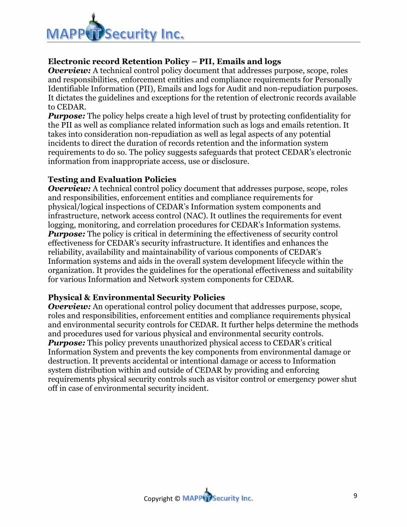
Electronic record Retention Policy – PII, Emails and logs Overview: A technical control policy document that addresses purpose, scope, roles and responsibilities, enforcement entities and compliance requirements for Personally Identifiable Information (PII), Emails and logs for Audit and non-repudiation purposes. It dictates the guidelines and exceptions for the retention of electronic records available to CEDAR. Purpose: The policy helps create a high level of trust by protecting confidentiality for the PII as well as compliance related information such as logs and emails retention. It takes into consideration non-repudiation as well as legal aspects of any potential incidents to direct the duration of records retention and the information system requirements to do so. The policy suggests safeguards that protect CEDAR’s electronic information from inappropriate access, use or disclosure. Testing and Evaluation Policies Overview: A technical control policy document that addresses purpose, scope, roles and responsibilities, enforcement entities and compliance requirements for physical/logical inspections of CEDAR’s Information system components and infrastructure, network access control (NAC). It outlines the requirements for event logging, monitoring, and correlation procedures for CEDAR’s Information systems. Purpose: The policy is critical in determining the effectiveness of security control effectiveness for CEDAR’s security infrastructure. It identifies and enhances the reliability, availability and maintainability of various components of CEDAR’s Information systems and aids in the overall system development lifecycle within the organization. It provides the guidelines for the operational effectiveness and suitability for various Information and Network system components for CEDAR. Physical & Environmental Security Policies Overview: An operational control policy document that addresses purpose, scope, roles and responsibilities, enforcement entities and compliance requirements physical and environmental security controls for CEDAR. It further helps determine the methods and procedures used for various physical and environmental security controls. Purpose: This policy prevents unauthorized physical access to CEDAR’s critical Information System and prevents the key components from environmental damage or destruction. It prevents accidental or intentional damage or access to Information system distribution within and outside of CEDAR by providing and enforcing requirements physical security controls such as visitor control or emergency power shut off in case of environmental security incident.

Copyright © 10
Remote Access Policy Overview: An operational control policy document that addresses purpose, scope, roles and responsibilities, enforcement entities and compliance for security control related changes. It further trickles down to the creation of procedures for change and configuration associated with change defined within the scope of the policy. Purpose: The purpose of this policy is to define standards for connecting to CEDAR’s network from any host. These standards are designed to minimize the potential exposure to CEDAR from damage which may result from unauthorized use of CEDAR resources. Damages include the loss of sensitive or company confidential data, intellectual property, damage to public image, damage to critical CEDAR internal systems, etc. Risk Assessment and Management Policy Overview: A management control policy document that addresses purpose, scope, roles and responsibilities, commitment from the management, coordination within the organization and compliance requirements for the purpose of securing CEDAR’s Information Systems. The document evaluates the overall security and identifies the security gaps within CEDAR’s Information systems implementation. Purpose: This policy provides foundation for the security control enhancements and identifies the need for additional policies and procedure requirement for CEDAR’s Information Systems. Information security risk assessments are conducted periodically and act as the means to provide decision makers the information to understand various risk factors and the extent of actions required to make informed decisions in mitigating risks. It takes into account the internal and external threats and potential impacts, that may not otherwise be considered. The policy’s core purpose is to determine the risk associated with CEDAR’s Information System and make recommendations to mitigate or accept the potential risks. Business Continuity and Disaster Recovery Policy Overview: CEDAR’s Information System consists of large volume of electronic information and the availability to the information determines the continuity of its operations. Business continuity and disaster policy is an operational control policy document that addresses purpose, scope, roles and responsibilities, enforcement entities and compliance requirements for CEDAR’s information systems backup and recovery. It breaks down the process into procedures such as data backups, drills and reviews. Purpose: The purpose of the policy is to provide continuity, restoration and recovery process and guidelines in case of an adverse event affecting CEDAR’s critical infrastructure. It protects CEDAR from both natural and man-made disasters by providing continuous planning for backup and recovery.

Copyright © 11
2.2 Procedures2.2 Procedures2.2 Procedures2.2 Procedures
MAPP IT has identified a few key procedures that are critical to CEDAR’s overall Security Infrastructure Planning and Implementation. The following list includes the key procedures, however, is not exhaustive. There may be procedures added in future as a result of process requirements or periodic risk assessment. Critical Cyber Assets Identification Procedures Purpose: The purpose of this procedure is to identify the critical cyber assets belonging to CEDAR. This is critical procedure as it fulfills the NERC-CIP-002 requirement as well as provides a baseline for conducting an effective risk assessment. Overview: This procedure dictates that first, CEDAR should make a list of identified Critical Assets using an annual risk assessment based method. This list then provides the basis for determining associated Critical Cyber Assets essential to the operation of the identified Critical Asset. Critical Cyber Assets Security Management Controls Procedures Purpose: The purpose of this procedure is to provide a feedback for developing an overall Information Security Plan for CEDAR. It also fulfills the requirement for NERC-CIP-003-1. Overview: This procedures defines how critical cyber assets of CEDAR are classified and defines authorization boundary for the Information System This procedure enlists the security controls that are already in place and whether they are consistent with CEDAR’s security architecture. Security Patch Management procedures/ Vulnerability Management Procedure Purpose: This procedure is important in keeping all of CEDAR’s critical cyber assets protected from newly discovered vulnerabilities. Overview: This procedure outlines the automated process adopted to update patches, the frequency of updates, schedule for updating the systems as well as the response measure in case of an adverse effect from a patch update. The procedure provides details on Vulnerability scoring, patch deployment, validation process, etc. The procedure poses a prerequisite of testing all the patches on a test bed that contains mirrored configuration of CEDARs internal systems.

Copyright © 12
Security status Monitoring Guidelines/ Event Logging, Monitoring, and Correlation Procedures Purpose: The purpose of the procedure is to ensure that the security controls that are currently in place are effective and being adhered to. A very significant feature derived from the guidelines is being able to find new vulnerabilities that may not have been discovered yet. This early detection can potentially block any harm that may be done to CEDAR’s infrastructure.
Overview: The automated tools are used to implement the guidelines such as monitoring Internet traffic, Electronic mail traffic, LAN traffic, protocols, etc. The guidelines may include the type data that may be analyzed for monitoring purpose including, but not exhaustive of the following:
• Firewall logs
• Intrusion detection system logs
• User account logs
• Network scanning logs
• System error logs
• Application logs
• Data backup and recovery logs
• Telephone activity – Call Detail Reports
• SNMP traps and alerts Malicious software prevention procedure Purpose: The purpose of this procedure is to protect CEDAR’s critical cyber assets from various malicious attacks such as virus, Trojans and malwares, etc. Overview: The procedure outlines the automated software tools used for deployment. It also dictates how often CEDAR’s assets may be scanned and updated by the specific software. The outcome of the process may sometimes be used in incident response related activities. Disposal and Redeployment procedures Purpose: The purpose of this procedure is to establish process and protocols to be followed for safe disposal and redeployment of CEDAR’s cyber assets and media. Overview: The procedure may further outline standards adoption such as DOD 5220.22 Standard—Triple Overwrite of data with verification. This procedure provides the scenarios when the redeployment is approved/declined the authority required to implement the changes. Recovery procedures for Critical Cyber Assets Purpose: The purpose of this procedure is to provide details on how to recover CEDAR’s critical cyber assets and information systems post disaster. Overview: The procedure describes the personnel to be contacted, offsite details that may be set up for recovery purposes, detailed guidelines on how to restore services and the organizations or individuals to be contacted to do so. It identifies CEDAR’s critical assets and assigns priority to the key business functions.

Copyright © 13
Policy enforcement Procedures Purpose: The purpose of the procedure is to authorize or delegate enforcement responsibilities to ensure CEDAR is adhering to the recommended policies. Overview: The procedure outlines the process to be followed in case of violation. It also describes what consists of violation within CEDAR. This procedure takes in account that some policies are applicable for vendors and third parties and ensures that the process includes various scenarios in case of violation. The procedure is very important as it may lead to legal proceedings resulting from the follow up. Incident Reporting and Response Planning Procedures Purpose: The purpose of the procedure is to outline the step-by-step process and protocols to be followed in order to plan for Incident response and follow up. Overview: This procedure is derivative of incident response policy and ensures that CEDAR maintains a group of informal as well as formal incident response team. The roles and responsibilities of the team are specified as well. The procedure goes as far as the reporting instructions post an incident. This is yet another key procedure as it may act as guide for forensic use of the incident data reports. VPN Procedures Purpose: The purpose of the procedure is to enlist selection of specific process and technology that may be used to gain remote access to CEDAR’s internal network using Virtual Private Network. The procedure helps protect CEDAR from unauthorized access. Overview: The procedure includes details such as no split tunneling, the encryption standards that must be used while connecting to CEDAR’s network. The procedure outlines who may or may not be allowed to connect to CEDAR’s network using VPN. Backup and fault tolerance Procedures Purpose: The purpose of this procedure is to provide quick availability to critical information system in case of an adverse contained event or an accidental failure. The procedure may also provide ways to combat encryption themed malwares such as crypto locker. Overview: The backup procedure defines the technology used for backups. The details include how often the backups are conducted, the offsite location where the backups are maintained, the process of information retrieval from the backups, etc.

Copyright © 14
2.3 Staffing2.3 Staffing2.3 Staffing2.3 Staffing
To ensure that new security controls are managed effectively CEDAR will need to hire additional employees. The addition of these new employees will ensure that CEDAR’s investment in technical controls does not go to waste. The employees below will need to be hired. Five employees for an Information Security Team whose responsibilities will include the following:
• Obtain info on latest threats through various sources and provide recommendations to other teams.
• Obtain or determine digital signatures to be implemented on IDS
• Obtain Information on latest malicious URLs and make recommendations to sys admins on new patches
• Monitor Intrusion Detection Systems and other security monitoring implementations.
• Participate in Incident Response where information or security is threatened. Five System Administrators with the following responsibilities:
• Manage Citrix, Radius, RSA, DNS server, Windows Server, and hosting Application Servers.
• Working with third party services to ensure that our systems and their services work together as intended.
• Ensuring high availability of servers
• Update the Web Proxies, servers, and systems based on recommendations provided by Info Sec Team
Three Database Administrators with the following responsibilities:
• Manage Database functions and how they correlate with applications and servers
• Work with application engineers to ensure applications work hand-in-hand with servers
Three Application Engineers with the following responsibilities:
• Manage application programming to ensure functionality, user interface,
• Work with Database and other teams to ensure functions output the data and follows standard RFCs and protocols for communicating at all stages.
• Work with System Administrators and DB Admins to ensure applications function hand-in-hand with systems and databases.
Six Security Guards will also need to be hired (two per site) that will be responsible for monitoring entrances and exits at each location as well as camera feeds.

Copyright © 15
3. Lombard Customer Service Center3. Lombard Customer Service Center3. Lombard Customer Service Center3. Lombard Customer Service Center
3.13.13.13.1 NetworkNetworkNetworkNetwork
Redundant Internet Service Providers (ISPs) with MPLS MPLS is the latest scheme being deployed for WAN transmission systems. It is efficient, fast, and highly secure. VPN tunneling using IPSec would be implemented via MPLS network, provided by two separate Carriers / ISPs. Doing so would ensure confidentiality, integrity, and availability between all three CEDAR sites. The implementation would be a point-to-multipoint configuration with each site's edge router converging at the edge router in the ISP. The below listed diagram illustrates how this likely would be executed.
Routing Protocol As discussed earlier, for internal routing protocols, OSPF or EIGRP are the best choices. Currently OSPF is the defacto standard, but that is largely due to EIGRP being a Cisco proprietary protocol. That is now changing. Cisco, in the last year, has opened up EIGRP for interoperability with other systems, thus increasing its attractiveness for network deployments. EIGRP includes route summarization, speedy convergence, unequal cost load-sharing and a host of other benefits making it a good choice.
Copyright © 16
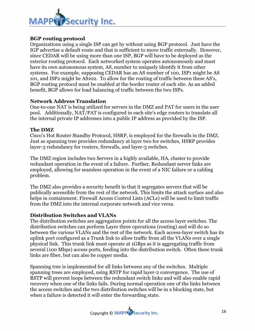
BGP routing protocol Organizations using a single ISP can get by without using BGP protocol. Just have the IGP advertise a default route and that is sufficient to move traffic externally. However, since CEDAR will be using more than one ISP, BGP will have to be deployed as the exterior routing protocol. Each networked system operates autonomously and must have its own autonomous system, AS, number to uniquely identify it from other systems. For example, supposing CEDAR has an AS number of 100, ISP1 might be AS 101, and ISP2 might be AS102. To allow for the routing of traffic between these AS's, BGP routing protocol must be enabled at the border router of each site. As an added benefit, BGP allows for load balancing of traffic between the two ISPs. Network Address Translation One-to-one NAT is being utilized for servers in the DMZ and PAT for users in the user pool. Additionally, NAT/PAT is configured in each site's edge routers to translate all the internal private IP addresses into a public IP address as provided by the ISP. The DMZ Cisco's Hot Router Standby Protocol, HSRP, is employed for the firewalls in the DMZ. Just as spanning tree provides redundancy at layer two for switches, HSRP provides layer-3 redundancy for routers, firewalls, and layer-3 switches. The DMZ region includes two Servers in a highly available, HA, cluster to provide redundant operation in the event of a failure. Further, Redundant server links are employed, allowing for seamless operation in the event of a NIC failure or a cabling problem. The DMZ also provides a security benefit in that it segregates servers that will be publically accessible from the rest of the network. This limits the attack surface and also helps in containment. Firewall Access Control Lists (ACLs) will be used to limit traffic from the DMZ into the internal corporate network and vice versa. Distribution Switches and VLANs The distribution switches are aggregation points for all the access layer switches. The distribution switches can perform Layer three operations (routing) and will do so between the various VLANs and the rest of the network. Each access-layer switch has its uplink port configured as a Trunk link to allow traffic from all the VLANs over a single physical link. This trunk link must operate at 1GBps as it is aggregating traffic from several (100 Mbps) access ports, feeding into the distribution switch. Often these trunk links are fiber, but can also be copper media. Spanning tree is implemented for all links between any of the switches. Multiple spanning trees are employed, using RSTP for rapid layer-2 convergence. The use of RSTP will prevent loops between the redundant switch links and will also enable rapid recovery when one of the links fails. During normal operation one of the links between the access switches and the two distribution switches will be in a blocking state, but when a failure is detected it will enter the forwarding state.

Copyright © 17
Concerning VLANs, CEDAR has defined more than a dozen of them for the various user roles and departments. Each access layer switch has a VLAN database that is defined once in a random switch and is then replicated to all the other switches in CEDAR's infrastructure via VLAN trunking protocol. Although all switches start with a baseline VLAN configuration, ports must be adjusted manually, assigning VLAN membership to various port groupings to suit user's needs. From there, all VLAN traffic channels through uplinks to the distribution switch where the VLAN endpoints are defined. A virtual IP address is needed as the endpoint for each VLAN. While VLANs are layer-two and have no idea what an IP address is, IP addresses need to be configured as the Default Gateways for each virtual LAN (VLAN). Knowing that a VLAN is a broadcast domain, there must be a mechanism to allow applications, that run on the end users (access devices), to be able to route traffic beyond the local network. The VLAN's default gateway is the next-hop router that allows VLAN traffic to span beyond its broadcast domain and get routed to other networks. This VLAN interface that is created to accomplish this is called a Switched virtual interface, SVI, and is defined in the Distribution switches. Please refer to the Device IP addresses workbook to view the default Gateways for each VLAN. Switch Port Security Switch ports should be configured with 802.1x and an attached RADIUS Server to ensure that any users (attached clients) wanting network access are first authenticated prior to being allowed to gain access to the network. EAP-TLS is a recommended protocol that can be used with 802.1x for secure authentication. Furthermore, port-security will be enabled on the switches to restrict the number of unique MAC addresses that can connect to a switch-port. To reduce configuration needs, the “sticky” option can be used to determine what MAC addresses will be allowed to connect to the port. SNMP Network Management Any large network needs a system in place for monitoring and managing network failures. Traditionally, SNMP has often been used for this purpose. All network devices already have an SNMP MIB, managed by an SNMP agent process on the device, that is the database for SNMP system. Within this MIB are all the objects that are logical representations of the device’s hardware components and subcomponents. SNMP management occurs via an SNMP manager, running on a Server, and interacting with all the SNMP agents on each of the network nodes. The SNMP manager entity must have knowledge of the MIBs of each network node it is managing. It manages via polling (status of network node components) and also via unsolicited traps coming from each network node, informing of a network incident requiring operator intervention. OpManager will be used to manage SNMP.

Copyright © 18
When implementing SNMP, version 3 (SNMPv3), needs to be deployed as prior versions do not encrypt the polling, trap messaging, community strings, etc. that are part of the SNMP communication exchange across the network. Firewall Change Management For firewall configuration changes, a change management process needs to be instituted to carefully track changes, quickly resolve problems, and provide a mechanism to absolve CEDAR of legal litigation should any problems arise. VPN for Field Techs The field technicians, in addition to having full disk encryption enabled on their PC, will use two-factor authentication to provide robust security. First, all laptops will have a VPN client installed. Second, an RSA random code generator will precede their password credential. This will allow for the secure transmission of data between the field techs and CEDAR’s network. The VPN will be terminated at the Cisco ASA5512-X firewalls in Lombard.
3.2 3.2 3.2 3.2 ServeServeServeServers and Workstationsrs and Workstationsrs and Workstationsrs and Workstations
All servers in the Lombard location should be virtualized on a cluster of redundant physical blade servers. Blade servers will be managed from the management VLANs while all other services will be segregated to their different respective VLANs. For redundancy purposes at least two physical servers must work as a cluster to host one logical server. DMZ Servers Lombard location will contain a Webserver as well as the Mail server which needs to be accessed by both the internal and external entities. These servers should be implemented on a DMZ hosted by the firewall directly connected to the edge routers. The DMZ network protocols should protect the unintended external traffic from ever getting on to the internal network while allowing services to be maintained to both external and internal entities. These servers should be located on a different physical blade servers compared to the rest of the Lombard servers. Credit Card Billing Credit card numbers received for payments should be sent encrypted to the CRM server for processing after which it is sent to a dedicated line for clearing at JPCC. Note that the CRM server should be on a different VLAN than other servers and only accessible by billing personnel. The CRM server should be implemented to pull data from the Historian SQL servers in Oak Brook or Waukegan without any direct access to the Historian servers behind the ESPs. The credit card information as well as any other customer personal identifiable information must be encrypted at all times after the information is inserted electronically within CEDAR’s environment.

Copyright © 19
Domain Controller All users’ workstations will utilize Windows 7 Professional operating systems. The accounts and permissions are to be managed on Windows Active Directory (AD). Users should be given permissions for accessing servers in the Windows domain strictly based on least privilege basis. Users should only have enough access to complete their duties and tasks. The AD domain controller at Lombard should control all user that will access the Windows domain. With active directory a user can use one account for multiple directories, systems, applications, etc. DNS Server There should be a Domain Naming Server (DNS) cluster located in the DMZ. This respective DNS server should provide host names utilizing an efficient naming convention for systems in CEDAR’s environment. This provides an extra layer of security in regards to redundancy such that DNS can point a specific host name to a different system with a different backup IP address in case a primary system with primary IP address goes down. A client user or system utilizing host names rather than IP addresses will never recognize such a fail over which is as intended until an incident is resolved. The DNS server from Lombard’s DMZ should be the primary DNS server used by CEDAR’s systems and personnel. However, the DNS server can have a backup public DNS server such as Google’s DNS server with IPv4 address 8.8.8.8 in order to resolve the public IP addresses unknown directly by CEDAR’s DNS server. Windows Server 2008 R2 license for each of the two nodes in the cluster should be sufficient for the software specifically needed to provide this service as it includes DNS services. RADIUS Server A dedicated remote authentication dial-in user service (RADIUS) must be implemented and synchronized with Active Directory to control access to systems. Access to users should be limited based on an individual user’s role and responsibilities. The RADIUS server should control access to all servers, networking devices, and network accessible management systems. The primary RADIUS server should be located at Lombard while the backup systems should be located at Oak Brook and Waukegan data centers. Most industry standard enterprise network devices and servers have the capability to use authentication servers, including RADIUS. This drastically helps with the methodology that employees should function on limited access enough to complete their tasks. A RADIUS server, when synchronized with Active Directory, provides the benefit of an enhanced tracking and reporting based on employee and affiliates’ use renames from Active Directory. All logs should be stored on the NAS logging servers. Windows Server 2008 R2 provides a Network Policy Server feature that can be implemented specifically as a dedicated RADIUS server. The RADIUS server can be implemented with port based security (802.1X) in order to prevent someone unauthorized from plugging in an unintended device into CEDAR’s network access points and obtaining access into CEDAR’s Intranet.

Copyright © 20
RSA Authentication Server An RSA Authentication Manager application can be run on redundant dedication virtual server provided by EMC^2 can be integrated with the RADIUS server for authentication on critical cyber assets. The RSA Authentication Manager will be synchronized with a small devices, called RSA Secure IDs, which are given to each employee who will need direct access to making changes to network accessible critical cyber assets. The two-factor authentication will require an employee’s username, a secret PIN number that employee sets up, and the randomly generated token from their RSA Secure ID that is synchronized with their RADIUS/Active Directory accounts. The RSA tokens can be used also for authenticating with the VPN server in order to provide a multi-factor authentication for anyone trying to obtain internal access to CEDAR’s environment from an outside unsecure location. Web Proxy It is recommended that the open source web proxy is implemented on redundant servers at CEDAR. These web proxies should be implemented on the DMZ in Lombard. All HTTP, HTTPS, and FTP traffic from any users must traverse to the web proxies. The web proxies make all web traffic viewable by administrators to ensure that sensitive or unintended information doesn’t leave CEDAR’s intranet. The proxy recommended to use is Squid as it is open source and accomplishes the same level of filtering as commercial web proxies do. The only challenge with the using Squid is to ensure that updated black listed sites are updated in Squid’s database to be blocked if any traffic attempts to communicate with the known bad websites. It is the security team’s responsibility to ensure that the latest lists of known malicious sites are sent to the web proxy administrators periodically and consistently. The proxies will be located in Lombard’s DMZ and all internal systems that go to the Internet from all sites must go to the proxies to be filtered. Network Area Storage (NAS) Servers NAS servers are needed to store a variety of data that are produced by other systems or applications servers. These included system logs, shared file partitions, and SQL databases for storing historian data. Other than the partitions intended for storing files by users the NAS servers do not complete the core processing of applications but rather are used for the storage of output and reference data that application servers produce. The NAS server at Lombard will be synchronized with the redundant NAS servers at Oak Brook and Waukegan. With a triple redundant storage server setup at three different locations up to two servers can fail and the stored data will still be available. Users Workstations All users’ workstations will consist of Dell laptops that contain solid-state hard drives which can make it less susceptible to swift movements of laptop. The workstations will also contain software used for completing assignments. BitLocker will be used for full disk encryption which will protect data stored on the laptop should it be lost or stolen.

Copyright © 21
4. 4. 4. 4. Oak Brook and Waukegan PoOak Brook and Waukegan PoOak Brook and Waukegan PoOak Brook and Waukegan Power Grid Control Centers (PGCC)wer Grid Control Centers (PGCC)wer Grid Control Centers (PGCC)wer Grid Control Centers (PGCC)
4.1 Network4.1 Network4.1 Network4.1 Network
The details of both PGCC networks are similar to that of the Lombard CSC. The only differences are that the VLAN-to-switch port mappings as defined in each switch will differ based on what domain the pool of users are associated with. At each PGCC a segment of the network will be separated from the corporate network with firewalls. This segment consists of the operator workstations, Solaris server, and HMI application and database servers that are used to control the grid. The segment is contained within an Electronic Security Perimeter (ESP). The ESP is required to comply with CIP and protects the endpoints that are responsible for controlling the grid from external attacks as well as to help prevent a compromise on the corporate network from spreading past the ESP. Traffic to and from the Internet will not be allowed. Only traffic to and from the SQL server in the PGCC will be allowed. This is to transfer usage data that can be used for billing by customer service. In addition the connections to MISO will also be protected by firewalls and will only allow outbound connections to MISO for the purpose of sending load information. Currently the connection to MISO uses FTP which transmits usernames, passwords and data in clear-text. It is recommended that SFTP be used instead which provides a secure method for transmitting the information via an encrypted channel. In addition, there will be two links to MISO to ensure timely transmission of load information.
4.2 Servers and Workstations4.2 Servers and Workstations4.2 Servers and Workstations4.2 Servers and Workstations
All servers and management systems from Oak Brook are mirrored at the Waukegan site. With virtualization and synchronized servers when a primary system goes down at Oak Brook (primary systems) then the backup systems at Waukegan would take over a process to limit down time of services. Systems behind the Electronic Security Perimeter (ESP) There are certain systems and servers that are required to be protected by the electronic security perimeter as they have direct access in making changes to the electric grid which are considered critical assets. These systems should not be directly accessible by systems outside of the ESP. All the systems used within the operations center in Waukegan and Oak Brook must be behind the electronic security perimeter. This includes the Solaris servers, historian servers, fileservers, and all systems that will have direct access in making changes to grid or obtaining information directly from the electrical grid. A redundant connection from the ESP to MISO, at Oak Brook and Waukegan locations, should be implemented to allow transfer of grid load information from the FTP server within the ESP.

Copyright © 22
Historian Server The historian sever is one of the servers protected behind the ESP within Oak Brook as well as the mirror backup server Waukegan. This brings the challenge of how the billing personnel obtain this data without getting direct access to the historian server that contains access to CEDAR’s electrical grid. The historian server and back up servers, which obtain the electrical usage of customers, should be implemented to have unidirectional SFTP access to a SQL server outside the ESP. Electrical usage should be propagated from the historian server to the respective SQL server. The billing personnel from Lombard can then directly access that SQL server for obtaining customer’s electrical usage information to be used for billing purposes. This would maintain the ESP requirements for NERC CIP compliance. Grid Operators All systems, including the Windows XP machines, used by grid operators with direct access to the electrical grid must be located behind the ESP. In its current state the grid application on the Windows XP machines is not compatible with newer versions of Windows. The Windows XP machines currently have multiple layers of defense to protect them, however, it is recommended that the application is upgraded in the future in order to be compatible with more modern operating systems that will still be supported by the Vendor such as Windows 7 and have the systems upgraded as well to the more modern and secure Operating systems. As of April 2014, Microsoft will no longer support Windows XP. Virtualizing Servers Other than servers behind the ESP, Server located at a Lombard DMZ, and the CRM server, all servers will be virtualized using VMware VSphere capabilities at all locations. Server virtualization will reduce the dependency of business applications from any one set of physical servers. This will provide the capability to rapidly fail over any specific virtual server without losing any active session information. Citrix Servers The Citrix servers are intended to provide redundancy to access of applications that run on systems outside of the ESP. The applications run on the Citrix servers will have access to CEDAR’s intranet only in order to ensure that files produced on these systems will not have access to environment outside of CEDAR. Files can be produced and sent from to other internal storage systems such as shared partitions on the NAS servers.

Copyright © 23
5. Security Controls5. Security Controls5. Security Controls5. Security Controls Threat Intelligence In order to ensure that the layers of defense stay up-to-date and modern to counter the threats faced by CEDAR there should be a small team that is dedicated to gathering intelligence. This team can be as small as a team of one individual who gathers intelligence from various sources such as Internet publications, recent books, articles, etc. and make recommendations to other teams if any of the threats found pose danger to CEDAR’s systems, information, or operations. The teams receiving the recommendations should then assess their environment and determine on how much of a threat a vulnerability poses and whether changes in their environments would mitigate the threats or not. The threat Intel team can also use resources such as Threat Connect to provide updates to the web proxies. The threat intelligence team can blacklist traffic to known malicious sites based on a threat intelligence service provided by ThreatConnect. ThreatConnect obtains information from a community of many organizations about URLs that are reported to provide. The intelligence is then distributed to all other organizations participating in the community in order to raise awareness where organizations can take actions to block or mitigate traffic flow from internal to the Internet. The threat intelligence team can use the free version of threat connect to obtain signatures and information on the latest threats. The threat intelligence team should forward the latest signatures to team members that manage the IDS signature database. In order to update the web proxies, the threat intelligence team can utilize SquidBlackList services for obtaining the most recent lists of malicious websites. This includes all websites that risk infecting internal systems with malware, potential informational loss, financial damage, stress, loss of time, and loss of customers’ trust, all which are avoidable if blocking users from being able to access all known bad websites For now the threat intelligence team needs to propagate the threats manually to systems. However, in the future it is recommended that a threat signatures received from a variety of sources should be automatically propagated by simple Linux scripts that would automatically run and propagate signatures to Intrusion Detections Systems. These scripts can also be used to grab known malicious websites received from ThreatConnect and propagate them to the web proxies in Lombard. It is also recommended that CEDAR join organizations such as the Electrical Sector Information Sharing and Analysis Center (ES-ISAC) and the Industrial Control Systems Cyber Emergency Response Team (ICS-CERT) to obtain intelligence about threats encountered by other organizations.

Copyright © 24
5.1 Network Based Controls5.1 Network Based Controls5.1 Network Based Controls5.1 Network Based Controls
Network Intrusion Detection Systems A mirror port should be created on all core switches where a duplicate of traffic traversing goes to the SPAN port. A Snort/Source Fire IDS should be placed at those SPAN ports to analyze traffic. If any anomalies or incidents are detected then it should alert the incident response team who will further analyze the situation and further determine what actions to take. All logs can be stored on a partition of the NAS servers as these stored logs can be very large. A cleanup program should be implemented where IDS logs should be deleted after one year in order to prevent unnecessary mass storage of logs that may not be relevant anymore. Intrusion Detection and Incident Response could be combined into one team in smaller teams. The IDS recommended is SNORT and can be installed on an open source Linux environment. CentOS Linux operating system can be implemented on servers at the Lombard, Oak Brook, and Waukegan and should be connected to the SPAN ports of the core switches. This will allow a copy of all traffic traversing to be sent to the IDS servers for analysis without disrupting the original traffic.
Email Security
Trend Micro provides a service for analyzing and verifying that e-mails traversing to and from CEDAR’s environment do not contain malware attachments. This e-mail security service also blocks spam e-mail from known bad sources. In order to accomplish this the MX record on the DNS server to an IP address provided by Trend Micro. This will cause all e-mails being sent to go through Trend Micro’s analysis before being sent to CEDAR’s exchange server which would relay the message to a destination client. This reduces the need to add additional responsibilities and costs of maintaining system’s on CEDAR’s end when the subscription for this services is much more affordable. This services costs around $12,000 dollars for three years with most of the responsibilities being handled by Trend Micro which significantly reduces one of the greatest threat vectors by which malware is distributed from.
Syslogs and SIEM There should be monitors implemented to analyze all the syslogs coming in and send alerts when more critical or abnormal logs are detected. There will be two instances of applications that will monitor syslogs coming in. All servers and networking devices, where possible, should send system logs to the syslog server. We will be using two monitoring tools, Alien Vault and OpManager, which will monitor all logs. Alien Vault’s Unified Security Management (USM) solution provides the benefit of detecting known vulnerabilities and exploits in an environment based on a database updated Alien Vault monitoring based on information obtained by the community utilizing Alien Vault. Alien vault can also be used for optimal reporting on threats that may exist in CEDAR’s environment for assisting with Incident Response. Alien Vault provides the capability for detecting malicious activities, network level attacks, as well as SCADA system attacks. Alien Vault should be virtualized, as there is a great cost saving

Copyright © 25
with implemented as such. Alien Vault provides a control for detecting Advanced Persistent Threats that may be located in CEDAR’s environment. OpManager syslogs monitoring offers a suite of tools that monitors syslogs produced by servers and networking devices as well as application logs. OpManager offers the benefit of monitoring the health of application processes, configuration changes, anomalies that occur, and various other monitoring capabilities that can alert administrators when something is wrong with a system or process. OpManager also provides a very useful reporting tool that is beneficial to incident response for seeing patterns and trends in systems or applications. Logs will also assist in viewing the extent and scope of an incident when they occur for a better understanding on how to mitigate the situation. OpManager has an alerting feature that can send e-mail as well as SMS alerts to administrators for rapid incident response when specified incidents are detected based on the logs monitored. There should be a cleanup program that deletes syslogs after a certain amount of time in order to prevent unneeded use of large digital storage space of older logs.
5.2 5.2 5.2 5.2 Host Based ControlsHost Based ControlsHost Based ControlsHost Based Controls
Host Intrusion Detection System A host intrusion detection system should be implemented on all server nodes as well as user’s workstations. Symantec Critical System Protection offers the benefit of being compatible with Windows and Linux environments whether they’re virtualized or not. This specific host IDS will log changes made on a specific system and can be used for assisting with incident response. All servers and workstations that will run Symantec Critical System Protection can be managed from a Symantec Management server that will synchronize with all end client machines every time they’re on CEDAR’s network. Benefits include file integrity monitoring, configuration monitoring, wide platform support, and, as mentioned, centralized management. Symantec Critical System protection has other benefits that can be used in CEDAR’s servers and workstations such as IPS capabilities. Data Loss Prevention Symantec management server also has the capability to block multiple forms of media from being used on systems. This includes preventing client systems from being able to write data to external media such as removable USB devices and CD/DVDs. Symantec Data Loss Prevention can also block information on specific servers from being faxed or printed. This will ensure that sensitive information is not at risk of being lost.
Active Directory Groups and Group Policies Users will be placed into groups in Active Directory. This will allow administrators to assign permissions to groups rather than users, thus creating a more efficient way to manage access and permissions by only having to add users to groups rather than assign permissions to individual users. Group policies will be used to enforce policies such as password requirements, administrative rights and other access and permissions across the domain.

Copyright © 26
Antivirus Software Malware can have great impact on CEDAR’s organization as they can be formed to block services, steal identities, financial data, or other sensitive information, and even encrypt sensitive information and hold it for ransom. All workstations and servers should have Symantec anti-virus installed on them. Anti-virus software is an important layer of defense in protecting systems from malware. All the client systems that will have anti-virus software should be managed from the Symantec management server for ensuring that the anti-virus software is updated on a regular basis. Anti-virus with a combination of other layers of security should ensure that the threats of malware are mitigated significantly to an acceptable level. For non-technical controls please refer to the Policies, Procedures and Staffing Section.

Copyright © 27
6. Physical Security6. Physical Security6. Physical Security6. Physical Security CEDAR’s current physical security controls are not sufficient to prevent a breach, theft or
damage to critical assets. CEDAR’s facilities house multiple servers and network devices. The
devices themselves have a significant financial value. However, the servers and network devices
store data that can be of significantly higher value. Failure to physically secure the servers and
devices on which the data resides and through which the data is transmitted can lead to breaches
resulting in significant financial, operational and reputational impact. To mitigate the risks of
such a breach the controls below are proposed.
6.1 6.1 6.1 6.1 Access Control and LoggingAccess Control and LoggingAccess Control and LoggingAccess Control and Logging
To properly restrict access to CEDAR’s facilities RF badge readers will be installed at the
facilities’ entrances. Employees will be given RF Badges to gain access to the buildings.
Furthermore, the side entrances will require both a valid badge and a PIN to open from the
outside. The side doors should only be used as emergency exits As such alarm locks will be
installed on each of the side doors. When opened the alarm will go off thereby providing an alert
that the door was opened. In the electric grid control rooms in the Oak Brook and Waukegan
locations, one of the exits will also be equipped with the alarm locks. The exits that leads from
the cubicle area to the hallway leading to the warehouse in Oak Brook and the side door in
Waukegan will also be equipped with alarm looks. In Lombard it is recommended that the
revolving door be removed and only one door be left to better secure it.
Badge readers will also be installed inside the facilities to further restrict access to areas where
only certain employee have a business need for access. In the Lombard Customer Service Center
the datacenter room will be restricted only to employees that have a valid business to access the
area. In the Oak Brook and Waukegan locations the areas with the servers, telecom, SCADA,
and electric grid control center will also be restricted with badge readers. In addition, a mantrap
that requires a badge and PIN at the first door and a badge at the second door will protect these
areas at all locations.
The badge readers will be networked to allow for central access management using infinias
Intelli-M Access Professional Access Control Software that can integrate with LDAP for user
and access management. This will also provide logging of who accessed what area and the date
and time of the access. The logs can then support any security breach investigations.
6.2 6.2 6.2 6.2 Networked Security CamerasNetworked Security CamerasNetworked Security CamerasNetworked Security Cameras
Dome style cameras will be installed on the perimeter of the facilities. The proposed cameras are
network enabled and support Power over Ethernet (PoE), which reduces the number of wires that
need to be run to support them. They will be installed in locations that ensure maximum
visibility especially visibility to the entrances. The security cameras and software, Eyeline
Processional Video Surveillance, will allow CEDAR to monitor and have video evidence of who
enters and exits the facilities. In addition, cameras will also be placed inside the facilities to
monitor restricted areas such as the datacenters, electric grid controls rooms, telecom and
SCADA equipment rooms. Cameras will also be placed to monitor emergency exits and main
entrances from inside the facilities.

Copyright © 28
The proposed LG cameras have motion-sensing capabilities to help reduce the amount of video
that is recorded and conserve storage space.
6.3 6.3 6.3 6.3 Visitor ControlVisitor ControlVisitor ControlVisitor Control
At times it might be necessary for a non-employee to access the facilities. For this purpose a
visitor control program will be put in place to register and track visitors. The program will
include a process where users make an appointment with receptionists who can then enter them
into a logbook. Upon arrival a visitor will have to sign the logbook along with the date and time
of arrival as well as time of departure when leaving. Visitors who will be at the facilities for
more than a day can be issued visitor badges. Any visitors entering the data centers, telecom,
electric grid or SCADA rooms will be issued a visitor badge regardless of length of visit.

Copyright ©
6.4 6.4 6.4 6.4 Lombard Physical Security DiagramLombard Physical Security DiagramLombard Physical Security DiagramLombard Physical Security Diagram

Copyright ©
6.5 6.5 6.5 6.5 Oak Brook PGOak Brook PGOak Brook PGOak Brook PGCC Physical Security DiagramCC Physical Security DiagramCC Physical Security DiagramCC Physical Security Diagram

Copyright ©
6.6 6.6 6.6 6.6 Waukegan PGCC Physical Security DiagramWaukegan PGCC Physical Security DiagramWaukegan PGCC Physical Security DiagramWaukegan PGCC Physical Security Diagram
Copyright ©
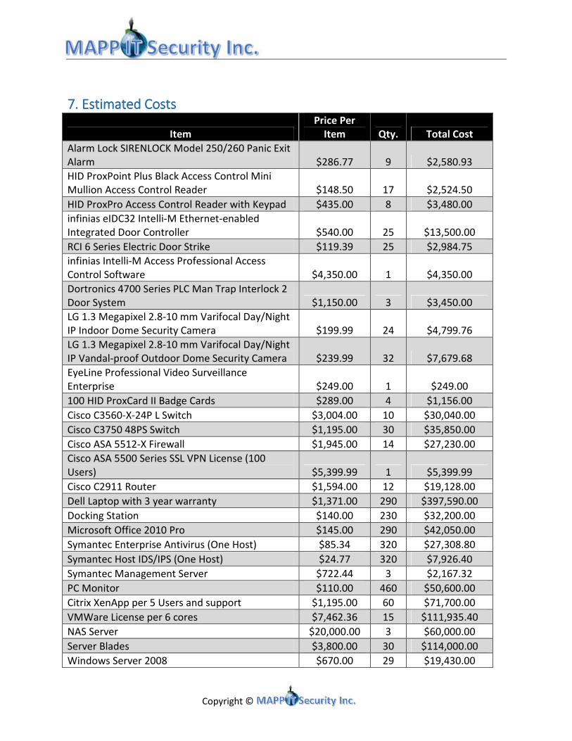
7. 7. 7. 7. Estimated Estimated Estimated Estimated CostsCostsCostsCosts
Item
Price Per
Item Qty. Total Cost
Alarm Lock SIRENLOCK Model 250/260 Panic Exit
Alarm $286.77 9 $2,580.93
HID ProxPoint Plus Black Access Control Mini
Mullion Access Control Reader $148.50 17 $2,524.50
HID ProxPro Access Control Reader with Keypad $435.00 8 $3,480.00
infinias eIDC32 Intelli-M Ethernet-enabled
Integrated Door Controller $540.00 25 $13,500.00
RCI 6 Series Electric Door Strike $119.39 25 $2,984.75
infinias Intelli-M Access Professional Access
Control Software $4,350.00 1 $4,350.00
Dortronics 4700 Series PLC Man Trap Interlock 2
Door System $1,150.00 3 $3,450.00
LG 1.3 Megapixel 2.8-10 mm Varifocal Day/Night
IP Indoor Dome Security Camera $199.99 24 $4,799.76
LG 1.3 Megapixel 2.8-10 mm Varifocal Day/Night
IP Vandal-proof Outdoor Dome Security Camera $239.99 32 $7,679.68
EyeLine Professional Video Surveillance
Enterprise $249.00 1 $249.00
100 HID ProxCard II Badge Cards $289.00 4 $1,156.00
Cisco C3560-X-24P L Switch $3,004.00 10 $30,040.00
Cisco C3750 48PS Switch $1,195.00 30 $35,850.00
Cisco ASA 5512-X Firewall $1,945.00 14 $27,230.00
Cisco ASA 5500 Series SSL VPN License (100
Users) $5,399.99 1 $5,399.99
Cisco C2911 Router $1,594.00 12 $19,128.00
Dell Laptop with 3 year warranty $1,371.00 290 $397,590.00
Docking Station $140.00 230 $32,200.00
Microsoft Office 2010 Pro $145.00 290 $42,050.00
Symantec Enterprise Antivirus (One Host) $85.34 320 $27,308.80
Symantec Host IDS/IPS (One Host) $24.77 320 $7,926.40
Symantec Management Server $722.44 3 $2,167.32
PC Monitor $110.00 460 $50,600.00
Citrix XenApp per 5 Users and support $1,195.00 60 $71,700.00
VMWare License per 6 cores $7,462.36 15 $111,935.40
NAS Server $20,000.00 3 $60,000.00
Server Blades $3,800.00 30 $114,000.00
Windows Server 2008 $670.00 29 $19,430.00
Copyright ©
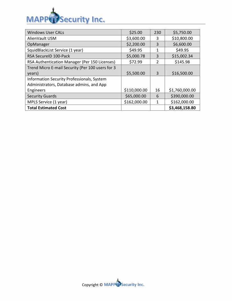
Windows User CALs $25.00 230 $5,750.00
AlienVault USM $3,600.00 3 $10,800.00
OpManager $2,200.00 3 $6,600.00
SquidBlackList Service (1 year) $49.95 1 $49.95
RSA SecureID 100-Pack $5,000.78 3 $15,002.34
RSA Authentication Manager (Per 150 Licenses) $72.99 2 $145.98
Trend Micro E-mail Security (Per 100 users for 3
years) $5,500.00 3 $16,500.00
Information Security Professionals, System
Administrators, Database admins, and App
Engineers $110,000.00 16 $1,760,000.00
Security Guards $65,000.00 6 $390,000.00
MPLS Service (1 year) $162,000.00 1 $162,000.00
Total Estimated Cost $3,468,158.80

Copyright ©
Appendix A Appendix A Appendix A Appendix A –––– Network DiagramNetwork DiagramNetwork DiagramNetwork Diagramssss
Waukegan
Lombard
DMZ
Switch6Switch5
USERS
Switch25 Switch26 Switch27 Switch28
JPCC
R1
FW1 FW2
PGCC Network;
Operations and GRM
Switch11 Switch12
Users
FW3 FW4
Users
Switch32Switch31Switch13
Switch2Switch1
Field Techs
VPN
ISP2
MPLSISP1
MPLS
R2
R8
R7
Switch23
Switch24
Security Server *
Domain Controller *
File/Print Server *
Symantec Server *Lombard
CRM
Historian
SQL Server
Operators
Switch17 Switch18
Switch4
MISO FW5
FW6
R4
R3
Switch15
Switch16
File/Print Server
Switch20
Switch19
FW11 FW12
Operators
Switch35 Switch36
Switch9 Switch10
MISO
FW17
FW18
R11
R12
Switch37
Switch38
File/Print Server
Switch34Switch33
Solaris
Electronic Security PerimeterElectronic Security Perimter
Oakbrook
RSTP
RSTP
RSTP
RSTP
RSTPRSTP
RSTP
Switch14 Switch29
Switch7 Switch8
30
R9 R10
FW9 FW10
FW7 FW8
R6R5
Switch3
Switch22
Switch21 HSRP
FW7 & FW8
Exchange Server
Cluster
Web Server
Cluster
Backup Lombard
Servers *
Web Proxy
Cluster
Historian
SQL Server
Citrix Application
ServerCitrix Application
Servers
Backup Lombard
Servers *
Log Server *
Network & Host IDS
Management
Servers *
Historian
Solaris
Historian
DNS Server
Cluster

Copyright ©
Lombard
DMZ
Switch6Switch5
USERS
Switch25 Switch26 Switch27 Switch28
JPCC
R8
R7
Switch23
Switch24
Security Server *
Domain Controller *
File/Print Server *
Symantec Server *Lombard
CRM
RSTP
RSTP
FW7 FW8
R6R5
Switch22
Switch21 HSRP
FW7 & FW8
Exchange Server
Cluster
Web Server
Cluster
Web Proxy
Cluster
Log Server *
Network & Host IDS
Management
Servers *
DNS Server
Cluster

Copyright ©
Oak Brook
R1
FW1 FW2
PGCC Network;
Operations and GRM
Switch11 Switch12
Users
FW3 FW4
Switch13
Switch2Switch1
R2
Historian
SQL Server
Operators
Switch17 Switch18
Switch4
MISO FW5
FW6
R4
R3
Switch15
Switch16
File/Print Server
Switch20
Switch19
RSTP
RSTP
RSTP
Switch14
Switch3
Backup Lombard
Servers *
Citrix Application
Server
Historian
Solaris
Electronic Security Perimeter

Copyright ©
Waukegan
Users
Switch32Switch31
FW11 FW12
Operators
Switch35 Switch36
Switch9 Switch10
MISO
FW17
FW18
R11
R12
Switch37
Switch38
File/Print Server
Switch34Switch33
Solaris
Electronic Security Perimter
RSTP
RSTP
Switch29
Switch7 Switch8
30
R9 R10
FW9 FW10
Historian
SQL Server
Citrix Application
Servers
Backup Lombard
Servers *
Historian
Copyright ©
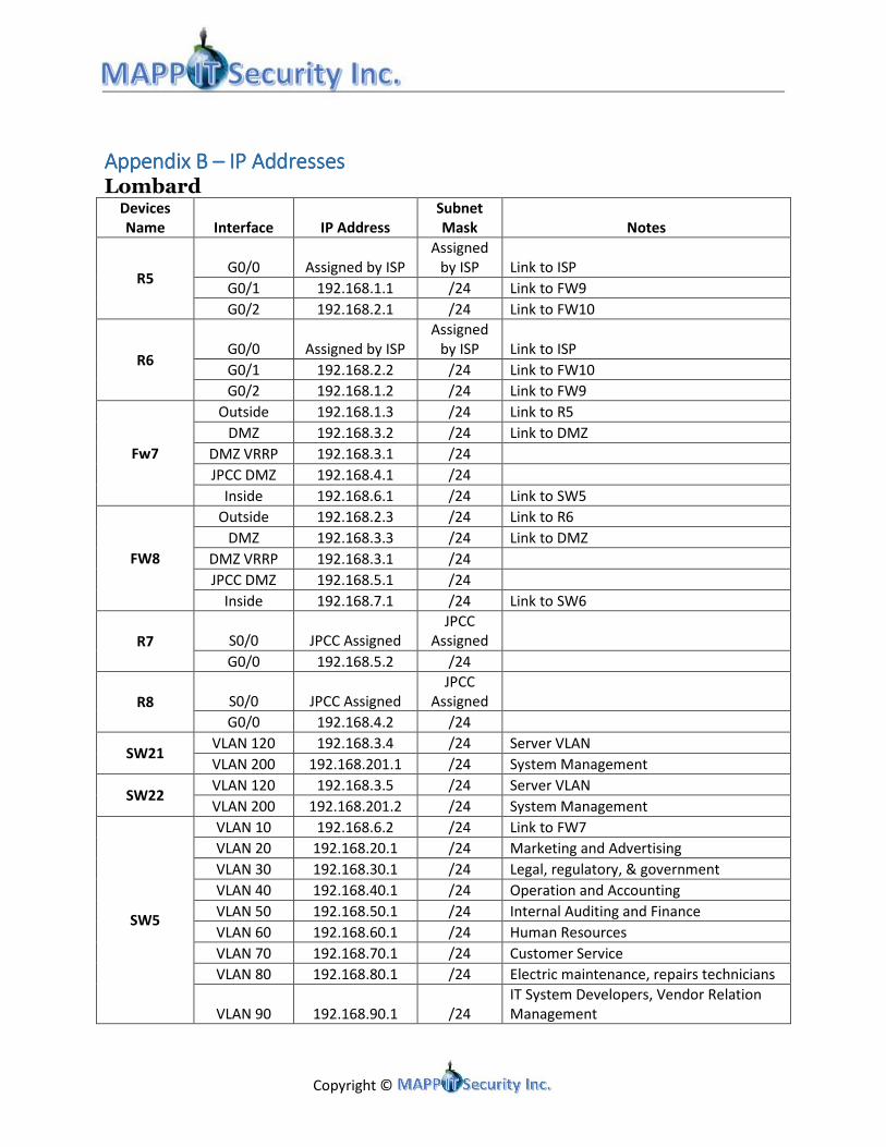
Appendix B Appendix B Appendix B Appendix B –––– IP Addresses IP Addresses IP Addresses IP Addresses Lombard
Devices
Name Interface IP Address
Subnet
Mask Notes
R5 G0/0 Assigned by ISP
Assigned
by ISP Link to ISP
G0/1 192.168.1.1 /24 Link to FW9
G0/2 192.168.2.1 /24 Link to FW10
R6 G0/0 Assigned by ISP
Assigned
by ISP Link to ISP
G0/1 192.168.2.2 /24 Link to FW10
G0/2 192.168.1.2 /24 Link to FW9
Fw7
Outside 192.168.1.3 /24 Link to R5
DMZ 192.168.3.2 /24 Link to DMZ
DMZ VRRP 192.168.3.1 /24
JPCC DMZ 192.168.4.1 /24
Inside 192.168.6.1 /24 Link to SW5
FW8
Outside 192.168.2.3 /24 Link to R6
DMZ 192.168.3.3 /24 Link to DMZ
DMZ VRRP 192.168.3.1 /24
JPCC DMZ 192.168.5.1 /24
Inside 192.168.7.1 /24 Link to SW6
R7 S0/0 JPCC Assigned
JPCC
Assigned
G0/0 192.168.5.2 /24
R8 S0/0 JPCC Assigned
JPCC
Assigned
G0/0 192.168.4.2 /24
SW21
VLAN 120 192.168.3.4 /24 Server VLAN
VLAN 200 192.168.201.1 /24 System Management
SW22 VLAN 120 192.168.3.5 /24 Server VLAN
VLAN 200 192.168.201.2 /24 System Management
SW5
VLAN 10 192.168.6.2 /24 Link to FW7
VLAN 20 192.168.20.1 /24 Marketing and Advertising
VLAN 30 192.168.30.1 /24 Legal, regulatory, & government
VLAN 40 192.168.40.1 /24 Operation and Accounting
VLAN 50 192.168.50.1 /24 Internal Auditing and Finance
VLAN 60 192.168.60.1 /24 Human Resources
VLAN 70 192.168.70.1 /24 Customer Service
VLAN 80 192.168.80.1 /24 Electric maintenance, repairs technicians
VLAN 90 192.168.90.1 /24
IT System Developers, Vendor Relation
Management

Copyright ©
VLAN 100 192.168.100.1 /24 IT Support - Lombard
VLAN 110 192.168.110.1 /24
Security (Surveillance, IP Cameras, Badge
Readers)
VLAN 120 192.168.120.1 /24 Server
VLAN 130 192.168.130.1 /24 Upper Executive Management
VLAN 200 192.168.200.1 /24 System Management
SW6
VLAN 10 192.168.7.2 /24 Link to FW8
VLAN 20 192.168.20.2 /24 Marketing and Advertising
VLAN 30 192.168.30.2 /24 Legal, regulatory, & government
VLAN 40 192.168.40.2 /24 Operation and Accounting
VLAN 50 192.168.50.2 /24 Internal Auditing and Finance
VLAN 60 192.168.60.2 /24 Human Resources
VLAN 70 192.168.70.2 /24 Customer Service
VLAN 80 192.168.80.2 /24 Electric maintenance, repairs technicians
VLAN 90 192.168.90.2 /24
IT System Developers, Vendor Relation
Management
VLAN 100 192.168.100.2 /24 IT Support - Lombard
VLAN 110 192.168.110.2 /24
Security (Surveillance, IP Cameras, Badge
Readers)
VLAN 120 192.168.120.2 /24 Server
VLAN 130 192.168.130.2 /24 Upper Executive Management
VLAN 200 192.168.200.2 /24 System Management
SW23 VLAN 130 192.168.200.2 /24 System Management
SW24 VLAN 130 192.168.200.3 /24 System Management
SW25 VLAN 130 192.168.200.4 /24 System Management
SW26 VLAN 130 192.168.200.5 /24 System Management
SW27 VLAN 130 192.168.200.6 /24 System Management
SW28 VLAN 130 192.168.200.7 /24 System Management

Copyright ©
Oak Brook Devices
Name Interface IP Address
Subnet
Mask Notes
R1 G0/0 Assigned by ISP
Assigned
by ISP Link to ISP
G0/1 172.16.1.1 /24 Link to FW1
G0/2 172.16.2.1 /24 Link to FW2
R2 G0/0 Assigned by ISP
Assigned
by ISP Link to ISP
G0/1 172.16.2.2 /24 Link to FW2
G0/2 172.16.1.2 /24 Link to FW1
FW1 Outside 172.16.1.3 /24 Link to R1
Inside 172.16.3.1 /24 Link to SW1
FW2 Outside 172.16.2.3 /24 Link to R2
Inside 172.16.4.1 /24 Link to SW2
SW1
VLAN 10 172.16.3.2 /24 Link to FW1
VLAN 20 172.16.20.1 /24 Grid Operators
VLAN 30 172.16.30.1 /24 IT Support
VLAN 40 172.16.40.1 /24 Server
VLAN 50 172.16.50.1 /24 ESP
VLAN 60 172.16.60.1 /24
Security (Surveillance, IP Cameras,
badge readers)
VLAN 200 172.16.200.1 /24 Management
SW2
VLAN 11 172.16.4.2 /24 Link to FW2
VLAN 20 172.16.20.2 /24 Grid Operators
VLAN 30 172.16.30.2 /24 IT Support
VLAN 40 172.16.40.2 /24 Server
VLAN 50 172.16.50.2 /24 ESP
VLAN 60 172.16.60.2 /24
Security (Surveillance, IP Cameras,
badge readers)
VLAN 200 172.16.200.2 /24 Management
FW3 Outside 172.16.5.3 /24 Link to SW1
Inside 172.16.100.1 /24 Link to SW3
FW4 Outside 172.16.5.4 /24 Link to SW2
Inside 172.16.101.1 /24 Link to SW4
SW3
VLAN 100 172.16.100.2 /24 Link to FW3
VLAN 120 172.16.120.1 /24 Users
VLAN 130 172.16.130.1 /24 Servers
VLAN 140 172.16.140.1 /24 MISO
VLAN 150 172.16.150.1 /24 Waukegan Connection
VLAN 160 172.16.160.1 /24
Security (Surveillance, IP Cameras,
badge readers)
VLAN 200 172.16.201.1 /24 Management
SW4 VLAN 101 172.16.101.2 /24 Link to FW4

Copyright ©
VLAN 120 172.16.120.2 /24 Users
VLAN 130 172.16.130.2 /24 Servers
VLAN 140 172.16.140.2 /24 MISO
VLAN 150 172.16.150.2 /24 Waukegan Connection
VLAN 160 172.16.160.2 /24
Security (Surveillance, IP Cameras,
badge readers)
VLAN 200 172.16.201.2 /24 Management
FW5
Outside 172.16.160.2 /24 Link to MISO R3
Inside 1 172.16.140.3 /24 Link to SW3
Inside 2 172.16.141.1 /24 Link to SW15
FW6
Outside 172.16.161.2 /24 Link to MISO R4
Inside 1 172.16.140.4 /24 Link to SW4
Inside 2 172.16.142.1 /24 Link to SW16
R3 S0/0 MISO Assigned
MISO
Assigned
G0/0 172.16.160.1 /24
R4 S0/0 MISO Assigned
MISO
Assigned
G0/0 172.16.161.1 /24
SW11 VLAN 200 172.16.200.3 /24 Management
SW12 VLAN 200 172.16.200.4 /24 Management
SW13 VLAN 200 172.16.200.5 /24 Management
SW14 VLAN 200 172.16.200.6 /24 Management
SW15 VLAN 201 172.16.201.3 /24 Management
SW16 VLAN 201 172.16.201.4 /24 Management
SW17 VLAN 201 172.16.201.5 /24 Management
SW18 VLAN 201 172.16.201.6 /24 Management
SW19 VLAN 201 172.16.201.7 /24 Management
SW20 VLAN 201 172.16.201.8 /24 Management

Copyright ©
Waukegan Devices
Name Interface IP Address
Subnet
Mask Notes
R9
G0/0 Assigned by ISP
Assigned
by ISP Link to ISP
G0/1 10.0.1.1 /24 Link to FW9
G0/2 10.0.2.1 /24 Link to FW10
R10
G0/0 Assigned by ISP
Assigned
by ISP Link to ISP
G0/1 10.0.2.2 /24 Link to FW10
G0/2 10.0.1.2 /24 Link to FW9
FW9
Outside 10.0.1.3 /24 Link to R9
Inside 10.0.3.1 /24 Link to SW7
FW10
Outside 10.0.2.3 /24 Link to R10
Inside 10.0.4.1 /24 Link to SW8
SW7
VLAN 10 10.0.3.2 /24 Link to FW9
VLAN 20 10.0.20.1 /24 Grid Operators
VLAN 30 10.0.30.1 /24 IT Support
VLAN 40 10.0.40.1 /24 Server
VLAN 50 10.0.50.1 /24 ESP
VLAN 60 10.0.60.1 /24
Security (Surveillance, IP
Cameras, badge readers)
VLAN 200 10.0.200.1 /24 Management
SW8
VLAN 11 10.0.4.2 /24 Link to FW10
VLAN 20 10.0.20.2 /24 Grid Operators
VLAN 30 10.0.30.2 /24 IT Support
VLAN 40 10.0.40.2 /24 Server
VLAN 50 10.0.50.2 /24 ESP
VLAN 60 10.0.60.2 /24
Security (Surveillance, IP
Cameras, badge readers)
VLAN 200 10.0.200.2 /24 Management
FW11
Outside 10.0.5.3 /24 Link to SW7
Inside 10.0.100.1 /24 Link to SW9
FW12
Outside 10.0.5.4 /24 Link to SW8
Inside 10.0.101.1 /24 Link to SW10
SW10
VLAN 100 10.0.100.2 /24 Link to FW11
VLAN 120 10.0.120.1 /24 Users
VLAN 130 10.0.130.1 /24 Servers
VLAN 140 10.0.140.1 /24 MISO
VLAN 150 10.0.150.1 /24 Waukegan Connection
VLAN 160 10.0.160.1 /24
Security (Surveillance, IP
Cameras, badge readers)
VLAN 200 10.0.201.1 /24 Management
SW9 VLAN 101 10.0.101.2 /24 Link to FW12

Copyright ©
VLAN 120 10.0.120.2 /24 Users
VLAN 130 10.0.130.2 /24 Servers
VLAN 140 10.0.140.2 /24 MISO
VLAN 150 10.0.150.2 /24 Waukegan Connection
VLAN 160 10.0.160.2 /24
Security (Surveillance, IP
Cameras, badge readers)
VLAN 200 10.0.201.2 /24 Management
FW18
Outside 10.0.160.2 /24 Link to MISO
Inside 1 10.0.140.3 /24 Link to SW10
Inside 2 10.0.141.1 /24 Link to SW38
FW17
Outside 10.0.161.2 /24 Link to MISO
Inside 1 10.0.140.4 /24 Link to SW9
Inside 2 10.0.142.1 /24 Link to SW37
R11
S0/0 MISO Assigned
MISO
Assigned
G0/0 10.0.160.1 /24
R12
S0/0 MISO Assigned
MISO
Assigned
G0/0 10.0.161.1 /24
SW32 VLAN 200 10.0.200.3 /24 Management
SW31 VLAN 200 10.0.200.4 /24 Management
SW30 VLAN 200 10.0.200.5 /24 Management
SW29 VLAN 200 10.0.200.6 /24 Management
SW38 VLAN 201 10.0.201.3 /24 Management
SW37 VLAN 201 10.0.201.4 /24 Management
SW36 VLAN 201 10.0.201.5 /24 Management
SW35 VLAN 201 10.0.201.6 /24 Management
SW34 VLAN 201 10.0.201.7 /24 Management
SW33 VLAN 201 10.0.201.8 /24 Management