Final-Feasibility-Report22-06-17.pdf - National Highway ...
444
fl ,> F DIRECTOR CENERAI, CENTRAL DESIGN OFFICE' GOVERNMENT OFTHESTATE OF AZAD JAMMU & KASHMIR MUZAFFARABAD PRE-FEASIBILITY ANDFEASIBILITY STUDY oF TWO (2) NOS. TUNNELS WITH REALIGNMENT OF ROADS INAJK Kahori Tunnel (Chellabandi - Patika Road) Aueusr 2013 rf*r t!! P w H EF FI rq l: w FJ FE Fl tD (D s) 5 I F
-
Upload
khangminh22 -
Category
Documents
-
view
2 -
download
0
Transcript of Final-Feasibility-Report22-06-17.pdf - National Highway ...

fl
,>F
DIRECTOR CENERAI, CENTRAL DESIGN OFFICE'GOVERNMENT OF THE STATE OF AZAD JAMMU & KASHMIR
MUZAFFARABAD
PRE-FEASIBILITY AND FEASIBILITY STUDYoF TWO (2) NOS. TUNNELS
WITH REALIGNMENT OF ROADS INAJK
Kahori Tunnel (Chellabandi - Patika Road)
Aueusr 2013
rf*rt!!PwHEFFIrq
l:wFJFE
Fl
tD
(D
s)5
I
F

- l
DIRECTOR GENEML, CENTRAL DESIGN OFFICE,GOVERNMENT OF THE STATE OFAZAD JAMMU & KASHMIR
MUZAFFARABAD
PRE-FEASIBILITY AND FEASIBILITY STUDYoF TWO (2) NOS. TLTNNELS
WITH REALIGNMENT OF ROADS IN AJK
HIN\IATFBASNHLIT'YRB-PORT"Kahori Tunnel (Chellabandi - Patika Road)
Ausust.2013
! .
DIRECTOR GENERAL, CENTRAL DESIGN OFFICE,GOVERNMENT OFTHE STATE OF AZADJAMMU & KASHMIR
MUZAFFARABAI)
PRE.FEASIBILITY AND FEASIBILITY STUDYoF TWO (2) NOS. TUNNELS
WITH REALIGNMENT OF ROADS IN AJK
FINAL FEASIBILITY REPORT(Chella Bandi to Patika Road)
AUGUST.2Ol3
CHUNIL ENGINEERING CONSULTANTS CO. LTD.SAMAN CORPORATION JOINT I'ENTURE
In Association withPRIME ENGINEERING & TESTING CONSULTAI\TS PVT. LTD. &
ASrF ALI ASSOCIATES (PVT.) LTD.

}D !s r9 tL D l= t= Le lF B t@ \r?
r!! I= .E
o m c r
.Il tl [r-q 'l ' c
ll I t
a 1 I i
iri{ig
gii;;
sliis
Eu"
,'iiii
ili",
{ ii
tt: to
,.,.
.;1
,-."
, ..
\iil
iii
pl.r

<,/ ' 7.,
DISTRIGT MUZAF
AN
FARABAD
TITHWAL
L E G E f , D
*oI
!
E
Kohala to
Chel la Bandi-Pat ika Road
l|nd U.. I frriotEul D.ptl
al,
a I ' f '
\s

EXECUTIVE SUMI\IARY
A. BACKGROTJI{D AND OBIECTIVES OF TIIE PROJECT
A-1 Background of the Project
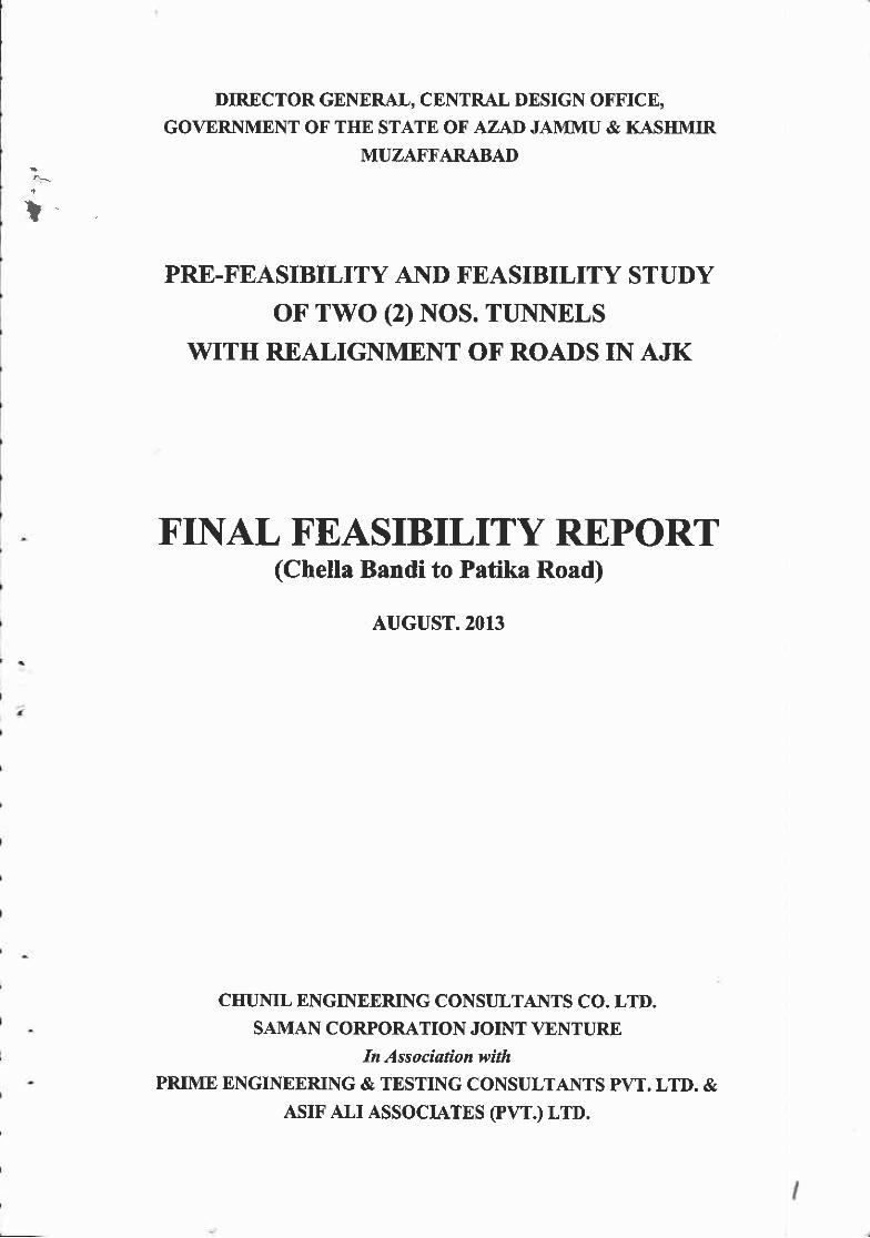
ChellaBandi-Patika road is about 23kn running along the bank of Neelum River. ChellaBandi islocated near chella bridge in Muzaffarabad. The proposed road is the part of the main roadconnecting Muzaffarabad with Athmuqam (L:80hn), Sharda, Kel and Jalkhad located innorthem area of Neelum D strict resulring in linking S 1(Gilgit_skardu Road, L:167km) andN35(Hassanabdal-Abbottabad-Thakot-Gilgit-Khunjrab, L:806hn) upto china. The proposedroad is main road linking Muzaffarabad with Neelum District. This route is gateway to Nielumvalley as well as important military road.
However, Kamsar to Kahori Landslide and further to Patika area with constantly tlreateninglandslides result in closure of chella Bandi-patika road and loss of life and goods every year.Therefore' a tunnel about 4 km length was envisaged to provide all-weather connection.
A-2 Objectives ofthe Project
Closure of main roads during persisting rainfall is the root causes of poverty, illiteracy and socioeconomic development of this region. ln this context, construction of road tunnels is one of themost appropriate tecbniques not only to overcome this problern, but also to minimize totaltransport cost leadrng to overall economic development in this regron.The main objectives ofthe project are given as under :
r To provide an all-weather u Eportation link between Muzaffarabad and rest of thecormtry for passengers and cargo t'affic.
o To reduce poverty and provide better access for population to markets and social servicesby improving and rehabilitating the rural access road network.
. To reduce cost ofall supplies and cost ofliving index.o To provide incentive to tourism and access to marketing of arts and crafts and dwelop
tourism related facilities like hotels, motels and rocreation facilities etc.
B. TrafEc Study
B- I Trallic Survey
The suvey of tafEc volume has been performed at 6 posts for 2 days o minimize weekly deviationand the average value is applied for analysis. Tuming traffic volume of the intersection has beenexamined by analyzing the u'affic volume of each direction, and then estimatins the total trafEcvolume in the intersection From this analysis of nrming tzfic volume, the levll of service wasdeterrnined. o/D survey was carried out to investigate origin, destination, vehicle composition,purpose of tip, and nurnber ofpassengers by the interviews conducted on the road side.The Survey results ofthe 24 hours traffic volume are as follows:
Vehicle Type MotorCycle
PassengerCar
MiniBus
LargeBuc
SmallTruck
MediurETruck
LargeTruck
TotalVolume
CbellBandi -Patik& Route 557 't43
391 477 l5l 3 1 8 350 3,189

The consultants have selected corridor analysis to forecast the future traffic demand for this project. Inorder to forecast the future t'affic volume for the target years, grouth estimates of GDP, populatior D
and vehicle ownership ofAzad Jammu and Kashmir (AIK) h;ve been utilized by usingsocioeconomic indicators of Pakistan. Normal growth rate of traffic volume was based on theestinated growth rate ofvehicle ownership. The number ofvehicles is assumed to increase at the rateof 5.3% dwing 2010 - 2015, 4.26% d\rm92015 - 2020,3.58% during 2020 - 2025, ard 3.10o/odurins 2025 - 2030.
Estimated Traffic Vohtme for Years VehicleYear 2009 2014 2018 2023 2024 2033
ChellBandi - PatikaRotrte
3,189 4,t29 4,879 5,817 6,776 '7,893
The required number oflales was calculated as a two - Iane road.
C. RO[]'TE SELECTION
C - 1 Prepamtion of Alternatives
1. Approach to Preparation ofAltematives
A total of Tbree (3) viable altematives were prepared to review based on the following principalcontrol points.
. Route altematives for guarantee of the road function and balance between mobility andaccess
. Route altematives for maximum utilization of existing road if possible
. Route altematives conforming to topographic characteristics
. Route altematives ofblpass of hmnel/bridge optiors ata large scale landslide arear Route altematives corsidering the related projects around study area i.e. west bank bypass
Prqec! Patrind hydro-power plant project and Muzaffarabad Athmuqam road Project'. Route altematives considenng the landslides as the major control points.
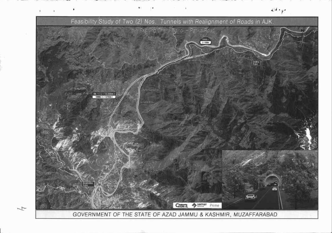
Proposed alignment No. I consists of two turmels almost 3.7 km and 0.6 km long. Tunnel No.l(L-3.7 km) starts from Kamsar at its south portal and culminates at Harama More at its North Portal.Kamsar area is located at a distance of 10 lan from Neelurn Bridge. Road distance fiom Kamsar toHarama More is 5.5 kn. This portion of road from Kamsar to Harama More is characterized withunavoidable land slide area.
Proposed alignment No. 2 consists of two hrnnels almost 6.2 hn and 0.6 lcn long. It starts fromchella Bridge at its south portal and culminates at Harama More at its North Portal. The proposednorth portal of alignment No .l and 2 is more or less at the same place adjacent to Harama More. Thisalignment alternative of 8.1 kn redrrce the road distance by approximately 1.4 kn and avoids theKahori land slide hazards along the road.
Propos€d alignment No. 3 consists of two hurrels almost 1.8 kn and 0'6 km long It starts fromKamsar at its South Portal and culninale at Dunkakas bridge at its North Portal. Kalrsar area slocated at a distanc€ of 1 0 lcn from Neelum Bridge.
{\, r x.
C-2 Route Selection
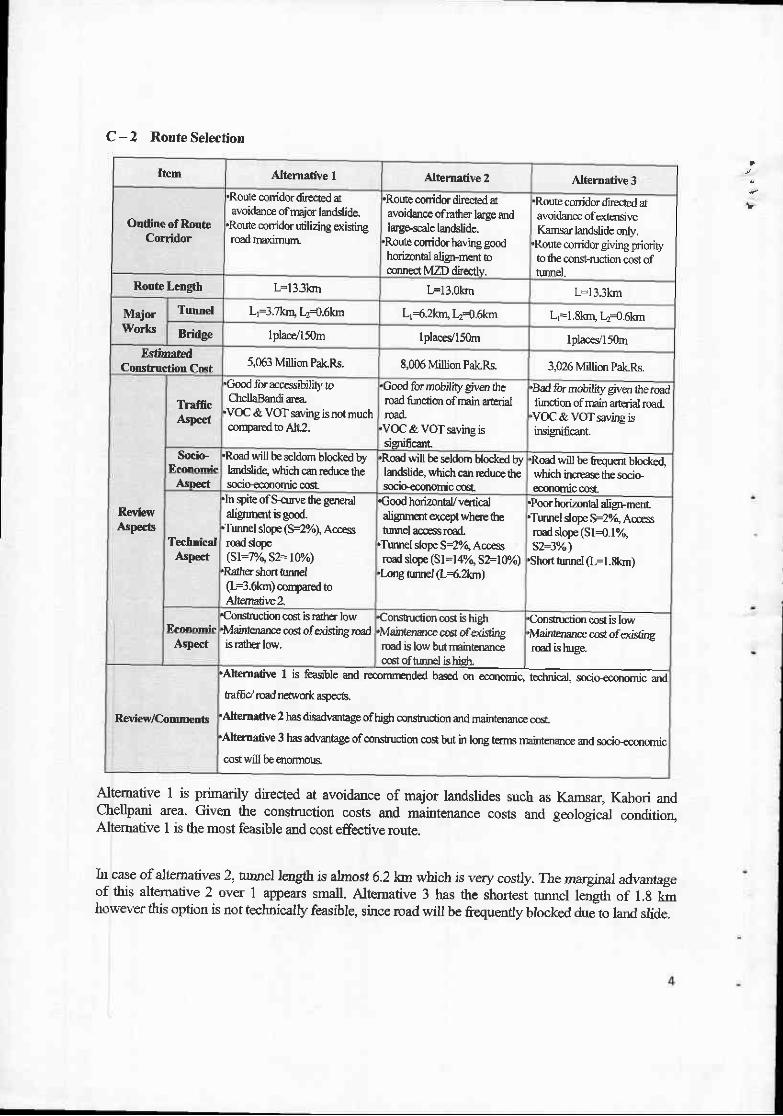
Item Alternative I Alternative 2 Alternative 3
Oudine of RouteCorridor
.Route conidor dir€$ed davoidanoe of m4icr landslide.
'Route coridor utilizing o<istingroad maxirrttlrl
.Route conidor dlected atavoidance ofrather lage ardlargeralc lcdslide.
'Route corridor having goodhorizorrbl align-'Inmt tlconn€d MZD dir€ctly.
.Route ccrrid0 dir€cted davoidance ofextosireKamsar landslide only,
,Route {uridor giving prioriq,to the const-{uction cost oftunel-
Route Length L=IJ-JXII| IF13.okn L=l J.-'Cll
MajorWorks
Tunnel Lr=3.7hq tr{.6lon Lr+.2kn, Lr{.6kn Lr=l .8krr Ld.6kn
Bridge lplace/l50n l placesl150m lplaceVI50mFrtfurated
ConBhustiol Cdt5,063 Million PalcPs. 8,006 Million PakRs. 3,026 Million Pak.Rs.
ReviewA!pects
TrafficAspoct
.Good for accessibility toCtrcllaBandi area,
.VOC & VOT sa,/ing is not muchco[D€r€d to Alr2.
'Oood for mobility given &eroad fiDcrion of llain aturialrcad,VOC & VOT saving issignifcanl
'Bad for mobrlif given dre roadfindim ofmain arterial ro€d
'VOC & VOT saviDg jsinsigmficant.
Socio- ,Road will be seldom blocked Sladslide, whidr cm rEduc€ lhesocio€co0omic co6t
'Road will be seldom blocked byladslidg which can rcduce thesocio<conomic co6t
.Rod will be fiequent blocke4which incrcase tre socio-rylorniccortArD€ct
TechnicalAsp€ct
.In spite ofs-cuae th€ genetalatignDflt is good
.Tunnel slope (S=2olo), Acc€ssrud slqo(Sl:F/q 52= l0olo)
,Rdhtr slrcrt tnfl€l(L:3-6knr) aoryarcd toAltenatirc2,
€ood horizonal,/vqticalaligffisrt o(oept wherE thet-suel accEss rud
'Tunnel slope S=29l0, Acc€ssrud slope (Sl=147q SFl0/o)
'Long tuffEl (L<.2&m)
.Poorhorizonhl aligrrnent
.Turmel slope ts27q Accesrcad slope (Sl{,17qs>3%)
'Short tmnel (L=l .8krn)
tr'l.nnnmir{onstuction c61is tath€r low.IvlatntenarE cost of€)dgir€ rcadis rath6low,
'Corstuclion cog is highMaintenance co ofo<i*ingrcad is low but mainerynce06l oftutnel ishietr.
Consudion mst is Iow'Maintenance cod ofed{i,?gred ishugaAsp€ct
RevieVComrnents
'Alternafive I is feasble atd r€co
hdffd rcad nd\eork aeect,.Alternrtiye 2 has disadvanbge ofhigh construdion and rnaintenanoe cost.,AlterEative 3 has adlanbge ofconstuclim co$ but in log turns maintenanc.e 4d soclc€conofluc
co$ will be enoffDus,
Alt€mative I is primarily dirccted at avoidance of major landslides such asChelpani area. Givexr the construction costs and maintenance costs andAltemative I is the most feasible and cost effective route.
Irl case of albematives 2, hunel l€ngth is almost 6.2lor which is very costly. The marginal advantageof this alternative 2 over 1 appears small. Altemative 3 has the shortest tunnel tensth or t.s k"however this option is not technically feasible, since rcad will be frequently blocked due to land slide.
Kamsar, Kahori andgmlogical condition,

I
D. Engineering Investigation
D - I Developing Topographic Map by Sttellite Imagitrary & DEM.
The Project site is such a rugged and mountainous area that conventional suwey cannot cover thebroad band of corridor to study route alternatives. However broad band and accurate topographtc dataare prerequisite. As such considering accuracy, Geo Eye - I satellite imagery with DEM was used todevelop topographic map whose scale is l:1000. A Geo Eye I Satellite imagery of 0.5m resolutionwas procured with the provision of DEM with contour intewals of I meter.
D - 2 Geological / Geotechnical Investigation.
l. Screen Line Survey for Geological Mapprng
The preliminary topographic survey (screen line survey) in sufticient detail was carried out along theproposed tunnel alignrnen! Alternative I and 2, to enable uo geological mapping.
Along with the suwey, a closed t-averse has been carried out which connects the portals of theproposed tunnel. The haverse provided a verification of relative coordinates and elevation of turmelporbls.
2. Geologrcal Mapping
The investigated area lies at 4lon from Muzaffarabad city in the base ofNeelum Valley. Gorerally thereliefofthe area is the north-eastem and south-eastem parts. Steep slopes are characteristic features ofthe area. The weathering of the rocks depends upon the climatic conditions, s0uchues, topognphy,vegetation and slopes of the area. Both types of weathering i.e. mechanical weathering and chemicalweathering are prominent in the area. Rainfall is the main weathering agent. Weathering ispronounced in carborntes rocks (dolomite and limestone) exposed in the localities.
The lithostratigraphic units exposed in the area are ranging in age from Precambrian to recentand consist mainly of sedimentary and metamorphic rocks. Hazara formation is the oldestformation and Murree formation is the youngest. The sedimentary rocks cover more than 60 o/o
of the total area.
Geological mapping of Alignment 1 and 2 has been carried out. Given main strike direction andtururel axis, excavation conditions ofAlignment 1 is geotechnically favourable and good toachieve the tunnel stability with small amorurt of reinforcement.
3. Geotechnical Interpretation(D Gcotechnical Character and Classffication of Rock Mass
The rock mass for lhe tunnel section is the most imporbnt influencing fictor in constuction costs,being connected direcdy to the hmnel support pattern. Therefore, bedrock classification should beachieved after understanding data, such as checking the stength of local bedroc! the state ofdiscontinuity, state ofweathering, whether or not fracture zones exisg fault sections, etc.
This phase of shrdy is the feasibility phase, so visual inspection was implemented along the task lineand the tunnel was designed by applyine Geotechnical Unit (GTI), Rock Mass Type fiMf) andRock Mass behavior Type (RBT) according to Austian Guideline for Geomechanical Design.
E. Design criteria
E - 1 Classification of Road
A collector road fi.mctioning as arterial road
E - 2 Design speed and Geometric Desigtr Standards
Design speed and geometic design standard were adopted "A Policy on Geometric design ofHighways and Strees, AASHTO" The adopted geometric design criteria are given below.
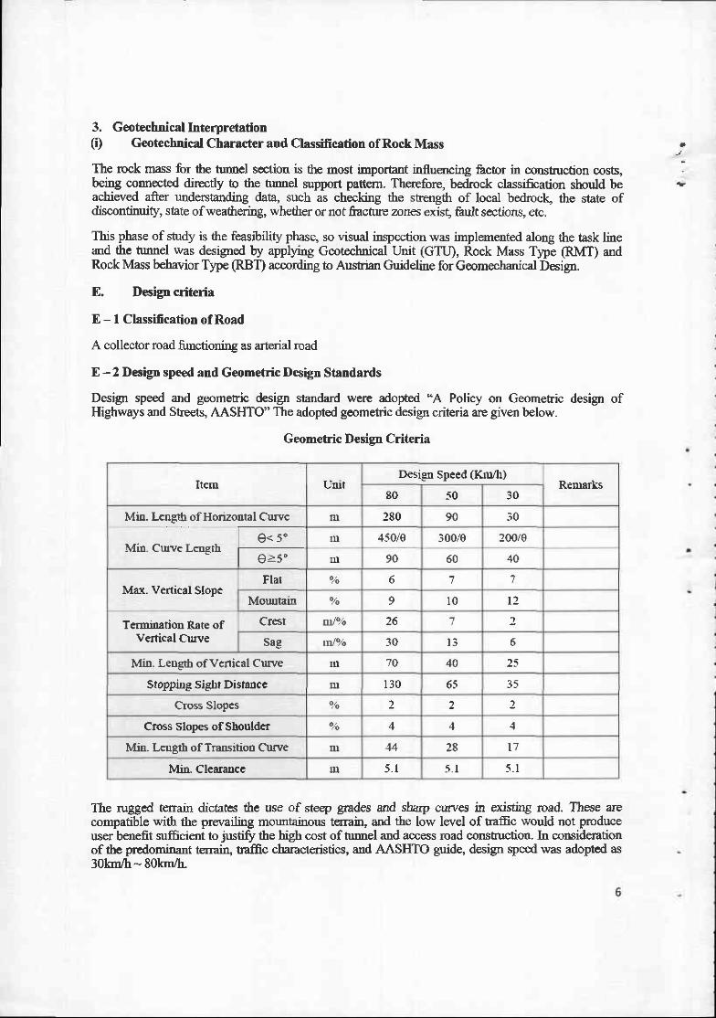
Geometric Design Criteria
Item L'nitDesi€lr Speed (Kn4l)
ReDrarks80 50 30
Mi!. Length of Horizontal Cuwe
t e'F-Min. curve Lengrh
t e.5.
m 280 90
m .150i0 300/e 200/e
m 90 60 40
Max. Vcrtical SlopeFlat % 6 7 J
MouuEin o.to 9 t 0 t 2
Termimtion Rate ofV€rtical Clrrve
Cr€st n:Jo/o 26 7 )
sag tloJot6 30 t 3 6
Mi.n. Le|rstl of venical Cruve tu 10 40 25
Stopp.int si€Crt DismEce tll 1 3 0 65 3 5
Cross Slopes 9/o 2 2 )
Cross slopes of Shoulder o/o 4 4
Min. Lensth of Trallsitioo Curve m 44 28 l 7
MiL Clearancc m 5 . 1 5 . I 5 . 1
The rugged terrain dicaes dre use of steep grades and sharp curves in existing road. These arecompatible with the prer'ailing moutainous terrain, and the low level of traffic would not produceuser benefit sufficient to justifr the high cost of tumel and access road construction In considerationof the predominant terranr, naffc ctaractaistics, and AASHTO guide, design speed was adopted as30lsn/h - 80h/b-

E - 3 llpical cross Section
-- Carriageway width was adopted 3.5m given expectod tramc vohme and characteristics of projectroad. The slodder width was adopted i.5m for pedesrian and non-modorized traffic. The elemerrts
'. ofcross section adooted is as follows.
Item Ro{dwsI Bridge TtrDBel
Roadway widh [email protected]=7.Orr [email protected]=?.0lD 2@ 3.5=7.0m
shouldcrRigl 1.5|lr 1.5lu l.orn
LeII l I l .5m 1.orn
Mediatrs 0.5rrr 0.5!l 0.5l]l
Total Roadway Wid.h l0.5ur I L4ur 9 5 m
F. Preliminary Design
F-l Road design
1. Earth Works
Tlre guantity-ofearth work for access roads was estimated based on the following typical cross sectionto calculate the conshucuon cost.
Tlpical Cross Section
2. Pavement Design
The lnvement desip for the access road bas been carried out based on the methodology given inAASI{TO guide for pavement design . The pavement stuchre consists of asphdtic concrete wearing,asphaltic base course, aggregate base couse and granular subbase coume.

l
3. DrainageDesign
The study covered the principal task i.e.
(r) Study of precipitation data (ii) Processing and analyzing data for determining rainfallintensity by the retum period and (iii) Study of surfrce drainage with regard to catchmentarea characteristics, time ofconcentration and rainfall intensity. On the basis ofthis shrdy,design discharge ofbox / pipe culverts was calculated and capacity was daermined-
F- 2 Tunnel Design
1. Excavation MethodDrill & Blast and TBM (Tuonel Boring Machine) method were reviewed and Drill & Blastmethod was applied for following reasons.
(t To go for TBM excavation requires that the tunnel must have reasonable length (aboutmore rhan 5^-6ikrns) to motivate the large investnent in a turmel boring machine
(ii) Given low traffic volume is characteristics of the project road, labor-based and low-cost approach are reasonable.
(iii) Lowari Kohat tunnel having similar topographical, geological features werecorstucted by drill-and-blast trmneling method.
(lv) Considering the variable gmlogical conditions, cost effectiveness, and trmnel lengt],Drill and Blast er(cavation is recommended. ln poor rock conditions, Road Headersball be utilized.
2, Typical Cross SectionAn optimum cross section was studied aking into consideration of width, space for facilitiesand marginal space for consEuction
e Carriageway: 7.0mQ@).5m)o Shoulder : I .0 me Vertical clearance: 5.1 m. Comer clearance 1.0 m @) x l.l m (H)
(KAHORI TUNNEL) (CHELLPANI TUNNEL)
| ' .ers I leo l lobl s.slo lr.rrz Ir----.--------]I--l- ' i _ 1 - 1 , ' -
lr.se6l r.,aso l jcbl r.rlo lr.erolr----..------. '3ft-l__=_-|ft7r-
G, Estimation of Construction Cost and Implementation Plan
G - 1 Date of Estimation
o Date of Estimation: Decernber, 2012.o Exchange rate: I USD=l00Rs
G - 2 Cost Estimate Sunmary
The cost of the project bas beeir prepared including all variatiors, prevailing national market ratesand CSR provided by NIIA. Atl the unit prlc€ has been prcpared in accordance to market survey,other similar' rcc€nt ploiects.
Other similar recent projects referred to this project are "Lowari Trmnel and Access Roads Project"and "Rehabilitation and Reconstuction ofMuzaffarabad-Athmuqam Road Project".
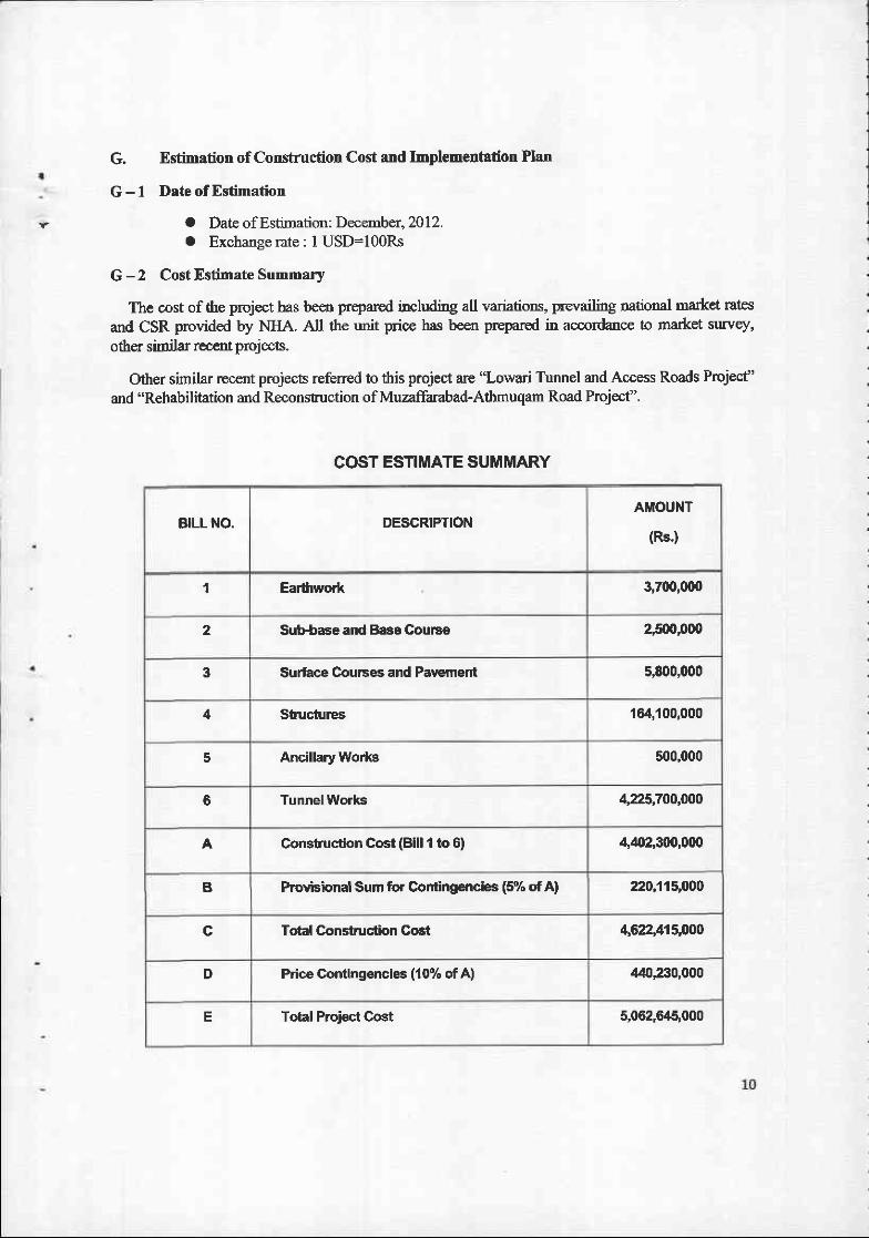
COST ESTIMATE SUMMARY
BILL NO. DESCRIPTIONAMOUNT
(Rs')
1 Earthwort 3,700,000
2 Sub+se and Base CouFe 2,5flt,000
3 Surface Courses and Pavement s,800,000
4 Structures 164,100,000
5 Ancillary Works 500,000
6 Tunnel Works 4,?,25,7OO,OO0
A Constuction Cost (Blll I to 0) 4,O2,300,000
B Provbional Sum for Contingencies (5% of A) 220,115,000
c Total Construc'tion Goct 4622,415,OOO
D Pdce Contingencies (10% of A) .140,2:10,000
E Total Project Cost 5,062,6/15,000
aG -3 Implementation Schedule
1. Starting and Completion Date ofthe Projec'ta Starting Date : Iamary,20l4o Coryletion Date : Dece.mber, 2016
2. Itemwisg Yearwise Implementation Schedule
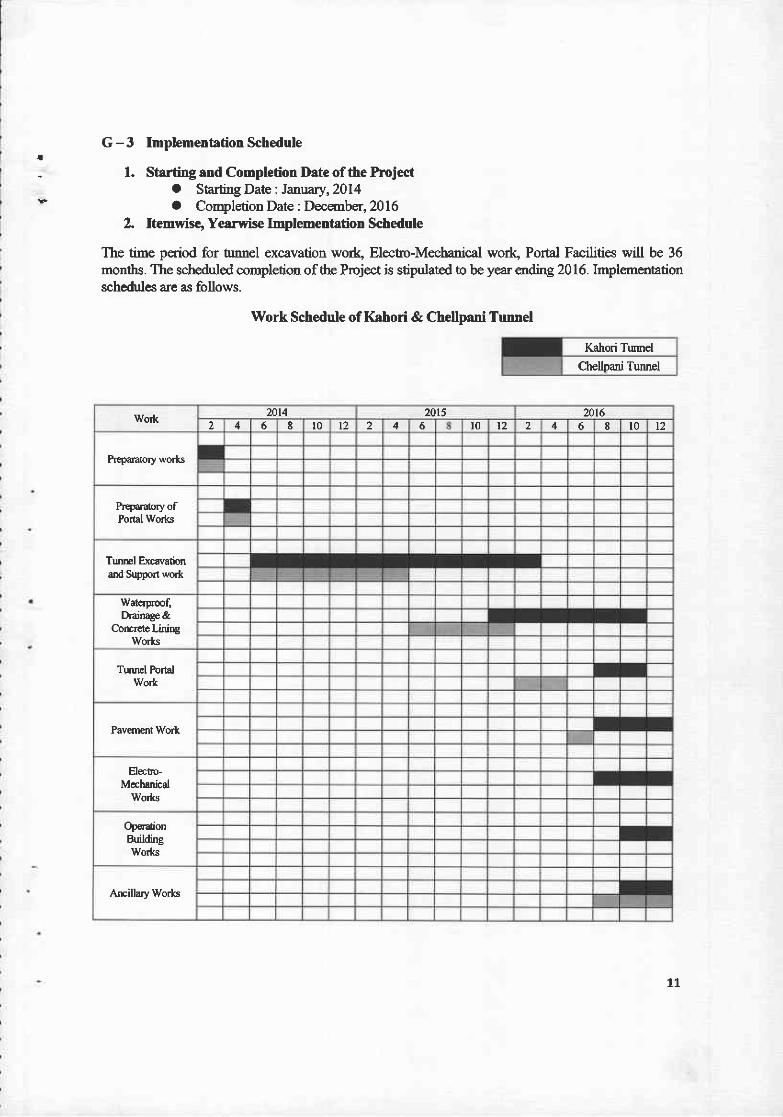
The tine period for hrnnel excavation wod Elecho-Mechanical work, Portal Facilities will be 36months. The scheduled cornpletion ofthe Project is stipulated to be year ending 2016. Irnplementationschedules are as follows.
Work Schedule of Kahori & Chellpani Tunnel
Kahori Tunel
Chellpani Tunnel
t l
Wo* mt4 mt5 ml62 a l 0 t2 2 6 t0 t2 2 4 8 l0 t2
Prwdatory wo*s
Prqor-atory ofPortal Works
TuDrEl Excwationard Sutport wo*
waterpoof,Drainage &
Concrete LiniogWo*s
Tuuel Po.talWork
Paventent Wor*.
H€cto-Mechrnical
Wo*s
OpFa[ionBuildingWorl<s
Amillary Works
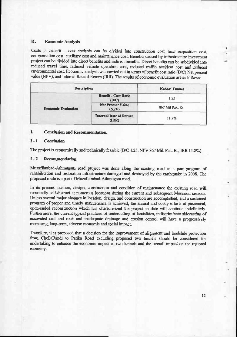
H. Economic Analysis
costs in benefit - cost analysis can be divided into consft.lction cos! land acquisition cosgcompensation cosg auxiliary cost and maintenance cost. Benefits caused by infrastruchne investnentproject can be divided into direct benefits and indirect benefits. Direct benefits can be subdivided intoreduced t'avel time, reduced vetricle operation cost, reduc€d t-affc accident cost and reducedqrvironmental cost. Economic analysis was canied out in terms of benefit cost ratio (B/C) Net presentvalue (NPV), and Intemal Rate ofRetum (IRR). The results ofeconomic evaluation are as follJws:
Descriptiol Krhori Tutrtrel
Economic Evaluation
Bemfit - Cost Rrdo(B/C) t.23
Net Precert ValueNP11 E67 Mil Pak. Rs.
lnternal Rste of Returtr(IRR) l l . 8 %
L Conclusion and Recommendation.
I - | Conclusion
The project is economically and tecbnically feasible (B/C 1.23, NPV 867 Mil. Pak. Rs, IRR I 1.8%)
I - 2 Reconrmendation
Muzaffarabad-Atbnugam road prcject was done along the existing road as a part program ofrehabilitation and restoration infi-ashucbrc damaged and destroyed by the earthquake in 2008. Theproposed route is a part of Muzaffarabad-Athmugam road.
In its present location, design, constsuction and condition of maint,enance the existing road willrepeatedly self-distuct at numerorb locations during the current and subsequent Monsoon seasons.Unless several major changes in locatioq design, and constnrction are accomplishd and a sustainedprogram of proper and timely maintenance is achieved, the annual and cosdy efforts at piecerneal,open-ended recorstruction which has characterized the project to date will continue indefinitely.Furthermore, the current typical p:actices of undercutting of landslides, indiscriminate r;6o35ting ofexcavated soil and rock and inadequate drainage and erosion contol will have a progressivelyincreasing, long+ernr, advers€ economic and social impact.
Therefore, it is proposed that a decision for the inprovement of alignrnent and landslide protectionfrom ChellaBandi to Patila Road excluding proposed two trrnnels should be considered forundertaking to enhance the economic impact of Wo tmnels and the overall impact on the regionaleconomy.
L2

TABLE OF CONTENTS
Chapter l. Introduction
1.1 Project Backgrounds and Objectives
1.1.1 Project Backgrounds...
1.1.2 Objectives
Outline of the Project
1.2.1 Chella Bandi to Patika Road .. . . . . . . . . . . . . . . . .
Work Plan
1.3.1 Main Activities of the Assignment
1.3.2 Schedule of Deliverables
1.4 Organization and Staffing
L4.I Team Organization
1.4.2 Staffing
1.4.3 Work Assignment Schedule
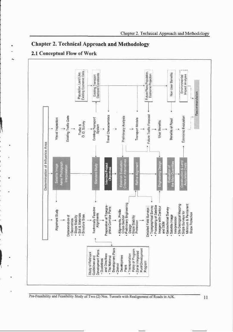
Chapter 2. Technical Approach and Methodolory
2.1 Conceptual Flow of Work
2.2 Objectives of the Study 12
2.3 Methodology for Pre-Feasibility Study L2
2.3.1 PreparatoryWork... . . . . . . . . . . . 12
2.3.2 Data Collection and Site Reconnaissance 12
2.3.3 Socio-Economic Study
2.3.4 Economic Study on Agriculture, Forestry, etc. ................... . . .
2.3.5 Traffrc Survey and Traffic Forecasts 14
2.3.6 Signifrcance of the Project 14
2.3.7 Route Selection . . . . . . . . . . . . . . . . : . . . . . . . . 15
2.3.8 Route Refinement . . . . . . . . . . . . . . . . . . 16
2.3.9 Mapping and Topographic Survey .. . . . . . . . . . . . . . . . . . . . . . . 17
2.4 Methodology for Feasibility Study .............. 18
2.4.1 Technical Investigation I . . . . . . . . . . . . . . . . . . . . . . . 18
t .2
1.3
I
I
)
z
3
J
3
5
5
6
7
l l
I J
13
t3
2.4.2 Prel iminary Road and Tunnel Design (Stage D .. . . . . . . . . . . . . . . . . . . . . . . . . . . . . . . . 19
2.4.3 Technical Investigation II ..................... 20
2.4.4 Preliminary Road and Tunnel Design (Stage II) .............................. 2l
2.4.5 Project Evaluation .. . . . . . . . . . . . . . . . . . . 22
2.4.6 Implementation Program 23
2.5 Methodology for Initial Environment Examination (IEE) 23
2.5.1 IEE Process 23
2.5.2 Kick off Meetins .. . . . . . . . . . . . . . . . . . . . 25
2.5.3 Scoping Study .. . . . . . . . . . . . . . 25
2.5.4 Initial Environmental Examination ................... 26
2.5.5 Description of the Baseline Environmental Conditions 27
2.5.6 Prediction of Imoacts 27
2.5,7 Evaluation of Impacts 27
2.5.8 Mitigation, Management & Monitoring 28
2.5.9 Final IEE Report . . . . . . . . . . . . . . . . . . . . . . 30
Chapter 3. Site Reconnaissance
3.1 Introduction 31
3.1.1 Desk Study 31
3.1 .2 Site Recoruraissance Trip 31
3.1.3 Geological / Geotechnical Field Survey 32
3.2 Chella Bandi to Patika Road .. . . . . . . . . . . . . . 33
3.2.1 Description of Existing Road 33
3.2.2 Geology Along the Existing Road ..............-. 35
3.2.3 Landslide 37
3.2.4 Alignment
3.2.5 Anticipated Tunnel Portal
3.2.6 Pavement
3 .2 .'7 Retaining Structures
3.2.8 Bridees... . . . . . . . . . .
J - J
II
42
46
48
48
50
General Comments and Recommendation 53
3.3 .1 Genera l Comments . . . . . . . . . . . . . . . . . . . . . . 53
3.3.2 Location of Route Corridor.. . . . . . . . . . . . . . . . . . . . 54
3.3.3 Road Alignment 54
3.3.4 Road Design 55
3.3.5 Road Construction .. . . . . . . . . . . . . . . . . . 58
3.3.6 Maintenance 58
3.3.7 Recommendation for Drainage Protection of Unstable Area .......... . 59
Chapter 4. Traffic Analysis
4.I Overview of Traffic Analysis 63
4.1 .l Objectives of Traffic Analysis 63
4.1.2 The Proposed Roads and Road Network of Muzaffarabad .............. 63
4.2 Survey and Analysis of the Current Traffic Conditions ....... . ........... 65
4.2.1 Overview of Traffic Survey 65
4.2.2 Description of Traffrc Survey 65
4.2.1 The Result of Street Traffic Volume Survey 68
4.2.4 Survey Results of Intersection Tuming Traffic Volume ......................... 80
4.2.5 Analysis of Level-of-Service for Street 86
4.2.6 Analysis of Intersection Level-of-Service.. 90
4.2.7 Survey Results of Road Side O/D interview 98
4.3 Traffic Demand Forecast 101
4.3.1 Approaches to Traffic Demand Forecast 101
4.3.2 Socio-economic lndicators & Forecasts I02
4.3.3 Traffic Demand Forecast of the Project Route 109
4.3.4 Calculation of Number of Lanes and Capacity for the Project Route ........ 113
Chapter 5. Field Survey for Engineering Design
5.1 Topographic Survey
5.1.l Khori Land Slide Tunnel
l l9
119
IC
134
t34
134
141
143
168
180
5.4
5.5
5.2 Procurement of Satellite Imagery with DEM
5.2.1 Introduction
5.2.2 Remote Sensed Satellite Imases
5.2.3 Satellite Imagery & DEM
5.2.4 About GeoEye-1
5.2.5 lm Contour Topo Map Produced by Geo-Eyel Satellites Dem
5.3 Geology & Geotechnical Survey
5.3. 1 General Geological Description...,..,
5.3.2 Chella Bandi - Patika Road Tunne|.........
Meteolog5r and Ilydrology Survey.............
Construction Material Survey.............
Chapter 6. Route Alternatives
Related Projects around the Study Area 183
6.1.1 West Bank Bypass Project 183
6.1.2 Patrind Hydro-power Plant Project .......-........... ...... 186
6.I.3 Muzaffarabad-Athmuqam Road Project 187
6.1.4 Road Network of Muzaffarabad......---........... 188
Tentative Design Standards f90
6.2.1 Review of Design Criteria 190
6.2.2 Functional Classif icat ion of Road and Design Speed... . . . . . . . . . . . . . . . . . . 190
6.2.3 Geometric Design Standards .. . . . . . . . . . . . . . . . . . . . . . 191
6.2.4 Cross Section Elements 191
Alternatives Preparation and Preliminary Route Selection .............. 193
6.3.1 Basic Concepts for Alternatives Preparation 193
6.3.2 Methodology of Preliminary Route Selection 195
Route Selection of Chella Bandi to Patika ............. I91
6.4.I Description of Route Altematives ............... 197
6.4.2 Major Control Points of Route Selection 199
6.4-3 Preliminary Route Selection ......... 212
t J )
t37
140
141
6.1
6.2
6.3
6.4
Chapter 7. Preliminary Design of Access Roads

7.1 Earth Works ...
7 .l .1 Cross Section of Access Road
7 .l.2 Earth Works
Chapter 8. Tunnel Design
8.1 General
8.1.1 Salient Features ofTunnel
8.1.2 Case Study on Existing Tunnel in Pakistan
8.1.3 ExcavationMethod
2r52t5
2t5
_ 7 .2 Pavement Works ......... 217
7.2.1 ComparisonofPavementType Zl7
7.2.2 Design Criteria for Pavement 218
7.2.3 Design of Pavement Layer 2lB
7 .3 Drainage Works ...... . . . .. 223
8.2
8.3
Typical Cross section ofTunnel
J '<
225
226
227
228
232
233
234
237
241
266
266
266
270
272
272
274
277
279
281
28r
Rock Mass classification
8.3.1 Geotechnical Unit (cTU)
8.3.2 Rock Mass Types (RMT)
8.3.3 Rock Mass Behavior Types (RBT)
8.3.4 Excavation classes (ECL)
8.4 Excavation method
8.4.1 Outline
8.4.2 Classification of excavation method
8.4.3 Muck removal
8.5 Tunnel Support
8.5.1 Tunnel Support types and main functions
8.5.2 Shotcrete
8.5.3 Rock Bolt
8.5.4 Steel-rib
Blasting8.6
8.6.1 Inffoduction
t7
8.7
8.6.2 Blasting method classification 281
8.6.3 Cut blasting method comparison 283
8.6.4 Explosives 283
8.6.5 Solution ofblasting pollution 288
Auxiliary construction method 290
8.7.1 Classification according to reinforcement purpose 290
8.7 .2 Tunnel crown stabilization 294
8.7.3 Stabilization of Tururel Face 298
8.7.4 Applied auxiliary method .................... 299
Waterproofing and drainage ..................... 300
8.8.1 Waterproofing 300
8.8.2 Waterproofing of open cut tunnel 304
8.8.3 Drainage during operation....... . . 305
8.8.4 Drainage during construction 307
Inner concrete l ining and open cut tunnel ............ -.. 309
8.9.1 Introduction 309
8.9.2 Decision of placement time and thickness 3l I
8.9.3 Main turmel design criteria 312
8.9.4 Open cut tunnel(portal) sections design criteria 313
8.9.5 Lining construction ................ . . 314
8.10 Portal design 316
8.10.1 Introduction 316
8.10.2 PortalArea'sproblem 317
8.10.3 Design criteria ....... 317
8.1I Tunnel Excavation Facilities 319
8.11.1 BasicPolicy 319
8.11.2 TunnelDisasterPreventionPlan.................. 319
8.11.3 Plan for Major Disaster Prevention Facilities.. 325
8.12 Venti lation Plan ............... 326
g.12.1 Out1ine............ 326
8.12.2 Design Procedures ..................... 32'1
8.8
8.9
/8

8.12.3 Venti lat ion System Classif icat ions... . . . . . . . .
8.12.4 Comparison of Available Ventilation Systems
8.12.5 Venti lat ion System Application .. . . . . . . . . . . . . . .
Chapter 9. Bridge Design
9.1
9.2
9.3
9.4
328
329
330
33r332
333
334
334
JJ+
335
336
337
3 t I
338
Des ign Concept . . . . . . . . . . . . . . . . .
Bridge Design Process
Bridge Location
Design Criteria
9.4.1 Clearance of Bridee
9.4.2 Usaee Standard for Materials
9.4.3 Design loads and load combinations . . ........ . . .
9 .4.4 Design Method
9.5 Bridge Design
9.5.1 Type ofapplicable bridge
9.5.2 Chella Bandi - Patika Road
Chapter 10. Economic Analysis
10.1 Overview of Economic Analvsis
l0.l.l Economic Analysis Procedure
10.1.2 Economic Analysis Method
10.2 Costs Evaluation
10.2.1 Concept ofCosts
10.2.2 Costs Evaluation Details
10.3 Benefits Evaluation
10.3.1 Benefits Evaluation Details ................
10.4 Economic Analysis
10.4.1 Results of Economic Analysis ...............
10.4.2 Results of Costs and Benefits by Year
10.5 Sensitivity Analysis
10.5.1 Overview of Sensitivitv Analvsis
341
341
342
343
343
343
346
346
353
353
354
357
357
358
lq
10.5.2 Result
Chapter 11. Conclusion and Recommendation
I 1.1 Conclusion
11.2 Recommendation
Appendix: Drawings

a
Chapter 1. Introduction
1.1 Project Backgrounds and Objectives
1.1.1 Project Backgrounds
Azad Jammu and Kashmir (AJK) is mainly comprises of hilly/mormtainous terrain particularly t}le
northem part have steep sloping lofty mountain peaks. The main inter-District and some sub divisional
roads have to traverse over quite high elevations / peaks which remain covered with snow in the winter.
Moreover, fragile geological formations along some routes are constantly threatening for huge
landslides and debris and mud flow. Closure of these main roads in the winter and during persisting
rainfall is one of the root causes of poveny, illiteracy and socio-economic development of this region.There is also immense potential ofcultural exchange and tourism developmant in AJK through Neelumvalley with Gilgit & northem areas. But very peaky mountairs between these two areas are still denyingroad access to connect these areas direcdy with AJK. Construction of road turmels is one of the mostappropriate techniques not only to overcome these problems, but also to minimize total fianspofi costleading to overall economic development in the concerned region
There is a huge potential of road tunneling to cut short distances and minimizing traveiing cost onAJK road network and provide safety to life and property.
Howwer, to begin wit! nvo (2) sites to avoid land slides hazards are identified under this projecr,
feasibility of these sites has to be ascertained under this project to achieve the objectives ofsocioeconomic and tourism development of this region by having all weather roads with minimum totaltransport cost between the cormecting destinations and to provide safety.
With respect to landslides hazard, two (2) sites are included in this scheme. The two (2) sites areLohar Gali Landslide on Abbottabad road and Kamsar to Kahori Landslide on Neelum Vallev road inDistrict Muzaffambad.
Salient Features of Kahori Tunnel Sites
Sr,Name of Site
Location(District)
PeakElevation
(R.L)
Approx. RLof TunnelCrossing
Approx. Lengthof Tunnel Remarks
IKahori Neelum
Valley RoadMuzaffarabad Land slides
tunnels2500-3000 ft. 4-5 KIn
Land SlidesHazards
Kamsar to Kahori landslide and f,rther to Patika area with constrantly thrcatenibg landslides result inaccident and loss of life and goods every year. Therefore, a tunnel in 4 kn length is anvisaged to avoidthe accidents and to provide all-weather corurection.
Pre-Feasibilitv and Feasibilitv ofTwo (2) Nos. Tunnels with Realignment ofRoads in AJK.

I.,:; PRE-FEASIBILITYREPORT
1.1.2 Objectives
Closure of main roads during persisting rainfall is one ofthe root causes poverty, illiteracy and socio-
economic development of this region.
To provide all weather elficient and teliable road communication for Neelum valley for its socio-
economic and tourism dwelopment, constuction of road tunnels is one of the most appropriate
techniques not only to overcome this problenr, but also to minimize total transport cost leading to
overall economic dwelopment in the concemed region
1.2 Outline of the Project
With respect to landslides hazard two (2) sites are included in this scheme. The two (2) sites are
Inhar Gdi Landslide on Abbottabad road and Kamsar to Kahori Landslide on Neelum Vallw road in
Distict Muzaffarabad.
l2.l Chella Bandi to Patika Road
The road connecting Chella Bandi with Kalrori Bridge, the sterch in which the proposed tunnel will
be locatd is part of the main road connecting Muzatrarabad (Capital of AJK) with Neelur4 the Distict
of AJIL The langth of road from Chella Bandi to Kahori Bridge is about 12.5 km running along the
bank ofNeelum River. This is a two lane road but is not in good condition The road is used by all kinds
of public and private t'affic. The density of traffic on this road was noticed to be moderate during tlre
site visit.
The mad was followed northward where several large landslide scars could be seen on the slopes.
Whilst most of the landslides ap'peared to be shallow debris avalanches. They had considerable surface
area.
Most of the length of Ore road between Chella Bandi and Kahori Bridge is subjected to frequent
landslides during monsoon season blocking the flow of traffic on the section sometimes continuously
for two to thnee days. In order to overcome these frequent long intenuptions, it has been proposed in
RFP to have a nrnnel of 4 to 5 kn length between these two destinations bypassing the landslide
affected stetches of the road to pmvide an improved all-weather link betrveen these two destinafions. It
was however observed during the site visit that as an altemate to a long tunnel in ttris stretc[ the
ptovision of galleries in the affected stetches to avoid the intemrption in the road traffic due to
landslides, coupled with other slope protection measures, shall also have to be examined.
The project area falls within Seisrnic Zone-4 as per IIBC 1997 (most swere zone). Landslides in
some offhe stetches caused by the eardrquake ofOctober 2005 are still visible.

I Chapter l. Intrcrtiuction
The poposed road trumel is located at
Chella Bandi to Patika roa4 distict
Muzaffarabad. The main water body of the
area is River Neelum that meets River Jehlum
making junction at Domel, which is linked
with Distict Neehnn (Kel, Shormter and
Rattu) by metaled and fair weather road.
\
I
n
I
1.3 Work Plan
1.3.1 Main Activities of the AssigDment
There may have to be some flexibility in the timing of field work depending upon the project
conunencement date. The constraint on the conmencemelrt of the fieldwork is the completion of the
desk study. The Consr tants have scheduled the fieldwork only after the desk study is completed so the
field team can use the collect€d dat4 mapq etc to their best advantage. Following the fieldwork there
would be period of office based work in order to conpl*e the Field Work Report.
The selection of humel alignmentq portal locations, erc. would corlmence after zubmission of the
fieldwork report to ensure tlrat all parties including the consultant's project team have access to tlre data
Following an agreement in principal regarding the two or three tunnel options, the schematic plans and
drawings would be prepared to allow a comparative cost estimate ofthe options to be made.
1.3,2 Schedule of Deliverables
The deliverables which me proposed to be provided during the Pre-Feasibility Study and Feasibility
Study are detailed as below. The Consultants have also indicated the typical contents for each although
it is possible there may be some variability depending upon the tunnel in question. Delivery dates ae
indicated on the programme presentod.
Schedule of Deliverables
Stage Deliverable Typical Contents
Inception Inception Report
rMethodology with regards to the specifictunnel site.rConfirmation of staffing inputs.rConfirmation of programme.
Pre-Feasibiliry and Feasibility Study of Two (2) Nos. Tunnels with Realignment ofRoads in AJK.

Pre-Feasibility
Pre-Feasibility
Reconnaissance Report
rPrevalent site conditions including anychanses since initial visit.
rAcce-ss constraints.rLogistics for Field Work.
Topographic Survey oResults of sunrey in ACAD or ARCView Format.
Field Work Report oDraft. . Preliminary engineering geologicalmaps/plans.
Interpretive
GeologicaVGeotechnical
Report
.Summary of the desk study.
.Satellite knagery.rFinal Preliminary engineering geologicalmapVplans.
rldeirtification of seohazards and recommendationsfor tunnel portal areas and link access roads.
rldentification of areas of complex or difficultsround for tuffieling.
o'Recommendations for fuither fieldwork andground investigation.
Pre-Feasibility Report rSummary of the work undertaken and findingsof the fieldwork.
.Findings of the Soil and ConsouctionMaterials Sources Assessment.
oFindings of the Traffic Survey and socio-economlc survey.
oFindings of the Seismic Hazard RiskAssessment.
.Presentation of two or three tunnel alignment
three options.
Feasibility
Topographic Survey.Resule of survey in ACAD or ARCViwe FormatoPresentation of base line environmental dataincluding physical, biological, socio economicand cultural information.
IEE Report
rResults of any field tests carried out.rldentification of Environmental impactsduring construction and operational stages ofthe proiect.
.Enviroilnental Mitigation and Management Plano Environmental monitoring plan.
Draft PC-l
.Description and justification of project
.CaDital cost estimatesrDehand and supply analysisoEconomic analysis
Feasibility RePortoFindings of additional fieldwork carded out atFeasibilitv Staee.
.Developrirent ind application of a rock massclassification system.
'l
+ nnels with Realignment of Roads in AJK'
Chapter l. Inhoduction
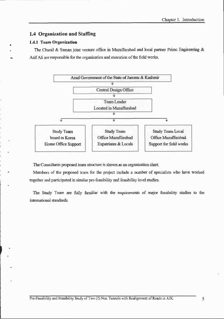
1.4 Orgxnuttion and Stafring
1.4.1 Team Organization
The Chunil & Saman joint ventue office in Muzaffarabad and local parher Prime Engineering &
Asif Ali are resoonsible for the orsadzation and execution ofthe field works.
Study Team
based in Korea
Home Office Support
StudyTearrOffice MuzaffarabadExpatiates & Locals
Study Team Local
Office Muzaffarrabad
Support for field wo*s
The Consultants proposed team strucnrre is shown as an organization chart.
Members of the proposed team for the project include a number of specialists who have worked
together and participa'ted in similar pre-feasibility and feasibility lwel shrdies.
The Study Team are firlly familiar with the requirernents of major feasibility studies to the
intemational standards-
Azad Government of the State of Jammu & Kashmir
Pre-Feasibility and Feasibility Study ofTwo (2) Nos. Tunnels with Realignment ofRoads in AJK.
PRE.FEASIBILITY REPORT
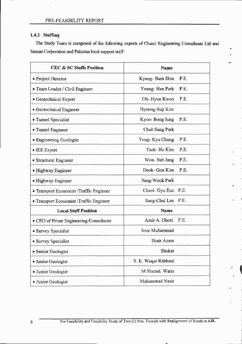
1.4.2 Staffing
The Study Team is composed of the following experts of Chrmil Engineering Consultants Ltd and
Saman Coryoration and PakisAn local support staff:
CEC & SC Staffs Position Name
r Proiect Director Kyung- Bum Shin P.E-
o Team kader / Civil Engineer Young- Han Park P.E.
r Geotechnical Exoert Oh- Hyun Kwon P.E.
r Geotechnical Eneineer Hyoung-Sup Kim
o Truurel Soecialist Kyoo- Bong Jung P.E.
o Turmel Eneineer Chul-Sung Park
r Engineering Geologist Yong- Kyu Chung P.E.
r IEE Expert Taek- Ho Kim P.E.
. Structural Ensineer Won- Sub Jane P.E.
o Higlrway Engineer Deok- Gon Kim P.E.
o Highway Engineer Sane-Wook Park
. TransDort Economist /Traffrc Ensineer Cheol- Gyu Eun P.E.
. TransDort Economist /Traffic Ensineer Sans-Chul Lee P.E.
Local Staff Position Name
r CEO of Prime Engineering Consultants Amir A. Ghori. P.E.
o Survey Specialist Israr Muhammad
r Survey Specialist Shair Azam
o Senior Geologist Shokat
r Junior Geolosist S. K. Waaar Rabbani
r Junior Geologist M.Shazad. Waris
r Junior Geologist Muhammad Nasir
I
l
6 Pre-Feasibility and Feasibility Study ofTwo (2) Nos. Tunnels with Realignment ofRoads in AJK.
Chapter l. Introduction
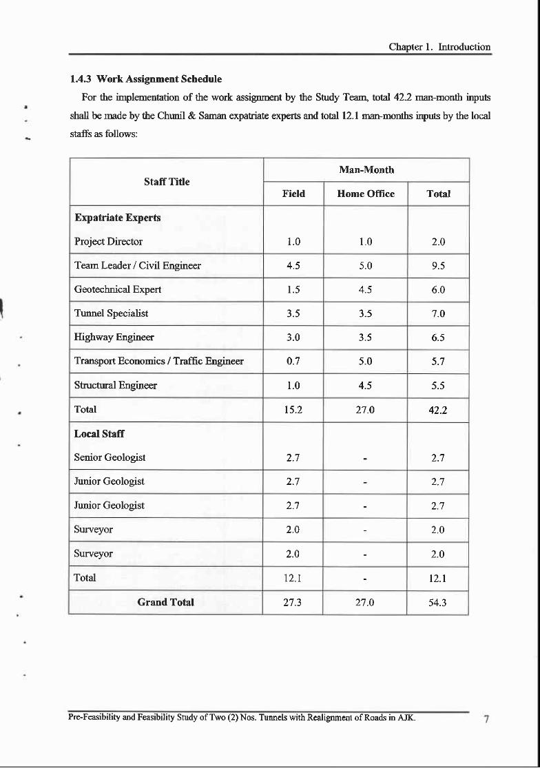
1.4.3 Work Assignment Schedule
For the irplerrentation of the work assignnent by the Study Teanl total 42.2 man-month inputs
shall be made by the Chunil & Saman expatriate experts and total l2.l man-months inprns by the local
staffs as follows:
Staff TifleMan-Month
Field Home Office Total
Expatriate Experts
Project Director 1 .0 I . t , 2.0
Tean Leader / Civil Engineer 4.5 5 .0 9.5
Geotecbnical Expert 1.5 ,1 < 6.0
Tumel Specialist 3.5 J - f'7.O
Highway Engineer 3.0 3 .5 6.5
Transport Economics / Traffic Engineer 0-7 5.0 5.7
Stuctural F.ngineer 1.0 4.5 5.5
Total 15.2 27.O 42.2
Local Staff
Senior Geologist 2.7 2 ;7
Junior Geoloeist ) 1 2.7
Junior Geologist 2.7 2.7
Surveyor 2.0 2 .0
Surveyor 2.0 2.0
Total 12.1 12. l
Grand Total 27.3 27 -0 54.3
Pre-Feasibility and Feasibility Study ofTwo (2) Nos. Tunnels with Realignment ofRoads in AJK.

doEXPATRIATE STAFFING SCHEDULE
WORK IN PAKISTANWORK IN KOREAFLEXIBLE WORK SCHEDULE IN KOREA
Iv7'"v77V)
Staff Title Name2009 2010 Man-Months
6June
7July
8Aus
9Sep
l0Oct
l lNov
t2Dec
IJan
2Feb
J
Mar4
Aprf
MavMZDOffice
HomeOffice
Total
Team Leader Young Han Park m4.5 5.0 9.5
Geotechnical ExpertOh Hyun KwonHyung Sup Kim
I @t .5 4.5 6.0
Tunnel SpecialistKyoo Bong Jung
Sung Chul Parkm
J . ) J . ) 7.0
Highway Engineer Deok Gon KimSang Wook Park
777723.0 3.5 o.J
TransportEconomics
Cheol Gyu EunSang Cheol Lee
I T w m 0.7 5.0 J . t
Structural Engineer Won- Sub Jang 7^ 1.0 4.5 ) . )
Proiect Director Kyung Bum Shin I t1 .0 1 .0 2.O
Reporting+
Inception Report I
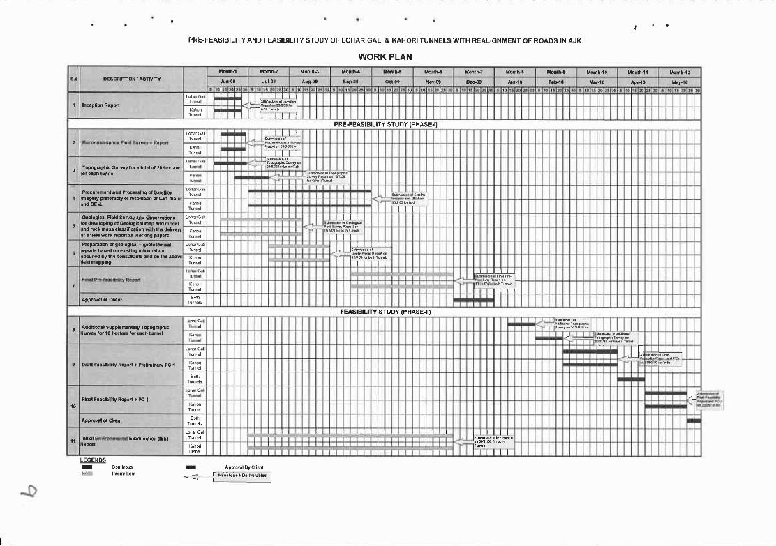
PRE-FEASIBILITY AND FEASIBILITY STUDY OF LOHAR GALI & KAHORI TIINNELS WITH REALIGNMENT OF ROADS IN AJK
WORK PLAN
DESCFIPTION /ACTWTTY
Fl.rl+;"J*.!,']F ' t
l t t t lPRE.FEASIBILITY STUDY (PHASE.I)
ll r:hi:{*l^li,-Lfll
To9oldDhic slmy fd . roEl or 20 n.d.rc
[email protected] P.@rslnE 6a &b[n.rnlg.ry pEfoEbt ot Esorurkn or 0.61 mer6l
t | lG.ologiel Fi.rld slmr .nd ob&mli6tbr thElocing ot G..lolial n.p lnd mod.lrnd drm.$ cr.s.mc.lion wnh rh. d.f€tut. rEld *orr Epdr d smking pap€6 l t t lPEp.r.nm oa g..{ogkrl - q.d*hnkrl
i I T f I - I I
l.pd|.b.&don.'i 'rhgh'dfl.1i6
G;
T l -
FEASIBILITY STUDY (PHASE.ID
Additoi|| SuDplom.nLry ToDngEphicluNy tor l0 tEir.E lor €d6h tunml
III
D. F..llhlny RoDon + Pfttnirury PC-l
- JfIfT
Fr|.r F..Einr[t ILDon r Pc-1 AT
l l
LEGENDSI ADprovalByclietrl

Slu
dy o
l Re
leva
nt
Gu
id€
lin
€s
a
nd
De
velo
pm
snt
Pla
ns
. Gu
de
line
sa
nd
Dir
ect
ive
s. T
he
Na
lion
al
De
vglo
pm
en
t P
lan
s. D
isln
ctD
eve
lop
me
nl
Pla
ns
. Tra
nsp
orl
ati
on
Po
licy o
r Pro
gra
m. Z
on
al In
teg
rate
dF
uru
l0e
vo
lop
me
nt
Prc
Van
Alig
nm
en
t Stu
dy
ID
ete
rmin
ati
on
o
t.
Ge
om
etr
ics
' Slo
pe
Sta
biii
ty'
So
il & lM
ale
als
. Str
uct
ure
S
ito
s
IT
ech
nic
ally
F
ea
sib
leA
lign
me
nls
J
Vis
ua
l lnsp
scti
on
+E
xist
ing
T
ralli
c Da
laI
Tra
flic
&O
D. S
uru
ey
Exi
stin
g
Tra
nsp
orl
Sys
lem
Po
pu
lalio
r,
La
nd
LJs
e,
Exi
stin
g Eco
norn
ic
Dat
a
Pre
linin
ary
A
na
lysi
s
IT
ran
spo
rl l\4
od
els
l IU
ser B
en
€lil
sI
Be
ne
lits ol R
oa
d
Eco
no
mic
E
valu
ati
on
I
J e
nvi
ro-n
me
"tit
I lm
pa
ct An
aly
sis
--R
ocom
mon
dalio
n
t;"f
#",
8T
"iJJ
ftd
ffJr
" W
r'
rave
rch
ara
cre
rist
ics
lri
' Alig
nm
en
ls,
Pro
lile
Cro
ss-S
€cl
ion
. Prs
limin
ary
E
ng
ine
eri
ng
Oe
sig
n.
Slo
pe
Sta
bili
lyP
rote
oti
on I
De
taile
d
Fie
ld Su
rv€
ys
:. T
op
og
rsp
hic
al
Su
rve
y.
Pro
cess
ing
o
l Sa
telli
telm
ag
ery
w
ilh C
on
tou
ra
nd
DE
M. G
€o
tech
nic
al
Su
rve
y. S
ate
llile
lm
ag
eh
lerp
reta
lion
' Sit
e Ge
olo
gic
al
Ma
pp
ing
' Slo
pe
Su
rv€
ys
lor
Min
imu
m
& P
erm
an
en
tS
lop
e Pro
tecl
ion
<a
tr oq
o !.', a o E.
o 'Et ci F' o o 0c
FINAI- . v,FEASIBILITYREPORT
2.2 Objectives of The Study
The objectives of the study of Pre-Feasibility and Feasibility Study of Two (2) Nos. Tunnels with
realignment ofroads in AJK are:
To assess economic and technical feasibility of the Project and carry out comprehensive evaluation of
the hoject, based on the three main iterns of studies as follow:
E Socio-economic Data and Their Analysis
With due effect of new flrnnel constuction on the increased overall economic activities in the
influence zones in future as well as any possible effects of future ptojects in nearby are leing taken into
account.
E Traffic Data and Their Analysis
With the effecl of new tunnel constuction and resulting increased demand of taffic in and near the
Prcject area being taken into account
O Preliminary Road & Tunnel Desig! and Cost Estinate
Taking due consideration on technical diffculties such as steep topography, unfavorable geology, hard
rainfr[ erc. foreseenable in the Project implemenation.
2.3 Methodology for Pre-Feasibility Study
2.3.1 Preparatory \Vork
Prior to the mobiliztion and dispatch of the Study Team to Pakistaq the following preparatory work
has beor completed by the Srudy Team:
r Collection ofdaa and previous reports related to the Project
r Preparation of questionnafes
o Preparation ofwork schedule
2.3.2 Data Collection and Site Reconnaissance
The Study Team will collect data and information necessary for the study and carry out a review on
these items. In parallel with these activities, the Study Team will conduct site reconnaissance on the
Proiect site to familiarize themselves with.
I:
12 Pro-Fcasibility and Feasibility Study ofTwo (2) Nos. Tunnels with Realignment of Roads in AJK.

Chapter 2. Tecbnical Approach and li.Iethodology
2.3.3 Socio-Economic Study
Socio-economic data are the basis of confirming the necessity of estimating future traffic volume and
the development effects to be derived form the proposed Road. Analysis of socio-econonic frame work
concems mainly with the following items:
o Distribution and tend ofpopulation
o Trend ofgross regional product by sector
o Trend oferrployment by sector
. Export and irnport by conirnodity
o National development programs by secor such as agriculture, forestry and transportation
r Ongoing and fuhtre programs on rellional development
r Determination of influence zonc
. Zoning
Based on the analysis of data collected, possible future development plals, etc. firture projection of
socio-economic fi'ame work within the area !o be studied will be developd as for population, numbers
ofemployees, amount & quantity ofproduction, income, number ofvehicles retained etc.
2,3.4 Economic Study on Agriculture, Forestry etc.
This str:dy is cafried out in order to obtain basic data to estimate development benefit due to
agriculttual, forestry and other development that will become possible due to the tururel constuction.
Some large amount of development benefit will defnitely accnre, occupying some Iarge portion of the
total benefit derived from the road construction itself, in addition to the road users benefit.
The items to be studied will include as follows.
Quantiy of agriculhre production
Producer's (loco) prices of agricultural products
Production costs &reclamation costs
Present usage of land
Topogpphy & soil conditiors
Planning of future land usages
Forecasting of future production
Pre-Feasibility and Feasibility Study ofTwo (2) Nos. Twrnels with Realignment of Roads in AJK. 13
FINAL FEASIBILIry REPORT
(Similar study will be conducted as for foresty and other possible industrial development to be
anticipated in the Project area),
2.3,5 TraIIic Surveys and Traflic Forecasts
E Traffic Surveys:
The following traffic surveys will be conducted to det€rmine the present taffic conditions.
o Survey for present traffic facilities
o Traffc volume counts
o Road side O-D survey
e Running speed srnvey
o Road network inventory survey and
r Vehicle operation cost suw€y
E Traffic Forecasting:
The futr:re traffc volumes will be estimated taking the following iteins into consideration
o Undersanding on & grasping oflocal economic issues '
o Understanding on & grasping ofuansporhtion issues on local economy
. Futr{e prospects oflocal development projects, including projects already wrder way
. Future prospocts oftransportation projects, including projects aLeady under way
o Opinions and intention ofofficer in charge oftransporhtion planning
Traffic forecasting procedures generally include:
. Forccast oftaffic ganeration and attraction
o Forecast of futurc O-D tables and
o Classification and assignmant of futr.ue n-affic
2.3.6 Significance of the Project
The sigrificance of the Project implementation is going to be skessed by studying dre following merits
of rather unquaatitafive nafife.
. Developm€nt stategy ofnational road network
o Impact ofroad conskuction on regional development
o Reduction ofeconomic disoadties
I
14 Pre-Feasibility and Feasibility Study ofTwo (2) Nos. Tunnels with Realignment ofRoads in AJK.
Chapter 2. Technical Approach and Methodology
2.3.7 Route Selection
Conceivable route alternatives will be selected on available topographic maps to a scale of l/50,000
360, with the following work items included:
E Study on design standards
Tentative desrgn standards for road and fimneV bridge will be established rn dre light of standards
applied intemationally such as AASIITO, Korea Road Standards erc.
O Study on route selection
The objective of this shrdy is 1o carry out preliminary route selection among conceivable route
altematives for turmels on topoga.phic map (scale 1/50,000) and satellite imagery. The work items
included in this study are as follows.
. Preparation of conceivable route altematives
On the basis of field recormaissance and taking present and fttw€ socio-economic activities and
dwelopment plars into account, conceivable route altematives will be prepared on topographic rnap to a
scale of l/63, 360 and satrellite imagery.
0 Landslide investigation
In order to identify the possibld existing locations of large-scale landslides as the major & possible
control poinfs for route selection, landslide specialist, after int€rpreting the satellite imagery presently
availablg conducts geological investigation on foot in order to confinn, the following items.
r Distribution of soils & geology
r Location offaults and possible slides in large scale
o Location and distribution ofuncemented deposits
r Location and extmt of erosion and sedimentation alone riv€rs
E Approximate cost estimate
An approximate estimate of consfruction costs for each conceivable route altemative is to be maoe as
for the cost comparison purpose, based on the cost per a linear l<rn of similar project in Pakistan.
O Selection of preliminar5r route alternatives
The alternatives are to be mmpared with respect to the following items in order to determine
preliminary routg through discussion with the client.
Pre-Feasibility and Feasibility Study ofTwo (2) Nos. Tunnels with Realignment ofRoads ir AJK- l5

FINAL -FEASIBILITY REPORT
r Economic viewpoint
- Corshuction Cost
- Maintenance Cost
o Technical viewpoint
- Asswned landslide during conshuction or in future
o Fua[€ road network plan
o Socio economic viewpoint
- Funre development plan
- Econornic impact to be induced
2.3,8 Route Relinement
The objective of this study is to refine the preliminary roule by using topographic map and o select
optimum route for further road and tunnel design works. The work itenrs io be included in this study are
as follows.
E Establishment of Design Criteria:
The sUrdy team will establish ihe design criteria to apply in the Study, in due consideration of future
tr.affic volume, rcquirenrent ofthe project road and the design criteria of the existing road in Pakistan.
The principal design critmia will include the following:
. Roadway eleraents;
Design speed, lane width, shoulder width, number oflanes, gradient, horizontal and vertical alignment,
pavement composition (tentative) etc.
o Loading conditions for bridge & stuctures
Shtdy on tumel and other works and related road works. Design elements of road and hurnel will be
scrutinized as for
o Turnels & oiher works:
- To determine locatiors of urmels required
- Fmdamental design of turmel, ventilation and other facilities
- To estimate work quantities
I
I
I
Study ofTwo Nos. Tunnels with Realignment o

Chapter 2. Technical Approach and Methodology
I e r Road Works:
- To determine locations ofroad where widening, raising etc. are required
- To determine prelimimrily pavement design
- To detennine drainage including cross pipes & pipe (or box) culverts
To determine other stucture such as rctaining walls, river raining or bank prot€ction
: - To estfunat€ v/ork quantities
tr Optimum route selection
Preliminary route selected will be refined takmg mainly the following technical control poinb inlo
, u"ao*t.
; . Location oflandslides and talus deposits
' . Location of turmels
, . lncation ofbridges
o High water level ofrivers' o Esablished design criteria
I o Geological conditions
' Cost estfunate, consi5ting of construction costs, naint€nance, land acquisition costs erc- is to be made
' for the respective altemative by using cost daa of similar project
The optimum route will be selected taking inlo account the technical, economical and socio-economic
aspects.
After the route refinement, the optimum route will be delivered to the survey team who will
comple,rrent topographic maps.
' 2.3.9 Mapping and Topographic Survey
, The Mappmg Grorry will conduct following surveying work, after respective order for surveying is' issued by the Road Planning Grory.
Pre-Feasibility and Feasibility Study ofTwo (2) Nos. Tunnels with Realignment ofRoads in AJK. t7
FINAL' ^. .-FEASIBILITY REPORT
2.4 Methodology for Feasibility Study
Main work items in the Feasibility Study will include;
E Technicallnvestigation-I
E Preliminary Road & Tunnel Design (StageJ)
E Tecbnical Investigation-Il
E Preliminary Road & Tunnel Design (StageJI)
O Project Evaluation
E Preparation of Implementation Schedule and
D Conclusion & Recornmendation
2.4.1 Technicallnvestigation-I
This work item consists of meteorological, hydrologicat riverbd seismic investigation and soiV
nnterials investigation.
O Meteorological data collection
Rainfall, wind velocity and temperatue daa recorded at the meteorclogical observatories located
closely to the Project area will be collected to establish design condition such as rainfall inteffity,
snowfrll (ifany) required for the desioing ofdrainage system of the road, thermal effects and wind load.
O Hydrological Investigation
This investigation mnsists of two items of studies & investigation as follows:
- Investigation as for traces ofold floods, or hearing the merrory of old pmple at the bridge sites erc.
- Collection ofriver flow data at flow gauging stations in (or near) the Project area, or calculation of
possible flood based on rainfall data etc. obtained fomr data collection as stated in meteorological
daca collection.
E River bed investigation
The purpose of riverbed investigation is to obtain as much stability of the nver bed and bank after
completion of the Project (structur€s), both against erosion and sedimentation, so as to bring about long
and srsured lives of structures and roadwav.
E Seismic Studies
A complete review analysis of published data, research work carried by various national and
intemational agencies, will be carried out io arrive at an acceptable gound acceleration and remedial
I
(
18 Pre-Feasibility and Feasibility Study ofTwo (2) Nos- Tunnels with Realignment of Roads in AJK.

measure for slope stability.
D Soil/lltaterials fnvestigation:
The objective of this investigation is to provide required soiVrnaterials data along the project rout€ an{i
at borow pit and quarry site for further preliminary road and turmel design work.
The study Gam will carry out the survey of the construction mat€rials for ernbankrnent as well as forpavement and shuchlres. Location of quames shall be properly identified and marked. A chaptermvering naturally occuring construction nnterials such as fill, agg€gates, sands etc, as well as thernanufactrued materials such as asphalt, cemen1 reinforcing steel shall be include.
2.4,2 Preliminary Road and Tunnel Design (Stage I)
After dre design criteria and design mnditiors are confirmed based on snrdy results of technicalinvestigation-I prelimirury road and turmel design will be conducted with the use of topographic map ofl/1000 scale.
D Alignment design:
The vertical and horizontal alignment will be elaborated based on the following surdies.
. Height ofcut or fill slope
. Stability ofcut or fill slope
o Balance ofearthwork volume
o Estimated high-water level and requfu€d height ofstuctures
E Pavement design
The pavernent will be designed according to the criteria on the estimated fuhue tmfEc volume andsubsoil survey results.
Tunnel Design
The turmels will be selected based on the pre-Feasibility snrdy for firther detailed andaugmented topographic survey of portal areas and accass roads, refnement of GeologicalMapping along the selected alignment
Rock classification in tem of GTU, RMT & RBT and adjusted preliminary Design of numelswith services & utilities and major components of the tunnel-
tra
\
FINAI FEASIBILITY REPORT
E Bridge Design
In the light of desip crituia and conditions, type of bridge & span distribution will be refined and
standard bridge type for short span bridges will be established, based on the use of topogaphic map of I :
1000 scale.
The supentuctr,ue and substruchue of the long span bridges and standardized strort span bridges will
be scrutinized.
E Drainage facilities Design
On the basis of ihe results of hydrological investigatio4 cross dminage stuctwe including inlet and
oudet treatnent and type of side ditch will be desigred.
Roadway shuchrre such as retaining wall, slope protection work, riverbank protection wolk etc. will
be designed taking into account the following aspects.
r Soil condition
o Terrain
r Availabilig of local materials
r Structural stability
r Erosion ofbanls, ifany anticipated
E Design Drawings
Preliminary desip drawings consist of as follows.
. Standard crDss section
. Plar& profile
. G€ntral view oftunnel
. Standard drawing ofretaining wall, culve4 slope Fotection, sideditch
o Feasibilities drawing such as t'affic line, traffic sign etc.
2.4.3 Technicallnvestigation-Il
Technical investigation-tr is fie1d investigation for proposed route alignment in steep te[ain areas,
which will be conducted by the team of surveyor and Highway Plarurer.

Highway Planner will pinpoint the area which might require field check on foot of the proposed
alignment by the previous study (Preliminary Road &Tunnel Design, stage-I). And Suweyor will
conduct cengering and cross-sectional survey in steep terrain areas to be checked by the Highway Plarmer.
2.4.4 Preliminary Road and Tunnel Design (Stage II)
E Review of Preliminary Design
On the basis of the results of technical investigationJl, preliminary design will be modified, if
necessary with respect io vertical andlor horizontal alignment and cross section design.
D Quantities Calculation
Based on the resglts of preliminary design, work quantities will be estimated on work (or pay itern)
basis.
fl Construction Sequence, Method and Schedule
Because of geogp.phical remoteness of the Project and much difficulties to be anticipated even in
access to the Project site especially in the initial period ofconstuction, the Study Team has !o pay much
attention to the sequance, method and schedule of constmction, so as to bring about general economy il
construction For this purpose, the Sn-rdy Team will review say for irstance, some measrres such as:
. Standardization ofshort (and middle) span bridge, to save construction period
o Apprcpriate apportioning ofconstruction sections to make their progress optimum and
o Use of local malerials (sands & stones) as much as possible, etc.
E Cost Estimate
The preliminary cost, which will comprise constuction cost, maintenance cost, land acquisition and
compensation cost will be estimated in accordance with the outcome of the preliminary design and the
construction method.
o Construction Cost:
The constucXion cost will be assessed by summing up the respective cost elements of equipmen!
materials and labour.
The cost breakdown is to be pfepal€d for the rnajor work items. The general expenses and the
contingency reserves will be estimated by referring to those of similar projects in Pakistan and abroad and
to the trend ofthe prevailing inflation rate.
2L

FINAL.,II , FEASIBILITY REPORT
. Maint€nance Cost:
The maintenance cost will include maintenance and repair cost for rcads and turmels, overlay cost in
consistence vr'ith the future tzffic increase and cost due to possible landslides anticipated.
r Land Acquisition and Compensation Cost:
This cost is estimated based on approximate area of land acquisition and number of houses to be
removed due to the project imple.mentation.
o Engineering Cost:
A certain appropriate percentage to the constuction cost.
2.4.5 Project Evaluation
The project will be evaluated fiom the aspects of viability in the Iight of mrsnuction cost, economy
and finance.
E Economic Evaluation
The evaluation indexes of economic benefit cost ratio, economic intemal rate ofretum and net pres€nt
value will be calculated and ernployed for the justification of the project.
The economic cost will be the financial cost minus fansfer payment like taxes. The economic benefits
will come from saving of vehicle operation cost and time saving cost of passengers plus development
benefits due o possible increase in primarily, agricultural and foresty production.
O Social Impact and Development Impact
The social and development impacts will be sh:dies separately from the economic evaluation.
Social Impact and Development Impact:
The social and the development impacs will be shrdies separately form the economic evaluation.
E Financial Evaluation:
The financial cost including taxes and duties, will be capitalized to the present value, which will cover
all the costs arising from the detailed desigrl constuctiorl land acquisition, compensation, constuction
supervision and any other experses related to the project.
t
22 Pre-Feasibility and Feasibility Study ofTwo (2) Nos. Tunnels with Realignment ofRoads in AJK.
Chapter 2. Technical Approach and M,-thodology
2.4.6 ImplementationProgramme
, The implementation programme will be prepared fiom practical and realistic vie*point and will
compnse:
, . Description ofthe project (major work iterns with quantities will be clarified)
: t ImPlernentation time schedules
,, o Fund disbursement schedule
: t Organization chart for implementation
\ 2.5 Methodology for Initial Environment Examination (IEE)t
: 2.5.1 IEE Process
r I APPROACH&METEoDoL0GY
, The IEE will require the following activities:
: t Kick-offmeeting with Project Team.
o Obtaining of information including the nmnel description, feasibility shrdy, rcsowc€
requirement, background information, schedule and constuction and operations pmgram to, produce an TFF according to regulatory rcquirements.
,) . Investigation ofregulatory requir€.m€nt.
o Identification of any major issues and in particular tlpse which may have all impact on
plarming; design, consfiuction and operation.
, . Assessnent ofpotential impacts and identification of mitigation measures to rcduce any impacts.
, . Development of an environmental management plan to moniior the implementation of the'
Foposed mitigation measurcs to ensure regulatory compliance.
: t PreParation of final IEE rePort
, Key tasks are described in the following sections; the overall IEE process is shown in the following
: o*'
:
:
I
:
tre-Feasibility and Feasibility Study ofTwo (2) Nos. Tunnels with Realignment of Roads in AJK. 23
'

FINAI - 1[...,-FF.ASIBILITY REPORT
ht)
(]ct)
c)
q)
€
6)
The IEE Process
24 Pre-Feasibility and Feasibility Study ofTwo (2) Nos. Tunnels with Realignment ofRoads in AJK.
Chapter 2. Technical Approach and I'lSthodology
2.5.2 Kick-Off Meeting
A kick offmeoting will be schedule with client and/or rnanagement consultant to discuss the proposed
program ofactivities based on the methodology described in this document. It is anticipated that the kick-
offmeeting will also be used to collect the following types of information:
o Plarming and design data
. Project description related to constuction and operations
. Resouce requirement during constuction and operations
o Feasibility study for the project
o f,xisting baseline data for the strdy area
r Geophysical investigations for the shrdy area
r Other specific details regarding project.
After the kick-ofr meaing, the field visits will be schedule and will make logistical arrangements for
the subsequent field efforts.
2.53 Scoping Study
Following the Kick-off meeting wi0r client and preliminary data collection task described abovg a
scoping exercise will be underaken in parallel with a regulatory review. The regulatory review will
consider and sunmarize relevant local, regional, national and intemational regulations and criteria
applicable to the project.
IEE scoping is esablished good pa-actice. The scoping process identifies the key issues upon which the
assessment in the IEE should focus and it provides the information necessary for environmental
acceptability of the project and to suggest ways in which poteirtial benefis can be enhanced. Properly
undertaken it ensures a focused and fit for purpose IEE. Once these areas of focus are agreed the most
important potential impacts associated wift the proposed project can be assessed in detail. A srrccessfirl
and effective IEE process is directly dependent upon a core prctocol that entails the following:
. A clear undemtanding of ttre development, including the altemative design concepts that are
available for evaluation and assessment.
o Sufficient undenanding of the physical, biological and social baseline environment of the area
that will be affected by the proposed project - in addition to cunent knowledge.
. A clear mandate for the development of effective mitigation measures and providing an accurate
representation of impacts.
Pre-Feasibility and Feasibility Study ofTwo (2) Nos. Tunnels with Realignmert of Roads in AJK. 25
FINAL. FEASIBTLTTYREPORT
2.5.4 InitialEnvironmentalExamination
E Overview
The IEE will be firlly corryliant with the AJK Regulations on EIA/IEE and will include the following , :o Description ofthe proposed project
o kgislative requirement of the projec!
o Description ofthe existing physical, biological and socioeconomic envincnment;
. AssessDeDt of impacts, including a clear statement of sipifcance criteria;
o Recommending mitigation measures to eliminatdminimize or reduce the impacts to aslow-as-
reasonably p:actical (ALARP) levels
o An Environmental Management Plan (EMP) specifying how the commitnents fiom the TFE will
be implernented and monitored during constuction and operations phase.
o An executive sunrmary ofthe above.
El Project Description
The description of fte project forms one of the foundation stones of the IEE process. It will include
information on all aspects of the proposed project and associated support facilities, like:
o Land use ofthe proposed project
o Schedule and planned procedures for design, plarming, constuction and operation ofthe goposed
proJect
o Details ofall infrastuctures necessary to support all phases of the project.
o Resowce use during project activities.
A thorougb project description tied with an accurate description of the baseline anvironmatt provides
the necessary basis for a robust impact assessment for the full project lifecycle. It is essential that
sufficient information is made available by EMS in a timely manner for the project description to be
compiled.
As part ofthe project description data will be gathered on all potential sipifrcant aspect that have their
impact in terms ofdischarge to the different envfuonmental media (air, wat€r and land). The list will be
used as the basis for assessing environrnental impacts from the project and proposing the mitigation
measures.
26 Pre-Feasibility and Feasibility Study ofTwo (2) Nos. Tunnels with Realigrment ofRoads in AJK.
Chapter 2. Technical Approach anC ivfethodology
. 2.5.5 Description of the Baseline Environmental Conditions
- tr Deektop Studies
.- Deslcop studies are anticipated to be adequate to cover many aspects of the baseline. The available
data of baseline would be coUected tom publishes, non- published docume,ntVreports and if available
and would be reviewed. This desktop study would be used to develop the baseline.
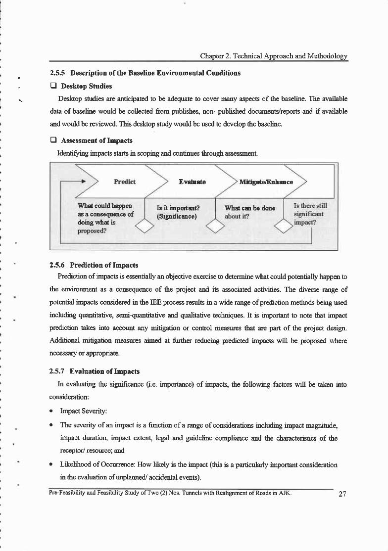
E Assessment of Impacts
Identifl,ing impacts starts in scoping and continues tbrough assessment.
Ev rdo Midgrtn/Enhance
What could hqpenas a consequence ofdoing uitd is
Is it importaf?(Signifrcmce)
What cm be done
2.5.6 Prediction of Impacts
Prediction of impacts is essentially an objective exercise to determine what could potreotially happ€n to
the environment as a @nsequ€nce of the project and its associated activities. The divene nnge of
potential iryacts considered in the IEE process results in a wide range of prediction methods being used
including quantitativg se.rriquantitative and qualitative techniques. It is important to note that iryact
prediction takes into accouDt any mitigation or conhol measures that are part of the project design.
Additional mitigation measur€s aimed at firther reducing predicted impacs will be proposed where
necessary or appropnate.
2.5,7 Evaluation of Impacts
In evaluating the sipificance (i.e. importance) of impacts, the following factors will be aken into
coruideration:
. Impact Severity:
r The severity of an impact is a fimction of a range of consideratioos including irnpact magnitudg
impact duration, iryact extent, legal and guideline compliance and the characteristics of the
receplor/ rcsowce; and
o Likelihood of Occurrence: How likely is the impact (this is a particularly important mrsideration
in the evaluation ofunplarmed/ accidantal events).
Prc-Feasibility and Feasibility Study ofTwo (2) Nos. Tunnels with Rcalignment ofRoads in AJK. 27
FINAI:' . FEASIBILITYREPORT
E Severity Criteria for Environmental Impacts
In evaluating the severrty of environmental funpacts, the following factors will be taken into
consideration
. Receptor/ Resouce Characteristics
o The nature, importance (i.e. is it of local, national, rrgional or intemational importance) and
sersitivity to change of the receptors or resources ttnt could be affected;
o Inrpact Magnitude;
o The magnitude ofthe change that is induced (ie. % ofa resource that is lost; the predicted increase
in ambient pollutant levels etc.);
. Impact Duration: The time period over which the impact is expected to lasq
o Impact Extent The geogra.phical extent ofthe induced change; and
. Regulations, Standards & Guidelines: The status of the impact in relation to regulations (e.g.
discharge limits), standards (e.g. environmenlal quality criteria) and guidelines. Where
quantification ofpotential impacts is possible, derived severity criteria will be based on numerical
values, representing regulatory limits, project standards or guidelines (eg. noise and air quality
iryacts).
2.5.8 Mitigation, Management & Monitoring
The IEE process is intended to r€duce the negtive impacts and enhance the benefits of an intended
activity by identiffing impacts and benefits and the ways 6f d66ling with them during the planning and
design stages of the projecr Plarmed mitigation measures will be described; additional mitigation
measures/ controls will be recommended where irnpacts are corsidered unacceptable- Recommended
post project monitoring will be identified and included in the monitoring section of the IEE.
Close corsultation with management of EMS during the mitigation measures waluation is imporant
to ensure that any significant adverse or potentially adverse impacts identified by the IEE process are
avoided or eliminated by incorporating mitigation measures.
It is important to demonstrate in the IEE Report that project is applying Best Available Techniques
(BAT) and Best Practicable Environmental Option (BPEO) and that all residual impacts are as low as
reasonably practicable. All mitigation measures will be discussed with Environmental Management
Services at the earliest possible time !o ensw€ that their implementation is technically and economically
feasible.
28 Pre-Feasibility and Feasibility Study ofTwo (2) Nos. TLuurcls with Realignment of Roads in AJK.

Chapter 2. Technical Approach and I i .ithodology
The mitigation hierarchy for planned wents is as follows:
project so that a featLfe causing an impact is designed out or altered
, ,. Abate on Site: This involves adding something to the basic design to abate the impact - pollution
' controls fall within this category
| . Abate at Recepior Ifan impact cannot be abated on-site then measrues can be implemented off-
. Repair or Remedy: Some impacts involve unavoidable damage to a resource. Repair involves
restoration and reinstatement type measures
. Compe.nsate in Kind,i Compersate Through Other Means: Where other mitigation approaches are
not possible or fully effective, then compensation for loss or damage might be appropriate. The
nature ofthe project is such that there is a risk of something unforeseen happening even after the
likelihood bas been reduced to as low as reasonably practical through control measures and
recovery measures must also be planned for. The mitigation hierarchy for unplarmed events is as
follows:
e Contol The objective is to reduce the risk to as low as reasonably practicable (AI-ARP) which
can be achiwed by rcducing the likelihood of the initiating event or by reducing the corsequence
or by a combination of both.
o Recovery: Tlpical contingency measures include Emeryency Response Plans and Pmcedures and
Spill Contingency Plars and Equipment
E Specilic Impact Tasks
e SocioeconomicAssessmgnt
Socioeconomic impacts resulting fiom the project (e.g. transportation impacts, real estate impacts,
public health issues, general nuisance and impacts on cultral or historical areas) will be assessed
subjectively by review of existing published infomration and site visil
Issues to be considercd will include:
o knpacts to norradic groups, ifapplicable
. Displacement oflocal residences or businesses, ifany;
. Estimated change in ernployment/income characteristics during constuction pbase.
Pro-Feasibility and Feasibility Study ofTwo (2) Nos. Tunnels with Realignment of Roads in AJK. 29

FINAL. : FEASIBILITYREPORT
E Environmental Management Plant
Outline for the EMP will be developed. It should be emphasised that the EMP is a living document,
which will be developed over the life of the project. The EMP will include the following sections.
E Outline of Environmental Management Plan:
An environmental management plan (EMP) to be implemented during constuction and operation will
b€ obtained. This outline plan will define roles and responsibilities in generic terrns, identifr potential
significant waste streans (accordmg to volume ard hazafi), describe their characterization and
classification, evaluate poterrtial teatnent and disposal options and make appropriate recomrnendations.
2.5.9 Final IEE Report
The information gathered during the IEE process will be collated and condensed into one Draft IEE
Report. Wherever possible, information collected during the environmental baseline characterisatton
(desk and field studies) and anvironmental impact assessme,nt will be docume €d in a format suitable for
tnmediat€ inclusion in the IEE Report. This will avoid duplication of effort during report preparation,
and allow the project schedule to be achieved.
It is assumed tlat Management ConsulantVclient will provrde one consolidated set of reueu/
comments on the draft IEE within 0 I week of submission by the Consultants. Comments and suggestions
will be incorporated into the Final IEE Reports to be submitted to the Client.
30 Pre-Foasibiliry and Feasibility Study ofTwo (2) Nos. Tunnels with Realignment of Roads in AJK.
Chapter 3. Site Reconnaissance
Chapter 3. Site Reconnaissance
3.1 Introduction
3.1.1 Desk Study
The desk study compiled existing available and relevant data, including topographic and geological
mapping published literatue, existing project reports and available satellite imagery etc. The desk study
identified the following parameters relevant to this stage ofthe PFS (Pre-Feasibility Study):
r The overall topogaphy of the trunel sites (from publistred topogaphic map made arailable
and later from DEMs obtained through satellite imagery).
. The geological outcrop pattem and structural geology of the site from publistred geological
maps, satellite imagery and any available aoial photographs.
The presence ofsuperficial depositg such as alluvium and colluvium fiom published mapping,
satellite imagery and any available aerial photographs.
The climate regime of the area and its likely influence on the design and geo-hazarrds, namely
rainfall pattemg river hydrolory and ground wat€r conditions.
The presence of geo-hazards, which could affect the turmel, portal areas and link access roads.
At this stage, The Study Team envisage what these are most likely to include landslideg debris
flow and the presence of shear zonel thrust faults.
3.1.2 Site Reconnaissance Trip
Based on the desk study, a detailed and interdisciplinary reconnaissance survey is the most irryortant
prerequisite for a successfi.rl Pre-Feasibility Study. It is essential to investigate the project area or the
proposed alignment corridors in a joint reconnaissance trip. It is not to split the mission into several'fields of engineering teams' or disciplines, but to carry out a joint reconnaissance trip to promote
immediate technical discussions with differei:t fields exoerts.
An experienced field geologist and geotechnical expert investigated the corridors and record details.
Geological data hydrological data as well as particular details of infrastructrue leading up to the
potential sites of the project will be assessed. The work input of the highway design expe4 the
tunneling expert and stuctural expert will mainly depend on the results ofthe recoruraissance trip.
But as their expertise will not inlluence the general alignment, they are not considered to be essential
during the on-site reconnaissance, e.g. the tunnel alignment is based on the expertise ofthe geologist and
the geotechnical exper! the o,pen road alignment is based on the expertise of the geologist, the geo-
Pre-FEasibility and Feasibility Study of Two (2) Nos. Tunnels with Realignment ofRoads in AJK.

FINAL FEASIBILITY REPORT
hazmd expert, and the bridges are based on hydraulic requirements and geotechnical expertise.
The reconnaissance includes physical aspects for the different variants or alignment conidors. This
contains important geological and hydrological aspects of the alignments as well as economic aspects
Iike logistics (existing roads), land use (agricultrual areas) and environmental or social aspects (populate
areas, habitats, tourist rcsorts).
A very important reconnaissance issue is the detection and evaluation of potential geo-hazard or
other risk areas (covering rockfall, landslide, slope erosiorl mud and debris flows, flooding, river
erosion etc. areas) including ttre appreciation ofgeological geotechnical and hydrological conditions and
rhe identification of problematic area-
3.1.3 GeologicaU Geotechnical Field Survey
The site reconnaissance of experienced geologists who always focus on dre feasibility of tunnel and
open track alignment and the additional local geological mapping including sampling of rocks will
provide sullicient information for this stage of study. The main investigation targets will be:
. Localization ofmajor stuctural features (far-rlts, fractured zones, etc.)
. Identification ofpredominant ground types (litholory, pefography, etc.)
o Identification ofpredomhant rock mass types (overall assessment ofrock mass quality)
o Localization of crucial areas relating to difficult and/or hazardous geologicaVgeotechnical
conditions, such as gypsum deposits, rocldalls, landslides etc.
. Identification of hydro-geological situation.
The results will be presented in a geological map, which shall cover feasible alignment corridors.
Finally the geologist advises the alignment and tmneling engineer as regards the best alignment and
elaborates rough gmlogical-gmtechnical longitudinal sections of tunnels. The extent of preliminary
geological and geotechnical field survey is limited to the areas along the proposed nmel alignments and
the portal areas.
)z Pre-Feasibility and Feasibility Study ofTwo (2) Nos. Tunnels with Realignment ofRoads in AJK.

Chapter 3. Site Reconnaissance
3.2 Chella Bandi to Patika Road
3.2.1 Description of Existing Road
There ane tlrree main roads that join Muzaffarabad to other districts which are, Muzafarabad-Kohalla,
Muzatrarabad-Chakothi and Muzaffmabad-Neelurn These roads are most vulnemble regarding
landslides in heavy rains. These roads often face landslides which causes breakaee of communication
and t"ansport systern.
Cunently, there are potential threats of road blockage due to landslide at Dunka Kas, Harrama,
Chhon. These all slides are on Muzafarabad-Neelum road.
The project area is located in the North-east of Muzaffarabad. Ifuhori landslide ranges 12.5kn from
Chella Bandi to Kahori Bridge. The road connecting Chella Bandi with Kahori Bridge, the stretch in
which the proposed tunnel will be locatd is part of the main road connecting Muzaffarabad (Capital of
AJK) wittr Neelurq the Distict of AJK. The road is used by all kinds of public and private taffc. The
dersity of traffic on this road was noticed to be moderate during the site visit.
The road was followed northward where several large landslide scars could be seen on the slopes.
Whilst most ofthe ladslides appeared to be slnllow debris avalanches. Ihey had considerable surface area-
Most of the length of the road betr,veen Chella Bandi and Kahori Bridge is subjected to frequent
ladslides during monsoon season blocking the flow of taffic on the section sometimes continuously
for two to three days. In order to overcome these frequent long intern4tions, it has been proposed in
RFP to have a tunnel of 4 to 5 lcn length between these two destinatiors bl4rarsing the landslide
affected sbetches ofthe road to provide an improved all-weather link between these two destinations.
The projeA area falls within Seismic Zone-4 as per UBC 197 (most swere zone). Landslides in
some ofthe stretches caused bv the ofOctober 2005 are still visible.
The proposed road tunnel is located at
Chella Bandi to Patika road, district
Muzaffarabad. The main water body of the
area is River Neelum that meets River Jehlum
making junction at Domel, which is linked
with Dstrict Neelum (Kel, Shounter and
Rattu) by metaled and fair weather road
Pre-Feasibility and Feasibility Study ofTwo (2) Nos. Tunnels with Realignment ofRoads in AJK. J J

*81.
EI
:=t]a;L!
,l
EI
I
r ' t q , r
l ) t ln t i t i . l r .7 !1 i
l l '
t .
I
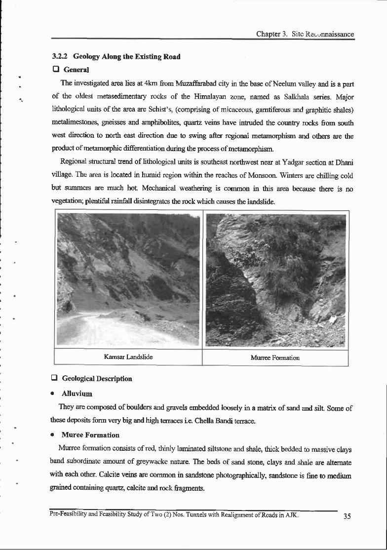
Chapter 3. Site ReLunnaissance
3.2.2 Geology Along the Existing Road
O General
The investigated arca lies at 4lar from Muzaffarabad city in the base of Neelum valley and is a part
of the oldest metasedimentary rocks of the Himalayan zone, named as Salkhala series. Major
lithological units of the area are Schist's, (comprising of micaceous, gamtiferous and graphitic shales)
metalimestones, gneisses and arryhiboliteq quartz veins have intruded the cormtry rocks from south
west diretion to north east direction due to swing aftrr regional metamorphisn and others are the
product of metamorphic differentiation during the process ofmetamorphisrn
Regional structural tend of litlrological rmits is southeast northwest near at Yadgar section at Dhani
village. The area is located in humid region within the reaches of Monsoon. Winters are chilling cold
but summen are much hot Mechmical weathering is common in this area because there is no
vegetatioq, plentifiil rainfall disintegra:tes the rock which causes the landslide.
Kamsar Landslide Murree Forrnation
tr Geological Description
r Alluvium
They are corrposed of boulders and gravels errbedded loosely in a marix of sand and silt. Some of
these dqosits form very big and high terraces i.e. Chella Bandi tenace.
. Muree Formation
Murree formation consists of re4 ttinly laminated siltstone and shale, thick bedded to massive clays
band subordinate amount of greywacke nature. The beds of sand stong clays and shale are aftemare
with each other. Calcite veirs are common in sandstone photographically, sandsto,ne is fine to medium
gra.ined containing quarE, calcite and rock fragrnorb.
:s

FINAL. , . ,FEASIBIL ITYREPORT
36 Pre-Feasibility and Fea-sibilrty Study of T\\'o (2) Nos Tunnels with Realignment ofRoads in AJK
Chapter 3. Site Reconnaissance
3.2.3 Landslide
E General
The greatest benefit in rmderstanding landslide producing processes and mechanisms lies in the use
ofunderstanding to anticipate and devise measures to minimize and prevent major landslides. The term
major should be underscored here because it is neither possible nor feasible, nor even desirable, to
prevent all landslides that can be handled more effectively and at less cost after they occur. Landslide
avoidance through selective locationing is obviously desired-even required in many cases.
Therefore, the study team put emphasis on the following two main points during the site
reconnaissance.
r Major landslide areas and landslide prcne area were investigated to avoid there geo-hazard
areas.
o Minor landslide areas were investigated to understand the lurdslide-producing process and to
find the remedial measures.
Landslide may be conected or controlled by one or any combination of four principle measures;
modification of slope geomety, drainage, retaining stuctures and intemal slope reinforcement,
0 Stope Failures Categories
The different types of landslides that are responsible for causing damage to existing road are as
follows;
r Falls:
Different type of falls e.g. earth fall, rock fall and debris fall are frequent. The rock fall can be
teated in most cases but the rockslide is like a landslide and may become difficult to stabilize. Falls
generally occur along ste€p slopes. The material is detached from the parent one usually by
weathering and jointing-
- Trcatrnent Stabilization work can be carried out only at those sites where teatnent is possible.
For earth/ debris fall, series of gabion check dam can be constructed and the water will be
diverted by surface and subsurface drains. For rock fall, gabion retaining walls will be built.
Bosides combination ofvegetative hrfing and jute & coir netting can be also used.
Topple:
It is a type of fall. It generally involves pivoting or forward motion of rocks, debris or soil. It is
difficult and expensive to stabilize the topple falls. Hence such sites will be usually avoided.
Rotational Landslide:
Pre-Feasibility and Feasibility Study ofTwo (2) Nos. Tunnels with Realignrnent ofRoads in AJIC

FINAL',, FEASIBILITYREPORT
Rotational slide is that form of failure which occun along a distinct more or less semi-cicular or
curved shear slip surface (spoon shape) and usually occurs in shales, mudstones and clays.
It is very diflicult to contol the deep-seated rotational slide and is quite expensive too.- Treatrnent It usually consists of a combination of slope dressing, surface and subsurface
drainage and provision of retaining stuctures (such as soil nailing, bolting and anchoring).
Retaining wall (cement masonry / Gabion wall) application at the toe of the landslide area is
quite common in roadside slopes.
o Translational landslide (Plane failwe)
Translational slides occur on surfaces of weakness, such as faults and bedding planes or at the
contact betwe€n firm rock and overlying loose spoils. The shallow deposit above the bed rock slips
down due to the loss ofinterface shear stength,
- Treafinent: It usually consists of a combination of slope dressing, surface and zubsurface
drainage and provision ofreaining stuctures Gabion wall, breast wall).
o Debris Flows:
Debris flow is a common landslide in project site. It is usually associated with the high intensity of
rainfall. Debris flow is movements in which loose soils, rocks and organic matters combining with
enbained water to form slurries.
- Treatnr€nt Management of surface and subsurface water comes under the first priority to control
all types oflandslide- Gabion check dams can be built to conrol.
E Landslide from Kamsar to Yadgar due to October 8, 2005 earthquake
An earthquake measuring 7.6 on Richter scale occurred October 8, 2005. Muzaffarabad city, the
capital of AJlq is located close to the epicenter ofthe eathquake. In project site rock units are sandstone,
shalq limestone and dolomite. Dolomitic rock unit is intensively sheared and this unit is thought to be
constihrting the fault fracture zone. The surfrcial slope failure in dolonute rock was spectacular and
continued for several kilometers as thev are clearlv noticed in satellite imaee.
Pre-Feasibility and Feasibility Study ofTwo (2) Nos. Tunnels with Realignment ofRoads in AJK.
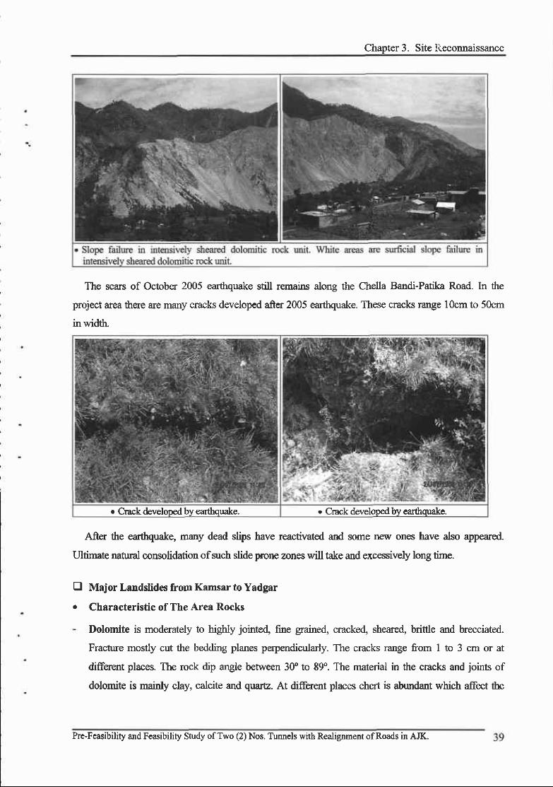
Chapter 3. Site iieconnaissance
The scars of October 2005 earttrquake still rernains along the Chella Bandi-Patika Road. In the
project area there are many cracks developed after 2005 earthquake. These cracks range 10cm to 50cm
in widtlr"
e Crack developed try earthquake. o Crack develooed bv earthquake.
A-fter the many dead slips have reactivated and some new ones have also appeared.
Ultfunate natual consolidation ofsuch slide prone zones will take and excessively long time.
Major Landslides from Kamsar to Yadgar
Characteristic of The Area Rocks
Dolomite is moderately to higttly jointed fine grained, cracked, sheared, brittle and b,recciated.
Fracture mostly cut the bedding planes perpendicularly. The cracks range from 1 to 3 cm or at
diffe.rent places. The rock dip angle between 3f to 89'. The matenal in the cracks and joints of
dolomite is mainly clay, calcite and quare. At different places chert is abundant which affect the
tra
Pre-Feasibility and Feasibility Study ofTwo (2) Nos. Tunnels with Realignment ofRoads in AJK.

FINAL -,.:',,FEASIBILITY REPORT
geotechnical propenies of the rock.
- Limestone is fure to medium grained, jointed and frachrd nodular, higbly fossiJiferous and highly
tenacious. Fractures are mahly oblique to the bedding plane. The rock dip angle between 40" to g9".
The material in the cracks and joints of limestone is mair y clay and calcite, quartz veins are also
present.
The type of sliding in the area is debris flow with rock slide.
. Debris Flow with rock slide
A debris flow with rock slide is a form of rapid mass movement in which a combination of loose soil,
rock and water mobilize as slurry that flows down slope. Debris flow with rock slide include <50% fines.
Debris flows are commonly caused by intense zurface-water flow, due to heavy precipitation or rapid
snoumelt that erodes and mobilizes loose soil or rock on steeo slooes.
Major Landslide of The Kahori
Characteristics of The Area Rocks
The rocks of the area consist of clay, shale and sandstone of Muree Formation. Sandstone beds are
dominating in the study area altemating with shalg clay, mudstone and siltstone, The sandstone is very
hard to slightly hard. It is highly jointed, fractured and cracked. The cracks are 1cm to 6cm wide open or
more at place in the study area. The fractures are along the bedding planes and cut obliquely at places.
Texturally, sandstones are medium to coarse grained, micaceous and at places soft and crumble when
crushed in hand.
The mudstone and shale loosely cernented and get sticky when wet. The water penetrates in the
fractures and extensively swells the clayey rocks. Due to swelling and shrinkage of the rocks fractures
are opened and trigger the slide. The rocks dip angle between 35o 0o 85o.
D
40 Pre-Feasibility and Feasibility Study ofTwo (2) Nos. Tunnels with Realignment ofRoads in AJK.
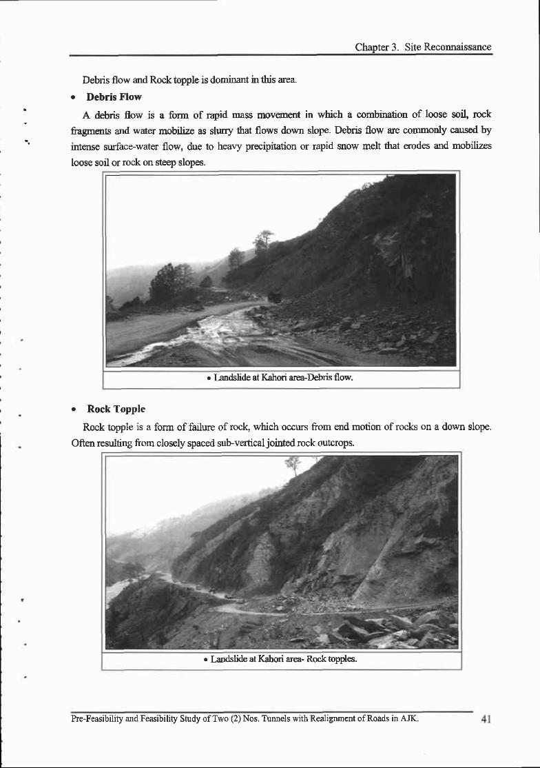
Chapter 3. Sile Reconnaissance
Debris flow and Rock tnpple is dominant in this area.
o Debris Flow
A debris flow is a form of r4id mass firovement in which a combination of loose soil, rcck
fragrnents and water mobilize as slurry ihat flows down slope. Debris flow ue commonly caused by
intense surface-water flow, due to heary precipitation or rapid snow melt that erodes and mobilizes
loose soil or rock on steep slopes.
. I-andslide at Kahori area-Dehris flow.
o Rock Topple
Rock topple is a form of failure of rock, which occurs from end motion of rocks on a down slope.
Often resulting from closely spaced sub-vertical jointed rock outcrops.
r l^andslide at Kahori area- Rock opoles-
Pre-Feasibility and Feasibility Study ofTwo (2) Nos, Tunnels with Realignrnent ofRoads in AJK.
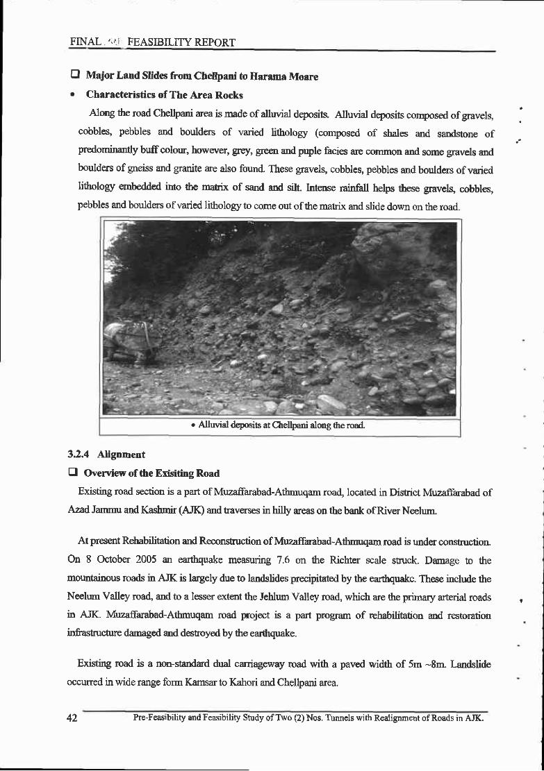
FINAL.,;ii FEASIBILITY REPORT
fl Major Land Stides fiom Chellpani to Harama Moare
o Characteristics of The Area Rocks
Along the road Chellpani area is made of alluvial deposib. Alluvial deposits composed ofgravelg :cobbles, pebbles and boulders of varied lithology (composed of slrales and sandstone ofpreaominanay buffcolour, howwer, grey, green and puple facies are common and some gra.vels and
boulders of grreiss and granite ate also found. These gravels, cobbles, pebbles and boulders of varied
lithology ernMded into the matrix of sand and silt. lntense rainfall helps these gravels, cobbles,
pebbles and boulders ofvaried lithology to come out ofthe matrix and slide down on the road.
. Aluvial d+osits at Chellpani alolrg the road
3.2,4 AHgnment
E Overview of the Erisiting Road
Existing road section is a part of Muzaffarabad-Athmuqam road, located in District Muzaffarabad of
Azad Jammu and Ifusbnir (AJK) and raverses in hilly areas on the bank of River Neelunr-
At present Rehabilitation and Roconslruction of Muzaffarabad-Athmuqam road is under constnrction
On 8 October 2005 an earthquake measuring 7.6 on the Richter scale stuck. Damage to the
mountainous roads in AJK is largely due to landslides precipitated by ttre earthquake. These include the
Neelum Valley road, and to a lesser extent the Jehlum Valley road, which are the primary arterial roads r
in AJK- Muzaffarabad-Atbmuqam rcad project is a part program of rehabilitation and restoration
infasnuctue damagod md destoyed by the earthquake.
Efsting road is a non-standard dual carriageway road with a paved width of 5m -8m. Landslide
occuned in wide range form Kamsar to Kahori and Chellpani area.
42 he-F€asibility and Feasibility Study ofTwo (2) Nos. Tunncls with Realignmcnt ofRoads in AJK.
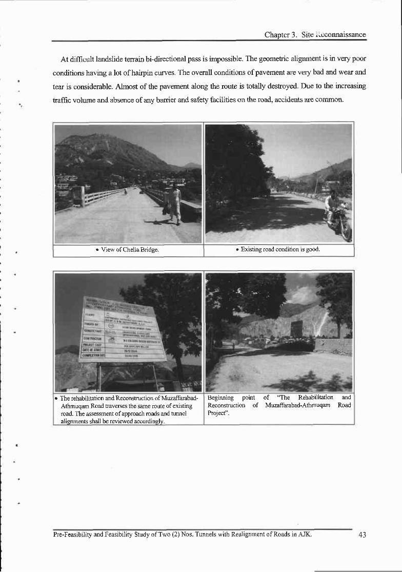
Chanter 3. Site iiuconnaissance
At difiicult landslide tenain bi-directional pass is impossible. The geometric alignment is in very poor
conditions having a lot of hairpin cruves. The overall conditions ofpavement are very bad and wear and
tear is considerable. Almost of the pavement along the route is totally destroyed. Due to the increasing
traffrc volume and absence of any barrier and safety facilities on the road, accidents are common.
o View of Chella Bridge. r Existing road condition is good.
. The rchabilitation and Reconstruction ofMuzaffarabad-Athrnuqam Road haverses the sarne route of existingroad. The assessment ofapproach roads and turutelalisrments shall be reviewed accordinslv.
Beginning point of "The Rehabilitation andReconstruction of Muzaffarabad-Athmuqam RoadProiect"-
Pre-Feasibility and Feasibility Study ofTwo (2) Nos. Tunnels with Realignment ofRoads in AJK. 43
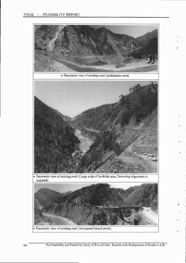
tFINAL ,: , - - ,FEASIBILITY REPORT
. Panoramic view of existing road (problematic area).
. Panoramic view of existhg road. (Large scale oflandslide area, Detouring alignments isreruired).
. Panoramic view ofexisting road (Anticipated n-rnnel portal)
44 Pre-Feasibility and Feasibility Study ofTwo (2) Nos. Tunnels with Roalignment ofRoads in AJK.

Chaoter 3. Site Reconnaissance
E Comments on Design Standards
In order to cater to the road fimction of existing road, it needs improvement of alignment and
upgading. Designing the access roads, local criteria (NHA, NWFP standards) will be as design
standards. In additio4 the design will be based on the criteria and specifications set out by intemational
design rules and regulations or as otherwise agreed with the client.
According to TOR (Terms of Reference) AASHTO will be considered for the geometic design of
stuctues. Road Design Criteria is as follows:
r Pavement width :
o Shoulder width :
7.3m
3.0m
(Either side) Treated
. Design speed : 50krn/ hr (Mountainous Terrain)
The described deign criteria must be reviewed since the road with over specifications, like
extraordinary carriageway or formation widt[ would entail heary side hill cut, thereby generating huge
volumes of spoil, increased destabilization of shaken slopes and other soil strata. Adoption of
unnecessarily wide and exc€ssive desigr speed will be neither feasible nor desirable.
Pre-Feasibility and Feasibility Study ofTwo (2) Nos, Tunnels with Realignment ofRoads in AJK. 45
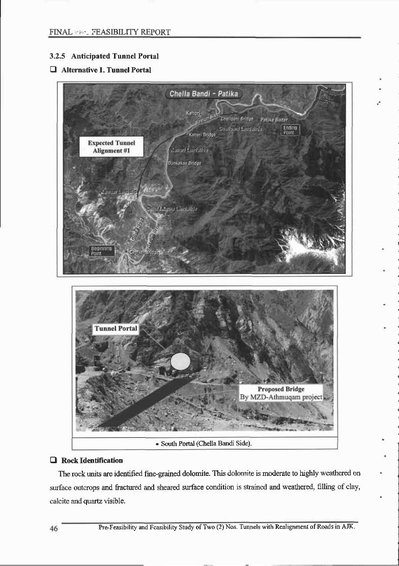
FINAL ',;','- FEASIBILITY REPORT
3.2.5 Anticipated Tunnel Portal
E Alternative l. Tunnel Portal
. South Portal (Chella Bandi Side)-
O Rock Identification
The rock rmits are identified fine-grained dolomite. This dolomite is moderate to hig$y weathered on
surface outcrops and fractured and sheared surface condition is strained and weathered, filling of clay,
calcite and quartz visible.
Pre-Feasibility and Feasibility Study of TVo (2) Nos. Tunnels with Realignment ofRoads in AJK.
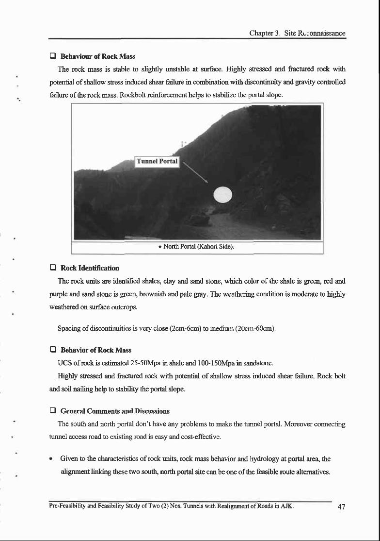
Chapta 3. Site Rc; onnaissance
E Behaviour of Rock Mass
The rock mass is stable to sliglrtly unstable at surface. Higbty stressed and fractured rock with
potential ofshallow stress induced shear failure in combination with discontinuity and gravity contolled
failure of the rock mass. Rockbolt reinforcement helps to stabilize the portal slope.
. North Portal (Kahori Side).
fl Rock ldentification
The rock unie are identified shales, clay and sand stone, which color of the shale is geen, red and
purple and sand stone is greeq brownish and pale gray. The weathering condition is moderate to highly
weathered on surface outcrops.
Spacing of discontirnrities is very close (2cm-6cm) to medium (20cm-60cm).
E Behavior of Rock Mass
UCS of rock is estimated 25-50Mpa in shale and 100-150Mpa in sandstone.
Higbly stessed and fractured rock with potential of shallow stress induced shear failure. Rock bolt
and soil nailing help to stability rlrc portal slope.
E General Comments and Discussions
The south and north portal don't have any problems to make the tr.uurel portal. Moreover cormecting
tunnel access road to existing road is easy and cost-effective.
. Given to the characteristics ofrock units, rock mass behavior and hydrolory at portal arca, the
alignment linking these two soudr, norh portal site can be orre ofthe feasible route altematives.
Pre-Feasibility and Feasibility Study of Two (2) Nos. Tunnels with Realignment ofRoads in AJK. 47

FINAI .].'FEASIBILITYREPORT
3.2.6 Pavement
fl General Comments and Discussion
The overall conditions of pavernent are very bad and wear and tear is considerable. Almost of the
pavement along the route is totally destroyed. Given Rehabilitation and reconstruction of this road
section is scheduled by Mwaftarabad-Athmuqam road projec! the study team will review the design
drawings and PC-l ofthe mentioned projects.
The black top pavement is lacking maintenance with numerous surface damages. Therefore, it
has been planned to improve the enti.re pavement of Chella Bandi to Patika road section to
enhance stabilrty of the road structure and in view of the projected taflic volume gowth and
user benefits.
A common practice for the design of new pavement in Pakistan is to follow the procedure,
reconmended in Overseas Road Note 31(Fourth Editioa Overseas Center, TRL 1993), titled
"A Guide to the structural design of bitumen-surfaced road in tropical and sub-tropical
countries". In this project, recommended pavef,nent sf,uctures in Road Note 31 or AASHTO
will be adopted for the pavement design.
. Pavements are completely deteorated due to the heavyaxle load- Door maintenance and poot &ainage system.
. Bitumen and fine aggegates are completely segregated.ReDavement is required.
3.2.7 Retaining Structures
E General Comments on Retaining Walls
Several cases were observed of masonry wall mder construction in which the base was partially
placed on firm bedrock and the remainder on colluvium subject to large settlements. It is therefore likely
that difFerential setdement will crack the un-rehforced masonry. Several failures of retaining walls were
obsewed which displayed obvious signs of piping both under the structure and around the end wing
walls. Cracks indicative of overhming suggest that the wall design was inadequate for the materials
used as bacldll, inadequate provision was made for previous gravel dmbs to dissipate high pore
48 Pre-Feasibility and Feasibility Study of Two (2) Nos. Tunnels with Realignment ofRoads in AJK.

Chapter 3- Site P.econnaissance
pressues- In no case were ground wat€r int€rc€pt henches observed under consnrrction which would
reduce seepage pressure and increase the effective stsength of the bacldll by lowering pore prcssures.
Not one case was observed whoe any design measures were erployed to attenpt to control landslides.
c In the middle ofrnortared masonry rctaining wall,conveir planes can be seen. Reinforcement is requiredimmediately axle load, poor maintanance and poordrainase system.
o Two deep and wide longitudinal cncks have developed.Some parts was missing. If the retaining waU is high,mortared masonry wall carurot su$ain the loads.
Pre-Feasibility and Feasibility Study ofTwo (2) Nos. Tunnels with Realignment ofRoads in AJtrL 49
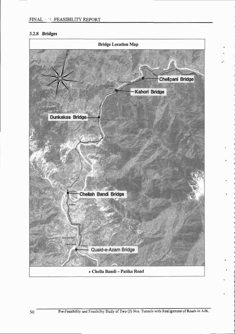
FINAL 'I ,FEASIBILITY REPORT
Bridges
50 Pre-Feasibility and Feasibility Study of Two (2) Nos. T\rnnels with Realignmcnt of Roads in AJK.

Chapter 3. Sitt il-econnaissance
E General Comments on Bridges
If economic evaluation option is improvement of whole alignment with trmnel constuctioq the
repair/ reconstuction and maintenance cost of existing bridge should be included, In this regard the
overall condition survey ofexisting bridge was carried out.
. The general condition of existing Quaid-+Azam Birdge (Prestressed Concrete Girder) Bridge
is good. Only minor repair is required such as concrete barrier, expansion joint, slab deck
pavemenL erc.
o The general condition of Dunkakas Bridges (Prestessed Concrete Girdo) is good. But partial
failure of wing wall drd s€vere scour at abutnent foundation are required to repair.
. Kahori Bridge (Prestessed Concrete Box Girder with Gerber) was damaged at Gerber beam
ledges due to 2005 earthquake, which is repairing by Chinese Contractor of Muzaffarabad
Athmuqam road project. The access road of the first tunnel is to be corurected to the present
Kahori Bridge location.
. Chellpani Bridge (Phi-Type Rahman) was completely damaged by 2005 earthquake.
Reconstruction of this bridge is scheduled by Muzaffarabad-Athmuqam Reconstruction
Program. The new location of Chellpani Bridge will be reviewed to comect the access road of
the second nurnel.
Quaid-e-Azam Bridge Chella Bandi Bridge
o Qtraid-e-Azam Bridge is gaber PSC box gird type.General condition ofthe bridee is fair-
. Ascon d€sk slab shows a couple of potholes andr€pairment is urgent to prerrent conosion of reinforcingste€l and conqste block failure. General conditions ofChella Bardi Bridee is fair.
Pr€-Feasibility and Feasibility Study ofTwo (2) Nos. Tunnels with Realignment ofRoads in AJK.

FINAL. FEASIBILITY REPORT
Dumkas Bridqe Chellpani Bridse
. Super Structure type of the Dumkas Bridge is PSCbeam bridse remaininc cood condition-
o View ofn shqe Rahman bridge to qoss a small deeprallev. Chellpani Bridee.
Che[pani Bridge Chelpani Bridee
r Ascon of desk slab lave been completely fallen outand desk slab has numerous broad cracks
Chellpani Bridge is completely damaged by 2005Muzaffarabad eadhquakes. Pier concrete is exfoliatedand reinforcing bars yielded.
Kahori Bridee Kahori Bridee
o This bridge t'as 3-+an PSC box gider bridge sryended intpmid sran
. At p€salt rclBbilitaion ofbridge is underway..
52 Pre-Feasibility and Feasibility Study ofTwo (2) Nos. Tunnels with Realignment ofRoads in AJK.

Chapter 3. Site Reconnaissance
3.3 General Comments and Recommedation
3.3.1 General Commenk
During site reconnaissance trips of existing Bararkot to Lohar Gali and Chella Bandi to Patika road,
the study team had the opportrmity to see all or at least portions of the roads which have been or are
presently being constructed such as 'Rehabilitation and Reconstuction of Muzaffarabad-Athmuqam
road project including five major bride' in Chella Bandi-Patika road sectior5 Muzaffarabad{hakothi
road and maintenance works at Muzaffarabad- Kohala road.
On the basis of site reconnaissance of these road constuction sites and maintenance conditions of
existing road, the Study Team may comment on the existing Bararkot to Lohar Gali and Chella Bandi to
Patika road as follows:
In its present locatioq desigrr, consfruction and condition of maintenance the existing road will
repeatedly self-distuct at numerous locations during the current and subsequent Monsoon seasons.
Unless several major changes in locatiorq design, and construction are accomplished and a sustained
program ofpmper and timely maintenance is achievd the armual and costly efforts at piecemeal, open-
ended reconstuction which has characterized the project to dae will continue indefinitely. Fwthennore,
the current typical practices of undercutting of landslides, indiscriminate sidecasting of excavated soil
and rock and inadequate drainage and erosion contol will have a progressively increasing, long-tem1
adverse economic and social impact.
In tenain such as the Siwalik Hills and Lower Himalayas, landslide processes are the prirnipal and
decisive factors effecting the feasibility, cost, performance and impact, of roads and other engineering
$rucnues.
Experience in mountainous areas tkoughout the world provides numerous examples of the critical
role of landslides in determining the feasibility, cost and performance of engineering projects. It is not
unusual for unanticipated landslides and/or improper$ diagnosed conditions of instability to increase
the cost of construction by one or wen two orders of magritude (10 to 100 times). Developed industrial
economies can occasionallyjustifo such unanticipated cost over-runs because ofthe surplus productivity
of the economic sector, which the road serves. The overall economy rnay occasionally sustain such
luxury waste.
On the other hand, in the case of developing countries with very limited resources, and marginal
economy, it is especially important that zuch hazards be adequately waluated at the sage of the
Pre-Feasibility and Feasibilrty Study of Two (2) Nos. Tunnels with Realignment ofRoads in AJK. J J
FINAL. ., FEASIBILITYREPORT
feasibilify study to avoid the prospect of the road costing far more in long-term maintenance and
environmental costs than the economy can zustain. An exteme example of this situation may be found
in northem Guatemal4 where in 1957 a newly-paved, 4O-mile mountainous stretch of Inter-Amencan
Highway was closed by landslides one week after the formal opening ceremonies and has since never
reopened.
3.3.2 Location of Route Corridor
Given, Chella Bandi is a fixed starting poinl an4 Patika is a fixed ending poing three relatively stable
altemative routes were identifiod in our sMy. However these altematives are still studying.
3.3.3 Road Alignment
Given the selection ofthe road corridor, however unsupported by geologic data, considerable latitude
nevertheless remained to pennit adjustrnent of the detailed alignment to the major constaints imposed
by the tenain. The great majority of the landslides traversed by the road were dormant slides which
existed prior to road construction Of the several types of slides encountered, most are highly
responsible to the particular route and marurer by which they are crossed. For example, slides with a
sigrificant rotational component may actually be fully stabilized or have their factor of safety increased
by a properly placed and designed road cut or fill. In general, the stability ofrotational slides is actually
increased by the placement of properly designed fills in their toe zones and by removal of material in
their cmwn zone.
Unfortunately, the routine engineering practice of attempting to balance cuts and fills typically leads
to the constuction of cuts across bulges or ridges on slopes which are often the toe deposits of rotational
slides. This practice is, of course, systematically adverse to stability. Similarly, the placement of fills
across swales, declivities or depressions on slopes which have been produced by the displacement of
slide material further reduces the stability ofthe slope through increases in the driving moment.
Given the characteristic bias for firll bench cuts in consruction, it is apparcnt that many of the slides
were tigger€d and others reactivated by irnproperly situated cuts with respect to the preexisting slides
geometry. In many cases, a shift in detailed road alignment of less than 100 m could have entirely
avoided crossing some landslides or could have crossed them in a marmer which would have
contibuted to their stability.
Pre-Feasibitity and Feasibility Study ofTwo (2) Nos. Tunnels with Realignment ofRoads in AJK.
Chapter 3' Site Reconnaissance
3.3.4 Road Design'
Q Design "standards" (Width, Grade, Turn Radii)'
The desigrr standards which have r€ached advanced stages of consfiuction appear to be intemally
inconsistent. while there has generally been at attempi to keeP longitudinal grades to 8 percent or less'
longstretchesofroadhavebeenconstuctedatgradesof6percentorlesswithinrmstablezones.This
inconsistentandinappropriatedesignhasdiscardgdavaluableopportunitytogainelevationsoasto
minimize the length of road within slide prone areas'
Similarly,unnecessarilywidestetchesofroadarecombinedwithbarelyminimumtumradii,and
overly wide sections have been cawed across the lulnerable toes of large, pre-existing rotational slides'
E D€sign of Road Cuts
In the coruse of our investrgation we have observed not a single case in which the desigrr of the
roadcutatalands| idecrossingwasinanywaymodif iedtodealwithaproblemofinstabi l i ty.
Particularlyinlandslide-pronetefrai'litisnecessarytorecogrrizethelimitationsandconstraints
imposed hy nature and to avoid unnecessarily ambitious road standards'
The road design, including its detailed alignment, must be primarily directed at landslide avoidance'
stabilization and the non-aggravation of existing or potential landslide Hazards; whenever necessary' the
road grade should be "rolled" to conform to the terain insofar as possible, and cuts and fills must not be
..balanced,,inasimplisticwaybasedonanillusory@onomyinhaulandexcavationcosB.Whenever
landslides are anticipated on the basis of a geotechnical study of the selected rcute corridor' the design
for that section of rcad must then be primarily directed toward the solution of anticipated stability
problems.
D Drainage ofRoad Surface'
The existing road has been uniforrnly in-sloped with the surface drainage directed toward drainage
ditches constructed at the base ofthe road cut'
An in-slope road presumes that the drainage ditctr will firnction as designed. This presumption has
been consistently erroneous. Raveling of the road cut, even in the dry season' has obsftrcted and even
buried the inner edge of the road as well as tho drainage ditch. These ditches were plugged at numerous
localities. With the fust heaw Monsoon rains, when fimctioning drainage ditches are requird
superficial slides or more massive failures of the cut face have insured their non-performance' If
essential maintenance cannor be accomplished during the dry seasoq how can it be guaranteed during
55
I

FINAL- .FEASIBILITY REPORT
Monsoon storms when portions of the road will not even be assessable.
One ofthe claimed theoretical advantages of in sloping is that erosion is reduced by preventing
runoff from reaching the natural hill-slope surface below the road. Instead, it is supposed to be
controlled in specially designed ditches and culverts. In real-world applications, however, with real
rock cuts, which are subject to small failures during the mission, the runoff is free to erode and
saturate not only the road surface but the native material at the base ofthe cut.
The runoff, d.eived from both direct rainfall interception by the road surface, ol'erland flow
coming from the ground surface at the top of the cut and seepage fiom draining uniformly offthe
outer edge of the road. Instead, the cumulative flow has been directed generally along the aris of
the road for distances up to 100m due to inadequately spaced and unprotected cross drains. In the
case of almost every significant mapped landslide crossed by the existing road, cumulative road
drainage was firnneled into the landslide mass due to the practice of in-sloping, inoperable plugged
drainage ditches, and plugged cross drains. The irrigated landslide material of course has a lower
effective stength than it would have under conditions of normal interception and information.
In contrast, were the road outsloped, a lower road cut would be constructed, and runoff would
not be cumulative regardless of superficial failures of the cut. Even if portiors of the road were
completely inaccessible for maintenance during periods of intense storms, the road would not self-
destruct as it now does. Stability would not progessively deteriorate even if access and
maintenance were ternporarily impossible.
B Culverts and Cross-Drains
Major problerns are progressively developing at the $eat majority of culverts and cross drains
prirnarily as a result of grossly improper design. Accepted enginee.ring practice, especially in steep
mountainous terrain with high stream discharge bedload, requires that the culverts be so positioned that
their gra.dient approximately matches the gradient of the natural channel in order to minimize the height
ofthe free drop at the outfall.
At alrnost all of the culvert installations on the existing road, the gadients are substantially less than
the natural slope, resulting in free drops which commonly o<ceed 5 m and occasionally exceed 8 m. the
enhanced scouring power of zuch outfalls has already caused severe erosion problems on the general
slope and channel below the road. Furthermorg the sharp reduction n gaAierrt of fue flow entering the
culvert has generally caused the deposition of bed load which has partially or completely plugged the
Pre-Feasibility and Feasibility Study ofTwo (2) Nos. Tunnels with Realignment ofRoads in AJK.

Chapter 3. Site Reconnaissance
culvert entrances- This has frequently caused piping failures in the culvert backfill and severe erosion of
the roadway with zubsequent failure ofthe adjacent road cut.
Another design problem frequently connected with the orientation of culverts and especially cross
drains is the frequently observed sharp bend in axis (plan view) at their enrance. In some cases the cross
drain is nearly at right angles to dre road axis which fi.rther encourages deposition and plugging of
drafus.
Not a single culvert or cross drain has been equipped wittr a debris rack, despite the obvious problem
ofplugging by tree branches, logs, boulders, cobbles, and finer sediments accumulating behind the dam.
Rarely has any provision been made for effective energy dissipaters at the outfall ofculverts and cross
drairs to control erosion. Many cases of obvious over sizing of culverts were observed without any
apparent rationale. Most of these same culverts were nevertheless plugged due to the other design
deficiarcies described above.
O Retaining Walls
Although very impressive in their scale, number and amount oflabor invested in construction, many
of the masonry retaining walls are improperly designed for their foundations. Most of the retaining walls
appear to have been designed as gravity walls with a sharp increase (cantilever) in their back slope near
the top. No reinforcing steel was used in those which we observed under corstruction.
Several failures of retaining walls were observed in both sites which displayed obvious signs of
piping both under the structure and around the end wing walls. Cracks indicative of overtuming suggest
that the wall design was inadequate for the materials used as backfill, inadequate provision was made
for previous gravel drains to dissipate high pore pressures, and inadequate and poorly placed weep holes
and inadequate keying-in ofthe ends of the walls in native material, so as to intemrpt and resistance to
Several cases were observed of masonry walls under constuction in which the base was partially
placed on firm bedrock and the remainder on colluvium subject to large setdements. It is therefore likely
that differential settlement will crack the unreinforced masonrv.
In no case were ground water intercept henches observed rmder constructior5 which would reduce
seepage pressure and increase the effective stangth of the bacldrll by lowering pore pressures.
F€asibility Study ofTwo (2) Nos. Tunnels with Realignment ofRoads in AJK-

Q Stope Stabitization
Not one case was obsewed where any design measures were employed to attempt to contol
landslides except breast gabion wall.
Q Subsurface Drainage
The haphazard use of weep holes in a variety of stuctures ranging ftom poor placement near the top
retaining walls, irregular qpacing or their complete absencg combined with the absence of gravel drains
which the holes were intended to serve, suggests a general lack of understanding ofthe role ofpore and
seepage pressrues and the importance of subsurface drainage desigr in earthwork engineering.
3.3.5 Road Construction
Q Lack of Adequate Construction Specifications and/or Compliance Inspection
Numerous examples were observed of uncontolled fills being placed by hand or by bulldozers as
backfill over culverts and behind retaining walls. Tree tunks, limbs, lenses of organic topsoil, and of
coarse rock fragnrents may be observed. lf the retaining walls have a high enough safety to
accommodate such indiscriminate conslruction practices, they are unnecessarily over-desigrred. If not
they are very badly constructed.
Q Culvert Construction
The common practices of indiscriminate side casting of debris, the lack of erosion conffol and
drainage energ' dissipaters, lack of gully contol, the tiggering of new slides and the reactivation of
dormant slides, coupled with the complete lack of any landslides stabilization measwes have produced a
very significant adverse environmental effect on stream sediment loads.
3.3.6 Maintenance
To this date there has been no program ofpreventive maintenance. On the other hand, many sections
of existing road, particularly where landslides are crosse4 have experienced sweral cycles of seasonal
cons'huction and reconstruction. This has also been the situation at many culverts and retaining walls.
The most alarming conditions were found at cuTvert and, cross drain entrances, the great majority of
which were inoperable just prior to the Monsoon season as a result of being completely or partially
plugged widr logs, boulders cobbles, and finer debris. The urgent need to clean out these drains and to
protect the entrances with suitably designed debris racks is required.
Pre-Feasibility and Feasibility Study ofTwo (2) Nos. Tunnels with Realignment ofRoads in AJK.

Chaoter 3. Site I | )onnaissance
3.3.7 Recommendation for I)rainage Protection of Unstable Area
During our recoruraissance trip, in no case were drainage facilities observed except culverts and
bridges. However only drainage facilities can do protect the unsable area efficiently without hampering
the economy. A briefofdrainage protection ofunstable area are described in the following paras:
0 Spacing and Placement of Culverts and Water Bars
Il order to reduce the infiltratio4 ground water pore pressures and erosion of unsnable materials
during critical storm periods, it is highly desirable to intercept drainage along the axis of the road at
frequent intervals and to carry the discharge across the road at spill points most able to resist landslide
failure and erosion. The flow volume which is discharged at any single point on urstable, unprotected
slopes should be contolled by the out sloping ofthe road with frequent use of water barq slope drainage
intercept trenches and culverts. Wherever roads are in-sloped, crossroad drains should be provided at
intervals of 30m or less. Where distance to the nearest culvert exceed 30m water bars should be
constructed to limit the cumulative volume of longitudinal drainage.
E Hilside Surface Runofr Diversion
Landslides usually develop open fractue systems which unfortunately have the capacity of rapidly
infiltrating and transnitting large quantities of water, which may grcatly elevate pore pressures along
critical slide surfaces. One of the most effective and least expasive methods of enhancing slope
stability is to reduce the amount and rate of infiltation of surface nmoff by appropriate surface water
diversion stuctures. Depending on local soil and rock conditions, slope inclinatioq and the availability
and cost of materials and labor, open unlined diversion trenches, trenches lined with flexible membraneg
trenches bacldrlled with highly pervious rubble with or without pervious pipe may be employed.
E Subsurface Groundwater Intercept Drains
Such measures, desigred to intercept subsurface goundwater flow and to reduce pore prcssures
within a limited "downslope" of the dmin are effective in applications such as increasing the effective
strength of the critical toe of a landslide or to redirect seepage paths and remove adverse seepage
pressure form the free face ofan artificial cut.
An example of a simple intercept drain which would be feasible on the existing road consists of a
deep trench lined with a permeable membrane and backfilled with select highly pervious rubble. Where
large flows are to be intercepted, a perforated pipe may be placed near the bottom of the trench. A
longitudinal gradient of at least l5 percent should be maintained.
Pre-Feasibility and Feasibility Study ofTwo (2) Nos. Tunnels with Realignm€nt ofRoads in AJK. 59
FINAL FEASIBILITY REPORT
E Counterfort Drains
These structures, commonly called "French drains" or'rtrench drains", are often effective in
achieving a limited reduction in pore and seepage pressures on the face of exposod cuts, The trenches,
normally limited to a width of 1m to 1.5m are usually oriented perpendicular to the slope or
appmximately normal to the road axis. The tenches are filled with highly pervious, more or less
uniforrnly sorted rubble. A perforated pipe sub drain may be installed where large discharges are
expected. When necessary to prevent progressive piping, a filter membrane or graded aggregate filt€r
may be placed between the native material at the sides and base of the tench and the coarse rubble
bacldll.
Altlnugh the maximum possible grormdwater draw down is, of course, limited to the depth of the
tenclL significant impovement in sfength may nevertheless be achieved by localized lowering of pore
pressures and by redirection ofseepage forces toward the drain rather than downslope.
To stabilize large masses, several counterfort drains may installed in a parallel array with spacing
varying between 3m and lOm depending on the permeability of the native materials and the general
draw down of pore pressures that is required. It is necessary to provide and adequately desigred open
charmel and/or zubsurface drain to safely and effectively handle the crmulative maximum discharge of
tlre drain system
E Horizontal Drains
Horizontal drairs have much the same function as counterforl draim but consist of bore holes 8cm to
l5crn in diameter lined with perficrated pipe. They are typically irstalled perpendicular to the face ofthe
cut they are pfotecting, are inclined at an angle ofat lesst 5 to 10 degrees so as to insute free draining
toward the exposed face. ftr ordinary applications, they are typically 30m. or morc in length and are
spaced at 3m to 6m intervals. P.V.C. plastic is an increasingly popular material for such irstallations due
to its corrosion resistance. Provision is made for access by high pressure water jets used to periodically
flush and clean the pipes.
E Drained Buttesses
These sfructures are usually desigred to serve several simultaneous flnctions, each of which add to
the factor of safety against sliding.
o The mass of the butfesses is usually constructed of dense, high frictional strength, well-drained
aggregate materials. The resulting mechanical swcharge mobilizes frictional strength while
providing, in the case of deep rotational slides, a mechanical movement which counteracts the
Pre-Feasibility and Feasibility Study wo (2) Nos. Tunnels with Realignment ofRoads in AJK.

tr
Chaoter 3. Site Reconnaissance
driving movement generated at the head ofthe slide.
Deliberate interruption of the failure surface itself with artificially placed high stenglh material
subject to strain hardening. Particularly in the case of slip surlaces lined with clay or other low-
stength materi4 a mass of dense, high frictional strength aggregate is placed so as to replace
weak material and force future shear displacements through the aggregale. Sufficient buttress
height is designed to insure adequate confining pressure (nomal stress).
The placement of an embanlcnent without special provision for basal and intercept drairs would
result in the general rise in the water table oward and into the ernbalknent This would destoy
a significant portion of the strenglh (as much as 50%) gained through the increase in confning
pressure along the base of the retaining wall. In fact, undo hydrogeologic conditions corffnor y
encountered near the toes of landslides. On the other hand, the incorporation of a properly
designed blanket drain extending along the base and up against its upslope contact with the
native material will insure the safe dissipation of all excess pore "uplift" pressures, whether
"normal hydrostatic" or artesian.
Fully-Drained Buttresses
The use ofgabion modules, already being effectively used to a limited extent on the existing road,
is an admirable example of a cost-effective "appropriate technolory" well suited for corstruction
in landslide terrain. Gabion retaining walls and buttesses not only permit the placement of a high
suengtb high-density buttress on stee? slopes in excess of the angle of repose of ordinary
ernbanknent materials, but have the major design advantage ofbeing free draining. Although we
observed gabions in currtrrt use as retaining walls and as entire supporting structures for the
roadbed itself, we were puzzled to not a single example of their application as a buttress or
landslide control structu€. We stongly recommend their extensive use on the cut slope side of
the road as a method ofdraining and supporting unstable cutslopes and landslide toes.
In additio4 low gabion buttresses or platforms may be utilized in an funovative procedure which
would be particularly applicable to those situations in which the sliding surface daylights above
the level ofthe road
Slide debris is removed from the cut slope and a platform excavated above a surface inclined
slightly upward which projects from the road platform into the slide material. Such excavation
should be perfonned during the middle of the dry season when the local water table is
approaching its minimal annual level.
- A low broad gabion buthess is constructed from the planned inner edge of the road toward the
Pre-Feasibility and Feasibility Study ofTwo (2) Nos. Tunncls with Realignment ofRoads in AJK. 6l

FINAL . .- -FEASIBILITY REPORT
maximum inner edge of the excavated slide debris. The buttress may range from one to two or
more layers in height, depending on the specific geotechnical properties of the material and the
geometric configwation of the site.
Any funre slide displacements will deposit debris over the low gabion embankment, partially
burying it and insuring its effrcient dewatering.
The slide rubble will thus be provided with a basal drain and given a reasonable range in its
permeability, will fir(rction as is own growing buttess as fi;rther slide incremene tansport
additional material to and over the buttess. (See accompanying sketch)
New Positionol Walerlabl€ Boundary ol E)lcavat€d Sl;de oeoosit
Original Posilion ol Road Cut
Origlnal Posilion ol Toe ol Slide Debris
SlLdo mEbbl€- ^/ OJtslooed Boad Suttace_ Foa4
Natura, S,ooes
LandSlide
Section sidn' s{,i*
F u b b r o t t | . n h r . . c 6 r d d r l n " _ _ _ _ - _ \ " - - -
New Position ot Stide Toe
62 Pre-Feasibility and Feasibility Study ofTwo (2) Nos. Tunnels 'xith Realignment ofRoads in AJK.

Chapter 4. Traffic Analysis
Chapter 4. Traffic Analysis
4.1 Overview of Tralfic Analysis
4,1,1 Objectives of Tralfic Analysis
The objectives of this project are to solve a regional isolation during winter and monsoon
seasons by constucting a tunnel to connect mountainous tenzin between Muzaffarabad in AJK
and outer regions and contribute to the regional development through providing safe and rapid road
networks and reducing distribution cost.
This site, where tle earthquake occuned in 2005, requires safe regional road networks because
ofthe possibilities ofthe landslides and the frequency ofthe earftquakes.
Accordingly, the tra{Iic analysis has purposes to forecast the future traffic volume for the target
year through analysis of the curr€nt faffic conditions, and to determine the optimal number of
traffic lanes and construct efficient road svstem.
4.1.2 The Proposed Roads and Road Network of Muzaffarabad
Bararkot - Lohar Gali road is the portion of the main highway connecting Muzaffarabad with
Gari Habibullah (L=26km). The starting point of Bararkot is located near the border line of
Pakistan and AJK tenitory and the ending point is Lohar Gali connecting to the Muzaffarabad city.
The pmposed road connecting to Abbottabad and Mansehra (NWFP) is one of four main roads of
Muzaffarabad city such as;
- Muzaffarabad - Kohala Road (L=35km)
- Muzaffarabad - Chakothi Road (Ld2km)
- Muzaffarabad - Gari Habibullah Road (L=261ro;
- Muzaffarabad - Athmuqam Road (80km)
lf Muzaffarabad Kohala road is blocked, this route is the only way linking Islamabad,
Rawalpindi, Lahore with Muzaffarabad.
Chellah Bandi Patika road is about lSkm running along the bank of Neelum River. Chellah
Bandi is located near Chellah Bridge in Muzaffarabad. The proposed road is the portion of the
main road connecting Muzaffarabad with Athmuqam (L=80km). ln other words the proposed road
is main road linking Muzaffarabad with Neelum District. This route is a gateway to Neelum Valley
as well as imoortant militarv road.
Pre-Feasibility and Feasibility Study ofTwo (2) Nos. Tunnels uith Realignment ofRoads in AJK. OJ

FINAL' . . - .FEASIBILITY REPORT
Current Conditions of tle Road Network in Muzaffarabad
Pre-Feasibil i ty and Feasibil i ty Study ofTwo (2) Nos. Tunnels with Realignment ofRoads in AJK.
Chapter 4. Traffic Analysis
4.2 Survey and Analysis of the Current Traffic Conditions
4.2,1 Overview of Traffic Survey
The purpose of traffic survey is to analyze the current level of service by investigating the
curent trafftc conditions, the road geometry, and the curent traffic flow ofthe project area.
The result ofanalysis for the cunent taffic conditions is used as basic data in forecast the future
traffic demand, which include traffrc volume, tuming traffic volume for the intersections, and O/D
survey.
The survey of traffic volume has been performed at 6 spots for 2 days to minimize weekly
deviation, and the average value is applied for analysis.
Tuming traffic volume of the intersection has been examined by analyzing the traffic volume of
each direction, and then analyzing the total ffamc volume in the intersection. From this analysis of
tuming traffic volume, fte level of service was determined.
O/D survey was carried out to investigate origin, destination, vehicle composition, purpose of
trip, and number ofpassengers by the interviews conducted on the road side.
4.2.2. Description of Traffic Survey
E Traffic Volume Counts by Street
r Objective of the survey : Identifying peak hour and traffic delay rate for each road in the
networh conection oftraflic volume in intersection, basic data in forecast of future traffic
volume.
o Survey Dates : June 30, 2009(Tuesday) - July l, 2009(Wednesday) : 2 Days
Survey Method : Traffic counts for 16 hours(06:00-22:00)by Surveyor
Survey Location r 6 (Domel Bridge, Tanga Adda Road, Neelum Valley Road, Alama
Iqbal Bridge(Neelum Bridge), Chellah Bandi Bridge, Lohar Gali)
Vehicle Composition : 7 Vehicle types(Motor cycle, Passenger car, Minibus, Large bus,
Small truc( Medium truck, Large truck)
Pre-Feasibility and Feasibility Study ofTwo (2) Nos. Tunnels with Realignment ofRoads in AJK.
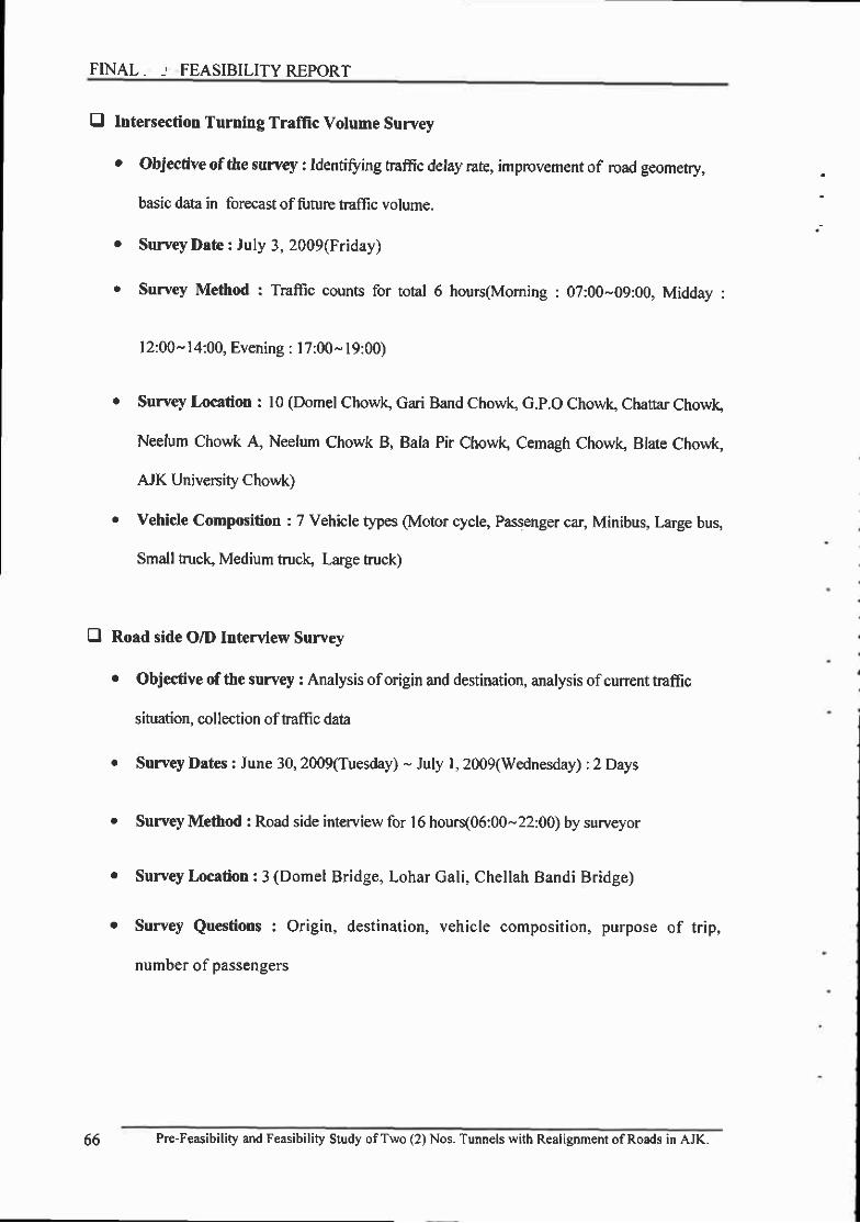
FINAL. -' FEASIBILITY REPORT
E Intersection Turning Traffic Volume Survey
r Objective of the survey : ldentiffing traffic detay rate, imprcvement of road geometry,
basic data in forecast of future traflic volume.
e SurveyDate: July 3, 2009(Friday)
. Survey Method : Traffic counts for total 6 hours(Moming : 07:00-09:00, Midday :
l2:00- l4:00, Evening : l7:00- l9:00)
. Surve.y Location : l0 (Domel Chowlq Gari Band Chow( G.p.O Chowls Chattar Chowk
Neelum Chowk A, Neelum Chowk B, Bala Pir Chowlg Cemagh Chow( Blate Chowk,
AJK University Chowk)
r Vehicle Composition : 7 Vehicle types (Motor cycle, Passenger car, Minibus, large bus,
Small truclq Medium truclg Large truck)
E Road side O/D Interview Survey
o Objective of ttre survey : Analysis oforigin and destination, analysis ofcurrent traffic
situation. collection of traflic data
. Survey l)ates : June 30, 2009(Tuesday) - July l, 2009(Wednesday) :2 Days
. Survey Method : Road side interview for l6 hours(06:00-22:00) by surveyor
o Survey Location : 3 (Domel Bridge, Lohar Gali, Chellah Bandi Bridge)
o Survey Questions : Origin, destination, vehicle composition, purpose of trip,
number of passengers
66 Pre-Feasibility and Feasibility Study ofTwo (2) Nos. Tunnels with Realignment ofRoads in AJK.

fl Traffic Survey
otr
\
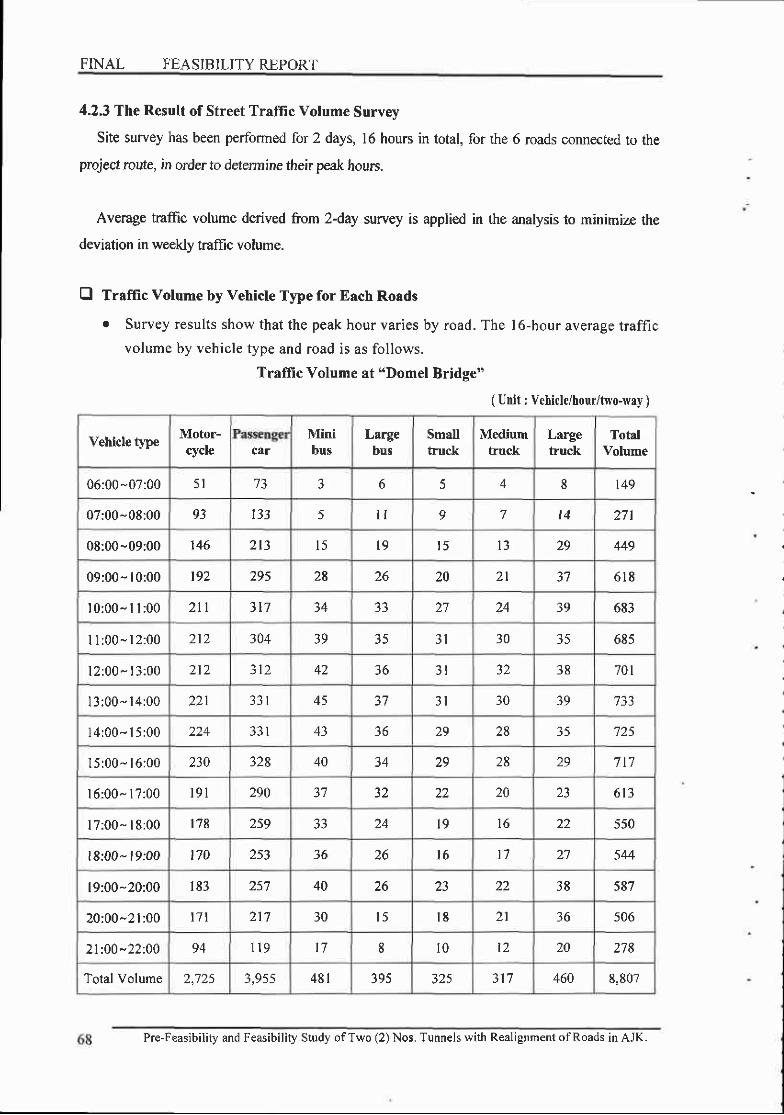
FINAL FEASIBILITY REPORT
4.2.3 The Result of Street Traffic Volume Survey
Site survey has been performed for 2 days, 16 hours in total, for the 6 roads connected to the
project route, in order to determine their peak hours.
Average traffic volume derived from 2-day survey is applied in the analysis to minimize the
deviation in weekly traffic volume.
E Traffic Volume by Vehicle Type for Each Roads
r Survey results show that the peak hour varies by road. The | 6-hour average traffic
volume by vehicle type and road is as follows.
Traffic Volume at "Domel Bridge"
( Unit : Vehicle/hour/two-way )
Vehicle type Motor-cycle car
Minibus
Largebus
Smalltruck
Mediumhuck
Largetruck
TotalVolume
06:00-07:00 5 l 3 b f, 4 8 t49
07:00-08:00 93 l ) J 5 l t o 7 t4 271
08:00-09:00 146 213 l 5 l 9 t 5 29 449
09:00- l0:00 t97 zv) 28 zo 20 2 l 618
l0:00- I l :00 2t l 317 34 J J 27 24 39 683
I I : 00 - l 2 :00 212 304 39 35 . ' I 30 35 685
l2:00 - l3:00 2 lz 312 42 36 3 l 38 701
I3:00- l4:00 271 45 J I 30 39 733
l4:00- I 5:00 43 36 29 28 3 5 7?5
l5:00- l6:00 230 328 40 34 29 28 29 7t ]
l6:00- l7:00 l 9 l 290 1 1 32 22 20 6 1 3
l7:00- l8:00 t78 259 33 l9 t6 22 550
l8:00- l9:00 170 253 36 26 l 6 t 7 27 544
l9:00-20:00 I 8 3 257 40 zo 22 38 587
20:00-21:0O t7 l 2 1 7 30 l 5 l 8 2 l 36 506
2l:00*22:00 94 l l 9 t7 8 10 l? 20 278
Total Volume 2,725 ? q { ( 4 8 1 395 325 317 460 8,807
Pre-Feasibility and Feasibility Study ofTwo (2) Nos, Tunnels with Realignment ofRoads in AJK.

Chapter 4. Traffic Analysis
Vehicle typeMotor-cycle car
Minibus
Largebus
Smalltruck
Mediumrucl(
Largehuck
ToaIVolume
06:00-07:00 60 58 E 8 A 8 l0 156
07:00-08:00 I l 0 1 0 5 t 4 t 4 8 l5 l9 284
08:00-09:00 232 t4 l 45 4 l t7 t3 5 l I
09:00- l0:00 356 218 / f 52 30 l 8 24 773
l0:00- I l :00 451 273 l 3 l 75 r8 l 3 l 5 974
I | :00- l2:00 498 313 t2l 77 l5 8 l0 1,040
| 2:00- l3:00 4 1 8 300 t z J < A l 0 7 't 917
l3:00- l4:00 oz.t 401 l J ) 89 l l 2 1,283
l4:00- l5:00 604 374 t2l OJ 6 J 2 | ,172
l5:00- l6:00 489 381 1 3 8 47 l l 6 7 1,076
l6:00- l7:00 422 283 i l9 6 l l l 7 t 904
l7:00- l8:00 )1i J I 1 8 6 8 9 t9 885
l8:00- l9:00 329 z5) 55 29 7 6 662
l9:00-20:00 313 230 25 l l 8 l0 626
20:00-21:00 303 z5> 49 l 4 t 6 9 22 646
2l:00-22:00 166 t29 27 7 9 5 t2 355
Total Volume 5,646 3,885 1,259 829 184 127 t75 t2,261
)
Traffic Volume at "Tanga Adda Road"
( Unit : Vehicle/hour/two-way )
Pre-Feasibility and Feasibility Study ofTwo (2) Nos. Tunnels with Realignment ofRoads in AJK. 69

( Unit : Vehicle/hour/two-wey )
Vehicle typ€Motor-cycle ctr
Minibus
L,argebus
Smallfuck
Mediumtruck
Largehuck
TotalVolume
06:00-07:00 t02 43 28 9 l 4 l 0 7
07:00-08:00 1 8 5 78 5 l l 7 2J l 9 1' . ) 387
08:00 -09:00 251 l 1 9 95 ) 1 J O 3 l 25 583
09:00 - l0:00 326 t94 l 5 l 36 77 62 871
l0:00- I l :00 364 726 130 25 69 J O 880
I l :00- l2:00 517 282 149 25 68 38 1 , 1 0 9
l2:00-13:00 483 284 l5 t 30 63 40 . ' I 1,080
l3:00- l4:00 581 347 229 36 73 38 27 1,330
l4:00- l5:00 602 355 34 74 l o 2 l |,364
l5:00- l6:00 474 294 187 25 f,f, 26 27 | ,086
l6:00- l7:00 5 0 1 286 96 40 7 l 4l 28 1,065
I 7:00- 18:00 393 87 30 52 36 844
l8:00" 19:00 327 197 68 t8 3 l t7 699
l9:00^20:00 265 ?03 o+ zo 41 zo 20 649
20:00-21 :00 284 203 100 26 46 20 702
2l:0O-22:00 r56 l l l 55 l 4 )s I . ' 386
Total Volume 5,706 3,400 1 ,85 t 405 8 1 5 498 355 r3,245
Traffic Volume at "Neelum Vallev Road"
Pre-Feasibility and Feasibility Study ofTwo (2) Nos. Tunnels with Realignment ofRoads in AJK.
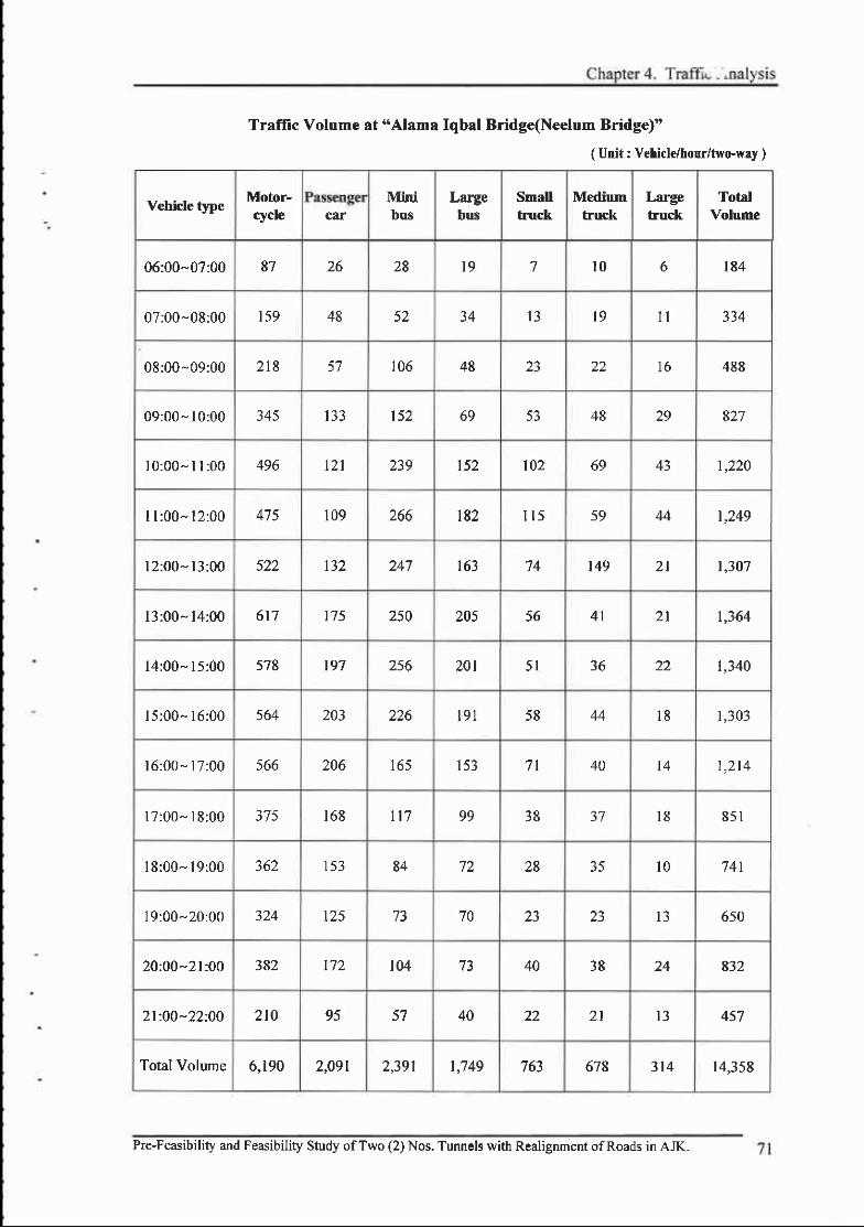
Traflic Volume at "Alama Iqbal Bridge(Neelum Bridge)"
( Unit : Vehicle/horr/fwo.way )
Vehicle typeMotor-cycle car
Minibus
Largebus
Smallhuck
Mediumfuck
Largefuck
TotalVolume
06:00-07:00 87 26 28 l9 7 l0 o 184
07;00-08:00 1 5 9 48 52 34 I J t9 I I
08:00- 09:00 2 t8 ) t 106 48 23 72 l 6 488
09:00- l0:00 345 133 152 69 53 48 29 E27
l0:00* I I :00 496 l2l 239 152 102 69 43 t,220
I l :00- l2:00 475 109 loo t82 I 1 5 59 44 1,249
l2:00-13:00 522 247 l o J 74 t49 2 l |,307
l3:00- l4:00 617 t75 z)u 205 56 4 l 2 l 1,364
l4:00- l5:00 578 197 2.56 201 ) t J O 22 1,340
l5:00- l6:00 564 203 226 191 t 6 44 1 8 1,303
l6:00" l7:00 566 206 l b ) l ) J 7 l 40 I 4 t ,2t4
l7:00" 18:00 375 1 6 8 n7 99 38 37 l 8 8 5 1
l8:00- l9:00 JOZ 1 5 3 84 72 28 J f l 0 741
19:00-20:00 324 125 73 70 t3 650
20:00-21:00 382 t72 104 40 38 24 832
2l:00-22:00 2t0 95 57 40 22 2 l I J + ) t
Total Volume 6,190 2,091 2,391 | ,749 / oJ 678 314 r4,358
Pre-Feasibility and Feasibility Study ofTwo (2) Nos. Tunnels with Realignment ofRoads in AJK.
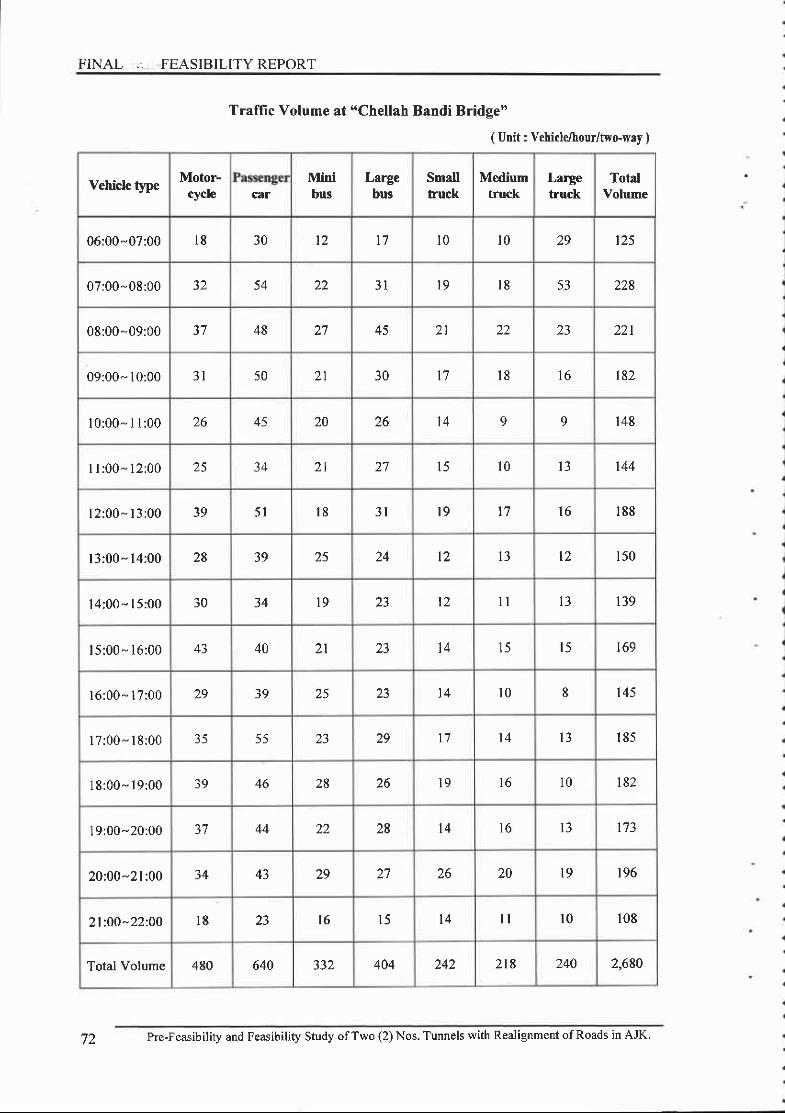
FINAL ,. FEASIBILITY REPORT
Vehicle type Motor-rycle car
Minibus
Largebus
Smalltruck
Mediumtruck
Largetmck
Tot4lVolume
06:00-07:00 l8 30 12 t7 l 0 l 0 29 l z )
07:00-08:00 32 54 zz 3 l t a l 8 53 228
08:00-09:00 48 27 45 2 l 22 221
09:00- l0:00 l l 50 30 l7 l 8 t6 182
l0:00- I I :00 26 45 20 zo 't4 o 9 1 4 8
I l :00" 12:00 25 34 2 l 27 l f l 0 l 3 144
l2:00" l3:00 5 l l 8 3 l t 9 l 7 l 6 1 8 8
l3:00- l4:00 28 39 25 24 l2 t2 1 5 0
l4:00 - l5:00 30 34 l9 l 2 l l I ' 139
| 5:00 - l6:00 43 40 2 l l 4 t5 t5 t69
l6:00 - l7:00 29 39 25 I 4 l 0 8 145
l7:00 - l8:00 J J 5 5 t 7 t 4 1 8 5
l8:00- l9:00 39 46 28 26 l 9 t o 10 l 8 ?
l9:00-20:00 37 44 22 28 t4 l 6 l 3 173
20:00-21:00 34 43 29 27 26 20 t9 196
2l:0O-22:00 l8 l 6 l ) l 4 l l r0 108
Total Volume 480 640 404 242 2t8 240 2,680
Traffic Volume at "Chellah Bandi Bridge"
( Utrit : Vehicle/hour/two-wNy )
72 Pre-Feasibility and Feasibility Study ofTwo (2) Nos. Tunnels with Realignment ofRoads in AJK.

ChaDter 4. Traffic .\nalvsis
( Unit : Vehicle/hour/two-way )
Vehicle type Motor-rycle cor
Minibus
Largebus
Smalltruck
Mediumtruck
Largehuck
TotalVolume
06:00 -07:00 23 24 22 5 t2 t0 l 0 103
07:00-08:00 4 l 43 40 o t9 l 8 1 8 8
08:00-09:00 74 95 49 9 J J 23 T7 299
09:00- l0:00 oz+ 60 55 o 36 22 l ) 255
l0:00- I l :00 96 t 27 90 83 t6 453
I l :00- l2:00 l0 l 108 109 0 t4 25 429
l2:00- l3:00 80 r09 92 0 68 .)J 20 400
l3:00- l4:00 84 89 48 0 47 25 2 l J I J
l4 :00- l5 :00 62 46 45 J 22 l6 8 202
l5:00" l6:00 l ) 53 42 26 t7 l 6 208
l6:00- | 7:00 48 60 +J , 25 25 t5 z t o
l7:00- l8:00 6 t 5 l 30 J I l 6 2 t l
l8:00- l9:00 62 o) 46 J 40 t7 260
l9:00 -20:00 89 2 24 35 17 304
20:00-21:00 59 oz +) 27 22 248
2l:00 -22:00 34 I J I l 8 l 5 t2 136
Total Volume I ,005 1,093 799 J J ) ) / 380 253 4,224
Traffic Volume at "Lohar Gali"
Pre-Feasibility and Feasibility Study ofTwo (2) Nos. Tunnels with Realignment ofRoads in AJK. 73
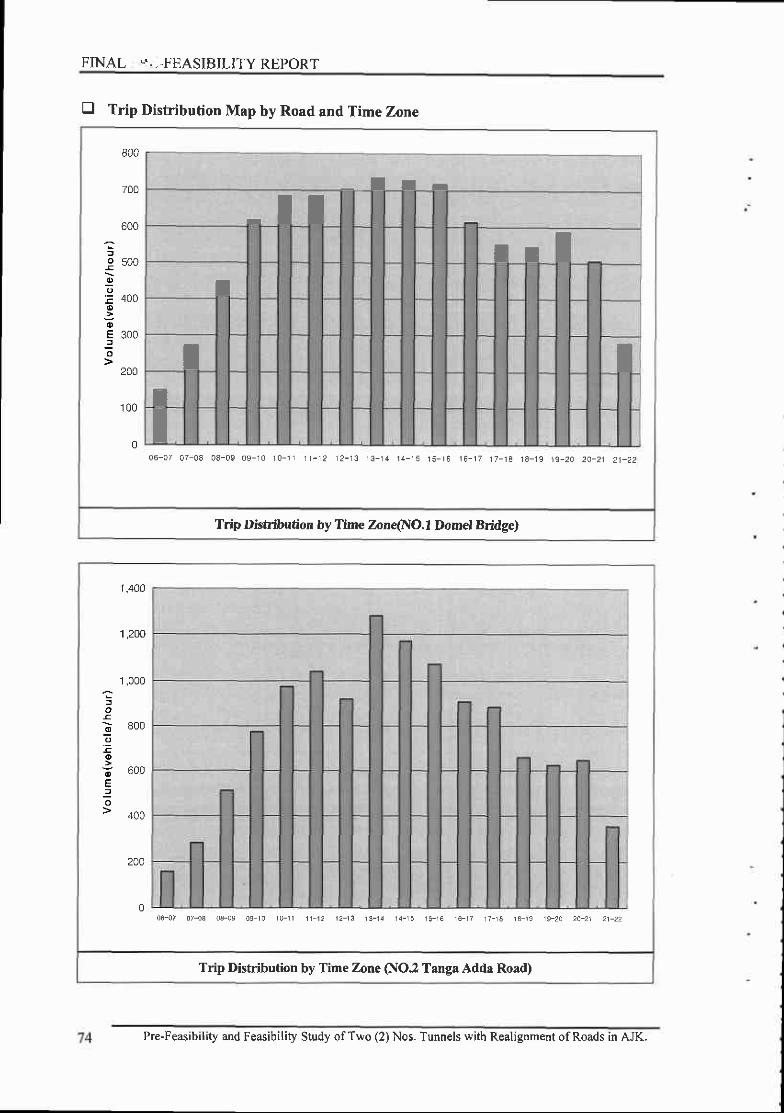
FINAL *.,-FEASIBILITY REPORT
tr Trip nistriUution Map by Road and Time Zone
-c
800
700
600
500
400
300
200
1 0 0
00 6 - 0 7 0 7 - 0 8 0 8 - 0 9 0 9 - 1 0 r 0 - 1 r | - 1 2 1 2 - 1 3 1 3 - . 1 4 1 4 - 1 5 t 5 - t 6 1 6 - 1 7 1 7 - 1 8 1 8 - 1 9 1 9 - 2 0 2 A - 2 1 2 1 - 2 2
Trip Distribution by Time Zone(NO.l Domel Bridge)
- - l I r
I IIr I
T
I TIT
1 ,400
't ,200
'1 ,000
800
600
400
200
0
Trip Distribution by Time Zone (NO.z Tanga Adda Road)
06-07 07-03 03-09 09 r0 10-11 11 t2 12- t3 13-14 14-15 15-15 1€- r7 17-1A 1A 19 19-2D 2A-21 21-22
Pre-Feasibility and Feasibility Study ofTwo (2) Nos. Tunnels with Realignment ofRoads in AJK.

1 ,600
1 ,400
1 200
I
E 800
oE 6006
400
06- 07- 08- 09-07 08 09 10
Trip Distribution by Time Zone (NO.3 Neelum Valley Road)
1 0 - 1 1 - 11 1 1 2
2- 13- 14- 15- 16- 17- 18-1 3 1 4 1 5 1 6 1 7 t 8 1 9
19-20 22
1,600
1 ,400
1,200
o
ID
o
oE;
1,000
800
600
400
200
0
Trip Distribution by Time Zone (NO. 4 Alama lqbal Bridg{Neetum Bridge))
06- {7 07- {3 03-09 09-10 r0 - l i t1 -12 12- i3 t3 - t4 I4_ t5 t5 - t6 t6 -17 17_13 t i_1s 1F20 20 '21 21_22
Pre-Feasibility and Feasibiliry study ofrwo (2) Nos. Tunnels with Realignment ofRoads in AJK.

F INAL , .FEASIB IL ITYREPORT
2- 13- 14- 15- 16- 17- 18- 19- 20- 21-1 3 1 4 1 5 1 6 1 7 1 8 1 9 2 0 2 1 2 2
Trip Distribution by Ttme Zone (NO.5 Chellah Bandi Bridge)
'10- 1 1- 11 1 1 2
06- 07- 08- 09-07 08 09 10
E 150
2220-2120
r 2 - I 3 - 14 - I 5 - 16 - 1 7 - 18 -1 3 1 4 1 5 1 6 1 7 1 8 1 9
Trip Disaibution by Time Zone (NO.6 Lohar Gali )
1 0 - 1 1 -1 1 1 2
06- 07- 08- 0$-07 08 09 10
o
66 ZCU
E zvu
9 ,uo'100
76 Pre-Feasibility and Feasibility Study ofTwo (2) Nos. Tunnels with Realignment ofRoads in AJK.
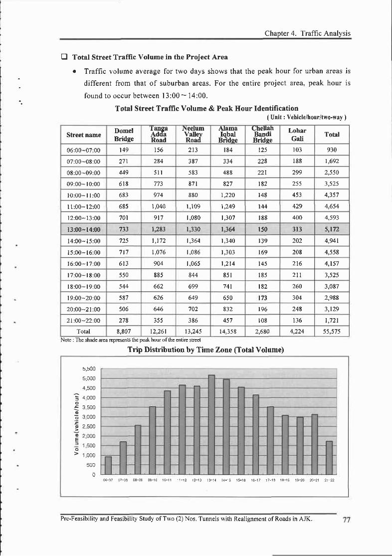
Chanter 4. Traffic Analvsis
E Total Street Traffic Volume in the Project Area
o Traffic volume average for two days shows that the peak hour for urban areas is
different from that of suburban areas. For the entire project area, peak hour is
found to occur between I 3:00 - 14:00.
Total Street Traffic Volume & Peak Hour Identification( Unit : Vehicle/hour/two-way )
Street nameDomelBridge
I angaAddsRoad
N eelumVallevRoed
AlamaIqbal
Bridee
CheuahBandiBridse
LoharGali
Total
06:00-07:00 t49 156 t 8 4 t25 103 930
07:00"08:00 27r 284 3E7 334 228 1 8 8 1,692
08:00-09:00 449 5 l l 583 488 221 299 2,550
09:00" l0:00 6 1 8 871 827 't82 255 1 s t S
l0 ;00- I l :00 683 974 880 |,220 t48 453 a all
l1:00- l2:00 685 1,040 l ,109 r249 144 429 4,654
l2 :00- l3 :00 ?01 9t1 1,080 't,307 IEE 400 r' so1
l3:00- l4:00 1,283 1,330 r,364 150 313 5,t72
l4 :00- l5 :00 ?25 t , 1 7 2 |,364 1,340 I39 202 4,941
l5:00- l6:00 ? t 7 |,076 I ,0E6 1,303 169 20E 4,558
l6 :00- l7 :00 6 t 3 904 I ,065 | ,214 1 4 5 2t6 4,157
l7 :00 ' lE:00 550 885 844 8 5 1 1 8 5 2t l I 5 ? {
I8 :00- l9 :00 544 662 699 741 lE2 260 3,087
l9:00-20:00 5E? 626 649 650 t?3 304 2,988
20:00-21:00 506 646 ?02 832 196 24E l t r o
2I:0O-22:O0 278 355 386 457 1 0 8 1 3 6 | ,721
Total 8,807 t2,261 13,245 14,358 2,680 1r ))4
Note : The shade area rep€sents tle pezk hour of the entire su'eet
Trip Distribution by Time Zone (Total Volume)
5,500
5,000
4,500
4 000
3,500
3,000
25AA
2,000
1 ,500
1 ,000
500
005-07 07-03 03-09 09-10 1o- f i 1 r -12 r2 '13 l3 -1{ 14-15 15-16 16-17 17-14 1A-19 19-20 2A-21 21-22
Pre-Feasibility and Feasibility Study ofTwo (2) Nos. Tunnels with Realignment of Roads in AJK.

FINAL 1 .FEASIBILITY REPORT
E The Current Traflic Volume Condition for the Project Area
o Peak hour (13:00- l4:00) traffic volume for the entire project area is as follows.
r The traffic volume of the Alama Iqbal Bridge was found to be the heaviest
followed by that ofthe Neelum Valley Road and the Tanga Adda Road.
Current Map of the Street Traffic Volume at Peak Hour(13:0(F14:00)
+
ieetun nd
cl{H B0
]oiar6alll
I_qry!.f4dr !9!d-
llomalErtbt
.1, DorEl clrtrrl(C Gdl Band Chowk@ 0xr cmvtrO ctEttar ctDul5) teetutl chowk A
- East ot l€elfn 8fldga ChorJlO le€lun Chouk B
- uest o[ ileelum EdqFO 8da Ptr (lDrlr.O cemash cm|tO Brste cmwkE Nr unrverdu cnour
78 Pre-Feasibitity and Feasibility Study ofTwo (2) Nos. Tunnels with R€alignment ofRoads in AJK'

E Estimation of Night Time Traffic and Daily Traffic Volumes
e PTPS(Pakistan Transport Plan Study) shows rhar 24 hours daily traffic is
estimated as 1.25 times of 16 hours daily traffic (06:00 - 22:00) and for rrucks
conversion factor is estimated as 1.46 times, which is greater than the average forall types of vehicles.
o Therefore, according to the survey, the night time(22:00 - 06:00) traffic volume is
20.3o/o and the night traffic volume for trucks is 31.5% of the daily traffic volume.
o The 24 hours daily traffic volume including the night time traffic volume is asfollows.
The 24 Hour Daily Traffic Volume of the Project Area
The Ratio of 24-Hour Traffic Volume to 16-Hours Traffic Volume
Vehicletwe car
Minibus
Largebus
Pickuphuck
Z-Axlehuck
3-Axletuck
Con-tainertruck
Agri-cultureftactor
Total
Ratio l . l 6(14.0o/o)
l . l I( l 0 . l % )
1 .30(22.9%)
t . ) z
(24j%)1 . 5 3
(34.7o/o)t .5?
(34.0%)t .4 l
(2e.3%)
t.2l( t7. to/o)
t . z5@3Y")
1 .18(15.60/o)
1.46(31.5o/o)
Source : Pakistar TraDsport Plan Study in The Islamic
( Unit : Vehicle/day )
Vehicle tlpe Motorcycle
Passen-gercar
Minibus
Largebus
Smalltruck
Mediumtruck
Largetruck
TotalVolume
Chellah Bandi -
Patika Rotte557 743 391 i 1 '7 J ) J 3r8 350 3, r89
Pre-Feasibility and Feasibility study ofrwo (2) Nos. Tunnels with Realignment ofRoads in AJK.

FINAL. . FEASIBILITY REPORT
4.2.4 Survey Results of Intersection Turning Traffic Volume
E Intersection Turning Traffic Volume Survey Locations
Intersection NO.l Domel Chowk
Picture of Intersection Point Volume (2009, Vehicle/hour)
gt
t_
lr
Intersection Analysis Result
Average Control Delay
(Second/vehicle)LOS
15.2 c
Intersection NO.2 Gari Band Chowk
Picture of Intersection Point Volume (2009, Vehicle/hour)
F
AI
I
I
NC
Intersection Analysis Result
Average Control Delay
(Second/vehicle)LOS
20.0 (-
Pre-Feasibility and Feasibility Study ofTwo (2) Nos. Tunnels with Realignment of Roads in AJK-
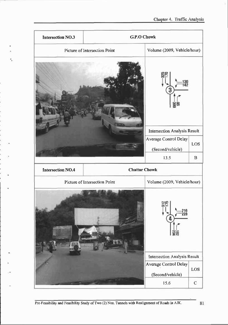
Chapter 4. Traffic Analysis
Intersection NO.3 G.P.O Chowk
Picture of Intersection Point Volume (2009, Vehicle/hour)
o:
t,
Intersection Analysis Result
Average Control Delay
(Second,/vehicle)LOS
13 .5 B
Intersection NO.4 Chattar Chowk
Picture of Intersection Point Volume (2009, Vehicle/hour)
6
Irttt\
\-zrsf-223
lr
lntersection Analysis Result
Average Control Delay
(Second/vehicle)LOS
15.6 C
Pre-Feasibility and Feasibility Study ofTwo (2) Nos. Tunnels with R€alignment ofRoads in AJK.
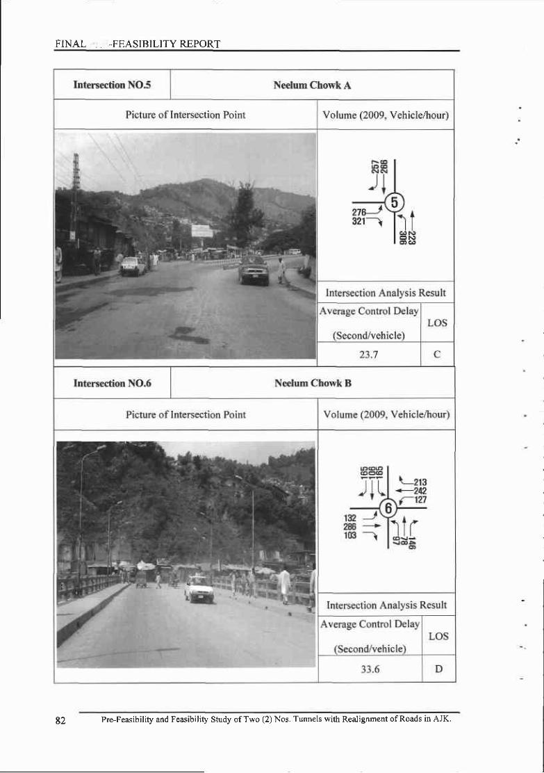
FINAL -, , .FEASIBILITYREPORT
82 Pre-Feasibility and Feasibility Study ofTwo (2) Nos. Tunnels with Realignment ofRoads in AJK.
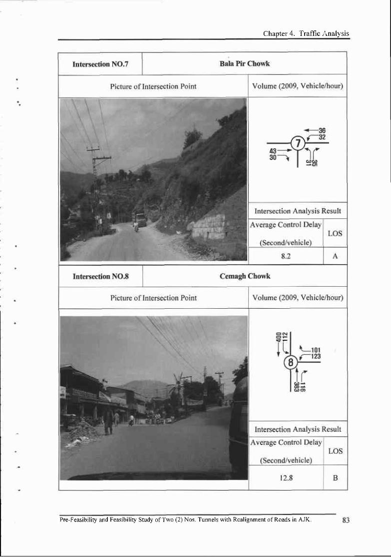
Chapter 4. Traffic I'nalysrs
Pre-Feasibility and Feasibility Study ofTwo (2) Nos. Tunnels with Realignment ofRoads in AJK.
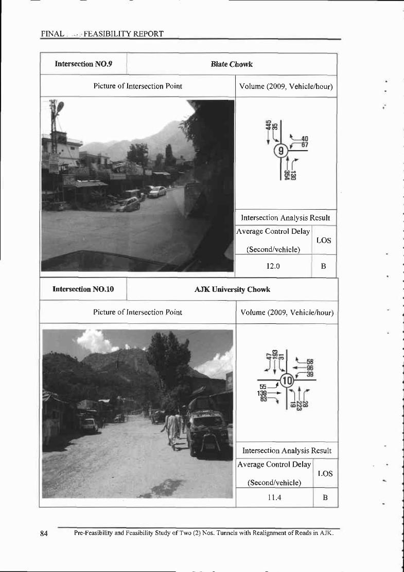
FINAL. ,,. FEASIBILITY REPORT
Intersection NO,9 Blate Chowk
Picture of Intersection Point Volume (2009, Vehicle,4rour)
Intersection Analysis Result
Average Control Delay
(Second/vehicle)LOS
12.0 B
Intersection NO.10 AJK University Chowk
Picture of Intersection Point Volume (2009, Vehicle/hour)
Intersection Analysis Result
Average Control Delay
(Second/vehicle)LOS
I 1 .4 B
84 Pre-Feasibility and Feasibility Study ofTwo (2) Nos. Tunnels with Realignment ofRoads in AJK.

Chapter 4. Traffic Analysis
E Intersection Turning Traffic Volume of the Project Route
The tuming traffic volume of intersections at the peak hour (13:00-14:00) of the entire project
area is as follows.
Current Map of the Intersection Turning Trafrc Volume at Peak Hour(13:01F14:l[)
J/ oom€l ChorvlO cart Ba|d CNrow[3i 6ltr ChowkO cnanar Chof,k:5) ile€tm Ctbf,( A
- Eggt 0l le€|trn ofise Cmvrk'O il€€tur ctDm I- f88t 0f lleslum Eddge
O Bs r clrflt3l c€lEgh chof,tO Ehtc cnofiE x untvsrsg cm|t
+
Pre-Feasibility and Feasibility Study ofTwo (2) Nos. Tunnels with Realignment ofRoads in AJK.
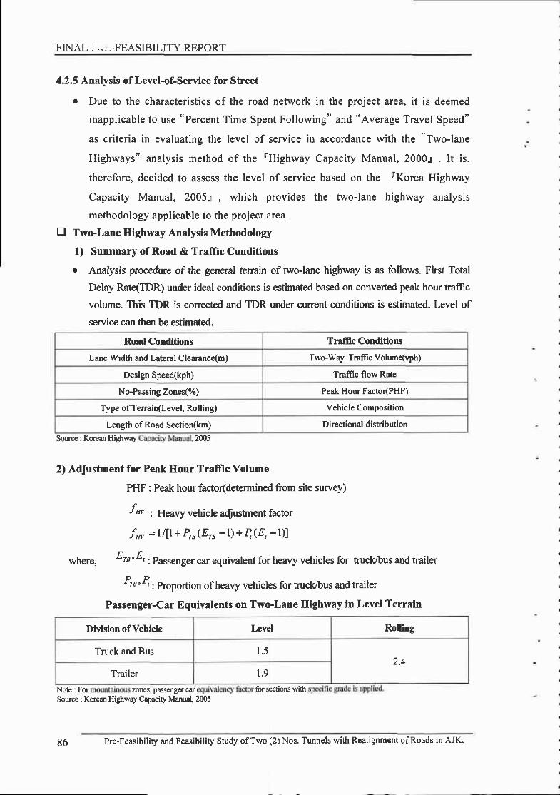
FINAL, ...,.,FEASIBILITY REPORT
4.2.5 Analysis of Level-of-Service for Street
. Due to the characteristics of the road network in the project area, it is deemed
inapplicable to use "Percent Time Spent Following" and "Average Travel Speed"
as criteria in evaluating the level of service in accordance with the "Two-lane
Highways" analysis method of the rHighway Capacity Manual, 2000t . It is,
therefore, decided to assess the level of service based on the FKorea Highway
Capacity Manual, 2005t , which provides the two-lane highway analysis
methodology applicable to the project area.
E Two-Lane Highwuy Analysis Methodolos/
1) Summary of Road & Traffic Conditions
o Analysis procedure of the general terrain of twoJane highway is as follows. First Total
Delay Pate(TDR) under ideal conditions is estimated based on converted peak hour traffrc
volume. This TDR is corrected and TDR under current conditions is estimated. Level of
s€rvic€ can then be estimated.
Road Conditions Traffic Conditions
Lare Width and Lateral Clearance(m) Twcway Trafficvolum{Wh)
Design Speed(kph) Tramc flow Raie
No-Passing Zones(%) Peak Hour Facto(PHF)
Type of Terrain(Level, Rolling) Vehicle Composition
Length of Road Section(km) Directional distribution
So|nce : Korcan Higlxvay 200,5
2) Adjustment for Peak Hour Tralffc Volume
PHF : Peak hour factor(determined from site survey)
f* , Heavy nehicle adjustment factor
fx, =l l l l+ Pu(En - l)+4(8, - l) l
where, Eo'4 , P^r"nger car equivalent for heavy vehicles for fuck/bus and trailer
Pt '4 'propo,llon ofheavy vehicles for truck/bus and trailer
passeng€rSource : Korean Highway Capacity Manu4 2005
Passenger-Car Equivalents on Two-Lane Highway in Level Terrain
Division ofVehicle Lrvel Rolling
Truck and Bus l . )n 1
Trailer 1 . 9
Note : For zones, car for sectioru with
86 Pre-Feasibility and Feasibility Study ofTwo (2) Nos. Tunnels with Realignment ofRoads in AJK.

Chapter 4. Traffic Analysis
3) Estination of Traffic Flow Rate
v^= VPHF x f,,
., where, 'r; Converted peak hour traffic volume(ltcph)
4) Capacity Assessment
. Peak hour one-way traffic volume is estimated by applying the larger of the
directional distribution ratio to the peak hour traffic volume. And this peak hour
one-way traffic volume is then compared with one way maximum capacity (1,700
pcph) and two-way maximum capacity (3.200 pcph) of two-lane highway. If any
of these capacity is exceeded, the level of service is evaluated as "F" and the
analysis procedure is ended. lf not, the process could continue.
5) Calculation of Total Delay Rate(TDRi) under ldeal Condition
. Total Delay Rate(TDRI) under ideal conditions is calculated from the equation
elow based on converted peak hour traffic volume.
Road Type I :TD&=0 '0 l2xv Road Type n :TDRI =0 '0 l55xv
where, DRt , Totul D"luy Rate of road type I under ideal condition(%)
DRn : Total Delay Rate of road type II under ideal condirion(7o)v : Flow rate(pcph)
6) Adjustment for Total Delay Rate(TDR)
Fdw : Adjustment for lane width and lateral clearance for total delay rate(TDR).
fdD-p : Adjustment for combined effect of directional distribution of traffic and
percentage of no-passing zones for total delay rate(TDR).
Adjustment for Lane Width and Lateral Clearance
on Twel,ane Highway in Level Terrain
a
a
--r-..._ Lane Width(m)Lateral
-""\.\
Clearance(m) ---'-..- > 3.50 > 3.25 > 3.00 > 2.75
> 1 .5 1 .00 I .03 1.06 1.09
> 1 .0 1 .03 1.06 1.09 l . t 2
> 0.5 l.06 L09 1 . 1 2 l . l 5
Soure : Korean HiBhway C@city Manual, 2005
Pre-Feasibility and Feasibility Study ofTwo (2) Nos. Tunnels with Realignment ofRoads in AJK.

FINAL '." FEASIBILITY REPORT
TSo-WayFlow Rate
(pcph)
Adjushent Factor
NoPassing Zone(7")
0 <20 <40 s60 <80 s 100
Directional Solit 50/50< 400 1.00 L0 l | .02 1 .04 1 . 0 5 1.06
< 800 1 .00 | ,03 1 .05 1.07 I .09 | . 12< 1,200 1.00 L l l l . l 4 t . 16 l . l 8 1.20< 1,600 l 00 1 .08 t . t 0 t . I 2 l l 4 L 1 6
< 2,000 1.00 1.06 r .08 l l 0 | . 12 t . t 4< 2,400 1.00 1.03 t .05 L06 1.07 1.08
< 2,800 L00 1.02 t .03 I .04 1.05 1.06< 3,200 1.00 1.00 1.00 L00 1.00 1.00
Directional Split 60/40< 400 1.00 L0l | .02 1.05 1.06 |.07< 800 1.03 1.04 1.06 1.08 l . l 0 t . l 3
< I ,200 1.06 | . t 2 l . l5 t . t7 l . l 9 t .2 l< I,600 1.05 1.09 L l l l . l 3 l . l 5 t . t7< 2,000 1.04 1.07 1.09 l . l I l . l 3 L t5<2,400 1.03 1.04 1.06 1.07 1.08 1.09< 2,800 r.00 1.00 1.00 t.00 1.00 1.00
Directional Split 70/30< 400 r.00 1.02 1.03 1.05 1.07 1.08
< 800 1.04 1.05 t .07 1.09 l . l I l . l 4
< I,200 L07 t . l 3 L l6 l . l 8 1.20 1.22< 1,600 1 .06 l . l 0 t . t2 l . l 4 I . 16 l . l 8
< 2,000 t .05 r .08 Lt0 | .12 l . l 4 l l 6
< 2,400 1.00 | .00 1.00 r .00 1.00 1.00Directicnal Split 80/20
< 400 1.00 l 03 1.04 1.06 1 . 0 8 L09< 800 1 . 0 5 L06 1 .08 L l0 l . t 2 l l 5
< 1,200 L08 t-14 | . 17 L19 | . z l< I ,600 t .07 l . l I t . t3 t . l 5 1 . 1 7 1 . l 9
< 2,000 1.06 r.09 l . l I t . l J I . I 5 t . t7<2,200 1.00 r.00 1.00 1.00 1.00 1.00
Directional Split 90/10< 400 1.00 1.04 L05 1.07 1.09 l . l 0
< 800 1.06 t .o7 L09 l . l I l . l 3 l . l 6
< I,200 l .09 l . l 5 L l8 t .20 1.22 1.24
< t,600 1.08 t . l 7 l . l 4 t . l 6 l . l 8 1.20< t,900 1.00 r.00 1.00 1.00 1.00 1.00
Nol,e : Wh€n not qven the values of and Ue percentage ate
Adjusfinent for Combined Effect of Directional Distribution of Traffic and
Percentage of NePassing Zones on Two'Lane Higbway in Level Terrain
glv€n
Source : Korean Highway Capacity Mmual,2005
88 Pre-Feasibility and Feasibitity Study ofTwo (2) Nos Tunnels with Realigoment ofRoads in AJK.

Chapter 4. Traffrc Analysis
7) Estimation of Total Delay Rate(TDR)
TDR=TDR.x fa* x .fro-,
Where , ZDR : Total Delay Rate in highway and traffic conditions
DR, : Total Delay Rat€ of road type in ideal condition
/rt ' Adjurtrn"nt for lane width and lateral clearance for total delay rate
r/D-P: Adjustment for combined effect ofdirectional distribution of
traffic and percentage of no-passing zones for total delay rate
8) Level-of-Service Criteria
r The level of service can be determined for each road type based on the Total
Delay Rate(TDR) calculated above.
Section Total Delay Rat€ : TDR(%)Flow Rate@cph)
Level of Service Road T)?e I Road Tlpe II
<8 < l 0 < 650
B < 15 <20 < | ,300
C <23 <30 < t ,900
D s30 <40 3 2,600
E < 38 <50 < 3,200
F )38 >50Soulce : Korean Manual,2005Capacity
E Analysis Result of Level-of-Service of Two-Way Highways
. Two-way highways analysis shows that the Total Delay Rate(TDR) is 4.0 *30.9%.
e The Level-of-Service(LOS) of the two-way highways are shown to be in the range
of "A" - "D", which indicates that the service level is satisfactory.
. The results of the Level-of-Serv ice(LOS) analysis for the project area are
presented in the table below.
Pre-Feasibility and Feasibility Study ofTwo (2) Nos. Tunnels with Realignment ofRoads in AJK-

PINAL i.;iI FEASIBILITY REPORT
Result of Level-of-Service Analysis of Two-Way Highways
Road Section
Two-wey
TrafficVolume
(vph)
P€akTineFlowR.te
(pcph)
Split
(sh)
FrlwTDR
(%)
LOS
t. Domel Chowk e 2. Gari Band Chowk 733 9 t5 0.52 |.06 t . t 4 t7.2 B
3. G.P.O Chowk <, 5. Neelum Chowk A |,290 | 461 0.55 r.06 t . l 7 28.1 (-
5. Neelum ChowkA e 6. Neelum Chowk B |,364 1629 0.50 1.06 1 . l 6 30.9 D
6. Neelurn Chowk B e 7. Bala Pir Chowk 313 414 0.50 r.06 1.06 7.?
8. Cemagh Chowk ., 9. Blate Chowk t ,330 1506 0.51 r.06 t . t7 ?8.9 C
19, AJK Universiry e rr Kahori BridgeChowk Chowk
151 225 0.s6 r.06 1.07 4.0
4.2.6 Analysis of Intersection Level-of-Service
o The level of service(LOS) for the intersections of the project area is evaluated in
accordance with the Unsignalized Intersections Analysis Procedure provided in
the rHighway Capacity Manual, 2000.1 since the intersections in the project area
are all unsignalized ones.
E Process of Unsignalized Intersections Analysis
. There are three types of unsignalized intersections addressed generally, including
two-way stop-controlled(TwSC), all-way stop-controlled(AWSC), and
roundabouts.
o Level of service of two-way stop-controlled(TWSC) intersections which is the
most typical unsignalized intersections has been analyzed using a methodology
presented in rHighway Capacity Manual, TRB, 2000.r .
I Two-Way Stop-Controlled(TWSC) Intersections
Pre-Feasibility and Feasibility Study ofTwo (2) Nos. Tunnels with Realignment ofRoads in AJK-
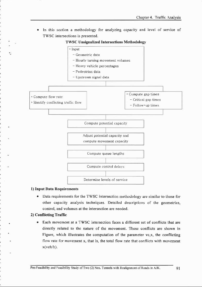
Chanter 4. Traffic .\nalvsis
o ln this section a methodology for analyzing capacity and level of service of
TWSC intersections is oresented.
1) Input Data Requirements
. Data requirements for the TWSC intersection methodology are similar to those for
other capacity analysis techniques. Detailed descriptions of the geometrics,
control, and volumes at the intersection are needed.
2) Conflicting Traffic
. Each movement at a TWSC intersection faces a different set of conflicts that are
directly related to the nature of the movement. These conflicts are shown in
Figure, which illustrates the computation of the parameter vc,x, the conflicting
flow rate for movement x. that is. the total flow rate that conflicts with movement
x(veh/h).
9 l
TWSC Unsignalized Intersections Methodology
. lnput- Geometric data- Hourly turning movement volumes- Heavy vehicle percentages- Pedestrian data- Upstream signal data
. Compute
" Identify c
f low rate
cnfl icting traffic f low
" Compute gap times- Critical gap times- Follow-up times
Compute potential capacity
Adjust potential capacity and
compute movement capaclt].
Compute queue lengths
Compute control delays
Determine levels of service
Pre-Feasibility and Feasibility Study ofTwo (2) Nos. Tunnels with Realignmeot ofRoads in AJK.

FINAL J ., FEASIBILITY REPORT
StnFdlldmi
ai!t6G, tt,
lqatl
.----1-6----.
i--t---
6)- r .1.vg+1,F|11r,
2_re- _ _ _ _ - . ,
I t
fr , t=rfrrt3g+qt
mrmI
r3i
I
.----T
,.,r=$.os{tl*r,3.r,3
]|nEl|l
$Fl 16
\-5<-5t-a
r.g.2q r g +rsFl +q5
l-t
3-\ t5
Itr l tr=at+12rvlBfvrs
.. . . -l-5-. -. -
I@l
I
r.6 =2v1rrq +05501+ 16
loI
...__-t..--t6
rcrn = 2tr r rs + OSr|II + rr:
Itr. LI
Sb0r I Jl'I
13 :
I
r.r:.2rr. # + Oirfl r OSvoltsl +O5[1 r !3
I
: l{
IJt,ff'"att' f - os".F' o*Ptl'
.----!9---t
dv47 =?q +12 r o5vfl rq5
@lt
*""rj i-- '- l---i
r41=Q rr3 + OSqIl + v15
Definition rnd Computation of Conllicting Flows
92 Pre-Feasibility and Feasibility Study ofTwo (2) Nos. Tunnels with Realignment ofRoads in AJK.

Chapter 4. Trafi., . .ralysis
3) Critical Gap and Follow-up Time
r The critical gap, tc is defined as the minimum length time interval in the major
- atreet traffic stream that allows intersection entry for one minor street vehicle.' Thus, the driver's critical gap is the minimum gap that would be found acceptable.
, . The time span between the departure of one vehicle from the minor street and the
departure ofthe next vehicle using the same major street gap, under a condition of
continuous queuing on the minor street, is called the follow-up time, tf. Put' another way, tf is the headway that defines the saturation flow rate for the
approach ifthere were no conflicting vehicles on movements of higher rank.
Base Critical Gaps and Follow-up Times for TWSC Intersections
Vehicle Movernent
Base Critical Gap, tc,base(s)Base Follow-up Time, tf,base(s)
2-Lane MajorSfteet
4-Lane MajorStreet
Leff tum from major 4 . 1 4 . 1 2.2
Right tum from minor o.z 6.9 J . J
Through traffic on minor 6.5 o.) 4.0
Left tum from minor 7 .1 7.5 3.5
Souroe : Highway Capacity Manual,2000
4) Potential Capacity
. The gap acceptance model used in this method computes the potential capacity of
each minor traffic stream in accordance with under Eouation.-v- . t" " /3600
e-" 'L p , *
= V" , t l - -v . . r . . /3600l - e ' ' ' '
where,
a- P'x : Potential capacity of minor movement x(veh/h)
Conflicting flow rate for movement x(veh-ftr)
Critical gap (i.e., the minimum time interval that allowsintersection entry for one minor sheam vehicle), q for minormovement x
Follow-up time (i.e., the time between the departure of onevehicle from the minor street and the departure of the next under acontinuous queue condition), s, for minor movement x
t t '
Pre-Feasibility and Feasibility Study ofTwo (2) Nos. Tunnels with Realignment ofRoads in AJK, 93

FINAL . ]' .FEASIBILITY REPORT
5) Movement Capacity
. The potential capacity of a movement is denoted as cp,x (for movement x), and is
defined as the capacity for a specific movement, assuming the following base
conditions:- Traffic from nearby inters€ctions does not back up into the subject intersection.- A separate lane is provided for the exclusive use ofeach minor street movement.- An upstream signal does not affect the arrival pattem ofthe major street traffic.- No other movements ofrank 2, 3, or 4 impede the subject movement.
r The potential capacity, cp,x, minor street movements is given in Figure for a two-
lane major road, and in Figure 4 for a four-lane major road.
. The potential capacity is expressed as vehicles per hour (veh/h). It can be seen
from the exhibits that the potential capacity is a function of the conflicting flow
rate vc,x expressed as an hourly rate, as well as the particular minor street
movement being analyzed.
@ Impedalce Effects
- Vehicle lmpedance- Pedestrian Impedance
@ Shared-Lane Capacity
- Where several movements share the same lane, and cannot stop side-by-side at the stop
line ofthe intersection, Under equation is used to compute shared-lane capacity.
where,
C,,
l"
Capacity of the shared lane(veh./h)
Flow rate ofthe y movement in the subject shared lane(veh,/h)
Movement capacity of the y movement in the subject
shared lane(veh/h)
94 Pre-Feasibiliry and Feasibility Study ofTvro (2) Nos. Tunnels with Realignment ofRoads in AJK.
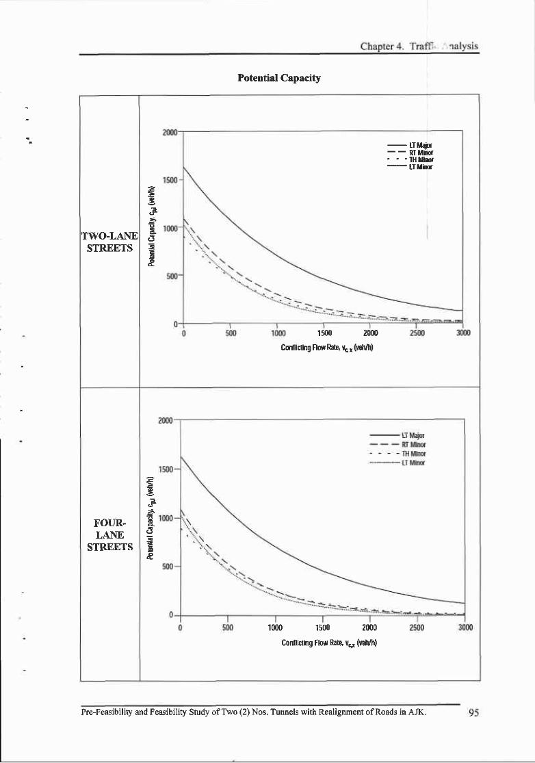
Potential Capacity
TWO-LANESTREETS
g.F5
Ed
-- RI lJrmr' ' ' f i M E r---- tT llir
1500 20m
Cdl|icting Flow kte, vc r (uch/h)
FOUR.LANE
STREETS
?
.=:
..1-
a
1000 1500 2000
Confllcling tlow Rite vsr (vdvh)
Pre-Feasibility and Feasibility Study ofTwo (2) Nos. Tunnels with Realignment ofRoads in AJK.

FINAL i .ii-,FEASIBILITY REPORT
6) Confrol Delay
o Control delay includes initial deceleration delay, queue move-up time, stopped
delay, and final acceleration delay. With respect to field measurements, control
delay is defined as the total elapsed time from when a vehicle stops at the end of
the queue until the vehicle departs from the stop line.
. This total elapsed time includes the time required for the vehicle to travel from the
last-in-queue position to the first-in-queue position.
where,
Average control delay(Vveh)
FIow rate for movement x(vefuh)
Capacity of movement x(veh/h)
T Analysis time period, h (T = 0.25 for a l5-min period)
7) Level-of-Service Criteria
. Level of service for a TWSC intersection is determined by the computed or
measured control delay, and is defined for each minor movement. Level of service
is not defined for the intersection as a whole.
Level-of-Service Criteria for TWSC Intersections
Level ofService Average Control Delay (second/vehicle)
B
c
D
E
F
0 - l 0
l 0 - 15
t5 -25
?5 -35
35 -50
50
2000HighBay C4acity M&ual,
Pre-Feasibility and Feasibility Study ofTwo (2) Nos. Tunnels with Realignment ofRoads in AJK.
I
96

Chapter 4. Traffir Analysis
O Result of Intersection Level-of-Service Analysis
Two-way stop-controlled(TWSC) Intersection Analysis Method is applied since
the intersections in the project area are all Unsignalized Intersections.
The analysis of the traffic delay rate shows the Average Control Delay to be 8.2
sec/veh * 33.6 sec/veh.
The Level-of-Service(LOS) for the intersections is found to be within 'A" *'D"
range, which indicates that the level of service is satisfactory.
The results of the Level-of-Service(LOS) analysis for the project area are shown
in the table below.
Intersection Level of Service Analysis Results (13:00- 14:00)
Intersection NameFlow Rate
(vph)Average Control Ilelay
(second/vehicle) Level of Service
l. Domel Chowk L,447 15.2 c
2. Gari Band Chowk | ,574 20.0 L
3. G.P.O Chowk |,261 | 3.5 B
4. Chattar Chowk 1 7 4 ) 15.6 c
5. Neelum Chowk A | ,649 23.7 C
6. Neelum Chowk B 1,860 33.6 D
7. Bala Pir Chowk 207 8.2
8. Cemagh Chowk I ? < t 2.8 B
9. Blate Chowk 1,071 t2 .0 B
10. AJK University Chowk l ,0 l I t l .4 B
Pre-Feasibility and Feasibility Study oftwo (2) Nos. Tunnels with Realignment ofRoads in AJK.
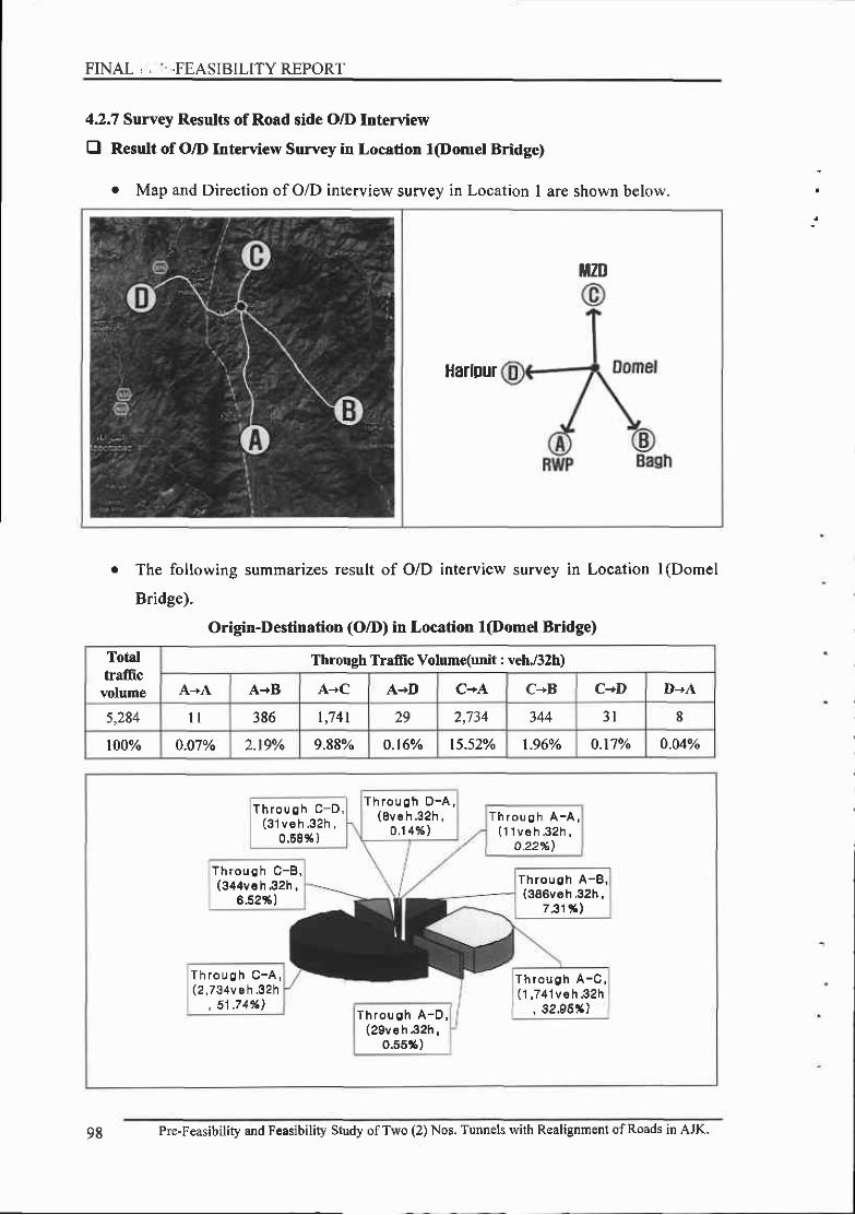
FINAL , , I'.FEASIBILITYREPORT
4.2.7 Survey Results of Road side O/D Interview
O Result of O/D Interview Survey in Location l(Domel Bridge)
o Map and Direction of O/D interview survey in Location 1 are shown below.
ililt
Harlpur
o The following summarizes result of O/D interview survey in Location I (Domel
Bridge).
Origin-Destination (O/D) in Location l(Domel Bridge)
Totalhafncvolume
Through Tlaffic Volume(unit : veh./32h)
A-A A-+B A-+C A+I) C*A C+B C-+D D-A
5,284 386 t,741 29 2,734 344 8
100% 0.07o/o 2.19o/o 9.88v" 0.t6% t5.s2% 1.96% 0.17o/o 0.04%
T h r o u g h D - A ,( 8 v e h . 3 2 h ,
0 . 1 4 % )
T h r o u s h C - D ,( 3 1 v e h . 3 2 h ,
0.58% )
T h r o u o h A - A ,( 1 1 v 6 h . 3 2 h ,
o.22%)
T h r o u c h C - 8 ,(344ve h .32h ,
6.52%)T h r o u o h A - 8 ,(386veh.32h,
7 31!trl
T h r o u g h C - A ,(2 ,734v e h .32h
, 51 .74%l
T h r o u g h A - C ,[1 ,741v€ h 32h
, 32,95?()T h r o u g h A - 0 ,(29ve h 32h,
0.55*)
98 Pre-Feasibility and Feasibility Study ofTwo (2) Nos. Tunnels with Realignment ofRoads in AJK.
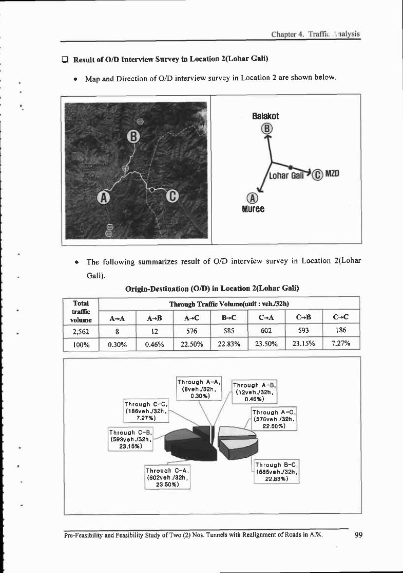
E Resutt of O/D Interview Survey in Location 2(Lohar Gali)
. Map and Direction of O/D interview survey in Location 2 are shown below.
Balal(ot
Muree
o The following summarizes result of O/D interview survey in Location 2(Lohar
Gali).
Origin-Destination (O/D) in Location 2(Lohar Gali)
TotalfrafEcvolume
Thmugh Ttaffc Volum{unit : veh.82h)
A+A A-B A-+C B-C C-+A C-+B C*C
2,562 I t2 576 585 602 593 18,6
100% 0.30% 0.46% 22.50o/o 22.83% 23.50o/o 23.15o/o 7.27%
T h r o u c h A - 4 ,(8ve h . /32h ,
0 ,30* )
T h r o u g h A(12veh, /32h,
0 .46%)T h r o u o h C - C ,(186ve h./32h ,
7 27%)
T h r o u g h C(503veh -/32h,
23 .15* )
Through C-4,(602ve h -/32h,
23.50*)
Throuoh A-C(S76vsh
"/32h,22.50%l
h r o u c h B - C ,(585veh. /32h,
22 A3/"1
Pre-Feasibility and Feasibility Study ofTwo (2) Nos. Tunnels with Realignment ofRoads in AJK. 99

FINAL ,i ,. FEASIBILITY REPORT
E Result of O/D Interview Survey in Location 3(Chellah Bandi Bridge)
r Map and Direction of O/D interview survey in Location 3 are shown below.
r The following summarizes result of O/D interview survey in Location 3(Chellah
Bandi Bridge).
Origin-Destination (O/D) in Location 3(Chellah Bandi Bridge)
Totaltraffic
volume
Through Trallic Volume(unit : vehJ3Zh)
A-rB B-+B B+C C-rB
1,607 32 1,440 bJ 72
100% 1.96% 89.600/o 3.95o/o 4.49%
T h r o u g h C - 8 ,(72veh. /32h,
4.49%lT h r o u g h B - C ,(63vehJ32h,
3.95 % )
h r o u g h A - 8 ,
Throuoh B-8 ,(1 ,44ove h./32h ,
89.60%)
Pre-Feasibility and Feasibilig Study ofTwo (2) Nos. Tunnels with Realignment of Roads in AJK.

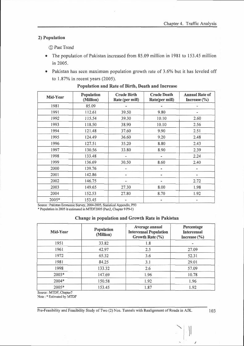

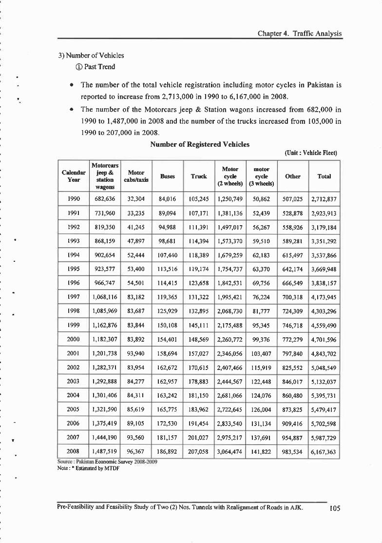
I
Chapter 4. Traflic Analysis
3) Number of Vehicles
O Past Tr€nd
o The number of the total vehicle registration including motor cycles in Pakistan is
reported to increase from 2,713,000 in 1990 to 6,167,000 in 2008.
o The number of the Motorcars jeep & Station wagons increased from 682,000 in
1990 to 1,487,000 in 2008 and the number of the trucks increased from 105,000 in1990 to 207,000 in 2008.
Number of Registered Vehicles
SuueyNote: * Etimated by MTDF
(Ulit : Vehicle Fleet)
CslendarYear
Motorcarsjeep &stationwlSons
Motorcrb6/trxis Bus€s Truck
Motorcyde
(2 wheets)
motorcyclc
(3 wb€els)Oller Total
1990 682,636 32,304 84,016 t05,245 1,250,749 50,862 507,025 2,712,837
l99l 73t,960 ? ? t ? ( 89,094 107,17 | l , 3 8 1 , 1 3 652,439 528,878 2,923,913
1992 E 19,350 4l,245 94,988 r l r ,391 |,497,017 56,267 558,926 3,t79,t84
t993 868,t 59 47,897 9E,6El I t4,394 |,5?3,370 59,510 589,281 ? ? { t ? 4 ,
t994 902,654 52,444 107,440 I18,389 t,6?9259 62,183 6t5,497 3,53?,866
r 995 923,577 53,400 I 1 3 , 5 1 6 tt9,t74 |,754,737 63,370 642,t74 3,669,948
1996 966,747 54,501 I 14 ,415 r23,65t |,842,531 69,756 666,549 3,83t ,157
1997 1,068,1 l6 E3,182 |9,365 t3t,322 1,995,421 76,224 700,318 4,t73,94s
1998 1,085,969 E3,687 l , < oto t32,895 2,068,730 8t,777 724309 4,303,296
t999 t,t62,t76 E3,8,14 150, r08 1 4 5 , 1 I I 2,175,488 95,345 746,718 4,559490
2000 |,t82,307 83,892 154,401 148,569 2,260,772 99,376 7?2,279 4,70t,596
2001 t,20t,738 93,940 15E,694 t57,027 2,346,056 103,407 797,840 4,E43,702
2002 |,282,37 | 83,954 t62,672 170,6152,407,466 I 1 5 , 9 1 9 825,552 5,048,549
2003 |,292,888 84,277 t62,957 I7E,EE3 2,444,567 122,448 846,017 5,132,037
2004 1,301,40684,31 | 163,242 l 8 l , 1 5 0 2,6Et,066 t24,076 E60,480 5,395,731
2005 t,32t,590 85,619 t65,775 t83,962 2,722,645 t26,004 E73,825 < a1q a.l1
2006 t,37 5,4t9 89,105 172,530 19t,454 2,833,540 l3 l , t34 909,4t6 5,102,598
2007 t,444,190 93,560 l 8 l , l 5 7 201,027 2,975,217 r37,691 954,887 5,987,729
2008 t,487,519 96,367 186,892 207,05E 3,064,474 t4l,822 9E3,534 6,t67,363
Eoonomic
Pre-Feasibility and Feasibility Study ofTwo (2) Nos. Tunnels with Realignment ofRoads in AJK. I 05
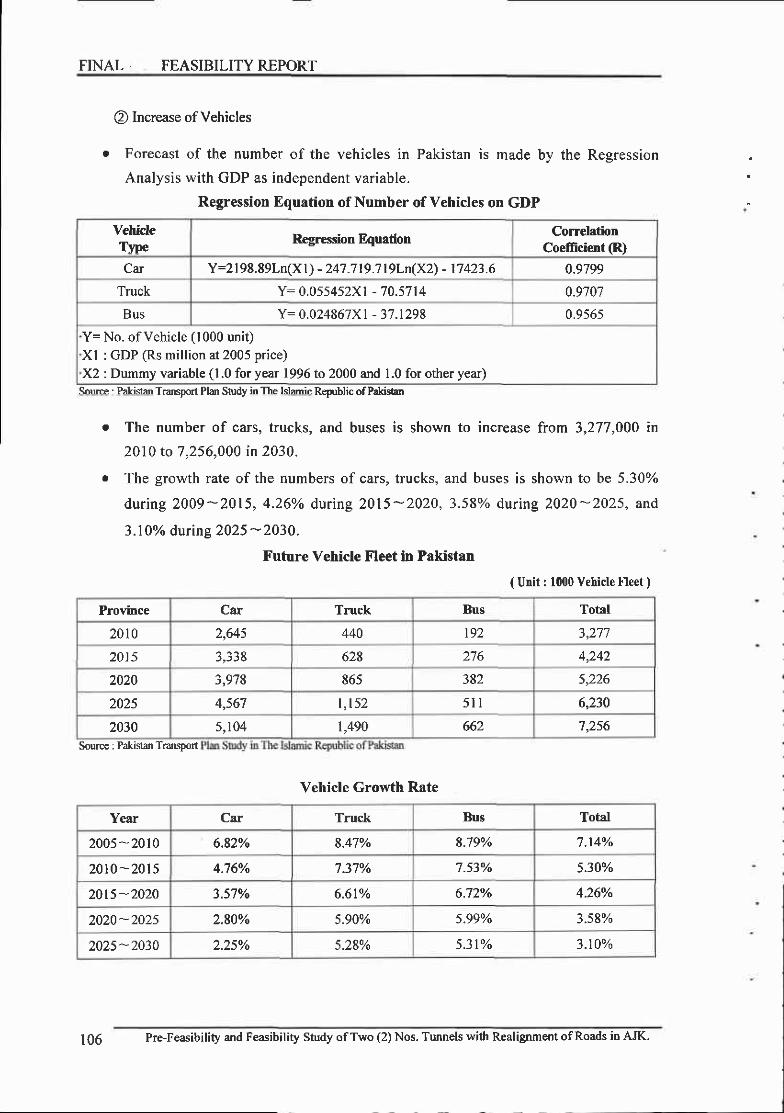
FINAL FEASIBILITY REPORT
@ Increase of Vehicles
o Forecast of the number of the vehicles in Pakistan is made by the Regression
Analysis with GDP as independent variable.
Trms?orl Pldr Study Republic of PakistaD
and buses is shown to increase from 3.277.000 inr The number of cars, trucks,
2010 ro 7.256.000 in 2030
o The growth rate of the numbers of cars, trucks, and buses is shown to be 5.30%
during 2009-2015, 4.26% during 2015-2020, 3.58% during 2020*2025, and
3.10%o durins 2025 -2030-
Future Vehicle Fleet in Pakistan
Vehicle Growth Rate
Regression Equation of Number of Vehicles on GDP
VehideTvpe
Regression F4uation CorrelationCoefficient (R)
Car Y=2198.89Ln(X l) - 247 .7 t9.7 t9Ln(Xz) - 17423.6 0.9799
Truck Y= 0.0554s2X1 - 70.5714 0.9707
Bus Y= 0.024867X I - 37 .t298 0.956s
Y= No. of Vehicle (1000 unit)Xl : GDP (Rs million at 2005 price)X2 : Dummy variable (l .0 for year 1996 to 2000 and 1.0 for other year)
S.'rfte : Pakis{ff| Plan in The Ishmic of Pakistan
{ Unit : 1000 Vehicle Fle€t )
Province Car Truck Bus TotNl
2010 2,645 440 l9? 3,277
2015 3,338 628 4,24?
2020 3,978 865 382 5,226
2025 4,567 t , t52 5 l l 6,230
2030 5,104 1,490 662 7,256SourE€ : Pakistan TransDort
Year Car Truck Bus Total
2005 -2010 6.82% 8.47Yo 8.79o/o 7 . l4yo
2010 - 2015 4.76% 7.37% 7.53v. 5.30%
20t5-2020 3.57o/o 6 .6 t% 6.720/o 4.26%
2020-2025 2,80% 5.90% s.99% 3.58%
2025 - 2030 2.2s% 5.28% 5.31% 3.10%
t06 Pre-Feasibility and Feasibility Study ofTwo (2) Nos. Tunnels with Realignment ofRoads in AJK.

Chapter 4. Traflic Analysis
E Trend of Socioeconomic Indices in Azad Jammu and Kashmir(AJK)
1) Economic Growth
O Recent Economic Grotth
. The economic growth rate in Azad Jammu and Kashmir(AJK) in recent years is
2.80% in Muzaffarabad ^nd 2.41o/o overull.
Recent Economic Growt} Rate in AJK
Province Economic Growth Rate(7o)
AzadJammu and
Muzaffarabad
Muzaffarabad 2.80Neelum
sum 2.80
Mirpur 2.09
Bhimber 2.60Kashmir(AJK)
Kodi t ( o
Poonch
Baeh and Haveli 2.00
Sudhnati t .99total 2.41
Source : wurw.ajkgov.pkNot€ : Data based fi 2009
2) Population
O Past and Recent Population
e The population of Muzaffarabad in Azad Jammu and Kashmir(AJK) has increased
from 0.746 million in 1998 to 0.754 million in 2009 and the overall population
has increased from 2.973 million in 1998 to 3.798 million in 2009.
Past and Recent Population in AJK
ProvincePopulationMillion)
1998 2002 2Ut9
AzadJammu and
Kashmir(AJK)
M uzaffarabad
Muzaffarabad 0.746 0.833 0.7 54. Neelum 0.126
Sum 0.746 0.833 0.880Mirpur 0.334 U.JOJ 0.746
Bhimber 0.302 0.335 0.352Kotli 0.563 0.624 0.656
Poonch 0 .41 I 0.449 0.469Bash and Haveli 0.393 0.425 0.443
Sudhnati 0.224 0.242 0.252Total 2.973 3.271 3.798
.pk
Pre-Feasibility and Feasibility Study ofTwo (2) Nos. Tunnels with Realignment ofRoads in AJK. lO7

FINAL FEASIBILITY REPORT
@ Population Forecast
. The population of Muzaffarabad in Azad Jammu and Kashmir(AJK) is expected to
increase from 0.754 million in 2009 to |.007 million in 2033 at the rate of l.2lyo.
The overall population is expected to grow from 3.798 million in 2009 to 5.082
mif lion in 2033 at the rate of | .22%;o.
Future Population Forecast in AJK
hovince
Population(Million) AverrgeAnnual
PopulationGronthRrtq%)2009 2014 2018 2023 z02a 2033
AzadJammu
andKashmir(AJK)
Muzaffarabad
Muzaffarabad 0.754 0 .8110.853 0.904 0.955 r.007 t .2.1%
Neelum 0.t26 0. 136 0 . 1 4 4 0 . t53 0.162 0 . l 7 l t ,z8%
Sum 0.880 0.947 0.997 1.057 1 . t17 I . 178 1.22%
Mirpur 0.746 0.803 0.845 0.895 0.945 0.997 1.22o/o
Bhimber 0.352 0.379 0.399 0.423 0.447 0.472 1.23o/o
Kotli 0.6s6 0.706 0.743 0.787 0.831 0.876 t . z t%
Poonch 0.469 0.505 0.532 0.564 0.596 0.629 | .230/o
Baeh & Haveli o.443 0.477 0.502 0.532 0.562 0.593 | .22o/o
Sudhnati 0.252 0.271 0.285 0.302 0.319 0.337 1,22%
Total 3.798 4.0884.303 4.560 4.8t7 s.082 |,22Yo
108 Pre-Feasibility and Feasibility Study ofT o (2) Nos. Tunnels with Realignment ofRoads in AJK.
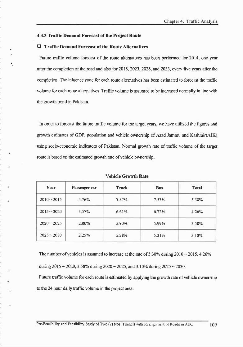
Chaoter 4. Traffic Analvsis
4.3.3 Traffic Demand Forecrst of the Project Route
B Traffic Demand Forecast of the Route Alternatiyes
Future traffic volume forecast of the route altematives has been performed for 2014, one year
after the completion ofthe road and also for 2018,2023,2028, arrd 2033, every five years after the
completion. The inluence zone for each route altematives has been estimated to forecast the kamc
volume for each route altematives. Traflic volume is assumed to be increased normally in line with
the srowth trend in Pakistan.
In order to forecast the future traffic volume for the target years, we have utilized the figures and
growth estimates of GDP, population and vehicle ownership of Azad Jammu and Kashmi(AJK)
using socio-economic indicators of PakisAn. Normal growth rate of traffic volume of the target
route is based on the estimated erowth rate ofvehicle ownershio.
Vehicle Growth Rate
Year Passenger car Truck Bus Total
2010-2015 4.76% 7.37% 7 .53% 5.30o/o
2015 -2020 3.57% 6.61Yo 6.72% 4.260/o
2020 -20?5 2.80% 5.90% 5.99% 3.58vo
2025 -2030 z.2s% 5.28o/o 5 . 3 l % 3.10%
The number ofvehicles is assumed to increase at the rate of5.30% durins 2010 * 2015.4.26%
during 2015 - 2020,3-58Yo during2020 - 2025, and 3.10% during 2025 - 2030.
Future traffic volume for each route is estimated by applying the growth rate of vehicle ownership
to the 24 hour daily traffic volume in the project area.
Pre-Feasibility and Feasibility Study ofTwo (2) Nos. Tunnels with Realignment ofRoads in AJK. 109
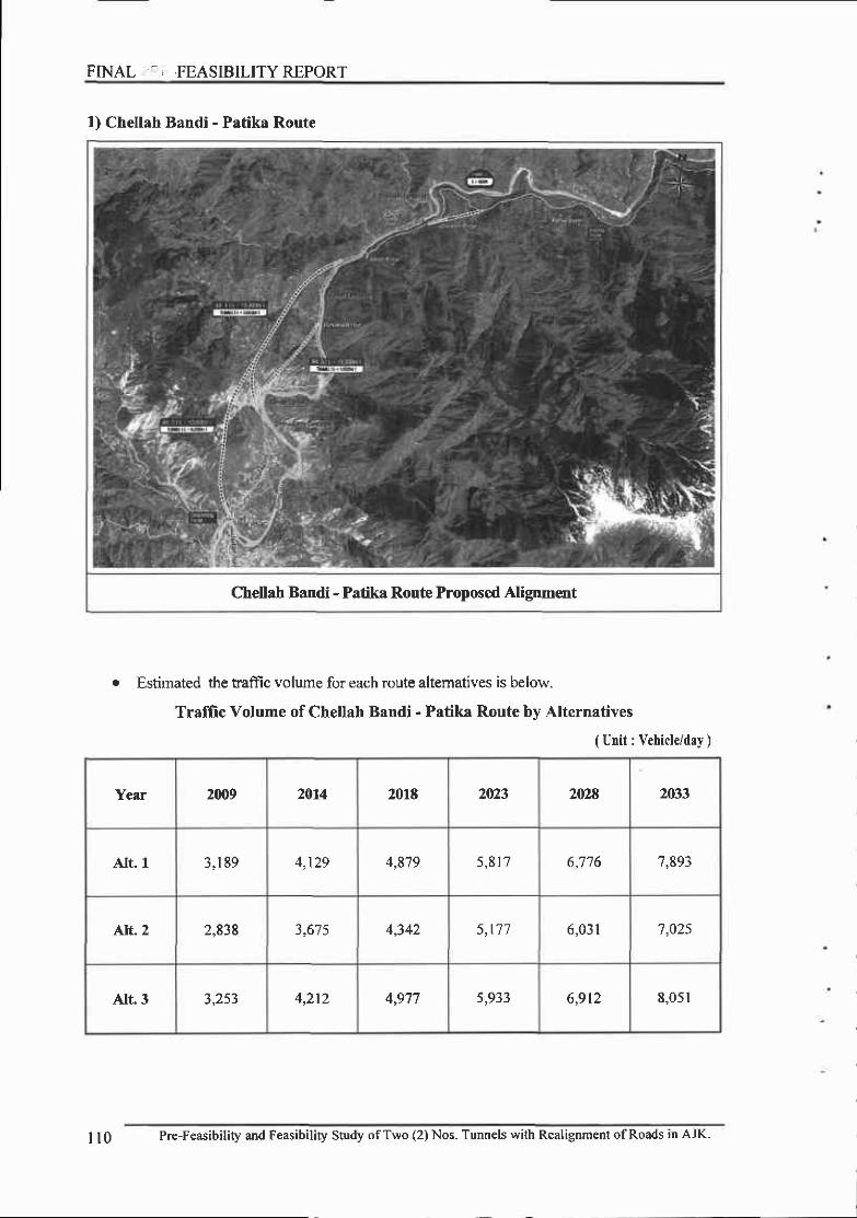
FINAL - ' ,FEASIBILITYREPORT
1) Chellah Bandi - Patika Route
Chellah Bandi - Patika Route Proposed Alipment
o Estimated the ffaffic volume for each route altematives is below-
Traffic Volume of Chellah Bandi - Patika Route bv Alternatives
( Unit : Vehicle/dry )
Year 2009 2014 2018 2023 2028 2033
AIt. I 3,1 89 4 l t o 4,819 5 , 8 1 7 6,775 7 ,893
Alt. 2 2,838 3,67 5 4,342 5 , 1 7 7 6,03l 7 ,025
Alt. 3 3,253 4,212 l q11 5,933 6,9t2 8,051
| | 0 Pre-Feasibility and Feasibility Study of Two (2) Nos. Tunnels with Realigoment of Roads in AJK.

Chapter 4. Traffiu .',nalysis
2) Traffic Volume for the Opfimlm Route
o Traffic volume for taget years of the optimum route is below.
Traffic Volume for Target Years of the Optimum Route
( Unit : Vehicle/day )
Yefi 2009 2014 20r8 2023 2024 7fr33
Chellah Bandi - Patika Route 3 ,189 4,t29 4,879 5 , 8 1 7 6,776 7,893
r Chellah Bandi - Patika Route
9,m0
&m
zm
6,m
s,m
4,m0
3,0m
2,0@
trom
0
Pre-Feasibility ard Feasibility Study ofTwo (2) Nos. Tunnels with Realignment ofRoads in AJK.
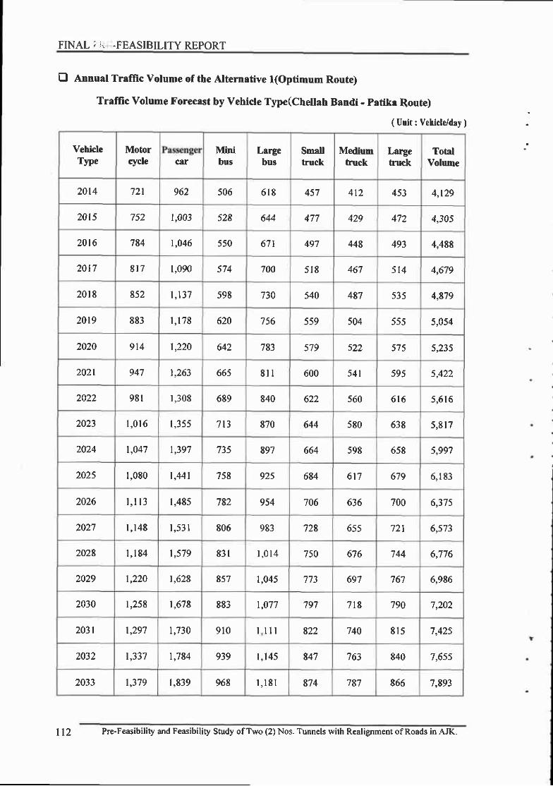
FINAL ; i. .FEASIBILITY REPORT
E Annual Tralfic Volume of the Alternative l(Optimum Route)
Traffic Volume Forecast by Vehicle Type(Chellah Bandi - patika Route)
( Unit : Vehicle/day )
VehicleTyPe
Motorcycle car
Minibus
Lrrgebus
Smalltruck
Mediumfruck
Largetuck
TotalVolume
2014 721 962 506 618 457 4tz 453 4,t29
2015 752 t,003 528 644 477 429 472 4,305
2016 784 |,046 550 671 497 448 493 4,488
20 l7 817 t,090 574 700 5 t8 + o l 514 4,679
2018 852 |, t37 598 730 540 487 ) J i 4,879
20t9 883 r , r78 620 't56 559 504 555 5,054
2020 9t4 1,220 o+z 783 579 s22 ) / ) s t?{
2021 947 1,263 665 8n 600 5 4 1 595 5,422
981 r,308 689 840 622 s60 616 5,516
2023 l ,0 r 6 1,355 713 870 644 580 638 5 ,8 t7
2024 |,047 1,397 735 897 664 598 658 5,99',7
2025 1,080 | ,441 758 92s 684 617 679 6,183
2026 t , l r3 1,485 782 954 706 636 700 6,375
2027 I ,148 1 ,531 806 983 728 o55 721 6,573
2028 1 ,184 t,579 831 | , 0 1 4 750 676 744 6,776
2029 |,220 t,628 857 1,045 773 697 767 6,986
2030 t,258 1,678 883 |,077 797 718 790 7,202
2031 |,297 t,730 910 l l l 822 740 815 7,425
2032 1,337 1,784 939 l ,145 847 to3 840 7,6s5
2033 |,379 1,839 968 | , l 8 t 8',t4 787 865 7,893
ll2 Pre-Feasibility and Feasibility Study ofTwo (2) Nos. Tunnels with Realignment ofRoads in AJK.

Chapter 4. Traffic Analysis
4,3.4 Calculation of Number of Lanes and Capacity for the Project Route
The highway capacity can be defined as the maximum volume ofvehicles or people passing a
spot over a certain period of time under given conditions. This is used for determining the number
oflanes and the level ofservice.
Also, the number of lanes should be calculated with regards to the level of service, the future
traflic volume and the traffic characteristics. In this project the capacity and the facility size are
determined in accordance with the 0Korean Highway Capacity Manual.r
Process of Calculation of Number of Lanes
Service Flow( S{ )
SF, = C, x(V / C), x N x f,' x f*
Service flow in level-of-sewice " j "
Capacity in design speed level " r "(pcphpl)Ratio oftraffic volume by capacity in level-of-service "i "
Adjustrnent for lane width and lateral clearanc€
Heavy vehicle adjustment factor
(F
cj
(v tc),f"
(LeveDll + P"](En -D + Pr2(Er2 -Dl
l
ll + Prr(E rr - l)l(Rolling, Mountainous)
Adjustment for D€sign Hourly Volume by Peak Hour Factor
PDDHY =DDHI/ =PHF PHF
PDDHI/ ' Peak directional design hourly volume(vph)DDW ' 9ir"6ional design hourly volume(vph)PIIF . peak h6u.16g161
AADT ; Prrlrrtla,l ayerage daity traffic(vpd)K : Design hourly factorD : Heavier direction factor
AADT x Kx D
Compute of Number of Lanes(N)
PDDHV(F
CapacityAnalysis
RequiredNumber
ofLanes
Pre-Feasibility and F€asibility Study ofTwo (2) Nos. Tunnels with Realignment ofRoads in AJK. I l - t

FINAL ;',..; FEASIBILITY REPORT
E Calculation of Number of Lanes
l) Design Hourly Factor(K), Ileavier Directional Factor@) and Peak Hour Factor(PHF)
Design Hourly Facto(K) is the ratio of Design Hourly Volume(DHV) to Annual Average
Daily Tmffic(AADT). Design Hourly Volume (DHV) is obtained fiom Design Hourly Facro(K)
through AADT.
It is generally encouraged to use K3o(the ratio of tlre thirtieth highest hourly volume to the
highest one when traffic volume is measured every hours for I year) as a design hourly factor but it
is allowed to use up factors up to Kroo depending on local road characteristics
If the design hourly facto(K) is set too high, road construction might be implemented in an
uneconomical way since the design hourly traffic volume would be much higher than the hourly
traffic volume. If the design hourly factor(K) is set too low, there could be frequent traffic
congestion since there would be many time zones where fte hourly traffrc volume is greater than
the design hourly volume.
Heavier Directional Factor(D) is the percentage of the one way volume in the predominant
direction of travel in the design hour. If it is set too high, road might be constructed in an
uneconomical way and if it is set too low, traffic congestion might occur frequently.
Peak Hour Factor(PFIF) is ratio ofthe peak hour traffic volume to the value, where the value is
obtained by multiplying the peak lS-minutes traffic volume within the peak hour by 4. PHF is used
as the basic data to determine Peak Directional Design Hourly Volume (PDDHV).
where,
PHF= V
Vux4
Peak hour factor
One hour traffic volume(vph)
Peak l5 minutes traflic volume(veh/l5min)
PHF
v
f/, t 5
ll4 Pre-Feasibility and Feasibility Study ofTwo (2) Nos. Tunnels with Realignment ofRoads in AJK.

Chapter 4. Trafii,. '.nalysis
2) Calculation of Design Ilourly Volume
The directional design hourly traffic volume at peak hour is calculated as follows, based on
directional design hour and traffic characteristics ofpeak hourly fuctor.
PDDHY = AADTxKxDI PHF = DDHV / PHF
where,
AADT
/\
D
DDHV
PHF
Annual average daily traffic
Design hourly factor
Heavier direction factor
Directional design hourly volume
Peak hour factor
3) Calculation of Service Flow
Service flow is calculated based on the proportion of volume to capacity at the service level i in
the ideal condition, the lane width and lateral clearance, the effect ofheavy vehicles. The equation
for calculating the service traffic volume is as follows.
SFt = C j x(T I C),x N x f , ,x f , ,
where.54 ' M*i.r. service flow for the highway and traffic conditions in level-of-service
'1"(vph)
c. ̂-, : Capacig in design speed level " J "Ocphpl)
" -i : Ratio oftrallic volume by capacity in level-of-service "t "A/
.f,.Number of lanes
Adjustment for lane width and lateral clearance
Heavy vehicle adjushnent factor
.f ,, fl + 4lErt -l) + Prz(Er2 - l)J lkvet)
I
[] + PHI(E Hv - l)J iRolling, tr.lounrainous, Specific Grade)
D Dt rt" 12 i Proponion ofmiddle and large vehicles (%o/100)D D"rt'Lr2 : Passenger car equivalent for middle and large vehicles
D' flr : Proportion ofheavy vehicles (7ol100)
"l'/ : Passenger car equivalent for healy vehicles
Pre-Feasibility and Feasibility Study ofTwo (2) Nos. Tunnels with Realignment ofRoads in AJK.
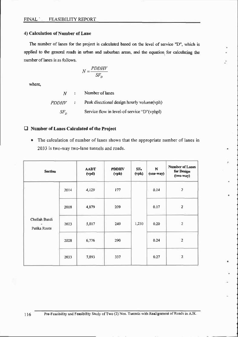
FINAL' FEASIBILITY REPORT
4) Calculation of Number of Lane
The number of lanes for the project is calculated based on the level of service "D", which is
applied to the general roads in urban and suburban areas, and the equation, for calculating the
number of lanes is as follows.
where,
^t _PDDHVSF,
Number of lanes
Peak directional design hourly volume(vph)
Service flow in level-of-service "D"(vphpl)
N
PDDHI/
sr;
E Number of Lanes Calculated of the Project
r The calculation of number of lanes shows that the appropriate number of lanes in
2033 is two-way two-lane tunnels and roads.
SectiooAAI}T(vpd)
PDDIIV(vph)
SFr(vph)
N(one.wry)
NuDber of l,ro€sfor Desigo(two-waD
Chellah Bandi
Patika Route
2014 A l J A 1 7 7
I ,230
0.14 2
20tt 4,879 209 0.17 2
2023 5,817 249 0.20 2
2028 6,776 290 0.24 2
2033 7,893 0.27 2
1 16 Pre-Feasibility and Feasibility Study ofTwo (2) Nos. Tunnels with Realignment ofRoads in AJK.

Chapter 4. Traffic Analysis
E Analysis of Level-of-service for the Project Route
r The road planned in the Project is two-lane road. Consequently, we have analyzed
the level ofservice based on the method of analysis for two-way highways.
o The Level-of-Service for the main line is found to be appropriate, belonging to the
ranee of ,'A'' - ''B'..
Itoject lloute
Ttvo-WayTr4ffcVolume
(vph)
Peak TimeFlow Rrte
(pcph)
Sprt
(sh)
Fdw FdD+IDR
("/")
LOS
Chellah Bandi
Patika Route
20t4 177 240 0.52 1.00 1.06 3.1
2018 209 2E3 0.52 t.00 1.06 3.6
2023 249 337 0.52 r.00 1.06 42
202t 290 393 0.52 1.00 1.06 5
2033 337 457 0.52 t.00 1.07 5.9 A
Pre-Feasibility and Feasibility Study ofT\ryo (2) Nos. Tunnels with Realignment ofRoads in AJK. ll7

Chapter 5. FieH Survey for Engineering Design
5.1 Topographic Survey
5.1.1 Khori Land Slide Tunnel
(1) Introduction
Azad Jarrrnu and Kashmir (AJ&K) is mainly comprises of hilly/mountainous terrain
particularly the northem part have steep sloping lofty mountain peaks. The main inter-District
and some sub divisional roads have to traverse over high peaks and fragile geological formations
results in huge land slide, debris and mud flow along some routes.
Khori land slide along the route from Muzaffarabad to kamsar and further to Patika is one of
such area with constantly threatening land5tjdes results in accidef,t and loss of life and goods
every year. Therefore, a tunnel between 4 km to 8.5 km is envisaged to avoid the accidents and
to provide all weather connection through the Khori Land slide area.
(2) Brief Scope Of Topographic Survey As Per Consultancy Contract
The scope of work of Topographic survey is mentioned in clauses A2 (2,3), A,4 and A'5 of
Appendix A of the Consultanoy Contact.
Pursuant to clause AZ (2-3), Consultants are required to carry out the Topographic survey to
delineate the identification of tunnel and link access road alignment, vertical grade of proposed
access road supported with general topographic in descriptive form.
Pusuant to clause A4 at the pre-feasibility study (phase-Ustage), the Consultants are required
to carry out preliminary topographic suwey of proposed portal arca artd link access road and
Pre-Feasibility and Fcasibility Study ofTwo (2) Nos. Tunnels with Realignment ofRoads in AJK. l 19

FINAI FEASIBILITY REPORT
wherever required at this stage. The approximate area envisaged is 20 hectares for each tunnel
project.
Pursuant to clause A5 at the feasibility study (phase-Il/stage), the consultants are required to
carry out further detailed and augmented Topographic survey of portal areas and link access
roads about l0 hectare for each Tunnel Proiect.
(3) Topography
l) General
The investigated area lies at 4 km from Muzaffarabad city in the base of Neelum Valley.
Generally the reliefofthe area is the north-eastem and south-eastem parts. The main focus of the
project area is the Khori land slide along the road connecting Chella Bandi to Kamsur and frrrther
to Pafika on Neelum Road. Physiographically, the area is characterized by rugged mountain
including major "V" shape valley developed by river Neelum.
The area axis of the project area is NE and SE. Moreover, fragile geological information in
that area mostly with steep sloped mountains is the characteristic feature of the area. The
weathering of the rocks depends upon the climatic conditions, struchlres, topography, vegetation
and slopes of the area. Both t1pes of weathedng i.e. mechanical weathering and chemical
weathering are prominent in the area-
This road starts at Ne€hrm Bridge in Muzaffarabad. The total road distance from the Neelum
Bridge in Muzaffarabad to Patika along the existing road traversing tbrough Khori Land slide is
approximately 23 Km. The Tururel site starts at Chella Bridge is located on this road at a distance
ofabout 6 km from Neelum Bridge.
The area at the Tunnel site is mountainous with srrall streams along the exposed rock surfaces
and covered with trees and vegetation. The streams are intermittent to ephemeral to some extent
and carry varying amount of water during rainy season depending upon their catchment area.
Three alignments are envisaged for the Neelum land slide project. The preliminary
topographic survey in sufEcient detail is carried out along the proposed Tunnel Alignment
Aliernative 1, 2 & 3, their portal areas and proposed link access roads.
120 Pre-Feasibility and Feasibility Study ofTwo (2) Nos. Tunnels with Realignment ofRoads in AJK-

Along with the survey a closed traverse has been carried out which connects the Portals of both
the proposed Alignments ofthe proposed hrnnel. This traverse provided a verification ofrelative
coordinates and elevations of Tunnel Portals.
2) Description of Tunnel Alternative Alignment No. 1, 2 & 3
Proposed Alignrrent No. I consists of two Tunnels almost 3.7 km and 0.6 km long- Tunnel No.
1 which is 3.9 km starts from Kamsar at its South Portal and culrninates at Harama More at its
North Portal. Karnsar atea is located at a distance of l0 kn frorm Neelum Bridge. Road distance
from Kamsar to Harama More is 5.5 }m. This podion of road from Kamsar to Harama More is
characterized with "navoidable larrd slide area.
Road distance from Harama More to Kahori Bridge is 0.5 kn and road distance from Kahon
Bridge to Chella Pani is almost 2 kn. Tunnel No. 2 which is 0.6 km stads from Chella Pani at its
South Portal and culminates at Donea Nala at its North Portal. Road distance from Chella Pani to
Donga Nala is 1.5 km.
Therefore the total road distance from Kamsar to Donga Nala is 9.5 km. The road distance
along the proposed Aliguent No. I with two tunnels (3.9 km & 0.6 km) and 2.5 km of road
between Harama More to Chella Pam is 7.0 km. Therefore, this alignment No. I reduces the road
distance by approx. 2.5 km and completely avoids the land slide hazards along the road.
Proposed Alignment No.2 is almost 8.1 km long. It starts from Chella bridge at its south
Portal and culminat€s at Hurama Mor at its North Portal. Challaha Bridge is 6 m from the
Neelum Bridge. The proposed North Portals of Alignment No. I and 2 are more or less at the
same place adjacent to Harama Mor. The North Portal of Alignment No. 2 is located at a road
distance of approximalsly 9.5 km from Soudr Portal at Chella bridge. Therefore, this alignment
altemative 0f8.1 km reduces the road distance by approx. 1.4 km and avoids the Khori land slide
hazards along the road. Since this alignment has 8.1 lan of Tunnel which is very costly. The
marginal advantage of this alignment 2 over I is appears small therefore, this alignment is not
considered for further study.
Pre-Feasibility and Fcasibilily Study ofT\ryo (2) Nos. Tunnels wirh Realignment ofRoads in AJK. l2l
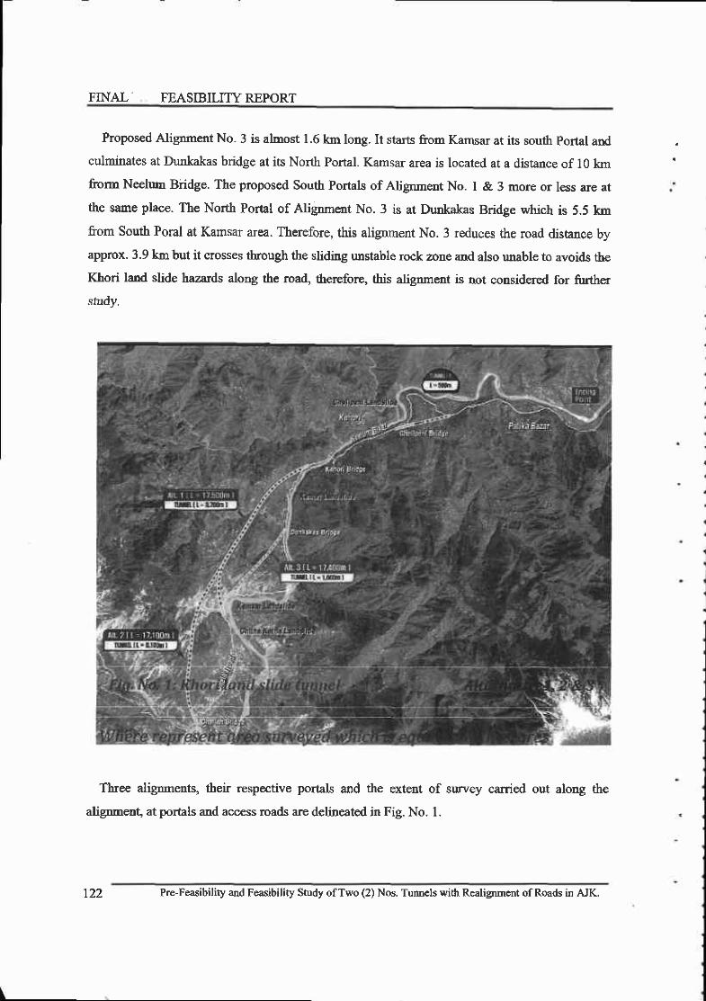
FINAL' FEASIBILITYREPORT
Proposed Alignment No. 3 is almost 1.6 km long. It starts from Kamsar at its south portal and
culminates at Dunkakas bridge at its North Podal. Kamsar area is located at a distance of 10 km
frorm Neelum Biidge. The proposed South Portals of Alignme.nt No. I & 3 more or less are at
tle same place. The North Portal of Alignment No. 3 is at Dunkakas Bridge which is 5.5 km
from south Poral at Kamsar area. Therefore, this alignment No. 3 reduces the road distance by
approx. 3.9 km but it crosses through the sliding unstable rock zone and also unable to avoids the
Khori land slide hazerds along the road, therefore, this alignment is not considered for further
study.
Tbree alignmens, their respective por0als and the extent of survey carried out along the
alignment, at portals and access roads are delineated in Fig. No. l.
t22 Pre-Fe$ibility and Fesibility Study ofTwo (2) Nos. Turmcls with Realignmcnt ofRoads in AJK.

3) Survey Of Pakistan Bench Mark (SOPBM) and Datum
The obtained coordinates of survey of Pakistan bench rnarks from FWO are shown in the table
below which forms the basis of the suwey of Tururel and thereby linked the survey to the
benchrnarks surveyed by the Survey of Pakistan. The datum of all reduced levels is mean sea
level and conformed to Survey of Pakistan Bench rnark levels.
4) Survey Monuments
The survey bench marks are installed at Khori Land slide Tunnel using the SOP Bench Marks
as above by double/close faverse. The tpe and dimensions of Survey monuments installed at
site along-with the coordinates are shown below. Besides start and at the end, as required the
markers are fixed in the traverse.line at an interval of about 300 to 400 meters or as required by
the topography of the area. These are fixed at such locations that these are least susceptible to
disturbance and damage.
monument will be reestablished and correct values will be provided during Phase - II survey.
S. No. Easting Northing Elevation (m)
P-3 f244800.13 1132300.25 718 .851
P-4 3245006.39 1132398.69 732.153
S. No. Easting Northing Elevation (m)
KS-I 3245310.456 1139032.872 729.965
KN-2 3245324.182 1t38725.031 753.097Please note that the monuments were disturbed due to the construction activity. The
Pre-Feasibility and Feasibility Study ofTwo (2) Nos. Tunnels with Realignment ofRoads in AJK.
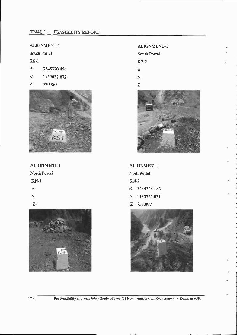
FINAL- . FEASIBILITY REPORT
ALIGNMENT.l
South Potal
lLJ- l
E 3245370.4s6
N 1139032.872
z 729.96s
ALIGNMENT-I
South Portal
KS-2
E
N
z
ALIGNMENT-1
North Portal
KN-1
E.
N.
z-
ALIGNMENT.l
Norh Portal
KN-2
E 3245324.182
N 1138725.031
z 753.097
t24 Pre-Feasibility and Feasibility Study ofTwo (2) Nos- Tunnels witb Realignment of Roads in AJK.

Chapter 5. Field Survey for Engineeri.- Design
5) Control for Traverse
The conlrol for traverse is established with dre Survey of Pakistan Grid Lambert Conical
Projection with Everest datum. Total statioo sets are used to connect the Traverse with the
Survev of Pakistan Bench Mark.
6) Survey corridor
The detailed topographic survey are carried out near dre proposed locations of the both the
portals for the envisaged alignments I in a corridor of20 m along the atgnment. Survey strip
may even be reduced to l0 m in case where the access is not available due to shear fall or
vertical cliff adjacent to the proposed alignments. At locations of crossing rivers, nalas the detail
of suwey is extended to appropriate distance.
7) Mapping (Unit of Measurement)
Metric units are used throughout.
E) Scale
Mapping of drawings is plotted to a scale of l:1000 (Horizontal and vertical)
9) Contours
After digital data collection of survey points at site, the conlour generation is done by using
computer software. The contour interval is I m. The smoothness factor is defined in the software
which avoids distorting the ground contour representation. The contours are well labeled. During
data collection, break lines on the ground should are very well picked that affects the contour
generation. In the steep slopes areas the reflector less total stations are used to record the co-
ordinates.
10) Total Surveyed Area
The area suweyed by the Consultant is shoum in Figures I above. The survey was carried out
along the Alignment No. I, their respective Portal Areas. Area surveyed at the portals is
approximately 16 Hectares, area surveyed along the Alignment is approximately 3l Hectares and
Pre-Feasibility ard Feisibility Study ofTwo (2) Nos. Tunn€ls with Realignment ofRoads in AJK. t25
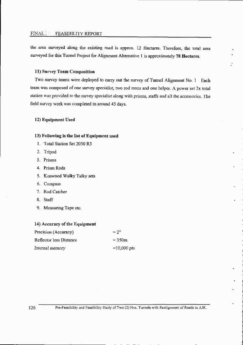
FINAL. FEASIBILITY REPORT
the area surveyed along the existing road is aprprox. 12 Hectares. Therefore, the total area
surveyed for this Tunnel Project for Alignment Altemative I is approximately ?8 Hectares.
I l) Survey Team Composition
Two surrrey teams were deployed to carry oui the suwey of Tunnel Alignment No. I Each
team was composed ofone survey specialist, two rod mans and one helper. A power set 2x total
station was provided to the survey specialist along with prisms, staffs and all the accessories. The
field survey work was completed in around 45 days.
12) Equipment Used
13) Following is the list of Equipment used
L Total Station Set 2030 R3
2. Tripod
3. Prisms
4. Prism Rods
5. Kenwood Walky Talky sets
6. Compass
7. Rod Catcher
8. Staff
9. Measuring Tape etc.
14) Accuracy ofthe Equipment
Precision (Accuracy)
Reflector less Distance
Internal memory
:350m
=i0,000 pts
t z o Pre-Feasibility and Feasibili! Study ofTwo (2) Nos. Tunnels with Realignment ofRoads iD AJK.

(4) Topography along the Alignment No. I and its Portal Areas
l) Alignment No. I - Tunnel No. I
The Topography along the alignment is mountainous with a variation of overburden from l0
meter at station 0+300 km to 487 meters ar l+420 station lffi along the alignment The average
slope of the mountain is 407o from Soulh Potal at station 0+220 km to station 1+420 km where
the overburden is highest, and then the mountain descends down at an average slope of 360lo
from station l+420 km to station 2+540 km where the overburden is 77m. Form this point the
monntain ascends up with an average slope of 80% at 2+920 where the overburden is 290 m and
then mountain is again descends down at an average slope of30m at North Portal. The mountain
is covered with green grass and bushes with many trees along the alignruent. The relatively plain
areas along the alignment are being used for cultivation by nearby resident. The whole alignmsaf
is crossed by one or two Nalas and streams which are mostly ephemeral and runs almost
perpendicular to the direction of the alignment. On right side ofthe alignment and the Khori land
slide tunnel, Neelum River is flowing and is making a big meandering at Kamsar area.
2) South Portal - Tunnel No. I
The Elevation of existing road is El. 765.00 meters at the Souttr Portal. The depth of
overburden is 10 meters approx. at a distance of 20 meters along the alignment direction from
the existing road. Therefore, the South Portal is located at the across Kamsar NaIa at an
Elevation of765.40 meters. Ground surface Elevation at this point is 782.87 meters. Topography
at the South Portal is rugged and mountainous and most important topographic feature at this
Portal is the Kamsar Nala. Kamsar crushing plant is very close to south portal and the alignment
of the turnel. On the right side of the tunnel alignment Neelum river is flowing with flushing
water. The Kamsar Nala is mostly ephemeral carries rain water (flood waterl) from its catchment
area and ends into the Neelum River. A Bridge is required on the existing road where the Kamsar
Nala crosses it along the link access road to cross this Nala before entering hto the South Portal.
Terraces are not available in front of this Portal and adjacent to the Kamsar Nala which are
required to be constructed for the Placement of Portal Facilities. The area around the Portal is
covered with hard dolomitic lime stone rock, some grass with some trees. A small link access
road of about 300 m is required at South Portal by improving 280 m ofexisting road in terms of
Pre-Feasibility and Feasibitity Sndy ofTwo (2) Nos. Tunnels with RealigDment of Roads in AJK.

FINAI:" , -FEASIBILITYREPORT
grade and width and also by providing a bridge. Approximate location of south Portal is marked
on the pictr.ue below.
3) North Portal - Tunnel No, I
The Elevation of existing road is El. 778.00 meters at the North Portal. The depth of
overburden is 30 meters approx. at a distance of 60 meters along the alignment direction from
the existing road. Therefore, ttre North Portal is located at the across Hurama more at an
Elevation of 791.95 meten. Ground surface Elevation at this point is 809.65 meters. Topogaphy
at the North Portal is rugged and mountainous and most important topographic feature at this
Portal is the Hurama More. On right side of the tunnel alignment Neelurn river is flowing with
flushing water. This Nala at Hurama More is mostly ephemeral carries rain water (flood waterl)
from its catchment area and ends into the Neelum River- Small terraces are not available in front
of this north Portal and adjacent to the Hurama more which are required to be constsucted for the
Placement of Portal Facilities. The area around the Portal is covered with Shale, silt stone and
Murree sand stone rock. The mountain is covered with green grass and bushes with many trees
along the alispment. A snall link access road of about l20m is required at North Portal by
Picture No. 1: South Portal Area at Kamsar Nala - Tunnel No. I
128 Pre-Feasibility and Feasibility Snrdy ofTwo (2) Nos. Tunnels with Realignment of Roads in AJK.

improving 60 m of existing road in terms of grade and width. Approximate location of North
Portal is marked on the picture below.
Picture No. 2: North Portal Area at Harama More - Tunnel No. I
4) Tunnel Gradient - Tunnel No. I
The Elevation difference between the South Portal (El. 765.40 m) and North Portal (El. 791.95 m)
is 26.55 meters over the length of 3.900 km resulting into gradient of less than 1.00% in the Tunnel.
(5) Topography alorg the Alignment No. 2 and its Portal Areas
l) Alignment No. I - Tunnel No. 2
The Topography along the alignment is mountainous with a overburden of98 meters at 0+220
station lnn along the alignment The average slope of the mountain ts 260/o from South Portal at
station 0+220 km to station 0+380 hn where the overburden is highest, and then the mountain
descends down at an average slope of l7o/o from station 0+400 km to station 0+410 km where
the overburden is 100m. Form this point the mountain ascends an average slope of l7% at 0+410
where the overburden is 100 m and then mountain is again descends dolrn at an average slope of
Pre-Feasibility and Feasibility Study of Two (2) Nos. Tunnels with Realignment ofRoads in AJK.

FINAL- -FEASIBILITY REPORT
l7m at North Portal. The nountain is covered with green grass and bushes with many trees along
the alignment. The relafively plain areas along the alignment are being used for cultivation by
nearby resident. A small link access road ofabout 320 meters is required to be made to connect
this proposed portal to the existing road
2) South Portal - Tunnel No. 2
The Elevation of existing road is El. 771 meters at the South Portal. The overburden is 100
mete,rs approx. A link access road of about 280 meters is required to be made to coDnect this
proposed portal to the existing road. Therefore, the South Portal is located at the across
chellapani at an Elevation of 825.43 metem. Ground surface Elevation at this point is 843.13
meters. Topography at the South Portal is mountainous and most important topographic feature
at this Portal is the chellapani NaIa. On the top of this mountairL a plane area is present beign
used by the resident cultivation. Small terraces are required to be developed for the placement of
Portal Facilities. The area around the Poral is covered with alluvial deposit which are consist
cobble, pebble, boulder gravel, sand, silt and clay soft rock, with grass big trees. Approximate
location of south Portal is marked on the oicture below.
Picture No, 3: South Portal Area at Chella Pani - Tunnel No. 2
130 Pre-Feasibility and Feasibility Study ofTwo (2) Nos- Tuonels with Realignmcnt ofRoads in AJK.

3) North Portal - Tunnel No. 2
The Elevation of existing road is El. 844 meters at the North Portal of the Tunnel No. 2. T[re
overburden is 100 meters approx. Therefore, the North Portal is located at the across Donga at an
Elwation of 841.76 meters. Ground surface Elevation at this point is 859.46 meters. Topography
at the North Portal is mountainous and most important topogFphic feature at this Portal is the
Donga Nala. Small terraces are required to be developed for the placement of Portal Facilities.
The area around the Portal is covered with alluvial deposit which are consist cobble, pebbfle,
boulder gravel, sand, silt and clay soft rock, with grass big trees. Approximate location of Noitl
Porlal is marked on the picture below.
4) Tunnel Gradient - Tunnel No. 2
The Elevation difference between the South Portal (El. 825.43) and North Portal (El. 841.76)
is 16.33 meters over the length of 0.600 km resulting into gradient of 3.007o in the Tunnel.
Picture No. 4: North Portal Area at Donga Nala - Tunnel No. 2
Pre-Feasibility and F@sibility Study ofTwo (2) Nos. Tunncls with Realignment ofRoads in AJK.

Bu
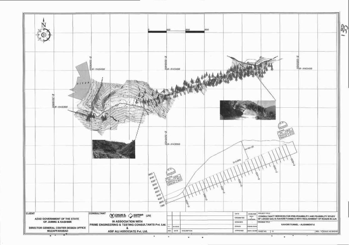

FINAL -FEASIBILITY REPORT
5.2 Procurement of Satellite Imagery with DEM
51.1 Introduction
As per the scope of work defined in the TO& a satellite imagery of 0.61 minimum
resolutions will be procured with the provision of DEM (Digital Elevarion Model) orDTM Digital Terrain model with contorus with intervals of lm.
Therefore, the providers of satellite imagery were contacted and imagery with theprescribed resolution was obtained after processing for ortho-rectification and
atmosphere and temperature correction. For DEM from the same provider a pair of
stereo-image was obtained which made processes for the development of DEM with one
metef contour-
5.2,2 Remote Sensed Satellite Imaqes
Rerrote Sensed satellite images provides an economical, accurate and rapid means of
obtaining quick assessment for any significant construction or engineering project, e.g.,
airstrip, bridge, danr, water, power plant, sewer, industrial park, canal and storm utilities,
etc., the first phase of site selection and evaluation. One goal of this phase is to obtain
information about surficial materials (granular, cohesive, permeable, non-uniform, etc.),
thickness of the soil mantle, nature of the bedrock, drainage, presence of unstable
materials and conditions, presence of subsurface solution cavides, fractures, joints, faults,
stc.
Remote sensing data from Satellite Senson such as GeoEye-l, Worldview-2,
QuickBird, IKONOS, LANDSAT, SPOT-5, ASTER, aerial photography and LIDAR is
used in a variety of civil and environmental engineering applications, including site
selection, resource mapping, water quality and quantity monitoring, geotechnical
measurements, and non-destuctive testing. Satellite Imagery analysis of surficial
materials measures and provides inventory on land and water resources. It embodies
134 Prc-Feasibjlity and Feasibility Study ofTwo (2) Nos. Tunr:els wjth R€ajignDeDt ofRoads in AJK_

traditional engineering disciplines of data analysis, photogammetry, and surveying, as
well as emerging areas of image processing, geographic information systems (GIS) and
global positioning systems (GPS) technologies.
5.2.3 Satellite Imagery & DEM
E Remote Sensing
Both of the project sites are rugged and mountainous area
Conventional Survey cannot cover the broad band of corridor to study route
altematives
For alternative route study, broad band and accurate iopo- data are prerequisite
Remote Sensing a6>zJ=Geo-Eyel
700-90okm
, i l
AerialPhotography^ i i j-Wi i i-<^ : i
i ! i iro-tzkmi : r l
1.2-i.5hn i I i i
Aerial Television i i i I
@iiii+ i i i i
Prc-Feasibility and F€asibility Study ofTwo (2) Nos. Tunnels with Realignmcnt ofRoads in AJK.

FINAL FEASIBILITYREPORT
E Selection Remote Sensing
. Considering the accuracy, Geo-Eyel Satellite Imagery with DEM was used
E Resolution by Satellite
. Launch September. 2008
. Features Highest resolution sensots
commercially available
. Sensor Resolution 0.5m resolution
Satellite Name Geo-Eye I QuickBird IKONOS SPOT-5
Resolution 0.5m 0.6m 2m-5m 5rn-l0m
136 Pre'Feasibility and Feasibility Study ofTwo (2) Nos. Tunnels with Realignment of Roads in AJK.
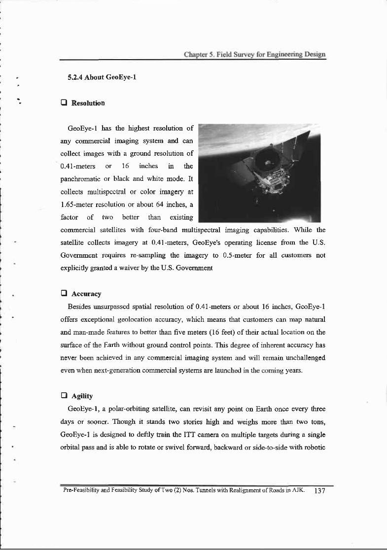
5.2.4 About GeoEye-1
O Resolution
GeoEye- I has lhe highest resolution of
any commercial imaging system and can
collect images with a ground resolution of
0 .4 I -meters or 16 inches in the
panchromatic or black and white mode. It
collects multispectral or color imagery at
L65-meter resolution or about 64 inches, a
factor of two better than *isting
commercial satellites with four-band multispectral imaging capabilities. While the
satellite collects inagery at 0.41-meters, GeoEye's operating license from the U.S.
Govemment requires re-sampling the imagery to 0.5-meter for all customers not
explicidy granted a waiver by the U.S. Govemment
E Accuracy
Besides unsurpassed spatial resolution of 0.41-meters or about 16 inches, GeoEye-l
offers exceptional geolocation accuracy, which means that customers can map natural
and man-made features to betier than five meters (16 fee| of their actual location on the
surface of the Earth without ground control points. This degree of inherent accuracy has
never been achieved in any commercial imaging system and will remain unchallenged
even when next-generation commercial systems are launched in the coming years.
B Agitiry
GeoEye- I, a polar-orbiting satellite, can revisit any point on Earth once every three
days or sooner. Though it stands two stories high and weighs more than two tons,
GeoEye-l is designed to deftly tain the ITT camera on multiple targets during a single
orbital pass and is able to rotate or swivel forward, backward or side-to-side with robotic
Pre-Feasibility and Feasibility Study ofTwo (2) Nos. Tunnels with Realignment ofRoads in AJK. I37

FINAI . - *,-FEASIBILITYREPORT
precision. This unrivaled agility enables it to collect much more imagery during a single
pass.
B Frequency
GeoEye- I makes 15 orbits per day flying at an altitude of68l kilometers or 423 miles
with an orbital velocity of about 7.5 km/ses or 16,800 mi/hr. Its sun-slmchronous orbit
allows it to pass over a given area at about 10:30 a.m. local time every day. Given its
altitude and sun-synchronous orbit, field of view and superior resolution GeoEye-l can
"revisit" any point on the globe every three days or sooner, depending upon the required
look angle. The satellite complements GeoEye's current IKONOS system and will collect
imagery about 40 percent faster for panchromatic and 25 percent faster for multispectral
collections. Together, the IKONOS and GeoEye-l satellites collect alnost one million sq
km of imagery per day.
Q Volume
In the panchromatic mode the satellite collects up to 700,000 square kilometers in a
single day, an area about the size ofTexas, and in the multispectral mode 350,000 square
kilometers per day; the equivalent of photographing in color the entire State of New
Mexico. This capability is ideal for large-scale mapping projects. Our customers have
assured access to high-resolution, high-quality commercial imagery well into the 2015
timeframe.
O Camera
GeoEye- I 's optical telescope, detectors, focal plane assemblies and high-speed digital
processing electronics are capable of processing 700 million pixels per second. GeoEye-
I's agile camera allows for side-to-side extensions of the camera's 15.2 kilometer (9.44
miles)-wide swath width or multiple rmages of the same target during a single pass to
create a stereo picture. The camera and electronics represent a S-times gain in power
efficiency, a l0-times improvem€nt in weight efficiency and 3-times advance in cost
efficiency.
138 Pre-Feasibility and Feasibility Study ofTwo (2) Nos. Tunnels with Realignment ofRoads in AJK,

O Products
GeoEye-l customers have a choice of ordering basic, ortho-rectified or stereo irnagery
as well as imagery-derived products, including Digital Elevation Models (DEM's) and
Digital Surface Models (DSM's), large area mosaics and feature maps. GeoEye- I
products will serve a wide variety ofapplications for:
. Defense
o National and Homeland Security
o Air and Marine Transportation
o Oil and Gas
. Enefgy
o MininB
. Mapping and Location-based Services
. State and Local Government
r Insurance and Risk Management
o Agriculture
o Nahrral Resources and Environmental Monitorine
E Ground Stations
GeoEye upgraded a centralized command and control ground station facility at its
headquarters in Dulles, Virginia. This operations center sends tasking and operating
commands to the satellite and receives data downlinks from it. Tbree other stations are
operated or leased by GeoEye in Barrow, Alaska; Tromso, Norway and Troll, Antarctica.
The four ground stations provide the primary data reception needed due to the large
volume of imagery that is captured by the satellite. The Thomton, Colorado regional
operational facility has also been upgraded as a back-up grormd station for GeoEye- I .
Pre-Feasibility and Feasibilify Study ofTwo (2) Nos. Tunnels with Realignment ofRoads in AJK. 139
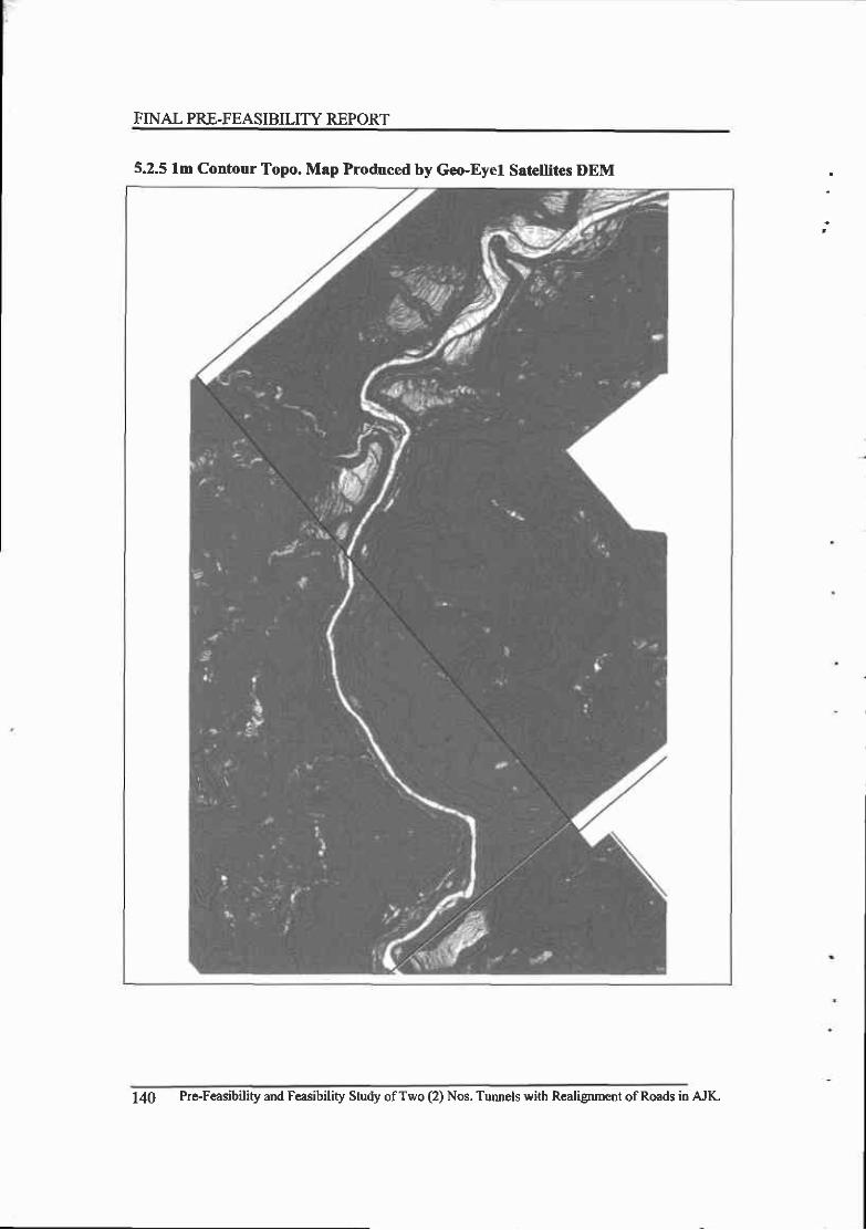
FINAL PRE-FEASIBILITY REPORT
5.2.5 lm Contour Topo. Map Produced by Geo-Eyel Satellites DEM
140 Pre-Feasibility and Feasibility Study ofTwo (2) Nos. Turnels with R€alignment ofRoads in AJK.
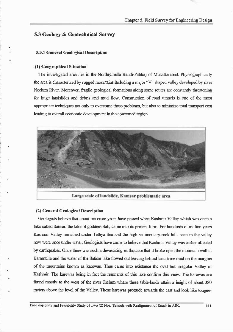
Chapter 5. Field Survey for Engineering Design
5.3 Geology & Geotechnical Survey
5.3.1 General Geological Description
(l) Geographical Situation
The investigated area lies in the Nort(Chella Bandi-Patika) of Muzaffarabad. Physiographically
the area is characterized by rugged mountains including a major "V" shaped valley developed by river
Neelum River- Moreover, fragile geological formations along some routes are constantly t}reatening
for huge landslides and debris and mud flow. Constuction of road tunnels is one of the most
appropriate techniques not only to overcome these problems, but also to minimize total transport cost
leading to overall economic development in the concemed region
(2) General Geological Description
Geologists believe that about ten crore years have passed when Kashmir Valley which was once a
lake called Satisar, the lake of goddess Sati, came inio its present form. For hundreds of million years
Kashmir Valley remained unda Tethya Sea and the high sedimentary-rock hills seen in the valley
now were once under water. Geologists have come to believe that Kashmir Valley was earlier affected
by earthquakes. Once there was such a devastating earfiquake that it broke open the mountain wall at
Baramulla and the water of the Satisar lake flowed out leaving behind lacustrine mud on the margins
of the mountains known as karewas. Thus came into existance the oval but irregular Valley of
Kashmir. The karewas being in fact.the rcrnnants of this lake confirm this view. The karewas are
formd mosdy to the west of the river Jhelum where these table-lands attain a height of about 380
meters above the level of the Valley. These karewas protude towards the east and look like tongue-
Pre-Feasibility and Feasibility Study ofTwo (2) Nos. Tunnels with Realignment ofRoads in AJI( t4l

FINAL FEASIBILITY REPORT
shaped spun wilh deep ravines.
The investigated area is part of the sedimentary cover of Precambrian age. Sweral names have been
given to this formation as Slate s€ries ofHazara and Hazara slate fornation.
Hazara formation is exposed on Muzaffambad - Mansehra road and on the right bank of Jeblum Rrver.
The Formation consists of slate, phyllite and shale with minor occurrence of limestone and glpsurn
The fresh color.r of slate and phyllite are black and green to dark greeq weathering colour is brown
and yellowish The sedimentary stuctures like fine laminatioq slumps, g"ded bedding and cross
bedding can be seen in the slate. In the mapped area the principal sedimenary lamination of clay and
silty size material, but gra.ded bedding can be found.
ln MuzaJfarabad area the relationship between the Hazara formation and the Murree formation and
the Abbbttabad formation are not conformable. There is a gypsum units and a limestone rmit appear to
lie in conformable stratigraphic position with the sunounding slate. A Late-Precambrian age has been
suggested by previous workers.
Pre-Feasibility and Feisibility Study of Two (2) Nos. Turnels with Realigunent ofRoads in AJK.

Chapter 5. Field Survey for Engineering Desigrr
5.3.2 Chella Bandi - Patika Road Tunnel
(l) 13t Road Tunnel
1) Overall l"t Tunnel Geolory
The investigated area lies at 4kn from Muzaffarabad city in the base of Neelum Valley. Generally
the relief of the area is the north-eastem and south'eastern parts. Steep slopes are characteristic
featues of the area. The weathering of the rocks depends upon the climatic conditions, structures,
topography, vegetation and slopes of the area. Both types of weathering i.e. mechanical weathering
and chemical weathering are prominent in the area. Rainfall is the main weathering ag€,!t. Solution
weathering is pronounced in carbonates rocks (dolomite and limestone) exposed in the localities.
Heavy rainfall, high refiee highly sheared and fractured rock rmis have made mass wasting an
important degadation process in the area.
The lithostratigraphic units exposed in the area are ranging in age tom hecambrian to recent and
corsist mainly of sedimentary and metamorphic rocks. Hazara formation is the oldest formation and
Murree formation is the youngest.
Chella Bandi - Patika I't Road Tunnel Proposed Alignment
Pre-Feasibility and Feasibility Study ofTwo (2) Nos. Tunnels with Realignment ofRoads in AJK. t43
FINAL -.-FEASIBILITY REPORT
The sedimentary rocks cover more than 60plo of the total area. The Formations found alons the
tunnel a.lignment area is as follows
o Abbottabad Formation
In the project area, the formation is exposed in the east ofJehlum fault in the core of Muzaffarabad
anticline.
The Abbottabad formation is mainly composed of dolomite, quaftite and phyllite. The dolomite is
thickly bedded. weathered colour is light brown and grey and fresh colour is grey to dark grey. The
dolomite is fine grained- The rock is associated with chert bands. These rocks are characterized bv
sodimentary breccia and skomatolites. The cracks and veins are filled with argillaceous material.
The upper contact of the formation is not exposed in the area. The lower contact with the Murree
formation is faulted and is, therefore, not possible to measure the true thickness ofthe formation.
Topographically it forms cliffs, and steep to almost vertical slopes. A Cambrian age has been designed
to these rocks.
At some places, basal conglomerate is overlain by quartozose sandstone followed upward by
altemating dolomite and limesone which is mainly ft'actured with white, gey, creamistL off white
and blue in colour. The large sizd stromatolites up to one meter radius are present at basod bedding
plains especially in Yadgar area of Muzaffarabad
oPaleocene Eocene Limestone
This formation is composed of grey, dark grey to black limestone with subordinate greenish grey
Shale. The limestone is frne to medium grained, thinly to thickly bedded and highly fi'actured. The
modularity is well developed in limestone found within the limestone. The formation is highly
fossiliferous.
oMurree Formation
The Munee formation occupies the major extent ofthe project area. It has a faulted contact with the
Abbottabad formation and Hazara fonnation.
The formation is composed of red thinly laminated siltstone, shalg clay, with zubordinate
int'aformational conglomerate. The sandstone is fine to medium grained, pale green to grey, maroon
coloured, calcareous and greywacke in natr.ue The beds ofsandstong clay or shale alternate with each
other. This pattem strows a cyclic deposition In sandstone veins ofcalcite and quartz are comnon At
few places beds of calcareous sandy conglomerates are calcareous, flattsned and squeezed in vanous
shapes. Some of which are tapered to point on one er1d. Evidently these pebbles originally were soft
calcareous and balls formed at the site of depositions rather than the detritus material brought from
744 Pre-Feasibility and Feasibility Study ofTwo (2) Nos. Tunnels with Realignment ofRoads in AJK.
\
Chapter 5. Field Suwey for Engineering Desigrt
elsewhere.
The age of the formation is Early to Middle Miocene
oAlluvium
In the area along the Neelum River the alluvium is present These deposis are confned to river and
few main streams. They are mainly composed of gravel, pebbles, cobbles and boulders embedded in
the matix of sandsone and siltstone.
The age ofthe alluvium is Recent.
o Characteristics of Major Rock Unit
The rocks types along the alignment are Dolomite (light to da* grey), Limestone (dark grcy to
black), Shale (green and red) and sandstone (greerU grey and purple).
Dolomite is moderately to higlrly jointed, fine graine{ cracko{ sheare4 britde and brecciated.
Weathered colour is light brown and grey and fresh colour is grey to dark grey. The rock is generally
dipping north eastward and dip angle between 30' to 89p. The joint planes dip at an angle of 30" to
9f.Fracture mostly cut the bedding planes perpendicularly. The cracks range from 1 to 3 cm or at
different places. The material in the cracks and joints of dolomite is mainly clay, calcite and quartz. At
different places chert is abundant which affect the geotechnical propenies of the rock The calcite and
quartz are the cementing material in dolomite.
Limestone is fine to medium grained, jointed and fractrue4 nodular, highly fossiliferous, hard
compact and highly tenacious. Fractues are mafu y oblique to the bedding plane. Limestone colow is
grey, dark grey, to black. Weathered colour is light brown. The rock dip angle between 40o to 89o. The
joint planes dip at an angle of 35" to 89'.The material in the cracks and joints of limestone is mainly
clay and calcitg quare veins are also present.
Shale are fine grained. Weathering is obvious on outqops. Along the alignment the rocks are
higl y stressed due to these stresses folding and sheared z)nes are predominant formd in Shale.
Foliation is found. Quartz veins are also present. The rock dip angle between 35" to 85". The joint
planes dip at an angle of 14'to 89".
Sand stone is fine to coarse grained and is highly fractured andjointed. At places it is thick beddd
hard and shows high tenacity. The rock dip at an angle of30P to 87 in a northward direction. Joint
planes dip fiom 25" to 85'mostly in southeast direction. The cracks range fiom 0.5mm to 3mm. The
material in the cracks is mainly clay and silts. Calcite and quarE vefus are also present.
o Hydrological conditions
According to investigation on surface oukrops JoinB and other discontinuities of almost all rock
Pre-Feasibility and Feasibility Study ofTwo (2) Nos. Tunnels with Realignment ofRoads in AJIC 145
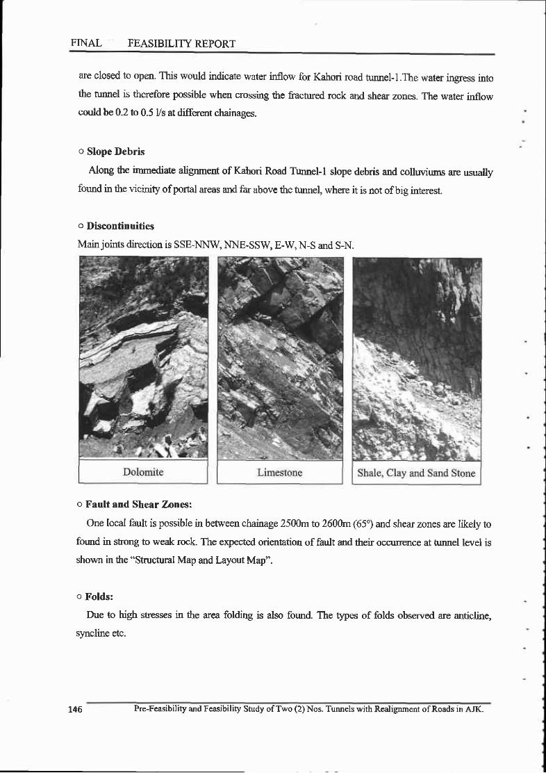
FINAL FEASIBILITY REPORT
are closed to open. This would indicate water inllow for Kahori road tururel-l.The water ingress into
the tunnel is therefore possible when crossing the fractured rock and shear zones. The water inflow
could b€ 0.2 to 0.5 Vs at diffrrent chainages.
o Slope Debris
Along the immediate alignment of Kahori Road Turmel-l slope debris and colluviums are usually
fomd in the vicinity of portal areas and far above the tunnel, where it is not of big interest.
o Discontinuities
Main joints direction is SSE-NNW, NNRSSW E-W, N-S and S-N.
o Fault and Shear Zones:
One local fault is possible in befween chainage 2500rnto 2600m (65o) and shear zones are likely to
found in stong to weak rock. The expected orientation of fault and their occunence at tunel level is
shown in the "Structural Map and Layout Map".
o Folds:
Due to high stresses in the area folding is also found. The types of folds observed are anticline,
syncline etc.
146 Pre-Feasibility and Feasibility Study ofTwo (2) Nos. Tunnels with R€lignment ofRoads in AJK.

Chapter 5. Field Survey for Engineering Design
2) Engineering Geological Mapping Unit
Main geological unit of Altemative 1 can be specified gpically as dolomitg shalg clay and sand
stone. Characteristics of each geological rmit is described as follows:
o Micaceous slat€
Item Description
Rock types Dolomite
Colour Grey to Dark Grey
Texture Fine Grained
Spacing of discontinuities Modoate(20-60cm) to Close (6cm - 20cm)
Persistence of discontinuities Medium
Roughness of discontinuities Rough
Surface of discontinuities Stained and weathered, frlling of clay, calcite and quartz visible.
Weathering Moderate to higl y weathered on surface outcrops
Sensitivity to water Sensitivity of dolomite indicated
Water Conditions Nil or Water ingression possible (0.5l/min, Gr700)
UCS of rock samole 100 | 50Mpa
o Limestone
Item Descdption
Rock types Limestone
Colour Grey ,Dark Grcy to Black
Texture Fine to Midium Grained
Spacing of discontinuities Close (6-20cm) to medium(2Ocm - 60cm), to Wide(60cm-200cm)
Persistence of discontinuities Medium
Rouehness of discontinuities Rough
Surface of discontinuities Stained and weathered, filling ofclay, calcite and quartz visible.
Weathering Moderate to highly weathered on surface outcrops
Sensitivity to water Sensitivity of Limestone indicated
Water Conditions Nil or Litde possible (0.2 Vmin, l+100)
UCS of rock samDle 100 - 200Mpa
Pre-Feasibility and Feasibility Study of Two (2) Nos. Tunnels witb Realignment ofRoads in AJK.

FINAL .I FEASIBILITY REPORT
o Shale, Clay and Sand Stone
Item Description
Rock types Shale, Clay and Sand Stone
Colour Varied colour, shale (green, red and purple) Sand stone (green,brownish and pale grey)
Texture Shale (fine grained) Sand stone (fine to medium grain)
Spacing of discontinuities Very close (2 cm - 6 cm) medium (20 cm - 60 cm)
Persistence of discontinuities Medium to High
Rouglness of discontinuities Smooth (shale) rough (sandstone)
Surface of discontinuities Weathered (filling of clay quartz and calcite visible.)
Weathering Modefate to highly weathered on surface outcrops
Sensitivity to water Sensitivity of Shale and sandstone indicated
Water Conditions Nl or Little possible (2+500, 3+350)
UCS of rock sample Shale (25 - 50MPa), Sandstone (100 -l5OMPa)
(
Pre-Feasibility and Feasibility Study ofTVo (2) Nos, Tunnels with Realignment ofRoads in AJK,
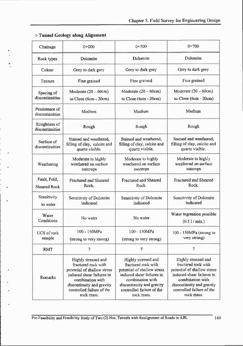
Chapter 5. Field Survey for Engineering Design
o Tunnel Geology along Alignment
Chainage 0+000 0+500 0+700
Rock types Dolomite Dolomite Dolomite
Colour Grey to dark grey Grey to dark grey Grey to dark grey
Texture Fine grained Fine grained Fine grained
Spacing ofdiscontinuities
Moderate (20 - 60cm)
to Close (6cm - 20crn)
Moderate (20 - 60cm)
to Close (6cm - 20cm)
Moderate (20 - 60cm)
to Close (6cm - 20cm)
Persistence ofdiscontinuities Medium Medium Medium
Roughness ofdiscontinuities
Rough Rough Rough
Surface ofdiscontinuities
Stained and weathered,filling ofclay, calcite and
quartz visible.
Stained and weathered,filling ofclay, calcite and
quartz visible.
Stained and weathered,filling of clay, calcite and
quartz visible.
WeatheringModerate to highly
weathered on surfaceoutcrops
Moderate to highlyweathered on surface
outcrops
Moderate to highlyweathered on surface
outcrops
Fault, Fold,
Sheared Rock
Fractured and ShearedRock.
Fractured and ShearedRock.
Fractured and ShearedRock.
Sensitivity
io water
Sensitivity of Dolomiteindicated
Sensitivity of Dolomiteindicated
Sensitivity of Dolomiteindicated
WaterConditions
No water No waterWater ingression possible
(0.5 I / min.)
uus ot rocl(sample
100 - 150MPa
(strong to very strong)
100 - l5OMPa
(sfong to very shong)100 - 150MPa (skong to
very strong)
RMT 7 7 7
Remarks
Highly sfessed andfractured rock with
potential of shallow stressinduced shear failures in
combination withdiscontinuity and gravitycontrolled failwe of the
tock mass.
Highly stressed andfractured rock with
potential of shallow sfessinduced shear failues in
combination withdiscontinuity and gravitycontrolled failure of the
rock mass.
Highly stressed andfractured rock with
potential of shallow stressinduced shear failures ir
combination withdiscontinuity and gravitycontrolled faihue of the
rock mass.
Pre-Feasibility and Feasibility Study ofTwo (2) Nos. Tunnels with Realignment of Roads in AJK.

FINAL -; .FEASIBILITY REPORT
Chainage I +100 t+400 1+600
Rock types Limestone Limestone Shale, Clay and Sand stone
Colour Grey. dark grey, to black Grey, dark grey, to black
Varied colour, shale(green, red and purple)
Sand stone (green,brownish and oale prev)
Texture Fine to medium grained Fine to medium srainedShale (fine gra.ined) Sand
stone (fine to mediumgram)
Spacing ofdiscontinuities
Close (6 cm - 20 cm)to wide (60 - 200cm)
Close (6 cm - 20 cm)medium (20 - 60cm)
very close (2 un - 5 cm)medium (20 cm - 60 cm)
Persistence ofdiscontinuities Medium Medium Medium to high
Roughness ofdiscontinuities Rough Rough Smooth (Shale) rough
(sandstone)
Surface ofdiscontinuities
Stained and weathered,filling ofclay, calcite and
quartz visible.
Stained and weathered,filling of clay, calcite and
quartz visible.
Weathered (filling of clayand calcite visible.)
Weatheringmoderate to highly
weathered on surfaceoutcrops
moderate to highlyweathered on surface
outcroDs
Moderate to highlyweathered on surface
outcropsFault, Fold,
Sheared RockSlightly Sheared rock Slightly Sheared rock
Shale (Sheared rock)Sandstone (Iiacrured)
Sensitivityto water
Sensitivity of limestoneindicated
Sensitivity of limestoneindicated
Sensitivity of Shale andsandstone indicated
WaterCondiiions
Little Possible (0.2 I /min)
No water No water
UCS of rocksample
(100 - 200MPa)(strong to very shong)
(100 - 200MPa)(strong to very shong)
Shale (25 - 50MPa)Sandstone ( I 00 -l50MPa)
RMT 6 o 9 & l 0
Remarks
Highly Fractured rock-Deep reaching,
discontinuity controlled,gravity induced falling and
sliding ofblocks,occasional local shear
failure.
Highly Fractured rock.Deep reaching,
discontinrity controlled,gravity induced falling and
sliding ofblocks,occasional local shear
failure.
Highly stessed andfractured rock with
potential of small localshear failure.
150 Pre-Feasibility and Feasibility Study ofTwo (2) Nos. Tunnels with Realignment ofRoads in AJK.
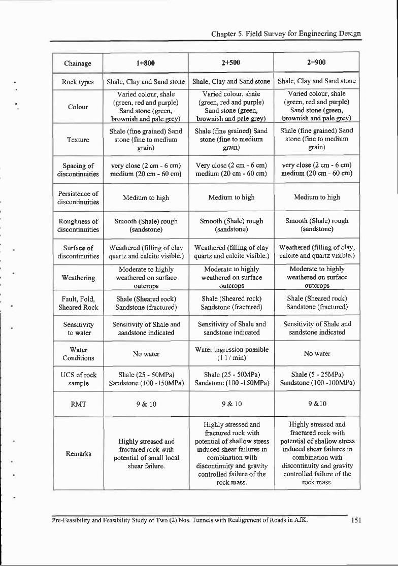
Chapter 5. Field Survey for Engineering Design
Chainage l+800 2+500 2+900
Rock types Shale, Clay and Sand stone Shale, Clay and Sand stone Shale, Clay and Sand stone
Colour
Varied colour, shale(green, red and purple)
Sand stone (green,brownish and pale srey)
Varied colour, shale(green, red and purple)
Sand stone (green,brownish and pale srev)
Varied colour, shale(green, red and purple)
Sand stone (green,brownish and pale grey)
Texn:reShale (fine grained) Sand
stone (frne to mediumgrain)
Shale (fine grained) Sandstone (fine to medium
graln)
Shale (fine grained) Sandstone (flrne to medium
gain)
Spacing ofdiscontinuities
very close (2 cm - 6 cm)medium (20 cm - 60 cm)
Very close (2 cm - 6 cm)medium (20 crn - 60 cm)
very close (2 cm - 6 cm)medium (20 cm - 60 cm)
Persistence ofdiscontinuities
Medium to high Medium to high Medium to high
Roughness ofdiscontinuities
Smooth (Shale) rough(sandstone)
Smooth (Shale) rough(sandstone)
Smooth (Shale) rough(sandstone)
Surface ofdiscontinuities
Weathered (filling of clayquartz and calcite visible.)
Weathered (filling of clayouartz and calcite visible.)
Weathered (filling of clay,calcite and quartz visible.)
WeatheringModerate to highly
weathered on surfaceoutcrops
Moderate to highlyweathered on surface
outcroDs
Moderate to highlyweathered otr surface
outcrops
Fault, Fold,Sheared Rock
Shale (Sheared rock)Sandstone (fractured)
Shale (Sheared rock)Sandstone (fractured)
Shale (Sheared rock)Sandstone (fractured)
SensitivityIO Waaer
Sensitivity of Shale andsandstone indicated
Sensitivity of Shale andsandstone indicated
Sensitivity of Shale andsandstone indicated
WaterConditions
No waterWater ingression possible
(l I / min)No water
UCS of rocksample
Shale (25 - 50MPa)Sandstone ( 100 -150MPa)
Shale (25 - 50MPa)Sandstone (100 -l50MPa)
Shale (5 - 25MPa)Sandstone ( 100 -l00MPa)
RMT 9& l 0 9& l 0 9 &10
Remarks
Highly snessed andfractured rock with
potential of small localshear failure.
Highly stressed andfiachued rock with
potential of shallow stressinduced shear failures in
combination withdiscontinuity and gravitycontrolled failure of the
rock mass,
Highly stressed andfractured rock with
potential of shallow stressinduced shear failures in
combination withdiscontinuity and gravitycontrolled failure of the
rock mass.
Pre-Feasibility and Feasibility Study ofTwo (2) Nos. Tunnels with Realignment ofRoads in AJK.
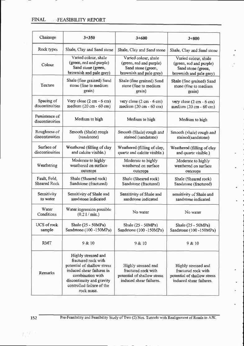
FINAL -FEASIBILITYREPORT
Chainage 3+350 3+600 3+E00
Rock types Shale, Clay and Sand stone Shale, Clay and Sand store Shale, Clay and Sand stone
Colour
Varied colour, shale(green, red and purple)
Sand stone (green,brownish and pale grey)
Varied colour, shale(geen, red and purple)
Sand stone (green,brownish aad pale grey)
Varied colour, shale(green, red and purple)
Sald stone (green,brownish and pale $ev)
TextureShale (frne grained) Sand
stone (fine to mediumgrain)
Shale (fine gained) Sandstone (fine to medium
grain)
Shale (frne grained) Sandstone (fine to medium
grain)
Spacing ofdiscontinuities
Very close (2 cm - 6 cm)medium (20 cm - 60 cm)
very close (2 cm - 6 cm)medium (20 crn - 60 cm)
very close (2 cm - 6 cm)mediurn (20 cm - 60 cm)
Persistence ofdiscontinuities Medium to high Medium to high Mediurn to high
Roughness ofdiscontinuities
Smooth (Shale) rough(sandstone)
Smooth (Shale) rough andstained (sandstone)
Smooth (shale) rough andstained(sandstone)
Surface ofdiscontinuities
Weathered (filling of clayand calcite visible.)
Weathered (filling of clay,ouartz and calcite visible.)
Weathered (frlling of clayand quartz visible.)
WeatheringModerate to highly
weathered on surfaceoutcrops
Moderate to highlyweathered on surface
outcroDs
Moderate to highlyweathered on surface
outcrops
Fault, Fold,Sheared Rock
Shale (Sheared rock)Sandstone (fractured)
Shale (Sheared rock)Sandstone (ftactured)
Shale (Sheared rock)Sandstone (fractured)
Sensitivityto water
Sensitivity of Shale andsandstone indicated
Sensitivity of Shale andsandstone indicated
sensitivity of Shale andsandstone indicated
WaterConditions
Water ingression possible(0.2 I / min.)
No water No water
UCS of rocksample
Shale (25 - 50MPa)Sandstone (100 -l50MPa)
Shale (25 - 50MPa)Sandstone (100 -l5OMPa)
Shale (25 - 50MPa)Sandstone (100 -150MPa)
RMT 9&10 9 & l 0 9& l 0
Remarks
Highly stressed andfractured rock with
potential of shallow stressinduced shear failures in
combination withdiscontinuity and gravitycontrolled failure of the
rock mass,
Highly stressed andfrach:red rock with
potential of shallow shessinduced shear failures.
Highly stressed andfractured rock with
potential of shallow stressinduced shear failures.
152 Pre-Feasibility and Feasibility Study ofTwo (2) Nos. Tunnels with Realignment ofRoads in AJK.


Ghella Bandi - Patika Road 1st TunnelGelogical Map(Section View)
Longltudlnal Sectlon(Sta. 0+61r0-Sla.1 +540)
."s
SECTION C.D
Longitudlnal Section(Sta. 1+540-Sta.2+1 80)
SECTION E.F
Longitudinal Sectlon(Sta. 3+1 80-Sta.4+060)
ill
CUElfT
A2AO OOVERXXEI{T OF IHE 9IATEOFJAXIIU I KASHMR
DIRECTOR gENERAL CENTRAI. DESIGN OFFICEMUZAFFARASAD
consulrAf{r cDglll* ? g!!Fn r'rvr
PRIME ENGINEERING &TESTING CONAULTANTS PVT. LTD,a
ASIF AU ASSOCIATE P\/r' LTD.
PRE.FEASIBIUW ATD FEASISUTT STUOYoF rrvo {2) Nos. flfi{ Els v{fiH REAUGT{mEI{T OF ROADS l Al(
Cholh Brndl. Patlka Road lalTunnelG.loolEl [ap(s.ollon vl.,,N]
oMqNGm td F&'0 t ,44,:As'iowN
.tlF^9
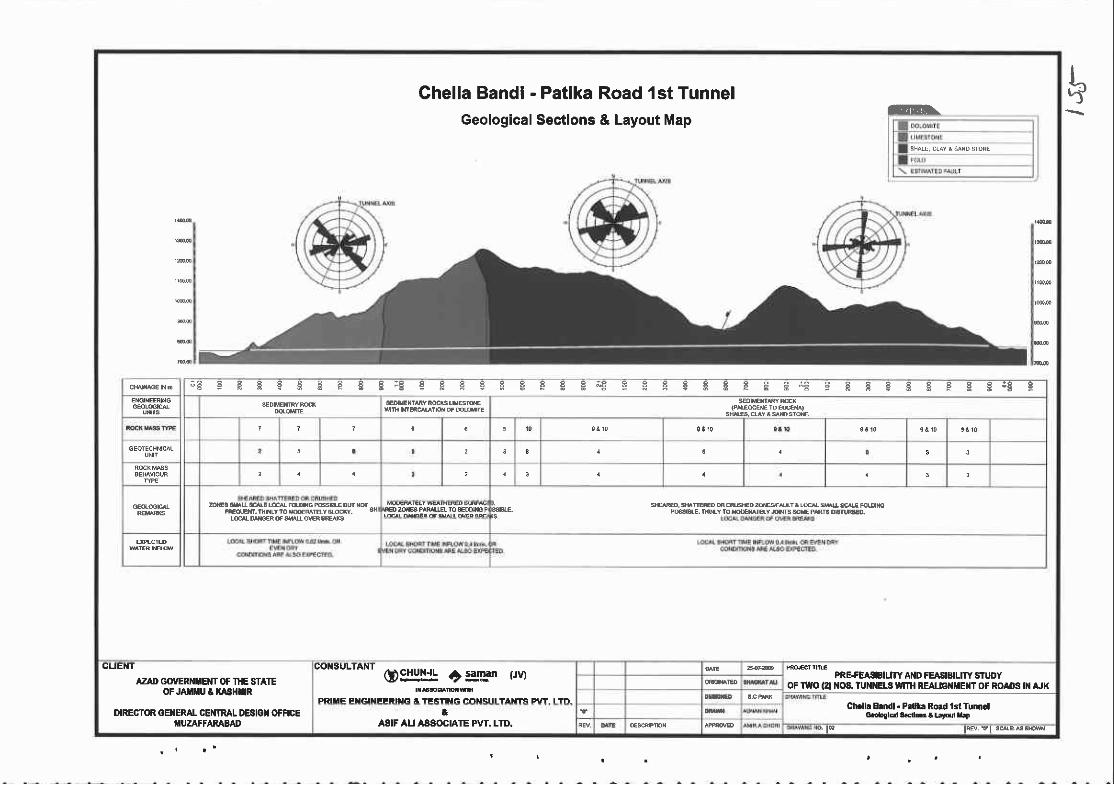
Ghella Bandi - Patlka Road 1st TunnelGeological Sectlons & Layout Map
m.
; E E F F g S B € E E : E E € F E H g F € E i g E F g g g g P g E ; E 9 E f , g g E P E E 3 T E
s|*B'uYlgDsr*.
no 20€e PIMUE ro 80('$€ P
CUE I
AZAD d)VERiIXEIT OF THE 8TA1EOF JAXIMU t XASHTR
OIRECTOR GEI{ERAL CEI{TRAL OESIGT OFfICEIUZAFFAMBAD
OgIXll! r'=!89" (Jv)
PRIflE Et{GlilEERlt{tl t TESTIiIG CorfSlll lA nC F\tl I Tll
PRE+CAIIILITY AI{D FEASIEILII Y Sf UDYoF IWO (21 t{OS.IUXXELS tVIrH REA|.tct{HEilT OF RO D€ [{ AJK
Ch.ll. 8.ndl . P.fl€ Rord lst Tur||Glo.oSald 34dM I rrFd L.P&
ASIF AU AASOCIAIE PVT. LTD. ' to t@. r t s4eB. rM
h

Chella Bandi - Patika Road 1st TunnelGeological Structure Map
E E F E 9 q E.E E E E F F E -8 E E F C E F E F F ! ? q E F E F ? F ! F ! F F F + EE
F E E E E F E E E E F F E E E F E E g E H H C E E F E g E F F € g f ; E F H H E " B
CUET{I
AZAD GOVERI{XEIIT OF THE STAIEoFJ XXU t t{A3HnR
DIFECTOR GEI{EML CE|fTRAL DEEIGT OFF|CEIIUZAFFAR^EAD
co sulraNr oDg!:y! ? :gg- r.rvl
PR|IIE EXGINEE NG A IESTII{G CONSULTANTS PVT. LID.a
AS|F Au ASSoC|ATE PvT. Lnt.
PRE+EASIBIUTY AI{D FEASIBIUIY STUDYOFIV{O (2I I{06. TU }IELS IUIH REALIGilTEI{TOF ROADS III AJK
Cft.lb Ee tl . frd*. Food lsi TunrGlG.oloakJdrEtE 4
@*rc@t@ twvt sc@a6x@
E

Chapter 5. Field Survey for Engineering Design
4) Structural Analysis of Discontinuities
Diagram ofpole points and direction ofdiscontinuities are shown below.
Given main strike direction and tunnel axis, excavation conditions of ltt tunnel is geotechnically
favourable excluding minor strike which is parallel to trmnel axis and rockfall due to vertical joint may
not be anticipated. Generally excavation condition of 1$ tunnel is good to achieve the tunnel stability
with small amount of reinforcement.
Geotechnical DescriptionPole Points ofjoints
vertical joints. High possibility of rockfall
Strike direction of Joitrtg Geotechnical Description
strike direction of joint is WN-ES,
ionship between strike direction and tumel a.xis
excludins some minor strike direction.
Pre-Feasibility and Feasibility Study ofTwo (2) Nos- Tunnels with Realignmcnt ofRoads in AJK.
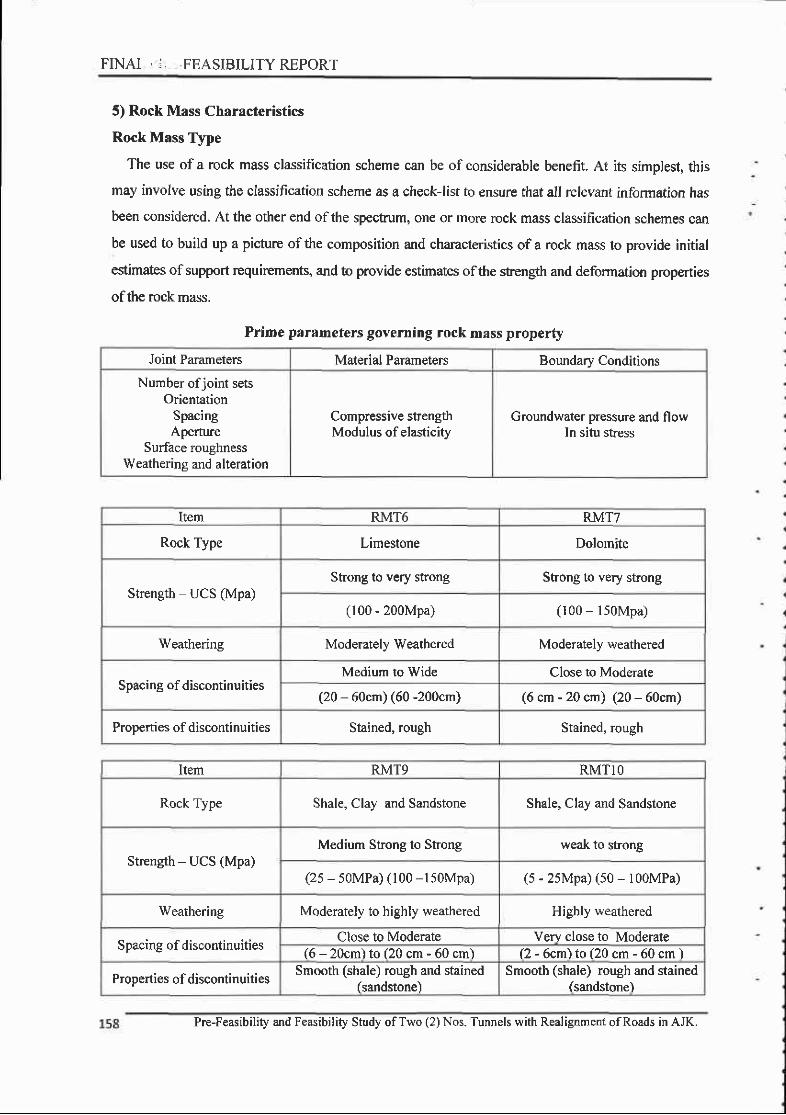
FINAI . : , ,FEASIBILITYREPORT
5) Rock Mass Characteristics
Rock Mass Type
The use of a rock mass classification scheme can be of considerable benefit. At its simplest, this
may involve using the classification scheme as a check-list to ensure that all relevant information has
been considered. At the other end ofthe spectrum, one or more rcck mass classification schemes can
be used to build up a picture ofthe composition and characteristics ofa rock mass to provide initial
estimates of support rcquirements, and to provide estimates ofthe strength and deformation properties
ofthe rock mass.
Prime parameters governing rock mass property
Joint Parameters Material Parameters Boundary Conditions
Number ofjoint setsOrientation
SpacingAperture
Surface roughnessWeathering and alteration
Compressive strengthModulus of elasticity
Groundwater pressure and flowIn situ stress
Item RMT6 RMTT
Rock Type Limestone Dolomite
Strenglh UCS (Mpa)Shong to very strong Strong to very strong
(100 - 200Mpa) (100 - l50Mpa)
Weathering Moderately Weathered Moderately weathered
Spacing of discontinuitiesMedium to Wide Close to Moderate
(20 - 60cm) (60 -200cm) (6 cm - 20 cn) (20 - 60cm)
Properties of discontinuities Stained, rough Stained, rough
Item RMT9 RMTIO
Rock Type Shale, Clay and Sandstone Shale, Clay and Sandstone
Strength - UCS (Mpa)Medium Strong to Strong weak to sfiong
(2s - soMPa) (100 -l50Mpa) (s - 2sMpa) (s0 - l00MPa)
Weathering Moderately to highly weathered Highly weathered
Spacing of discontinuitiesClose to Moderate Very close to Moderate
(6 - 20cm) to (20 cm - 60 cm) (2 - 6cm) to (20 cm - 60 cm )
Properties of discontinuitiesSmooth (shale) rough and stained
(sandstone)Smooth (shale) rough and stained
(sandstone)
Pre-Feasibility and Feasibility Study ofTwo (2) Nos. Tunnels with Realignment ofRoads in AJK.
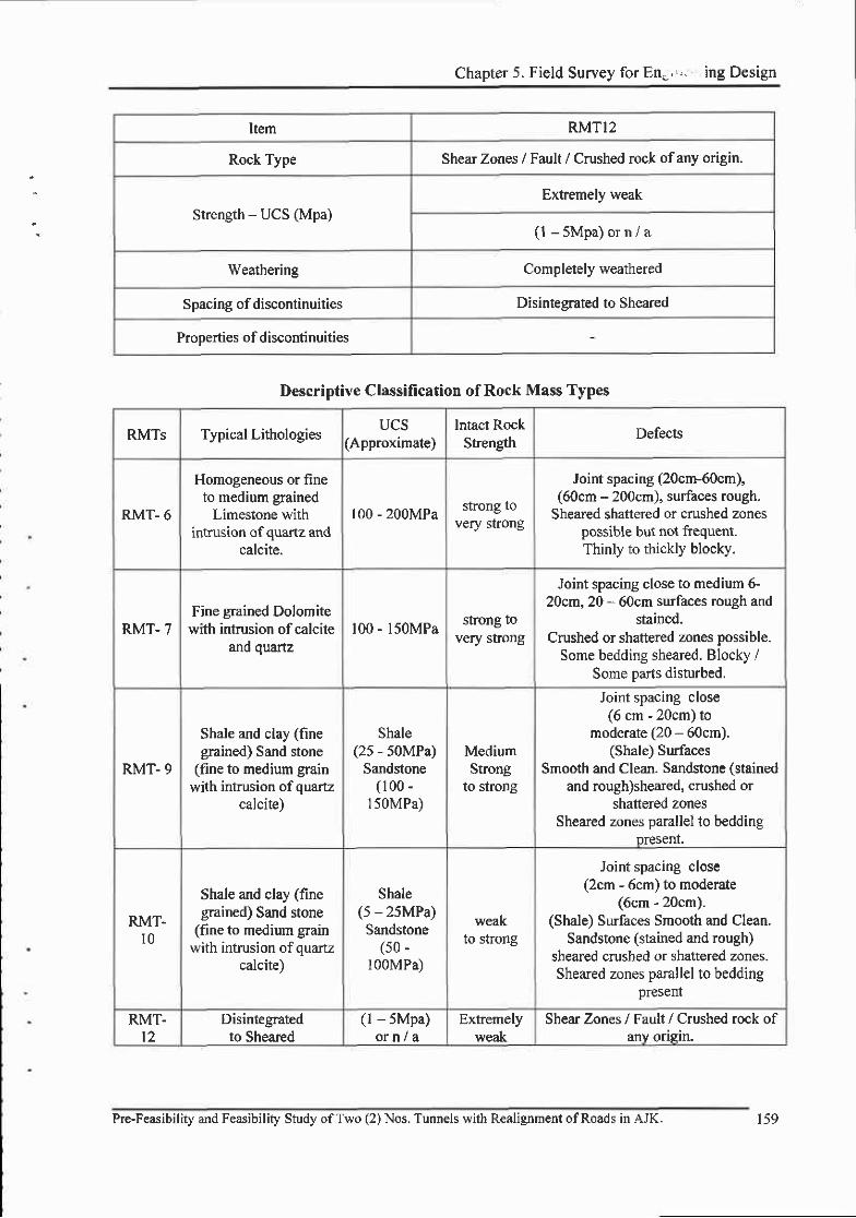
Chapter 5. Field Survey for En.',,. ing Design
Item RMTI2
Rock Type Shear Zones / Fault / Crushed rock of any origin.
Strenglh - UCS (Mpa)Extremely weak
( l - 5Mpa )o rn /a
Weathering Completely weathered
Spacing of discontinuities Disinteerated to Sheared
Prooerties of discontinuities
Descriptive Classilication of Rock Mass Types
RMTs Typical LithologiesUCS
(Approximate)Intact Rock
SfrenglhDefects
RMT- 6
Homogeneous or fineto medium grained
Limestone withintrusion of quartz and
calcite.
100 - 200MPa strong tovery stfong
Joint spacing (20cm-60cm),(60cm - 200cm), surfaces rough.
Sheared shattered or crushed zonespossible but not ftequent.Thinly to thickly blocky.
RMT.7Fine grained Dolomite
with intrusion of calciteand quartz
100 - lSOMPa strong tovery stong
Joint spacing close to medium 6-20cm, 20 - 60cm surfaces rough and
stained.Crushed or shattered zones possible.
Some bedding sheared, Blocky /Some Darts disturbed.
RMT- 9
Shale and clay (finegrained) Sand stone
(fine to medium grainwith intrusion of quartz
calcite)
Shale(25 - 50MPa)
Sandstone(100 -
150MPa)
MediumStrong
ro $rong
Joint spacing close(6 cm - 20cm) to
moderate (20 - 60cm).(Shale) Surfaces
Smooth and Clean. Sandstone (stainedand rough)sheared, crushed or
shattered zonesSheared zones parallel lo bedding
Dresent'
RMT-l0
Shale and clay (finegrained) Sand stone
(fine to medium grainwith intrusion of quartz
calcite)
Shale(s - 2sMPa)Sandstone
(s0 -l00MPa)
weakto srong
Joint spacing close(2cm - 6cm) to moderate
(6cm - 20cm).(Shale) Surfaces Smooth and Clean.
Sandstone (stained and rough)sheared crushed or shattered zones.Sheared zones parallel to bedding
present
RMT.t2
Disintegratedto Sheared
(l - 5Mpa)o rn / t
Extremelyweak
Shear Zones / Fault / Crushed rock ofanv origin.
Pre-Feasibility and Feasibility Study ofTwo (2) Nos. Tunnels with Realignment ofRoads in AJK. 159

FINAL ...h,i .FEASIBILITY REPORT
(2) 2'd Tunnel Geology
1) Overall 2"d Tunnel Geology
The Project area has rugged topography with high altitude up to 2100 meters. Due to rugged
topography of the area accessibility is a problem, the main rivers Neelum of Azad Kashmir run
through the arc4 the roads mainly leads along the river. In addition to these Jeepable roads, foot tracks,
mule trackq suspension bridges and rope bridges ar€ means of communication. During raining
seasons the roads are sometime blocked and create traffic Droblems.
The stratigraphy ofthe area range in age from Cambrian to recent. Mostly these sediments are non-
marine deposits. The stratigra.phic succession of Pakistan indicates that in the past geological periods,
the environments of deposition within through (Tethyan Sea) were not uniform and thus different
basins of deposition were established Gatif 1970). These basins show different pattem of events and
indicate the existence ofdefinite cycles oftransgression and regression.
The tunnel Alignment passes through the alluvial deposits of Muree formation. The alluvium is
composed mainly of gravel cobbles, pebbles and boulder of igneous metamorphic and sedimentary
Chella Bandi -Patika 2oo Tunnel Proposed Alignment
160 Pre-Feasibilig and Feasibility Study ofTwo (2) Nos. Tunnels with Realignment ofRoads in AJK.
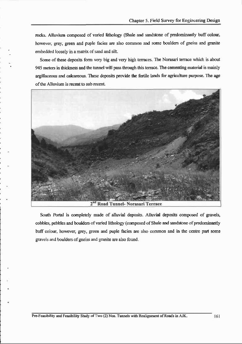
Chapter 5- Field Survey for Engiaeering Design
rocks. Alluvium composed of varied lithologr (Shale and sandstone of predominantly buff colour,
however, gay, green and puple facies are also common and some boulders of gneiss and granite
embedded loosely in a matrix of sand and silt.
Some of these deposis form very big and very high terraces. The Norasari ten-ace which is about
945 meters in thickness and the tunnel will pass through this terrac€. The cementing material is mainly
argillaceous and calcareous. Thes€ deposits provide the fertile lands for agricultue purpose. The age
ofthe Alluvium is r€cent to sub rec€nt
Soudr Portal is completely made of alluvial deposits. Alluvial deposits composed of gravelq
cobbleg pebbles and boulders ofvaried lithology (composed ofShale and sandstone ofpredominantly
buff colour, however, grey, green and puple facies are also common and in the cenfie part some
gravels and boulders ofgneiss and granite are also found.
Pre-Feasibility and Feasibility Study ofTwo (2) Nos. Tunnels wirh Realignment ofRoads in AJK.
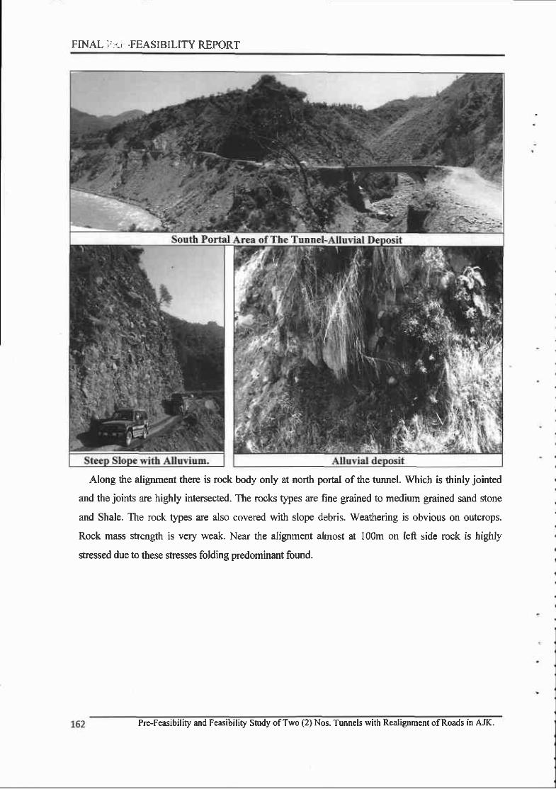
FINAL :':'., .FEASIBILITY REPORT
Along the alignment there is rock body only at north pofal of the tunnel. Which is drinly jointed
and the joints are highly intersected. The rock types are fine grained to medium grained sand stone
and Shale. The rock types are also covered with slope debris. Weatlrering is obvious on outcrops.
Rock mass strength is very weak. Near the alignment almost at I00m on Ieft side rock is highly
stressed due to these stresses folding predominant found-
Pre-Feasibility and Feasibility Study ofTwo (2) Nos. Tunnels with Realignment ofRoads in AJK.
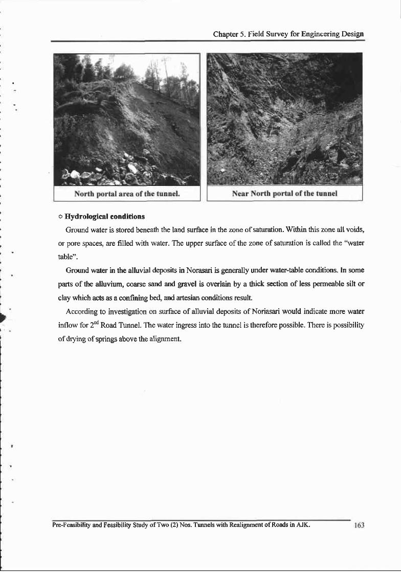
Chapter 5. Field Survey for Engincering Design
o Hydrological conditions
Ground water is store.d beneath the land surface in the zone of saturation, Within this zone a.ll voids,
or pore spaces, are filled with water. The upper surface ofthe zone of satumtion is called the "water
table".
Ground water in the alluvial deposifs in Norasari is generally under water-table conditions. In some
parts of the alluvium, coarse sand and gravel is overlah by a thick section of less permeable silt or
clay which acts as a confining bed, and artesian mnditions result.
According to investigation on surface of alluvial deposits of Noriasari would indicate more water
inflow for 2nd Road Tunnel. The water ingress into the tunnel is therefore possible. There is possibility
of drying of springs above the alignment.
Pre-Feasibility and Feasibility Study ofT\ryo (2) Nos. Tunnels with Realignment ofRoads in AJK.

FINAL I ,' , .FEASIBILITY REPORT
164 Pre-F€asibility and Feasibility Study ofTwo (2) Nos. Tunnels with Realignment ofRoads in AJK.

Chapter 5. Field Survey for En;rrreglilg f)s5ign
2) Engineering Geological Mapping Unit
Main geological unit of 2no tunnel consist ofalluvial deposit along the tunnel alignment and shale/
sandstone with alluvial deposit at north portal area,
The characteristics of this alluvia.l deDosit are as follows.
o Alluvial deoosit
Item Description
Soil types Alluvial Deposit
Colour Varied lithological colour(red, brown, green etc.)
Texture Gravels, cobbles, pebbles and boulders
Weathering ComDletelv weathered alluvial material
SensitiYitv to water Sediments are sensitive to water
Water Conditions Flowing 0.1^"0.3 Vs or Dry
UCS of rock sample 0.1 - 0.5 MPa
o Shale and sandstone with alluvrum
Item Description
Rock types Shale and sandstone with alluvium
Colour Varied lithological colour (red, brown, green etc.)
TextureFine grain shale and fine to coarse gtain sand stone.
Gravels, cobbles, pebbles and boulders
Weatherins Completely weathered alluvial material
Sensitivify to wat€r Sediments are sensitive to water
Water Conditions Flowing 0.3 l/s or Dry
UCS of rock sample l -5MPa(veryweak)
Pre-Feasibility and Feasibility Study ofTwo (2) Nos. Tunnels with Realignment ofRoads in AJK.
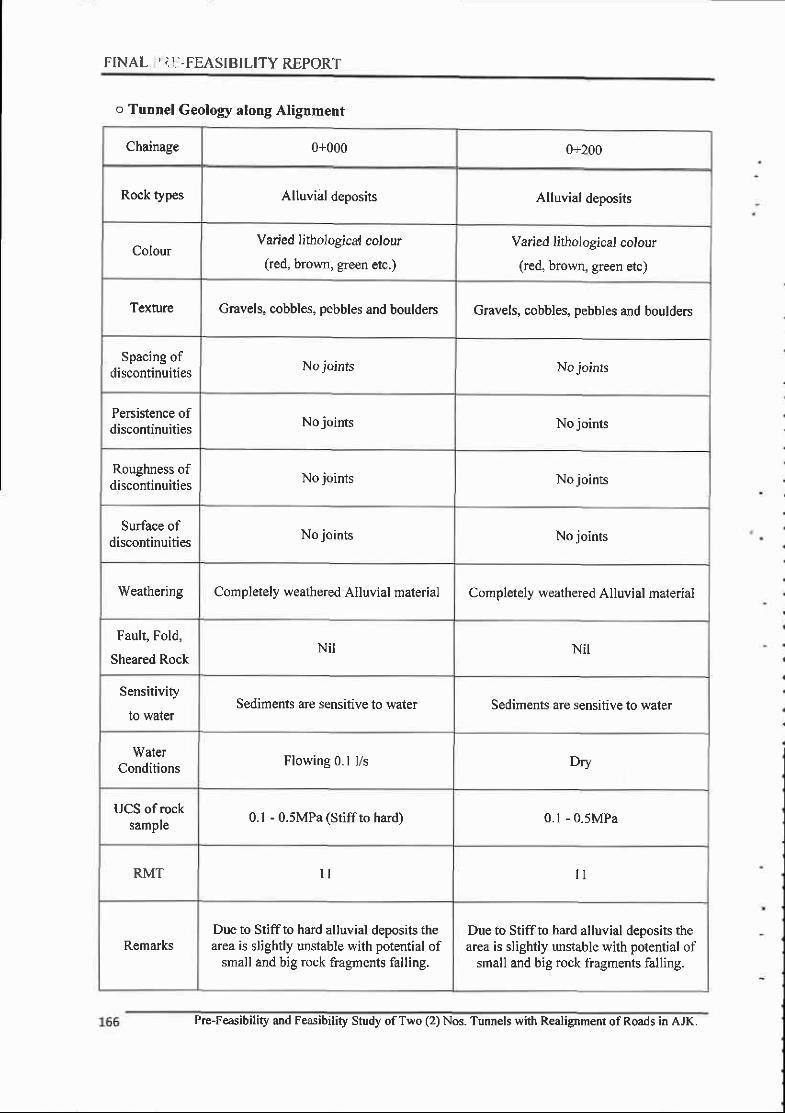
FINAL ,.] I]-FEASIBILITY REPORT
o Tunnel Geology along Alignment
Chainage 0+000 0+200
Rock types Alluvial deposits Alluvial deposits
ColourVaried lithologica,l colour
(red, brown, green etc.)
Varied lithological colour
(red, brown, green etc)
Texture Gravels, cobbles, pebbles and boulders Gravels, cobbles, pebbles and boulders
Spacing ofdiscontinuities No joints No joints
PeBistence ofdiscontinuities No joints No joints
Roughness ofdiscontinuities No joints No joints
Surface ofdiscontinuities No joints No joints
Weathering Completely weathered Alluvial material Completely weathered Alluvial malerial
Fault, Fold,
Sheared RockNil Nir
Sensitivity
lo walerSediments are sensitive to water Sediments are sensitive to water
WaterConditions Flowing 0.1 l/s Dry
UCS of rocksample 0.1 - 0.5MPa (Stiff to hard) 0.1 - 0 .5MPa
RMT l l I I
RemarksDue to Stiffto hard alluvial deposits thearea is slightly unstable with potential of
small and big rock fragments falling.
Due to Stiffto hard alluvial deposits thearea is slightly unstable with potential of
small and big rock fragments falling.
Pre-Feasibility and Feasibility Study ofTwo (2) Nos. Tunnels with Realignment ofRoads in AJK.
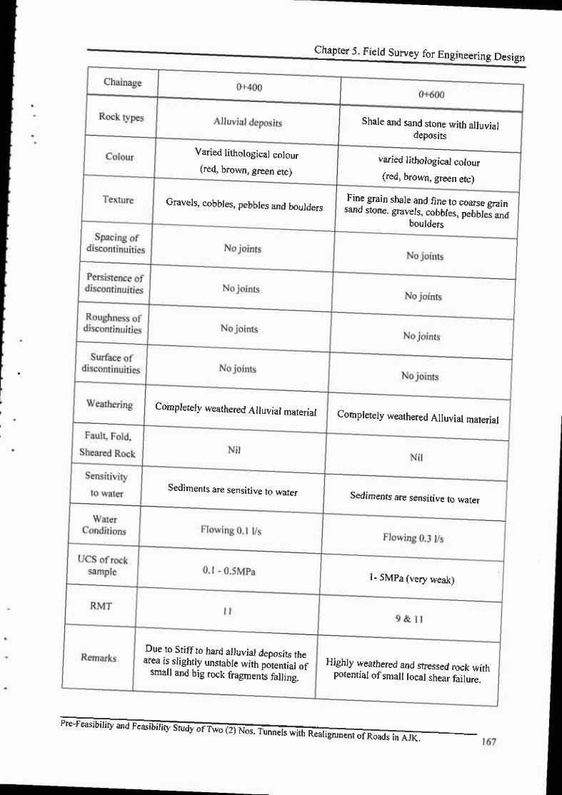
Chapter 5. Field Survey for Engineering Design
Shale and sand stone with alluvialdeposirs
Varied lithological colour(red, brown, green etc)
varied lithological colour(red, brown, green etc)
Gnvels, cobbles, pebbles and boulders _Fine grain shale and fine to coarse grain
sand stone. gravels, cobbles, pebbles andboulders
Completely weathered Alluvial material Completely weathered Alluvial material
Sediments are sensitive to,tvater Sedimen6 are sensitive to water
l- 5MPa (very weak)
DueJo Sriff to hard alluvial deposits thearea rs.slightly unstable with potential ofsmall and big rock fiagments falline.
Highly lveathered and stressed rock withpotential ofsmall local shear failure.

3) Geological Tunnel LayoutChella Bandi - Patlka Road 2nd Tunnel
Geloglcal Map(Plan View)
E C E E 9 F : . E F F f i R ' E F H f i 3 F f ; ::E g E g E EC
CLIEIIT
AZAD OOVERI{I{CI{T OF T E STATEoF JA itU I XATSHfltR
cot{SULTA T(DgI!l! <) 91I3n t'ru
oF IWO (21 O8. TUNNE| S wrH REALtcltENf OF ROADS fi{ AJt(PRII{E ENGINEERING & TESTINO CONSULTANTS PVT. LTD.
&ASIFALI ASSOCIATE PVT. LTD
Ch.ll! Bendl . Pa{ka Rord2nd TsnnolGdoglc.lUaplPhn VL{,1
DIRECTOR GENERAL GETITRAL DESIGN OFFICEiIUZAFFARABAD
t R e v . . f | * a e a q @ N

Chella Bandi - Patika Road 2nd TunnelGeologlcal Sectlone & Layout Map
G.
E E A a a a a a S a a a 8
EnE a FUToES e ra.!g saiD arols
CLIENT
AZAD OO/ERNMENT OF THE STATEOF JAT'IilU E MSHMIR
URECTOR GEiIERAL CEIITRAL DEEGiI OFFICEIIUZAFFAMEAD
EqNruLrANr @$yyr .} $tlan rwr
PRIME ENGINEERIT{G & TESTING COi{SULTAI{TS PVT. LlD.&
ASIF ALI ASSOCIATE PVT. LTD.
PRE.FEASIEILITY AND FEAEIBILITY STUDYOF TWO (2} NOS.TUNNEL8 MTH REALICI{MENT OF ROADS IN AJK
Chelh Blndl. Prtlk Ro.d 2nd Tunn.lG.olookrl S.dlon. I rlyo|r| ltp
F' tiEv. f I rqr:asffi
R.
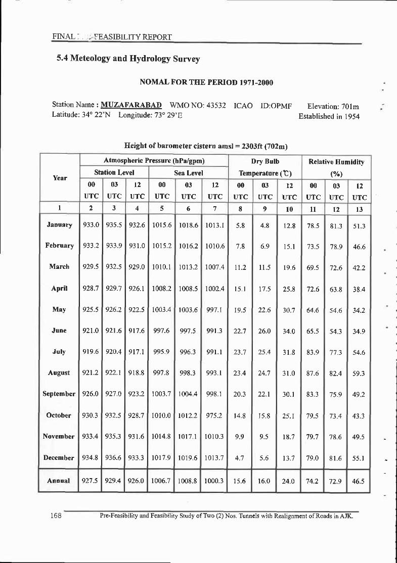
FINAL, , ,-.FEASIBILITY REPORT
5.4 Meteology and Hydrology Survey
NOMAL F'OR THE PERIOD I97I-2OOO
station Name : MUZAFARABAD wMo No: 43532 ICAO ID:opMF Elevation: 701mLatitude: 34o 22'N Longitude: 73o 29'E Established in 1954
Height of barometer cistern amsl = 2303ft (702m)
Year
Atmosph€ric Pressure (hPa/gpm) Dry Bulb
Temperature (t)Relative Humidity
(%\Station Level Sea Level
00
UTC
03
UTC
t2UTC
00
UTC
03
UTC
12
UTC
00
UTC
03
UTC
12
UTC
00
UTC
03
UTC
t2UTC
I ) 3 4 f, 6 7 8 9 t0 l t 12 l3
January
February
March
April
May
June
July
August
September
October
November
Decernber
933.0
933.2
929.5
928.7
925.5
92t.0
919.6
921.2
926.0
930.3
933.4
934.8
935.5
933.9
932.s
929.7
926.2
921.6
920.4
922.1
921 .0
q?? 5
935.3
936.6
932.6
931.0
929.0
926.1
922.5
917 .6
917.1
918 .8
923.2
928.7
931.6
933.3
1015,6
1 0 1 5 . 2
l 0 l 0 . l
1008.2
I003.4
991.6
99s.9
997.8
1003.7
1010.0
1014.8
t0 t7 .9
1018 .6
1016.2
1013.2
1008.5
1003.6
997 .5
996.3
998.3
1004.4
1012.2
1017 .1
1019 .6
1013 .1
1010.6
1007 .4
t002.4
997.l
991.3
991 .1
993.l
998.1
975.2
t010 .3
1013 .7
5.8
7.8
n.2
l 5 . t
19.5
22.7
23 .7
23.4
20.3
14.8
9.9
4.8
6.9
l l . 5
t7 .5
26.0
25.4
22.1
r 5.8
9.5
5 .6
12.8
15 .1
19 .6
25.8
30.7
34.0
31 .8
31 .0
30.1
25.1
t8.7
t3.7
/ d . )
73.5
69.s
72.6
64.6
65.5
83.9
87.6
83.3
79.5
79.7
79.0
8 1 . 3
78.9
72.6
63.8
54.6
54.3
"77 .3
82.4
75.9
73.4
78.6
8 1 . 6
5 1 .3
46.6
42.2
38.4
34.2
34.9
54.6
fv.J
49.2
43.3
49.5
55 .1
Annual 927 .5 929.4 926.0 1006.7 1008.81000.3 I ) - O 16.0 24.O 74.2 72.9 46.5
I 6 8 Pre-Feasibility Feasibility Study ofTwo (2) Nos. Tunnels with Realignnent ofRoads in AJK.

NOMAL FOR THE PERIOD I}7I.2OOO
Station Name : MUZAFARABADLatitude: 34. 22'N Longitude:73.
WMO NO: 43532 ICAO29'E
ID:OPMF Elevation:701m
Established in I954
Height of Steven$on screen amsVagt = 2300 tt eIlm) l.2m
169
ycrr
pRECIpITATION (|tlr|.)
Totd cloud {Okros)wcttesr moDth 1 ni"Iilll Hcrviest frll il 24hrMcaa
AmouDt Ycrr A|noutrt Ycsr
traloy
Dey Mcr! Extrcme Drac00
UTC
03
UTC
l2
UTCza 29 30 3 I 32 33 34 33 36 37 3t 39
J,rly
August
, " / , "
t91
l98l
l 9 . l 199(
t4 7-
7 9.(
l2.l
l0.l
lo.2
t0.3
t7 .8
t l ?
8.8
4.'7
2.9 2
2:
"r I
88.e lt4/te?6
41.3 | 107.4 | 26/t9el
4_3
3.9
4.3
4.9
45.3
25.0
79.2
51.9
r8.8
0.5
182.7
737.7
89.8
23/1993
2t/1981
02J tng 2.6
4.6
4.3
5.3
4.8
1.0 4.4
3.9
5. t
4 . 1
0.6 ? )
2.0 2.4
92.2 tat986 | 2.5 3,8
AnnuNl l S l T 7 2(|11 1 t976 tt97.7 1974 1t 6 .0 39.1 I 10/09200.5 |
| /19923,2 4.0
-

FINAL FEASIBILITY REPORT
NOMAL FOR THE PERIOD T97I-2OOO
StationName: MUZAFARABAD WMO NO:43532 ICAO ID:OPMF Elevation: 701mLatitude:34" 22'N Longitude:73" 29'E Established in 1954
t
Height of anemometer above ground:2lft (6m)
y€ar
Me{D
Tcntperature
(t)
MiDimum TernperrturE(t) Mexirnurn Tempereture(T)Wind Spe€d (knots)
Mean
Lowest
Meao
Highest
Mean Extreme Drta M€an Extreme I)rte00
UTC
03
UTC
l 2
UTC
t4 l 5 l6 I t I 9 20 21 22 24 25 26
January
February
March
April
May
June
July
August
September
October
Nov€mber
December
9.6
1 1 . 6
t5.6
21.4
26.O
29.6
28.5
28.0
26.3
21.6
16.0
1 1 . 0
3.3
5.3
9.4
14.2
18.5
21.8
22.6
19.4
13.3
7.8
4.2
0.6
1.7
5.2
9.3
16.8
19.2
I E.7
1 5 . 5
9.5
4.3
1.4
-2.0
- 1 . 0
1 . 0
6.5
7.0
12.0
1 5 . 5
1 6 . 0
t2.4
6.5
1 . 0
-0.6
28tr977
20/1979
09/19'79
08/1996
09/1997
02/1979
25/1993
28/1997
30/1991
23n990
30/r978
2t/1984
15.9
17.8
2r .9
28.6
33.5
37.4
34.5
33.7
3 3.3
29.9
24.2
t'7.9
22.s
24.8
30.3
36.2
39.9
42.9
39.9
3?.1
J6.4
34.0
29.2
23.0
27.0
29.0
37.O
40.5
46.5
46.2
43.5
39.5
39.0
37.2
27.O
05/1988
28/1985
2s/r977
29t1988
3l l19E8
17/199s
0s/198'7
12/1987
07 /t987
tu197 |
01t1999
Mn988
0.4
0.6
1 . 8
1.2
1.2
0.8
03
0.2
0.2
0.3
0.1
Annual 20.4 I 1 . 5 9.6 -2.02ElOL
1197727.4 33.0 46.5
3t/05
/ t 9880.E
170 Pre-Feasibility and Feasibility Study ofTwo (2) Nos. Tunnels with Realignment ofRoads in AJK.

NOMAL FOR THE PERIOD I97I-2OOO
Station Name : GARHI DUPAITA WMO NO: 43533 ICAO ID:N/ALatitude: 34' l3'N Longitude:73" 37'E
Elevation: 8l2mEstablished in 1954
Height of barometer cistern amsl = 2668ft (813m)
Yerr
Atmospberic Pressure (bPa/gpm)Dry Bulb Temperature (C)
Relative Humidity
(n/n)Station LeYel Sea l,evel
00
UTC
03
UTC
t2
UTC
00
UTC
03
UTC
l2
UTC
00
UTC
03
UTC
t 2
UTC
00
UTC
03
UTC
l 2
UTC
I 4 5 6 7 8 9 1 0 l l l 2 13
January
Februrry
March
April
May
Jun€
July
August
September
Octobcr
November
Dccember
9t9.3
916.2
9 l 1 . 8
909.9
912.1
916.7
925.1
923.7
922.3
919.9
9t6.7
912.2
9 1 1 . 1
9t2.7
917.4
922.7
925.5
922.7
921.1
919.6
916.9
9t3.7
908.7
908.1
909.8
914.1
91,9.2
922.1
923.5
1464.6
t446.9
14t2.9
1404.0
1 4 1 8 . 5
1453.4
1496.0
t4t7.2
14E5.6
14E0.8
1460.5
t426.0
L4r3.4
t428.l
1466.1
t 501.9
l 5 l 0 . l
1506.E
1489.3
14t0.8
r476.7
1465.1
t445.6
1406.6
1396.2
t4r0.7
1449.0
l4E5.E
1498.6
t499.1
17.9
z l .4
23.0
22.6
19.0
4.9
10.9
t6.4
22.2
25.6
25.4
24.6
2 1 . 8
15.9
9-6
5.7
10.9
t3.2
17.7
24.1
29.1
33.0
30.8
29.9
28.2
22.9
16.7
I l .9
80.6
1) A.
70.7
86.0
90.5
88.0
7 5.9
78.5
77.8
68.9
56.2
55.1
76.2
8 1 . 7
7 5 . 1
70.6
77.4
78.8
54.0
) t . l
50.6
43.8
37.4
5E.5
64.0
55.4
48.2
52.1
56.2
Annual 9t9.6 916.6 147 |.9 1458.6 15.8 22.4 72.7 50.7
Pre-Feasibility and Feasibility Study ofTwo (2) Nos. T[nnels with Realignment of Roads in AJK. T7 I
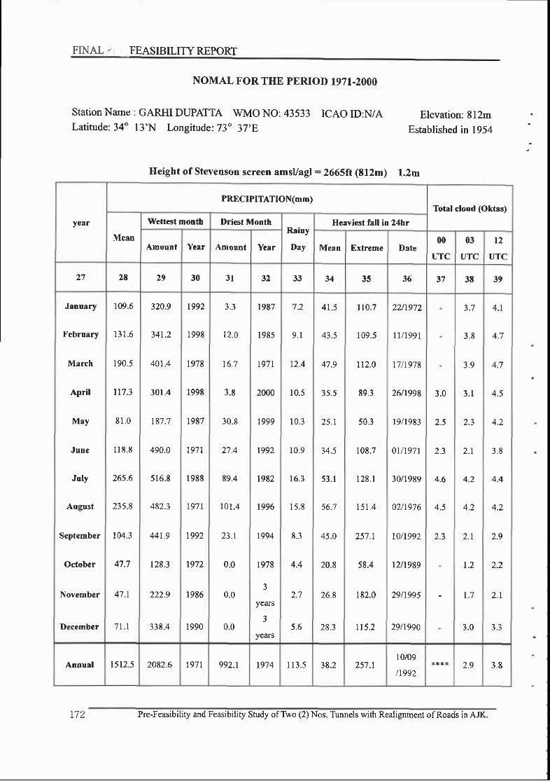
FINAL. FEASIBILITY REPORT
NOMAL FOR THE PERIOD 197I-2OOO
Station Name : GARHI DUPAITA WMO NO: 43533 ICAO ID:N/ALatitude:34" l3'N Longitude: 73" 37,E
Elevation: 812mEstablished in 1954
Height of Stevenson screen amsl/agl = 2665ft (tf2m) 1.2m
year
PRECIPITATION(mm)Total cloud (Oktas)
Mean
W€ftest motrth Driest MotrthRainy
Day
Heaviest fall in 24hr
Amount Year Amount Year Mean Extreme Date00
UTC
03
UTC
12
UTC
a 1 28 29 30 3l 1 t 33 34 35 36 J8 39
January
February
March
April
May
June
July
August
September
October
November
Deccmbcr
r09.6
r 3 1 . 6
190,5
|7 -3
8 l . 0
I 1 8 . 8
265.6
235.8
104,3
47.7
47.1
7 t . l
320.9
34r.2
401.4
301.4
r87.7
490.0
516_E
482.3
44t.9
r28.3
222.9
338.4
t992
1998
1978
1998
1987
197 |
19E8
197 |
1992
t9'12
t986
1990
12.0
t6.7
3-8
30.8
) 1 4
E9.4
1 0 1 . 4
0.0
0.0
0.0
t9E7
1985
t97 |
2000
r ooo
1992
t9E2
r996
r994
r978
3
yeaJs
3
years
7.2
9 . 1
12.4
10.5
10.3
10.9
16.3
1 5 . 8
8.3
4.4
2 .?
5 .6
41.5
43.5
4'1.9
35.5
25.1
34.5
53. t
56.7
45.0
20.8
26.8
28.3
l 1 0 . 7
109.5
112.0
89.3
50.3
106.7
1 2 8 . I
151.4
25',7 .l
58.4
182.0
fi5.2
2U1972
tl/1991
17 /1978
26/1998
19t1983
0l l '197 |
30^989
02/19'7 6
t0/t992
12/1989
29/199s
29^990
3.0
2.5
2.3
+.o
4.5
3.8
3.9
3.1
2.3
2.r
4.2
4.2
2 . 1
t .2
t .7
3.0
4.1
4.7
4.7
4.5
3 . 8
4.4
4.2
2.9
2.2
2.r
Annual t512.5 2082.6 t97 | 992.r t9'74 1 1 3 . 5 3E.2 25'7 .ll0/09
n9922.9 3.E
r72 Pre-Feasibility and Feasibility Study ofTwo (2) Nos. Tunnels with Realignment ofRoads in AJIa

Station Name :
Latitude: 34"
NOMAL FOR THE PERIOD I97 I-2OOO
GARHIDUPAIA WMONO:43533 ICAOID:N/A13'N Lonsitude:73" 37'E
Elevation:812mEstablished in 1954
Ileight of anemometer above ground = f9.6ft (6m)
yerr
Mean
Temperature
(t)
Minimum Temp€rature(t) Maximum Temperature(t)Wind speed (knots)
Mean
Lowest
M€rn
Highest
Mean Extreme Drt€ Mean Ertrcme Datc00
UTC
03
UTC
12
UTC
t4 t5 16 t7 l 8 l9 20 2l 24 25 25
January
February
March
April
May
June
July
August
September
October
November
I)ecember
8 .4
10.0
13.8
19.4
24.4
28.1
27.7
27.O
24.9
19.8
14.4
10.0
2.8
4 . 1
7.7
t2.l
16.7
20.2
22.0
21.6
1E.0
l l . 8
6.6
-o.'7
0.3
3.5
7.0
12.0
15.5
1 8 . 3
r7.5
r3.4
'7.9
3.0
o.2
-6.0
-'1.2
-2.E
2.8
8 . 1
5.0
r1.'7
r1.'7
7.8
2.8
22/t974
03n988
IEN9EE
t6/1991
09t1997
0l /1988
15n988
28/1988
3 0n 98E
z0n9E7
28/1987
26/t987
14.0
l 5 . E
19.9
26.6
32.0
36.r
33.4
3 1 . 9
27.E
16.4
19.6
22.5
27.9
34.O
38.5
41.7
38.6
35.8
34.8
32.3
27.2
2t.I
23.4
33.0
37.8
42-8
45.8
42.8
38.9
37.7
35.3
31.4
23.9
25/1990
lt/1993
20/tg't4
30t1999
3ll1984
20n986
o5t t987
12/1987
04/1998
01n998
10n996
05n988
o.7
0.8
0.6
0.5
0.4
0.4
0,0
0.2
1.4
t . ?
0;1
0.7
0.8
l . l
o.7
o.7
0.6
0.4
0.4
0.5
0.9
Antrual l9_0 12.3 8.2 -7.203/02
n98825.',I 3t.2 45.8
20t06
tr9E60-7
Pre-Feasibility and Feasibitity Study ofTwo (2) Nos. Tunnels with Rcalignment ofRoads in AJIC

FINA.L I, . -FEASIBILITY REPORT
Station Name : I(OTLI WMO NO: 43563
Latitude:34" I'N Longitude: 73' 4'E
NOMAL F'OR THE PERIOD 197T-2OOO
ICAO ID:N/A Elevation: 615m
Established in | 952
Height of barometer cistern amsl = 2017ft (615m)
Year
Atmospheric Pr€ssure (hPa/gpm)
Dry Bulb T€mperrture (C) Relative Hu]nidity (Yo)
Statior Level S€N Level
00
UTC
03
UTC
t2
UTC
00
UTC
03
UTC
12
UTC
00
UTC
03
UTC
l2
UTC
00
UTC
03
UTC
12
UTC
I ', 3 4 5 6 7 8 9 10 l l l 2 IJ
Jatruary
February
MNrch
Aplil
May
June
July
August
September
()ctob€r
November
December
939.1
935.6
931.5
9 3 1 . 1
933.0
937.2
947.7
945.O
943.2
940-0
936.5
932.5
932.0
933.8
938.2
943.5
946.5
947.7
944.7
943.l
941.1
937.7
933.9
929.4
929.4
931.3
935.7
941.0
944.0
945.6
r010.0
1005.0
1000.0
999.s
1000.7
I007.0
r02t.2
r018.7
1015.5
1010.6
100s.6
1000.5
1000.2
1001.3
\o07.7
l0l4_5
1019.6
1022.4
t 015.9
10t4.4
1 0 1 1 . 2
1006.1
1 0 0 1 . r
995.6
996.4
998.8
1003.4
1009.5
1014.4
10t7.4
t t .0
22.6
25.3
25.1
21.8
6.4
8.9
13.7
t9.7
24.8
2',7.',l
26.4
25.4
23.2
r7.9
l 1 . 8
6 .9
14.9
21.9
28.1
33.0
35.3
3 1 . 5
30.4
30.0
27.0
21.5
16.5
60.1
l l . o
57.1
E I.E
8 8 , 1
79.9
Annuel 940-5 938.1 1 0 1 1 . 5 1007.1 17.7 25.6
174 Pre-Feasibility and Feasibility Study ofTwo (2) Nos. Tunnels with Realignment ofRoads in AJK.

NOMAL FOR THE PERIOD I97I-2OOO
ICAO ID:N/AStationName r jqEI WMONO:43563Latitude: 34' l'N Longitude:73" 4'E
Elevation: 613m
Established in 1952
Height of Stevenson screen amsVagl = 2012ft (613m) 1.2m
year
PRECIPITATION(mm)Total cloud (Oktas)
Mean
Wettest month Driest MonthRairy
Day
Heaviest fell in 24hrs
Amount Year Amount Year Mecn Extreme Date00
UTC
03
UTC
t2
UTC
)1 2a 29 30 3 l 32 33 34 35 36 37 38 39
January
February
March
April
Mry
June
July
August
September
October
November
December
't9.o
95.4
12'1.2
73.7
46.8
91-6
285.E
297.6
92.1
3r.7
25.2
49.5
2 | . 4
2 3 t . 3
328.0
274.0
243.3
7 1 1 . 0
54?.5
2 1 2 . 1
93.8
93.7
309.3
1992
t976
l 9 8 l
1983
t987
t97l
r988
t976
t992
1983
1986
1990
2.0
) .9
0.0
0.0
3.0
4.8
78.0
94.0
0.0
0.0
0,0
1984
197'7
t977
t999
1993
1985
t996
t993
t9'7 |
3
years
o
years
7
years
o.J
8.4
7.2
o .J
9 . 1
l6.E
15.6
8.0
2.8
1 . 9
J . J
32.9
43.0
42.4
28.9
19.5
37.1
76.7
88.s
3 5 . 1
18.2
t6.4
24.6
84.3
119.4
155;7
90.4
52.6
1 1 8 _ l
326.9
333.5
1 1 5 . 0
72-9
75.0
t57.6
221r972
0t/r9?2
17 /1978
l3l1983
lv1977
30/1978
09t1972
06/1972
091t992
14/1983
t6/t982
29/1990
2..8
2-3
4.8
4.6
2.4
-1.0
3.5
3.0
2.1
2.1
4.7
4.5
2.4
1 . t
I . 6
3 . 1
3.9
4.3
4.4
3.8
3.5
3.0
4 . 1
4.0
2.4
1.4
1 . 8
3 , 1
Annual r295.7 1929-3 t976 794.5 1987 9t.9 3 8,6 333.506/08
/t9723,0 3.3
Pre-Feasibility and Feasibility Study of T\.vo (2) Nos. Tirnnels with Realignment ofRoads in AJK. 175
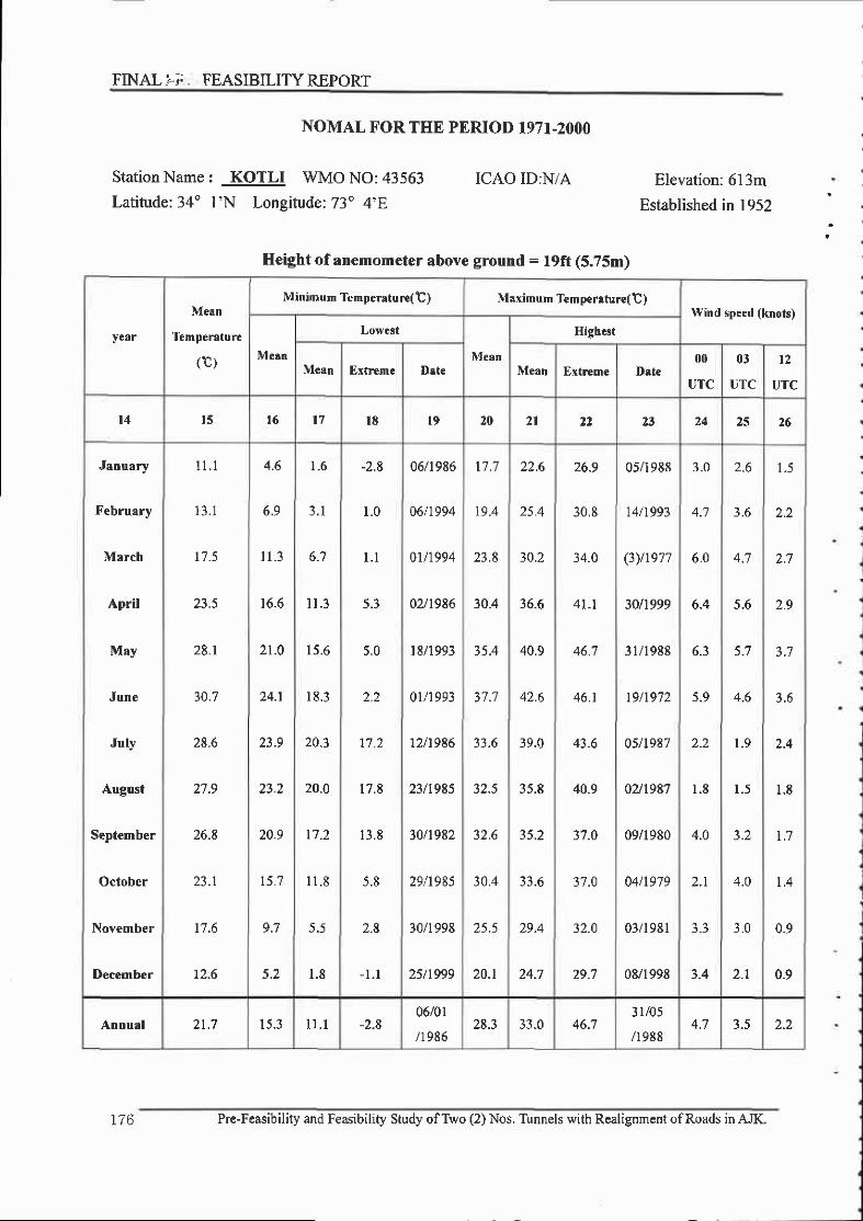
FINALIi. FEASIBILITYREPORT
Station Name : KOTLI WMO NO: 43563Latitude:34' l'N Longitude: 73" 4'E
NOMAL FOR THE PERIOD I97I-2OOO
ICAO ID:N/A Elevation: 613m
Established in 1952
Height of anemometer above ground = f9ft (5.75m)
year
Meen
Temperrtur€
(c)
Minimum TemDeratur€(t) Maximurn Temperature( t )Wind speed (knots)
M€cn
Lowest
M€an
High.st
Mean Extreme Dst€ Mean Extreme Dste00
UTC
03
UTC
l 2
UTC
l4 r5 t6 l 7 l8 l9 20 2l 23 24 z5 26
January
February
March
April
May
June
July
August
September
October
November
December
1 1 . 1
1 3 . 1
r7.5
23.5
28.r
10.7
28.6
2',7 -9
26-8
23.1
t7.6
12.6
6.9
1 1 . 3
to.o
21.0
24.1
23.9
23.2
20.9
t5.7
9.7
5.2
1.6
3 . 1
1 1 . 3
15.6
1 8 . 3
20.1
20.o
17.2
l l . 8
5.5
1.8
-2.8
1.0
l . t
5.3
5.0
2.2
17.2
17.8
l 3 . E
5.8
2.8
- t . t
06/1986
06/t994
01/1994
02^9t6
t8/1993
0ln 993
12/t986
23tr985
30/1982
29/1985
30/1998
25/t999
t7.7
19.4
23.8
30.4
3s.4
37.7
33.6
32.5
30.4
25.5
20.1
22.6
) s a
30.?
36,6
40.9
42.6
3 9.0
35.8
35.2
33.6
29.4
24.7
26.9
30.8
34.0
4l.l
46.7
46.1
43.6
40.9
3'1.0
37.0
32.0
29.7
05n9E8
l4/t993
(3)/r977
3011999
31/1988
t9/1972
05/t987
02^9E7
09n980
04/1979
03/1981
0E/199E
3.0
4.7
6.0
6.4
6.3
5.9
2.2
1.8
4.0
2.r
3.3
3.4
2.6
3.6
4.7
5.6
i - l
4.6
1 .9
1 .5
4.0
3.0
l . )
2.2
2.7
2.9
J . O
2.4
l . E
1 . 7
1 . 4
0.9
0.9
Anoual 21.7 15.3 I r . 1 -2.806/01
/t98628.3 33.0 46.7
3r/05
n9884.7 3.5 2.2
176 Pre-Feasibility and Feasibiliry Study ofTwo (2) Nos. Tunnels with Realignment ofRoads in AJK.

o Precipitation(mm) - MUZAFARABAD
o Temperature - MUZAFARABAD
Pre-Feasibility and Feasibility Study ofT\tro (2) Nos. Tunnels with Realignment ofRoads in AJK.
Jan-
urry
Fcb
ruary
Mar-
chApril May June July
Aug-
ust
Sept-
eber
Oci-
ober
NoY-
ember
Dec-
ember
MeNtr 105.9 136.1 lE l .8 103.3 t22 .1 359.4 227.4 108-l 39.6 10.3
Weatesa 273.8 293.4 534.37 204.5 241.5 380.2 721 531.2 335.2 94 176.1 327.1
Driest to.z 25.5 3.6 l 9 . l t9.4 142.2 59.8 18.3 0 0 0
MUZAFARABAI)
7N
600
? 500
E
i'6 300
200
0AusE Scplstrbs OEbhs Norahfi D!..ddlrdEry F.bndt Ntaich
Jan-
uary
Feb-
ru{ry
Mar-
chApril May June July
Aug-
ust
Sept-
eber
Oct-
ober
Nov-
ember
Dec-
ember
Mc!n 9.6 I l . 6 15 .6 2t .4 26 29.6 28.5 2t 26.3 2t.6 l 6 l l
W€ttest 3.3 5.3 9.4 t4.2 18.5 2t.8 22.4 19.4 l J .3 7 .8 4.2
Driest 17 .8 21.9 28.6 33.5 37.4 34.5 33.1 29.9 24.2 t1 .9
MUZAFARABAD
l 5
30
P_ 25
g ? 0
r 0
5
0
JaEry F€bMry March AW61 SqL'ds O.robd Ndridd DEda

FINAL -.;.. FEASIBILITY REPORT
r Precipitafion(mm) - GARHIDUPATTA
Jan-
urry
Feb-
ruary
Mar-
chApril May June July
Aug-
usa
Sept-
eber
Oci-
ober
Nov-
ember
Dec-
ember
Mean 109.6 l 3 t . 6 190.5 1 1 7 . 3 8 1 I t 8 . 8 165.6 23s.8 104.3 47 .1 7 t . l
W€ttesa 320.9 341.2 401.4 301.4 t87 7 490 5 t6 .8 482.3 441.9 | 28.3 222 9 338.4Driest 3 .3 l 2 16.7 1.8 30.8 89.4 t 0 t . 4 ? 1 1 0 0 0
GARHT DUPATTA
?00
600
€ i00
E€ 400
E
20Q
t00
0
AL$$! S.plmter O.tobcr Nor€n$er DaeED.r
tr Temperature - GARHIDUPATTA
Jan-
uary
Feb-
ruary
Mar-
chApril Mry June July
Aug-
ust
Sept-
eber
Oct-
ober
Nov-
ember
Dec-
ember
Mcr|| 8-4 l 0 13.8 t 9 4 24.4 28.1 27.7 21 24.9 t9 .8 \4.4 l 0
Wettest 2.8 4 . 1 7.7 t2 . l 16.7 20.2 22 zt.6 l 8 .8 6.6
Driesl 1 4 15.8 19.9 36.1 27.8 22.3 t6.4
35
3o
t ! t
i , oE
t 0
Ie@ry F.bMry March Algut S.pidbd Ocrob* NoEFbq De.erb*
CARHI DUPATTA
178 Pre-Feasibility and Feasibility Study ofTwo (2) Nos. Tunnels with Realignment ofRoads in AJK.

o Precipitation(mm) - KOTLI
Jan-
uary
Feb-
ruary
Mar-
chApril Mey June July
Aug-
ust
Sept-
eber
Oct-
ober
Ncv-
ember
D€c-
ember
Meatr'79 95.4 127.2 73.7 46.8 9 l .6 285.8 297.6 92.1 3t.7 25.2 49.5
Wett€st 211.4 231.3 328 274 r 33.2 243.3 l r l 2t2 .1 93.8 9j.7 309.3
Driest 2 0 0 3 4.8 78 94 t7 . l 0 0 0
600
e 5ooE
e 400
E: roo
100
r00
0lanDry FcbnE y Mdch aad Septcmbd Odobd Nold$d Den$d
tr Temperature - KOTLI
Jatr-
uary
Feb-
ruary
Mar-
chApril May June July
Aug-
ust
Sept-
eber
Oct-
ober
Nov-
ember
Dec-
ember
Mean I l . l 1 3 . 1 t7 .5 l J ) 28.1 30.7 28.6 27.9 26.8 t2.6
Wettest 4.6 6.9 I 1 . 3 t6.6 2 l 24.1 23.9 20.9 t5.7 9.1
Driest 1 7 7 19.4 2 3 8 30.4 35.4 37.7 33.6 32.5 30.4 25.5 20.1
KOTL
l 5
i0
E t i
5
a,{ld seprsibdr otubs Nos.bg DsI6r
Pre-Feasibility and Feasibility Study ofTwo (2) Nos. Tunnels with Realignment ofRoads in AJK. 179

FINAL .. FEASIBILITY REPORT
5.5 Construction Material Survev
construction Material such as coarse aggegate, fine aggregate(for concrete), steel, cement and
biflmen are not available in the vicinity of the project.
1) Coarse aggregates
Coarse aggregates complying with the specification requirement for use in cement concrete and
asphalt concrete works are not available in the vicinity of the project area. Coarse aggregates for
use in cement concrete and asphalt concrete works will have to be obtained from Margallah
quarries, located in the vicinity of Taxila and Hasan Abdal.
2) Fine Aggregates(Sand)
Fine sand obtained by pulverization of sandstone is available in local nallahs & streams and also
as local sand deposits in the outcrops ofrocks, exposed along the side of ttre road. The quantity of
such deposits is however less and its quality also does not comply with the AASHTO/ASTM
Standard Specification requirement. Its use is therefore limited to the construction of minor and
unimportant concrete structures.
For major & important concrete structure sand will have to be procured from Lawrencepur sand
quarries located at around 50Km from Islamabad
3) Water
Water will be available from natural springs emanating from top of the mountains and whose
outcrops are exposed along the side of the road. Water can also be obtained by installing tube wells
at different stations in the strearn/river rururing along the road for most of its length
4) Steel
Standard quality steel of different grades and types complying with AASHTO Standard is being
manufactured at
Fazal Steel, Islamabad
Park Steel, Islamabad
Pre-Feasibility and Feasibility Study of Two (2) Nos. Tunnels with Re.lignment of Roads in AJK.
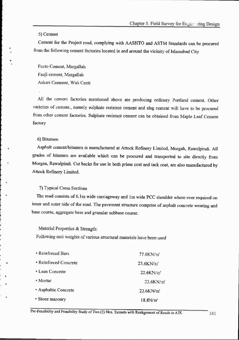
5) Cement
cement for the Project road, complying with AASHTO and ASTM standards can be procured
fiom the following cement factories located in and around the vicinity of Islamabad citv
Fecto Cerrent, Margallah
Fauji cement, Margallah
Askari Ceement, Wah Cantt
All the cement factories mentioned above are producing ordinary portland cement. othervarieties of cement., namely sulphate resistant cement and slag cement will have to be procured
from other cement factories. Sulphate resistant cemenf can be obtaned from Maple Leaf Cemenrfactory
6) Bitumen
Asphalt cement/bitumen is manufactufed at Attock Refinery Limited, Morgab, Rawalpindi. AIIgrades of bitumen are available which can be procured and transported to site dfuecfly fromMorgan, Rawalpindi. Cut backs for use in both prime coat and tack coat, are also manufactured bvAttock Refinery Limited.
7) Typical Cross Sections
The road consists of 6.lm wide carriageway and lm wide PCC shoulder where ever required oninner and outer side ofthe road. The pavement stucture comprise of asphalt concrete wearing andbase course, aggregate base and granular subbase course.
Material Properties & Strength:
Fo.llowing un.it weights of various structural materials have been used
. Reinforced Bars
. Reinforced Concrste
. Lean Concrete
. Mortar
. Asphaltic Concrete
. Stone masonry
77.0KN/nr'
23.6KN/nI
22.6KN/m'
22.6KN/m'
22.6KN/m
18.8N/m'
Pre-Feasibiliry and F.a"iuitity st@ent of Roads inArK.

FINAL FEASIBILITYREPORT
Following strengths of the construction materials have been used in design and detailing
Concrete at 28 days cylinder strengths:
. Prestressed Concrete (Class D)
. Reinforced Concrete (Class Al)
. Reinforced Concrete (Class ,A3
. Lean Concrete
34.5KN/n'
2l N/m'
28N im
l:4:8 nominal mix
Reinforcing Steel:
Deformed billet steel bars (Grade-60 and Grade-4O conforming to ASTM A-615 or High yield
deformed bars with minimum yield or characteristic strength of 425/460 N/nff conforming to BS
M6l
Prestressing Strands:
strand confordng to ASTM 4'416 Grade 2?0
Structural Steel:
All structural steel, plates, angles etc. conforming to ASTM ,4.-36 Steel
I82 Pre-Feasibility and Feasibilrty Study ofTwo (2) Nos. Tunnels with Realignment of Roads in AJK.
Steel for prestressing is either seven-wire low relaxing strand or seven-wire normal relaxation

Chapter 6. Route Alternatives
Chapter 6. Route Alternatives
6.1 Related Projects around study Area
6.1.1 West Bank Bypass Project
D General
After the earthquake on 8 October 2005, JICA conducted "Master Plan Study of Rehabilitation
and Reconstruction in Muzaffarabad City" from February to August 2006 in order to propose
appropriate measures for rehabilitating and reconstructing the city. The master plan selected the
Project as an urgent and the highest priority project among nine proposed projects.
The main existing road in Muzaffarabad city is the Neelum Valley road, which is congested
during daltime and has reached the capacity ofthe road, it is expected to increase traffic volume
when the reconstruction and rehabilitation work start in full scale.
The project intends to provide additional capacity through by a new bypass road in the westem
part of the city. The project expects to enhance rehabilitation and r€construction activities in the
damaged anea not only inside the city but also outside the city in terms ofproviding and altemative
corridor to ease congestion as well as improving the transporting convenience between the
periphery and the city to reduce travel time.
The proposed bypass mainly passes through residential and commercial areas. Main settlements
are Naluchi, Bela Noor Shah and Chella Bandi. The existing road is insufficient for the inter city
transport needs ofthe present population of project area.
To meet the requirements of increasing traffic volume, which will have a remarkable increase
after the rehabilitation of Muzaffarabad city as per Master Plan, PWD planned to upgrade the
existing road and to constructed a new road section into a dual carriageway with a bridge and a
viaduct at Naluchi, which is about 5.0 Kilometeres long. The existing road will be widened from
about 8m to 1 1.3m.
E Location of the Project
The Project road is situated in Muzaffarabad city. The proposed road runs through the westem
river terrace ofthe Neelurn Valley ascending north fiom the intersection of Muzaffarabad - Kohala
Road near the Supreme Court, AJK, through a proposed Naluchi Bridge to Chella Bandi its end
Doint-
Pre-Feasibility and Feasibility Study ofTwo (2) Nos. Tunnels with Realignment ofRoads in AJK. 183

FINAL FEASIBILITY REPORT
E Project Components
The project includes improving of the
existing road section from Naluchi to Chella
Bandi with some new construction portion
and the construction of a new bridge and a
viaduct at Jehlum River at Naluchi. After the
completion of the Project, the existing road
will be improved to a dual carriageway.
The Bypass provides an impoltant
communication link to meet the growing
traffic demand and enhance road safety. The
construction and rehabilitation will
comprise: (i) widening and improvement of
3.95 km of the existing road section; (ii)
construction of new alignment section 650
meters (iii) construction of Naluchi Bridge
and a viaduct of 414 m: (iv) rehabilitation
and construction of small size bridges at
three location; (v) counter measures for land
slide sections; (vi) slope stability measure at
climbing section; (vii) intersection
improvements at four (4) Iocations.
There was a plan to construct a bridge
over Jehlum River at Naluchi and part of
foundation works of a Naluchi bridge across
the Jehlum River had been carried out.
However, since the said bridge was not
designed to consider large-scale seismic
force, the construction of the bridge was
cancelled after the October 8 Earthquake in
2005. The project proposes a new Naluchi
Bridge and a Viaduct and it should be a core
Pre-Feasibil i ty and Feasibil i ty Study ofTwo (2) Nos. Tunnels with Realignment of Roads in AJK.
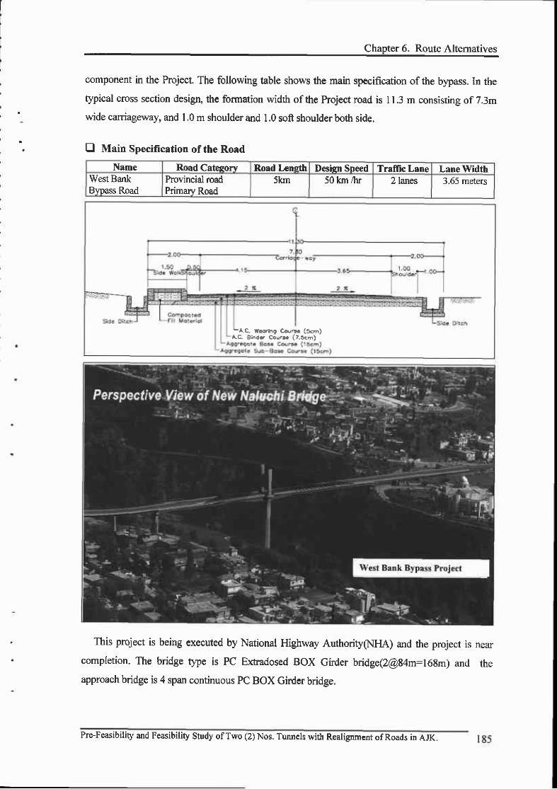
Chapter 6. Route Alternatives
component in the Project. The following table shows the main specification of the bypass. ln the
typical cross section design, the formation width of the hoject road is I 1.3 m consisting of 7.3m
wide carriageway, and 1,0 m shoulder and 1.0 soft shoulder both side.
E Main Specification of the Road
Name Road Catesory Road Leneth Design Speed Traflic Lane Lane WidthWest BankBtpass Road
Provincial roadPrimary Road
5km 50 km /hr 2 lanes 3.65 meters
This project is being executed by National Highway Authority(NFlA) and the project is nearcompletion. The bridge type is PC E*radosed BOX Girder bridge(2@84m=168m) and theapproach bridge is 4 span continuous PC BOX Girder bridge.
-^.c. [email protected] ca.!. (56)Ac Bi^d? Cou'r (?.5cn)
Pre-Feasibility and Feasibility Study ofTwo (2) Nos. Tunnels with Realignment ofRoads in AJK.
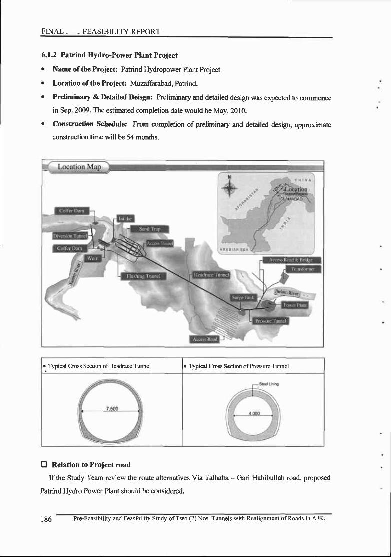
FINAL. -..FEASIBILITYREPORT
6.1.2 Patrind Hydro-Power Plant Project
r Name of the Project: Patrind Hydropower Plant Project
. Location of the Project: Muzaffarabad, Patrind.
r Preliminary & Detailed Deisgn: Preliminary and detailed design was expected to commence
in Sep.2009. The estimated completion date would be May.20l0.
. Construction Schedule: From completion of preliminary and detailed desigr, approx.imate
construction time will be 54 months.
. Typical Cross Section ofHeadrace Tunnel . Typical Cross Section ofPressure Trmnel
fl Relation to Project road
If the Study Team review the route altematives Via Talhatta - Gari Habibullah road, proposed
Patrind Hydro Power Plant should be considercd.
186 Pre-Feasibility and Feasibility Study ofTwo (2) Nos. Tunnels with Realignment ofRoads in AJK.
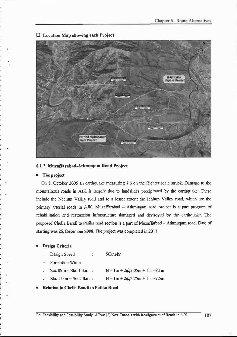
D Location Map showing each Project
6.13 Muzaffarabad-Athmuqam Road Project
o The pmject
On 8, October 2005 an earthquake measuring 7.6 on the Richter scale struck. Damage to the
mountainous roads in AJK is largely due to landslides precipitated by the earthquake. These
include the Neelum Valley road and to a lesser extent the Jehlum Valley road, which are the
primary arterial roads in AJK. Muzaffarabad - Athmuqam road project is a part program of
rehabilitation and restoration infrastructure damaged and desftoyed by the earthquake. The
proposed Chella Bandi to Patika road section is a part of Muzaffarbad - Athmuqam mad. Date of
starting was 26, December 2008. The project was completed in 201 l.
r Design Criteria- Design Speed- Formation Width
. Sta.Okrn - Sta. l5km
. Sta. l5kn - Sra 24km
5Okm,hr
B = lm + [email protected] + lm =8.1m
B= lm + [email protected] + lm =7.5m
. Relation to Chella Bandi to Patika Road
Pre-Feasibility and Feasibility Study ofTwo (2) Nos. Tunnels with Realignment ofRoads in AJK.
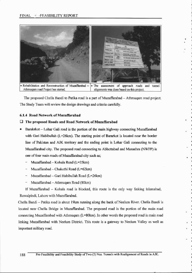
FINAL " -FEASIBILITY REPORT
The proposed Chella Bandi to Patika road is a part of Muzaffarabad - Athmuqam road project.
The Study Team will review the design drawings and criteria carefully.
6.1.4 Road Network of Muzaffarabad
E The proposed Roads and Road Network of Muzaffarabad
o Baral<rkot - Lohar Gali road is the portion of the main highway connecting Muzaffarabad
with Gari Habibullah (L+6km). The starting point of Bararkot is located near the bonder
line of Pakistan and AJK territory and the ending point is Lohar Gali connecting to the
Muzaffarabad city. The proposed road connecting to Abbottabad and Mansehra (NWFP) is
one offour main roads of Muzaffarabad city such as;
- Muzaffarabad - Kohala Road (L=35km)
- Muzaffarabad - Chakothi Road (L=62km)
- Muzaffarabad - Gari Habibullah Road (L=26km)
- Muzaffarabad - Athmuqam Road (80km)
If Muzaffarabad - Kohala road is blocked, this route is the only way linking Islamabad,
Rawalpindi, Lahore with Muzaffarabad.
Chella Bandi - Patika road is about l9km running along the bank of Neelum River. Chella Bandi is
located near Chella Bridge in Muzafarabad. The proposed road is the portion of the main road
connecting Muzaffarabad with Athmuqam (L=80km). In other words the proposed road is main road
linking MuzaiFarabad with Neelum District. This route is a gateway to Neelum Valley as well as
important military road.
o Rehabilitdion and Reconstuction of Muzaftrabad -
road Proiect has started.The assessmeht of approach roads and tunnel
was done based on ihis
Pre-Feasibility and Feasibility Study ofTwo (2) Nos. Tunnels with Realignment ofRoads in AJK.

Chanter 6. Route Aliernatives
Pre-Feasibility and Feasibility Study ofTwo (2) Nos. Tunnels with Realignment ofRoads in AJK. 189
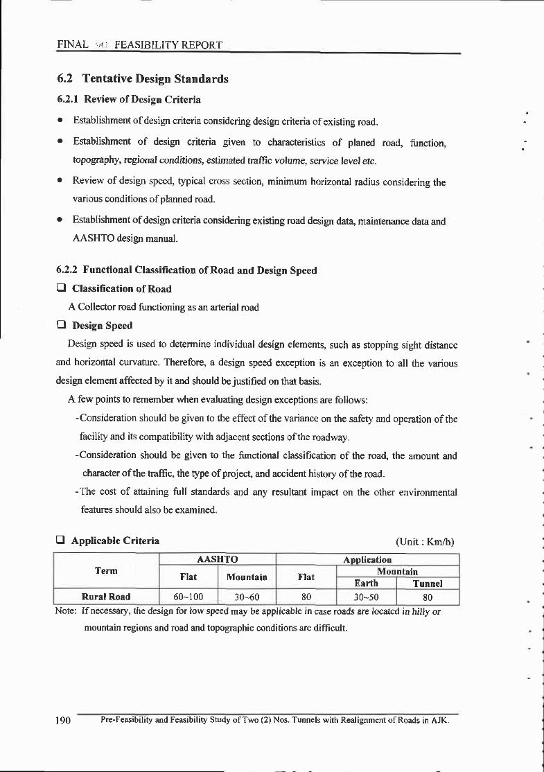
FINAL .,I: FEASIBILITYREPORT
6.2 Tentative Design Standards
6.2.1 Review of Design Criteria
. Esfablishment ofdesign criteria considering design criteria ofexisting road.
. Establishment of design criteria given to characteristics of planed road, firnction,
topography, regional conditions, estimated traffic volume, service level etc.
r Review of design speed, typical cross section, minimum horizontal radius considering the
various conditions of planned road.
o Establishment ofdesign criteria considering existing road design dat4 maintenance data and
AASHTO design manual.
6.2.2 Functional Classification ofRoad and Design Speed
0 Classification of Road
A Collector road functioning as an arterial road
E Design Speed
Design speed is used to determine individual design elements, such as stopping sight distance
and horizontal curvature. Therefore, a design speed exception is an exception to all the various
design element affected by it and should bejustified on that basis.
A few points to remember when evaluating design exceptions are follows:
-Consideration should be given to the effect ofthe variance on the safety and operation of the
facility and its compatibility with adjacent sections ofthe roadway.
-Consideration should be given to the functional classification of the road, the amount and
character ofthe traffic, the type ofproject, and accident history ofthe road.
-The cost of attaining full standards and any resultant impact on the other environmental
features should also be examined.
E Appticable Criteria (Unit : Km/h)
Note: Ifnecessary, (he design for low speed may be applicable in case roads are located in hilly or
mountain regions and road and topographic conditions are difficult.
TermAASHTO Application
Flat Mountain FlatMountain
Earth TunnelRural Road 60-100 30-60 80 30-s0 80
190 Pre-Feasibility and Feasibility Study ofTwo (2) Nos. Tunnels with Realignment of Roads in AJK.
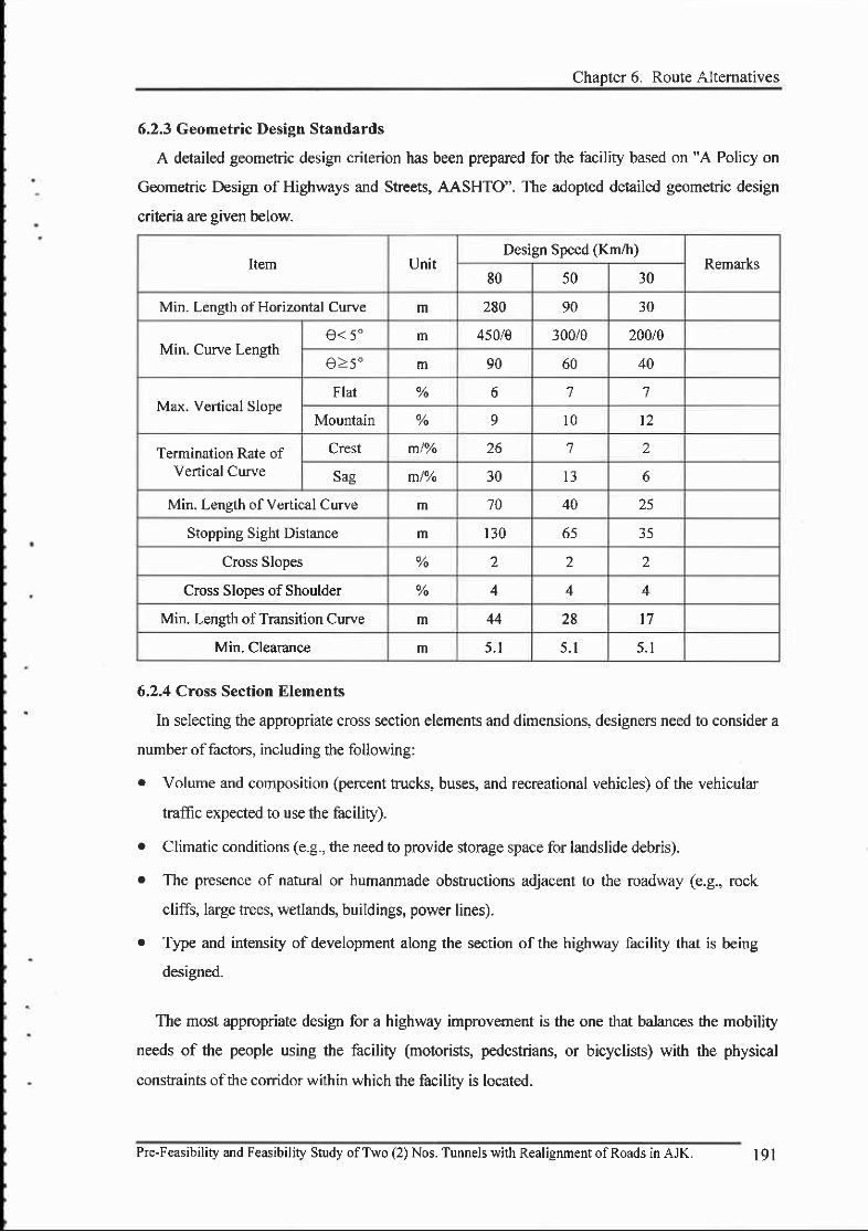
Item UnitDesign Speed (Km/h)
Remarks80 50 30
Min. Leneth of Horizontal Curve m 280 90 30
Min. Curve Lengthe< 5" m 450/Q 300/e 200/g
A> <o m 90 60 40
Ma"x. Vertical SlopeFlat % o 7 7
Mountain % 9 l 0 l 2
Termination Rate ofVenical Curve
Crest m/Vo 26 7 2
Sag mlYo 30 l3 6
Min. Leneth of Vertical Curve m 70 40 25
Stopping Sight Distance m 130 b5 35
Cross Slopes % 2 2 2
Cross Slooes of Shoulder % 4 4
Min. Leneth of Transition Curve m 44 28 17
Min. Clearance m 5 . 1 5 . 1 5 . 1
Chapter 6. Route Altematives
6.2.3 Geometric Design Standards
A detailed geometric design criterion has been prepared for the facility based on "A Policy on
Geometric Design of Highways and Streets, AASHTO". The adopted detailed geometric design
criteria are given below.
6.2.4 Cross Section Elements
In selecting the appropriate cross section elements and dimensions, designers need to consider a
number offactors, including the following:
r Volume and composition (percent trucks, buses, and recreational vehicles) of the vehicular
traflic expected to use the facility).
o Climatic conditions (e.g., the need to provide storage space for landslide debris).
r The presence of natural or humanmade obstructions adjacent to the roadway (e.g., rock
cliffs, large trees, wetlands, buildings, power lines).
. Type and intensity of development along the section ofthe highway facility that is being
designed.
The most appropriate design for a highway improvement is the one that balances the mobility
needs of the people using the facility (motorists, pedestrians, or bicyclists) with the physical
constraints of the conidor within which the faciliW is located.
Pre-Feasibility and Feasibility Study ofTwo (2) Nos. Tunnels with Realignment ofRoads in AJK. l 9 l
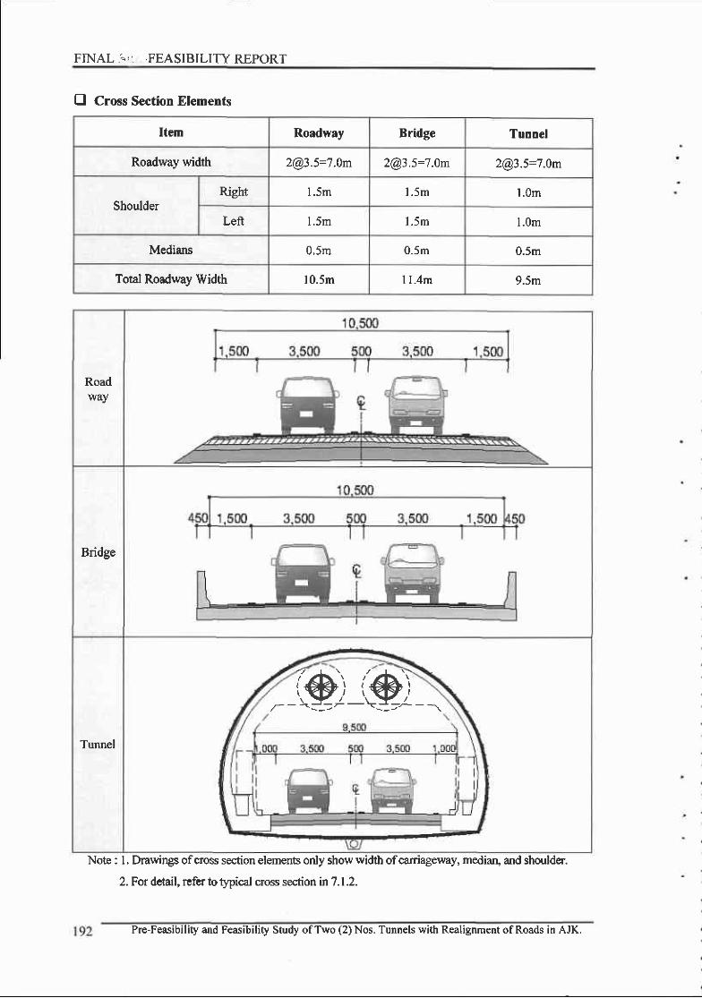
FINAL.'"'. .FEASIBILITY REPORT
E Cross Section Elements
Item Roadway Bridgc Tunoel
Roadway width [email protected]=7.0m 2@35:7.0m [email protected]=7.0m
ShoulderRisht I . )m l . 5 m l . 0m
Left l .5m l . 5 m l .0m
Medians 0,5m 0.5m 0.5m
Total Roadway Width 10.5m I l .4m 9.5m
Roadway
Bridge
Tunnel
('&)-'<-----^
,1,@)<-=,"-
Note : l. Drawings ofcross section elements only show width ofcarriageway, mediaru and shoulder.
2. For detail, refer to gpiel cross sectionin7.1.2.
Pre-Feasibility and Feasibility Study ofTwo (2) Nos, Tunnels with Realignment of Roads in AJK.

Chapter 6. Route Alternatives
tr
6.3 Alternatives Preparation and Preliminary Route Selection
6.3.1 Basic Concepts for Alternatives Preparation
0 Basic Concepts
. Route altematives for Guarantee of the Road Function & Balance between Mobility and
Access
. Route Altematives for Maximum Utilization of Existing Road if possible
. Route Altematives conforming to Topographic Characteristics
. Route Altematives ofBypass or Tunnel /Bridge options at a Large Scale landslide Area
Approach for Alternatives Preparation
Improvement of Existing Road:
-Utilizing the existing road only if it can be improved without a lot of construction and
maintenance cost.
-Review oftunnel alignment which can be improved existing road effectively.
-Minimum land acquisition by planning to use the existing road.
New Access Road:
-Planning ofnew access road where the alignment ofexisting road is very poor to conform to
the design speed (V=30-50km/hr) in mountainous terrain.
- Planning ofnew access road considering the location oftunnel portals.
Tunnels:
-Tunnels where a large scale landslide occuned.
-Tunnels where the horizontal and vertical alignment ofthe existing road is very poor.
- Tunnels where the existing road traverses the landslide or landslide dormant area.
E Route Alternatives for Landslide Area
. Short-term Measures
Satellite ald/or aerial photographs provide useful information about geotechnic€l hazards along
existing roads. Extracting high-risk points, quick and thorough investigations are to be conducted at
these high-risk points.
Unstable soiUrock masses remaining above the road are to be removed. If impossible, a possible
distal and of landslide masVdebris is to be estimated. Existing debris deposits will give and
important hint. If road is to be constructed over debris deposie and/or landside masses, stabilize
Pre-Feasibility and Feasibility Study ofTwo (2) Nos. Tunnels with Realignment ofRoads in AJK. 193
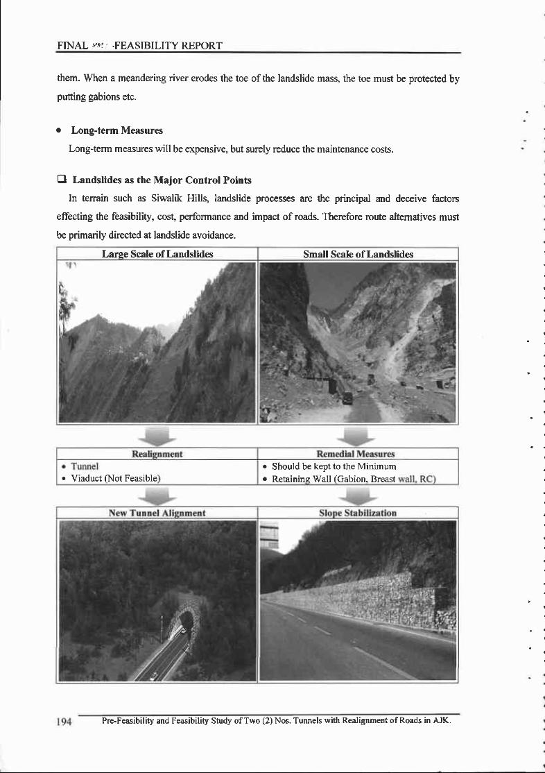
FINAL ."sr. .FEASIBILITY REPORT
them. When a meandering river erodes the toe of the landslide rnass, the toe must be protected by
putting gabions etc.
. Long-term Measur€s
Long-term measures will be expensive, but surely reduce the maintenance costs.
E Landslides as the Major Control Points
In tenain such as Siwalik Hills, landslide prcc€sses are the principal and deceive factors
effecting the feasibility, cosg performance and impact of roads. Therefore route altemalives must
be primarily directed at landslide avoidance.
Larse Scale of Landslides Small Scale of Landslides
r Viaduct (Not Feasibleo Should be keot to the Minimum. Retainins Wall (Gabion. Breast
Pre-Feasibility and Feasibility Study ofTwo (2) Nos. Tunnels with Realignment of Roads in AJK.
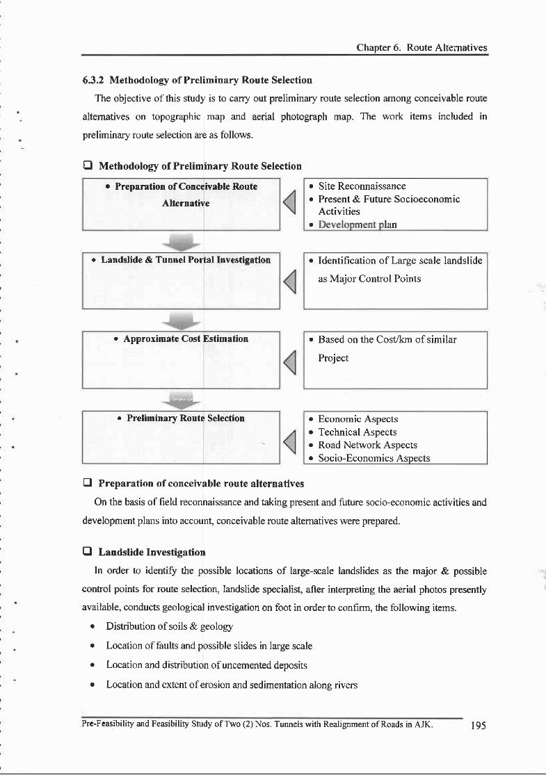
Chapter 6. Route Alternatives
6,3.2 Methodolory of Preliminary Route Selection
The objective of this study is to carry out preliminary route selection among conceivable route
altematives on topographic map and aerial photograph map. The work items included in
preliminary route selection are as follows.
O Methodology of Preliminary Route Selection
. Preprration of Conccivtble Rout€
Alternative
-ryo Preliminary Route Selection
r Site Reconnaissancec Present & Future Socioeconomic
ActivitiesI lan
. Identification ofLarge scale landslide
as Maior Control Points
r Based on the Cosi&m of similar
Project
o Economic Aspects. Technical Aspectso Road Network Aspectso Socio-Economics Asoe
E Preparation of conceivable route alternatives
On the basis offield reconnaissance and taking present and future socio-economic activities and
development plans into accoun! conceivable route altematives were prepared.
fl Landslidelnvestigation
In order to identifo the possible locations of large-scale landslides as the major & possible
control points for route selection, landslide specialist, after interpreting the aerial photos presently
available, conducts geological investigation on foot in order to confirm, the following items.
e Distribution ofsoils & geology
e Location offaults and possible slides in large scale
r Location and distribution ofuncemented deposits
. Location and extent oferosion and sedimentation alons rivers
o Landslide & Tunnel Portal Investisation
. Approximate Cost Estimation
Pre-Feasibility and Feasibility Study ofTwo (2) Nos. Tunnels with Realignment ofRoads in AJK. 195
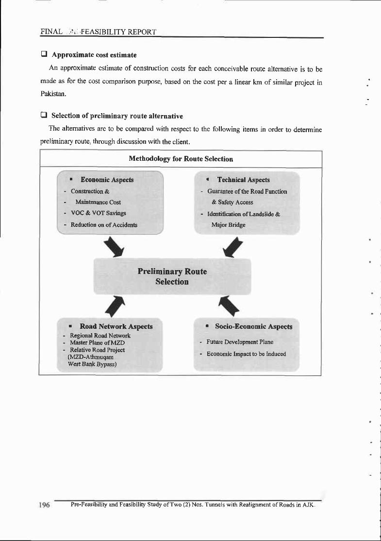
FINAL .,I. ,FEASIBILITY REPORT
E Approximate cost estimate
An approximate estimate of construction costs for each conceivable route altemative is to be
made as for the cost comparison purpose) based on the cost per a linear km of similar project in
Pakistan.
E Selection of preliminary route alternative
The altematives are to be compared with respect to the following items in order to determine
preliminary route, through discussion with the client.
Methodolory for Route Selection
. Economic Aspecb- Construction &- Maintenance Cost- VOC & VOT Savings
- ReductioD or ofAccidenb
r Technicrl Aspecb
- Guarantee ofthe Road Function
& Safety Access
- Identifcarion oflandslide &
Major Bridge
Preliminary RouteSelection
. Road Network Aspects- Regional Road Network- Master Plane of MZD- Relative Road Project
(MZD-Athmuqamlv€st Bank Bwass)
r Socio-EconomicAspects
- Futue Development Plane
- Economic Impact to be Induced
Pre-Feasibility and Feasibility Study ofTwo (2) Nos. Tunnels witi Realignment ofRoads in AJK.
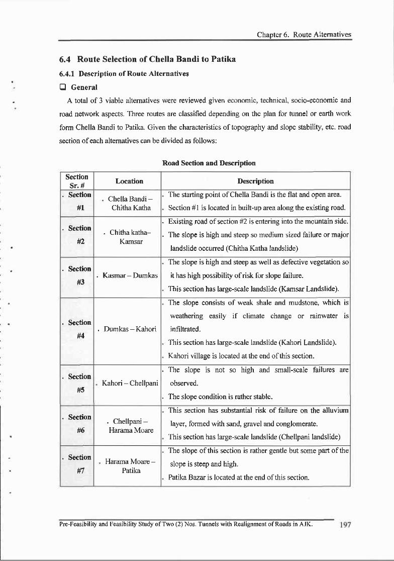
Chaoter 6. Route Alternatives
6.4 Route Selection of Chella Bandi to Patika
6.4,1 Description of Route Alternatives
E General
A total of 3 viable altematives were reviewed given economic, technical, socio-economic and
road network aspects. Three routes are classified depending on the plan for tunnel or earth work
form Chella Bandi to Patika. Given the characteristics of topography and slope stability, etc. road
section ofeach alternatives can be divided as follows:
Road Section and Description
SectionSr. #
Location Description
, Section
#LChella Bandi -Chitha Katha
The starting point of Chella Bandi is the flat and open area.
Section # I is located in built-up area along the existing road.
. Section4a
. Chitha katha-Kamsar
. Existing road of section #2 is entering into the mountain side.
. The slope is high and steep so medium sized failure or major
landslide occuned (Chitha Katha landslide)
. Section
#3. Kasmar - Dumkas
The slope is high and steep as well as defective vegetation so
it has high possibility of risk for slope failure.
This section has larse-scale landslide (Kamsar Landslide).
, Section
#4. Dumkas - Kahori
The slope consists of weak shale and mudstone, which is
weathering easily if climate change or rainwater is
infiltrated.
This section has large-scale landslide (Kahori Landslide).
Kahori villaee is locaied at the end ofthis section.
. Section
tt3Kahori - Chellpani
. The slope is not so high and small-scale failures are
observed.
. The slope condition is rather stable.
. Section
#6. Chellpani-Harama Moare
This section has substantial risk of failure on the alluvium
layer, formed with sand, gravel and conglomerate.
This section has large-scale landslide (Chellpani landslide)
. Section Harama Moare -Patika
The slope of this section is rather gentle but some part ofthe
slope is steep and high.
Patika Bazar is located at the end ofthis section.
Pre-Feasibility and Feasibility Study of T\,vo (2) Nos. Tunnels with Realignment of Roads in AJK.
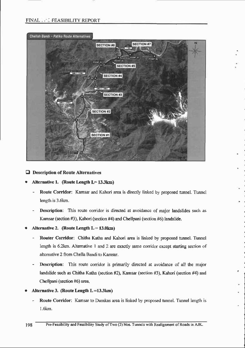
FINAL., -.FEASIBILITYREPORT
El Description of Route Alternatives
. Alternative l. @oute Lcngth IF l33km)
- Route Corridor: Kamsar and Kahori area is directly linked by proposed tunnel. Tumel
length is 3.6km.
- Description: This route corridor is dir€cted at avoidancs of major landslides such as
Kamsar (section #3), Kahori (section #4) and Chellpani (section #6) landslide.
o Alternative 2. (Route Length L : l3.0km)
- Router Corridor: Chitha Katha and Kahori area is linked by proposed tunnel. Tunnel
length is 6.2km. Altemative I and 2 are exactly same corridor except starting section of
altemative 2 from Chella Bandi to Kamsar.
- Description: This route corridor is primarily directed at avoidance of all the major
landslide such as Chitha Katha (section #2), Kamsar (section #3), Kahori (section fl4) and
Chellpani (section #6) area.
I Alternative 3. @oute Length L :133km)
- Route Corridor: Kamsar to Dumkas area is linked by proposed tunnel. Tunnel length is
l.6km.
198 Pre-Feasibility and Feasibility Study ofTwo (2) Nos. Tunn€ls with Realignment of Roads in AJK.
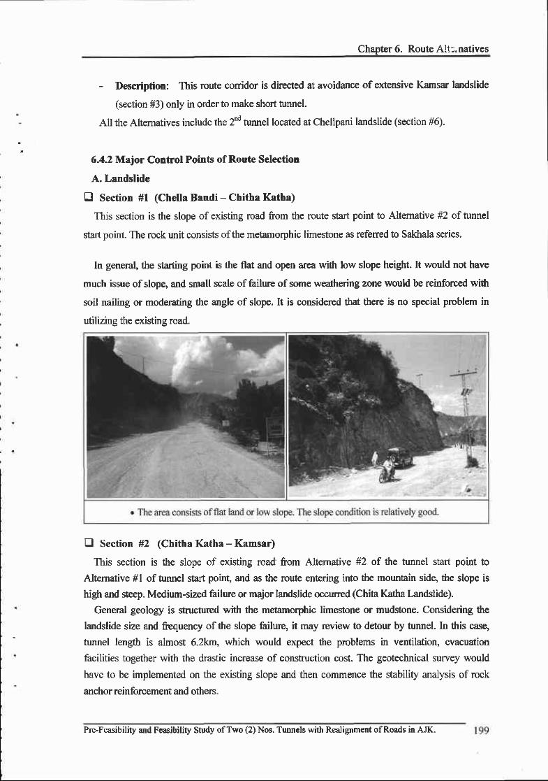
Chapter 6. Route All:.natives
- Description: This route conidor is directed at avoidance of extensive Kamsar landslide
(section #3) only in order to make short funnel.
All the Altematives include the 2nd tumel located at Chellpani landslide (section #6).
6.42 Major Control Points of Route Selection
A. Landslide
E Section #l (Chella Bandi - Chitha Katha)
This section is the slope of existing road from the route start point to Altemative #2 of tunnel
start point. The rock unit consists ofthe metamorphic limestone as referred to Salftala series.
In general, the starting point is the flat and open area wilh low slope height. It would not have
much issue of slope, and small scale of failure of some weat'rering mne would be reinforced with
soil nailing or moderating the angle of slope. It is considered ftat there is no special problem in
utilizing the existing road.
E Section #2 (Chitha Katha - Kamsar)
This section is the slope of existing road fom Altemative #2 of the tunnel start point to
Altemative #l of tunnel start point, and as the route entering into the mountain sidg the slope is
high and steep. Medium-sized failure or major landslide occurred (Chita Katha Landslide).
General geology is stuctured with the metamorphic limestone or mudstone. Considering the
landslide size and fsquency ofrhe slope failure, it may review to detour by tunnel. In this case,
tunnel length is almost 6.2km, which would expect the problems in ventilation, evacuation
facilities together with the dmstic increase of construction cost. The geotechnical survey would
have to be implemented on the existing slope and then commence the stability analysis of rock
anchor reinforcement and others.
Pre-Feasibility and F€asibility Study ofTwo (2) Nos. Tunnels with Realignment ofRoads in AJK.

FINAL -'I'I -FEASIBILITY REPORT
E Section #3 (Kamsar - Dumkas)
This section is the slope ofexisting road from Altemative #1 and #3 oftunnel start point to the
Altemative #3 of tunnel end point. The rock unit consists of sand stone, mud stone, shales.
Generally, the slope is high and steep as well as defective vegetation so that it has high possibility
ofrisk for slope failure and this section has large-scale landslide (Kamsar Landslide).
The size of the landslide reaches to the slope height of 50-150m and in order to rcinforce the
slope, drainage facilities preventing rain-water infiltration and reinforcement of rock anchor are
required at entire landsliding area, therefore huge amount of reinforcement costs are required so it
is considered too difticult to reinforce entire slope in realistic view points. It is nor feasible and nor
desirable. Accordingly it is recommended to bypass this landslide area by tunnel.
I
200 Pre-Feasibility and Feasibility Study ofTwo (2) Nos. Tunnels with Realignment of Roads in AJK.
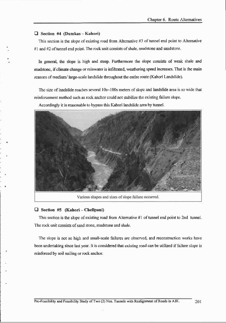
Chapter 6. Route Alternatives
El Section #4 (Dumkas - Kahori)
This section is the slope of existing road from Altemative #3 of tunnel end point to Altemative
#l and #2 oftunnel end point. The rock unit consists ofshale, mudstone and sandstone.
In general, the slope is high and steep. Furthermore the slope consists of weak shale and
mudstone, ifclimate change or rainwater is infiltrated, weathering speed increases. That is the main
reasons ofmedium/ large-scale landslide throughout the entfue route (Kahori Landslide).
The size oflandslide reaches several l0s-100s meters ofslope and landslide area is so wide that
reinforcement method such as rock anchor could not stabilize the existing failure slope.
Accordingly it is reasonable to bypass this Kahori landslide area by tunnel.
O Section #5 (Kahori - Chellpani)
This section is the slope of existing road from Altemative #1 oftunnel end point to 2nd tunne..
The rock unit consists of sand stone, mudstone and shale.
The slope is not so high and small-scale failures are observed, and reconstruction works have
been undertaking since last year. It is considered that existing road can be utilized iffailure slope is
reinforced by soil nailing or rock anchor.
Pre-Feasibility and Feasibility Study ofTwo (2) Nos. Tunnels with Realignment ofRoads in AJK.

FINAL :.',, ;: FEASIBILITY REPORT
E Section *6 (Chellpani - Earama Moare)
This section is the slope of existing road from 2nd tunnel start point to 2nd tunnel end point. The
rock unit consists of sand stone and mudstone as the base rock and the alluvium of substantial
thickness (10-20m).
This section has subsantial risk of failure on the alluvium layer, formed with the sand, gravel
and conglomerate on the upper part ofthe slope. Since the shength ofalluvium layer is reduced in
rainy season and rock mass is also severely weafiered. During rainfall clayl shale absorb water and
fine gra.in e.g. clay starts oreeping to slope dircction this buildup more pr€ssure results in slumping
of loose material. This process is more active where the fine grained material clay or shale is in
dominant, where rocky slata slope stability is mor€, That is the major reasons of extensive
landslide occurenc€.
For thiq reduction of slope angle together with drainage method could be recommended.
However the slope is so st€ep that reduction of slope angle is impossible. In that case rock
anchoring method would be applied in general .but it is doubtful of ib reinforcing effect.
Consequently it is desirable to bypass the Chellapani landslide area by tunnel altemative.
202 Pre-Feasibility and Feasibility Study ofTwo (2) Nos. Tunnels with Realignment ofRoads in AJK.

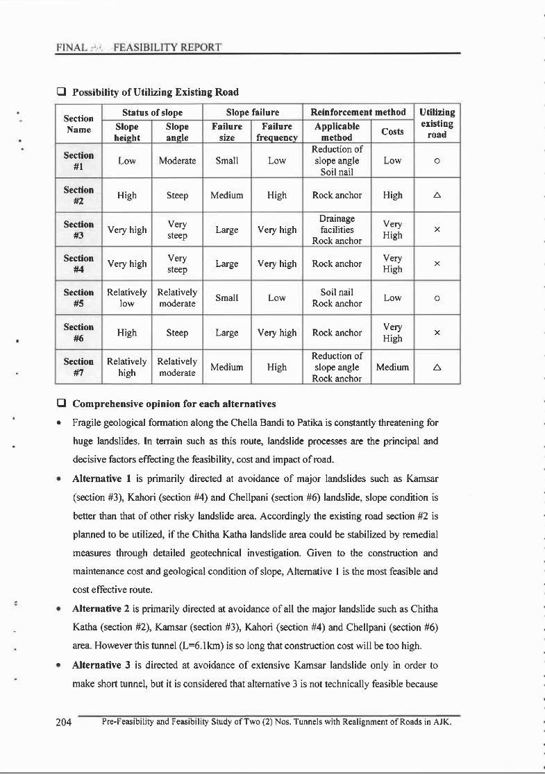
E Possibility of Utilizing Existing Road
Comprehensive opinion for each alternatives
Fragile geological formation along the Chella Bandi to Patika is constantly threatening for
huge landslides. In terrain such as this route, landslide processes arc the principal and
decisive factors effecting the feasibility, cost and impact ofroad.
Alternative 1 is primarily directed at avoidance of major landslides such as Kamsar
(section #3), Kahori (section #4) and Chellpani (section #6) landslide, slope condition is
better than that of other risky landslide area. Accordingly the existing road section #2 is
planned to be utilized, if the Chitha Katha landslide area could be stabilized by remedial
measures through detailed geotechnical investigation. Civen to the construction and
maintenance cost and geological condition ofslope, Altemative I is the most feasible and
cost eflective route.
Alternative 2 is primarily directed at avoidance of all the major landslide such as Chitha
Katha (section #2), Kamsar (section #3), Kahori (section #4) and Chellpani (section #6)
area. However this tunnel (L=6.lkm) is so long that construction cost will be too high.
Alternative 3 is directed at avoidance of extensive Kamsar landslide only in order to
make short tunnel, but it is considered that altemative 3 is not technically feasible because
tra
SectionName
Status ofslope Slope failure Reinforcement method Utilizingexisting
roadSlopeheisht
Slopeansle
Failuresize
Failurefreo uencv
Applicablemethod
Costs
Secfion#l
Low Moderate Small LowReduction ofslope angle
Soil nailLow o
Secfion#2 High Steep Medium High Rock anchor High
Section#3
Very high Verysteep Large Very high
Drainagefacilities
Rock anchor
veryHigh
X
Section#4
Very high Verysteep Large Very high Rock anchor very
HighX
Sectionttr
Relativelylow
Relativelymoderate
Small LowSoil nail
Rock anchorLow o
Section#6
High Steep Large Very high Rock anchorVeryHigh
X
Section#7
Relativelyhigh
Relativelymoderate
Medium HighReduction ofslope angle
Rock anchorMedium A
204 Pre-Feasibility and Feasibilig Study ofTwo (2) Nos. Tunnels with Realignment ofRoads in AJK.
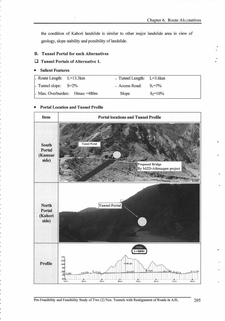
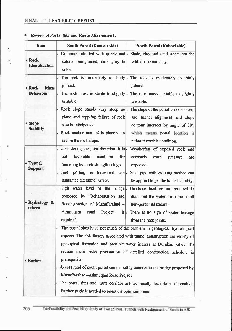
FEASIBILITY REPORT
Review of Portal Site and Route Alternative l.
Item South Portal (Kamsar side) North Portal (Kahori side)
. RockIdentification
. Dolomite intruded with quartz and
calcite fine-grained, dark gray in
color.
Shale, clay and sand stone intruded
with quartz and clay.
. Rock MassBehaviour
. The rock is moderately to thinly
jointed.
. The rock mass is stable to slightly
unstable.
. The rock is moderately to thinly
jointed.
. The rcck mass is slable to slightly
unstable.
. SlopeStability
. Rock slope stands very steep so
plane and toppling failure of rock
sloe is anticipated
. Rock anchor method is planned to
secure the rock slope,
The slope ofthe portal is not so steep
and tunnel alignment and slope
contour intersect by angle of 30o,
portal
rather favorable condition.
. TunnelSupport
Considering the joint direction, it is
not favorable condition for
tunneling but rock stength is high.
Fore polling reinforcement can
guarantee the tunnel safety.
. Weathering of exposed rock and
eccentric earth pressul€ are
expected.
. Steel pipe with grouting method can
be applied to get the tunnel stability.
. Hydrolory &others
High water level of the bridge
proposed by "Rehabilitation and
Reconstuction of Muzaffarabad -
Athmuqam road Project" is
required.
. Headrace facilities are requir€d to
drain out the water form the small
non-perennial stream.
. There is no sign of water leakage
from the rock ioints.
. Review
The portal sites have not much of the problem in geological, hydrological
aspects. The risk factors associated with tunnel construction arc variety oI
geological formation and possible water ingress at Dumkas valley. To
teduce these risk prepantion of detailed construction schedule is
prerequ is ite.
Access road of south portal can smoothly connect to the bridge proposed by
Muzaffarabad -Athmuqam Road Project.
The portal sites and route corridor are technically feasible as altemative.
Further study is needed to select the optimum route.

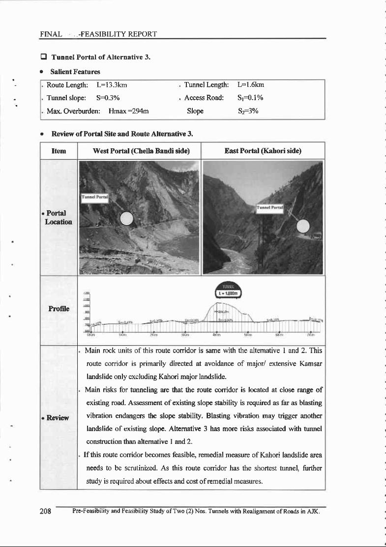
FTNAL --FEASIBILITY REPORT
Route kngth: L:13.3km
Tunnel slope: S{.3%
Max.Overburden: Hmax:294m
Tunnel Length:
Access Road:
Slope
L:1.6km
sr{.1%
sfl%
tra
Tunnel Portal of Alternative 3.
Salient Feafures
r Review of Portal Site and Route AlGrnative 3,
Item West Porbl (Chella Bandi side) East Portal (Kahori side)
. PortalLocation
Profile
. Review
Main rock units of this route conidor is same with the altemative I and 2. This
route corridor is primarily directed at avoidance of major/ extensive Kamsar
landslide only excluding Kahori major landslide.
Main risk for tunneling arc that the route corridor is located at close range of
existing road. Assessment of existing slope stability is required as far as blasting
vibration endangers the slope stability. Blasting vibration may trigger another
landslide of existing slope. Altemative 3 has more risks associated with tunnel
construction lhan altemarive I and 2.
Ifthis route conidor becomes feasible, remedial measure of Kahori landslide area
needs to be scrutinized. As this route conidor has the shortest tunnel, firrther
study is required about effects and cost of remedial measures.
208 Pre-Feasibility and Feasibility Study ofT$/o (2) Nos. Tunnels with Realignment ofRoads in AJK.
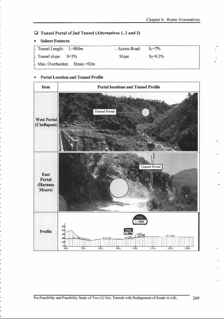
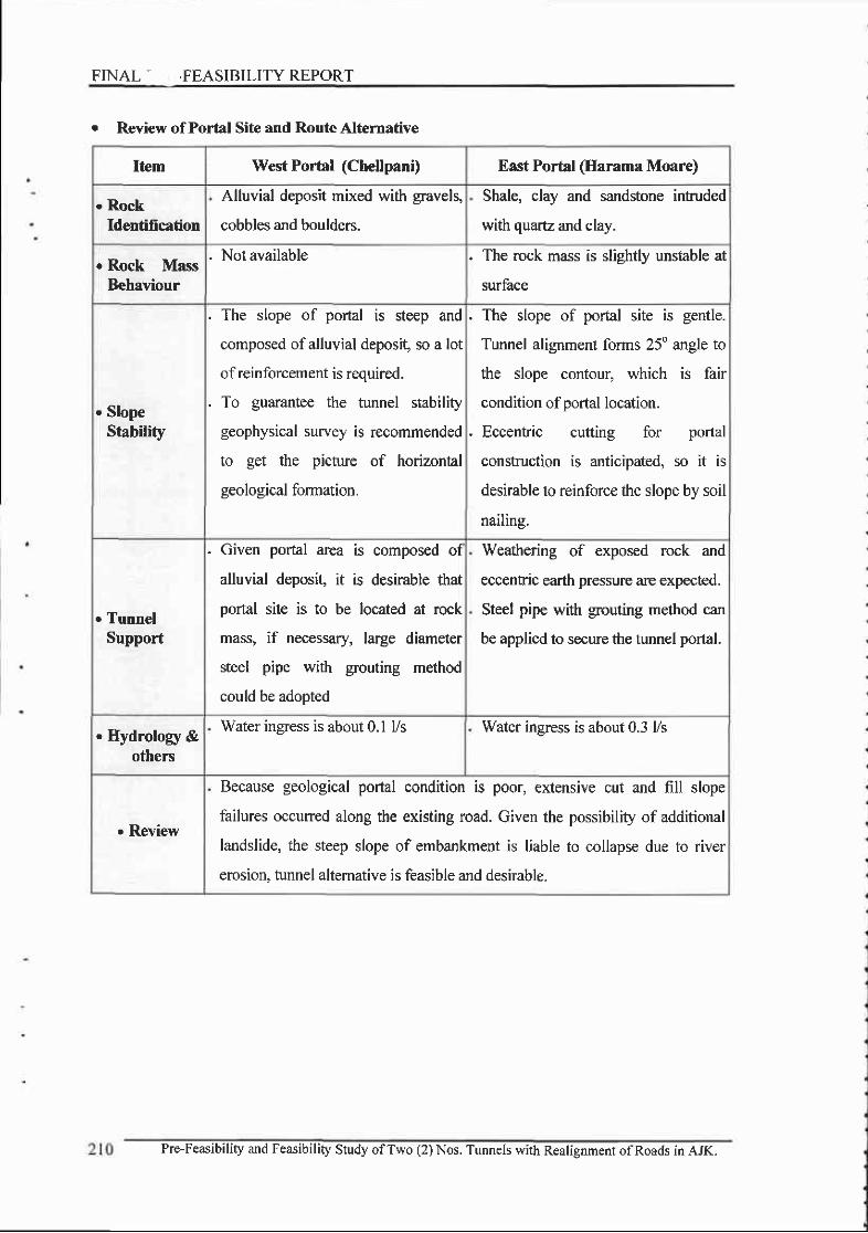
FINAL - ,FEASIBILITY REPORT
e Review ofPortal Site and Route Alternative
Item WestPortal (Chellpani) East Portal (Ilarama Moare)
. RockIdentification
Alluvial deposit mixed with gra.vels,
cobbles and boulders.
Shale, clay and sandstone intruded
with quare and clay.
. Rock MassBehaviour
. Not available . The rock mass is slightly unstable at
surface
. SlopeStability
. The slope of portal is steep and
composed ofalluvial deposit, so a lot
of reinforcement is required.
. To guarantee the tunnel stability
geophysical survey is recommended
to get the picture of horizontal
geological formation.
. The slope of portal site is gentle.
Tunnel alignment forms 25" angle to
the slope contour, which is fair
condition of portal location.
. Eccentric cutting for portal
construction is anticipated, so it is
desirable to reinforce the slope by soil
nailing.
. TunnelSupport
. Given poral area is composed of
alluvial deposil it is desirable that
portal site is to be located at rock
mass, if necessaq/, large diameter
steel pipe with grouting method
could be adopted
Weaftering of exposed rock ancl
eccentic earth pressure are expected.
Steel pipe with grouting method can
be applied to secure the tunnel portal.
. Hydrology &others
Water ingress is about 0.1 Vs Water insress is about 0.3 l/s
. Review
Because geological portal condition is poor, extensive cut and fill slope
failures occurred along the existing road. Given the possibility of additional
landslide, the steep slope of embankment is liable to collapse due to river
erosion, tunnel altemative is feasible and desirable.
Pre-Feasibility and Feasibility Study ofTwo (2) Nos. Tunnels with Realigrment ofRoads in AJK.
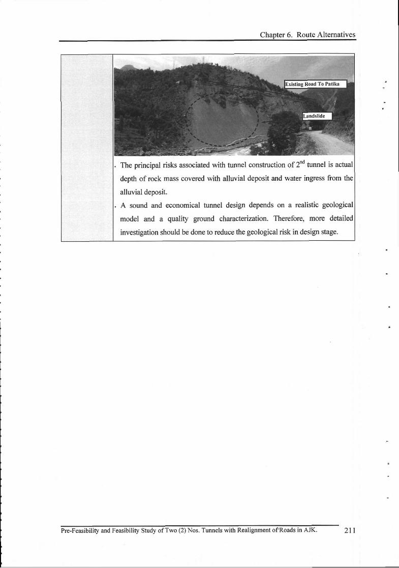
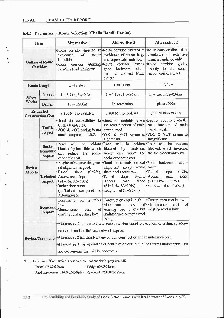
FINAL .FEASIBILITY REPORT
6.4.3 Preliminary Route Selection (Chella Bandi -Patika)
Item Alternative I Alternative 2 Alternative 3
Outline of RouteCorridor
,Route conidor directed atavoidance of majorlandslide.
'Route corridor utilizingexis-ting road maximum.
'Route conidor directed atavoidance of rather largeand large-scale landslide.
'Route coffidor havinggood horizontal align-ment to connect MZDdirectlv.
,Route coridor directed atavoidance of extensiveKamsar landslide only.
'Route conidor givingpdority to the const-ruction cost oftunnel.
Route Length L:l3.3km L=l3.0km L-13.3km
MajoIWorks
Tunnel Lr=3.7km, La=0.6km Lr=6.2km, Lz:O.6km Lr=l.8kn, Lr=0.6kn
Bridge I place/200m lplaceV200m I places/200m
EstimatedConstruction Cost
3,300 Million Pak.Rs. 5,300 Million Pak.Rs. 1,800 Million Pak.Rs.
ReviewAspects
TrafficAspect
'Good for accessibility toChella Bandi area.
,VOC & VOT saving is notmuch compared to Alt.2.
'Good for mobiliry giventhe road function of mainarterial road.
'VOC & VOT saving issisnificant.
'Bad for mobility given theroad funcrion of mainarterial road.
,VOC & VOT saving isirsimificant.
Socio-'Road will be seldomblocked by landslide, whichcan reduce the socio-economic cost.
'Road will be seldomblocked by landslide,which can reduce thesocio-economic cost.
will be frequentblocked. which in-creasethe socio-economic cost.
'Road
Aspect
Tenhnicql
'ln spite of S-curve the gene-ral alignment is good.
'Tunnel slope (S=2"4,Access road slope(sl:7%, s2: ttr/")
'Rather short tunel(L:3 .6km) compared toAltemative 2.
'Good horizontal/ verticalalignrnent except wherethe tunnel access road.
'Tunnel slope S=2o/o,Access road slope(sl=14%, s2=10%)
'Long tunnel (L=5.2km)
'Poor horizontal align-ment.
'Tunnel slope S:7YqAccess road slope(sl:0.r%, s2:3% )
'Short tunnel (L:l.8km)Aspec't
t'.connmir
'Construction cost is ratherlow
'Maintenance cost ofexisting road is rather low.
'Construction cost is high'Maintenance cost ofexisting road is low butmaintenance cost of turirelis hieh.
'Construction cost is low'Maintenance cost ofexisting road is huge.
Aspect
RevieVComments
Atternative 1 is feasible and recommended based on economic, technical, socio-
economic and traffic/ road network aspects.
Alternative 2 has disadvantage ofhigh construction and maintenance cost.
Alteroative 3 has advantage of construction cost but in long terms maintenance and
socio-economic cost will be enormom.
Note: . Estimation of Consh uction is base on 2 lahe road and similar project in AJK.
- Tunnel : ?50,000 Rsim - Bridge: 600,000 Rsi m
- Road Imprcvement: 30,000,000 Rskm -New Road : 85,000,000 Rs,&m
Realisnment of Roads in AJK.Two (2) Nos. Tunnels

P\r"

laI
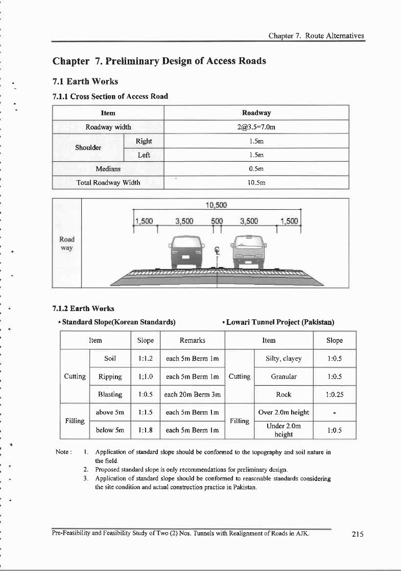
Chaoter 7. Route Altematives
l .
2.3 .
Chapter 7. Preliminary Design of Access Roads
7.1 Earth Works
7.1.1 Cross Section ofAccess Road
7.1.2 Earth Works
. Standard Slope(Korean Standards) . Lowari Tunnel Project (Pakistan)
Note : Application of standard slope should be conformed to the topography and soil taturc inthe field-Proposed standard slope is only recommendations for preliminary design.Application of standard slope should be conformed to reasonable standards consideringthe site condition and actual consfiuction practice in Pakistan,
Item Roadway
Roadway width [email protected]:7.0n
ShoulderRiCht l .5m
Left 1.5m
Medians 0.5m
Total Roadway Width 10.5m
Item Slope Remarks Item Slope
Cutting
Soil 1 : 1 . 2 each 5m Berm lm
Cutting
Silry, clayey l :0.5
Ripping 1; l .o each 5m Berm lm Granular l :0 .5
Blasting l :0 .5 each 20m Berm 3m Rock l :0.25
Fillingabove 5m l : 1 . 5 each 5m Berm lm
FillingOver 2.0m height
below 5m l : l - 8 each 5m Berm lm Under 2.0mheiqht l : 0 .5
Pre-Feasibility and Feasibilif Study ofTwo (2) Nos. Tunnels with Realignment ofRoads in AJK. 2t5

s= l : 100
TYPICAL CROSS SECTION
ROAD WAY
t500 500
lf.{4'*
TUNNEL
(CHELLAH-BANDI TUNNEL) (PATIKA TUNNEL)
r0,500
3 500 500
CLIENT
AZAD GOVERI{lilEtfT OF tHE STATEOF JATTIU & KASHIN
DIRECIOR GEI{E'I,AL CEI{TRAL OESIGT{ OFFICEMUZA'FARABAD
CONSULTAI{Tr glyli: t:gHn (w)
PRIME EI{GINEERING & TESTIIIG COI{SULTANTS PVT. LTD.&
ASIF ALI ASIiOCIATE PVT. LTO.
PRE+EASEIUTY AXO FEASBIUTY STUDYoF lVtO (4 t{OS. IUI{NELS ll'mr REALTGiTXEI{T OF ROATNi r{ AJK
TYPICALCROAS AECTION
N-s\
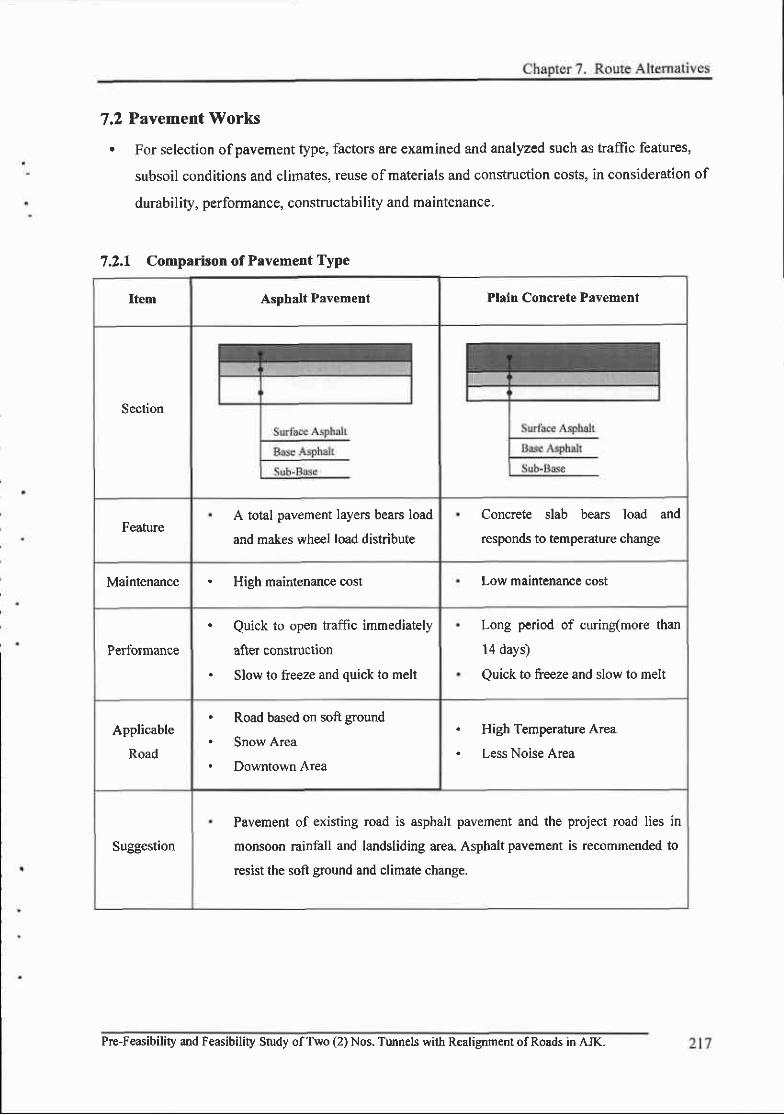
7.2 Pavement Works
. For selection ofpavement type, factors are examined and analyzed such as traffic features,
subsoil conditions and climates, reuse of materials and construction costs, in consideration of
durability, performance, constructability and maintenance.
7.2.1 Comparison of Pavement TyPe
Item Asphalt Pavem€nt Plain Concrete PaYement
Section
FeahlreA total pavement layers bears load
and makes wheel load distribute
Concrete slab bears load and
responds to temperature change
Maintenance . Hieh maintenance cost Low maintenance cost
Performance
. Quick to open traffic immediately
after construction
. Slow to freeze and quick to melt
Long period of curing(more than
l4 days)
Quick to freeze and slow to melt
Applicable
Road
. Road based on soft ground
. Snow Area
. Downtown Area
High Temperature Area
Less Noise Area
Suggestion
Pavement of existing road is asphalt pavement and the project road lies in
monsoon rainfall and landsliding area. Asphalt pavement is recommended to
resist the soft ground and climate change.
Pre-Feasibility and Feasibility Study ofTwo (2) Nos. Tunnels with Realignment ofRoads in AJK.
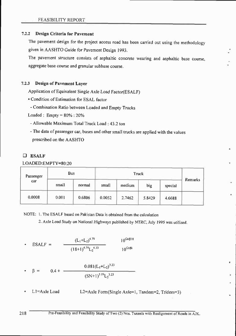
FEASIBILITY REPORT
7.2.2 Design Criterir for Pavement
The pavement design for the project access road has been carried out using the methodology
given in AASHTO Cuide for Pavement Design 1993.
The pavement structure consists of asphaltic concrete wearing and asphaltic base course,
aggregate base course and granular subbase course.
7.2.3 Design of Pavement Layer
Application of Equivalent Single Axte Load Factor(ESALF). Condition of Estimation for ESAL factor
- Combination Ratio between Loaded and Empty Trucks
Loaded : Empty : 80Vo :20o/o
- Aflowable Maximum Total Truck Load :43.2ton
- The data ofpassenger car, buses and other small trucks are applied with the values
prescribed on the AASHTO
fl ESALF
LOADED:EMPTY=80:20
Passengercar
Bus TruckRemarks
small normal small medium big special
0.0008 0.001 0.6806 0.0052 2.7462 5.8429 4.6688
NOTE: I . The ESALF based on Pakistan Data is obtained from the calcularion
2. Axle Load Study on National Highways published by NTRC, July 1995 was utilized.
(Lr+Lz)a t' l6cr/Pl t. ESALF =
( l 8+l )4 7eL24 13
l6ct/Pi
0.081(L;+L2)3 23' P= 0 .4+
(sN+ I )s reL23 23
. Ll:Axle Load L2=Axle Form(Single Axlrl, Tandem=1, Tridem=3)
2l 8 Pre-Feasibility and Feasibility Study of Two (2) Nos. Tunnels witb Realignment of Roads in AJK.

Chapter 7. Route Alterr.z.tives
E Future Traffic Volumedav)vehicles/
Year PassengerCar
Bus TruckSpecialTruck
Total
Snall Nornal Small Medium Big
2014 721 962 506 6r t 457 412 453 4,129
2015 752 1,00J 528 644 477 429 4,305
2016 784 r ,046 550 671 497 448 493 4,489
2017 8 1 7 1,090 700 5 1 8 467 514 4,680
2018 852 1, t37 598 730 540 487 535 4,879
20t9 883 | ,178 620 756 559 504 555 5 0 1 5
2020 914 1,220 642 783 579 522 575 { r l {
202r 947 1,263 bt)) 8 l l 600 541 595 5,422
2022 9 8 1 t ,308 689 840 622 560 616 5,616
2023 r , 016 1,355 7t3 E70 644 580 638 5,816
2024 |,047 |,397 735 89',1 664 59E 658 5,996
2025 r,080 t,441 75E 925 684 6t7 679 6,1E4
2026 l . l l 3 t,485 782 954 706 636 700 6,376
2027 t , t 4 8 1,531 806 983 '128o J ) 721 6,572
2028 r , t 64 |,579 8 3 1 1,o14 '7 50 744 6,778
2029 |,220 |,628 857 1,045 773 697 6,987
2030 1,25E t,67E 883 I s1'l 797 7 l E 790 't,201
2031 1,297 |,730 9t0 l . l l l 822 740 8 r5 7 L)\
2032 r,337 t,784 939 1,145 841 840 7 6aa
2033 t,379 1,839 968 1 , 1 8 1 874 787 866 7,894
2t9Pre-Feasibility and Feasibility Study ofTwo (2) Nos. Tunnels with Realignm€nt ofRoads in AJK.

'- ..FEASIBILITYREPORT
Year PassengerCsr
Bos TruckSpecialTruck
ESAL(Dry)
ESAr,{r01(Year)
AccumuLtedESAL(101
Smsll Normal Smrll Mcdium Big
ESALF 0.0008 0.00r0 0.6806 0.0052 2.1462 s.E429 4.6688
2014 0.6 1 .0 344.4 3.2 r,255.0 2,401.32,115.0 6t26.3906 2.236
20t5 0.6 1 . 0 359.4 1,309.9 2,506.6 2,203.7 6384.5253 2.330 4.566
2016 0.6 t . 0 374.3 J . ) r,364.9 2,611.6 2,30t.7 6663.6914 2.432 6.999
20t'7 0.'7 l . l 390.7 3.6 1 d,'r) a 2,728.6 2,399.E 6946.9771 2.536 9.534
2018 0.7 l . l 407.0 3 .8 1,482.9 2,845.5 2,49't.8 7238.8617 2.642 12.177
2019 0.7 t_2 422.0 3.9 2,944.8 2,591.2 7 498.9190 2.131 t4.9t4
2020 0.7 1.2 436.9 4 .1 t,590.0 3,050.02,684.6 7767.57l6 2.835 l7.749
2021 0.8 1.3 452.6 4.2 |,647.7 3 , t6 t .0 2,111.9 8045.s0r 7 2.937 20.685
2022 0.8 468.9 4.4 t,708.1 3,212.02,816.0 833t .5354 3.041 23_726
2023 0.8 t.4 485-3 r,768.6 3,388.9 2,978.7 8628.0888 3.149 26.476
2024 0.8 1 . 4 500.2 4 .7 |,823,5 3,494.l 3,072.1 8896.74t4 1.247 30.t23
2025 0,9 t . 4 515.9 4 .8 t.878,4 3,605.1 3 ,170. t 9176 s9sl 3.349 33.472
2026 0.9 1 .5 532.2 5.0 r.938,8 3,', lt6.l 3,268.2 9462.62',10 3.454 36.926
2027 0 9 1 . 5 548.6 5 . 1 1.999.2 3,821.1 3,366.2 9'148.6625 3.558 40.485
2028 0.9 1 .6 565.6 2,059.7 3,949.8 3,473.6 t0056.4 t52 3.671 44.t55
2029 1.0 t , 6 583.3 5.4 2,122.8 4,0't2.5 3 ,581.0t0367.5957 3.784 47.939
2030 1.0 l 1 601.0 5.6 2,188.1 4,t95.2 3,688.4 r068 | .5302 3.899 5 r .838
2031 1.0 1 .1 6t9.3 1.5 7 7a'1 4 a 1 )1 7 3,805.1 I1014.0852 4.020 55.858
2032 l . l 1.8 639.1 6.0 2,326.0 4,458.1 3,921.8 I1353.8471 4.t44 60.002
2033 l . l 1.8 658.8 6. t 2,400.2 4,598.4 4,043.2 | 1709.6261 4.274 u.276
O Equivalent Traffic Yolume(lSKips) (AP)
220 Pre-Feasibility and Feasibility Study ofTwo (2) Nos. Tunnels with Realignrnent ofRoads in AJK.

Chapter 7. Route Altematives
E Asphalt Pavernent Thickness Based on AASHTO 1993
Clsssificction Input Calculation Remark
Growth Rate(o/o) 4.03 F/S data
Cumulative ESALS(10 6) 64.28 Basic Traffic Volume based on 2009 Calculated
DirectioDal Factor 0.5
Lane Distribution Factor I
ESALs for Design Lane 32.14 Cumulative ESALS x DD x DL
CBR(Subgrade) l 0
SSv(Subgrade) t - t SSV=3.8xlog(CBR)+1.3
SSV(Subbase) 7.E SSV=3.Exlog(CBR)+1.4, Subbase CBR=50
al (surfacc) 0.165 Layer Coefficient
a2(middle layer) 0 . 1 5 3 Layer Coe{ficient
a3(Base) 0.055 Layer Coellicient(a.3=0.249(toCEbs)-0.977), Ebs:kl @12
a4(Subbas€) 0.049
ml I Drainage Coefficient
rrr2 I Drainage Coefficient
m3 I Drainage Coefficient
PSI(initial) 4.2
PSI(terminal) 2.5
APSI 1.7
Reliability (%) 95
zk -t.645 Standard Normal Deviation
s 0.45 Standard Deviation
Mr(Asphalt) (psi) 400,000
M(Base) (psi) 30,000
M(Subbase) (psi) 18,000
M(Subgrade) (psi) 15,000
Mr(Roadbed) (psi) Mr=1500*CBR, 00000
Pre-Feasibility and Feasibility Study ofTwo (2) Nos. Tunnels with Realignment ofRoads in AJK. 221
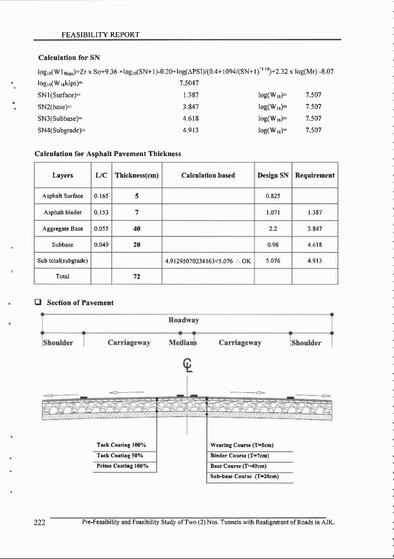
FEASIBILITY REPORT
Calculation for SN
logro(W I rri*)=Zr x So+9.36 x logro(SN+ I )-0.20+log(APSly(0.4+ 1094(SN+ l)^t 't)+2.32 x log(Mr) -8.07
logl(W;skips)=
SN l(Surface)=
SN2(base)=
SN3(Subbase)=
SN4(Subgrade)=
7 .5047
|.387
3.847
4.6t8
4.9t3
log(W;)=
log(W1s)=
log(W;s)=
log(W 1)=
7.507
7.507
1.507
1.507
Calculation for Asphalt Pavement Thickness
Lryers Ltc Thickness(cm) Calculation based Design SN Requirement
Asphalt Surface 0.165 f, 0.825
Asphalt binder 0.153 7 1.071 1.387
Aggregate Base 0.055 40 2.2 1.847
Subbase 0.049 20 0.98 4.618
Sub total(subgade) 4.9t295070234|63<5.076 . . OK 5.076 4 . 9 t 3
Total 72
E Section of Pavement
Trck Corting loooy'o Werring Course (T=scm)
Trck Coatitrg 50ol/o Binder Course (T=7cm)
PriBe Coating 1007o Base Course (T-40cm)
Sub.base Course (T=20cm)
222 Pre-Feasibility and Feasibility Study ofTwo (2) Nos. Tunnels with Realignment ofRoads in AJK.

7.3Drainage Works
The hydrological investigation was carried out such as rainfall data" rainfall patterns and
intensities with recurrence periods, catchment area, estimation of run off for use in cross
drainage design. The study covered the following principal activities:
- Study of Precipitation Data,
- Processing and analyzing data for determining rainfall intensity by the retum period,
- Study ofsurface Drainage with regard to catchments characteristics, time of
concentration and rainfall intensity.
The bridges and culverts could be designed for design discharge corresponding to return period of
100' 25 and 15 years respectively. The procedure for discharge estimation depends upon data
availability and different frequencies adopted for this purpose.
The data fiom station and other information gathered from the client were utilized for estimation
ofpeak discharge. Other design discharges would be synthesized using precipitation data.- Frequency Analysis
Frequency Analysis was carried out to estimate design discharge.- Calculate Design Discharge
. Prelirninary Design Process
. Calculale
. Calculate
. Calculate
calchment areaarrival timealttude ditlerence
Hflv
' Halional lormula (A<4km?). Standard run-oll m€thod
(A<40km?). Hydroora0h roulin0 rnelhod
(A>40km?)
. Flood quantity O=A . V
. Existing Flood level survey
. Existing river Cross s€ctionreview
Pre-Feasibility and Feasibility Study ofTwo (2) Nos. Tunnels with Realignment ofRoads in AJK. 223

p t\J

Chapter 8. Tunnel Design
8.1 General
8.1.1 Salient Features of Tirnnel
This 'Pre-Feasibility and Feasibility Study of Two (2) Tunngls with roads realignment in AJK'
deals with two tunnel sections: the Barmkot to Lohar Gali and Chella Bandi to Patika in District
Muzaffarabad. The existing roads are located in a rugged topography and graceful nature. The
tunnel was planned to avoid the landslide ofthe existing road. The tunnels were designed aiming at
preservation of the ecological system and minimizing the landslide. There are strong issues of
construction difficulty due to slope stability. However construction of road tunnel is one of the
most appropriate tecbniques not only to overcome landslide problem, but also to minimize total
transport cost leading to overall economic development in this region. The salient features of
tunnel is described as under.
Tunnel Detail Plan
Division Chella Bandi to Patika Road
Tunnel Name Kahori Tunnel Challpani Tunnel
Tunnel Length 3,7 46m 560m
Horizontal Alignment Curve*Straisht+Curve Straight line
Slope 0.9469% J.0%
Cross-Sectional grade -2.0% -2.0%
PortalType
StartingPoint
Arch shape Arch shape
EndingPoint
Arch shape Arch shape
Ventilation Svstem Jet Fan Longitudinal Ventilation Natural Ventilation
Tunnel excavationtMethod NATM NATM
Refuge facilityEmergency Parking Bay
+Emergency Shelter
Emergency Shelter
Pre-Feasibitity and Feasibility Study ofTwo (2) Nos. Tunnels with Realignment ofRoads in AJK.

] FEASIBILITY REPORT
E.I.2 Case Study on Existing Tunnel in Pakistan
At present, there exist the Lowari road tunnel, Lakpass tunnel and Kohat tunnel in Pakistan.
Lowari road tunnel is currently under construction. Taking into account tunnel length and the
importance ofexcavation method, a case study oflowari and Kohat tunnels was carried out. :
Case Study on Existing Tunnels in Pakistan
Section Lowari road tunnel Kohat road tunnel
Status
kt - ij ' t
Location Dir - Chitral. NWFP Peshawar - Kohat. NWFP
TunnelLength
0.9km(Under construction) l .885km
ExcavationMethod NATM NATM
Maxinumgrade 5.0o/o 2.2%
Verticalclearance
5 . l m ) . 1 m
Carriagewidth 7.3m I . J M
Walkway oneither side
0.85m 0.75m
Shoulderwidth
0.3m 0.3m
Lining Single shell Double shell
Pavement Asphalt concrete pavement Concrete oavement
VentilationJet fan
Loneitudinal ventilationJet fan
Longitudinal ventilation
Client NHA NHA
226 Pre-Feasibility and Feasibility Study ofTwo (2) Nos. Tunnels with Realignment ofRoads in AJK
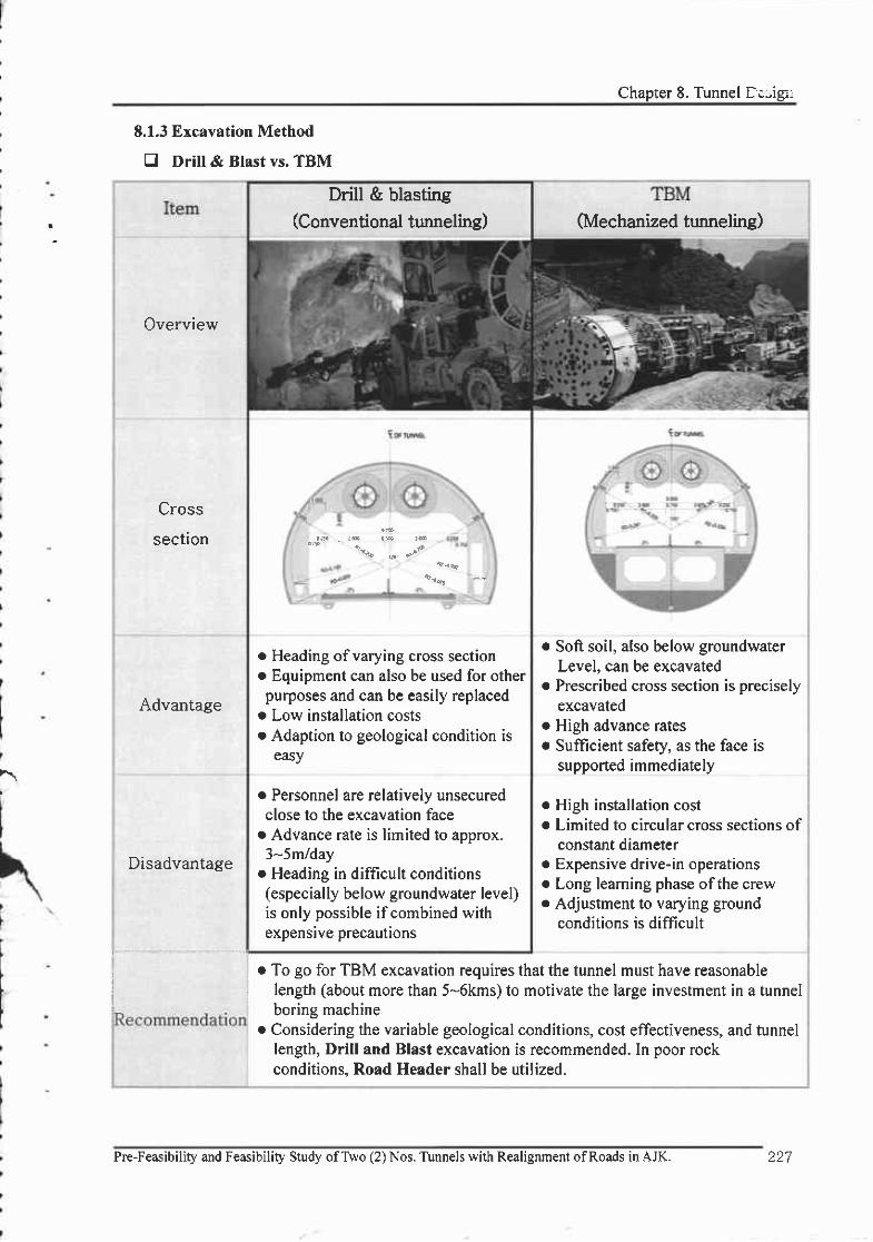
Chapter 8. Tunnel Dc-igi:
Drill & blasting(Conventional tunneling)
o Heading of varying cross sectiono Equipment can also be used for otherpurposes and can be easily replaced
o Low installation costs. Adaption to geological condition is
easy
. Personnel are relatively unsecuredclose to the excavation face
o Advance rate is limited to approx.3-5m/day
o Heading in difficult conditions(especially below groundwater level)is only possible if combined withexpensive precautions
E.1.3 Excavation Method
tr Drill & Blast vs. TBM
Overview
Cross
section
Advantage
Disadvantage
(Mechanized tunneling)
o Soft soil, also below groundwaterLevel, can be excavated
o Prescribed cross section is preciselyexcavated
o High advance ratesr Suflicient safety, as the face is
supported immediately
o High installation cost. Limited to circular cross sections of
constant diameterr Expensive drive-in operationso Long leaming phase ofthe crew. Adjustment to varying ground
conditions is difficult
r To go for TBM excavation requires that the tunnel must have reasonablelength (about more than 5-6kms) to motivate the large investment in a tunnelboring machine
o Considering the variable geological conditions, cost effectiveness, and tunnellength, Drill and Blast excavation is recommended. In poor rockconditions, Road Header shall be utilized.
I
Pre-Feasibility and Feasibility Study ofTwo (2) Nos. Tunnels with Realignment ofRoads in AJK. 227

- , . - . - FEASIBILITY REPORT
8.2 Tlpical Cross Section of Tirnnel
The tunnel's cross section is the most important factor in designing the tunnel as construction
costs vary greatly accordingly. Therefore, an optimum cross section was planned taking into
consideration, amount of width, space for instituting everything, and marginal maintenarce space
according to required clearance and horizontal alignment conditions.
l) The minimum clearance outline was designed as follows, comparing and anatyzing the current
Lowari road tunnel and Kohat tunnel in Pakistan.
. Caniageway : 7 .0m (2 @ 3.5 - two lanes )
" Shoulder : left - 1.0m, right - l.0m
. Inspection passage: the margin from the minimum clearance is 1.000m (left), 0.g5m
(right)
" Venicalc learance: 5. lm
" Corner s ize ofclearance (widthxheight) : l .0mxl. lm
. Lights and cable duct are installed.
The egg-shape, which is structurally stable, was selected, taking the above factors and tunnel's
cross-sectional slope of -2olo into account.
TypicalTunnelCross
Section
:L
228 Pre-Feasibility and Feasibility Study ofTwo (2) Nos. Tunnels with Realignment ofRoads in AJK
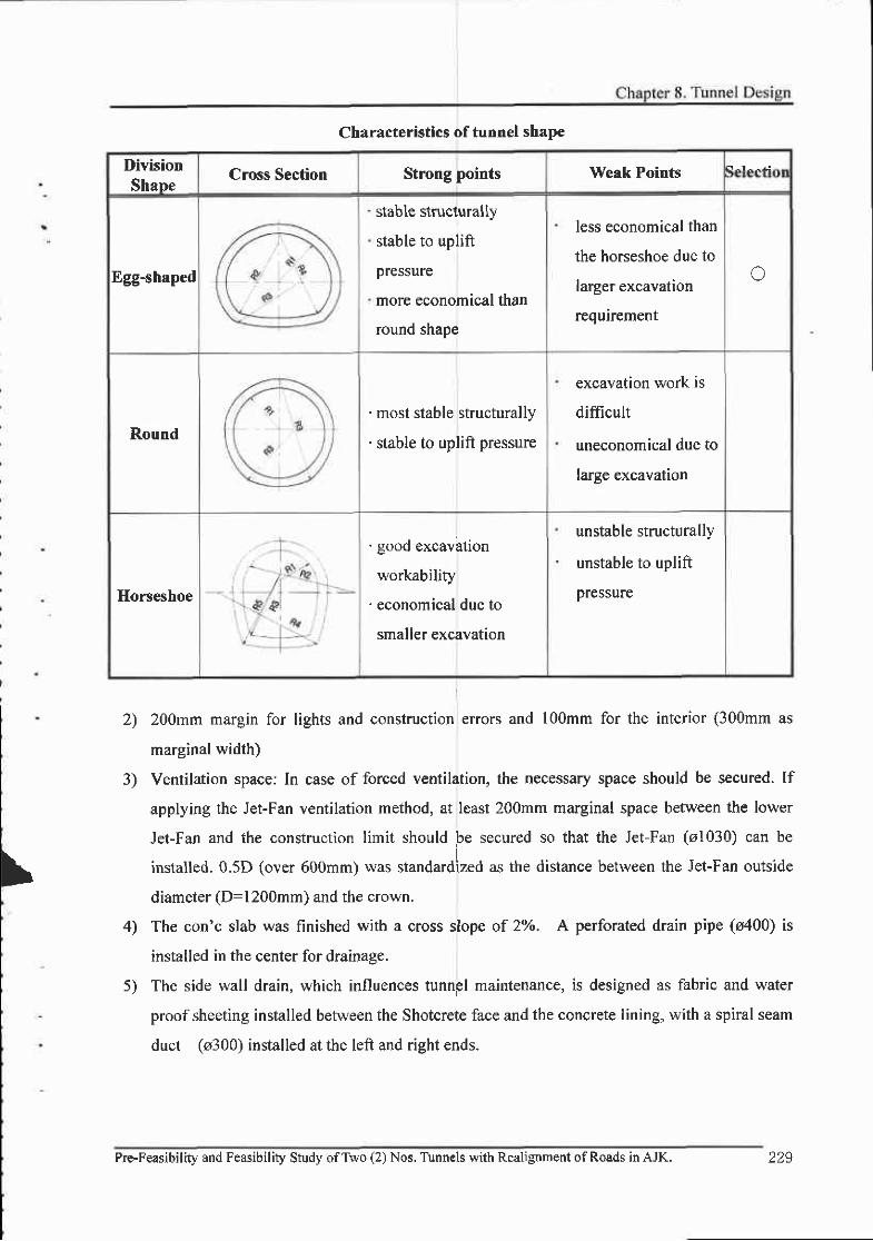
Characteristics of tunnel shape
DivisionShape
Cross Section Strong points Weak Pcints
Egg-shaped
stable structu rally
stable to uplift
pressure
more economical than
round shape
less economical than
the horseshoe due to
larger excavation
requirement
o
Round
' most stable structurally
' stable to uplift pressure
excavation work is
diflicult
uneconomical due to
large excavation
Horseshoe
. good excavbtion
workability
' economical due to
smaller excavation
unstable structurally
unstable to uplift
pressure
3)
2) 200mm margin for lights and construction errors and l00mm for the interior (300mm as
marginal width)
Ventilation space: In case of forced ventilation, the necessary space should be secured. I1
applying the Jet-Fan ventilation method, at least 200mm marginal space between the lower
Jet-Fan and the construction limit should be secured so that the Jet-Fan (o1030) can be
installed.0.5D (over 600mm) was standardized as the distance between the Jet-Fan outside
diameter (D=l200mm) and the crown.
The con'c slab was finished with a cross slope of 2Vo. A perforated drain pipe (s400) is
installed in the center for drainage.
The side wall drain, which influences tunngl maintenance, is designed as fabric and water
proof sheeting installed between the Shotcrete face and the concrete lining, with a spiral seam
duct (o300) installed at the left and right ends.
\
4)
Pre-Feasibility and Feasibility Study ofTwo (2) Nos. Tirnnels with Realignment of Roads in AJK. 225

. FEASIBILITY REPORT
6) The side wall drain, having high-density polyethylene perforated drain pipe (o100) protected
by filter concrete is installed between the shotcrete face and the second concrete lining.(C.T.C 10m)
7) To drain surface water, P.V.c. perforated drain pipe (o50) is connected to the drainage ditch
by C.T.C 10.0m.
o Typical Tunnel Cross Section
ChellaBandi foPatikaRoad
Chella BandiTunnel
Patika Tunnel
230 Pre-Feasibility and Feasibility Study ofTwo (2) Nos. Tunnels with Realignment ofRoads in AJK
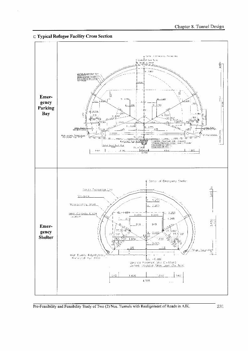


Chapter 8. Tunnel Design
E.3.1 Geotechnical Unit (GT[I)
A Geotechnical Unit in terms of geotechnical interpretation reflects a section of tunnel where
relatively consistent ground conditions are anticipated. Thus tunnel alignment is divided into l0
units (Geotechnical Units, GTU) where the combined effects of engineering-geological conditions,
initial stress situation and ground water conditions, including variations, are predicted to present
consistent tunneling conditions.
In this project, Geotechnical Unit Criteria (GTU) are defined as presented in the following table.
On the basis ofthis rock mass characterization ofsignificant rock mass types, the distribution of
Geotechnical Units along the tunnel alignment is shown in the longitudinal section of the
"Geological Tunnel Layout" drawing.
Geotechnical Units (GT[I)
GeotechnicalRock
StrensthWeathering(Considering
discontinuities)
WaterIngress
Problematic StructuralGeoloryUnits Approx.
UCS
I >250 Fresh (unweathered) Nil Ni l
, 100-2s0 Slightly weathered Nil Nit
3 50-100 Moderately weathered Nil Ni l
4 25-50 Highly weathered Nil Ni l
5 5-25 Completely weathered Nil Ni l
6 25-50 Highly weathered Yes Nit
)-z> Completely weathered Yes Nit
E 25-50 Highly weathered Ni l Fault, Shear or Fold
9 5-25 Completely weathered Ni l Fault, Shear or Fold
10 0-5 Completely weatheredand gavels, cobbles etc.
Yes Alluvial Deposit
Pre-Feasibility and Feasibility Study ofTwo (2) Nos. Tunnels with Realignment ofRoads in AJK.

..FEASIBILITY REPORT
8,3,2 Rock Mass Types (RMT)
Rock Mass Types are selected and defined according to their characteristic geotechnioal feaiures.
Rock mass characterization includes: intact rock oharacteristics (lithology, physical properties),
. Discontinuities (frequency, surface properties)
. Influence of weathering,
. Properties of faulted rock.
On the basis of this rock mass characterization,
presented in the following table.
significant rock mass types are defined as
The use ofa rock mass classification scheme can be ofconsiderable benefit. At its simplest, this
may involve using the classification scheme as a check-list to ensure that all relevant information
has been considered. At the other end of the spectrum, one or more rock mass classification
schemes can be used to build up a picture of the composition and characteristics of a rock mass to
provide initial estimates of support requirements, and to provide estimates of the strength and
deformation properties ofthe rock mass.
Prime Parameters Governing Rock Mass Property
Joint Parameters Material Parameters Boundary Conditions
Number of joint setsOrientation
SpacingAperture
Surface roughnessWeathering and alteration
Compressive strengthModulus of elasticity
Groundwater pressure andflow
In situ stress
234 Pre-Feasibility and Feasibility Study ofTwo (2) Nos. Tunnels with Realignment of Roads in AJK

l) Chella Bandi - Patika 1$ Road Tunnel
Rock Mass Types
RIVITsTlpical
Lithologies
UCS
(Approximate)
Intact Rock
StrengthDescripfion
RMT- 6
Homogeneous
or fine to
medium grained
Limestone with
calcite and
quartz intrusion.
100 - 200MPastrong to
very slrong
Joint spacing 20cm-60cm to
60cm - 200cm, surfaces rough.
Sheared, shattered or crushed
zones possible but not
frequent.
Thinly to thickly blocky.
RMT- 7
Fine grained
Dolomite with
calcite and
quartz intrusion
100 - l50MPasrong Io
very strong
Joint spacing close to medium
6-20cn,2O - 60cm surfaces
rough and stained.
Crushed or shattered zones
possible.
Some bedding sheared.
Blocky / Some parts disturbed.
RMT-9
Shale and clay
(fine grained)
Sandstone
(fine to medium
grain with
calcite and
quartz intrusion)
Shale
(2s - s0MPa)Sandstone
(100 - lsOMPa)
Medium
Strong
to strong
Joint spacing close6 cm -
20cm to moderate 2O - 60cm.
Surfaces Smooth and Clean.
Sandstone (stained and rough)
sheared, crushed or shattered
zones-
Sheared zones parallel to
bedding present.
RMT- 10
Shale and clay
(fine grained)
Sandstone
(fine to medium
grain with
calcite
and quartz
intrusion)
Shale
(5 - 2sMPa)Sandstone
(s0 - l00MPa)
weak
to $rong
Joint spacing close 2cm - 6cm
to moderate 6cm - 20cm.
(Shale) Surfaces Smooth and
Clean.
Sandstone (stained and rough)
sheared crushed or shattered
zones.
Sheared zones parallel to
bedding present
RMT. 12Disintegrated
to Sheared
(l - sMpa)
orn /a
Extremely
weak
Shear Zones / Fault / Crushed
rock ofany origin.
Pre-Feasibility and Feasibiliry Study ofTwo (2) Nos. Tunnels with Rsalignment ofRoads in AJK.

- ..FEASIBILITY REPORT
2) Chella Bandi - Patika 2nd Road Tunnel
Rock Mass Types are correlated to Engineering Geological Units. The estimated distribution of
RMTs along the alignment is shown in the longitudinal section of the "Geological runnel
Layout" drawing
Pre-Feasibility and Feasibility Study ofTwo (2) Nos. Tunnels with Realignment ofRoads in AJK236
Rock Mass Types
RMTsTlpical
Lithologies
UCS
(Approximate)
Intact Rock
StrengthDescription
RMT-9
Fine or very fine-
grained Shale
with Sandstone
with quartz
intrusion
I - 5MPa Very weak
Joint spacing 2-6cm and
surfaces smooth, rough and
stained.
Crushed or shattered zones.
Some bedding sheared. Some
parts disturbed.
RMT|-
1 l
Completely
Alluvial material,
d is integrated
0.1 - 0.5Mpa
orn /a .Stiffto Hard
Crushed rock ofany origin or
gravels, cobbles, pebbles and
boulders embedded loosely in a
matrix of sand and silt.

Chapter 8. Tunnel Design
8.3.3 Rock Mass Behavior Types (RBT)
The rock mass behavior was determined by the results of the combined analysis of rock mass
types including the expected influence of system factors and the unsupported tunnel. The result
had a number ofpossible failure modes that could be related to one single rock mass type or which
might cover several. The rock mass behavior types were based on basic behavior types but were
adopted to cover the specific local geotechnical conditions within the corridor area.
A general indication ofthe reaction of the rock mass to tunnel excavation is given by means of
Rock Mass behavior Types (RBT).
Besides the rock characterization as described by RMTs, assessment of stress conditions in the
ground was equally important for rock mass behavior appraisal behavior during excavation.
Geological factors influencing initial stress conditions are:
Height of overburden, position of water table,
Morphology,
Lithology (changes in weak and strong rocks),
Rock structure, in particular bedding or foliation,
Ceological history of the region.
By empirical methods or simple analytical models the magnitudes of stress and rate of
deformation can be predicted along with potential failure phenomena. Besides the mechanical
properties of the ground, the location and orientation of zones of weakness relative to the tunnel
axis will influence rock mass behavior. RBT does not take the effect of support measures and
subdivision of the cross section into account. Rock Mass Behavior Types are correlated to
Geotechnical Units (GTU). The estimated distribution of RBTs along the alignment is shown on
the longitudinal section ofthe "Geological Tunnel Layout" drawing.
Rock Mass behavior also depends on the size ofthe excavation cross section. The cross section
for the Tunnel is in general approx. 93 nf.
Pre-Feasibility and Feasibility Study ofTwo (2) Nos. Tunnels with Realignment ofRoads in AJK.

--r.. .- .' FEASIBILITY REPORT
The following RBTs, defined according to the Austrian Guidelines for Geomechanical Design,
are applicable to rhe this Project. In rhis project, RBT-6 is added to 'Rock
Mass Behavior Types'
because there are alluvial deposits in the chealla Bandi-Patika 2"d Road Tunnel south Mouth.
The typical provisions for excavation and primary support as indicated in the detailed RBTs
description will guarantee the required stable system behavior.
Rock Mass Behavior Types
Rock Mass Behavior Type (RBT)Description of potential failure modeVmechanisms
during unsupported mck mass excavation
RBT I StableStable rock mass with the potential of small local gravity
induced falling or block sliding
RBT2
Stable with the potential
ofdiscontinuity
controlled block fall
Deep reaching, controlled discontinuity, gravity induced
block falling and sliding , occasional local shear failure
RBT3
Shallow spalling and
shear failure mechanism,
raveling material from
the crown
Shallow stress induced shear failures in combination with
discontinuity and gravity controlled failure ofthe rock
RBT 4Deep seated shear
failure
Deep seated stress induced shear failures and large
deformations
RBT5 Rock burst
Sudden and violent failure ofrock mass, caused by highly
stressed brittle rocks and rapid release ofaccumulated
strain energy
RBT 6 Collapse
Collapse due to insufficient bearing capacity in alluvium
(or colluvium) deposit. Excavation method using rock mass
bearing capacity could not be used.
The expected project-specific rock mass behavior is described for
excavation, assuming smooth blasting by skilled workers. Rock mass
excavation and support provisions are described below:
drilling and blasting
behavior and typical
238 Pre-Feasibiliry and Feasibitity Study ofTwo (2) Nos. Tunnels with Realignment ofRoads in AJK
Chapter 8. Tunnel Design
n RBTI
Stable (intact) rock mass is characterized by the potential of small local gravity induced block
falling or sliding. After scaling, rock mass remains more or less stable. In the long term smaller
portions can fall, if unsupported, but overall stability will not be affected. The joint pattern is
usually medium to wide and closed joints with a rough surface prevail. Very small displacements
of tunnel layout can be expected, which subside soon after blasting. The presence of water has no
effect on rock mass stability.
. Spot bolting and shotcrete will be required occasionally during construction. Shotcrete and
wire mesh will be required for long term crown protection in case of close and unfavorable joint
pafierns.
. Type ofexcavation: Full face excavation. Possible round lenglhs > 3 m.
o RBT2
Small rock portions may fall or slide quite soon after blasting, induced by discontinuities and
gravity. Small displacements usually subside quickly. Joints are developed. The presence of water
has some influence on rock mass stability.
. Bolting, shotcrete with wire mesh required.
. Type ofexcavation: Full face excavation. Possible round lengths 2 to 3 m.
n RBT3
Small to medium large rock portions may fall, induced by discontinuities, gravity and
occasional local shear failures. Shear failure propagation and development ofshallow plastic zones
can occur. Displacements continue for some weeks but show a significant decrease in
displacement rate after a short time. Joints are well developed. The presence of water has a
negative effect on rock mass stability.
. Steel ribs (or better lattice girders), systematic bolting and shotcrete with wire mesh required.
Occasionally forepoling will be necessary.
. Type ofexcavation: Full face excavation with occasional face bolting and sealing of face with
shotcrete, Possible round lengths 1,4 to 2 m.
Pre-Feasibility and Feasibility Study ofTwo (2) Nos, Tunnels uith Realignment ofRoads in AJK. 239

FEASIBILITY REPORT
tr RBT4
Development of deep plastic zones. Large and long lasting displacements. Presence of water
leads to further reduction ofrock mass stability.
' Opening of face (if required in sections) with immediate application of shotcrete. Use of
steel ribs (or lattice girders) and forepoling necessary. Systematic rock bolting, shotcrete with wire
mesh and invert are required to establish equilibrium after a few months. In special cases
temporary invert also required, underpinning of top heading footings, face bolting, etc. may be
required.
' Type of excavation: Division into top heading, bench and invert or full face excavation with
Iong systematic face bolting, Possible round lengths 0,8 to 1,4 m.
o RBT5
Rock burst. Sudden and violent failure of rock mass close to excavated surface, caused by
highly stressed brittle rock and the rapid release of accumulated strain energy. Usually only occurs
in sparsely jointed rock mass under high overburden.
. Dense short bolting and shotcrete, possibly with steel fibers required for safety reasons.
. Type ofexcavation: Full face excavation.
o RBT6
Collapse due to insufficient bearing capacity in alluvium (or colluvium) deposit.
. Excavation method using rock mass bearing capacity could not be used.
' Opening of face by ring cut with immediate application of shotcrete. Use of high graded steel
ribs and self-drilling steel pipe with cement grouting necessary. Shotcrete with wire mesh and
temporary invert required to achieve equilibrium after excavation. Permanent invert concrete
lining, elephant foot, face bolting, etc. may be required.
' Type ofexcavation: sequential ring cut remaining, core, bench and invert with long systematic
face bolting required. Possible round length 0.8m
l
240 Pre-Feasibility and Feasibility Study ofTwo (2) Nos. Tunnels with Realignment ofRoads in AJK

Chapter 8. Tunnel Design
8.3.4 Excavation Classes @CL)
Based on the determination of Geotechnical Units and Rock Mass behavior Types and the
consideration of given constraints and requirements for the tunnelling operation the details of
excavation procedures and support provisions, including auxiliary measures, are defined. Also, the
performance of the composite system of tunnel support and rock surround is evaluated and
compared with the requirements.
In order to create a manageable design and construction process a limited number of
characteristic systems is identified, related to typical rock mass behavior, excavation method and
tunnel support. These are termed as Excavation Classes (ECL) and are the basis lor the execution
and contractual handling ofthe tunnel excavation works.
As a result ofthe gectechnical design, six Excavation Classes have been developed. They differ
in terms ofround lenglh, excavation sequence, required support, and auxiliary measures, but are all
associated with conventional excavation methods (mostly Drill & Blast). A detailed description of
the Excavation Classes will be given in The Feasibility Report and the corresponding drawings,
which also indicate the related quantities per m oftunnel.
The particular Excavation Classes and their relationship to the Rock Mass behavior Types as
defined in section 5.1.3 are presented in the table below. In addition, from the evaluation of the
system behavior for each Excavation Class the expected maximum deformations of the tunnel
support have been derived, which are also included in this table.
Excavation Class Related RBT Max. Deformation(m) Description
I RBTI 0.05
l a RBT5 0.05
RBT2 (r.UJ
1 RBT3 0.10
4 RBT4 0.15
f RBT4 0.25
6 RBT4 o.25 Reinforced Class(Mouth Area)
6a RBT6 0.30 Ring Cut
6b RBT6 0.30 Closed InvertLinins
Pre-Feasibility and Feasibility Study ofTwo (2) Nos. Tunnels with Realignment ofRoads in AJK.
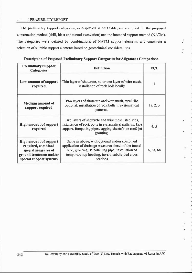
. FEASIBILITY REPORT
The preliminary support categories, as displayed in next table, are complied for the proposed
construction method (drill, blast and tunnel excavation) and the intended support method (NATM).
The categories were defined by combinations of NATM support elements ard constitute a
selection of suitable support elements based on geotechnical considerations.
Description of Proposed Preliminary Support Categories forAlignment Comparison
Preliminary SupportCategories
Definition ECL
Low amount of supportrequired
Thin layer ofshotcrete, no or one layer ofwire mesh,installation ofrock bolt locally
I
Medium amount ofsupport required
Two layers of shotcrete and wire mesh, steel ribsoptional, installation of rock bolts in systematical
Dafiems.la,2, 3
High amount of supportrequired
Two layers of shotcrete and wire mesh, steel ribs,installation of rock bolts in systematical patterns, facesupport, forepoling pipes/lagging sheets/pipe roofl jet
grouting.
4 5
High amount of supportrequired, combinedspecial measures of
ground treatment and/orspecial support systems
Same as above, with optional and/or combinedapplication ofdrainage measures ahead ofthe tunnel
face, grouting, self-drilling pipe, installation oftemporary top heading, invert, subdivided cross
sections
6,6a, 6b
Pre-Feasibility and Feasibility Study ofTwo (2) Nos. Tunnels with Realignment ofRoads in AJK

I Excavrtlon Classes of Matn Tunnel & Disaster Drevention Tunnel
DMslorMrh Turr.l ED€rg cyPrrHtrg Bry Emsrgetrcy Shdter
ECLI ECT-1 ECI,3 ECI-4 ECLs ECI.6 ECI,{A ECI.6B ECI.IB ECL2B ECLlS ECr-2S ECr-3{;
lCycle Advance/SuFport lntcrval
(UDjtt m)3 5t1.0 3.5t3.5 20t20 Uppefll.5/L 5
Lowcr:3 0/3.0Upter:12l1.2La\\crt.U |.2
Uppcri l .0/1,0Lowcnl.0/1.0
Upper:0.E/0.8Lowcrio E/0.E
Upper:0.8/0.3Lowc.:0 E/0 E ? 4 t 2 0 Upp€i l .r l .2
Lowqt12tl.2 2.012.0 2.012 0 1 5 / t 5
Excavation Type Ful lFncc Ful lFncc FL ' l lFnccBench CuL
Top I l€ading/Bcnch Cul
Top llcaLling/Bcnch Cut
R ingColl{insCtrt/ Iop IladiDs
Bcnclt CutTop Ile(ling/
Bcnch Cul Full lacc Full Ficc
Shotcrete fiickness 5cnrtNon Fibcrl
5cn)(Stccl Fibcr) (Stccl Fibcr) {StcclFibcr) (Stccl Fibct
20cm(StcclFibcr)
25cm(SrcclFibcr)
25cnl(SrcclFibc.)
Lzcn(Stccl Fibcr) (SlcclFibcr)
8cln(Stccl Fibcr) (S tcc lF ibcr l (Slcol Fibct
RockBol t
Length 3rn lnr Nil 5'n 5nl 3m 3nr 3In
Inter-val
Longi-ruoe
2.0m 2.Om l 5 m l.2m l 0 m 0 8 m NiI 2.0m 2 0'n 2.0n' 2.0m l 5 n
Trans-2 0 m l .5m l .5nr I 5nt l 5 m Nil l .5m l .5n) 2 0'n I 5 m l.5m
Steel Ribl t -125x 125 x6 5x9 l l - 1 5 0 ' 1 5 0 \ 7 ' l 0 l t . l 5 0 ' t 5 0 l ? . t 0
Con'c LrningThickness
3ftm 30cm 30cm locm 30cm 30cm
CTU I 2 3 5 , 6 , 1 , 1 3 6 , 9 t 0 l 0 t , 2 . 3 4 , 5 , 6 , E , 9 2 3 , 4 5 , 6 , 7 , ' t , 0
RMT
Muzatlhrabad l { ) l l 8 9 , l 0 8 ,9 , t 0 l 0
Chella BaDdi 6 7 l{ t l 0 l z 6 . 7 9 . t 0 6 7 ,9 , t 0 t 0
Patika TunDcl l l
RtsT I 6 l
RMR Value > t l E 0 - 6 1 6 0 - 4 1 4 0 - 2 1 2(X (Utpcr Farc r Soil) (Full Fsc€ : Soil)>El E 0 - 4 l
Q Value 4 0 - t 0 t 0 - 4 4 " 1 >40 4 0 - 4
Auxiliary Method S|€el PipeGrourids
Sl€el PiFCroutint
ttcel Pipe Gro in!wirh
Sell Dnl|nrg Type
St€el Pipe Groutinrrvi l
Self Drillirt Type GrcuIng
Fore Poling or SteelPipeGbuling

vsouTLlNE OF TYPTCAL EXCAVATTON GLASS & SUPPORT PATTERN (1)
OivisionECL 1 €cL-2 ECL-4 ECL 6 €CL 6a ECL 6b
G I U 2 J 5,6.7,A 6,9
t l
ro 1 0 12
6 I O 1 0 't2
B B T l , ? 2,! J.4
6 0 - 6 1 1 0 " 2 1
.r0 - lo 1 0 - 4
Top Hc.dhg/o...h Cul roP H@diftg/o.n.h cut rop H6dtng/B.Eh cut dr'g cuvr{porery lrcn
S,rnnnd lntaru'l{llni : ml 1.3/3.5 2n/2O 1,2 /1 ,2
Jver ereak ihickness (mm) r50 200 2QO 2(,0 2@ 2(l0
lSealrno)
3rd
5'o ! 0
BoltJ ,5 2.O t , 5 1 .O 1.O
2 0 t , 5 r , 5
H- | 00x 1o0x6x6 H-1ooxto0x6x€ H- | (lox 100x6xa H - I25X|25X6,5X9 H 125X125X6.5X9
t , 5 1,2 o aCon'c Unhs Thrckn€sstcn) J0,0 10,0 to,o J O O
0
CLIENT
AZAD GOVERNIUENT OF THE STATEOF JAMITIU * KASHMIR
__ ___ oDglllx! a: IFn (JV)
PRIME ENGINEERING & TESTING CONSIJLTANIA PVT. LTD.
PRE+EASIBILITY AND FEASIBILITY STUDYoF IwO (2)NOS. TUIINELS W|TH REAL|GI{MENT OF ROADS tN AJK
ffi;;OUTLINE OF TYPICAL EXCAVATIOH CLASS A SUPPORT PATTERN {1)DIRECTOR GENEML CEITTRAL DESIGN OFFICE
MUZAFFARABADa
ASIF ALI ASSOCIATE PVT. LTD.lRry. a l scALE=lse
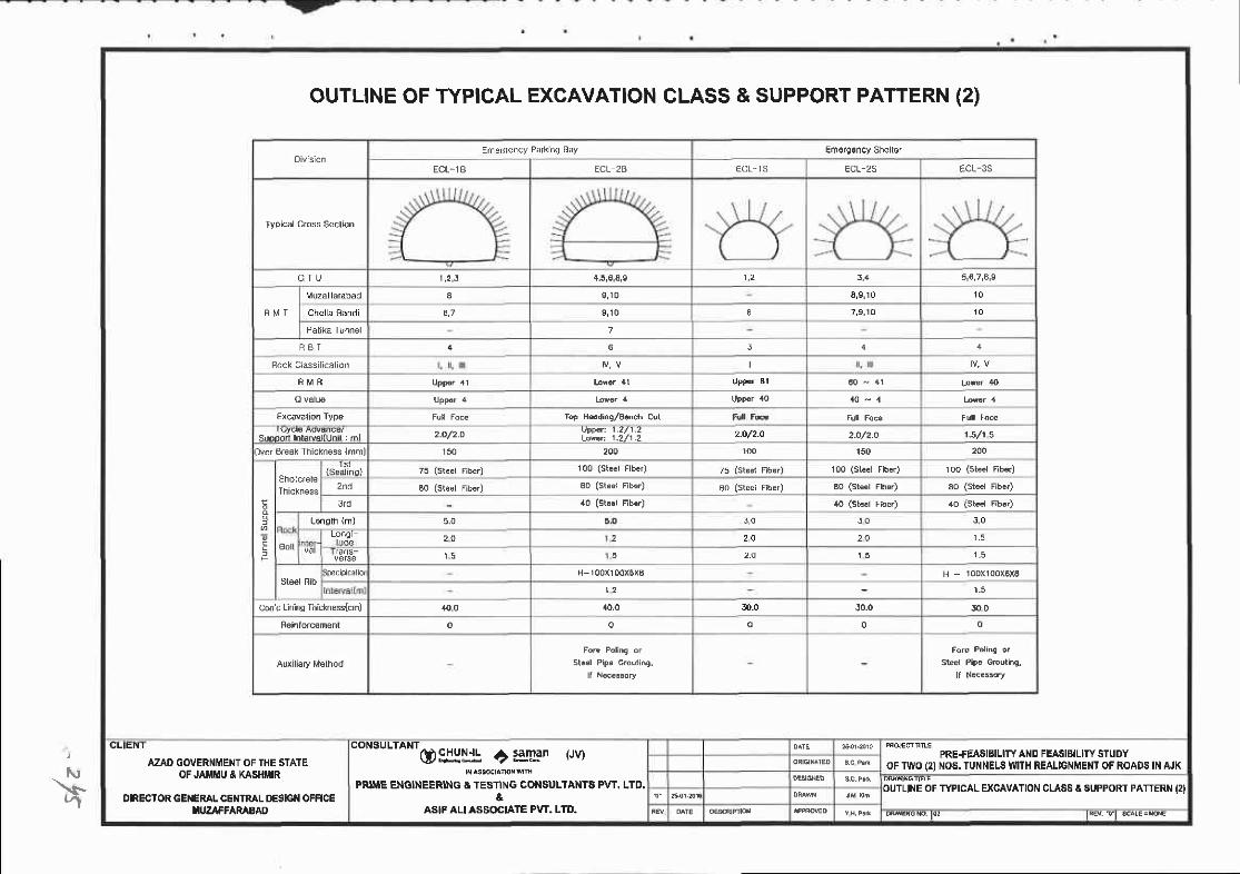
- r\,\r-r"1
Emeroe.cy Parkino Eay Em6rg6ncy Sh€ller
ECt- tB ECL 26 ECL- 'S ECL-2S ECL-35
G ] U 1,2 ,3 4,5,€,€,9 5 ,6 ,7 ,4 ,9
F M I
€ , r 0 8,9 ,10
Che la Sand i 9 , 1 0 6 7,9 ,10
7
R B T 3
I
60 - ,(1
rop H6d'n9/Bdch Cor
2.O/2.O| .2/1.21.2/1.2 2.O/2-O 2.O/2-o 1.5/1 5
lve. Break Thickness {mml 15() 200 150
lSeallnq)
2^.1
3rd
L€ngth (m) 5 ,0 J O J O
Eol l2 0 2 2 0
5 2_O 1 5 1 , 5
H-r00x100xBxB H - 100x100x0x6
1_5
Cm c tinino Ihichess(cmj /rc0 att,o 30.0 40.0 J O 0
0 0
ouTLtNE OF TYP|CAL EXCAVATION CLASS & SUPPORT PATTERN (2)
ULIEN I
AZAD GOVERNME}IT OF THE STATEOF JAMMU & KASHiIIR
OIRECTOR GENERAL CE IRAL DESGI{ OFFICETUZAFFARAEAD
"on""to"t@ lI:I j: + $lgan (JV)
PRIME ENGINEERING &TESTING CONSULTANTS PVT. LTD.&
ASIF ALI ASSOCIATE PvT. LTO.
PRE+EASIBILITY AND FEASIBILITY STUDYOFTWO (2INOS. TUNNELS WNH REALIGNMENT OF ROADS IN AJK
OUTLIT{E OF TYPICAL EXCAVATION CLASS A SUPPORT PATTERTT I2I
Rqrcrc. |@ tRd. rt sc4r=lN

F5.+s\
PROFILE OF EXCAVATION CLASS & SUPPORT(CHELLAH.BANDI TUNNEL}
PATTERN (1)
5 <
i - 8 5 i Y ! 9 i :
0_; t :a : p ! ! : ! ! p I p e I I ; 1 p e i c : : : : E N : i : i i s t ! : i l t : r : t i : : : : : i fi i d€ € ! t a i i a p i F : d i s * ; ; n fl q i * A d H ii ,I ; I I ii * i i t ; i i i- t i F ; i i i
CLIENT
AZAO GOVERI{MENT OF TTIE STATEOF JAlYllilU & KASHMIR
@9jH$.* +:3!IFn (Jv)
PRIME EIIGINEERING g TESTIiIG COiISULTANTS PW. LTO,&
ASIF ALI ASSOCIATE PVT. LTD,
PRE+EAEIBILITY AND FEASIBILIfi STUDYoF TWO (2) NOS. TUNNELS W|TH REALTGNMENT OF ROADS |l,t AJK
PROFILE OF EXCAVAIION CLASS & SUPPORT PATTERN (1IICHELLAH€ANDI TUNNEL)DIRECTOR GENERAL CENTRAL DESIGN OFFICE
f,IUZAFFARABADo g t @ n t s c A r € : I : , 0 ! 0

le\s-
PROFILE OF EXCAVATION CLASS & SUPPORT(CHELLAH.BANDI TUNNEL)
PATTERN (2)
U 94 =
> i
f++.rec{mlffffi iqt
s t S t t B $ H s ; s * s I E ff R
5 g
P € F f t P - 3 8 9. \ i r : s : 4 : 1 t ! a < : u p
AZAD GOVERNIIENT OF TIIE STATEOFJA MU A KASHIiIIR
DIRECTOR GENERAL CENTRAI. OESIGII OFFICEIiIUZAFFARABAD
"ontutt ntc)
slli: a grlan (Ju
PRIME ENGINEERING & TESTING CONSULTANIS PVT. LTD.a
ASIF ALI ASSOCIATE PVT. LTD.
PRE+EASIBIUTY AND FEASBIUTY STUDYoFflvo(2) ltos.ru NELS vuTH REALTGI|MENT OF ROADS t AJX
PROFILE OF EXCAVATION CLASS ASUPPORT PATTERN I2I(cHELLAH.BAi{0t TUilNEL)
or5 tr*. !.t 3c4Er.:r.@0
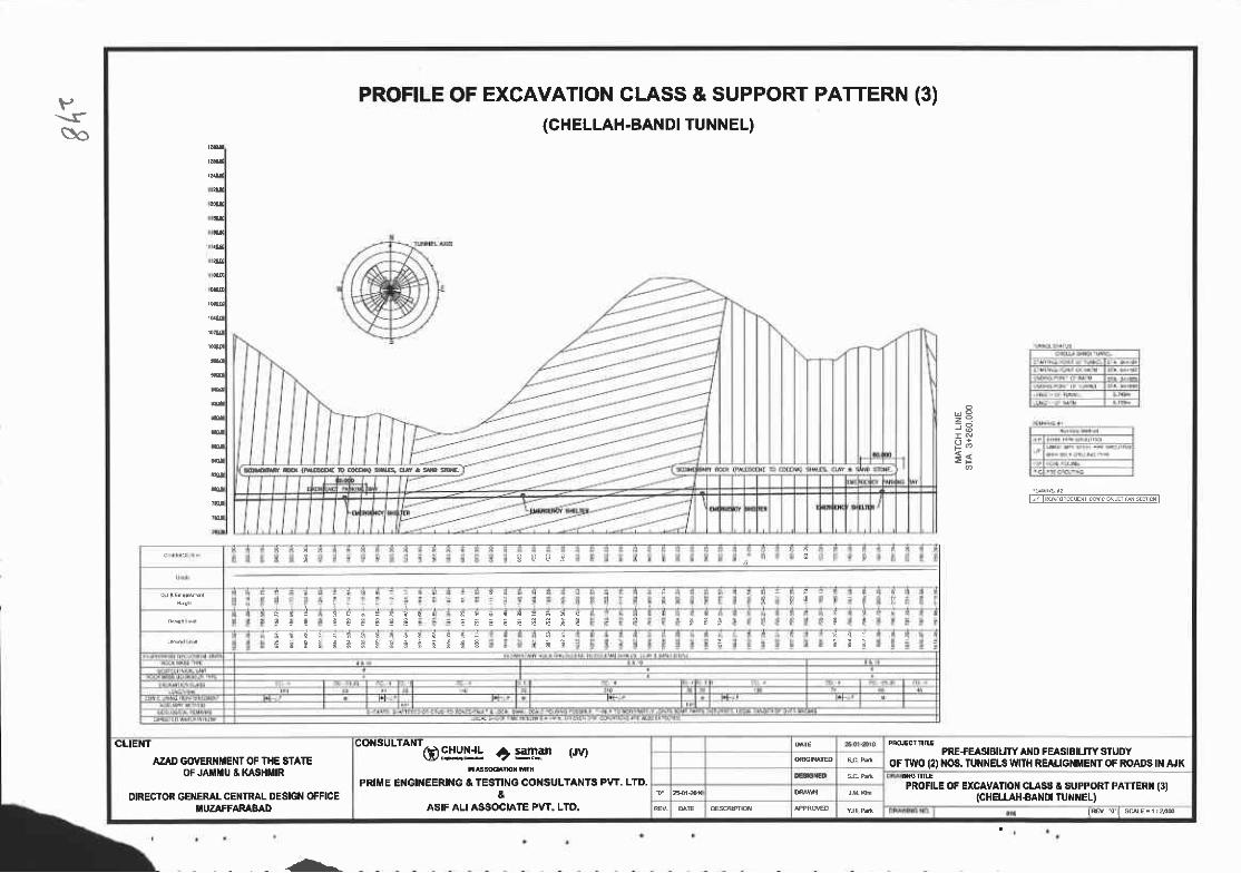
t,-\re\o
PROFILE OF EXCAVATTON CLASS & SUPPORT PATTERN (3)(CHELLAH.BANDI TUNNEL)
d P
3;
r,:TP..r-j-
s * a a !
I t l
E i i l d i * t s
GLIENT
AZAD GOVERI{iiIENT OF THE STAIEOF JA}IiIU E KASHMIR
DIRESIOR GEI{ERAL CEI{TRAL DESIGN OFFICEIl|UZAFFARABAD
CONSULTANT
@$YH: t:ggan (re
PRIiIE EIGINEERING & TESTING CO'{SULTANTS PvT. LTD.&
ASIF ALI ASSOCIATE PVT. LTD.
PRE+EASIBIIJTYAND FEASIAIUTY STUDYOF TWO 12) NOS. TUNNELS WIIH REAIIGI{IilEiIT OF ROADS IT AJK
PROFILE OF EXCAVATIOI{ CIASS I SUPPORT PATTERT FIICHELI.AH€ANd TU NEL)
- . - -
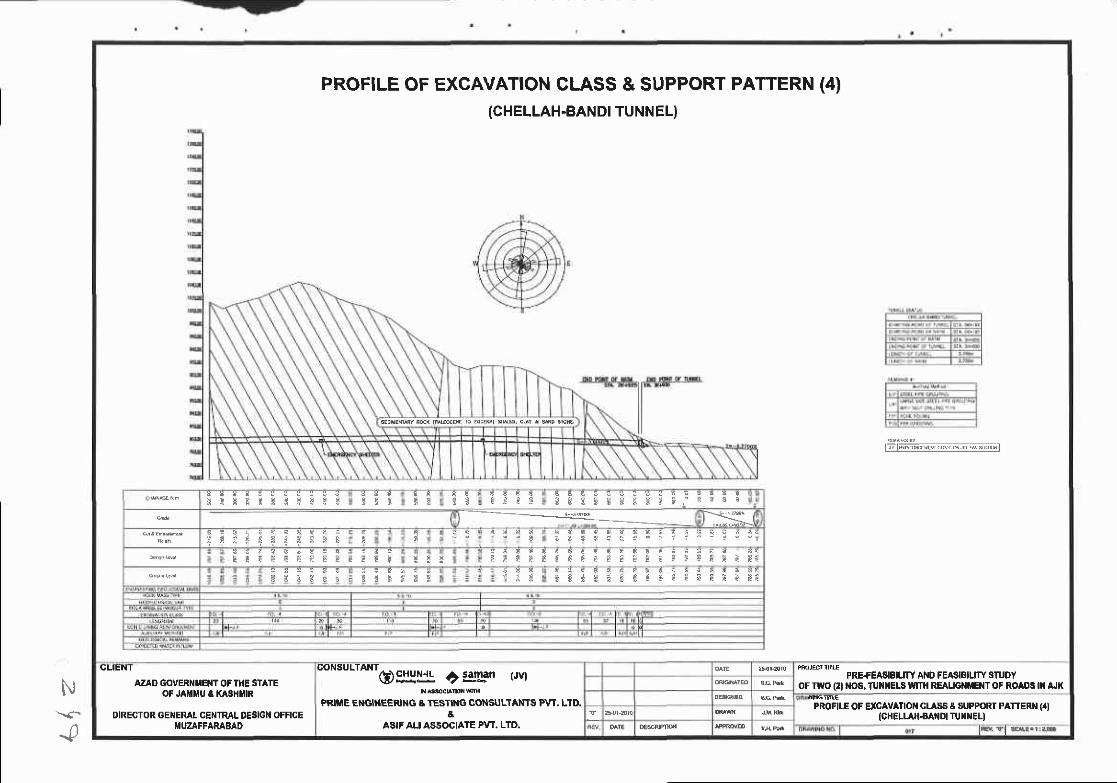
N\<-
...p
PROFILE OF EXCAVATION CLASS & SUPPORT(CHELLAH-BANDI TUNNEL)
PATTERN (4)
E;lk-iaiEwrcilfni.Adt,rtl
* E T E I I : ! F : E 3 t t T E 3 C c E 3 C f , f ; 5 E ; i . ' e e a B---s-!
- * i ! 7 r r
t t E i { s E E E f t e € l ! € € * n F ! ! ! F t € & n E i p f i
c 5 B 3 f l S i I { ; i : ; € € n i i a I i E s-E
CLIEN I
AZAI} GOVERI{iIENT OF THE STATEOF JAiIIIU & KASHIIIR
DIREGTOR GENERAL CENTRAL DESIGT{ OFFICEI'UZAFFARABAD
to"""t*tq):rlli! o:g,3n (Jv)
PRII'E E}IGIIIEERIT{G & TESTII{G CONSULTANTS FvT, LTD.&
ASIF AU ASSOCIATE PVT. LTD.
PRE{EASISIUTY AND FEASIEIUTY STUOYoF rv{o (21 r{oa. TUil [ELs $,mt REALtGf{tc T oF RoADs t A.tK
PROFILE OF EXCAVAIIOT{ GLASS & SUPFORT PATTERI{ (4IlcHELL ll€A DI TU)r{EL)
^*
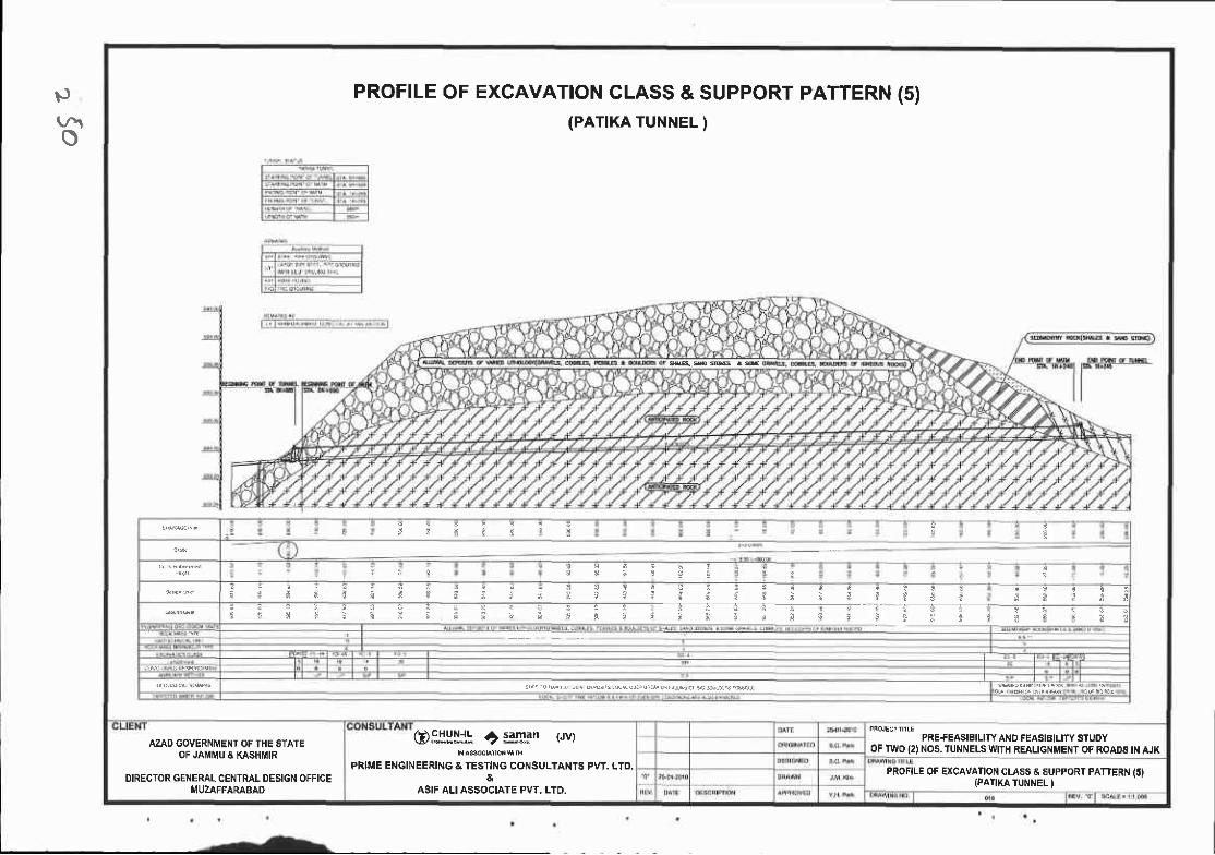
p
o
PROFILE OFEXCAVATTON CLASS & SUPPORT PATTERN (5)(PATIKA TUNNEL )
PRE+EASIBILITY AND FEASIBIUTY STUOYOF III/O 12) NOS,lUNNELS WITH REALIGNMENT OF ROADS IN AJK
a
i ! q !I r ! * i
i i g f l t ; i * ; f f ; ; ; : i f t t ; i i f ; ; ? { g E ;; 1 r : . i 1 i . 1 :
e : f i ) : h : ; t i r s i B i ) ; r i t ! i i j i l : i ;
AZAD GOVERNII,IENT OF THE STATEOF JAMMU A KASIIIIIR
DIRECTOR GENERAL CENTRAL DESIGN OFFICEti4 UZAFFAR^BAD
(Dgj:I* o rJIFn trvr
FRIME ENGINEERING & TESNNG CONSULTANTS PW. LTD.&
ASIF ALI ASSOCIATE PVT, LTD.
FROFILE OF EXCAVAIION CLASS E SUPPORT PATIERN 15}IPATIKA TUNNEL I

P{a,
TYPICAL CROSS SECTION OF CHELLAH.BANDI TUNNEL(rYPtcAL CROSS SECTTON)
_ - - - \ - - - ! 1 - - - z - - -
I
lrIr F
it
CLIENI
AZAD GOVERNITEi/T OF THE STATEOF JAT MU & KASHtr,tlR
DIRECTOR GENERAL CENTRAL OESIG}I OFFICEI|lUZAFFAMBAO
CONSULTANI
O$IYL ?:gan (Je
PRIME ENGI}IEERING I TESTING CONgULTANTS PVT. LTO.&
ASIF ALI ASSOCIATE PW, LTD.
PRE+EASISIUTY AND FEASIBIUTYSTUDYOF TWO (2) NOS. TUNNELS WTII REALIG}II'ENT OF ROADS III AJK
ftPICAL CROSS SECTIOI{ OF CHEI.LAH.BANDI TUI{NEL(rYPlcAL CROSS SECTTONt

tt
FTYPICAL CROSS SECTION OF PATIKATUNNEL
(wPtcAL cRoss sEcTtoN)
IIIIIIIIII
cuEI!.f
AZAD GOTERI{trlEllT OF l}lE STATEoF JAnrru t t(ASHltR
"'ou" n'6)g1l1:, c :3!rrn .,v)
PRI E El{Gt}lEERtt{G & rESTrr{c CONAULTAITII p!rr- LrD-
PRE+EISIBIIITY AI{D FEASIBIUTY SIUOYoF nflo e) 1106, ruxilEt s wnH REAUGT{flEltT OF ROAr}a N AJK
TYPICAL CROSS SECIIO]{ OF PATIKA TUIII{EL(tYPtcAL CROgS SECTTON)DIRECTOR GEIIERAL CENTRAI DESIG}I OFFICE
MUZAFFARABAD&
ASIFA ASSOCIATE PVT. LTD,
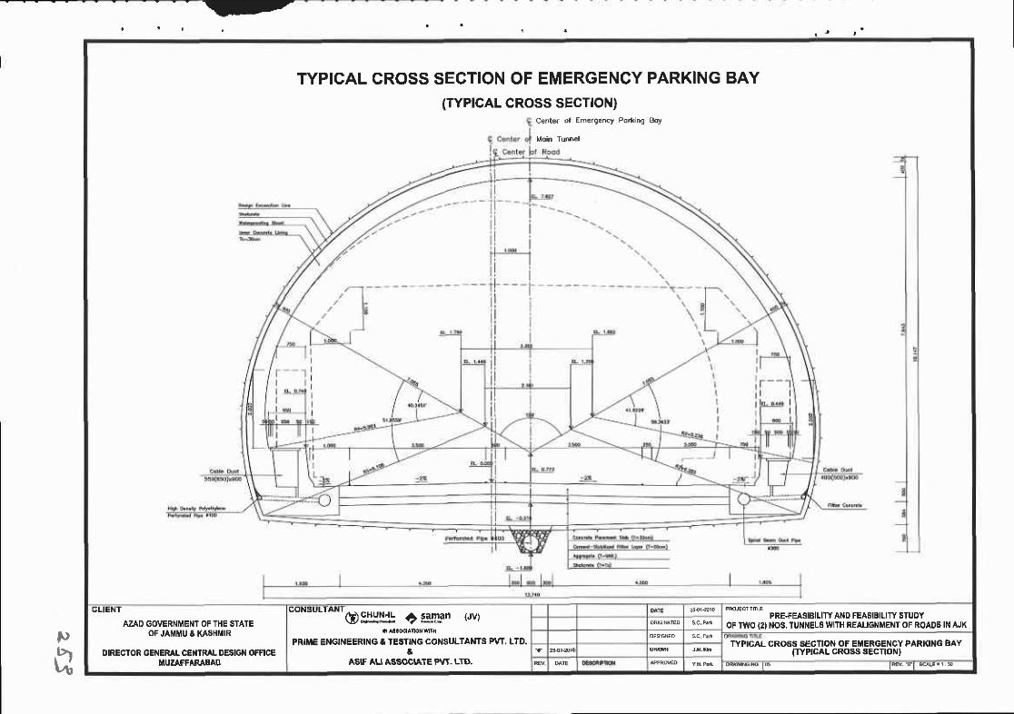
-
l)a
TYPTCAL CROSS SECTION OF EMERGENCY PARKING BAY(TYPICAL CROSS SECTTON)
Cente. of Emergency Porkinq goy
GLIENT
A?ID GOVERNMENT OF THE STATEOF JAMMU A KASHI'IR
DIRECTOR GEI{EML CEI{TRAL OESIGI,I OfFICEUUZAFFARABAS
consu'ANr15) !rl!15 ? iSnan r'ryt
PRIIIE ENGINEERING I TESTI G CONSULTANTS PVT. LTD.a
ASIF ALI ASSOCIATE PVT. LTII,
PRE+EASIBILITY AND FEASIBILITY STUDYOF TWO I2I NOS,TUNNELSWITH REAIIGT.IMENT OF ROAOS IN AJK
TYPICAL CROSS SECTION OF EiIERGE}ICY PARKING BAY(TYPTCAL CROSS SECTTON)
odturc t6 tftv ft *r!E 11 e

}'t
vlN
TYPICAL CROSS SECTION OF EMERGENCY SHELTER(TYPTCAL CROSS SECTTON)
I
CLIENT
AZAD GOVER}IIEI{T OF T}IE STAIEOF JAI U A XASHIIIR
DIRECTOR G€I{EML CEI{TRAL DESIGN OFFICEIIUZAFFARABAO
"o*"uttont6)Slljf, C s_gp-an (.rv)
PRltrlE El{clNEERlxG E TESTII{G GOI{SULTANTS Pw. LTD.&
ASIF AU ASSOCIATE PvT. LTD.
PRE+EASIBILITY AND FEASIBILITY STUDYOF TIYO (2} [OS,'I'I'NNEUI WTTH REAUG TEI{T OF ROAO6IN AJK
TYPICAL GROSS SECTIOT{ OF EI{ERGEIICY SHE|'IER(TYPICAL CROSS SECTTOT{}
t E t F w T l
^5..

-
l0t,\
EXCAVATTON CLASS OF CHELLAH-BANDITUNNEL (1)
ECL.1 ECL.2
Section A - A Section B - B
)li{g*+=: KI)r.A4 \. KI7 /il\{r_-,2- -ll- \ \*}_ ./ -
;€
CLIENI
AZAD GOVERNI'ENT OF THE STATEOF JA[.II'U & KASHIIIR
DIRECIOR GENERAL CENTML DESIGN OFFICEf,UZAFFARABAO
--'--- '-'- O$lSLl I tgglFn trvt
PRIME ENGINEERING & TESTING CONSULTANTS PVT, LTD.
ASIF ALI ASSOCI,ATE PVT. LTD.
PRE{EASIBILTTY AND FEASEILITY STUDYOF TWO (2INOS. TUN}IELS MIH REALIGNMEI{T OF ROADS II{ AJK
EXCAVAIION CLASE OF CHELLAH.BANDI TUiINEL II)
tor tEv rl

EXCAVATTON CLASS OF CHELLAH-BANDI TUNNEL (2)
ECL€
Sectlon A - A Section B - B
a
t'E'-J-!x:,__, .n
CLIENT
AZAD GOVERT{MENT OF THE STATEOF JAIiII{U & KASHMIR
__.___ ... cDFj:y* a sslFn (Jv)
PRIME ENGINEERING A TESTING CONSULTANTS PVT. LTD.&
ASIF ALI ASSOCIATE PvT, LTD.
PRE+EAS|a||1rY A D FEASIEILITY STUDYOF II'YO (2) NOs. TUNI{ELS WITH REALIGNMENT OF ROADS IN AJK
EXCAVANON CLA88 OF CH ELLATI.BANDI TUNI{EL I2IDIRECTOR GENERAL CEN IRAL T'b5IUN (JTTIqE
I'UZAFFARABAD
v\.?l
So
^L
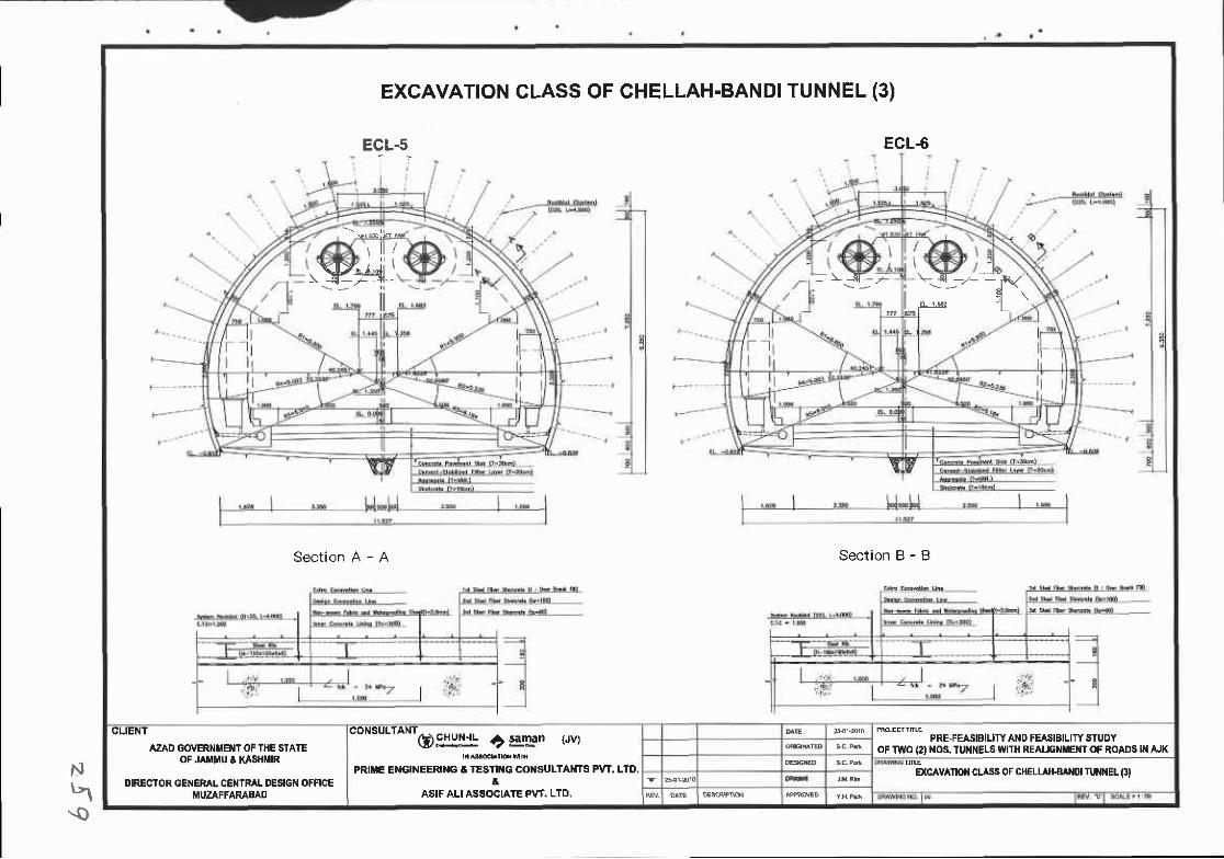
Nh\.o
ECL-5
)li(. \prs!41'3'-- -T-
EXCAVATTON CLASS OF CHELLAH-BANDITUNNEL (3)
ECL.6
Section A - A Section B - B
!__{__F
CLIENT
AZAD GO'ERN E ' OF THE STATEOF JA}I U A XASHI'IR
OIRECTOR GENERAL CEIITRAL DESIGN OFFICEMUZAFFARAAAD
coNsutrANrogrllj: ?:gEgn tryt
PRIME ENGINEERITG A TESTII{G COI{SULTANTS PVT. LTD.&
ASIF ALIASSOCIATE PW. LTD.
PRE.FEASIBILITY AND FEASIBILITY SIUDYoF TWO (2) l{OS. TUNNELS V TH REAIJG ET{T OF ROADS lI AJK
EXCAVAltolt CLASS OF CHELLAHAff{U lUNt{EL (31

p$.tt
EXCAVATTON CLASS OF CHELLAH-BAND| TUNNEL (4)
ECL-OA F(
Section A - A Section B - B
ECL6B
, d1 6 = ' t E a 7 . , : .
CLIENT
AZAI} OOVERNMENT OF THE STATEoF JAt{ttu I xASHi{R
COI{SULTAI{T
@EIII!* C saman (Jv) PRE+EASIBIUTY A D FEAI'IBILITY STUDYoF two (21 t{os. TUI{NEL$ wtTH REALtcIMEilT OF ROAD6 t}t AJK
PRITIE ENGI}IEERING & TESIr{G CONSULTAITS PVT. LTD. EXCAVAnoiT CLASS 0f CHEtt t{€A ot TUNi{EL {atOIRECTOR GENERAI CENTRAL DESIGII OFFICEIIUZAFFARABAD
aASIF ALI ASSOGIATE PvT. LTD.
I r tREv r t *a€- t $
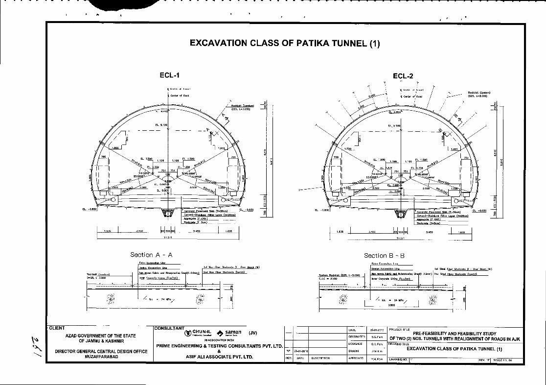

P$r
EXCAVATTON CLASS OF pATtKA TUNNEL (2)
ECLA ECL4
Sectlon A - A Section B - B
- - - - I - - - _ 3 _ l
t t z a - r t r , I'p;
| - . '
: ; "^ , I
CLIENT
AZAO GOVERNIIENT OF THE STATEOFJAI'!'U A KASHiIIR
oorturnNrqp !rll!J! ?:g3n (re
PRIME ENGINEERING & TESTING CONEULTANTS PvT. LTO.&
ASIF ALI ASSOCITATE PVT. LTD.
PRE+EASIBIUTY AND FEASEIUTY STUOYOF TWO G} NOS. TUNNELS WTH REAUG MEI|T OF ROADS II{ AJK
EXCAVATION CLASS OF PATIKATUNNEL (2)DIRECTOR GENERAL CEI{TRAL OESIGN OFFICEMUzAFFARABAD

l"t\r
ECL.5
_ _ _ _ _ t s
EXCAVATTON CLASS OF pATtKA TUNNEL (3)
EGL.6
I.
Section A - A Section B - B
_ _ _ _ 0
(rLlEN I
AZAO GOVERNME}IT OF THE STATEOF JAMMU & KASHIIIR
DIRECTOR GENERAL CENTRAL DESIGN OFFICEMUZAFFARABAD
u'nou''^n'ft)s.HIi: ?i SFn twt
PRIME ENGINEERII{G & TESTING CONSULTANTS FVT. LTD.&
ASIFALI ASSOCIATE PVT. LTD.
PRE-FEASIBILIrY ANO FEASISIUTY STUOYOF TwO{2I NOS,IUNNELSWITH REAUoNMENTOF ROAOS II{ AJK
EXCAVATION CLASS OF PATIKATUTINEL {3)
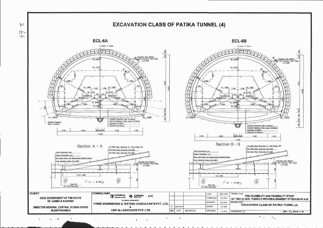
vOt.s
EXCAVATION
ECL-6A
CLASS OF PATTKA TUNNEL (4)
- ":i:L @ - 2 . r k 7 i ,
CLIENT
AZAD GOVERNMENTOF THE STATEOF JAI{MU & XASHI IR
OIRECTOR GENERAL CENTRAL DESIGN OFFICEMUZAFFARABAO
C O N S U L I A N I
oEIgI* af saman {Jvr
PRIME ENGINEERING A TESTING CONSULTANTS PW, LTD.&
ASIF ALI ASSOCI,ATE PVT. LTO.
PRE.FEASBILIW ANO FEASIBILITY STUDYOF TWO (2} NO6. TUNI{ELS $flTH REALIGNMENT OF ROADS IN AJK
EXCAVATION CLASS OF PATIKA TUNNEL (4I
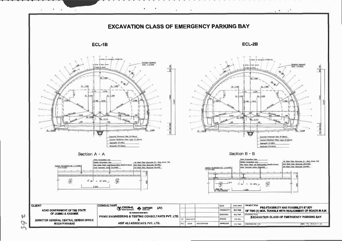
- - '
;,
$'5
EXCAVATION GLASS OF EMERGENCY PARKING BAY
ECL.1B ECL.2B
Sectlon A - A Section B - B
z e,l - z+up.t l,Ft @=.*.=,t#,
gUEN I
AZAD GOVERiIf,EI'IT OF IHE STAICOF JAIIIIU I KASHI'IR
DIRECTOR GENERAL CEI{TRAL OEsIGN OFFICEItlUZAFFARABAD
"onsu'a*rqPgllll! +**'- (ru
PRIME ENGINEERI G A TESTII{G CONSULTANTS PVT. LTO.&
ASIF ALI ASSOCIATE PVT, LTD.
PRE+EASIBIUIY AND FEASB|UN' STUOYOF fl'O 12) }IO8. TUIII{ELS TUII{ REAUGIIIIENT OF ROADS III AJX
EXCAVATION CLASS OF EMERGENCY PARKING BAY
DM{ l rcNo l r l iEv '01 sc(E= i :d
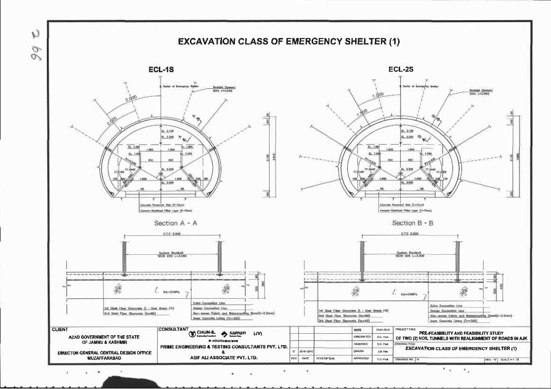
EXCAVATION CLASS OF EMERGENCY SHELTER (1)
ECL.1S ECL-zS
CLIENT
AZAD GOVER |iENT OF THE STAIEOF JAHIU A KASHIIIR
DIRECTOR GEilERAI. CENIRAL DESIGN OFFICEiIUZAFFARABAO
"on"uttontos:ljl c gn t'rvr
PRITIE EiIGI'IEERI G A TESTIIIG COIISULTAI'TS} PVT. LID.a
ASIF ALI ASSOGI,AIE PVT. LTD.
PREfEASIBIUTYAND FEAS|aILITYSTUOYOF TI{O I2I NOS. TUI{NEL8 UiIIH REAUGII?'EI{T OF ROADS II{ AJK
EXCAVA'IOI{ CLASA OF EIIERGENCY SHELTER I,|}
t R r t s c . ' s

. FEASIBILITYREPORT
8.4 Excavation method
8.4.1 Outline
When designing and constructing tunnels, excavation method is a important factor in
determining tunnel stability, feasibility, construction period, and other concems. Therefore, the
safest and most economical method should be selected, taking into account cross sectional size,
condition of the tunnel face, the bearing capacity of the ground, geological features, excavation
equipment, transportation method, etc.
8.4.2 Classilication of excavation method
l) Classification according to geological features
Method Condition for applying Strong and weak points
Full Face Cut
General method for small sections
Can be used for medium and
large sections in good ground
conditions.
Where bedrock itself, has a
great bearing capacity due to itsgood rock quality
As stress rearrangement due to
excavation is completed in one
cycle, it theoretically matches
with NATM
' Work is simple' The full section is
reinforced simultaneously.' No possibility of damage to
support for upper portion by
blasting in the lower portion of
the excavation-' Better for fast construction
. Easy to handle the muck
Divided
Excavalion
LongRennh frrt
Ceneral method for medium and
large sections on relatively good
ground
Bench length L>50m
' Parallel work in upper and lower
portion is possible' Easy to use general equipmentmethod method
Short
Bench Cut
method
General method for medium and
large sections on ordinary ground
Bench length 10m<L<50m
Easy to respond to the ground
changes during excavation
Easy to use general equipment
Not enough space for upper face
work
266 Pre-Feasibility and Feasibility Study ofTwo (2) Nos. Tunnels with Realignment ofRoads in AJK.
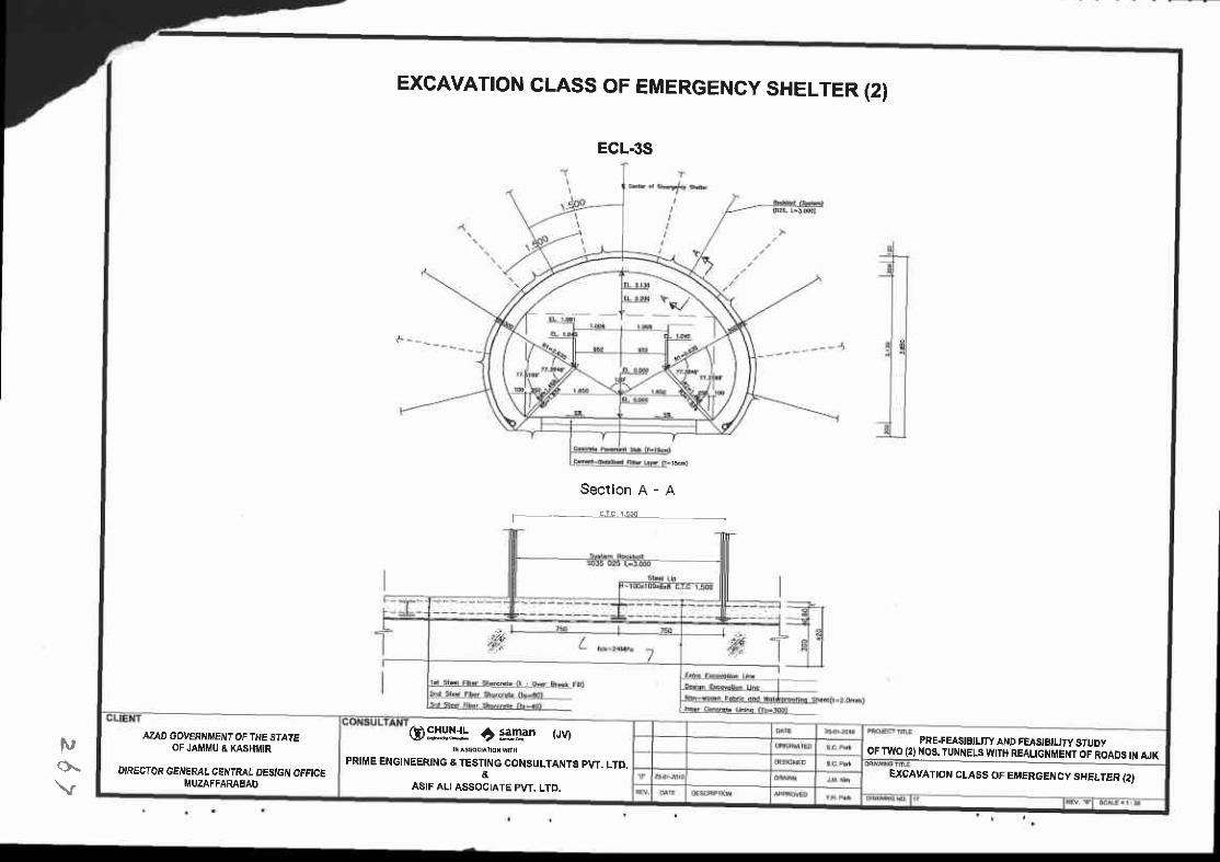
t',(}.
ECL.3S
EXCAVATTON CLASS OF EMERGENCY SHELTER (2)
Section A - A
I - c.rc 1.500
i
AZAD GOV€RAIIIENT OF THE SIAIEOF JA Ii,tU & KASHMIR
DIRECTOR GENEML CENTRAL OESIG( OFFICEITIUZAFFARAEAD
@$fH! t:ellan (JV)
FRIME ENGINEERING & TESTING CONSULTANTS PW. LTD,&
ASIF ALIASSOCIATE PvT. LTO
PRE.FEASISIUTY AI{D FGASISILIry STUDYOFTWO {2}NOS.TUNNELS WITH REALIGNMENTOF ROADS IN ruK
EXCAYATION CLASS OFET'ERGENCY SHELTER {2)

Chapter 8. Tunnel Design
Mini
Bench Cut
method
' For medium and small sections on
weak ground, Bench length is
L<l0m or within twice of tunnel
diameter
' When early closed invert is
required on expansible ground
Early closed invert is possible
Can suppress settlement to the
minimum
Less economical than Short
Bench
Multi
Bench Cut
method
If tunnel face's condition is
extremely bad at medium and
large sections
Top heading's height is too high,
and exceeds the range ofthe
excavation capability of applied
equipment.
Easy to secure muck removal
Can use general equipment at
large sections also.
Muck removal and excavation
overlaps at Tunnel heading
A bigger displacement and
settlement than Short Bench
Temporary
Invert
Method
For enlarging Bench length and
suppressing ground displacement
at middle and large sections
Cround is weathered rock or
Worse
Can enlarge work space in
making bench lenglh oftop
heading longer
Top heading construction Speed
reduced
Low feasibility due to necessity
of separated invert shotcrete
Pilot or
Side Pilot
method
' Ifground is relatively bad at large
sections
' When necessary to minimize
Settlement
Minimized seftlement at large
section construction
Possible to drain to the side
wall pilot tunnel
Tunnel face stability is secured
at the large face
High construction cost
Pre-Feasibility and Feasibility Study ofTwo (2) Nos. Tunnels with Realignment ofRoads in AJK. 267
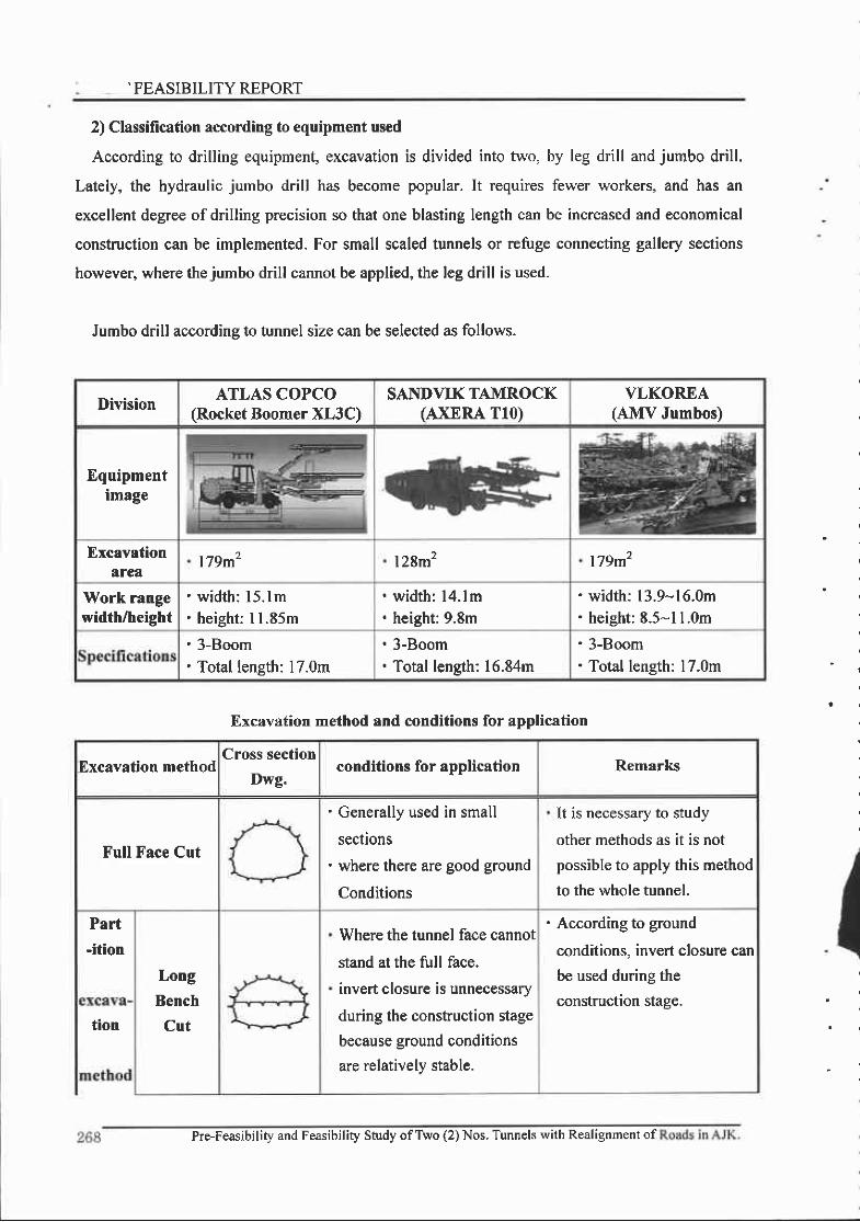
.FEASIBILITY REPORT
2) Classification according to equipment used
According to drilling equipment, excavation is divided into two, by teg drill and jumbo drill.
Lately, the hydraulic jumbo drill has become popular. It requires fewer workers, and has an
excellent degree of drilling precision so that one blasting length can be increased and economical
constuction can be implemented. For small scaled tunnels or refuge connecting gallery sections
however, where thejumbo drill cannot be applied, the leg drill is used.
Jumbo drill according to tunnel size can be selected as follows.
Division ATLAS COPCO(Rocket Boomer XL3C)
SANDVIKTAMROCK(AXERA T10)
VLKOREA(AMV Jumbos)
Equipmentimage
Excavationarea
179m2 l28m2 179m2
Work rangewidth/height
. widt l : l5. lm
. height: I 1.85m
. width: l4. lm' height: 9.8m
width: 13.9-16.0mheight: E.5-l LOm
' 3-Boom' Total length: 17.0m
' 3-Boom' Total length: 16.84m
' 3-Boom' Total length: 17.0m
Excavation method and conditions for application
Excavation methodCross section
Dwg.conditions for application Remarks
Full Face Cut
' Generally used in small
sections' where there are good ground
Conditions
It is necessary to study
other methods as it is not
possible to apply this method
to the whole tunnel.
Part-ition
Long
Bench
Cut
Where the tunnel lace cannot
stand at the full face.
invert closure is unnecessary
during the construction stage
because ground conditions
are relatively stable.
' According to ground
conditions, invert closure can
be used during the
construction stage.
tion
Pre-Feasibility and Feasibility Study ofTWo (2) Nos. Tunnels with Realignment of
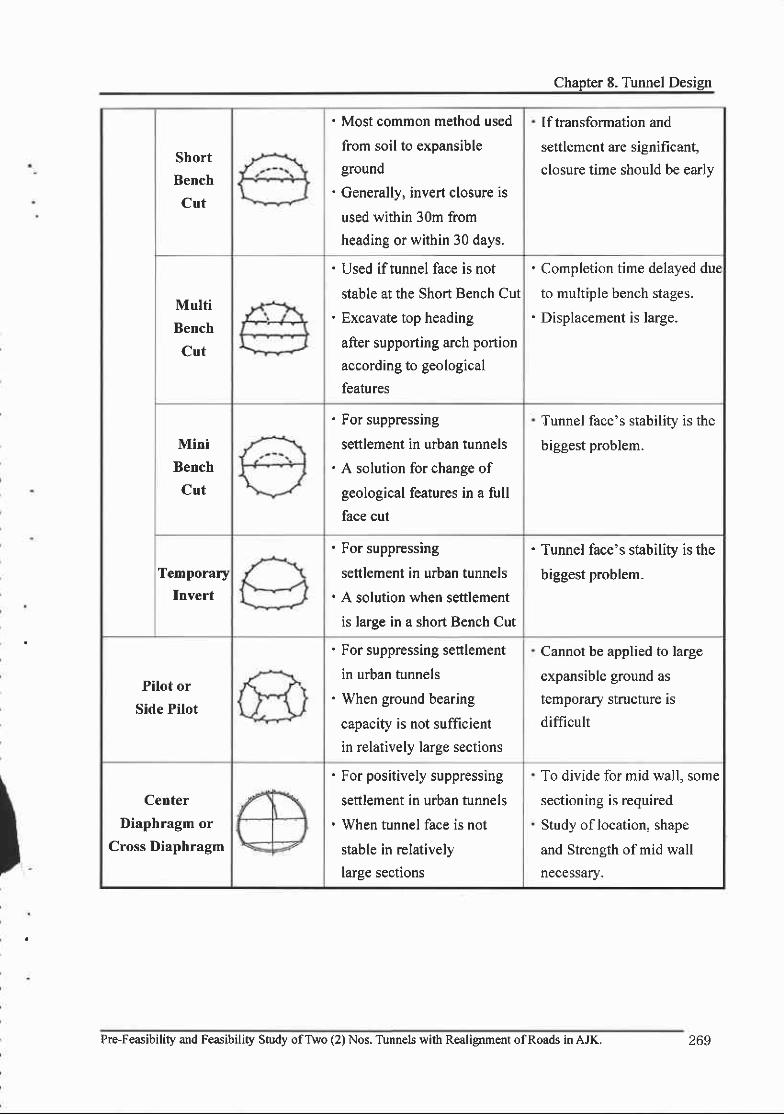
Chapter 8. Tunnel Design
Short
Bench
Cut
' Most common method used
from soil to expansible
ground' Generally, invert closure is
used within 30m from
heading or within 30 days.
Iftransformation and
settlement are significant
closure time should be early
Multi
Bench
Cut
' Used iftunnel face is not
stable at the Short Bench Cut' Excavate top heading
after supporting arch portion
according to geological
features
. Completion time delayed due
to multiple bench stages.' Displacement is large.
Mini
Bench
Cut
' For suppressing
settlement in urban tunnels' A solution for change of
geological features in a full
face cut
Tunnel face's stability is the
biggest problem.
Temporary
Invert
' for suppressrng
settlement in urban tunnels. A solution when settlement
is laree in a short Bench Cut
' Tunnel face's stability is the
biggest problem.
Pilot or
Side Pilot
' For suppressing settlement
in urban tunnels' When ground bearing
capacity is not sufficientin relatively large sections
Cannot be applied to large
expansible ground as
temporary structure is
difficult
Center
Diaphragm or
Cross Diaphragm
' For positively suppressing
settlement in urban tunnels. When tunnel face is not
stable in relativelylarge sections
To divide for mid wall, some
sectioning is required
Study of location, shape
and Strength of mid wall
necessary.
PrFFeasibility and Feasibility Study ofTwo (2) Nos. Tunnels with Realignment ofRoads in AJK. 269

FEASIBILITY REPORT
E,4,3 Muck removal
l) Summary
Muck removal is a factor requiring 1/4-l/3 of tunnel cycle time. It is possible to reduce the
time according to how equipment is combined. This influences the excavation progress each day
and greatly affects excavation costs.
Construction time related to blasting and tunnel support in the total cycle time are determined
according to tunnel diameter, geological features, and other factors. It is thus difficult to reduce
them significantly, but muck removal time can be reduced if the equipment combination matches
the tunnel effectively.
2) Muck removal method
Muck removal methods are generally classified as follows.
- Rail method
The rail method is a method of loading muck into trolleys or other conveyances by reversing the
bucket, which pumps out excavated muck using a shovel moving on rails. The loaded muck is
removed from the pit by battery car.
- Tire method
The tire method is loading muck into dump trucks by crawler wheel loaders and removing it
without rails. There is also a means whereby muck is taken out of the pit aller being loaded by a
proper sized loader. However, when the tire method is applied, the followings should be checked.
'The geological features should be good and tunnel ground should be stable.
'Tunnel diameter should be more than 3.5m
. When it is verified that water is not in excess.
'When gas treatment is perfect.
I
270 Pre-Feasibitity and Feasibility Study ofTwo (2) Nos. Tunnels with Realignment of Roads in AJK.


.. N: .'FEASIBILITY REPORT
E.5 T[nnel Support
E.5.1 Tunnel support types and main functions
l) Tunnel support types
To use the support function of the ground surrounding the tunnel, after synthetically
reviewing all design factors such as topography, geological features, dynamic ground character,
whether or not water exists, excavation section size, surface settlement, construction method, etc.,
the tunnel support should be designed reasonably, The types are as follows.
Support types
division Support Concept
1o support
Steel fiber
reinforced
shotcrete
(SFRS)
rock-bolt
steel-rib
This is installed so that the surrounding ground can perform a
support function, and suppress the ground movement so as to be
stable aftet excavation. Ground movement by excavation is
suppressed early so that the bearing capacity and strength ofthe
ground can be used if possible and the ground can be stabilized.
2nd supporl Con'c l in ing
' For drain type tunnels, the I't support is responsible for all ofthe
exerted loads and the lining is responsible for extra
functions such as protecting facilities in the tunnel, maintaining
fresh spaces, etc.
' For water prooftunnels, the water pressure generated must be
supported by blocking underground water discharge.
Auxiliary
Techniques
forepoling,
pregrouting,
Steel pipe
grouting
For bad ground, this is installed at the work face for stabilizing
fractured zone. Theoretically, it reinforces the I't support.
Pre-Feasibility and Feasibility Study ofTwo (2) Nos. Tunnels with Realignment ofRoads in AJK-

I
Chapter 8. Tunnel Design
2) Tunnel support main functions
Tunnel support should be selected after reviewing their functions. Tunnel support's main
functions according to ground conditions are as follows.
Tunnel support's main functions according to ground conditions
Ground
conditionsSupport concept Support purpose Main support
Extremely
hard rock
and hard
rock
Sunounded ground is
responsible for permanent
suppon
To avoid rockfall' Shotcrete
' Random rock bolt
Hard rock
and
Regular
rock
Support member is a
permanent structure,
Lining increases stability
To avoid rockfall,
To support relaxed Earth
pressure
'Shotcrete
' System rock bolt
Soft rock
Support member is a
permanent structure,
Lining increases stability
To avoid rockfall,
To partially support
initial Earth pressure
'Shotcrete
' System rock bolt
Weathered
rock
Support member is a
permanent structure,
Lining increases stability
To partially support initial
Earth pressure
' Shotcrete
' System rock bolt
Soil
Support member is a
permanent structure,
Lining increases stability
To suppress ground
displacement,
To suppoft relaxed Earth
pressure
Shotcrete
System rock bolt
Crush zone
Fault zone
Support member is a
permanent structure,
Lining increases stability
To suppress ground
displacement,
To support relaxed Earth
pressure
' Shotcrete
' System rock bolt
Pre-Feasibility ard Feasibility Study ofTwo (2) Nos. Tunnels with Realignment ofRoads in AJK- 273
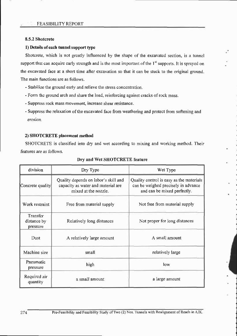
FEASIBILITY REPORT
E.5.2 Shotcrete
l) Details ofeach tunnel support type
Shotcrete, which is not greatly influenced by the shape of the excavated section, is a tunnel
support that can acquire early strength and is the most important ofthe | "t supports. It is sprayed on
the excavated face at a short time after excavation so that it can be stuck to the original ground.
The main functions are as follows.
- Stabilize the ground early and relieve the stress concentration.
- Form the ground arch and share the load, reinforcing against cracks ofrock mass,
- Suppress rock mass movement, increase shear resistance-
- Suppress the relaxation ofthe excavated face from weathering and protect from softening and
erosion.
2) SHOTCRETE placement method
SHOTCRETE is classified into dry and wet according to mixing and working method. Their
features are as follows.
Dry and Wet SHOTCR-ETE feature
division Dry Type Wet Type
concrete qualityQuality depends on labor's skill andcapacity as water and material are
mixed at the nozzle.
Quality control is easy as the materialscan be weighed precisely in advance
and can be mixed perfectly.
Work restraint Free from material supply Not free from material supply
Transferdistance by
pressureRelatively long distances Not proper for long distances
Dust A relatively large amount A small amount
Machine size small relatively large
Pneumaticpressure
high low
Required airquantity a small amount a nrge anTount
t .7 i Pro-Feasibility and Feasibility Study ofTwo (2) Nos. Tunnels with Realignment ofRoads inAJK.
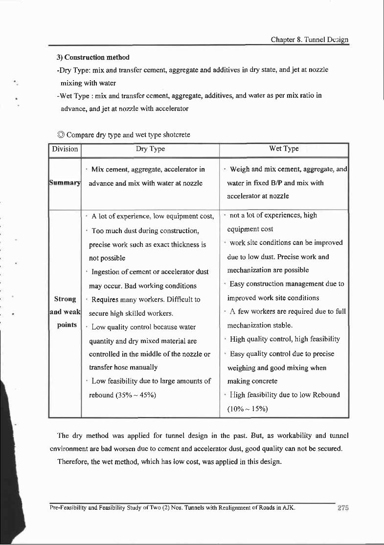
Chapter 8. Tunnel Design
3) Construction method
-Dry Type: mix and transfer cement, aggregate and additives in dry state, and jel at nozzle
mixing with water
-Wet Type : mix and transfer cement, aggregate, additives, and water as per mix ratio in
advance, and jet at nozzle with accelerator
The dry method was applied for tunnel design in the past. But, as workability and tunnel
environment are bad worsen due to cement and accelerator dust, good quality can not be secured.
Therefore, the wet method, which has low cost, was applied in this design.
@ Compare dry type and wet type shotcrete
Division Dry Type Wet Type
\ l lmmtFt
Mix cement, zggregate, accelerator in
advance and mix with water at nozzle
Weigh and mix cement, aggregate, and
water in fixed B/P and mix with
accelerator at nozzle
Strong
and weak
points
A lot of experience, low equipment cost,
Too much dust during construction,
precise work such as exact thickness is
not possible
Ingestion ofcement or accelerator dust
may occur. Bad working conditions
Requires many workers. Difficult to
secure high skilled workers,
Low quality control because water
quantity and dry mixed material are
controlled in the middle of the nozzle or
transfer hose manually
Low feasibiliry due to large amounts of
rebound (35% * 45%)
not a lot of experiences, high
equipment cost
work site conditions can be improved
due to low dust. Precise work and
mechanization are possible
Easy construction management due to
improved work site conditions
A few workers are required due to full
mechanlzation stable.
High quality control, high feasibility
Easy quality control due to precise
weighing and good mixing when
making concrete
High feasibility due to low Rebound
(10o/o - l5Vo)
Pre-Feasibility and Feasibility Study ofTwo (2) Nos. Tunn€ls with Realignment ofRoads in AJK.

- -.-, . :. FEASIBILITYREPORT
4) Accelerator
Accelerator is used to make early strength development of shotcrete so that shotcrete can
perform the function ofsupport. It is an additive for concrete and the Qrpes are as follows.
@ according to shape
Division liquid accelerator Powder type accelerator
Adding method
Transferred after water andaccelerator are mixed in advance.
mixed with dry or wet concrete at
Nozzle
Added at shotcrete just before concretebeing transferred and mixed at nozzle
with water
Compressive
strength
Better early strength development
due to short reaction time with cement
Somewhat late early strengthdevelopment as it reacts after
dissolution in waterRebound rate Relatively low Relatively high
Accelerator pH pH 13 pH l0 -13
@ according to component
division Silicate family aluminate family Alkali-free familyCement mineral
family
Cornponent Na2OnSi02 NaAlOz, KAIOz Al(OH)xRy(x+y:3)cr2A7, cr rA7(CAF2),
CSA
MechanismGlue effect bybecoming a gel
Promotes cementhydration
Promotes cementHydration and forms
6 n r i n n ; r a! ! u , r 1 6 , r r
forms ettringite byreacting with
Ca(OH)2 and SO3
Standardamount used
8-l50% of cement 3-8% ofcement 4-87o ofcement 4*8o% ofcement
HarmAccumulated in
body whenbreathing (Si02)
Can be Burnedwhen working
Low pungencySimilar pungency
IO Cemenl
f,'. n wi rnn rn cn trEnvironmentalPollution by
dissolving aldeluting
EnvironmentalPollution by
strong alkali baseeluting water
No environmentalpollution
No environmentalpollutionpollution
Remarks
high early strength
low long term
strength
large amount of
rebound
low early strengtl
low long termstrengthsensitive to
cement featuresand temperaturehigh amount of
rebound
low early strength
high long term
strength
high price, pump
Amendment required
low amount of
rebound
high early strengtt
high long term
pump amendmentrequired
low amount ofrebound
Pre-Feasibility and Feasibilig Study ofTwo (2) Nos. Tunnels with Realignment ofRoads in AJK.
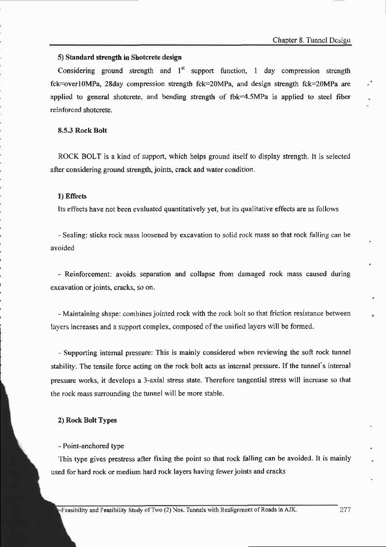
Chapter 8. Tunnel Desigu
5) Standard strength in Shotcrete design
Considering ground strenglh and l't support function, 1 day compression strength
fckruverl0MPa, 28day compression strength fck=20MPa, and design strength fck=20MPa are
applied to general shotcrete, and bending strength of fbk=4.5MPa is applied to steel fiber
reinforced shotcrete.
8,5.3 Rock Bolt
ROCK BOLT is a kind of support, which helps ground itself to display strength. It is selected
after considering ground strength, joints, crack and water condition.
l) Elfecb
Its effects have not been evaluated quantitatively yet, but its qualitative effects are as follows
- Sealing: sticks rock mass loosened by excavation to solid rock mass so that rock falling can be
avoided
- Reinforcement: avoids separation and collapse from damaged rock mass caused during
excavation orjoints, cracks, so on.
- Maintaining shape: combines jointed rock with the rock bolt so that friction resistance between
layers inueases and a support complex, composed ofthe unified layers will be formed.
- Supporting intemal pressure: This is mainly considered when reviewing the soft rock tunnel
stability. The tensile force acting on the rock bolt acts as intemal pressure. If the tunnel's intemal
pressure works, it develops a 3-axial stress state. Therefore tangential stress will increase so that
the rock mass surrounding the tunnel will be more stable.
2) Rock Bolt Types
- Point-anchored type
This type gives prestress after fixing the point so tlat rock falling can be avoided. It is mainly
used for hard rock or medium hard rock layers having fewerjoints and cracks
easibilify and Feasibility Study ofTwo (2) Nos. Tunnels with Realignment ofRoads in AJK. 277
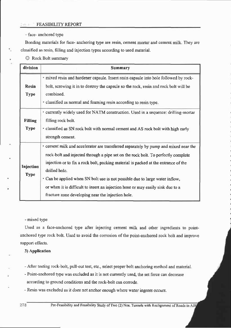
FEASIBILITY REPORT
- face- anchored type
Bonding materials for face- anchoring type are resin, cement mortar and cement milk. They are
classified as resin, frlling and injection t)?es according to used material.
O Rock Bolt summary
- mrxed t)4e
Used as a face-anchored rype after injecting cement milk and other ingredients to point-
anchored type rock bolt. Used to avoid the corrosion of the point-anchored rock bolt and improve
support effects.
3) Application
- After testing rock-bolt, pull-out test, etc., select proper bolt anchoring method and material.
- Point-anchored type was excluded as it is not currently used, the set force can decrease
according to ground conditions and the rock-bolt can conode.
- Resin was excluded as it does not anchor enough where water ingress occurs.
division Summary
Resin
Type
mixed resin and hardener capsule. Insert resin capsule into hole followed by rock-
bolt, screwing it in to destroy the capsule so the rock, resin and rock bolt will be
combined.
classified as normal and foaming resin according to resin type.
tr'illing
Type
' currently widely used for NATM construction. Used in a sequence: drilling-mortar
filling rock bolt.
. classified as SN rock bolt with normal cement and AS rock bolt with high early
strensth cement.
Injection
Type
' cement milk and accelerator are transferred separately by pump and mixed near the
rock-bolt and injected though a pipe set on the rock bolt. To perfectly complete
injection or to fix a rock bolt, packfug material is packed at the entrance of the
drilled hole.
' Can be applied when SN bolt use is not possible due to large water inflow,
or when it is difficult to insert an injection hose or may easily sink due to a
fracture zone developing near the injection hole.
278 Pre-Feasibility and Feasibility Study ofTwo (2) Nos. Tunnels with Realignment ofRoads in

Chapter 8. Turnel Desigl
' 8.5.4 Steel-rib
, Steel rib displays a support role at the beginning until the shotcrete hardens, and improves
support with shotcrete after hardening. Steel ribs include U type, H type, and Lattice Girder and
their firnctions are as follows. In this design, the H-shaped rib was selected and Lattice Girder may
be used under consultation with local supervisor's approval
l) Function of steel rib
- Temporary support until hardening of shotcrete is placed
- Direct support to non-suppofied ground and disperses shotcrete lining's load
- Support when auxiliary work such as forepoling, Pipe Roofing, etc. is implemented
- Checking the tunnel diameter. Guide to blasting
2) Steel support feetures
t
@ steel support features
division H-shaped support Lattice Girder
shape ' H-shaped section 3 angles, 4 angles grid type
Material features' yield stress: 240MPa(S5400)' allowable stress: l4OMPa
yield stress: 520MPa (high performance steel)allowable stress : 300MPa
Problemsand
solutionsfunction
void occurs at the back ofsupportbig resistance to displacementdue to high rigidityeasy supply
shotcrete sealing is possiblewater-proof effect due to excellentbonding force with shotcretetunnel safety increased byforming a continuous body withshotcreteavoids unexpected grounddisplacement
(-nnsff|rr'linn
. mechanization is required due toheavy weight
' construction line is loweredwhen auxiliary-work applied(hard to maintain drillingangle at l5')
' easy installation due to lighhess(40-60%)' possible to maintain required
drilling angle when auxiliary-work is applied
line
Pre-Feasibility and Feasibility Study ofTwo (2) Nos. Tunnels with Realignment ofRoads in AJK. 279

!-J(., i FEASIBILITYREPORT
Feasibility
shotcrete rebound is increasedto H-shape steel rib
saves shotcrete placement timesaves time for supportinstallationdecreases shotcrete rebound
Remarks' thorough quality control is
required as allocated axial forceis increased.
Application
better for ground with bad soil orhard rock sround
better in most tunnels wherecontinuous displacement occursbetter in weathered rocktunnelsbetter in tunnels whereshotcrcte thickness is hieh
3) Application
If Lattice Girder is applied, the void on the support's back space is minimized and shotcrete and
support are unified so that tunnel stability is increased, Lattice Girder has better functionality,
workability, and feasibility than H-shaped support. All required amount should be imported
however, as there is no Lattice Girder manufacturer in the project atea. There forms sedimentary
rock in this area, so the Found is not regular and it is expected that big displacements will occur.
Therefore, H-shaped support, with strong rigidity and resistance to displacement, is applied in this
proJ ect.
280 Pre-Feasibility and Feasibility Shrdy ofTwo (2) Nos. Tunnels with Realignment ofRoads in AJK.

Chapter 8. Tunnel Desigu
8.6 Blasting
8.6.1 Introduction
In blasting design, there are restraints according to local conditions such as excavated rock
features, geological features, utilities location and influence on environment, etc. Therefore, the
blasting effect should be maximized taking those conditions and construction methods into account.
The basic concept selected was that overbreaking should be minimized at the short excavation
advance with soft rock and the blasting effect should be maximized at the long excavation advance
with less support and hard rock, so that tunnel stability and excavation tunnel should be optimized.
The most important thing in hrnnel blasting is that free face where blasting is executed. Whether
or not dnlling is successful is decided according to the blasting results, for making the new free
face. Besides that, explosives and detonator with the best feasibility and workability under the
conditions should be selected, after reviewing the rock features and work conditions.
8.6.2 Blasting method classification
I) Items reviewed when selecting the blasting method
" Influences to surroundings such as blasting vibrations, noise, etc.
. Drilling workability and drilling time
. Fragment scattering distance and muck size
. Blasting effectiveness (drill length/drilling length)
. damage to tunnel heading and surrounding rock (stability of over break and structure)
. Economical feasibility
Pre-Feasibility and Feasibility Study ofTwo (2) Nos. Tunnels with Realignment ofRoads in AJK. 28r
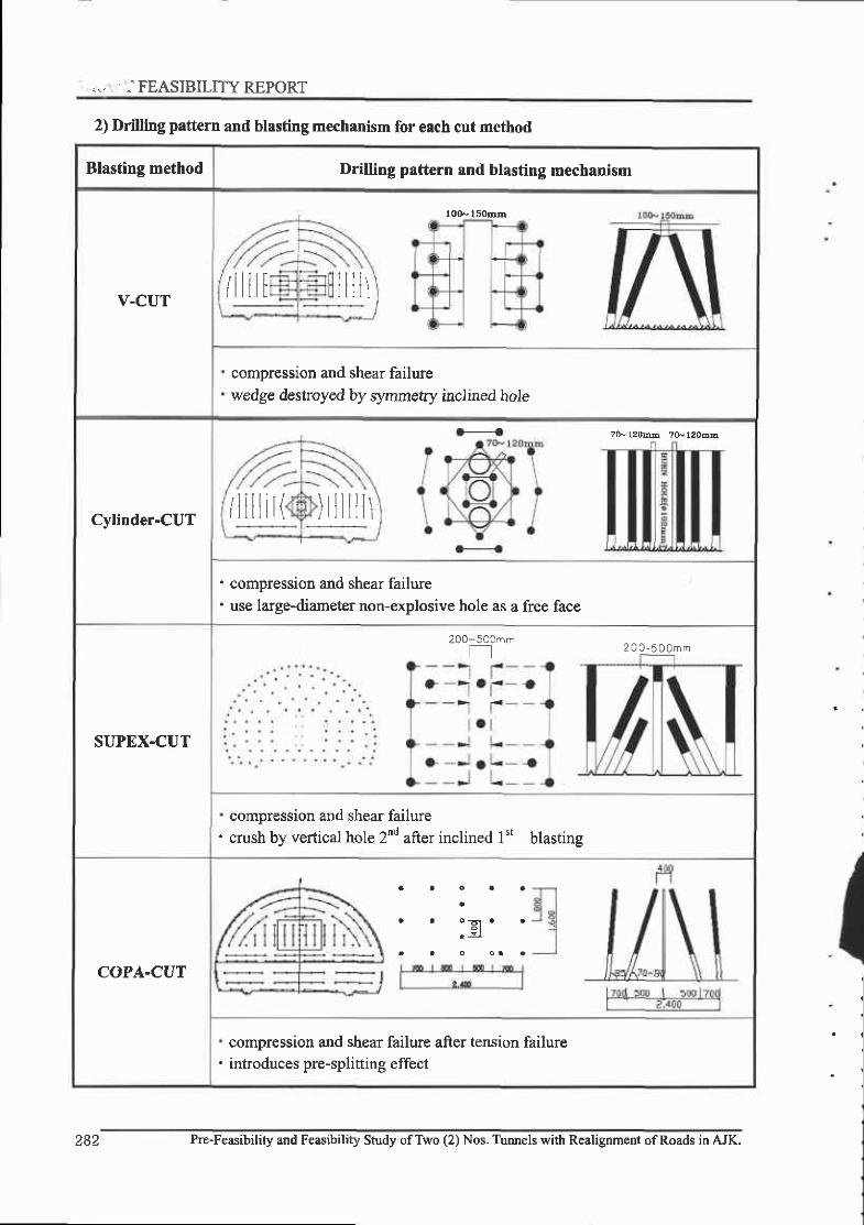
... ...FEASIBILITYREPORT
2) Drilling pattern and blasting mechanism for each cut method
Blasting method Drilling pattern and blasting mechanism
V-CUT
10(}-l5omm
/llllN llllr
compression and shear failurewedge destroyed by synmetry inclined hole
Cylinder-CUT
?0- lzorqb ?S, l?oEE
/lillit()tlllllr
compression and shear failureuse large-diameter non-explosive hole as a free face
SUPEX-CUT
200-500mmft 2 0 0 - 5 0 0 m m
compression and shear failurecrush by vertical hole 2nd after inclined l"t blasting
COPA-CUT
compression and shear failure after tension failureintroduces pre-splitting effect
282 Pre-Feasibility and Feasibility Study ofTwo (2) Nos- Tunnels with Realignment ofRoads in AJK.

Chapter 8. Turmel Desibn
8.6.3 Cut blasting method comparison
division Features and strong points
V-CUT. simple &illing paftem
. effective in one-hole blasting or soft rock blasting
Cylinder-CUT
. possible to increase excavation length
. possible to control vibration
. used for long-hole blasting or hard rock blasting
SUPEX-CUT
. can be used regardless ofrock type and heading area or drilling length
. explosive amount ratio is small with good blasting effect
. good feasibility as the whole drilling work is improved and drilling time
is decreased.
COPA.CUT
. blasting vibration and noise is decreased due to pre-spliting
. increased blasting effect due to pre-spliting
. easy drilling works and fewer drilling numbers due to large inclined angle
. excellent crushing effect due to pre-spliting
. small non-explosive quantity ratio
. excavation cost is low
8-5.4 Explosives
1) Explosives selection criteria
. safe against outside physical forces (heat, friction, impact)
" low blasting vibration and noise
" excellent water-resistance to underground water and excellent following of blasting gas, etc.
. easy.loading and larger loaded density
. minimizes overbreak and loosened zone of surroundins rock
Pre-Feasibility and Feasibility Study ofTwo (2) Nos. Tunnels with Realignment of Roads in AJK.
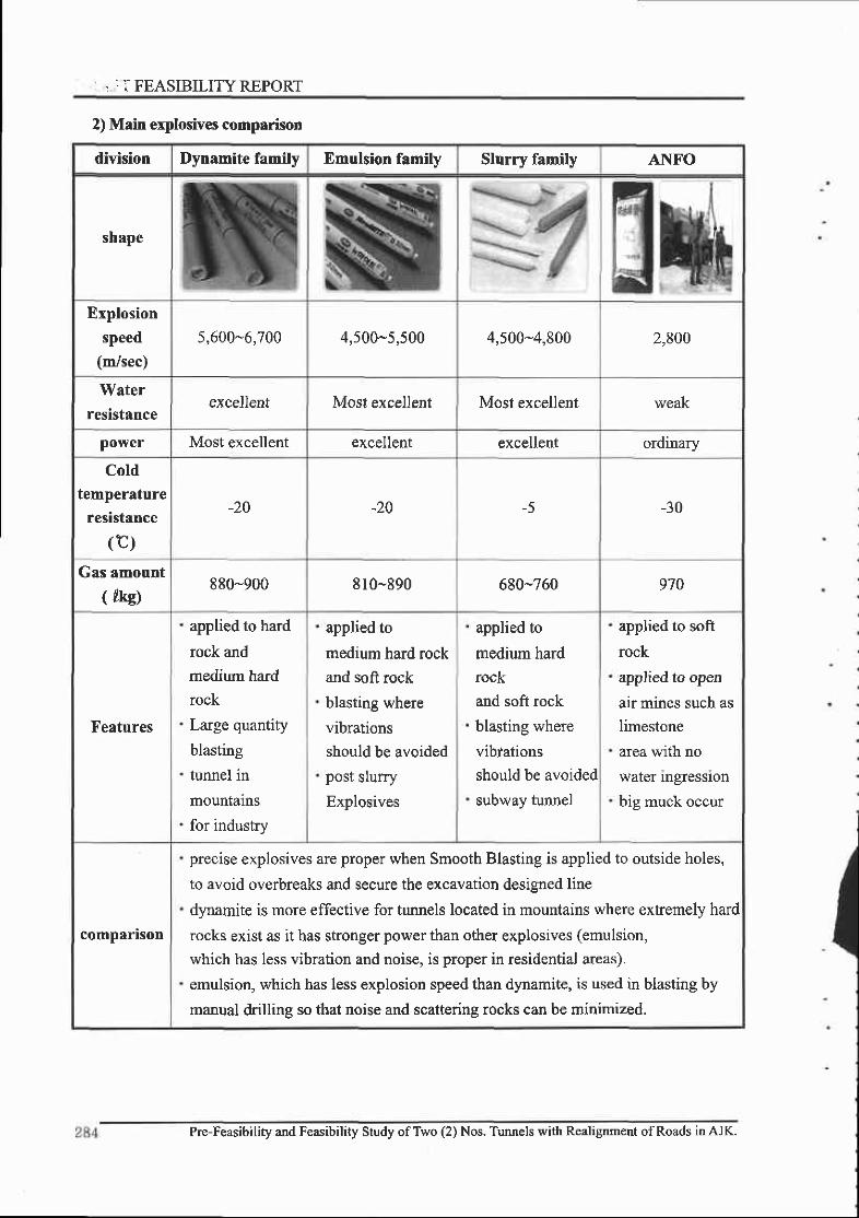
] . : I FEASIBILITYREPORT
2) Main explosives comparison
division Dynamite family Emulsion family Slurry family A1\{FO
shape
Explosion
speed(m/sec)
5,600-6,700 4,500-5,500 4,500-4,800 2,800
Waterresistance
excellent Most excellent Most excellent weak
power Most excellent excellent excellent ordinary
Cold
temperatureresistance
(c)-20 -20 -5 -30
Gas amount( 4kc)
880-900 810-890 680-760 970
Features
applied to hard
rock and
medium hard
rock
Large quantity
blasting
tunnel in
mountains
for industry
applied to
medium hard rock
and soft rock
blasting where
vibrations
should be avoided
post slurry
Explosives
applied to
medium hard
rock
and soft rock
blasting where
vibfations
should be avoided
subway tunnel
applied to soft
rock
applied to open
air mines such aslimestone
area with no
water rngresslon
big muck occur
companson
precise explosives are proper when Smooth Blasting is applied to outside holes,
to avoid overbreaks and secure the excavation designed line
dynamite is more effective for tunnels located in mountains where extremely hard
rocks exist as it has stronger power than other explosives (emulsion,
which has less vibration and noise, is proper in residential areas).
emulsion, which has less explosion speed than dynamite, is used in blasting by
manual drilline so that noise and scatterins rocks can be minimized.
Pre-Feasibility and Feasibility Study ofTwo (2) Nos. Tunnels with Realignment ofRoads in AJK.
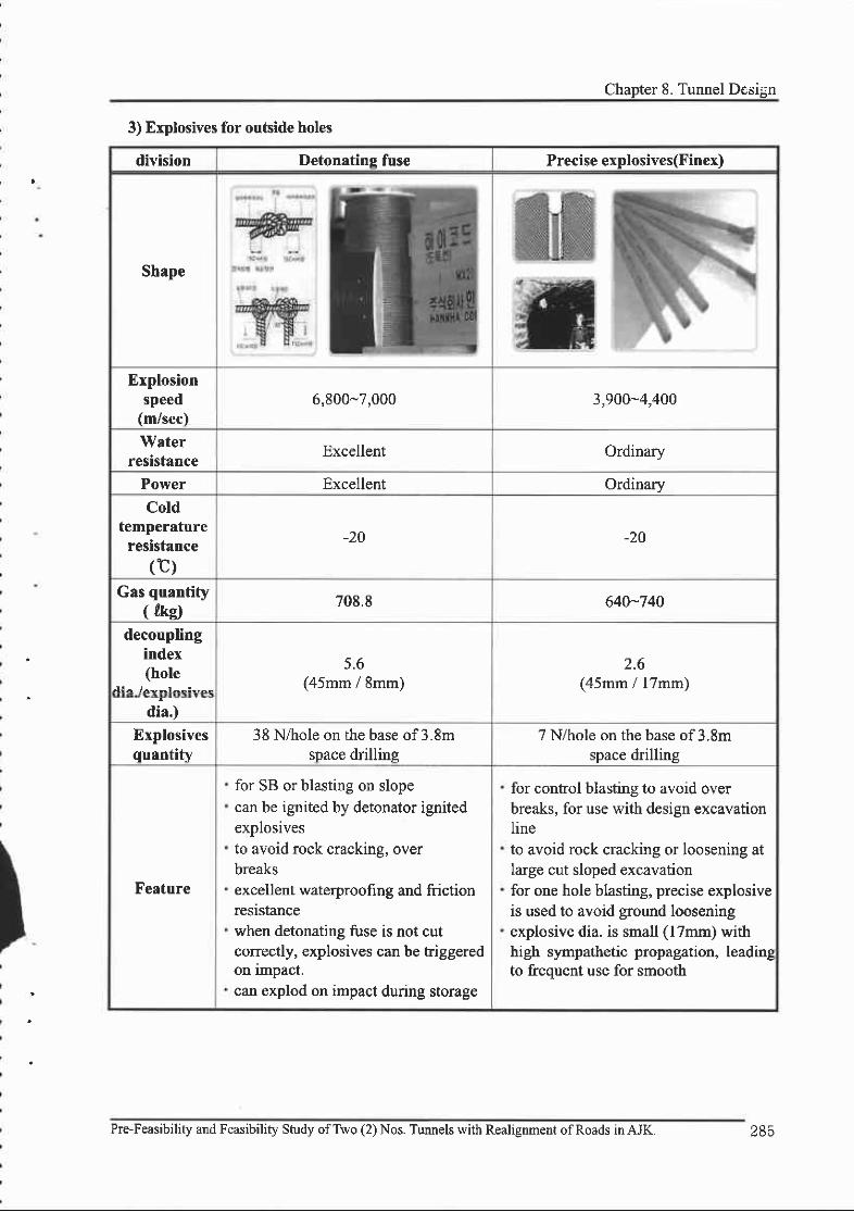
Chapter 8. Tunnel Design
3) Explosives for outside holes
division Detonating fuse Precise explosives(Finex)
Shape
Erplosionspeed
(m/sec)6,800-7,000 3,900"4,400
WaterresistaDce Excellent Ordinary
Power Excellent OrdinaryCold
temperatureresistance
(t)-20 -20
Gas quantify( rke) 708.8 640-740
decouplingindex(hole
; l ! - /^*-r^- : - ,^-
5.6(45mm / 8mm)
2.6(45mm / llmm)
dia.)
Explosivesquentity
38 N/hole on the base of 3.8mspace drilling
7 N/hole on the base of 3.8mspace drilling
Feature
for SB or blasting on slopecan be ignited by detonator ignitedexplosivesto avoid rock cracking, overbreaksexcellent waterproofi ng and frictionresrstancewhen detonating fuse is not cutcorrectly, explosives can be triggeredon impact.can explod on impact during storage
for control blasting to avoid overbreaks, for use with design excavationIineto avoid rock cracking or loosening atIarge cut sloped excavationfor one hole blasting, precise explosiveis used to avoid ground looseningexplosive dia. is small (l7mm) withhigh sympathetic propagation, leadingto ftequent use for smooth
Pre-Feasibility and Feasibility Study ofTwo (2) Nos. Tunnels with Realignment of Roads in AJK. 285

-: ,.'i l 'FEASIBILITY REPORT
4) Detonator
o detonator feature
division Electric detonator Non-Electric detonator
Shape
Workability. skilled worker is required, easy
handling, excel lent workability
. skilled worker required, excellent
workability
Economy Excellent Higher price than electric detonator
Available
time
difference
combined interval is limited
various differences possible
using multistage blasting device
(better vibration control)
non limit time difference possible via
connector (better vibration contol)
Outside
current
sensitive to electric cause such as
stray current, static electricity, radio
waves, etc.
stable to outside physical cause,
stray current, static electricity, radio
waves, etc,
Check
connecting
' easy to check connection and
resistance (tester)
. visual connection check only
['. ffcofiven acs
' multi-blasting can be applied when
using multiple devices
' excellent blasting effectiveness
' maximize time effect, excellent
blasting effectiveness
' construction period can be decreased
Pre-Feasibility and Feasibility Study ofTwo (2) Nos. Tunnels with Realignment of Roads in AJK.
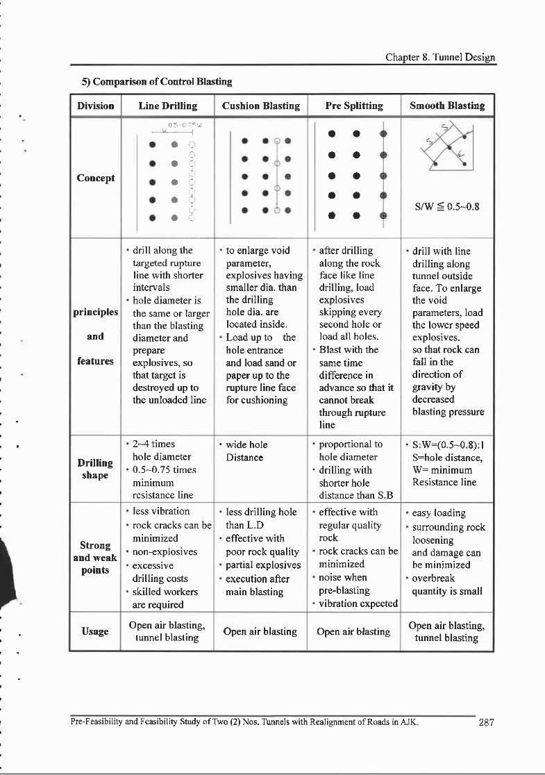
Chapter 8. Tunnel Deslgn
5) Comparison of Control Blasting
Division Line Drilling Cushion Blasting Pre Splitting Smooth Blasting
Concept
r l 5 - a t 5 " /i +i
a ,:,
O .
o, :
o :
O C
ao
ao
aaoa
aas/w < 0.5-0.8
principles
and
features
drill along thetargeted ruptureline with shorterintervalshole diameter isthe same or largerthan the blastingdiameter andprepareexplosives, sothat target isdestroyed up tothe unloaded line
to enlarge voidparameler,explosives havingsmaller dia. thanthe drillinghole dia. arelocated inside.Load up to thehole entranceand load sand orpaper up to therupture line facefor cushioning
after drillingalong the rockface like linedrilling, loadexplosivesskipping everysecond hole orload all holes.Blast with thesame timedifference inadvance so that itcannot breakthrough ruptureline
drill with linedrilling alongtunnel outsideface. To enlargethe voidparameters, loadthe lower speedexplosives.so that rock canfall in thedirection ofgravrty bydecreasedblasting pressure
Drillingshape
2*4 timeshole diameter0.5*0.75 timesminimumresistance line
' wide holeDistance
' proportional tohole diameter
' drilling withshorter holedistance than S.B
. S:w:(0.5-0.8):lS:hole distance,W: minimumResistance line
Strongand weak
points
less vibrationrock cracks can beminimizednon-explosivesexcessivedrilling costsskilled workersare required
less drilling holethan L.Deffective withpoor rock qualitypartial explosivesexecution aftermain blasting
effective withregular qualityrockrock cracks can beminimizednoise whenpre-blastingvibration expected
easy loadingsurounding rocklooseningand damage canbe minimizedoverbreakquantity is small
UsageOpen air blasting,
tunnel blastingOpen air blasting Open air blasting
Open air blasting,tunnel blasting
Pre-Feasibility and Feasibility Study ofTwo (2)Nos. Tirnnels with R€alignment ofRoads inAJK. 287
. FEASIBILITY REPORT
8.6,5 Solution of blasting pollution
l) Solution of blasting vibration
- changing explosive type
Blasting vibration waves increase as the dynamic destructive effect ratio decreases. It is thus
preferable to use explosives with a dynamic destructive effect ratio to reduce vibrations (low
specific gravity and low explosion speed). (detonation speed is proportional to explosive density
by the square ofexplosion speed)
- Change ofload method alteration
Decrease the drill hole diameter and use decoupling explosives so that the shock wave can be
relieved by voids and the dynamic destructive effect ratio decreases for a reduction in blasting
vibration.
(use an explosive with controlled blasting: Smooth Blasting, Pre Splitting, etc.)
- Change of detonation method
Duration ofthe blasting vibration is short. Where maximum vibration value is a evaluation unit
such as vibration speed, if simple blasting is implemented, the vibration wave shape will be
separated, and the quantity of explosive is not the total explosive quantity, but the quantity per
delay. So, for planned blasting holes, instant detonators should not be used exclusively, rather
delayed electric detonators or non-electric detonators should be used, so that blasting vibration is
reduced.
- Blocking wave propagation
Vibrations can be reduced through excavation or other means between the explosion point and
frequency-receiving point. It is not commonly used as it requires a lot oflabor for small effect.
288 Pre-Feasibility and Feasibility Study ofTwo (2) Nos. Tunnels with Realignment ofRoads in AJK.
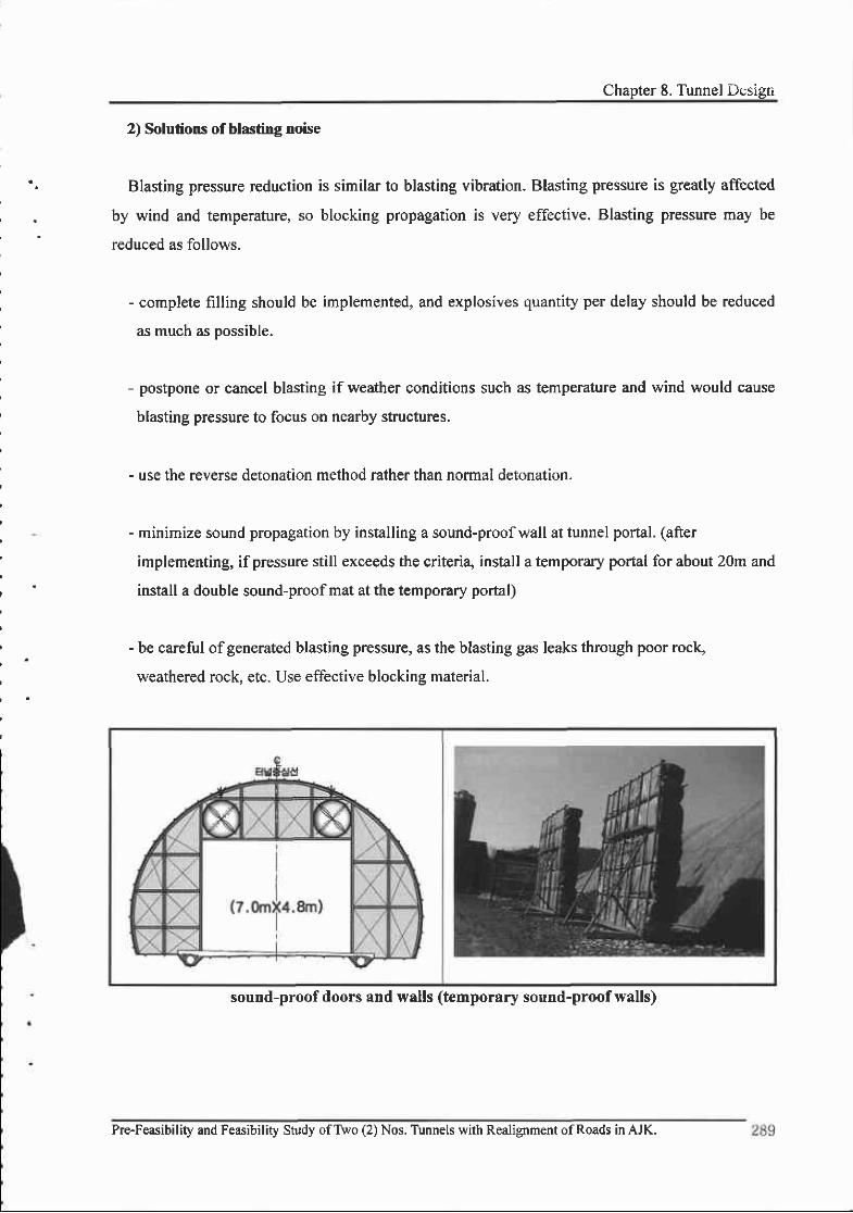
Chapter 8. Tunnel D,;sigti
2) Solutions of blasting noise
Blasting pressure reduction is similar to blasting vibration. Blasting pressure is greatly affected
by wind and temperature, so blocking propagation is very effective. Blasting pressure may be
reduced as follows.
- complete filling should be implemented, and explosives quantity per delay should be reduced
as much as possible.
- postpone or cancel blasting if weather conditions such as temperature and wind would cause
blasting pressure to focus on nearby structures.
- use the reverse detonation method rather than normal detonation.
- minimize sound propagation by installing a sound-proofwall at tunnel portal. (after
implementing, if pressure still exceeds the criteri4 install a temporary portal for about 2Om and
install a double sound-proofmat at the temporary portal)
- be careful ofgenerated blasting pressure, as the blasting gas leaks through poor rock,
weathered rock, etc. Use effective blocking material.
sound-proof doors and walls (temporary sound-proof walls)
Pre-Feasibility and Feasibility Study ofTwo (2) Nos. Tunnels with Realignment ofRoads in AJK.

;.] .' ] FFASIBILITY REPORT
8.7 Auxiliary construction method
8.7.1 Classification according to reinforcement purpose
It is important to use shotcrete directly after excavation via the NATM method. The safety
premise is that the tunnel face becomes stand up(usually 3-4 hrs). Shotcrete use is usually diffrcult
due to too excess water ingression, so it is necessary to use the main and auxiliary method
simultaneously according to surrounding ground conditions and water conditicn. The auxiliary
method can be classified as follows.
Tunnelstability
Drain-method
Fore Poling
General drilling multi-grcuting with general drillingmulti stage gouting with self drilling
Mini Pipe roof
. Steel sheet piles
. Core (Ring Cut)
. Tunnel Face Shotcrete
Tunnel Face Rock Bolt
Ground improvernent by chernical grouting etc.(Pre-grouting method, etc.)
Freezing method
Chemical grouting method
Freezing me thod
. Pressure method
Deep Well me thod
Well Point method
Pre-boring for drainage
Pre-Feasibility and F€asibility Study ofTwo (2) Nos. Tunnels with Realignment ofRoads in AJK.

Chapter 8. Tunnel Lesign
Fore poling was chosen from among the auxiliary methods, for application to weak rock or
fracture zones as a stabilizing method for crowns and work faces in this project. Multi stage
grouting was applied in weak rock or weathered rock zones at beginning and ending sections oftlre
tunnel, and multi stage grouting with self drilling is applied where the drill hole cannot stand by
itself. Where there is a lot water however, the ground improvement method using pregrouting
should be considered.
Auxiliary method summary
PurposeAuxiliary
methodDescription
Tunnel face
stabilization
method
Forepoling
drilling angle : l5o - 20"
horizontal distance : 40 - 60cm
leng th :2 -3m
material : steel bar(D25), steel pipe(o32mm)
type : mortar injection type
applying to every tunnel face
Pipe Roof
Single stage
grouting
or
Multi stage
grouting
drilling angle: 15" - 20"
horizontal distance : 40 - 60cm
leng th :6 - l 2m
material : steel pipe (o50 - 100mm)
overlaplength:3-4m
- sealing fracture zone by injecting cement milk once to
whole length
- positively sealing fracture zone (use Packer) by injecting
cement milk at each depth many times
Horizontal
high pressure
injection
grouting
drilling angle : 6'
horizontal distance : 40 - 60cm
length : l2m
form cement bulb by mixing unconsolidated ground soil with
cement through extremely high pressure injection
overlap length : about 4m
Pre-Feasibility and Feasibility Study ofTwo (2) Nos. Tunnels with Realignment ofRoads in AJK. 2SI

Vertical high
pressure
injection
grouting
.d i s tance :0 .6 - l . 0m
' injection with 2.5 - 5.0m thickness at upper crown area
Root Milk
method
' after drilling up to planned depth, insert rebar (D25) into
hole, pressure injection using packer, casing, or steel pipe so that
rebar and ground work together to improve ground strength.
' hole interval : l.0m
Tunnel face
shotcrete
Iftunnel face cannot be made stand up, it will be
reinforced by cement placing.
thickness : more than 3.Ocm
implementing with rock-bolt as per the conditions
Water
blocking
method
SGR grouttng
LW grouting
' 2.5m - 5.0m cut offlayer formed on tunnel crown
. install cut-off wall on the left and right
so that ground water inflow is blocked and the outside ground
water level can be maintained.
The importance of each auxiliary method varies according to ground conditions, underground
water condition, tunnel purpose, tunnel size, etc. Therefore, after exactly determining the
application purpose, the proper method for local conditions should be selected according to the
ground inspection.
The following tabte roughly shows the auxiliary method applications mainly applied for tunnel
excavation. For reasonable applications, two or three ground auxiliary methods according to local
conditions are used in conjunction, complying with the reinforcement purpose.
Pre-F€asibility and Feasibility Study ofTwo (2) Nos. Tunnels with Realignment of Roads in AJK.292

Applicability of auxiliary method
solution method
Original groundcondition rernarkPur PUrr
IIardrock
Softrock
soil
Solutionfor work
facestability
CrownStability
Pipe roof A A
Inclined rock bolt A
Forepoling A AUse steel rods, bars,
pipes etc.
Steel pipe multi stage
( I stage) groutingA C
Chemical grouting C
work face/floor face
Tunnel face shotcrete A C
Tunnel face rock bolt A 1\
Core A A Ring Cut
chemical grouting o
rcmporary mven
archA A
Watersolution
Cut off/drain
chemical grouting A o o
Drainage A o o Including well point,
deep well method
WeIl point C
Deep well oO : relatively common method, : ordinary method
Pre-Feasibility and Feasibility Study ofTwo (2) Nos. Tunnels with Realignment ofRoads inAJK. 293

' ,i . 1 -,
FEASIBILITY REPORT
8.7.2 Tunnel crown stabilization
To secure tunnel crown stability, the tunel support interval or drilling length is reduced so that
arch action, which prevents rock fall, can be expected between tunnel face and lst Lining in the
back. In actual construction however, auxiliary methods are often necessaf,y, and the generally
used methods are as follows.
l) Forepoling method
Forepoling is an effective method to secure crown stability, considering the geological features
of the tunnel face. Overbreak occurrences are reduced and upper face collapse is avoided by
reducing the length of the excavated free face. The items to be considered in construction are as
follows.
. applied ground : when tunnel crown is weathered soil, weathered rock or fracture zone and
when reinforcing the tunnel entrances
" location: within 120' oftunnel crown
" interval : every work face in the Iongitudinal direction, cross direction would be 0.5m
. angle : as horizontal as possible
' length : L:3.0 m
. Hole diameter: Q46mm
. material : $38mm steel pipe
294 Pre-Feasibility and Feasibility Shrdy ofTwo (2) Nos. Tunnels with Realignment of Roads in AJK.

Chapter 8. Tunnel Dss,gri
2) Mini piperoof method
This is used to avoid ground loosening or falling by sticking pipe to the wall by driving pipe ofa
diameter a little larger than the drilling hole diameter, mainly targeting soil tunnels.
If rebar diameter is increased, handling becomes difficult. Therefore, pipe with good bending
stiffness and workability is selected.
Pipe is selected according to the following table. The main direction pitch is 20-60 cm, and the
length generally 2.0 m, but 3.0 - 5.0m is used at the entrance-
3) Double layered steel pipe with multi-stage grouting method
To avoid ground loosening or collapse, materials (cement milk and polyurethane) are injected
through a double layered steel pipe. Soil and rock layers near the excavated tunnel face can be
reinforced in this way. This is an auxiliary tunnel construction method that can expect an additive
waterproof effect.
Double layered steel pipe specifications, made especially for smooth injection, is as follows.
General double steel pipe Large diameter double steel pipe
Outside pipe Inside pipe Outside pipe Inside pipe
O.D. :60 .5mm+3mmthickness:
4.0mm*lmmlength : 12.0m+20mm
O.D. :42.7mm+3mmthickness :
4.0mmalmmlength : 1 1.9m+20mm
O.D. : I l4.3mm+3mmthickness:
6.0mm+1mmlength : 12.0m+20mm
O.D. : 89.0mm+3mmthickness :
5.0mmflmmleng th :11 .9m+20mm
PIPE specifrcation
Outside dia.D(mm)
thicknesst(mm)
weightW(kg/n)
Section areaA(cm2)
Moment ofinertia (cma)
Sectionmodulus
(cm )
34.0 z , ) 1.80 2,29r 2.89 1.70
A a ' f . A
2.292.393 .12
2,9193,0393,97 |
5.976 .197,77
2.802.903.64
48.63.2
2.63
3.s8
3,1463,4834,564
8.999.32I 1 .80
3.703.834.85
Pre-Feasibility and Feasibility Study ofTwo (2) Nos. Tunnels with Realignment ofRoads in AJK.

,. FEASIBILITYREPORT
Auxiliary method for crown stabilization
division
Multi stsge grouting method
Small diameter steel pipemulti stage grouting
FRPMulti stage grouting
Large diameter steel pipemulti stage
grouting
summarv
Steel pipe or FRP pipe insertion after drilling
equipment drilling machine for tunnels only, crawler drill,horizontal drilling machine, etc.
Drlllingdiameter
105 - 150 mm 125 - 165 mm
Steel pipe (50, 60mm) FRP pipe (60,76mm) Steel pipe (t 14, l39.8mm)material
Injectionmaterial
cement * sodiumbicarbonate silicate
Cement + FRC admixture +sodium bicarbonate silicate
cement * sodiumbicarbonate silicate
Drillinglength L=12- 16m L:12- 24m L: t2 -24m
seq|rence drilling-steel pipe insertion--+caulking-sealing-multi stage grouting
Features
- low construction cost- cavitation occurswhen drilling andremoving slime
- easy supply- easy equipment supply- material cost lowerthan FRP pipe
- use 3.0m single pipe
- a little higherconstructlon cost
- easy handling and goodworkability as reinforcingmaterial is light
- good constructionquality
- weak to flexure due tomaterial brittleness
- excellent chemical andcoffosion resistance
- use 3.0m single pipe
- a little higherconstructron cost
- excellent reinforcementeffect
- use steel pipe withoutconnectron
- transfer in tunnel isdifficult as steel pipeis long
- good drilling precisionusing exclusiveequipment
epplication
- stratum that can maintain drill holes(better stratum than firm soil or weathered rock)
- stratum that canmaintain drillholes (firm soil)
- weathered sections or sections where rock mass isdistributed thinlv on tunnel crown
- where weight(load) isloaded on upperfunnel area
- where upper soil layeris heavily loaded
Pre-Feasibility and Feasibility Study ofTwo (2) Nos. Tunnels with Realignment ofRoads in AJK.

Chapter 8. Tumel Desigir
Auxiliary method for crown stabilization
divisionMulti strge grouting method with self drilling
Large dia. steel pipeMulti stage grouting
Double steel pipe multi stage grouting
Description
Insert steel pipe simultaneously whendrilling by connecting with bit assembly
lnsert double layered steel pipe after drilling
Equipment drilling machine, crawler drill, horizontaldrilling machine, etc.
Cement * sodium bicarbonate silicate orpolymer polyurethane
Drill holedia. 105 - 165 mm 76 - 150 mm
auxiliarymaterial Steel pipe (60.5, I 14, l39.8mm)
outside pipe: @60.5-1 l4.3mmlnside pipe: (&.2.7 -89.0mm
Injectedmaterial
Cement + sodium bicarbonate silicate
Drillinglength
L:12-24m L=6-12.0m
Sequence(Drilling + steel pipe insertion) -
caulking -multi stage groutingDrilling--- steel pipe insertion
+caulking-sealing- multi stage gouting
feature
- a little higher construction cost- steel pipe with high stiffness can beused
- 3m length connected steel pipe is used- drill hole dia. quality improved bystabilizer attached drilling
- construction angle and workabilityimproved by attaching HI-VP pipe
- stiffrres is high by usingdouble layer steel pipe so beamformation effect is excellent.
- Iess pipe is used than steel pipe multistage grouting by using double layer steelpipe.
- less piping reduces consfiuction time- heavier than existing single pipe(double pipe)
Annlicefinn
- stratum that can not maintaindrill holes (weak soil,crushed rock, boulders etc.)
- where it is hard to maintain drillholes due to upper section composed ofsoil and where a longitudinal archingeffect cannot be expected.
- stratum that can maintain dril-holes (solid soil)
- if the load is exerted on the uppertunnel
- if the upper soil layer fturctions as a largeload
Pre-Feasibility and Feasibility Study ofTwo (2) Nos, Tunnels with Realignment ofRoads in AJK, 297

i FEASIBILITY REPORT
8.7.3 Stabilization of Tunnel Face
To stabilize the tunnel face, the exposed face is minimized by dividing the excavation face. Face
exposure cannot be helped in the work face, so when the work face needs protection, the following
are generally used.
l) Core
Used mainly in ground where the tunnel face has weak stability. The core is maintained to resist
the force acting on the tunnel face. The core length is usually 2-3 m. The drilling method with
remaining core is called the Ring Cut method.
2) Placing shotcrete on the tunnel face
Used to restrain tunnel face loosening and expansion by shotcrete placement. Shotcrete relieves
workface roughness, so that focused stress can be dispersed and moving from the rock mass joint
can be avoided by shotcrete's shear resistance.
3) Reducing the lengtl of excavation
Tunnel face loosening is extended gradually from the upper area. Ifdrilling length extends, the
load reacting on the tunnel face increases. Therefore, load can be reduced by shortening the
excavation length.
4) Reinforcing with Rock Bolts, etc-
For expansive ground or extremely unstable ground, it is possible to use removable rock bolt
like fiberglass vertically on the tunnel face. The installation frequency is usually I piece per I - 2
m2 with a length of 4.0 - 6.0m.
O Pregrouting
The pregrouting method to prevent water is mostly used in expressway tunnel design as an
auxiliary method. A l0% of tunnel length is reflected in the design. The effect, suitability of
application, feasibility, etc. should be generally reviewed compared with other auxiliary methods.
Remarks in applying are as follows
" drill hole should be washed with clean water before grouting.
" grouting pressure may gradually increase according to quantity, with a marimum amount of
1MPa.
Pre-Feasibility and Feasibility Study ofTwo (2) Nos. Tunnels with Realignment ofRoads in AJK.
6) Horizontal pilot boring
Parallel drilling in the tunnel longitudinal direction is carried out to determine the tunnel face's
geological features in advance where geological features change greatly. It is usually performed in
1 place on the tunnel face's upper portion and in 2 places on the side wall.
Precise mapping ofthe tunnel face is done in consultation with the supervisor
" Drilling is implemented by 1-1.5m downward from the crown.
" Drilling in the side wall is implemented lm separated from the excavation face on the
spring line.
" proper drilling angle is 0-3" with drilling length of20m.
. diameter uses double trrbe core banel according to NX specifications
. ground changes during horizontal boring, and water quantity per hr should be observed
orecisslv.
8.7.4 Applied auxiliary method
In the NATM metlod, shotcrete and rock-bolt (tunnel support) work are implemented at once
after excavation so that the excavated tunnel ground can be stabilized and the surrounding ground
can become support. It is a precondition for safe construction that the tunnel face should remain
independent until the tunnel support is installed. The tunnel face's stability depends on the
engineering character of surrounding ground condition, excavated section size, and ingress of
water. Sections where geological structure zones are expected, should implement a horizontal
boring test in particular, so that rock quality can be checked and a solution can be prepared. At the
tunnel entrance. the rock mass at the crown could be weak so that a relaxation load can react
excessively when excavating. Therefore, by applying the tunnel auxiliary method after considering
feasibility and workability, such as multi stage grouting, multi stage grouting with selfdrilling, etc.,
entrance safety can be secured.
For excess water when excavating, Pre-grouting should be implemented so that tunnel face
stability can be secured. This auxiliary method is made by limited exploration, so for local
excavation, proper auxiliary and reinforcement methods complying with local conditions should be
selected after precisely analyzing tunnel face conditions and measured results and consulting with
the supervisor.
Pre-Feasibility and Feasibility Study ofTwo (2) Nos. Tunnels with Realignment ofRoads in AJK. 299

1 FEASIBILITY REPORT
8.8 Waterproofing and drainage
8.8.1 Waterproofing
1) Introduction
Where tunnel structure is exposed to underground water, underground water can penetrate into
the concrete itself due to its absorptive character and through hair cracks, etc. Therefore material
quality is weakened and the function and durability oftunnel facilities is lessened. It can also cause
driving obstacles such as road face freezing, and falling icicles in wintertime.
Therefore, when waterproofing, to improve durability, maintenance, securing functions,
avoiding erosion of the main structure, etc., multilateral analysis should be implemented in
advance including not only ground conditions and underground water level, but also surrounding
conditions, economic aspects like initial investment and long-term maintenance costs.
2) Waterproofing method
Generally, the main aspects considered when designing a tunnel are as follows.
(1) Ground conditions and underground water level
The surrounding stratum's permeability, underground water level and drain consolidation degree
(2) Facilities surrounding the tunnel
Buried facilities and underground structure types, sizes, condition, and importance
(3) Economic Aspects
Compare and analyze initial investment and long-term maintenance costs
(4) Waterproof technology level
In this design, the currently u/arerproofing method, its technology level, material workability,
etc. were considered. The tunnel will pass through mountains and there will usually be deep tunnel
so it was decided that the geological features would good and there would be no problems from
Iowered underground water levels. The paftial waterproofing with good economic aspect and
workability, was therefore selected.
Pre-Feasibility and Feasibility Study ofTwo (2) Nos. Tunnels with Realignment ofRoads in AJK.
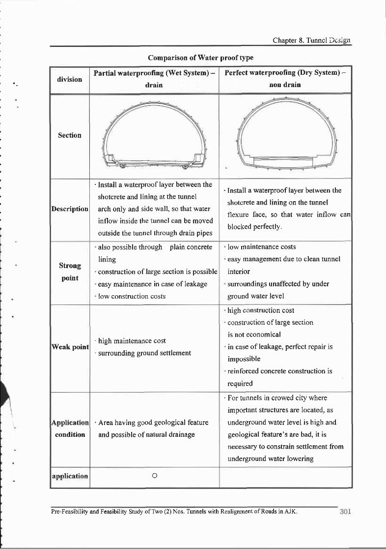
Chapter 8. Tunnel Design
Comparison of Water proof type
divisionPartial waterproofing (Wet System) -
drain
Perfect waterprooling (Dry System) -
non drain
Section
Description
' Install a waterproof layer between the
shotcrete and lining at the tunnel
arch only and side wall, so that water
inflow inside the tunnel can be moved
outside the tunnel through drain pipes
- Install a waterproof layer between the
shotcrete and lining on the tunnel
flexure face, so that water inflow can
blocked perfectly.
Strong
point
also possible through plain concrete
lining
construction of large section is possible
easy maintenance in case of leakage
low construction costs
low maintenance costs
easy management due to clean tunnel
interior
surroundings unaffected by under
ground water level
Weak point' high maintenance cost' surrounding ground settlement
high construction cost
construction of large section
is not economical
in case of leakage, perfect repair is
impossible
rein forced concrete construction is
required
Annlicefion ' Area having good geological feature
and possible of natural drainage
. For tunnels in crowed city where
important structures are located, as
underground water level is high and
geological feature's are bad, it is
necessary to constrain settlement from
underground water lowering
condition
annlicaiion o
Pre-Feasibility and Feasibility Study ofTwo (2) Nos. Tunnels with Realignment ofRoads in AJK.
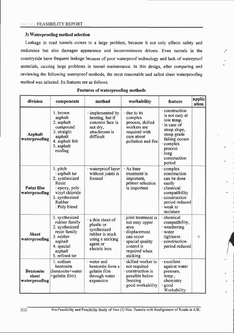
3) Waterprooling method selection
Leakage in road tunnels comes to a large problem, because it not only affects safety and
endurance but also damages appearance and inconveniences drivers. Even tunnels in the
countryside have frequent leakage because of poor waterproof technology and lack of waterproof
materials, causing large problems in tunnel maintenance. In this design, after comparing and
reviewing the following waterproof methods, the most reasonable and safest sheet waterproofing
method was selected. Its features are as follows.
Features of waterproofing methods
division components method workability feature application
Asphaltwaterproofing
I . brownasphalt
2. asphaltcompound
3. straightasphalt
4- asphalt felt5. asphaltroofing
' implemented byheating, but ifconcrete face isnot dry,aftachment isdifficult
' due to itscomplexprocess, skilledworkers arerequired withcare aboutpollution and fire
constructionis not easy atlow temp.in case ofsteep slope,steep gradefalling occurscomplexprocesslongconstructionperiod
Paint filmwaterprooling
I . pitch: asphalt tar
2. synthesizedResin: epoxy, polyvinyl chloride
3. synthesizedRubber: Poly blend
' waterproof layerwithout joints isformed
' As basetreatment isimportant,primer selectionis important
complexconstructioncan be doneeasilychemicalcompatibilityconstructionperiod reducedweak tomoisture
Sheetwaterprooling
I . synthesizedrubber family
2. synthesizedresin family
3. rubberasphalt
4. specialasphalt
5. refined tar
' a thin sheet ofplastic orsynthesizedrubber is stuckusing a stickingagent orelectric iron
joint treatment isnot easy upperareadisplacementcan occurspecial qualitycontrol isrequired whensticking
chemicalcompatibility,weatheringwatertightnessconstructionperiod reduced
o
Bentonitesheet
waterproofing
1 . sodiumbentonite
(bentonitelwater=gelatin film)
' water andbentonite form agelatin filmthrough waterexpanslon
skilled worker isnot requiredconstruction ispossible belowfreezinggood workability
'excel lentagainst waterpressure,temp.,chemistry
' goodWorkability
Pre-Feasibility and Feasibility Study ofTwo (2) Nos. Tunnels with Realignment ofRoads in AJK,

Chapter 8. Tq44g!q9!iC';
Also, as a waterproof material, the reasonable and safe ethylene acetate resin family sheet
waterproofing method was selected.
Waterproofi ng sheet materia.
division Vinyl chloride resin family Ethylene acetate resin family
thickness Over 2.0mm Over 2.0mm
Tensile strength
(untreated,20t)Over 10.2 MPa Over 12.8 MPa
Elongation rate when ruptured
(untreated, 20 C)Over 350% Over 500%
Tearing strength
(untreated, 20 t)Over 4.0E MPa 4.08 MPa
Expansion quantity when
Heated
expansion under 2mm
shrinkage under 4mm
expansion under 2mm
shrinkage under 4mm
Tensile
[unction
after
aging
tensile
strength
ratio
Heat
treatment80-150% 80*t50%
Alkali
treatment80-120% 80-t?0%
Rlnnolf inn
Heat
treetmenfOver 70o/o Over 70o/o
ratio Alkali
treatmentOver 90/o Over 80%
Connected shapeDisagreement from standard line and spalling length should be
under 5mm with no irresularities
Pre-Feasibility and Feasibility Study ofTrvo (2) Nos. Tunnels with Realignment ofRoads in AJK.

I FEASIBILITY REPORT
E.E.2 Waterproofing of open cut tunnel
1) Purpose
Tunnel portal has a structure that can be exposed to external temperature changes or weathering
easily. If water penetrates from outside, lining damage by underground water freezing, icicles, and
freezing on the road face can disturb safe driving. Waterproofing performed to protect facilities
and increase utility value by preventing water penetration.
2) Waterprooling types and features
Waterproofing types and features in open cut tunnel are as follows. In this design, sheet
waterproofing with a low construction cost, high safety and much experience, was selected
(
Trench tunnel waterproofing types and features
division Sheet waterproofing Paint film waterproofing Bentonite
shape' waterproofing sheet
I layer
' waterproofing by liquid
state penetration
' gelatin film(bentonite + water)
Constructionmethod
' thin sheet ofplastic or
synthesized rubber isstuck using a stickingagent or electric iron
' by coating pitch or
urethane family.
' after injecting bentonite
between panels, stick to
structure using concretegel
Workability
. uneasy joint treatmentupper portion
' displacement can occur
' base treatment of
outside is important
' skilled worker is not
required' construction is possible
below freezing
features
chemical compatibility,weathering
watertight, stable to
temperature changes
uneven treatment isrequiredconstruction period isreducedlow construction costsused frequently
easy workability,
construction time is
reduced
chemical compatibility
ifcracks occur in
structure, cracks are
transferred to
waterproofi ng material,high construction costs
excellent against waterpressure, temperature.,chemistrygood workability
if water is contactedduring construction,effect of waterproofingdisappears.high construction costs
suggest o
304 Pre-Feasibility and Feasibility Study ofTwo (2) Nos. Tunnels with Realignment ofRoads in AJK.
Chapter 8. Tunnel Desigc
3) Waterproofing layer protector
A waterproofing layer protector is installed on the outside ofthe waterproofing material to make
the existing waterproof layer perform its original function properly, with the purpose ofpreventing
damage to the watorproofing material, followed by construction such as refilling, dismantling the
temporary structure, etc.. Polyethylene foam insulator (T:30nm) is used as a protector, with the
following characteristics.
. easy handling and transfer as it is light.
" easy workability (sticking is simple and easy as protector's upper face is treated with agent)
. hardening is unnecessary and work is possible in small spaces.
. easy qtrality control by using existing product
. better protection ofwaterproofing material due to excellent impact absorption
. can be torn by sharp stones or devices and sticking is difficult if there is moisture on the
surface ofthe waterproof layer.
. low construction costs
E.E.3 Drainage during operation
In tunnels, drainage is one ofthe most important features in terms of safety and endurance. It is
classified into \ aterproof tunnels like subways with installed invert, and drain tunnels with
drainage facilities. For mountain tunnels, the drainage tunnel is used to reduce water pressure and
excavated section areas. Project tunnel is a mountain tunnel and partially waterproof is selected.
Water inflow through shotcrete should drain smoothly, so water pressure cannot react with the
structure, Polluted water from washins and water at the lower face should also be treated.
1) Tunnel drainage types
A) Surface drainage
To treat surface water inside of the tunnel and surface moisture: treatment through a drainage
ditch after mixing with underground water, and treatment through a separate passage after
separation from underground water.
B) Back space drainage
To treat water from the back of the waterproof sheet with great effect on tunnel structure.
Longitudinally perforated drainage pipe is installed and connected to the drainage ditch at proper
intervals to be finally treated through the drainage ditch.
Pre-Feasibili| and Feasibility Study ofTwo (2) Nos. Tunnels with Realignment ofRoads in AJK. 305
FEASIBILITY REPORT
C) Bottom drainage
The drainage hole of underground water is for utility water from the lower portion ofthe tunnel
floor. Installed at center throughout the length ofthe tunnel, so that water undemeath the road bed
can be drained smooth ly.
2) Drainage method
Drainage hole planning is determined after considering the condition ofthe location, amount of
water, longitudinal grade, etc. Details ofdrainage for this tunnel are as follows.
(l) water generated during drilling and construction, should be drained at once using temporary
drainage pipes before shotcrete is placed.
(2) water that flows out from the non-woven fabric installed between shotcrete face and concrete
lining is collected by high-density polyethylene perforated drainage pipe (0100) installed
longitudinally on both sides.
(3) leaking water collected by the high-density polyethylene perforated drainage pipe is drained
into the drainage ditch (spiral seam duct, 0300) separately through P.V.C piping (9100) installed
every C.T.C 10.0m.
(4) water that floods the lower part is drained through the perforated drainage pipe(0400)
installed alons the center.
(5) for waste water flowing into the utility tunnel, the drain pipe (P.V.C Pipe. Q50,
CTC=|0.0m), through which water travels to the drainage ditch, is connected to the drainage ditch
(spiral seam duct, Q300).
(6) the side wall (lower portion) drainage method was selected for drainage in this project- But,
after considering natural conditions, frost penetration depth, water quantity, etc., thorough
construction should be implemented to prevent freezing damage in the winter, which comes from
stagnant water from geological features (soft rock and more) and unevenness during construction.
306 Pre-Feasibility and Feasibility Study ofTwo (2) Nos. Tunnels with Realignment ofRoads in AJK.

Chuplglt TullgLqqtE"
8.8.4 Drainage during construction
l) Drainage during construction
Tunnel excavation is usually implemented below the underground water level, so underground
water may flow into the tunnel during excavation., It is therefore essential that dry working
conditions be maintained and drainage should be implemented during construction.
(1) Treatment ofwater on the tunnel face
'Weep holes should be installed when underground water flows suddenly. They should be over
25mm diameter, l-2 depth from tunnel face, frontal and radial.
' water spilled when making weep holes or horizontal drilling investigations should be
funneled to a temporary ditch through a flexible pipe.
' radial weep holes should be installed to drain water from the excavated face where the l"'
shotcrete is placed.
(2) Drainage after shotcrete sealing
. when water exists in some areas and is not excessive: Dl20_100 mm pipe is installed on the
shotcrete wall face.
when water is excessive: a protector is attached to the shotcrete wall face for drainage
when the underground water outflow location is apparent: a bundle of pipes or non-woven
fabric is installed to collect and drain area before placing shotcrete.
' when invert shotcrete is necessary: drain using small scale perforated drain pipe
Front View Ctoss Section
Seal'noShotcr€re
Drainage using pipe
Front View Cross Secl ion
Drainage using half divided pipe
Pre-Feasibility and Feasibility Study ofTwo (2) Nos. Tunnels with Realignment ofRoads h AJK.

2) Collection and drainage system during excavation
At most construction sites, drainage is not implemented properly. In particular, if underground
water is neglected and stagnates during excavation at the downward slope, the base ground will
soften. Equipment operation causes ground softening, so ground strength will rapidly decrease. As
a result, the shotcrete lining will settled with the shotcrete base portion softening and subsequent
ground settlement will occur. Therefore, proper drainage measures during construction are very
important and should be maintained until the final drainage system is operational,
The tunnel face is an area where thorough drainage is required, because most utility water is
used there. The tunnel face location changes as excavation progresses, so an underwater pump that
can be easily carried and used at the wall where water is collected is prepared.
- for upward slope excavation
After being drained to a sand basin at the tunnel entrance using both left and right ditches, it
receives treatment.
ary Di tch
- for downward slope excavation
A collected water well drainage method where water flowing into an underground tunnel and
utility water from excavation equipment is collected and pumped, was planned. The required drain
pump head increases as work progresses, so that wells and pumps are installed for relay-drainage
about every 400m.
Drain Pipe
308 Pr€-Feasibility and Feasibility Study ofTwo (2) Nos. Tunnels with Realignment of Roads in AJK.
8.9 Concrete lining and open cut tunnel
8.9.1 Introduction
In NATM tunnel design, initial stress is supported first with shotcrete (rock-bolt) and the inner
lining is designed to take on many roles such as strain management, improvement ofdurability and
support, and waterproofing sheet protection. Inner lining stability inspection must determine and
interpret load according to geological conditions, form ofwaterproofing and drainage, tunnel depth
and tunnel scale. The determined load must be accounted for in view of variables caused by any
lining construction errors.
For a drainage(wet system) tunnel, the first supports generally regarded as permanent, so the
first support must retain all ground loads. The lining is designed as a structure which does not
receive external forces except its own weight in draining groundwater.
Although it is a drainage tunnel, water pressure can still have an effect on the lining through
ground conditions, ground water source and drainage system capability. Furthermore, cases where
the load carrying capacity of the first suppon declines or where main tunnel shotcrete ground
loses its ability to support, should be carefully considered are being reported more frequently.
Although there are differing views, whether concrete lining plays a role in tunnel structure or not,
the resolution ofthis issue is decided by the behavior ofthe ground and first support. The drainage
type tunnel concrete lining is designed only to support its own weight because all tunnels will be
stabilized by the first support
It should be considered that the durability of the 1" supporl can decreased for a variety of
reasons such as quality during construction, surroundings, etc. and load sustained by the l" support
finally spreads to the lining if the ground bearing capacity decreases. Through verification, a
practical lining method should be established. Lining is an important element in the tunnel
structure and must stand loads such as earth and water pressure over the long term without causing
cracks, deformation or failure. It must also have properties such as water tightness and surface
inegularity as well as durabilily, to maintain necessary space and function as a tunnel. The lining
has the following role in particular during NATM excavation.
Pre-Feasibility and Feasibility Study ofTwo (2) Nos. Tunnels with Realignment ofRoads in AJK. 309
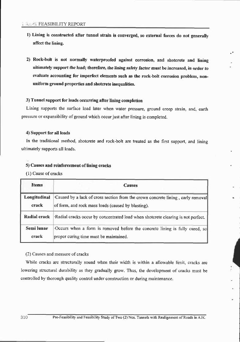
. T, . - . FEASIBILITY REPORT
1) Lining is constructed after tunnel strain is converged, so external forces do not generally
affect the lining.
2) Rock-bolt is not normally waterproofed against corrosion, and shotcrete and lining
ultimately support the load; thereforg the lining safety factor must be increased, in order to
evaluate accounting for imperfect elements such as the rock-bolt corrosion problem, non-
uniforrn ground properties and shotcrete inequalities,
3) Tunnel support for loads occurring after lining completion
Lining supports the surface load later when water pressure, ground creep strain, and, earth
pressure or expansibility ofground which occurjust after lining is completed.
4) Support for all loads
In the traditional method, shotcrete and rock-bolt are treated as the first support, and lining
ultimately supports all loads.
5) Causes and reinforcement of lining cracks
( I ) Cause of cracks
Items Causes
Longitudinal
crack
'Caused by a lack ofcross section from the crown concrete lining, early removal
of form, and rock mass loads (caused by blasting).
Radial crack 'Radial cracks occur by concentrated load when shotcrete clearing is not perfect.
Semi lunar
crack
'Occurs when a form is removed before the concrete lining is fully cured, sc
proper curing time must be maintained.
(2) Causes and measure of cracks
While cracks are structurally sound when their width is within a allowable limit, cracks are
lowering structural durability as they gradually grow. Thus, the development of cracks must be
controlled by thorough quality control under construction or during maintenance.
310 PreFeasibility and Feasibility Study of Two (2) Nos. Tunnels with Realignment of Roads in AJK.

Chaptel J.Tu449LD9t€q
Items Cause Measure
crack thatoccursunder
construction
' lack ofcross section area from thecrown concrete lining
' inject cement milk at the posterior byinstalling a grouting hole
"early form removal' maintain concrete strength by securingthe proper curing time
' increase in rock mass load caused byover blasting
' minimize there relaxation region bycontrolled blasting
' stress concentration phenomenoncaused by lack of shotcrete clearing
' disperse concentrated loads bycarrying out shotcrete clearing
Settlement caused when impurities inthe tunnel ground foundation are notcleaned
'Maintaining of clean ground duringinvert concrete installation
' lack of fixing facilities duringform moving
' install after concrete lining is properlycured
crack thatoccursduring
' crack caused by temperaturedifferences
' longitudinal : install an expansion joint' traverse : steel reinforcement
' increase in rear water pressure causedby weakened water drain and drainagepipe
' Establish measures depending on crackcause by installing piezometer andstress cell
' lack of lateral bearingcapacity of foundation ofthe tunnel
' Increase foundation size and changedrainage pipe location.
8.9.2 Decision of placement time and thickness
The best time for placement is when displacement is converged. Generally displacement is
converged l-3 months after shotcrete is placed. However, placing must be carried out affer
examining the results through monitoring and determining whether to converge it or not as it is
possible that over I year is required for expansible ground,
Because placing thickness is determined after displacement is converged, examination of
allowable stress determines whether or not steel has to be reinforced.
Pre-Feasibility and Feasibility Study ofTrvo (2) Nos, Tunnels vith Realignment ofRoads in AJK.

' . FEASIBILITYREPORT
8,9,3 Main tunnel design criteria
l) Introduction
Structure examination consists of lining structure analysis and stress examination, and the
necessary amount of reinforcement is calculated with the strenglh design method.
2) Materials used
(l) Concrete: design compressive strength (fck) > 24MPa
(2) Steel: SD30.
3) Design load
The load and the ground properties around the tunnel can be classified by tunnel support
pattems.
X B: Tunnel width, Ht: Tunnel height
(1) Dead load: When a dead load is calculated, depending on the thickness ofthe inside lining
concrete, the unit weight of plain concrete is 23.5kN/m3, and the unit weight of steel concrete is
25.0 kN/m'
(2) Blasting and rock mass relaxation load: the area damaged (0.5m) by blasting, classified by
tunnel support pattem and Terzaghi modified rock mass load are treated as the relaxation loac.
l- !Tf!!'
(3) Water pressure: 5'"ry-MPa, 7^^^'o*MPa on tunnel upper portion of each tunnel support
paftern. It is assumed that the pressure decreases to 0 at the tunnel base.
4) Design application
Examining the stress effect on the concrete lining using an allowable stress design reveals that
tunnel support pattern ECL-5 is stable as a self supporting, and the lining stability was secured by
steel reinforoement at the tunnel support pattern ECL-6.
tunnelsupportpattern
rock mass loadResidual water pressure
(MPa)
ECLI^.5 P-0.2). (B + H r)xT r P" ,= f rHr rs*
ECL-6 p:0.{^ 0.6},(B + H r)xv I F" ,= f rHr ry*
P6-la P:0.?x (B + H r)xv r P " , : { r H , r s *
Pre-Feasibility and Feasibility Study ofTwo (2) Nos. Tunnels with Realignment of Roads in AJK.
Chapter 8. Tunnel \sign
8.9.4 Open cut tunnel(portal) sections design criteria
.- 1) Introduction
. In structure calculations for open cut tunnel, a two-dimensional analysis was performed taking-
into consideration of the ground conditions, the weight ofthe open cut tunnel, the earth pressure
depending on backfill, overburden height and the temperature load, using a two-dimensional beam
element.
2) Materials used
(l) Concrete: design compressive strength (fok) Z 24MPa
(2) Steel: SD30
3) Load
(l) Dead load: When dead load is calculated depending on the concrete lining thickness, the
plain concrete unit weight is 23.5kN/m3, and the reinforced concrete unit weight is 25.0 kN/m3
(2) Backfill, overburden height: applied by dividing it into vertical earth pressure and lateral
earth pressure.
3) Temperature and shrinkage load: differences in temperature between interior and exterior
(r5.C), the temperature load (consider -15 'C (o=l.0xl0-5)) were considered.
4) Design application
Examining stress effects on concrete lining in open cut tunnel using an allowable stress design
reveals that stability was not secured with the concrete strength alone, so lining stability was
secured by steel reinforcement concrete.
Pre-Feasibitity and Feasibility Study ofTwo (2) Nos. Tunnels with Realignment of Roads in AJK. 313
FEASIBILITY REPORT
E.9.5 Lining construction
1) Form construction
A) In a form structure, amount of concrete placed, placement length and placement speed must
be considered each time with the form structure
B) Form must be designed and produced to have good mobility, access shaft should be installed
in order to check the concrete placement conditions.
C) Form must not exceed I 5m in length for constructability and stability.
D) When removing form, measures must be taken.
E) Form must not be removed until the concrete crown strength can stand a load, and it must be
removed after concrete compressive strength is revealed to be over 3 MPa.
F) Form track must move the form stably, and be installed solidly so as to prevent settlement
when placing or moving concrete.
2) Concrete placement
A) Lining concrete placement should be performed after ground displacement is converged, and
whether or not displacement is converged must be determined by analysis of monitored data.
Placement time must be determined on the basis of displacement quantity and speed when concrete
lining is constructed ifexpansible ground displacement is not perfectly converged.
B) When placing concrete, material must be loaded equally, so segregation and voids do not
occur.
C) First division fixed concrete must be placed continually to prevent cracks due to shrinkage.
Placement speed must be maintained to prevent material segregation.
D) Concrete placement must have bilateral symmetry to prevent reduction in form pressure, and
be tamped in some method such as a vibrator.
3) Expansion joinb
A) Expansion joints must be constructed at intervals of 20-30m within 50m ofthe tunnel entry
and exit, and at intervals of 20-60m inside the tunnel. Additional expansion joints can be
constructed at the changing sections, sudden stratum change sections, steel and plain concrete
junctions and so on.
B) Sealant must be applied after spreading primer paste.
3 1 4 Pre-Feasibility and Feasibility Study ofTwo (2) Nos. Tunnels with Realignment ofRoads in AJK.

Chapter 8. Tunnel L-sign
4) Quality control
A) 24 MPa is the standard concrete strength, and high-strength concrete can be used if high-
strenglh is required.
B) Average concrete lining thickness must exceed design thickness, with approved errors within
a 1Ocm or I/3 range ofthe design thickness for specific areas.
C) Concrete lining strenglh ofthe 28 days must exceed design strength. Ifnot up to standards on
first examination, a reexamination is made within a 5m range to the left and right of the exam
location. lfthose results are not up to the required strength, they must be modified, supplemented
or reconstructed.
Concrete lining quality control
ItemsManagement
check points
Management contents and
examinationExam frequency
Daily
management
Degree of
construction
precision
Location ofsteel and form
construction conditions
Each time when a form is
installed
Thickness Thickness manasementEach time when a form is
installed
Cracks, strainsCrack and strain conditions after
placementFrequently after placemenl
Regular
management
Slump value Slump valueBased on quality test
standards
compressive
strength testcompressive stength
Based on quality test
standards
Pre-Feasibility and Feasibility study ofrwo (2) Nos. Tunnels with Realignment ofRoads in AJK.

-. . FEASIBILITY REPORT
8.10 Portal design
E.l0.l Introduction
The portal area, where rock often becomes weathered or joints develop has the thinnest
overburden of all tunnel sections and is easily affected by surface water. Load acts as eccentric
pressure depending on the geographical features. Relaxed ground may occur due to portal
excavation, therefore portal is determined after considering geographical features, ground
conditions, weather conditions, the environment, traffic, maintenance convenience, and so on,
before the tunnel poftal is designed.
. Stability: The tunnel portal must stabilize a slope losing balance because ofportal access, and
be designed safe from earth pressure, falling stones and other concerns.
. Workability: Construction must be easy as the tunnel portal is closely related to tunnel
portal area.
. Scenery: A design that relieves drivers offeelings ofpressure and resistance is preferable for a
road tunnel portal- Also, a design with a reduced concave surface is preferable as very concave
surfaces enlarge outside luminance affecting the mood ofthe lighting.
. Weather conditions: Portal must be designed to withstand or prevent meteorological disasters
such as landslides, abnormal water ingression and so on. In snowy areas, it is necessary to consider
whether the inflow and freezing ofsnow is high or low and if snow-removal is easy or difficult.
Safe and smooth traffic flow on highways should be maintained and natural damage minimized,
and the tunnel portal in particular should protect the road safely from falling rocks, avalanche and
landslide during thawing and localized torrential downpours.
J 1 0 Pre-Feasibility and Feasibility Study ofTwo (2) Nos. Tunnels with Realignment ofRoads in AJK.

E.10.2 Portal Area,s problem
" Excess cutting of the upper portion of a portalnatural damage because of a tendency to focusconstruction
Ieads to poor traffic safety and extensive
on econornical efficiency in design and
" covering a open cut tunner, reads to poor compaction ofthe backfi'ed section ofportar (loadon concrete lining, cause ofsliding during rainy season)
" The berr rnouth poftal and a backfi, side wafl portion read to weakness regarding flood rerateddisasters
" A wall type portal leads to oppression at the entryway, and is inadequate for smooth entrv.
E.10.3 Design criteria
l) Determining portal location
" It is preferabre that a portar shourd not cross a vatey waterway, center rine of road orgeographically steep surface which crosses at dght angles.
. Road alignment allowing a crossing angle exceeding 60" is preferable2) Determining portal form' Fast and slow motion in geographically steep surfaces at the upper portion ofa portal is the
main factor in design such as drainage around the porlar, possibirity of faring rocks or randsrides,and harmony with nature.
. Examine portal based on geographical conditions3) Minimize cutting area
" to compry with enviro-poritics, which have become stricter, and to secure safety on the slopesof a portar' the en*ance was standardized and designed to be formed where 3-5 m, of the upperportion ofthe portal cover is secured.
" If forming a portal within 5m of ground surface because soi.r conditions at the portar aredifficult, the design depends on the results ofspeciar examination.
=----pre_Feasibitity an rl7
-
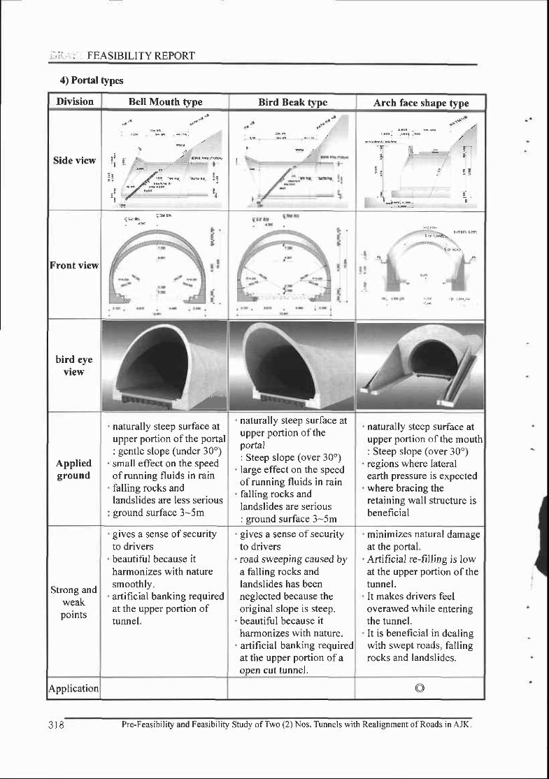
..;: : FEASIBILITYREPORT
4) Portal types
Division Bell Mouth type Bird Beak type Arch face shape t;ipe
Side view
Front view
bird eyeview
-a
Appliedground
naturally steep surface atupper portion ofthe portal: gentle slope (under 30')small effect on the speedof running fluids in rainfalling rocks andlandslides are less seriousground surface 3-5m
naturally steep surface atupper portion oftheportal: Steep slope (over 30')large effect on the speedof running fluids in rainfalling rocks andlandslides are serious: ground surface 3-5m
naturally steep surface atupper portion ofthe mouth: Steep slope (over 30")regions where lateralearth pressure is expectedwhere bracing theretaining wall structure isbeneficial
Strong andweakpolnts
gives a sense of securityto driversbeautiful because itharmonizes with naturesmoothly.artificial banking requiredat the upper portion oftunnel.
gives a sense of securityto driversroad sweeping caused bya falling rocks andlandslides has beenneglected because theoriginal slope is steep.beautiful because itharmonizes with nature.artificial banking requiredat the upper portion ofaopen cut tunnel.
minimizes natural damageat the portal.Aftificial re-filling is lowat the upper portion ofthetunnel.It makes drivers leeloverawed while enteringthe tunnel.It is beneficial in dealingwith swept roads, fallingrocks and landslides.
Application o
3r8 Pre-Feasibil i ty and Feasibil i ty Study ofTwo (2) Nos. Tunnels with Realignment ofRoads in AJK.
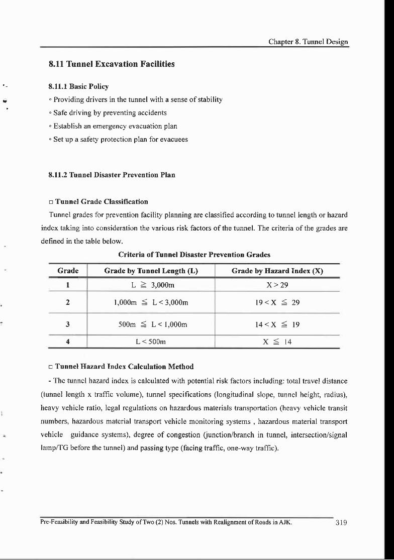
Chapter 8. Tunnel Design
E.11 Tunnel Excavation Facilities
'- 8.Il.l Basic Policy
t " Providing drivers in the tunnel with a sense ofstability
Safe driving by preventing accidents
. Establish an emergency evacuation plan
. Set up a safety protection plan for evacuees
E.ll,2 Tunnel Disaster Prevention Plan
n Tunnel Crade Classification
Tunnel grades for prevention facility planning are classified according to tunnel length or hazard
index taking into consideration the various risk factors of the tunnel. The criteria of the grades are
defined in the table below.
Criteria ofTunnel Disaster Prevention Grades
9.'9:I
Grade by Tunnel Length (L) Grade by Hazard Index (X)
L > 3,000m x>29
2 1,000m S L < 3,000m 19<x < 29
500m S L < 1,000m l4<x < l 9
4 L < 500m x<14
a Tunnel Ilazard Index Calculation Method
- The tunnel hazard index is calculated with potential risk factors including: total travel distance
(tunnel length x traffic volume), tunnel specifications (longitudinal slope, tunnel height, radius),
heavy vehicle ratio, legal regulations on hazardous materials transportation (heavy vehicle transit
numbers, hazardous material transport vehicle monitoring systems, hazardous material transport
vehicle guidance systems), degree of congestion (unction/branch in tunnel, intersection/signal
lamp/TG before the tunnel) and passing type (facing traffic, one-way traffic).
Pre-Feasibility and Feasibitity Study ofTwo (2) Nos. Tunnels with Realignment ofRoads in AJK. 319

.FEASIBILITY REPORT
o The methods of calculating h""ard factor indexes are as follows:
@ For hazard index-based grading for facing traffic, the hazard index shall be calculated
separately for tunnel tubes, with the higher index employed for tunnel grading.
@ The total travel distance as a product of traflic volume and tunnel length shall be based on
daily traffic volume per tube, averaged on a yearly basis as expected in the target year (20 years
after tunnel completion).
@ The elevation difference that comprises the clearance between the entrance/exit elevation
and the lowest point of the tunnel is calculated as the total sum of the product of the sectional
gradient and length ofthe tunnel.
@ The slope ofthe approaching section is calculated by the distance weighted average for the
1,000m before the tunnel.
@ The tunnel height is the distance between the road bed and the highest point of the tunnel.
@ The ratio of heavy vehicles shall be the value applied to road design.
@ For calculation oftotal travel distance, heavy vehicles refers to medium trucks, Iarge trucks,
and special trucks. The total heavy vehicle travel distance is the product of the number of daily
heavy vehicle passes per tube averaged on a yearly basis with tunnel length.
@ Monitoring and guidance systems for vehicles carrying hazardous materials are systems
which control the passage of hazardous materials or systems where a vehicle carrying hazardous
material passes under a convoy.
@ Intersection/signal lamps in tle tunnel approach are those within 1,000m ahead ofthe tunnel.
@ Onty road shoulders whose width is 2.0m or wider will be taken into consideration.
O Onty median strips whose width is l.0m or wider and secures safety equivalent to or better
than a double guardrail will be taken into consideration.
o Grade, based on the hazard index, shall be applied by shifting up or down in comparison
with grade based on length, as follows:
O Grade by hazard index can be shifted up or down one level from grade based on length.
@ Shifting up/down in paragraph O above shall be applied to tunnels longer than 500m
(grade 3 or higher by length-based grade).
@ For tunnels whose grades are evaluated to be 2nd or above on a length-basis and 3'o or below
on a hazard index basis, quantitative hazard evaluation can be conducted and grade adjusted
accordins to reevaluation results-
320 Pre-Feasibility and F€asibility Study ofTwo (2) Nos. Tunnels with Realignment ofRoads in AJK.

Tirnnel Ilazard Evaluation Criteria
Evaluation Item Range Hazard Index
Probability of
Accident
Total Travel Distance(TrafficVolumex Length)
(Veh . km/tube. day)
8,000 or less t - f
8,000 or over -16,000 orless
2.J
16,000 or over -32,000 orless 5.0
32,000 or over -64,000 orless
7.5
64,000 or over 10.0
Tunnellharaclristics
ElevationDifference and
Slope
ElevationDifference
between Entryand Exit (m)
l0 or less 0.5
10 or more -20 or less 1 .0
20 or more -30 or less 1 .5
30 or more 2.0
Slope ofApproach (%)
3.0 or less 0.5
3.0 or more 1 .0
Tunnel Height (m)
7.5 or more t .0
5.0 or more -7.5 or less 2.0
5.0 or less 3.0
Tunnel Radius (m)1,800m or more u.)
1,800m or less t .0
IIeavyVehicles
Hazardous MaterialTransportation
Ratio of HeavyVehicles
(%)
l0 or less 0.5
l0 or more - 17.5 or less 1.0
17.5 or more -25 or less 1 .5
25 or more 2.0
Total HeavyVehicle Travel
Distance(vehicle-
.km/tube-day)
500 or less 0.5
500 or more -1,000 or less I
I,000 or more -2,500 or less 2
2.500 or more -5.000 or less 4
5,000 or more 6
MonitoringSystem
Yes 0
No I
GuidanceSystem
Yes 0
No I
Pre-Feasibility and Feasibility Study ofTwo (2) Nos. Tunnels with Realignment ofRoads in AJK.
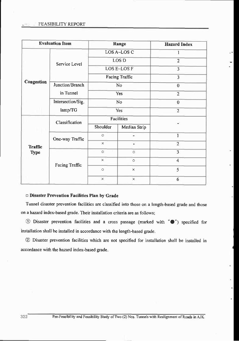
. FEASIBILITY REPORT
Evaluation Item Range Hazard Index
Congestion
Service Level
LOS A-LOS C I
LOS D 2
LOS E-LOS F 5
Facine Traffic )
Junction/Branch
in Tunnel
No 0
Yes 2
Intersection/Sig.
lamp/TG
No 0
Yes 2
TralficTlpe
ClassificationFacilities
Shoulder Median Strip
One-way Traffico I
2
Facing Traftic
o o J
o
o K )
X 6
tr Disaster Prevention Facilities Plan by Grade
Tunnel disaster prevention facilities are classified into those on a lengh-based grade and those
on a hazard index-based grade. Their installation criteria are as follows;
O Disaster prevention facilities and a cross passage (marked with "O") specified for
installation shall be installed in accordance with the length-based grade.
@ Disaster prevention facilities which are not specified for installation shall be installed in
accordance with th e hazard index-based grade.
322 Pre-Feasibility and Feasibility Study ofTWo (2) Nos. Tunnels with Realignment of Roads in AJK.
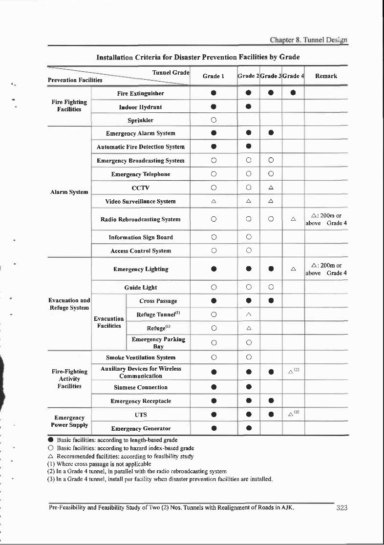
Installation Criteria for Disaster Prevention Facilities by Grade
Tunnel Grad(Preveotion Facilities
Grade 1 Grade 2 Grade 3 Grade 4 Remark
Fire FightingFacilities
Fire Exxinguisher a a a aIndoor Hydrant a I
Sprinkler o
Alarm System
Emergency Alarm System a a oAutomatic Fire Detection System a aEm€rgency Broadcastitrg System o o o
Emergency Telephone o o occTv o o A
Vid€o Surveillalce System A A. A
Radio Rebroadcasting System o o o AA: 200m or
above Grade 4
Information Sign Board o oAccess Cotrtrol System o o
Evacuation andRefuge System
Emergency Lighting a a a ,AA: 200m or,ove Grade 4
Guide Light o o o
EvacuatlotrFacilities
Cross Passage a O aRefuge Tirnnel{r) o A
Refuge{r) o A
Emergency ParkingBry o o
Fire-FightingActivityFacilities
Smoke Ventilrtion Systcm o oAuxiliary Devices for Wireless
CommuDicationa a a at2)
Siamese Connectio|| o aEmergency Receptacle o a a
EmergencyPower Suppbt
UTS a a a a(3)
Emergetrcy GeDerator a oO Basic facilities: according to length-based grade
O Basic facilities: according to hazard index-based gradeA Recommended facilities: according to feasibility study(l) Where cross passage is not applicable(2) In a Grade 4 tunnel, in parallel with the radio rebroadcasting system(3) In a Grade 4 tunnel, install per facility when disaster prevention facilities are installed.
Pre-Feasibility and Feasibility Study ofTwo (2) Nos. Tunnels with Realignment ofRoads in AJK. 323

Facility Position and Method of Installation Intervals
Fire(tinguirSystem
Manual Extinsuisher
Cn€-way tmfnc tunnel: 3 or fewer car lanes.nstall on right side wall, for tunnels with 4rr more lanes on both side walls.Facing traffic tunnel: install on both side'valls crosswise. One set of 2 extinsuishersn each box.
Within 50m
Indoor Hydrant
One-way, 3 or fewer lanes: on right sidewall.
Facing, single lane: one per side wall.One-way & 4 or more lanes, and facing 2 or
more lanes each way: on both side walls
Within 50m
Sprinkler On side wall (uniform spray over the entireroad surface)
Spray area: 25m min.,3 areas at the same
time
AlarmSystem
Emergency Alarm System On manual fire extinguisher or indoorhydrant box Within 50m
Fire Detection System At optimal performance positionRequired detection
range by ventilationmethod
Emergency BroadcastingSystem
On the tunnel wall and refuge (refuge tunnel,emergency parking lot) Within 50m
Emergency Telephone
At the entrance and exit, on the tunnel walland refuge (refuge tunnel, emergency
parking lot)Wirhin 50m
CCTV On the tunnel wall (to enable monitoring ofentire refuge and tunnel length)
In tunnel: at 200 *
400m intervalsOut of tunnel; within
500mVideo Suweillance System Entire tunnel length must be monitored At l00m
Radio RebroadcastingSystem Entire tumel length must be covered
InformationSign Board
Entrance Within 500m ofthe entrance
AccessControl
Within 500m ofthe entrance
LaneControlSignal At 400 - 500m
, .r FEASIBILITY REPORT
o The positions and intervals for the tunnel disaster prevention facilities shall be as follows:
Positions and intervals for the tunnel disaster prevention facilities
- l
324 Pre-Feasibility and Feasibility Study ofTwo (2) Nos. Tunnels with Realignment of Roads in AJK.
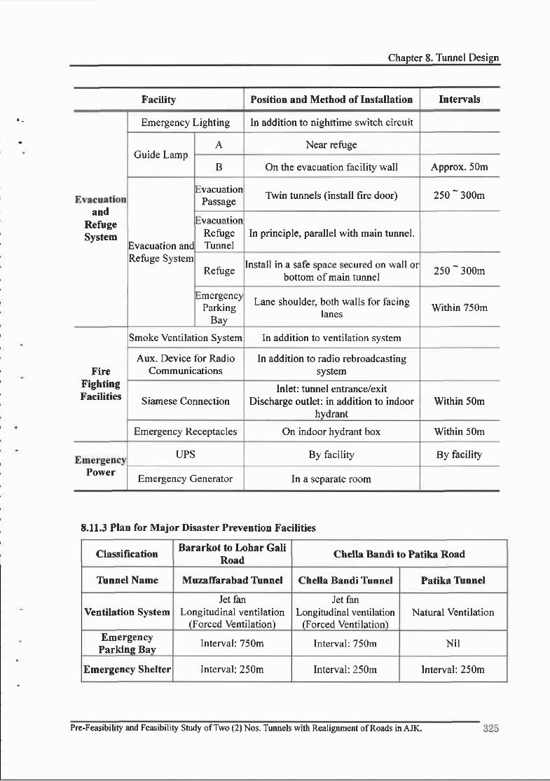
Chapter 8. Tunnel Design
Facility Position and Method of Installation Intervals
andRefugeSystem
Emergency Lighting In addition to nishttime switch circuit
Guide LampA Near refuge
B On the evacuation facility wall Approx.50m
Evacuation ancRefuge System
vacuationPassage
Twin tunnels (install fire door) 250 -
300m
vAcuation
In principle, parallel with main tunnel.RefugeTunnel
Refuge Install in a safe space secured on wall otbottom of main tunnel
250 -
300m
Lane shoulder, both walls for facinglanes
Within 750mParkingBav
FireFightingFacilities
Smoke Ventilation System In addition to ventilation system
Aux. Device for RadioCommunications
In addition to radio rebroadcastinssystem
Siamese ConnectionInlet : tunnel entrance/exit
Discharge outlet: in addition to indoorhydrant
Within 50m
Emergency Receptacles On indoor hydrant box Within 50m
Power
UPS By facitity By facllity
Emergency Generator ln a separate room
E.11.3 Plan for Major Disaster Prevention Facilities
ClassificationBararkot to Lohar Gali
Road Chella Bandi to Patika Road
Tunnel Name Muzaffarabad Tunnel Chella Bandi Tunnel Patika Tunnel
Ventilation SystemJet fan
Longitudinal ventilation(Forced Ventilation)
Jet fanLongitudinal ventilation
(Forced Ventilation)Natural Ventilation
EmergencyParkinq Bay
Interval :750m Interval:750m Ni l
Emergency Shelter Interval:250m Interval:250m Interval:250m
Pre-Feasibility and Feasibility Study ofTwo (2) Nos. Tunnels with Realignmert ofRoads in AJK.

, -.
FEASIBILITYREPORT
8.12 Ventilation Plan
8.I2.1 Outline
Road tunnel ventilation methods can be broadly classified into dilution and ventilation. The
dilution method maintains tunnel air within allowable criteria by introducing fresh outside air to
dilute pollutants inside the tunnel, by estimating the required air change volume. The ventilation
method replaces polluted air in the tunnel with fresh outside air, using air flow driven by pressure
differences.
To calculate required fresh air volume, the pollutant generation rate must be estimated precisely.
Regulation of pollutant emissions varies by nation. In this project, the appropriate ventilation
system, disaster prevention system, and smoke ventilation system were planned to maintain the
tunnel environment within allowable criteria and secure the safety of passengers in case of tunnel
disasters such as a fire accident.
Major Tasks Activities
One-wav traffic tunnel. tunnel lensth
Survey & analysis oflong tunnel ventilationsystems.
Secure safety and allowable level ofpollutionin tunnel.
Secure reliability for normal ventilationEstimate pollutant generation in tunnel. Secure I performance.
safety and pleasant environment I Economic efliciency in construction and
Reentry ofpollutants through the portalInstall emergency evacuation tunnel-
Simulate & analyze the impact of pollutantreentry.
fl
326 Pre-Feasibility and Feasibility Study of Two (2) Nos. Tunnels with Realignment of Roads in AJK.
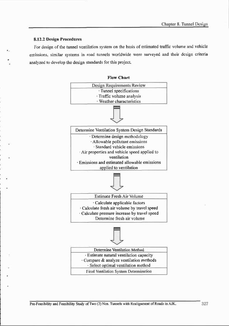
8.12.2 Design Procedures
For design ofthe tunnel ventilation system on the basls of estimated traffic volume and vehicle
emissions, similar systems in road tunnels worldwide were surveyed and their design criteria
analyzed to develop the design standards for this project.
Flow Chart
Review' Tunnel specifications
' Traffic volume analysis, Weather characteristics
Estimate Fresh Air Volume' Calculate applicable factors
. Calculate fresh air volume by travel speed' Calculate pressure increase by travel speed
Determine fresh air volume
Determine Ventilation Method. Estimate natural ventilation capacity
. Compare & analyze ventilation methods. Selecl ootimal ventilation method
Final Ventilation System Determination
Determine Ventilation System Design Standards' Determine design methodology' Allowable pollutant emissions
' Standard vehicle emissions. Air properties and vehicle speed applied to
ventilation. Emissions and estimated allowable emissions
to ventilation
Pre-Feasibility and Feasibility Study ofTwo (2) Nos. Tunnels with Realignment ofRoads in AJK.

FEASIBILITY REPORT
E.12.3 Ventilation System Classifications
Road tunnel ventilation systems are designed taking into consideration tunnel length, location,
climate, environment, disaster, accident prevention and rescue activities, etc. In this project, the
tunnel system was determined considering economic efficiency in addition to the above factors,
thorough survey and analyses.
Road TunnelVentilationSystems
NaturalVentilation
MechanicalVentilation
Longitudinalflow
Semi-traverse
Ventilation
TraverseVentilation
Others,combination
type
Jet Fan Type
Electric Precipitation
Ventilation through shaft
Electric Precipitation + Shaft
Semi-traverse Ventilation withfeed air
Semitraverse Ventilation withexhaust
NaturalYentilation
' Ifrequired fresh air can be supplied by the 'piston effect' ofvehiclespassing through tunnel.
'Generally, applicable to tunnels whose length is 1,000m or less.
MechanicalVentilation
' For long tunnels where natural ventilation is not sufficient.' Many types of systems can be considered according to road conditions,topography, area, traffic direction and volume, ease ofaccident preventionand rescue activity, and economic efficiency.
s28 Pre-Feasibility and Feasibility Study ofTwo (2) Nos. Tunnels with Realignment of Roads in AJK.

Chapter 8. Tunnel ! r-:ign
E.12.4 Comparison of Available Ventilation Systems
Methodology Schematic Diagram Features Selection
LongitudinalFlow Type
Jet Fan
Low initial inYestmentEasy installation and expansionEasy response to traffic volumeSmall€r tunnel cross sectionEfncient utilization of ventilationby traffic
o
Elec.Precipitator
Suitable when a large system isrequired due to high ratio ofheavy, diesel vehiclesEfficient utilizatioo of ventilationby trafficSuitable for downtown tunnelswhere outside environment mustbe consideredHigh initial investrnent due tounderground precipitation pit andDreciDitator svstem
Shaft
Efficient utilizarion of ventilationby trafficNot restriqted by tunnel lengthLandscape danage from shaftHigh initial investment inunderground ventilation room,shaft and laree blower
Semi-Traverse
Flow Type
Air SupplyType
Less impact from llatural windDucts require wider tunnel crosssectlonUniform distribution ofconcentration across lanesLarge, s€parate ventilation roomrequiredDelay in reverse rotation ofaxialfan under fire
AirExhaust
Type
Irtegular concentrationdistribution across lanes,lower efficiencyEnvironment at the mouths isgood, but poor at exhaust towerLarge, separate ventilation roomrequired
Traverse Flow Type
Uniform distribution ofconcentration across lanesHigh installation and operatingcost due to ducts and largeventilation equipmentSimple response to fireEmissions conceofiated atexhaust air tower
Pre-Feasibility and Feasibility Study ofTwo (2) Nos. Tunnels with Realignment ofRoads in AJK.
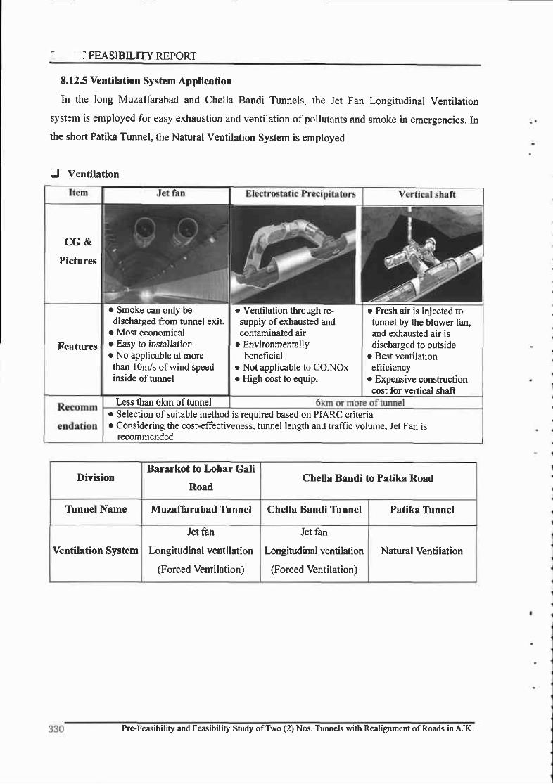
] FEASIBILITY REPORT
8.12.5 Ventilation System Application
In the long Muzaffarabad and Chella Bandi Tunnels, the Jet Fan Longitudinal Ventilation
system is employed for easy exhaustion and ventilation ofpollutants and smoke in emergencies. In
the short Patika Tunnel, the Natural Ventilation System is employed
O Ventilation
DivisionBararkot to Lohar Gali
RoadChella Bandi to Patika Road
Tirnnel Name Muzaffarabad Tlnnel Chella Bandi Tirnnel Patika Tunnel
Ventilation Svstem
Jet fan
Longitudinal ventilation
(Forced Ventilation)
Jet fan
l,ongitudinal ventilation
(Forced Ventilation)
Natural Ventilation
CG&
Pictures
Features
r Smoke can only bedischarged from onnel exit.
o Most economicalt Easy to instal lation. No applicable at morethan lOm./s of wind speedinside of tunnel
. Ventilation through re-supply ofexhausted andcontaminated air
t Environmentallybeneficial
o Not applicable ro co.Noxo High cost to equip.
o Fresh air is injected totunnel by the blower fan,and exhausted air isdischarged to outside
. Best ventilationefficiency
. ExpensiYe constructioncost for vertical shaft
Less than 6km oftunnelr Selection of suitable method is required based on PIARC criteriar Considering the cost-effectiveness, tunnel lenglh and traffic volume, Jet Fan is
recommended
Pre-Feasibility and Feasibility Study ofTwo (2) Nos. Tunnels with Realignment ofRoads in AJK-

Chapter 9.Bridge Design
Chapter 9. Bridge Design
9.1 Design Concept
. Easy access to village through improvingexisting road alignmenl
. Bridge conlorming to regional
detailed analysis. Preventron of serious damages
through seismic design
Safe Bridge
Dlanned bridges
Beautitul Bridge. Bddge type selection harmonizing
with sunounding landscape. Consideration of symbol and
for conslruclion. Selection ol bridge material easily
available at local area aEconomic Bridge
' Considering the accessibility oferection equipment and tansportation
problems of steel, Concrete is tumed out to be appropriate material for bddges.
' Two erection methods are adopted according to site condition.
One is cast-in-place method applicable to the site having restrictions for
carrying precast members. The other is crane erection method for the site
where the manufacturing shop can be easily built.
'The footing part of abutnent is designed in consideration ofbedrock slope, in
order to minimize the cutting of slope.
' Along the project road, 4 bridges are located from Chellabandi to Patika i.e.
Chellabandi bridge, Dunkakas bridge, Kahori bridge, and Challpani bridge.
These bridges were constructed in the reconstruction program (EEAP).
Therefore, a new bridge approaching the planned Challpani turnel is required
irrespective of reconstructed Challpani bridge.
Location Bridge No Bridge Type Length
Chellpani BR. I PSC Beam Bridge [email protected]:150.00m
Pre-Feasibility and Feasibility Study ofTwo (2) Nos. Tunnels with Realignment ofRoads in AJK. 331

FEASIBILITY REPORT
9.2 Bridge Design Process
. Surrounding lopography,
geological teature, environrnent. Road/traffic situation, land usage. Road cross-sectron and obstacle
Review on related master plan
. Expansion plan for new road
. Land usage plan for nearby location
. Various development plan
oata collection,field study
. Geological investigalion
. Obstacle survey
. Traftic, weather evaluation
Selection of optirnalbridge type
Construction circumstance evaluation
. Natural condition: topography,geological feature, etc
. Social condilion: civil petition,
environment conservation, land usage. Possibility of malerial storage al field. Needs for construclion road and bypass. Conskuction condition
. Durabil ity
. Economic leasibility
. Functionality
. Construciron feasibility
. Aeslhetics
. Mainlenance
. l\4aterial and type' Consideration on span length. Cross-section. Conskuchon method. Substructure and foundalion. Conslruclion cost and duration
332 Pre-Feasibility and Feasibi,ity Study ofTwo (2) Nos. TuDnels with Realignment ofRoads in AJK.
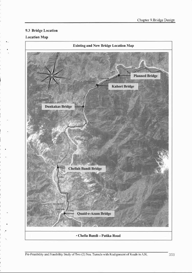
Chapter 9.Bridge Design
Existing and New Bridge Location Map
. Chella Bandi - Patika Road
9.3 Bridge Location
Location Map
II
I
I
I
I
I
I
I
I
I
Pre-Feasibility and Fcasibility Study ofTwo (2) Nos Tunnels with Realignment ofRoads inAJK 333

.FEASIBILITY REPORT
9.4 Design Criteria
9.4.1 Clearance of Bridge
'Road : 4.5m or more (if possible 4.7m or more)
.River : Clearance guarante€ on flooding
estimation
'Railroad : 7.01m or more
Typbaf Cnss Sectionof Bri[e
9.4.2 Usage Standard for Materials
lConcrete
'Standards ofcement concrete to be used for the
.Standard Specifications for Highway Bridges (AASHTO)
Clearance ofBridge Flooding estimation Clearance of Bridge
(m/s) (m)
200 or less 0.6 or more
200 - 500 0.8 or more
500 - 2,000
2,000 - s,000
5,000 - 10,000
| 0,000 or more
.Clearance : Height
bearing
I .0 or more
1.2 or more
1.5 or more
2.0 or more
between of H.W.L and
i
. lI
I
project are as shown in table.
P.C
Class 'A' 'SuDerstructure- Rahmen
Class 'B'
Class 'C'
Class'D'
40
50
24
2 l
l 5
.Substructure, Caisson, Sidewalk, Railing,
Footing, Approach slab, Culvert'Gravity walls, Mass concrete'Leveling, Fill, Lean concrete
I Reinforcing Bar
'Reinforcing bars will conform to AASHTO M3l (ASTM A 615) Grade 60. trz=3ggttu Ourt
will be used for the structure like abutment partially. It is permissible to use ry:500MPa bars. If
ductility or welding is required, bars will conform to ASTM A706M. The mechanical couplers
conforming to Article 5.5.3.4 of AASHTO LRFD Bridge Design Specifications will be used and
develop at least 125Vo ofthe specified yield strength ofthe bar.
Concrete
Strength (MPa)
Aggregates
Max. Size (mm)
Pre.Feasibility and Feasibility study ofTwo (2) Nos. Tunnels with Realignment ofRoads in AJK.

Chapter 9.Bridge Design
9.4.3 Design loads and load combinations
D Dead Load (DC,DW,EW)
The unit weight of material as used for design load purposes shall be as follows.
Material Unit Weight Msterial Unit Weight
Reinforced and pre-stressed
concrete (DC)24.5kN/m3 Asphalt paving (DW) 22.5kN/m3
Plain concrete (DC) 23.5kN/ml Structural steel (DC) 77.0kN/m3
E Vehicular Live Load (LL)
Vehicular live loading on the roadways of bridges or incidental structures, designated HL-93,
shall consist ofa combination ofthe: Desisn truck or lane load
aoomm Gcmrrlffi;iiilffie;ffl
Figure.l Characteristics of the Design Truck
E Earth Load (H : EV EH, ES,DD)
Earth pressure, earth surcharge and downdrag loads shall be considered in accordance with
AASHTO LRFD Bridge Design Specifications.
E wind Loads
The design base wind velocity is l0 minute average wind speed which is determined reasonably
considering wind speed historical of the project area, topography and environment around the
structure, height ofbridge superstructure and etc
E Earthquake Loads
Earthquake loads are given by the product of the elastic seismic response coefficient Csm and
the equivalent weight of the superstructure. The equivalent weight is a function of the actual
weight and bridge configuration and is automatically included in both the single-mode and
multimode methods
O-lgn La|t lam mm
Pre-Feasibility and Feasibility Study ofTwo (2) Nos. Tunnels with Realignment ofRoads in AJK. 335

. . FEASIBILITY REPOR]
tr Load Combinations and Load Factors
LOADCOMBINATION
IIMIT STATE
DC
DI)
Dll
EII
EV
ES
EL
LL
IM
CE
BR
PL
LS
WA WSWL FR
TU
CR
SH
TG SE EQ
STRENGTH
LIMIT STATESTRENGTH- I fp l - t ) I .00 1.00
0.50
t.20
1.00
EXTREME EVENT
LIMIT STATE
EXTREME
EVENT- IfP feq r .00 1.00 1.00
SERVICE
LIMIT STATESERVICE- I 1.001.001.000.30l .00 r.00
1.00
t.20
1.00
0.50
0_50
STRENGTH- I -Basic load combination relating to the normalvehicular use of the bridge without wind
EXTREME EVENT- I -Load combination including earthquake
SERVICE- I - Load combination relating to the normal operational use of the bridge with a 90km,&r
wind and all loads taken at their nominal values.
9.4.4 Design Method
'Structures are designed either with respect to service loads and allowable stresses as ptovided in
Allowable Stress Design Method, or with respect to load factors and strengths as provided in
Strength Design Method.
Allowable Stress Design Method
(Service Load Design)
'Superstructures (steel and prcstressed concrete
girder) preferably are designed with allowable stess
design method.
Strength Design Method
(Load Factor Design)
concrete shuclwes (slab, pier,
retaining wall, box culve4 etc.)
are designed with shength design
'Referenced
abutrnent,
preferably
medrod.
336 Pre-Feasibility and Feasibility Study ofTwo (2) Nos. Tunnels with Realignment ofRoads in AJK.
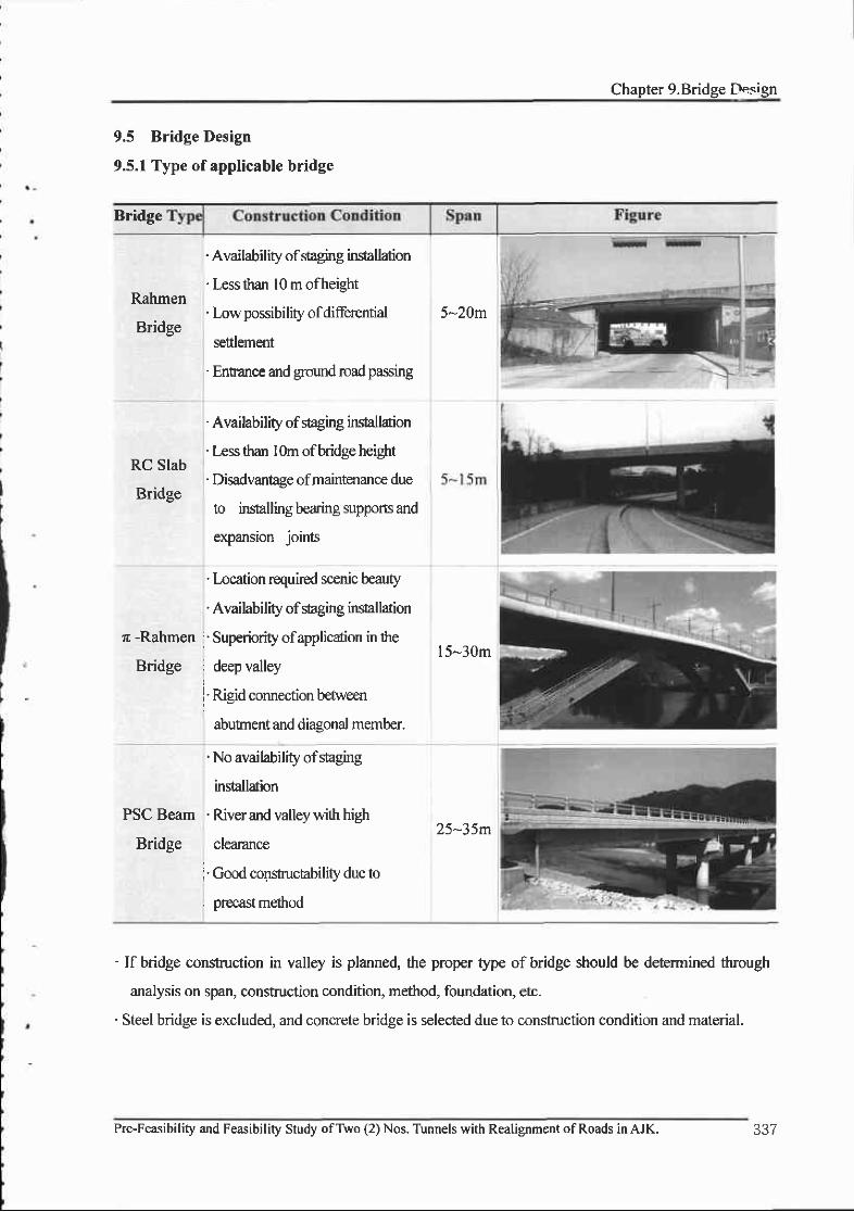
Chapter 9.Bridge Design
9.5 Bridge Design
9.5.1 Type of applicable bridge
Bridge
Rahmen
Bridge
RC Slab
Bridge
z -Rahmen
Bddge
. Availability of staging installaion
' Less than l0 m ofheight
' Low possibility ofdiferential
settlement
' Enn'ance and ground road passing
' Availability of *aging in*allation
' Less than l0m ofbridge heiglrt
' Disadvantage ofmaintenance due
to insalling bearing supports and
expansion joints
' location required scenic beauty
' Availability of suging ins'tallarion
' Superiority ofapplicaion in the
deep valley
' Rigid connection between
abutnent and diasonal member.
5-20m
l5-30m
PSC Beam
Bridge
' No availability of staging
installation
' River and valley with high
clearance
' Good construcfability due to
precast method
zf-J)m
' If btidge construction in valley is planned, the proper type of bridge should be determined through
analysis on span, construction condition, method, foundation, etc.
' Steel bridge is excluded, and concrete bridge is selected due to construction condition and material.
Pre-Feasibility and Feasibility Study ofTwo (2) Nos. Tunnels with Reatignment of Roads in AJK.

FEASIBILITY REPORT
9.5.2 Chella Bandi - Patika Road
I Bridge Location Map
I Plan of bridge
'There is a bridge between Chella Bandi and Patica Road
' Topography where abutrnents and piers ar€ consfucted has a steep slope, and the water fiom the top of
the mountain flows into a river during rainy season. Therefore the location ofpiers must be avoided the
central of river.
'A concrete bridge is planed beceuse the steel bridge causes the decline ofconstructability due to
manufacturg transportation, and the entrance oferection equipment and bent.
I Circumferential bridges
' Chellpani Bridge, r -Rahmen, is nearby deep valley below
planed bridge.
' Chellpani Bridge is completely damaged by 2005
Muzaffarabad earthquakes, Pier concrete is exfoliated and
reinforcing bars yielded
338 Pre-Feasibility and Feasibility Study ofTwo (2) Nos. Tunnels with Realignment ofRoads in AJK.

Chapter 9.Bridge Design
I Comparison of bridges (BR. | )
Itom Altemative I Alternative 2
Type PSC Beam Bridge PSC BOX Bridee
Plan
-"**' "" .,:': sp
_-d_ffi
Span [email protected]=150 .0 [email protected]=1s0.0
Method of
constructionInstallation by crane FSM (Full Staging Method)
Profile
"f"r,l1F
Features
. Consfucting a linear bridge due to the
curvatwe radius of 1,300m
' rapid construction
.Excellent Stability for constuction
'Lowcostofconsfi ction
' Possibility for construction regardless of
pier's height
' Excellent constructability for the linear
and curved bridge
' High cost ofconstruction in case that
the height of pier is over 20m.
- Not applicable to the site where the
settine of formwork is difficult.
application o
Result
PSC Beam Bridge is selected because of the excellent stability, the short
duration, the low cost, and the minimum erection equipment when a height of
oier is over 20m.
Pre-Feasibility and Feasibility Study ofTwo (2) Nos. Tunnels with Realignment ofRoads in AJK.
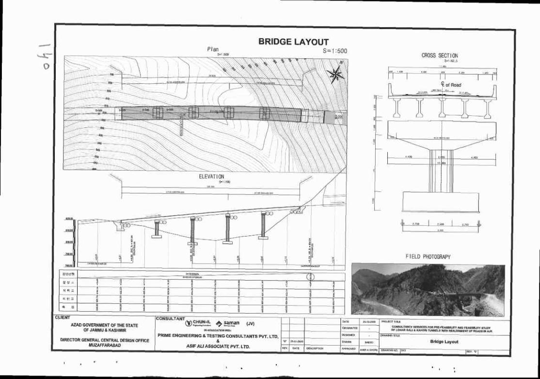

Chapter 10. Economic Analvsis
Chapter 10. Economic Analysis
10.1 Overview of Economic Analysis
The benefits ofthis project can be assessed by economic analysis. The result of analysis should
show that the benefit ofthe project is greater than its costs, ifit should be beneficial.
The standard procedures for the economic analysis are aprplied in the course of the feasibility
study. The basic unit for benefits calculation can be obtained by all available data in Pakistan and
the estimations from insufficient data is required to execute the analysis.
The period for economic analysis is set to 30 years after opening. The social discount rate is
assumed 9.7% as of2009.
l0.l.l Economic Analysis Procedure
o Economic analysis is appropriate for waluating public investnent projects because rhis can
lead to objective evaluation ofthe project with various altematives.
' Construction cost' Maintenance cost
' Reduced travel time' Reduced vehicle operation cost' Reduced traffic accident cost. Reduced environmental cost
Cunent value ofcosts & benefits
. Benefit-Cost Ratio(B/C)
. Net Present Value(NPV)' Internal Rate of Return(lRR)
Pre-Feasibility and Feasibility Study ofTwo (2) Nos. Tunnels with Realignment ofRoads in AJK. 341

FEASIBILITY REPORT
10.1.2 Economic Analysis Metlods
Economic Analysis rnay be assessed in terrns of Benefit-Cost Ratio@/C), Net Present
Valu{NPV), or Internal Rate of Retum(IRR).
The Benefit4ost Ratio(B/C) is the ratio of total discounted benefit and total discomted cost
and if the ratio is greater than 1, the project is considered to be economical-
The Net Present Valu{NPV) is defined as the diflerence between the total discounted benefit
and the total discounted cost. If the value is greater than 0, the project is corsidered to be
economical.
The Intemal Rate of Retum(IRR) is the discount rate that makes the net present value to be 0,
i.e., the total discomted cost equals the total discounted benefit.
The BenefirCost Ratio(B/C) could be varied depending upon what is regarded as benefit or cost
but it is generally regarded as the standard criterion ofinvestnent.
The Net Present Value(NPV) is not appropriate for comparing the profitability of various
projects because it increases according to the size of the project, while the lntemal Rate of
Retum(IRR) is not affected by the size of the project. IRR is still inappropriate for evaluation ofthe
project v/ith externely large or small profitability.
Summary of Economic Analysis
Section Evaluation Index Criteria
Benefit-Cost Ratio(Bic)
iB,, iC,, t L / 4,=o (I+r) ,=n u.|/.1
Benefit-Cost RatioB / C > I
Net Present Value(NP\)
$8,- fC,t4 \ r+r ) "o p+r)
Net Present ValueN P V > O
Intemal Rate of Retum(IRR)
$8,=*C,,*- (l+1RR)' -.- (l+1RR)'
Intemal Rate of RenrrnIRR ) Social Discor:nt Rate(r)
Note : 8/ : Benefit of'?'year, Cl: Cost of "f'year, / : Social discount ralq , : Project Life qcb
Pre-Feasibility and Feasibility Study ofTwo (2) Nos. Tunnels with Realignment ofRoads in AJK.

I
Chapter 10. Economic Analvs;.s
10.2 Costs Evaluation
10.2.1 Concept of Costs
o The costs in benefit-cost analysis can be divided into the cost of conshuction before the
opening, and cost for the land acquisition, the auriliary facilities, and the maintenance in
serwice.
Types of Costs Evaluation
Iems Details
ConstructiotrCosts
. Construction cost : building and project cost required for constructing
roads
. Land acquisition cost : expense paid for purchasing land property for
road cotrstruction
o Cornpensation cost : the cost for the damage occurred in road
constr:uotion stage, which include general construction compensation
cost and comoensation for business losses
o Auxiliary cost : fees for suwey, design, and supervision
MaintenanceCosts
. Expense required to preserve or maintain the road structure and traffic
function after opening to public
10.2.2 Costs Evaluation Details
E Evaluation of Construction Costs
r Economic feasibility is to be analyzed in terms ofb€nefit and cost. The constuction cost is
armually applied for 3 years. The land acquisition cost is applied for the first 2 ye€.rs of the
constmction period-
. Land acquisition cost is included in construction costs ofthis project-
The Analysis of Costs in Road Construction Proj€ct
Costs Yeor I Year 2 Year 3 Total
Construction Costs 25o/o 45o/o 30% too%
Pre-Feasibility and Feasibility Study ofTwo (2) Nos. Tunnels with Realignment ofRoads in AJK. 343

...' _ FEASIBILITY REPORT
E Location Map showing each Alernatives of Chetla Bandi-Patika
E Consffuctions Costs of Chella Bandi-Patika
. Construction costs in economic analysis of Chella Bandi-Patika are below.
Constructions Costs for each Alternatives of Chella Bandi-Patika
o The following zurnrnarizes annual construction cost based on altemative and yearly input ratio.
Construction Costs for Yearly Input Ratio of Chella Bandi-Patika
Section Alternfive 1 Alternative 2 Alt€rnsti!'E 3
Route Length L--l3.3km L=13.0km L:13.3km
Majorworks
Tunncl Ll:3-7lcn, L2=0.6km Lld.2km, L2:0-6km L1:l.8km, L2=0.5km
Bridge lplaceVl5Om I places,/l 50m lplaces/150m
Estimat€d Construction Cost 5.063 Million Pak.Rs. t,006 Miltion Pak.Rs- 3,026 Million Pak.Rs.
( Unit : Million Pak,Rs. )
Year Alternative I AftEmaaiv€ 2 Altemrlive 3
20r4 I , l0 l 1,'741 656
2015 1,982 3,134 1,165
2016 1 a)' , 2,o90 792
Total 4,405 6,965 2,633
Pre-Feasibility and Feasibility Study ofTwo (2) Nos. Tunnels with Realignment ofRoads in AJK.

E Evaluation of Maintenance Costs
Maintenance costs can be defined as the costs used by maintenance, managemen! and
repair after opening roads for pleasant driving.
In this project, maintenance costs were considered including items such as road
managernent, administrative labor cost, pavement re,pair, structure examination cost,
stucture repair, slope repair, maintenance cost caused by a disaster and damagg safety
facilities maintenance, snow rernoval and road cleaning cost.
In this project, since there is no reference for maintenance costs, Kofean maintenance
application method is used with correction for AJK region
According to Korean maintenance applicatione maintenance costs in goreral road reaches
20-30% to that of highway
Annual maintenance cosb per hr on this proj ect are shown below.
Annual Maintenance Costs on This Project( Unit : Millior Pak.Rs./km )
Year Mairtenrnce Costs Year Maintenance Costs
I 7 .44 l 6 57.84
2 8.88 l'1 62.48
3 10.48 t 8 66.88
4 12.40 l9 7 t . t3
5 14.56 20 74.97
6 t7 .04 2 l 78.51
7 19.92 22 81.77
8 23.M 84.65
9 26.56 24 87.21
l0 30.40 ?5 89.45
l t 34.56 26 91.45
t2 38.96 27 93 .13
l3 43.60 28 94.57
I 4 48.32 29 95.77
l5 53.04 30 96.81
Pre-Feasibility and Feasibility Study ofTwo (2) Nos. Tunnels with Realignment ofRoads in AJK.

,.,:J FEASIBILITYREPORT
10.3 Benefits Evaluation
10.3.1 Benefits Evaluation Details
E Benefit Items
The bsnefits caused by road facilities inveshnent project can be divided into direct benefits
and indirect benefits. Direct benefits can be subdivided into user benefits and nonuser
benefits, and user benefits include factors such as economy, time and psychology. The
b€nefib of reduced tavel time and vehicle operation cost are important factors since it can
be numerically measured.
It is desirable to analpe both direct and indirect benefits, however, only direct benefits are
presented in this project.
When calculating user benefit, it should include not only people using project section but
also users using all the road, and the road users mean car driver and passenger. At this time,
the sum of benefits is surplus part, this shows the difference between cost that users pay
willingly and cost that user pay actually.
Benefit of reduced travel time is calculated by multiplying the reduced travel time by the
value of travel time. Travel time value is calculated by estimating the value of product or
service that is gained from investing vehicle fiavel time in production activity-
Benefit of reduced vehicle operation cost is calculated by considering fuel, engine oil and
depreciation cost to reflect changes ofroad condition due to the construction ofroad.
Also, the costs for travel time and vehicle operation are used with the correction of inflation
rate based on FBS(Federal Bureau of Statistics).
Section Details
Direct benefits
Reduced travel time
Reduced vehicle operation cost
Reduced traffrc accident cost
Reduced environmental cost
Indirect benefits
Local developmant effect
Expansion of market area
Imorovement of local indusW structure
346 Pre-Feasibility and Feasibility Study ofTwo (2) Nos. Tunnels with Realignment ofRoads in AJK.
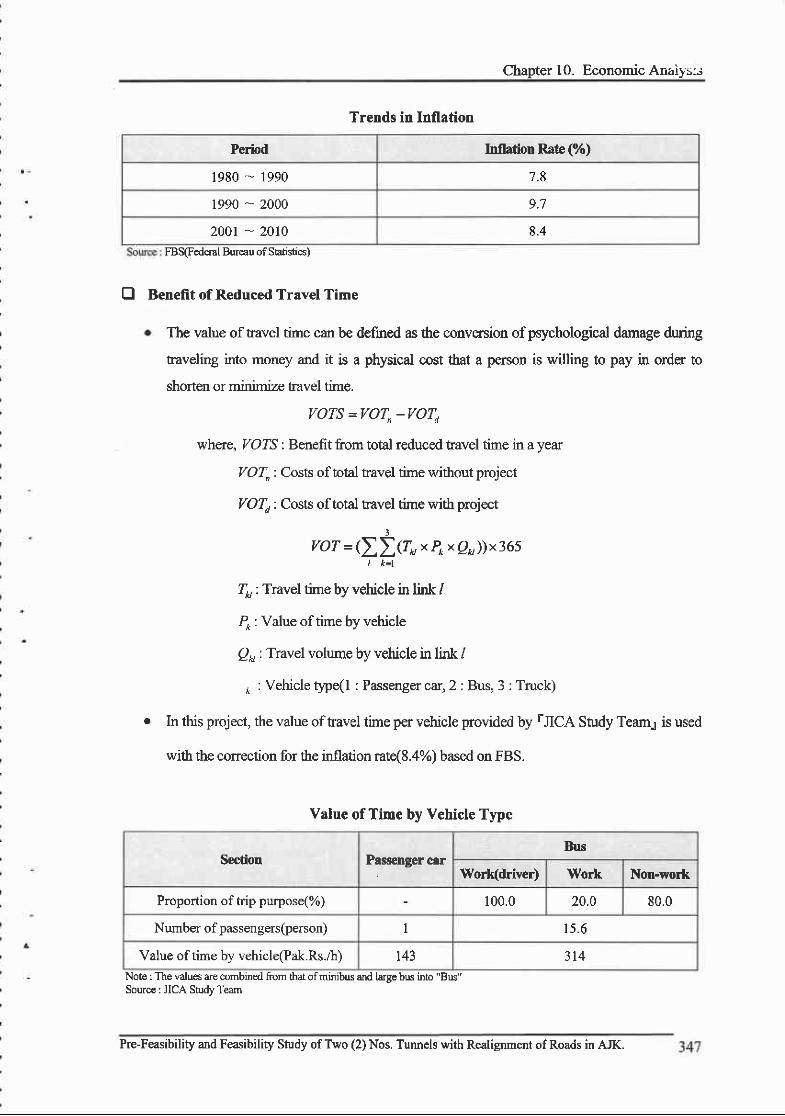
Chapter 10. Economic Anz,iy':s
Period Inflation Rate (%)
1980 .- 1990 7.8
1990 - 2000 9.7
200r - 2010 8.4Bureau
Trends in Inflation
FBS(Federal of Shtistics)
E Benefit of Reduced Travel Time
The value oftravel time can be defined as the conversion ofpsychological damage during
taveling into money and it is a physical cost that a person is willing to pay in onder to
shorten or minimize travel time.
VOTS =VOT,-VOTd
wherc, VOTS : Benefit from total reduced tavel time in a year
ZO{, : Costs of total travel tine without project
,/O4 : Costs of toal ravel time with project
vor = (ZI(r H x p^ x e )) x 365
Z, : Travel time by vehicle in link /
P* : Value of time by vehicle
p, : Travel volume by vehicle in link /
* :Vehicletype(l : Passengercar,2: Bus,3: Truck)
r In this project, the value oftavel time per vehicle provided by rJICA Study Team.1 is used
with the conection for the inflation rat{8.4%) based on FBS.
Noie : The values are combined from that ofminibus and larce bus into "Bus"Sourc€ : JICA SMy Team
Value of Time by Vehicle Type
Seclion Passenger carBus
Work(driver) Work Non-work
Proportion of trip purpose(%) 100.0 20.0 80.0
Number of passengers(person) 1 1 5 . 6
Value of time by vehicle(Pak.Rs.ih) 143 314
Pre-Feasibility and Feasibility Study of Two (2) Nos. Tunnels with Realignment ofRoads in AJK.

,',i... FF.ASIBILITY REPORT
E Benefit of Reduced Vehicle Operation Cost
r Vehicle Operation Cost can be taken in a broad serse that not only includes direct expenses
such as fixed costs, variable costs, but also extemal costs such as time, traffc accident
environrnent for the simplicity. Only direct expenses are considered for the calculation of
Vehicle Operation Cost.
VOCS =VOC"-VOCd
where, VOCS : Benefit from redrced total vehicle operation cost in a year
VOC ,: Total vehicle operation cost in a year without project
VOC o : Total vdticle operation cost in a year with project
voc =1lfP*xvTrx365)
Do, : Vehicle distance ' kn of link /
/70 : Vehicle operation cost by vehicle depending on speed
po, : Travel volurne by vehicle in link /
i : Vehicle type (1 : Passenger car, 2 : Bus, 3 : Truck)
o In this project, the value oftravel time per vehicle providod by rICA Shrdy Tearq is us€d
with the conection for the inflation ratd8.4%) based on FBS.
Average Vehicle Price and Tire Cost
( Unit : PakRs. )
Vehicle TlTeFinancial Hce Economic Price
Yehicle Tire Vehicle Tire
1. Motorcycle 76,228 531 52,47 6 317
2. Ca(< 1000cc) 604,t72 2,013 415,916 1,430
3. Car(> l000cc) |,249,290 3,071 860,019 2,182
4. Wagon 2,253,690 |,399,807 ) \ 4 1
5. MiniBus 3,179,632 s,636 2,396,245 4,004
6. Bus 4,43t,713 9,788 3,317 ,501 6,953
7. Truck(2-Axle) 3,631,500 13,500 2,308,948 9,589
8. Truck(3-Axle) 4,543,088 r4,68 t 2,889,404 r0429
9. Truck(Articulated) 4,165,425 15,863 2,648,423 tl,267
Source: Capital Motorq Azeern Motor\ Hini-Pah Universal Autocq Geneial Tyr€s, Islamabad.
348 he-Feasibility and Feasibility Study ofTwo (2) Nos. Tunnels with Realignment ofRoads in AJK.
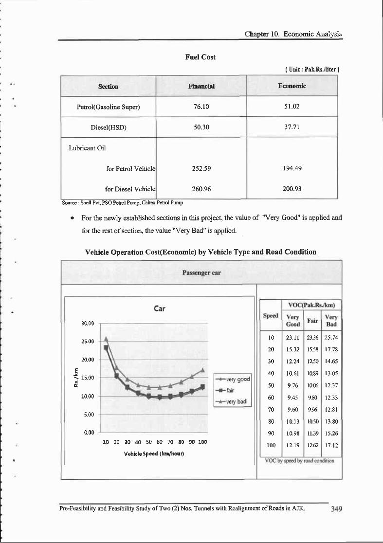
Chapter 10. Economic AraiTsis
( Unit : Pak.Rs.fliter )
Section tr'lnancial Economic
Petrol(Casoline Super) 76.10 5r.02
Diesel(HSD) 50.30 37.7r
Lubricant Oil
for Petrol Vehicle
for Diesel Vehicle
252.59
260.96
t94.49
200.93
Source: Shell Pvt PSO Pefol Pumo. Caltex
Fuel Cost
Pvl, PSO Pefol Pump, Caltex PetDl Pump
o For the newly established sectioru in this project, the value of
lor the rest ofsection, the value "Very Bad" is applied.
Vehicle Operatiotr Cost(Economic) by Vehicle Type and Road Condition
30.00
25_00
20.00
i rs.oool
10.00
5.00
0.00
L0 20 30 40 s0 50 70 80 90 100
Vehiclespe€d (kt hour)
l 0
20
30
40
50
60
70
80
90
100
1558
tz.fi
r0,89
r0.06
9.80
LX
1050
ll39
12.62
23.t|
15.32
12.24
10.61
9.76
9.45
9.60
10.13
r0.96
t2-19
25.'14
17.'18
14.65
r3.05
12.31
t2.33
1 2 . 8 1
13.80
t5.26
11. t2
Pre-Feasibility and Feasibility Study ofTwo (2) Nos. Tunnels with Realignment ofRoads in AJK.

-' .,. - FEASIBILITY REPORT
Source : JICA Study Team
Pre-Feasibility and Feasibility Study ofTwo (2) Nos. Tunnels with Realignment ofRoads in AJIL
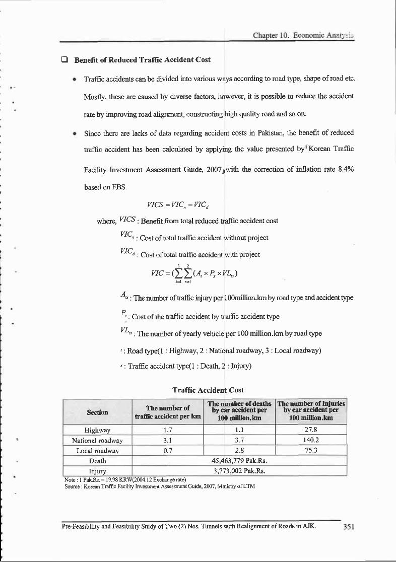
E Benefit of Reduced Traflic Accident Cost
Traffic accidents can be divided into various ways according to road tlpe, shape ofroad etc.
Mostly, these are caused by diverse factors, however, it is possible to reduce the accident
rate by improving road alignment, constucting high quality road and so on
Since there are lacks of data regarding accident costs in Pakistan, the benefit of reduced
tr-dffic accident has been calculated by applying the value presented by rKorean Traffic
Facility Investnent Ass€ssment Guide, 20073with the correction of inflation rate 8-4o/o
based on FBS.
VICS =WC,-VICa
*1er., ZICS ; Benefit from total reduced traffic accident cost
214 , Co.t oftotul taflic accident without project
ZIQ : Cost oftotal traffic accident with project
3 2
vIC:(ZZ(A,xP"xvl^)
"" : The number of raftc injury per I O0million.kn by road t}pe and accident tlpo
D' " : Cost of the traffrc accidant by traffic accident type
' "" : The number ofyearly vehicle per 100 million.lan by road type
,: Road type(l : Highway,2 :National roadway,3 : Local madway)
" : Traffic accident type(l : Death 2 : Iqiury)
Traffic Accident Cost
SectionThe number of
haffic accident per km
The number of deathsby car accident per
llX) million.lot
The number of Iniuriesby car accident per
100 million,km
Highway 1 . 1 l . l 27 .8
National roadway 3 . I 3.7 r40.2Local roadway 0.7 2.8 75.3
Death 45.463.779 Pak.Rs.
Injury 3,773,002 Pak.Rs.Note : I PakRs. = 19.98 KRW(2004.12 Exchange rate)Sourcc : Korean Tmffic Facility Investrnert Assessrnent Cuide, 2007, Minishy ofLTM
Pre-Feasibiliry and Feasibility Study ofTwo (2) Nos. Tunnels with Realignment ofRoads in AJK.
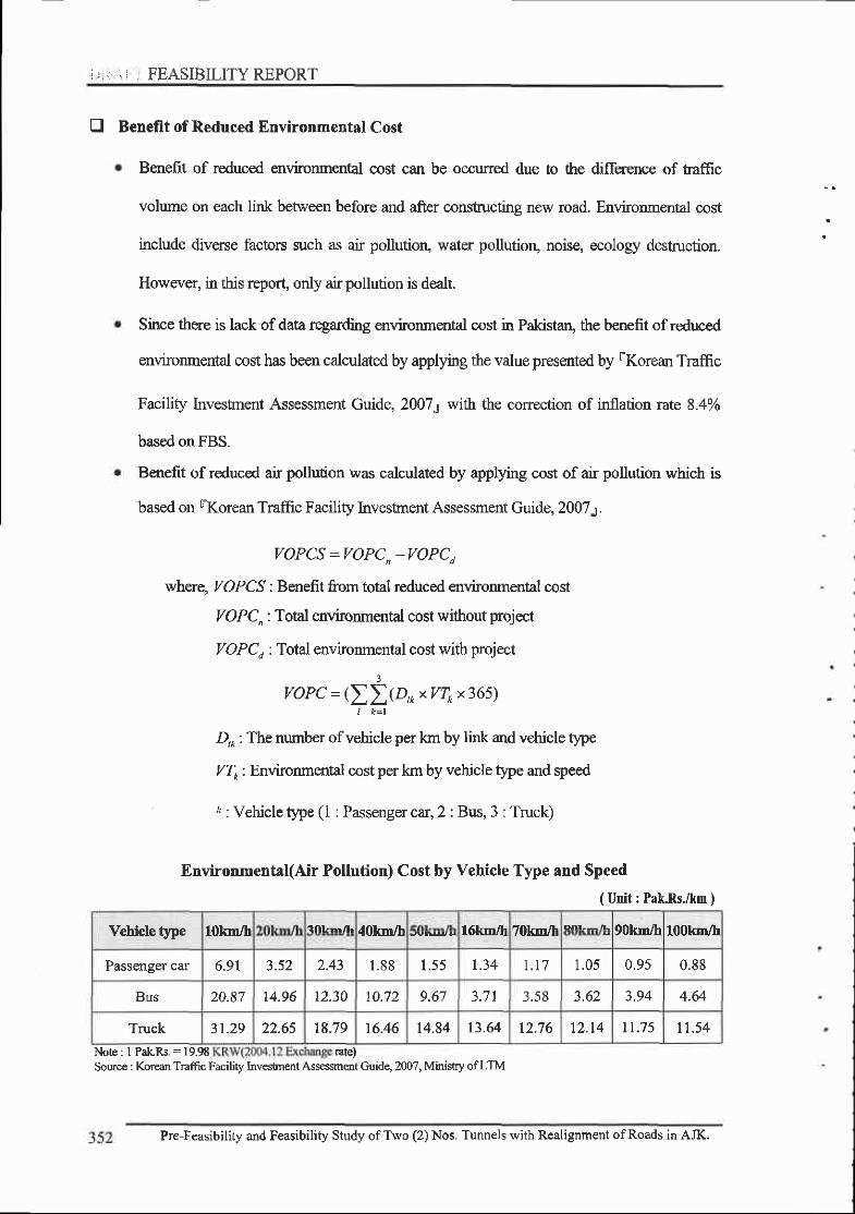
i,..r ',i r FEASIBILITYREPORT
E Benefit of Reduced Environmental Cost
Benefit of reduced environmental cost can be occurred due to the difference of taftic
volume on each link between before and after constructing new road. Environmental cost
include diverse factors such as air pollutioq water pollutiorq noise, ecology destruction.
Howwer, in this report, only air pollution is dealt.
Since there is lack of data regarding environmenal cost in Pakistaq the benefit of reduced
environmental cost has been calculated by applying ttre value presented by rKorean Traffic
Facility Invesftient Assessment Guide, 20071 with the correction of inllation 1?lte 8.4%o
based on FBS,
Benefit of reduced air pollution was calculated by applying cost of air pollution which is
based on rKorean Traffrc Facility Investment Assessment Guide, 2007s.
VOPCS =VOPC,-VOPCI
where, VOPCS : Benefit from total reduced environmental cost
ZOPC, : Total environmental cost without project
VOPC, : Total envtronmental cost with project
voPC =(Lltr.toxvTox365lI k= l
D,* : The number ofvehicle per km by link and vehicle type
Zf : Environmental cost per km by vehicle type and speed
r : Vehicle type (l : Passenger car, 2 : Bus, 3 : Truck)
Environmental(Air Pollution) Cost by Vehicle Type and Speed
( Unit : Pak.Rs./km )
Vehicle type 101fln/h l0lrrn/h dOlrm/h I lllrrn/h Olllrn/h 100km/htolgll/[ /ulqrvtr
Passenger car 6.91 3.52 2.43 1 . 8 8 l . ) ) | .34 1 . t 7 1.0s 0.95 0.88
Bus 20.87 14.96 t2.30 10.72 9.67 3.7 t 3.58 a 6 ) 3.94 4.64
Truck 31.29 22.65 18.79 16.46 t4.84 13.64 12.76 12 . t4 t1.75 I 1 . 5 4
Note: I PakRs.:19.98 rate)Sourc. : Korean Traffic Facility Inv6tn€nt Ass€ssment Guide, 200?, Minislry ofLTM
Pre-Feasibility and Feasibility Study ofTwo (2) Nos. Tunnels with Realignment ofRoads in AJK.

E Result of Benefit for Chella Bandi-Patika
r The following summarizes the result of benefit of Chella Bandi-Patika by altemative.
Result of Benefit for Each Alternatives of Chella Bandi-Patika( Unit : Millior Pak.Rs. )
Section Altemrtive I Alternative 2 Altemative 3
l. Reduced travel time 12,558.0 14,416.1 7,801.5
2- Reduced vehicle oDeration cost < 4 7 < A 7,451.7 4,220.8
3. Reduced traffrc accident cost 237 .7 317.8 449.6
4. Reduced environmental cost 3,792.8 4,959.E
Total 22,263.9 27,t45.4 15,791.1
10.4 Economic Analysis
10.4.1 Results of Economic Analvsis
D Economic Analysis Results of Chella Bandi-Patika
r Economic analysis results show that altemative l, 3 are economically feasiblg since the
B/C ratio ofalternative 1 and altemative 3 are satisfactorv as more rhan 1.0.
Summary of Economic Analysis Results of Chella Bandi-Patika( Unit : Million Pak.Rs. )
SectionEconomic Analysis Results
Altemative 1 Alternrtiv€ 2 Alternative 3
RoutePlan
Route length L=l3.3km L=l3.0km L:13.3km
Construction cost 4405.0 6965.0 2573.0
Costs&
Benefit
Total discounted costs 3,731.2 5,911.0 2,t76.9
Total discounted benefits L <O1 1 5,813.9 3,186.3
Benefit-Cost Ratio(B/c) t . 23 0.98 t.46
AnalysisResults
Net Present Value(NP9 866.5 -97.1 1,009.5
Intemal Rate of RetumORR)
11.77o/o 9.54 13.55%
Pre-Feasibility and Feasibility Study ofTwo (2) Nos. Tunnels with Realignment ofRoads in AJK. 353

, : FEASIBILITY REPORT
10.4.2 Results of Costs and Benelits by Year
E Costs and Benefits Results of Chella Bandi-Patika by Yearo The following shows the arurual costs and benefits for the Chella Bandi-Patika Route by a
process ofcost and benefit calculation
Annual Costs and Benefits Results(Altertrative l)( Utrit : Miuion Pak.Rs. )
S€dim cd Bgrft Wi&&c0.ntrdepJ"/ol
Piojed]rar
Coo*uUimoo6a
Nlsiturrecd Tdl Reduc.d
twdltn
Reducadd|He
arrdqlcd
Rnnrc.dMc
acd.dcd
Rrdrxderrtfre|tr rnd
Cd
Tdl c6 Brnefs
20t4 I , 1 0 1 . 0 0.0 l , l 0 l . 0 0.0 0.0 0.0 0.0 0.0 I,003.6 0.02015 1,9E2.0 0.0 1,982.0 0.0 0.0 0.0 0.0 0.0 |,647.0 0.02016 1,322.0 0.0 1,322.0 0.0 0.0 0.0 0.0 0.0 I ,00t .4 0.02017 0.0 2.5 2.5 260.7 l l l I 1 . 4 77.6 450.E t . 7 3 l 1 . 32018 0.0 3 . 0 3.0 272.7 116.6 I . 9 8 1 . 3 472.5 1 . 9 29'1.42019 0.0 3.6 J . O 284.9 122.0 2.4 84.9 494.2 2 . 1 283.62020 0.0 4.2 4.2 296.9 t27.5 88.6 5 1 6 . I 2.2 270.Q2021 0.0 4.9 4.9 309.0 133.0 3.6 92.2 537.8 256.42022 0.0 5.E 5.E 320.8 138.9 4.2 95.9 559.7 2 . ) 243.32023 0.0 6.E 6.8 332.5 144.7 4.9 99.5 581.6 2.? 230.42024 0.0 7.8 7.8 344.3 150.7 ) . ) 103.0 603.5 2.8 218.02025 0.0 9.0 9.0 356.0 156.6 6 . 1 106;1 625.3 3.0 205.9
2026 0.0 10.3 1 0 . 3 t62.5 6.8 110 .3 647.3 J . l 194.32Q27 0.0 tr.7 tr.'7 380.7 168.5 7.2 I 14.3 6',70.7 1 8 3 . 5202E 0.0 t3.2 t3.2 393.7 174.6 7.7 1 1 8 . 4 694.3 3.3 t73.22029 0.0 14.8 14.8 406.6 I E0.5 8.2 t22.4 7 t'7 .8 1O5.2
2030 0.0 t6.4 t6.4 4t9.6 186.6 8.6 t26.5 74t .3 3.4 1 5 3 . 62031 0.0 1 8 . 0 18.0 432.5 192.5 9.2 I30.5 764.8 3.4 144 {
2032 0.0 19.6 19.6 446.2 200.6 9.5 134.9 7 9 t . 1 3.4 136.22033 0.0 21.2 21.2 459.9 208.6 9 ; 7 t39.2 Et7.4 128.3
2034 0.0 22.7 22.7 473.7 2t6.5 r0 . l t43.6 E,14.0 120.8
2035 0.0 24.2 24.2 4E1.4 224.6 10.4 r48.0 870.3 I I 3 . 5
2036 0.0 25.5 25.5 501 . l 232.6 10.7 t52.3 896.7 3.0 106.6
2037 0.0 5 0 1 . 1 232.6 t0.7 152.3 896.7 2.9 97.2
2038 0.0 27.E 27.E 5 0 1 . 1 232.6 10.7 152.3 896.7 2.7 88.5
2039 0.0 28.7 28.? 5 0 1 . l 232.6 10.7 t52.3 896.7 2.6 80.E
2040 0.0 29.6 29.6 5 0 1 . 1 232.6 10.7 | 52.3 896.7 2.4 73.6
2Ml 0.0 30.4 30.4 5 0 1 . l 232.5 10.7 r52.3 896;l 67.r20/.2 0.0 3 1 . 1 3 r . l 5 0 1 . 1 232.6 10.7 152.3 895.'l 2 . 1 6t.22043 0.0 3 t .6 5 0 1 . l 232.6 r0.7 t52.3 896.'t 2.0 ) ) . r2044 0.0 32.1 32.1 5 0 1 . 1 t0.7 t52.3 896.7 1 . 8 50.8
2045 0.0 32.5 32.5 501.1 232.6 10.7 r52.3 896.7 t . 7 46.3
2046 0.0 32.9 32.9 50r .1 t0.7 t52.3 896.7 1 . 6 42.2
Total 4,405.0 548.6 4,953.612,558.05,67 5.4 237; l 3,792.822,263.91,731.24,59't.7
354 Pre-Feasibility and Feasibility Study ofTwo (2) Nos. Tunnels with Realignment ofRoads in AJK.

Chaoter 10. Economic A,r ' ,,si.
Annual Costs and Benefits Results(Alternative 2)( Unit : Million Prk.Rs. )
Sedim Cos nt.|€ffb Wih discoEt rateoJo/o\
Pruj€d]rar
TtrI Reducedtsrddme
Reduceddddc
qrrdqrcd
Reducrdbiffc
uilotaod
Rfdrd6vireffit
codTdrl c6 Bcnef6
c6 c6
20t4 1,741.0 0.0 t,'74r.0 0.0 0.0 0.0 0.0 0.0 1,587.1 0.0
2015 3,134.0 0.0 3,r34.0 0.0 0.0 0.0 0.0 0.0 2,604.3 0.0
2016 2,090.0 0.0 2,090.0 0.0 0.0 0.0 0.0 0.0 1,583.2 0.0
2017 0.0 4.4 4.4 3 39,1 t46.r 10t .3 590.8 3.0 40'7.9
2018 0.0 5.2 5.2 354.9 153.4 5.3 106.1 619.7 390.0
2019 0.0 o . l 3'70.6 160.5 110.8 648.0 3 . 5 3 7 1 . 8
2020 0.0 7.3 386.4 167.7 7.O I r 5 .6 676-6 3.E 353.9
2021 0.0 8.5 8.5 402.0 174.8 8.0 120.4 '705.2 4.1 J J O . J
2022 0.0 10.0 10,0 417.6 r 82.5 8.4 t25.1 4.3 3 1 8 . 9
2023 0.0 tt.7 I t . 7 433.1 t90.2 8.6 129.9 761.8 4.6 301.8
2024 0.0 13.5 13.5 448.6 19',7 .9 9.0 134.6 190.2 4.9 285.4
2025 0.0 1 5 . 5 1 5 . 5 464.1 205.6 9.3 139.5 8 1 8 . 5 5 . 1 269.5
2026 0.0 17.8 17.8 479.5 213.3 9.7 t44.2 846.7 ) . J 254.1
2027 0.0 20.2 20.2 485.2 22t .3 9.9 t49.4 865.8 5.5 236.9
2028 0.0 22.8 22.E 490;7 229.2 10.0 154.7 884.7 5.7 220.6
2029 0.0 25.5 25.5 496.4 237.2 l 0 . l 159 .8 903.6 5.8 205.4
2030 0.0 2E.3 28_3 501.9 245.0 10.4 165.1 922.5 5.9 191.2
2031 0.0 3 1 . 0 3 1 , 0 507.6 253.0 10.5 t 70.4 941.5 5.9 17'7.9
2032 0.0 3 3.E 3 3.8 5 1 1 . 0 263.5 1 1 , 1 t7 6.2 96t.7 5.8 165.6
2033 0,0 36.5 514.5 2'.73.9 1 t , 5 182.0 98r .9 5.7 154.1
2034 0.0 39.l 39.1 517.9 284.3 t2.0 187.8 1,002.0 5-6 143.4
2035 0.0 4l .6 41.6 521.4 294.7 't2.6 193.6 t,022.2 13].4
2036 0.0 43.8 43.8 524.9 305.2 1 3 . 1 199.4 't,042.6 5.2 124.O
2037 0.0 46.0 46.0 524.9 305.2 1 3 . 1 199.4 |,042.6 5.0 1 1 3 . 0
2038 0.0 47.8 47.8 524.9 305.2 l 3 . l t99.4 I,042.6 4.7 103.0
2039 0.0 49.5 49.5 524.9 305.2 t 3 . 1 199.4 1,042.6 4.5 93.9
2040 0.0 5 1 . 0 5 1 . 0 524.9 305.2 l 3 . l 199.4 1,042.6 4.2 85.6
2041 0.0 52.3 52.3 524.9 305.2 t 3 . 1 199.4 1,042-6 3.9 78,0
2042 0.0 53.5 ) J . ) 524.9 105.2 l 3 , l t99.4 |,042-6 3 ; t 11.1
2043 0.0 54.5 54.5 524.9 305.2 l 3 . l 199.4 |,042.6 3.4 64.9
2044 0.0 55.3 55.3 524.9 305.2 l 3 . l t99.4 |,042.6 59.1
2045 0.0 56.0 56.0 524.9 305.2 1 3 . 1 t99.4 |,042.6 2.9 53.9
2046 0.0 56.6 )o. t l 524.9 305.2 1 3 . 1 r99.4 1,042.6 2.',7 49.l
Total 6,965.0 945.1 7 , 9 1 0 . 114,416.17,45t.7 3r7 .8 4,959.827,145.45,911.0{ f , ] ? O
Pre-Feasibitity and Feaibility Study ofTwo (2) Nos. Tunnels with Realignment ofRoads in AJK.
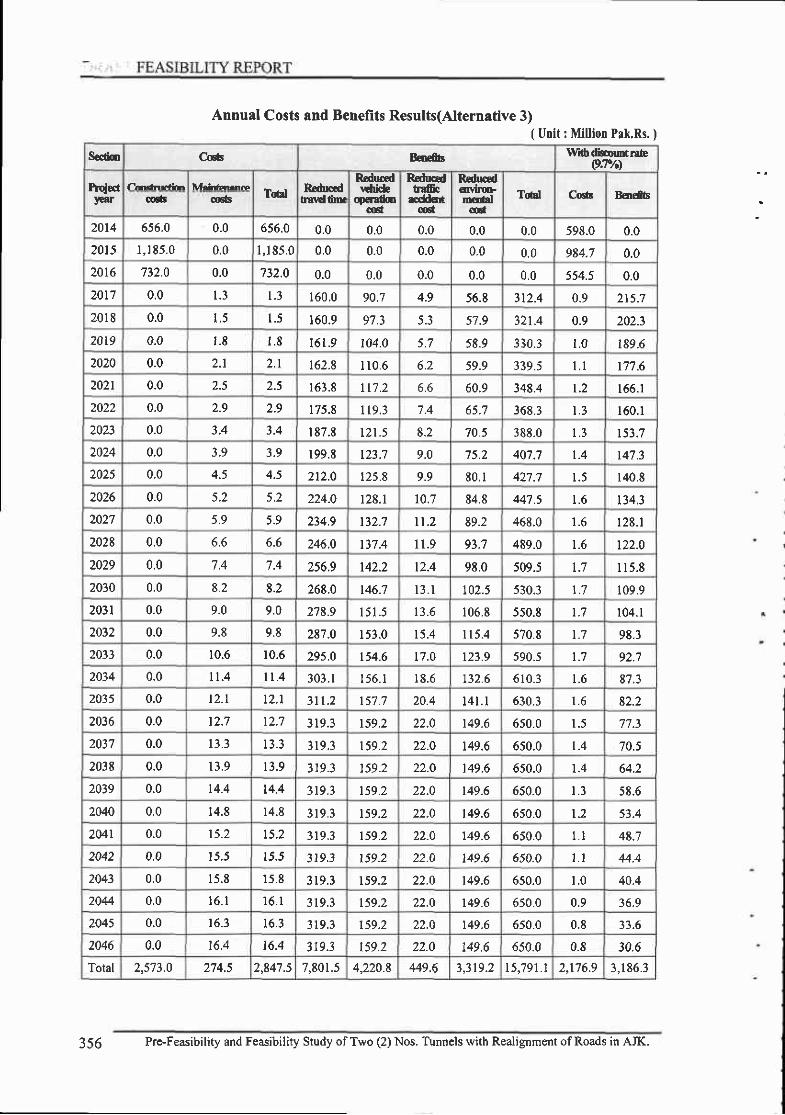
S€tu c* Broffbrnfrb dbcoutrsb
pp/ol
HG.f}tar
{1rrnrcftrrTdl Rcdrd
hrtdfu.
Rrdurdl6i&
qqdiocd
R:ductdbffic
dE*cd
Red*dqvtGDfdl
(dTdl C6a Baefbcos o6G
20t4 556.0 0.0 656.0 0.0 0.0 0.0 0.0 0.0 598.0 0.02015 I ,185.0 0.0 1,185.0 0.0 0.0 0.0 0.0 0.0 984.7 0.02016 732.0 0.0 732.0 0.0 0.0 0.0 0.0 0.0 554.5 0.020t7 0.0 1 . 3 1 . 3 160.0 90.7 4.9 56.8 3t2.4 0.9 215.7
2018 0.0 l . ) 1 . 5 160.9 9'7.3 5.3 57.9 32t.4 0.9 202.3
20t9 0.0 1 . 8 1 . 8 t61.9 104.0 5.7 58.9 330.3 1.0 189 -62020 0.0 2.1 2 . 1 t62.8 I 1 0 . 6 o.z 59.9 339.5 l . l r7'7.6202r 0.0 2.5 2.5 163.8 lr'7.2 o.o 60.9 348.4 t .2 t 66.12022 0.0 2-9 2.9 175.8 I 1 9 . 3 7.4 368.3 160.1
2023 0.0 3.4 3.4 187.E tzt.5 8.2 70.5 388.0 r53.72024 0.0 3.9 3.9 199.t t23;7 9.0 75.2 40'7;7 1.4 r47.32025 0.0 4.5 212.O 125.8 9.9 E0. l 42'1.7 1 . 5 140.8
2026 0.0 5.2 5.2 224.0 128.1 10.7 84.8 44'7.5 t .6 t34.32027 0.0 5.9 5.9 234.9 t 3 2 ; l | . 2 89.2 468.0 1 . 6 1 2 8 . 1
2028 0.0 6.6 246.0 I 1 . 9 93;7 489.0 1.6 t22.02029 0.0 7.4 7.4 256.9 142.2 t2.4 9E.0 509.5 1.7 I t5 .8
2030 0.0 8.2 8.2 268.0 146.7 l 3 . l 102.5 530.3 t . 7 109.9
2031 0.0 9.0 9.0 2'1E.9 1 5 1 . 5 13.6 106.8 550.8 t . 7 104.1
2032 0.0 9.8 9.8 287.0 153.0 r 5.4 I 15.4 570.8 t . 7 98.32033 0.0 10.6 10.6 29s.0 t54.6 17.0 r23.9 590.s t .? 92.'.l
2034 0.0 tt.4 l l .4 303. l 156.1 lE.6 t32.5 610.3 1 . 6 87.3
2035 0.0 1 2 . l t2.l 311.2 157.7 20.4 l 4 l . l 630.3 1 . 6 82.2
2036 0.0 t2.7 t2.7 3t9.3 r59.2 22.0 149.6 650.0 1.5 77.3
2Q37 0.0 13.3 1 3 . 3 319.3 t59.2 22.0 t49.6 6s0.0 t .4 70.5
203t 0.0 13.9 1 3 . 9 319.3 159.2 22.O 149.6 650.0 1.4 64.2
2039 0.0 t4.4 14.4 3t9.3 t59.2 22.0 t49.6 650.0 l . J ) 6 . O
2040 0.0 14.8 14.8 3 1 9 . 3 t59.2 22.O t49.6 650.0 1.2 53.4
2Mr 0.0 | ) . 2 t5.2 319.3 159.2 22.0 149.6 550.0 L l 48.7
2042 0.0 l ) . J IJ .J Jr9.3 | 59.2 22.0 149.6 650.0 1 . 1 44.4
2043 0.0 15.E 15.8 319.3 t59.2 22.0 149.6 650.0 1 . 0 40.4
2044 0.0 t 6 . l I O . l 319.3 t59.2 22.0 149.6 650.0 0.9 36.9
2045 0.0 l o . J 16.3 3 1 9 . 3 r59.2 22.0 t49.6 6s0.0 0.8 33.6
2046 0.0 16.4 16.4 3r9.3 159.2 22.0 t49.6 650.0 0.6 30.6Total 2,573.0 274.5 2,847.57,801.54,220.8 449.6 ? 1 1 0 ? t { ? o l I 2,t76.9 3,186_3
Annual Costs and Benefits Results(Alternative 3)( Urit : Million Prk.Rs. I
356 Pre-Feasibility and Feasibility Study ofTwo (2)Nos. Tunnels with Realignment ofRoads in AJK.

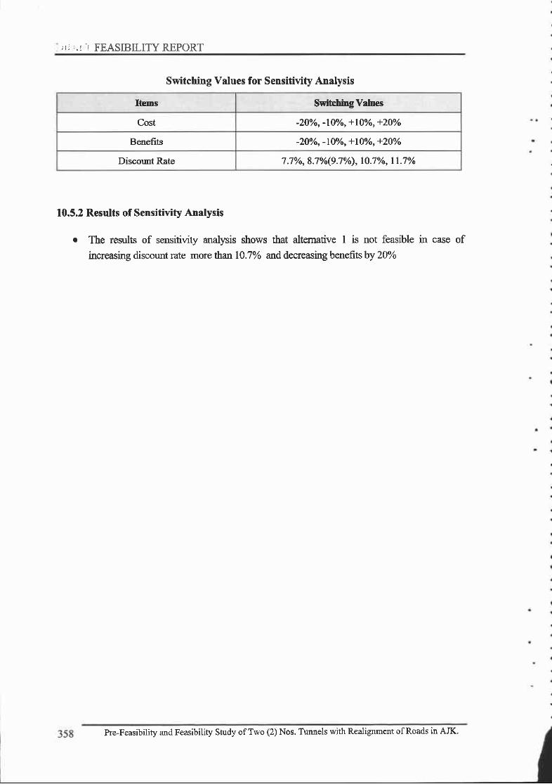
;I: ..: .: FEASIBILITY REPORT
Switching Values for Sensitivity Analysis
Ibms Switc.hing Valuec
Cost -2oo/o, -l0o/o, +l0o/o, +20Yo
Benefits -2U/o, -l0%o, +Iff/o, +2OVo
Discout Rate 7 .7o/o, 8.7o/o(9.7o/o), l0 .7o/o, 11 .7o/o
10.5.2 Results of Sensitivity Analysis
. The results of sensitivity analysis shows that altemative I is not feasible in case of
increasing discount mte more than 10.7% and decreasing benefits by 20%
Pre-Feasibility and Feasibility Study ofTwo (2) Nos. Tunnels with Realignment ofRoads in AJK'
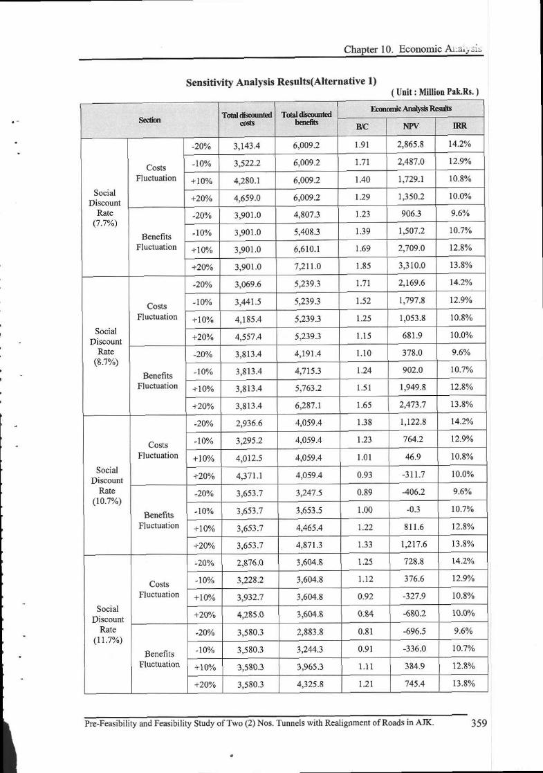
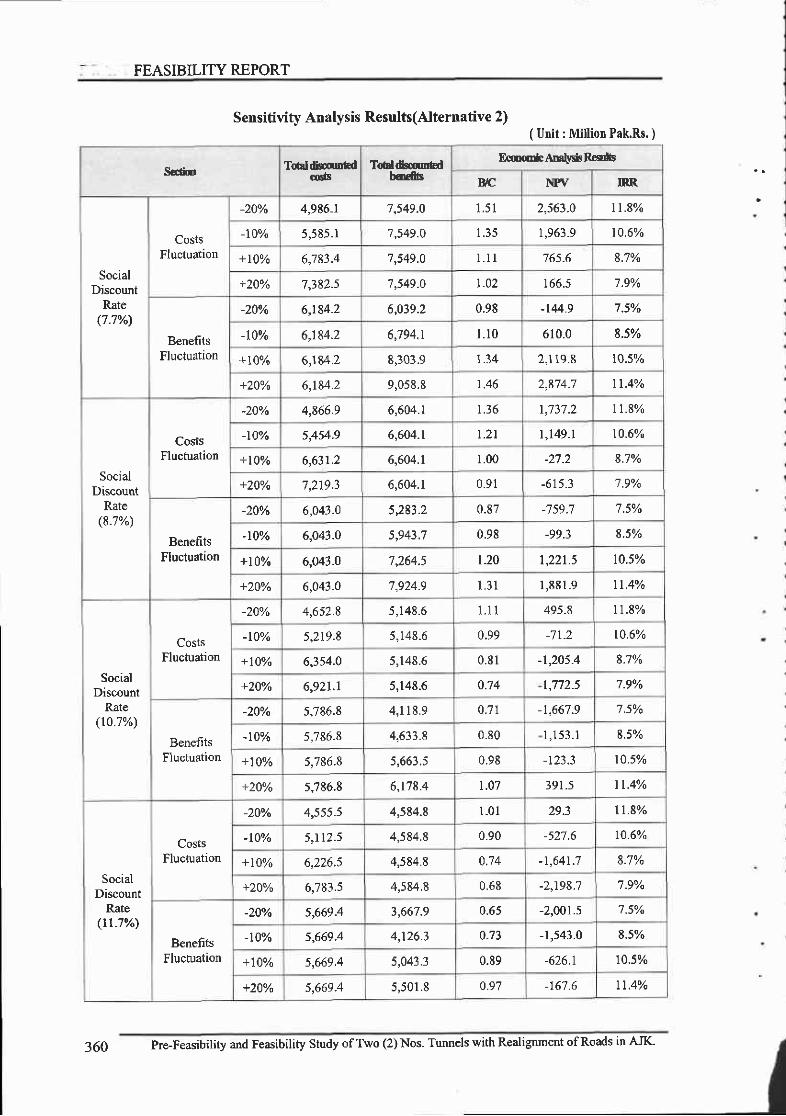
FEASIBILITY REPORT
( Utrit : Million Pak.Rs. )
Sedim Tdldis. ntdtd
Tdl&cuntdhqft
E(mmlcADdydrR€urfE
B,lC NPV IRR
SocialDiscount
Rate(7.7%)
CostsFluctuation
-200/0 4,9E6-l 7,549.0 l . 5 l 2,563-0 lt.E%
-10% 5,585.1 7,549.0 l . J ) I,963.9 10.6%
+ l0%o 6,783.4 '7,549.O I . I I 765.6 8.'1%
+20y" 7,382.s '7,549-0 t .02 I66 .5 7.9%
BenefitsFluctuation
-20% 6,184.2 6,039.2 0.98 -144.9 7.5o/o
-t0% 6,184.2 6,794.r I . 1 0 610.0 8.5%
+t0% 6,184.2 E,303.9 1.34 2,119.8 r0.5%
+20yo 6,184.2 9,058.8 1.46 t 91A '7 tt.4%
SocialDiscount
Rate(8.7%)
CostsFluctuation
-20% 4,866.9 6,604.r 1.36 1,737.2 tt.8%
-100/o 51s4.9 6,604.1 t . 2 l t,149-l 10.6%
+10% 6,63r.2 6,604.r 1.00 -27.2 8.7%
+20Yo 7 ,219.3 6,604.1 0.91 -615.3 '7.9%
BenefitsFluctuation
-20% 6,O43.0 { t Q ? t 0.87 -7 59.7 7.5o/o
-r0% 6,043.0 14 r ' . 71 0.98 -99.3 8s%
+10% 6,043.0 '7,264.5 t.20 1,22r.5 t0.5%
+20Yo 6,043.O 7,924.9 l , 3 l 1 ,881,9 rt.4%
SocialDiscount
Rate(r0.7%)
CostsFluchration
-20% 4,652.8 5,148.6 l l l 495.8 I I .E%
-t0% 5,219.8 5,t48.6 0.99 -7 t.2 t0.6%
+l0o/" 6,354.0 5,148.6 0.81 -1,205.4 8.7%
+20vo 6,921.1 5,148.6 o.74 t,772.5 7.9%
BenefitsFluctuation
-20% 5,786.8 4 , 1 1 8 . 9 0.7 | -t,667.9 75%
-10% 5,786.8 4,633.8 0.80 1 , 1 5 3 . 1 8.5%
+10% s,786.8 5,661.5 0.98 10.50/o
+20yo s,'186.8 6,t78.4 t .07 39t.5 1t.4Vo
SocialDiscount
Rate(rr-7%)
CostsFluctuation
-20% 4,555.5 4,5E4.8 l .0 l 29.3 1 1 . 8 %
-10% 5,112.5 4,564.8 0.90 -527.6 10.60/.
+10% 6,226.5 4,564.8 0.74 -1 AAl 1 8.7%
+ZlVo 6,783.s 4,584.8 0.68 -2,198;7 '7 .90/o
BenefitsFluctuation
-200/0 5,669.4 3,667.9 u-b) -2,001.s '7.50/.
-t00/o s,669.4 4, t26.3 0.73 -1,543.0 8.5%
+10% s,669.4 5,043 .3 0.89 -626.1 10.5%
+20vo s,669.4 5,501.8 o.97 -16'7.6 It.4%
Sensitivity Analysis Results(Alternative 2)
360 Pre-Feasibility and Feasibility Study ofTwo (2) Nos. Tunnels with Realignment ofRoads in AJK'
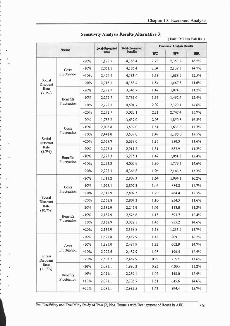
Chapter 10. Economic Analysis
Setrsitivity Analysis Results(Alternative 3)( Unit : Million Pak,Rs. )
S€dfoo Totrldimutedcocb
Tdtdtcf,rbdb €fib
EcmomhA[altrnr Raa s
B/C NPV IRR
SocialDiscount
Rate(1.1%)
CostsFluctuation
-20% 1,829.5 4,183.4 2.29 t ? < 1 0 16.2%
-10% 2,051.1 4,t83.4 2.04 2,r32.3 14.7%
+ljYo ) AOA A L 1 9 7 4 1.68 1,688.9 12.5Y't
+20yo 2,7 t6.l 4 . 1 9 4 a 1.54 1,467 .3 tt.6%
BonefitsFluctuation
-20% ) ) 1 ) 1 3,346.7 1.47 |,o74.0 1t.2%
-10% , ) 1 ) 7 3,7 65.0 1.66 1,492.4 12.4%
+l)Yo 2,2'.72.7 4,601.7 2.02 2,329.1 t4.604
+ZjYo ) ) 1 ) 7 5,020.1 2.21 ) 1 4 7 4 15.7%
SocialDiscount
Rate(8.7o/o)
CostsFluctuation
-200/0 1,788.2 3,639.0 2.03 1,850.8 l6.zYo
-t00/" 2,005.8 3,639.0 l . 8 l 1,633.2 14.7%
+lOYo 2,44t.0 3,639.0 |.49 1,19E.0 t2.syo
+20Yo 2,658.7 3,639.0 | . 3 7 980.3 11.6%
BenefitsFluctuation
-200/0 2,9rt.2 l . 3 l 687.9 ll.2o/o
-100/0 3,275.1 1.47 t ,051.8 t2.4V.
+l0Yo 2,223.3 4,002.9 l .80 r,779.6 14.6%
+20yo ) ) ) 1 \ 4,366.8 r.96 2,143.5 15.1yn
SocialDiscount
Rate(r0.7%)
CostsFluctuation
-20o/o t,7 t3.2 2,807.3 t.64 1,094.1 16.2%
-t00/o |,923.1 2,807.3 1.46 884.2 14.7%
+10y" ) 7 4 ) 0 2,807.3 1.20 464.4 12.5V.
+20Yo 2,552.8 2,807.3 l . l 0 254.5 tt.6yo
BenefitsFluctuation
-20% ' , 1 \ ) O 2,245.9 1.05 I 1 3 . 0 tl.2v.
-r0% t 1 1 ? q ) <74 A l . l E 393.7 12.40/o
+ lQYo t 1 1 ' O 3,088.1 |.45 955 -2 14.6%
+20% 2,132.9 3,368.8 L58 1,235.9 t5.7%
SocialDiscount
Rate(rt.'t%)
CostsFluctuation
-20% 1,678.8 2,487 .9 1.48 809.1 t6.2%
-10% 1,8E5.0 2,48'1.9 1.32 602.9 14.'7%
+10vo 2,297.5 2,48'7 .9 1.08 190.5 t2.5yo
+200/0 2,503.7 2,487.9 0.99 -15 ,8 11.6Vo
BenefitsFluctuation
-20o/o 2,091.1 1,990.3 0-95 -100.8 11.2%
-10% 2,091,1 2,239.1 1.07 148.0 t2.4%
+10% 2,091.1 2,736.7 1 . 3 1 645.6 t4.6%
+20% 2,091.1 ? 0 t { { 1.43 894.4 t5.7%
Pre-Feasibility and Feasibility Study of Two (2) Nos. Tunnels with Realignmant ofRoads in AJK. 361

^\\c{r
Chaoter Il' Conclusion and Recorrunendation
Chapter 11. Conclusion and Recommendation
11.1. Conclusion
Project road section from Chella Bandr to Patika is a part of Muzaffarabad-Athmuqam road
rehabilitationprojectwhichhasbeencompletedin20llandallbridgesoftheprojectsitedamagedby
earthquakeinoctober2005havebeenbuiltinthereoonstuctionandrestorationofffiastucture
program (EEAP)'
Eventhoughreconstuotiodrehabilitationhasbeenperformedintheprojectsites,iniBpresent
locatioq desigtr, constuction and condition of maintenance, the existing road will repeatedly self-
destnrct at numerol.ls locations due to fragile geology during the current and subsequent Monsoon
seasors.UnlessseveralmajorchangesinlocatiorudesigrLandconsfiuctionareaccomplished.anda
sustainedProgramofproperandtimelymairrterranceisachieved,theannualandcosttyeffortswillbeat
piecemealandopen-errdedrcconstructionwhichhascharacterizedtrep'rojecttodatewillcontinue
indefinitely. Furthermore, the current typical practices ofrrndercutting oflandslides, indlscnminate side
casting ofexcavated soil and rock and inadequate drainage and erosion control vdll have a progressively
increasinglong+enrr,adverseeconomicandsocialimpact.AccordinglyinterrainzuchasSiwalikHi[s"
larrdslide processes are the principal and decisive facton affecting the feasibility, costs, performance and
impact of roads- The consultants, therefore, corrcluded that route altemative should be prirnarily
directed at avoidance of major landslide-prone area'
Assuch , tunne lop t i onhasbeenrev iewedand t t resn rdy res r r l t sshowtha t thep ro jec t i s
environmentally, technically, and economically feasible'
tr B/c :1.23
E NPV : 867 Million Pakistan RuPees
O IRR :11 .8%o
11.2. Recommendation
without adequate rural ransport infrastructure, community lack the necessary physical access for
basic domestic chores, agricultural, social and econorfc services and job opportunities without
reliable access ro markets ard producdve resouces, economic developmert stagnates. and poverty
reduction cannot be sustained. The provision of all-weather basic motodz€d access is therefore essential
for rural dwelopment. Given low traffrc volume is characteristics of this road, minimum length of
tunnel was proposed based on the extent ofthe major landslides area'
Thereforeitisrecornnendedthatadecisionfortheimprovementoftheroadsectionsto|inktothe

FINAL,,-FEASIBILITYREPORT
Foposed nlmels i.e. ChellaBandi-Kamsar, Kahori-Chellpani, and Chellpani-Patika should beconsidered for undertaking to enhance the economic impact of Kahori and Chellpani hmnel and overallimpact in the regional economy and geo-political relationship as well.
Frmds for inf:astructure projects can come from various sources. in a very schematic way, at thelevel of a given project funds may come from four main sources as follows;
E Users of the services
E Tax-payers via the govemment budget
E Private participation
E Extemal sources (such as intemational lending institution)
Given site conditions, traffic volume level, and the results of economic evaluation, funding by users
of the services and private participation approach would not be feasible for this project. While bothgovemment budget and extemal sources, donor agencies, would be viable. The consultants recommend
fimding of donor agencies. . However it should always be kept in mind that tappurg extemal sources
usually means financing for a limited period of time and according to the nrles of extemal organization
Pre-Feasibility and Feasibility Study ofTwo (2) Nos. Tunnels with Realignment ofRoads in AJK16

f '
Appendix: Drawings
al E

TABLE OF CONTENTS

t^,\
9t0IIVUSNSO INSV
9r0Itw3N30 uStd
w0Ij.no^vt tAVSs
er0trno^Vt 3cotua
zr0I3drd 'l3fls uslSy,rvto lzrs 30u\rr 9Nrsn ooH13r4 Hcuv v'r'r3us!"rn ro'1tvrtso
rr0IooHrStr! Hcuv v]tlua!'{n io 1v130
0r0I0Ntlnou9-3ud lo 1v130
6e0IgNt-tod 3aoJ Jo 1vr30
8e0tlNoz 03unrcvBr No 0Nt-rod fuoJ cNV rtoa)cou ro -LdrcNoc lN3w3cuorNlfa
le0I3CNtnOlS NOTTCnUISNOC ONV rtOA vCOU JO 1V130
9e0INOtrcfs lNtot' tvcrdlr
9e0 - reozu3l'l]HS ACN30U3W3 JO SS\nC NOTTVAVCX3
ee0Iu3I'r3HS ACN39UlW3 lO NOTIC3S SSOUS lVCrd,^.r
ze0IAVA eNt)UVd ACNf9USttrS JO SSVTC NOtIVAVCX:
te0IAVe 0Ntvuvd AcNSeuS!r{3 Jo Nollc3s ssouS tvcldAl
0e0 - ezoIlfNNnI Nlvtl JO SSV-13 NOI]V VCX3
zz0 - lz0zr3NNn1 NVt JO NOIC3S SSOUC']VCrdAl
020610zNUSJ.IVd rEOddnS 3 SS\frC NOIV VCX3 lO 3]AVl
sl0tr09NurrLvd luoddns f ss\nc NotIV Vcx3 lo 3' joud
€t0zt0zvtu3rluc N0ts30
lt0INOtrc3s ssouc tvcld^r
0r0 - r000r3-IJOUd E N\nd.ON ENIMVUO39vd3'tIrl 0NtMVUO

PLAN & PROFILE
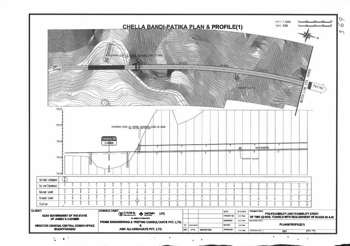
sr\o\
1,000500PROFTLE(1)
hllicil ali[r[l \ t ,
hl &{ E$rbtr i a r q: E : ? : ? T ? t
0ssi0 lewlt ;
t i S i E i i : t i i e r i l i i i
Ctud ts',€l i l q ! ! q ! t t q a q {P T P : ! T I : A E : E i a a i t d d ' {
Slationn i q E q q q q v q c a a
9 E : S t e i t f ,4 A i i i i S3 E : r s s f i
9 e
SLIEN I
AZA0 GOtrERIltEt{t OF tHE Et lEoFJ filtu t t(43]m
I'IRECTOR GENERAI CEIIIML DESIGI{ OFFICEIIUZAFFARAB^D
COXEULTAXT
o$y!l! ctgg[| r.'vrPRIIIE E GI'{EERIIIG t TEEfl G COI{SULTAI{T8 PVT. LTD.
aAA|F AU AAAOChIE PVT. LTD.
PRE+EASIBIUW AIID FEASIBIUTY STUDYoF lw\t (2) llo& TUllitEL$ wmt REruo MEl{t oF RoADS t}l AJK
PLAXCPROFIqII
0o{ tiEv. vl
-Z
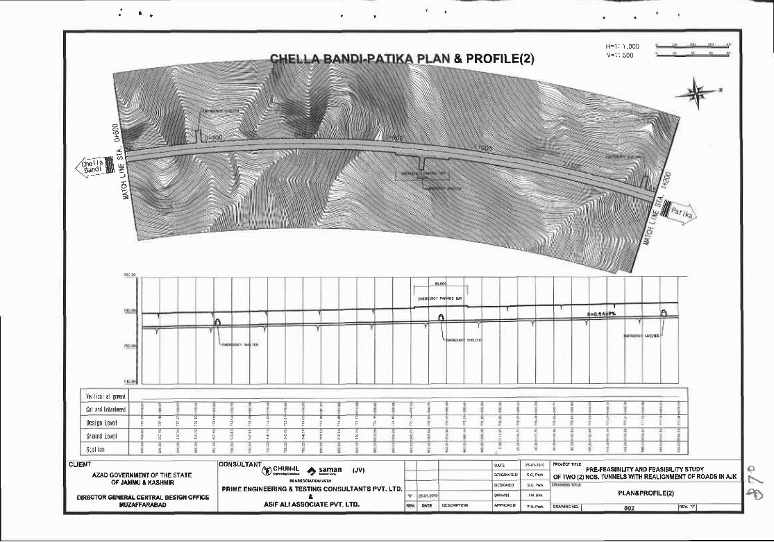
& PROFTLE(2)H=1 : 1 ,000V=1 :500
aE
@,sEE-4e=
J
AI
Verl ic{ l al i0rpnl
ful and Enba'{ltlll
0esi0n Level
crdrnd Lewl
Stal ion
CLIENT
A?jD GOVERNMENT OF THE STATEOF JAiIMU A XASHMIR
coNsulrANr@S::jjl C saman (Jv)
PRIME ENGINEERING A TESTING CONSULTANTS PVT. LTD,&
ASIF ALI ASSOCIATE PVT. LTD.
PRE+EASIBILJTY AND FEASIBILITY STUDYOF TWO {2) NOS. TUNNELSWITH REALIGNMENT OF ROADS INAJK
PLANEPROFILE(2)u|l(EG I r,n UENEXAT UE|l I KAL UESt{tN (,rrtuE
IIUZAFFARAFAO 0m
€N
€
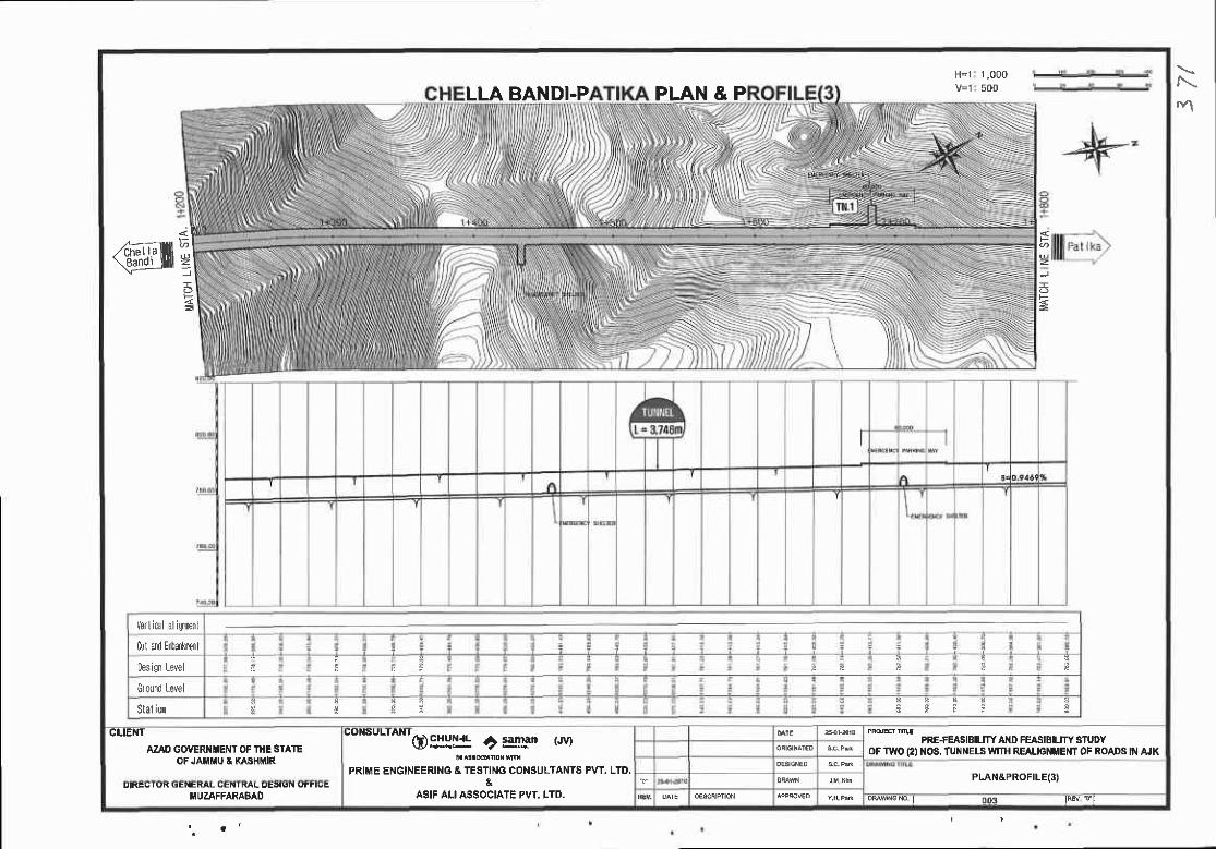
LLA BANDI.P PLAN & PH-1 r ,000
500
@ffiqz
*<
E
Y l ical al i0ne[l
Cul a|]d Enbal]lronl
Desi0n Level F i F p
0round Level
$tatiol t
CLIEiIT
AzAD GOVERIIIIENT OF I}IE SIATEOF JAIIUU A KAJIHMIR
"o""utt* (D Pirlj! ? tl!!-'an tru
PRIME ENGINEERING & TESTING CONSULTANTS PvT. LTO.&
ASIF ALI ASSOCIATE PVT. LTD.
PREfEASE||IrY ATD FEASIBIUW STUDYOF TWO 12) t{OS, TUI{ ELS WITH REAUGNMEMT OF ROADS IN AJK
PLAN&PROFILE(3)UIIG|,IUK SENEML LEN
I.I UZAFFARABAD DMvbrc|ro | 003 lhEv dl
r.\
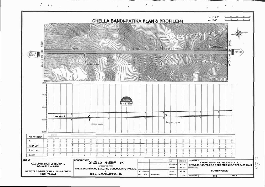
1 .000500ELLABAN PLAN & PROFI
rilrl
t=3 ,7
llA
I'r
l/erlicol aliqlsrl
Des ign Levs F
Ground Level
Stationr a n a
r a r g3 a a c a e - B I r a C P , B e
GLIENT
AZAD GOI/ERNMENT OF TIIE STATEOF JAMiIU & KASHIIIIR
DIRECTOR GENERAL CENTRAL DESIGN OFFICEMUZAFFARABAD
"o""utt nt@gJ:Ii!
+ :gllin (Jv)
PRIME ENGINEERING & TESTING CONSULTANTS P\'T I T'I
PRE+EASIBILITY AND FEASIBILITY STUDYOF TWO 12)NOg. TUNNELSWITH REALIGNII,IENT OF ROADS IN AJK
PLAN&PROFILE{4I&ASIF ALI ASSOCI,AIE PVT. LTD. mrmlo | 004 lF* fl
NN
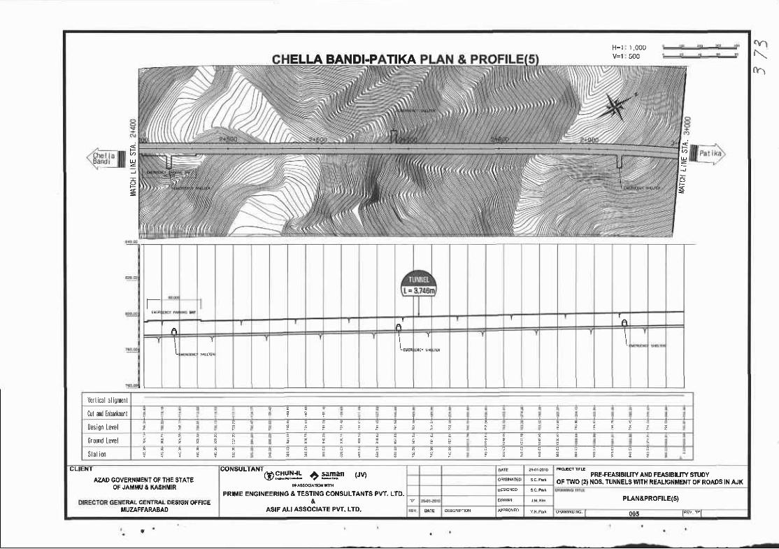
ELLA BANDI.PTIKAH=1 1 ,000
500
P=
lr'l=
II
I I
Verl iml al i f frnl
tul a{ Enhr*rsrl
oesign tewl
0roud Level
Slal ion g s
CLIENT
AZAD GOVERNMENT OFTHE STATEOF JAMIIU & KASTIMIR
"on"utto-o sYlij: ? Etgan t'rvl
PRIME ENGINEERING &TESNNG CONSULTANTS PVT. LTD.&
ASIF ALIASSOCIATE PVT' LTD.
PRE+EASIEIUTY AND FEASIBIUTY STUOYOF TWO (2I NOS. TUNNELS WITH REALIGNMENT OF ROADS IN AJK
PLAN&PROFILE(5}
MUZAFFARABAD oo5 F+ r'l
crl
\
ft-l

1 ,000500
Pat ik;
ler I ca aliUE]rl
tut fld Etadrnl $
Desi0n tevel
Ground lewl
Stal iona u : r *
CLIEI{T
AZAD GOVER}IMENT OF T}IE STATEOFJA MU A KASHMIR
DIRECTOR GENERAL CENTRAL DESIGI{ OFFICEI'UZAFFAMBAD
"o'surrANr@$Hrll ? tlrln twt
PRIME ENGINEERIiIG & TESTING COi{SULTANTG PVT. LTD.&
ASIF ALI ASSOCIATE PvT. LTD.
PRE+EASIBITY A D FEASIBILITY SIUDYOF TI'YO 12) NOS. TUI{NELS TYITH REAUGNMEIIT OF ROADS IN AJK
PI.AN&PROFILE(6)
006 IRB/. vl
f\.-
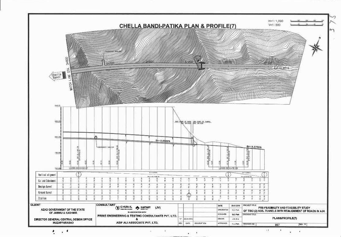
1 ,000500
Itrlical aliclenl (
oit ald Etudfienle 3 ! g I r 5 a a ai i : E a 5 f I I ? i . i f i : r ? e
oesis|| Level F F I E F E F I
Ground level ! i : * '
Stal ion
n' l
CLIENT
AZAD GOVERNMENT OF THE STATEOFJAMMU & KASHtrtlR
DIRECTOR GENERAL CENTRAL OESIGN OFFICEMUZAFFARABAD
CONSULTANT
osY::Jh + samar (Jv)
PRIME ENGINEERING & TESNiT CONSULTANTS PVT. LTD.
PRE+EASIBILlrY AND FEASIBILITY EIUDYOFTWO 12} NOS.TUNNELSWITH REALIGNMENT OF ROADS IN AJK
PLAN&PROFILE{7}&ASIF ALI ASSOCIAIE PvT. LTD.
007 la€v. ql
| , 1

t ' l
& PROFTLE(8)T 000500
3.lo OOOO*
Ver I cll aliFr€nl O .,,1;;.;,: @ .-SO r';.;':,.;;, Q0rl ad tda*,rml
Desi0n Level
oround Level
Stal ion
(;LIEN I
AZAO GOVERNIIENT OF THE STATEOF JAIYI U A KASHMIR
DIRECTOR GENERAL CENTRAL DESIGN OFFICE
"o""ut-o*tosg!1\ i l3lgqn rwt
PRIME ENGINEERING & TESTING CONSULTANTS PVT. LTD,&
ASIF ALI ASSOCIATE PVT. LTD.
PRE+EASIBILTTY AND FEASIBILITY STUDYOF TWO 12) NOS.TUNNELSWITH REALIGNMENT OF ROADS IN AJK
PLAN&PROFILE{8I
00a lFEv !,
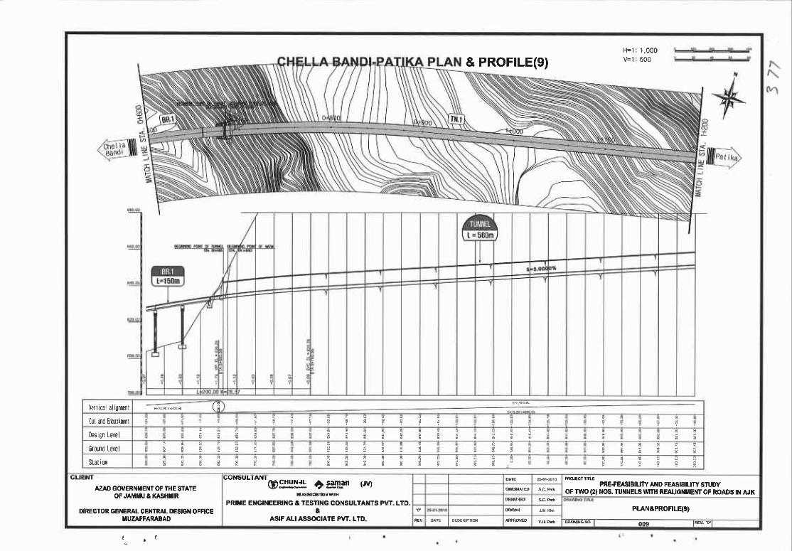
& PROFTLE(g)1 ,000500
Verllca ali0TDtl
Cut rt E|ltonkDnl i C l n
Des 0n Lelrl
Grou Level
Slation c s : r i l i c ! g E E B
OULNI
AZAD GOTIERI{flEI{T OF IHE SIATEOF JAIilIIU I KASH||R
DIRECTOR GENERAI- CE}IIRAI- DESIGI{ OFFICEMUZAFFARABAO
"on"u"to*qDgrgli! ?:glm tryt
PRlilE EIIGINEERING & TESTIiIG CONSIILTAI{TS PvT LTD
PRE€EASIBIUTYAND FEAS|aILITYS'IUDYoF r$o (2) Nos, TUilNEt-S U'mt REALTGT{MENI OF ROADS tN AJK
PLANAPROFILqg)aASIF ALI ASSOCIATE PYT. LTD.
ooe la. "l

1 ,000500LLA BANDI.PATIKA PLAN & PROFI 10
@trJ I- ls tgA
Verfical ali0lenl G)_*KC)0 dn Ebdoctl
q q & b ! ! R c e? r ? Y r r
oesi0n Levell 9 € 3! E s s i i E E E i !
Ground Levol
Slat ionE E * t : a a ! 3H fi ;i ii ft 6 E : * g _i
CLIENI
AZAO GOVERiITIIEIIT OF THE STATEOF JAMMU A KASHI'IR
DIRECTOR GEIIERAL CENTRAL DESIGI{ OFFICETUZAFFARABAI)
"o^"uttont6)gry*l! +) ::!La" rJV)
PRIiIE EXGII'IEERNG A TESTIXG COI{SULTANTS PVT. LTD.a
ASIF ALI ASSOCIATE PvT. LTD.
PRE+EASIEILITY AND FEASIBILITY STIJDYOF TWO (2I NOS,TUNNELS IVITH REAITGNMENT OF ROAOE N ruK
PLAr{tPROFILE{r0)
010 lF€'/ rl
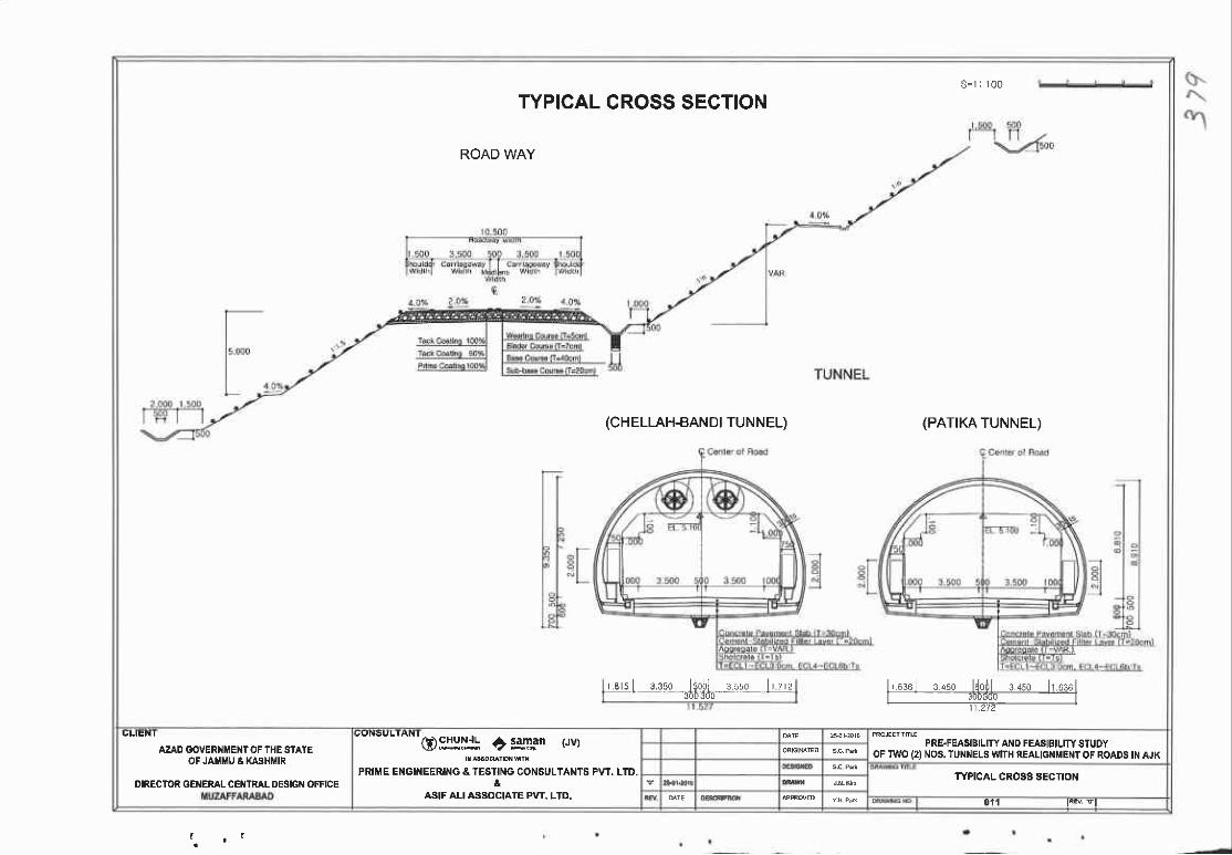
S = 1 : 1 0 0
TYPICAL CROSS SECTION
ROAD WAY
(CHELLAH.BANDI TUNNEL) (PATIKA TUNNEL)
l r oso : rso ldodl r+so l r .oss lr ------lw------r a ts I ooso l {ob l r .sso l r . z rz' -36bCdo-- - '
AZAD GOVERIIiIENTOF THE STAIEOF JAlllrtu e KAsHlillR
DIRECTOR GENEML CEI{TML DESIGN OFFICE
oglllll 6 saman (Jv)
PRIME EI{GINEERING & TESIING CONSULTANTS FW. LID.&
ASIF ALI ASS{)CIATE PvT. LTD.
PRE.FEASIBILITY AND FEASIBILITY STUDYoF TWO (2lNOS.TUNNELS tlrnH REALTGNT ENT OF ROADS TNAJK
TYPICAL CROSS SECTION
0'll lie ! l

TUNNEL

DESTGN CRTTERTA (1)
1. Design Load and Clearance Limit
rne ded lodd is *lidoted by *eiqhi or slructure,
. Live Load : tls20-44
. App l ic€ t ion o l D€s ign l le thod
3. Appllcatlon Standard ol Construclion Materialsr Concrel9
Aoolicotion ol Deoiqn Method
Strcmth txriqn rr.|hod
shord€re i r'rlg u.jhg corc.ete Alloru6r. s|re D.itg. M.thod
AlloKbl. 51,G5 D..tF M.tlEd
. lh6 tunrot dncr.t thins d-utd b. .Emin d f* o orobt 6ird! d6i9n n.thod,hll b. crcmin.d Id .L6o9lfi daiq. mtlEd h c@ oa buq ...d.d [email protected]
I ne slruclu.e oppli€d 3trength de&ign nEthod i. .rcmircd for eri6o6litr .uch .. .tdl.ctid, croct, .lc
. Height of Clearance Lin i l : 0ver 5. ln
2, Geomelry ol Road
. Classi l ical ion ol Road : Rural Road
I Desisn Speed : 8okn/hr
. TtPtcAL Cn0ss sEcTtolt
xol.) rn€ llidd6 ol ogqrsgote .nsy b. chong.d by si[o dditbns or .quipm.nl,
. Relorc lng BarCHELLAH-BANDI TUI{I']EL PA'I I II''INEL Desiqn Slrenqth ol ADDlicoirion Concrete
4. Measurement of Cross Section and Exlra Excavation
1) lh! h.osu..h.nt iht Nl is..t by sup.pisois in6lructiohs consid.nnq site.ohditions
but lt l. 5m 't it r... not tor sup.disor's instruotions-
2) Ih. cr6.. ...tioi rilh .rtrc .rcdv{{ion oro m€sured $tng
lh.n tn. r.€!lt ol md.ur.h.nt i6 dubmitted to ruDeMsor
)c.ign Strcngtl(MPo) GimI
Tunher Lininq c.ncdte. ir
SubdructvrE of Bidqe, {ing voll of Bddge, Reinlorced con.rete,
R.toi.i.q lydl, Curb, cu&err, Srob ot curErt Joil S€ctioh,
Foundot'ion oa SoundF@f l/vqlls, Fqcitltsl Tunn l hl.t ond Out€t
25v-ttpe o .h, L-typ. oit h, u-rrp€ D,rch. c6g 6r u-vp. Dnch,
Colk li.g Pit of U.don Slrijp, dlould.i Colletinq Pita.r 5
Grevit Reroining xbfl. l|6 contEt€,
Foundoton ol sub.tdiory F@ iti6. Founddtion or tJrlin Phe.
c.nedi.g Pil, u-t ps tx.i, l|ilq y|ol .f omi. Pip.
a
L@rnq Coh.cG. L€6. Cscr.t€
1 9 L typ. Ditch (M.cftin6 Aft6nrdu, B.
l,=5.o pownl !.d. C.mr.te
J2 4"6.4
( ;Lt tNl
AZAO GOVERNMENT OF THE STATEOF JAI'i'U & KASHMIR
DIRECTOR GEI{ERAL CEIITRAL OESIGN OFFICEI'UZAFFARABAD
oon"u"*'oPJHljl +) ig[Fn rrvl
PRIME ENGINEERING & TESTING COI{ITULTANTS PVT- LTD.
PRE+EASIBILITY AND FEASIBILITY STUDYOF TWO (2) NOS. TUNNELS WITH REALIGNMENT OF ROAD6IN AJK
DESIGN CRITERIA{I)&ASIFALI ASSOCIATE PVT. LTD. r t { e E = $ M
ootr4
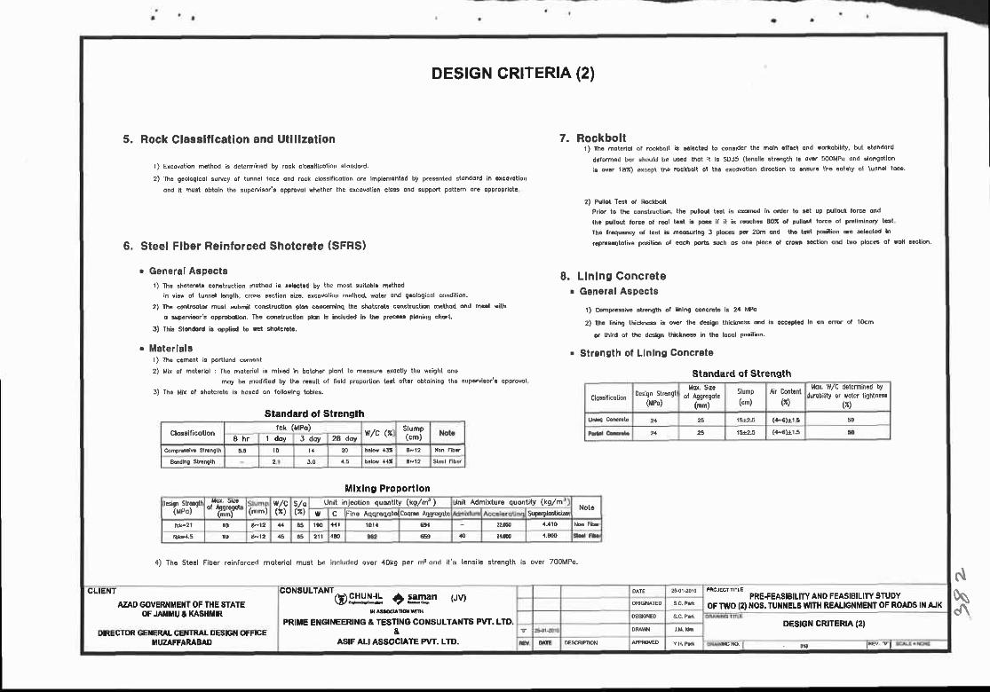
DESTGN GR|TERIA (2)
5, Rock Clas3ltlcalion and Utlllzatlon 7. Rockbolt1) rh. dotc.iot or..dib.ll i3 4l..t.d to snlrder th. m.ih.ll.cl and rortohilrv, but stdhdord
r) Ercovdtion m€thod '. d.tdrmined bt rock .larril i.orion .rdndo.d, delo'm6d bor ehould be us'd thot lt l! sD35 (tensllc att'nqth l! o.r sooMPa dnd 3lo'oolion
ii d.r 137) ercepr rh6 rcc*bolt ot tn. d.dotlon dnocton to .n8ur. th6 ddf.ty of tunh.r roc..
2) Ih. gaoloElcdl 3urcy of tunndl fdc. oid rock crossili6tio^ dru ihPl.d.nl.d by P.e*ded stohddrd in .rcovotlon
did n hBt obtoih the sup€Bis6/3 oppEvol *h.ther the er..vdtion clo$ dhd support pdttcrh dr. oPp.opnot.
2) P{llot Tcst of Ro.lh.lt
Prb. to th. coFlructio., th. pulloul t€l is *on*d ih o.d.r to 3.t up pultdt fo@ dnd
th. Pullout foc. of @l tln i. po.6 if it b rdchd AOI or ,ulour torce or FEliminory r'il
Ih. fr.qrlncy or l.sr is ne3lrlno 3 ploc6 pcr 20.r ond th. tcl pGition aE slcct.d In
6. Steel Flber Reintorced shotcrete (sFRs) 6pEs.Dlriv6 pdr'rion or €dch po'ri.u.h G 6n. pr.c. or c'o$ retion ond te pro.@ ot Nri.eri6
. General Aapectal) ln. ol.roi. con6lruotion n€thod l. &l.ct.d by the host suitobl. h.thod
in vi.r ol tunn.l Lnqth, cd8 llotion !i2.. .rcovotion n€thod, "olor
ond qeloqicdl conditi.n.
2) Ih. @ntr@tor nost sbmit 'u6tructotr gtor 6&.minq th. d€tcr.t coct {ction mudd md (.!t lilh
o !uD.Bi!or'. opprob.td, lllc cm.i'lctlon plon b indudcd In tn. proc.* plo.inq chorl.
3) Thh stodo.d it oeDlicd to rct sholcr.i.,
. Materblsl) th3 c.h.nt i. Dorrld^d csm€nt
2) Mir of hot€riol : Tne mdtedol is mir.d in b.tch6r pldhi to m.druro rxoctly th€ kight ond
moy b€ moditiad by th! clult ol fi€ld prcporton t.tt olt.r obtoininq tha 6up€di.o/. opprowl
3) Ih. Mar ot .hotcrcte ie bdsed bn tolloplng tobr€,
Standard of Strengthlck (MPo) w/c <x:.Slump
(cm)a h r 3 doy 28 doy
Mlxlng Proporllon
L Lln Ing Concreter General Aspecls
l) cmp..i.i@ str.n4th 6f llnlng concct is 2,1 llPd
2) th. lini.! thidcle i. e. th. deign occ.Dr.d h on ffi ol loch
d lhird ot the d6ign thi.tN in th. locol pGi[on.
r Sttgngth of Llnlng Concrste
Standard of St(ength
(mm) (cm) (i)
Mor, VC d€temin.d byjurobilit d rclr tr9htn6.
tz')
4) Th. St.!l Fiber rcinrorced hoteriol hust b. included over 40t9 Per noand its t.nsil. st..ngth is over 700MPo.
,gign Sb4glr(uPo) G.I (r) (zl
Unn injectio. quoatlty (kglm') hit Admittur€ quo.tity (kqlm(nm) c Fins AqqEqot6lc.o6 @€sqk
CLIET{T
AZAD @VER}I}IEI{T OF THE STATEOF JAf,IXU T KASHIIf,'
coNsulraNr@slli! <) !3lL* tuvt
PRIiIE EIIGINEERII{G & TESIING COI{SULTA TS PvT. LTD,&
ASIF ALI ASSOCI,AIE PYT. LTD.
PRE+EASIBILITY ANO FEASIBILITY STUDYOF TIT{O O TO3. TU}INELS WITI{ REALIOI{MEI{T OF ROAO6 IN AJK
DESIGN CRNERIA (2}DREGIOR GEXERAL CE||IiAL DESIGII OFFICE
I{UZAFFAMBAD E E t t u v u l
cl0\J\
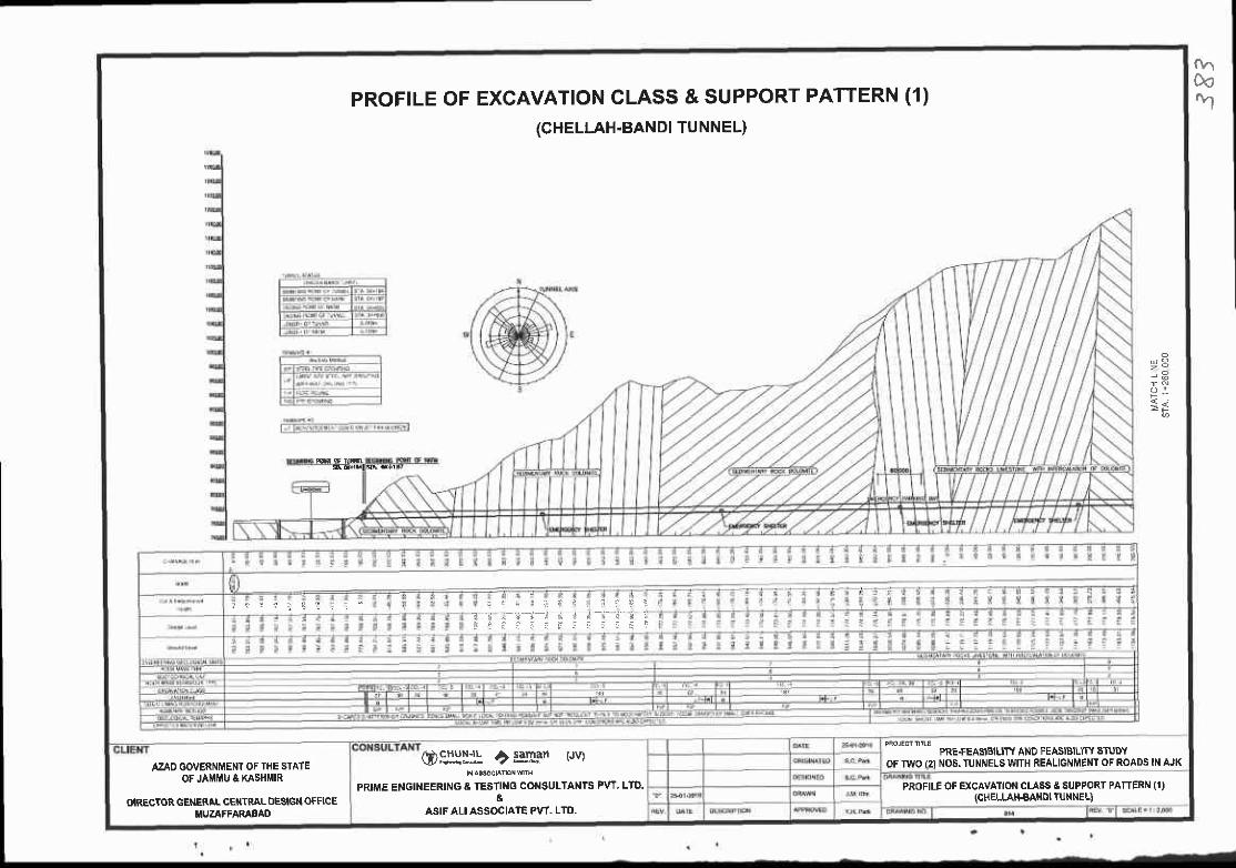
oaOotv|PROFTLE OF EXCAVATION CLASS & SUPPORT PATTERN (1)
(cHELLAH-BANDI TUNNEL)
i 3
ogJII* CElll.an pvr
PRIME ENGIT{EERING A TESTING COI'ISULTANTS PW' LTO.&
ASIF ALI ASSOCIATE PW. LTO.
T - i I i - " r d ! d - i - ( - i - i
PRE+EASIBIUTY AND FEASIBILITY STUDYOF TWO I2I NOS.TUNNELSWITH REALIGNMENT OF ROADS IN AJK
PROFILE OF EXCAVATION CLASS &SUPPORT PATTERN (1){CHELLAH€AIId TU NEL)
AZAO OOVERNMENT OF THE STATEOF JAMMU & KASHIIIIR
OIRECTOR GENERIL CETITRAL OESIGN OFFICEMUZAFFARAEAD
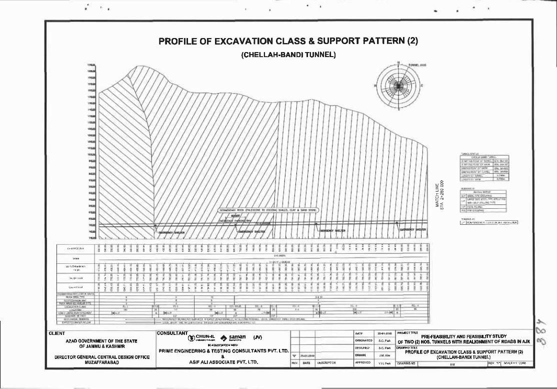
PROFILE OF EXGAVATION CLASS & SUPPORT(CHELLAH.BANDI TUNNEL)
PATTERN (2)
u 9
{ <
[iEnoRvNiiNcuJ ui;l
tt I $ I
d!
J
F F
E
GLIENT
AZAD GOVER ME T OF IHE STATTOF JAiIMU I KASHIIIR
OIRECTOR GENERAL CENTRAI. DESIGN OFFICEiIUZAFFARABAO
ton"utt*tc)grlljl c :3pfl (Je
PRIME ENGINEERING A TESTING CONSULTANTS PVT. LTO.&
ASIFALI ASSOCIATE PVT. LTD.
PRE+EASISIUTY AIID FEASIBIUTY STUDYOF IWO (2) 08. TUil}IELS ITITTI REALIG}II|ENT OF ROADS I[ AJK
PROFII.E OF EXCAVATIOI{ CLASS & SUPPORT PAT]ERN I2IICHELLAH.AANDI TUNNEL)
ouaNoNo I or lrd t' l scAE., ?I@
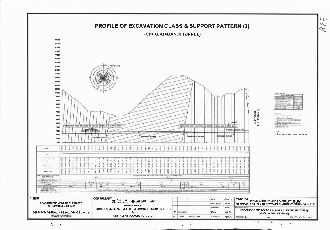
PROFILE OFEXCAVATION CLASS & SUPPORT PATTERN (3)(CHELLAH.BANDI TUNNEL)
> ;
r;lN:!!"'drj*v6ts;i{si
I t 5 J I
f I t $
I F : F E E E ' E ' i i ' : i n ! [ T
B r s S t * l P g t s i ; I t B I i i i E ! ts i ! ! ! s I
CLIENT
AZAD GOVERNMENT OF THE STATEOF JAMMU E KASBMR
DIRECTOR GENERAL CENIRAL DESIGN OFFICE
UONSULIAN I
@:IlH! C:g!:im (JV)
PRIME EI{GINEERITIG & TESTING CONSULTANT6 PVT. LTD.a
AAIF ALI ASSOCIATE PVT. LTD.
PRE+EASIBILITY ANO FEASIBILITY STUDYOF TWO (A NOS. TUI{NELS IVIIH REALIGNMEMTOF ROADS IN AJK
PROFILE OF EXCAVATION CLASS A SUPPORT PATTERN (3)(CHELLAHAANDI TUI{NEL)
or tRry 51 scrE, r : ,@
tooa.tO

pRoFtLE OF EXGAVATION CLASS & SUPPORT PATTERN (4)(cHELLAH.BANDI TUNNEL)
t jl]iindis-rB\!e\r+Ml
i
-::*-
F T E E 3 F E t * i 1 l i * { * t ? t i F E i p ? E E p E
3 ; ! t g ! q * f l i I i ! E F F p F
CLIENT
AZAO OOVERI{iIE T OF flC STATEoF JAlmu & xAsHutR
OIRECTOR 6€I{EMT CENTRAL OESIGI{ OFFICEMUZAFFAR^IAD
COIISULTANT
@!Iltr'! f :g!L- t'wt
PRIME ENGINEERING & TESTING COI{SULTANTS PVT. LTD.&
ASIF ALI ASSOCI,ATE PVT. LTO.
PRE+EA8ISIUTY AND FEASIBIUTY STUDYOF IWO (2} NOS. TUI{i{EL8 MTH REAUGI{IIENT OF ROADS IN AJK
PROFILE OF EXCAVATIOI{ CI.A8S E SUPPORT PATTER (4IICHELLAH€AI{OI TUNNEL)
NNGNoI u , lw

PROFILEOF EXCAVATION CLASS & SUPPORT PATTERN (5)
(PANKA TUNNEL )
Ffii*#iilr,-,--t^.6
,, ..;**' " -. ".",a-:i*r9"1i:L-*
Til"T.ffi ::'nffi gq'$"Jiifl i'#.K"#"*l*.'***oglly5 ? *lLan ovr
$a$dqlMsB
PRTIIE ET{6INEERIiIG A TESTTNG COI{SULTAI{TS PW' LTD'
&ASIF ALIAS9OCIATE PW. LTD.
AZAD GOVERI{IUEI{T OF THC STATEoF JAltttU t l(ASHttllR
unEcToR GEI{ERALFGE TRALoOESIGII oFFlcE
fRijH.' or ExcavtlfJl;T;i,fri j'*1"',1' t

TABLE OF EXCAVATION CLASS & SUPPORT PATTERN (1)
ECL J ECL 2 ECL 3 ECL-A ECL 6 ECL-6a ECL-6b
G T I / 1 2 J 5,6,7,4 1 0
B 1 0
Chel€ Band 6 I 1 0
6 I 1 0 1 0 ' t2
R B T 1 2,3
A O - 6 1 1 0 - 2 r
,lO - l0 l 0 - , 1
ToC B.odhglB.rch cur Iop hcoding^.nch Cut lop Beodihg/a€nch c'n Ring Cutlremporcry lNr
Sunoorl lnlaMl(Uhii : m) 3.sn o 2.O/2.O
lvsr Eroak lhlckn9ss (mm) 100 150 200 200 200 200
rs"lirl',ot 100 ($d nb.r)
2nd
3fd
Lenorh {n) t ,0 4,0
Bol lL0n0r- 2,0 1 5 t 2 1 0 0.4
2 0 1 5 5 1 5 1 , 5
St€et RibH-tooxtmx6xa H-tot)xtmx5xa H - | 50X t 50X7X | 0 H - l50xt50x7xr0
\-2 0,4 o3
Con c unrno Thckl6s(dn) 30.o 30.0 J O O J0,0
N ll
s.lf Ddlllni Typ.
CLIET{T
AZAD GO'ERIIEI{T OF THE STAIEOF JAilllU E KASHT{IR
CONSULTAI{T
@:I:u! t:gLm (Jv)
PRIT'E ENGI}IEERII{G & TESIII'IO CONSULIATTS PvT. LTD.&
ASIF AU ASSOCIATE PVT. LTO.
PRE+EASIEILFYAI{D FEASIBILIWSTUDYOF IIrc (2} NOS. TUNNELS WITH REAUGI{ ETT OF ROADS IN AJK
TAELE OF EXCAVANON CLASS & SUPPORT PATTER (1)
I'UZAFFARABAD DM$r6ro I oj, tRn Tt saE.FE
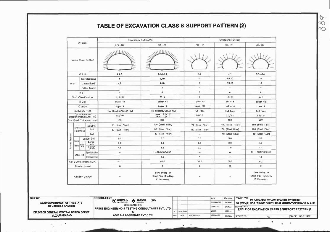
G.ooac
Emsrc€ncv Parhinq B€y
ECL IB ECL-28 ECL-rS ECL-25 ECL-35
G I U r,2,f, 4,5.6.4.e 2 5,4 5,6,7.A,9
a 9.ro 4,9.r0 1 0
Chella Bandi 9 . to 6
8 B T 3 4
60 - ,11
Lp Heddiht/B.n.h Cul Top H@dhg//Brch Cut
S ' h A n h r . N ' r l r h i i I m ) 2O/2-O 2.O/2.O 2,O/2.O 1.5 /1 ,5
lv6r Br€sk Thickness {mml 150 200 100 200
lS€alins) 100 (Si.el Fibad
100 (s1..1 fibed
3d
5-0 5 0 J.O 3,O J.0
BotlL9n9F 2,O r,2 2,O 2.O t .5
2,0 1 , 5 r .5
st6et FibH-1DoX10DX5XA H - l00l100x6xa
1,2 l 5
con c Linillc Thictnssstctn) 400 10.0 J D D 3 0 0
o o o
TABLE OF EXCAVATION CLASS & SUPPORT PATTERN (2)
GLIENT
AZAD OOVERI{IIEI{T (x IHE 8TA1EOF JAiIMU A KASHIIIR
DIRECTOR 6ENERAL CENTRAL DESIGN OFFICEMUZAFFARABAD
"onsur*wggrll! ? sgFn r'rvl
PRIME ENOINEERING & TESTII{G CONSULTANT8 PW, LTO.
AgIF ALI ASSOCIATE PvT. LTD.
PRE+EASIEIUW AI{D FEASIEIUW SIUDYoF TV{O l2l OS, TUNNELS Vrftr REAUO}|i|ENT OF ROAoS lN AJK
TABLE OF EXCAVATION CLA88 A SUPPORT PATTERN (2)
o$ F tu a ts -E. rcE

rabl6 ol Shotcr€l€ Thrckneat
TYPTCAL CROSS SECTTON OF MAIN TUNNEL (1)(CHELLAH.BANDI TUNNEL)
---::-.-_{-;,8
CLIENI
AZAD GOVERIIIEI{T OF TIIE STAIEOF JAIITIU I XAIIHNR
ORECTOR GEiIEMI. CEI{IRAL DESIGI{ OFF]CEIIUZAFFAMBAO
'on'u"*c) gyli! r) =Fgn t'ru
PRIIE ENGINEERING & TESTING COTSULTANTI9 PVT. LID.&
ASIF ALI ASSOCIATE PVT. LTD.
PRE+EA3EIUTY AIIO FEASIBIJTY SIUDYOF IWO (2} I{OA. TUI{NELS V'TTH REAIGNiIE}IT OF ROADS ItI AIK
TYPICAL CROSS SECTTOI| OF rrArfl TUNNEL (1)(CHELLAH€A DIIUI{NEL}
Dqwss. t o I Fw. .d t sca lE ' . s

T6b6 or Sholcrol€ Thickn€ss
TYPTGAL CROSS SEGT|ON OF MA|N TUNNEL (2)(PAT|KA TUNNEL)
i
iIIIIl
AZAD OOVERNMENTOF THE STATEOF JA MU A MSHI'IR
OIRECTOR GENERAL CENTML DESIGN OFFICEMUZAFFARABAD
(DSJH[* O $ngn t'rvrFRIME EI{GII{EERING & TESTING CONSULTANTS PVT, LTD.
&ASIF ALI ASSOCIAIE PvT, LTD
, PRE+EASIBILITY AND FEASIEILITY STUDYoF TWO (2) NOS. TUNNELS |VITH REAL|GNMET{TOF ROAD8 tN AJK
OFI'AIN TUNNEL (2)
s:.*cro

EXCAVATTON CLASS OF MA|N TUNNEL (1)(CHELLAH.BANDI TUNNEL)
ECL-I ECL.2
Sectlon Section B - B
{n 1-G-r!!1S.rt.Wo-e{r,.Wl-l*
:'4, 16 - atu7 ,,: i: i :4 .
CLIENT
AZAO GOIIERI{ITENT OF THE STAIEOF JAffi'U A KASHMIR
DIRECTOR GENERAL CEt{TRAL DE9IGN OFFICEMUZAFFAMSAD
"n""'^*'ft)9r:Ij! ? IgLan (Jv)
PRIME ENOII'IEERINO ! TESTING CONSULTANTS PVT. LTO,&
ASIF ALI ASSOC]ATE PVT. LTD.
PRE+EASIBILITYAND FEASIBIUW STUOYOF TWO {2)NOE. TUTINELS WIT}I REALIGNMENTOF ROADS IN fuK
EXCAVATION CLASS OF MAIN TUNI{EL (1}{CHELLAH.BANDI TUNNEL)
$lo-o
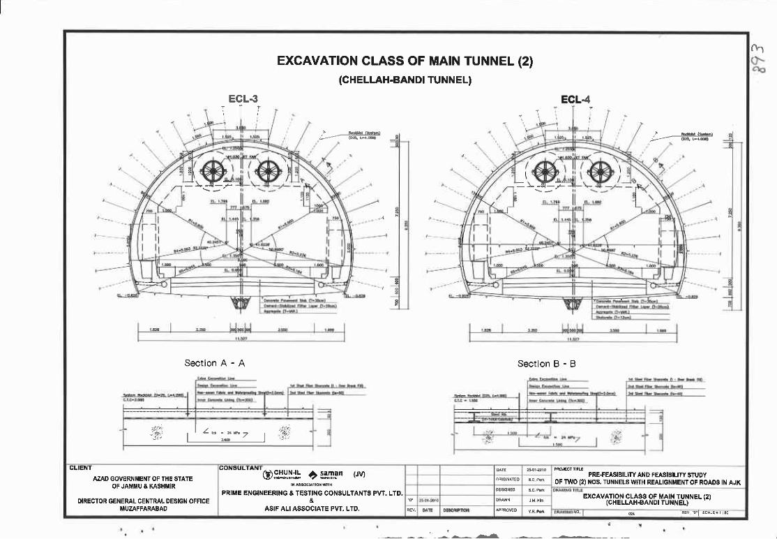
EXCAVATION CLASS OF MA|N TUNNEL (2)(CHELLAH.BANDI TUNN EL)
ECLS ECL4
- ' ts
Sectlon A - A Sectlon B - B
- \ F - __.<.-_r-*e--r
;,i:i l , .!!.: p . . t t
z - E . a ^ 7 | . , i ' : $ . i' r e l .
fh
CLIE T
AZAD GOVERT{MENT OF THE STAIEOF JAI{I$U A KASH IR
DIRECTOR GENERAL CENTRAL DESIGN OFFICEMUZAFFARABAD
@#lH! c;3n3n (JV)
PRIME EI'IGINEERING & TESTING CONSULTANTS PW. LTD.&
ASIF ALIASSOCIATE PVT. LTD.
PRE.FEASIBILITY AND FEASIBIUW STUDYOF TWO 12) NOS. TUNNELS WTH REALIGNMENTOF ROAOS IN AJK
EXCAVATION CLASS OF MAIN TUNNEL {2)ICHELLAH€ANDI TUNNEL)
' f l ,.A-Er i h
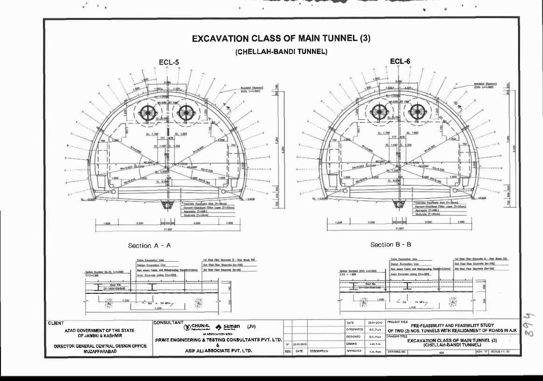
--7r t
EXCAVATION CLASS OF MAIN TUNNEL (3)(CHELLAH.BANDI TUNNEL)
ECL-5 ECL-6
j - - - :
Section A - A Section B - B
-\-5--F
CLIENT
AZAD GOII,/ERNMENT OF THE STAIEOF JAIiII'U & KASHMIR
"on""- n'G):rllill
? ;3nm t'rvt
PRIME ENOINEERINO & TESIING CONSULIANTS PVT. LTD.
ASIF ALIASSOCIATE PVT. LTD.
PRE.FEASIBILITYAND FEASIBIUTY STUDYOF TWO (2I NOS.TUNNELS TIIITH REALIGNMENT OF ROADS INAJK
EXCAVATION CLASS OF MAIN TUNNEL (3)ICHELLAH€ANDI TUNNEL}glREgl(,t( qENEi{AL riElt I RAL UEstliN Utr'rUE
MUZAFFARABAD oqwNcNo I d! tev a l
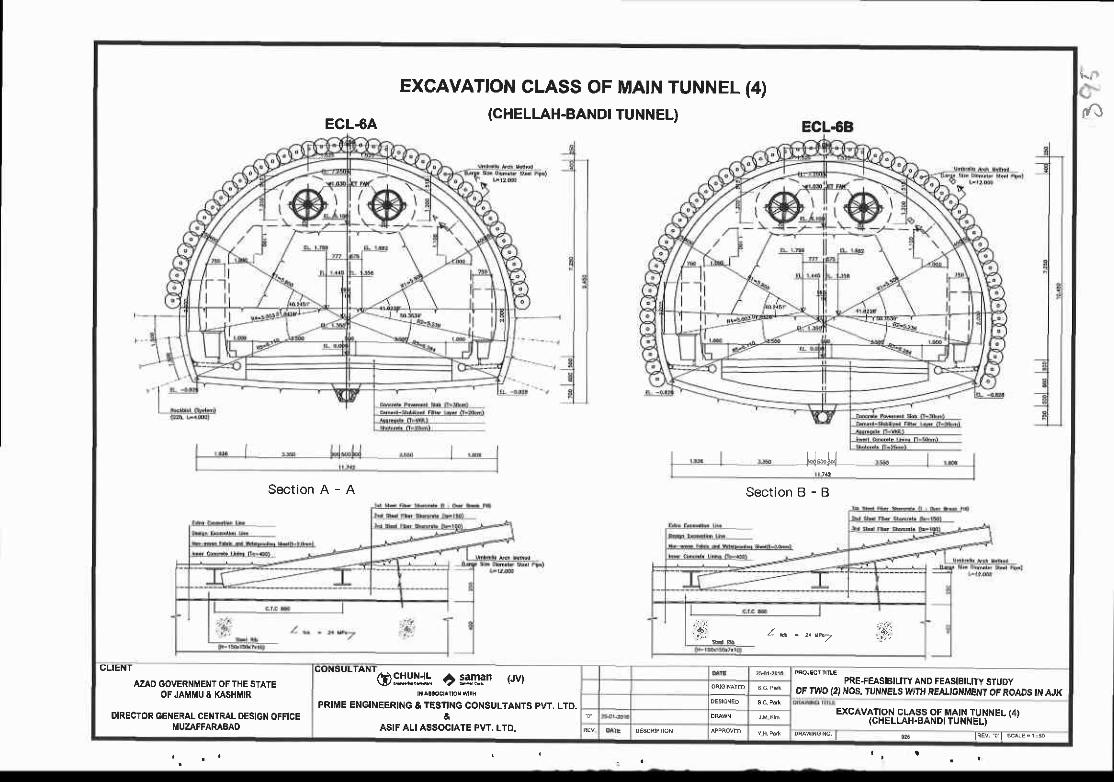
EXCAVATION CLASS OFMAIN TUNNELTUNNEL)
(4)
ECL4A(CHELLAH-BANDI
Section A Section
ECL.6B
H*UB - B
,. -: . :r.
f . * * z__^ ,_ . ' f ,
CLIENT
AZAD GOVERNMENT OF THE STATEOF JAMMU & KASHtrtlR
O:II!:15 ? isLan rwr PRE+EASIBILITY AND FEASIEILITY STUDYoF ryyo {2) Nos. tuNNELs wlTu REAucxti{Et 7 oF RoADS { AJK
PRIME ENGINEERING & TESflNG CONSULTANTS PW, LTD.&
ASIF ALI ASSOCIATE PVT. LTD.
EXCAVATION CLASS OF [4AIN TUNNEL (4)(CHELLAH.SANDI TUNNEL)
DIRECTOR GENERAL CENTRAL DESIGN OFFICEMUZAFFARABAO
Ylryl: | @6 lqd rl s F', s
|fJ
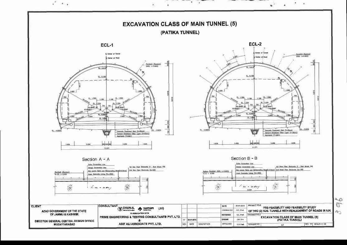
EXCAVATIONCLASS OF MAIN TUNNEL (5)(PATIKA TUNNEL)
ECL.2
Section A - A Section B - B
- - - - J - _ _ _ - 9 _ )
r i f ; ' L k ' ' z + E / i . f i ,i ' t * ; " ' -
, ' i
CLIENT
AZAD GOVERN!'EI{T OF THE STATEOF JAI'iIU & KASHMIR
DIRECTOR GENERAL CENTRAL DESIGN OFFICEI.|UZAFFARABAD
consurraNr6frylJ! c igLan rrvt
PRIME ENGINEERING & TESTING CONSULIAiITS PVT. LTD.
ASIF ALI ASSOCIATE PVT. LTD,
^*"*' r*u.r*slBrrny AND FEAsrBlLtry sruDy
OF TWO (2} NOS.TUNNELS MTH REAUGNMENT OF ROADS IN AJK
EXCAVATIOI.I CLASS OF MAIN TUNNEL {5){PATIKATUNNEL}
oMst rcMi d ' IRE ' . o l rc^ rE '1 :e

ECL-3
_ _ _ _ _ $ _ l
EXCAVATTON CLASS OF MA|N TUNNEL (6)(PAT|KA TUNNEL)
Secrion B - B
ECL.4
Section A - A
AZAO GOETI|IIEitr OF lI{E STAIEoFJAf[u4 tq$ flf,
DIRECTOR GENERALFCENTRAL DESTGN OFFTCE
O$yll! C pgga r.rvrPRIIIE ENCINEERII{G I rEAfl G COIISULTAI{III PVT. LTD.&
ASIF ALI ASEOC|ATE PyT. LTD.
*H#l!ss: ttri:ltTiil"-:trJiw#lRloo.,n _**u*tf"ifrf ',o,fn[f $
TUr{irEL (6t'
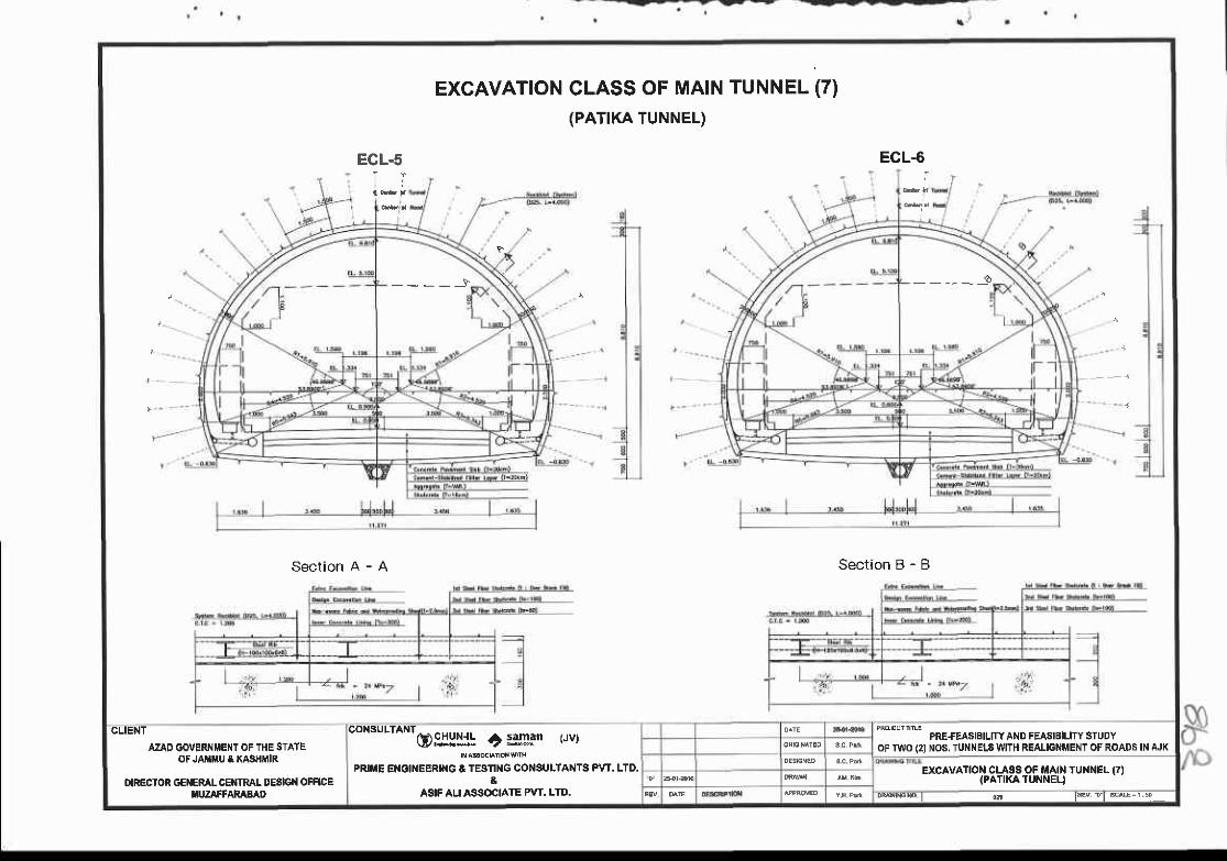
EXCAVATION CLASS OF MAIN TUNNEL (7)(PATIKA TUNNEL)
ECL.5 ECL-6
Section A - A Section B - B
- - - _ - } _ _ _ _ _ o
GUENT
AZAD GOVERIIMEI{T OF THE STATEOF JMiIU & XASHMIR
IXRECIOR GEIIERAL CEIITRAI. DESIGI{ OFFICE|,UZAFTAMBAD
CONSULTAI{To$lu: t:gLan (Jv)
PRIIIE EI{GINEERII{C & TESflI{G CONSULTANTS PW. LTD.&
ASIF AU ASSOCIATE PVT. LTD.
PRE.FEASIBITY ANO FEASIBILITY STUDYOF TWO (2I NOS, TUI{NELsWITH REALIGNMENT OF ROADS IN AJK
excrvrrof"f;Hr*rorin$tr N TUNNEL (7)
@ l w r l s M = r ; s
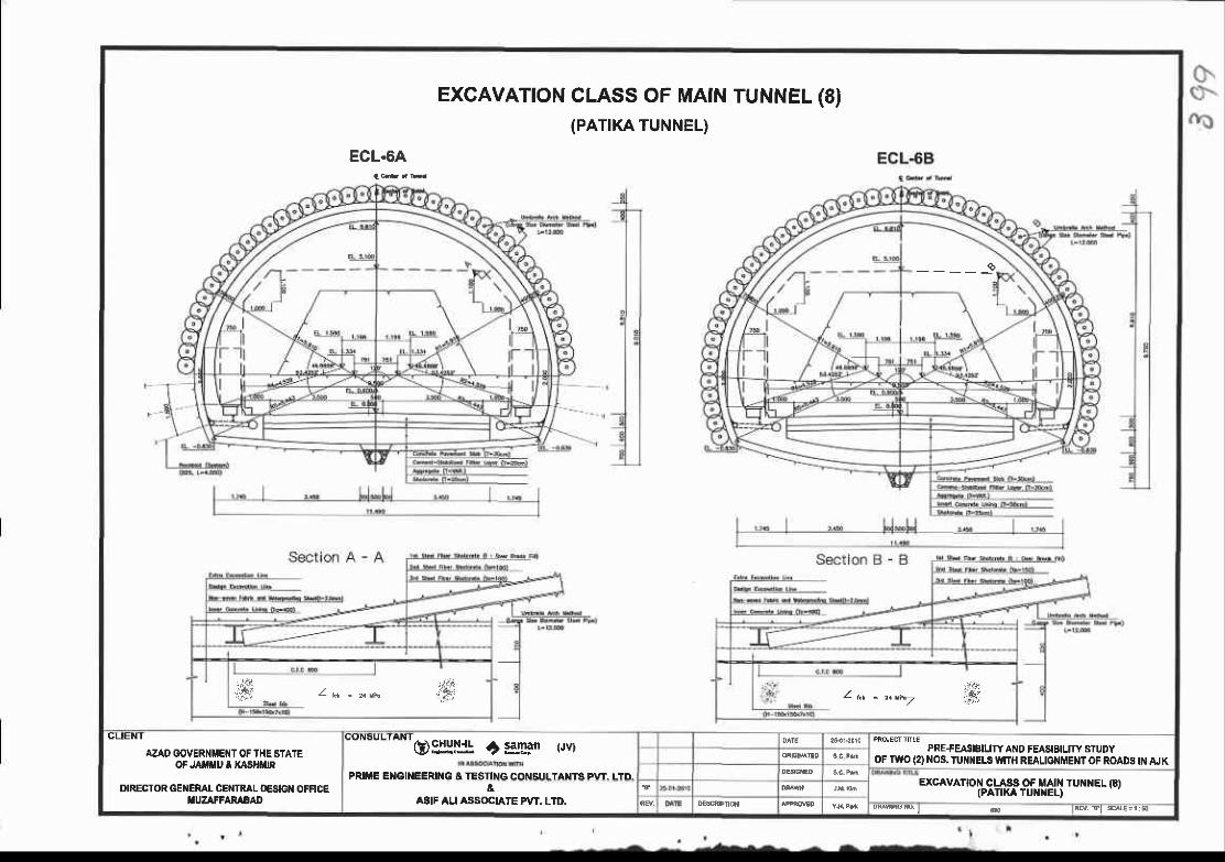
ECL.6A
EXCAVATIONCLASS OF MAIN(PATIKA TUNNEL)
TUNNEL (8)
_ _ _ _ _ 9
.:r. .,:ir. i f , - z e - s " N ; g )':ar.
Zt - t tt"Z ,..#i'
CLIENT
AZAO GOVERNUETIT OF THE STATEOF JAIIIIU E XASHTN
DIRECTOR GEiIEML CETITRAL O€SG OFF|CEIIUZAFFAMEAD
utnou"'^ntogi:lljl t samar (Jv) PRE+EA:IIBIFI AI{D FEASIBIUTY STUDY
oF TWO (2) XOS. TlrNlEtS WITH REALTONMENT OF ROAOS tN AJKPRIIIE EI{GII{EERII{G & TESTING CONSIILTANTS PVI LID
EXCAVATION CLASS OF MAIN TUiINEL G)IPATIKA TUNXEL)&
ASIF ALI ASSOGIATE A'T. LID.

-_ - - . - - - -v . { | ! - - -
shor.rcb Jr'idiid$.l
TYPICAL CROSS SECTION OF EMERGENCY PARKING BAYTable ol shotcrete Thickness
q Cenier or Emersency Porking Eoy
\\ \ \
____\____\
\ l
\ '\
II
IIIII
CLIENI
AZAD G(ryERNTENT OF TIIE STATEOF JAMMU & KASHI{IR
DIRECTOR GENERAL CENTRAL DESIGN OFFICEttlUZAFFARABAD
------'-' olllnu. r):gg.n r.rvr
PRIME ENGINEERING &IESTING GOIISULTANTE PVT. LTD.&
ASIF ALI ASSOCIATE PvT. LTD.
PRE+EA$BIUTY AND FEASIEIL]TY STUDYoF TWO (2) OS. IU]{NELE WrrH REALIO MEI{T OF ROADS lil AJK
TYPICAL CROSS SECTION OF EMEROENCY PARKING BAY
Dqq\o{o. | 6 liE!

EXCAVATION CLASS OF EMERGENCY PARKING BAY
ECL.1B ECL.2B
Section A - A Section B - B
z* t - 2aw.7 6 : | + ,* ) , ,1 _,."" . . .#:
CUENT
AZAD OOYERI{IIEIIT OF TIIE SIAIEOF JAllllU O TA3HIIR
OIRECTOR GETIERAI CEI{TRAL D€SIGII OFFICEIIUZAFFARIAAD
COI|SULTA T
Ogljl'+ ri elnan Pv)
PRIIIE E GI EErul{G A TESTTNG COXSUL'AMTS PVT. LTD.&
ASIF AU ASSOCIATE PVT, LTD.
PRE+'EASIBIUTY A}ID FEAIIIEILITY STUDYOF T{VO {2} IIO8.IUI{IIEL8 WfH REALIGNMENT OF ROADS I AJK
EXCAVATIOX CI.ASA OF Ef,ERGEI{CY PARKI]{6 BAY
Ml'eb. I e tEv. Tt sa€=l:o
a-F

Et - ts
ECt-tE
ECL-JS
TYPICAL CROSS SECTION OF EMERGENCY SHELTER
Table ol Shotcrete Thickness
CUEIIT
AZAD GO'ERI{METT OF TI{E STATEOF JAIUU A KASHMR
OFECTOR GEXERAL CE}ITRAL OE3IGII OFFICEiIUZAFFARABAD
@$:!l! C t3tr3" t'rvt
P E ENGINEERI'{G & TESTINGCO SULTANF PVT. LTO.&
ASIF ALI ASSOCIATE PVT. LTD.
PRE'FEASEIUTY ANO FEASIBUTY STUOYOF IWO (2I I{06. TUI{NELS II'TTH REAI.IGNMEXT OF ROAI}S IT ruK
TYPICAL CROIIS SECTION OF EI|ERGEIICY SHELTER

EXCAVATTON CLASS OF EMERGENCY SHELTER (1)
Section A - A Jec on B - B
ECL.1S
6rF d EffiFry ettur Ro<M (s6r
ECL.zS
AZAO GOVERNI'ENT OF THE STATEOF JAIrlIrtU & MSHMIR
OIRECTOR GENERAL CENTRAL DESIGN OFFICEMUZAFFARABAO
@.cill!{! t:glFn (JV}
PRIME ENGINEERING & TESTING CONSULTANTS PVT, LTD.&
ASIF ALI ASSOCIATE PvT. LTO.
PRE-FEASIBILITY AND FEASIBIL]TY STUDYOF TTVO (2)NOS. TUNNELS WITH REAUGNMENTOF ROADS IN AJK
EXCAVATION CLASS OF EMERGENCY SHELIER 11}
fF\o
s

a ) ' I
EXCAVATTON CLASS OF EMERGENCY SHELTER (2)
ECL.3S
{
CLIENT
AZAD GOVERNMENT OF THE STATEOFJAII ' E KASTNflR
DIRECTOR GENERAL CENTRAL DESIGTI OFFICE[IUZAFFARABAD
(;ottsulIa f
@$:!{ +} sslgn trvt
PRIME ENGINEERING & TEBTING CONSULTANTS PVT. LTD,
ASIFALI ASSOCIATE PvI. LTD.
PRE+EASIflLTTY AND FEASIBILIW STUOYOF TII'O IO NOS, TUNNELS V'ITH REALIGNMENTOF ROADS IN AJK
EXCAVATION CLASS OF EMERGENCY SHELTER (2)

(
s-\*
TYPICAL JOINT SECTION
EMERGENCY PARKING BAY - EMEFGENCY SHELTER
lhoo6
tr@
@
MAIN TUtin{EL - EMER]ENCY STIELTER
AZAD GOVERNi4ENT OF THE STATEOF JAMMU A XASHMIR
OIRECTOR GEiIERAL CETiTRAL OESIGI{ OFFICEMUZAFFARABAD
QPJ:|'"-' t:g!!:Fn (JV)
PRIME ENOINEERING A TESTING CONSULTANTS PW. LTD.&
ASIF ALI ASSOCIATE PvT. LTD.
PRE+EA$IBIUTY AND FEASIBILITY STUDYOF TWO (2INO6. TUNNELSWITH REALIGNMENTOF ROADS IN fuK
1\ t

DETAIL OF ROCK BOLT AND CONSTRUCTION SEQUENGE
Cemen t mor tar type Resin typeConstruct ion of rockbol t in crushing crown par t
O InsBr t Ine ol resin
| 30Ll L ax : 0?(x)+omJ+0{o7+0'r07
Construct ion concept of rock bol t in f ractur ing s ide wal l par t
l ' lho le sur face bonding tYPe bo I t
Q o r t t t i r u
@ Cernen t mortar oroutlng
O In€srl ins ol bol l
@ fastenino Dl bear ln€ plate
I_t
O tt ixins ot resin by
O conp t " t i on o t i nso r t i no bo l t
@ rastenino or reli
t
*'"* ,*E*tosEtalry attD FEAstBtLirY sruDY
oG lt{o t2l }16. Tln{t{ELs YltrH REAtlcl{illE}fr oG RoAD6 ll{ AJKOllgll+ i :gllsn t,"t
PRIME EI{OINEERI G & TESTINGCONSULTA TA PVT. LTD.&
ASIF ALI ASSOCIAIE PvT. LTD.
azAo GolrER f,El$ OF Tl{E srAlEOF JATIU & KASHIiIR
DIRECTOR GENEML CENTRAL OEgIGt{ OFFICEI,lUZAFFARABAD
DETAIL OF ROCK BOLTAT{D CONSTRUCTIOiI SEQUENCE
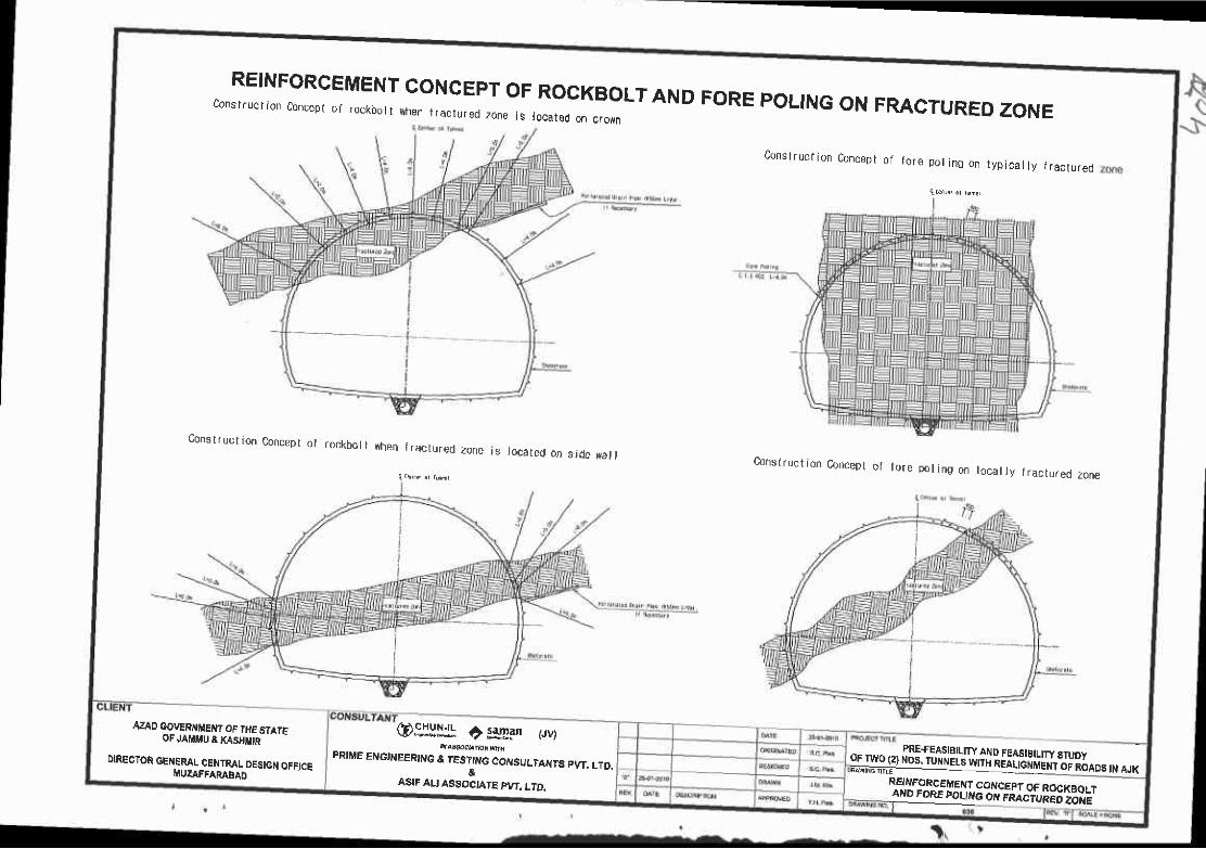
c"":'^:::,::et.:T:)1',::::,::,:ff:::":""":LTAND FoRE poLrNG oN FMCTURED zoNE
Cons t ruc t i on Concep t o f f o re po t i n0 on t yp i ca l l y i r ac l u red
q h r , o r r r , !
COnstruction Concept of rockbol t rhen fractured
{ r5h( d rf t ,
zone is located on s,dc {al l Cons I ruct ion Concspl q1 to re po l i ng on l oca l l y f r ac lu red zone
AZqD OOVERI{MET{T OF T'IE STArFoF JAMI'U a xA$tt|tn
oIREGTOR GENEMLFCENTRAL DEStcN OFFiCE
@.9'IlHt ? !g!an pvrPRIME ENGlritEERtNe & tEST_tt{G COI\tSULTaryTs pvT. LTD.
&ASIF ALI ASSOC'ATE PY,,. !TD.
*#gi55.",ii.,i:ltT,iil lliifl ihlT,TlRloo.,*,*i'i[1'i^",-y"113"A",.[Iff,[33!'"i.J
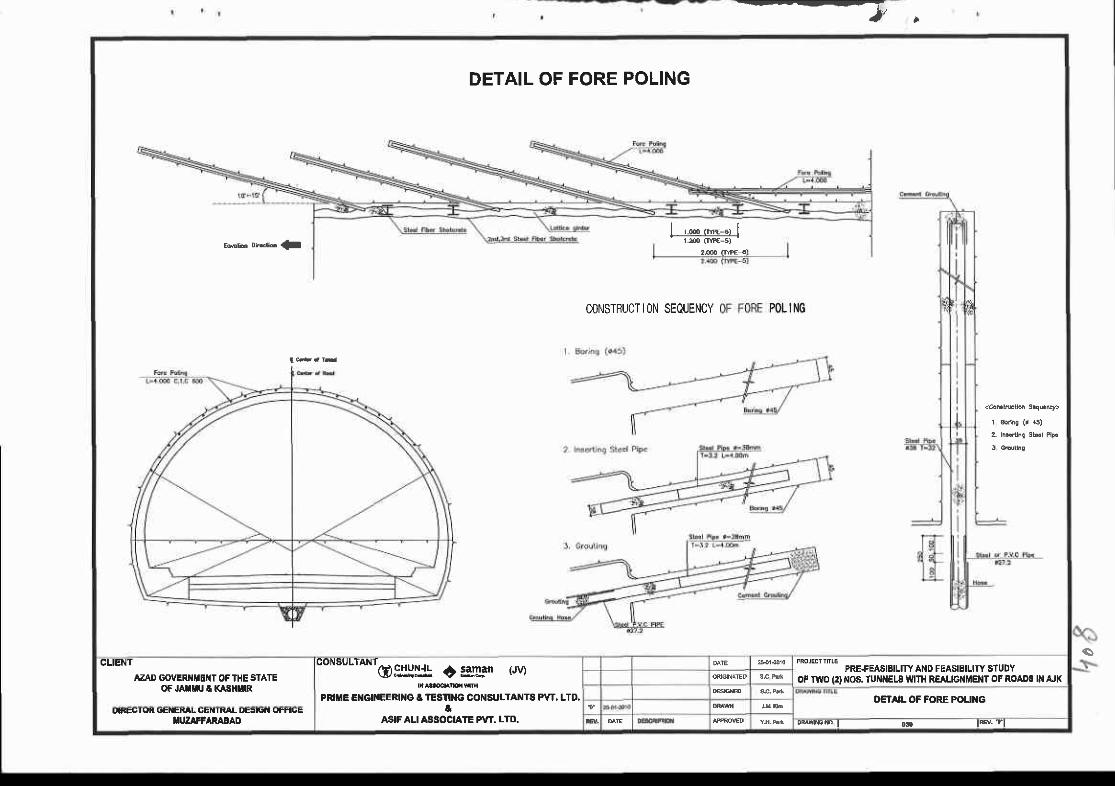
--V I
DETAIL OF FORE POLING
CONSTRUCT ION SEQUENCY POL ING
t t
sCLIENT
AZAD GOVERNIIEIIT OF THE STATEOF JAXUU T KASHMR
co'tsu urNr6 IIIIJ! c;g'Lan r'rvl
PRllrlE E GlllEERll{G & lESn[G CoilsuLTANTA PVT. LTO.a
ASIF ALI ASSOCATE P\'T. LTD.
PRE+EASIEIUTY A D FEASIEILITY STUDYoF TwO (2) NOS. TUNNELS V{|TH REALTGNMENT OF ROA08 lN AJK
DETAIL OF FORE POUI{GI'iEU I qK (,E|IEXAL UE|l I |!|AL UEFi'I t,'T|uE
f,I'ZIFFARABAD DMrrE.D I o!. lB. tl

Sra-s-DETAIL OF PRE.GROUTING
F r o n t S ide
P l a n
'\'i, \ \ i Concept of la tera l Dre-bor ing
\ . \ . \ i i i i','J, i 'r i i\\Li \ i i i i
I
@o
o@
Quan t l ty tabula l ion
AZAD GOVERNMENT OF THE STATEOF JAMIIIU & XASHMIR
ONECIOR GEI{ERAL GEIIIR I- DES|G OfFICEf,UZAFFARABAD
O$!l!l! | IsrFm twtPRIIIE ENGINEERING & TESTING CONSULTANTS PvI. LTD.
&ASIF ALI ASSOCIATE PVT. LTD.
PRE+EASIEILTTY AND FEASIBILITY STUDYOF lwo (2} NOS.TUNNELS IUIH REAUGNMEI{T OF ROADS IN AJK
DETAIL OF PRE€ROUTIiIO
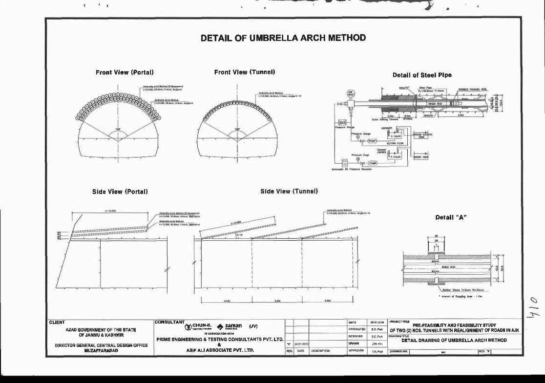
-_--1/
DETAIL OF UMBRELLA ARCH METHOD
Front Vl€w (Portal) Front Vlew (Tunnel)Detall of Steel Pipe
Side Vlew (Portal) Slde Vlew (Tunnel)
Derall "A'
CtlE I
AZAD GO'ERNMENT OF THE STATEOF JAMMU 8 KASHMIR
to""utt *o)sHlJ: c s*'Fn rwl
PRIME ENoIIEERING &TESTING CONSULTANTS PW. LTD.&
AgIF ALI AgSOC|ATE PvT. LTO.
PRE+EASIB|LITY AND FEASIBILITY STUDYOF TWO (2) NOS.TUNNELSWITH REALIGNMENT OF ROADS IN AJK
DETAIL DRAWING OF UMBRELLA ARCH METHODUI,(EI';IUK UEfiEKAL UEII
IIUZAFFARABAD DRreb I s, FEv. rl
\
J\
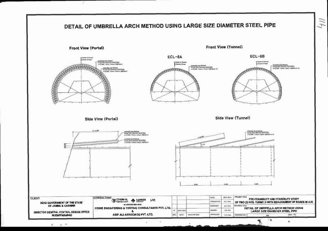
DETAIL OF UMBRELLA ARCHMETHOD USING LARGE SIZE DIAMETER STEEL PIPE
Front Vlew (Portal) Front view (Tunnel)
Slde Vlew (Por ta l ) Slde Vlew (Tunnel)
ECL-6A
PRE+EASIEIUTY ANO FEASIBIUW SnJOYOF TWO O iIOs. TUI{I{ELS
"IIITII REAUGNMEI{T OF ROADS II{ AJK0$:!l- +:ggan (Jv)
PRIME ENGII'IEERING & TESTING COI{SULTAI{TS PvT. LTD.&
ASIF AU ASSOCIATE PW. LTO.
AzAD GOVERI{IIEI{T OF THE STAIEOF JA MU 8 KASHMIR
DIRECTOR GENERAL CEIITFAL DESIGN OFFICEI{UZAFFARAFAD
DETAIL OF UMBRELLAARCH METHOD U8INGLARGE SIZE DIAMETER STEEL PIPE
BRIDGE

P lanS=1r500
BRIDGE LAYOUTs=1:500 CROSS SECT ION
s-r:6r,5
F IELD PHOTOGRAPY
ELEVAT ION
Ee€t--* ' :
E € . ! !
co{r[r r€Y sERvrccs FoR EoF rofi.i oa! a (xro& ruuEl8G)EII!!+ i i3F3" t.wt
rld*'c tbilwn
PRIME ENGINEERING & TESTIT{G CONSULTANTS PW. LID.
ASIF ALI ASSOCIATE PVT. LTD.
AzAD GOVERI{IIENI OF I}IE STAIEOF JAMiIU E KASHiIIR
DIRECTOR GENERAL CENTRAL DESIGN OFFICEMUZAFFARABAD
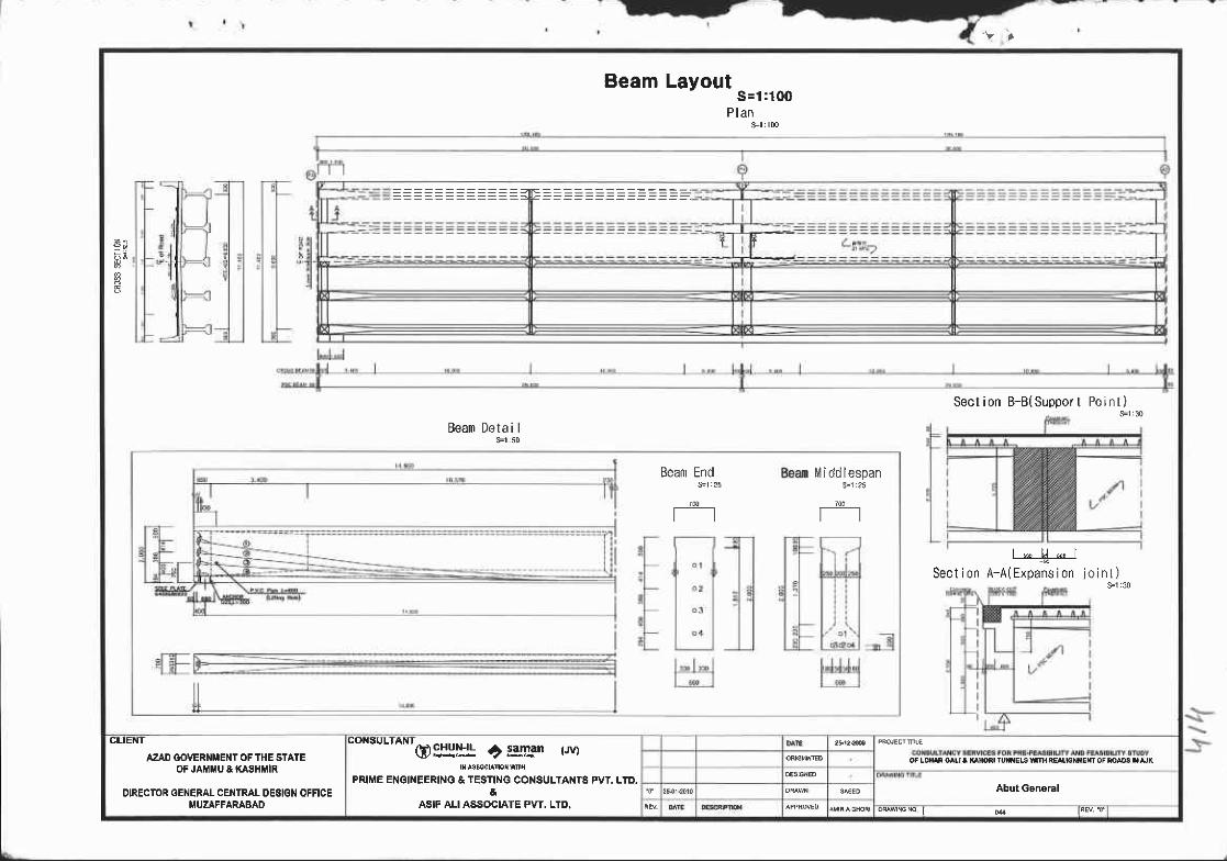
BeamLayoutS = 1 : 1 0 0
P l a ns= l : lm
6 i
n
Sect ion B-B(Suppor t P o i n t )sEr30
BeamDeta i I
Sect ion, * ] i * ,
A-A(Expans i on j o i n t )S=1:30
Beam End BeaInMiddlespans-r:25
CLIENT
AZAD GOVERNMENT OF THE STAIEOF JAtttttu & KASHMIR
DIRECTOR GENERAL CEI'{IRAL DESIGN OFFICEMUZAFFARABAD
"orsur*Nrg !rl!J! ? t4ln r.ryl
PRIME ET{GI EERING & TESTING CONSULTANTS PVT. LTO.&
ASIF ALI ASSOCIATE PVT. LTD,
oFlom o^rr a |(lnofl rul|xEls
AbutGeneral
oq{{cs I o{ t4v f
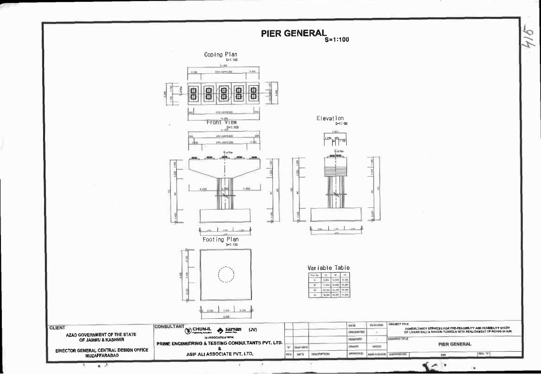
PIER GENERALs= 1 :100
Coping Plan9r : l c0
E I evat ion
I l l r I
Foot ing Plans-1 i116
( , )Var iab le Table
coirsulrMy 8Eivrcls Fot Pn!.arasrlrlllY r D FErd!|Lm sfuDYoF LOHAi eALt I n^nod ru{ilEt€ wIfl iEAlotlxErd oF aoao3 ||r !K@9J:!l! ? l*Fn trvt
PRII|E ETTGU{EERING & TESTII{G CO SULTAiITS PVT. LTD.&
ASIF ALI ASSOCIATE PVT. LTD.
AZAD GOVERNI{ENI OF THE STATEOF JAI iIU & KASHI'IR
DIRECTOR GENEFAL CENTML DESIGN OFFICEMUZAFFARABAD
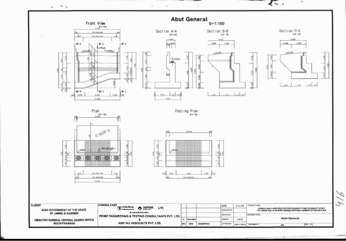
F.
Abut GeneralFront V iev/ S = 1 : 1 0 0
Sect ion B-B$1 100
f;; -;_-l
l
Sect ion A-AS"1 100
E;r-r-lt l
Sect ion C-C
, " , t , , " , , , t , ,1
t , "" t , , " t , , " t , , .1
Foot ing P lan
CLIENT
AZAD GOVERNMENT OF THE SIATEOF JAMiIU & KASHMIR
DIREGTOR GETIERAL CEHTRAL DESIGN OFFICEMUZAFFARABAD
@9iY*l ') tglgan trvt
PRIME ENGINEERING & TESTING CONSULTANTS PVT. LTD,&
ASIF ALI ASSOCIATE PVT, LTD.
Abut Gen€ral
04 lRcv {'